Embed Size (px)
Citation preview
Beyond 400G TechnicalWhite Paper
Beyond 400G Technical White Paper
All rights reserved. No spreading without permission of ZTE 1
Beyond 400G Technical White PaperVersion Date Author Reviewer Remark
V1.0 2021/07/13 ZTE ZTE First Released
© 2021 ZTE Corporation. All rights reserved.
ZTE CONFIDENTIAL: This document contains proprietary information of ZTE and is not to be disclosed or used
without the prior written permission of ZTE.
Due to update and improvement of ZTE products and technologies, information in this document is subjected to
change without notice.
Beyond 400G Technical White Paper
2 All rights reserved. No spreading without permission of ZTE
Contents
1 Introduction.....................................................................................................................................3
2 B400G Technologies and Solutions......................................................................................... 42.1 B400G Technologies....................................................................................................................42.1.1 Forward Error Correction (FEC)..............................................................................................52.1.2 Baud Rate and High-Order Modulation Modes.................................................................... 52.1.3 Polarization Multiplexing...........................................................................................................62.1.4 Special Fibers............................................................................................................................ 72.1.5 Wave Channel Extension.........................................................................................................82.2 B400G Solutions...........................................................................................................................82.2.1 400G PM-16QAM......................................................................................................................92.2.2 400G PCS-16QAM................................................................................................................. 102.2.3 400G PM-QPSK......................................................................................................................102.2.4 600G PCS-64QAM................................................................................................................. 112.2.5 800G PCS-64QAM................................................................................................................. 112.2.6 1.2T PCS-64QAM................................................................................................................... 11
3 B400G OTN Architecture........................................................................................................... 133.1 B100G OTN Mapping and Multiplexing.................................................................................. 133.2 Flex ROADM............................................................................................................................... 15
4 B400G Networks and Devices..................................................................................................164.1 B400G Network Architecture....................................................................................................164.2 B400G Cross-Connection.........................................................................................................174.3 B400G Control and Management............................................................................................184.3.1 Routing and Spectrum Management...................................................................................184.3.2 Control Plane Technology..................................................................................................... 19
5 B400G Standards Progress...................................................................................................... 205.1 ITU-T .........................................................................................................................................205.2 IEEE .........................................................................................................................................205.3 OIF .........................................................................................................................................205.4 CCSA .........................................................................................................................................21
6 ZTE B400G Overview..................................................................................................................21
7 Conclusion.................................................................................................................................... 24
8 Reference.......................................................................................................................................24
9 Abbreviations............................................................................................................................... 24
Beyond 400G Technical White Paper
All rights reserved. No spreading without permission of ZTE 3
1 IntroductionThe high-speed optical transmission system is the backbone of the global telecommunication
network and it connects people in every corner of the world. According to the R&D of mainstream
research institutions and equipment manufacturers, the single-channel rate of optical
communication has increased from 2.5Gbit/s 20 years ago to 400Gbit/s and 800Gbit/s now, and
the single-fiber system capacity has increased to 48Tb. However, this is still not enough. With the
advent of the 5G, cloud computing, and AI era, the annual demand for network traffic increases
dramatically, and mainstream operators are promoting higher-rate networks to meet the
increasingly urgent bandwidth requirements of customers.
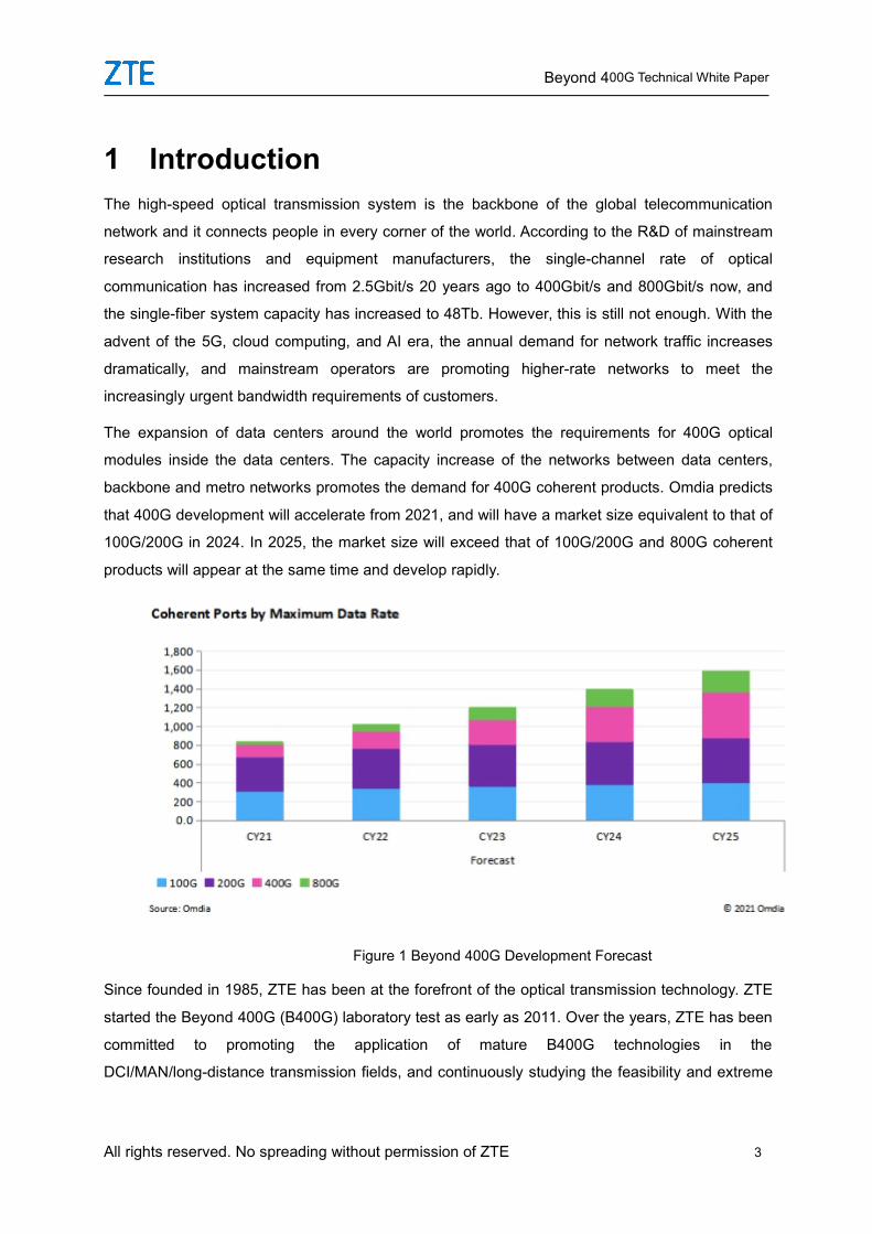
The expansion of data centers around the world promotes the requirements for 400G optical
modules inside the data centers. The capacity increase of the networks between data centers,
backbone and metro networks promotes the demand for 400G coherent products. Omdia predicts
that 400G development will accelerate from 2021, and will have a market size equivalent to that of
100G/200G in 2024. In 2025, the market size will exceed that of 100G/200G and 800G coherent
products will appear at the same time and develop rapidly.
Figure 1 Beyond 400G Development Forecast
Since founded in 1985, ZTE has been at the forefront of the optical transmission technology. ZTE
started the Beyond 400G (B400G) laboratory test as early as 2011. Over the years, ZTE has been
committed to promoting the application of mature B400G technologies in the
DCI/MAN/long-distance transmission fields, and continuously studying the feasibility and extreme
Beyond 400G Technical White Paper
4 All rights reserved. No spreading without permission of ZTE
application of other new modulation technologies.
This white paper describes ZTE’s views on ultra-high-speed optical transmission. The second
section of this white paper gives a detailed introduction to the technologies and solutions of B400G.
Section 3 discusses the new OTN architecture of the B400G technology. Section 4 introduces the
key elements and devices of the B400G network. Section 5 introduces the progress of the B400G
standards. Section 6 gives an overview of ZTE’s development in B400G.
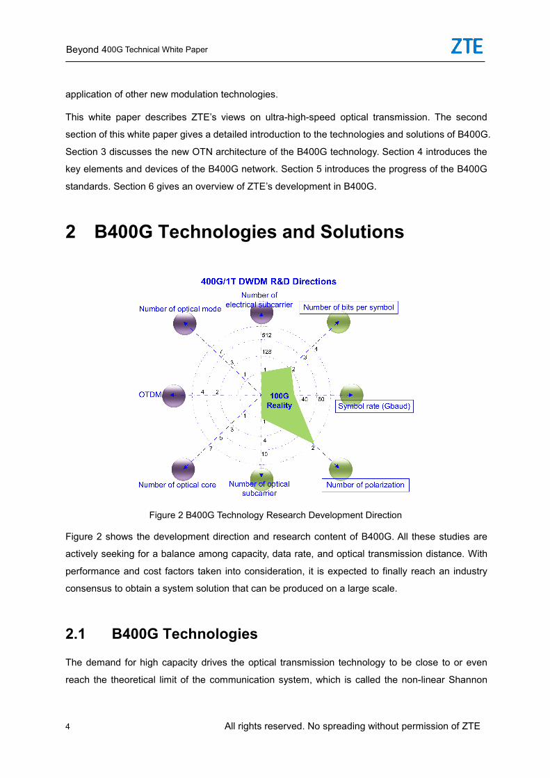
2 B400G Technologies and Solutions
Figure 2 B400G Technology Research Development Direction
Figure 2 shows the development direction and research content of B400G. All these studies are
actively seeking for a balance among capacity, data rate, and optical transmission distance. With
performance and cost factors taken into consideration, it is expected to finally reach an industry
consensus to obtain a system solution that can be produced on a large scale.
2.1 B400G Technologies
The demand for high capacity drives the optical transmission technology to be close to or even
reach the theoretical limit of the communication system, which is called the non-linear Shannon
Beyond 400G Technical White Paper
All rights reserved. No spreading without permission of ZTE 5
limit. Claude Shannon proposed it in the Bell laboratory in 1948 for the further evolution of the
optical transmission system. The non-linear Shannon limit provides an available upper limit of
signal rate for non-linear optical fibers with noise. It is a final system information capacity that can
be obtained by taking into account non-linear factors such as Optical Signal-Noise Ratio (OSNR)
and pulse distortion of optical fibers.
The whole communications industry, including ZTE, has devoted a lot of time and efforts to
improving system performance, high data rate, and high noise tolerance (low OSNR limit). Below
is an introduction to the technologies used in the B400G field to improve system performance.
2.1.1 Forward Error Correction (FEC)
FEC has been effectively used in satellite communications, undersea communications, and other
systems significantly affected by noise. The FEC performance is measured by its coding gain (low
noise tolerance) and overhead. That is to achieve a balance between the increased online rate
and the low OSNR caused by high noise tolerance under a given signal rate.
The application of FEC in optical fiber transmission originated in 1991 and was written in the ITU-T
G.709 “Optical Transport Network (OTN) Interface” standard. The subsequent standards define
the FEC algorithms and overheads available to vendors. In terms of time and performance, FEC
has undergone three generations: traditional hard decision coding, hard decision cascade coding
that integrates cascading, interleaving, and iterative decoding technologies, and the most
advanced soft decision decoding.
Considering the balance between interoperability and performance, ZTE supports standard 15%
OFEC. However, in the long-distance application scenario, ZTE will still use higher overhead FEC
to obtain better OSNR, such as 20% FEC and 27% FEC. It cannot guarantee general
interoperability, but can only guarantee interoperability in scenarios where the transmitter and
receiver are of the same model.
2.1.2 Baud Rate and High-Order Modulation Modes
Increasing the signal baud rate is a classic method for improving the system capacity under the
given spectral width. Compared with electrical signals, optical fiber has an infinite capacity.
Therefore, before the 100G WDM technology was applied, the spectral efficiency was not valued
in optical fiber communication. Now, with the exhaustion of the available spectrum of optical fibers,
and the pressure of rapid traffic growth brought by 5G, cloud computing and AI and the pressure of
Beyond 400G Technical White Paper
6 All rights reserved. No spreading without permission of ZTE
reducing commissioning and O&M costs, there is an increasingly urgent demand to increase
system capacity. Increasing the signal baud rate can improve the transmission rate and thus
improve the single-fiber system capacity. As the chip processing technology is improved from
16nm to 7nm and 5nm, the baud rate of optical components and optical-to-electrical and
electrical-to-optical converter components is also improved from 32Gbaud to 64+Gbaud,
90+Gbaud and 120+Gbaud. As different manufacturers use different optical-to-electrical and
electrical-to-optical converter components and FEC algorithms, the baud rates vary. As the baud
rate increases, the corresponding single-channel transmission rate increases from 100G to 400G,
800G and 1.2T.
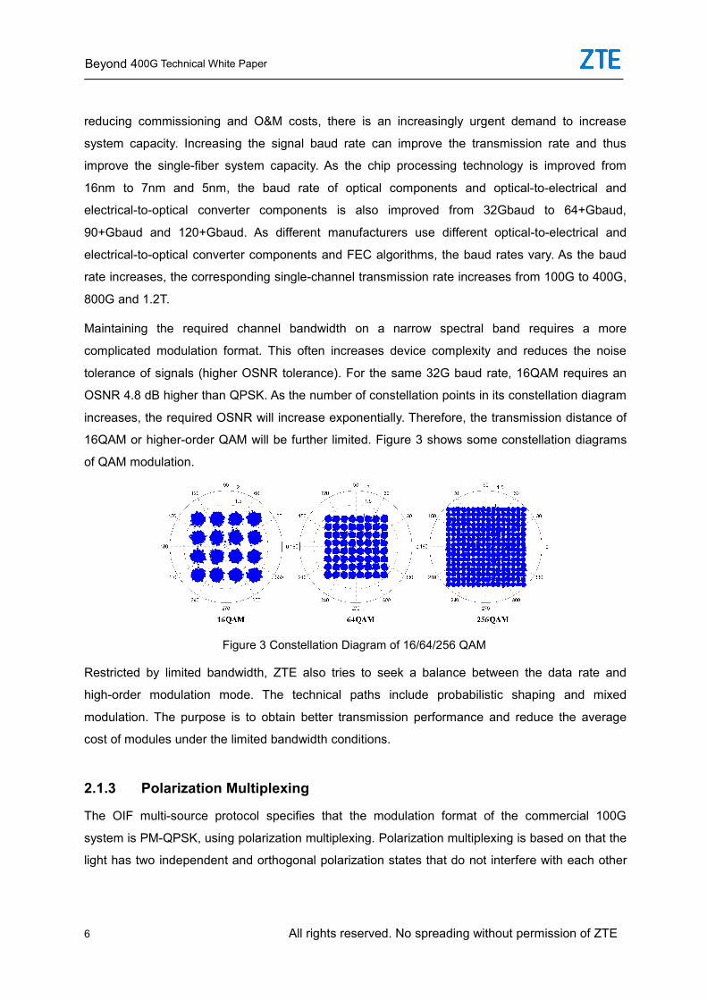
Maintaining the required channel bandwidth on a narrow spectral band requires a more
complicated modulation format. This often increases device complexity and reduces the noise
tolerance of signals (higher OSNR tolerance). For the same 32G baud rate, 16QAM requires an
OSNR 4.8 dB higher than QPSK. As the number of constellation points in its constellation diagram
increases, the required OSNR will increase exponentially. Therefore, the transmission distance of
16QAM or higher-order QAM will be further limited. Figure 3 shows some constellation diagrams
of QAM modulation.
Figure 3 Constellation Diagram of 16/64/256 QAM
Restricted by limited bandwidth, ZTE also tries to seek a balance between the data rate and
high-order modulation mode. The technical paths include probabilistic shaping and mixed
modulation. The purpose is to obtain better transmission performance and reduce the average
cost of modules under the limited bandwidth conditions.
2.1.3 Polarization Multiplexing
The OIF multi-source protocol specifies that the modulation format of the commercial 100G
system is PM-QPSK, using polarization multiplexing. Polarization multiplexing is based on that the
light has two independent and orthogonal polarization states that do not interfere with each other
Beyond 400G Technical White Paper
All rights reserved. No spreading without permission of ZTE 7
when transmitted in optical fibers. PM-QPSK modulates the light sent out by the laser into two
polarization states separately, and multiplexes the two polarization states into one before
transmitting the light to the optical fiber. The processing procedure is reverse at the receiving end.
The two polarization states are used to double the system capacity and halve the line rate under
the given capacity.
The 100G system based on the PM-QPSK has been put into large-scale commercial use. In the
Beyond 100G (B100G) era, the PM-QPSK is still the cornerstone of modulation technology. The
high-performance 400G/800G using PM-QPSK modulation will be more widely used.
2.1.4 Special Fibers
Space division multiplexing (SDM) using Multi-Core Fiber (MCF) or Few-Mode Fiber (FMF) and
integrating Multi-Input Multi-Output (MIMO) signal processing is widely studied. Both theoretical
prediction and recent progress indicate that it can achieve good results in special optical fiber
structures and transmission performance. However, except in design and manufacturing, it will
face great challenges in connection, coupling, fusion splicing, and integration of amplifiers and
transceivers. In addition, the use of these technologies requires replacing optical fibers on site,
which is the biggest obstacle. Therefore, it is too early to put this technology into commercial use.
In the 100G era, the G.652 fiber is widely used as a large-capacity and long-distance transmission
medium due to good non-linearity and large mode field diameter. In the B400G era, as the
transmission rate increases, the OSNR tolerance decreases a lot, and the system requires higher
OSNR after transmission. Therefore, it is necessary to find a solution to improve the system OSNR.
The system OSNR is proportional to the input optical power and optical fiber attenuation. The input
optical power is limited by the non-linearity of optical fibers. If it exceeds the optimal incident
optical power, the transmission performance will be reduced. The non-linearity of optical fibers can
be improved and the input optical power of optical fibers can be increased by increasing the mode
field area. In addition, the SNR of the system can be directly improved by reducing the
transmission loss of optical fibers. Especially in undersea systems, due to the long transmission
distance, higher requirements are posed for OSNR improvement. Under this background,
research on ultra-low-loss and large-effective-area optical fibers represented by G.654E is widely
carried out. G.654E optical fibers are classified into two types: undersea application and terrestrial
application. Among them, the G.654E fiber for subsea use has an effective area of 150μm², and an
attenuation coefficient of 0.17dB/km. For terrestrial application, the optical fibers from different
manufacturers have different effective areas, ranging 110-130μm². The attenuation coefficient of
low-loss G.654E optical fiber is 0.19dB/km, and that of ultra-low-loss G.654E optical fiber is up to
Beyond 400G Technical White Paper
8 All rights reserved. No spreading without permission of ZTE
0.17dB/km. Several operators have tested the terrestrial application of G.654E in existing
networks. It is expected that G.654E will be widely used with the commercial use of B400G.
2.1.5 Wave Channel Extension
The wave channel spacing increases with the modulation rate. When the number of wave
channels is required to be unchanged, the available spectral bands for optical fibers must be
extended. For 64Gbaud, 200G PM-QPSK and 400G PM-16QAM, 75GHz channel spacing needs
to be used. For an 80-channel system, C band needs to be extended to C++ band. The C++ band
optical transmission system has been put into commercial use. For 90+Gbaud and 120+Gbaud,
400G PCS-16QAM, 400G PM-QPSK, 800G PCS-64QAM and 1.2T PCS-64QAM, 100GHz,
112.5GHz, 137.5GHz and 150GHz spacing need to be used, and the working band of the system
needs to be further extended from C++ to L. Therefore, the development of ultra-high-speed
technologies also needs to overcome some problems caused by the application of signals on new
bands, including the support of product in ecology, product costs, and product availability.
2.2 B400G Solutions
The line rate is proportional to the modulation order and baud rate. If the modulation order is
increased, the noise tolerance is reduced, and thus a higher OSNR is required, affecting the
transmission distance and application scenarios. High baud rate increases the loss of high-speed
electrical signals during transmission and decreases the anti-interference capability. Therefore,
the existing circuits need to be optimized. The commercial B400G solution needs to take the
influence of the modulation mode and baud rate increase into comprehensive consideration. In
addition, the FEC algorithm is used to guarantee transmission performance and spectral efficiency.
For B400G, in the first phase, the baud rate is increased from 32Gbaud to 64GBaud, and the
corresponding high-order modulation mode is 400G PM-16QAM. In the second phase, the baud
rate is increased from 64GBaud to 90+GBaud, and 400G PCS-16QAM and 600G/800G
PCS-64QAM can be implemented correspondingly. In the third phase, the baud rate is upgraded
to 120+GBaud and 400G PM-QPSK and 600G/800G/1.2T PCS-64QAM can be implemented
correspondingly.
The 64GBaud-based 400G PM-16QAM supports 400km-600km transmission distance and meets
the requirements of MAN. The extended C++ band can be used to transmit 80 wavelengths. The
90+GBaud-based 400G PCS-16QAM and 120+GBaud-based 400G PM-QPSK further improve
the transmission performance, covering all scenarios from backbone, metro, access to DCI
Beyond 400G Technical White Paper
All rights reserved. No spreading without permission of ZTE 9
networks, laying the foundation for the commercial use of 400G in 2022.
The 90+GBaud-based 800G PM-64QAM is only applicable to DCI. The next generation
120+GBaud-based 800G PCS-64QAM further improves the transmission performance and the
application scope is extended to some metro, access and DCI networks. It is expected that a few
commercial applications will be launched since 2022. The performance of the 120+GBaud-based
1.2T PCS-64QAM is only applicable to the DCI scenario and needs to be further tested and
verified.
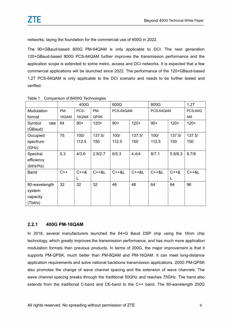
Table 1 Comparison of B400G Technologies400G 600G 800G 1.2T
Modulationformat
PM-
16QAM
PCS-
16QAM
PM-
QPSK
PCS-64QAM PCS-64QAM PCS-64Q
AM
Symbol rate(GBaud)
64 90+ 120+ 90+ 120+ 90+ 120+ 120+
Occupiedspectrum(GHz)
75 100/112.5
137.5/150
100/112.5
137.5/150
100/112.5
137.5/150
137.5/150
Spectralefficiency(bit/s/Hz)
5.3 4/3.6 2.9/2.7 6/5.3 4.4/4 8/7.1 5.8/6.3 8.7/8
Band C++ C++&L
C++&L C++&L C++&L C++&L C++&L
C++&L
80-wavelengthsystemcapacity(Tbit/s)
32 32 32 48 48 64 64 96
2.2.1 400G PM-16QAM
In 2018, several manufacturers launched the 64+G Baud DSP chip using the 16nm chip
technology, which greatly improves the transmission performance, and has much more application
modulation formats than previous products. In terms of 200G, the major improvement is that it
supports PM-QPSK, much better than PM-8QAM and PM-16QAM. It can meet long-distance
application requirements and solve national backbone transmission applications. 200G PM-QPSK
also promotes the change of wave channel spacing and the extension of wave channels. The
wave channel spacing breaks through the traditional 50GHz and reaches 75GHz. The band also
extends from the traditional C-band and CE-band to the C++ band. The 80-wavelength 200G
Beyond 400G Technical White Paper
10 All rights reserved. No spreading without permission of ZTE
PM-QPSK is generally realized, which ensures the increase of single-wavelength bandwidth and
the corresponding total bandwidth. At present, the 200G technology is mature and has multiple
modulation modes such as 200G PM-QPSK, 200G PCS-16QAM and 200G PM-16QAM. With
excellent transmission performance, it completely covers the application scenarios of backbone,
metro, access and DCI, so it is widely used.
The 400G PM-16QAM employs the same technology, with a wave channel spacing of 75GHz.
Applied to the extended C++ band system, it achieves 80-wavelength 400G. The system capacity
reaches 32Tbit/s, and the transmission performance can meet metro application scenarios. At
present, there are two types of coherent optical modules at the 400G line side: MSA encapsulation
and CFP2 encapsulation. The former has better OSNR tolerance than the latter, but has higher
power consumption, so it is applicable to the scenario where high transmission performance is
required. With an OSNR tolerance of 21dB, the 400G PM-16QAM is mainly applicable to some
MAN applications. Now, it is mainly used for test and trial commercial use. It is estimated that it will
be gradually put into commercial use with the emergence of 400GBASE service requirements in
2022.
2.2.2 400G PCS-16QAM
In 2020, some manufacturers used 7nm chip technology and 90+GBaud DSP chip together with
FEC and probability shaping algorithm to realize 400G PCS-16QAM. The current line-side
coherent optical module is MSA encapsulation and non-pluggable. Compared with 400G
PM-16QAM, its OSNR tolerance is more than 3dB lower. The transmission performance can meet
the requirements of provincial backbone networks and metro networks. As the baud rate is
increased to 90+GBaud, the wave channel spacing is also increased to 100GHz/112.5GHz. The
transmission performance is damaged by using 100GHz channel spacing. The filtering cost is high,
and the ROADM pass-through capability is limited. At the same time, the existing C++ band
cannot transmit 80 wavelengths and needs to be expanded to L band. In 2021, the 400G
PCS-16QAM is mainly used for laboratory and existing network tests. It is estimated that it will be
put into commercial use in batches in 2022.
2.2.3 400G PM-QPSK
In 2021, some manufacturers adopted 5nm chip technology and 120+Gbaud DSP chip, together
with FEC and probability shaping algorithm to implement 400G PM-QPSK. Compared with 400G
PCS-16QAM, the OSNR tolerance is further reduced. The transmission performance can meet the
Beyond 400G Technical White Paper
All rights reserved. No spreading without permission of ZTE 11
national and provincial backbone requirements. The 400G PM-QPSK needs to use
137.5GHz/150GHz wave channels for transmission. Similarly, to realize 80-wavelength
transmission, it is necessary to expand from C++ band to L band. It is expected that it will be put
into commercial use in batches in 2022.
2.2.4 600G PCS-64QAM
Employing 7nm chip technology and 90+GBaud DSP chip, several manufacturers have launched
the 600G PCS-64QAM coherent line-side optical module. Its transmission performance meets the
access and DCI network applications. It is estimated that the 600 G PCS-64QAM coherent
line-side optical module using 120+Gbaud DSP and the 5nm chip technology will also be launched
in 2021. With the emergence of 600G PCS-64QAM, 800G PCS-64QAM is also developing rapidly.
Considering that the 400GE has been standardized, and the 800GE interface standard MSA has
been started, which match the line-side 400G and 800G, it is estimated that 600G PCS-64QAM is
rarely used at the line side.
2.2.5 800G PCS-64QAM
800G PCS-64QAM uses the same technology as 600G PCS-64QAM. The first-generation 800G
line-side coherent optical module adopts the 7nm chip technology and 90+GBaud DSP chip, and
the transmission performance can only meet the DCI application requirements. It is estimated that
the second-generation 800G PCS-64QAM coherent line-side optical module using 5nm chip
technology and 90+Gbaud DSP will also be launched in 2021. The transmission performance will
be improved to meet the requirements of the metro, access, and DCI applications. The 800 G
PCS-64QAM needs to use 137.5GHz/150GHz channel for transmission. Similarly, to realize
80-wavelength transmission, it is necessary to expand from C++ band to L band. At present, 800G
only supports PCS-16QAM and the transmission performance is largely different from 400 G. It is
estimated that 800G will be mainly used in DCI scenarios in the early stage.
2.2.6 1.2T PCS-64QAM
Restricted by chip technology, optical components and baud rate increase of DA/AD components,
which rate to be used as the standard in 800G is still under research. This conclusion can be
reached only after the 5nm new product technology is mature and the future 3nm chip technology
is put into commercial use. Some manufacturers started the development of beyond 1T (B1T)
based on the 5nm chip technology. It is estimated that the first-generation 1.2T PCS-64QAM
Beyond 400G Technical White Paper
12 All rights reserved. No spreading without permission of ZTE
coherent line-side optical module using 5nm chip technology and 120+Gbaud will be launched in
2021. It is estimated that its transmission performance can meet DCI application requirements.
Beyond 400G Technical White Paper
All rights reserved. No spreading without permission of ZTE 13
3 B400G OTN ArchitectureThe previous chapters introduce the latest research progress of B400G in terms of transmission
rate, transmission distance and spectral efficiency. In terms of B100 G, software can also be used
to select the modulation mode, for example, whether QAM is used, and the number of carriers in
the super channel used. The rate and spectrum bandwidth of the carriers can be optimized in
accordance with the transmission distance. These new ideas can be implemented by variable ITU
grids and flexible OTN. This is a reform of the traditional OTN architecture and the rigid data
transmission rate. The B100G network needs to provide a flexible super rate, and multiple ITU
grids will be integrated to let a super channel pass.
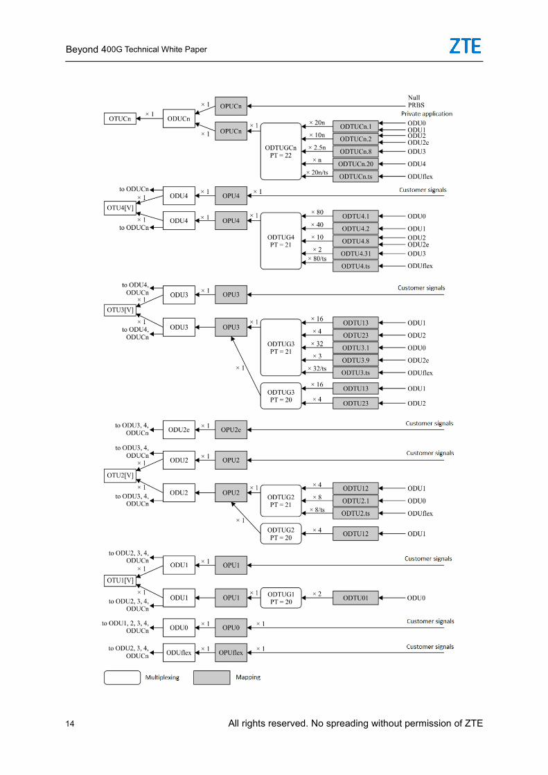
3.1 B100G OTN Mapping and Multiplexing
The 100GE/200GE/400GE interface at the client side converts the client-side signals into optical
signals and maps them to the ODU4/ODUflex, and then maps the ODU4/ODUflex to the
ODUC1/ODUC2/ODUC4, and finally encapsulates them into OTUC1/OTUC2/OTUC4 signals. In
tributary-line separation mode, the line board schedules ODUk services at all levels through the
centralized cross-connect unit and performs real-line mapping and multiplexing to achieve more
flexible electrical layer signal scheduling and higher bandwidth utilization.
Beyond 400G Technical White Paper
14 All rights reserved. No spreading without permission of ZTE
Beyond 400G Technical White Paper
All rights reserved. No spreading without permission of ZTE 15
Figure 4 OTN Multiplexing and Mapping Architecture
3.2 Flex ROADM
The traditional DWDM networks include Mux, Demux and WSS, which are designed based on
fixed grids and use fixed-bandwidth channels to transmit optical signals. B400G will break these
traditions and facilitate free selection of modulation formats and multi-subcarrier multiplexing
technologies. In B400G scenarios, the spectral width of a signal changes, and the traditional fixed
grid DWDM equipment is not suitable. ITU-T standard G.694.1 proposes a new method for
dividing the available bandwidth of band C, and introduces the definition of a variable DWDM grid:
The standard frequency of the frequency slot is 192.1 + nx0.00625 standard frequency (unit: THz),
and the slot width is 12.5xm. In other words, the ITU slot width will be multiple 12.5 GHz.
The Flex Grid ROADM meets the following features: Gridless, colorless, directionless and
contentionless (GCDC). The gridless transmission uses a finer granularity in spectrum allocation
than the traditional 50GHz channel. The minimum adjustment spacing reaches 6.25GHz, which is
more suitable for transmitting 400G, 800G and B1T signals. With the emergence of 400G, 800G
and 1.2T, the WSS, the core component of ROADM, also needs to be extended from C++ band to
C++&L band to simplify the configuration and footprint of ROADM.
Beyond 400G Technical White Paper
16 All rights reserved. No spreading without permission of ZTE
4 B400G Networks and DevicesThe B400G optical transmission is actually a work of finding the optimal solution among the
spectral efficiency, data rate and transmission distance. Although operators have given priority to
researches on continuing to improve spectral efficiency, bit rate, and transmission distance.
However, in actual systems OSNR has been applied to the extreme. Therefore, the operator can
effectively use fiber resources only by maximizing the transmission distance and spectral
efficiency.
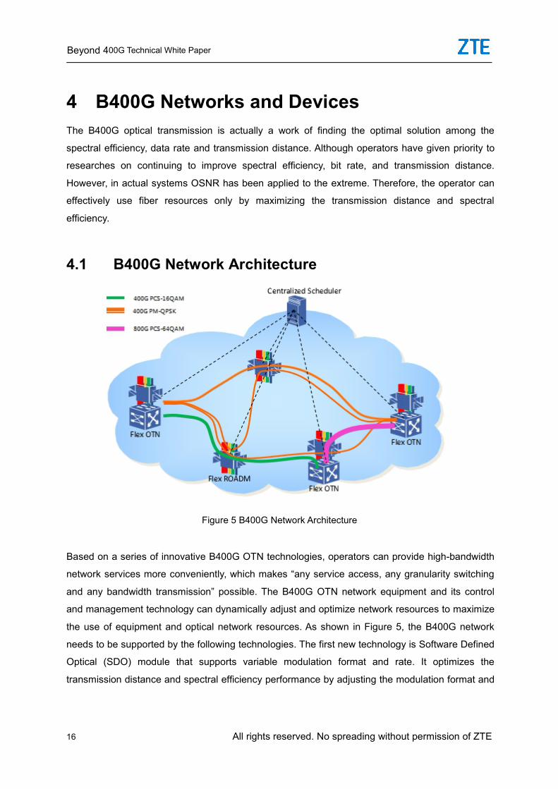
4.1 B400G Network Architecture
Figure 5 B400G Network Architecture
Based on a series of innovative B400G OTN technologies, operators can provide high-bandwidth
network services more conveniently, which makes “any service access, any granularity switching
and any bandwidth transmission” possible. The B400G OTN network equipment and its control
and management technology can dynamically adjust and optimize network resources to maximize
the use of equipment and optical network resources. As shown in Figure 5, the B400G network
needs to be supported by the following technologies. The first new technology is Software Defined
Optical (SDO) module that supports variable modulation format and rate. It optimizes the
transmission distance and spectral efficiency performance by adjusting the modulation format and
Beyond 400G Technical White Paper
All rights reserved. No spreading without permission of ZTE 17
bit rate. The second new technology is the multi-carrier optical module that supports multi-carrier
multiplexing. Due to the limitations of the basic laws of semiconductor technology and
communication system, it is difficult to use the single-carrier mode to meet the rate increase
requirements. The B400G system adopts the multi-carrier technology to improve the
single-channel rate, and the system should support flexible grid accordingly. As the ODU/OTU at a
fixed rate is difficult to adapt to dynamic changes of the network, the B100G needs to adopt
variable modulation format and multi-carrier technology. And Flexible ODU/OUT that supports
separate spectrum and non-shared transmission are generated to maximize the utilization of
network spectrum resources. Therefore, the third new technology is Flexible OTN that supports
variable rate.
To achieve selectable optical module modulation format, variable ODU/OTU container and tunable
grid spectral width, the fourth new technology is the control plane technology that is capable of
routing and spectrum allocation.
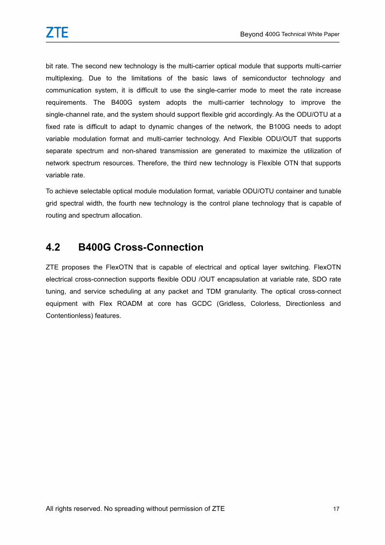
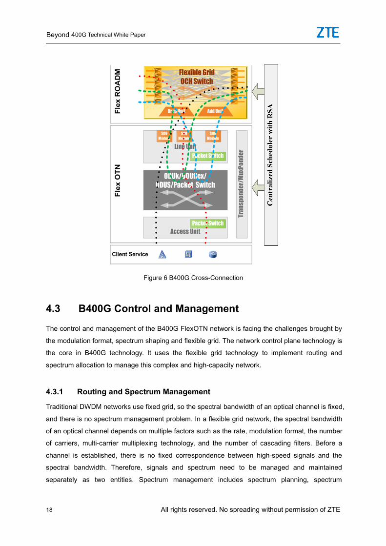
4.2 B400G Cross-Connection
ZTE proposes the FlexOTN that is capable of electrical and optical layer switching. FlexOTN
electrical cross-connection supports flexible ODU /OUT encapsulation at variable rate, SDO rate
tuning, and service scheduling at any packet and TDM granularity. The optical cross-connect
equipment with Flex ROADM at core has GCDC (Gridless, Colorless, Directionless and
Contentionless) features.
Beyond 400G Technical White Paper
18 All rights reserved. No spreading without permission of ZTE
Figure 6 B400G Cross-Connection
4.3 B400G Control and Management
The control and management of the B400G FlexOTN network is facing the challenges brought by
the modulation format, spectrum shaping and flexible grid. The network control plane technology is
the core in B400G technology. It uses the flexible grid technology to implement routing and
spectrum allocation to manage this complex and high-capacity network.
4.3.1 Routing and Spectrum Management
Traditional DWDM networks use fixed grid, so the spectral bandwidth of an optical channel is fixed,
and there is no spectrum management problem. In a flexible grid network, the spectral bandwidth
of an optical channel depends on multiple factors such as the rate, modulation format, the number
of carriers, multi-carrier multiplexing technology, and the number of cascading filters. Before a
channel is established, there is no fixed correspondence between high-speed signals and the
spectral bandwidth. Therefore, signals and spectrum need to be managed and maintained
separately as two entities. Spectrum management includes spectrum planning, spectrum
Beyond 400G Technical White Paper
All rights reserved. No spreading without permission of ZTE 19
allocation, and spectrum adjustment. On the one hand, spectrum utilization and construction
efficiency can be improved through effective spectrum planning and spectrum allocation. On the
other hand, spectrum adjustment can reduce the impact of spectrum fragments on network
performance. In a flexible grid network, routing is restricted by both spectrum consistency and
spectrum continuity, and it is one of the key factors determining the network transport capability
and construction efficiency.
4.3.2 Control Plane Technology
Due to the separation of the signal layer from the spectrum layer, routing protocols, signaling
protocols, and link resource management protocols need to be extended to support the flexible
grid function. On the other hand, unlike the traditional DWDM network, the flexible grid technology
requires stronger control function to support its flexibility in various aspects, while the transport
network is also changed from the traditional fixed pipe to the intelligent elastic pipe. Therefore,
intelligent optical networks based on various flexible grid technologies and the ideology of SDN
technology may be the evolution trend of the B400G system control plane in the future.
Beyond 400G Technical White Paper
20 All rights reserved. No spreading without permission of ZTE
5 B400G Standards ProgressITU-T, IEEE, OIF and CCSA are the major organizations involved in B400G standard formulation.
5.1 ITU-T
The Q6 and Q11 of the ITU-T SG15 are responsible for the standardization of the optical physical
layer and the logical layer of OTN. The Q6 is standardizing the code parameters of the 80km and
200~450km application scenarios of the 200G and 400G. The Q11 has finished the
standardization of the frame structure, timeslot granularity, format and rate of the interconnection
interface (FlexO), service mapping and multiplexing of the B100G (OTUCn), and has completed
the FEC specifications for the interconnection interfaces of 80km and 200~450km. It is about to
start the discussion about B400G.
5.2 IEEE
The IEEE 802.3 group works on the standardization of 400GE Ethernet interface physical layer,
and has completed the specifications for multiple distances (100m/150m/500m/2km/10km/40km)
of 400GBASE-SR8, 400GBASE-SR4.2, 400GBASE-DR4, 400GBASE-FR8, 400GBASE-LR8 and
400GBASE-ER8. At the same time, for the data center interconnection scenarios not exceeding
120km, it has formed the first draft of the 400GBASE-ZR. It determines the physical layer
parameters of 400G-ZR and employs DP-16QAM and coherent receiving to support
multi-wavelength applications and implement at least 80km transmission.
5.3 OIF
The Optical Internetworking Forum (OIF) is responsible for the standardization of the
optical/electrical modules and high-speed interfaces at the Physical Link Layer (PLL). It has now
completed the 400ZR optical module implementation suggestions and determined the interfaces
and optical indices of the coherent 120km coherent 400ZR. At the same time, it has determined
two application scenarios: 120km and below, multi-wavelength links with amplification and
point-to-point noise restriction,, and single-wavelength links with point-to-point loss restriction but
without amplification. The router adopts the 400ZR module and works with the WDM
multiplexer/demultiplexer to implement multi-wavelength transmission. This application scenario is
Beyond 400G Technical White Paper
All rights reserved. No spreading without permission of ZTE 21
only applicable to transmission within 120km and point-to-point networking. The application
scenario is very limited. Now it is discussing the application specifications of 400G with 75GHz
channel spacing, and has started the project of 800G.
5.4 CCSA
The WG4 of the China Communications Standards Association (CCSA) TC6 keeps pace with the
international researches about B100G standardization. TC6 WG4 has completed the industrial
standardization of backbone 400G DWDM and metro 400G DWDM. Among them, the Technical
Requirements for Nx400Gb/s Optical Wavelength Division Multiplexing (WDM) System for
backbone networks was released in December 2020. This standard specifies the 2x200G
PM-16QAM and 2x200G PM-QPSK super channel 400G modulation codes and main optical
channel interface parameters used in the backbone network. Since the transmission distance of
400G PM-16QAM does not meet the backbone requirements, it is not included in the standard.
With the emergence of 400G PCS-16QAM and 400G PM-QPSK, the single-carrier 400G
transmission performance is greatly improved. The 400G PM-QPSK is especially suitable for the
backbone network. The MAN standard “Technical Requirements for MAN Nx400Gb/s Optical
Wavelength Division Multiplexing (WDM) System” is applicable to MAN with the transmission
distance of 720km or less. This standard specifies the 2x200G super channel and 400G
PM-16QAM modulation codes and main optical channel interface parameters of the MAN. At the
same time, it adds the Nx60km transmission specifications based on the Nx80km transmission
specifications.
6 ZTE B400G OverviewOver the years, ZTE has been committed to the research of B100G technologies such as 400G,
600G, 800G and B1T and the R&D and application of product solutions. Based on the research
and development of cutting-edge B100G high-speed signal transmission technologies, ZTE has
tackled several key technologies in this field, and has published related research results OFC,
ECOC and International Organization for Standardization (ISO).
ZTE was the first to implement the single-channel 11.2Tbit/s optical signal in an experiment, and
successfully transmitted the signal in the standard single-mode fiber over 640km, setting a new
Beyond 400G Technical White Paper
22 All rights reserved. No spreading without permission of ZTE
world record for the optical signal at a maximum single-channel transmission rate of 1Tbit/s. The
test results were released as a post-deadline paper on the OFC in 2011.
ZTE implemented 24Tb/s (24x1.3Tb/s) WDM signal transmission, which was the first 24Tbit/s
WDM technology in the industry. The test results were released at OECC 2011.
In February 2012, ZTE and DT (Deutsche Telekom) successfully completed the 2450km
long-distance hybrid transmission of 100G/400G/1T signals in Germany. The detailed test results
were released as a post-deadline paper at OFC 2012. The hybrid transmission distance and rate
were the highest in the industry and were of milestone significance.
In September 2012, ZTE set up another world record by successfully implementing 40-wavelength
DWDM channels with the patent technology. PM-QPSK signals of 400GB/s were loaded to each
channel and were successfully transmitted over 2800km in the standard single-mode fiber. The
result was published at ECOC 2012.
ZTE’s single-carrier 400 Gbit/s signal transmission uses a simple transmitting and receiving device,
which makes it an attractive solution for increasing channel rate and system capacity. Compared
with the 1200km transmission distance of the single-carrier 400G technology that requires
expensive special filters and Raman amplifier, ZTE’s patent technology more than doubled the
transmission distance. The single-carrier PM-QPSK has a mature high-sensitivity receiver solution.
It is applicable to the medium and long-distance transmission in optical fiber infrastructure
dominated by standard single-mode optical fibers and common Erbium-Doped Fiber Amplifiers
(EDFA). This experiment has successfully transmitted the signals over 35 spans, each with a
length of 80km, demonstrating the possibility of long-distance transmission of B100G network in
the existing optical fiber system.
In 2012, ZTE released seven 400G/1T DWDM prototypes according to different network
application scenarios. These prototypes include the multi-subcarrier OFDM 400G/1T solution
covering ultra-long-distance applications, and the 16QAM solution with the highest bandwidth
utilization rate for MAN and local applications, as well as the Nyquist WDM solution with both
long-distance transmission and high bandwidth efficiency. ZTE has many patents in B400G,
involving optical modulation, framing, systems and other technologies.
In 2014, ZTE implemented single-carrier 400G signal transmission with a channel spacing of 100
GHz and a record-setting symbol rate of 110G. This result was released at OFC in 2014.
In 2015, ZTE’s B100G products were put in large-scale commercial use.
By 2016, ZTE’s B100G products had been widely used in a number of domestic and overseas
Beyond 400G Technical White Paper
All rights reserved. No spreading without permission of ZTE 23
operators like China Mobile, True Thailand, Singtel, and HKT.
In 2017, ZTE employed PM-256QAM high-order modulation to achieve single-carrier 400G, and
the result was included on OFC highly scored.
In 2018, ZTE was the first in the industry to launch the single-carrier 600G product.
In 2019, ZTE’s single-carrier 400G products were commercialized in the provincial backbone and
metro networks.
In 2020, ZTE’s 200G PM-QPSK product was commercialized in the national backbone network of
China Mobile.
Over the years, ZTE has been committed to promoting the application of mature 400G
technologies in MAN/long-distance transmission and continuously studying the feasibility and
extreme applications of other new modulation technologies. In the future, as people’s demands for
bandwidth will never end, ZTE will continue to focus on and invest in new B100G technologies,
and continuously lead and promote the commercial deployment of B100G technologies.
Beyond 400G Technical White Paper
24 All rights reserved. No spreading without permission of ZTE
7 ConclusionWith the increasing maturity of the 400G technology and the wide application in the transmission
market, 800G and B1T will be the next development direction in order to meet the growing
demand for data services. ZTE has taken the lead in the R&D of 800G/B1T, and launched a series
of 600G transmission link solutions during the transitional period.
To make full use of the potential of the B400G network, ZTE proposes a flexible OTN architecture,
FlexOTN. To simplify B400G management, the control plane needs to be further developed. The
FlexOTN proposed by ZTE can better exploit the advantages of the B400G technology.
ZTE has been working closely with global operators to actively participate in all work of relevant
standardization organizations, invest more R&D resources, and promote the evolution of the
B400G network, in order to eventually achieve the ultimate goal of providing any service, any
bandwidth, any location, and any media service in the near future.
8 Reference YD/T 3783-2020 Technical Requirements for Nx400Gb/s Optical Wavelength Division
Multiplexing (WDM) System
Technical Requirements for MAN Nx400Gb/s Optical Wavelength Division Multiplexing (WDM)
System
OIF-400ZR-01.0 Implementation Agreement 400ZR
IEEE P802.3cw™/D1.0 Draft Standard for Ethernet Amendment: Physical Layers and
Management Parameters for 400 Gb/s Operation over DWDM systems
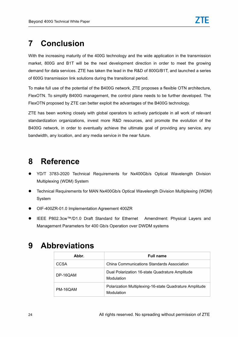
9 AbbreviationsAbbr. Full name
CCSA China Communications Standards Association
DP-16QAMDual Polarization 16-state Quadrature AmplitudeModulation
PM-16QAMPolarization Multiplexing-16-state Quadrature AmplitudeModulation
Beyond 400G Technical White Paper
All rights reserved. No spreading without permission of ZTE 25
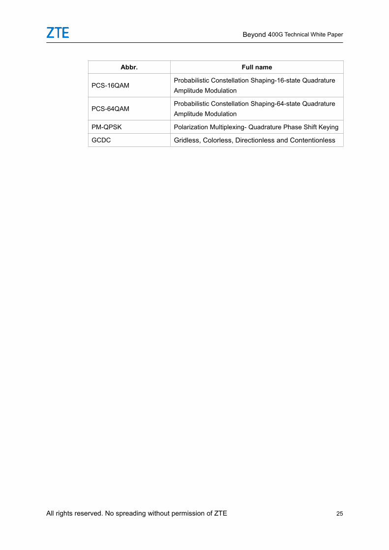
Abbr. Full name
PCS-16QAMProbabilistic Constellation Shaping-16-state QuadratureAmplitude Modulation
PCS-64QAMProbabilistic Constellation Shaping-64-state QuadratureAmplitude Modulation
PM-QPSK Polarization Multiplexing- Quadrature Phase Shift Keying
GCDC Gridless, Colorless, Directionless and Contentionless


