Embed Size (px)
Citation preview

�����������������
Citation: Cruz, M.; Maranha, V.;
Moita, F.; Cruz, N.; Rasteiro, D.;
Carvalho, F.; Lains, J.; Roseiro, L.
Biomechanical Device for
Measurement of Adductors Strength
and Aid in Self-Catheterisation of
Spastic Patients. Designs 2022, 6, 7.
https://doi.org/10.3390/
designs6010007
Academic Editor: Richard Drevet
Received: 23 November 2021
Accepted: 17 January 2022
Published: 20 January 2022
Publisher’s Note: MDPI stays neutral
with regard to jurisdictional claims in
published maps and institutional affil-
iations.
Copyright: © 2022 by the authors.
Licensee MDPI, Basel, Switzerland.
This article is an open access article
distributed under the terms and
conditions of the Creative Commons
Attribution (CC BY) license (https://
creativecommons.org/licenses/by/
4.0/).
Article
Biomechanical Device for Measurement of Adductors Strengthand Aid in Self-Catheterisation of Spastic PatientsMaria Cruz 1,2, Vítor Maranha 1,2,3 , Fernando Moita 1,2 , Nuno Cruz 1, Deolinda Rasteiro 1,2, Filipe Carvalho 2,4,Jorge Lains 2,4,5 and Luis Roseiro 1,2,3,*
1 Polytechnic of Coimbra, ISEC, Rua Pedro Nunes—Quinta da Nora, 3030-199 Coimbra, Portugal;[email protected] (M.C.); [email protected] (V.M.); [email protected] (F.M.);[email protected] (N.C.); [email protected] (D.R.)
2 Applied Biomechanics Laboratory, i2A—Institute of Applied Research, Polytechnic of Coimbra, Lagar dosCortiços–S. Martinho do Bispo, 3030-093 Coimbra, Portugal; [email protected] (F.C.);[email protected] (J.L.)
3 Department of Mechanical Engineering, Materials and Processes (CEMMPRE), University of Coimbra,3030-788 Coimbra, Portugal
4 Centro de Medicina de Reabilitação da Região Centro, Hospital Rovisco Pais, Quinta da Fonte Quente,3064-908 Tocha, Portugal
5 Faculty of Medicine, University of Coimbra, 3004-504 Coimbra, Portugal* Correspondence: [email protected]; Tel.: +351-967-845-829
Abstract: Intermittent vesical self-catheterisation is a legitimate and safe technique that has beenreported since the 1970s as a solution for the treatment and prevention of vesical urinary complicationsresulting from spinal cord injury. This practice, using clean technology, has been asserting itself asone of the best alternatives for people with neurogenic bladder. However, adherence is not completedue to some barriers imposed to this procedure by the injured, with emphasis on positioning, agility,and visual impairment. The solutions presented today to support self-catheterisation are expensiveequipment that does not allow patients with advanced levels of spasticity to have their autonomy. Abiomechanical support device was developed to aid self-catheterisation, mainly aimed at women withspasticity, filling the gap in the existing products. Despite the main objective of self-catheterisation,the system’s design made it possible to quantify the strength of the adductors for the sitting positionduring the execution of the adduction movement, particularly relevant for spastic patients. Thedevice’s production was entirely carried out using the FDM methodology, with 3D printers, and itsdesign and operation were thought to overcome the physical and psychological barriers imposed bythe users. The system was first tested with a group of healthy volunteers to obtain a pattern of theadductors force in a sitting position and after with a group of spastic volunteers. The obtained dataallows to compare the adductor force data and optimize the system, with particular functionalitiesfor spastic patients, with the implementation of a motorised version and a visualization camera. Thesystem, its developments, and results obtained are present and discussed.
Keywords: self-catheterisation; spasticity; adductors strength; biomechanical rehabilitation
1. Introduction
Spinal cord injury is a syndrome that makes a person impaired in motor, sensory,visceral, sexual, and autonomic functions (Assis and Faro, 2011) [1]. There are severalpossible consequences for this type of injury, such as paralysis, vesico-urinary dysfunction,and spasticity. This work focuses on vesico-urinary dysfunction, termed the productof the interruption of communication between the bladder and the urinary centre inthe brain. In the human body, there is, in addition to others, the autonomic nervoussystem (ANS) and which contains the pelvic splanchnic nerves, which communicatewith the brain concerning the urinary bladder and external genital organs. According to
Designs 2022, 6, 7. https://doi.org/10.3390/designs6010007 https://www.mdpi.com/journal/designs

Designs 2022, 6, 7 2 of 20
Shenot (2018) [2], the possible treatments for this type of disease include catheterisation ormeasures to trigger urination. One of the main measures to trigger urination is intermittenturethral catheterisation, designed as self-catheterisation if performed by the patient. Thismethod allows the patient to empty the bladder by introducing a catheter. This process isrecommended temporarily or permanently at any age and gender (Mazzo et al., 2014) [3].Seth et al (2014) [4] report that this type of process has improved quality of life for patients,offering them greater freedom to participate in daily and social activities. However, there isresistance to vesical catheterisation due to practical barriers such as dexterity, positioning,visual impairment, and external factors such as appropriate catheters and assistive devices.Baczkoski [5], in 1981, wrote that there is a considerable number of patients dependent oncatheterisation who are independent and can perform self-catheterisation. However, thereare still individuals, especially women, who cannot perform it. The most salient reasonsare the difficulty visualizing the urogenital triangle area due to its body physiognomy(wrinkled skin, protruding abdomen, large breasts, among other conditions) or its physicalcondition (inability to flex the spine or weakness in certain positions). Few support deviceshave been developed and built to overcome these difficulties. For example, in 1968, Levy [6]invented a set formed by a mirror mounted between a pair of clamps, which is placedbetween the legs, and the individual moving of the legs in various directions can adjustit. The device’s purpose was to free an individual’s hand, to allow for depilation and theapplication of make-up. However, for an individual with spasticity, the set is not suitable asthe position of the mirror is affected whenever the legs move. In addition, the mechanismfor supporting the setup was designed so that the opening of the person’s legs is minimal,and any movement with higher amplitude promotes the set to fall. Baczkoski (1981) [5]published a device with a mirror designed to free both patient’s hands when the patientneeds to carry out personal hygiene and allows viewing parts of the body that are difficultto access under these circumstances. This device will enable patients some autonomyregarding their cleaning, dressing, and catheterisation. This set consists of a mirror that isfixed by mounting elements of an adjustable plate, which has the option of being attachedto the lower part of the patient’s leg. The recommended position to facilitate the applicationis lying down, making the process cleaner and safer, but it does not favour the issue ofvisibility. In 1990, Billau and Howland [7] created three devices that complement eachother: a lip expander, female quadriplegic forceps, and an illuminated catheterisationmirror. These solutions are intended for patients with agility and strength in the lowerlimbs and at least in one of the upper limbs. Following these developments, Gerace(1994) [8] proposed a set adapted for use in self-catheterisation procedures, consisting ofa base with a mounted mirror and a pair of claws that are placed on the legs. This set isdesigned to be mounted on the patient’s legs, in a seated position, with the mirror in thecentre and between the legs so that she can adjust the base through the opening or closingmovement of the legs. The mirror is adjustable for different clinics, and the extension of theleg claws does not change its inclination. The user can also attach a removable mirror to anelongated member with a snap-on flexible fitting. Alvi et al. [9] proposed a mirror with asupport member attached to one end of the toilet. There is a hinge on the mirror supportmember that helps adjust the member for self-inspection.
Advancements with the developed devices offer some help to patients with needsconcerning the catheterisation process. However, there is still a need for a complete device,mainly to cover the barriers associated with a self-catheterisation process, for example,spastic patients or patients with weak limb strength. This paper presents a biomechanicaldevice that allows the implementation of the self-catheterisation process by these typesof patients.
The literature shows several instruments measuring muscle strength, from dynamome-ters to weight machines, including traction devices such as the Pivot Fitness 820 [10], orspecific tests such as BEP IIIa [11]. Within the dynamometers, there are portable onessuch as Smart Groin [12], and isokinetic ones such as Cybex II [13], Power Track 11, Com-mande [14], KForce Muscle Controller [15], and ForceFrame [16]. All these instruments aim
Designs 2022, 6, 7 3 of 20
to measure strength in any individual. However, there are specific instruments for individu-als with pathologies, particularly patients with spasticity. Cabrera et al., 2007, [17] proposeda device that, when the extremity is moved around an axis, it is possible to quantify theacceleration, angular velocity, force, and time required for the movement. Subsequently,the acquired values generated the hypertonic condition of the limb. In addition, Wanget al. (2016) [18] presented a device that quantifies spasticity by measuring the speed andstrength in the movement of a limb.
Over time, studies were carried out to quantify muscle strength [10,11,13,14,19,20].They contained the limitation that the strength studied was the abductors. The studiedpopulation did not refer to individuals who suffered from spinal cord injury but who hadundergone arthroplasty. In 2017, Gafner et al. [21] studied the strength of hip adductorsand abductors in the elderly. However, Pinto (2020) [12] carried out a study to evaluate hipstrength in elite players in Portugal, and Ryan, Kempton, Pacecca, and Coutts (2019) [22] inprofessional Australian footballers, assessing the strength of the adductor muscles. Themethodology for evaluating of adductors was for the volunteer to exert a contractionagainst the evaluator. There are several studies like this one that focuses on athletes fromdifferent sports. In 2018, a study was carried out by Vega et al. [23], which consisted ofevaluating the validity and reliability of the test–retest, through the quantification of theisometric strength of the abductor’s muscles, in a healthy young population.
The studies found in the literature differ from this work, mainly due to the group ofmuscles and movements evaluated (abductor muscles and abduction movement) as wellas its sample as it includes elite players from different sports or people recovering fromsurgery, leaving space for the study of ordinary healthy citizens and people with spinalinjury and spasticity.
The presented device, like some others, has a load cell attached. However, it differsfrom other devices, providing the possibility to adjust the opening of the thighs, allowingthe measurement for different degrees of space and the evaluation of the two thighssimultaneously. The device developed allowed us to perform a study to obtain andcompare healthy young individuals with people with spinal cord injury.
2. Materials and Methods2.1. Device Development—3D Models
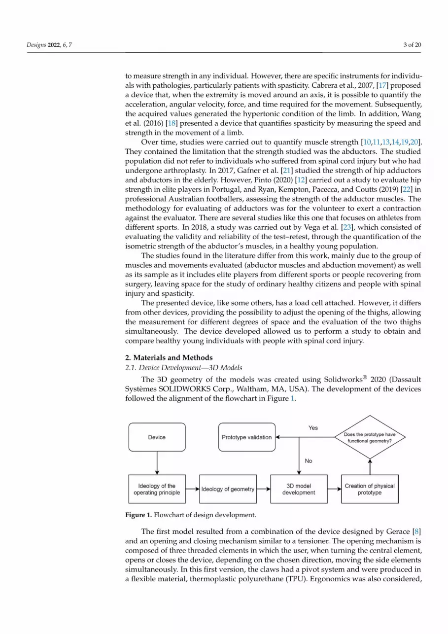
The 3D geometry of the models was created using Solidworks® 2020 (DassaultSystèmes SOLIDWORKS Corp., Waltham, MA, USA). The development of the devicesfollowed the alignment of the flowchart in Figure 1.
Designs 2022, 6, x FOR PEER REVIEW 3 of 21
portable ones such as Smart Groin [12], and isokinetic ones such as Cybex II [13], Power Track 11, Commande [14], KForce Muscle Controller [15], and ForceFrame [16]. All these instruments aim to measure strength in any individual. However, there are specific instruments for individuals with pathologies, particularly patients with spasticity. Cabrera et al., 2007, [17] proposed a device that, when the extremity is moved around an axis, it is possible to quantify the acceleration, angular velocity, force, and time required for the movement. Subsequently, the acquired values generated the hypertonic condition of the limb. In addition, Wang et al. (2016) [18] presented a device that quantifies spasticity by measuring the speed and strength in the movement of a limb.
Over time, studies were carried out to quantify muscle strength [10,11,13,14,19,20]. They contained the limitation that the strength studied was the abductors. The studied population did not refer to individuals who suffered from spinal cord injury but who had undergone arthroplasty. In 2017, Gafner et al. [21] studied the strength of hip adductors and abductors in the elderly. However, Pinto (2020) [12] carried out a study to evaluate hip strength in elite players in Portugal, and Ryan, Kempton, Pacecca, and Coutts (2019) [22] in professional Australian footballers, assessing the strength of the adductor muscles. The methodology for evaluating of adductors was for the volunteer to exert a contraction against the evaluator. There are several studies like this one that focuses on athletes from different sports. In 2018, a study was carried out by Vega et al. [23], which consisted of evaluating the validity and reliability of the test–retest, through the quantification of the isometric strength of the abductor’s muscles, in a healthy young population.
The studies found in the literature differ from this work, mainly due to the group of muscles and movements evaluated (abductor muscles and abduction movement) as well as its sample as it includes elite players from different sports or people recovering from surgery, leaving space for the study of ordinary healthy citizens and people with spinal injury and spasticity.
The presented device, like some others, has a load cell attached. However, it differs from other devices, providing the possibility to adjust the opening of the thighs, allowing the measurement for different degrees of space and the evaluation of the two thighs simultaneously. The device developed allowed us to perform a study to obtain and compare healthy young individuals with people with spinal cord injury.
2. Materials and Methods 2.1. Device Development—3D Models
The 3D geometry of the models was created using Solidworks® 2020 (Dassault Systèmes SOLIDWORKS Corp., Waltham, MA, USA). The development of the devices followed the alignment of the flowchart in Figure 1.
Figure 1. Flowchart of design development.
The first model resulted from a combination of the device designed by Gerace [8] and an opening and closing mechanism similar to a tensioner. The opening mechanism is composed of three threaded elements in which the user, when turning the central element, opens or closes the device, depending on the chosen direction, moving the side elements
Figure 1. Flowchart of design development.
The first model resulted from a combination of the device designed by Gerace [8]and an opening and closing mechanism similar to a tensioner. The opening mechanism iscomposed of three threaded elements in which the user, when turning the central element,opens or closes the device, depending on the chosen direction, moving the side elementssimultaneously. In this first version, the claws had a pivot system and were produced ina flexible material, thermoplastic polyurethane (TPU). Ergonomics was also considered,

Designs 2022, 6, 7 4 of 20
especially in the region of contact between the thigh and the device, to make the experienceof opening the thighs as pleasant as possible. This prototype also sought to guide the userto the correct use, demonstrating that its geometry is intuitive to manipulate. Figure 2illustrates the results of the first idea, designed as a mechanical device.
Designs 2022, 6, x FOR PEER REVIEW 4 of 21
simultaneously. In this first version, the claws had a pivot system and were produced in a flexible material, thermoplastic polyurethane (TPU). Ergonomics was also considered, especially in the region of contact between the thigh and the device, to make the experience of opening the thighs as pleasant as possible. This prototype also sought to guide the user to the correct use, demonstrating that its geometry is intuitive to manipu-late. Figure 2 illustrates the results of the first idea, designed as a mechanical device.
(a) (b)
Figure 2. 3D model of the mechanical device: (a) Global visualization; (b) Detail of pivot system.
As the literature does not give results concerning the quantification of the force made in the adduction movement in the sitting position, particularly for patients with spinal cord injury, the possibility of introducing the ability to quantify the force exerted on the system under development was studied. To this purpose, a load cell with reduced dimen-sions was selected, from the Interface brand, reference WMC-500, with a load capacity of 2.22 kN. The changes went through creating a “bed” where the load cell rests, and the material and system fix the device’s claws. The new fixation system was subdivided, hav-ing a fixed claw with a tightening design between screw and nut and another claw, which fits in the load cell, with a pin-type system. The screw-nut fixation system had high rigid-ity. Therefore, one of the fixed side elements was changed so that a bearing was attached to give some freedom for adjusting the claw to the position. Consequently, the central part underwent modifications, increasing the thread on the side where the instrumented side element was presented and decreasing the thread on the fixed side element, reaching the instrumented device. Version 1 is represented in Figure 3.
(a) (b)
Figure 3. 3D model of the instrumented device for force measurement: (a) Global visualization; (b) Detail with components, (1)—fixed claw, (2)—fixed side element, (3)—central element, (4)—mobile side element, (5)—load cell, (6)—instrumented claw.
Figure 2. 3D model of the mechanical device: (a) Global visualization; (b) Detail of pivot system.
As the literature does not give results concerning the quantification of the force madein the adduction movement in the sitting position, particularly for patients with spinal cordinjury, the possibility of introducing the ability to quantify the force exerted on the systemunder development was studied. To this purpose, a load cell with reduced dimensions wasselected, from the Interface brand, reference WMC-500, with a load capacity of 2.22 kN.The changes went through creating a “bed” where the load cell rests, and the material andsystem fix the device’s claws. The new fixation system was subdivided, having a fixed clawwith a tightening design between screw and nut and another claw, which fits in the loadcell, with a pin-type system. The screw-nut fixation system had high rigidity. Therefore,one of the fixed side elements was changed so that a bearing was attached to give somefreedom for adjusting the claw to the position. Consequently, the central part underwentmodifications, increasing the thread on the side where the instrumented side element waspresented and decreasing the thread on the fixed side element, reaching the instrumenteddevice. Version 1 is represented in Figure 3.
Designs 2022, 6, x FOR PEER REVIEW 4 of 21
simultaneously. In this first version, the claws had a pivot system and were produced in a flexible material, thermoplastic polyurethane (TPU). Ergonomics was also considered, especially in the region of contact between the thigh and the device, to make the experience of opening the thighs as pleasant as possible. This prototype also sought to guide the user to the correct use, demonstrating that its geometry is intuitive to manipu-late. Figure 2 illustrates the results of the first idea, designed as a mechanical device.
(a) (b)
Figure 2. 3D model of the mechanical device: (a) Global visualization; (b) Detail of pivot system.
As the literature does not give results concerning the quantification of the force made in the adduction movement in the sitting position, particularly for patients with spinal cord injury, the possibility of introducing the ability to quantify the force exerted on the system under development was studied. To this purpose, a load cell with reduced dimen-sions was selected, from the Interface brand, reference WMC-500, with a load capacity of 2.22 kN. The changes went through creating a “bed” where the load cell rests, and the material and system fix the device’s claws. The new fixation system was subdivided, hav-ing a fixed claw with a tightening design between screw and nut and another claw, which fits in the load cell, with a pin-type system. The screw-nut fixation system had high rigid-ity. Therefore, one of the fixed side elements was changed so that a bearing was attached to give some freedom for adjusting the claw to the position. Consequently, the central part underwent modifications, increasing the thread on the side where the instrumented side element was presented and decreasing the thread on the fixed side element, reaching the instrumented device. Version 1 is represented in Figure 3.
(a) (b)
Figure 3. 3D model of the instrumented device for force measurement: (a) Global visualization; (b) Detail with components, (1)—fixed claw, (2)—fixed side element, (3)—central element, (4)—mobile side element, (5)—load cell, (6)—instrumented claw.
Figure 3. 3D model of the instrumented device for force measurement: (a) Global visualization; (b)Detail with components, (1)—fixed claw, (2)—fixed side element, (3)—central element, (4)—mobileside element, (5)—load cell, (6)—instrumented claw.
The results obtained from the experimental tests, both in healthy volunteers and inpatients present in Section 3.2, allow improving the mechanical device for a motorised

Designs 2022, 6, 7 5 of 20
version. With the need to couple an embedded micro-motor, the geometries of somecomponents changed, such as the clamping system of the claws, the mobile side element,and the central element. Figure 4 shows the 3D model of this version of the device. Thediagram in Figure 4b represents the cable connections inside the central element where theend limit switches are coupled.
Designs 2022, 6, x FOR PEER REVIEW 5 of 21
The results obtained from the experimental tests, both in healthy volunteers and in patients present in Section 3.2, allow improving the mechanical device for a motorised version. With the need to couple an embedded micro-motor, the geometries of some com-ponents changed, such as the clamping system of the claws, the mobile side element, and the central element. Figure 4 shows the 3D model of this version of the device. The dia-gram in Figure 4b represents the cable connections inside the central element where the end limit switches are coupled.
(a) (b)
Figure 4. 3D model of the motorised device: (a) Global visualization; (b) Detail with components, (1)—motor grip, (2)—movable side element, (3)—DC motor, (4)—threaded element, (5) central ele-ment, (6)—fastening element, (7)— fixed grip, (8)—positioning of end limit switches, (9)—embed-ded wire for signal transport.
The DC motor, the joystick, and the microcontroller to manage the device stroke, as well as safety limits, have been incorporated into a patient-accessible control box (Figure 5a). One of the aspects referred as a barrier in the self-catheterisation process is the diffi-culty in visualizing the insertion area. Therefore, a system was developed that allows an-choring a mirror (Figure 5c) or a camera (Figure 5b), an essential feature in this device.
(a) (b) (c)
Figure 5. Add-ons: (a) Control unit; (b) Anchoring the camera; (c) Mirror anchor.
Figure 4. 3D model of the motorised device: (a) Global visualization; (b) Detail with components, (1)—motor grip, (2)—movable side element, (3)—DC motor, (4)—threaded element, (5) central element,(6)—fastening element, (7)— fixed grip, (8)—positioning of end limit switches, (9)—embedded wirefor signal transport.
The DC motor, the joystick, and the microcontroller to manage the device stroke, aswell as safety limits, have been incorporated into a patient-accessible control box (Figure 5a).One of the aspects referred as a barrier in the self-catheterisation process is the difficulty invisualizing the insertion area. Therefore, a system was developed that allows anchoring amirror (Figure 5c) or a camera (Figure 5b), an essential feature in this device.
Designs 2022, 6, x FOR PEER REVIEW 5 of 21
The results obtained from the experimental tests, both in healthy volunteers and in patients present in Section 3.2, allow improving the mechanical device for a motorised version. With the need to couple an embedded micro-motor, the geometries of some com-ponents changed, such as the clamping system of the claws, the mobile side element, and the central element. Figure 4 shows the 3D model of this version of the device. The dia-gram in Figure 4b represents the cable connections inside the central element where the end limit switches are coupled.
(a) (b)
Figure 4. 3D model of the motorised device: (a) Global visualization; (b) Detail with components, (1)—motor grip, (2)—movable side element, (3)—DC motor, (4)—threaded element, (5) central ele-ment, (6)—fastening element, (7)— fixed grip, (8)—positioning of end limit switches, (9)—embed-ded wire for signal transport.
The DC motor, the joystick, and the microcontroller to manage the device stroke, as well as safety limits, have been incorporated into a patient-accessible control box (Figure 5a). One of the aspects referred as a barrier in the self-catheterisation process is the diffi-culty in visualizing the insertion area. Therefore, a system was developed that allows an-choring a mirror (Figure 5c) or a camera (Figure 5b), an essential feature in this device.
(a) (b) (c)
Figure 5. Add-ons: (a) Control unit; (b) Anchoring the camera; (c) Mirror anchor. Figure 5. Add-ons: (a) Control unit; (b) Anchoring the camera; (c) Mirror anchor.

Designs 2022, 6, 7 6 of 20
2.2. Production of Prototypes
The idea concerning the project’s development was to use additive manufacturing toimprove the costs of the mechanical components and implement “green” thinking withpossible recycled materials. In the mechanical device, the material chosen for the clawswas the polyethene glycol-ethylene terephthalate (PETG) due to its characteristics. Thepivot system was produced in a flexible material, thermoplastic polyurethane (TPU). In themotorised model, the material of the mechanical components was changed to polylacticacid (PLA) due to its best characteristics associated with the friction and coupling of themotor. As a complement to the devices, pads were created in Elastosil M 4512 from theWacker brand, offering greater comfort and easy cleaning. The anchoring systems forthe mirror and the camera were produced with PETG. Table 1 shows the mechanicalcharacteristics of the material used for additive manufacturing.
Table 1. Properties of the material used for additive manufacturing.
Material Specific Massρ (kg/m3)
Young’sModulusE (MPa)
TensileStrengthσc (MPa)
Poisson’s Ratioν
PETG 1420 2960 57.3 0.37PLA 1240 3500 70.0 0.36TPU 1120 26 45.0 0.39
Elastosil M4512 * 1190 - 3.5 -* Hardness Shore A: 20.
As the different models were developed, produced prototypes allow testing variousaspects of their functionality, such as ergonomics and design. Figure 6a shows an example of3D prototyping, with a Prusa i3 mk3s+ equipment, producing the mechanical componentsin the respective materials mentioned above (example in Figure 6b).
Designs 2022, 6, x FOR PEER REVIEW 6 of 21
2.2. Production of Prototypes
The idea concerning the project’s development was to use additive manufacturing to
improve the costs of the mechanical components and implement “green” thinking with
possible recycled materials. In the mechanical device, the material chosen for the claws
was the polyethene glycol-ethylene terephthalate (PETG) due to its characteristics. The
pivot system was produced in a flexible material, thermoplastic polyurethane (TPU). In
the motorised model, the material of the mechanical components was changed to polylac-
tic acid (PLA) due to its best characteristics associated with the friction and coupling of
the motor. As a complement to the devices, pads were created in Elastosil M 4512 from
the Wacker brand, offering greater comfort and easy cleaning. The anchoring systems for
the mirror and the camera were produced with PETG. Table 1 shows the mechanical char-
acteristics of the material used for additive manufacturing.
Table 1. Properties of the material used for additive manufacturing.
Material Specific Mass
ρ (kg/m3)
Young’s Modulus
E (MPa)
Tensile Strength
σc (MPa)
Poisson’s Ratio
ν
PETG 1420 2960 57.3 0.37
PLA 1240 3500 70.0 0.36
TPU 1120 26 45.0 0.39
Elastosil M4512 * 1190 - 3.5 -
* Hardness Shore A: 20.
As the different models were developed, produced prototypes allow testing various
aspects of their functionality, such as ergonomics and design. Figure 6a shows an example
of 3D prototyping, with a Prusa i3 mk3s+ equipment, producing the mechanical compo-
nents in the respective materials mentioned above (example in Figure 6b).
(a) (b)
Figure 6. (a) Prusa i3 mk3s+ equipment; (b) Example of a printing detail.
2.3. Real Devices
Figure 6. (a) Prusa i3 mk3s+ equipment; (b) Example of a printing detail.

Designs 2022, 6, 7 7 of 20
2.3. Real Devices
Figure 7 shows the final mechanical device obtained after production, showing themirror system coupled to one side.
Designs 2022, 6, x FOR PEER REVIEW 7 of 21
Figure 7 shows the final mechanical device obtained after production, showing the mirror system coupled to one side.
Figure 7. Mechanical device with the mirror system coupled.
The instrumented device is present in Figure 8a, with all the components assembled but without the mirror or the camera. A National Instruments data board (NI cDAQ-9174 Chassis and NI 9219 Acquisition Module) was used to connect the load cell by means of a developed LabView program running on a PC.
Figure 8b shows the interface with the user for the load cell. The program allows watching, in real-time, the force applied by the user and was developed to provide an automatic calibration of the load cell, the register of the force/time, and the generation of a final report with the data acquired.
(a) (b)
Figure 8. (a) Instrumented device; (b) Interface of Labview program to connect the load cell.
Four open positions of the system can be considered as predefined, as shown in Fig-ure 9, which corresponds to the most closed (0 mm) and 20, 40 and 60 mm of opening.
Figure 7. Mechanical device with the mirror system coupled.
The instrumented device is present in Figure 8a, with all the components assembledbut without the mirror or the camera. A National Instruments data board (NI cDAQ-9174Chassis and NI 9219 Acquisition Module) was used to connect the load cell by means of adeveloped LabView program running on a PC.
Designs 2022, 6, x FOR PEER REVIEW 7 of 21
Figure 7 shows the final mechanical device obtained after production, showing the mirror system coupled to one side.
Figure 7. Mechanical device with the mirror system coupled.
The instrumented device is present in Figure 8a, with all the components assembled but without the mirror or the camera. A National Instruments data board (NI cDAQ-9174 Chassis and NI 9219 Acquisition Module) was used to connect the load cell by means of a developed LabView program running on a PC.
Figure 8b shows the interface with the user for the load cell. The program allows watching, in real-time, the force applied by the user and was developed to provide an automatic calibration of the load cell, the register of the force/time, and the generation of a final report with the data acquired.
(a) (b)
Figure 8. (a) Instrumented device; (b) Interface of Labview program to connect the load cell.
Four open positions of the system can be considered as predefined, as shown in Fig-ure 9, which corresponds to the most closed (0 mm) and 20, 40 and 60 mm of opening.
Figure 8. (a) Instrumented device; (b) Interface of Labview program to connect the load cell.
Figure 8b shows the interface with the user for the load cell. The program allowswatching, in real-time, the force applied by the user and was developed to provide anautomatic calibration of the load cell, the register of the force/time, and the generation of afinal report with the data acquired.
Four open positions of the system can be considered as predefined, as shown inFigure 9, which corresponds to the most closed (0 mm) and 20, 40 and 60 mm of opening.

Designs 2022, 6, 7 8 of 20Designs 2022, 6, x FOR PEER REVIEW 8 of 21
Figure 9. Device positions considered in the tests.
The motorised device is shown in Figure 10a. The connection of the control unit (Fig-ure 10b) to the device is made through a cable mounted with a protection system, already referenced in Section 2.1, Figure 4b, called end limit switches, which turns off the motor as soon as it reaches the minimum or maximum allowed stroke.
(a) (b)
Figure 10. (a) Motorised device: (1) Camera with adjustable cable; (b) Detail of the command unit: (2) Button on/off; (3) Joystick.
2.4. Finite Element Models Although the developed systems have been experimentally tested, the finite element
method [24] was also implemented to analyse their structural behaviour. For this purpose, two models were created, considering the instrumented system and the motorised system, given some of its components’ differences in geometry and cross-sections. The models were implemented using the Solidworks® software, with simplified geometry, to facili-tate its definition by removing elements that would not influence the analysis. The study considers the worst position of the devices, with its extended opening.
The instrumented device is generally PET, while the motorised device is made of PLA. The materials are considered to have isotropic characteristics, an accepted simplifi-cation in numerical models. Thus, finite element models consider the mechanical charac-teristics described in Table 1.
The models assumed isotropic linear elastic properties for all the components. They were defined with tetrahedral parabolic solid elements (solid elements from Solidworks
Figure 9. Device positions considered in the tests.
The motorised device is shown in Figure 10a. The connection of the control unit(Figure 10b) to the device is made through a cable mounted with a protection system,already referenced in Section 2.1, Figure 4b, called end limit switches, which turns off themotor as soon as it reaches the minimum or maximum allowed stroke.
Designs 2022, 6, x FOR PEER REVIEW 8 of 21
Figure 9. Device positions considered in the tests.
The motorised device is shown in Figure 10a. The connection of the control unit (Fig-ure 10b) to the device is made through a cable mounted with a protection system, already referenced in Section 2.1, Figure 4b, called end limit switches, which turns off the motor as soon as it reaches the minimum or maximum allowed stroke.
(a) (b)
Figure 10. (a) Motorised device: (1) Camera with adjustable cable; (b) Detail of the command unit: (2) Button on/off; (3) Joystick.
2.4. Finite Element Models Although the developed systems have been experimentally tested, the finite element
method [24] was also implemented to analyse their structural behaviour. For this purpose, two models were created, considering the instrumented system and the motorised system, given some of its components’ differences in geometry and cross-sections. The models were implemented using the Solidworks® software, with simplified geometry, to facili-tate its definition by removing elements that would not influence the analysis. The study considers the worst position of the devices, with its extended opening.
The instrumented device is generally PET, while the motorised device is made of PLA. The materials are considered to have isotropic characteristics, an accepted simplifi-cation in numerical models. Thus, finite element models consider the mechanical charac-teristics described in Table 1.
The models assumed isotropic linear elastic properties for all the components. They were defined with tetrahedral parabolic solid elements (solid elements from Solidworks
Figure 10. (a) Motorised device: (1) Camera with adjustable cable; (b) Detail of the command unit:(2) Button on/off; (3) Joystick.
2.4. Finite Element Models
Although the developed systems have been experimentally tested, the finite elementmethod [24] was also implemented to analyse their structural behaviour. For this purpose,two models were created, considering the instrumented system and the motorised system,given some of its components’ differences in geometry and cross-sections. The models wereimplemented using the Solidworks®software, with simplified geometry, to facilitate itsdefinition by removing elements that would not influence the analysis. The study considersthe worst position of the devices, with its extended opening.
The instrumented device is generally PET, while the motorised device is made of PLA.The materials are considered to have isotropic characteristics, an accepted simplificationin numerical models. Thus, finite element models consider the mechanical characteristicsdescribed in Table 1.
The models assumed isotropic linear elastic properties for all the components. Theywere defined with tetrahedral parabolic solid elements (solid elements from Solidworks

Designs 2022, 6, 7 9 of 20
library), with 3 degrees of freedom per node, representing the translations in the threeorthogonal directions.
2.4.1. Instrumented Device
For the instrumented version of the device, the simplification of the geometry con-siders only the two central components, namely the nut and screw, as they are the mostcritical parts (Figure 11). The boundary conditions for the model consider the restrictionof all degrees of freedom on the end face of the nut-type structural element (most rigidcomponent). The force value and condition were based on the experimental results obtainedfrom the tests with patients. The 235 N force was applied on the surface of the screw element(uniformly distributed and perpendicular to the surface), which translates the maximumforce exerted by the volunteer’s legs in the device for the considered position.
Designs 2022, 6, x FOR PEER REVIEW 9 of 21
library), with 3 degrees of freedom per node, representing the translations in the three orthogonal directions.
2.4.1. Instrumented Device For the instrumented version of the device, the simplification of the geometry con-
siders only the two central components, namely the nut and screw, as they are the most critical parts (Figure 11). The boundary conditions for the model consider the restriction of all degrees of freedom on the end face of the nut-type structural element (most rigid component). The force value and condition were based on the experimental results ob-tained from the tests with patients. The 235 N force was applied on the surface of the screw element (uniformly distributed and perpendicular to the surface), which translates the maximum force exerted by the volunteer’s legs in the device for the considered position.
A study of convergence for the mesh was carried out, based on the energy of defor-mation, considering the maximum value of the resulting displacement in the model. Viewing the typology of the geometries under analysis and using the mesh-type option in the software, the maximum and minimum dimensions of the model were successively adjusted. The displacement stabilisation was obtained from elements between 0.5 mm and 2.5 mm. The contact between the surfaces considers the “no penetration” definition.
Figure 11. Visualization of the mesh, boundary conditions, and force applied in the finite element model of the instrumented device.
2.4.2. Motorised Device For the motorised model, the geometry considers all the structural components. The
opening length was kept the same as the instrumented device, corresponding to the worst position. The boundary and load conditions adopted also simulate the situation of a user exerting force on the device.
As this model considers the two claws, the option for boundary condition was to keep the nut component wholly anchored to the user’s leg, with all degrees of freedom constrained in its contact surface. The other claw allows movement and is considered for load application. Two different force conditions were applied. The first one was based on the symmetry of the force, which simulates the situation of a user with the dimensions of the leg adapted to the size of the claw. The other considers some eccentricity, simulating the situation in which the dimensions of the limb are larger than those of the claw, as shown in Figure 12.
Figure 11. Visualization of the mesh, boundary conditions, and force applied in the finite elementmodel of the instrumented device.
A study of convergence for the mesh was carried out, based on the energy of de-formation, considering the maximum value of the resulting displacement in the model.Viewing the typology of the geometries under analysis and using the mesh-type optionin the software, the maximum and minimum dimensions of the model were successivelyadjusted. The displacement stabilisation was obtained from elements between 0.5 mm and2.5 mm. The contact between the surfaces considers the “no penetration” definition.
2.4.2. Motorised Device
For the motorised model, the geometry considers all the structural components. Theopening length was kept the same as the instrumented device, corresponding to the worstposition. The boundary and load conditions adopted also simulate the situation of a userexerting force on the device.
As this model considers the two claws, the option for boundary condition was tokeep the nut component wholly anchored to the user’s leg, with all degrees of freedomconstrained in its contact surface. The other claw allows movement and is considered forload application. Two different force conditions were applied. The first one was based onthe symmetry of the force, which simulates the situation of a user with the dimensions ofthe leg adapted to the size of the claw. The other considers some eccentricity, simulating thesituation in which the dimensions of the limb are larger than those of the claw, as shownin Figure 12.

Designs 2022, 6, 7 10 of 20Designs 2022, 6, x FOR PEER REVIEW 10 of 21
Figure 12. Load and boundary conditions for both situations.
The contact between the surfaces considers the “no penetration” definition. The mesh convergence of the model was performed following the same methodology as for the in-strumented model, based on the comparative analysis of the maximum resulting displace-ments and their location, leading to elements that ranged from 0.98 mm to 5 mm.
2.5. Experimental Tests As referred, the experimental tests were performed with the instrumented device,
considering two groups of volunteers, namely healthy young students from the Coimbra School of Engineering and patients with spinal cord injury from the Hospital Rovisco Pais.
The experimental test protocol with volunteers was prepared following the Declara-tion of Helsinki. It was approved by the Ethics Committee of the Polytechnic of Coimbra (Reference no. 118_CEIPC2/2020) for the healthy volunteers and according to the hospital rules for the spinal cord injury volunteers. Each volunteer was assigned to a code with no identity records, safeguarding the necessary confidentiality.
Data statistical analysis was performed with two different statistical software: Mi-crosoft Excel and IBM® SPSS® Statistics. With Excel, the data set acquired from each vol-unteer was studied to assess his/her behaviour throughout the experiment. The evolution of the peak strength of each volunteer was studied, and there could be a comparison of the various curves according to relevant parameters. With statistical analysis software IBM SPSS, the results obtained from the device for each volunteer were processed to verify the existence of correlations between the acquired data to validate the device and obtain valid biometric conclusions.
2.5.1. Tests with Healthy Young Volunteers Concerning the experimental test, age was considered as an inclusion criterion.
Firstly, the objectives and methodology of the study were presented to the volunteer, and they signed a form giving free and informed consent. After this, the protocol consisted of acquiring several biometric values, such as sex, age, height, weight, body mass index (BMI), body fat percentage, skeletal muscle percentage, visceral fat level, and resting kil-ocalories. Then, the volunteer answered a questionnaire with additional data on the
Figure 12. Load and boundary conditions for both situations.
The contact between the surfaces considers the “no penetration” definition. Themesh convergence of the model was performed following the same methodology as forthe instrumented model, based on the comparative analysis of the maximum resultingdisplacements and their location, leading to elements that ranged from 0.98 mm to 5 mm.
2.5. Experimental Tests
As referred, the experimental tests were performed with the instrumented device,considering two groups of volunteers, namely healthy young students from the CoimbraSchool of Engineering and patients with spinal cord injury from the Hospital Rovisco Pais.
The experimental test protocol with volunteers was prepared following the Declarationof Helsinki. It was approved by the Ethics Committee of the Polytechnic of Coimbra(Reference no. 118_CEIPC2/2020) for the healthy volunteers and according to the hospitalrules for the spinal cord injury volunteers. Each volunteer was assigned to a code with noidentity records, safeguarding the necessary confidentiality.
Data statistical analysis was performed with two different statistical software: Mi-crosoft Excel and IBM® SPSS® Statistics. With Excel, the data set acquired from eachvolunteer was studied to assess his/her behaviour throughout the experiment. The evolu-tion of the peak strength of each volunteer was studied, and there could be a comparisonof the various curves according to relevant parameters. With statistical analysis softwareIBM SPSS, the results obtained from the device for each volunteer were processed to verifythe existence of correlations between the acquired data to validate the device and obtainvalid biometric conclusions.
2.5.1. Tests with Healthy Young Volunteers
Concerning the experimental test, age was considered as an inclusion criterion. Firstly,the objectives and methodology of the study were presented to the volunteer, and theysigned a form giving free and informed consent. After this, the protocol consisted ofacquiring several biometric values, such as sex, age, height, weight, body mass index (BMI),body fat percentage, skeletal muscle percentage, visceral fat level, and resting kilocalories.Then, the volunteer answered a questionnaire with additional data on the history of injuries

Designs 2022, 6, 7 11 of 20
and the quantity and quality of their weekly physical activity. The existence of pathologiesin the lower limbs for less than five years was considered an exclusion criterion.
After completing the questionnaire, the volunteer sat in a comfortable position, asshown in Figure 13.
Designs 2022, 6, x FOR PEER REVIEW 11 of 21
history of injuries and the quantity and quality of their weekly physical activity. The ex-istence of pathologies in the lower limbs for less than five years was considered an exclu-sion criterion.
After completing the questionnaire, the volunteer sat in a comfortable position, as shown in Figure 13.
Figure 13. Position of the volunteer to perform the test of the instrumented device.
When the volunteer was ready, four positions in an opening interval of (0, 60) mm were considered for the acquisition: P0 force values, corresponding to the initial force po-sitions (opening of 0 mm); P1 force (position of 20 mm); P2 force (open position of 40 mm); P3 force (open position of 60 mm). All these positions are represented in Figure 9. The volunteer was asked to contract their legs against the device as hard as possible in each position. The volunteer rested for 1 minute between sections while adjusting the device to the next position. During testing, the volunteer could monitor the strength in real-time in the GUI shown, previously, in Figure 8.
2.5.2. Tests with Volunteers with Spinal Cord Injury The setup of tests with patients with spinal cord injury was referred to in the previous
section and is represented in Figure 14. In this case, the test procedure differed in some aspects. Due to the particular health situation of the volunteers, there was no filling out of the device evaluation questionnaire or the graphic interface. Additionally, the only data acquired were age, height, weight, sex, and opening in the Budda position, as they were considered enough to understand and compare the device’s performance. In particular, the aim of acquiring the opening in the Budda position was to normalize the device size relating it to the volunteer’s height. Clinical data such as the gradient of muscle function, grade AIS (Abbreviated Injury Scale) and type and location of paralysis were also needed to understand whether the volunteer’s grade of disease would influence strength.
The specific position of the volunteer was maintained, additionally, the wheelchair usually used by the user was considered. This type of testing is closer to real use by this type of patient.
Figure 13. Position of the volunteer to perform the test of the instrumented device.
When the volunteer was ready, four positions in an opening interval of (0, 60) mmwere considered for the acquisition: P0 force values, corresponding to the initial forcepositions (opening of 0 mm); P1 force (position of 20 mm); P2 force (open position of40 mm); P3 force (open position of 60 mm). All these positions are represented in Figure 9.The volunteer was asked to contract their legs against the device as hard as possible in eachposition. The volunteer rested for 1 minute between sections while adjusting the device tothe next position. During testing, the volunteer could monitor the strength in real-time inthe GUI shown, previously, in Figure 8.
2.5.2. Tests with Volunteers with Spinal Cord Injury
The setup of tests with patients with spinal cord injury was referred to in the previoussection and is represented in Figure 14. In this case, the test procedure differed in someaspects. Due to the particular health situation of the volunteers, there was no filling out ofthe device evaluation questionnaire or the graphic interface. Additionally, the only dataacquired were age, height, weight, sex, and opening in the Budda position, as they wereconsidered enough to understand and compare the device’s performance. In particular,the aim of acquiring the opening in the Budda position was to normalize the device sizerelating it to the volunteer’s height. Clinical data such as the gradient of muscle function,grade AIS (Abbreviated Injury Scale) and type and location of paralysis were also neededto understand whether the volunteer’s grade of disease would influence strength.

Designs 2022, 6, 7 12 of 20Designs 2022, 6, x FOR PEER REVIEW 12 of 21
Figure 14. Setup of tests at Hospital Rovisco Pais.
3. Results 3.1. Numerical Results 3.1.1. Instrumented Device
The von Mises stress distribution obtained is shown in Figure 15, presenting a uni-form distribution and values lower than the material yield stress. As can be observed, the contact regions show a peak of 33.2 MPa, corresponding to the beginning of the contact for the threaded element, associated with the geometric conditions of the model. Based on the results and for the requirements of the model, an adequate strength can be considered.
(a) (b)
Figure 15. Distribution of von Mises stress for the instrumented device.
3.1.2. Motorised Device In the case of the motorised model, for both load cases, all the components presented
von Mises stress values lower than the yield stress of considered PLA, due to its charac-teristics, particularly with friction between the central element and the threaded element.
Table 2 summarises the more significant value of von Mises stress on each part for both force conditions. The obtained results show an adequate strength for the model.
Table 2. Maximum values of von Mises stress on the components.
Figure 14. Setup of tests at Hospital Rovisco Pais.
The specific position of the volunteer was maintained, additionally, the wheelchairusually used by the user was considered. This type of testing is closer to real use by thistype of patient.
3. Results3.1. Numerical Results3.1.1. Instrumented Device
The von Mises stress distribution obtained is shown in Figure 15, presenting a uniformdistribution and values lower than the material yield stress. As can be observed, the contactregions show a peak of 33.2 MPa, corresponding to the beginning of the contact for thethreaded element, associated with the geometric conditions of the model. Based on theresults and for the requirements of the model, an adequate strength can be considered.
Designs 2022, 6, x FOR PEER REVIEW 12 of 21
Figure 14. Setup of tests at Hospital Rovisco Pais.
3. Results 3.1. Numerical Results 3.1.1. Instrumented Device
The von Mises stress distribution obtained is shown in Figure 15, presenting a uni-form distribution and values lower than the material yield stress. As can be observed, the contact regions show a peak of 33.2 MPa, corresponding to the beginning of the contact for the threaded element, associated with the geometric conditions of the model. Based on the results and for the requirements of the model, an adequate strength can be considered.
(a) (b)
Figure 15. Distribution of von Mises stress for the instrumented device.
3.1.2. Motorised Device In the case of the motorised model, for both load cases, all the components presented
von Mises stress values lower than the yield stress of considered PLA, due to its charac-teristics, particularly with friction between the central element and the threaded element.
Table 2 summarises the more significant value of von Mises stress on each part for both force conditions. The obtained results show an adequate strength for the model.
Table 2. Maximum values of von Mises stress on the components.
Figure 15. Distribution of von Mises stress for the instrumented device: (a) View of the global model;(b) Detail of von Mises stress distribution in the contact region.

Designs 2022, 6, 7 13 of 20
3.1.2. Motorised Device
In the case of the motorised model, for both load cases, all the components presentedvon Mises stress values lower than the yield stress of considered PLA, due to its character-istics, particularly with friction between the central element and the threaded element.
Table 2 summarises the more significant value of von Mises stress on each part forboth force conditions. The obtained results show an adequate strength for the model.
Table 2. Maximum values of von Mises stress on the components.
ComponentMaximum von Mises Stress (MPa)
LOAD CASE 1 LOAD CASE 2
Motor grip 13.15 18.39Movable side element 5.84 7.67
Central element 12.55 10.04Threaded element 19.10 104.30Fastening element 0.73 4.89
Fixed Grip 0.51 4.17
Figure 16 shows the contact zone between the elements for load case 1, where a stresspeak can be observed at the beginning of the contact for the threaded element (19.1 MPa).It must be noted that the positioning of the screw is the most unfavourable. Moreover,geometric conditions associated with the end of the threat and the mesh performed con-tributed to the peak in the initial contact zone. These results show consistency that thevalue is minimal in relation to the material’s yield strength.
Designs 2022, 6, x FOR PEER REVIEW 13 of 21
Component Maximum von Mises Stress (MPa)
LOAD CASE 1 LOAD CASE 2 Motor grip 13.15 18.39
Movable side element 5.84 7.67 Central element 12.55 10.04
Threaded element 19.10 104.30 Fastening element 0.73 4.89
Fixed Grip 0.51 4.17
Figure 16 shows the contact zone between the elements for load case 1, where a stress peak can be observed at the beginning of the contact for the threaded element (19.1 MPa). It must be noted that the positioning of the screw is the most unfavourable. Moreover, geometric conditions associated with the end of the threat and the mesh performed con-tributed to the peak in the initial contact zone. These results show consistency that the value is minimal in relation to the material’s yield strength.
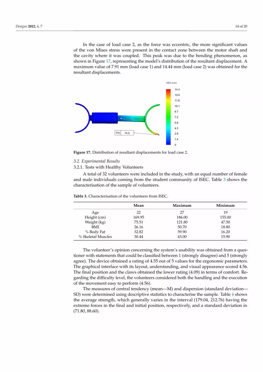
In the case of load case 2, as the force was eccentric, the more significant values of the von Mises stress were present in the contact zone between the motor shaft and the cavity where it was coupled. This peak was due to the bending phenomenon, as shown in Figure 17, representing the model’s distribution of the resultant displacement. A maximum value of 7.91 mm (load case 1) and 14.44 mm (load case 2) was obtained for the resultant dis-placements.
Figure 16. Distribution of von Mises stress in the mechanical components: (a) Load Case 1—axial force; (b) Load Case 2—eccentric force.
Figure 16. Distribution of von Mises stress in the mechanical components: (a) Load Case 1—axialforce; (b) Load Case 2—eccentric force.
Designs 2022, 6, 7 14 of 20
In the case of load case 2, as the force was eccentric, the more significant valuesof the von Mises stress were present in the contact zone between the motor shaft andthe cavity where it was coupled. This peak was due to the bending phenomenon, asshown in Figure 17, representing the model’s distribution of the resultant displacement. Amaximum value of 7.91 mm (load case 1) and 14.44 mm (load case 2) was obtained for theresultant displacements.
Designs 2022, 6, x FOR PEER REVIEW 14 of 21
Figure 17. Distribution of resultant displacements for load case 2.
3.2. Experimental Results 3.2.1. Tests with Healthy Volunteers
A total of 32 volunteers were included in the study, with an equal number of female and male individuals coming from the student community of ISEC. Table 3 shows the characterisation of the sample of volunteers.
Figure 17. Distribution of resultant displacements for load case 2.
3.2. Experimental Results3.2.1. Tests with Healthy Volunteers
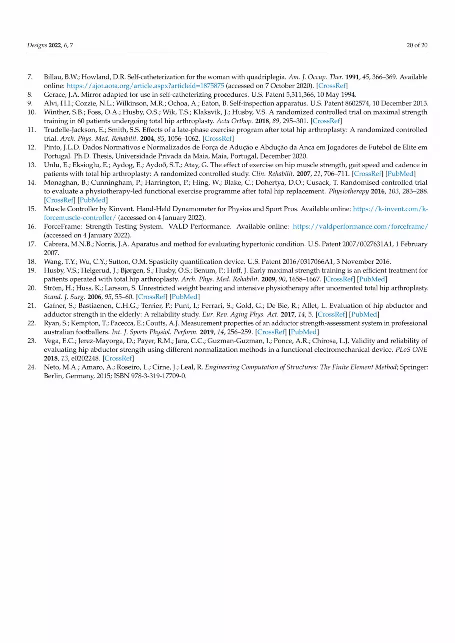
A total of 32 volunteers were included in the study, with an equal number of femaleand male individuals coming from the student community of ISEC. Table 3 shows thecharacterisation of the sample of volunteers.
Table 3. Characterisation of the volunteers from ISEC.
Mean Maximum Minimum
Age 22 27 19Height (cm) 169.95 186.00 155.00Weight (kg) 75.51 121.80 47.50
BMI 26.16 50.70 18.80% Body Fat 32.82 59.90 16.20
% Skeletal Muscles 30.44 43.00 15.90
The volunteer’s opinion concerning the system’s usability was obtained from a ques-tioner with statements that could be classified between 1 (strongly disagree) and 5 (stronglyagree). The device obtained a rating of 4.55 out of 5 values for the ergonomic parameters.The graphical interface with its layout, understanding, and visual appearance scored 4.56.The final position and the claws obtained the lower rating (4.09) in terms of comfort. Re-garding the difficulty level, the volunteers considered both the handling and the executionof the movement easy to perform (4.56).
The measures of central tendency (mean—M) and dispersion (standard deviation—SD) were determined using descriptive statistics to characterise the sample. Table 4 showsthe average strength, which generally varies in the interval (179.04, 212.76) having theextreme forces in the final and initial position, respectively, and a standard deviation in(71.80, 88.60).

Designs 2022, 6, 7 15 of 20
Table 4. Means (M), standard deviations (SD), minimums, and maximums for the total sample forcesof the volunteers from ISEC.
Total Sample (n = 32)
M SD Median Minimum Maximum
Force P0 212.76 88.60 224 70.33 416.92Force P1 206.28 78.12 197 75.77 345.22Force P2 188.52 71.80 207 65.40 371.81Force P3 179.04 80.02 207 46.10 327.27
The comparison between gender is present in Table 5, with the measures of centraltendency for independent samples.
Table 5. Means (M), standard deviations (SD), minimums, and maximums for the independentsamples by gender.
Male(n = 16)
Female(n = 16)
M SD Minimum Maximum M SD Minimum Maximum
Force P0 257.32 88.09 70.33 416.92 198.81 72.64 96.35 295.70Force P1 244.14 71.34 10.22 345.22 191.70 71.10 87.32 283.84Force P2 225.22 57.04 68.00 371.81 159.92 68.04 65.40 251.24Force P3 212.76 68.39 51.48 327.27 150.50 77.78 60.13 264.66
To complement the results expressed in Table 5, the box plot of Figure 18 shows theinfluence of gender on the strength value in each position.
Forc
e (N
)
Figure 18. Boxplot of forces by gender.

Designs 2022, 6, 7 16 of 20
To corroborate the previous statement, t-tests were performed with a significance of5% (and 95% confidence intervals) for the equality of the means of the forces, obtaining theresults described in Table 6.
Table 6. t-test for equal force averages in the healthy population (independent samples test).
Force EqualVariances
Levene’s TestEquality ofVariances
t-Test for Equality of Means
t df p-Value MeanDifference
Std. ErrorDifference
95% ConfidenceInterval of the
Difference
F Sig. Lower Upper
P0Assumed
0.691 0.4132.71 30.00 0.011 77.30 28.55 18.99 135.59
Not Assumed 2.71 28.95 0.011 77.30 28.55 18.99 135.59
P1Assumed
0.054 0.8182.70 30.00 0.011 68.02 25.18 16.60 119.44
Not Assumed 2.70 30.00 0.011 68.02 25.18 16.60 119.44
P2Assumed
2.333 0.1373.25 30.00 0.003 72.05 22.20 26.72 117.39
Not Assumed 3.25 29.11 0.003 72.05 22.20 26.72 117.39
P3Assumed
1.121 0.2982.65 30.00 0.013 68.56 25.89 15.68 121.44
Not Assumed 2.65 29.52 0.013 68.56 25.89 15.68 121.44
To analyse the influence of biometric parameters, Pearson correlations were deter-mined. There were several correlations between weight and BMI (ρ = 0.883) and thepercentage of skeletal muscles and body fat (ρ = −0.908). Another moderate linear cor-relation of 0.39 < ρ < 0.477 was observed between the rate of skeletal muscles and thevarious forces. Some graphs, represented in Figure 19, were constructed to understand theforce behaviour with the variation of the related biometric data.
(a) (b)
(c) (d)
Figure 19. Graphical visualisation of force against some biometric data: (a) Force—IMC; (b) Force—Weight; (c) Force—Hight; (d) Force—Age.

Designs 2022, 6, 7 17 of 20
The correlations between the forces were analysed using the Pearson correlationsshown in Table 7.
Table 7. Pearson’s correlations for ISEC volunteer strengths.
Force P0 Force P1 Force P2 Force P3
Force P0 1 0.671 0.716 0.732Force P1 0.671 1 0.784 0.626Force P2 0.716 0.784 1 0.814Force P3 0.732 0.626 0.814 1
3.2.2. Tests with Patients
The sample used in the present tests consists of ten volunteers (five female and fivemales) with spinal cord injury (SCI) from the Hospital Rovisco Pais. The volunteers, agedbetween 30 and 72 years (M = 62.6; SD = 13.074), had heights between 145 cm and 183 cm(M = 167.7; SD = 11.71) and weights between 46 kg and 84 kg (M = 70.6; SD = 10.56).Regarding their clinical data, 50% (n = 5) had a gradient of muscle function of 4, 10% (n = 1)of 3, 30% (n = 3) of 2, and 10% (n = 1) of 0.
The AIS scale describes the functional behaviour of the persons with spinal cord injury.It is divided into 5 degrees: A (complete), B (sensory incomplete), C (motor incomplete), D(motor incomplete), E (normal). As far as the AIS degree was concerned, the one with thehighest percentage of volunteers, 80% (n = 8), was D, with the remainder being degree C(n = 1, 10%) and degree A (n = 1, 10%).
The measures of central tendency (mean—M) and dispersion (standard deviation—SD)for the total sample were calculated using descriptive statistics and are shown in Table 8.
Table 8. Means (M), standard deviations (SD), minimums, and maximums for the total sample forcesfor the patients.
Total Sample (n = 10)
M SD Median Minimum Maximum
Force P0 106.29 78.40 87 19.76 235.47Force P1 118.95 69.46 89 33.12 233.07Force P2 123.10 65.28 121 44.17 214.44Force P3 130.32 76.33 109 33.29 235.47
Similar to what was discussed in Section 3.2.1 and to investigate gender differences,independent samples were characterised, and the results can be seen in Table 9.
Table 9. Means (M), standard deviations (SD), minimums, and maximums for the independentsample.
Male(n = 5)
Female(n = 5)
M SD Minimum Maximum M SD Minimum Maximum
Force P0 163.01 66.00 60.60 235.47 49.56 37.79 19.76 112.51Force P1 173.34 52.03 89.58 233.07 64.55 27.40 33.12 87.41Force P2 175.58 36.79 118.10 214.44 70.62 36.76 44.17 123.52Force P3 194.78 44.63 122.16 235.47 65.86 27.01 33.29 96.20
The t-tests were performed with a significance of 5% (and 95% confidence intervals)for the equality of the means of the forces, obtaining the results described in Table 10.

Designs 2022, 6, 7 18 of 20
Table 10. t-test for equal force averages for tests at Hospital Rovisco Pais (independent samples test).
Force EqualVariances
Levene’s TestEquality ofVariances
t-Test for Equality of Means
T df p-Value MeanDifference
Std. ErrorDifference
95% ConfidenceInterval of the
Difference
F Sig. Lower Upper
P0Assumed
0.718 0.4223.34 8.00 0.010 113.45 34.01 35.02 191.88
Not Assumed 3.34 6.37 0.014 113.45 34.01 31.38 195.52
P1Assumed
0.342 0.5754.14 8.00 0.003 108.80 26.30 48.15 169.44
Not Assumed 4.14 6.06 0.006 108.80 26.30 44.60 172.99
P2Assumed
0.164 0.6964.51 8.00 0.002 104.96 23.26 51.33 158.59
Not Assumed 4.51 8.00 0.002 104.96 23.26 51.33 158.59
P3Assumed
0.666 0.4385.53 8.00 0.001 128.91 23.33 75.12 182.71
Not Assumed 5.53 6.58 0.001 128.91 23.33 73.03 184.79
Table 11 shows the Pearson’s correlations concerning the forces obtained from the testsin Rovisco Pais Hospital.
Table 11. Pearson’s correlations of the test’s strength at Rovisco Pais.
Force P0 Force P1 Force P2 Force P3
Force P0 1 0.900 0.757 0.789Force P1 0.900 1 0.942 0.948Force P2 0.757 0.942 1 0.975Force P3 0.789 0.948 0.975 1
4. Discussion
In the literature, several studies aim to quantify the strength in the lower limbs. Mostfocus on the abductor muscle and the hip abduction movement. In addition, the sampleis usually made up of high-competition athletes or people who have undergone surgery,such as arthroplasty. The present study differs, as it focuses on the adduction movement tothe “sitting” position in a healthy population with no history of pathologies in the lowerlimbs and people with spinal cord injury. Another objective of the studies was to acquiredata and information that would help design a safe and applicable device to support theself-catheterisation process.
In addition to validating the device and evaluating its applicability, the tests wereperformed to provide a basis for strength reference values for future work. With the resultsobtained in both tests, it can be concluded that, in general, females have lower strengthvalues than males. Force values, in the case of healthy volunteers, are in the range (46, 417)N while the values of the Rovisco Pais tests of persons with a SCI are in the range (20, 235)N. Through Pearson correlations and designed graphics, it was possible to corroborate therobustness of the device demonstrated by the numerical analysis.
Through the research and all the feedback acquired during hospital tests, it was pos-sible to design a device that supports the process, not only in the person’s position butalso in the visualisation of the probe insertion area with the mirror (an add-on that alreadyexists in other devices) or camera (an innovative add-on from the current devices). Anotheradvantage is the possibility of being a 2 in 1 device. The instrumented version makes it pos-sible to couple the add-ons and is a measurement and support device. Another differenceis motorisation. Currently, there are no devices in this area that allow commanded open-ing. The survey results show that dimensions, contact surface, aesthetics, and ergonomicsadopted are suitable for using the devices.
The values acquired will serve as a reference for future work.

Designs 2022, 6, 7 19 of 20
5. Conclusions
The present work involved developing and studying a biomechanical device to sup-port the self-catheterisation of spastic patients. The work involved the construction ofseveral models of the components that make up the device, reaching the final geometryafter verifying the existence of a link between geometry, functionality, ease, simplicity ofuse, and the prediction of its structural behaviour. This link was achieved at three relevantlevels: clinical adherence, with emphasis on the ease of performing the self-catheterisationtechnique; mechanical behaviour, carried out numerically through finite element modelsand with experimental tests carried out on volunteers; the production facility by additivemanufacturing, with a design that simplifies the printing process. Several experimentaltrials have been implemented in healthy volunteers and individuals with spinal cord injury.
The data collected was analysed, and the results obtained allowed us to draw conclu-sions that compared the two groups on various factors. In the case of healthy volunteers,the results allowed the creation of a reference pattern that will be useful in future workin the context of this type of patient. The ratings attributed to the device’s functionalityshowed that it fits the objectives defined for the work while also being easy to use. It isessential to mention the mechanical resistance demonstrated in the final version of thedevice, even with the production of components by additive manufacturing.
The observation of the tests showed that the device developed can support the self-catheterisation process. Despite the main objective of self-catheterisation, the system’sdesign made it possible to quantify the strength of the adductors for the sitting positionduring the execution of the adduction movement, particularly relevant for spastic patients.It can be adapted to assist in the rehabilitation of patients with pathologies in which thetype of movement and force exerted can be recommended. This solution will also helpimprove individuals’ self-esteem and independence with spinal cord injury, providing theconfidence necessary to adhere to the process.
Author Contributions: Conceptualization, M.C., L.R., N.C., J.L. and F.C.; methodology, M.C., L.R.,J.L. and F.C.; software, V.M.; validation, D.R., F.C. and J.L.; writing—original draft preparation, M.C.and L.R.; writing—review and editing, J.L., F.C., D.R. and F.M. All authors have read and agreed tothe published version of the manuscript.
Funding: This research received no external funding.
Institutional Review Board Statement: The experimental tests were conducted according to theguidelines of the Declaration of Helsinki and approved by the Ethics Committee of the Polytechnic ofCoimbra (Reference no. 118_CEIPC2/2020) and the rules of the Hospital Rovisco Pais.
Informed Consent Statement: Informed consent was obtained from all subjects involved in the study.
Data Availability Statement: Not applicable.
Acknowledgments: This research was sponsored by FEDER funds through the COMPETE—ProgramaOperacional Factores de Competitividade program and by national funds through the Fundação paraa Ciência e a Tecnologia (FCT) under project UIDB/00285/2020.
Conflicts of Interest: The authors declare no conflict of interest.
References1. Assis, G.M.; Faro, A.C.M. Clean intermittent self catheterization in spinal cord injury. Rev. da Esc. de Enferm. da USP 2011, 45,
282–286. [CrossRef]2. Shenot, P.J. Bexiga neurogénica. Available online: https://www.msdmanuals.com/pt/profissional/dist%C3%BArbios-
geniturin%C3%A1rios/dist%C3%BArbios-miccionais/bexiga-neurog%C3%AAnica (accessed on 14 October 2020).3. Mazzo, A.; Souza-Junior, V.D.; Jorge, B.M.; Nassif, A.; Biaziolo, C.F.; Cassini, M.F.; Santos, R.C.R.; Mendes, I.A.C. Intermittent
urethral catheterization—Descriptive study at a Brazilian service. Appl. Nurs. Res. 2014, 27, 170–174. [CrossRef] [PubMed]4. Panicker, J.; Seth, J.; Haslam, C. Ensuring patient adherence to clean intermittent self-catheterization. Patient Prefer. Adher. 2014, 8,
191–198. [CrossRef] [PubMed]5. Baczkoski, J.S. Mirror assembly for patients with personal hygiene problems. U.S. Patent 4,257,680, 24 March 1981.6. Levy, E.A. Mirror assembly to be held between the knees of a user. U.S. Patent 3,411,842, 19 November 1968.
Designs 2022, 6, 7 20 of 20
7. Billau, B.W.; Howland, D.R. Self-catheterization for the woman with quadriplegia. Am. J. Occup. Ther. 1991, 45, 366–369. Availableonline: https://ajot.aota.org/article.aspx?articleid=1875875 (accessed on 7 October 2020). [CrossRef]
8. Gerace, J.A. Mirror adapted for use in self-catheterizing procedures. U.S. Patent 5,311,366, 10 May 1994.9. Alvi, H.I.; Cozzie, N.L.; Wilkinson, M.R.; Ochoa, A.; Eaton, B. Self-inspection apparatus. U.S. Patent 8602574, 10 December 2013.10. Winther, S.B.; Foss, O.A.; Husby, O.S.; Wik, T.S.; Klaksvik, J.; Husby, V.S. A randomized controlled trial on maximal strength
training in 60 patients undergoing total hip arthroplasty. Acta Orthop. 2018, 89, 295–301. [CrossRef]11. Trudelle-Jackson, E.; Smith, S.S. Effects of a late-phase exercise program after total hip arthroplasty: A randomized controlled
trial. Arch. Phys. Med. Rehabilit. 2004, 85, 1056–1062. [CrossRef]12. Pinto, J.L.D. Dados Normativos e Normalizados de Força de Adução e Abdução da Anca em Jogadores de Futebol de Elite em
Portugal. Ph.D. Thesis, Universidade Privada da Maia, Maia, Portugal, December 2020.13. Unlu, E.; Eksioglu, E.; Aydog, E.; Aydoð, S.T.; Atay, G. The effect of exercise on hip muscle strength, gait speed and cadence in
patients with total hip arthroplasty: A randomized controlled study. Clin. Rehabilit. 2007, 21, 706–711. [CrossRef] [PubMed]14. Monaghan, B.; Cunningham, P.; Harrington, P.; Hing, W.; Blake, C.; Dohertya, D.O.; Cusack, T. Randomised controlled trial
to evaluate a physiotherapy-led functional exercise programme after total hip replacement. Physiotherapy 2016, 103, 283–288.[CrossRef] [PubMed]
15. Muscle Controller by Kinvent. Hand-Held Dynamometer for Physios and Sport Pros. Available online: https://k-invent.com/k-forcemuscle-controller/ (accessed on 4 January 2022).
16. ForceFrame: Strength Testing System. VALD Performance. Available online: https://valdperformance.com/forceframe/(accessed on 4 January 2022).
17. Cabrera, M.N.B.; Norris, J.A. Aparatus and method for evaluating hypertonic condition. U.S. Patent 2007/0027631A1, 1 February2007.
18. Wang, T.Y.; Wu, C.Y.; Sutton, O.M. Spasticity quantification device. U.S. Patent 2016/0317066A1, 3 November 2016.19. Husby, V.S.; Helgerud, J.; Bjørgen, S.; Husby, O.S.; Benum, P.; Hoff, J. Early maximal strength training is an efficient treatment for
patients operated with total hip arthroplasty. Arch. Phys. Med. Rehabilit. 2009, 90, 1658–1667. [CrossRef] [PubMed]20. Ström, H.; Huss, K.; Larsson, S. Unrestricted weight bearing and intensive physiotherapy after uncemented total hip arthroplasty.
Scand. J. Surg. 2006, 95, 55–60. [CrossRef] [PubMed]21. Gafner, S.; Bastiaenen, C.H.G.; Terrier, P.; Punt, I.; Ferrari, S.; Gold, G.; De Bie, R.; Allet, L. Evaluation of hip abductor and
adductor strength in the elderly: A reliability study. Eur. Rev. Aging Phys. Act. 2017, 14, 5. [CrossRef] [PubMed]22. Ryan, S.; Kempton, T.; Pacecca, E.; Coutts, A.J. Measurement properties of an adductor strength-assessment system in professional
australian footballers. Int. J. Sports Physiol. Perform. 2019, 14, 256–259. [CrossRef] [PubMed]23. Vega, E.C.; Jerez-Mayorga, D.; Payer, R.M.; Jara, C.C.; Guzman-Guzman, I.; Ponce, A.R.; Chirosa, L.J. Validity and reliability of
evaluating hip abductor strength using different normalization methods in a functional electromechanical device. PLoS ONE2018, 13, e0202248. [CrossRef]
24. Neto, M.A.; Amaro, A.; Roseiro, L.; Cirne, J.; Leal, R. Engineering Computation of Structures: The Finite Element Method; Springer:Berlin, Germany, 2015; ISBN 978-3-319-17709-0.


