Embed Size (px)
Citation preview
1/10/2017
Copyright 2017 G W Milicich. Private use only. 1
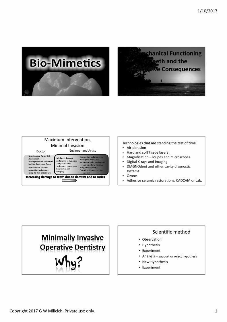
Non‐invasive Caries Risk Assessment Management of a diseased biofilm. Caries and Perio.
Non‐invasive surface‐protection techniques using Re‐min and/or GIC
Minimally invasive restorative techniques and preparation techniques to preserve biomechanical integrity
Restorative techniques to avoid pulp exposures, help retain pulp vitality and restore long term function using biomechanical /biomimetic concepts and techniques
Maximum Intervention, Minimal Invasion
Doctor Engineer and Artist
Technologies that are standing the test of time• Air‐abrasion• Hard and soft tissue lasers• Magnification – loupes and microscopes• Digital X‐rays and imaging• DIAGNOdent and other cavity diagnostic
systems• Ozone• Adhesive ceramic restorations. CADCAM or Lab.
Scientific method• Observation• Hypothesis• Experiment• Analysis – support or reject hypothesis
• New Hypothesis• Experiment
1/10/2017
Copyright 2017 G W Milicich. Private use only. 2
Scientific method• Problem‐ Cavity in a tooth• Hypothesis‐ Amalgam might work• Experiment ‐ Fill millions of teeth• Analysis – sort of works ‐ Lots of teeth fracture in the long term
• New Hypothesis‐ Amalgam still might work
• New Experiment‐ Place more amalgams
Tooth Structure Biomechanics
All occlusal cavity preparations decreased the strength of the tooth in proportion to
the width of the preparation
All occlusal cavity preparations decreased the strength of the tooth in proportion to
the width of the preparation
Fracture Strength of Human Teeth With Cavity Preparations
Mondelli, Steagall, Ishikiriama, de Lima Navarro & SoaresJourn Pros Dent; 43(4):419‐422, 1980
Fracture Strength of Human Teeth With Cavity Preparations
Mondelli, Steagall, Ishikiriama, de Lima Navarro & SoaresJourn Pros Dent; 43(4):419‐422, 1980
The width of the occlusal portion of the preparation affects the strength of the crown.
The width of the occlusal portion of the preparation affects the strength of the crown.
Effects of Prepared Cavities on the Strength of TeethLarson, Douglas & Geistfeld
Op Dent;6:2‐5, 1981
Effects of Prepared Cavities on the Strength of TeethLarson, Douglas & Geistfeld
Op Dent;6:2‐5, 1981
The addition of minimal proximal boxes do not further significantly reduce the strength of the tooth.
The addition of minimal proximal boxes do not further significantly reduce the strength of the tooth.
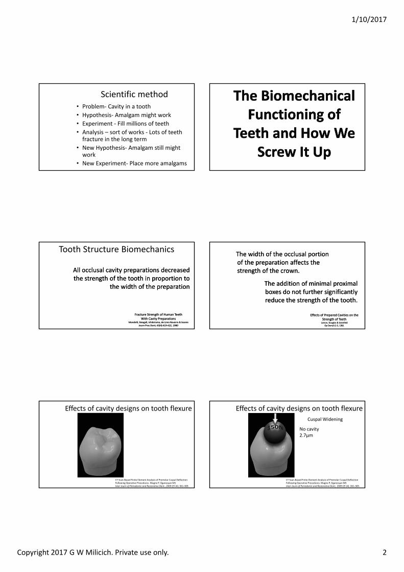
Effects of cavity designs on tooth flexure
CT Scan‐Based Finite Element Analysis of Premolar Cuspal Deflection Following Operative Procedures. Magne P, OganesyanMSInter Journ of Periodontic and Restorative Dent:, 2009:29 (4).:361‐369.
Effects of cavity designs on tooth flexure
CT Scan‐Based Finite Element Analysis of Premolar Cuspal Deflection Following Operative Procedures. Magne P, OganesyanMSInter Journ of Periodontic and Restorative Dent:, 2009:29 (4).:361‐369.
Cuspal Widening
No cavity2.7µm
1/10/2017
Copyright 2017 G W Milicich. Private use only. 3
Effects of cavity designs on tooth flexure
CT Scan‐Based Finite Element Analysis of Premolar Cuspal Deflection Following Operative Procedures. Magne P, OganesyanMSInter Journ of Periodontic and Restorative Dent:, 2009:29 (4).:361‐369.
Cuspal Widening
Amalgam Composite
Effects of cavity designs on tooth flexure
CT Scan‐Based Finite Element Analysis of Premolar Cuspal Deflection Following Operative Procedures. Magne P, OganesyanMSInter Journ of Periodontic and Restorative Dent:, 2009:29 (4).:361‐369.
Amalgam5µm
Cuspal Widening
Composite3.5µm
Effects of cavity designs on tooth flexure
CT Scan‐Based Finite Element Analysis of Premolar Cuspal Deflection Following Operative Procedures. Magne P, OganesyanMSInter Journ of Periodontic and Restorative Dent:, 2009:29 (4).:361‐369.
Cuspal Widening
Amalgam5µm
Composite3.5µm
Effects of cavity designs on tooth flexure
CT Scan‐Based Finite Element Analysis of Premolar Cuspal Deflection Following Operative Procedures. Magne P, OganesyanMSInter Journ of Periodontic and Restorative Dent:, 2009:29 (4).:361‐369.
Cuspal Widening
Amalgam5µm5.4µm
Composite3.5µm3.8µm
Effects of cavity designs on tooth flexure
CT Scan‐Based Finite Element Analysis of Premolar Cuspal Deflection Following Operative Procedures. Magne P, OganesyanMSInter Journ of Periodontic and Restorative Dent:, 2009:29 (4).:361‐369.
Cuspal Widening
Amalgam5µm5.4µm
Composite3.5µm3.8µm
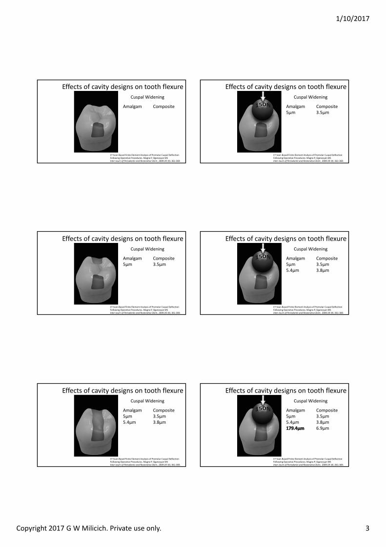
Effects of cavity designs on tooth flexure
CT Scan‐Based Finite Element Analysis of Premolar Cuspal Deflection Following Operative Procedures. Magne P, OganesyanMSInter Journ of Periodontic and Restorative Dent:, 2009:29 (4).:361‐369.
Cuspal Widening
Amalgam5µm5.4µm
Composite3.5µm3.8µm6.9µm
1/10/2017
Copyright 2017 G W Milicich. Private use only. 4
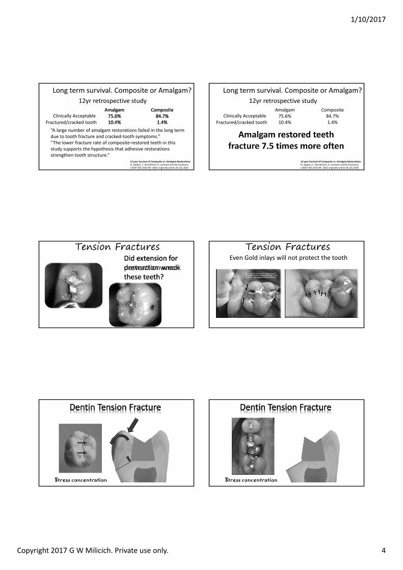
Long term survival. Composite or Amalgam?
12‐year Survival of Composite vs. Amalgam RestorationsN. Opdam, E. Bronkhorst, B. Loomans and M.HuysmansJ DENT RES 2010 89: 1063 originally online 26 July 2010
12yr retrospective study
Clinically AcceptableFractured/cracked tooth“A large number of amalgam restorations failed in the long term due to tooth fracture and cracked‐tooth symptoms.”“The lower fracture rate of composite‐restored teeth in this study supports the hypothesis that adhesive restorations strengthen tooth structure.”
Long term survival. Composite or Amalgam?
12‐year Survival of Composite vs. Amalgam RestorationsN. Opdam, E. Bronkhorst, B. Loomans and M.HuysmansJ DENT RES 2010 89: 1063 originally online 26 July 2010
12yr retrospective studyAmalgam75.6%10.4%
Composite84.7%1.4%
Clinically AcceptableFractured/cracked tooth
Did extension for prevention wreck these teeth?
Did extension for destruction wreck these teeth?
Tension FracturesEven Gold inlays will not protect the tooth
Tension Fractures
Stress concentration Stress concentration
1/10/2017
Copyright 2017 G W Milicich. Private use only. 5
New Concept The Peripheral Rim
Moiré FringesA birefringence study of human tooth structure
R Z Wang, S Weiner. Strain Structure in human teeth using Moiré fringes.Journal of Biomechanics 1998 Feb;31(2):135‐141.
New Concept The Peripheral Rim
Increased width indicates increased stress
Stress concentration occurs where the fringes are close together
The direction of the fringes indicates the direction of the stressEnergy
Sink
R Z Wang, S Weiner. Strain Structure in human teeth using Moiré fringes.Journal of Biomechanics 1998 Feb;31(2):135‐141.
New Concept The Peripheral Rim
Clinical Presentations of Stress Distribution in Teeth and the Significance in Operative Dentistry.
Milicich GW, Rainey JT:
Pract Periodontics Aesthet Dent 2000:12(7),695‐700
In engineering terms, this concept is known as a tension ring
The Peripheral Rim - compression dome
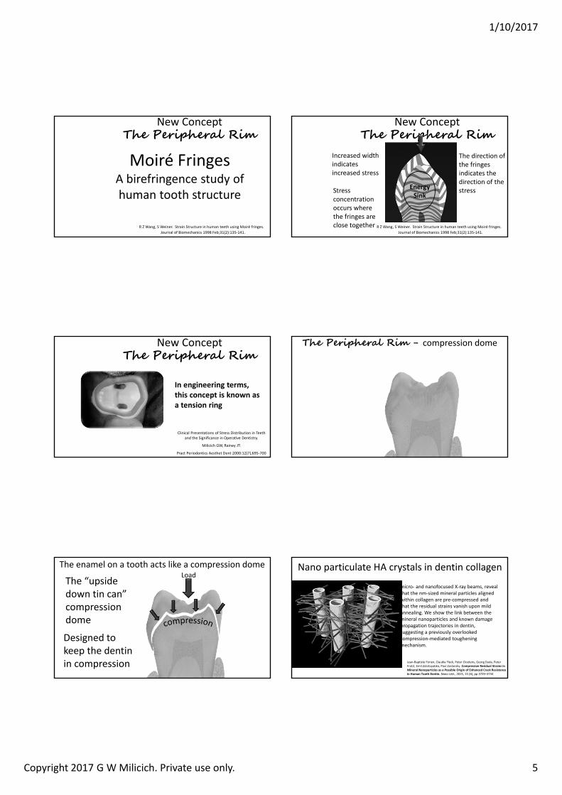
The enamel on a tooth acts like a compression domeLoad
Designed to keep the dentin in compression
The “upside down tin can” compression dome
Jean‐Baptiste Forien, Claudia Fleck, Peter Cloetens, Georg Duda, Peter Fratzl, Emil Zolotoyabko, Paul Zaslansky. Compressive Residual Strains in Mineral Nanoparticles as a Possible Origin of Enhanced Crack Resistance in Human Tooth Dentin. Nano Lett., 2015, 15 (6), pp 3729–3734
Nano particulate HA crystals in dentin collagen
micro‐ and nanofocused X‐ray beams, reveal that the nm‐sized mineral particles aligned within collagen are pre‐compressed and that the residual strains vanish upon mild annealing. We show the link between the mineral nanoparticles and known damage propagation trajectories in dentin, suggesting a previously overlooked compression‐mediated toughening mechanism.
1/10/2017
Copyright 2017 G W Milicich. Private use only. 6
Jean‐Baptiste Forien, Claudia Fleck, Peter Cloetens, Georg Duda, Peter Fratzl, Emil Zolotoyabko, Paul Zaslansky. Compressive Residual Strains in Mineral Nanoparticles as a Possible Origin of Enhanced Crack Resistance in Human Tooth Dentin. Nano Lett., 2015, 15 (6), pp 3729–3734
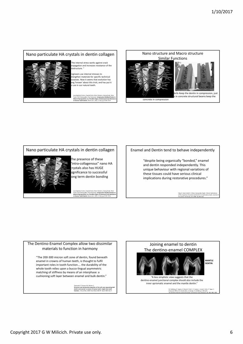
Nano particulate HA crystals in dentin collagen
“The internal stress works against crack propagation and increases resistance of the biostructure. “
Engineers use internal stresses to strengthen materials for specific technical purposes. Now it seems that evolution has long 'known' about this trick, and has put it to use in our natural teeth.
Nano structure and Macro structureSimilar Functions
The “pre‐stressed” collagen fibrils Keep the dentin in compression, just like pre‐stressed steel tendons in concrete structural beams keep the concrete in compression
Jean‐Baptiste Forien, Claudia Fleck, Peter Cloetens, Georg Duda, Peter Fratzl, Emil Zolotoyabko, Paul Zaslansky. Compressive Residual Strains in Mineral Nanoparticles as a Possible Origin of Enhanced Crack Resistance in Human Tooth Dentin. Nano Lett., 2015, 15 (6), pp 3729–3734
Nano particulate HA crystals in dentin collagen
The presence of these “intra‐collagenous” nano HA crystals also has HUGE significance to successful long term dentin bonding
Enamel and Dentin tend to behave independently
Vijay K. Goel, Satish C. Khera, Kanwerdip Singh. Clinical implications of the response of enamel and dentin to masticatory loads. Journal of Pros Dent: Vol 64 (4), Oct 1990, Pg 446–454
“despite being organically “bonded,” enamel and dentin responded independently. This unique behaviour with regional variations of these tissues could have serious clinical implications during restorative procedures.”
The Dentino‐Enamel Complex allow two dissimilar materials to function in harmony
Zaslansky P, Friesem AA, Weiner S.Structure and mechanical properties of the soft zone separating bulk dentin and enamel in crowns of human teeth: insight into tooth function. J Struct Biol. 2006 Feb;153(2):188‐99. Epub 2005 Dec 9.
“The 200‐300 micron soft zone of dentin, found beneath enamel in crowns of human teeth, is thought to fulfil important roles in tooth function…. the durability of the whole tooth relies upon a bucco‐lingual asymmetric matching of stiffness by means of an interphase: a cushioning soft layer between enamel and bulk dentin.”
Joining enamel to dentinThe dentino‐enamel COMPLEX
M. Goldberg, D. Septier, K. Bourd, R. Hall, J.‐C. Jeanny, L. Jonet,S. Colin, F. Tager, C. Chaussain‐Miller, M. Garab´edian, A. George, H. Goldberg, S. MenashiThe Dentino‐Enamel Junction Revisited. Connective Tissue Research, 43: 482–489, 2002
“A less simplistic view suggests that the dentino‐enamel junctional complex should also include the
inner aprismatic enamel and the mantle dentin.”
MANTLE DENTIN
1/10/2017
Copyright 2017 G W Milicich. Private use only. 7
Resin impression of the Dentino‐enamel Complex• The DEC is a more open
structure• Lower mineral content
than enamel or dentin• Acts as a stress breaker
between the enamel compression dome and the dentin
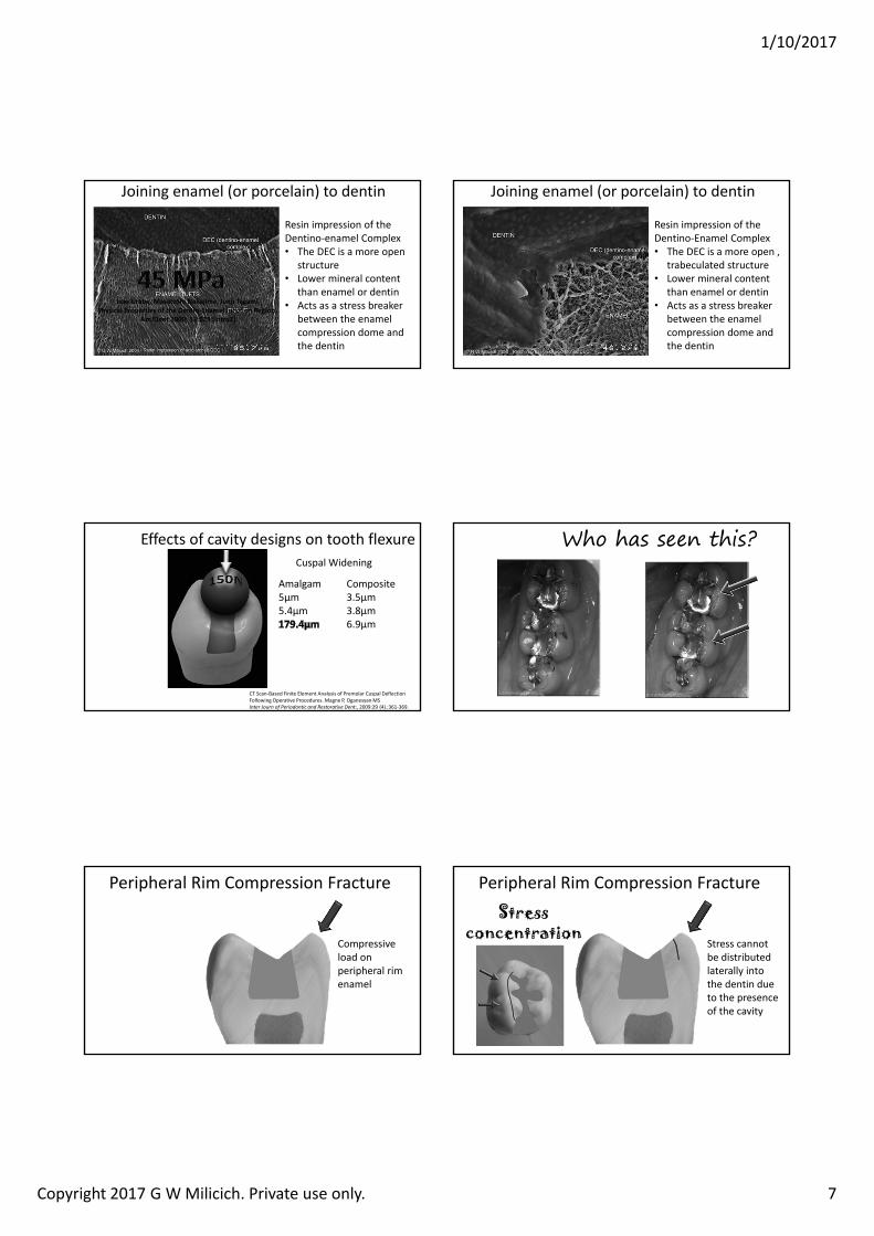
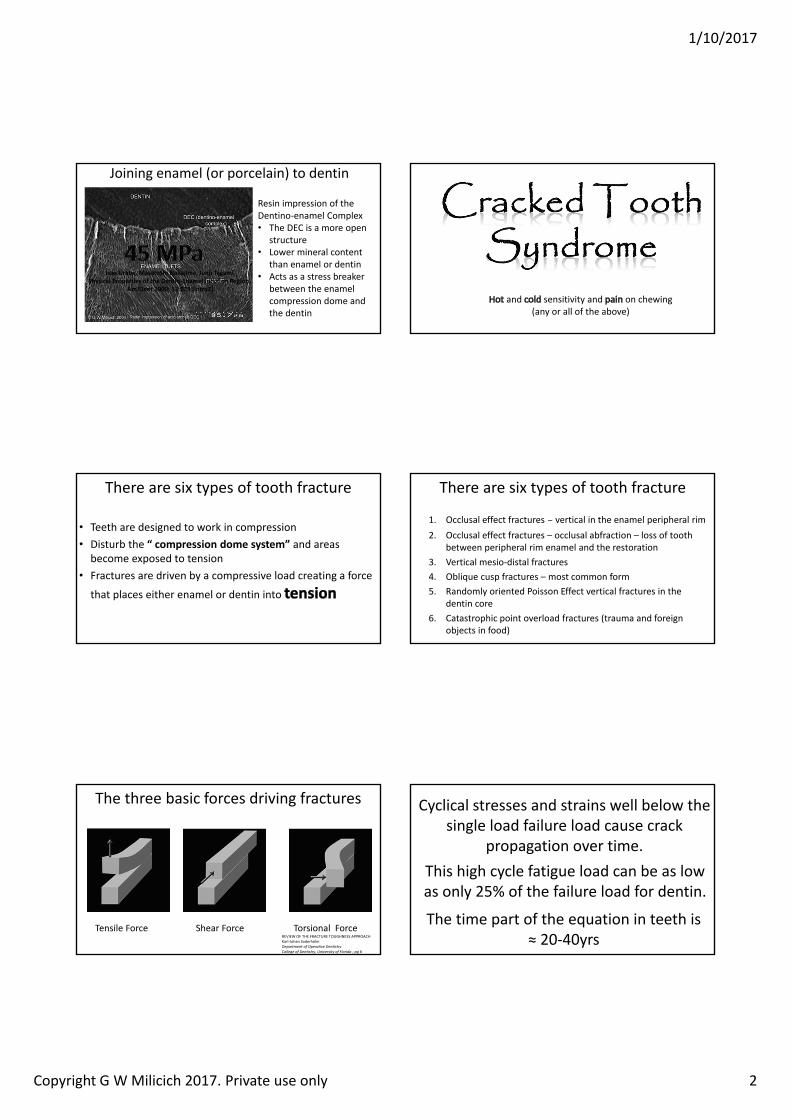
Isao Urabe, Masatoshi Nakajima, Junji TagamiPhysical Properties of the Dentin‐Enamel Junction Region.
AmJDent 2000; 13:129 [intro2]
Joining enamel (or porcelain) to dentin
Resin impression of the Dentino‐Enamel Complex• The DEC is a more open ,
trabeculated structure• Lower mineral content
than enamel or dentin• Acts as a stress breaker
between the enamel compression dome and the dentin
Joining enamel (or porcelain) to dentin
Effects of cavity designs on tooth flexure
CT Scan‐Based Finite Element Analysis of Premolar Cuspal Deflection Following Operative Procedures. Magne P, OganesyanMSInter Journ of Periodontic and Restorative Dent:, 2009:29 (4).:361‐369.
Cuspal Widening
Amalgam5µm5.4µm
Composite3.5µm3.8µm6.9µm
Who has seen this?
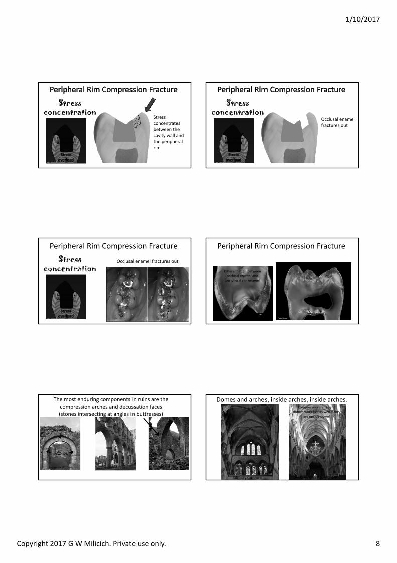
Peripheral Rim Compression Fracture
Compressive load on peripheral rim enamel
Peripheral Rim Compression Fracture
Stress cannot be distributed laterally into the dentin due to the presence of the cavity
Stress concentration
1/10/2017
Copyright 2017 G W Milicich. Private use only. 8
Stress concentrates between the cavity wall and the peripheral rim
Stress concentration
Lost energy dissipation
Occlusal enamel fractures out
Stress concentration
Lost energy dissipation
Peripheral Rim Compression Fracture
Occlusal enamel fractures outStress concentration
Lost energy dissipation
Peripheral Rim Compression Fracture
Differentiation between occlusal enamel and peripheral rim enamel
The most enduring components in ruins are the compression arches and decussation faces (stones intersecting at angles in buttresses)
Rievaulx Abbey Rievaulx Abbey Talley Abbey
Keystone
Skewback
Domes and arches, inside arches, inside arches.
Salisbury Cathedral Wells Cathedral Scissor Arch
Compression arches and domes work just as well if they
are upside down!
1/10/2017
Copyright 2017 G W Milicich. Private use only. 9
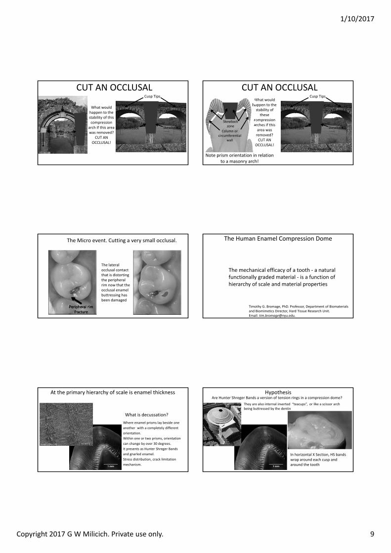
What would happen to the stability of this compression
arch if this area was removed?
CUT AN OCCLUSAL!
Chirk Aqueduct
Cusp Tips
CUT AN OCCLUSAL
SkewbackSkewback Skewback
KeystoneWhat would happen to the stability of
these compression arches if this area was removed?CUT AN
OCCLUSAL!Chirk Aqueduct
Cusp Tips
CUT AN OCCLUSAL
Skewback Skewback
Note prism orientation in relation to a masonry arch!
Skewbackzone
Column or circumferential
wall
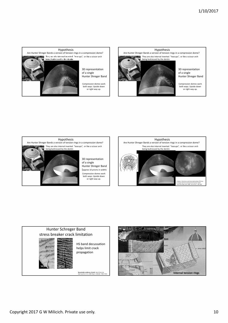
The Micro event. Cutting a very small occlusal.
Peripheral rim fracture
The lateral occlusal contact that is distorting the peripheral rim now that the occlusal enamel buttressing has been damaged
The Human Enamel Compression Dome
The mechanical efficacy of a tooth ‐ a natural functionally graded material ‐ is a function of hierarchy of scale and material properties
Timothy G. Bromage, PhD. Professor, Department of Biomaterials and Biomimetics Director, Hard Tissue Research Unit. Email: [email protected].
What is decussation?Where enamel prisms lay beside one another with a completely different orientation. Within one or two prisms, orientation can change by over 30 degrees.It presents as Hunter Shreger Bands and gnarled enamel.Stress distribution, crack limitation mechanism.
At the primary hierarchy of scale is enamel thickness HypothesisAre Hunter Shreger Bands a version of tension rings in a compression dome?
In horizontal X Section, HS bands wrap around each cusp and around the tooth
They are also internal inverted “teacups”, or like a scissor arch being buttressed by the dentin
1/10/2017
Copyright 2017 G W Milicich. Private use only. 10
HypothesisAre Hunter Shreger Bands a version of tension rings in a compression dome?
They are also internal inverted “teacups”, or like a scissor arch being buttressed by the dentin
3D representation of a single Hunter Shreger Band
Compression domes work both ways. Upside down
or right way up.
HypothesisAre Hunter Shreger Bands a version of tension rings in a compression dome?
They are also internal inverted “teacups”, or like a scissor arch being buttressed by the dentin
3D representation of a single Hunter Shreger Band
Compression domes work both ways. Upside down
or right way up.
HypothesisAre Hunter Shreger Bands a version of tension rings in a compression dome?
They are also internal inverted “teacups”, or like a scissor arch being buttressed by the dentin
3D representation of a single Hunter Shreger Band(approx 10 prisms in width)
Compression domes work both ways. Upside down
or right way up.
HypothesisAre Hunter Shreger Bands a version of tension rings in a compression dome?
They are also internal inverted “teacups”, or like a scissor arch being buttressed by the dentin
J Osborn. Directions and Interrelationship of Prisms in Cuspal and Cervical Enamel of Human TeethJ Dent Res May‐June 1968. Vol 47 No. 3. 395‐402
Hunter Schreger Band stress breaker crack limitation
Remarkable resilience of teeth. Herzl Chai et al.Natl Acad Sci U S A. 2009 May 5; 106(18): 7289–7293.
HS band decussation helps limit crack propagation
Internal tension rings
Florence Basilica
1/10/2017
Copyright 2017 G W Milicich. Private use only. 11
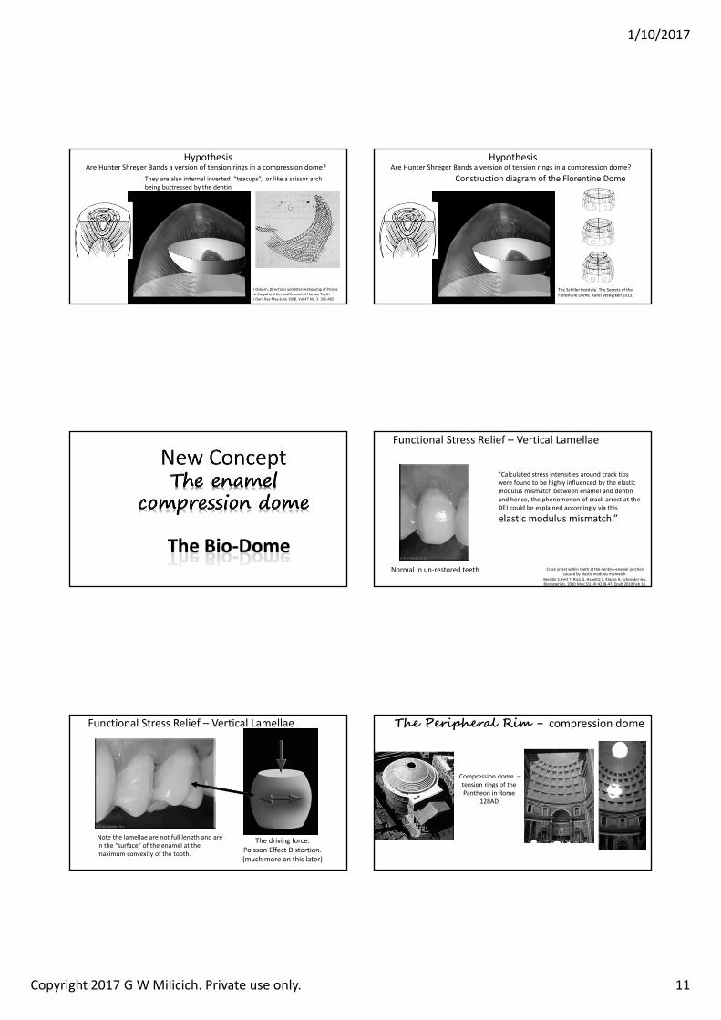
HypothesisAre Hunter Shreger Bands a version of tension rings in a compression dome?
They are also internal inverted “teacups”, or like a scissor arch being buttressed by the dentin
J Osborn. Directions and Interrelationship of Prisms in Cuspal and Cervical Enamel of Human TeethJ Dent Res May‐June 1968. Vol 47 No. 3. 395‐402
HypothesisAre Hunter Shreger Bands a version of tension rings in a compression dome?
Construction diagram of the Florentine Dome
The Schiller Institute. The Secrets of the Florentine Dome. Karel Vereycken 2013.
The Bio‐Dome
Functional Stress Relief – Vertical Lamellae
Normal in un‐restored teeth
“Calculated stress intensities around crack tips were found to be highly influenced by the elastic modulus mismatch between enamel and dentin and hence, the phenomenon of crack arrest at the DEJ could be explained accordingly via this
elastic modulus mismatch.”
Crack arrest within teeth at the dentino‐enamel junction caused by elastic modulus mismatch.
Bechtle S, Fett T, Rizzi G, Habelitz S, Klocke A, Schneider GA.Biomaterials. 2010 May;31(14):4238‐47. Epub 2010 Feb 18.
Functional Stress Relief – Vertical Lamellae
Note the lamellae are not full length and are in the “surface” of the enamel at the maximum convexity of the tooth.
The driving force. Poisson Effect Distortion.(much more on this later)
Compression dome –tension rings of the Pantheon in Rome
128AD
The Peripheral Rim - compression dome
1/10/2017
Copyright 2017 G W Milicich. Private use only. 12
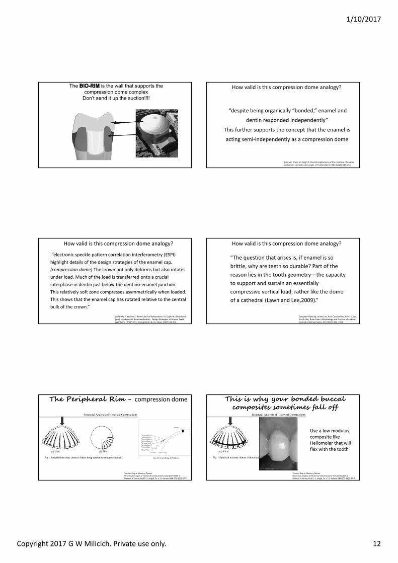
The is the wall that supports the compression dome complex
Don’t send it up the suction!!!!
Pantheon ‐ Rome
How valid is this compression dome analogy?
“despite being organically “bonded,” enamel and
dentin responded independently”
This further supports the concept that the enamel is
acting semi‐independently as a compression dome
Goel VK, Khera SC, Singh K. Clinical implications of the response of enamel and dentin to masticatory loads. J Prosthet Dent 1990; 64 (4):446–454.
How valid is this compression dome analogy?
“electronic speckle pattern correlation interferometry (ESPI) highlight details of the design strategies of the enamel cap. (compression dome) The crown not only deforms but also rotates under load. Much of the load is transferred onto a crucial interphase in dentin just below the dentino‐enamel junction. This relatively soft zone compresses asymmetrically when loaded.This shows that the enamel cap has rotated relative to the central bulk of the crown.”
Zaslansky P, Weiner S. Biomechanical Adaptations. In: Epple M, Bäuerlein E (eds). Handbook of Biomineralization. Design Strategies of Human Teeth. Weinheim: WILEY‐VCH Verlag GmbH & Co. KGaA, 2007:183‐202.
How valid is this compression dome analogy?
Sangwon Myoung, James Lee, Paul Constantino, Peter Lucas, Herzl Chai, Brian Lawn. Morphology and fracture of enamel.Journal of Biomechanics 42 (2009) 1947–1951
“The question that arises is, if enamel is so brittle, why are teeth so durable? Part of the reason lies in the tooth geometry—the capacity to support and sustain an essentially compressive vertical load, rather like the dome of a cathedral (Lawn and Lee,2009).”
The Peripheral Rim - compression dome
Tension Ring in Masonry DomesStructural Analysis of Historical Constructions, New Delhi 2006 1Mahesh N Varma, Prof R. S. Jangid, Dr. V. G. Achwal ISBN 972‐8692‐27‐7
This is why your bonded buccal composites sometimes fall off
Tension Ring in Masonry DomesStructural Analysis of Historical Constructions, New Delhi 2006 1Mahesh N Varma, Prof R. S. Jangid, Dr. V. G. Achwal ISBN 972‐8692‐27‐7
Use a low modulus composite like Heliomolar that will flex with the tooth
1/10/2017
Copyright 2017 G W Milicich. Private use only. 13
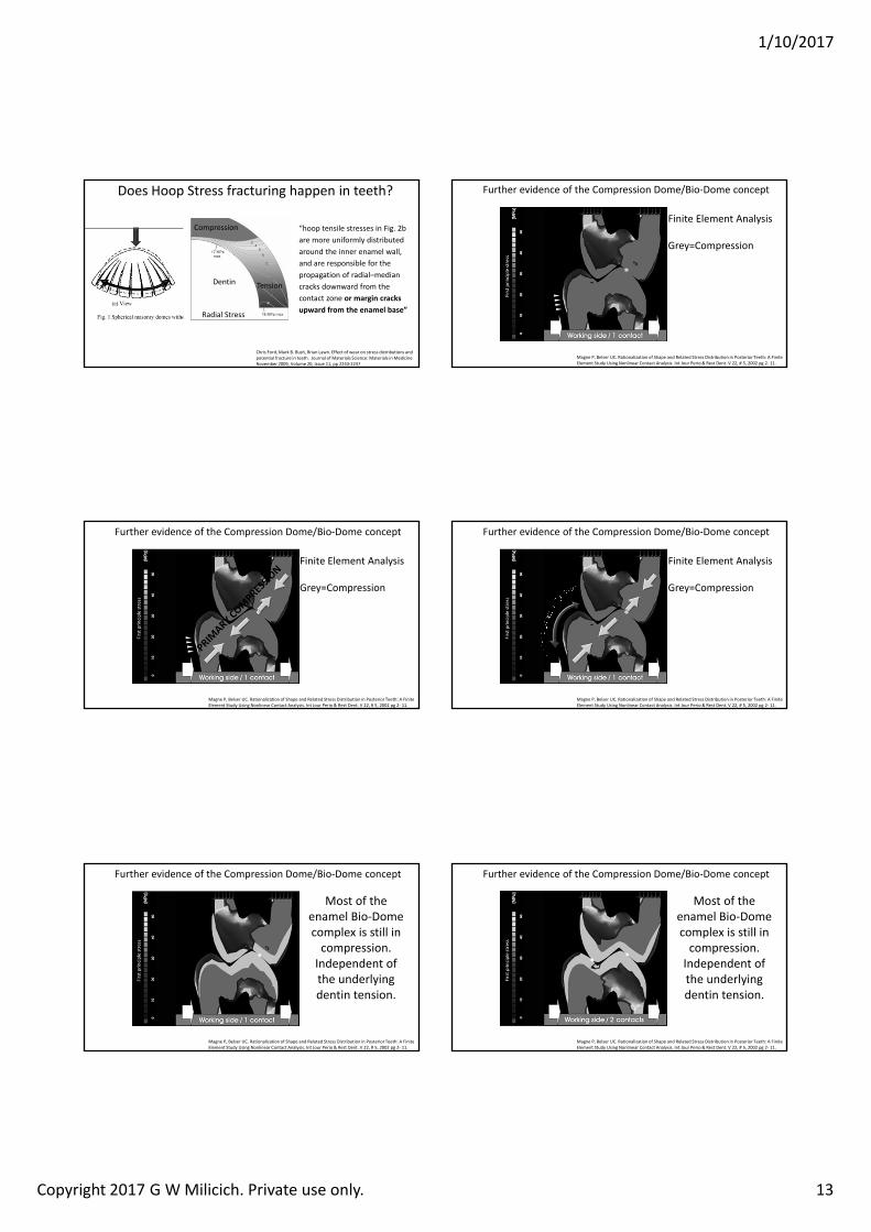
Does Hoop Stress fracturing happen in teeth?
Chris Ford, Mark B. Bush, Brian Lawn. Effect of wear on stress distributions and potential fracture in teeth. Journal of Materials Science: Materials in Medicine November 2009, Volume 20, Issue 11, pp 2243‐2247
Compression
Tension
“hoop tensile stresses in Fig. 2b are more uniformly distributed around the inner enamel wall, and are responsible for the propagation of radial–median cracks downward from the contact zone or margin cracks upward from the enamel base”
Dentin
Radial Stress
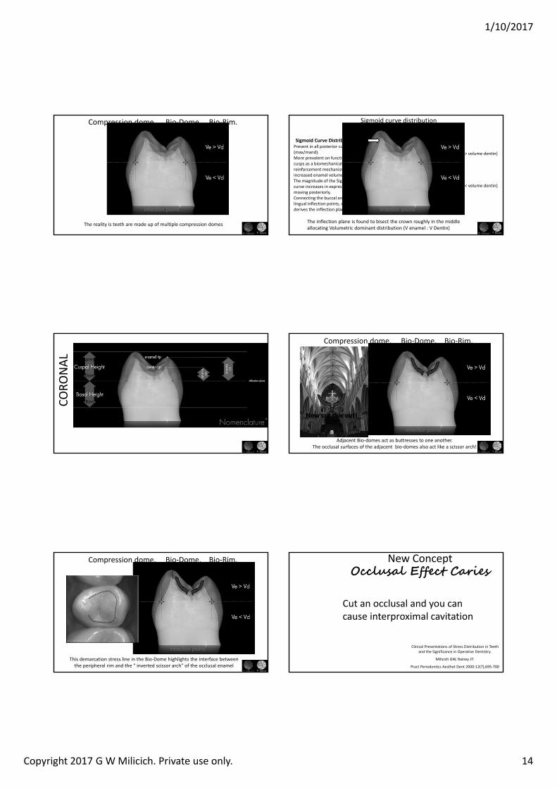
Further evidence of the Compression Dome/Bio‐Dome concept
Magne P, Belser UC. Rationalization of Shape and Related Stress Distribution in Posterior Teeth: A Finite Element Study Using Nonlinear Contact Analysis. Int Jour Perio & Rest Dent. V 22, # 5, 2002 pg 2‐ 11.
Finite Element Analysis
Grey=Compression
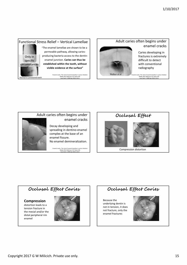
Further evidence of the Compression Dome/Bio‐Dome concept
Magne P, Belser UC. Rationalization of Shape and Related Stress Distribution in Posterior Teeth: A Finite Element Study Using Nonlinear Contact Analysis. Int Jour Perio & Rest Dent. V 22, # 5, 2002 pg 2‐ 11.
Most of the enamel Bio‐Dome complex is still in compression.Independent of the underlying dentin tension.
1/10/2017
Copyright 2017 G W Milicich. Private use only. 14
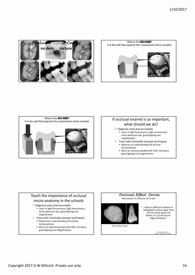
Compression dome. Bio‐Dome. Bio‐Rim.
The reality is teeth are made up of multiple compression domes
(volume enamel > volume dentin)
(volume enamel < volume dentin)
Sigmoid curve distribution
Sigmoid Curve DistributionPresent in all posterior cusps, (max/mand).More prevalent on functional cusps as a biomechanical reinforcement mechanism with increased enamel volume.The magnitude of the Sigmoid curve increases in expression moving posteriorly.Connecting the buccal and lingual inflection points, one derives the inflection plane.
The inflection plane is found to bisect the crown roughly in the middle allocating Volumetric dominant distribution (V enamel : V Dentin)
CORO
NAL Compression Dome
Bio‐Dome
Bio‐Rim
Compression dome. Bio‐Dome. Bio‐Rim.
Adjacent Bio‐domes act as buttresses to one another.The occlusal surfaces of the adjacent bio‐domes also act like a scissor arch!
Compression dome. Bio‐Dome. Bio‐Rim.
This demarcation stress line in the Bio‐Dome highlights the interface between the peripheral rim and the “ inverted scissor arch” of the occlusal enamel
New Concept Occlusal Effect Caries
Clinical Presentations of Stress Distribution in Teeth and the Significance in Operative Dentistry.
Milicich GW, Rainey JT:
Pract Periodontics Aesthet Dent 2000:12(7),695‐700
Cut an occlusal and you can cause interproximal cavitation
1/10/2017
Copyright 2017 G W Milicich. Private use only. 15
Functional Stress Relief – Vertical Lamellae“The enamel lamellae are shown to be a permeable pathway, allowing caries‐
producing bacteria access to the dentin‐enamel junction. Caries can thus be established within the tooth, without
visible evidence at the surface”
Enamel cracks. The role of enamel lamellae in caries initiation Walker BN, Makinson OF, Peters MC Aust Dent J 1998 Apr;43(2):110‐6
Only in specific
circumstances
Normal in unrestored teeth
Adult caries often begins under enamel cracks
Walker et al
Caries developing in fractures is extremely difficult to detect with conventional radiography
Enamel cracks. The role of enamel lamellae in caries initiation Walker BN, Makinson OF, Peters MC Aust Dent J 1998 Apr;43(2):110‐6
Adult caries often begins under enamel cracks
Decay developing and spreading in dentino‐enamel complex at the base of an enamel fissure. No enamel demineralization.
Enamel cracks. The role of enamel lamellae in caries initiation Walker BN, Makinson OF, Peters MC Aust Dent J 1998 Apr;43(2):110‐6
Occlusal Effect
Compression distortion
Occlusal Effect Caries
Compressiondistortion leads to a tension fracture in the mesial and/or the distal peripheral rim enamel
Occlusal Effect Caries
Because the underlying dentin is not in tension, it does not fracture, only the enamel fractures
1/10/2017
Copyright 2017 G W Milicich. Private use only. 16
Walker et al
Occlusal Effect Cariesno dentin fracture
What is the It is the wall that supports the compression dome complex
Pantheon ‐ Rome
What is the It is the wall that supports the compression dome complex
Pantheon ‐ Rome
If occlusal enamel is so important, what should we do?
• Diagnose early and accurately� Laser or light fluorescence, light transmission, caries detection dye, good lighting and magnification
• Treat with minimally invasive techniques� Requires an understanding off occlusal microanatomy.
� Micro‐air abrasion guided with CDD, microburs, good lighting and magnification.
Teach the importance of occlusal micro‐anatomy in the schools
• Diagnose early and accurately� Laser or light fluorescence, light transmission, caries detection dye, good lighting and magnification
• Treat with minimally invasive techniques� Requires an understanding off occlusal microanatomy.
� Micro‐air abrasion guided with CDD, microburs, good lighting and magnification.
Occlusal Effect CariesWhy doesn’t it show on an X‐ray?
ROCK WP, KIDD EAM.Br Dent J. 164(8): 243‐47, 1988.
“… decay is difficult to detect in radiographs unless larger than
2mm to 3mm deep into dentin, or 1/3 the bucco‐
lingual distance.”
2mm deep “cavity”
1/10/2017
Copyright 2017 G W Milicich. Private use only. 17
Occlusal Effect CariesWhy doesn’t it show on an X‐ray?
ROCK WP, KIDD EAM.Br Dent J. 164(8): 243‐47, 1988.
3mm deep “cavity” 4mm deep “cavity”
1/3 occlusal width
Occlusal Effect CariesWhy doesn’t it show on an X‐ray?
ROCK WP, KIDD EAM.Br Dent J. 164(8): 243‐47, 1988.
Less than 1/3 width of tooth
ROCK WP, KIDD EAM.Br Dent J. 164(8): 243‐47, 1988.
Greater than 1/3 width of tooth
Occlusal Effect CariesWhy doesn’t it show on an X‐ray?
The evidence is before us, but at the same time, invisible to us, because it is fragmented and
dispersed in the research literature. However, when the pieces of the puzzle are assembled in a certain way, a new picture is
beginning to emerge.
Biomimetic Dentistry Mimicking Mother Nature as closely as we can with current materials, techniques and technologies.
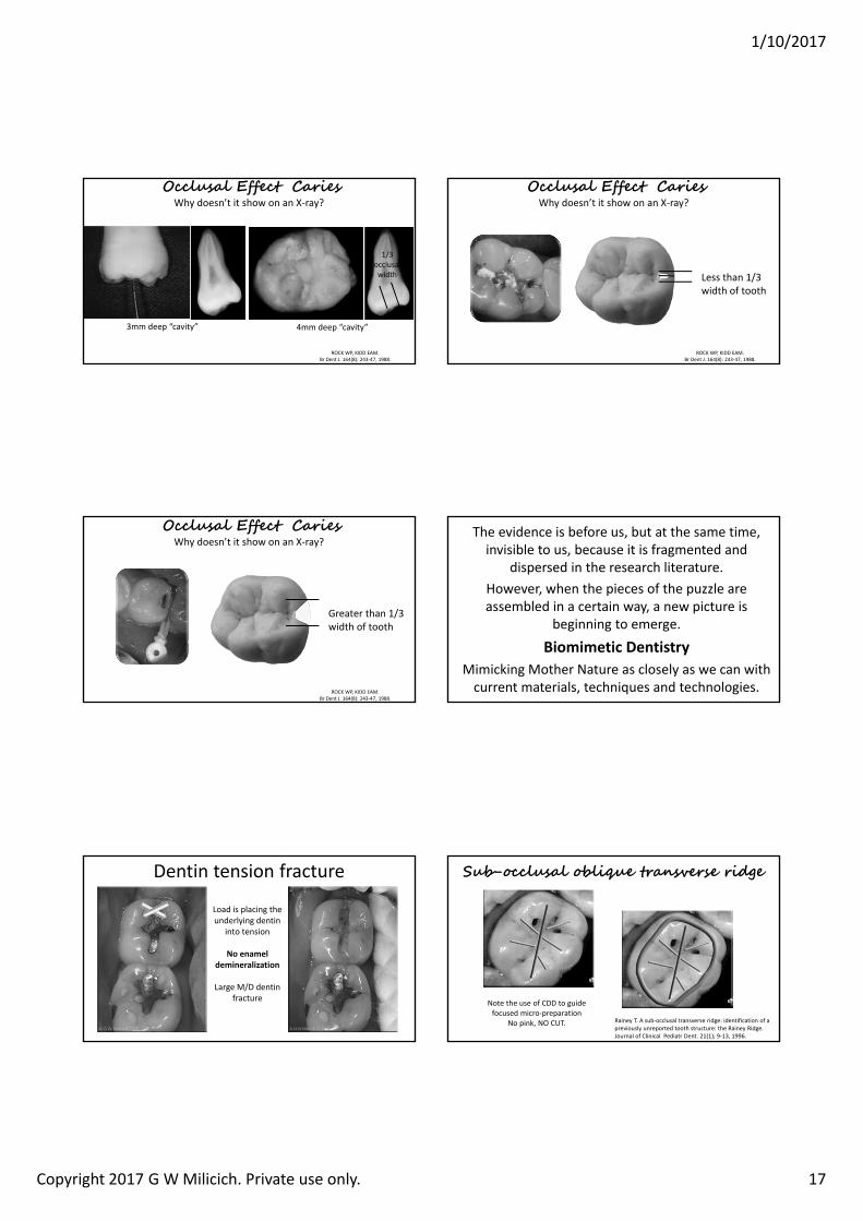
Dentin tension fracture
Load is placing the underlying dentin
into tension
No enamel demineralization
Large M/D dentin fracture
Rainey T. A sub‐occlusal transverse ridge: identification of a previously unreported tooth structure: the Rainey Ridge. Journal of Clinical Pediatr Dent. 21(1); 9‐13, 1996.
Sub-occlusal oblique transverse ridge
Note the use of CDD to guide focused micro‐preparation
No pink, NO CUT.
1/10/2017
Copyright 2017 G W Milicich. Private use only. 18
Rainey T. A sub‐occlusal transverse ridge: identification of a previously unreported tooth structure: the Rainey Ridge. Journal of Clinical Pediatr Dent. 21(1); 9‐13, 1996.
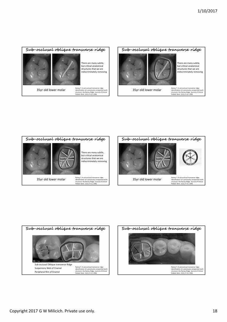
Sub-occlusal oblique transverse ridge
There are many subtle, but critical anatomical structures that we are indiscriminately removing
35yr old lower molarRainey T. A sub‐occlusal transverse ridge: identification of a previously unreported tooth structure: the Rainey Ridge. Journal of Clinical Pediatr Dent. 21(1); 9‐13, 1996.
Sub-occlusal oblique transverse ridge
There are many subtle, but critical anatomical structures that we are indiscriminately removing
35yr old lower molar
Rainey T. A sub‐occlusal transverse ridge: identification of a previously unreported tooth structure: the Rainey Ridge. Journal of Clinical Pediatr Dent. 21(1); 9‐13, 1996.
Sub-occlusal oblique transverse ridge
There are many subtle, but critical anatomical structures that we are indiscriminately removing
35yr old lower molar
Sub-occlusal oblique transverse ridge
Rainey T. A sub‐occlusal transverse ridge: identification of a previously unreported tooth structure: the Rainey Ridge. Journal of Clinical Pediatr Dent. 21(1); 9‐13, 1996.
35yr old lower molar
Sub-occlusal oblique transverse ridge
Rainey T. A sub‐occlusal transverse ridge: identification of a previously unreported tooth structure: the Rainey Ridge. Journal of Clinical Pediatr Dent. 21(1); 9‐13, 1996.
Sub‐occlusal Oblique transverse RidgeSuspensory Web of EnamelPeripheral Rim of Enamel
Sub-occlusal oblique transverse ridge
Rainey T. A sub‐occlusal transverse ridge: identification of a previously unreported tooth structure: the Rainey Ridge. Journal of Clinical Pediatr Dent. 21(1); 9‐13, 1996.
65yr old Greek. Owns a Citrus Grove!Some instability developing
1/10/2017
Copyright 2017 G W Milicich. Private use only. 19
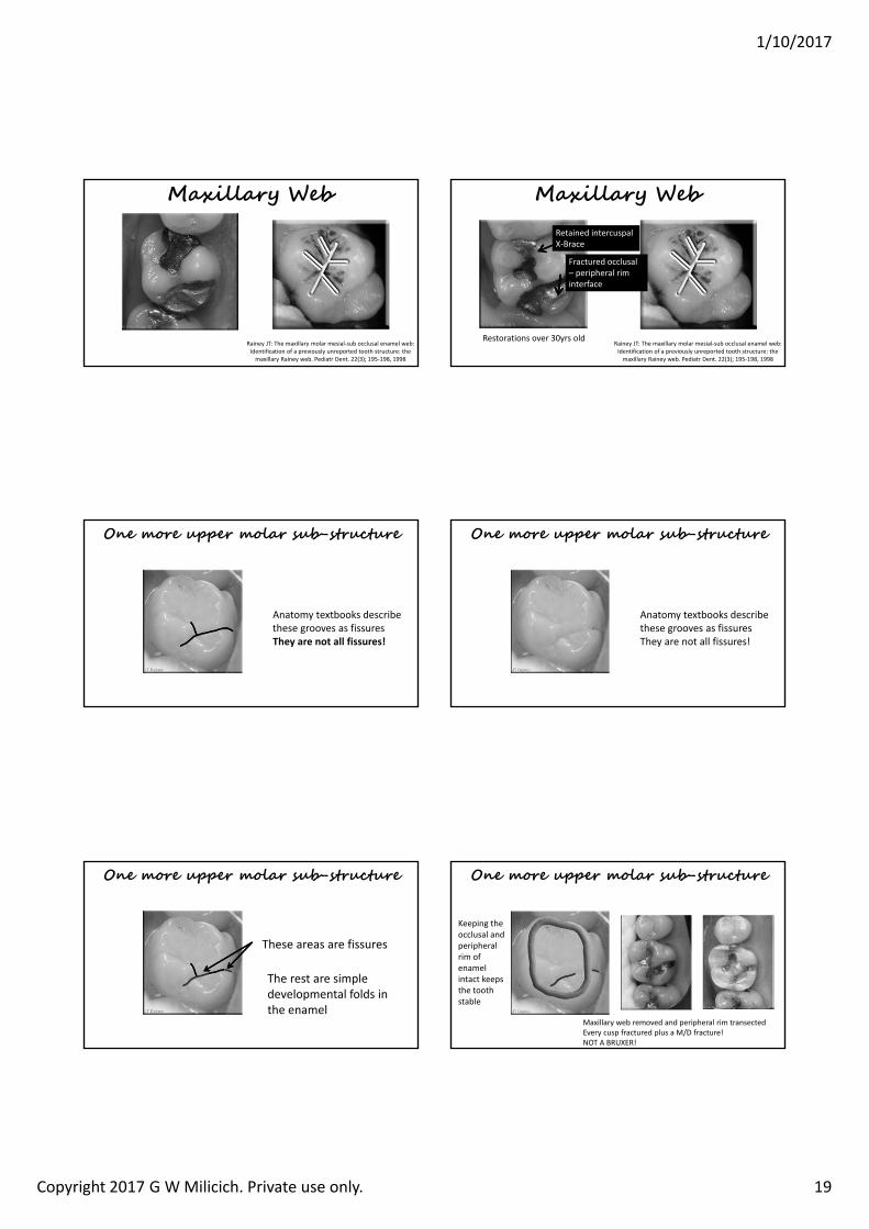
Maxillary Web
Rainey JT: The maxillary molar mesial‐sub occlusal enamel web: Identification of a previously unreported tooth structure: the maxillary Rainey web. Pediatr Dent. 22(3); 195‐198, 1998
Maxillary Web
Rainey JT: The maxillary molar mesial‐sub occlusal enamel web: Identification of a previously unreported tooth structure: the maxillary Rainey web. Pediatr Dent. 22(3); 195‐198, 1998
Retained intercuspalX‐Brace
Fractured occlusal – peripheral rim interface
Restorations over 30yrs old
One more upper molar sub-structure
Anatomy textbooks describe these grooves as fissuresThey are not all fissures!
One more upper molar sub-structure
Anatomy textbooks describe these grooves as fissuresThey are not all fissures!
These areas are fissures
The rest are simple developmental folds in the enamel
One more upper molar sub-structure One more upper molar sub-structure
Keeping the occlusal and peripheral rim of enamel intact keeps the tooth stable
Maxillary web removed and peripheral rim transectedEvery cusp fractured plus a M/D fracture!NOT A BRUXER!
1/10/2017
Copyright G W Milicich 2017. Private use only 1
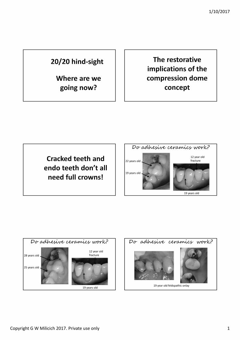
Do adhesive ceramics work?
22 years old
19 years old
12 year oldfracture
19 years old
Do adhesive ceramics work?
28 years old
25 years old
12 year oldfracture
19 years old19 year old feldspathic onlay
Do adhesive ceramics work?
1/10/2017
Copyright G W Milicich 2017. Private use only 2
7
Resin impression of the Dentino‐enamel Complex• The DEC is a more open
structure• Lower mineral content
than enamel or dentin• Acts as a stress breaker
between the enamel compression dome and the dentin
Isao Urabe, Masatoshi Nakajima, Junji Tagami Physical Properties of the Dentin‐Enamel Junction Region.
AmJDent 2000; 13:129 [intro2]
Joining enamel (or porcelain) to dentin
and sensitivity and on chewing (any or all of the above)
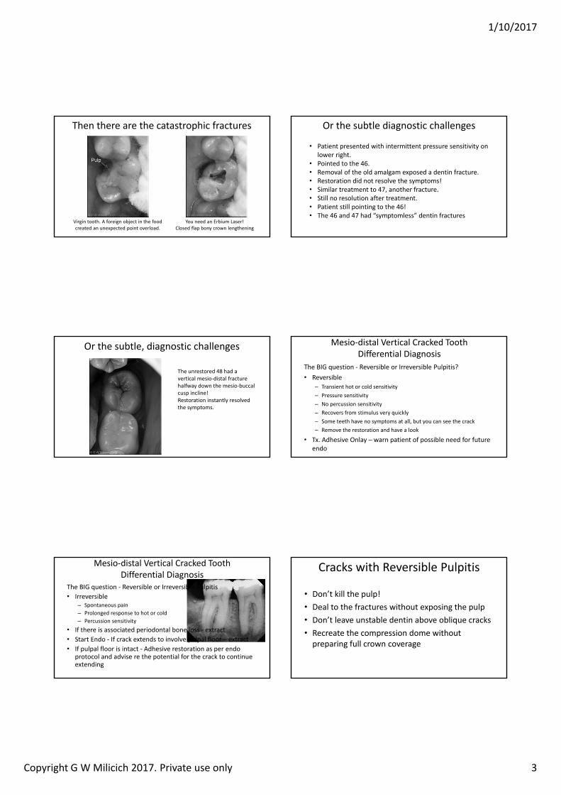
There are six types of tooth fracture
• Teeth are designed to work in compression• Disturb the compression dome system” and areas become exposed to tension
• Fractures are driven by a compressive load creating a force
that places either enamel or dentin into
There are six types of tooth fracture
1. Occlusal effect fractures – vertical in the enamel peripheral rim2. Occlusal effect fractures – occlusal abfraction – loss of tooth
between peripheral rim enamel and the restoration3. Vertical mesio‐distal fractures4. Oblique cusp fractures – most common form5. Randomly oriented Poisson Effect vertical fractures in the
dentin core6. Catastrophic point overload fractures (trauma and foreign
objects in food)
The three basic forces driving fractures
Tensile Force Shear Force Torsional ForceREVIEW OF THE FRACTURE TOUGHNESS APPROACH Karl‐Johan SoderholmDepartment of perative Dentistr Co ege of Dentistr niversit of orida pg
Cyclical stresses and strains well below the single load failure load cause crack
propagation over time.
The time part of the equation in teeth is 20‐40yrs
This high cycle fatigue load can be as low as only 25% of the failure load for dentin.
1/10/2017
Copyright G W Milicich 2017. Private use only 3
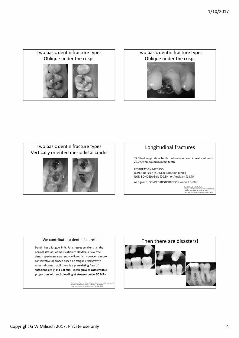
Then there are the catastrophic fractures
Virgin tooth. A foreign object in the food created an unexpected point overload.
You need an Erbium Laser! Closed flap bony crown lengthening
Or the subtle diagnostic challenges
• Patient presented with intermittent pressure sensitivity on lower right.
• Pointed to the 46.• Removal of the old amalgam exposed a dentin fracture. • Restoration did not resolve the symptoms!• Similar treatment to 47, another fracture.• Still no resolution after treatment.• Patient still pointing to the 46!• The 46 and 47 had “symptomless” dentin fractures
Or the subtle, diagnostic challenges
The unrestored 48 had a vertical mesio‐distal fracture halfway down the mesio‐buccal cusp incline!Restoration instantly resolved the symptoms.
Mesio‐distal Vertical Cracked Tooth Differential Diagnosis
The BIG question ‐ Reversible or Irreversible Pulpitis?• Reversible
Transient hot or cold sensitivityPressure sensitivityNo percussion sensitivityRecovers from stimulus very quicklySome teeth have no symptoms at all, but you can see the crackRemove the restoration and have a look
• Tx. Adhesive Onlay – warn patient of possible need for future endo
The BIG question ‐ Reversible or Irreversible Pulpitis• Irreversible
Spontaneous painProlonged response to hot or coldPercussion sensitivity
• If there is associated periodontal bone loss ‐ extract• Start Endo ‐ If crack extends to involve pulpal floor – extract• If pulpal floor is intact ‐ Adhesive restoration as per endo
protocol and advise re the potential for the crack to continue extending
Mesio‐distal Vertical Cracked Tooth Differential Diagnosis
Cracks with Reversible Pulpitis
• Don’t kill the pulp!• Deal to the fractures without exposing the pulp• Don’t leave unstable dentin above oblique cracks• Recreate the compression dome without preparing full crown coverage
1/10/2017
Copyright G W Milicich 2017. Private use only 4
Two basic dentin fracture typesOblique under the cusps
Two basic dentin fracture typesOblique under the cusps
Two basic dentin fracture typesVertically oriented mesiodistal cracks
Longitudinal fractures
Seo DJ,Yi YA, Shin SJ, Park JW. Analysis of factors associated with cracked teeth.J Endod. 2012 Mar;38(3):288‐92. doi: 10.1016/j.joen.2011.11.017. Epub 2012 Jan 5.
72.0% of longitudinal tooth fractures occurred in restored teeth28.0% were found in intact teeth.
RESTORATION METHODBONDED: Resin (4.7%) or Porcelain (0.9%)NON‐BONDED: Gold (20.5%) or Amalgam (18.7%)
As a group, BONDED RESTORATIONS worked better
We contribute to dentin failure!
The Mechanical Properties Of Human Dentin: Critical Review And Re‐evaluation Of The Dental Literature. J.H. Kinney, S.J. Marshall, G.W. Marshall.Critical Reviews in Oral Biology & Medicine. 14(1):13‐29 (2003)
Dentin has a fatigue limit. For stresses smaller than the normal stresses of mastication, 30 MPa, a flaw‐free dentin specimen apparently will not fail. However, a more conservative approach based on fatigue crack growth rates indicates that if there is a pre‐existing flaw of sufficient size 0.3‐1.0 mm , it can grow to catastrophic proportion with cyclic loading at stresses below 30 MPa.
Then there are disasters!
1/10/2017
Copyright G W Milicich 2017. Private use only 5
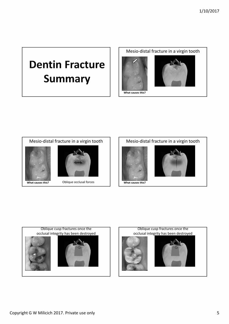
Mesio‐distal fracture in a virgin tooth
hat causes this
Mesio‐distal fracture in a virgin tooth
hat causes this Oblique occlusal forces
TENSION
Mesio‐distal fracture in a virgin tooth
hat causes this
Oblique cusp fractures once the occlusal integrity has been destroyed
Oblique cusp fractures once the occlusal integrity has been destroyed
1/10/2017
Copyright G W Milicich 2017. Private use only 6
Oblique cusp fractures once the occlusal integrity has been destroyed
Oblique cusp fractures once the occlusal integrity has been destroyed
The bricks above the crack in the wall are NOT CONNECTED to the base. A big shove and they will tip off.
The dentin above the oblique fractures is NOT CONNECTED to the underlying dentin
Oblique cusp fractures once the occlusal integrity has been destroyed
The bricks above the crack in the wall are NOT CONNECTED to the base. A big shove and they will tip off.
The dentin above the oblique fractures is NOT CONNECTED to the underlying dentin
Flicked off with a probe!
How do we account for mesio‐distal and bucco‐lingual fractures in teeth with existing oblique fractures?
Same tooth with oblique fractures removed
How do we account for mesio‐distal and bucco‐lingual fractures in teeth with existing oblique fractures?
Same tooth with oblique fractures removed Poisson Effect
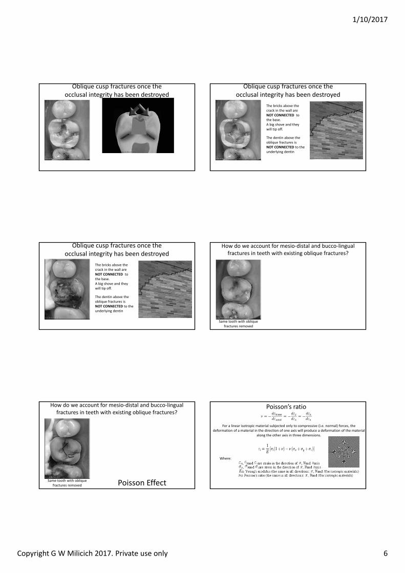
Poisson’s ratio
For a linear isotropic material subjected only to compressive (i.e. normal) forces, the deformation of a material in the direction of one axis will produce a deformation of the material
along the other axis in three dimensions.
Where:
1/10/2017
Copyright G W Milicich 2017. Private use only 7
How do we account for mesio‐distal and bucco‐lingual fractures in teeth with existing oblique fractures?
Same tooth with oblique fractures removed Poisson Effect
Tension
Compression
This effect is three dimensional
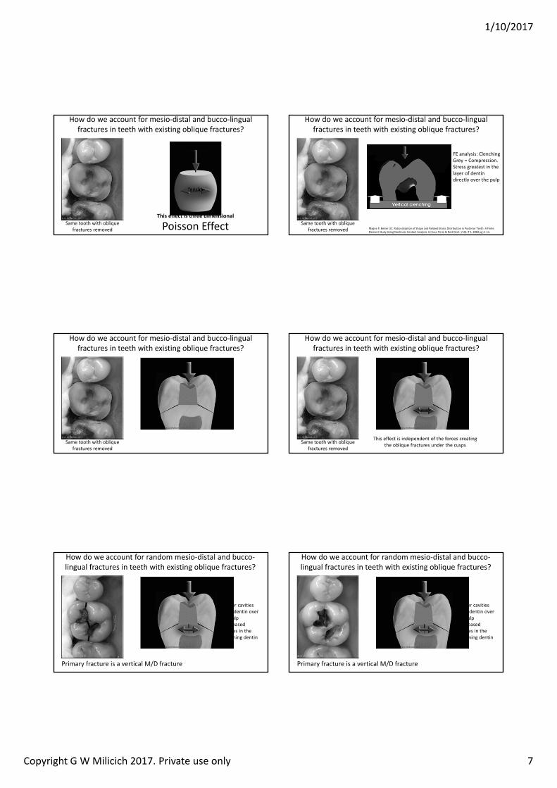
How do we account for mesio‐distal and bucco‐lingual fractures in teeth with existing oblique fractures?
Same tooth with oblique fractures removed Magne P, Belser UC. Rationalization of Shape and Related Stress Distribution in Posterior Teeth: A Finite
Element Study Using Nonlinear Contact Analysis. Int Jour Perio & Rest Dent. V 22, # 5, 2002 pg 2‐ 11.
FE analysis: ClenchingGrey = Compression.Stress greatest in the layer of dentin directly over the pulp
How do we account for mesio‐distal and bucco‐lingual fractures in teeth with existing oblique fractures?
Same tooth with oblique fractures removed
How do we account for mesio‐distal and bucco‐lingual fractures in teeth with existing oblique fractures?
Same tooth with oblique fractures removed
TENSION
This effect is independent of the forces creating the oblique fractures under the cusps
How do we account for random mesio‐distal and bucco‐lingual fractures in teeth with existing oblique fractures?
Deeper cavities= less dentin over the pulp= increased stresses in the remaining dentin
Primary fracture is a vertical M/D fracture
How do we account for random mesio‐distal and bucco‐lingual fractures in teeth with existing oblique fractures?
Deeper cavities= less dentin over the pulp= increased stresses in the remaining dentin
Primary fracture is a vertical M/D fracture
1/10/2017
Copyright G W Milicich 2017. Private use only 8
How do we account for random mesio‐distal and bucco‐lingual fractures in teeth with existing oblique fractures?
Independent of the M/D fracture is an area of Poisson Effect fracturing under the old amalgam
Deeper cavities= less dentin over the pulp= increased stresses in the remaining dentin
Note: buccal and palatal enamel have not been reduced down to the dentin
How do we account for random mesio‐distal and bucco‐lingual fractures in teeth with existing oblique fractures?
Deeper cavities= less dentin over the pulp= increased stresses in the remaining dentin
Independent of the M/D fracture is an area of Poisson Effect fracturing under the old amalgam
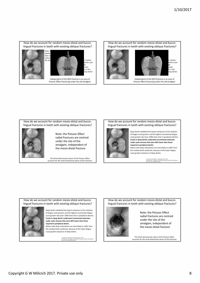
How do we account for random mesio‐distal and bucco‐lingual fractures in teeth with existing oblique fractures?
The three dimensional nature of the Poisson effect accounts for the multi‐directional nature of the fractures
Note: the Poisson Effect radial fractures are centred under the site of the amalgam, independent of the mesio‐distal fracture
How do we account for random mesio‐distal and bucco‐lingual fractures in teeth with existing oblique fractures?
J. Ivancik, N.K. Neerchal, E. Romberg, and D. Arola. The Reduction in Fatigue Crack Growth Resistance of Dentin with Depth. J Dent Res 2011 90(8):1031‐1036.
Deep dentin exhibited the lowest resistance to the initiation of fatigue crack growth, and the highest incremental fatigue crack growth rate (over 1000 times that in peripheral dentin). Cracks in deep dentin underwent incremental extension under cyclic stresses that were 0 lower than those required in peripheral dentin. Molars with deep restorations are more likely to suffer from the cracked‐tooth syndrome, because of the lower fatigue crack growth resistance of deep dentin.
How do we account for random mesio‐distal and bucco‐lingual fractures in teeth with existing oblique fractures?
The three dimensional nature of the Poisson effect accounts for the multi‐directional nature of the fractures
Note: the Poisson Effect radial fractures are centred under the site of the amalgam, independent of the mesio‐distal fracture
1/10/2017
Copyright G W Milicich 2017. Private use only 9
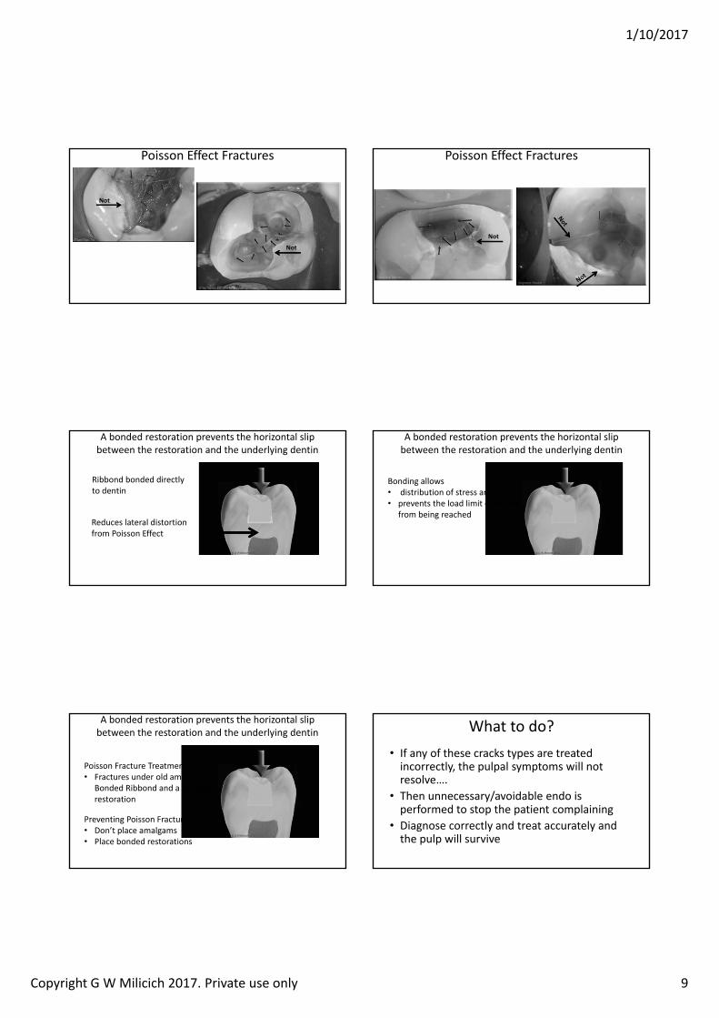
Poisson Effect Fractures
Not
Not
Poisson Effect Fractures
Not
A bonded restoration prevents the horizontal slip between the restoration and the underlying dentin
Ribbond bonded directly to dentin
Reduces lateral distortion from Poisson Effect
A bonded restoration prevents the horizontal slip between the restoration and the underlying dentin
Bonding allows• distribution of stress and strain • prevents the load limit of dentin
from being reached
A bonded restoration prevents the horizontal slip between the restoration and the underlying dentin
Poisson Fracture Treatment• Fractures under old amalgams –
Bonded Ribbond and a bonded restoration
Preventing Poisson Fracture • Don’t place amalgams• Place bonded restorations
What to do?• If any of these cracks types are treated incorrectly, the pulpal symptoms will not resolve….
• Then unnecessary/avoidable endo is performed to stop the patient complaining
• Diagnose correctly and treat accurately and the pulp will survive
1/10/2017
Copyright G W Milicich 2017. Private use only 10
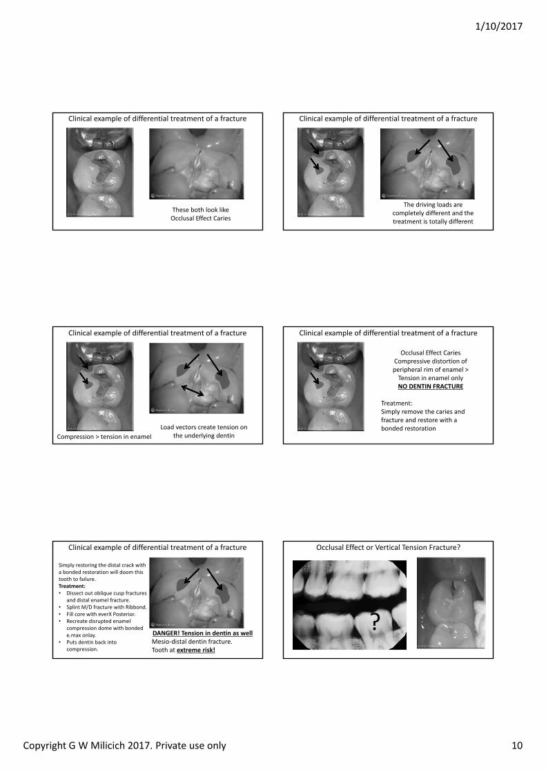
Clinical example of differential treatment of a fracture
These both look like Occlusal Effect Caries
Clinical example of differential treatment of a fracture
The driving loads are completely different and the treatment is totally different
Clinical example of differential treatment of a fracture
Load vectors create tension on the underlying dentinCompression > tension in enamel
Clinical example of differential treatment of a fracture
Occlusal Effect CariesCompressive distortion of peripheral rim of enamel >Tension in enamel onlyNO DENTIN RACTURE
Treatment: Simply remove the caries and fracture and restore with a bonded restoration
Clinical example of differential treatment of a fracture
DANGER! Tension in dentin as wellMesio‐distal dentin fracture.Tooth at extreme risk!
Simply restoring the distal crack with a bonded restoration will doom this tooth to failure.Treatment:• Dissect out oblique cusp fractures
and distal enamel fracture.• Splint M/D fracture with Ribbond.• Fill core with everX Posterior.• Recreate disrupted enamel
compression dome with bonded e.max onlay.
• Puts dentin back into compression.
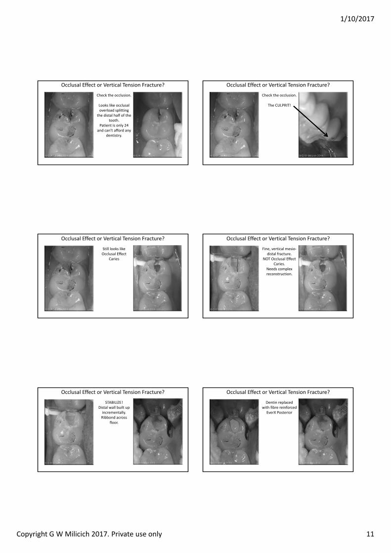
Occlusal Effect or Vertical Tension Fracture?
?
1/10/2017
Copyright G W Milicich 2017. Private use only 11
Occlusal Effect or Vertical Tension Fracture?
Check the occlusion.
Looks like occlusal overload splitting
the distal half of the tooth.
Patient is only 24 and can’t afford any
dentistry.
Occlusal Effect or Vertical Tension Fracture?
Check the occlusion.
The CULPRIT!
Occlusal Effect or Vertical Tension Fracture?
Still looks like Occlusal Effect
Caries
Occlusal Effect or Vertical Tension Fracture?
Fine, vertical mesio‐distal fracture.
NOT Occlusal Effect Caries.
Needs complex reconstruction.
Occlusal Effect or Vertical Tension Fracture?
STABILIZE!Distal wall built up incrementally.Ribbond across
floor.
Occlusal Effect or Vertical Tension Fracture?
Dentin replaced with fibre reinforced
EverX Posterior
1/10/2017
Copyright G W Milicich 2017. Private use only 12
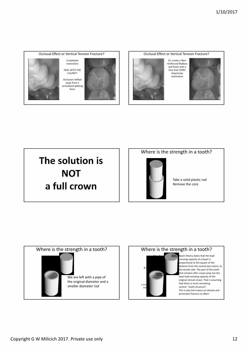
Occlusal Effect or Vertical Tension Fracture?
Completed restoration
DEAL WITH THE CULPRIT!
Occlusion shifted away from a
centralized splitting force
Occlusal Effect or Vertical Tension Fracture?
Or, create a fibre reinforced BioBaseand finish with a One Visit CEREC
inlay/onlay restoration
Where is the strength in a tooth?
Take a solid plastic rodRemove the core
Where is the strength in a tooth?
We are left with a pipe of the original diameter and a smaller diameter rod
Where is the strength in a tooth?3mm
. mm
4.52 = 20.25
1.5mm walls
32 = 9 Beam theory states that the load‐carrying capacity of a beam is proportional to the square of the distance from the neutral axis centre, to the tensile side. The part of the tooth that remains after crown prep has the least load resisting capacity of the original clinical crown. That is assuming that there is much remaining central “tooth structure”.This is why full crowns on laterals and premolars fracture so often!
1/10/2017
Copyright G W Milicich 2017. Private use only 13
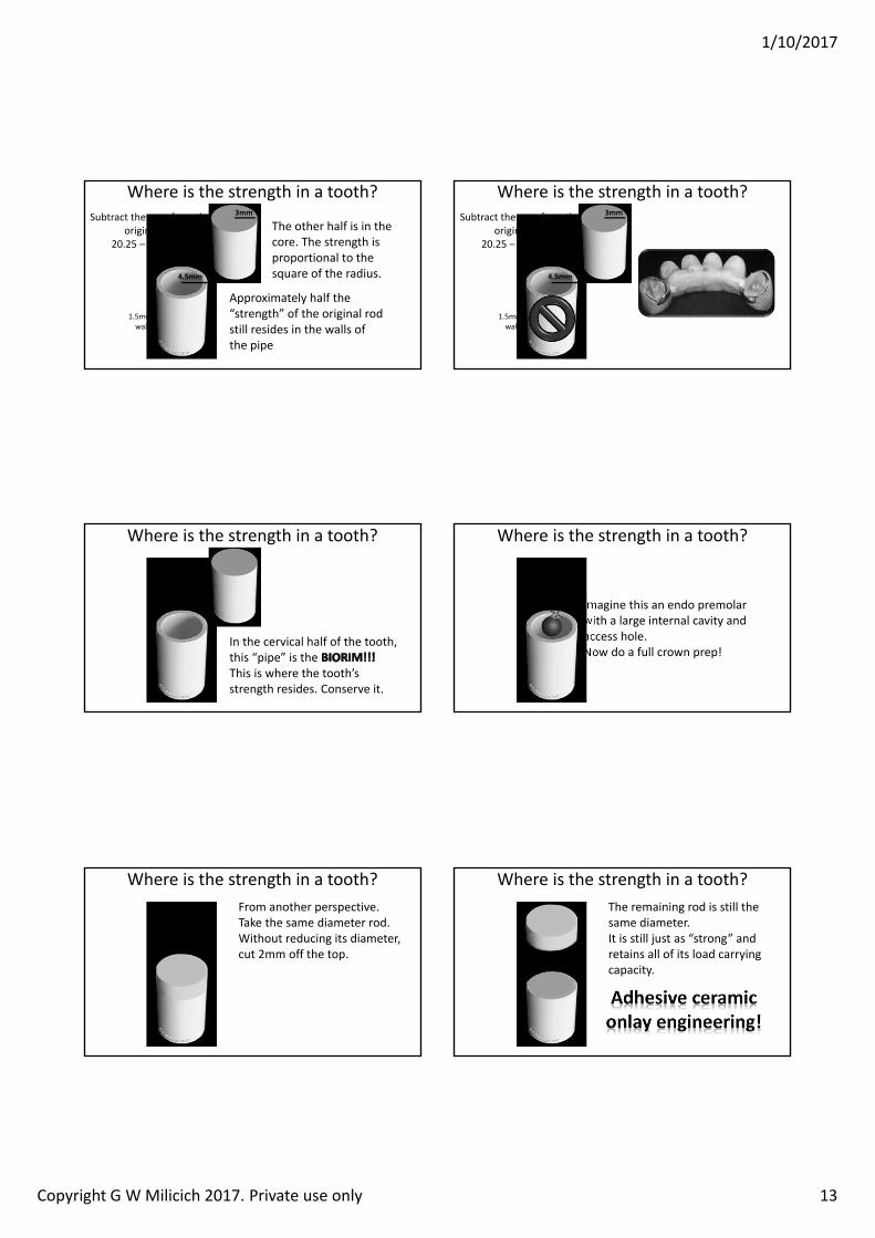
Where is the strength in a tooth?
Approximately half the “strength” of the original rod still resides in the walls of the pipe
The other half is in the core. The strength is proportional to the square of the radius.
3mm
. mm
1.5mm walls
Subtract the core from the original rod
20.25 – 9 = 11.25
Where is the strength in a tooth?3mm
. mm
1.5mm walls
Subtract the core from the original rod
20.25 – 9 = 11.25
Where is the strength in a tooth?
In the cervical half of the tooth, this “pipe” is the This is where the tooth’s strength resides. Conserve it.
Where is the strength in a tooth?
Imagine this an endo premolar with a large internal cavity and access hole.Now do a full crown prep!
Where is the strength in a tooth?From another perspective.Take the same diameter rod.Without reducing its diameter, cut 2mm off the top.
Where is the strength in a tooth?The remaining rod is still the same diameter.It is still just as “strong” and retains all of its load carrying capacity.
1/10/2017
Copyright G W Milicich 2017. Private use only 14
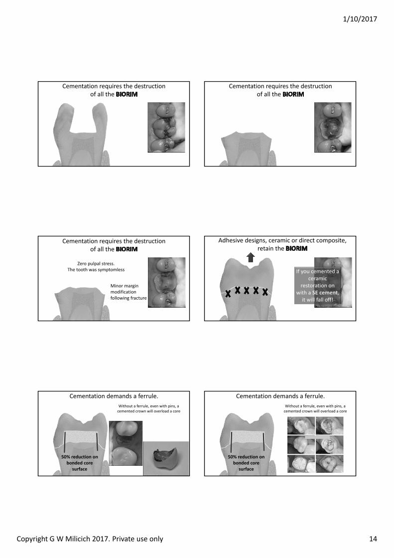
Cementation requires the destruction of all the
Cementation requires the destruction of all the
Cementation requires the destruction of all the
Minor margin modification following fracture
Zero pulpal stress. The tooth was symptomless
Adhesive designs, ceramic or direct composite, retain the
If you cemented a ceramic
restoration on with a SE cement,
it will fall off!
Cementation demands a ferrule. Without a ferrule, even with pins, a cemented crown will overload a core
0 reduction on bonded core
surface
Cementation demands a ferrule. Without a ferrule, even with pins, a cemented crown will overload a core
0 reduction on bonded core
surface
1/10/2017
Copyright G W Milicich 2017. Private use only 15
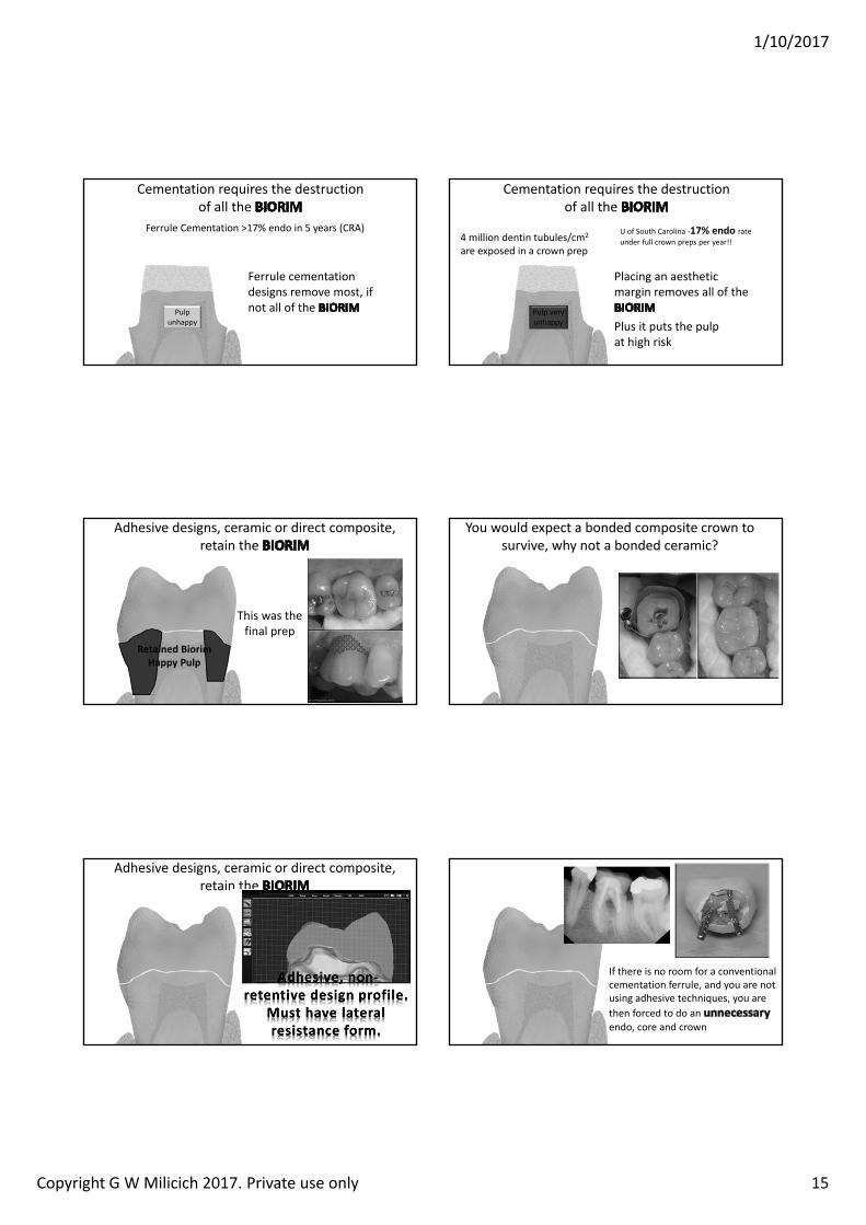
Cementation requires the destruction of all the
Ferrule cementation designs remove most, if not all of the Pulp
unhappy
Ferrule Cementation >17% endo in 5 years (CRA)
Cementation requires the destruction of all the
Placing an aesthetic margin removes all of the
Pulp very unhappy
4 million dentin tubules/cm2
are exposed in a crown prep
Plus it puts the pulp at high risk
U of South Carolina ‐1 endo rate under full crown preps per year!!
Adhesive designs, ceramic or direct composite, retain the
This was the final prep
Retained BiorimHappy Pulp
You would expect a bonded composite crown to survive, why not a bonded ceramic?
Adhesive designs, ceramic or direct composite, retain the
If there is no room for a conventional cementation ferrule, and you are not using adhesive techniques, you are then forced to do an endo, core and crown
1/10/2017
Copyright G W Milicich 2017. Private use only 16
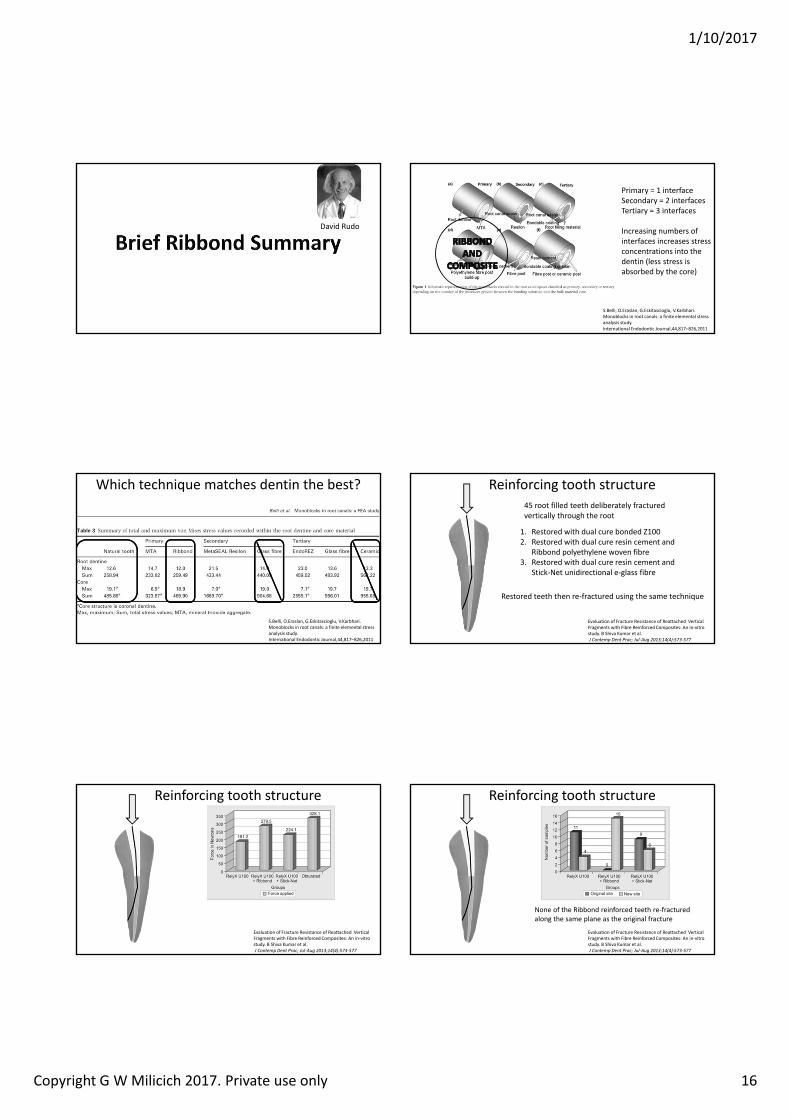
David Rudo
S.Belli, O.Eraslan, G.Eskitascioglu, V.Karbhari. Monoblocks in root canals: a finite elemental stress analysis study. International Endodontic Journal,44,817–826,2011
Primary = 1 interfaceSecondary = 2 interfacesTertiary = 3 interfaces
Increasing numbers of interfaces increases stress concentrations into the dentin (less stress is absorbed by the core)
Which technique matches dentin the best?
S.Belli, O.Eraslan, G.Eskitascioglu, V.Karbhari. Monoblocks in root canals: a finite elemental stress analysis study. International Endodontic Journal,44,817–826,2011
Reinforcing tooth structure
Evaluation of Fracture Resistance of Reattached Vertical Fragments with Fibre Reinforced Composites: An in‐vitro study. B Shiva Kumar et al.J Contemp Dent Prac Ju ug ( )
1. Restored with dual cure bonded Z1002. Restored with dual cure resin cement and
Ribbond polyethylene woven fibre3. Restored with dual cure resin cement and
Stick‐Net unidirectional e‐glass fibre
Restored teeth then re‐fractured using the same technique
45 root filled teeth deliberately fractured vertically through the root
Reinforcing tooth structure
Evaluation of Fracture Resistance of Reattached Vertical Fragments with Fibre Reinforced Composites: An in‐vitro study. B Shiva Kumar et al.J Contemp Dent Prac Ju ug ( )
Reinforcing tooth structure
Evaluation of Fracture Resistance of Reattached Vertical Fragments with Fibre Reinforced Composites: An in‐vitro study. B Shiva Kumar et al.J Contemp Dent Prac Ju ug ( )
None of the Ribbond reinforced teeth re‐fractured along the same plane as the original fracture
1/10/2017
Copyright G W Milicich 2017. Private use only 17
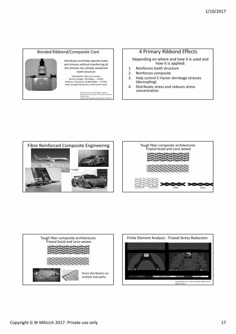
Bonded Ribbond/Composite Core
Distributes and helps absorbs loads and stresses without transferring all the stresses into already weakened
tooth structurePolyethylene Fibre Leno weave
Tensile strength 435,000psi – 3.0GPaModulus of Elasticity 24,800,000psi – 171GPa(high strength fishing lines, bullet proof vests)
S.Belli, O.Eraslan, G.Eskitascioglu, V.Karbhari. Monoblocks in root canals: a finite elemental stress analysis study. International Endodontic Journal,44,817–826,2011
4 Primary Ribbond EffectsDepending on where and how it is used and
how it is applied:1. Reinforces tooth structure2. Reinforces composite3. Help control C‐Factor shrinkage stresses
(decoupling)4. Distributes stress and reduces stress
concentration
Fibre Reinforced Composite Engineering Tough fiber composite architecturesTriaxial braid and Leno weave
THM Ultra
Tough fiber composite architecturesTriaxial braid and Leno weave
Stress distribution via multiple load paths
Finite Element Analysis : Triaxial Stress Reduction
Eskitascioglu et al. J Dent. Research 2006; Vol. 85Special issue A
i ond eno wea e Unidirectional glass
Multi‐directional linear orientation
1/10/2017
Copyright G W Milicich 2017. Private use only 18
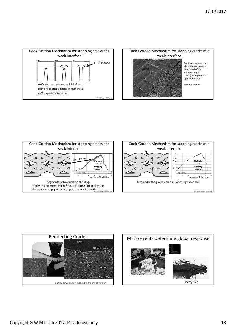
a rac approaches a wea inter ace
Inter ace rea s ahead o main crac
c T shaped crac stopper
EDJ/Ribbond
David Rudo ‐ Ribbond
Cook‐Gordon Mechanism for stopping cracks at a weak interface
Enamel
Dentin
Fracture planes occur along the decussationinterfaces) of the Hunter Shregerbands(prism groups in opposite planes
Arrest at the DEC
Cook‐Gordon Mechanism for stopping cracks at a weak interface
Cook‐Gordon Mechanism for stopping cracks at a weak interface
Segments polymerization shrinkageNodes inhibit micro‐cracks from coalescing into real cracksStops crack propagation, encapsulates crack growth
No fibre
THM Ultra
Multiple crack
stopping events
Drs. Selim Erkut and zlem Acar
Cook‐Gordon Mechanism for stopping cracks at a weak interface
Area under the graph = amount of energy absorbed
THM Ultra
Multiple crack
stopping events
Drs. Selim Erkut and zlem Acar
No fibre
Redirecting Cracks
BIOMECHANICAL PROPERTIES AND CLINICAL USE OF A POLYETHYLENE FIBRE POST‐CORE MATERIALSEMA BELLI & G RCAN ESKITASCIOGLU INTERNATIONAL DENTISTRY SOUTH AFRICA VOL 8., NO 3
The Ribbond should have been at the bottom of the beam!
Note: the composite fractures above the Ribbond look just like the enamel tufts in the SEM
Micro events determine global response
Liberty Ship
1/10/2017
Copyright G W Milicich 2017. Private use only 19
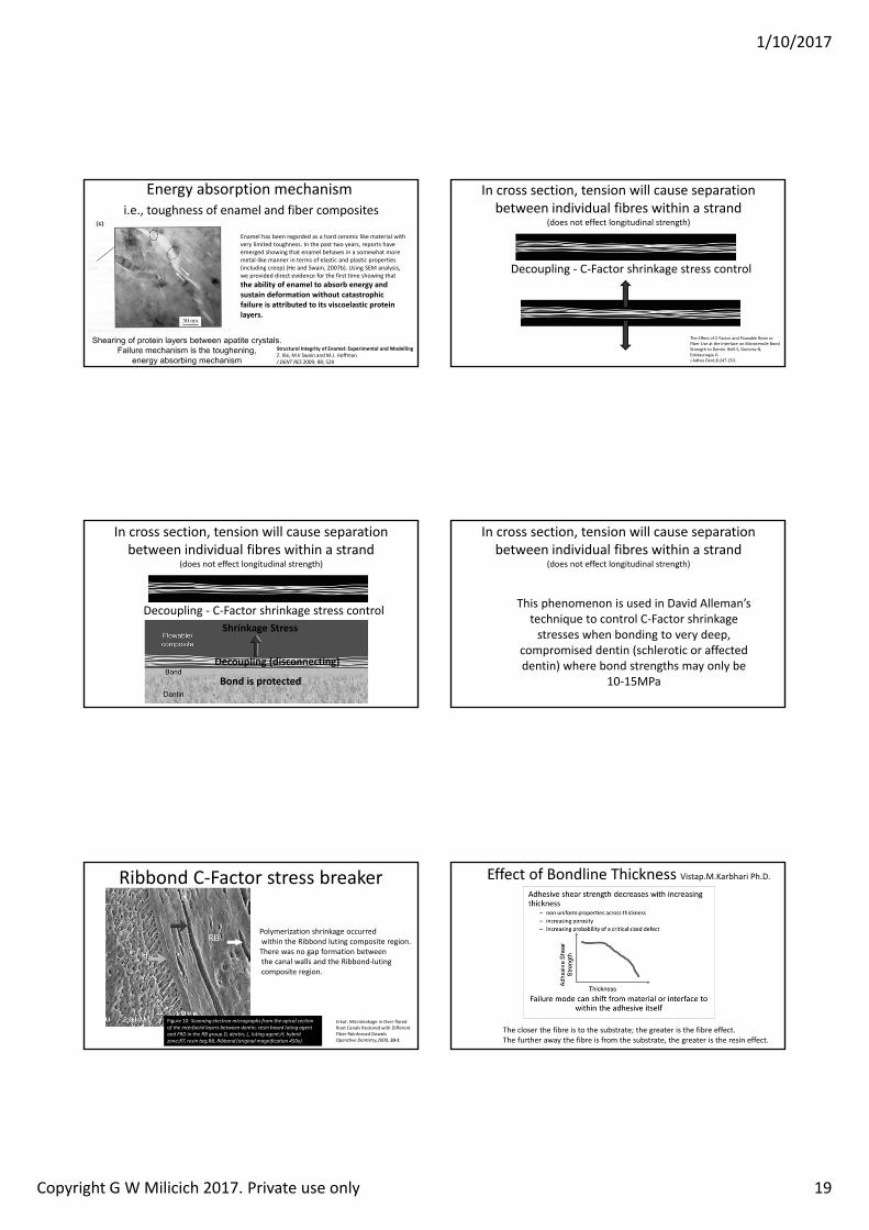
Energy absorption mechanismi.e., toughness of enamel and fiber composites
hearin o protein la ers etween apatite cr stalsailure mechanism is the tou henin
ener a sor in mechanismStructural Integrity of Enamel: Experimental and Modelling Z. Xie, M.V Swain and M.J. HoffmanJ DENT RES 2009; 88; 529
Enamel has been regarded as a hard ceramic like material with very limited toughness. In the past two years, reports have emerged showing that enamel behaves in a somewhat more metal‐like manner in terms of elastic and plastic properties (including creep) (He and Swain, 2007b). Using SEM analysis, we provided direct evidence for the first time showing that the ability of enamel to absorb energy and sustain deformation without catastrophic failure is attributed to its viscoelastic protein layers.
In cross section, tension will cause separation between individual fibres within a strand
(does not effect longitudinal strength)
Decoupling ‐ C‐Factor shrinkage stress control
The Effect of C‐Factor and Flowable Resin or Fiber Use at the Interface on Microtensile Bond Strength to Dentin. Belli S, Donemz N, Eskitasciogiu G. J Adhes Dent;8:247‐253.
In cross section, tension will cause separation between individual fibres within a strand
(does not effect longitudinal strength)
Decoupling ‐ C‐Factor shrinkage stress control
Bond is protected
Shrinkage Stress
Decoupling disconnecting
In cross section, tension will cause separation between individual fibres within a strand
(does not effect longitudinal strength)
This phenomenon is used in David Alleman’s technique to control C‐Factor shrinkage stresses when bonding to very deep,
compromised dentin (schlerotic or affected dentin) where bond strengths may only be
10‐15MPa
Ribbond C‐Factor stress breaker
Erkut. Microleakage in Over flared Root Canals Restored with Different Fiber Reinforced Dowelsperative Dentistr 33‐1
Figure 10: Scanning e ectron micrographs from the apica section of the interfacia a ers bet een dentin resin based uting agent and RD in the R group.D dentin L uting agent h brid one RT resin tag R Ribbond (origina magnification ).
Polymerization shrinkage occurredwithin the Ribbond luting composite region.There was no gap formation betweenthe canal walls and the Ribbond‐lutingcomposite region.
Effect of Bondline Thickness Vistap.M.Karbhari Ph.D.
The closer the fibre is to the substrate; the greater is the fibre effect.The further away the fibre is from the substrate, the greater is the resin effect.
1/10/2017
Copyright G W Milicich 2017. Private use only 20
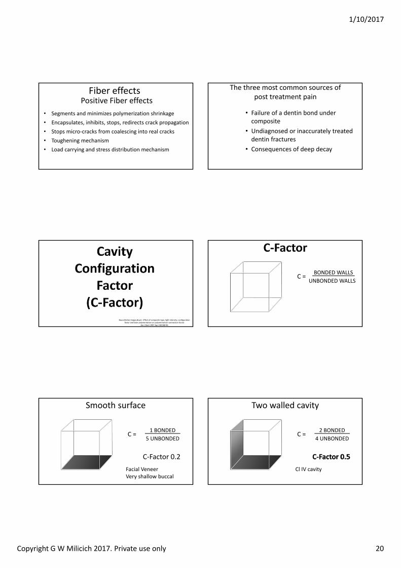
Fiber effectsPositive Fiber effects
• Segments and minimizes polymerization shrinkage• Encapsulates, inhibits, stops, redirects crack propagation• Stops micro‐cracks from coalescing into real cracks• Toughening mechanism• Load carrying and stress distribution mechanism
The three most common sources of post treatment pain
• Failure of a dentin bond under composite
• Undiagnosed or inaccurately treated dentin fractures
• Consequences of deep decay
Bouschlicher,Vargas,Boyer. Effect of composite type, light intensity, configuration factor and laser polymerisation on polymerisation contraction forces
Am J Dent 1997 Apr,10(2)88‐96
C = BONDED WALLSUNBONDED WALLS
Smooth surface
C = 1 BONDED5 UNBONDED
C‐Factor 0.2Facial VeneerVery shallow buccal
C = 2 BONDED4 UNBONDED
C‐Factor 0.5
Two walled cavity
Cl IV cavity
C‐ actor 0.
1/10/2017
Copyright G W Milicich 2017. Private use only 21
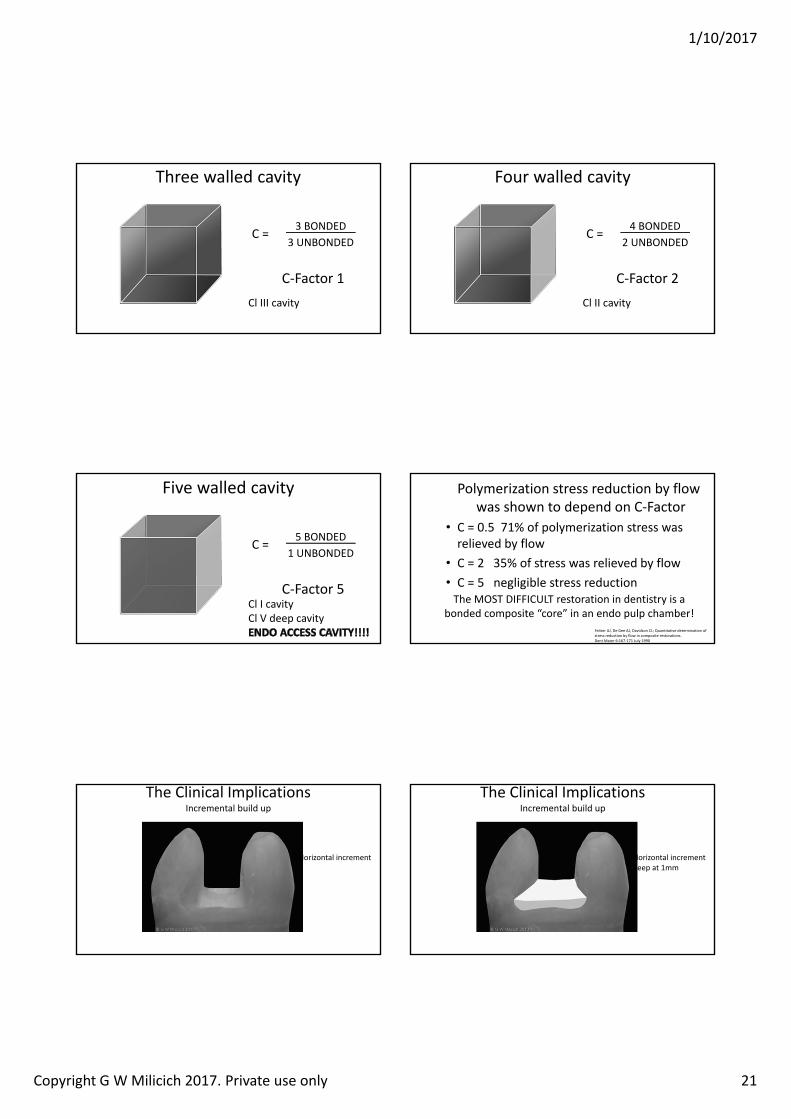
C = 3 BONDED3 UNBONDED
C‐Factor 1
Three walled cavity
Cl III cavity
C = 4 BONDED2 UNBONDED
C‐Factor 2
Four walled cavity
Cl II cavity
C = 5 BONDED1 UNBONDED
C‐Factor 5
Five walled cavity
Cl I cavityCl V deep cavity
Feilzer AJ, De Gee AJ, Davidson CL; uantitative determination of stress reduction by flow in composite restorations.Dent Mater 6:167‐171 July 1990
Polymerization stress reduction by flow was shown to depend on C‐Factor
• C = 0.5 71% of polymerization stress was relieved by flow
• C = 2 35% of stress was relieved by flow• C = 5 negligible stress reductionThe MOST DIFFICULT restoration in dentistry is a
bonded composite “core” in an endo pulp chamber!
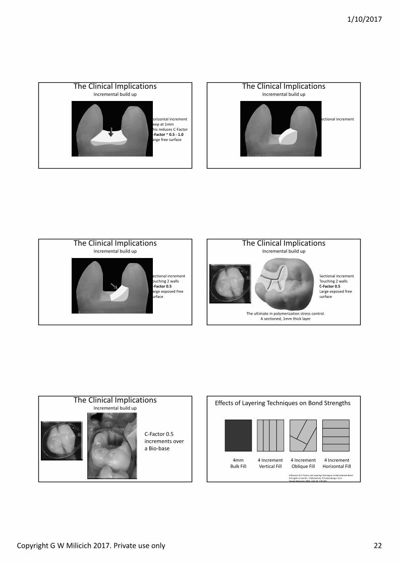
The Clinical Implications Incremental build up
Horizontal increment
The Clinical Implications Incremental build up
Horizontal incrementKeep at 1mm
1/10/2017
Copyright G W Milicich 2017. Private use only 22
The Clinical Implications Incremental build up
Horizontal incrementKeep at 1mmThis reduces C‐FactorC‐ actor 0. ‐ 1.0Large free surface
The Clinical Implications Incremental build up
Sectional increment
The Clinical Implications Incremental build up
Sectional incrementTouching 2 wallsC‐ actor 0.Large exposed free surface
The Clinical Implications Incremental build up
Sectional incrementTouching 2 wallsC‐ actor 0.Large exposed free surface
The ultimate in polymerization stress control.A sectioned, 1mm thick layer
The Clinical Implications Incremental build up
C‐Factor 0.5 increments over a Bio‐base
Effects of Layering Techniques on Bond Strengths
Influence of C‐Factor and Layering Technique on Microtensile Bond Strengths to Dentin. S Nikolaenko, R.Fankenberger et alDental Materials 2004, Voll 20: 579‐585
4mm Bulk Fill
4 Increment Vertical Fill
4 Increment Oblique Fill
4 Increment Horizontal Fill
1/10/2017
Copyright G W Milicich 2017. Private use only 23
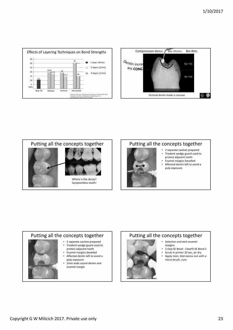
Effects of Layering Techniques on Bond Strengths
Influence of C‐Factor and Layering Technique on Microtensile Bond Strengths to Dentin. S Nikolaenko, R.Fankenberger et alDental Materials 2004, Voll 20: 579‐585
5
10
15
20
25
30
35
MPa
ObliqueBulk Fill Vertical Horizontal
1 layer (4mm)
2 layers (2mm)
4 layers (1mm)
11
1617.6 19
15.7
31
19.8
Compression dome. Bio‐Dome. Bio‐Rim.
Occlusal dentin shade is concave
Putting all the concepts together
Where is the decay? Symptomless tooth!
Putting all the concepts together• 2 separate cavities prepared• Triodent wedge guard used to
protect adjacent tooth• Enamel margins bevelled • Affected dentin left to avoid a
pulp exposure
Putting all the concepts together• 2 separate cavities prepared• Triodent wedge guard used to
protect adjacent tooth• Enamel margins bevelled • Affected dentin left to avoid a
pulp exposure• 2mm wide sound dentin and
enamel margin
Putting all the concepts together• Selective acid etch enamel
margins• 2 step SE Bond ‐ Clearfil SE Bond 2• Scrub in primer 20 sec, air dry• Apply resin, blot excess out with a
micro‐brush, cure
1/10/2017
Copyright G W Milicich 2017. Private use only 24
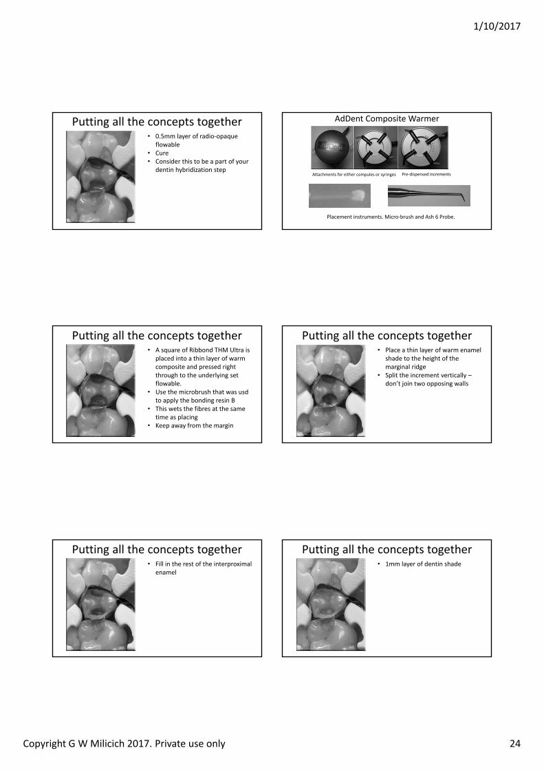
Putting all the concepts together• 0.5mm layer of radio‐opaque
flowable• Cure • Consider this to be a part of your
dentin hybridization step
AdDent Composite Warmer
Attachments for either compules or syringes Pre‐dispensed increments
Placement instruments. Micro‐brush and Ash 6 Probe.
Putting all the concepts together• A square of Ribbond THM Ultra is
placed into a thin layer of warm composite and pressed right through to the underlying set flowable.
• Use the microbrush that was usdto apply the bonding resin B
• This wets the fibres at the same time as placing
• Keep away from the margin
Putting all the concepts together• Place a thin layer of warm enamel
shade to the height of the marginal ridge
• Split the increment vertically –don’t join two opposing walls
Putting all the concepts together• Fill in the rest of the interproximal
enamel
Putting all the concepts together• 1mm layer of dentin shade
1/10/2017
Copyright G W Milicich 2017. Private use only 25
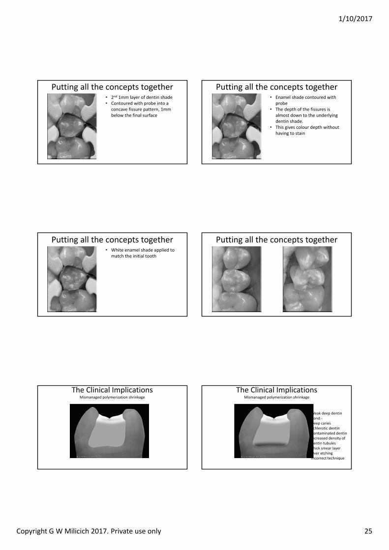
Putting all the concepts together• 2nd 1mm layer of dentin shade• Contoured with probe into a
concave fissure pattern, 1mm below the final surface
Putting all the concepts together• Enamel shade contoured with
probe• The depth of the fissures is
almost down to the underlying dentin shade.
• This gives colour depth without having to stain
Putting all the concepts together• White enamel shade applied to
match the initial tooth
Putting all the concepts together
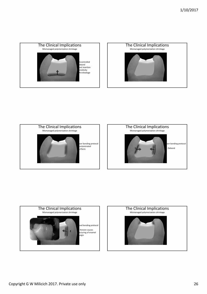
The Clinical ImplicationsMismanaged polymerization shrinkage
The Clinical ImplicationsMismanaged polymerization shrinkage
Weak deep dentin bond:‐Deep caries Schlerotic dentinContaminated dentinIncreased density of dentin tubulesThick smear layerOver etchingIncorrect technique
1/10/2017
Copyright G W Milicich 2017. Private use only 26
The Clinical ImplicationsMismanaged polymerization shrinkage
Uncontrolled debondPost insertion sensitivityMicroleakage
The Clinical ImplicationsMismanaged polymerization shrinkage
The Clinical ImplicationsMismanaged polymerization shrinkage
Poor bonding protocolContaminated surfaces
The Clinical ImplicationsMismanaged polymerization shrinkage
Poor bonding protocol
1. Debond1
The Clinical ImplicationsMismanaged polymerization shrinkage
Good bonding protocol
2. Tension causes fracturing of enamel margin
2
The Clinical ImplicationsMismanaged polymerization shrinkage
1/10/2017
Copyright G W Milicich 2017. Private use only 27
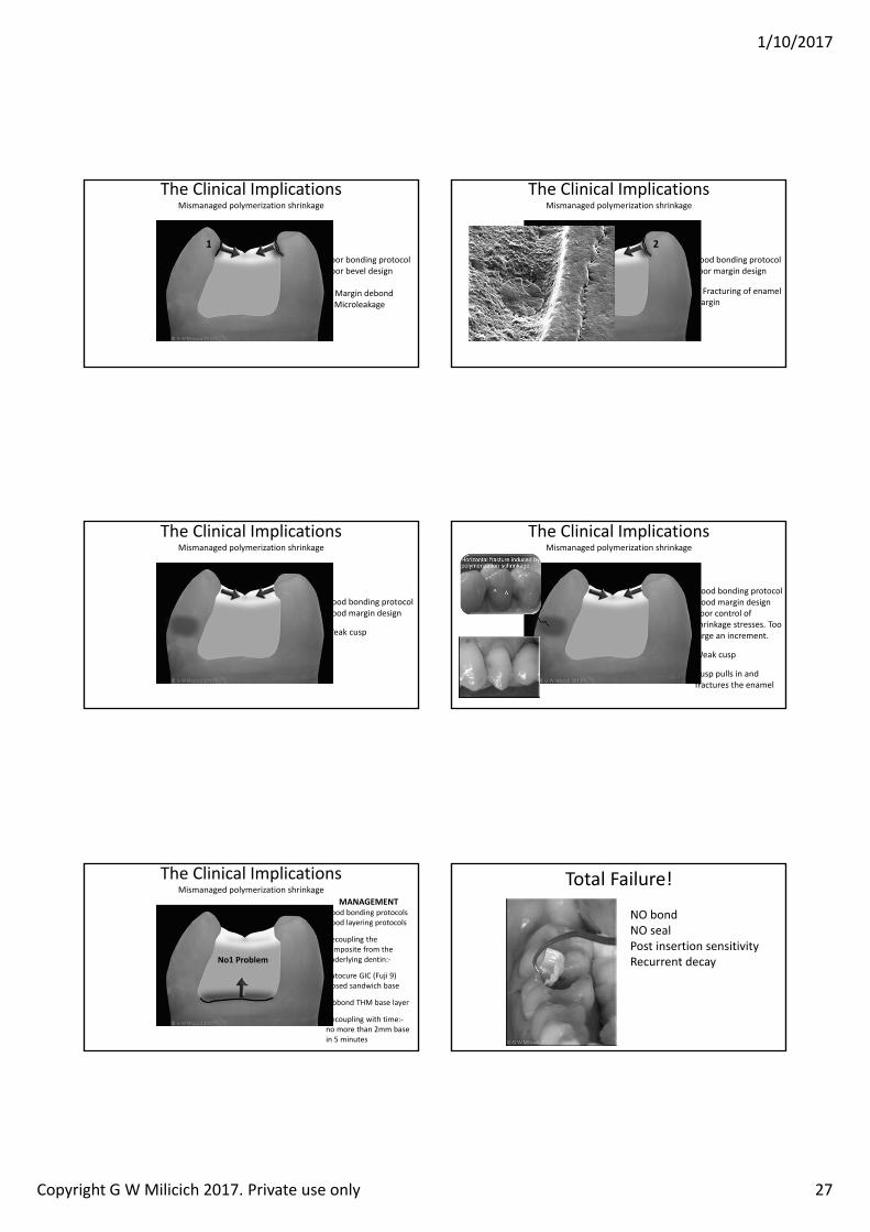
The Clinical ImplicationsMismanaged polymerization shrinkage
Poor bonding protocolPoor bevel design
1. Margin debondMicroleakage
1
The Clinical ImplicationsMismanaged polymerization shrinkage
Good bonding protocolPoor margin design
2. Fracturing of enamel margin
2
The Clinical ImplicationsMismanaged polymerization shrinkage
Good bonding protocolGood margin design
Weak cusp
The Clinical ImplicationsMismanaged polymerization shrinkage
Good bonding protocolGood margin designPoor control of shrinkage stresses. Too large an increment.
Weak cusp
Cusp pulls in and fractures the enamel
The Clinical ImplicationsMismanaged polymerization shrinkage
MANAGEMENTGood bonding protocolsGood layering protocols
Decoupling the composite from the underlying dentin:‐
Autocure GIC (Fuji 9) closed sandwich base
Ribbond THM base layer
Decoupling with time:‐no more than 2mm base in 5 minutes
No1 Problem
Total Failure!
NO bondNO sealPost insertion sensitivityRecurrent decay

1/10/2017
Copyright G W Milicich 2017. Private use only 28
The Adhesive Equation
G L Unterbrink, W H Liebenberg. Flowable resin composites as “filled adhesives”: Literature Review and Clinical Recommendations. uintescence Int 1999; 30:249‐257
“Adhesive dentistry could be expressed as a simple relationship between bonds and stress. If the bond can
withstand the stress, the restorative technique will be successful”
What about uncontrolled stress in the tooth?
The Biomechanical EquationThe other half of the equation
“Following a successful restoration, if the remaining tooth structure can successfully absorb the loads and stresses, the tooth will also survive. A successful restoration does not
necessarily guarantee the stability or survival of the tooth”
1/10/2017
Copyright G W Milicich 2017. Private use only 1
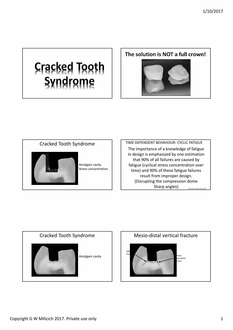
Cracked Tooth Syndrome
Amalgam cavityStress concentration
The importance of a knowledge of fatigue in design is emphasized by one estimation
that 90% of all failures are caused by fatigue (cyclical stress concentration over time) and 90% of these fatigue failures
result from improper design. (Disrupting the compression dome
Sharp angles)ashington.edu me a chap
TIME DEPENDENT BEHAVIOUR: CYCLIC FATIGUE
Cracked Tooth Syndrome
Amalgam cavity
Mesio‐distal vertical fracture
Oblique fracture
Vertical mesio‐distal fracture
1/10/2017
Copyright G W Milicich 2017. Private use only 2
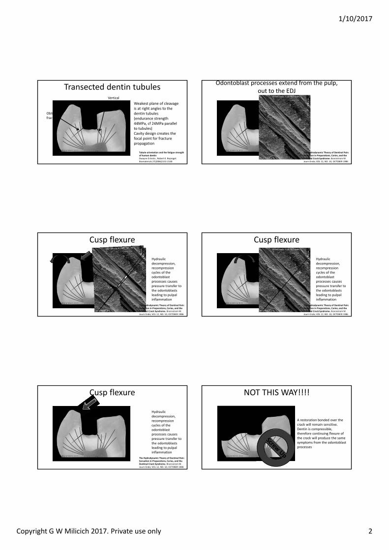
Transected dentin tubules
Oblique fracture
Vertical mesio‐distal fracture
Weakest plane of cleavage is at right angles to the dentin tubules (endurance strength 44MPa, cf 24MPa parallel to tubules)Cavity design creates the focal point for fracture propagation
Tubule orientation and the fatigue strength of human dentinDwayne D.Arola , Robert K. Reprogel. Biomaterials 27(2006)2131‐2140
Odontoblast processes extend from the pulp, out to the EDJ
The Hydrodynamic Theory of Dentinal Pain: Sensation in Preparations, Caries, and the Dentinal Crack Syndrome. BrannstromM.Journ Endo; VOL 12, NO. 10, OCTOBER 1986
Cusp flexure
Hydraulic decompression, recompression cycles of the odontoblastprocesses causes pressure transfer to the odontoblastsleading to pulpal inflammation
The Hydrodynamic Theory of Dentinal Pain: Sensation in Preparations, Caries, and the Dentinal Crack Syndrome. BrannstromM.Journ Endo; VOL 12, NO. 10, OCTOBER 1986
Hydraulic decompression, recompression cycles of the odontoblastprocesses causes pressure transfer to the odontoblastsleading to pulpal inflammation
Cusp flexure
The Hydrodynamic Theory of Dentinal Pain: Sensation in Preparations, Caries, and the Dentinal Crack Syndrome. BrannstromM.Journ Endo; VOL 12, NO. 10, OCTOBER 1986
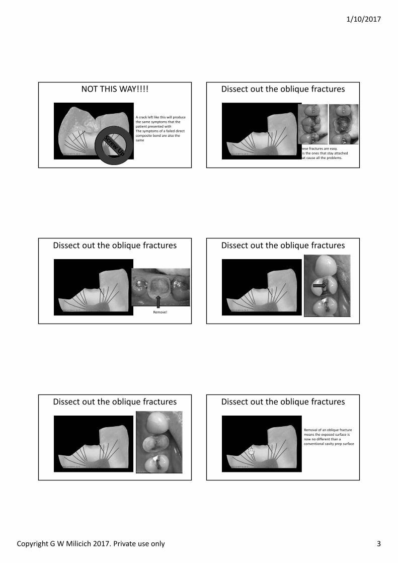
NOT THIS WAY!!!!
A restoration bonded over the crack will remain sensitive.Dentin is compressible, therefore continuing flexure of the crack will produce the same symptoms from the odontoblastprocesses
1/10/2017
Copyright G W Milicich 2017. Private use only 3
NOT THIS WAY!!!!
A crack left like this will produce the same symptoms that the patient presented withThe symptoms of a failed direct composite bond are also the same
Dissect out the oblique fractures
These fractures are easy.It is the ones that stay attached that cause all the problems.
Dissect out the oblique fractures
Remove!
Dissect out the oblique fractures
Dissect out the oblique fractures Dissect out the oblique fractures
Removal of an oblique fracture means the exposed surface is now no different than a conventional cavity prep surface
1/10/2017
Copyright G W Milicich 2017. Private use only 4
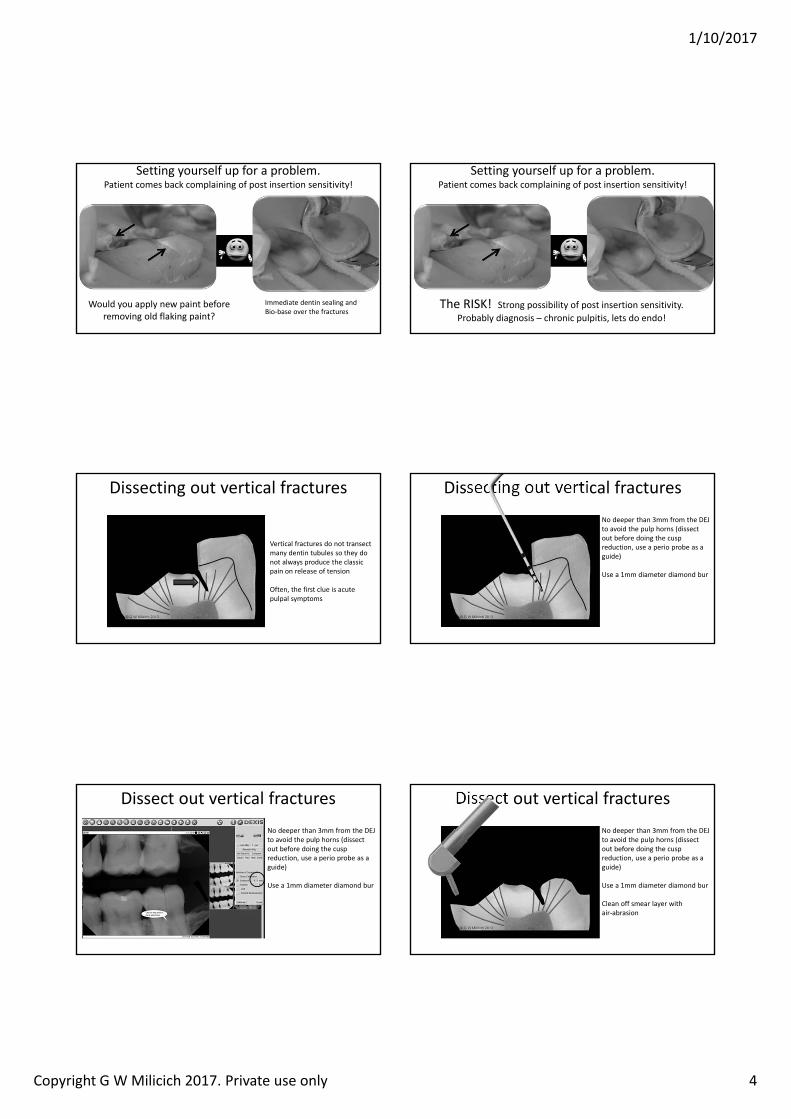
Setting yourself up for a problem.Patient comes back complaining of post insertion sensitivity!
Immediate dentin sealing and Bio‐base over the fractures
Would you apply new paint before removing old flaking paint?
Setting yourself up for a problem.Patient comes back complaining of post insertion sensitivity!
The RISK! Strong possibility of post insertion sensitivity. Probably diagnosis – chronic pulpitis, lets do endo!
Dissecting out vertical fractures
Vertical fractures do not transect many dentin tubules so they do not always produce the classic pain on release of tension
Often, the first clue is acute pulpal symptoms
Dissecting out vertical fracturesNo deeper than 3mm from the DEJ to avoid the pulp horns (dissect out before doing the cusp reduction, use a perio probe as a guide)
Use a 1mm diameter diamond bur
Dissect out vertical fracturesNo deeper than 3mm from the DEJ to avoid the pulp horns (dissect out before doing the cusp reduction, use a perio probe as a guide)
Use a 1mm diameter diamond bur
Dissect out vertical fracturesNo deeper than 3mm from the DEJ to avoid the pulp horns (dissect out before doing the cusp reduction, use a perio probe as a guide)
Use a 1mm diameter diamond bur
Clean off smear layer with air‐abrasion
1/10/2017
Copyright G W Milicich 2017. Private use only 5
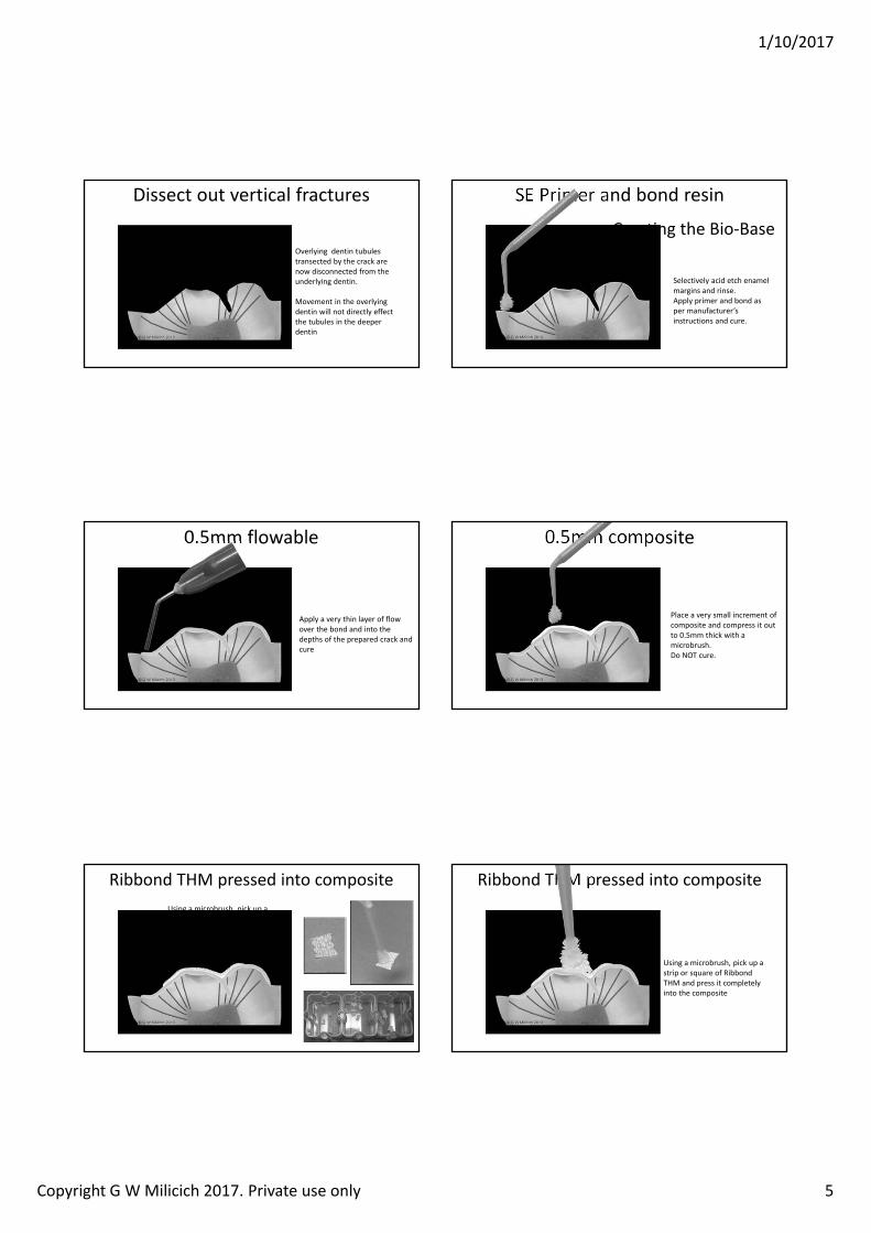
Dissect out vertical fractures
Overlying dentin tubules transected by the crack are now disconnected from the underlying dentin.
Movement in the overlying dentin will not directly effect the tubules in the deeper dentin
Selectively acid etch enamel margins and rinse.Apply primer and bond as per manufacturer’s instructions and cure.
SE Primer and bond resin
Creating the Bio‐Base
0.5mm flowable
Apply a very thin layer of flow over the bond and into the depths of the prepared crack and cure
0.5mm composite
Place a very small increment of composite and compress it out to 0.5mm thick with a microbrush. Do NOT cure.
Ribbond THM pressed into compositeUsing a microbrush, pick up a strip or square of Ribbond THM and press it completely into the composite
Ribbond THM pressed into composite
Using a microbrush, pick up a strip or square of Ribbond THM and press it completely into the composite
1/10/2017
Copyright G W Milicich 2017. Private use only 6
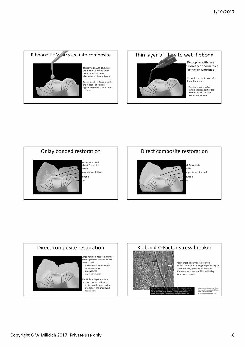
Ribbond THM pressed into composite
This is the DECOUPLING use of Ribbond to protect weak dentin bonds on deep affected or schlerotic dentin
To splint and reinforce a crack, the Ribbond should be applied directly to the bonded surface
Thin layer of Flow to wet Ribbond
Wet with a very thin layer of flowable and cure
This is a stress breaker system that is a part of the BioBase which can also include the BioRim
Decoupling with timeNo more than 1.5mm thick
in the first 5 minutes
Onlay bonded restoration
Flowable
Composite and Ribbond
BondFlowable
e.max CAD or pressed or Indirect Composite
Direct composite restoration
Flowable
Composite and Ribbond
BondFlowable
Direct Composite
Direct composite restorationLarge volume direct composites place significant stresses on the dentin bond • uncontrolled high C‐Factor
shrinkage vectors • large volume • large increments
The Ribbond layer acts as a DECOUPLING stress breaker• protects and preserves the
integrity of the underlying dentin bond
Ribbond C‐Factor stress breaker
Erkut. Microleakage in Over flared Root Canals Restored with Different Fiber Reinforced Dowelsperative Dentistr 33‐1,
Figure 10: Scanning e ectron micrographs from the apica section of the interfacia a ers bet een dentin resin based uting agent and RD in the R group.D dentin L uting agent h brid one RT resin tag R Ribbond (origina magnification ).
Polymerization shrinkage occurredwithin the Ribbond luting composite region.There was no gap formation betweenthe canal walls and the Ribbond‐lutingcomposite region.
1/10/2017
Copyright G W Milicich 2017. Private use only 7
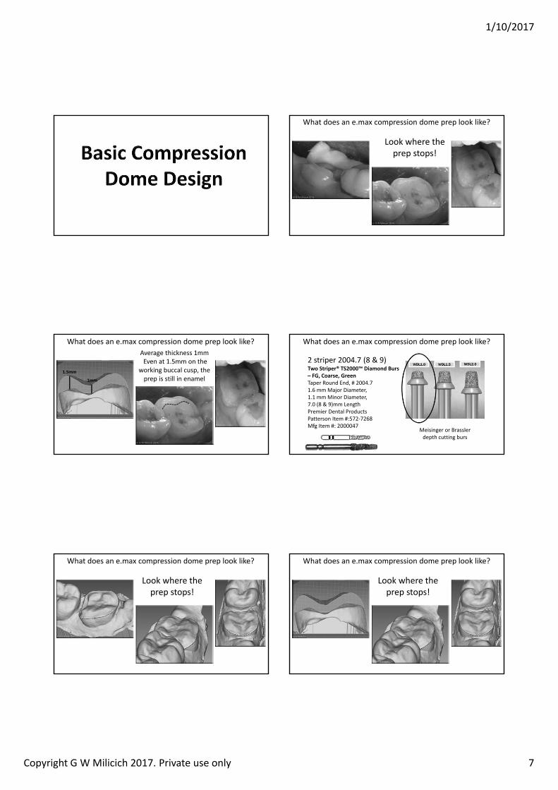
What does an e.max compression dome prep look like?
Look where the prep stops!
What does an e.max compression dome prep look like?Average thickness 1mmEven at 1.5mm on the
working buccal cusp, the prep is still in enamel
1. mm
1mm
What does an e.max compression dome prep look like?
2 striper 2004.7 (8 & 9)Two Striper TS2000 Diamond Burs
G, Coarse, GreenTaper Round End, # 2004.7 1.6 mm Major Diameter, 1.1 mm Minor Diameter, 7.0 (8 & 9)mm Length Premier Dental Products Patterson Item #:572‐7268 Mfg Item #: 2000047
Meisinger or Brasslerdepth cutting burs
What does an e.max compression dome prep look like?
Look where the prep stops!
What does an e.max compression dome prep look like?
Look where the prep stops!
1/10/2017
Copyright G W Milicich 2017. Private use only 8
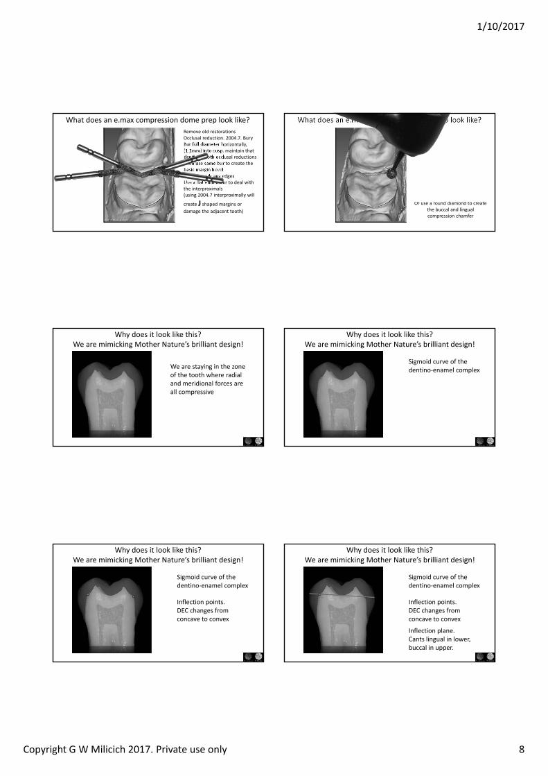
Remove old restorationsOcclusal reduction. 2004.7. Bury Bur full diameter horizontally, (1.1mm) into cusp, maintain that depth on both occlusal reductionsThen use same bur to create the basic margin bevelThen smooth any edges Use a flat ended bur to deal with the interproximals(using 2004.7 interproximally will
create J shaped margins or damage the adjacent tooth)
What does an e.max compression dome prep look like?
Or use a round diamond to create the buccal and lingual compression chamfer
What does an e.max compression dome prep look like?
Why does it look like this?We are mimicking Mother Nature’s brilliant design!
We are staying in the zone of the tooth where radial and meridional forces are all compressive
Sigmoid curve of the dentino‐enamel complex
Why does it look like this?We are mimicking Mother Nature’s brilliant design!
Sigmoid curve of the dentino‐enamel complex
Inflection points. DEC changes from concave to convex
Why does it look like this?We are mimicking Mother Nature’s brilliant design!
Sigmoid curve of the dentino‐enamel complex
Inflection plane.Cants lingual in lower, buccal in upper.
Inflection points. DEC changes from concave to convex
Why does it look like this?We are mimicking Mother Nature’s brilliant design!
1/10/2017
Copyright G W Milicich 2017. Private use only 9
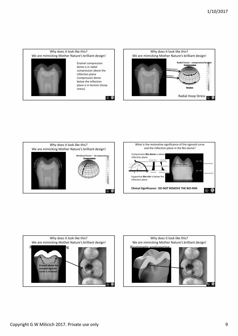
Enamel compression dome is in radial compression above the inflection planeCompression dome below the inflection plane is in tension (hoop stress)
Why does it look like this?We are mimicking Mother Nature’s brilliant design!
Radial orces compression/tension
Radial Hoop Stress
Why does it look like this?We are mimicking Mother Nature’s brilliant design!
Meridional orces all compression
Why does it look like this?We are mimicking Mother Nature’s brilliant design!
(volume enamel > volume dentin)
(volume enamel < volume dentin)
What is the restorative significance of the sigmoid curve and the inflection plane in the Bio‐dome?
Supportive Bio‐rim is below the inflection plane
Compression Bio‐dome is above the inflection plane
Clinical Significance: DO NOT REMO E THE BIO‐RIM
Inflection plane
Enamel above the concave sigmoid curve is retained
Biomimetic engineering
Why does it look like this?We are mimicking Mother Nature’s brilliant design!
Why does it look like this?We are mimicking Mother Nature’s brilliant design!
Biomimetic engineering
1/10/2017
Copyright G W Milicich 2017. Private use only 10
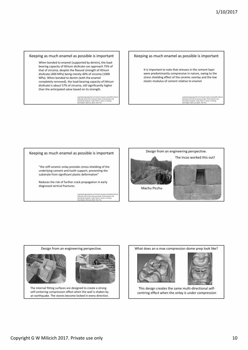
Keeping as much enamel as possible is important
Load‐bearing properties of minimal‐invasive monolithic lithium disilicate and zirconia occlusal onlays: finite element and theoretical analyses. Li Ma, Petra C. Guess, Yu Zhang.Dent Mater. 2013 Jul; 29(7): 742–751.
When bonded to enamel (supported by dentin), the load‐bearing capacity of lithium disilicate can approach 75% of that of zirconia, despite the flexural strength of lithium disilicate (400 MPa) being merely 40% of zirconia (1000 MPa). When bonded to dentin (with the enamel completely removed), the load‐bearing capacity of lithium disilicate is about 57% of zirconia, still significantly higher than the anticipated value based on its strength.
Keeping as much enamel as possible is important
Load‐bearing properties of minimal‐invasive monolithic lithium disilicate and zirconia occlusal onlays: finite element and theoretical analyses. Li Ma, Petra C. Guess, Yu Zhang.Dent Mater. 2013 Jul; 29(7): 742–751.
It is important to note that stresses in the cement layer were predominantly compressive in nature, owing to the stress shielding effect of the ceramic overlay and the low elastic modulus of cement relative to enamel
Keeping as much enamel as possible is important
Load‐bearing properties of minimal‐invasive monolithic lithium disilicate and zirconia occlusal onlays: finite element and theoretical analyses. Li Ma, Petra C. Guess, Yu Zhang.Dent Mater. 2013 Jul; 29(7): 742–751.
“the stiff ceramic onlay provides stress‐shielding of the underlying cement and tooth support, preventing the substrate from significant plastic deformation”
Reduces the risk of further crack propagation in early diagnosed vertical fractures.
Design from an engineering perspective.
The Incas worked this out!
Machu Picchu
Design from an engineering perspective.
The internal fitting surfaces are designed to create a strong self‐centering compression effect when the wall is shaken by an earthquake. The stones become locked in every direction.
What does an e.max compression dome prep look like?
This design creates the same multi‐directional self‐centring effect when the onlay is under compression

1/10/2017
Copyright G W Milicich 2017. Private use only 11
What does an e.max compression dome prep look like?
The peripheral chamfer, mainly in enamel, places the cusps in compression
What does an e.max compression dome prep look like?
Stay above the inflection plane unless previous dentistry or decay
dictates otherwise
Prism orientation and margin bevels
Unsupported enamel. Separates along the prism long axis when placed in tension. HITE LINES
Prism orientation and margin bevelsComposite shrinkage is powerful enough to pull enamel apart!
Unsupported enamel. Separates along the prism long axis when placed in tension. HITE LINES
Prism orientation and margin bevels
Supported enamel. Strong in tension.
Prism orientation and margin bevels
In the bottom of a deep proximal box, DON T cut of the last thin layer of enamel
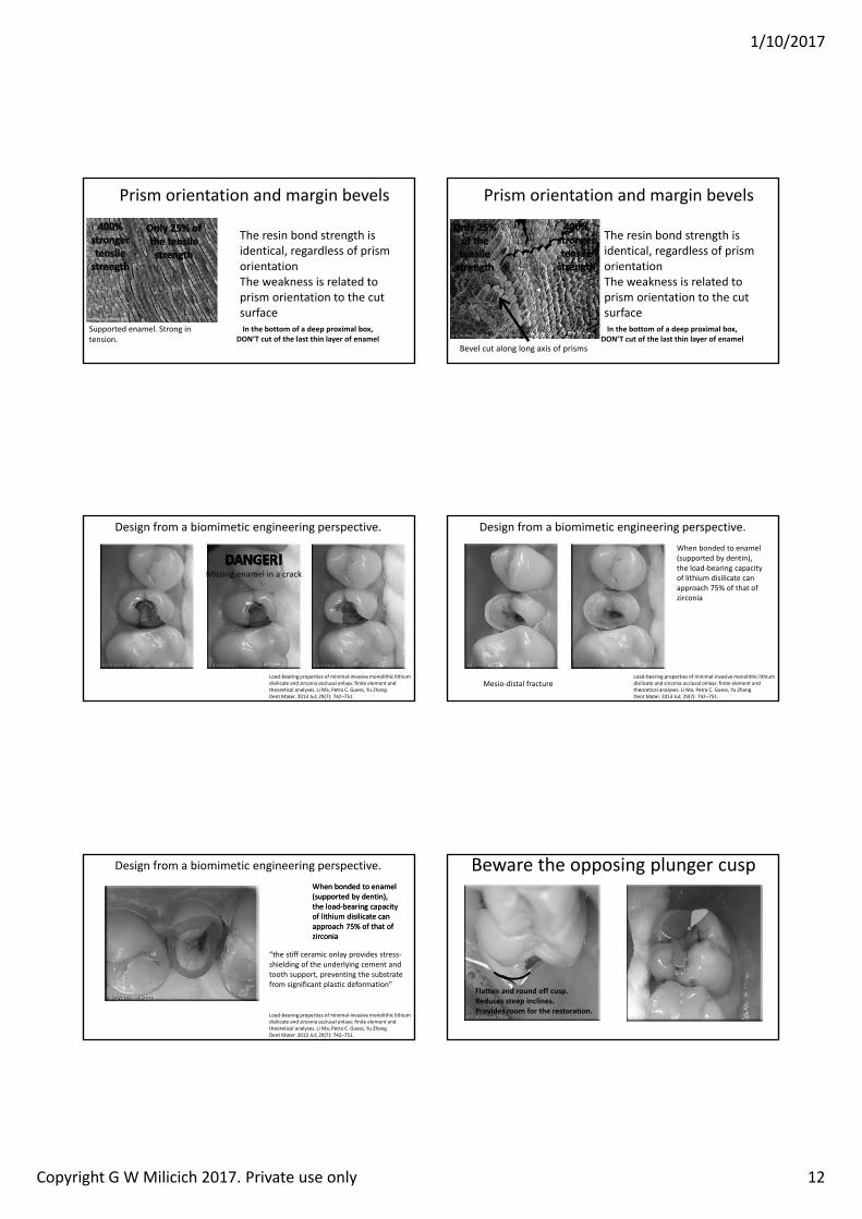
1/10/2017
Copyright G W Milicich 2017. Private use only 12
Supported enamel. Strong in tension.
Prism orientation and margin bevels
In the bottom of a deep proximal box, DON T cut of the last thin layer of enamel
The resin bond strength is identical, regardless of prism orientationThe weakness is related to prism orientation to the cut surface
Prism orientation and margin bevels
In the bottom of a deep proximal box, DON T cut of the last thin layer of enamel
The resin bond strength is identical, regardless of prism orientationThe weakness is related to prism orientation to the cut surface
Bevel cut along long axis of prisms
Load‐bearing properties of minimal‐invasive monolithic lithium disilicate and zirconia occlusal onlays: finite element and theoretical analyses. Li Ma, Petra C. Guess, Yu Zhang.Dent Mater. 2013 Jul; 29(7): 742–751.
Missing enamel in a crack
Design from a biomimetic engineering perspective.
Load‐bearing properties of minimal‐invasive monolithic lithium disilicate and zirconia occlusal onlays: finite element and theoretical analyses. Li Ma, Petra C. Guess, Yu Zhang.Dent Mater. 2013 Jul; 29(7): 742–751.
When bonded to enamel (supported by dentin), the load‐bearing capacity of lithium disilicate can approach 75% of that of zirconia
Mesio‐distal fracture
Design from a biomimetic engineering perspective.
When bonded to enamel (supported by dentin), the load‐bearing capacity of lithium disilicate can approach 75% of that of zirconia
When bonded to enamel (supported by dentin), the load‐bearing capacity of lithium disilicate can approach 75% of that of zirconia
Load‐bearing properties of minimal‐invasive monolithic lithium disilicate and zirconia occlusal onlays: finite element and theoretical analyses. Li Ma, Petra C. Guess, Yu Zhang.Dent Mater. 2013 Jul; 29(7): 742–751.
“the stiff ceramic onlay provides stress‐shielding of the underlying cement and tooth support, preventing the substrate from significant plastic deformation”
Design from a biomimetic engineering perspective. Beware the opposing plunger cusp
latten and round off cusp.Reduces steep inclines.Provides room for the restoration.
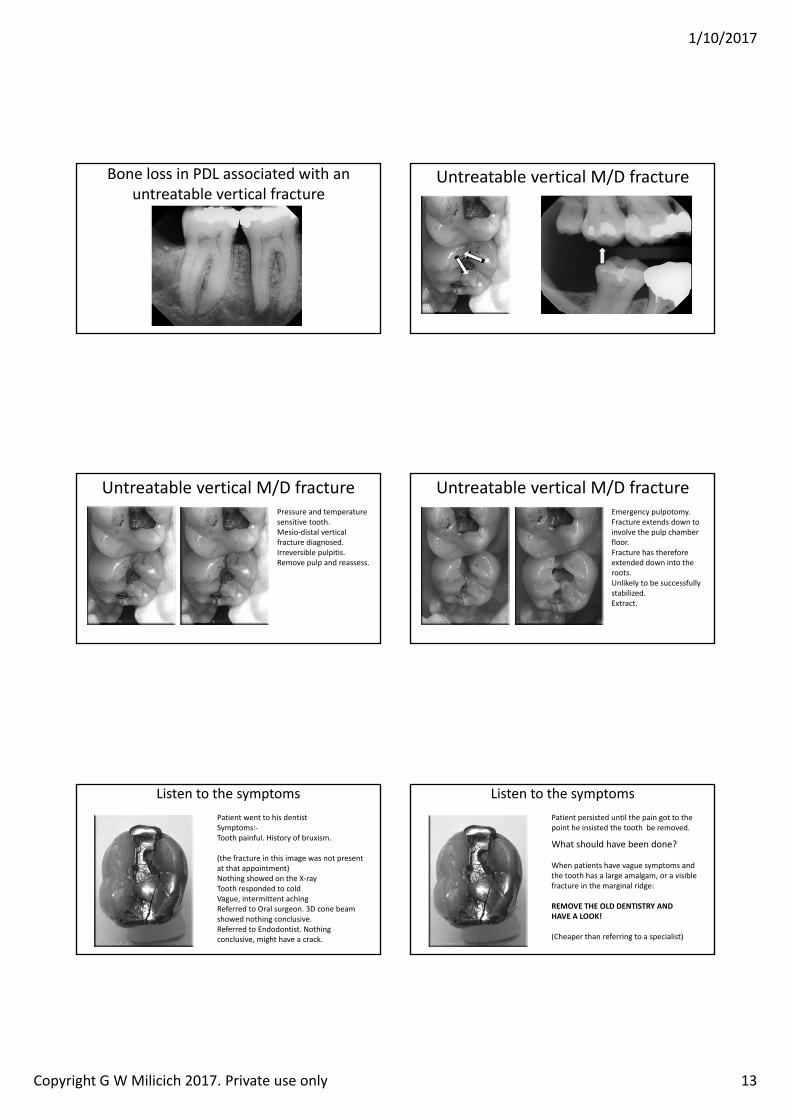
1/10/2017
Copyright G W Milicich 2017. Private use only 13
Bone loss in PDL associated with an untreatable vertical fracture
Untreatable vertical M/D fracture
Untreatable vertical M/D fracturePressure and temperature sensitive tooth.Mesio‐distal vertical fracture diagnosed.Irreversible pulpitis.Remove pulp and reassess.
Untreatable vertical M/D fractureEmergency pulpotomy.Fracture extends down to involve the pulp chamber floor.Fracture has therefore extended down into the roots.Unlikely to be successfully stabilized.Extract.
Listen to the symptomsPatient went to his dentistSymptoms:‐Tooth painful. History of bruxism.
(the fracture in this image was not present at that appointment)Nothing showed on the X‐rayTooth responded to coldVague, intermittent achingReferred to Oral surgeon. 3D cone beam showed nothing conclusive.Referred to Endodontist. Nothing conclusive, might have a crack.
Altered image
Listen to the symptomsPatient persisted until the pain got to the point he insisted the tooth be removed.
What should have been done?
When patients have vague symptoms and the tooth has a large amalgam, or a visible fracture in the marginal ridge:
REMO E THE OLD DENTISTR ANDHA E A LOO !
(Cheaper than referring to a specialist)
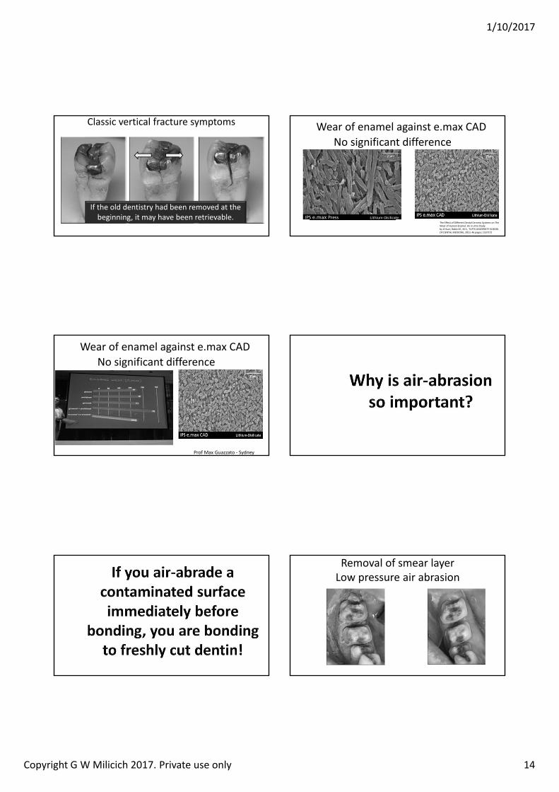
1/10/2017
Copyright G W Milicich 2017. Private use only 14
Classic vertical fracture symptoms
If the old dentistry had been removed at the beginning, it may have been retrievable.
Wear of enamel against e.max CADNo significant difference
The Effect of Different Dental Ceramic Systems on The Wear of Human Enamel: An in vitro Study by E huni Rabie ., M.S., TUFTS UNIVERSITY SCHOOL OF DENTAL MEDICINE, 2013, 46 pages; 1537272
Wear of enamel against e.max CADNo significant difference
Prof Max Guazzato ‐ Sydney
Removal of smear layerLow pressure air abrasion
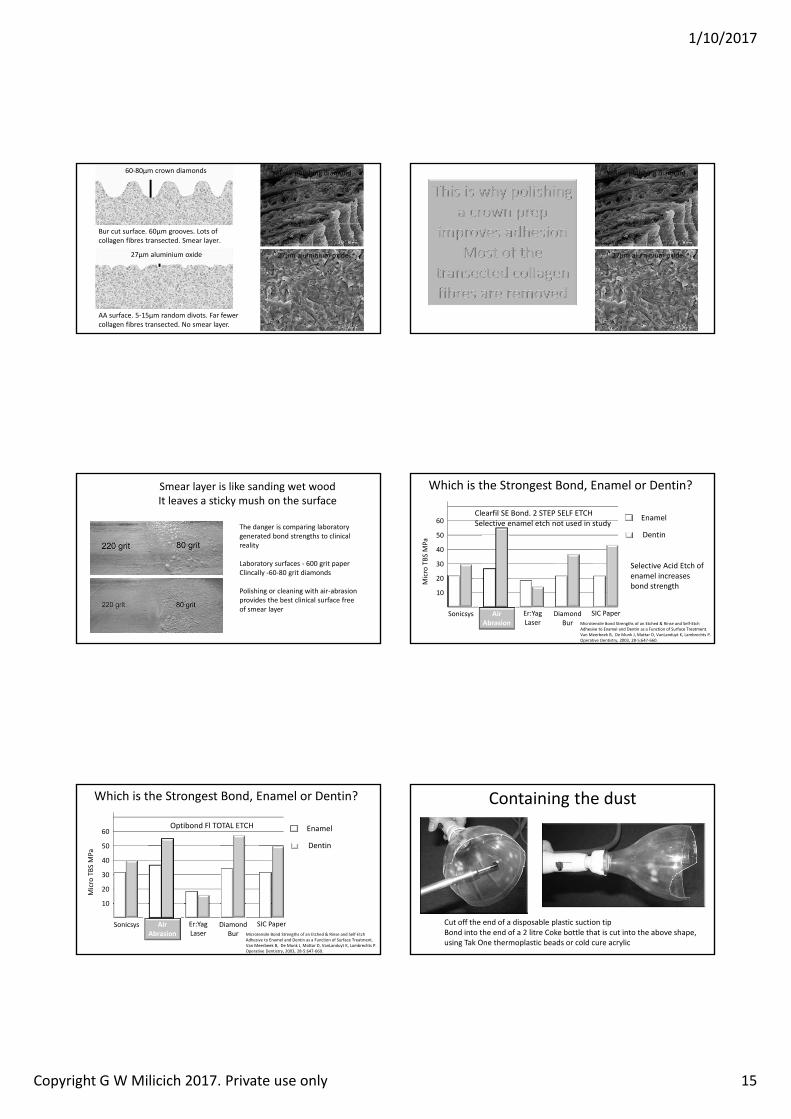
1/10/2017
Copyright G W Milicich 2017. Private use only 15
Bur cut surface. 60µm grooves. Lots of collagen fibres transected. Smear layer.
Yellow polishing diamond60‐80µm crown diamonds
AA surface. 5‐15µm random divots. Far fewer collagen fibres transected. No smear layer.
27µm aluminium oxide 27µm aluminium oxide
Yellow polishing diamond
27µm aluminium oxide
Smear layer is like sanding wet woodIt leaves a sticky mush on the surface
The danger is comparing laboratory generated bond strengths to clinical reality
Laboratory surfaces ‐ 600 grit paperClincally ‐60‐80 grit diamonds
Polishing or cleaning with air‐abrasion provides the best clinical surface free of smear layer
Which is the Strongest Bond, Enamel or Dentin?
Microtensile Bond Strengths of an Etched & Rinse and Self‐Etch Adhesive to Enamel and Dentin as a Function of Surface Treatment.Van Meerbeek B, De Munk J, Mattar D, VanLanduyt K, Lambrechts P.Operative Dentistry, 2003, 28‐5:647‐660.
10
20
30
40
50
60
Micro TBS
MPa
Air Abrasion
Sonicsys Er:YagLaser
Diamond Bur
Enamel
Dentin
SIC Paper
Selective Acid Etch of enamel increases bond strength
Clearfil SE Bond. 2 STEP SELF ETCHSelective enamel etch not used in study
Which is the Strongest Bond, Enamel or Dentin?
Microtensile Bond Strengths of an Etched & Rinse and Self‐Etch Adhesive to Enamel and Dentin as a Function of Surface Treatment.Van Meerbeek B, De Munk J, Mattar D, VanLanduyt K, Lambrechts P.Operative Dentistry, 2003, 28‐5:647‐660.
10
20
30
40
50
60
Micro TBS
MPa
Air Abrasion
Sonicsys Er:YagLaser
Diamond Bur
Enamel
Dentin
Optibond Fl TOTAL ETCH
SIC Paper
Containing the dust
Cut off the end of a disposable plastic suction tipBond into the end of a 2 litre Coke bottle that is cut into the above shape, using Tak One thermoplastic beads or cold cure acrylic
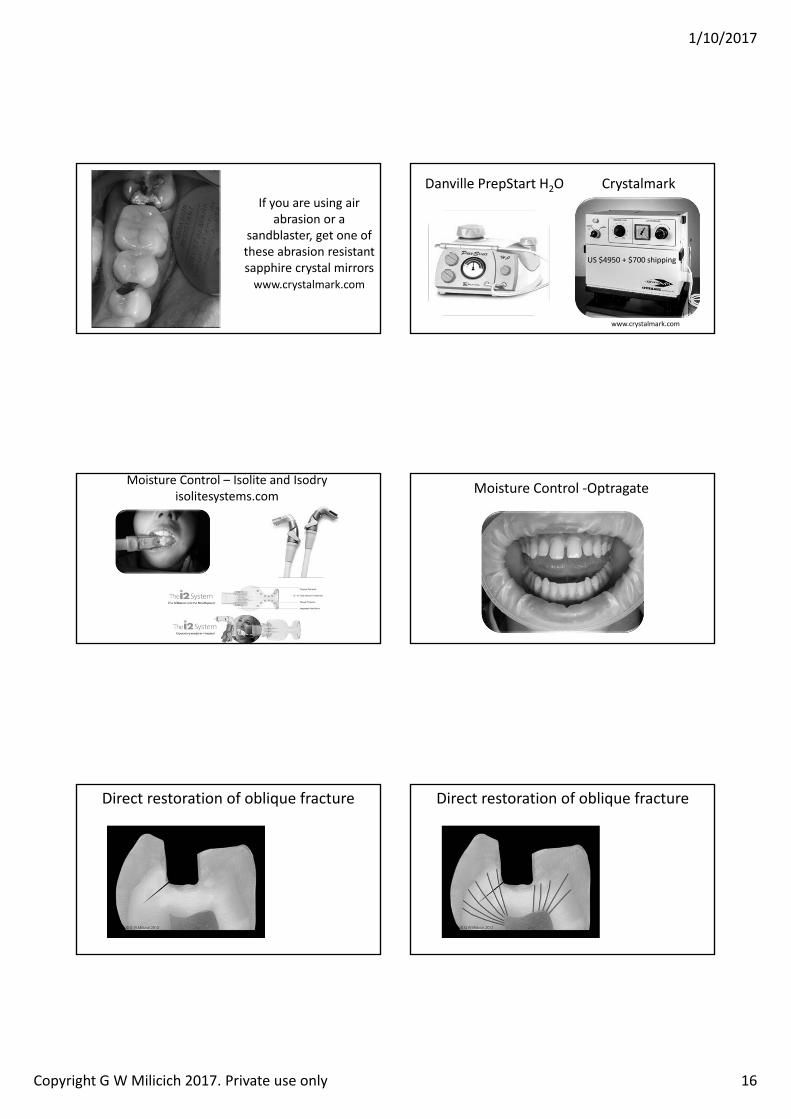
1/10/2017
Copyright G W Milicich 2017. Private use only 16
If you are using air abrasion or a
sandblaster, get one of these abrasion resistant sapphire crystal mirrorswww.crystalmark.com
Danville PrepStart H2O Crystalmark
www.crystalmark.com
US 4950 700 shipping
Moisture Control – Isolite and Isodryisolitesystems.com Moisture Control ‐Optragate
Direct restoration of oblique fracture Direct restoration of oblique fracture
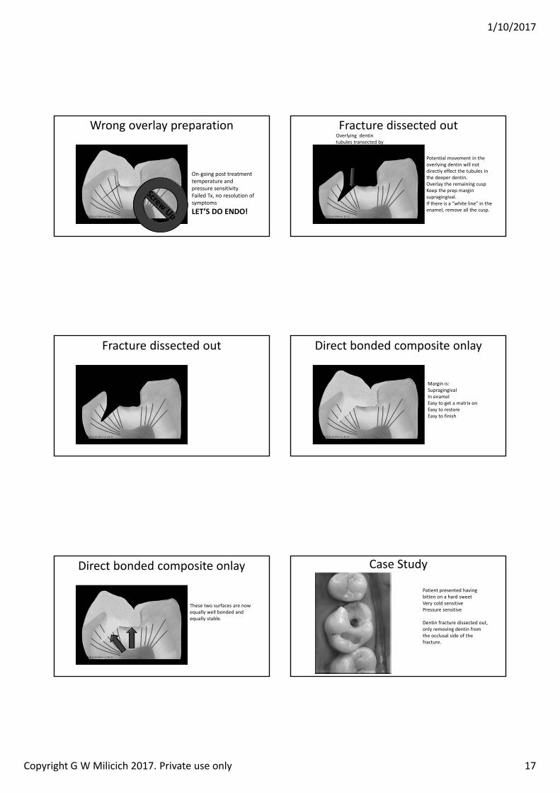
1/10/2017
Copyright G W Milicich 2017. Private use only 17
Wrong overlay preparation
On‐going post treatment temperature and pressure sensitivityFailed Tx, no resolution of symptomsLET S DO ENDO!
Fracture dissected out
Potential movement in the overlying dentin will not directly effect the tubules in the deeper dentin.Overlay the remaining cuspKeep the prep margin supragingival.If there is a “white line” in the enamel, remove all the cusp.
Overlying dentin tubules transected by the crack are now disconnected from the underlying dentin.
Fracture dissected out Direct bonded composite onlay
Margin is:SupragingivalIn enamelEasy to get a matrix onEasy to restoreEasy to finish
Direct bonded composite onlay
These two surfaces are now equally well bonded and equally stable.
Case Study
Patient presented having bitten on a hard sweetVery cold sensitivePressure sensitive
Dentin fracture dissected out, only removing dentin from the occlusal side of the fracture.
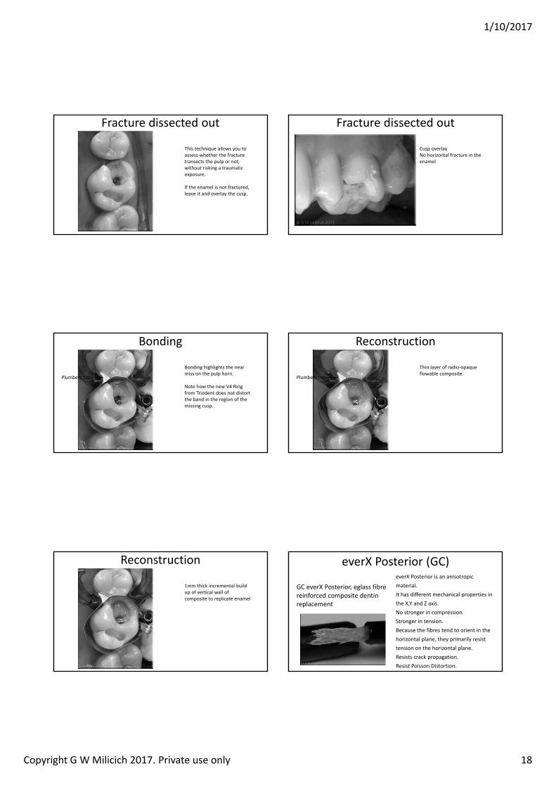
1/10/2017
Copyright G W Milicich 2017. Private use only 18
Fracture dissected out
This technique allows you to assess whether the fracture transects the pulp or not, without risking a traumatic exposure.
If the enamel is not fractured, leave it and overlay the cusp.
Fracture dissected out
Cusp overlay No horizontal fracture in the enamel
Bonding
Bonding highlights the near miss on the pulp horn.
Note how the new V4 Ring from Triodent does not distort the band in the region of the missing cusp.
Plumbers tape
Reconstruction
Thin layer of radio‐opaque flowable composite
Plumbers tape
Reconstruction
1mm thick incremental build up of vertical wall of composite to replicate enamel
everX Posterior (GC)
GC everX Posterior, eglass fibre reinforced composite dentin replacement
everX Posterior is an anisotropic material.It has different mechanical properties in the X,Y and Z axis.No stronger in compression.Stronger in tension. Because the fibres tend to orient in the horizontal plane, they primarily resist tension on the horizontal plane. Resists crack propagation.Resist Poisson Distortion.
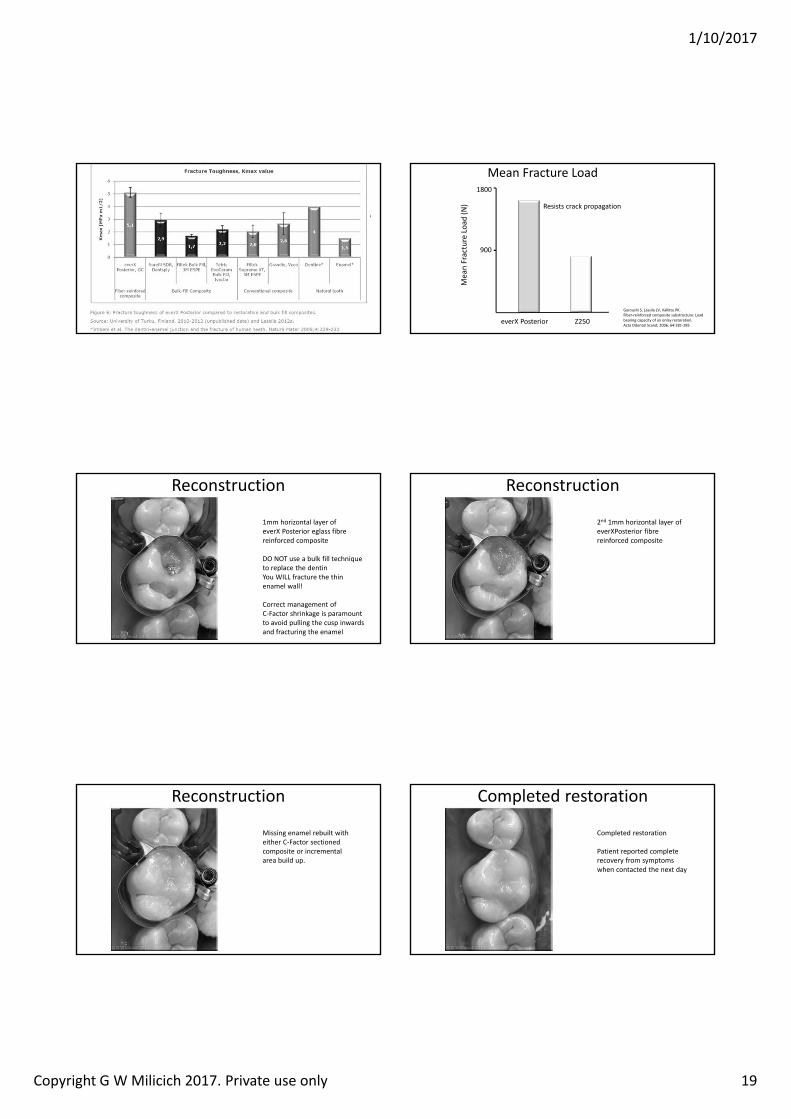
1/10/2017
Copyright G W Milicich 2017. Private use only 19
• GC EverXPosterior fibre reinforced composite placed into the core of the cavity
• 2mm below occlusal table (to leave room for the final e.max onlay)
Crack Limiting and Stress Reduction Core
Mea
n Fracture Loa
d (N)
1800
900
everX Posterior Z250
Mean Fracture Load
Garoushi S, Lassila LV, Vallittu PK. Fiber‐reinforced composite substructure: Load bearing capacity of an onlay restoration. Acta Odontol Scand; 2006, 64:281‐285
Resists crack propagation
Reconstruction
1mm horizontal layer of everX Posterior eglass fibre reinforced composite
DO NOT use a bulk fill technique to replace the dentinYou WILL fracture the thin enamel wall!
Correct management of C‐Factor shrinkage is paramount to avoid pulling the cusp inwards and fracturing the enamel
Reconstruction
2nd 1mm horizontal layer of everXPosterior fibre reinforced composite
Reconstruction
Missing enamel rebuilt with either C‐Factor sectioned composite or incremental area build up.
Completed restoration
Completed restoration
Patient reported complete recovery from symptoms when contacted the next day
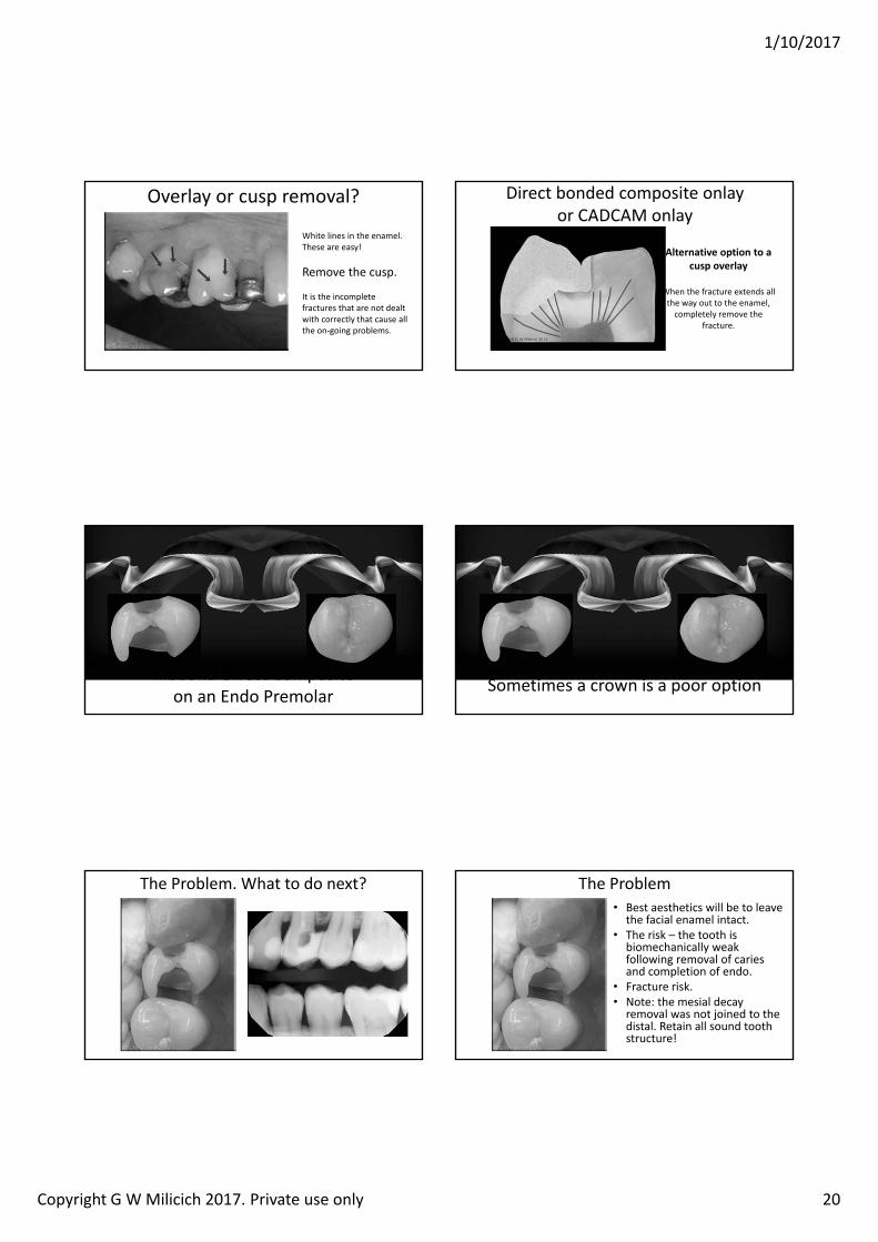
1/10/2017
Copyright G W Milicich 2017. Private use only 20
Overlay or cusp removal?
White lines in the enamel.These are easy!
Remove the cusp.
It is the incomplete fractures that are not dealt with correctly that cause all the on‐going problems.
Alternative option to a cusp overlay
When the fracture extends all the way out to the enamel,completely remove the
fracture.
Direct bonded composite onlayor CADCAM onlay
Ribbond‐Direct Compositeon an Endo Premolar Sometimes a crown is a poor option
The Problem. What to do next?• Best aesthetics will be to leave
the facial enamel intact.• The risk – the tooth is
biomechanically weak following removal of caries and completion of endo.
• Fracture risk.• Note: the mesial decay
removal was not joined to the distal. Retain all sound tooth structure!
The Problem
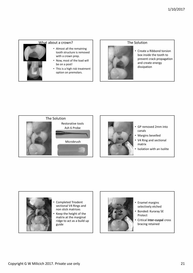
1/10/2017
Copyright G W Milicich 2017. Private use only 21
• Almost all the remaining tooth structure is removed with a crown prep.
• Now, most of the load will be on a post!
• This is a high risk treatment option on premolars.
What about a crown?
• Create a Ribbond torsion box inside the tooth to prevent crack propagation and create energy dissipation
The Solution
The SolutionRestorative toolsAsh 6 Probe
Microbrush
• GP removed 2mm into canals
• Margins bevelled• V4 Ring and sectional matrix
• Isolation with an Isolite
• Completed Triodentsectional V4 Rings and non stick matrices
• Keep the height of the matrix at the marginal ridge to act as a build up guide
• Enamel margins selectively etched
• Bonded: Kuraray SE Protect
• Critical cross bracing retained
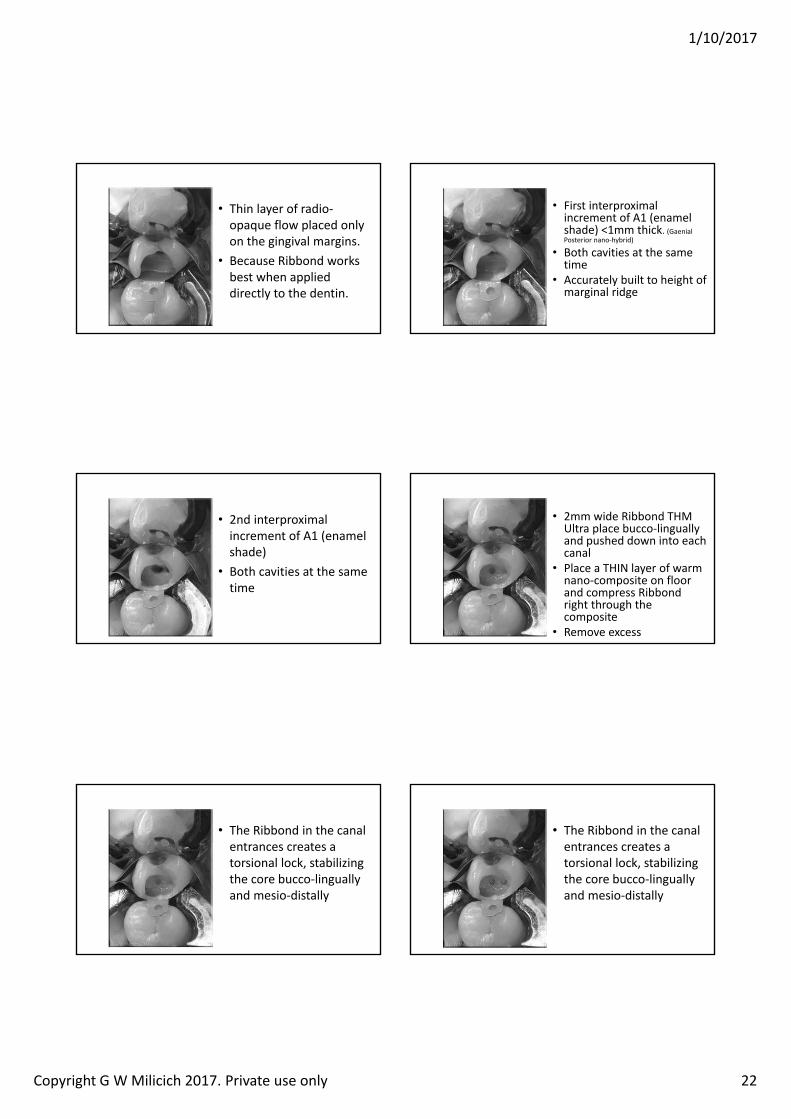
1/10/2017
Copyright G W Milicich 2017. Private use only 22
• Thin layer of radio‐opaque flow placed only on the gingival margins.
• Because Ribbond works best when applied directly to the dentin.
• First interproximal increment of A1 (enamel shade) <1mm thick. (GaenialPosterior nano‐hybrid)
• Both cavities at the same time
• Accurately built to height of marginal ridge
• 2nd interproximal increment of A1 (enamel shade)
• Both cavities at the same time
• 2mm wide Ribbond THM Ultra place bucco‐linguallyand pushed down into each canal
• Place a THIN layer of warm nano‐composite on floor and compress Ribbond right through the composite
• Remove excess
• The Ribbond in the canal entrances creates a torsional lock, stabilizing the core bucco‐linguallyand mesio‐distally
• The Ribbond in the canal entrances creates a torsional lock, stabilizing the core bucco‐linguallyand mesio‐distally
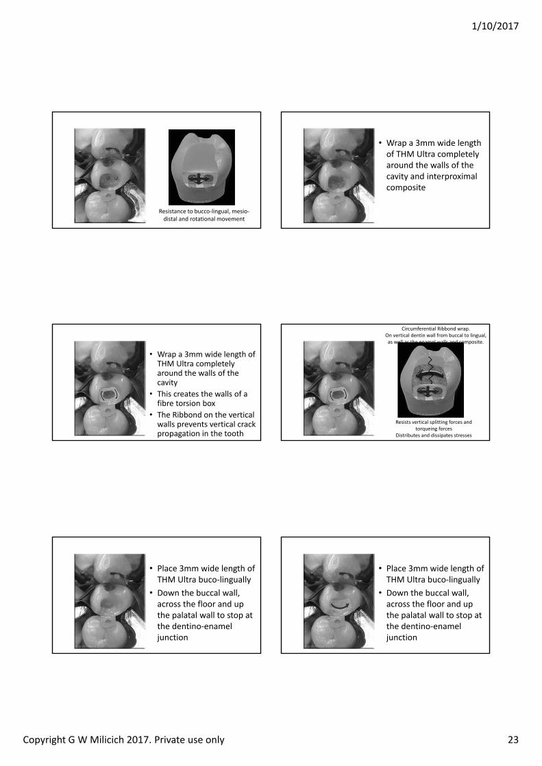
1/10/2017
Copyright G W Milicich 2017. Private use only 23
Resistance to bucco‐lingual, mesio‐distal and rotational movement
• Wrap a 3mm wide length of THM Ultra completely around the walls of the cavity and interproximal composite
• Wrap a 3mm wide length of THM Ultra completely around the walls of the cavity
• This creates the walls of a fibre torsion box
• The Ribbond on the vertical walls prevents vertical crack propagation in the tooth
Circumferential Ribbond wrap. On vertical dentin wall from buccal to lingual, as well as the enamel walls and composite.
Resists vertical splitting forces and torqueing forces
Distributes and dissipates stresses
• Place 3mm wide length of THM Ultra buco‐lingually
• Down the buccal wall, across the floor and up the palatal wall to stop at the dentino‐enamel junction
• Place 3mm wide length of THM Ultra buco‐lingually
• Down the buccal wall, across the floor and up the palatal wall to stop at the dentino‐enamel junction
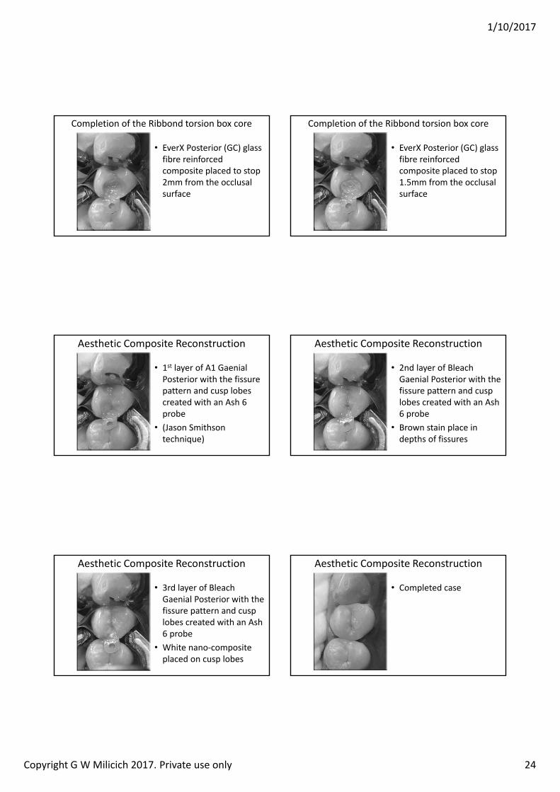
1/10/2017
Copyright G W Milicich 2017. Private use only 24
• EverX Posterior (GC) glass fibre reinforced composite placed to stop 2mm from the occlusal surface
Completion of the Ribbond torsion box core
• EverX Posterior (GC) glass fibre reinforced composite placed to stop 1.5mm from the occlusal surface
Completion of the Ribbond torsion box core
• 1st layer of A1 GaenialPosterior with the fissure pattern and cusp lobes created with an Ash 6 probe
• (Jason Smithson technique)
Aesthetic Composite Reconstruction
• 2nd layer of Bleach Gaenial Posterior with the fissure pattern and cusp lobes created with an Ash 6 probe
• Brown stain place in depths of fissures
Aesthetic Composite Reconstruction
• 3rd layer of Bleach Gaenial Posterior with the fissure pattern and cusp lobes created with an Ash 6 probe
• White nano‐composite placed on cusp lobes
Aesthetic Composite Reconstruction
• Completed case
Aesthetic Composite Reconstruction
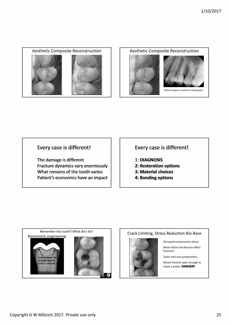
1/10/2017
Copyright G W Milicich 2017. Private use only 25
Aesthetic Composite Reconstruction Aesthetic Composite Reconstruction
Ribbond appears mottled in Radiographs
Remember this tooth? What did I do?
Enamel above the concave sigmoid curve is retained
Biomimetic engineeringDisrupted compression dome.
Mesio‐distal and Poisson effect fractures.
Tooth vital and symptomless.
Mesial fracture open enough to retain a probe.
Crack Limiting, Stress Reduction Bio‐Base
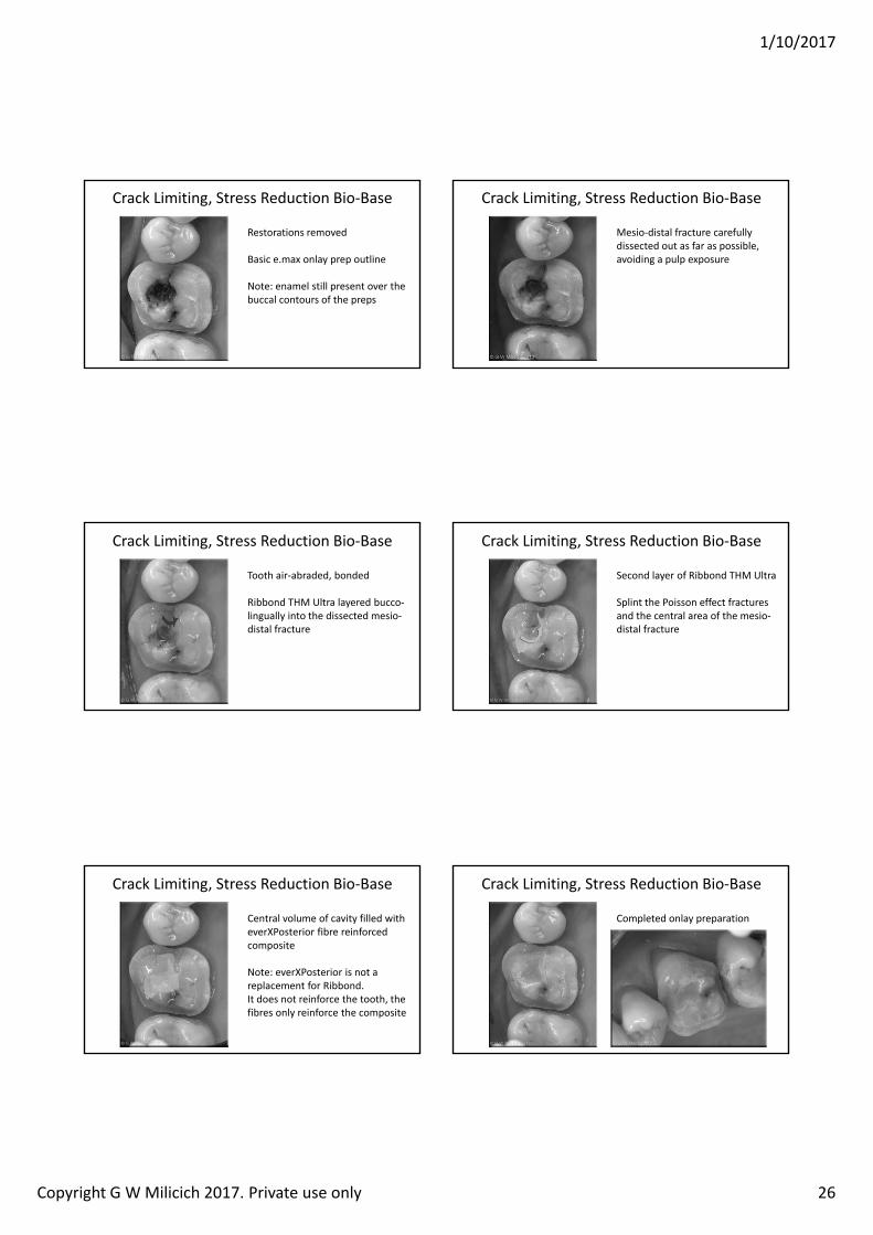
1/10/2017
Copyright G W Milicich 2017. Private use only 26
Restorations removed
Basic e.max onlay prep outline
Note: enamel still present over the buccal contours of the preps
Crack Limiting, Stress Reduction Bio‐Base
Mesio‐distal fracture carefully dissected out as far as possible, avoiding a pulp exposure
Crack Limiting, Stress Reduction Bio‐Base
Tooth air‐abraded, bonded
Ribbond THM Ultra layered bucco‐lingually into the dissected mesio‐distal fracture
Crack Limiting, Stress Reduction Bio‐Base
Second layer of Ribbond THM Ultra
Splint the Poisson effect fractures and the central area of the mesio‐distal fracture
Crack Limiting, Stress Reduction Bio‐Base
Central volume of cavity filled with everXPosterior fibre reinforced composite
Note: everXPosterior is not a replacement for Ribbond. It does not reinforce the tooth, the fibres only reinforce the composite
Crack Limiting, Stress Reduction Bio‐Base
Completed onlay preparation
Crack Limiting, Stress Reduction Bio‐Base
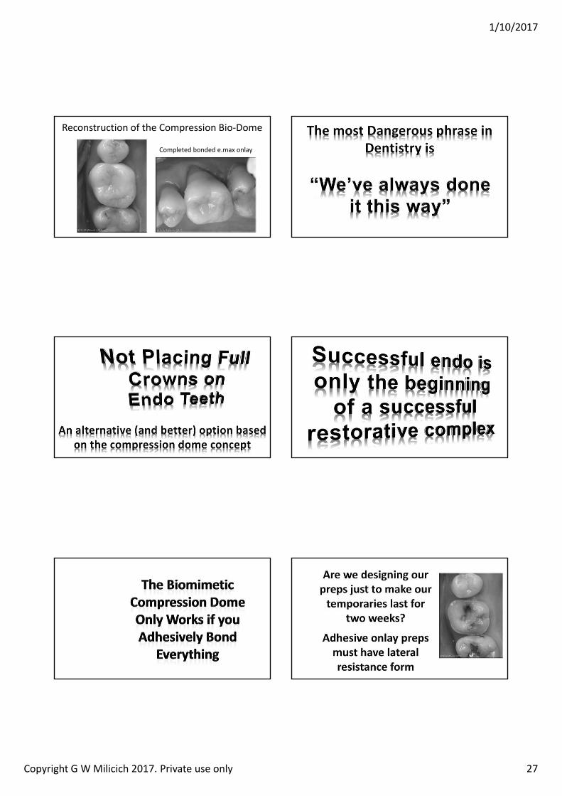
1/10/2017
Copyright G W Milicich 2017. Private use only 27
Reconstruction of the Compression Bio‐Dome
Completed bonded e.max onlay
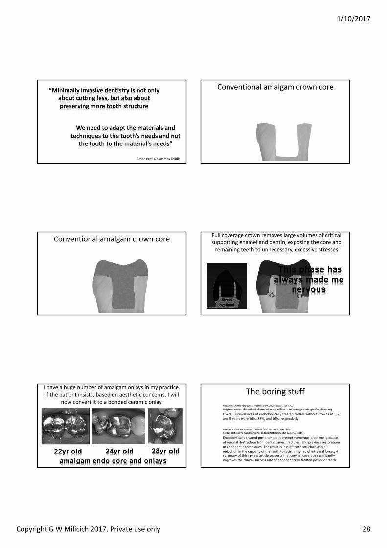
1/10/2017
Copyright G W Milicich 2017. Private use only 28
Assoc Prof. Dr Kosmas Tolidis
Conventional amalgam crown core
Conventional amalgam crown core Full coverage crown removes large volumes of critical supporting enamel and dentin, exposing the core and remaining teeth to unnecessary, excessive stresses
Lost energy dissipation
I have a huge number of amalgam onlays in my practice. If the patient insists, based on aesthetic concerns, I will
now convert it to a bonded ceramic onlay.
amalgam endo core and onlays
The boring stuffNagasiri R, Chitmongkolsuk S.J Prosthet Dent. 2005 Feb;93(2):164‐70.Long‐term survival of endodontically treated molars without crown coverage: a retrospective cohort study.
Overall survival rates of endodontically treated molars without crowns at 1, 2, and 5 years were 96%, 88%, and 36%, respectively.
Tikku AP, Chandra A, Bharti R.J Conserv Dent. 2010 Oct;13(4):246‐8.Are full cast crowns mandatory after endodontic treatment in posterior teeth
Endodontically treated posterior teeth present numerous problems because of coronal destruction from dental caries, fractures, and previous restorations or endodontic techniques. The result is loss of tooth structure and a reduction in the capacity of the tooth to resist a myriad of intraoral forces. A summary of this review article suggests that coronal coverage significantly improves the clinical success rate of endodontically treated posterior teeth.
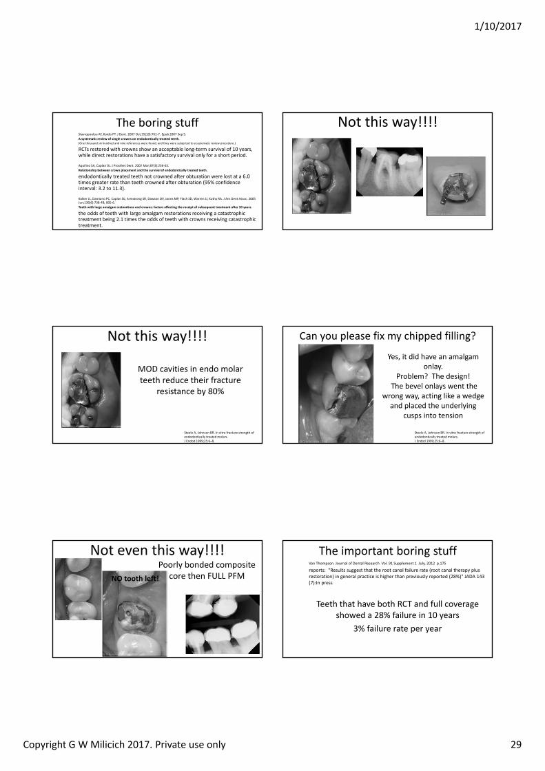
1/10/2017
Copyright G W Milicich 2017. Private use only 29
The boring stuffStavropoulou AF, Koidis PT. J Dent. 2007 Oct;35(10):761‐7. Epub 2007 Sep 5.A systematic review of single crowns on endodontically treated teeth.(One thousand six hundred and nine references were found, and they were subjected to a systematic review procedure.)
RCTs restored with crowns show an acceptable long‐term survival of 10 years, while direct restorations have a satisfactory survival only for a short period.
Aquilino SA, Caplan DJ. J Prosthet Dent. 2002 Mar;87(3):256‐63.Relationship between crown placement and the survival of endodontically treated teeth.
endodontically treated teeth not crowned after obturation were lost at a 6.0 times greater rate than teeth crowned after obturation (95% confidence interval: 3.2 to 11.3).
Kolker JL, Damiano PC, Caplan DJ, Armstrong SR, Dawson DV, Jones MP, Flach SD, Warren JJ, Kuthy RA. J Am Dent Assoc. 2005 Jun;136(6):738‐48; 805‐6.Teeth with large amalgam restorations and crowns: factors affecting the receipt of subsequent treatment after 10 years.
the odds of teeth with large amalgam restorations receiving a catastrophic treatment being 2.1 times the odds of teeth with crowns receiving catastrophic treatment.
Not this way!!!!
Not this way!!!!
MOD cavities in endo molar teeth reduce their fracture
resistance by 80%
Steele A, Johnson BR. In vitro fracture strength of endodontically treated molars.J Endod 1999;25:6–8.
Can you please fix my chipped filling?
Yes, it did have an amalgam onlay.
Problem? The design!The bevel onlays went the
wrong way, acting like a wedge and placed the underlying
cusps into tension
Steele A, Johnson BR. In vitro fracture strength of endodontically treated molars.J Endod 1999;25:6–8.
Not even this way!!!!Poorly bonded composite
core then FULL PFMNO tooth left!
The important boring stuffVan Thompson. Journal of Dental Research Vol. 91 Supplement 1 July, 2012 p.175
reports: Results suggest that the root canal failure rate (root canal therapy plus restoration) in general practice is higher than previously reported (28%) JADA 143 (7):In press
Teeth that have both RCT and full coverage showed a 28% failure in 10 years
3% failure rate per year
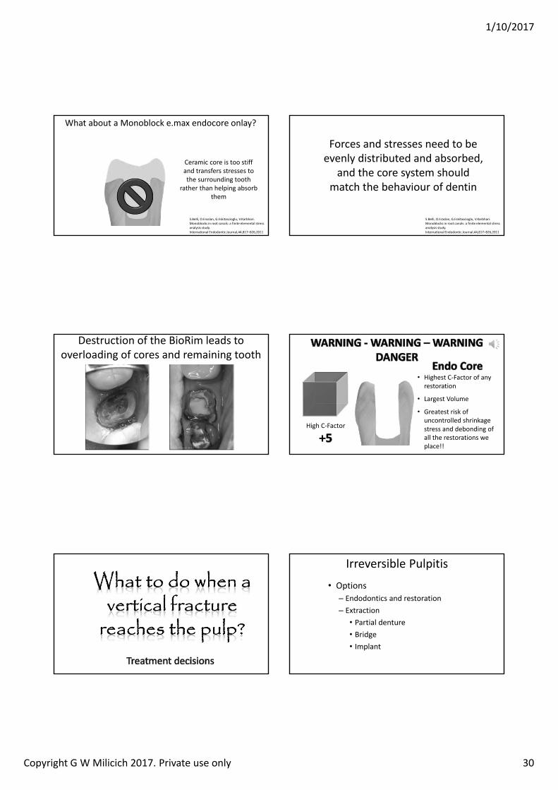
1/10/2017
Copyright G W Milicich 2017. Private use only 30
What about a Monoblock e.max endocore onlay?
Ceramic core is too stiff and transfers stresses to the surrounding tooth
rather than helping absorb them
S.Belli, O.Eraslan, G.Eskitascioglu, V.Karbhari. Monoblocks in root canals: a finite elemental stress analysis study. International Endodontic Journal,44,817–826,2011
Forces and stresses need to be evenly distributed and absorbed,
and the core system should match the behaviour of dentin
S.Belli, O.Eraslan, G.Eskitascioglu, V.Karbhari. Monoblocks in root canals: a finite elemental stress analysis study. International Endodontic Journal,44,817–826,2011
Destruction of the BioRim leads tooverloading of cores and remaining tooth
High C‐Factor
• Highest C‐Factor of any restoration
• Largest Volume
• Greatest risk of uncontrolled shrinkage stress and debonding of all the restorations we place!!
Irreversible Pulpitis
• OptionsEndodontics and restorationExtraction• Partial denture• Bridge• Implant
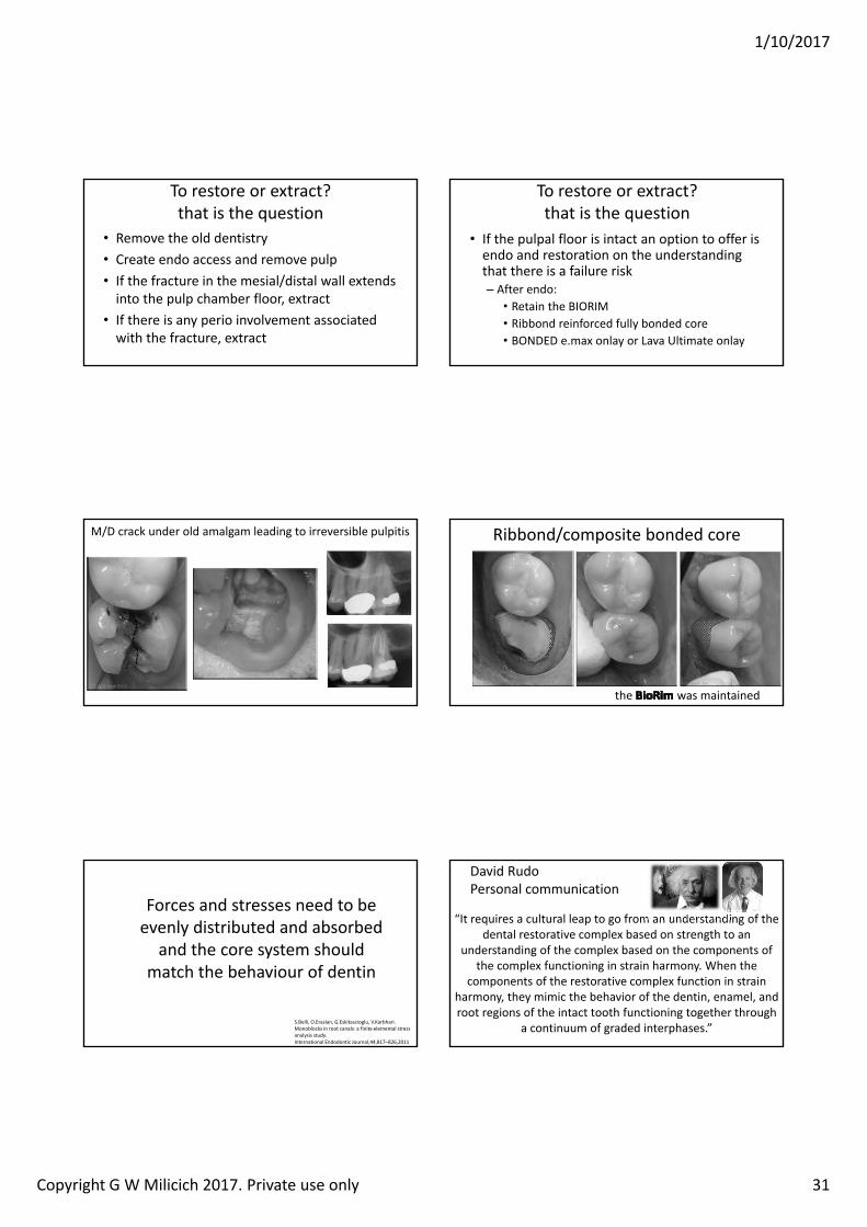
1/10/2017
Copyright G W Milicich 2017. Private use only 31
To restore or extract?that is the question
• Remove the old dentistry• Create endo access and remove pulp• If the fracture in the mesial/distal wall extends into the pulp chamber floor, extract
• If there is any perio involvement associated with the fracture, extract
To restore or extract?that is the question
• If the pulpal floor is intact an option to offer is endo and restoration on the understanding that there is a failure risk
After endo:• Retain the BIORIM• Ribbond reinforced fully bonded core• BONDED e.max onlay or Lava Ultimate onlay
M/D crack under old amalgam leading to irreversible pulpitis Ribbond/composite bonded core
the was maintained
Forces and stresses need to be evenly distributed and absorbed
and the core system should match the behaviour of dentin
S.Belli, O.Eraslan, G.Eskitascioglu, V.Karbhari. Monoblocks in root canals: a finite elemental stress analysis study. International Endodontic Journal,44,817–826,2011
David RudoPersonal communication
“It requires a cultural leap to go from an understanding of the dental restorative complex based on strength to an
understanding of the complex based on the components of the complex functioning in strain harmony. When the
components of the restorative complex function in strain harmony, they mimic the behavior of the dentin, enamel, and root regions of the intact tooth functioning together through
a continuum of graded interphases.”
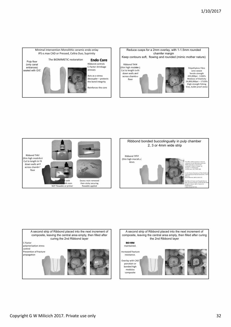
1/10/2017
Copyright G W Milicich 2017. Private use only 32
Minimal intervention Monolithic ceramic endo onlay IPS e.max CAD or Pressed, Celtra Duo, Suprinity
ulp loor onl canal entrances
sealed with I
The BIOMIMETIC restorationRibbond controls C‐Factor shrinkage stresses
Acts as a stress decoupler – protects the bond integrity
Reinforces the core
educe cusps or a mm o erla with mm rounded cham er mar in
eep contours so t lowin and rounded mimic mother nature
Ribbond THM(thin high modulus)Cut to length to fit down walls and across chamber
floor
Polyethylene FibreLeno weave
Tensile strength 435,000psi ‐ 3.0GPaModulus of Elasticity
24,800,000psi – 171GPa(high strength fishing
lines, bullet proof vests)
Ribbond THM(thin high modulus)Cut to length to fit down walls and across chamber
floor
Wetted first with unfilled BISGMA resin NOT flowable or primer
Excess resin removed then sticky securing flowable applied
i ond onded uccolin uall in pulp cham er or mm wide strip
The Effect of C‐Factor and Flowable Resin or Fiber Use at the Interface on Microtensile Bond Strength to Dentin. Belli S, Donemz N, Eskitasciogiu G. J Adhes Dent;8:247‐253.
In vitro Fracture Resistance of Fiber Reinforced Cusp‐replacing Composite Restorations. Fennis WM et alDental Materials 2005;21:565‐572
Ribbond THM (thin high modulus)
4mm The effect of fibre insertion on fracture resistance of root filled molar teeth with MOD preparations restored with composite. S. Bellil, A. Erdemir, M . Ozcopurr, G. Eskitascioglu.Int Endo Journ, 38, 73‐80, 2005
second strip o i ond placed into the next increment o composite lea in the central area empt then illed a ter
curin the nd i ond la erC‐Factor polymerization stress controlPrevention of fracture propagation
second strip o i ond placed into the next increment o composite lea in the central area empt then illed a ter curin
the nd i ond la er
maintained.
Increased fracture resistance.
Overlay with CAD porcelain or bonded high modulus composite
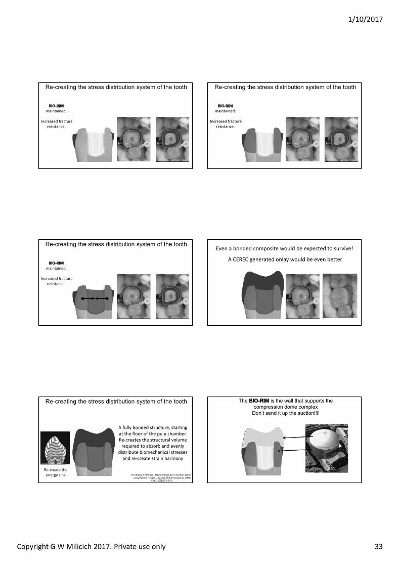
1/10/2017
Copyright G W Milicich 2017. Private use only 33
e creatin the stress distri ution s stem o the tooth
maintained.
Increased fracture resistance.
e creatin the stress distri ution s stem o the tooth
maintained.
Increased fracture resistance.
e creatin the stress distri ution s stem o the tooth
maintained.
Increased fracture resistance.
Even a bonded composite would be expected to survive!
A CEREC generated onlay would be even better
Lost energy dissipation
A fully bonded structure, starting at the floor of the pulp chamber. Re‐creates the structural volume required to absorb and evenly
distribute biomechanical stresses and re‐create strain harmony
e creatin the stress distri ution s stem o the tooth
R Z Wang, S Weiner. Strain Structure in human teeth using Moiré fringes. Journal of Biomechanics 1998
Feb;31(2):135‐141.
Re‐create the energy sink
The is the wall that supports the compression dome complex
Don’t send it up the suction!!!!
Pantheon ‐ Rome
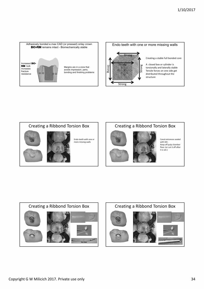
1/10/2017
Copyright G W Milicich 2017. Private use only 34
dhesi el onded e max D or pressed onla crownremains intact iomechanicall sta le
Increased ul
increases racture resistance
ar ins are in a one that a oids impression perio
ondin and inishin pro lems
ndo teeth with one or more missin walls
Creating a stable full bonded core
A closed box or cylinder is torsionally and laterally stableTensile forces on one side get distributed throughout the structure
Strong
Strong Strong
Strong
Strong
Creating a Ribbond Torsion Box
Endo teeth with one or more missing walls
Creating a Ribbond Torsion Box
Canal entrances sealed with GIC. Keep off pulp chamber floor. (or cut it off after it is set.)
Creating a Ribbond Torsion Box Creating a Ribbond Torsion Box
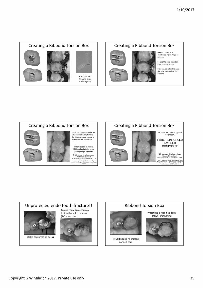
1/10/2017
Copyright G W Milicich 2017. Private use only 35
Creating a Ribbond Torsion Box
A 2nd piece of Ribbond is run buccolingually
Creating a Ribbond Torsion BoxDIRECT COMPOSITETwo buccolingual strips of Ribbond
Ensure the cusp reduction leaves enough room
Slots can be cut in the cusp tips to accommodate the Ribbond
Creating a Ribbond Torsion BoxTooth can be prepared for an adhesive onlay any time in the future without having to re‐address the endo core.
B‐L transversing techniqueRibbond in occlusal
increased fracture resistance 57 %S. Belli, A. Erdemir, C. Yildirim, Reinforcement effect of
poylyethylene fibre in root‐filled teeth: comparison of two restoration techniques, Internationa Endodontic Journa (2005)
Vol 38:1‐7.
When loaded in ossa i ond acts in tension
pullin cusps to ether
Creating a Ribbond Torsion Box
B‐L transversing techniqueRibbond in occlusal
increased fracture resistance 57 %S. Belli, A. Erdemir, C. Yildirim, Reinforcement effect of poylyethylene fibre in root‐filled teeth: comparison
of two restoration techniques, Internationa Endodontic Journa (2005) Vol 38:1‐7.
What do we call this t pe o restoration
I I D D IT
Unprotected endo tooth fracture!!Ensure there is mechanical lock in the pulp chamber (1/2 round bur)
Stable compression cusps
Ribbond Torsion Box
THM Ribbond reinforced bonded core
Waterlase closed flap bony crown lengthening
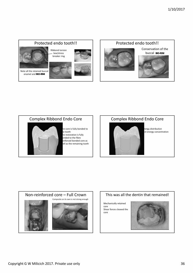
1/10/2017
Copyright G W Milicich 2017. Private use only 36
Protected endo tooth!!
Note all the retained buccalenamel and
Ribbond torsion box/stress breaker ring
Protected endo tooth!!Conservation of the
buccal
Complex Ribbond Endo Core
Bondede.max
The core is fully bonded to the tooth The restoration is fully bonded to the fibre reinforced bonded core as well as the remaining tooth
Complex Ribbond Endo Core
Energy distributionNot energy concentration
Non‐reinforced core – Full CrownComposite on its own is not strong enough
This was all the dentin that remained!
Mechanically retained coreShear forces cleaved the core
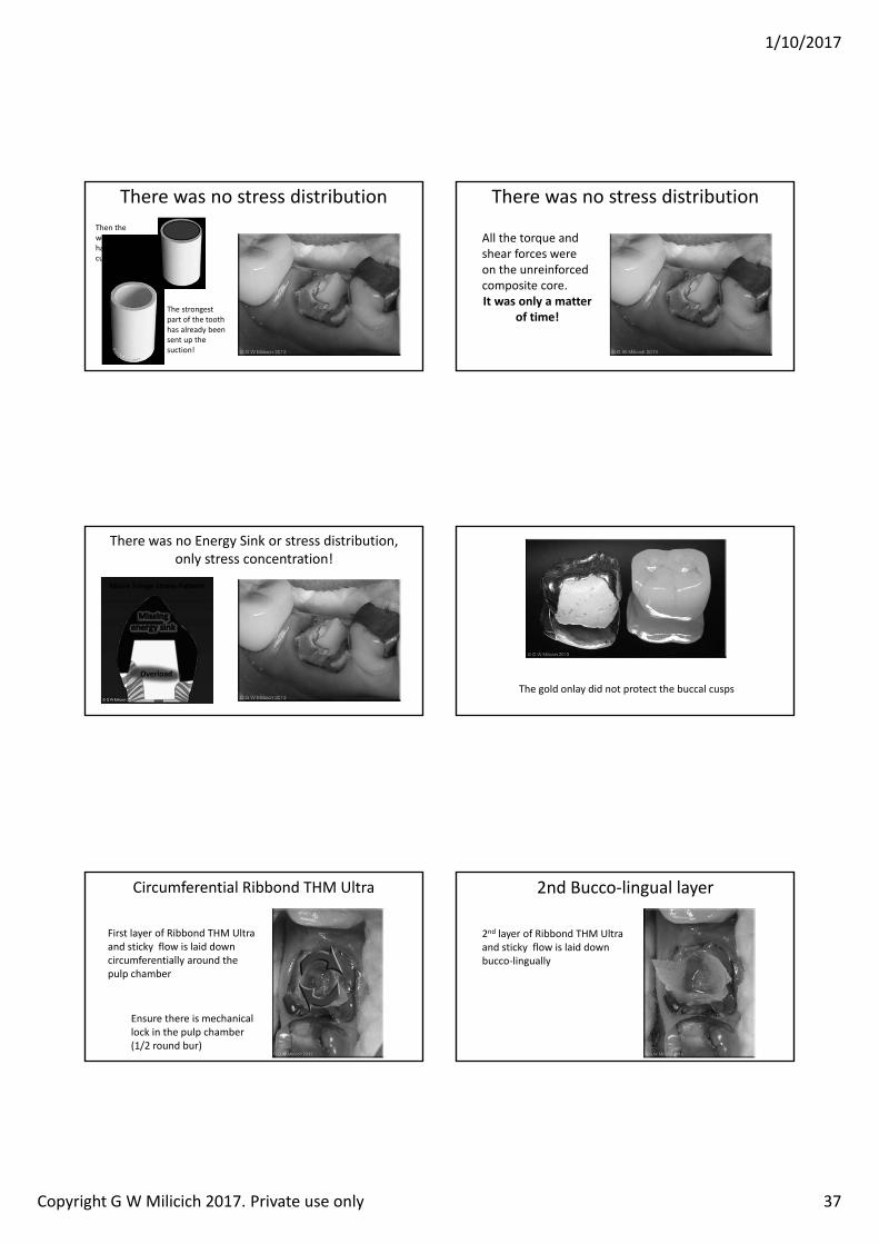
1/10/2017
Copyright G W Milicich 2017. Private use only 37
There was no stress distribution
The strongest part of the tooth has already been sent up the suction!
Then the weaker core had the guts cut out of it!
There was no stress distribution
All the torque and shear forces were on the unreinforced composite core.It was only a matter
of time!
There was no Energy Sink or stress distribution, only stress concentration!
Overload
Moire ringe Stress Pattern
The gold onlay did not protect the buccal cusps
Circumferential Ribbond THM Ultra
First layer of Ribbond THM Ultra and sticky flow is laid down circumferentially around the pulp chamber
Ensure there is mechanical lock in the pulp chamber (1/2 round bur)
2nd Bucco‐lingual layer
2nd layer of Ribbond THM Ultra and sticky flow is laid down bucco‐lingually
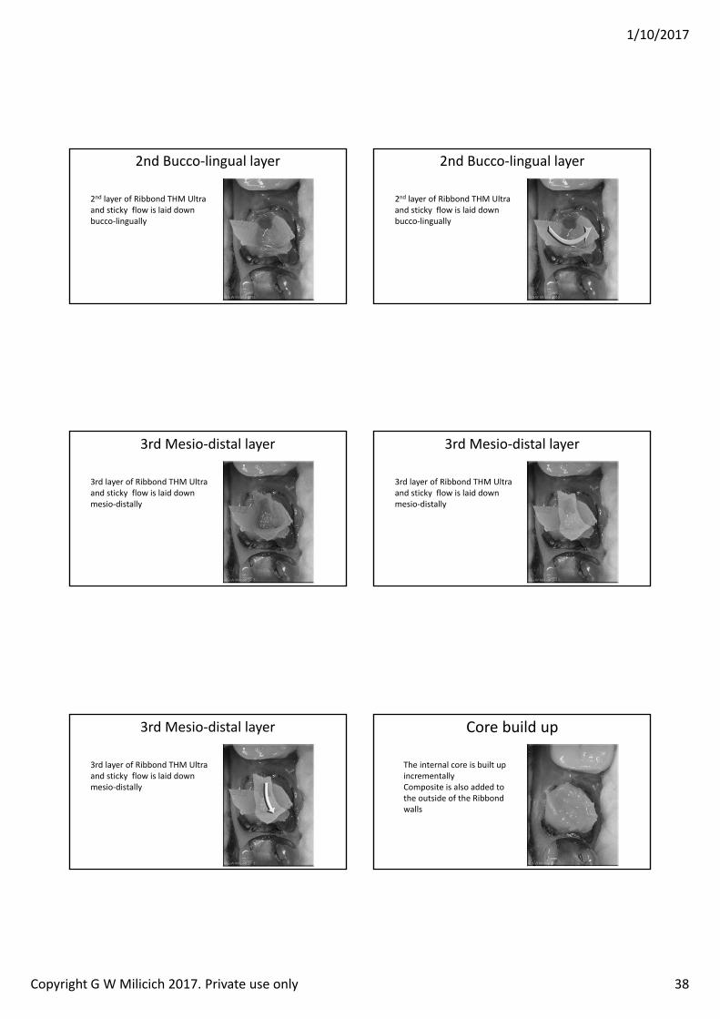
1/10/2017
Copyright G W Milicich 2017. Private use only 38
2nd Bucco‐lingual layer
2nd layer of Ribbond THM Ultra and sticky flow is laid down bucco‐lingually
2nd Bucco‐lingual layer
2nd layer of Ribbond THM Ultra and sticky flow is laid down bucco‐lingually
3rd Mesio‐distal layer
3rd layer of Ribbond THM Ultra and sticky flow is laid down mesio‐distally
3rd Mesio‐distal layer
3rd layer of Ribbond THM Ultra and sticky flow is laid down mesio‐distally
3rd Mesio‐distal layer
3rd layer of Ribbond THM Ultra and sticky flow is laid down mesio‐distally
Core build up
The internal core is built up incrementallyComposite is also added to the outside of the Ribbond walls
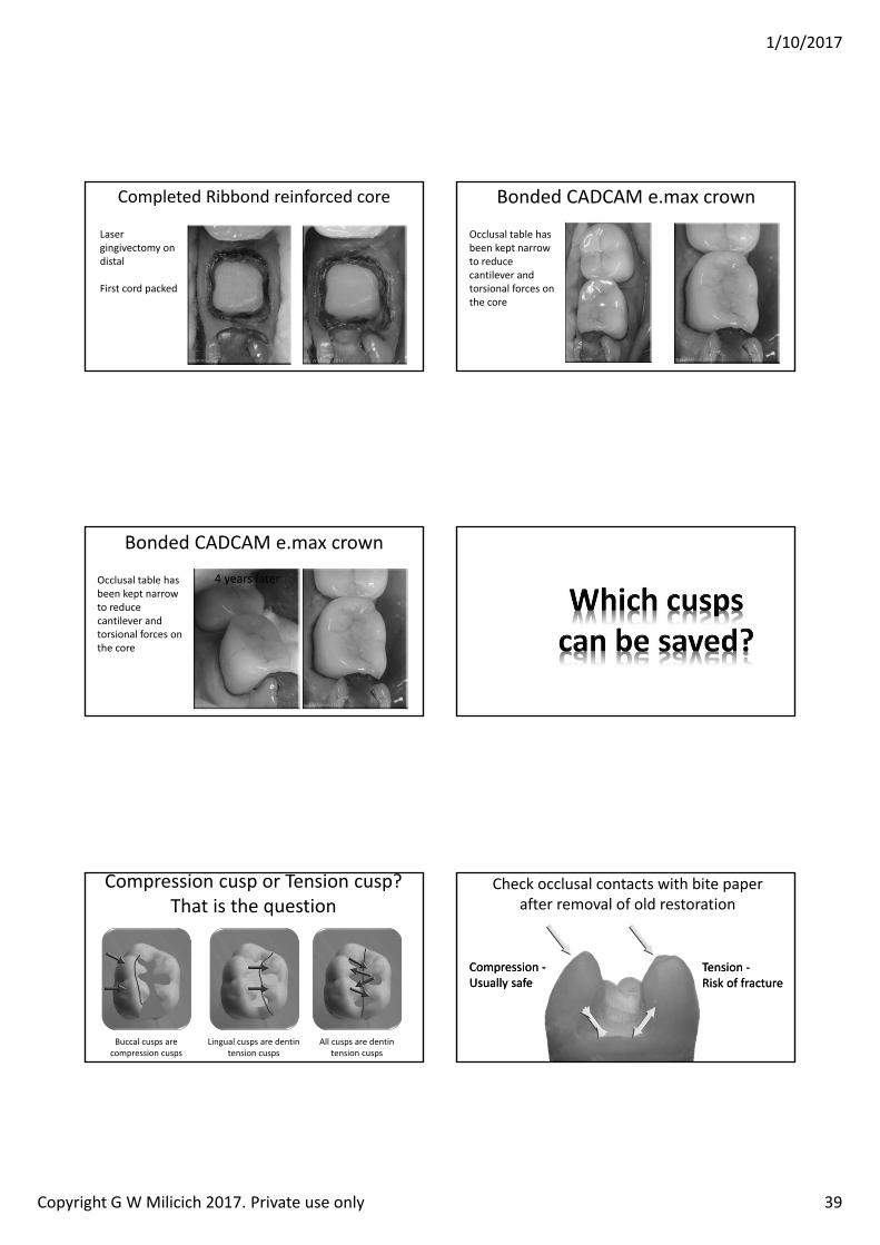
1/10/2017
Copyright G W Milicich 2017. Private use only 39
Completed Ribbond reinforced core
Laser gingivectomy on distal
First cord packed
Bonded CADCAM e.max crown
Occlusal table has been kept narrow to reduce cantilever and torsional forces on the core
Bonded CADCAM e.max crown
Occlusal table has been kept narrow to reduce cantilever and torsional forces on the core
4 years later
Compression cusp or Tension cusp?That is the question
All cusps are dentin tension cusps
Buccal cusps are compression cusps
Lingual cusps are dentin tension cusps
Check occlusal contacts with bite paper after removal of old restoration
Compression ‐Usually safeCompression ‐Usually safe
Tension ‐Risk of fractureTension ‐Risk of fracture
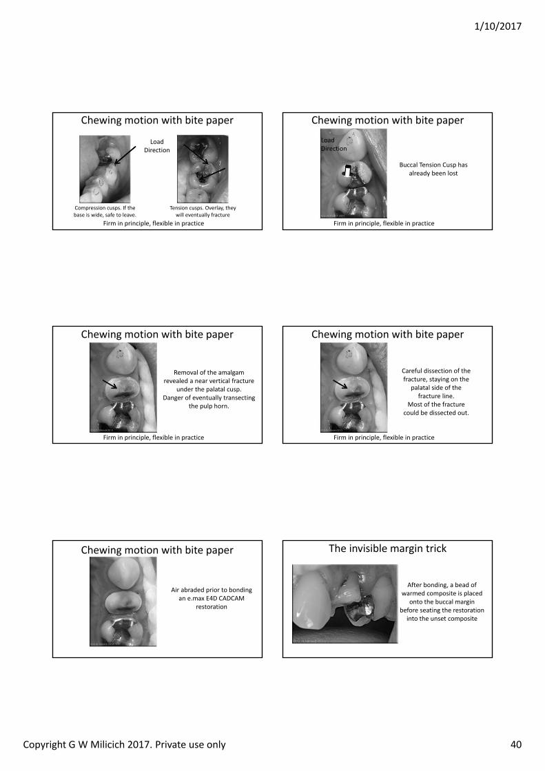
1/10/2017
Copyright G W Milicich 2017. Private use only 40
Chewing motion with bite paper
Compression cusps. If the base is wide, safe to leave.
Tension cusps. Overlay, they will eventually fracture
LoadDirection
Firm in principle, flexible in practice
Chewing motion with bite paper
Buccal Tension Cusp has already been lost
LoadDirection
Firm in principle, flexible in practice
Chewing motion with bite paper
Removal of the amalgam revealed a near vertical fracture
under the palatal cusp.Danger of eventually transecting
the pulp horn.
Firm in principle, flexible in practice
Chewing motion with bite paper
Careful dissection of the fracture, staying on the
palatal side of the fracture line.
Most of the fracture could be dissected out.
Firm in principle, flexible in practice
Chewing motion with bite paper
Air abraded prior to bonding an e.max E4D CADCAM
restoration
The invisible margin trick
After bonding, a bead of warmed composite is placed
onto the buccal margin before seating the restoration
into the unset composite
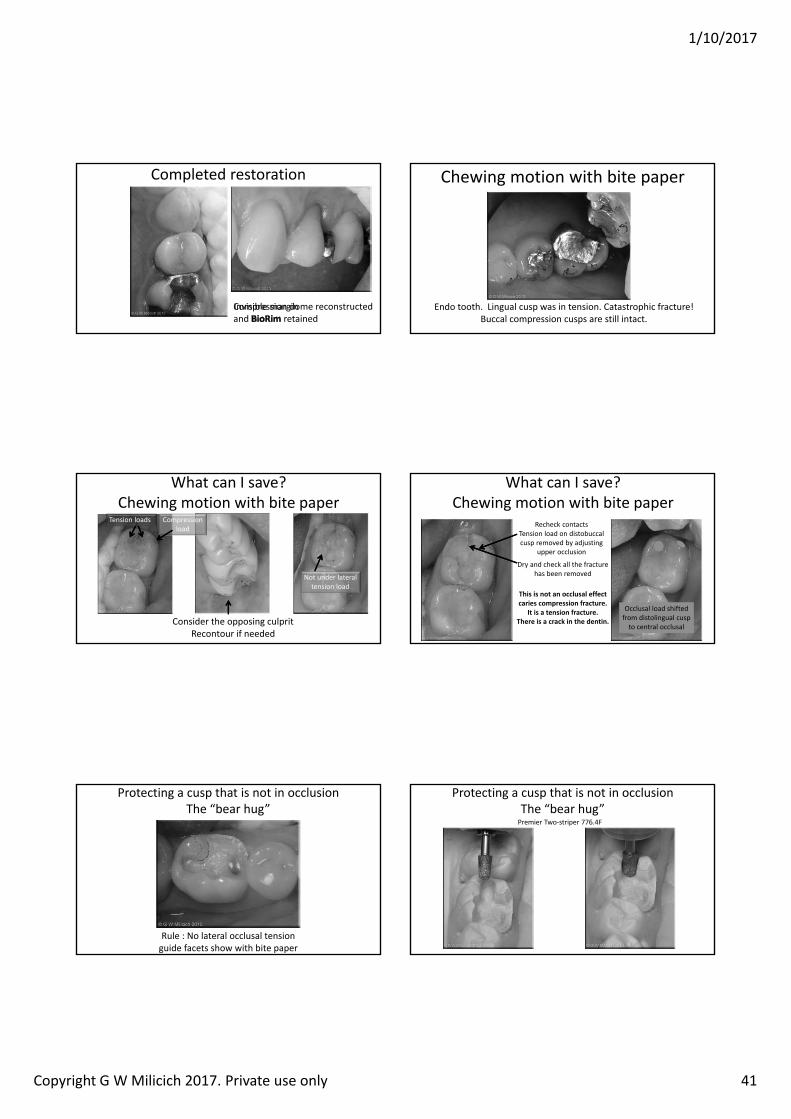
1/10/2017
Copyright G W Milicich 2017. Private use only 41
Completed restoration
Compression dome reconstructed and retainedInvisible margin
Chewing motion with bite paper
Endo tooth. Lingual cusp was in tension. Catastrophic fracture!Buccal compression cusps are still intact.
Consider the opposing culpritRecontour if needed
What can I save?Chewing motion with bite paper
Not under lateral tension load
Tension loads Compression load Recheck contacts
Tension load on distobuccalcusp removed by adjusting
upper occlusion
Dry and check all the fracture has been removed
What can I save?Chewing motion with bite paper
This is not an occlusal effect caries compression fracture.
It is a tension fracture.There is a crack in the dentin.
Occlusal load shifted from distolingual cusp to central occlusal
Protecting a cusp that is not in occlusionThe “bear hug”
Rule : No lateral occlusal tension guide facets show with bite paper
Protecting a cusp that is not in occlusionThe “bear hug”Premier Two‐striper 776.4F
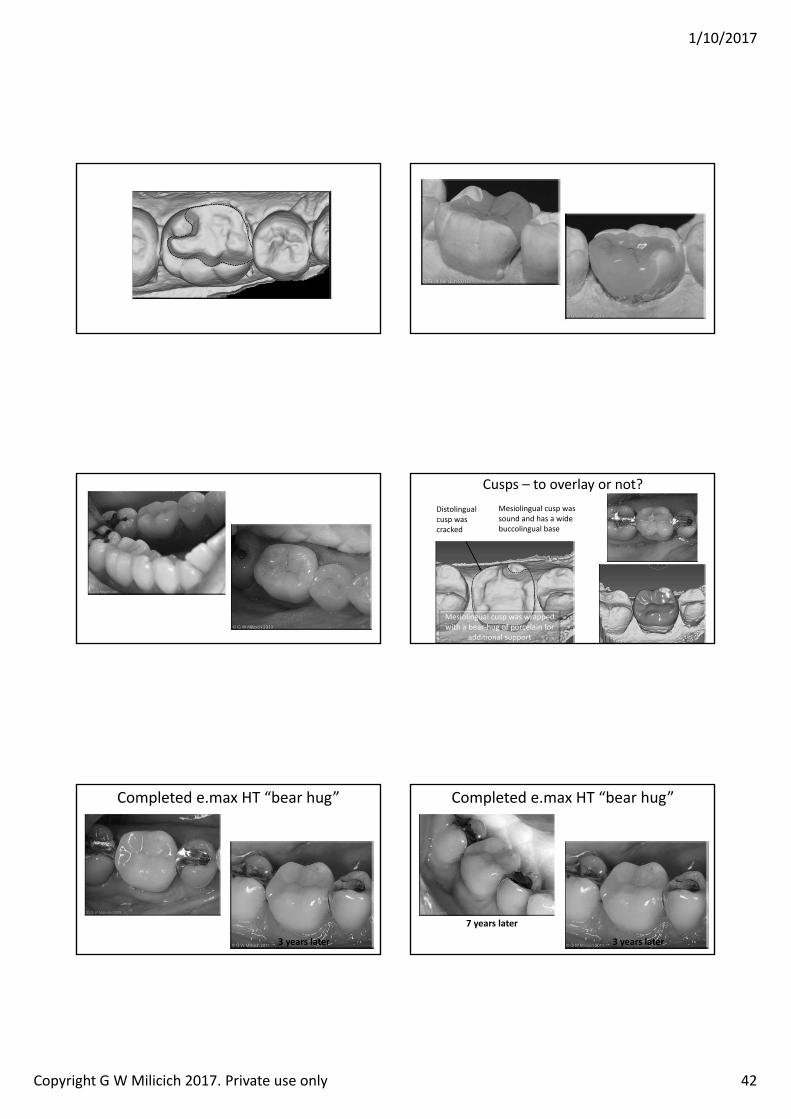
1/10/2017
Copyright G W Milicich 2017. Private use only 42
Cusps – to overlay or not?Distolingualcusp was cracked
Mesiolingual cusp was sound and has a wide buccolingual base
Mesiolingual cusp was wrapped with a bear‐hug of porcelain for
additional support
Completed e.max HT “bear hug”
3 years later
Completed e.max HT “bear hug”
3 years later
years later
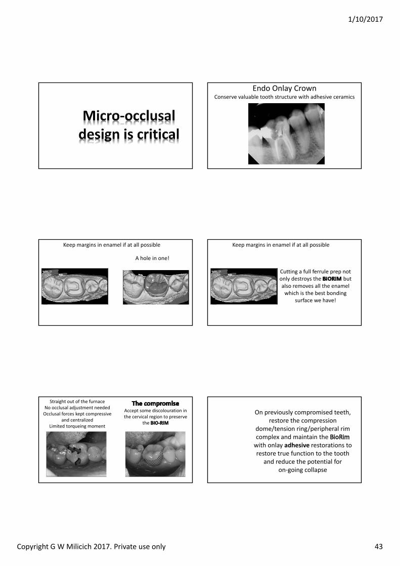
1/10/2017
Copyright G W Milicich 2017. Private use only 43
Endo Onlay CrownConserve valuable tooth structure with adhesive ceramics
Keep margins in enamel if at all possible
A hole in one!
Keep margins in enamel if at all possible
Cutting a full ferrule prep not only destroys the but also removes all the enamel which is the best bonding
surface we have!
Straight out of the furnaceNo occlusal adjustment neededOcclusal forces kept compressive
and centralized Limited torqueing moment
Accept some discolouration in the cervical region to preserve
the
On previously compromised teeth, restore the compression
dome/tension ring/peripheral rim complex and maintain the with onlay adhesive restorations to restore true function to the tooth
and reduce the potential for on‐going collapse

1/10/2017
Copyright G W Milicich 2017. Private use only 44
So Much Information!What do I do on Monday Morning?
Do nothing, or put in a progressive plan to instigate controlled change?
The plan is different for everyone, depending on where you currently are
Without a written plan, nothing will change.
So Much Information!What do I do on Monday Morning?
• Preparation designs; Oblique fractures, Mesiodistalfractures, Adhesive Onlays, Ribbond endo cores
• Bonding systems• Materials. Ribbond THM, everXPosterior• Adhesive options, direct and indirect• Air‐abrasion• Magnification• CADCAM
Bibliographywww.advancedental‐ltd.com
(Bibliography tab)
[email protected] of Endo Core Technique


![[IJCST-V3I2P37]: Mantoj Kaur, Malti Rani, Tulika Mehta](https://img.pdfslide.net/doc/110x75/633221c74e01430403008629/ijcst-v3i2p37-mantoj-kaur-malti-rani-tulika-mehta.jpg)


