Embed Size (px)
Citation preview

IEEE TRANSACTIONS ON INSTRUMENTATION AND MEASUREMENT, VOL. 61, NO. 1, JANUARY 2012 221
Identification of Defective Areas in CompositeMaterials by Bivariate EMD Analysis of Ultrasound
Marco Leo, David Looney, Member, IEEE, Tiziana D’Orazio, Member, IEEE, andDanilo P. Mandic, Senior Member, IEEE
Abstract—In recent years, many alternative methodologies andtechniques have been proposed to perform nondestructive inspec-tion and maintenance operations of moving structures. In partic-ular, ultrasonic techniques have shown to be very promising forautomatic inspection systems. From the literature, it is evident thatthe neural paradigms are considered, by now, the best choice toautomatically classify ultrasound data. At the same time, the mostappropriate preprocessing technique is still undecided. The aim ofthis paper is to propose a new and innovative data preprocessingtechnique that converts real-valued ultrasonic data into complex-valued signals. This allows analysis using phase synchrony, arobust tool that has been previously employed in brain science forestablishing robust features in noisy data. Synchrony estimation isachieved using complex extensions of empirical mode decomposi-tion, a data-driven algorithm for detecting temporal scales, thusfacilitating the modeling of nonlinear and nonstationary signaldynamics. Experimental tests aiming to detect defective areas incomposite materials are reported, and the effectiveness of theproposed methodology is illustrated.
Index Terms—Aerospace safety, feature extraction, neural net-works, pattern recognition, ultrasonic imaging.
I. INTRODUCTION
THE CHALLENGE of guaranteeing reliable and efficientsafety checks for engineering structures has received
much attention in recent years in many industrial contextsmostly owing to the advances in computer technology, aswell as to the emergence of powerful signal processing andlearning methodologies [1]–[3]. In particular, this challenge isof crucial importance for a number of industrial applicationsincluding manufacturing processes, hazardous waste manage-ment systems, inspection and maintenance of aircraft, andelectrical power lines where unpredictable behavior, such aspoor performance or even unsafe operation, can result fromabnormal deviations and/or anomalies in components, sensors,and actuators [4].
Manuscript received September 14, 2010; revised February 8, 2011; acceptedFebruary 24, 2011. Date of publication July 14, 2011; date of current versionDecember 8, 2011. The Associate Editor coordinating the review process forthis paper was Dr. Shant Kenderian.
M. Leo and T. D’Orazio are with the Institute of Intelligent Systems forAutomation, Italian National Research Council, 70126 Bari, Italy (e-mail:[email protected]; [email protected]).
D. Looney and D. P. Mandic are with the Department of Electrical andElectronic Engineering, The Imperial College of Science, Technology andMedicine, SW7 2BT London, U.K. (e-mail: [email protected];[email protected]).
Color versions of one or more of the figures in this paper are available onlineat http://ieeexplore.ieee.org.
Digital Object Identifier 10.1109/TIM.2011.2150630
Traditionally, abnormal deviations and/or anomalies are de-tected by trained human operators, but, unfortunately, thisapproach does not ensure an adequate reliability level, and atthe same time, it requires prohibitive amounts of time and highcosts. In addition, humans cannot detect cracks or any otherirregularities in the structure components which are not visibleto the naked eye.
To address the aforementioned problems, many alternativemethodologies and techniques have been proposed to per-form nondestructive inspection (NDT) and maintenance op-erations. These are based on the analysis of different signalssuch as ultrasonics, acoustic emissions, thermography, laserultrasonics, X-radiography, eddy currents, shearography, andlow-frequency methods [5]. In particular, in the last decade,ultrasonic techniques have shown to be very promising forNDT and the control of components in engineering systems,becoming an effective alternative to such traditional and well-studied approaches such as thermography, eddy currents, andshearography.
Most of the works in the literature describing ultrasound-based techniques for inspection and evaluation purposes con-centrate on the study of data acquisition and manipulationprocesses in order to prove the relationship between data andstructural defects or composition of the material [6]–[11].Some of the work is based on the a posteriori analysis of theultrasound data in order to (fully or partially) refer to somecomputational algorithm the automatic recognition of materialcomposition, operative conditions, presence of defects, andso on. Works concerning this subject, on which this paperis focused, are less developed, and moreover, their level ofinspection reliability is still inadequate, particularly for thosesectors (namely transportation) where an error can have serioushealth and safety consequences.
The pioneering works on the a posteriori analysis of ultra-sonic data date back to the early 1990s: they suggested thatsolutions to the problem of automatic ultrasonic NDT datainterpretation could be found by expert systems which embodythe knowledge of human interpreters [12], [13]. More effectiveapproaches, based on advanced signal processing and artificialintelligence paradigms, have been proposed in the last decade.In [14], the authors addressed the flaw detection problem byusing a radial basis function neural network, and they tried todemonstrate that a neural-based approach overcame the clas-sical threshold-based approach for flaw detection problems. In[15], the wavelet transform was used in conjunction with an ar-tificial neural network to distinguish the ultrasonic flaw echoesfrom those scattered by microstructures. A similar approach
0018-9456/$26.00 © 2011 IEEE

222 IEEE TRANSACTIONS ON INSTRUMENTATION AND MEASUREMENT, VOL. 61, NO. 1, JANUARY 2012
was introduced in [16] which addressed the problem of pipeinspection by ultrasonic guided waves. The automatic detectionof internal defects in composite materials with nondestructivetechniques based on ultrasonic techniques was addressed alsoin [17]. The authors proposed a preliminary iterative normal-ization procedure in order to manage materials of differentthickness and a two-level set of neural classifiers that segmentdefective areas from sound areas and determine the differentdefect characteristics (such as defect position and the defecttype). The author’s idea in [18] was, instead, to cluster the sig-nals in the similarity space (using the Kohonen self-organizingalgorithm to cluster data sets in an unsupervised manner) andthen to use this result in order to distinguish between signalscorresponding, respectively, to nondefects, flat defects (cracks),and volumetric defects. A high-resolution pursuit-based signalprocessing method was proposed in [19] for detecting flawsclose to the surface of strongly scattering materials, such assteel and composites, in NDT applications. In [20], an approachto nondestructive pipeline testing using ultrasonic imaging wasproposed. In [21], an evaluation of various types and config-urations of neural networks developed for the purpose of as-sisting in accurate flaw detection in steel plates was illustrated,whereas, in [22], a neural network was trained, by using thetime/space variations in a sequence of thermographic images,to extract the information that characterizes a range of internaldefects in different types of composite materials.
Despite the large effort that has been put into devisingefficient algorithms for this purpose, there is still a lot of workto do in order to satisfy the performance requirements of theconsidered application context where noise, complexity, anduncertainty play a major role. The use of multiple sensors inconjunction with advanced data fusion (the classifier operateson either the raw data or features extracted directly from themultiple sensor measurements obtained from associated data-bases, if appropriate) or decision fusion approaches (the deci-sions from the individual classifiers for different data channelsare combined) [23], recently introduced in somewhat relatedapplications (e.g., understanding and interpreting biomedicalsignals for healthcare), could be an effective way to pursue im-proved accuracies and more specific inferences [24] but, on theother hand, introduce a potentially overwhelming quantity ofdata that requires further investigation to reduce computationalcost and required storage space [25].
In summary, it is evident that the neural paradigms areconsidered the best choice to classify ultrasound data in an auto-matic inspection system. At the same time, the most appropriatepreprocessing technique is still undecided. As widely demon-strated in recent related works involving automatic pattern iden-tification using neural paradigms [26], [27], the wavelet-basedapproaches appear to be the most promising, but, consideringthat in the considered context an error could waste time, money,and even endanger someone’s life, further efforts have to bedone in order to increase reliability.
The aim of this paper is to propose a new and innovative datapreprocessing technique to explore the patterns embedded inthe data. A methodology is first proposed to obtain a complex-valued representation for each of the ultrasound signals. Bydesign, the complex representation highlights the presence or
absence of defects in the analyzed material. This representa-tion is then decomposed using complex/bivariate extensionsof empirical mode decomposition (EMD) [28], [29] into a setof complex-valued oscillating components, known as intrinsicmode functions (IMFs). In this way, the phase informationfor the real and imaginary components can be defined locally[30]. This facilitates the detection of phase synchrony, thatis, the temporal locking of phase information between thecomponents, which is an established tool in brain science forperforming feature extraction [31]. The existence of phasesynchrony, across time and frequency, is used to characterizethe degree of shared dynamics between the components of thecomplex representation and is consequently used to detect thepossible presence of defects.
It is this methodology of converting a real-valued data sourceinto a complex signal in order to obtain a set of synchrony fea-tures that is novel to our work. The new data representation isthen applied as an input to a supervised neural classifier trainedto recognize the defective areas from the nondefective ones.To demonstrate the effectiveness of the proposed approach,it has been applied to detect and classify internal defects incomposite materials and, in particular, in a honeycomb structurecontaining different inserts placed to simulate some of the mostcommon defective situations in composite materials.
The remainder of this paper is organized as follows:Section II describes EMD and its extensions while Section IIIdescribes the process by which phase synchrony is estimated.Section IV describes the proposed approach, and Section Vdescribes the experimental setup and reports the results ofdifferent experiments which demonstrate the effectiveness ofthe proposed approach with respect to the related techniquesfrom the literature. Finally, in Section VI, conclusions andfuture research directions are considered.
II. EMD AND EXTENSIONS
The following sections describe EMD and bivariate EMD(BEMD).
A. EMD Algorithm
EMD [28] is a data-driven time-frequency technique whichadaptively decomposes a signal, by means of a process calledthe sifting algorithm, into a finite set of AM/FM modulatedcomponents. These components, called “IMFs,” represent theoscillation modes embedded in the data. By definition, an IMFis a function for which the number of extrema and the numberof zero crossings differ by at most one, and the mean of the twoenvelopes associated with the local maxima and local minimais approximately zero. The EMD algorithm decomposes thesignal x(t) as
x(t) =M∑i=1
Ci(t) + r(t) (1)
where Ci(t), i = 1, . . . ,M , represents the IMFs and r(t) is theresidual. The first IMF is obtained as follows [28].
1) Let x̃(t) = x(t).

LEO et al.: IDENTIFICATION OF DEFECTIVE AREAS IN COMPOSITE MATERIALS BY BEMD ANALYSIS 223
2) Identify all local maxima and minima of x̃(t).3) Find an “envelope” emin(t) [respectively, emax(t)] that
interpolates all local minima (respectively, maxima).4) Extract the “detail”d(t)= x̃(t)−(1/2)(emin(t)+emax(t)).5) Let x̃(t) = d(t), and go to step 2); repeat until d(t)
becomes an IMF.
Once the first IMF is obtained, the procedure is appliediteratively to the residual r(t) = x(t) − d(t) to obtain all theIMFs. The extracted components satisfy the so-called mono-component criteria, and the Hilbert transform can be appliedto each IMF separately. This way, it is possible to generateanalytic signals, having an IMF as the real part and its Hilberttransform as the imaginary part, that is, x + jH(x), where H(·)is the Hilbert transform operator. Equation (1) can therefore beaugmented to its analytic form given by
X(t) =M∑i=1
ai(t) · ejθi(t) (2)
where the trend r(t) is purposely omitted, due to its over-whelming power and lack of oscillatory behavior. Observe that,now, from (2), the time-dependent amplitude ai(t) and phasefunction θi(t) can be extracted. By plotting the amplitude ai(t)versus time t and instantaneous frequency fi(t) = dθi/dk [32],a time–frequency-amplitude representation of the entire signalis obtained, the so-called Hilbert–Huang spectrum.
B. Complex Extensions of EMD
Several extensions of EMD to the field of complex numbershave been recently developed. These include “complex EMD”[33], “rotation-invariant EMD (RIEMD)” [34], and “bivariateEMD (BEMD)” [29]. However, only RIEMD and BEMD oper-ate directly in C making them suitable in practical applications[35]. In particular, BEMD facilitates enhanced local mean es-timation compared to RIEMD [35] and was used in synchronyanalysis.
In order to obtain a set of M complex/bivariate IMFs γi(t),i = 1, . . . , M , from a complex signal z(t) using BEMD, thefollowing procedure is adopted [29]:
1) Let z̃(t) = z(t).2) To obtain Q signal projections, given by {pθq
}Qq=1,
project the complex signal z̃(t), by using a unit complexnumber e−jθq , in the direction of θq as
pθq= �
{e−jθq z̃(t)
}, q = 1, . . . , Q (3)
where �{·} denotes the real part of a complex numberand θq = 2qπ/Q.
3) Find the locations {tqj}Qq=1 corresponding to the maxima
of {pθq}Q
q=1.4) Interpolate (using spline interpolation) between the max-
ima points [tqj , z̃(tqj)] to obtain the envelope curves
{eθq}Q
q=1.5) Obtain the mean of all the envelope curves m(t) and sub-
tract from the input signal, that is, d(t) = z̃(t) − m(t).
Let z̃(t) = d(t), and go to step 2); repeat until d(t)becomes an IMF.
Similarly to real-valued EMD, once the first IMF is obtainedγ1(t), the procedure is applied iteratively to the residual r(t) =z(t) − d(t) to obtain all the IMFs.
Once the IMFs have been obtained, the real and imaginarycomponents can be treated as two sets of IMFs: �{γi(t)} and�{γi(t)}. The instantaneous amplitudes, namely, �{ai(t)} and�{ai(t)}, and phases, namely, �{θi(t)} and �{θi(t)}, for eachset of IMFs can then be determined.
Consider a complex signal z = x1 + jx2. The real and imag-inary parts of z are given, respectively, in the first panels ofFig. 1(a) and (b). The real part of the decomposition obtainedusing BEMD for z is shown in the subsequent panels ofFig. 1(a), and the imaginary part is shown in the subsequentpanels of Fig. 1(b). Note that, for convenience, not all the high-frequency IMFs have been displayed. For example, the secondpanel of Fig. 1(a) shows the summation of the first six real-valued IMFs
∑6i=1 �{γi}. Observe how the BEMD operation
presents a data-driven framework to compare the temporalscales of z.
III. PHASE SYNCHRONY
Phase synchrony between two signals is defined as thetemporal locking of phase information. That is, for a givenfrequency, phase synchrony exists if the phase difference re-mains constant over a period of time. It is a popular tool inbrain science for robustly modeling any shared dynamics thatexist between the sources. To measure the phase synchronybetween x1 and x2, BEMD is first applied to the complex signalx1 + jx2. The instantaneous phase difference between the realand imaginary parts of each IMF component is given by ψi(t).The degree of phase synchrony between x1 and x2 is givenby [30]
φi(t) =Hmax − H
Hmax(4)
where H = −∑N
n=1 pn ln pn represents the Shannon entropyof the distribution of ψi(t − (W/2) : t + (W/2)) defined by awindow of length W , N is the number of bins, and pn is theprobability of ψi(t − (W/2) : t + (W/2)) within the nth bin[36]. The maximum entropy Hmax is given by
Hmax = 0.626 + 0.4 ln(W − 1). (5)
The value of φ is between zero and one, with one indicatingperfect synchrony and zero a nonsynchronous state. An addi-tional step can be incorporated to model simultaneously forcomponent relevance
φi(t) ={
0, if �{ai(t)} < ε0, if �{ai(t)} < ε
(6)
where ε is an appropriate threshold. Once the phase synchronyinformation has been estimated, it can be conveniently repre-sented by the matrix ρ(f, t), which denotes the phase synchronyat index t and frequency f .

224 IEEE TRANSACTIONS ON INSTRUMENTATION AND MEASUREMENT, VOL. 61, NO. 1, JANUARY 2012
Fig. 1. Decomposition of z = x1 + jx2, shown in the top panels of (a) and (b), into a set of complex IMFs γi using BEMD. (a) Real component. (b) Imaginarycomponent.
IV. PROPOSED APPROACH
Ultrasonic inspection uses sound signals at frequencies be-yond human hearing (more than 20 kHz) to estimate someproperties of the irradiated material by analyzing either thereflected (reflection working modality) or transmitted (trans-mission working modality) signals. A typical ultrasonic inspec-tion system consists of several functional units: pulser, receiver,transducer, and display devices. A pulser is an electronic devicethat can produce a high-voltage electrical pulse. Driven by thepulser, the transducer generates a high-frequency ultrasonicwave which propagates through the material. In the transmis-sion modality, the receiver is placed on the opposite side of thematerial from the pulser, whereas, in the reflection modality,the pulser and the receiver are placed on the same side of thematerial.1
Ultrasonic data can be collected and displayed in a number ofdifferent formats. The three most common formats are knownin the NDT community as A-scan, B-scan, and C-scan pre-sentations. Each presentation mode provides a different way oflooking at and evaluating the region of material being inspected.
1Inspection devices may or may not be in contact with the material. In theformer case, a liquid or a paste (couplant) is used to facilitate the transmissionof ultrasonic vibrations from the transducer to the test surface. In noncontactultrasound, ambient air is instead the only acoustic coupling medium.
In this paper, the analysis of ultrasonic data acquired fromthe reflection working modality and A-scan representation isreported. This means that, for each point of the inspected mate-rial, we have a continuous signal that represents the amount ofreceived ultrasonic energy as a function of time.
The temporal evolution of the ultrasound signal x(t) is theinput to the core of the proposed approach that consists oftwo main steps: the preprocessing of the data in order toemphasize the characteristics of the signals belonging to thesame class, and the following neural classification. Fig. 2 showsthe different procedures involved in the proposed approach.In the preprocessing step, a methodology is first proposed toextend each real-valued ultrasonic signal xu,v(t), where (u, v)denotes a point in the material, to the complex domain Zu,v(t).
Consider first an ultrasonic signal for an area of the materialthat is defect free; see Fig. 3(a). Observe that there are largeextrema at the beginning and at the end. These changes inultrasound energy are caused by the transmitted signals beingreflected by the boundaries of the material. These boundaryextrema are referred to as toolside and bagside peaks, respec-tively. The ultrasonic signal for an area of material that containsdefects is, instead, given in Fig. 4(a). Note that, in additionto the boundary extrema, the signal contains extrema at othertime locations caused by defective components. A defect-freearea of material is therefore characterized by a data set which

LEO et al.: IDENTIFICATION OF DEFECTIVE AREAS IN COMPOSITE MATERIALS BY BEMD ANALYSIS 225
Fig. 2. Schematic representation of the different procedures involved in theproposed approach.
Fig. 3. (a) Example of a nondefective ultrasonic signal and (b) its complexextension.
is symmetrical about its center and contains boundary extremaonly. Thus, it is proposed to divide each data set about its center
Fig. 4. (a) Example of a defective ultrasonic signal and (b) its complexextension.
x(T/2), thus producing two segments, namely, x1 and x2, by
x1
(1, 2, . . . ,
T
2, . . . ,
T
2+ KR
)
= x
(1, 2, . . . ,
T
2, . . . ,
T
2+ KR
)
x2
(1, 2, . . . ,
T
2, . . . ,
T
2+ KR
)
= x
(T, T − 1, . . . ,
T
2, . . . ,
T
2− KR
). (7)
Note that each segment is additionally extended by KR
points at the right-sided edge (t = T/2). These segments arethen extended at the left-sided edge by KL points. Thesesegments are denoted by x̂1 and x̂2 and are dependent on theposition of the toolside peak and bagside peak, respectively. If,for example, the boundary extremum relevant to x1(t), that is,the toolside peak, occurs at t = e1, then x̂1(t) is given by
x̂1
(e1, . . . ,
T
2+ KR
)= x1
(e1, . . . ,
T
2+ KR
)x̂1(e1 − 1, . . . , e1 − KL) = x1(e1 + 1, . . . , e1 + KL) (8)
where x̂2(t) is constructed in a similar fashion around thebagside peak. The extended components for the ultrasonicsignals shown in Figs. 3(a) and 4(a), are shown, respectively,in Figs. 3(b) and 4(b). Thus, the complex extension of the real-valued ultrasound signal, for point (u, v), is given by Zu,v(t) =x̂1(t) + jx̂2(t).
The signal Zu,v(t) is decomposed into a set of complex os-cillation modes (IMFs) γi(z), where i = 1, . . . , M , by applying

226 IEEE TRANSACTIONS ON INSTRUMENTATION AND MEASUREMENT, VOL. 61, NO. 1, JANUARY 2012
a complex extension of EMD, i.e., BEMD [29]. The real andimaginary parts of the decomposition �{γi(t)} and �{γi(t)}denote the IMFs for x̂1(t) and x̂2(t), respectively. By construc-tion, the phase information for each IMF is well defined at eachinstant t and facilitates a highly localized comparison betweenthe phase information of x̂1(t) and x̂2(t) [30]. The degree ofphase synchrony, which is the temporal locking of phase infor-mation between �{γi(t)} and �{γi(t)}, is then determined tocharacterize the dynamics of Zu,v(t), that is the symmetry ofthe original ultrasound signal about its center as well as thelocation of its extrema. The information is represented by amatrix ρu,v(f, t) which denotes the synchrony at index t andfrequency f .
In the analysis, two additional preprocessing steps were per-formed on the complex data representation, Zu,v(t), in order tofacilitate more robust synchrony estimation. Synchrony analy-sis involves the calculation of entropy for phase distributionswhich requires long data lengths so Zu,v(t) was initially up-sampled. Furthermore, a noise-assisted EMD facilitates a morenatural separation of scale components [37]. For this reason,white Gaussian noise was added to the real and imaginary com-ponents before applying BEMD, and ρu,v(f, t) was obtainedby averaging the synchrony results over several realizationsof noise.
The synchrony matrix for each ultrasound signal ρu,v(f, t)is then vectorised and downsampled. Principal componentanalysis (PCA) is then applied to reduce dimensionality givinga feature vector Yu,v = [y1, y2, . . . , yN ] for each ultrasoundsignal. The M most informative components are finally given asthe input to a neural classifier trained with a back propagationalgorithm to distinguish defective from nondefective areas.
V. EXPERIMENTAL SETUP AND RESULTS
To illustrate the effectiveness of the proposed approach, aset of ultrasound measurements on a composite material hasbeen considered. The material has a honeycomb structure withNomex Core and 128 ply thicknesses (each ply has a thicknessof 0.19 mm). Ultrasonic data was obtained by an ultrasonicreflection technique that uses a single transducer serving astransmitter and receiver (5 MHz).
The collected data are relative to defective and nondefec-tive areas: defective areas contain artificial defects introducedduring the manufacturing process and are composed of thefollowing materials: brass foil (0.02 ± 0.01 mm thick), pressuresensitive tape,2 and dry peel ply (0.12 mm thick). In particular,brass inserts, dry peel ply, and adhesive tape were introducedto represent voids and delamination, inclusions by means ofreflection techniques, and inclusions by means of transmissiontechniques, respectively. In the following, [A] stands for tape,[F] stands for peel ply, and [B] stands for brass. The typicalinsert locations are the following:
1) one and two plies from toolside surface for brass and pres-sure sensitive Tape and 1016 mm from toolside surfacefor peel ply (Top);
2American Biltrite 6782, Tape Product Division, American Biltrite, Inc.,105 Whittendale, Moorestown, NJ, 08057
2) midpart thickness (Mid);3) one and two plies from bagside surface for brass and pres-
sure sensitive tape and 1016 mm from bagside surface forpeel ply (Bottom).
Each x(u,v)(t), which is the ultrasound signal correspondingto point (u, v), contains 77 temporal samples. This signalwas converted into a complex signal Z(u,v)(t), and synchronyanalysis was performed on the IMFs obtained by applyingBEMD to the upsampled signal. Because of the initialupsampling, only low-frequency synchrony information wasconsidered in the analysis. Each synchrony matrix ρ(u,v)
was then vectorised and downsampled obtaining a 1198-longfeature vector. This is the input of the classification stepinvolving PCA data reduction and neural classification ofdefective and nondefective points.
First of all, the experimental data set consisting of 2620ultrasound signals was built. Specifically, the data set wascomposed of 1920 signals acquired for the three differenttypes of defect (640 signals for each defect type: [A], [B],and [F]) and 700 signals obtained from areas which did notcontain any defects. For each defect type, the points in thedata set were equally relative to the defects placed at midthick-ness level, at the top, and at the bottom of the inspectedmaterial.
The aim of the preliminary experimental phase was to deter-mine the values of some important parameters of the proposedframework. The number of required principal components(PCs) was first considered. This is a crucial step consideringthat underestimation of this number would discard valuableinformation, whereas overestimation could result in a largenumber of spurious components carrying useless informationthat could compromise further steps in data classification. Apopular ad hoc rule is to plot the eigenvalues in decreasing order(scree plot) and search for a peak which denotes that the signaleigenvalues are on the left side and the noise eigenvalues areon the right. Another approach is to compute the cumulativepercentage of the total variation explained by the PCs and retainthe number of PCs that represents 70% or 80% of the totalvariation [38]. The choice of the number of components toretain could be also seen as a problem of model selection. Thisprobabilistic reformulation of PCA permits many extensions[39]. Two interesting approaches were formulated in [40] and[41]: the authors developed a model selection criterion forestimating the true dimension of the observed data set (or thenumber of PCs to retain) where “true dimension” denoted thesufficient dimension to fully describe the information available.
In Fig. 5, the variance and the cumulative variance of the first200 PCs computed from the considered data set are plotted.In Fig. 6, a probabilistic analysis of the PCs is reported. Thedashed curve shows the likelihood relative to different datadimensionality computed by the method proposed in [40],which makes use of Bayesian model selection, and for thisreason, it is referred to as the Bayesian information criterion. Ina similar way, the solid curve indicates the likelihood computedby the method proposed in [41] and is referred to as Laplace(it makes use of the Laplace’s method to get model parameterestimation). Statistical and probabilistic information in Figs. 5

LEO et al.: IDENTIFICATION OF DEFECTIVE AREAS IN COMPOSITE MATERIALS BY BEMD ANALYSIS 227
Fig. 5. Variance and cumulative variance of the first 200 PCs.
Fig. 6. Probabilistic analysis of the PCs.
and 6 indicate that the optimal number of PCs that should beretained is 70.
Once the number of significant PCs was fixed, the featurevector Y(u,v) = [y1, y2, . . . , y70] for each ultrasound signal wascalculated. The next step was to select the most appropriateneural architecture for the considered problem. A three-layerfeedforward network, with tansig activation functions in thehidden layer and linear activation functions in the output layer,is often used in the literature. Considering that the problemrequires binary classification and that there exists a sufficientamount of data examples for each of the two classes, the backpropagation algorithm was used to train the neural network. Thenumber of neurons of the input layer was set to the numberof input variables (i.e., 70), and the number of neurons in theoutput layer was one. The network was trained such that theoutput value 1 denoted a defective signal and the value −1denoted a nondefective signal.
The network size has a strong influence on the networkperformance: setting too few hidden units causes high trainingerrors and high generalization errors due to underfitting, whiletoo many hidden units results in low training errors but still highgeneralization errors due to overfitting. Despite this, there isno straightforward way to obtain the correct number of hiddenlayer neurons for the considered task. Several researchers haveproposed some ad hoc solutions to this problem. However, suchrules are not applicable in most circumstances as they do notconsider the training set size (number of training pairs), thecomplexity of the data set to be learnt, etc. It is argued that
Fig. 7. Overall classification error obtained with different numbers of neuronsin the hidden layer of the network architectures.
the optimal number of hidden units depends on the numbersof input and output units, the number of training cases, theamount of noise in the targets, the complexity of the function orclassification to be learned, the architecture, the type of hiddenunit activation function, the training algorithm, etc. Thus, in theexperiments, different neural architectures (with the number ofhidden neurons ranging from 1 to 50) were considered, and theirclassification performances were evaluated.
The experimental phase made use of a training set consistingof 500 ultrasonic signals: 300 signals were relative to defectivepoints, whereas the remaining 200 were relative to nondefectivepoints. The 300 defective training points belonged to the threedefect types (100 for [A], 100 for [B], and 100 for [F]), and foreach type, 40 of them were relative to defects placed at the top,40 to defects placed at the bottom, and 20 to defects placed inthe middle part of the material.
The ability to classify the remaining 2120 signals of the dataset as defective or nondefective was then evaluated in the firstexperimental phase. In Fig. 7, the correct classification rate foreach neural architecture is shown. It is possible to observe thatthe best rate (84.15%) was obtained with eight neurons in thehidden layer. This demonstrated that, while a lower number ofneurons limited the knowledge of the input data (underfitting),a higher number of neurons made it difficult for the classifier togeneralize that knowledge (overfitting).
In Table I, classification performance using the optimalneural architecture is shown. The left column states the type andthe thickness level placement of the testing signals. For exam-ple, [A]-m refers to signals extracted from [A]-type defectiveareas placed at the midthickness level. In the same column, thesignals extracted from areas which did not contain any defectsare referred as “ND.” The middle and right columns reportthe classification results (in terms of defective/nondefectivesignals) obtained by the proposed approach.
Although the correct defect identification rate is high, it canbe deduced that the performance of the proposed methodologydepends on both the following:
1) the defect type;2) the defect location in the inspected material.
Table I illustrates that defective areas at the midthicknesslevel are always better classified than those located either atthe top or at the bottom. The defect location is one of the most

228 IEEE TRANSACTIONS ON INSTRUMENTATION AND MEASUREMENT, VOL. 61, NO. 1, JANUARY 2012
TABLE ICLASSIFICATION PERFORMANCES WITH THE OPTIMAL
NEURAL NETWORK ARCHITECTURE
Fig. 8. Two signals pointing out the different acoustic reflection coefficientfor two different defect types. (a) Example of acoustic reflection for an[A]-type defect. (b) Example of acoustic reflection for an [F]-type defect.
important factors in ultrasound inspection. The defects placedeither at the top or at the bottom of the inspecting structure are,in general, the most difficult to detect since their echo is mixedwith the toolside or the bagside echo. However, defective areasin the midpart of the material thickness produce a distinct peakin the signal trend that is straightforward to identify [compareFigs. 3(a) and 4(a)].
From Table I, it is clear that the defect type also affects theclassification rate. Each defect type has a different acousticreflection coefficient. The larger this acoustic coefficient, themore prominent it will be in the ultrasound data and themore straightforward the defect is to detect. In particular, itis observed that [A]-type defective points were better iden-tified than [B]. The most poorly identified was the [F]-type
TABLE IICORRECT DEFECT IDENTIFICATION RATE FOR
THE THREE COMPARED APPROACHES
defects. In Fig. 8, the different acoustic reflection behavior for[A]-type [Fig. 8(a)] and [F]-type [Fig. 8(b)] defects is shown.The [A]-type defect reflects much more acoustic energy thanthe [F]-type as is illustrated by both the higher amplitude of thecentral echo and the lower amplitude of the bagside echo.
The second experimental phase compared the proposed ap-proach with the methods that are among the most effectivein automatic defect identification. In particular, two other ap-proaches were considered. For the first method, the ultrasonicsignals were classified by a neural network without any pre-processing (specifically, the 77 available samples for each pointwere given as input to the net after the normalization in therange [−1,1]). For the second method, classical preprocessingbased on the wavelet decomposition was applied to the ul-trasonic signal, and selected coefficients were supplied to theneural classifier.3 The same neural architecture as before wasused to classify the features obtained for both methods. Theoptimal number of hidden neurons was experimentally foundto be 30 for the wavelet-based approach and 15 for the directapproach with no preprocessing.
Table II compares results for the three approaches, obtainedusing the same data set as before. On the one hand, the proposedBEMD-based approach gave the best defect identification rate(for all considered defect types and defect locations), but, on theother hand, it also generated a larger number of false positivesfor nondefective points.
In particular, it is evident that BEMD preprocessing can ac-curately detect certain defective points, placed at the top and atthe bottom of the considered material, which are not detectable
3The DB3 family was used, and the decomposition was carried out untillevel 3. The resulting 92 coefficients were then used to represent the ultrasoundsignal.

LEO et al.: IDENTIFICATION OF DEFECTIVE AREAS IN COMPOSITE MATERIALS BY BEMD ANALYSIS 229
Fig. 9. Different echoes in the case of (a) a nondefective ultrasonic signal and(b)–(c) two [B]-type ultrasonic defective signals relative to defect areas placedat different location into the inspecting composite material. (a) Nondefectiveultrasonic signal. (b) Ultrasonic signal relative to a defect placed two plies fromtoolside surface. (c) Ultrasonic signal relative to a defect placed two plies frombagside surface.
using direct-input and wavelet-based approaches. In Fig. 9,we report a nondefective ultrasonic signal [Fig. 9(a)] togetherwith two [B]-type defective signals obtained from two areasplaced two plies from the toolside surface [Fig. 9(b)] and twoplies from the bagside surface [Fig. 9(c)]. The similarity of thethree signals is quite evident and causes standard preprocessingtechniques to fail. The proposed complex-valued representationof the ultrasonic signals highlights the small differences thatcan be found in the toolside and bagside peaks, and the phasesynchrony analysis detects the presence of defects. Using theBEMD-based approach, only a very small percentage of de-fective points was missed. This performance is useful in theconsidered inspection context (particularly, for transportation
purposes) where it is important to detect all the defective areaseven at the cost of increasing the number of false positives.
The benefits of the proposed approach are further illustratedin the third experimental phase in which the neural architec-tures trained with the three different approaches were used tofully inspect a small part of the considered honeycomb struc-ture with Nomex Core. The inspected part contains differentdefective insertions as shown in Fig. 10(a). Fig. 10(b)–(d) showthe inspection results obtained using the direct-input, wavelet,and BEMD approaches, respectively.
Clearly, the BEMD-based approach can more accurately de-tect all defective areas, but it also results in a higher number offalse positives. Considering that these false detections are iso-lated and do not form connected regions having a considerablearea value, the elimination of these points is straightforward ifsome a priori knowledge about the minimum expected size ofthe defective areas is available. For example, in Fig. 11(a)–(c),the inspection results, after a filtering process based on theconnectivity analysis of the detected defective regions and aselection criterion based on removing the regions having anarea less than 20 pixels, are shown. Observe that the directinput approach completely missed three (placed on the topand on the bottom of the materials) of the nine defectiveinsertions [see Fig. 11(a)]. Wavelet preprocessing was able todetect two of the missed insertions but still missed the [B]-typeinsertion placed at the top of the material [see Fig. 11(b)]. TheBEMD preprocessing facilitated an increase in the percentageof detected defective points such that all the defective areaswere identified [see Fig. 11(c)].
The proposed method is significantly more computation-ally complex than the other considered approaches.4 However,the aim of this paper is to facilitate highly accurate analysisat the expense of computation cost. It would be possible toreduce the complexity of the EMD operation using linearenvelope interpolation or adjusting stopping parameters, butthis is outside the scope of this paper.
VI. CONCLUSION
The aim of this paper is to propose a new and innovative datapreprocessing technique that converts real-valued ultrasonicsignals into complex-valued signals, making them suitable toapply phase synchrony analysis using complex/bivariate exten-sions of EMD, a data-driven algorithm for detecting temporalscales in nonlinear and nonstationary data. It has been illus-trated experimentally that the proposed preprocessing approachis suitable for detecting defective components in composite ma-terials. Obtaining the complex-valued representation, a defect-free component is characterized by a unique similarity betweenthe real and imaginary parts at a given time and frequency. Thus,the application of BEMD facilitates a highly localized time–frequency analysis of the complex representation, and thesubsequent calculation of phase synchrony can be used to
4As a data-driven operation, EMD does not have a rigorous mathematicalderivation, meaning that, for example, the number of decompositions cannotbe controlled directly and makes accurate analysis of the computation costdifficult.

230 IEEE TRANSACTIONS ON INSTRUMENTATION AND MEASUREMENT, VOL. 61, NO. 1, JANUARY 2012
Fig. 10. Results of the inspection of (a) a honeycomb structure by using the three methods (b), (c), and (d). (a) Layout of the defective regions. (b) Inspectionresults obtained using the direct input. (c) Inspection results obtained using the wavelet preprocessing. (d) Inspection results obtained using BEMD preprocessing.
Fig. 11. Effect of a filtering process based on the connectivity analysis of the detected defective regions using a selection criterion based on the removal of pointswith a surrounding area value of less than 20 pixels. (a) Inspection results obtained using the direct input and a further area-based region filtering. (b) Inspectionresults obtained using wavelet preprocessing and a further area-based region filtering. (c) Inspection results obtained using BEMD preprocessing and a furtherarea-based region filtering.
quantify the degree of similarity between the real and imaginaryparts.
Different experiments were carried out to compare the pro-posed preprocessing methodology with the most common andeffective preprocessing techniques found in the literature. Theresults have demonstrated that the BEMD-based preprocessingapproach performs better in terms of defect detections andallows the recognition of defective areas at difficult-to-detectlocations such as near the top or the bottom of the material,scenarios which can cause standard approaches to fail.
Future work will focus on investigating the defect-identification capability of the proposed BEMD-basedapproach. This will be achieved by extending the analysisto material with different thicknesses and different defectiveinsertions. In the future, we will also investigate the possibility
of using an unsupervised-learning approach in order to reducehuman intervention.
REFERENCES
[1] A. Papadimitropoulos, G. A. Rovithakis, and T. Parisini, “Fault detectionin mechanical systems with friction phenomena: An online neural approx-imation approach,” IEEE Trans. Neural Netw., vol. 18, no. 4, pp. 1067–1082, Jul. 2007.
[2] G. Simone and F. C. Morabito, “RBFNN-based hole identification systemin conducting plates,” IEEE Trans. Neural Netw., vol. 12, no. 6, pp. 1445–1454, Nov. 2001.
[3] D. Mery and D. Filbert, “Automated flaw detection in aluminum cast-ings based on the tracking of potential defects in a radioscopic imagesequence,” IEEE Trans. Robot. Autom., vol. 18, no. 6, pp. 890–901,Dec. 2002.
[4] H. A. Talebi, K. Khorasani, and S. Tafazoli, “A recurrent neural-network-based sensor and actuator fault detection and isolation for nonlinear
LEO et al.: IDENTIFICATION OF DEFECTIVE AREAS IN COMPOSITE MATERIALS BY BEMD ANALYSIS 231
systems with application to the satellite’s attitude control subsystem,”IEEE Trans. Neural Netw., vol. 20, no. 1, pp. 45–60, Jan. 2009.
[5] C. Boller, F.-K. Chang, and Y. Fujino, Encyclopedia of Structural HealthMonitoring. Hoboken, NJ: Wiley, 2009.
[6] S. Wagle and H. Katoa, “Ultrasonic wave intensity reflected from frettingfatigue cracks at bolt joints of aluminum alloy plates,” NDT & E Int.,vol. 42, no. 8, pp. 690–695, Dec. 2009.
[7] A. A. Shah, Y. Ribakov, and S. Hirose, “Nondestructive evaluation ofdamaged concrete using nonlinear ultrasonics,” Mater. Des., vol. 30, no. 3,pp. 775–782, Mar. 2009.
[8] S. K. Nath, K. Balasubramaniam, C. V. Krishnamurthy, andB. H. Narayana, “An ultrasonic time of flight diffraction techniquefor characterization of surface-breaking inclined cracks,” Mater. Eval.,vol. 67, no. 2, pp. 141–148, 2009.
[9] R. Y. Vun, K. Hoover, J. Janowiak, and M. Bhardwaj, “Calibration of non-contact ultrasound as an online sensor for wood characterization: Effectsof temperature, moisture, and scanning direction,” Appl. Phys. A, Mater.Sci. Process., vol. 90, no. 1, pp. 191–196, Jan. 2008.
[10] R. S. Edwards, S. Dixon, and X. Jian, “Characterisation of defects in therailhead using ultrasonic surface waves,” NDT & E Int., vol. 39, no. 6,pp. 468–475, Sep. 2006.
[11] R. Raišutis, E. Jasiuniene, R. Šliteris, and A. Vladišauskas, “The reviewof non-destructive testing techniques suitable for inspection of the windturbine blades,” Ultragarsas (Ultrasound), vol. 63, no. 1, pp. 26–30, 2008.
[12] A. McNab and I. Dunlop, “A review of artificial intelligence applied toultrasonic defect evaluation,” Insight, vol. 37, no. 1, pp. 11–16, 1995.
[13] A. A. Hopgood, N. Woodcock, N. J. Hallani, and P. Picton, “Interpretingultrasonic images using rules, algorithms and neural networks,” Eur. J.Nondestruct. Test., vol. 2, no. 4, pp. 135–149, 1993.
[14] R. Gil Pita, R. Vicen, M. Rosa, M. P. Jarabo, P. Vera, and J. Curpian,“Ultrasonic flaw detection using radial basis function networks (RBFNs),”Ultrasonics, vol. 42, no. 1–9, pp. 361–365, Apr. 2004.
[15] F. Bettayeb, T. Rachedi, and H. Benbartaoui, “An improved automatedultrasonic NDE system by wavelet and neuron networks,” Ultrasonics,vol. 42, no. 1–9, pp. 853–858, Apr. 2004.
[16] P. Rizzo, I. Bartoli, A. Marzani, and F. Lanza di Scalea, “Defect classifi-cation in pipes by neural networks using multiple guided ultrasonic wavefeatures,” ASME J. Pressure Vessel Technol., vol. 127, no. 3, pp. 294–303,Aug. 2005.
[17] T. D’Orazio, M. Leo, A. Distante, C. Guaragnella, V. Pianese, andG. Cavaccini, “Automatic ultrasonic inspection for internal defect detec-tion in composite materials,” NDT & E Int., vol. 41, no. 2, pp. 145–154,Mar. 2008.
[18] T. M. Meksen, B. Boudraa, and M. Boudraa, “Defects clustering usingKohonen networks during ultrasonic inspection,” IAENG Int. J. Comput.Sci., vol. 36, no. 3, pp. 225–228, 2009.
[19] N. Ruiz-Reyes, P. Vera-Candeas, J. Curpian-Alonso, J. C. Cuevas-Martinez, and J. L. Blanco-Claraco, “High-resolution pursuit for detectingflaw echoes close to the material surface in ultrasonic,” NDT & E Int.,vol. 39, no. 6, pp. 487–492, Sep. 2006.
[20] H. Ravanbod, “Application of neuro-fuzzy techniques in oil pipeline ultra-sonic nondestructive testing,” NDT & E Int., vol. 38, no. 8, pp. 643–653,Dec. 2005.
[21] F. W. Margrave, K. Rigas, D. A. Bradley, and P. Barrowcliffe, “The use ofneural network in ultrasonic flaw detection,” Measurement, vol. 25, no. 2,pp. 143–154, 1999.
[22] T. D’Orazio, C. Guaragnella, M. Leo, and P. Spagnolo, “Defect detec-tion in aircraft composites by using a neural approach in the analysisof thermographic images,” NDT & E Int., vol. 38, no. 8, pp. 665–673,Dec. 2005.
[23] D. P. Mandic, D. Obradovic, A. Kuh, T. Adali, U. Trutschell, M. Golz,P. De Wilde, J. Barria, A. Constantinides, and J. Chambers, “Data fu-sion for modern engineering applications: An overview,” in Proc. IEEEICANN, 2005, pp. 715–721.
[24] D. P. Mandic, M. Golz, A. Kuh, D. Obradovic, and T. Tanaka, SignalProcessing Techniques for Knowledge Extraction and InformationFusion. New York: Springer-Verlag, 2008.
[25] Z. Xu, I. King, M. R. T. Lyu, and R. Jin, “Discriminative semi-supervisedfeature selection via manifold regularization,” IEEE Trans. Neural Netw.,vol. 21, no. 7, pp. 1033–1047, Jul. 2010.
[26] H. Pan and L. Z. Xia, “Efficient object recognition using boundary repre-sentation and wavelet neural network,” IEEE Trans. Neural Netw., vol. 19,no. 12, pp. 2132–2149, Dec. 2008.
[27] J. S. Lim, “Finding features for real-time premature ventricular contrac-tion detection using a fuzzy neural network system,” IEEE Trans. NeuralNetw., vol. 20, no. 3, pp. 522–527, Mar. 2009.
[28] N. E. Huang, Z. Shen, S. R. Long, M. L. Wu, H. H. Shih, Z. Quanan,N. C. Yen, C. C. Tung, and H. H. Liu, “The empirical mode decompositionand the Hilbert spectrum for nonlinear and non-stationary time seriesanalysis,” Proc. Roy. Soc. A, vol. 454, no. 1971, pp. 903–995, Mar. 1998.
[29] G. Rilling, P. Flandrin, P. Goncalves, and J. M. Lilly, “Bivariate empir-ical mode decomposition,” IEEE Signal Process. Lett., vol. 14, no. 12,pp. 936–939, Dec. 2007.
[30] D. Looney, C. Park, P. Kidmose, M. Ungstrup, and D. P. Mandic, “Measur-ing phase synchrony using complex extensions of EMD,” in Proc. IEEEStat. Signal Process. Symp., 2009, pp. 49–52.
[31] C. M. Sweeny-Reed and S. J. Nasuto, “A novel approach to the detectionof synchronisation in EEG based on empirical mode decomposition,”J. Comput. Neurosci., vol. 23, no. 1, pp. 79–111, Aug. 2007.
[32] L. Cohen, “Instantaneous anything,” in Proc. IEEE ICASSP, 1993, vol. 4,pp. 105–108.
[33] T. Tanaka and D. P. Mandic, “Complex empirical mode decomposition,”IEEE Signal Process. Lett., vol. 14, no. 2, pp. 101–104, Feb. 2007.
[34] M. U. Bin Altaf, T. Gautama, T. Tanaka, and D. P. Mandic, “Rotation in-variant complex empirical mode decomposition,” in Proc. IEEE ICASSP,2007, vol. 3, pp. III-1009–III-1012.
[35] D. Looney and D. Mandic, “Multi-scale image fusion using complex ex-tensions of EMD,” IEEE Trans. Signal Process., vol. 57, no. 4, pp. 1626–1630, Apr. 2009.
[36] P. Tass, M. G. Rosenblum, J. Weule, J. Kurths, A. Pikovsky, J. Volkmann,A. Schnitzler, and H.-J. Freund, “Detection of n:m phase locking fromnoisy data: Application to magnetoencephalography,” Phys. Rev. Lett.,vol. 81, no. 15, pp. 3291–3294, Oct. 1998.
[37] Z. Wu and N. E. Huang, “Ensemble empirical mode decomposition: Anoise-assisted data analysis method,” Center for Ocean-Land-AtmosphereStudies, Calverton, MD, Tech. Rep. 193, 2004.
[38] I. T. Jolliffe, Principal Component Analysis. New York: Springer-Verlag, 2002.
[39] M. E. Tipping and C. M. Bishop, “Probabilistic principal componentanalysis,” J. Roy. Stat. Soc., Ser. B, vol. 61, no. 3, pp. 611–622, 1999.
[40] A. Seghouanea and A. Cichocki, “Bayesian estimation of the numberof principal components,” Signal Process., vol. 87, no. 3, pp. 562–568,Mar. 2007.
[41] T. P. Minka, “Automatic choice of dimensionality for PCA,” in Proc. Adv.NIPS, 2000, pp. 598–604.
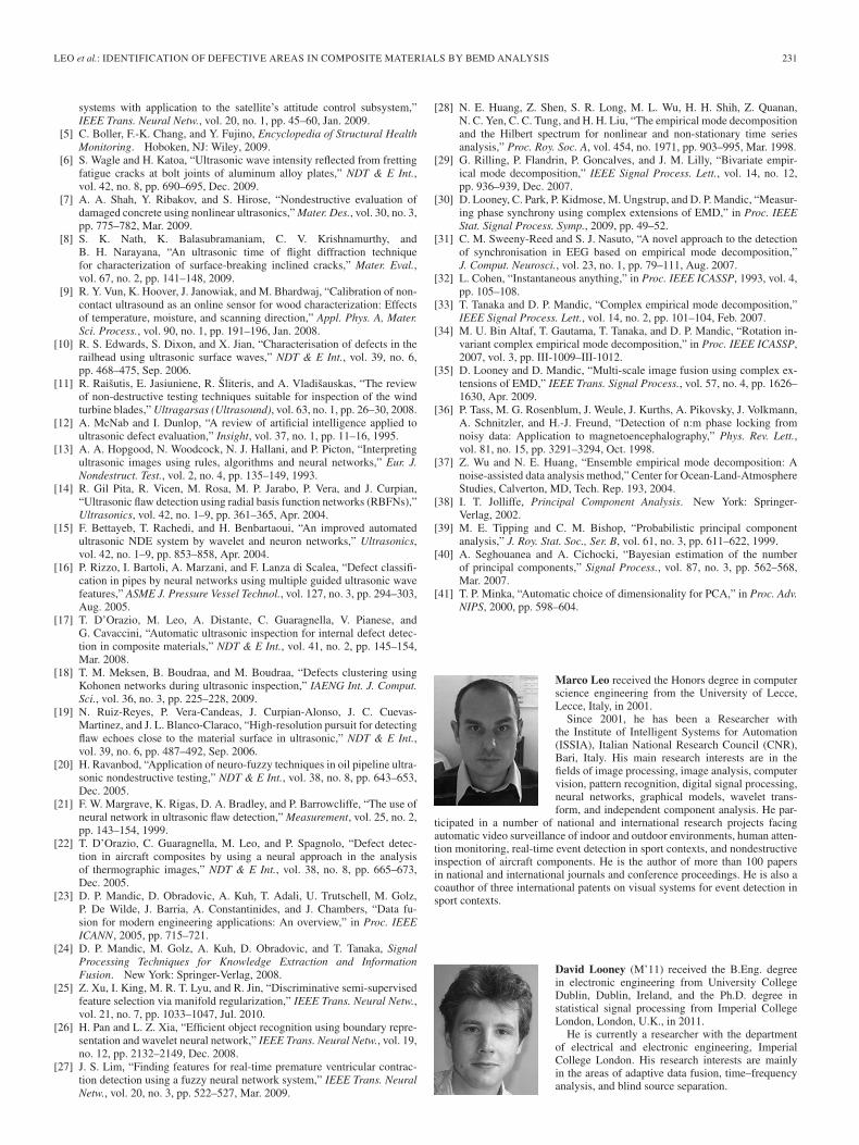
Marco Leo received the Honors degree in computerscience engineering from the University of Lecce,Lecce, Italy, in 2001.
Since 2001, he has been a Researcher withthe Institute of Intelligent Systems for Automation(ISSIA), Italian National Research Council (CNR),Bari, Italy. His main research interests are in thefields of image processing, image analysis, computervision, pattern recognition, digital signal processing,neural networks, graphical models, wavelet trans-form, and independent component analysis. He par-
ticipated in a number of national and international research projects facingautomatic video surveillance of indoor and outdoor environments, human atten-tion monitoring, real-time event detection in sport contexts, and nondestructiveinspection of aircraft components. He is the author of more than 100 papersin national and international journals and conference proceedings. He is also acoauthor of three international patents on visual systems for event detection insport contexts.
David Looney (M’11) received the B.Eng. degreein electronic engineering from University CollegeDublin, Dublin, Ireland, and the Ph.D. degree instatistical signal processing from Imperial CollegeLondon, London, U.K., in 2011.
He is currently a researcher with the departmentof electrical and electronic engineering, ImperialCollege London. His research interests are mainlyin the areas of adaptive data fusion, time–frequencyanalysis, and blind source separation.
232 IEEE TRANSACTIONS ON INSTRUMENTATION AND MEASUREMENT, VOL. 61, NO. 1, JANUARY 2012
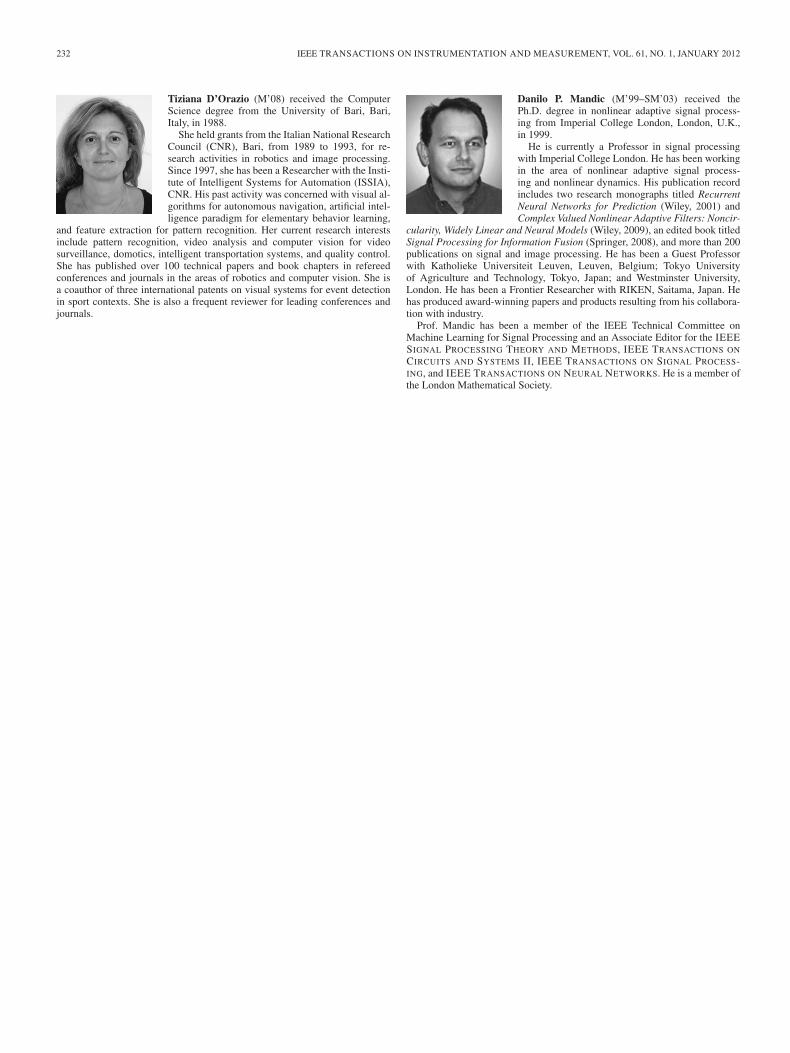
Tiziana D’Orazio (M’08) received the ComputerScience degree from the University of Bari, Bari,Italy, in 1988.
She held grants from the Italian National ResearchCouncil (CNR), Bari, from 1989 to 1993, for re-search activities in robotics and image processing.Since 1997, she has been a Researcher with the Insti-tute of Intelligent Systems for Automation (ISSIA),CNR. His past activity was concerned with visual al-gorithms for autonomous navigation, artificial intel-ligence paradigm for elementary behavior learning,
and feature extraction for pattern recognition. Her current research interestsinclude pattern recognition, video analysis and computer vision for videosurveillance, domotics, intelligent transportation systems, and quality control.She has published over 100 technical papers and book chapters in refereedconferences and journals in the areas of robotics and computer vision. She isa coauthor of three international patents on visual systems for event detectionin sport contexts. She is also a frequent reviewer for leading conferences andjournals.
Danilo P. Mandic (M’99–SM’03) received thePh.D. degree in nonlinear adaptive signal process-ing from Imperial College London, London, U.K.,in 1999.
He is currently a Professor in signal processingwith Imperial College London. He has been workingin the area of nonlinear adaptive signal process-ing and nonlinear dynamics. His publication recordincludes two research monographs titled RecurrentNeural Networks for Prediction (Wiley, 2001) andComplex Valued Nonlinear Adaptive Filters: Noncir-
cularity, Widely Linear and Neural Models (Wiley, 2009), an edited book titledSignal Processing for Information Fusion (Springer, 2008), and more than 200publications on signal and image processing. He has been a Guest Professorwith Katholieke Universiteit Leuven, Leuven, Belgium; Tokyo Universityof Agriculture and Technology, Tokyo, Japan; and Westminster University,London. He has been a Frontier Researcher with RIKEN, Saitama, Japan. Hehas produced award-winning papers and products resulting from his collabora-tion with industry.
Prof. Mandic has been a member of the IEEE Technical Committee onMachine Learning for Signal Processing and an Associate Editor for the IEEESIGNAL PROCESSING THEORY AND METHODS, IEEE TRANSACTIONS ON
CIRCUITS AND SYSTEMS II, IEEE TRANSACTIONS ON SIGNAL PROCESS-ING, and IEEE TRANSACTIONS ON NEURAL NETWORKS. He is a member ofthe London Mathematical Society.


