Embed Size (px)
Citation preview

977ACI Structural Journal/July-August 2014
ACI STRUCTURAL JOURNAL TECHNICAL PAPER
When analyzing reinforced concrete (RC) framed structures under monotonic loading—for example, progressive collapse and push-over analysis—besides flexural deformation, the so-called “fixed end” rotations induced by longitudinal bar slips at the beam-column ends connected to the joints can be significant and may result in additional vertical deformations not accounted for in the conventional analysis. Hence, it is important to quantify the deformations arising from the fixed end rotations. In this paper, shortcomings of existing bond stress-slip models are discussed in terms of application limitation and prediction accuracy. A new analytical model based on the bond stress integration along the bar stress propagation length is proposed to predict the bar-slip behavior in RC beam-column joints under monotonic loading. The phenomena of combined axial pullout and transverse dowel action at the joints are considered. The proposed model is validated with experimental studies from published literature and is shown to be simple, yet reliable.
Keywords: analytical model; axial pullout; bar stress propagation length; beam-column joint; bond stress-slip relationship; dowel action; monotonic loading.
INTRODUCTIONPrevious studies1-4 on bond-slip behavior in reinforced
concrete under generalized excitations showed that besides flexural deformations, significant additional deformations were caused by the fixed end rotations due to slippage of longitudinal steel reinforcement at the beam-column joints. Numerical simulations4,5 showed that the behavior of rein-forced concrete (RC) members with and without bond action is quite different in terms of predicted structural ductility and stiffness. The bar slip behavior causes significant stiff-ness degradation in the load-deformation relationships of moment-resisting frames.1 In some extreme situations, brittle bond failure in anchorage zones may cause severe partial or total collapse of structures.1 Therefore, bar slip behavior should be incorporated for better prediction of monotonic loading resistance of RC beam-column structures—for example, progressive collapse and pushover analysis.
In the previous studies, a number of local bond stress-slip relationships between steel reinforcement and concrete subjected to axial pullout have been proposed and can gener-ally be classified in terms of bond stress distribution, as shown in Fig. 1 and 2. One of them is a piecewise uniform distribution3,6,7—that is, bond stress distribution is idealized as mechanical bond τE and frictional bond τY along the entire embedment length, as shown in Fig. 1. Nevertheless, the boundary conditions considered in these models are limited to a few cases. Moreover, these analytical models were orig-inally proposed for seismic loading with damage accumu-
lation considered to quantify the bar slippage. Because the focus of the present study is on monotonic loading analysis, the bond stress distributions in these analytical models need to be validated against detailed bar-slip experiments subjected to monotonic loading.
Alternatively, some types of piecewise nonuniform distri-butions1,2,4,8,9 are found in the literature, as shown in Fig. 2. However, the multi-linear distribution,8 which is derived based on a non-yielding bar, is too simplistic to represent the complicated bar-slip behavior. In the logarithmic distri-bution,4 there is no descending branch to reflect bond deteri-oration, and the logarithmic distribution results in an unrea-sonably large bond stress. The nonlinear equation-controlled models1,2,9 are similar in form, but the embedment length has to be divided into many segments, upon which iterative
Title No. 111-S83
Bond Stress-Slip Prediction under Pullout and Dowel Action in Reinforced Concrete Jointsby Long Xu, Tan Kang Hai, and Lee Chi King
ACI Structural Journal, V. 111, No. 4, July-August 2014.MS No. S-2013-068.R2, doi: 10.14359/51686816, was received July 12, 2013, and
reviewed under Institute publication policies. Copyright © 2014, American Concrete Institute. All rights reserved, including the making of copies unless permission is obtained from the copyright proprietors. Pertinent discussion including author’s closure, if any, will be published ten months from this journal’s date if the discussion is received within four months of the paper’s print publication.
Fig. 1—Bond stress distribution in piecewise uniform form.
Fig. 2—Bond stress distributions in piecewise nonuniform form.
978 ACI Structural Journal/July-August 2014
calculations have to be performed. Consequently, too much computational effort is required when analyzing large-scale RC framed structures.
On the other hand, one common demerit of existing analytical models is that only pullout action is accounted for and dowel action of reinforcing bars is ignored. In fact, with increasing deformation, dowel action at the bottom steel reinforcement of the joint region commences as well in a typical column-removal scenario in progressive collapse. The inclination angle of beams with respect to the hori-zontal axis is observed to be up to 15 degrees when catenary action is mobilized.10 Additionally, experimental studies11,12 showed that the steel reinforcement under the combined axial pullout and transverse dowel actions will yield earlier than the steel reinforcement subjected to only pullout actions. Therefore, the actual bar-slip behavior should incor-porate not only the pullout mechanism but also dowel action to resist transverse shear.
Based on the previous discussions on the demerits of previous analytical models, the ideal bond stress-slip rela-tionship for large-scale structures should be simple and reli-able, incorporating the important factors associated with: a) nonlinearity of steel materials; b) different embedment lengths and boundary conditions; and c) the coexistence of axial pullout and transverse dowel action. Therefore, to overcome the demerits of existing models, an analytical model is proposed in the present study by employing a piece-wise uniform bond stress distribution to perform monotonic loading analysis for RC framed structures with simplicity, reliability, and practicability.
It should be noted that the proposed analytical model focuses on the predictions of bond-slip response in RC joints under monotonic loading. Dynamic loading effects, such as damage accumulation and unloading/reloading scenarios, are not taken into consideration.
RESEARCH SIGNIFICANCEAn analytical model is proposed to predict the bar-slip
behavior in the RC beam-column joints under monotonic loading. The proposed model addresses the limit embed-ment length in RC joints and the coexistence of axial pullout and dowel action. The derivations are based on the concept of stress propagation length: steel constitutive law; equi-librium of bond; bar forces; and compatibility of deforma-tion along the steel reinforcement. According to validations using experimental results, the proposed simple and reliable analytical model is capable of effectively predicting the bar-slip behavior subjected to axial pullout with and without transverse dowel action in RC joints.
BOND-SLIP ANALYTICAL MODEL UNDER AXIAL PULLOUT ACTION
AssumptionsIn this paper, the term slip S is defined as the relative
longitudinal displacement between main steel reinforcement and concrete, which can be measured at the loaded ends of embedded bars if careful instrumentations are made. For the surrounding concrete, no splitting failure is assumed
to occur along the steel reinforcement. This assumption is fairly reasonable, as splitting failure is seldom observed in RC joints confined by transverse reinforcement.7 The area of steel reinforcement is considered to be small and the steel strain is sufficiently large so the influence of concrete defor-mation on slip is negligible.
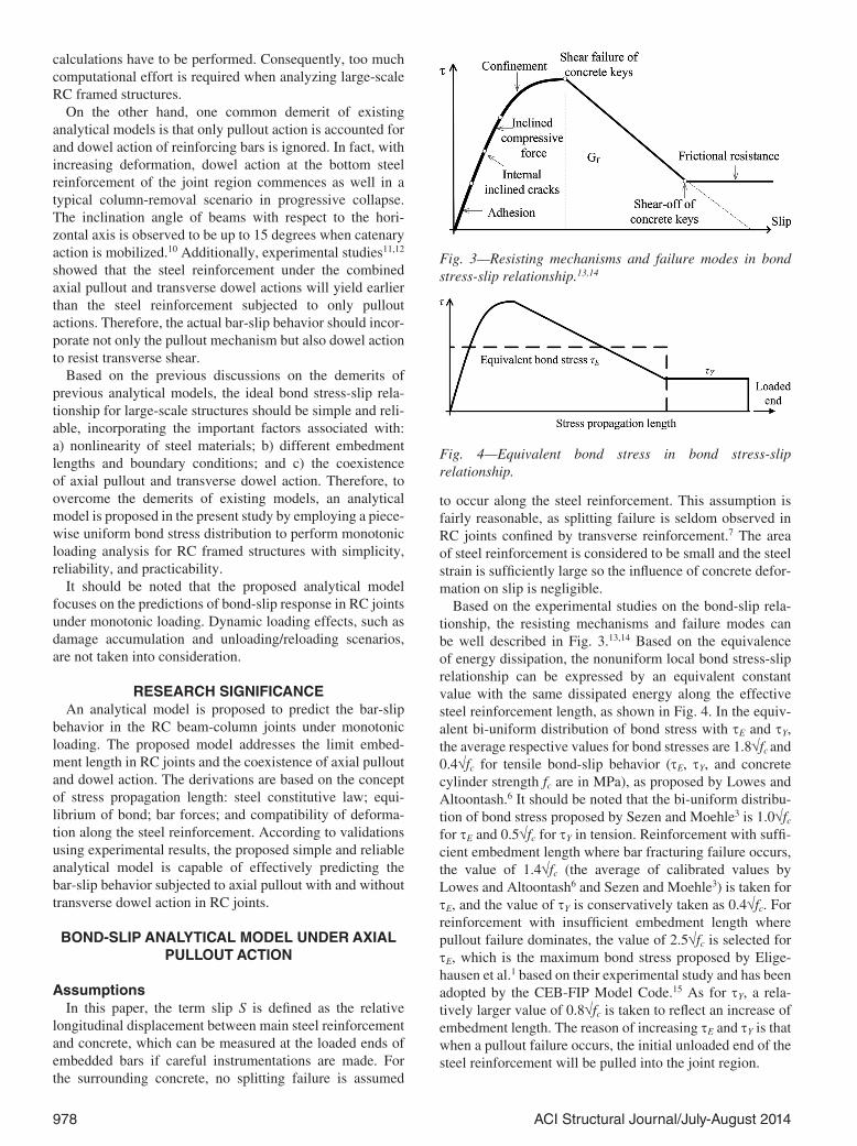
Based on the experimental studies on the bond-slip rela-tionship, the resisting mechanisms and failure modes can be well described in Fig. 3.13,14 Based on the equivalence of energy dissipation, the nonuniform local bond stress-slip relationship can be expressed by an equivalent constant value with the same dissipated energy along the effective steel reinforcement length, as shown in Fig. 4. In the equiv-alent bi-uniform distribution of bond stress with τE and τY, the average respective values for bond stresses are 1.8√fc and 0.4√fc for tensile bond-slip behavior (τE, τY, and concrete cylinder strength fc are in MPa), as proposed by Lowes and Altoontash.6 It should be noted that the bi-uniform distribu-tion of bond stress proposed by Sezen and Moehle3 is 1.0√fc for τE and 0.5√fc for τY in tension. Reinforcement with suffi-cient embedment length where bar fracturing failure occurs, the value of 1.4√fc (the average of calibrated values by Lowes and Altoontash6 and Sezen and Moehle3) is taken for τE, and the value of τY is conservatively taken as 0.4√fc. For reinforcement with insufficient embedment length where pullout failure dominates, the value of 2.5√fc is selected for τE, which is the maximum bond stress proposed by Elige-hausen et al.1 based on their experimental study and has been adopted by the CEB-FIP Model Code.15 As for τY, a rela-tively larger value of 0.8√fc is taken to reflect an increase of embedment length. The reason of increasing τE and τY is that when a pullout failure occurs, the initial unloaded end of the steel reinforcement will be pulled into the joint region.
Fig. 3—Resisting mechanisms and failure modes in bond stress-slip relationship.13,14
Fig. 4—Equivalent bond stress in bond stress-slip relationship.
979ACI Structural Journal/July-August 2014
The effective embedment length of a steel reinforcement is not necessarily taken as the actual embedment length. A concept termed “stress propagation length” is proposed to describe the propagation of bar stresses along the steel reinforcement. The stress propagation length can be smaller than the actual embedment length for reinforcement with sufficient embedment. On the other hand, stress propaga-tion length can also be greater than the actual embedment length for reinforcement with insufficient embedment, in which certain boundary conditions for the reinforcement can contribute to an additional equivalent embedment length. One such example is that the midpoint of a continuous rein-forcement in a joint can provide symmetric boundary forces for the stress propagations at both sides. The concept of “stress propagation length” is able to overcome the disad-vantages of existing analytical models,3,6 such as the predic-tions of bar-slip behavior with an insufficient embedment length of steel reinforcement.
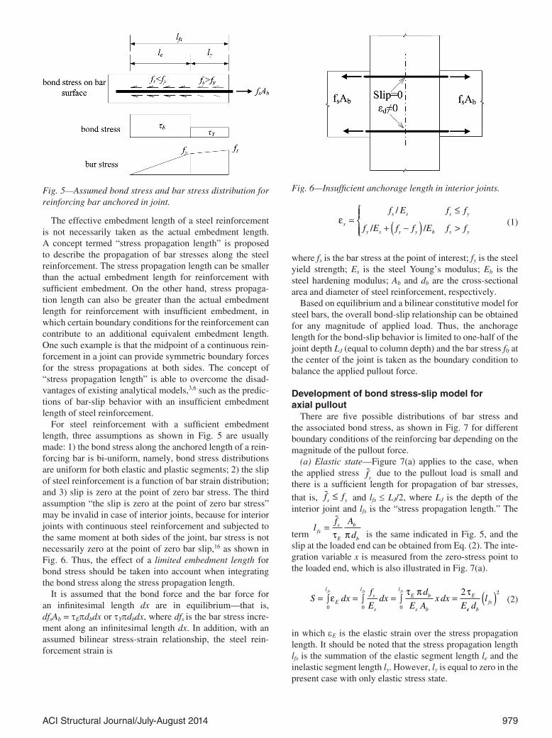
For steel reinforcement with a sufficient embedment length, three assumptions as shown in Fig. 5 are usually made: 1) the bond stress along the anchored length of a rein-forcing bar is bi-uniform, namely, bond stress distributions are uniform for both elastic and plastic segments; 2) the slip of steel reinforcement is a function of bar strain distribution; and 3) slip is zero at the point of zero bar stress. The third assumption “the slip is zero at the point of zero bar stress” may be invalid in case of interior joints, because for interior joints with continuous steel reinforcement and subjected to the same moment at both sides of the joint, bar stress is not necessarily zero at the point of zero bar slip,16 as shown in Fig. 6. Thus, the effect of a limited embedment length for bond stress should be taken into account when integrating the bond stress along the stress propagation length.
It is assumed that the bond force and the bar force for an infinitesimal length dx are in equilibrium—that is, dfsAb = τEπdbdx or τYπdbdx, where dfs is the bar stress incre-ment along an infinitesimal length dx. In addition, with an assumed bilinear stress-strain relationship, the steel rein-forcement strain is
εs
s s s y
y s s y h s y
f E f f
f E f f E f f=
≤
+ −( ) >
/
/ / (1)
where fs is the bar stress at the point of interest; fy is the steel yield strength; Es is the steel Young’s modulus; Eh is the steel hardening modulus; Ab and db are the cross-sectional area and diameter of steel reinforcement, respectively.
Based on equilibrium and a bilinear constitutive model for steel bars, the overall bond-slip relationship can be obtained for any magnitude of applied load. Thus, the anchorage length for the bond-slip behavior is limited to one-half of the joint depth LJ (equal to column depth) and the bar stress f0 at the center of the joint is taken as the boundary condition to balance the applied pullout force.
Development of bond stress-slip model for axial pullout
There are five possible distributions of bar stress and the associated bond stress, as shown in Fig. 7 for different boundary conditions of the reinforcing bar depending on the magnitude of the pullout force.
(a) Elastic state—Figure 7(a) applies to the case, when the applied stress �fs
due to the pullout load is small and there is a sufficient length for propagation of bar stresses,
that is, �f fs y≤ and lfs ≤ LJ/2, where LJ is the depth of the interior joint and lfs is the “stress propagation length.” The
term l
f A
dfss
E
b
b
=�
τ π is the same indicated in Fig. 5, and the slip at the loaded end can be obtained from Eq. (2). The inte-gration variable x is measured from the zero-stress point to the loaded end, which is also illustrated in Fig. 7(a).
S dx
f
Edx
d
E Ax dx
E
l
E
ls
s
lE b
s b
Efs fs fs
= ∫ = ∫ = ∫ =0 0 0
2ε
τ π τ
ss bfsd
l( )2
(2)
in which εE is the elastic strain over the stress propagation length. It should be noted that the stress propagation length lfs is the summation of the elastic segment length le and the inelastic segment length ly. However, ly is equal to zero in the present case with only elastic stress state.
Fig. 5—Assumed bond stress and bar stress distribution for reinforcing bar anchored in joint.
Fig. 6—Insufficient anchorage length in interior joints.

980 ACI Structural Journal/July-August 2014
(b) Elastic state with non-zero stress boundary—Under increasing force �f As b at the joint perimeter (Fig. 7(b)), the bar stress along the steel reinforcement will propagate toward the joint center. If the joint depth is insufficient and the bar yield strength is relatively large, then the distribu-tions of bond stress and bar stress as shown in Fig. 7(b) are
mobilized with �f fs y≤ and lfs > LJ/2. The integrated slip at the loaded end is given in Eq. (3).
S dxf f f
Edx
fd
Ax
E
L
E
L
s
s
L E b
b
J J
J
= ∫ = ∫+ −( )
= ∫+
0
2
0
20 0
0
20
ε
τ π
ss s
J E
s b
Jdxf
E
L
E d
L
= +
0
2
2
2
2
τ
(3)
Fig. 7—Stress propagation of steel reinforcement and corresponding bond stress.
981ACI Structural Journal/July-August 2014
with f f
d
A
Ls
E b
b
J0 2
= −�τ π
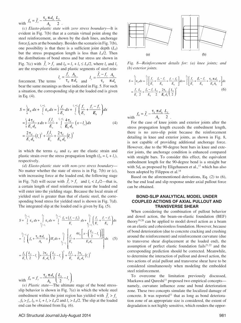
.(c) Elasto-plastic state with zero stress boundary—It is
evident in Fig. 7(b) that at a certain virtual point along the steel reinforcement, as shown by the dash lines, anchorage force f0 acts at the boundary. Besides the scenario in Fig. 7(b), one possibility is that there is a sufficient joint depth (LJ) but the stress propagation length is less than LJ/2. Then the distributions of bond stress and bar stress are shown in
Fig. 7(c) with �f fs y> and lfs = ly + le ≤ LJ/2, where le and ly are the respective elastic and plastic segments of steel rein-
forcement. The terms l
f A
de
y
E
b
b
=τ π and
lf f A
dy
s y
Y
b
b
=−�
τ π bear the same meanings as those indicated in Fig. 5. For such a situation, the corresponding slip at the loaded end is given in Eq. (4).
S dx dxf
Edx
f
E
f fl
El
l l
Y
ls
s l
l ly
s
s ye
e
y e e
e
y e
= ∫ + ∫ = ∫ + ∫ +−+ +
0 0
ε εEE
dx
E dx dx
f l
E
h
lE
s b
y y
s l
l lY
e
e
y e
= ∫ + + ∫+
0
4 4τ τEE d
x l dx
E dl
f l
E E d
h be
E
s be
y y
s
Y
h b
−( )
= ( ) + + 2 22τ τ
lly( )2
(4)
in which the terms εE and εY are the elastic strain and plastic strain over the stress propagation length (lfs = le + ly), respectively.
(d) Elasto-plastic state with non-zero stress boundary—No matter whether the state of stress is in Fig. 7(b) or (c), with increasing force at the loaded end, the following stage
in Fig. 7(d) will occur with �f fs y> and ly < LJ/2—that is, a certain length of steel reinforcement near the loaded end will enter into the yielding stage. Because the local strain of yielded steel is greater than that of elastic steel, the corre-sponding bond stress for yielded steel is shown in Fig. 7(d). The integrated slip at the loaded end is given by Eq. (5).
S dx dxf f f
Edx
Ll
EL
l
L
Y
Ll
s
s
Jy
Jy
J Jy
= ∫ + ∫ = ∫+ −( )
+−
−
−
0
2
2
2
0
20 0ε ε
LLl
L
y
s
s y
h
Ll
E b
b
Jy
J
Jy
f
E
f f
Edx
fd
Ax
2
2
0
2
0
−
−
∫ +−
= ∫ + τ π
+ ∫ +− −
−
/E dxf
E
xL
l
E dsL
l
L
y
s
YJ
y
h bJy
J
2
24
2τ
= −
+ −
+
dx
f
E
Ll
E d
Ll
f
s
Jy
E
s b
Jy
0
2
2
2
2
τ yy y
s
Y
h by
l
E E dl+ ( )2 2τ
(5)
with f f
d
A
Lly
E b
b
Jy0 2
= − −
τ π.
(e) Plastic state—The ultimate stage of the bond stress-slip behavior is shown in Fig. 7(e) in which the whole steel embedment within the joint region has yielded with �f fs y>, f0 > fy, lfs = le + ly > LJ/2 and ly > LJ/2. The slip at the loaded end can be obtained from Eq. (6).
S dxf
E
f f
E
f f
Edx
f
E
L
Y
L
y
s
y
h
s
h
L
y
s
J J J
= ∫ = ∫ +−
+−
= ∫ +
0
2
0
2 0 0
0
2
εff f
E
d
E Ax dx
f
E
L f f
E
L
y
h
Y b
h b
y
s
J y
h
J Y
0
0
2 2
2
−+
= +−
+
τ π
τ
EE d
L
h b
J
2
2
(6)
with f f
d
A
Ls
Y b
b
J0 2
= −�τ π
.For the case of knee joints and exterior joints after the
stress propagation length exceeds the embedment length, there is no zero-slip point because the reinforcement detailing in knee and exterior joints, as shown in Fig. 8, is not capable of providing additional anchorage force. However, due to the 90-degree bent bars in knee and exte-rior joints, the anchorage condition is enhanced compared with straight bars. To consider this effect, the equivalent embedment length for the 90-degree bend is a straight bar with 5db as proposed by Eligehausen et al.,17 which has also been adopted by Filippou et al.18
Based on the aforementioned derivations, Eq. (2) to (6), the bar end load and slip response under axial pullout force can be obtained.
BOND-SLIP ANALYTICAL MODEL UNDER COUPLED ACTIONS OF AXIAL PULLOUT AND
TRANSVERSE SHEARWhen considering the combination of pullout behavior
and dowel action, the beam-on-elastic foundation (BEF) theory19,20 can be applied to model dowel action as a beam on an elastic and cohesionless foundation. However, because of bond deterioration (due to concrete cracking and crushing around the reinforcement) and reinforcement curvature (due to transverse shear displacement at the loaded end), the assumption of perfect elastic foundation fails21,22 and the corresponding prediction should be corrected. Meanwhile, to determine the interaction of pullout and dowel action, the two actions of axial pullout and transverse shear have to be considered simultaneously when modeling the embedded steel reinforcement.
To overcome the limitation previously discussed, Maekawa and Qureshi11 proposed two empirical concepts—namely, curvature influence zone and bond deterioration zone. These two concepts simulate the localized damage of concrete. It was reported11 that as long as bond deteriora-tion zone of an appropriate size is considered, the extent of degradation is not highly sensitive, which renders the oppor-
Fig. 8—Reinforcement details for: (a) knee joints; and (b) exterior joints.

982 ACI Structural Journal/July-August 2014
tunity to adopt the proposed bi-uniform bond-slip model in the present work.
Curvature influence zoneFor the curvature influence zone as shown in Fig. 9(a), the
length of the initial curvature influence zone Lc0 is obtained from Eq. (7) based on the BEF theory.11,19,20
L
E I
Kcs b
04
3
4
4=
π (7)
where Es is the steel Young’s modulus; Ib is the moment of inertia of the reinforcing bar cross section; and K = 150fc
0.85 as given by Soltani et al.23 With increasing transverse shear displacement δb, as shown in Fig. 9(a), the curvature influ-ence zone is observed to increase one to two times bar diam-eter. By defining a non-dimensional damage parameter DI, the length of the curvature influence zone11 can be empiri-cally expressed in Eq. (8).
LL DI
L DIc
c
c
=<
+ −0
0
0 02
1 3
.
00 02 0 020 8
. ..( ){ } ≥
DI (8)
where DI = (1 + 150Slip/db)δb/db. It should be noted that DI represents the damage due to curvature influence zone. Therefore, the curvature distribution11 along a reinforcing bar is empirically given in Eq. (9), with the maximum curva-ture Φmax = 64δb/(11Lc
2) obtained by satisfying the boundary and continuity conditions.24
Φ
Φ
( )xL
L L xL
xc
c cc
=
−
− −
≤3 3
43
20
2
2
max xxL
L x
L
c
c
c
≤
−( )2
32
2
Φmax L
x Lcc2
< ≤
(9)
Bond deterioration zoneThe region where the bond performance may deteriorate
near the interface is empirically taken into account, as shown
in Fig. 9(b). The length of bond deterioration zone Lb is taken as the greater value of Lc and 5db as proposed by Maekawa and Qureshi.11 Consequently, the bond stress distribution is given in Eq. (10).
τ τb
b
b
bb
xL
Lx
Lx L
=≤ ≤
< ≤
0 0
2
2max
(10)
where τmax is equal to the bond stress with τE or τY as proposed for axial pullout, depending on the stress state near the joint interface.
Thus, the curvature distribution along the reinforcing bar and the bond stress deterioration near the beam-column joint interface can be calculated and both the axial and transverse stresses in the embedded bar can be iteratively computed with the coupled axial pullout behavior and transverse dowel action. A similar concept has been adopted by other researchers25 in finite element analysis to model the dowel action of reinforcement in RC structures at a structural level. However, such a concept has not been considered in any previous bar-slip analytical models.
Computational procedureThe overall computational procedure is schematically
shown in Fig. 10. To accurately describe the stress-strain profiles at the critical zones (bond deterioration zone and curvature influence zone), the bar embedment length and the reinforcement cross section are discretized for iterative calculations. To balance accuracy with computational cost, 20 segments are employed for bar embedment length and 10 fibers are employed for reinforcement cross section in the present study. A typical case is illustrated in Fig. 11, where there are totally 21 nodes (N = 21 shown in Fig. 10). As shown in Fig. 10, two nested iteration loops over the embedment length of bars should be conducted to enforce equilibrium, local bond-slip relationships (as proposed for axial pullout), constitutive models of steel and compati-bility conditions between steel and concrete. First, with the plane-section-remains-plane assumption for the section of the embedded bar, the average bar strain εs is iteratively obtained to satisfy the steel constitutive model with local
Fig. 9—Bar curvature and bond stress distributions along embedded bar.11

983ACI Structural Journal/July-August 2014
bar strain εsi and bar stress σsi at each steel fiber over the cross-sectional area, and the average bar stress σs is calcu-lated based on local bond stress-bar stress equilibrium. Second, with the satisfaction of cross-sectional analysis at each segment, the stress propagation length lfs is iteratively determined to satisfy the boundary condition of bar slip at the loaded end. A worked example for the flowchart shown in Fig. 10 is given in the Appendix.*
*The Appendix is available at www.concrete.org/publications in PDF format, appended to the online version of the published paper. It is also available in hard copy from ACI headquarters for a fee equal to the cost of reproduction plus handling at the time of the request.
It should be noted that to describe the shear transfer mechanism in a more accurate way, the aggregate interlock model proposed by Maekawa and Qureshi26 was applied with the shear transfer by dowel action. Nevertheless, aggre-gate interlock mechanism does not contribute much to the bar-slip behavior when analyzing a single reinforcing bar at the tensile region in an RC joint. This is because the crack has already propagated throughout the concrete area around the reinforcing bar and there is an interface formed at the crack. Thus, the effect of aggregate interlock mechanism is excluded in the present work.
VALIDATIONS OF PROPOSED MODEL
Axial pullout actionTo validate the prediction accuracy of the proposed
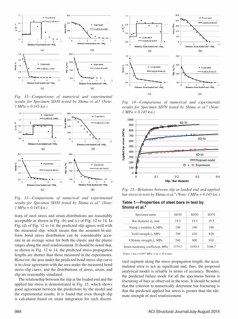
analytical model in the axial pullout loading scenario, the experimental studies by Ueda et al.8 and Shima et al.4 are employed due to their comprehensive descriptions of the test details and well-cited test results. Due to space limitations, only the three well-designed tests conducted by Shima et al.4 are discussed in detail—that is, Specimens SD30, SD50, and SD70 with embedded straight bars. The embedment length of 50 times of the bar diameter is sufficient to provide the boundary condition of zero slip at the unloaded end. To emphasize the effect of steel reinforcement in the post-yield range, three kinds of steel with the same Young’s modulus but different yield strengths were used as shown in Table 1. The stress-strain relationship of the steel bars used in the analysis by Shima et al.4 was described by complex equa-tions, which are too complicated to be employed in prac-tice. Instead, a simple bilinear stress-strain relationship is assumed in the present study and the strain-hardening coeffi-cients of steel bars in Table 1 are obtained based on the slope of the stress-strain curves between the yielding initiation and the maximum applied stress (approximately corresponding to 3% strain) as reported by Shima et al.4 The compressive strength of concrete fc was 19.6 MPa (2.84 ksi) for all the three specimens. The steel bars were embedded in concrete with a sufficient cover to avoid splitting cracks.
In Fig. 12 to 14, the distributions of bond stress, slip, steel stress, and strain along the bar obtained from the proposed analytical model for all three specimens are compared with the experimental results. As shown in Fig. 12(a), 13(a), and 14(a), the general trend of the bond stress distribution and the critical points between elastic and plastic ranges of steel reinforcement are reasonably predicted. Also, the predic-
Fig. 10—Computational procedure of combination of axial pullout and transverse dowel action.
Fig. 11—Typical case of discretized bar embedment length and reinforcement cross section.
984 ACI Structural Journal/July-August 2014
tions of steel stress and strain distributions are reasonably acceptable as shown in Fig. (b) and (c) of Fig. 12 to 14. In Fig. (d) of Fig. 12 to 14, the predicted slip agrees well with the measured slip, which means that the assumed bi-uni-form bond stress distribution can be considerably accu-rate in an average sense for both the elastic and the plastic ranges along the steel reinforcement. It should be noted that, as shown in Fig. 12 to 14, the predicted stress propagation lengths are shorter than those measured in the experiments. However, the area under the predicted bond stress-slip curve is in close agreement with the area under the measured bond stress-slip curve, and the distributions of stress, strain, and slip are reasonably simulated.
The relationship between the slip at the loaded end and the applied bar stress is demonstrated in Fig. 15, which shows good agreement between the predictions by the model and the experimental results. It is found that even though slip is calculated based on strain integration for each discret-
ized segment along the stress propagation length, the accu-mulated error is not as significant and, thus, the proposed analytical model is reliable in terms of accuracy. Besides, the predicted failure mode for all the specimens herein is fracturing of bars as observed in the tests. It should be noted that the criterion to numerically determine bar fracturing is that the predicted applied bar stress is greater than the ulti-mate strength of steel reinforcement.
Table 1—Properties of steel bars in test by Shima et al.4
Specimen name SD30 SD50 SD70
Bar diameter db, mm 19.5 19.5 19.5
Young’s modulus E, MPa 190 190 190
Yield strength fy, MPa 350 610 820
Ultimate strength fu, MPa 540 800 910
Strain-hardening coefficient, MPa 1775.7 3359.5 3166.7
Notes: 1 ksi = 6.897 MPa; 1 in. = 25.4 mm.
Fig. 12—Comparisons of numerical and experimental results for Specimen SD30 tested by Shima et al.4 (Note: 1 MPa = 0.145 ksi.)
Fig. 13—Comparisons of numerical and experimental results for Specimen SD50 tested by Shima et al.4 (Note: 1 MPa = 0.145 ksi.)
Fig. 14—Comparisons of numerical and experimental results for Specimen SD70 tested by Shima et al.4 (Note: 1 MPa = 0.145 ksi.)
Fig. 15—Relations between slip at loaded end and applied bar stress in tests by Shima et al.4 (Note: 1 MPa = 0.145 ksi.)

985ACI Structural Journal/July-August 2014
It should be clarified that the reported experiments did not continue until the steel bars fractured as their ultimate strengths indicated. However, the ultimate tensile strengths (Table 1) are employed as the criterion of steel fracture in the analytical model. Thus, the maximum slips and ulti-mate applied bar stresses predicted by the proposed analyt-ical model are slightly greater than those obtained from the experimental studies.
In general, the proposed analytical model is capable of predicting the bond-slip behavior with pullout failure and bar fracturing due to axial pullout action.
Axial pullout and transverse dowel actionWhen validating the proposed analytical model with
consideration of both pullout behavior and dowel action, the two empirical concepts of the bond deterioration zone and the curvature influence zone will be validated first. The experimental studies conducted by Maekawa and Qureshi11 and Soltani and Maekawa12,24 are employed herein.
To illustrate the effect of dowel action to the steel rein-forcement embedded in concrete, Specimen 411 is analyzed with the two empirical concepts of bond deterioration zone and curvature influence zone. Similar to the distributions shown by Soltani et al.,12 the predicted distributions of axial steel stress, strain, and curvature along the embedded bar illustrate that the curvature distribution near the interface does influence the stress and strain distributions and results in localized yielding. On the other hand, the curvature distri-butions along the bar for different transverse displacements are calculated and compared with the experimental results24 in Fig. 16, which shows that the predictions by the proposed analytical model agree well with the experimental results.
Finally, a series of tests from Maekawa and Qureshi11 are employed to validate the proposed analytical model in the presence of both axial pullout and transverse dowel action. The predictions for all the eight specimens are shown in Fig. 17 in terms of the relationship between the slip at the loaded end and the applied bar stress. Generally, the analyt-ical model is capable of predicting the coupled actions of axial pullout and transverse shear. As shown in Fig. 17, the predictions subjected to an axial pullout are denoted as ‘Pullout only’ and the results subjected to coupled axial and transverse actions are denoted as ‘Pullout and dowel action.’ It is apparent that the presence of the transverse dowel action brings about an evident degradation of the pullout resistance due to the localized yielding, as discussed previously, and it is important to simultaneously consider axial pullout and transverse shear when modeling the behavior of embedded steel reinforcement.
However, it should be noted that there are certain discrep-ancies for Specimens 3 and 8. The discrepancy for Spec-imen 3 is due to damage accumulation from the applied cyclic loading even when the specimen was approaching failure in the test. As for Specimen 8, it is found that the ratio of transverse displacement with respect to slip is of the same order with that for Specimens 3 as reported by Maekawa and Qureshi,11 which is much greater than the ratios for the other specimens in the same series. Therefore, the proposed analytical model is more suitable for the predictions of bond-
slip behavior subjected to monotonic loading with relatively moderate transverse displacement with respect to axial slip.
CONCLUSIONSA simple and reliable analytical model based on a bi-
uniform bond stress distribution is proposed to predict the relationship between the slip at the loaded end and the applied load in the RC joints under monotonic loading. Based on experimental results obtained from the literature, the bi- uniform bond stress distribution is suggested. Different formulations according to the proposed stress propagation length are derived to satisfy the equilibrium and compati-bility conditions in the axial pullout loading scenario. Addi-tionally, dowel action of steel reinforcement is also incorpo-rated to emphasize the effects of transverse displacement at the beam/column and joint interface.
The proposed bond-slip analytical model is validated against experimental results under monotonic loading scenarios of axial pullout with and without transverse dowel action. The validations for axial pullout predictions include not only the comparisons of the slip-force relationship, but also the comparisons of the detailed distributions of bond stress, bar stress, and bar strain along the steel reinforce-ment. Finally, the proposed analytical model is validated against a series of tests in the presence of both axial pullout and transverse dowel action. It is shown that the proposed model is considerably reliable in terms of accuracy, even though the slip is calculated based on strain integration for each discretized segment along the stress propagation length. Moreover, it is demonstrated that the presence of the transverse dowel action results in an evident degradation of pullout resistance and it is important to account for the effects of dowel action in the bond-slip analytical model. In conclusion, the proposed analytical model is capable of effectively predicting the bar-slip behavior under monotonic loading scenarios of axial pullout with and without trans-verse dowel action in the RC beam-column joints.
AUTHOR BIOSLong Xu is a PhD Student at Nanyang Technological University, Singa-pore. He received his BS from Tongji University, Shanghai, China, and his MS from the Institute of Mechanics, Chinese Academy of Sciences, Beijing,
Fig. 16—Curvature distributions along embedded bar with different transverse displacements, validated against exper-iment results from Soltani and Maekawa.24 (Note: 1 mm = 0.0394 in.)

986 ACI Structural Journal/July-August 2014
China. His research interests include finite element analysis of framed structures under extreme loading.
Tan Kang Hai is a Professor and Director of NTU-MINDEF Protective Technology Research Center at Nanyang Technological University. He received his BS and PhD from the University of Manchester, Manchester, UK. His research interests include structural fire engineering, strut-and-tie modeling of reinforced concrete structures, progressive collapse analysis and testing of structures, finite element programs for heat transfer analysis, and nonlinear structural analysis.
Lee Chi King is an Associate Professor at Nanyang Technological Univer-sity. He received his BS from the University of Hong Kong, Hong Kong, China, and his PhD from the University of London, Imperial College, London, UK. His research interests include finite element model genera-tion, error analysis, adaptive algorithms, fatigue analysis of tubular joints, and steel structures.
REFERENCES1. Eligehausen, R.; Popov, E. P.; and Bertero, V. V., “Local Bond Stress-
Slip Relationships of Deformed Bars under Generalized Excitations,”
Fig. 17—Relations between slip at loaded end and applied bar stress in tests by Maekawa and Qureshi.11 (Note: 1 MPa = 0.145 ksi; 1 mm = 0.0394 in.)

987ACI Structural Journal/July-August 2014
Report UCB/EERC-83/23, Earthquake Engineering Research Center, University of California, Berkeley, Berkeley, CA, 1983, 169 pp.
2. Russo, G.; Zingone, G.; and Romano, F., “Analytical Solution for Bond-Slip of Reinforcing Bars in R.C. Joints,” Journal of Structural Engi-neering, ASCE, V. 116, No. 2, Feb. 1990, pp. 336-355.
3. Sezen, H., and Moehle, J. P., “Bond-Slip Behavior of Reinforced Concrete Members,” fib-Symposium: Concrete Structures in Seismic Regions, CEB-FIP, Athens, Greece, 2003, 10 pp.
4. Shima, H.; Chou, L. L.; Okamura H., “Micro and Macro Models for Bond in Reinforced Concrete,” Journal of the Faculty of Engineering, V. XXXIX, No. 2, 1987, pp. 133-194.
5. Lykidis, G. C., and Spiliopoulos, K., “3D Solid Finite-Element Analysis of Cyclically Loaded RC Structures Allowing Embedded Rein-forcement Slippage,” Journal of Structural Engineering, ASCE, V. 134, No. 4, 2008, pp. 629-638.
6. Lowes, L. N., and Altoontash, A., “Modeling Reinforced-Concrete Beam-Column Joints Subjected to Cyclic Loading,” Journal of Structural Engineering, ASCE, V. 129, No. 12, Dec. 2003, pp. 1686-1697.
7. Alsiwat, J. M., and Saatcioglu, M., “Reinforcement Anchorage Slip under Monotonic Loading,” Journal of Structural Engineering, ASCE, V. 118, No. 9, Sept. 1992, pp. 2421-2438.
8. Ueda, T.; Lin, I.; and Hawkins, N. M., “Beam Bar Anchorage in Exte-rior Column-Beam Connections,” ACI Journal, V. 83, No. 3, May-June 1986, pp. 412-422.
9. Eligehausen, R.; Ozbolt, J.; Genesio, G.; Hoehler, M. S.; and Pampanin, S., “Three-Dimensional Modelling of Poorly Detailed RC Frame Joints,” Proceedings of the New Zealand Society for Earthquake Engineering Conference 2006, New Zealand, 2006, 10 pp.
10. Yu, J., and Tan, K. H., “Experimental and Numerical Investigation on Progressive Collapse Resistance of Reinforced Concrete Beam Column Sub-assemblages,” Engineering Structures, V. 55, Oct. 2013, pp. 90-106.
11. Maekawa, K., and Qureshi, J., “Computational Model for Rein-forcing Bar Embedded in Concrete under Combined Axial Pullout and Transverse Displacement,” Journal of Materials, Concrete Structures and Pavements, V. 31, 1996, pp. 227-239.
12. Soltani, M.; An, X.; and Maekawa, K., “Localized Nonlinearity and Size-Dependent Mechanics of In-Plane RC Element in Shear,” Engineering Structures, V. 27, No. 6, 2005, pp. 891-908.
13. Haskett, M.; Oehlers, D. J.; and Ali, M. S. M., “Local and Global Bond Characteristics of Steel Reinforcing Bars,” Engineering Structures, V. 30, No. 2, Feb. 2008, pp. 376-383.
14. Goto, Y., “Cracks Formed in Concrete Around Deformed Tension Bars,” ACI Journal, V. 68, No. 4, Apr. 1971, pp. 244-251.
15. Comité Euro-International du Béton (CEB), “CEB-FIP Model Code 2010 (first complete draft),” Lausanne, Switzerland, 2010, 293 pp.
16. Yu, J., and Tan, K. H., “Bar Stress-Slip Relationship in Reinforced Concrete Joints with Large Inelastic Bar Strains,” The 4th International Conference on Design and Analysis of Protective Structures, Jeju, Korea, 2012, pp. 652-663.
17. Eligehausen, R.; Bertero, V. V.; and Popov, E. P., “Hysteretic Behavior of Reinforcing Deformed Hooked Bars in R/C Joints,” Proceed-ings of the Seventh European Conference on Earthquake Engineering, Athens, Greece, 1982, pp. 171-178.
18. Filippou, F. C.; Popov, E. P.; and Bertero, V. V., “Effects of Bond Deterioration on Hysteretic Behavior of Reinforced Concrete Joints,” Report UCB/EERC-83/19, Earthquake Engineering Research Center, University of California, Berkeley, Berkeley, CA, 1983, 184 pp.
19. Dei Poli, S.; Di Prisco, M.; and Gambarova, P., “Shear Response, Deformations, and Subgrade Stiffness of a Dowel Bar Embedded in Concrete,” ACI Structural Journal, V. 89, No. 6, Nov.-Dec. 1992, pp. 665-675.
20. Hetényi, M., Beams on Elastic Foundation, The University of Mich-igan Press, Ann Arbor, MI, 1946, 255 pp.
21. Maekawa, K., and Qureshi, J., “Embedded Bar Behavior in Concrete under Combined Axial Pullout and Transverse Displacement,” Journal of Materials, Concrete Structures and Pavements, V. 30, No. 532, 1996, pp. 183-196.
22. Mishima, T.; Suzuki, A.; Shinoda, Y.; and Maekawa, K., “Nonelastic Behavior of Axial Reinforcement Subjected to Axial and Slip Deforma-tion at the Crack Surface,” ACI Structural Journal, V. 92, No. 3, May-June 1995, pp. 380-385.
23. Soltani, M.; An, X.; and Maekawa, K., “Computational Model for Post Cracking Analysis of RC Membrane Elements Based on Local Stress-Strain Characteristics,” Engineering Structures, V. 25, No. 8, 2003, pp. 993-1007.
24. Soltani, M., and Maekawa, K., “Path-Dependent Mechanical Model for Deformed Reinforcing Bars at RC Interface under Coupled Cyclic Shear and Pullout Tension,” Engineering Structures, V. 30, No. 4, 2008, pp. 1079-1091.
25. He, X. G., and Kwan, A. K. H., “Modeling Dowel Action of Rein-forcement Bars for Finite Element Analysis of Concrete Structures,” Computers & Structures, V. 79, No. 6, 2001, pp. 595-604.
26. Maekawa, K., and Qureshi, J., “Stress Transfer Across Inter-faces in Reinforced Concrete Due to Aggregate Interlock and Dowel Action,” Journal of Materials, Concrete Structures and Pavements, 1997, pp. 159-172.

988 ACI Structural Journal/July-August 2014
NOTES:


