Embed Size (px)
Citation preview

Digital Electronics
Boolean Algebra

Generating Logic Functions
A single logic gate is rarely enough to to implement a practice digital system.
Combining multiple logic gates, allows the creation of circuits to process any inputs and outputs.
The combination of multiple gates to perform a complex function is known as Combination Logic.
Boolean Algebra is the mathematical underpinning of the design and implementation of combination logic.

Generating Logic Functions
Example: An intensive care ventilator should sound an alarm if there is a patient connected to it(A) and the patient stops breathing (B). It must also sound an alarm if the patients breathing drops below a set level (C). This is quite obviously two AND statement and an OR statement.
Y = (A.B)+(A.C)

Generating Logic Functions
However, looking at this again, we can see that one of the inputs to the AND gate is the same in both cases – the patient must be connected to the ventilator
This allows us to simplify the boolean expression.
Y = A(B+C)

Boolean Reduction
Simplification of the Boolean expression from the initial
Y = (AB)+(AC)
To the more one gate fewer
Y = A(B+C)
Is known as Boolean Reduction, in this case it looks identical to normal factorisation, but it has been carried out with Boolean Algebra

Boolean Algebra
Boolean algebra provides a set of Axioms just like standard algebra, however it only uses two operators:
+ = OR
. = AND
These are NOTNOT the usual mathematical addition and multiplication operators.

Boolean Algebra
The three laws of Boolean algebra:
1. Commutative law:A+B = B+A
AB = BA
2. Associative law: A+(B+C) = (A+B)+C
A(BC) = (AB)C
3. Distributive law:A(B+C) = AB+AC
(A+B)(C+D) = AC+AD+BC+BD

Boolean Algebra
The 10 rules of Boolean algebra:1. A . 0 = 0 A AND 0 = 0 (See AND gate – both inputs 1 for 1 out)
2. A . 1 = A A AND 1 = A (Depends what A is)
3. A + 0 = A A OR 0 = A (See OR gate – either input high for 1 out)
4. A + 1 = 1 A OR 1 = 1 (At least one input is 1, so out is 1)
5. A . A = A A AND A = A
6. A + A = A A OR A = A
7. A . A' = 0 A AND NOT A = 0 (Only 1 input high, so 0 out)
8. A + A' = 1 A OR NOT A = 1 (One input defined to be 1, so 1 out)
9. A'' = A NOT NOT A = A (Double negation)
10. A +(A'B) = A + B also A' + (AB) = A' + B

Logic tables
A A' A+A'0 1 11 0 1
A logic table can often be the easiest way to visualise a relationship. Ex: Show A+A' = 1

Logic tablesA logic table can often be the easiest way to visualise a relationship. Ex: Show AB+AB' = A
A B B' AB AB' AB+AB'
0 0 1 0 0 0
1 0 1 0 1 1
0 1 0 0 0 0
1 1 0 1 1 1

Logic tablesA logic table can often be the easiest way to visualise a relationship. Ex: Show AB+AB' = A
A B B' AB AB' AB+AB'
0 0 1 0 0 0
1 0 1 0 1 1
0 1 0 0 0 0
1 1 0 1 1 1

Representing logic expressionsX Y Z F
0 0 0 0 1
1 0 0 1 1
2 0 1 0 0
3 0 1 1 0
4 1 0 0 0
5 1 0 1 1
6 1 1 0 1
7 1 1 1 0
Literal: A variable or its complement – X,Y,X',Z, etcProduct term: Logic AND of literals – X'Y or XYZ'Sum term: Logic OR of literals – X+Z or X+Y+Z'Sum of products: Logic OR of Product terms – XY+ZMinterm: Product terms where each variable appears only once

Representing logic expressionsX Y Z F
0 0 0 0 1
1 0 0 1 1
2 0 1 0 0
3 0 1 1 0
4 1 0 0 0
5 1 0 1 1
6 1 1 0 1
7 1 1 1 0
Each minterm is a different row of the truth tableRow 0: minterm = X'Y'Z'Row 1: minterm = X'Y'ZCan define a Canonical Sum of all minterms with output 1
F = ΣX,Y,Z
(0,1,5,6)

Designing Circuits
● Use whatever gates you need to implement the circuit logic.
● Check if you can perform any obvious simplification.
● Construct a Boolean expression for the circuit and attempt to simplify it. Feed the results of the simplification back into the design.

Simplifying a circuit
This circuit turns on a light, following the conditions shown
Boolean expression: X = B(A+C) + C
Apply Distributive law: X = BA + BC +C → X = BA + C(B + 1)
Rule 4 (B + 1 = 1): X = BA + C.1
Rule 2 (C.1 = C): X = BA + C
Apply Commutative law: X = AB + C

De Morgan's Theorum
Allows the simplification of circuits containing NAND & NOR
Converts total inversions to single variable inversions
Essentially provides a means to swap an AND for an OR, or an OR for an AND
(A.B)' = A' + B'
(A+B)' = A' . B'Holds for more variables:
(A.B.C.D)' = A'+B'+C'+D
(Z+Q+E+F)' = Z'.Q'.E'.F'

Venn Diagrams
Venn Diagrams provide an easy way to see de Morgan in action


De Morgan

Example
Simplify the following circuit
1. Boolean Expression : X = (A.B)' . (B+C)'
2. Apply de Morgan: X = (A' + B') . (B'.C')
3. Distributive law: X = A'.B'.C' + B'.B'.C'B.B = B, so X = A'.B'.C' + B'.C'X = B'.C'(A+1)
Rule 4 (A+1 = 1)X = B'.C'

Example
Draw the logic for the Boolean Expression:X = (A.B')' +(A.(A'+C))'
Example
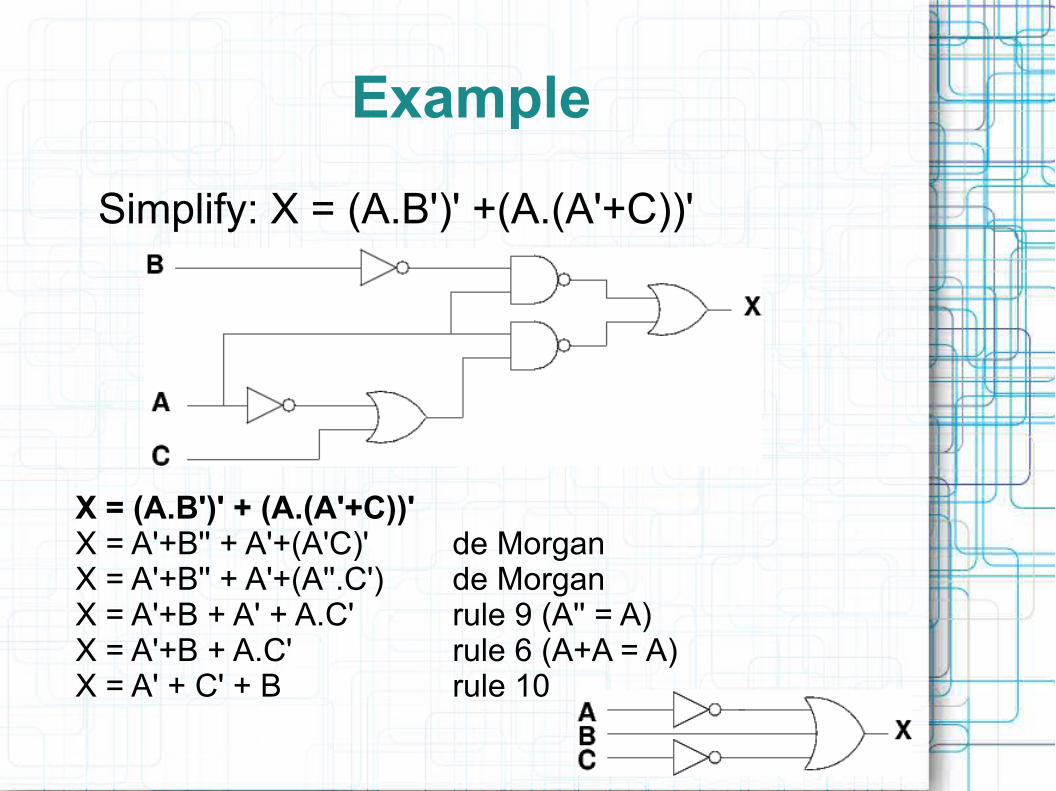
Simplify: X = (A.B')' +(A.(A'+C))'
X = (A.B')' + (A.(A'+C))'X = A'+B'' + A'+(A'C)' de MorganX = A'+B'' + A'+(A''.C') de MorganX = A'+B + A' + A.C' rule 9 (A'' = A)X = A'+B + A.C' rule 6 (A+A = A)X = A' + C' + B rule 10

Karnaugh maps
K-maps are a pictorial method of mapping expressions to remove redundant variables.
Systematic approach to produce simplest output from the reduction
All possible inputs and outputs are displayed compactly in the map
Works with any number of variables

Karnaugh maps

Karnaugh maps
You commonly fill in a K-map from a truth table

Karnaugh maps
Number of map cells = number of entries in truth table.
You can only change one variable when moving across ordown the map. The map has Torus-Like connectivity

K-map minimisation
1) Group the 1s2) Determine the group product3) Sum the results
No zeros in groupsNo diagonalsGroup size to be power of 2Groups to be as large as possibleFewest number of groupsCan overlap if unique group

Don't Care!
There are times when you may not care what output certain inputs give. These are don't care inputs.
Don't Cares can help simply solutions to k-maps. Groups can be larger.
Groups containing just DCs are not needed.
Don't Cares can be shown as a Canonical Sum.

Don't Care!
A B C D X
0 0 0 0 0 1
1 0 0 0 1 0
2 0 0 1 0 d
3 0 0 1 1 0
4 0 1 0 0 d
5 0 1 0 1 0
6 0 1 1 0 1
7 0 1 1 1 0
8 1 0 0 0 1
9 1 0 0 1 0
10 1 0 1 0 d
11 1 0 1 1 0
12 1 1 0 0 0
13 1 1 0 1 1
14 1 1 1 0 1
15 1 1 1 1 0
F = ΣABCD
(0,6,8,13,14)
d = ΣABCD
(2,4,10)
F = B'D' + CD' + ABC'D

Example
A B C X0 0 0 10 0 1 10 1 0 10 1 1 11 0 0 11 0 1 01 1 0 11 1 1 1
Draw the circuit for the following expressionX = (A.B')' + (A.(A'+C))'
Construct the canonical sum, and use a K-map to simplifyThe truth table should help


