Embed Size (px)
Citation preview
3/30/2019 Direct-Hit -- Search Fixes\Information Available - Asset Details
http://dh.identifix.com/AssetDetailsViewer/GetAssetDetailViewer?ROID=222173445&VID=2185578&AssetId=82d0ee8f-2ec7-4203-9014-aa12371e2… 1/30
BOSCH ME 7.2 ENGINE MANAGEMEN...
Bosch ME 7.2 Engine Management System
Introduction
The V8 engine used in New Range Rover is controlled by the Bosch ME 7.2 engine management system (EMS).This system is similar to the Bosch 5.2.1 system used in previous Land Rover V8 engines. The main differencebetween the two systems is the “drive by wire” capabilities of the Me 7.2 EMS.
Another main difference between the 5.2.1 system and the ME 7.2 system is that ME 7.2 uses the Keywordprotocol 2000* (KWP2000*) which is a ISO 9141 K Line compatible version of the Key Word 2000 protocol.
General
The key functions of the Bosch ME 7.2 engine management system are:
To control the amount of fuel supplied to each cylinderTo calculate and control the exact point of fuel injectionTo calculate and control the exact point of ignition in each cylinderTo optimise adjustment of the injection timing and ignition timing to deliver the maximum engineperformance throughout all engine speed and load conditionsTo calculate and maintain the desired air/fuel ratio, to ensure the 3 way catalysts operate at their maximumefficiencyTo maintain full idle speed control of the engineTo ensure the vehicle adheres to the emission standards (set at the time of homologation)To ensure the vehicle meets with the fault handling requirements, as detailed in the European On-BoardDiagnostic (EOBD) III legislationTo provide an interface with other electrical systems on the vehicleTo facilitate the drive by wire functionsTo control the Variable Camshaft Control (VCC).
To deliver these key functions, the Bosch ME 7.2 Engine Control Module (ECM) relies upon a number of inputs andcontrols a number of outputs. As with all electronic control units, the ECM needs information regarding the currentoperating conditions of the engine and other related systems before it can make calculations, which determine theappropriate outputs. A Controller Area Network (CAN) bus is used to exchange information between the ECM andthe Electronic Automatic Transmission (EAT) ECU
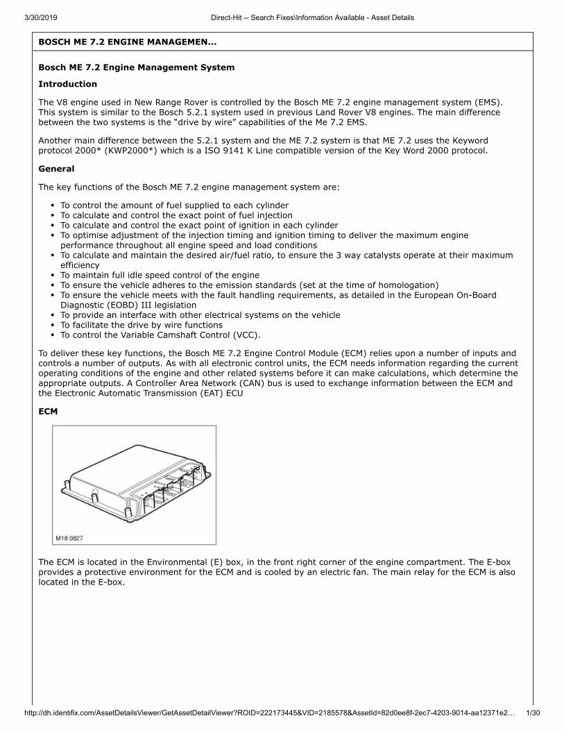
ECM
The ECM is located in the Environmental (E) box, in the front right corner of the engine compartment. The E-boxprovides a protective environment for the ECM and is cooled by an electric fan. The main relay for the ECM is alsolocated in the E-box.
3/30/2019 Direct-Hit -- Search Fixes\Information Available - Asset Details
http://dh.identifix.com/AssetDetailsViewer/GetAssetDetailViewer?ROID=222173445&VID=2185578&AssetId=82d0ee8f-2ec7-4203-9014-aa12371e2… 2/30
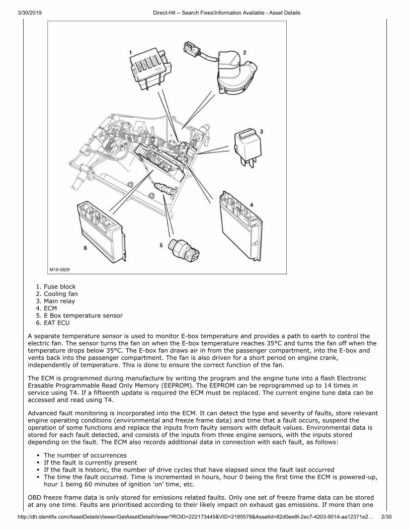
1. Fuse block2. Cooling fan3. Main relay4. ECM5. E Box temperature sensor6. EAT ECU
A separate temperature sensor is used to monitor E-box temperature and provides a path to earth to control theelectric fan. The sensor turns the fan on when the E-box temperature reaches 35°C and turns the fan off when thetemperature drops below 35°C. The E-box fan draws air in from the passenger compartment, into the E-box andvents back into the passenger compartment. The fan is also driven for a short period on engine crank,independently of temperature. This is done to ensure the correct function of the fan.
The ECM is programmed during manufacture by writing the program and the engine tune into a flash ElectronicErasable Programmable Read Only Memory (EEPROM). The EEPROM can be reprogrammed up to 14 times inservice using T4. If a fifteenth update is required the ECM must be replaced. The current engine tune data can beaccessed and read using T4.
Advanced fault monitoring is incorporated into the ECM. It can detect the type and severity of faults, store relevantengine operating conditions (environmental and freeze frame data) and time that a fault occurs, suspend theoperation of some functions and replace the inputs from faulty sensors with default values. Environmental data isstored for each fault detected, and consists of the inputs from three engine sensors, with the inputs storeddepending on the fault. The ECM also records additional data in connection with each fault, as follows:
The number of occurrencesIf the fault is currently presentIf the fault is historic, the number of drive cycles that have elapsed since the fault last occurredThe time the fault occurred. Time is incremented in hours, hour 0 being the first time the ECM is powered-up,hour 1 being 60 minutes of ignition 'on' time, etc.
OBD freeze frame data is only stored for emissions related faults. Only one set of freeze frame data can be storedat any one time. Faults are prioritised according to their likely impact on exhaust gas emissions. If more than one
3/30/2019 Direct-Hit -- Search Fixes\Information Available - Asset Details
http://dh.identifix.com/AssetDetailsViewer/GetAssetDetailViewer?ROID=222173445&VID=2185578&AssetId=82d0ee8f-2ec7-4203-9014-aa12371e2… 3/30
emissions related fault occurs, freeze frame data is stored for the fault with the highest priority. Freeze frame dataconsists of the following:
Engine speedEngine loadShort term fuelling trim of LH and RH cylinder banksLong term fuelling trim of LH and RH cylinder banksFuelling status of LH and RH cylinder banksEngine coolant temperatureRoad speed.
Fault information is stored in a volatile Random Access Memory (RAM) in the ECM, so will be deleted if a powerfailure or battery disconnection occurs.
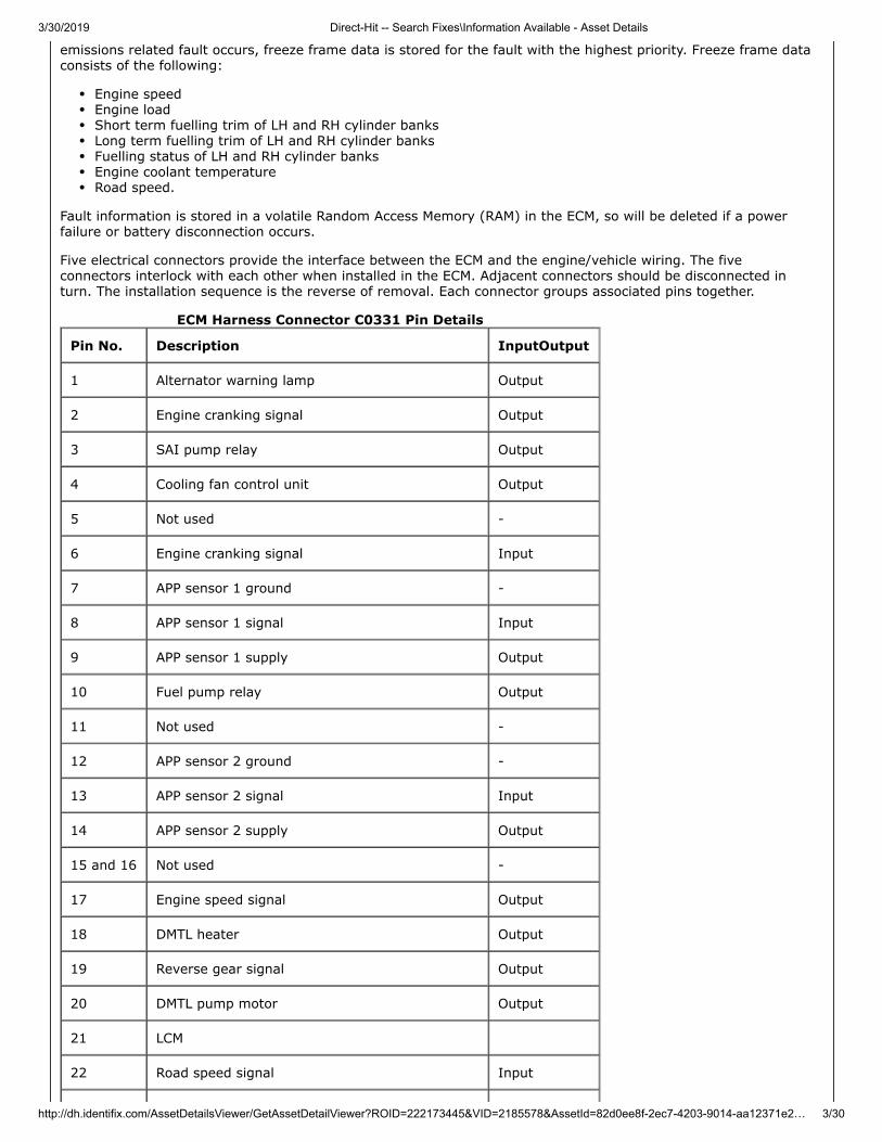
Five electrical connectors provide the interface between the ECM and the engine/vehicle wiring. The fiveconnectors interlock with each other when installed in the ECM. Adjacent connectors should be disconnected inturn. The installation sequence is the reverse of removal. Each connector groups associated pins together.
ECM Harness Connector C0331 Pin Details
Pin No. Description InputOutput
1 Alternator warning lamp Output
2 Engine cranking signal Output
3 SAI pump relay Output
4 Cooling fan control unit Output
5 Not used -
6 Engine cranking signal Input
7 APP sensor 1 ground -
8 APP sensor 1 signal Input
9 APP sensor 1 supply Output
10 Fuel pump relay Output
11 Not used -
12 APP sensor 2 ground -
13 APP sensor 2 signal Input
14 APP sensor 2 supply Output
15 and 16 Not used -
17 Engine speed signal Output
18 DMTL heater Output
19 Reverse gear signal Output
20 DMTL pump motor Output
21 LCM
22 Road speed signal Input
3/30/2019 Direct-Hit -- Search Fixes\Information Available - Asset Details
http://dh.identifix.com/AssetDetailsViewer/GetAssetDetailViewer?ROID=222173445&VID=2185578&AssetId=82d0ee8f-2ec7-4203-9014-aa12371e2… 4/30
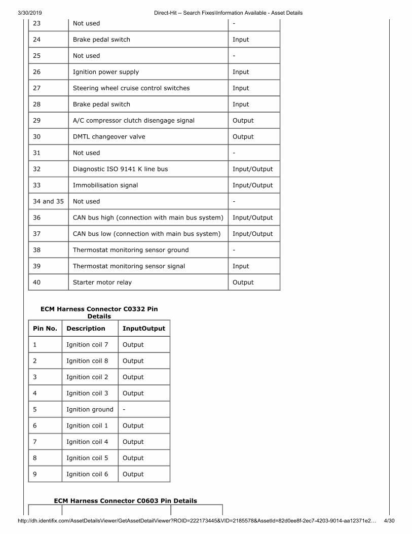
23 Not used -
24 Brake pedal switch Input
25 Not used -
26 Ignition power supply Input
27 Steering wheel cruise control switches Input
28 Brake pedal switch Input
29 A/C compressor clutch disengage signal Output
30 DMTL changeover valve Output
31 Not used -
32 Diagnostic ISO 9141 K line bus Input/Output
33 Immobilisation signal Input/Output
34 and 35 Not used -
36 CAN bus high (connection with main bus system) Input/Output
37 CAN bus low (connection with main bus system) Input/Output
38 Thermostat monitoring sensor ground -
39 Thermostat monitoring sensor signal Input
40 Starter motor relay Output
ECM Harness Connector C0332 PinDetails
Pin No. Description InputOutput
1 Ignition coil 7 Output
2 Ignition coil 8 Output
3 Ignition coil 2 Output
4 Ignition coil 3 Output
5 Ignition ground -
6 Ignition coil 1 Output
7 Ignition coil 4 Output
8 Ignition coil 5 Output
9 Ignition coil 6 Output
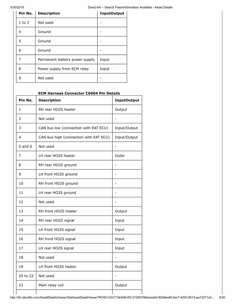
ECM Harness Connector C0603 Pin Details
3/30/2019 Direct-Hit -- Search Fixes\Information Available - Asset Details
http://dh.identifix.com/AssetDetailsViewer/GetAssetDetailViewer?ROID=222173445&VID=2185578&AssetId=82d0ee8f-2ec7-4203-9014-aa12371e2… 5/30
Pin No. Description InputOutput
1 to 3 Not used -
4 Ground -
5 Ground -
6 Ground -
7 Permanent battery power supply Input
8 Power supply from ECM relay Input
9 Not used -
ECM Harness Connector C0604 Pin Details
Pin No. Description InputOutput
1 RH rear HO2S heater Output
2 Not used -
3 CAN bus low (connection with EAT ECU) Input/Output
4 CAN bus high (connection with EAT ECU) Input/Output
5 and 6 Not used -
7 LH rear HO2S heater Outer
8 RH rear HO2S ground -
9 LH front HO2S ground -
10 RH front HO2S ground -
11 LH rear HO2S ground -
12 Not used -
13 RH front HO2S heater Output
14 RH rear HO2S signal Input
15 LH front HO2S signal Input
16 RH front HO2S signal Input
17 LH rear HO2S signal Input
18 Not used -
19 LH front HO2S heater Output
20 to 22 Not used -
23 Main relay coil Output
3/30/2019 Direct-Hit -- Search Fixes\Information Available - Asset Details
http://dh.identifix.com/AssetDetailsViewer/GetAssetDetailViewer?ROID=222173445&VID=2185578&AssetId=82d0ee8f-2ec7-4203-9014-aa12371e2… 6/30
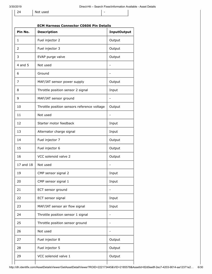
24 Not used -
ECM Harness Connector C0606 Pin Details
Pin No. Description InputOutput
1 Fuel injector 2 Output
2 Fuel injector 3 Output
3 EVAP purge valve Output
4 and 5 Not used -
6 Ground -
7 MAF/IAT sensor power supply Output
8 Throttle position sensor 2 signal Input
9 MAF/IAT sensor ground -
10 Throttle position sensors reference voltage Output
11 Not used -
12 Starter motor feedback Input
13 Alternator charge signal Input
14 Fuel injector 7 Output
15 Fuel injector 6 Output
16 VCC solenoid valve 2 Output
17 and 18 Not used -
19 CMP sensor signal 2 Input
20 CMP sensor signal 1 Input
21 ECT sensor ground -
22 ECT sensor signal Input
23 MAF/IAT sensor air flow signal Input
24 Throttle position sensor 1 signal -
25 Throttle position sensor ground -
26 Not used -
27 Fuel injector 8 Output
28 Fuel injector 5 Output
29 VCC solenoid valve 1 Output
3/30/2019 Direct-Hit -- Search Fixes\Information Available - Asset Details
http://dh.identifix.com/AssetDetailsViewer/GetAssetDetailViewer?ROID=222173445&VID=2185578&AssetId=82d0ee8f-2ec7-4203-9014-aa12371e2… 7/30
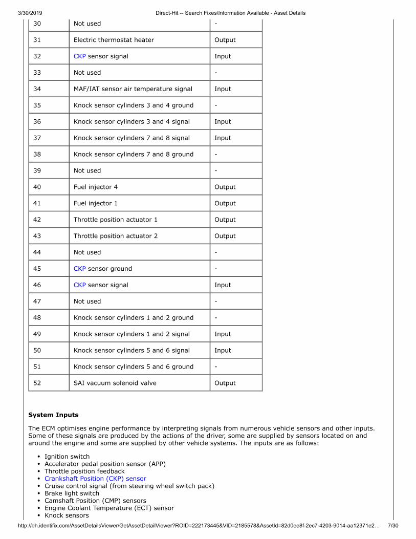
30 Not used -
31 Electric thermostat heater Output
32 CKP sensor signal Input
33 Not used -
34 MAF/IAT sensor air temperature signal Input
35 Knock sensor cylinders 3 and 4 ground -
36 Knock sensor cylinders 3 and 4 signal Input
37 Knock sensor cylinders 7 and 8 signal Input
38 Knock sensor cylinders 7 and 8 ground -
39 Not used -
40 Fuel injector 4 Output
41 Fuel injector 1 Output
42 Throttle position actuator 1 Output
43 Throttle position actuator 2 Output
44 Not used -
45 CKP sensor ground -
46 CKP sensor signal Input
47 Not used -
48 Knock sensor cylinders 1 and 2 ground -
49 Knock sensor cylinders 1 and 2 signal Input
50 Knock sensor cylinders 5 and 6 signal Input
51 Knock sensor cylinders 5 and 6 ground -
52 SAI vacuum solenoid valve Output
System Inputs
The ECM optimises engine performance by interpreting signals from numerous vehicle sensors and other inputs.Some of these signals are produced by the actions of the driver, some are supplied by sensors located on andaround the engine and some are supplied by other vehicle systems. The inputs are as follows:
Ignition switchAccelerator pedal position sensor (APP)Throttle position feedbackCrankshaft Position (CKP) sensorCruise control signal (from steering wheel switch pack)Brake light switchCamshaft Position (CMP) sensorsEngine Coolant Temperature (ECT) sensorKnock sensors
3/30/2019 Direct-Hit -- Search Fixes\Information Available - Asset Details
http://dh.identifix.com/AssetDetailsViewer/GetAssetDetailViewer?ROID=222173445&VID=2185578&AssetId=82d0ee8f-2ec7-4203-9014-aa12371e2… 8/30
Air Mass/Intake Air Temperature (MAF/IAT) sensorHeated Oxygen Sensors (HO2S)Immobilisation signal (from immobilisation ECU)Fuel level signal (via CAN)Vehicle speed signal (from ABS ECU)Radiator outlet temperature sensorInternal ambient barometric pressure sensor (altitude sensor)Electronic Automatic Transmission (EAT) information.
Electric Throttle System
The EMS incorporates an electric throttle control system. This system comprises three main components:
Electronic throttle control valveAccelerator pedal position sensor (APP)ECM.
When the accelerator pedal is depressed the APP sensor provides a change in the monitored signals. The ECMcompares this against an electronic “map” and moves the electronic throttle valve via a pulse width modulatedcontrol signal which is in proportion to the APP angle signal.
The system is required to:
Regulate the calculated intake air load based on the accelerator pedal sensor input signals and programmedmappingMonitor the drivers input request for cruise control operationAutomatically position the electronic throttle for accurate cruise controlPerform all dynamic stability control throttle control interventionsMonitor and carry out maximum engine and road speed cut out.
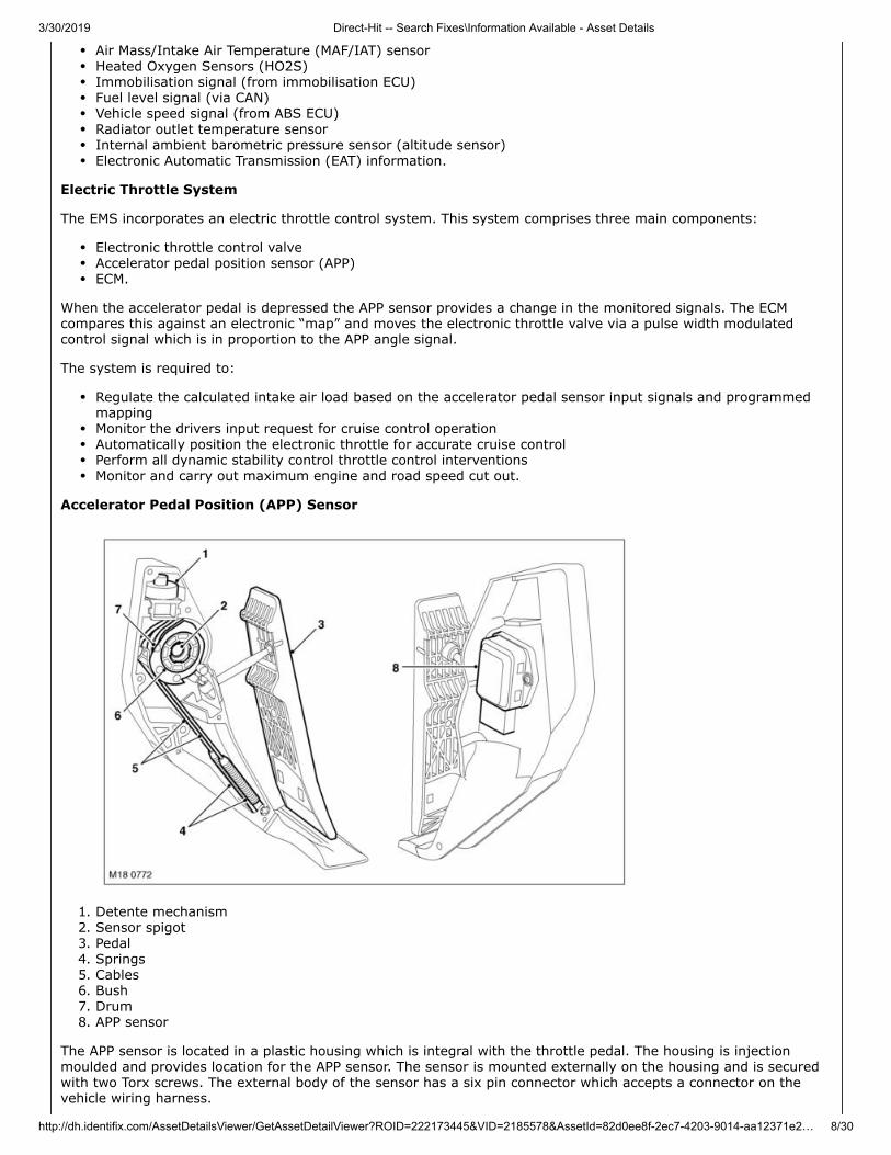
Accelerator Pedal Position (APP) Sensor
1. Detente mechanism2. Sensor spigot3. Pedal4. Springs5. Cables6. Bush7. Drum8. APP sensor
The APP sensor is located in a plastic housing which is integral with the throttle pedal. The housing is injectionmoulded and provides location for the APP sensor. The sensor is mounted externally on the housing and is securedwith two Torx screws. The external body of the sensor has a six pin connector which accepts a connector on thevehicle wiring harness.
3/30/2019 Direct-Hit -- Search Fixes\Information Available - Asset Details
http://dh.identifix.com/AssetDetailsViewer/GetAssetDetailViewer?ROID=222173445&VID=2185578&AssetId=82d0ee8f-2ec7-4203-9014-aa12371e2… 9/30
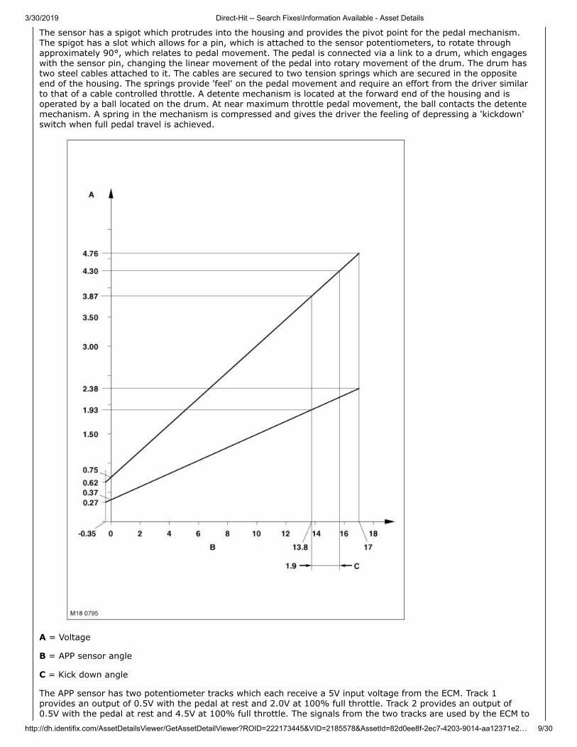
The sensor has a spigot which protrudes into the housing and provides the pivot point for the pedal mechanism.The spigot has a slot which allows for a pin, which is attached to the sensor potentiometers, to rotate throughapproximately 90°, which relates to pedal movement. The pedal is connected via a link to a drum, which engageswith the sensor pin, changing the linear movement of the pedal into rotary movement of the drum. The drum hastwo steel cables attached to it. The cables are secured to two tension springs which are secured in the oppositeend of the housing. The springs provide 'feel' on the pedal movement and require an effort from the driver similarto that of a cable controlled throttle. A detente mechanism is located at the forward end of the housing and isoperated by a ball located on the drum. At near maximum throttle pedal movement, the ball contacts the detentemechanism. A spring in the mechanism is compressed and gives the driver the feeling of depressing a 'kickdown'switch when full pedal travel is achieved.
A = Voltage
B = APP sensor angle
C = Kick down angle
The APP sensor has two potentiometer tracks which each receive a 5V input voltage from the ECM. Track 1provides an output of 0.5V with the pedal at rest and 2.0V at 100% full throttle. Track 2 provides an output of0.5V with the pedal at rest and 4.5V at 100% full throttle. The signals from the two tracks are used by the ECM to
3/30/2019 Direct-Hit -- Search Fixes\Information Available - Asset Details
http://dh.identifix.com/AssetDetailsViewer/GetAssetDetailViewer?ROID=222173445&VID=2185578&AssetId=82d0ee8f-2ec7-4203-9014-aa12371e… 10/30
determine fuelling for engine operation and also by the ECM and the EAT ECU to initiate a kickdown request for theautomatic transmission.
The ECM monitors the outputs from each of the potentiometer tracks and can determine the position, rate ofchange and direction of movement of the throttle pedal. The 'closed throttle' position signal is used by the ECM toinitiate idle speed control and also overrun fuel cut-off.
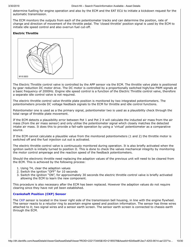
Electric Throttle
The Electric Throttle control valve is controlled by the APP sensor via the ECM. The throttle valve plate is positionedby gear reduction DC motor drive. The DC motor is controlled by a proportionally switched high/low PWM signals ata basic frequency of 2000Hz. Engine idle speed control is a function of the Electric Throttle control valve, thereforea separate idle control valve is not required.
The electric throttle control valve throttle plate position is monitored by two integrated potentiometers. Thepotentiometers provide DC voltage feedback signals to the ECM for throttle and idle control functions.
Potentiometer one is used as a the primary signal, potentiometer two is used as a plausibility check through thetotal range of throttle plate movement.
If the ECM detects a plausibility error between Pot 1 and Pot 2 it will calculate the inducted air mass from the airmass (from the air mass sensor) and only utilise the potentiometer signal which closely matches the detectedintake air mass. It does this to provide a fail-safe operation by using a 'virtual' potentiometer as a comparativesource.
If the ECM cannot calculate a plausible value from the monitored potentiometers (1 and 2) the throttle motor isswitched off and the fuel injection cut out is activated.
The electric throttle control valve is continuously monitored during operation. It is also briefly activated when theignition switch is initially turned to position II. This is done to check the valves mechanical integrity by monitoringthe motor control amperage and the reaction speed of the feedback potentiometers.
Should the electronic throttle need replacing the adaption values of the previous unit will need to be cleared fromthe ECM. This is achieved by the following process:
1. Using T4, clear the adaption values2. Switch the ignition “OFF” for 10 seconds3. Switch the ignition “ON”, for approximately 30 seconds the electric throttle control valve is briefly activated
allowing the ECM to learn the new component.
This procedure is also necessary after the ECM has been replaced. However the adaption values do not requireclearing since they have not yet been established.
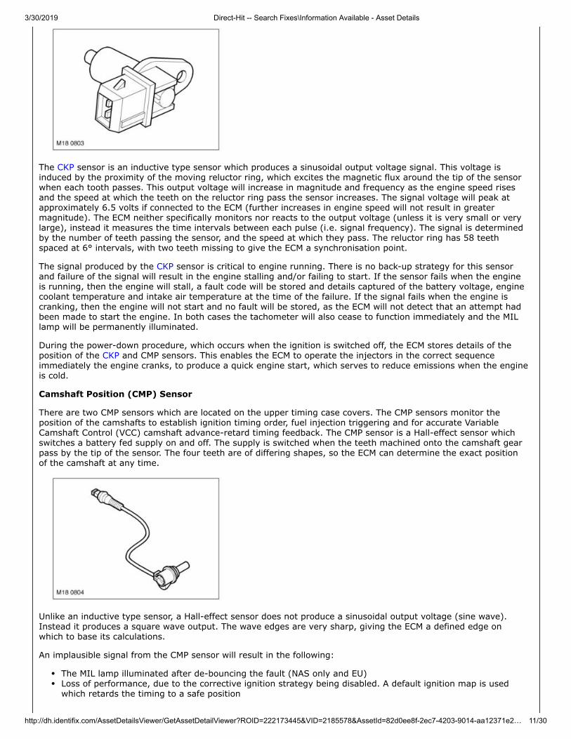
Crankshaft Position (CKP) Sensor
The CKP sensor is located in the lower right side of the transmission bell housing, in line with the engine flywheel.The sensor reacts to a reluctor ring to ascertain engine speed and position information. The sensor has three wiresattached to it; two signal wires and a sensor earth screen. The sensor earth screen is connected to chassis earththrough the ECM.
3/30/2019 Direct-Hit -- Search Fixes\Information Available - Asset Details
http://dh.identifix.com/AssetDetailsViewer/GetAssetDetailViewer?ROID=222173445&VID=2185578&AssetId=82d0ee8f-2ec7-4203-9014-aa12371e2… 11/30
The CKP sensor is an inductive type sensor which produces a sinusoidal output voltage signal. This voltage isinduced by the proximity of the moving reluctor ring, which excites the magnetic flux around the tip of the sensorwhen each tooth passes. This output voltage will increase in magnitude and frequency as the engine speed risesand the speed at which the teeth on the reluctor ring pass the sensor increases. The signal voltage will peak atapproximately 6.5 volts if connected to the ECM (further increases in engine speed will not result in greatermagnitude). The ECM neither specifically monitors nor reacts to the output voltage (unless it is very small or verylarge), instead it measures the time intervals between each pulse (i.e. signal frequency). The signal is determinedby the number of teeth passing the sensor, and the speed at which they pass. The reluctor ring has 58 teethspaced at 6° intervals, with two teeth missing to give the ECM a synchronisation point.
The signal produced by the CKP sensor is critical to engine running. There is no back-up strategy for this sensorand failure of the signal will result in the engine stalling and/or failing to start. If the sensor fails when the engineis running, then the engine will stall, a fault code will be stored and details captured of the battery voltage, enginecoolant temperature and intake air temperature at the time of the failure. If the signal fails when the engine iscranking, then the engine will not start and no fault will be stored, as the ECM will not detect that an attempt hadbeen made to start the engine. In both cases the tachometer will also cease to function immediately and the MILlamp will be permanently illuminated.
During the power-down procedure, which occurs when the ignition is switched off, the ECM stores details of theposition of the CKP and CMP sensors. This enables the ECM to operate the injectors in the correct sequenceimmediately the engine cranks, to produce a quick engine start, which serves to reduce emissions when the engineis cold.
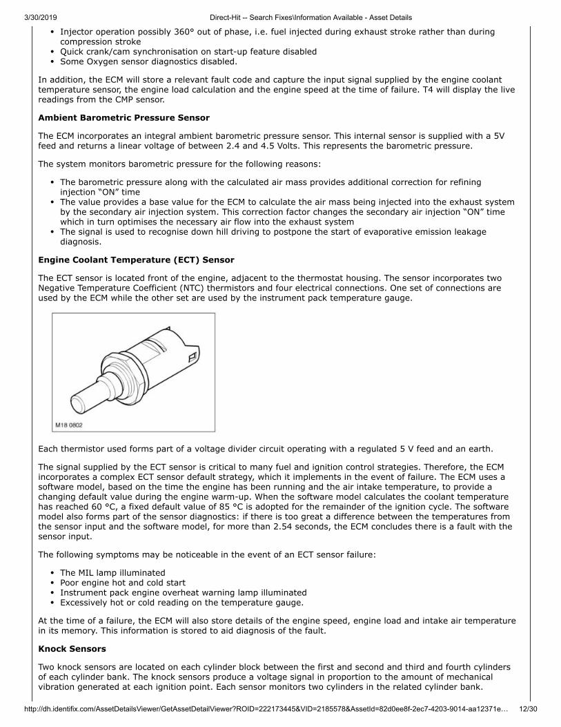
Camshaft Position (CMP) Sensor
There are two CMP sensors which are located on the upper timing case covers. The CMP sensors monitor theposition of the camshafts to establish ignition timing order, fuel injection triggering and for accurate VariableCamshaft Control (VCC) camshaft advance-retard timing feedback. The CMP sensor is a Hall-effect sensor whichswitches a battery fed supply on and off. The supply is switched when the teeth machined onto the camshaft gearpass by the tip of the sensor. The four teeth are of differing shapes, so the ECM can determine the exact positionof the camshaft at any time.
Unlike an inductive type sensor, a Hall-effect sensor does not produce a sinusoidal output voltage (sine wave).Instead it produces a square wave output. The wave edges are very sharp, giving the ECM a defined edge onwhich to base its calculations.
An implausible signal from the CMP sensor will result in the following:
The MIL lamp illuminated after de-bouncing the fault (NAS only and EU)Loss of performance, due to the corrective ignition strategy being disabled. A default ignition map is usedwhich retards the timing to a safe position
3/30/2019 Direct-Hit -- Search Fixes\Information Available - Asset Details
http://dh.identifix.com/AssetDetailsViewer/GetAssetDetailViewer?ROID=222173445&VID=2185578&AssetId=82d0ee8f-2ec7-4203-9014-aa12371e… 12/30
Injector operation possibly 360° out of phase, i.e. fuel injected during exhaust stroke rather than duringcompression strokeQuick crank/cam synchronisation on start-up feature disabledSome Oxygen sensor diagnostics disabled.
In addition, the ECM will store a relevant fault code and capture the input signal supplied by the engine coolanttemperature sensor, the engine load calculation and the engine speed at the time of failure. T4 will display the livereadings from the CMP sensor.
Ambient Barometric Pressure Sensor
The ECM incorporates an integral ambient barometric pressure sensor. This internal sensor is supplied with a 5Vfeed and returns a linear voltage of between 2.4 and 4.5 Volts. This represents the barometric pressure.
The system monitors barometric pressure for the following reasons:
The barometric pressure along with the calculated air mass provides additional correction for refininginjection “ON” timeThe value provides a base value for the ECM to calculate the air mass being injected into the exhaust systemby the secondary air injection system. This correction factor changes the secondary air injection “ON” timewhich in turn optimises the necessary air flow into the exhaust systemThe signal is used to recognise down hill driving to postpone the start of evaporative emission leakagediagnosis.
Engine Coolant Temperature (ECT) Sensor
The ECT sensor is located front of the engine, adjacent to the thermostat housing. The sensor incorporates twoNegative Temperature Coefficient (NTC) thermistors and four electrical connections. One set of connections areused by the ECM while the other set are used by the instrument pack temperature gauge.
Each thermistor used forms part of a voltage divider circuit operating with a regulated 5 V feed and an earth.
The signal supplied by the ECT sensor is critical to many fuel and ignition control strategies. Therefore, the ECMincorporates a complex ECT sensor default strategy, which it implements in the event of failure. The ECM uses asoftware model, based on the time the engine has been running and the air intake temperature, to provide achanging default value during the engine warm-up. When the software model calculates the coolant temperaturehas reached 60 °C, a fixed default value of 85 °C is adopted for the remainder of the ignition cycle. The softwaremodel also forms part of the sensor diagnostics: if there is too great a difference between the temperatures fromthe sensor input and the software model, for more than 2.54 seconds, the ECM concludes there is a fault with thesensor input.
The following symptoms may be noticeable in the event of an ECT sensor failure:
The MIL lamp illuminatedPoor engine hot and cold startInstrument pack engine overheat warning lamp illuminatedExcessively hot or cold reading on the temperature gauge.
At the time of a failure, the ECM will also store details of the engine speed, engine load and intake air temperaturein its memory. This information is stored to aid diagnosis of the fault.
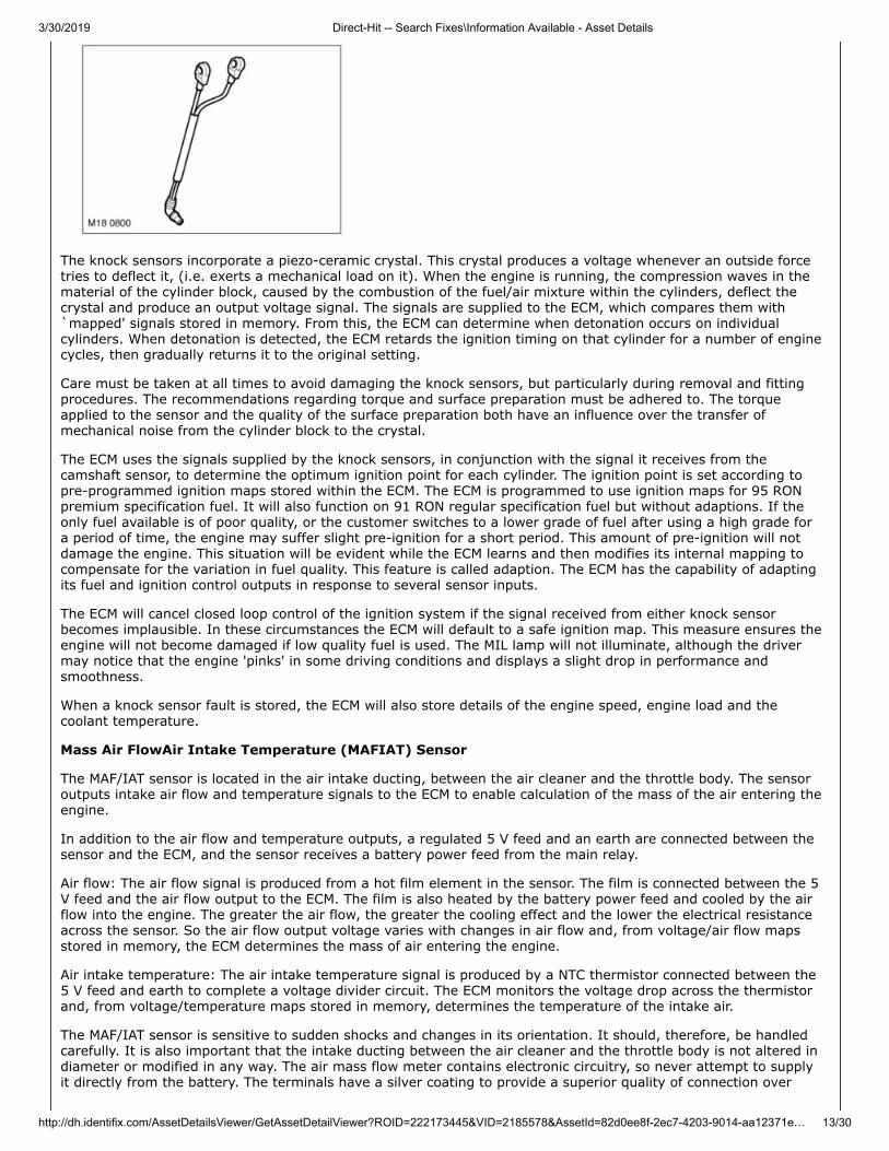
Knock Sensors
Two knock sensors are located on each cylinder block between the first and second and third and fourth cylindersof each cylinder bank. The knock sensors produce a voltage signal in proportion to the amount of mechanicalvibration generated at each ignition point. Each sensor monitors two cylinders in the related cylinder bank.
3/30/2019 Direct-Hit -- Search Fixes\Information Available - Asset Details
http://dh.identifix.com/AssetDetailsViewer/GetAssetDetailViewer?ROID=222173445&VID=2185578&AssetId=82d0ee8f-2ec7-4203-9014-aa12371e… 13/30
The knock sensors incorporate a piezo-ceramic crystal. This crystal produces a voltage whenever an outside forcetries to deflect it, (i.e. exerts a mechanical load on it). When the engine is running, the compression waves in thematerial of the cylinder block, caused by the combustion of the fuel/air mixture within the cylinders, deflect thecrystal and produce an output voltage signal. The signals are supplied to the ECM, which compares them with`mapped' signals stored in memory. From this, the ECM can determine when detonation occurs on individualcylinders. When detonation is detected, the ECM retards the ignition timing on that cylinder for a number of enginecycles, then gradually returns it to the original setting.
Care must be taken at all times to avoid damaging the knock sensors, but particularly during removal and fittingprocedures. The recommendations regarding torque and surface preparation must be adhered to. The torqueapplied to the sensor and the quality of the surface preparation both have an influence over the transfer ofmechanical noise from the cylinder block to the crystal.
The ECM uses the signals supplied by the knock sensors, in conjunction with the signal it receives from thecamshaft sensor, to determine the optimum ignition point for each cylinder. The ignition point is set according topre-programmed ignition maps stored within the ECM. The ECM is programmed to use ignition maps for 95 RONpremium specification fuel. It will also function on 91 RON regular specification fuel but without adaptions. If theonly fuel available is of poor quality, or the customer switches to a lower grade of fuel after using a high grade fora period of time, the engine may suffer slight pre-ignition for a short period. This amount of pre-ignition will notdamage the engine. This situation will be evident while the ECM learns and then modifies its internal mapping tocompensate for the variation in fuel quality. This feature is called adaption. The ECM has the capability of adaptingits fuel and ignition control outputs in response to several sensor inputs.
The ECM will cancel closed loop control of the ignition system if the signal received from either knock sensorbecomes implausible. In these circumstances the ECM will default to a safe ignition map. This measure ensures theengine will not become damaged if low quality fuel is used. The MIL lamp will not illuminate, although the drivermay notice that the engine 'pinks' in some driving conditions and displays a slight drop in performance andsmoothness.
When a knock sensor fault is stored, the ECM will also store details of the engine speed, engine load and thecoolant temperature.
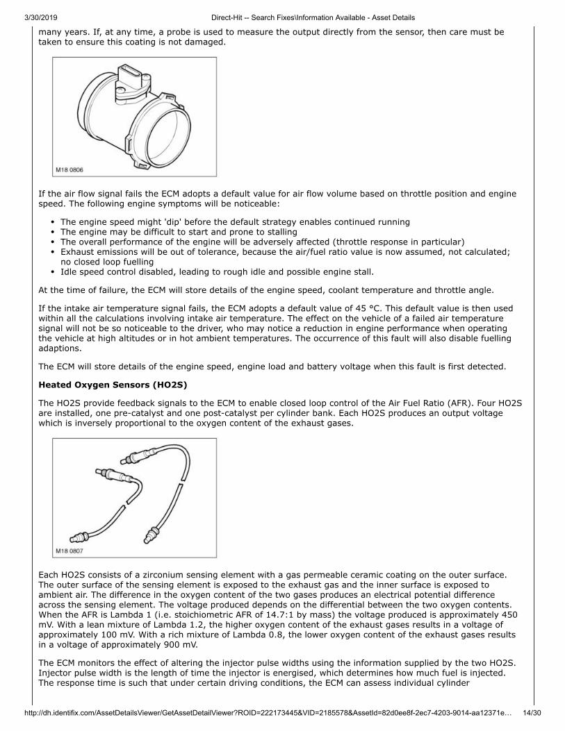
Mass Air FlowAir Intake Temperature (MAFIAT) Sensor
The MAF/IAT sensor is located in the air intake ducting, between the air cleaner and the throttle body. The sensoroutputs intake air flow and temperature signals to the ECM to enable calculation of the mass of the air entering theengine.
In addition to the air flow and temperature outputs, a regulated 5 V feed and an earth are connected between thesensor and the ECM, and the sensor receives a battery power feed from the main relay.
Air flow: The air flow signal is produced from a hot film element in the sensor. The film is connected between the 5V feed and the air flow output to the ECM. The film is also heated by the battery power feed and cooled by the airflow into the engine. The greater the air flow, the greater the cooling effect and the lower the electrical resistanceacross the sensor. So the air flow output voltage varies with changes in air flow and, from voltage/air flow mapsstored in memory, the ECM determines the mass of air entering the engine.
Air intake temperature: The air intake temperature signal is produced by a NTC thermistor connected between the5 V feed and earth to complete a voltage divider circuit. The ECM monitors the voltage drop across the thermistorand, from voltage/temperature maps stored in memory, determines the temperature of the intake air.
The MAF/IAT sensor is sensitive to sudden shocks and changes in its orientation. It should, therefore, be handledcarefully. It is also important that the intake ducting between the air cleaner and the throttle body is not altered indiameter or modified in any way. The air mass flow meter contains electronic circuitry, so never attempt to supplyit directly from the battery. The terminals have a silver coating to provide a superior quality of connection over
3/30/2019 Direct-Hit -- Search Fixes\Information Available - Asset Details
http://dh.identifix.com/AssetDetailsViewer/GetAssetDetailViewer?ROID=222173445&VID=2185578&AssetId=82d0ee8f-2ec7-4203-9014-aa12371e… 14/30
many years. If, at any time, a probe is used to measure the output directly from the sensor, then care must betaken to ensure this coating is not damaged.
If the air flow signal fails the ECM adopts a default value for air flow volume based on throttle position and enginespeed. The following engine symptoms will be noticeable:
The engine speed might 'dip' before the default strategy enables continued runningThe engine may be difficult to start and prone to stallingThe overall performance of the engine will be adversely affected (throttle response in particular)Exhaust emissions will be out of tolerance, because the air/fuel ratio value is now assumed, not calculated;no closed loop fuellingIdle speed control disabled, leading to rough idle and possible engine stall.
At the time of failure, the ECM will store details of the engine speed, coolant temperature and throttle angle.
If the intake air temperature signal fails, the ECM adopts a default value of 45 °C. This default value is then usedwithin all the calculations involving intake air temperature. The effect on the vehicle of a failed air temperaturesignal will not be so noticeable to the driver, who may notice a reduction in engine performance when operatingthe vehicle at high altitudes or in hot ambient temperatures. The occurrence of this fault will also disable fuellingadaptions.
The ECM will store details of the engine speed, engine load and battery voltage when this fault is first detected.
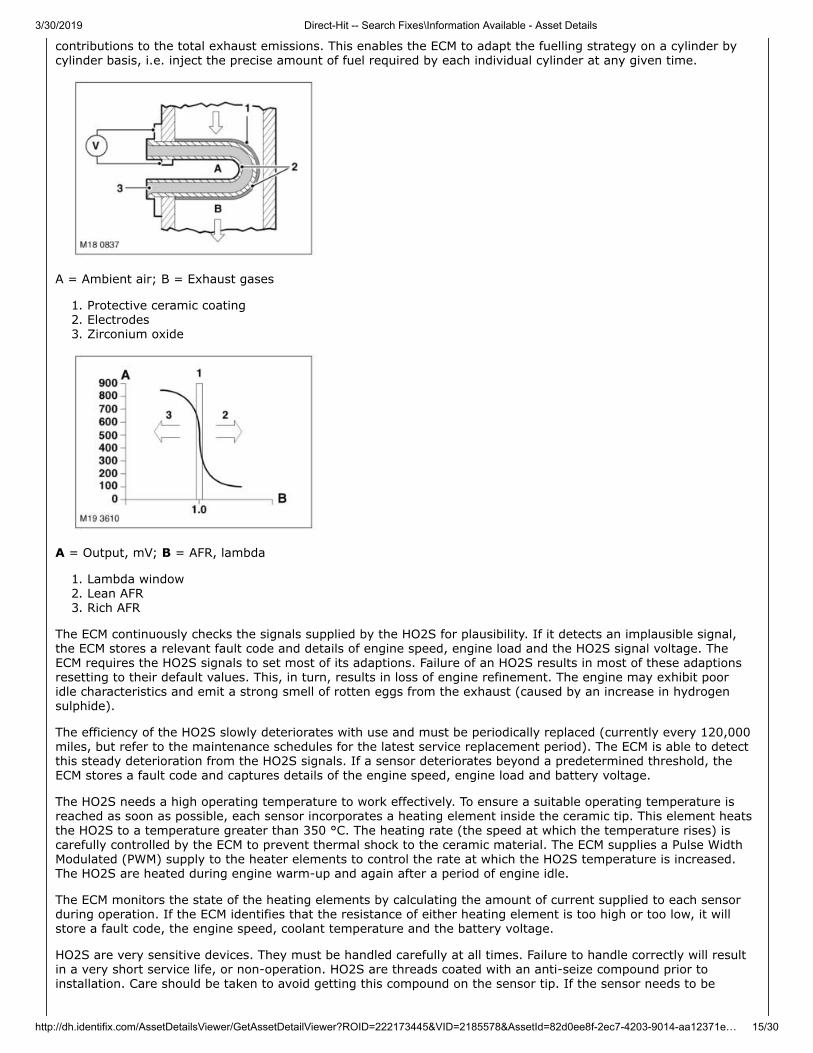
Heated Oxygen Sensors (HO2S)
The HO2S provide feedback signals to the ECM to enable closed loop control of the Air Fuel Ratio (AFR). Four HO2Sare installed, one pre-catalyst and one post-catalyst per cylinder bank. Each HO2S produces an output voltagewhich is inversely proportional to the oxygen content of the exhaust gases.
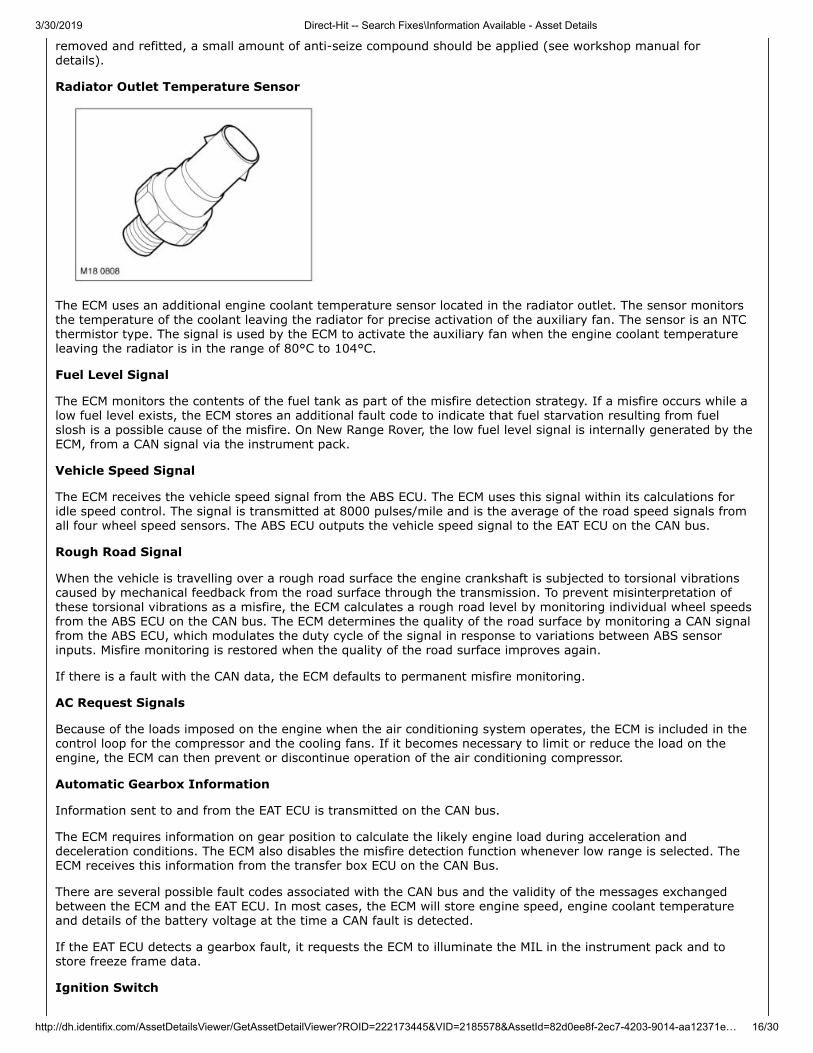
Each HO2S consists of a zirconium sensing element with a gas permeable ceramic coating on the outer surface.The outer surface of the sensing element is exposed to the exhaust gas and the inner surface is exposed toambient air. The difference in the oxygen content of the two gases produces an electrical potential differenceacross the sensing element. The voltage produced depends on the differential between the two oxygen contents.When the AFR is Lambda 1 (i.e. stoichiometric AFR of 14.7:1 by mass) the voltage produced is approximately 450mV. With a lean mixture of Lambda 1.2, the higher oxygen content of the exhaust gases results in a voltage ofapproximately 100 mV. With a rich mixture of Lambda 0.8, the lower oxygen content of the exhaust gases resultsin a voltage of approximately 900 mV.
The ECM monitors the effect of altering the injector pulse widths using the information supplied by the two HO2S.Injector pulse width is the length of time the injector is energised, which determines how much fuel is injected.The response time is such that under certain driving conditions, the ECM can assess individual cylinder
3/30/2019 Direct-Hit -- Search Fixes\Information Available - Asset Details
http://dh.identifix.com/AssetDetailsViewer/GetAssetDetailViewer?ROID=222173445&VID=2185578&AssetId=82d0ee8f-2ec7-4203-9014-aa12371e… 15/30
contributions to the total exhaust emissions. This enables the ECM to adapt the fuelling strategy on a cylinder bycylinder basis, i.e. inject the precise amount of fuel required by each individual cylinder at any given time.
A = Ambient air; B = Exhaust gases
1. Protective ceramic coating2. Electrodes3. Zirconium oxide
A = Output, mV; B = AFR, lambda
1. Lambda window2. Lean AFR3. Rich AFR
The ECM continuously checks the signals supplied by the HO2S for plausibility. If it detects an implausible signal,the ECM stores a relevant fault code and details of engine speed, engine load and the HO2S signal voltage. TheECM requires the HO2S signals to set most of its adaptions. Failure of an HO2S results in most of these adaptionsresetting to their default values. This, in turn, results in loss of engine refinement. The engine may exhibit pooridle characteristics and emit a strong smell of rotten eggs from the exhaust (caused by an increase in hydrogensulphide).
The efficiency of the HO2S slowly deteriorates with use and must be periodically replaced (currently every 120,000miles, but refer to the maintenance schedules for the latest service replacement period). The ECM is able to detectthis steady deterioration from the HO2S signals. If a sensor deteriorates beyond a predetermined threshold, theECM stores a fault code and captures details of the engine speed, engine load and battery voltage.
The HO2S needs a high operating temperature to work effectively. To ensure a suitable operating temperature isreached as soon as possible, each sensor incorporates a heating element inside the ceramic tip. This element heatsthe HO2S to a temperature greater than 350 °C. The heating rate (the speed at which the temperature rises) iscarefully controlled by the ECM to prevent thermal shock to the ceramic material. The ECM supplies a Pulse WidthModulated (PWM) supply to the heater elements to control the rate at which the HO2S temperature is increased.The HO2S are heated during engine warm-up and again after a period of engine idle.
The ECM monitors the state of the heating elements by calculating the amount of current supplied to each sensorduring operation. If the ECM identifies that the resistance of either heating element is too high or too low, it willstore a fault code, the engine speed, coolant temperature and the battery voltage.
HO2S are very sensitive devices. They must be handled carefully at all times. Failure to handle correctly will resultin a very short service life, or non-operation. HO2S are threads coated with an anti-seize compound prior toinstallation. Care should be taken to avoid getting this compound on the sensor tip. If the sensor needs to be
3/30/2019 Direct-Hit -- Search Fixes\Information Available - Asset Details
http://dh.identifix.com/AssetDetailsViewer/GetAssetDetailViewer?ROID=222173445&VID=2185578&AssetId=82d0ee8f-2ec7-4203-9014-aa12371e… 16/30
removed and refitted, a small amount of anti-seize compound should be applied (see workshop manual fordetails).
Radiator Outlet Temperature Sensor
The ECM uses an additional engine coolant temperature sensor located in the radiator outlet. The sensor monitorsthe temperature of the coolant leaving the radiator for precise activation of the auxiliary fan. The sensor is an NTCthermistor type. The signal is used by the ECM to activate the auxiliary fan when the engine coolant temperatureleaving the radiator is in the range of 80°C to 104°C.
Fuel Level Signal
The ECM monitors the contents of the fuel tank as part of the misfire detection strategy. If a misfire occurs while alow fuel level exists, the ECM stores an additional fault code to indicate that fuel starvation resulting from fuelslosh is a possible cause of the misfire. On New Range Rover, the low fuel level signal is internally generated by theECM, from a CAN signal via the instrument pack.
Vehicle Speed Signal
The ECM receives the vehicle speed signal from the ABS ECU. The ECM uses this signal within its calculations foridle speed control. The signal is transmitted at 8000 pulses/mile and is the average of the road speed signals fromall four wheel speed sensors. The ABS ECU outputs the vehicle speed signal to the EAT ECU on the CAN bus.
Rough Road Signal
When the vehicle is travelling over a rough road surface the engine crankshaft is subjected to torsional vibrationscaused by mechanical feedback from the road surface through the transmission. To prevent misinterpretation ofthese torsional vibrations as a misfire, the ECM calculates a rough road level by monitoring individual wheel speedsfrom the ABS ECU on the CAN bus. The ECM determines the quality of the road surface by monitoring a CAN signalfrom the ABS ECU, which modulates the duty cycle of the signal in response to variations between ABS sensorinputs. Misfire monitoring is restored when the quality of the road surface improves again.
If there is a fault with the CAN data, the ECM defaults to permanent misfire monitoring.
AC Request Signals
Because of the loads imposed on the engine when the air conditioning system operates, the ECM is included in thecontrol loop for the compressor and the cooling fans. If it becomes necessary to limit or reduce the load on theengine, the ECM can then prevent or discontinue operation of the air conditioning compressor.
Automatic Gearbox Information
Information sent to and from the EAT ECU is transmitted on the CAN bus.
The ECM requires information on gear position to calculate the likely engine load during acceleration anddeceleration conditions. The ECM also disables the misfire detection function whenever low range is selected. TheECM receives this information from the transfer box ECU on the CAN Bus.
There are several possible fault codes associated with the CAN bus and the validity of the messages exchangedbetween the ECM and the EAT ECU. In most cases, the ECM will store engine speed, engine coolant temperatureand details of the battery voltage at the time a CAN fault is detected.
If the EAT ECU detects a gearbox fault, it requests the ECM to illuminate the MIL in the instrument pack and tostore freeze frame data.
Ignition Switch
3/30/2019 Direct-Hit -- Search Fixes\Information Available - Asset Details
http://dh.identifix.com/AssetDetailsViewer/GetAssetDetailViewer?ROID=222173445&VID=2185578&AssetId=82d0ee8f-2ec7-4203-9014-aa12371e… 17/30
The ignition switch signal enables the ECM to detect if the ignition is on or off. The signal is a power feed that isconnected to the ECM while the ignition switch is positions II and III. On the New Range Rover, the power feedcomes from the ignition relay in the engine compartment fuse box.
When it first receives the signal, the ECM 'wakes-up' and initiates a power-up sequence to enable engine startingand operation. The power-up sequence includes energising the main relay, which supplies the main power feed tothe ECM, energising the fuel pump relay and initiating a self check of the engine management system.
When it detects the ignition has been turned off, the ECM stops activating the fuel injectors and ignition coil, tostop the engine, and de-energises the fuel pump relay, but keeps the main relay energised while it performs apower down sequence. During the power down sequence the ECM records the engine sensor values required for aquick-start function to operate the next time the engine is cranked. At the end of the power down sequence, theECM de-energises the main relay to switch itself off.
System Outputs
The ECM receives and processes the input information previously described and modifies the fuelling and theignition points for each cylinder accordingly. The ECM will also supply output information to other vehicle systems.
The ECM drives the following components:
Fuel injectorsIgnition coilsMain relay and fuel pump relayTank Leakage Detection (NAS)Secondary Air Injection PumpSecondary Air Injection valveVCC ValvesElectrically heated thermostatAir conditioning compressor (relay drive).
The ECM provides other systems with information regarding the:
Engine speedDriver demandATC requestAutomatic TransmissionFuel usedAuxiliary cooling fan.
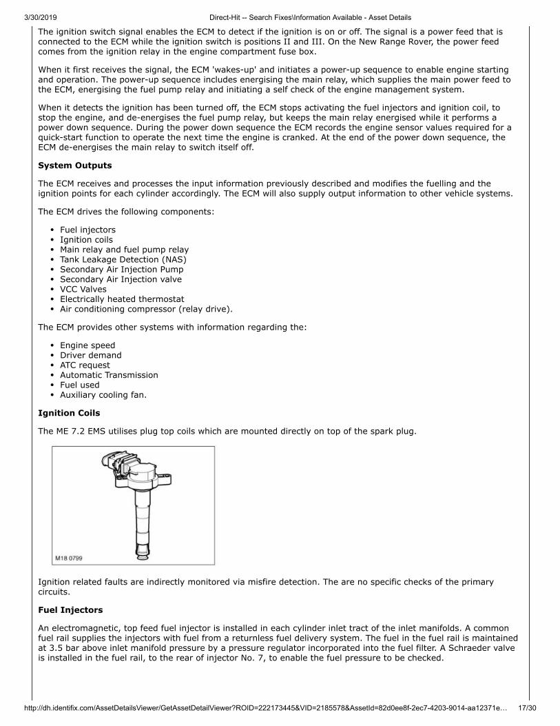
Ignition Coils
The ME 7.2 EMS utilises plug top coils which are mounted directly on top of the spark plug.
Ignition related faults are indirectly monitored via misfire detection. The are no specific checks of the primarycircuits.
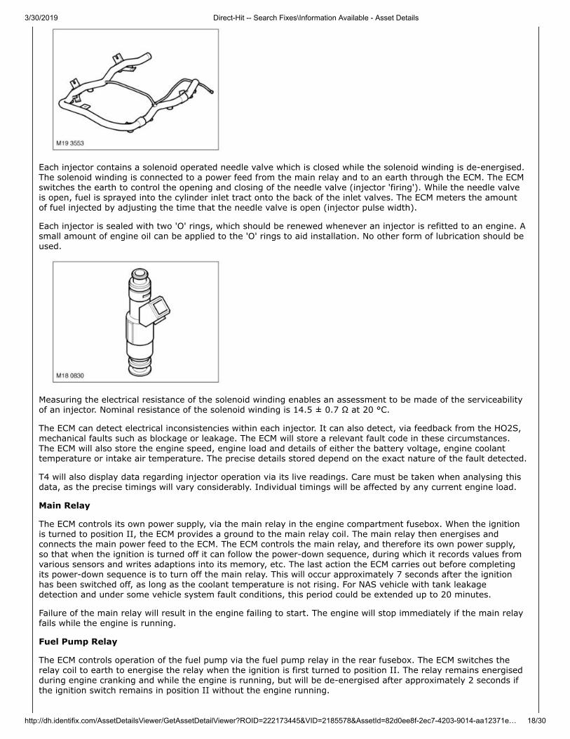
Fuel Injectors
An electromagnetic, top feed fuel injector is installed in each cylinder inlet tract of the inlet manifolds. A commonfuel rail supplies the injectors with fuel from a returnless fuel delivery system. The fuel in the fuel rail is maintainedat 3.5 bar above inlet manifold pressure by a pressure regulator incorporated into the fuel filter. A Schraeder valveis installed in the fuel rail, to the rear of injector No. 7, to enable the fuel pressure to be checked.
3/30/2019 Direct-Hit -- Search Fixes\Information Available - Asset Details
http://dh.identifix.com/AssetDetailsViewer/GetAssetDetailViewer?ROID=222173445&VID=2185578&AssetId=82d0ee8f-2ec7-4203-9014-aa12371e… 18/30
Each injector contains a solenoid operated needle valve which is closed while the solenoid winding is de-energised.The solenoid winding is connected to a power feed from the main relay and to an earth through the ECM. The ECMswitches the earth to control the opening and closing of the needle valve (injector 'firing'). While the needle valveis open, fuel is sprayed into the cylinder inlet tract onto the back of the inlet valves. The ECM meters the amountof fuel injected by adjusting the time that the needle valve is open (injector pulse width).
Each injector is sealed with two 'O' rings, which should be renewed whenever an injector is refitted to an engine. Asmall amount of engine oil can be applied to the 'O' rings to aid installation. No other form of lubrication should beused.
Measuring the electrical resistance of the solenoid winding enables an assessment to be made of the serviceabilityof an injector. Nominal resistance of the solenoid winding is 14.5 ± 0.7 Ω at 20 °C.
The ECM can detect electrical inconsistencies within each injector. It can also detect, via feedback from the HO2S,mechanical faults such as blockage or leakage. The ECM will store a relevant fault code in these circumstances.The ECM will also store the engine speed, engine load and details of either the battery voltage, engine coolanttemperature or intake air temperature. The precise details stored depend on the exact nature of the fault detected.
T4 will also display data regarding injector operation via its live readings. Care must be taken when analysing thisdata, as the precise timings will vary considerably. Individual timings will be affected by any current engine load.
Main Relay
The ECM controls its own power supply, via the main relay in the engine compartment fusebox. When the ignitionis turned to position II, the ECM provides a ground to the main relay coil. The main relay then energises andconnects the main power feed to the ECM. The ECM controls the main relay, and therefore its own power supply,so that when the ignition is turned off it can follow the power-down sequence, during which it records values fromvarious sensors and writes adaptions into its memory, etc. The last action the ECM carries out before completingits power-down sequence is to turn off the main relay. This will occur approximately 7 seconds after the ignitionhas been switched off, as long as the coolant temperature is not rising. For NAS vehicle with tank leakagedetection and under some vehicle system fault conditions, this period could be extended up to 20 minutes.
Failure of the main relay will result in the engine failing to start. The engine will stop immediately if the main relayfails while the engine is running.
Fuel Pump Relay
The ECM controls operation of the fuel pump via the fuel pump relay in the rear fusebox. The ECM switches therelay coil to earth to energise the relay when the ignition is first turned to position II. The relay remains energisedduring engine cranking and while the engine is running, but will be de-energised after approximately 2 seconds ifthe ignition switch remains in position II without the engine running.
3/30/2019 Direct-Hit -- Search Fixes\Information Available - Asset Details
http://dh.identifix.com/AssetDetailsViewer/GetAssetDetailViewer?ROID=222173445&VID=2185578&AssetId=82d0ee8f-2ec7-4203-9014-aa12371e… 19/30
A fuel cut-off function is incorporated into the ECM to de-energise the fuel pump in a collision. The cut off functionis activated by a signal from the SRS DCU in the event of an airbag activation. The ECM receives an airbagactivation signal from the SRS DCU on the CAN Bus.
The fuel cut-off function can only be reset by using T4.
The ECM monitors the state of the wiring to the coil winding within the fuel pump relay. The ECM will store relevantfault codes if the ECM detects a problem. The ECM is not able to assess the state of the fuel pump circuit becauseit is isolated by the function of the relay. However, if the fuel pump circuit fails, or the pump fails to deliversufficient fuel (while the fuel level is above the minimum level), the ECM will store adaptive faults as it tries toincrease the air/fuel ratio by increasing the pulse width of the injectors.
Failure of the fuel pump relay will result in the engine failing to start. If the fuel pump fails while the engine isrunning, the symptoms will be engine hesitation and engine misfire. These symptoms will worsen progressivelyuntil the engine stops. The ECM will store several fault codes under this condition.
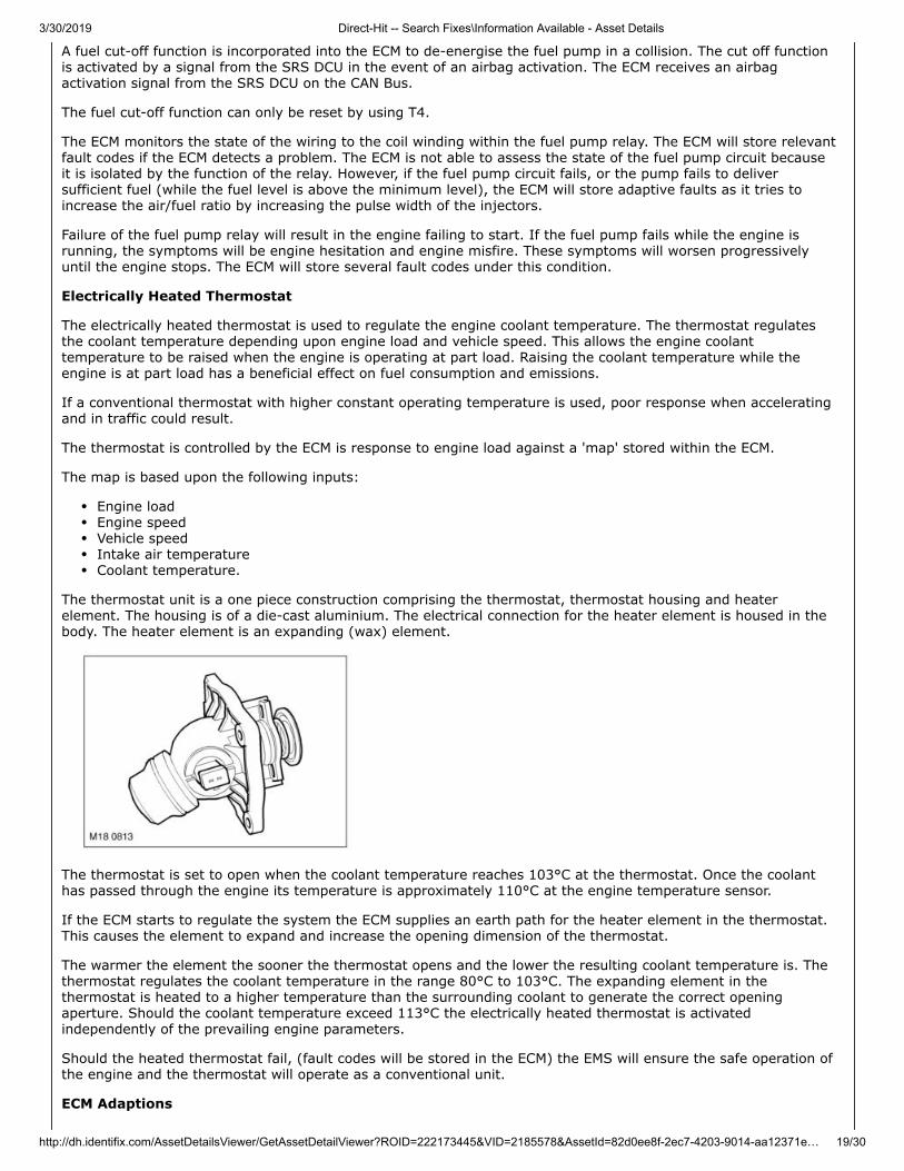
Electrically Heated Thermostat
The electrically heated thermostat is used to regulate the engine coolant temperature. The thermostat regulatesthe coolant temperature depending upon engine load and vehicle speed. This allows the engine coolanttemperature to be raised when the engine is operating at part load. Raising the coolant temperature while theengine is at part load has a beneficial effect on fuel consumption and emissions.
If a conventional thermostat with higher constant operating temperature is used, poor response when acceleratingand in traffic could result.
The thermostat is controlled by the ECM is response to engine load against a 'map' stored within the ECM.
The map is based upon the following inputs:
Engine loadEngine speedVehicle speedIntake air temperatureCoolant temperature.
The thermostat unit is a one piece construction comprising the thermostat, thermostat housing and heaterelement. The housing is of a die-cast aluminium. The electrical connection for the heater element is housed in thebody. The heater element is an expanding (wax) element.
The thermostat is set to open when the coolant temperature reaches 103°C at the thermostat. Once the coolanthas passed through the engine its temperature is approximately 110°C at the engine temperature sensor.
If the ECM starts to regulate the system the ECM supplies an earth path for the heater element in the thermostat.This causes the element to expand and increase the opening dimension of the thermostat.
The warmer the element the sooner the thermostat opens and the lower the resulting coolant temperature is. Thethermostat regulates the coolant temperature in the range 80°C to 103°C. The expanding element in thethermostat is heated to a higher temperature than the surrounding coolant to generate the correct openingaperture. Should the coolant temperature exceed 113°C the electrically heated thermostat is activatedindependently of the prevailing engine parameters.
Should the heated thermostat fail, (fault codes will be stored in the ECM) the EMS will ensure the safe operation ofthe engine and the thermostat will operate as a conventional unit.
ECM Adaptions
3/30/2019 Direct-Hit -- Search Fixes\Information Available - Asset Details
http://dh.identifix.com/AssetDetailsViewer/GetAssetDetailViewer?ROID=222173445&VID=2185578&AssetId=82d0ee8f-2ec7-4203-9014-aa12371e… 20/30
The ECM has the ability to adapt the values it uses to control certain outputs. This capability ensures the EMS canmeet emissions legislation and improve the refinement of the engine throughout its operating range.
The components which have adaptions associated with them are:
The APP sensorThe HO2SThe MAF/IAT sensorThe CKP sensorElectric throttle body.
HO2S and MAFIAT Sensor
There are several adaptive maps associated with the fuelling strategy. Within the fuelling strategy the ECMcalculates short-term adaptions and long term adaptions. The ECM will monitor the deterioration of the HO2S overa period of time. It will also monitor the current correction associated with the sensors.
The ECM will store a fault code in circumstances where an adaption is forced to exceed its operating parameters.At the same time, the ECM will record the engine speed, engine load and intake air temperature.
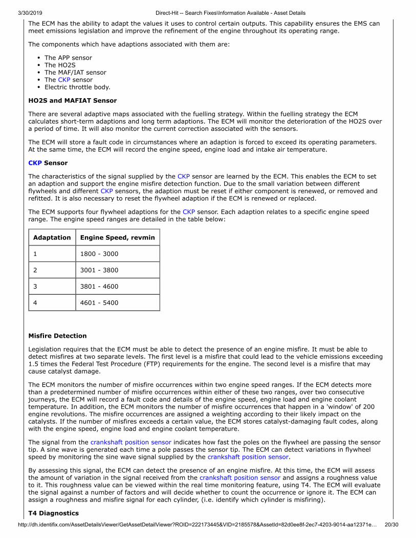
CKP Sensor
The characteristics of the signal supplied by the CKP sensor are learned by the ECM. This enables the ECM to setan adaption and support the engine misfire detection function. Due to the small variation between differentflywheels and different CKP sensors, the adaption must be reset if either component is renewed, or removed andrefitted. It is also necessary to reset the flywheel adaption if the ECM is renewed or replaced.
The ECM supports four flywheel adaptions for the CKP sensor. Each adaption relates to a specific engine speedrange. The engine speed ranges are detailed in the table below:
Adaptation Engine Speed, revmin
1 1800 - 3000
2 3001 - 3800
3 3801 - 4600
4 4601 - 5400
Misfire Detection
Legislation requires that the ECM must be able to detect the presence of an engine misfire. It must be able todetect misfires at two separate levels. The first level is a misfire that could lead to the vehicle emissions exceeding1.5 times the Federal Test Procedure (FTP) requirements for the engine. The second level is a misfire that maycause catalyst damage.
The ECM monitors the number of misfire occurrences within two engine speed ranges. If the ECM detects morethan a predetermined number of misfire occurrences within either of these two ranges, over two consecutivejourneys, the ECM will record a fault code and details of the engine speed, engine load and engine coolanttemperature. In addition, the ECM monitors the number of misfire occurrences that happen in a 'window' of 200engine revolutions. The misfire occurrences are assigned a weighting according to their likely impact on thecatalysts. If the number of misfires exceeds a certain value, the ECM stores catalyst-damaging fault codes, alongwith the engine speed, engine load and engine coolant temperature.
The signal from the crankshaft position sensor indicates how fast the poles on the flywheel are passing the sensortip. A sine wave is generated each time a pole passes the sensor tip. The ECM can detect variations in flywheelspeed by monitoring the sine wave signal supplied by the crankshaft position sensor.
By assessing this signal, the ECM can detect the presence of an engine misfire. At this time, the ECM will assessthe amount of variation in the signal received from the crankshaft position sensor and assigns a roughness valueto it. This roughness value can be viewed within the real time monitoring feature, using T4. The ECM will evaluatethe signal against a number of factors and will decide whether to count the occurrence or ignore it. The ECM canassign a roughness and misfire signal for each cylinder, (i.e. identify which cylinder is misfiring).
T4 Diagnostics
3/30/2019 Direct-Hit -- Search Fixes\Information Available - Asset Details
http://dh.identifix.com/AssetDetailsViewer/GetAssetDetailViewer?ROID=222173445&VID=2185578&AssetId=82d0ee8f-2ec7-4203-9014-aa12371e… 21/30
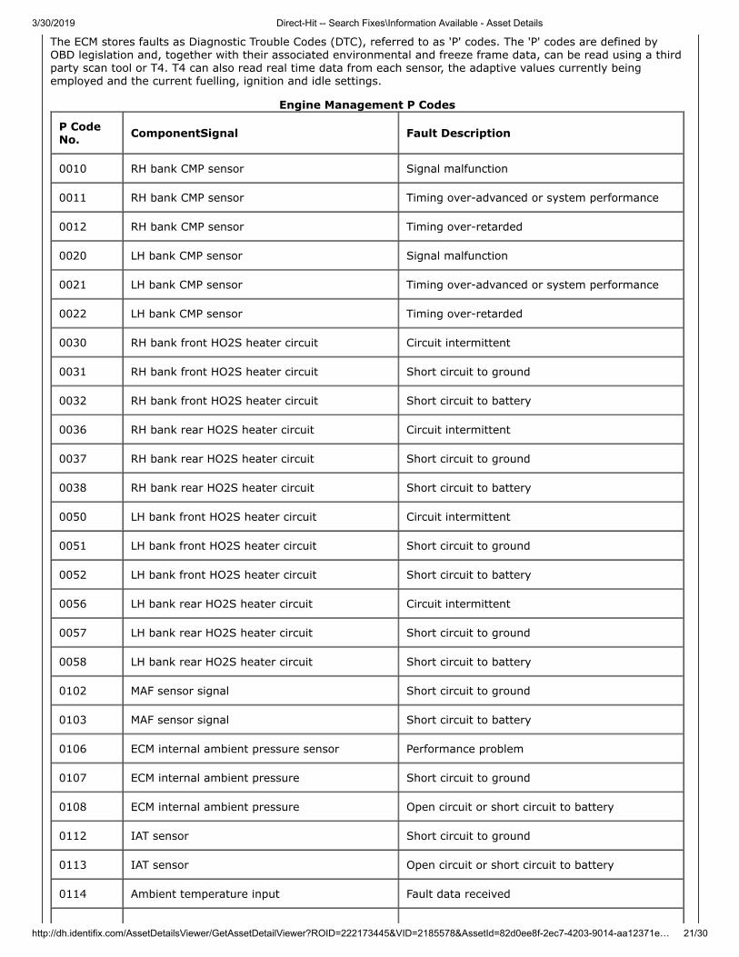
The ECM stores faults as Diagnostic Trouble Codes (DTC), referred to as 'P' codes. The 'P' codes are defined byOBD legislation and, together with their associated environmental and freeze frame data, can be read using a thirdparty scan tool or T4. T4 can also read real time data from each sensor, the adaptive values currently beingemployed and the current fuelling, ignition and idle settings.
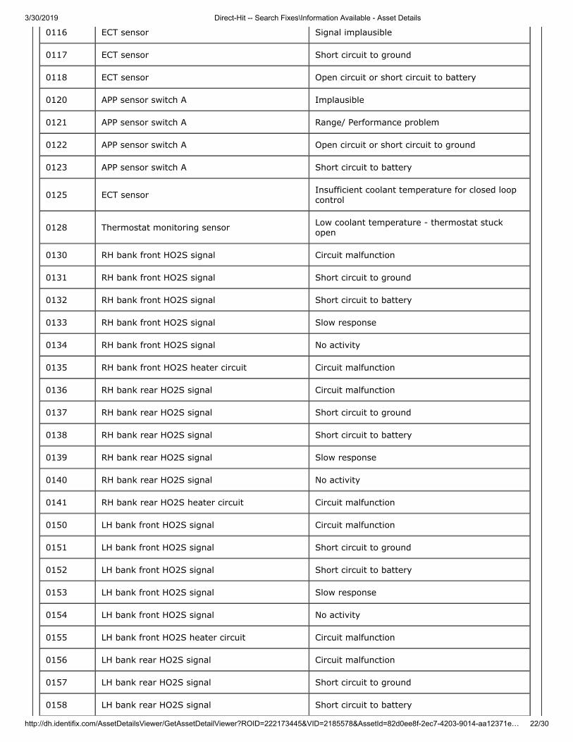
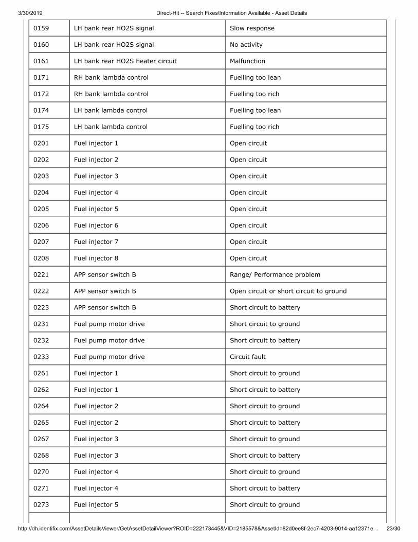
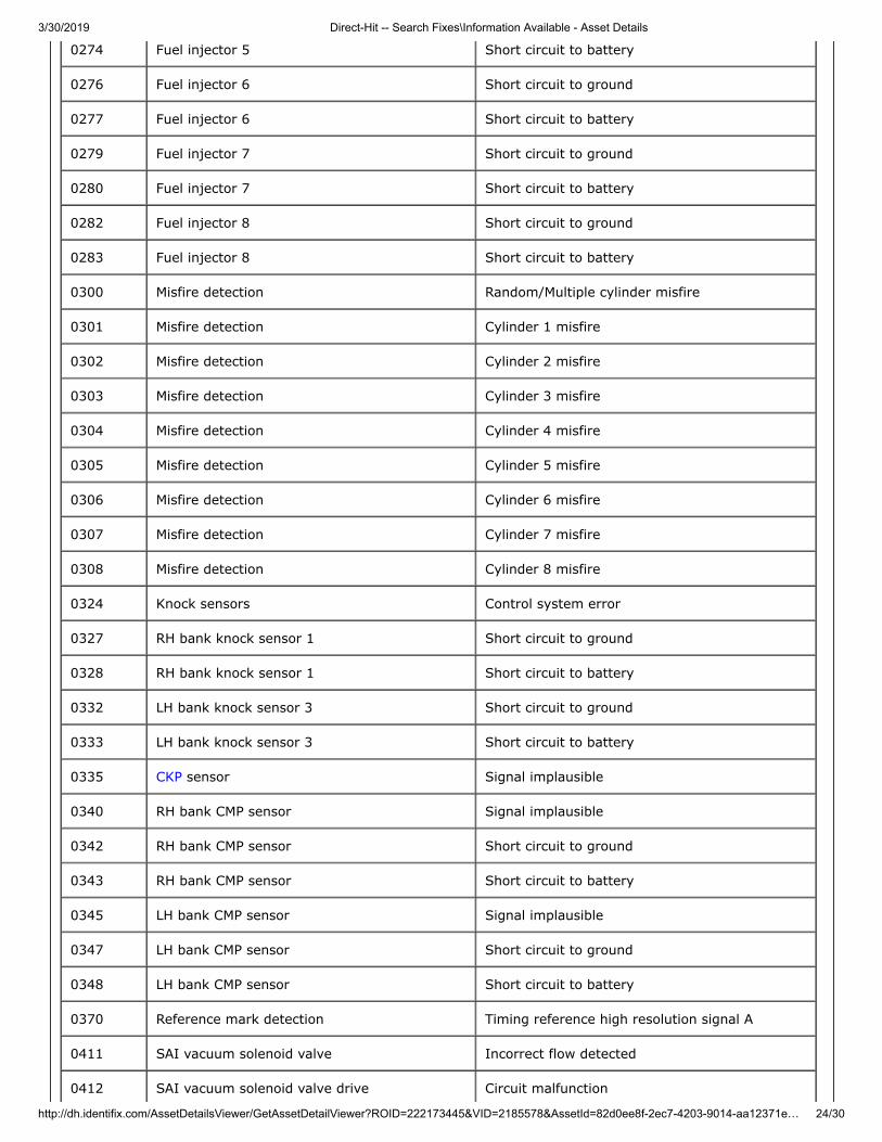
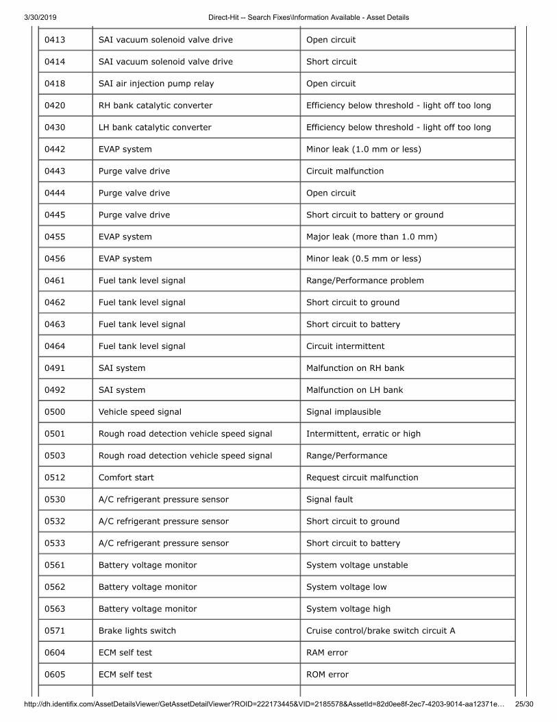
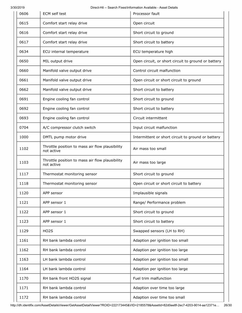
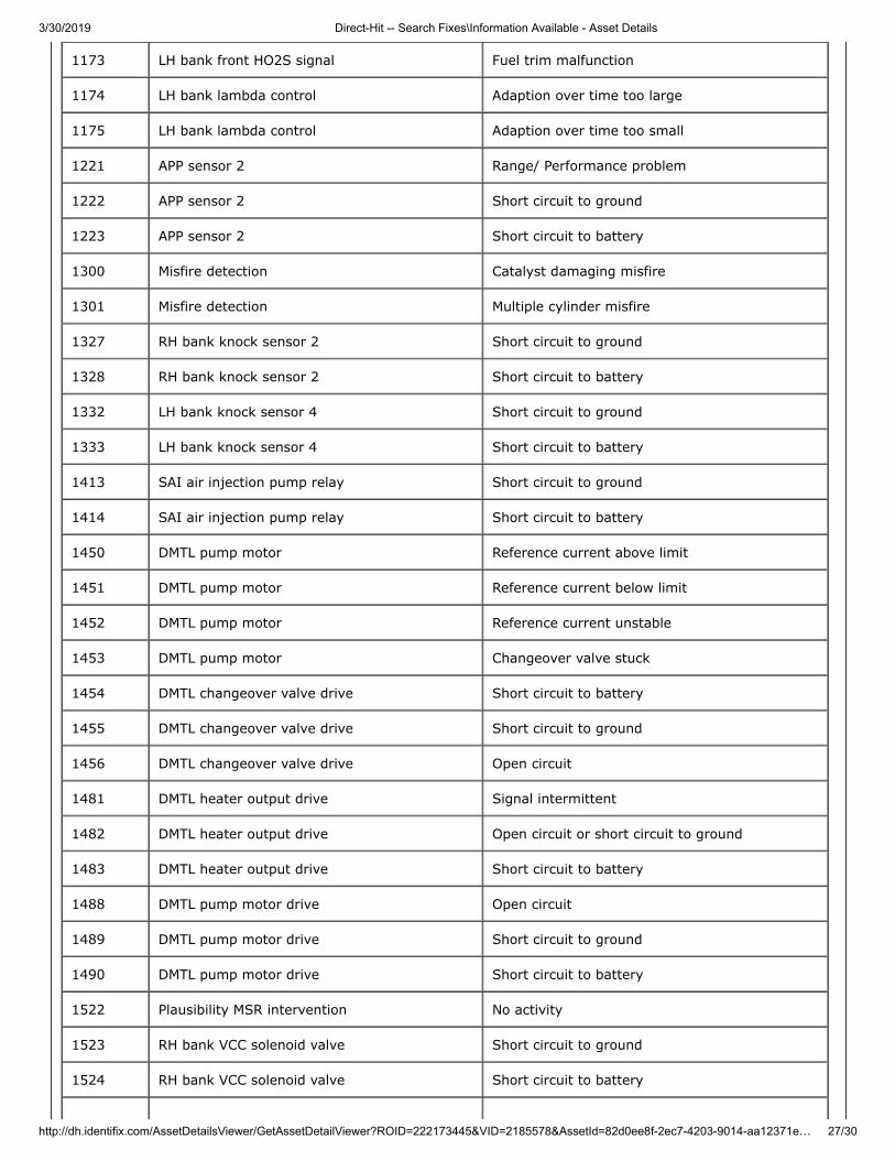
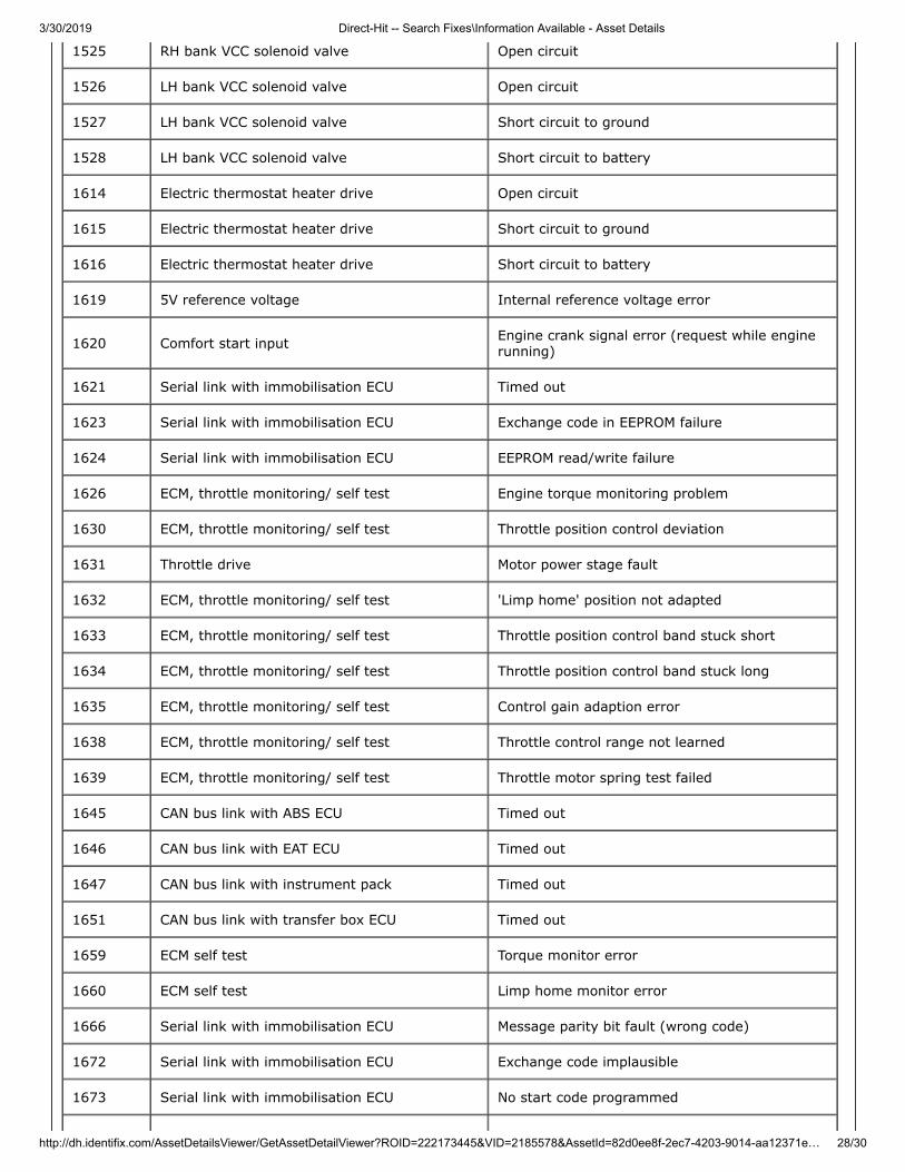
Engine Management P Codes
P CodeNo. ComponentSignal Fault Description
0010 RH bank CMP sensor Signal malfunction
0011 RH bank CMP sensor Timing over-advanced or system performance
0012 RH bank CMP sensor Timing over-retarded
0020 LH bank CMP sensor Signal malfunction
0021 LH bank CMP sensor Timing over-advanced or system performance
0022 LH bank CMP sensor Timing over-retarded
0030 RH bank front HO2S heater circuit Circuit intermittent
0031 RH bank front HO2S heater circuit Short circuit to ground
0032 RH bank front HO2S heater circuit Short circuit to battery
0036 RH bank rear HO2S heater circuit Circuit intermittent
0037 RH bank rear HO2S heater circuit Short circuit to ground
0038 RH bank rear HO2S heater circuit Short circuit to battery
0050 LH bank front HO2S heater circuit Circuit intermittent
0051 LH bank front HO2S heater circuit Short circuit to ground
0052 LH bank front HO2S heater circuit Short circuit to battery
0056 LH bank rear HO2S heater circuit Circuit intermittent
0057 LH bank rear HO2S heater circuit Short circuit to ground
0058 LH bank rear HO2S heater circuit Short circuit to battery
0102 MAF sensor signal Short circuit to ground
0103 MAF sensor signal Short circuit to battery
0106 ECM internal ambient pressure sensor Performance problem
0107 ECM internal ambient pressure Short circuit to ground
0108 ECM internal ambient pressure Open circuit or short circuit to battery
0112 IAT sensor Short circuit to ground
0113 IAT sensor Open circuit or short circuit to battery
0114 Ambient temperature input Fault data received
3/30/2019 Direct-Hit -- Search Fixes\Information Available - Asset Details
http://dh.identifix.com/AssetDetailsViewer/GetAssetDetailViewer?ROID=222173445&VID=2185578&AssetId=82d0ee8f-2ec7-4203-9014-aa12371e… 22/30
0116 ECT sensor Signal implausible
0117 ECT sensor Short circuit to ground
0118 ECT sensor Open circuit or short circuit to battery
0120 APP sensor switch A Implausible
0121 APP sensor switch A Range/ Performance problem
0122 APP sensor switch A Open circuit or short circuit to ground
0123 APP sensor switch A Short circuit to battery
0125 ECT sensor Insufficient coolant temperature for closed loopcontrol
0128 Thermostat monitoring sensor Low coolant temperature - thermostat stuckopen
0130 RH bank front HO2S signal Circuit malfunction
0131 RH bank front HO2S signal Short circuit to ground
0132 RH bank front HO2S signal Short circuit to battery
0133 RH bank front HO2S signal Slow response
0134 RH bank front HO2S signal No activity
0135 RH bank front HO2S heater circuit Circuit malfunction
0136 RH bank rear HO2S signal Circuit malfunction
0137 RH bank rear HO2S signal Short circuit to ground
0138 RH bank rear HO2S signal Short circuit to battery
0139 RH bank rear HO2S signal Slow response
0140 RH bank rear HO2S signal No activity
0141 RH bank rear HO2S heater circuit Circuit malfunction
0150 LH bank front HO2S signal Circuit malfunction
0151 LH bank front HO2S signal Short circuit to ground
0152 LH bank front HO2S signal Short circuit to battery
0153 LH bank front HO2S signal Slow response
0154 LH bank front HO2S signal No activity
0155 LH bank front HO2S heater circuit Circuit malfunction
0156 LH bank rear HO2S signal Circuit malfunction
0157 LH bank rear HO2S signal Short circuit to ground
0158 LH bank rear HO2S signal Short circuit to battery
3/30/2019 Direct-Hit -- Search Fixes\Information Available - Asset Details
http://dh.identifix.com/AssetDetailsViewer/GetAssetDetailViewer?ROID=222173445&VID=2185578&AssetId=82d0ee8f-2ec7-4203-9014-aa12371e… 23/30
0159 LH bank rear HO2S signal Slow response
0160 LH bank rear HO2S signal No activity
0161 LH bank rear HO2S heater circuit Malfunction
0171 RH bank lambda control Fuelling too lean
0172 RH bank lambda control Fuelling too rich
0174 LH bank lambda control Fuelling too lean
0175 LH bank lambda control Fuelling too rich
0201 Fuel injector 1 Open circuit
0202 Fuel injector 2 Open circuit
0203 Fuel injector 3 Open circuit
0204 Fuel injector 4 Open circuit
0205 Fuel injector 5 Open circuit
0206 Fuel injector 6 Open circuit
0207 Fuel injector 7 Open circuit
0208 Fuel injector 8 Open circuit
0221 APP sensor switch B Range/ Performance problem
0222 APP sensor switch B Open circuit or short circuit to ground
0223 APP sensor switch B Short circuit to battery
0231 Fuel pump motor drive Short circuit to ground
0232 Fuel pump motor drive Short circuit to battery
0233 Fuel pump motor drive Circuit fault
0261 Fuel injector 1 Short circuit to ground
0262 Fuel injector 1 Short circuit to battery
0264 Fuel injector 2 Short circuit to ground
0265 Fuel injector 2 Short circuit to battery
0267 Fuel injector 3 Short circuit to ground
0268 Fuel injector 3 Short circuit to battery
0270 Fuel injector 4 Short circuit to ground
0271 Fuel injector 4 Short circuit to battery
0273 Fuel injector 5 Short circuit to ground
3/30/2019 Direct-Hit -- Search Fixes\Information Available - Asset Details
http://dh.identifix.com/AssetDetailsViewer/GetAssetDetailViewer?ROID=222173445&VID=2185578&AssetId=82d0ee8f-2ec7-4203-9014-aa12371e… 24/30
0274 Fuel injector 5 Short circuit to battery
0276 Fuel injector 6 Short circuit to ground
0277 Fuel injector 6 Short circuit to battery
0279 Fuel injector 7 Short circuit to ground
0280 Fuel injector 7 Short circuit to battery
0282 Fuel injector 8 Short circuit to ground
0283 Fuel injector 8 Short circuit to battery
0300 Misfire detection Random/Multiple cylinder misfire
0301 Misfire detection Cylinder 1 misfire
0302 Misfire detection Cylinder 2 misfire
0303 Misfire detection Cylinder 3 misfire
0304 Misfire detection Cylinder 4 misfire
0305 Misfire detection Cylinder 5 misfire
0306 Misfire detection Cylinder 6 misfire
0307 Misfire detection Cylinder 7 misfire
0308 Misfire detection Cylinder 8 misfire
0324 Knock sensors Control system error
0327 RH bank knock sensor 1 Short circuit to ground
0328 RH bank knock sensor 1 Short circuit to battery
0332 LH bank knock sensor 3 Short circuit to ground
0333 LH bank knock sensor 3 Short circuit to battery
0335 CKP sensor Signal implausible
0340 RH bank CMP sensor Signal implausible
0342 RH bank CMP sensor Short circuit to ground
0343 RH bank CMP sensor Short circuit to battery
0345 LH bank CMP sensor Signal implausible
0347 LH bank CMP sensor Short circuit to ground
0348 LH bank CMP sensor Short circuit to battery
0370 Reference mark detection Timing reference high resolution signal A
0411 SAI vacuum solenoid valve Incorrect flow detected
0412 SAI vacuum solenoid valve drive Circuit malfunction
3/30/2019 Direct-Hit -- Search Fixes\Information Available - Asset Details
http://dh.identifix.com/AssetDetailsViewer/GetAssetDetailViewer?ROID=222173445&VID=2185578&AssetId=82d0ee8f-2ec7-4203-9014-aa12371e… 25/30
0413 SAI vacuum solenoid valve drive Open circuit
0414 SAI vacuum solenoid valve drive Short circuit
0418 SAI air injection pump relay Open circuit
0420 RH bank catalytic converter Efficiency below threshold - light off too long
0430 LH bank catalytic converter Efficiency below threshold - light off too long
0442 EVAP system Minor leak (1.0 mm or less)
0443 Purge valve drive Circuit malfunction
0444 Purge valve drive Open circuit
0445 Purge valve drive Short circuit to battery or ground
0455 EVAP system Major leak (more than 1.0 mm)
0456 EVAP system Minor leak (0.5 mm or less)
0461 Fuel tank level signal Range/Performance problem
0462 Fuel tank level signal Short circuit to ground
0463 Fuel tank level signal Short circuit to battery
0464 Fuel tank level signal Circuit intermittent
0491 SAI system Malfunction on RH bank
0492 SAI system Malfunction on LH bank
0500 Vehicle speed signal Signal implausible
0501 Rough road detection vehicle speed signal Intermittent, erratic or high
0503 Rough road detection vehicle speed signal Range/Performance
0512 Comfort start Request circuit malfunction
0530 A/C refrigerant pressure sensor Signal fault
0532 A/C refrigerant pressure sensor Short circuit to ground
0533 A/C refrigerant pressure sensor Short circuit to battery
0561 Battery voltage monitor System voltage unstable
0562 Battery voltage monitor System voltage low
0563 Battery voltage monitor System voltage high
0571 Brake lights switch Cruise control/brake switch circuit A
0604 ECM self test RAM error
0605 ECM self test ROM error
3/30/2019 Direct-Hit -- Search Fixes\Information Available - Asset Details
http://dh.identifix.com/AssetDetailsViewer/GetAssetDetailViewer?ROID=222173445&VID=2185578&AssetId=82d0ee8f-2ec7-4203-9014-aa12371e… 26/30
0606 ECM self test Processor fault
0615 Comfort start relay drive Open circuit
0616 Comfort start relay drive Short circuit to ground
0617 Comfort start relay drive Short circuit to battery
0634 ECU internal temperature ECU temperature high
0650 MIL output drive Open circuit, or short circuit to ground or battery
0660 Manifold valve output drive Control circuit malfunction
0661 Manifold valve output drive Open circuit or short circuit to ground
0662 Manifold valve output drive Short circuit to battery
0691 Engine cooling fan control Short circuit to ground
0692 Engine cooling fan control Short circuit to battery
0693 Engine cooling fan control Circuit intermittent
0704 A/C compressor clutch switch Input circuit malfunction
1000 DMTL pump motor drive Intermittent or short circuit to ground or battery
1102 Throttle position to mass air flow plausibilitynot active Air mass too small
1103 Throttle position to mass air flow plausibilitynot active Air mass too large
1117 Thermostat monitoring sensor Short circuit to ground
1118 Thermostat monitoring sensor Open circuit or short circuit to battery
1120 APP sensor Implausible signals
1121 APP sensor 1 Range/ Performance problem
1122 APP sensor 1 Short circuit to ground
1123 APP sensor 1 Short circuit to battery
1129 HO2S Swapped sensors (LH to RH)
1161 RH bank lambda control Adaption per ignition too small
1162 RH bank lambda control Adaption per ignition too large
1163 LH bank lambda control Adaption per ignition too small
1164 LH bank lambda control Adaption per ignition too large
1170 RH bank front HO2S signal Fuel trim malfunction
1171 RH bank lambda control Adaption over time too large
1172 RH bank lambda control Adaption over time too small
3/30/2019 Direct-Hit -- Search Fixes\Information Available - Asset Details
http://dh.identifix.com/AssetDetailsViewer/GetAssetDetailViewer?ROID=222173445&VID=2185578&AssetId=82d0ee8f-2ec7-4203-9014-aa12371e… 27/30
1173 LH bank front HO2S signal Fuel trim malfunction
1174 LH bank lambda control Adaption over time too large
1175 LH bank lambda control Adaption over time too small
1221 APP sensor 2 Range/ Performance problem
1222 APP sensor 2 Short circuit to ground
1223 APP sensor 2 Short circuit to battery
1300 Misfire detection Catalyst damaging misfire
1301 Misfire detection Multiple cylinder misfire
1327 RH bank knock sensor 2 Short circuit to ground
1328 RH bank knock sensor 2 Short circuit to battery
1332 LH bank knock sensor 4 Short circuit to ground
1333 LH bank knock sensor 4 Short circuit to battery
1413 SAI air injection pump relay Short circuit to ground
1414 SAI air injection pump relay Short circuit to battery
1450 DMTL pump motor Reference current above limit
1451 DMTL pump motor Reference current below limit
1452 DMTL pump motor Reference current unstable
1453 DMTL pump motor Changeover valve stuck
1454 DMTL changeover valve drive Short circuit to battery
1455 DMTL changeover valve drive Short circuit to ground
1456 DMTL changeover valve drive Open circuit
1481 DMTL heater output drive Signal intermittent
1482 DMTL heater output drive Open circuit or short circuit to ground
1483 DMTL heater output drive Short circuit to battery
1488 DMTL pump motor drive Open circuit
1489 DMTL pump motor drive Short circuit to ground
1490 DMTL pump motor drive Short circuit to battery
1522 Plausibility MSR intervention No activity
1523 RH bank VCC solenoid valve Short circuit to ground
1524 RH bank VCC solenoid valve Short circuit to battery
3/30/2019 Direct-Hit -- Search Fixes\Information Available - Asset Details
http://dh.identifix.com/AssetDetailsViewer/GetAssetDetailViewer?ROID=222173445&VID=2185578&AssetId=82d0ee8f-2ec7-4203-9014-aa12371e… 28/30
1525 RH bank VCC solenoid valve Open circuit
1526 LH bank VCC solenoid valve Open circuit
1527 LH bank VCC solenoid valve Short circuit to ground
1528 LH bank VCC solenoid valve Short circuit to battery
1614 Electric thermostat heater drive Open circuit
1615 Electric thermostat heater drive Short circuit to ground
1616 Electric thermostat heater drive Short circuit to battery
1619 5V reference voltage Internal reference voltage error
1620 Comfort start input Engine crank signal error (request while enginerunning)
1621 Serial link with immobilisation ECU Timed out
1623 Serial link with immobilisation ECU Exchange code in EEPROM failure
1624 Serial link with immobilisation ECU EEPROM read/write failure
1626 ECM, throttle monitoring/ self test Engine torque monitoring problem
1630 ECM, throttle monitoring/ self test Throttle position control deviation
1631 Throttle drive Motor power stage fault
1632 ECM, throttle monitoring/ self test 'Limp home' position not adapted
1633 ECM, throttle monitoring/ self test Throttle position control band stuck short
1634 ECM, throttle monitoring/ self test Throttle position control band stuck long
1635 ECM, throttle monitoring/ self test Control gain adaption error
1638 ECM, throttle monitoring/ self test Throttle control range not learned
1639 ECM, throttle monitoring/ self test Throttle motor spring test failed
1645 CAN bus link with ABS ECU Timed out
1646 CAN bus link with EAT ECU Timed out
1647 CAN bus link with instrument pack Timed out
1651 CAN bus link with transfer box ECU Timed out
1659 ECM self test Torque monitor error
1660 ECM self test Limp home monitor error
1666 Serial link with immobilisation ECU Message parity bit fault (wrong code)
1672 Serial link with immobilisation ECU Exchange code implausible
1673 Serial link with immobilisation ECU No start code programmed
3/30/2019 Direct-Hit -- Search Fixes\Information Available - Asset Details
http://dh.identifix.com/AssetDetailsViewer/GetAssetDetailViewer?ROID=222173445&VID=2185578&AssetId=82d0ee8f-2ec7-4203-9014-aa12371e… 29/30
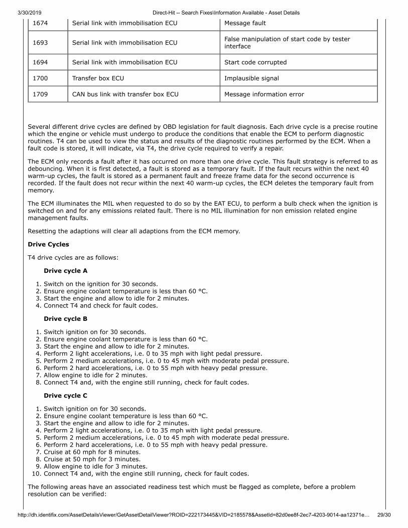
1674 Serial link with immobilisation ECU Message fault
1693 Serial link with immobilisation ECU False manipulation of start code by testerinterface
1694 Serial link with immobilisation ECU Start code corrupted
1700 Transfer box ECU Implausible signal
1709 CAN bus link with transfer box ECU Message information error
Several different drive cycles are defined by OBD legislation for fault diagnosis. Each drive cycle is a precise routinewhich the engine or vehicle must undergo to produce the conditions that enable the ECM to perform diagnosticroutines. T4 can be used to view the status and results of the diagnostic routines performed by the ECM. When afault code is stored, it will indicate, via T4, the drive cycle required to verify a repair.
The ECM only records a fault after it has occurred on more than one drive cycle. This fault strategy is referred to asdebouncing. When it is first detected, a fault is stored as a temporary fault. If the fault recurs within the next 40warm-up cycles, the fault is stored as a permanent fault and freeze frame data for the second occurrence isrecorded. If the fault does not recur within the next 40 warm-up cycles, the ECM deletes the temporary fault frommemory.
The ECM illuminates the MIL when requested to do so by the EAT ECU, to perform a bulb check when the ignition isswitched on and for any emissions related fault. There is no MIL illumination for non emission related enginemanagement faults.
Resetting the adaptions will clear all adaptions from the ECM memory.
Drive Cycles
T4 drive cycles are as follows:
Drive cycle A
1. Switch on the ignition for 30 seconds.2. Ensure engine coolant temperature is less than 60 °C.3. Start the engine and allow to idle for 2 minutes.4. Connect T4 and check for fault codes.
Drive cycle B
1. Switch ignition on for 30 seconds.2. Ensure engine coolant temperature is less than 60 °C.3. Start the engine and allow to idle for 2 minutes.4. Perform 2 light accelerations, i.e. 0 to 35 mph with light pedal pressure.5. Perform 2 medium accelerations, i.e. 0 to 45 mph with moderate pedal pressure.6. Perform 2 hard accelerations, i.e. 0 to 55 mph with heavy pedal pressure.7. Allow engine to idle for 2 minutes.8. Connect T4 and, with the engine still running, check for fault codes.
Drive cycle C
1. Switch ignition on for 30 seconds.2. Ensure engine coolant temperature is less than 60 °C.3. Start the engine and allow to idle for 2 minutes.4. Perform 2 light accelerations, i.e. 0 to 35 mph with light pedal pressure.5. Perform 2 medium accelerations, i.e. 0 to 45 mph with moderate pedal pressure.6. Perform 2 hard accelerations, i.e. 0 to 55 mph with heavy pedal pressure.7. Cruise at 60 mph for 8 minutes.8. Cruise at 50 mph for 3 minutes.9. Allow engine to idle for 3 minutes.
10. Connect T4 and, with the engine still running, check for fault codes.
The following areas have an associated readiness test which must be flagged as complete, before a problemresolution can be verified:
3/30/2019 Direct-Hit -- Search Fixes\Information Available - Asset Details
http://dh.identifix.com/AssetDetailsViewer/GetAssetDetailViewer?ROID=222173445&VID=2185578&AssetId=82d0ee8f-2ec7-4203-9014-aa12371e… 30/30
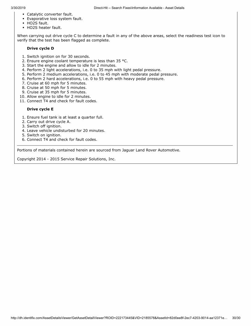
Catalytic converter fault.Evaporative loss system fault.HO2S fault.HO2S heater fault.
When carrying out drive cycle C to determine a fault in any of the above areas, select the readiness test icon toverify that the test has been flagged as complete.
Drive cycle D
1. Switch ignition on for 30 seconds.2. Ensure engine coolant temperature is less than 35 °C.3. Start the engine and allow to idle for 2 minutes.4. Perform 2 light accelerations, i.e. 0 to 35 mph with light pedal pressure.5. Perform 2 medium accelerations, i.e. 0 to 45 mph with moderate pedal pressure.6. Perform 2 hard accelerations, i.e. 0 to 55 mph with heavy pedal pressure.7. Cruise at 60 mph for 5 minutes.8. Cruise at 50 mph for 5 minutes.9. Cruise at 35 mph for 5 minutes.
10. Allow engine to idle for 2 minutes.11. Connect T4 and check for fault codes.
Drive cycle E
1. Ensure fuel tank is at least a quarter full.2. Carry out drive cycle A.3. Switch off ignition.4. Leave vehicle undisturbed for 20 minutes.5. Switch on ignition.6. Connect T4 and check for fault codes.
Portions of materials contained herein are sourced from Jaguar Land Rover Automotive. Copyright 2014 - 2015 Service Repair Solutions, Inc.