Embed Size (px)
Citation preview
1/15Duplex filter
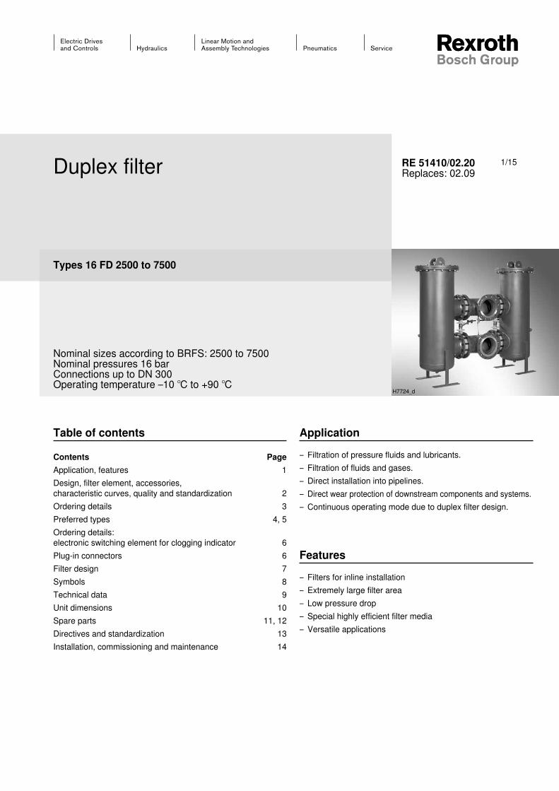
Types 16 FD 2500 to 7500
Nominal sizes according to BRFS: 2500 to 7500 Nominal pressures 16 barConnections up to DN 300Operating temperature –10 ℃ to +90 ℃
RE 51410/02.20Replaces: 02.09
Application
– Filtration of pressure fluids and lubricants.– Filtration of fluids and gases.– Direct installation into pipelines.– Direct wear protection of downstream components and systems.– Continuous operating mode due to duplex filter design.
Features
– Filters for inline installation– Extremely large filter area– Low pressure drop– Special highly efficient filter media– Versatile applications
H7724_d
Table of contents
Contents PageApplication, features 1Design, filter element, accessories, characteristic curves, quality and standardization 2Ordering details 3Preferred types 4, 5Ordering details: electronic switching element for clogging indicator 6Plug-in connectors 6Filter design 7Symbols 8Technical data 9Unit dimensions 10Spare parts 11, 12Directives and standardization 13Installation, commissioning and maintenance 14
2/15 Bosch Rexroth AG Hydraulics 16 FD 2500 - 7500 RE 51410/02.20
Design
Steel welded construction of two filter housings that are con-nected with each other as switch unit by means of four shut-off valves. The connections are aligned vertically. Filter cover with bleed and filter housing with drain screws. Materials as per spare parts list.
Filter element
Pleated design with optimized pleat density and various filter media. The filter element is the most important component of the "FILTER" system in view of the prolonged life and the wear protection of the systems. The most important criteria for selection are the required de-gree of cleanliness of the operating medium, the initial pres-sure differential and the contamination retention capacity.
For further detailed information please refer to our brochure "Filter Elements". Bypass valve To protect the filter element during startup and over pressur-ization due to clogging.
Accessories
Clogging indicatorBasically, the filter is equipped with mechanical optical clog-ging indicator. The electronic clogging indicator is connect-ed via the electronic switching element with 1 or 2 switching points, which has to be ordered separately. The electronic switching element is attached to the mechanical optical clog-ging indicator and held by means of a locking ring.
Bleed valve For bleeding the filter in the commissioning and for the safe reduction of the operating pressure.
Quality and standardization
The development, manufacture, and assembly of BRFS industrial filters and BRFS filter elements is carried out within the framework of a certified quality management system in accordance with ISO 9001:2000.
The pressure filters for hydraulic applications according to 51410 are pressure holding equipment according to article 1, section 2.1.4 of the pressure equipment direc-tive 97/23/EC (DGRL). However, on the basis of the excep-tion in article 1, section 3.6 of the DGRL, hydraulic filters are exempt from the DGRL if they are not classified higher than category I (guideline 1/19). They do not receive a CE mark.
Characteristic curves
An optimum filter selection is made possible by our "BRFilterSelect" software, see download area http://www.boschrexroth.com/filter.
Additional characteristic curves for the filters in this catalogue can be found in the BRFS filter calculation program.
Further design variants available on request.
Hydraulics Bosch Rexroth AGRE 51410/02.20 16 FD 2500 - 7500 3/15
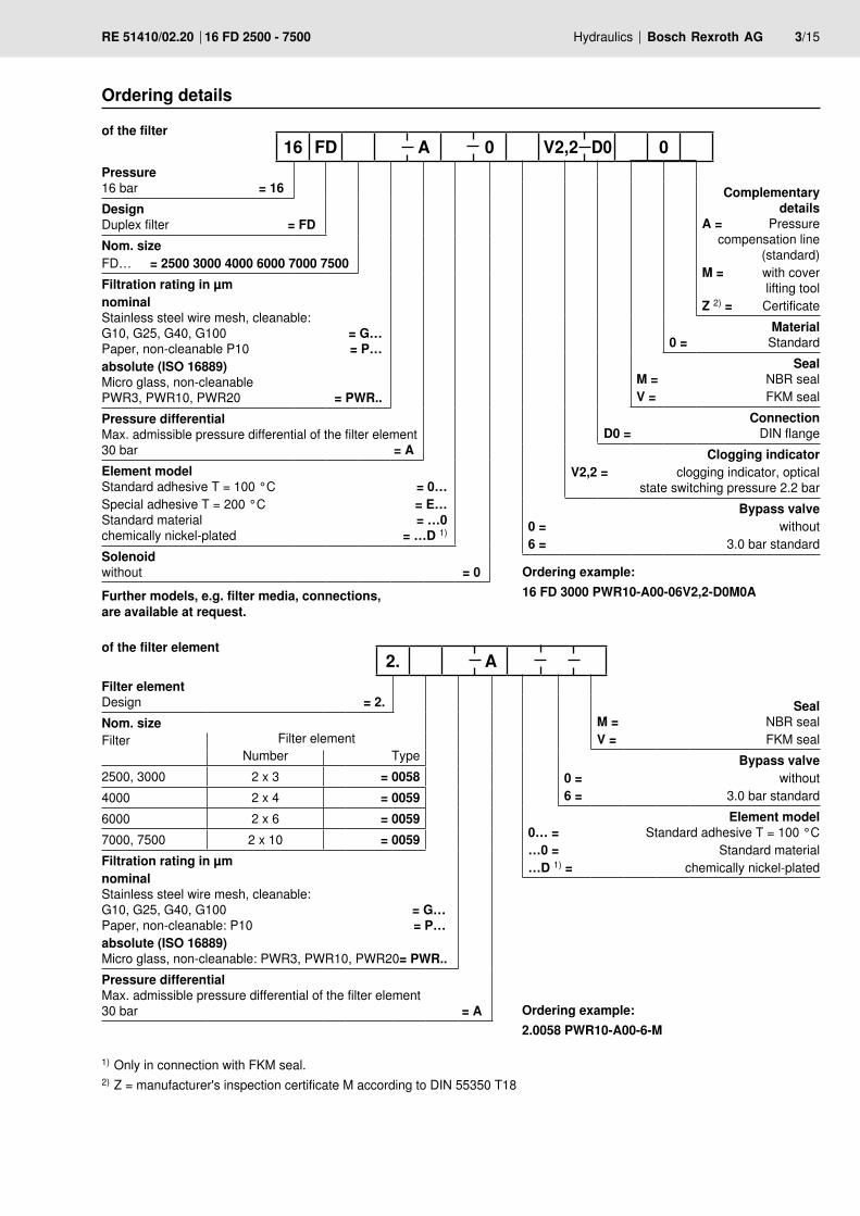
Pressure 16 bar = 16
Design Duplex filter = FDNom. sizeFD… = 2500 3000 4000 6000 7000 7500 Filtration rating in µmnominal Stainless steel wire mesh, cleanable: G10, G25, G40, G100 = G… Paper, non-cleanable P10 = P…absolute (ISO 16889) Micro glass, non-cleanable PWR3, PWR10, PWR20 = PWR..Pressure differential Max. admissible pressure differential of the filter element 30 bar = AElement model Standard adhesive T = 100 °C = 0…Special adhesive T = 200 °C = E… Standard material = …0 chemically nickel-plated = …D 1)
Solenoid without = 0
Complementary details
A = Pressure compensation line
(standard)M = with cover
lifting toolZ 2) = Certificate
Material 0 = Standard
Seal M = NBR sealV = FKM seal
Connection D0 = DIN flange
Clogging indicatorV2,2 = clogging indicator, optical
state switching pressure 2.2 barBypass valve
0 = without6 = 3.0 bar standard
16 FD A 0 V2,2 D0 0
Ordering details
of the filter element
Filter element Design = 2.Nom. size Filter Filter element
Number Type2500, 3000 2 x 3 = 00584000 2 x 4 = 00596000 2 x 6 = 00597000, 7500 2 x 10 = 0059Filtration rating in µmnominal Stainless steel wire mesh, cleanable: G10, G25, G40, G100 = G… Paper, non-cleanable: P10 = P…absolute (ISO 16889) Micro glass, non-cleanable: PWR3, PWR10, PWR20 = PWR..Pressure differential Max. admissible pressure differential of the filter element 30 bar = A
Seal M = NBR sealV = FKM seal
Bypass valve 0 = without6 = 3.0 bar standard
Element model 0… = Standard adhesive T = 100 °C…0 = Standard material…D 1) = chemically nickel-plated
2. A
Ordering example:2.0058 PWR10-A00-6-M
of the filter
1) Only in connection with FKM seal. 2) Z = manufacturer's inspection certificate M according to DIN 55350 T18
Ordering example:16 FD 3000 PWR10-A00-06V2,2-D0M0AFurther models, e.g. filter media, connections,
are available at request.
4/15 Bosch Rexroth AG Hydraulics 16 FD 2500 - 7500 RE 51410/02.20
Preferred types
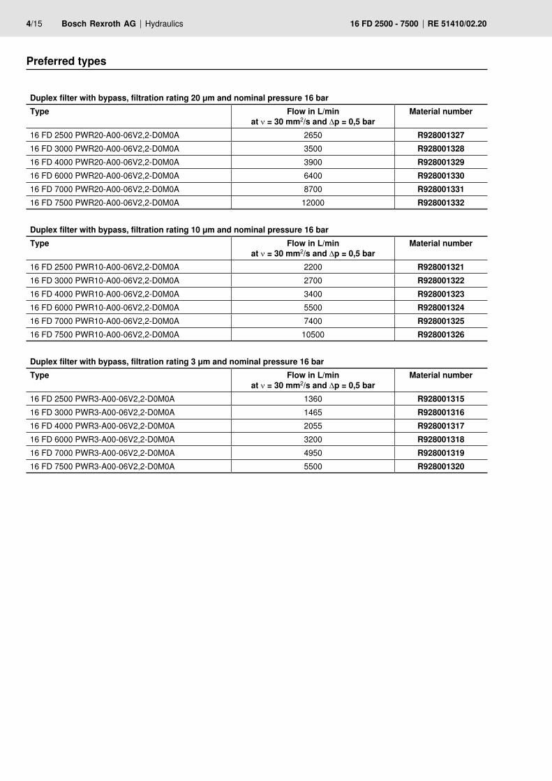
Duplex filter with bypass, filtration rating 20 μm and nominal pressure 16 barType Flow in L/min
at ν = 30 mm2/s and Δp = 0,5 barMaterial number
16 FD 2500 PWR20-A00-06V2,2-D0M0A 2650 R92800132716 FD 3000 PWR20-A00-06V2,2-D0M0A 3500 R92800132816 FD 4000 PWR20-A00-06V2,2-D0M0A 3900 R92800132916 FD 6000 PWR20-A00-06V2,2-D0M0A 6400 R92800133016 FD 7000 PWR20-A00-06V2,2-D0M0A 8700 R92800133116 FD 7500 PWR20-A00-06V2,2-D0M0A 12000 R928001332
Duplex filter with bypass, filtration rating 10 μm and nominal pressure 16 barType Flow in L/min
at ν = 30 mm2/s and Δp = 0,5 barMaterial number
16 FD 2500 PWR10-A00-06V2,2-D0M0A 2200 R92800132116 FD 3000 PWR10-A00-06V2,2-D0M0A 2700 R92800132216 FD 4000 PWR10-A00-06V2,2-D0M0A 3400 R92800132316 FD 6000 PWR10-A00-06V2,2-D0M0A 5500 R92800132416 FD 7000 PWR10-A00-06V2,2-D0M0A 7400 R92800132516 FD 7500 PWR10-A00-06V2,2-D0M0A 10500 R928001326
Duplex filter with bypass, filtration rating 3 μm and nominal pressure 16 barType Flow in L/min
at ν = 30 mm2/s and Δp = 0,5 barMaterial number
16 FD 2500 PWR3-A00-06V2,2-D0M0A 1360 R92800131516 FD 3000 PWR3-A00-06V2,2-D0M0A 1465 R92800131616 FD 4000 PWR3-A00-06V2,2-D0M0A 2055 R92800131716 FD 6000 PWR3-A00-06V2,2-D0M0A 3200 R92800131816 FD 7000 PWR3-A00-06V2,2-D0M0A 4950 R92800131916 FD 7500 PWR3-A00-06V2,2-D0M0A 5500 R928001320
Hydraulics Bosch Rexroth AGRE 51410/02.20 16 FD 2500 - 7500 5/15
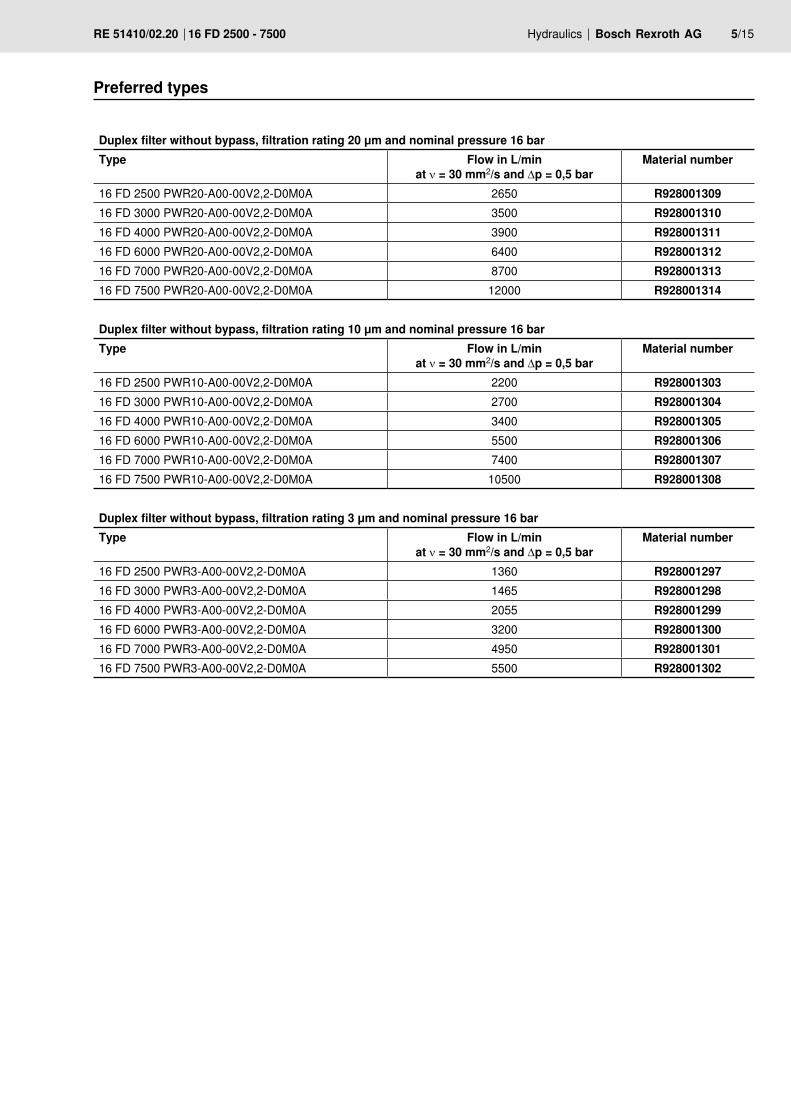
Preferred types
Duplex filter without bypass, filtration rating 20 μm and nominal pressure 16 barType Flow in L/min
at ν = 30 mm2/s and Δp = 0,5 barMaterial number
16 FD 2500 PWR20-A00-00V2,2-D0M0A 2650 R92800130916 FD 3000 PWR20-A00-00V2,2-D0M0A 3500 R92800131016 FD 4000 PWR20-A00-00V2,2-D0M0A 3900 R92800131116 FD 6000 PWR20-A00-00V2,2-D0M0A 6400 R92800131216 FD 7000 PWR20-A00-00V2,2-D0M0A 8700 R92800131316 FD 7500 PWR20-A00-00V2,2-D0M0A 12000 R928001314
Duplex filter without bypass, filtration rating 10 μm and nominal pressure 16 barType Flow in L/min
at ν = 30 mm2/s and Δp = 0,5 barMaterial number
16 FD 2500 PWR10-A00-00V2,2-D0M0A 2200 R92800130316 FD 3000 PWR10-A00-00V2,2-D0M0A 2700 R92800130416 FD 4000 PWR10-A00-00V2,2-D0M0A 3400 R92800130516 FD 6000 PWR10-A00-00V2,2-D0M0A 5500 R92800130616 FD 7000 PWR10-A00-00V2,2-D0M0A 7400 R92800130716 FD 7500 PWR10-A00-00V2,2-D0M0A 10500 R928001308
Duplex filter without bypass, filtration rating 3 μm and nominal pressure 16 barType Flow in L/min
at ν = 30 mm2/s and Δp = 0,5 barMaterial number
16 FD 2500 PWR3-A00-00V2,2-D0M0A 1360 R92800129716 FD 3000 PWR3-A00-00V2,2-D0M0A 1465 R92800129816 FD 4000 PWR3-A00-00V2,2-D0M0A 2055 R92800129916 FD 6000 PWR3-A00-00V2,2-D0M0A 3200 R92800130016 FD 7000 PWR3-A00-00V2,2-D0M0A 4950 R92800130116 FD 7500 PWR3-A00-00V2,2-D0M0A 5500 R928001302
54
M12
x 1
Ø19
,6
[2.12]
[0.7
7]
M12
x 1
Ø19
,6
41,5 [1.63]
[0.7
7]
6/15 Bosch Rexroth AG Hydraulics 16 FD 2500 - 7500 RE 51410/02.20
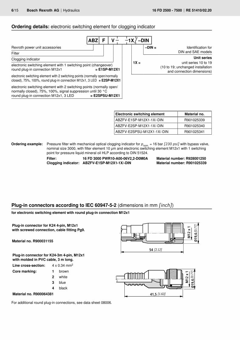
Ordering example: Pressure filter with mechanical optical clogging indicator for pnom. = 16 bar [230 psi] with bypass valve, nominal size 3000, with filter element 10 μm and electronic switching element M12x1 with 1 switching point for pressure liquid mineral oil HLP according to DIN 51524.
Filter: 16 FD 3000 PWR10-A00-06V2,2-D0M0A Material number: R928001250 Clogging indicator: ABZFV-E1SP-M12X1-1X/-DIN Material number: R901025339
Plug-in connectors according to IEC 60947-5-2 (dimensions in mm [inch])
Plug-in connector for K24 4-pin, M12x1 with screwed connection, cable fitting Pg9.
Material no. R900031155
Plug-in connector for K24-3m 4-pin, M12x1 with molded in PVC cable, 3 m long.Line cross-section: 4 x 0.34 mm2
Core marking: 1234
brownwhiteblueblack
Material no. R900064381
for electronic switching element with round plug-in connection M12x1
For additional round plug-in connections, see data sheet 08006.
Ordering details: electronic switching element for clogging indicator
Rexroth power unit accessories FilterClogging indicatorelectronic switching element with 1 switching point (changeover) round plug-in connection M12x1 = E1SP-M12X1electronic switching element with 2 switching points (normally open/normally closed), 75%, 100%, round plug-in connection M12x1, 3 LED = E2SP-M12X1electronic switching element with 2 switching points (normally open/normally closed), 75%, 100%, signal suppression until 30 °C round plug-in connection M12x1, 3 LED = E2SPSU-M12X1
–DIN = Identification for DIN and SAE models
Unit series1X = unit series 10 to 19
(10 to 19; unchanged installation and connection dimensions)
ABZ F V 1X –DIN
Electronic switching element Material no.ABZFV-E1SP-M12X1-1X/-DIN R901025339ABZFV-E2SP-M12X1-1X/-DIN R901025340ABZFV-E2SPSU-M12X1-1X/-DIN R901025341
Hydraulics Bosch Rexroth AGRE 51410/02.20 16 FD 2500 - 7500 7/15
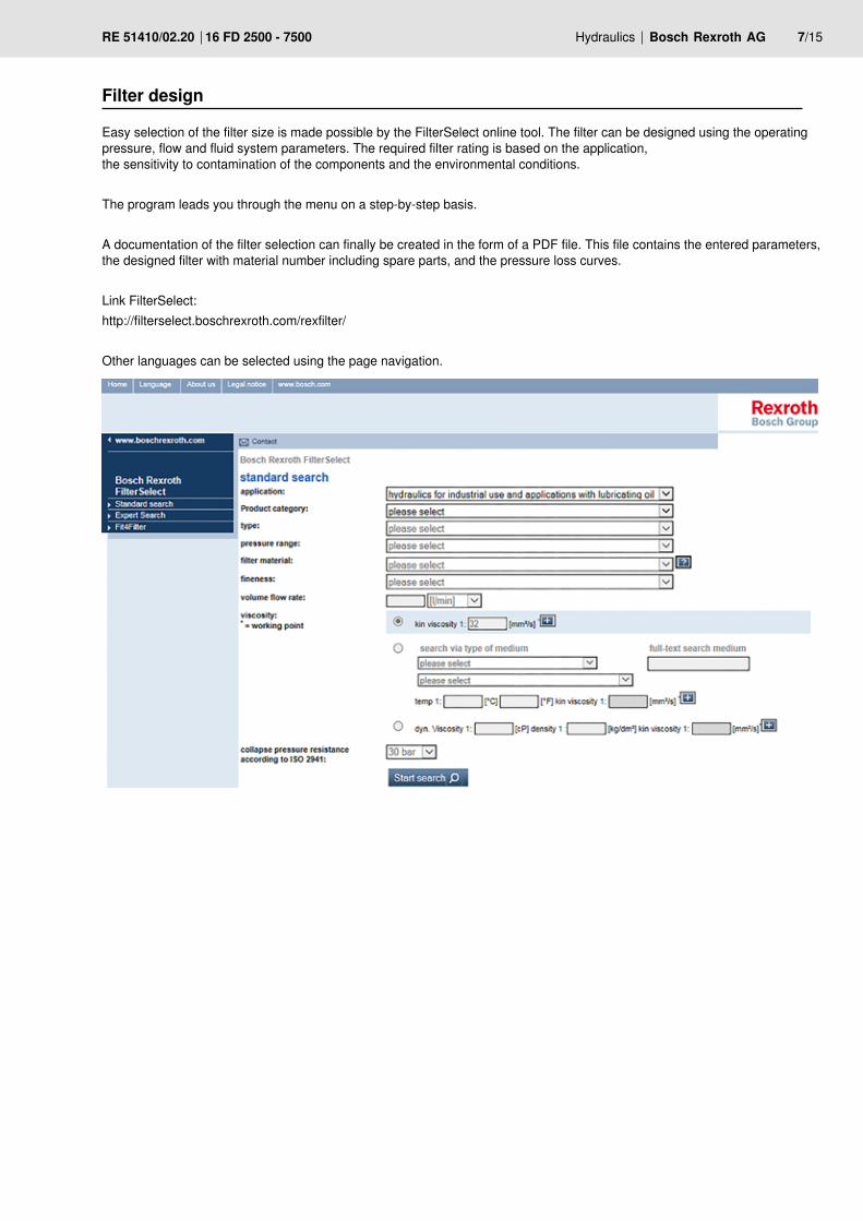
Filter design
Easy selection of the filter size is made possible by the FilterSelect online tool. The filter can be designed using the operating pressure, flow and fluid system parameters. The required filter rating is based on the application, the sensitivity to contamination of the components and the environmental conditions.
The program leads you through the menu on a step-by-step basis.
A documentation of the filter selection can finally be created in the form of a PDF file. This file contains the entered parameters, the designed filter with material number including spare parts, and the pressure loss curves.
Link FilterSelect:http://filterselect.boschrexroth.com/rexfilter/
Other languages can be selected using the page navigation.
100%2475%
1(+)
3(–)
2K2100%
4
K175% 1(+)
3(–)K2K1
S175% S2-100%
2
4
1(+)
3(–)
8/15 Bosch Rexroth AG Hydraulics 16 FD 2500 - 7500 RE 51410/02.20
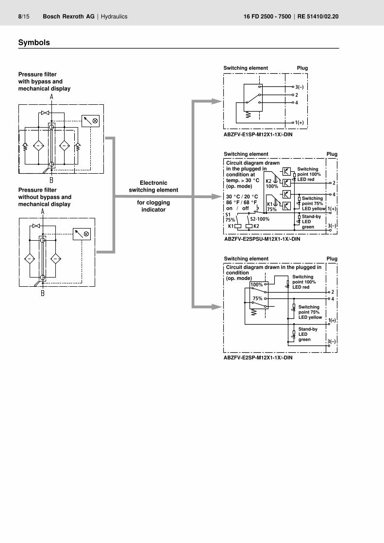
Pressure filter with bypass and mechanical display
Pressure filter without bypass and mechanical display
Symbols
Switching element Plug
Switching point 100% LED red
Switching point 75% LED yellowStand-by LED green
Circuit diagram drawn in the plugged in condition at temp. > 30 °C (op. mode)
30 °C / 20 °C 86 °F / 68 °F on / off
Electronic switching element
for clogging indicator
ABZFV-E1SP-M12X1-1X/-DIN
ABZFV-E2SPSU-M12X1-1X/-DIN
ABZFV-E2SP-M12X1-1X/-DIN
Switching element Plug
Switching point 100% LED red
Switching point 75% LED yellow
Stand-by LED green
Circuit diagram drawn in the plugged in condition (op. mode)
Switching element Plug
Hydraulics Bosch Rexroth AGRE 51410/02.20 16 FD 2500 - 7500 9/15
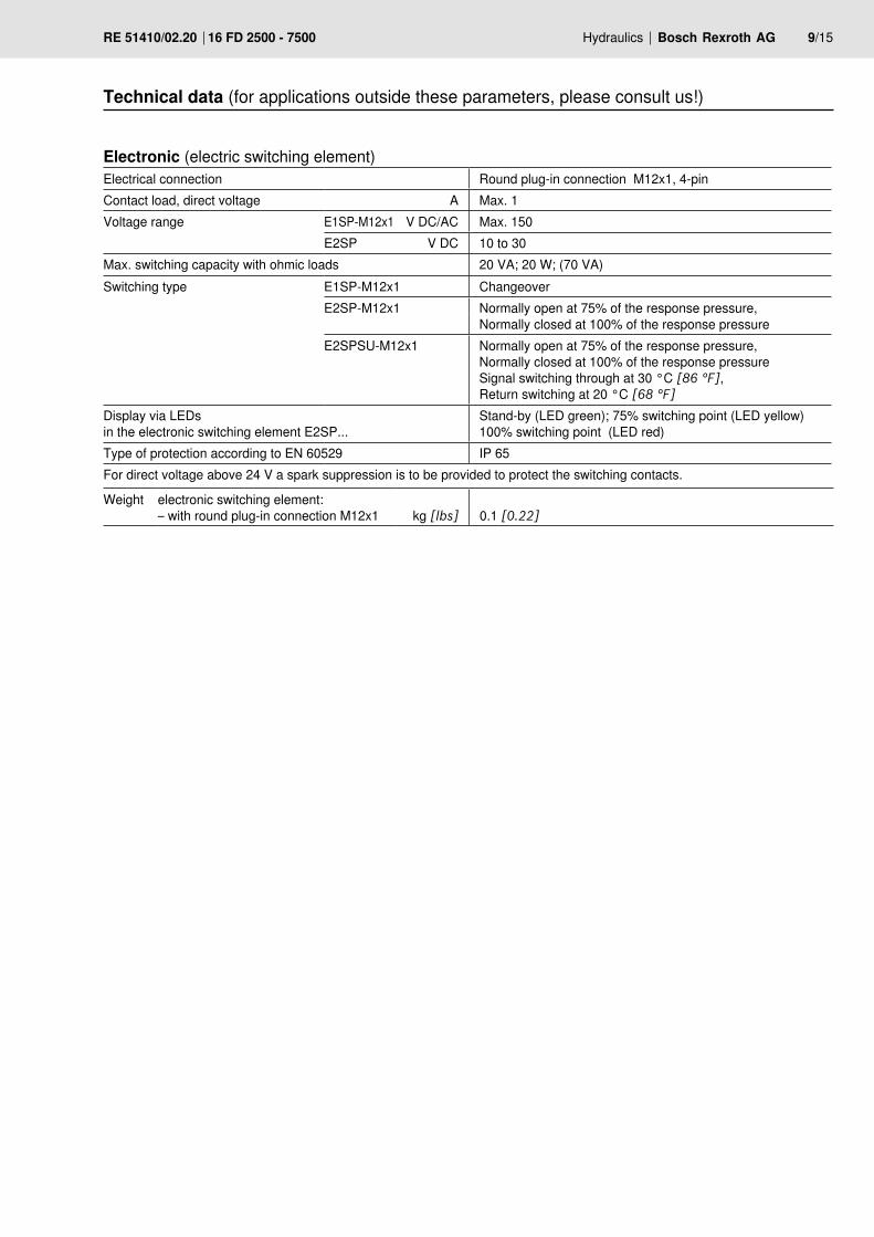
Electronic (electric switching element) Electrical connection Round plug-in connection M12x1, 4-pinContact load, direct voltage A Max. 1Voltage range E1SP-M12x1 V DC/AC Max. 150
E2SP V DC 10 to 30Max. switching capacity with ohmic loads 20 VA; 20 W; (70 VA)Switching type E1SP-M12x1 Changeover
E2SP-M12x1 Normally open at 75% of the response pressure, Normally closed at 100% of the response pressure
E2SPSU-M12x1 Normally open at 75% of the response pressure,Normally closed at 100% of the response pressureSignal switching through at 30 °C [86 °F], Return switching at 20 °C [68 °F]
Display via LEDs in the electronic switching element E2SP...
Stand-by (LED green); 75% switching point (LED yellow)100% switching point (LED red)
Type of protection according to EN 60529 IP 65For direct voltage above 24 V a spark suppression is to be provided to protect the switching contacts.
Technical data (for applications outside these parameters, please consult us!)
Weight electronic switching element: – with round plug-in connection M12x1
kg [lbs]
0.1 [0.22]
10/15 Bosch Rexroth AG Hydraulics 16 FD 2500 - 7500 RE 51410/02.20
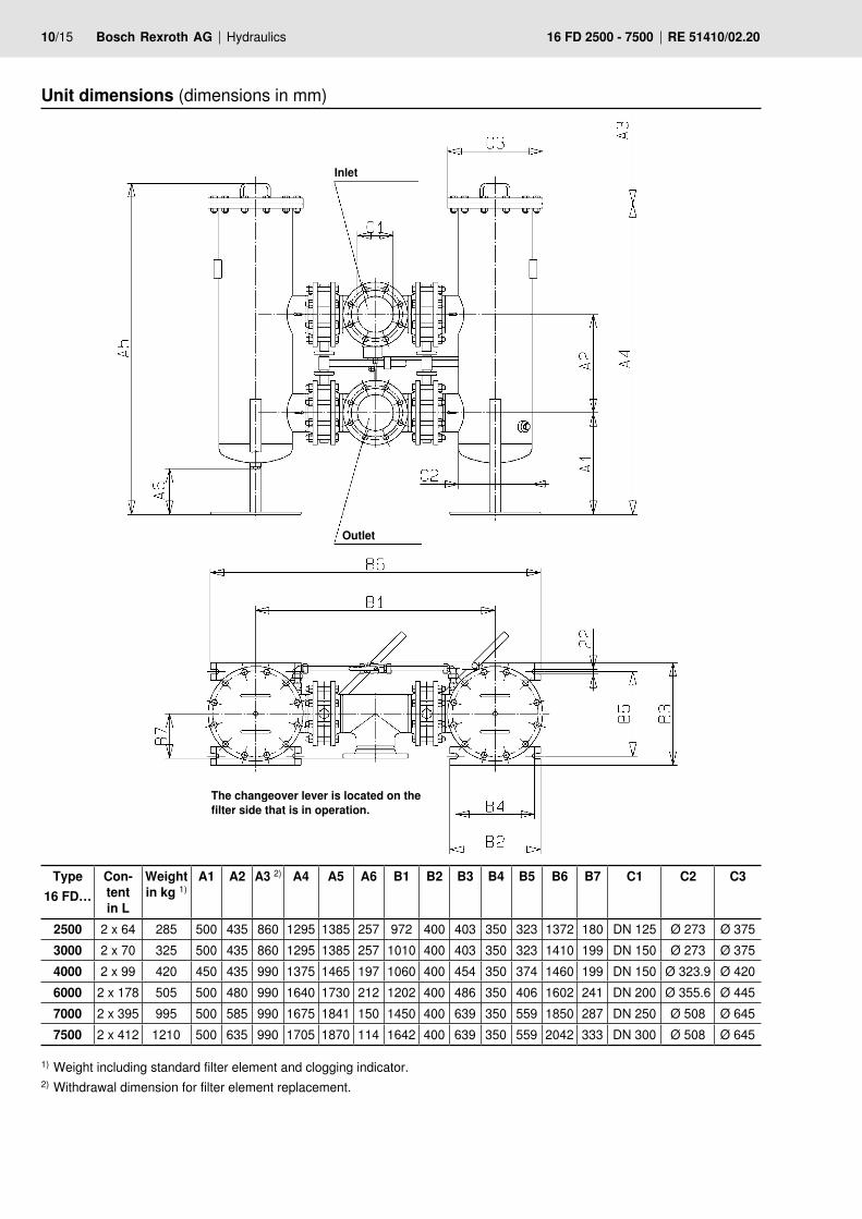
Type 16 FD…
Con-tent in L
Weight in kg 1)
A1 A2 A3 2) A4 A5 A6 B1 B2 B3 B4 B5 B6 B7 C1 C2 C3
2500 2 x 64 285 500 435 860 1295 1385 257 972 400 403 350 323 1372 180 DN 125 Ø 273 Ø 3753000 2 x 70 325 500 435 860 1295 1385 257 1010 400 403 350 323 1410 199 DN 150 Ø 273 Ø 3754000 2 x 99 420 450 435 990 1375 1465 197 1060 400 454 350 374 1460 199 DN 150 Ø 323.9 Ø 4206000 2 x 178 505 500 480 990 1640 1730 212 1202 400 486 350 406 1602 241 DN 200 Ø 355.6 Ø 4457000 2 x 395 995 500 585 990 1675 1841 150 1450 400 639 350 559 1850 287 DN 250 Ø 508 Ø 6457500 2 x 412 1210 500 635 990 1705 1870 114 1642 400 639 350 559 2042 333 DN 300 Ø 508 Ø 645
Unit dimensions (dimensions in mm)
1) Weight including standard filter element and clogging indicator.2) Withdrawal dimension for filter element replacement.
Inlet
Outlet
The changeover lever is located on the filter side that is in operation.
Hydraulics Bosch Rexroth AGRE 51410/02.20 16 FD 2500 - 7500 11/15
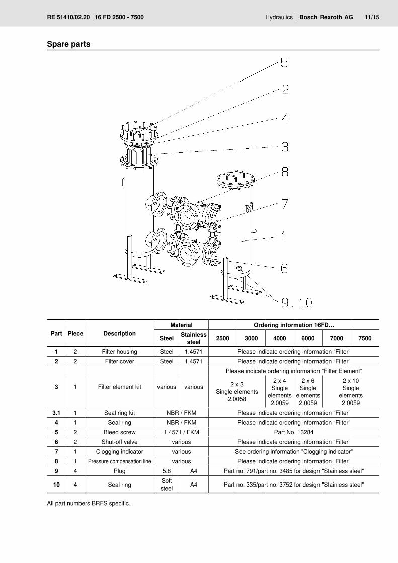
Spare parts
All part numbers BRFS specific.
Part Piece DescriptionMaterial Ordering information 16FD…
Steel Stainless steel 2500 3000 4000 6000 7000 7500
1 2 Filter housing Steel 1.4571 Please indicate ordering information “Filter”2 2 Filter cover Steel 1.4571 Please indicate ordering information “Filter”
3 1 Filter element kit various various
Please indicate ordering information “Filter Element”
2 x 3 Single elements
2.0058
2 x 4 Single
elements 2.0059
2 x 6 Single
elements 2.0059
2 x 10 Single
elements 2.0059
3.1 1 Seal ring kit NBR / FKM Please indicate ordering information “Filter”4 1 Seal ring NBR / FKM Please indicate ordering information “Filter”5 2 Bleed screw 1.4571 / FKM Part No. 132846 2 Shut-off valve various Please indicate ordering information “Filter”7 1 Clogging indicator various See ordering information "Clogging indicator"8 1 Pressure compensation line various Please indicate ordering information “Filter”9 4 Plug 5.8 A4 Part no. 791/part no. 3485 for design "Stainless steel"
10 4 Seal ring Soft steel A4 Part no. 335/part no. 3752 for design "Stainless steel"
12/15 Bosch Rexroth AG Hydraulics 16 FD 2500 - 7500 RE 51410/02.20
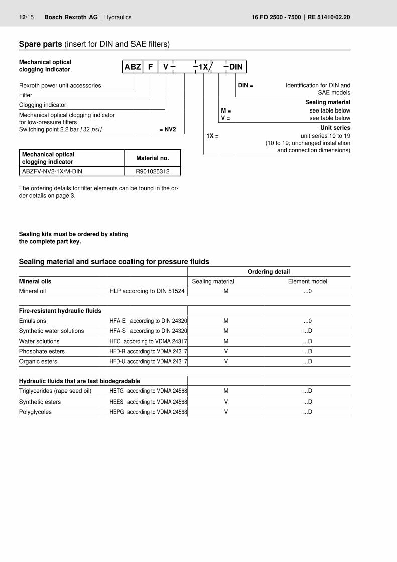
Spare parts (insert for DIN and SAE filters)
DIN = Identification for DIN and
SAE modelsSealing material
M = see table below V = see table below
Unit series1X = unit series 10 to 19
(10 to 19; unchanged installation and connection dimensions)
Mechanical optical clogging indicator ABZ F V 1X DIN Rexroth power unit accessories
FilterClogging indicatorMechanical optical clogging indicator for low-pressure filters Switching point 2.2 bar [32 psi] = NV2
Mechanical optical clogging indicator Material no.
ABZFV-NV2-1X/M-DIN R901025312
The ordering details for filter elements can be found in the or-der details on page 3.
Sealing kits must be ordered by stating the complete part key.
Sealing material and surface coating for pressure fluidsOrdering detail
Mineral oils Sealing material Element model Mineral oil HLP according to DIN 51524 M ...0
Fire-resistant hydraulic fluidsEmulsions HFA-E according to DIN 24320 M ...0Synthetic water solutions HFA-S according to DIN 24320 M ...DWater solutions HFC according to VDMA 24317 M ...DPhosphate esters HFD-R according to VDMA 24317 V ...DOrganic esters HFD-U according to VDMA 24317 V ...D
Hydraulic fluids that are fast biodegradableTriglycerides (rape seed oil) HETG according to VDMA 24568 M ...D
Synthetic esters HEES according to VDMA 24568 V ...DPolyglycoles HEPG according to VDMA 24568 V ...D
Hydraulics Bosch Rexroth AGRE 51410/02.20 16 FD 2500 - 7500 13/15
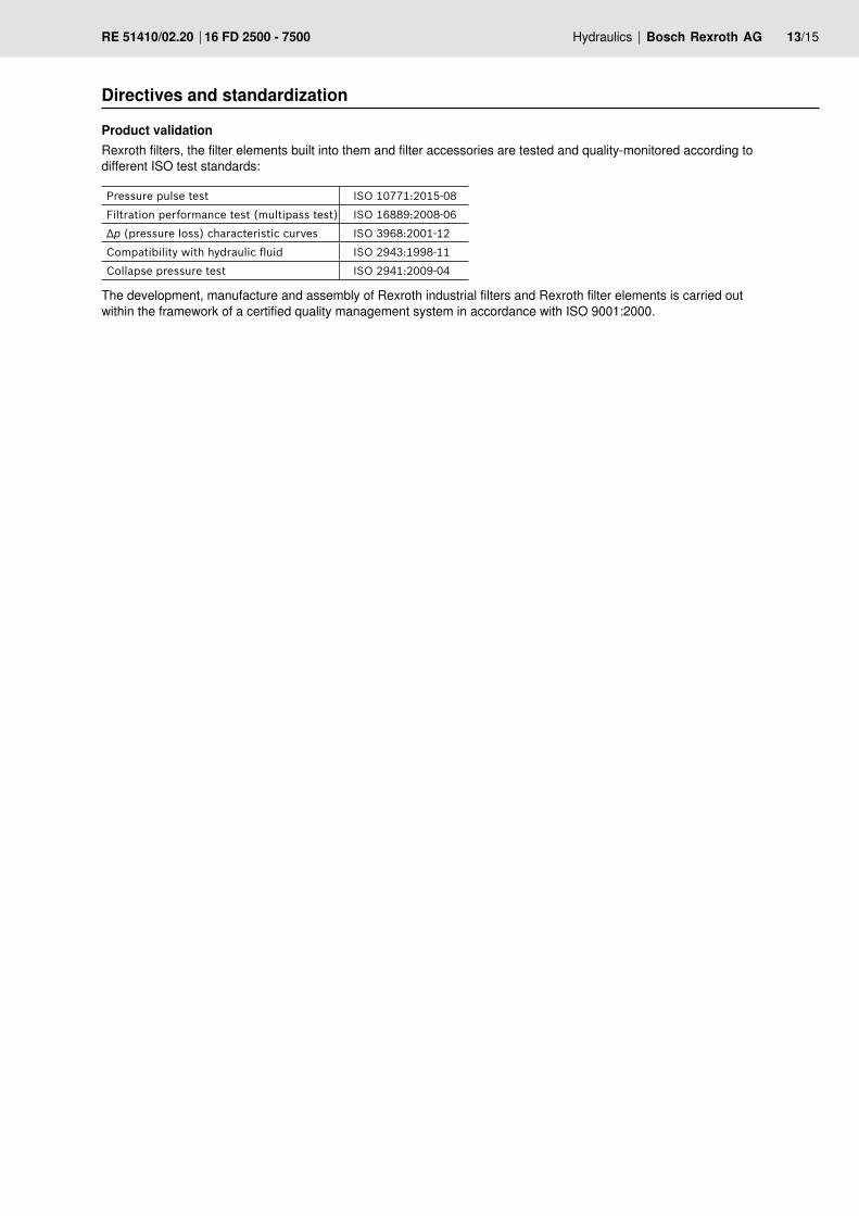
Directives and standardization
Rexroth filters, the filter elements built into them and filter accessories are tested and quality-monitored according to different ISO test standards:
Pressure pulse test ISO 10771:2015-08
Filtration performance test (multipass test) ISO 16889:2008-06
Δp (pressure loss) characteristic curves ISO 3968:2001-12
Compatibility with hydraulic fluid ISO 2943:1998-11
Collapse pressure test ISO 2941:2009-04
The development, manufacture and assembly of Rexroth industrial filters and Rexroth filter elements is carried out within the framework of a certified quality management system in accordance with ISO 9001:2000.
Product validation
14/15 Bosch Rexroth AG Hydraulics 16 FD 2500 - 7500 RE 51410/02.20
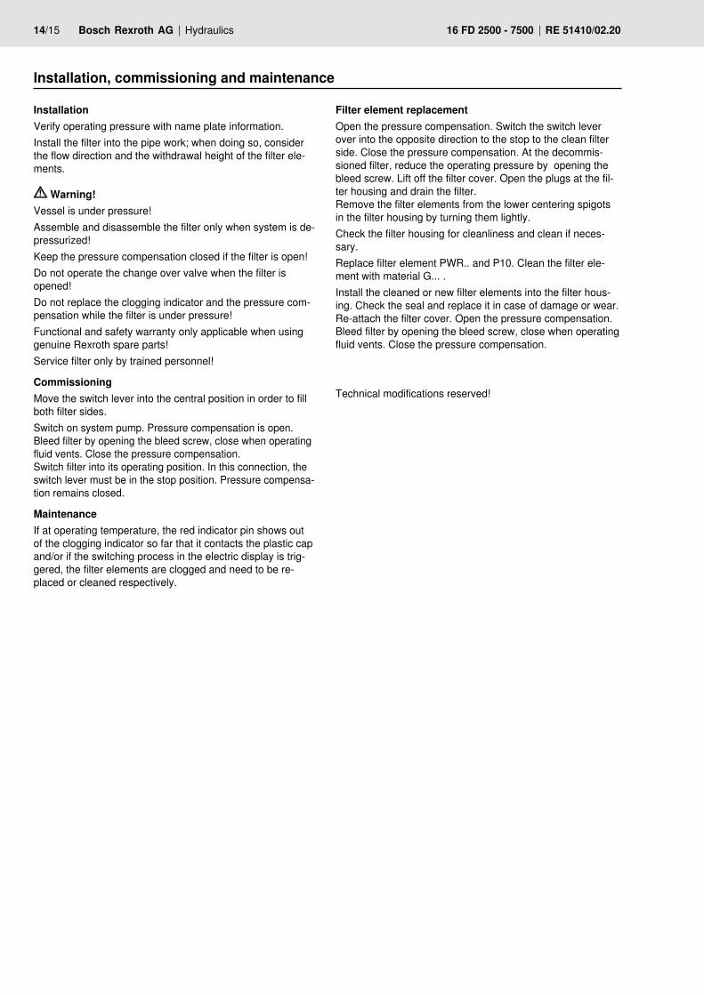
Installation, commissioning and maintenance
InstallationVerify operating pressure with name plate information. Install the filter into the pipe work; when doing so, consider the flow direction and the withdrawal height of the filter ele-ments.
Warning!Vessel is under pressure!Assemble and disassemble the filter only when system is de-pressurized!Keep the pressure compensation closed if the filter is open!Do not operate the change over valve when the filter is opened!Do not replace the clogging indicator and the pressure com-pensation while the filter is under pressure!Functional and safety warranty only applicable when using genuine Rexroth spare parts!Service filter only by trained personnel!
CommissioningMove the switch lever into the central position in order to fill both filter sides.Switch on system pump. Pressure compensation is open. Bleed filter by opening the bleed screw, close when operating fluid vents. Close the pressure compensation. Switch filter into its operating position. In this connection, the switch lever must be in the stop position. Pressure compensa-tion remains closed.
MaintenanceIf at operating temperature, the red indicator pin shows out of the clogging indicator so far that it contacts the plastic cap and/or if the switching process in the electric display is trig-gered, the filter elements are clogged and need to be re-placed or cleaned respectively.
Filter element replacementOpen the pressure compensation. Switch the switch lever over into the opposite direction to the stop to the clean filter side. Close the pressure compensation. At the decommis-sioned filter, reduce the operating pressure by opening the bleed screw. Lift off the filter cover. Open the plugs at the fil-ter housing and drain the filter. Remove the filter elements from the lower centering spigots in the filter housing by turning them lightly.Check the filter housing for cleanliness and clean if neces-sary.Replace filter element PWR.. and P10. Clean the filter ele-ment with material G... . Install the cleaned or new filter elements into the filter hous-ing. Check the seal and replace it in case of damage or wear. Re-attach the filter cover. Open the pressure compensation. Bleed filter by opening the bleed screw, close when operating fluid vents. Close the pressure compensation.
Technical modifications reserved!
Bosch Rexroth Filtration Systems GmbHHardtwaldstraße 43, 68775 Ketsch, GermanyPOB 1120, 68768 Ketsch, Germany Phone +49 (0) 62 02 / 6 03-0 Fax +49 (0) 62 02 / 6 03-1 [email protected] www.eppensteiner.de
© This document, as well as the data, specifications and other informa-tion set forth in it, are the exclusive property of Bosch Rexroth AG. It may not be reproduced or given to third parties without its consent.The data specified above only serve to describe the product. No state-ments concerning a certain condition or suitability for a certain applica-tion can be derived from our information. The information given does not release the user from the obligation of own judgment and verification. It must be remembered that our products are subject to a natural process of wear and aging.
Hydraulics Bosch Rexroth AGRE 51410/02.20 16 FD 2500 - 7500 15/15
Notes


