Embed Size (px)
Citation preview
Received June 11, 2020, accepted June 21, 2020, date of publication June 25, 2020, date of current version July 6, 2020.
Digital Object Identifier 10.1109/ACCESS.2020.3004745
Building Decentralized Fog Computing-BasedSmart Parking Systems: From DeterministicPropagation Modeling to Practical DeploymentMIKEL CELAYA-ECHARRI 1, (Graduate Student Member, IEEE), IVÁN FROIZ-MÍGUEZ2,3,LEYRE AZPILICUETA 1, (Senior Member, IEEE),PAULA FRAGA-LAMAS 2,3, (Senior Member, IEEE), PEIO LOPEZ-ITURRI 4,5,FRANCISCO FALCONE 4,5, (Senior Member, IEEE),AND TIAGO M. FERNÁNDEZ-CARAMÉS 2,3, (Senior Member, IEEE)1School of Engineering and Sciences, Tecnologico de Monterrey, Monterrey 64849, Mexico2Department of Computer Engineering, Universidade da Coruña, 15071 A Coruña, Spain3CITIC Research Center, Universidade da Coruña, 15071 A Coruña, Spain4Department of Electrical, Electronic and Communication Engineering, Public University of Navarre, 31006 Pamplona, Spain5Institute of Smart Cities, Public University of Navarre, 31006 Pamplona, Spain
Corresponding author: Leyre Azpilicueta ([email protected])
This work was supported in part by the School of Engineering and Sciences, Tecnologico de Monterrey, in part by the Xunta de Galiciaunder Grant ED431G2019/01, in part by the Agencia Estatal de Investigación of Spain under Grant TEC2016-75067-C4-1-R,Grant RED2018-102668-T, and Grant PID2019-104958RB-C42, in part by the European Regional Development Fund (ERDF) funds ofthe European Union (EU) (AEI/FEDER, UE), and in part by the Ministerio de Ciencia, Innovación y Universidades, Gobierno de España(MCI-U/AEI/FEDER,UE) under Grant RTI2018-095499-B-C31.
ABSTRACT The traditional process of finding a vacant parking slot is often inefficient: it increases drivingtime, traffic congestion, fuel consumption and exhaust emissions. To address such problems, smart parkingsystems have been proposed to help drivers to find available parking slots faster using latest sensing andcommunications technologies. However, the deployment of the communications infrastructure of a smartparking is not straightforward due to multiple factors that may affect wireless propagation. Moreover, a smartparking system needs to provide not only accurate information on available spots, but also fast responseswhile guaranteeing the system availability even in the case of lacking connectivity. This article describesthe development of a decentralized low-latency smart parking system: from its conception, design andtheoretical simulation, to its empirical validation. Thus, this work first characterizes a real-world scenarioand proposes a fog computing and Internet of Things (IoT) based communications architecture to providesmart parking services. Next, a thorough analysis on the wireless channel properties is carried out by meansof an in-house developed deterministic 3D-Ray Launching (3D-RL) tool. The obtained results are validatedthrough a real-world measurement campaign and then the communications architecture is implemented byusing ZigBee sensor nodes. The implemented architecture also makes use of Bluetooth Low Energy beacons,an Android app, a decentralized database and fog computing gateways, whose performance is evaluated interms of response latency and processing rate. Results show that the proposed system is able to deliverinformation to the drivers fast, with no need for relying on remote servers. As a consequence, the presenteddevelopment methodology and communications evaluation tool can be useful for future smart parkingdevelopers, which can determine the optimal locations of the wireless transceivers during the simulationstage and then deploy a system that can provide fast responses and decentralized services.
INDEX TERMS Smart parking, fog computing, ZigBee, BLE, IoT, wireless channel, 3D-Ray Launching,IPFS.
I. INTRODUCTIONThe Internet of Things (IoT) enables the development ofwireless sensor networks (WSNs) for making transportation
The associate editor coordinating the review of this manuscript and
approving it for publication was Ding Xu .
safer and more efficient within the context of intelligenttransportation systems (ITSs) and smart cities. There iscurrently intense research devoted to finding effective solu-tions for reducing traffic congestion, fuel consumption andgreenhouse gas emissions while increasing drivers’ and
117666 This work is licensed under a Creative Commons Attribution 4.0 License. For more information, see https://creativecommons.org/licenses/by/4.0/ VOLUME 8, 2020
M. Celaya-Echarri et al.: Building Decentralized Fog Computing-Based SP Systems
citizens’ security [1]. In the context of traffic-congestedcities, the improvement of traffic management and urbanmobility becomes necessary, so smart parking (SP) systemscan be a really useful tool in this regard [2]. Essentially,SP systems collect information about parking availabilityand, by using some sort of platform, send real-time parkinginformation to potential or subscribed drivers. Thus, traveltime for commuters, urban traffic congestion and air pollutionare reduced. In addition, pricing and parking reservation canbe managed by SP systems [3].
In order to obtain real-time parking availability data in acity, fixed and mobile sensing systems can be deployed [4].Different kinds of sensors can be installed for the detectionof parked vehicles, either in parking space infrastructure(e.g., infrared sensors, ultrasonic sensors, optical sensors) orin vehicles (e.g., laser detectors, sonars or Radio FrequencyIdentification (RFID) tags) [5]. It is also worth noting thatmany works on SP systems are focused on sensing tech-nologies, architectural development or on specific mobileapps. However, the performance of such smart managementsystems depends largely on the sensor capabilities and onreal-time wireless data communications. Therefore, althoughaspects like security should be carefully considered [6],the location of the deployed sensors is essential, since it deter-mines the connectivity and, ultimately, the performance of theSP system. In order to achieve an optimized deployment ofWSNs within parking environments, radio channel propaga-tion studies are necessary. Moreover, considering the adventof 5th generation (5G) communications and IoT WSNs,where high-density deployments of wireless transceivers areexpected, especially in the smart city context, extensive radiofrequency (RF) planning will be required.
Regardless of the selected technology, wireless communi-cation protocols are commonly used to transmit informationfrom the sensor nodes to the platform in charge of the datamanagement. Short-range technologies like Bluetooth, WiFior ZigBee are often used to implement WSNs for small-scaleurban parking areas. In such systems, sensors exchange datathrough a local network whose data are collected and sent toa gateway. Such a gateway can use a long-range communi-cations system to send the information to a remote platform,where it is stored, analyzed and processedwith the aim of pro-viding valuable information to parking managers, to driversand to the general public.
For large-scale deployments, centralized architecturesbased on WiFi and cellular networks are commonly used toprovide parking information to users [2]. The popularity andubiquity of smartphones that can connect to existing mobilenetworks make centralized architectures an attractive solu-tion, since drivers can receive parking information directlyon their smartphones via an application. Nowadays, many SPimplementations and architectures proposed in the literatureare based on IoT technologies, whose collected informationis stored in a remote server on a cloud to provide SP ser-vices by means of specific mobile apps [7]–[9]. However,
such traditional server-based architectures have two commonlimitations:• All data are usually stored in a cloud server that may bedown during certain periods of time due to maintenance,hardware/software problems, cyberattacks or congestionderived from excessive incoming sensor traffic.
• There is usually a long physical distance between thesensor nodes and the cloud, so responses are in generalnot fast when providing information to the drivers orwhen rapid decision times are required.
To tackle the mentioned problems, different IoT paradigmshave recently been proposed to offload cloud computingcapabilities and then distribute computational tasks andreduce response latency [10]. Fog computing is one of suchparadigms: it offloads the cloud by moving part of the com-putational power and storage resources to the network edge,to devices located close to the sensor nodes that are able torespond fast to node requests [11], [12]. However, in order toprovide a proper quality of service and reduce deploymentcost, fog computing systems need to perform a thoroughwireless channel characterization, analysis and optimizationduring their design stage.
This article includes four main contributions aimed at cre-ating a decentralized cost-effective fog computing-based SPsystem. First, in order to establish the basics, it presents adetailed review of the state of the art of SP wireless channelcharacterization, the most relevant fog computing-based SPsystems and the main communication technologies used inSP. Second, it presents a novel development methodology fora successful and cost-effective SP deployment. Third, as partof such methodology the article thoroughly explains eachof the phases that include the design, theoretical simulation,validation, implementation and empirical validation of a fogSP system that is low cost and scalable in terms of protocolsand technologies. Finally, performance tests of the decentral-ized fog computing approach and the proposed decentralizeddatabase are presented in Section VI to guarantee properoperation under low-latency conditions.
The rest of this paper is organized as follows. Section IIreviews the state of the art on previous fog computing-basedSP systems and on the most relevant aspects that impacttheir development, like wireless channel modeling or theused communications technologies. Section III presents thedesign of the proposed system, while Section IV validatesit by means of an in-house 3D-RL tool. Section V detailsthe system implementation, which is evaluated in terms ofresponse latency in SectionVI. Finally, SectionVII is devotedto the conclusions.
II. STATE OF THE ARTA. SMART PARKING WIRELESS CHANNELCHARACTERIZATIONPrevious literature has detailed different approaches to ana-lyze communications links for Vehicle-to-everything (V2X)scenarios [13]. In the specific case of parking lots, park-
VOLUME 8, 2020 117667
M. Celaya-Echarri et al.: Building Decentralized Fog Computing-Based SP Systems
ing buildings and parking applications, some studies havebeen presented. Stochastic models have been proposed tostudy predictable propagation characteristics when applied todifferent vehicular environments, including outdoor parkinglot scenarios. For instance, some of the existing results pro-vide models for short range communications, with maximumtransceiver distances of up to 15m, focusing mainly in Line-of-Sight (LoS) conditions [14]. Wireless propagation charac-terizations have also been performed for parking buildings bymeans of upper bound-lower bound models for the 1.8GHzband [15]. Moreover, a previous work has performed wirelesschannel characterization in the 433MHz band in an out-door parking and whose measurement results were comparedwith a free space path-loss model and a two-ray path lossmodel [16]. The obtained empirical results provide a char-acterization of a specific radial location within the parking.
The impact of obstructions in vehicle-to-vehicle (V2V)communications links for parking lot scenarios has also beenanalyzed in [17] for Dedicated-short-range-communication(DSRC) within the 5.9GHz band. In such a work,the Received Signal Strength Indicator (RSSI) values arecorrelated with packet error rate in order to estimate thequality of service.
In addition, measurement results have been obtained forpath-loss estimation and root mean-square delay spread inparking buildings, considering same floor and floor to floorV2V links in the 5GHz frequency band [18]. Undergroundtunnel-like parking scenarios have been analyzed in termsof the determination of quasi-static channel conditions inthe 5.3GHz band and for different Multiple-Input MultipleOutput (MIMO) configurations related to V2V communi-cation links [19]. Channel impulse response models havebeen proposed, based on different measurement sets consid-ering motion and motionless conditions, at a center frequencyof 5.12GHz [20]. More recently, in [21] the authors presentan empirical based model for indoor and outdoor parkingenvironments.
The previously mentioned works show that, although sev-eral theoretical models exist, radio propagation is usuallyestimated by using empirical propagation models that arebased on measurements obtained from specific environmentsand provide more accurate RF signal propagation estimationswhen applied to the same specific kind of environments.However, these empirical approaches exhibit disadvantagessuch as low reusability, low scalability and high cost, in addi-tion to being time-intensive. In this context, this articleproposes the use of an in-house deterministic propagationmodel based on a 3D-Ray Launching (3D-RL) algorithm forRF propagation analysis within SP environments.
B. FOG COMPUTING-BASED SMART PARKING SYSTEMSSince fog computing was coined by Cisco in 2012 [11], onlya few authors proposed SP implementations that are actuallybased on it [22]–[26]. For instance, in [22] the authors presenta fog computing-based SP architecture and suggest differentalgorithms to optimize parking request allocation so as to
reduce parking cost, fuel consumption and gas emissions.The system makes use of fog gateways that are deployedthroughout different parking lots and send parking recom-mendations to the existing vehicles. Such recommendationsare based on multiple factors, like the costs related to waiting,to walking or to keep on driving to find a spot. Another fogcomputing-based SP system is described in [23]. There theauthors show through simulations how fog computing canreduce lag and network usage in comparison to traditionalcloud-based deployments.
A similar approach is detailed in [24], but, instead of foggateways, a relatively powerful computer is used to provideadvanced edge computing services (machine learning pro-cessing), presenting an architecture that is similar to the onesused with cloudlets [27]. In the mentioned article, the authorsfocused on improving vehicle position accuracy on the park-ing lot, which, in the selected experimental scenario, reached99.1% thanks to the use of machine learning techniquesthat processed the Received Signal Strength Indicator (RSSI)from Bluetooth Low Energy (BLE) beacons deployed in aparking lot.
Finally, it is worth mentioning the work in [25] and [26]:the former paper describes a theoretical design for anIoT-enabled fog computing-based SP, while the latter pro-poses a low-cost smart parking system based on Arduinonodes that was devised having the Nigerian market in mind.
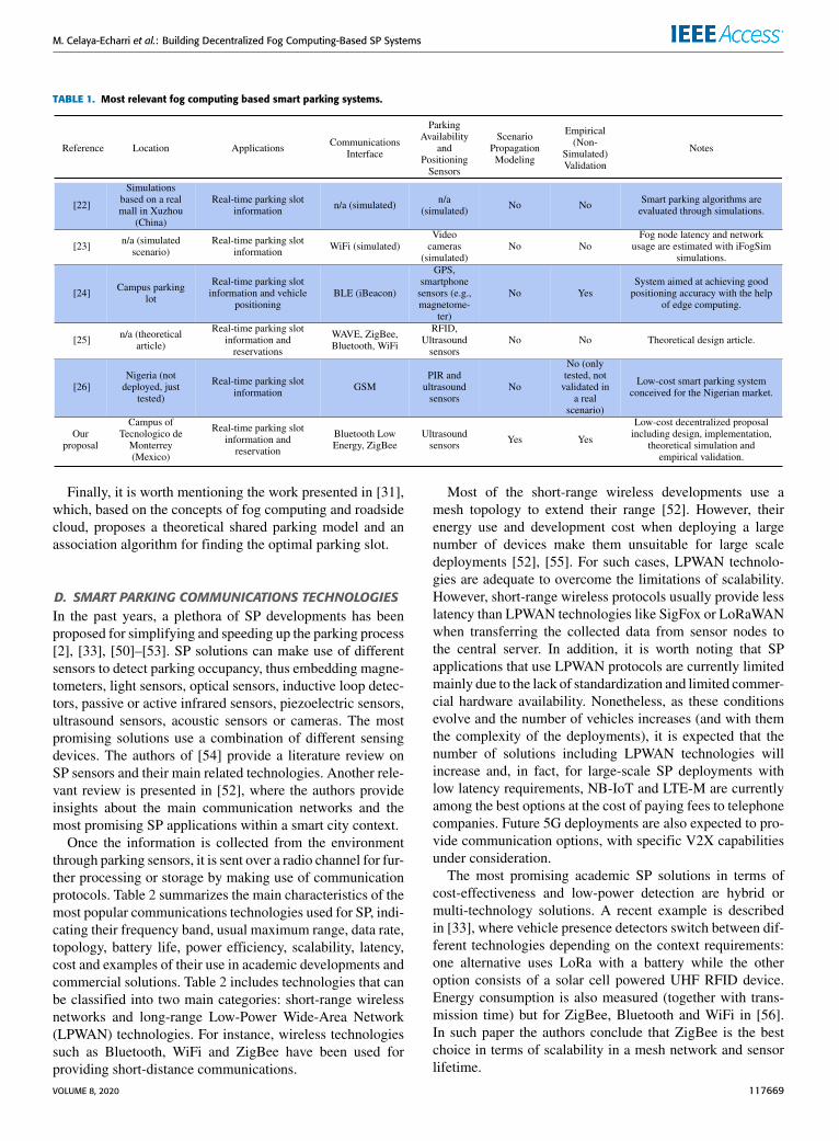
As a summary, Table 1 shows the features of the most rele-vant characteristics of the previously mentioned fog comput-ing based smart parking systems and compares them with theproposed work. As it can be observed in Table 1, in contrastto the proposed work, most of the compared solutions havenot been validated in real environments and none modeledthe practical scenario with the objective of optimizing thecommunications coverage or the existing throughput.
C. OTHER USES OF FOG COMPUTING FOR PARKINGSYSTEMSThe fog computing paradigm has also been proposed recentlyby diverse researchers in order to harness its benefits fordifferent parking applications. An example of such proposalsis described in [28], where the authors present a vehicularfog computing solution for parking reservation auctions thatcombines SP features and parked vehicle assistance. Theproposed system involves the use of parked vehicles (whichact as static network infrastructure) to improve connectivityin areas where roadside units are not available or have poorcoverage.
Another interesting application is detailed in [29], whichproposes a scheme that combines crowdsourced informationand data from fog computing nodes in order to indicateparking availability. Due to the vast amount of informationthat can be gathered through SP systems, in [30] the authorspropose an analytics system based on Hadoop MapReduce.Such a system runs on a cluster of commodity computers thatthe authors denote as ‘fog computing node’, but whose powerseems to be more like a cloudlet.
117668 VOLUME 8, 2020
M. Celaya-Echarri et al.: Building Decentralized Fog Computing-Based SP Systems
TABLE 1. Most relevant fog computing based smart parking systems.
Finally, it is worth mentioning the work presented in [31],which, based on the concepts of fog computing and roadsidecloud, proposes a theoretical shared parking model and anassociation algorithm for finding the optimal parking slot.
D. SMART PARKING COMMUNICATIONS TECHNOLOGIESIn the past years, a plethora of SP developments has beenproposed for simplifying and speeding up the parking process[2], [33], [50]–[53]. SP solutions can make use of differentsensors to detect parking occupancy, thus embedding magne-tometers, light sensors, optical sensors, inductive loop detec-tors, passive or active infrared sensors, piezoelectric sensors,ultrasound sensors, acoustic sensors or cameras. The mostpromising solutions use a combination of different sensingdevices. The authors of [54] provide a literature review onSP sensors and their main related technologies. Another rele-vant review is presented in [52], where the authors provideinsights about the main communication networks and themost promising SP applications within a smart city context.
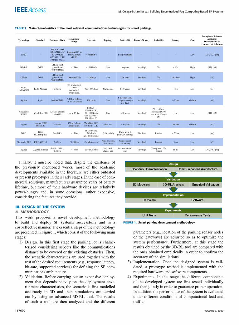
Once the information is collected from the environmentthrough parking sensors, it is sent over a radio channel for fur-ther processing or storage by making use of communicationprotocols. Table 2 summarizes the main characteristics of themost popular communications technologies used for SP, indi-cating their frequency band, usual maximum range, data rate,topology, battery life, power efficiency, scalability, latency,cost and examples of their use in academic developments andcommercial solutions. Table 2 includes technologies that canbe classified into two main categories: short-range wirelessnetworks and long-range Low-Power Wide-Area Network(LPWAN) technologies. For instance, wireless technologiessuch as Bluetooth, WiFi and ZigBee have been used forproviding short-distance communications.
Most of the short-range wireless developments use amesh topology to extend their range [52]. However, theirenergy use and development cost when deploying a largenumber of devices make them unsuitable for large scaledeployments [52], [55]. For such cases, LPWAN technolo-gies are adequate to overcome the limitations of scalability.However, short-range wireless protocols usually provide lesslatency than LPWAN technologies like SigFox or LoRaWANwhen transferring the collected data from sensor nodes tothe central server. In addition, it is worth noting that SPapplications that use LPWAN protocols are currently limitedmainly due to the lack of standardization and limited commer-cial hardware availability. Nonetheless, as these conditionsevolve and the number of vehicles increases (and with themthe complexity of the deployments), it is expected that thenumber of solutions including LPWAN technologies willincrease and, in fact, for large-scale SP deployments withlow latency requirements, NB-IoT and LTE-M are currentlyamong the best options at the cost of paying fees to telephonecompanies. Future 5G deployments are also expected to pro-vide communication options, with specific V2X capabilitiesunder consideration.
The most promising academic SP solutions in terms ofcost-effectiveness and low-power detection are hybrid ormulti-technology solutions. A recent example is describedin [33], where vehicle presence detectors switch between dif-ferent technologies depending on the context requirements:one alternative uses LoRa with a battery while the otheroption consists of a solar cell powered UHF RFID device.Energy consumption is also measured (together with trans-mission time) but for ZigBee, Bluetooth and WiFi in [56].In such paper the authors conclude that ZigBee is the bestchoice in terms of scalability in a mesh network and sensorlifetime.
VOLUME 8, 2020 117669
M. Celaya-Echarri et al.: Building Decentralized Fog Computing-Based SP Systems
TABLE 2. Main characteristics of the most relevant communications technologies for smart parkings.
Finally, it must be noted that, despite the existence ofthe previously mentioned works, most of the academicdevelopments available in the literature are either outdatedor present prototypes in their early stages. In the case of com-mercial solutions, manufacturers guarantee years of batterylifetime, but most of their hardware devices are relativelypower-hungry and, in some occasions, rather expensive,considering the features they provide.
III. DESIGN OF THE SYSTEMA. METHODOLOGYThis work proposes a novel development methodologyto build and deploy SP systems successfully and in acost-effective manner. The essential steps of the methodologyare presented in Figure 1, which consist of the followingmainstages:
1) Design. In this first stage the parking lot is charac-terized considering aspects like the communicationsdistance to be covered or the existing obstacles. Then,the scenario characteristics are used together with therest of the desired requirements (e.g., response latency,bit-rate, supported services) for defining the SP com-munications architecture.
2) Validation. Before carrying out an expensive deploy-ment that depends heavily on the deployment envi-ronment characteristics, the scenario is first modelledaccurately in 3D and then simulations are carriedout by using an advanced 3D-RL tool. The resultsof such a tool are then analyzed and the different
FIGURE 1. Smart parking development methodology.
parameters (e.g., location of the parking sensor nodesor the gateways) are adjusted so as to optimize thesystem performance. Furthermore, at this stage theresults obtained by the 3D-RL tool are compared withthe ones obtained empirically in order to confirm theaccuracy of the simulations.
3) Implementation. Once the designed system is vali-dated, a prototype testbed is implemented with therequired hardware and software components.
4) Experiments. In this stage the different componentsof the developed system are first tested individuallyand then jointly in order to guarantee proper operation.In addition, the performance of the system is evaluatedunder different conditions of computational load andtraffic.
117670 VOLUME 8, 2020
M. Celaya-Echarri et al.: Building Decentralized Fog Computing-Based SP Systems
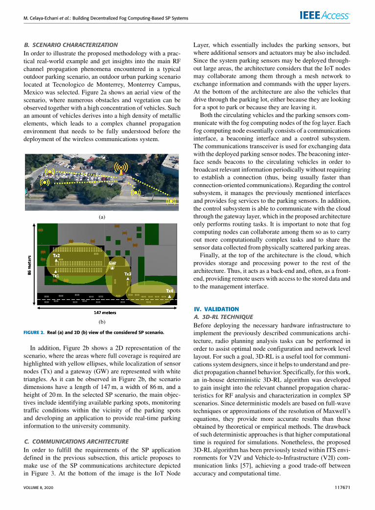
B. SCENARIO CHARACTERIZATIONIn order to illustrate the proposed methodology with a prac-tical real-world example and get insights into the main RFchannel propagation phenomena encountered in a typicaloutdoor parking scenario, an outdoor urban parking scenariolocated at Tecnologico de Monterrey, Monterrey Campus,Mexico was selected. Figure 2a shows an aerial view of thescenario, where numerous obstacles and vegetation can beobserved together with a high concentration of vehicles. Suchan amount of vehicles derives into a high density of metallicelements, which leads to a complex channel propagationenvironment that needs to be fully understood before thedeployment of the wireless communications system.
FIGURE 2. Real (a) and 2D (b) view of the considered SP scenario.
In addition, Figure 2b shows a 2D representation of thescenario, where the areas where full coverage is required arehighlighted with yellow ellipses, while localization of sensornodes (Tx) and a gateway (GW) are represented with whitetriangles. As it can be observed in Figure 2b, the scenariodimensions have a length of 147m, a width of 86m, and aheight of 20m. In the selected SP scenario, the main objec-tives include identifying available parking spots, monitoringtraffic conditions within the vicinity of the parking spotsand developing an application to provide real-time parkinginformation to the university community.
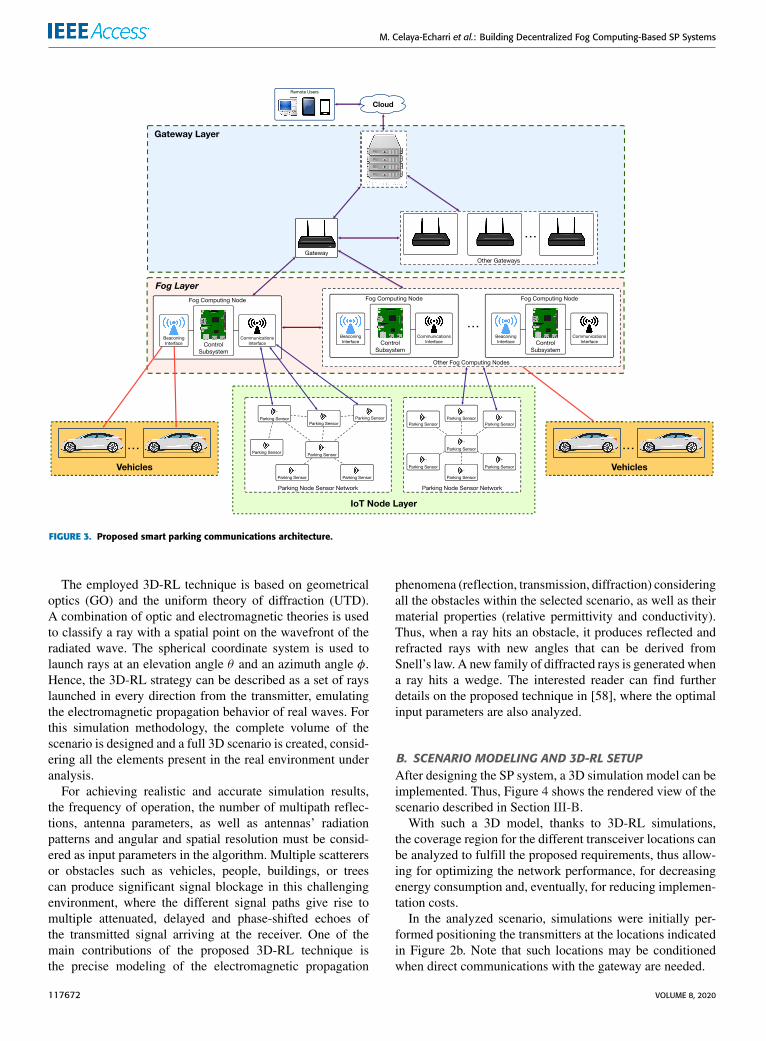
C. COMMUNICATIONS ARCHITECTUREIn order to fulfill the requirements of the SP applicationdefined in the previous subsection, this article proposes tomake use of the SP communications architecture depictedin Figure 3. At the bottom of the image is the IoT Node
Layer, which essentially includes the parking sensors, butwhere additional sensors and actuators may be also included.Since the system parking sensors may be deployed through-out large areas, the architecture considers that the IoT nodesmay collaborate among them through a mesh network toexchange information and commands with the upper layers.At the bottom of the architecture are also the vehicles thatdrive through the parking lot, either because they are lookingfor a spot to park or because they are leaving it.
Both the circulating vehicles and the parking sensors com-municate with the fog computing nodes of the fog layer. Eachfog computing node essentially consists of a communicationsinterface, a beaconing interface and a control subsystem.The communications transceiver is used for exchanging datawith the deployed parking sensor nodes. The beaconing inter-face sends beacons to the circulating vehicles in order tobroadcast relevant information periodically without requiringto establish a connection (thus, being usually faster thanconnection-oriented communications). Regarding the controlsubsystem, it manages the previously mentioned interfacesand provides fog services to the parking sensors. In addition,the control subsystem is able to communicate with the cloudthrough the gateway layer, which in the proposed architectureonly performs routing tasks. It is important to note that fogcomputing nodes can collaborate among them so as to carryout more computationally complex tasks and to share thesensor data collected from physically scattered parking areas.
Finally, at the top of the architecture is the cloud, whichprovides storage and processing power to the rest of thearchitecture. Thus, it acts as a back-end and, often, as a front-end, providing remote users with access to the stored data andto the management interface.
IV. VALIDATIONA. 3D-RL TECHNIQUEBefore deploying the necessary hardware infrastructure toimplement the previously described communications archi-tecture, radio planning analysis tasks can be performed inorder to assist optimal node configuration and network levellayout. For such a goal, 3D-RL is a useful tool for communi-cations system designers, since it helps to understand and pre-dict propagation channel behavior. Specifically, for this work,an in-house deterministic 3D-RL algorithm was developedto gain insight into the relevant channel propagation charac-teristics for RF analysis and characterization in complex SPscenarios. Since deterministic models are based on full-wavetechniques or approximations of the resolution of Maxwell’sequations, they provide more accurate results than thoseobtained by theoretical or empirical methods. The drawbackof such deterministic approaches is that higher computationaltime is required for simulations. Nonetheless, the proposed3D-RL algorithm has been previously tested within ITS envi-ronments for V2V and Vehicle-to-Infrastructure (V2I) com-munication links [57], achieving a good trade-off betweenaccuracy and computational time.
VOLUME 8, 2020 117671
M. Celaya-Echarri et al.: Building Decentralized Fog Computing-Based SP Systems
FIGURE 3. Proposed smart parking communications architecture.
The employed 3D-RL technique is based on geometricaloptics (GO) and the uniform theory of diffraction (UTD).A combination of optic and electromagnetic theories is usedto classify a ray with a spatial point on the wavefront of theradiated wave. The spherical coordinate system is used tolaunch rays at an elevation angle θ and an azimuth angle φ.Hence, the 3D-RL strategy can be described as a set of rayslaunched in every direction from the transmitter, emulatingthe electromagnetic propagation behavior of real waves. Forthis simulation methodology, the complete volume of thescenario is designed and a full 3D scenario is created, consid-ering all the elements present in the real environment underanalysis.
For achieving realistic and accurate simulation results,the frequency of operation, the number of multipath reflec-tions, antenna parameters, as well as antennas’ radiationpatterns and angular and spatial resolution must be consid-ered as input parameters in the algorithm. Multiple scatterersor obstacles such as vehicles, people, buildings, or treescan produce significant signal blockage in this challengingenvironment, where the different signal paths give rise tomultiple attenuated, delayed and phase-shifted echoes ofthe transmitted signal arriving at the receiver. One of themain contributions of the proposed 3D-RL technique isthe precise modeling of the electromagnetic propagation
phenomena (reflection, transmission, diffraction) consideringall the obstacles within the selected scenario, as well as theirmaterial properties (relative permittivity and conductivity).Thus, when a ray hits an obstacle, it produces reflected andrefracted rays with new angles that can be derived fromSnell’s law. A new family of diffracted rays is generated whena ray hits a wedge. The interested reader can find furtherdetails on the proposed technique in [58], where the optimalinput parameters are also analyzed.
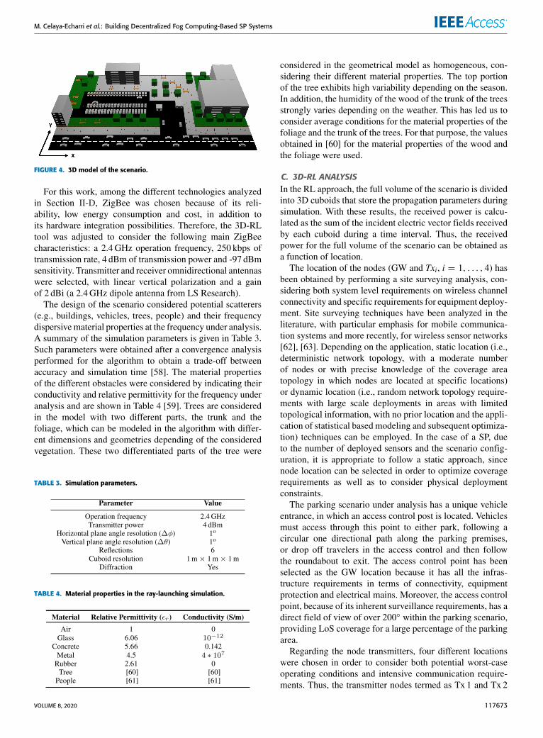
B. SCENARIO MODELING AND 3D-RL SETUPAfter designing the SP system, a 3D simulation model can beimplemented. Thus, Figure 4 shows the rendered view of thescenario described in Section III-B.With such a 3D model, thanks to 3D-RL simulations,
the coverage region for the different transceiver locations canbe analyzed to fulfill the proposed requirements, thus allow-ing for optimizing the network performance, for decreasingenergy consumption and, eventually, for reducing implemen-tation costs.
In the analyzed scenario, simulations were initially per-formed positioning the transmitters at the locations indicatedin Figure 2b. Note that such locations may be conditionedwhen direct communications with the gateway are needed.
117672 VOLUME 8, 2020
M. Celaya-Echarri et al.: Building Decentralized Fog Computing-Based SP Systems
FIGURE 4. 3D model of the scenario.
For this work, among the different technologies analyzedin Section II-D, ZigBee was chosen because of its reli-ability, low energy consumption and cost, in addition toits hardware integration possibilities. Therefore, the 3D-RLtool was adjusted to consider the following main ZigBeecharacteristics: a 2.4GHz operation frequency, 250 kbps oftransmission rate, 4 dBm of transmission power and -97 dBmsensitivity. Transmitter and receiver omnidirectional antennaswere selected, with linear vertical polarization and a gainof 2 dBi (a 2.4GHz dipole antenna from LS Research).
The design of the scenario considered potential scatterers(e.g., buildings, vehicles, trees, people) and their frequencydispersivematerial properties at the frequency under analysis.A summary of the simulation parameters is given in Table 3.Such parameters were obtained after a convergence analysisperformed for the algorithm to obtain a trade-off betweenaccuracy and simulation time [58]. The material propertiesof the different obstacles were considered by indicating theirconductivity and relative permittivity for the frequency underanalysis and are shown in Table 4 [59]. Trees are consideredin the model with two different parts, the trunk and thefoliage, which can be modeled in the algorithm with differ-ent dimensions and geometries depending of the consideredvegetation. These two differentiated parts of the tree were
TABLE 3. Simulation parameters.
TABLE 4. Material properties in the ray-launching simulation.
considered in the geometrical model as homogeneous, con-sidering their different material properties. The top portionof the tree exhibits high variability depending on the season.In addition, the humidity of the wood of the trunk of the treesstrongly varies depending on the weather. This has led us toconsider average conditions for the material properties of thefoliage and the trunk of the trees. For that purpose, the valuesobtained in [60] for the material properties of the wood andthe foliage were used.
C. 3D-RL ANALYSISIn the RL approach, the full volume of the scenario is dividedinto 3D cuboids that store the propagation parameters duringsimulation. With these results, the received power is calcu-lated as the sum of the incident electric vector fields receivedby each cuboid during a time interval. Thus, the receivedpower for the full volume of the scenario can be obtained asa function of location.
The location of the nodes (GW and Txi, i = 1, . . . , 4) hasbeen obtained by performing a site surveying analysis, con-sidering both system level requirements on wireless channelconnectivity and specific requirements for equipment deploy-ment. Site surveying techniques have been analyzed in theliterature, with particular emphasis for mobile communica-tion systems and more recently, for wireless sensor networks[62], [63]. Depending on the application, static location (i.e.,deterministic network topology, with a moderate numberof nodes or with precise knowledge of the coverage areatopology in which nodes are located at specific locations)or dynamic location (i.e., random network topology require-ments with large scale deployments in areas with limitedtopological information, with no prior location and the appli-cation of statistical based modeling and subsequent optimiza-tion) techniques can be employed. In the case of a SP, dueto the number of deployed sensors and the scenario config-uration, it is appropriate to follow a static approach, sincenode location can be selected in order to optimize coveragerequirements as well as to consider physical deploymentconstraints.
The parking scenario under analysis has a unique vehicleentrance, in which an access control post is located. Vehiclesmust access through this point to either park, following acircular one directional path along the parking premises,or drop off travelers in the access control and then followthe roundabout to exit. The access control point has beenselected as the GW location because it has all the infras-tructure requirements in terms of connectivity, equipmentprotection and electrical mains. Moreover, the access controlpoint, because of its inherent surveillance requirements, has adirect field of view of over 200◦ within the parking scenario,providing LoS coverage for a large percentage of the parkingarea.
Regarding the node transmitters, four different locationswere chosen in order to consider both potential worst-caseoperating conditions and intensive communication require-ments. Thus, the transmitter nodes termed as Tx 1 and Tx 2
VOLUME 8, 2020 117673
M. Celaya-Echarri et al.: Building Decentralized Fog Computing-Based SP Systems
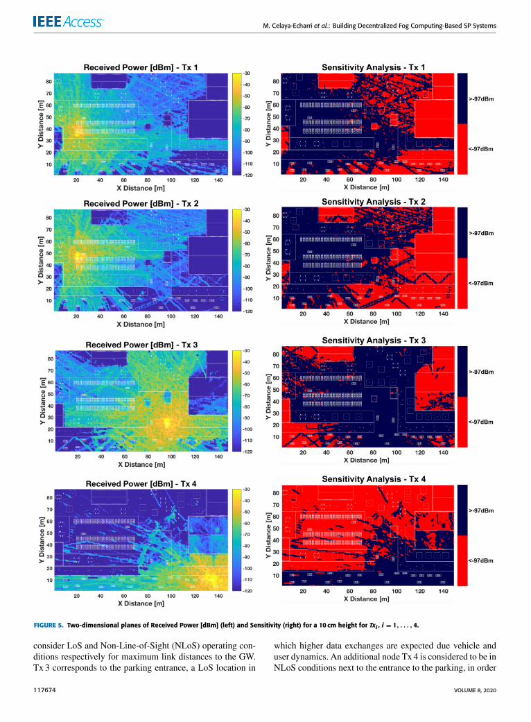
FIGURE 5. Two-dimensional planes of Received Power [dBm] (left) and Sensitivity (right) for a 10 cm height for Txi , i = 1, . . . , 4.
consider LoS and Non-Line-of-Sight (NLoS) operating con-ditions respectively for maximum link distances to the GW.Tx 3 corresponds to the parking entrance, a LoS location in
which higher data exchanges are expected due vehicle anduser dynamics. An additional node Tx 4 is considered to be inNLoS conditions next to the entrance to the parking, in order
117674 VOLUME 8, 2020
M. Celaya-Echarri et al.: Building Decentralized Fog Computing-Based SP Systems
to provide information to the drivers prior to their accessto the parking premises. Moreover, for all the consideredlocations of the sensor nodes Txi, i = 1, . . . , 4, infrastructurerequirements (e.g., the possibility of having access to theelectrical mains or to install nodes on the floor) have also beentaken into account, analyzing the existence of pre-existingelements, such as lamp posts or indication posts.
For the selected urban smart parking environment,the transmitter locations (shown in Figure 2b) were simu-lated to assess radio wave propagation characteristics and,specifically, direct communication with the GW. Thus, first,the electromagnetic radio wave propagation impact for theselected transmitter positions was assessed. Figure 5, on itsleft side, shows the received power XY-planes for transmit-ters Txi, i = 1, . . . , 4, which were located in each areaof interest at the same height as the receiver antenna (thesurface plane was placed on the road). As it can be observed,the influence of the multiple obstacles present in the scenario(e.g., vehicles, buildings, vegetation, people) has a significantimpact on signal propagation, existing significant multipathinterference in the scatterer zone.
To gain insight into the system performance, sensitivityfulfillment planes (according to the ZigBee characteristics)are presented on the right of Figure 5 for transmitters Txi,i = 1, . . . , 4. Such figures show that sensitivity fulfillmentis highly dependent on the transmitter location and on themorphology and topology of the considered scenario. Thereceived power variations (and hence sensitivity fulfillment)can be strongly mitigated by changing the morphology of thewireless network (i.e., by adding sensor nodes), thus obtain-ing an adequate received power level for all the transceiverlocations in the areas of interest.
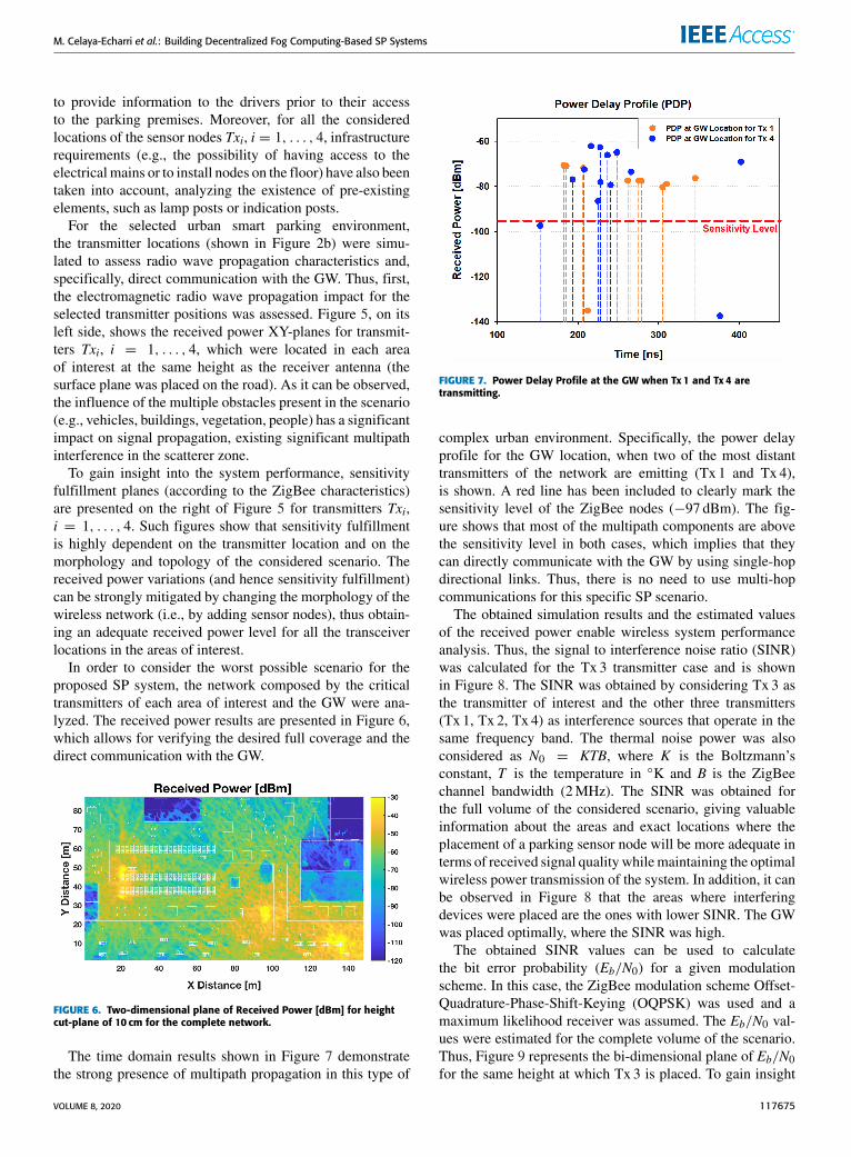
In order to consider the worst possible scenario for theproposed SP system, the network composed by the criticaltransmitters of each area of interest and the GW were ana-lyzed. The received power results are presented in Figure 6,which allows for verifying the desired full coverage and thedirect communication with the GW.
FIGURE 6. Two-dimensional plane of Received Power [dBm] for heightcut-plane of 10 cm for the complete network.
The time domain results shown in Figure 7 demonstratethe strong presence of multipath propagation in this type of
FIGURE 7. Power Delay Profile at the GW when Tx 1 and Tx 4 aretransmitting.
complex urban environment. Specifically, the power delayprofile for the GW location, when two of the most distanttransmitters of the network are emitting (Tx 1 and Tx 4),is shown. A red line has been included to clearly mark thesensitivity level of the ZigBee nodes (−97 dBm). The fig-ure shows that most of the multipath components are abovethe sensitivity level in both cases, which implies that theycan directly communicate with the GW by using single-hopdirectional links. Thus, there is no need to use multi-hopcommunications for this specific SP scenario.
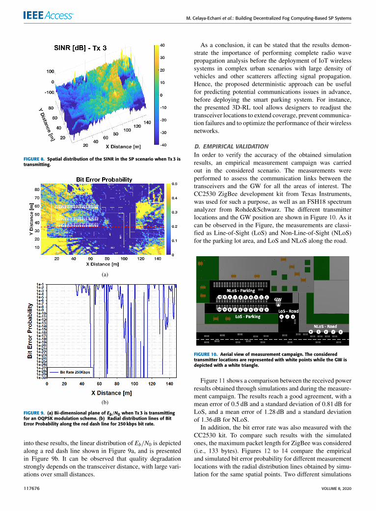
The obtained simulation results and the estimated valuesof the received power enable wireless system performanceanalysis. Thus, the signal to interference noise ratio (SINR)was calculated for the Tx 3 transmitter case and is shownin Figure 8. The SINR was obtained by considering Tx 3 asthe transmitter of interest and the other three transmitters(Tx 1, Tx 2, Tx 4) as interference sources that operate in thesame frequency band. The thermal noise power was alsoconsidered as N0 = KTB, where K is the Boltzmann’sconstant, T is the temperature in ◦K and B is the ZigBeechannel bandwidth (2MHz). The SINR was obtained forthe full volume of the considered scenario, giving valuableinformation about the areas and exact locations where theplacement of a parking sensor node will be more adequate interms of received signal quality whilemaintaining the optimalwireless power transmission of the system. In addition, it canbe observed in Figure 8 that the areas where interferingdevices were placed are the ones with lower SINR. The GWwas placed optimally, where the SINR was high.
The obtained SINR values can be used to calculatethe bit error probability (Eb/N0) for a given modulationscheme. In this case, the ZigBee modulation scheme Offset-Quadrature-Phase-Shift-Keying (OQPSK) was used and amaximum likelihood receiver was assumed. The Eb/N0 val-ues were estimated for the complete volume of the scenario.Thus, Figure 9 represents the bi-dimensional plane of Eb/N0for the same height at which Tx 3 is placed. To gain insight
VOLUME 8, 2020 117675
M. Celaya-Echarri et al.: Building Decentralized Fog Computing-Based SP Systems
FIGURE 8. Spatial distribution of the SINR in the SP scenario when Tx 3 istransmitting.
FIGURE 9. (a) Bi-dimensional plane of Eb/N0 when Tx 3 is transmittingfor an OQPSK modulation scheme. (b) Radial distribution lines of BitError Probability along the red dash line for 250 kbps bit rate.
into these results, the linear distribution of Eb/N0 is depictedalong a red dash line shown in Figure 9a, and is presentedin Figure 9b. It can be observed that quality degradationstrongly depends on the transceiver distance, with large vari-ations over small distances.
As a conclusion, it can be stated that the results demon-strate the importance of performing complete radio wavepropagation analysis before the deployment of IoT wirelesssystems in complex urban scenarios with large density ofvehicles and other scatterers affecting signal propagation.Hence, the proposed deterministic approach can be usefulfor predicting potential communications issues in advance,before deploying the smart parking system. For instance,the presented 3D-RL tool allows designers to readjust thetransceiver locations to extend coverage, prevent communica-tion failures and to optimize the performance of their wirelessnetworks.
D. EMPIRICAL VALIDATIONIn order to verify the accuracy of the obtained simulationresults, an empirical measurement campaign was carriedout in the considered scenario. The measurements wereperformed to assess the communication links between thetransceivers and the GW for all the areas of interest. TheCC2530 ZigBee development kit from Texas Instruments,was used for such a purpose, as well as an FSH18 spectrumanalyzer from Rohde&Schwarz. The different transmitterlocations and the GW position are shown in Figure 10. As itcan be observed in the Figure, the measurements are classi-fied as Line-of-Sight (LoS) and Non-Line-of-Sight (NLoS)for the parking lot area, and LoS and NLoS along the road.
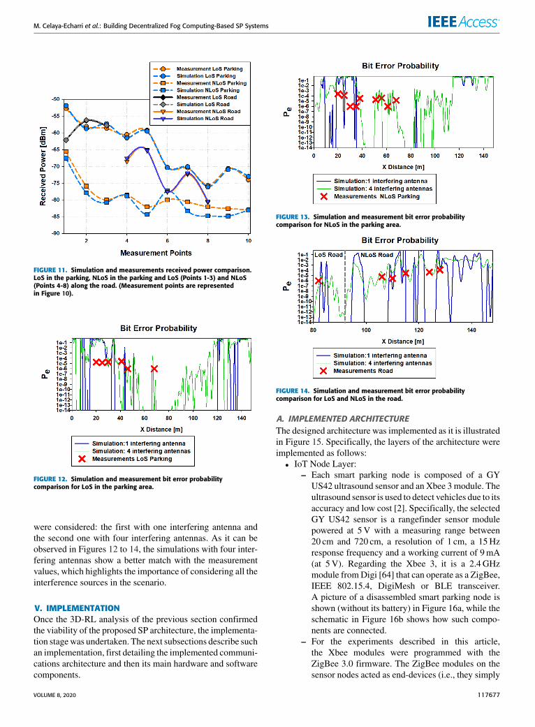
FIGURE 10. Aerial view of measurement campaign. The consideredtransmitter locations are represented with white points while the GW isdepicted with a white triangle.
Figure 11 shows a comparison between the received powerresults obtained through simulations and during the measure-ment campaign. The results reach a good agreement, with amean error of 0.5 dB and a standard deviation of 0.81 dB forLoS, and a mean error of 1.28 dB and a standard deviationof 1.36 dB for NLoS.
In addition, the bit error rate was also measured with theCC2530 kit. To compare such results with the simulatedones, the maximum packet length for ZigBee was considered(i.e., 133 bytes). Figures 12 to 14 compare the empiricaland simulated bit error probability for different measurementlocations with the radial distribution lines obtained by simu-lation for the same spatial points. Two different simulations
117676 VOLUME 8, 2020
M. Celaya-Echarri et al.: Building Decentralized Fog Computing-Based SP Systems
FIGURE 11. Simulation and measurements received power comparison.LoS in the parking, NLoS in the parking and LoS (Points 1-3) and NLoS(Points 4-8) along the road. (Measurement points are representedin Figure 10).
FIGURE 12. Simulation and measurement bit error probabilitycomparison for LoS in the parking area.
were considered: the first with one interfering antenna andthe second one with four interfering antennas. As it can beobserved in Figures 12 to 14, the simulations with four inter-fering antennas show a better match with the measurementvalues, which highlights the importance of considering all theinterference sources in the scenario.
V. IMPLEMENTATIONOnce the 3D-RL analysis of the previous section confirmedthe viability of the proposed SP architecture, the implementa-tion stagewas undertaken. The next subsections describe suchan implementation, first detailing the implemented communi-cations architecture and then its main hardware and softwarecomponents.
FIGURE 13. Simulation and measurement bit error probabilitycomparison for NLoS in the parking area.
FIGURE 14. Simulation and measurement bit error probabilitycomparison for LoS and NLoS in the road.
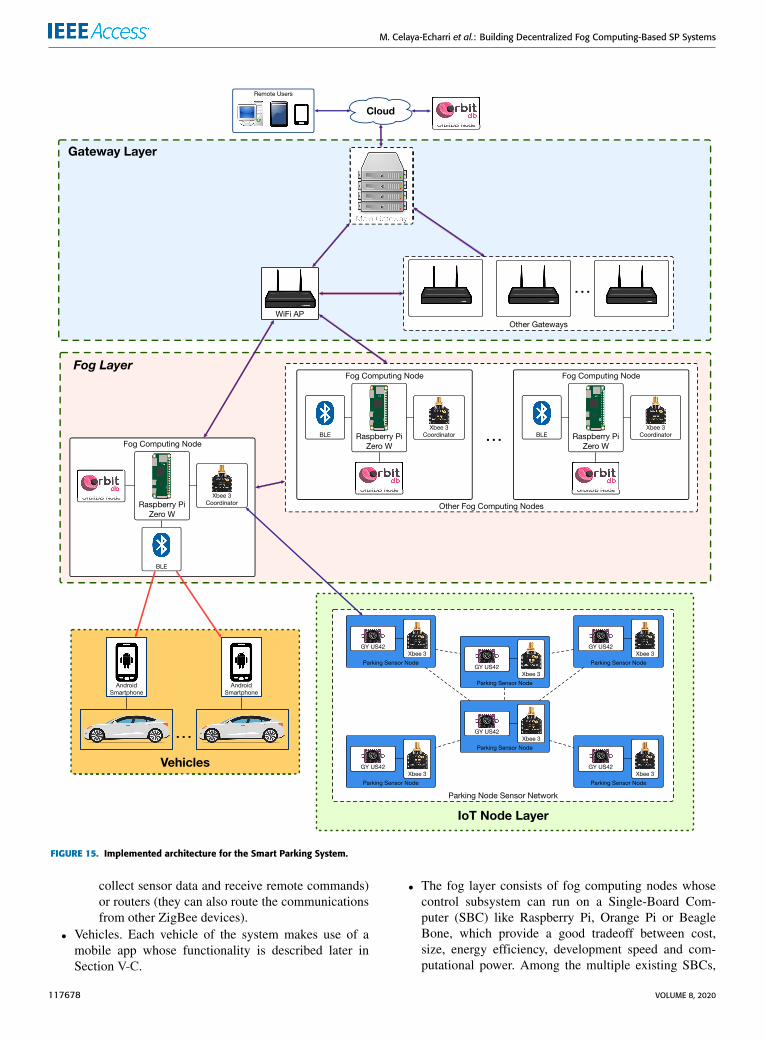
A. IMPLEMENTED ARCHITECTUREThe designed architecture was implemented as it is illustratedin Figure 15. Specifically, the layers of the architecture wereimplemented as follows:• IoT Node Layer:
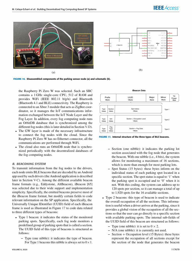
– Each smart parking node is composed of a GYUS42 ultrasound sensor and an Xbee 3 module. Theultrasound sensor is used to detect vehicles due to itsaccuracy and low cost [2]. Specifically, the selectedGY US42 sensor is a rangefinder sensor modulepowered at 5V with a measuring range between20 cm and 720 cm, a resolution of 1 cm, a 15Hzresponse frequency and a working current of 9mA(at 5V). Regarding the Xbee 3, it is a 2.4GHzmodule fromDigi [64] that can operate as a ZigBee,IEEE 802.15.4, DigiMesh or BLE transceiver.A picture of a disassembled smart parking node isshown (without its battery) in Figure 16a, while theschematic in Figure 16b shows how such compo-nents are connected.
– For the experiments described in this article,the Xbee modules were programmed with theZigBee 3.0 firmware. The ZigBee modules on thesensor nodes acted as end-devices (i.e., they simply
VOLUME 8, 2020 117677
M. Celaya-Echarri et al.: Building Decentralized Fog Computing-Based SP Systems
FIGURE 15. Implemented architecture for the Smart Parking System.
collect sensor data and receive remote commands)or routers (they can also route the communicationsfrom other ZigBee devices).
• Vehicles. Each vehicle of the system makes use of amobile app whose functionality is described later inSection V-C.
• The fog layer consists of fog computing nodes whosecontrol subsystem can run on a Single-Board Com-puter (SBC) like Raspberry Pi, Orange Pi or BeagleBone, which provide a good tradeoff between cost,size, energy efficiency, development speed and com-putational power. Among the multiple existing SBCs,
117678 VOLUME 8, 2020
M. Celaya-Echarri et al.: Building Decentralized Fog Computing-Based SP Systems
FIGURE 16. Disassembled components of the parking sensor node (a) and schematic (b).
the Raspberry Pi Zero W was selected. Such an SBCcontains a 1GHz single-core CPU, 512 of RAM andprovides WiFi (IEEE 802.11 b/g/n) and Bluetooth(Bluetooth 4.1 and BLE) connectivity. The Raspberry isconnected to an Xbee 3 module that acts as ZigBee coor-dinator, so it manages the IoT communications infor-mation exchanged between the IoT Node Layer and theFog Layer. In addition, every fog computing node runsan OrbitDB database that is synchronized among thedifferent fog nodes (this is later detailed in Section V-D).
• The GW layer is made of the necessary infrastructureto connect the fog nodes with the cloud. Since theRaspberry Pi Zero W has no Ethernet connector, all thecommunications are performed through WiFi.
• The cloud also runs an OrbitDB node that is synchro-nized periodically with the decentralized databases ofthe fog computing nodes.
B. BEACONING SYSTEMTo transmit information from the fog nodes to the drivers,each node emits BLE beacons that are decoded by an Androidapp used by such drivers (theAndroid application is describedlater in Section V-C). Among the different available beaconframe formats (e.g., Eddystone, AltBeacon), iBeacon [65]was selected due to their wide support and implementationsimplicity. Specifically, the emitted beacons preserve most ofthe iBeacon frame format, but modify certain fields to coderelevant information on the SP application. Specifically, theUniversally Unique IDentifier (UUID) field of each iBeaconframe is used as illustrated in Figure 17 to code data relatedto three different types of beacons:
• Type 1 beacon: it indicates the status of the monitoredparking spots. Specifically, each fog node monitors apredefined group of parking spots that is called a section.The UUID field of this type of beacons is structured asfollows:
– Type (one nibble): it indicates the type of beacon.For Type 1 beacons this nibble is always set to 0×1.
FIGURE 17. Internal structure of the three types of BLE beacons.
– Section (one nibble): it indicates the parking lotsection associated with the fog node that generatesthe beacon. With one nibble (i.e., 4 bits), the systemallows for monitoring a maximum of 16 sections,which is more than enough for most parking lots.
– Spot Status (15 bytes): these bytes inform on theindividual status of each parking spot located in aspecific section. The spot status is equal to ‘1’ whenthe parking spot is occupied and to ‘0’ when it isnot. With this coding, the system can address up to120 spots per section, so it can manage a total of upto 1,920 spots for the 16 available sections.
• Type 2 beacons: this type of beacon is used to indicatethe overall occupation of all the sections. This informa-tion is useful when a driver arrives at the parking, since itprovides a global vision of the occupation of all the sec-tions so that the user can go directly to a specific sectionwith available parking spots. The internal sub-fields ofthe UUID field of this beacon are structured as follows:
– Type (one nibble): it is set to 0× 2.– N/A (one nibble): it is currently not used.– Section + Occupation level (15 Bytes): these bytes
represent the occupation of all sections except forthe section of the node that generates the beacon
VOLUME 8, 2020 117679
M. Celaya-Echarri et al.: Building Decentralized Fog Computing-Based SP Systems
(i.e., the fog node informs with this type of beaconon the occupancy level of the other sections, sinceit already informs on its monitored section throughType 1 beacons). For each of the 15 bytes, the firstnibble indicates the section while the second onecodifies the section occupation. Since the secondnibble has only 4 bits to encode the occupancy ofthe 120 parking spots of a section, they are codedas follows:∗ 0× 0 - there are no spots available.∗ 0× 1 - there is one spot available.∗ 0× 2, 0× 03. . . 0xA - there are two, three. . . ten
spots available.∗ 0xB - there are between 10 and 20 spots
available.∗ 0xC - there are more than 20 spots available.In addition, the second nibble is set to 0xF whenit is used as a delimiter to indicate the system thatthere is no more information on the occupancy ofthe sections (this is used when the 16 sections arenot managed by the system).
• Type 3 beacon: this is a generic beacon used to providerelevant information from the decentralized database.It consists of the following sub-fields of its UUID field:– Type (one nibble): it is always set to 0× 3.– Fog type (one nibble): it defines the type of data that
is embedded into the beacon.– Section + Fog Data (15 bytes): these bytes carry
the provided data, which can be related to a specificsection, to all the sections or to the whole system.For instance, these data can be used to indicate theaverage amount of time that a driver would haveto wait for an empty spot (this information maybe estimated by applying a probabilistic predictionalgorithm).
The usual operation of the beaconing system of a fog nodecan be divided into two stages. In the first stage the ZigBeeinterface of the fog node receives the information from theassociated parking sensor nodes and updates their status inthe database. During the second stage the different types ofbeacons are generated periodically: the collected informa-tion is first read from the database, then coded according tothe previously described beacon frame formats and, finally,the beacons are broadcast. Type 1 and 2 beacons are sentmore frequently than Type 3 beacons, since their informationis updated more frequently. In this regard, it is important topoint out that the information broadcast by Type 1 and 2 bea-cons does not need data persistence if storing historical datais not necessary. In such a case, a subscription/publicationmessaging strategy could be more efficient, especially whenthe broadcast information needs to be updated fast. In con-trast, Type 3 beacons are not updated frequently, but theinformation they use requires persistence in order to gener-ate the involved statistics. The experiments detailed later inSection VI analyze the performance of the two previouslymentioned data storage approaches.
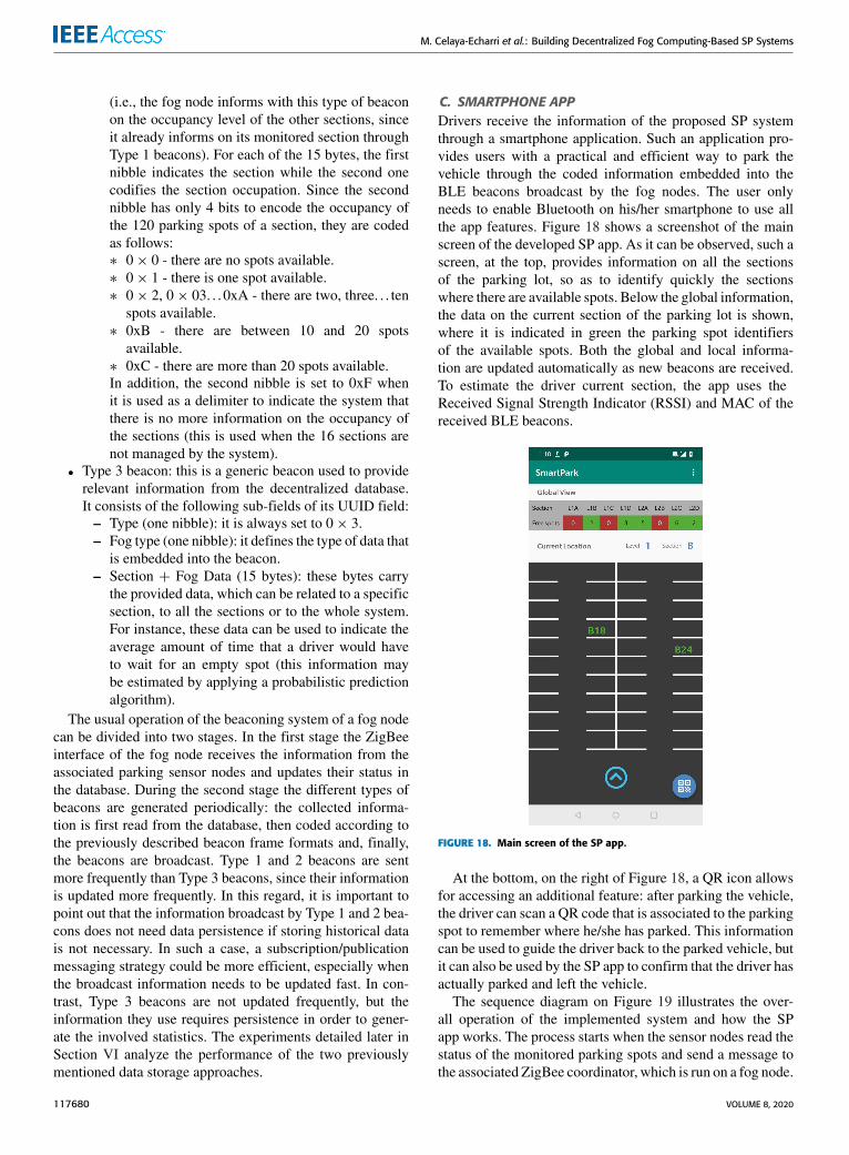
C. SMARTPHONE APPDrivers receive the information of the proposed SP systemthrough a smartphone application. Such an application pro-vides users with a practical and efficient way to park thevehicle through the coded information embedded into theBLE beacons broadcast by the fog nodes. The user onlyneeds to enable Bluetooth on his/her smartphone to use allthe app features. Figure 18 shows a screenshot of the mainscreen of the developed SP app. As it can be observed, such ascreen, at the top, provides information on all the sectionsof the parking lot, so as to identify quickly the sectionswhere there are available spots. Below the global information,the data on the current section of the parking lot is shown,where it is indicated in green the parking spot identifiersof the available spots. Both the global and local informa-tion are updated automatically as new beacons are received.To estimate the driver current section, the app uses theReceived Signal Strength Indicator (RSSI) and MAC of thereceived BLE beacons.
FIGURE 18. Main screen of the SP app.
At the bottom, on the right of Figure 18, a QR icon allowsfor accessing an additional feature: after parking the vehicle,the driver can scan a QR code that is associated to the parkingspot to remember where he/she has parked. This informationcan be used to guide the driver back to the parked vehicle, butit can also be used by the SP app to confirm that the driver hasactually parked and left the vehicle.
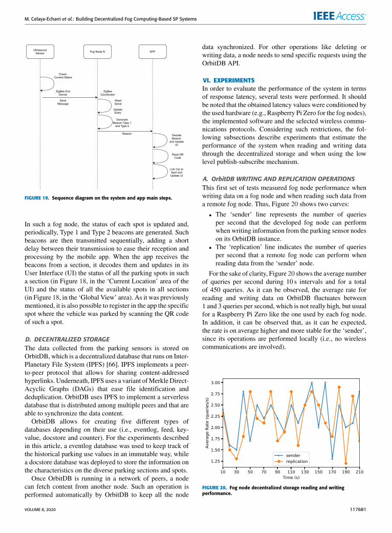
The sequence diagram on Figure 19 illustrates the over-all operation of the implemented system and how the SPapp works. The process starts when the sensor nodes read thestatus of the monitored parking spots and send a message tothe associated ZigBee coordinator, which is run on a fog node.
117680 VOLUME 8, 2020
M. Celaya-Echarri et al.: Building Decentralized Fog Computing-Based SP Systems
FIGURE 19. Sequence diagram on the system and app main steps.
In such a fog node, the status of each spot is updated and,periodically, Type 1 and Type 2 beacons are generated. Suchbeacons are then transmitted sequentially, adding a shortdelay between their transmission to ease their reception andprocessing by the mobile app. When the app receives thebeacons from a section, it decodes them and updates in itsUser Interface (UI) the status of all the parking spots in sucha section (in Figure 18, in the ‘Current Location’ area of theUI) and the status of all the available spots in all sections(in Figure 18, in the ‘Global View’ area). As it was previouslymentioned, it is also possible to register in the app the specificspot where the vehicle was parked by scanning the QR codeof such a spot.
D. DECENTRALIZED STORAGEThe data collected from the parking sensors is stored onOrbitDB, which is a decentralized database that runs on Inter-Planetary File System (IPFS) [66]. IPFS implements a peer-to-peer protocol that allows for sharing content-addressedhyperlinks. Underneath, IPFS uses a variant ofMerkleDirect-Acyclic Graphs (DAGs) that ease file identification anddeduplication. OrbitDB uses IPFS to implement a serverlessdatabase that is distributed among multiple peers and that areable to synchronize the data content.
OrbitDB allows for creating five different types ofdatabases depending on their use (i.e., eventlog, feed, key-value, docstore and counter). For the experiments describedin this article, a eventlog database was used to keep track ofthe historical parking use values in an immutable way, whilea docstore database was deployed to store the information onthe characteristics on the diverse parking sections and spots.
Once OrbitDB is running in a network of peers, a nodecan fetch content from another node. Such an operation isperformed automatically by OrbitDB to keep all the node
data synchronized. For other operations like deleting orwriting data, a node needs to send specific requests using theOrbitDB API.
VI. EXPERIMENTSIn order to evaluate the performance of the system in termsof response latency, several tests were performed. It shouldbe noted that the obtained latency values were conditioned bythe used hardware (e.g., Raspberry Pi Zero for the fog nodes),the implemented software and the selected wireless commu-nications protocols. Considering such restrictions, the fol-lowing subsections describe experiments that estimate theperformance of the system when reading and writing datathrough the decentralized storage and when using the lowlevel publish-subscribe mechanism.
A. OrbitDB WRITING AND REPLICATION OPERATIONSThis first set of tests measured fog node performance whenwriting data on a fog node and when reading such data froma remote fog node. Thus, Figure 20 shows two curves:
• The ‘sender’ line represents the number of queriesper second that the developed fog node can performwhen writing information from the parking sensor nodeson its OrbitDB instance.
• The ‘replication’ line indicates the number of queriesper second that a remote fog node can perform whenreading data from the ‘sender’ node.
For the sake of clarity, Figure 20 shows the average numberof queries per second during 10 s intervals and for a totalof 450 queries. As it can be observed, the average rate forreading and writing data on OrbitDB fluctuates between1 and 3 queries per second, which is not really high, but usualfor a Raspberry Pi Zero like the one used by each fog node.In addition, it can be observed that, as it can be expected,the rate is on average higher and more stable for the ‘sender’,since its operations are performed locally (i.e., no wirelesscommunications are involved).
FIGURE 20. Fog node decentralized storage reading and writingperformance.
VOLUME 8, 2020 117681
M. Celaya-Echarri et al.: Building Decentralized Fog Computing-Based SP Systems
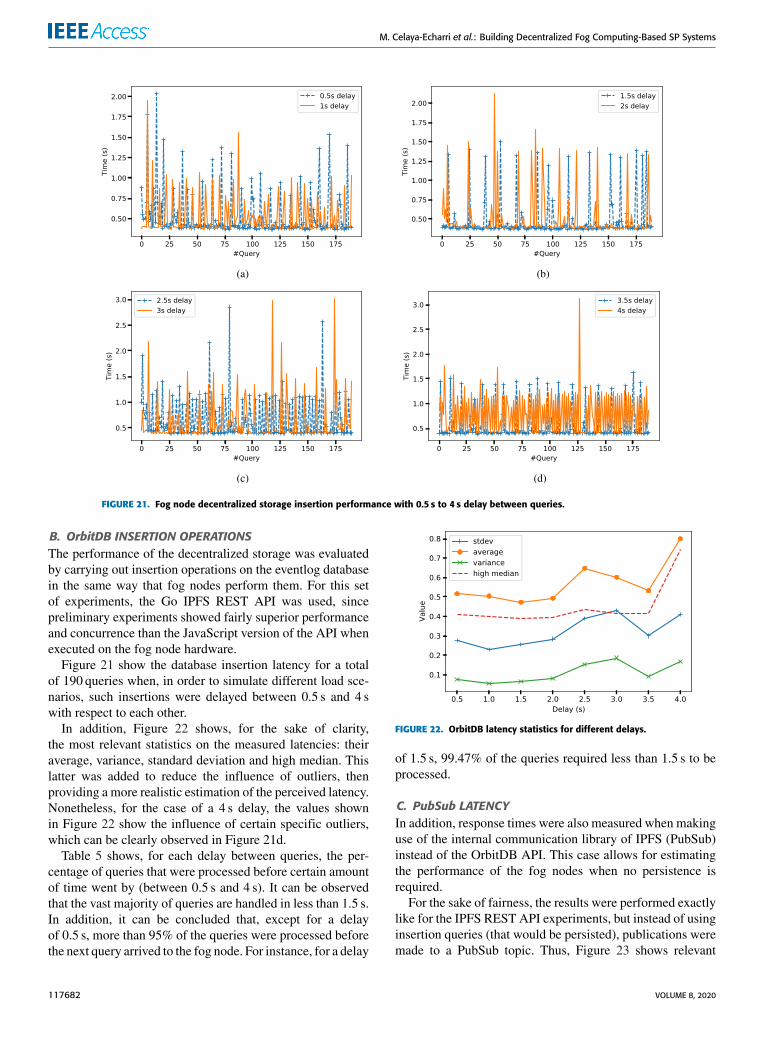
FIGURE 21. Fog node decentralized storage insertion performance with 0.5 s to 4 s delay between queries.
B. OrbitDB INSERTION OPERATIONSThe performance of the decentralized storage was evaluatedby carrying out insertion operations on the eventlog databasein the same way that fog nodes perform them. For this setof experiments, the Go IPFS REST API was used, sincepreliminary experiments showed fairly superior performanceand concurrence than the JavaScript version of the API whenexecuted on the fog node hardware.
Figure 21 show the database insertion latency for a totalof 190 queries when, in order to simulate different load sce-narios, such insertions were delayed between 0.5 s and 4 swith respect to each other.
In addition, Figure 22 shows, for the sake of clarity,the most relevant statistics on the measured latencies: theiraverage, variance, standard deviation and high median. Thislatter was added to reduce the influence of outliers, thenproviding a more realistic estimation of the perceived latency.Nonetheless, for the case of a 4 s delay, the values shownin Figure 22 show the influence of certain specific outliers,which can be clearly observed in Figure 21d.
Table 5 shows, for each delay between queries, the per-centage of queries that were processed before certain amountof time went by (between 0.5 s and 4 s). It can be observedthat the vast majority of queries are handled in less than 1.5 s.In addition, it can be concluded that, except for a delayof 0.5 s, more than 95% of the queries were processed beforethe next query arrived to the fog node. For instance, for a delay
FIGURE 22. OrbitDB latency statistics for different delays.
of 1.5 s, 99.47% of the queries required less than 1.5 s to beprocessed.
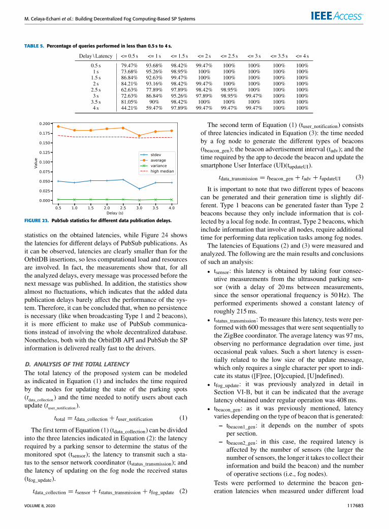
C. PubSub LATENCYIn addition, response times were also measured when makinguse of the internal communication library of IPFS (PubSub)instead of the OrbitDB API. This case allows for estimatingthe performance of the fog nodes when no persistence isrequired.
For the sake of fairness, the results were performed exactlylike for the IPFS REST API experiments, but instead of usinginsertion queries (that would be persisted), publications weremade to a PubSub topic. Thus, Figure 23 shows relevant
117682 VOLUME 8, 2020
M. Celaya-Echarri et al.: Building Decentralized Fog Computing-Based SP Systems
TABLE 5. Percentage of queries performed in less than 0.5 s to 4 s.
FIGURE 23. PubSub statistics for different data publication delays.
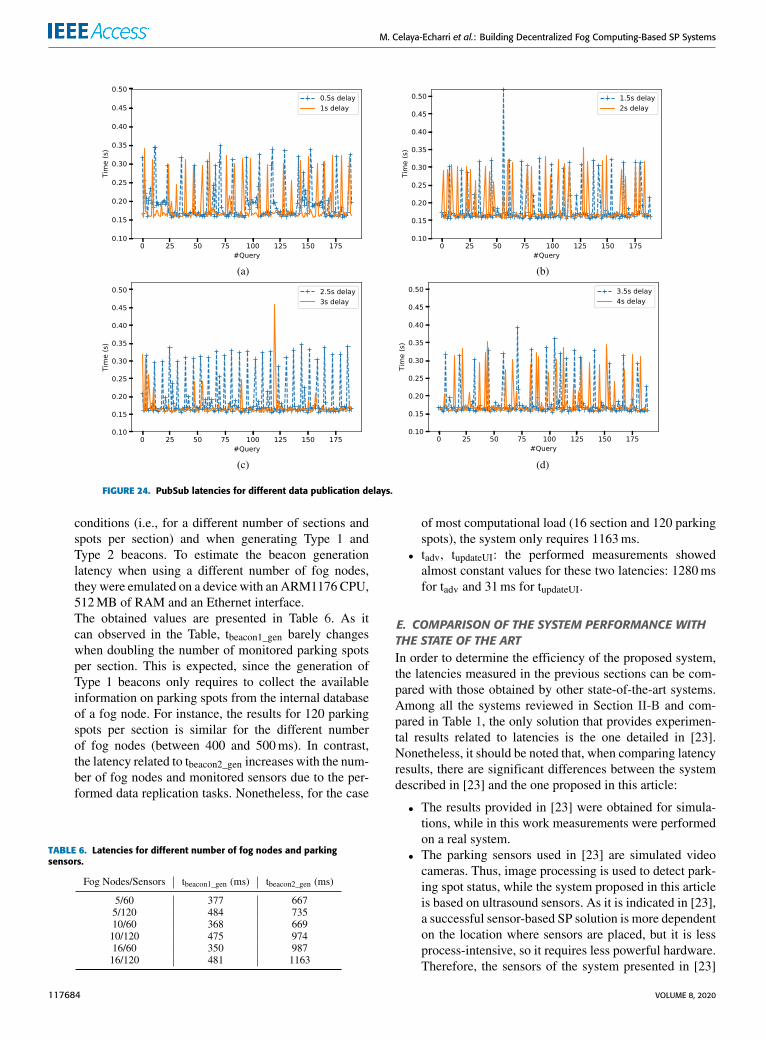
statistics on the obtained latencies, while Figure 24 showsthe latencies for different delays of PubSub publications. Asit can be observed, latencies are clearly smaller than for theOrbitDB insertions, so less computational load and resourcesare involved. In fact, the measurements show that, for allthe analyzed delays, every message was processed before thenext message was published. In addition, the statistics showalmost no fluctuations, which indicates that the added datapublication delays barely affect the performance of the sys-tem. Therefore, it can be concluded that, when no persistenceis necessary (like when broadcasting Type 1 and 2 beacons),it is more efficient to make use of PubSub communica-tions instead of involving the whole decentralized database.Nonetheless, both with the OrbitDB API and PubSub the SPinformation is delivered really fast to the drivers.
D. ANALYSIS OF THE TOTAL LATENCYThe total latency of the proposed system can be modeledas indicated in Equation (1) and includes the time requiredby the nodes for updating the state of the parking spots(tdata_collection) and the time needed to notify users about eachupdate (tuser_notification).
ttotal = tdata_collection + tuser_notification (1)
The first term of Equation (1) (tdata_collection) can be dividedinto the three latencies indicated in Equation (2): the latencyrequired by a parking sensor to determine the status of themonitored spot (tsensor); the latency to transmit such a sta-tus to the sensor network coordinator (tstatus_transmission); andthe latency of updating on the fog node the received status(tfog_update).
tdata_collection = tsensor + tstatus_transmission + tfog_update (2)
The second term of Equation (1) (tuser_notification) consistsof three latencies indicated in Equation (3): the time neededby a fog node to generate the different types of beacons(tbeacon_gen); the beacon advertisement interval (tadv); and thetime required by the app to decode the beacon and update thesmartphone User Interface (UI)(tupdateUI).
tdata_transmission = tbeacon_gen + tadv + tupdateUI (3)
It is important to note that two different types of beaconscan be generated and their generation time is slightly dif-ferent. Type 1 beacons can be generated faster than Type 2beacons because they only include information that is col-lected by a local fog node. In contrast, Type 2 beacons, whichinclude information that involve all nodes, require additionaltime for performing data replication tasks among fog nodes.
The latencies of Equations (2) and (3) were measured andanalyzed. The following are the main results and conclusionsof such an analysis:• tsensor: this latency is obtained by taking four consec-utive measurements from the ultrasound parking sen-sor (with a delay of 20ms between measurements,since the sensor operational frequency is 50Hz). Theperformed experiments showed a constant latency ofroughly 215ms.
• tstatus_transmission: To measure this latency, tests were per-formed with 600 messages that were sent sequentially tothe ZigBee coordinator. The average latency was 97ms,observing no performance degradation over time, justoccasional peak values. Such a short latency is essen-tially related to the low size of the update message,which only requires a single character per sport to indi-cate its status ([F]ree, [O]ccupied, [U]ndefined).
• tfog_update: it was previously analyzed in detail inSection VI-B, but it can be indicated that the averagelatency obtained under regular operation was 408ms.
• tbeacon_gen: as it was previously mentioned, latencyvaries depending on the type of beacon that is generated:– tbeacon1_gen: it depends on the number of spots
per section.– tbeacon2_gen: in this case, the required latency is
affected by the number of sensors (the larger thenumber of sensors, the longer it takes to collect theirinformation and build the beacon) and the numberof operative sections (i.e., fog nodes).
Tests were performed to determine the beacon gen-eration latencies when measured under different load
VOLUME 8, 2020 117683
M. Celaya-Echarri et al.: Building Decentralized Fog Computing-Based SP Systems
FIGURE 24. PubSub latencies for different data publication delays.
conditions (i.e., for a different number of sections andspots per section) and when generating Type 1 andType 2 beacons. To estimate the beacon generationlatency when using a different number of fog nodes,they were emulated on a device with an ARM1176 CPU,512MB of RAM and an Ethernet interface.The obtained values are presented in Table 6. As itcan observed in the Table, tbeacon1_gen barely changeswhen doubling the number of monitored parking spotsper section. This is expected, since the generation ofType 1 beacons only requires to collect the availableinformation on parking spots from the internal databaseof a fog node. For instance, the results for 120 parkingspots per section is similar for the different numberof fog nodes (between 400 and 500ms). In contrast,the latency related to tbeacon2_gen increases with the num-ber of fog nodes and monitored sensors due to the per-formed data replication tasks. Nonetheless, for the case
TABLE 6. Latencies for different number of fog nodes and parkingsensors.
of most computational load (16 section and 120 parkingspots), the system only requires 1163ms.
• tadv, tupdateUI: the performed measurements showedalmost constant values for these two latencies: 1280msfor tadv and 31ms for tupdateUI.
E. COMPARISON OF THE SYSTEM PERFORMANCE WITHTHE STATE OF THE ARTIn order to determine the efficiency of the proposed system,the latencies measured in the previous sections can be com-pared with those obtained by other state-of-the-art systems.Among all the systems reviewed in Section II-B and com-pared in Table 1, the only solution that provides experimen-tal results related to latencies is the one detailed in [23].Nonetheless, it should be noted that, when comparing latencyresults, there are significant differences between the systemdescribed in [23] and the one proposed in this article:
• The results provided in [23] were obtained for simula-tions, while in this work measurements were performedon a real system.
• The parking sensors used in [23] are simulated videocameras. Thus, image processing is used to detect park-ing spot status, while the system proposed in this articleis based on ultrasound sensors. As it is indicated in [23],a successful sensor-based SP solution is more dependenton the location where sensors are placed, but it is lessprocess-intensive, so it requires less powerful hardware.Therefore, the sensors of the system presented in [23]
117684 VOLUME 8, 2020
M. Celaya-Echarri et al.: Building Decentralized Fog Computing-Based SP Systems
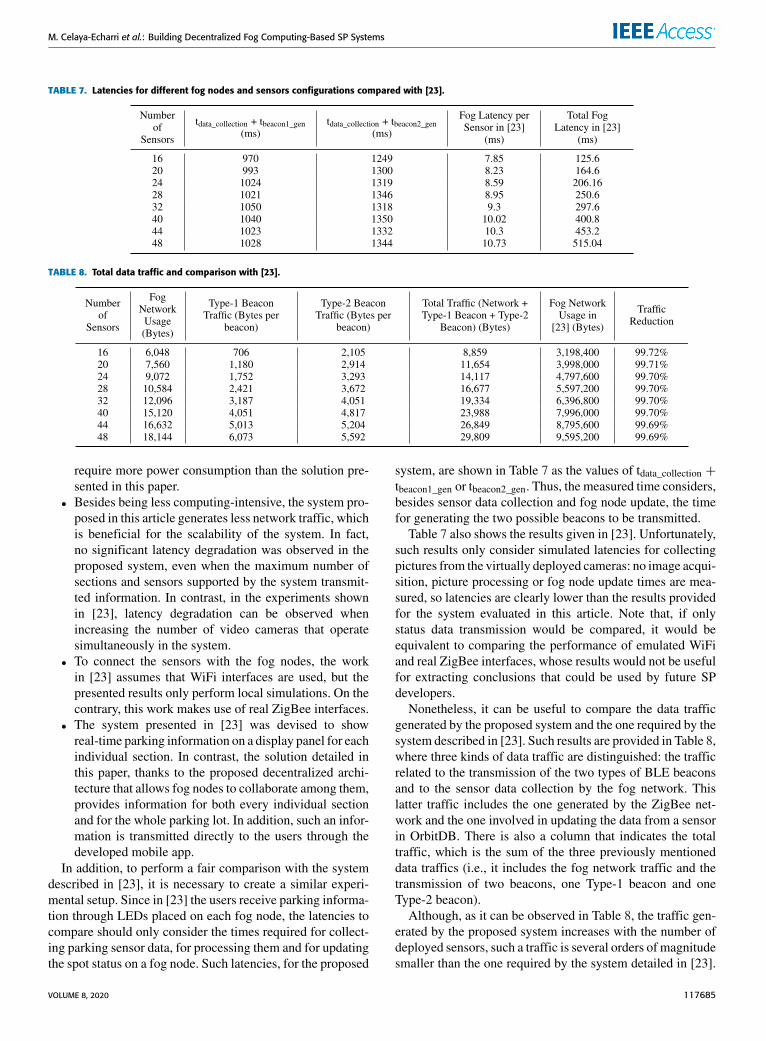
TABLE 7. Latencies for different fog nodes and sensors configurations compared with [23].
TABLE 8. Total data traffic and comparison with [23].
require more power consumption than the solution pre-sented in this paper.
• Besides being less computing-intensive, the system pro-posed in this article generates less network traffic, whichis beneficial for the scalability of the system. In fact,no significant latency degradation was observed in theproposed system, even when the maximum number ofsections and sensors supported by the system transmit-ted information. In contrast, in the experiments shownin [23], latency degradation can be observed whenincreasing the number of video cameras that operatesimultaneously in the system.
• To connect the sensors with the fog nodes, the workin [23] assumes that WiFi interfaces are used, but thepresented results only perform local simulations. On thecontrary, this work makes use of real ZigBee interfaces.
• The system presented in [23] was devised to showreal-time parking information on a display panel for eachindividual section. In contrast, the solution detailed inthis paper, thanks to the proposed decentralized archi-tecture that allows fog nodes to collaborate among them,provides information for both every individual sectionand for the whole parking lot. In addition, such an infor-mation is transmitted directly to the users through thedeveloped mobile app.
In addition, to perform a fair comparison with the systemdescribed in [23], it is necessary to create a similar experi-mental setup. Since in [23] the users receive parking informa-tion through LEDs placed on each fog node, the latencies tocompare should only consider the times required for collect-ing parking sensor data, for processing them and for updatingthe spot status on a fog node. Such latencies, for the proposed
system, are shown in Table 7 as the values of tdata_collection +tbeacon1_gen or tbeacon2_gen. Thus, the measured time considers,besides sensor data collection and fog node update, the timefor generating the two possible beacons to be transmitted.
Table 7 also shows the results given in [23]. Unfortunately,such results only consider simulated latencies for collectingpictures from the virtually deployed cameras: no image acqui-sition, picture processing or fog node update times are mea-sured, so latencies are clearly lower than the results providedfor the system evaluated in this article. Note that, if onlystatus data transmission would be compared, it would beequivalent to comparing the performance of emulated WiFiand real ZigBee interfaces, whose results would not be usefulfor extracting conclusions that could be used by future SPdevelopers.
Nonetheless, it can be useful to compare the data trafficgenerated by the proposed system and the one required by thesystem described in [23]. Such results are provided in Table 8,where three kinds of data traffic are distinguished: the trafficrelated to the transmission of the two types of BLE beaconsand to the sensor data collection by the fog network. Thislatter traffic includes the one generated by the ZigBee net-work and the one involved in updating the data from a sensorin OrbitDB. There is also a column that indicates the totaltraffic, which is the sum of the three previously mentioneddata traffics (i.e., it includes the fog network traffic and thetransmission of two beacons, one Type-1 beacon and oneType-2 beacon).
Although, as it can be observed in Table 8, the traffic gen-erated by the proposed system increases with the number ofdeployed sensors, such a traffic is several orders of magnitudesmaller than the one required by the system detailed in [23].
VOLUME 8, 2020 117685
M. Celaya-Echarri et al.: Building Decentralized Fog Computing-Based SP Systems
In fact, the proposed system allows for removing roughly99.7% of the traffic generated by the SP system describedin [23], thus decreasing significantly fog network traffic andpower consumption needs.
VII. CONCLUSIONSThis paper detailed the complete development of a decen-tralized fog computing-based SP system. Such a devel-opment followed a methodology that includes its initialdesign, its theoretical simulation and its empirical validation.Specifically, for this article, a parking lot located inMonterrey (Mexico) was analyzed and modeled in 3D inorder to evaluate through a 3D-RL tool its wireless channelproperties. The results obtained by the 3D-RL tool were latervalidated through a ZigBee measurement campaign, allowingfor obtaining the optimal sensor node and GW locations,and concluding that the proposed technologies and architec-ture are adequate for implementing the SP system. Finally,the proposed system was built by making use of parkingsensor nodes based on ZigBee transceivers and ultrasoundsensors, while fog computing nodes were created based ona Raspberry Pi Zero and ZigBee/BLE interfaces. Such fognodes also provided decentralized storage, whose perfor-mance was evaluated. The results show that the proposedsystem is able to deliver information to the driver smartphonein less than 4 s by using lightweight and scalable protocolsand with no need for relying on remote servers. Therefore,the article demonstrates the feasibility of the proposed SPdevelopment methodology and the usefulness of the used3D-RL tool. Moreover, this article provides the necessarydetails on the steps involved in the development of a prac-tical decentralized low-latency system, thus providing usefulguidelines for future SP developers.
ACKNOWLEDGMENTThe authors would like to thankDr. Cesar Vargas-Rosales andDr. Mahdi Zareei at Tecnologico de Monterrey, for helpfuldiscussion in the preliminary stage of this work.
REFERENCES[1] T. M. Fernandez-Carames and P. Fraga-Lamas, ‘‘A review on the applica-
tion of blockchain to the next generation of cybersecure industry 4.0 smartfactories,’’ IEEE Access, vol. 7, pp. 45201–45218, 2019.
[2] T. Lin, H. Rivano, and F. Le Mouel, ‘‘A survey of smart parking solu-tions,’’ IEEE Trans. Intell. Transport. Syst., vol. 18, no. 12, pp. 3229–3253,Dec. 2017.
[3] A. O. Kotb, Y.-C. Shen, X. Zhu, and Y. Huang, ‘‘iParker—A new smartcar-parking system based on dynamic resource allocation and pricing,’’IEEE Trans. Intell. Transport. Syst., vol. 17, no. 19, pp. 2637–2647,Sep. 2016.
[4] C. Roman, R. Liao, P. Ball, S. Ou, and M. de Heaver, ‘‘Detecting on-street parking spaces in smart cities: Performance evaluation of fixed andmobile sensing systems,’’ IEEE Trans. Intell. Transport. Syst., vol. 19,no. 7, pp. 2234–2245, Jul. 2018.
[5] A. Bagula, L. Castelli, and M. Zennaro, ‘‘On the design of smart parkingnetworks in the smart cities: An optimal sensor placement model,’’ Sen-sors, vol. 15, no. 7, pp. 15443–15467, Jun. 2015.
[6] T. M. Fernández-Caramés, P. Fraga-Lamas, M. Suárez-Albela, andL. Castedo, ‘‘A methodology for evaluating security in commercial RFIDsystems,’’ in Radio Frequency Identification. Rijeka, Croatia: InTech,2017.
[7] Z. Ji, I. Ganchev, M. O’Droma, L. Zhao, and X. Zhang, ‘‘A cloud-basedcar parking middleware for IoT-based smart cities: Design and implemen-tation,’’ Sensors, vol. 14, no. 12, pp. 22372–22393, Nov. 2014.
[8] J. Lanza, L. Sánchez, V. Gutiérrez, J. Galache, J. Santana, P. Sotres, andL. Muñoz, ‘‘Smart city services over a future Internet platform based onInternet of Things and cloud: The smart parking case,’’ Energies, vol. 9,no. 9, p. 719, Sep. 2016.
[9] M. Garcia, P. Rose, R. Sung, and S. El-Tawab, ‘‘Secure smart parking atJames Madison University via the cloud environment (SPACE),’’ in Proc.IEEE Syst. Inf. Eng. Design Symp. (SIEDS), Apr. 2016, pp. 271–276.
[10] K. Dolui and S. K. Datta, ‘‘Comparison of edge computing implemen-tations: Fog computing, cloudlet and mobile edge computing,’’ in Proc.Global Internet Things Summit (GIoTS), Jun. 2017, pp. 1–6.
[11] F. Bonomi, R. Milito, J. Zhu, and S. Addepalli, ‘‘Fog computing and itsrole in the Internet of Things,’’ in Proc. 1st Ed. MCC Workshop MobileCloud Comput. (MCC), Helsinki, Finland, Aug. 2012, pp. 13–16.
[12] T. Fernández-Caramés, P. Fraga-Lamas, M. Suárez-Albela, andM. Díaz-Bouza, ‘‘A fog computing based cyber-physical system forthe automation of pipe-related tasks in the industry 4.0 shipyard,’’Sensors, vol. 18, no. 6, p. 1961, Jun. 2018.
[13] W.Viriyasitavat,M. Boban, H.-M. Tsai, andA.Vasilakos, ‘‘Vehicular com-munications: Survey and challenges of channel and propagation models,’’IEEE Veh. Technol. Mag., vol. 10, no. 2, pp. 55–66, Jun. 2015.
[14] A. Domazetovic, L. J. Greenstein, N. B. Mandayam, and I. Seskar,‘‘Propagation models for short-range wireless channels with predictablepath geometries,’’ IEEE Trans. Commun., vol. 53, no. 7, pp. 1123–1126,Jul. 2005.
[15] S. Phaiboon, ‘‘Propagation path loss models for parking buildings,’’ inProc. 5th Int. Conf. Inf. Commun. Signal Process., 2005, pp. 1348–1351.
[16] K. Phaebua, C. Phongcharoenpanich, D. Torrungrueng, andJ. Chinrungrueng, ‘‘Short-distance and near-ground signal measurementsin a car park of wireless sensor network system at 433 MHz,’’ in Proc.5th Int. Conf. Electr. Eng./Electron., Comput., Telecommun. Inf. Technol.,vol. 1, May 2008, pp. 241–244.
[17] R. Meireles, M. Boban, P. Steenkiste, O. Tonguz, and J. Barros, ‘‘Experi-mental study on the impact of vehicular obstructions in VANETs,’’ in Proc.IEEE Veh. Netw. Conf., Dec. 2010, pp. 338–345.
[18] R. Sun, D.W.Matolak, and P. Liu, ‘‘Parking garage channel characteristicsat 5 GHz for V2 V applications,’’ in Proc. IEEE 78th Veh. Technol. Conf.(VTC Fall), Sep. 2013, pp. 1–5.
[19] R. He, O. Renaudin, V.-M. Kolmonen, K. Haneda, Z. Zhong, B. Ai, andC. Oestges, ‘‘Characterization of quasi-stationarity regions for vehicle-to-vehicle radio channels,’’ IEEE Trans. Antennas Propag., vol. 63, no. 5,pp. 2237–2251, May 2015.
[20] R. Sun, D. W. Matolak, and P. Liu, ‘‘5-GHz V2 V channel character-istics for parking garages,’’ IEEE Trans. Veh. Technol., vol. 66, no. 5,pp. 3538–3547, May 2017.
[21] T. O. Olasupo, C. E. Otero, L. D. Otero, K. O. Olasupo, and I. Kostanic,‘‘Path loss models for low-power, low-data rate sensor nodes for smartcar parking systems,’’ IEEE Trans. Intell. Transport. Syst., vol. 19, no. 6,pp. 1774–1783, Jun. 2018.
[22] C. Tang, X. Wei, C. Zhu, W. Chen, and J. J. P. C. Rodrigues,‘‘Towards smart parking based on fog computing,’’ IEEE Access, vol. 6,pp. 70172–70185, 2018.
[23] K. S. Awaisi, A. Abbas, M. Zareei, H. A. Khattak, M. U. S. Khan, M. Ali,I. Ud Din, and S. Shah, ‘‘Towards a fog enabled efficient car parkingarchitecture,’’ IEEE Access, vol. 7, pp. 159100–159111, 2019.
[24] C. Lee, S. Park, T. Yang, and S.-H. Lee, ‘‘Smart parking with fine-grainedlocalization and user status sensing based on edge computing,’’ in Proc.IEEE 90th Veh. Technol. Conf. (VTC-Fall), Sep. 2019, pp. 1–5.
[25] O. Abdulkader, A. M. Bamhdi, V. Thayananthan, K. Jambi, andM. Alrasheedi, ‘‘A novel and secure smart parking management system(SPMS) based on integration of WSN, RFID, and IoT,’’ in Proc. 15thLearn. Technol. Conf. (L T), Feb. 2018, pp. 102–106.
[26] E. C. Anderson, K. C. Okafor, O. Nkwachukwu, and D. O. Dike, ‘‘Realtime car parking system: A novel taxonomy for integrated vehicular com-puting,’’ in Proc. Int. Conf. Comput. Netw. Informat. (ICCNI), Oct. 2017,pp. 1–9.
[27] T. Fernández-Caramés, P. Fraga-Lamas, M. Suárez-Albela, andM. Vilar-Montesinos, ‘‘A fog computing and cloudlet based augmentedreality system for the industry 4.0 shipyard,’’ Sensors, vol. 18, no. 6,p. 1798, Jun. 2018.
[28] Y. Zhang, C.-Y. Wang, and H.-Y. Wei, ‘‘Parking reservation auction forparked vehicle assistance in vehicular fog computing,’’ IEEE Trans. Veh.Technol., vol. 68, no. 4, pp. 3126–3139, Apr. 2019.
117686 VOLUME 8, 2020
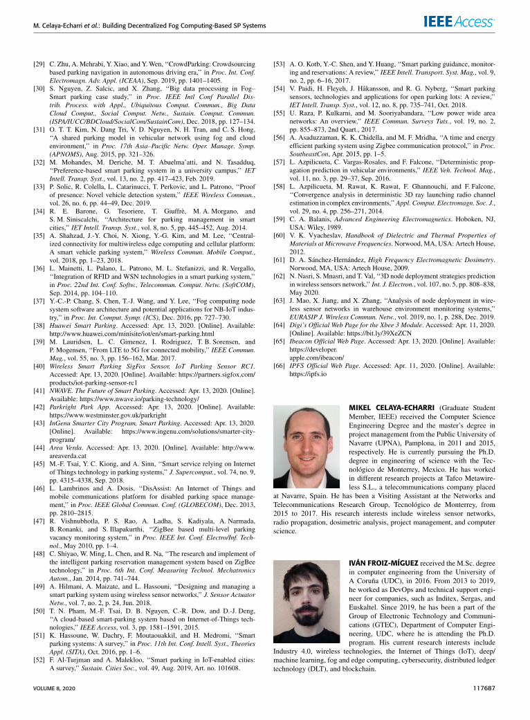
M. Celaya-Echarri et al.: Building Decentralized Fog Computing-Based SP Systems
[29] C. Zhu, A.Mehrabi, Y. Xiao, and Y.Wen, ‘‘CrowdParking: Crowdsourcingbased parking navigation in autonomous driving era,’’ in Proc. Int. Conf.Electromagn. Adv. Appl. (ICEAA), Sep. 2019, pp. 1401–1405.
[30] S. Nguyen, Z. Salcic, and X. Zhang, ‘‘Big data processing in Fog–Smart parking case study,’’ in Proc. IEEE Intl Conf Parallel Dis-trib. Process. with Appl., Ubiquitous Comput. Commun., Big DataCloud Comput., Social Comput. Netw., Sustain. Comput. Commun.(ISPA/IUCC/BDCloud/SocialCom/SustainCom), Dec. 2018, pp. 127–134.
[31] O. T. T. Kim, N. Dang Tri, V. D. Nguyen, N. H. Tran, and C. S. Hong,‘‘A shared parking model in vehicular network using fog and cloudenvironment,’’ in Proc. 17th Asia–Pacific Netw. Oper. Manage. Symp.(APNOMS), Aug. 2015, pp. 321–326.
[32] M. Mohandes, M. Deriche, M. T. Abuelma’atti, and N. Tasadduq,‘‘Preference-based smart parking system in a university campus,’’ IETIntell. Transp. Syst., vol. 13, no. 2, pp. 417–423, Feb. 2019.
[33] P. Solic, R. Colella, L. Catarinucci, T. Perkovic, and L. Patrono, ‘‘Proofof presence: Novel vehicle detection system,’’ IEEE Wireless Commun.,vol. 26, no. 6, pp. 44–49, Dec. 2019.
[34] R. E. Barone, G. Tesoriere, T. Giuffrè, M. A. Morgano, andS. M. Siniscalchi, ‘‘Architecture for parking management in smartcities,’’ IET Intell. Transp. Syst., vol. 8, no. 5, pp. 445–452, Aug. 2014.
[35] A. Shahzad, J.-Y. Choi, N. Xiong, Y.-G. Kim, and M. Lee, ‘‘Central-ized connectivity for multiwireless edge computing and cellular platform:A smart vehicle parking system,’’ Wireless Commun. Mobile Comput.,vol. 2018, pp. 1–23, 2018.
[36] L. Mainetti, L. Palano, L. Patrono, M. L. Stefanizzi, and R. Vergallo,‘‘Integration of RFID and WSN technologies in a smart parking system,’’in Proc. 22nd Int. Conf. Softw., Telecommun. Comput. Netw. (SoftCOM),Sep. 2014, pp. 104–110.
[37] Y.-C.-P. Chang, S. Chen, T.-J. Wang, and Y. Lee, ‘‘Fog computing nodesystem software architecture and potential applications for NB-IoT indus-try,’’ in Proc. Int. Comput. Symp. (ICS), Dec. 2016, pp. 727–730.
[38] Huawei Smart Parking. Accessed: Apr. 13, 2020. [Online]. Available:http://www.huawei.com/minisite/iot/en/smart-parking.html
[39] M. Lauridsen, L. C. Gimenez, I. Rodriguez, T. B. Sorensen, andP. Mogensen, ‘‘From LTE to 5G for connected mobility,’’ IEEE Commun.Mag., vol. 55, no. 3, pp. 156–162, Mar. 2017.
[40] Wireless Smart Parking SigFox Sensor, IoT Parking Sensor RC1.Accessed: Apr. 13, 2020. [Online]. Available: https://partners.sigfox.com/products/iot-parking-sensor-rc1
[41] NWAVE. The Future of Smart Parking. Accessed: Apr. 13, 2020. [Online].Available: https://www.nwave.io/parking-technology/
[42] Parkright Park App. Accessed: Apr. 13, 2020. [Online]. Available:https://www.westminster.gov.uk/parkright
[43] InGenu Smarter City Program, Smart Parking. Accessed: Apr. 13, 2020.[Online]. Available: https://www.ingenu.com/solutions/smarter-city-program/
[44] Area Verda. Accessed: Apr. 13, 2020. [Online]. Available: http://www.areaverda.cat
[45] M.-F. Tsai, Y. C. Kiong, and A. Sinn, ‘‘Smart service relying on Internetof Things technology in parking systems,’’ J. Supercomput., vol. 74, no. 9,pp. 4315–4338, Sep. 2018.
[46] L. Lambrinos and A. Dosis, ‘‘DisAssist: An Internet of Things andmobile communications platform for disabled parking space manage-ment,’’ in Proc. IEEE Global Commun. Conf. (GLOBECOM), Dec. 2013,pp. 2810–2815.
[47] R. Vishnubhotla, P. S. Rao, A. Ladha, S. Kadiyala, A. Narmada,B. Ronanki, and S. Illapakurthi, ‘‘ZigBee based multi-level parkingvacancy monitoring system,’’ in Proc. IEEE Int. Conf. Electro/Inf. Tech-nol., May 2010, pp. 1–4.
[48] C. Shiyao, W. Ming, L. Chen, and R. Na, ‘‘The research and implement ofthe intelligent parking reservation management system based on ZigBeetechnology,’’ in Proc. 6th Int. Conf. Measuring Technol. MechatronicsAutom., Jan. 2014, pp. 741–744.
[49] A. Hilmani, A. Maizate, and L. Hassouni, ‘‘Designing and managing asmart parking system using wireless sensor networks,’’ J. Sensor ActuatorNetw., vol. 7, no. 2, p. 24, Jun. 2018.
[50] T. N. Pham, M.-F. Tsai, D. B. Nguyen, C.-R. Dow, and D.-J. Deng,‘‘A cloud-based smart-parking system based on Internet-of-Things tech-nologies,’’ IEEE Access, vol. 3, pp. 1581–1591, 2015.
[51] K. Hassoune, W. Dachry, F. Moutaouakkil, and H. Medromi, ‘‘Smartparking systems: A survey,’’ in Proc. 11th Int. Conf. Intell. Syst., TheoriesAppl. (SITA), Oct. 2016, pp. 1–6.
[52] F. Al-Turjman and A. Malekloo, ‘‘Smart parking in IoT-enabled cities:A survey,’’ Sustain. Cities Soc., vol. 49, Aug. 2019, Art. no. 101608.
[53] A. O. Kotb, Y.-C. Shen, and Y. Huang, ‘‘Smart parking guidance, monitor-ing and reservations: A review,’’ IEEE Intell. Transport. Syst. Mag., vol. 9,no. 2, pp. 6–16, 2017.
[54] V. Paidi, H. Fleyeh, J. Håkansson, and R. G. Nyberg, ‘‘Smart parkingsensors, technologies and applications for open parking lots: A review,’’IET Intell. Transp. Syst., vol. 12, no. 8, pp. 735–741, Oct. 2018.
[55] U. Raza, P. Kulkarni, and M. Sooriyabandara, ‘‘Low power wide areanetworks: An overview,’’ IEEE Commun. Surveys Tuts., vol. 19, no. 2,pp. 855–873, 2nd Quart., 2017.
[56] A. Asaduzzaman, K. K. Chidella, and M. F. Mridha, ‘‘A time and energyefficient parking system using Zigbee communication protocol,’’ in Proc.SoutheastCon, Apr. 2015, pp. 1–5.
[57] L. Azpilicueta, C. Vargas-Rosales, and F. Falcone, ‘‘Deterministic prop-agation prediction in vehicular environments,’’ IEEE Veh. Technol. Mag.,vol. 11, no. 3, pp. 29–37, Sep. 2016.
[58] L. Azpilicueta, M. Rawat, K. Rawat, F. Ghannouchi, and F. Falcone,‘‘Convergence analysis in deterministic 3D ray launching radio channelestimation in complex environments,’’Appl. Comput. Electromagn. Soc. J.,vol. 29, no. 4, pp. 256–271, 2014.
[59] C. A. Balanis, Advanced Engineering Electromagnetics. Hoboken, NJ,USA: Wiley, 1989.
[60] V. K. Vyacheslav, Handbook of Dielectric and Thermal Properties ofMaterials at Microwave Frequencies. Norwood, MA, USA: Artech House,2012.
[61] D. A. Sánchez-Hernández, High Frequency Electromagnetic Dosimetry.Norwood, MA, USA: Artech House, 2009.
[62] N. Nasri, S. Mnasri, and T. Val, ‘‘3D node deployment strategies predictionin wireless sensors network,’’ Int. J. Electron., vol. 107, no. 5, pp. 808–838,May 2020.
[63] J. Mao, X. Jiang, and X. Zhang, ‘‘Analysis of node deployment in wire-less sensor networks in warehouse environment monitoring systems,’’EURASIP J. Wireless Commun. Netw., vol. 2019, no. 1, p. 288, Dec. 2019.
[64] Digi’s Official Web Page for the Xbee 3 Module. Accessed: Apr. 11, 2020.[Online]. Available: https://bit.ly/39XeZCN
[65] Ibeacon Official Web Page. Accessed: Apr. 13, 2020. [Online]. Available:https://developer.apple.com/ibeacon/
[66] IPFS Official Web Page. Accessed: Apr. 11, 2020. [Online]. Available:https://ipfs.io
MIKEL CELAYA-ECHARRI (Graduate StudentMember, IEEE) received the Computer ScienceEngineering Degree and the master’s degree inproject management from the Public University ofNavarre (UPNA), Pamplona, in 2011 and 2015,respectively. He is currently pursuing the Ph.D.degree in engineering of science with the Tec-nológico de Monterrey, Mexico. He has workedin different research projects at Tafco Metawire-less S.L., a telecommunications company placed
at Navarre, Spain. He has been a Visiting Assistant at the Networks andTelecommunications Research Group, Tecnológico de Monterrey, from2015 to 2017. His research interests include wireless sensor networks,radio propagation, dosimetric analysis, project management, and computerscience.
IVÁN FROIZ-MÍGUEZ received the M.Sc. degreein computer engineering from the University ofA Coruña (UDC), in 2016. From 2013 to 2019,he worked as DevOps and technical support engi-neer for companies, such as Inditex, Sergas, andEuskaltel. Since 2019, he has been a part of theGroup of Electronic Technology and Communi-cations (GTEC), Department of Computer Engi-neering, UDC, where he is attending the Ph.D.program. His current research interests include
Industry 4.0, wireless technologies, the Internet of Things (IoT), deep/machine learning, fog and edge computing, cybersecurity, distributed ledgertechnology (DLT), and blockchain.
VOLUME 8, 2020 117687
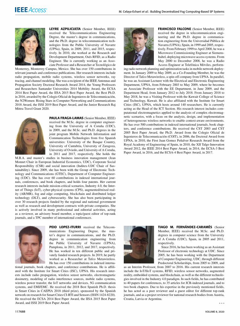
M. Celaya-Echarri et al.: Building Decentralized Fog Computing-Based SP Systems
LEYRE AZPILICUETA (Senior Member, IEEE)received the Telecommunications EngineeringDegree, the master’s degree in communications,and the Ph.D. degree in telecommunication tech-nologies from the Public University of Navarre(UPNa), Spain, in 2009, 2011, and 2015, respec-tively. In 2010, she worked at the Research andDevelopment Department, Osés RFID, as a RadioEngineer. She is currently working as an Asso-ciate Professor and a Researcher at Tecnológico de
Monterrey, Monterrey Campus, Mexico. She has over 150 contributions inrelevant journals and conference publications. Her research interests includeradio propagation, mobile radio systems, wireless sensor networks, raytracing, and channel modeling. She was a recipient of the IEEEAntennas andPropagation Society Doctoral Research Award 2014, the Young Professorsand Researchers Santander Universities 2014 Mobility Award, the ECSA2014 Best Paper Award, the IISA 2015 Best Paper Award, the Best Ph.D.in 2016, awarded by the Colegio Oficial de Ingenieros de Telecomunicación,the N2Women: Rising Stars in Computer Networking and Communications2018 Award, the ISSI 2019 Best Paper Award, and the Junior Research RajMittra Travel Grant 2020.
PAULA FRAGA-LAMAS (Senior Member, IEEE)received the M.Sc. degree in computer engineer-ing from the University of A Coruña (UDC),in 2009, and the M.Sc. and Ph.D. degrees in thejoint program Mobile Network Information andCommunication Technologies from five Spanishuniversities: University of the Basque Country,University of Cantabria, University of Zaragoza,University of Oviedo, and University of A Coruña,in 2011 and 2017, respectively. She holds the
M.B.A. and master’s studies in business innovation management (JeanMonnet Chair in European Industrial Economics, UDC), Corporate SocialResponsibility (CSR) and social innovation (Inditex-UDC Chair of Sus-tainability). Since 2009, she has been with the Group of Electronic Tech-nology and Communications (GTEC), Department of Computer Engineer-ing (UDC). She has over 60 contributions in indexed international jour-nals, conferences, and book chapters, and holds four patents. Her currentresearch interests include mission-critical scenarios, Industry 4.0, the Inter-net of Things (IoT), cyber-physical systems (CPS), augmented/mixed real-ity (AR/MR), fog and edge computing, blockchain and distributed ledgertechnology (DLT), and cybersecurity. She has also been participating inover 30 research projects funded by the regional and national governmentas well as research and development contracts with private companies. Sheis actively involved in many professional and editorial activities, actingas a reviewer, an advisory board member, a topic/guest editor of top-rankjournals, and a TPC member of international conferences.
PEIO LOPEZ-ITURRI received the Telecom-munications Engineering Degree, the mas-ter’s degree in communications, and the Ph.D.degree in communication engineering fromthe Public University of Navarre (UPNA),Pamplona, in 2011, 2012, and 2017, respectively.He has worked in ten different public and pri-vately funded research projects. In 2019, he partlyworked as a Researcher at Tafco Metawireless.He has over 150 contributions in indexed interna-
tional journals, book chapters, and conference contributions. He is affili-ated with the Institute for Smart Cities (ISC), UPNA. His research inter-ests include radio propagation, wireless sensor networks, electromagneticdosimetry, modeling of radio interference sources, mobile radio systems,wireless power transfer, the IoT networks and devices, 5G communicationsystems, and EMI/EMC. He received the 2018 Best Spanish Ph.D. thesisin Smart Cities in CAEPIA 2018 (third prize), sponsored by the Spanishnetwork on research for Smart Cities CI-RTI and Sensors (ISSN 1424-8220).He received the ECSA 2014 Best Paper Award, the IISA 2015 Best PaperAward, and ISSI 2019 Best Paper Award.
FRANCISCO FALCONE (Senior Member, IEEE)received the degree in telecommunication engi-neering and the Ph.D. degree in communica-tion engineering from the Universidad Pública deNavarra (UPNA), Spain, in 1999 and 2005, respec-tively. From February 1999 to April 2000, he was aMicrowave Commissioning Engineer at Siemens-Italtel, deployingmicrowave access systems. FromMay 2000 to December 2008, he was a RadioAccess Engineer at Telefónica Móviles, perform-
ing radio network planning and optimization tasks inmobile network deploy-ment. In January 2009 to May 2009, as a Co-Founding Member, he was theDirector of Tafco Metawireless, a spin-off company from UPNA. In parallel,he was an Assistant Lecturer with the Electrical and Electronic EngineeringDepartment, UPNA, from February 2003 to May 2009, where he becomesan Associate Professor with the EE Department, in June 2009, and theDepartment Head, from January 2012 to July 2018. From January 2018 toMay 2018, he was a Visiting Professor with the Kuwait College of Scienceand Technology, Kuwait. He is also affiliated with the Institute for SmartCities (ISC), UPNA, which hosts around 140 researchers. He is currentlyacting as the Head of the ICT Section. His research interest includes com-putational electromagnetics applied to the analysis of complex electromag-netic scenarios, with a focus on the analysis, design, and implementationof heterogeneous wireless networks to enable context-aware environments.He has over 500 contributions in indexed international journals, book chap-ters, and conference contributions. He received the CST 2003 and CST2005 Best Paper Award, the Ph.D. Award from the Colegio Oficial deIngenieros de Telecomunicación (COIT), in 2006, the Doctoral Award fromUPNA, in 2010, the First Juan Gomez Peñalver Research Award from theRoyal Academy of Engineering of Spain, in 2010, the XII Talgo InnovationAward 2012, the IEEE 2014 Best Paper Award, in 2014, the ECSA-3 BestPaper Award, in 2016, and the ECSA-4 Best Paper Award, in 2017.
TIAGO M. FERNÁNDEZ-CARAMÉS (SeniorMember, IEEE) received the M.Sc. and Ph.D.degrees in computer science from the Universityof A Coruña (UDC), Spain, in 2005 and 2011,respectively.
Since 2016, he has been working as an AssistantProfessor of electronic technology at UDC. Since2005, he has been working with the Departmentof Computer Engineering, UDC, through differentPredoctoral Scholarships, from 2005 to 2009, and
as an Interim Professor, from 2007 to 2016. His current research interestsinclude the IoT/IIoT systems, RFID, wireless sensor networks, augmentedreality, embedded systems, and blockchain, as well as the different technolo-gies involved in the Industry 4.0 paradigm. In such fields, he has contributedto 40 papers for conferences, to 35 articles for JCR-indexed journals, and totwo book chapters. Due to his expertise in the previously mentioned fields,he has acted as a peer reviewer and a guest editor for different top-rankjournals, and as a project reviewer for national research bodies from Austria,Croatia, Latvia or Argentina.
117688 VOLUME 8, 2020


