Embed Size (px)
Citation preview
- -
-
Bunya Street Eagle Farm SPS SP010 Pump Instrumentation OM Manual Volume 6B
Q-Pulse Id TMS640 Active 29/01/2014 Page 1 of 376
BRISBANE CITY COUNCIL
DEPARTMENT OF WATER SUPPLY AND SEWAGE
PUMPWELL NO. .1
EAGLE FARM. PUMP STATION
OPERATION AND MAINTENANCE INSTRUCTION MANUAL
WEIR ENGINEERING JOB NO. 15140 BCC CONTRACT NO. S.20/95/963
WEIR ENGINEERING PTY LTD A.C.N. 000 373 339
Envirotech
weir
MANUAL PREPARED BY
WEIR ENGINEERING PTY LTD
15 GINDURRA ROAD SOMERSBY NSW 2250
TELEPHONE: (02) 4349 2999 FACSIMILE: (02) 4349 2801
Bunya Street Eagle Farm SPS SP010 Pump Instrumentation OM Manual Volume 6B
Q-Pulse Id TMS640 Active 29/01/2014 Page 2 of 376
BRISBANE CITY COUNCIL Dept. Water Supply and Sewage Pumpwell No 1, Eagle Farm Pump Station
BCC Contract No S20/95/96 System Instrumentation
Operation and Maintenance Manual
Section 4 Installation and Pre-Commissioning
4.1 Installation
The installation procedures for specific transducers and Bent ly Nevada modules are generally covered in the relevant part of Section 2 of this manual.
4.2 3300 System Installation
The following publication entitled 3300 System Installation Instructions (Part No 80172-01 Rev L) has been prepared by Bent ly Nevada for plant personnel who operate and maintain the system. It provides detailed information on the installation of the Bent ly Nevada 3300 rack mounted monitoring system.
The following sections are included:
4.2.1 Receiving Inspection
4.2.2 Handling and Storage Considerations
4.2.3 Rack Assembly Options
4.2.4 Rack Installation (Panel Mount)
4.2.5 Rack Installation (19-inch EM)
4.2.6 Panel Cutout Dimensions
4.2.7 Weatherproof Housing Installation
4.2.8 Power Supply Installation
4.2.9 System Monitor Installation
4.2.10 Monitor Installation (Typical)
4.2.11 Power Input Module
4.2.12 Signal Input Relay Module
4.2.13 Alert Relay Actuation Circuits
15140/Inst Man/BRH Issue 1 29-Apr-98 Page 4-1
Bunya Street Eagle Farm SPS SP010 Pump Instrumentation OM Manual Volume 6B
Q-Pulse Id TMS640 Active 29/01/2014 Page 3 of 376

BRISBANE CITY COUNCIL Dept. Water Supply and Sewage Pumpwell No 1, Eagle Farm Pump Station
BCC Contract No S20/95/96 System Instrumentation
Operation and Maintenance Manual
4.2.14 Danger Relay Actuation Circuits
4.2.15 Field Grounding Technique
4.2.16 Index
4.2. 17 Appendix
15140/Inst Man/BRH Issue 1 29-Apr-98 Page 4-2
Bunya Street Eagle Farm SPS SP010 Pump Instrumentation OM Manual Volume 6B
Q-Pulse Id TMS640 Active 29/01/2014 Page 4 of 376
3300 SYSTEM INSTALLATION INSTRUCTIONS
BENTLY NEVADA
MADE IN U.S A.
PART NO. 80172-01 REVISION L.,
FEBURARY 1994
0 a
adage a a
Bunya Street Eagle Farm SPS SP010 Pump Instrumentation OM Manual Volume 6B
Q-Pulse Id TMS640 Active 29/01/2014 Page 5 of 376
80172-01 Installation Instructions
NOTICE
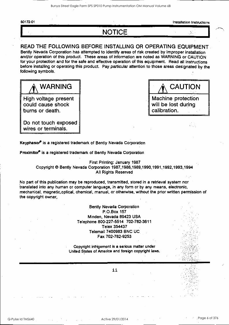
READ THE FOLLOWING BEFORE INSTALLING OR OPERATING EQUIPMENT Bent ly Nevada Corporation has attempted to identify areas of risk created by improper installation and/or operation of this product. These areas of information are noted as WARNING or CAUTION for your protection and for the safe and effective operation of this equipment. Read all instructions before installing or operating this product. Pay particular attention to those areas designated by the following symbols.
*WARNING High voltage present could cause shock burns or death.
Do not touch exposed wires or terminals.
Keyphasoe is a registered trademark of Bent ly Nevada Corporation
Proximitoe is a registered trademark of Bent ly Nevada Corporation
CAUTION
Machine protection will be lost during calibration.
First Printing: January 1987 Copyright © Bent ly Nevada Corporation 1987,1988,1989,1990,1991,1992,1993,1994
All Rights Reserved
No part of this publication may be reproduced, transmitted, stored in a retrieval system nor translated into any human or computer language, in any form or by any means, electronic, mechanical, magnetic,optical, chemical, manual, or otherwise, without the prior written permission of the copyright owner,
Bent ly Nevada Corporation P.O.Box 157
Minden, Nevada 89423 USA Telephone 800-227-5514 702-782-3611
Telex 354437 Telemail 7400983 BNC UC
Fax 702-782-9253
Copyright infrigement is a serious matter under United States of America and foreign copyright laws.
Bunya Street Eagle Farm SPS SP010 Pump Instrumentation OM Manual Volume 6B
Q-Pulse Id TMS640 Active 29/01/2014 Page 6 of 376
Installation Instructions 80172-01
FOREWORD
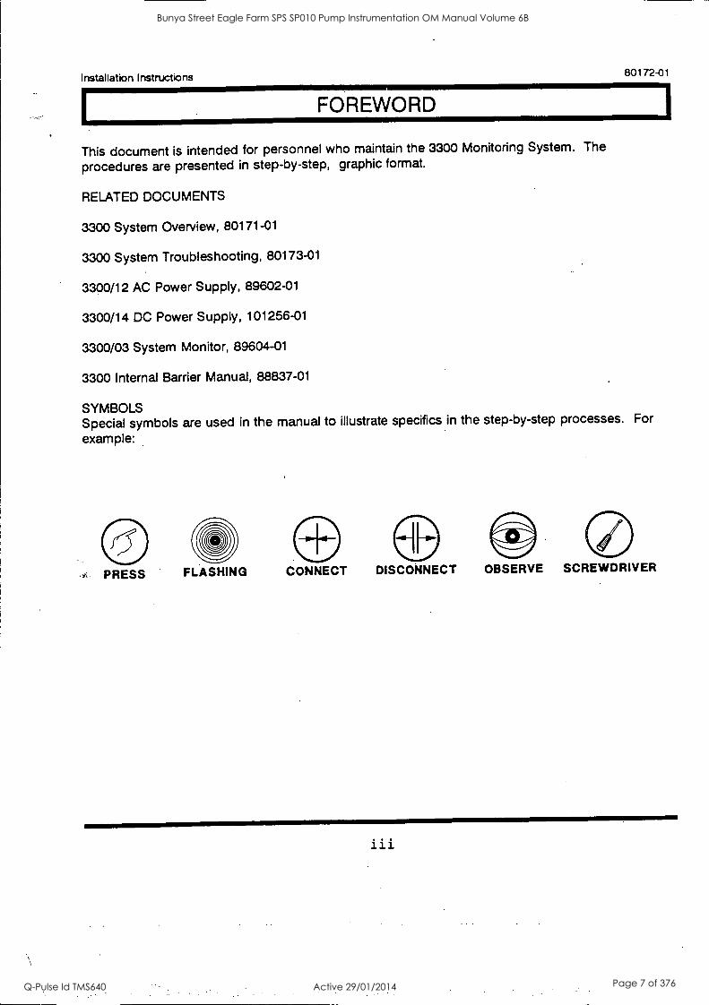
This document is intended for personnel who maintain the 3300 Monitoring System. The
procedures are presented in step-by-step, graphic format.
RELATED DOCUMENTS
3300 System Overview, 80171-01
3300 System Troubleshooting, 80173-01
3300/12 AC Power Supply, 89602-01
3300/14 DC Power Supply, 101256-01
3300/03 System Monitor, 89604-01
3300 Internal Barrier Manual, 88837-01
SYMBOLS Special symbols are used in the manual to illustrate specifics in the step-by-step processes. For
example:
4=- PRESS FLASHING CONNECT DISCONNECT OBSERVE SCREWDRIVER
iii
Bunya Street Eagle Farm SPS SP010 Pump Instrumentation OM Manual Volume 6B
Q-Pulse Id TMS640 Active 29/01/2014 Page 7 of 376

80172-01 Installation Instructions
iv
Bunya Street Eagle Farm SPS SP010 Pump Instrumentation OM Manual Volume 6B
Q-Pulse Id TMS640 Active 29/01/2014 Page 8 of 376
Installation Instructions 80172-01
CONTENTS
SECTION TITLE PAGE
1 Receiving Inspection 1
2 Handling & Storing Considerations 2
3 Rack Assembly Options 3
4 Rack Installation (Panel Mount) 4
5 Rack Installation (19-inch EIA) 5
6 Panel Cutout Dimensions 6
7 Weatherproof Housing Installation 7
8 Power Supply Installation 13
9 System Monitor Installation 15
10 Monitor Installation (Typical) 16
11 Power Input Module 17
12 Signal Input Relay Modules 18
13 Alert Relay Actuation Circuits 21
14 Danger Relay Actuation Circuits 23
15 Field Grounding Technique 25
16 Index 26
17 Appendix 27
Bunya Street Eagle Farm SPS SP010 Pump Instrumentation OM Manual Volume 6B
Q-Pulse Id TMS640 Active 29/01/2014 Page 9 of 376

80172-01 Installation Instructions
vi
Bunya Street Eagle Farm SPS SP010 Pump Instrumentation OM Manual Volume 6B
Q-Pulse Id TMS640 Active 29/01/2014 Page 10 of 376
=1111
Installation Instructions 80172-01
I RECEIVING INSPECTION
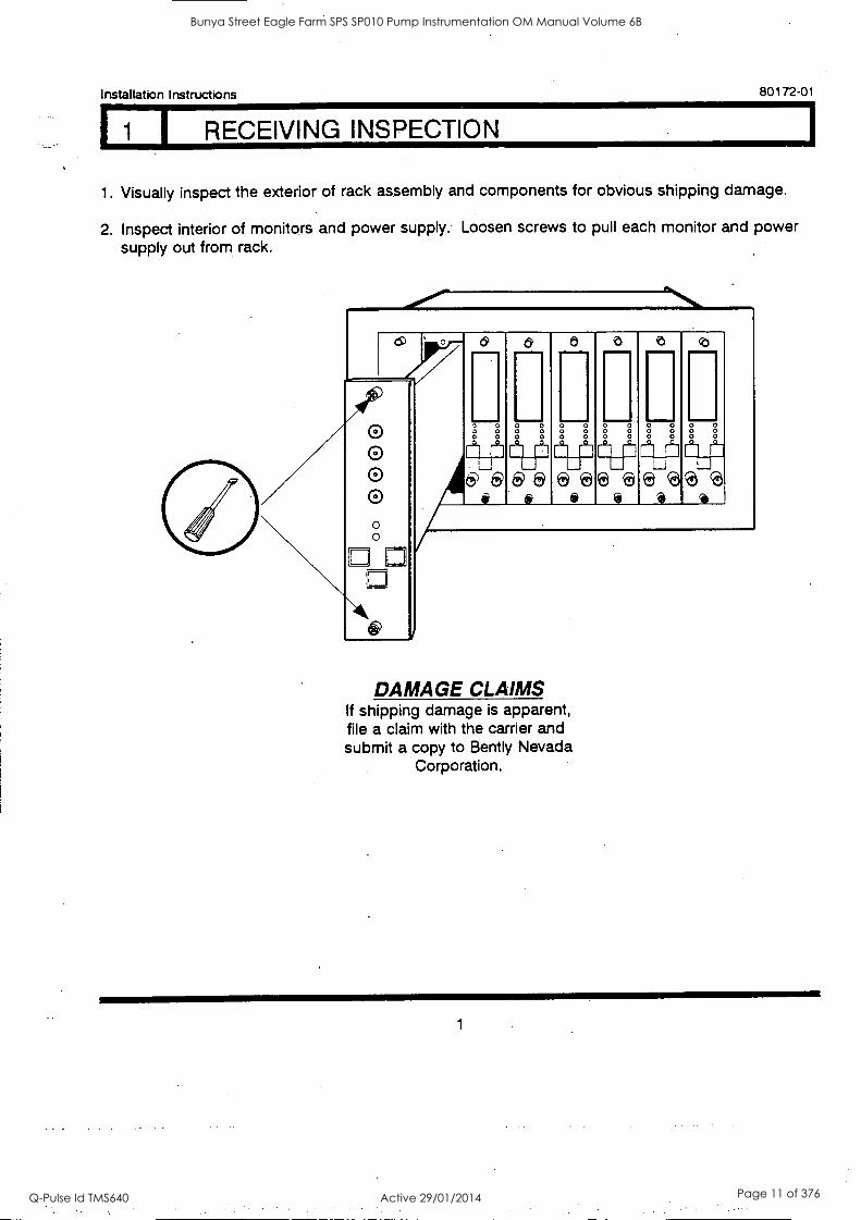
1. Visually inspect the exterior of rack assembly and components for obvious shipping damage.
2. Inspect interior of monitors and power supply. Loosen screws to pull each monitor and power supply out from rack.
O O O 0 0
1.1
1121 8 9 3
V] 0 9 3
O
DAMAGE CLAIMS If shipping damage is apparent, file a claim with the carrier and submit a copy to Bent ly Nevada
Corporation.
1
Bunya Street Eagle Farm SPS SP010 Pump Instrumentation OM Manual Volume 6B
Q-Pulse Id TMS640 Active 29/01/2014 Page 11 of 376
80172-01 Installation Instructions
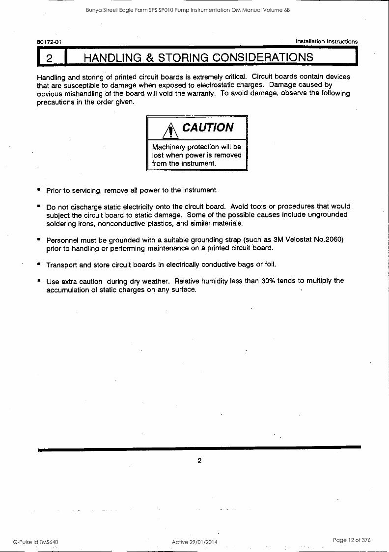
2 1 HANDLING .& STORING CONSIDERATIONS
Handling and storing of printed circuit boards is extremely critical. Circuit boards contain devices that are susceptible to damage when exposed to electrostatic charges. Damage caused by obvious mishandling of the board will void the warranty. To avoid damage, observe the following precautions in the order given.
*CAUTION Machinery protection will be lost when power is removed from the instrument.
Prior to servicing, remove all power to the instrument.
Do not discharge static electricity onto the circuit board. Avoid tools or procedures that would subject the circuit board to static damage. Some of the possible causes include ungrounded soldering irons, nonconductive plastics, and similar materials.
Personnel must be grounded with a suitable grounding strap (such as 3M Velostat No.2060) prior to handling or performing maintenance on a printed circuit board.
Transport and store circuit boards in electrically conductive bags or foil.
Use extra caution during dry weather. Relative humidity less than 30% tends to multiply the accumulation of static charges on any surface.
2
Bunya Street Eagle Farm SPS SP010 Pump Instrumentation OM Manual Volume 6B
Q-Pulse Id TMS640 Active 29/01/2014 Page 12 of 376
Installation Instructions 80172-01
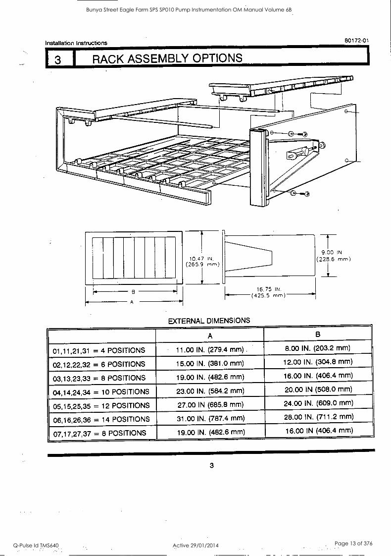
I 3 I RACK ASSEMBLY OPTIONS
B
A
10.47 IN
(265.9 mm
EXTERNAL DIMENSIONS
16.75 IN. (425.5 mm)
9.00 IN
(225.6 mm)
A B
01,11,21,31 = 4 POSITIONS 11.00 IN. (279.4 mm) . 8.00 IN. (203.2 mm)
02,12,22,32 = 6 POSITIONS 15.00 IN. (381.0 mm) 12.00 IN. (304.8 mm)
03,13,23,33 = 8 POSITIONS 19.00 IN. (482.6 mm) 16.00 IN. (406.4 mm)
04,14,24,34 = 10 POSITIONS 23.00 IN. (584.2 mm) 20.00 IN (508.0 mm)
05,15,25,35 = 12 POSITIONS 27.00 IN (685.8 mm) 24.00 IN. (609.0 mm)
06,16,26,36 = 14 POSITIONS 31.00 IN. (787.4 mm) 28.00 IN. (711.2 mm)
07,17,27,37 = 8 POSITIONS 19.00 IN. (482.6 mm) 16.00 IN (406.4 mm)
3
Bunya Street Eagle Farm SPS SP010 Pump Instrumentation OM Manual Volume 6B
Q-Pulse Id TMS640 Active 29/01/2014 Page 13 of 376
80172-01 Installation I nstruct ions
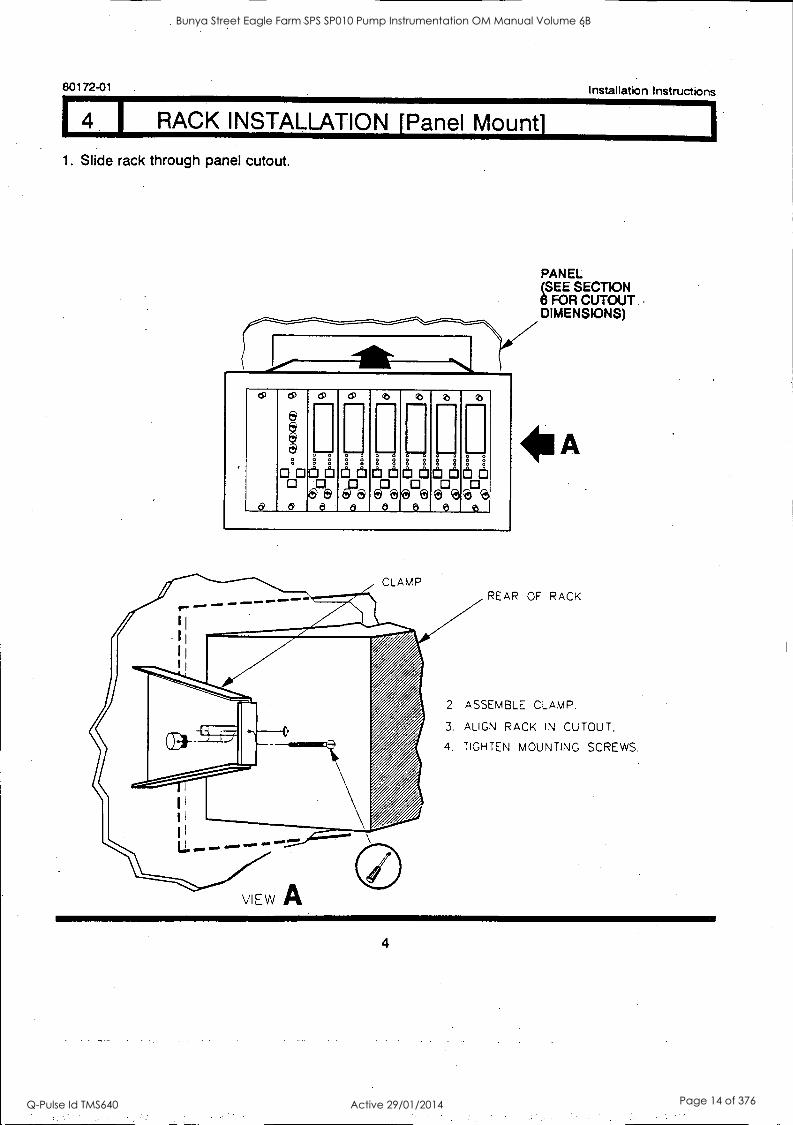
I RACK INSTALLATION [Panel Mount]
1. Slide rack through panel cutout.
0
as
0
g
S 00ifitilidd 0
0 --,
8
&Da 6
m
g 2,
EP& 5
(PeeL:10
0 - S 3 tilt
o
t
SgSgg CaittlOtt
e
0 - 0°0
e
0
1:14 i).
0
PANEL (SEE SECTION 6 FOR CUTOUT .
DIMENSIONS)
REAR OF RACK
2 ASSEMBLE CLAMP.
3. ALIGN RACK IN CUTOUT.
4, TIGHTEN MOUNTING SCREWS.
4
Bunya Street Eagle Farm SPS SP010 Pump Instrumentation OM Manual Volume 6B
Q-Pulse Id TMS640 Active 29/01/2014 Page 14 of 376
Installation Instructions 80172-01
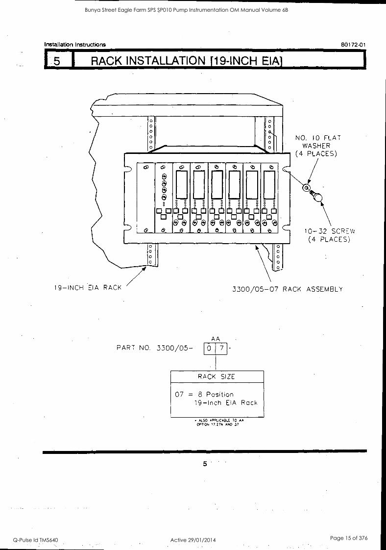
I RACK INSTALLATION [19-INCH
0 0 0
d
do
a a e
sig. is
d
o) CP 2 b
[1) ' 0 aaeaa 6
c''i '' 0 6
e
88 0
.1 Jill a
5
11111 a 0 Ei
5
ji (6 Ce
0
0 0 0
19-INCH EIA RACK
PART NO. 3300/05- AA
0 7
o
0
NO. 10 FLAT WASHER
(4 PLACES)
10-32 SCREW (4 PLACES)
3300/05-07 RACK ASSEMBLY
RACK SIZE
07 = 8 Position
19 -Inch EIA Rack
ALSO APPLICABLE 70 AA OPTION 17.27N ANO 37
5
Bunya Street Eagle Farm SPS SP010 Pump Instrumentation OM Manual Volume 6B
Q-Pulse Id TMS640 Active 29/01/2014 Page 15 of 376
80172-01 Installation Instructions
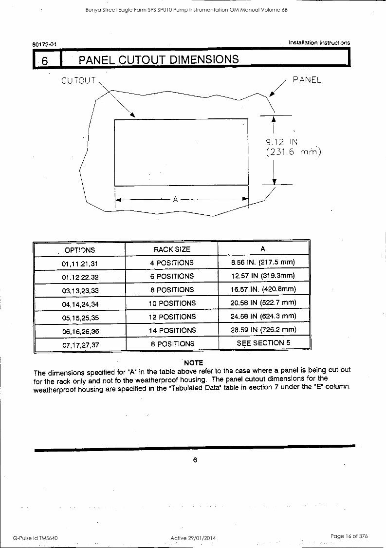
I PANEL CUTOUT DIMENSIONS.
PANEL
9.12 IN
(231.6 mm)
OPTIONS RACK SIZE A
01,11,21,31 4 POSITIONS 8.56 IN. (217.5 mm)
01.12.22.32 6 POSITIONS 12.57 IN (319.3mm)
03,13,23,33 8 POSITIONS 16.57 IN. (420.8mm)
04,14,24,34 10 POSITIONS 20.58 IN (522.7 mm)
05,15,25,35 12 POSITIONS 24.58 IN (624.3 mm)
06,16,26,36 14 POSITIONS 28.59 IN (726.2 mm)
07,17,27,37 8 POSITIONS SEE SECTION 5
NOTE
The dimensions specified for "A" in the table above refer to the case where a panel is being cut out
for the rack only and not fo the weatherproof housing. The panel cutout dimensions for the
weatherproof housing are specified in the "Tabulated Data" table in section 7 under the "E" column.
6
Bunya Street Eagle Farm SPS SP010 Pump Instrumentation OM Manual Volume 6B
Q-Pulse Id TMS640 Active 29/01/2014 Page 16 of 376

Installation Instructions 80172-01
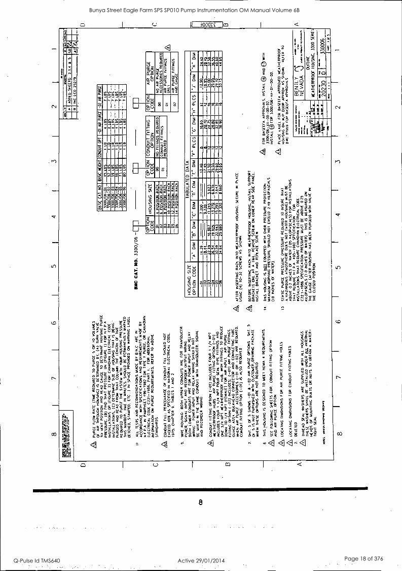
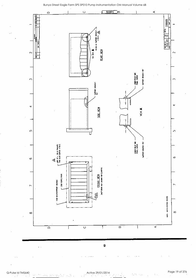
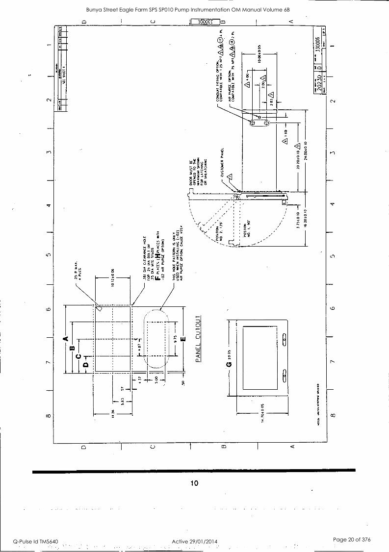
(7 I WEATHERPROOF HOUSING INSTALLATION
The next 5 pages contain the weatherproof housing installation drawing, 330006.
7
Bunya Street Eagle Farm SPS SP010 Pump Instrumentation OM Manual Volume 6B
Q-Pulse Id TMS640 Active 29/01/2014 Page 17 of 376
8 7
6 5
A P
UR
GE
F
LOW
R
AT
E
(TIM
E
RE
OU
IRE
D
10
PU
RG
E
5 O
R
10
VO
LUM
ES
OF
A
IR
TH
RO
UG
H
HO
US
ING
) IS
D
ET
ER
MIN
ED
B
Y:
(A)
TU
RN
V
ALV
E
TO
V
EN
T
PO
SIT
ION
A
ND
R
EA
D
CA
UC
E
TO
D
ET
ER
MIN
E
HO
US
ING
P
UR
GE
P
RE
SS
UR
E.
(8)
FIN
D
TH
AT
P
RE
SS
UR
E
ON
(F
IGU
RE
I)
FO
R N
EP
A
INS
TA
LLA
TIO
NS
O
R ((
WA
RE
2)
F
OR
C
AN
AD
IAN
E
LEC
TR
ICA
L C
OD
E
INS
TA
LLA
TIO
NS
. (C
) D
ET
ER
MIN
E
SIZ
E
OF
H
OU
SIN
G
TH
AT
IS
B
EIN
G'
PU
RG
ED
A
ND
R
EA
D
FR
OM
T
HA
T
CO
LUM
N
TH
E
LEN
GT
H
OF
T
IME
RE
QU
IRE
D
TO
P
UR
GE
T
HE
S
YS
TE
M
WIT
H
YO
UR
H
OU
SIN
G
PR
ES
SU
RE
T
HIS
N
UM
BE
R.
TIM
E
IN
MIN
UT
ES
. S
HO
ULD
B
E
PE
RM
AN
EN
TLY
M
AR
KE
D
(ET
CH
ED
. S
TA
MP
ED
. E
TC
.. )
IN
SP
AC
E
PR
OV
IDE
D O
N
WA
RN
ING
LA
BE
L
II A
LL
TE
ST
S
AN
D
RE
CO
MM
EN
DA
TIO
NS
M
AD
E
BY
B
N.C
. A
RE
IN
AC
CO
RD
AN
CE
W
ITH
S
PE
CIF
ICA
TIO
NS
A
ND
R
EO
uIR
EM
EN
TS
MA
DE
B
Y
N,F
.P.A
. IN
P
AM
PH
LET
49
6-19
82
FO
R
TY
PE
Y
P
UR
GE
. O
R
CA
NA
DIA
N
ELE
CT
RIC
AL
CO
DE
C
22I-
1986
. P
AR
T
1.
FO
R
AD
DIT
ION
AL
INF
OR
MA
TIO
N
ON
P
UR
GE
R
EQ
UIR
EM
EN
TS
. R
EF
ER
10
A
BO
VE
ST
AN
DA
RD
S.
CO
ND
UIT
FIL
L:
PE
RC
EN
TA
GE
O
F
CO
ND
UIT
F
ILL
SH
OU
LD N
OT
EX
CE
ED
40
Z
AS
S
PE
CIF
IED
IN
N
AT
ION
AL
ELE
CT
RIC
AL
CO
DE
.
1975
. C
HA
PT
ER
9.
T
AB
LES
1
AN
D
2
9.
TA
RE
R
OU
TIN
G:
BO
TH
U
PP
ER
C
ON
DU
ITS
A
RE
F
OR
T
RA
NS
DU
CE
R
PO
WE
R.
SIG
NA
L IN
PU
T
AN
D
RE
CO
RD
ER
O
UT
PU
T
WR
ING
, B
OT
H
LOW
ER
CO
ND
UIT
S
AR
E
FO
R
PO
WE
R
INP
UT
A
ND
R
ELA
Y
WIR
ING
. P
OW
ER
IN
PU
T
AN
D
RE
LAY
T
AR
ING
S
HO
ULD
N
OT
BE
M
IXE
D
IN
TH
E
SA
ME
C
ON
DU
IT
WIT
H
TR
AN
SD
UC
ER
. S
IGN
AL
AN
D
RE
CO
RD
ER
W
IRIN
G.
A CO
ND
UIT
F
ITT
ING
O
PT
ION
(-
01)
INC
LUD
ES
F
OU
R 1
1/
4 N
PT
WE
AT
HE
RP
RO
OF
HU
BS
. A
IR
PU
RG
E
FIT
TIN
G
OP
TIO
N (-
01)
INC
LUD
ES
F
OU
R
1 1/
4 N
PT
P
OU
R
SE
AL
TY
PE
F
ITT
ING
S
AN
D
ON
E
3/4
NP
I W
EA
TH
ER
PR
OO
F
HU
B.
WIT
H
FIT
TIN
GS
10
R
ED
UC
E
DO
WN
T
O
1/4
NP
T
(FE
MA
LE)
FO
R
AIR
IN
PU
T.
AIR
P
UR
GE
(MIN
G
OP
TIO
N (
-02)
IN
CLU
DE
S:
(-01
) A
IR
PU
RG
E F
ITT
ING
S.
WA
GE
A
SS
Y.
BU
LKH
EA
D C
ON
NE
CT
OR
A
ND
C
ON
NE
CT
ING
T
UB
E.
WH
EN
A
IR
PU
RG
E
AC
CE
SS
OR
IES
(-
01
OR
-0
2)
AR
E
RE
QU
IRE
D.
CO
ND
UIT
F
ITT
ING
O
PT
ION
(-
01)
IS
ALS
O
RE
QU
IRE
D
7.
SH
T.
5 O
F
5 S
HO
WS
-0
1 &
-0
2 A
IR
PU
RG
E
OP
TIO
NS
S
W.
5
OF
5
IS
NO
T
FU
RN
ISH
ED
W
ITH
C
US
TO
ME
R.D
RA
WIN
C
PA
CK
AG
E
WH
EN
T
HE
SE
O
PT
ION
S
AR
E
NO
T
RE
QU
IRE
D
6 T
HIS
H
OU
SIN
G
IS
DE
SIG
NE
D
10
ME
ET
N
EM
A
4 R
EQ
UIR
EM
EN
TS
.
A SE
E
FO
LLO
WIN
G
SH
EE
TS
F
OR
. C
ON
DU
IT
FIT
TIN
G
OP
TIO
N
AN
D
AIR
P
UR
GE
O
PT
ION
A LO
CA
TIN
G
DIM
EN
SIO
NS
F
OR
A
IR
PU
RG
E
FIT
TIN
G
HO
LES
LOC
AT
ING
D
IME
NS
ION
S
FO
R
CO
ND
UIT
F
ITT
ING
H
OLE
S.
2.
DE
LET
ED
.
A TH
RE
AD
S
EA
L W
AS
HE
RS
A
RE
S
UP
PLI
ED
M
TH
A
LL
HO
US
ING
S
TH
ES
E
WA
SH
ER
S
SH
ALL
O
E
INS
TA
LLE
D U
ND
ER
6m
. IN
TE
RN
AL
HE
AD
S
OF
M
OU
NT
ING
W
ITS
O
R
NU
TS
T
O
OB
TA
IN
A
WA
TE
R-
TIG
HT
S
EA
L.
tOal
ft 01
40.1
1
j 4
2
ON
C C
AT
. N
O.
3300
/06
-
6.11
AD
DE
D
SH
EE
TS
: 2.
3.4
J.
5 S
S ft
,
INC
E
CO
25
279
A.F
41;
BA
SIC
C
AT
N
O
BA
SIC
C
CM
C
CN
Dul
l O
PT
-0
1 A
S
PuR
CF
-0
2 A
R
PU
RG
E
3300
06
-01
45 L
BS
Li
ll 4
LBS
7
LOS
33
00
06-0
2 52
LB
S
I 4
LBS
7
LEIS
3300
06
-03
59
LBS
1
LB
4 LB
S
7 LE
TS
3300
06
-04
66
LBS
I
LB
4 L§
7 te
r 33
00/0
6 -0
5 73
IB
S
I LE
T
4 16
5 7
LBS
3300
/06
-06
BO
IB
S
1 LB
4
LBS
7
LBS
OP
TIO
N
CO
DE
H
OU
SIN
G
SIZ
E
01
1 P
OS
ITIO
N
RA
CK
02
6
PO
SIT
ION
R
AC
K
. 4
I It,
R
04
10
PO
SIT
ION
R
AC
K
14
Pt
IT II
R
A
K
L _J
OP
IO
N
CO
DE
C
ON
DU
IT
FIT
TIN
G
OP
TIO
N
00
NO
F
ITT
ING
S
RE
WIR
ED
01
CO
ND
UIT
F
ITT
ING
S
RE
QU
IRE
D
OP
IO
N
CO
DE
A
IR
PU
RG
E
OP
TIO
N
00
NO
A
IR
PU
RG
E
AC
CE
SS
OR
IES
R
EQ
UIR
ED
01
02
AIR
P
UR
GE
F
ITT
ING
S
ON
LY
Qfi
AIR
P
UR
GE
F
ITT
ING
S
AN
D
GA
UG
E
HO
US
ING
S
IZE
OP
TIO
N
CO
DE
TA
BU
LAT
ED
D
A T
A
' A
'
DIM
"E
r D
IM
"C"
DIM
"D
D
IM
'E"
DIM
"T
" P
LCS
"G
" D
IM
"J"
DIM
"K
" D
IM
-01
-02
18.4
4 7
Id
9.22
0 4
17.4
5 70
24
4()
_ 20
.42.
_ 32
50
12 9
0
-03
22
49
16 B
1)7
IT
215 IN
I 27
.50
20
24
75
12
16
16 9
5 21
.00
-64
-05
4
30.5
9 1 72
.915
I
7.
,mis
n 29
60
. I 16
50
5 36
55
29.1
0 40
.60
-06
1.6
Mg=
33
15
44
AF
TE
R
INS
ER
TIN
G
RA
CK
IN
TO
W
EA
TH
ER
PR
OO
F H
OU
SIN
G.
SE
CU
RE
IN
P
LAC
E
US
ING
(4
) 10
-32
SC
RE
WS
A
S
SH
Ow
N.
BE
FO
RE
IN
SE
RT
ING
R
AC
K
INT
O
WE
AT
HE
RP
RO
OF
HO
US
ING
. IN
ST
ALL
S
UP
PO
RT
B
RA
CK
ET
S
ON
E
AT
A
T
IME
. R
EM
OV
E
SC
RE
W
ON
LO
NE
R
RE
AR
S
IDE
P
AN
EL.
IN
ST
ALL
B
RA
CK
ET
A
ND
R
EP
LAC
E SCREW,
14.
TH
IS
HO
US
ING
IS
N
M E
QU
IPP
ED
W
ITH
O
VE
R
PR
ES
SU
RE
P
RO
TE
CT
ION
. M
AX
IMU
M
WO
RK
ING
P
RE
SS
UR
E
SH
OU
LD
NO
T
EX
CE
ED
2.
49
KIL
OP
AS
CA
LS
(10
INC
HE
S
OF
W
AT
ER
).
13
ST
AT
IC
PU
RG
E
PR
ES
SU
RE
(P
RE
SS
UR
E
RE
WIR
ED
T
O
INS
UR
E
TH
AT
A
HA
ZA
RD
OU
S
AT
MO
SP
HE
RE
D
OE
S
NO
T
EN
TE
R
HO
US
ING
) 41
151
BE
AB
OV
E 02
IN
CH
ES
OF
W
AT
ER
(
05 K
ILO
PA
SC
ALS
) F
OR
IN
S1A
LLA
TIO
NS
T
HA
T
RE
QU
IRE
N
EP
A
495-
1982
S
PE
CIF
ICA
TIO
N
FO
R
INS
TA
LLA
TIO
NS
TH
AT
R
EQ
UIR
E
CA
NA
DIA
N
ELE
CT
RIC
AL
CO
DE
C
22.1
-198
6 S
PE
CIF
ICA
TIO
N
PR
ES
SU
RE
MU
ST
B
E
AB
OV
E
0.25
K
it O
PA
SC
ALS
(1
0 IN
CH
ES
O
F
WA
TE
R)
TH
IS
IS
ME
AS
UR
ED
O
N
TH
( G
AU
GE
(A
FT
ER
H
OU
SIN
G H
AS
B
EE
N
PU
RG
ED
) W
ITH
V
ALV
E
IN
TH
E
CLO
SE
D
PO
SIT
ION
A F
OR
B
AS
EE
FA
A
PP
RO
VA
LS.
INS
TA
LL 0
AN
D 0
VAIN
)300
/067
43- 0
0- 0
0-02
. IN
ST
ALL
16
F
OR
33
00/0
6- xX
- 01
- 00-
02.
A P
LAC
E
LAB
EL
FO
R
BA
SE
EF
A
AP
PR
OV
ED
W
EA
TH
ER
PR
OO
F
HO
ITS
ING
O
N
w/P
DO
OR
A
PP
RO
X
AS
S
HO
WN
R
EF
ER
T
O
DW
G
8196
9 F
OR
B
AS
ELF
A
AP
PR
OV
ALS
Mal
e V
IN,M
os
non.
. m
.o.&
B
EN
TLY
-
NE
VA
DA
00
RIN
E
WE
AT
HE
RP
RO
OF
HO
US
ING
. 33
00
SE
RIE
UV
OL.
.._T
a
2023
0 1
- D
1
3300
06 to
5
8 7
I 6
5 I
4 3
2 I
1
D C
CD
O
0,1
Bunya Street Eagle Farm SPS SP010 Pump Instrumentation OM Manual Volume 6B
Q-Pulse Id TMS640 Active 29/01/2014 Page 18 of 376
6
Cr)
I 0
In
CAI 330005 it (-)
Bunya Street Eagle Farm SPS SP010 Pump Instrumentation OM Manual Volume 6B
Q-Pulse Id TMS640 Active 29/01/2014 Page 19 of 376
8 I
7 6
5 1
4 I
3 I
2 I
1
Ni--
- .2
81
DIA
C
LEA
RA
NC
E H
al
FO
R
25
DIA
B
OLT
O
R
.75
DIA
T
AM
S
TU
DS
F P
LAC
ES
(H
PLA
CE
S W
ITH
-02
AIR
P
UR
GE
O
PT
ION
)
PA
NE
L C
UT
OU
T
G
1005
14.7
0)00
5
Oltl
a 11
091.
51
TH
IS
HO
LE
PA
TT
ER
N
IS
ON
LY
US
ED
m
aE11
IN
ST
ALL
ING
( -
07)
AIR
P
UR
GE
O
PT
ION
. G
AU
GE
A
SS
Y
:PO
Sin
oN
NO
7.
13
5'
P05
9011
N
O.
I, 90
'
3 75
10 1
0
16 21
310.
10
--r-
L3 D
OO
R
MU
ST
B
E
OP
INE
D
TO
T
HE
M
AX
IMU
M
SH
OW
N
FO
R
LAT
CH
ING
O
R
UN
LAT
CH
ING
CU
ST
OM
ER
PA
NE
L
MIR
I 60
--
70 2
010.
10
24.0
010.
10
101.
10
.1
SE
T 9t
El
I
O
8
CO
ND
UIT
M
ING
OP
TIO
N,
CO
MP
AT
OT
LE
MT
H
1 25
N
PT
ZLA
04 P
T.
B
AIR
P
UR
GE
O
PT
ION
. C
OM
PA
TIB
LE
m11
4 75
N
PT
&A
,® 2
Pt
,&
1
2
4 00
.00A
1
283&
1000
)005
NM
US
.
2023
0 0
I I
- 3300
06
mp
s
8 I
7 6
5 4
3 2
1
A
Bunya Street Eagle Farm SPS SP010 Pump Instrumentation OM Manual Volume 6B
Q-Pulse Id TMS640 Active 29/01/2014 Page 20 of 376
7 I
6 I
5 1
4 I
3 I
2 I
1
A
4 R
CS
144
r S
U 96
(1 I
03t0
06
10.0
3 1.
0340
06
CC
:NI:W
it H
UB
C
CK
4PA
1AB
LE
SH
IN
1-1/
4 N
P1,
M
AX
4
PtC
S.
CU
SIO
HC
R
°PU
GIN
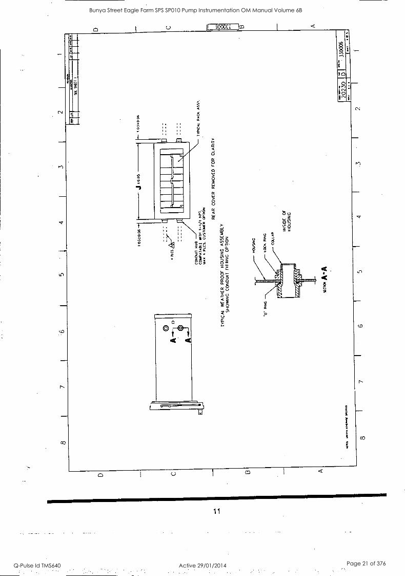
TYPICAL WEATHER PROOF HOUSING ASSEMBLY
SNOWING CONDUIT FIT TING OPTION
-0"
RIN
G
.4:4
11
04 M
S 0
1414
44/
WO
AD
SIC
IOi A
-A
REAR COVER REMOVED FOR CLARITY
INSIDE OF
HOUSING
IYIN
CA
L R
AC
K
AS
SY
.
2023
0
8 7
I 6
I 5
4 .3
I
2
"" 33
0006
I 0
Bunya Street Eagle Farm SPS SP010 Pump Instrumentation OM Manual Volume 6B
Q-Pulse Id TMS640 Active 29/01/2014 Page 21 of 376
8 I
7
FIG
1
(58
PU
RG
E)
NF
P
A.
496-
1982
PU
RG
E
WA
RN
ING
LAB
EL
PR
ES
SU
RE
(I
N
INC
HE
S
OF
W
AT
ER
)
FLO
W (
IN
CIA
O
RIR
U
AIR
P
UR
GE
O
PT
ION
K
u V
ALV
E
TIM
E
(IN
M
INU
TE
S)
FO
R
PU
RG
ING
w/P
HO
US
ING
=M
N
El lE
ll I C
P
lall
I 2P
up
.3
3 .4
.67
UM
I=
31
6 .8
19
22
E
l 29
.8
1.00
16
18
21
24
1.0
1.08
14
17
20
22
.
itiM
ME
NtL
ii Ir
i9H
lif
ill
U
ININ
I 12
. 2
5 5
0 1.
8 1
.o
2 00
4
.11
NH
, 1
I
:10
50
2.22
3 5.
5
MIN
IMA
INIM
Ilmin
..1
1.
OM
AR
ICE
6.5
7 0
IMim
mnl
ial
1101
1.41
1MIN
NIII
MU
MN
I119
1 w
.e...
.--m
ninb
9
1113
11M
1111
1.
x-00
S
lImilI
LIIII
IMM
IN
8 5
9 0
9.5
11.0
man
s M
ISS
004.
51 S
I4C
1111
0
FIG
. 2
(10X
P
UR
GE
)
CA
NA
DIA
N
ELE
CT
RIC
AL
CO
DE
C
22 1
-198
6 P
AR
T
I
PR
ES
SU
RE
A
IR
FLO
W
TH
RU
P
UR
GE
O
PT
ION
K
IT
VA
LVE
TIM
E
10
PU
RG
E
WE
AT
HE
RP
RO
OF
H
OU
SIN
G
IN
AIM
INC
HE
S
KIL
O
WA
TE
R
PA
SC
AL
FT
3U
IN
IA 3
/HR
4P
6P
8P
10
P
12P
T
IP
IMIC
IEF
IIIIM
ITM
IMM
I III
MM
EIE
RN
IIIIIE
NIU
m
cktio
nam
mum
mew
ani
ER
N
AM
18
1 .
lInlig
44
20
16
24
NE
IMA
N
ri E
D 30
E
RE
m
y .
gel
BrI
N
.
mum
. iti :64
12
:,0
IN)
14
2 11
IL
IEU
I :
12
I
EIM
INE
E11
1111
1M11
1 m
in.
1 1.
50
2.52
-1
-56-
1.
11
4 10
1 I
1
9 1.
11
' 10
Li i
nifi
E
xam
piw
zmoM
AM
Bilt
illir
li IN
EK
IIIIw
iimIll
EIL
IMIJ
K)
mum
K
IM
M11
1111
11M
1111
1010
1113
1113
11
IIIM
IIIIIM
/111
1411
1111
1111
M11
11
1107
11:1
11M
EN
IEM
MIN
E11
1111
11
imam
IM
Iffin
PA
CK
ING
F
IBE
R
2 P
tCS
PO
UR
S
EA
L T
IEIN
G
!MI
Vao
la
SE
E
9((T
RE
AR
C
OV
ER
R
EM
OV
ED
FO
R
CLA
RIT
Y
TY
PIC
AL
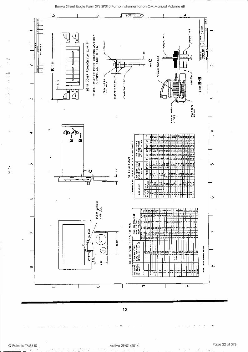
WE
AT
HE
R
PR
OO
F
HO
US
ING
A
SS
EM
BLY
S
HO
WIN
G
AIR
P
UR
GE
O
PT
ION
DR
ILL
.43
DIA
M
TG
. N
OLL
BU
LKH
EA
D F
IT T
ING
CO
NN
EC
TIN
G
TU
BE
SE
ALI
NG
C
OM
PO
UN
D
1711
11.
.110
1111
1111
1111
1111
111.
0111
1101
1r
....Z
ON
N%
%%
N11
1
AD
AP
TO
R
sEC
TIC
H B
-B
LOC
AN
ut
HO
US
ING
W
ALL
CO
ND
UIT
H
UB
2023
0 33
0006
I
8 6
5 .
4 3
2 1
0
Bunya Street Eagle Farm SPS SP010 Pump Instrumentation OM Manual Volume 6B
Q-Pulse Id TMS640 Active 29/01/2014 Page 22 of 376
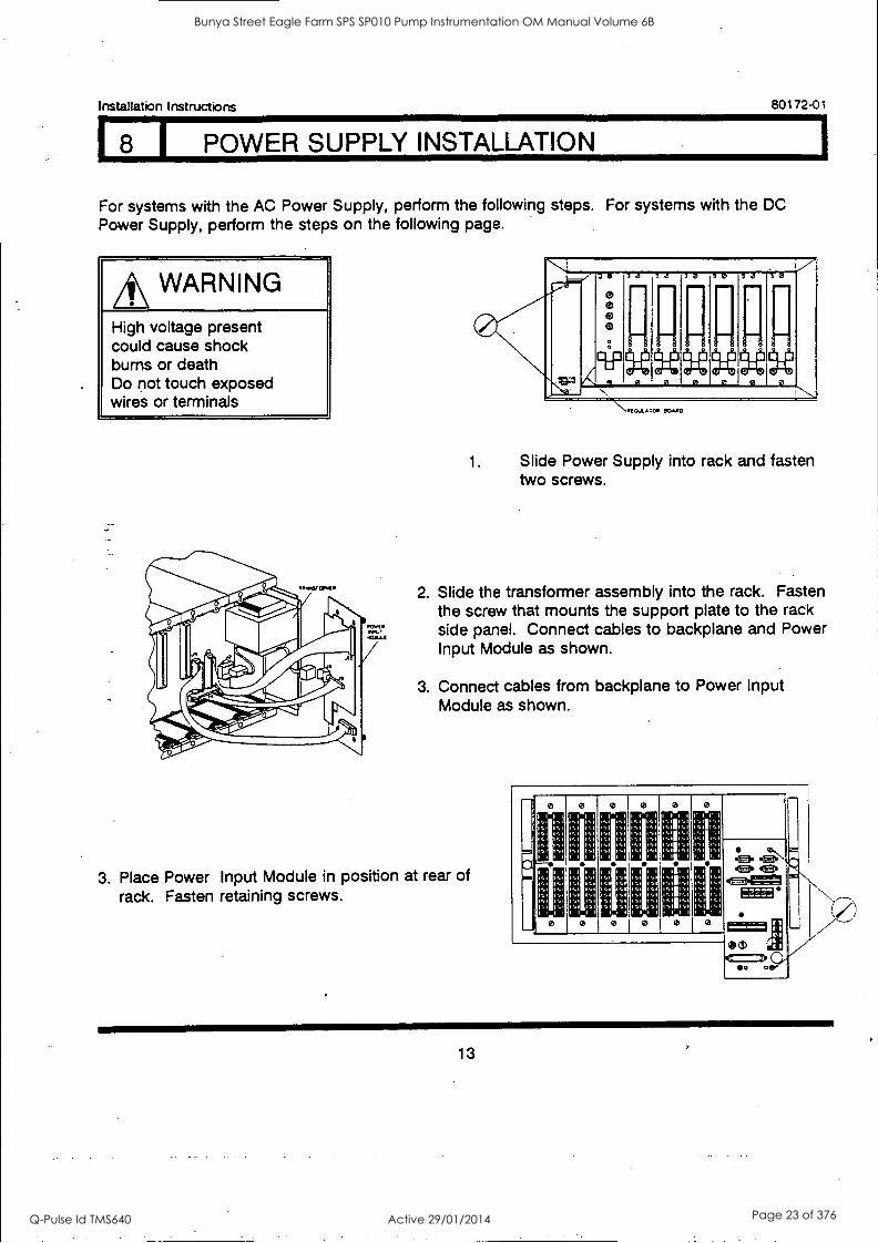
(8 I POWER SUPPLY INSTALLATION
Installation Instructions 80172-01
For systems with the AC Power Supply, perform the following steps. For systems with the DC Power Supply, perform the steps on the following page.
A\ WARNING
High voltage present could cause shock bums or death Do not touch exposed wires or terminals
70
r. ..4:3
7 0
i
cw.
la la ra 1-0
..... 70
l 0 ..
0 J 0 0 0
N
NO[CA11, ATP, SC/Antl
1. Slide Power Supply into rack and fasten two screws.
2. Slide the transformer assembly into the rack. Fasten the screw that mounts the support plate to the rack side panel. Connect cables to backplane and Power Input Module as shown.
3. Connect cables from backplane to Power Input Module as shown.
3. Place Power Input Module in position at rear of rack. Fasten retaining screws.
I
: 1,1 ,
1111
1:1 l
1
1 ,, .1
,1 .1
l 1
1 1
,1
.1
,1 1
1,1
1 ,1
1
1,1 1,1
1,1
/
1,1
,1
1,1
1
1,1 1 1
1,1 1:1
1 1 1
1 1
1 1 1
l 1 1 l 1
I I
1 1
I I
fl
ea
I
13
Bunya Street Eagle Farm SPS SP010 Pump Instrumentation OM Manual Volume 6B
Q-Pulse Id TMS640 Active 29/01/2014 Page 23 of 376
80172-01 Installation I nstructio ns
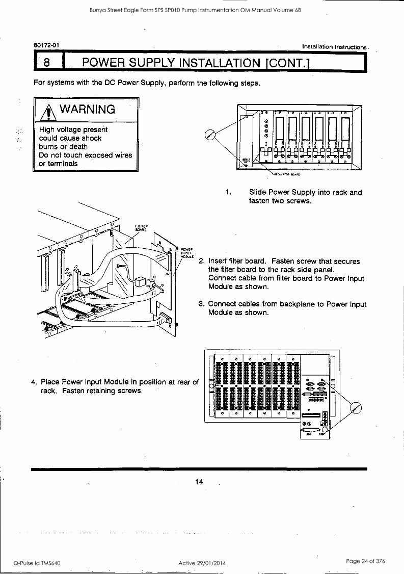
I POWER SUPPLY INSTALLATION [CONY.).
For systems with the DC Power Supply, perform the following steps.
A\ WARNING
High voltage present could cause shock bums or death Do not touch exposed wires or terminals
FILTER BOARD
ROVER INPUT MODULE
7111
i clpuuuu-ii.....
1.3 12 12 12 12 12
.N..../1( CUL. ? C. BOAP
1. Slide Power Supply into rack and fasten two screws.
2. Insert filter board. Fasten screw that secures the filter board to the rack side panel. Connect cable from filter board to Power Input Module as shown.
3. Connect cables from backplane to Power Input Module as shown.
4. Place Power Input Module in position at rear of rack. Fasten retaining screws.
I I 1 1111 1 1 1 1 1 1 1
1
'1 /,1 1S1
1,1 1,1
1,1 1,1
,1 ,1 5,1
*tit J,1 1 11 1
I I I I I 1 1 1
1,1 1,1
,1 ,1 1:111:1 1 1,1
1,1 1,1 1;:111.: I I I I 1 1 1 1 1 1
14
Bunya Street Eagle Farm SPS SP010 Pump Instrumentation OM Manual Volume 6B
Q-Pulse Id TMS640 Active 29/01/2014 Page 24 of 376
Installation Instructions 80172-01
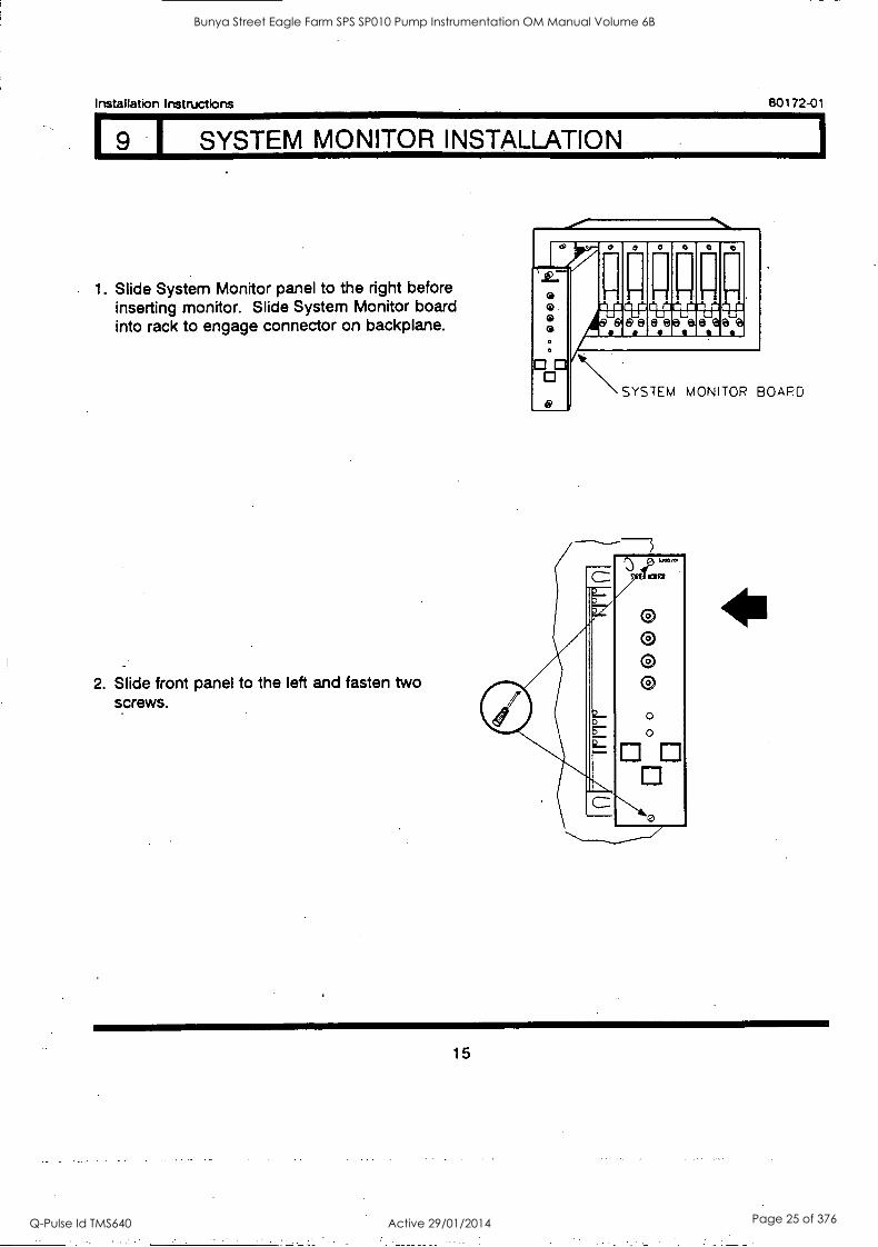
I SYSTEM MONITOR INSTALLATION
1. Slide System Monitor panel to the right before inserting monitor. Slide System Monitor board into rack to engage connector on backplane.
2. Slide front panel to the left and fasten two screws.
o.
0 0 0
r r - 11r.r1Pr`
ee
n *Ca
r.
SYSTEM MONITOR BOARD
15
Bunya Street Eagle Farm SPS SP010 Pump Instrumentation OM Manual Volume 6B
Q-Pulse Id TMS640 Active 29/01/2014 Page 25 of 376
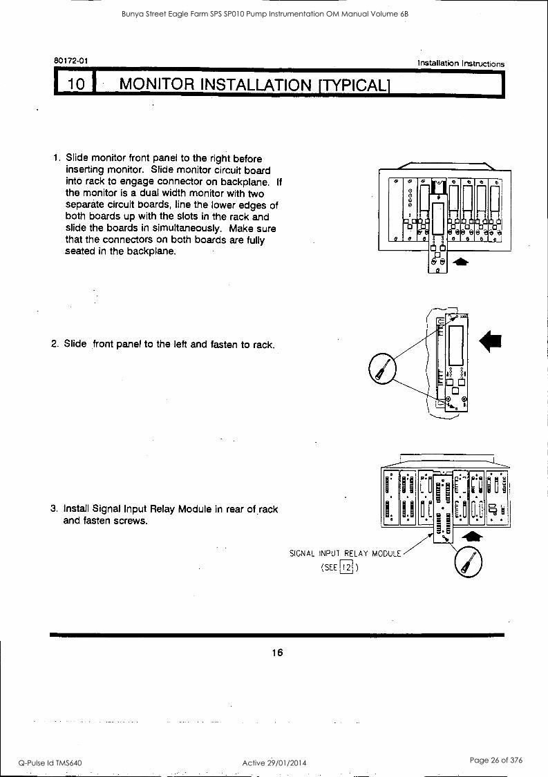
110 MONITOR INSTALLATION ATYPICAL]
80172-01 Installation Instructions
1. Slide monitor front panel to the right before inserting monitor. Slide monitor circuit board into rack to engage connector on backplane. If the monitor is a dual width monitor with two separate circuit boards, line the lower edges of both boards up with the slots in the rack and slide the boards in simultaneously. Make sure that the connectors on both boards are fully seated in the backplane.
2. Slide front panel to the left and fasten to rack.
3. Install Signal Input Relay Module in rear of Jack and fasten screws.
0 0 0
0
00 96
e e e
a
0
O
SIGNAL INPUT RELAY MODULE
(SEE rT )
16
Bunya Street Eagle Farm SPS SP010 Pump Instrumentation OM Manual Volume 6B
Q-Pulse Id TMS640 Active 29/01/2014 Page 26 of 376
Installation Instructions 80172-01
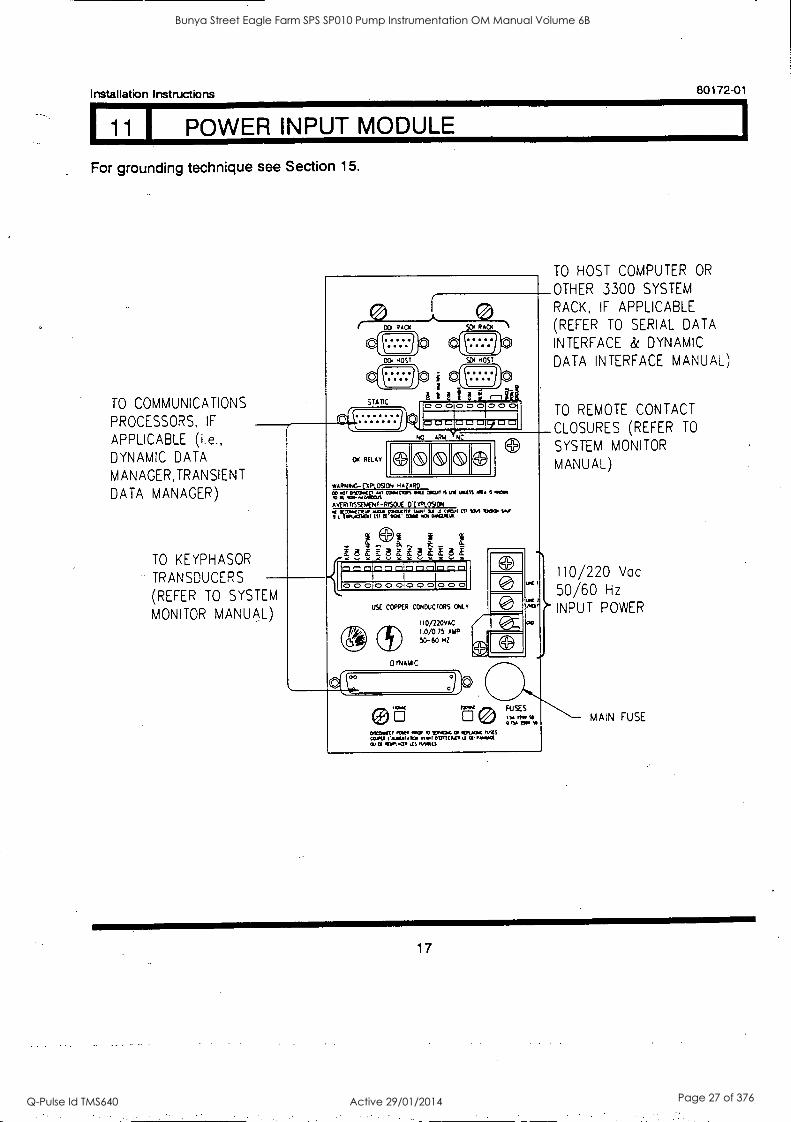
1 11 1 POWER INPUT MODULE
For grounding technique see Section 15.
TO COMMUNICATIONS
PROCESSORS, IF
APPLICABLE (i.e., DYNAMIC DATA
MANAGER, TRANSIENT
DATA MANAGER)
TO KEYPHASOR
TRANSDUCERS
(REFER TO SYSTEM
MONITOR MANUAL)
CO RAd RAO(
WARNING-DP(09000 HAZARD CO 00, ariaNCV Crim(C130% Ai [ICI, lip MISS MA' fl
00..0203/5. AVM tr5SEK)41-P5OvE EYPLOSION 1,arriavirap.acteolr.60talfirrt (Si WA 1J it,
a
0 0 010 0 010 0 010 0 0
USE COPPER catoucices c41,
ii0/220vAC 1.0/0.75 AMP
SO-60 HZ
DYNAMIC
FU 'IS ot 1110 II
0 n aMv 0602CC, 0010 000:00) 4703C CP SRAM MIS CARA 1'4101_01 Ayr, OMITCWAY li 11100401
alotsa go 0.661$
1
TO HOST COMPUTER OR
OTHER 3300 SYSTEM
RACK, IF APPLICABLE
(REFER TO SERIAL DATA
INTERFACE & DYNAMIC
DATA INTERFACE MANUAL)
TO REMOTE CONTACT
CLOSURES (REFER TO
SYSTEM MONITOR
MANUAL)
110/220 Vac
50/60 Hz
INPUT POWER
MAIN FUSE
17
Bunya Street Eagle Farm SPS SP010 Pump Instrumentation OM Manual Volume 6B
Q-Pulse Id TMS640 Active 29/01/2014 Page 27 of 376
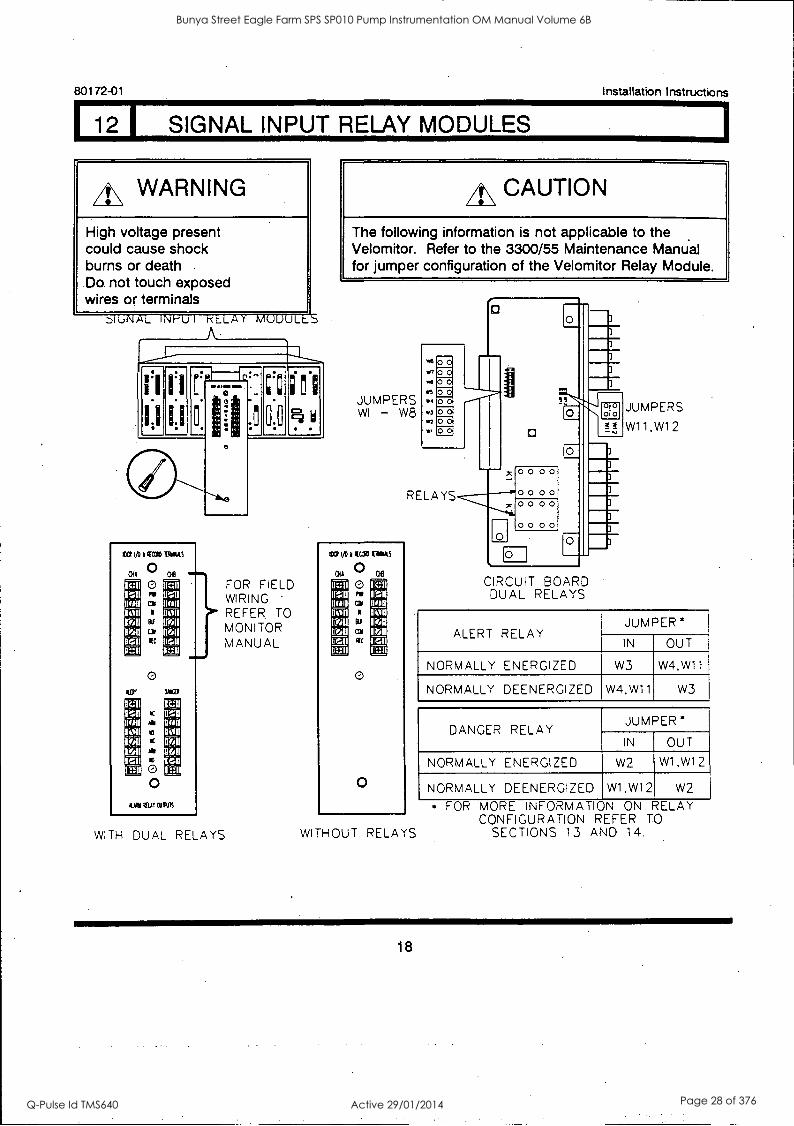
112 SIGNAL INPUT RELAY MODULES
80172-01 Installation Instructions
A\ WARNING
High voltage present could cause shock burns or death Do not touch exposed wires or terminals
JIhNAL INi-U I r LAY MUUULt A
tO 1/0 l G[CtyD IltAS
0 0 re
ar coo
NC
oe
0 Aar tan
to
a
O 0
ccu
Pon
011 Cu
Aural EAT CONS
WITH DUAL RELAYS
FOR FIELD WIRING REFER. TO MONITOR MANUAL
CAUTION
The following information is not applicable to the Velomitor. Refer to the 3300/55 Maintenance Manual for jumper configuration of the Velomitor Relay Module.
JUMPERS WI - W8
CO t/011410 TAW AS
0, 0 O
coo
Eif
coo
0
0
of I c: I
11%.;11
null mon
II' II
W4
*3
0
O
RELAYS
WITHOUT RELAYS
O
0 0 0 0
00 00 00 00
00 00
O
I
I
EH
I
I
\3
CIRCUIT BOARD DUAL RELAYS
JUMPERS
W11,W12
ALERT RELAY JUMPER *
IN OUT
NORMALLY ENERGIZED W3 W4,W11
NORMALLY DEENERGIZED W4,W11 W3
DANGER RELAY JUMPER*
IN OUT
NORMALLY ENERGIZED W2 W1,W12
NORMALLY DEENERGIZED W1,W12 W2
* FOR MORE INFORMATION CONFIGURATION REFER TO
SECTIONS 13 AND 14.
18
Bunya Street Eagle Farm SPS SP010 Pump Instrumentation OM Manual Volume 6B
Q-Pulse Id TMS640 Active 29/01/2014 Page 28 of 376
Installation Instructions 80172-01
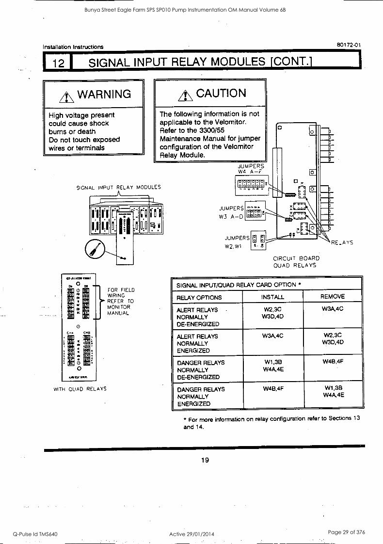
12 1 SIGNAL INPUT RELAY MODULES 1CONT.1
4\ WARNING
High voltage present could cause shock bums or death Do not touch exposed wires or terminals
LL, CAUTION
The following information is not applicable to the Velomitor. Refer to the 3300/55 Maintenance Manual for jumper configuration of the Velomitor Relay Module.
SIGNAL INPUT RELAY MODULES
0,
1::11 can I WI tr
FAU
11/.11
su
C,A 1::u
an
if.a at
ksLat
0 O p.
031
Its
0
0 0
FOR FIELD WIRING REFER TO MONITOR MANUAL
I
.1_741
non
I cm ::il
CH8 11::11
11:11 11/1
n611 I 1:1
II::11
4AW CAI WPM
WITH QUAD RELAYS
JUMPERS W4 A-F
EIHEIHNH n 3.
JUMPERS
W3 A-D
o
g151'
JUMPERS
W2,W1 0
CIRCUIT BOARD QUAD RELAYS
SIGNAL INPUT/QUAD RELAY CARD OPTION *
RELAY OPTIONS INSTALL REMOVE
ALERT RELAYS NORMALLY DE-ENERGIZED
W2,3C W3D,4D
W3A,4C
ALERT RELAYS NORMALLY ENERGIZED
W3A,4C W2,3C W3D,4D
DANGER RELAYS NORMALLY DE-ENERGIZED
W1,3B W4A,4E
W4B,4F
DANGER RELAYS NORMALLY ENERGIZED
W48,4F W1,38 W4A,4E
* For more information on relay configuration refer to Sections 13
and 14.
19
Bunya Street Eagle Farm SPS SP010 Pump Instrumentation OM Manual Volume 6B
Q-Pulse Id TMS640 Active 29/01/2014 Page 29 of 376
80172-01 Installation I nstructions
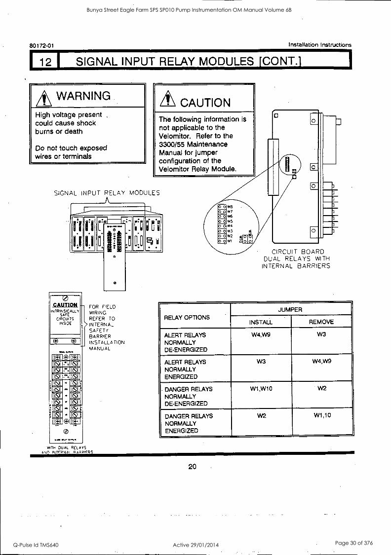
112 I SIGNAL INPUT RELAY MODULES ECONT.1
WARNING
High voltage present .
could cause shock burns or death
Do not touch exposed wires or terminals
CAUTION The following information is not applicable to the Velomitor. Refer to the 3300/55 Maintenance Manual for jumper configuration of the Velomitor Relay Module.
SIGNAL INPUT RELAY MODULES A
1,1
CAUTION INTRINSICALLY
SAFE CIRCUITS
INSIDE
1014 0.0.11S
0.
11
77, 11111 MEM
fl
0
0
FOR FIELD WIRING.
REFER TO
INTERNAL SAFETY BARRIER INSTALLATION MANUAL
WITH DUAL RELAYS Anin INTT-pkot Q pirpg
0.0
2.1
CIRCUIT BOARD DUAL RELAYS WITH
INTERNAL BARRIERS
RELAY OPTIONS .
JUMPER
INSTALL REMOVE
ALERT RELAYS NORMALLY DE-ENERGIZED
W4,W9 W3
ALERT RELAYS NORMALLY ENERGIZED
W3 W4,W9
DANGER RELAYS NORMALLY DE-ENERGIZED
W1,W10 W2
DANGER RELAYS NORMALLY ENERGIZED
W2 W1,10
20
Bunya Street Eagle Farm SPS SP010 Pump Instrumentation OM Manual Volume 6B
Q-Pulse Id TMS640 Active 29/01/2014 Page 30 of 376
Installation Instructions 80172-01
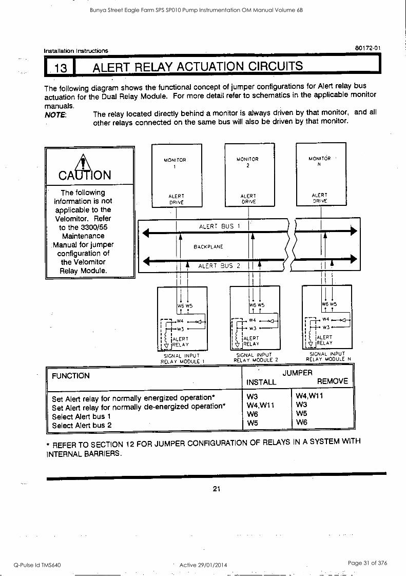
13 1 ALERT RELAY ACTUATION CIRCUITS
The following diagram shows the functional concept of jumper configurations for Alert relay bus
actuation for the Dual Relay Module. For more detail refer to schematics in the applicable monitor
manuals. NOTE: The relay located directly behind a monitor is always driven by that monitor, and all
other relays connected on the same bus will also be driven by that monitor.
The following information is not applicable to the Velomitor. Refer
to the 3300/55 Maintenance
Manual for jumper configuration of the Velomitor Relay Module.
MONITOR
ALERT DRIVE
MONITOR
2
ALERT DRIVE
ALERT BUS 1
BACKPLANE
ALERT BUS 2 1i
SIGNAL INPUT RELAY MODULE 1
W6 W5
1 T
W4
W3
'ALERT LJRELA Y
SIGNAL INPUT RELAY MODULE 2
MONITOR N
ALERT DRIVE
SIGNAL INPUT RELAY MODULE N
FUNCTION JUMPER INSTALL REMOVE
Set Alert relay for normally energized operation* Set Alert relay for normally de-energized operation*
Select Alert bus 1
Select Alert bus 2
W3 W4,W11 W6 W5
W4,W11 W3 W5 W6
* REFER TO SECTION 12 FOR JUMPER CONFIGURATION OF RELAYS IN A SYSTEM WITH
INTERNAL BARRIERS.
21
Bunya Street Eagle Farm SPS SP010 Pump Instrumentation OM Manual Volume 6B
Q-Pulse Id TMS640 Active 29/01/2014 Page 31 of 376
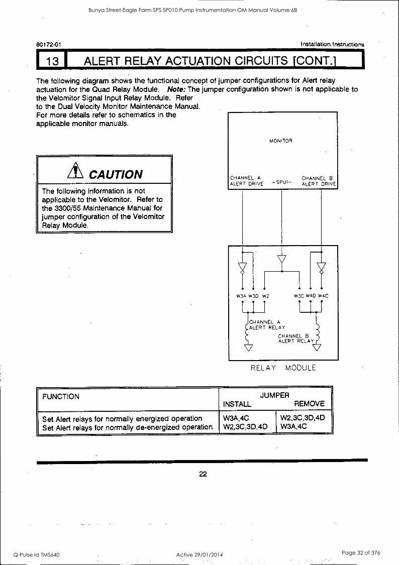
113 I ALERT RELAY ACTUATION CIRCUITS [CONT.] 1
80172-01 Installation Instructions
The following diagram shows the functional concept of jumper configurations for Alert relay actuation for the Quad Relay Module. Note: The jumper configuration shown is not applicable to the Velomitor Signal Input Relay Module. Refer to the Dual Velocity Monitor Maintenance Manual. For more details refer to schematics in the applicable monitor manuals.
CAUTION The following information is not applicable to the Velomitor. Refer to the 3300/55 Maintenance Manual for jumper configuration of the Velomitor Relay Module.
MONITOR
CHANNEL A CHANNEL B ALERT DRIVE -SPUI- ALERT DRIVE
w3A W3D W2 W3C W4D W4C
CHANNEL A ALERT RELAY
CHANNEL B ALERT RELAY
RELAY MODULE
FUNCTION JUMPER INSTALL REMOVE
Set Alert relays for normally energized operation Set Alert relays for normally de-energized operation
W3A,4C W2,3C,3D,4D
W2,3C,3D,4D W3A,4C
22
Bunya Street Eagle Farm SPS SP010 Pump Instrumentation OM Manual Volume 6B
Q-Pulse Id TMS640 Active 29/01/2014 Page 32 of 376
Installation Instructions 80172-01
14 DANGER RELAY ACTUATION CIRCUITS
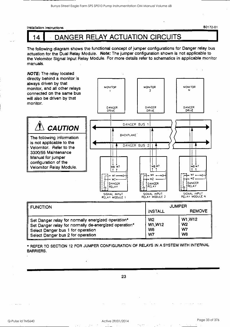
The following diagram shows the functional concept of jumper configurations for Danger relay bus actuation for the Dual Relay Module. Note: The jumper configuration shown is not applicable to the Velomitor Signal Input Relay Module. For more details refer to schematics in applicable monitor manuals.
NOTE: The relay located directly behind a monitor is always driven by that monitor, and all other relays connected on the same bus will also be driven by that monitor.
CAUTION The following information is not applicable to the Velomitor. Refer to the 3300/55 Maintenance Manual for jumper configuration of the Velomitor Relay Module.
MONITOR
DANGER DRIVE
MONITOR
2
DANGER DRIVE
DANGER BUS
BACKPLANE
441.mmmlimin DANGER BUS 2
SIGNAL INPUT RELAY MODULE 1
MONITOR N
DANGER DRIVE
w8 W7
W2
DANGER RELAY
1.-J SIGNAL INPUT
RELAY MODULE 2 SIGNAL INPUT
RELAY MODULE N
FUNCTION JUMPER INSTALL REMOVE
Set Danger relay for normally energized operation* Set Danger relay for normally de-energized operation* Select Danger bus 1 for operation Select Danger bus 2 for operation
W2 W1,W12 W8 W7
W1,W12 W2 W7 W8
* REFER TO SECTION 12 FOR JUMPER CONFIGURATION OF RELAYS IN A SYSTEM WITH INTERNAL
BARRIERS.
23
Bunya Street Eagle Farm SPS SP010 Pump Instrumentation OM Manual Volume 6B
Q-Pulse Id TMS640 Active 29/01/2014 Page 33 of 376
80172-01 Installation Instructions
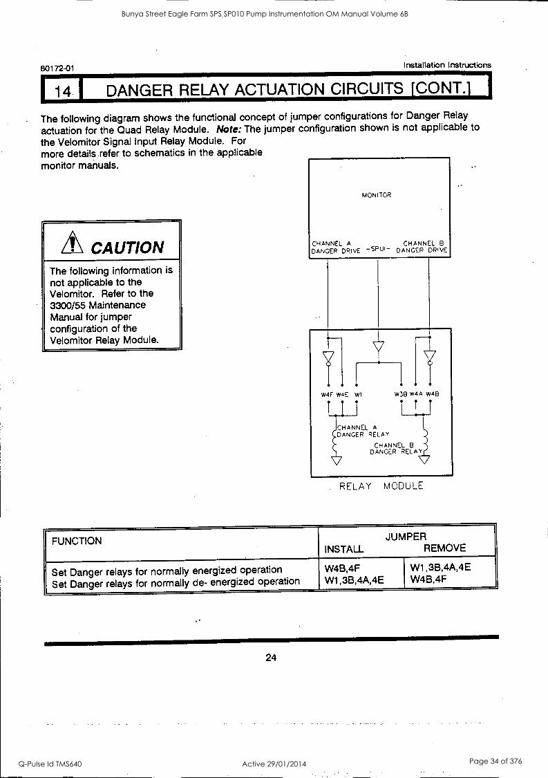
14 DANGER RELAY ACTUATION CIRCUITS [CONT.]
The following diagram shows the functional concept of jumper configurations for Danger Relay
actuation for the Quad Relay Module. Note: The jumper configuration shown is not applicable to
the Velomitor Signal Input Relay Module. For
more details refer to schematics in the applicable monitor manuals.
CAUTION The following information is
not applicable to the Velomitor. Refer to the 3300/55 Maintenance Manual for jumper configuration of the Velomitor Relay Module.
MONITOR
CHANNEL A CHANNEL B DANGER DRIVE -SPUI- DANGER DRIVE
W4F w4E wt w3B W4A W48
1.1 1 1 1.1
CHANNEL A DANGER RELAY
CHANNEL B DANGER RELAY
RELAY MODULE
FUNCTION JUMPER INSTALL REMOVE
Set Danger relays for normally energized operation
Set Danger relays for normally de- energized operation W4B,4F W1,3B,4A,4E
W1,3B,4A,4E W4B,4F
24
Bunya Street Eagle Farm SPS SP010 Pump Instrumentation OM Manual Volume 6B
Q-Pulse Id TMS640 Active 29/01/2014 Page 34 of 376
Installation Instructions 80172-01
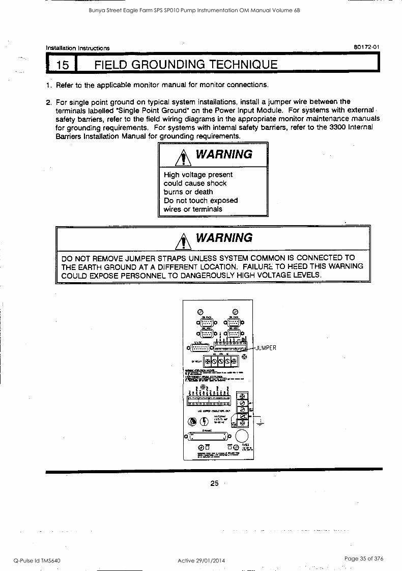
15 I FIELD GROUNDING TECHNIQUE
1. Refer to the applicable monitor manual for monitor connections.
2. For single point ground on typical system installations, install a jumper wire between the terminals labelled 'Single Point Ground' on the Power Input Module. For systems with external safety barriers, refer to the field wiring diagrams in the appropriate monitor maintenance manuals for grounding requirements. For systems with internal safety barriers, refer to the 3300 Internal Barriers Installation Manual for grounding requirements.
*WARNING High voltage present could cause shock burns or death Do not touch exposed wires or terminals
*WARNING DO NOT REMOVE JUMPER STRAPS UNLESS SYSTEM COMMON IS CONNECTED TO THE EARTH GROUND AT A DIFFERENT LOCATION. FAILURE TO HEED THIS WARNING COULD EXPOSE PERSONNEL TO DANGEROUSLY HIGH VOLTAGE LEVELS.
samC-ORSISCp .02M4 I r.f=sa: - -0 - -- sor.ST.C.,./Sal OtM2501 MOM WeirTaVtii.7 °
uSI my COOLVIR On,
u0/770.4 to/finer
""-c
25
Bunya Street Eagle Farm SPS SP010 Pump Instrumentation OM Manual Volume 6B
Q-Pulse Id TMS640 Active 29/01/2014 Page 35 of 376
80172-01 Installation Instructions
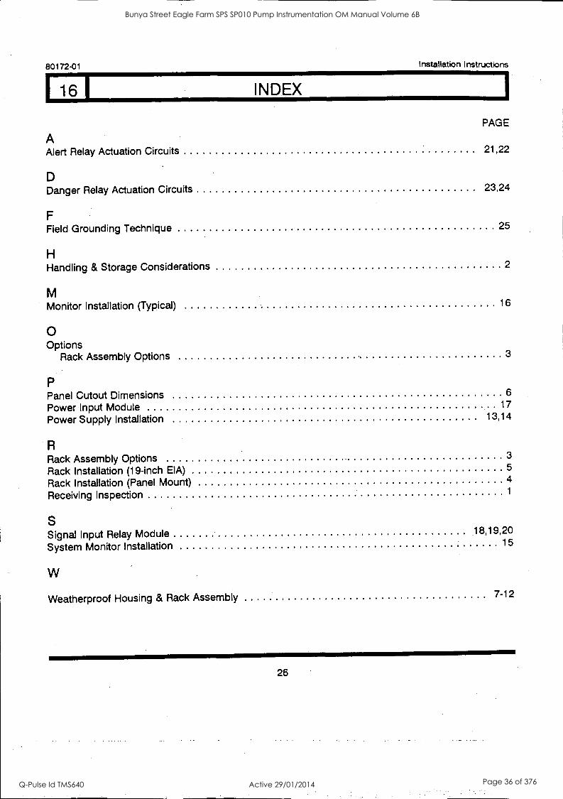
16 I INDEX
PAGE
Alert Relay Actuation Circuits 21,22 A
D Danger Relay Actuation Circuits 23,24
F Field Grounding Technique 25
H Handling & Storage Considerations 2
M Monitor Installation (Typical) 16
0 Options
Rack Assembly Options 3
P Panel Cutout Dimensions 6
Power Input Module 17
Power Supply Installation 13,14
Rack Assembly Options 3
Rack Installation (19-inch EIA) 5
Rack Installation (Panel Mount) 4
Receiving Inspection 1
S Signal Input Relay Module 18,19,20
System Monitor Installation 15
Weatherproof Housing & Rack Assembly 7-12
26
Bunya Street Eagle Farm SPS SP010 Pump Instrumentation OM Manual Volume 6B
Q-Pulse Id TMS640 Active 29/01/2014 Page 36 of 376
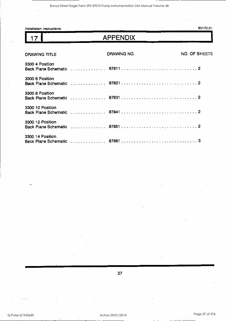
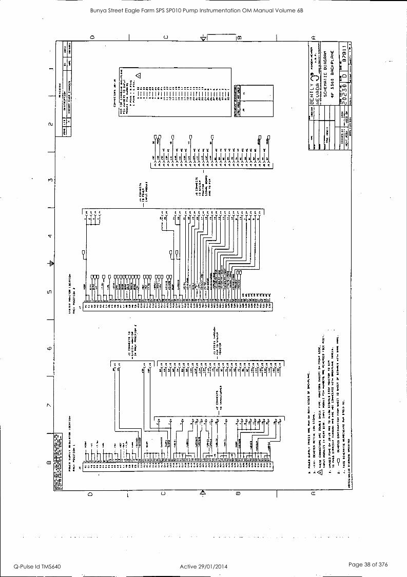
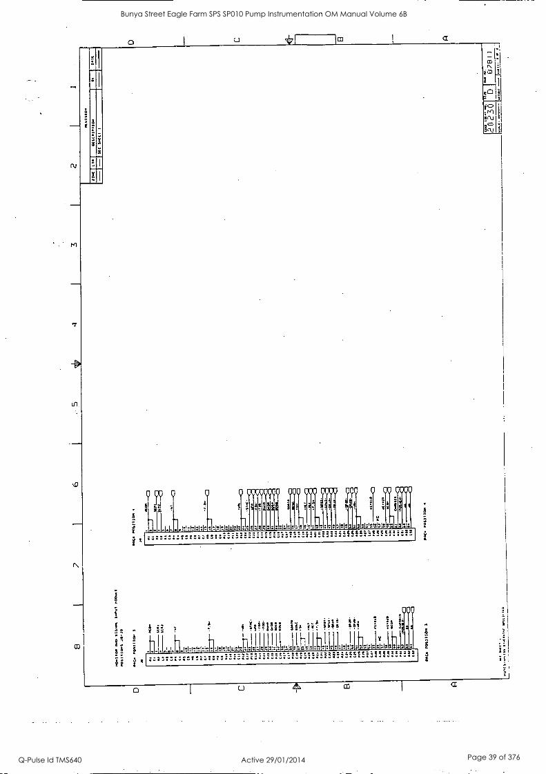
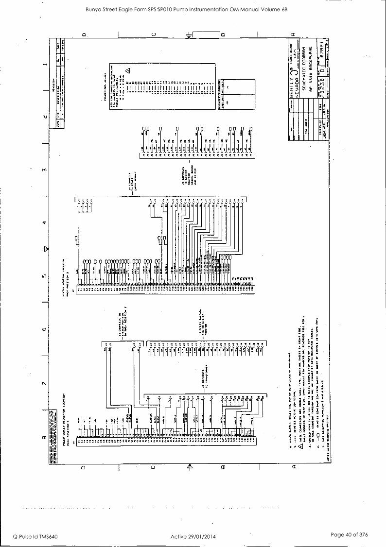
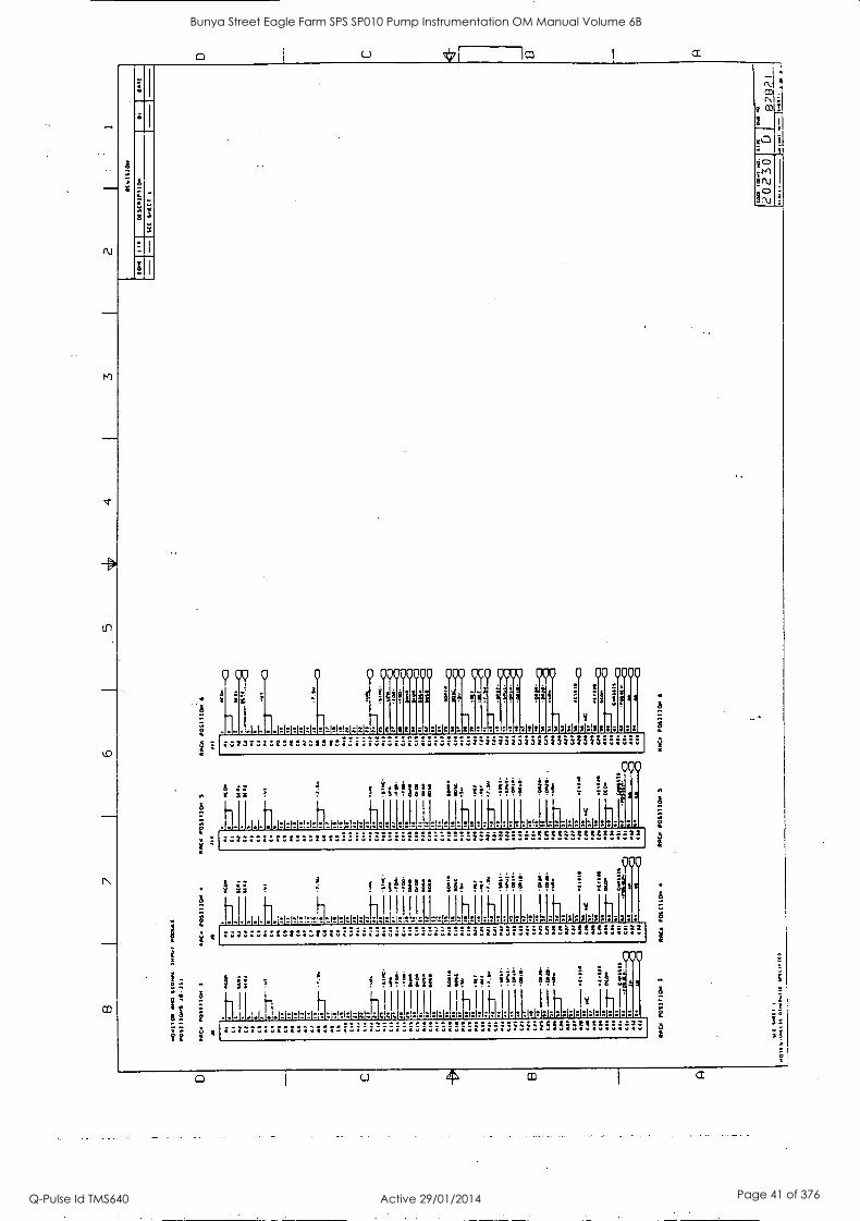
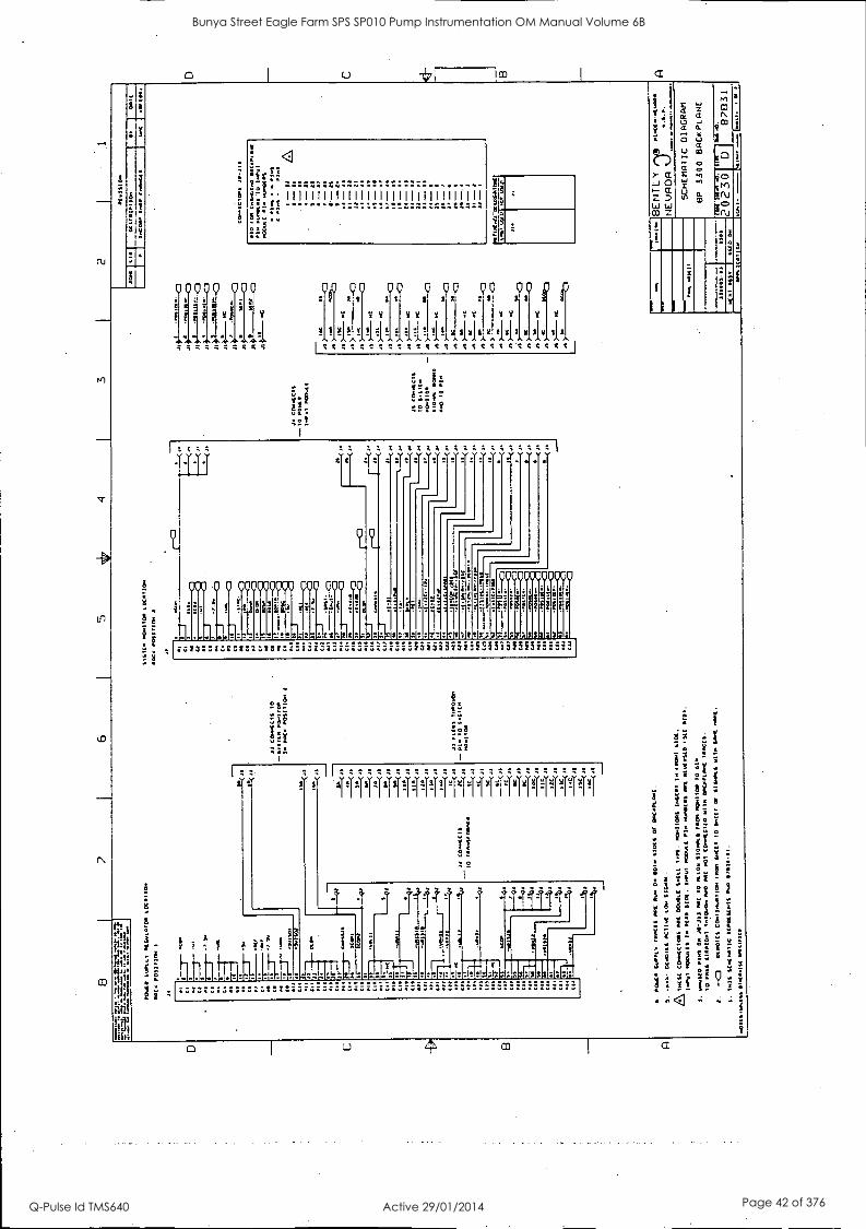
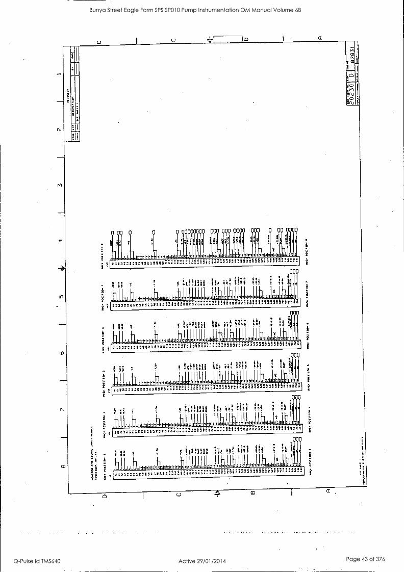
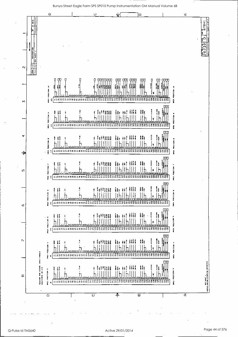
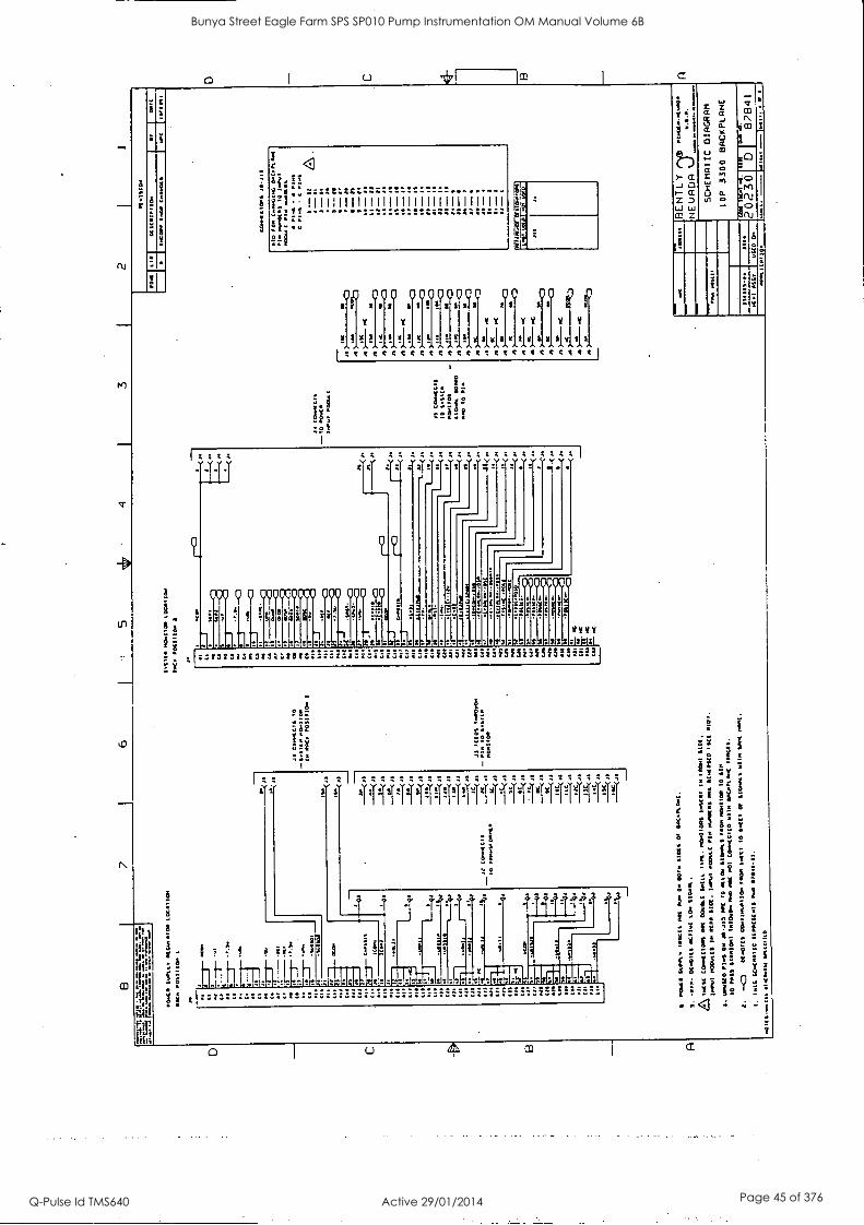
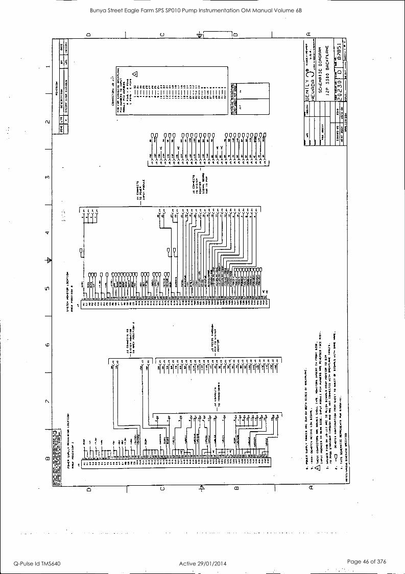
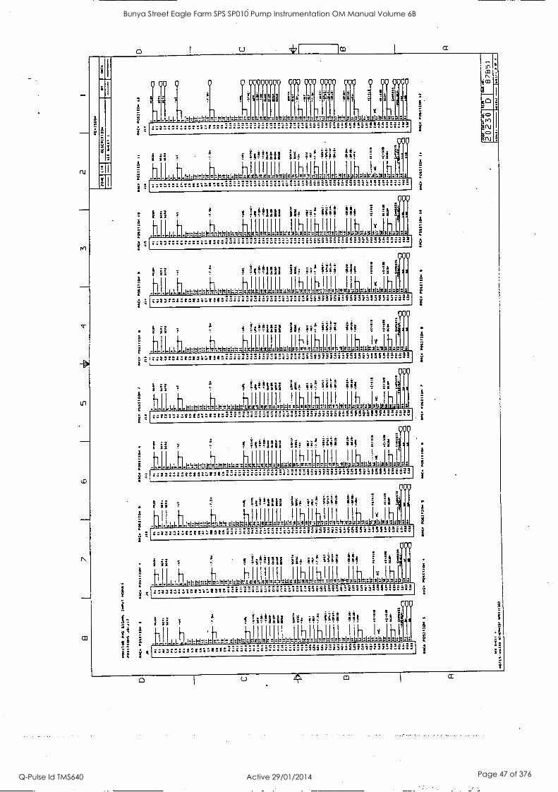
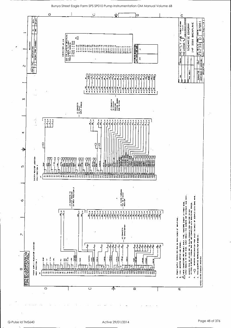
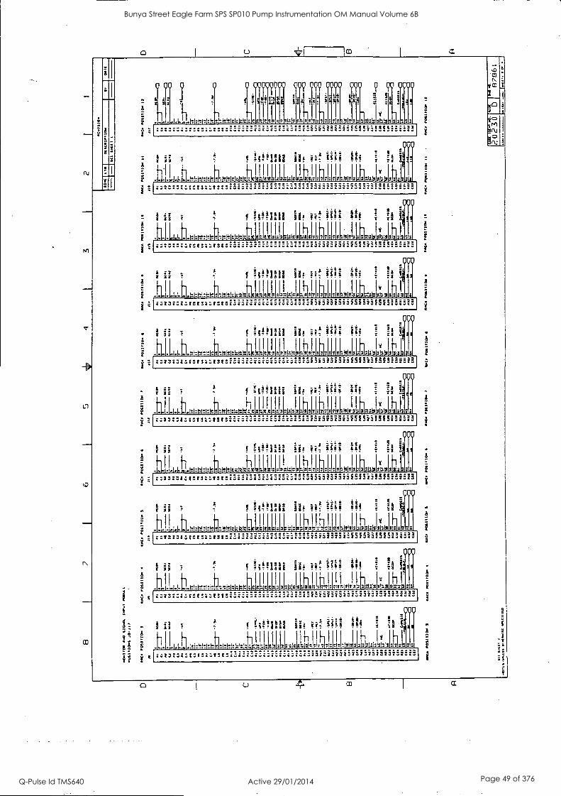
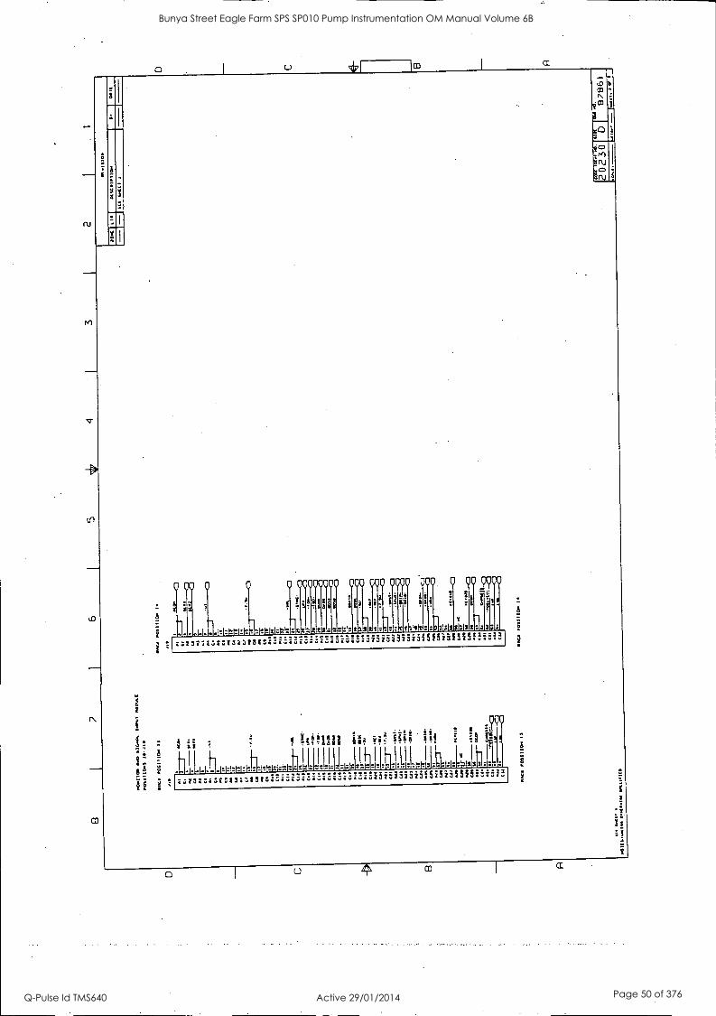
117 1 APPENDIX 1
Installation Instructions 80172-01
DRAWING TITLE
3300 4 Position Back Plane Schematic
3300 6 Position Back Plane Schematic
3300 8 Position Back Plane Schematic
3300 10 Position Back Plane Schematic
3300 12 Position Back Plane Schematic
3300 14 Position Back Plane Schematic
DRAWING NO. NO. OF SHEETS
87811 2
87821 2
87831 2
87841 2
87851 2
87861 3
27
Bunya Street Eagle Farm SPS SP010 Pump Instrumentation OM Manual Volume 6B
Q-Pulse Id TMS640 Active 29/01/2014 Page 37 of 376
Y
0
VVV VVV:' V V V V
1114! !.151!1: ;MIIVI! 4111144 tivISINI
It777tg;77:ZZZ:ZISZtzezczve I
it. i
000 0 0`Q00 0000 POO 000 00
! ii! 2
'14:11_44 ---------- ZIZ.Z4 :41.1
i.173731:4:1S'ZI3V
Z S:::
0
VVVYYYVVYY ft stlsOls:1:0:41
2323737323i535iii5154:^222
!!
;E:
'11-15qqqqqiiiiiifliqq1114K
ta
2:2
i 7 1 a ii! IA 4 i
g
hh-rh Ihh :Iv!Prr
TT. ii
. ..................
0 iJ CO
W
U
a.
Vc' 714)
.N ac)
V
Bunya Street Eagle Farm SPS SP010 Pump Instrumentation OM Manual Volume 6B
Q-Pulse Id TMS640 Active 29/01/2014 Page 38 of 376
44 v Sy
0 upoyoyoo 000 000 Luu °co 0 00 0000
-1I -I I -- 1
ii i ri sa
........... -11-1-1 . ..... """ ---"-"CCLL"tagt::::As
000.
f II, ii:t II
_b111.1.11.1e±m*!,14474h 4 .11411.=11 ; ,:w.I 4 hll !I .
! .. . I ... . "%---""'ARLAZZALtt.12:22
0 1 U CC
Bunya Street Eagle Farm SPS SP010 Pump Instrumentation OM Manual Volume 6B
Q-Pulse Id TMS640 Active 29/01/2014 Page 39 of 376
N
1.1
.2-
Ul
N
U
rAh.
hit!
iftlj liAa
8
ab
5. ii:!! 111111111111111111.11111111111111
al
0 00 0 00 AQ 10 2 s X 3 I 3 W
i V V 9 i 9 9 9 9 V . 9
A A AN! A1110 41110 V 1411V 441 V SIV 41 ... ... 9 9 9 9 91 9 9 9 9 C; S; 9 C; 9 9 9 9 9 S; 9 9 I
8. ! vra A;r1- .0A-4
WO 0 0 0 00 000 000 000 00 93
aiii vs a
:1911:1:o- c
V V V V
2
:::::: !.
a
0000
88888888 222 22,11212t.14121:4I
2222.12222iSIMMS"""
I
i oa
C CI
0- C ZD L.1
Z 0
(1.1
0:1
9
co
c)
N
N
1
yY
fs I
9-.111111
: -- -- h 7T _ L ...... .......... ............. ..........
0 4
Bunya Street Eagle Farm SPS SP010 Pump Instrumentation OM Manual Volume 6B
Q-Pulse Id TMS640 Active 29/01/2014 Page 40 of 376
3
Ul
co
0 U 717 1c3 I a
3
5
-1-1.1-11'
o cyoyyoyo coo 000 COCO oyo 0 00 0000 2 c I
Is 1 30
iit 8 8 : :8 Si
V VC 12 t
,-
-1.1-I 1 - cc:cez-12:kk: It I 1:12:: a :412121:42222
' M3C373237373232323
000
! g .i 1 ea ea:
.i.i i:t !.!. s i
!. hIIIIhm-,,,,thi.,.,:i-H-h ' I .. 1 . I .. 1-.1-1,141 ..... . 1 . 1 . 1.1.,-,1-1t1-,,4..1.1.1:1 . 1 ... i
1
------ ---------------ceculzwe::::33
..:900
. i iissie Aq .A iiii Aix I .
1 i i .f . ! =t taall IP !!' f If f fl i ii 1,
I
§ :-.
!
i 1.11...1..±.1,1:1,1,!:J.11,),1:14,1:1,111,11 .. LI.,, A l'ff.j21: :t"1:1:1JALillj . 111 .. .. . A11" l'I'h -1 ... E
i '
zz: I ------"."--."5-5 '-""CCC*174CCCt::::ca g
c 1YY°
ii i ii C. 2 .2 .1 ii ! .
f =l,tiall !if ir.i ?;q ffi : A t9 '"
- I
h I- 111111 1
' II- 1Y 11- I.
.1..1.1,,.,.1 :i :1=1.1 -121: ! Ill I I I I t,:,t,:,=XJ:::,:W!:,:::1:1:1=12m1::,:*::::=1.14:41:1:41::1: . : 1111111-1
Bunya Street Eagle Farm SPS SP010 Pump Instrumentation OM Manual Volume 6B
Q-Pulse Id TMS640 Active 29/01/2014 Page 41 of 376
3
(11
03
0 U
a ;
:
3
! I
IN!
dha
1.i"
hfil
A
I 1
<1
iit!! 2-f. '
11111111111111111111111111111111
of
1
0 0 0 0 40 IS22 II
V y
_ 1.11! 4212 2j. 21 s
gellsts:22222222 I
is.
.,038 _4
000 0 0 0 0 4000 00
!nib irY
A-2
00 0
.21C
12 000000000
ii
2 2 2
2323C:13282323222 * 2222222222f515i21515---
i!
va .7
. ! 1 A ;4 f
t 1144
a2 a.
I I
2
U 4
Bunya Street Eagle Farm SPS SP010 Pump Instrumentation OM Manual Volume 6B
Q-Pulse Id TMS640 Active 29/01/2014 Page 42 of 376
0 Op
!.;;".
1-1..111 .1.1 I I-1
0p 000 70 000 0 00 0000
i ! i
i . i iise i
a i i r.; .
A
.1%, it I:10 : : 20;13 31312 3 : 2 2 : i 7311232323M595/355Hi3l. azz3::xmlirsaatst '
00
f 114 iit !
.k .i.t 1.0I, mfr30[11.113U331 h1111.11*1.1,117-f - 11114 ,0.1f.:, ZIZZ732:1131C132373t*
23232313235555751555555P!
000
3 !Mill iit s3lee a!
13131.1
I
A:1314
I
3.
I kni 3t 1313131:13 3 3
Igalat.:vactsattst ' 23232n.3:3/5151515f52:4-22
11t1,_ c,ILLar
Poo
ifa ii! iais ! !
1LL4 .111111114411:141:4666: I:1: 3
'
z323232323fSM513551iii!!
IOWA! ih #4 Mil Ili i
-11111.K41h Lititil111:*1: 1212:ISNI 2LtIlih11.11 II3.1 7 IS v
000
I:: Z3
..2 tat:23t 732323 2323232373.523
yclo
s .;!!1211 W gqe I;i
hil l l h.i.. -',r21!121.:1:1:4:11.111-1;11:1- 11. ' - -411-111% ;7) :WI: t1 -
Z.2 -----
Bunya Street Eagle Farm SPS SP010 Pump Instrumentation OM Manual Volume 6B
Q-Pulse Id TMS640 Active 29/01/2014 Page 43 of 376
eb
yoo
I A
4-
1"1"1"1-11" 1.1'1.11
Q 00009000 000 000 0000 000 0 00 coy
5s I I ..
V
tZ:XXV ::..3
000 c
0 5i A
f ilA :A
h h1-1.1"&f41
I
111^ . 11 . ... 1-1^li'L . . . . f" . I . 141 . . h . ... ..
0 43 3
t A "II VA. f if? Pt '41 f5!
.. I . I . b.1:1:1:1:17.1ttitlelt1:1:131111::111: tItle
. t IV s A 1
000
31:411:13
23737323333373337323
v :3 ,
- 1.1 --- 1.1.11.174:1*1.1131t131
hfflii ilf ii 5iaai 11! °x
A
.000
Sa
o...
1 1
Iv c:.cc::2:I:0:13::::: :::1*:;2:11.110112133:: 3 Z13 33732333232323237323
! 7i 7 ? Yf68ddii ilA W Sbb .0!
A
. -
A
..... I. I L1. 11 UataltIvIlL
000
31:11 t: ::::::::::::::::: 23232373237323732323
3 !;0.1201 iic i4f
. .............. .. I II
0
mw.0041,0ft.O0 CCLC:ZUCCC::::23
hH 1
! :;alit:: ils ii'; iiee Ai. CC!
. 11 . 1 -A-
000
0 :
_009
. ii I ff- 17
A VslAs-
t A
. .... 11. .. . ..
A
A
A
0
Bunya Street Eagle Farm SPS SP010 Pump Instrumentation OM Manual Volume 6B
Q-Pulse Id TMS640 Active 29/01/2014 Page 44 of 376
a
In
I;', 111,
03
!
fin
8
!
lig!! !i; II I II I I 1 1 1 1 1 11 1 1 1 1 I I 111111111111
deb
0 00 0000 009 0 00 p a s I s s s ! 1! s I I$ t
V V Y Y Y V V V
.11 v I 1 ! ! 1 1!1? ! ! Y= ! ! 1143 k 44 i . ild 113
I IttCgS1C24CCWIttt1C2C211 t I
Z. i;." LiEf2 ....a-a
o 0 occocoocc 000 000 00
fi
rl
'1 lee IR
2 t222222
-:13731:fStS2.1S: '
A S,SiS its FQ 00000000
C
VYYV tAS i SA :131:1
sar3s:13: o5S15:31315:5M3
E:a :
2 :
- - - -1--
51 S
s . A 7; it li L'
?
i
t 1'
h i (1
-- ,- Y 1s ,--t 4-41 r ILtaltaL r
g;41,.,gcomt . .7
..... ........ . ...... .... ...... .... ......... ..
1
8
f; !!
1
og
t,
at
I
1.1
f. 2
Y A i
" " !
0
Bunya Street Eagle Farm SPS SP010 Pump Instrumentation OM Manual Volume 6B
Q-Pulse Id TMS640 Active 29/01/2014 Page 45 of 376
rri
-40
N
w
O IC3
e a;
1;11
fi..
I III
a
i;
5
q:11 2-1:: -
F.1.11111111;11111111111:11111111111 4:::
i
a
ik
DIY
000 00 00000 0000000.0 *es is! !ow es!!
V w V
ti1!!!111.41:1!!w11Ia1iw1 Y Ale
S L gg t t t t t t ggg.ggg C S t t t t g
!.
LIU= ..A2st
000 0 0 co c0000y 000
; -
il;:t:trt
000
tc2 "2.22 C7,2323:LtC/32C/3
22:22
000000000
VV
ts:tt::7S ;es is .1:
v3:323;c2355I5Icf155:" 221
2
Is!g iiv !r.
t
El
f;!
in co
C°
10
r-
yo
r
gl3
i)
f
zctczlccic,:
Ea
t9
JL iiiiq"
r-4- I r- cic°1 - 1/1* -17 cmIc11*;;131::
O
Bunya Street Eagle Farm SPS SP010 Pump Instrumentation OM Manual Volume 6B
Q-Pulse Id TMS640 Active 29/01/2014 Page 46 of 376
000 0
: - r xr
.- nn
7 ..
a
2
0 000
i ii. . 11,tAlii i ii
00
11
0 44°
0 0
2
2 .A iiti 4i. 141 : M
00 5000
lie
000
h 415
IL1111-1-1-1-1:11±1-hrzx -4LUILWelitil:lk:':11:1:L111:1J81:41,1111 :1 i
IS:tit% C3C.2 2%Ci i
000
T fIlllaii 141 iF: Ifif oqf
1.1
-1.1.11.14141-1--1-d"--f-f-iIztetzzell itill:Lfell[b ' ' h '' fshrl(zfzfzl:l : k(sf:bfs :he: CCC214.:22
000 : ii.
- f gfhlii hi pf iof, ol 4, . , ::
....1 v
1., 11 Ill H-i-f-H-1:14H 14-1.. - vli eleLLILL1:11::1121elib:I.*14:1811:1: : i 8388.888:8:238:8 --------- ----- ------ iiiii5i5iif5i5i5f5i5::::"'
r ii s f lif iit iil; II! I. 2
l
- 8888888388f5i5V815f5i511513
_Tv
000
; f 10191:1 iIf ii! is! !I L - I
k "
1.111 i-1-1.78...r.cli 811121141= +8-1118:18:418 44 44 88/3'43838 - 5823838883f515i515/5f22"3
000
I II f kflIIII ilt Pi f Of I $ .
a k k 1 1
i -LI- -Lt.1.1.1.1,1itgv:;:i.4.1:21tIsiti:fr.o. ztlelli.L.Lb,,, h 1,,,,,c1J.,b,...,,,,Y,:4,11.0c, , i .343::.:28/823888 2523732321f5f5i315f$2.222
000 :
1 ii T '
f kftini ii i4 1;; Ofd $
_
.J11.11.1-17H-ith-bcilleigliLL[b-1 4-11-11Litig[jsi$48bo3:
v42321.:8828:3181 138373707355i5731515i2222 2
a
8
To
ii #
. .. ,
f fiiiiii il. 8-11. i;31113 $1,1 i it g ,
i
I L'rfi It H" It^ ht-I.H.*Te z 2. els12 : 10.12.1sillel ' 1 '''' '' I^ LI z 2242012 V120242/2 2
:
..
.. ''''''''''''''''''' ................. '' -.1282:::8813:t131* 232378832183732323i3
'' 21 i
000
- 0 5 g h"1001 iit iii; 884 ly
1 .1 II LH Ylh - - c:
0 U CD
Bunya Street Eagle Farm SPS SP010 Pump Instrumentation OM Manual Volume 6B
Q-Pulse Id TMS640 Active 29/01/2014 Page 47 of 376
0 (.3
:V
2
rti
rn
cr
to
CO
< Vic!!
..
v-gn VI 11111111111111111111111111111111 g.cc 17,zz
;Zs
,Q, 0 000000 00 00 0.0.000.0p0 : k I 2 !I i 12A:i A OA , s S S
V It!! 4 4 3 l!! IS 2 2 t$ 282:2 1 " li
.... ^^ ....... ....... ^ ICC 2 !: 2 CC:SC:CSC:CW:4 2 CC!!
I. gt.--
Ytc ttfU
000 Q 0 00700 0 000 000
zE
a-
21
" ! -
2 2
2 2 CO 000000000
22 cf rg 2 2 2
S:232:SZtSIZZZI3t 23222312232273237373
s I f ii; f
T13jj 5: .CS SASZ:t3t
Id
-
6
rfil I
.Id:- .......... ..... z. z . ...
a.
siD
CO N
I a)
CI a
111
.Ni qo
Vi\J
a
Bunya Street Eagle Farm SPS SP010 Pump Instrumentation OM Manual Volume 6B
Q-Pulse Id TMS640 Active 29/01/2014 Page 48 of 376
c
0 y yy oy 0 000 0 0 OPOO
1;,a
v
4-H-4,11!:!ttM362i:1:01-.0 .. .0 104:0 :::::: ......... .........
...
I iftllii ;if
; --1-4.1-1-1-141a111111141144144
A
000
§
1:Osta::
000
1 10:1::: ilf Pt i0;
Ift.514:h - 1111.1.1...L.a. h LILL V h
it°1:1: Pt ill; ilf
-111-111-111 . [21-1-1:111LL :323:::::313:t13:3
:S
4:0111: 23:32373732323:3232:
00
f =fieliii iif ffif f
!, :, ill
-.123231:13:::313:* 2atav323:a5515iii5f5:3"
000
f =0:1:11 iif Pt ill;
- ..,...L.11.11,:,11[11.:71: ILO SIX111:1:: 232323232355157513f5"449
_000
i f iit ;If !! 11
a
. rhrtt41-1.44,1,...mzvtich.kkl*141.1 ibri*WAsol:4111:: -II II II 111-H-1 I 111-1
............... i5i5i5i5iiiSini1555332-33
000
1 it ; N1:11 it iii; ill it
J1.1..,..,4).1.K;tALLIILL111...14 h I
1
:::3::::tets::::: r23:323z3f5f5i5ASS5".7-3
000 %*
I W ..1
LI 1.1-11th 11-11-1 vIhr ..4. ..... ri.Mil;:43:011;0:;74::4
:31:2ZI:t'.. ......... '''
000 * . i;!!
1 77 T W-1:1 I ell s
hill I 1[ ihi_ ----''-- iiiii5iSi5iSi5ii5i5
a
A
1
Bunya Street Eagle Farm SPS SP010 Pump Instrumentation OM Manual Volume 6B
Q-Pulse Id TMS640 Active 29/01/2014 Page 49 of 376
t 8 E
i
0 00 0
lit 7
...,
,.. I I I 1.1-1-1-1.1.-
q 0
i
1-1.zIlr
00000000
t
e ,:: s r
yoo
i
:Ws
000
i
np r:
oyoo
A
?
:I:
.000.
!I
1.00
0
.1:12.31:4::::::
A
0000
i : A
i
i '
az732313:6t3::113t 737373231355/57515/5:324221 ;
as
ii s Wmil ilf W Siee lis I
11141. .Ittlt*Nttitie4f1 111:011L 411H1-2:11174m ;5732:1:43,3::1/31.
a373737373iSinif315:2--33
0
Bunya Street Eagle Farm SPS SP010 Pump Instrumentation OM Manual Volume 6B
Q-Pulse Id TMS640 Active 29/01/2014 Page 50 of 376
BRISBANE CITY COUNCIL Dept. Water Supply and Sewage Pumpwell No 1, Eagle Farm Pump Station
BCC Contract No S20/95/96 System Instrumentation
Operation and Maintenance Manual
4.3 Pre-Commissioning
A detailed Inspection and Test Plan (ITP) has been prepared for the on site pre- commissioning and commissioning of the pump system. The ITP together with all of the relevant testing data has been included in Volume 3.
The following factory test data is enclosed:
4.3.1 Velometer Final Test Data
4.3.2 Inspection and Test Plan for Local Instrumentation Panel
15140/Inst Man/BRH Issue 1 29-Apr-98 Page 4-3
Bunya Street Eagle Farm SPS SP010 Pump Instrumentation OM Manual Volume 6B
Q-Pulse Id TMS640 Active 29/01/2014 Page 51 of 376
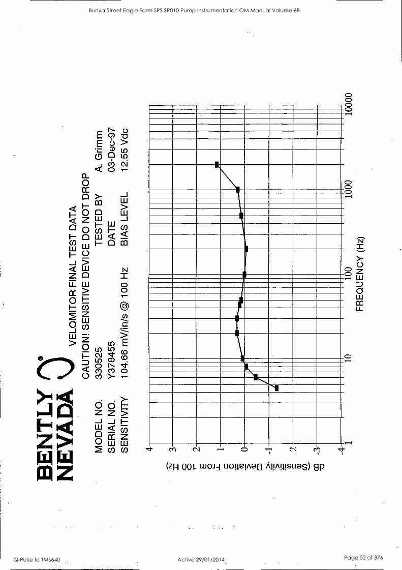
BE
NT
LY
N
EV
AD
A \J
VELO
MIT
OR
FIN
AL
TE
ST
DA
TA
C
AU
TIO
N!
SE
NS
ITIV
E D
EV
ICE
DO
NO
T D
RO
P
MO
DE
L N
O.
3305
25
TE
ST
ED
BY
A
. G
rimm
S
ER
IAL
NO
. Y
3784
55
DA
TE
03
-Dec
-97
SE
NS
ITIV
ITY
10
4.66
mV
/in/s
@ 1
00 H
z B
IAS
LE
VE
L 12
.55
Vdc
4
N
3 0
0
E
O
LL 0
2 1
..F4 5'
0 a)
0 -1
c (/)
-2
a)
-4 1
10
100
FR
EQ
UE
NC
Y (
Hz)
1000
10
000
Bunya Street Eagle Farm SPS SP010 Pump Instrumentation OM Manual Volume 6B
Q-Pulse Id TMS640 Active 29/01/2014 Page 52 of 376

BE
NT
LY
01'
NE
VA
DA
V
ELO
MIT
OR
FIN
AL
TE
ST
DA
TA
C
AU
TIO
N!
SE
NS
ITIV
E D
EV
ICE
DO
NO
T D
RO
P
MO
DE
L N
O.
3305
25
TE
ST
ED
BY
A
. G
rimm
S
ER
IAL
NO
. Y
3784
56
DA
TE
03
-Dec
-97
SE
NS
ITIV
ITY
10
1.36
mV
/in/s
@ 1
00 H
z B
IAS
LE
VE
L 12
.40
Vdc
4 3 2 1 0 -1
-2
-3
-4 1
10
100
FR
EQ
UE
NC
Y (
Hz)
1000
10
000
Bunya Street Eagle Farm SPS SP010 Pump Instrumentation OM Manual Volume 6B
Q-Pulse Id TMS640 Active 29/01/2014 Page 53 of 376

BE
NT
LY
N
EV
AD
A \
J V
ELO
MIT
OR
FIN
AL
TE
ST
DA
TA
C
AU
TIO
N!
SE
NS
ITIV
E D
EV
ICE
DO
NO
T D
RO
P
MO
DE
L N
O.
3305
25
TE
ST
ED
BY
K
. N
ong
SE
RIA
L N
O.
Y37
4672
D
AT
E
22-D
ec-9
7
SE
NS
ITIV
ITY
99
.85
mV
/in /s
@ 1
00 H
z B
IAS
LE
VE
L 12
.09
Vdc
4 3 2 1 0 -1
-2
-3
-4- 1
-110
=11
111
10
100
FR
EQ
UE
NC
Y (
Hz)
1000
10
000
Bunya Street Eagle Farm SPS SP010 Pump Instrumentation OM Manual Volume 6B
Q-Pulse Id TMS640 Active 29/01/2014 Page 54 of 376

BE
NT
LY
N
EV
AD
A \J
VELO
MIT
OR
FIN
AL
TE
ST
DA
TA
C
AU
TIO
N!
SE
NS
ITIV
E D
EV
ICE
DO
NO
T D
RO
P
MO
DE
L N
O.
3305
25
TE
ST
ED
BY
K
. N
ong
SE
RIA
L N
O.
Y37
4677
D
AT
E
22-D
ec-9
7 S
EN
SIT
IVIT
Y
95.1
7 m
V/in
/s @
100
Hz
BIA
S L
EV
EL
12.3
1 V
dc
4 3 2 1 0 -2
-3
-4 1
10
100
FR
EQ
UE
NC
Y (
Hz)
1000
10
000
Bunya Street Eagle Farm SPS SP010 Pump Instrumentation OM Manual Volume 6B
Q-Pulse Id TMS640 Active 29/01/2014 Page 55 of 376

BE
NT
LY
N
EV
AD
A
VE
LOM
ITO
R F
INA
L T
ES
T D
AT
A
CA
UT
ION
! S
EN
SIT
IVE
DE
VIC
E D
O N
OT
DR
OP
M
OD
EL
NO
. 33
0525
T
ES
TE
D B
Y
K.
Non
g S
ER
IAL
NO
. Y
3789
82
DA
TE
22
-Dec
-97
SE
NS
ITIV
ITY
10
2.10
mV
/in/s
@ 1
00 H
z B
IAS
LE
VE
L 12
.84
Vdc
4 3 2 1 0 1 -2
-3
-4 1
10
100
FR
EQ
UE
NC
Y (
Hz)
10
00
1000
0
Bunya Street Eagle Farm SPS SP010 Pump Instrumentation OM Manual Volume 6B
Q-Pulse Id TMS640 Active 29/01/2014 Page 56 of 376
BE
NT
LY
OT
h N
EV
AD
A
VE
LOM
ITO
R F
INA
L T
ES
T D
AT
A
CA
UT
ION
! S
EN
SIT
IVE
DE
VIC
E D
O N
OT
DR
OP
MO
DE
L N
O.
3305
25
TE
ST
ED
BY
K
. N
ong
SE
RIA
L N
O.
Y37
8983
D
AT
E
22-D
ec-9
7
SE
NS
ITIV
ITY
99
.92
mV
/in/s
@ 1
00 H
z B
IAS
LE
VE
L 12
.52
Vdc
4 3 2 1 0 -1
-2
-3
-4 1
10
100
1000
10
000
FR
EQ
UE
NC
Y (
Hz)
Bunya Street Eagle Farm SPS SP010 Pump Instrumentation OM Manual Volume 6B
Q-Pulse Id TMS640 Active 29/01/2014 Page 57 of 376
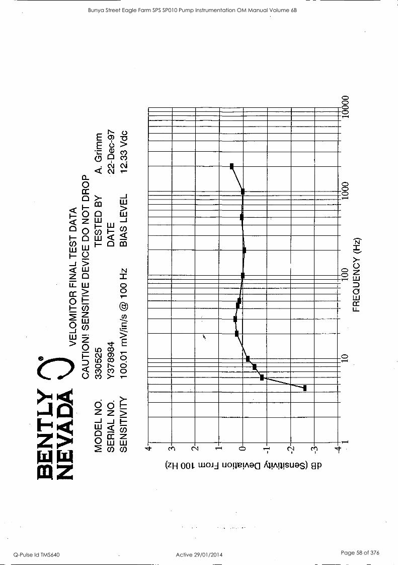
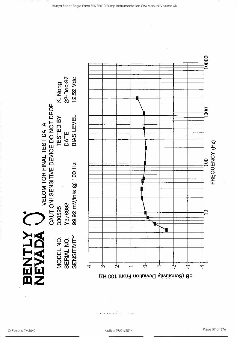
BE
NT
LY
N
EV
AD
A
VE
LOM
ITO
R F
INA
L T
ES
T D
AT
A
CA
UT
ION
! S
EN
SIT
IVE
DE
VIC
E D
O N
OT
DR
OP
M
OD
EL
NO
. 33
0525
T
ES
TE
D B
Y
A.
Grim
m
SE
RIA
L N
O.
Y37
8984
D
AT
E
22-D
ec-9
7 S
EN
SIT
IVIT
Y
100.
01
mV
/in/s
@ 1
00 H
z B
IAS
LE
VE
L 12
.33
Vdc
4
N
3 0 0
2 E 2 u_
1
0
'5
0 a)
a -1
5 c cn
-2
a)
03
-3
-4 1
10
100
FR
EQ
UE
NC
Y (
Hz)
1000
10
000
Bunya Street Eagle Farm SPS SP010 Pump Instrumentation OM Manual Volume 6B
Q-Pulse Id TMS640 Active 29/01/2014 Page 58 of 376

BE
NT
LY
N
EV
AD
A
VE
LOM
ITO
R F
INA
L T
ES
T D
AT
A
CA
UT
ION
! S
EN
SIT
IVE
DE
VIC
E D
O N
OT
DR
OP
M
OD
EL
NO
. 33
0525
T
ES
TE
D B
Y
K.
Non
g S
ER
IAL
NO
. Y
3789
85
DA
TE
22
-Dec
-97
SE
NS
ITIV
ITY
10
1.18
mV
/in/s
@ 1
00 H
z B
IAS
LE
VE
L 12
.38
Vdc
4 3 2 1 0 -1
-2
-3
-4
10
FR
EQ
UE
NC
Y
100
(Hz)
1000
10
000
Bunya Street Eagle Farm SPS SP010 Pump Instrumentation OM Manual Volume 6B
Q-Pulse Id TMS640 Active 29/01/2014 Page 59 of 376

BE
NT
LY
08'
NE
VA
DA
V
ELO
MIT
OR
FIN
AL
TE
ST
DA
TA
C
AU
TIO
N!
SE
NS
ITIV
E D
EV
ICE
DO
NO
T D
RO
P
MO
DE
L N
O.
3305
25
TE
ST
ED
BY
K
. N
ong
SE
RIA
L N
O.
Y37
8986
D
AT
E
22-D
ec-9
7 S
EN
SIT
IVIT
Y
101.
77 m
V/in
/s @
100
Hz
BIA
S L
EV
EL
11.7
3 V
dc
4 3 2 1 0 - 1 -3
-4 1
10
100
FR
EQ
UE
NC
Y (
Hz)
1000
10
000
Bunya Street Eagle Farm SPS SP010 Pump Instrumentation OM Manual Volume 6B
Q-Pulse Id TMS640 Active 29/01/2014 Page 60 of 376

BE
NT
LY
N
EV
AD
A
VE
LOM
ITO
R F
INA
L T
ES
T D
AT
A
CA
UT
ION
! S
EN
SIT
IVE
DE
VIC
E D
O N
OT
DR
OP
MO
DE
L N
O.
3305
25
TE
ST
ED
BY
K
. N
ong
SE
RIA
L N
O.
Y37
8987
D
AT
E
22-D
ec-9
7 S
EN
SIT
IVIT
Y
101.
22 m
V/in
/s @
100
Hz
BIA
S L
EV
EL
11.7
7 V
dc
4 3 2 1 0 -1
-2
-3-
-4 1
-IM
F
10
100
FR
EQ
UE
NC
Y (
Hz)
1000
10
000
Bunya Street Eagle Farm SPS SP010 Pump Instrumentation OM Manual Volume 6B
Q-Pulse Id TMS640 Active 29/01/2014 Page 61 of 376

BE
NT
LY
N
EV
AD
A
VE
LOM
ITO
R F
INA
L T
ES
T D
AT
A
CA
UT
ION
! S
EN
SIT
IVE
DE
VIC
E D
O N
OT
DR
OP
MO
DE
L N
O.
3305
25
TE
ST
ED
BY
K
. N
ong
SE
RIA
L N
O.
Y37
8988
D
AT
E
22-D
ec-9
7
SE
NS
ITIV
ITY
10
0.94
mV
/in/s
@ 1
00 H
z B
IAS
LE
VE
L 12
.50
Vdc
4
N
3
0 0 2
E 0
1
0 -1
c -2
a)
-4
NM
1 10
10
0 10
00
1000
0
FR
EQ
UE
NC
Y (
Hz)
Bunya Street Eagle Farm SPS SP010 Pump Instrumentation OM Manual Volume 6B
Q-Pulse Id TMS640 Active 29/01/2014 Page 62 of 376
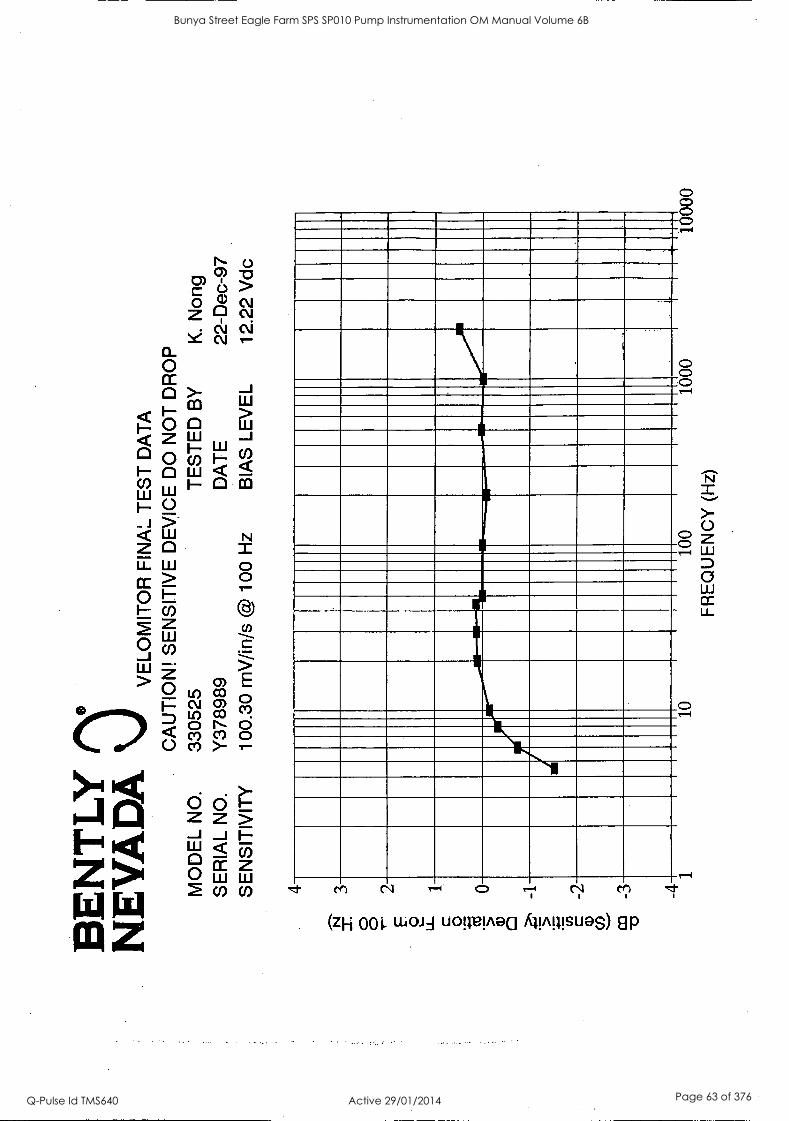
BE
NT
LY
N
EV
AD
A
VE
LOM
ITO
R F
INA
L T
ES
T D
AT
A
CA
UT
ION
! S
EN
SIT
IVE
DE
VIC
E D
O N
OT
DR
OP
M
OD
EL
NO
. 33
0525
T
ES
TE
D B
Y
K.
Non
g S
ER
IAL
NO
. Y
3789
89
DA
TE
22
-Dec
-97
SE
NS
ITIV
ITY
10
0.30
mV
/in/s
@ 1
00 H
z B
IAS
LE
VE
L 12
.22
Vdc
4 3 2 1 0 -1
-2
-3
-4 1
10
100
FR
EQ
UE
NC
Y (
Hz)
1000
10
000
Bunya Street Eagle Farm SPS SP010 Pump Instrumentation OM Manual Volume 6B
Q-Pulse Id TMS640 Active 29/01/2014 Page 63 of 376

BE
NT
LY
N
EV
AD
A
VE
LOM
ITO
R F
INA
L T
ES
T D
AT
A
CA
UT
ION
! S
EN
SIT
IVE
DE
VIC
E D
O N
OT
DR
OP
MO
DE
L N
O.
3305
25
TE
ST
ED
BY
K
. N
ong
SE
RIA
L N
O.
Y37
8990
D
AT
E
22-D
ec-9
7
SE
NS
ITIV
ITY
99
.88
mV
/in/s
@ 1
00 H
z B
IAS
LE
VE
L 12
.60
Vdc
4 3 2 1 0 -1
-2
-3
-4 1
10
100
FR
EQ
UE
NC
Y (
Hz)
1000
10
000
Bunya Street Eagle Farm SPS SP010 Pump Instrumentation OM Manual Volume 6B
Q-Pulse Id TMS640 Active 29/01/2014 Page 64 of 376

BE
NT
LY
N
EV
AD
A
VE
LOM
ITO
R F
INA
L T
ES
T D
AT
A
CA
UT
ION
! S
EN
SIT
IVE
DE
VIC
E D
O N
OT
DR
OP
MO
DE
L N
O.
3305
25
TE
ST
ED
BY
K
. N
ong
SE
RIA
L N
O.
Y37
8992
D
AT
E
22-D
ec-9
7 S
EN
SIT
IVIT
Y
101.
66 m
V/in
/s @
100
Hz
BIA
S L
EV
EL
12.0
2 V
dc
4 3 2 1 0 -1
-2
-3
-4 1
10
100
FR
EQ
UE
NC
Y (
Hz)
1000
10
000
Bunya Street Eagle Farm SPS SP010 Pump Instrumentation OM Manual Volume 6B
Q-Pulse Id TMS640 Active 29/01/2014 Page 65 of 376

BE
NT
LY
N
EV
AD
A
VE
LOM
ITO
R F
INA
L T
ES
T D
AT
A
CA
UT
ION
! S
EN
SIT
IVE
DE
VIC
E D
O N
OT
DR
OP
M
OD
EL
NO
. 33
0525
T
ES
TE
D B
Y
K.
Non
g S
ER
IAL
NO
. Y
3789
93
SE
NS
ITIV
ITY
10
2.19
mV
/in/s
@ 1
00 H
z B
IAS
LE
VE
L 1
2.1
9 V
dc
DA
TE
22
-Dec
-97
4
ry
3
0 0 2
E
0
1
0
0 a)
-4 1
10
100
FR
EQ
UE
NC
Y (
Hz)
1000
10
000
Bunya Street Eagle Farm SPS SP010 Pump Instrumentation OM Manual Volume 6B
Q-Pulse Id TMS640 Active 29/01/2014 Page 66 of 376

(RERGLE SW IT CHBORR DS) INSPECTION AND TEST PLAN Job Name:/ .<,' t`-"441 --i.stErIP-6 - '9554/S Coy Ctaa.A._Job Number CT 94- SCA Designation: AV_fixil-'<--/-> Ck-si-v-:7-er: Date: /0 (47 G.A. Drawing Numbers: d C c _ 9 7- 3 Revision: / Electrical Schematic Drawing Numbers: dc: (9 7- 41 -rD 17 Revision: 2, 1) zi 1-) -1--;Z--) 2-) 2_
1 2 2 Z 2 I JA..-z-,/,it Hold Operation Applicable Acceptance Criteria Reagle Client Other
. , Records Kept
Point Procedure or
_
Standard
10.2 RECEIVING INSPECTION AND TESTING 1 Purchased
Products QP10.2 Check conformance with
details specified on X Delivery Dockets
Purchase order 2 Customer
Supplied QP7.1, QP10.2
Check conformance with details provided by
X Delivery Dockets
Products Customer.
10.3 IN PROCESS INSPECTION AND TESTING 3 Sheetmetal QP10.3 Check conformance with
details provided on drawings and/or specification (refer QPF10.2B)
X Job Inspection Sheet QPF10.2B
4 Painting QP10.3 Check conformance with details provided on drawings and/or specification (refer QPF10.2B)
X Job Inspection Sheet QPF10.2B
5 Electrical Equipment
QP10.3 Check conformance with details provided on drawings and/or specification (refer QPF10.2B)
X Job Inspection Sheet QPF10.2B
6 Copper Busbars
QP10.3 Check conformance with details provided on drawings and/or specification (refer QPF10.2B)
N/A Job Inspection Sheet QPF10.2B
7 Electrical Cabling
QP10.3 Check conformance with details provided on drawings and/or specification (refer QPF10.2B)
X Job Inspection Sheet QPF10.2B
9 Electrical Connections
QP10.3 Check all busbar joint bolt torques. Give pull check for all cable terminations (refer QPF10.2B)
N/A
X
Job Inspection Sheet QPF10.2B
10 Labels and
Name Plates QP10.3 Check conformance with
details provided on drawings and/or specification (refer QPF10.2B)
X Job Inspection Sheet QPF10.2B
ABBREVIATIONS: QP - Quality Procedure QPF - Quality Procedure Form X - Test/Inspection required N/A - Not Applicable
1,012M: OPF 10- I B. DOC ISSUE: I AM EN UM ENT: A DATE: I 7Sep-97 PAGE I OF 2
Bunya Street Eagle Farm SPS SP010 Pump Instrumentation OM Manual Volume 6B
Q-Pulse Id TMS640 Active 29/01/2014 Page 67 of 376
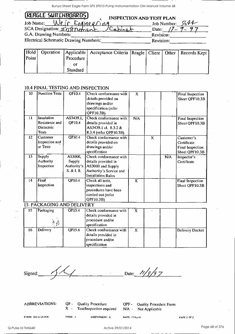
(RERGLE SINCHBORRDS) Job Name: klOcii r CAI Inc SCA Designation: G.A. Drawing Numbers: Electrical Schematic Drawing Numbers:
INSPECTION AND TEST PLAN Job Number: 5-6<14' Date: /7- 7- 9 7 Revision: Revision:
Hold Operation Applicable Acceptance Criteria Reagle Client Other Records Kept Point Procedure
Of
Standard
10.4 FINAL TESTING AND INSPECTION 10 Function Tests QP10.4 Check conformance with
details provided on
drawings and/or specification (refer QPF10.3B)
X Final Inspection Sheet QPF10.3B
11 Insulation Resistance and Dielectric Tests
AS3439.1, QP10.4
Check conformance with details provided in
AS3439.1 cl. 8.3.2 & 8.3.4 (refer QPF10.3B)
N/A Final Inspection Sheet QPF10.3B
12 Customer Inspection and or Tests
QP10.4 Check conformance with details provided on drawings and/or specification
X Customer's Certificate Final Inspection Sheet QPF10.3B
13 Supply Authority Inspection
AS3000, Supply
Authority's S. & I. R.
Check conformance with details provided in
AS3000 and Supply Authority's Service and Installation Rules
N/A Inspector's Certificate
14 Final Inspection
QP10.4 Check all tests, inspections and
Procedures have been carried out (refer QPF10.3B)
X Final Inspection Sheet QPF10.3B
15. PACKAGING AND DELIVERY 15 Packaging 'QP15.4 Check conformance with
details provided in
procedure and/or specification
X
16 Delivery QP15.6 Check conformance with details provided in
procedure and/or specification
X Delivery Docket
Signed: Date: /0/7
ABBREVIATIONS: QP - Quality Procedure QPF - Quality Procedure Form X - Test/Inspection required N/A - Not Applicable
FORM: QPFID-IB.DOC ISSUE: I AMENDMENT: A DATE: I7 -S. -97 PAGE 2 OF 2
Bunya Street Eagle Farm SPS SP010 Pump Instrumentation OM Manual Volume 6B
Q-Pulse Id TMS640 Active 29/01/2014 Page 68 of 376
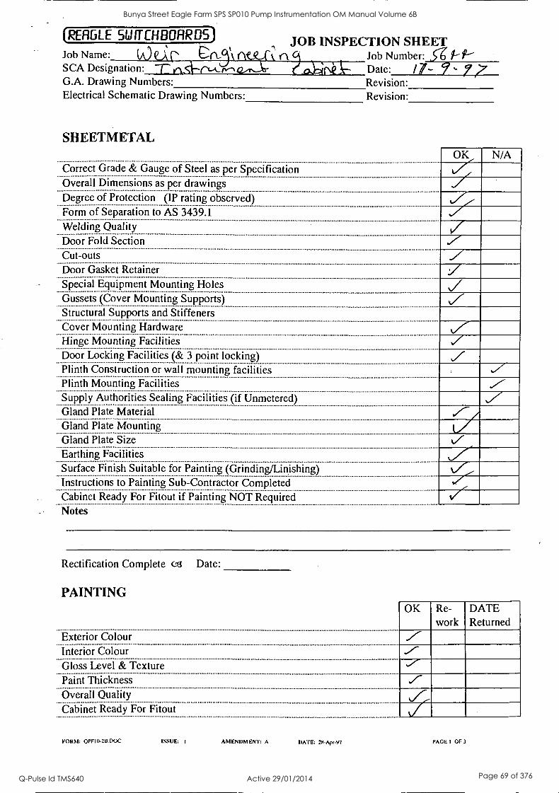
(RERGLE SWITCHBOARDS)
Job Name: r rAtexk: SCA Designation: a.1 G.A. Drawing Numbers: Electrical Schematic Drawing Numbers:
JOB INSPECTION SHEET Job Number: 56 it- f2--
SHEETMETAL
Date: /7-- - Revision: Revision:
OK Correct Grade & Gauge of Steel as per Specification Overall Dimensions as per drawings
N/A
Degree of Protection (IP rating observed) Form of Separation to AS 3439.1 Welding Quality Door Fold Section Cut-outs Door Gasket Retainer Special Equipment Mounting Holes Gussets (Cover Mounting Supports) Structural Supports and Stiffeners Cover Mounting Hardware Hinge Mounting Facilities Door Locking Facilities (& 3 point locking) Plinth Construction or wall mounting facilities Plinth Mounting Facilities Supply Authorities Sealing Facilities (if Unmetered) Gland Plate Material Gland Plate Mounting Gland Plate Size Earthing Facilities Surface Finish Suitable for Painting (Grindin inishing) Instructions to Painting Sub-Contractor Completed Cabinet Ready For Fitout if Painting NOT Required V Notes
Rectification Complete 03 Date:
PAINTING OK Re-
work DATE Returned
Exterior Colour Interior Colour Gloss Level & Texture Paint Thickness Overall Quality Cabinet Ready For Fitout
FORM: OPF10-213.DOC ISSUE: I AMENDMENT: A DATE: 2S.Apr-97 PAGE I OF 3
Bunya Street Eagle Farm SPS SP010 Pump Instrumentation OM Manual Volume 6B
Q-Pulse Id TMS640 Active 29/01/2014 Page 69 of 376
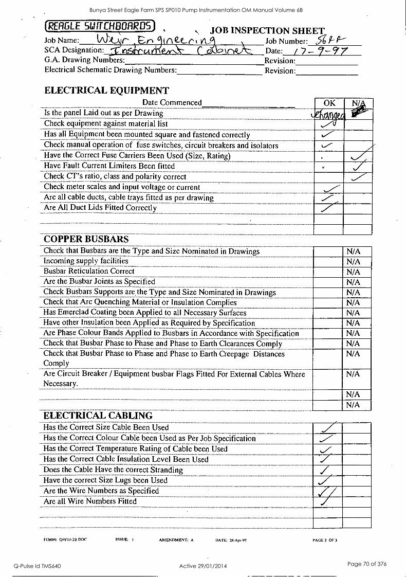
(REFIGLE SWITCHBOARDS) .,. JOB INSPECTION SHEET
Job Name: (Akivr- t--1 ine-e-rtvL Job Number: SCA Designation: \-- b Date: / 7 - 7-97 G.A. Drawing Numbers: Revision: Electrical Schematic Drawing Numbers: Revision:
ELECTRICAL EQUIPMENT Date Commenced
Is the panel Laid out as per Drawing Check equipment against material list
OK N/
Has all Equipment been mounted square and fastened correctly Check manual operation of fuse switches, circuit breakers and isolators Have the Correct Fuse Carriers Been Used (Size, Rating) Have Fault Current Limiters Been fitted Check CT's ratio, class and polarity correct Check meter scales and input voltage or current Are all cable ducts, cable trays fitted as per drawing Are All Duct Lids Fitted Correctly
COPPER BUSBARS Check that Busbars are the Type and Size Nominated in Drawings N/A Incoming supply facilities Busbar Reticulation Correct
N/A N/A
Are the Busbar Joints as Specified N/A Check Busbars Supports are the Type and Size Nominated in Drawings N/A Check that Arc Quenching Material or Insulation Complies N/A Has Emerclad Coating been Applied to all Necessary Surfaces N/A Have other Insulation been Applied as Required by Specification N/A Are Phase Colour Bands Applied to Busbars in Accordance with Specification N/A Check that Busbar Phase to Phase and Phase to Earth Clearances Comply N/A Check that Busbar Phase to Phase and Phase to Earth Creepage Distances Comply
N/A
Are Circuit Breaker / Equipment busbar Flags Fitted For External Cables Where Necessary.
ELECTRICAL CABLING Has the Correct Size Cable Been Used Has the Correct Colour Cable been Used as Per Job Specification Has the Correct Temperature Rating of Cable been Used Has the Correct Cable Insulation Level Been Used
y
N/A
N/A
N/A
Does the Cable Have the correct Stranding Have the correct Size Lugs been Used Are the Wire Numbers as Specified Are all Wire Numbers Fitted
FORM: OPE19-213.DOC ISSUE: I AMENDMENT: A DATE: II-Apr-97 PAGE 2 OF 3
Bunya Street Eagle Farm SPS SP010 Pump Instrumentation OM Manual Volume 6B
Q-Pulse Id TMS640 Active 29/01/2014 Page 70 of 376
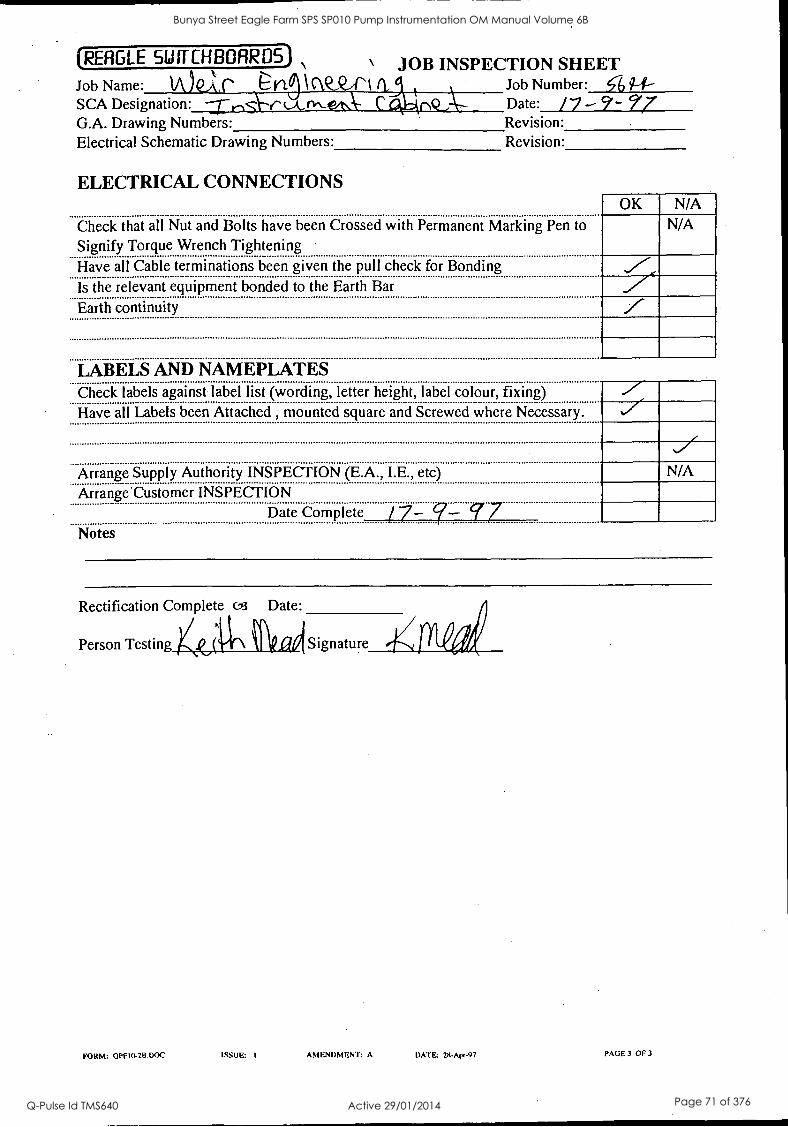
(REAGLE SWITCHBOARDS) \ JOB INSPECTION SHEET Job Name: v\.) eks- E-ri, IcW_QiN a, Job Number: .51, g-f-
t SCA Designation: r '_A Mt Date: /7- 99- 77 G.A. Drawing Numbers: Revision: Electrical Schematic Drawing Numbers: Revision:
ELECTRICAL CONNECTIONS OK
Check that all Nut and Bolts have been Crossed with Permanent Marking Pen to
Signify Torque Wrench Tightening
N/A N/A
Have all Cable terminations been given the pull check for Bonding Is the relevant equipment bonded to the Earth Bar
Earth continuity
LABELS AND NAMEPLATES Check labels against label list (wording, letter height, label colour, fixing)
Have all Labels been Attached , mounted square and Screwed where Necessary.
Arrange Supply Authority INSPECTION (E.A., I.E., etc) N/A
Arrange Customer INSPECTION Date Complete
Notes
Rectification Complete 03 Date:
Person Testing Signature
FORM: OPF10-213.00C ISSUE: I AMENDMENT: A DATE: 2R.Apr-97 PAGE 3 OF 3
Bunya Street Eagle Farm SPS SP010 Pump Instrumentation OM Manual Volume 6B
Q-Pulse Id TMS640 Active 29/01/2014 Page 71 of 376
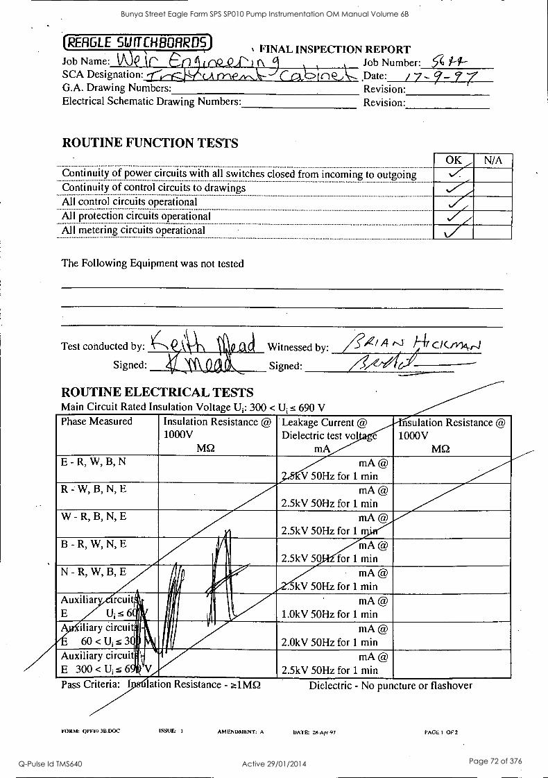
(RERGLE SWITCHBOARDS) N FINAL INSPECTION REPORT
Job Name: WP (.-, 0 (Q__,2, ,, ' E ,_
Job Number: c4 Pf--- SCA Designation: .11,--1-. (A ry\e,,,,-A- (la inQ_, Date: / 7 - ?- 7 G.A. Drawing Numbers: Revision: Electrical Schematic Drawing Numbers: Revision:
ROUTINE FUNCTION TESTS
Continuity of power circuits with all switches closed from incoming to outgoing Continuity of control circuits to drawings All control circuits operational All protection circuits operational All metering circuits operational
N/A
The Following Equipment was not tested
Test conducted by:
Signed:
ROUTINE ELECTRICAL TESTS
se/ Ft/ cl(m,vr.1 Witnessed by:
Signed:
Main Circuit Rated Insulation Voltage Ui: 300 < U s 690 V
Phase Measured Insulation Resistance @ 1000V
MQ
Leakage Current @ Dielectric test vol
mA
nsulation Resistance @ 1000V
MQ E - R, W, B, N mA@
V 50Hz for 1 min R - W, B, N, E mA@
2.5kV 50Hz for 1 min W - R, B, N, E mA@
2.5kV 50Hz for 1
B - R, W, N, E l
iir mA@
2.5kV 50 - for 1 min N - R, W, B, E
Hi V
!fl Al mA @
. kV 50Hz for 1 min Auxiliar ircuit ik
E U; s 64 n
. iliary circuitq 60 < U, s 31.1
111111 llig
1 ilE Mt.
mA @ 1.0kV 50Hz for 1 min
mA @ 2.0kV 50Hz for 1 min
Auxiliary circuit:' E 300 < U; s 6*
11
' mA @ 2.5kV 50Hz for 1 min
Pass Criteria: I lation Resistance - alMQ
FORM: OPE I 0-3B.DOC ISSUE I
Dielectric - No puncture or flashover
AMENDMENT: A DATE: 26-Apr-97 PAGE I OF 2
Bunya Street Eagle Farm SPS SP010 Pump Instrumentation OM Manual Volume 6B
Q-Pulse Id TMS640 Active 29/01/2014 Page 72 of 376
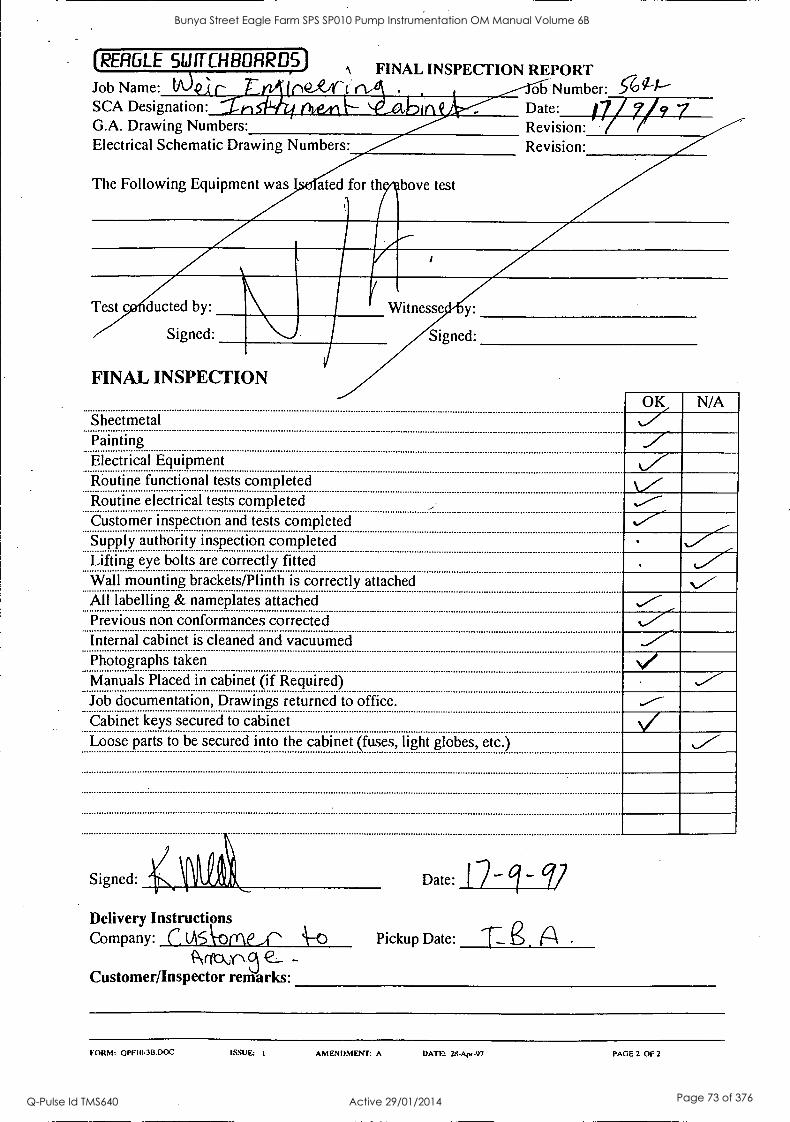
(RERGLE 511111-CH BOAR DS) 1 FINAL INSPECTION REPORT
Job Name: tA)(r n#2..1rc ob Number: 5-694" SCA Designation: A
G.A. Drawing Numbers: Revision: 7/ ? 7 1.1. A- Date: 71 Revision: Electrical Schematic Drawing Numbers:
The Following Equipment was ated for th bove test
Test c ducted by:
Signed:
FINAL INSPECTION
Sheetmetal OK
Painting
N/A
Electrical Equipment Routine functional tests completed Routine electrical tests completed Customer inspection and tests completed
.V
Supply authority inspection completed Lifting eye bolts are correctly fitted Wall mounting brackets/Plinth is correctly attached \v- All labelling & nameplates attached Previous non conformances corrected Internal cabinet is cleaned and vacuumed Photographs taken Manuals Placed in cabinet (if Required) Job documentation, Drawings returned to office. Cabinet keys secured to cabinet Loose parts to be secured into the cabinet (fuses, light globes, etc.)
Signed:
Delivery Instructions Company: C (As Vorne_A^ '-43
Pv-100-1 e_ - Customer/Inspector remarks:
Date: I -
Pickup Date:
FORM: QPFIO.3B.DOC ISSUE I AMENDMENT: A DATE 2S-A1w-97 PAGE 2 OF 2
Bunya Street Eagle Farm SPS SP010 Pump Instrumentation OM Manual Volume 6B
Q-Pulse Id TMS640 Active 29/01/2014 Page 73 of 376

BRISBANE CITY COUNCIL Dept. Water Supply and Sewage Pumpwell No 1, Eagle Farm Pump Station
BCC Contract No S20195196 System Instrumentation
Operation and Maintenance Manual
Section 5 Start-Up and Shut-Down Procedures
This Section is not applicable to the System Instrumentation. The start up and shutdown procedures for the pumping system are included in Volume 2.
15140/last ManIBRH Issue 1 29-Apr-98 Page 5-1
Bunya Street Eagle Farm SPS SP010 Pump Instrumentation OM Manual Volume 6B
Q-Pulse Id TMS640 Active 29/01/2014 Page 74 of 376
BRISBANE CITY COUNCIL Dept. Water Supply and Sewage Pumpwell No 1, Eagle Farm Pump Station
BCC Contract No S20/95/96 System Instrumentation
Operation and Maintenance Manual
Section 6 Commissioning
A detailed Inspection and Test Plan (ITP) has been prepared for the on site pre- commissioning and commissioning of the pump system. The ITP together with all of the relevant testing data has been included in Volume 3.
15140/Inst Man/BRH Issue 1 29-Apr-98 Page 6-1
Bunya Street Eagle Farm SPS SP010 Pump Instrumentation OM Manual Volume 6B
Q-Pulse Id TMS640 Active 29/01/2014 Page 75 of 376
BRISBANE CITY COUNCIL Dept. Water Supply and Sewage Pumpwell No 1, Eagle Farm Pump Station
BCC Contract No S20/95/96 System. Instrumentation
Operation and Maintenance Manual
Section 7 Operations
This Section is not applicable to the Pump Instrumentation. The operational procedures for the pumping system are included in other volumes.
The operational procedures for specific items of equipment supplied under this contract are generally covered in other sections of this manual.
15140/Inst Man/BRH Issue 1 29-Apr-98 Page 7-1
Bunya Street Eagle Farm SPS SP010 Pump Instrumentation OM Manual Volume 6B
Q-Pulse Id TMS640 Active 29/01/2014 Page 76 of 376
BRISBANE CITY COUNCIL Dept. Water Supply and Sewage Pumpwell No 1, Eagle Farm Pump Station
BCC Contract No S20195196 System Instrumentation
Operation and Maintenance Manual
Section 8 Maintenance
Maintenance of the field sensors generally involves replacement on failure. The Bently Nevada 3300 System Monitor may require maintenance or adjustment. This can be carried with reference to the following Bently Nevada Publications. It should be noted that the procedures described in this section should only be carried out by a qualified Electronics Technician.
8.1 Temperature Monitor
The following publication entitled 3300 Six Channel Temperature Monitor Maintenance Manual (Part No 80183-01 Rev L) is prepared by Bently Nevada for plant personnel who install and maintain the system. It provides a detailed description of the maintenance and adjustment procedures for the Temperature Monitor.
The following sections are included:
8.1.1 Six Channel Temperature Monitor System
8.1.2 Monitor Functions
8.1.3 Monitor Options
8.1.4 Programmable Options
8.1.5 OK
8.1.6 Bypass
8.1.7 Alarm 1
8.1.8 Alarm 2
8.1.9 Read Channel Temperature
8.1.10 Read Alarm 1 Setpoint Levels
8.1.11 Read Alarm 2 Setpoint Levels
8. 1. 12 Self Test
8.1.13 Error Codes
15140/Inst Man/BRH Issue 1 29-Apr-98 Page 8-1
Bunya Street Eagle Farm SPS SP010 Pump Instrumentation OM Manual Volume 6B
Q-Pulse Id TMS640 Active 29/01/2014 Page 77 of 376
BRISBANE CITY COUNCIL Dept. Water Supply and Sewage Pumpwell No 1, Eagle Farm Pump Station
BCC Contract No S20/95/96 System Instrumentation
Operation and Maintenance Manual
8.1.14 Disassembly Procedure
8.1.15 Recorder /Relay Module
8.1.16 Temperature Input Module
8.1.17 Installed Program Options
8.1.18 RTD Analogue Board Options
8.1.19 First Out, Alarm Delays, Alarm 2 Options
8.1.20 Transducer Type, OK Options
8.1.21 Full Scale, Recorder Options
8.1.22 Alarm Setpoint Adjustment
8.1.23 Channel Bypass
8.1.24 Alarm 2 Bypass
8.1.25 Test Channel Alarms - TC
8.1.26 Test Channel Alarms - RTD
8.1.27 Test OK Limits - TC
8.1.28 Test OK Limits - RTD
8.1.29 Test OK Limits - TC
8.1.30 Test OK Limits - RTD
8.1.31 Test/Calibration - TC
8.1.32 Test/Calibration - RTD
8.1.33 Field Wiring Diagrams
8.1.34 Recommended Spare Parts -TC Monitor
8.1.35 Recommended Spare Parts - RTD Monitor
8.1.36 Specifications
15140/Inst Man/BRH Issue 1 29-Apr-98 Page 8-2
Bunya Street Eagle Farm SPS SP010 Pump Instrumentation OM Manual Volume 6B
Q-Pulse Id TMS640 Active 29/01/2014 Page 78 of 376
PART NO. 80183-01 .REVISION L,
NOVEMBER 1996
3300 SIX CHANNEL TEMPERATURE MONITOR
3300/30 - THERMOCOUPLE 3300/35 - RTD
MAINTENANCE MANUAL
BENTLY NEVADA
Bunya Street Eagle Farm SPS SP010 Pump Instrumentation OM Manual Volume 6B
Q-Pulse Id TMS640 Active 29/01/2014 Page 79 of 376
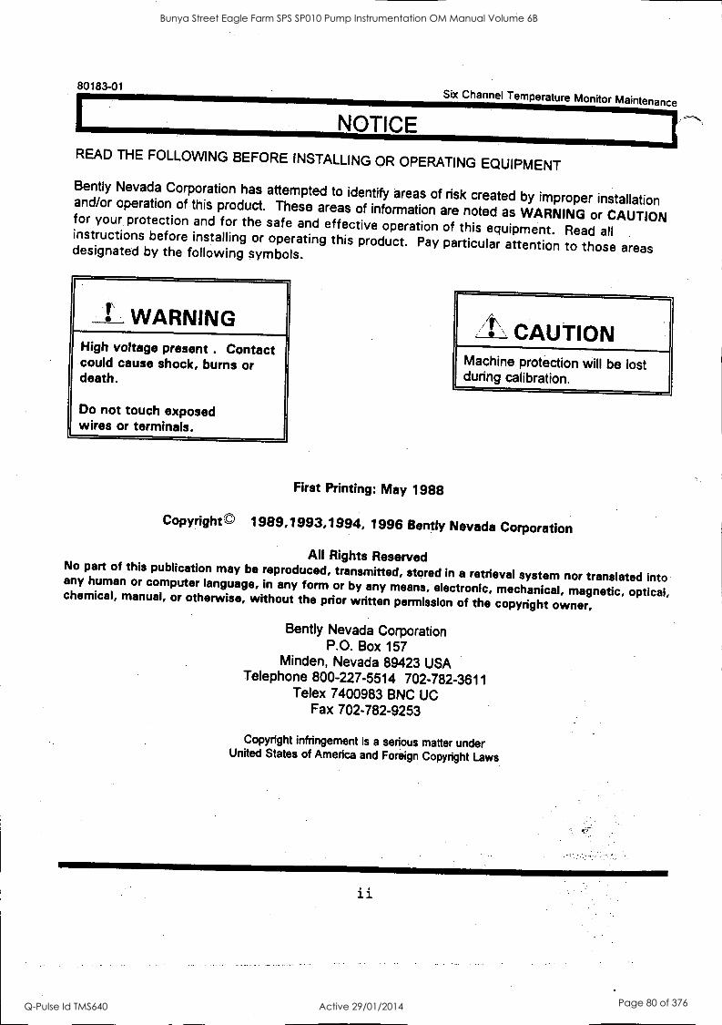
80183-01 Six Channel Temperature Monitor Maintenance
NOTICE READ THE FOLLOWING BEFORE INSTALLING OR OPERATING EQUIPMENT
Bent ly Nevada Corporation has attempted to identify areas of risk created by improper installation and/or operation of this product. These areas of information are noted as WARNING or CAUTION for your protection and for the safe and effective operation of this equipment. Read all instructions before installing or operating this product. Pay particular attention to those areas designated by the following symbols.
WARNING High voltage present . Contact could cause shock, bums or death.
Do not touch exposed wires or terminals.
First Printing: May 1988
14\\ CAUTION Machine protection will be lost during calibration.
Copyright © 1989,1993,1994, 1996 Bently Nevada Corporation
All Rights Reserved No part of this publication may be reproduced, transmitted, stored in a retrieval system nor translated into any human or computer language, in any form or by any means, electronic, mechanical, magnetic, optical, chemical, manual, or otherwise, without the prior written permission of the copyright owner,
Bently Nevada Corporation P.O. Box 157
Minden, Nevada 89423 USA Telephone 800-227-5514 702-782-3611
Telex 7400983 BNC UC Fax 702-782-9253
Copyright infringement is a serious matter under United States of America and Foreign Copyright Laws
ii
Bunya Street Eagle Farm SPS SP010 Pump Instrumentation OM Manual Volume 6B
Q-Pulse Id TMS640 Active 29/01/2014 Page 80 of 376

Sbc Channel Temperature Monitor Maintenance 80183-01
FOREWORD
This document is intended for personnel who install and maintain the 3300 Monitoring System. The procedures are presented in step-by-step graphic format.
RELATED DOCUMENTS
3300 System Overview, 80171-01
3300 System Installation Instructions, 80172-01
3300 System Troubleshooting, 80173-01
3300/12 AC Power Supply, 89602-01
3300/14 DC Power Supply, 101256-01
3300/03 System Monitor, 89604-01
3300/30 and 3300/35 Six Channel Temperature Monitor Operation, 80182-01
3300 Internal Barrier Installation, 88837-01
Keyphasor® and Proximitor are registered trademarks of Bent ly Nevada Corporation
SYMBOLS Special symbols are used in the manual to illustrate specifics in the step-by-step process. For example:
PRESS FLASHING CONNECT
TEST EQUIPMENT (Recommended) Digital Wattmeter Decade Resistance
GOO
4 1/2-D.g.t Display 0 to 1000 Voc /Vdc
0 to 10 megohms
DISCONNECT
Monitor Extender Board
0 0 0 0 0 0 0 0
Range 0.01 ohm to 11.1111 Kohn
in Five decodes t 0.01% 2.5
miliiomm
BENTLY NEVADA CORPORATION P/N 78894-01
OBSERVE SCREWDRIVER
MI Molt Source
Range 0 to t 20V Resolution t ImV
(.1 10AV with 1001 divider )
111
Bunya Street Eagle Farm SPS SP010 Pump Instrumentation OM Manual Volume 6B
Q-Pulse Id TMS640 Active 29/01/2014 Page 81 of 376

80183-01 Six Channel Temperature Monitor Maintenance
iv
Bunya Street Eagle Farm SPS SP010 Pump Instrumentation OM Manual Volume 6B
Q-Pulse Id TMS640 Active 29/01/2014 Page 82 of 376
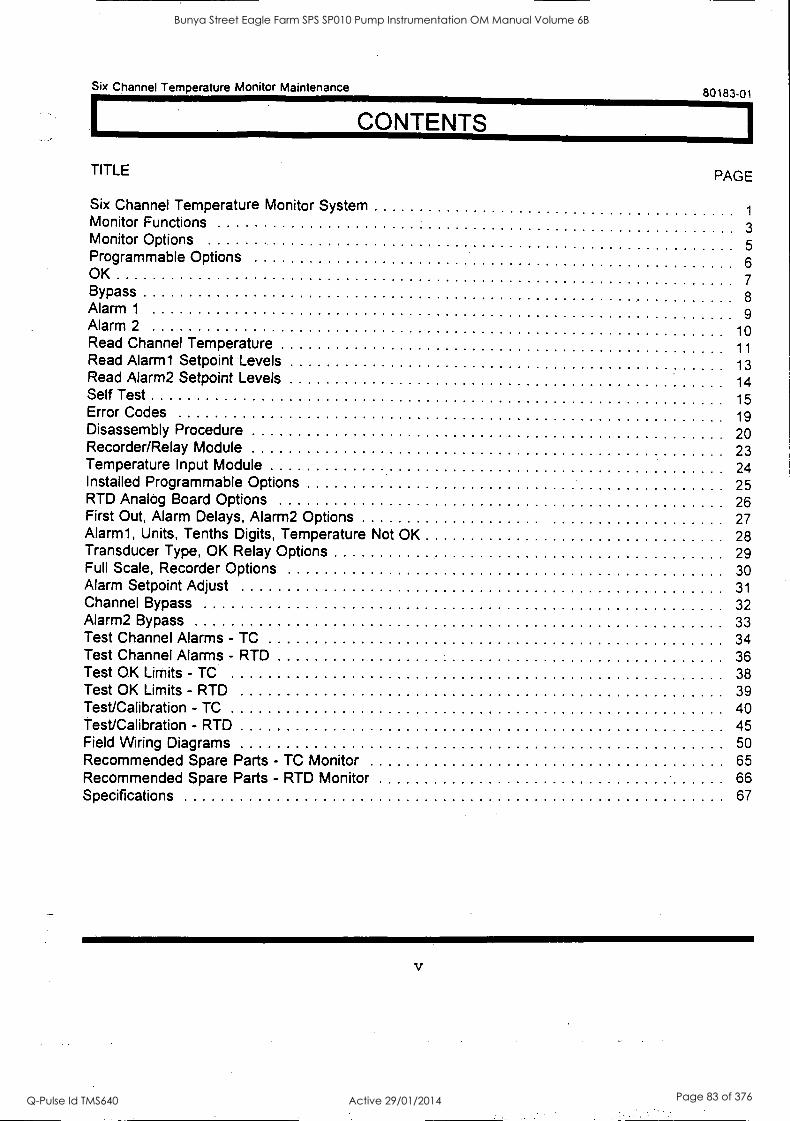
Six Channel Temperature Monitor Maintenance 80183-01
CONTENTS
TITLE PAGE
Six Channel Temperature Monitor System 1
Monitor Functions 3 Monitor Options 5 Programmable Options 6 OK
7 Bypass 8 Alarm 1 9 Alarm 2 10 Read Channel Temperature 11 Read Alarm1 Setpoint Levels 13 Read Alarm2 Setpoint Levels 14 Self Test 15 Error Codes 19 Disassembly Procedure 20 Recorder/Relay Module 23 Temperature Input Module 24 Installed Programmable Options 25 RTD Analog Board Options 26 First Out, Alarm Delays, Alarm2 Options 27 Alarm1, Units, Tenths Digits, Temperature Not OK 28 Transducer Type, OK Relay Options 29 Full Scale, Recorder Options 30 Alarm Setpoint Adjust 31 Channel Bypass 32 Alarm2 Bypass 33 Test Channel Alarms - TC 34 Test Channel Alarms - RTD 36 Test OK Limits - TC 38 Test OK Limits - RTD 39 Test/Calibration - TC 40 Test/Calibration - RTD 45 Field Wiring Diagrams 50 Recommended Spare Parts - TC Monitor 65 Recommended Spare Parts - RTD Monitor 66 Specifications 67
V
Bunya Street Eagle Farm SPS SP010 Pump Instrumentation OM Manual Volume 6B
Q-Pulse Id TMS640 Active 29/01/2014 Page 83 of 376

80183-01 Six Channel Temperature Monitor Maintenance
vi
Bunya Street Eagle Farm SPS SP010 Pump Instrumentation OM Manual Volume 6B
Q-Pulse Id TMS640 Active 29/01/2014 Page 84 of 376
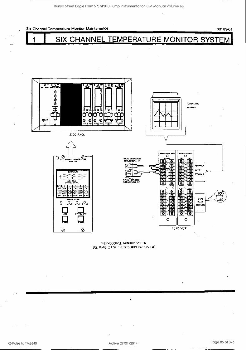
Fl SIX CHANNEL TEMPERATURE MONITOR SYSTEM1
Six Channel Temperature Monitor Maintenance 80183-01
V 0-
=3
1,...ii- 3
6 6 6 6
--T. Hr It-CI
170/1- cicogoopo
a 1" 1
inti
0 '''' LIZ
0
Lila'
0
- o
0
.7" .N.. 3300 RACK
0 1 9. Cmrrod0. II:WPC 0 4(4471" MC4I TOR
i I._
0...wWi.
0.114 2
It WPCR6
I I I
WAGN
3
Mk
-1 SAO S I.A3
4
__I I
5 6
01 61112
41141
EPP
OK AL. M 2
ALIO
819
OK ACM2 A6111
PP
OK ALM2 ALM 1
13YP
OK AM2 kW 1 8 rl,
OK ALM2 At IA I
840
(C?
w,e0,
4449647
wOCIE
M. /O.
0
SIAM
4.244.
046+6:1.
62ss
snr
ft../
0
MICA UNVONXD DEINOMPLE TO
Kt=PC73-
TYPICAL GROWCED NERtiCCOIPIE TO
THERMOCOUPLE MONITOR SYSTEM
(SEE PACE 2 FOR THE RT0 MONITOR SYSTEM)
INFORATURE
ROVOER
NINIECIZOU
El
.41 0 0 El
410}066 0,1KM
0 0 El
oec-,.11111:31
1 71 al is KsII
ICs31
1(z31. IC:11 Cs
Es/ Cs
ra 1CollwICsl 1-1 El
0
El El Efl El 1(011121M Csi IMIEMICs31 Call Cs3
IC:310 ('ill IM $11:3 Csl
ICII Ks] 1(a (.]I IM w Cs]
El El 0 El 0 0
REAR VIEW
1
Bunya Street Eagle Farm SPS SP010 Pump Instrumentation OM Manual Volume 6B
Q-Pulse Id TMS640 Active 29/01/2014 Page 85 of 376
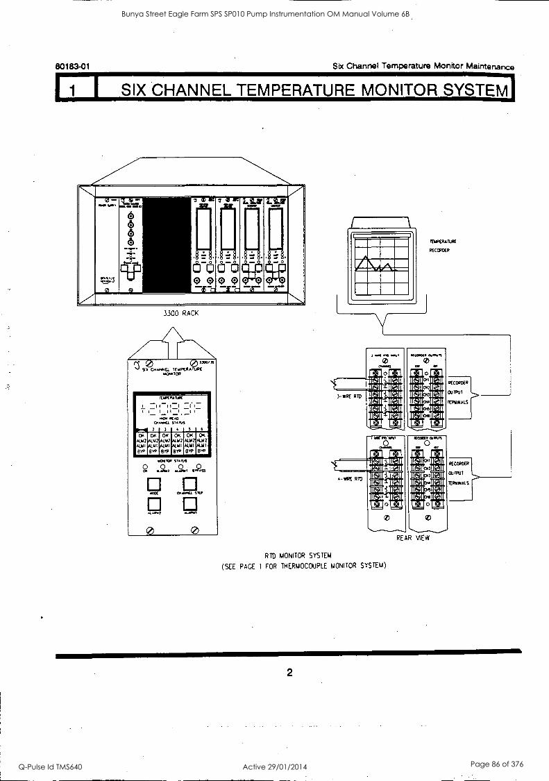
I SIX CHANNEL TEMPERATURE MONITOR SYSTEM]
80183-01 Six Channel Temperature Monitor Maintenance
.1 W-
tr.1:z
g
1..s
-a-
- 3
C5
(5 6 6 -a -a-
0001:1 lir 17)(;)®(;)o e --crn
a lig
0-
3 a 11
0-0
Vii-
LitZ
0-0
oo -DT".
13.1K
0-0
r- o
7 1. 3300 RACK
(3. 3" I, Cs El. IE &AVER* TupE36.
1,06. Top
_
1
' I
7 t_ 00041
2
VORA
I 11_1 _II_,.._, .01 mt.,
3
ft.(
1.7,1.01
4
_ _11_
,
3
_
6
C* C., A742 0'7 "1 LW
RIP Dro
OK Oa 011 erp
og kii2 41,1
'i.4)
NrcwoR
.,..0....,
. ...a67
0
srmvs 0
0.014
, ."Qs9
STEp
0.1.01
0
IDOIRATURE
RECORDER
3- MK RID IC:11
- MRE RID
0
REAR VIEW
RTD MONITOR SYSTEM
(SEE PAGE 1 FOR THERMOCOUPLE MONITOR SYSTEM)
RECORDER
01.11Pu I
TERvout.S
RECORDER
CU IPUI
TEMPI ALS
Bunya Street Eagle Farm SPS SP010 Pump Instrumentation OM Manual Volume 6B
Q-Pulse Id TMS640 Active 29/01/2014 Page 86 of 376
Six Channel Temperature Monitor Maintenance 80183-01
I MONITOR FUNCTIONS
SIX CHANNEL TEMPERATURE MEASUREMENTS - Temperature measurements can be obtained from various machine components and are important for the quality of the process involved. The 3300/30 Six Channel Temperature Monitor provides six independent channels of on-line thermocouple (TC) temperature monitoring. The monitor accepts input from up to six TC transducers with either grounded or ungrounded tips. The 3300/35 Six Channel Temperature Monitor provides six independent channels of on-line resistance temperature detection (RID) temperature monitoring. The monitor accepts input from up to six 3-wire or six 4-wire RTD transducers.
OK - When the TC output voltage or RTD resistance is within its upper and lower limits, the transducer is defined as OK. The OK detection circuit controls the channel OK the monitor OK and the monitor relay drive to the OK Relay. If the monitor has the latching OK option enabled, a System Reset is required to reset the OK function.
OK RELAY - The OK Relay is located on the Power Input Module. Every channel in the rack must be OK or bypassed to energize the OK Relay.
ALARM - Pressing the ALARMI and ALARM2 switches on the front panel of the monitor causes the corresponding first-level alarm or second-level alarm setpoints on each channel to be displayed on the front panel LCD. ALM1 and ALM2 indications are displayed when the transducer signal level exceeds preset levels for the selected time delay, and appropriate Alarm 1 and Alarm 2 relay contacts are activated. Alarm 2 setpoint levels can be optionally set for over or under alarm conditions. Alarm 1 setpoint levels can be set only for an over alarm. AND and OR voting logic options per pair of channels (channels 1 and 2, 3 and 4, 5 and 6) determine when the Alarm 2 relay contacts are activated.
RACK FIRST OUT - The first channel in the rack to have an alarm ALM1 or ALM2 (called ALERT or, DANGER in many monitors) since the last reset or power-up will flash its ALM1 or ALM2 LCD (ALERT or DANGER LED on other monitors) indicator if the First Out option is enabled.
MONITOR FIRST OUT - When enabled, Monitor First Out ignores all other alarms in the rack and indicates First Out only for the six channels in the monitor. Both ALM1 and ALM2 have separate First Out circuitry.
ALARM RELAYS - Monitor alarms can be programmed for either latching or nonlatching mode. In
the nonlatching mode, the alarm resets automatically when the alarm condition no longer exists. In
the latching mode, the alarm must be reset manually by pressing the RESET switch on the front panel of the System Monitor (or by closing external Reset contacts). The alarm will not reset if the alarm condition still exists.
RECORDER OUTPUT - A recorder output is provided for each channel. Depending on the option selected, the recorder output levels, proportional to recorder full scale, are either 0 to -10 Vdc, +1
to +5 Vdc, or +4 to +20 mA.
3
Bunya Street Eagle Farm SPS SP010 Pump Instrumentation OM Manual Volume 6B
Q-Pulse Id TMS640 Active 29/01/2014 Page 87 of 376
80183-01 Six Channel Temperature Monitor Maintenance
171 MONITOR FUNCTIONS
SELF TEST - The monitor has three categories of self test: cyclic, power-up, and user-invoked.
Cyclic Self Test is performed automatically during monitor operation. Any error encountered during a cyclic test disables the monitor and flashes an LCD error code. Should the error be intermittent, the monitor will return to operation, but the error code is stored for retrieval during user-invoked self-tests. Stored error codes are annunciated by the OK LED and the OK LCD flashing at 5 Hz provided that the channel is OK
Power-Up Self Test is performed automatically each time the monitor power is turned on. A series of basic tests and transducer OK tests are performed.
User-invoked Self Test performs power-up self test and allows error messages stored during cyclic tests to be read and cleared. Stored errors are annunciated by the OK LED and the OK LCD flashing at 5 Hz and the error codes displayed on the front panel LCD.
4
Bunya Street Eagle Farm SPS SP010 Pump Instrumentation OM Manual Volume 6B
Q-Pulse Id TMS640 Active 29/01/2014 Page 88 of 376
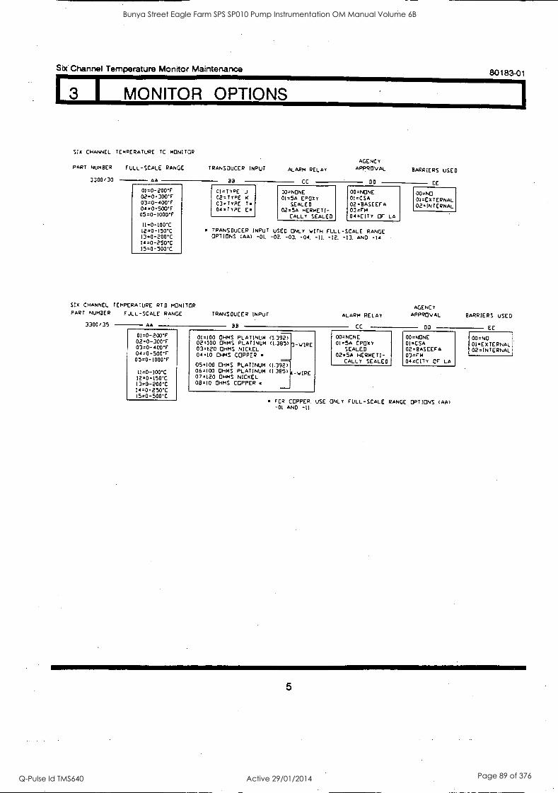
1
Six Channel Temperature Monitor Maintenance 80183-01
I MONITOR OPTIONS
Slx CHANNEL TEMPERATURE TC MONITOR
AGENCY PART NUMBER FULL-SCALE RANGE TRANSDUCER INPUT ALARM RELAY APPROVAL BARRIERS USED
3300/30 AA BB CC DD EE
01.0-200- 02=0-300'r 03=0-400'r 04=0-500'F 05=0-1000F
11=0-100C i2=0-150C 130-200C 14=0-250C 15=0-500.0
.
01=TYPE J
02=TYPE K
03=Typt T. 04 =TYPE E
USED -01. -02.
00=NONE 01.5A EPDXY
SEALED 02=5A HERMETI-
CALLY SEALED
-13.
00=NONE 01=CSA 02=BASEEFA 03 =rM 04 =CITY OF LA
00=NO 01=EXTERNAL 02=INTERNAL
TRANSDUCER INPUT OPTIONS (AA)
ONLY WITH FULL-SCALE -03, -04. -IL -12,
RANGE AND -14
SIX CHANNEL TEMPERATURE PART NUMBER FULL-SCALE
3300/35
RID MONITOR
RANGE
AA
TRANSDUCER INPUT
BB
ALARM RELAY
CC
AGENCY APPROVAL
DD
BARRIERS USED
EE
01=0-200 02=0-300r 03=0-400T 04=0-500T os=o-l000r
01=100 OHMS 02=100 OHMS 03=120 OHMS 04=10 OHMS
PLATINUM PLATINUM NICKEL
COPPER
(1392) (1.385)
===
3-WIRE 00=NONE 01=5A EPDXY
SEALED 02=5A HERMETI-
CALLY SEALED
00=NONE 01=CSA 02=BASEEFA 03 =rM 04 =CITY or LA
00=NO 01=ExTERNAL 02=INTERNAL
05 =100. OHMS PLATINUM (1.392) 11=0-100 06=100 OHMS PLATINUM (1385) 4 -WIRE
12=0-150*C 07=120 OHMS NICKEL 13=0-200C 08=10 OHMS COPPER 14=0-250*C 15=0-500
FOR COPPER. USE ONLY FULL-SCALE RANGE OPTIONS (AA) -01 AND -11.
5
Bunya Street Eagle Farm SPS SP010 Pump Instrumentation OM Manual Volume 6B
Q-Pulse Id TMS640 Active 29/01/2014 Page 89 of 376
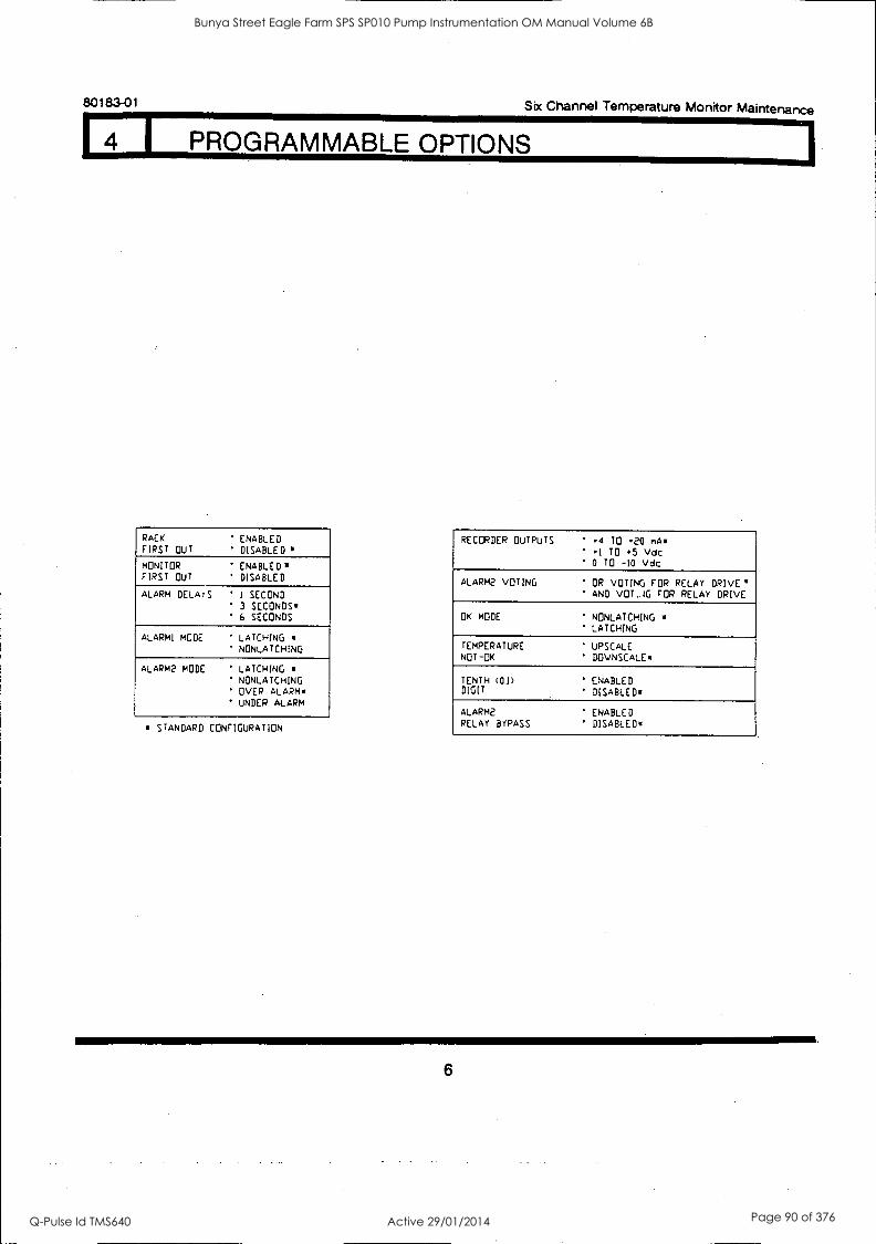
80183-01 Six Channel Temperature Monitor Maintenance
4 1 PROGRAMMABLE OPTIONS
RACK FIRST OUT
' ENABLED ' DISABLED
MONITOR
FIRST OUT ENABLED* DISABLED
ALARM DELArS ' I SECOND 3 SECONDS 6 SECONDS
ALARM! MODE LATCHING NONLATCHING
ALARM2 MODE ' LATCHING ' NONLATCHING OVER ALARM UNDER ALARM
* STANDARD CONFIGURATION
RECORDER OUTPUTS .4 TO .20 mA *1 TO *5 Vdc 0 TO -10 Vdc
ALARM2 VOTING OR VOTING FOR RELAY DRIVE' AND VOT.JG FOR RELAY DRIVE
OK MODE NONLATCHING LATCHING
TEMPERATURE NOT-OK
UPSCALE DOVNSCALE
TENTH (0.1)
DIGIT
ENABLED DISABLED'
ALARM2 RELAY BYPASS
ENABLED DISABLED'
6
Bunya Street Eagle Farm SPS SP010 Pump Instrumentation OM Manual Volume 6B
Q-Pulse Id TMS640 Active 29/01/2014 Page 90 of 376
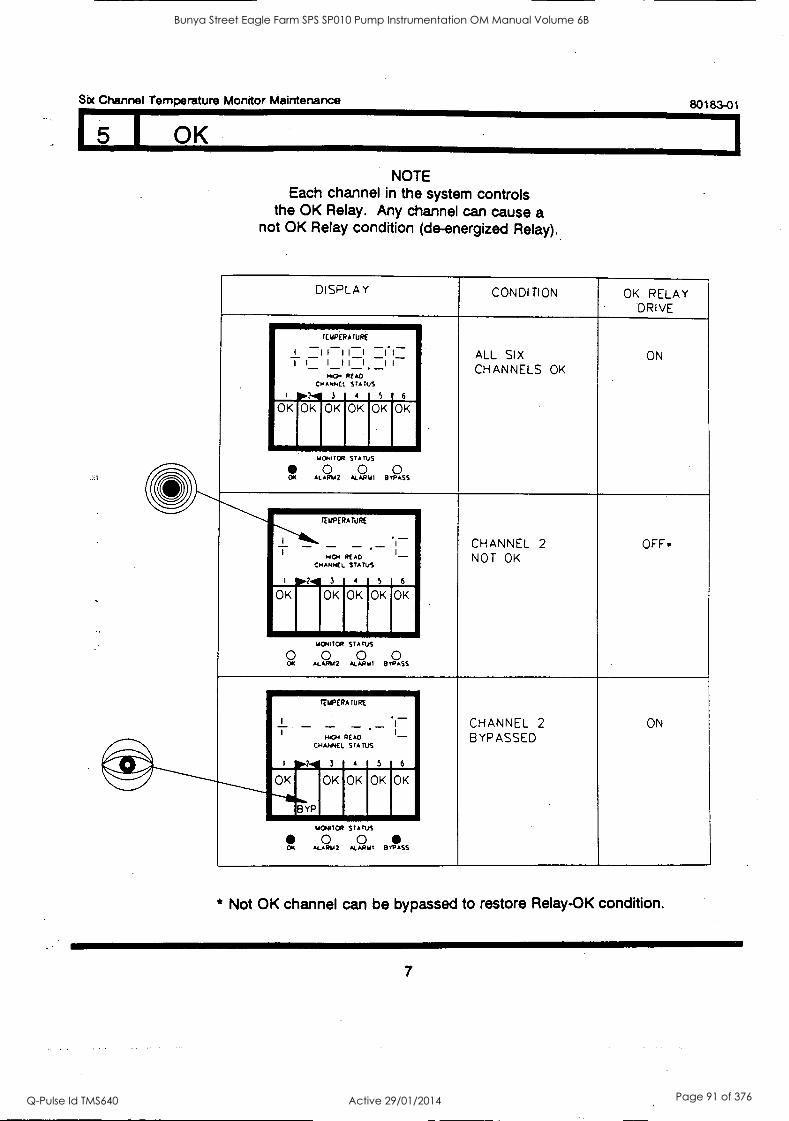
Six Channel Temperature Monitor Maintenance so 1 ea-o1
I OK
NOTE Each channel in the system controls
the OK Relay. Any channel can cause a not OK Relay condition (de-energized Relay).
DISPLAY CONDITION OK RELAY DRIVE
ALL SIX CHANNELS OK
ON
tEuPERATURE _ I 11H T t- _1
HoOH
CHANNE
3
1
- - READ STATUS
4
. It I-
5
-
6 01010I
K OK OK OK
mowca STATUS
0 0 0 OK ALAR42 ALAMO BYPASS
/
CHANNEL 2 NOT OK
OFF.
TELIPERAIURE
1
HIGH
CHANNEL
I 3
READ STATUS
4
.
5
_ 1
1-
6
OK OK OK OK OK
moroop STATUS
0 0 0 0 OK ALARIA2 ALARui BYPASS
CHANNEL 2 BYPASSED
ON
----Thihr3YP
rELIPERATURE
_ _ _ HOY READ
CHANNEL STATUS
I 3 4
_
5
I
- 1_
6
OK OK OK OK OK
mewl:a STATUS
0 0 ss ALARtn ALAmo evvA
* Not OK channel can be bypassed to restore Relay-OK condition.
7
Bunya Street Eagle Farm SPS SP010 Pump Instrumentation OM Manual Volume 6B
Q-Pulse Id TMS640 Active 29/01/2014 Page 91 of 376
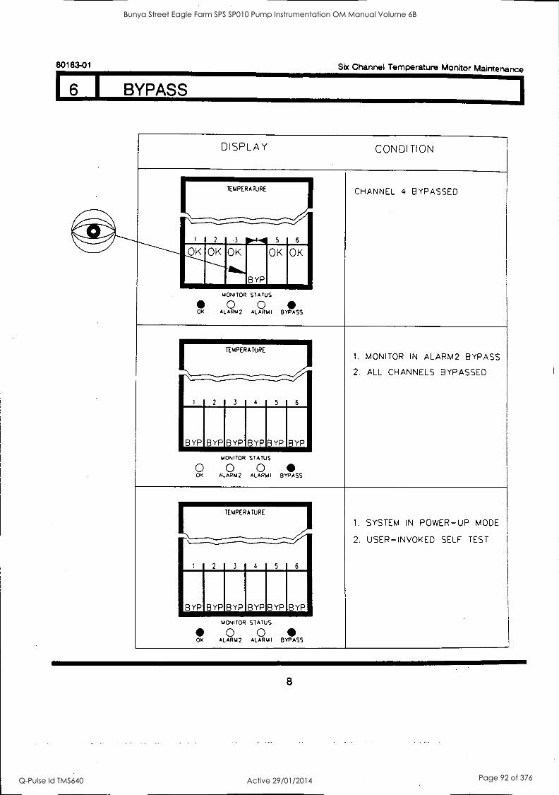
80183-01 Six Channel Temperature Monitor Maintenance
I BYPASS
DISPLAY CONDITION
CHANNEL 4 BYPASSED
I 2
TEMPERATURE
3 6 9.4.1 5
OK OK OK
BYP
OK OK
MONITOR STATUS
0 0 OK ALARM2 ALARMI BYPASS
1. MONITOR IN ALARM2 BYPASS
2. ALL CHANNELS BYPASSED
1 2
TEMPERATURE
3 6 4 5
BYP_ BYP BYP BYP BYP BYP
MONITOR STATUS
0 0 0 OK ALARM2 ALARM1 BYPASS
1. SYSTEM IN POWER-UP MODE
2. USER-INVOKED SELF TEST
TEMPERATURE
\--.....,
6 1 2 3 4 5
BYP BYP BYP BYPBYPBYP
OK
MONITOR STATUS
0 0 ALARM2 ALARM; BYPASS
8
Bunya Street Eagle Farm SPS SP010 Pump Instrumentation OM Manual Volume 6B
Q-Pulse Id TMS640 Active 29/01/2014 Page 92 of 376
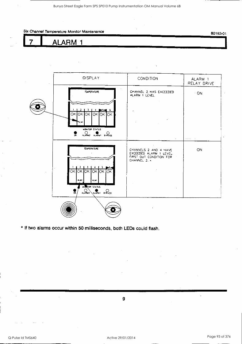
Six Channel Temperature Monitor Maintenance 80183-01
I ALARM 1
DISPLAY CONDITION ALARM 1
RELAY DRIVE
CHANNEL 2 HAS EXCEEDED ALARM 1 LEVEL
- ON TEMPERATURE
i 2 3
_./."
4 i). 6 .
OK OK OK OK OK OK
I MI
' \ mom TOR STATUS
0 0 OK ALARM? ALAMO BYPASS
CHANNELS 2 AND 4 HAVE ON TEMPERATURE
EXCEEDED ALARM 1 LEVEL. FIRST OUT CONDITION FOR CHANNEL 2.
1 2 3 4 5 1 OK OK OK OK OK OK
ALAII ALM1
U OR STATUS
0 0 OK ALAR1A2 \ ALARM 1 BYPASS
* If two alarms occur within 50 milliseconds, both LEDs could flash.
9
Bunya Street Eagle Farm SPS SP010 Pump Instrumentation OM Manual Volume 6B
Q-Pulse Id TMS640 Active 29/01/2014 Page 93 of 376
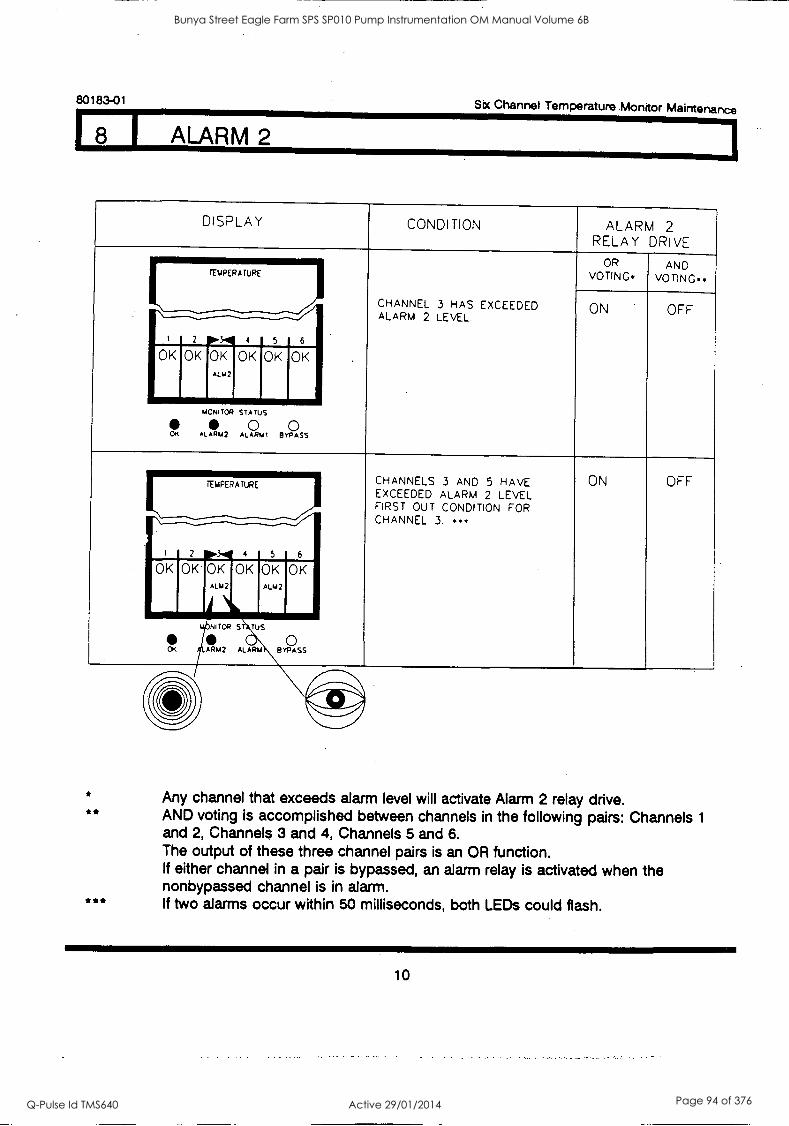
80183-01
8 1 ALARM 2
Six Channel Temperature .Monitor Maintenance
DISPLAY CONDITION ALARM 2 RELAY DRIVE
OR VOTING.
AND VOTING TEMPERATURE
CHANNEL 3 HAS EXCEEDED ON OFF ALARM 2 LEVEL.
I 2 OK 0K 04K 05K ALM2
Fl 105K
MONITOR STATUS
0 0 OK ALARM? ALARMI BYPASS
CHANNELS 3 AND 5 HAVE ON OFF TEMPERATURE EXCEEDED ALARM 2 LEVEL. FIRST OUT CONDITION FOR .11M111 CHANNEL 3.
OK OK OK ALM2
NITOR ST TUS ill 0 OK RM2 ALARM BYPASS
** Any channel that exceeds alarm level will activate Alarm 2 relay drive. AND voting is accomplished between channels in the following pairs: Channels 1
and 2, Channels 3 and 4, Channels 5 and 6. The output of these three channel pairs is an OR function. If either channel in a pair is bypassed, an alarm relay is activated when the nonbypassed channel is in alarm. If two alarms occur within 50 milliseconds, both LEDs could flash.
10
Bunya Street Eagle Farm SPS SP010 Pump Instrumentation OM Manual Volume 6B
Q-Pulse Id TMS640 Active 29/01/2014 Page 94 of 376
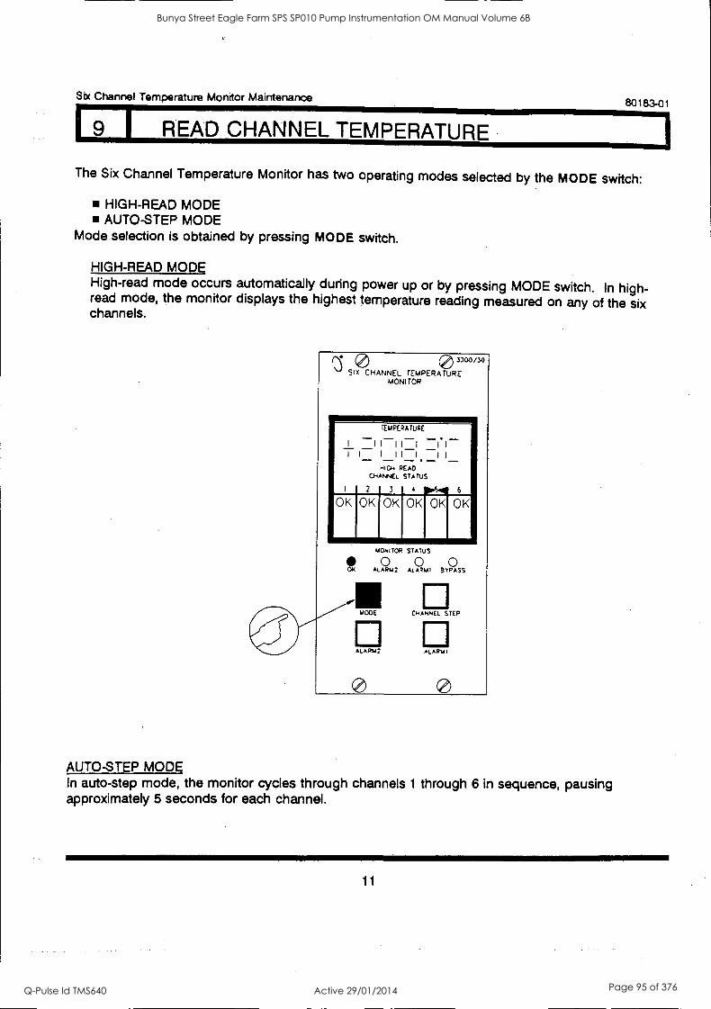
I9 I READ CHANNEL TEMPERATURE
Six Channel Temperature Monitor Maintenance 80183-01
The Six Channel Temperature Monitor has two operating modes selected by the MODE switch:
HIGH-READ MODE AUTO-STEP MODE
Mode selection is obtained by pressing MODE switch.
HIGH-READ MODE High-read mode occurs automatically during power up or by pressing MODE switch. In high- read mode, the monitor displays the highest temperature reading measured on any of the six channels.
0 3300/30
SIX CHANNEL TEMPERATURE MONI TOR
TEMPERATURE
I-I I:I =I. I
I 1 1 1 1 1 I I
HIGH READ CHANNEL STATUS
2 3 4 0.6.40 6
OK OK OK OK OK OK
1.<1
MONITOR STATUS
AL ARA12 ALARMI BYPASS
MODE CHANNEL STEP
ALARM 2 ALARMI
AUTO-STEP MODE In auto-step mode, the monitor cycles through channels 1 through 6 in sequence, pausing approximately 5 seconds for each channel.
11
Bunya Street Eagle Farm SPS SP010 Pump Instrumentation OM Manual Volume 6B
Q-Pulse Id TMS640 Active 29/01/2014 Page 95 of 376
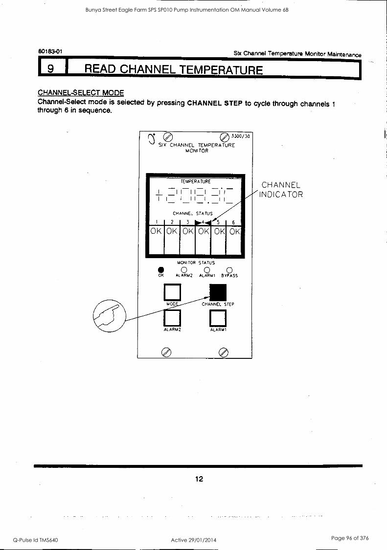
80183-01 Six Channel Temperature Monitor Maintenance
I READ CHANNEL TEMPERATURE
CHANNEL-SELECT MODE Channel-Select mode is selected by pressing CHANNEL STEP to cycle through channels 1
through 6 in sequence.
0 3300/30
SIX CHANNEL TEMPERATURE MONITOR
TEMPERATURE
- - CHANNEL STATUS
2 3 4 5 6
OK OK OK OK OK OK
MONITOR STATUS
0 0 0 OK ALARM2 ALARM1 BYPASS
MOO CHANNEL STEP
ALARM2 ALARM1
CHANNEL INDICATOR
12
Bunya Street Eagle Farm SPS SP010 Pump Instrumentation OM Manual Volume 6B
Q-Pulse Id TMS640 Active 29/01/2014 Page 96 of 376
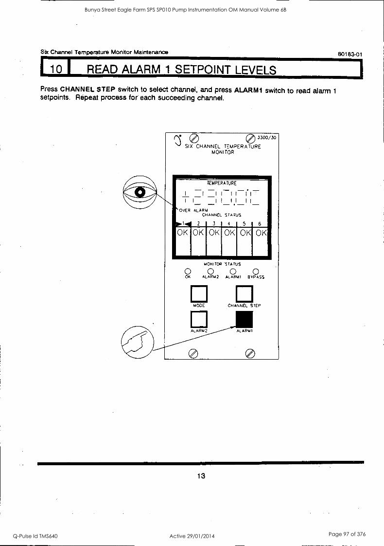
Six Channel Temperature Monitor Maintenance 80183 -01
1 10 1 READ ALARM 1 SETPOINT LEVELS
Press CHANNEL STEP switch to select channel, and press ALARMI switch to read alarm 1
setpoints. Repeat process for each succeeding channel.
10 3300/30
SIX CHANNEL TEMPERATURE MONITOR
TEMPERATURE
I I 11 11 11
I I - II II 11 - - - OVER ALARM
CHANNEL STATUS
2 3 4 5
OKI OK 6
OK OK
AIMMI MONITOR STATUS
0 0 0 0 OK ALARM2 ALARMI BYPASS
MODE
ALARm2
CHANNEL STEP
ALARMI
13
Bunya Street Eagle Farm SPS SP010 Pump Instrumentation OM Manual Volume 6B
Q-Pulse Id TMS640 Active 29/01/2014 Page 97 of 376
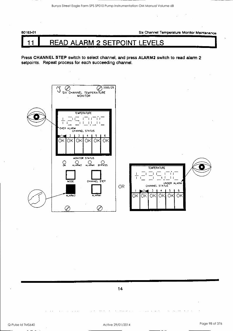
80183-01 Six Channel Temperature Monitor Maintenance
11 I READ ALARM 2 SETPOINT LEVELS
Press CHANNEL STEP switch to select channel, and press ALARM2 switch to read alarm 2 setpoints. Repeat process for each succeeding channel.
0 3300/25
SIX CHANNEL TEMPERATURE MONITOR
TEMPERATURE
I II I II I. I
I I I I II II 640vER ALARM
CHANNEL STATUS
010K 10K 2 3 4 5 6
OKI OK OK
O OK
MONITOR STATUS
0 ALARM2 ALARMI BYPASS
MODE CHANNEL STEP
ALARMI
OR
TEMPERATURE
I I II I I. I
I I I I I I
UNDER ALARM CHANNEL STATUS
2 3 4 5
14
Bunya Street Eagle Farm SPS SP010 Pump Instrumentation OM Manual Volume 6B
Q-Pulse Id TMS640 Active 29/01/2014 Page 98 of 376
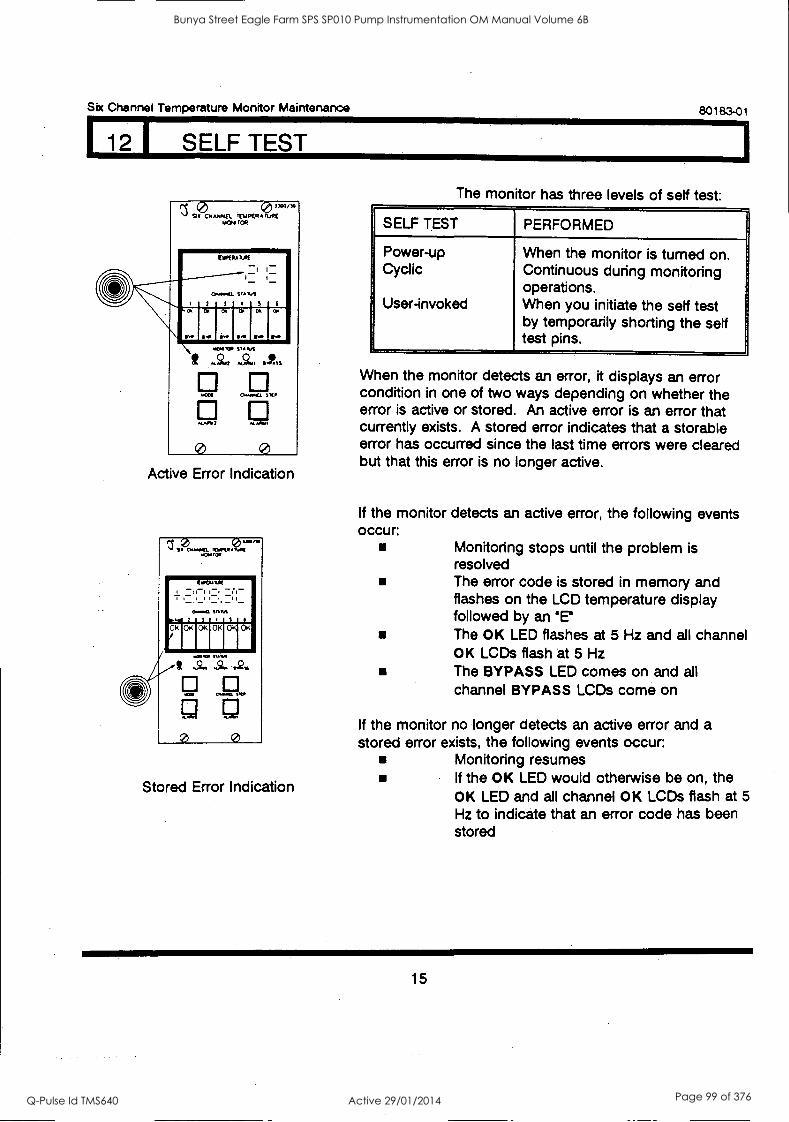
Six Channel Temperature Monitor Maintenance 80183-01
1 12 I SELF TEST
/ 9i Crwoda TEupER rya;
O.
TDPEPA
.f'.
11.0(
I I
Vanes
; r.
ol
an
o
. ii. Sl . v . \ It
MOWS*
4f.t:24
KM
0
VA Ilri
4.9111
OworCL
Mt%
SW
0 Active Error Indication
Stored Error Indication
The monitor has three levels of self test:
SELF TEST PERFORMED
Power-up Cyclic
User-invoked
When the monitor is turned on. Continuous during monitoring operations. When you initiate the self test by temporarily shorting the self test pins.
When the monitor detects an error, it displays an error condition in one of two ways depending on whether the error is active or stored. An active error is an error that currently exists. A stored error indicates that a storable error has occurred since the last time errors were cleared but that this error is no longer active.
If the monitor detects an active error, the following events occur:
Monitoring stops until the problem is resolved The error code is stored in memory and flashes on the LCD temperature display followed by an me The OK LED flashes at 5 Hz and all channel OK LCDs flash at 5 Hz The BYPASS LED comes on and all channel BYPASS LCDs come on
If the monitor no longer detects an active error and a stored error exists, the following events occur:
Monitoring resumes If the OK LED would otherwise be on, the OK LED and all channel OK LCDs flash at 5
Hz to indicate that an error code has been stored
15
Bunya Street Eagle Farm SPS SP010 Pump Instrumentation OM Manual Volume 6B
Q-Pulse Id TMS640 Active 29/01/2014 Page 99 of 376
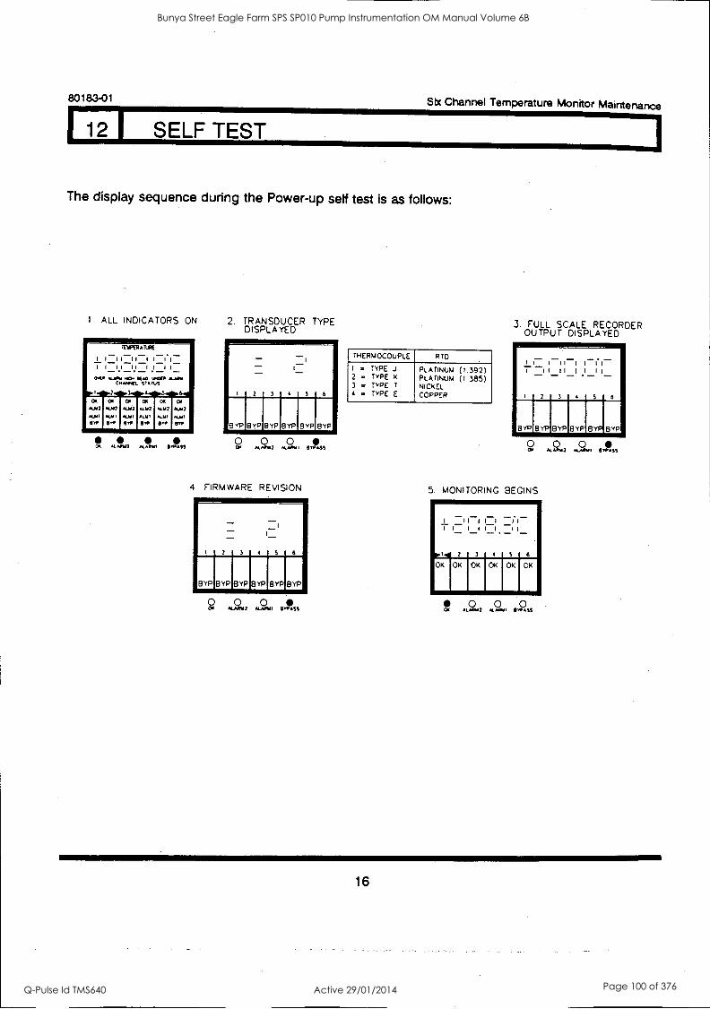
80183-01 Six Channel Temperature Monitor Maintenance
1 12 I SELF TEST
The display sequence during the Power-up self test is as follows:
I. ALL INDICATORS ON 2. TRANSDUCER TYPE DISPLAYED
At. W2 4.11, I ASS
2 3 4
VP BYP BYP BYP BYP BYP
49 2 0111445
4. FIRMWARE REVISION
1 BYP BYP
2 3 4 5 6
BYPLYPIBYPIBYP
0.+7 I VIPASS
THERMOCOUPLE RTD
I = 2 = 3 = 4 =
TYPE TYPE TYPE TYPE
.1
K
T
E
PLATINUM PLATINUM NICKEL COPPER
(1.392) (1.385)
3. FULL SCALE RECORDER OUTPUT DISPLAYED
0 0 0 0, *4.A4.12 4.411./. ',PASS
5. MONITORING BEGINS
I I -r I - I I I I
5 6
OK I OK
0 0 0 Clt F442 0 9 55
16
Bunya Street Eagle Farm SPS SP010 Pump Instrumentation OM Manual Volume 6B
Q-Pulse Id TMS640 Active 29/01/2014 Page 100 of 376
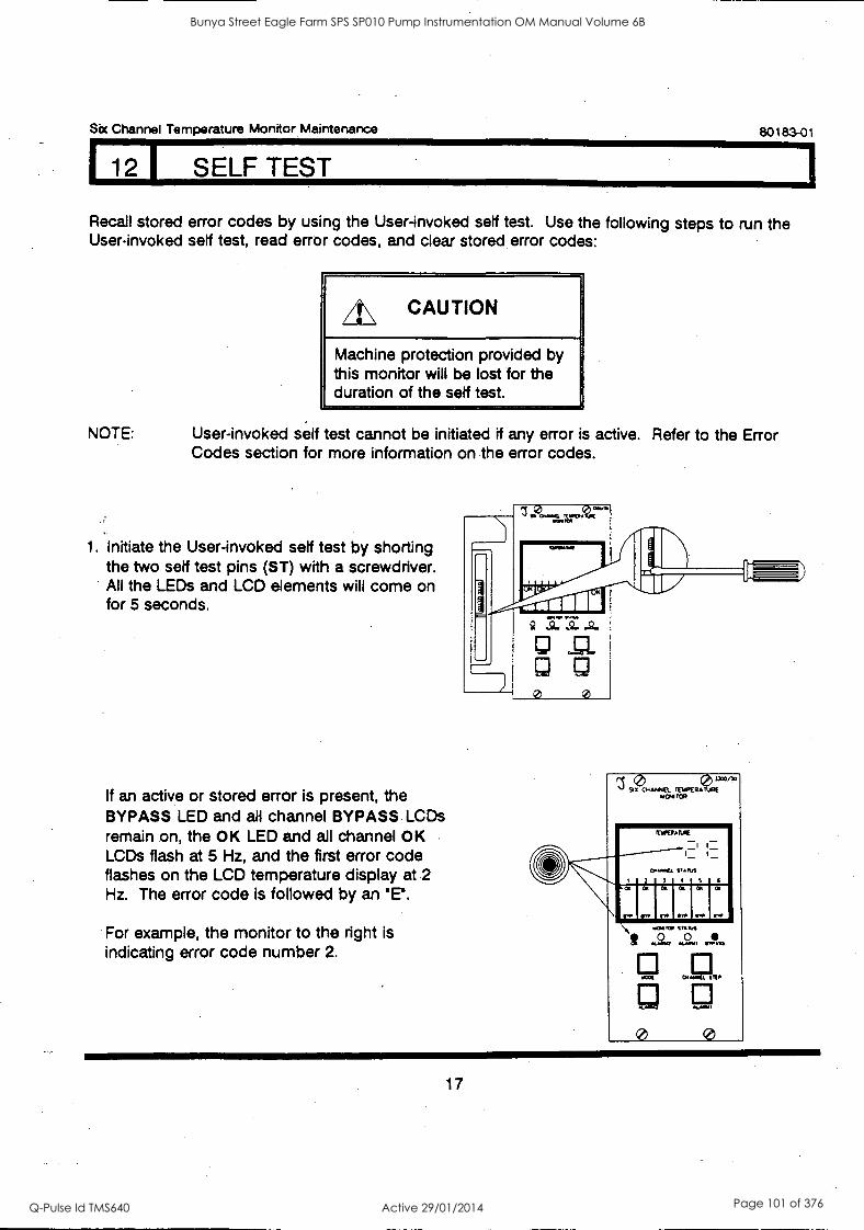
Six Channel Temperature Monitor Maintenance 80183-01
I 12 1 SELF TEST
Recall stored error codes by using the User-invoked self test. Use the following steps to run the User-invoked self test, read error codes, and clear stored error codes:
CAUTION
Machine protection provided by this monitor will be lost for the duration of the self test.
NOTE: User-invoked self test cannot be initiated if any error is active. Refer to the Error Codes section for more information on the error codes.
1. Initiate the User-invoked self test by shorting the two self test pins (ST) with a screwdriver. All the LEDs and LCD elements will come on for 5 seconds.
If an active or stored error is present, the BYPASS LED and all channel BYPASS LCDs remain on, the OK LED and all channel OK LCDs flash at 5 Hz, and the first error code flashes on the LCD temperature display at 2 Hz. The error code is followed by an
For example, the monitor to the right is indicating error code number 2.
/ 90 1.1e0/313
' 4 TOR
0s...4
111.166104
3,MS .1
\ ,,, r. rr
.3
ip
.4
I.
.S
Ir.
.6
r.
\ ft .060 /
0
VAMOS
a 7 a . , An
0.64 VIP
CAM.
0
17
Bunya Street Eagle Farm SPS SP010 Pump Instrumentation OM Manual Volume 6B
Q-Pulse Id TMS640 Active 29/01/2014 Page 101 of 376
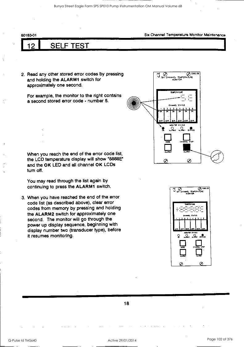
1
80183-01 Six Channel Temperature Monitor Maintenance
112 I SELF TEST
2. Read any other stored error codes by pressing and holding the ALARMI switch for approximately one second.
For example, the monitor to the right contains a second stored error code - number 5.
When you reach the end of the error code list,
the LCD temperature display will show 68888E1
and the OK LED and all channel OK LCDs turn off.
You may read through the list again by
continuing to press the ALARM1 switch.
3. When you have reached the end of the error code list (as described above), clear error codes from memory by pressing and holding the ALARM2 switch for approximately one second. The monitor will go through the power up display sequence, beginning with display number two (transducer type), before it resumes monitoring.
0 1X0/30
Si X 0....No4EL rE.aPERATURE TAONI TOR
CATARAO. STATUS
S0. ST 3 4P V: C: BM SW OR.
orc
warIrC0 Sr 0
..41.140 2 KAM/ I BYPASS
EPIANTIEL STEP
0 MARIO
K 0 SS CP El. ERMEJPE"aa'"
Pad TOR
TESPEPASPE
I I:II:I I:I 1=1.1-_
0.P.O. SIAM
r. I' I 11,41, ... VW Ir. VP _
popTCP
0 CP m...
MAX
4/0402
0
SUNS
0 0 .II ALAINo
0.041
Mss
STIP
*NMI
0
18
Bunya Street Eagle Farm SPS SP010 Pump Instrumentation OM Manual Volume 6B
Q-Pulse Id TMS640 Active 29/01/2014 Page 102 of 376
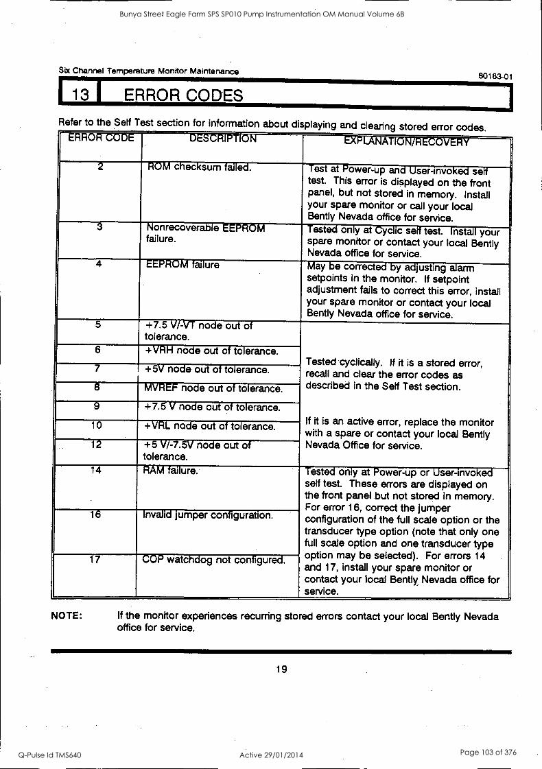
Six Channel Temperature Monitor Maintenance 80183-01
113 I ERROR CODES
Refer to the Setf Test section for information about displaying and clearing stored error codes. "O' O D ' 1 s"1/. V . I ' V
'
ROM checksum failed. Test at Power-up and User-invoked self test. This error is displayed on the front panel, but not stored in memory. Install your spare monitor or call your local Bently Nevada office for service.
3 Ionrecover - e - V
failure. est: on y at is se' test. nst- your
spare monitor or contact your local Bently Nevada office for service.
4 EEPROM failure May be corrected by adjusting alarm setpoints in the monitor. If setpoint adjustment fails to correct this error, install your spare monitor or contact your local Bently Nevada office for service.
5 +7.5 V/-VT node out of tolerance.
Tested cyclically. If it is a stored error, recall and clear the error codes as described in the Setf Test section.
If it is an active error, replace the monitor with a spare or contact your local Bently Nevada Office for service.
6 +VRH node out of tolerance.
7 +5V node out of tolerance.
8 MVREF node out of tolerance.
9 +7.5 V node out of tolerance.
10 +VRL node out of tolerance.
12 +5 V/-7.5V node out of tolerance.
14 RAM failure. Tested only at Power-up or User-invoked self test. These errors are displayed on the front panel but not stored in memory. For error 16, correct the jumper configuration of the full scale option or the transducer type option (note that only one full scale option and one transducer type option may be selected). For errors 14 and 17, install your spare monitor or contact your local Bently Nevada office for service.
16 -' Invalid jumper configuration.
17 COP watchdog not configured.
NOTE: If the monitor experiences recurring stored errors contact your local Bently Nevada office for service.
19
Bunya Street Eagle Farm SPS SP010 Pump Instrumentation OM Manual Volume 6B
Q-Pulse Id TMS640 Active 29/01/2014 Page 103 of 376
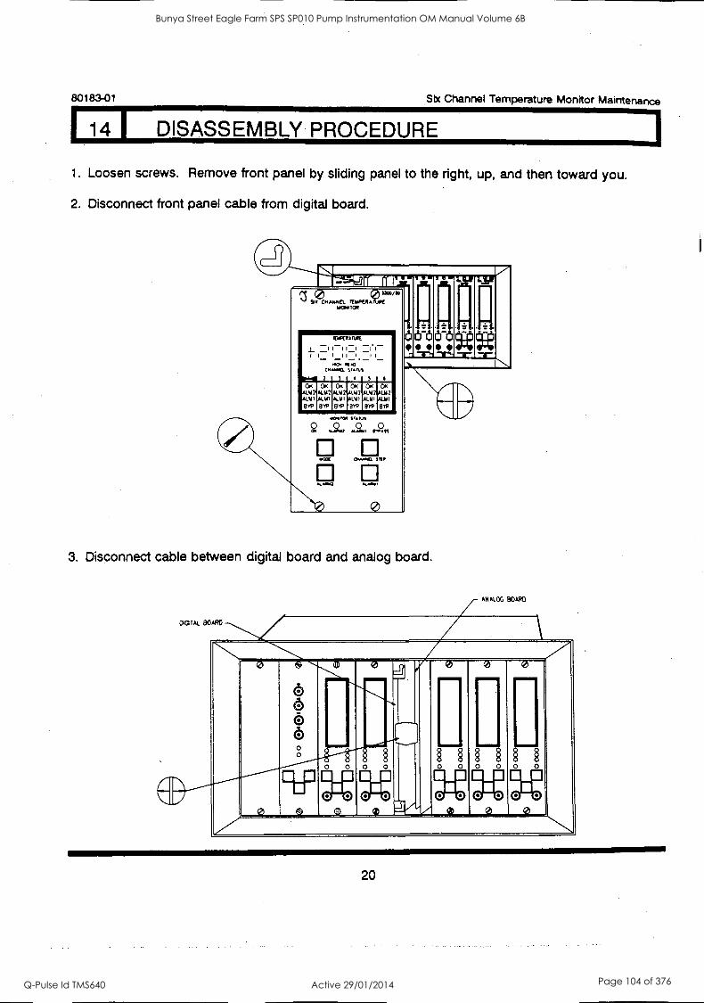
80183-01 Six Channel Temperature Monitor Maintenance
14 DISASSEMBLY PROCEDURE
1. Loosen screws. Remove front panel by sliding panel to the right, up, and then toward you.
2. Disconnect front panel cable from digital board.
51,1?)CN EL rtliPfit Lrei" wCom TCN
ITIPEVAIURE
j I II I _ICI I I 1 1 1 I 1 1 -
..o NC .0 SC,1,15
droop - -11"1-1
1 7 5 I OK OK OK OK OK OK
112 A1.112 MAI On L112
191 ALIO A1.111 ALYI "111 8W 8.19 82'9 Bw 919
0
3. Disconnect cable between digital board and analog board.
oorAL BOARD
ANALOG SOAK!
.N*, 7 ,V.
0
o 6 6 6
§ 0
§ 0
§ 0
§ 0
§
0 0
e , a 0
0 0 0 0 0
0 0 0
0 V
20
Bunya Street Eagle Farm SPS SP010 Pump Instrumentation OM Manual Volume 6B
Q-Pulse Id TMS640 Active 29/01/2014 Page 104 of 376
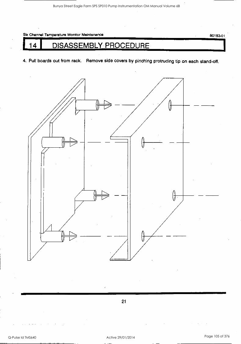
1
Sec Channel Temperature Monitor Maintenance 80183-01
14 DISASSEMBLY PROCEDURE
4. Pull boards out from rack. Remove side covers by pinching protruding tip on each stand-off.
21
Bunya Street Eagle Farm SPS SP010 Pump Instrumentation OM Manual Volume 6B
Q-Pulse Id TMS640 Active 29/01/2014 Page 105 of 376
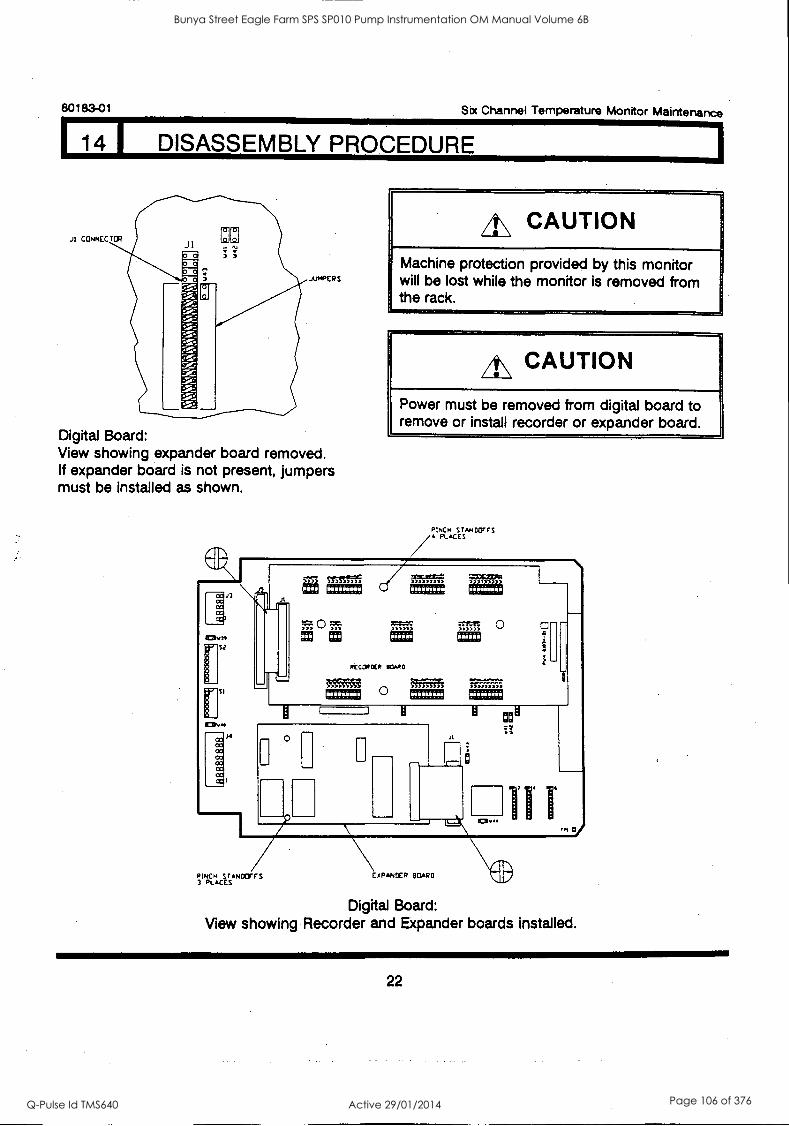
80183-01 Six Channel Temperature Monitor Maintenance
14 I DISASSEMBLY PROCEDURE
JUMPERS
Digital Board: View showing expander board removed. If expander board is not present, jumpers must be installed as shown.
it\ CAUTION
Machine protection provided by this monitor will be lost while the monitor is removed from the rack.
A\ CAUTION
Power must be removed from digital board to remove or install recorder or expander board.
Digital Board: View showing Recorder and Expander boards installed.
22
Bunya Street Eagle Farm SPS SP010 Pump Instrumentation OM Manual Volume 6B
Q-Pulse Id TMS640 Active 29/01/2014 Page 106 of 376
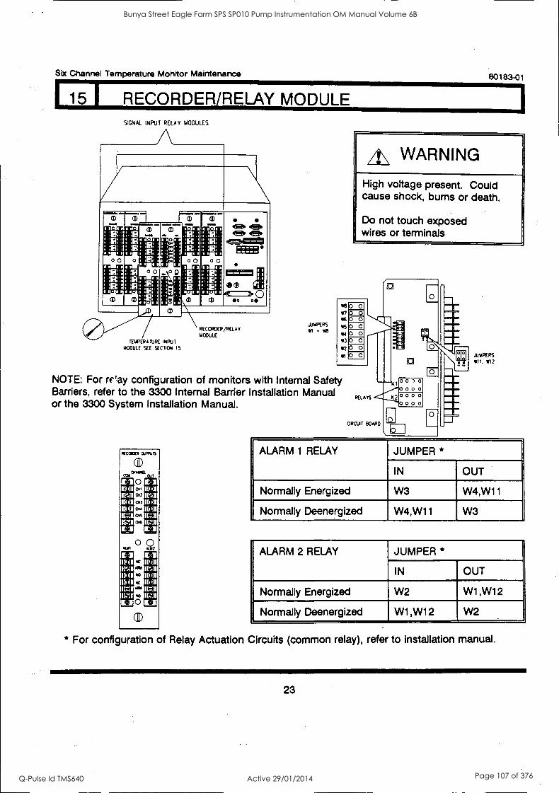
Six Channel Temperature Monitor Maintenance
15 I RECORDER/RELAY MODULE SIGNAL INPUT RELAY MODULES
TEMPERATURE INPUT
UOOULE SEE SECTIom IS
00
FI 0 =r 0 m
RECORDER/KLAN, 14004.111
JAPERS - MO
80183-01
A\ WARNING
High voltage present. Could cause shock, bums or death.
Do not touch exposed wires or terminals
*30 0 m0 0 1% 0 0 (5 0 0 vm 0 0 W3 0 0 (2 0 0 In 0
NOTE: For relay configuration of monitors with Internal Safety Barriers, refer to the 3300 Internal Barrier Installation Manual or the 3300 System Installation Manual.
(COMM OLIIMUTS
00
'(!)'
CD
Kid
ID 01
1501 K=11 IC:II
JUMPERS (11. (12
ALARM 1 RELAY JUMPER *
IN OUT
Normally Energized W3 W4,W11
Normally Deenergized W4,W11 W3
.
ALARM 2 RELAY
.
JUMPER *
IN OUT
Normally Energized W2 W1,W12
Normally Deenergized W1,W12 W2
* For configuration of Relay Actuation Circuits (common relay), refer to installation manual.
23
Bunya Street Eagle Farm SPS SP010 Pump Instrumentation OM Manual Volume 6B
Q-Pulse Id TMS640 Active 29/01/2014 Page 107 of 376
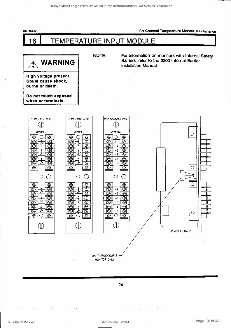
80183-01 Six Channel Temperature Monitor Maintenance
16 I TEMPERATURE INPUT MODULE
A\ WARNING
High voltage present. Could cause shock, burns or death.
Do not touch exposed wires or terminals.
4 WIRE RTD INPUT
a) CHANNEL
0 0
aD
gal
3 *IRE RTD INPUT
a) CHANNEL
1[3 0 LAI
0 0 FA VI MIR II IC 71 K 71
19171 Del 15\11
IC= IC11.
0 ti aD
NOTE: For information on monitors with Internal Safety Barriers, refer to the 3300 Internal Barrier Installation Manual.
THERMOCOUPLE INPUT
a) CHANNEL
CD
ON THERMOCOUPLE 1 MONITOR ONLY
0
0
CIRCUIT BOARD
24
Bunya Street Eagle Farm SPS SP010 Pump Instrumentation OM Manual Volume 6B
Q-Pulse Id TMS640 Active 29/01/2014 Page 108 of 376
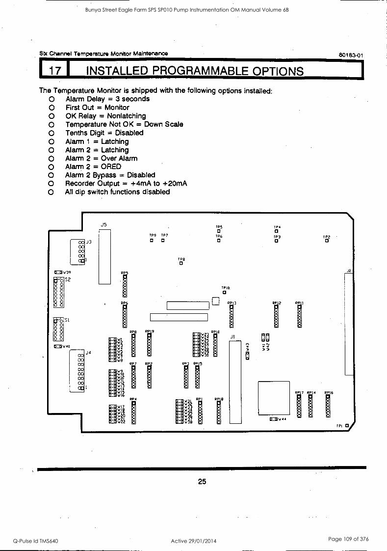
Sbc Channel Temperature Monitor Maintenance
17 I INSTALLED PROGRAMMABLE OPTIONS
The Temperature Monitor is shipped with the following options installed: O Alarm Delay = 3 seconds O First Out = Monitor O OK Relay = Nonlatching O Temperature Not OK = Down Scale O Tenths Digit = Disabled O Alarm 1 = Latching O Alarm 2 = Latching O Alarm 2 = Over Alarm O Alarm 2 = ORED O Alarm 2 Bypass = Disabled O Recorder Output = +4mA to +20mA O All dip switch functions disabled
80183-01
cc cc co cc
t7o3 V39
O 0 O 0 O 0 O
§ §
88 O 0
S2
SI
CO CO CO CO 00 CO CO CC
J3
J4
J5
RP
RP
TP5 TP4 a a
TP9 TP7 TP6 TP3 TP2 a a a a a
TP8 a
RP R 9 V
V
V V
VEI
?
PR 7 RP
. v.0 tdf
Vic VI
I HVI4 116
RP4
VI7
TPIO
a
RPIO
:111
RP 8
JI as P1 N
CEDV44 P 1R7
17014 0PI6
rpi
J2
25
Bunya Street Eagle Farm SPS SP010 Pump Instrumentation OM Manual Volume 6B
Q-Pulse Id TMS640 Active 29/01/2014 Page 109 of 376
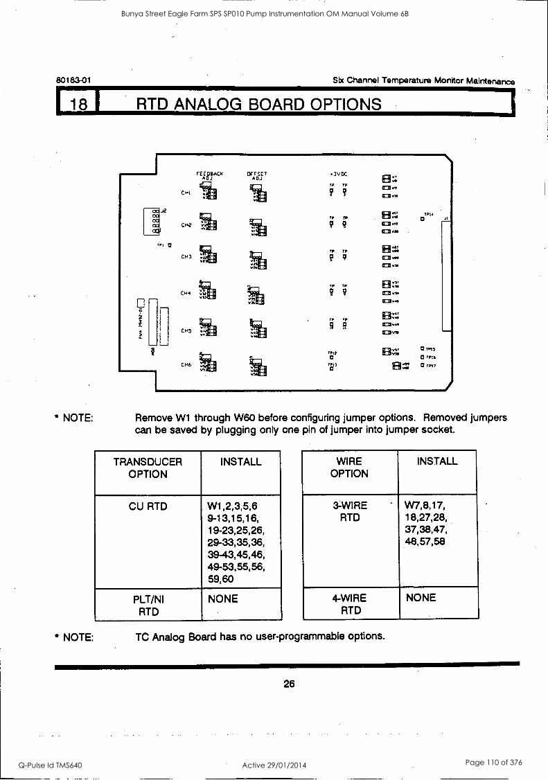
80183-01 Sbc Channel Temperature Monitor Maintenance
18 L RTD ANALOG BOARD OPTIONS
Tel Q
1
CHI
042
CH3
FEEDBACK ADJ DJ
OFFSET A
045
CH6 1.1
3VDC
TP TP
9 9
TP TP
TP TP
TP TP
TP TP
TPI) a
tP13 a
CE2 vs
TPI4 a
* NOTE: Remove W1 through W60 before configuring jumper options. Removed jumpers can be saved by plugging only one pin of jumper into jumper socket.
TRANSDUCER OPTION
INSTALL
CU RTD W1,2,3,5,6 9-13,15,16, 19-23,25,26, 29-33,35,36, 39- 43,45,46, 49-53,55,56, 59,60
PLT/NI NONE RTD
WIRE OPTION
INSTALL
3-WIRE W7,8,17, RTD 18,27,28,
37,38,47, 48,57,58
4-WIRE NONE RTD
* NOTE: TC Analog Board has no user-programmable options.
26
Bunya Street Eagle Farm SPS SP010 Pump Instrumentation OM Manual Volume 6B
Q-Pulse Id TMS640 Active 29/01/2014 Page 110 of 376
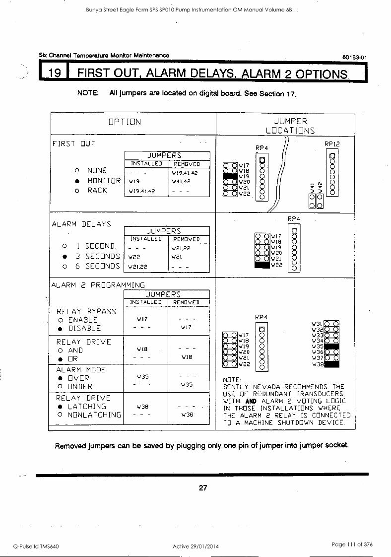
Six Channel Temperature Monitor Maintenance 80183-01
19 I FIRST OUT, ALARM DELAYS, ALARM 2 OPTIONS I NOTE: All jumpers are located on digital board. See Section 17.
OPTION JUMPER LOCATIONS
FIRST OUT RP4
RP12
0 0
8 0
o NONE
MONITOR o RACK
JUMPERS INSTALLED REMOVED gerovi7 I
AIC v18 W19 W20
,/ 22
0 0 o 0 0 0
(41
- - -
W19
wI9,41,42
W19,41,42
W41,42
- - - MUW21 ; Pit ) 0 ) 0
ALARM DELAYS RP4
0 0 0 0 0 00
o 1 SECOND
3 SECONDS o 6 SECONDS
JUMPERS Ni WNIXON18 W17
W20 W21 W22
INSTALLED REMOVED
Xtwi9 _ _ _
W22
W2122
v21,22 W21
- - -
Me
ALARM 2 PROGRAMMING
RP4
JUMPERS INSTALLED REMOVED
RELAY BYPASS o ENABLE
DISABLE W17
- - -
- - - W17 "
0 0 0 8
00 0
W31 W32
FON
. W17 W33114 RELAY DRIVE o AND
OR W18
- - - - - -
W18
MD AZ CO
W18 W19
W 34 W35 W 36 W 37
MIA [OM MX
#1 IQ W0 AI Q W221
0 W22 ALARM MODE
OVER o UNDER
W35 - - - W35
NOTE: BENTLY NEVADA RECOMMENDS THE USE OF REDUNDANT TRANSDUCERS WITH AND ALARM 2 VOTING LOGIC IN THOSE INSTALLATIONS WHERE THE ALARM 2 RELAY IS CONNECTED TO A MACHINE SHUTDOWN DEVICE.
RELAY DRIVE LATCHING
o NONLATCHING W38
- - -
_ _ _
W38
Removed jumpers can be saved by plugging only one pin of jumper into jumper socket.
27
Bunya Street Eagle Farm SPS SP010 Pump Instrumentation OM Manual Volume 6B
Q-Pulse Id TMS640 Active 29/01/2014 Page 111 of 376
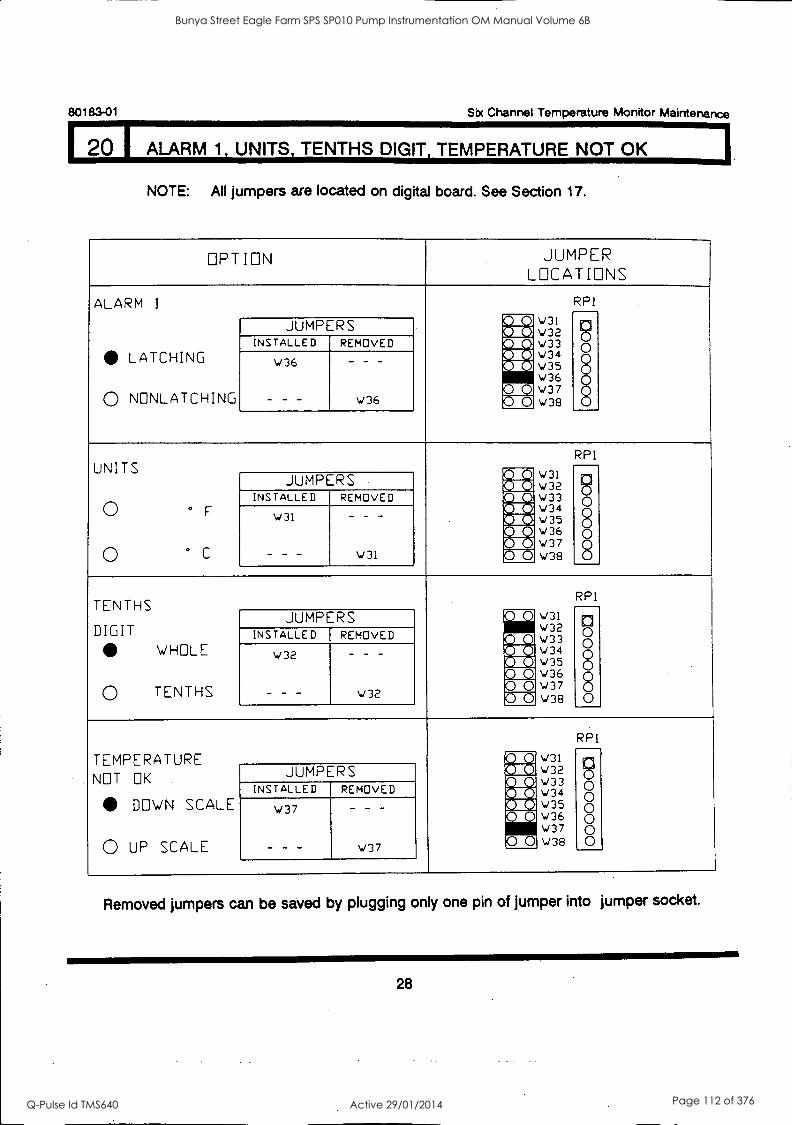
80183-01 Six Channel Temperature Monitor Maintenance
20 I ALARM 1, UNITS, TENTHS DIGIT, TEMPERATURE NOT OK
NOTE: All jumpers are located on digital board. See Section 17.
OPTION JUMPER LOCATIONS
ALARM 1 RP1
3000 V31 w32 V33 v34 w35 W3 W36 7
w38
ri 51 0 0 0 0 0 0
JUMPERS INSTALLED REMOVED Nall
oxio
WIE
LATCHING
0 NNLATCHING
w36
- - -
_
w36 rAxj
UNITS RP1 r v31
v32 w33 w 34 w35 W36 w37 w38
rq *ir
0 o 0 0 0
0 - F
0 ° C
JUMPERS INSTALLED REMOVED 5M11
NM mig W3I
- - -
_ _ _
W31
8 0
TENTHS RP1
We M
W31 W32 W33 ../ 3 4
w35 W36 W37 W38
Z5 n 6 0 0 0 0
DIGIT WHOLE
0 TENTHS
JUMPERS INSTALLED REMOVED
w32
- - -
- - -
W32
: ai 5610] WI MIEI
TEMPERATURE
RP1
Me W31 h 6 0 0 0 0 0
NOT OK
DOWN SCALE
0 UP SCALE
JUMPERS A 0.1 I Mr] V32
rA M
010 'Si] It
\433 W 3 4
W 3 5
INSTALLED REMOVED
W37
- - -
- _ -
w37
MIN W36 w37
MD W38
Removed jumpers can be saved by plugging only one pin of jumper into jumper socket.
28
Bunya Street Eagle Farm SPS SP010 Pump Instrumentation OM Manual Volume 6B
Q-Pulse Id TMS640 Active 29/01/2014 Page 112 of 376
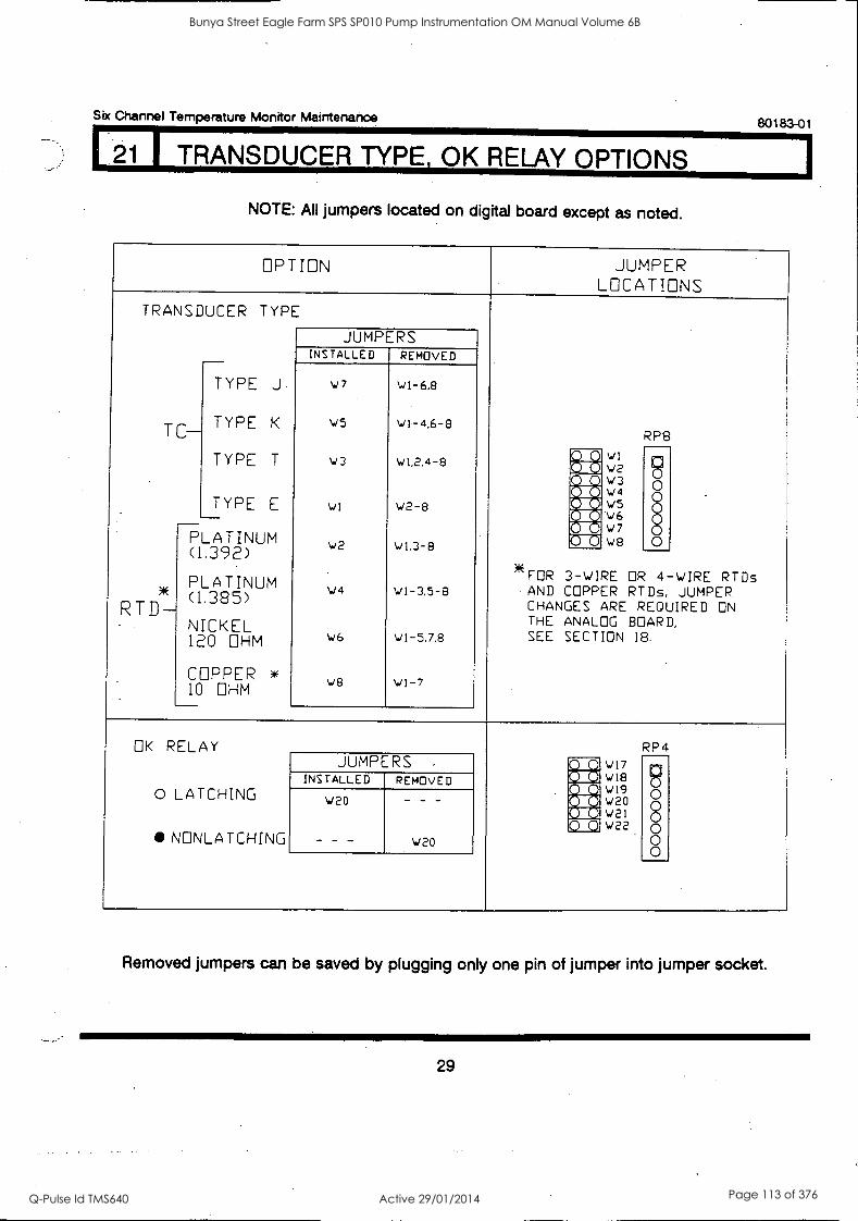
121 TRANSDUCER TYPE OK RELAY OPTIONS
Six Channel Temperature Monitor Maintenance 80183-01
NOTE: All jumpers located on digital board except as noted.
OPTION JUMPER LOCATIONS
TRANSDUCER
TC-
RTD-
TYPE
*FOR 3-WIRE
AND COPPER CHANGES THE ANALOG SEE SECTION
w1 w2 w3 wa w5 w6 \i7
\../8
OR RT
ARE REQUIRED BOARD, 18.
RP8
RTDs JUMPER
ON
JUMPERS INSTALLED REMOVED _
TYPE J
TYPE K
TYPE T
TYPE E
OHM
A(
OHM
w7
w5
w3
wi
w2
wa
w6
we
w1-6,8
wi-4,6-8
w1,2.4-8
V2-8
w1.3-8
w1-3,5-8
w1-5,7,8
wi-7
RIM (WM
ZD°
0 0 a 0 0 0
E NM CON
PLATINUM (1.392)
PLATINUM (1.385)
NICKEL 120
COPPER 10
4-WIRE Ds,
OK RELAY
o LATCHING
NNLATCHING
w17 W18 W19 W20 W21 v/22
RP4 JUMPERS
AM n 0 0 0 0 0 0
INSTALLED REMOVED g Mg w20
- - -
_ _ _
w20
11 0 0
Removed jumpers can be saved by plugging only one pin of jumper into jumper socket.
29
Bunya Street Eagle Farm SPS SP010 Pump Instrumentation OM Manual Volume 6B
Q-Pulse Id TMS640 Active 29/01/2014 Page 113 of 376
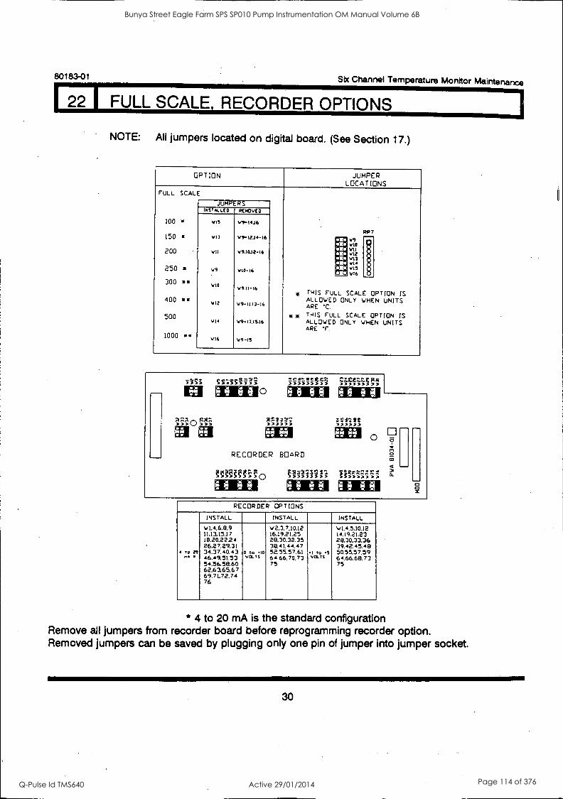
80183-01 Sbc Channel Temperature Monitor Maintenance
22 1 FULL SCALE, RECORDER OPTIONS
NOTE: All jumpers located on digital board. (See Section 17.)
OPTION JUMPER LOCATIONS
FULL SCALE
JUMPERS NsTALLco REMOVED
100 w vi5 V9-I4.16
150 RP7
vI3 V1-12.14-16 olio v9 XID %no
200 VII v9.1we 0.12-I6 lia die.
v11 vie V13
MD VII 250 v9 vt0-I6 ogo; vI5
AIM V16
300 VIO v9.II-16 * THIS FULL SCALE OPTION IS 400 .1, V12 v9-11.13-I6
ALLOWED ONLY WHEN UNITS APE .C.
500 1 , THIS FULL SCALE OPTION IS v14 v9-13.15.16 ALLOWED ONLY WHEN UNITS
APE F. 1000 0* VI6 v9-15
MM
517; stsTsini 40 00 O A 9 I 01
ee es
RECORDER BOARD
gaM10 44 00 4 0 F., 0
0 9 0
2,1,201)
ee MN O
11T-;`1.-7;;:
'4 0
RECORDER OPTIONS
INSTALL INSTALL INSTALL
v1.4.6.8.9 V2,3.7.10.12 v1.4.5.10.12 11.13.15.17 16.19.21.25 14.19.21.23 18.2022.24 28.30.32.35 28.30.33.36 26.27.29.31 38,41.44.47 39.42.45.48
4 to to 34.37.40.43 o to -to 52.55.57.61 1 to 5 50.55,57.59 ^A 46.49.51.53 Va." 64.66.70.73 vci-Ts 64.66.68,73
54.56.58,60 75 75 62.63,65,67 69.71,72.74 76
* 4 to 20 mA is the standard configuration Remove all jumpers from recorder board before reprogramming recorder option. Removed jumpers can be saved by plugging only one pin of jumper into jumper socket.
30
Bunya Street Eagle Farm SPS SP010 Pump Instrumentation OM Manual Volume 6B
Q-Pulse Id TMS640 Active 29/01/2014 Page 114 of 376
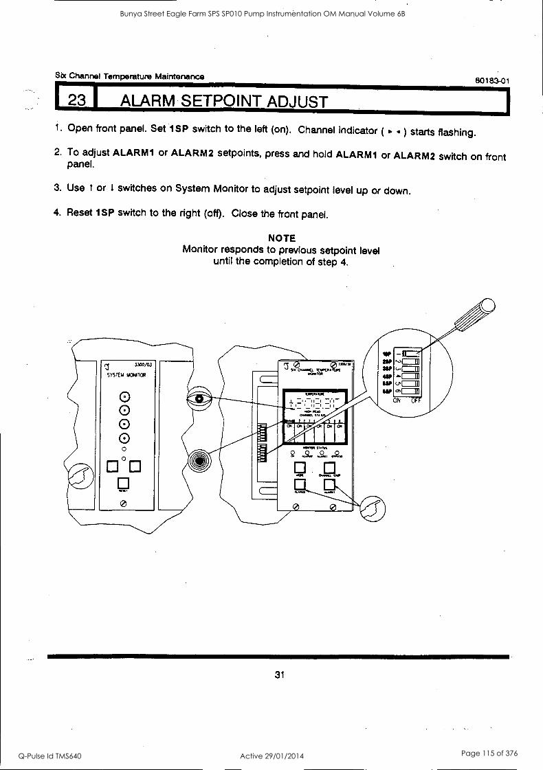
Six Channel Temperature Maintenance 80183-01
I ALARM SETPOINT ADJUST
1. Open front panel. Set 1SP switch to the left (on). Channel indicator ( ) starts flashing.
2. To adjust ALARM1 or ALARM2 setpoints, press and hold ALARM1 or ALARM2 switch on front panel.
3. Use t or 1 switches on System Monitor to adjust setpoint level up or down.
4. Reset 1SP switch to the right (off). Close the front panel.
NOTE Monitor responds to previous setpoint level
until the completion of step 4.
31
Bunya Street Eagle Farm SPS SP010 Pump Instrumentation OM Manual Volume 6B
Q-Pulse Id TMS640 Active 29/01/2014 Page 115 of 376
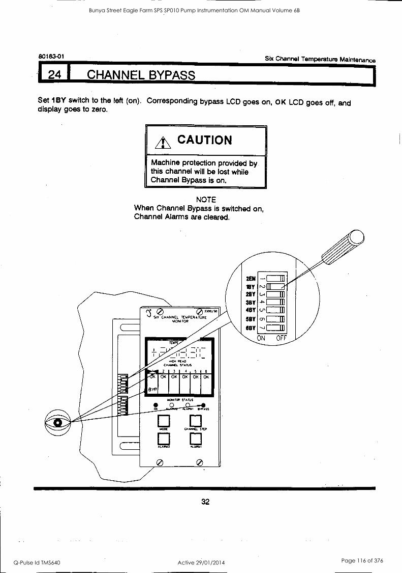
80183-01 Six Channel Temperature Maintenance
124 1 CHANNEL BYPASS
Set 1BY switch to the left (on). Corresponding bypass LCD goes on, OK LCD goes off, and display goes to zero.
A\ CAUTION
Machine protection provided by this channel will be lost while Channel Bypass is on.
NOTE When Channel Bypass is switched on, Channel Alarms are cleared.
SIX CHANNEL TEMPERA0RJR3E300/30
pro-
IT O R
40 RE AD cmANLL STATUS
2 3 4 5
I
I
010
10 BYP
4/41[-71-0
OK OK OK OK OK
itONITC* STATUS
O ."11 °WASS
o CD WOE CHANNEL STEP
Cl ALARW2 ..LARY I
3BY 4BY
5BY
6BY
cr Ill
lu
ON OFF
32
Bunya Street Eagle Farm SPS SP010 Pump Instrumentation OM Manual Volume 6B
Q-Pulse Id TMS640 Active 29/01/2014 Page 116 of 376
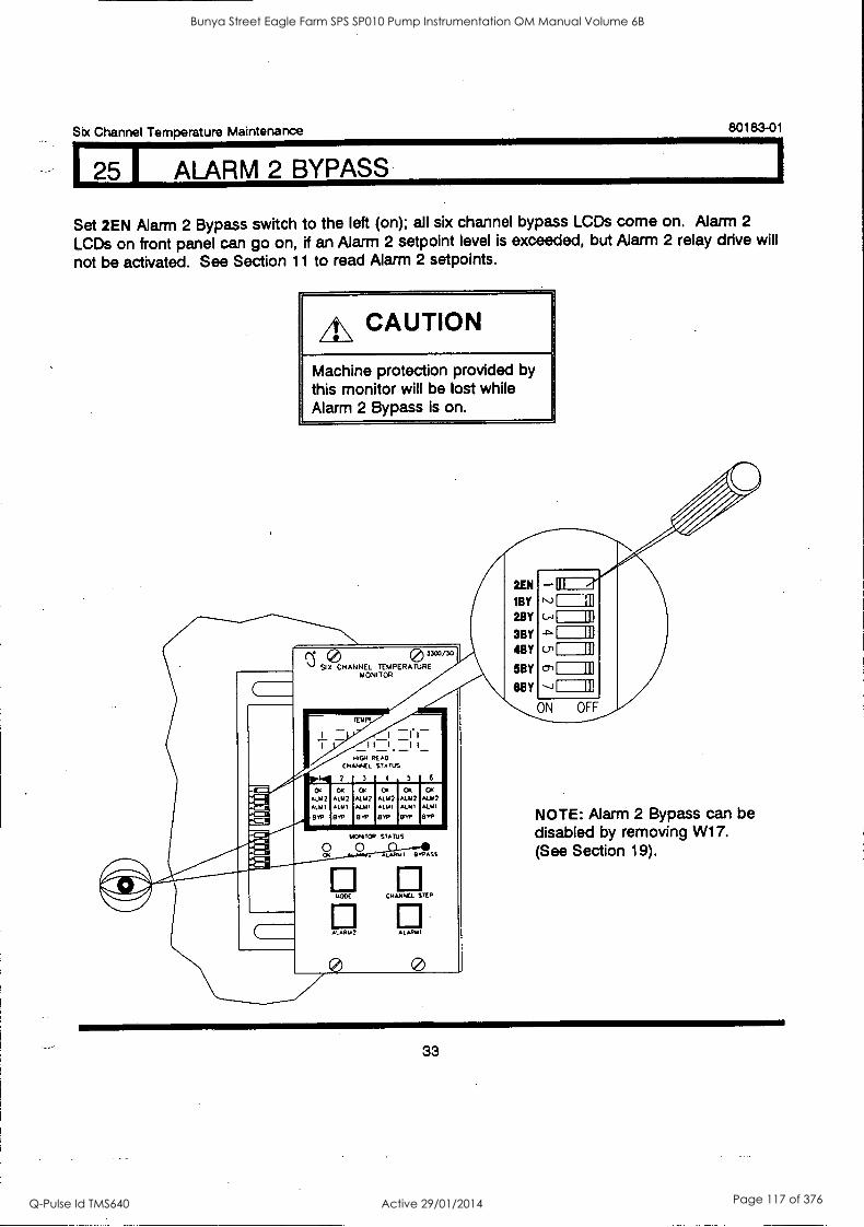
125 I ALARM 2 BYPASS
Six Channel Temperature Maintenance 80183-01
Set 2EN Alarm 2 Bypass switch to the left (on); all six channel bypass LCDs come on. Alarm 2
LCDs on front panel can go on, if an Alarm 2 setpoint level is exceeded, but Alarm 2 relay drive will
not be activated. See Section 11 to read Alarm 2 setpoints.
4\ CAUTION
Machine protection provided by this monitor will be lost while Alarm 2 Bypass is on.
0 3303/30
SID CHANNEL TEMPERATURE MONITOR
2EN -DI 4' 1BY N)=.19] 2BY (-4
3BY 4BY on
5BY
8BY
ON OFF
OK
ALM2
WI FOP
r '- I I I I I - - - -
14;04 READ CHANNEL STATUS
2 1 3 4 5 1 6
OK CO OK OK OR
A1.112 ALM2 ALM2 ALM2 ALM2 ALMI KLM, ALMI ALM 1 ALMI
GYP El 1. EITP GYP GYP
MONITOR STATUS
0 LAIKa I a v9A SS
POSE C.IANNEJ. STEP
Al ARIA 2 ALARLI I
® 0
I III
11
r ii I III
f III
NOTE: Alarm 2 Bypass can be disabled by removing W17. (See Section 19).
33
Bunya Street Eagle Farm SPS SP010 Pump Instrumentation OM Manual Volume 6B
Q-Pulse Id TMS640 Active 29/01/2014 Page 117 of 376
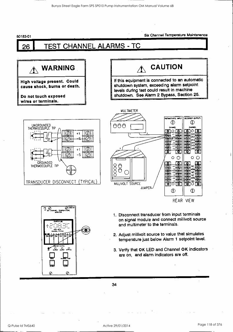
80183-01 Six Channel Temperature Maintenance
I TEST CHANNEL ALARMS - TC
A\ WARNING
High voltage present. Could cause shock, burns or death.
Do not touch exposed wires or terminals.
4?)04AMNEL ?) IM'X' MOMIOR
wett Nme.ti Srt
AL/IN} MANI
0 0
A\ CAUTION
If this equipment is connected to an automatic shutdown system, exceeding alarm setpoint levels during test could result in machine shutdown. See Alarm 2 Bypass, Section 25.
MULTIMETER
000 DEIVCCO-FlE PO
1CD
0 1:+1 !RidIMIC(01 :1-(61.11= 11
ICV,11331C-e71
IR 01,M10101 IRgiM15,01
;:11 (Coll .1oll l..
fi
110P.° .1-'/I'-00-e..111Paill.iik
IV] Er]
0 0 O PI O p O L-) 0 0
MILLIVOLT SOURCE.
JUMPE
RECCRDS OUTPUTS
(11)
04AMCI.
C.HI
CH2
CH3
014 CH5
CH6
0 0 NC
ARM
NO
NC
ARM
NO
0
QD
It 3
REAR VIEW
1. Disconnect transducer from input terminals on signal module and connect millivolt source and multimeter to the terminals.
2. Adjust millivolt source to value that simulates temperature just below Alarm 1 setpoint level.
3. Verify that OK LED and Channel OK indicators are on, and alarm indicators are off.
34
Bunya Street Eagle Farm SPS SP010 Pump Instrumentation OM Manual Volume 6B
Q-Pulse Id TMS640 Active 29/01/2014 Page 118 of 376
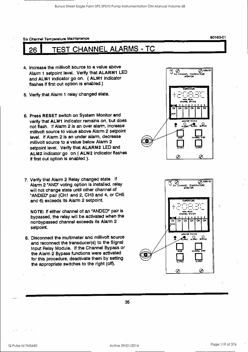
Scx Channel Temperature Maintenance 80183-01
26 I TEST CHANNEL ALARMS - TC
4. Increase the millivolt source to a value above
Alarm 1 setpoint level. Verify that ALARM1 LED and ALM1 indicator go on. ( ALM1 indicator flashes if first out option is enabled.)
5. Verify that Alarm 1 relay changed state.
6. Press RESET switch on System Monitor and verify that ALMI indicator remains on, but does
not flash. If Alarm 2 is an over alarm, increase millivolt source to value above Alarm 2 setpoint level. If Alarm 2 is an under alarm, decrease millivolt source to a value below Alarm 2
setpoint level. Verify that ALARM2 LED and
ALM2 indicator go on ( ALM2 indicator flashes if first out option is enabled ).
7. Verify that Alarm 2 Relay changed state. If
Alarm 2 'AND' voting option is installed, relay will not change state until other channel of ' ANDED' pair (CH1 and 2, CH3 and 4, or CH5 and 6) exceeds its Alarm 2 setpoint.
NOTE: If either channel of an 'ANDED' pair is
bypassed, the relay will be activated when the nonbypassed channel exceeds its Alarm 2
setpoint.
8. Disconnect the multimeter and millivolt source and reconnect the transducer(s) to the Signal Input Relay Module. If the Channel Bypass or the Alarm 2 Bypass functions were activated for this procedure, deactivate them by setting the appropriate switches to the right (off).
sxo ix) 94 CHANNEL TEMPERATURE
ON1 TOR
IDPERAIUPE
j_ 1 111-1 _1.1- 1 1 1 1 1 I if
MO, READ 0.4444E1 STATUS
2 5 4 r 5 r 6
01;1 OK OK OK
eun
OK
ALAISA7 A4ARAD
0 0
r 0 0 3300/30
NJ SO( CHANNEL TEMPERATURE MONITOR
TEMPERATURE
1 1 I-1 11 1 1 I II I II - .
READ CHARNEL ST ARA
OK I OKI OK 1 OKI OK p.141 3 4 5 6
OK
mom MA STATNS
AIME ALAMO BYPASS
1:1 MOLE CHAPtEL STEP
0 0
35
Bunya Street Eagle Farm SPS SP010 Pump Instrumentation OM Manual Volume 6B
Q-Pulse Id TMS640 Active 29/01/2014 Page 119 of 376
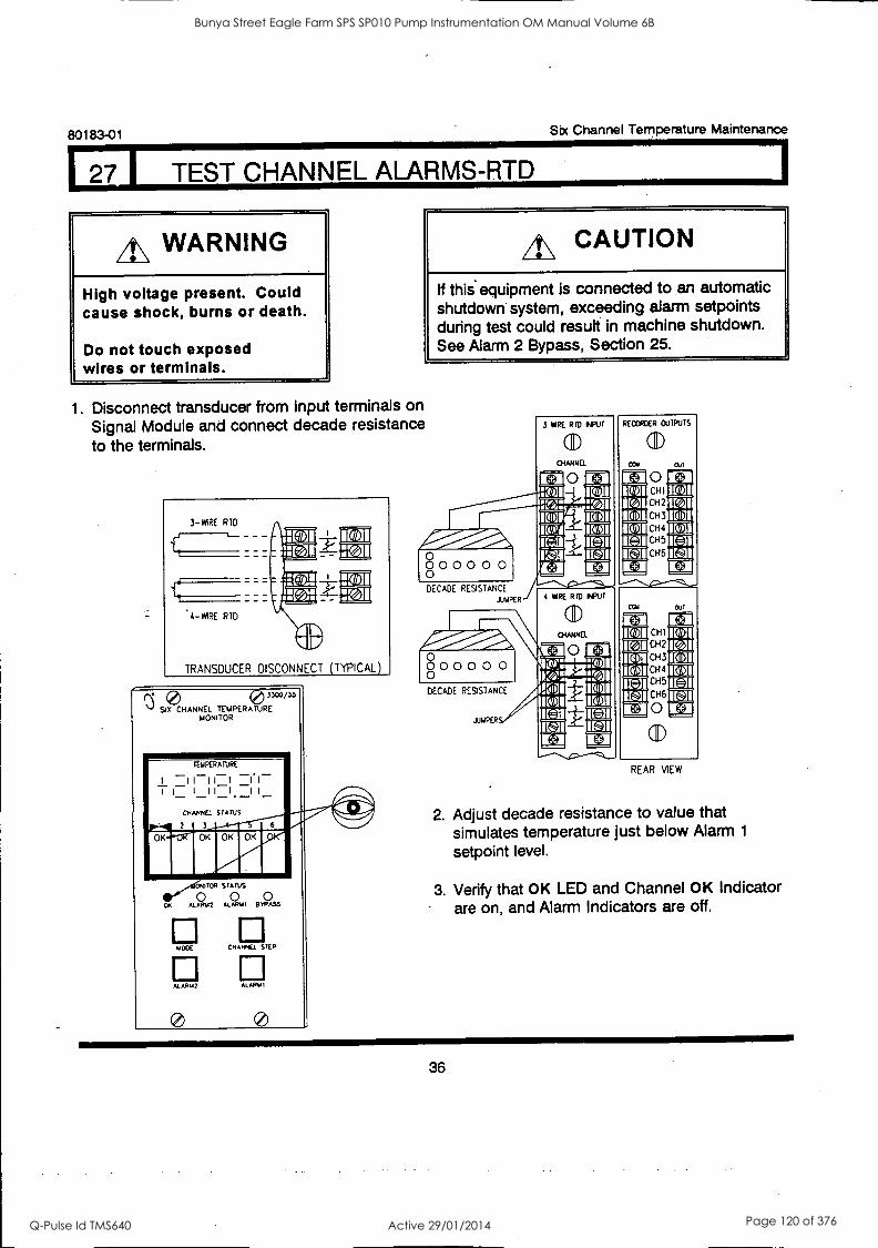
80183-01 Six Channel Temperature Maintenance
27 j TEST CHANNEL ALARMS-RTD
A\ WARNING
High voltage present. Could cause shock, burns or death.
Do not touch exposed wires or terminals.
4\ CAUTION
If this equipment is connected to an automatic shutdown system, exceeding alarm setpoints during test could result in machine shutdown. See Alarm 2 Bypass, Section 25.
1. Disconnect transducer from input terminals on Signal Module and connect decade resistance to the terminals.
3 -WIRE RID
4-WIRE RTD
TRANSDUCER DISCONNECT (TYPICAL)
(2) 3300/35
SIX CHANNEL TEMPERATURE MONITOR
TEMPERATURE
1 1
- 111 1
. 1
1 1 11 I I I
CHANNEL STATUS '44711 "1/"' 2 3
K
oK
TOP STAINS
0 0 0 ALARM2 A.EAPUI BWASS
1100E EP OPEL STEP
AL ITM2 ALARM I
DECADE RESISTANCE
.LIMPER
0 00000 o 0
DECADE RESISTANCE
JUmPER
3 YOE RID INPUT
(11)
CHANNEL
O
RECORDER OUTPUTS
(1) cow Out
1E41
O CHI
012 CH3
CH4
CH5
CH6
4 WRE RID INPUT
a) puma 0
Cul
IE+:1 CHI
CH2
CH3
CH4
CH5
CH6
0
REAR VIEW
2. Adjust decade resistance to value that simulates temperature just below Alarm 1
setpoint level.
3. Verify that OK LED and Channel OK Indicator are on, and Alarm Indicators are off.
36
Bunya Street Eagle Farm SPS SP010 Pump Instrumentation OM Manual Volume 6B
Q-Pulse Id TMS640 Active 29/01/2014 Page 120 of 376
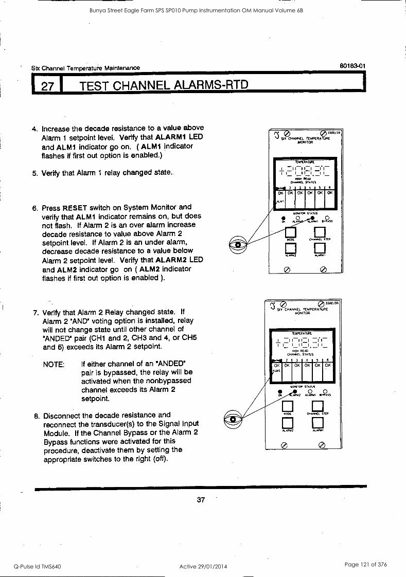
Six Channel Temperatuie Maintenance 80183-01
7 1 TEST CHANNEL ALARMS RTD
4. Increase the decade resistance to a value above Alarm 1 setpoint level. Verify that ALARM1 LED
and ALM1 indicator go on. ( ALM1 indicator flashes if first out option is enabled.)
5. Verify that Alarm 1 relay changed state.
6. Press RESET switch on System Monitor and verify that ALM1 indicator remains on, but does not flash. If Alarm 2 is an over alarm increase decade resistance to value above Alarm 2 setpoint level. If Alarm 2 is an under alarm, decrease decade resistance to a value below Alarm 2 setpoint level. Verify that ALARM2 LED
and ALM2 indicator go on ( ALM2 indicator flashes if first out option is enabled ).
7. Verify that Alarm 2 Relay changed state. If
Alarm 2 'AND' voting option is installed, relay will not change state until other channel of 'ANDED' pair (CH1 and 2, CH3 and 4, or CH5 and 6) exceeds its Alarm 2 setpoint.
NOTE: If either channel of an "ANDED" pair is bypassed, the relay will be activated when the nonbypassed channel exceeds its Alarm 2
setpoint.
8. Disconnect the decade resistance and reconnect the transducer(s) to the Signal Input Module. If the Channel Bypass or the Alarm 2
Bypass functions were activated for this procedure, deactivate them by setting the appropriate switches to the right (oft).
0 0 3300/35
Six CHANNEL TEMPERATURE MONITOR
TERPERATIRE
I -II-II-I 1.1- I I_ I I LI. _I I_
N104 READ 044ANCL STATUS
2 5 5 5
07 OK OK OK OK OK
"MI
0 0
0 3300/35
(3 SIX CHANNEL TEMPERATURE MONITOR
ruKRATURE
I 1 I I I1 1.1- I I_ I I I I _I I
HK:41 READ EHANTEL STATUS
0411 2 3 4 5 6
OK OK OK OK OK OK
7UO2
DM
TIC44TOP STATUS
0 0 LARUE ALAPUI BYPASS
MOOS ENAMEL STEP
1:1 ALAPU2 ALARIJI
0 0
37
Bunya Street Eagle Farm SPS SP010 Pump Instrumentation OM Manual Volume 6B
Q-Pulse Id TMS640 Active 29/01/2014 Page 121 of 376
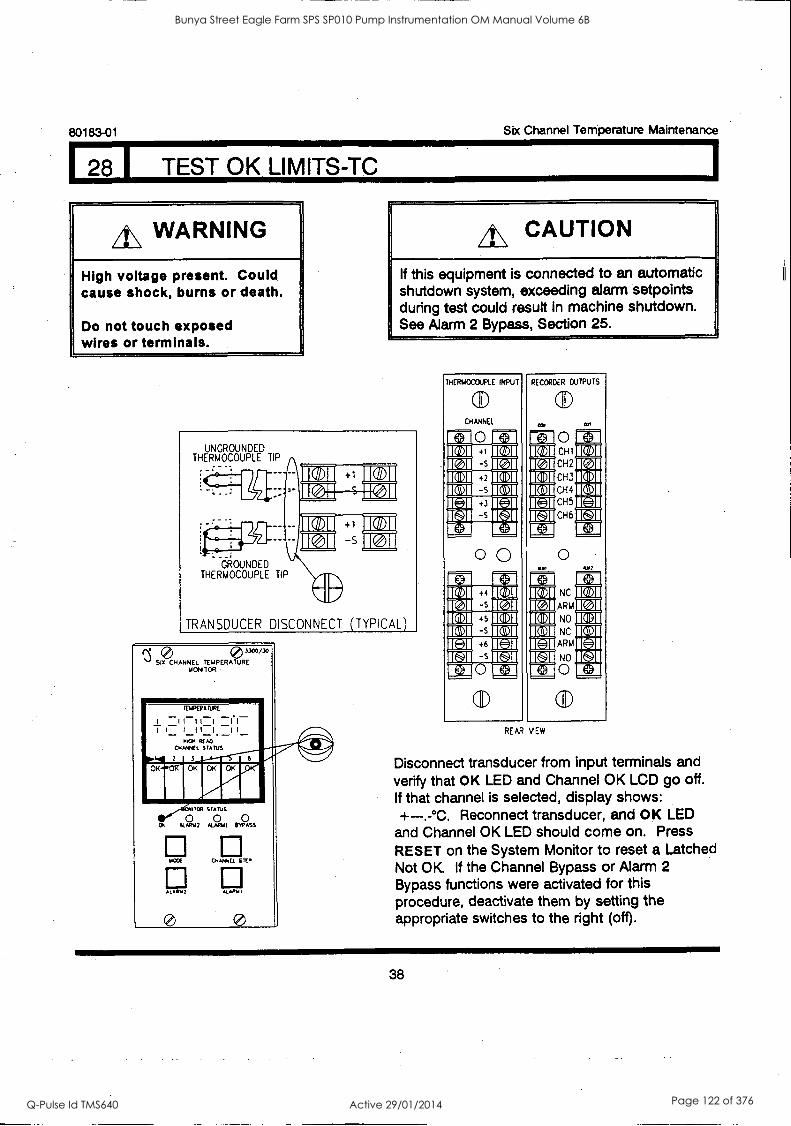
80183-01 Six Channel Temperature Maintenance
8 I TEST OK LIMITS-TC
4\ WARNING
High voltage present. Could cause shock, burns or death.
Do not touch exposed wires or terminals.
A\ CAUTION
If this equipment is connected to an automatic shutdown system, exceeding alarm setpoints during test could result in machine shutdown. See Alarm 2 Bypass, Section 25.
UNGROUNDED THERMOCOUPLE TIP
Eo
.e !
GROUNDED THERMOCOUPLE TIP
TRANSDUCER DISCONNECT (TYPICAL)
3300/30
SIX CHANNEL TEMPERATURE MONITOR
WEE CHANNEL STEP
Al AA. 2 KAHN
0
THERMOCOUPLE INPUT
CHANNEL
PI 0 IC-3
0 0
RECORDER OUTPUTS
MIA
IC 31
0 CHI
CH2
CH3
CH4
CH5
CH6
0
NC
ARM
NO
NC
ARM
NO
0
ICS 1I 10 71
I I
REAR NEW
Disconnect transducer from input terminals and verify that OK LED and Channel OK LCD go off. If that channel is selected, display shows: +-..°C. Reconnect transducer, and OK LED
and Channel OK LED should come on. Press
RESET on the System Monitor to reset a Latched Not OK If the Channel Bypass or Alarm 2 Bypass functions were activated for this procedure, deactivate them by setting the appropriate switches to the right (off).
38
Bunya Street Eagle Farm SPS SP010 Pump Instrumentation OM Manual Volume 6B
Q-Pulse Id TMS640 Active 29/01/2014 Page 122 of 376
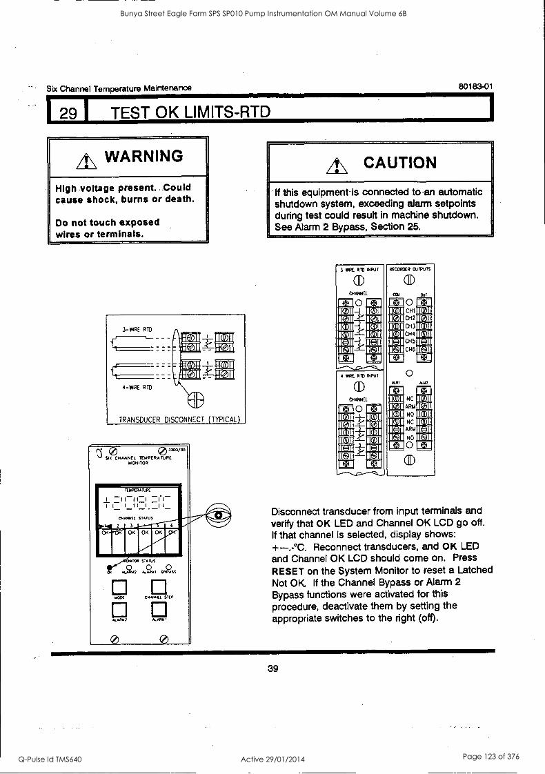
1[,]I DOI 1511 ICON
Six Channel Temperature Maintenance 80183-01
29 I TEST OK LIMITS-RTD
A\ WARNING
High voltage present. Could cause shock, burns or death.
Do not touch exposed wires or terminals.
3-MIRE RTD
4 -PARE RTD
IT 11
TRANSDUCER DISCONNECT (TYPICAL)
0 3300/35
SIX CHANNEL TEMPERATURE MONITOR
TEMPERATURE
I I I I II (1 I I 11111 1_
cHANNEI. STATUS
2 3
OK
toR STATUS
0 0 0 OA AEARm2 4AR111 WASS
AWE CPANAEE STEP
ALAR,42 ALARM
A\ CAUTION
If this equipment is connected to-an automatic shutdown system, exceeding alarm setpoints during test could result in machine shutdown. See Alarm 2 Bypass, Section 25.
3 TIRE RID INPUT
CID
04ANHEL
0 1[011 1011 1511 E]I
4 WIRE RID INPUT
O
(ID
CAI
1511 1E211
RECORDER OUTPUTS
(11)
Cal
0 CHI
CH2
CH3
CH4
0-15
CH6
OUT
NC
ARM
NO
NC
ARIA
NO
0
U+3
Disconnect transducer from input terminals and verify that OK LED and Channel OK LCD go off. If that channel is selected, display shows: +-.-°C. Reconnect transducers, and OK LED and Channel OK LCD should come on. Press
RESET on the System Monitor to reset a Latched Not OK If the Channel Bypass or Alarm 2
Bypass functions were activated for this procedure, deactivate them by setting the appropriate switches to the right (off).
39
Bunya Street Eagle Farm SPS SP010 Pump Instrumentation OM Manual Volume 6B
Q-Pulse Id TMS640 Active 29/01/2014 Page 123 of 376
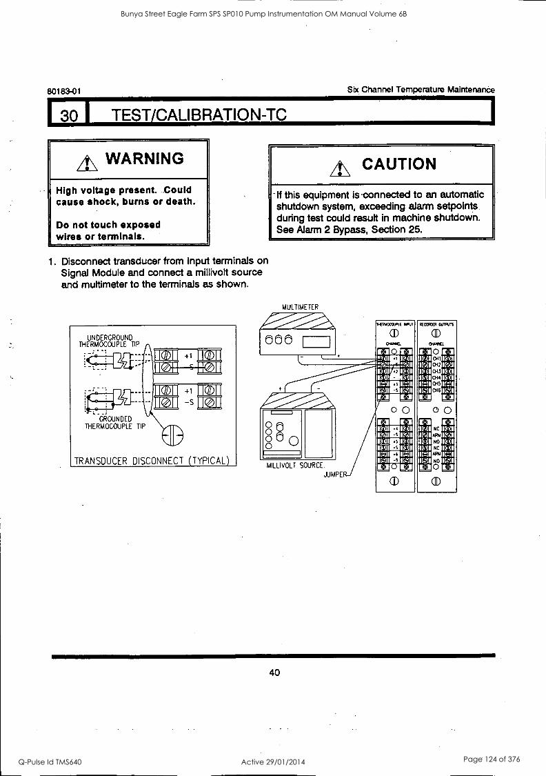
80183-01 Six Channel Temperature Maintenande
I 30 I TEST/CALIBRATION-TC
A\ WARNING
High voltage present. Could cause shock, burns or death.
Do not touch exposed wires or terminals.
1. Disconnect transducer from input terminals on Signal Module and connect a millivolt source and muttimeter to the terminals as shown.
UNDERGROUND THERMOCOUPLE TIP
-
(s. _;
. _
it0
0
GROUNDED THERMOCOUPLE TIP
410 TRANSDUCER DISCONNECT (TYPICAL)
A\ CAUTION
-If this equipment is-connected to an automatic shutdown system, exceeding alarm setpoints during test could result in machine shutdown. See Alarm 2 Bypass, Section 25.
MULTIMETER
660
TA11°' _ak. o 00 0 0
MILLIVOLT SOURCE.
JUMPE
INERPCCSIJPIE
11.3 K,
al)
milicf
.,
Ell a 1%41
RECORDER
ID ill I1Q1
OUIPU1S
(I) CREPPIEL
0 CH2
1.3 ID 3
IDAI/MID91 ID el 043 ID CI IN 41=5 ql 15 ql 044 3 IC=11MIC41 1=1 045
IC:A111131C41 1C-11 CH6
Etai Ell 11 1.1
tql 00
t-1 IC 31DAI 1111141
ID 41 11,.11
NC
ARIA
It., I 10.31
ID CIM gl ID 01 NO IDII 15 qlgUIL4 ID gl NC
11=31011=3 11=3 ARIA 11=3 IC:11
Ell It 3 0 IL 3
40
Bunya Street Eagle Farm SPS SP010 Pump Instrumentation OM Manual Volume 6B
Q-Pulse Id TMS640 Active 29/01/2014 Page 124 of 376
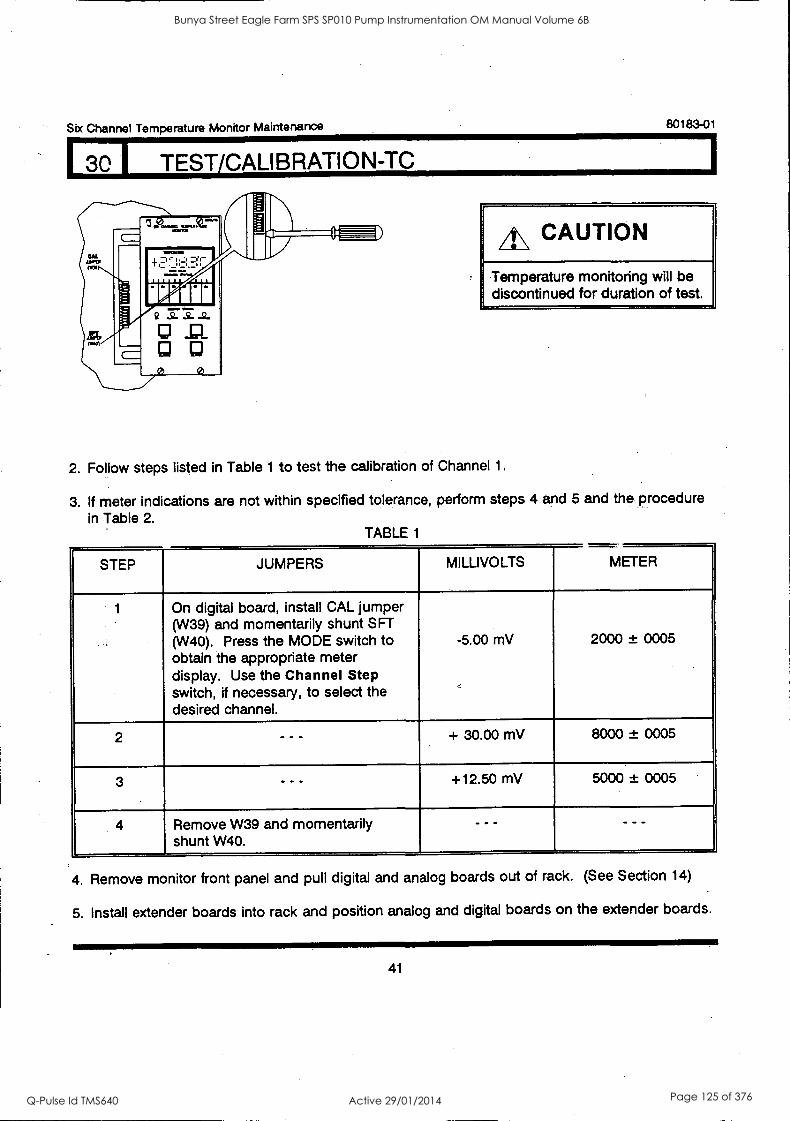
Six Channel Temperature Monitor Maintenance 80183-01
1 TEST/CALIBRATION-TC
A\ CAUTION
Temperature monitoring will be discontinued for duration of test.
2. Follow steps listed in Table 1 to test the calibration of Channel 1.
3. If meter indications are not within specified tolerance, perform steps 4 and 5 and the procedure in Table 2.
TABLE 1
STEP JUMPERS MILLIVOLTS METER
1 On digital board, install CAL jumper (W39) and momentarily shunt SFT (W40). Press the MODE switch to obtain the appropriate meter display. Use the Channel Step switch, if necessary, to select the desired channel.
-5.00 mV 2000 ± 0005
2 - - - + 30.00 mV 8000 ± 0005
3 - - - +12.50 mV 5000 ± 0005
4 Remove W39 and momentarily shunt W40.
- - - - - -
4. Remove monitor front panel and pull digital and analog boards out of rack. (See Section 14)
5. Install extender boards into rack and position analog and digital boards on the extender boards.
41
Bunya Street Eagle Farm SPS SP010 Pump Instrumentation OM Manual Volume 6B
Q-Pulse Id TMS640 Active 29/01/2014 Page 125 of 376
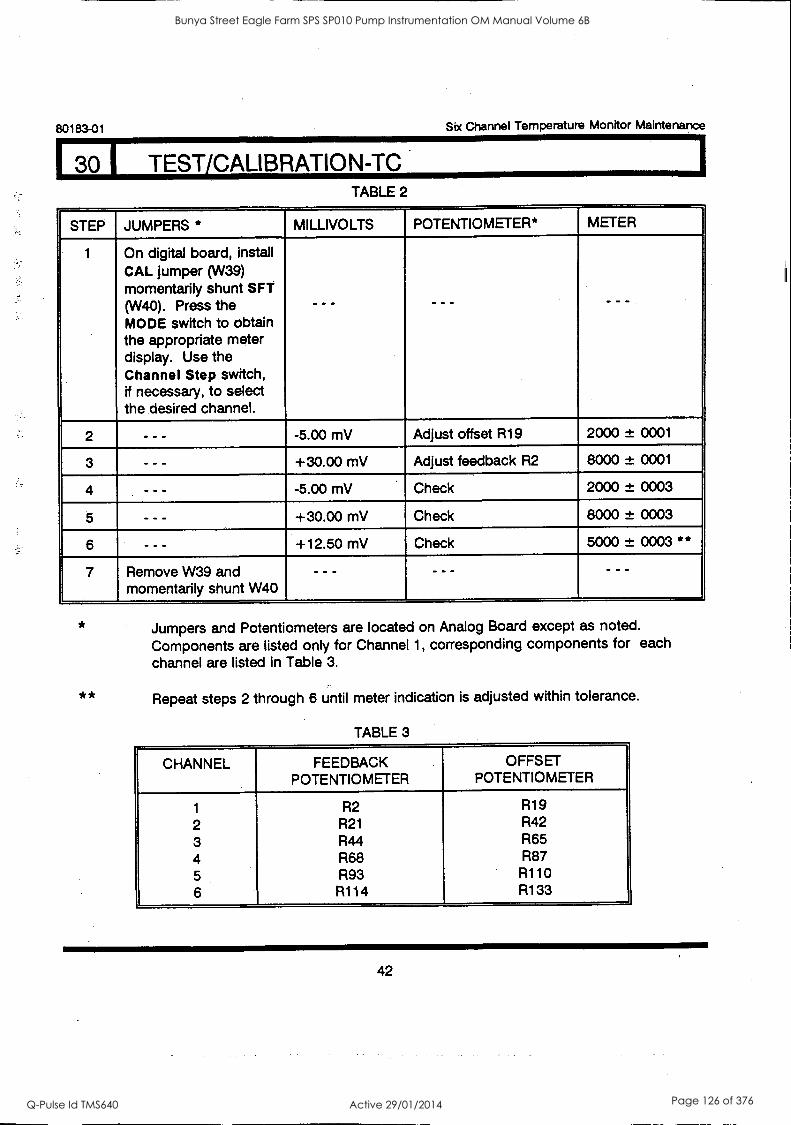
80183-01 Six Channel Temperature Monitor Maintenance
1 30 1 TEST/CALIBRATION-TO TABLE 2
STEP JUMPERS * MILLIVOLTS POTENTIOMETER* METER
1 On digital board, install CAL jumper (W39) momentarily shunt SFT (W40). Press the MODE switch to obtain the appropriate meter display. Use the Channel Step switch, if necessary, to select the desired channel.
- -- - - - - - -
2 - - - -5.00 mV Adjust offset R19 2000 ± 0001
3 - - - +30.00 mV Adjust feedback R2 8000 ± 0001
4 -5.00 mV Check 2000 ± 0003
5 - - - +30.00 mV Check 8000 ± 0003
6 - - - +12.50 mV Check 5000 ± 0003 **
7 Remove W39 and momentarily shunt W40
- -- - - - - - -
**
Jumpers and Potentiometers are located on Analog Board except as noted.
Components are listed only for Channel 1, corresponding components for each channel are listed in Table 3.
Repeat steps 2 through 6 until meter indication is adjusted within tolerance.
TABLE 3
CHANNEL FEEDBACK POTENTIOMETER
OFFSET POTENTIOMETER
1 R2 R19
2 R21 R42
3 R44 R65 4 R68 R87
5 R93 R110
6 R114 R133
42
Bunya Street Eagle Farm SPS SP010 Pump Instrumentation OM Manual Volume 6B
Q-Pulse Id TMS640 Active 29/01/2014 Page 126 of 376
Six Channel Temperature Monitor Maintenance 80183-01
TEST/CALIBRATION-TC
The monitor is calibrated upon completion of the procedure in Table 2 (or if it meets the tolerances specified in Table 1). The following two procedures are optional. The first allows you to verify the calibration at a temperature of your choice. The second allows you to verify the recorder output.
If you do NOT wish to perform the following procedures, disconnect the muttimeter and millivolt source and reconnect the transducer(s) to the Signal Input Module. If the Channel Bypass or the Alarm 2 Bypass functions were activated for this procedure, deactivate them by setting the appropriate switches to the right (off).
I. Verify calibration at a specific temperature
1. Read the Cold Junction Compensation (CJC) temperature. To do this, choose any channel and disconnect that channel's transducer from the input terminals on the Signal Input
Module. Install jumper wires between the + and - terminals and the - and S terminals of this channel. Read the front panel meter temperature displayed for this channel. This is the CJC
temperature.
2. Using a Thermocouple Table, convert the CJC temperature measured in step one to the CJC
voltage. (Vcjc).
NOTE: In converting thermocouple temperatures to voltages, be sure to use the specific Thermocouple Table corresponding to the thermocouple type the monitor is optioned for. If you are unsure of the thermocouple type, perform the User-invoked self test and note the transducer type displayed in the power-up display sequence (see Self Test section).
3. Choose a temperature within the full scale range of the monitor as your desired test temperature. Convert it to your test voltage (Vtest) using the Thermocouple Table.
4. Calculate the appropriate input voltage (Vin) by subtracting the CJC voltage from the test voltage.
EXAMPLE: Assume that the CJC temperature measured in step one is 28.7°C, that the monitor is set up for Type J thermocouples, and that you wish to test the monitor at 100°C.
Round the CJC temperature to the nearest degree, 29°C. From the Thermocouple Table, this corresponds to a CJC voltage (Vcjc) of 1.484 mV.
From the same table, a test temperature of 100°C corresponds to a test voltage (Vtest) of 5.268 mV.
Vin = Vtest - Vcjc = 5.268 - 1.484 mV = 3.784 mV
43
Bunya Street Eagle Farm SPS SP010 Pump Instrumentation OM Manual Volume 6B
Q-Pulse Id TMS640 Active 29/01/2014 Page 127 of 376
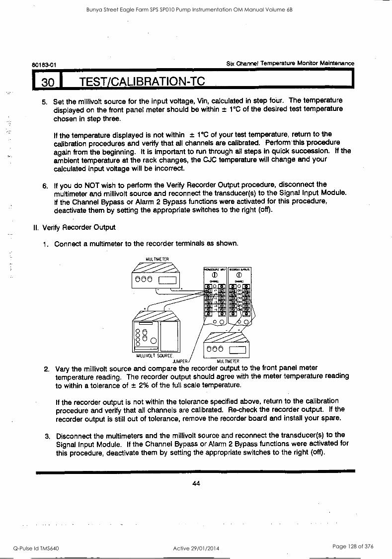
80183-01 Sbc Channel Temperature Monitor Maintenance
1 30 1 TEST/CALIBRATION-TC
5. Set the millivolt source for the input voltage, Vin, calculated in step four. The temperature displayed on the front panel meter should be within ± 1°C of the desired test temperature
chosen in step three.
If the temperature displayed is not within ± 1°C of your test temperature, return to the calibration procedures and verify that all channels are calibrated. Perform-this procedure again from the beginning. It is important to run through all steps in quick succession. If the ambient temperature at the rack changes, the CJC temperature will change and your calculated input voltage will be incorrect.
6. If you do NOT wish to perform the Verify Recorder Output procedure, disconnect the multimeter and millivolt source and reconnect the transducer(s) to the Signal Input Module. If the Channel Bypass or Alarm 2 Bypass functions were activated for this procedure, deactivate them by setting the appropriate switches to the right (off).
II. Verify Recorder Output
1. Connect a multimeter to the recorder terminals as shown.
MULTIMETER
000
o 00 8 0
fl IRCOW onion
1,1 11-1
owe 110 11
lOr":1
,!:dp1"Pi C1013
II -:1 11:11
1.1
Itit1 Itt I1Z:1
1.1
It:qv/HI:0 Imm- ix
V.4.11
Air "1".1101111.1.--
000 MILLIVOLT SOURCE.
JUMRE MULTIMETER
2. Vary the millivolt source and compare the recorder output to the front panel meter temperature reading. The recorder output should agree with the meter temperature reading to within a tolerance of ± 2% of the full scale temperature.
If the recorder output is not within the tolerance specified above, return to the calibration procedure and verify that all channels are calibrated. Re-check the recorder output. If the
recorder output is still out of tolerance, remove the recorder board and install your spare.
3. Disconnect the multimeters and the millivolt source and reconnect the transducer(s) to the Signal Input Module. If the Channel Bypass or Alarm 2 Bypass functions were activated for
this procedure, deactivate them by setting the appropriate switches to the right (off).
44
Bunya Street Eagle Farm SPS SP010 Pump Instrumentation OM Manual Volume 6B
Q-Pulse Id TMS640 Active 29/01/2014 Page 128 of 376
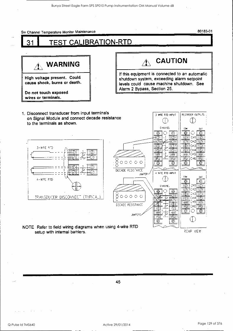
131 1 TEST CALIBRATION--RTD
Six Channel Temperature Monitor Maintenance 80183-01
WARNING
High voltage present. Could cause shock, burns or death.
Do not touch exposed wires or terminals.
1. Disconnect transducer from input terminals on Signal Module and connect decade resistance to the terminals as shown.
4\ CAUTION
If this equipment is connected to an automatic shutdown system, exceeding alarm setpoint levels could cause machine shutdown. See Alarm 2 Bypass, Section 25.
TRANSDUCER DISCONNECT (TYPICAL)
O 0 0 0 0 0 0 0 DECADE RESISTANCE
JUMPER
0 0 0 0 0 0 0
I '
DECADE RESISTANCE
JUMPERS,
NOTE Refer to field wiring diagrams when using 4-wire RTD
setup with internal barriers.
3 WIRE RTD INPUT
CHANNEL
e 0 ;rail
RECORDER OUTPUTS
COM Out
CH1
CH2
CH3
11 1 CH4
CH5
CH6 IL.
4 WIRE RID INPUT
o CHANNEL
Ian MEM
car,
AM.
I
CON
IN 1511
CH2
CH3
CH4
CH5
CH6
QL)
ICS
REAR VIEW
45
Bunya Street Eagle Farm SPS SP010 Pump Instrumentation OM Manual Volume 6B
Q-Pulse Id TMS640 Active 29/01/2014 Page 129 of 376
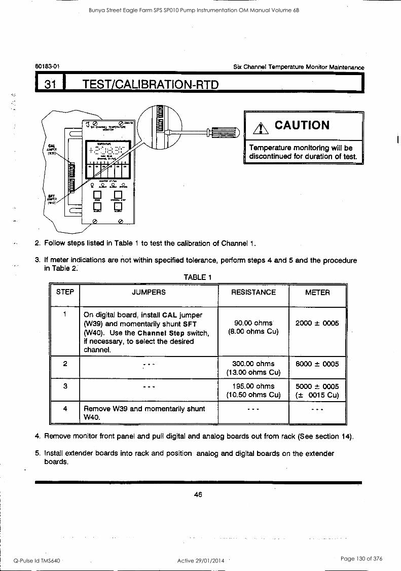
80183-01
31 I TEST/CALIBRATION-RTD
Six Channel Temperature Monitor Maintenance
Temperature monitoring will be discontinued for duration of test.
2. Follow steps listed in Table 1 to test the calibration of Channel 1.
3. If meter indications are not within specified tolerance, perform steps 4 and 5 and the procedure in Table 2.
TABLE 1
STEP JUMPERS RESISTANCE METER
1 On digital board, install CAL jumper (W39) and momentarily shunt SFT (W40). Use the Channel Step switch, if necessary, to select the desired channel.
90.00 ohms (8.00 ohms Cu)
2000 ± 0005
2 7 - - 300.00 ohms (13.00 ohms Cu)
8000 ± 0005
3 - - - 195.00 ohms (10.50 ohms Cu)
5000 ± 0005 (± 0015 Cu)
4 Remove W39 and momentarily shunt W40.
- - - - - -
4. Remove monitor front panel and pull digital and analog boards out from rack (See section 14).
5. Install extender boards into rack and position analog and digital boards on the extender boards.
46
Bunya Street Eagle Farm SPS SP010 Pump Instrumentation OM Manual Volume 6B
Q-Pulse Id TMS640 Active 29/01/2014 Page 130 of 376
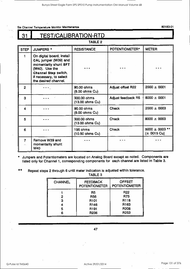
Six Channel Temperature Monitor Maintenance 80183-01
I31 1 TEST/CALIBRATION-RTD TABLE 2
STEP JUMPERS * RESISTANCE POTENTIOMETER* METER
1 On digital board, install CAL jumper (W39) and momentarily shunt SFT (W40). Use the Channel Step switch, if necessary, to select the desired channel.
- -- - - - - - -
2 - - - 90.00 ohms (8.00 ohms Cu)
Adjust offset R22 2000 ± 0001
3 - - - 300.00 ohms (13.00 ohms Cu)
Adjust feedback R5 8000 ± 0001
4 - - - 90.00 ohms (8.00 ohms Cu)
Check 2000 ± 0003
5 - - - 300.00 ohms (13.00 ohms Cu)
Check 8000 ± 0003
6 - - - 195 ohms (10.50 ohms Cu)
Check 5000 ± 0003 ** (± 0015 Cu)
7 Remove W39 and momentarily shunt W40
- -- - - - - - -
* Jumpers and. Potentiometers are located on Analog Board except as noted. Components are listed only for Channel 1, corresponding components for each channel are listed in Table 3.
** Repeat steps 2 through 6 until meter indication is adjusted within tolerance. TABLE 3
CHANNEL FEEDBACK POTENTIOMETER
OFFSET POTENTIOMETER
1 R5 R22 2 R56 R73 3 R101 R118 4 R146 R163 5 R191 R208 6 R236 R253
47
Bunya Street Eagle Farm SPS SP010 Pump Instrumentation OM Manual Volume 6B
Q-Pulse Id TMS640 Active 29/01/2014 Page 131 of 376
80183-01 Six Channel Temperature Monitor Maintenance
31 I TEST/CALIBRATION-RTD
The monitor is calibrated upon completion of the procedure in Table 2 (or if it meets the tolerances
specified in Table 1). The following two procedures are optional. The first allows you to verify the
calibration at a temperature of your choice. The second allows you to verify the recorder output.
If you do NOT .wish to perform the following procedures, disconnect the decade resistance and reconnect the transducer(s) to the Signal Input Module. If the Channel Bypass or the Alarm 2
Bypass functions were activated for this procedure, deactivate them by setting the appropriate switches to the right (off).
I. Verify calibration at a specific temperature
1. Choose a temperature within the full scale range of the monitor as your desired test temperature. Convert it to your test resistance (Rtest) using an RTD Table.
NOTE: In converting RTD temperatures to resistances, be sure to use the specific RTD Table corresponding to the RTD type the monitor is optioned for. If you are unsure of the RTD type, perform the User-invoked self test and note the transducer type displayed in the Power-up display sequence (see Self Test section).
EXAMPLE: Assume that the monitor is set up for platinum (1.385) RTDs and that you wish to test the monitor at 100°C.
From the RTD Table, this corresponds to a test resistance (Rtest) of 138.5 ohms.
2. Set the decade resistance for the test resistance, Rtest, found in step one. The temperature displayed on the front panel meter should be within ± 1°C of the desired test temperature chosen in step one.
If the temperature displayed is not within ± 1°C of your test temperature, return to the calibration procedure and verify that all channels are calibrated. Perform this procedure again from the beginning.
3. If you do NOT wish to perform the Verify Recorder Output procedure, disconnect the decade resistance and reconnect the transducer(s) to the Signal Input Module. If the Channel Bypass or the Alarm 2 Bypass functions were activated for this procedure, deactivate them by setting the appropriate switches to the right (off).
48
Bunya Street Eagle Farm SPS SP010 Pump Instrumentation OM Manual Volume 6B
Q-Pulse Id TMS640 Active 29/01/2014 Page 132 of 376
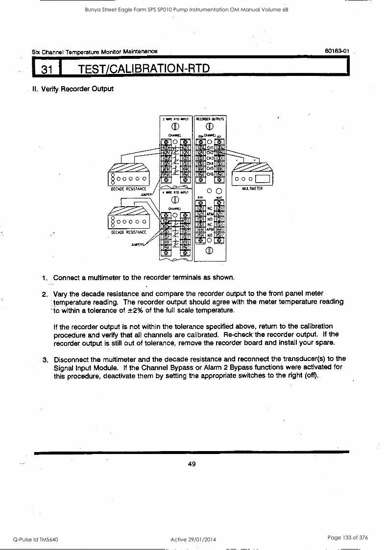
Six Channel Temperature Monitor Maintenance 80183-01
31 I TEST/CALIBRATION-RTD
II. Verify Recorder Output
§ 0 0 0 0 0
DECADE RESISTANCE
JUI4PfR
.11
0 0 0 0 0
DECADE RESIS1ANCE
3 IMRE RID ORM
0
ar
4 111RE RID IMPLII
CID
0
RECCRIXR ClITPUIS
(ID 03,00/4114.1 an
O CHI
CH
CH3
CH5
CH6
U4
r-1+! I 15/1
1E4
1[331 "..10%Pwii/-
00 NC
ARM
NO
NC
ARM
NO
0
(ID
1[21 IBICI 150 Kra
0 0 0
1. Connect a multimeter to the recorder terminals as shown.
MULTIIAElER
2. Vary the decade resistance and compare the recorder output to the front panel meter 'temperature reading. The recorder output should agree with the meter temperature reading to within a tolerance of ±2% of the full scale temperature.
If the recorder output is not within the tolerance specified above, return to the calibration procedure and verify that all channels are calibrated. Re-check the recorder output. if the recorder output is still out of tolerance, remove the recorder board and install your spare.
3. Disconnect the multimeter and the decade resistance and reconnect the transducer(s) to the Signal Input Module. If the Channel Bypass or Alarm 2 Bypass functions were activated for this procedure, deactivate them by setting the appropriate switches to the right (off).
49
Bunya Street Eagle Farm SPS SP010 Pump Instrumentation OM Manual Volume 6B
Q-Pulse Id TMS640 Active 29/01/2014 Page 133 of 376
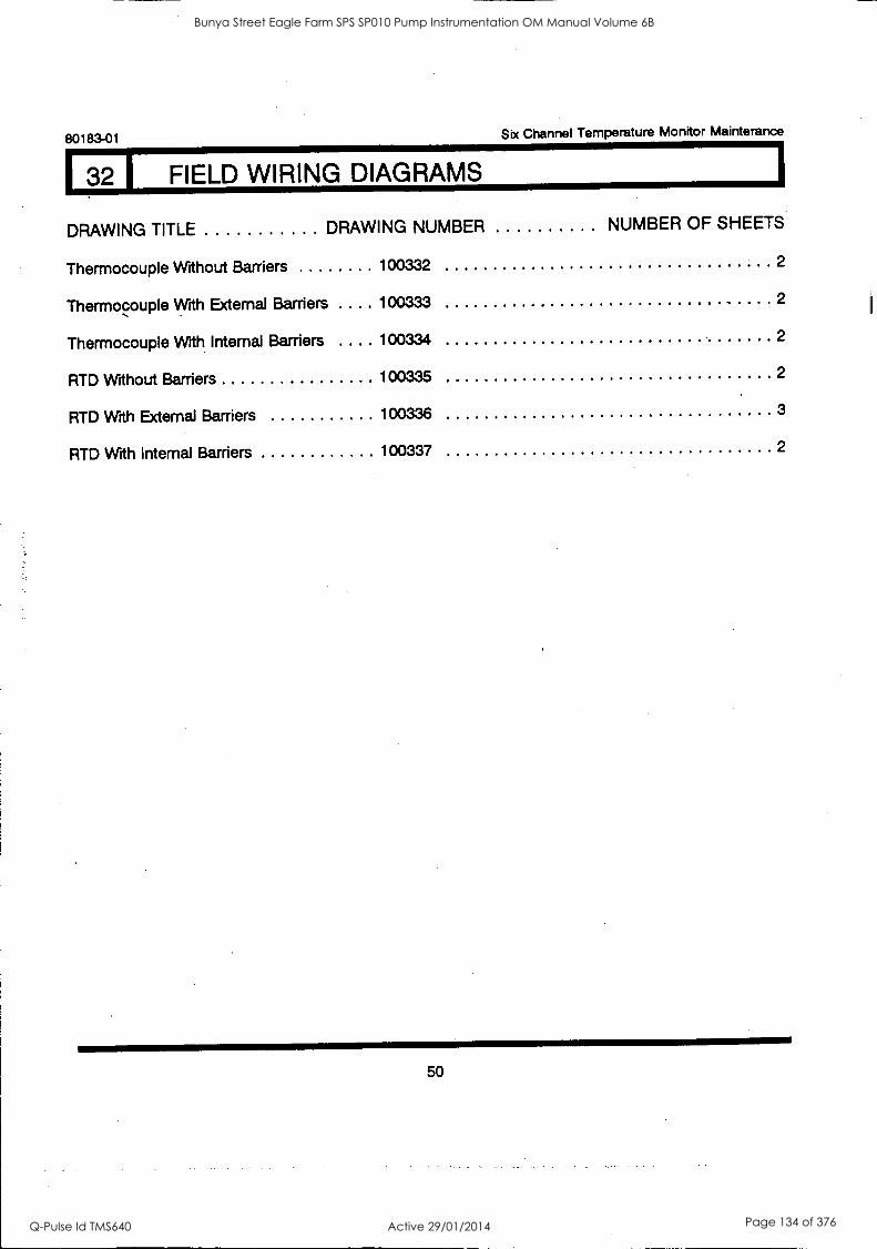
80183-01 Six Channel Temperature Monitor Mainterance
32 I FIELD WIRING DIAGRAMS
DRAWING TITLE DRAWING NUMBER NUMBER OF SHEETS
Thermocouple Without Barriers 100332 2
Thermocouple With External Barriers . 100333 2
Thermocouple With Internal Barriers 100334 2
RTD Without Barriers 100335 2
RTD With External Barriers 100336 3
RTD With Internal Barriers 100337 2
50
Bunya Street Eagle Farm SPS SP010 Pump Instrumentation OM Manual Volume 6B
Q-Pulse Id TMS640 Active 29/01/2014 Page 134 of 376
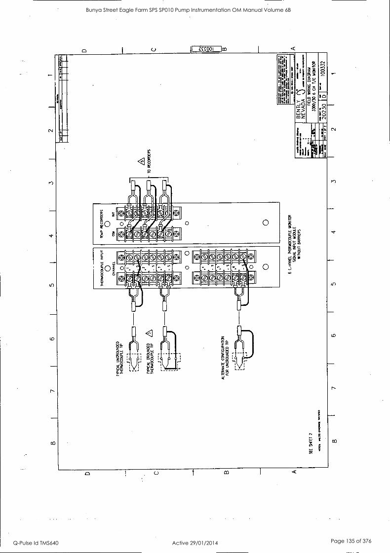
8
SEE
SH
EE
T
2
7
KIN
, st
tn 01
1041
/M
OR
D
8
6 5
4 3
2 I
I
TY
PIC
AL
U
NG
RO
UN
DE
D
TH
ER
MO
CO
UPL
E
TIP
TY
PIC
AL
G
RO
UN
DE
D
TH
ER
MO
CO
UPL
E
TIP
z\
IHE
RH
OC
OU
PLE
IN
PU
T
O
CH
AN
NE
L
AL
TE
RN
AT
E
CO
NFI
GU
RA
TIO
N
FOR
UN
GR
OU
ND
ED
T
IP
r - -
6 C
oAN
NE
L
TH
ER
MO
CO
UPL
E
MO
NIT
OR
SIG
NA
L
INPU
T
MO
DU
LE
WIT
HO
UT
B
AR
RIE
RS
TO
R
EC
OR
DE
RS
a./
waM
fain
WP
M
OM
MM
.. W
PM
.1
1
.0.1
01,
Mal
Wm
. M
ID
011 M
aga.
./
la V
on M
b W
O 14
.11.
1. /M
P a
die
...M
M..
Ma.
al
CM
OS
OM
MA
IM
0 .
myn
a oa
r
D C
1.
21.1
111M
I
aMO
D M
ama
IMA
MS
a
4991
1111
=
1M11
1
BE
NT
LY
NE
VA
DA
%
.)
woo
-
Wol
e 'n
orm
. alM
aMO
M
FIE
LD
W
RIN
G
DIA
GR
AM
3300
/30
6 C
H
T/C
MO
NIT
OR
OM
2023
0 0 ".
10
0332
7 6
5 4
3 2
1
CS
I rI
oM
O
Bunya Street Eagle Farm SPS SP010 Pump Instrumentation OM Manual Volume 6B
Q-Pulse Id TMS640 Active 29/01/2014 Page 135 of 376
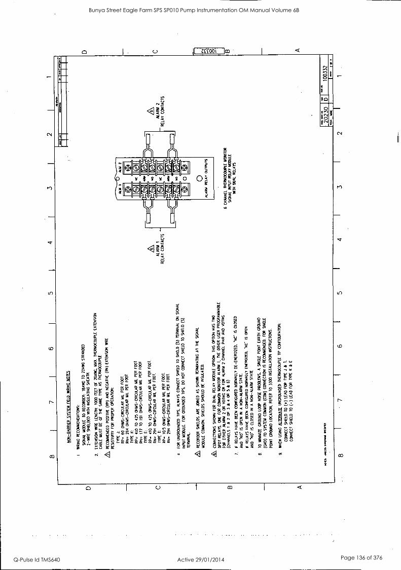
D C
B
A
8 7
4 I
3 2
NO
N-B
AR
RIE
R
SY
ST
EM
F
IELD
W
RIN
G
NO
TE
S
I. W
RIN
G
RE
CO
MM
EN
DA
TIO
NS
:
SIG
NA
L M
OD
ULE
T
O
RE
CO
RD
ER
: !B
AN
G
TO
22
AW
G
ST
RA
ND
ED
2-W
IRE
S
HIE
LDE
D
WIT
H
INS
ULA
TIN
G
SH
EA
TH
.
2.
EX
TE
NS
ION
'A
AR
E
LEN
GT
H:
1000
FE
ET
or
N
AN
G.
MA
X.
TH
ER
MO
CO
UP
LE E
XT
EN
SIO
N
CA
BLE
M
US
T
BE
O
F
TH
E
SA
ME
T
YP
E
AS
T
HE
RM
OC
OU
PLE
RE
CO
MM
EN
DE
D
PO
SIT
IVE
(R
P)
AN
D
NE
GA
TIV
E
(RN
) E
XT
EN
SIO
N
WIR
E
RE
SIS
TIV
ITY
FO
R
PR
OP
ER
O
PE
RA
TIO
N:
TY
PE
J:
RP
=
60
OH
MS
-CIR
CU
LAR
MIL
P
ER
F
OO
T.
RN
=
294
OH
MS
-CIR
CU
LAR
MIL
P
ER
FOOT.
TY
PE
K
:
RP
=
410
TO
42
5 O
HM
S-C
IRC
ULA
R M
IL
PE
R FOOT.
RN
=
177
TO
19
1 O
HM
S- C
IRC
ULA
R M
il P
ER
F
OO
T
TY
PE
E
:
RP
- 11
0 10
42
5 O
HM
S-C
IRC
ULA
R M
IL
PE
R
F00
1
RN
=
294
OH
MS
-CIR
CU
LAR
MIL
P
ER
F
OO
T.
TY
PE
1:
RP
=
10.5
O
HM
S-C
IRC
ULA
R
MIL
P
ER
F
OO
T.
RN
=
294
OH
MS
-CIR
CU
LAR
M
IL
PE
R
FO
OT
.
4 F
OR
U
NG
RO
UN
DE
D
TIP
S,
ALW
AY
S
CO
NN
EC
T
SH
IELD
T
O
SH
IELD
(5
) T
ER
MIN
AL
ON
S
IGN
AL
INP
UT
M
OD
ULE
F
OR
G
RO
UN
DE
D
TIP
S,
DO
N
OT
C
ON
NE
CT
S
HIE
LD
10
SH
IELD
(S
)
TE
RM
INA
L.
RE
CO
RD
ER
S
HIE
LDS
A
RE
JO
INE
D
AS
S
HO
WN
T
ER
MIN
AT
ING
A
l T
HE
S
IGN
AL
MO
DU
LE
CO
MM
ON
. S
HIE
LDS
S
HO
ULD
B
E
INS
ULA
TE
D.
/6,
CO
NN
EC
TIO
NS
SH
OW
N
FO
R
DU
AL
RE
LAY
M
OD
ULE
O
PT
ION
. T
HIS
O
PT
ION
H
AS
T
WO
DP
DT
R
ELA
YS
. O
NE
F
OR
C
OM
MO
N M
ON
ITO
R
ALA
RM
I.
TH
E
OT
HE
R U
SE
R
PR
OG
RA
MM
AB
LE
FO
R
EIT
HE
R
ALA
RM
2
OR
V
OT
ING
O
R
FO
R
ALA
RM
2
CH
AN
NE
L P
AIR
A
ND
V
OT
ING
(CH
AN
NE
LS
1 &
2
OR
3
&
4 O
R
5 &
6)
.
7.
IF
RE
LAY
S
HA
VE
B
EE
N C
ON
FIG
UR
ED
NO
RM
ALL
Y D
E-E
NE
RG
IZE
D.
NC
' IS
C
LOS
ED
AN
D
110"
IS
O
PE
N
IN
A
NO
N-A
LAR
M S
TA
TE
.
IF
RE
LAY
S
HA
VE
B
EE
N
CO
NF
IGU
RE
D N
OR
MA
LLY
E
NE
RG
IZE
D. 'N
C
IS
OP
EN
AN
D
NO
" IS
C
LOS
ED
IN
A
N
ON
-ALA
RM
ST
AT
E
8.
TO
M
INIM
IZE
G
RO
UN
D L
OO
P
NO
ISE
PR
OB
LEM
S.
A
SIN
GLE
P
OIN
T
EA
RT
H
GR
OU
ND
(CN
D)
TO
S
YS
TE
M
CO
MM
ON
(C
OM
) C
ON
NE
CT
ION
IS
R
EC
OM
ME
ND
ED
. F
OR
S
ING
LE
PO
INT
G
RO
UN
D L
OC
AT
ION
. R
EF
ER
70
3300
IN
ST
ALL
AT
ION
IN
ST
RU
CT
ION
S.
9.
WH
EN
U
SIN
G
ALE
RN
AT
F
UN
GR
OU
ND
ED
T
HE
RM
OC
OU
PLE
T
IP
CO
NF
IGU
RA
TIO
N:
CO
NN
EC
T
SH
IELD
T
O
(+)
LEA
D
FO
R
TY
PE
J
&
T.
CO
NN
EC
T
SH
IELD
T
O (-
) LE
AD
F
OR
T
YP
E
K
& E
MO
MS
MU
SS 0
1.00
4 IF
ICC
D
ALA
RM
I
RE
LAY
C
ON
TA
CT
S
1111
112/
10
6 C
HA
NN
EL
TH
ER
MO
CO
UP
LE
MO
NIT
OR
SIG
NA
L IN
PU
T
RE
LAY
MO
DU
LE
WIT
H
DU
AL
RE
LAY
S
ALA
RM
2
RE
LAY
CO
NT
AC
TS
Oa
2023
0 15
I
- 10
0332
8 7
6 5
4 3
lose
PO
I(
7R7
2 1
B A
Bunya Street Eagle Farm SPS SP010 Pump Instrumentation OM Manual Volume 6B
Q-Pulse Id TMS640 Active 29/01/2014 Page 136 of 376
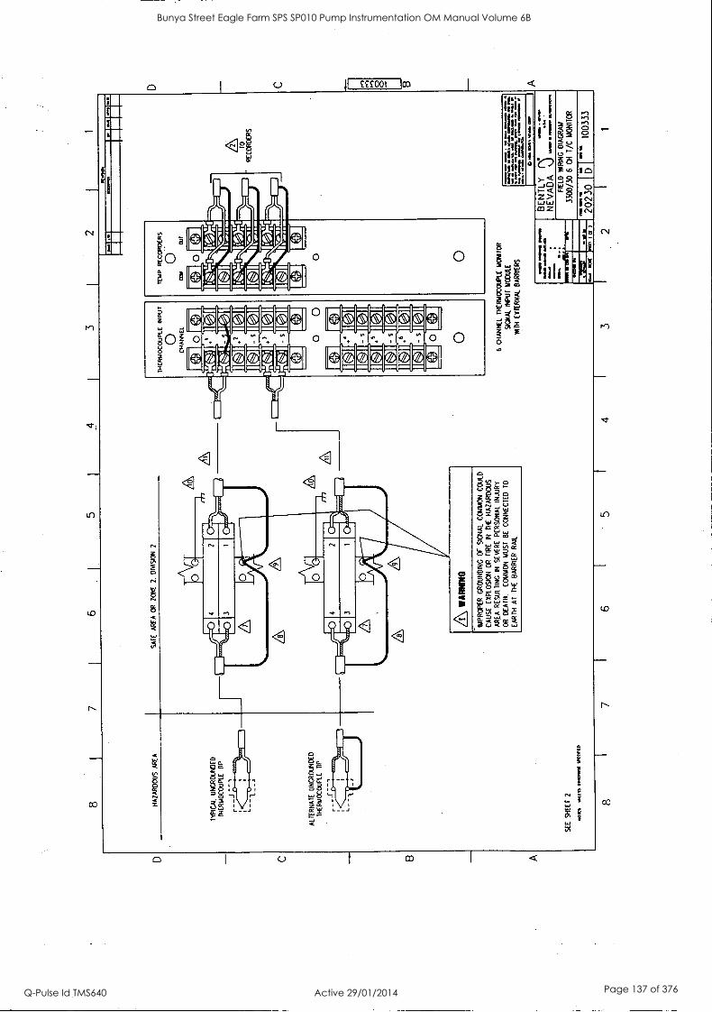
8 5
1 4
I 3
1 2
I 1
HA
ZA
RD
OU
S
AR
EA
S
AF
E
AR
EA
O
R
ZO
NE
2.
D
IVIS
ION
2
TY
PIC
AL
UN
GR
OU
ND
ED
TH
ER
MO
CO
UP
LE
TIP
ALT
ER
NA
TE
U
NG
RO
UN
DE
D
TH
ER
MO
CO
UP
LE
TIP
SE
E
SH
EE
T
2
MM
. W
EIS
S
01V
OV
VIE
114
(1/1
1,
A WA
RN
ING
IMP
RO
PE
R
GR
OU
ND
ING
O
F
SIG
NA
L C
ON
ON
C
OU
LD
CA
US
E
EX
PLO
SIO
N
OR
F
IRE
IN
T
HE
H
AZ
AR
DO
US
AR
EA
R
ES
ULT
ING
IN
S
EV
ER
E
PE
RS
ON
AL
INJU
RY
OR
D
EA
TH
. C
OM
MO
N
MU
ST
B
E
CO
NN
EC
TE
D
TO
EA
RT
H
AT
T
HE
B
AR
RIE
R
RA
IL
1121
194.
6 C
HA
NN
EL
TH
ER
MO
CO
UP
LE
MO
NIT
OR
SIG
NA
L N
PU
1MC
OU
LE
Rin
i E
XT
ER
NA
L B
AR
RIE
RS
TO
RE
CO
RD
ER
S
NM
I R
PM
it
011
MV
O le
l. N
O M
Y
11
ItLei
n .8
M
.. w
an I..
ea.
n
vazo
rtin
/P
.M V
ma
on. g
m...
raw
MA
N
MO
M
110
MY
. M
ilN
BE
NT
LY
N
NE
VA
DA
) ."
D
FIE
LD
WR
ING
D
IAG
RA
M
3300
/30
6 C
H
1/C
MO
NIT
OR
2023
0 D
1003
33
8 7
6 5
4 3
2 1
O O
Bunya Street Eagle Farm SPS SP010 Pump Instrumentation OM Manual Volume 6B
Q-Pulse Id TMS640 Active 29/01/2014 Page 137 of 376
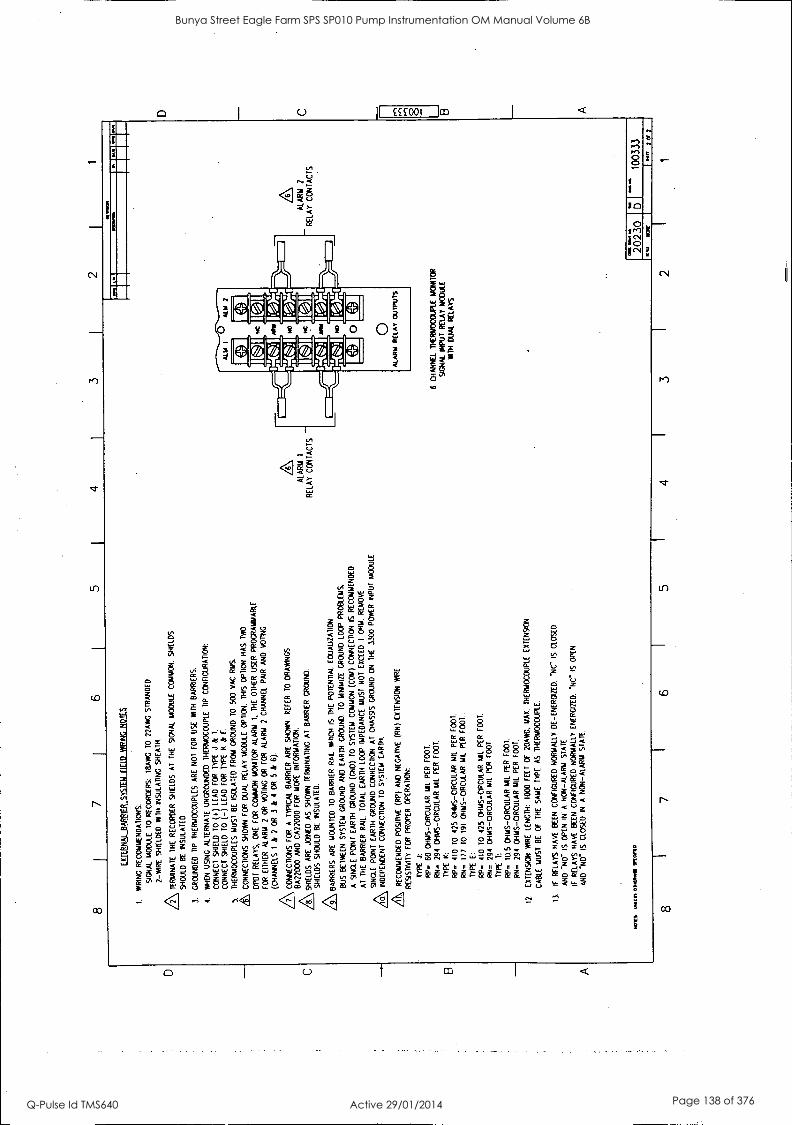
D
C B
A
8 7
3 2
XI
,A
: I
I ,
,1
1.
WIR
ING
R
EC
OM
ME
ND
AT
ION
S:
SIG
NA
L M
OD
ULE
T
O
RE
CO
RD
ER
S:
113A
WG
10
22
AW
G
ST
RA
ND
ED
2-W
IRE
S
HIE
LDE
D
WIT
H I
NS
ULA
TIN
G
SH
EA
TH
.
AT
ER
MIN
AT
E
TH
E R
EC
OR
DE
R
SH
IELD
S
AT
T
HE
S
IGN
AL
MO
DU
LE
CO
MM
ON
. S
HIE
LDS
SH
OU
LD
BE
IN
SU
LAT
ED
3.
GR
OU
ND
ED
T
IP
TH
ER
MO
CO
UP
LES
A
RE
N
OT
F
OR
U
SE
W
ITH
B
AR
RIE
RS
.
4.
WH
EN
U
SIN
G
ALT
ER
NA
TE
U
NG
RO
UN
DE
D
TH
ER
MO
CO
UP
LE
TIP
C
ON
FIG
UR
AT
ION
:
CO
NN
EC
T
SH
IELD
T
O (4
) LE
AD
F
OR
T
YP
E
J &
T
.
CO
NN
EC
T
SH
IELD
70
(-
) LE
AD
F
OR
T
YP
E
K
& E
.
5.
TH
ER
MO
CO
UP
LES
M
US
T B
E
ISO
LAT
ED
F
RO
M
GR
OU
ND
T
O
500
VA
C
RM
S.
& CO
NN
EC
TIO
NS
S
HO
WN
F
OR
D
UA
L R
ELA
Y
MO
DU
LE
OP
TIO
N.
TH
IS
OP
TIO
N
HA
S
TW
O
DP
ET
T R
ELA
YS
. O
NE
F
OR
C
OM
MO
N
MO
NIT
OR
A
LAR
M
1,
TH
E
OT
HE
R
US
ER
P
RO
GR
AM
MA
BLE
FO
R
EIT
HE
R
ALA
RM
2
OR
V
OT
ING
O
R
FO
R
ALA
RM
2
CH
AN
NE
L P
AIR
A
ND
V
OT
ING
(CH
AN
NE
LS
I &
2
OR
3
&
4 O
R
5 k
6).
AC
ON
NE
CT
ION
S
FO
R
A
TY
PIC
AL
BA
RR
IER
A
RE
S
HO
WN
. R
EF
ER
T
O
DR
AW
ING
S
BA
2200
0 A
ND
C
A22
000
FO
R
MO
RE
IN
FO
RM
AT
ION
.
SH
IELD
S
AR
E
JOIN
ED
A
S
SH
OW
N T
ER
MIN
AT
ING
A
T
BA
RR
IER
GR
OU
ND
.
SH
IELD
S
SH
OU
LD
BE
IN
SU
LAT
ED
.
AB
AR
RIE
RS
A
RE
M
OU
NT
ED
T
O
BA
RR
IER
R
AIL
W
HIC
H
IS
TH
E
PO
TE
NT
IAL
EO
UA
LIZ
AT
ION
BU
S
BE
TW
EE
N S
YS
TE
M
GR
OU
ND
A
ND
E
AR
TH
G
RO
UN
D.
TO
M
INIM
IZE
G
RO
UN
D
LOO
P
PR
OB
LEM
S,
A
SIN
GLE
P
OIN
T
EA
RT
H
GR
OU
ND
(G
ND
) T
O
SY
ST
EM
C
OM
MO
N
(CO
W)
CO
NN
EC
TIO
N I
S
RE
CO
MM
EN
DE
D
AT
T
HE
B
AR
RIE
R
RA
IL.
TO
TA
L E
AR
TH
LO
OP
IM
PE
DA
NC
E
MU
ST
N
OT
E
XC
EE
D
1 O
HM
. R
EM
OV
E
0. S
ING
LE
PO
INT
E
AR
TH
G
RO
UN
D C
ON
NE
CT
ION
A
T
CH
AS
SIS
G
RO
UN
D
ON
T
HE
33
00
PO
WE
R
INP
UT
M
OD
ULE
IND
EP
EN
DE
NT
CO
NN
EC
TIO
N
TO
S
YS
TE
M
EA
RT
H.
A REC
OM
ME
ND
ED
P
OS
ITIV
E (R
P)
AN
D
NE
GA
TIV
E (R
N)
EX
TE
NS
ION
W
IRE
RE
SIS
TIV
ITY
F
OR
P
RO
PE
R
OP
ER
AT
ION
:
TY
PE
J:
RP
. 60
O
HM
S-C
IRC
ULA
R
MIL
PE
R
FO
OT
.
RN
- 29
4 O
HM
S- C
IRC
ULA
R M
IL
PE
R
FO
OT
.
TY
PE
K
:
RP
=
410
TO
42
5 O
HM
S-C
IRC
ULA
R
MIL
P
ER
F
OO
T,
RN
=
177
TO
19
1 O
HM
S-C
IRC
ULA
R
MIL
P
ER
F
OO
T.
TY
PE
E
:
RP
=
410
TO
42
5 O
HM
S-C
IRC
ULA
R
MIL
P
ER
F
OO
T.
RN
=
294
OH
MS
- CIR
CU
LAR
M
IL
PE
R
FO
OT
,
TY
PE
T
:
RP
=
10.5
O
HM
S-C
IRC
ULA
R M
IL
PE
R
FO
OT
.
RN
=
294
OH
MS
- CIR
CU
LAR
M
IL
PE
R
FO
OT
.
12.
EX
TE
NS
ION
W
IRE
LE
NG
TH
: 10
00
FE
ET
O
F
20A
WG
, M
AX
. T
HE
RM
OC
OU
PLE
E
XT
EN
SIO
N
CA
BLE
M
US
T
BE
O
F
TH
E
SA
ME
T
YP
E
AS
T
HE
RM
OC
OU
PLE
.
13.
IF
RE
LAY
S
HA
VE
BE
EN
C
ON
FIG
UR
ED
NO
RM
ALL
Y
DE
-EN
ER
GIZ
ED
, N
C-
IS
CLO
SE
D
AN
D
"NO
* IS
O
PE
N
IN
A
NO
N -
ALA
RM
S
TA
TE
IF
RE
LAY
S
HA
VE
BE
EN
C
ON
FIG
UR
ED
NO
RM
ALL
Y
EN
ER
GIZ
ED
. N
C"
IS
OP
EN
AN
D
NO
IS
C
LOS
ED
IN
A
N
ON
-ALA
RM
S
TA
TE
.
MO
W%
M
ES
S O
lOfl
vian
to
8 7
6
A
ALA
RM
1
RE
LAY
C
ON
TA
CT
S -
6 C
HA
NN
EL
TH
ER
MO
CO
UP
LE
MO
NIT
OR
S
IGN
AL
INP
UT
R
ELA
Y
MO
DU
LE
1011
4 D
UA
L R
ELA
YS
A
ALA
RM
2
RE
LAY
C
ON
TA
CT
S T
r
2023
0 '6
I 10
0333
5 4
I 3
2
I Cf
D
C
In
8
B A
Bunya Street Eagle Farm SPS SP010 Pump Instrumentation OM Manual Volume 6B
Q-Pulse Id TMS640 Active 29/01/2014 Page 138 of 376
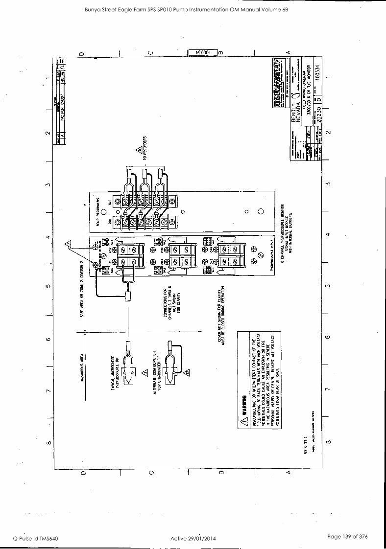
0 0 (.44
4.
b££001 T
O,
a O
f ZO
Z
aotoon alt N
3 9 O
f/00Ct
nyttovo 3/41801(
01311
VC
1VA
3N
.NJ
A1IN
3E1
iX111=
E=
M=
1 E
LLIM10,--111 lerfr7
ILIfMitrl fa
aorNea
a aaaaaa.a,
.anaos ..1.1 sm
. Inaaa sea. w
la1 rte:`
11 MM
.) Pa V
OX
. O... In
NM
I VIIIIIV
IMaIV
Z.
1:21 .7. O
w artm
.an...tie .11.111M
y
..,111111:1 L6LO
ZI
83c1 JN
I lioP
elasdir lb.
a/ I
WW
I
5213080338 01
1
0I16
17 L
2
StaldtIV
EI
701113041 3100011
tndNi T
oors thom
ori 3180030N3H
113NN
YH
3 9
Jidnoorwom
1t
(2)
:10 1MS
NJ:
piZlg
tfrt I..1
Gif)
P113 fH
3
(2>
fa I 50
11011:
DM
Z
MI
SU
M
3
(IWY
* Saab.) 1$01 13,01
L 137x6 335
ND
Y21
10 S
Y38
YI0/11 S
1Y11N
310d
39Y110A
7/Y
340Y
138 'H
I Y30 80 A
WN
! 1Y
NO
S811
383A3S
N
I O
N1118S
38 V
381( S0008Y
ZY
H
3H1
NI
3814 80 N
OIS
OldX
3 N
V
3snya ainoa S1Y
IIN3IO
d nynon
HO
IH H
IM sivN
troni >ova
01 3N
ILIYA
01313
3H1
JO 13Y
1NO
3 IN31101831N
I 80 O
N1133N
NO
)S/Y
1
ON
IMIY
/A
NO
ilV83d0 w
arm
03S013 38 isnn
A118Y
13 d04 /GN
S
ION
83A
03
2101
11RC
H6
ION
9
118H1
Z S
13NN
YH
3
801 SN
0I133NN
D3
dll 030N
110er3N8
801
NO
N Y
/10311NO
3 31Y
N8311Y
77.
dU
31d1103011d3H1
830N80213N
O
1v3IdAl
V
Z N
06o110 N
OZ
113 Y
38Y
33YS
1
YIP
/ S
O088Y
ZY
H
9 1
L
1 9
Bunya Street Eagle Farm SPS SP010 Pump Instrumentation OM Manual Volume 6B
Q-Pulse Id TMS640 Active 29/01/2014 Page 139 of 376
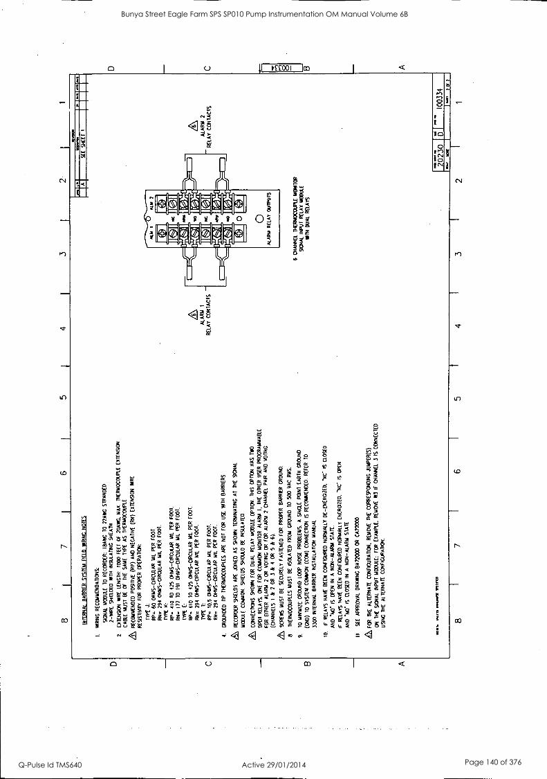
D
C
B
A
8 7
I 6
5 4
3
INT
ER
NA
I B
AR
RIE
R
SY
ST
EM
F
IELD
W
IRIN
G
NO
TE
S
I. W
IRIN
G R
EC
OM
ME
ND
AT
ION
S:
SIG
NA
L M
OD
ULE
T
O
RE
CO
RD
ER
: (B
AN
G
TO
22
AW
G
ST
RA
ND
ED
2-M
IRE
S
HIE
LDE
D
WIT
H
INS
ULA
TIN
G
SH
EA
TH
2.
EX
TE
NS
ION
W
IRE
LE
NG
TH
: 10
00 F
EE
T
OF
20
AW
G,
MA
X.
TH
ER
MO
CO
UP
LE E
XT
EN
SIO
N
CA
BLE
M
US
T
BE
O
F
TH
E
SA
ME
T
YP
E
AS
T
HE
RM
OC
OU
PLE
.
Zt
RE
CO
MM
EN
DE
D
PO
SIT
IVE
(R
P)
AN
D
NE
GA
TIV
E
(RN
) E
XT
EN
SIO
N
HA
RE
RE
SIS
TIV
ITY
FO
R
PR
OP
ER
C
PE
RA
T1C
N:
TY
PE
J:
RP
=
60
OH
MS
-CIR
CU
LAR
MIL
P
ER
F
OO
T.
RN
=
294
OH
MS
-CIR
CU
LAR
M
IL
PE
R
FO
OT
.
TY
PE
K
:
RP
- 41
0 T
O 42
5 O
HM
S -C
IRC
ULA
R M
il P
ER
F
OO
T.
RN
- 17
7 10
19
1 O
HM
S- C
IRC
ULA
R
MIL
P
ER
F
OO
T.
TY
PE
E
:
RP
=
410
TO
42
5 O
HM
S- C
IRC
ULA
R
MIL
P
ER
F
OO
T.
RN
=
294
OH
MS
-CIR
CU
LAR
M
IL
PE
R
FO
OT
.
TY
PE
T
:
RP
=
10.5
O
HM
S-C
IRC
ULA
R
MIL
P
ER
F
OO
T.
RN
=
294
OH
MS
-OR
CuL
AR
MIL
P
ER
F
OO
T.
4.
(RO
UN
DE
D
TIP
T
HE
RM
OC
OU
PLE
S
AR
E
NO
T
FO
R
US
E
WIT
H
BA
RR
IER
S.
RE
CO
RD
ER
SH
IELD
S
AR
E
JOIN
ED
A
S
SH
OW
N T
ER
MIN
AT
ING
A
T
TH
E
SIG
NA
L
MC
OU
LE C
OM
MO
N.
SH
IELD
S
SH
OU
LD
BE
IN
SU
LAT
ED
.
CO
NN
EC
TIO
NS
S
HO
WN
FO
R
DU
AL
RE
LAY
M
OD
ULE
O
PT
ION
. T
HIS
O
PT
ION
H
AS
T
WO
DP
OT
R
ELA
YS
. O
NE
F
OR
C
OM
MO
N
MO
NIT
OR
A
LAR
M I.
TH
E
OT
HE
R
US
ER
P
RO
GR
AM
MA
BLE
FO
R
EIT
HE
R
ALA
RM
2
OR
V
OT
ING
O
R
FO
R
ALA
RM
2
CH
AN
NE
L P
AIR
A
ND
V
OT
ING
(CH
AN
NE
LS
1 &
2
OR
3
&
4 O
R
S
&
6).
ZL
SC
RE
WS
M
US
T
BE
S
EC
UR
ELY
FA
ST
EN
ED
F
OR
P
RO
PE
R B
AR
RIE
R
GR
OU
ND
.
8.
TH
ER
MO
CO
UP
LES
M
US
T B
E
ISO
LAT
ED
F
RO
M
GR
OU
ND
TO
50
0 V
AC
RM
S.
9.
TO
M
INIM
IZE
G
RO
UN
D
LOO
P
NO
ISE
P
RO
BLE
MS
. A
S
ING
LE
PO
INT
E
AR
TH
G
RO
UN
D
(CN
D)
TO
S
YS
TE
M
CO
MM
ON
(C
ON
) C
ON
NE
CT
ION
IS
R
EC
OM
ME
ND
ED
. R
EF
ER
T
O
3300
IN
TE
RN
AL
BA
RR
IER
IN
ST
ALL
AT
ION
M
AN
UA
L
la
IF
RE
LAY
S
HA
VE
B
EE
N
CO
NF
IGU
RE
D
NO
RM
ALL
Y
DE
-EN
ER
GIZ
ED
, 'N
C I
S
CLO
SE
D
AN
D
.110
" IS
O
PE
N I
N
A
NO
N-A
LAR
M
ST
AT
E.
IF
RE
LAY
S
HA
VE
B
EE
N
CO
NF
IGU
RE
D
NO
RM
ALL
Y
EN
ER
GIZ
ED
. 'N
C IS
O
PE
N
AN
D
"NO
' IS
C
LOS
ED
IN
A
N
ON
-ALA
RM
S
TA
TE
.
11
SE
E
AP
PR
OV
AL
DR
AW
ING
8A
2200
0 O
R
CA
2200
0
A FO
R
TH
E
ALT
ER
NA
TE
CO
NF
IGU
RA
TIO
N,
RE
MO
VE
T
HE
C
OR
RE
SP
ON
DIN
G
JUM
PE
R(S
)
ON
T
HE
S
IGN
AL
INP
UT
M
OD
ULE
: F
OR
E
XA
MP
LE.
RE
MO
VE
W
3 IF
C
HA
NN
EL
3 IS
C
ON
NE
CT
ED
US
ING
T
HE
A
LTE
RN
AT
E
CO
NF
IGU
RA
TIO
N.
TO
RS
ON
LE
SS n.
.011
WK
S'.
8 I
7 I
6
ALA
RM
1
- R
ELA
Y
CO
NT
AC
TS
2 I
1
IRM
O.
1112
A
S
EE
S
HE
ET
1
6 C
HA
NN
EL
TH
ER
MO
CO
UP
LE M
ON
ITO
R
SW
AN
_ IN
PU
T
RE
LAY
M
OD
ULE
W
ITH
D
UA
L R
ELA
YS
ALA
RM
2
RE
LAY
C
ON
TA
CT
S
2023
0 6
I
~
1003
34
5 4
3 2
W A
/ 10
12
1 W
1
D
C
B A
Bunya Street Eagle Farm SPS SP010 Pump Instrumentation OM Manual Volume 6B
Q-Pulse Id TMS640 Active 29/01/2014 Page 140 of 376
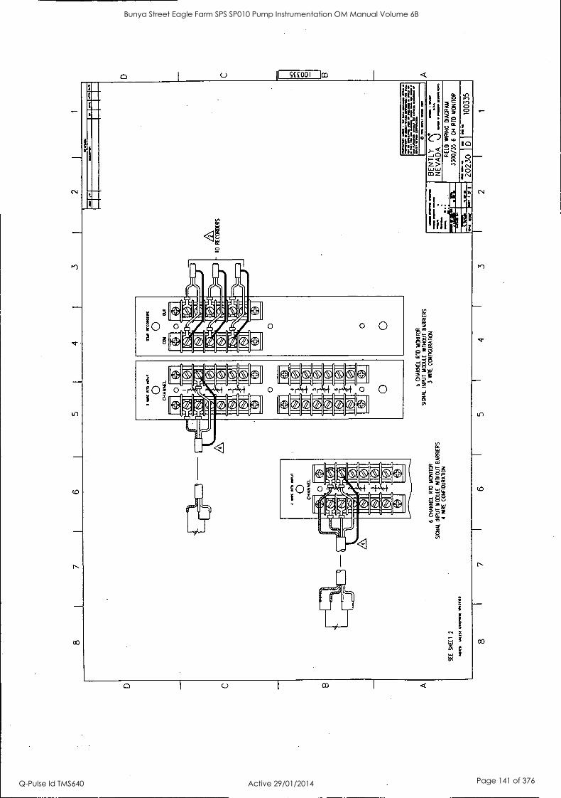
C
B
A
8
SE
E
SH
EE
T
2
7 6
5 3
2 I
1
41:1
1t
IM1S
3 01
1O51
911
110
Ot
PR
I IS
OU
I
0 C
HA
NN
EL
IC
I IC
.01
IC
I IN
I
6 C
HA
NN
EL
RA
) M
ON
ITO
R
SIG
NA
L
INPU
T
MO
DU
LE
W
ITH
OU
T B
AR
RIE
RS
4 W
IRE
C
ON
FIG
UR
AT
ION
b C
HA
NN
EL
R
TD
M
ON
ITO
R
SIG
NA
L
INPU
T
MO
DU
LE
W
ITH
OU
T
BA
RR
IER
S 3
*IR
E
CO
NFI
GU
RA
TIO
N
1WIO
N
l ri
-r-
1.11
1144
40
90 4
1 00
4 10
1414
/ 01
114
104 44
4 14
01
.1
1011
. 41
OP 0.
111
a*
01
10 /4
4 4
44
40 1
4 4
04 0
14 0
044
414
.11 44
400
dr
14. 4
4 04
0.
4) "m
a as
.
IIM O
M. R
PM
so
ws
amm
o =
ma
mow
rwm
.
BE
N T
LY n
,:,"-
N
EV
AD
AN
.) .
1 N
OW
FIE
LD
MIR
ING
D
IAG
RA
M
3300
/35
6 C
H
RIO
M
ON
ITO
R
..;17
1:,
2023
0 D
10
0335
8 7
6 5
4 3
2 1
D
.11 0 B
A
Bunya Street Eagle Farm SPS SP010 Pump Instrumentation OM Manual Volume 6B
Q-Pulse Id TMS640 Active 29/01/2014 Page 141 of 376
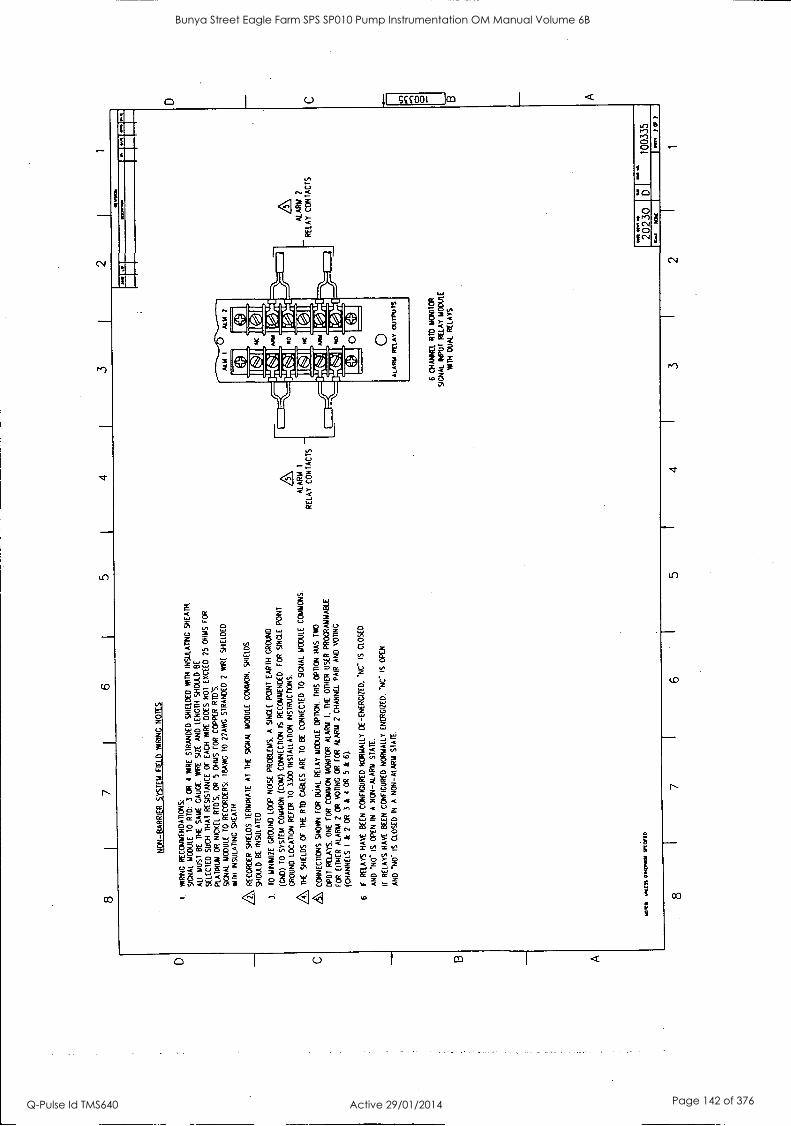
D C B
A
8 7
6 4
3 2
NO
N-B
AR
RIE
R S
YS
TE
M F
IELD
WR
ING
N
OT
ES
1.
WR
ING
R
EC
OM
ME
ND
AT
ION
S
SIG
NA
L M
OD
ULE
T
O
RID
: 3
OR
4
PA
RE
S
IRA
ND
ED
S
HIE
LDE
D
WIT
H
INS
ULA
TIN
G
SH
EA
TH
.
ALL
M
US
T
BE
T
HE
S
AM
E
GA
UG
E.
PA
RE
S
IZE
A
ND
LE
NG
TH
SH
OU
LD
BE
SE
LEC
TE
D
SU
CH
T
HA
I R
ES
IST
AN
CE
O
F
EA
CH
P
AR
E
DO
ES
N
OT
E
XC
EE
D
25 O
HM
S
FO
R
PLA
TIN
UM
O
R
NIC
KE
L R
IDS
. O
R
5 O
HM
S
FO
R
CO
PP
ER
R
ID'S
.
SIG
NA
L M
OD
ULE
T
O
RE
CO
RD
ER
S:
IBA
WG
T
O
22A
WG
S
TR
AN
DE
D
2 W
IRE
S
HIE
LDE
D
111T
H
INS
ULA
TIN
G
SH
EA
TH
& RE
CO
RD
ER
SH
IELD
S
TE
RM
INA
TE
A
l T
HE
S
IGN
AL
MO
DU
LE
CO
MM
ON
. S
HIE
LDS
SH
OU
LD
BE
IN
SU
LAT
ED
3,
TO
M
INIM
IZE
G
RO
UN
D
LOO
P
NO
ISE
P
RO
BLE
MS
. A
S
ING
LE
PO
INT
E
AR
TH
G
RO
UN
D
(CN
D)
TO
S
YS
TE
M
CO
MM
ON
(C
ON
) C
ON
NE
CT
ION
IS
R
EC
OM
ME
ND
ED
. F
OR
S
ING
LE
PO
INT
GR
OU
ND
LO
CA
TIO
N R
EF
ER
T
O
3300
IN
ST
ALL
AT
ION
IN
SIR
UC
DO
NS
.
L\ TH
E
SH
IELD
S O
F
TH
E
RID
C
AB
LES
A
RE
T
O
BE
C
ON
NE
CT
ED
T
O
SIG
NA
L M
OD
ULE
C
OM
MO
NS
.
CO
NN
EC
TIO
NS
SH
OW
N ro
e D
UA
L R
ELA
Y
MO
DU
LE P
'110
N.
TH
IS O
PT
ION
H
AS
T
WO
DP
DT
R
ELA
YS
, O
NE
F
OR
C
OM
MO
N
MO
NIT
OR
A
LAR
M
I. T
HE
O
TH
ER
U
SE
R
PR
OG
RA
MM
AB
LE
FO
R
EIT
HE
R
ALA
RM
2
OR
Y
OU
NG
O
R
FO
R
ALA
RM
2
CH
AN
NE
L P
AIR
A
ND
V
OT
ING
(CH
AN
NE
LS
I &
2
OR
3
&
4 O
R
5 &
6).
6 IF
R
ELA
YS
H
AV
E
BE
EN
C
ON
FIG
UR
ED
N
OR
MA
LLY
D
E-E
NE
RG
IZE
D.
*NC
" IS
C
LOS
ED
AN
D N
O-
IS O
PE
N I
N
A
NO
N-A
LAR
M S
TA
TE
.
IF
RE
LAY
S
HA
VE
BE
EN
C
ON
FIG
UR
ED
N
OR
MA
LLY
E
NE
RG
IZE
D,
"NC
IS
O
PE
N
AN
D
1N0-
IS
C
LOS
ED
IN
A
N
ON
-ALA
RM
S
TA
TE
.
MO
SS
M
iss
07.0
011
9i0I
lD
ALA
RM
I
RE
LAY
C
ON
TA
CT
S -
%M
OM
kg
.
6 C
HA
NN
EL
RID
M
ON
ITO
R
SIG
NA
L IN
PU
T
RE
LAY
MO
DU
LE
WIT
H
DU
AL
RE
LAY
S
AL
AR
M
2
RE
LAY
C
ON
TA
CT
S
20230
1
- 10
0335
8 7
I 6
5 I
4
11.f
1 C
F
3 I
2 1
D C B A
Bunya Street Eagle Farm SPS SP010 Pump Instrumentation OM Manual Volume 6B
Q-Pulse Id TMS640 Active 29/01/2014 Page 142 of 376
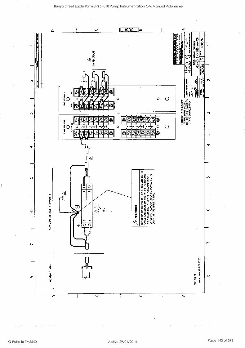
C B
A
8
HA
ZA
RD
OU
S
AR
EA
7 6
5 3
SA
FE
A
RE
A
OR
Z
ON
E
2.
DIV
ISIO
N
SE
E
SH
EE
T
3
Ott
Wt.
0114
11 M
OM
,
3 I\ W
AR
NIN
G
IMP
RO
PE
R
GR
OU
ND
ING
OF
S
IGN
AL
CO
MM
ON
CO
ULD
CA
US
E
EX
PLO
SIO
N
OR
F
IRE
IN
T
HE
H
AZ
AR
DO
US
AR
EA
R
ES
ULT
ING
IN
S
EV
ER
E
PE
RS
ON
AL
INJU
RY
OR
D
EA
TH
. C
OM
MO
N
MU
ST
B
E
CO
NN
EC
TE
D
TO
EA
RT
H
AT
T
HE
B
AR
RIE
R
RA
IL
3 M
K P
M W
RIT
0 C
HA
NN
EL
---1
140)
.4)
IC:1
1
0
If;
IC41
IC
.11
I MI
0 O
two,
6 C
HA
NN
EL
RT
D
MO
NIT
OR
S
IGN
AL
INP
UT
M
OD
ULE
W
M E
X T
ER
RA
/ B
AR
RIE
RS
3
WIR
E
CO
NF
IGU
RA
TIO
N
- T
O
RE
CO
RD
ER
S
IWO
m
a w
ay e
v O
N P
O.
MO
M
P 0
.1.1
011.
M.
WM
.6
Mow
s am
mo . a
wns
i.
o am
.% m
ow.
ow
MO
MS
1,
1111
.111
PIM
= =
ME
MO
10
1111
0
MI
BE
NT
LY
NE
VA
DA
\.)
,....
D.,
FIE
LD
WIR
ING
D
IAG
RA
M
3300
/35
6 C
H
RT
D
MO
NIT
OR
11
111.
0
1V
i 3
202.
30
D
Ole
.0
1003
36
8 7
6 5
4 3
2 1
D C
O
O
A
Bunya Street Eagle Farm SPS SP010 Pump Instrumentation OM Manual Volume 6B
Q-Pulse Id TMS640 Active 29/01/2014 Page 143 of 376
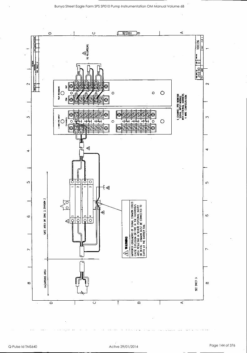
8 7
6 5
4 3
2
OM
AN
S
EE
9I
1(1
1
HA
ZA
RD
OU
S
AR
EA
S
AF
E
AR
EA
O
R
ZO
NE
2.
D
IVIS
ION
2
0 0
IMP
RO
PE
R
GR
OU
ND
ING
O
F
SIG
NA
L C
OM
MO
N C
OU
LD
CA
US
E
EX
PLO
SIO
N
OR
F
IRE
IN
T
HE
H
AZ
AR
DO
US
AR
EA
RE
SU
LTIN
G
IN
SE
VE
RE
P
ER
SO
NA
L IN
JUR
Y
OR
D
EA
TH
. C
OM
MO
N
MU
ST
BE
C
ON
NE
CT
ED
70
EA
RT
H
Al
TH
E
BA
RR
IER
R
AIL
SE
E
SH
EE
T
3
6 C
HA
NN
EL
RID
M
ON
ITO
R
SIG
NA
L IN
PU
T
MO
DU
LE
WIT
H
EX
TE
RN
AL
BA
RR
IER
S
4 H
IRE
CO
NF
IGU
RA
TIO
N
I
" I-
'
.6\
TO
R
EC
OR
DE
RS
000
D M
M O
O
2023
0 1
PIO
,M
I
1003
36
HO
C
8 7
6 5
4 3
2
B A
Bunya Street Eagle Farm SPS SP010 Pump Instrumentation OM Manual Volume 6B
Q-Pulse Id TMS640 Active 29/01/2014 Page 144 of 376
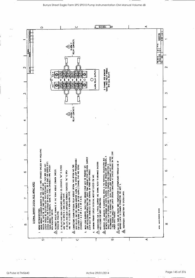
C
B A
8 7
6 5
4 3
2 I
1
EX
TE
RN
AL
BA
RR
IER
S
YS
TE
M F
IELD
W
IRIN
G
NO
TE
S
I W
IRIN
G
RE
CO
M1A
EN
DA
DO
NS
: S
IGN
AL
MO
DU
LE
TO
B
AR
RIE
R-B
AR
RIE
R T
O
RT
D:
3 O
R
4 M
IRE
S
TR
AN
DE
D
SH
IELD
ED
W
ITH
IN
SU
LAT
ING
SH
EA
TH
. A
LL
MU
ST
BE
T
HE
S
AM
E
GA
UG
E.
WIR
E
SIZ
E
AN
D
LEN
GT
H
SH
OU
LD B
E
SE
LEC
TE
D
SU
CH
T
HA
T
RE
SIS
TA
NC
E
OF
E
AC
H
WA
RE
' D
OE
S
NO
1
EX
CE
ED
25
O
HM
S
FO
R P
LAT
INU
M
OR
N
ICK
EL
RID
S.
OR
5
OH
MS
FO
R
CO
PP
ER
R
IDS
.
SIG
NA
L M
OD
ULE
TO
R
EC
OR
DE
RS
: (B
AN
G
TO
22
AW
G
ST
RA
ND
ED
2
WIR
E
SH
IELD
ED
WIT
H
INS
ULA
TIN
G
SH
EA
TH
.
RE
CO
RD
ER
S
HIE
LDS
T
ER
MIN
AT
E A
l T
HE
S
IGN
AL
MO
DU
LE
CO
MM
ON
. S
HIE
LDS
SH
OU
LD
BE
IN
SU
LAT
ED
.
3.
IF
RE
LAY
S
HA
VE
B
EE
N
CO
NF
IGU
RE
D
NO
RM
ALL
Y
DE
-EN
ER
GIZ
ED
. N
C IS
C
LOS
ED
AN
D
140-
IS
O
PE
N I
N
A
NO
N -A
LAR
M S
TA
TE
.
IF
RE
LAY
S
HA
VE
B
EE
N
CO
NF
IGU
RE
D
NO
RM
ALL
Y
EN
ER
GIZ
ED
. 14
C
IS
OP
EN
AN
D 'N
O"
IS
CLO
SE
D
IN
A
NO
N-A
LAR
M
ST
AT
E.
CO
NN
EC
TIO
NS
S
HO
WN
FO
R
DU
AL
RE
LAY
M
OD
ULE
OP
TIO
N.
TH
IS
OP
TIO
N
HA
S
TW
O
DP
DT
R
ELA
YS
. O
NE
F
OR
C
OM
MO
N
MO
NIT
OR
A
LAR
M
I. T
HE
O
TH
ER
U
SE
R
PR
OG
RA
MM
AB
LE
FO
R
EIT
HE
R
ALA
RM
2
OR
V
OT
ING
O
R
FO
R
ALA
RM
2
CH
AN
NE
L P
AIR
A
ND
V
OT
ING
(CH
AN
NE
LS
I &
2
OR
3
&
4 O
R
5 &
6)
.
5.
ME
N U
SIN
G
BA
RR
IER
S.
SIN
GLE
P
OIN
T
GR
OU
ND
ST
RA
P
MU
ST
BE
R
EM
OV
ED
. S
EE
3.30
0 IN
ST
ALL
AT
ION
IN
ST
RU
CT
ION
S F
OR
S
ING
LE
PO
NT
G
RO
UN
D
ST
RA
P
LOC
AT
ION
. B
AR
RIE
R
EA
RT
H
MU
ST
B
E
CO
NN
EC
TE
D
TO
C
CM
T
ER
MIN
AL
CN
P
OW
ER
IN
PU
T
MO
DU
LE
6.
MA
XIM
UM
P
RIM
AR
Y C
IRC
UIT
P
OT
EN
TIA
L M
US
T
NO
T
EX
CE
ED
25
0 V
AC
.
& CO
NN
EC
TIO
NS
FO
R
A
TY
PIC
AL
BA
RR
IER
A
RE
S
HO
WN
. R
EF
ER
T
O
DR
AW
ING
S
BA
2200
0
AN
D
CA
2200
0 F
OR
M
OR
E
INF
OR
MA
TIO
N.
L\ BA
RR
IER
S
AR
E
MO
UN
TE
D
TO
B
AR
RIE
R R
AIL
W
HIC
H
IS
TH
E
PO
TE
NT
IAL
EO
UA
LIZ
AT
ION
B
US
BE
TW
EE
N S
YS
TE
M
GR
OU
ND
AN
D
EA
RT
H
GR
OU
ND
. T
O
MIN
IMIZ
E
GR
OU
ND
LO
OP
P
RO
BLE
MS
, A
SIN
GLE
P
ON
T E
AR
TH
G
RO
UN
D (
GN
D)
TO
S
YS
TE
M
CO
MM
ON
(C
OM
) C
ON
NE
CT
ION
IS
RE
CO
MM
EN
DE
D
Al
TH
E
BA
RR
IER
R
AIL
. T
OT
AL
EA
RT
H
LOO
P
IMP
ED
AN
CE
M
US
T
NO
T
EX
CE
ED
I C
HM
. R
EM
OV
E
SIN
GLE
P
ON
T
EA
RT
H
GR
OU
ND
CO
NN
EC
TIO
N
AT
C
HA
SS
IS
GR
OU
ND
O
N
TH
E
3300
P
OW
ER
IN
PU
T
MO
DU
LE.
TH
E
RID
T
HIR
D
CR
F
OU
RT
H
WIR
E
CO
MP
EN
SA
TIO
N
IS
AC
CO
MP
LIS
HE
D
TH
RO
WN
U
SE
O
F
BA
RR
IER
EA
RT
H
TO
C
OM
MO
N
CO
NN
EC
TIO
N.
SE
E
NO
TE
5.
A IND
EP
EN
DE
NT
C
ON
NE
CT
ION
T
O
SY
ST
EM
E
AR
TH
.
WV
. fli
ts 0
140.
.1 1
CV
ED
z\
ALA
RM
1
- R
ELA
Y C
ON
TA
CT
S
@M
N
43.
6 C
HA
NN
EL
RT
D
MO
NIT
OR
SIG
NA
L IN
PU
T
RE
LAY
M
OD
ULE
W
ITH
D
UA
L R
ELA
YS
ALA
RM
RE
LAY
C
ON
TA
CT
S "r
r
2023
0 D
SIM
1003
36
8 I
7 6
Nog
4 I
3 I
2 1
3 C
r 3
D C
ID
O
B
A
Bunya Street Eagle Farm SPS SP010 Pump Instrumentation OM Manual Volume 6B
Q-Pulse Id TMS640 Active 29/01/2014 Page 145 of 376
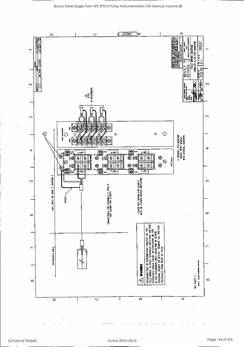
4
HA
ZA
RD
OU
S
AR
EA
S
AF
E
AR
EA
C
R
ZO
NE
.
DIV
I9O
N
2
3 M
EP
IN
CO
ME
/4
0 C
OO
O
UT
SH
IELD
i.
i 'I
II C
UM
1 an
5I0I
f, tia
d .
CN
I 01
2 0
as,
ogN
i
i: y,
.4
ti:,
o 14
0.
""
f.IL Si
1411
'
.
liz,!
..%.1
lie
nLI
.I ....
...,.
1/41
=t =
4I../
0
I ee.a
l kbf
f..
a I M
s
"
CO
NN
EC
TIO
NS
FO
R
CH
AN
NE
LS
2 T
HR
U
6 N
OT
S
HO
WN
F
OR
CLA
RIT
Y
.11
:I/E
0,3
1111
1:1K
11
r[a*
17rf
far.
14
_ 43
ig __
.14
0,4 :
.11 E
W .! A
jo.
1 a
P
. .
Irel
mva
L1-
\_
Niii
...
_,1*
3
3 0 0 0
l II
a CH
O
'1.
l 4e/
a MO
I It:
Q)
mid
l
WA
RN
ING
C
OV
ER
N
OT
S
HO
WN
F
OR
C
LAR
ITY
M
US
T
BE
C
LOS
ED
D
UR
ING
O
PE
RA
TIO
N
MIS
CO
NN
EC
TIN
C O
R
INT
ER
MIT
TE
NT
C
ON
TA
CT
O
F
TH
E
FIE
LD
WR
ING
10
RA
CK
T
ER
MIN
ALS
W
ITH
H
IGH
V
OLT
AG
E
PO
TE
NT
IALS
C
OU
LD
CA
US
E
AN
E
XP
LOS
ION
O
R
FIR
E
IN
TH
E
HA
ZA
RD
OU
S
AR
EA
RE
SU
LTIN
G I
N
SE
VE
RE
PE
RS
ON
AL
INJU
RY
OR
D
EA
TH
. R
EM
OV
E
ALL
V
OLT
AG
E
PO
TE
NT
IALS
FR
OM
R
EA
R
OF
R
AC
K.
3 3
PT
O
INP
UT
SE
E
SH
EE
T
2
WO
O
OaL
SS
OIN
UN
ES
E
1404
1/
8
6 C
HA
NN
EL
RID
MO
NIT
OR
9GN
AL
INP
UT
M
OD
ULE
WIT
H
INT
ER
NA
L B
AR
RIE
RS
P-
PI
NN
E
IP
MO
W.
aw
INC
PC
R
1234
297
JC 1:
FL
'1""
10
RE
CO
RD
ER
S
114
NI
MA
T If
o O
M 11
VIM M
IMI.
.
PM.
61
sop
If
.0.
: ...pa
U.,
arm
y M
OIL
* 11
11M
.
0 M
PS.
ange
l N
OY
=O
ft
s
if.
GE
NT
LY
.;7
NE
VA
DA
\)
A
P.
FIE
LD
WIR
ING
D
IAG
RA
M
3300
/35
6 C
H
RID
MO
NIT
OR
7 1
6 1
5 I
4 1
3 1
2
1730
ID.
I 10
0337
D C 8
Bunya Street Eagle Farm SPS SP010 Pump Instrumentation OM Manual Volume 6B
Q-Pulse Id TMS640 Active 29/01/2014 Page 146 of 376
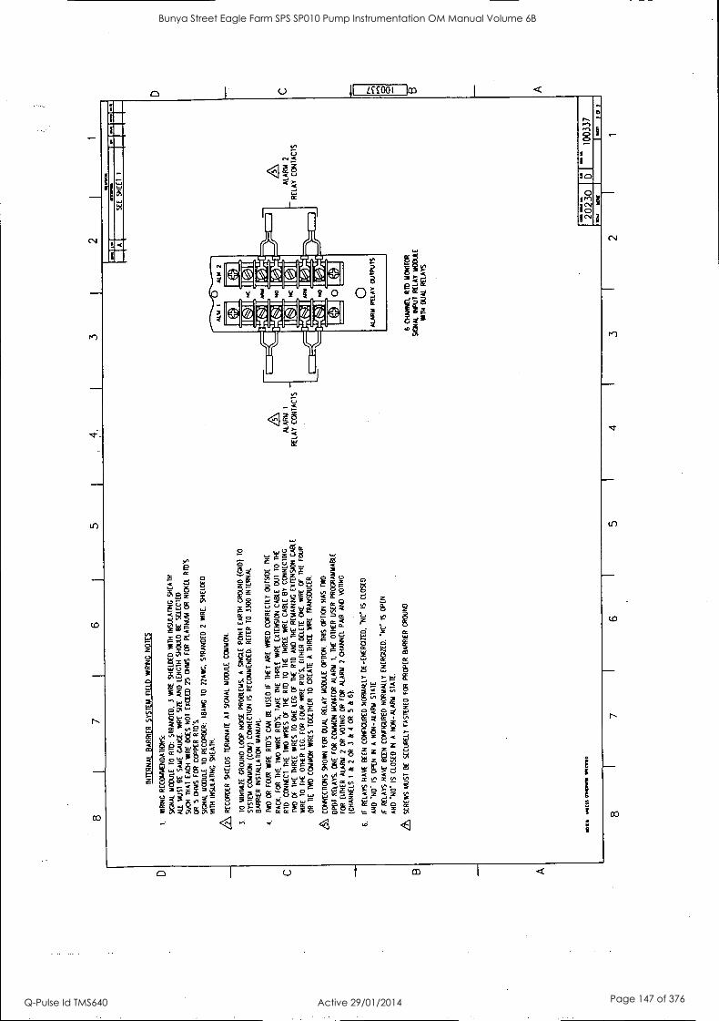
7 I
6 5
1
INT
ER
NA
L B
AR
RIE
R S
YS
TE
M
FIE
LD
WIR
ING
N
OT
ES
I. W
IRIN
G
RE
CO
MM
EN
DA
TIO
NS
:
SIG
NA
L M
OD
ULE
10
RID
: S
TR
AN
DE
D.
3 W
IRE
S
HIE
LDE
D
WIT
H
INS
ULA
TIN
G
SH
EA
TH
.
ALL
M
US
T
BE
S
AM
E
GA
UG
E.
WIR
E
SIZ
E
AN
D L
EN
GT
H
SH
OU
LD B
E
SE
LEC
TE
D
SU
CH
T
HA
T E
AC
H
WIR
E
DC
ES
N
OT
E
XC
EE
D
25
OH
MS
F
OR
P
LAT
INU
M
OR
N
ICK
EL
RID
.S
OR
5
OH
MS
F
OR
C
OP
PE
R R
ID'S
S
IGN
AL
MO
DU
LE
10 R
EC
OR
DE
R:
IBA
WO
T
O
22A
WG
. S
TR
AN
DE
D
2 W
IRE
. S
HIE
LDE
D
WIT
H
INS
ULA
TIN
G
SH
EA
TH
,
RE
CO
RD
ER
S
HIE
LDS
T
ER
MIN
AT
E
AT
S
IGN
AL
MO
DU
LE
CO
MM
ON
.
3.
10 M
INIM
IZE
G
RO
UN
D
LOO
P
NO
ISE
P
RO
BLE
MS
, A
S
ING
LE
PO
INT
E
AR
TH
GR
OU
ND
(G
ND
) T
O
SY
ST
EM
C
OM
MO
N
(CO
M)
CO
NN
EC
TIO
N
IS
RE
CO
MM
EN
DE
D.
RE
FE
R
TO
33
00 I
NT
ER
NA
L
BA
RR
IER
IN
ST
ALL
AT
ION
M
AN
UA
L.
4,
TW
O O
R
FO
UR
W
IRE
R
ID'S
C
AN
B
E
US
ED
IF
T
HE
Y
AR
E
WIR
ED
C
OR
RE
CT
LY
OU
TS
IDE
T
HE
RA
CK
. F
OR
T
HE
T
WO
W
IRE
R
IDS
. T
AK
E
TH
E
TH
RE
E
WIR
E
EX
TE
NS
ION
C
AB
LE
OU
T
TO
T
HE
RT
D.
CO
NN
EC
T
TH
E
TW
O
WIR
ES
C
f T
HE
R
ID
TO
T
HE
T
HR
EE
IM
RE
C
AB
LE
BY
C
ON
NE
CT
ING
TW
O
OF
T
HE
T
HR
EE
W
IRE
S
TO
O
NE
LE
G
OF
T
HE
R
ID
AN
D
TH
E
RE
MA
ININ
G
EX
TE
NS
ION
C
AB
LE
WA
RE
10
T
HE
O
TH
ER
LE
G.
FO
R
FO
UR
W
IRE
R
FD
's.
EIT
HE
R
DE
LET
E
ON
E.
WIR
E
OF
T
HE
F
OU
R
OR
T
IE
TW
O
CO
MM
ON
W
IRE
S T
OG
ET
HE
R
TO
C
RE
AT
E
A
TH
RE
E
WIR
E
TR
AN
SD
UC
ER
.
CO
NN
EC
TIO
NS
S
HO
WN
F
OR
D
UA
L R
ELA
Y
MO
DU
LE
OP
TIO
N.
TH
IS O
PT
ION
H
AS
T
WO
DP
OT
R
ELA
YS
, O
NE
F
OR
C
OM
MO
N
MO
NIT
OR
A
LAR
M
1.
TH
E
OT
HE
R
US
ER
P
RO
GR
AM
MA
BLE
FO
R
EIT
HE
R
ALA
RM
2
OR
V
OT
ING
O
R
FO
R
ALA
RM
2
CH
AN
NE
L P
AIR
A
ND
V
OT
ING
(CH
AN
NE
LS
I &
2
OR
3
& 4
O
R
5 &
6)
6.
IF
RE
LAY
S H
AV
E
BE
EN
C
ON
FIG
UR
ED
N
OR
MA
LLY
DE
-EN
ER
GIZ
ED
. -N
C
IS
CLO
SE
D
AN
D
IS O
PE
N
IN
A
NO
N-A
LAR
M
ST
AT
E
IT
RE
LAY
S
HA
VE
B
EE
N
CO
NF
IGU
RE
D N
OR
MA
LLY
E
NE
RG
IZE
D.
*NC
" IS
O
PE
N
AN
D
No"
IS
C
LOS
ED
IN
A
N
ON
-ALA
RM
S
TA
TE
.
SC
RE
WS
M
US
T B
E
SE
CU
RE
LY
FA
ST
EN
ED
FO
R
PR
OP
ER
BA
RR
IER
G
RO
UN
D.
10,1
.11
MIS
S 0
1111
111
1.1.
0
ALA
RM
I
RE
LAY
CO
NT
AC
TS
-
tl (w
w14
,
SE
E
SH
EE
T
I
6 C
HA
NN
EL
RID
MO
NIT
OR
SIE
TN
N..
INP
UT
R
ELA
Y
MO
DU
LE
WIT
H
DU
AL
RE
LAY
S
ALA
RM
2
RE
LAY
C
ON
TA
CT
S I- I -.
'-.
8 7
I 6
5 I
4
2023
0 D
I
1003
37
.11
2 I
1
D B A
Bunya Street Eagle Farm SPS SP010 Pump Instrumentation OM Manual Volume 6B
Q-Pulse Id TMS640 Active 29/01/2014 Page 147 of 376

80183-01 Six Channel Temperature Monitor Mainterance
64
Bunya Street Eagle Farm SPS SP010 Pump Instrumentation OM Manual Volume 6B
Q-Pulse Id TMS640 Active 29/01/2014 Page 148 of 376
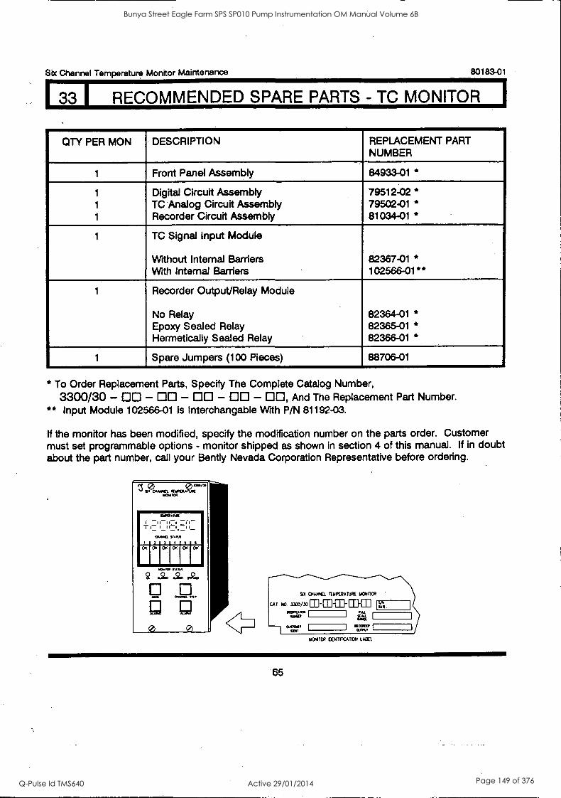
Sbr Channel Temperature Monitor Maintenance
I 33 I RECOMMENDED SPARE PARTS - TC MONITOR
80183-01
QTY PER MON DESCRIPTION REPLACEMENT PART NUMBER
1 Front Panel Assembly 84933-01 *
1 Digital Circuit Assembly 79512-02 * 1 TC Analog Circuit Assembly 79502-01 * 1 Recorder Circuit Assembly 81034-01 *
1 TC Signal Input Module
Without Internal Barriers 82367-01 * With Internal Barriers 102566-01**
1 Recorder Output/Relay Module
No Relay 82364-01 * Epoxy Sealed Relay 82365-01 * Hermetically Sealed Relay 82366-01 *
1 Spare Jumpers (100 Pieces) 88706-01
* To Order Replacement Parts, Specify The Complete Catalog Number,
3300/30 - - - - - , And The Replacement Part Number. ** Input Module 102566-01 is Interchangable With P/N 81192-03.
If the monitor has been modified, specify the modification number on the parts order. Customer must set programmable options - monitor shipped as shown in section 4 of this manual. If in doubt about the part number, call your Bently Nevada Corporation Representative before ordering.
110MTCR CENIVCATION LABEL
65
Bunya Street Eagle Farm SPS SP010 Pump Instrumentation OM Manual Volume 6B
Q-Pulse Id TMS640 Active 29/01/2014 Page 149 of 376
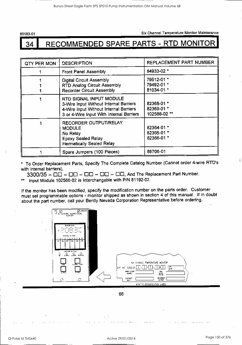
80183-01 Six Channel Temperature Monitor Mainterance
RECOMMENDED SPARE PARTS - RTD MONITOR
QTY PER MON DESCRIPTION REPLACEMENT PART NUMBER
1 Front Panel Assembly 84933-02 *
1 Digital Circuit Assembly .79512 -01 *
1 RTD Analog Circuit Assembly 79492-01 *
1 Recorder Circuit Assembly 81034-01 *
1 RTD SIGNAL INPUT MODULE 3-Wire Input Without Internal Barriers 82368-01 *
4-Wire Input Without Internal Barriers 82369-01 *
3 or 4-Wire Input With Internal Barriers 102566-02 **
1 RECORDER OUTPUT/RELAY MODULE 82364-01 *
No Relay 82365-01 *
Epoxy Sealed Relay 82366-01 *
Hermetically Sealed Relay
1 Spare Jumpers (100 Pieces) 88706-01
* To Order Replacement Parts, Specify The Complete Catalog Number (Cannot order 4-wire RTD's
with internal barriers),
3300/35 - DO - DO - DO - DO - DO, And The Replacement Part Number.
** Input Module 102566-02 is Interchangable with P/N 81192-02.
If the monitor has been modified, specify the modification number on the parts order. Customer
must set programmable options - monitor shipped as shown in section 4 of this manual. If in doubt
about the part number, call your Bent ly Nevada Corporation Representative before ordering.
ItuPEP,TURE
I I I II I I
'
I
C. .6,C6 S22us
2 3 A 6 6
OK OK OK OK OK
SIA CHANNEL TEMPERATURE MONITOR
m M CAT NC _ 00i,- -,__,_, , ,
1.001%.11CA: sutc666.
CITA!. 1
Nu RANGE RANCE
.CCOROC. 0,11Pul
SPA
DMA
IHNTIFICATION LABEL
66
Bunya Street Eagle Farm SPS SP010 Pump Instrumentation OM Manual Volume 6B
Q-Pulse Id TMS640 Active 29/01/2014 Page 150 of 376
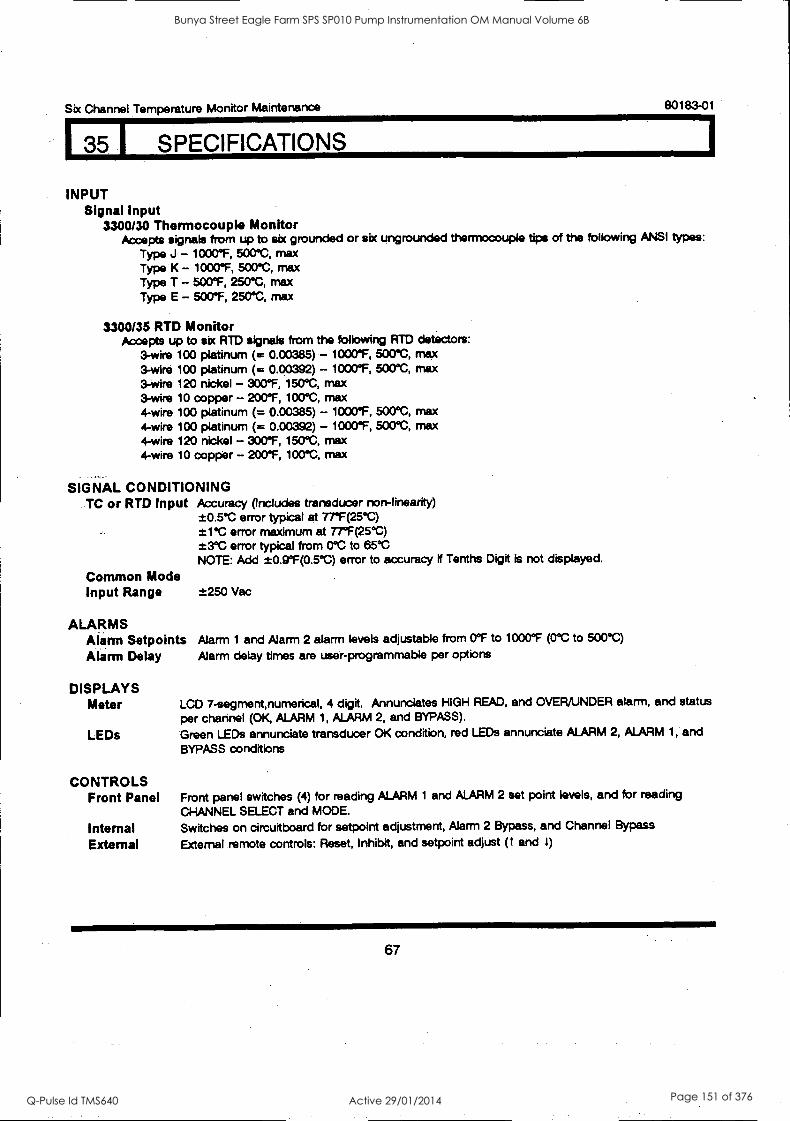
Six Channel Temperature Monitor Maintenance 80183-01
I 35 SPECIFICATIONS
INPUT Signal Input
3300/30 Thermocouple Monitor Accepts signals from up to six grounded or six ungrounded thermocouple tips of the following ANSI types:
Type J - 1000°F, 500°C, max Type K - 1000°F, 500°C, max Type T - 500°F, 250°C, max Type E - 500°F, 250°C, max
3300/35 RTD Monitor Accepts up to six RTD signals from the following RTD detectors:
3-wire 100 platinum (= 0.00385) - 1000°F, 500°C, max 3-wire 100 platinum (= 0.00392) - 1000°F, 500°C, max 3-wire 120 nickel - 300°F, 150°C, max 3-wire 10 copper - 200°F, 100°C, max 4-wire 100 platinum (= 0.00385) - 1000°F, 500°C, max 4-wire 100 platinum (= 0.00392) - 1000°F, 500°C, max 4-wire 120 nickel - 300°F, 150°C, max 4-wire 10 copper - 200°F, 100°C, max
SIGNAL CONDITIONING TC or RTD Input Accuracy (Includes transducer non-linearity)
±0.5°C error typical at 77'F(25°C) ±1°C error maximum at 77°F(25°C) ±3°C error typical from 0°C to 65°C NOTE: Add t0.9°F(0.5°C) error to accuracy if Tenths Digit is not displayed.
Common Mode Input Range ±250 Vac
ALARMS Alarm Setpoints Alarm 1 and Alarm 2 alarm levels adjustable from 0°F to 1000°F (0°C to 500°C)
Alarm Delay Alarm delay times are user-programmable per options
DISPLAYS Meter
LEDs
CONTROLS Front Panel
Internal External
LCD 7-segment,numerical, 4 digit. Annunciates HIGH READ, and OVER/UNDER alarm, and status
per channel (OK ALARM 1, ALARM 2, and BYPASS).
Green LEDs annunciate transducer OK condition, red LEDs annunciate ALARM 2, ALARM 1, and
BYPASS conditions
Front panel switches (4) for reading ALARM 1 and ALARM 2 set point levels, and for reading
CHANNEL SELECT and MODE.
Switches on circuitboard for setpoint adjustment, Alarm 2 Bypass, and Channel Bypass
External remote controls: Reset, Inhibit, and setpoint adjust (1 and I)
67
Bunya Street Eagle Farm SPS SP010 Pump Instrumentation OM Manual Volume 6B
Q-Pulse Id TMS640 Active 29/01/2014 Page 151 of 376
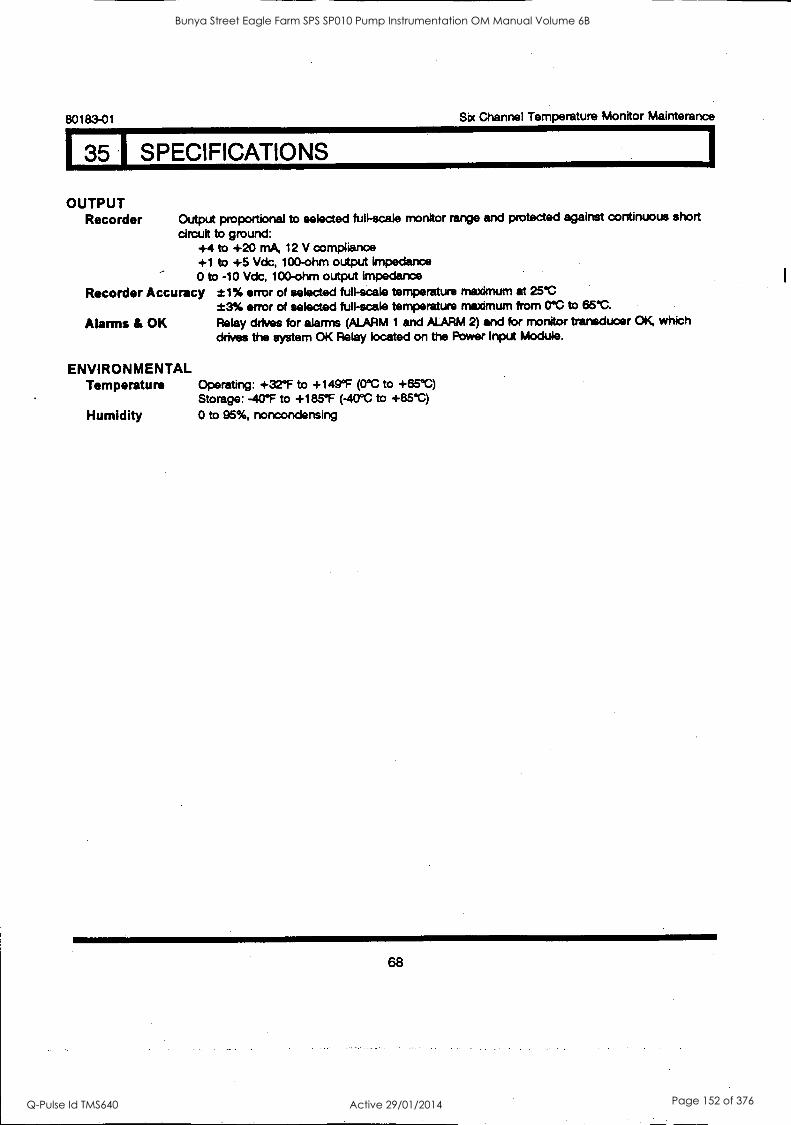
135 1 SPECIFICATIONS
80183-01 Six Channel Temperature Monitor Mainterance
OUTPUT Recorder Output proportional to selected full-scale monitor range and protected against continuous short
circuit to ground: +4 to +20 mA, 12 V compliance +1 to +5 Vdc, 100-ohm output impedance 0 to -10 Vdc, 100-ohm output impedance
Recorder Accuracy ±1% error of selected full-scale temperature may at 25°C *3% error of selected full-scale temperature maximum from 0°C to 65°C.
Alarms & OK Relay drives for alarms (ALARM 1 and ALARM 2) and for monitor transducer OK, which drives the system OK Relay located on the Power Input Module.
ENVIRONMENTAL Temperature Operating: +32°F to +149°F (0°C to +65°C)
Storage: -40°F to +185°F (-40°C to +85°C)
Humidity 0 to 95%, noncondensing
68
Bunya Street Eagle Farm SPS SP010 Pump Instrumentation OM Manual Volume 6B
Q-Pulse Id TMS640 Active 29/01/2014 Page 152 of 376
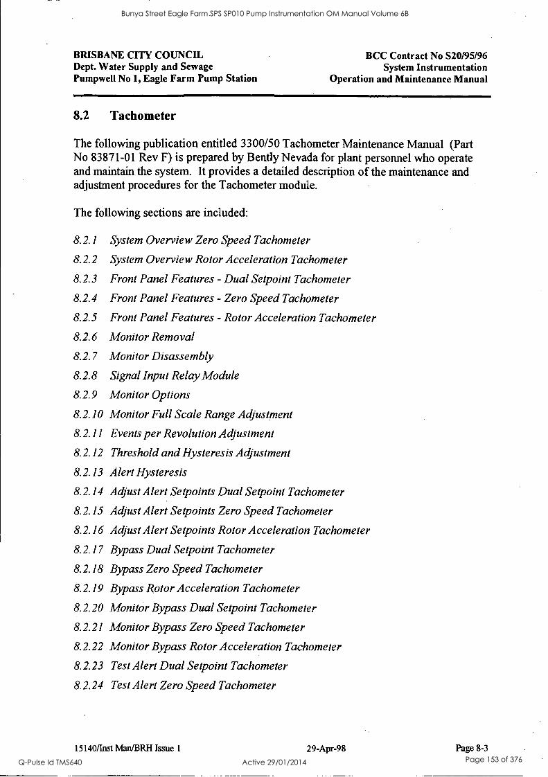
BRISBANE CITY COUNCIL Dept. Water Supply and Sewage Pumpwell No 1, Eagle Farm Pump Station
BCC Contract No S20195196 System Instrumentation
Operation and Maintenance Manual
8.2 Tachometer
The following publication entitled 3300/50 Tachometer Maintenance Manual (Part No 83871-01 Rev F) is prepared by Bent ly Nevada for plant personnel who operate and maintain the system. It provides a detailed description of the maintenance and adjustment procedures for the Tachometer module.
The following sections are included:
8.2.1 System Overview Zero Speed Tachometer
8.2.2 System Overview Rotor Acceleration Tachometer
8.2.3 Front Panel Features - Dual Setpoint Tachometer
8.2.4 Front Panel Features - Zero Speed Tachometer
8.2.5 Front Panel Features - Rotor Acceleration Tachometer
8.2.6 Monitor Removal
8.2.7 Monitor Disassembly
8.2.8 Signal Input Relay Module
8.2.9 Monitor Options
8.2.10 Monitor Full Scale Range Adjustment
8.2.11 Events per Revolution Adjustment
8.2.12 Threshold and Hysteresis Adjustment
8.2.13 Alert Hysteresis
8.2.14 Adjust Alert Setpoints Dual Setpoint Tachometer
8.2.15 Adjust Alert Setpoints Zero Speed Tachometer
8.2.16 Adjust Alert Setpoints Rotor Acceleration Tachometer
8.2.17 Bypass Dual Setpoint Tachometer
8.2.18 Bypass Zero Speed Tachometer
8.2.19 Bypass Rotor Acceleration Tachometer
8.2.20 Monitor Bypass Dual Setpoint Tachometer
8.2.21 Monitor Bypass Zero Speed Tachometer
8.2.22 Monitor Bypass Rotor Acceleration Tachometer
8.2.23 Test Alert Dual Setpoint Tachometer
8.2.24 Test Alert Zero Speed Tachometer
15140/Inst Man/BRH Issue 1 29-Apr-98 Page 8-3
Bunya Street Eagle Farm SPS SP010 Pump Instrumentation OM Manual Volume 6B
Q-Pulse Id TMS640 Active 29/01/2014 Page 153 of 376

BRISBANE CITY COUNCIL Dept. Water Supply and Sewage Pumpwell No 1, Eagle Farm Pump Station
BCC Contract No S20/95/96 System Instrumentation
Operation and Maintenance Manual
8.2.25 Test Alert Rotor Acceleration Tachometer
8.2.26 Test Trigger OK's
8.2.27 Self Test
8.2.28 Wiring Diag - Dual Setpoint Tachometer
8.2.29 Wiring Diag - Zero Speed Tachometer
8.2.30 Wiring Diag - Rotor Acceleration Tachometer
8.2.31 Recommended Spare Parts
8.2.32 Specifications
8.2.33 Index
8.2.34 Schematics and Technical Drawings
15140/Inst Man/BRH Issue 1 29-Apr-98 Page 8-4
Bunya Street Eagle Farm SPS SP010 Pump Instrumentation OM Manual Volume 6B
Q-Pulse Id TMS640 Active 29/01/2014 Page 154 of 376
3300/50 TACHOMETER
INCLUDES DUAL SETPOINT, ZERO SPEED, AND ROTOR ACCELERATION TACHOMETERS.
MAINTENANCE MANUAL
BENTLY (11\ NEVADA
PART NO. 83871-01 REVISION F,
JANUARY 1995
AAAAAA n v.. .0
a A
um .
Bunya Street Eagle Farm SPS SP010 Pump Instrumentation OM Manual Volume 6B
Q-Pulse Id TMS640 Active 29/01/2014 Page 155 of 376
Tachometer Maintenance 83871-01
NOTICE
READ THE FOLLOWING BEFORE INSTALLING OR OPERATING EQUIPMENT
Bent ly Nevada Corporation has attempted to identify areas of risk created by improper installation
and/or operation of this product. These areas of information are noted as WARNING or CAUTION
for your protection and for the safe and effective operation of this equipment. Read all instructions
before installing or operating this product. Pay particular attention to those areas designated by
the following symbols.
A\ WARNING
High voltage could cause shock, burns or death.
Do not touch exposed wires or terminals.
A\ CAUTION
Machine protection will be lost during calibration.
Keyphasore Is a registered trademark of Bent ly Nevada Corporation
ProximItore is a registered trademark of Bently Nevada Corporation
First Printing: March 1989
©Copyright 1989, 1993, 1994, 1995 Bently Nevada Corporation
All Rights reserved
No part of this publication may be reproduced, transmitted, stored in a retrieval system nor translated
into any human or computer language, in any form or by any means, electronic, mechanical, magnetic,
optical, chemical, manual, or otherwise, without the prior written permission of the copyright owner,
Bently Nevada Corporation P.O. Box 157
Minden, Nevada 89423 USA
Telephone 800-227-5514 702-782-3811 Telex 354437
Telemail 7400983 BNC UC
Fax 702-782-9253
Copyright infringement is a serious matter under
United States of America and Foreign Copyright Laws
ii
..... .,
Bunya Street Eagle Farm SPS SP010 Pump Instrumentation OM Manual Volume 6B
Q-Pulse Id TMS640 Active 29/01/2014 Page 156 of 376
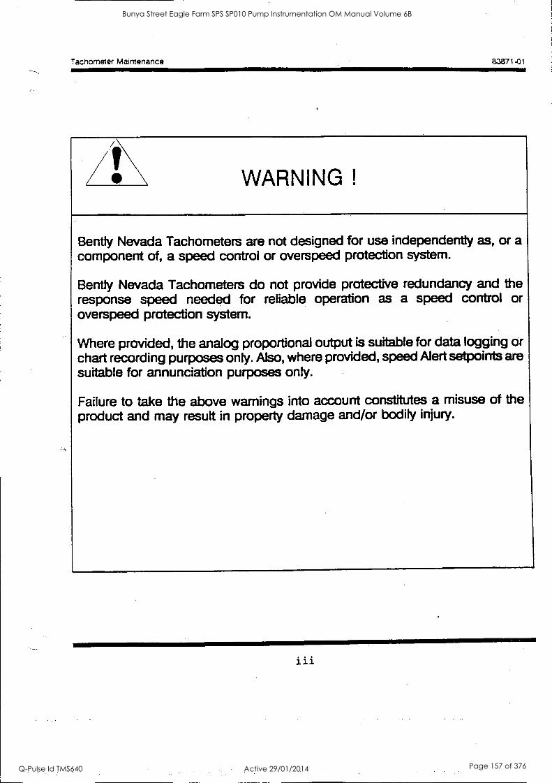
Tachometer Maintenance 83871-01
/10\ WARNING !
Bently Nevada Tachometers are not designed for use independently as, or a component of, a speed control or overspeed protection system.
Bently Nevada Tachometers do not provide protective redundancy and the response speed needed for reliable operation as a speed control or overspeed protection system.
Where provided, the analog proportional output is suitable for data logging or chart recording purposes only. Also, where provided, speed Alert setpoints are suitable for annunciation purposes only.
Failure to take the above warnings into account constitutes a misuse of the product and may result in property damage and/or bodily injury.
iii
Bunya Street Eagle Farm SPS SP010 Pump Instrumentation OM Manual Volume 6B
Q-Pulse Id TMS640 Active 29/01/2014 Page 157 of 376

Tachometer Maintenance
iv
Bunya Street Eagle Farm SPS SP010 Pump Instrumentation OM Manual Volume 6B
Q-Pulse Id TMS640 Active 29/01/2014 Page 158 of 376

Tachometer Maintenance 83871-01
FOREWORD
This document is intended for personnel who maintain the 3300 Monitoring System. The
procedures are presented in step-by-step, graphic format.
RELATED DOCUMENTS
3300 System Overview, 80171-01
3300 System Installation Instructions, 80172-01
3300 System Troubleshooting, 80173-01
3300/12 AC Power Supply, 89602-01
3300/14 DC Power Supply, 101256-01
3300/03 System Monitor, 89604-01
3300/50 Tachometer Operation, 83870-01
SYMBOLS Special symbols are used in the manual to illustrate specifics in the step-by-step processes. For
example:
PRESS FLASHING CONNECT DISCONNECT OBSERVE SCREWDRIVER
V
Bunya Street Eagle Farm SPS SP010 Pump Instrumentation OM Manual Volume 6B
Q-Pulse Id TMS640 Active 29/01/2014 Page 159 of 376
Tachometer Maintenance 83871-01
Bunya Street Eagle Farm SPS SP010 Pump Instrumentation OM Manual Volume 6B
Q-Pulse Id TMS640 Active 29/01/2014 Page 160 of 376
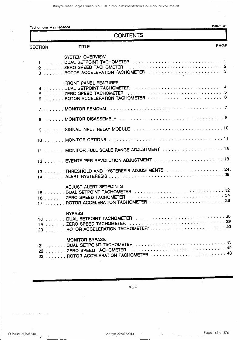
Thchometer Maintenance. 83871-.01
CONTENTS
SECTION TITLE PAGE
SYSTEM OVERVIEW 1 DUAL SETPOINT TACHOMETER 1
2 ZERO SPEED TACHOMETER 2
3 ROTOR ACCELERATION TACHOMETER 3
FRONT PANEL FEATURES 4 DUAL SETPOINT TACHOMETER 4
5 ZERO SPEED TACHOMETER 5
6 ROTOR ACCELERATION TACHOMETER 6
7 MONITOR REMOVAL 7
8 MONITOR DISASSEMBLY 8
9 SIGNAL INPUT RELAY MODULE 10
10 MONITOR OPTIONS 11
11 MONITOR FULL SCALE RANGE ADJUSTMENT 15
12 EVENTS PER REVOLUTION ADJUSTMENT 18
13 THRESHOLD AND HYSTERESIS ADJUSTMENTS 24
14 ALERT HYSTERESIS 28
ADJUST ALERT SETPOINTS
15 DUAL SETPOINT TACHOMETER 32
16 ZERO SPEED TACHOMETER 34
17 ROTOR ACCELERATION TACHOMETER 36
BYPASS 18 DUAL SETPOINT TACHOMETER 38
19 ZERO SPEED TACHOMETER 39
20 ROTOR ACCELERATION TACHOMETER 40
MONITOR BYPASS
21 DUAL SETPOINT TACHOMETER 41
22 ZERO SPEED TACHOMETER 42
23 ROTOR ACCELERATION TACHOMETER 43
vii
Bunya Street Eagle Farm SPS SP010 Pump Instrumentation OM Manual Volume 6B
Q-Pulse Id TMS640 Active 29/01/2014 Page 161 of 376
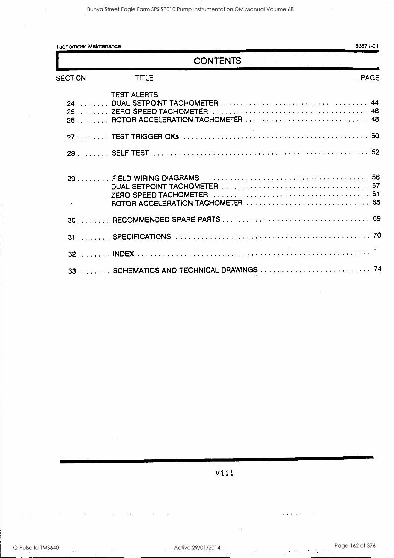
Tachometer Maintenance 83871-01
CONTENTS
SECTION TITLE PAGE
TEST ALERTS 24 DUAL SETPOINT TACHOMETER 44 25 ZERO SPEED TACHOMETER 46
26 ROTOR ACCELERATION TACHOMETER 48
27 TEST TRIGGER OKs 50
28 SELF TEST 52
29 FIELD WIRING DIAGRAMS 56
DUAL SETPOINT TACHOMETER 57
ZERO SPEED TACHOMETER 61
ROTOR ACCELERATION TACHOMETER 65
30 RECOMMENDED SPARE PARTS 69
31 SPECIFICATIONS 70
32 INDEX
33 SCHEMATICS AND TECHNICAL DRAWINGS 74
viii
Bunya Street Eagle Farm SPS SP010 Pump Instrumentation OM Manual Volume 6B
Q-Pulse Id TMS640 Active 29/01/2014 Page 162 of 376
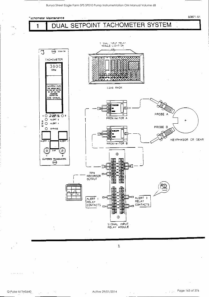
Thchometer Maintenance 83871-01
DUAL SETPOINT TACHOMETER SYSTEM
noo,lo
TACCmETER
3 6 0 C RPM
WARNING P41 tOPPO 011LAT
Rigol SR .00PS CP WO Al I MI
sw_PIRIPP IOTRI la
SEE MANUAL
A 0 ;1:17. r. 0 0 ALERT
p0 ALERT
0 BYPASS
ALERT 2
GAP
ALERT I
A a
eLFFSED TRAA4SOUCERS
,,;:AL ',:P.fr r,ELAf mCOULE L:CAT!:N
3300 RACK
PROX I M I TOR A
PROBE A
PROBE B
RPM - RECORDER OUTPUT
ALERT 1
RELAY CONTACTS
P'ROX I M I TOR 8
SIGNAL I NPUT RELAY MODULE
ALERT 2
RELAY CONTACTS
KEYPHASOR CR GEAR
Bunya Street Eagle Farm SPS SP010 Pump Instrumentation OM Manual Volume 6B
Q-Pulse Id TMS640 Active 29/01/2014 Page 163 of 376
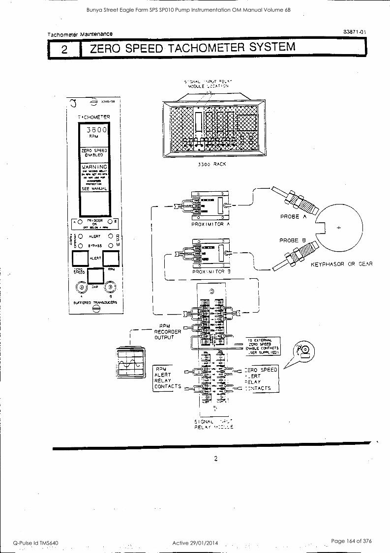
Tachometer Maintenance 8.3871-01
ZERO SPEED TACHOMETER SYSTEM
1,00/10 i
.-/
TICHOmETER
3000 Rpm
ZERO SPEED ENABLED
WARNING ar Mme 0E4,
Do RP% .0.In CO Or W ray
04111 moprICT Os
SEE mANuAL
4111.1 QT
R RtGGER CK
07 error. Rift
0 ALERT 0 F:f,
° 0 a'Ass Q
ALERT
;,AP
RPM
A 8
SUFFERED TRANSDUCERS
S
S'ONAL 'NOuT mODULE LCCAriT.N
3300 RACK
PROX I M TOR A
KEYPHASOR CR GEAR
RPM
I
RECORDER OUTPUT
RPM ALERT RELAY CONTACTS
SIGNAL -
RELA(
TO EXTERNAL ZERO SPEED
ENABLE CONTACTS .sER SUPPLIED)
ZERO SPEED _ERT
7:NTACTS
Bunya Street Eagle Farm SPS SP010 Pump Instrumentation OM Manual Volume 6B
Q-Pulse Id TMS640 Active 29/01/2014 Page 164 of 376
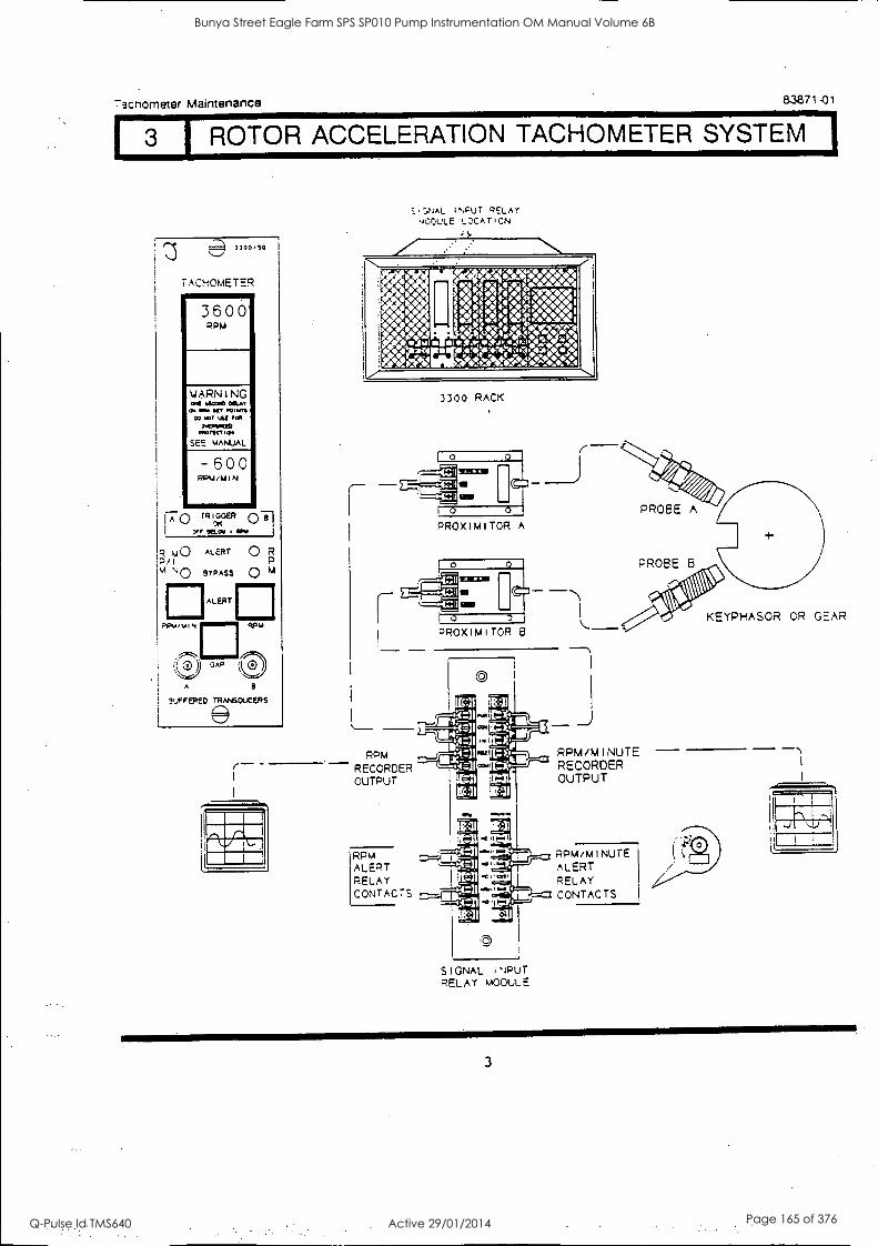
I 3 1 ROTOR ACCELERATION TACHOMETER SYSTEM I Mcnometer Maintenance 83871 -01
3300/50
TACHOMETER ......... 3600 PPM
WARNING 04 MOO O&M
cos Mr NT 03001 CO WO OA OM
040114E13 coOMC5 la
SEE mANUAL
-600 RPU/MIN
FO r F"cfER
MCA/
R m0 ALERT P/I M NO BYPASS
PPM/MIN
ALERT
O R O 4
RPM
A
BUFFERED TRANSDUCERS
NAL 1PuT DELAY v0OULE LOCA T I CN
:y
3300 RACK
PROximITOR A
PROSE A
PROBE 8
RPM RECORDER OUTPUT
RPM ALERT RELAY CONTACTS ,---
PROXIMITOR 8
CD
I I
731 -N
1-11
01,11
914-41
COO
VC I
AC CO
te. I
SIGNAL INPUT RELAY MODULE
RPM/MINUTE RECORDER OUTPUT
RPM /MINUTE ALERT RELAY CONTACTS
KEYPHASOR CR GEAR
3
Bunya Street Eagle Farm SPS SP010 Pump Instrumentation OM Manual Volume 6B
Q-Pulse Id TMS640 Active 29/01/2014 Page 165 of 376
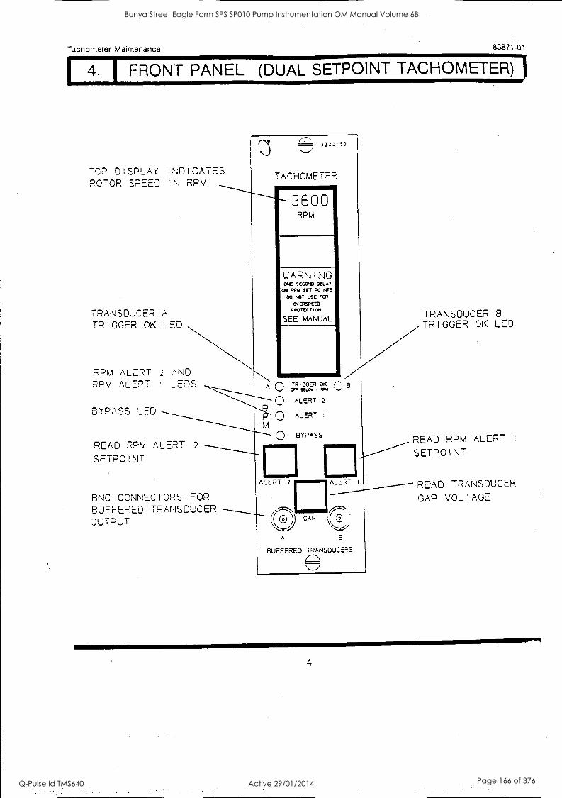
FRONT PANEL (DUAL SETPOINT TACHOMETER) j acnometer Maintenance 83871-01
TOP DISPLAY ROTOR SPEED
ND I CATES N RPM
TRANSDUCER A TRIGGER OK LED
RPM ALERT 2 AND RPM ALERT ! _EDS
BYPASS LED
33:::!0
TACHOMETER MMEMMEMMMEMMI
3600 RPM
WARNING ONE SEC DELAY
Orr ROW SET POINTS
00 NOT USE FC
ovennen PROTECTICN
SEE MANUAL
n TRIGGED op( 3 OFR EEL $ 'Cm -
READ RPM ALERT 2
SETPOINT
BNC CONNECTORS. FOR BUFFERED TRANSDUCER OUTPUT
M
ALERT 2
0 ALERT :
Q BYPASS
ALERT 2 ALERT
GAP
A
BUFFERED TRANSOUCEFS
(-)
TRANSDUCER 8
TRIGGER OK LED
READ RPM ALERT 1
SETPOINT
READ TRANSDUCER GAP VOLTAGE
4
Bunya Street Eagle Farm SPS SP010 Pump Instrumentation OM Manual Volume 6B
Q-Pulse Id TMS640 Active 29/01/2014 Page 166 of 376
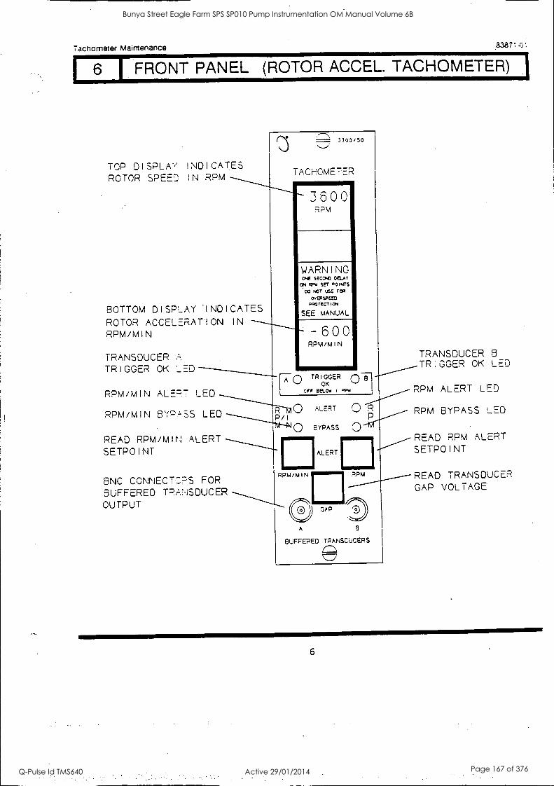
I FRONT PANEL (ROTOR ACCEL. TACHOMETER) 1
Tachometer Maintenance .2,3871-0;
TOP DISPIAY INDICATES ROTOR SPEED IN RPM
BOTTOM DISPLAY 'INDICATES ROTOR ACCELERATION IN
RPM/MIN - 6 0 0 RPM/MIN
3300/50
TACHOMETER
3600
RPM
WARNING ONE SECOAC DELAY ON RPW SET MINTS
DO WT USE Fut
OvERSPEED PPOTECTiON
SEE MANUAL
TRANSDUCER A
TRIGGER OK ._ED
RPM/MIN ALERT LED
RPM/MIN BYPASS LED
0
0 TRIGGER
CFF BELOW 1 qow OK
READ RPM/MIN ALERT SETPOINT
BNC CONNECTORS FOR BUFFERED TRANSDUCER OUTPUT
ALERT
BYPASS
ALERT
RPM/MIN
O R
a
A
GAP
P.PA4
3
BUFFERED TRANSDUCERS
TRANSDUCER B
TR:GGER OK LED
RPM ALERT LED
RPM BYPASS LED
READ RPM ALERT SETPOINT
READ TRANSDUCER GAP VOLTAGE
6
Bunya Street Eagle Farm SPS SP010 Pump Instrumentation OM Manual Volume 6B
Q-Pulse Id TMS640 Active 29/01/2014 Page 167 of 376
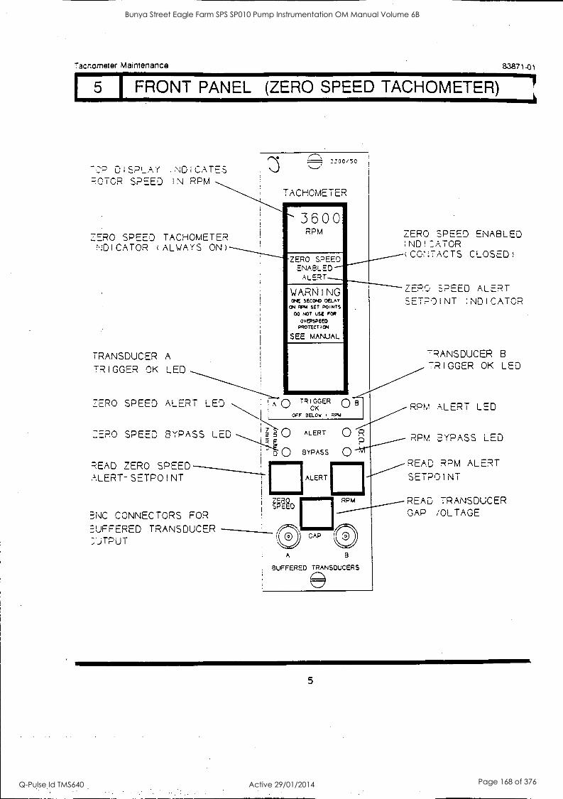
73cnometer Maintenance 83871-01
1 5 FRONT PANEL (ZERO SPEED TACHOMETER)
-OP DISPI :NDICATES 7.5
POTCR SPEED IN RPM TACHGMETER
3600
'300/50
ZERO SPEED TACHOMETER NDICATOR (ALWAYS ON)
TRANSDUCER A
TRIGGER OK LED
RPM
ZERO SPEED ENABLED
ALERT
WARNING ONE SECOND OELAy ON PPN SET POINTS
CO 1...3T USE FOR
ovERsPeE0 PROTECTION
SEE MANUAL
EFRO SPEED ENABLED IND! ,TOR (CONTACTS CLOSED)
ZERO SPEED ALERT SETPOINT :NDICATOR
ZERO SPEED ALERT LED TR el ?<GER C) B
OFF BELOW i MPU
=FRO SPEED BYPASS
READ ZERO SPEED ALERT-SETPOINT
BNC CONNECTORS FOR BUFFERED TRANSDUCER ;JTPUT
ALERT
BYPASS
ALERT
0 R
0
TRANSDUCER B
TRIGGER OK LED
RPM ALERT LED
RPM BYPASS LED
READ RPM ALERT SETPOINT
RPM READ TRANSDUCER GAP /OLTAGE
A
GAP
B
BUFFERED TRANSDUCERS
5
Bunya Street Eagle Farm SPS SP010 Pump Instrumentation OM Manual Volume 6B
Q-Pulse Id TMS640 Active 29/01/2014 Page 168 of 376
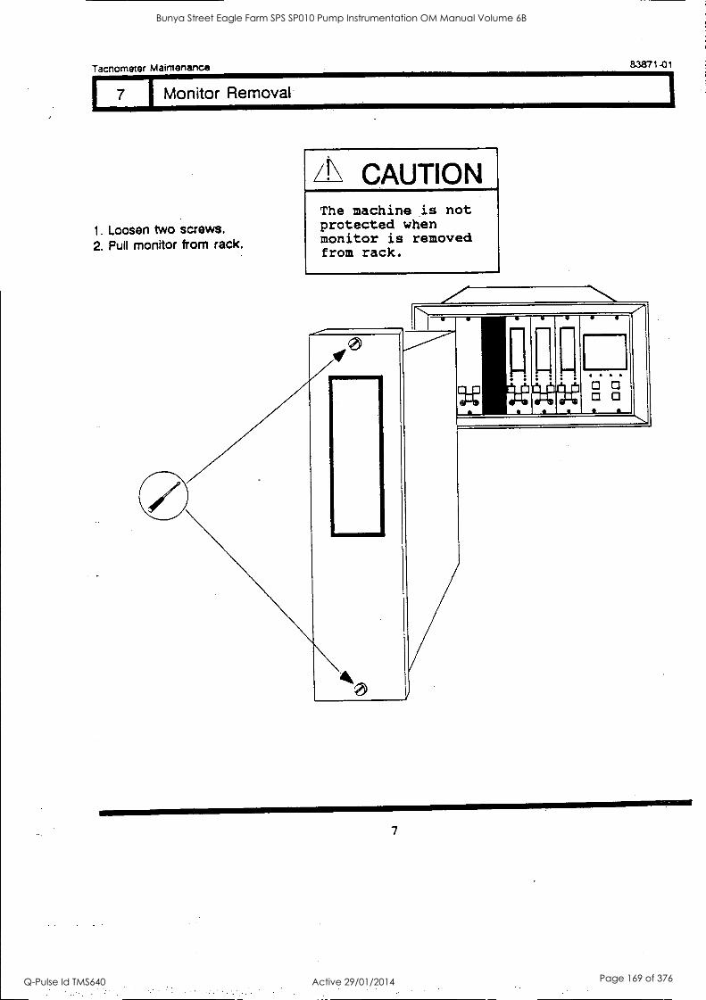
111111111111I
411111111111
Tachometer Maintenance 83871-01
7 I Monitor Removal
1. Loosen two screws. 2. Pull monitor from rack.
/I\ CAUTION The machine is not protected when monitor is removed from rack.
0 0o
7
Bunya Street Eagle Farm SPS SP010 Pump Instrumentation OM Manual Volume 6B
Q-Pulse Id TMS640 Active 29/01/2014 Page 169 of 376
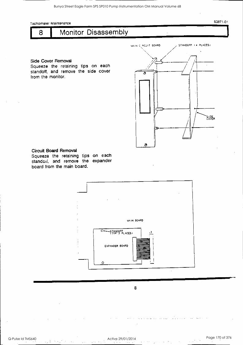
Tachometer Maintenance 83871-01
8 I Monitor Disassembly
Side Cover Removal Squeeze the retaining tips on each standoff, and remove the side cover from the monitor.
Circuit Board Removal Squeeze the retaining tips on each standoii, and remove the expander board from the main board.
MAIN C.FC'JIT ?,0APCI STANDOFF 14 PLACES)
///
MAIN BOARD
C.----STANDOFF ITYP 3 PLACES
EXPANDER BOARD
0
8
Bunya Street Eagle Farm SPS SP010 Pump Instrumentation OM Manual Volume 6B
Q-Pulse Id TMS640 Active 29/01/2014 Page 170 of 376
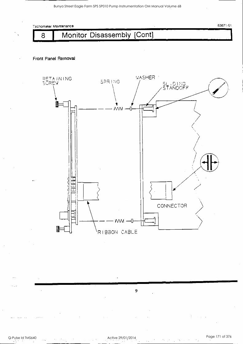
Tacnometer Maintenance
8 I Monitor Disassembly [Cont]
Front Panel Removal
I N I NG 30REW
ti
SPRING
iNAM
VVVVI
83871-ot
WASHER SLIDING STANDOFF
CONNECTOR
RIBBON CABLE
9
Bunya Street Eagle Farm SPS SP010 Pump Instrumentation OM Manual Volume 6B
Q-Pulse Id TMS640 Active 29/01/2014 Page 171 of 376
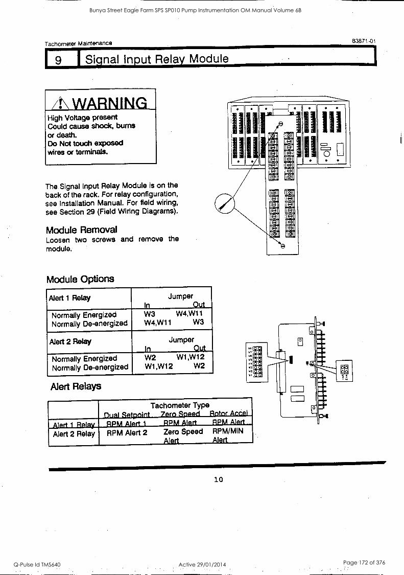
Tachometer Maintenance 83871-01
I9 _I Signal Input Relay Module
4.\ WARNING High Voltage present Could cause shock, bums or death. Do Not touch exposed wires or terminals.
The Signal Input Relay Module is on the back of the rack. For relay configuration, see Installation Manual. For field wiring, see Section 29 (Field Wiring Diagrams).
Module Removal Loosen two screws and remove the module.
Module Options
Alert 1 Relay Jumper In Out
Normally Energized Normally De-energized
W3 W4,W1 1
W4,W11 W3
Alert 2 Relay Jumper In Out
Normally Energized Normally De-energized
W2 W1 ,W1 2
W1,W12 W2
Alert Relays
I
0
1-61
: C=3 11=1
IC=3
-
A :- 114
DI Ial E=1
IL=.1 t=3 C=1
Eel ID3
el 1E11
IL-11 L=11 111ii
II=3 IC=3 L=11
11=3
-1 IC -] 11.311
1101
VI V1
VS
V.
113
Vt
VI
Pa1 (.1.1
Co"
rz 1.11
Tachometer Type Dual Satnoint 7ero Sneed Rotor Accel
Alert 1 Relay Alert 2 Relay
RPM Alert I RPM Alert RPM Alert
RPM Alert 2 Zero Speed RPM/MIN Alert Alert
In =c3
10
Bunya Street Eagle Farm SPS SP010 Pump Instrumentation OM Manual Volume 6B
Q-Pulse Id TMS640 Active 29/01/2014 Page 172 of 376
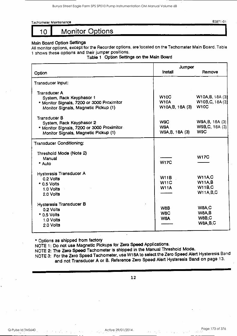
Tachometer Maintenance 83871-01
10 I Monitor Options
Main Board Option Settings All monitor options, except for the Recorder options, are located on the Tachometer Main Board. Table
I shows these options and their jumper positions. Table 1 Option Settings on the Main Board
Option
Jumper Install Remove
Transducer Input:
Transducer A System, Rack Keyphasor 1 W10C W10A,B, 18A (3
* Monitor Signals, 7200 or 3000 Proximitor W10A W10B,C, 18A (31
Monitor Signals, Magnetic Pickup (1) W10A,B, 18A (3) W10C
Transducer B System, Rack Keyphasor 2 W9C W9A,B, 18A (3)
* Monitor Signals, 7200 or 3000 Proximitor W9A W9B,C, 18A (3)
Monitor Signals, Magnetic Pickup (1) W9A,B, 18A (3) W9C
Transducer Conditioning:
Threshold Mode (Note 2) Manual W17C
* Auto W17C
Hysteresis Transducer A 0.2 Volts W11B W11A,C
* 0.5 Volts W11C W11A,B
1.0 Volts W11A W11B,C
2.0 Volts W11A,B,C
Hysteresis Transducer B -
0.2 Volts W8B W8A,C
* 0.5 Volts W8C W8A,B
1.0 Volts W8A W8B,C
2.0 Volts W8A,B,C
* Options as shipped from factory NOTE 1: Do not use Magnetic Pickups for Zero Speed Applications.
NOTE 2: The Zero Speed Tachometer is shipped in the Manual Threshold Mode.
NOTE 3: For the Zero Speed Tachometer, use W18A to select the Zero Speed Alert Hysteresis Band
and not Transducer A or B. Reference Zero Speed Alert Hysteresis Band on page 13.
12
Bunya Street Eagle Farm SPS SP010 Pump Instrumentation OM Manual Volume 6B
Q-Pulse Id TMS640 Active 29/01/2014 Page 173 of 376
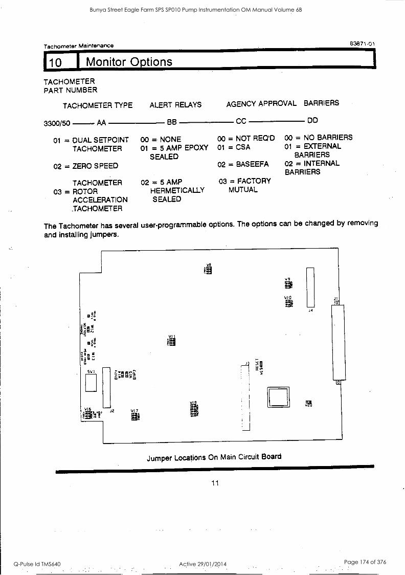
Tachometer Maintenance 83871-01
110 1 Monitor Options
TACHOMETER PART NUMBER
TACHOMETER TYPE
3300/50 AA
ALERT RELAYS
BB
AGENCY APPROVAL BARRIERS
CC DD
01 = DUAL SETPOINT 00 = NONE 00 = NOT REQ'D 00 = NO BARRIERS
TACHOMETER 01 = 5 AMP EPDXY 01 = CSA 01 = EXTERNAL
SEALED BARRIERS
02 = ZERO SPEED 02 = BASEEFA 02 = INTERNAL BARRIERS
TACHOMETER 02 = 5 AMP 03 = FACTORY
03 = ROTOR HERMETICALLY MUTUAL
ACCELERATION SEALED .TACHOMETER
The Tachometer has several user-programmable options. The options can be changed by removing
and installing jumpers.
SWI
V16 A S_AOJ J2 5417
A
Ve
VIo
JI
VCV
JI Io
Jumper Locations On Main Circuit Board
11
Bunya Street Eagle Farm SPS SP010 Pump Instrumentation OM Manual Volume 6B
Q-Pulse Id TMS640 Active 29/01/2014 Page 174 of 376

Tachometer Maintenance 83871-01
10 1 Monitor Options
Table 1 Option Settings on the Main Board (Continued)
Option
Jumper Install Remove
Alert Modes:
Alert 1 (See Table 2) * Over Alert
Under Alert * Latching Alert
Non latching Alert
Alert 2 (See Table 2) * Over Alert (Notes 4 and 7)
Under Alert * Latching Alert
Nonlatching Alert
W1 8B W188
W1 8C W1 8C
W180 W180
W1 8E W1 8E
First Out Alert Option: (Note 5)
* First Out Alert Enable First Out Alert Disable
W1 7A W1 7A
Monitor Options: (Note 6)
Alert 1 (See Table 2) Bypass Switch Enable
* Bypass Switch Disable
Alert 2 (See Table 2) Bypass Switch Enable
* Bypass Switch Disable
W14 W14
W15 W15
Zero Speed Alert Hysteresis Band: (Note 8)
0 rpm 1 rpm W18A
5 rpm W178
* 10 rpm W178,18A
W17B,18A W17B W18A
Options as shipped from factory Note 4: W180 has no affect on the Zero Speed Alert. Zero Speed is always an Under /gait
Note 5: All Alerts drive the rack Fimt Out Alert Bus. The Tachometers do not drive the rack Filet out Danger Bus.
Note 6: W14 has no affect on the Dual Selpoint Tachometer. Only the RPM Alert 2 Relay may be Bypassed on the
Dual Setpoint Tachometer. Note 7: W180 has no affect on the Rotor Accei Tachometer. Rotor Accel is always an Over Alen
Note 8: Refer to section 14 for more information about the Zero Speed Alert Hysteresis Band.
13
Bunya Street Eagle Farm SPS SP010 Pump Instrumentation OM Manual Volume 6B
Q-Pulse Id TMS640 Active 29/01/2014 Page 175 of 376
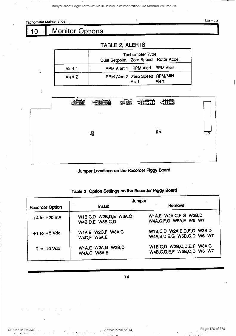
Tachometer Maintenance 83871 -01
110 I Monitor Options
TABLE 2, ALERTS
Tachometer Type
Dual Setpoint Zero Speed Rotor Accel
Alert 1 RPM Alert 1 RPM Alert RPM Alert
Alert 2 RPM Alert 2 Zero Speed RPM/MIN Alert Alert
'38
<m u G31..0 u- 0 e;ditl :r2g= ;
J5
Jumper Locations on the Recorder Piggy Board
Table 3 Option Settings on the Recorder Piggy Board
Recorder Option Install Jumper
Remove
+4 to +20 mA
+1 to +5 Vdc
0 to -10 Vdc
W1B,C,D W2B,D,E W3A,C W4B,D,E W5B,C,D
W1A,E W2C,F W3A,C W4C,F W5A,E
W1A,E W2A,G W3B,D W4A,G W5A,E
W1A,E .W2A,C,F,G W3B,D W4A,C,F,G W5A,E W6 W7
W1B,C,D W2A,B,D,E,G W3B,D W4A,B,D,E,G W5B,C,D W6 W7
W1B,C,D W2B,C,D,E,F W3A,C W4B,C,D,E,F W5B,C,D W6 W7
14
Bunya Street Eagle Farm SPS SP010 Pump Instrumentation OM Manual Volume 6B
Q-Pulse Id TMS640 Active 29/01/2014 Page 176 of 376
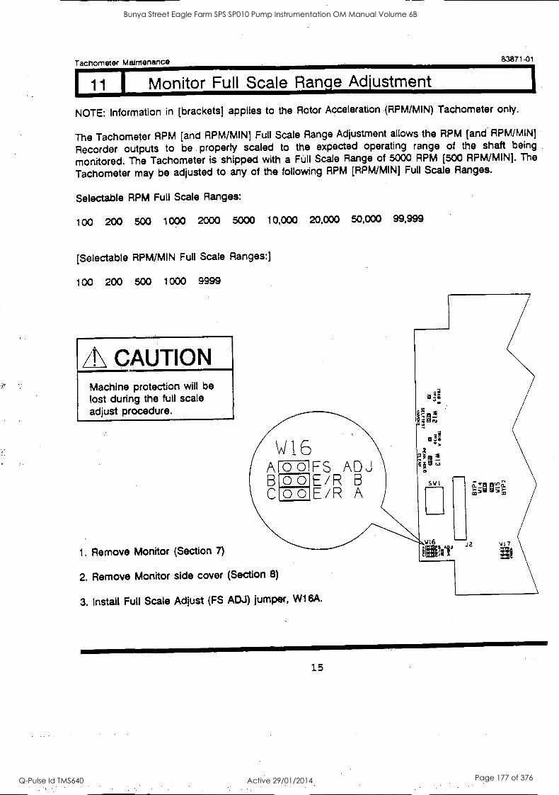
J Tachometer Maintenance 83871-01
11 1 Monitor Full Scale Range Adjustment
NOTE: Information in [brackets] applies to the Rotor Acceleration (RPM/MIN) Tachometer only.
The Tachometer RPM [and RPM /MIN] Full Scale Range Adjustment allows the RPM [and.RPM/MIN]
Recorder outputs to be property scaled to the expected operating range of the shaft being
monitored. The Tachometer is shipped with a Full Scale Range of 5000 RPM [500 RPM/MIN]. The
Tachometer may be adjusted to any of the following RPM [RPM/MIN] Full Scale Ranges.
Selectable RPM Full Scale Ranges:
100 200 500 1000 2000 5000 10,000 20,000 50,000 99,999
[Selectable RPM/MIN Full Scale Ranges:]
100 200 500 1000 9999
th CAUTION Machine protection will be lost during the full scale adjust procedure.
B C
W16 O 0 O 0 O 0
FS ADJ EAR B EAR A
1. Remove Monitor (Section 7)
2. Remove Monitor side cover (Section 8)
3. Install Full Scale Adjust (FS ADJ) jumper, W16A.
V16 (4- P.. I !AV
4) 7
15
Bunya Street Eagle Farm SPS SP010 Pump Instrumentation OM Manual Volume 6B
Q-Pulse Id TMS640 Active 29/01/2014 Page 177 of 376
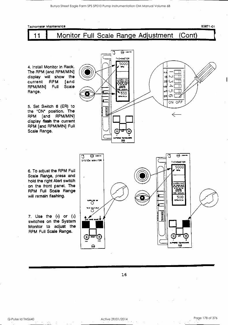
Tachometer Maintenance
11 1 Monitor Full Scale Range Adjustment (Cant)
83871-01
4. Install Monitor in Rack. The RPM [and RPM /MIN] display will show the current RPM [and RPM/MIN] Full Scale Range.
5. Set Switch 6 (ER) to the "ON" position. The RPM [and RPM /MIND display flash the current RPM [and RPM/MIN] Full Scale Range.
6. To adjust the RPM Full Scale Range, press and hold the right Alert switch on the front panel. The RPM Full Scale Range will remain flashing.
7. Use the (t) or (1)
switches on the System Monitor to adjust the RPM Full Scale Range.
1260 Ad
A C 1404E1' ER
11 5000
WARNING
. Sai *4401
500 1101/14 IN
(.1 I t\ 2e
me
Lir
ER 0) I
ON OFF 41111111
C
'3 SYSTEM IACti I TCR
16
Bunya Street Eagle Farm SPS SP010 Pump Instrumentation OM Manual Volume 6B
Q-Pulse Id TMS640 Active 29/01/2014 Page 178 of 376
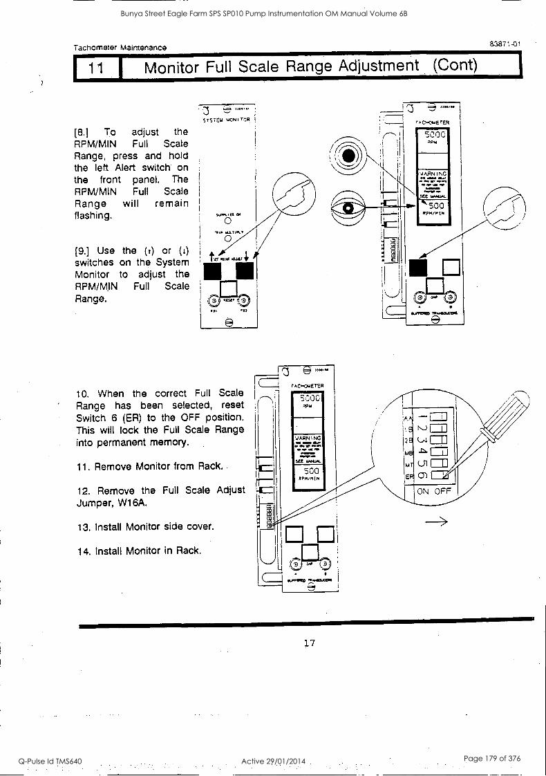
Tachometer Maintenance 83871.0t
11 Monitor Full Scale Range Adjustment Cont)
[8.) To adjust the RPM/MIN Full Scale Range, press and hold the left Alert switch on the front panel. The RPM/MIN Full Scale Range will remain flashing.
(9.] Use the (r) or (I) switches on the System Monitor to adjust the RPM/MIN Full Scale Range.
33333 . "STEW MCNITCR.
316..
TAO-OmETER
5000 RP./
ARN I NG
500 RPM/MIN
Amummlommo
10. When the correct Full Scale Range has been selected, reset Switch 6 (ER) to the OFF position. This will lock the Full Scale Range into permanent memory.
11. Remove Monitor from Rack.
12. Remove the Full Scale Adjust Jumper, W16A.
13. Install Monitor side cover.
14. Install Monitor in Rack.
rr
rAcK.,ETER
5000
WARNING wow
See 4W-1AL
.500 RPM /MIN
APN
18
26
MB
mi
ER
poreINMS ry NNIOXISMI
17
Bunya Street Eagle Farm SPS SP010 Pump Instrumentation OM Manual Volume 6B
Q-Pulse Id TMS640 Active 29/01/2014 Page 179 of 376
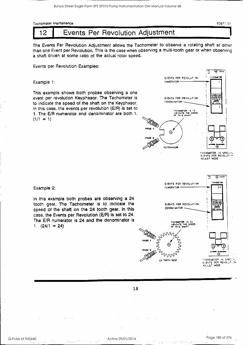
1, wARNINO
mmilmb
La a...
411111111111.
Tacnometer Maintenance
12 I Events Per Revolution Adjustment
The Events Per Revolution Adjustment allows the Tachometer to observe a rotating shaft at other than one Event per Revolution. This is the case when observing a multi-tooth gear or when observing a shaft driven at some ratio of the actual rotor speed.
83871-01
Events per Revolution Examples:
Example 1:
This example shows both probes observing a one event per revolution Keyphasor. The Tachometer is
to indicate the speed of the shaft on the Keyphasor. In this case, the events per revolution (E/R) is set to 1. The E/R numerator and denominator are both 1.
(1/1 = 1)
Example 2:
In this example both probes are observing a 24
tooth gear. The Tachometer is to indicate the
speed of the shaft on the 24 tooth gear. In this case, the Events per Revolution (E/R) is set to 24.
The E/R numerator is 24 and the denominator is
1. (24/1 = 24)
EVENTS PER REvOLUT'ON
M),IERATOR e.
EVENTS PER REVOLUTION
DENOMINATOR
TACHOMETER iS TO INDICATE n-E SPEED OF THIS SHAFT
EVENTS PER REVOLUTION
NUmERATOR
EVENTS PER REVOLUTION
DENOMINATOR
TACHINETEp is TO INDICATE THE SPEED OF THIS SHAFT
. r addli
TACHOMETER IN SPECIAL EVENTS PER REVOLuTI^. ADJUST MODE
-.CHCMETM
24
MrelyInEll
-C!..CmETER IN SPEC.,..
E,ENTS PER REVOLUTION A0_,L.ST MODE
18
Bunya Street Eagle Farm SPS SP010 Pump Instrumentation OM Manual Volume 6B
Q-Pulse Id TMS640 Active 29/01/2014 Page 180 of 376
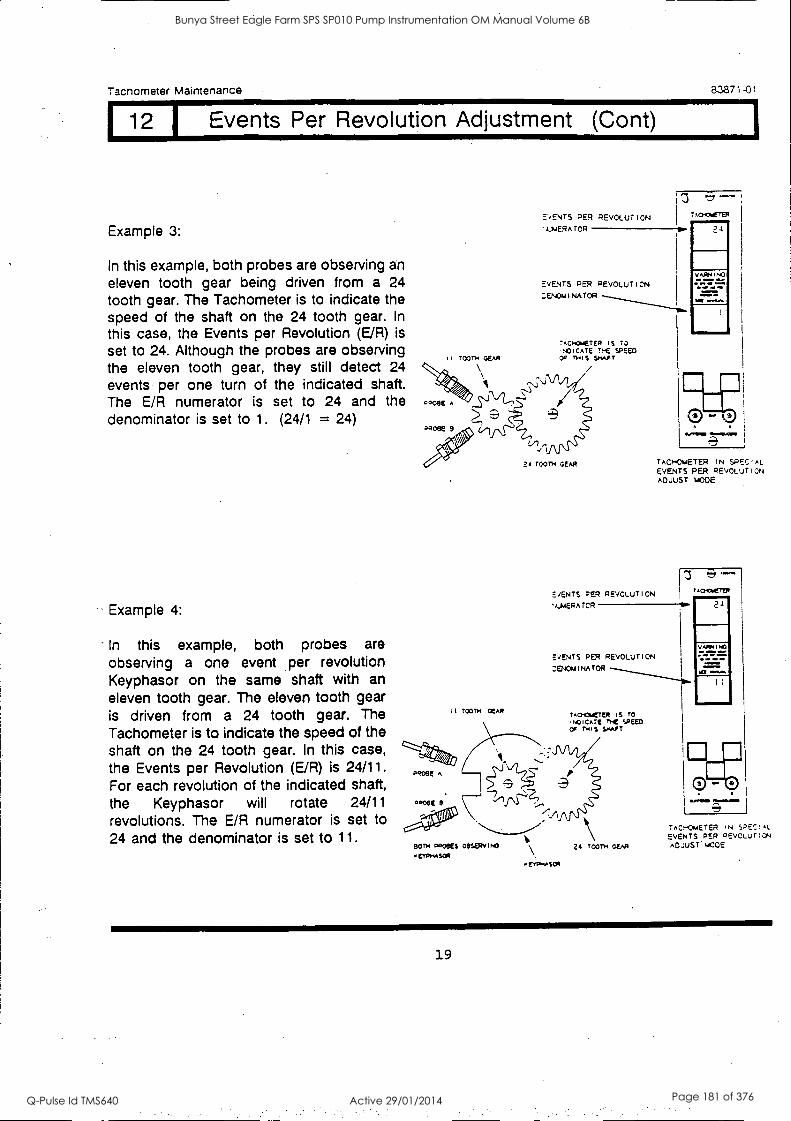
Tachometer Maintenance 8.3871-01
12 I Events Per Revolution Adjustment (Cont)
Example 3:
In this example, both probes are observing an eleven tooth gear being driven from a 24 tooth gear. The Tachometer is to indicate the speed of the shaft on the 24 tooth gear. In
this case, the Events per Revolution (E/R) is
set to 24. Although the probes are observing the eleven tooth gear, they still detect 24 events per one turn of the indicated shaft. The E/R numerator is set to 24 and the denominator is set to 1. (24/1 = 24)
Example 4:
In this example, both probes are observing a one event per revolution Keyphasor on the same shaft with an eleven tooth gear. The eleven tooth gear is driven from a 24 tooth gear. The Tachometer is to indicate the speed of the shaft on the 24 tooth gear. In this case, the Events per Revolution (E/R) is 24/11. For each revolution of the indicated shaft, the Keyphasor will rotate 24/11 revolutions. The E/R numerator is set to 24 and the denominator is set to 11.
E'BENTS PER REVOLUTION
'kuERAT0R-
EVENTS PER PEvOLuTIDN
:ENOmINAT0R
II TOOTH GEAR
i :3 w.
T.0.04-T94
OW 444..
0.0.11111M MINOAN,
TAomOmETER IN SPECIAL EVENTS PER PEVOLuTioN ADJUST WOE
1 3.M TAcHcmETER
E/ENTS PER REVOLUTION
'4.44ERATOR O.
EVENTS PER REVOLUTION
:ENOMINATOR
TACHOMETER IS TO
,NOICATE rHE SPEED. OF THIS SMART
Pqoee
PPOOE 8
E
80TH PRO8ES OBSERVING
erPHAsca
2 r0011.4 GEAR
orrO.ASCO
23
vApml.o
111.0.01M
TAOHOmETER IN SPECIAL
EVENTS PER ?EVOLUTION ADJuSr.w0E
19
Bunya Street Eagle Farm SPS SP010 Pump Instrumentation OM Manual Volume 6B
Q-Pulse Id TMS640 Active 29/01/2014 Page 181 of 376
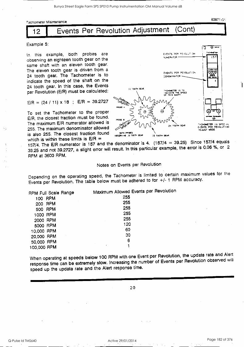
Tachometer Maintenance. 83871-01
12 Events Per Revolution Adjustment (Cont)
Example 5:
In this example, both probes are
observing an eighteen tooth gear on the
same shaft with an eleven tooth gear.
The eleven tooth gear is driven from a
24 tooth gear. The Tachometer is to
indicate the speed of the shaft on the
24 tooth gear. In this case, the Events
per Revolution (E/R) must be calculated:
E/R = (24 / 11) x 18 ; E/R = 39.2727
To set the Tachometer to the proper E/R, the closest fraction must be found.
The maximum E/R numerator allowed is
255. The maximum denominator allowed
is also 255. The closest fraction found
which is within these limits is E/R = 157/4. The E/R numerator is 157 and the denominator is 4. (157/4 = 39.25) Since 157/4 equals
39.25 and not 39.2727, a slight error will result. In this particular example, the error is 0.06 %, or 2
RPM at 3600 RPM.
TOOTH GEAR
EVENTS 2ER 2EvOLN NumERATCR
EVENTS 2°_R PEVOLUT!CN
'3ENOMINATOR
rCHOwETER 'S TO INDICATE 1)-E SPEED OF THIS SHAFT
a.oeE A
x?DE1E
ROTH Poems OOSERvim3 le Toon.' GEAR
11\
le TOOTH
24 TOOTH DEAR
,0014111.
157
VAANINO
ow
MI masa
4
.1 7CH4ETER IN SPECIAL EvENTS PER REVOLUTION ADJUST MODE
Notes on Events per Revolution
Depending on the operating speed, the Tachometer is limited to certain
Events per Revolution. The table below must be adhered to for +/- 1 RPM
RPM Full Scale Range Maximum Allowed Events per Revolution
100 RPM 255
200 RPM 255
500 RPM 255
1000 RPM 255
2000 RPM 255
5000 RPM 120
10,000 RPM 60
20,000 RPM 30
50,000 RPM 6
100,000 RPM 1
maximum values for the accuracy.
When operating at speeds below 100 RPM with one Event per Revolution, the update rate and Alert
response time can be extremely slow. Increasing the number of Events per Revolution observed will
speed up the update rate and the Alert response time.
20
Bunya Street Eagle Farm SPS SP010 Pump Instrumentation OM Manual Volume 6B
Q-Pulse Id TMS640 Active 29/01/2014 Page 182 of 376
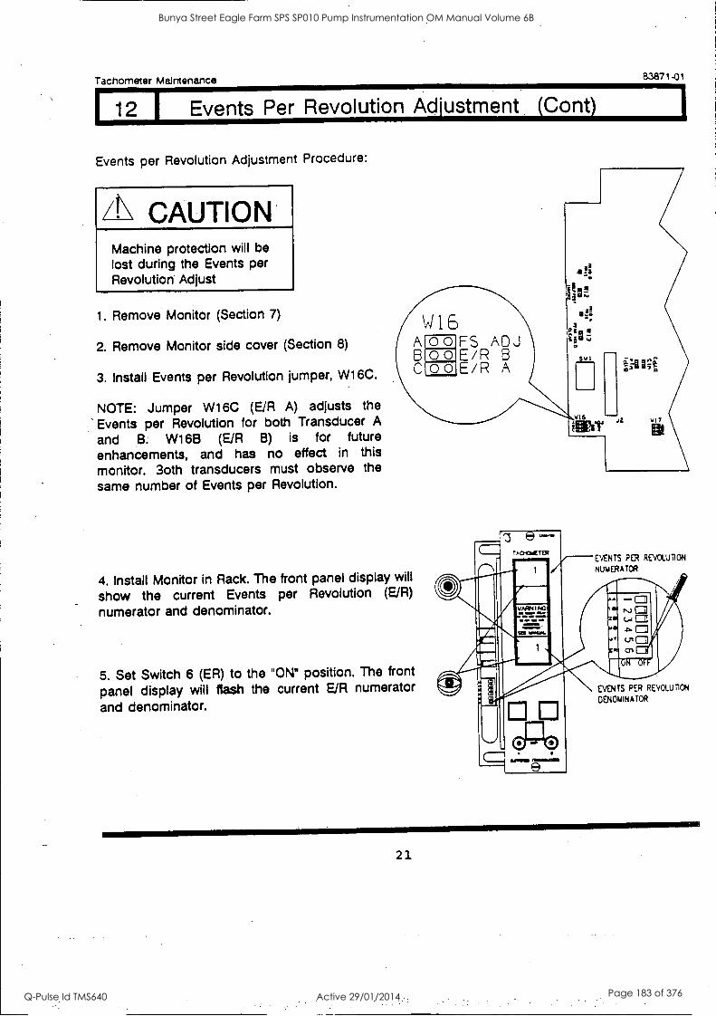
Tachometer Maintenance 83871-01
1.12 Events Per Revolution Adjustment (Cont
Events per Revolution Adjustment Procedure:
CAUTION Machine protection will be lost during the Events per Revolution Adjust
1. Remove Monitor (Section 7)
2. Remove Monitor side cover (Section 8)
3. Install Events per Revolution jumper, W16C.
NOTE: Jumper W16C (E/R A) adjusts the Events per Revolution for both Transducer A
and B. W1613 (E/R B) is for future enhancements, and has no effect in this monitor. 3oth transducers must observe the same number of Events per Revolution.
FS ADJ E/R B E/R A
4. Install Monitor in Rack. The front panel display will
show the current Events per Revolution (E/R)
numerator and denominator.
5. Set Switch 6 (ER) to the "ON' position. The front
panel display will flash the current E/R numerator
and denominator.
TACKSIETER EVENTS PER REVOLUTION
1 NUMERATOR
1111.7.7.
:1111P EVENTS PER REVOLUTION
DENOMINATOR
21
Bunya Street Eagle Farm SPS SP010 Pump Instrumentation OM Manual Volume 6B
Q-Pulse Id TMS640 Active 29/01/2014 Page 183 of 376
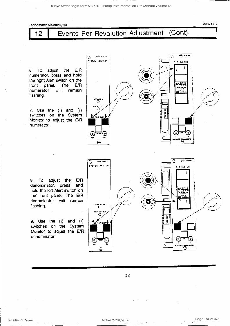
Tachometer Mairnenance
12 I Events Per Revolution Adjustment (Cont)
6. To adjust the E/R numerator, press and hold the right Alert switch on the front panel. The E/R numerator will remain flashing.
7. Use the (r) and (t) switches on the System Monitor to adjust the E/R numerator.
8. To adjust the E/R denominator, press and hold the left Alert switch on the front panel. The E/R denominator will remain flashing.
9. Use the (t) and (1)
switches on the System Monitor to adjust the E/R denominator.
' :3 ""'"
SYS TEU 644:Ni TOR
I
e SOS
83871-01
IM.'
WARNING es =MO
OM .17 Mo.
INMININI
22
Bunya Street Eagle Farm SPS SP010 Pump Instrumentation OM Manual Volume 6B
Q-Pulse Id TMS640 Active 29/01/2014 Page 184 of 376
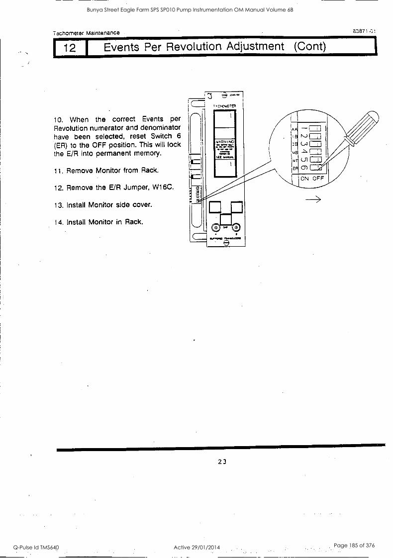
Tachometer Maintenance 838714.,
12 I Events Per Revolution Adjustment (Cont)
10. When the correct Events per Revolution numerator and denominator have been selected, reset Switch 6
(ER) to the OFF position. This will lock the E/R into permanent memory.
11. Remove Monitor from Rack.
12. Remove the E/R Jumper, W16C.
13. Install Monitor side cover.
14. Install Monitor in Rack.
= 3301110-111
YARNING
Nor wm.
mammas, =WWI
SEE KOCK
111116.
A - I. K.) FTI 2 (."I 1-71
LA
E. CD
ON OFF
23
Bunya Street Eagle Farm SPS SP010 Pump Instrumentation OM Manual Volume 6B
Q-Pulse Id TMS640 Active 29/01/2014 Page 185 of 376
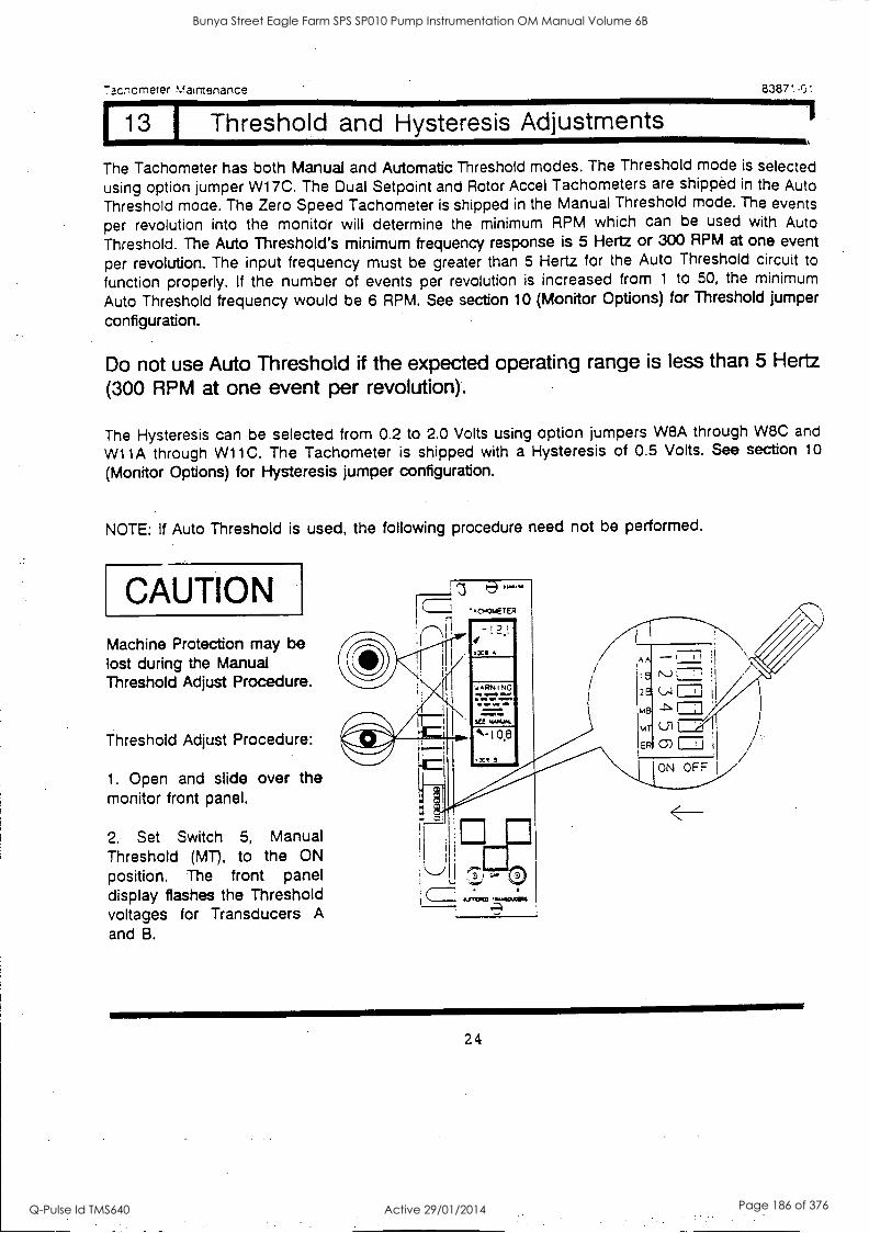
racticrneter Maienance
13 1 Threshold and Hysteresis Adjustments 8387!-0-.
1
The Tachometer has both Manual and Automatic Threshold modes. The Threshold mode is selected
using option jumper W17C. The Dual Setpoint and Rotor Accel Tachometers are shipped in the Auto Threshold mode. The Zero Speed Tachometer is shipped in the Manual Threshold mode. The events
per revolution into the monitor will determine the minimum RPM which can be used with Auto
Threshold. The Auto Threshold's minimum frequency response is 5 Hertz or 300 RPM at one event
per revolution. The input frequency must be greater than 5 Hertz for the Auto Threshold circuit to
function properly. If the number of events per revolution is increased from 1 to 50, the minimum
Auto Threshold frequency would be 6 RPM. See section 10 (Monitor Options) for Threshold jumper
configuration.
Do not use Auto Threshold if the expected operating range is less than 5 Hertz
(300 RPM at one event per revolution).
The Hysteresis can be selected from 0.2 to 2.0 Volts using option jumpers W8A through W8C and
W11 A through W11C. The Tachometer is shipped with a Hysteresis of 0.5 Volts. See section 10
(Monitor Options) for Hysteresis jumper configuration.
NOTE: If Auto Threshold is used, the following procedure need not be performed.
CAUTION Machine Protection may be lost during the Manual Threshold Adjust Procedure.
Threshold Adjust Procedure:
1. Open and slide over the monitor front panel.
2. Set Switch 5, Manual Threshold (MD, to the ON position. The front panel display flashes the Threshold voltages for Transducers A
and B.
24
Bunya Street Eagle Farm SPS SP010 Pump Instrumentation OM Manual Volume 6B
Q-Pulse Id TMS640 Active 29/01/2014 Page 186 of 376
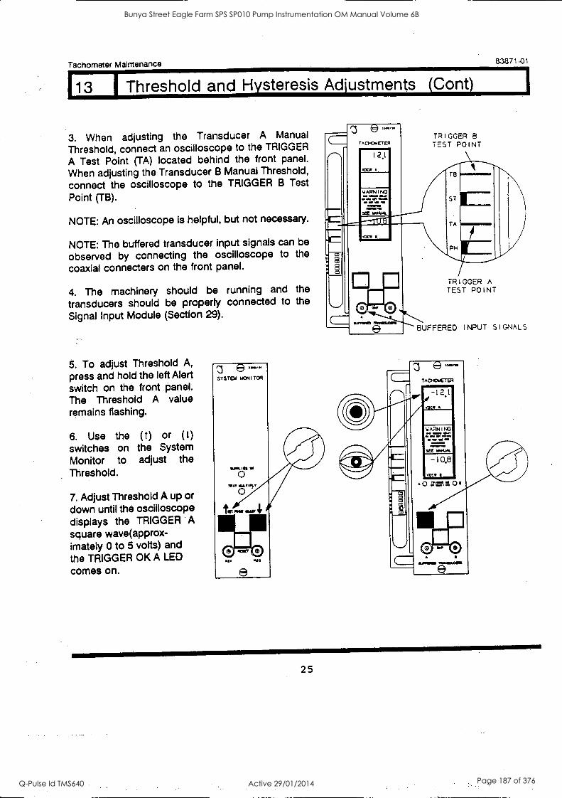
Tachometer Maintenance
13 J Threshold and Hysteresis Adjustments (Cant)
3. When adjusting the Transducer A Manual
Threshold, connect an oscilloscope to the TRIGGER
A Test Point (TA) located behind the front panel.
When adjusting the Transducer B Manual Threshold,
connect the oscilloscope to the TRIGGER B Test
Point (TB).
NOTE: An oscilloscope is helpful, but not necessary.
NOTE: The buffered transducer input signals can be
observed by connecting the oscilloscope to the
coaxial connecters on the front panel.
4. The machinery should be running and the
transducers should be properly connected to the
Signal Input Module (Section 29).
5. To adjust Threshold A,
press and hold the left Alert switch on the front panel. The Threshold A value remains flashing.
6. Use the (t) or (1)
switches on the System Monitor to adjust the Threshold.
7. Adjust Threshold A up or down until the oscilloscope displays the TRIGGER A square wave(approx- imately 0 to 5 volts) and the TRIGGER OK A LED
comes on.
'3 e TAO-OwETER
2_i
WARN I NO an gilia
1110 10 .011/11.11
83871-01
TRIGGER B TEST POINT
TA
PH
TRIGGER TEST POINT
e
0 0 SUFFERED INPUT SIGNALS
z 8- TAO-OL-TER
0 21."...11
111.1WWIW
25
Bunya Street Eagle Farm SPS SP010 Pump Instrumentation OM Manual Volume 6B
Q-Pulse Id TMS640 Active 29/01/2014 Page 187 of 376
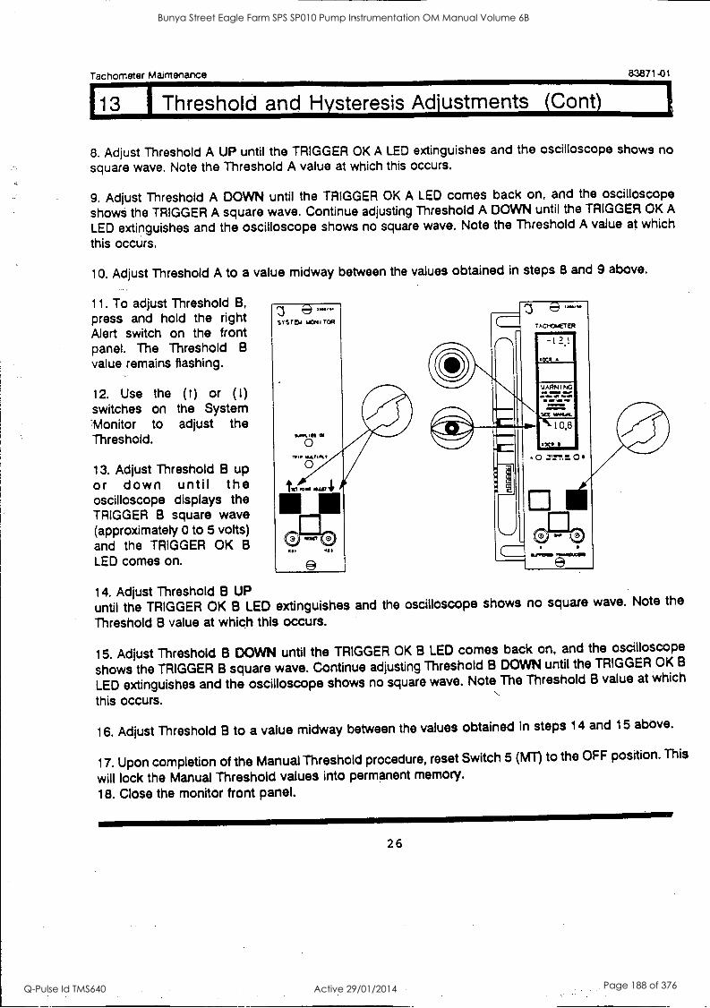
Tachometer Maintenance 83871-01
113 1 Threshold and Hysteresis Adjustments (Cont)
8. Adjust Threshold A UP until the TRIGGER OK A LED extinguishes square wave. Note the Threshold A value at which this occurs.
9. Adjust Threshold A DOWN until the TRIGGER OK A LED comes shows the TRIGGER A square wave. Continue adjusting Threshold A
LED extinguishes and the oscilloscope shows no square wave. Note this occurs.
and the oscilloscope shows no
back on, and the oscilloscope DOWN until the TRIGGER OK A the Threshold A value at which
10. Adjust Threshold A to a value midway between the values obtained in steps 8 and 9 above.
11. To adjust Threshold B,
press and hold the right Alert switch on the front panel. The Threshold B
value remains flashing.
12. Use the ( t) or (1)
switches on the System 'Monitor to adjust the Threshold.
13. Adjust Threshold B up or down until the oscilloscope displays the TRIGGER B square wave (approximately 0 to 5 volts) and the TRIGGER OK B
LED comes on.
14. Adjust Threshold B UP until the TRIGGER OK B LED extinguishes and the oscilloscope shows no square wave. Note the
Threshold B value at which this occurs.
15. Adjust Threshold B DOWN until the TRIGGER OK B LED comes back on, and the oscilloscope
shows the TRIGGER B square wave. Continue adjusting Threshold B DOWN until the TRIGGER OK B
LED extinguishes and the oscilloscope shows no square wave. Note The Threshold B value at which
this occurs.
16. Adjust Threshold B to a value midway between the values obtained in steps 14 and 15 above.
17. Upon completion of the Manual Threshold procedure, reset Switch 5 (MT) to the OFF position. This
will lock the Manual Threshold values into permanent memory.
18. Close the monitor front panel.
26
Bunya Street Eagle Farm SPS SP010 Pump Instrumentation OM Manual Volume 6B
Q-Pulse Id TMS640 Active 29/01/2014 Page 188 of 376
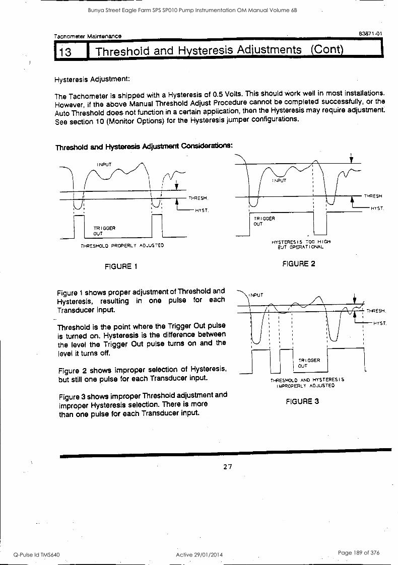
Tachometer Maintenance 83871-01
13 Threshold and H steresis Ad ustments Cont
Hysteresis Adjustment:
The Tachometer is shipped with a Hysteresis of 0.5 Volts. This should work well in most installations.
However, if the above Manual Threshold Adjust Procedure cannot be completed successfully, or the
Auto Threshold does not function in a certain application, then the Hysteresis may require adjustment.
See section 10 (Monitor Options) for the Hysteresis jumper configurations.
Threshold and Hysteresis Adjustment Considerations:
INPUT
TRIGGER OUT
/
THRESH. F HYST. THRESHOLD PROPERLY ADJUSTED
FIGURE 1
Figure 1 shows proper adjustment of Threshold and
Hysteresis, resulting in one pulse for each
Transducer input.
Threshold is the point where the Trigger Out pulse
is turned on. Hysteresis is the difference between
the level the Trigger Out pulse turns on and the
level it turns off.
Figure 2 shows improper selection of Hysteresis,
but still one pulse for each Transducer input.
Figure 3 shows improper Threshold adjustment and
improper Hysteresis selection. There is more
than one pulse for each Transducer input.
INPUT
TRIGGER OUT
THRESH.
HYSTERESIS TOO HIGH BUT OPERATIONAL
FIGURE 2
HYST.
TRIGGER OUT
THRESHOLD AND HYSTERESIS IMPROPERLY ADJUSTED
FIGURE 3
27
Bunya Street Eagle Farm SPS SP010 Pump Instrumentation OM Manual Volume 6B
Q-Pulse Id TMS640 Active 29/01/2014 Page 189 of 376
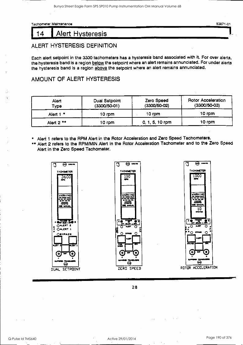
Tachometer Maintenance
1 14 1 Alert Hysteresis
83871-01
ALERT HYSTERESIS DEFINITION
Each alert setpoint in the 3300 tachometers has a hysteresis band associated with it. For over alerts, the hysteresis band is a region below the setpoint where an alert remains annunciated. For under alerts the hysteresis band is a region above the setpoint where an alert remains annunciated.
AMOUNT OF ALERT HYSTERESIS
Alert Dual Setpoint Zero Speed Rotor Acceleration Type (3300/50-01) (3300/50-02) (3300/50-03)
Alert 1 * 10 rpm 10 rpm 10 rpm
Alert 2 ** 10 rpm 0, 1, 5, 10 rpm 10 rpm
* Alert 1 refers to the RPM Alert in the Rotor Acceleration and Zero Speed Tachometers. ** Alert 2 refers to the RPM/MIN Alert in the Rotor Acceleration Tachometer and to the Zero Speed
Alert in the Zero Speed Tachometer.
DUAL SETPOINT ZERO SPEED ROTOR ACCELERATION
28
Bunya Street Eagle Farm SPS SP010 Pump Instrumentation OM Manual Volume 6B
Q-Pulse Id TMS640 Active 29/01/2014 Page 190 of 376
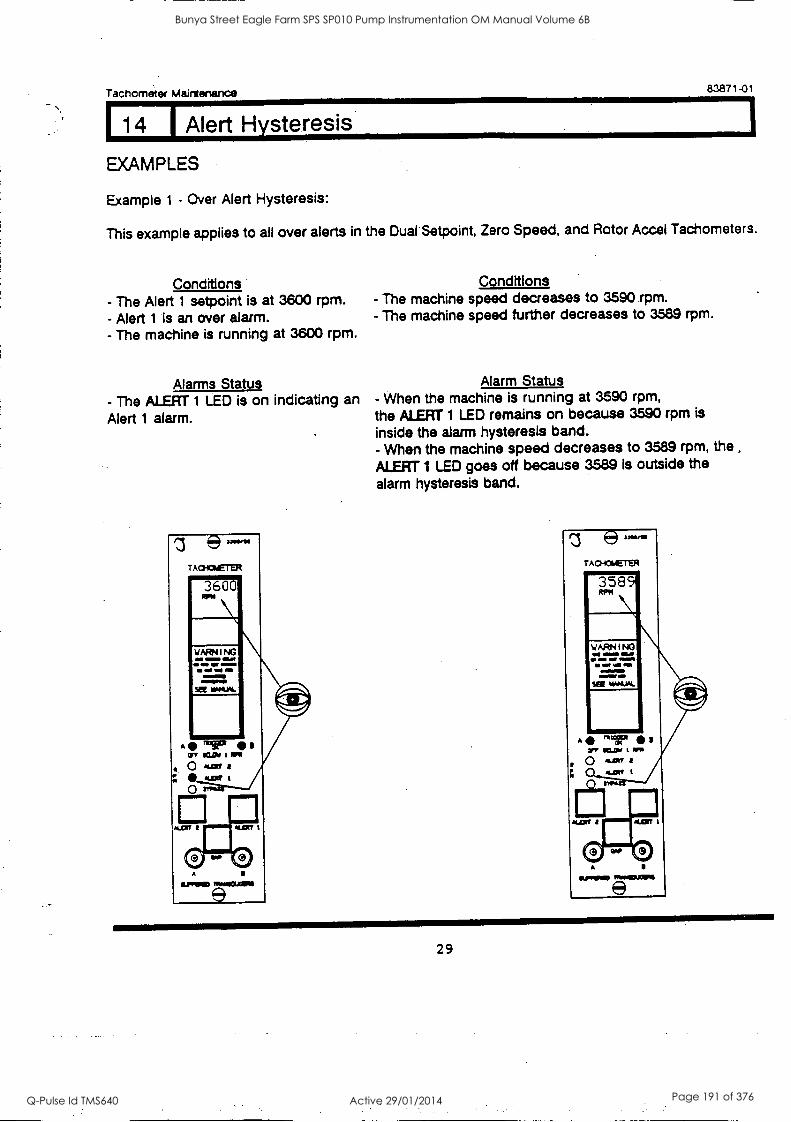
114 1 Alert Hysteresis
Tachometer Maintenance 83871-01
EXAMPLES
Example 1 - Over Alert Hysteresis:
This example applies to all over alerts in the Dual Setpoint, Zero Speed, and Rotor Accel Tachometers.
Conditions - The Alert 1 setpoint is at 3600 rpm. - Alert 1 is an over alarm. - The machine is running at 3600 rpm.
Alarms Status - The ALERT 1 LED is on indicating an Alert 1 alarm.
(e) pawls
A0101ETER
PRP=
Conditions - The machine speed decreases to 3590 rpm. - The machine speed further decreases to 3589 rpm.
Alarm Status - When the machine is running at 3590 rpm, the ALERT 1 LED remains on because 3590 rpm is
inside the alarm hysteresis band. - When the machine speed decreases to 3589 rpm, the
ALERT 1 LED goes off because 3589 is outside the alarm hysteresis band.
AO404E7ER
A
e
29
Bunya Street Eagle Farm SPS SP010 Pump Instrumentation OM Manual Volume 6B
Q-Pulse Id TMS640 Active 29/01/2014 Page 191 of 376
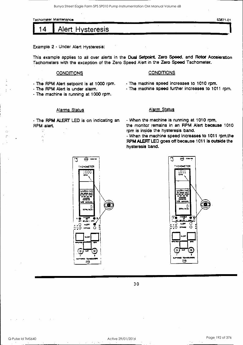
Tachometer Maintenance 83871-01
14 I Alert Hysteresis
Example 2 - Under Alert Hysteresis:
This example applies to all over alerts in the Dual Setpoint, Zero Speed, and Rotor Acceleration Tachometers with the exception of the Zero Speed Alert in the Zero Speed Tachometer.
CONDITIONS CONDITIONS
- The RPM Alert setpoint is at 1000 rpm. - The RPM Alert is under alarm. - The machine is running at 1000 rpm.
Alarms Status
- The RPM ALERT LED is on indicating an RPM 'alert.
- The machine speed increases to 1010 rpm. - The machine speed further increases to 1011 rpm.
Alarm Status
- When the machine is running at 1010 rpm, the monitor remains in an RPM Alert because 1010 rpm is inside the hysteresis band. - When the machine speed increases to 1011 rpm,the RPM ALERT LED goes off because 1011 is outside the hysteresis band.
30
Bunya Street Eagle Farm SPS SP010 Pump Instrumentation OM Manual Volume 6B
Q-Pulse Id TMS640 Active 29/01/2014 Page 192 of 376
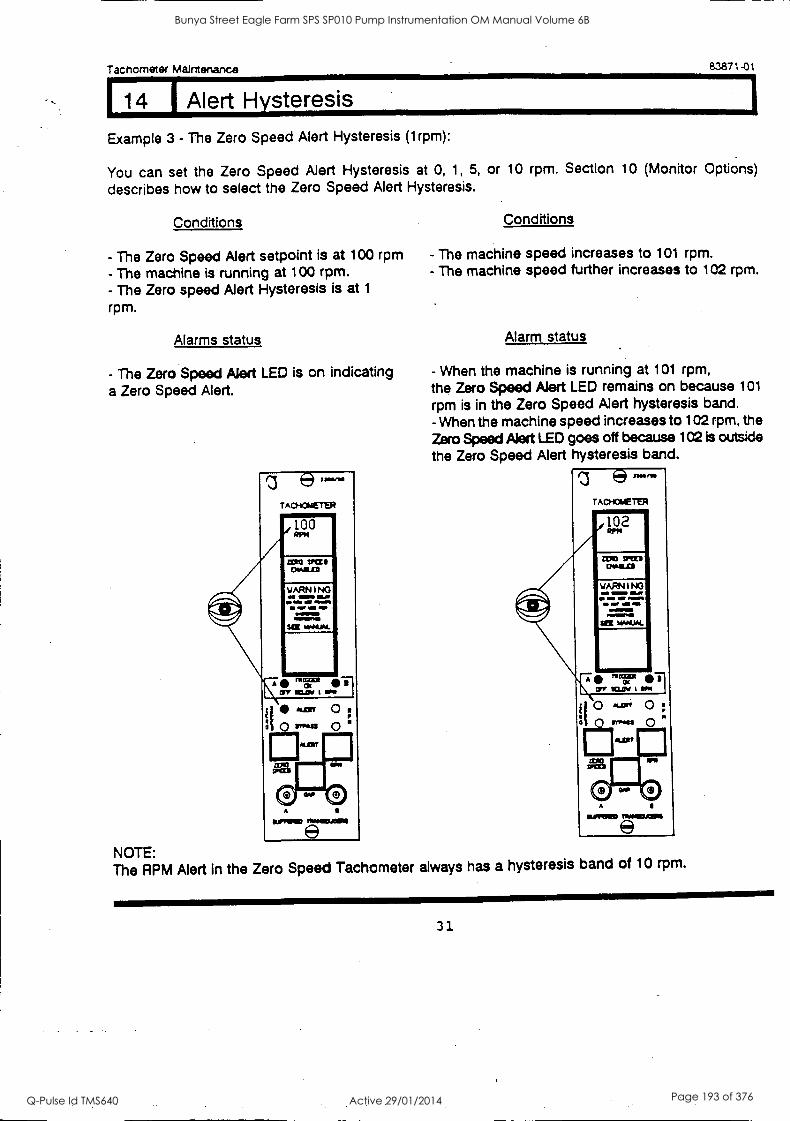
Tachometer Maintenance 83871-01
14 I Alert Hysteresis
Example 3 - The Zero Speed Alert Hysteresis (1rpm):
You can set the Zero Speed Alert Hysteresis at 0, 1, 5, or 10 rpm. Section 10 (Monitor Options)
describes how to select the Zero Speed Alert Hysteresis.
Conditions
- The Zero Speed Alert setpoint is at 100 rpm - The machine is running at 100 rpm. - The Zero speed Alert Hysteresis is at 1
rpm.
Alarms status
- The Zero Speed Alert LED is on indicating a Zero Speed Alert.
e- TACHOMETER
100 RPM
LON TPCL I OWILLZI
WARNING as =MO ELM
WM WI ODOM% Maw ONNIMMID MM..=
SEE MAMMA.
ur
Conditions
- The machine speed increases to 101 rpm. - The machine speed further increases to 102 rpm.
Alarm status
- When the machine is running at 101 rpm, the Zero Speed Alert LED remains on because 101
rpm is in the Zero Speed Alert hysteresis band. - When the machine speed increases to 102 rpm, the Zero Speed Alert LED goes off because 102 is outside
the Zero Speed Alert hysteresis band.
TAGS OLETO1
11002
ITIZI MM US
WARNINO a s as. asss sEE hANUAL
an car i Ia
NOTE: The RPM Alert in the Zero Speed Tachometer always has a hysteresis band of 10 rpm.
31
Bunya Street Eagle Farm SPS SP010 Pump Instrumentation OM Manual Volume 6B
Q-Pulse Id TMS640 Active 29/01/2014 Page 193 of 376
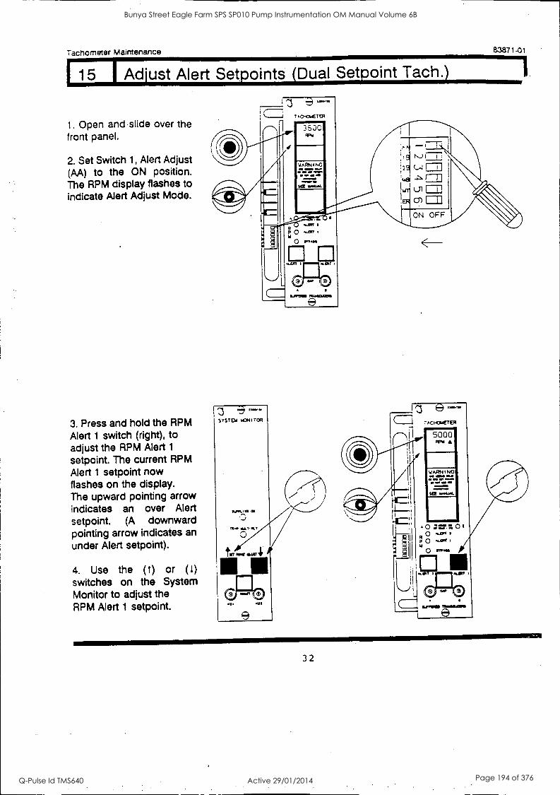
Tachometer Maintenance 83871-01
I 15 I Adjust Alert Setpoints (Dual Setpoint Tach.)
1. Open and slide over the front panel.
2. Set Switch 1, Alert Adjust (AA) to the ON position. The RPM display flashes to indicate Alert Adjust Mode.
3. Press and hold the RPM Alert 1 switch (right), to adjust the RPM Alert 1
setpoint. The current RPM Alert 1 setpoint now flashes on the display. The upward pointing arrow indicates an over Alert setpoint. (A downward pointing arrow indicates an under Alert setpoint).
4. Use the (1) or (1)
switches on the System Monitor to adjust the RPM Alert 1 setpoint.
STSTD 6CN I TOR
../01..01 01
ALT10.1 0
t.. 1111
VI
9
DOM= MAMMON
e
5000 Apw
WARNING et
mu AN
SEE WINO&
32
Bunya Street Eagle Farm SPS SP010 Pump Instrumentation OM Manual Volume 6B
Q-Pulse Id TMS640 Active 29/01/2014 Page 194 of 376
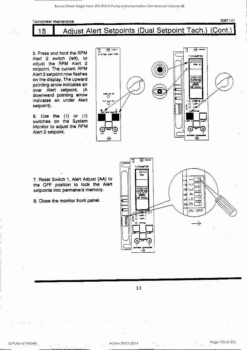
Tachometer Maintenance 83871 -01
15 Adjust Alert Setpoints (Dual Setpoint Tach.) (Cont.)
5. Press and hold the RPM Alert 2 switch (left), to adjust the RPM Alert 2 setpoint. The current RPM Alert 2 setpoint now flashes on the display. The upward pointing arrow indicates an over Alert setpoint. (A downward pointing arrow indicates an under Alert setpoint).
6. Use the ( t) or (1)
switches on the System Monitor to adjust the RPM Alert 2 setpoint.
20000 RPM
YARN I N G
7. Reset Switch 1, Alert Adjust (AA) to the OFF position to lock the Alert setpoints into permanent memory.
8. Close the monitor front panel.
"b810.41111
=m1
33
Bunya Street Eagle Farm SPS SP010 Pump Instrumentation OM Manual Volume 6B
Q-Pulse Id TMS640 Active 29/01/2014 Page 195 of 376
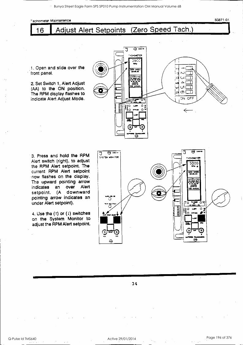
7achometer Maintenance 83871-01
1 16 1 Adjust Alert Setpoints (Zero Speed Tach.)
1. Open and slide over the front panel.
2. Set Switch 1, Alert Adjust (AA) to the ON position. The RPM display flashes to indicate Alert Adjust Mode.
3. Press and hold the RPM Alert switch (right), to adjust the RPM Alert setpoint. The current RPM Alert setpoint now flashes on the display. The upward pointing arrow indicates an over Alert setpoint. (A downward pointing arrow indicates an under Alert setpoint).
4. Use the (1) or (t) switches on the System Monitor to adjust the RPM Alert setpoint.
e 'AG-PETER
I I 36CC
rf ZERO %DUO
EWA ED
WARNING OM IN=P QUO
ON IV MOM
KC
0 --EPT 0 ; ° 0 .-44 0 6,
.IpT
e
34
Bunya Street Eagle Farm SPS SP010 Pump Instrumentation OM Manual Volume 6B
Q-Pulse Id TMS640 Active 29/01/2014 Page 196 of 376
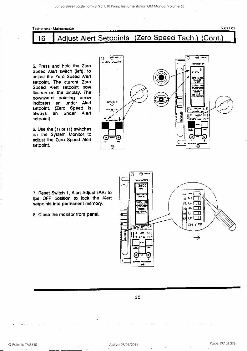
Tachometer Maintenance a3871-01
16 I Adjust Alert Setpoints (Zero Speed Tach.) (Cont.)
5. Press and hold the Zero Speed Alert switch (left), to adjust the Zero Speed Alert setpoint. The current Zero Speed Alert setpoint now flashes on the display. The downward pointing arrow indicates an under Alert setpoint. (Zero Speed is always an under Alert setpoint).
6. Use the (1) or (t) switches on the System Monitor to adjust the Zero Speed Alert setpoint.
QI *et
SYSTEM WONI TCR
7. Reset Switch 1, Alert Adjust (AA) to the OFF position to lock the Alert setpoints into permanent memory.
8. Close the monitor front panel.
rAcrGiCIIR
e
35
Bunya Street Eagle Farm SPS SP010 Pump Instrumentation OM Manual Volume 6B
Q-Pulse Id TMS640 Active 29/01/2014 Page 197 of 376
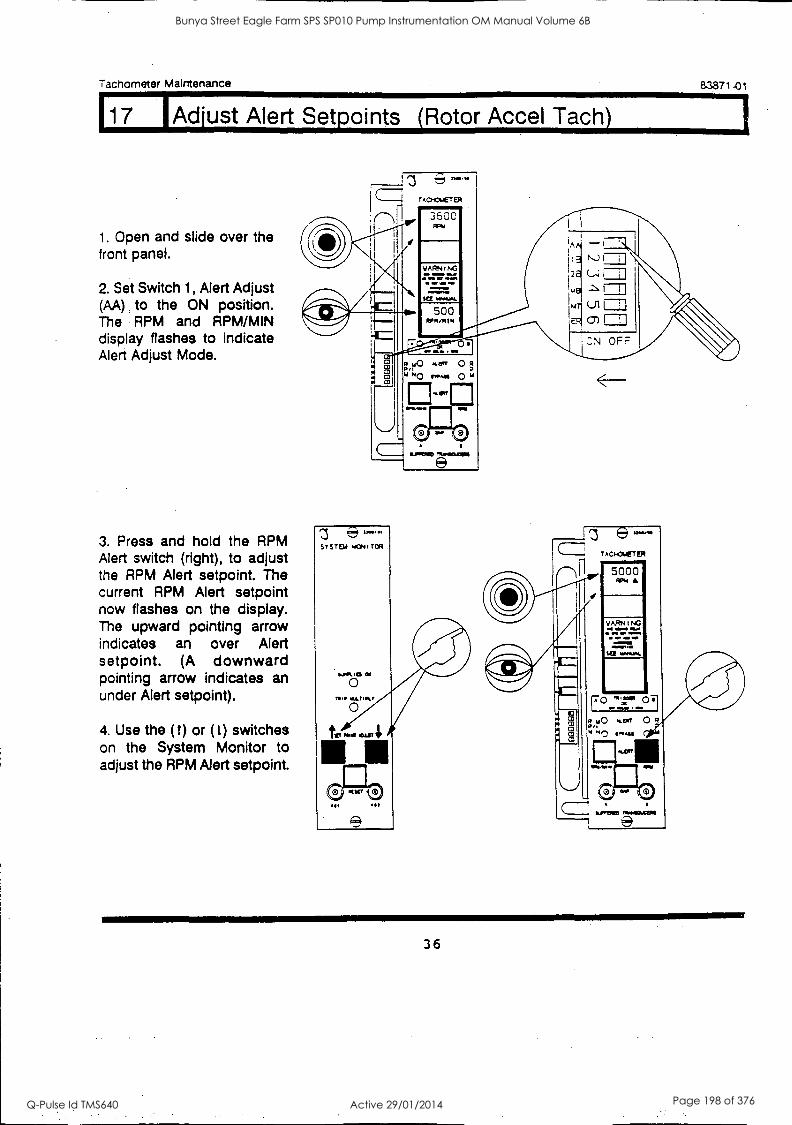
Tachometer Maintenance
117
83871-01
Adjust Alert Setpoints (Rotor Accel Tach)
1. Open and slide over the front panel.
2. Set Switch 1, Alert Adjust (M) to the ON position. The RPM and RPM/MIN display flashes to indicate Alert Adjust Mode.
3. Press and hold the RPM Alert switch (right), to adjust the RPM Alert setpoint. The current RPM Alert setpoint now flashes on the display. The upward pointing arrow indicates an over Alert setpoint. (A downward pointing arrow indicates an under Alert setpoint).
4. Use the ( t) or (1) switches on the System Monitor to adjust the RPM Alert setpoint.
TACIptT EA
3500 PPM
WARN I NC 1 a al,
11*MAI.
500 RN/MI
0 Ii C3
C13
SYSTEM M:P41 TOR
0 nip WV Ilk?
all 01
al0
140 Kee 0 /
'"40 r".41 M
KEW
(0 0 &MOM
A
2
N...) I
ON OFF
36
Bunya Street Eagle Farm SPS SP010 Pump Instrumentation OM Manual Volume 6B
Q-Pulse Id TMS640 Active 29/01/2014 Page 198 of 376
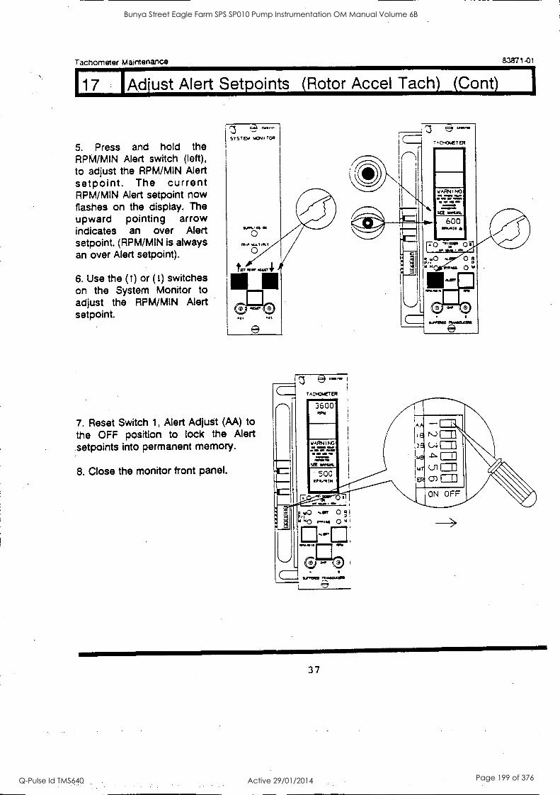
Tachometer Maintenance 83871-01
17 lAdjust Alert Setpoints (Rotor Accel Tach) (Cont)
5. Press and hold the RPM/MIN Alert switch (left), to adjust the RPM/MIN Alert setpoint. The current RPM/MIN Alert setpoint now flashes on the display. The upward pointing arrow indicates an over Alert setpoint. (RPM/MIN is always an over Alert setpoint).
6. Use the (1) or (1) switches on the System Monitor to adjust the RPM/MIN Alert setpoint.
600 Mall
7. Reset Switch 1, Alert Adjust (AA) to the OFF position to lock the Alert setpoints into permanent memory.
8. Close the monitor front panel.
37
Bunya Street Eagle Farm SPS SP010 Pump Instrumentation OM Manual Volume 6B
Q-Pulse Id TMS640 Active 29/01/2014 Page 199 of 376
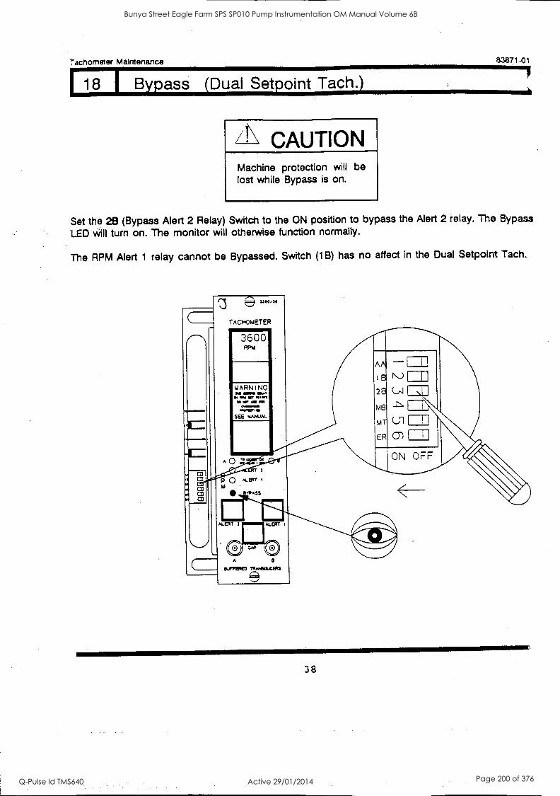
Tachometer Maintenance 83871-01
18 I Bypass (Dual Setpoint Tach.)
CAUTION Machine protection will be lost while Bypass is on.
Set the 28 (Bypass Alert 2 Relay) Switch to the ON position to bypass the Alert 2 relay. The Bypass
LED will turn on. The monitor will otherwise function normally.
The RPM Alert 1 relay cannot be Bypassed. Switch (1B) has no affect in the Dual Setpoint Tach.
38
Bunya Street Eagle Farm SPS SP010 Pump Instrumentation OM Manual Volume 6B
Q-Pulse Id TMS640 Active 29/01/2014 Page 200 of 376
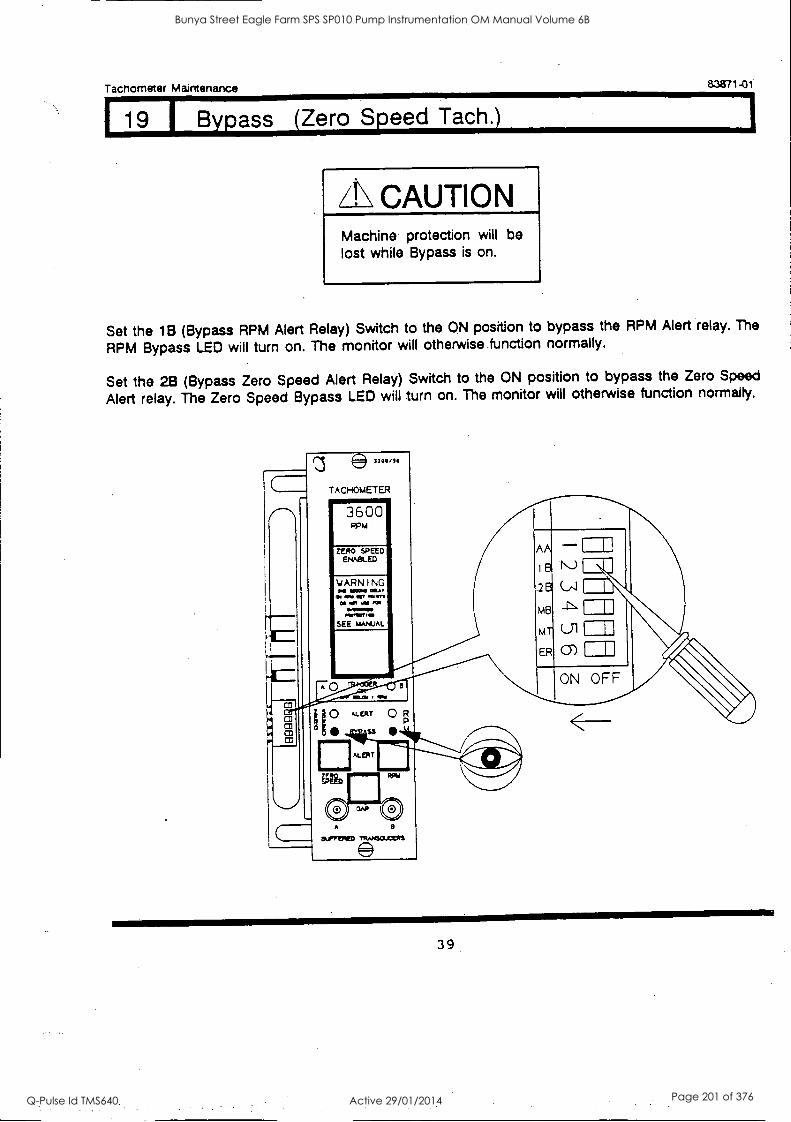
1
Tachometer Maintenance 83871-01
19 1 Bypass (Zero Speed Tachj
CAUTION Machine protection will be lost while Bypass is on.
Set the 1B (Bypass RPM Alert Relay) Switch to the ON position to bypass the RPM Alert relay. The
RPM Bypass LED will turn on. The monitor will otherwise function normally.
Set the 28 (Bypass Zero Speed Alert Relay) Switch to the ON position to bypass the Zero Speed
Alert relay. The Zero Speed Bypass LED will turn on. The monitor will otherwise function normally.
a.
CD
3300/10
TACHOMETER
3600 RPM
ZERO SPEED ENN3L ED
YARNING rionl MOO OIL.
04 OM err N., CO .0" W PM
owinaml mrlIsr
SEE MANUAL
0 May
0
a kLERT 0 R
ss
m.ERT
OLIFVIED
39
Bunya Street Eagle Farm SPS SP010 Pump Instrumentation OM Manual Volume 6B
Q-Pulse Id TMS640 Active 29/01/2014 Page 201 of 376
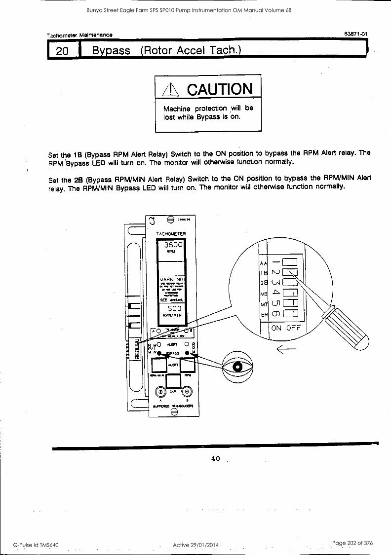
Tachometer Maintenance 83871-01
20 B ass Rotor Accel Tach.
/1\ CAUTION Machine protection ,will be lost while Bypass is on.
Set the 1B (Bypass RPM Alert Relay) Switch to the ON position to bypass the RPM Alert relay. The
RPM Bypass LED will turn on. The monitor will otherwise function normally.
Set the 2B (Bypass RPM/MIN Alert Relay) Switch to the ON position to bypass the RPM/MIN Alert
relay. The RPM/MIN Bypass LED will turn on. The monitor will otherwise function normally.
A
® 130111/S
TACHOOAETER
3600 RPM
SEE unst.IAL
500 RPM/MIN
1
le N-)( 28 C,JI
MT
ER 0)
ON OFF
P it *Len 0 R
N ASS
A 9
BLIFFEND
40
Bunya Street Eagle Farm SPS SP010 Pump Instrumentation OM Manual Volume 6B
Q-Pulse Id TMS640 Active 29/01/2014 Page 202 of 376
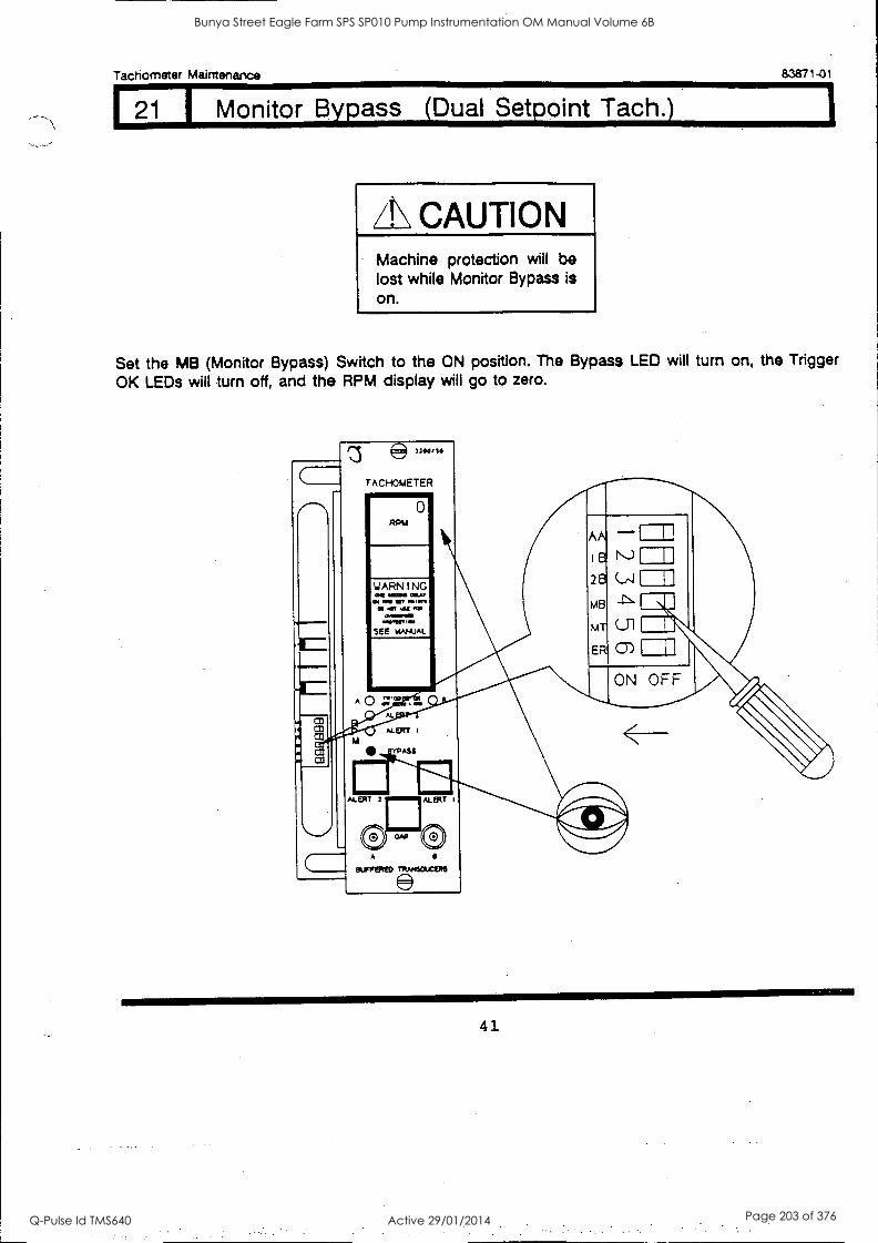
Tachometer Maintenance 83871-01
21 I Monitor Bypass (Dual Setpoint Tach.)
CAUTION Machine protection will be lost while Monitor Bypass is on.
Set the MB (Monitor Bypass) Switch to the ON position. The Bypass LED will turn on, the Trigger
OK LEDs will turn off, and the RPM display will go to zero.
es 3304/10
TACHOMETER
0
0111 1000 MY 01 11111 10 OM Ws
CO /01 W MI 0011110110
MORO it SEE MANUAL
AA -1 I
B
26 (_/,1
MB
MT
EN! Ulf
ON OFF A
O TV ICA
AL
ALERT I
ASS
ALE" ALERT t
0 SUFFERED
410
41
Bunya Street Eagle Farm SPS SP010 Pump Instrumentation OM Manual Volume 6B
Q-Pulse Id TMS640 Active 29/01/2014 Page 203 of 376
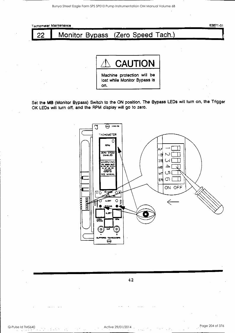
122 I Monitor Bypass (Zero Speed Tach.)
Tachometer Maintenance 83871-01
CAUTION Machine protection will be lost while Monitor Bypass is on.
Set the MB (Monitor Bypass) Switch to the ON position. The Bypass LEDs will turn on, the Trigger
OK LEDs will turn off, and the RPM display will go to zero.
z®»110,111
TACHOMETER
0
ZERO SPEED ENABLED
WARNING
AP
18
28
MB
MT
ER
Ul I 0)
ON OFF
ALERT
ELPTEIReD
42
Bunya Street Eagle Farm SPS SP010 Pump Instrumentation OM Manual Volume 6B
Q-Pulse Id TMS640 Active 29/01/2014 Page 204 of 376
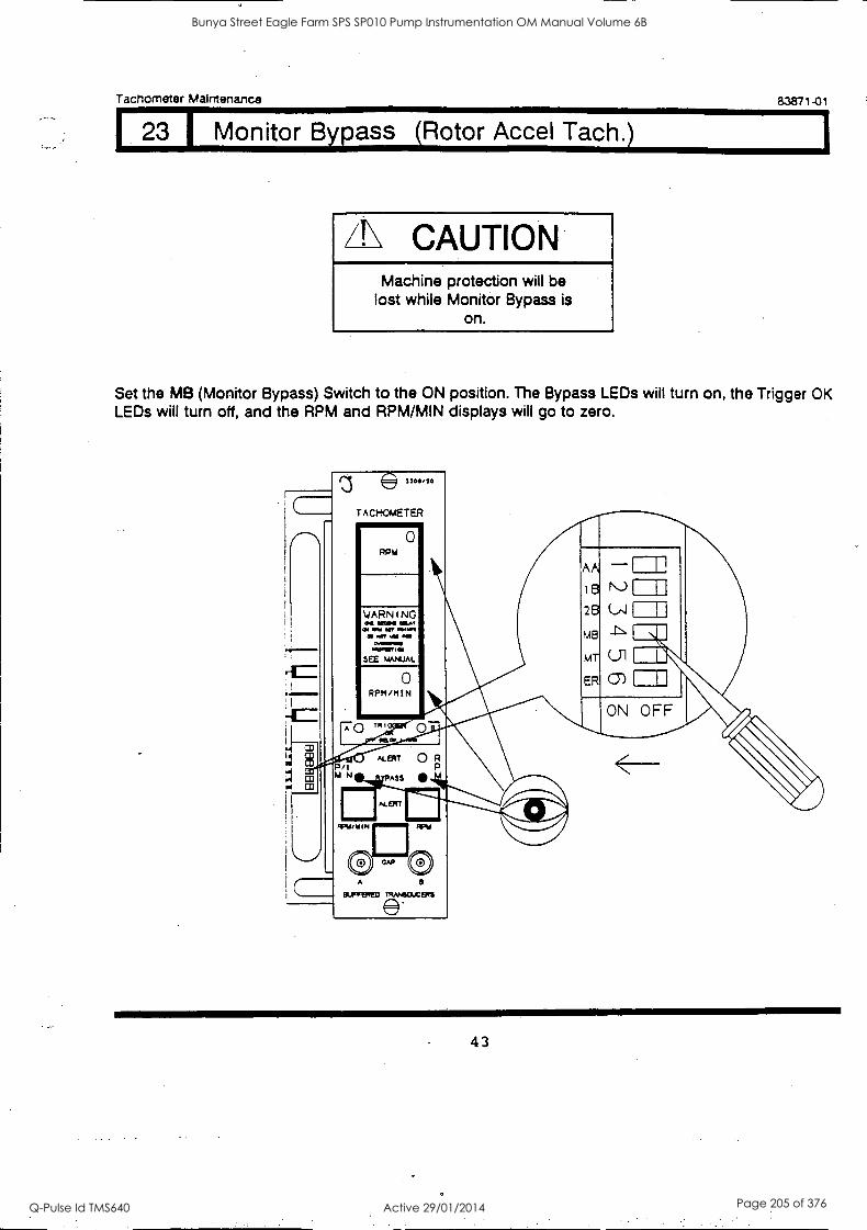
Tachometer Maintenance 83871 -01
23 I Monitor Bypass (Rotor Accel Tach.)
/I\ CAUTION Machine protection will be
lost while Monitor Bypass is on.
Set the MB (Monitor Bypass) Switch to the ON position. The Bypass LEDs will turn on, the Trigger OK LEDs will turn off, and the RPM and RPM/MIN displays will go to zero.
(Th
TACHOMETER Iiimmemmir
RPm
0
A
BUFFERED TRANSOXIMS
43
Bunya Street Eagle Farm SPS SP010 Pump Instrumentation OM Manual Volume 6B
Q-Pulse Id TMS640 Active 29/01/2014 Page 205 of 376
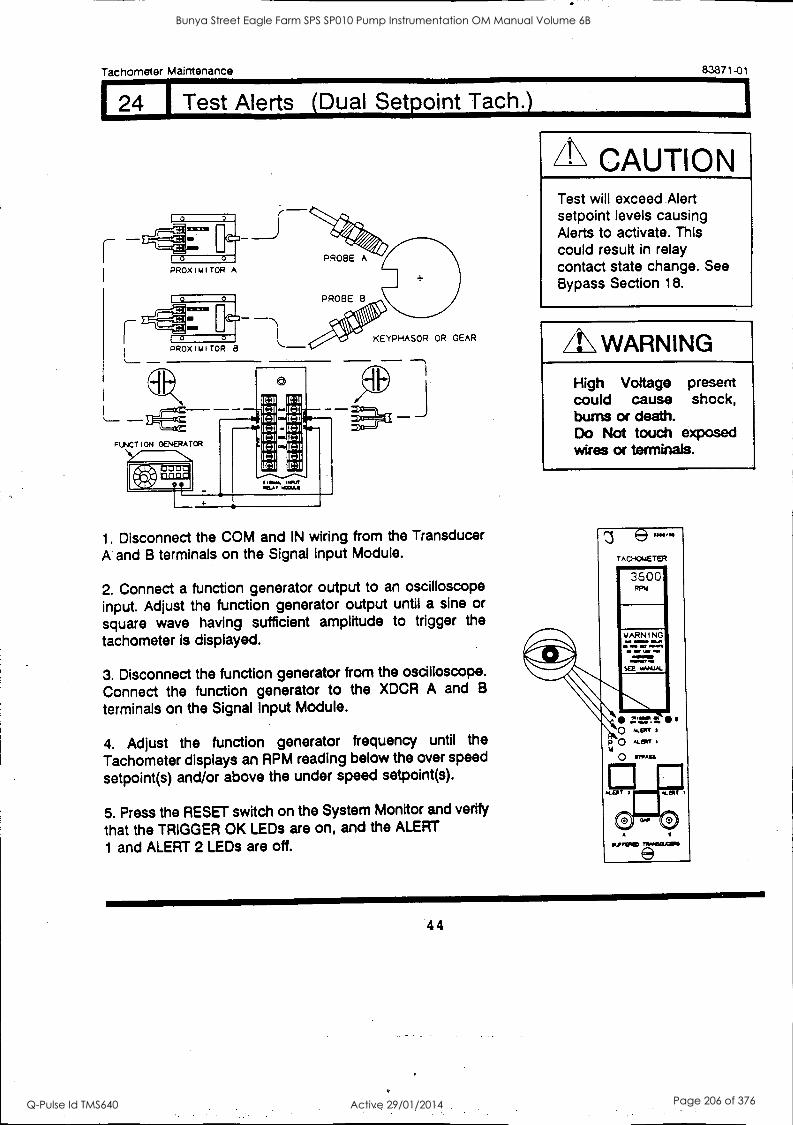
Tachometer Maintenance 83871-01
24 Alerts (Dual Setpoint Tach.)
PROXIMITCR A
pRoxlmiToR B
PROBE A
PROBE 8
KEYPHASOR OR GEAR
1. Disconnect the COM and IN wiring from the Transducer A and B terminals on the Signal Input Module.
2. Connect a function generator output to an oscilloscope input. Adjust the function generator output until a sine or
square wave having sufficient amplitude to trigger the
tachometer is displayed.
3. Disconnect the function generator from the oscilloscope. Connect the function generator to the XDCR A and B
terminals on the Signal Input Module.
4. Adjust the function generator frequency until the
Tachometer displays an RPM reading below the over speed
setpoint(s) and/or above the under speed setpoint(s).
5. Press the RESET switch on the System Monitor and verify
that the TRIGGER OK LEDs are on, and the ALERT
1 and ALERT 2 LEDs are off.
A\ CAUTION Test will exceed Alert setpoint levels causing Alerts to activate. This could result in relay contact state change. See Bypass Section 18.
/I\ WARNING
High Voltage present could cause shock, bums or death. Do Not touch exposed wires or terminals.
e rAcHomETER
3600
A
ILA,RFIE)
44
Bunya Street Eagle Farm SPS SP010 Pump Instrumentation OM Manual Volume 6B
Q-Pulse Id TMS640 Active 29/01/2014 Page 206 of 376
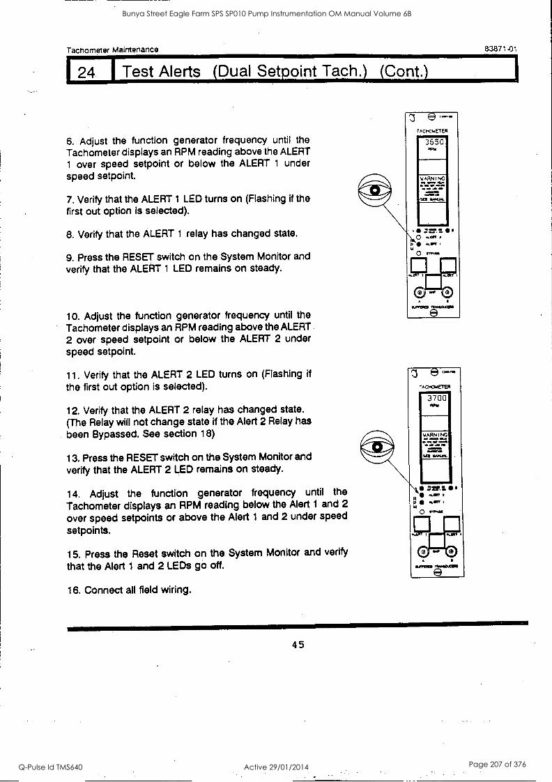
Tachometer Maintenance 83871-01
24 1 Test Alerts (Dual Setpoint Tach.) (Cont.)
6. Adjust the function generator frequency until the Tachometer displays an RPM reading above the ALERT 1 over speed setpoint or below the ALERT 1 under speed setpoint.
7. Verify that the ALERT 1 LED turns on (Flashing if the first out option is selected).
8. Verify that the ALERT 1 relay has changed state.
9. Press the RESET switch on the System Monitor and verify that the ALERT 1 LED remains on steady.
10. Adjust the function generator frequency until the Tachometer displays an RPM reading above the ALERT 2 over speed setpoint or below the ALERT 2 under speed setpoint.
11. Verify that the ALERT 2 LED turns on (Flashing if the first out option is selected).
12. Verify that the ALERT 2 relay has changed state. (The Relay will not change state if the Alert 2 Relay has been Bypassed. See section 18)
13. Press the RESET switch on the System Monitor and verify that the ALERT 2 LED remains on steady.
14. Adjust the function generator frequency until the
Tachometer displays an RPM reading below the Alert 1 and 2
over speed setpoints or above the Alert 1 and 2 under speed
setpoints.
15. Press the Reset switch on the System Monitor and verify
that the Alert 1 and 2 LEDs go off.
16. Connect all field wiring.
45
Bunya Street Eagle Farm SPS SP010 Pump Instrumentation OM Manual Volume 6B
Q-Pulse Id TMS640 Active 29/01/2014 Page 207 of 376
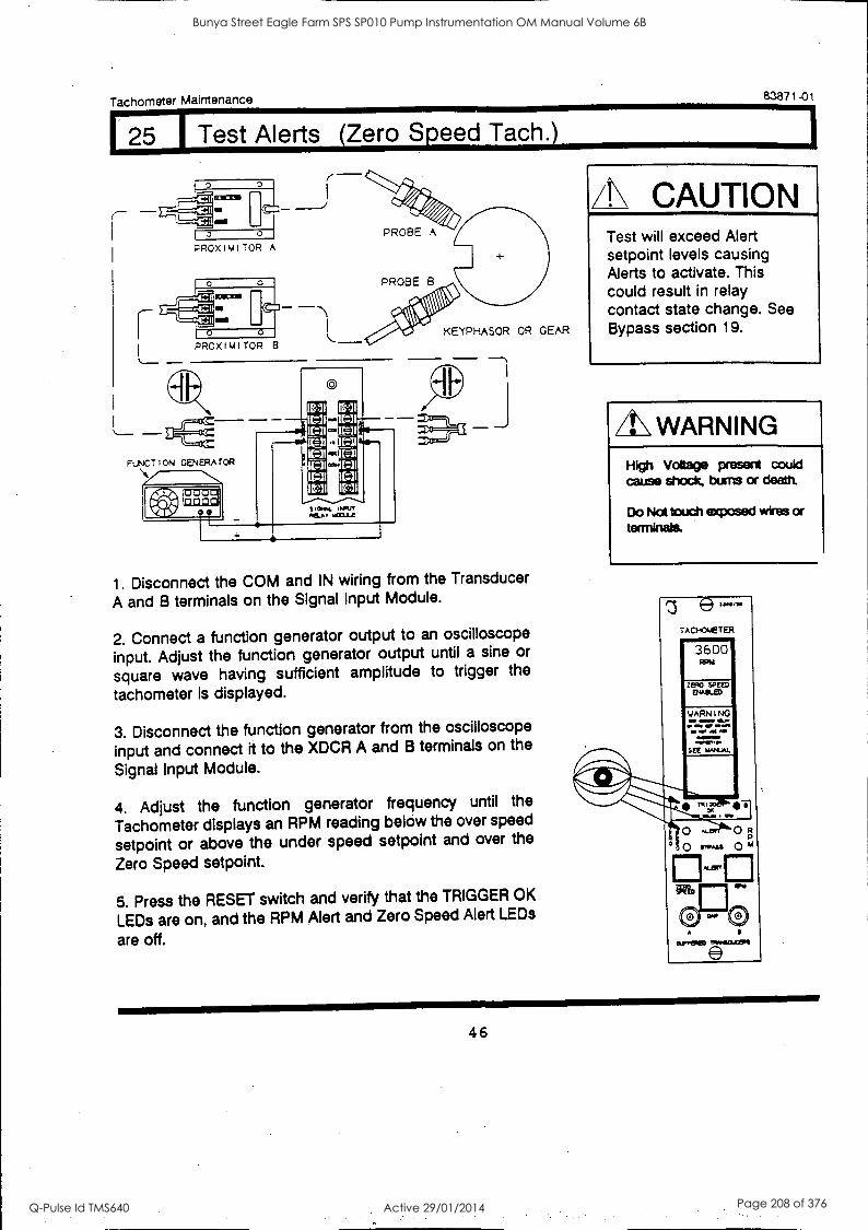
Tachometer Maintenance 83871-01
25 Test Alerts (Zero Speed Tach.)
0 0
PROX I M I TOR A
KEYPHASOR OR GEAR PROXIMITOR 8
FUNCT I ON GENERATOR
A.11.111 galfE
fitalkINMM
C
CNN. WA' .11LAv mat
1. Disconnect the COM and IN wiring from the Transducer
A and B terminals on the Signal Input Module.
2. Connect a function generator output to an oscilloscope
input. Adjust the function generator output until a sine or
square wave having sufficient amplitude to trigger the
tachometer is displayed.
3. Disconnect the function generator from the oscilloscope
input and connect it to the XDCR A and B terminals on the
Signal Input Module.
4. Adjust the function generator frequency until the
Tachometer displays an RPM reading below the over speed
setpoint or above the under speed setpoint and over the
Zero Speed setpoint.
5. Press the RESET switch and verify that the TRIGGER OK
LEDs are on, and the RPM Alert and Zero Speed Alert LEDs
are off.
A\ CAUTION Test will exceed Alert setpoint levels causing Alerts to activate. This could result in relay contact state change. See Bypass section 19.
/!WARNING High Voltage present could cause shock, bums or death.
Do Not touch exposed wires or terminals.
T A CHNET ER
WARNING
""
0
c.,
0 R
° 0 swags 0 m :ler
tUnTPIED
46
Bunya Street Eagle Farm SPS SP010 Pump Instrumentation OM Manual Volume 6B
Q-Pulse Id TMS640 Active 29/01/2014 Page 208 of 376
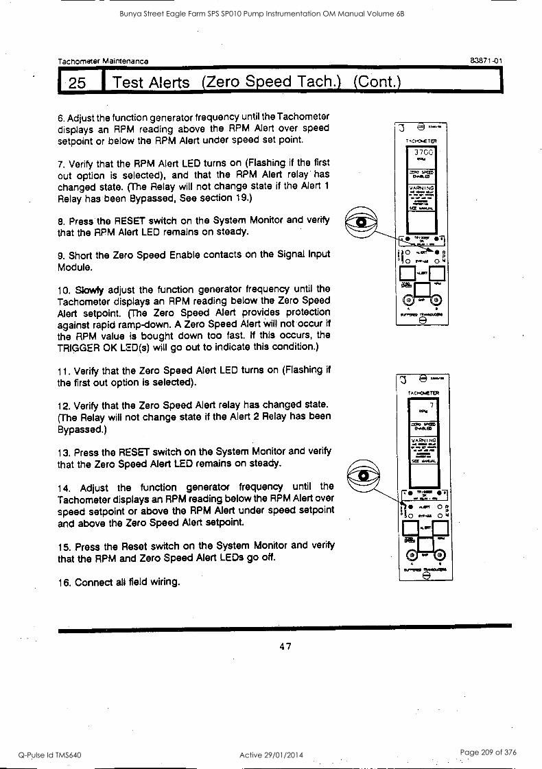
Tachometer Maintenance 83871 -01
1 25 I Test Alerts (Zero Speed Tach.) (Cont.)
6. Adjust the function generator frequency until the Tachometer displays an RPM reading above the RPM Alert over speed setpoint or below the RPM Alert under speed set point.
7. Verify that the RPM Alert LED turns on (Flashing if the first
out option is selected), and that the RPM Alert relay has changed state. (The Relay will not change state if the Alert 1
Relay has been Bypassed, See section 19.)
8. Press the RESET switch on the System Monitor and verify that the RPM Alert LED remains on steady.
9. Short the Zero Speed Enable contacts on the Signal Input Module.
10. Slowly adjust the function generator frequency until the Tachometer displays an RPM reading below the Zero Speed Alert setpoint. (The Zero Speed Alert provides protection against rapid ramp-down. A Zero Speed Alert will not occur if
the RPM value is bought down too fast. If this occurs, the TRIGGER OK LED(s) will go out to indicate this condition.)
11. Verify that the Zero Speed Alert LED turns on (Flashing if
the first out option is selected).
12. Verify that the Zero Speed Alert relay has changed state.
(The Relay will not change state if the Alert 2 Relay has been Bypassed.)
13. Press the RESET switch on the System Monitor and verify
that the Zero Speed Alert LED remains on steady.
14. Adjust the function generator frequency until the
Tachometer displays an RPM reading below the RPM Alert over
speed setpoint or above the RPM Alert under speed setpoint
and above the Zero Speed Alert setpoint.
15. Press the Reset switch on the System Monitor and verify
that the RPM and Zero Speed Alert LEDs go off.
16. Connect all field wiring.
3700
z e TAC'<WIER
7 ROW
rev sfteo 0.81.CD
MISINIMEN . 1111i, el 11
SW 4.11 I
t 0 R
0 "4' O id
0J,TPIED
47
Bunya Street Eagle Farm SPS SP010 Pump Instrumentation OM Manual Volume 6B
Q-Pulse Id TMS640 Active 29/01/2014 Page 209 of 376
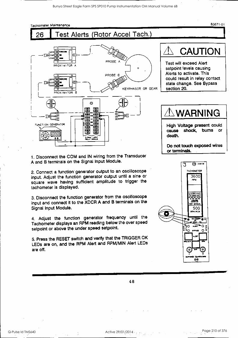
Tachometer Maintenance 83871-01
1 26 I Test Alerts (Rotor Accel Tach.)
PROximiToR A PROBE A
PROBE 8
#4*. KEYPHASOR OR GEAR
1. Disconnect the COM and IN wiring from the Transducer A and B terminals on the Signal Input Module.
2. Connect a function generator output to an oscilloscope input. Adjust the function generator output until a sine or
square wave having sufficient amplitude to trigger the
tachometer is displayed.
3. Disconnect the function generator from the oscilloscope
input and connect it to the XDCR A and B terminals on the
Signal Input Module.
4. Adjust the function generator frequency until the
Tachometer displays an RPM reading below the over speed
setpoint or above the under speed setpoint.
5. Press the RESET switch and verify that the TRIGGER OK
LEDs are on, and the RPM Alert and RPM/MIN Alert LEDs
are off.
/N CAUTION Test will exceed Alert setpoint levels causing Alerts to activate. This could result in relay contact state change. See Bypass section 20.
/1.\ WARNING High Voltage present could cause shock, bums or death.
Do not touch exposed wires or terminals.
t3 e- TACI-ENETER
3600 WW
500 RPM/MIN
*1%,
R MO ALEY---'7esT 0 R P/I
u ".41 0 4
48
Bunya Street Eagle Farm SPS SP010 Pump Instrumentation OM Manual Volume 6B
Q-Pulse Id TMS640 Active 29/01/2014 Page 210 of 376
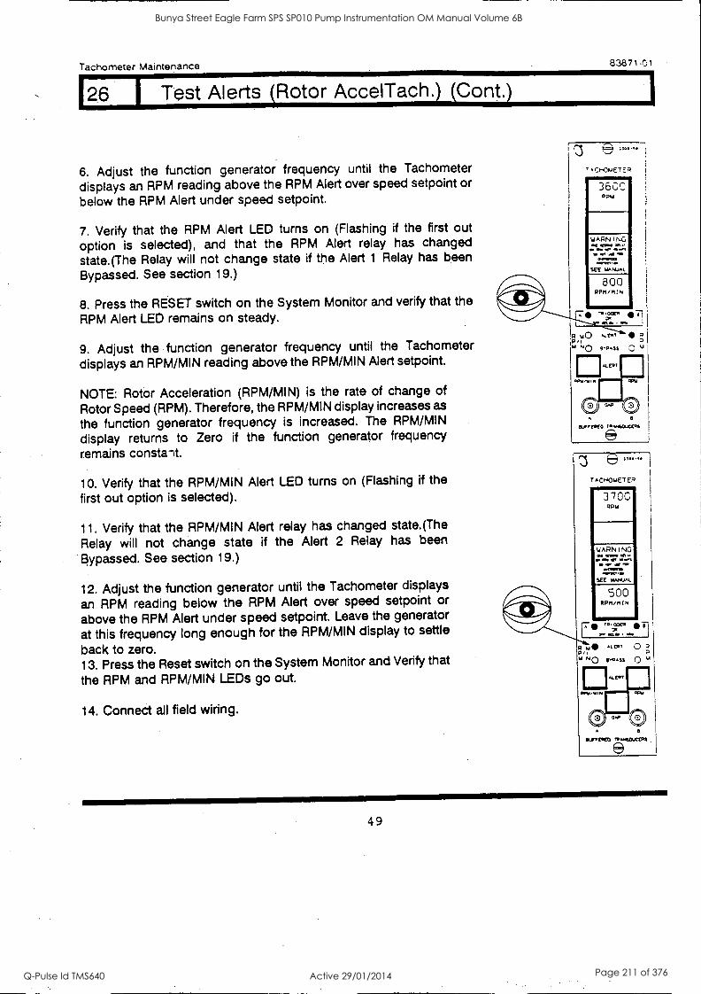
Tachometer Maintenance 83871.01
Test Alerts (Rotor AccelTach.) (Cont.)
6. Adjust the function generator frequency until the Tachometer
displays an RPM reading above the RPM Alert over speed setpoint or below the RPM Alert under speed setpoint.
7. Verify that the RPM Alert LED turns on (Flashing if the first out option is selected), and that the RPM Alert relay has changed state.(The Relay will not change state if the Alert 1 Relay has been
Bypassed. See section 19.)
8. Press the RESET switch on the System Monitor and verify that the RPM Alert LED remains on steady.
9. Adjust the function generator frequency until the Tachometer displays an RPM/MIN reading above the RPM/MIN Alert setpoint.
NOTE: Rotor Acceleration (RPM /MIN) is the rate of change of
Rotor Speed (RPM). Therefore, the RPM/MIN display increases as
the function generator frequency is increased. The RPM/MIN
display returns to Zero if the function generator frequency remains constalt.
10. Verify that the RPM/MIN Alert LED turns on (Flashing if the first out option is selected).
11. Verify that the RPM/MIN Alert relay has changed state.(The
Relay will not change state if the Alert 2 Relay has been
Bypassed. See section 19.)
12. Adjust the function generator until the Tachometer displays
an RPM reading below the RPM Alert over speed setpoint or
above the RPM Alert under speed setpoint. Leave the generator
at this frequency long enough for the RPM/MIN display to settle
back to zero. 13. Press the Reset switch on the System Monitor and Verify that
the RPM and RPM/MIN LEDs go out.
14. Connect all field wiring.
ftf.vmoto.4a4oft
3700 RPAI
WARNING WU.
ON
SEE uNLIAL
500 RPM/MCM
41111111
eurTemto ro50..CEIn
49
Bunya Street Eagle Farm SPS SP010 Pump Instrumentation OM Manual Volume 6B
Q-Pulse Id TMS640 Active 29/01/2014 Page 211 of 376
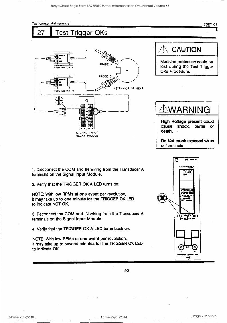
Tachometer Maintenance
127 1 Test Trigger OKs
83871 -01
1
zROXIMITOR A
0
5 I GNAL INPUT RELAY MODULE
KEYPHASOR OR GEAR
7
1. Disconnect the COM and IN wiring from the Transducer A terminals on the Signal Input Module.
2. Verify that the TRIGGER OK A LED turns off.
NOTE: With low RPMs at one event per revolution, it may take up to one minute for the TRIGGER OK LED
to indicate NOT OK
3. Reconnect the COM and IN wiring from the Transducer A terminals on the Signal Input Module.
4. Verify that the TRIGGER OK A LED turns back on.
NOTE: With low RPMs at one event per revolution, it may take up to several minutes for the TRIGGER OK LED
to indicate OK
CAUTION
Machine protection could be lost during the Test Trigger OKs Procedure.
ZLWARNING High Voltage present could cause shock, bums or death.
Do Not touch exposed wires or terrnirals
z e TAcHOmETER
3600
El El
50
Bunya Street Eagle Farm SPS SP010 Pump Instrumentation OM Manual Volume 6B
Q-Pulse Id TMS640 Active 29/01/2014 Page 212 of 376
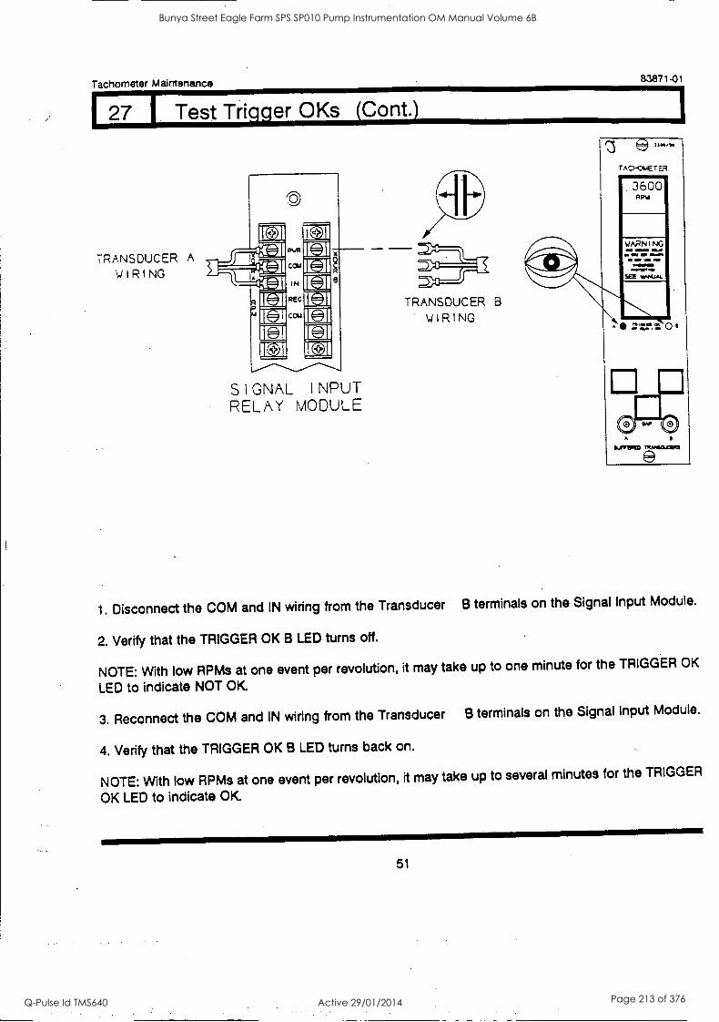
Tachometer Maintenance 83871-01
27 Trigger OKs (Cont.)
TRANSDUCER A
WIRING
ie
CD
SIGNAL INPUT RELAY MODULE
TRANSDUCER B
WIRING
z A C7-401.4E T ER
360G Apia
TIRM401J2130
1. Disconnect the COM and IN wiring from the Transducer B terminals on the Signal Input Module.
2. Verify that the TRIGGER OK B LED turns off.
NOTE: With low RPMs at one event per revolution, it may take up to one minute for the TRIGGER OK
LED to indicate NOT OK
3. Reconnect the COM and IN wiring from the Transducer B terminals on the Signal Input Module.
4. Verify that the TRIGGER OK B LED turns back on.
NOTE: With low RPMs at one event per revolution, it may take up to several minutes for the TRIGGER
OK LED to indicate OK.
51
Bunya Street Eagle Farm SPS SP010 Pump Instrumentation OM Manual Volume 6B
Q-Pulse Id TMS640 Active 29/01/2014 Page 213 of 376
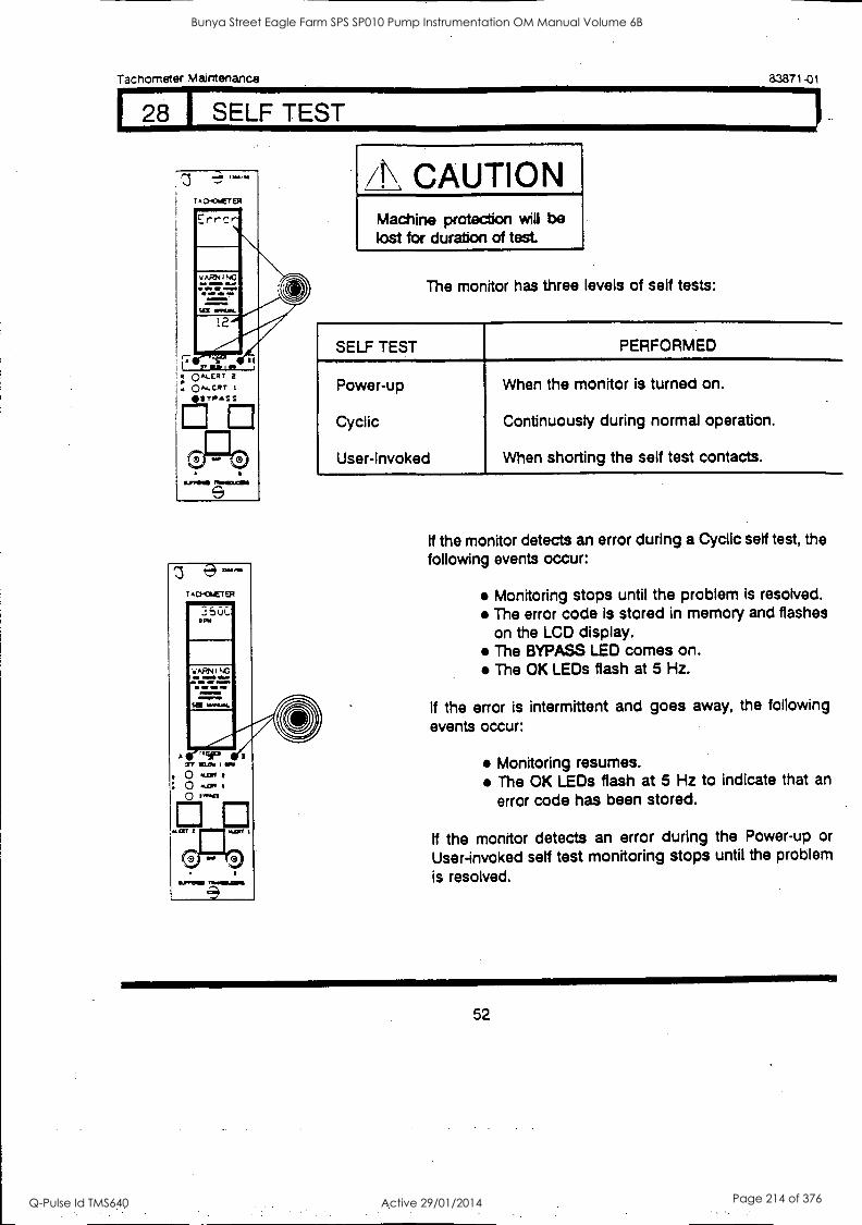
Tachometer Maintenance
9 -- T A crocr ER
`w!'!".,
ARN I NG
AM OM 11,11111 *WOE.
set WILIAL
83871-01
/1.\ CAUTION Machine protection will be lost for duration of test.
The monitor has three levels of self tests:
SELF TEST PERFORMED
Power-up
Cyclic
User-Invoked
When the monitor is turned on.
Continuously during normal operation.
When shorting the self test contacts.
SOMPUI
If the monitor detects an error during a Cyclic self test, the following events occur:
Monitoring stops until the problem is resolved. The error code is stored in memory and flashes on the LCD display. The BYPASS LED comes on. The OK LEDs flash at 5 Hz.
If the error is intermittent and goes away, the following events occur:
Monitoring resumes. The OK LEDs flash at 5 Hz to indicate that an
error code has been stored.
if the monitor detects an error during the Power-up or
User-invoked self test monitoring stops until the problem is resolved.
52
Bunya Street Eagle Farm SPS SP010 Pump Instrumentation OM Manual Volume 6B
Q-Pulse Id TMS640 Active 29/01/2014 Page 214 of 376
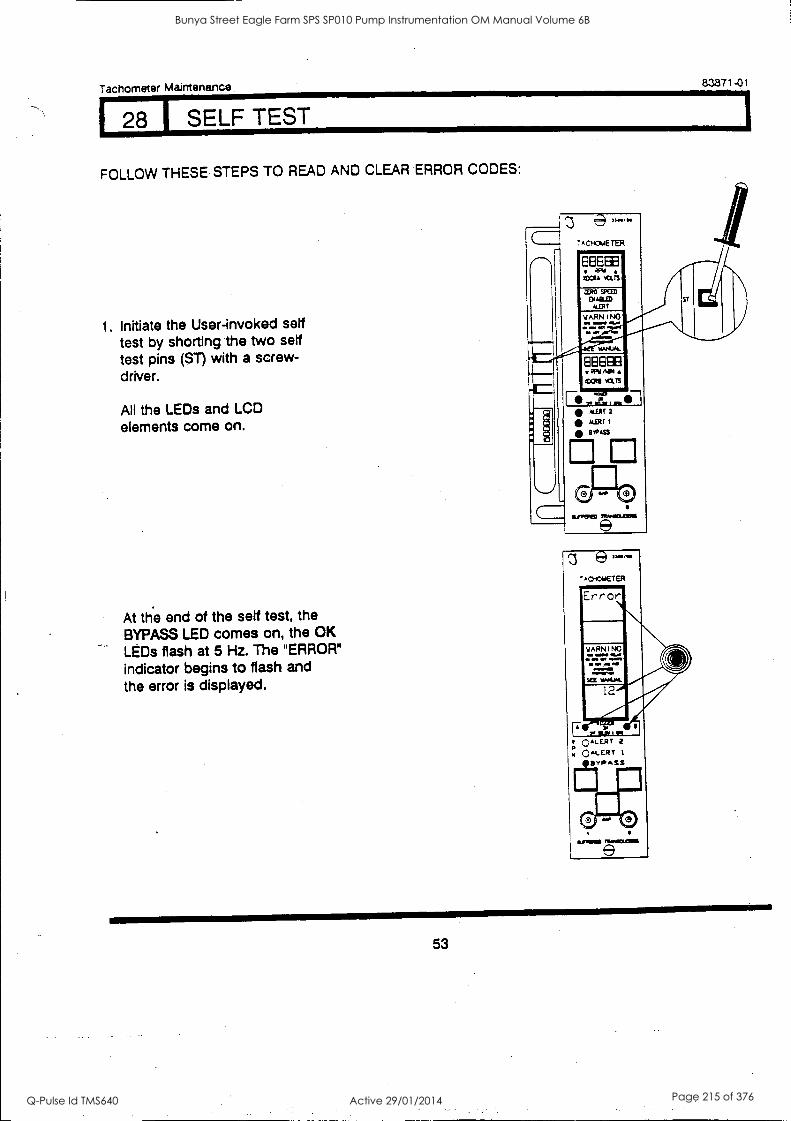
Tachometer Maintenance 83871-01
28 1 SELF TEST
FOLLOW THESE STEPS TO READ AND CLEAR ERROR CODES:
1. Initiate the User-invoked self test by shorting the two self test pins (ST) with a screw- driver.
All the LEDs and LCD elements come on.
At the end of the self test, the BYPASS LED comes on, the OK LEDs flash at 5 Hz. The "ERROR"
indicator begins to flash and the error is displayed.
s,-- -ACIOMETER
°ALERT 2
m 041-ERT IPIPSS
53
Bunya Street Eagle Farm SPS SP010 Pump Instrumentation OM Manual Volume 6B
Q-Pulse Id TMS640 Active 29/01/2014 Page 215 of 376
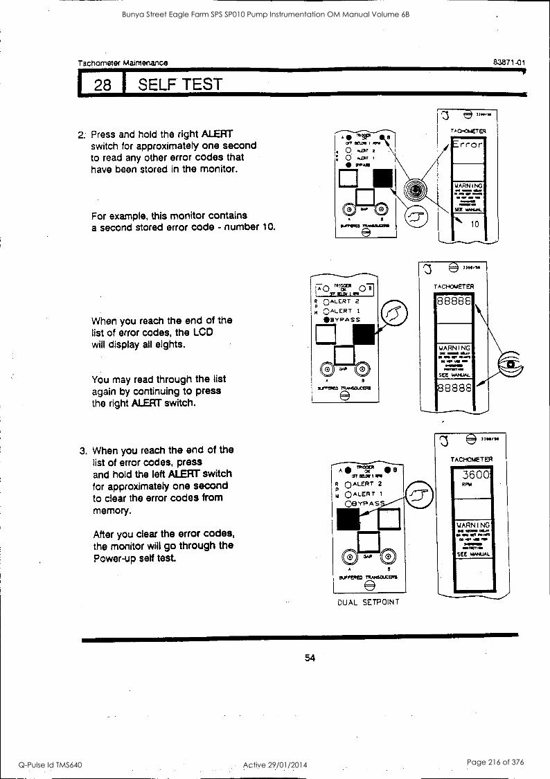
Tachometer Maintenance
128 I SELF TEST
83871-01
2. Press and hold the right ALERT switch for approximately one second to read any other error codes that have been stored in the monitor.
For example, this monitor contains a second stored error code - number 10.
When you reach the end of the list of error codes, the LCD will display all eights.
You may read through the list again by continuing to press the right ALERT switch.
3. When you reach the end of the list of error codes, press and hold the left ALERT switch for approximately one second to clear the error codes from memory.
After you clear the error codes, the monitor will go through the Power-up self test.
A 'or crr moo I mu
R 0 ALERT 2
°ALERT 1
03 VP A S
e3304/S0
TACHOMETER
88888
WARNING awn 4rt
et Off VW AM 0.4404111 monflorn
SEE WANUAL
8 8888
BUFFERED TRAMSDIXERS
DUAL SETPOINT
® 3304/54
TACHOMETER
3600 RPM
WARNING
Bunya Street Eagle Farm SPS SP010 Pump Instrumentation OM Manual Volume 6B
Q-Pulse Id TMS640 Active 29/01/2014 Page 216 of 376
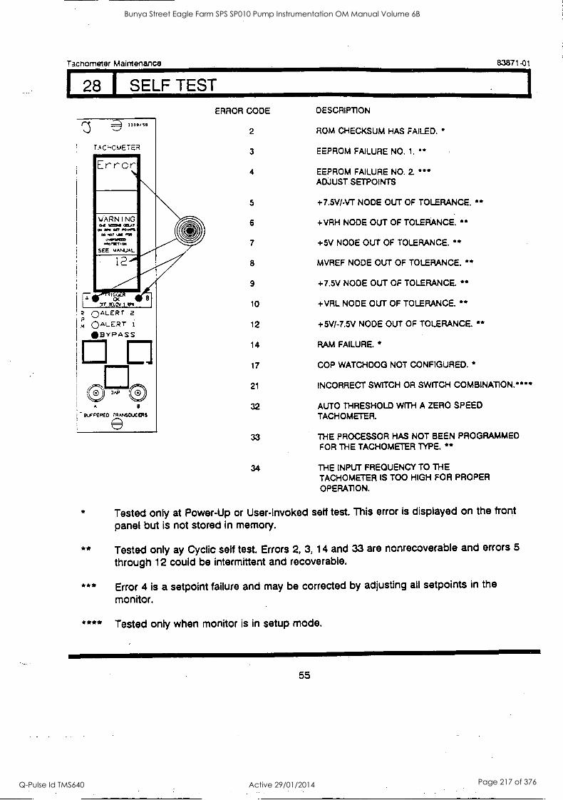
Tachometer Maintenance 83871-01
128 1 SELF TEST
33 0 0 /10
rAc:--cmETER
°ALERT 2 m °ALERT i
BVPA SS
E G 0
A 8
BUFFERED r8Ar4e00ERS
ERROR CODE
2
3
DESCRIPTION
ROM CHECKSUM HAS FAILED.
EEPROM FAILURE NO. 1.
4 EEPROM FAILURE NO. 2 '6" ADJUST SETPOINTS
5 +7.5V/-VT NODE OUT OF TOLERANCE. * 6 +VRH NODE OUT OF TOLERANCE. **
7 +5V NODE OUT OF TOLERANCE. **
8 MVREF NODE OUT OF TOLERANCE. * 9 +7.5V NODE OUT OF TOLERANCE. **
10 +VRL NODE OUT OF TOLERANCE. **
12 +5V/-7.5V NODE OUT OF TOLERANCE. * 14 RAM FAILURE. *
17 COP WATCHDOG NOT CONFIGURED. *
21 INCORRECT SWITCH OR SWITCH COMBINATION.****
32 AUTO THRESHOLD WITH A ZERO SPEED TACHOMETER.
33 THE PROCESSOR HAS NOT BEEN PROGRAMMED FOR THE TACHOMETER TYPE. **
34 THE INPUT FREQUENCY TO THE TACHOMETER IS TOO HIGH FOR PROPER
OPERA-110N.
Tested only at Power-Up or User-Invoked self test. This error is displayed on the front panel but is not stored in memory.
**
***
****
Tested only ay Cyclic self test. Errors 2, 3, 14 and 33 are nonrecoverable and errors 5
through 12 could be intermittent and recoverable.
Error 4 is a setpoint failure and may be corrected by adjusting all setpoints in the
monitor.
Tested only when monitor is in setup mode.
55
Bunya Street Eagle Farm SPS SP010 Pump Instrumentation OM Manual Volume 6B
Q-Pulse Id TMS640 Active 29/01/2014 Page 217 of 376
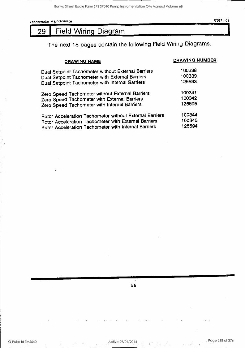
Tachometer Maintenance 83871-01
29 1 Field Wring Diagram
The next 18 pages contain the following Field Wiring Diagrams:
DRAWING NAME DRAWING NUMBER
Dual Setpoint Tachometer without External Barriers 100338
Dual Setpoint Tachometer with External Barriers 100339
Dual Setpoint Tachometer with Internal Barriers 125593
Zero Speed Tachometer without External Barriers 100341.
Zero Speed Tachometer with External Barriers 100342
Zero Speed Tachometer with Internal Barriers 125595
Rotor Acceleration Tachometer without External Barriers 100344
Rotor Acceleration Tachometer with External Barriers 100345
Rotor Acceleration Tachometer with Internal Barriers 125594
56
Bunya Street Eagle Farm SPS SP010 Pump Instrumentation OM Manual Volume 6B
Q-Pulse Id TMS640 Active 29/01/2014 Page 218 of 376
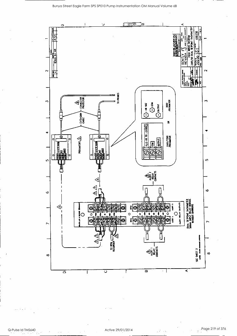
5 4
TO
R
NA
R
EC
OR
DE
R
AT
ER
T
RE
LAY
-
CO
NT
AC
TS
V/
1111
IIIIIP
Mea
1
0 P
RO
TA
AT
OR
S,L
C
ON
NE
CT
OR
P
RO
TE
CT
OR
ION
at I
...O
il 1
0 A
LCM
IM
AM
O
UT
UrS
DU
AL
SE
IPC
INT
IA
CN
OLL
ET
ER
SIG
N/d
. IN
PU
T R
ELA
Y M
OD
ULE
%T
RIM
BA
RR
IER
S
SE
E
SLE
ET
2
sal
osaM
S I
NIN
IOM
S O
WN
S
Lil
.Mgr
--
ALE
RT
y2
RE
lA
-CO
T (A
CT
S
1300
/720
0 P
RO
Vel
l TO
R
OR
TO
PR
OB
ES
0 -I
s w
e
0 ca
m
0 ou
Tpu
r.
3000
P
RO
AN
ICR
us11
1
man
n an
imal
I II
GE
NT
LY
NE
VA
DA
%
...)
FIE
LD R
INK
DiA
CR
AT
A
1.30
0/S
0 D
UA
L. S
EIK
INT
T
AC
TIO
AT
IR
-5-2
10
(3.
I 10
0338
8 6
5 I
4 3
2 1
Bunya Street Eagle Farm SPS SP010 Pump Instrumentation OM Manual Volume 6B
Q-Pulse Id TMS640 Active 29/01/2014 Page 219 of 376
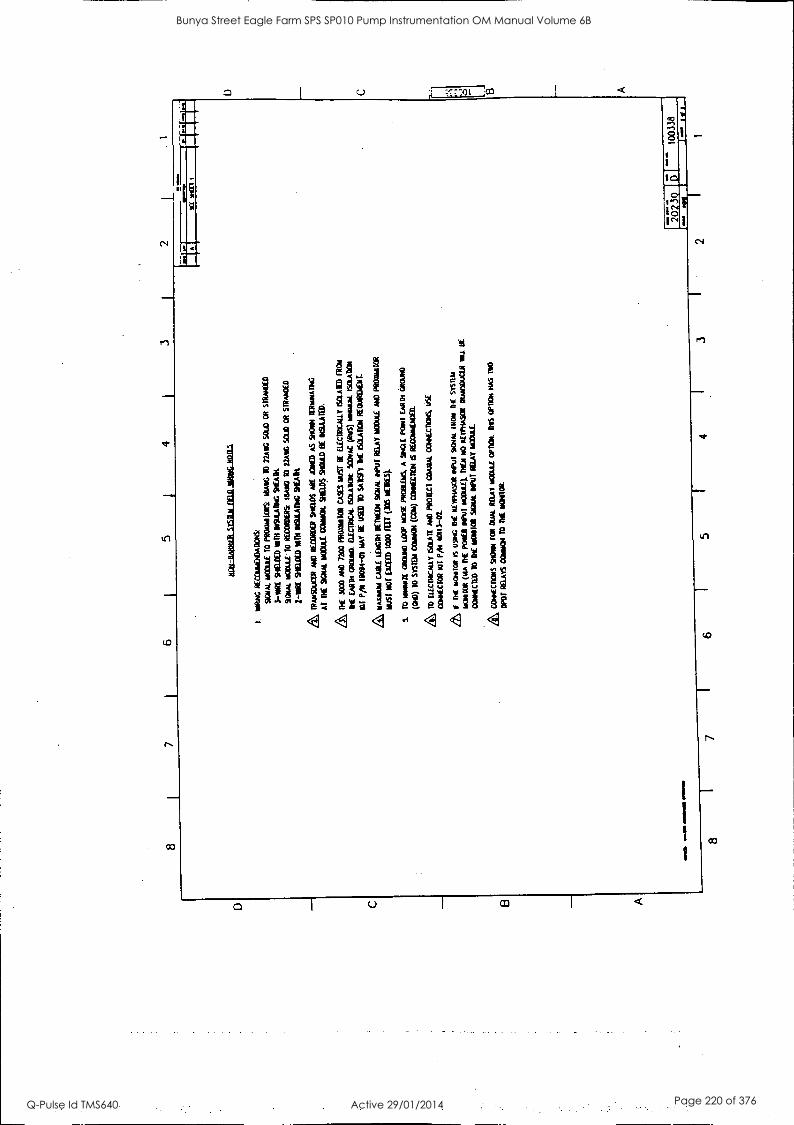
8 I
7 I
6 I
5 1
4 I
3 2
t. ei
Rui
C R
EC
Cem
EN
DA
MT
S:
Mal
mO
Dui
f T
O
PRO
MIT
OR
S ID
AM
TO
27
AM
SO
u0 C
R
SUM
ME
D
3-M
E S
HE
IDE
D M
TH
WA
ILA
MG
SM
EA
R
SCIT
AL
m
ania
TO
R
EM
ME
RS
MA
IN T
O
22A
M S
CU
D
OR
SI
lbui
DE
D
2-11
K D
IET
BE
D
MD
1 B
ISU
LA
DIC
MC
AR
IRA
TT
SIV
CIE
R
AN
D F
awn
snap
s A
RE
JO
INE
D
AS
SuC
m
AT
D
C 9
CW
1 M
OO
LIE
C
OM
M D
ia.D
S SH
OU
LD
BE
*M
AIM
LIE
30
00 P
M 7
200
PRO
TD
ITO
R C
ASE
S M
UST
B
E
EU
CT
RIC
AL
LY
IS
CE
AT
ID F
RO
M
DIE
E
AR
D1
MO
M. D
EC
TR
CA
E S
MA
RM
SC
OvA
C (
UT
S) m
axim
. IS
OL
AT
ION
CI
PA
100
94-0
1 M
AY
B
E
USE
D
To
sosn
111
E 6
01.A
101
RE
OL
AR
OC
NI.
a, MA
XIM
UM
C
AB
LE
LE
NG
TH
ear
tna
soot
INPU
T M
AT
iT0O
utE
A
M)
PRO
Bei
TO
R
MST
Nor
EX
CE
ID
1000
HD
(30
S M
EW
LS}
S.
TO
ur
emZ
E
CR
ouM
WV
NO
ISE
PR
OB
LE
MS,
A
SI
NG
LE
PO
NT
DA
M (
Act
ed)
(QC
) T
O sr
sum
CO
RM
(C
AM
) C
OM
EC
OC
N 6
RE
CC
eitA
DE
D.
TO
fa
cnac
aty
scuf
f AN
D
PRO
TE
CT
CO
AX
AL
co
atcn
oris
, U
SE
Coe
CC
ToR
aT
MI
401I
3-02
.
DE
wom
bat
IS us
es D
IE
ilwim
soR
Mut
scu
m m
om
DC
m
ud
WH
IM (
MA
R
E p
owE
R e
aPuT
m
OD
uta
DC
A
NO
aL
rftlA
SOR
Rom
sOuC
IA
mu.
OE
CC
eeC
CIE
D
10 D
IE M
ON
ITO
R SO
YA
NU
T M
AT
IC
OM
L
&W
OW
Sto
w f
OR
OU
AI
RE
LA
Y m
Ort
af o
rnom
ne
s O
PTte
t R
AS
Ts0
OPD
T R
EL
AK
001
001
TO
T
IC M
OM
smA
IND
10
1111
11M
O
MI le
a.
-'-...
.-...
..'1"
./Th[
I
MP
S
91E
11
I
2023
0 10
0338
8 7
6 5
4 3
2 1
Bunya Street Eagle Farm SPS SP010 Pump Instrumentation OM Manual Volume 6B
Q-Pulse Id TMS640 Active 29/01/2014 Page 220 of 376
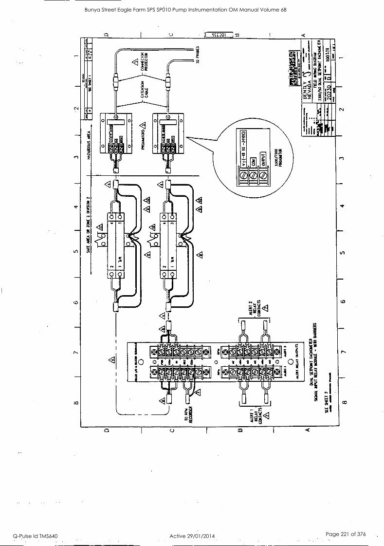
5 3
1
TO
R
PM
RE
CO
RD
ER
ALE
RT
1
RE
LAY
C
OR
TIZ
TS
4/0
KO
= 1
1311
0
Ell
N
MIX
sst 0
INI
*LW
I
sm.1
3If
3
0 A
LLR
I R
ELA
Y
OU
ITU
r3
DU
AL
SE
IPO
ra f
AC
HC
AIE
WR
S
IGN
AL
Id'J
T R
ELA
Y M
OD
ULE
-
RA
ND
ER
S
511
SH
EE
T
2 M
all
OM
AN
I M
EM
O Il
iViM
111
SA
FE
A
RE
A
OR
Z
ON
E
2 O
PA
SO
r 2
HA
ZA
RD
OU
S
AR
EA
1121
0
0
3 2
alIM
1 I*
'Il
i
Fe4.
.j3
JALE
RT
2
CO
NT
AC
TS
1.
s&
L4
0 0
PR
O3A
MIC
RS
ZI,
421r
nytr
...1
Icy
lc=
Z
.'
ICI
WE
T I
X
MIN
N
yxR
AS
ION
C
Otu
tEC
IOR
LA
DLE
P
RO
lIC F
OR
111E
MIN
0111
8 -1
111
=E
INE
M W
OO
=
= mom.M
. N
akao
&
M.O
.. I.
MM
.
C
10
PR
OB
ES
a)
BE
N T
LY
.;
A
NE
VA
DA
F
ED
NIR
TR
IG D
IAG
RA
M
1300
/50
DU
AL
SE
IPO
NT
TA
CH
INE
ICK
1003
39
I 6
5 I
4 I
3 2
Bunya Street Eagle Farm SPS SP010 Pump Instrumentation OM Manual Volume 6B
Q-Pulse Id TMS640 Active 29/01/2014 Page 221 of 376
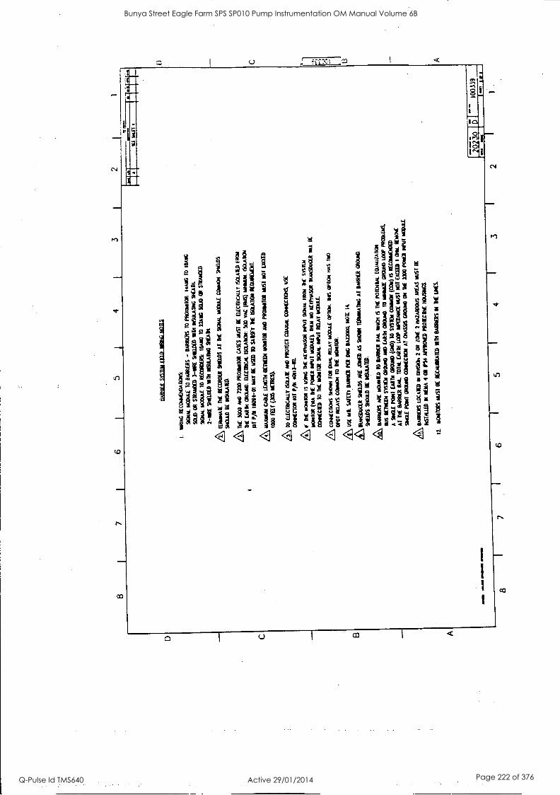
8 7
6 5
4 I
3
tuun
ut sy
sina
filD
ont
iG N
oTE
S
1.
WO
NG
R
EC
CK
ME
ND
AT
1ON
S:
9CN
AL
WW
1 10
BA
RR
IER
S -
BA
RR
EN
S T
O PR
O/M
OO
R:
14A
NG
T
O
SUN
G
SOL
D O
R
STR
AN
DE
D
3-11
1NE
St
iaD
ED
M
TN
MA
CO
N&
R
EA
D1.
9110
4. M
OD
UL
E
TO
RE
CO
RD
ER
S:
IMM
O
TO
22
AII
G S
CU
D O
R
S1R
AN
DE
D
2-1N
RE
99(
1.1E
D 4
1111
91
SUL
A11
NO
Sl
f.A
114.
n IE
EO
IMIE
O
E R
EC
OR
DE
R
SHIE
LD
S A
l D
IE
SIG
NA
L N
OM
E
CO
NA
ION
. SH
IEL
DS
940u
LD
BE
IN
SuL
AT
ED
.
DE
30
00 A
ND
72
00 P
RO
MO
OR
CA
SES
MU
ST
BE
E
LE
CT
RIC
AL
LY
IS
OL
AT
ED
FR
O/
DI
EA
RM
CR
OT
AN
D.
EL
EC
T1O
CA
L SM
AR
M 5
00
VA
C (M
e) 1r
4MW
1.
ISC
LA
D01
Ill
P/11
190
64-0
1 M
AY
1E
USE
D
10 S
AL
TY
ME
&
WO
N R
EC
uME
ME
NT
.
NA
Ium
UM
CA
BL
E L
EII
CO
I B
ET
IED
a T
iOta
lOR
A
ND
PR
OM
MO
OR
M
UST
NO
T W
EE
D
1000
FE
ET
005
ME
TR
ES}
& TO
f.L
EC
ITD
CM
LY
SIA
TE
AN
D
PRO
TE
CT
CO
AX
IAL
00M
4EC
ICK
USE
CO
NN
EC
TO
R N
IT P
/11
4011
3-02
111[
b1C
4410
11
IS U
SIN
G D
E K
EY
INiA
SOR
*V
W 9
0444
IR
ON
R
E S
ISIL
la
1101
410E
(M
A
DE
PO
NE
R
INPU
T m
0Out
E).
L
IEN
N
O al
fttA
SER
1R
AN
SE0E
IR
MIL
01
CO
NN
EC
ID
TO
D
IE M
ON
ITO
R SU
M W
in R
EL
AY
MO
DU
LE
com
mC
nois
ro
N D
ux R
EL
AY
m
oXlii
.E
OM
EN
. M
S 0'
143,
1 H
AS
TK
O
DPW
MA
YS
0341
410N
T
O
DIE
w00
101.
USE
mi.
SWE
TT
BA
ND
ER
PO
I O
NG
BA
2200
0. N
OM
14.
kIR
AK
EIA
TE
KID
S A
RE
JO
NG
) A
S sn
ow t
esm
ears
es A
T B
MW
CR
OW
D.
SHIE
LD
S SH
OU
LD
EE
D
ISIA
TE
D.
te, M
INE
RS
AR
E
RO
AM
ED
10
BA
RR
IER
N
M.
WE
N I
S T
HE
ME
ND
& c
cuA
uzA
nas
sus
KN
EE
N S
YST
EM
CR
OW
° 9.
10 E
MIR
CR
OW
/ 10
WO
RE
GR
OW
.) W
OP
PRO
OL
US.
A
SIN
GL
E
PON
T
EA
RT
H G
RO
UN
D (
NO
) T
O
SYST
IN C
ON
NO
R
(C
l) I
S R
EC
ON
AD
TO
ED
AT
D
IE W
W1
RI&
T
OT
AL
D
AM
117
11.
&N
UA
NC
E M
KT
NO
T M
ID I
OM
. K
NO
W
SIN
GL
E
PON
T C
RO
WD
CO
NT
EC
TO
T
AT
OT
ASS
TS M
oe O
N
DIE
IW
O P
OK
ED
Deu
r W
AA
L
kBA
RR
IER
S L
OC
AT
ED
N
I 01
41:9
011
2 (A
l Z
ON
E 2
MU
MS
AR
EA
S M
UST
B
E
RE
STA
LL
ED
M 1
11.1
1A 4
OR
1P
54 A
PPR
O's
ED
PR
OIE
CT
IVE
HO
USI
NG
S
12_
MO
NIT
OR
S M
UST
B
E
RE
CA
UB
RA
TE
D
MM
BA
NG
S
Di
NN
E
LIM
ES
1
Bunya Street Eagle Farm SPS SP010 Pump Instrumentation OM Manual Volume 6B
Q-Pulse Id TMS640 Active 29/01/2014 Page 222 of 376
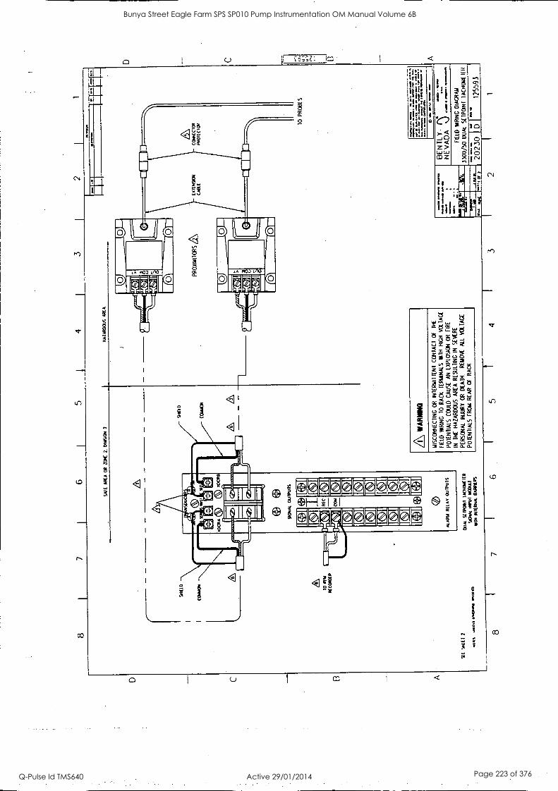
0 E3 A
8 I
7 6
5 4
3 I
2 I
1
YE
SH
EE
1 2
SAFE
A
RE
A
OR
/O
lt 2.
D
M9O
N
2 H
AZ
AR
DO
US
AR
EA
Mae
0141
1 a.
%
10 R
pil
RE
CO
RD
ER
Alt*
11 of
W(I
.' 10
1101
.
PR
oxam
ioR
SQ
C
CH
LO
CIO
R
PRE
HC
CIC
H
N\
y0cR
6)
6)
AD
CR
B
/ E
d is
SIG
NA
L
OU
TPU
TS
AR
C
com
*LA
MA
R
EL
AY
O
UT
PUT
S
DU
AL
SE
IPO
INI
1AO
Rsz
EIE
R
SEC
NA
L M
u! H
OD
utt
NM
*H
ER
M.
BA
RR
IER
S
A WA
RIN
G
IMS
CO
NN
EC
TIN
G
OR
IN
TE
MIL
T1I
NI
CO
NT
AC
T
OF
T
HE
FIE
LD
WR
ING
10
R
AC
K
TE
RM
INA
LS
YA
M
HIG
H
VO
LTA
GE
PO
TE
NT
IALS
C
OU
LD C
AU
SE
A
N
EX
PLO
SIO
N
OR
F
IRE
IN
TH
E
HA
ZA
RD
OU
S A
RE
A
RE
SU
LTIN
G
IN
SE
VE
RE
PE
RS
ON
AL
INJU
RY
O
R
DE
AT
H.
RE
MO
VE
A
LL
VO
LTA
GE
PO
TE
NT
IALS
F
RO
M
RE
AR
C
F
RA
CK
8 7
6 5
4 3
10
PR
OB
ES
rz...
....z
.,....
.....,
::::=
,..=
.....
Om
. N
I* 0
11
=
1/10
111S
*g
amm
a w
awa
IM.
BE
NT
LY
NE
VA
DA
FIE
LD
WR
ING
D
IAG
RA
M
3300
/50
DU
AL
SE
1PO
N1
1 A
CH
OM
E I
T I
t
2023
0 12
5593
2 1
0 C
U 1
U A
Bunya Street Eagle Farm SPS SP010 Pump Instrumentation OM Manual Volume 6B
Q-Pulse Id TMS640 Active 29/01/2014 Page 223 of 376
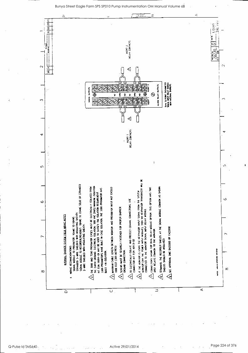
D I3 A
8 6
5 4
3 2
INT
ER
NA
L B
AR
RIE
R S
YS
TE
M o
no W
RIN
G
NO
TE
S
I W
IRIN
G
RE
CO
MM
EN
DA
TIO
NS
:
SIG
NA
L M
OD
ULE
10
P
RO
xRN
TO
R:
16A
WG
T
O
I8A
WC
ST
RA
ND
ED
3-W
IRE
S
HIE
LDE
D
MT
H
INS
ULA
TIN
G
SH
EA
TH
.
SIG
NA
L M
OD
ULE
10
R
EC
OR
DE
R /R
EA
DO
UT
: ill
Aw
C
10
22A
WG
S
OLI
D
OR
S
TR
AN
DE
D
2 -W
IRE
S
HIE
LDE
D
WIT
H I
NS
ULA
TIN
G S
HE
AT
H.
AT
HE
30
00
AN
D
7200
PR
OX
IMIIO
R
CA
SE
S M
US
T B
E
ELE
CT
RIC
ALL
Y I
SO
LAT
ED
F
RC
N
ITIE
E
AR
TH
G
RO
UN
D.
ELE
CT
RIC
AL
ISO
LAT
ION
: 50
0 V
AC
(R
MS
) M
INIM
UM
. IS
OLA
TIO
N
KIT
P
/N 1
9094
-01
MA
Y
BE
U
SE
D 10
SA
TIS
FY
TH
E
ISO
LAT
ION
REQUIREMENT.
3300
P
RO
XIM
ITO
RS
H
AV
E
BU
ILT
IN
C
AS
E
ISO
LAT
ION
. T
HE
33
00
PR
OU
TT
IOR
H
AS
BU
ILT
-I
N I
SO
LAT
ION
.
AM
AX
IMU
M
CA
BLE
LE
NG
IH K
NE
EN
MO
NIT
OR
A
ND
P
RO
wiN
ICR
M
US
T
NO
T E
XC
EE
D
1000
F
EE
( (3
05
ME
TR
ES
)
A SCRE
WS
M
US
T
BE
S
EC
UR
ELY
F
AS
TE
NE
D
KR
P
RO
PE
R
BA
RR
IER
CR
OuN
D CONNECTION.
/5\ 1
0 E
LEC
TR
ICA
LLY
IS
OLA
TE
A
ND
P
RO
TE
CT
C
OA
XIA
L C
ON
NE
CT
ION
S.
US
E
CO
NN
EC
TO
R
1(11
P
/N
4011
3-02
/a\ if
III
E
uuN
iloR
IS
U
SIN
G
DIE
K
ET
PH
AS
OR
IN
PU
T
SIG
NA
L F
RO
M
TH
E
SY
ST
EM
'AM
OU
R
(NA
IN
( P
OK
R I
NP
UT
M
OD
ULE
).
TH
EN
N
O K
YP
HA
SC
O2
TR
AN
SD
UC
ER
R
ILL
BE
CO
NN
EC
ILO
10
11
11
woN
uOR
SIG
NA
L IN
PU
T R
ELA
Y
MO
DU
LE
AC
a4N
IC N
uNS
S
HO
WN
T
OR
D
UA
L R
ELA
Y
MO
DU
LE
OP
TIO
N
TH
IS O
PT
ION
H
AS
IW
O
DP
OI
RE
LAY
S C
OM
MO
N
10
TH
E
MO
NIT
OR
.
/8\ T
ER
MIN
AT
E
TH
E
RE
CO
RD
ER
S
HIE
LDS
A
T
TH
E
SIG
NA
L M
OD
ULE
C
OM
MO
N
AS
S
HO
WN
.
SH
IELD
S
SH
OU
LD
BE
IN
SU
LAT
ED
AS
EE
A
PP
RO
VA
L D
WG
B
A22
000
OR
C
A22
000
Oal
f1 O
MIIt
MV
O.
ALE
RT
I
RE
LAY
CO
NT
AC
TS
SIG
NA
L O
uIP
UIS
VA
* (D
I
1
ALE
RT
1
Mitt
2
ALA
RM
IK
LAY
OU
IPU
IS
DU
AL
siT
poN
I IA
OgY
LIT
R
SIG
NA
L N
WT
RE
LAY
B
OW
IE
van
INT
ER
VA
L D
AR
NE
R'S
8 7
6 5
3
ALE
RT
2
ALL
AY
C
IINIA
CIS
2023
0 D
I 2
5'.1
!) 3
"
Bunya Street Eagle Farm SPS SP010 Pump Instrumentation OM Manual Volume 6B
Q-Pulse Id TMS640 Active 29/01/2014 Page 224 of 376
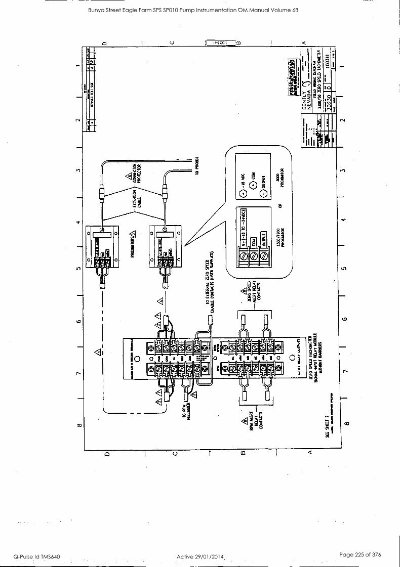
8 6
5
10 R
PM
RE
OR
DE
R
NU
PLE
AT
MA
Y -
CO
N1.
CT
S
SE
E
SH
EE
T
2
V.
716
111M
I 01
101M
II I
MM
O
t+1
Cal
Ol No
NC
No
A p
DE
M
IIK
ED
4 1
3 1
2
1131
1111
1111
111C
111
PR
OU
ST
OR
11
1121
1111
1111
1111
1211
111
1113
1111
1111
311
TO
(M
EW
L Z
ER
O
SP
EE
D
EN
AB
LE C
ON
TA
CT
S (
uSE
R S
uPP
LCD
)
-Cfa
i-'
ES,
a)
INI
ALE
RT
R
ELA
Y
n
E
0 11
0.A
lf ou
trun
AR
O
SP
EE
D
TA
CN
ON
EIE
R
scam
. re
in M
AT
NO
ME
ol
liOrT
BA
RR
IER
S
3300
/120
0 P
RO
XM
IOR
O
R
01m
M:a
P
RO
UT
OR
10 P
RO
BE
S
0 -I
s 1,
0c
cal
0 ou
wur
3000
P
RO
RN
OO
R
L 11
1:1
I4
IVA
IED
IO
ti S I
12-a
r f-
.4..1
Ora
* 1 11
W
OM
Mft
MM
E
BE
N T
LY
N
EV
AD
A
-r-
11E
LD
MIN
G 0
1AC
RA
N
4300
/50
ZE
RO
SPE
ED
lA
CN
ON
E11
.11
1523
0 1 E
d 10
0341
1
8 7
6 5
4 3
2
0 C o A
Bunya Street Eagle Farm SPS SP010 Pump Instrumentation OM Manual Volume 6B
Q-Pulse Id TMS640 Active 29/01/2014 Page 225 of 376
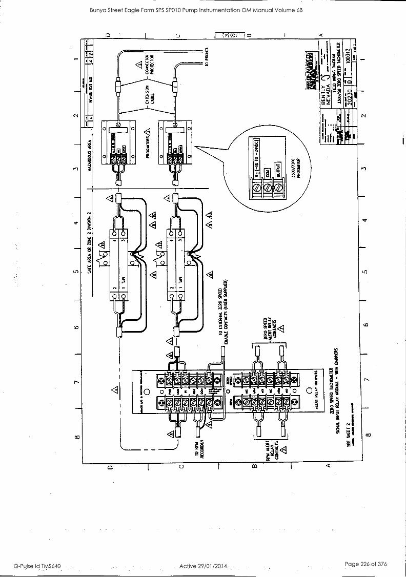
8 7
6 5
1 4
i 3
2
CO
NN
EC
TO
R'
PR
OT
EC
TO
R
TO
R
PM
RE
CO
RD
ER
ILA
T
O
EX
TE
RN
AL
ZE
RO
S
PE
ED
ER
AD
d C
ON
TA
CT
S (
uSE
1 9I
PLIE
D)
RP
M A
LER
T
RE
LAY
C
ON
TA
CT
S
1,LR
O
ED
T S
PE
y C
ON
TA
CT
S
&
ZE
RO
S
PIE
D
IAC
HO
RE
TE
R
SG
RA
L R
tPuT
RE
LAY
M
OD
ULE
- 11
1TH
B
AR
KE
RS
10
PR
OV
ES
fl
BE
NT
LY
A
NE
VA
DA
0 --
- S
EE
S
HE
ET
2
WO
m
all 0
1111
0111
MO
M
8 7
6
MA
MA
VA
20
230
D
1003
42
1- l
wl
FE
D
*IN
C o
iAcR
ms
1100
/50
ZE
RO
S
PE
ED
TA
CK
ME
TE
R
5 I
4 3
2
Bunya Street Eagle Farm SPS SP010 Pump Instrumentation OM Manual Volume 6B
Q-Pulse Id TMS640 Active 29/01/2014 Page 226 of 376
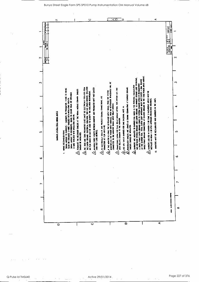
8 7
6 5
4 3
1111
1 am
.M. M
OM
, ~M
I
8 7
taB
BE
1 .1
1111
3111
1111
1032
111S
1.
WR
ING
R
Ecc
usfr
oAno
ws.
SE
RPA
. M
OD
UL
E
TO
B
AR
KE
RS
- B
AR
RIE
RS
10
PRO
SEO
R:
14A
1G
10
MA
RC
SOL
D O
R
STR
AN
DE
D
3-11
RE
SH
EIL
ED
IO
M
INSL
IAD
NG
SH
EA
TH
SAC
RA
L
MO
DU
LE
T
O
RE
CO
RD
ER
S II
LM
IG
10
22,4
10 5
131)
OR
SI
RA
/C10
2-W
E 9
1EL
IED
M
M W
SLIA
1141
0 Sh
alt
1110
11A
1E D
E R
EC
OR
DE
R 91
1105
AT
DIE
92
IAL
NO
DU
LE
MIE
N 9
11L
IS
SHO
W E
E W
SUU
11(0
.
ON
E 3
000
ArI
O
7L30
PR
Ons
IOR
CA
SES
MU
ST E
E E
LE
CIR
CA
LL
Y I
SOL
AIE
D f
ilCm
RE
E
AR
N C
RO
WD
. E
TE
CIR
ICA
L &
LA
BO
R
500
VA
C
(106
) W
awa
154A
D41
131
PA 1
1109
4-01
M
AT
BE
USE
D
10 S
AB
SPI lt
ISO
LA
DO
N
RE
OuI
RE
ND
IL
Z\ M
AX
IM E
AR
LE
1IN
CD
1 B
E11
1031
1101
110R
A
ND
Pe
CIA
IIT
OR
MU
ST
NO
l E
A=
10
00 f
1E1
DO
S M
ET
RE
S}
10
EL
EC
IRIC
AU
.Y
60L
AT
E A
ND
PR
OT
EC
T C
OA
XIA
L
CC
401E
CT
1016
. U
SE
CO
NN
EC
TO
R K
IT Pi
ta 4
0113
-02.
DE
m
0m10
11 I
S U
914
DE
RE
WN
ASO
R
INPU
T 90
4N.
TR
W llf
515
101
moN
IOR
D
E P
ON
D D
IPuT
mO
DA
E).
T
HE
N
NO
R
ET
PNA
SOR
IR
...M
OW
ER
*t
It
CO
RN
ICE
D
10
DIE
11
0610
11
SEIM
&cu
r R
aAY
RO
NA
L
AC
O/H
CT
ION
S Sa
0v0
TO
R
DU
AL
R
O.A
Y W
OW
Mow
D
os o
PDO
N N
As
DPW
RE
LA
YS
CO
RK
IN
10
TH
E N
OC
K
Z\ U
SE
NIL
SP
IED
BA
RR
CII
PE
R
Dw
G R
A22
000.
NO
M
14.
\ "imam
/all
snaD
s A
RE
AR
O)
AS
SHO
RN
10
110.
014
Al
BA
RK
ER
CR
OuN
D.
STE
WS
SHO
UL
D
BE
MO
WE
D.
k,
BA
RK
ER
S A
RE
W
OO
ED
10
BA
RR
IER
R
At.
MIR
E I
S D
E
POR
MII
AL
E
WA
LIZ
AR
ON
BU
S B
ET
RE
01
S1S1
EN
GR
OU
ND
AN
D
EA
RD
1 M
OR
EL
10
1011
21 C
RO
W)
LO
OP
PRO
BL
INS,
A
DIE
TE
PO
NT
EA
RT
H C
RO
W)
(ON
O)
TO
M
ini
CC
MI1
11 (O
IS PE
CA
MN
OM
ID
AT
D
E
BA
RR
ER
LW
ID
IAL
E
AR
TH
LO
OP
IMPE
ILM
CE
M
UST
NO
T (M
ID 1
W
M R
EN
O*
SAW
PO
NT
C
RO
WD
CoN
NIX
DO
N A
T O
IAS9
S M
ama
Ow
1N
E 3
300
PON
E)
OiN
IT m
OO
UL
L
QE
B
AR
RIE
RS
LO
CA
ND
NI
OD
OM
2 C
l Z
ON
E
2 H
AZ
AR
DO
US
WA
S M
IST
BE
1614
1111
II
ME
NA
4
Cl P
54 A
PPR
OL
ED
Mon
a* is
Out
ileC
S
IT.
Nom
IOR
S M
t It
RE
CA
uOR
AT
ED
D
i DA
MS
M it
istS
.
6 E
. 5
4 I
3 2
1003
42
1" l
ar
1
Bunya Street Eagle Farm SPS SP010 Pump Instrumentation OM Manual Volume 6B
Q-Pulse Id TMS640 Active 29/01/2014 Page 227 of 376
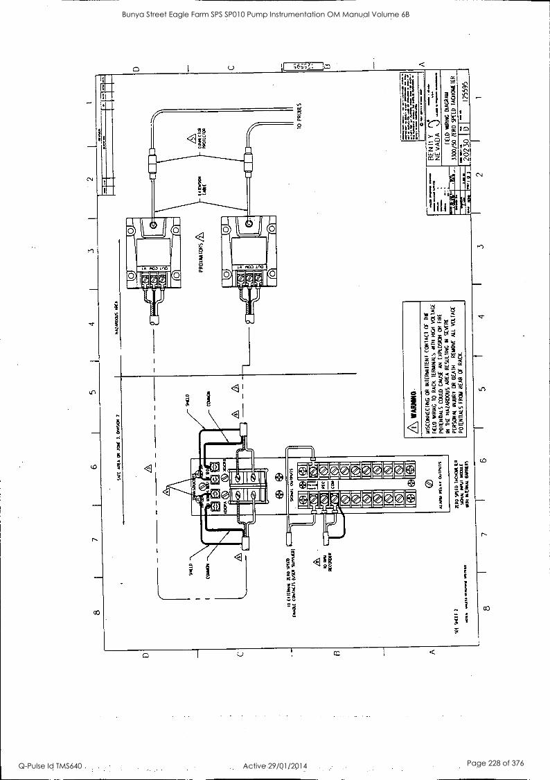
8 7
6 5
4 3
2 I
1
1
%C
D
WE
AR
EA
OR
/C
NC
2.
Onn
9ON
2
HA
2000
6 A
RE
A
OR
t01.
90
Afi
SOU
C
G
10 (
.1E
RN
A.1
Z
ER
O SP
UD
D
IAB
LE
C
OA
LE
D (
USE
R Su
ff11
0)
SlE
94
[(1
2
tO R
PM
R[C
OPU
R
wai
fs ~
am W
I MO
W
SKA
IAL
pY
IPU
IS
8
AE
C
CO
Y
C
C
C
C C.]
MA
RIA
R
E I
AY
O
JIPU
IS
AR
O S
PEE
D
1/01
0WA
R
Sank
Rw
l K
W(
111,
1 W
IRR
AL
B
AR
RIE
RS
SH(.
10
&
PR
OK
RA
IOR
S
D
DIM
E (L
OB
PR
OI1
C
A WA
RIN
G.
MiS
CO
NN
EC
TIN
G
OR
IN
TE
RT
AIIE
NT
C
ON
TA
CT
O
f 11
11
DU
O
WR
ING
T
O
RA
CK
IE
RM
INA
LS
MT
H H
IGH
V
OLT
AG
E
PO
TE
NT
IALS
C
OU
LD C
AU
SE
A
N E
XP
LOS
ION
O
R
EIR
E
IN
TH
E
HA
ZA
RD
OU
S
AR
EA
R
ES
OLI
NG
IN
S
EV
ER
E
PE
RS
ON
AL
INJU
RY
O
R D
EA
N
RE
MO
VE
A
LL
VO
L F
AC
E
PO
TE
NT
IALS
F
RO
M
RE
AR
O
F
RA
CK
.
C
10 P
RO
BE
S
I 11
14
4* w
oo s
ox.
se
A
.1.1
17 0
01.1
0.1
1.11
* sm
ola
Innm
e O
W.=
m
w.
BE
NT
E Y
NE
VA
DA
J
FIE
LD
WIR
ING
D
IAG
RA
M
3300
/50
ZE
RO
SP
EE
D
IAC
TIC
AA
EIE
R
=M
ITI.
I C
M W
e..
2023
0 D
1110
,NI
1255
95
8 7
6 5
4 3
2 1
Bunya Street Eagle Farm SPS SP010 Pump Instrumentation OM Manual Volume 6B
Q-Pulse Id TMS640 Active 29/01/2014 Page 228 of 376
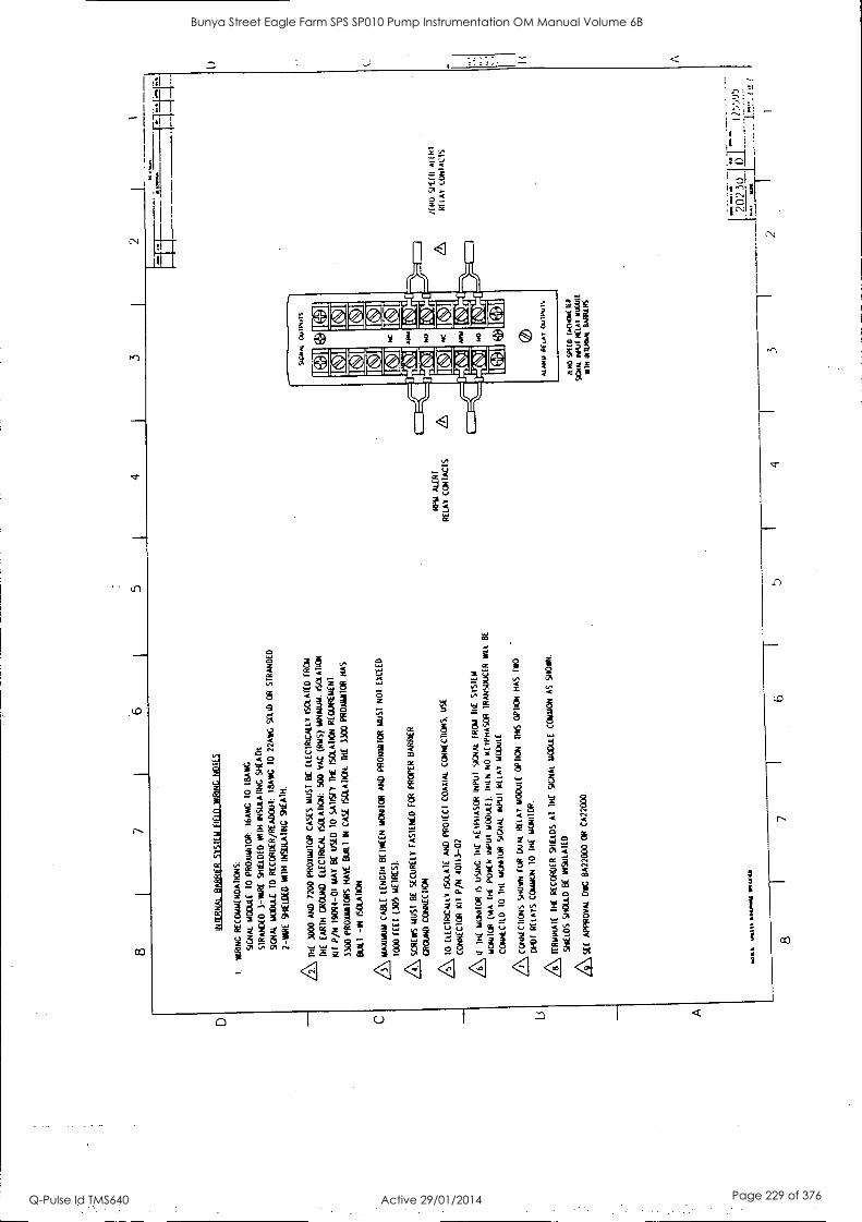
8 I
7 4
2
INF
ER
NA
L B
AR
RIE
R
SY
ST
EM
FIE
LD
WR
ING
tiO
lES
I. W
RIN
G
RE
CO
WE
ND
AD
ON
S:
SIG
NA
L M
OD
ULE
10
P
RO
AR
RIO
R:
16A
NG
10
18
AIV
C
SIR
AN
DE
O
3 -R
AR
E
SH
IELD
ED
W
IN I
NS
ULA
INC
SH
EA
TH
SIG
NA
L M
OD
ULE
T
O R
EC
OR
DE
R /R
EA
DO
UT
: LE
LAW
G
10 22
AIK
SO
UR
O
R
ST
RA
ND
ED
1-W
IRE
S
HIE
LDE
D
WIN
IN
SU
LAT
ING
S
HE
AT
H.
/ l D
IE
3000
A
ND
72
00 P
RO
MM
I1O
R
CA
SE
S
MU
ST
B
E
ELE
CT
RIC
ALL
Y
ISO
LAT
ED
F
RO
M
DIE
E
AR
TH
G
RO
UN
D.
ELE
CT
RIC
AL
SO
O
VA
C
(RM
S)
YW
WU
M.
ISO
LAT
ION
ml
P/N
19
4394
-01
MA
Y B
E
US
ED
10
SA
DS
TY
D
i( IS
OLA
TIO
N R
EC
RIIR
EH
EN
I.
3300
P
RO
MIT
OR
S H
AW
B
UIL
T
IN
CA
SE
IS
CI.A
DC
H.
INC
33
00 P
RO
AN
IOR
H
AS
BU
ILT
-I
N
ISO
LAD
CN
.
73\ 1
1AA
ILIU
M
CA
BLE
LE
NG
TH
KN
EE
N M
CN
I1C
R
AN
D
PR
OX
ILU
IOR
M
US
T N
01
EX
CE
ED
1000
FE
U
(305
WIR
ES
).
/4\ S
CR
EW
S
MU
ST
B
E
SE
CU
RE
LY
FA
ST
EN
ED
F
OR
P
RO
PE
R B
AR
RIE
R
GR
OU
ND
CO
NN
EC
TIO
N
A\ 1
0 E
LEC
TR
ICA
LLY
IS
OLA
TE
A
ND
P
RO
TE
CT
C
OA
XIA
L C
ON
NE
CT
ION
S.
US
E
CO
NN
EC
10R
1(
11
P/N
40
113 -
02
AII
TH
E
m11
NI1
0R
IS
LAS
ING
lit
KE
YP
HA
SO
R v4
Pul
S
IGN
AL
FR
OM
IR
E
SY
ST
EM
LiO
NIU
R
(NA
T
HE
P
OO
R
INP
UT
M
OD
ULE
).
111t
H
NO
R
EY
PH
AS
CR
T
RA
NS
DU
CE
R W
LL
BE
CO
NT
NC
ILLI
10
N
il m
EN
NIO
R
SIG
NA
L IN
PU
T
RE
LAY
m
CO
uLE
Aco
iwci
.,..6
SH
UN
F
OR
D
UA
L K
im H
OD
utE
O
PT
ION
D
RS
OP
TIO
N H
AS
tw
o
ow R
ELA
YS
C
OM
MO
N 1
0 T
HE
m
orot
oR.
AT
ER
HIN
AIE
T
IM
RE
CO
RD
ER
S
HIE
LDS
A
l 1H
E
SIG
NA
L M
OD
ULE
C
OIT
ION
A
S
SH
OY
N.
SH
IELD
S
SH
OU
LD
BE
IN
SU
LAT
ED
/9\ S
EE
A
PP
RO
VA
L D
WG
8A
2200
0 O
R C
A22
000
Van
Oba
NG
NI
MO
HO,
8 7
RP
M
ALE
RT
RE
LAY
C
ON
IAC
IS
SIG
NA
L O
ulP
uTS
I eh
I (1
1)
EID
!MI
NC
AR
IL
NO
AR
M
NO
ALA
RM
R
ELA
Y O
UT
PU
TS
AD
O S
PIE
D
fAC
HO
K R
P
SIG
1Ik
HIll
RE
LAY
IN
OU
ti W
ITH
IN
IVO
IN.
Bia
tiRS
6 5
4 7
11 7
01,
1
1111
0 91
110
Al iN
I M
AY
CO
NIA
CIS
2023
u
2
----
F
I ')Y
.P./5
11
/
Bunya Street Eagle Farm SPS SP010 Pump Instrumentation OM Manual Volume 6B
Q-Pulse Id TMS640 Active 29/01/2014 Page 229 of 376
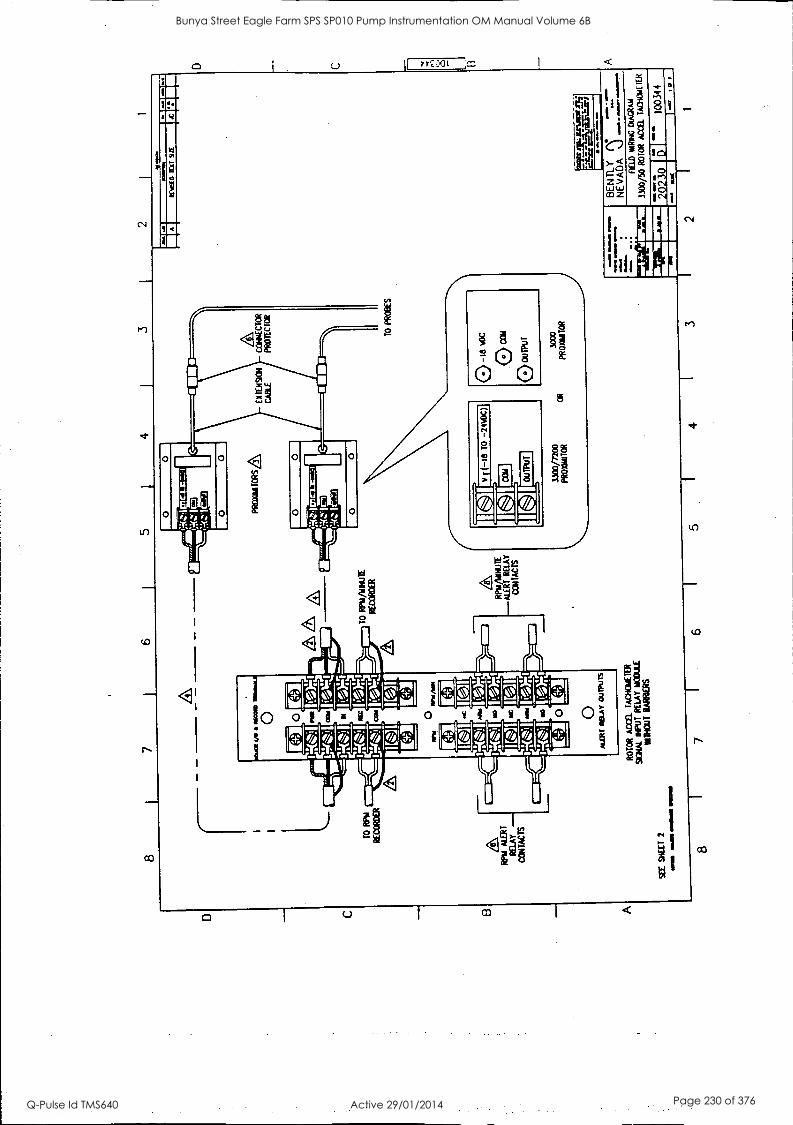
TO RPN
RECORDER
NPR ALERT
RELAY -
CONTACTS
PROmaTORS&
Ex !E
AS
ON
CONLECTOR
CABLE
PROTECTOR
TO RPM/14mM
RECORCER
ROTOR ACM T
ACNONETER
9GNAL rem RELAY 0001LE
vilITIOUT BARRIERS
SEE Slat 2
WW
1 =
AS
~IO
W M
OR
O
Rpu/VoluE
-ALERT RELAY
CONTACTS
1300
/72c
0 PROxiNiTOR
OR
3000
P
RO
NN
ITO
R
-I-.
12
1491
0 II
71I
2/E
11 ab
lblO
n W
INIO
N1
=E
NS
w
e A
NN
IOM
L .1
B
EN
TL
Y
N
NE
VA
DA
--
- fl
u) M
IRIN
G D
IAG
RA
M
3300
/50
RO
TO
R
AC
EE
L T
AC
IIGN
E T
ER
1211.
Ars
8 7
I 6
1 5
f 4
3 2
2023
0 oa
5 I
1003
44
I-
1
D C 0
Bunya Street Eagle Farm SPS SP010 Pump Instrumentation OM Manual Volume 6B
Q-Pulse Id TMS640 Active 29/01/2014 Page 230 of 376
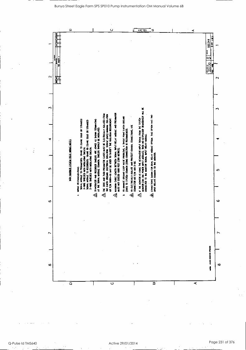
8 5
4 3
I. N
AN
G
RE
coLN
EN
DA
noN
s
SO
IL N
OM
A/
TO
P
RO
AN
TIO
RS
. I6
A
TO
N
AN
G S
CU
3 O
R
SIR
AM
X0
3-N
RE
SK
IM)
NM
IN
SU
LAT
ING
S
HE
AT
H.
SO
UL
'sco
w to
RE
CO
RD
ER
S:
IWO
TO
22
Als
C S
CIT
O
OR
m
um
2-10
1E S
HIE
LDE
D N
M I
NS
IJLA
ING
S
HE
AR
TR
AN
SO
M:IR
A
ND
RE
CO
RD
ER
S
tiELO
S
AR
E
AH
ED
AS
SH
ON
T
IER
LAN
AIN
G
AT
M
E S
OIL
MO
DU
LE
CO
MM
ON
. S
HO
OS
S
HO
ULD
it
INS
AA
TE
D.
TH
E
3000
A
NO
72
00 P
RO
OM
ITO
R C
AS
ES
M
US
T B
E
Etic
n0C
ALL
Y T
SO
LAT
ED
IR
MA
TH
E E
AR
N G
RO
UN
D.
ELE
CT
MC
AL
60LA
DO
N S
OO
VA
C (A
NS
) is
milL
IN M
AS
ON
O
T P
/11
1001
14-0
1 M
AY
OE
U
SW
T
O S
AT
ISF
Y It
ISO
LAT
ION
R
EO
JIR
EM
EN
T.
11A
3AN
A1
cAal
LE
NG
TH
B
ET
IED
1 %
MA
L N
PU
T R
ELA
Y w
ow N
D P
RO
NN
ITO
R
MA
T N
OT
E
N=
1000
M
T (3
05
M(
S)
S.
ID m
irmei
rE G
RO
uNO
LO
OP
NO
SE
P
RO
BLE
MS
. A
IN
GT
E
PO
NT
C
AR
D, G
wO
uNO
(OW
) 10
511
1131
C
ON
NO
I (C
OW
) C
ON
NE
CT
ION
IS
RE
GO
INE
NC
ED
.
to E
lICIR
ICA
ILY
scu
m m
e m
ow c
omm
. co
otac
Ks.
US
E
CO
NN
EC
TO
R
101
P/0
1 40
113-
02.
I' D
IE A
MC
OR
IS
U
SW
TH
E it
WHA
SO
R D
PW
SO
U/
IRO
N
111
SY
ST
EM
Wan
t (W
A A
t P
OP
O S
CU
T
HO
OLI
LE).
M
DT
N
O A
FT
PH
AS
OR
T
RA
wso
uaR
N
il B
E
CO
NN
EC
TE
D T
O at
LO
CO
! S
UM
NP
uT M
AY
140
41.
CO
I414
.010
IS W
WI
Rd
OW
L R
OM
WO
W °
Pro
w
NS
mom
IIA
S IM
)
DP
OT
gam
s O
NN
ON
T
O
ME
MIN
IM
Bunya Street Eagle Farm SPS SP010 Pump Instrumentation OM Manual Volume 6B
Q-Pulse Id TMS640 Active 29/01/2014 Page 231 of 376
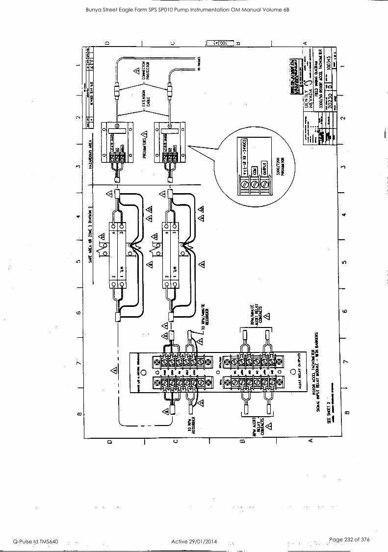
8 7
6 I
5 4
3 2
SA
FE
A
RE
A O
R
TO
NE
2
CLA
SO
N
2 N
AZ
AR
Cou
s A
RE
A
Mlu
1.21
,,1
1.
PR
OLA
NT
OR
5a,
Ex
IEN
SIC
N
CA
BLE
TO
R
PL/
R
EC
oRO
CR
TO
R
IVA
AN
uTE
R
EC
OR
DE
R
&A
13
Wu
ME
RL
RE
IM
CO
NT
AC
TS
1RP
AA
NN
ulE
A
LER
T R
ELA
Y
CO
NT
AC
TS
O
Mar
MA
T O
UP
UT
S
RO
TO
R
AC
cEL
IAC
HoN
EIE
R
90A
AL
"Vol
RE
LAY
NO
OLJ
LE -
r1A
1 B
AR
RIE
RS
4E S
LEE
T
2 N
M
ME
ND
IMO
./ 11
1171
1/11
11
8 7
IJE
NIL
Y
NE
VA
DA
V
.-
CO
NN
EC
TO
R
PR
OT
EC
TO
R
M M
OW
FIE
LD M
IRIN
G C
oAC
RA
N
3200
/30
RO
TO
R A
. TA
CT
IouL
TIR
2023
0 61
- 10
0345
6 4
3 2
L. A
Bunya Street Eagle Farm SPS SP010 Pump Instrumentation OM Manual Volume 6B
Q-Pulse Id TMS640 Active 29/01/2014 Page 232 of 376
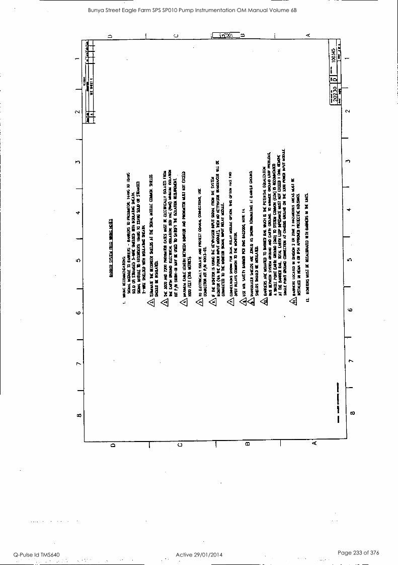
a ziglw
it AO g ag.
! 2 1 'ail 1 11 : 1 illii w
iii IN i ll! : t 54 Mil i! ;it i iig ! 1 ip 1 i illii 1
eala g
ill!! rg 1 1 Ill 4 1 ;la
.!. apid 46 X S L 5 62.4 1. la. ii i "1 1 °d il iX ! 10 12131 "s ga vi 10 igi xl 1§ l I; i Wi e:;g ill wi IV 4g 1 Ill 11 r li §1;11 !I
!Li !: lii 1! la Pi 15 5 11 1 " il° 11 !g 11; n !II ik !I i liSti ii
44 4 44 4 4.1 A 4
1
Bunya Street Eagle Farm SPS SP010 Pump Instrumentation OM Manual Volume 6B
Q-Pulse Id TMS640 Active 29/01/2014 Page 233 of 376
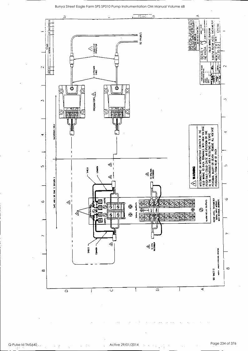
8 I
7
WE
AR
EA
O
R Z
ON
E
2,
Om
SIC
AY
2
MaZ
AR
OO
uS
AR
IA
1 C
OW
EN
P
RO
UN
TO
RS
,&
- LU
N/tI
CIO
N
FR
0110
011
to
RH
A
RE
CO
RD
ER
SE
E S
KI!
2
wat
l. lll
t 1/
1131
11.0
A
® g
)C"
EIN
E-A
ff
[pm
m
i a.
44.
9Cm
at
Oul
PuT
S
la R
OC
CO
m
43±
I
ALA
RM
R
ELA
Y
OU
IPU
IS
RO
TO
R
AC
Ctl.
IA
CR
OB
EIE
R
SO
IAL
INP
UT
M
OD
ULE
101N
14
1tal
tot
BA
RR
IER
S
A WA
RM
ING
INS
CO
NN
EC
TiN
G
OR
iN
TE
RT
AIT
TE
NI
CO
NT
AC
T
Of
TH
E
FIE
LD
NtR
iNG
10
RA
CK
1E
RiN
NA
LS
NU
T N
IGH
V
OLT
AG
E
PO
TE
NT
IALS
C
OU
LD C
AU
SE
A
N
EX
PLO
SIO
N O
R
FIR
E
IN
TH
E
HA
ZA
RD
OU
S
AR
EA
RE
SU
LTIN
G I
N
SE
VE
RE
PE
RS
ON
AL
INJU
RY
O
R
DE
AT
H
RE
MO
VE
ALL
V
OLT
AG
E
PO
TE
NT
IALS
F
RO
u R
EA
R
Of
RA
CK
8 7
6 5
4
10
PR
OM
S
wal
t...
IMA
N, N
I* 0
Ira.
inor
m w
ove
Q
mot
or
,
eon.
.
BE
N T
LY
rN
NE
VA
DA
%
.)
11.1
110
FIE
LD
WIR
ING
D
IAG
RA
M
3100
/50
RO
IL*
AC
CE
L IA
Ctio
ul
R
aso
"u~
2023
i D
_
_ I1
5!94
_
Bunya Street Eagle Farm SPS SP010 Pump Instrumentation OM Manual Volume 6B
Q-Pulse Id TMS640 Active 29/01/2014 Page 234 of 376
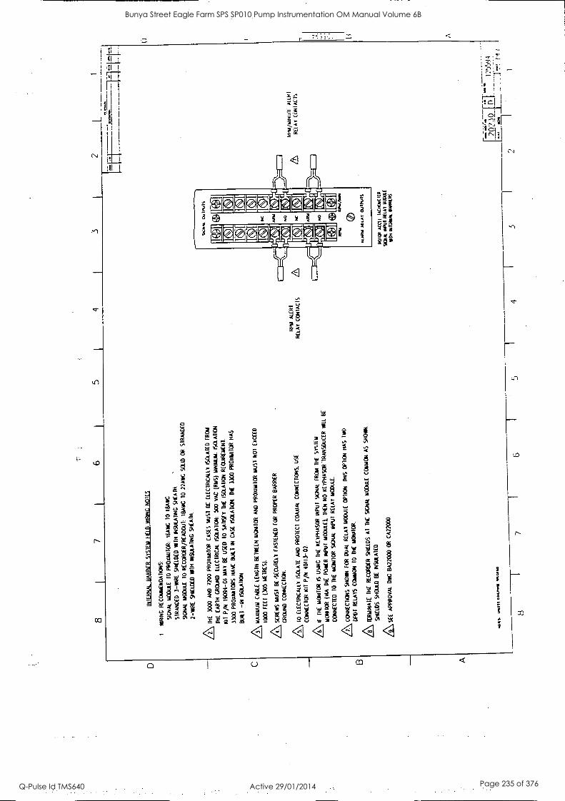
D B A
8 7
6 5
1 4
INT
ER
NA
L B
AR
RIE
R S
YS
TE
M [C
D W
IRIN
G
N01
15
1 M
IRIN
G
RE
CO
MM
EN
DA
TIO
NS
:
9CN
AL
MO
DU
LE
TO
P
FIO
XIIR
IOR
: 16
AW
C
10 IR
AK
ST
RA
ND
ED
3
-WIR
E
SH
IELD
ED
W
ITH
IN
SU
LAT
ING
SHEATH.
SIG
NA
L M
OD
ULE
10
RE
CO
RD
ER
/RE
AD
C01
: IB
AW
C
10
22A
WC
SO
LID
O
R
ST
RA
ND
ED
2 -M
IRE
S
HIE
LDE
D
111T
H
INS
ULA
TIN
G
SH
EA
TH
.
TH
E
3000
A
ND
72
00
PR
O/0
1410
R
CA
SE
S
MU
ST
B
E
ELE
CT
RIC
ALL
Y I
SO
LAT
ED
F
RO
M
TH
E
EA
RT
H
GR
OU
ND
E
LEC
TR
ICA
L IS
OLA
TIO
N:
500
VA
C
(IM
S)
MIN
IUM
. IS
OLA
TIO
N
TU
T
P/N
19
094-
01
MA
Y
BE
U
SE
D
10
SA
TIS
FY
T
HE
IS
OLA
TIO
N
RE
QU
IRE
ME
NT
.
3300
P
RO
XIM
ITO
RS
H
AV
E 1
3U11
.1
IN
CA
SE
(S
CU
D/M
. T
HE
33
00 P
RO
XIM
ITO
R
HA
S
BU
ILT
-I
N I
SO
LAT
ION
.
/3\ M
AX
IMU
M C
AB
LE
LEN
GT
H 1
3111
1fE
N M
ON
ITO
R A
ND
P
RO
XIM
ITO
R M
US
T
NO
T
EX
CE
ED
1000
F
EE
T (3
05
ME
TR
ES
).
AS
CR
EW
S M
US
T
BE
S
EC
UR
ELY
F
AS
TE
NE
D F
OR
P
RO
PE
R
BA
RR
IER
GR
OU
ND
C
ON
NE
CT
ION
.
/5\ T
O E
LEC
TR
ICA
LLY
IS
OLA
TE
A
ND
P
RO
TE
CT
CO
AX
IAL
CO
NN
EC
TIO
NS
. US
E
CO
NN
EC
TO
R K
IT P
/N
4011
3-02
.
/6\ If
TH
E
MO
NIT
OR
IS
U
SIN
G
TH
E
XE
YP
HA
SO
R
INP
UT
S
IGN
AL
FR
OM
T
HE
S
YS
TE
M
MO
NIT
OR
(M
A
TH
E
PO
WE
R
INP
UT
M
OD
ULE
).
TH
EN
N
O
XE
YP
HA
SC
R
TR
AN
SD
UC
ER
WIL
L B
E
CO
NN
EC
TE
D
10
TH
E
MO
NIT
OR
S
TC
NA
L IN
PU
T
RE
LAY
M
OD
ULE
.
/7\ C
ON
NE
CT
ION
S
SH
OW
N
FO
R
DU
AL
RE
LAY
M
OD
ULE
O
PT
ION
T
HIS
O
PT
ION
H
AS
T
WO
CIP
OT
R
ELA
YS
C
OM
MO
N
10 T
HE
M
ON
ITO
R.
Z\ T
ER
MIN
AT
E
TH
E
RE
CO
RD
ER
S
HIE
LDS
A
l T
HE
S
IGN
AL
MO
DU
LE
CO
MM
ON
A
S
SH
OW
N.
SH
IELD
S
SH
OU
LD
BE
IN
SU
LAT
ED
&S
EE
AP
PR
OV
AL
DW
C B
A22
000
OR
C
A22
000
Wal
l to
ol SS
O
NLN
NN
8 1
7 6
RP
M M
IR 1
RE
LAY
C
ON
TA
CT
S
3 I
2 L
7'11
1T
SIC
NA
J.
Ou
IPU
IS
®I®
RP
M
NC
AR
IA
NO
NC
AR
IA
NO
Coy
IL
I I
RP
M A
NN
ALA
RM
PIL
AW
O
UIP
IJIS
RO
ICR
A
CM
IA
CN
OW
Ill
SIG
NA
L Ill
RECA
P 1
1001
11I
EN
ION
IN.
BA
RR
IER
S
RP
M/M
INIM
A
IDE
I
RE
LAY
C
UN
IAC
IS
:fI0
-1
:*:_
'-ci5
5:)4
.
-.
1 t:
--
,...)
.. _7
.1.1
.1.-
i.
1 4
1 .5
1
I 1
Bunya Street Eagle Farm SPS SP010 Pump Instrumentation OM Manual Volume 6B
Q-Pulse Id TMS640 Active 29/01/2014 Page 235 of 376
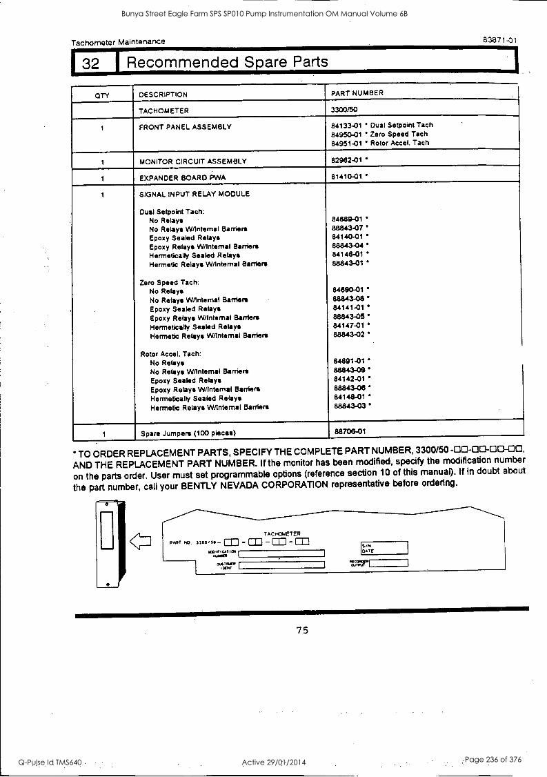
Tachometer Maintenance 83871-01
132 1 Recommended Spare Parts
QTY DESCRIPTION PART NUMBER
TACHOMETER 3300/50
1 FRONT PANEL ASSEMBLY 84133-01 Dual Setpoint Tach 84950-01 Zero Speed Tach 84951-01 Rotor Accel. Tach
1 MONITOR CIRCUIT ASSEMBLY 82962-01
1 EXPANDER BOARD PWA 81410-01
1 SIGNAL INPUT RELAY MODULE
Dual Setpoint Tach: No Relays 84689-01 No Relays W/Intemal Barriers 88843-07 Epoxy Sealed Relays 84140-01 Epoxy Relays W/Intemal Barriers 88843-04 Hermetically Sealed Relays 84148-01
Hermetic Relays W/Intemal Barriers 88843-01
Zero Speed Tech: No Relays 84690-01
No Relays W/Intemal Barriers 88843-08
Epoxy Sealed Relays 84141-01
Epoxy Relays W/Intemal Barriers 88843-05 Hermetically Sealed Relays 84147-01
Hermetic Relays W/Intemal Barriers 88843-02
Rotor Accel. Tach: No Relays 84691-01
No Relays W/Intemal Barriers 88843 -09' Epoxy Sealed Relays 84142-01
Epoxy Relays W/Intemal Bafflers 88843-06 Hermetically Sealed Relays 84148-01
Hermetic Relays W/Intemal Bafflers 88843-03
1 Spare Jumpers (100 pieces) 88706-01
TO ORDER REPLACEMENT PARTS, SPECIFY THE COMPLETE PART NUMBER, 3300/50 -00-00-00-00, AND THE REPLACEMENT PART NUMBER. If the monitor has been modified, specify the modification number
on the parts order. User must set programmable options (reference section 10 of this manual). If in doubt about
the part number, call your BENTLY NEVADA CORPORATION representative before ordering.
PART P43
TACHOMETER
- CID -CD -m - CAT 1CN
...A4101
0-0,01LIP COO
1
S'N DATE
%TAUT r
75
Bunya Street Eagle Farm SPS SP010 Pump Instrumentation OM Manual Volume 6B
Q-Pulse Id TMS640 Active 29/01/2014 Page 236 of 376
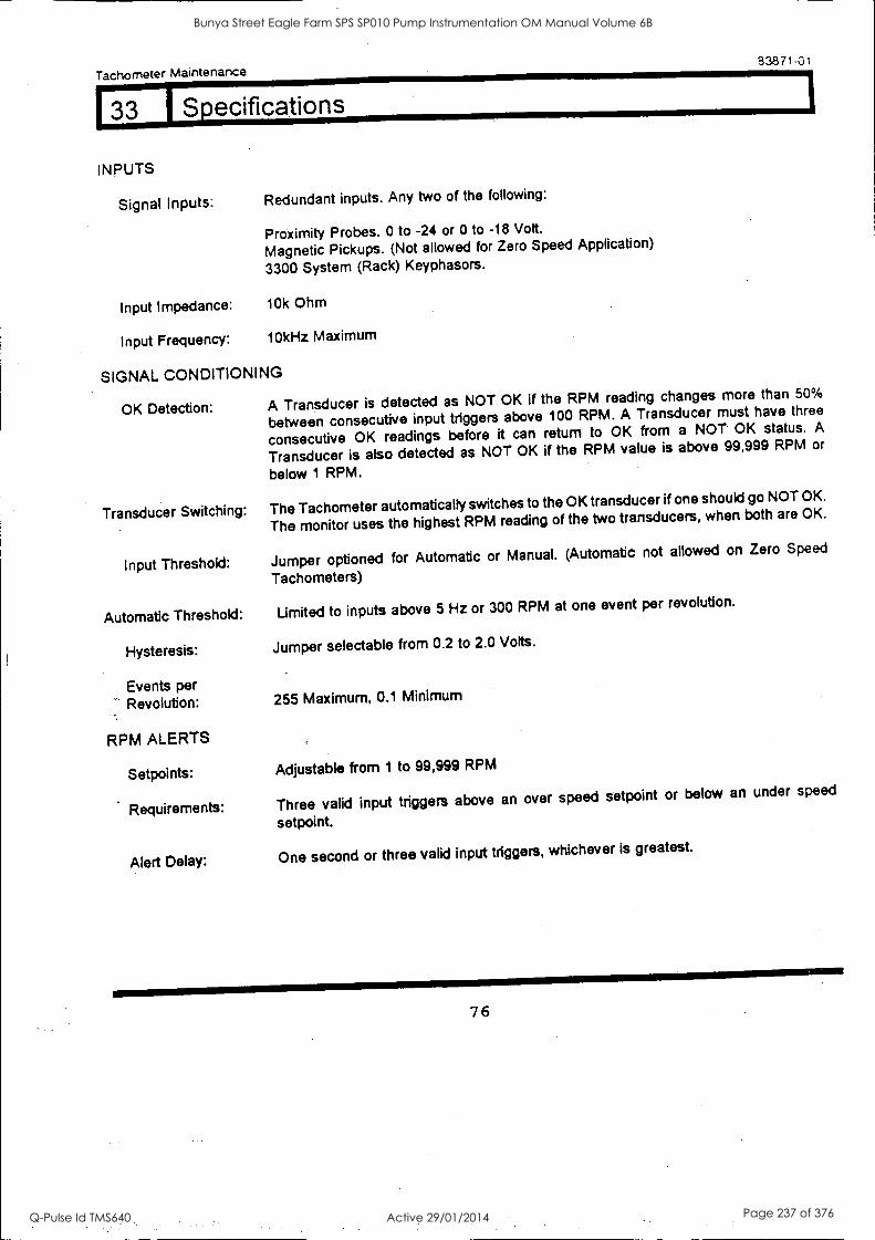
Tachometer Maintenance
INPUTS
Signal Inputs:
Input Impedance:
Redundant inputs. Any two of the following:
Proximity Probes. 0 to -24 or 0 to -18 Volt.
Magnetic Pickups. (Not allowed for Zero Speed Application)
3300 System (Rack) Keyphasors.
10k Ohm
Input Frequency: 10k Hz Maximum
SIGNAL CONDITIONING
OK Detection:
Transducer Switching:
Input Threshold:
Automatic Threshold:
Hysteresis:
Events per Revolution:
RPM ALERTS
Setpoints:
Requirements:
83871-01
A Transducer is detected as NOT. OK if the RPM reading changes more than 50%
between consecutive input triggers above 100 RPM. A Transducer must have three
consecutive OK readings before it can return to OK from a NOT OK status. A
Transducer is also detected as NOT OK if the RPM value is above 99,999 RPM or
below 1 RPM.
The Tachometer automatically switches to the OK transducer if one should go NOT OK.
The monitor uses the highest RPM reading of the two transducers, when both are OK.
Jumper optioned for Automatic or Manual. (Automatic not allowed on Zero Speed
Tachometers)
Limited to inputs above 5 Hz or 300 RPM at one event per revolution.
Jumper selectable from 0.2 to 2.0 Volts.
255 Maximum, 0.1 Minimum
Adjustable from 1 to 99,999 RPM
Three valid input triggers above an over speed setpoint or below an under speed
setpoint.
Alert Delay: One second or three valid input triggers, whichever is greatest.
Bunya Street Eagle Farm SPS SP010 Pump Instrumentation OM Manual Volume 6B
Q-Pulse Id TMS640 Active 29/01/2014 Page 237 of 376
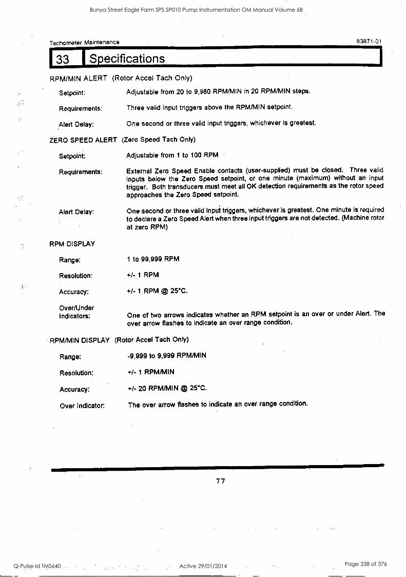
Tachometer Maintenance 83871-01
133 I Specifications
RPM/MIN ALERT (Rotor Accel Tach Only)
Setpoint: Adjustable from 20 to 9,980 RPM/MIN in 20 RPM/MIN steps.
Requirements: Three valid input triggers above the RPM/MIN setpoint.
Alert Delay: One second or three valid input triggers, whichever is greatest.
ZERO SPEED ALERT (Zero Speed Tach Only)
Setpoint: Adjustable from 1 to 100 RPM
Requirements: External Zero Speed Enable contacts (user-supplied) must be closed. Three valid inputs below the Zero Speed setpoint, or one minute (maximum) without an input
trigger. Both transducers must meet all OK detection requirements as the rotor speed
approaches the Zero Speed setpoint.
Alert Delay: One second or three valid input triggers, whichever is greatest. One minute is required
to declare a Zero Speed Alert when three input triggers are not detected. (Machine rotor
at zero RPM)
RPM DISPLAY
Range: 1 to 99,999 RPM
Resolution: +/- 1 RPM
Accuracy: +/- 1 RPM @ 25°C.
Over/Under Indicators: One of two arrows indicates whether an RPM setpoint is an over or under Alert. The
over arrow flashes to indicate an over range condition.
RPM/MIN DISPLAY (Rotor Accel Tach Only)
Range: -9,999 to 9,999 RPM/MIN
Resolution: +/- 1 RPM/MIN
Accuracy: +/- 20 RPM/MIN 25°C.
Over Indicator. The over arrow flashes to indicate an over range condition.
77
Bunya Street Eagle Farm SPS SP010 Pump Instrumentation OM Manual Volume 6B
Q-Pulse Id TMS640 Active 29/01/2014 Page 238 of 376
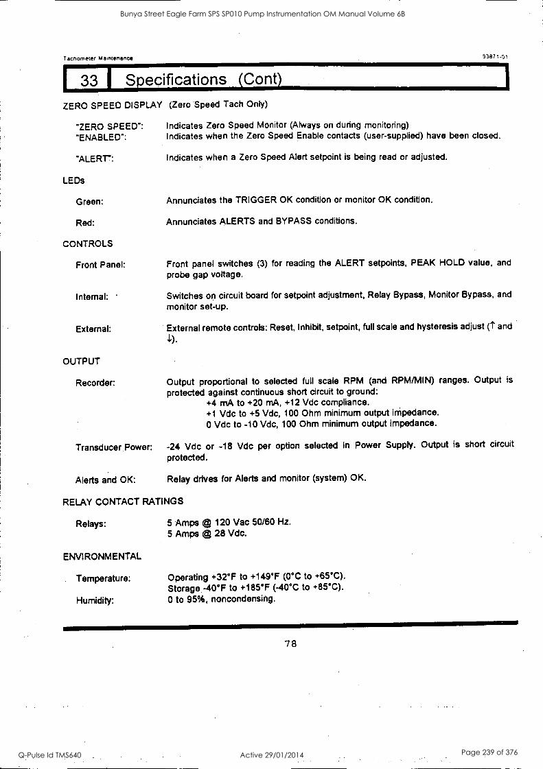
Tachometer Maintenance 53871.01
1 33 1 Specifications (Cont)
ZERO SPEED DISPLAY (Zero Speed Tach Only)
"ZERO SPEED": Indicates Zero Speed Monitor (Always on during monitoring)
"ENABLED": Indicates when the Zero Speed Enable contacts (user-supplied) have been closed.
"ALERT:
LEDs
Green:
Red:
CONTROLS
Front Panel:
Internal:
External:
OUTPUT
Recorder:
Indicates when a Zero Speed Alert setpoint is being read or adjusted.
Annunciates the TRIGGER OK condition or monitor OK condition.
Annunciates ALERTS and BYPASS conditions.
Front panel switches (3) for reading the ALERT setpoints, PEAK HOLD value, and
probe gap voltage.
Switches on circuit board for setpoint adjustment, Relay Bypass, Monitor Bypass, and
monitor set-up.
External remote controls: Reset, Inhibit, setpoint, full scale and hysteresis adjust (t and
Output proportional to selected full scale RPM (and RPM/MIN) ranges. Output is
protected against continuous short circuit to ground: +4 mA to +20 mA, +12 Vdc compliance. +1 Vdc to +5 Vdc, 100 Ohm minimum output impedance. 0 Vdc to -10 Vdc, 100 Ohm minimum output impedance.
Transducer. Power: -24 Vdc or -18 Vdc per option selected in Power Supply. Output is short circuit
protected.
Alerts and OK: Relay drives for Alerts and monitor (system) OK.
RELAY CONTACT RATINGS
Relays: 5 Amps (44 120 Vac 50/60 Hz.
5 Amps © 28 Vdc.
ENVIRONMENTAL
Temperature: Operating +32°F to +149°F (0°C to +65°C).
Storage -40°F to +185°F (-40°C to +85°C).
Humidity: 0 to 95%, noncondensing.
78
Bunya Street Eagle Farm SPS SP010 Pump Instrumentation OM Manual Volume 6B
Q-Pulse Id TMS640 Active 29/01/2014 Page 239 of 376
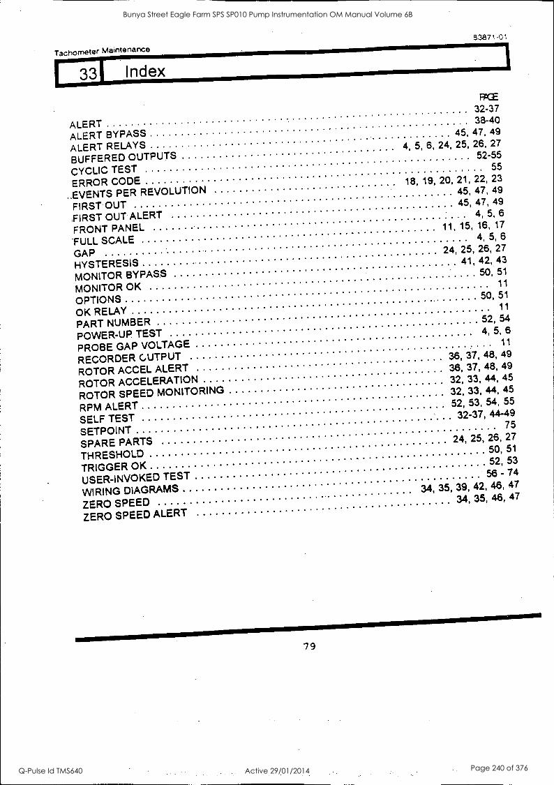
Tachometer Maintenance
53871-01
331 Index
ALERT ALERT BYPASS
32-37 38-40
ALERT RELAYS 45, 47, 49
BUFFERED OUTPUTS 4, 5, 6, 24, 25, 26, 27
CYCLIC TEST 52-55
ERROR CODE
55
..EVENTS PER REVOLUTION 18, 19, 20, 21, 22, 23
FIRST OUT
45, 47, 49
,FIRST OUT ALERT 45, 47, 49
FRONT PANEL
4, 5, 6
"FULL SCALE
11, 15, 16, 17
GAP
4, 5, 6
HYSTERESIS
24, 25, 26, 27
MONITOR BYPASS 41, 42, 43
MONITOR OK
50, 51
OPTIONS
11
OK RELAY
50, 51
PART NUMBER
11
POWER-UP TEST 52, 54
PROBE GAP VOLTAGE 4, 5, 6
RECORDER GUTPUT
11
ROTOR ACCEL ALERT 36, 37, 48, 49
ROTOR ACCELERATION 36, 37, 48, 49
ROTOR SPEED MONITORING 32, 33, 44, 45
RPM ALERT
32, 33, 44, 45
SELF TEST
52, 53, 54, 55
S ETPOI NT
32-37, 44-49
SPARE PARTS
75
THRESHOLD
24, 25, 26, 27
TRIGGER OK
50, 51
USER -INVOKED TEST
52, 53
WIRING DIAGRAMS
56 - 74
ZERO SPEED
34, 35, 39, 42, 46, 47
ZERO SPEED ALERT 34, 35, 46, 47
79
Bunya Street Eagle Farm SPS SP010 Pump Instrumentation OM Manual Volume 6B
Q-Pulse Id TMS640 Active 29/01/2014 Page 240 of 376

BRISBANE CITY COUNCIL Dept. Water Supply and Sewage Pumpwell No 1, Eagle Farm Pump Station
BCC Contract No S20/95/96 System Instrumentation
Operation and Maintenance Manual
8.3 Vibration Monitor
The following publication entitled 3300/55 Dual Velocity Monitor Maintenance Manual (Part No 130748-01 Rev C) is prepared by Bent ly Nevada for plant personnel who install and maintain the system. It provides a detailed description of the maintenance and adjustment procedures for the of the Dual Velocity module.
The following sections are included:
8.3.1 Dual Velocity Monitor System
8.3.2 Front Panel Features
8.3.3 Monitor Removal
8.3.4 Monitor Disassembly
8.3.5 Signal Input Relay Module
8.3.6 Monitor Options
8.3.7 Main Board Jumper Locations
8.3.8 PK-PK Filter Board Jumper Locations
8.3.9 RMS Filter Jumper Locations
8.3.10 First Out, Alarm Delays
8.3.11 Alert Mode, Danger Mode
8.3.12 Danger Relay Voting
8.3.13 Buffered Transducer Output Option
8.3.14 Transducer Channel Units Input Option
8.3.15 Transducer Type Option
8.3.16 Channel A Full Scale Range Option
8.3.17 Channel B Full Scale Range Option
8.3.18 Barriers, Trip Multiply Options
8.3.19 Alarm Setpoint Adjustment
8.3.20 Bypass Monitor Channel
8.3.21 Danger Bypass
15140/Inst Man/BRH Issue 1 29-Apr-98 Page 8-5
Bunya Street Eagle Farm SPS SP010 Pump Instrumentation OM Manual Volume 6B
Q-Pulse Id TMS640 Active 29/01/2014 Page 241 of 376

BRISBANE CITY COUNCIL Dept. Water Supply and Sewage Pumpwell No 1, Eagle Farm Pump Station
BCC Contract No S20/95/96 System Instrumentation
Operation and Maintenance Manual
8.3.22 Test Channel Alarms
8.3.23 Test OK Limits
8.3.24 Calibrate Channels
8.3.25 Filter Programming
8.3.26 Self Test
8.3.27 Field Wiring Diagram
8.3.28 Recommended Spare Parts
8.3.29 Specifications
8.3.30 Index
15140/Inst Man/BRH Issue 1 29-Apr-98 Page 8-6
Bunya Street Eagle Farm SPS SP010 Pump Instrumentation OM Manual Volume 6B
Q-Pulse Id TMS640 Active 29/01/2014 Page 242 of 376
3300/55 DUAL VELOCITY MONITOR
MAINTENANCE MANUAL
BENTLY NEVADA
PART NO. 130748-01 REVISION, C
APRIL 1997
a a a 0
Bunya Street Eagle Farm SPS SP010 Pump Instrumentation OM Manual Volume 6B
Q-Pulse Id TMS640 Active 29/01/2014 Page 243 of 376
130748-01 Dual Velocity Monitor Maintenance
NOTICE
READ THE FOLLOWING BEFORE INSTALLING OR OPERATING EQUIPMENT
,I15ently Nevada Corporation has attempted to identify areas of risk created by improper installation and/or operation of this product,. These areas of information are noted as WARNING or CAUTION for your protection for the4afe.and effective operation of this eciuipment. .-130:04-alrinatniCtiOns
. .,,.... befor9.instatting:er,o erating this product Pay particular attention to thos e... are as!designated : the following ymbqs
2-;:*
High VO)ioie::,pie'seht:.;: Contact could cause
ishisdk; burns, or death._ ..
_S
Maéhine rcti6r during uroti
=
0 t *
=4i . -
t...1:1;41_111r: z /110.1. 7 011 A
, 7
pfrig.ht.inf.1146-e-meht-..isla--;ten'o-ut...Atilte, a. e
Uflited States of America and rprOigtopyright
1 - . -
Bunya Street Eagle Farm SPS SP010 Pump Instrumentation OM Manual Volume 6B
Q-Pulse Id TMS640 Active 29/01/2014 Page 244 of 376
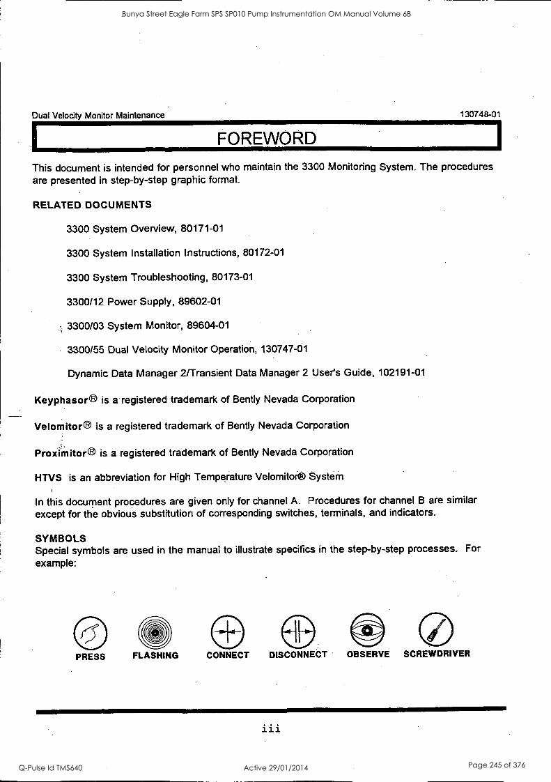
Dual Velocity Monitor Maintenance 130748-01
FOREWORD
This document is intended for personnel who maintain the 3300 Monitoring System. The procedures are presented in step-by-step graphic format.
RELATED DOCUMENTS
3300 System Overview, 80171-01
3300 System Installation Instructions, 80172-01
3300 System Troubleshooting, 80173-01
3300/12 Power Supply, 89602-01
3300/03 System Monitor, 89604-01
3300/55 Dual Velocity Monitor Operation, 130747-01
Dynamic Data Manager 2/Transient Data Manager 2 User's Guide, 102191-01
Keyphasor® is a registered trademark of Bently Nevada Corporation
Velomitor® is a registered trademark of Bently Nevada Corporation
Proximitora is a registered trademark of Bently Nevada Corporation
HTVS is an abbreviation for High Temperature Velomitor® System
In this document procedures are given only for channel A. Procedures for channel B are similar except for the obvious substitution of corresponding switches, terminals, and indicators.
SYMBOLS Special symbols are used in the manual to illustrate specifics in the step-by-step processes. For example:
PRESS FLASHING CONNECT DISCONNECT OBSERVE SCREWDRIVER
iii
Bunya Street Eagle Farm SPS SP010 Pump Instrumentation OM Manual Volume 6B
Q-Pulse Id TMS640 Active 29/01/2014 Page 245 of 376
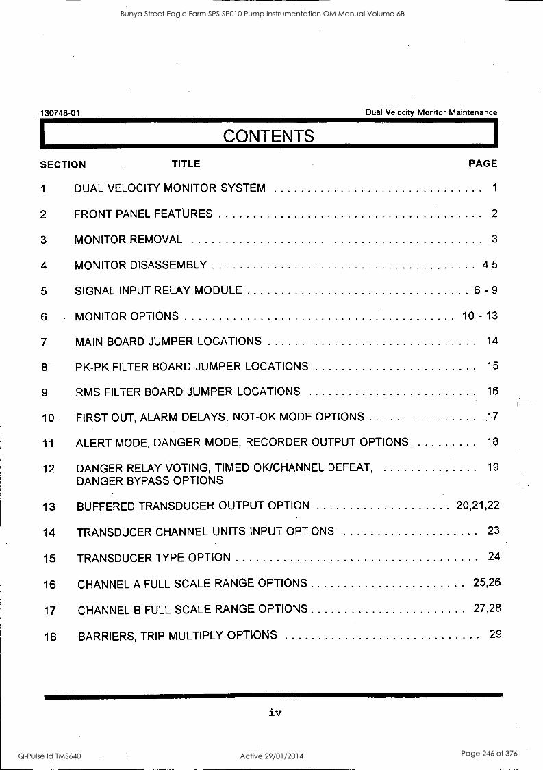
130748-01 Dual Velocity Monitor Maintenance
CONTENTS
SECTION TITLE
1 DUAL VELOCITY MONITOR SYSTEM
2 FRONT PANEL FEATURES
3 MONITOR REMOVAL
4 MONITOR DISASSEMBLY
5 SIGNAL INPUT RELAY MODULE
PAGE
1
2
3
4,5
6 - 9
6 MONITOR OPTIONS 10 - 13
7 MAIN BOARD JUMPER LOCATIONS 14
8 PK-PK FILTER BOARD JUMPER LOCATIONS 15
9 RMS FILTER BOARD JUMPER LOCATIONS 16
10 FIRST OUT, ALARM DELAYS, NOT-OK MODE OPTIONS .17
11 ALERT MODE, DANGER MODE, RECORDER OUTPUT OPTIONS 18
12 DANGER RELAY VOTING, TIMED OK/CHANNEL DEFEAT, DANGER BYPASS OPTIONS
19
13 BUFFERED TRANSDUCER OUTPUT. OPTION 20,21,22
14 TRANSDUCER CHANNEL UNITS INPUT OPTIONS 23
15 TRANSDUCER TYPE OPTION 24
16 CHANNEL A FULL SCALE RANGE OPTIONS 25,26
17 CHANNEL B FULL SCALE RANGE OPTIONS 27,28
18 BARRIERS, TRIP MULTIPLY OPTIONS 29
iv
Bunya Street Eagle Farm SPS SP010 Pump Instrumentation OM Manual Volume 6B
Q-Pulse Id TMS640 Active 29/01/2014 Page 246 of 376
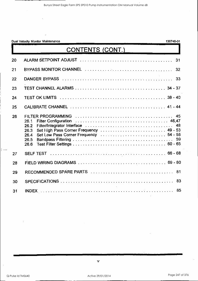
Dual Velocity Monitor Maintenance 130748-01
CONTENTS (CONT.)
20 ALARM SETPOINT ADJUST
21 BYPASS MONITOR CHANNEL 32
31
22 DANGER BYPASS 33
23 TEST CHANNEL ALARMS 34 - 37
24 TEST OK LIMITS 38 - 40
25 CALIBRATE CHANNEL 41 - 44
26 FILTER PROGRAMMING 45 26.1 Filter Configuration 46,47 26.2 Filter/Integrator Interface 48 26.3 Set High Pass Corner Frequency 49 - 53 26.4 Set Low Pass Corner Frequency 54 - 58 26.5 Bandpass Filtering 59 26.6 Test Filter Settings 60 - 65
27 SELF TEST 66 - 68
28 FIELD WIRING DIAGRAMS 69 - 80
29 RECOMMENDED SPARE PARTS 81
30 SPECIFICATIONS 83
31 INDEX 85
Bunya Street Eagle Farm SPS SP010 Pump Instrumentation OM Manual Volume 6B
Q-Pulse Id TMS640 Active 29/01/2014 Page 247 of 376

130748-01 Dual Velocity Monitor Maintenance
THIS PAGE INTENTIONALLY LEFT BLANK
vi
Bunya Street Eagle Farm SPS SP010 Pump Instrumentation OM Manual Volume 6B
Q-Pulse Id TMS640 Active 29/01/2014 Page 248 of 376
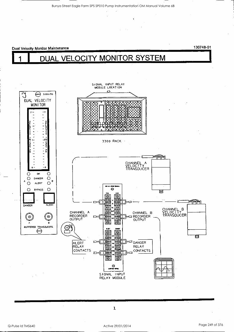
Dual Velocity Monitor Maintenance
1 I DUAL VELOCITY MONITOR SYSTEM
SIGNAL INPUT RELAY MODULE LOCATION
3300 RACK
CHANNEL A RECORDER OUTPUT
ALERT RELAY CONTACTS
CHANNEL A VELOCITY TRANSDUCER
SIGNAL I NPUT RELAY MODULE
130748-01
CHANNEL B CHANNEL B VELOCITY RECORDER TRANSDUCER OUTPUT -Th
DANGER RELAY CONTACTS
Bunya Street Eagle Farm SPS SP010 Pump Instrumentation OM Manual Volume 6B
Q-Pulse Id TMS640 Active 29/01/2014 Page 249 of 376
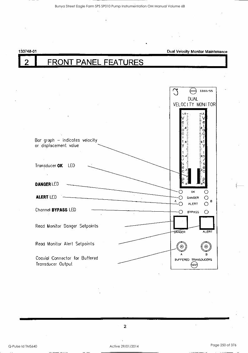
130748-01 Dual Velocity Monitor Maintenance
2 I FRONT PANEL FEATURES
Bar graph - indicates velocity or displacement value
Transducer OK LED
DANGER LED
ALERT LED
3300/55
DUAL
VELOCITY MONITOR
Channel BYPASS LED
Read Monitor Danger Setpoints
Read Monitor Alert Setpoints
Coaxial Connector for Buffered Transducer Output
1.0-2
V= e
= .8- o= c=
I =
n /_ s=
-4.0-
EV e
=,9 I
=o 1c
t y
=An z
s =e
c
OK
DANGER 0 A
ALERT Q B BYPASS 0
ANGER ALERT
A
BUFFERED TRANSDUCERS
2
Bunya Street Eagle Farm SPS SP010 Pump Instrumentation OM Manual Volume 6B
Q-Pulse Id TMS640 Active 29/01/2014 Page 250 of 376

Dual Velocity Monitor Maintenance 130748-01
3 I MONITOR REMOVAL
1. Loosen two screws. 2. Pull monitor from rack.
As, CAUTION
The machine is not protected when the monitor is removed from the rack.
3
Bunya Street Eagle Farm SPS SP010 Pump Instrumentation OM Manual Volume 6B
Q-Pulse Id TMS640 Active 29/01/2014 Page 251 of 376
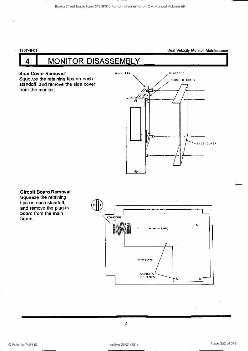
130748-01 Dual Velocity Monitor Maintenance
4 I MONITOR DISASSEMBLY
Side Cover Removal Squeeze the retaining tips on each standoff, and remove the side cover from the monitor.
Circuit Board Removal Squeeze the retaining tips on each standoff, and remove the plug-in board from the main board.
MAIN PWA STANDOFF
PLUGIN BOARD
SIDE COVER
4
Bunya Street Eagle Farm SPS SP010 Pump Instrumentation OM Manual Volume 6B
Q-Pulse Id TMS640 Active 29/01/2014 Page 252 of 376
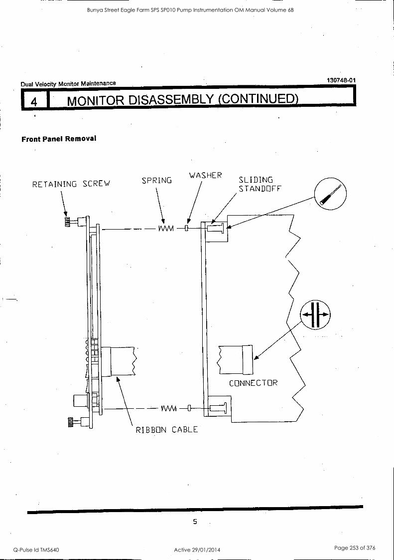
Dual Velocity Monitor Maintenance 130748-01
4 I MONITOR DISASSEMBLY (CONTINUED)
Front Panel Removal
RETAINING SCREW SPRING
VVVV1
VVV\A
WASHER SLIDING STANDOFF
CONNECTOR
RIBBON CABLE
5
Bunya Street Eagle Farm SPS SP010 Pump Instrumentation OM Manual Volume 6B
Q-Pulse Id TMS640 Active 29/01/2014 Page 253 of 376
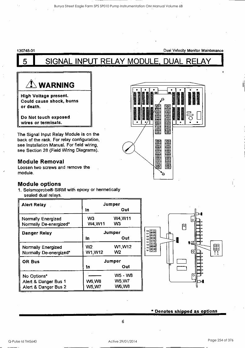
5 I SIGNAL INPUT RELAY MODULE, DUAL RELAY I
130748-01 Dual Velocity Monitor Maintenance
WARNING High Voltage present. Could cause shock, burns or death.
Do Not touch exposed wires or terminals.
The Signal Input Relay Module is on the back of the rack. For relay configuration, see Installation Manual. For field wiring, see Section 28 (Field Wiring Diagrams).
Module Removal Loosen two screws and remove the module.
Module options 1. Seismoprobe® SIRM with epoxy or hermetically
sealed dual relays.
si
-31
Alert Relay Jumper In Out
Normally Energized Normally De-energized*
W3 W4,W11 W4,W11 W3
Danger Relay Jumper In Out
Normally Energized Normally De-energized*
W2 W1 ,W12 W1 ,W12 W2
OR Bus Jumper In Out
No Options* Alert & Danger Bus 1
Alert & Danger Bus 2
W5 W8 - W6,W8 W5,W7 W5,W7 W6,W8
@I
II of
III
5
* Denotes shipped as options
6
Bunya Street Eagle Farm SPS SP010 Pump Instrumentation OM Manual Volume 6B
Q-Pulse Id TMS640 Active 29/01/2014 Page 254 of 376
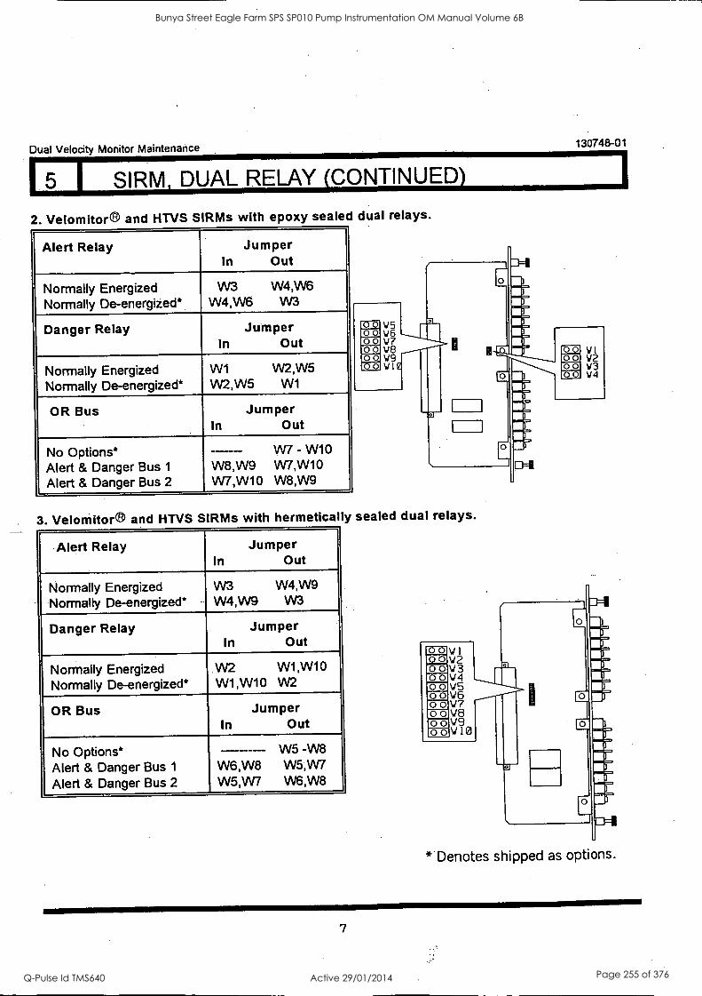
Dual Velocity Monitor Maintenance 130748-01
SIRM, DUAL RELAY (CONTINUED)
2. Velomitor® and HTVS SIRMs with epoxy sealed dual relays.
Alert. Relay Jumper In Out
Normally Energized Normally De-energized*
W3 W4,W6 W4,W6 W3
Danger Relay Jumper In Out
Normally Energized Normally De-energized*
W1 W2,W5 W2,W5 W1
OR Bus Jumper In Out
No Options* Alert & Danger Bus 1
Alert & Danger Bus 2
--- W7 - W10 W8,W9 VV7,W10 W7,W10 W8,W9
-00 00 00 00 00 00
V5 V6 V7 V8 V9 VI
1
3. Velomitor® and HTVS SIRMs with hermetically sealed dual relays.
Alert Relay Jumper In Out
Normally Energized Normally De-energized*
W3 W4,W9 W4,W9 W3
Danger Relay Jumper In Out
Normally Energized Normally De-energized*
.W2 W1 ,W10 W1,W10 W2
OR Bus Jumper In Out
No Options* Alert & Danger Bus 1
Alert & Danger Bus 2
W5 - -W8 W6,W8 W5,W7 W5,W7 W6,W8
00 00 00 00
Vl V2 W3 W4
* Denotes shipped as options.
7
Bunya Street Eagle Farm SPS SP010 Pump Instrumentation OM Manual Volume 6B
Q-Pulse Id TMS640 Active 29/01/2014 Page 255 of 376
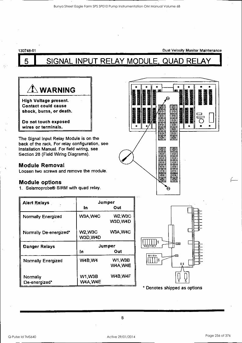
130748-01 Dual Velocity Monitor Maintenance
5 I SIGNAL INPUT RELAY MODULE, QUAD RELAY I
WARNING High Voltage present. Contact could cause shock, burns, or death.
Do not touch exposed wires or terminals.
The Signal Input Relay Module is on the back of the rack. For relay configuration, see Installation Manual. For field wiring, see Section 28 (Field Wiring Diagrams).
Module Removal Loosen two screws and remove the module.
Module options 1. Seismoprobe® SIRM with quad relay.
Alert Relays Jumper In Out
Normally Energized
Normally De-energized*
W3A,W4C W2,W3C W3D,W4D
W2,W3C W3A,W4C W3D,W4D
Danger Relays Jumper In Out
Normally Energized
Normally De-energized*
W4B,W4 W1 ,W3B W4A,W4E
W1 ,W3B W4B,W4F W4A,W4E
L+
[1. 8
m- r;
Cod
tJ
c-
HI
,IMOrICLI>
On CO>
00 * Denotes shipped as options
8
Bunya Street Eagle Farm SPS SP010 Pump Instrumentation OM Manual Volume 6B
Q-Pulse Id TMS640 Active 29/01/2014 Page 256 of 376
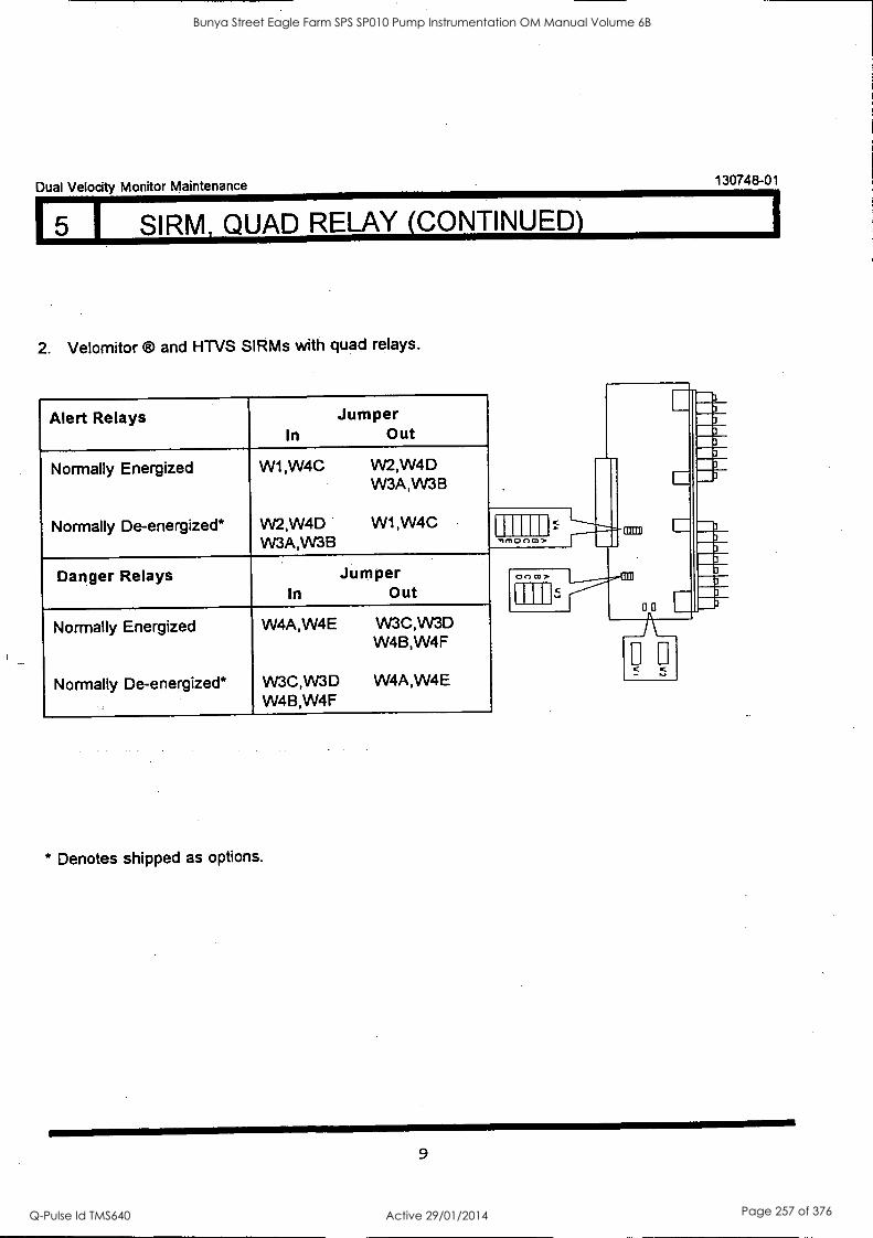
Dual Velocity Monitor Maintenance 130748-01
5 1 SIRM, QUAD RELAY (CONTINUED)
2. Velomitor ® and HTVS SIRMs with quad relays.
Alert Relays In
Jumper Out
Normally Energized W1,W4C VV2,W4D W3A,VV3B
Normally De-energized* W2,W4D VV3A,W3B
W1,W4C
Danger Relays In
Jumper Out
Normally Energized
Normally De-energized*
W4A,W4E
VV3C,VV3D W4B,W4F
W3C,W3D W4B,W4F
W4A,W4E
* Denotes shipped as options.
on m>
fl 0o C
as
9
Bunya Street Eagle Farm SPS SP010 Pump Instrumentation OM Manual Volume 6B
Q-Pulse Id TMS640 Active 29/01/2014 Page 257 of 376
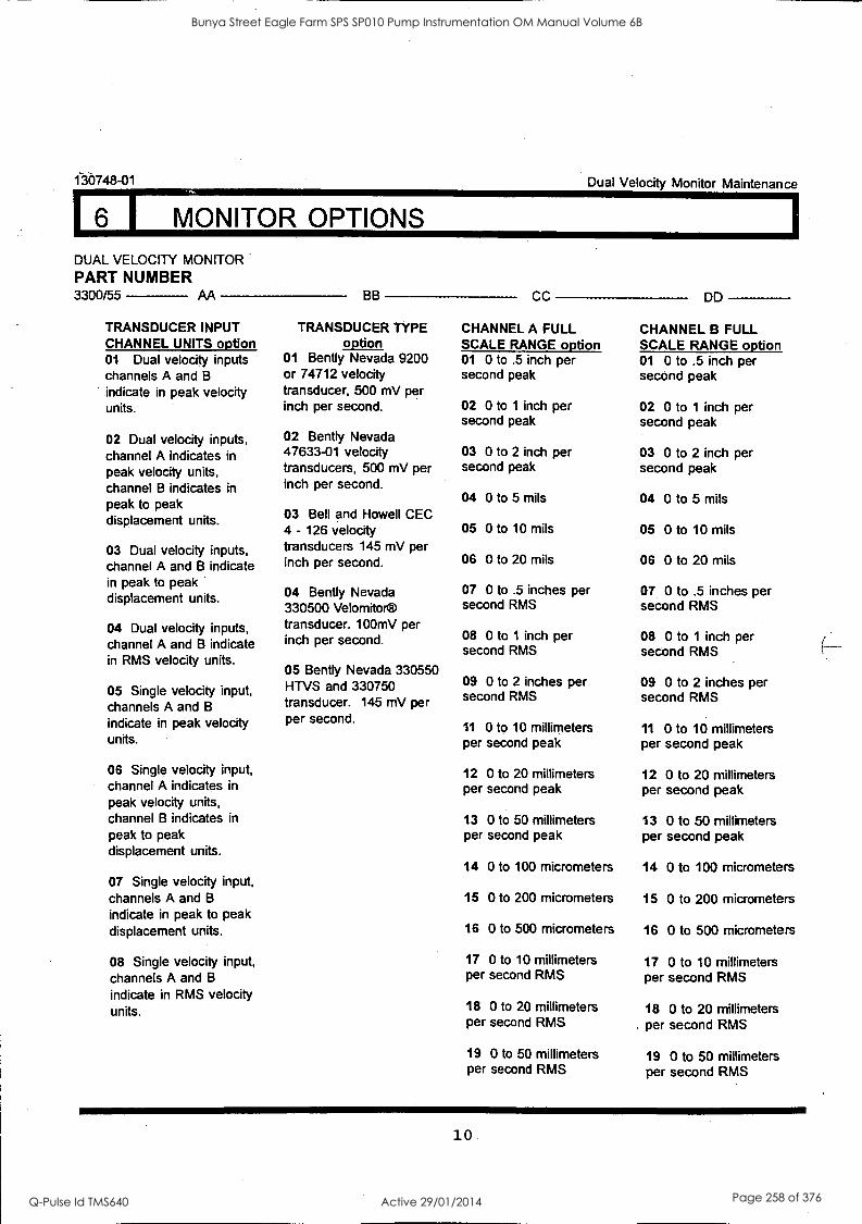
1-30748-01 Dual Velocity Monitor Maintenance
6 I MONITOR OPTIONS
DUAL VELOCITY MONITOR
PART NUMBER 3300/55 AA
TRANSDUCER INPUT CHANNEL UNITS option 01 Dual velocity inputs channels A and B indicate in peak velocity units.
02 Dual velocity inputs, channel A indicates in peak velocity units, channel B indicates in peak to peak displacement units.
03 Dual velocity inputs, channel A and B indicate in peak to peak displacement units.
04 Dual velocity inputs, channel A and B indicate in RMS velocity units.
05 Single velocity input, channels A and B
indicate in peak velocity units.
06 Single velocity input, channel A indicates in
peak velocity units, channel B indicates in
peak to peak displacement units.
07 Single velocity input, channels A and B
indicate in peak to peak displacement units.
08 Single velocity input, channels A and B
indicate in RMS velocity units.
BB
TRANSDUCER TYPE option
01 Benny Nevada 9200 or 74712 velocity transducer, 500 mV per inch per second.
02 Bent ly Nevada 47633-01 velocity transducers, 500 mV per inch per second.
03 Bell and Howell CEC 4 - 126 velocity transducers 145 mV per inch per second.
04 Bent ly Nevada 330500 Velomitor® transducer. 100mV per inch per second.
05 Bent ly Nevada 330550 HTVS and 330750 transducer. 145 mV per per second.
CC
CHANNEL A FULL SCALE RANGE option 01 0 to .5 inch per second peak
02 0 to 1 inch per second peak
03 0 to 2 inch per second peak
04 0 to 5 mils
05 0 to 10 mils
06 0 to 20 mils
07 0 to .5 inches per second RMS
08 0 to 1 inch per second RMS
09 0 to 2 inches per second RMS
11 0 to 10 millimeters per second peak
12 0 to 20 millimeters per second peak
13 0 to 50 millimeters per second peak
14 0 to 100 micrometers
15 0 to 200 micrometers
16 0 to 500 micrometers
17 0 to 10 millimeters per second RMS
18 0 to 20 millimeters per second RMS
19 0 to 50 millimeters per second RMS
DD
CHANNEL B FULL SCALE RANGE option 01 0 to .5 inch per second peak
02 0 to 1 inch per second peak
03 0 to 2 inch per second peak
04 0 to 5 mils
05 0 to 10 mils
06 0 to 20 mils
07 0 to .5 inches per second RMS
08 0 to 1 inch per second RMS
09 0 to 2 inches per second RMS
11 0 to 10 millimeters per second peak
12 0 to 20 millimeters per second peak
13 0 to 50 millimeters per second peak
14 0 to 100 micrometers
15 0 to 200 micrometers
16 0 to 500 micrometers
17 0 to 10 millimeters per second RMS
18 0 to 20 millimeters . per second RMS
19 0 to 50 millimeters per second RMS
10
Bunya Street Eagle Farm SPS SP010 Pump Instrumentation OM Manual Volume 6B
Q-Pulse Id TMS640 Active 29/01/2014 Page 258 of 376
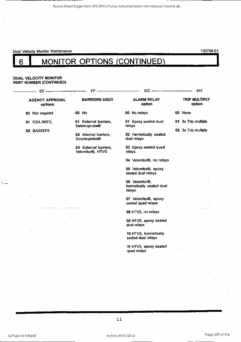
Dual Velocity Monitor Maintenance 130748-01
6 I MONITOR OPTIONS (CONTINUED)
DUAL VELOCITY MONITOR PART NUMBER (CONTINUED)
EE FF GG HH
AGENCY APPROVAL BARRIERS USED ALARM RELAY TRIP MULTIPLY options option option
00 Not required 00 No 00 No relays 00 None
01 CSA /NRTL 01 External barriers, 01 Epoxy sealed dual 01 2x Trip multiply Seismoprobe® relays
02 BASEEFA 02 3x Trip multiply 02 Internal barriers, 02 Hermetically sealed Seismoprobe® dual relays
03 External barriers, 03 Epoxy sealed quad Velomitor®, HTVS relays
04 Velomitor®, no relays
05 Velomito®, epoxy sealed dual relays
08 Velomitor®, hermetically sealed dual relays
07 Velomitor®, epoxy sealed quad relays
08 HTVS, no relays
09 HTVS, epoxy sealed dual relays
10 HTVS, hermetically sealed dual relays
11 HTVS, epoxy sealed quad relays
11
Bunya Street Eagle Farm SPS SP010 Pump Instrumentation OM Manual Volume 6B
Q-Pulse Id TMS640 Active 29/01/2014 Page 259 of 376
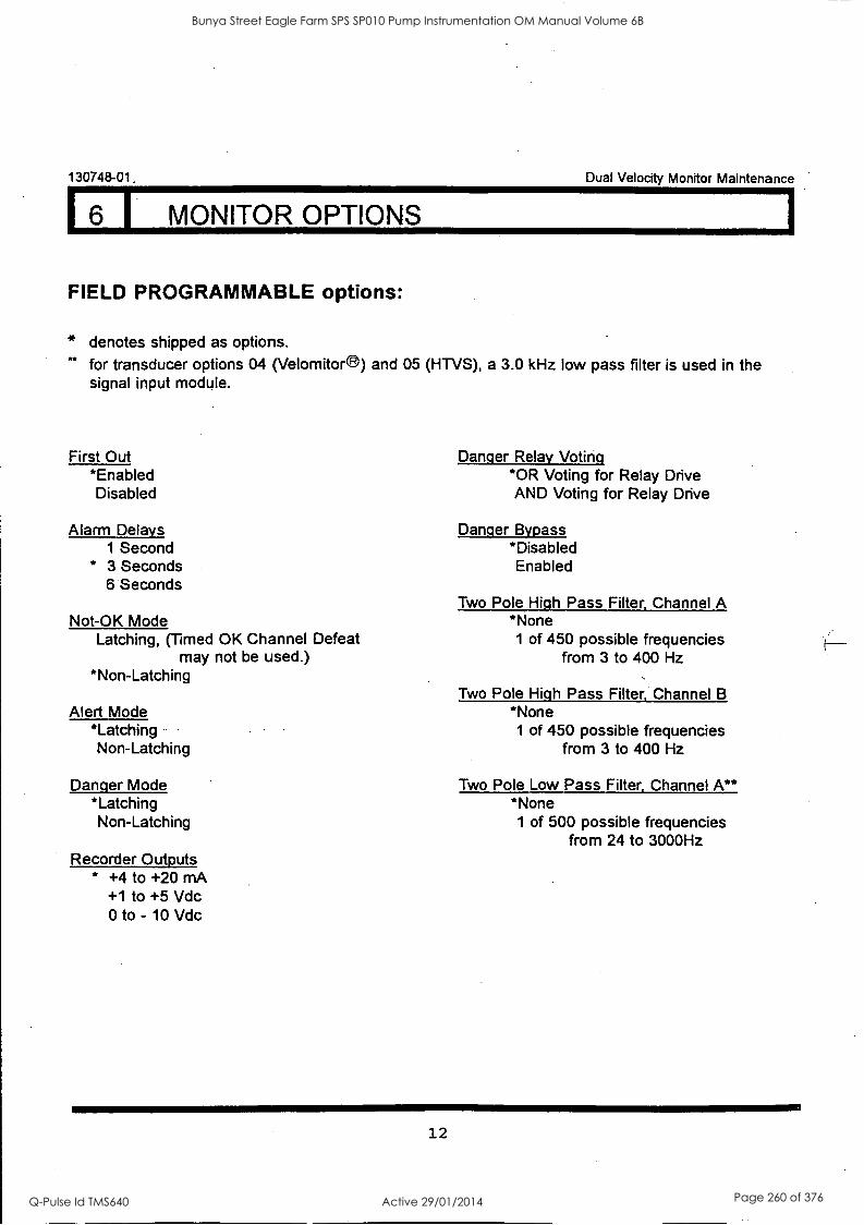
130748-01. Dual Velocity Monitor Maintenance
6 I MONITOR OPTIONS
FIELD PROGRAMMABLE options:
* denotes shipped as options. for transducer options 04 (Velomitor ) and 05 (HTVS), a 3.0 kHz low pass filter is used in the signal input module.
First Out *Enabled Disabled
Alarm Delays 1 Second
* 3 Seconds 6 Seconds
Not-OK Mode Latching, (Timed OK Channel Defeat
may not be used.) *Non-Latching
Alert Mode *Latching Non-Latching
Danger Mode *Latching Non-Latching
Recorder Outputs * +4 to +20 mA
+1 to +5 Vdc 0 to - 10 Vdc
Danger Relay Voting *OR Voting for Relay Drive AND Voting for Relay Drive
Danger Bypass *Disabled Enabled
Two Pole High Pass Filter, Channel A *None
1 of 450 possible frequencies from 3 to 400 Hz
Two Pole High Pass Filter, Channel B *None
1 of 450 possible frequencies from 3 to 400 Hz
Two Pole Low Pass Filter, Channel A** *None
1 of 500 possible frequencies from 24 to 3000Hz
12
Bunya Street Eagle Farm SPS SP010 Pump Instrumentation OM Manual Volume 6B
Q-Pulse Id TMS640 Active 29/01/2014 Page 260 of 376
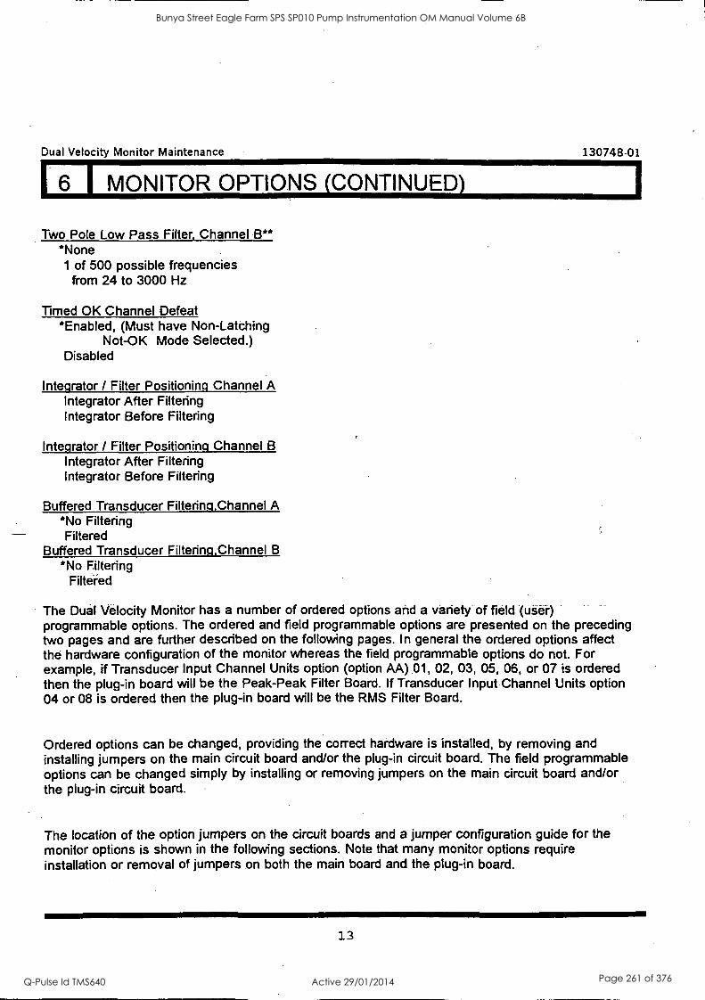
Dual Velocity Monitor Maintenance 130748-01
6 I MONITOR OPTIONS (CONTINUED)
Two Pole Low Pass Filter, Channel B** *None
1 of 500 possible frequencies from 24 to 3000 Hz
Timed OK Channel Defeat *Enabled, (Must have Non-Latching
Not-OK Mode Selected.) Disabled
Integrator / Filter Positioning Channel A Integrator After Filtering Integrator Before Filtering
Integrator / Filter Positioning Channel B
Integrator After Filtering Integrator Before Filtering
Buffered Transducer Filtering,Channel A *No Filtering Filtered
Buffered Transducer Filtering,Channel B
*No Filtering Filtaed
The Dual Velocity Monitor has a number of ordered options and a variety of field (user) programmable options. The ordered and field programmable options are presented on the preceding two pages and are further described on the following pages. In general the ordered options affect the hardware configuration of the monitor whereas the field programmable options do not. For example, if Transducer Input Channel Units option (option AA) 01, 02, 03, 05, 06, or 07 is ordered then the plug-in board will be the Peak-Peak Filter Board. If Transducer Input Channel Units option 04 or 08 is ordered then the plug-in board will be the RMS Filter Board.
Ordered options can be changed, providing the correct hardware is installed, by removing and installing jumpers on the main circuit board and/or the plug-in circuit board. The field programmable options can be changed simply by installing or removing jumpers on the main circuit board and/or the plug-in circuit board.
The location of the option jumpers on the circuit boards and a jumper configuration guide for the monitor options is shown in the following sections. Note that many monitor options require installation or removal of jumpers on both the main board and the plug-in board.
13
Bunya Street Eagle Farm SPS SP010 Pump Instrumentation OM Manual Volume 6B
Q-Pulse Id TMS640 Active 29/01/2014 Page 261 of 376
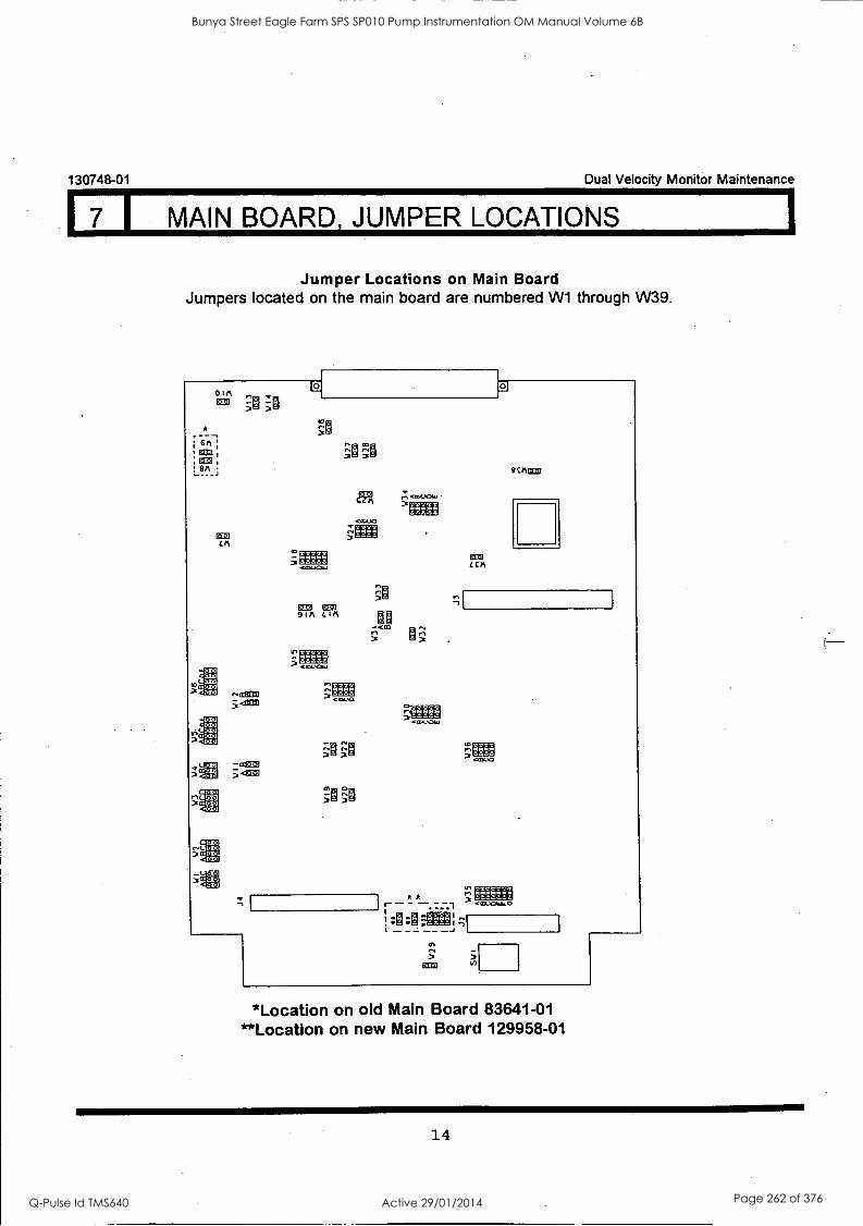
130748-01 Dual Velocity Monitor Maintenance
7 I MAIN BOARD, JUMPER. LOCATIONS
Jumper Locations on Main Board Jumpers located on the main board are numbered W1 through W39.
0 I I%
r3-'0
X..1
.(11
t.I1 5ne
en]
Roza oz]
ow _c_ .a.1 . C4.1
- a:1320 ;=1
1%02 9im CIA
77
,..<19.01.
k k - - 4¢,044.0
9 CAME
m
3 ECM
*Location on old Main Board 83641-01 **Location on new Main Board 129958-01
14
Bunya Street Eagle Farm SPS SP010 Pump Instrumentation OM Manual Volume 6B
Q-Pulse Id TMS640 Active 29/01/2014 Page 262 of 376
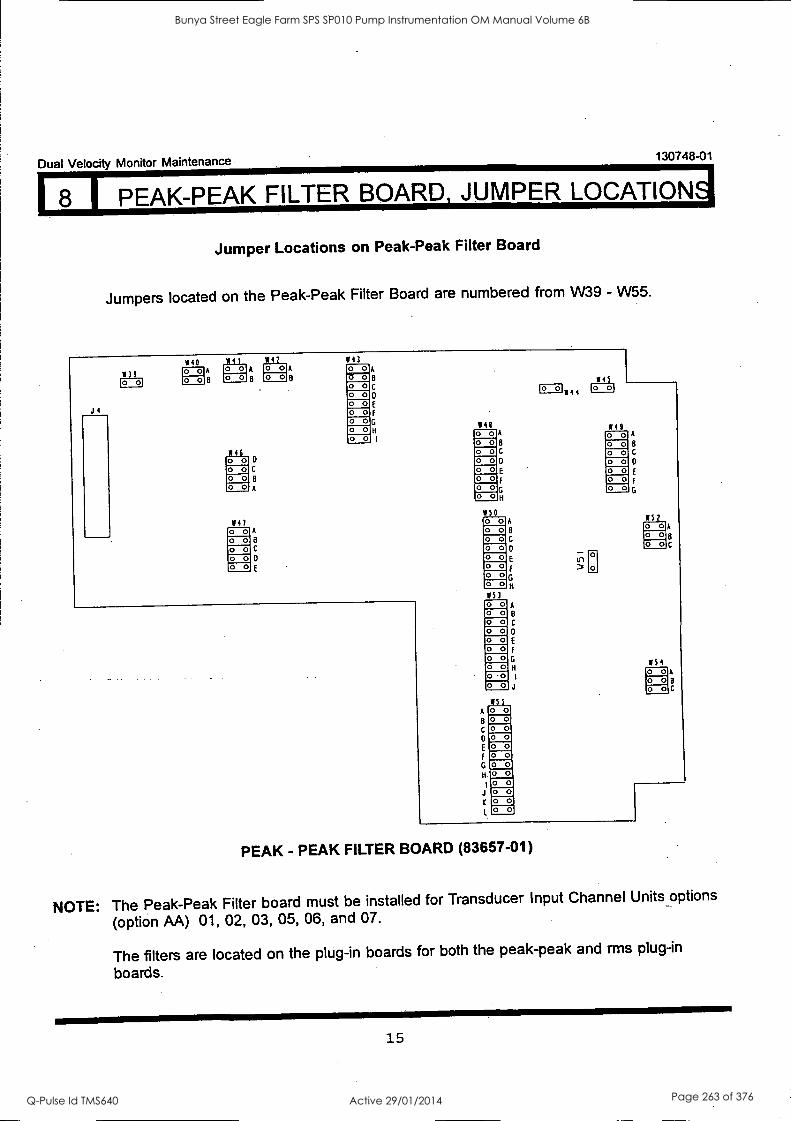
Dual Velocity Monitor Maintenance
LUPEAK-PEAK FILTER BOARD, JUMPER LOCATION4
130748-01
Jumper Locations on Peak-Peak Filter Board
Jumpers located on the Peak-Peak Filter Board are numbered from W39 - W55.
1139 CND
J4
140 M41 A rI A
8
M46
o o C
o o 8
o 0 A
III O 0 O 0 O 0 O 0 O 0
A
8
C
0
M42 o o o o
A
143 A
C
D
G
H
O 0 O 0 O 0 O 0 O 0 O 0 O 0 O 0 O 0
111 O 0 O 0 O 0 O 0 O 0 O 0 O 0 O 0
1150
A.
8
C
0
H
0 O 0 O 0 O 0 O 0 O 0 O 0 O 0
A
B
C
F
K
153 O 0 O 0 O 0 O 0 O 0 O 0 O 0 O 0 0 -0 O 0
W55
A
8 C
0
H
O 0 O 0 O 0 O 0 O 0 O 0
A
B
C
D
J
.0 0
O 0 0 0 O 0 O 0
145
IIM4 4 to °I
M49 O 0 O 0 O 0 O 0 O 0 O 0 O 0
A
C
0
1152 O 0 O 0 O 0
'54 O 0 O 0 O 0
A
8
C
8 C
PEAK - PEAK FILTER BOARD (83657-01)
NOTE: The Peak-Peak Filter board must be
(option M) 01, 02, 03, 05, 06, and
The filters are located on the plug-in boards.
installed for Transducer Input Channel Units options
07.
boards for both the peak-peak and rms plug-in
15
Bunya Street Eagle Farm SPS SP010 Pump Instrumentation OM Manual Volume 6B
Q-Pulse Id TMS640 Active 29/01/2014 Page 263 of 376
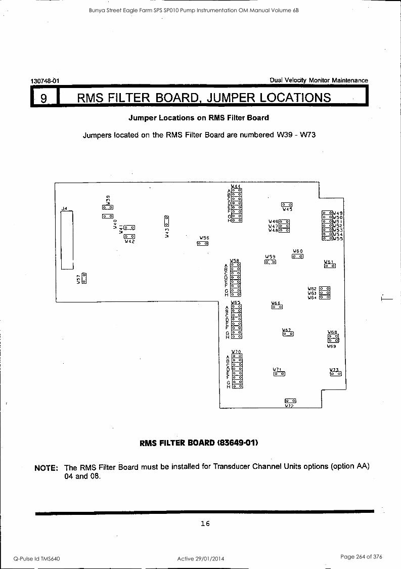
130748-01 Dual Velocity Monitor Maintenance
I RMS FILTER BOARD, JUMPER LOCATIONS
Jumper Locations on RMS Filter Board
Jumpers located on the RMS Filter Board are numbered W39 - W73
J4
s
0)
0 3 ;CI
W42 1456
A B
E F
H
A B C D E F
H
,444 O 0 O 0 O 0 O 0 O 0 o o
O 0
W58
A B C D E F
H.
A B C
F
H
O 0 O 0 O 0 O 0 O 0 O 0 O 0 O 0
W65 O 0 O 0 O 0 O 0 O 0 O 0 O 0 o o
W70 O 0 o o O 0 O 0 O 0 O 0 O 0 O 0
C=3 W45
S./ 49 50
0 0 0
W46 0 0 0 0 51 W47 0 0 0 0 52 W48 0 0 0 0 53
0 o\4 54 o 014 55
W60 W59 1=3 C=I
W66
1'0'701
W71
C=3
V77
1/62 W63 1464
1461 lo of
O 0 0_0 O 0
W68 o o o o
W69
W73 10 of
RMS FILTER BOARD (83649-01)
NOTE: The RMS Filter Board must be installed for Transducer Channel Units options (option AA)
04 and 08.
16
Bunya Street Eagle Farm SPS SP010 Pump Instrumentation OM Manual Volume 6B
Q-Pulse Id TMS640 Active 29/01/2014 Page 264 of 376
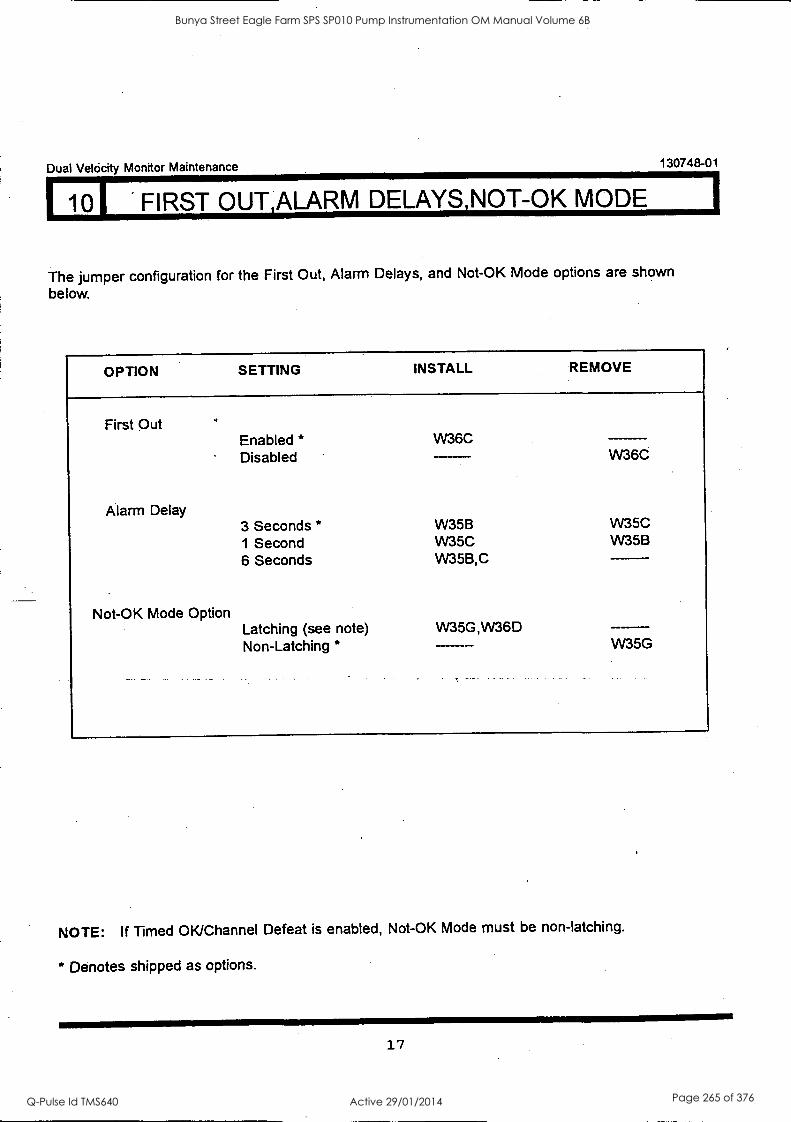
Dual Velocity Monitor Maintenance 130748-01
10I FIRST OUT,ALARM DELAYS,NOT-OK MODE
The jumper configuration for the First Out, Alarm Delays, and Not-OK Mode options are shown
below.
OPTION SETTING INSTALL REMOVE
First Out Enabled * W36C
W36C Disabled
Alarm Delay 3 Seconds * W35B W35C 1 Second W35C W35B
6 Seconds W35B,C
Not-OK Mode Option Latching (see note) VV35G,W36D Non-Latching * W35G
NOTE: If Timed OK/Channel Defeat is enabled, Not-OK Mode must be non-latching.
* Denotes shipped as options.
17
Bunya Street Eagle Farm SPS SP010 Pump Instrumentation OM Manual Volume 6B
Q-Pulse Id TMS640 Active 29/01/2014 Page 265 of 376
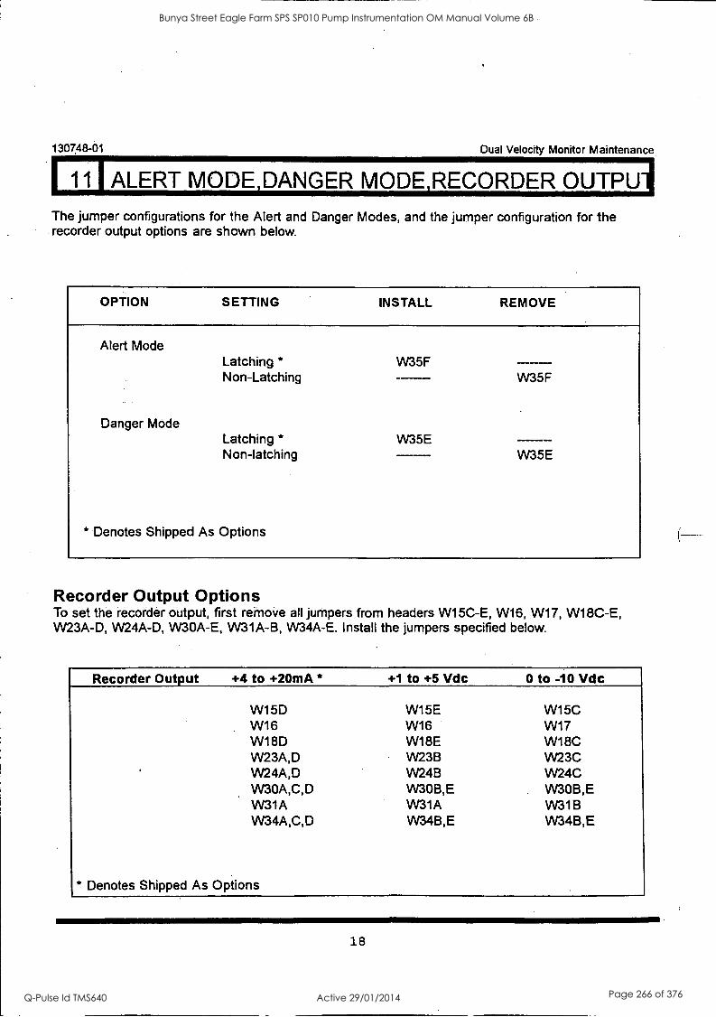
130748-01 Dual Velocity Monitor Maintenance
11 i ALERT MODE,DANGER MODE,RECORDER OUTPUll The jumper configurations for the Alert and Danger Modes, and the jumper configuration for the recorder output options are shown below.
OPTION SETTING INSTALL REMOVE
Alert Mode
Danger Mode
Latching * Non-Latching
Latching * Non-latching
* Denotes Shipped As Options
W35F
W35E
W35F
W35E
Recorder Output Options To set the recorder output, first remove all jumpers from headers W15C-E, W16, W17, W18C-E, W23A -D, W24A -D, W30A-E, VV31A-B, W34A -E. Install the jumpers specified below.
Recorder Output +4 to +20mA * +1 to +5 Vdc 0 to -10 Vdc
W15D W15E W15C W16 W16 W17 W18D W18E W18C W23A,D W23B W23C VV24A,D W24B W24C VV30A,C,D VV30B,E VV30B,E VV31A VV31A W31B W34A,C,D W34B,E W34B,E
* Denotes Shipped As Options
18
Bunya Street Eagle Farm SPS SP010 Pump Instrumentation OM Manual Volume 6B
Q-Pulse Id TMS640 Active 29/01/2014 Page 266 of 376
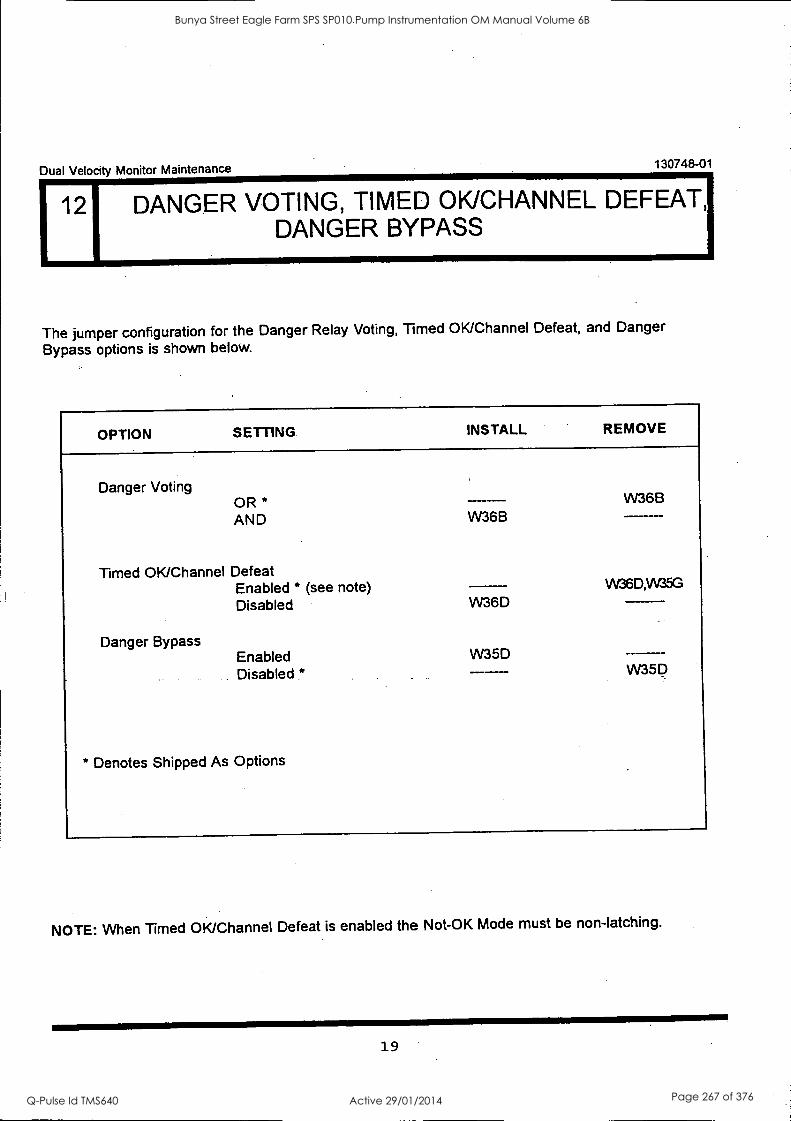
Dual Velocity Monitor Maintenance 130748-01
1 12 DANGER VOTING, TIMED OK/CHANNEL DEFEAT, DANGER BYPASS
The jumper configuration for the Danger Relay Voting, Timed OK/Channel Defeat, and Danger
Bypass options is shown below.
OPTION SETTING INSTALL REMOVE
Danger Voting OR * AND
Timed OK/Channel Defeat Enabled * (see note) Disabled
Danger Bypass
W36B
W36D
Enabled W35D Disabled *
* Denotes Shipped As Options
W36B
W36D,W35G
W35D
NOTE: When Timed OK/Channel Defeat is enabled the Not-OK Mode must be non-latching.
19
Bunya Street Eagle Farm SPS SP010 Pump Instrumentation OM Manual Volume 6B
Q-Pulse Id TMS640 Active 29/01/2014 Page 267 of 376
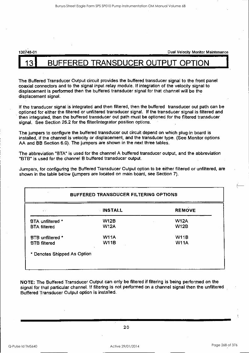
113I BUFFERED TRANSDUCER OUTPUT OPTION I
130748-01 Dual Velocity Monitor Maintenance
The Buffered Transducer Output circuit provides the buffered transducer signal to the front panel coaxial connectors and to the signal input relay module. If integration of the velocity signal to displacement is performed then the buffered transducer signal for that channel will be the displacement signal.
If the transducer signal is integrated and then filtered, then the buffered transducer out path can be optioned for either the filtered or unfiltered transducer signal. If the transducer signal is filtered and then integrated, then the buffered transducer out path must be optioned for the filtered transducer signal. See Section 26.2 for the filter/integrator position options.
The jumpers to configure the buffered transducer out circuit depend on which plug-in board is installed, if the channel is velocity or displacement, and the transducer type. (See Monitor options AA and BB Section 6.0). The jumpers are shown in the next three tables.
The abbreviation "BTA" is used for the channel A buffered transducer output, and the abbreviation "BTB" is used for the channel B buffered transducer output.
Jumpers, for configuring the Buffered Transducer Output option to be either filtered or unfiltered, are shown in the table below (jumpers are located on main board, see Section 7).
BUFFERED TRANSDUCER FILTERING OPTIONS
INSTALL
BTA unfiltered * BTA filtered
BTB unfiltered * BTB filtered
* Denotes Shipped As Option
W12B W12A
W11A W11B
REMOVE
W12A W1 2B
W11B W11A
NOTE: The Buffered Transducer Output can only be filtered if filtering is being performed on the signal for that particular channel. If filtering is not performed on a channel signal then the unfiltered Buffered Transducer Output option is installed.
20
Bunya Street Eagle Farm SPS SP010 Pump Instrumentation OM Manual Volume 6B
Q-Pulse Id TMS640 Active 29/01/2014 Page 268 of 376
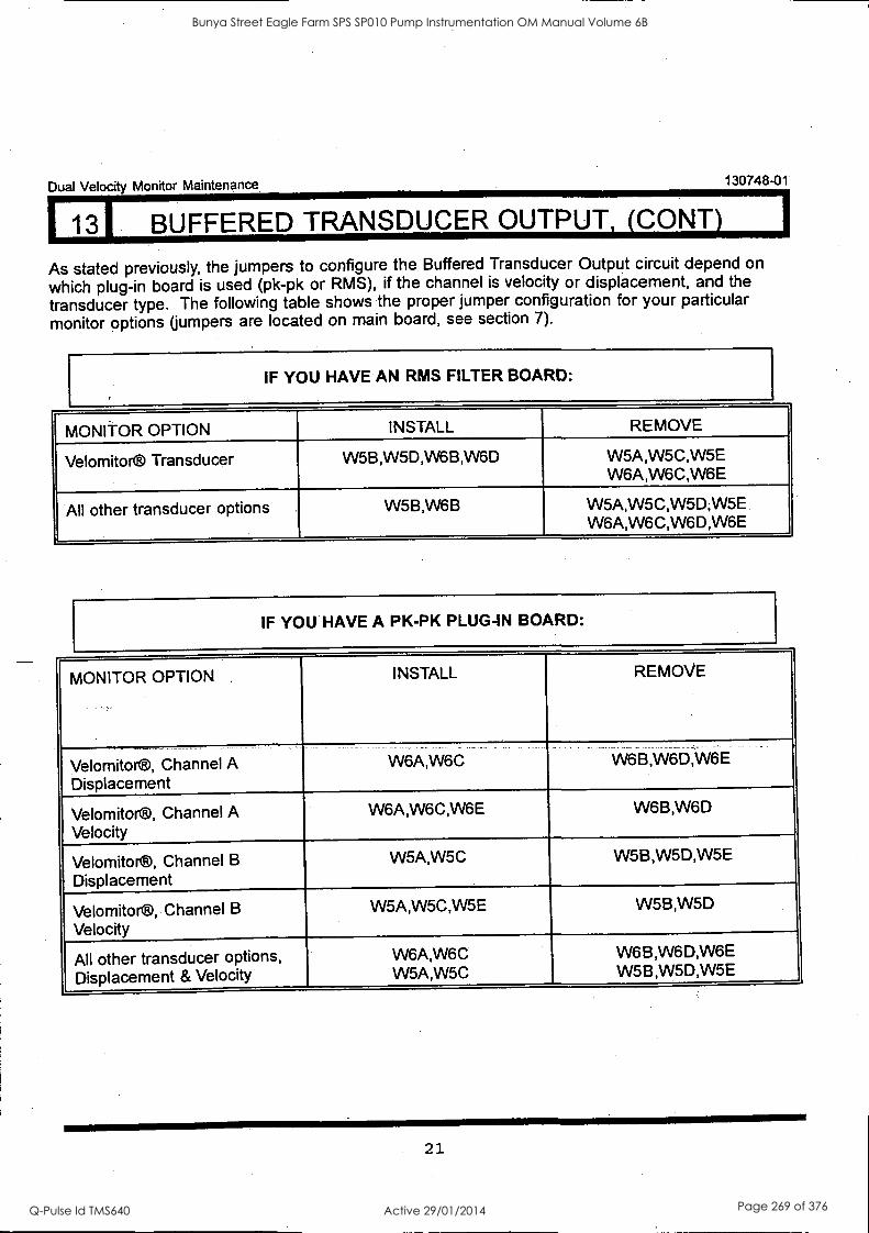
113I BUFFERED TRANSDUCER OUTPUT, (CONY) Dual Velocity Monitor Maintenance 130748-01
As stated previously, the jumpers to configure the Buffered Transducer Output circuit depend on
which plug-in board is used (pk-pk or RMS), if the channel is velocity or displacement, and the
transducer type. The following table shows the proper jumper configuration for your particular monitor options (jumpers are located on main board, see section 7).
IF YOU HAVE AN RMS FILTER BOARD:
MONITOR OPTION INSTALL REMOVE
Velomitor® Transducer W5B,W5D,W6B,W6D W5A,W5C,W5E W6A,W6C,W6E
All other transducer options W5B,W6B W5A,W5C,W5D,W5E W6A,W6C,W6D,W6E
IF YOU HAVE A PK-PK PLUG-IN BOARD:
MONITOR OPTION INSTALL REMOVE
Velomitor®, Channel A Displacement
W6A,W6C W6B,W6D,W6E
Velomitor®, Channel A Velocity
W6A,W6C,W6E W6B,W6D
Velomitor®, Channel B
Displacement
W5A,W5C W5B,W5D,W5E
Velomitor®, Channel B
Velocity
W5A,W5C,W5E W5B,W5D
All other transducer options, Displacement & Velocity
W6A,W6C W5A,W5C
W6B,W6D,W6E W5B,W5D,W5E
21
Bunya Street Eagle Farm SPS SP010 Pump Instrumentation OM Manual Volume 6B
Q-Pulse Id TMS640 Active 29/01/2014 Page 269 of 376
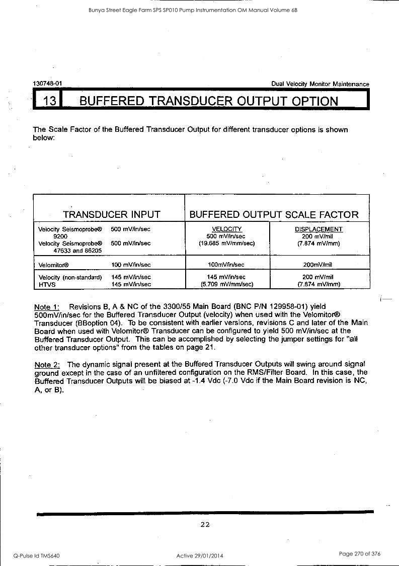
130748-01 Dual Velocity Monitor Maintenance
13I BUFFERED TRANSDUCER OUTPUT OPTION
The Scale Factor of the Buffered Transducer Output for different transducer options is shown below:
TRANSDUCER INPUT BUFFERED OUTPUT SCALE FACTOR Velocity Seismoprobe® 500 mV/in/sec
9200 Velocity Seismoprobe® 500 mV/in/sec
47633 and 86205
VELOCITY DISPLACEMENT 500 mV/in/sec
(19.685 mV/mm/sec) 200 mV/mil
(7.874 mV/mm)
Velomitor® 100 mV/in/sec 100mV/in/sec 200mV/mil
Velocity (non-standard) 145 mV/in/sec HTVS 145 mV/in/sec
145 mV/in/sec (5.709 mV /mm/sec)
200 mV/mil (7.874 mV/mm)
Note 1: Revisions B, A & NC of the 3300/55 Main Board (BNC P/N 129958-01) yield 500mV/in/sec for the Buffered Transducer Output (velocity) when used with the Velomitor® Transducer (BBoption 04). To be consistent with earlier versions, revisions C and later of the Main Board when used with Velomitor® Transducer can be configured to yield 500 mV/in/sec at the Buffered Transducer Output. This can be accomplished by selecting the jumper settings for "all other transducer options" from the tables on page 21.
Note 2: The dynamic signal present at the Buffered Transducer Outputs will swing around signal ground except in the case of an unfiltered configuration on the RMS/Filter Board. In this case, the Buffered Transducer Outputs will be biased at -1.4 Vdc (-7.0 Vdc if the Main Board revision is NC, A, or B).
22
Bunya Street Eagle Farm SPS SP010 Pump Instrumentation OM Manual Volume 6B
Q-Pulse Id TMS640 Active 29/01/2014 Page 270 of 376
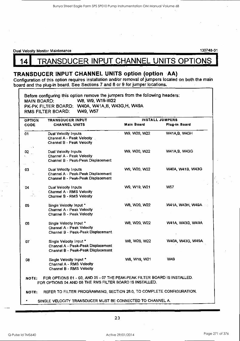
114I TRANSDUCER INPUT CHANNEL UNITS OPTIONS
Dual Velocity Monitor Maintenance 130748-01
TRANSDUCER INPUT CHANNEL UNITS option (option .AA) Configuration of this option requires installation and/or removal of jumpers located on both The main board and the plug-in board. See Sections 7 and 8 or 9 for jumper locations.
Before configuring this option remove the jumpers from the following headers: MAIN BOARD: W8, W9, W19-W22 PK-PK FILTER BOARD: W40A, W41A,B, W43G,H, W49A RMS FILTER BOARD: W49, W57
OPTION TRANSDUCER INPUT INSTALL JUMPERS CODE CHANNEL UNITS Main Board Plug -in. Board
01 Dual Velocity Inputs W9, W20, W22 W41A,B, W43H Channel A - Peak Velocity Channel B - Peak Velocity
02 Dual Velocity Inputs W9, W20, W22 W41A,B, W43G Channel A - Peak Velocity Channel B - Peak-Peak Displacement
03 Dual Velocity Inputs W9, W20, W22 W40A, W41B, W43G Channel A - Peak-Peak Displacement Channel B - Peak-Peak Displacement
04 Dual Velocity Inputs W9, W19, W21 W57 Channel A - RMS Velocity Channel B - RMS Velocity
05 Single Velocity Input' W8, W20, W22 W41A, W43H, W49A Channel A - Peak Velocity Channel B - Peak Velocity
06 Single Velocity Input " W8, W20, W22 W41A, W43G, W49A Channel A - Peak Velocity Channel B - Peak-Peak Displacement
07 Single Velocity Input W8, W20, W22 W40A, W43G, W49A Channel A - Peak-Peak Displacement Channel B - Peak-Peak Displacement
08 Single Velocity Input W8, W19, W21 W49
Channel A - RMS Velocity Channel B - RMS Velocity
NOTE: FOR OPTIONS 01 - 03, AND 05 - 07 THE PEAK-PEAK FILTER BOARD IS INSTALLED. FOR OPTIONS 04 AND 08 THE RMS FILTER BOARD IS INSTALLED.
NOTE: REFER TO FILTER PROGRAMMING, SECTION 26.0, TO COMPLETE CONFIGURATION.
SINGLE VELOCITY TRANSDUCER MUST BE CONNECTED TO CHANNEL A
23
Bunya Street Eagle Farm SPS SP010 Pump Instrumentation OM Manual Volume 6B
Q-Pulse Id TMS640 Active 29/01/2014 Page 271 of 376
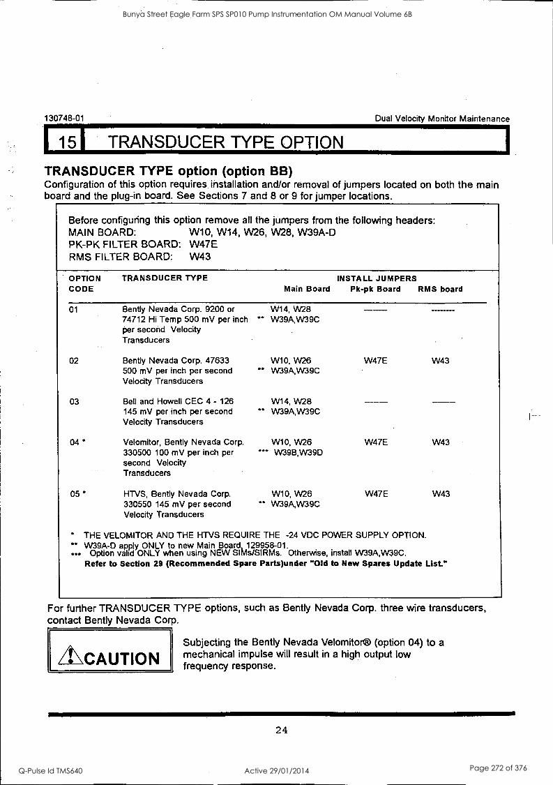
115I TRANSDUCER TYPE OPTION
130748-01 Dual Velocity Monitor Maintenance
TRANSDUCER TYPE option (option BB) Configuration of this option requires installation and/or removal of jumpers located on both the main board and the plug-in board. See Sections 7 and 8 or 9 for jumper locations.
Before configuring this option remove all the jumpers from the following headers: MAIN BOARD: W10, W14, W26, W28, W39A-D PK-PK FILTER BOARD: W47E RMS FILTER BOARD: W43
OPTION CODE
TRANSDUCER TYPE Main Board
INSTALL JUMPERS Pk-pk Board RMS board
01 Bently Nevada Corp. 9200 or W14, W28 74712 Hi Temp 500 mV per inch per second Velocity
** W39A,W39C
Transducers
02 Bently Nevada Corp. 47633 W10, VV26 W47E W43 500 mV per inch per second ** VV39A,VV39C Velocity Transducers
03 Bell and Howell CEC 4 - 126 W14, W28 145 mV per inch per second ** W39A,W39C Velocity Transducers
04 * Velomitor, Bently Nevada Corp. W10, W26 W47E W43 330500 100 mV per inch per second Velocity
*** VV39B,VV39D
Transducers
05 * HTVS, Bently Nevada Corp. W10, W26 W47E W43 330550 145 mV per second ** W39A,W39C Velocity Transducers
* THE VELOMITOR AND THE HTVS REQUIRE THE -24 VDC POWER SUPPLY OPTION. ** W39A -D apply ONLY to new Main Board, _129958-01.
Option valid ONLY when using NEW SIMs/SIRMs. Otherwise, install W39A,W39C. Refer to Section 29 (Recommended Spare Parts)under "Old to New Spares Update List."
For further TRANSDUCER TYPE options, such as Bently Nevada Corp. three wire transducers, contact Bently Nevada Corp.
CAUTION Subjecting the Bently Nevada Velomitor® (option 04) to a mechanical impulse will result in a high output low frequency response.
24
Bunya Street Eagle Farm SPS SP010 Pump Instrumentation OM Manual Volume 6B
Q-Pulse Id TMS640 Active 29/01/2014 Page 272 of 376
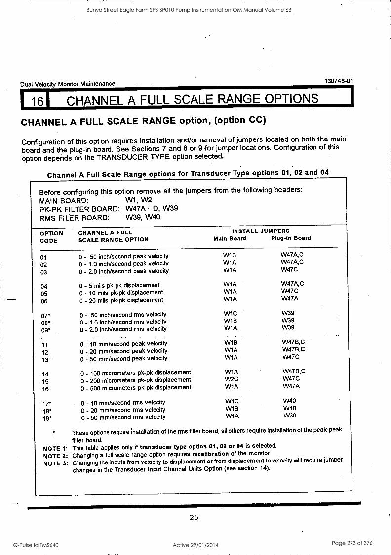
Dual Velocity Monitor Maintenance 130748-01
161 CHANNEL A FULL SCALE RANGE OPTIONS
CHANNEL A FULL SCALE RANGE option (option CC)
Configuration of this option requires installation and/or removal of jumpers located on both the main
board and the plug-in board. See Sections 7 and 8 or 9 for jumper locations. Configuration of this
option depends on the TRANSDUCER TYPE option selected.
Channel A Full Scale Range options for Transducer Type options 01, 02 and 04
Before configuring this option remove all the jumpers from the following headers:
MAIN BOARD: W1, W2 PK-PK FILTER BOARD: W47A - D, W39 RMS FILER BOARD: W39, W40
OPTION CODE
01
02 03
04 05 06
07' 08' 09'
11
12 13
14
15 16
17' 18* 19*
CHANNEL A FULL SCALE RANGE OPTION
INSTALL JUMPERS Main Board Plug-in Board
0 - .50 inch/second peak velocity WIB W47A,C
0 - 1.0 inch/second peak velocity W1A W47A,C
0 - 2.0 inch/second peak velocity W1A W47C
0 - 5 mils pk-pk displacement W1A W47A,C
0 - 10 mils pk-pk displacement WIA W47C
0 - 20 mils pk-pk displacement WIA W47A
0 - .50 inch/second rms velocity WIC W39
0 - 1.0 inch/second rms velocity W1B W39
0 - 2.0 inch/second rms velocity W1A W39
0 - 10 mm/second peak velocity W1B W47B,C
0 - 20 mm/second peak velocity W1A W47B,C
0 - 50 mm/second peak velocity W1A W47C
0 - 100 micrometers pk-pk displacement W1A W47B,C
0 - 200 micrometers pk-pk displacement W2C W47C
0 - 500 micrometers pk-pk displacement WIA W47A
0 - 10 mm/second rms velocity WIC W40
0 - 20 mm/second rms velocity WIB W40
0 - 50 mm/second rms velocity WIA W39
These options require installation of the rms filter board, all others require installation of the peak-peak
filter board.
NOTE 1: This table applies only if transducer type option 01, 02 or 04 is selected.
NOTE 2: Changing a full scale range option requires recalibration of the monitor.
NOTE 3: Changing the inputs from velocity to displacement or from displacement to velocity will require jumper
changes in the Transducer Input Channel Units Option (see section 14).
25
Bunya Street Eagle Farm SPS SP010 Pump Instrumentation OM Manual Volume 6B
Q-Pulse Id TMS640 Active 29/01/2014 Page 273 of 376
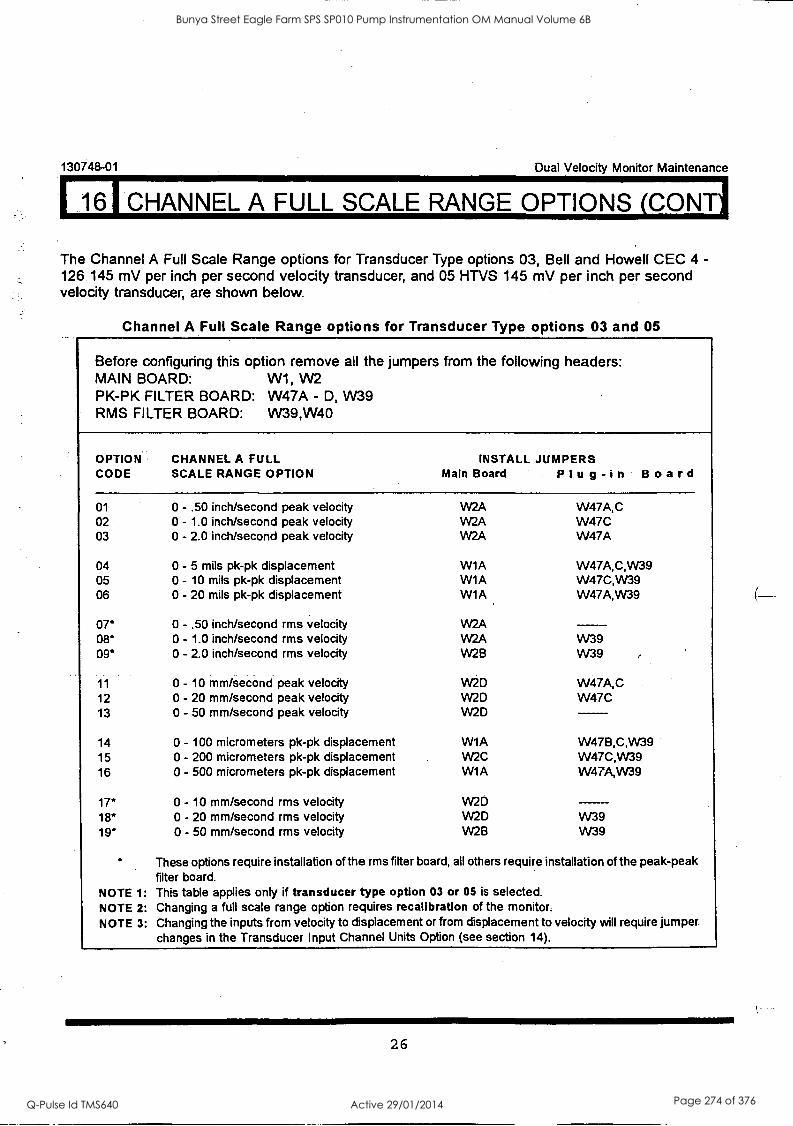
161 CHANNEL A FULL SCALE RANGE OPTIONS (CONTI
130748-01 Dual Velocity Monitor Maintenance
The Channel A Full Scale Range options for Transducer Type options 03, Bell and Howell CEC 4 - 126 145 mV per inch per second velocity transducer, and 05 HTVS 145 mV per inch per second velocity transducer, are shown below.
Channel A Full Scale Range options for Transducer Type options 03 and 05
Before configuring this option remove all the jumpers from the following headers: MAIN BOARD: W1, W2 PK-PK FILTER BOARD: W47A - D, W39 RMS FILTER BOARD: W39,W40
OPTION CHANNEL A FULL INSTALL JUMPERS CODE SCALE RANGE OPTION Main Board Plug-in Board
01 0 - .50 inch/second peak velocity W2A W47A,C 02 0 - 1.0 inch/second peak velocity W2A W47C 03 0 - 2.0 inch/second peak velocity W2A W47A
04 0 - 5 mils pk-pk displacement W1A W47A,C,W39 05 0 - 10 mils pk-pk displacement W1A W47C,W39 06 0 - 20 mils pk-pk displacement W1A W47A,W39
07 0 - .50 inch/second rms velocity W2A 08 0 - 1.0 inch/second rms velocity W2A VV39 09 0 - 2.0 inch/second rms velocity W2B W39
11 0 - 10 mm/second peak velocity W2D W47A,C 12 0 - 20 mm/second peak velocity W2D W47C 13 0 - 50 mm/second peak velocity W2D
14 0 - 100 micrometers pk-pk displacement W1A W47B,C,W39 15 0 - 200 micrometers pk-pk displacement W2C W47C,W39 16 0 - 500 micrometers pk-pk displacement W1A W47A,W39
17 0 - 10 mm/second rms velocity W2D 18 0 - 20 mm/second rms velocity W2D W39 19 0 - 50 mm/second rms velocity W2B W39
These options require installation of the rms filter board, all others require installation of the peak-peak filter board.
NOTE 1: This table applies only if transducer type option 03 or 05 is selected. NOTE 2: Changing a full scale range option requires recalibratlon of the monitor. NOTE 3: Changing the inputs from velocity to displacement or from displacement to velocity will require jumper
changes in the Transducer Input Channel Units Option (see section 14).
26
Bunya Street Eagle Farm SPS SP010 Pump Instrumentation OM Manual Volume 6B
Q-Pulse Id TMS640 Active 29/01/2014 Page 274 of 376
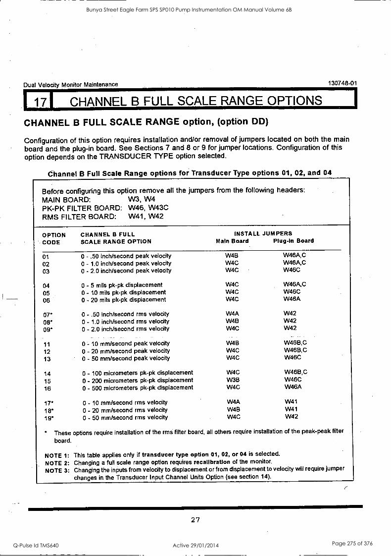
Dual Velocity Monitor Maintenance 130748-01
171 CHANNEL B FULL SCALE RANGE OPTIONS
CHANNEL B FULL SCALE RANGE option, (option DD)
Configuration of this option requires installation and/or removal of jumpers located on both the main board and the plug-in board. See Sections 7 and 8 or 9 for jumper locations. Configuration of this option depends on the TRANSDUCER TYPE option selected.
Channel B Full Scale Range options for Transducer Type options 01, 02, and 04
Before configuring this option remove all the jumpers from the following headers: MAIN BOARD: W3, W4 PK-PK FILTER BOARD: W46, W43C RMS FILTER BOARD: W41, W42
OPTION CODE
CHANNEL B FULL SCALE RANGE OPTION
INSTALL JUMPERS Main Board Plug-In Board
01 0 - .50 inch/second peak velocity W4B W46A,C
02 0 - 1.0 inch/second peak velocity W4C W46A,C
03 0 - 2.0 inch/second peak velocity W4C W46C
04 0 - 5 mils pk-pk displacement W4C W46A,C
05 0 - 10 mils pk-pk displacement W4C W46C
06 0 - 20 mils pk-pk displacement W4C W46A
07' 0 - .50 inch/second rms velocity W4A W42
08* 0 - 1.0 inch/second rms velocity W4B W42
09* 0 - 2.0 inch/second rms velocity W4C W42
11 0 - 10 mm/second peak velocity W4B W46B,C
12 0 - 20 mm/second peak velocity W4C W46B,C
13 0 - 50 mm/second peak velocity W4C W46C
14 0 - 100 micrometers pk-pk displacement W4C W46B,C
15 0 - 200 micrometers pk-pk displacement W3B W46C
16 0 - 500 micrometers pk-pk displacement W4C W46A
17* 0 - 10 mm/second rms velocity W4A W41
18* 0 - 20 mm/second rms velocity W4B W41
19* 0 - 50 mm/second rms velocity W4C W42
These options require installation of the rms filter board, all others require installation of the peak-peak filter
board.
NOTE 1: This table applies only if transducer type option 01, 02, or 04 is selected.
NOTE 2: Changing a full scale range option requires recalIbration of the monitor.
NOTE 3: Changing the inputs from velocity to displacement or from displacement to velocity will require jumper
changes in the Transducer Input Channel Units Option (see section 14).
27
Bunya Street Eagle Farm SPS SP010 Pump Instrumentation OM Manual Volume 6B
Q-Pulse Id TMS640 Active 29/01/2014 Page 275 of 376
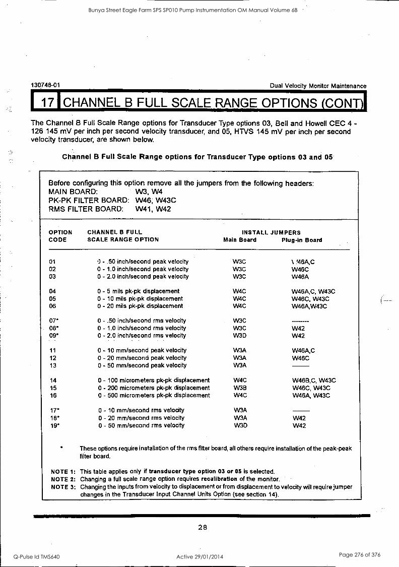
130748-01 Dual Velocity Monitor Maintenance
17ICHANNEL B FULL SCALE RANGE OPTIONS (CONT)
The Channel B Full Scale Range options for Transducer Type options 03, Bell and Howell CEC 4 - 126 145 mV per inch per second velocity transducer, and 05, HTVS 145 mV per inch per second velocity transducer, are shown below.
Channel B Full Scale Range options for Transducer Type options 03 and 05
Before configuring this option remove all the jumpers from the following headers: MAIN BOARD: W3, W4 PK-PK FILTER BOARD: W46, W43C RMS FILTER BOARD: W41, W42
OPTION CODE
CHANNEL B FULL SCALE RANGE OPTION
INSTALL JUMPERS Main Board Plug-in Board
01 0 - .50 inch/second peak velocity W3C % '46A,C 02 0 - 1.0 inch/second peak velocity W3C W46C 03 0 - 2.0 inch/second peak velocity W3C W46A
04 0 - 5 mils pk-pk displacement W4C W46A,C, W43C 05 0 - 10 mils pk-pk displacement W4C W46C, W43C 06 0 - 20 mils pk-pk displacement W4C W46A,W43C
07* 0 - .50 inch/second rms velocity W3C 08" 0 - 1.0 inch/second rms velocity W3C W42 09* 0 - 2.0 inch/second rms velocity W3D W42
11 0 - 10 mm/second peak velocity W3A W46A,C 12 0 - 20 mm/second peak velocity W3A W46C 13 0 - 50 mm/second peak velocity W3A
14 0 - 100 micrometers pk-pk displacement W4C W46B,C, W43C 15 0 - 200 micrometers pk-pk displacement W3B W46C, W43C 16 0 - 500 micrometers pk-pk displacement W4C W46A, W43C
17* 0 - 10 mm/second rms velocity W3A 18* 0 - 20 mm/second rms velocity W3A W42 19* 0 - 50 mm/second rms velocity W3D W42
These options require installation of the rms filter board, all others require installation of the peak-peak filter board.
NOTE 1: This table applies only if transducer type option 03 or 05 is selected. NOTE 2: Changing a full scale range option requires recalibratIon of the monitor. NOTE 3: Changing the inputs from velocity to displacement or from displacement to velocity will require jumper
changes in the Transducer Input Channel Units Option (see section 14).
28
Bunya Street Eagle Farm SPS SP010 Pump Instrumentation OM Manual Volume 6B
Q-Pulse Id TMS640 Active 29/01/2014 Page 276 of 376
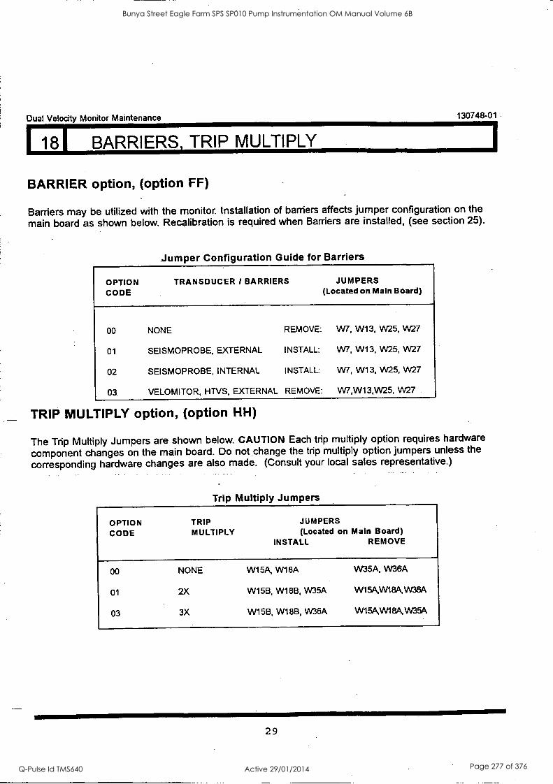
Dual Velocity Monitor Maintenance 130748-01
118I BARRIERS, TRIP MULTIPLY
BARRIER option, (option FF)
Barriers may be utilized with the monitor. Installation of barriers affects jumper configuration on the
main board as shown below. Recalibration is required when Barriers are installed, (see section 25).
Jumper Configuration Guide for Barriers
OPTION CODE
TRANSDUCER / BARRIERS JUMPERS (Located on Main Board)
00 NONE REMOVE: W7, W13, W25, W27
01 SEISMOPROBE, EXTERNAL INSTALL: W7, W13, W25, W27
02 SEISMOPROBE, INTERNAL INSTALL: W7, W13, W25, W27
03 VELOMITOR, HTVS, EXTERNAL REMOVE: W7,W13,W25, W27
TRIP MULTIPLY option, (option HH)
The Trip Multiply Jumpers are shown below. CAUTION Each trip multiply option requires hardware
component changes on the main board. Do not change the trip multiply option jumpers unless the
corresponding hardware changes are also made. (Consult your local sales representative.)
Trip Multiply Jumpers
OPTION TRIP JUMPERS
CODE MULTIPLY (Located on Main Board) INSTALL. REMOVE
00 NONE W15A, W18A W35A, W36A
01 2X W15B, W18B, W35A W15A,W18A,VV36A
03 3X W15B, W18B, W36A W15A,W1 eA, VV35A
29
Bunya Street Eagle Farm SPS SP010 Pump Instrumentation OM Manual Volume 6B
Q-Pulse Id TMS640 Active 29/01/2014 Page 277 of 376
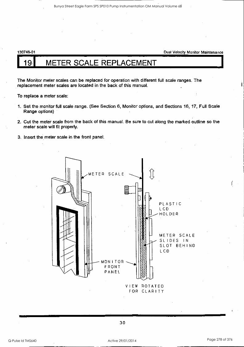
119I METER SCALE REPLACEMENT
130748-01 Dual Velocity Monitor Maintenance
The Monitor meter scales can be replaced for operation with different full scale ranges. The replacement meter scales are located in the back of this manual.
To replace a meter scale:
1. Set the monitor full scale range. (See Section 6, Monitor options, and Sections 16, 17, Full Scale Range options)
2. Cut the meter scale from the back of this manual. Be sure to cut along the marked outline so the meter scale will fit properly.
3. Insert the meter scale in the front panel.
METER SCALE
MONITOR FRONT PANEL
PLASTIC LCD HOLDER
METER SCALE SLIDES IN
SLOT BEHIND LCD
VIEW ROTATED FOR CLARITY
30
Bunya Street Eagle Farm SPS SP010 Pump Instrumentation OM Manual Volume 6B
Q-Pulse Id TMS640 Active 29/01/2014 Page 278 of 376
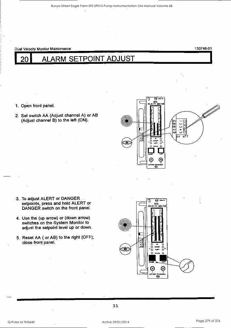
Dual Velocity Monitor Maintenance 130748-01
201 ALARM SETPOINT ADJUST
1. Open front panel.
2. Set switch AA (Adjust channel A) or AB (Adjust channel B) to the left (ON).
3. To adjust ALERT or DANGER setpoints, press and hold ALERT or DANGER switch on the front panel.
4. Use the (up arrow) or (down arrow) switches on the System Monitor to adjust the setpoint level up or down.
5. Reset AA ( or AB) to the right (OFF); close front panel.
31
Bunya Street Eagle Farm SPS SP010 Pump Instrumentation OM Manual Volume 6B
Q-Pulse Id TMS640 Active 29/01/2014 Page 279 of 376
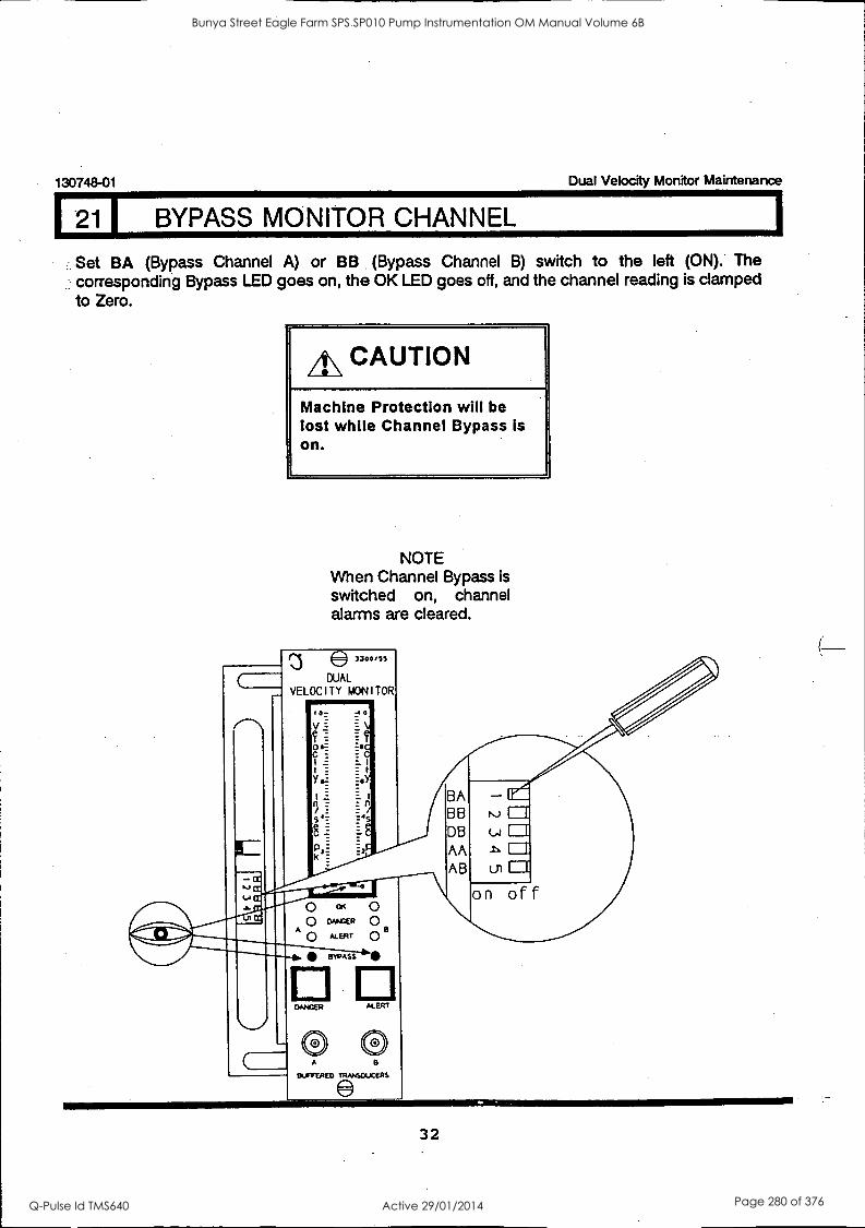
130748-01 Dual Velocity Monitor Maintenance
1 1 BYPASS MONITOR CHANNEL
Set BA (Bypass Channel A) or BB (Bypass Channel B) switch to the left (ON). The corresponding Bypass LED goes on, the OK LED goes off, and the channel reading is clamped to Zero.
A\ CAUTION
Machine Protection will be lost while Channel Bypass is on.
NOTE When Channel Bypass is switched on, channel alarms are cleared.
3304,5s
DUAL VELOCITY MONITOR
BA BB DB
AA AB ui
on of f o OK 0 0 cuvizR Q
ALERT Co B
BYPASS
CANCER ALERT
® A
BUFFERED TRANSDUCERS
32
Bunya Street Eagle Farm SPS SP010 Pump Instrumentation OM Manual Volume 6B
Q-Pulse Id TMS640 Active 29/01/2014 Page 280 of 376
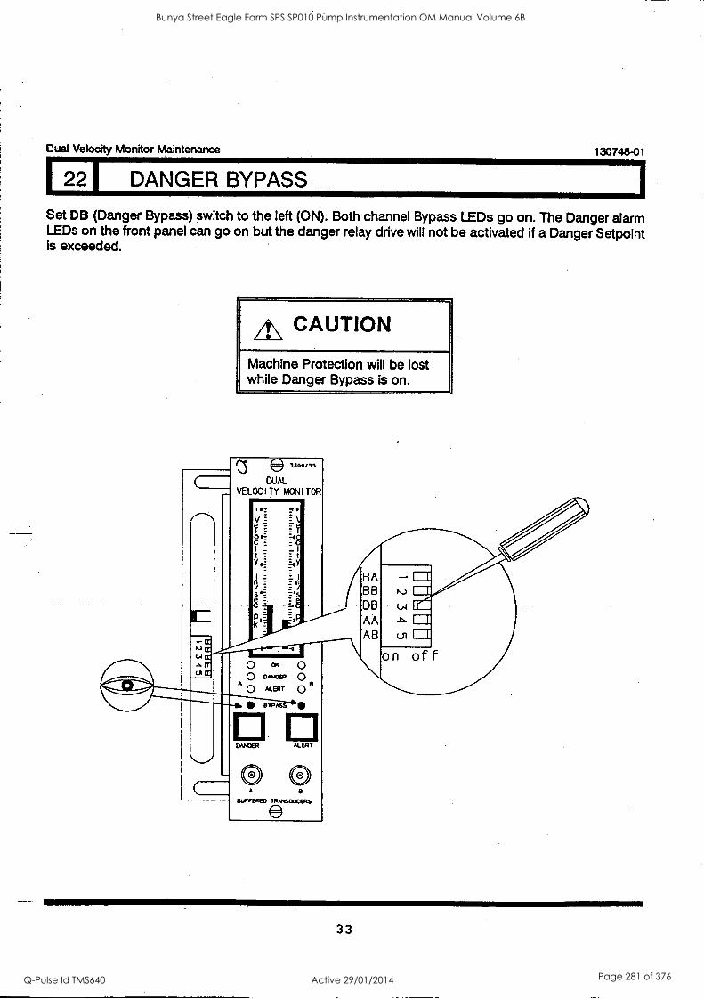
Dual Velocity Monitor Maintenance 130748-01
I 22 DANGER BYPASS
Set DB (Danger Bypass) switch to the left (ON). Both channel Bypass LEDs go on. The Danger alarm LEDs on the front panel can go on but the danger relay drive will not be activated if a Danger Setpoint is exceeded.
A\ CAUTION
Machine Protection will be lost while Danger Bypass is on.
3300/55
DUAL
VELOCITY MONITOR
C
t I
YF
_
s
10
BA BB DB AA AB
o Cft o O DANCel
A o ALERT o wrpms
RANGER
on of F
ALERT
lc?
33
Bunya Street Eagle Farm SPS SP010 Pump Instrumentation OM Manual Volume 6B
Q-Pulse Id TMS640 Active 29/01/2014 Page 281 of 376
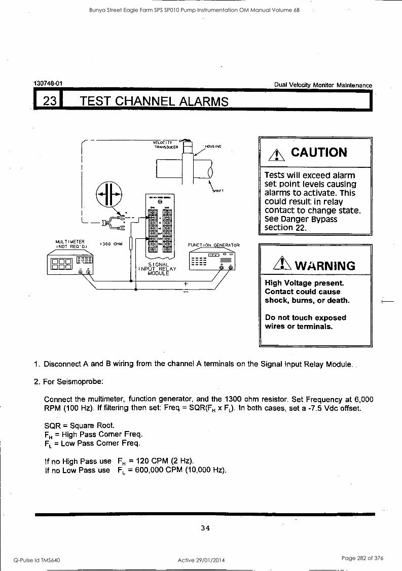
130748-01 Dual Velocity Monitor Maintenance
2 I TEST CHANNEL ALARMS
MULTIMETER tNOT REWO)
000 0 0 0
VEL OC I 7 Y
TRANS DUC ER
1300 OHM
9
SIGNAL INPUT RELAY
MODULE
HOUS ING V
SHAFT
CAUTION
Tests will exceed alarm set point levels causing alarms to activate. This could result in relay contact to change state. See Danger Bypass section 22.
WARNING High Voltage present. Contact could cause shock, burns, or death.
Do not touch exposed wires or terminals.
1. Disconnect A and B wiring from the channel A terminals on the Signal Input Relay Module.
2. For Seismoprobe:
Connect the multimeter, function generator, and the 1300 ohm resistor. Set Frequency at 6,000 RPM (100 Hz). If filtering then set: Freq = SQR(FH x FL). In both cases, set a -7.5 Vdc offset.
SQR = Square Root. FH = High Pass Corner Freq. FL = Low Pass Corner Freq.
If no High Pass use FH = 120 CPM (2 Hz). If no Low Pass use FL = 600,000 CPM (10,000 Hz).
34
Bunya Street Eagle Farm SPS SP010 Pump Instrumentation OM Manual Volume 6B
Q-Pulse Id TMS640 Active 29/01/2014 Page 282 of 376
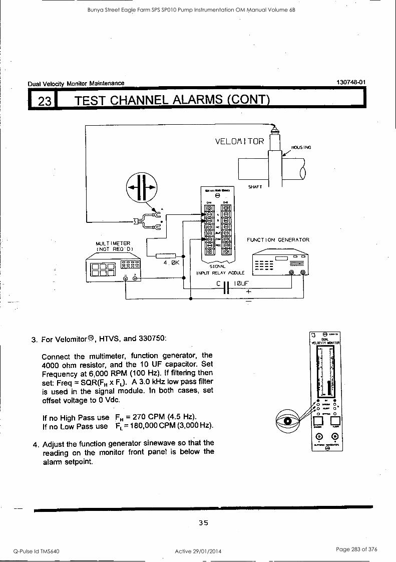
00 1-11-77,
Dual Velocity Monitor Maintenance 130748-01
231 TEST CHANNEL ALARMS (CONY)
VELOM I TOR 110US I NG
+ 11111,460011001$
(E) .
MA
muLTImETER (NOT REO'D) 7
4. 0K SIGNAL
INPUT RELAY PCOULE
3. For Velomitor ®, HTVS, and 330750:
Connect the multimeter, function generator, the 4000 ohm resistor, and the 10 OF capacitor. Set Frequency at 6,000 RPM (100 Hz). If filtering then set: Freq = SQR(FH x FL). A 3.0 kHz low pass filter is used in the signal module. In both cases, set offset voltage to 0 Vdc.
If no High Pass use FH = 270 CPM (4.5 Hz).
If no Low Pass use FL = 180,000 CPM (3,000 Hz).
4. Adjust the function generator sinewave so that the
reading on the monitor front panel is below the
alarm setpoint.
SHAFT
FUNCTION GENERATOR
C 11 IOUF
+
ELK VELOCITY MONITOR
`11M11111
o .... 0
'
0' ::, 4... 0
0 0 11.0000
35
Bunya Street Eagle Farm SPS SP010 Pump Instrumentation OM Manual Volume 6B
Q-Pulse Id TMS640 Active 29/01/2014 Page 283 of 376
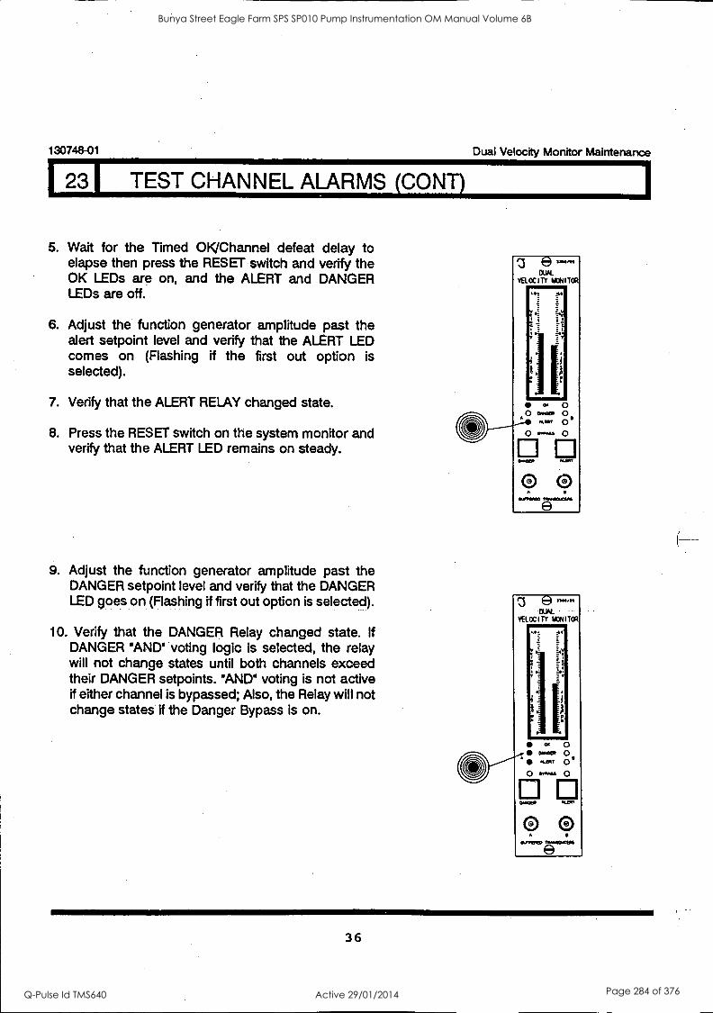
130748-01 Dual Velocity Monitor Maintenance
231 TEST CHANNEL ALARMS (CONT)
5. Wait for the Timed OK/Channel defeat delay to elapse then press the RESET switch and verify the OK LEDs are on, and the ALERT and DANGER LEDs are off.
6. Adjust the function generator amplitude past the alert setpoint level and verify that the ALERT LED comes on (Flashing if the first out option is selected).
7. Verify that the ALERT RELAY changed state.
8. Press the RESET switch on the system monitor and verify that the ALERT LED remains on steady.
9. Adjust the function generator amplitude past the DANGER setpoint level and verify that the DANGER LED goes on (Flashing if first out option is selected).
10. Verify that the DANGER Relay changed state. If DANGER 'AND' voting logic is selected, the relay will not change states until both channels exceed their DANGER setpoints. AND voting is not active if either channel is bypassed; Also, the Relay will not change states if the Danger Bypass is on.
36
Bunya Street Eagle Farm SPS SP010 Pump Instrumentation OM Manual Volume 6B
Q-Pulse Id TMS640 Active 29/01/2014 Page 284 of 376
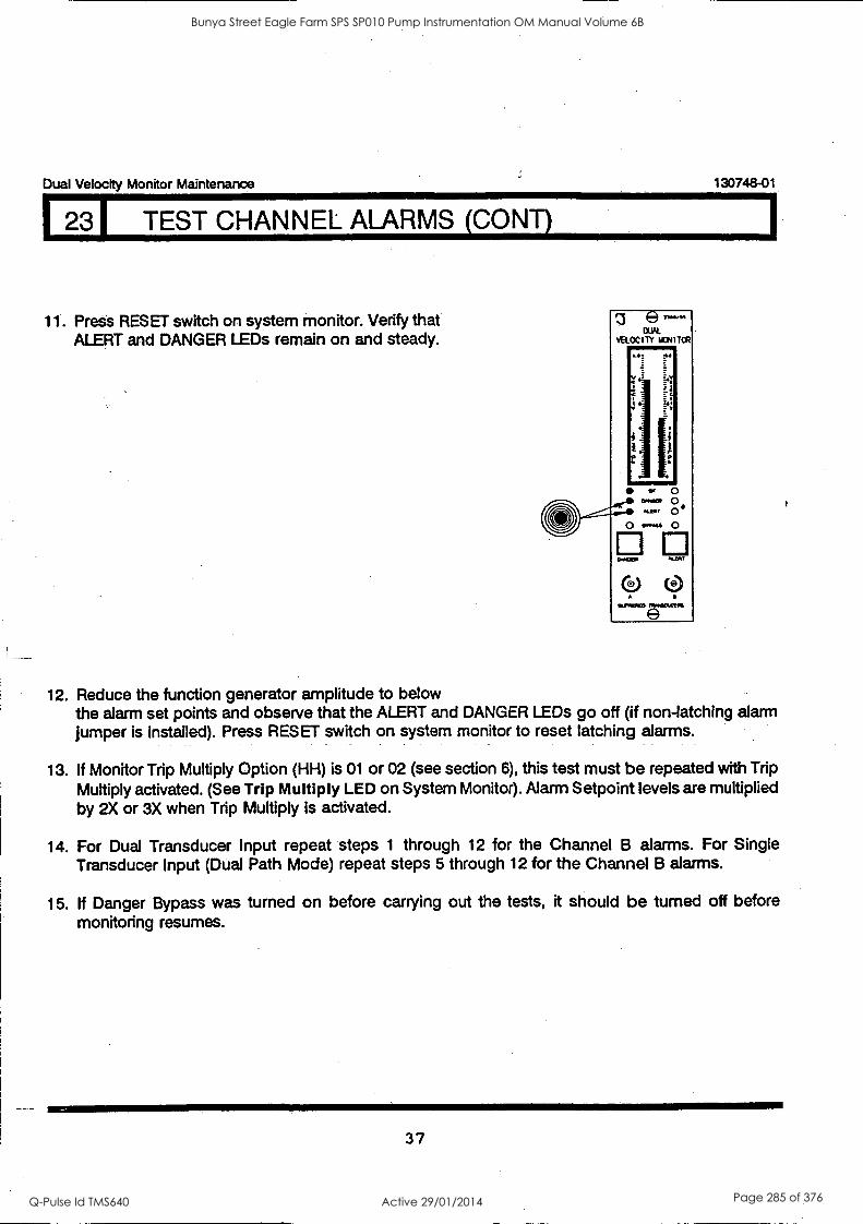
Dual Velocity Monitor Maintenance 130748-01
I 231 TEST CHANNEL ALARMS (CONT)
11. Press RESET switch on system monitor. Verify that ALERT and DANGER LEDs remain on and steady.
fe) morn
DUAL VELOCITY WIN I TOR 111
Mk, 44
4
1, o
c. 0 awe. 0 scum 0
0 DO ..C2)
111.1.003)
12. Reduce the function generator amplitude to below the alarm set points and observe that the ALERT and DANGER LEDs go off (if non-latching alarm jumper is installed). Press RESET switch on system monitor to reset latching alarms.
13. If Monitor Trip Multiply Option (HH) is 01 or 02 (see section 6), this test must be repeated with Trip Multiply activated. (See Trip Multiply LED on System Monitor). Alarm Setpoint levels are multiplied by 2X or 3X when Trip Multiply is activated.
14. For Dual Transducer Input repeat steps 1 through 12 for the Channel B alarms. For Single Transducer Input (Dual Path Mode) repeat steps 5 through 12 for the Channel B alarms.
15. If Danger Bypass was turned on before carrying out the tests, it should be turned off before monitoring resumes.
37
Bunya Street Eagle Farm SPS SP010 Pump Instrumentation OM Manual Volume 6B
Q-Pulse Id TMS640 Active 29/01/2014 Page 285 of 376
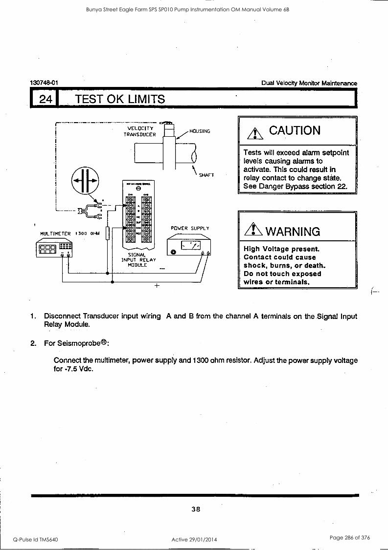
130748-01 Dual Velocity Monitor Maintenance
241 TEST OK LIMITS
VELOCITY TRANSDUCER
MULTIMETER 1300 OHM
V
V] I L=11
SIGNAL INPUT RELAY
MODULE
HOUSING
SHAFT
POWER SUPPLY
/-
/7
A\ CAUTION
Tests will exceed alarm setpoint levels causing alarms to activate. This could result in relay contact to change state. See Danger Bypass section 22.
WARNING High Voltage present. Contact could cause shock, burns, or death. Do not touch exposed wires or terminals.
1. Disconnect Transducer input wiring A and B from the channel A terminals on the Signal Input Relay Module.
2. For Seismoprobe ®:
Connect the muttimeter, power supply and 1300 ohm resistor. Adjust the power supply voltage for -7.5 Vdc.
38
Bunya Street Eagle Farm SPS SP010 Pump Instrumentation OM Manual Volume 6B
Q-Pulse Id TMS640 Active 29/01/2014 Page 286 of 376
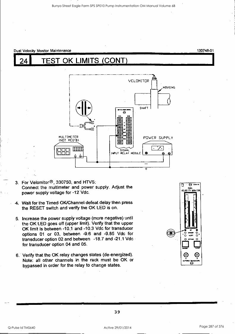
Dual Velocity Monitor Maintenance
124I TEST OK LIMITS (CONY)
L.__
MULTIMETER (NOT REGT) 7
000
j -IC
0000
130748-01
VELDMITOR
O ala MIMS
ow
a
cam
SHAFT
SIGNAL INPUT RELAY MODULE
HOUSING
POWER SUPPLY
1/- O
3, For Velomitor®, 330750, and HTVS: Connect the multimeter and power supply. Adjust the power supply voltage for -12 Vdc.
4. Wait for the Timed OK/Channel defeat delay then press the RESET switch and verify the OK LED is on.
5. Increase the power supply voltage (more negative) until the OK LED goes off (upper limit). Verify that the upper OK limit is between -10.1 and -10.3 Vdc for transducer options 01 or 03, between -9.6 and -9.85 Vdc for transducer option 02 and between -18.7 and -21.1 Vdc for transducer option 04 and 05.
6. Verify that the OK relay changes states (de-energized). Note: all other channels in the rack must be OK or bypassed in order for the relay to change states.
1
39
Bunya Street Eagle Farm SPS SP010 Pump Instrumentation OM Manual Volume 6B
Q-Pulse Id TMS640 Active 29/01/2014 Page 287 of 376
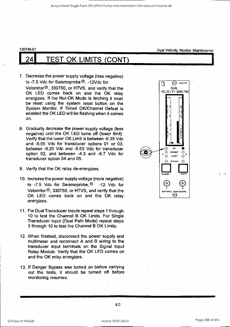
130748-01
124I TEST OK LIMITS (CONY)
7. Decrease the power supply voltage (less negative) to -7.5 Vdc for Seismoprobe e, -12Vdc for Velomitor ®, 330750, or HTVS, and verify that the OK LED comes back on and the OK relay energizes. If the Not-OK Mode is latching it must be reset using the system reset button on the System Monitor. If Timed OK/Channel Defeat is enabled the OK LED will be flashing when it comes on.
8. Gradually decrease the power supply voltage (less negative) until the OK LED turns off (lower limit). Verify that the lower OK Limit is between -6.35 Vdc and -6.65 Vdc for transducer options 01 or 03, between -6.25 Vdc and -6.60 Vdc for transducer option 02, and between -4.3 and -6.7 Vdc for transducer option 04 and 05.
9. Verify that the OK relay de-energizes.
10. Increase the power supply voltage (more negative) to -7.5 Vdc for Seismoprobe, e -12 Vdc for Velomitor ®, 330750, or HTVS, and verify that the OK LED comes back on and the OK relay. energizes.
11. For Dual Transducer Inputs repeat steps 1 through 10 to test the Channel B OK Limits. For Single Transducer Input (Dual Path Mode) repeat steps 3 through 10 to test the Channel B OK Limits.
12. When finished, disconnect the power supply and multimeter and reconnect A and B wiring to the transducer input terminals on the Signal Input Relay Module. Verify that the OK LED comes on and the OK relay energizes.
13. If Danger Bypass was turned on before carrying out the tests, it should be turned off before monitoring resumes.
Dual Velocity Monitor Maintenance
e3300/55
DUAL VELOCITY MONITOR
DANCER ALERT
0 0 A 8
BUFFERED TRANSDUCERS
40
Bunya Street Eagle Farm SPS SP010 Pump Instrumentation OM Manual Volume 6B
Q-Pulse Id TMS640 Active 29/01/2014 Page 288 of 376
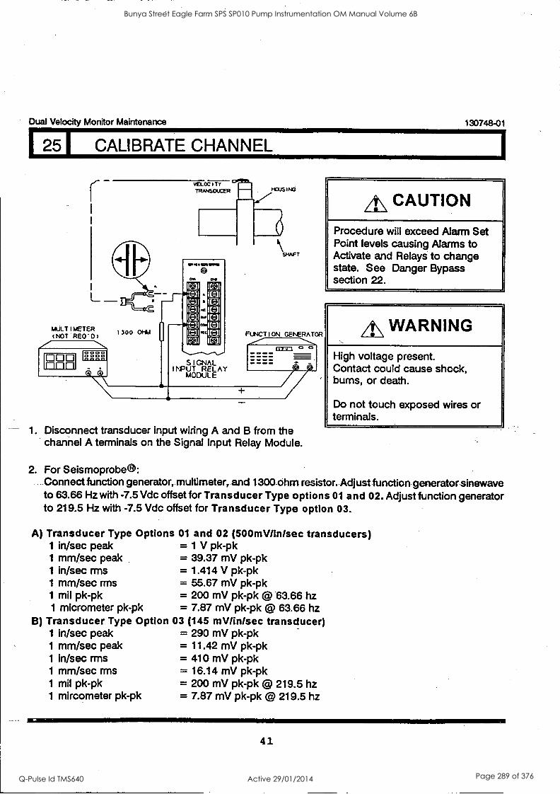
Dual Velocity Monitor Maintenance 130748-01
251 CALIBRATE CHANNEL
-.1111111111M
FUNCTION GENERATOR
Ca=
1. Disconnect transducer input wiring A and B from the channel A terminals on the Signal Input Relay Module.
A\ CAUTION
Procedure will exceed Alarm Set Point levels causing Alarms to Activate and Relays to change state. See Danger Bypass section 22.
A\ WARNING
High voltage present. Contact could cause shock, bums, or death.
Do not touch exposed wires or terminals.
2. For Seismoprobeel: Connect function generator, multimeter, and 1300 ohm resistor. Adjust function generator sinewave to 63.66 Hz with -7.5 Vdc offset for Transducer Type options 01 and 02. Adjust function generator to 219.5 Hz with -7.5 Vdc offset for Transducer Type option 03.
A) Transducer Type Options 01 and 02 (500mV/in/sec transducers) 1 in/sec peak = 1 V pk-pk 1 mm/sec peak = 39.37 mV pk-pk 1 in/sec rms = 1.414 V pk-pk 1 mm/sec mis = 55.67 mV pk-pk 1 mil pk-pk = 200 mV pk-pk @ .63.66 hz 1 micrometer pk-pk = 7.87 mV pk-pk @ 63.66 hz
B) Transducer Type Option 03 (145 mV/in/sec transducer) 1 in/sec peak 1 mm/sec peak 1 in/sec mis 1 mm/sec rms 1 mil pk-pk 1 mircometer pk-pk
= 290 mV pk-pk = 11.42 mV pk-pk = 410 mV pk-pk = 16.14 mV pk-pk = 200 mV pk-pk @ 219.5 hz = 7.87 mV pk-pk @ 219.5 hz
41
Bunya Street Eagle Farm SPS SP010 Pump Instrumentation OM Manual Volume 6B
Q-Pulse Id TMS640 Active 29/01/2014 Page 289 of 376
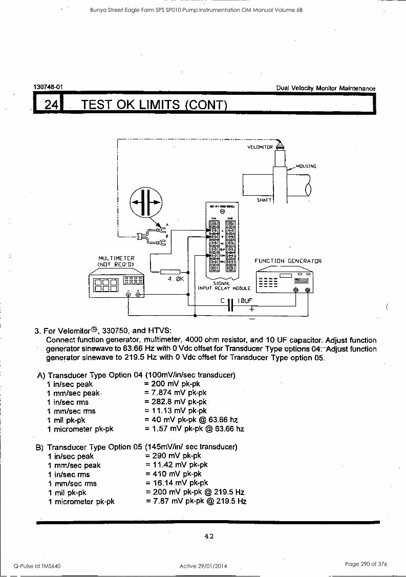
130748-01 Dual Velocity Monitor Maintenance
24I TEST OK LIMITS (CONY)
L._
MULTIMETER (NOT REQ'D)
000 rinn
A
4.0K SIGNAL
INPUT RELAY MODULE
C II IOUF
FUNCTION GENERATOR
I-1 °
3. For Velomitor®, 330750, and HTVS: Connect function generator, multimeter, 4000 ohm resistor, and 10 OF capacitor. Adjust function generator sinewave to 63.66 Hz with 0 Vdc offset for Transducer Type options 04. Adjust function generator sinewave to 219.5 Hz with 0 Vdc offset for Transducer Type option 05.
A) Transducer Type Option 1 in/sec peak 1 mm/sec peak. 1 in/sec rms 1 mm/sec rms 1 mil pk-pk 1 micrometer pk-pk
04 (100mV/in/sec transducer) = 200 mV pk-pk = 7.874 mV pk-pk = 282.8 mV pk-pk = 11.13 mV pk-pk = 40 mV pk-pk @ 63.66 hz = 1.57 mV pk-pk @ 63.66 hz
B) Transducer Type Option 05 1 in/sec peak 1 mm/sec peak 1 in/sec rms 1 mm/sec rms 1 mil pk-pk 1 micrometer pk-pk
(145mV/in/ sec transducer) = 290 mV pk-pk = 11.42 mV pk-pk = 410 mV pk-pk = 16.14 mV pk-pk = 200 mV pk-pk @ 219.5 Hz = 7.87 mV pk-pk @ 219.5 Hz
42
Bunya Street Eagle Farm SPS SP010 Pump Instrumentation OM Manual Volume 6B
Q-Pulse Id TMS640 Active 29/01/2014 Page 290 of 376
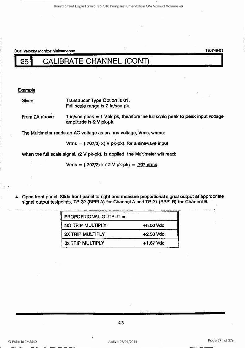
Dual Velocity Monitor Maintenance 130748-01
2 I CALIBRATE CHANNEL (CONT)
Example
Given: Transducer Type Option is 01. Full scale range is 2 in/sec pk.
From 2A above: 1 in/sec peak = 1 Vpk-pk, therefore the full scale peak to peak input voltage amplitude is 2 V pk-pk.
The Multimeter reads an AC voltage as an rms voltage, Vrms, where:
Vrms = (.707/2) x( V pk-pk), for a sinewave input
When the full scale signal, (2 V pk-pk), is applied, the Multimeter will read:
Vrms = (.707/2) x ( 2 V pk-pk) = .707 Vrms
4. Open front panel. Slide front panel to right and measure proportional signal output at appropriate signal output testpoints, TP 22 (BPPLA) for Channel A and TP 21 (BPPLB) for Channel B.
PROPORTIONAL OUTPUT =
NO TRIP MULTIPLY +5.00 Vdc
2X TRIP MULTIPLY +2.50 Vdc
3x TRIP MULTIPLY +1.67 Vdc
43
Bunya Street Eagle Farm SPS SP010 Pump Instrumentation OM Manual Volume 6B
Q-Pulse Id TMS640 Active 29/01/2014 Page 291 of 376
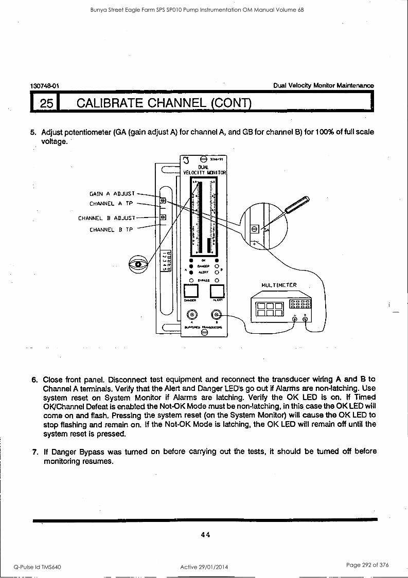
130748-01 Dual Velocity Monitor Maintenance
I CALIBRATE CHANNEL (CONT)
5. Adjust potentiometer (GA (gain adjust A) for channel A, and GB for channel B) for 100% of full scale voltage.
GAIN A ADJUST
CHANNEL A TP
CHANNEL B ADJUST
CHANNEL B TP
DUAL VELOCITY MONITOR
A-
tE
1
t v
si 2C
FD
omax-a
ALERT 0 a 0 ("ASS 0
El El ALERT
A
WAVERED
MULTIMETER
ODD 1-11-11-1
0 0 0 0 ) 0 0 0 0 0 0 0 0
6. Close front panel. Disconnect test equipment and reconnect the transducer wiring A and B to Channel A terminals. Verify that the Alert and Danger LED's go out if Alarms are non-latching. Use system reset on System Monitor if Alarms are latching. Verify the OK LED is on. If Timed OK/Channel Defeat is enabled the Not-OK Mode must be non-latching, in this case the OK LED will come on and flash. Pressing the system reset (on the System Monitor) will cause the OK LED to stop flashing and remain on. If the Not-OK Mode is latching, the OK LED will remain off until the system reset is pressed.
7. If Danger Bypass was turned on before carrying out the tests, it should be turned off before monitoring resumes.
44
Bunya Street Eagle Farm SPS SP010 Pump Instrumentation OM Manual Volume 6B
Q-Pulse Id TMS640 Active 29/01/2014 Page 292 of 376
I26.01 FILTER PROGRAMMING
Dual Velocity Monitor Maintenance 130748-01
OVERVIEW
The two optional plug-in boards , Peak-Peak Filter Board and RMS Filter Board, both have identical two pole low pass and two pole high pass programmable filters on each channel, Programming the filters is done by installing and removing jumpers on the respective plug-in board. In the following description of filter programming take care to use the tables which correspond to the plug-in board installed in your monitor system. If the ordered Transducer Input Channel Units option is 01, 02, 03,
05, 06, or 07 then the Peak-Peak Filter Board is installed. If "Transducer Input Channel Units Option" is 04 or 08 then the RMS Filter Board is installed. See section 6.
The steps required to program the monitor for operation with or without filters are as follows: 1) Set Filter Configuration (see section 26.1). The Options are:
A.) High Pass (HP) B.) Low Pass (LP) C.) Bandpass (Both HP and LP) D.) No Filters
2) Set Filter/Integrator Interface (see section 26.2). This option is only to set the filter position with respect to the integrator. If integration without filtering is desired see 1 D above and
section 26.1. The Filter/Integrator Interface Options are: A.) Filter after Integrate B.) Filter before Integrate C.) Filterwithout integration (filtered peak velocity signal)
3) Set Filter Corner Frequency A.) HP Filter only (see section 26.3) B.) LP Filter only (see section 26.4) C.) Bandpass Filter (see section 26.5)
4) Test Filter Settings, (not required if configuration is for no filters) see section 26.6.
A FILTER CONFIGURATION OPTION MUST BE SET FOR MONITOR OPERATION WITH OR
WITHOUT FILTERS. THIS OPTION MUST BE CONFIGURED WHETHER INTEGRATION IS
PERFORMED OR NOT.
FILTER/INTEGRATE INTERFACE OPTIONS ARE ONLY APPLICABLE IF THE PEAK-PEAK
BOARD IS INSTALLED.
FOR TRANSDUCER OPTION 04 (Velomitor ®), A 3.0 kHZ LOW PASS FILTER IS USED IN THE
SIGNAL MODULE.
Note: CPM (cycles per minute) = 60 x (frequency in Hertz)
45
Bunya Street Eagle Farm SPS SP010 Pump Instrumentation OM Manual Volume 6B
Q-Pulse Id TMS640 Active 29/01/2014 Page 293 of 376
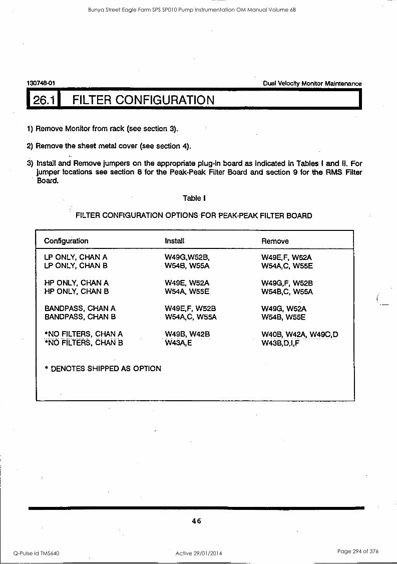
130748-01 Dual Velocity Monitor Maintenance
26.11 FILTER CONFIGURATION
1) Remove Monitor from rack (see section 3).
2) Remove the sheet metal cover (see section 4).
3) Install and Remove jumpers on the appropriate plug-in board as indicated in Tables I and II. For jumper locations see section 8 for the Peak-Peak Fitter Board and section 9 for the RMS Filter Board.
Table I
FILTER CONFIGURATION OPTIONS FOR PEAK-PEAK FILTER BOARD
Configuration Install Remove
LP ONLY, CHAN A LP ONLY, CHAN B
HP ONLY, CHAN A HP ONLY, CHAN B
W49G,W52B, W54B, W55A
W49E, W52A W54A, W55E
BANDPASS, CHAN A W49E,F, W52B BANDPASS, CHAN B W54A,C, W55A
*NO FILTERS, CHAN A *NO FILTERS, CHAN B
* DENOTES SHIPPED AS OPTION
W49B, W42B W43A,E
W49E,F, W52A W54A,C, W55E
W49G,F, W52B W54B,C, W55A
W49G, W52A W54B, W55E
W40B, W42A, W 9C,D W43B,D,I,F
46
Bunya Street Eagle Farm SPS SP010 Pump Instrumentation OM Manual Volume 6B
Q-Pulse Id TMS640 Active 29/01/2014 Page 294 of 376
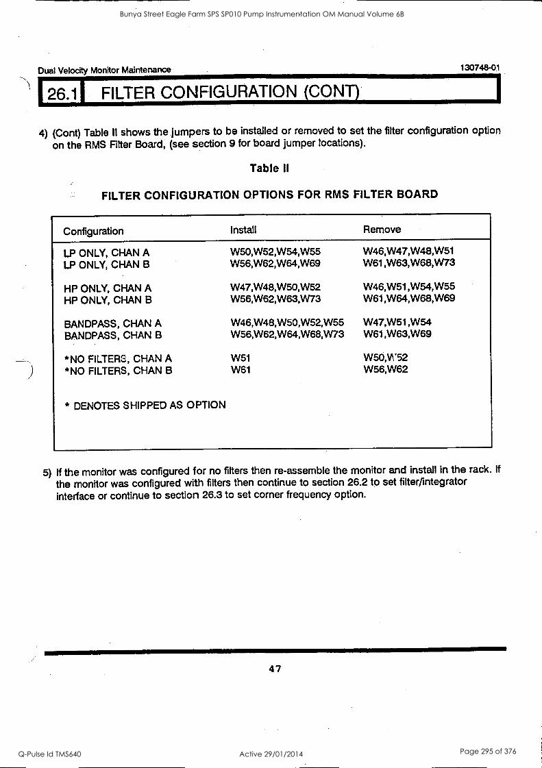
Dual Velocity Monitor Maintenance 130748-0.1
26.1 FILTER CONFIGURATION (CONT)
4) (Cont) Table II shows the jumpers to be installed or removed to set the filter configuration option
on the RMS Filter Board, (see section 9 for board jumper locations).
Table II
FILTER CONFIGURATION OPTIONS FOR RMS FILTER BOARD
Configuration Install Remove
LP ONLY, CHAN A LP ONLY, CHAN B
HP ONLY, CHAN A HP ONLY, CHAN B
BANDPASS, CHAN A BANDPASS, CHAN B
*NO FILTERS, CHAN A *NO FILTERS, CHAN B
* DENOTES SHIPPED AS OPTION
W50,W52,W54,W55 W56,W62,W64,W69
W47,W48,W50,W52 W56,W62,W63,W73
W46,W48,W50,W52,W55 W56,W62,W64,W68,W73
W51 W61
W46,W47,W48,W51 W61,W63,W68,W73
W46,W51,W54,W55 W61,W64,W68,W69
W47,W51,W54 W61,W63,W69
W50,Vt'52 W56,W62
5) If the monitor was configured for no filters then re-assemble the monitor and install in the rack. If
the monitor was configured with filters then continue to section 26.2 to set filter/integrator interface or continue to section 26.3 to set corner frequency option.
47
Bunya Street Eagle Farm SPS SP010 Pump Instrumentation OM Manual Volume 6B
Q-Pulse Id TMS640 Active 29/01/2014 Page 295 of 376
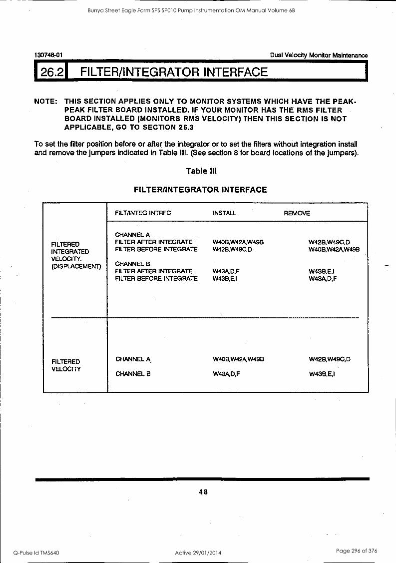
130748-01 Dual Velocity Monitor Maintenance
26.21 FILTER/INTEGRATOR INTERFACE
NOTE: THIS SECTION APPLIES ONLY TO MONITOR SYSTEMS WHICH HAVE THE PEAK- PEAK FILTER BOARD INSTALLED. IF YOUR MONITOR HAS THE RMS FILTER BOARD INSTALLED (MONITORS RMS VELOCITY) THEN THIS SECTION IS NOT APPLICABLE, GO TO SECTION 26.3
To set the filter position before or after the integrator or to set the filters without integration install and remove the jumpers indicated in Table III. (See section 8 for board locations of the jumpers).
Table HI
FILTER/INTEGRATOR INTERFACE
FILTERED INTEGRATED VELOCITY. (DISPLACEMENT)
F1LT/INTEGINTRFC INSTALL REMOVE
CHANNEL A FILTER AFTER INTEGRATE FILTER BEFORE INTEGRATE
CHANNEL B FILTER AFTER INTEGRATE FILTER BEFORE INTEGRATE
W40B,W42A,W49B W42B,W49C,D
W43A,D,F W43B,E,I
W42B,W49C,D W40B,W42A,W49B
W43B,E,I W43A,D,F
FILTERED VELOCITY
CHANNEL A
CHANNEL B
W40B,W42A,W49B
W43A,D,F
W42B,W49C,D
W43B,E,I
48
Bunya Street Eagle Farm SPS SP010 Pump Instrumentation OM Manual Volume 6B
Q-Pulse Id TMS640 Active 29/01/2014 Page 296 of 376
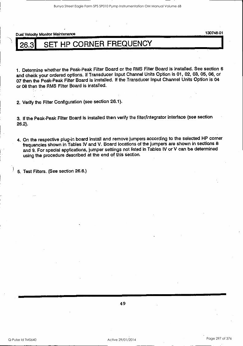
Dual Velocity Monitor Maintenance 130748-01
26.31 SET HP CORNER FREQUENCY
1. Determine whether the Peak-Peak Filter Board or the RMS Filter Board is installed. See section 6
and che.ck your ordered options. If Transducer Input Channel Units Option is 01, 02, 03, 05, 06, or
07 then the Peak-Peak Filter Board is installed. If the Transducer Input Channel Units Option is 04
or 08 then the RMS Filter Board is installed.
2. Verify the Filter Configuration (see section 26.1).
3. If the Peak-Peak Alter Board is installed then verify the filter /integrator interface (see section
26.2).
4. On the respective plug-in board install and remove jumpers according to the selected HP corner
frequencies shown in Tables IV and V. Board locations of the jumpers are shown in sections 8
and 9. For special applications, jumper settings not listed in Tables IV or V can be determined
using the procedure described at the end of this section.
5. Test Filters. (See section 26.6.)
49
Bunya Street Eagle Farm SPS SP010 Pump Instrumentation OM Manual Volume 6B
Q-Pulse Id TMS640 Active 29/01/2014 Page 297 of 376
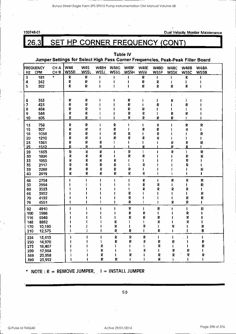
130748-01 Dual Velocity Monitor Maintenance
126.31 SET HP CORNER FREQUENCY (CONY)
Table IV Jumper Settings for Select High Pass Corner Frequencies, Peak-Peak Filter Board
FREQUENCY CH A Hz CPM CH B
W44 .
W55D W45 W55L
W48H W55J
W48G W55G
W48F W55H
W48E W55I
W48D W55F
W48C W55K
W48B W55C
W48A W55B
3 4 5
181 a
242 302
R
R
R
R
R
R
I
I
I
I
I
I
I
I
I
R
R
R
I
R
R
I
I
R
R
I
R
I
I
6 363 R R I I R I I R I I
7 423 R R I I R I R I R I
8 484 R R I I R R I I I I
9 544 R R I I R R I R R I
10 605 R R I I R R R R I I
13 756 R R I R I I R I R R
15 907 R R I R I R R I R I
18 1058 R R I R R I R I I R
20 1210 R R I R R R R I I I
23 1361 R R R I I I I R R R
25 1512 _R R R 1 I R I R R I
28 1663 R R R I R 1 1 R I R
30 1804 R R R I R R I I R R
33 1955 R R R R I I I I R I
35 2117 R R R R I R I I R 1
38 2268 R R R R R I I I I R
40 2419 R R R R R R I I I I
46 2754 I I I I I R I R R R
50 2994 I I I I I R R I I R
60 3593 I I I I I R R R R I
66 3952 I I I I R I I I I R
70 4192 I I I I R I I I R R
76 4551 I I I I R I I R R 1
82 4910 I I I I R I R I I R
100 5988 i 1 I 1 R R I 1 R 1
116 6946 I I I I R R R I R 1
148 8862 I I I R I I R I R 1
170 10,180 I .1 I R I R I R I R
210 12,575 I 1 I R R I R I 1 R
224 13,413 I I I R R R I I 1
250 14,970 I I I R R R R R I R
273 16,407 I I R I I I R I I R
299 17,964 I I R I I R 1 R R I
349 20,958 I I R I R I R R R R
399 23,952 I I R R I I R I I I
* NOTE : R = REMOVE JUMPER, I = INSTALL JUMPER
50
Bunya Street Eagle Farm SPS SP010 Pump Instrumentation OM Manual Volume 6B
Q-Pulse Id TMS640 Active 29/01/2014 Page 298 of 376
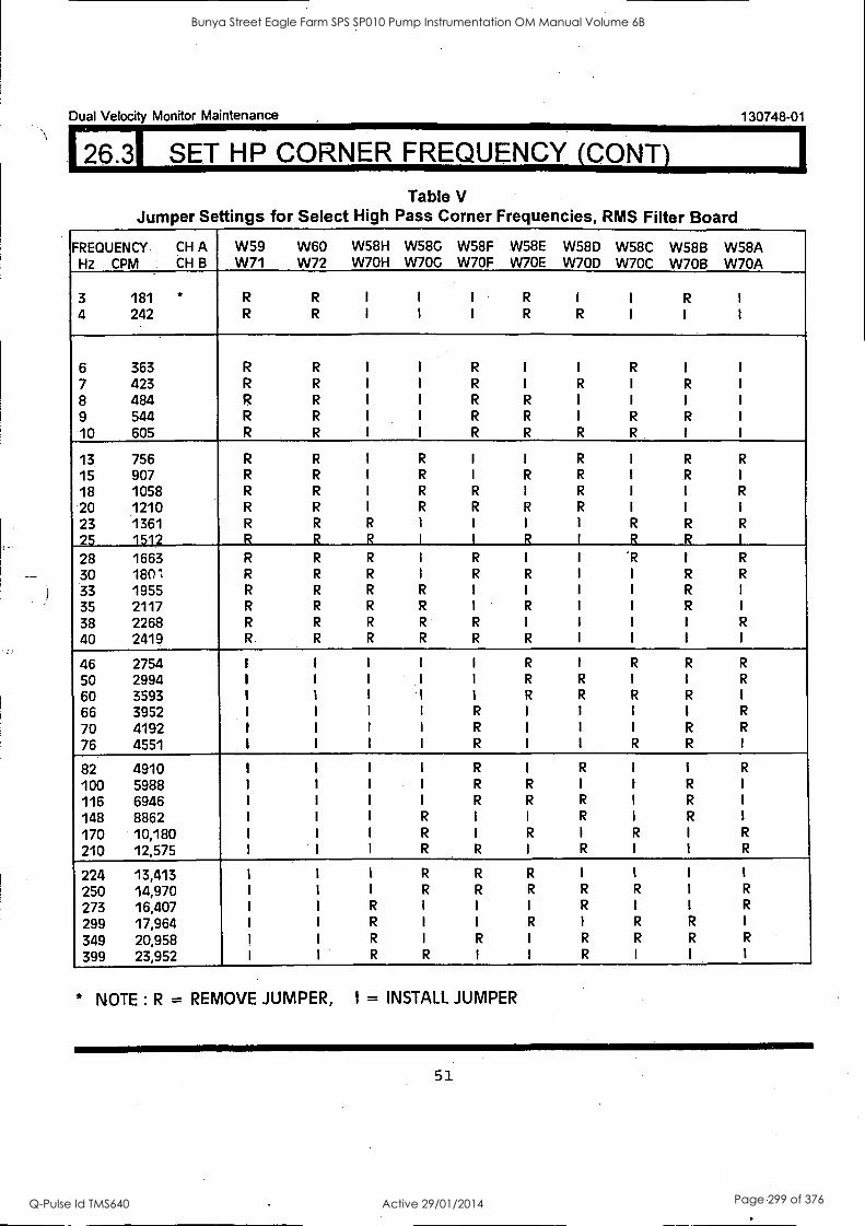
Dual Velocity Monitor Maintenance
26.31 SET HP CORNER FREQUENCY (CONT)
130748-01
Table V Jumper. Settings for Select High Pass Corner Frequencies, RMS Filter Board
FREQUENCY HZ CPM
CH A CH B
W59 W71
W60 W72
W58H W7OH
W58G W7OG
W58F W7OF
W58E W70E
W58D W7OD
W58C W70C
W58B W7OB
W58A W70A
3 181 * R R I I I R I I R I
4 242 R R I I I R R I I I
6 363 R R I I R I I R I I
7 423 R R I I R I R I R I
8 484 R R I I R R I I I
9 544 R R I I R R I R R I
10 605 R R I I R R R R I I
13 756 R R I R I I R I R R
15 907 R R I R I R R I R I
18 1058 R R I R R I R I I R
20 1210 R R I R R R R I I I
23 1361 R R R I 1 1 1 R R R
25 1512 R R_ R I I R I R R I
28 1663 R R R I R I I 'R I R
30 1801 R R R I R R I I R R
33 1955 R R R R I I I I R I
35 2117 R R R R I R I I R I
38 2268 R R R R R I I I I R
40 2419 R R R R R R I i i t
46 2754 1 I I I I R I R R R
50 2994 I I I I I R R I I R
60 3593 1 I I I I R R R R I
66 3952 I I I I R I I I I R
70 4192 1 1 I I R I I I R R
76 4551 I I I I R I I R R I
82 4910 I I I I R I R I I R
100 5988 I I I I R R I I R I
116 6946 I I I I R R R I R I
148 8862 I I I R I I R I R I
170 10,180 I I I R I R I R I R
210 12,575 I I I R R I R I I R
224 13,413 1 1 1 R R R I I I I
250 14,970 I I I R R R R R I R
273 16,407 I I R I I I R I I R
299 17,964 I I R I I R I R R I
349 20,958 I I R I R I R R R R
399 23,952 I I R R I I R I I I
* NOTE : R = REMOVE JUMPER, I = INSTALL JUMPER
51
Bunya Street Eagle Farm SPS SP010 Pump Instrumentation OM Manual Volume 6B
Q-Pulse Id TMS640 Active 29/01/2014 Page 299 of 376
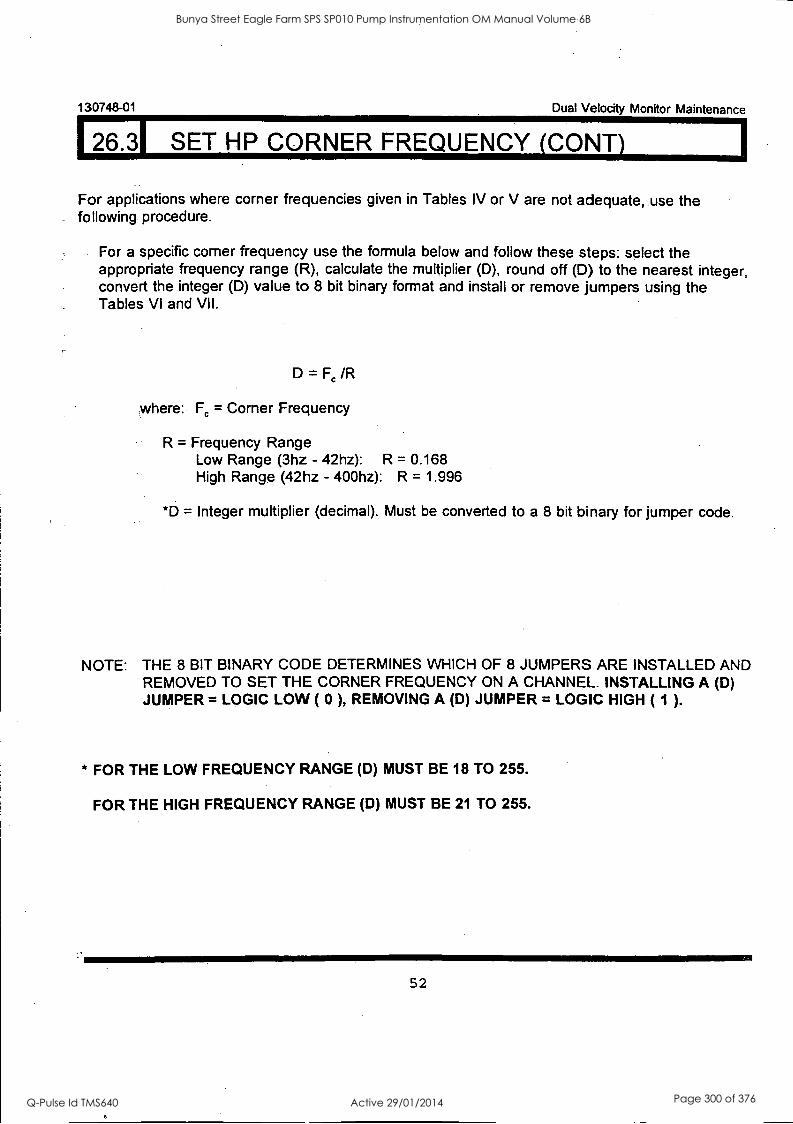
130748-01 Dual Velocity Monitor Maintenance
26.31 SET HP CORNER FREQUENCY (CONT)
For applications where corner frequencies given in Tables IV or V are not adequate, .use the following procedure.
For a specific corner frequency use the formula below and follow these steps: select the appropriate frequency range (R), calculate the multiplier (D), round off (D) to the nearest integer, convert the integer (D) value to 8 bit binary format and install or remove jumpers using the Tables VI and VII.
D = /R
where: Fc = Corner Frequency
R = Frequency Range Low Range (3hz - 42hz): R = 0.168 High Range (42hz - 400hz): R = 1.996
*D = Integer multiplier (decimal). Must be converted to a 8 bit binary for jumper code.
NOTE: THE 8 BIT BINARY CODE DETERMINES WHICH OF 8 JUMPERS ARE INSTALLED AND REMOVED TO SET THE CORNER FREQUENCY ON A CHANNEL. INSTALLING A (D) JUMPER = LOGIC LOW ( 0 ), REMOVING A (D) JUMPER = LOGIC HIGH ( 1 ).
* FOR THE LOW FREQUENCY RANGE (D) MUST BE 18 TO 255.
FOR THE HIGH FREQUENCY RANGE (D) MUST BE 21 TO 255.
52
Bunya Street Eagle Farm SPS SP010 Pump Instrumentation OM Manual Volume 6B
Q-Pulse Id TMS640 Active 29/01/2014 Page 300 of 376
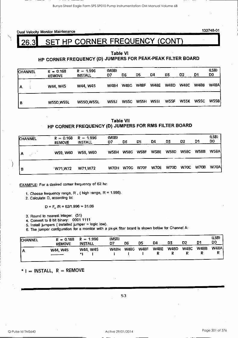
Dual Velocity Monitor Maintenance 130748-01
126.31 SET HP CORNER FREQUENCY (CONY)
Table VI
HP CORNER FREQUENCY (D) JUMPERS FOR PEAK-PEAK FILTER BOARD
CHANNEL R = 0.168 R = 1.996 (MSB) (LSB)
REMOVE INSTALL D7 D6 D5 D4 D3 D2 D1 DO
A W44, W45 W44, W45 W48H W48G W48F W48E W48D W48C W48B W48A
W55D,W55L W55D,W55L W55J W55G W55H W55I W55F W55K W55C W55B
Table VII
HP CORNER FREQUENCY (D) JUMPERS FOR RMS FILTER BOARD
CHANNEL R = 0.168 R = 1.996 (MSB) (LSB)
REMOVE INSTALL D7 D6 D5 D4 D3 D2 D1 DO
A W59, W60 W59, W60 W58H W58G W58F W58E W58D W58C W58B W58A
B W71,W72 W71,W72 W7OH W70G VV7OF W70E W70D W70C W7OB W70A
EXAMPLE: For a desired corner frequency of 62 hz:
1. Choose frequency range, R , ( high range, R = 1.996).
2. Calculate D, according to:
D = F, /R = 62/1.996 = 31.06
3. Round to nearest integer (31)
4. Convert to 8 bit binary: 0001 1111
5. Install jumpers ( installed jumper = logic low).
6. The jumper configuration for a monitor with a pk-pk filter board is shown below for Channel A:
CHANNEL R = 0.168 R = 1.996 (MSB) (LSB)
REMOVE INSTALL D7 D6 D5 D4 D3 D2 D1 DO
A W44, W45 W44, W45 W48H W48G W48F W48E W48D W48C W48B W48A
*I I
* I = INSTALL, R = REMOVE
53
Bunya Street Eagle Farm SPS SP010 Pump Instrumentation OM Manual Volume 6B
Q-Pulse Id TMS640 Active 29/01/2014 Page 301 of 376
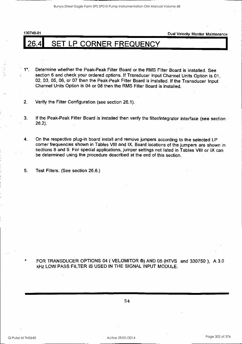
130748-01 Dual Velocity Monitor Maintenance
126.41 SET LP CORNER FREQUENCY
1*. Determine whether the Peak-Peak Filter Board or the RMS Filter Board is installed. See section 6 and check your ordered options. If Transducer Input Channel Units Option is 01, 02, 03, 05, 06, or 07 then the Peak-Peak Filter Board is installed. If the Transducer Input Channel Units Option is 04 or 08 then the RMS Filter Board is installed.
2. Verify the Filter Configuration (see section 26.1).
3. If the Peak-Peak Filter Board is installed then verify the filter/integrator interface (see section 26.2).
4. On the respective plug-in board install and remove jumpers according to the selected LP corner frequencies shown in Tables VIII and IX. Board locations of the jumpers are shown in sections 8 and 9. For special applications, jumper settings not listed in Tables VIII or IX can be determined using the procedure described at the end of this section.
5. Test Filters. (See section 26.6.)
FOR TRANSDUCER OPTIONS 04 ( VELOMITOR ®) AND 05 (HTVS and 330750 ), A 3.0 kHz LOW PASS FILTER IS USED IN THE SIGNAL INPUT MODULE.
54
Bunya Street Eagle Farm SPS SP010 Pump Instrumentation OM Manual Volume 6B
Q-Pulse Id TMS640 Active 29/01/2014 Page 302 of 376
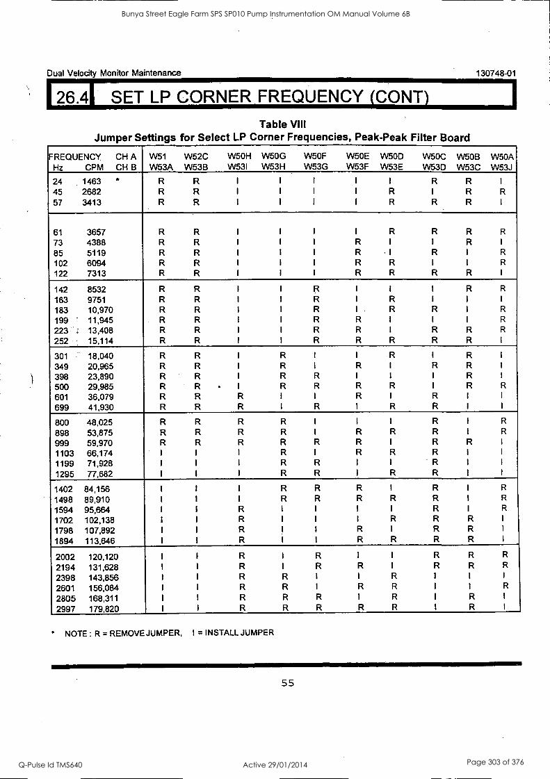
Dual Velocity Monitor Maintenance 130748-01
126.41 SET LP CORNER FREQUENCY (CONY)
Table VIII Jumper Settings for Select LP Corner Frequencies, Peak-Peak Filter Board
FREQUENCY CH A Hz CPM CH B
W51 W53A
W52C W53B
W5OH W53I
W5OG W53H
W5OF W53G
W50E W53F
W5OD W53E
W50C W53D
W5OB W53C
W50A W53J
24 1463 * R R I I I I I R R 45 2682 R R I I I I R I R R
57 3413 R R I I I I R R R
61 3657 R R I I I I R R R R
73 4388 R R I I I R 1 1 R 85 5119 R R I I I R 1 R 1 R
102 6094 R R 1 I I R R I I R
122 7313 R R I I I R R R R
142 8532 R R I I R I I I R R
163 9751 R R I I R I R
183 10,970 R R I I R I R R I R
199 ' 11,945 R R I I R R 1 I I R
223 _. 13,408 R R I I R R I R R R
252 15,114 R R I I R R R R R
301 18,040 R R I R I I R I R 349 20,965 R R I R I R I R R 398 23,890 R R 1 R R I I I R
500 29,985 R R I R R R R 1 R R
601 36,079 R R R I I R I R
699 41,930 R R R I R I R R
800 48,025 R R R R I I I R I R
898 53,875 R R R R I R R R I R
999 59,970 R R R R R R I R R
1103 66,174 1 I I R I R R R 1199 71,928 I I I R R I I R
1295 77,682 I I I R R I R R
1402 84,156 1 I I R R R I R I R
1498 89,910 I I I R R R R R I R
1594 95,664 I I R I I I I R I R
1702 102,138 I I R I I I R R R I
1798 107,892 I I R I 1 R 1 R R I
1894 113,646 I I R I I R R R R I
2002 120,120 1 I R I R I I R R R
2194 131,628 I I R I R R I R R R
2398 143,856 I I R R I I R I I I
2601 156,084 I I R R I R R I 1 R
2805 168,311 I I R R R I R I R I
2997 179,820 I I R R R R R I R I
NOTE : R = REMOVE JUMPER, I = INSTALL JUMPER
55
Bunya Street Eagle Farm SPS SP010 Pump Instrumentation OM Manual Volume 6B
Q-Pulse Id TMS640 Active 29/01/2014 Page 303 of 376
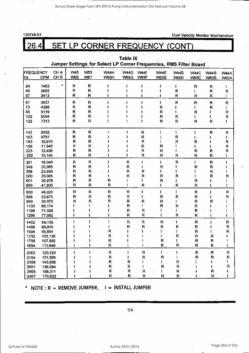
130748-01 Dual Velocity Monitor Maintenance
26.41 SET LP CORNER FREQUENCY (CONT)
Table IX Jumper Settings for Select LP Corner Frequencies, RMS Filter Board
FREQUENCY CH A Hz CPM CH B
W45 VV66
W53 VV67
W44H VV65H
W44G VV65G
W44F VV65F
W44E VV65E
W44D VV65D
W44C W65C
W44B VV65B
W44A VV65A
24 1463 ' R R I I I I I R R 45 2682 R R I I I I R I R R 57 3413 R R I I I I R R R
61 3657 R R I I I I R R R R 73 4388 R R I I I R I I R 85 5119 R R I I I R I R I R 102 6094 R R I I I R R 1 I R
122 7313 R R I I I R R R R
142 8532 R R I I R I I I R R
163 9751 R R I I R I R I I
183 10,970 R R I I R I R R I R
199 11,945 R R I I R R I I I R
223 13,408 R R 1 I R R I R R R
252 15,144 R R I I R R R R R
301 18,040 R R I R I I R I R 349 20,965 R R I R I R I R R 398 23,890 R R I R R I I I R 500 29,985 R R 1 R R R R I R R 601 36,079 R R R I I R I R 699 41,930 R R R I R I R R
800 48,025 R R R R I 1 I R I R
898 53,875 R R R R I R R R I R
999 59,970 R R R R R R I R R 1103 66,174 I I I R I R R R 1199 71,928 I I I R R 1 I R 1295 77,682 I I I R R I R R
1402 84,156 I I I R R R I R I R
1498 89,910 I I I R R R R R I R
1594 95,664 I I R I I 1. R I R
1702 102,138 I I R I I I R R R I
1798 107,892 I I R I I R I R R I
1894 113,646 I I R I I R R R R I
2002 120,120 I I R I R I I R R R
2194 131,628 I I R 1 R R I R R R
2398 143,856 I I R R I I R I I I
2601 156,084 I I R R I R R I I R
2805 168,311 I I R R R I R I R I
2997 179,820 I I R R R R R I R
* NOTE : R = REMOVE JUMPER, I = INSTALL JUMPER
56
Bunya Street Eagle Farm SPS SP010 Pump Instrumentation OM Manual Volume 6B
Q-Pulse Id TMS640 Active 29/01/2014 Page 304 of 376
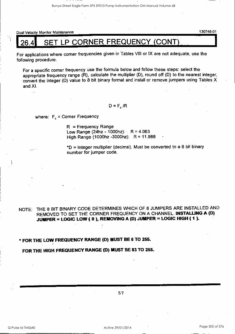
Dual Velocity Monitor Maintenance 130748-01
26.41 SET LP CORNER FREQUENCY (CONY)
For applications where corner frequencies given in Tables VIII or IX are not adequate, use the following procedure.
For a specific corner frequency use the formula below and follow these steps: select the appropriate frequency range (R), calculate the multiplier (D), round off (D) to the nearest integer, convert the integer (D) value to 8 bit binary format and install or remove jumpers using Tables X and XI.
D = /R
where: Fc = Corner Frequency
R = Frequency Range Low Range (24hz - 1000hz): R = 4.063 High Range (1000hz -3000hz): R = 11.988
*D = Integer multiplier (decimal). Must be converted to a 8 bit binary number for jumper code.
NOTE: THE 8 BIT BINARY CODE DETERMINES WHICH OF 8 JUMPERS ARE INSTALLED AND
REMOVED TO SET THE CORNER FREQUENCY ON A CHANNEL. INSTALLING A (D)
JUMPER = LOGIC LOW ( 0 ), REMOVING A (D) JUMPER = LOGIC HIGH ( 1 ).
* FOR THE LOW FREQUENCY RANGE (D) MUST BE 6 TO 255.
FOR THE HIGH FREQUENCY RANGE (0) MUST BE 83 TO 255.
57
Bunya Street Eagle Farm SPS SP010 Pump Instrumentation OM Manual Volume 6B
Q-Pulse Id TMS640 Active 29/01/2014 Page 305 of 376
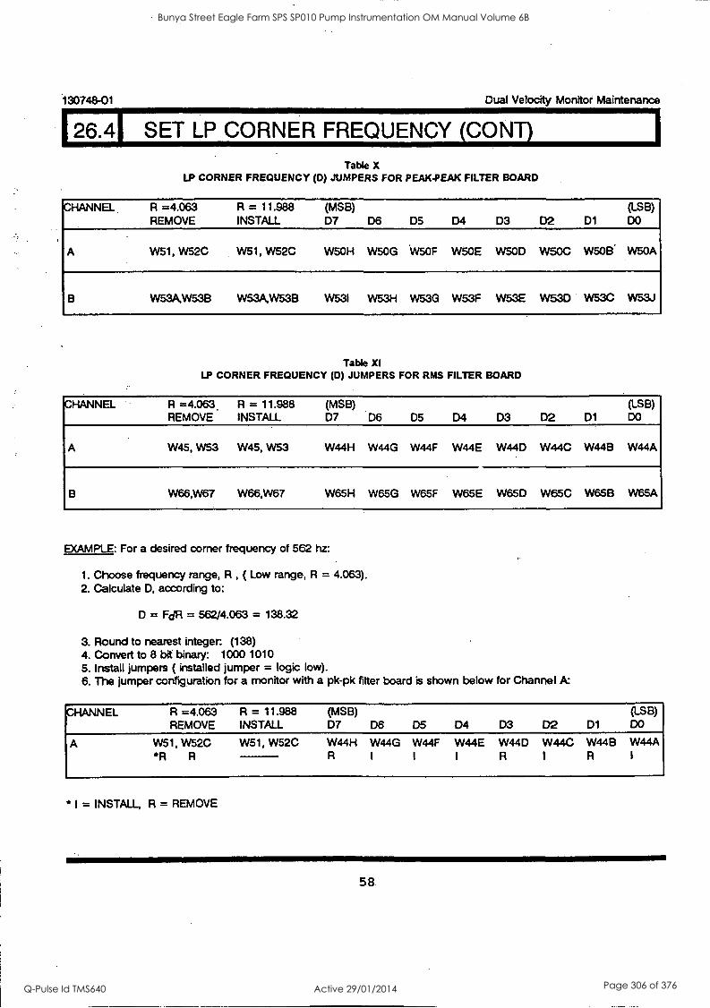
I26.41 SET LP CORNER FREQUENCY (CONT)
i30748-01 Dual Velocity Monitor Maintenance
Table X LP CORNER FREQUENCY (D) JUMPERS FOR PEAK-PEAK FILTER BOARD
CHANNEL. R =4.063 R = 11.988 (MSB) (LSB) REMOVE INSTALL D7 D6 D5 D4 D3 D2 D1 DO
A W51, W52C W51, W52C W5OH W5OG 'W5OF W50E W500 W50C W5013' W50A
B W53A.W53B W53A,W53B W53I W53H W53G W53F W53E W530 W53C W53J
Table XI LP CORNER FREQUENCY (D) JUMPERS FOR RMS FILTER BOARD
CHANNEL R =4.063 R = 11.988 (MSB) (LSB) REMOVE INSTALL D7 D6 D5 D4 D3 D2 D1 DO
W45, W53 W45, W53 W44H W44G W44F W44E W44D W44C W44B W44A
W66,W67 W66,W67 W65H W65G W65F W65E W65D W650 W65B W65A
EXAMPLE: For a desired corner frequency of 562 hz:
1. Choose frequency range, R , ( Low range, R = 4.063). 2. Calculate D, according to:
D = FdR = 562/4.063 = 138.32
3. Round to nearest integer. (138) 4. Convert to 8 bit binary: 1000 1010 5. Install jumpers ( installed jumper = logic low). 6. The jumper configuration for a monitor with a pk-pk filter board is shown below for Channel A:
CHANNEL R =4.063 R = 11.988 (MSB) (LSB) REMOVE INSTALL D7 D6 D5 D4 D3 D2 D1 DO
A W51, W52C W51, W52C W44H W44G W44F W44E W44D W44C W44B W44A R R
* I = INSTALL, R = REMOVE
58
Bunya Street Eagle Farm SPS SP010 Pump Instrumentation OM Manual Volume 6B
Q-Pulse Id TMS640 Active 29/01/2014 Page 306 of 376
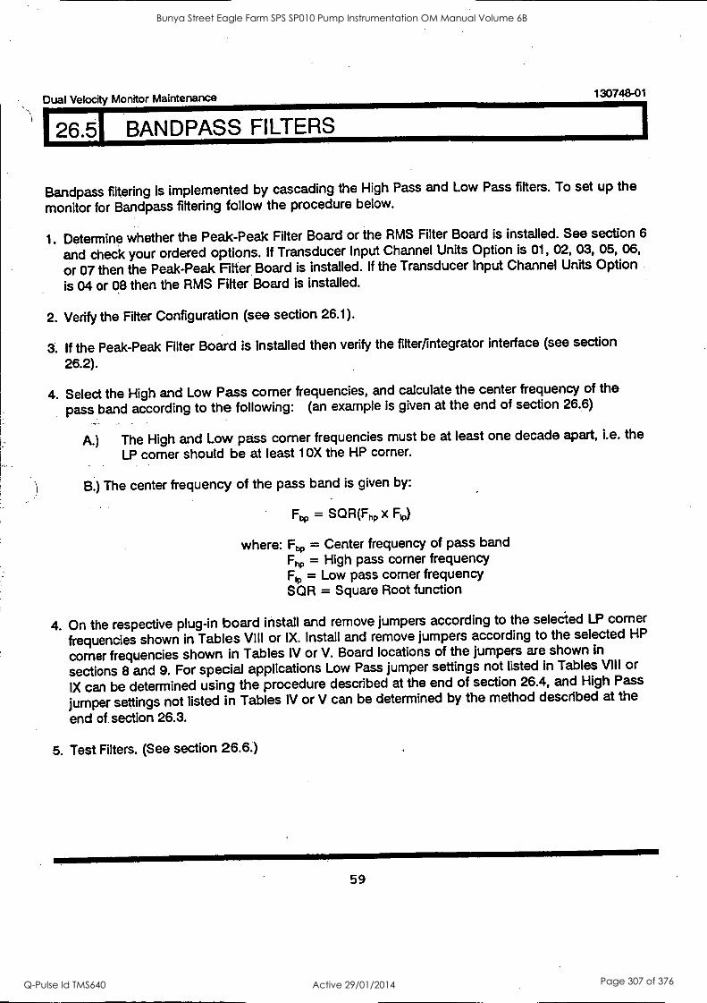
I26.5 BANDPASS FILTERS
Dual Velocity Monitor Maintenance 130748-01
Bandpass filtering is implemented by cascading the High Pass and Low Pass fitters. To set up the
monitor for Bandpass filtering follow the procedure below.
1. Determine whether the Peak-Peak Filter Board or the RMS Filter Board is installed. See section 6
and check your ordered options. If Transducer Input Channel Units Option is 01, 02, 03, 05, 06,
or 07 then the Peak-Peak Filter Board is installed. If the Transducer Input Channel Units Option
is 04 or 08 then the RMS Fitter Board is installed.
2. Verify the Filter Configuration (see section 26.1).
3. If the Peak-Peak Filter Board is installed then verify the filter/integrator interface (see section
26.2).
4. Select the High and Low Pass corner frequencies, and calculate the center frequency of the
pass band according to the following: (an example is given at the end of section 26.6)
A.) The High and Low pass corner frequencies must be at least one decade apart, i.e. the
LP corner should be at least 10X the HP corner.
B.) The center frequency of the pass band is given by:
Fhp = SQR(Fhp x Flp)
where: Fa, = Center frequency of pass band Fhp = High pass corner frequency Fro = Low pass corner frequency SQR = Square Root function
4. On the respective plug-in board install and remove jumpers according to the selected LP corner
frequencies shown in Tables VIII or IX. Install and remove jumpers according to the selected HP
corner frequencies shown in Tables IV or V. Board locations of the jumpers are shown in
sections 8 and 9. For special applications Low Pass jumper settings not listed in Tables VIII or
IX can be determined using the procedure described at the end of section 26.4, and High Pass
jumper settings not listed in Tables IV or V can be determined by the method described at the
end of section 26.3.
5. Test Filters. (See section 26.6.)
59
Bunya Street Eagle Farm SPS SP010 Pump Instrumentation OM Manual Volume 6B
Q-Pulse Id TMS640 Active 29/01/2014 Page 307 of 376
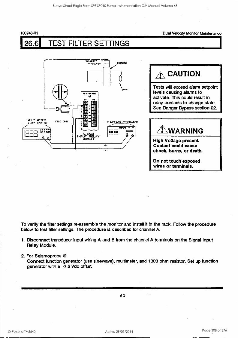
130748-01 Dual Velocity Monitor Maintenance
26.61 TEST FILTER SETTINGS
VELOCITY TRANS OXEN HOUS I NO
le MI OM EMI
MULTIMETER (NOT REO'DI
1300 01-11V FUNCTION GENERATOR
A\ CAUTION
Tests will exceed alarm setpoint levels causing alarms to activate. This could result in relay contacts to change state. See Danger Bypass section 22.
A.VVARNING High Voltage present. Contact could cause shock, burns, or death.
Do not touch exposed wires or terminals.
To verify the filter settings re-assemble the monitor and install it in the rack. Follow the procedure below to test filter settings. The procedure is described for channel A.
1. Disconnect transducer input wiring A and B from the channel A terminals on the Signal Input Relay Module.
2. For Seismoprobe Connect function generator (use sinewave), multimeter, and 1300 ohm resistor. Set up function generator with a -7.5 Vdc offset.
60
Bunya Street Eagle Farm SPS SP010 Pump Instrumentation OM Manual Volume 6B
Q-Pulse Id TMS640 Active 29/01/2014 Page 308 of 376
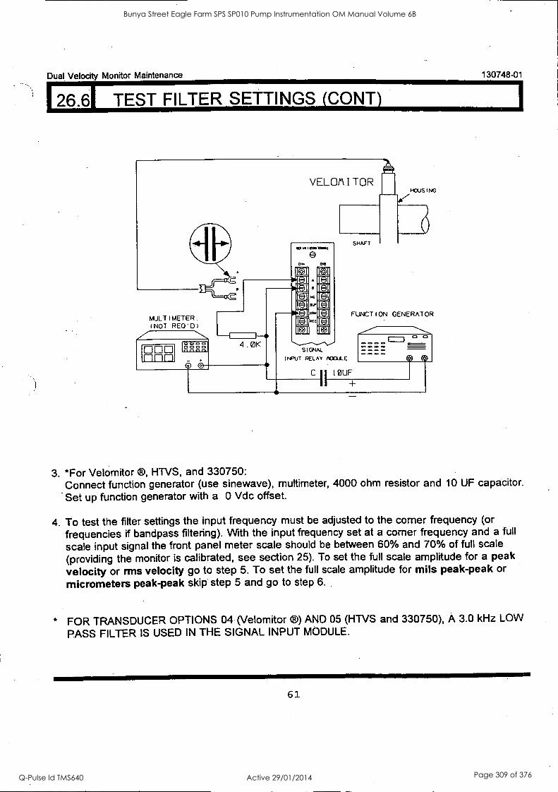
Dual Velocity Monitor Maintenance
I 26.61 TEST FILTER SETTINGS (CONT)
130748-01
VELOM I TOR HOUSING
MULTIMETER (NOT RE0'01
to
SHAFT
FUNCTION GENERATOR
°
DOD SIGNAL
I NPUT RELAY ACICILLE
=
C
II IOUF
I +
3. *For Velomitor ®, HTVS, and 330750: Connect function generator (use sinewave), multimeter, 4000 ohm resistor and 10 OF capacitor.
Set up function generator with a 0 Vdc offset.
4. To test the filter settings the input frequency must be adjusted to the corner frequency (or
frequencies if bandpass filtering). With the input frequency set at a corner frequency and a full
scale input signal the front panel meter scale should be between 60% and 70% of full scale
(providing the monitor is calibrated, see section 25). To set the full scale amplitude for a peak
velocity or rms velocity go to step 5. To set the full scale amplitude for mils peak-peak or
micrometers peak-peak skip step 5 and go to step 6.
* FOR TRANSDUCER OPTIONS 04 (Velomitor ®) AND 05 (HTVS and 330750), A 3.0 kHz LOW
PASS FILTER IS USED IN THE SIGNAL INPUT MODULE.
61
Bunya Street Eagle Farm SPS SP010 Pump Instrumentation OM Manual Volume 6B
Q-Pulse Id TMS640 Active 29/01/2014 Page 309 of 376
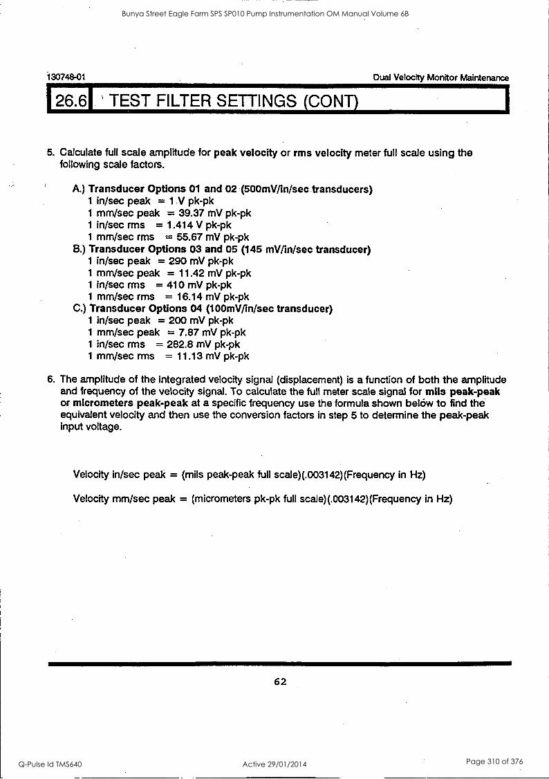
130748-01 Dual Velocity Monitor Maintenance
26.61 TEST FILTER SETTINGS (CONT)
5. Calculate full scale amplitude for peak velocity or rms velocity meter full scale using the following scale factors.
A.) Transducer Options 01 and 02 (500mV/in/sec transducers) 1 in/sec peak = 1.V pk-pk 1 mm/sec peak = 39.37 mV pk-pk 1 in/sec rms = 1.414 V pk-pk 1 mm/sec rms = 55.67 mV pk-pk
B.) Transducer Options 03 and 05 (145 mV/in/sec transducer) 1 in/sec peak = 290 mV pk-pk 1 mm/sec peak = 11.42 mV pk-pk 1 in/sec rms = 410 mV pk-pk 1 mm/sec rms = 16.14 mV pk-pk
C.) Transducer Options 04 (100mV/in/sec transducer) 1 in/sec peak = 200 mV pk-pk 1 mm/sec peak = 7.87 mV pk-pk 1 in/sec rms = 282.8 mV pk-pk 1 mm/sec rms = 11.13 mV pk-pk
6. The amplitude of the integrated velocity signal (displacement) is a function of both the amplitude and frequency of the velocity signal. To calculate the full meter scale signal for mils peak-peak or micrometers peak-peak at a specific frequency use the formula shown below to find the equivalent velocity and then use the conversion factors in step 5 to determine the peak-peak input voltage.
Velocity in/sec peak = (mils peak-peak full scale)(.003142)(Frequency in Hz)
Velocity mm/sec peak = (micrometers pk-pk full scale)(.003142)(Frequency in Hz)
62
Bunya Street Eagle Farm SPS SP010 Pump Instrumentation OM Manual Volume 6B
Q-Pulse Id TMS640 Active 29/01/2014 Page 310 of 376
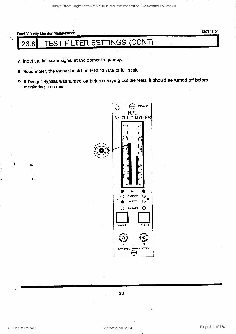
Dual Velocity Monitor Maintenance, 130748-01
26.61 TEST FILTER SETTINGS (CONT)
7. Input the full scale signal at the corner frequency.
8. Read meter, the value should be 60% to 70% of full scale.
9. If Danger Bypass was turned on before carrying out the tests, it should be turned off before
monitoring resumes.
3300/SS
DUAL
VELOCITY MONITOR
1.0- -i.0
a a
k
OK
O DANGER 0 A
ALERT 0 8 O BYPASS 0
ALERT DANGER
0 A
BUFFERED TRANSDUCERS
63
Bunya Street Eagle Farm SPS SP010 Pump Instrumentation OM Manual Volume 6B
Q-Pulse Id TMS640 Active 29/01/2014 Page 311 of 376
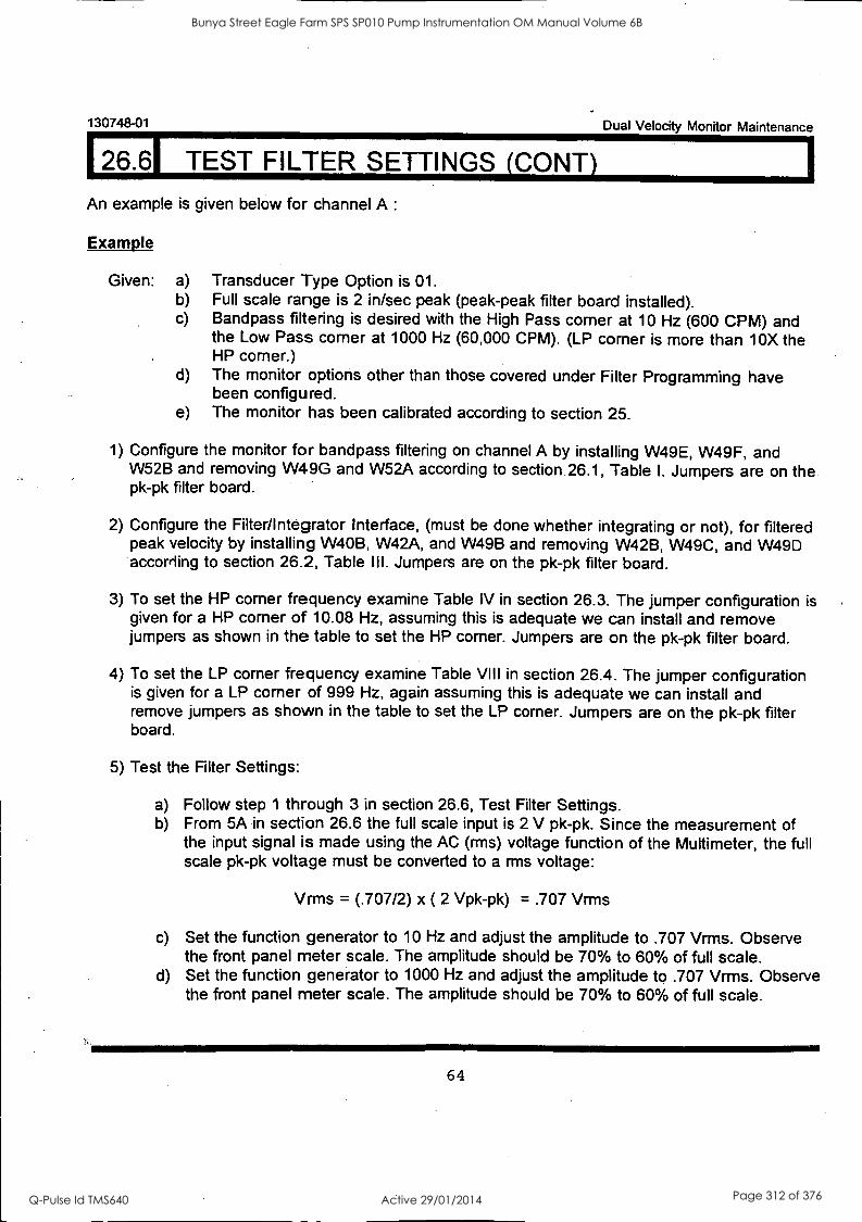
130748-01
126.61 TEST FILTER SETTINGS (CONY)
An example is given below for channel A :
Example
Given: a) b) c)
Dual Velocity Monitor Maintenance
Transducer Type Option is 01. Full scale range is 2 in/sec peak (peak-peak filter board installed). Bandpass filtering is desired with the High Pass corner at 10 Hz (600 CPM) and the Low Pass corner at 1000 Hz (60,000 CPM). (LP corner is more than *10X the HP corner.)
d) The monitor options other than those covered under Filter Programming have been configured.
e) The monitor has been calibrated according to section 25.
1) Configure the monitor for bandpass filtering on channel A by installing W49E, W49F, and W52B and removing W49G and W52A according to section 26.1, Table I. Jumpers are on the pk-pk filter board.
2) Configure the Filter/Integrator Interface, (must be done whether integrating or not), for filtered peak velocity by installing W40B, W42A, and W49B and removing W42B, W49C, and W49D according to section 26.2, Table III. Jumpers are on the pk-pk filter board.
3) To set the HP corner frequency examine Table IV in section 26.3. The jumper configuration is given for a HP corner of 10.08 Hz, assuming this is adequate we can install and remove jumpers as shown in the table to set the HP corner. Jumpers are on the pk-pk filter board.
4) To set the LP corner frequency examine Table VIII in section 26.4. The jumper configuration is given for a LP corner of 999 Hz, again assuming this is adequate we can install and remove jumpers as shown in the table to set the LP corner. Jumpers are on the pk-pk filter board.
5) Test the Filter Settings:
a) Follow step 1 through 3 in section 26.6, Test Filter Settings. b) From 5A in section 26.6 the full scale input is 2 V pk-pk. Since the measurement of
the input signal is made using the AC (rms) voltage function of the Multimeter, the full scale pk-pk voltage must be converted to a mis voltage:
Vrms = (.707/2) x ( 2 Vpk-pk) = .707 Vrms
c) Set the function generator to 10 Hz and adjust the amplitude to .707 Vrms. Observe the front panel meter scale. The amplitude should be 70% to 60% of full scale.
d) Set the function generator to 1000 Hz and adjust the amplitude to .707 Vrms. Observe the front panel meter scale. The amplitude should be 70% to 60% of full scale.
64
Bunya Street Eagle Farm SPS SP010 Pump Instrumentation OM Manual Volume 6B
Q-Pulse Id TMS640 Active 29/01/2014 Page 312 of 376
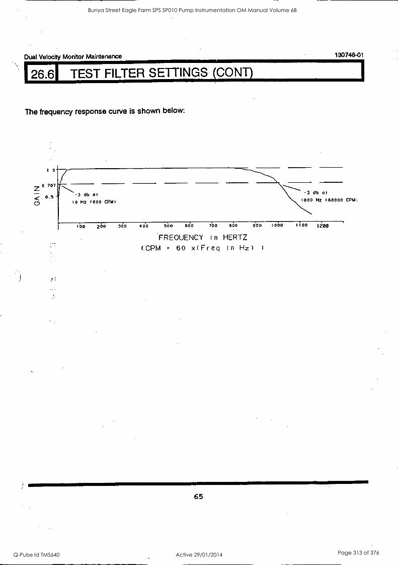
Dual Velocity Monitor Maintenance 130748-01
26.61 TEST FILTER SETTINGS (CONY)
The frequency response curve is shown below:
1 0
-,. 0 707
< 0.5
0 -3 db 01
10 Hz (600 CPM)
...---..-----'---s.\\ 3 db 01 ---"----- -
1000 Hz (60000 CPM:
160 200 300 400 500 600 700 800 900 1000 1100 1200
FREQUENCY I n HERTZ
( CPM = 60 x(Freq in Hz) )
65
Bunya Street Eagle Farm SPS SP010 Pump Instrumentation OM Manual Volume 6B
Q-Pulse Id TMS640 Active 29/01/2014 Page 313 of 376
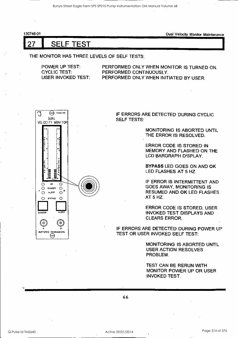
130748-01 Dual Velocity Monitor Maintenance
127 I SELF TEST
THE MONITOR HAS THREE LEVELS OF SELF TESTS:
POWER UP TEST: CYCLIC TEST: USER INVOKED TEST:
3300/55
DUAL
VELOCITY MONITOR 1117111011071W
I.0
0
:La
;aei
at
2C p
IOC k IOC
0 0 DANGER
A U ALERT
0 BYPASS
DANGER ALERT
® ® BLFFERED TRANSDUCERS
PERFORMED ONLY WHEN MONITOR IS TURNED ON. PERFORMED CONTINUOUSLY. PERFORMED ONLY WHEN INITIATED BY USER.
IF ERRORS ARE DETECTED DURING CYCLIC SELF TESTS:
MONITORING IS ABORTED UNTIL THE ERROR IS RESOLVED.
ERROR CODE IS STORED IN MEMORY AND FLASHED ON THE LCD BARGRAPH DISPLAY.
BYPASS LED GOES ON AND OK LED FLASHES AT 5 HZ.
IF ERROR IS INTERMITTENT AND GOES AWAY, MONITORING IS RESUMED AND OK LED FLASHES AT 5 HZ.
ERROR CODE IS STORED. USER INVOKED TEST DISPLAYS AND CLEARS ERROR.
IF ERRORS ARE DETECTED DURING POWER UP TEST OR USER INVOKED SELF TEST:
MONITORING IS ABORTED UNTIL USER ACTION RESOLVES PROBLEM.
TEST CAN BE RERUN WITH MONITOR POWER UP OR USER INVOKED TEST.
66
Bunya Street Eagle Farm SPS SP010 Pump Instrumentation OM Manual Volume 6B
Q-Pulse Id TMS640 Active 29/01/2014 Page 314 of 376
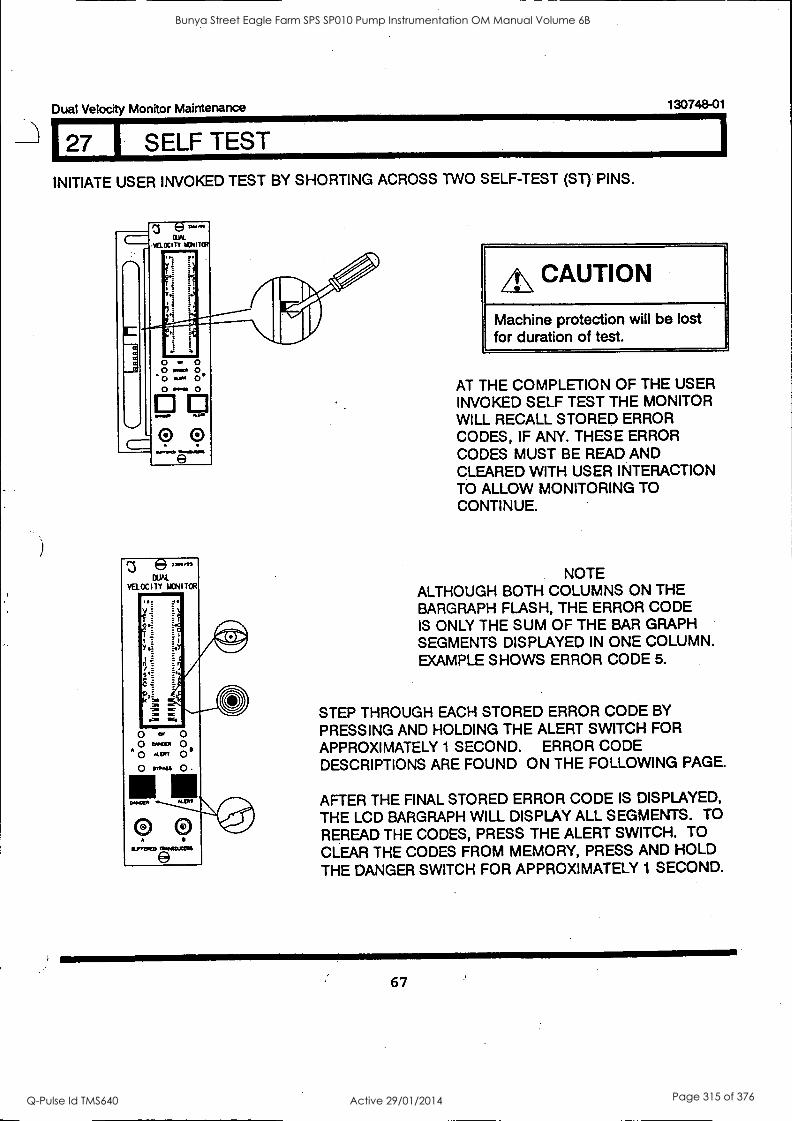
Dual Velocity Monitor Maintenance 130748-01
127 SELF TEST
INITIATE USER INVOKED TEST BY SHORTING ACROSS TWO SELF-TEST (ST) PINS.
z e mons
DUN. VELOCITY MONITOR
INI.M111,
o I.' o WOW
0 KP o- (3 IM.SS
/!\ CAUTION
Machine protection will be lost for duration of test.
AT THE COMPLETION OF THE USER INVOKED SELF TEST THE MONITOR WILL RECALL STORED ERROR CODES, IF ANY. THESE ERROR CODES MUST BE READ AND CLEARED WITH USER INTERACTION TO ALLOW MONITORING TO CONTINUE.
NOTE ALTHOUGH BOTH COLUMNS ON THE BARGRAPH FLASH, THE ERROR CODE IS ONLY THE SUM OF THE BAR GRAPH SEGMENTS DISPLAYED IN ONE COLUMN. EXAMPLE SHOWS ERROR CODE 5.
STEP THROUGH EACH STORED ERROR CODE BY
PRESSING AND HOLDING THE ALERT SWITCH FOR APPROXIMATELY 1 SECOND. ERROR CODE DESCRIPTIONS ARE FOUND ON THE FOLLOWING PAGE.
AFTER THE FINAL STORED ERROR CODE IS DISPLAYED,
THE LCD BARGRAPH WILL DISPLAY ALL SEGMENTS. TO REREAD THE CODES, PRESS THE ALERT SWITCH. TO CLEAR THE CODES FROM MEMORY, PRESS AND HOLD
THE DANGER SWITCH FOR APPROXIMATELY 1 SECOND.
67
Bunya Street Eagle Farm SPS SP010 Pump Instrumentation OM Manual Volume 6B
Q-Pulse Id TMS640 Active 29/01/2014 Page 315 of 376
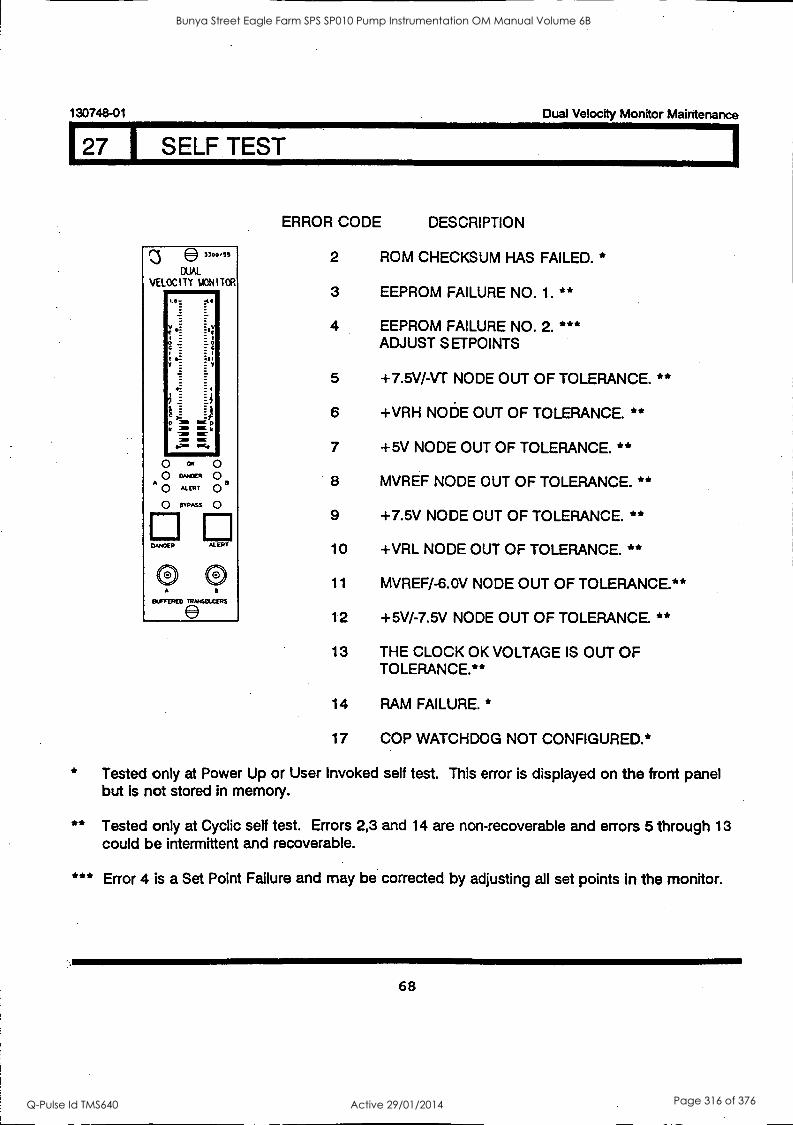
130748-01 Dual Velocity Monitor Maintenance
27 I SELF TEST
*
**
***
e3300 /55
CUAL
VELOCITY MONITOR 1111111/
'-a :t.
M
o CK o O OMOCK 0
AU" 0 a
o PPAss 0
El El DANDER KERT
0) ii.FFERFD
ERROR CODE DESCRIPTION
2 ROM CHECKSUM HAS FAILED. *
3 EEPROM FAILURE NO. 1.
4 EEPROM FAILURE NO. 2. ADJUST S ETPOINTS
5 +7.5V/-VT NODE OUT OF TOLERANCE.
6 +VRH NODE OUT OF TOLERANCE. **
7 +5V NODE OUT OF TOLERANCE. **
8 MVREF NODE OUT OF TOLERANCE. **
9 +7.5V NODE OUT OF TOLERANCE. **
10 +VRL NODE OUT OF TOLERANCE. **
11 MVREF/-6.0V NODE OUT OF TOLERANCE.**
12 +5V/-7.5V NODE OUT OF TOLERANCE. **
13 THE CLOCK OK VOLTAGE IS OUT OF TOLERANCE.**
14 RAM FAILURE. *
17 COP WATCHDOG NOT CONFIGURED.*
* *
** *
**
Tested only at Power Up or User Invoked self test. This error is displayed but is not stored in memory.
Tested only at Cyclic self test. Errors 2,3 and 14 are non-recoverable and could be intermittent and recoverable.
on the front panel
errors 5 through 13
Error 4 is a Set Point Failure and may be corrected by adjusting all set points in the monitor.
68
Bunya Street Eagle Farm SPS SP010 Pump Instrumentation OM Manual Volume 6B
Q-Pulse Id TMS640 Active 29/01/2014 Page 316 of 376
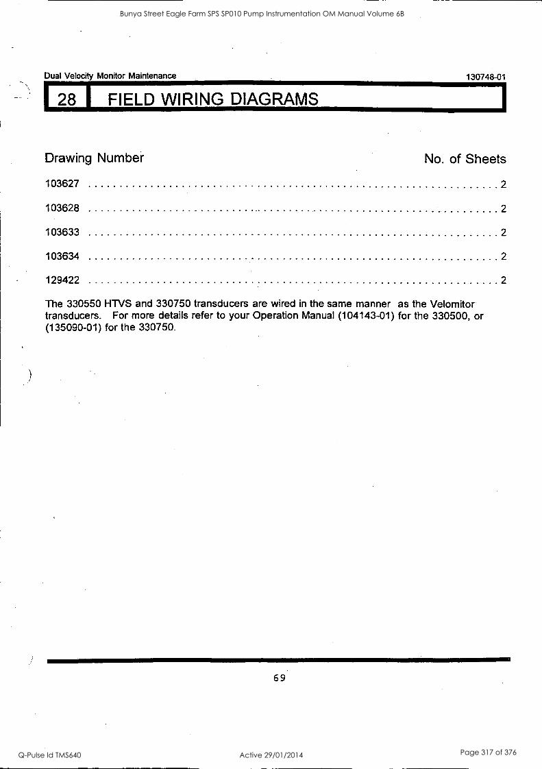
Dual Velocity Monitor Maintenance 130748-01
28 I FIELD WIRING DIAGRAMS
Drawing Number No. of Sheets
103627 2
103628 2
103633 2
103634 2
129422 2
The 330550 HTVS and 330750 transducers are wired in the same manner as the Velomitor transducers. For more details refer to your Operation Manual (104143-01) for the 330500, or (135090-01) for the 330750.
69
Bunya Street Eagle Farm SPS SP010 Pump Instrumentation OM Manual Volume 6B
Q-Pulse Id TMS640 Active 29/01/2014 Page 317 of 376
130748-01 Dual Velocity Monitor Maintenance
70
Bunya Street Eagle Farm SPS SP010 Pump Instrumentation OM Manual Volume 6B
Q-Pulse Id TMS640 Active 29/01/2014 Page 318 of 376
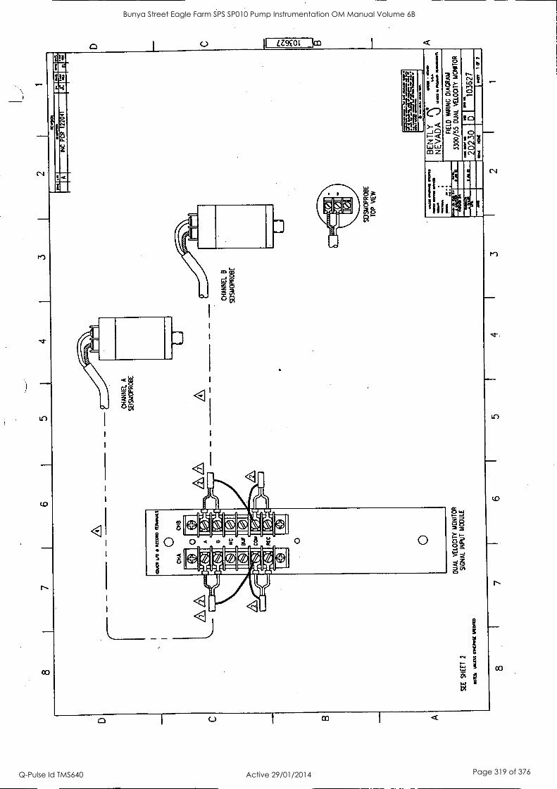
8 I
7 I
6 I
5 4
3 1
SE
E
SH
EE
T
2
,L
KM
* M
tn O
IKIS
E W
OO
8 I
DU
AL
VE
LOC
ITY
MO
NIT
OR
SIG
NA
L IN
PU
T
MO
DU
LE
CH
AN
NE
L A
SE
ISM
OP
RO
BE
,a,
7 I
6 I
5 I
KW
IC%
O
N
altl~
eV
INC
P
CR
12
2041
CH
AN
NE
L B
SE
ISM
OP
RO
BE
SE
ISM
OP
RO
BE
TO
P
VIE
W
MO
ISIN
INI
OM
, ..,
_:
a ...
......
...
BE
N T
LY
( 'L
ir"
NE
VA
DA
N
J .,-
,-.4
....
FIE
LD
WIR
ING
D
IAG
RA
M
3300
/55
DU
AL
VE
LOC
ITY
MO
NIT
OR
76..7
30
VII D
OM
%a
...
1036
27
1...
1(17
3 I
2 I
1
Bunya Street Eagle Farm SPS SP010 Pump Instrumentation OM Manual Volume 6B
Q-Pulse Id TMS640 Active 29/01/2014 Page 319 of 376
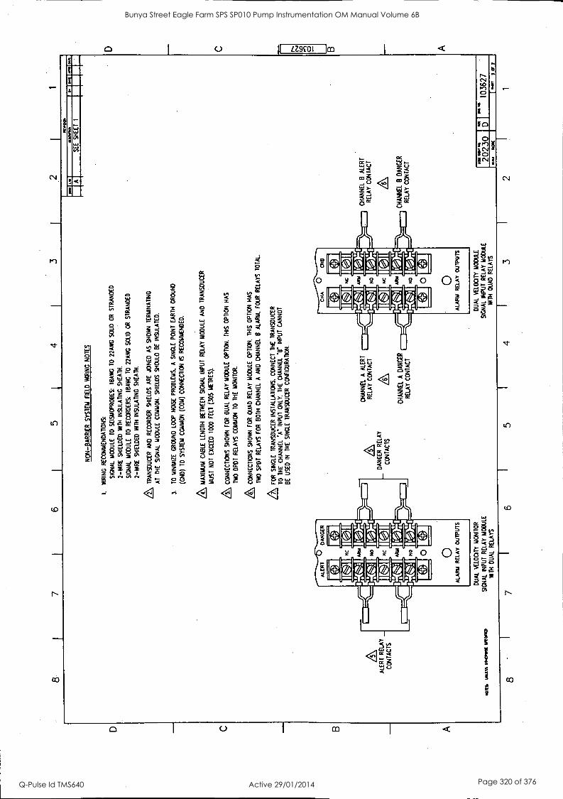
8 7
6 5
4 2
1
NO
N-B
AR
RIE
R
SY
ST
EM
F
IELD
W
IRIN
G N
OT
ES
1.
WIR
ING
R
EC
OM
ME
ND
AT
ION
S:
SIG
NA
L M
OD
ULE
T
O
SE
ISM
OP
RO
BE
S:
IRA
K T
O
22A
WG
S
OU
D
OR
S
TR
AN
DE
D
2-W
IRE
SH
IELD
ED
W
ITH
IN
SU
LAT
ING
S
HE
AT
H.
SIG
NA
L M
OD
ULE
T
O
RE
CO
RD
ER
S:
18A
WG
T
O
22A
WG
S
OLI
D
OR
S
TR
AN
DE
D
2-W
IRE
SH
IELD
ED
W
ITH
IN
SU
LAT
ING
S
HE
AT
H.
TR
AN
SD
UC
ER
A
ND
R
EC
OR
DE
R S
HIE
LDS
A
RE
JO
INE
D
AS
S
HO
WN
T
ER
MIN
AT
ING
AT
T
HE
S
IGN
AL
MO
DU
LE
CO
MM
ON
. S
HIE
LDS
S
HO
ULD
B
E
INS
ULA
TE
D.
3.
TO
MIN
IMIZ
E
GR
OU
ND
LO
OP
NO
ISE
P
RO
BLE
MS
. A
S
ING
LE
PO
INT
E
AR
TH
G
RO
UN
D
(GN
D)
TO
S
YS
TE
M
CO
MM
ON
(C
OM
) C
ON
NE
CT
ION
IS
R
EC
OM
ME
ND
ED
.
MA
XIM
UM
C
AB
LE
LEN
GT
H
BE
TW
EE
N
SIG
NA
L IN
PU
T
RE
LAY
MO
DU
LE
AN
D
TR
AN
SD
UC
ER
MU
ST
N
OT
EX
CE
ED
10
00
FE
ET
(3
05
ME
TR
ES
).
CO
NN
EC
TIO
NS
S
HO
WN
F
OR
D
UA
L R
ELA
Y M
OD
ULE
O
PT
ION
. T
HIS
OP
TIO
N
HA
S
TW
O
DP
DT
RE
LAY
S
CO
MM
ON
T
O
TH
E
MO
NIT
OR
.
CO
NN
EC
TIO
NS
SH
OW
N
FO
R
OU
AD
R
ELA
Y
MO
DU
LE
OP
TIO
N.
TH
IS O
PT
ION
H
AS
TW
O
SP
OT
RE
LAY
S
FO
R
BO
TH
C
HA
NN
EL
A
AN
D
CH
AN
NE
L B
A
LAR
M.
FO
UR
R
ELA
YS
T
OT
AL.
A FOR
S
ING
LE
TR
AN
SD
UC
ER
IN
ST
ALL
AT
ION
S.
CO
NN
EC
T T
HE
T
RA
NS
DU
CE
R
TO
T
HE
C
HA
NN
EL
'A -I
NP
UT
O
NLY
. T
HE
CH
AN
NE
L Y
INP
UT
C
AN
NO
T
BE
U
SE
D
IN
TH
E
SIN
GLE
T
RA
NS
DU
CE
R C
ON
FIG
UR
AT
ION
.
ALE
RT
R
ELA
Y _
CO
NT
AC
TS
DA
NG
ER
R
ELA
Y
CO
N 'A
CT
S
NO
M.
MIS
% 0
1140
1111
3t M
OM
)
DU
AL
VE
LOC
ITY
MO
NIT
OR
SIG
NA
L IN
PU
T
RE
LAY
M
OD
ULE
WIT
H
DU
AL
RE
LAY
S
CH
AN
NE
L A
A
LER
T
RE
LAY
C
ON
TA
CT
CH
AN
NE
L A
D
AN
CE
R
RE
LAY
C
ON
TA
CT
8 '
7 6
5
DU
AL
VE
LOC
ITY
MO
DU
LE
SIG
NA
L IN
PU
T
RE
LAY
MO
DU
LE
WIT
H
QU
AD
R
ELA
YS
4
PU
.SO
CH
AN
NE
L 8
ALE
RT
R
ELA
Y
CO
NT
AC
T
CH
AN
NE
L B
D
AN
GE
R
RE
LAY
C
ON
TA
CT
Mom
* S
EE
S
HE
ET
1
2023
0 I
-a 10
3627
N
OW
O
en
7of2
2 1
Bunya Street Eagle Farm SPS SP010 Pump Instrumentation OM Manual Volume 6B
Q-Pulse Id TMS640 Active 29/01/2014 Page 320 of 376
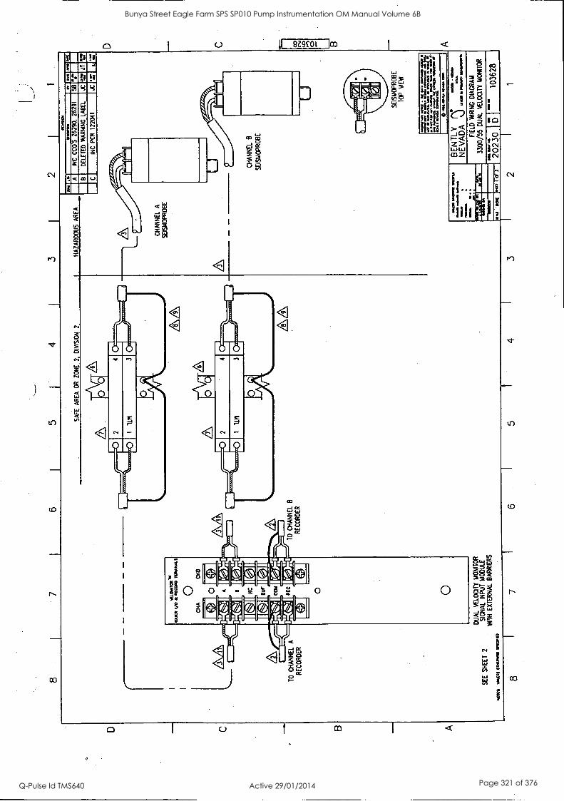
8 7
1 6
5 1
4 3
SA
FE
A
RE
A
OR
Z
ON
E
2,
DIV
ISIO
N
2
SE
E S
HE
ET
2
war
V
ain
01K
1111
111
1
DU
AL
VE
LOC
ITY
MO
NIT
OR
SIG
NA
L IN
PU
T
MO
DU
LE
WIT
H E
XT
ER
NA
L B
AR
RIE
RS
7 6
5
2 1
HA
ZA
RD
OU
S A
RE
A
RH
OO
a I-
ta
1010
1 O
at
A
WC
C
CO
'S
2629
0,
2629
1
8 D
ELE
TE
D W
AR
NIN
G
LAB
EL
JC
J1
C
INC
P
CR
12
2041
JC
FL
00.
011
4 3
CH
AN
NE
L A
SE
ISM
OP
RO
BE
CH
AN
NE
L B
SE
ISM
OP
RO
BE
SE
ISM
OP
RO
BE
TO
P
ME
W
1010
010/
1 00
110
00 0
1
1000
0112
.241
M
OM
b. 1
0 do
rm 0
004
0110
.011
1014
at
It I
ulaa
l tal
i at
Ona
ala
1 P
fa
pay
faat
ti. M
a W
Y 0
e a al
N
ames
wan
t1 a
t ta
n* na
ttaM
S e
K
aty.
M
aIla
afa
tail
ID n
u A
mor
ave
.
. W
WI .
0_c
1101
011
0111
7000
10.
00
my.
10
.1.1
11
1011
0 O
w
JO
BE
NT
LY
NE
VA
DA
J
ule
FIE
LD
WIR
ING
D
IAG
RA
M
3300
/55
DU
AL
VE
LOC
ITY
MO
NIT
OR
Man
It.
N
cHE
sa
l I
K 2
0101
11
1036
28
D A
Bunya Street Eagle Farm SPS SP010 Pump Instrumentation OM Manual Volume 6B
Q-Pulse Id TMS640 Active 29/01/2014 Page 321 of 376
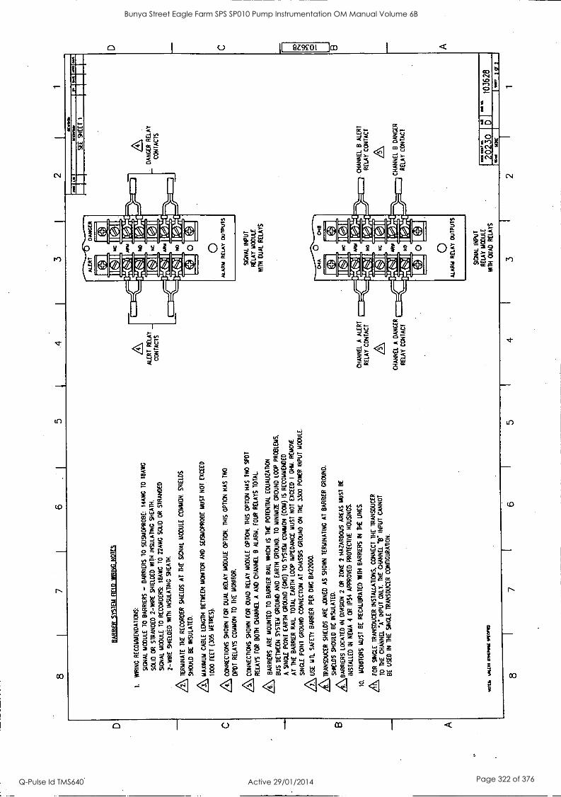
8 7
6 5
4 3
2 1
EIA
BE
ILLS
ISIF
ILB
ELI
Lida
ltial
=
I. W
IRIN
G
RE
CO
MM
EN
DA
TIO
NS
:
SIG
NA
L M
OD
ULE
T
O B
AR
RIE
RS
-
BA
RR
IER
S
70
SE
ISA
IOP
RO
BE
: I4
AW
G
TO
I8
AW
G
SO
LID
O
R
ST
RA
ND
ED
2 -W
IRE
S
HIE
LDE
D
WIT
H
INS
ULA
TIN
G S
HE
AT
H.
SIG
NA
L M
OD
ULE
T
O
RE
CO
RD
ER
S:
18A
WG
T
O
22A
WG
S
OLI
D
OR
S
TR
AN
DE
D
2-W
RE
S
HIE
LDE
D
MA
IN
INS
ULA
TIN
G
SH
EA
TH
.
AT
ER
MIN
AT
E T
HE
R
EC
OR
DE
R
SH
IELD
S A
T T
HE
S
IGN
AL
MO
DU
LE
CO
MM
ON
. S
HIE
LDS
SH
OU
LD
BE
IN
SU
LAT
ED
.
ZI\M
AX
IMU
M C
AB
LE
LEN
GT
H B
ET
WE
EN
M
ON
ITO
R AND SEISMOPROBE MUST NOT EXCEED
1000 FEET (
305
METRES).
CONNECTIONS
SH
OW
N
FO
R
DU
AL
RE
LAY
M
OD
ULE
O
PT
ION
. T
HIS
O
PT
ION
H
AS
T
WO
DP
DT
R
ELA
YS
CO
MM
ON
T
O
TH
E
MO
NIT
OR
.
CO
NN
EC
TIO
NS
S
HO
WN
F
OR
O
UA
D
RE
LAY
M
OD
ULE
O
PT
ION
. T
HIS
O
PT
ION
H
AS
T
WO
S
PO
T
RE
LAY
S F
OR
B
OT
H
CH
AN
NE
L A
A
ND
C
HA
NN
EL
8 A
LAR
M.
FO
UR
R
ELA
YS
T
OT
AL.
AB
AR
RIE
RS
A
RE
M
OU
NT
ED
T
O
BA
RR
IER
R
AIL
W
HIC
H
IS
TH
E
PO
TE
NT
IAL
EQ
UA
UZ
AT
ION
BU
S
BE
TW
EE
N
SY
ST
EM
G
RO
UN
D
AN
D
EA
RT
H
GR
OU
ND
. T
O
MIN
IMIZ
E
GR
OU
ND
LO
OP
P
RO
BLE
MS
.
A S
ING
LE
PO
INT
E
AR
TH
G
RO
UN
D (
GN
D)
TO
S
YS
TE
M
CO
MM
ON
(C
OM
) IS
R
EC
OM
ME
ND
ED
AT
T
HE
B
AR
RIE
R R
AIL
. T
OT
AL
EA
RT
H
LOO
P
IMP
ED
AN
CE
M
US
T N
OT
E
XC
EE
D
I O
HM
. R
EM
OV
E
A
SIN
GLE
P
OIN
T
GR
OU
ND
C
ON
NE
CT
ION
A
T
CH
AS
SIS
G
RO
UN
D
ON
T
HE
33
00
PO
WE
R
INP
UT
M
OD
ULE
.
\ US
E
MIL
SA
FE
TY
B
AR
RIE
R
PE
R D
X B
A22
000.
k TR
AN
SD
UC
ER
S
HIE
LDS
AR
E
JOIN
ED
A
S
SH
OW
N
TE
RM
INA
TIN
G
AT
B
AR
RIE
R
GR
OU
ND
.
SH
IELD
S
SH
OU
LD
BE
IN
SU
LAT
ED
.
AA
BA
RR
IER
S L
OC
AT
ED
IN
D
INS
ION
2
OR
Z
ON
E
2 H
AZ
AR
DO
US
A
RE
AS
M
US
T
BE
INS
TA
LLE
D
IN
NE
MA
4
OR
IP
54
AP
PR
OV
ED
P
RO
TE
CT
IVE
HO
US
ING
S.
10.
MO
NIT
OR
S
MU
ST
B
E
RE
CA
UB
RA
TE
D
WIT
H
BA
RR
IER
S
IN
TH
E
UN
ES
.
A FO
R
SIN
GLE
. TR
AN
SD
UC
ER
INS
TA
LLA
TIO
NS
. C
ON
NE
CT
T
HE
T
RA
NS
DU
CE
R
TO
T
HE
C
HA
NN
EL
°A.
INP
UT
ON
LY.
TH
E
CH
AN
NE
L .B
" IN
PU
T
CA
NN
OT
BE
U
SE
D
IN
TH
E
SIN
GLE
T
RA
NS
DU
CE
R
CO
NF
IGU
RA
TIO
N.
ootts
l ta
us' o
nom
it Im
am
8 7
6
ALE
RT
RE
LAY
CO
NT
AC
TS
CH
AN
NE
L A
A
LER
T
RE
LAY
CO
NT
AC
T
A
CH
AN
NE
L A
DA
NG
ER
RE
LAY
C
ON
TA
CT
SIG
NA
L IN
PU
T
RE
LAY
M
OD
ULE
W
IN
DU
AL
RE
LAY
S
5
SIG
NA
L IN
PU
T
RE
LAY
M
OD
ULE
MA
TH
O
UA
D
RE
LAY
S
3
SE
E K S
HE
ET
1.
IMAIWM
WIC.
DA
NG
ER
R
ELA
Y
CO
NT
AC
TS
CH
AN
NE
L B
A
LER
T
RE
LAY
C
ON
TA
CT
CH
AN
NE
L B
D
AN
CE
R
RE
LAY
C
ON
TA
CT
20230
I
Ns°
10
3628
2 1
D 0 A
Bunya Street Eagle Farm SPS SP010 Pump Instrumentation OM Manual Volume 6B
Q-Pulse Id TMS640 Active 29/01/2014 Page 322 of 376
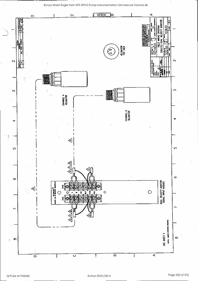
SE
E
SH
EE
T
2
MOM WIUSWOONWASKOAM
DU
AL
VE
LOC
ITY
MO
NIT
OR
SIG
NA
L IN
PU
T
MO
DU
LE
CH
AN
NE
L B
VE
LOM
ITO
R
CH
AN
NE
L A
VE
LOM
ITO
R
7 6
wr
SW
IM
104.
1l
.+1
OM
INC
P
CR
12
2041
VE
LOM
ITO
R
TO
P
VIE
W
graf
t um
WIL
SM
ION
MIR
DI.
NO
M .1
11.1
41
11/1
1011
M
MA
m
WM
A
~4
Mos
BE
N T
LY
NE
VA
DA
./
FIE
LD
WIR
ING
D
IAG
RA
M
3300
/55
DU
AL
VE
LOC
ITY
MO
NIT
OR
1036
33
INV
1 OF 2
4 3
2 1
C 0
Bunya Street Eagle Farm SPS SP010 Pump Instrumentation OM Manual Volume 6B
Q-Pulse Id TMS640 Active 29/01/2014 Page 323 of 376
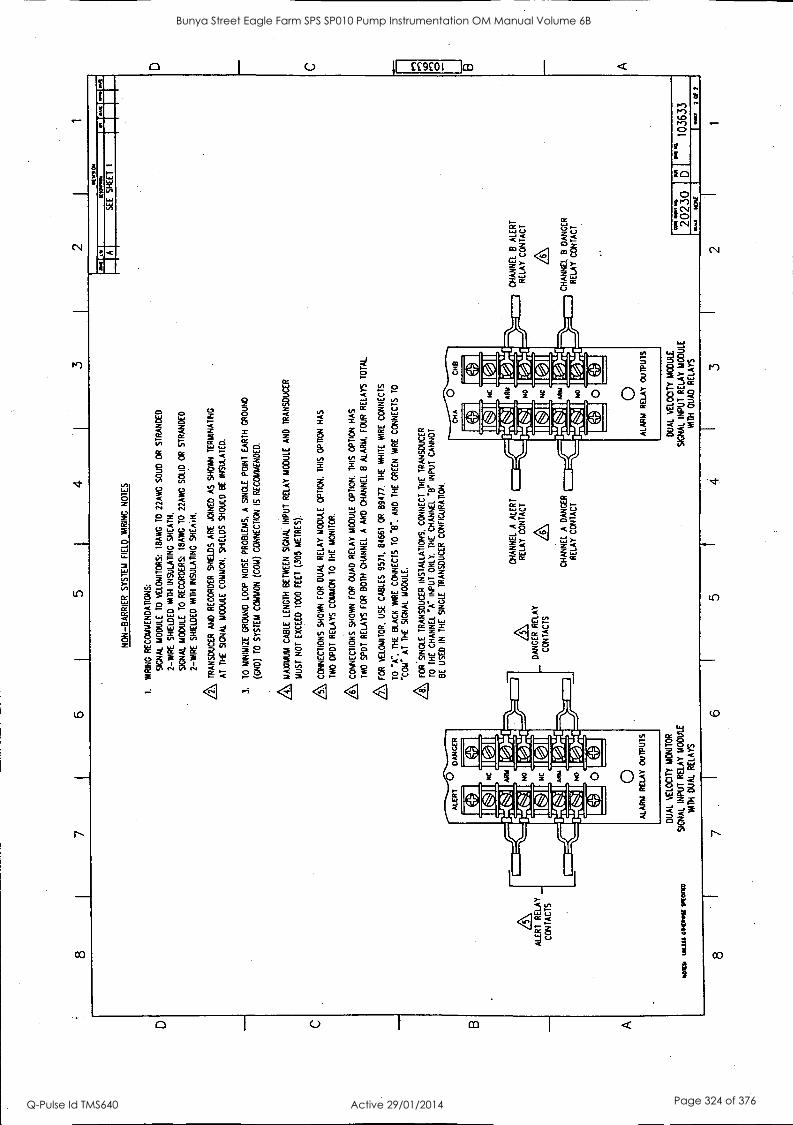
8
L
ALE
RT
R
ELA
Y
CO
NT
AC
TS
-"
7 6
5 1
4 3
NO
N-B
AR
RIE
R
SY
ST
EM
F
IELD
W
IRIN
G
NO
TE
S
1.
WIR
ING
R
EC
OM
ME
ND
AT
ION
S:
SIG
NA
L M
OD
ULE
T
O
VE
LOM
ITO
RS
: I8
AW
G T
O
22A
WG
S
OLI
D
OR
S
TR
AN
DE
D
2-W
IRE
S
HIE
LDE
D N
M I
NS
ULA
TIN
G
SH
EA
TH
,
SIG
NA
L M
OD
ULE
T
O
RE
CO
RD
ER
S
18A
NC
TO
22
AW
G S
OLI
D
OR
S
TR
AN
DE
D
2-W
IRE
S
HIE
LDE
D
WIT
H
INS
ULA
TIN
G S
HE
A*,
A TR
AN
SD
UC
ER
A
ND
RE
CO
RD
ER
S
HIE
LDS
AR
E
JOIN
ED
A
S
SH
OW
N
TE
RM
INA
TIN
G
AT
T
HE
S
IGN
AL
MO
DU
LE
CO
MM
ON
. S
HIE
LDS
S
HO
ULD
B
E
INS
ULA
TE
D.
3.
TO
M
INIM
IZE
G
RO
UN
D
LOO
P
NO
ISE
P
RO
BLE
MS
. A
SIN
GLE
P
OIN
T
EA
RT
H
GR
OU
ND
(GN
D)
TO
S
YS
TE
M C
OM
MO
N
(CO
M)
CO
NN
EC
TIO
N I
S
RE
CO
MM
EN
DE
D.
& MA
XIM
UM
C
AB
LE
LEN
GT
H B
ET
WE
EN
S
IGN
AL
INP
UT
R
ELA
Y
MO
DU
LE
AN
D
TR
AN
SD
UC
ER
MU
ST
N
OT
E
XC
EE
D
1000
F
EE
T
(305
ME
TR
ES
).
& CO
NN
EC
TIO
NS
SH
OW
N
FO
R
DU
AL
RE
LAY
MO
DU
LE
OP
TIO
N.
TH
IS
OP
TIO
N
HA
S
TW
O
OP
DT
R
ELA
YS
C
OM
MO
N T
O
TH
E
MO
NIT
OR
.
CO
NN
EC
TIO
NS
S
HO
WN
F
OR
O
UA
D
RE
LAY
MO
DU
LE
OP
TIO
N.
TH
IS
OP
TIO
N
HA
S
TW
O
SP
OT
R
ELA
YS
F
OR
B
OT
H
CH
AN
NE
L A
AN
D
CH
AN
NE
L B
ALA
RM
. F
OU
R R
ELA
YS
T
OT
AL.
FO
R
YE
LOM
ITO
R,
US
E
CA
BLE
S
9571
, 84
661
OR
89
477.
T
HE
W
HIT
E
WIR
E C
ON
NE
CT
S
TO
A
. T
HE
B
LAC
K W
IRE
C
ON
NE
CT
S
TO
V
. A
ND
T
HE
G
RE
EN
W
IRE
C
ON
NE
CT
S
TO
"CO
M"
AT
T
HE
S
IGN
AL
MO
DU
LE.
Z%
FO
R'S
ING
LE
TR
AN
SD
UC
ER
IN
ST
ALL
AT
ION
S,
CO
NN
EC
T T
HE
T
RA
NS
DU
CE
R
TO
T
HE
C
HA
NN
EL
"A"
INP
UT
O
NLY
. T
HE
C
HA
NN
EL
V IN
PU
T
CA
NN
OT
BE
U
SE
D
IN
TH
E
SIN
GLE
T
RA
NS
DU
CE
R C
ON
FIG
uRA
TiO
N,
DA
NG
ER
RE
LAY
CO
NT
AC
TS
may
m
ass
omvr
est
IRM
O)
8
DU
AL
VE
LOC
ITY
MO
NIT
OR
SIG
NA
L IN
PU
T R
ELA
Y
MO
DU
LE
WIT
H
DU
AL
RE
LAY
S
7
CH
AN
NE
L A
A
LER
T
RE
LAY
C
ON
TA
CT
CH
AN
NE
L A
DA
NG
ER
RE
LAY
CO
NT
AC
T
5
DU
AL
VE
LOC
ITY
MO
DU
LE
SIG
NA
L IN
PU
T
RE
LAY
M
OD
ULE
W
ITH
Q
UA
D
RE
LAY
S
4 3
2 M
MIH
M
KO
VN
O
A
SE
E
SH
EE
T
1
CH
AN
NE
L B
A
LER
T
RE
LAY
C
ON
TA
CT
CH
AN
NE
L B
DA
NG
ER
R
ELA
Y
CO
NT
AC
T
MR
2023
0 6'
.."
1 10
3633
2 I
1
Bunya Street Eagle Farm SPS SP010 Pump Instrumentation OM Manual Volume 6B
Q-Pulse Id TMS640 Active 29/01/2014 Page 324 of 376
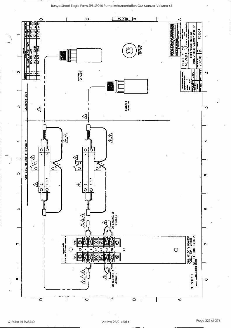
8 I
7 6
5 j
4 3
1
AR
EA
O
R
ZO
NE
2
OP
AS
ION
2
HA
ZA
RD
. S
A
RE
A
(.00
0-1
er-"
reite
l, --
i.)11
1111
/-0N
r T
O
CH
AN
NE
L -4
1140
F
11
.41;
I T
O
CH
AN
NE
L B
RE
CO
RD
ER
R
EC
OR
DE
R
SE
E
SH
EE
T 2
DU
AL
VE
LOC
ITY
M
ON
ITO
R
SIG
NA
L IN
PU
T
MO
DU
LE
WIT
H
EX
TE
RN
AL
BA
RR
IER
S
MO
IL&
IM
ISS
OW
N(
tnet
nal
8 7
6 5
4
CH
AN
CE
B
Vtl.
CA
CT
OR
3
PC
INW
IN
sae
Men
a A
IN
C
CC
O'S
26
290.
26
291
58
B
RE
MS
ED
N
OT
E
11
JC 12
JT
C
INC
C
CO
12
2041
JC
D
INC
P
CR
12
3769
JE
1.7
CH
AN
NE
L A
VE
LOIA
TO
R
VT
.1.0
61T
IOR
TO
P
NE
W
LIT
22.
;.7.2
4,=
=
7 L.
...2.
.1 .1 16
s 2r
. 0
ma
wo.
./.1%
ark
wel
l Mom
mol
l m
ama*
aaaa
m
ma.
a
'al
I O
f 2
BE
NT
LY
N
4111
01
1111
04
nas
NE
VA
DA
.)
~
An
amow
n
FIE
LD
WIR
ING
D
IAG
RA
M
3300
/55
DU
AL
VE
LOC
ITY
M
ON
ITO
R
7721
0 1 6
I
"'"
1036
34
2 1
1
Bunya Street Eagle Farm SPS SP010 Pump Instrumentation OM Manual Volume 6B
Q-Pulse Id TMS640 Active 29/01/2014 Page 325 of 376
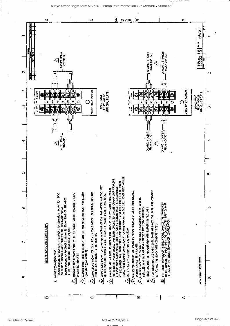
8 6
5 4
3 2
1
BA
RR
IER
ITIT
EIL
EIE
LELN
RIti
ctlic
aES
1.
WIR
ING
R
EC
OM
ME
ND
AT
ION
S:
SIG
NA
L M
OD
ULE
T
O B
AR
RIE
RS
- B
AR
RIE
RS
T
O
VE
LOIA
ITO
R:
I4A
WG
T
O
18A
WG
SO
LID
O
R
ST
RA
ND
ED
2-
WIR
E
SH
IELD
ED
W
ITH
IN
SU
LAT
ING
S
HE
AT
H.
SIG
NA
L M
OD
ULE
T
O
RE
CO
RD
ER
S:
I8A
WG
T
O
22A
WG
S
OLI
D
OR
S
TR
AN
DE
D
2-W
IRE
S
HIE
LDE
D
WIT
H
INS
ULA
TIN
G
SH
EA
TH
.
LS,
TE
RM
INA
TE
T
HE
RE
CO
RD
ER
S
HIE
LDS
A
T
TH
E
SIG
NA
L M
OD
ULE
C
OM
MO
N.
SH
IELD
S
SH
OU
LD
BE
IN
SU
LAT
ED
.
MA
XIM
UM
C
AB
LE
LEN
GT
H
BE
TW
EE
N M
ON
ITO
R
AN
D
VE
LOM
ITO
R M
US
T
NO
T E
XC
EE
D
1000
F
EE
T (
305
ME
TR
ES
).
,A CO
NN
EC
TIO
NS
S
HO
WN
F
OR
D
UA
L R
ELA
Y M
OD
ULE
O
PT
ION
. 11
415
OP
TIO
N
HA
S
TW
O
DP
DT
RE
LAY
S
CO
MM
ON
T
O
TH
E
MO
NIT
OR
.
AC
ON
NE
CT
ION
S
SH
OW
N
FO
R
QU
AD
R
ELA
Y
MO
DU
LE
OP
TIO
N.
TH
IS
OP
TIO
N
HA
S
TW
O
SP
OT
RE
LAY
S F
OR
B
OT
H C
HA
NN
EL
A
AN
D
CH
AN
NE
L B
A
LAR
M.
FO
UR
RE
LAY
S
TO
TA
L.
,L BA
RR
IER
S A
RE
M
OU
NT
ED
T
O
BA
RR
IER
RA
IL
WH
ICH
IS
T
HE
PO
TE
NT
IAL
EO
UA
UZ
AR
ON
BU
S
BE
TW
EE
N
SY
ST
EM
G
RO
UN
D
AN
D
EA
RT
H G
RO
UN
D.
TO
M
INIM
IZE
G
RO
UN
D L
OO
P
PR
OB
LEM
S.
A
SIN
GLE
P
OIN
T
EA
RT
H
GR
OU
ND
(C
ND
) T
O
SY
ST
EM
C
OM
MO
N
(CO
M)
IS
RE
CO
MM
EN
DE
D
AT
T
HE
B
AR
RIE
R
RA
IL
TO
TA
L E
AR
TH
LO
OP
IM
PE
DA
NC
E
MU
ST
N
OT
E
XC
EE
D
I O
HM
. R
EM
OV
E
A
SIN
GLE
P
OIN
T
GR
OU
ND
C
ON
NE
CT
ION
A
T
CH
AS
SIS
GR
OU
ND
O
N
TH
E
3300
PO
WE
R
INP
UT
M
OD
ULE
.
US
E
NIL
SA
FE
TY
B
AR
RIE
R
PE
R
DW
G
0A22
000.
4\ TRA
NS
DU
CE
R
SH
IELD
S
AR
E J
OIN
ED
A
S
SH
OW
N
TE
RM
INA
TIN
G
At
BA
RR
IER
GR
OU
ND
.
SH
IELD
S
SH
OU
LD
BE
IN
SU
LAT
ED
.
AA
BA
RR
IER
S L
OC
AT
ED
IN
D
PA
SIO
N 2
O
R
ZO
NE
2
HA
ZA
RD
OU
S
AR
EA
S M
US
T
BE
INS
TA
LLE
D
IN
NE
MA
4
OR
IP
54
AP
PR
OV
ED
P
RO
TE
CT
IVE
H
OU
SIN
GS
.
10.
MO
NIT
OR
S
MU
ST
BE
R
EC
AU
BR
AT
ED
W
ITH
B
AR
RIE
RS
IN
T
HE
LI
NE
S.
A FO
R
VE
LOA
IITO
R.
US
E
CA
BLE
95
71,
8466
1 O
R
6947
7. T
HE
W
HIT
E
WIR
E
CO
NN
EC
TS
TO
"A
-,
AN
D
TH
E
BLA
CK
W
IRE
C
ON
NE
CT
S
TO
T
.
A FOR
S
ING
LE
TR
AN
SD
UC
ER
IN
ST
ALL
AT
ION
S,
CO
NN
EC
T
TH
E
TR
AN
SD
UC
ER
TO
T
HE
C
HA
NN
EL
.A.
INP
UT
O
NLY
. T
HE
C
HA
NN
EL
'T IN
PU
T
CA
NN
OT
BE
U
SE
D
IN
TH
E
SIN
GLE
T
RA
NS
DU
CE
R C
ON
FIG
UR
AT
ION
.
was
. w
as en
c.'s
/ wor
n
8
1100
1101
la
11
1111
10.0
ALE
RT
RE
LAY
_
CO
NT
AC
TS
CH
AN
NE
L A
A
LER
T
RE
LAY
C
ON
TA
CT
CH
AN
NE
L A
D
AN
GE
R
RE
LAY
C
ON
TA
CT
7 6
5 4
SIG
NA
L IN
PU
T
RE
LAY
MO
DU
LE
WIT
H
DU
AL
RE
LAY
S
SIG
NA
L IN
PU
T
RE
LAY
M
OD
ULE
W
ITH
O
UA
D
RE
LAY
S
3
SE
E
SH
EE
T
I
z\
DA
NG
ER
R
ELA
Y
CO
NT
AC
TS
CH
AN
NE
L B
A
LER
T
RE
LAY
C
ON
TA
CT
CH
AN
NE
L B
D
AN
GE
R
RE
LAY
CO
NT
AC
T
0411
.0
20230
5' I
"1"
1036
34
2 1
Bunya Street Eagle Farm SPS SP010 Pump Instrumentation OM Manual Volume 6B
Q-Pulse Id TMS640 Active 29/01/2014 Page 326 of 376
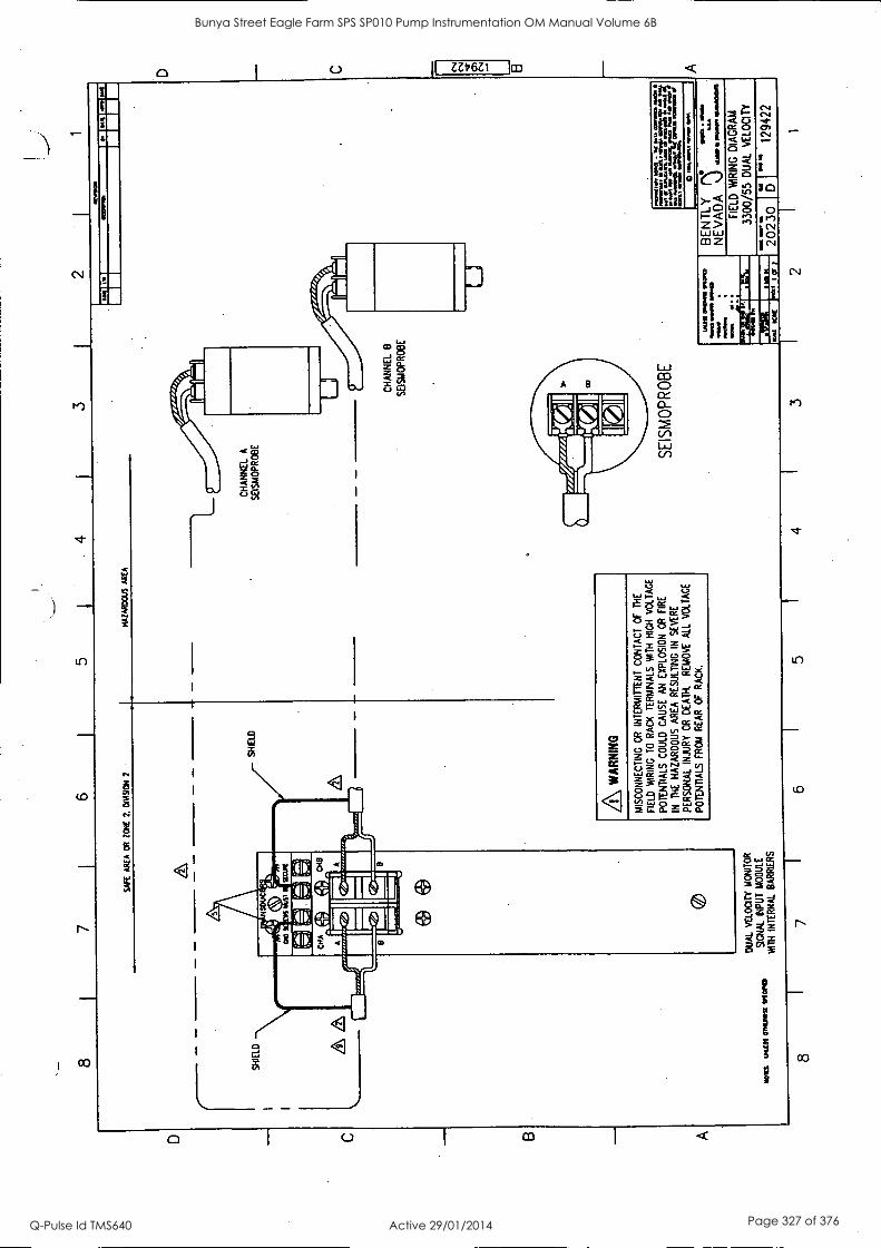
2 1
WE
AR
EA
OR
Z
ON
E 2.
O
DA
9ON
2
HA
ZA
RD
OU
S A
RE
A
MO
WS
IN
NS
OM
AN
I 91
0/11
3)
DU
AL
VE
LOC
ITY
M
ON
ITO
R
SIG
NA
L IN
PU
T
MO
DU
LE
WIT
H
INT
ER
NA
L B
AR
RIE
RS
A WA
RN
ING
MIS
CO
NN
EC
TIN
C O
R
INT
ER
MIT
TE
NT
C
ON
TA
CT
OF
T
HE
FIE
LD
WR
ING
T
O
RA
CK
T
ER
MIN
ALS
W
ITH
H
IGH
V
OLT
AG
E
PO
TE
NT
IALS
CO
ULD
C
AU
SE
A
N E
XP
LOS
ION
O
R
FIR
E
IN
NE
HA
ZA
RD
OU
S
AR
EA
RE
SU
LTIN
G I
N
SE
VE
RE
PE
RS
ON
AL
INJU
RY
OR
D
EA
TH
. R
EM
OV
E
ALL
VO
LTA
GE
PO
TE
NT
IALS
F
RO
M
RE
AR
O
F
RA
CK
.
CH
AN
NE
L A
SE
ISM
OP
RO
BE
CH
AN
NE
L B
SE
ISM
OP
RO
BE
CO
SE
ISM
OP
RO
BE
41
..1=
= am
.?
r.:1
7,21
:14
1=11
°..."
o
me,
MN
. Ms.
. O
M.
MC
. 0.0
0111
1 IN
OP
IED
70 MI
NIM
172
N
EW
AP
0112
M
ena
GE
NT
LY
NE
VA
DA
"S
""M
'aa°
"
FIE
LD
WR
ING
D
IAG
RA
M
3300
/55
DU
AL
VE
LOC
ITY
.sk
ICY
K
W
I O
r
low
2023
0 5
11
1294
22
8 7
6 5
4 3
2 1
C
CV
Cn
CV
Bunya Street Eagle Farm SPS SP010 Pump Instrumentation OM Manual Volume 6B
Q-Pulse Id TMS640 Active 29/01/2014 Page 327 of 376
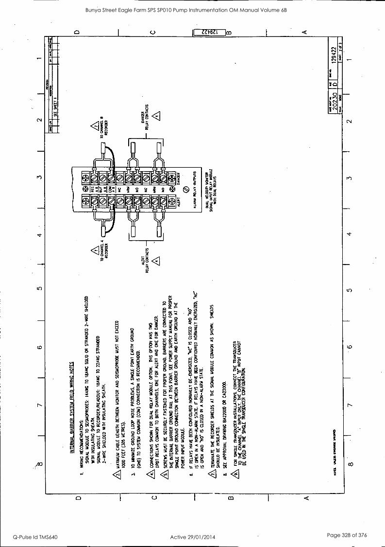
D
C
B
A
7 6
5 4
3 2
INT
ER
NA
L B
AR
RIE
R
SY
ST
EM
F
IELD
W
IRIN
G
NO
TE
S
1.
WIR
ING
R
EC
OM
ME
ND
AT
ION
S:
SIG
NA
L M
OD
ULE
T
O
SE
ISM
OP
RO
BE
S:
I4A
WG
TO
18
AW
C
SO
LID
OR
S
TR
AN
DE
D
2-W
IRE
S
HIE
LDE
D
WIN
IN
SU
LAT
ING
S
HE
AT
H.
SIG
NA
L M
OD
ULE
10
R
EC
OR
DE
R/R
EA
DO
UT
: 18
AW
G
TO
22
AW
G
ST
RA
ND
ED
2 -W
IRE
WE
LDE
D
WIT
H
INS
ULA
TIN
G
SH
EA
TH
.
AM
AX
IMU
M
CA
BLE
LE
NG
TH
B
ET
WE
EN
M
ON
ITO
R
AN
D
SE
ISM
OP
RO
BE
M
US
T
NO
T
EX
CE
ED
1000
F
EE
T (3
05
ME
TR
ES
).
1.
TO
M
INIM
IZE
G
RO
UN
D
LOO
P
NO
ISE
P
RO
BLE
MS
. A
S
ING
LE
PO
INT
E
AR
TH
G
RO
UN
D
(GN
D)
TO
S
YS
TE
M
CO
MM
ON
(C
OM
) C
ON
NE
CT
ION
IS
R
EC
OM
ME
ND
ED
.
AC
ON
NE
CT
ION
S S
HO
WN
F
OR
D
UA
L R
ELA
Y
MO
DU
LE
OP
TIO
N.
TH
IS
OP
TIO
N
HA
S
TW
O
DP
DT
R
ELA
YS
C
OM
MO
N T
O
BO
TH
C
HA
NN
ELS
. O
NE
F
OR
A
LER
T
AN
D
ON
E
FO
R
DA
NG
ER
.
Z\ S
CR
EW
S
MU
ST
B
E
SE
CU
RE
LY
FA
ST
EN
ED
F
OR
P
RO
PE
R
GR
OU
ND
. B
AR
RIE
RS
A
RE
C
ON
NE
CT
ED
T
O
TH
E
INT
ER
NA
L B
AR
RIE
R G
RO
UN
D
RA
IL
AT
T
HIS
PO
INT
. S
EE
P
OW
ER
S
UP
PLY
MA
NU
AL
FO
R
PR
OP
ER
SIN
GLE
P
OIN
T
GR
OU
ND
C
ON
NE
CT
ION
B
ET
WE
EN
B
AR
RIE
R
GR
OU
ND
A
ND
E
AR
TH
G
RO
UN
D A
T
TH
E
PO
WE
R I
NP
UT
M
OD
ULE
.
6.
IF
RE
LAY
S
HA
VE
B
EE
N
CO
NF
IGU
RE
D N
OR
MA
LLY
D
E-E
NE
RG
IZE
D.
''NC
" IS
C
LOS
ED
A
ND
N
O"
IS
OP
EN
IN
A
N
ON
-ALA
RM
ST
AT
E.
IF
RE
LAY
S
HA
VE
B
EE
N
CO
NF
IGU
RE
D
NO
RM
ALL
Y
EN
ER
GIZ
ED
, 'N
C'
IS
OP
EN
A
ND
14
0. I
S
CLO
SE
D
IN
A
NO
N-A
LAR
M S
TA
TE
.
,A T
ER
MIN
AT
E
TH
E
RE
CO
RD
ER
S
HIE
LDS
A
T
TH
E
SIG
NA
L M
OD
ULE
C
OM
MO
N A
S
SH
OW
N.
SH
IELD
S
SH
OU
LD
BE
IN
SU
LAT
ED
.
B.
SE
E
AP
PR
OV
AL
DR
AW
ING
B
A22
000
OR
C
A22
000.
FO
R
SIN
GLE
T
RA
NS
DU
CE
R
INS
TA
LLA
TIO
NS
, C
ON
NE
CT
TH
E
TR
AN
SD
UC
ER
TO
T
HE
C
HA
NN
EL
'A IN
PU
T O
NLY
. T
HE
C
HA
NN
EL
V IN
PU
T
CA
NN
OT
BE
U
SE
D
IN
TH
E
SIN
GLE
T
RA
NS
DU
CE
R
CO
NF
IGU
RA
TIO
N.
110R
1 1.
01n0
010
1011
00 0
0000
10
TO
C
HA
NN
EL
A
RE
CO
RD
ER
ALE
RT
RE
LAY
C
ON
TA
CT
S
N E
C
BU
F
A R
CO
Y
AR
N
C
ALE
RT
D
AN
GE
R
5 f
4
ALA
RM
R
ELA
Y
OU
TP
UT
S
DU
AL
YE
LOO
TY
11C
NT
OR
S
IGN
AL
INP
UT
RE
LAY
MO
DU
LE
NT
H D
UA
L R
ELA
YS
1
211
1100
1Ins
.
SE
E
SH
EE
T
1
10 C
HA
NN
EL
B
RE
CC
RD
ER
DA
NC
ER
- R
ELA
Y C
ON
TA
CT
S
0201
1013
0 10
1
2023
0 S
I
I 12
9422
=
re
NO
NE
so
n T
OE
]
7 6
3 I
2 I
1
Bunya Street Eagle Farm SPS SP010 Pump Instrumentation OM Manual Volume 6B
Q-Pulse Id TMS640 Active 29/01/2014 Page 328 of 376
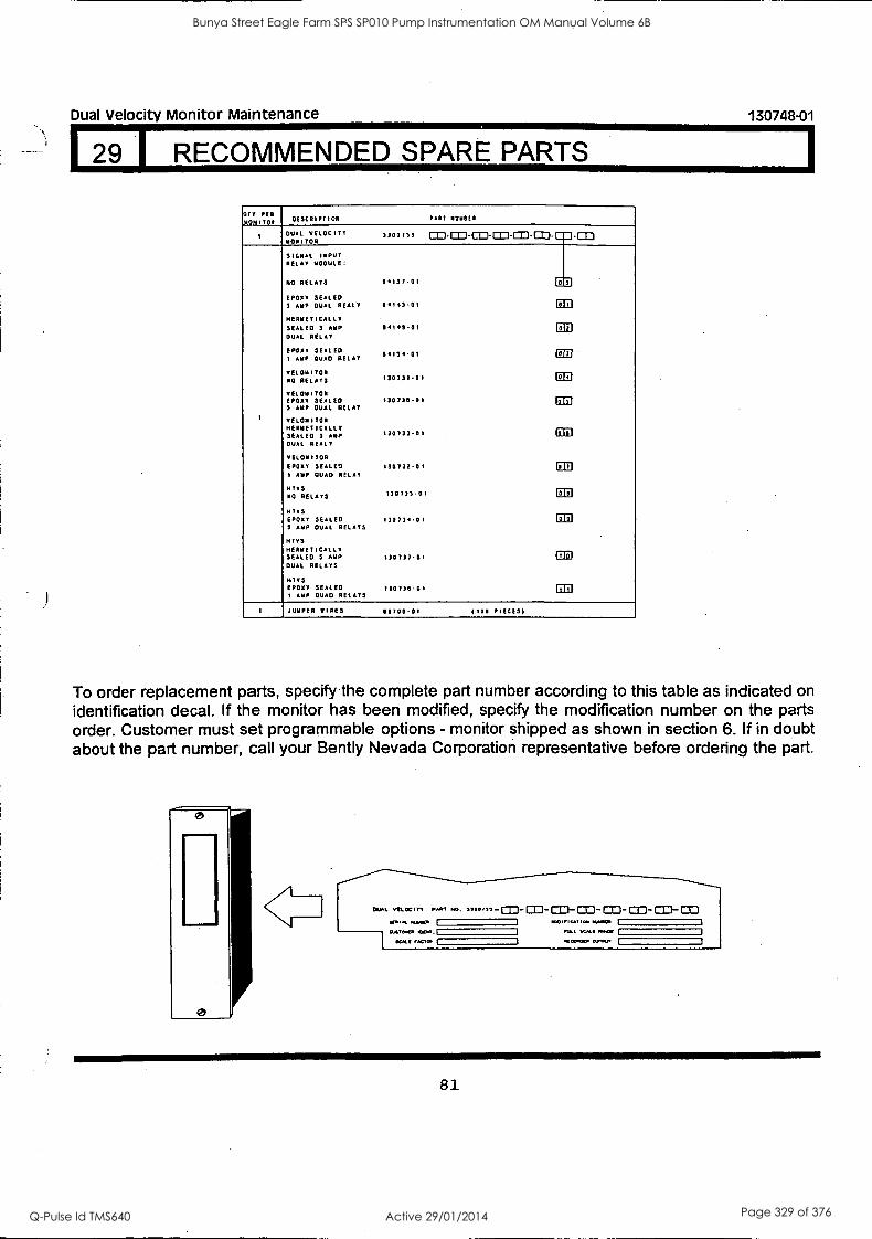
Dual Velocity Monitor Maintenance 130748-01
I RECOMMENDED SPARE PARTS
OTT PER 11011101 OESCRIPTION PAR1 1010E1
1 DUAL VELOCITY MONITOR
3300133 co.m_cacacricacp.0:3 SIGNAL INPUT RELAY MODULE:
NO RELAYS 14137-01 ED EPDXY SEALED 3 AMP DUAL REALY 14143-01 CD HERMETICALLY SEALED 3 AMP 04143.01 CB DUAL RELAY
EPDXY SEALED I AMP QUAD RELAY
04134.01 OB
VE1011701 NO RELAYS 130731.01 CD VEL0141701 EPDXY SEALED 130730-01 Oil 3 AMP DUAL RELAY
1 VII :MIMI HERMETICALLY SEALED 3 AMP 130733-01 Oil DUAL REALY
VELOM(TOR EPDXY SEALED 130732-01 CCI 1 AMP QUAD RELAY
H15 NO RELAYS 130733-01 CD
HEYS EPDXY SEALED 130)34.01 Eil 3 AMP DUAL RELAYS
MTVS HERMETICALLY SEALED S AMP 130737.01 Oil DUAL RELAYS
1705 EPDXY SEALED 130736-01 ED I AMP QUAD RELAYS
I JUMPER TIRES 16706-01 (100 PIECES)
To order replacement parts, specify the complete part number according to this table as indicated on identification decal. If the monitor has been modified, specify the modification number on the parts order. Customer must set programmable options - monitor shipped as shown in section 6. If in doubt about the part number, call your Bent ly Nevada Corporation representative before ordering the part.
0
0
OVAL VELOCITY ."'" ,,,,, CO- CD- OD- OD - CO- CO- CO- OD 10...1. M.. I I we $or mom. I
CL6,0100 ItOd. SCA. 'AMP worm. MAP I
34. Ma M
81
Bunya Street Eagle Farm SPS SP010 Pump Instrumentation OM Manual Volume 6B
Q-Pulse Id TMS640 Active 29/01/2014 Page 329 of 376
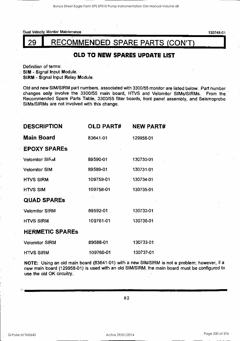
Dual Velocity Monitor Maintenance 130748-01
29 I RECOMMENDED SPARE PARTS (CON'T)
OLD TO NEW SPARES UPDATE LIST
Definition of terms: SIM - Signal Input Module. SIRM - Signal Input Relay Module.
Old and new SIM/SIRM part numbers, associated with 3300/55 monitor are listed below. Part number changes only involve the 3300/55 main board, HTVS and Velomitor SIMs/SIRMs. From the Recommended Spare Parts Table, 3300/55 filter boards, front panel assembly, and Seismoprobe SIMs/SIRMs are not involved with this change.
DESCRIPTION OLD PART# NEW PART#
Main Board 83641-01 129958-01
EPDXY SPAREs
Velomitor 89590-01 130730-01
Velomitor SIM 89589-01 130731-01
HTVS SIRM 109759-01 130734-01
HTVS SIM 109758-01 130735-01
QUAD SPAREs
Velomitor SIRM 89592-01 130732-01
HTVS SIRM 109761-01 130736-01
HERMETIC SPAREs
Velomitor SIRM 89588 -01. 130733-01
HTVS SIRM 109760-01 130737-01
NOTE: Using an old main board (83641-01) with a new SIM/SIRM is not a problem; however, if a
new main board (129958-01) is used with an old SIM/SIRM, the main board must be configured to use the old OK circuitry.
82
Bunya Street Eagle Farm SPS SP010 Pump Instrumentation OM Manual Volume 6B
Q-Pulse Id TMS640 Active 29/01/2014 Page 330 of 376
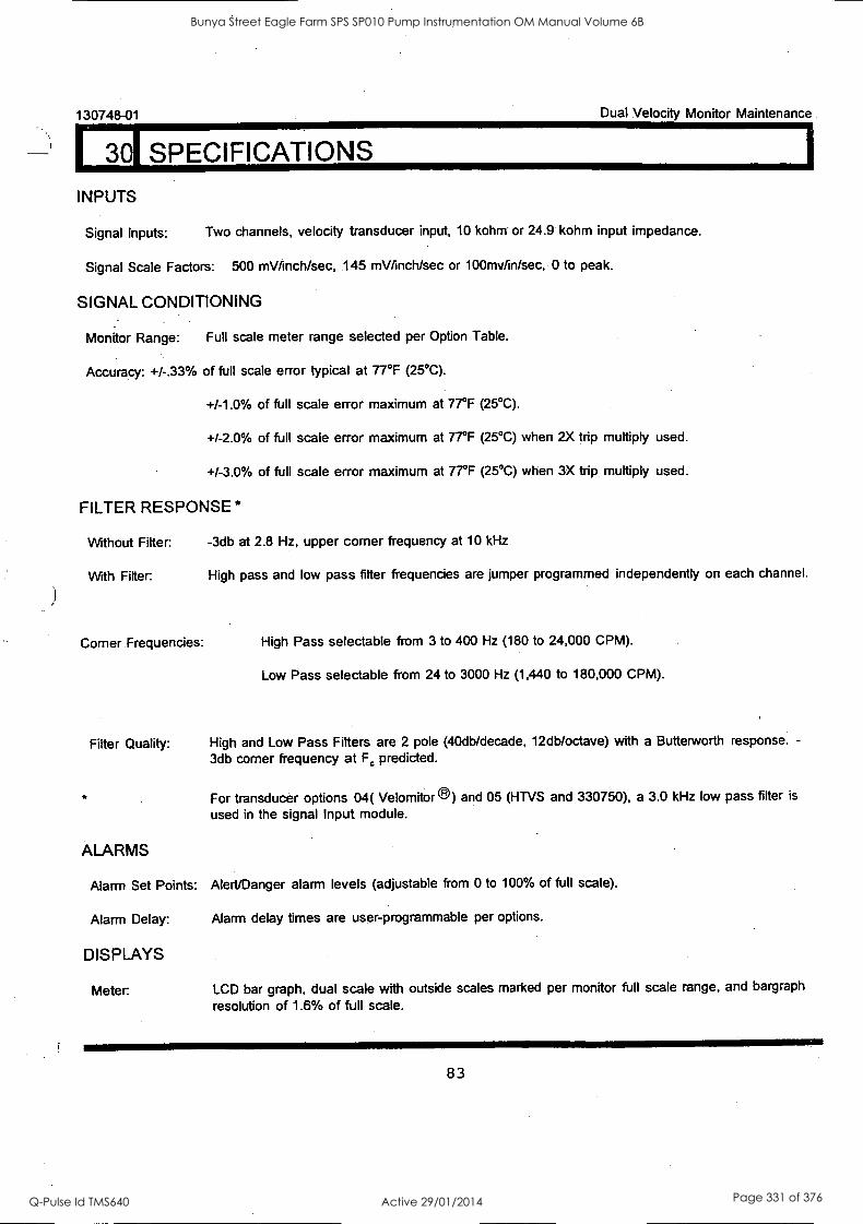
130748-01 Dual Velocity Monitor Maintenance
301 SPECIFICATIONS
INPUTS
Signal Inputs: Two channels, velocity transducer input, 10 kohm or 24.9 kohm input impedance.
Signal Scale Factors: 500 mV/inch/sec, 145 mV/inch/sec or 100mv/in/sec, 0 to peak.
SIGNAL CONDITIONING
Monitor Range: Full scale meter range selected per Option Table.
Accuracy: +/-.33% of full scale error typical at 77°F (25°C).
+/-1.0% of full scale error maximum at 77°F (25°C).
+/-2.0% of full scale error maximum at 77°F (25°C) when 2X trip multiply used.
+/-3.0% of full scale error maximum at 77°F (25°C) when 3X trip multiply used.
FILTER RESPONSE *
Without Fitter: -3db at 2.8 Hz, upper corner frequency at 10 kHz
With Filter: High pass and low pass filter frequencies are jumper programmed independently on each channel.
Corner Frequencies: High Pass selectable from 3 to 400 Hz (180 to 24,000 CPM).
Low Pass selectable from 24 to 3000 Hz (1,440 to 180,000 CPM).
Filter Quality: High and Low Pass Filters are 2 pole (40db/decade, 12db/octave) with a Butterworth response. -
3db corner frequency at F, predicted.
For transducer options 04( Velomitor ) and 05 (HTVS and 330750), a 3.0 kHz low pass filter is
used in the signal Input module.
ALARMS
Alarm Set Points: Alert/Danger alarm levels (adjustable from 0 to 100% of full scale).
Alarm Delay:
DISPLAYS
Meter:
Alarm delay times are user-programmable per options.
LCD bar graph, dual scale with outside scales marked per monitor full scale range, and bargraph
resolution of 1.6% of full scale.
83
Bunya Street Eagle Farm SPS SP010 Pump Instrumentation OM Manual Volume 6B
Q-Pulse Id TMS640 Active 29/01/2014 Page 331 of 376
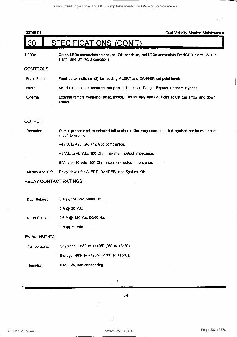
I30 I SPECIFICATIONS (CON'T)
130748-01 Dual Velocity Monitor Maintenance
LED's: Green LEDs annunciate transducer OK condition, red LEDs annunciate DANGER alarm, ALERT alarm, and BYPASS conditions.
CONTROLS
Front Panel: Front panel switches (2) for reading ALERT and DANGER set point levels.
Internal: Switches on circuit board for set point adjustment, Danger Bypass, Channel Bypass.
External: External remote controls: Reset, Inhibit, Trip Multiply and Set Point adjust (up arrow and down arrow).
OUTPUT
Recorder. Output proportional to selected full scale monitor range and protected against continuous short circuit to ground:
+4 mA to +20 mA, +12 Vdc compliance.
+1 Vdc to +5 Vdc, 100 Ohm maximum output impedance.
0 Vdc to -10 Vdc, 100 Ohm maximum output impedance.
Alarms and OK: Relay drives for ALERT, DANGER, and System OK.
RELAY CONTACT RATINGS
Dual Relays: 5 A @ 120 Vac 50/60 Hz.
5 A @ 28 Vdc.
Quad Relays: 0.6 A @ 120 Vac 50/60 Hz.
2 A @ 30 Vdc.
ENVIRONMENTAL
Temperature: Operating +32°F to +149°F (0°C to +65°C).
Storage -40°F to +185°F (-40°C to +85°C).
Humidity: 0 to 95%, non-condensing.
84
Bunya Street Eagle Farm SPS SP010 Pump Instrumentation OM Manual Volume 6B
Q-Pulse Id TMS640 Active 29/01/2014 Page 332 of 376
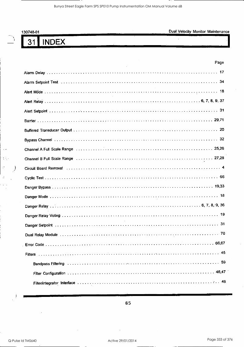
1
130748-01
I 311 INDEX
Dual Velocity Monitor Maintenance
AlarmDelay
Alarm Setpoint Test
Alert Mode
Alert Relay
Alert Setpoint
Barrier
Buffered Transducer Output
Bypass Channel
Channel A Full Scale Range
Channel B Full Scale Range
Circuit Board Removal
Cyclic Test
Danger Bypass
Danger Mode
Danger Relay
Danger Relay Voting
Danger Setpoint
Dual Relay Module
Error Code
Filters
Bandpass Filtering
Filter Configuration
Filter/integrator Interface
6,
6,
7,
7,
Page
17
34
18
8, 9, 37
31
29,71
20
32
25,26
27,28
4
66
19,33
18
8, 9, 36
19
31
70
66,67
45
59
46,47
48
85
Bunya Street Eagle Farm SPS SP010 Pump Instrumentation OM Manual Volume 6B
Q-Pulse Id TMS640 Active 29/01/2014 Page 333 of 376
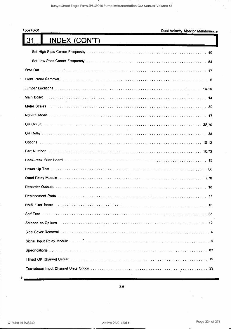
130748-01 Dual Velocity Monitor Maintenance
31 I INDEX (CON'T) Set High Pass Corner Frequency 49
Set Low Pass Corner Frequency 54
First Out 17
Front Panel Removal 5
Jumper Locations 14-16
Main Board 14
Meter Scales 30
Not-OK Mode 17
OK Circuit 38,70
OK Relay 38
Options 10-12
Part Number 10,73
Peak-Peak Filter Board 15
Power Up Test 66
Quad Relay Module 7,70
Recorder Outputs 18
Replacement Parts 77
RMS Fitter Board 16
Self Test 65
Shipped as Options 12
Side Cover Removal 4
Signal Input Relay Module 6
Specifications 83
Timed OK Channel Defeat 19
Transducer Input Channel Units Option 22
86
Bunya Street Eagle Farm SPS SP010 Pump Instrumentation OM Manual Volume 6B
Q-Pulse Id TMS640 Active 29/01/2014 Page 334 of 376
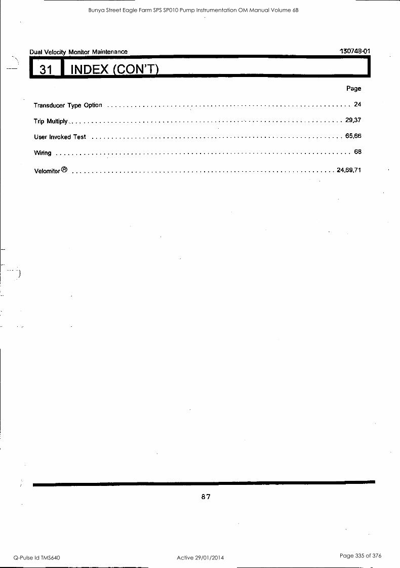
Dual Velocity Monitor Maintenance
31 INDEX (CON'T)
130748-01
Page
Transducer Type Option 24
Trip Multiply 29,37
User Invoked Test 65,66
Wiring 68
Velomitor ® 24,69,71
87
Bunya Street Eagle Farm SPS SP010 Pump Instrumentation OM Manual Volume 6B
Q-Pulse Id TMS640 Active 29/01/2014 Page 335 of 376
Dual Velocity Maintenance Manual 130748-01
88
Bunya Street Eagle Farm SPS SP010 Pump Instrumentation OM Manual Volume 6B
Q-Pulse Id TMS640 Active 29/01/2014 Page 336 of 376
BRISBANE CITY COUNCIL Dept. Water Supply and Sewage Pumpwell No 1, Eagle Farm Pump Station
BCC Contract No S20/95/96 System Instrumentation
Operation and Maintenance Manual
Section 9 Fault Protection and Rectification
9.1 Alarm Protection and Safety Devices
Alarm and trip setpoints are provided for the temperature, speed and vibration monitors in the form of voltage free contacts to the BCC control system. A summary of the setpoints is shown in drawing WD4358.
9.2 Trouble Shooting
The field sensors do not require any specialised procedures other than normal electrical checks.
The Bently Nevada 3300 Monitoring System does require a systematic approach to identify potential problems. The following publication entitled 3300 System Trouble Shooting (Part No 80173-01 Rev C) has been prepared by Bently Nevada for plant personnel who operate and maintain the system. It provides a detailed description of the basic trouble shooting procedure in case of system malfunction.
15140/Inst Man/BRH Issue 1 29-Apr-98 Page 9-1
Bunya Street Eagle Farm SPS SP010 Pump Instrumentation OM Manual Volume 6B
Q-Pulse Id TMS640 Active 29/01/2014 Page 337 of 376
3300 SYSTEM TROUBLESHOOTING
BENTLY NEVADA
PART NO. 80173-01 REVISION C,
NOVEMBER 1993
Bunya Street Eagle Farm SPS SP010 Pump Instrumentation OM Manual Volume 6B
Q-Pulse Id TMS640 Active 29/01/2014 Page 338 of 376
80173 System Troubleshooting
NOTICE
Read the following before installing or operating equipment
Bent ly Nevada Corporation has attempted to identify areas of risk created by improper installation and/or operation of this product. These areas of information are noted as WARNING or CAUTION for your protection and for the safe and effective operation of this equipment. Read all instructions before installing or operating this product. Pay particular attention to those areas designated by the following symbols.
WARNING
High voltage present could cause shock bums or death
Do not touch exposed wires or terminals
Keyphasor® is a registered trademark of Bent ly Nevada Corporation
Proximitor® is a registered trademark of Bent ly Nevada Corporation
*CAUTION
Machine protection will be lost during calibration.
CO Copyright Bent ly Nevada Corporation 1987,1988,1989,1990,1991,1992, 1993 All Rights Reserved
No part of this publication may be reproduced, transmitted, stored in a retrieval system or translated into any human or computer language, in any form or by any means, electronic, mechanical, magnetic, optical, chemical, manual, or otherwise, without the prior written permission of the copyright owner,
Bent ly Nevada Corporation P.O. Box 157
Minden, Nevada 89423 USA Telephone 800-227-5514 702-782-3611
Telex 354437 Telemail 7400983 BNC UC
Fax 702-782-9253
Copyright infringement is a serious matter under United States of America and foreign copyright laws.
ii
a.
Bunya Street Eagle Farm SPS SP010 Pump Instrumentation OM Manual Volume 6B
Q-Pulse Id TMS640 Active 29/01/2014 Page 339 of 376
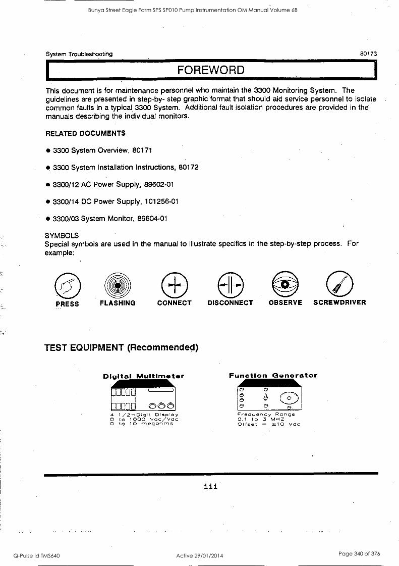
System Troubleshooting 80173
FOREWORD
This document is for maintenance personnel who maintain the 3300 Monitoring System. The guidelines are presented in step-by- step graphic format that should aid service personnel to isolate common faults in a typical 3300 System. Additional fault isolation procedures are provided in the manuals describing the individual monitors.
RELATED DOCUMENTS
3300 System Overview, 80171
3300 System Installation Instructions, 80172
3300/12 AC Power Supply, 89602-01
3300/14 DC Power Supply, 101256-01
3300/03 System Monitor, 89604-01
SYMBOLS Special symbols are used in the manual to illustrate specifics in the step-by-step process. For example:
PRESS FLASHING CONNECT
TEST EQUIPMENT (Recommended)
DISCONNECT OBSERVE SCREWDRIVER
Digital Multimeter Function Generator
4 1 / 2-Digit Display O to 1000 vac/Vac O to 10 rnegonms
Frequency Range 0.1 to 3 MHZ Offset = X10 Vc1c
Bunya Street Eagle Farm SPS SP010 Pump Instrumentation OM Manual Volume 6B
Q-Pulse Id TMS640 Active 29/01/2014 Page 340 of 376

80173 System Troubleshooting
iv
Bunya Street Eagle Farm SPS SP010 Pump Instrumentation OM Manual Volume 6B
Q-Pulse Id TMS640 Active 29/01/2014 Page 341 of 376
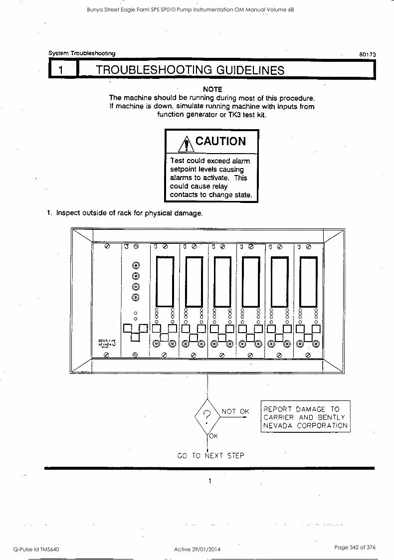
System Troubleshooting 80173
I TROUBLESHOOTING GUIDELINES
NOTE The machine should be running during most of this procedure. If machine is down, simulate running machine with inputs from
function generator or TK3 test kit.
*CAUTION Test could exceed alarm setpoint levels causing alarms to activate. This could cause relay contacts to change state.
1. Inspect outside of rack for physical damage.
z,N,L,1 _._
'® 0 o a a
1 0 3 0 1 0 1 0 z 0 1 0 ....... - - - -
. (:)(!) 0 . .
9 0
0 . o
90
8 0 0
0000 0 0
06. 0 0 0
0
. 0 0
00
0 0 0 0
0
0 . 0
00
6---6 0 0 0
0
0 0 0
0
GO TO NEXT STEP
REPORT DAMAGE TO CARRIER AND BENTLY NEVADA CORPORATION
1
Bunya Street Eagle Farm SPS SP010 Pump Instrumentation OM Manual Volume 6B
Q-Pulse Id TMS640 Active 29/01/2014 Page 342 of 376
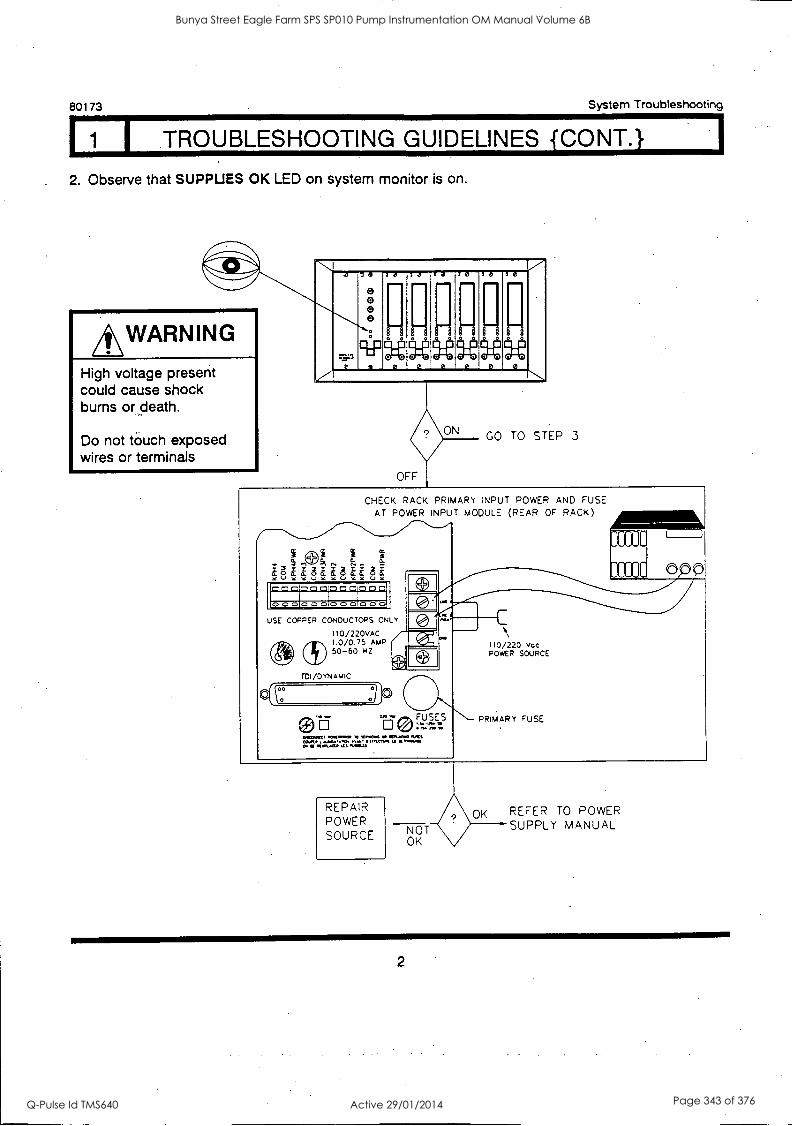
80173 System Troubleshooting
1 I TROUBLESHOOTING GUIDELINES {CONT.}
. 2. Observe that SUPPUES OK LED on system monitor is on.
*WARNING High voltage present could cause shock burns or death.
Do not touch exposed wires or terminals
*..,.. ...7
Y
0
S7 2000
70
i 943
10
III
o o0
321
ill OmM
ro
oa
:1 Um.
oo @
30
il Mun
no P
30
Om. 00
0
30
Um. o
0
o
ON GO TO STEP 3
CHECK RACK PRIMARY INPUT POWER AND FUSE AT POWER INPUT MODULE (REAR OF RACK)
0 0 0 CD CD CD CD CD 0 10 CD CD
USE COPPER CONDUCTORS ONLY
110/220VAC 1.0/0.75 AMP 50-60 HZ
T603/DYNAMIC
(oo
0 L_I
F USES V) FM WI
M.O. RTA.L. NILS O a 0.f llialati al, VMS!
11 1
tili1
110/220 Voc POWER SOURCE
PRIMARY FUSE
REPAIR POWER SOURCE NOT
OK
OK REFER TO POWER SUPPLY MANUAL
2
Bunya Street Eagle Farm SPS SP010 Pump Instrumentation OM Manual Volume 6B
Q-Pulse Id TMS640 Active 29/01/2014 Page 343 of 376
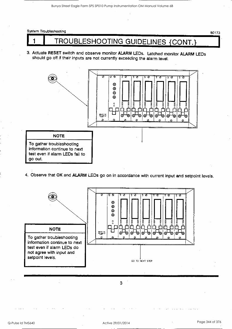
System Troubleshooting 80173
I TROUBLESHOOTING GUIDELINES {CONT.} 3. Actuate RESET switch and observe monitor ALARM LEDs. Latched monitor ALARM LEDs
should go off if their inputs are not currently exceeding the alarm level.
N .
'.
0
tr31:z
e
1
0 0 0 0
30 30 30 30 30 30 IIMENNIP IMII INIMMINW MNIMMI INIII
0 00 11
00 00 El__
00 00 0
0 o e @e 0; oDe
e oLt
0 cPe
g oo
e 7 NOTE
To gather troubleshooting information continue to next test even if alarm LEDs fail to go out.
4. Observe that OK and ALARM LEDs go on in accordance with current input and setpoint levels.
NOTE
To gather troubleshooting information continue to next test even if alarm LEDs do not agree with input and setpoint levels.
,.Z 0
:32,z1
0
Ze
0 0 0 0
30 30 10 30 a e I e 1I IIII INIMINII II
°
II
§ § § § ilia § §
0°0 0
§ §
ill § § ii 0°0
e
§ § i 0 ,3
e a 0;
0 0;
0 0
GO TO NEXT STEP
3
Bunya Street Eagle Farm SPS SP010 Pump Instrumentation OM Manual Volume 6B
Q-Pulse Id TMS640 Active 29/01/2014 Page 344 of 376
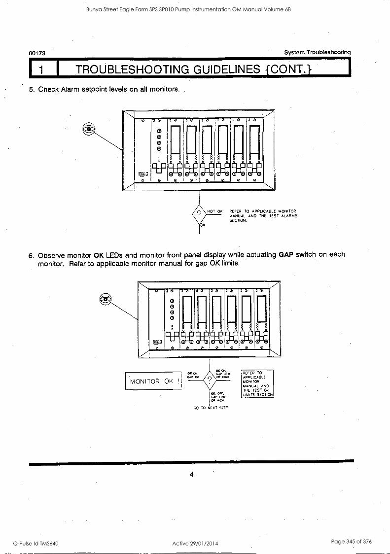
80173 System Troubleshooting
1 TROUBLESHOOTING GUIDELINES CONT.
5. Check Alarm setpoint levels on all monitors.
'NI '
x
:
0 0 0 0 0
'
§
vammr
§
iii
... . IMIIMM
1 0 1I
0 00 00 00 00 00 0
NOT OK REFER TO APPLICABLE MONITOR MANUAL AND THE TEST ALARMS SECTION.
6. Observe monitor OK LEDs and monitor front panel display while actuating GAP switch on each monitor. Refer to applicable monitor manual for gap OK limits.
7
7 016301030303030
:-....11
0
0 0 0 0 - .
11I
§ §§
qlf,
§§
limmimp
.
§§ i %MIMI /
§§ i
s 0 00 00000 00 00 00 00 0
e \. MONITOR OK !
REFER TO APPLICABLE MOM TOR
MANUAL AND
THE TEST OK LIMITS SECTION
4
Bunya Street Eagle Farm SPS SP010 Pump Instrumentation OM Manual Volume 6B
Q-Pulse Id TMS640 Active 29/01/2014 Page 345 of 376
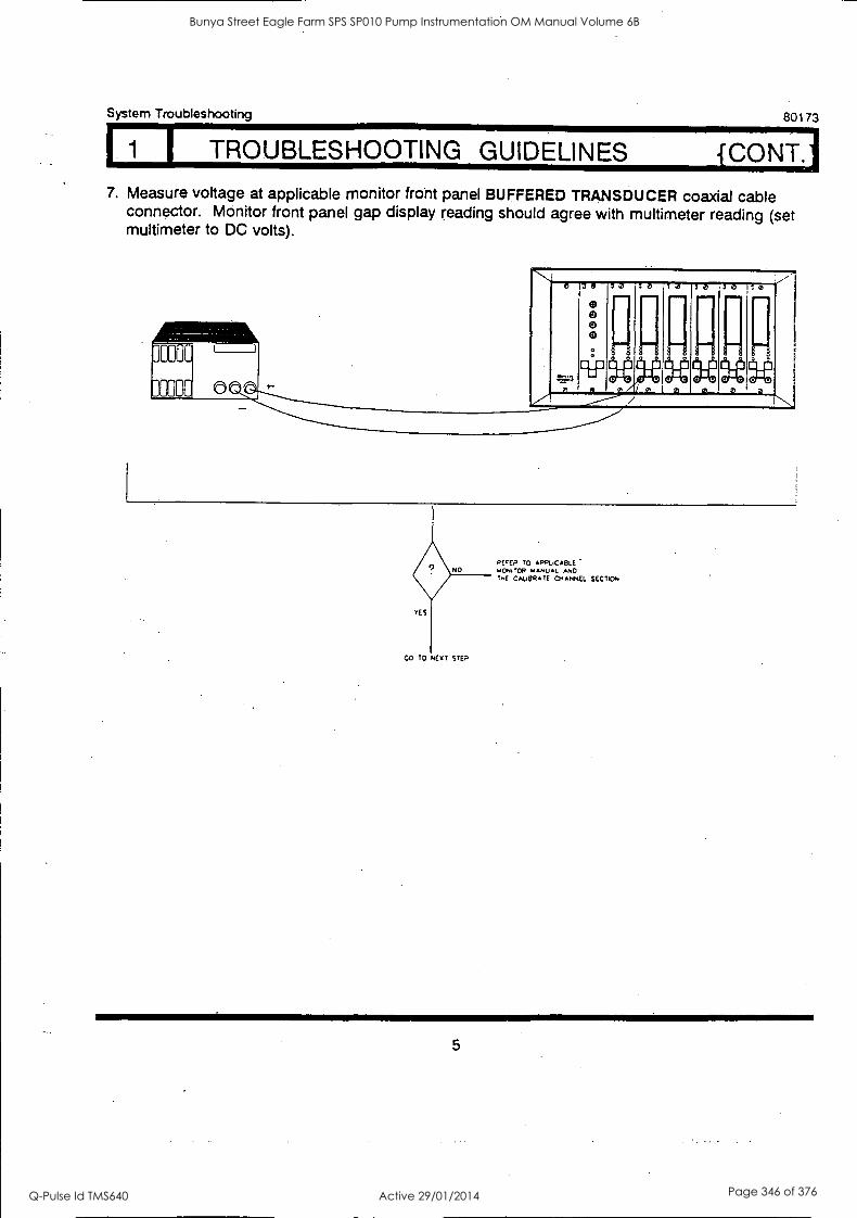
I TROUBLESHOOTING GUIDELINES {CONT.1
System Troubleshooting 80173
7. Measure voltage at applicable monitor front panel BUFFERED TRANSDUCER coaxial cable connector. Monitor front panel gap display reading should agree with multimeter reading (set multimeter to DC volts).
'',..... -4 '/ 0
=3 0
7 9
0 e e G
:a za
H
:a
11
:0
.
3 0 1 0
9 p 0 c
1 0 1 0 ..ouo. .
0/A i I
CO TO NEAT STEP
PEEP TO APPLICABLE upscrOR 1PANuAL ANO TOE CALIBRATE CHANNEL SECTION
5
Bunya Street Eagle Farm SPS SP010 Pump Instrumentation OM Manual Volume 6B
Q-Pulse Id TMS640 Active 29/01/2014 Page 346 of 376
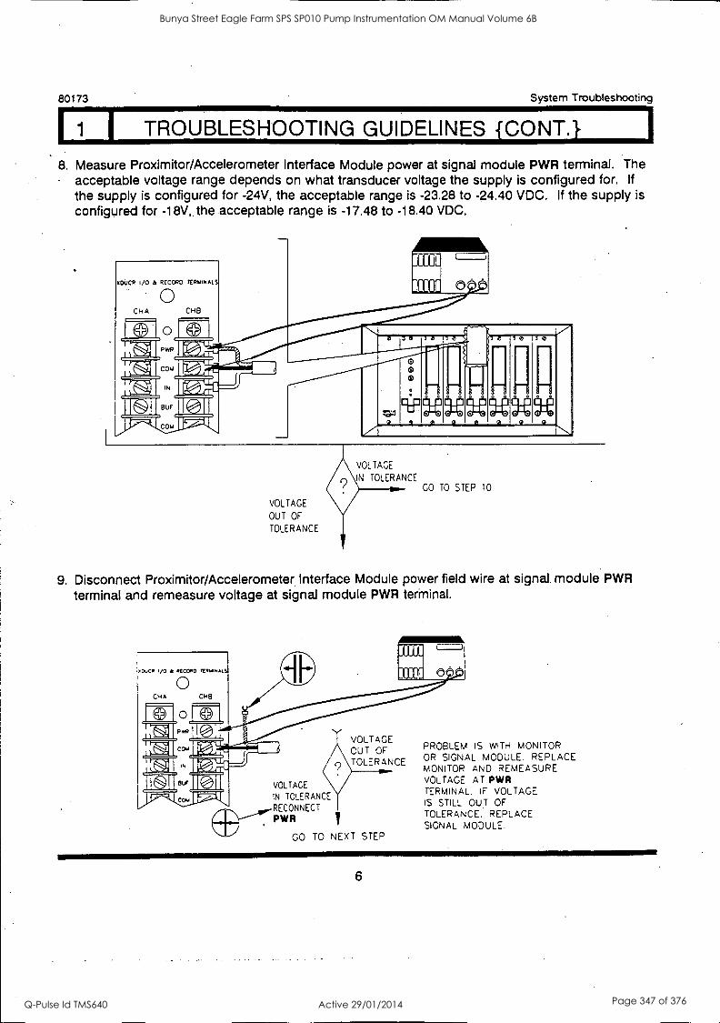
80173 System Troubleshooting
II 1 I TROUBLESHOOTING GUIDELINES {CONT.}
8. Measure Proximitor/Accelerometer Interface Module power at signal module PWR terminal. The - acceptable voltage range depends on what transducer voltage the supply is configured for. If
the supply is configured for -24V, the acceptable range is -23.28 to -24.40 VDC. If the supply is
configured for -18V, the acceptable range is -17.48 to -18.40 VDC.
VOLTAGE
IN TOLERANCE GO TO STEP 10
VOLTAGE
OUT OF
TOLERANCE
9. Disconnect Proximitor/Accelerometer, Interface Module power field wire at signal. module PWR
terminal and remeasure voltage at signal module PWR terminal.
cuC /0 & CCC&O
CH A
e 0 31
03
P*17
ca.
IN
El.)" BUF
CHB
VOLTAGE OUT OF TOLERANCE
VOLTAGE
IN TOLERANCE
RECONNECT
PWR
GO TO NEXT STEP
19
PROBLEM IS WITH MONITOR OR SIGNAL MODULE. REPLACE MONITOR AND REMEASURE VOLTAGE AT PWR TERMINAL. IF VOLTAGE IS STILL OUT OF
TOLERANCE. REPLACE SIGNAL MODULE.
6
Bunya Street Eagle Farm SPS SP010 Pump Instrumentation OM Manual Volume 6B
Q-Pulse Id TMS640 Active 29/01/2014 Page 347 of 376
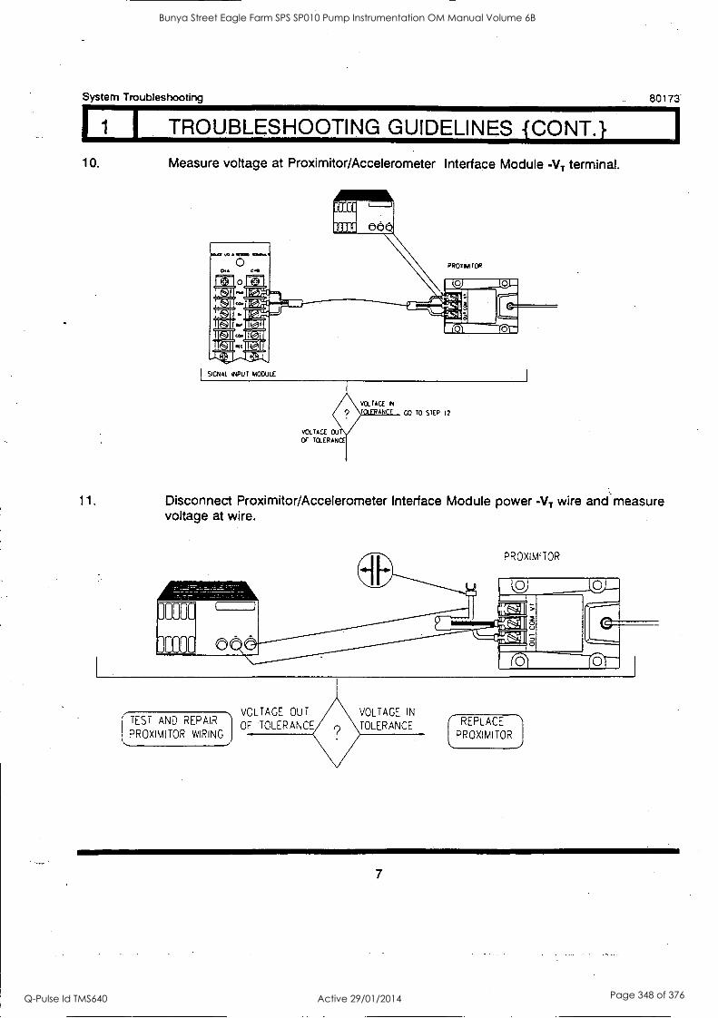
System Troubleshooting 80173
1 I TROUBLESHOOTING GUIDELINES {CONT.} 10. Measure voltage at Proximitor/Accelerometer Interface Module -VT terminal.
SIGNAL INPUT MODULE
VOLTAGE IN
VOLTAGE OU
Or TOLERANCE
CO TO STEP 12
11. Disconnect Proximitor/Accelerometer Interface Module power -VT wire and measure voltage at wire.
PROXIMITOR
TEST AND REPAIR
PROXIMITOR WIRING
VOLTAGE OUT VOLTAGE IN
OF TOLERANCE TOLERANCE I REPLACE
PROXIMITOR
7
Bunya Street Eagle Farm SPS SP010 Pump Instrumentation OM Manual Volume 6B
Q-Pulse Id TMS640 Active 29/01/2014 Page 348 of 376
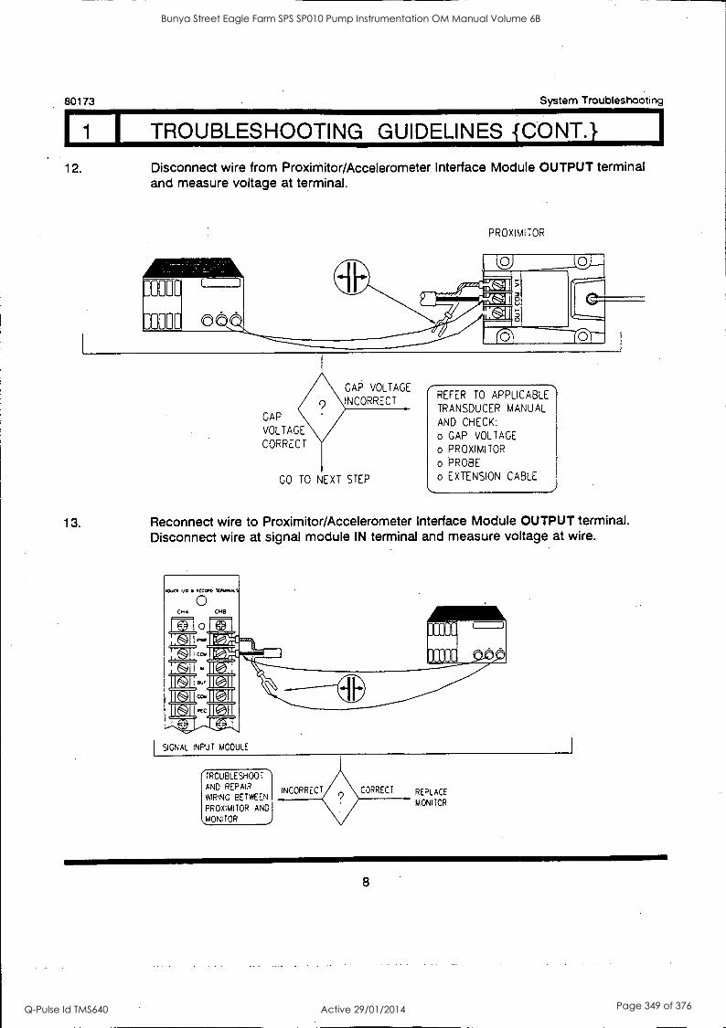
1
80173 System Troubleshooting
I 1 1 TROUBLESHOOTING GUIDELINES {CONT.}
12. Disconnect wire from Proximitor/Accelerometer Interface Module OUTPUT terminal and measure voltage at terminal.
PROXIMITOR
GAP VOLTAGE
INCORRECT
GAP
VOLTAGE
CORRECT
GO TO NEXT STEP
REFER TO APPLICABLE
TRANSDUCER MANUAL AND CHECK:
o GAP VOLTAGE
o PROXIMITOR
o PROBE
o EXTENSION CABLE
13. Reconnect wire to Proximitor/Accelerometer Interface Module OUTPUT terminal. Disconnect wire at signal module IN terminal and measure voltage at wire.
SIGNAL NPUT MODULE
/TROUBLESHOOT
WIRING BETWEEN
AND REPAIR INCORRECT
PROXIMITOR AND j QOONITOR
CORRECT REPLACE
MONITOR
8
Bunya Street Eagle Farm SPS SP010 Pump Instrumentation OM Manual Volume 6B
Q-Pulse Id TMS640 Active 29/01/2014 Page 349 of 376

BRISBANE CITY COUNCIL Dept. Water Supply and Sewage Pumpwell No 1, Eagle Farm Pump Station
BCC Contract No S20/95/96 System Instrumentation
Operation and Maintenance Manual
Section 10 Isolation and Restoration Procedures
This Section is not applicable to the System Instrumentation. The Isolation and Restoration procedures for the pumping system are included in other volumes.
The Local Instrumentation Panel can be isolated by the two moulded case circuit breakers in the back of the panel. Each MCCB will isolate an entire rack.
15140/Inst Man/BRH Issue 1 29-Apr-98 Page 10-1
Bunya Street Eagle Farm SPS SP010 Pump Instrumentation OM Manual Volume 6B
Q-Pulse Id TMS640 Active 29/01/2014 Page 350 of 376
BRISBANE CITY COUNCIL Dept. Water Supply and Sewage Pumpwell No 1, Eagle Farm Pump Station
BCC Contract No S20/95/96 System Instrumentation
Operation and Maintenance Manual
Section 11 List of Sub-Contractors and Proprietary. Equipment
Sub-contract suppliers of proprietary equipment include:
Vibration and Seed Monitoring - Bently Nevada 20 Healey Circuit Huntingwood NSW 2148
RTD Temperature Sensors -
Pump Junction Box -
15140/Inst Man/BRH Issue 1
Ph 02 9672 7447
Temperature Controls Pty Ltd 55 Henry Street Leichhardt NSW 2040
Ph 02 9560 0644
J & P Richardson Industries Pty Ltd Campbell Avenue Walcol QLD 4076
Ph 07 3271 2911
29-Apr-98 Page 11-1
Bunya Street Eagle Farm SPS SP010 Pump Instrumentation OM Manual Volume 6B
Q-Pulse Id TMS640 Active 29/01/2014 Page 351 of 376
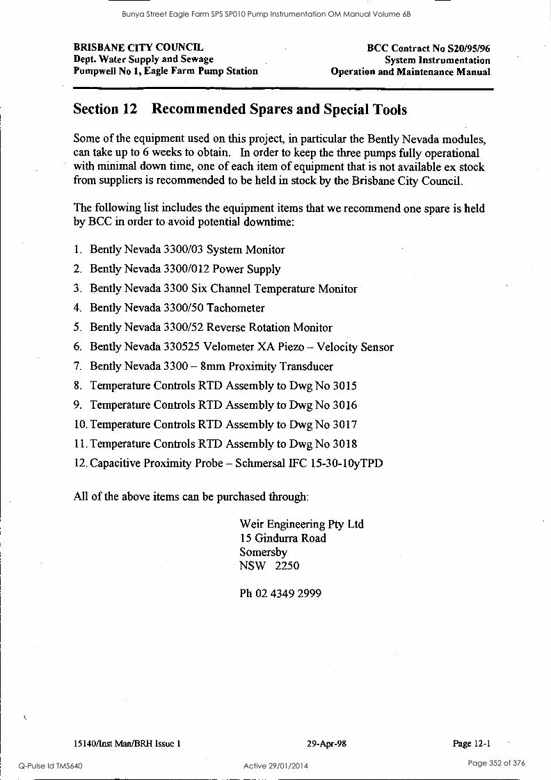
BRISBANE CITY COUNCIL Dept. Water Supply and Sewage Pumpwell No 1, Eagle Farm Pump Station
BCC Contract No S20/95/96 System Instrumentation
Operation and Maintenance Manual
Section 12 Recommended Spares and Special Tools
Some of the equipment used on this project, in particular the Bently Nevada modules, can take up to 6 weeks to obtain. In order to keep the three pumps fully operational with minimal down time, one of each item of equipment that is not available ex stock from suppliers is recommended to be held in stock by the Brisbane City Council.
The following list includes the equipment items that we recommend one spare is held by BCC in order to avoid potential downtime:
1. Bently Nevada 3300/03 System Monitor
2. Bently Nevada 3300/012 Power Supply
3. Gently Nevada 3300 Six Channel Temperature Monitor
4. Bently Nevada 3300/50 Tachometer
5. Bently Nevada 3300/52 Reverse Rotation Monitor
6. Bently Nevada 330525 Velometer XA Piezo - Velocity Sensor
7. Bently Nevada 3300 - 8mm Proximity Transducer
8. Temperature Controls RTD Assembly to Dwg No 3015
9. Temperature Controls RTD Assembly to Dwg No 3016
10. Temperature Controls RTD Assembly to Dwg No 3017
11. Temperature Controls RTD Assembly to Dwg No 3018
12. Capacitive Proximity Probe - Schmersal IFC 15-30-10yTPD
All of the above items can be purchased through:
15140/last Man/BR1i Issue 1
Weir Engineering Pty Ltd 15 Gindurra Road Somersby NSW 2250
Ph 02 4349 2999
29-Apr-98 Page 12-1
Bunya Street Eagle Farm SPS SP010 Pump Instrumentation OM Manual Volume 6B
Q-Pulse Id TMS640 Active 29/01/2014 Page 352 of 376
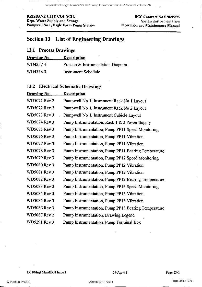
BRISBANE CITY COUNCIL Dept. Water Supply and Sewage Pumpwell No 1, Eagle Farm Pump Station
BCC Contract No S20/95/96 System Instrumentation
Operation and Maintenance Manual
Section 13 List of Engineering Drawings
13.1 Process Drawings
Drawing No Description
WD4357 4 Process & Instrumentation Diagram
WD4358 3 Instrument Schedule
13.2 Electrical Schematic Drawings
Drawing No Description
WD5071 Rev 2 Pumpwell No 1, Instrument Rack No 1 Layout
WD5072 Rev 2 Pumpwell No 1, Instrument Rack No 2 Layout
WD5073 Rev 3 Pumpwell No 1, Instrument Cubicle Layout
WD5074 Rev 3 Pump Instrumentation, Rack 1 & 2 Power Supply
WD5075 Rev 3 Pump Instrumentation, Pump PP11 Speed Monitoring
WD5076 Rev 3 Pump Instrumentation, Pump PP11 Vibration
WD5077 Rev 3 Pump Instrumentation, Pump PP11 Vibration
WD5078 Rev 3 Pump Instrumentation, Pump PP11 Bearing Temperature
WD5079 Rev 3 Pump Instrumentation, Pump PP12 Speed Monitoring
WD5080 Rev 3 Pump Instrumentation, Pump PP12 Vibration
WD5081 Rev 3 Pump Instrumentation, Pump PP12 Vibration
WD5082 Rev 3 Pump Instrumentation, Pump PP12 Bearing Temperature
WD5083 Rev 3 Pump Instrumentation, Pump PP13 Speed Monitoring
WD5084 Rev 3 Pump Instrumentation, Pump PP13 Vibration
WD5085 Rev 3 Pump Instrumentation, Pump PP13 Vibration
WD5086 Rev 3 Pump Instrumentation, Pump PP13 Bearing Temperature
WD5087 Rev 2 Pump Instrumentation, Drawing Legend
WD5291 Rev 3 Pump Instrumentation, Pump Terminal Box
15140/Inst Man/BRH Issue 1 29-Apr-98 Page 13-1
Bunya Street Eagle Farm SPS SP010 Pump Instrumentation OM Manual Volume 6B
Q-Pulse Id TMS640 Active 29/01/2014 Page 353 of 376
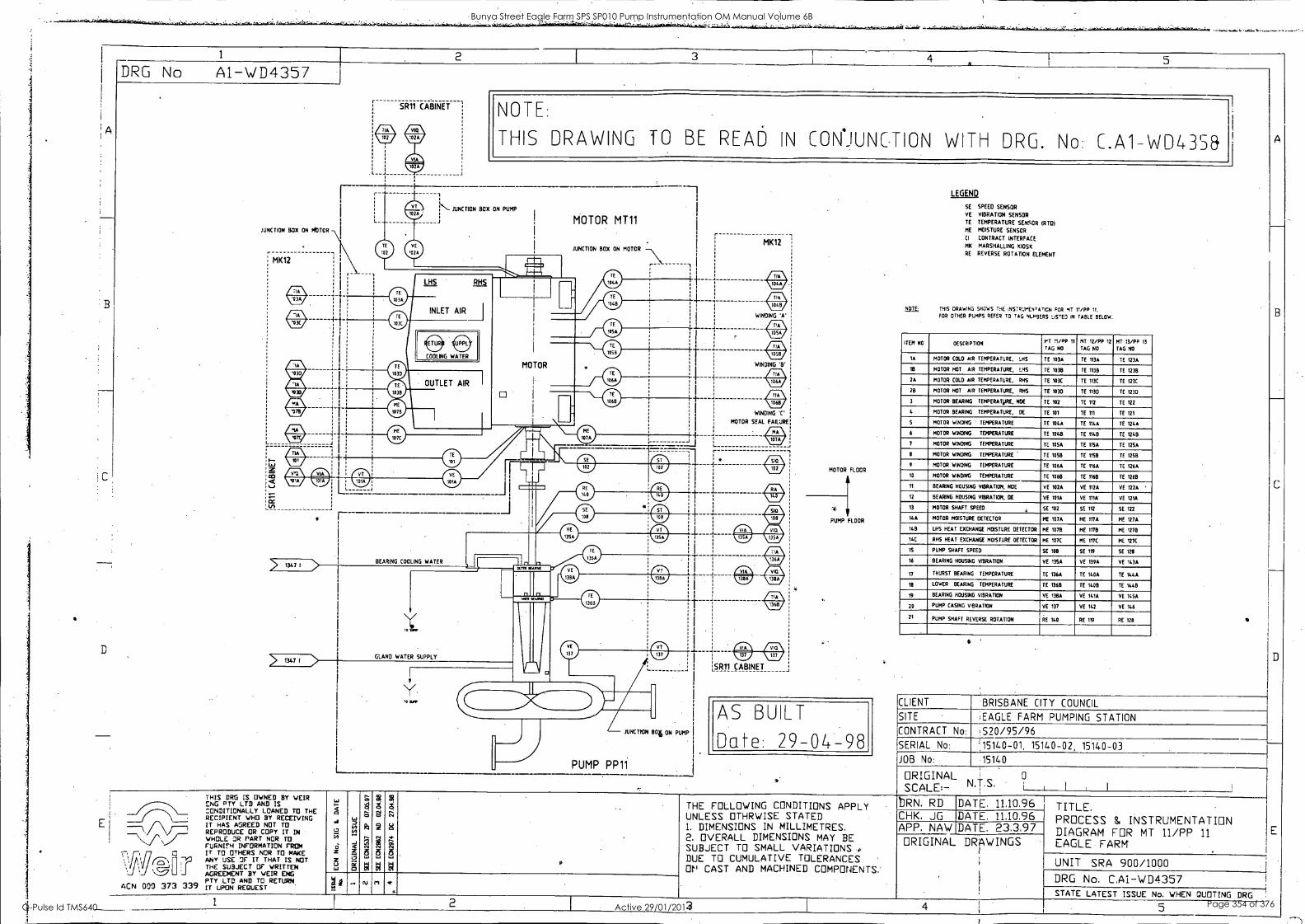
A
D
E
1 2 3 4 5 DRG No Al-WD4357
JUNCTION BOX ON MOTOR
MK12
w AIM w
e e
SR11 CABINET NOTE:
THIS DRAWING TO BE READ IN CON*JUNC.TION WITH DRG. No: C.A1- WD435&
Ns.- JUNCTION BOX ON PUMP 1
MOTOR MT11 1
JUNCTION BOX ON MOTOR
r -1 I
I1
1
T
÷ I
4
4i
r
MK12
AZ& w w
WINDING 'A'
AZ&
415. 11217
WINDING '8'
TIN
1068
WINDING 'C'
MOTOR SEAL FAILURE
4E11 11717
r
> 1347 I
> 1347 I
BEARING COOLING WATER
GLAND WATER SUPPLY
JUNCTION BOil ON PUMP
PUMP PP11
An Mr VW
1SR11 CABINET
MOTOR FLOOR
4
PUMP FLOOR
AS BUILT
Date: 29-04-98
LEGEND
SE
VE
TE
ME
CI
MK
RE
SPEED SENSOR
VIBRATION SENSOR
TEMPERATURE SENSOR MIDI MOISTURE SENSOR
CONTRACT INTERFACE
MARSHALLING KIOSK
REVERSE ROTATION ELEMENT
11121I THIS DRAWING SHOWS THE iNSTRUMENTATICN FOR MT 11/PP 11.
FOR OTHER PUMPS REFER TO TAG N1.1.49E.RS LISTED IN TABLE BELOW.
ITEM NO DESCRIPTION PT 11 /PP 11
TAG NO
MT 12/PP 12
TAG NO
MT 13/PP 13
TAG NO
IA MOTOR COLD AIR TEMPERATURE, ...115 TE 103A TE 113A TE 123A
18 MOTOR HOT AIR TEMPERATURE. 1145 TE 1038 TE 11315 TE 123B
2A MOTOR COLD AIR TEMPERATURE. RHS TE 103C TE 113C TE 123C
28 MOTOR HOT AIR TEMPERATURE. RHS TE 1035 TE 1130 TE 1230
3 MOTOR BEARING TEMPERATURE, NOE TE 102 TE 112 TE Ill 4 MOTOR BEARING TEMPERATURE, DE TE 101 TE 111 TE 121
5 MOTOR WINDING - TEMPERATURE TE 104A TE 114A TE 124A
6 MOTOR WINDING TEMPERATURE TE 1048 TE 114B TE 1248
7 MOTOR WINDING TEMPERATURE TE 1054 TE 1154 SE 1254
8 MOTOR WINDING TEMPERATURE TE 1058 TE 1158 TE 1258
9 MOTOR WINDING TEMPERATURE TE 1064 TE 1164 TE 1264
10 MOTOR WINDING TEMPERATURE TE 1068 TE 1168 TE 1268
11 BEARING HOUSING VIBRATION, NOE VE 1024 VE 1124 VE 1224
12 BEARING HOUSING VIBRATION, DE VE 101A VE 111A' VE 121A
13 MOTOR SHAFT SPEED SE 102 SE 112 SE 122
14A MOTOR MOISTURE DETECTOR ME 107A ME 1174 ME 127A
148 LHS HEAT EXCHANGE MOISTURE DETECTOR ME 1078 ME 1178 ME 1278
14C RHO HEAT EXCHANGE MOISTURE DETECTOR ME 107C ME 117C ME 127C
IS PUMP SHAFT SPEED SE 108 SE 119 SE 128
16 BEARING HOUSING VIBRATION VE 13SA VE 139A VE 143A
17 THURST BEARING TEMPERATURE TE 136A TE 140A TE 144A
113 LOWER BEARING TEMPERATURE TE 1368 TE 1408 TE 1448
19 BEARING HOUSING VIBRATION YE 138A VE 141A VT 145A
20 PUMP CASING VIBRATION VE 137 HE 142 VE 146
21 PUMP SHAFT REVERSE ROTATION RE 140 RE 119 RE 128
CLIENT BRISBANE CITY COUNCIL
SITE EAGLE FARM PUMPING STATION
CONTRACT No:
SERIAL No:
,S20/95/96 '15140-01, 15140 -02, 15140-03
JOB No: 15140
ORIGINAL '
SCALE:- N.T.S. 0
I
,1\ ACN 000 373 339
THIS DRG IS OWNED BY WEIR ENG PTY LTD AND IS CONDITIONALLY LOANED TO THE RECIPIENT WHO BY RECEIVING IT HAS AGREED NOT TO REPRODUCE CR COPY IT IN WHOLE OR PART NOR TO FURNIFH INFORMATION FROM IT TO OTHERS NOR TO MAKE ANY USE OF IT THAT IS NOT THE SUBJECT OF WRITTEN AGREEMENT BY WEIR ENG PTY LTD AND TO RETURN. IT UPON REQUEST
z
Col
-J
O
a
N
2
S
CU
THE FOLLOWING CONDITIONS APPLY UNLESS OTHRWISE STATED 1. DIMENSIONS IN MILLIMETRES. 2. OVERALL DIMENSIONS MAY BE SUBJECT TO SMALL VARIATIONS DUE TO CUMULATIVE TOLERANCES Or" CAST AND MACHINED COMPONENTS.
bRN. RD DATE, 11,10,96 CHK. JG DATE, 11.10.96 APP. NAW DATE. 23.3.97 ORIGINAL DRAWINGS
1
TITLE. PROCESS & INSTRUMENTATION DIAGRAM FOR MT 11/PP 11 EAGLE FARM
UNIT SRA 900/1000 DRG No. C.A1-WD4 357 STATE LATEST ISSUE No. WHEN QUOTING DRG
2 4 5
A
Bunya Street Eagle Farm SPS SP010 Pump Instrumentation OM Manual Volume 6B
Q-Pulse Id TMS640 Active 29/01/2014 Page 354 of 376
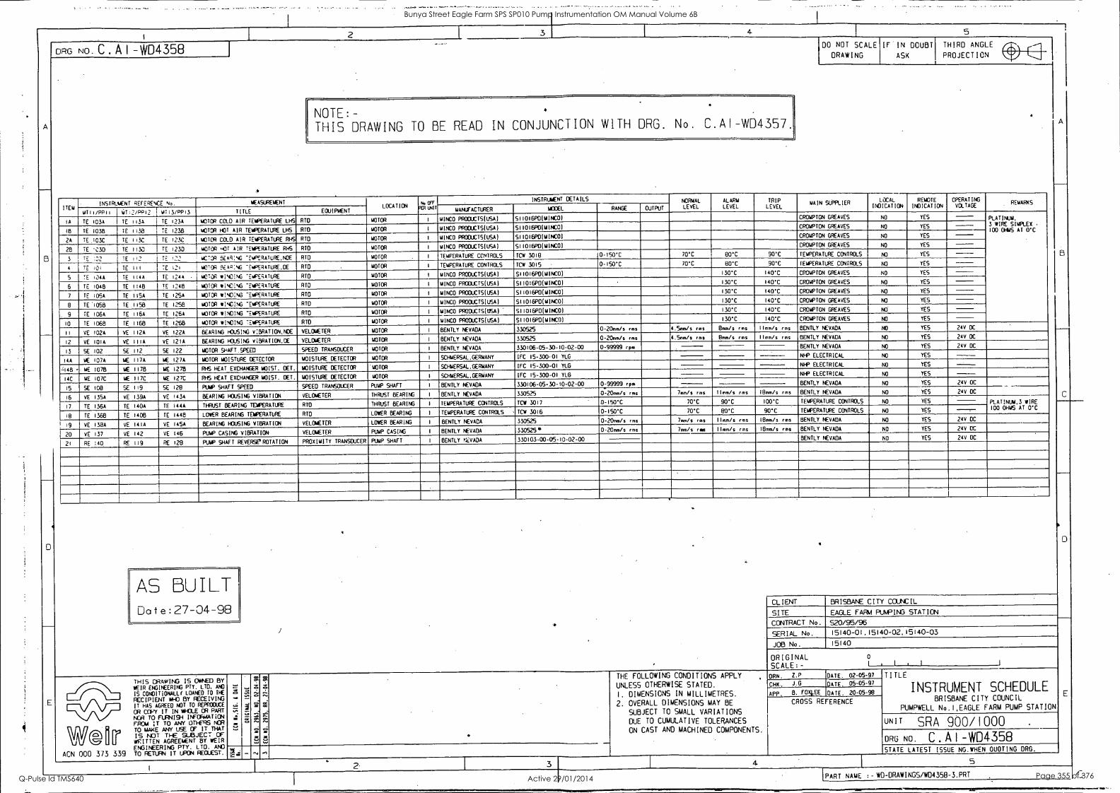
DRG No. C . A I -WD4358
5
NOTE:- THIS DRAWING TO BE READ IN CONJUNCTION WITH DRG. No. C.A1-W04357.
DO NOT SCALE
DRAWING
IF IN DOUBT
ASK
THIRD ANGLE 1
PROJECTION
ITEM INSTRUMENT REFERENCE No. MEASUREMENT
LOCATION N0017 pp WIT
INSTRUMENT DETAILS NORMAL LEVEL
ALARM LEVEL
TRIP LEVEL
MAIN SUPPLIER LOCAL
INDICATION REMOTE
INDICATION OPERATING VOLTAGE
REMARKS
MTII/RPii YT;2/PP12 mT13/PP13 TITLE EQUIPMENT MANUFACTURER MOM_ RANGE OUTPUT
IA TE I03A TE 113A TE 123A MOTOR COLD AIR TEMPERATURE LHS RID MOTOR I MINED PRODUCTS(USA) 511016P0(MINCO) CROMPTON GREAVES NO YES PLATINUM,
3 WIRE SIMPLEX 100 OHMS Al O'C 1E1 TE 1038 TE 1138 TE 1238 MOTOR HOT AIR TEMPERATURE LHS RTO MOTOR I MINCO PRODUCTS(USA) 511016P0(MINCO) CROMPTON GREAVES NO YES
2A II )03C TE 113C TE 123E MOTOR COLD AIR TEMPERATURE RHS RTC MOTOR I MINED PROCUCTS(USA) 511016PD(MINCO) CROMPTON GREAVES NO YES
28 TE '030 I TE 1130 TE 1230 MOTOR 40IT AIR TEMPERATURE RHS RIO MOTOR I MINCO PRODUCTS(USA) S11016P0(MINCO) CROMPTON GREAVES NO YES
3 TE :22 7E 112 YE 22 MOTOR 5E14i:NG -EIPERATURE,NOE Aro MOTOR I TEMPERATURE CONTROLS TCW 3018 0-150T 70'C 80'C 90'C TEMPERATURE CONTROLS NO YES
E 101 TE Ill TE 121 MOTOR 3EA;:NO TEmPERATURE,OE RTD MOTOR I TEMPERATURE CONTROLS TCW 3015 - 0-150*C 70'C 80*C 90'C TEMPERATURE CONTROLS NO YES
5 TE 104A TE 1144 TE 124A ACTOR wiNOING 'EMPERATURE RTO MOTOR I MINCO PRODUCTS(USA) 511016P0(MINCO) 130'C 140*C CROMPTON GREAVES NO YES
6 TE 1048 TE 1148 YE 1248 MOTOR WINDING "EMPERATURE RTO MOTOR I MINCO PROCUCTS(USA) 511016PD(MINCO) 130'C 140'C CROMPTON GREAVES NO YES
7 TE 1105A TE 1I5A TE 125A MOTOR WINO:NG TEMPERATURE RID MOTOR I MINED PROCUCTS(USA) 511016PD(MINCO) 130'C 140T CROMPTON GREAVES NO YES
8 TE 1058 TE 1158 TE 1058 MOTOR WINGING TEMPERATURE RID MOTOR I MINCO PROOUCTS(USA) 511016P0(MINCOI 130'C 140'C CROMPTON GREAVES NO YES
9 TE I06A TE II6A TE I26A MOTOR WINGING TEMPERATURE RTO MOTOR I MINCO PRODUCTS(USA) S11016PO(MINCO) 130*C 140T CROMPTON GREAVES NO YES
10 TE 1068 TE 1168 TE 1268 MOTOR WINCING TEMPERATURE RID MOTOR I MINED PRODUCTS(USA) 511016PD(MINCO) 130*C 140'C CROMPTON GREAVES NO YES
11 VE 102A VE 112A VE 122A BEARING HOUSING V:BRATION,NDE VELOMETER MOTOR I BENTLY NEVADA 330525 0 20mm/s rms 4.5mm/s rms 8mm/s rms lImm/s rms BENTLY NEVADA NO YES 24V DC
12 YE 101A VE 111A VE 121A BEARING HOUSING VIBRATICN.CE VELOMETER MOTOR I BENTLY NEVADA 330525 0-20mm/s rms 4.5mm/s rms 8mm /s rms 1Imm/s rms BENTLY NEVADA NO YES 24V DC
13 SE 102 SE 112 SE 122 MOTOR SHAFT. SPEED SPEED TRANSDUCER MOTOR I 8ENTLY NEVADA 330106-05-30-10-02-00 0-99999 rpm BENTLY NEVADA NO YES 24V DC
ME 107A 117A ME I27A MOISTURE DETECTOR MOISTURE DETECTOR MOTOR I SCHMERSAL,GERMANY IFC 15-300-01 YLG NHP ELECTRICAL NO YES 14A
L148 - ME I078
AC
14E II76 ME 1278
MOTOR
RHS HEAT EXCHANGER MOIST. DET. MOISTURE DETECTOR MOTOR I SCHMERSALGERMANY IFC 15-300-01 YLG NHP ELECTRICAL NO YES
14C ME 107C ME 117C ME 127C RHS HEAT EXCHANGER MOIST. DEL MOISTURE DETECTOR MOTOR I SCHUERSAL.GERMANY IFC 15-300-01 YLG NHP ELECTRICAL NO YES
15 SE 108 SE 119 SE 128 PUMP SHAFT SPEED SPEED TRANSDUCER PUMP SHAFT I 8ENTLY NEVADA 330106-05-30-10-02-00 0-99999 rpm 8ENTLY NEVADA NO YES 24V DC
16 VE I35A vE I39A VE 143A BEARING HOUSING VIBRATION VELOMETER THRUST BEARING I BENTLY NEVADA 330525 0-20mm/s rms 7mm/s rms 11mm /s rms 18mm/s rms BENTLY NEVADA NO YES 24V DC
17 TE I36A TE 140A TE 144A THRUST BEARING TEMPERATURE RID THRUST BEARING I TEMPERATURE CONTROLS TCW 3017 0-150"C 70T 90*C 100'C TEMPERATURE CONTROLS NO YES PLATINUM.3 WIRE 100 OHMS AT O'C
18 TE 1368 TE 1408 TE 1448 LOWER BEARING TEMPERATURE RTD LOWER BEARING I TEMPERATURE CONTROLS TCW 3016 0-150"C 70*C 80T 90'C TEMPERATURE CONTROLS NO YES
19 YE I32A VE 14IA YE 145A BEARING HOUSING VIBRATION VELOMETER LOWER BEARING I BENTLY NEVADA 330525 0-20mm/s rms 7mm/s rms Ilmm/s rms I8mm/s rms BENTLY NEVADA NO YES 24V DC
20 VE 137 VE 142 VE 146 PUMP CASING VIBRATION VELOACTER PUMP CASING 1 BENTLY NEVADA 330525* 0 20mm/s rms 7mm/s ras Ilmm/s rms 18mm/s rms BENTLY NEVADA NO YES 24V DC
21 RE 140 RE 119 RE 128 PUMP SHAFT REVERSEIROTATION PROXIMITY TRANSDUCER PUMP SHAFT I BENTLY NEVADA 330103-00-05-10-02-00 BENTLY NEVADA NO YES 24V DC
AS BUILT Date:27-04-98
W® F ACN 000 373 339
THIS DRAWING IS CIANDD BY
WEIR ENGINEERING PTY. LTD. AND
IS CONDITIONALL( LOANED TO THE
RECIPIENT WHO BY RECEIVING IT HAS AGREED NOT TO REPRODUCE
OR COPY IT IN WHOLE OR PART
NOR TO FURNISH INFORMATION FROM IT TO ANY OTHERS NOR TO MAKE ANY USE OF IT THAT
IS NOT TFE SUBJECT cr WRITTEN AGREEMENT BY WEIR ENGINEERING PTY. LTD. AND TO RETURN IT UPON REQUEST.
I
CLIENT BRISBANE CITY COUNCIL
SITE EAGLE FARM PUMPING STATION
CONTRACT No. 520/95/96
SERIAL No. 15140-01,15140.02.15140-03
JOB No. 15140
ORIGINAL 0
SCALE:- I I M I
4.01 arD
CC
0. CCI 01
f CC CC
kin
CC
2C
THE FOLLOWING CONDITIONS APPLY
UNLESS OTHERWISE STATED.
I. DIMENSIONS IN MILLIMETRES.
2. OVERALL DIMENSIONS MAY BE
SUBJECT TO SMALL VARIATIONS
DUE TO CUMULATIVE TOLERANCES
ON CAST AND MACHINED COMPONENTS.
DAN. Z.P DATE. 02-05-97 TITLE
INSTRUMENT SCHEDULE BRISBANE CITY COUNCIL
PUMPWELL No.I,EAGLE FARM PUMP STATION
CHK J.G DATE. 05-05-97
APP. B. FOXhEE DATE. 20-05-98
CROSS REFERENCE
UNIT SRA 900/1000 .
DRG NO. C A I -WD4358 5 STATE LATEST ISSUE NO.WHEN OUOTING DRG.
5
PART NAME :-WO-DRAWINGS/W04358-3.PRT
Bunya Street Eagle Farm SPS SP010 Pump Instrumentation OM Manual Volume 6B
Q-Pulse Id TMS640 Active 29/01/2014 Page 355 of 376
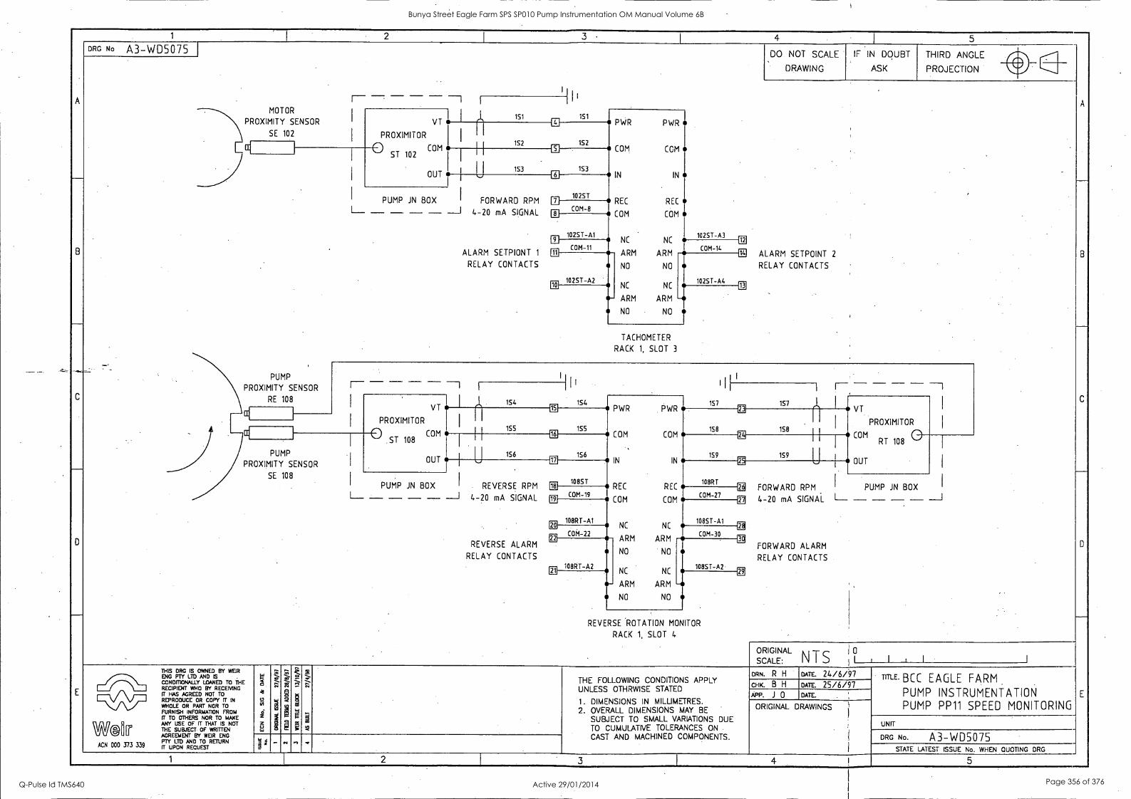
A
8
3 DRG No A3-WD5075
MOTOR
PROXIMITY SENSOR
SE 102
VT
PROXIMITOR
ST 102 COM
PUMP
PROXIMITY SENSOR
RE 108
o
OUT
151
152
PUMP JN BOX FORWARD RPM - - - - 4-20 mA SIGNAL
ALARM SETPIONT 1
RELAY CONTACTS
La
111
IO
8
111
151
152
153
1025T
COM-8
1025T-Al
COM-11
PWR PWR
COM COM
IN I Ni
REC REC
COM COM
102ST-A2
NC
ARM
NO
NC
0- ARM
NO
NC
ARM
NO
NC
ARM
NO
TACHOMETER
RACK 1, SLOT 3
4
DO NOT SCALE
DRAWING
IF IN DOUBT
ASK
5
THIRD ANGLE
PROJECTION
ALARM SETPOINT 2
RELAY CONTACTS
PUMP
PROXIMITY SENSOR
SE 108
VT
PROXIMITOR
0 COM ST 108
OUT
1S4
155
1S6
PUMP JN BOX REVERSE RPM - - ---I 4-20 mA SIGNAL
REVERSE ALARM
RELAY CONTACTS
113
E1
18
1S4
155
156
1085T
PWR PWR
COM C 0 M
IN
1E1
COM-19
108RT-Al
CO M- 22
REC
COM
108RT-A2
NC
ARM
NO
IN
157
158
1S9
EE
1
REC 08RT
COM COM-27
NC
ARM
NO
NC NC
s- ARM ARM - NO NO
1085T-Al
COM-30
108ST-A2
REVERSE ROTATION MONITOR
RACK 1, SLOT 4
157
158
EE
EE
EE
EE
159 U
FORWARD RPM
4-20 mA SIGNAL
FORWARD ALARM
RELAY CONTACTS
VT
PROXIMITOR
COM 0 RT 108
OUT
PUMP JN BOX
L - - - - _J
SCALE:
ORIGINAL NTS
0
ACN 000 373 339
THIS DRG IS OWNED BY WEIR ENG PTY LTD AND IS CONDMONALLY LOANED TO THE RECIPIENT WHO BY RECENING IT HAS AGREED NOT TO REPRODUCE OR COPY IT IN
WHOLE OR PART NOR TO FURNISH INFORMATION FROM IT TO OTHERS NOR TO MAKE ANY USE OF IT THAT IS NOT THE SUBJECT. OF WRITTEN AGREEMENT BY WEIR ENG PTY LTD AND TO RETURN IT UPON RECUEST
9
I ve
THE FOLLOWING CONDITIONS APPLY UNLESS OTHRWISE STATED
1. DIMENSIONS IN MILLIMETRES. 2. OVERALL DIMENSIONS MAY BE
SUBJECT TO SMALL VARIATIONS DUE TO CUMULATIVE TOLERANCES ON
CAST AND MACHINED COMPONENTS.
DRN. R I-1 DATE. 24/6/97 CHK. B H DATE. 25/6/97 APP. J 0 DATE.
ORIGINAL DRAWINGS
TITLE. BCC EAGLE FARM
PUMP INSTRUMENTATION PUMP PP11 SPEED MONITORING
UNIT
DRG No. A3-WD507S STATE LATEST ISSUE No. WHEN QUOTING DRG
1 2 3 4 5
Bunya Street Eagle Farm SPS SP010 Pump Instrumentation OM Manual Volume 6B
Q-Pulse Id TMS640 Active 29/01/2014 Page 356 of 376
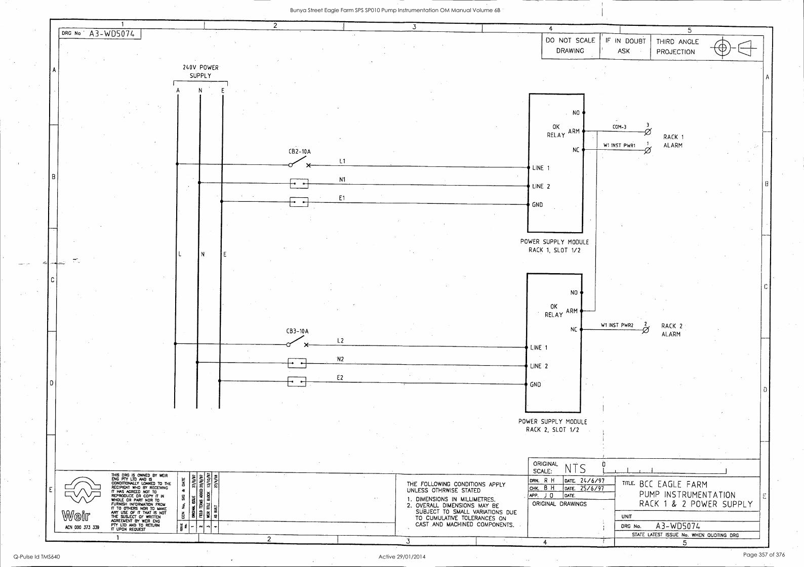
1 2 1 3 4 5
A
C
DRG No A3-WD5074 .
DO NOT SCALE IF IN DOUBT
ASK
THIRD ANGLE
A
__
B
C
-
D
_
E
PROJECTION NDDRAWING
240V POWER
SUPPLY
,
CB2-10A
Ll
NO
OK ARM
RELAY
NC
LINE 1
LINE 2
GND
COM-3
RACK 1
wi INST PWR1 1 ALARM
L
N1
N
- El
1-* -
POWER SUPPLY MODULE
RACK 1, SLOT 1/2 E
CB3-10A
L2
NO
OK ARM
RELAY
NC
LINE 1
LINE 2
GNU
W1 INST PWR2 2 RACK 2
ALARM
N2 *--I
E2
POWER SUPPLY MODULE
RACK 2, SLOT 1/2
SCALE:
ORIGINAL N T S IIILI
THIS DRG IS OWNED BY WEIR ENG PTY LTD AND 5 CONDITIONALLY LOANED TO THE RECIPIENT WHO BY RECEIVING fT HAS AGREED NOT TO REPRODUCE OR COPY fT IN WHOLE OR PART NOR TO FURNISH INFORMATION FROM IT TO OTHERS NOR TO MAKE
War ANY USE OF IT THAT 5 NOT THE SUBJECT OF WRITTEN AGREEMENT BY WEIR ENG PTY LTD AND TO RETURN
ACN 000 373 339 fr UPON REQUEST
"c
41
0 iii
z
ZZSZ 7.:-. ,..
I
7.--. ..
5' V
i
..; -
' g
;7::
-
DRN. R H DATE. 24/6/97 TITLE. BCC EAGLE FARM
PUMP INSTRUMENTATION RACK 1 & 2 POWER SUPPLY
THE FOLLOWING CONDITIONS APPLY UNLESS OTHRWISE STATED CHK. B H DATE 25/6/97
APP. J 0 DATE. 1. DIMENSIONS IN MILLIMETRES. 2. OVERALL DIMENSIONS MM' BE
SUBJECT TO SMALL VARIATIONS DUE TO CUMULATIVE TOLERANCES ON CAST AND MACHINED COMPONENTS. ,
ORIGINAL DRAWINGS
UNIT
. - .., .1 , DRG No. A3-WD5074 STATE LATEST ISSUE No. WHEN QUOTING ORG
1 2 3 4 I 5
Bunya Street Eagle Farm SPS SP010 Pump Instrumentation OM Manual Volume 6B
Q-Pulse Id TMS640 Active 29/01/2014 Page 357 of 376
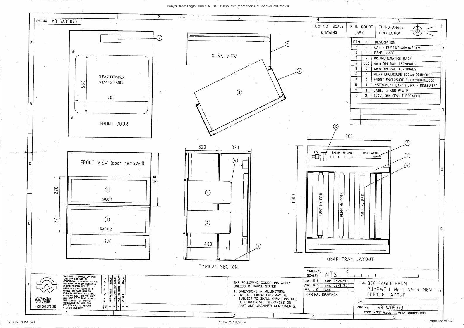
1 I 2 - 3 4 5
A
__
B
_
C
.---,
D
E
DRG No A3-WD5073 DO NOT SCALE
DRAWING
IF IN DOUBT
ASK
THIRD ANGLE
A
PROJECTION low
0 1 ll
0 ITEM No DESCRIPTION
PLAN VIEW
-
1 - CABLE DUCTING-40mmx50mm .
O 2 1 PANEL LABEL
3 2 INSTRUMENATION RACK
c) LLn n
CLEAR PERSPEX
VIEWING PANEL
700
4 330 4mm DIN RAIL TERMINALS
5 4 4mm DIN RAIL TERMINALS 0
0
b 1 REAR ENCLOSURE 800Wx1000Hx300D 7 1 FRONT ENCLOSURE 800Wx1000Hx300D 1- 8 1 INSTRUMENT EARTH LINK - INSULATED 9 1 CABLE GLAND PLATE
10 2 240V, 10A CIRCUIT BREAKER
) B I
o
FRONT DOOR 0 800
1-1 "1 0 320 320 h
0 0
PT4
E E /LINK N /LINK INST EARTH
FRONT VIEW (door removed)
o
I
I
I
Cl O I I
4
CI) C) cp ---
.
C
__,
D
-
0= o_
0 z o_ x 0_
- r, 0= a. o z
o_ r = o_
-
- fn CI o_
o z n_
= o_
- 0 r-- (-4
Ln
RACK 1
0 I
c7:. r-- c--.1
RACK 2
0 fl
f 400
u U 720
- _.- - -._...-_-
-1 GEAR TRAY LAYOUT -- TYPICAL SECTION
ORIGINAL
1., I i I I SCALE: NTS ° THIS DRG IS OWNED BY WEIR
11413PMOZYANIANISED TO THE RECIPIENT WHO BY RECEMNG IT HAS AGREED NOT TO REPRODUCE OR COPY IT IN WHOLE OR PART NOR TO FURNISH INFORMATION FROM
W©ri[r ANY USE OF IT THAT IS NOT THE SUBJECT OF WRITTEN AGREEMENT BY WEIR ENG
ACN 000 373 339 ,F.;rYug, zguTEOSTRETURN
H O
6 4 z ,,,0
s.^ -......
':-
Es
g
Z 1
rd
Z a ,.,
6
. W*
gi ,. ,S
= 2
THE FOLLOWING CONDITIONS APPLY UNLESS OTHRWISE STATED
1. DIMENSIONS IN MILLIMETRES. 2. OVERALL DIMENSIONS MAY BE
SUBJECT TO SMALL VARIATIONS DUE TO CUMULATIVE TOLERANCES ON CAST AND MACHINED COMPONENTS.
DRN. R H DATE. 24/6/97 TITLE. BCC EAGLE FARM
PUMPWELL No 1. INSTRUMENT CUBICLE LAYOUT
E
CHK B H DATE. 25/6/97 ,
APP. .1 0 DAME
ORIGINAL DRAWINGS
UNIT
DRG No. A3-WD5073 '4 4 g
- ,.., ,., - .,
STATE LATEST ISSUE No. WHEN QUOTING DRG 1 2 3 4 I 5
Bunya Street Eagle Farm SPS SP010 Pump Instrumentation OM Manual Volume 6B
Q-Pulse Id TMS640 Active 29/01/2014 Page 358 of 376
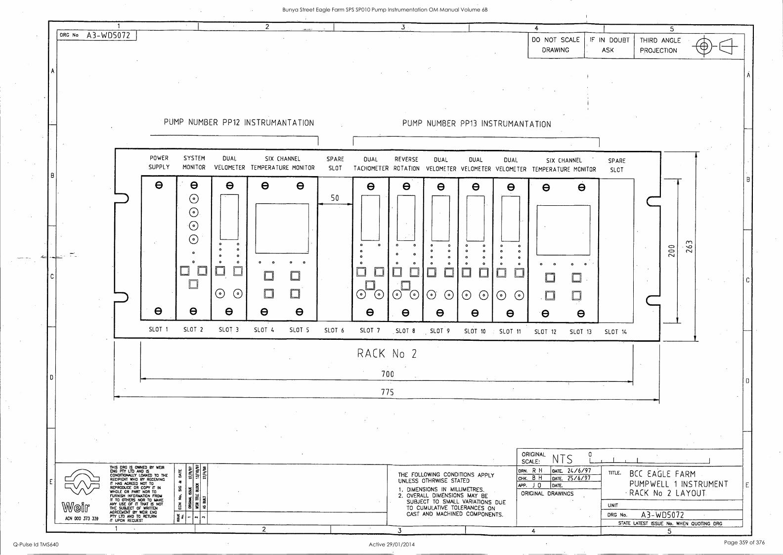
1 2 ---- 3 1 4 1
5
A
B
____
c
-`
0
E
DRG No A3-WD5072 DO NOT SCALE
DRAWING
IF IN DOUBT
ASK
THIRD ANGLE 111
8
_
c
0
E
PUMP NUMBER
PROJECTION w1
i -
I
PP12 INSTRUMANTATION PUMP NUMBER PP13 INSTRUMANTATION
I I
POWER SYSTEM DUAL SIX CHANNEL SPARE DUAL REVERSE DUAL DUAL DUAL SIX CHANNEL SPARE SUPPLY MONITOR VELOMETER TEMPERATURE MONITOR SLOT TACHOMETER ROTATION VELOMETER VELOMETER VELOMETER TEMPERATURE MONITOR SLOT
e
e
e
0 0 0
o
e e e 50
e e e e l
r sc. C\I
I
...
: CD CV
o o 0 o o o
o o o o o o
.1-
o
-
0
0
17
00
0
0 0
n
0 0
'
0
0
0
0 0
o
0
1-1
0
o
0
17
0
0
0
E
0.
0
0
0
0
0
0
0
0
0
0
0
Fl
0
0
0
ri
0
0
ri 0 0 0
e e e e e e e e e e SLOT 1 SLOT 2 SLOT 3 SLOT 4 SLOT 5 SLOT 6 SLOT 7 SLOT 8 SLOT 9 SLOT 10 SLOT 11 SLOT 12 SLOT 13 SLOT 14
RACK No 2
700
775
ORIG 1 I I , I [ SCALINAE:
L
NTS ° THIS DRG IS OWNED BY WEIR
CONDITIONALLY 131)AN"ED TO THE RECIPIENT WHO BY RECEMNG ET HAS AGREED NOT TO REPRODUCE OR COPY IT IN WHOLE OR PART NOR TO vizsg_ntincrizot FROM
Wear ANY USE OF IT THAT IS NOT THE SUBJECT OF WRETTEN
5 AI
o
i 3 w
a ,-.4 .
1
't .., - g m
;
,S . THE FOLLOWING CONDITIONS APPLY UNLESS OTHRWISE STATED
1. DIMENSIONS IN MILLIMETRES. 2. OVERALL DIMENSIONS MAY BE
SUBJECT TO SMALL VARIATIONS DUE TO CUMULATIVE TOLERANCES ON
DRN. R H OATE. 24/6/97 TITLE. BCC EAGLE FARM
PUMPWELL 1 INSTRUMENT - RACK No 2 LAYOUT
CHK. B H DATE. 2 5/6/9 7
APP. J 0 DATE.
ORIGINAL DRAWINGS
UNIT
DRG No. A3-WD5072 AGREEMENT BY WEIR ENG PTY LTD AND TO RETURN
ACN 000 373 339 if UPON REQUEST 1 ' CAST AND MACHINED COMPONENTS.
STATE LATEST ISSUE No. WHEN QUOTING DRG
1 2 3 4 5 -
Bunya Street Eagle Farm SPS SP010 Pump Instrumentation OM Manual Volume 6B
Q-Pulse Id TMS640 Active 29/01/2014 Page 359 of 376
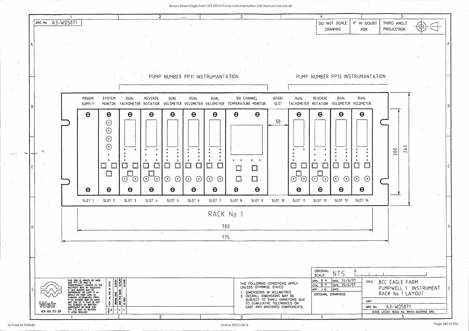
1 I. 2 -
4 I 5.
-
B
....._._
c
D
E
ORG No A3-WD5071 DO NOT SCALE
DRAWING
IF IN DOUBT
ASK
THIRD ANGLE al
A
B
c
D
PROJECTION ir
PUMP NUMBER PP11 INSTRUMANTATION PUMP NUMBER PP12 INSTRUMANTATION
POWER SYSTEM DUAL REVERSE DUAL DUAL DUAL SIX CHANNEL SPARE DUAL REVERSE DUAL DUAL
SUPPLY MONITOR TACHOMETER ROTATION VELOMETER VELOMETER VELOMETER TEMPERATURE MONITOR SLOT TACHOMETER ROTATION VELOMETER VELOMETER
e
e
e 0 0 0 0
e e e e e e e e e e
M 0 CN.J
50
0 CD CN
0 0
0
0 0 0 . 0 0
. 0
0 0 . . 0 0
0 0
0
0 0
0
0 0
0 0
0 0
0 0 0
0
E.
0
0
0 Fl 0
0
0
0
0
0
0
0
0
0
0
0
0
0
0
0
0
0
0
0
0
E
0
0. 0
0
0
Fl
0 0
1-1
E
0
e
0
0
Fl
0 F 0
0
0
0
0
E
0
0
0
0
0
0
0
0
0
0
0
0
0 e e e e e e e e e e e
SLOT 1 SLOT 2 SLOT 3 SLOT If SLOT 5 SLOT 6 SLOT 7 SLOT 8 SLOT 9 SLOT 10 SLOT 11 SLOT 12 SLOT 13 SLOT 14 .
RACK No 1
700 .... .
775
ORIGINAL
SCALE: NTS I I
THIS DRG IS OWNED BY WEIR ENG PTY LTD AND IS CONDMONALLY LOANED TO THE RECIPIENT WHO BY RECEMNG IT HAS AGREED NOT TO REPRODUCE OR COPY IT IN
WHOLE OR PART NOR TO . FURNISH INFORMATION FROM
IT TO OTHERS NOR TO MAKE
til if ANY USE OF IT THAT IS NOT THE SUBJECT OF WRITTEN WO AGREEMENT BY WEIR ENG PTY LTD AND TO RETURN
ACN 000 373 339 R upoN REQUEST
-
41
L7 th-
e; z z o .
.. .. e.
g .., 2 23 g
. - g . e. W
Z ^' .
i *
THE FOLLOWING CONDITIONS APPLY UNLESS OTHRWISE STATED
1. DIMENSIONS IN MILLIMETRES. 2. OVERALL DIMENSIONS MAY BE
SUBJECT TO SMALL VARIATIONS DUE TO CUMULATIVE TOLERANCES ON CAST AND MACHINED COMPONENTS.
DRN. R H DATE. 24/6/97 TITLE. BCC EAGLE FARM
PUMPWELL 1 INSTRUMENT RACK No 1 LAYOUT
CHK. B H DATE. 25/6/97 APP. .1 0 DATE.
ORIGINAL DRAWINGS
UNIT
DRG No. A3-WD5071 s' d 2 ' .- "I r,
STATE LATEST ISSUE No. WHEN QUOTING ORG
1 2 3 I 4 5
Bunya Street Eagle Farm SPS SP010 Pump Instrumentation OM Manual Volume 6B
Q-Pulse Id TMS640 Active 29/01/2014 Page 360 of 376
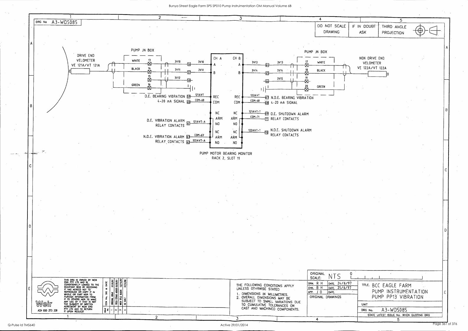
I 2 I
3 - 4 1
5
A
-
B
_
_._
C
D
E
DRG No A3-WD5085 DO NOT SCALE
DRAWING
IF IN DOUBT
ASK
THIRD ANGLE
A
B
--
C
1)
E
PROJECTION Ihir
PUMP JN BOX PUMP JN BOX DRIVE END _ . VELOMETER F WHITE 13
° I 3V10 3V10 (H A (H B
A A
B -
B
REC REC
COM COM
NC NC
ARM ARM
1--- - - - -1 3V13 3V13 P 17 WHITE
'4
NON DRIVE END
I VELOMETER VE 121A/VT 121A
BLACK 14
I n 56
3V14
M I I
18
n 1 VE 122A/VT 122A I
11
3V11 3V11 3V14 BLACK
kr]
C Fib ER N 19
U 15
3V12 3V15
I I
I GREEN 16
IM
I
III 122AVT
M
I
0 I 20 GREEN
2_ _____I
D.E. BEARING VIBRATION
I I I
121AVT 59
L 2 4-20 mA SIGNAL
D.E. VIBRATION ALARM
RELAY CONTACTS
N.D.E. VIBRATION ALARM
RELAY CONTACTS
COM-60 COM-68 ER N.D.E. BEARING VIBRATION
[E 4-20 mA SIGNAL
CE D.E. SHUTDOWN ALARM
i1 RELAY CONTACTS
N.D.E. SHUTDOWN ALARM
RELAY CONTACTS
M
- 121AVT-A
131
121AVT-T
COM -71
NO NO
NC NC 122AVT-T
IX COM-63'
122AVT-A ARM ARM - NO NO EE
PUMP MOTOR BEARING MONITOR
RACK 2, SLOT 11
ORIGINAL SCALE:
A N T S a tItI 1
THIS MG IS OWNED BY WEIR
ZINDPTIZ LMYAND ISED TO THE RECIPIENT WHO BY RECEMNG rr HAS AGREED NOT TO REPRODUCE OR COPY IT IN WHOLE OR PART NOR TO IFTUIZISH INFOFD4A0TRIOPT10 FROME
WAP ANY USE OF rT THAT IS NOT THE SUBJECT OF WRITTEN AGREEMENT BY WEIR ENG
ACN 000 373 339 Tr A) 1,11LTEOsTRETURN
5 Jel
g
Z 4
6 w
T;
"
f.5
a.
Zr, t " § S g 0
g
t .-, -
I
ill ,S "
:
THE FOLLOWING CONDITIONS APPLY UNLESS OTHRWISE STATED
1. DIMENSIONS IN MILLIMETRES. 2. OVERALL DIMENSIONS MAY BE
SUBJECT TO SMALL VARIATIONS DUE TO CUMULATIVE TOLERANCES ON CAST AND MACHINED COMPONENTS.
DRN. R H DATE. 24/6/97 TITLE. BCC EAGLE FARM
PUMP INSTRUMENTATION PUMP PP13 VIBRATION
CHK. B H DATE. 25/6/97 P. J 0 DATE.
ORIGINAL DRAWINGS
UNIT
DRG No. A3-WD5085 NI 2
_ .., ... . STATE LATEST ISSUE No. WHEN QUOTING DRG
1 2 3 4 5 -
Bunya Street Eagle Farm SPS SP010 Pump Instrumentation OM Manual Volume 6B
Q-Pulse Id TMS640 Active 29/01/2014 Page 361 of 376
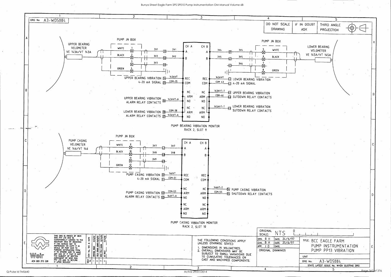
1 2 I_ 3
I 4 I 5
A
B
_
_
C
-
D
E
ORG No A3-WD5084 DO NOT SCALE
DRAWING
IF IN DOUBT
ASK
THIRD ANGLE
A
.
3
C
-
D
E
PROJECTION 0 Ca
PUMP JN BOX PUMP JN BOX
UPPER BEARING - - --1 VELOMETER P WHITE 1 I
3V1 3V1
CH A CH B
A A
B B
REC REC
COM COM
NC NC
,
3V4 3W.
- - - -1 5 WHITE
LOWER BEARING I VELOMETER VE 143A/VT 143A
I
N I I
BLACK I
VE 145A/VT 145A BLACK 3V2 3V2 3V5 3V5 1 1r C ffl 0
1 1
3V6
ei 7
..
I
3V3 E GREEN 4
ti/
I 1
143AVT
II 145AVT
3 I
ei 8 GREEN
PUMP CASING
VELOMETER
L__ _ UPPER
UPPER
ALARM
LOWER
ALARM
PUMP IN - F WHITE
N ___I
BEARING
4-20
BEARING
RELAY
BEARING
RELAY
BOX
ill '2 1 ___ 1 g LOWER BEARING VIBRATION VIBRATION
mA SIGNAL
VIBRATION
CONTACTS
VIBRATION
CONTACTS
COM-35 COM 43 Q 4 20 mA SIGNAL g
-, 143AVT -A
143AVT-T -g BEARING UPPER VIBRATION COM-46 g SUTDOWN RELAY CONTACTS ARM ARM
NO NO
NC NC
ARM ARM
ff3
COM-38
145AVT-T LOWER BEARING VIBRATION SUTDOWN RELAY CONTACTS
PUMP CASING VIBRATION SHUTDOWN RELAY CONTACTS
-- tE A 145AVI-
NO NO ffi
PUMP BEARING VIBRATION MONITOR
RACK 2, SLOT 9
- 7 9 I 3V7 3V7
CH A CH B
A A VE 146/VT 146 f 11 I BLACK
1
10 I n
3V8 8 B
3V8
I 11
I I I I U 3V9
I GREEN
@
12 I
'III L _ 0 146VT
REC PUMP CASING VIBRATION
4-20 mA SIGNAL
m 51 COM-
REC
COM ® COM
146VT-T
COM-53 NC NC 43
COM-55 PUMP CASING VIBRATION 1 146VT-A ALARM RELAY CONTACTS
ARM ARM M er NO NO
NC NC
ARM ARM
NO NO
PUMP CASING VIBRATION MONITOR
RACK 2, SLOT 10
ORIGINAL 0
SCALE: NTS 1 I I THIS CRC IS OWNED BY WEIR
ALL LON MD% L'yAND ISED TO THE RECIPIENT WHO BY RECEIVING CT HAS AGREED NOT TO REPRODUCE OR COPY IT IN WHOLE OR PART NOR TO FrrUftns,,11izsoR),i4tTRIO1 FROM
We01 [r ANY
LZ413T ITOF7vil IS NOT AGREEMENT BY WEIR ENG
ACN 000 373 339 rug LTD AND JTEOSTRETURN
5 AI
52 vi 4
5 4,
;1"
:.,. '' w g
17;
i Q c 0
S 5-;
kd 7' -I THE FOLLOWING CONDITIONS APPLY
UNLESS OTHRWISE STATED
1. DIMENSIONS IN MILLIMETRES. 2. OVERALL DIMENSIONS MAY BE
SUBJECT TO SMALL VARIATIONS DUE TO CUMULATIVE TOLERANCES ON CAST AND MACHINED COMPONENTS.
ORM R H DATE. 24/6/97 TITLE BCC EAGLE FARM
PUMP INSTRUMENTATION PUMP PP13 VIBRATION
CHK. B H DATE. 25/6/97 APP. J 0 DATE
RI I
ORIGINAL DRAWINGS
UNIT
ORG No. A3-WDS084 4 - . p.., . STATE LATEST ISSUE No. WHEN QUOTING DRG 1 2 3 4 5 ....
Bunya Street Eagle Farm SPS SP010 Pump Instrumentation OM Manual Volume 6B
Q-Pulse Id TMS640 Active 29/01/2014 Page 362 of 376
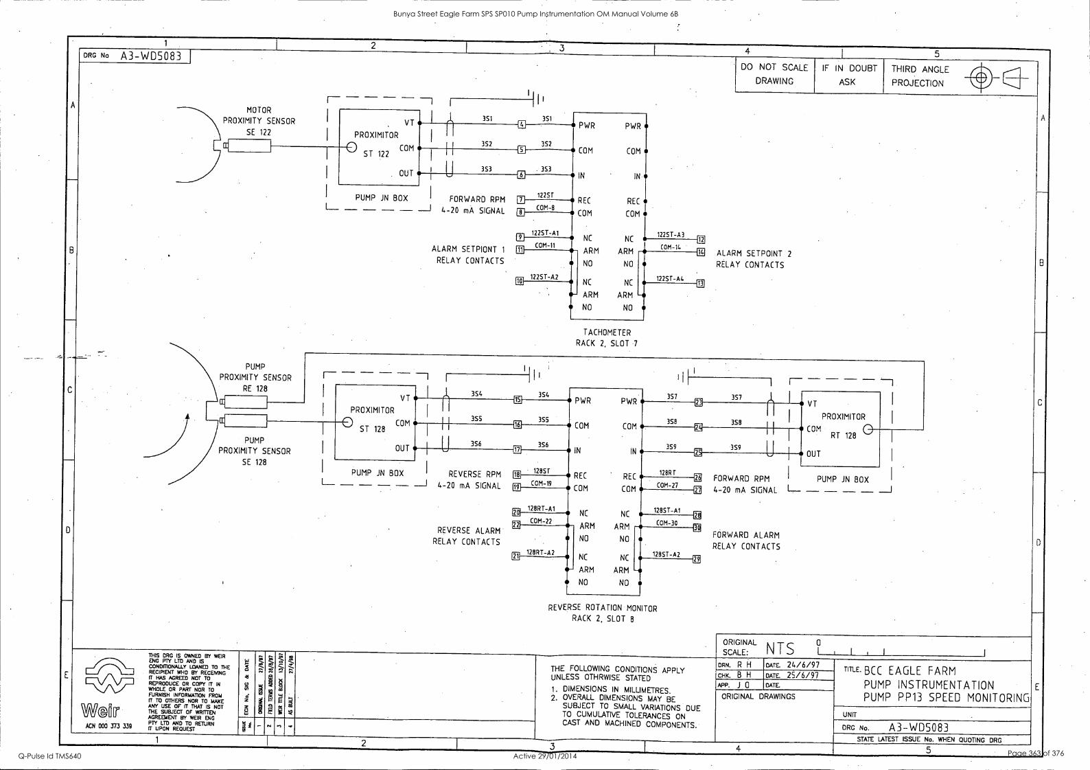
1 I 2
, 3 I_ 4
I 5
A
B
- .-
C
-
D
-
E
DRG No A3-WD5083 DO NOT SCALE
DRAWING
IF IN DOUBT
ASK
THIRD ANGLE
A
B
_
C
-
D
E
PROJECTION 11. ____ ___.
MOTOR
VT
PROXIMITOR
° COM ST 122
OUT
- 351 351 PWR PWR
COM COM
IN ' IN
REC REC
COM COM
NC NC 122S7 -A3
PROXIMITY SENSOR
SE 122 I
352 352
1
I
I
353
1:1
PROXIMITY
PUMP
SENSOR
RE 128
353
I FORWARD RPM
4-20 mA SIGNAL
ALARM SETPIONT 1
RELAY CONTACTS
122ST PUMP JN BOX L_ - - - -) U
COM-8 8
12251-A1 El
COM-11 011
12
COM-14 14
12257 -A2 El
ARM ARM
I NO NO
NC NC
ARM ARM
NO NO
ALARM SETPOINT 2
RELAY CONTACTS
12257 -A4 13
TACHOMETER
RACK 2, SLOT 7
- -1 I _ I
,i, 354
I i
I
1 354 357 357 l. 1 VT
PROXIMITOR
VT
PROXIMITOR
El
355
PWR PWR -
358
EE CC
I 3S5
3S8 COM 0 ST 128
16
356 E
COM COM
359
T 1 1
COM 0 RT 128
OUT I
PUMP
PROXIMITY SENSOR
SE 128
356 U 359
U OUT --- IN IN
REC REC 128RT
23---
PUMP JN BOX I REVERSE RPM 18 12857
FE I PUMP JN BOX I--- - - - - ---1 4-20 mA SIGNAL
REVERSE ALARM
RELAY CONTACTS
i
19 COM-19
COM COM COM-27
FORWARD RPM
4-20 SIGNAL 1- - - - - -1 128RT-A1 m NC NC
12851-Al
gE mA
EC
1E FORWARD ALARM
RELAY CONTACTS
COM-22 COM-30 !II
128RT-A2
ARM ARM
NO NO
12857 -A2 Eli NC NC - ARM ARM
NO NO
EC
REVERSE ROTATION MONITOR
RACK 2, SLOT 8
0 SCALEORIGINAL : N T S I I , I 1 THIS DRG IS OWNED BY WEIR
gO14 cfriZ LTD AND
An D IS ED TO THE RECIPIENT WHO BY RECEMNG IT HAS AGREED NOT TO REPRODUCE OR COPY IT IN WHOLE OR PART NOR TO IFTu.R43/ISH INFORIZIO.4:)FROME
W©ftri ANY USE OF Fr THAT IS NOT THE SUBJECT OF WRITTEN AGREEMENT BY WEIR ENG rPTTY LTD AND
REQUEST RETURN
5 4 g 0 ir
z 8
g ,..
SI2
g
g a
g
,.7' ... 121
R . g p
R'
{
;
..q._
;. ,... THE FOLLOWING CONDITIONS APPLY
UNLESS OTHRWISE STATED
1. DIMENSIONS IN MILLIMETRES. 2. OVERALL DIMENSIONS MAY BE
SUBJECT TO SMALL VARIATIONS DUE TO CUMULATIVE TOLERANCES ON CAST AND MACHINED COMPONENTS.
DRN. R H DATE. 24/6/97 TITLE. BCC EAGLE FARM
PUMP INSTRUMENTATION PUMP PP13 SPEED MONITORING
CHK. B H DATE. 25/6/97 APP. J 0 DATE.
ORIGINAL DRAWINGS
UNIT
DRG No. A3-WD5083 .,
STATE LATEST ISSUE No. WHEN QUOTING DRG 1 2 3 - 4 5
Bunya Street Eagle Farm SPS SP010 Pump Instrumentation OM Manual Volume 6B
Q-Pulse Id TMS640 Active 29/01/2014 Page 363 of 376
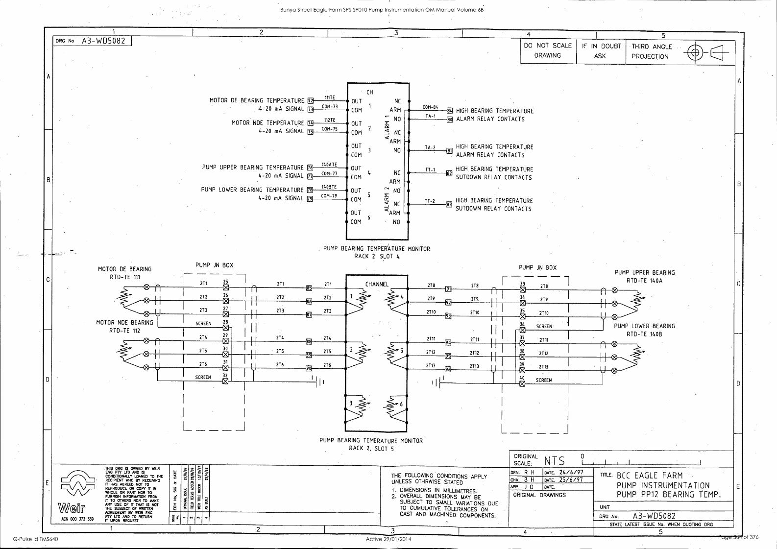
- 1 I I
3 4 1 5
A
-
B
G
D
E
DRG No A3-WD5082 DO NOT SCALE
DRAWING
IF IN DOUBT
ASK
THIRD ANGLE
A
-
B
c
--
D
--
E:
PROJECTION lir
'
MOTOR DE BEARING TEMPERATURE
4-20 mA SIGNAL
MOTOR NDE TEMPERATURE
4-20 mA SIGNAL
PUMP UPPER BEARING TEMPERATURE
4-20 mA SIGNAL .
PUMP LOWER BEARING TEMPERATURE
4-20 mA SIGNAL
PUMP JN BOX MOTOR DE BEARING
.
1117E
CH
OUT NC 1
ARM
ffi COM -73 COM-
m COM-84 HIGH BEARING TEMPERATURE
ALARM RELAY CONTACTS
HIGH BEARING TEMPERATURE
ALARM RELAY CONTACTS
HIGH BEARING TEMPERATURE
SUTDOWN RELAY CONTACTS
HIGH BEARING TEMPERATURE
SUTDOWN RELAY CONTACTS
PUMP JN BOX PUMP UPPER BEARING
112TE M
COM .--
NO OUT z
2 c6.,/
COM j- NC
OUT 3
aARM
NO COM
OUT
COM 4 NC
ARM
OUT r'' NO
COM ' < NC
OUT 6
'ARM COM NO
CO TA-1 g
COM -75 ER
140ATE FE
TA-2 81
T7 -1
I1 COM-77 - TT-2
82
cE
91
CB
14OBTE E ag
COM-79
PUMP BEARING TEMPERATURE MONITOR
RACK 2, SLOT 4
RTD -TE 111 - -
2T1
- 25
26 kTI
27 0 28
0 29 0
271 211 CHANNEL 218 I-- ------ - -2-18
---- 218 RTD -TE 140A
® n 272
LE
272 272 2T9 219 34 1
0 279 ill
U 273
02
213 213 2710 2710 I 35
2110 U 0
MOTOR NDE BEARING SCREEN
CE
2T4 214 CE
al
2711 EE
I
I
-03:1 I
36 SCREEN I PUMP LOWER BEARING
RTD-TE 112
214 2111
0 37
2111
RTD-TE 140B
0 n 275 30
275 275 2T12 2T12
0 38
2712
n 0 0 0
276 31
89
216 216 CE
Eg
2113 2113 Aj 39 2113
SCREEN 32
96 121
40 SCREEN
L ----. L J _ _ _ _I
, _ _ _ _ PUMP BEARING TEMERATURE MONITOR
RACK 2, SLOT 5
SCALE: ORIGINAL
N T S 1 , I , 1 1
THIS ORG IS OWNED BY WEIR
g4DRIONIZANUUED TO THE RECIPIENT WHO BY RECEMNG IT HAS AGREED NOT TO REPRODUCE OR COPY TT IN WHOLE OR PART NOR TO FURNISH igrittTRIolct FROM
WI [11 T ANY USE OF fT THAT IS NOT THE SUBJECT OF RI1TEN AGREEMENT BY WEIR ENG PTY LTD AND TO RETURN
ACN 000 373 339 IT UPON REQUEST
g,
g i z e,
'.7. ....
L:-.2- <..
0-
S
... S ,., (23
g m
p
Z., . 7-7-, -
g
;
SI -.. 4...--
tz,
:
THE FOLLOWING CONDITIONS APPLY UNLESS OTHRWISE STATED
1. DIMENSIONS IN MILLIMETRES. 2. OVERALL DIMENSIONS MAY BE
SUBJECT TO SMALL VARIATIONS DUE TO CUMULATIVE TOLERANCES ON CAST AND MACHINED COMPONENTS.
ORN. R H DATE. 24/6/97 TITLE. BCC EAGLE FARM
PUMP INSTRUMENTATION PUMP PP12 BEARING TEMP.
CHK. B H DATE. 25/6/97 APR J 0 DATE.
ORIGINAL DRAWINGS
UNIT
DRG No. A3-WD5082 j a 1 ' - . n
STATE LATEST ISSUE No. WHEN QUOTING DRG 1 2 3 5
Bunya Street Eagle Farm SPS SP010 Pump Instrumentation OM Manual Volume 6B
Q-Pulse Id TMS640 Active 29/01/2014 Page 364 of 376
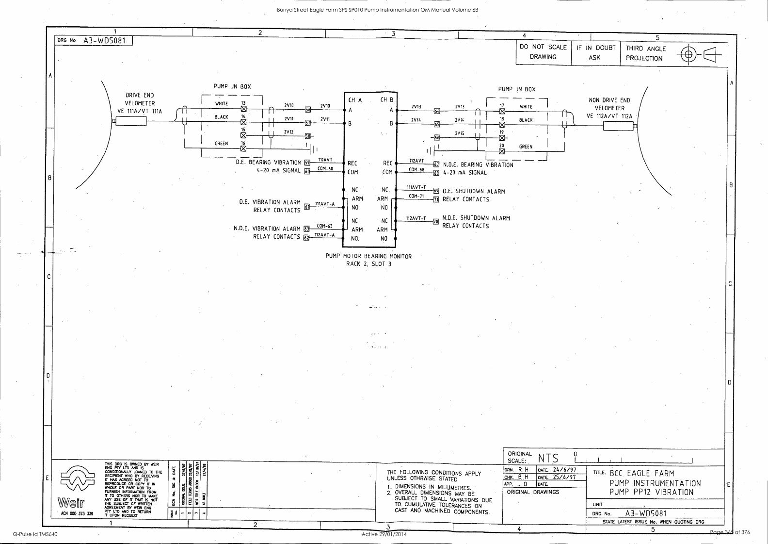
1 1 2
I 3 4
' 1 5
A
-
8
C
D
E
DRG No A3-WD5081 DO NOT SCALE
DRAWING
IF IN DOUBT
ASK
THIRD ANGLE
A
-
8
C
D
E
PROJECTION Ilir
PUMP JN BOX PUMP JN BOX DRIVE END
VELOMETER
1---
I WHITE 13 -- I. 2V10 2V10 CH A CH B
A A
B B
REC REC
COM COM
NC NC
2V13 2V13
- I 17 WHITE
@
NON DRIVE END
I VELOMETER VE 111A/VT 111A BLACK 14 I 9
WE
2V11 2V11
m n 18 BLACK I
VE 112A/VT 112A II 2V14 2Vit.
C. DrJ
0 15
0 gfi EV
W I r 2V12 2V15
I GREEN 16 I
WE
I
1
112AVT
ER 1
1 20 GREEN I c; L _ -D.E.
1 1 1
11IAVT
@ L___ __ ____ ____ ___J
BEARING VIBRATION
4-20 mA SIGNAL
D.E. VIBRATION ALARM
RELAY CONTACTS
N.D.E. VIBRATION ALARM
RELAY CONTACTS
4] COM 60
EE COM-68
N.D.E. BEARING VIBRATION
4-20 mA SIGNAL
D.E. SHUTDOWN ALARM
RELAY CONTACTS
N.D.E. SHUTDOWN ALARM
RELAY CONTACTS
rf
111AVT-A
0:3
111AVT-T .- EC COM -71 e- ARM ARM
NO NO
NC NC
AI
112AVT-T 0-
IN
tE COM-63
El
-- 112AVT-A
ARM ARM
NO. NO [E,'
PUMP MOTOR BEARING MONITOR
RACK 2. SLOT 3
' - ,..... .
ORIGINAL
SCALE: I 1 I 1 I I N T S 0 THIS DRG IS OWNED BY WEIR
gONOPIONTLYMUIDUED TO THE RECIPIENT WHO BY RECENING
ff=OtJtEEPR NOT
N WHOLE OR PART NOR TO FURNISH INFORMATION FROM (T TO OTHERS NOR TO MAKE
W2[Icr ANY USE OF if THAT IS NOT THE SUBJECT OF WRITTEN AGREEMENT BY WEIR ENG PTY LTD AND TO RETURN
ACN 000 373 339 m UPON REQUEST
H g
71
O 2 5 L.,
4.?". ....
,.,
!I la
''' t ..
g M
g
a
-
;
-....
: ,.,
_,..-
g
THE FOLLOWING CONDITIONS APPLY UNLESS OTHRWISE STATED
1, DIMENSIONS IN MILLIMETRES. 2. OVERALL DIMENSIONS MAY BE
SUBJECT TO SMALL VARIATIONS DUE TO CUMULATIVE TOLERANCES ON CAST AND MACHINED COMPONENTS.
ow R H DATE 24/6/97 TITLE. BCC EAGLE FARM
PUMP INSTRUMENTATION PUMP PP12 VIBRATION.
GHK. B H DATE 25/6/97 J 0 DATE.
ORIGINAL DRAWINGS
UNIT
DRG No. A3-WD5081 /4 - .. ...,
STATE LATEST ISSUE No. WHEN QUOTING DRG 1 2
I 4
Bunya Street Eagle Farm SPS SP010 Pump Instrumentation OM Manual Volume 6B
Q-Pulse Id TMS640 Active 29/01/2014 Page 365 of 376
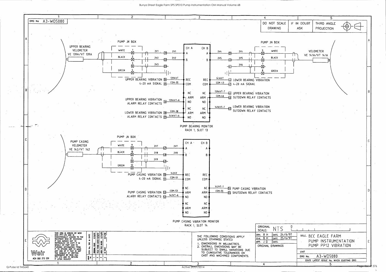
1 I 2
1 4
1 5
A
C
DRG No A3-WD5080 DO NOT SCALE
DRAWING
IF IN DOUBT
ASK
THIRD ANGLE il.
A
_
----
C
_
0
_
E
PROJECTION vl
PUMP JN BOX PUMP JN BOX
UPPER BEARING _ _
VELOMETER 1 WHITE 1
2V1 2V1 '
CH A CH B
A A
B B
REC REC
COM COM
NC NC
2V4 2V4 I 5 WHITE I VELOMETER 0 VE 139A/VT 139A
0 RI
2V2 2V5
al n VE 141A/VT 141A BLACK
LC
BLACK 2V2 2V5 - 4 f w III
GREEN
2V3 2V6 0 4
@II
111
141AVT
41
1 GREEN I
.
PUMP CASING
VELOMETER
I__. _ UPPER
UPPER
ALARM
LOWER
ALARM
PUMP JN
P'
VIBRATION
I
M 139AVT
M 1 ° - I
BEARING
4-20 mA SIGNAL
BEARING VIBRATION
RELAY CONTACTS
BEARING VIBRATION
RELAY CONTACTS
BOX
COM-35 COM 43 LOWER BEARING VIBRATION
g 4-20 mA SIGNAL
EE UPPER BEARING VIBRATION
3] SW-DOWN RELAY CONTACTS
LOWER BEARING VIBRATION Mi
SUTDOWN RELAY CONTACTS
., PUMP CASING VIBRATION
SHUTDOWN RELAY CONTACTS
g
139AVT-A 02
139AVT -T 1
COM-46 - ARM ARM
NO NO
NC NC 141AVT-T
COM-38 El --
141AVT-A ARM ARM
NO NO lib
PUMP BEARING MONITOR
RACK 1, SLOT 13
r- - -1 I WHITE 9 I 2V7 2V7
A ' CH B
VE 142/VT 142 f n e BLACK 10
n Lt
2V8
A U
2V8 CC co 11 B B
I
U 2V9
Ig 1
I GREEN 12 I
III I _ _ _ __I L e
142VT PUMP CASING VIBRATION
4-20 mA SIGNAL
PUMP CASING VIBRATION
ALARM RELAY CONTACTS
So
COM-51 ® REC REC
COM COM
142VT-T
COM-53 NC. NC
ARM COM-55
IN A 142VT-
ARM 011
al NO NO
NC NC
ARM ARM
NO NO
PUMP CASING VIBRATION MONITOR
RACK 1, SLOT 14 ORIGINAL 0
SCALE: N T S 1 , 1 I
THIS DRG IS OWNED BY WEIR
gUlglyAND LOANED To THE RECIPIENT WHO BY RECEMNG IT HAS AGREED NOT TO REPRODUCE OR COPY IT IN WHOLE OR PART NOR TO iFTURrr(lirvizgrorRiorr40FROME
W121Er ANY USE OF FT THAT IS NOT THE SUBJECT OF WRITTEN AGREEMENT BY WEIR ENG
ACN 000 373 339 IPTTYug MID TO
g
: 0 ii 5 LJ
.7.
z::
N
2
2, 8
'A
il
i g 0
g
t ..i
g ;
Iji
THE FOLLOWING CONDITIONS APPLY UNLESS OTHRWISE STATED
1. DIMENSIONS IN MILLIMETRES. 2. OVERALL DIMENSIONS MAY BE
SUBJECT TO SMALL VARIATIONS DUE TO CUMULATIVE TOLERANCES ON CAST AND MACHINED COMPONENTS.
DRN. R H DATE. 24/6/97 TITLE. BCC EAGLE FARM
PUMP INSTRUMENTATION PUMP PP12 VIBRATION
..;
I
CHK. B H DATE. 25/6/97 APP. J 0 DATE.
ORIGINAL DRAWINGS
UNIT
DRG No. A3-W05080 ~I
STATE LATEST ISSUE No. WHEN QUOTING MG 1 2 3 4 5. -
Bunya Street Eagle Farm SPS SP010 Pump Instrumentation OM Manual Volume 6B
Q-Pulse Id TMS640 Active 29/01/2014 Page 366 of 376
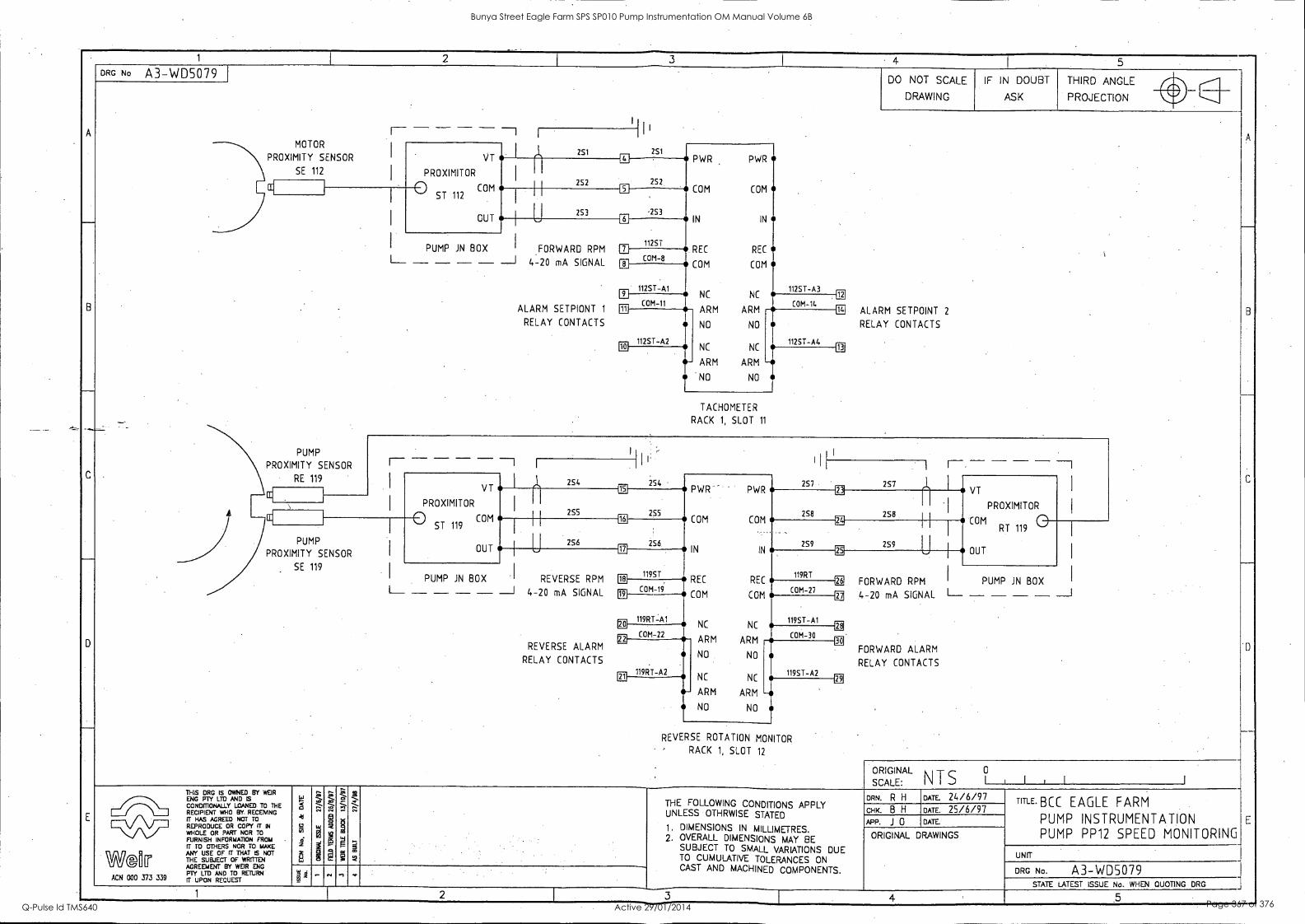
1 2 3 4 I 5
-
B
D
E
DRG No A3-WD5079 DO NOT SCALE
DRAWING
IF IN DOUBT
ASK
THIRD ANGLE
PROJECTION lir
A
B
C
-
D
E
- - - ---1 I Iii MOTOR
VT
PROXIMITOR
0 COM ST 112
OUT
el 251 2S1
PWR PWR
COM COM
IN IN
REC REC
COM COM
NC NC 1125T-A3
PROXIMITY SENSOR
SE 112
252
El
252
I
5
.253
. . - P
PUMP
R O X I M I T Y SENSOR
RE 119
U 253
-
FORWARD RPM
-20 mA SIGNAL
SETPIONT 1
CONTACTS
6
112ST PUMP JN BOX
1--- - - - - --1 4
ALARM
RELAY
El COM-8
1125T-A1 LI
COM-11
12
C
0M-14 14 ill
1125T-A2
ARM ARM
NO NO
NC NC
-- ARM ARM
NO NO
ALARM SETPOINT 2
RELAY CONTACTS
1125T-A4 ID 10
TACHOMETER
RACK 1, SLOT 11
I I
I
I
254
1 1-, --I - - - - VT
254 15 PWR '
2S7 257 ,I, VT
PROXIMITOR PROXIMITOR
PWR
258
E ' I
I
255 255 258 COM ° ST 119
m COM COM .
2S9
EE - COM RT 119 0
OUT PUMP
PROXIMITY SENSOR L
,
2S6 256 17
259 I
OUT IN IN
REC 119RT
EE ,- SE 119
PUMP REVERSE RPM 11:1 1195T.
26
EL
EL
29
I PUMP JN I JN BOX
1.- - - - - -1 4-2 0 mA SIGNAL
REVERSE ALARM
RELAY CONTACTS
19 COM -19
REC
COM COM-27
FORWARD RPM BOX
4-20 mA SIGNAL 1---- - - - - --1
FORWARD ALARM
RELAY CONTACTS
119RT-A1 E1
COM
NC 1195T-A1
COM-22 NC
ARM COM-30 a
119RT-A2 Ell
ARM
NO NO
NC
-4
1195T-A2 NC - ARM ARM
NO NO
-4
REVERSE ROTATION MONITOR
RACK 1, SLOT 12
ORIGINL I , I , 1 SCALE:
A NTS °
THIS DRG IS OWNED BY WEIR ENG FTf LTD AND IS cONDMONALLY LOANED TO THE RECIPIENT WHO BY. RECEIVING
IITEPHItLAJGCZEIODR NCCOITPPTT IN
WHOLE OR PART NOR TO
FURNISH INFORMATION FROM IT TO OTHERS NOR TO MAKE
W@Iffl ANY USE OF TT THAT IS NOT THE SUBJECT OF VIRDTEN AGREEMENT BY WEIR ENG PTY LTD AND TO RETURN
ACN 000 373 339 ff UPON RECUEST
's
4
o
8
r- co ,. 42 ;:.- "
2 1 I
e- o, -... 1173
-;i7 "
g
P
r=f -
;
-... 7:.- THE FOLLOWING CONDITIONS APPLY
UNLESS OTHRWISE STATED
1. DIMENSIONS IN MILLIMETRES. 2. OVERALL DIMENSIONS MAY BE
SUBJECT TO SMALL VARIATIONS DUE TO CUMULATIVE TOLERANCES ON CAST AND MACHINED COMPONENTS.
DRN. R H DATE. 24/6/97 TITLE. BCC EAGLE FARM
PUMP INSTRUMENTATION PUMP PP12 SPEED MONITORING
CHK. B H DATE 25/6/97 APP. J 0 DATE.
ORIGINAL DRAWINGS
uNn-
DRG No. A3-WD5079 - . .1 .. STATE LATEST ISSUE No. WHEN QUOTING DRG
1 2 3 4 .5
Bunya Street Eagle Farm SPS SP010 Pump Instrumentation OM Manual Volume 6B
Q-Pulse Id TMS640 Active 29/01/2014 Page 367 of 376
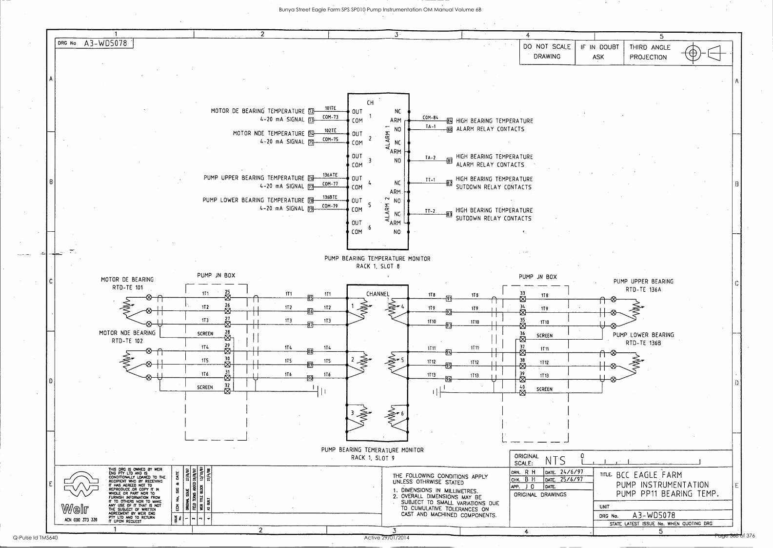
1 2 1
- 5
A
-
B
-
C
-
D
E
DRG Na A3-WD5078 . DO NOT SCALE
- DRAWING
IF IN DOUBT
ASK
THIRD ANGLE
A
--
B
--
c
_-
,
D.
_
E
PROJECTION vir
MOTOR DE BEARING TEMPERATURE ffl MITE
CH
OUT NC 1
ARM COM-84 COM-73 4-20 mA SIGNAL n
gn 102TE MOTOR NDE TEMPERATURE
COM
NO OUT x
= 2 COM n NC
<ARM
OUT 3 NO
COM
OUT
COM 4 NC
ARM.
OUT c" NO 5
COM cc < NC. _1
OUT <ARM
6 COM NO
TA-1 CB HIGH BEARING TEMPERATURE
eE ALARM RELAY CONTACTS
TA-2
4-20 mA SIGNAL
PUMP UPPER BEARING TEMPERATURE
4-20 mA SIGNAL
PUMP LOWER BEARING TEMPERATURE
4-20 mA SIGNAL
LL
75 COM- p§
136ATE m
HIGH BEARING TEMPERATURE 81
ALARM RELAY CONTACTS
HIGH BEARING TEMPERATURE EE
SUTDOWN RELAY
TT-1 COM-77 -
TT-2
Ep
136BTE 0.
CONTACTS
'
ffl COM-79 HIGH BEARING TEMPERATURE
E SUTDOWN RELAY CONTACTS -
PUMP BEARING TEMPERATURE MONITOR
RACK 1, SLOT 8
PUMP JN BOX ,
MOTOR DE BEARING PUMP JN BOX PUMP UPPER BEARING
RTD-TE 101
- 171 . 25 171 111 - CHANNEL 118
- - - - 118 T 33
118
RTD-TE 136A 0 *
112 26
LE
112 112
i a 119 119
n 34 179
n 0 0 0
113 27
CD
173 173
II IMO 1710
0 35
1110 C4
MOTOR NDE BEARING
F2
SCREEN 28
87
H 174 114
93
1711 1111
0 36
SCREEN
U 0 PUMP LOWER BEARING
RTD-TE 102 0
114 29
0 37 1111
RTD-TE 136B
C
115 30 ITS ITS
CE
1112 1112
0 38
0 39
1112
n ®
el.
176 116
ER
1113 1113 1113 C
SCREEN
0 32
il I
I I I
96 0 40
SCREEN I r
I
I
L _J
I
I I L i _ _ _ _
PUMP BEARING TEMERATURE MONITOR
RACK 1, SLOT 9 N 0 ORIGI
:AL NTS 1 . 1 I I SCAL THIS DRG IS OWNED BY WEIR
Nor% °Dv' IS TO THE
RECIPIENT WHO NOT IT HAS AGREED NOT TO
. REPRODUCE ,OR COPY IT IN WHOLE OR PART NOR TO FURNISH IrollSii Tr zorrio FROM
WSOIT ANY USE OF IT THAT IS NOT THE SUBJECT OF WRITTEN AGREEMENT BY WEIR ENG
ACN 000 373 339 rug ituTEOsTRETURN
w 'A
2 tri
4;
3 w
t-e, , 7i
g
g
%;
..;
.., 13
1
m
p
El . .:i -
;
J39 , ,S ,
.
THE FOLLOWING CONDITIONS APPLY UNLESS OTHRWISE STATED
1. DIMENSIONS IN MILLIMETRES. 2. OVERALL DIMENSIONS MAY BE
. SUBJECT TO SMALL VARIATIONS DUE TO CUMULATIVE TOLERANCES ON CAST AND MACHINED COMPONENTS.
DRN. R H DATE. 24/6/97 ,
Trn-E. BCC EAGLE FARM
PUMP INSTRUMENTATION PUMP PP11 BEARING TEMP.
CHK B H DATE 25/6/97 APP. J 0 DATE.
ORIGINAL DRAWINGS
UNIT
DRG No. A3-WD5078 gl la
.- . , ...
STATE LATEST ISSUE No. WHEN QUOTING DRG
1 2 3 4 5 -
Bunya Street Eagle Farm SPS SP010 Pump Instrumentation OM Manual Volume 6B
Q-Pulse Id TMS640 Active 29/01/2014 Page 368 of 376
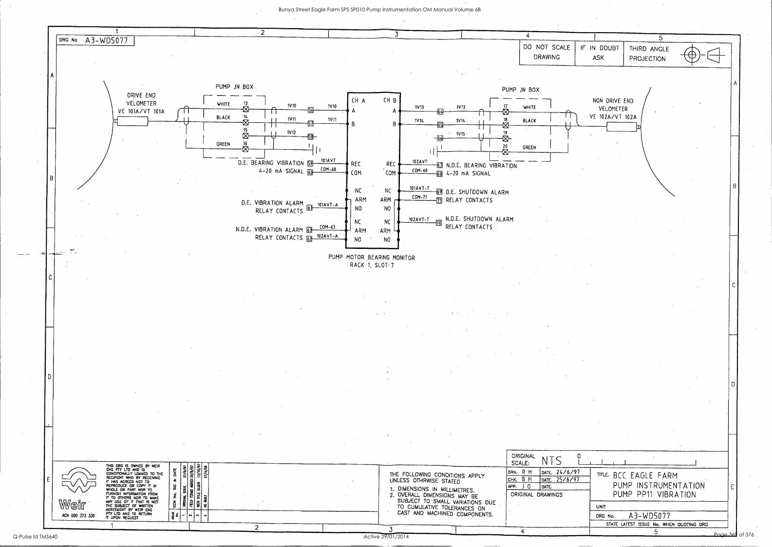
4 1 5
A
-
- -
C
DRG N. A3-WD5077 DO NOT SCALE
DRAWING
IF IN DOUBT
ASK
THIRD ANGLE ig
A
B
-
C
D
E
PROJECTION VI I IP
PUMP JN BOX PUMP JN BOX DRIVE END r - -' VELOMETER
-1 WHITE 13 I
1V10 1V10
CH A CH B
A A
8 B
REC REC
COM COM
NC NC
ARM
r NON DRIVE END 1V13 1V13 17 WHITE -1 VELOMETER
. ra VE 101A/VT 101A f fl 1
I
2)-----n 1L
gg
1V11
it----421 BLACK
VE 102A/VT 102A CC
BLACK 1V11 1V14 1V14 _,18
3:1
U ' Z 1 gi a IN. 19
El I GREEN
15 1
U 1V12
* 1V15 0 16
E ,
-El
II
I 20 GREEN
-
.
L EI 1 i 1 1
101AVT
EL - -D.E. BEARING VIBRATION
4-20 mA SIGNAL
D.E. VIBRATION ALARM
RELAY CONTACTS
N.D.E. VIBRATION ALARM
RELAY CONTACTS
102AVT BEARING VIBRATION 59
COM-60 Ell
COM-68 N.D.E.
4-20 mA SIGNAL
D.E. SHUTDOWN ALARM
RELAY CONTACTS
N.D.E. SHUTDOWN ALARM
RELAY CONTACTS
EE
101AVT-A 131
[ID
101AVT-T PI
COM-71 HI - ARM
NO NO
NC NC
ARM ARM
10 2AVT-T OD
ff COM-63 --*
10 2AVT-A NO ' NO EE
PUMP MOTOR BEARING MONITOR
RACK 1, SLOT 7
ORIGIN AL N T S ° I , I SCALE. I
THIS ORG IS OWNED BY WEIR Eva, LlOyAND ZED THE
RECIPIENT WHO BY RECEIVING
rfriEPICIDUCCREEEODR rOTP;(3rr IN WHOLE OR PART NOR TO FURNISH INFORMATION FROM ri TO OTHERS NOR TO MAKE
WM[r 1r VIBJEICFT ITCIFTZ117BANOT AGREBAENT BY WEIR ENG PTY LTD AND TO RETURN
ACN 000 373 339 IT UPON REQUEST
id
- o x
g
t" .?..
a
P
*"
; s -
THE FOLLOWING CONDITIONS APPLY UNLESS OTHRWISE STATED
1. DIMENSIONS IN MILLIMETRES. 2, OVERALL DIMENSIONS MAY BE
SUBJECT TO SMALL VARIATIONS DUE TO CUMULATIVE TOLERANCES ON CAST AND MACHINED COMPONENTS.
ORN. R H DATE. 24/6/97 TIME' BCC EAGLE FARM
PUMP INSTRUMENTATION PUMP PP11 VIBRATION
CHK. B H DATE. 25/6/97 APP. J 0 DATE
ORIGINAL DRAWINGS
UNIT
DRG No. A3-WD5077 . g
- « n ..
STATE LATEST ISSUE No WHEN QUOTING DRG 1 2
I 3 4 5
Bunya Street Eagle Farm SPS SP010 Pump Instrumentation OM Manual Volume 6B
Q-Pulse Id TMS640 Active 29/01/2014 Page 369 of 376
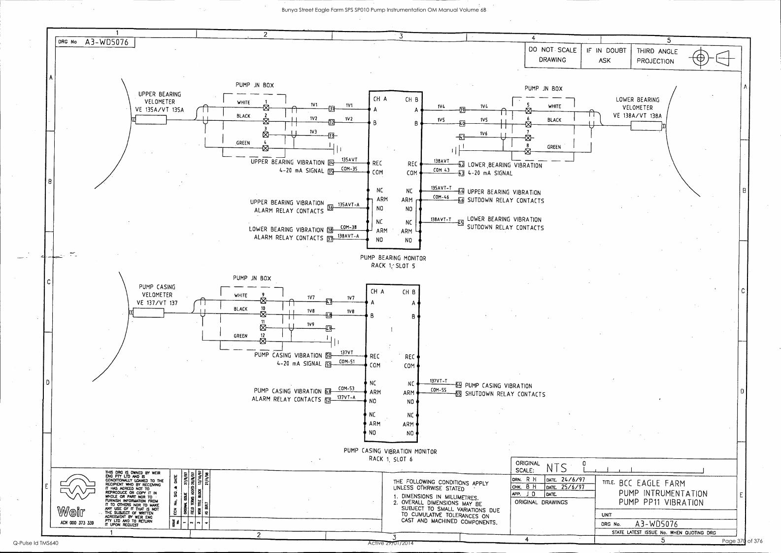
1
4 I 5
A
B
-
E
ORG No A3-WD5076 DO NOT SCALE
DRAWING
IF IN DOUBT
ASK
THIRD ANGLE
A
--
B
C
-
_
E
PROJECTION l' PUMP JN BOX
PUMP JN BOX UPPER BEARING
VELOMETER WHITE 1 ivi ivi CH A
A
CH B
A
B B
REC REC
COM COM
NC NC
iv4 1V4 _ ..
LOWER BEARING WHITE I VELOMETER VE 135A/VT 135A f n E n 1:11
1V2
al
1V5 1V5 1 I
@
6 BLACK VE 138A/VT 138A
CC BLACK 1V2
III U 1
GREEN
3
ffi 1V3 1 t 1V6 1 1
12) I
I
I 7
° 8 GREEN
0 4 I
1.1
I
i 1
138AVT
'
E '1)
.
--_
PUMP CASING
VELOMETER
L _ UPPER
UPPER
ALARM
LOWER
ALARM
PUMP JN - I- WHITE
E 1
__I I I 1
135AVT
I L -E1
IT= LOWER BEARING VIBRATION
BEARING VIBRATION
4-20 mA SIGNAL
BEARING VIBRATION
RELAY CONTACTS
BEARING VIBRATION
RELAY CONTACTS
BOX
T. COM-35 COM 43 31 4-20 mA SIGNAL
UPPER BEARING VIBRATION
SUTOOWN RELAY CONTACTS
LOWER BEARING VIBRATION
SUTOOWN RELAY CONTACTS
PUMP CASING VIBRATION
SHUTDOWN RELAY CONTACTS
M
135AVT-A il3
135AVT-T M
COM-46 -gA --- ARM ARM
NO NO
NC NC
ARM
138AVT-T
COM-38 EU
A 138AVT- -- ARM
NO NO iyj
PUMP BEARING MONITOR
RACK 1; SLOT 5
---i 9 I 1V7 1V7
fsi
CH A CH B
A A VE 137/VT 137 BLACK 10
n 1V8
B 1V8 II k2 LE
3:
B
I
11
fg} 1V9
I I GREEN 12 I
I L_ ksr4
_1 -PUMP 137VT
So REC CASING VIBRATION
4-20 mA SIGNAL
PUMP CASING VIBRATION ALARM RELAY CONTACTS
Si COM -51
REC
COM COM
NC NC 137VT-T
COM-53 ARM
M COM-55 N
137VT- A ARM 4,
NO
.2 , og NO
NC NC
ARM ARM
NO NO
PUMP CASING VIBRATION MONITOR
RACK 1, SLOT 6 ORIGINAL
SCALE: NTS 1 1 , 1 THIS DRG IS O`NNED BY WEIR
FOIJ DPM110ZYMIANISED TO THE RECIPIENT WHO SY RECEIVING IT HAS AGREED NOT TO REPRODUCE OR COPY IT IN WHOLE OR PART NOR TO FURNISH INFORMATION FROM IT TO OTHERS NOR TO MAKE
WO fil TI ANY USE OF IT THAT IS NOT THE SUBJECT a WRITTEN AGREEMENT BY WEIR ENG
339 PTY LTD AND TO RETURN ACN 000 373 3.3v IT UPON REQUEST
g 4
ul
z
Z"
.., I" 4...
§ s
't -,, -
W
R :^.
.
THE FOLLOWING CONDITIONS APPLY UNLESS OTHRWISE STATED
1. DIMENSIONS IN MILLIMETRES. 2. OVERALL DIMENSIONS MAY BE
SUBJECT TO SMALL VARIATIONS DUE TO CUMULATIVE TOLERANCES ON CAST AND MACHINED COMPONENTS.
DRN. R H DATE 24/6/97 TITLE. BCC EAGLE FARM
PUMP INTRUMENTATION PUMP PP11 VIBRATION
CHK. B H DATE. 25/6/97 APP. J 0 DATE.
ORIGINAL DRAWINGS
UNIT
ORG No. A3-WD5076 STATE LATEST ISSUE No. WHEN QUOTING DRG 1 2 3 4 5
Bunya Street Eagle Farm SPS SP010 Pump Instrumentation OM Manual Volume 6B
Q-Pulse Id TMS640 Active 29/01/2014 Page 370 of 376
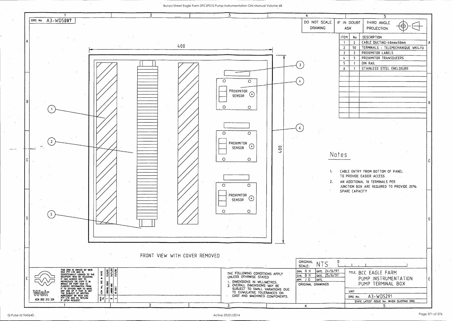
1 I 2 I
3 4 I
5
A
B
_
C
E
DRG No A3-WD5087 DO NOT SCALE
DRAWING
IF IN DOUBT
ASK
THIRD ANGLE 40
A
B
C
D
E
PROJECTION le' ITEM No DESCRIPTION
1 2 CABLE DUCTING-40mmx5Omm 400
2 50 TERMINALS - TELEMECHANIQUE WK 4/U 3 3 PROXIMITOR LABELS
0 4 PROXIMITOR TRANSDUCERS
0
PROXIMITOR
CI
c:) c) -.1-
S 1 DIN RAIL
ri
1111rANNA
6 1 STAINLESS STEEL ENCLOSURE
0
0 P RSOEXNI TRO R SM 01
Notes
0 0
SENSOR Q.)
o o
1. CABLE ENTRY FROM BOTTOM OF PANEL
TO PROVIDE EASIER ACCESS
2. AN ADDITIONAL 10 TERMINALS PER
JUNCTION BOX ARE REQUIRED TO. PROVIDE 20°/0
SPARE CAPACITY
0
0 PROXIMITOR
SENSOR 0 0
FRONT VIEW WITH COVER REMOVED
o
SCALE:
ORIGINAL NTS I I ,
THIS DRG IS OWNED BY WEIR
gm Pr Po' LTD
y AND
ID TO THE RECIPIENT WHO BY RECEMNG IT HAS AGREED NOT TO REPRODUCE OR COPY IT IN WHOLE OR TO
IT TO OTHERS NOR TO MAKE
W2IIP ANY USE OF IT THAT IS NOT THE SUBJECT OF WRITTEN AGREEMENT BY WEIR ENG PTY LTD AND TO RETURN
ACN 000 373 339 FT UPON REQUEST
W
g 4
2 6 z 2 u ta
;_- z . i 3 cs E
:- "..
g
21
,S CM
t.,.
2 *
THE FOLLOWING CONDITIONS APPLY UNLESS OTHRWISE STATED
1. DIMENSIONS IN MILLIMETRES. 2. OVERALL DIMENSIONS MAY 8E
SUBJECT TO SMALL VARIATIONS DUE TO CUMULATIVE TOLERANCES ON CAST AND MACHINED COMPONENTS.
DEM R H DATE. 24/6/97 TITLE. BCC EAGLE FARM
PUMP INSTRUMENTATION PUMP TERMINAL BOX
CHK. B H DATE. 25/6/97 APP. J 0 DATE.
ORIGINAL DRAWINGS
UNIT
DRG No. A3-WDS291 1 4 - ." ' STATE LATEST ISSUE No. WHEN QUOTING DRG
1 2 I 3 4 5
Bunya Street Eagle Farm SPS SP010 Pump Instrumentation OM Manual Volume 6B
Q-Pulse Id TMS640 Active 29/01/2014 Page 371 of 376
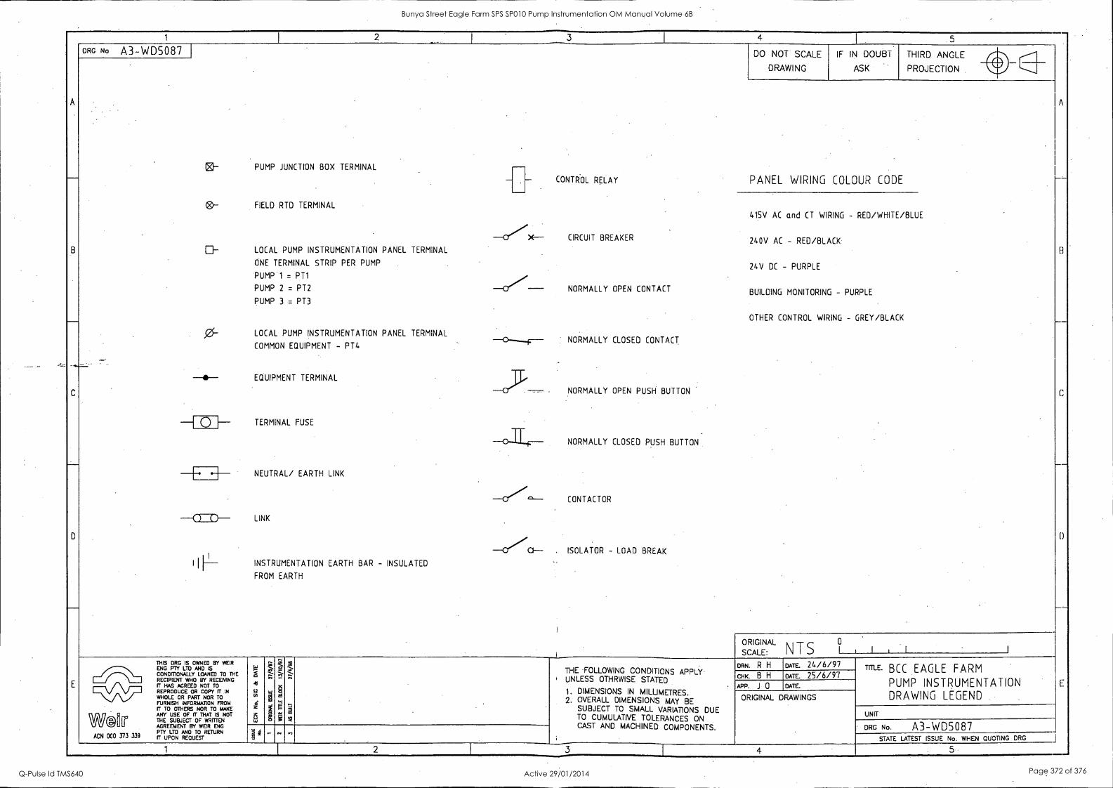
A
-
8
_
-......-__
C
D
E
1 I
2 - I 3 I 4 5
__
8
C
I)
E:
--
DRG No A3-WD5087
PUMP JUNCTION BOX TERMINAL
FIELD RTD TERMINAL
LOCAL PUMP INSTRUMENTATION PANEL TERMINAL
ONE TERMINAL STRIP PER PUMP
PUMP 1 = PT1
PUMP 2 = PT2
PUMP 3 = PT3
LOCAL PUMP INSTRUMENTATION PANEL TERMINAL
COMMON EQUIPMENT - PT4
EQUIPMENT TERMINAL
TERMINAL FUSE
NEUTRAL/ EARTH LINK
LINK
INSTRUMENTATION EARTH BAR - INSULATED
FROM EARTH
-
-0.X--
-0///
-c---F--
-03'
-0-1T-F--
-Vc"--
-CfC1---
- CONTROL RELAY
CIRCUIT BREAKER
NORMALLY OPEN CONTACT
NORMALLY CLOSED CONTACT
NORMALLY OPEN PUSH BUTTON
NORMALLY CLOSED PUSH BUTTON
CONTACTOR
, ISOLATOR - LOAD BREAK
I
DO NOT SCALE
DRAWING
IF IN DOUBT
ASK
THIRD ANGLE "
ca-
ei-
0--
PROJECTION WV
PANEL WIRING COLOUR CODE
415V AC and CT WIRING - RED/WHITE/BLUE
240V AC - RED/BLACK
24V DC - PURPLE
BUILDING MONITORING - PURPLE
OTHER CONTROL WIRING - GREY/BLACK
--0--
-I Q I-
-a:20--
I IP-
SCALE
ORIGINAL
: N T S 1
0
, I , 1 1
.
N#1/2 [11 tr ACN 000 373 339
THIS DRG IS OWNED BY WEIR
gOIDPM73 LTDYAND ISED TO THE RECIPIENT WHO BY RECEMNG fT HAS AGREED NOT TO
FZPORLESIC7ICIEPOAIR2TCri TrO IN rFrUtlISH INFORMATION NR.10 FROM
ANY USE OF IT THAT IS NOT THE SUBJECT OF WRMEN AGREEMENT BY WEIR ENG PTY LTD AND TO RETURN R UPON REQUEST
5 41
Mil 4
6 w
Q :.-_-; n
1
rt -
g
p, 5
,S m
*
THE FOLLOWING CONDITIONS APPLY ' UNLESS OTHRWISE STATED
1. DIMENSIONS IN MILLIMETRES. 2. OVERALL DIMENSIONS MAY BE
SUBJECT TO SMALL VARIATIONS DUE TO CUMULATIVE TOLERANCES ON CAST AND MACHINED COMPONENTS.
DRN. R H DATE. 24/6/97 TIME' BCC EAGLE FARM
PUMP INSTRUMENTATION DRAWING LEGEND
cHK. B H DATE. 25/6/97
APP. J 0 DATE
ORIGINAL DRAWINGS
UNfT
' DRG No. A3-WDS087 N 1 ta
.- n n STATE LATEST ISSUE No. WHEN QUOTING DRG J
1 2 3 4 5
Bunya Street Eagle Farm SPS SP010 Pump Instrumentation OM Manual Volume 6B
Q-Pulse Id TMS640 Active 29/01/2014 Page 372 of 376
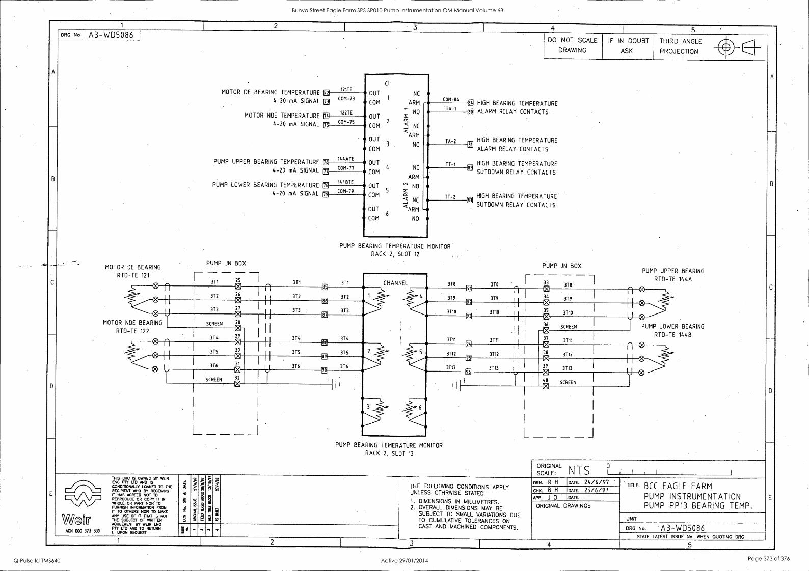
1 4 5
A
DRG No A3-WD5086 . DO NOT SCALE
DRAWING
IF IN DOUBT
ASK
THIRD ANGLE 401
C
E
PROJECTION fir
.
MOTOR DE BEARING TEMPERATURE
4-20 mA SIGNAL
MOTOR NDE TEMPERATURE
4-20 mA SIGNAL
PUMP UPPER BEARING TEMPERATURE
4-20 mA SIGNAL
PUMP LOWER BEARING TEMPERATURE
4-20 mA SIGNAL
_ PUMP iN BOX MOTOR DE BEARING
RTD-TE 121 _
-3 II 371
121TE CH
OUT NC
'
WI COM-73 COM-84
CP HIGH BEARING TEMPERATURE
80 ALARM RELAY CONTACTS
HIGH BEARING TEMPERATURE 81
ALARM RELAY CONTACTS
HIGH BEARING TEMPERATURE CE
SUTDOWN RELAY CONTACTS
HIGH BEARING TEMPERATURE. CE
SUTDOWN RELAY CONTACTS.
PUMP JN BOX PUMP UPPER BEARING - - - -
ig
122TE
ARM COM ,--
NO OUT
COM 2 cZ' NC <
OUT ARM
NO COM
OUT
COM 4 NC
ARM
OUT ''' NO
COM 5
ce
-J NC
OUT <ARM
COM 6
NO
TA -1
- TA-2
W. COM-75 a
144ATE TT-1 m
COM-77 - T7-2
in
14487E 1I
COM -79 COM- El
PUMP BEARING TEMPERATURE MONITOR
RACK 2, SLOT 12
3T1 CHANNEL 3T8 378
I--
I 33 3T8 RTD-TE 144A
n I
0 312 26
n ER
372 312
a in 319 379
I 0
34 379
n 0
373 27
CE
373 313
EE
3710 3710 I I
0 35 3110
U- MOTOR NOE BEARING I
SCREEN
CI
28 I
3T4
CE EX
3711 3711
0 36
SCREEN PUMP LOWER BEARING RTD-TE 122
, 3T4
f3
29 0 30
374
0 37
3T11 RTD-TE 144B : n
315
88
315 375
EE
3712 3T12
0 38
3712
n
376 31
89
376 376
ilii
3713 3713
0, 39 3713
SCREEN 32
VI 02 E 40
SCREEN 0 73
L _ _ _ . L _ _ _ _ i PUMP BEARING TEMERATURE MONITOR
RACK 2, SLOT 13
ORIGINAL NTS
0 SCALE: I I 1 I
THIS DRG IS OWNED BY WEIR
FOIOPMTY0 MYANIANSED TO THE RECIPIENT WHO BY RECEMNG IT HAS AGREED NOT TO REPRODUCE OR COPY IT IN WHOLE OR PART NOR TO FURNISH INFORMATION FROM IT TO OTHERS NOR TO MAKE
Wf@k ANY USE OF R THAT IS NOT THE SUBJECT OF WRITTEN AGREEMENT BY WEIR ENG PTY LTD AND TO RETURN
ACN 000 373 339 IT UPON REQUEST
<
0 n-
8
ZZSZ ..
1PR
S
s
.;; , THE FOLLOWING CONDITIONS APPLY UNLESS OTHRWISE STATED
1. DIMENSIONS IN MILLIMETRES. 2. OVERALL DIMENSIONS MAY BE
SUBJECT TO SMALL VARIATIONS DUE TO CUMULATIVE TOLERANCES ON CAST AND MACHINED COMPONENTS.
DRN. R H DATE. 24/6/97 TITLE. BCC EAGLE FARM
PUMP INSTRUMENTATION PUMP PP13 BEARING TEMP.
CHK. B H DATE. 25/6/97 APP. J 0 DATE.
ORIGINAL DRAWINGS
UNIT
DRG No. - A3-W05086 STATE LATEST ISSUE No. WHEN QUOTING DRG
1 2 3 I 4 5
Bunya Street Eagle Farm SPS SP010 Pump Instrumentation OM Manual Volume 6B
Q-Pulse Id TMS640 Active 29/01/2014 Page 373 of 376
BRISBANE CITY COUNCIL Dept. Water Supply and Sewage Pumpwell No 1, Eagle Farm Pump Station
BCC Contract No S20/95/96 System Instrumentation
Operation and Maintenance Manual
Section 14 Training
Please consult Weir Engineering for Operator and Staff training on 02 4349 2999.
15140/Inst Man/BRH Issue 1 29-Apr-98 Page 14-1
Bunya Street Eagle Farm SPS SP010 Pump Instrumentation OM Manual Volume 6B
Q-Pulse Id TMS640 Active 29/01/2014 Page 374 of 376
BRISBANE CITY COUNCIL Dept. Water Supply and Sewage Pumpwell No 1, Eagle Farm Pump Station
BCC Contract No S20/95/96 System Instrumentation
Operation and Maintenance Manual
Section 15 List of Contract Variations and Plant Modifications
The following plant modifications were made:
1. Accelerometers replaced with Velometers to measure machine vibration.
2. Original pump junction boxes were increased in size to provide better maintenance access.
15140/Inst Man/BRH Issue 1 29-Apr-98 Page 15-1
Bunya Street Eagle Farm SPS SP010 Pump Instrumentation OM Manual Volume 6B
Q-Pulse Id TMS640 Active 29/01/2014 Page 375 of 376

BRISBANE CITY COUNCIL Dept. Water Supply and Sewage Pumpwell No 1, Eagle Farm Pump Station
BCC Contract No S20/95/96 System Instrumentation
Operation and Maintenance Manual
Section 16 Commissioning and Test Reports
A detailed Inspection and Test Plan (ITP) has been prepared for the on site pre- commissioning and commissioning of the pump system. The ITP together with all of the relevant testing data has been included in Volume 3.
15140/Inst Man/BRH Issue 1 29-Apr-98 Page 16-1
Bunya Street Eagle Farm SPS SP010 Pump Instrumentation OM Manual Volume 6B
Q-Pulse Id TMS640 Active 29/01/2014 Page 376 of 376


