Embed Size (px)
Citation preview
; 4
0
...
7-7!*`"' .""` ...
*.
0
I U
I in
/DU
MP E
NST
RU
ME
NT
AT
IION
V
OL
UM
E 6A
CC
CO
NT
RA
CT
N(0). S.20/95/963
Section 1 to 3
i ,
L ;,
wy
,
-.4- -
WE
IR E
IMO
ME
TE
IMO
A
.C.N
. OC
E
Em
tech
Nnt
Bunya Street Eagle Farm SPS SP010 Pump Instrumentation OM Manual Volume 6A
Q-Pulse Id TMS649 Active 29/01/2014 Page 1 of 322

BRISBANE CITY COUNCIL Dept. Water Supply and Sewage Pumpwell No 1, Eagle Farm Pump Station
BCC Contract No S20/95/96 System Instrumentation
Operation and Maintenance Manual
BRISBANE CITY COUNCIL DEPARTMENT OF WATER SUPPLY
AND SEWAGE
PUMPWELL No 1
EAGLE FARM PUMP STATION
PUMP INSTRUMENTATION
OPERATION AND MAINTENANCE MANUAL
Volume 6
WEIR ENGINEERING PTY LTD JOB No 15140
BCC CONTRACT No S20/95/96
Bunya Street Eagle Farm SPS SP010 Pump Instrumentation OM Manual Volume 6A
Q-Pulse Id TMS649 Active 29/01/2014 Page 2 of 322

BRISBANE CITY COUNCIL Dept. Water Supply and Sewage Pumpell No. 1, Eagle Farm Pump Station
BCC Contract No.: S.20/95/96 . Vertical Sewage Pump
Operation and Maintenance Manual
REVISIONS/AMENDMENT CERTIFICATE
It is certified that the amendments promulgated in the undermentioned Amendment List have been incorporated
in this copy of the Publication.
Amendment List Topic/Set
Affected
*Amendment Effect Amended By Date
No. Date of Issue
1
2
3
4
5
6
7
8
9
10
11
12
13
14
15
16
17
18
19
20
*Note: Insert brief details of page(s) amended, inserted or cancelled.
15140.NIAN, ISSUE 2, APRIL 1998
Bunya Street Eagle Farm SPS SP010 Pump Instrumentation OM Manual Volume 6A
Q-Pulse Id TMS649 Active 29/01/2014 Page 3 of 322
BRISBANE CITY COUNCIL Dept. Water Supply and Sewage Pumpwell No 1, Eagle Farm Pump Station
BCC Contract No S20195196 System Instrumentation
Operation and Maintenance Manual
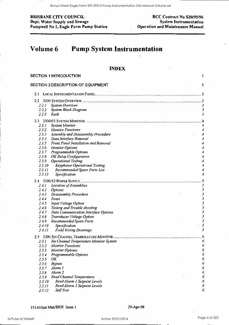
Volume 6 Pump System Instrumentation
INDEX SECTION 1 INTRODUCTION 1
SECTION 2 DESCRIPTION OF EQUIPMENT 1
2.1 LOCAL INSTRUMENTATION PANEL 2
2.2 3300 SYSTEM OVERVIEW 3
2.2.1 System Overview 3
2.2.2 System Block Diagram 3
2.2.3 Rack 3
2.3 3300/03 SYSTEM MONITOR 4 2.3.1 System Monitor 4
2.3.2 Monitor Functions 4
2.3.3 Assembly and Disassembly Procedure 4
2.3.4 Data Interface Removal 4
2.3.5 Front Panel Installation and Removal 4
2.3.6 Monitor Options 4
2.3.7 Programmable Options 4
2.3.8 OK Relay Configuration 4
2.3.9 Operational Testing 4 2.3.10 Keyphasor Operational Testing 4
2.3.11 Recommended Spare Parts List 4
2.3.12 Specification 4
2.4 3300/12 POWER SUPPLY 5
2.4.1 Location ofAssemblies 5
2.4.2 Options 5 2.4.3 Disassembly Procedure 5
2.4.4 Fuses 5
2.4.5 Input Voltage Option 5
2.4.6 Testing and Trouble shooting 5
2.4.7 Data Communication Interface Options 5
2.4.8 Transducer Voltage Option 5
2.4.9 Recommended Spare Parts 5
2.4.10 Specification 5
2.4.11 Field Wiring Drawings 5
2.5 3300 SIX CHANNEL TEMPERATURE MONITOR 6
2.5.1 Six Channel Temperature Monitor System 6
2.5.2 Monitor Functions 6
2.5.3 Monitor Options 6
2.5.4 Programmable Options 6
2.5.5 OK 6
2.5.6 Bypass 6
2.5.7 Alarm 1 6
2.5.8 Alarm 2 6
2.5.9 Read Channel Temperature 6
2.5.10 Read Alarm 1 Setpoint Levels 6
2.5.11 Read Alarm 2 Setpoint Levels 6
2.5.12 Self Test 6
15140/Inst Man/BRH Issue 1 29-Apr-98
Bunya Street Eagle Farm SPS SP010 Pump Instrumentation OM Manual Volume 6A
Q-Pulse Id TMS649 Active 29/01/2014 Page 4 of 322
BRISBANE CITY COUNCIL Dept. Water Supply and Sewage Pumpwell No 1, Eagle Farm Pump Station
BCC Contract No S20/95/96 System Instrumentation
Operation and Maintenance Manual
2.5.13 Error Codes 6
2.6 3300/50 TACHOMETER 7
2.6.1 System Overview Dual Setpoint Tachometer 7
2.6.2 System Overview Zero Speed Tachometer 7
2.63 System Overview Rotor Acceleration Tachometer 7
2.6.4 Monitor Options 7
2.65 Programmable Options 7
2.66 Monitor Functions 7
2.6.7 OK 7
2.68 Bypass Dual Setpoint Tachometer 7
2.6.9 Bypass Zero Speed Tachometer 7
2.6.10 Bypass Rotor Acceleration Tachometer 7
2.6.11 Alert Dual Setpoint Tachometer 7
2.612 Alert Zero Speed Tachometer 7
2.613 Alert Rotor Acceleration Tachometer 7
2.6.14 Read Gap Voltage 7
2.615 Read Setpoints Dual Setpoint Tachometer 7
2.616 Read Setpoints Zero Speed Tachometer 7
2.6.17 Read Setpoints Rotor Acceleration Tachometer 7
2.6.18 Read Peak Hold 8 2.6.19 Reset Peak Hold 8 2.6.20 Enable (Zero Speed Tachometer) 8 2.6.21 Self Test 8 2.6.22 Index 8
2.7 3300/52 REVERSE ROTATION MONITOR 9
2.7.1 Reverse Rotation Monitor System 9 2.7.2 Front Panel Features 9 2.7.3 Monitor Functions 9 2.7.4 Monitor Removal 9 2.7.5 Monitor Disassembly 9 2.7.6 Signal Input Relay Module 9 2.7.7 Monitor Functions 9 2.7.8 OK 9 2.7.9 Alert 9 2.7.10 Bypass 9 2.7.11 Read Setpoints 9 2.7.12 Read Gap Voltage 9 2.7.13 Read Max Reverse/ Peak Hold 9 2.7.14 Reset Max Reverse/ Peak Hold 9 2.7.15 Probe Installation 9 2.7.16 Reverse Rotation Enabled 9 2.7.17 Alert Hysteresis 10 2.7.18 Adjust Alert Setpoints 10 2.7.19 Bypass Alert Relays 10 2.7.20 Bypass Monitor 10 2.7.21 Adjust Threshold and Hysteresis 10 2.7.22 Adjust Full Scale Range 10 2.7.23 Test Trigger OK LED's 10 2.7.24 Test Alerts 10 2.7.25 Self Test 10 2.7.26 Error Codes 10 2.7.27 Recommended Spare Parts List 10 .
2.7.28 Specifications 10 2.7.29 Index 10 2.7.30 Field Wiring Diagram 10
2.8 330525 VELOMETER XA PIEZO VELOCITY SENSOR 11
15140/hist Man/BRH Issue 1 29-Apr-98
Bunya Street Eagle Farm SPS SP010 Pump Instrumentation OM Manual Volume 6A
Q-Pulse Id TMS649 Active 29/01/2014 Page 5 of 322
BRISBANE CITY COUNCIL Dept. Water Supply and Sewage Pumpwell No 1, Eagle Farm Pump Station
BCC Contract No S20/95/96 System Instrumentation
Operation and Maintenance Manual
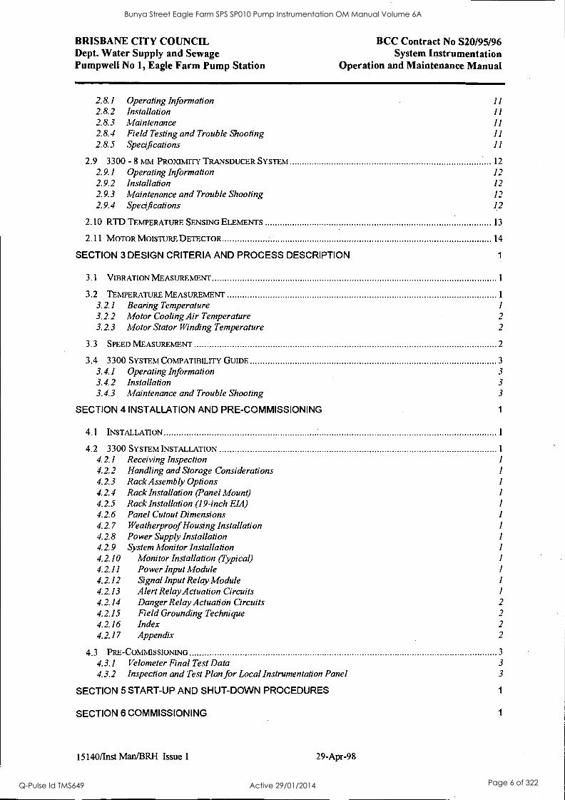
2.8.1 Operating Information 11
2.8.2 Installation 11
2.8.3 Maintenance 11
2.8.4 Field Testing and Trouble Shooting 11
2.8.5 Specifications 11
2.9 3300 - 8 NIM PROXIMITY TRANSDUCER SYSTEM 12
2.9.1 Operating Information 12 2.9.2 Installation 12
2.9.3 Alaintenance and Trouble Shooting 12
2.9.4 Specifications 12
2.10 RTD TEMPERATURE SENSING ELEMENTS 13
2.11 MOTOR MOISTURE DETECTOR 14
SECTION 3 DESIGN CRITERIA AND PROCESS DESCRIPTION 1
3.1 VIBRATION MEASUREMENT
3.2 TEMPERATURE MEASUREMENT 1
3.2.1 Bearing Temperature 1
3.2.2 Motor Cooling Air Temperature 2
3.2.3 Motor Stator Winding Temperature 2
3.3 SPEED MEASUREMENT 2
3.4 3300 SYSTEM COMPATIBILITY GUIDE 3
3.4.1 Operating Information 3
3.4.2 Installation 3
3.4.3 Maintenance and Trouble Shooting 3
SECTION 4 INSTALLATION AND PRE-COMMISSIONING 1
4.1 INSTALLATION
4.2 3300 SYSTEM INSTALLATION 1
4.2.1 Receiving Inspection 1
4.2.2 Handling and Storage Considerations 1
4.2.3 Rack Assembly Options 1
4.2.4 Rack Installation (Panel Mount) 4.2.5 Rack Installation (19-inch EM) 1
4.2.6 Panel Cutout Dimensions 1
4.2.7 Weatherproof Housing Installation 1
4.2.8 Power Supply Installation 1
4.2.9 System Monitor Installation I 4.2.10 Monitor Installation (Typical) 1
4.2.11 Power Input Module 1
4.2.12 Signal Input Relay Module 1
4.2.13 Alert Relay Actuation Circuits 1
4.2.14 Danger Relay Actuafion Circuits 2
4.2.15 Field Grounding Technique 2
4.2.16 Index 2
4.2.17 Appendix 2
4.3 PRE-COMMISSIONING 3
4.3.1 Velometer Final Test Data 3
4.3.2 Inspection and Test Plan for Local Instrumentation Panel 3
SECTION 5 START-UP AND SHUT-DOWN PROCEDURES 1
SECTION 6 COMMISSIONING 1
15140/Inst Man/BRH Issue 1 29-Apr-98
Bunya Street Eagle Farm SPS SP010 Pump Instrumentation OM Manual Volume 6A
Q-Pulse Id TMS649 Active 29/01/2014 Page 6 of 322
BRISBANE CITY COUNCIL Dept. Water Supply and Sewage Pumpwell No 1, Eagle Farm Pump Station
BCC Contract No S20/95/96 System Instrumentation
Operation and Maintenance Manual
SECTION 7 OPERATIONS 1
SECTION 8 MAINTENANCE 1
8.1 TEMPERATURE MONITOR 1
8.1.1 Six Channel Temperature Monitor System 1
8.1.2 Monitor Functions 1
8.1.3 Monitor Options 1
8.1.4 Programmable Options 1
8.1.5 OK 1
8.1.6 Bypass 1
8.1.7 Alarm 1 1
8.1.8 Alarm 2 1
8.1.9 Read Channel Temperature 1
8.1.10 Read Alarm 1 Setpoint Levels 1
8.1.11 Read Alarm 2 Setpoint Levels 1
8.1.12 Self Test 1
8.1.13 Error Codes 1
8.1.14 Disassembly Procedure 2 8.1.15 Recorder/Relay Module 2 8.1.16 Temperature Input Module 2 8.1.17 Installed Program Options 2 8.1.18 RTD Analogue Board Options 2 8.1.19 First Out, Alarm Delays, Alarm 2 Options 2 8.1.20 Transducer Type, OK Options 2 8.1.21 Full Scale, Recorder Options 2 8.1.22 Alarm Setpoint Adjustment 2 8.1.23 Channel Bypass 2 8.1.24 Alarm 2 Bypass 2 8.1.25 Test Channel Alarms - TC 2 8.1.26 Test Channel Alarms - RTD 2 8.1.27 Test OK Limits - TC 2 8.1.28 Test OK Limits - RTD 2 8.1.29 Test OK Limits - TC 2 8.1.30 Test OK Limits - RTD 2 8.1.31 Test/Calibration - TC 2 8.1.32 Test/Calibration - RTD 2 8.1.33 Field Wiring Diagrams 2 8.1.34 Recommended Spare Parts -TC Monitor 2 8.1.35 Recommended Spare Parts - RTD Monitor 2 8.1.36 Specifications 2
8.2 TACHOMETER 3
8.2.1 System Overview Zero Speed Tachometer 3
8.2.2 System Overview Rotor Acceleration Tachometer 3
8.2.3 Front Panel Features - Dual Setpoint Tachometer 3
8.2.4 Front Panel Features - Zero Speed Tachometer 3
8.2.5 Front Panel Features - Rotor Acceleration Tachometer 3 8.2.6 Monitor Removal 3
8.2.7 Monitor Disassembly 3
8.2.8 Signal Input Relay Module 3
8.2.9 Monitor Options 3
8.2.10 Monitor Full Scale Range Adjustment 3
8.2.11 Events per Revolution Adjustment 3
8.2.12 Threshold and Hysteresis Adjustment 3
8.2.13 Alert Hysteresis 3
8.2.14 Adjust Alert Setpoints Dual Setpoint Tachometer 3
8.2.15 Adjust Alert Setpoints Zero Speed Tachometer 3
15140/hist Man/BRH Issue 1 29-Apr-98
Bunya Street Eagle Farm SPS SP010 Pump Instrumentation OM Manual Volume 6A
Q-Pulse Id TMS649 Active 29/01/2014 Page 7 of 322

BRISBANE CITY COUNCIL Dept. Water Supply and Sewage Pumpwell No 1, Eagle Farm Pump Station
BCC Contract No S20/95/96 System Instrumentation
Operation and Maintenance Manual
8.2.16 Adjust Alert Setpoints Rotor Acceleration Tachometer 3
8.2.17 Bypass Dual Setpoint Tachometer 3 8.2.18 Bypass Zero Speed Tachometer 3 8.2.19 Bypass Rotor Acceleration Tachometer 3 8.2.20 Monitor Bypass Dual Setpoint Tachometer 3 8.2.21 Monitor Bypass Zero Speed Tachometer 3
8.2.22 Monitor Bypass Rotor Acceleration Tachometer 3
8.2.23 Test Alert Dual Setpoint Tachometer 3 8.2.24 Test Alert Zero Speed Tachometer 3 8.2.25 Test Alert Rotor Acceleration Tachometer 4 8.2.26 Test Trigger OK's 4 8.2.27 Self Test 4
8.2.28 Wiring Diag - Dual Setpoint Tachometer 4 8.2.29 Wiring Diag - Zero Speed Tachometer 4 8.2.30 Wiring Diag - Rotor Acceleration Tachometer 4
8.2.31 Recommended Spare Parts . 4 8.2.32 Specifications 4
8.2.33 Index 4 8.2.34 Schematics and Technical Drawings 4
8.3 VIBRATION MONITOR 5
8.3.1 Dual Velocity Monitor System 5 8.3.2 Front Panel Features 5 8.3.3 Monitor Removal 5 8.3.4 Monitor Disassembly 5 8.3.5 Signal Input Relay Module 5 8.3.6 Monitor Options 5
8.3.7 Main Board Jumper Locations 5
8.3.8 PK-PK Filter Board Jumper Locations 5 8.3.9 RMS Filter Jumper Locations 5
8.3.10 First Out, Alarm Delays 5 8.3.11 Alert Mode, Danger Mode 5
8.3.12 Danger Relay Voting 5 8.3.13 Buffered Transducer Output Option 5 8.3.14 Transducer Channel Units Input Option 5 8.3.15 Transducer Type Option 5
8.3.16 Channel A Full Scale Range Option 5
8.3.17 Channel B Full Scale Range Option 5
8.3.18 Barriers, Trip Multiply Options 5
8.3.19 Alarm Setpoint Adjustment 5 8.3.20 Bypass Monitor Channel 5 8.3.21 Danger Bypass 5
8.3.22 Test Channel Alarms 6
8.3.23 Test OK Limits 6
8.3.24 Calibrate Channels 6
8.3.25 Filter Programming 6 8.3.26 Self Test 6 8.3.27 Field Wiring Diagram 6
8.3.28 Recommended Spare Parts 6
8.3.29 Specifications 6
8.3.30 Index 6
SECTION 9 FAULT PROTECTION AND RECTIFICATION 1
9.1 ALARM PROTECTION AND SAFETY DEVICES 1
9.2 TROUBLE SHOOTING 1
SECTION 10 ISOLATION AND RESTORATION PROCEDURES 1
15140/Inst Man/BRH Issue 1 29-Apr-98
Bunya Street Eagle Farm SPS SP010 Pump Instrumentation OM Manual Volume 6A
Q-Pulse Id TMS649 Active 29/01/2014 Page 8 of 322
BRISBANE CITY COUNCIL Dept. Water Supply and Sewage Pumpwell No 1, Eagle Farm Pump Station
BCC Contract No S20/95/96 System Instrumentation
Operation and Maintenance Manual
SECTION 11 LIST OF SUB-CONTRACTORS AND PROPRIETARY EQUIPMENT 1
SECTION 12 RECOMMENDED SPARES AND SPECIAL TOOLS 1
SECTION 13 LIST OF ENGINEERING DRAWINGS 1
13.1 PROCESS DRAWINGS 1
13.2 ELECTRICAL SCHEMATIC DRAWINGS 1
SECTION 14 TRAINING 1
SECTION 15 LIST OF CONTRACT VARIATIONS AND PLANT MODIFICATIONS 1
SECTION 16 COMMISSIONING AND TEST REPORTS 1
15140/Inst Man/BRH Issue 1 29-Apr-98
Bunya Street Eagle Farm SPS SP010 Pump Instrumentation OM Manual Volume 6A
Q-Pulse Id TMS649 Active 29/01/2014 Page 9 of 322

BRISBANE CITY COUNCIL Dept. Water Supply and Sewage Pumpwell No 1, Eagle Farm Pump Station
BCC Contract No S20195/96 System Instrumentation
Operation and Maintenance Manual
Section 1 Introduction
The instrumentation supplied with this project is provided to monitor the operational state of both the 6.6kV Crompton Greaves motor and the Weir. Engineering SRA 900/1000 Double Volute Vertical Sewage pumps. This volume should be read in conjunction with Volume 2 - Vertical Sewage Pump Manual and Volume 5 - Crompton Geaves Motor Manual.
The instrumentation monitors the speed, vibration and temperature of the sewage pumps and supplies control/monitoring signals directly to the BCC control system. All control actions, sequencing and data logging derived from this instrumentation is carried out by the BCC control system.
This volume includes details of the following pump instrumentation: Local instrumentation panel housing two Bently Nevada 3300 Monitoring System racks receiving signals for vibration, bearing temperature and machine rotation.
Bently Nevada 330525 Velomitor XA Piezo - Velocity Sensors mounted on the pump and motor to sense machine vibration.
RTD temperature probes mounted on the pump and motor to monitor machine temperature.
Bently Nevada 3300/50 Tachometer to monitor pump and motor speed.
Bently Nevada 3300/52 Reverse Rotation Monitor to detect reverse pump rotation.
Moisture detector in the motor casing to monitor water leakage from the water cooled heat exchanger.
Local junction boxes on the pump and motor to marshal local instrumentation.
15140/Inst Man/BRH Issue 1 29-Apr-98 Page 1-1
Bunya Street Eagle Farm SPS SP010 Pump Instrumentation OM Manual Volume 6A
Q-Pulse Id TMS649 Active 29/01/2014 Page 10 of 322
BRISBANE CITY COUNCIL Dept. Water Supply and Sewage Pumpwell No 1, Eagle Farm Pump Station
BCC Contract No S20/95/96 System Instrumentation
Operation and Maintenance Manual
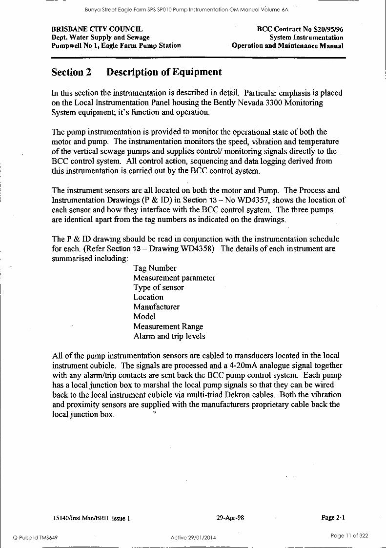
Section 2 Description of Equipment
In this section the instrumentation is described in detail. Particular emphasis is placed on the Local Instrumentation Panel housing the Bent ly Nevada 3300 Monitoring System equipment; it's function and operation.
The pump instrumentation is provided to monitor the operational state of both the motor and pump. The instrumentation monitors the speed, vibration and temperature of the vertical sewage pumps and supplies control/ monitoring signals directly to the BCC control system. All control action, sequencing and data logging derived from this instrumentation is carried out by the BCC control system.
The instrument sensors are all located on both the motor and Pump. The Process and Instrumentation Drawings (P & ID) in Section 13 - No WD4357, shows the location of each sensor and how they interface with the BCC control system. The three pumps are identical apart from the tag numbers as indicated on the drawings.
The P & ID drawing should be read in conjunction with the instrumentation schedule for each. (Refer Section 13 - Drawing WD4358) The details of each instrument are summarised including:
Tag Number Measurement parameter Type of sensor Location Manufacturer Model Measurement Range Alarm and trip levels
All of the pump instrumentation sensors are cabled to transducers located in the local instrument cubicle. The signals are processed and a 4-20mA analogue signal together with any alarm/trip contacts are sent back the BCC pump control system. Each pump has a local junction box to marshal the local pump signals so that they can be wired back to the local instrument cubicle via multi-triad Dekron cables. Both the vibration and proximity sensors are supplied with the manufacturers proprietary cable back the local junction box.
15140/Inst Man/BRH Issue 1 29-Apr-98 Page 2-1
Bunya Street Eagle Farm SPS SP010 Pump Instrumentation OM Manual Volume 6A
Q-Pulse Id TMS649 Active 29/01/2014 Page 11 of 322

BRISBANE CITY COUNCIL Dept. Water Supply and Sewage Pumpwell No 1, Eagle Farm Pump Station
BCC Contract No S20/95/96 System Instrumentation
Operation and Maintenance Manual
2.1 Local Instrumentation Panel
Local instrumentation panel is located on the Pump Drive Motor level in the Pumpwell. It houses two Bent ly Nevada 3300 Monitoring System racks. The Monitoring System receives signals for vibration, bearing temperature and machine rotation. The panel layout is shown in drawing WD5073. (Refer Section 13)
The requirement for rear access to the rack terminals and limited space in the pumpwell resulted in a double hinged panel design to provide access from the front to the rear terminals of the rack modules. A clear perspex-viewing panel in the front door allows observation of the local indication without opening the panel. This maintains the IP65 rating of the panel during normal pump operation.
Each rack is powered via a dedicated MCCB so that they can be individually isolated. There are 7 dedicated slots required for monitoring functions on each pump. They include a tachometer, reverse rotation monitor, 3 dual vibration monitors and a 6- channel temperature monitor. The modules for each pump are grouped together and clearly labeled for ease of identification. The module layout is shown in drawings WD5071 and WD5072. (Refer Section 13)
The control schematics for the instrumentation connected to the Local Instrumentation Panel is shown on drawings WD5074 to WD5087. (Refer Section 13) The interface point for wiring back to the BCC control system is a dedicated terminal strip for each pump located at the back of the control panel.
15140/Inst Man/BRH Issue 1 29-Apr-98 Page 2-2
Bunya Street Eagle Farm SPS SP010 Pump Instrumentation OM Manual Volume 6A
Q-Pulse Id TMS649 Active 29/01/2014 Page 12 of 322
BRISBANE CITY COUNCIL Dept. Water Supply and Sewage Pumpwell No 1, Eagle Farm Pump Station
BCC Contract No S20/95/96 System Instrumentation
Operation and Maintenance Manual
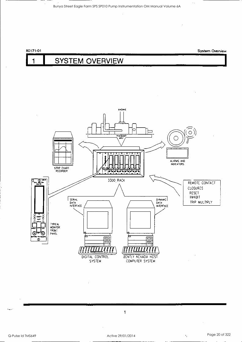
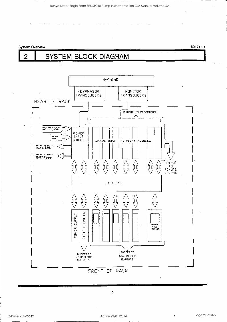
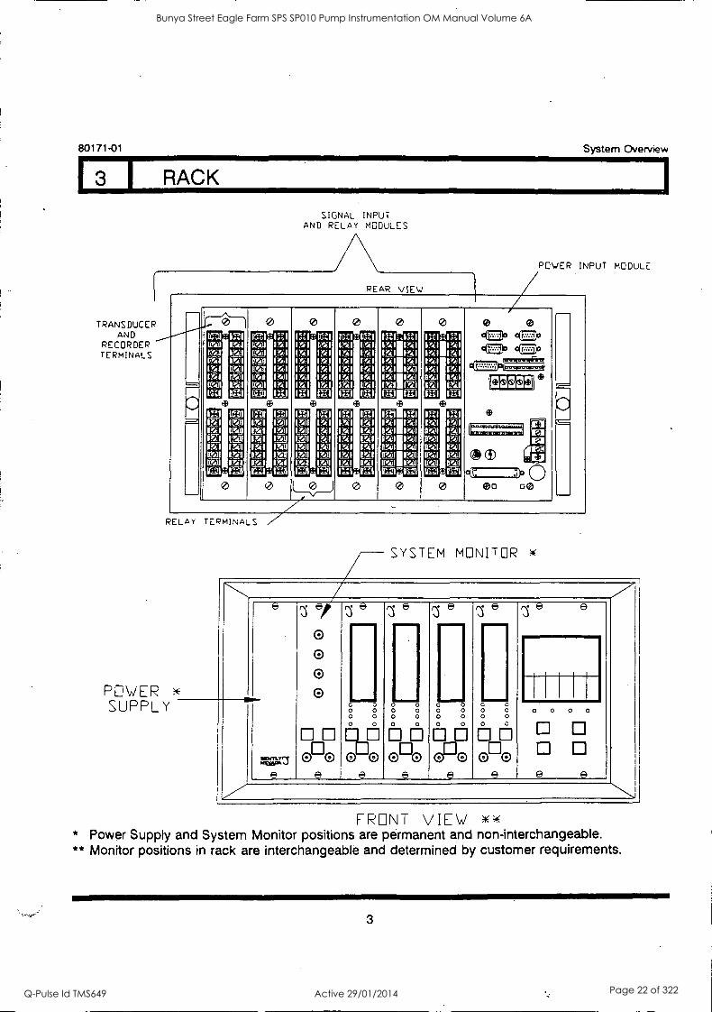
2.2 3300 System Overview
The following publication entitled 3300 System Overview (Part No 80171-01 Rev D) prepared by Bently Nevada provides a brief system overview of their 3300 monitoring system. A standard block diagram showing the system operation and a typical rack layout detail is provided.
The following sections are included:
2.2.1 System Overview
2.2.2 System Block Diagram
2.2.3 Rack
15140/Inst Man/BRH Issue 1 29-Apr-98 Page 2-3
Bunya Street Eagle Farm SPS SP010 Pump Instrumentation OM Manual Volume 6A
Q-Pulse Id TMS649 Active 29/01/2014 Page 13 of 322
3300 SYSTEM OVERVIEW
BENTLY(N NEVADA tJ
MADE IN U SA
PART NO. 80171 -01
REVISION D, MARCH 1994
e e
:
&See 00 %
Bunya Street Eagle Farm SPS SP010 Pump Instrumentation OM Manual Volume 6A
Q-Pulse Id TMS649 Active 29/01/2014 Page 14 of 322
fi
System Overview 80171-01
NOTICE
READ THE FOLLOWING BEFORE INSTALLING OR OPERATING EQUIPMENT
Bent ly Nevada Corporation has attempted to identify areas of risk created by improper installation and/or operation of this product. These areas of information are noted as WARNING or CAUTION for your protection and for the safe and effective operation of this equipment. Read all instructions before installing or operating this product. Pay particular attention to those areas designated by the following symbols.
WARNING High Voltage present Could cause shock, bums or death.
Do Not touch exposed wires or terminals.
CAUTION Machine protection will be lost during calibration.
Keyphasor® is a registered trademark of Bent ly Nevada Corporation
Proximitor® is a registered trademark of Bent ly Nevada Corporation
Copyright() 1987, 1990, 1991, 1992, 1994 Bently Nevada Corporation
All Rights Reserved No part of this publication may be reproduced, transmitted, stored In a retrieval system nor translated into any human or computer language, In any form or by any means, electronic, mechanical, magnetic, optical, chemical, manual, or otherwise, without the prior written permission of the copyright owner,
Bently Nevada Corporation P.O. Box 157
Minden, Nevada 89423 USA Telephone 800-227-5514 702-782-3611
Telex 7400983 BNC UC Fax 702-782-9253
Copyright infringement is a serious matter under United States of America and Foreign Copyright Laws
Bunya Street Eagle Farm SPS SP010 Pump Instrumentation OM Manual Volume 6A
Q-Pulse Id TMS649 Active 29/01/2014 Page 15 of 322
80171-01 System Overview
FOREWORD
This document is intended for personnel who operate the 3300 Monitoring System. The procedures are presented in step-by-step graphic format.
RELATED DOCUMENTS
3300 System Installation Instructions, 80172-01
3300 System Troubleshooting, 80173-01
3300/12 AC Power Supply, 89602-01
3300/03 System Monitor, 89604-01
Keyphasor ® and Proximitor are registered tradmarks of Bent ly Nevada Corporation
SYMBOLS Special symbols are used in the manual to illustrate specifics in the step-by-step process. For example:
PRESS FLASHING CONNECT DISCONNECT OBSERVE SCREWDRIVER
iii
Bunya Street Eagle Farm SPS SP010 Pump Instrumentation OM Manual Volume 6A
Q-Pulse Id TMS649 Active 29/01/2014 Page 16 of 322

System Overview 80171-01
iv
Bunya Street Eagle Farm SPS SP010 Pump Instrumentation OM Manual Volume 6A
Q-Pulse Id TMS649 Active 29/01/2014 Page 17 of 322
80171-01 System Overview
CONTENTS
TITLE SECTION
System Overview 1
System Block Diagram 2
Rack 3
Bunya Street Eagle Farm SPS SP010 Pump Instrumentation OM Manual Volume 6A
Q-Pulse Id TMS649 Active 29/01/2014 Page 18 of 322

System Overview 80171-01
vi
Bunya Street Eagle Farm SPS SP010 Pump Instrumentation OM Manual Volume 6A
Q-Pulse Id TMS649 Active 29/01/2014 Page 19 of 322
80171-01 System Overview
I SYSTEM OVERVIEW
STR P CHART RECORDER
ACHNE
ALARMS AND
INDICATORS
3300 RACK
SERIAL
DATA INTERFACE
DYNAMIC
DATA INTERFACE
REMOTE CONTACT
CLOSURES
RESET
INHIBIT
TRIP MULTIPLY
TYPICAL
MONi TOR
FRONT
PANEL
=
DIGITAL CONTROL
SYSTEM
BENTLY NEVADA HOST
COMPUTER SYSTEM
1
Bunya Street Eagle Farm SPS SP010 Pump Instrumentation OM Manual Volume 6A
Q-Pulse Id TMS649 Active 29/01/2014 Page 20 of 322
12 1 SYSTEM BLOCK DIAGRAM
System Overview 80171-01
MACHINE
REAR OF RACK
E Neuf fROm PCMOTE CONTACT CLOSIPCS
A0vER INPUT
STRUT TO DICIIAL
CONTROL STSTEN
OUTPUT TO ICNILT NEVADA HOST CO, UV Clr SYSTEM
KEYPHASR TRANSDUCERS
Ij
POWER INPUT
MODULE
MONITOR TRANSDUCERS
OUTPUT TO RECORDERS
SIGNAL INPUT AND RELAY MODULES
-'OUTPUT TO
REMOTE ALARMS
BACKPLANE
BUFFERED BUFFERED KCiTHASOR TRANSDUCER
OUTPUTS OUTPUTS
FRONT OF RACK
2
Bunya Street Eagle Farm SPS SP010 Pump Instrumentation OM Manual Volume 6A
Q-Pulse Id TMS649 Active 29/01/2014 Page 21 of 322
I3 I RACK
80171-01 System Overview
SIGNAL INPUT AND RELAY MODULES
TRANSDUCER AND
RECORDER TERMINALS
POWER INPUT MODULE
REAR VIEW
E5t1
DA I MI Oril priu MI !NI
11A1
V411 IN I
RELAY TERMINALS
POWER SUPPLY
0
P41 EA I I AI MAI I A. I 11 ti I
MI IN I IN I
IAA I1A I
tar:El:a 0 0 0
0 0 . 1E2° CM° aCO°
C2=3=
Thi
0 (3)
c=2D,
t1 1=1
rtgl_
o
SYSTEM MONITOR
e 7 0 0 0 0
,3e ,fie ,fie f) e
8 e
1 1
...3 e.
OE® e I
- C 0 0 0 O 0 0 00
olio e
- 0 0 0 0 0 0 00
40 e e
S . 0 0 0 0 0 00 000
e
- C 0 0 0 0 0
0 0 e
0 0 0 0
e e
FRONT VIEW w'AE
* Power Supply and System Monitor positions are permanent and non-interchangeable. ** Monitor positions in rack are interchangeable and determined by customer requirements.
3
Bunya Street Eagle Farm SPS SP010 Pump Instrumentation OM Manual Volume 6A
Q-Pulse Id TMS649 Active 29/01/2014 Page 22 of 322
BRISBANE CITY COUNCIL Dept. Water Supply and Sewage Pumpwell No 1, Eagle Farm Pump Station
BCC Contract No S20/95/96 System Instrumentation
Operation and Maintenance Manual
2.3 3300/03 System Monitor
The following publication entitled 3300/03 System Monitor (Part No 89604-01 Rev E) is prepared by Bent ly Nevada for plant personnel who operate and maintain the system. It provides a detailed description of their 3300 System Monitor including details of the monitor operation, functions, disassembly procedure, programmable options, testing and a general specification.
The following sections are included:
2.3.1 System Monitor
2.3.2 Monitor Functions
2.3.3 Assembly and Disassembly Procedure
2.3.4 Data Interface Removal
2.3.5 Front Panel Installation and Removal
2.3.6 Monitor Options
2.3.7 Programmable Options
2.3.8 OK Relay Configuration
2.3.9 Operational Testing
2.3.10 Keyphasor Operational Testing
2.3.11 Recommended Spare Parts List
2.3.12 Specification
15140/Inst Man/BRH Issue 1 29-Apr-98 Page 2-4
Bunya Street Eagle Farm SPS SP010 Pump Instrumentation OM Manual Volume 6A
Q-Pulse Id TMS649 Active 29/01/2014 Page 23 of 322
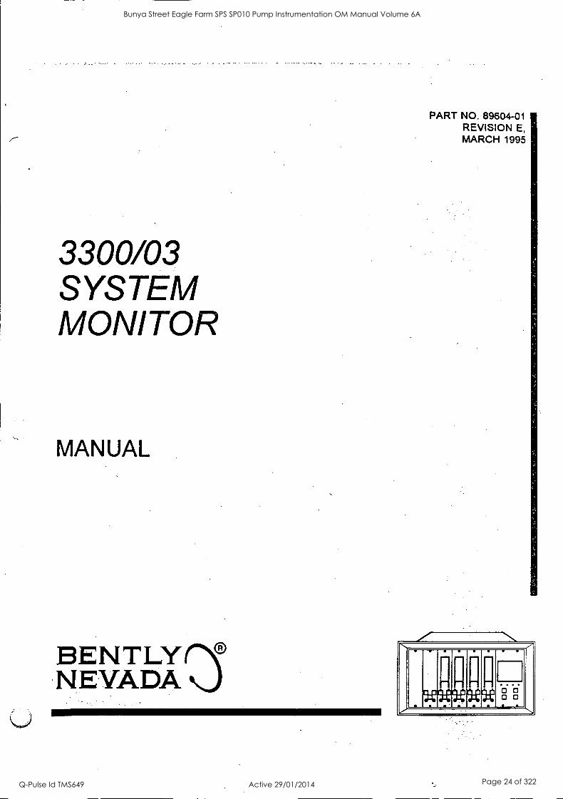
3300/03 SYSTEM MONITOR
MANUAL
BENTLY(N) NEVADA
PART NO. 89604-01 REVISION E, MARCH 1995
,.
9:Viznnne- Ici 12:
Bunya Street Eagle Farm SPS SP010 Pump Instrumentation OM Manual Volume 6A
Q-Pulse Id TMS649 Active 29/01/2014 Page 24 of 322
89804-01 SYSTEM MONITOR
NOTICE
READ THE FOLLOWING BEFORE INSTALLING OR OPERATING EQUIPMENT Bent ly Nevada Corporation has attempted to identify areas of risk created by improper installation and/or operatiOn of this product. These areas of information are noted as WARNING or CAUTION for your protection and for the safe and effective operation of this equipment. Read all instructions before installing or operating this product. Pay particular attention to those areas designated by the following symbols.
LLWARNING
High voltage present. Contact could cause shock, burns, or death.
Do not touch exposed wires or terminals.
A\ CAUTION
Machine protection will be lost during calibration.
Keyphasort, Proximitort, Dynamic Data Manager° and Transient Data Manager' are registered trademarks of Bent ly Nevada Corporation.
Copyright 1991, 1994, 1995 Bent ly Nevada Corporation
All Rights Reserved
No part of this publication may be reproduced, transmitted, stored in a retrieval system or translated Inb any human or computer language, it any form or by any means, electronic, mechanical, magnetic, optical, chemical, manual, or otherwise, without the prior written permission of the copyright owner,
Bently Nevada Corporation P.O. Box 157
Minden, Nevada 89423 USA Telephone 800-227-5514 702-782-3811
Telex 354437 Telemail 7400983 BNC UC
Fax 702-782-9253 Copyright Infringement is a serious matter under
United States of America and foreign copyright laws.
it
Bunya Street Eagle Farm SPS SP010 Pump Instrumentation OM Manual Volume 6A
Q-Pulse Id TMS649 Active 29/01/2014 Page 25 of 322
SYSTEM MONITOR 89604-01
FOREWORD This document is for plant personnel who operate and maintain the 3300 Monitoring System. The information includes description, disassembly instructions, performance tests, recommended spare parts, field changeable options, specifications and schematics. The procedures are presented in step- by-step graphic format.
RELATED DOCUMENTS
3300 System Overview, 80171-01
3300 System Installation Instructions, 80172-01
3300 System Troubleshooting, 80173-01
3300/12 Power Supply, 89602-01
Serial Data Interface & Dynamic Data Interface, 89541-01
Dynamic Data Managers System, 46390-01
Transient Data Manager User Guide, 79206-01
SYMBOLS Special symbols are used in the manual to illustrate specifics in the step-by-step processes. For
example:
PRESS FLASHt'JG CONNECT DISC OMECT OBSERVE SCREWDRIVER ALARM
iii
Bunya Street Eagle Farm SPS SP010 Pump Instrumentation OM Manual Volume 6A
Q-Pulse Id TMS649 Active 29/01/2014 Page 26 of 322

SYSTEM MONITOR
iv
Bunya Street Eagle Farm SPS SP010 Pump Instrumentation OM Manual Volume 6A
Q-Pulse Id TMS649 Active 29/01/2014 Page 27 of 322
SYSTEM MONITOR 89604-01
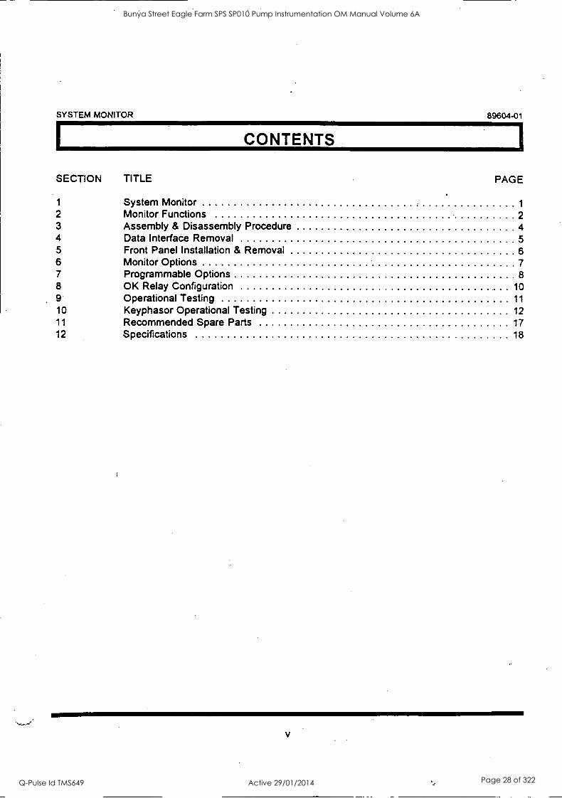
CONTENTS
SECTION TITLE PAGE
1 System Monitor 1
2 Monitor Functions 2 3 Assembly & Disassembly Procedure 4 4 Data Interface Removal 5 5 Front Panel Installation & Removal 6 6 Monitor Options 7 7 Programmable Options 8 8 OK Relay Configuration 10 9 Operational Testing 11
10 Keyphasor Operational Testing 12 11 Recommended Spare Parts 17 12 Specifications 18
Bunya Street Eagle Farm SPS SP010 Pump Instrumentation OM Manual Volume 6A
Q-Pulse Id TMS649 Active 29/01/2014 Page 28 of 322

89604-01 SYSTEM MONITOR
vi
Bunya Street Eagle Farm SPS SP010 Pump Instrumentation OM Manual Volume 6A
Q-Pulse Id TMS649 Active 29/01/2014 Page 29 of 322
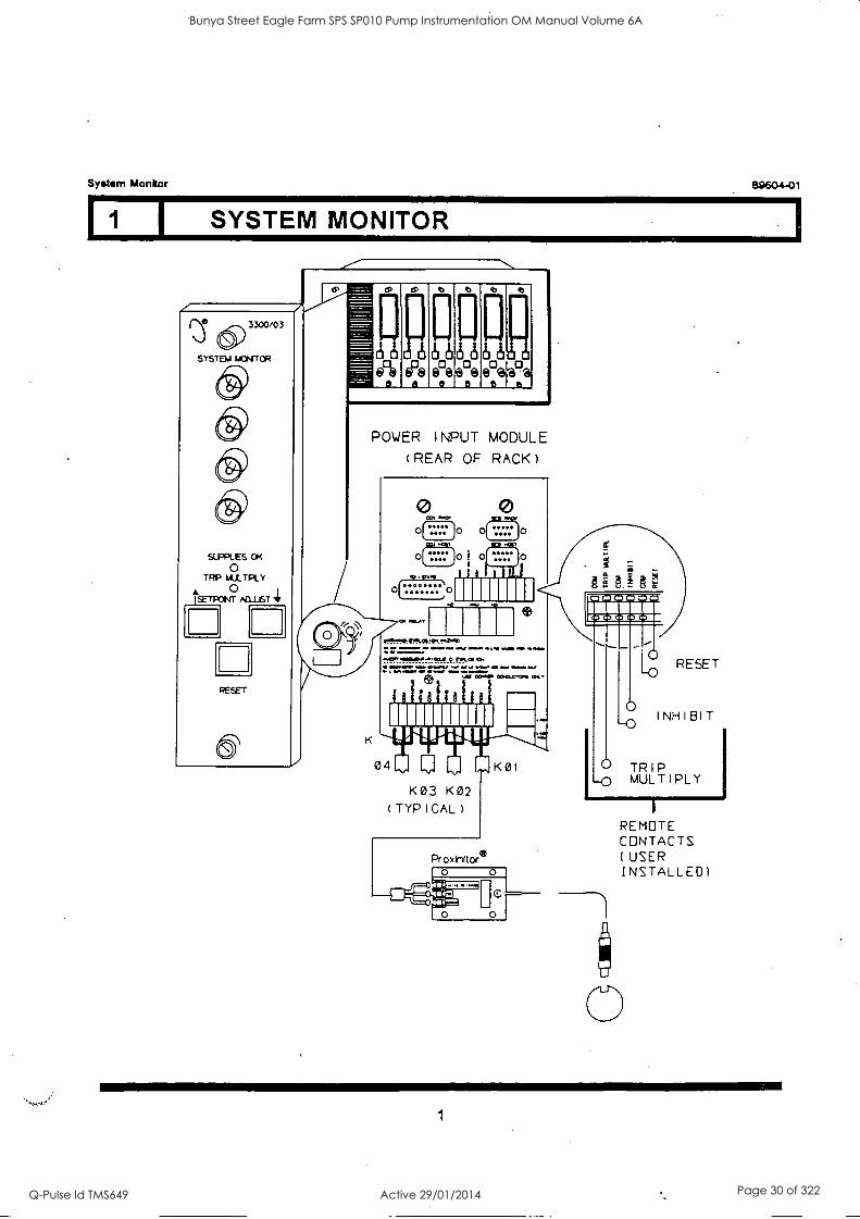
System Monitor 89604-01
1 I SYSTEM MONITOR
3300/03
SYSTEM laCNITOR
SIPPLES OK 0
TRP MLLTPLY 0
jSETPONT ACLUST 4
RESET
a
0 d 6 b6
0 ea@
0 0 0 irela
6 6
POWER INPUT MODULE (REAR OF RACK)
0 ****
0 0
o MILA
t.r:Itglr%S. OM lima . Val=
..IMMIMM.4111XDOIMWOo 1.11 OM.* 110
E0
1011110 - RI 04 K0I
K03 K02 (TYPICAL)
ProxirnItor6
0
INHIBIT
TRIP MULTIPLY
REMOTE CONTACTS (USER INSTALLED)
1
Bunya Street Eagle Farm SPS SP010 Pump Instrumentation OM Manual Volume 6A
Q-Pulse Id TMS649 Active 29/01/2014 Page 30 of 322
System Monitor 89604-01
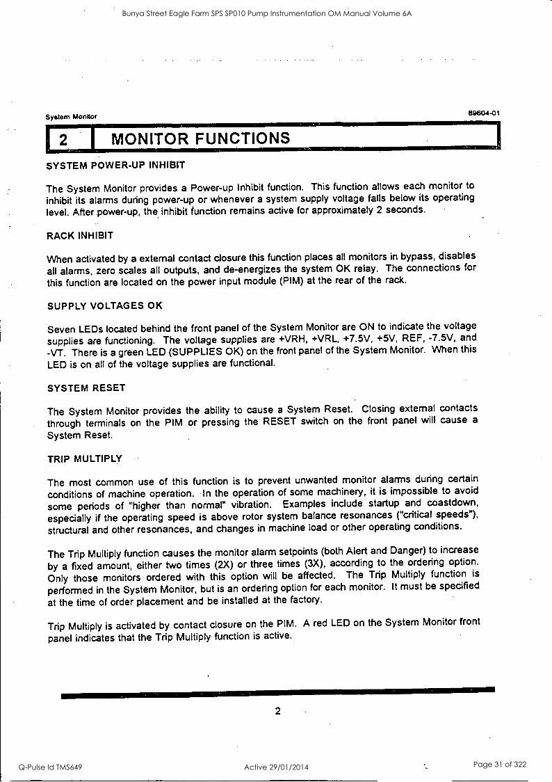
I MONITOR FUNCTIONS
SYSTEM POWER-UP INHIBIT
The System Monitor provides a Power-up Inhibit function. This function allows each monitor to
inhibit its alarms during power-up or whenever a system supply voltage falls below its operating
level. After power -up., the inhibit function remains active for approximately 2 seconds.
RACK INHIBIT
When activated by a external contact closure this function places all monitors in bypass, disables
all alarms, zero scales all outputs, and de-energizes the system OK relay. The connections for
this function are located on the power input module (PIM) at the rear of the rack.
SUPPLY VOLTAGES OK
Seven LEDs located behind the front panel of the System Monitor are ON to indicate the voltage
supplies are functioning. The voltage supplies are +VRH, +VRL, +7.5V, +5V, REF, -7.5V, and
-VT. There is a green LED (SUPPLIES OK) on the front panel of the System Monitor. When this
LED is on all of the voltage supplies are functional.
SYSTEM RESET
The System Monitor provides the ability to cause a System Reset. Closing external contacts
through terminals on the PIM or pressing the RESET switch on the front panel will cause a
System Reset.
TRIP MULTIPLY
The most common use of this function is to prevent unwanted monitor alarms during certain
conditions of machine operation. In the operation of some machinery, it is impossible to avoid
some periods of "higher than normal" vibration. Examples include startup and coastdown,
especially if the operating speed is above rotor system balance resonances ("critical speeds"),
structural and other resonances, and changes in machine load or other operating conditions.
The Trip Multiply function causes the monitor alarm setpoints (both Alert and Danger) to increase
by a fixed amount, either two times (2X) or three times (3X), according to the ordering option.
Only those monitors ordered with this option will be affected. The Trip Multiply function is
performed in the System Monitor, but is an ordering option for each monitor. It must be specified
at the time of order placement and be installed at the factory.
Trip Multiply is activated by contact closure on the PIM. A red LED on the System Monitor front
panel indicates that the Trip Multiply function is active.
2
Bunya Street Eagle Farm SPS SP010 Pump Instrumentation OM Manual Volume 6A
Q-Pulse Id TMS649 Active 29/01/2014 Page 31 of 322
System Monitor 89604-01
12 I MONITOR FUNCTIONS
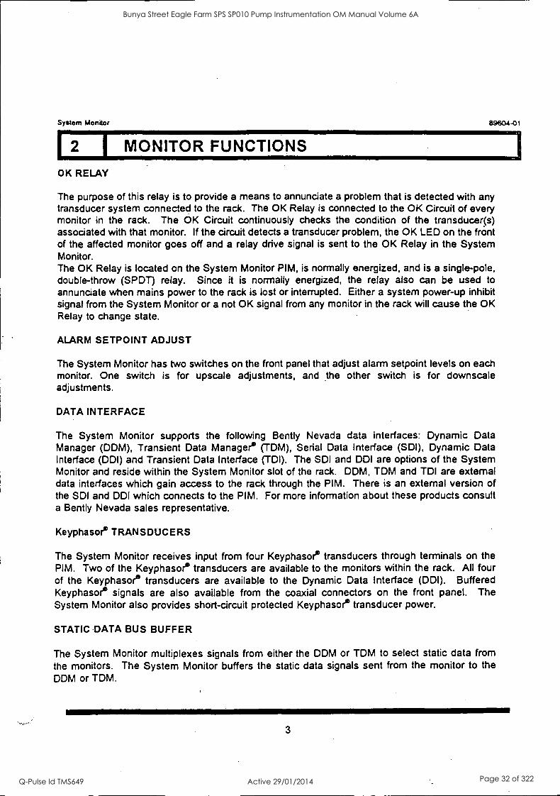
OK RELAY
The purpose of this relay is to provide a means to annunciate a problem that is detected with any transducer system connected to the rack. The OK Relay is connected to the OK Circuit of every monitor in the rack. The OK Circuit continuously checks the condition of the transducer(s) associated with that monitor. If the circuit detects a transducer problem, the. OK LED on the front of the affected monitor goes off and a relay drive signal is sent to the OK Relay in the System Monitor. The OK Relay is located on the System Monitor PIM, is normally energized, and is a single-pole, double-throw (SPDT) relay. Since it is normally energized, the relay also can be used to annunciate when mains power to the rack is lost or interrupted. Either a system power-up inhibit signal from the System Monitor or a not OK signal from any monitor in the rack will cause the OK Relay to change state.
ALARM SETPOINT ADJUST
The System Monitor has two switches on the front panel that adjust alarm setpoint levels on each monitor. One switch is for upscale adjustments, and the other switch is for downscale adjustments.
DATA INTERFACE
The System Monitor supports the following Bently Nevada data interfaces: Dynamic Data Manager (DDM), Transient Data Manager. (TDM), Serial Data Interface (SDI), Dynamic Data Interface (DDI) and Transient Data Interface (TDI). The SDI and DDI are options of the System Monitor and reside within the System Monitor slot of the rack. DDM, TDM and TDI are external data interfaces which gain access to the rack through the PIM. There is an external version of the SDI and DDI which connects to the PIM. For more information about these products consult a Bently Nevada sales representative.
Keyphasoe TRANSDUCERS
The System Monitor receives input from four Keyphasoe transducers through terminals on the PIM. Two of the Keyphasoe transducers are available to the monitors within the rack. All four of the Keyphasoe transducers are available to the Dynamic Data Interface (DDI). Buffered Keyphasoe signals are also available from the coaxial connectors on the front panel. The System Monitor also provides short-circuit protected Keyphasoe transducer power.
STATIC DATA BUS BUFFER
The System Monitor multiplexes signals from either the DDM or TDM to select static data from the monitors. The System Monitor buffers the static data signals sent from the monitor to the DDM or TDM.
3
Bunya Street Eagle Farm SPS SP010 Pump Instrumentation OM Manual Volume 6A
Q-Pulse Id TMS649 Active 29/01/2014 Page 32 of 322
System Monitor 89604-01
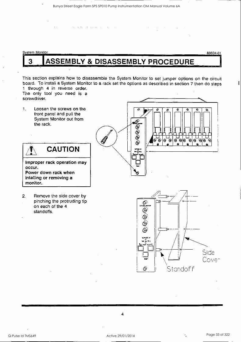
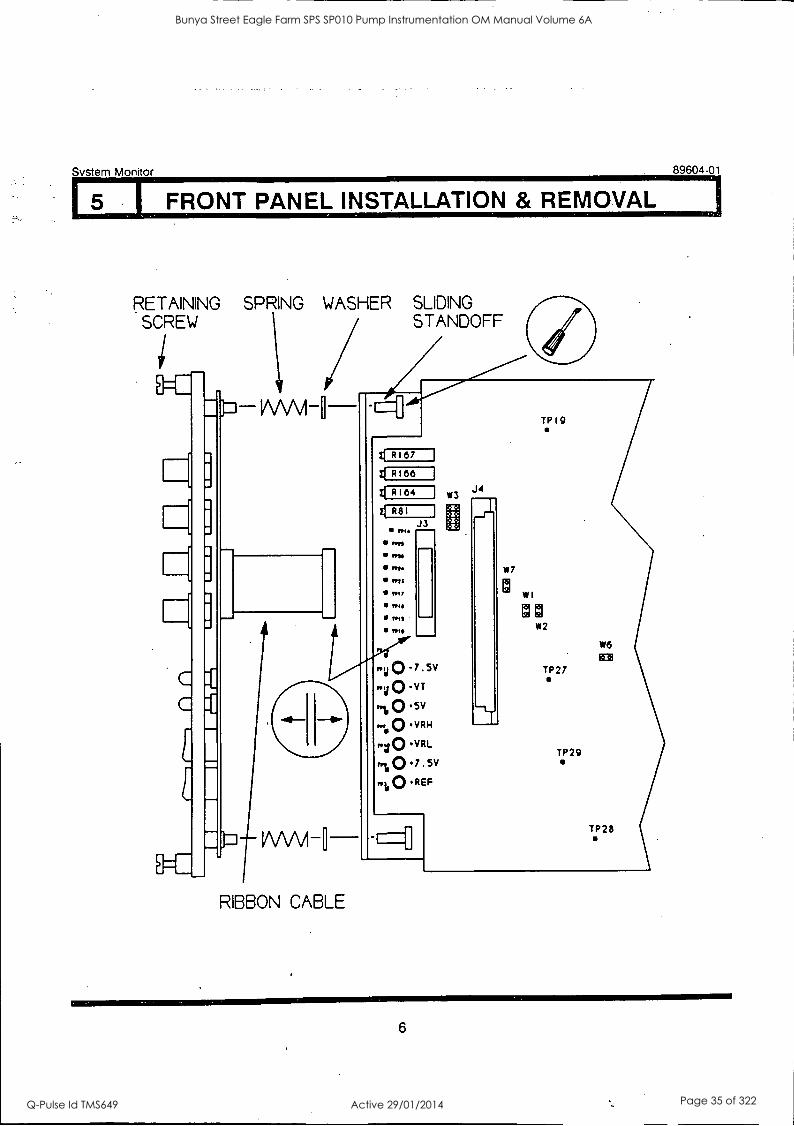
3 I ASSEMBLY & DISASSEMBLY PROCEDURE
This section explains how to disassemble the System Monitor to set jumper options on the circuit board. To install a System Monitor to a rack set the options as described in section 7 then do steps 1 through 4 in reverse order. The only tool you need is a screwdriver.
1. Loosen the screws on the front panel and pull the System Monitor out from the rack.
/41;\ CAUTION
Improper rack operation may occur. Power down rack when intalling or removing a monitor.
2. Remove the side cover by pinching the protruding tip on each of the 4 standoffs.
ww
0 z
1:2-1 q=p ig
8 8 8 000 6 6
ft-
Standoff
Side Cove
4
Bunya Street Eagle Farm SPS SP010 Pump Instrumentation OM Manual Volume 6A
Q-Pulse Id TMS649 Active 29/01/2014 Page 33 of 322
System Monitor 89604-01
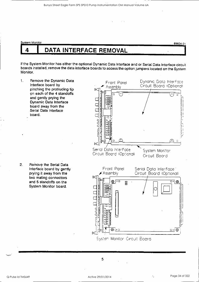
I 4 I DATA INTERFACE REMOVAL
If the System Monitor has either the optional Dynamic Data Interface and or Serial Data Interface circuit boards installed, remove the data interface boards to access the option jumpers located on the System Monitor.
1. Remove the Dynamic Data Interface board by pinching the protruding tip on each of the 4 standoffs and gently prying the Dynamic Data Interface board away from the Serial Data Interface board.
2. Remove the Serial Data Interface board by gently prying it away from the two mating connectors and 5 standoffs on the System Monitor board.
Front Panel Assembly
N'N Serial Data Interface System Monitor Circuit Board (Optional) Circuit Board
1-
Dynamic Data interface Circuit Board (Optional)
Front Panel Serial Data Interface. /Assembly Circuit Board (Optional)
LIE:11
d.i,
ti
0 o CEO
Cal
0
oolen_
System Monitor Circuit Board
5
Bunya Street Eagle Farm SPS SP010 Pump Instrumentation OM Manual Volume 6A
Q-Pulse Id TMS649 Active 29/01/2014 Page 34 of 322
System Monitor 89604-01
5 I FRONT PANEL INSTALLATION & REMOVAL I
RETAINING SPRING WASHER SLIDING SCREW
Hi
STANDOFF
IN NW TPI9
4 R167
4 R166
4 8164 I
4 R81
.13 eiHm
nns
Pm
1Il my MI TM
MO
ng 0 -7.5V
mil 0 -VT
'1,0 '5V
0 'VRH :0 vaL
0 7.5V .100 REF
W3 r 1:1
W2
TP27
TP29
TP28
RIBBON CABLE
6
Bunya Street Eagle Farm SPS SP010 Pump Instrumentation OM Manual Volume 6A
Q-Pulse Id TMS649 Active 29/01/2014 Page 35 of 322
System Monitor 89604-01
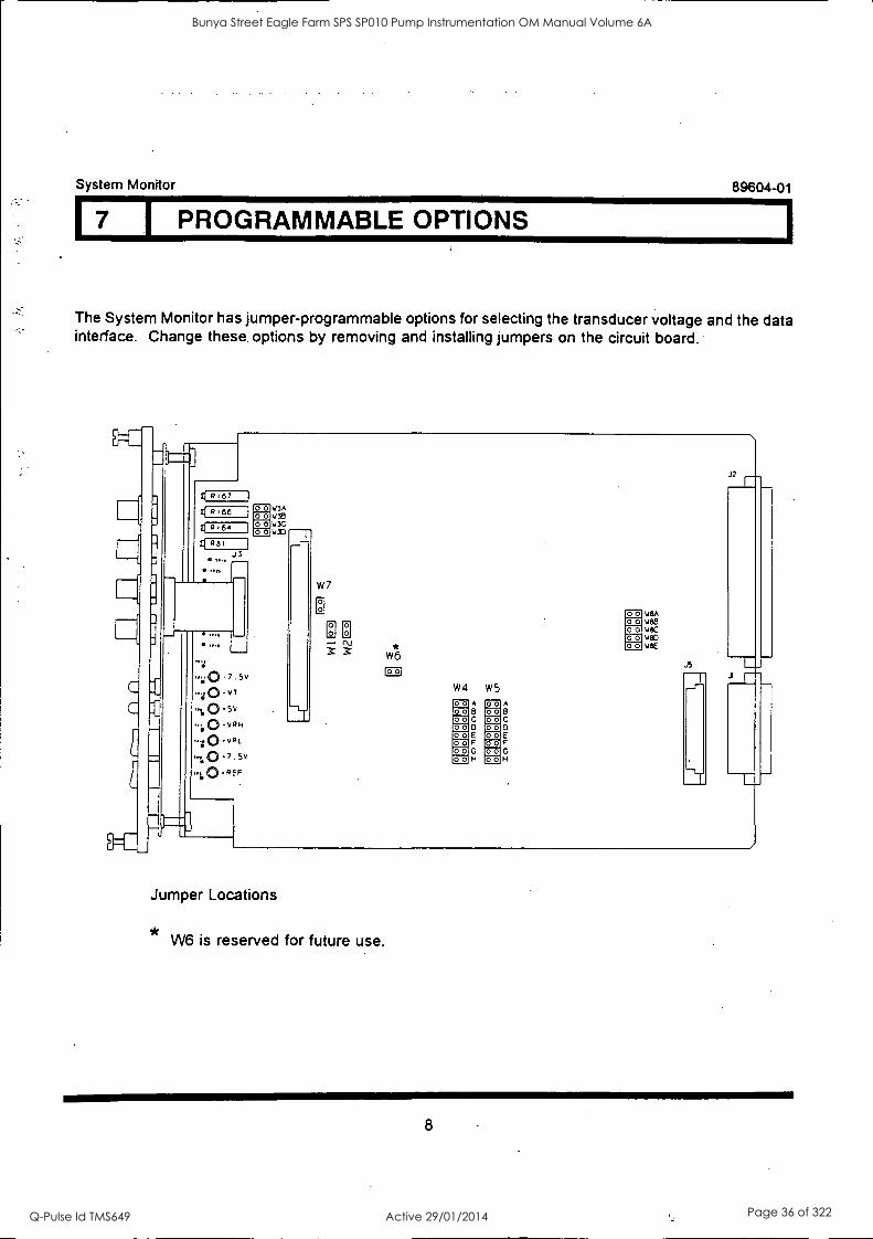
I PROGRAMMABLE OPTIONS
The System Monitor has jumper-programmable options for selecting the transducer voltage and the data interface. Change these, options by removing and installing jumpers on the circuit board.
6167
O 'VI 1.0 '5V
vRH
1,0 '7.5V
'REF
VIA '439 wY; %OD
W7
8 0 0 - r
O O
w*6
C3 W4 W5
00 ,2L,H.D
22 00 00 0 .
A A 8 218 C la r: O 9_2, 0 E E
C 9d
c F F
H co) (c),
H
0 o w8A O o V88 O o w8C O o w80 o o W6E
.12
Jumper Locations
W6 is reserved for future use.
8
Bunya Street Eagle Farm SPS SP010 Pump Instrumentation OM Manual Volume 6A
Q-Pulse Id TMS649 Active 29/01/2014 Page 36 of 322
89604-01 S vstem Monitor
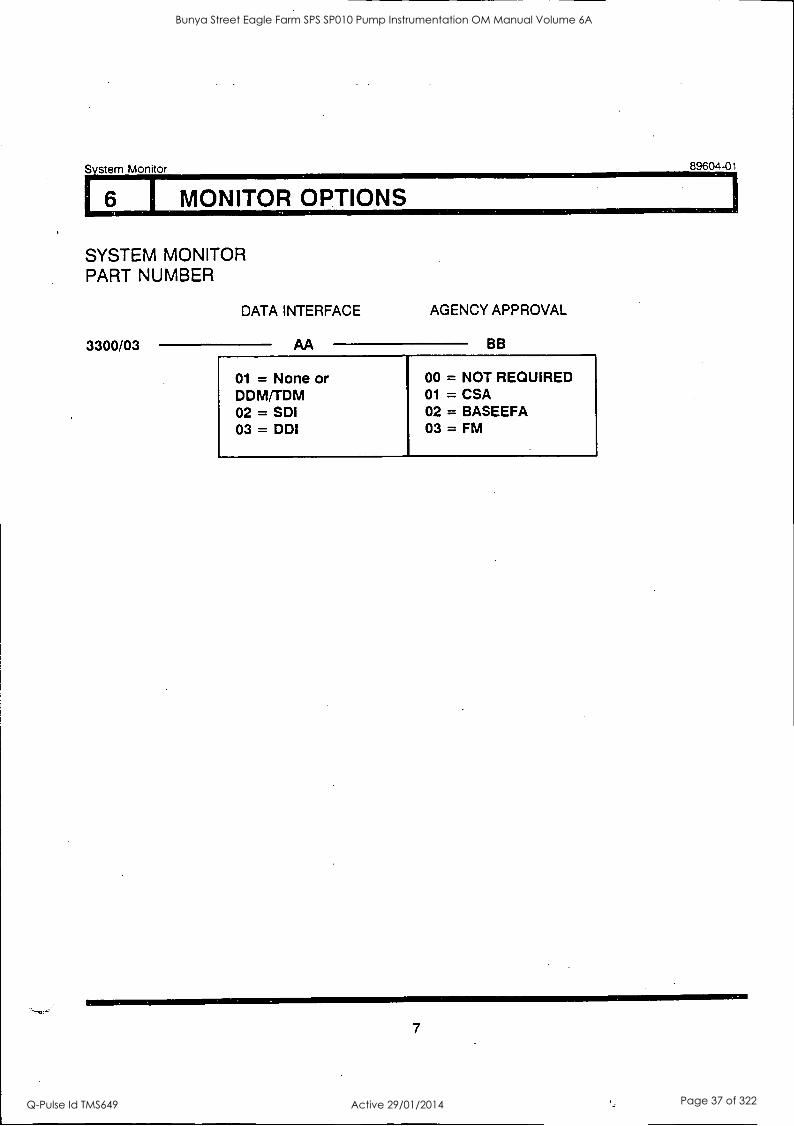
6 I MONITOR OPTIONS
SYSTEM MONITOR PART NUMBER
3300/03
DATA INTERFACE
AA
AGENCY APPROVAL
BB
01 = None or DDFATTDM 02 = SDI 03 = DDI
00 = NOT REQUIRED 01 = CSA 02 = BASEEFA 03 = FM
7
Bunya Street Eagle Farm SPS SP010 Pump Instrumentation OM Manual Volume 6A
Q-Pulse Id TMS649 Active 29/01/2014 Page 37 of 322
System Monitor 89604-01
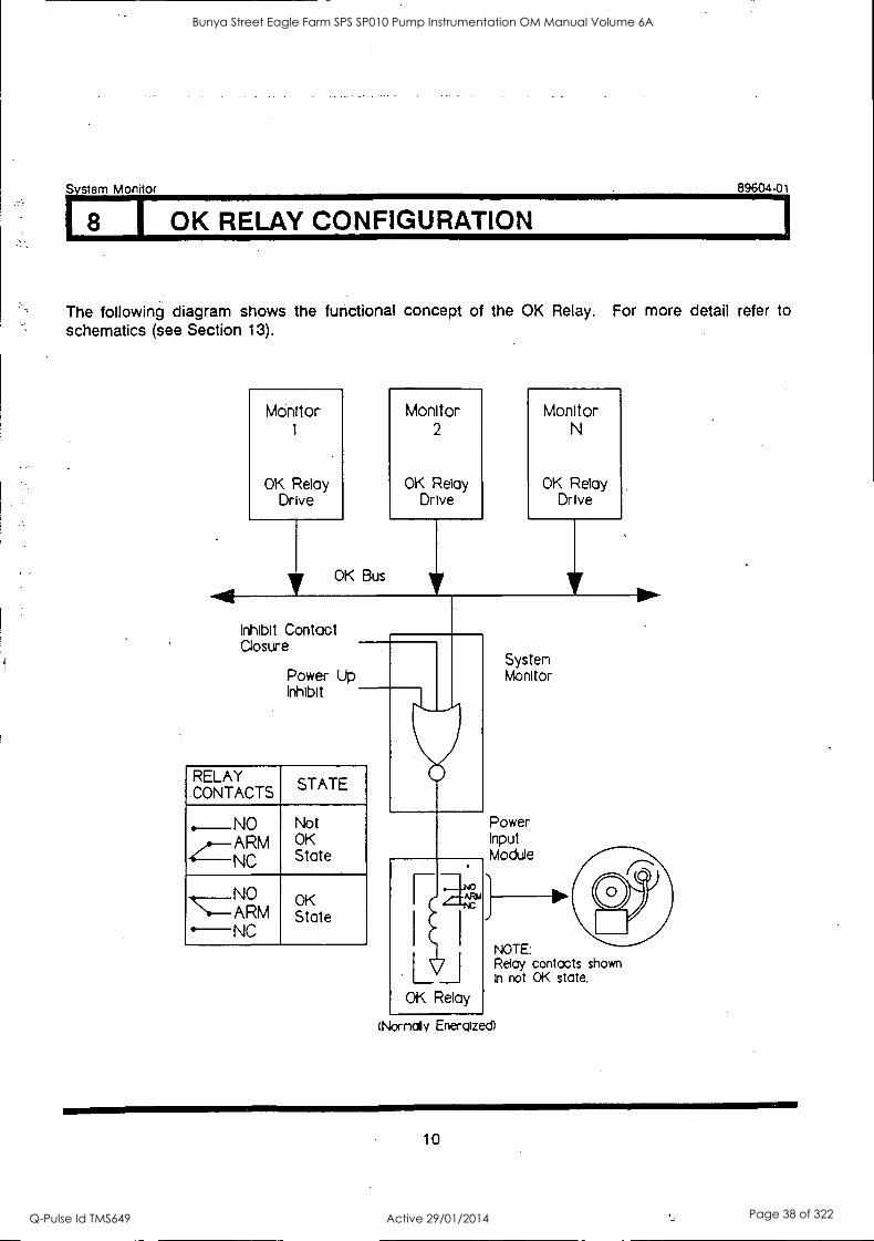
8 1 OK RELAY CONFIGURATION
The following diagram shows the functional concept of the OK Relay. For more detail refer to schematics (see Section 13).
Monitor 1
OK Relay Drive
OK Bus
Monitor 2
OK Relay Dr ve
Monitor N
OK Relay Drive
Inhibit Contact Closure
Power Up Inhibit
RELAY CONTACTS
STATE
..____NO Not .--ARM OK
4--NC State
.k NO OK ..--ARM
----NC state
Systen Monitor
Power Input Module
OK Relay
NOTE: Relay contacts shown In not OK state.
Nornaly Energized)
10
Bunya Street Eagle Farm SPS SP010 Pump Instrumentation OM Manual Volume 6A
Q-Pulse Id TMS649 Active 29/01/2014 Page 38 of 322
System Monitor 89604-01
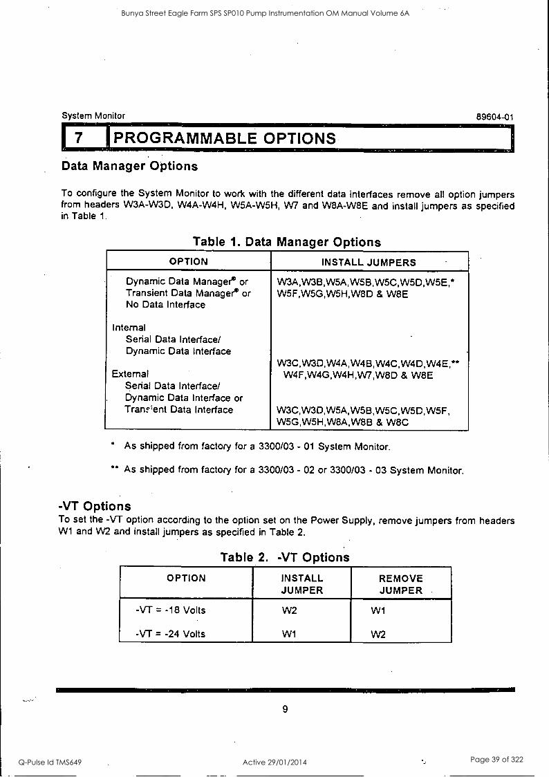
!PROGRAMMABLE OPTIONS
Data Manager Options
To configure the System Monitor to work with the different data interfaces remove all option jumpers from headers W3A-W3D, W4A-W4H, W5A-W5H, W7 and W8A-W8E and install jumpers as specified in Table 1.
Table 1. Data Manager Options OPTION INSTALL JUMPERS
Dynamic Data Manager° or VV3A,VV3B,W5A,W5B,W5C,W5D,W5E,* Transient Data Manager° or W5F,W5G,W5H,W8D & W8E No Data Interface
Internal Serial Data Interface/ Dynamic Data Interface
VV3C,VV30,W4A,W4B,W4C,W4D,W4E," External W4F,W4G,W4H,W7,W8D & W8E
Serial Data Interface/ . Dynamic Data Interface or
Tram"ent Data Interface W3C,W3D,W5A,W5B,W5C,W5D,W5F, W5G,W5H,W8A,W8B & W8C
As shipped from factory for a 3300/03 - 01 System Monitor.
" As shipped from factory for a 3300/03 - 02 or 3300/03 - 03 System Monitor.
-VT Options To set the -VT option according to the option set on the Power Supply, remove jumpers from headers W1 and W2 and install jumpers as specified in Table 2.
Table 2. -VT Options
OPTION INSTALL JUMPER
REMOVE JUMPER
-VT = -18 Volts
-VT = -24 Volts
W2
W1
W1
W2
9
Bunya Street Eagle Farm SPS SP010 Pump Instrumentation OM Manual Volume 6A
Q-Pulse Id TMS649 Active 29/01/2014 Page 39 of 322
System Monitor
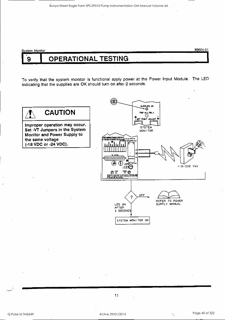
1 69 1 OPERATIONAL TESTING
89604-01
To verify that the system monitor is functional apply power at the Power Input Module. The LED
indicating that the supplies are OK should turn on after 2 seconds.
/I\ CAUTION
Improper operation may occur. Set -VT Jumpers in the System Monitor and Power Supply to the same voltage (-18 VDC or -24 VDC).
0 T MU_ TFL Y
0 I i PON T ADJUST II,
-11Z1L
1111111EL'.."'
eb IIMOT,IT ONNOOOI OLT
111111111111 Oil ...MO
4
sa"3- "Fe
SYSTEM MONITOR
TWO
OoTTorT,......0 0.0 OT 115 /Moral. tin. OTSAL
LED ON AFTER 2 SECOND
OFF
SYSTEM MONITOR OK
110/220 VOC
REFER TO POWER SUPPLY MANUAL
11
Bunya Street Eagle Farm SPS SP010 Pump Instrumentation OM Manual Volume 6A
Q-Pulse Id TMS649 Active 29/01/2014 Page 40 of 322
System Monitor
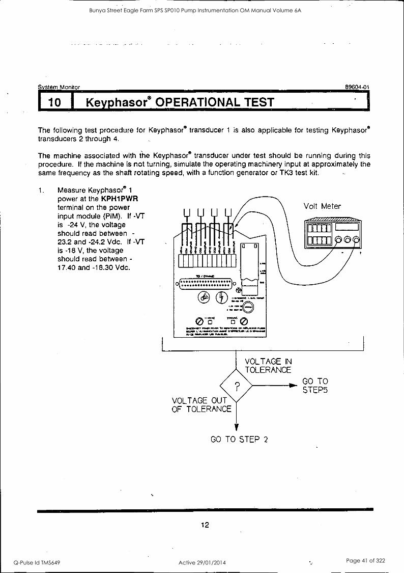
10 I Keyphasor® OPERATIONAL TEST
89604-01
The following test procedure for Keyphasore transducer 1 is also applicable for testing Keyphasore transducers 2 through 4.
The machine associated with the Keyphasor° transducer under test should be running during this procedure. If the machine is not turning, simulate the operating machinery input at approximately the same frequency as the shaft rotating speed, with a function generator or TK3 test kit.
1. Measure Keyphasore 1
power at the KPH1 PWR terminal on the power input module (PIM). If -VT is -24 V, the voltage should read between -
23.2 and -24.2 Vdc. If -VT is -18 V, the voltage should read between -
17.40 and -18.30 Vdc.
uuu up
111111111111 TO DORIC
MenemC 11-
...la nor No IRO. IN
1.M
Loa
EMEE=1, MAP 1141.1Cm. ON 0111.1...0 ROM *LIP LA.MADEAT adr. CrIVVEMEN LE IEN1 0,/ a MAAS. V PLAMIL/11.
Volt Meter
VOLTAGE IN TOLERANCE
GO TO STEP5
VOLTAGE OUT OF TOLERANCE
V
GO TO STEP 2
12
Bunya Street Eagle Farm SPS SP010 Pump Instrumentation OM Manual Volume 6A
Q-Pulse Id TMS649 Active 29/01/2014 Page 41 of 322
System Monitor 89604-01
110 I Keyphasor® OPERATIONAL TEST
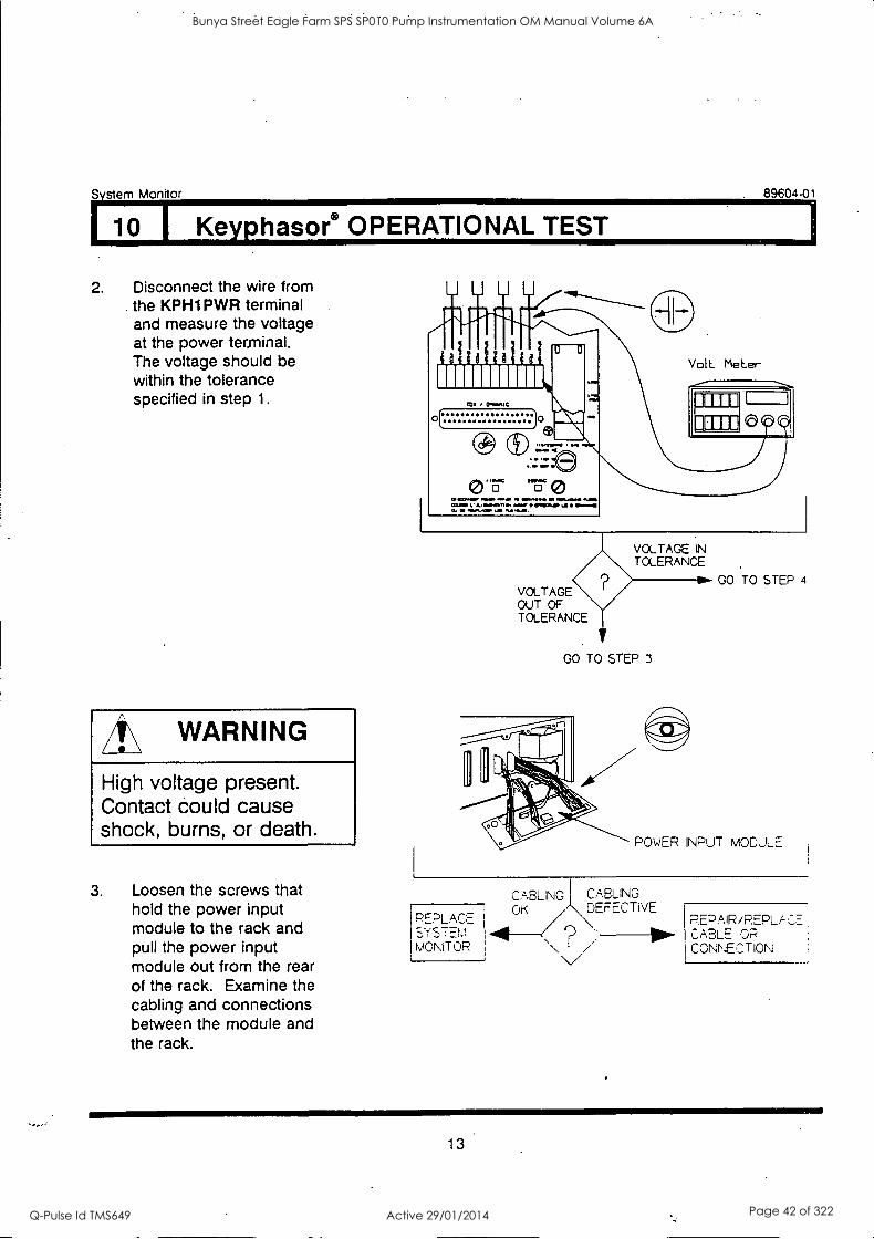
2. Disconnect the wire from the KPH1 PWR terminal and measure the voltage at the power terminal. The voltage should be within the tolerance specified in step 1.
/I\ WARNING
High voltage present. Contact could cause shock, burns, or death.
3. Loosen the screws that hold the power input module to the rack and pull the power input module out from the rear of the rack. Examine the cabling and connections between the module and the rack.
U Li LI
Volt Meier
VOLTAGE IN TOLERANCE
VOLTAGE OUT OF TOLERANCE
GO TO STEP 3
REPLACE 1SYSTEm MONITOR
1
GO TO STEP 4
POWER INPUT MODULE
CABLNG I CABLING
OK DEFEL TiVE REPAIR /REPLA -NO- CABLE OP
/ CONNECTION
13
Bunya Street Eagle Farm SPS SP010 Pump Instrumentation OM Manual Volume 6A
Q-Pulse Id TMS649 Active 29/01/2014 Page 42 of 322
System Monitor
10 I Keyphasor® OPERATIONAL TEST
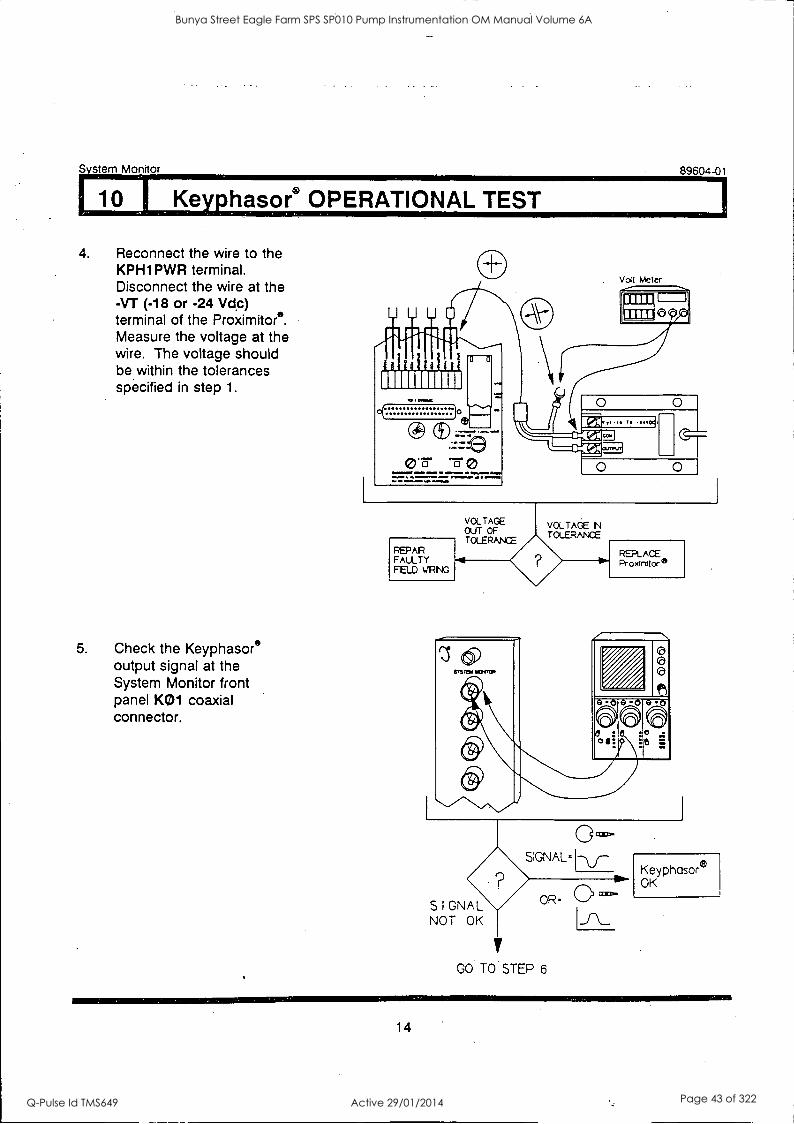
4. Reconnect the wire to the KPH1PWR terminal. Disconnect the wire at the -VT (-18 or -24 VOc) terminal of the Proximitore. Measure the voltage at the wire. The voltage should be within the tolerances specified in step 1.
5. Check the Keyphasore output signal at the System Monitor front panel KO1 coaxial connector.
89604-01
1. IOMMMOIP I/MIME
PEPAR FAULTY FIELD VRIG
REPLACE Proxinitcre
SIGNAL- 1-\_/-
OR= 0 c°3- S I GNAL NOT OK
y GO TO STEP 6
Keyphasore OK
14
Bunya Street Eagle Farm SPS SP010 Pump Instrumentation OM Manual Volume 6A
Q-Pulse Id TMS649 Active 29/01/2014 Page 43 of 322
System Monitor
I 10 1 Keyphasor® OPERATIONAL TEST
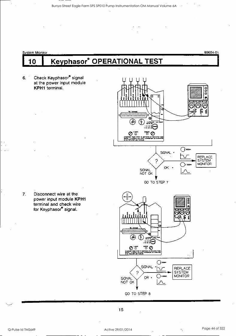
6. Check Keyphasore signal at the power input module KPH1 terminal.
7. Disconnect wire at the power input module KPH1 terminal and check wire for Keyphasore signal.
89604-01
erairelp reap ape re =Pee re er reksere ea.aor ',...Pelea 0 emur... Peer. Oa If realelle o.M
SIGNAL °cm-
SIGNAL NOT OK
OK -
GO TO STEP 7
o
frearme Pre rum enema ...Jeer PIM. MJl -
ribPs. 11
0 SIGNAL =I
SIGNAL OR =
NOT OK
y GO TO STEP 8
REPLACE SYSTEM MONITOR
REPLACE SYSTEM MONITOR
15
Bunya Street Eagle Farm SPS SP010 Pump Instrumentation OM Manual Volume 6A
Q-Pulse Id TMS649 Active 29/01/2014 Page 44 of 322
System Monitor 89604-01
10 I Keyphasor® OPERATIONAL TEST
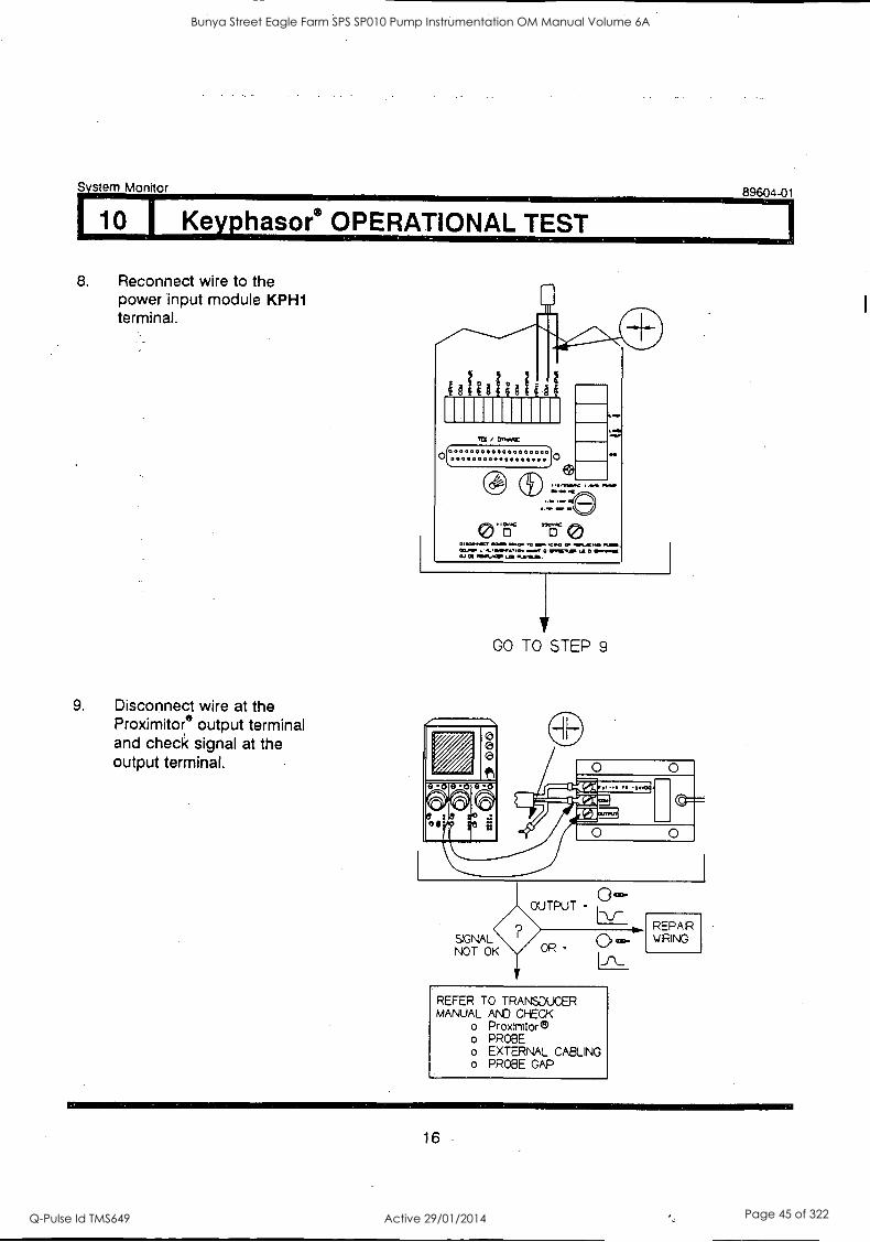
8. Reconnect wire to the power input module KPH1 terminal.
9. Disconnect wire at the Proximitore output terminal and check signal at the output terminal.
I gi MIN" / 1:7,WC
0
1141,1110C I . . .111.0
Gth.c "EC
co
ibmaseeer .41% Sas. RI wow .c.a -esoe LES MVO. SMOMMTI. mr WPM,. MI CM .004011.. LAS .
GO TO STEP 9
0
REFER TO TRANSDUCER MANUAL AND CHECK
o Proxinitore o PROBE o EXTERNAL CABLING o PROBE GAP
REPAIR WIRING
16
Bunya Street Eagle Farm SPS SP010 Pump Instrumentation OM Manual Volume 6A
Q-Pulse Id TMS649 Active 29/01/2014 Page 45 of 322
System Monitor
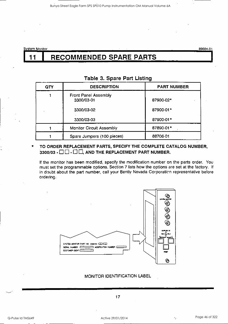
11 I RECOMMENDED SPARE PARTS
Table 3. Spare Part Listing
89604-01
OTY DESCRIPTION PART NUMBER
1 Front Panel Assembly 3300/03-01 87900-02*
3300/03-02 87900-01*
3300/03-03 87900-01*
1 Monitor Circuit Assembly 87890-01* .
1 Spare Jumpers (100 pieces) 88706-01
TO ORDER REPLACEMENT PARTS, SPECIFY THE COMPLETE CATALOG NUMBER, 3300/03 - - , AND THE REPLACEMENT PART NUMBER.
If the monitor has been modified, specify the modification number on the parts order. You must set the programmable options. Section 7 lists how the options are set at the factory. If
in doubt about the part number, call your Bent ly Nevada Corporaticn representative before ordering.
STSTB4 &MICR PART NO 330=3 -CO CID SERIAL NUEER I I Orr...ATON 141.MER I
cusracfr DENT I
MONITOR IDENTIFICATION LABEL
&PRES Ot 0 no aL111.1.
t=-tom2.twri a n RET
17
Bunya Street Eagle Farm SPS SP010 Pump Instrumentation OM Manual Volume 6A
Q-Pulse Id TMS649 Active 29/01/2014 Page 46 of 322
System Monitor
12 1 SPECIFICATIONS
INPUTS
No external loads, normal operation mode, 25C
Supply Voltage
+VRH: 23.65 ± 6.35 Vdc +VRL: 11.22 ± 3.09 Vdc +7.5V: 7.5 ± 0.1 Vdc +5V: 5.00 ± 0.05 Vdc REF: 5.00 ± 0.009 Vdc -7.5V: -7.5 ± 0.1 Vdc -VT (-24V Option): -23.75 ± 0.45 Vdc -VT (-18V Option): -17.9 ± 0.4 Vdc
SYSTEM POWER-UP INHIBIT
Delay: 2.1 ± 1 seconds
CONTACT CLOSURE RATING
89604-01
Contacts for System Reset, Inhibit, OK, and Trip Multiply
Active:
Keyphasor°
Output Voltage
< 100 0
-24V Option: -23.2 V to -24.2 V, Short-circuit Protected -18V Option: -17.4 V to -18.3 V, Short-circuit Protected
ENVIRONMENTAL
Temperature:
Humidity:
Operating +32 F to +149° F (0 C to +65 C). Storage -40° F to +185° F (40° C to +85° C).
0 to 95%, noncondensing.
18
Bunya Street Eagle Farm SPS SP010 Pump Instrumentation OM Manual Volume 6A
Q-Pulse Id TMS649 Active 29/01/2014 Page 47 of 322

BRISBANE CITY COUNCIL Dept. Water Supply and Sewage Pumpwell No 1, Eagle Farm Pump Station
BCC Contract No S20/95/96 System Instrumentation
Operation and Maintenance Manual
2.4 3300/12 Power Supply
The following publication entitled 3300/12 Power Supply Manual (Part No 89602-01 Rev J) is prepared by Bent ly Nevada for plant personnel who operate and maintain the system. It provides a detailed description of the Power Supply, set up options, disassembly procedure, testing, performance and trouble shooting guide.
The following sections are included:
2.4.1 Location of Assemblies
2.4.2 Options
2.4.3 Disassembly Procedure
2.4.4 Fuses
2.4.5 Input Voltage Option
2.4.6 Testing and Trouble shooting
2.4.7 Data Communication Interface Options
2.4.8 Transducer Voltage Option
2.4.9 Recommended Spare Parts
2.4.10 Specification
2.4.11 Field Wiring Drawings
15140/Inst Man/BRH Issue 1 29-Apr-98 Page 2-5
Bunya Street Eagle Farm SPS SP010 Pump Instrumentation OM Manual Volume 6A
Q-Pulse Id TMS649 Active 29/01/2014 Page 48 of 322

3300/12 POWER SUPPLY
MANUAL
BENTLY(N) NEVADA
PART NO. 89602-01 REVISION J,
JANUARY 1995
Bunya Street Eagle Farm SPS SP010 Pump Instrumentation OM Manual Volume 6A
Q-Pulse Id TMS649 Active 29/01/2014 Page 49 of 322
89602-01 Power Supply Manual
NOTICE
Bently Nevada Corporation has, attempted to identify areas of risk created by improper installation and/or operation of this product. These areas of information are noted as WARNING or CAUTION for your protection and for the safe and effective operation of this equipment. Read all instructions before installing or operating this product. Pay particular attention to those areas designated by the following symbols.
/WARNING
High voltage present. Contact could cause shock, bums, or death.
Do not touch exposed wires or terminals.
4\ CAUTION
Machine protection will be lost.
Keyphasor® is a registered trademark of Bently Nevada Corporation
©Copyright Bent ly Nevada Corporation 1992, 1993, 1994, 1995
All Rights Reserved
No part of this publication may be reproduced, transmitted, stored in a retrieval system or translated Into any human or computer language, In any form or by any means, electronic, mechanical, magnetic, optical, chemical, manual, or otherwise, without the prior written permission of the copyright owner,
Bently Nevada Corporation P.O. Box 157
Minden, Nevada 89423 USA Telephone 800-227-5514 702-782-3611
Telex 354437 Telemail 7400983 BNC UC
Fax 702-782-9253
Copyright infringement is a serious matter under United States of America and foreign copyright laws.
ii
Bunya Street Eagle Farm SPS SP010 Pump Instrumentation OM Manual Volume 6A
Q-Pulse Id TMS649 Active 29/01/2014 Page 50 of 322
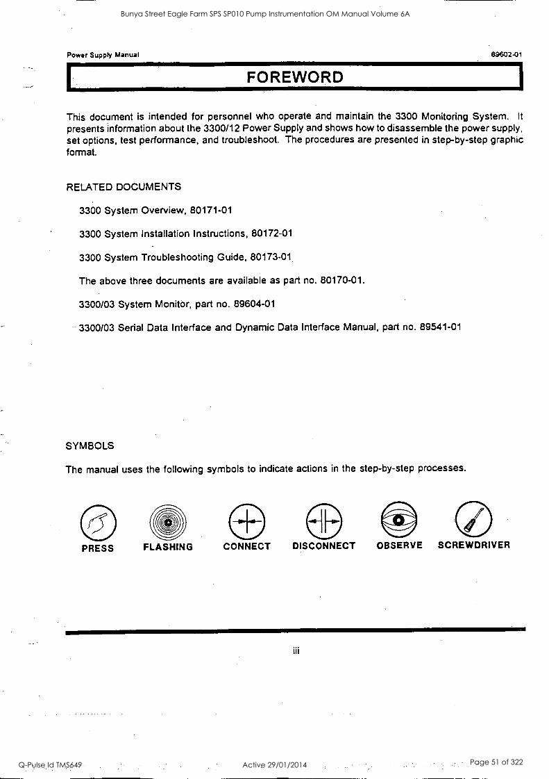
Power Supply Manual 89602-01
FOREWORD
This document is intended for personnel who operate and maintain the 3300 Monitoring System. It
presents information about the 3300/12 Power Supply and shows how to disassemble the power supply, set options, test performance, and troubleshoot. The procedures are presented in step-by-step graphic format.
RELATED DOCUMENTS
3300 System Overview, 80171-01
3300 System Installation Instructions, 80172-01
3300 System Troubleshooting Guide, 80173-01
The above three documents are available as part no. 80170-01.
3300/03 System Monitor, part no. 89604-01
3300/03 Serial Data Interface and Dynamic Data Interface Manual, part no. 89541-01
SYMBOLS
The manual uses the following symbols to indicate actions in the step-by-step processes.
PRESS FLASHING CONNECT DISCONNECT OBSERVE SCREWDRIVER
iii
Bunya Street Eagle Farm SPS SP010 Pump Instrumentation OM Manual Volume 6A
Q-Pulse Id TMS649 Active 29/01/2014 Page 51 of 322

Power Supply Manual
iv
Bunya Street Eagle Farm SPS SP010 Pump Instrumentation OM Manual Volume 6A
Q-Pulse Id TMS649 Active 29/01/2014 Page 52 of 322
Power Supply Manual 89602-01
CONTENTS
SECTION TITLE
1 Location of Assemblies 1
2 Options 3
3 Dissassembly Procedure 4
4 Fuses 7
5 Input Voltage Option 8
6 Testing and Troubleshooting 11
7 Data Communication Interface Options 18
8 Transducer Voltage Option 19
9 Recommended Spare Parts 20
10 Specifications 21
11 Field Wiring Drawings 22
PAGE
V
Bunya Street Eagle Farm SPS SP010 Pump Instrumentation OM Manual Volume 6A
Q-Pulse Id TMS649 Active 29/01/2014 Page 53 of 322

Power Supply Manual
vi
Bunya Street Eagle Farm SPS SP010 Pump Instrumentation OM Manual Volume 6A
Q-Pulse Id TMS649 Active 29/01/2014 Page 54 of 322
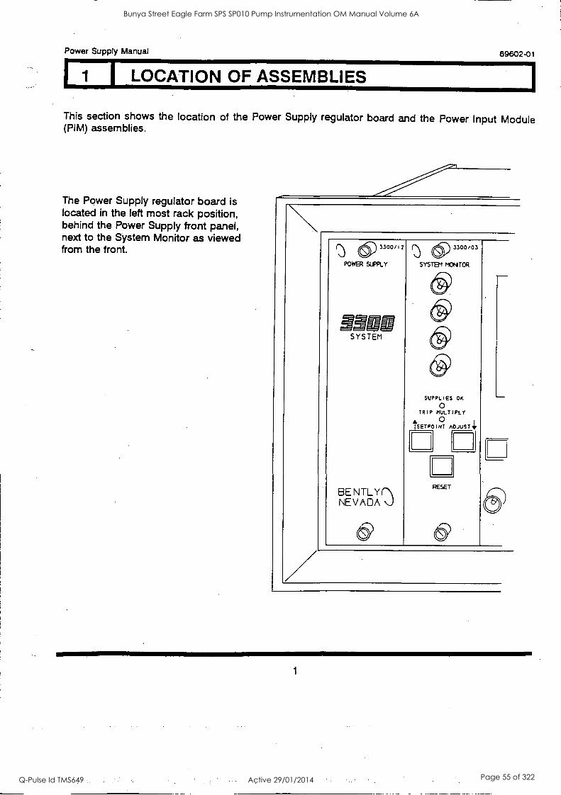
Power Supply Manual 89602-01
I LOCATION OF ASSEMBLIES
This section shows the location of the Power Supply regulator board and the Power Input Module (PIM) assemblies.
The Power Supply regulator board is located in the left most rack position, behind the Power Supply front panel, next to the System Monitor as viewed from the front. () 6) 3300/12
POWER SUPPLY
SYSTEM
BE N IL yr NEVADA \J
(5) 3300/03
SYSTEM MONTOR
SUPPLIES OK
0 TRIP MULTIPLY
0 ArSETPO I NT ADJUST Tit
RESET
1
Bunya Street Eagle Farm SPS SP010 Pump Instrumentation OM Manual Volume 6A
Q-Pulse Id TMS649 Active 29/01/2014 Page 55 of 322
89602-01 Power Supply Manual
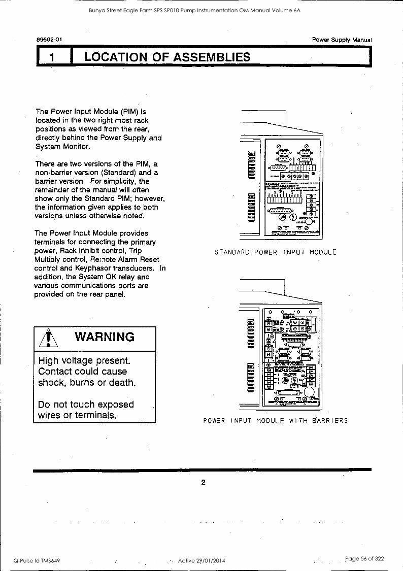
I LOCATION OF ASSEMBLIES
The Power Input Module (PIM) is located in the two right most rack positions as viewed from the rear, directly behind the Power Supply and System Monitor.
There are two versions of the PIM, a non-barrier version (Standard) and a barrier version. For simplicity, the remainder of the manual will often show only the Standard PIM; however, the information given applies to both versions unless otherwise noted.
The Power Input Module provides terminals for connecting the primary power, Rack Inhibit control, Trip Multiply control, Remote Alarm Reset control and Keyphasor transducers. In addition, the System OK relay and various communications ports are provided on the rear panel.
WARNING
High voltage present. Contact could cause shock, burns or death.
Do not touch exposed wires or terminals.
STANDARD POWER INPUT MODULE
POWER INPUT MODULE WITH BARRIERS
2
Bunya Street Eagle Farm SPS SP010 Pump Instrumentation OM Manual Volume 6A
Q-Pulse Id TMS649 Active 29/01/2014 Page 56 of 322
Power Supply Manual 89602-01
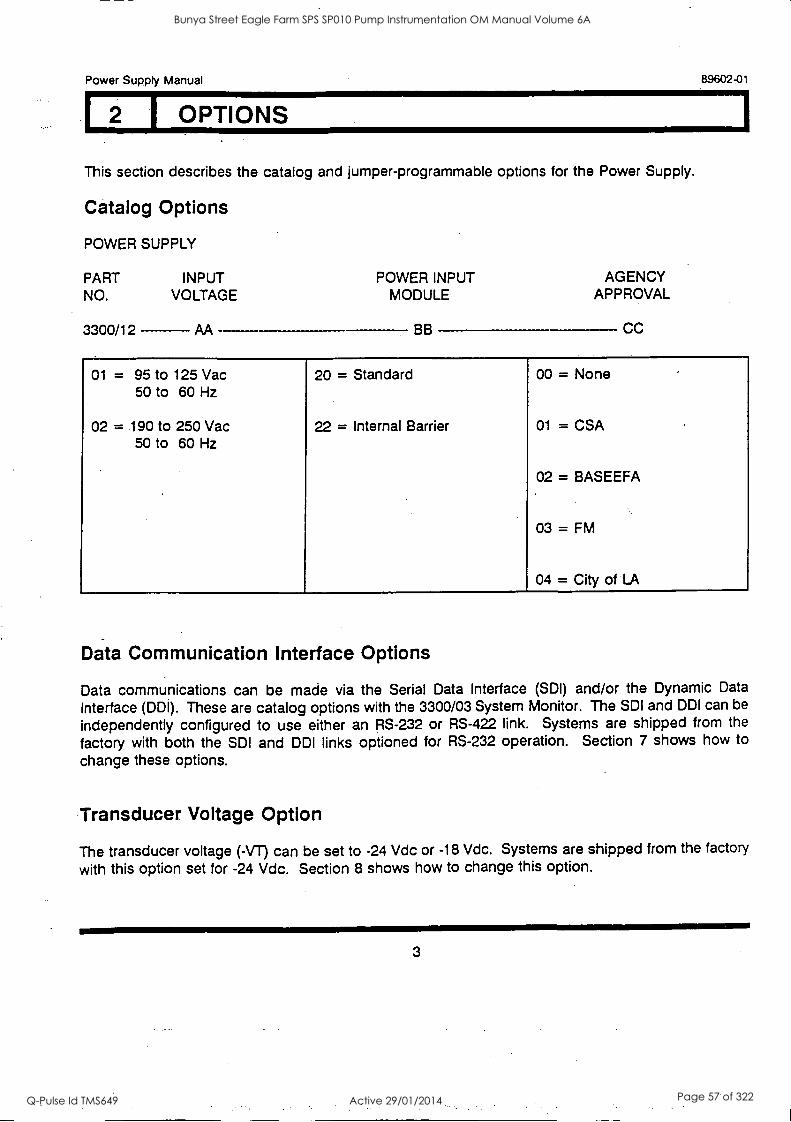
1 OPTIONS
This section describes the catalog and jumper-programmable options for the Power Supply.
Catalog Options
POWER SUPPLY
PART INPUT POWER INPUT AGENCY NO. VOLTAGE MODULE APPROVAL
3300/12 AA BB CC
01 = 95 to 125 Vac 50 to 60 Hz
02 = .190 to 250 Vac
20 = Standard
22 = Internal Barrier
00 = None .
01 = CSA 50 to 60 Hz
02 = BASEEFA . .
03 = FM
04 = City of LA
Data Communication Interface Options
Data communications can be made via the Serial Data Interface (SDI) and/or the Dynamic Data
Interface (DDI). These are catalog options with the 3300/03 System Monitor. The SDI and DDI can be
independently configured to use either an RS-232 or RS-422 link. Systems are shipped from the
factory with both the SDI and DDI links optioned for RS-232 operation. Section 7 shows how to
change these options.
Transducer Voltage Option
The transducer voltage (-VT) can be set to -24 Vdc or -18 Vdc. Systems are shipped from the factory
with this option set for -24 Vdc. Section 8 shows how to change this option.
3
Bunya Street Eagle Farm SPS SP010 Pump Instrumentation OM Manual Volume 6A
Q-Pulse Id TMS649 Active 29/01/2014 Page 57 of 322
89602-01 Power Supply Manual
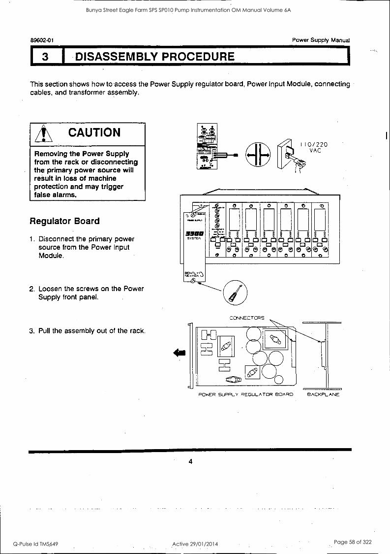
I DISASSEMBLY PROCEDURE
This section shows how to access the Power Supply regulator board, Power Input Module, connecting cables, and transformer assembly.
4\ CAUTION
Removing the Power Supply from the rack or disconnecting the primary power source will result in loss of machine protection and may trigger false alarms.
Regulator Board
1. Disconnect the primary power source from the Power Input Module.
2. Loosen the screws on the Power Supply front panel.
3. Pull the assembly out of the rack.
POW
MOO SYSTEM
XOL
0 0 0
c!3
000 [1.3
0 0
0
O 0
CONNECTORS
POWER SLPPLY REGULATOR BOARD BACKPLANE
4
Bunya Street Eagle Farm SPS SP010 Pump Instrumentation OM Manual Volume 6A
Q-Pulse Id TMS649 Active 29/01/2014 Page 58 of 322
Power Supply Manual 89602-01
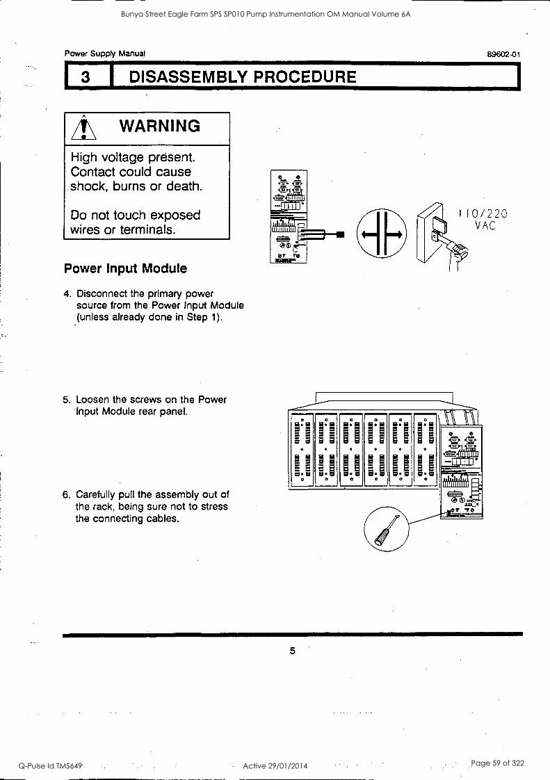
I 3 I DISASSEMBLY PROCEDURE
WARNING
High voltage present. Contact could cause shock, burns or death.
Do not touch exposed wires or terminals.
Power Input Module
4. Disconnect the primary power source from the Power Input Module (unless already done in Step 1).
5. Loosen the screws on the Power 'Input Module rear panel.
6. Carefully pull the assembly out of the rack, being sure not to stress the connecting cables.
MI"
11W11111111
5
Bunya Street Eagle Farm SPS SP010 Pump Instrumentation OM Manual Volume 6A
Q-Pulse Id TMS649 Active 29/01/2014 Page 59 of 322

89602-01 Power Supply Manual
DISASSEMBLY PROCEDURE
Connecting Cables
7. Release the retainer tabs on the ends of the cable connectors as required to remove the Power Input Module from the rack. Be sure all of the cables are properly secured when reconnecting the Power Input Module to the rack.
Transformer Assembly
The transformer is secured to a support plate with two bolts. The support plate slides into the rack behind the Power Input Module.
8. Remove the screw that mounts the support plate to the rack side panel.
9. Disconnect the primary and secondary connector plugs from the Power Input Module and backplane.
10. Slide the transformer and support plate assembly out of the rack.
RETAINER TABS
TRANSFORMER
POWER INPUT MODULE
(BACK SIDE)
SUPPORT PLATE
PRIMARY <----- CABLE AND
CONNECTOR SECONDARY CABLE AND CONNECTOR SUPPORT
PLATE MOUNTING SCREW (THROUGH SIDE OF RACK)
6
Bunya Street Eagle Farm SPS SP010 Pump Instrumentation OM Manual Volume 6A
Q-Pulse Id TMS649 Active 29/01/2014 Page 60 of 322
Power Supply Manual 89602-01
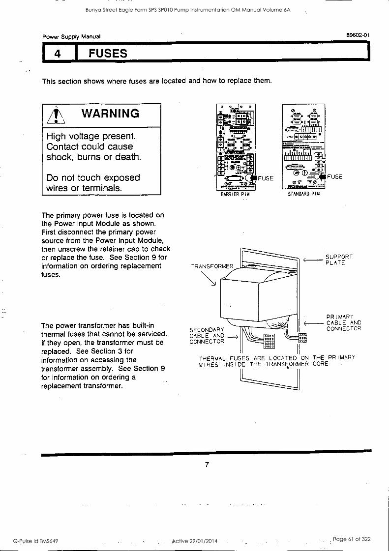
14 I FUSES
This section shows where fuses are located and how to replace them.
WARNING
High voltage present. Contact could cause shock, burns or death.
Do not touch exposed wires or terminals.
The primary power fuse is located on the Power Input Module as shown. First disconnect the primary power source from the Power Input Module, then unscrew the retainer cap to check or replace the fuse. See Section 9 for information on ordering replacement fuses.
The power transformer has built-in thermal fuses that cannot be serviced. If they open, the transformer must be replaced. See Section 3 for information on accessing the transformer assembly. See Section 9
for information on ordering a replacement transformer.
BARRIER PIM
TRANSFORMER
FUSE
= la
UHlin
'10.0161,1
crs s0 STANDARD PIM
SECONDARY CABLE AND CONNECTOR
0000 0000 0000 0000 0000
FUSE
SUPPORT ____ PLATE
PRIMARY 4----- CABLE AND
ooC
CONNECTOR 000
0
THERMAL FUSES ARE LOCATED ON THE PRIMARY WIRES INSIDE THE TRANSFORMER CORE
7
Bunya Street Eagle Farm SPS SP010 Pump Instrumentation OM Manual Volume 6A
Q-Pulse Id TMS649 Active 29/01/2014 Page 61 of 322
89602-01 Power Supply Manual
I 5 INPUT VOLTAGE OPTION
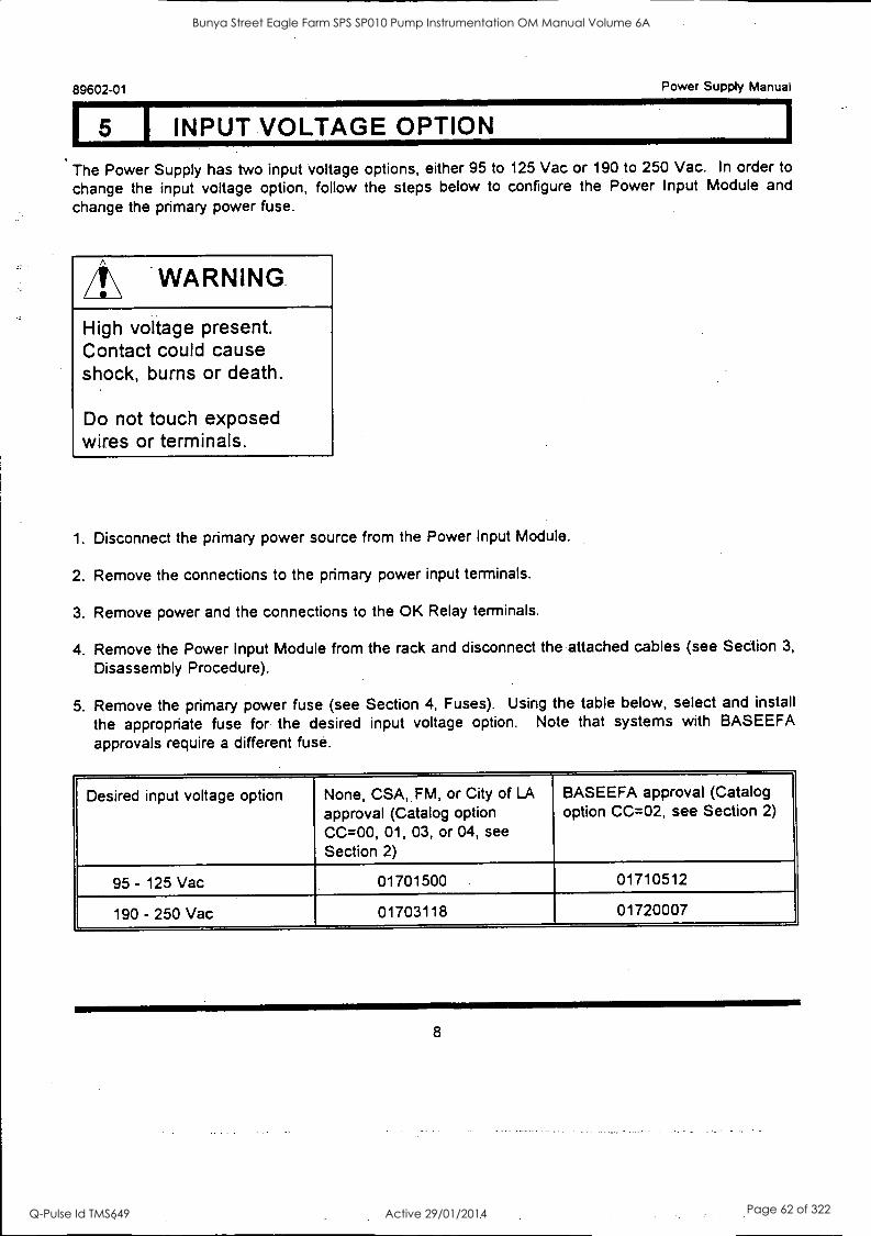
The Power Supply has two input voltage options, either 95 to 125 Vac or 190 to 250 Vac. In order to
change the input voltage option, follow the steps below to configure the Power Input Module and
change the primary power fuse.
/I\ WARNING.
High voltage present. Contact could cause shock, burns or death.
Do not touch exposed wires or terminals.
1. Disconnect the primary power source from the Power Input Module.
2. Remove the connections to the primary power input terminals.
3. Remove power and the connections to the OK Relay terminals.
4. Remove the Power Input Module from the rack and disconnect the attached cables (see Section 3,
Disassembly Procedure).
5. Remove the primary power fuse (see Section 4, Fuses). Using the table below, select and install
the appropriate fuse for the desired input voltage option. Note that systems with BASEEFA approvals require a different fuse.
Desired input voltage option None, CSA, FM, or City of LA
approval (Catalog option CC=00, 01, 03, or 04, see Section 2)
BASEEFA approval (Catalog option CC=02, see Section 2)
95- 125 Vac 01701500 01710512
190 - 250 Vac 01703118 01720007
8
Bunya Street Eagle Farm SPS SP010 Pump Instrumentation OM Manual Volume 6A
Q-Pulse Id TMS649 Active 29/01/2014 Page 62 of 322
Power Supply Manual 89602-01
I INPUT VOLTAGE OPTION
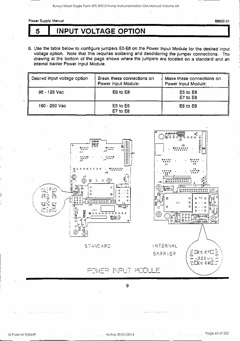
6. Use the table below to configure jumpers E5-E8 on the Power Input Module for the desired input voltage option. Note that this requires soldering and desoldering the jumper connections. The drawing at the bottom of the page shows where the jumpers are located on a standard and an internal barrier Power Input Module.
Desired input voltage option Break these connections on Power Input Module:
Make these connections on Power Input Module:
95 - 125 Vac E6 to E8 E5 to E6 E7 to E8
190 - 250 Vac E5 to E6 E7 to E8
E6 to E8
3333 .0000 0000 Ja
00. 0
J3
5 0 0 0 0 0 0 0 0 JS
!C) j' ;-"Ti (5) co
--- -- il: 2,- ail
0-- , . - - ,---3.0 ;lire4,...,3! : , 1---:_0--1
0
II ... (11
r 00001 E.7N z7
/
i , a 0 C
T. ";8...:,,
\ t7-1 0 t)-1 / : ''.)) " i E , e
0 0
...v J2
J6
(r
i i i
90000
.131.41.0351/ 310 CO: U (5 5 0 0 0 0 o -15
J6 80000000 m
. 0000000 2 O.
80000 0000 ' J 1
00009 0000
0000000000000 jg Sc000000eocoo
CIE.TLY0 I"M "(""a 0000000000000000 I
0 J121 0000000000000000 (C)),Ii
90000 0000
J2
J 00008 0000
9 o 0 0 000
(01 a00
0 K. I 0 O
0 0 0 cno>-.
0 0 0 0 E
Eiog
sals c7tn,
ic-,:arke EEC: J : . 22 0 I., L."' 0_7)17';
sT,fr;NnARD INTERNAL
BARRIER "c5,1E5
r220U7 ta6 Eel:" PnliFP INPUT MCOLLF-
9
Bunya Street Eagle Farm SPS SP010 Pump Instrumentation OM Manual Volume 6A
Q-Pulse Id TMS649 Active 29/01/2014 Page 63 of 322

15 I INPUT VOLTAGE OPTION
89602-01 Power Supply Manual
7. Reconnect the cables that were disconnected in step four and re-install the Power Input Module to the rack. Connect the wires to the OK Relay and the primary power input terminals. Apply the OK Relay power and the primary power. Do not apply power to the rack until the Power Input Module is completely installed.
10
Bunya Street Eagle Farm SPS SP010 Pump Instrumentation OM Manual Volume 6A
Q-Pulse Id TMS649 Active 29/01/2014 Page 64 of 322
Power Supply Manual 89602-01
6 TESTING AND TROUBLESHOOTING
This section shows how to verify that the Power Supply is operating properly and explains what to do if it is not.
WARNING
High voltage present. Contact could cause shock, burns or death.
Do not touch exposed wires or terminals.
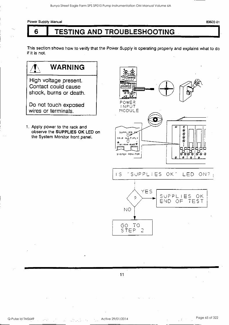
1. Apply power to the rack and observe the SUPPLIES OK LED on the System Monitor front panel.
471D. or Te
POWER INPUT
MODULE
SUPPLIES
TRIP MULTIPLY
SET .O (T ADJusta
SYSTEM MONITOR
I S **SUPPL I ES OK LED ON
YES
NO
GO TO STEP 2
SUPPLIES OK END OF TEST
11
Bunya Street Eagle Farm SPS SP010 Pump Instrumentation OM Manual Volume 6A
Q-Pulse Id TMS649 Active 29/01/2014 Page 65 of 322
89602-01 Power Supply Manual
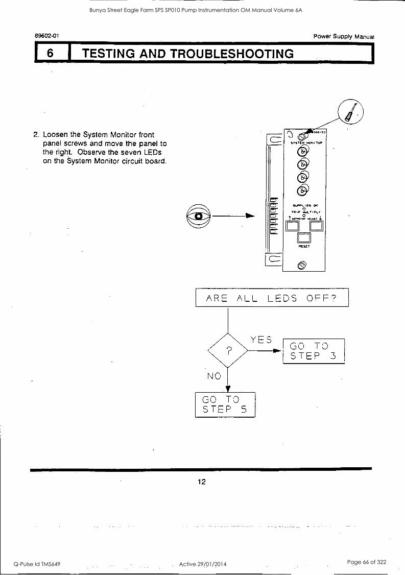
6 I TESTING AND TROUBLESHOOTING
2. Loosen the System Monitor front panel screws and move the panel to the right. Observe the seven LEDs on the System Monitor circuit board.
ARE ALL LEDS OFF?
NO
YES GO TO STEP 3
GO TO STEP 5
12
Bunya Street Eagle Farm SPS SP010 Pump Instrumentation OM Manual Volume 6A
Q-Pulse Id TMS649 Active 29/01/2014 Page 66 of 322
Power Supply Manual 89602-01
1.6.1 TESTING AND TROUBLESHOOTING
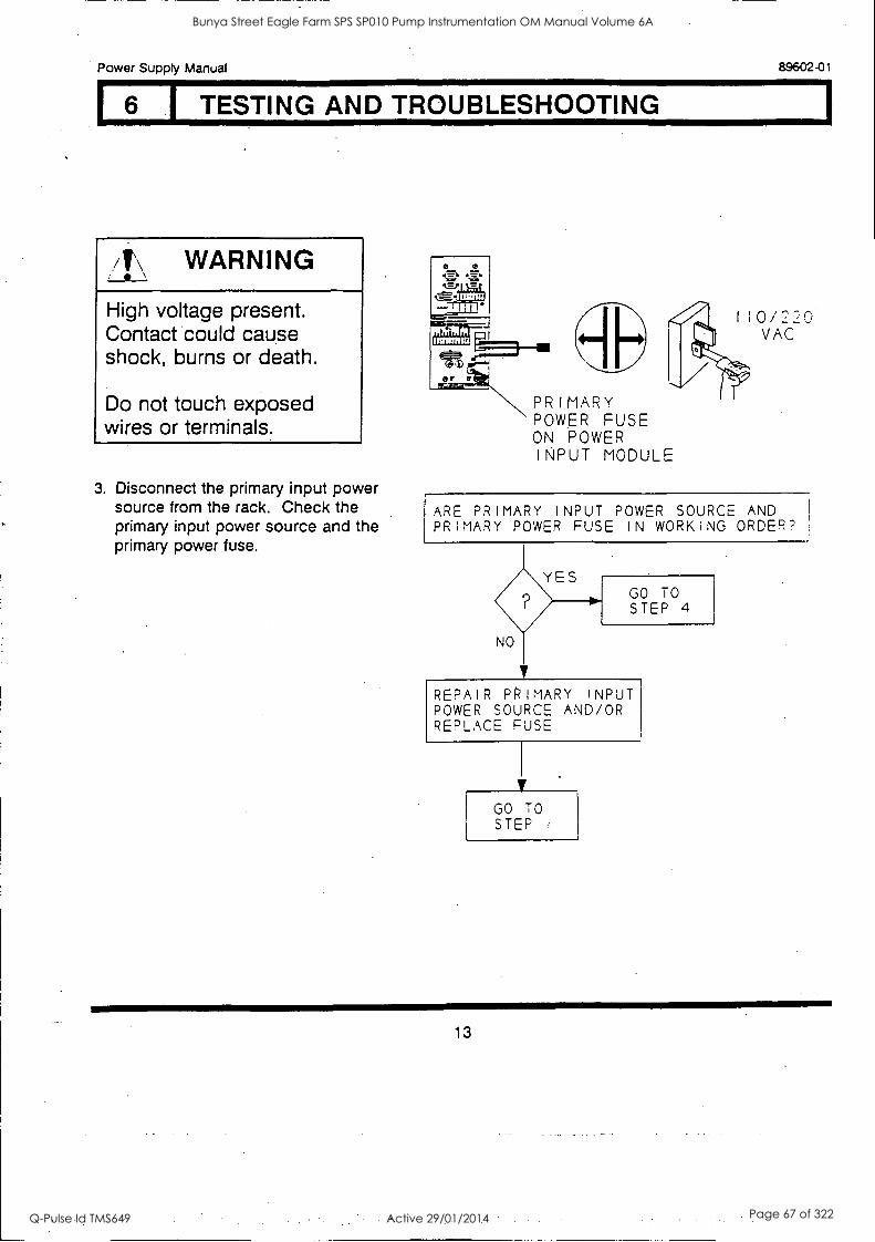
/I\ WARNING
High voltage present. Contact could cause shock, burns or death.
Do not touch exposed wires or terminals.
3. Disconnect the primary input power source from the rack. Check the primary input power source and the primary power fuse.
PRIMARY 'POWER FUSE ON POWER INPUT MODULE
ARE PRIMARY INPUT POWER SOURCE AND PRIMARY POWER FUSE IN WORKING ORDER?
REPAIR PRIMARY INPUT POWER SOURCE AND/OR REPLACE FUSE
GO TO STEP
13
Bunya Street Eagle Farm SPS SP010 Pump Instrumentation OM Manual Volume 6A
Q-Pulse Id TMS649 Active 29/01/2014 Page 67 of 322
89602-01 Power Supply Manual
6 TESTING AND TROUBLESHOOTING
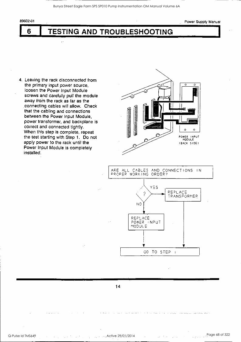
4. Leaving the rack disconnected from the primary input power source, loosen the Power Input Module screws and carefully pull the module away from the rack as far as the connecting cables will allow. Check that the cabling and connections between the Power Input Module, power transformer, and backplane is correct and connected tightly. When this step is complete, repeat the test starting with Step 1. Do not apply power to the rack until the Power Input Module is completely installed.
POWER INPUT MODULE
( BACK SIDE)
ARE ALL CABLES AND CONNECTIONS IN PROPER WORKING ORDER?
YES
NO
REPLACE POWER INPUT MODULE
REPLACE TRANSPORMER
V
GO TO STEP
14
Bunya Street Eagle Farm SPS SP010 Pump Instrumentation OM Manual Volume 6A
Q-Pulse Id TMS649 Active 29/01/2014 Page 68 of 322
Power Supply Manual
6 I TESTING AND TROUBLESHOOTING
89602-01
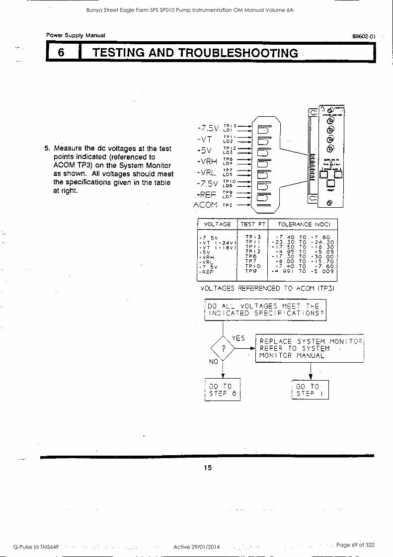
5. Measure the dc voltages at the test points indicated (referenced to ACOM TP3) on the System Monitor as shown. All voltages should meet the specifications given in the table at right.
-VT -5V -VRH -VRL -7.5V -REF
ACOM
TP I 3
LD I
TP I I --ow LD2
TPI2--- LDS
TP6 LD4
TP7 LDS T P LO6
TP9 LD7
TP3
WftWOM IVO &JO,
VOLTAGE TEST PT TOLERANCE (VDC)
-7.5v TP13 -7.40 TO -7.60 -VT (-24v) TP11 -23.30 TO -24.20 -VT (-18v) TPII -17.50 TO -18.30 -5V TP12 -4.95 TO -5.05 VRH TP6 I7.30 TO -30.00 -vRL TP7 -8.00 TO -15.70 -7.5v TP)0 -7.40 TO 7.60 -REP TP9 -4 991 TO -5.009
VOLTAGES REFERENCED TO ACOM (TP3)
DO ALL VOLTAGES MEET THE INDICATED SPECIFICATIONS?
YES
NO
I - u0 TO STEP 6
REPLACE SYSTEM MONITOR] REFER TO SYSTEM MONITOR MANUAL
V
GO TO STEP I
15
Bunya Street Eagle Farm SPS SP010 Pump Instrumentation OM Manual Volume 6A
Q-Pulse Id TMS649 Active 29/01/2014 Page 69 of 322
89602-01 Power Supply Manual U TESTING AND TROUBLESHOOTING
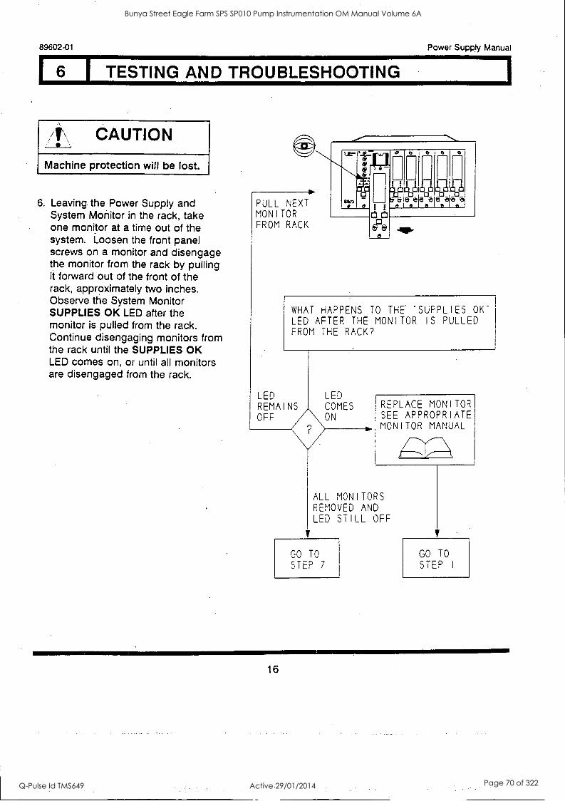
/I\ CAUTION
Machine protection will be lost.
6. Leaving the Power Supply and System Monitor in the rack, take one monitor at a time out of the system. Loosen the front panel screws on a monitor and disengage the monitor from the rack by pulling it forward out of the front of the rack, approximately two inches. Observe the System Monitor SUPPLIES OK LED after the monitor is pulled from the rack. Continue disengaging monitors from the rack until the SUPPLIES OK LED comes on, or until all monitors are disengaged from the rack.
PULL NEXT MONITOR FROM RACK
C C
4341110 &dee@ e 12PA+)
et 0 et e
WHAT HAPPENS TO THE 'SUPPLIES OK" LED AFTER THE MONITOR IS PULLED FROM THE RACK?
LED REMAINS OFF
LED COMES ON
REPLACE MONITOR SEE APPROPRIATE MONITOR MANUAL
ALL MON I TORS REMOVED AND LED ST ILL OFF
GO TO
STEP 7
GO TO
STEP I
16
Bunya Street Eagle Farm SPS SP010 Pump Instrumentation OM Manual Volume 6A
Q-Pulse Id TMS649 Active 29/01/2014 Page 70 of 322
1
Power Supply Manual 89602-01
6 I TESTING AND TROUBLESHOOTING
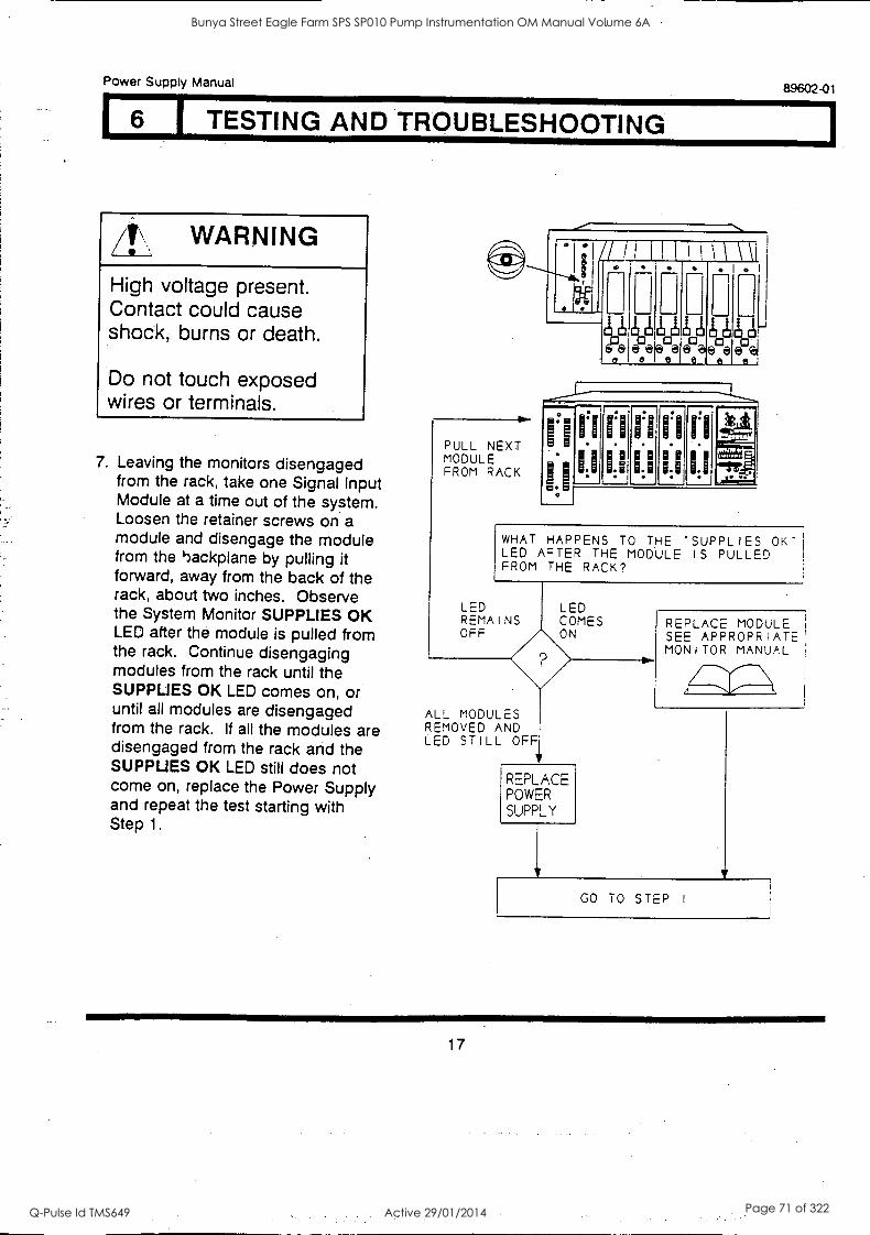
WARNING
High voltage present. Contact could cause shock, burns or death.
Do not touch exposed wires or terminals.
7. Leaving the monitors disengaged from the rack, take one Signal Input Module at a time out of the system. Loosen the retainer screws on a module and disengage the module from the imckplane by pulling it forward, away from the back of the rack, about two inches. Observe the System Monitor SUPPLIES OK LED after the module is pulled from the rack. Continue disengaging modules from the rack until the SUPPLIES OK LED comes on, or until all modules are disengaged from the rack. If all the modules are disengaged from the rack and the SUPPLIES OK LED still does not come on, replace the Power Supply and repeat the test starting with Step 1.
PULL NEXT MODULE FROM RACK
AI ee
.
ct---0-21J3ct epeic-: . ci . -
J....._
it Ili!, ecla
A
epeil
,....--
11 n11111111 ;1
WHAT HAPPENS TO THE SUPPLIES OK"1 LED AFTER THE MODULE IS PULLED FROM THE RACK?
LED REMAINS OFF
ALL MODULES REMOVED AND LED STILL OFF
LED COMES ON
REPLACE POWER
SUPPLY
REPLACE MODULE SEE APPROPRIATE MONITOR MANUAL
GO TO STEP I
17
Bunya Street Eagle Farm SPS SP010 Pump Instrumentation OM Manual Volume 6A
Q-Pulse Id TMS649 Active 29/01/2014 Page 71 of 322
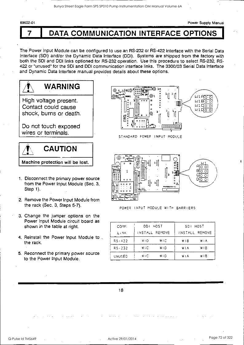
7 I DATA COMMUNICATION INTERFACE OPTIONS 1
89602-01 Power Supply Manual
The Power Input Module can be configured to use an RS-232 or RS-422 interface with the Serial Data Interface (SDI) and/or the Dynamic Data Interface (DDI). Systems are shipped from the factory with both the SDI and DDI links optioned for RS-232 operation. Use this procedure to select RS-232, RS- 422 or "unused" for the SDI and DDI communication interface links. The 3300/03 Serial Data Interface and Dynamic Data Interface manual provides details about these options.
/tf\' WARNING
High voltage present. Contact could cause shock, burns or death.
Do not touch exposed wires or terminals.
CAUTION
Machine protection will be lost.
1. Disconnect the primary power source from the Power Input Module (Sec. 3,
Step 1).
2. Remove the Power Input Module from the rack (Sec. 3, Steps 5-7).
3. Change the jumper options on the Power Input Module circuit board as shown in the table at right.
4. Reinstall the Power Input Module to the rack.
5. Reconnect the primary power source to the Power Input Module.
STANDARD POWER INPUT MODULE
ezn
" °
[moo 000 000 0 o o
f3 °9 00 0 0 ,to,
mc" gatamaits
:ih
n7:4
ory 0
0 0 .1.
Puo111209- 0 I
Boo Cool D 0 0 /
POWER INPUT MODULE WITH BARRIERS
COMM
LINK
DDI
INSTALL
HOST
REMOVE
SDI
INSTALL
HOST
REMOVE
RS-422 WID WIC WIB WIA
RS-232 WIC WID WIA WIB
UNUSED WIC WID WIA WIB
18
Bunya Street Eagle Farm SPS SP010 Pump Instrumentation OM Manual Volume 6A
Q-Pulse Id TMS649 Active 29/01/2014 Page 72 of 322
Power Supply Manual 89602-01
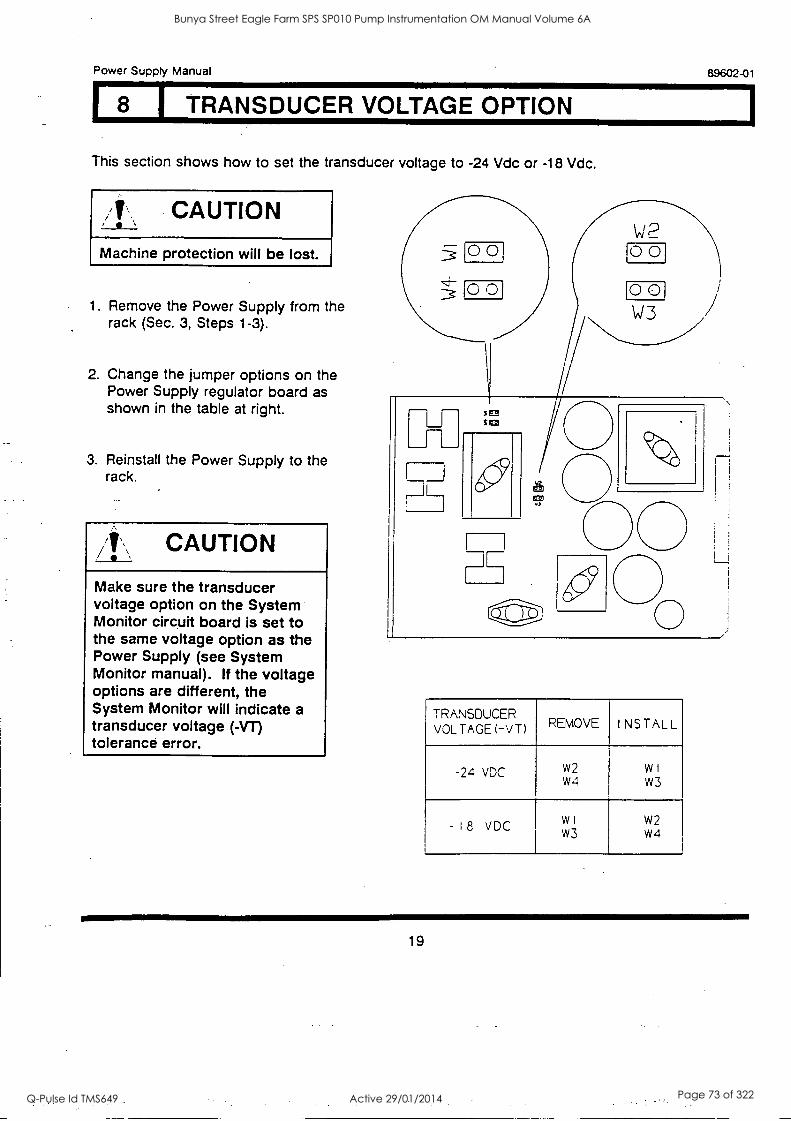
I TRANSDUCER VOLTAGE OPTION
This section shows how to set the transducer voltage to -24 Vdc or -18 Vdc.
CAUTION
Machine protection will be lost.
1. Remove the Power Supply from the rack (Sec. 3, Steps 1-3).
2. Change the jumper options on the Power Supply regulator board as shown in the table at right.
3. Reinstall the Power Supply to the rack.
zit , CAUTION
Make sure the transducer voltage option on the System Monitor circuit board is set to the same voltage option as the Power Supply (see System Monitor manual). If the voltage options are different, the System Monitor will indicate a transducer voltage (-VT) tolerance error.
W2
TRANSDUCER VOLTAGE (-VT) REMOVE INSTALL
-24 vDC w2 w4
w 1
W3
- 18 VDC w I
w3 w2 w4
19
Bunya Street Eagle Farm SPS SP010 Pump Instrumentation OM Manual Volume 6A
Q-Pulse Id TMS649 Active 29/01/2014 Page 73 of 322
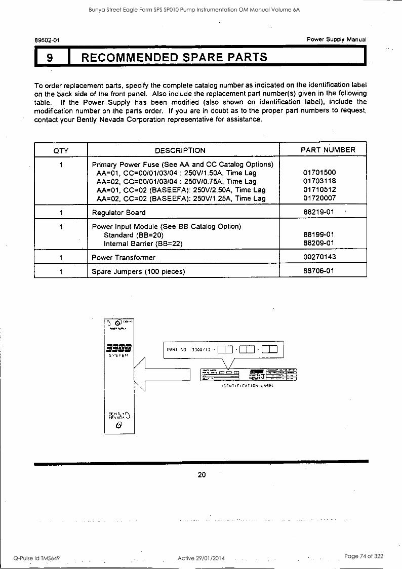
19 I RECOMMENDED SPARE PARTS
89602-01 Power Supply Manual
1
To order replacement parts, specify the complete catalog number as indicated on the identification label on the back side of the front panel. Also include the replacement part number(s) given in the following table. If the Power Supply has been modified (also shown on identification label), include the modification number on the parts order. If you are in doubt as to the proper part numbers to request, contact your Bent ly Nevada Corporation representative for assistance.
QTY DESCRIPTION PART NUMBER
1 Primary Power Fuse (See AA and CC Catalog Options) AA=01, CC=00/01/03/04 : 250V/1.50A, Time Lag 01701500 AA=02, CC=00/01/03/04 : 250V/0.75A, Time Lag 01703118 AA=01, CC=02 (BASEEFA): 250V/2.50A, Time Lag 01710512 AA=02, CC=02 (BASEEFA): 250V/1.25A, Time Lag 01720007
1 Regulator Board 88219-01
1 Power Input Module (See BB Catalog Option) Standard (BB=20) 88199-01 Internal Barrier (BB=22) 88209-01
1 Power Transformer 00270143
1 Spare Jumpers (100 pieces) 88706-01
PART NO 3300/12 - 1
.17.11. 141., CD
,
IDENTIFICATION LABEL
20
Bunya Street Eagle Farm SPS SP010 Pump Instrumentation OM Manual Volume 6A
Q-Pulse Id TMS649 Active 29/01/2014 Page 74 of 322
Power Supply Manual 89602-01
LIOJ SPECIFICATIONS
POWER INPUT
110 Vac Option: 95 to 125 Vac, Single Phase, 50 to 60 Hz, 0.6 A maximum.
220 Vac Option: 190 to 250 Vac, Single Phase, 50 to 60 Hz, 0.3 A maximum.
Start Up Surge: 20 A peak (7 A rms) for one cycle.
Surge Suppression: Clamp Voltage 285 to 300 V rms. Peak Surge Current 100 A for 6 msec maximum.
Power Dissipation: 60 W average.
ENVIRONMENTAL
Operating Temperature: +32F to +149F (0C to +65C)
Storage Temperature: -40F to +185F (-40°C to +85C)
Relative Humidity: 0 to 95%, noncondensing
21
Bunya Street Eagle Farm SPS SP010 Pump Instrumentation OM Manual Volume 6A
Q-Pulse Id TMS649 Active 29/01/2014 Page 75 of 322

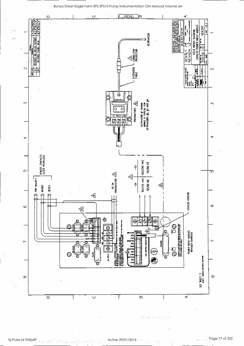
111 I FIELD WIRING DRAWINGS
89602-01 Power Supply Manual
DRAWING TITLE DRAWING NO. SHEETS
FIELD WRING DIAGRAM 3300 AC PIM, STANDARD 104297 2
FIELD WIRING DIAGRAM 3300 AC PIM, INTERNAL BARRIERS 104649 2
FIELD WRING DIAGRAM 3300 AC PIM, EXTERNAL BARRIERS . . . . 104298 2
22
Bunya Street Eagle Farm SPS SP010 Pump Instrumentation OM Manual Volume 6A
Q-Pulse Id TMS649 Active 29/01/2014 Page 76 of 322
RA
CK
ST
AT
IC
CU
N
IA
IRA
RN
INC
- M
ULL
N N
AZ
AR
rx
=ra
r ea
tinss
atta
-RIA
LDI X
PLO
SIC
h MIM
I D
I M
S O
RM
IM
O t+t
°01-
T
RIP
M
ULI
PLY
°01-
R
ES
ET
MX
IF =
M.
P. 00
......
. if
ittA
tiAtif
i
IR C
OP
PE
R
CO
DU
CT
OR
,
OY
NA
UC
)
MO
INIS
S, M
N?
MO
IM
MO
. P.
M3
CO
RA
41
1101
14 1
011.11,
1111
11
13:0
O
ILII
ILIS
PO
WE
R
INP
UT
MO
DU
LE
WIT
HO
UT
B
AR
RIE
RS
SEE SHEET 2
miss o
na.s
c w
an
RE
MO
TE
C
ON
TA
CT
S
(US
ER
IN
S IN
LLD
)
TO
OK
AN
NU
NC
IAT
OR
/3
\
CH
AS
SIS
G
RO
UN
D
-01
-02
95/1
25 VAC
190/250 VAC
50/60
50/60 HZ
0/60 HZ
ISIV
I901
N
1171
/11n
RE
VIS
ED
OK
R
ELA
Y
RA
TIN
G
JC
RE
VIS
ED
P
AN
EL
VIE
JC
C
G
PR
OX
IMI 1
OR
S
KE
YP
HA
SO
R
11
SH
OW
N
WIR
ING
IS
T
YP
ICA
L F
OR
KE
YP
HA
SO
RS
p.
p A
ND
j4
EX
TE
NS
ION
C
AB
LE
CO
NN
EC
TO
R
PR
OT
EC
TO
R
0 K
EY
PH
AS
OR
==
. "`
""%
:"`"
,
OD
Im
a on
. IP
Err
= s
o O
m
.'":
0 H
im r
wal
la 8
1 m
om
NW
/. 15
m
aaa
im
NBEENVATIDYA
FIE
LD
WIR
ING
D
IAG
RA
M
3300
/12
PO
WE
R
INP
UT
M
OD
ULE
MIN
O
EM
NS
2 0
2 3
0 D
1 0
4 2
9 7
NO
( I
CI
2
8 i
7 4
3 2
I 1
D
ri
0
Bunya Street Eagle Farm SPS SP010 Pump Instrumentation OM Manual Volume 6A
Q-Pulse Id TMS649 Active 29/01/2014 Page 77 of 322
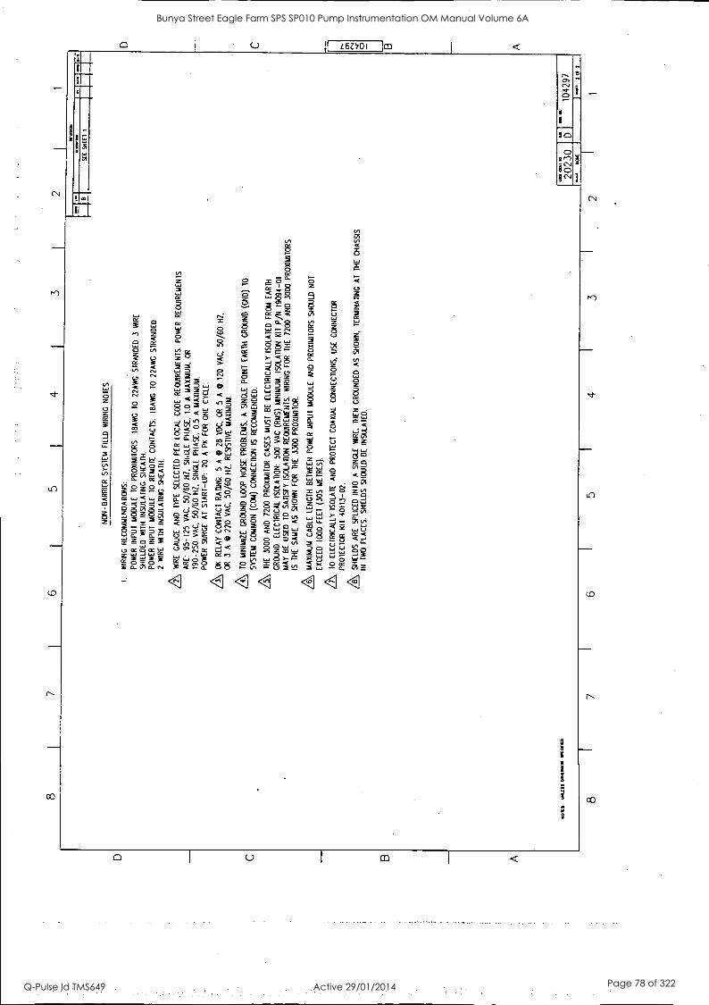
8 I
5 I
4 I
3
NO
N-B
AR
RIE
R
SY
ST
EM
F
IELD
W
RIN
G
NO
TE
S
I W
IRIN
G
RE
CO
MM
EN
DA
TIO
NS
:
PO
WE
R
INP
UT
M
OD
ULE
T
O
PR
OX
IMIT
OR
S:
18A
WG
T
O
22A
WG
S
TR
AN
DE
D 3
W
IRE
S
HIE
LDE
D
WIT
H
INS
ULA
TIN
G
SH
EA
TH
. P
OW
ER
IN
PU
T
MO
DU
LE
TO
R
EM
OT
E
CO
NT
AC
TS
: IB
AW
G
TO
22
AW
G
ST
RA
ND
ED
2
WIR
E
WIT
H
INS
ULA
TIN
G
SH
EA
TH
.
/2\
WIR
E
GA
UG
E
AN
D
TY
PE
S
ELE
CT
ED
P
ER
LO
CA
L C
OD
E
RE
QU
IRE
ME
NT
S.
PO
WE
R
RE
QU
IRE
ME
NT
S
AR
E:
95-1
25
VA
C,
50/6
0 H
Z.
SII,
ILE
P
HA
SE
. 1.
0 A
M
AX
IMU
M.
OR
190-
250
VA
C,
50/6
0 H
Z.
SIN
GLE
P
HA
SE
. 0.
5 A
M
AX
IMU
M.
PO
WE
R S
UR
GE
A
T
ST
AR
T-U
P:
20 A
P
K
FO
R
ON
E
CY
CLE
.
A OK
RE
LAY
C
ON
TA
CT
R
AT
ING
: 5
A 0
28
VD
C,
OR
5
A
0 12
0 V
AC
. 50
/60
HZ
. O
R
3 A
0
220
VA
C.
50/6
0 H
Z.
RE
SIS
TIV
E
MA
XIM
UM
.
A TO
MIN
IMIZ
E
GR
OU
ND
LO
OP
N
OIS
E
PR
OB
LEM
S.
A
SIN
GLE
P
OIN
T
EA
RT
H
GR
OU
ND
(C
IO)
TO
SY
ST
EM
C
OM
MO
N
(CO
M)
CO
NN
EC
TIO
N
IS
RE
CO
MM
EN
DE
D.
A THE
30
00
AN
D
7200
P
RO
XIIA
ITO
R
CA
SE
S
MU
ST
B
E
ELE
CT
RIC
ALL
Y
ISO
LAT
ED
F
RO
M
EA
RT
H
GR
OU
ND
. E
LEC
TR
ICA
L IS
OLA
TIO
N:
500
VA
C (
RM
S)
MIN
IMU
M.
ISO
LAT
ION
K
IT P
/N 1
9094
-01
MA
Y
BE
U
SE
D
TO
S
AT
ISF
Y
ISO
LAT
ION
R
EQ
UIR
EM
EN
TS
. W
IRIN
G
FO
R
TH
E
7200
A
ND
30
00 P
RO
XIM
ITO
RS
IS
T
HE
S
AM
E
AS
S
HO
WN
F
OR
T
HE
33
00 P
RO
XIM
ITO
R.
A MA
XIM
UM
C
AB
LE
LEN
GT
H B
ET
WE
EN
P
OW
ER
IN
PU
T M
OD
ULE
A
ND
P
RO
XIM
ITO
RS
SH
OU
LD
NO
T
EX
CE
ED
10
00 F
EE
T
(305
ME
TR
ES
).
A TO
E
LEC
TR
ICA
LLY
IS
OLA
TE
A
ND
P
RO
TE
CT
C
OA
XIA
L C
ON
NE
CT
ION
S,
US
E
CO
NN
EC
TO
R
PR
OT
EC
TO
R
KIT
40
113-
02.
A SH
IELD
S
AR
E
SP
LIC
ED
IN
TO
A
S
ING
LE
WIR
E.
TH
EN
G
RO
UN
DE
D
AS
S
HO
WN
, T
ER
MIN
AT
ING
A
T
TH
E
CH
AS
SIS
IN
T
WO
P
LAC
ES
. S
HIE
LDS
S
HO
ULD
B
E
INS
ULA
TE
D.
NO
W
YN
LIS
S
OM
IM
I( W
O,.
SIC
S
HE
EI
..1
1042
97
lioJ
NO
W
8 7
I 6
I 5
I 4
I 3
I 2
Bunya Street Eagle Farm SPS SP010 Pump Instrumentation OM Manual Volume 6A
Q-Pulse Id TMS649 Active 29/01/2014 Page 78 of 322
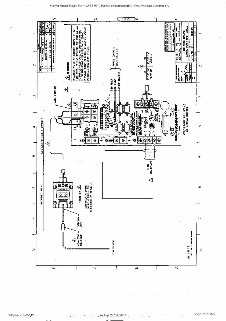
D
C
B A
8 7
6 5
4 3
2
HA
ZA
RD
OU
S A
RE
A
SA
FE
A
RE
A
OR
Z
ON
E
2.
DIV
ISIO
N
2
8 C
BA
RR
IER
G
RO
UN
D
CO
NN
EC
TO
R
EX
TE
NS
ION
P
RO
TE
CT
OR
C
AB
LE
PR
OX
IMI
TO
RS
L
IWY
PH
AS
CR
/1
S
HO
WN
W
RIN
G
IS
TY
PIC
AL
FO
R
KE
YP
HA
SO
RS
/2
. /3
AN
D
/4
TO
K
EY
PH
AS
OR
_9 w
oe
AD
DE
O
NO
TE
S
10 k
RE
VIS
ED
k
RE
DR
AIN
INC
C
EO
30
948
11..
KS
1 M
P
JLF
4L W
AR
NIN
G
MIS
CO
NN
EC
TIN
G
OR
IN
TE
RM
ITT
EN
T
CO
NT
AC
T
CF
T
HE
FIE
LD W
RIN
G
TO
R
AC
K
TE
RM
INA
LS
WIT
H
HIG
H
VO
LTA
GE
PO
TE
NT
IALS
CO
ULD
C
AU
SE
A
N
EX
PLO
SIO
N
OR
F
IRE
IN
TH
E
HA
ZA
RD
OU
S
AR
EA
R
ES
OLI
NG
IN
S
EV
ER
E
PE
RS
ON
AL
INJJ
RY
O
R
DE
AT
H.
RE
MO
VE
A
LL
VO
LTA
GE
PO
TE
NT
IALS
F
RO
M
RE
AR
O
F
RA
CK
I-
RE
SE
T
I IN
HIB
IT
RE
MO
TE
C
ON
TA
CT
S
- (U
SE
R
INS
TA
LLE
D)
I- T
RIP
M
ULT
IPLY
SE
E
SH
EE
T
2
WIL
L
1oa1
113
0141
.01
MO
T
TO
C
C
AN
NU
NC
IAT
OR
4 D
)(10
of
f ®
3300
/12
PO
KE
R
INP
UT
M
OD
ULE
KIT
H
INT
ER
NA
L B
AR
RIE
RS
95/1
25 V
AC
1190
/250
VA
C
50/6
0 H
Z
50/6
0 H
Z
-01
-02
1 11
1 II1
.
wo
4.1b
N
g .
, CIMI.. m
os. W
ay s
web
uft.
or
awe.
am
,
BE
N T
L Y
:
NE
VA
DA
E
lf D
M
IRIN
G
DIA
GR
AM
3300
/12
PO
KE
R
INP
UT
M
OD
ULE
2023
0 D
I1
4649
8 7
6 5
4 3
2 1
D
C
B
A
Bunya Street Eagle Farm SPS SP010 Pump Instrumentation OM Manual Volume 6A
Q-Pulse Id TMS649 Active 29/01/2014 Page 79 of 322
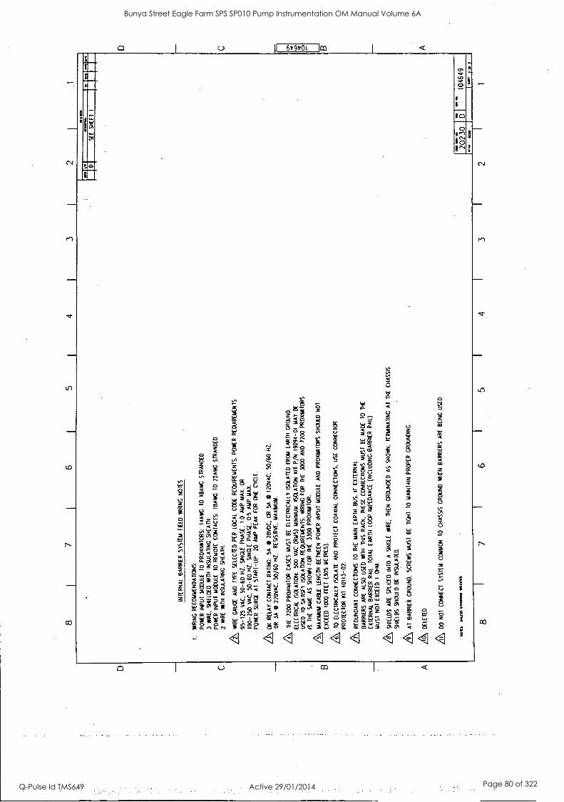
D C B A
8 6
5 4
3 2
INT
ER
NA
L B
AR
RIE
R S
YS
TE
M
FIE
LD
WIR
ING
N
OT
ES
I. W
RIN
G
RE
CO
MM
EN
DA
TIO
NS
:
PO
WE
R
INP
UT
M
OD
ULE
10
P
RO
XIM
ITO
RS
: 14
AW
G
10
IBA
WG
S
TR
AN
DE
D
3 W
IRE
. S
HIE
LDE
D
WIT
H
INS
ULA
TIN
G
SH
EA
TH
.
PO
WE
R I
NP
UT
M
OD
ULE
T
O
RE
MO
TE
C
ON
TA
CT
S:
I8A
WG
T
O
22A
WC
S
TR
AN
DE
D
2 W
IRE
WIT
H
INS
ULA
TIN
G
SH
EA
TH
.
A WIR
E
GA
UG
E
AN
D
TY
PE
S
ELE
CT
ED
P
ER
LO
CA
L C
OD
E
RE
QU
IRE
ME
NT
S.
PO
WE
R
RE
QU
IRE
ME
NT
S
95-1
25 V
AC
. 50
-60
HZ
. S
ING
LE
PH
AS
E,
I.0 A
MP
M
AX
. O
R
190-
250
VA
C,
50-6
0 H
Z,
SIN
GLE
P
HA
SE
, 05
AM
P
MA
X.
PO
WE
R
SU
RG
E
AT
S
TA
RT
-U
P:
20 A
MP
P
EA
K
FO
R
ON
E
CY
CLE
.
A, O
K
RE
LAY
C
ON
TA
CT
R
AT
ING
: 5A
0
2BV
DC
. O
R
SA
0
120V
AC
. 50
/60
HZ
.
OR
3A
0 2
20V
AC
. 50
/60
HZ
. R
ES
IST
IVE
. M
AX
IMU
M.
A TH
E
7200
P
RO
XIM
ITO
R
CA
SE
S
MU
ST
B
E
ELE
CT
RIC
ALL
Y
ISO
LAT
ED
F
RO
M
EA
RT
H
GR
OU
ND
.
ELE
CT
RIC
AT
. IS
OLA
TIO
N:
500
VA
C
(RM
S)
MIN
IMU
M.
ISO
LAT
ION
K
IT
P/N
19
091-
01
MA
Y B
E
US
ED
T
O
SA
TIS
FY
is
ouno
N R
EQ
UIR
EM
EN
TS
. W
IRIN
G
FO
R
TH
E
3000
A
ND
72
00 P
RO
XIM
ITO
RS
IS
TH
E
SA
ME
A
S
SH
OW
N
TO
R
TH
E
3300
PR
OX
IMIIO
R.
A MA
XIM
UM
C
AM
LE
NG
TH
B
ET
WE
EN
P
OW
ER
IN
PU
T
MO
DU
LE
AN
D
PR
OX
IMIT
OR
S
SH
OU
LD
NO
T
EX
CE
ED
10
00 F
EE
T
(305
ME
TR
ES
).
A TO
E
LEC
TR
ICA
LLY
IS
OLA
TE
AN
D
PR
OT
EC
T
CO
AX
IAL
CO
NN
EC
TIO
NS
. U
SE
C
ON
NE
CT
OR
PR
OT
EC
TO
R
KIT
10
113-
02.
A RE
DU
ND
AN
T
CO
NN
EC
TIO
NS
T
O
DIE
M
AIN
E
AR
TH
B
US
. IF
E
XT
ER
NA
L
BA
RR
IER
S
AR
E
ALS
O U
SE
D
WIT
H
TH
IS
RA
CK
. T
HE
SE
C
ON
NE
CT
ION
S
MU
ST
B
E
MA
DE
T
O
TH
E
EX
TE
RN
AL
BA
RR
IER
R
AIL
. T
OT
AL
EA
RT
H
LOO
P I
MP
ED
AN
CE
(I
NC
LUD
ING
B
AR
RIE
R
RA
IL)
MU
ST
N
OT
E
XC
EE
D
1 O
HM
.
A SH
IELD
S A
RE
S
PLI
CE
D
INT
O
A
SIN
GLE
W
IRE
. T
HE
N
GR
OU
ND
ED
A
S
SH
OW
N.
TE
RM
INA
TIN
G A
T
TH
E
CH
AS
SIS
.
SH
IELD
S
SH
OU
LD B
E
INS
ULA
TE
D.
7\ AT
B
AR
RIE
R
GR
OU
ND
. S
CR
EW
S
MU
ST
B
E
DG
HT
T
O
MA
INT
AIN
PR
OP
ER
G
RO
UN
DIN
G.
A DE
LET
ED
A DO
N
OT
C
ON
NE
CT
S
YS
TE
M
CO
MM
ON
T
O
CH
AS
SIS
GR
OU
ND
W
HE
N
BA
RR
IER
S
AR
E
BE
ING
U
SE
D.
MO
lit
Wat
t 01
17/0
11
9,1
MC
P
8 7
6
1;1
SE
E
SH
EE
T
1
O.
2023
0 D
1
1046
49
104
1 to
y
5 I
4 I
3 2
1 1
D
C 0 B A
Bunya Street Eagle Farm SPS SP010 Pump Instrumentation OM Manual Volume 6A
Q-Pulse Id TMS649 Active 29/01/2014 Page 80 of 322
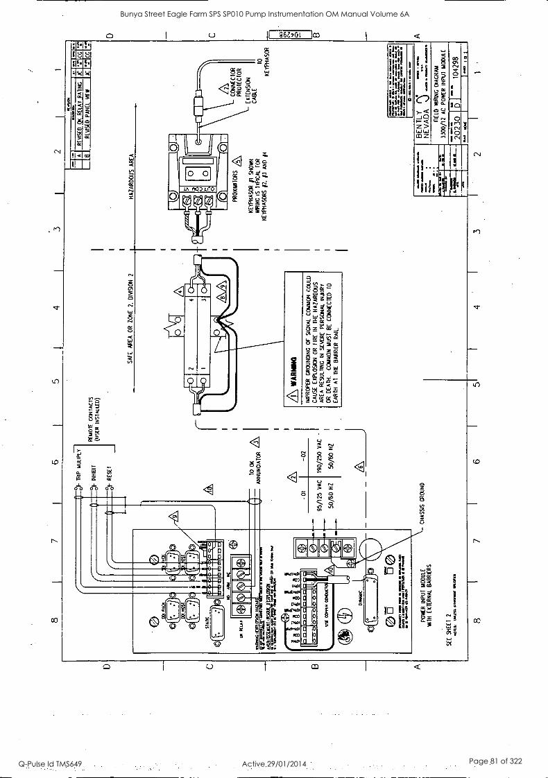
Ii
EX
:17E
1,1;
0CE
=
11L
a1:1
11:L
aal
NO
ANN
a
WA
MK
WL
°9C
NH
AZ
:T
RU
M
Etr
zus am
id=
bo
n Io
wa
OU
ILD
52.1
1NU
MU
LIE
LEIS
Ktt
a, a
s w
e Iv
o
of T
RIP MUUPLY
°oF
IN
HIB
IT
°01-
R
ES
ET
-01
RE
MO
TE
C
ON
TA
CT
S
(US
ER
IN
ST
ALL
ED
)
TO
O
K
A
AN
NU
NC
IAT
OR
/
-02
190/250 VAC
50/60 HZ
PO
WE
R
INP
UT
MO
DU
LE
WIT
H
EX
TE
RN
AL
BA
RR
IER
S
SEE SHEET 2
0011
%,
1.03
011
CIM
IU w
arn
SA
FE
AREA OR ZONE
2. DIVISION 2
2 1
ITITI
RE
VIS
ED
O
K RELAY
RA
TIN
G
B
RE
VIS
ED
P
AN
EL
NE
W
0.4
OM
X
.17
CG
JC
":"
CC
HA
ZA
RD
OU
S AREA
A WA
RN
ING
IMP
RO
PE
R
GR
OU
ND
ING
O
F
SIG
NA
L C
OM
MO
N
CO
ULD
C
AU
SE
E
XP
LOS
ION
O
R
FIR
E
IN
TH
E
HA
ZA
RD
OU
S
AR
EA
R
ES
ULT
ING
IN
S
EV
ER
E
PE
RS
ON
AL
INJU
RY
O
R
DE
AT
H.
CO
MM
ON
M
US
T
BE
C
ON
NE
CT
ED
T
O
EA
RT
H
AT
T
HE
B
AR
RIE
R
RA
IL.
PR
OX
IMI T
OR
S A
K
E1P
HA
SO
R fl
SH
OW
N
WIR
ING
IS
T
YP
ICA
L F
OR
KE
YP
HA
SO
RS
/2
. 13
A
ND
/4
CO
NN
EC
TO
R
PR
OT
EC
TO
R
EX
TE
NS
ION
CA
BLE
0
KE
YP
HA
SO
R
Nan
a I1
100[
11.
MO
W.
1107
1ain
ra
nt
ml
4 n a
l in
11
I
ram
..1
1111
. ...
do M
O =
N. n
W
WI
.1 1
1110
11
KN
OW
N
pont
61
M
N&
on
o. O
W
1111
11
MV
O. le
a..
Inco
m.
imam
a
BE
N T
LY
NE
VA
DA
w
arn
amua
llone
--so
ma
as
Yl
FIE
LD
WIR
ING
D
IAG
RA
M
3300
/12
AC
P
OW
ER
IN
PU
T
MO
DU
LE
8 7
6 5
4
011 20
230
I
"*
1042
98 a
1
1
C
A
Bunya Street Eagle Farm SPS SP010 Pump Instrumentation OM Manual Volume 6A
Q-Pulse Id TMS649 Active 29/01/2014 Page 81 of 322
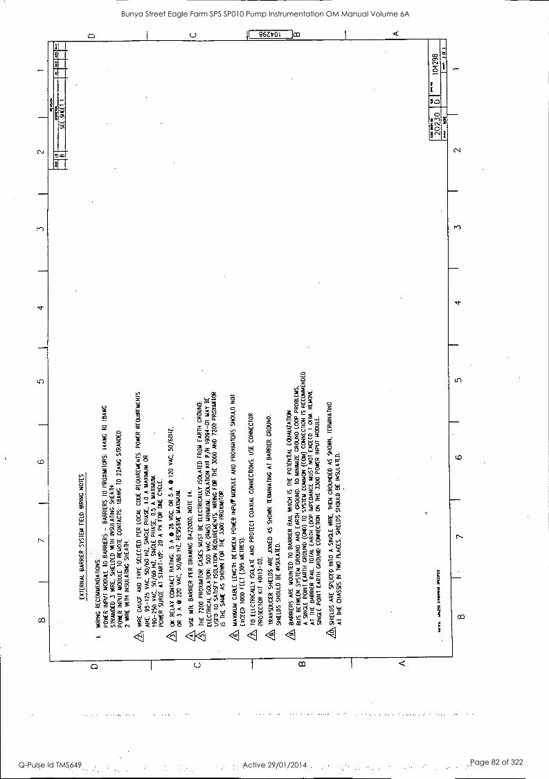
D
C B A
7 6
I 5
4 3
EX
TE
RN
AL
BA
RR
IER
S
YS
TE
M
FIE
LD
WIR
ING
N
OT
ES
1.
WIR
ING
R
EC
OM
ME
ND
AT
ION
S:
PO
WE
R
INP
UT
M
OD
ULE
TO
B
AR
RIE
RS
-
BA
RR
IER
S
TO
P
RO
XIM
ITO
RS
: 14
AW
G
TO
I8
AW
C
ST
RA
ND
ED
3
WIR
E.
SH
IELD
ED
W
ITH
IN
SU
LAT
ING
S
HE
AT
H.
PO
WE
R
INP
UT
M
OD
ULE
T
O
RE
MO
TE
C
ON
TA
CT
S:
I8A
WG
T
O
22A
WG
S
TR
AN
DE
D
2 W
IRE
W
ITH
IN
SU
LAT
ING
SH
EA
TH
.
& WIR
E
GA
UG
E.
AN
D
TY
PE
S
ELE
CT
ED
P
ER
LO
CA
L C
OD
E
RE
QU
IRE
ME
NT
S.
PO
WE
R
RE
QU
IRE
ME
NT
S
AR
E:
95-1
25
VA
C,
50/6
0 H
Z,
SIN
GLE
P
HA
SE
, 1.
0 A
M
AX
IMU
M
OR
190-
250
VA
C,
50/6
0 H
Z,
SIN
GLE
P
HA
SE
, 0.
5 A
M
AX
IMU
M.
PO
WE
R
SU
RG
E
AT
S
TA
RT
-UP
: 20
A
P
K
FO
R
ON
E
CY
CLE
.
a O
K
RE
LAY
CO
NT
AC
T
RA
TIN
G:
5 A
0
28
VD
C,
OR
5
A
0 12
0 V
AC
, 50
/60H
Z,
OR
3
A 0
220
VA
C,
50/6
0 H
Z,
RE
SIS
TIV
E M
AX
IMU
M.
4.
US
E
MT
L B
AR
RIE
R
PE
R
DR
AW
ING
8A
2200
0,
NO
TE
14
.
TH
E
7200
PR
OX
IMIT
OR
C
AS
ES
M
US
E
BE
E
LEC
TR
ICA
LLY
IS
OLA
TE
D F
RO
M
EA
RT
H
GR
OU
ND
.
ELE
CT
RIC
AL
ISO
LAT
ION
: 50
0 V
AC
(R
MS
) M
INIM
UM
. IS
OLA
TIO
N
KIT
P
/N
1909
4-01
M
AY
B
E
US
ED
T
O
SA
TIS
FY
IS
OLA
TIO
N
RE
QU
IRE
ME
NT
S.
WIR
ING
FO
R
TH
E
3000
AN
D
7200
PR
OX
IMIT
OR
IS
TH
E
SA
ME
A
S
SH
OW
N
FO
R
TH
E
3300
P
RO
XIM
ITO
R.
A MA
XIM
UM
C
AB
LE
LEN
GT
H
BE
TW
EE
N
PO
WE
R
INP
UT
MO
DU
LE
AN
D
PR
OX
IMIT
OR
S
SH
OU
LD
NO
T
EX
CE
ED
10
00
FE
ET
(3
05
ME
TR
ES
).
A TO
E
LEC
TR
ICA
LLY
IS
OLA
TE
A
ND
P
RO
TE
CT
C
OA
XIA
L C
ON
NE
CT
ION
S,
US
E
CO
NN
EC
TO
R
PR
OT
EC
TO
R
KIT
40
113-
02.
A TR
AN
SD
UC
ER
S
HIE
LDS
A
RE
JO
INE
D
AS
S
HO
W
TE
RM
INA
TIN
G
AT
B
AR
RIE
R
GR
OU
ND
.
SH
IELD
S
SH
OU
LD
BE
IN
SU
LAT
ED
.
Q9
BA
RR
IER
S
AR
E
MO
UN
TE
D
TO
B
AR
RIE
R
RA
IL
WH
ICH
IS
T
HE
P
OT
EN
TIA
L E
QU
ALI
ZA
TIO
N
BU
S
BE
TW
EE
N
SY
ST
EM
G
RO
UN
D
AN
D
EA
RT
H
GR
OU
ND
. T
O M
INIM
IZE
G
RO
UN
D L
OO
P
PR
OB
LEM
S,
A
SIN
GLE
P
OIN
T
EA
RT
H G
RO
UN
D
(GN
D)
TO
S
YS
TE
M
CO
MM
ON
(C
OM
) C
ON
NE
CT
ION
IS
RE
CO
MM
EN
DE
D
AT
T
HE
B
AR
RIE
R
RA
IL.
TO
TA
L E
AR
TH
LO
OP
IM
PE
DA
NC
E
MU
ST
N
OT
EX
CE
ED
1
OtIM
R
EM
OV
E
SIN
GLE
P
OIN
T
EA
RT
H
GR
OU
ND
C
ON
NE
CT
ION
O
N
TH
E
3300
PO
WE
R
INP
UT
M
OD
ULE
.
A SHIE
LDS
A
RE
S
PLI
CE
D
INT
O
A
SIN
GLE
W
IRE
, T
HE
N
GR
OU
ND
ED
A
S
SH
OW
N,
TE
RM
INA
TIN
G
AT
T
HE
C
HA
SS
IS
IN
IWO
P
LAC
ES
. S
HIE
LDS
S
HO
ULD
B
E
INS
ULA
TE
D.
Wilt
M
US
S
0110
.1.1
911
IRO
PIE
D
111.
.Ces
1
00(1
110.
SE
E
SH
EE
T
I
Pia
Mel
aft
2023
0 b1
10
4298
7
Or
1
7 I
6 I
5 I
4 I
3 I
2
D
C
co 0 B A
Bunya Street Eagle Farm SPS SP010 Pump Instrumentation OM Manual Volume 6A
Q-Pulse Id TMS649 Active 29/01/2014 Page 82 of 322
BRISBANE CITY COUNCIL Dept. Water Supply and Sewage Pumpwell No 1, Eagle Farm Pump Station
BCC Contract No S20/95/96 System Instrumentation
Operation and Maintenance Manual
2.5 3300 Six Channel Temperature Monitor
The following publication entitled 3300 Six Channel Temperature Monitor Operation Manual (Part No 80182-01 Rev F) is prepared by Bent ly Nevada for plant personnel who operate and maintain the system. It provides a detailed description of the Temperature Monitor, details of the operation, functions, alarm setup, programmable options, testing and error codes.
The following sections are included:
2.5.1 Six Channel Temperature Monitor System
2.5.2 Monitor Functions
2.5.3 Monitor Options
2.5.4 Programmable Options
2.5.5 OK
2.5.6 Bypass
2.5.7 Alarm 1
2.5.8 Alarm 2
2.5.9 Read Channel Temperature
2.5.10 Read Alarm 1 Setpoint Levels
2.5.11 Read Alarm 2 Setpoint Levels
2.5.12 Self Test
2.5.13 Error Codes
15 140/Inst Man/BRH Issue 1 29-Apr-98 Page 2-6
Bunya Street Eagle Farm SPS SP010 Pump Instrumentation OM Manual Volume 6A
Q-Pulse Id TMS649 Active 29/01/2014 Page 83 of 322

3300 SIX CHANNEL TEMPERATURE MONITOR
3300/30 - THERMOCOUPLE 3300/35 - RTD
OPERATION MANUAL
PART NO. 80182-01 REVISION F,
NOVEMBER 1993
BENTLY NEVADA
MADE 14 USA.
S.
- -,_ 0 0 04.0 II II
Bunya Street Eagle Farm SPS SP010 Pump Instrumentation OM Manual Volume 6A
Q-Pulse Id TMS649 Active 29/01/2014 Page 84 of 322
80182-01 Six Channel Temperature Operation
NOTICE
READ THE FOLLOWING BEFORE INSTALLING OR OPERATING EQUIPMENT
Bent ly Nevada Corporation has attempted to identify areas of risk created by. improper installation
and/or operation of this product. These areas of information are noted as WARNING or CAUTION
for your protection and for the safe and effective operation of this equipment. Read all instructions
before installing or operating this product. Pay particular attention to those areas designated by the
following symbols.
A\ WARNING High voltage present . Contact Could cause shock, bums or death.
Do not touch exposed wires or terminals.
First Printing: March 1989
A\ CAUTION Machine protection will be lost during calibration.
Copyright° 1989,1993, Bendy Nevada Corporation
AN Rights Reserved No part ci this publication may be reproduced, transmitted, stored in a retrieval system nor translated into any
human or computer language, in any fonn or by any means, electronic, mechanical, magnetic, optical,
chemical, manual, or otherwise, without the prior written permission of the copyright owner,
Ben* Nevada Corporation P.O. Box 157
Minden, Nevada 89423 USA Telephone 800-227-5514 702-782-3611
Telex 7400983 BNC UC Fax 702-782-9253
Copyright infringement is a serious matter under United States of America and Foreign Copyright Laws
ii
Bunya Street Eagle Farm SPS SP010 Pump Instrumentation OM Manual Volume 6A
Q-Pulse Id TMS649 Active 29/01/2014 Page 85 of 322
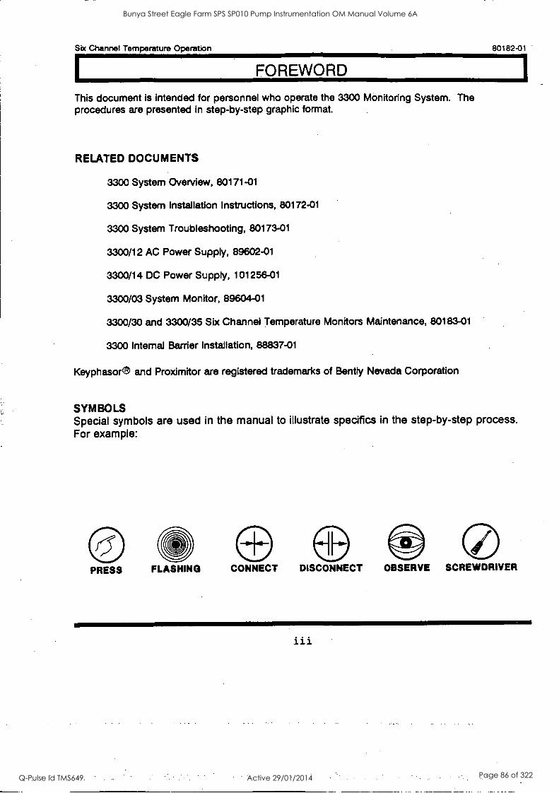
1
Six Channel Temperature Operation 80182-01
FOREWORD
This document is intended for personnel who operate the 3300 Monitoring System. The procedures are presented in step-by-step graphic format.
RELATED DOCUMENTS
3300 System Overview, 80171-01
3300 System Installation Instructions, 80172-01
3300 System Troubleshooting, 80173-01
3300/12 AC Power Supply, 89602-01
3300/14 DC Power Supply, 101256-01
3300/03 System Monitor, 89604-01
3300/30 and 3300/35 Six Channel Temperature Monitors Maintenance, 80183-01
3300 Internal Barrier Installation, 88837-01
Keyphasor® and Proximitor are registered trademarks of Bent ly Nevada Corporation
SYMBOLS Special symbols are used in the manual to illustrate specifics in the step-by-step process. For example:
PRESS FLASHING CONNECT DISCONNECT OBSERVE SCREWDRIVER
iii
Bunya Street Eagle Farm SPS SP010 Pump Instrumentation OM Manual Volume 6A
Q-Pulse Id TMS649 Active 29/01/2014 Page 86 of 322

80182-01 Six Channel Temperature Operation
iv
Bunya Street Eagle Farm SPS SP010 Pump Instrumentation OM Manual Volume 6A
Q-Pulse Id TMS649 Active 29/01/2014 Page 87 of 322
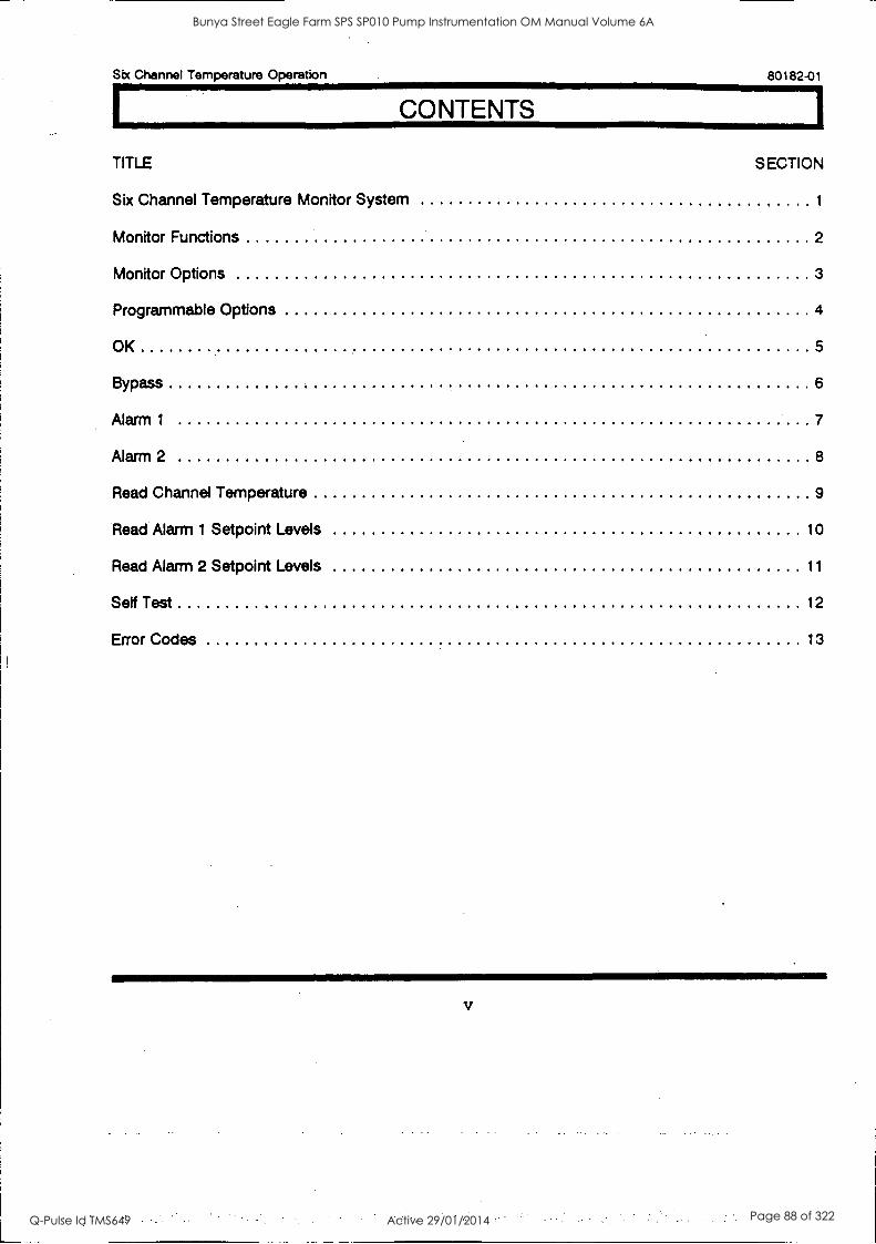
Six Channel Temperature Operation 80182-01
CONTENTS
TITLE SECTION
Six Channel Temperature Monitor System 1
Monitor Functions 2
Monitor Options 3
Programmable Options 4
OK 5
Bypass 6
Alarm 1 7
Alarm 2 8
Read Channel Temperature 9
Read Alarm 1 Setpoint Levels 10
Read Alarm 2 Setpoint Levels 11
Setf Test 12
Error Codes 13
Bunya Street Eagle Farm SPS SP010 Pump Instrumentation OM Manual Volume 6A
Q-Pulse Id TMS649 Active 29/01/2014 Page 88 of 322

80182-01 Six Channel Temperature Operation
vi
Bunya Street Eagle Farm SPS SP010 Pump Instrumentation OM Manual Volume 6A
Q-Pulse Id TMS649 Active 29/01/2014 Page 89 of 322
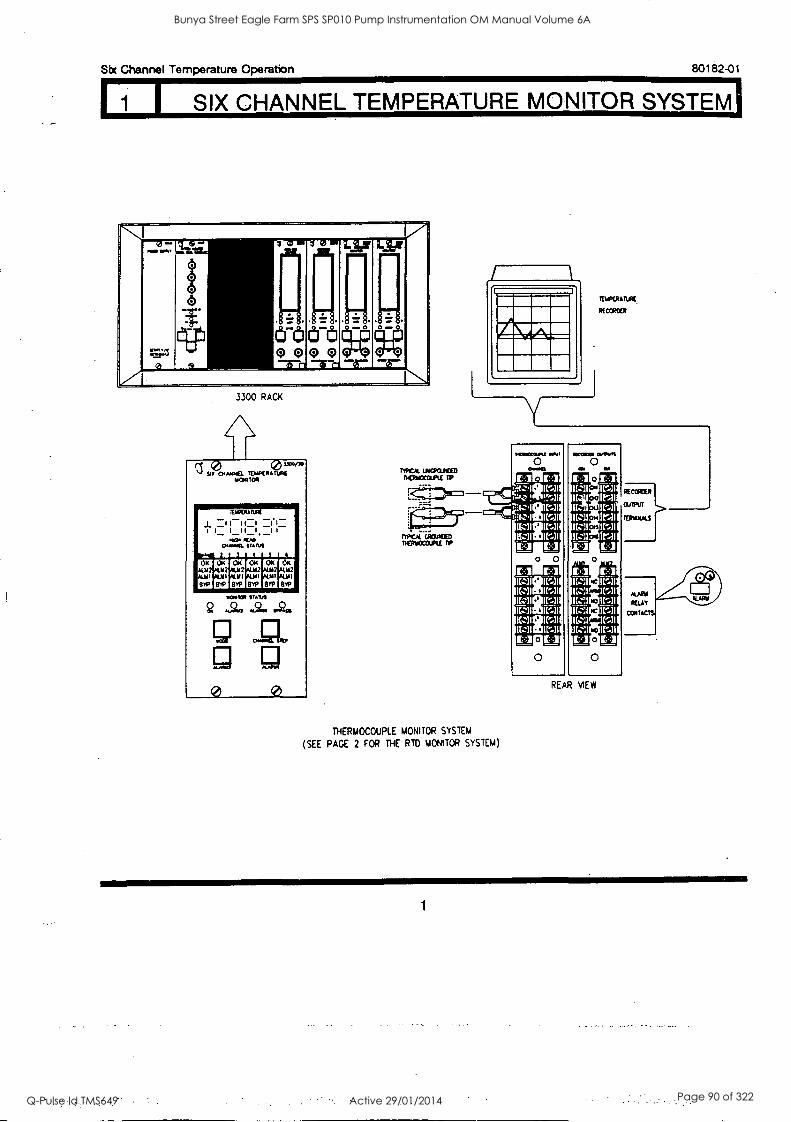
I SIX CHANNEL TEMPERATURE MONITOR SYSTEM'
Six Channel Temperature Operation 80182-01
- .......
`...4.3
3 " (5
t 0:5
,..?-.0.,
CFO illril
OQQQo :I
o-lt -
a co m il ol
ANL
3300 RACK
1.7 ITEM
a 0 0
TEUPERATURk
RECORDER
mut treortuce DElidOCO.FLE Tr
1002COIRA SOO
0 IC.1 [:1
71z.111g1lEslI
'07 0
MI - Ira A: ICS,1
Ira
CACUTIND 1- ra TIErrPcm. RWOIVII DP E-1 E1
r:1 0 0
1.-1 ]I I[:]
MI Ks]
[`]I I[:] KS1
67111MIN [:l0 LI ItI 0
THERMOCOUPLE MONITOR SYSTEM
(SEE PACE 2 FOR THE RTD MONITOR SYSTEM)
0 0
REAR MEW
1
Bunya Street Eagle Farm SPS SP010 Pump Instrumentation OM Manual Volume 6A
Q-Pulse Id TMS649 Active 29/01/2014 Page 90 of 322
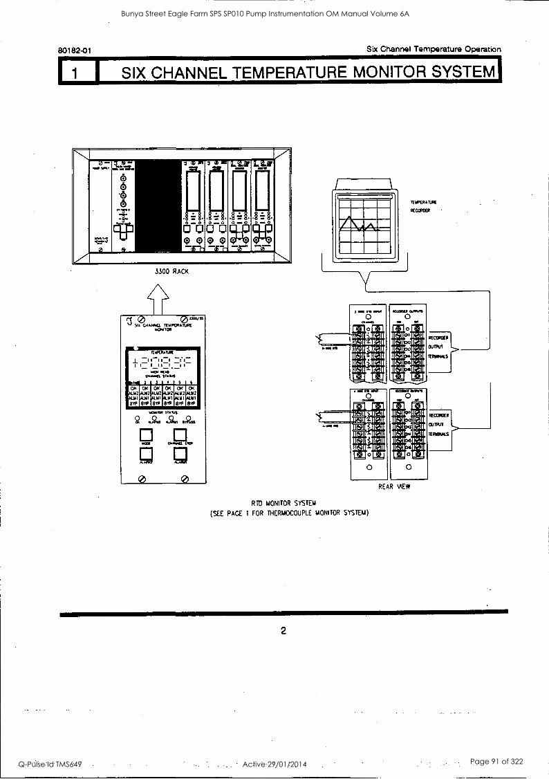
I SIX CHANNEL TEMPERATURE MONITOR SYSTEM'
80182-01 Six Channel Temperature Operation
V a .... ....,.. 7 s - ...,=. 1
6 6 .6 6 - 8- -a- -a-
04041111
"'I
i ..
0
if
irl.31.8'
.. 8O
LIZ
o coopc)(:)o oo
3300 RACK
1101f IOR
1211V7AnAlt i -I I I -I -1.1- i I I I I-I I I-
.01 RAO 0.~. SfARI
OK 2
8114
2 3 4
OK OK OK .44442 01112
ALM I ALMI ALIO
851. Big 8TP
OK 4112 4111 8TP
4
OK PLY 2
ALM I
8414
taes.0.
0 0
3 .01 O,13 MN
1111111114g
[II
R=311
1rAl 1(q1 Iran KAI
R TD MONITOR SYSTEM
(SEE PAGE 1 FOR THERMOCOUPLE MONITOR SYSTEM)
REAR VIEW
2
Bunya Street Eagle Farm SPS SP010 Pump Instrumentation OM Manual Volume 6A
Q-Pulse Id TMS649 Active 29/01/2014 Page 91 of 322
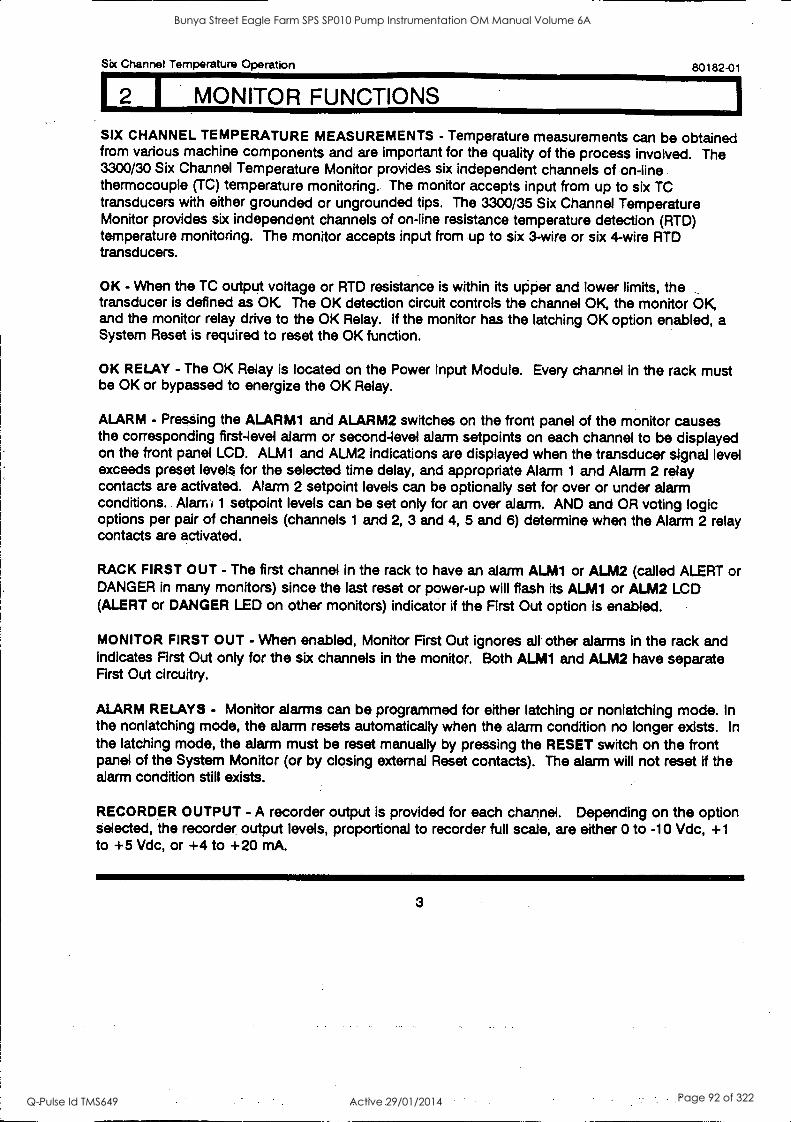
Sbc Channel Temperature Operation 80182-01
SIX CHANNEL TEMPERATURE MEASUREMENTS - Temperature measurements can be obtained from various machine components and are important for the quality of the process involved. The 3300/30 Six Channel Temperature Monitor provides six independent channels of on-line thermocouple (TC) temperature monitoring. The monitor accepts input from up to six TC transducers with either grounded or ungrounded tips. The 3300/35 Six Channel Temperature Monitor provides six independent channels of on-line resistance temperature detection (RTD) temperature monitoring. The monitor accepts input from up to six 3-wire or six 4-wire RTD transducers.
OK - When the TC output voltage or RTD resistance is within its upper and lower limits, the transducer is defined as OK The OK detection circuit controls the channel OK, the monitor OK, and the monitor relay drive to the OK Relay. If the monitor has the latching OK option enabled, a System Reset is required to reset the OK function.
OK RELAY - The OK Relay is located on the Power Input Module. Every channel in the rack must be OK or bypassed to energize the OK Relay.
ALARM - Pressing the ALARM1 and ALARM2 switches on the front panel of the monitor causes the corresponding first-level alarm or second-level alarm setpoints on each channel to be displayed on the front panel LCD. ALM1 and ALM2 indications are displayed when the transducer signal level exceeds preset levels for the selected time delay, and appropriate Alarm 1 and Alarm 2 relay contacts are activated. Alarm 2 setpoint levels can be optionally set for over or under alarm conditions. Alarm 1 setpoint levels can be set only for an over alarm. AND and OR voting logic options per pair of channels (channels 1 and 2, 3 and 4, 5 and 6) determine when the Alarm 2 relay contacts are activated.
RACK FIRST OUT - The first channel in the rack to have an alarm ALM1 or ALM2 (called ALERT or DANGER in many monitors) since the last reset or power-up will flash its ALM1 or ALM2 LCD (ALERT or DANGER LED on other monitors) indicator if the First Out option is enabled.
MONITOR FIRST OUT - When enabled, Monitor First Out ignores all other alarms in the rack and indicates First Out only for the six channels in the monitor. Both ALM1 and ALM2 have separate First Out circuitry.
ALARM RELAYS - Monitor alarms can be programmed for either latching or nonlatching mode. In the nonlatching mode, the alarm resets automatically when the alarm condition no longer exists. In the latching mode, the alarm must be reset manually by pressing the RESET switch on the front panel of the System Monitor (or by closing external Reset contacts). The alarm will not reset if the alarm condition still exists.
RECORDER OUTPUT -A recorder output is provided for each channel. Depending on the option selected, the recorder output levels, proportional to recorder full scale, are either 0 to -10 Vdc, +1 to +5 Vdc, or +4 to +20 mA.
Bunya Street Eagle Farm SPS SP010 Pump Instrumentation OM Manual Volume 6A
Q-Pulse Id TMS649 Active 29/01/2014 Page 92 of 322
80182-01 Six Channel Temperature Operation
I MONITOR FUNCTIONS
SELF TEST - The monitor has three categories of self test: cyclic, power-up, and user-invoked.
Cyclic Seff Test is performed automatically during monitor operation. Any error
encountered during a cyclic test disables the monitor and flashes an LCD error code.
Should the error be intermittent, the monitor will return to operation, but the error
code is stored for retrieval during user-invoked self-tests. Stored error codes are
annunciated by the OK LED and the OK LCD flashing at 5 Hz provided that the
channel is OK
Power-Up Self Test is performed automatically each time the monitor power is turned
on. A series of basic tests and transducer OK tests are performed.
User-invoked Self Test performs power-up self test and allows error messages stored
during cyclic tests to be read and cleared. Stored errors are annunciated by the OK
LED and the OK LCD flashing at 5 Hz and the error codes displayed on the front
panel LCD.
4
Bunya Street Eagle Farm SPS SP010 Pump Instrumentation OM Manual Volume 6A
Q-Pulse Id TMS649 Active 29/01/2014 Page 93 of 322
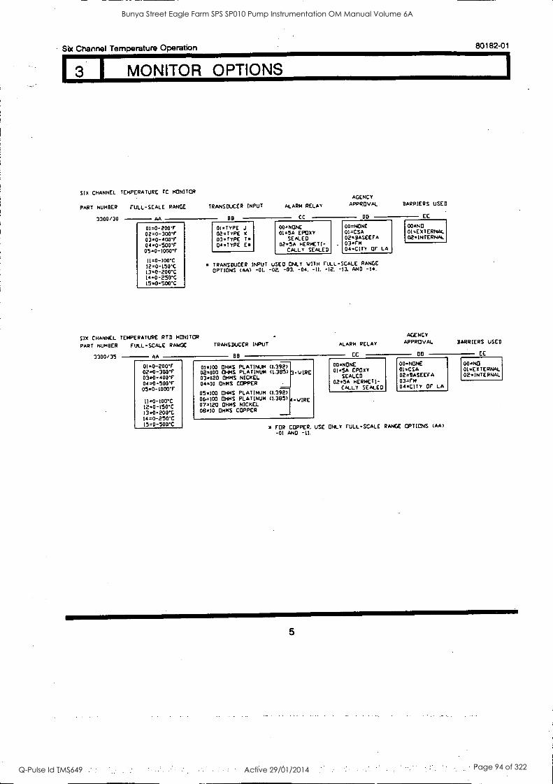
Sbc Channel Temperature Operation 80182-01
1 MONITOR OPTIONS
six CHANNEL TEMPERATURE IC MONITOR
PART NUMBER FULL-SCALE RANGE
3300/30 AA
TRANSDUCER INPUT
BB
ALARM RELAY
CC
AGENCY APPROVAL BARRIERS USED
DD EE
01.0-200'r 01.TypE j 00.NONE 00.NONE 00.NO
02.0-300T 02=TYPE 01.5A EPDXY 01.CSA 01- EXTERNAL
03.0-400T 03 -TYPE T. SEALED 02- BASEEFA 02-INTERNAL
04=0-500F 04=TYPE Es 02=5A HERMETI- 03.Fm
054-1000F CALLY SEALED 04-CITY OF LA
11=0-100'C I2.0-150C TRANSDUCER INPUT USED ONLY WITH FULL-SCALE RANGE
13.0-200'C OPTIONS (AA) -OL -02. -03. -04. -IL -12. -13. ANO -14.
14=0-250C 15.0-500'C
SIX CHANNEL TEMPERATURE RTD MONITOR
PART NUMBER FULL -SCALE RANGE TRANSDUCER INPUT ALARM RELAY
AGENCY APPROVAL BARRIERS USED
3300/35 AA BB CC DO EE
01.0-200'F 01=100 OHMS PLATINUM (1.392) 00=NONE 00-NONE 00 -NO
02=0-300'F 03.0-400'F
02-100 OHMS PLATINUM (L.385) 03.120 OHMS NICKEL
-VIRE 01=5A EPDXY SEALED
01=CSA 02.BASEEFA
01=ExTERNAL 02=INTERNAL
04.0-5001- 04=10 OHMS COPPER 02.5A HERMETI- 03.rm
05-0-1000'r CALLY SEALED. 04-CITY OF LA
05.100 OHMS PLATINUM (1.392)
11.0-100'C 06.100 OHMS PLATINUM (1.3135) 4 -WIRE
12a0-60 07.120 OHMS NICKEL
13=0-200C 08.10 OHMS COPPER
I4=0-250T 15.0-500"C FOR COPPER. USE ONLY FULL-SCALE RANGE OPTIONS (AA)
-01 AND -II.
5
Bunya Street Eagle Farm SPS SP010 Pump Instrumentation OM Manual Volume 6A
Q-Pulse Id TMS649 Active 29/01/2014 Page 94 of 322
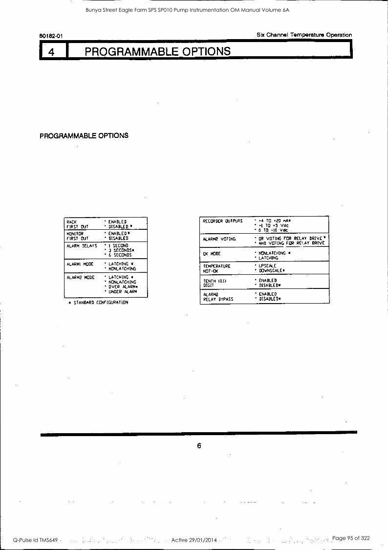
80182-01 Six Channel Temperature Operation
I PROGRAMMABLE OPTIONS
PROGRAMMABLE OPTIONS
RACK FIRST OUT
ENABLED DISABLED g
MONITOR ENABLED* FIRST OUT DISABLED
ALARM DELAYS ' 1 SECOND 3 SECONDS' 6 SECONDS
ALARM! MODE LATCHING .
NONLATCHING
ALARM2 MODE LATCHING NONLATCHING OVER ALARM. UNDER ALARM
STANDARD CONFIGURATION
RECORDER OUTPUTS 4.4 TO (20 nAs
1 TO 5 Vdc ' 0 TO -10 Vdc .
ALARM2 VOTING OR VOTING FOR RELAY DRIVE. AND VOTING FOR RELAY DRIVE
OK MODE NONLATCHING LATCHING
TEMPERATURE NOT-OK
UPSCALE DOVNSCALE
TENTH (0.1)
DIGIT
ENABLED DISABLED.
ALARM2 RELAY BYPASS
ENABLED DISABLED+
6
Bunya Street Eagle Farm SPS SP010 Pump Instrumentation OM Manual Volume 6A
Q-Pulse Id TMS649 Active 29/01/2014 Page 95 of 322
Sbc Channel Temperature Operation
NOTE Each channel in the system controls
the OK Relay. Any channel can cause a not OK Relay condition (de-energized Relay).
80182-01
DISPLAY CONDITION OK RELAY DRIVE
ALL SIX CHANNELS OK
ON
TEMPERATURE
I -I I-I 1 1 1 i
UGH CMANNEL
I. 3
1-1 i 1.
RE AO STATUS
4
7_ 1
1
5
1 7_ 1
6
OK FlOK OK OK OK
MOM TOR STATUS
0 0 0 OK ALARII2 MARIA BYPASS
. - I
I___
6
CHANNEL 2 NOT OK
OFF* 714PERATUK
NIGH CHANNEL
I 3
READ STATUS
4 5
OK OK OK OK OK
MONITOR STATUS
0 0 0 0 OK ALARM2 MAMA BYPASS
CHANNEL 2 BYPASSED
ON
TEMPERATURE
i
i H.cit CHANNEL
I p.2.4 3
READ STATUS
4 5 6
OK OK
BYP,
OK OK OK
MOM TOR STATUS
0 0 OK ALARia ALAMO BYPASS
* Not OK channel can be bypassed to restore Relay-OK condition.
7
Bunya Street Eagle Farm SPS SP010 Pump Instrumentation OM Manual Volume 6A
Q-Pulse Id TMS649 Active 29/01/2014 Page 96 of 322
80182-01 Six Channel Temperature Operation
6 I BYPASS
DISPLAY CONDITION
CHANNEL 4 BYPASSED
--... I 2 3 5 6
OK OK OK
BYP
OK OK
OK
MONITOR STATUS
0 0 ALARM2 ALARM1 BYPASS
1. MONITOR IN ALARM2 BYPASS
2. ALL CHANNELS BYPASSED
1 2
TEMPERATURE
3 6 4 5
BYP BYP BYP BYP BYP_BYP
0 OK
MONITOR
ALARM2 0
STATUS
0 ALARM1 BYPASS
1. SYSTEM IN POWER-UP MODE
2. USER-INVOKED SELF TEST
.
1 2
TEMPERATURE
J 4 5 6
BYP BYP SYP BYP BYP BYP
OK
MONITOR
ALARM2
STATUS
0 0 ALARM1 BYPASS
8
Bunya Street Eagle Farm SPS SP010 Pump Instrumentation OM Manual Volume 6A
Q-Pulse Id TMS649 Active 29/01/2014 Page 97 of 322
17 I ALARM 1
Six Channel Temperature Operation 80182-01
DISPLAY CONDITION ALARM 1
RELAY DRIVE
CHANNEL 2 HAS EXCEEDED ON M. ALARM 1 LEVEL.
2 3 106.4 6
OK OK OK OK OK OK
III
UCNTOR STATUS
OK AL0 AIN 2 ALAPI II1 BYPASS
CHANNELS 2 AND 4 HAVE ON TEMPERATURE
EXCEEDED ALARM 1 LEVEL. FIRST OUT CONDITION FOR CHANNEL 2. ./..--
2 3 4 5 1 OK OK OK OK OK OK
AIMI I
STATUS
O 0 OK ALARIA2 ALARYI BYPASS
If two alarms occur within 50 milliseconds, both LEDs could flash.
9
Bunya Street Eagle Farm SPS SP010 Pump Instrumentation OM Manual Volume 6A
Q-Pulse Id TMS649 Active 29/01/2014 Page 98 of 322
80182-01 Six Channel Temperature Operation
DISPLAY CONDITION ALARM 2 RELAY DRIVE
OR AND
TEMPERATURE VOTING* VOTING*
CHANNEL 3 HAS EXCEEDED ON OFF ALARM 2 LEVEL.
1 2 0K OK 10K r).13104K ALm2
105K
MONITOR STATUS
0 0 OK ALARM2 ALARM1 BYPASS
FIRST OUT CONDITION FOR CHANNELS 3 OR 5 THAT
ON OFF TEMPERATURE
HAVE EXCEEDED ALARM EL. TWO (OR MORE)
LEV------------------7- CHANNELS MAY INDICATE FIRST OUT FOLLOWING SELF
2 113411 4 5 6 TEST. *** OK
I\
OK OK OK OK OK ALL42 ALM2
NITOR S TUS
0 OK ARM2 ALARM BYPASS
**
***
Any channel that exceeds alarm level will activate Alarm 2 relay drive.
AND voting is accomplished between channels in the following pairs: Channels 1
and 2, Channels 3 and 4, Channels 5 and 6.
The output of these three channel pairs is an OR function.
If either channel in a pair is bypassed, an alarm relay is activated when the
nonbypassed channel is in alarm.
If two alarms occur within 50 milliseconds, both LEDs could flash.
10
Bunya Street Eagle Farm SPS SP010 Pump Instrumentation OM Manual Volume 6A
Q-Pulse Id TMS649 Active 29/01/2014 Page 99 of 322
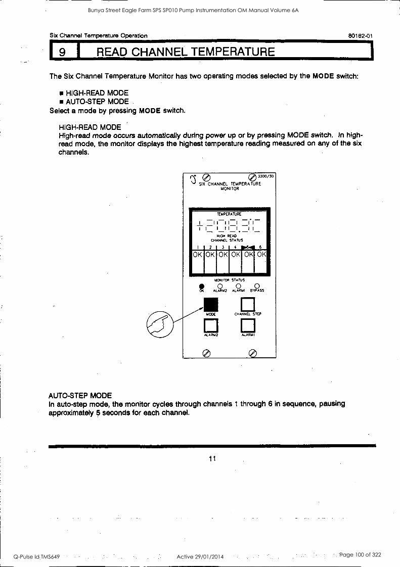
Six Channel Temperature Operation 80182-01
9 I READ CHANNEL TEMPERATURE
The Six Channel Temperature Monitor has two operating modes selected by the MODE switch:
HIGH-READ MODE AUTO-STEP MODE
Select a mode by pressing MODE switch.
HIGH-READ MODE High-read mode occurs automatically during power up or by pressing MODE switch. In high- read mode, the monitor displays the highest temperature reading measured on any of the six channels.
0 3300/30
SIX CHANNEL TEMPERATURE MONITOR
TEMPERATURE
I 11111 1.1- I I II
HIGH READ CHANNEL STATUS
I 2 3 4 p6. 6
OK OK OK OK OK OK
ct
MONITOR STATUS
0 0 0 AL ARO ALARMI BYPASS
El MODE CHANNEL STEP
ALAR142 ALARM I
AUTO-STEP MODE In auto-step mode, the monitor cycles through channels 1 through 6 in sequence, pausing approximately 5 seconds for each channel.
11
Bunya Street Eagle Farm SPS SP010 Pump Instrumentation OM Manual Volume 6A
Q-Pulse Id TMS649 Active 29/01/2014 Page 100 of 322
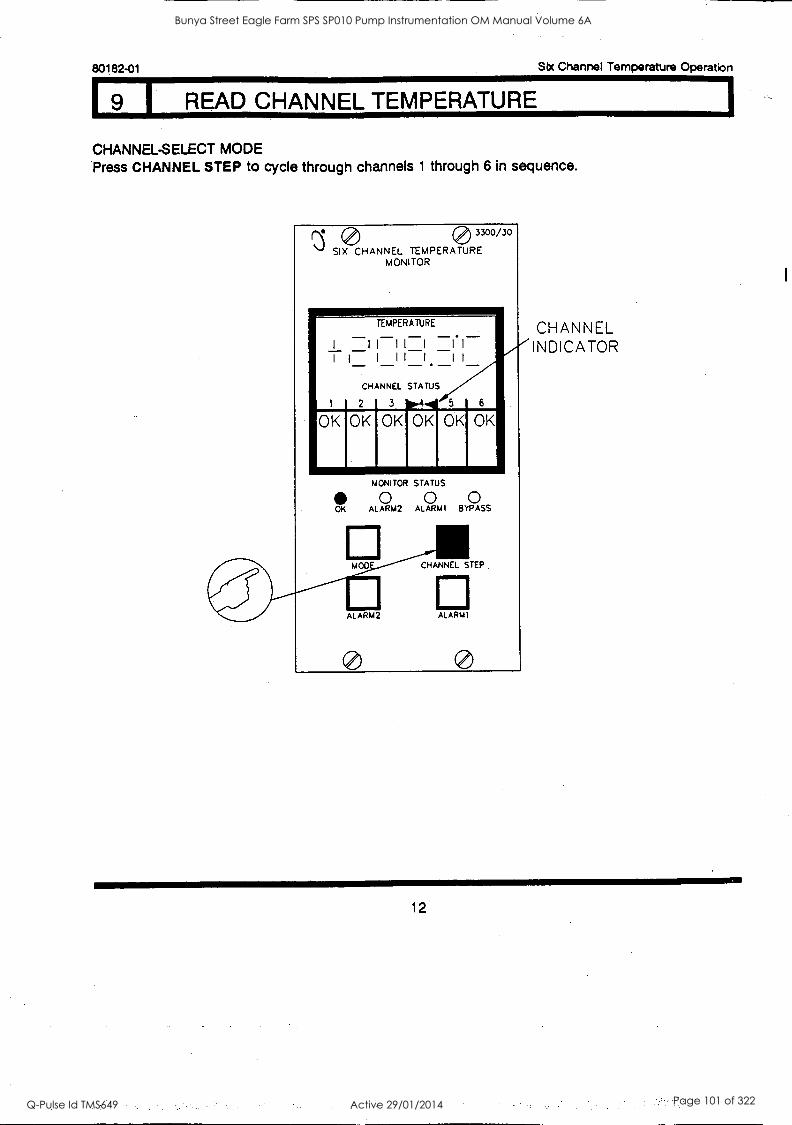
80182-01 Six Channel Temperature Operation
I READ CHANNEL TEMPERATURE
CHANNEL-SELECT MODE Press CHANNEL STEP to cycle through channels 1 through 6 in sequence.
0 3300/30
SIX CHANNEL TEMPERATURE MONITOR
TEMPERATURE
I I I II I i I
CHANNEL STATUS
2
OK OK 3 0°4'4
OK OK 5 6
OK OK
MONITOR STATUS
0 0 0 OK ALARM2 ALARMI BYPASS
MOO CHANNEL STEP.
ALARM2 ALARM1
CHANNEL INDICATOR
12
Bunya Street Eagle Farm SPS SP010 Pump Instrumentation OM Manual Volume 6A
Q-Pulse Id TMS649 Active 29/01/2014 Page 101 of 322
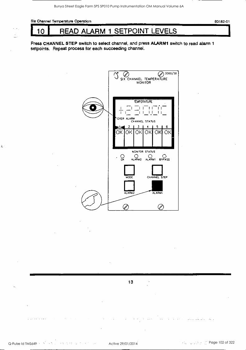
Six Channel Temperature Operation 80182-01
10 1 READ ALARM 1 SETPOINT LEVELS
Press CHANNEL STEP switch to select channel, and press ALARM1 switch to read alarm 1
setpoints. Repeat process for each succeeding channel.
0 3300/30
SIX CHANNEL TEMPERATURE MONITOR
TEMPERATURE
I I I I I I I
. I
I II II OVER ALARM
CHANNEL STATUS
P' 2 3 4 5
OK 10K OK OK OK OK
MONITOR STATUS
0 0 0 OK ALARM2 ALARM' 8 YPA SS
MODE CHANNEL STEP
ALARM2 ALARM1
13
Bunya Street Eagle Farm SPS SP010 Pump Instrumentation OM Manual Volume 6A
Q-Pulse Id TMS649 Active 29/01/2014 Page 102 of 322
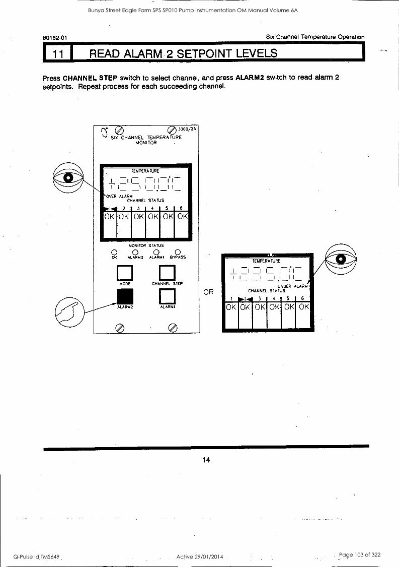
80182-01 Six Channel Temperature Operation
11 READ ALARM 2 SETPOINT LEVELS
Press CHANNEL STEP switch to select channel, and press ALARM2 switch to read alarm 2
setpoints. Repeat process for each succeeding channel.
° 0 3300/25
SIX CHANNEL TEMPERATURE MONITOR
TEMPERATURE
I I I _1_1.1_ 1 1 I
1
I l
1
i li OVER ALARM
CHANNEL STATUS
2 3 4 5 6
OK OK OK OK
O MONITOR STATUS
ALA0 RM2 ALARM' 0
BOSS
MODE CHANNEL STEP
ALARMI
OR
TEMPERATURE
I I 11 I 11
1 1 1 II II UNDER ALARM
CHANNEL STATUS
2 3 4 5
14
Bunya Street Eagle Farm SPS SP010 Pump Instrumentation OM Manual Volume 6A
Q-Pulse Id TMS649 Active 29/01/2014 Page 103 of 322
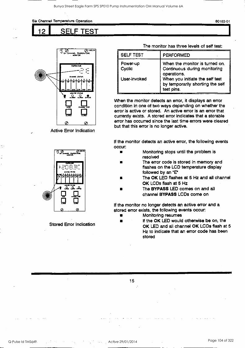
Six Channel Temperature Operation 80182-01
12 1 SELF TEST
nO 031M/10 Sx 0c61,040. TDIPERArUP£
. ii0P4 TOR
I
001.041
TEISTRAILItt
3
I ....
STMUS
I 5 6
\ SW SW
a
IIMT
a
IS
a
SW
a
11.
it mONI,C0
....,
WW1
0
SUNS
Al91
0.0.(1.
IIIIItS
STIP
PlA/11.
0 Active Error Indication
r.,
ir 21/II 010K I OKI OKI 01 OK
0 0
Stored Error Indication
The monitor has three levels of self test:
SELF TEST PERFORMED
Power-up Cyclic
User-invoked
When the monitor is turned on. Continuous during monitoring operations. When you initiate the sett test by temporarily shorting the sett test pins.
When the monitor detects an error, it displays an error condition in one of two ways depending on whether the error is active or stored. An active error is an error that currently exists. A stored error indicates that a storable error has occurred since the last time errors were cleared but that this error is no longer active.
If the monitor detects an active error, the following events occur
Monitoring stops until the problem is resolved The error code is stored in memory and flashes on the LCD temperature display followed by an 'El The OK LED flashes at 5 Hz and all channel OK LCDs flash at 5 Hz The BYPASS LED comes on and all
channel BYPASS LCDs come on
If the monitor no longer detects an active error and a stored error exists, the following events occur
Monitoring resumes If the OK LED would otherwise be on, the OK LED and all channel OK LCDs flash at 5
Hz to indicate that an error code has been stored
15
Bunya Street Eagle Farm SPS SP010 Pump Instrumentation OM Manual Volume 6A
Q-Pulse Id TMS649 Active 29/01/2014 Page 104 of 322
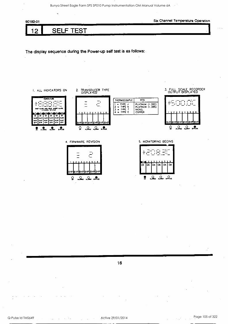
80182-01 Six Channel Temperature Operation
12 1 SELF TEST
The display sequence during the Power-up self test is as follows:
1. ALL INDICATORS ON 2. TRANSDUCER TYPE DISPLAYED
CI AL. vi M.4111 *Jfl Olt&
4. FIRMWARE REVISION
THERMOCOUPLE R TO
1
2 ., 3 .. 4 ,4
TYPE J TYPE K
TYPE T
TYPE E
PLATINUM PLATINUM NICKEL COPPER
(1.392) (1.385)
3. FULL SCALE RECORDER OUTPUT DISPLAYED
9, 0 0
5. MONITORING BEGINS
ct, .9. ti 0 , .2,.
16
Bunya Street Eagle Farm SPS SP010 Pump Instrumentation OM Manual Volume 6A
Q-Pulse Id TMS649 Active 29/01/2014 Page 105 of 322
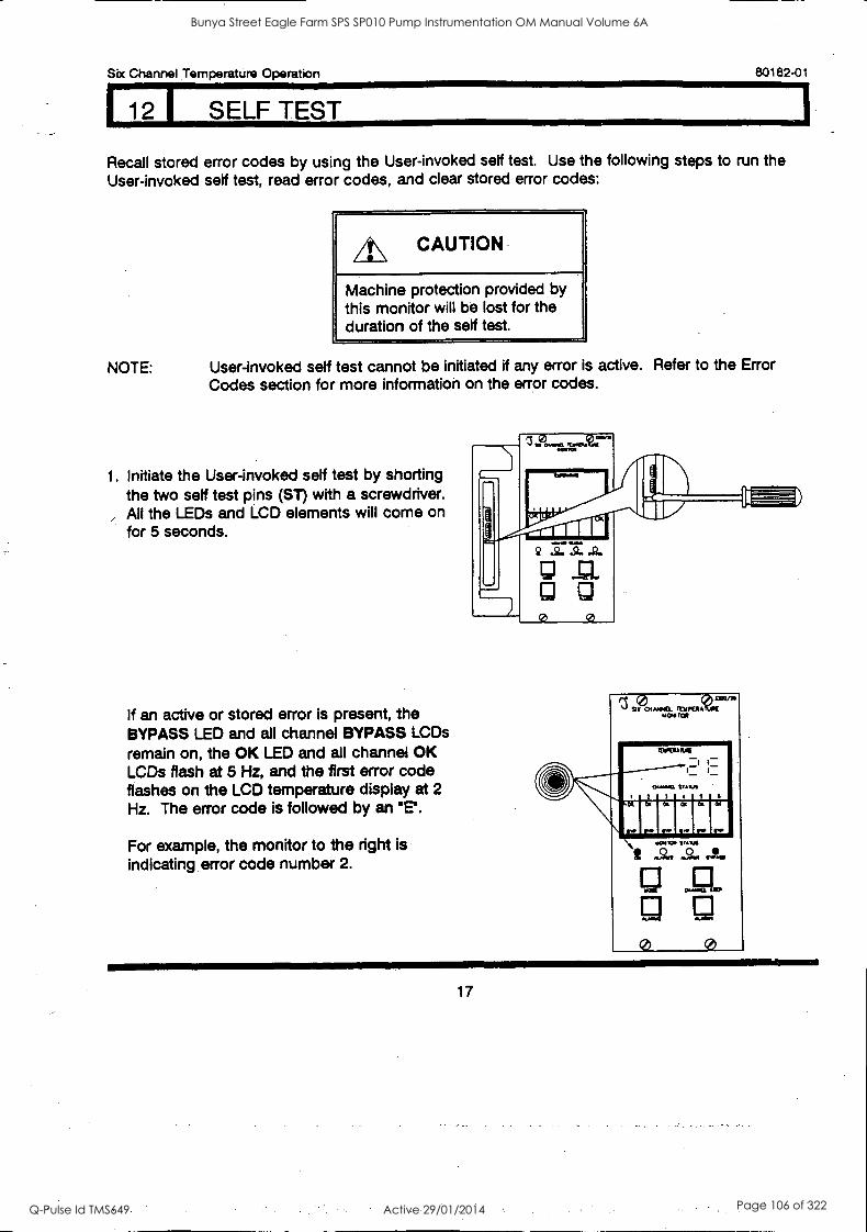
Six Channel Temperature Operation 80182-01
12 I . SELF TEST
Recall stored error codes by using the User-invoked self test. Use the following steps to run the User-invoked self test, read error codes, and clear stored error codes:
A\ CAUTION
Machine protection provided by this monitor will be lost for the duration of the self test.
NOTE: User-invoked self test cannot be initiated if any error is active. Refer to the Error Codes section for more information on the error codes.
1. Initiate the User-invoked self test by shorting the two self test pins (ST) with a screwdriver.
, All the LEDs and LCD elements will come on for 5 seconds.
If an active or stored error is present, the BYPASS LED and all channel BYPASS LCDs
remain on, the OK LED and all channel OK LCDs flash at 5 Hz, and the first error code flashes on the LCD temperature display at 2
Hz. The error code is followed by an 'E'.
For example, the monitor to the right is indicating error code number 2.
SI 041141. TINFIMA IAN IC*
O.
0 0
17
Bunya Street Eagle Farm SPS SP010 Pump Instrumentation OM Manual Volume 6A
Q-Pulse Id TMS649 Active 29/01/2014 Page 106 of 322
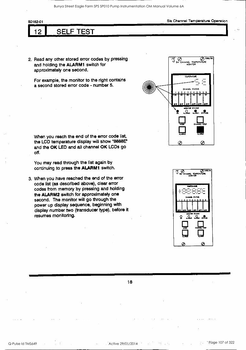
80182-01 Six Channel Temperature Operation
12 1 SELF TEST
2. Read any other stored error codes by pressing and holding the ALARM1 switch for approximately one second.
For example, the monitor to the right contains a second stored error code - number 5.
When you reach the end of the error code list, the LCD temperature display will show '8888E' and the OK LED and all channel OK LCDs go off.
You may read through the list again by continuing to press the ALARM1 switch.
3. When you have reached the end of the error code list (as described above), clear error codes from memory by pressing and holding the ALARM2 switch for approximately one second. The monitor will go through the power up display sequence, beginning with display number two (transducer type), before it resumes monitoring.
0 3
13
300/30
SIX CHANNEL TEMPERATURE MOM TOR
1... I
CHANNEL
2
TEMPERA
3
TURE
1-
STATUS
4,
- I 5 6
SW erP Qv, GYP GNP ew
t Wee
4494142
NCO(
41.A4.2
0
it41 MILS
44,41MI
OW*(l
BASS
STOP
.441la1
0
9?) MOIL?) "*"° 1,464I TOR
I
.
i
1=11'1 ,,,, 004413.
0
141.0441.1(
1_7I ,,,, 3
I
SUNS 4
-_r,- ,-_
S 6
S.. jp IOW r re r.
9
(2)
401004
t4cot
0
PAWS ai s.. st,
porn 140.
III
0
18
Bunya Street Eagle Farm SPS SP010 Pump Instrumentation OM Manual Volume 6A
Q-Pulse Id TMS649 Active 29/01/2014 Page 107 of 322
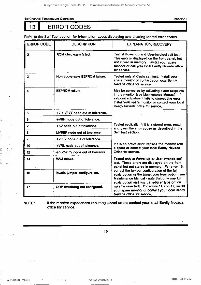
St< Channel Temperature Operation 80182-01
113 I ERROR CODES
Refer to the Self Test section for information about displaying and clearing stored error codes.
ERROR CODE DESCRIPTION EXPLANATION/RECOVERY
2 ROM checksum failed. Test at Power-up and User-invoked self test. This error .is displayed on the front panel, but not stored in memory. Install your spare monitor or call your local .gently Nevada office for service.
3 Nonrecoverable EEPROM failure. Tested only at Cyclic self test. Install your spare monitor or contact your local Bently Nevada office for service.
4 EEPROM failure May be corrected by adjusting alarm setpoints in the monitor (see Maintenance Manual). If setpoint adjustment fails to correct this error, install your spare monitor or contact your local Bently Nevada office for service.
5 +7.5 V/-VT node out of tolerance.
Tested cyclically. If it is a stored error, recall and clear the error codes as described in the Sett Test section.
If it is an active error, replace the monitor with a spare or contact your local Gently Nevada Office for service.
6 +VRH node out of tolerance.
7 +5V node out of tolerance.
8 MVREF node out of tolerance.
9 +7.5 V node out of tolerance.
10 +VRL node out of tolerance.
12 +5 V/-7.5V node out of tolerance.
14 RAM failure. Tested only at Power-up or User-invoked self test. These errors are displayed on the front panel but not stored in memory. For error 16, correct the jumper configuration of the full scale option or the transducer type option (see Maintenance Manual - note that only one full scale option and one transducer type option may be selected). For errors 14 and 17, install your spare monitor or contact your local Bently Nevada office for service.
16 Invalid jumper configuration.
17 COP watchdog not configured.
NOTE: If the monitor experiences recurring stored errors contact your local Bently Nevada office for service.
19
Bunya Street Eagle Farm SPS SP010 Pump Instrumentation OM Manual Volume 6A
Q-Pulse Id TMS649 Active 29/01/2014 Page 108 of 322

80182-01 Six Channel Temperature Operation
20
Bunya Street Eagle Farm SPS SP010 Pump Instrumentation OM Manual Volume 6A
Q-Pulse Id TMS649 Active 29/01/2014 Page 109 of 322

BRISBANE CITY COUNCIL Dept. Water Supply and Sewage Pumpwell No 1, Eagle Farm Pump Station
BCC Contract No S20/95/96 System Instrumentation
Operation and Maintenance Manual
2.6 3300/50 Tachometer
The following publication entitled 3300/50 Tachometer Operation Manual (Part No 83870-01 Rev D) is prepared by Benny Nevada for plant personnel who operate and maintain the system. It provides a detailed description of the Tachometer module, details of the operation, functions, alarm setup, programmable options, probe gap adjustment, and testing.
The following sections are included:
2.6.1 System Overview Dual Setpoint Tachometer
2.6.2 System Overview Zero Speed Tachometer
2.6.3 System Overview Rotor Acceleration Tachometer
2.6.4 Monitor Options
2.6.5 Programmable Options
2.6.6 Monitor Functions
2.6.7 OK
2.6.8 Bypass Dual Setpoint Tachometer
2.6.9 Bypass Zero Speed Tachometer
2.6.10 Bypass Rotor Acceleration Tachometer
2.6.11 Alert Dual Setpoint Tachometer
2.6.12 Alert Zero Speed Tachometer
2.6.13 Alert Rotor Acceleration Tachometer
2.6.14 Read Gap Voltage
2.6.15 Read Setpoints Dual Setpoint Tachometer
2.6.16 Read Setpoints Zero Speed Tachometer
2.6.17 Read Setpoints Rotor Acceleration Tachometer
15140/Inst Man/BRH Issue 1 29-Apr-98 Page 2-7
Bunya Street Eagle Farm SPS SP010 Pump Instrumentation OM Manual Volume 6A
Q-Pulse Id TMS649 Active 29/01/2014 Page 110 of 322

BRISBANE CITY COUNCIL Dept. Water Supply and Sewage Pumpwell No 1, Eagle Farm Pump Station
BCC Contract No S20/95/96 System Instrumentation
Operation and Maintenance Manual
2.6.18 Read Peak Hold
2.6.19 Reset Peak Hold
2.6.20 Enable (Zero Speed Tachometer)
2.6.21 Self Test
2.6.22 Index
15140/Inst Man/BRH Issue 1 29-Apr-98 Page 2-8
Bunya Street Eagle Farm SPS SP010 Pump Instrumentation OM Manual Volume 6A
Q-Pulse Id TMS649 Active 29/01/2014 Page 111 of 322
3300/50 TACHOMETER
INCLUDES DUAL SETPOINT, ZERO SPEED, AND ROTOR ACCELERATION TACHOMETERS.
OPERATION MANUAL
BENTLY(N NEVADA \)
PART NO. 83870-01 REVISION D,
FEBRUARY 1994
,.... 5:0:Me ile`'J
10.
Pi 0
Bunya Street Eagle Farm SPS SP010 Pump Instrumentation OM Manual Volume 6A
Q-Pulse Id TMS649 Active 29/01/2014 Page 112 of 322
Tachometer Operation 83870-01
NOTICE
READ THE FOLLOWING BEFORE INSTALLING OR OPERATING EQUIPMENT
Bent ly Nevada Corporation has attempted to identify areas of risk created by improper installation and/or operation of this product. These areas of information are noted as WARNING or CAUTION for your protection and for the safe and effective operation of this equipment. Read all instructions before installing or operating this product. Pay particular attention to those areas designated by the following symbols.
A\ WARNING
High voltage present, could cause shock, burns or death.
Do not touch exposed wires or terminals.
CAUTION
Machine protection will be lost during calibration.
Keyphasor® is a registered trademark of Bent ly Nevada Corporation
Proximitor® is a registered trademark of Bent ly Nevada Corporation
First Printing: March 1989
Copyright© 1989, 1993, 1994 Bent ly Nevada Corporation
All Rights reserved
No part of this publication may be reproduced, transmitted, stored in a retrieval system nor translated into any human or computer language, in any form or by any means, electronic, mechanical, magnetic, optical, chemical, manual, or otherwise, without the prior written permission of the copyright owner,
Bent ly Nevada Corporation P.O. Box 157
Minden, Nevada 89423 USA Telephone 800-227-5514 702-782-3611
Telex 7400983 BNC UC Fax 702-782-9253
Copyright infringement is a serious matter under United States of America and Foreign Copyright Laws
ii
Bunya Street Eagle Farm SPS SP010 Pump Instrumentation OM Manual Volume 6A
Q-Pulse Id TMS649 Active 29/01/2014 Page 113 of 322
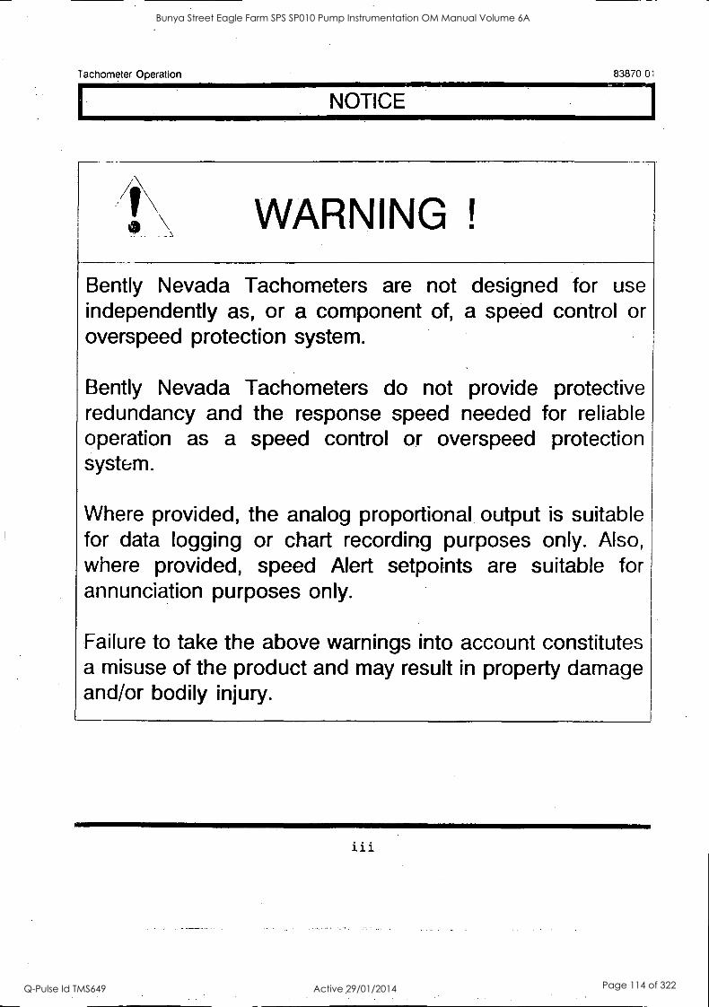
Tachometer Operation 83870 01
NOTICE
WARNING !
Bently Nevada Tachometers are not designed for use independently as, or a component of, a speed control or overspeed protection system.
Bently Nevada Tachometers do not provide protective redundancy and the response speed needed for reliable operation as a speed control or overspeed protection system.
Where provided, the analog proportional output is suitable for data logging or chart recording purposes only. Also, where provided, speed Alert setpoints are suitable for annunciation purposes only.
Failure to take the above warnings into account constitutes a misuse of the product and may result in property damage and/or bodily injury.
i i
Bunya Street Eagle Farm SPS SP010 Pump Instrumentation OM Manual Volume 6A
Q-Pulse Id TMS649 Active 29/01/2014 Page 114 of 322

Tachometer Operation 83870-01
Blank Page
iv
Bunya Street Eagle Farm SPS SP010 Pump Instrumentation OM Manual Volume 6A
Q-Pulse Id TMS649 Active 29/01/2014 Page 115 of 322
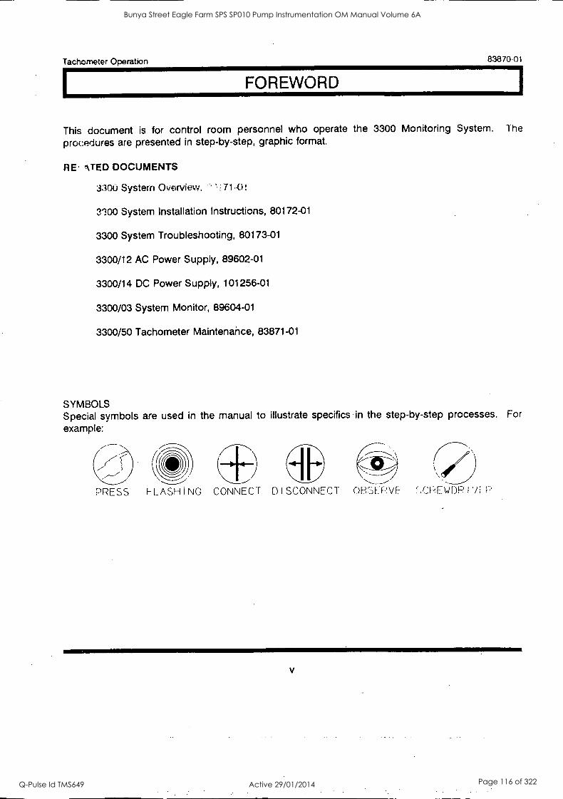
Tachometer Operation 83870-01
I FOREWORD
This document is for control room personnel who operate the 3300 Monitoring System. The
procedures are presented in step-by-step, graphic format.
RE' '\ TED DOCUMENTS
3300 System Overview. ' 71-0!
3'300 System Installation Instructions, 80172-01
3300 System Troubleshooting, 80173-01
3300/12 AC Power Supply, 89602-01
3300/14 DC Power Supply, 101256-01
3300/03 System Monitor, 89604-01
3300/50 Tachometer Maintenance, 83871-01
SYMBOLS Special symbols are used in the manual to illustrate specifics in the step-by-step processes. For
example:
PRESS FLASHING CONNECT DISCONNECT OBSERVE- CPEWDP I vi
V
Bunya Street Eagle Farm SPS SP010 Pump Instrumentation OM Manual Volume 6A
Q-Pulse Id TMS649 Active 29/01/2014 Page 116 of 322

Tachometer Operation 83870 -0
Blank Page
vi
Bunya Street Eagle Farm SPS SP010 Pump Instrumentation OM Manual Volume 6A
Q-Pulse Id TMS649 Active 29/01/2014 Page 117 of 322
Tachometer Operation 83870 -Di
CONTENTS
SECTION TITLE RAGE
SYSTEM OVERVIEW DUAL SETPOINT TACHOMETER 1
ZERO SPEED TACHOMETER 2
ROTOR ACCELERATION TACHOMETER 3
4 MONITOR OPTIONS 4
5 PROGRAMMABLE OPTIONS 5
6 MONITOR FUNCTIONS 6
7 OK 9
BYPASS 8 DUAL SETPOINT TACHOMETER 10
9 ZERO SPEED TACHOMETER 1 1
10 ROTOR ACCELERATION TACHOMETER 12
ALERT 11 DUAL SETPOINT TACHOMETER 13
12 ZERO SPEED TACHOMETER 14
13 ROTOR ACCELERATION TACHOMETER 15
14 READ GAP VOLTAGE 16
READ SETPOINTS 15 DUAL SETPOINT TACHOMETER 17
16 ZERO SPEED TACHOMETER 18
17 ROTOR ACCELERATION TACHOMETER 19
18 READ PEAK HOLD 20
19 RESET PEAK HOLD 21
20 ENABLE (ZERO SPEED TACHOMETER) 2 ,
21 SELF TEST 23
22 INDEX 27
vii
Bunya Street Eagle Farm SPS SP010 Pump Instrumentation OM Manual Volume 6A
Q-Pulse Id TMS649 Active 29/01/2014 Page 118 of 322

Tachometer Operation 83870-01
Blank Page
viii
Bunya Street Eagle Farm SPS SP010 Pump Instrumentation OM Manual Volume 6A
Q-Pulse Id TMS649 Active 29/01/2014 Page 119 of 322
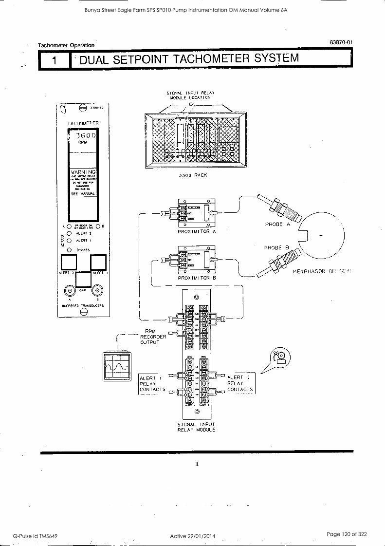
Tachometer Operation
DUAL SETPOINT TACHOMETER SYSTEM
3,00,50
i AcHOMF1ER
777
WARNING
RPM
OC SECOM MAT a. Wu SET POIMS
00 IOT IC01
OK051.0t0 PPOlf<TICH
SEE MANUAL
A 0 0 13
0 ALERT 2
R P L.) ALERT I
M
0 BYPASS
A
ouFFERED TRANSDUCERS
Ar
_
S I GNAL INPUT RELAY MODULE LOCATION
l': , 1,4,
1its 04Nta -#A14.51
....'
.,
1
/
.:
:54 .
a illistOpc412.4.144
. t
411 -
x 01 ta A0,10 V ,30 1 5 4I i
_84 a sa fIL) vi Rs
gtogrit2P.46,471:
Vfn
3300 RACK
(la
ORO
O O
PROXIMITOR A
RPM RECORDER OUTPUT
ALERT 1
RELAY CONTACTS
O
WW1
O
PROXIMITOR
83870-01
ea,
IN
IIKIC_]I MI- IC* Ittl iFIPTI-21'
I I
I
SIGNAL I NPUT RELAY MODULE
ALERT 2
RELAY CONTACTS
1
Bunya Street Eagle Farm SPS SP010 Pump Instrumentation OM Manual Volume 6A
Q-Pulse Id TMS649 Active 29/01/2014 Page 120 of 322

1
Tachometer Operation 83870-01
I 2 I ZERO SPEED TACHOMETER SYSTEM
(,)
I AC1 i0ME T ER NIIF 13 0 0
!Sr 51L[ fl I.NIEIL El)
',./ARNJ I NO
,e1 SO p0005 Pam
1,14
All
fr 4ARJAL
A 0 I I!!! C.C.CR 0 . '
I: 0 ALI.:RT
" 0 it SS
I ( I
FIT
OR M
Ri
)i (( (..;")
I! lisANS1)(J,[1:::,
I Gt 1AI nput NU A) MODUL LOCATION
si
RPM RECORDER OUTPUT-
3300 RACK
37-737 1=3
0 USD
PROX M I TOR A
rc
CI
.1 .
.1
- --- - !-,,:;- -
IP!! rt1.2 ptl 411
AL I P1 0: _'''''
Cnr,1 TAC TS r....2F--- _,---1
(.41AI 1111Ii I
11 1. A Mol n I;
1,; SP! I )
Ft E 1 , : . !
H
2
Bunya Street Eagle Farm SPS SP010 Pump Instrumentation OM Manual Volume 6A
Q-Pulse Id TMS649 Active 29/01/2014 Page 121 of 322
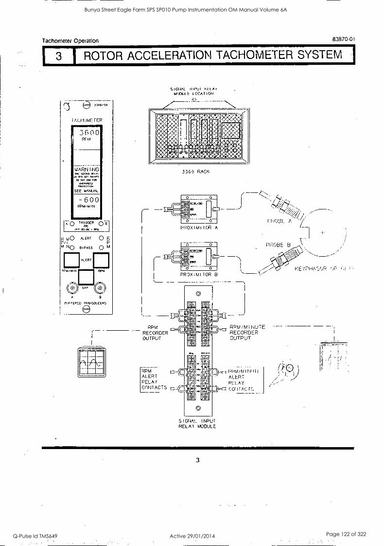
Tachometer Operation 83870-01
1 3 1 ROTOR ACCELERATION TACHOMETER SYSTEM 1
31001,0
AU OWE r ER
3600 RNA
WARNING OC SUP° (*LA' 9V HY OWTS
00 WO usE 104 0,4010(ED
PROTECT 104
SEE MANUAL
- 600 RPM/MIN
AO TRIGGER ON
L tvr 1(1041 01,1
R ki() ALERT 0 R Pil m N() BYPASS C) M
RPM/MIN
ALERT
RPM
A
purFERCE, TRANSDUCERS
SIGNAL 11PU REL A
MODULE 1 °CAT I ON
1 p* 44
.
00
1 a iit.44 prit4pervetinv tr4016510RANN
:C i k
< " ,p4e"
.
v ' .'<,
A0 /At owOR I.W.AA
41;01. vi
3300 RACK
0
PROXIMITOR A
RPM RECORDER OUTPUT
RPM ALERT RELAY C.Prl T AC TS
SIGNAL INPUT RELAY MODULE
RPM ,'M I NUTE RECORDER OUTPUT
PPM /KA I NI! r
ALERT PEI. A Y
COt VAC
PROBE A 7
PROBE B
(-11
KEYPHA(L/JP. 4-)12
3
Bunya Street Eagle Farm SPS SP010 Pump Instrumentation OM Manual Volume 6A
Q-Pulse Id TMS649 Active 29/01/2014 Page 122 of 322
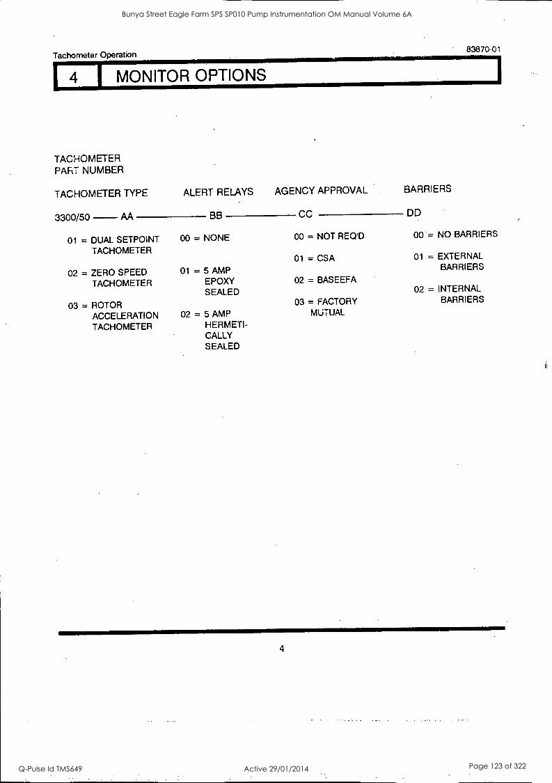
Tachometer Operation
TACHOMETER PART NUMBER
TACHOMETER TYPE ALERT RELAYS AGENCY APPROVAL BARRIERS
8387001
3300/50 AA BB CC DD
01 = DUAL SETPOINT TACHOMETER
00 = NONE 00 = NOT REQ'D 00 = NO BARRIERS
01 = CSA 01 = EXTERNAL
02 = ZERO SPEED 01 = 5 AMP BARRIERS
TACHOMETER EPDXY 02 = BASEEFA
SEALED 02 = INTERNAL
03 = ROTOR 03 = FACTORY BARRIERS
ACCELERATION 02 = 5 AMP MUTUAL
TACHOMETER HERMETI- CALLY SEALED
4
Bunya Street Eagle Farm SPS SP010 Pump Instrumentation OM Manual Volume 6A
Q-Pulse Id TMS649 Active 29/01/2014 Page 123 of 322
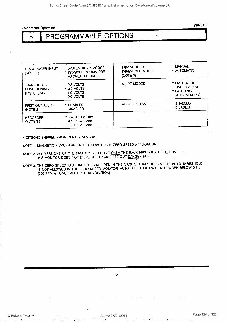
Tachometer Operation 83870-01
1 PROGRAMMABLE OPTIONS
TRANSDUCER INPUT (NOTE 1)
SYSTEM KEYPHASORS * 7200/3000 PROXIMITOR
MAGNETIC PICKUP
TRANSDUCER THRESHOLD MODE (NOTE 3)
MANUAL * AUTOMATIC
TRANSDUCER CONDITIONING HYSTERESIS
0.2 VOLTS * 0.5 VOLTS
1.0 VOLTS 2.0 VOLTS
ALERT MODES * OVER ALERT UNDER ALERT
* LATCHING NON-LATCHING
FIRST OUT ALERT (NOTE 2)
* ENABLED DISABLED
ALERT BYPASS ENABLED * DISABLED
RECORDER OUTPUTS
* +4 TO +20 mA +1 TO +5 Vdc
0 TO -10 Vdc
* OPTIONS SHIPPED FROM BENTLY NEVADA
NOTE 1: MAGNETIC PICKUPS ARE NOT ALLOWED FOR ZERO SPEED APPLICATIONS.
NOTE 2: ALL VERSIONS OF THE TACHOMETER DRIVE ONLY THE RACK FIRST OUT ALERT BUS.
THIS MONITOR DOES NOT DRIVE THE RACK FIRST OUT DANGER BUS.
NOTE 3: THE ZERO SPEED TACHOMETER IS SHIPPED IN THE MANUAL THRESHOLD MODE. AUTO THRESHOLD
IS NOT ALLOWED IN THE ZERO SPEED MONITOR. AUTO THRESHOLD WILL NOT WORK BELOW 5 Hz
(300 RPM AT ONE EVENT PER REVOLUTION).
5
Bunya Street Eagle Farm SPS SP010 Pump Instrumentation OM Manual Volume 6A
Q-Pulse Id TMS649 Active 29/01/2014 Page 124 of 322
Tachometer Operation 83870-01
I MONITOR FUNCTIONS
ROTOR SPEED MONITORING - The Tachometer function provides continuous monitoring of shaft rotative speed. The Tachometer accepts input from either a proximity probe or magnetic pickup (not recommended). The Tachometer measures the time between Keyphasor pulses and calculates the rotor speed in revolutions per minute (RPM). The monitor displays the rotor speed on the front panel and provides a proportional voltage or current recorder output. The Tachometer also outputs Alert status via rear panel relay contacts for external annunciation.
ZERO SPEED - The 3300 Tachometer provides, as a factory installed option, a Zero Speed function. Zero Speed measurements are generally taken on turbines, generators and other rotating machinery with large rotors.
Zero Speed is a preselected shaft rotative speed that allows for proper engagement of the turning gear. Continuous shaft rotation during machine shutdown is imperative to prevent shaft bow that could lead to possible machine damage during startup.
The Zero Speed function requires inputs from two transducers. Voting logic between the two transducers minimizes false Zero Speed indication in the event of a transducer failure. When the Zero Speed function is enabled, and the preselected Zero Speea is reached, an Alert LED indicates the condition. Alert relay contacts are also provided for use with an external indicator such as an annunciator panel.
ROTOR ACCELERATION - The 3300 Tachometer provides, as a factory installed option, a Rotor Acceleration indicator. The Rotor Acceleration function provides an indication of a machine's rotative acceleration. The acceleration/deceleration information is displayed on the front panel. A recorder output, as well as Alert relay outputs are provided.
Rotor Acceleration is used with machinery during startup or shutdown. The original machine manufacturer's recommended ramp up or ramp down rate must be maintained to minimize possible damage.
PROBE GAP VOLTAGE - Probe gap is measured in negative DC voltage and is directly proportional to the gap between the face of a proximity probe and the surface being monitored. Probe gap voltage for each transducer is displayed on the front panel by pressing the GAP switch.
TRIGGER OK - The TRIGGER OK LEDs indicate the status of the transducer input signal, and II
monitor. The TRIGGER OK LEDs remain on as long as the Tachometer is receiving valid input signal'. and the monitor is OK. The LEDs will extinguish when the input is less than 1 RPM or greater tl
99,999 RPM. An invalid trigger will not cause the system OK relay to go NOT OK.
OK RELAY - The OK Relay is located on the Power Input Module. Every monitor in the rack must he OK or bypassed to energize the OK Relay.
6
Bunya Street Eagle Farm SPS SP010 Pump Instrumentation OM Manual Volume 6A
Q-Pulse Id TMS649 Active 29/01/2014 Page 125 of 322
Tachometer Operation 83870-01
6 I MONITOR FUNCTIONS (CONY)
ALERT - Pressing one of the Alert switches on the front panel of the monitor causes the
corresponding Alert setpoint to be displayed on the front panel. When the particular Alert setpoint
conditions have been met, the Alert LEDs will illuminate and the Alert relay contacts are activated.
FIRST OUT ALERT - A monitor with the First Out option selected flashes an Alert LED if that Alert was
the first in the rack. Pressing the RESET switch acknowledges the First Out.
ALERT RELAYS - Monitor Alerts can be programmed for either latching or nonlatching modes. In the
nonlatching mode, the alert resets automatically when the Alert no longer exists. In the latching
mode, the Alert condition must be reset manually by pressing the RESET switch on the front panel
of the System Monitor (or by closing the external reset contacts). The Alert will not reset if the Alert
condition still exists.
ALERT BYPASS - An Alert can be bypassed using a switch located behind the front panel. When
bypassed, an Alert condition no longer causes the Alert LEDs to illuminate or the relay to actuate.
Alert bypass can be during maintenance. Alert Bypass is indicated by the front panel BYPASS LED.
Other front panel functions are not affected by Alert Bypass. This function can be disabled using a
programmable jumper within the monitor.
MONITOR BYPASS - The monitor can be completely bypassed using the Monitor Bypass switch
located behind the front panel. When bypassed, the monitor is completely nonfunctional, and can
be removed from the system monitoring loop. After this function is activated, the normal system OK
operation (OK Relay) will be restored for the remaining active monitors in the rack.
PEAK HOLD - The PEAK HOLD function allows recall of the maximum RPM value obtained since the
last PEAK HOLD reset. The PEAK HOLD value is read by pressing both Alert buttons simultaneously.
The Tachometer retains the PEAK HOLD value even after loss of monitor power. PEAK HOLD is
cleared by shorting two adjacent testpoints located behind the front panel.
BUFFERED OUTPUTS - The BUFFERED TRANSDUCER A and B coaxial cable connectors on the
front panel of the monitor provide buffered signals both redundant transducers. These connectors
can be used to connect external equipment to the monitor.
RECORDER OUTPUT - Depending on the option selected, the recorder output levels proportional
to RPM (and RPM/MIN with the Rotor Accel. Tach.) are either 0 to -10Vdc, +1 to +5Vdc, or 4 4 to
+20mA.
7
Bunya Street Eagle Farm SPS SP010 Pump Instrumentation OM Manual Volume 6A
Q-Pulse Id TMS649 Active 29/01/2014 Page 126 of 322
Tachometer Operation 83870-01
I 6 I MONITOR FUNCTIONS (CONY)
SELF TEST - The monitor has three categories of self test: power-up, cyclic, and user-invoked.
A power-up self test, consisting of a series of basic monitor OK tests, is performed automatically
each time the monitor is turned on.
A cyclic self test is performed automatically while the monitor is operating. Errors encountered
during cyclic tests disable the monitor and flash an error code on the front panel display. If the
error is intermittent, the monitor will begin operating again, and the error codes will be stored for
retrieval during user-invoked self tests. Stored error codes are indicated by the TRIGGER OK LEDs
flashing at 5 Hz (5 times per second) provided that the monitor (or trigger) is OK.
A user-invoked test performs a power-up self test and allows error messages stored during cyclic
tests to be read and cleared. Stored errors are annunciated by flashing the TRIGGER OK LEDs
at 5 Hz and displaying the error codes on the front panel LCD display.
MONITOR OK - A MONITOR NOT OK condition resulting from failing self test will drive the system
OK relay into its NOT OK state and extinguish the front panel TRIGGER OK LEDs.
8
Bunya Street Eagle Farm SPS SP010 Pump Instrumentation OM Manual Volume 6A
Q-Pulse Id TMS649 Active 29/01/2014 Page 127 of 322
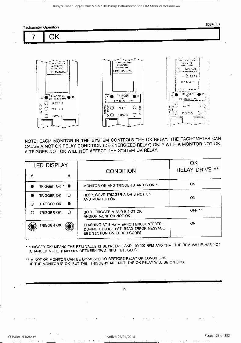
Tachometer Operation 83870-01
I 7 1 OK
CO NOT USE FOR
OvERSPEED PROTECT
SEE MANUAL
FCR
OvERSPEED PROTECT ION
SEE MANUAL
TRIGGER OK oFF BELOv I WY 6
0 ALERT
P 0 ALERT M
BYPASS
r A TRIGGER
OK OFF BEL Cy . Rpu
Z S E P ALERT 0 R R E 0 E
D 0 BYPASS 0 M
P P/ A
TRIGGi:P.
OFF BEL Ov OK
M C AL F FY
11C) e
NOTE: EACH MONITOR IN THE SYSTEM CONTROLS THE OK RELAY. THE TACHOMETER CAN
CAUSE A NOT OK RELAY CONDITION (DE-ENERGIZED RELAY) ONLY WITH A MONITOR NOT OK.
A TRIGGER NOT OK WILL NOT AFFECT THE SYSTEM OK RELAY.
LED DISPLAY
A B CONDITION
OK RELAY DRIVE **
TRIGGER OK * MONITOR OK AND TRIGGER A AND B OK * ON
TRIGGER OK 0
0 TRIGGER OK
RESPECTIVE TRIGGER A OR B NOT OK,
AND MONITOR OK ON
0 TRIGGER OK 0 BOTH TRIGGER A AND B NOT OK,
AND/OR MONITOR NOT OK
OFF **
(411!, TRIGGER OK * FLASHING AT 5 Hz = ERROR ENCOUNTERED
DURING CYCLIC TEST. READ ERROR MESSAGE
SEE SECTION ON ERROR CODES
ON
* "TRIGGER OK" MEANS THE RPM VALUE IS BETWEEN 1 AND 100,000 RPM AND THAT THE RPM VALUE HAS NOT
CHANGED MORE THAN 50% BETWEEN TWO INPUT TRIGGERS.
** A NOT OK MONITOR CAN BE BYPASSED TO RESTORE RELAY OK CONDITIONS.
IF THE MONITOR IS OK, BUT THE TRIGGERS ARE NOT, THE OK RELAY WILL BE ON (OK).
9
Bunya Street Eagle Farm SPS SP010 Pump Instrumentation OM Manual Volume 6A
Q-Pulse Id TMS649 Active 29/01/2014 Page 128 of 322
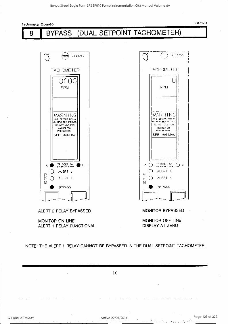
Tachometer Operation
I 8 I BYPASS (DUAL SETPOINT TACHOMETER)
A
3300/50
TACHOMETER
3600 RPM
WARNING ONE SECOND DELAY
ON RPM SET POINTS
DO NOT USE FOR
OVERSPEED PROTECTION
SEE MANUAL
TRIGGER OK OFF BElOy I RP1.4
0 ALERT 2
0 M
ALERT
BYPASS
B
ALERT 2 RELAY BYPASSED
MONITOR ON LINE ALERT 1 RELAY FUNCTIONAL
---
I ACI 101/11:
0 RPM
WARI- I NG or,E sEcor,r, ['ELK(
ON RPM SET POINT; DO NOT USE FOP
OVERSPEED PROTECT I ON
SEE MANUAL
A ( ) TRIGGER OK () OFF 60.0, PPm
O ALER1 2
p u ALERT I
M BYPASS
83870-01
MONITOR BYPASSED
MONITOR OFF LINE DISPLAY AT ZERO
NOTE: THE ALERT 1 RELAY CANNOT BE BYPASSED IN THE DUAL SETPOINT TACHOMETER.
1
10
Bunya Street Eagle Farm SPS SP010 Pump Instrumentation OM Manual Volume 6A
Q-Pulse Id TMS649 Active 29/01/2014 Page 129 of 322
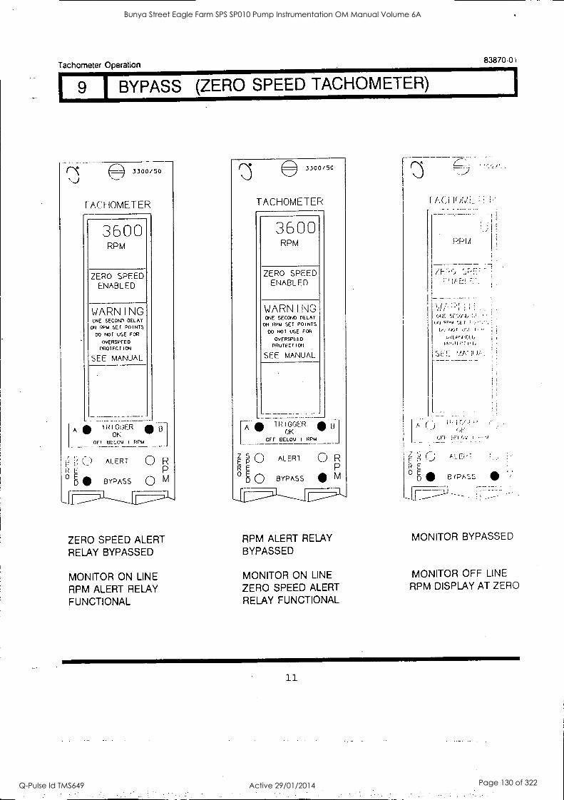
Tachometer Operation 83870-01
1 9 1 BYPASS (ZERO SPEED TACHOMETER)
(:2) 3300/50
LACHOMETER
3600 RPM
ZERO SPEED ENABLED
WARNING ONE SECOND DELAY ON RPM SET POINTS
DO NOT USE FOR
OVERSPEED PROTFCTICN
SEE MANUAL
TR I GOER OK
OFF BELOW I RPM
JI
ALERT
BYPASS
.131
0 R
M
ZERO SPEED ALERT RELAY BYPASSED
MONITOR ON LINE RPM ALERT RELAY FUNCTIONAL
to
E E
0 E D
T i IV,AL
PPM
3300/50
TACHOMETER
B
3600 RPM
ZERO SPEED ENABLED
7E r-c.; 1/-
1J,JI ;.
in,01C7Ph
r MA! :I /I.
WARNING ONE SECOND DELAY
ON RPM SET POINTS
DO NOT USE FOR
OvERSPLED PROTECTION
SEE MANUAL
Ei
B (PAS
TRIGGER OK
OFF BELOW I RPM
z s ALERT 0 R E P R E 0 E
D O BYPASS M
RPM ALERT RELAY BYPASSED
MONITOR ON LINE
ZERO SPEED ALERT RELAY FUNCTIONAL
MONITOR BYPASSED
MONITOR OFF LINE
RPM DISPLAY AT ZERO
11
Bunya Street Eagle Farm SPS SP010 Pump Instrumentation OM Manual Volume 6A
Q-Pulse Id TMS649 Active 29/01/2014 Page 130 of 322
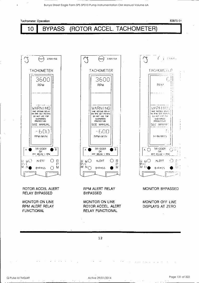
Tachometer Operation 83870-01
I 10' BYPASS (ROTOR ACCEL. TACHOMETER)
A TRIGGER OK
3300/50
TACHOMETER
3600 RPM
WARNING ONE SECOND DELAY ON RPM SET POINTS
DO NOT USE FOR
OVERSPEED PROTECTION
SEE MANUAL
-600 RPM/MIN
OFF BELOW I RPM
I: MO P/I M No
ALERT
BYPASS
0 R P
0 M
ROTOR ACCEL ALERT RELAY BYPASSED
MONITOR ON LINE RPM ALERT RELAY FUNCTIONAL
3300/50
TACHOMETER
3600 RPM
WARNING ONE SECOND DELAY ON RPM SET POINTS
DO NOT USE FOR
OVERSPEED PROTECTION
SEE MANUAL
-600 RPM/MIN
A TRIGGER OK
OFF BELOW I RPM
R MO P/I M
ALERT
BYPASS
0 R P
M
RPM ALERT RELAY BYPASSED
MONITOR ON LINE ROTOR ACCEL. ALERT RELAY FUNCTIONAL
TACHOMHiLP
1-
ONE SECOVC, GEtA, I
ON PPM ;ET POiNTH GO
OvEPSPEED PROTECT IAN
SEE MAHui-:
rd PPM/MIN I
A TR I GOER OK -)
OFF BELOW I PPM
MO P/I M t10
ALERT
BYPASS
1,
MONITOR BYPASSED
MONITOR OFF LINE DISPLAYS AT ZERO
12
Bunya Street Eagle Farm SPS SP010 Pump Instrumentation OM Manual Volume 6A
Q-Pulse Id TMS649 Active 29/01/2014 Page 131 of 322
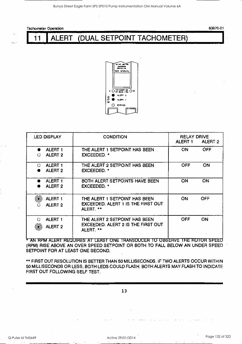
Tachometer Operation 83870-01
11 ALERT (DUAL SETPOINT TACHOMETER)
.0.11TTO 1.10110
SEE MANUAL
A 0 ea' ooER fa 0 e
R AL ER T
P AL EPT
0 BYP Ass
LED DISPLAY CONDITION RELAY DRIVE ALERT 1 ALERT 2
ALERT 1
C.: ALERT 2 THE ALERT 1 SETPOINT HAS BEEN EXCEEDED. *
ON OFF
C ALERT 1
ALERT 2
THE ALERT 2 SETPOINT HAS BEEN EXCEEDED. *
OFF ON
ALERT 1
ALERT 2 BOTH ALERT SETPOINTS HAVE BEEN EXCEEDED. *
ON ON
CD ALERT 1
C ALERT 2
THE ALERT 1 SETPOINT HAS BEEN EXCEEDED. ALERT 1 IS THE FIRST OUT ALERT. **
ON OFF
C ALERT 1 0 ALERT 2
THE ALERT 2 SETPOINT HAS BEEN EXCEEDED. ALERT 2 IS THE FIRST OUT ALERT. **
OFF ON
(RPM) RISE ABOVE AN OVER SPEED SETPOINT OR BOTH TO FALL BELOW AN UNDER SPEED SETPOINT FOR AT LEAST ONE SECOND.
** FIRST OUT RESOLUTION IS BETTER THAN 50 MILLISECONDS. IF TWO ALERTS OCCUR WITHIN 50 MILLISECONDS OR LESS, BOTH LEDS COULD FLASH. BOTH ALERTS MAY FLASH TO INDICATE FIRST OUT FOLLOWING SELF TEST.
13
Bunya Street Eagle Farm SPS SP010 Pump Instrumentation OM Manual Volume 6A
Q-Pulse Id TMS649 Active 29/01/2014 Page 132 of 322
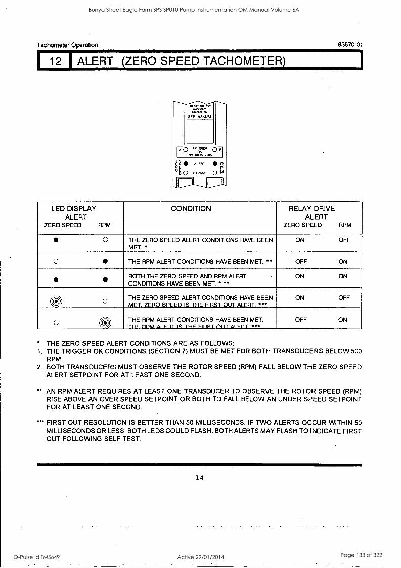
Tachometer Operation 83870-01
112 I ALERT (ZERO SPEED TACHOMETER)
owes:gm
SEE MANUAL
r0 TR lorER
0, SEL 61060 g ALERT R
og 0 BYPASS 0 M P
LED DISPLAY ALERT
ZERO SPEED RPM
CONDITION RELAY DRIVE ALERT
ZERO SPEED RPM
C THE ZERO SPEED ALERT CONDITIONS HAVE BEEN MET. *
ON OFF
C THE RPM ALERT CONDITIONS HAVE BEEN MET. ** OFF ON
BOTH THE ZERO SPEED AND RPM ALERT CONDITIONS HAVE BEEN MET. * **
ON ON
O C THE ZERO SPEED ALERT CONDITIONS HAVE BEEN MET. ZERO SPEED IS THE FIRST OUT ALERT. ***
ON OFF
C 0 THE RPM ALERT CONDITIONS HAVE BEEN MET. THE RPM Al FRT IS THE FIRST ill a Al FRT ***
OFF ON
THE ZERO SPEED ALERT CONDITIONS ARE AS FOLLOWS: 1. THE TRIGGER OK CONDITIONS. (SECTION 7) MUST BE MET FOR BOTH TRANSDUCERS BELOW 500
RPM. 2. BOTH TRANSDUCERS MUST OBSERVE THE ROTOR SPEED (RPM) FALL BELOW THE ZERO SPEED
ALERT SETPOINT FOR AT LEAST ONE SECOND.
** AN RPM ALERT REQUIRES AT LEAST ONE TRANSDUCER TO OBSERVE THE ROTOR SPEED (RPM) RISE ABOVE AN OVER SPEED SETPOINT OR BOTH TO FALL BELOW AN UNDER SPEED SETPOINT FOR AT LEAST ONE SECOND.
*** FIRST OUT RESOLUTION IS BETTER THAN 50 MILLISECONDS. IF TWO ALERTS OCCUR WITHIN 50 MILLISECONDS OR LESS, BOTH LEDS COULD FLASH. BOTH ALERTS MAY FLASH TO INDICATE FIRST OUT FOLLOWING SELF TEST.
14
Bunya Street Eagle Farm SPS SP010 Pump Instrumentation OM Manual Volume 6A
Q-Pulse Id TMS649 Active 29/01/2014 Page 133 of 322
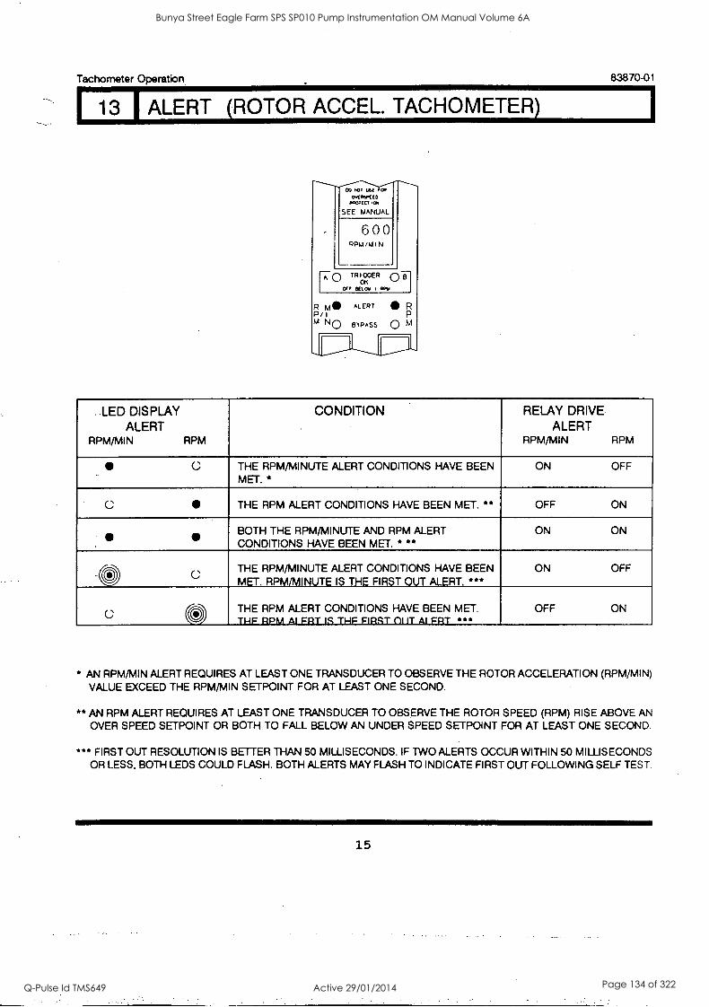
Tachometer Operation.
13 I ALERT (ROTOR ACCEL. TACHOMETER)
ovswao p.wm,a
SEE MANUAL
600 RPM/MIN
F0 TR rER ac Bad PPM
R M ALERT P/
Nr-N BYPASS
R
0 M
83870-01
..LED DISPLAY ALERT
RPM/MIN RPM
CONDITION RELAY DRIVE ALERT
RPM/MIN RPM
C THE RPM/MINUTE ALERT CONDITIONS HAVE BEEN MET.*
ON OFF
C THE RPM ALERT CONDITIONS HAVE BEEN MET. ** OFF ON
ID THE RPM/MINUTE AND RPM ALERT
CONDITIONS HAVE BEEN MET. * ** ON ON
C; THE RPM/MINUTE ALERT CONDITIONS HAVE BEEN MET. RPM/MINUTE IS THE FIRST OUT ALERT. ***
ON OFF
0 AIALEF RR TT ICONDITIONS FIRST
HAVE vIT E AB BEEN MET. . THE T THE RPM OFF ON
* AN RPM/MIN ALERT REQUIRES AT LEAST ONE TRANSDUCER TO OBSERVE THE ROTOR ACCELERATION (RPM /MIN) VALUE EXCEED THE RPM/MIN SETPOINT FOR AT LEAST ONE SECOND.
** AN RPM ALERT REQUIRES AT LEAST ONE TRANSDUCER TO OBSERVE THE ROTOR SPEED (RPM) RISE ABOVE AN OVER SPEED SETPOINT OR BOTH TO FALL BELOW AN UNDER SPEED SETPOINT FOR AT LEAST ONE SECOND.
*** FIRST OUT RESOLUTION IS BETTER THAN 50 MILLISECONDS. IF TWO ALERTS OCCUR WITHIN 50 MILLISECONDS OR LESS, BOTH LEDS COULD FLASH. BOTH ALERTS MAY FLASH TO INDICATE FIRST OUT FOLLOWING SELF TEST
15
Bunya Street Eagle Farm SPS SP010 Pump Instrumentation OM Manual Volume 6A
Q-Pulse Id TMS649 Active 29/01/2014 Page 134 of 322
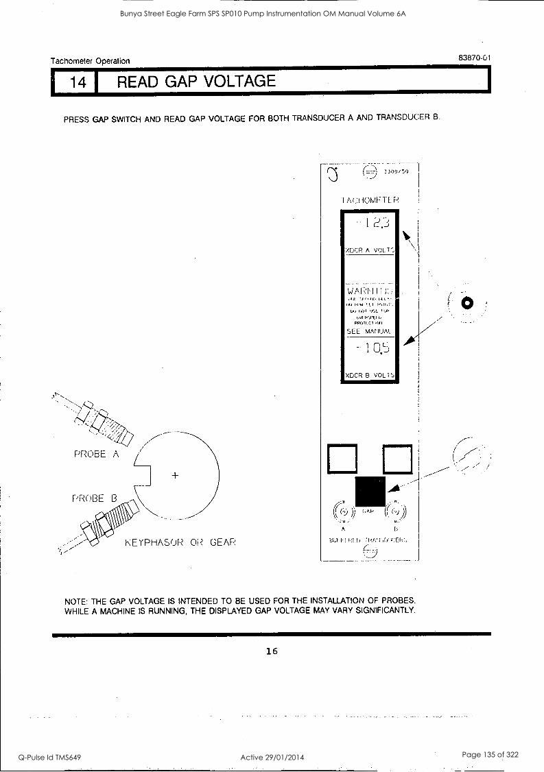
Tachometer Operation
I 14 I READ GAP VOLTAGE
83870-01
PRESS GAP SWITCH AND READ GAP VOLTAGE FOR BOTH TRANSDUCER A AND TRANSDUCER B
PROBE A
1-
\
KEYPHASOR OR GEAR
3300/50
WARrl 141.,
ON "M !.1_ I
NOT f,,f,
9VVRWElb PROlECT011
SEE MANUAL
XOCR B VOL TS
A
Bkfi Fl !) 11.Wr,fiu.:EP!,
NOTE: THE GAP VOLTAGE IS INTENDED TO BE USED FOR THE INSTALLATION OF PROBES.
WHILE A MACHINE IS RUNNING, THE DISPLAYED GAP VOLTAGE MAY VARY SIGNIFICANTLY.
16
Bunya Street Eagle Farm SPS SP010 Pump Instrumentation OM Manual Volume 6A
Q-Pulse Id TMS649 Active 29/01/2014 Page 135 of 322
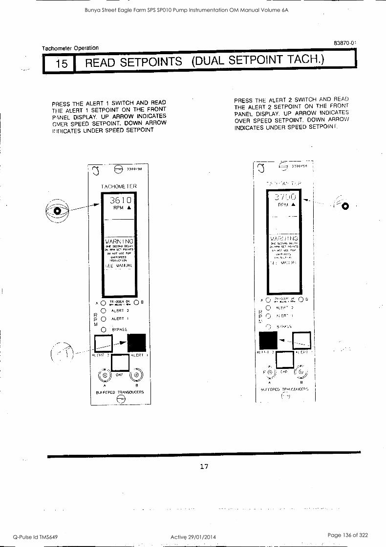
Tachometer Operation 83870 -0
15 READ SETPOINTS DUAL SETPOINT TACH.)
PRESS THE ALERT 1 SWITCH AND READ
THE ALERT 1 SETPOINT ON THE FRONT
P VVEL DISPLAY. UP ARROW INDICATES
OVER SPEED SETPOINT. DOWN ARROW
1: iiiiCATES UNDER SPEED SETPOINT
3300/50
TACHOMETER
3610 RPM
WARNING C.E SECCNO OELAY
C. RN+ SET POINTS
DO ErIE USE FOE
OvERfpCED onoItCTIOtI
:,EL MANUAL
ALERT 2
ALERT
Al 1 RT ALERT I
A
BUFFERED TRANSDUCERS
PRESS THE ALERT 2 SWITCH AND READ
THE ALERT 2 SETPOINT ON THE FRONT
PANEL DISPLAY. UP ARROW INDICATES
OVER SPEED SETPOINT. DOWN ARROW!
INDICATES UNDER SPEED SETPOINT.
..)
,==9 3 300 /50
PPM A
WARt 1 ! F IG VIE SEV,t, LEI,*
0, P./ SET LOINS 11,I vSt /CM
'.f MA:
0 &LEP', 2
P C.) AI Ern-
r3rPr::,s
At 2
It G ))
A
I EP
5tiF FEPED TRmr.DuCEF,.
17
Bunya Street Eagle Farm SPS SP010 Pump Instrumentation OM Manual Volume 6A
Q-Pulse Id TMS649 Active 29/01/2014 Page 136 of 322
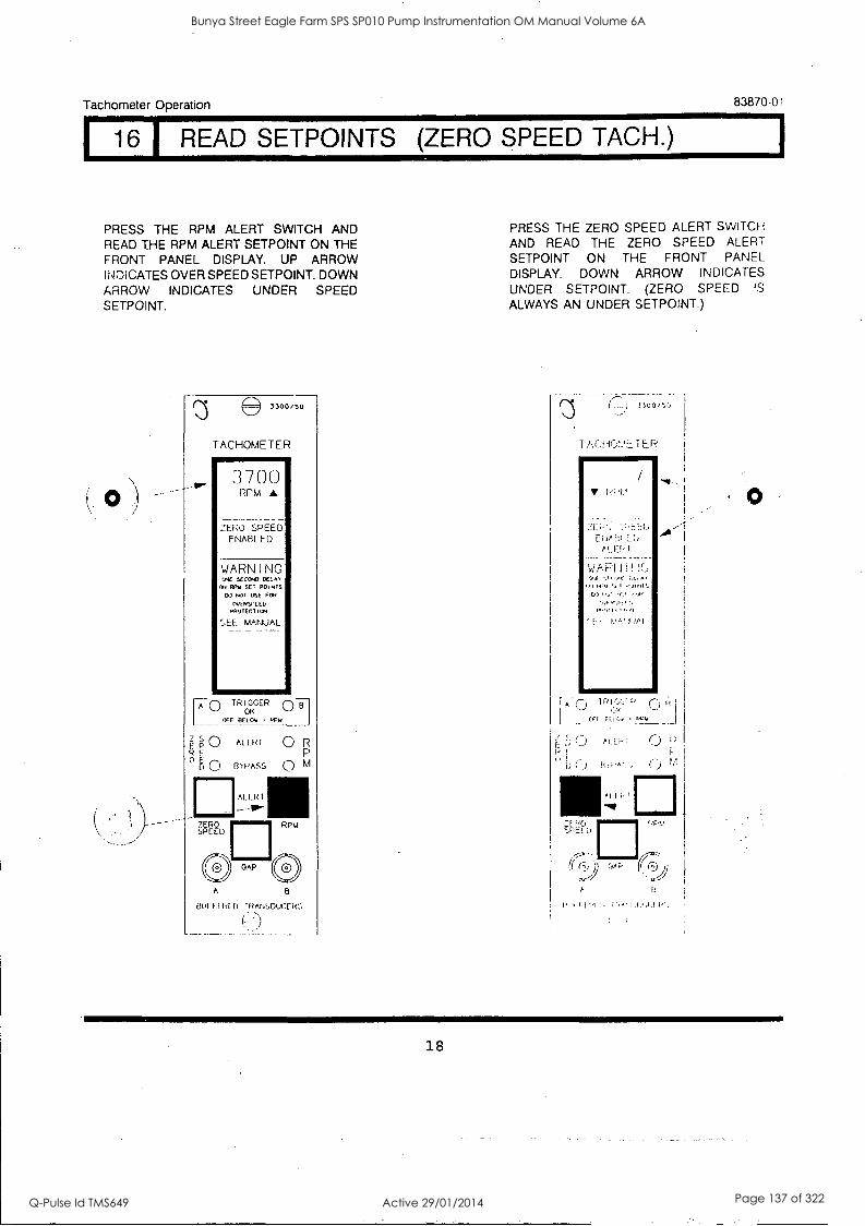
Tachometer Operation 83870-01
1 16 READ SETPOINTS (ZERO SPEED TACH.)
PRESS THE RPM ALERT SWITCH AND READ THE RPM ALERT SETPOINT ON THE FRONT PANEL DISPLAY. UP ARROW INDICATES OVER SPEED SETPOINT. DOWN ARROW INDICATES UNDER SPEED SETPOINT.
3300/50
TACHOMETER
3 7 0 0 RPM A
ZERO SPEED ENABLED
WARNING ONE SECOND DELAY
EN REV SET POINTS
DO NOT USE Ea. OvENSPEED ppolECIlay
SEE MANUAL
[A 0
FPO R E
E 0
Z SPEED
TRIGGER OK
F BELO,/ 1 FPu
AL ERf 0 R
BYPASS 0 M
AL E RI
RPM
OAP (2) OAP (i) A
BLIFFI RID IRANSDUCEPS
t-
PRESS THE ZERO SPEED ALERT SWITCH
AND READ THE ZERO SPEED ALERT SETPOINT ON THE FRONT PANEL DISPLAY. DOWN ARROW INDICATES UNDER SETPOINT. (ZERO SPEED IS
ALWAYS AN UNDER SETPOINT.)
r"; 33000,1
1 TER
k;
PLEDI
I
9* ,,, Al
CP) I,. I
! MAI
A' (.:) IR I. cc, nf,,, _._1
E
-) I f-
.:71 PC, SPEED
(f ca) (T!)
A
18
Bunya Street Eagle Farm SPS SP010 Pump Instrumentation OM Manual Volume 6A
Q-Pulse Id TMS649 Active 29/01/2014 Page 137 of 322
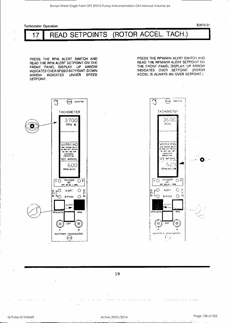
Tachometer Operation
1 17
83870-01
READ SETPOINTS (ROTOR ACCEL. TACH.)
PRESS THE RPM ALERT SWITCH AND READ THE RPM ALERT SETPOINT ON THE FRONT PANEL DISPLAY. UP ARROW INDICATES OVER SPEED SETPOINT. DOWN ARROW INDICATES UNDER SPEED SETPOINT.
3300/50
TACHOME TER lowsimir
3700 RPM
WARNING 01E 5E000 DELAY
ON RNA SET P01010 00 401 USE POR
00(00 EEO
M07E07104
SEE MANUAL
600 RPM/MIN
r A0 TRIGGER OK
MT MOW I MN
R M O ALERT P/I M NO BYPASS
AL EP T
0 R
0 M
RPM /MIN RPM
(0 OAP C? A
BUFFERED TRANSDUCERS
PRESS THE RPM/MIN ALERT SWITCH AND READ THE RPM/MIN ALERT SETPOINT ON THE FRONT PANEL DISPLAY. UP -ARROW
INDICATES OVER SETPOINT. (ROTOR
ACCEL IS ALWAYS AN OVER SETPOINT
TACHOMETEP
:3 6 0 0 PP!.,
WARN I NG IC SECUfs OCLA1
ad RPM St T P01111:.
CO NOT USE TOP
OVERWE ED
PROTEL 1 101
E MANUAL wAL
e)20 RPM/M I14
/It
r A0 TR I GGER
OK OFF 0E1Ov s Wu
R MO ALERT
P/I M N 0 BYPASS
RaiALF.P r
PPM/MIN
GAP
C) P
0 M
RPM
B
HUI'!-f F.! 1) !Pr Ir.( 1,',
(
19
Bunya Street Eagle Farm SPS SP010 Pump Instrumentation OM Manual Volume 6A
Q-Pulse Id TMS649 Active 29/01/2014 Page 138 of 322
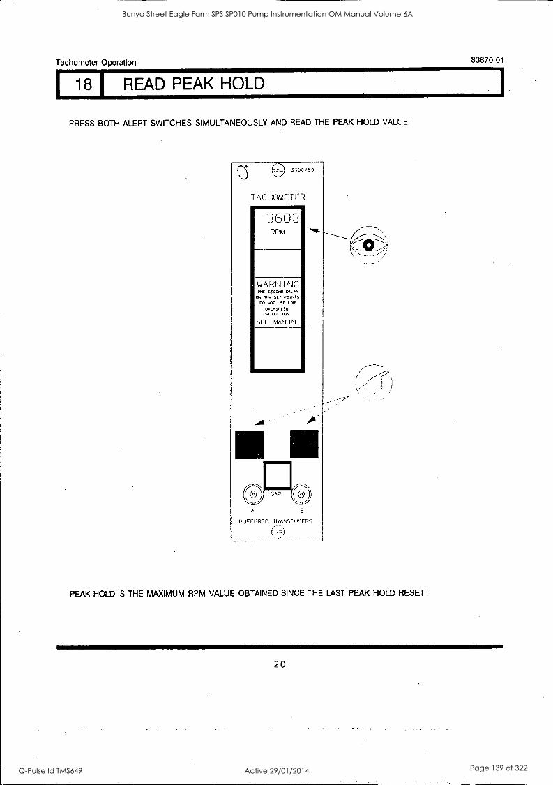
Tachometer Operation 83870-01
18 I READ PEAK HOLD
PRESS BOTH ALERT SWITCHES SIMULTANEOUSLY AND READ THE PEAK HOLD VALUE.
(;) 3300/50
TACHOMETER 1.111111.111111111111111F
3603 RPM
WARN I NG C.E SECOND DELAr
ON RPM :',Er POINTS
DO NOT USE FOR
OvERSREED cNOTECTION
SEE MANUAL
A
fitJFITRFO MANSDUCERS
(r
PEAK HOLD IS THE MAXIMUM RPM VALUE OBTAINED SINCE THE LAST PEAK HOLD RESET.
20
Bunya Street Eagle Farm SPS SP010 Pump Instrumentation OM Manual Volume 6A
Q-Pulse Id TMS649 Active 29/01/2014 Page 139 of 322
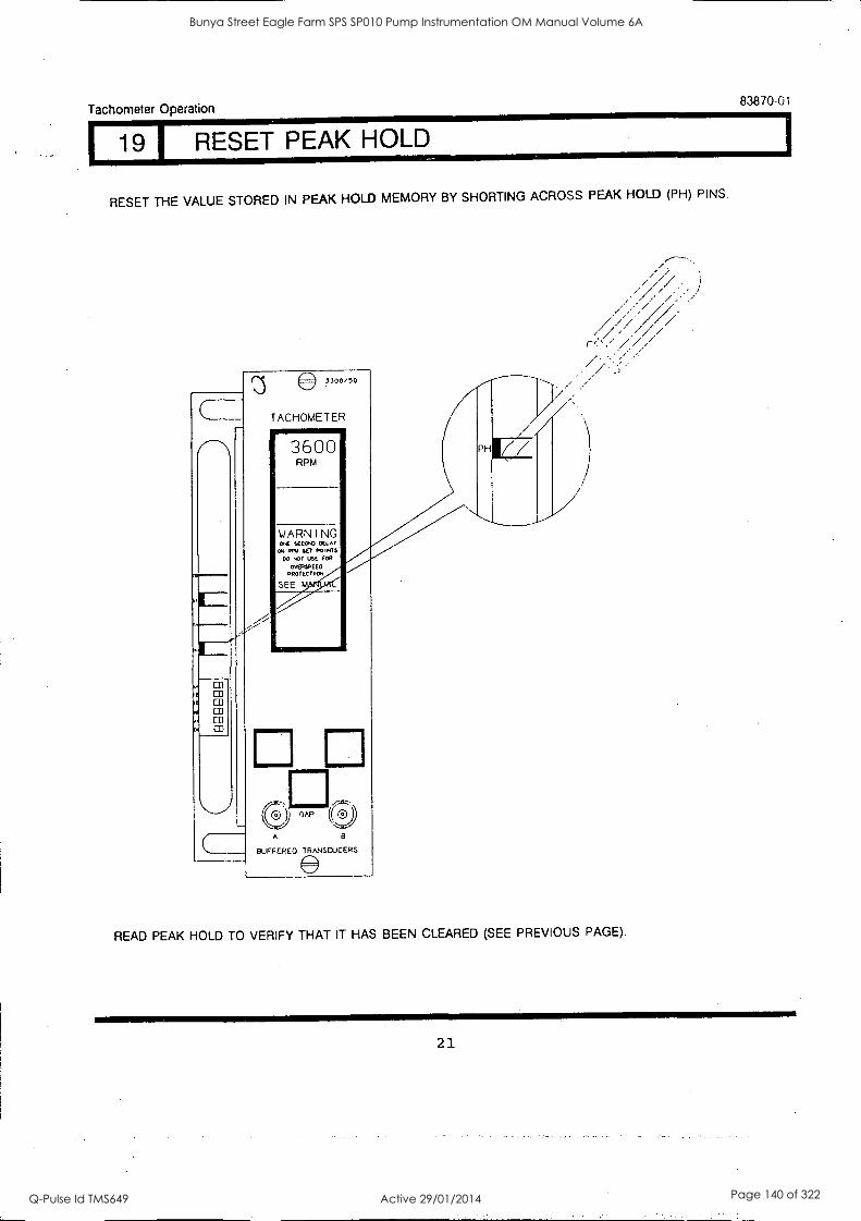
Tachometer Operation
I 19 I RESET PEAK HOLD
83870-01
RESET THE VALUE STORED IN PEAK HOLD MEMORY BY SHORTING ACROSS PEAK HOLD (PH) PINS.
Ie a
LU
3300/50
TACHOMETER vommimmemr
3600 RPM
WARNING Cr& SEC
ON RPM SET POIMS NOT USE FOR
OWASPEED PROTECTIO4
SEE M.
A
PI
BUFFERED TRANSDUCERS
PH 77'
READ PEAK HOLD TO VERIFY THAT IT HAS BEEN CLEARED (SEE PREVIOUS PAGE).
21
Bunya Street Eagle Farm SPS SP010 Pump Instrumentation OM Manual Volume 6A
Q-Pulse Id TMS649 Active 29/01/2014 Page 140 of 322
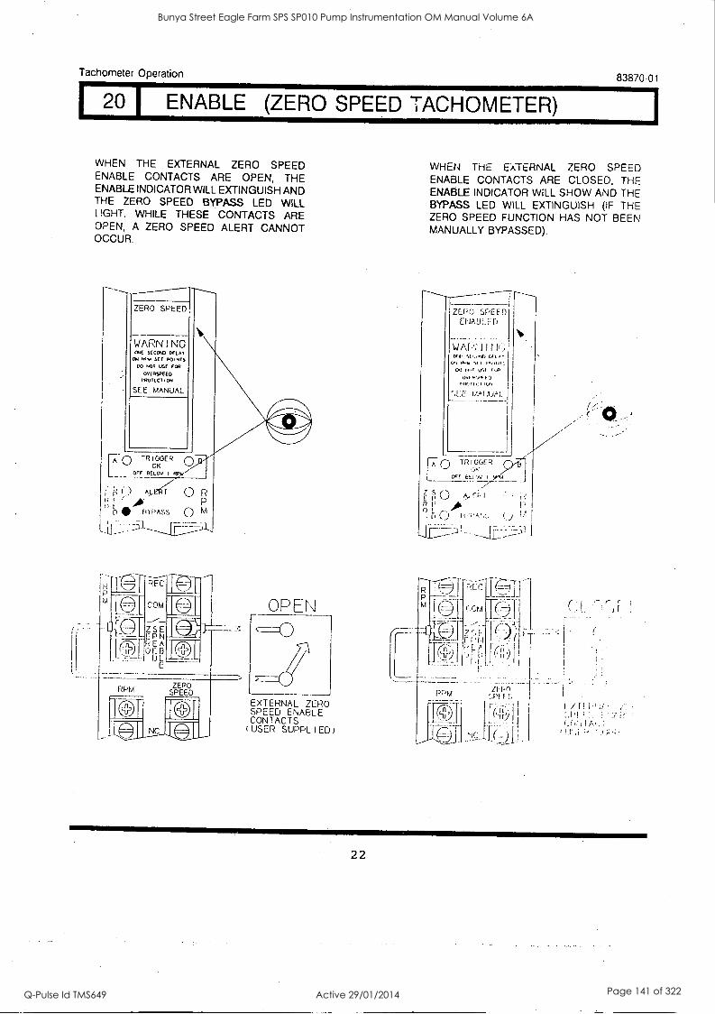
Tachometer Operation 83870-01
I 20 I ENABLE (ZERO SPEED TACHOMETER)
WHEN THE EXTERNAL ZERO SPEED ENABLE CONTACTS ARE OPEN, THE ENABLE INDICATOR WILL EXTINGUISH AND THE ZERO SPEED BYPASS LED WILL t IGHT. WHILE THESE CONTACTS ARE OPEN, A ZERO SPEED ALERT CANNOT OCCUR.
ZERO SPEED
WARNING ONE SEEDED DELAY
ON 111,A SET VENNES
CO NO1 USE FEN
OLNEESDEED
YN071CT ION
SEE MANUAL
O T R IOTER
OFF DELOV
A_LEIR R P
D NIP IlYPASS 0 M
Z S E E P N E A
0 B DL E
RPM ZEPO SPEED
OPEN
EXTERNAL ZERO SPEED ENABLE CONTACTS (USER SUPPLIED)
WHEN THE EXTERNAL ZERO SPEED ENABLE CONTACTS ARE CLOSED. THE ENABLE INDICATOR WILL SHOW AND THE BYPASS LED WILL EXTINGUISH (IF THE ZERO SPEED FUNCTION HAS NOT BEEN MANUALLY BYPASSED).
ZERO SPEED Er(AHLED
WAI-1 I I III,
J 0 TR [GOER
cfr fitt
0 A,nI P
[I (...) 11 I , J ;'
22
Bunya Street Eagle Farm SPS SP010 Pump Instrumentation OM Manual Volume 6A
Q-Pulse Id TMS649 Active 29/01/2014 Page 141 of 322
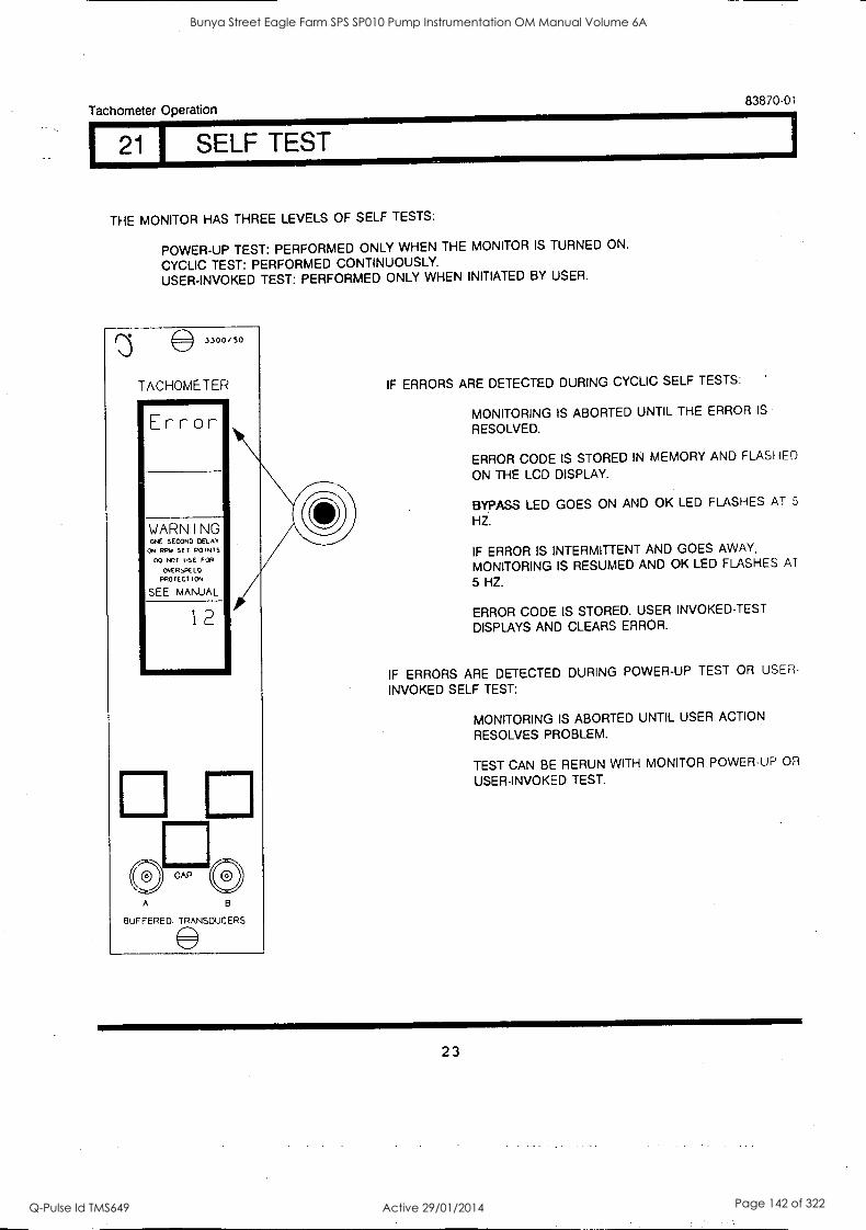
Tachometer Operation 83870-01
21 I SELF TEST
THE MONITOR HAS THREE LEVELS OF SELF TESTS:
POWER-UP TEST: PERFORMED ONLY WHEN THE MONITOR IS TURNED ON.
CYCLIC TEST: PERFORMED CONTINUOUSLY. USER-INVOKED TEST: PERFORMED ONLY WHEN INITIATED BY USER.
25 3300/50
TACHOMETER
Error
WARNING ONE SECOND DELAY
ON RPM SET POINTS
00 NOT IRE FOR
OVER;PC ED
PRO TEC 1 I ON
SEE MANUAL
12
e GAP
A
BUFFERED TRANSDUCERS
IF ERRORS ARE DETECTED DURING CYCLIC SELF TESTS:
MONITORING IS ABORTED UNTIL THE ERROR IS
RESOLVED.
ERROR CODE IS STORED IN MEMORY AND FLASHED
ON THE LCD DISPLAY.
BYPASS LED GOES ON AND OK LED FLASHES AT 5
HZ.
IF ERROR IS INTERMITTENT AND GOES AWAY,
MONITORING IS RESUMED AND OK LED FLASHES AT
5 HZ.
ERROR CODE IS STORED. USER INVOKED-TEST
DISPLAYS AND CLEARS ERROR.
IF ERRORS ARE DETECTED DURING POWER-UP TEST OR USER
INVOKED SELF TEST:
MONITORING IS ABORTED UNTIL USER ACTION
RESOLVES PROBLEM.
TEST CAN BE RERUN WITH MONITOR POWER-UP OR
USER-INVOKED TEST.
23
Bunya Street Eagle Farm SPS SP010 Pump Instrumentation OM Manual Volume 6A
Q-Pulse Id TMS649 Active 29/01/2014 Page 142 of 322
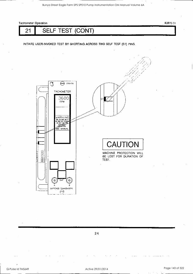
Tachometer Operation 83870-01
I 21 I SELF TEST (CONY)
INITIATE USER-INVOKED TEST BY SHORTING ACROSS TWO SELF TEST (ST) PINS.
C
I
111
fit ED CD CO
3300,50
TACHOMETER
3600 RPM
A
BUFFERED TRANSDUCERS
//
CAUTION MACHINE PROTECTION WILL BE LOST FOR DURATION OF TEST.
24
Bunya Street Eagle Farm SPS SP010 Pump Instrumentation OM Manual Volume 6A
Q-Pulse Id TMS649 Active 29/01/2014 Page 143 of 322
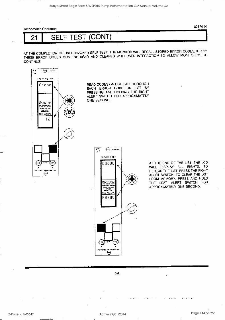
Tachometer Operation 83870-01
1 SELF TEST (CONT)
AT THE COMPLETION OF USER-INVOKED SELF TEST, THE MONITOR WILL RECALL STORED ERROR CODES, IF ANY
THESE ERROR CODES MUST BE READ AND CLEARED WITH USER INTERACTION TO ALLOW MONITORING TO
CONTINUE.
Error
WARNING Of NOM LSAT
ad aft yl Poo.. m IJK 101
0.0.1waco MITCV114
SEE MANUAL
12
41111
a
BUFFERED TRANSCVCERS
READ CODES ON LIST; STEP THROUGH EACH ERROR CODE ON LIST BY
PRESSING AND HOLDING THE RIGHT
ALERT SWITCH FOR APPROXIMATELY ONE SECOND.
))00/50
TACHOMETER 1111111W 88888
WARNING 1.0,0 0... Sal .0..es
00 TOT 1M FM
0476$.0 140,001,0
SEE MANUAL
88888
B
BUFFERED TRANSDUCERS
AT THE END OF THE LIST, THE LCD
WILL DISPLAY ALL EIGHTS. TO
REREAD THE LIST, PRESS THE RIGHT
ALERT SWITCH. TO CLEAR THE LIST
FROM MEMORY, PRESS AND HOLD
THE LEFT ALERT SWITCH FOR
APPROXIMATELY ONE SECOND.
25
Bunya Street Eagle Farm SPS SP010 Pump Instrumentation OM Manual Volume 6A
Q-Pulse Id TMS649 Active 29/01/2014 Page 144 of 322
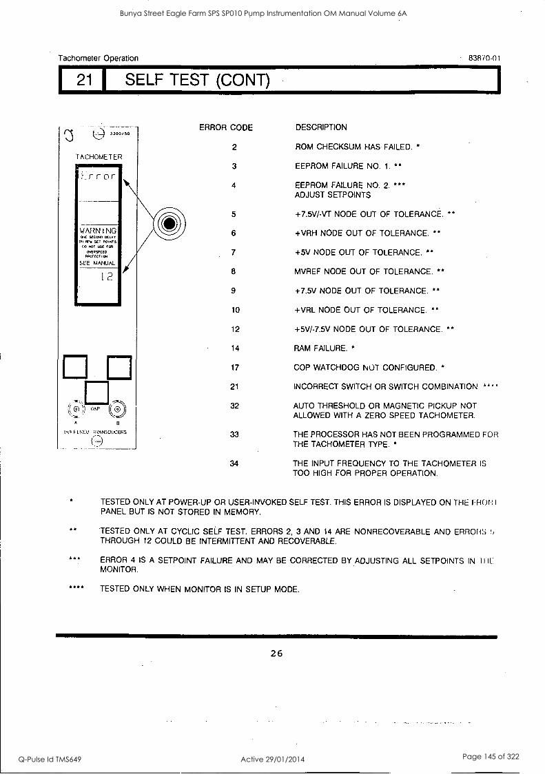
Tachometer Operation 83870 -01
I 21 I SELF TEST (CONY)
(3 3300/30
TACHOMETER wImmir f_r r or
WARNING GE SEEM!, CELP
Al Wu SET POINTS TO NOT USE POI
OvERSPEED OPGTECTICN
SEE MANUAL
12
(( Cij )) CAP (OD
A
101 FF!(ED I RAN;;DUCERS
ERROR CODE
2
3
DESCRIPTION
ROM CHECKSUM HAS FAILED. *
EEPROM FAILURE NO. 1. **
4 EEPROM FAILURE NO. 2. *** ADJUST SETPOINTS
5 +7.5V/-VT NODE OUT OF TOLERANCE. **
6 +VRH NODE OUT OF TOLERANCE. **
7 4-5V NODE OUT OF TOLERANCE. **
8 MVREF NODE OUT OF TOLERANCE. **
9 +7.5V NODE OUT OF TOLERANCE. **
10 +VRL NODE OUT OF TOLERANCE. **
12 +5V/-7.5V NODE OUT OF TOLERANCE. **
14 RAM FAILURE. *
17 COP WATCHDOG NOT CONFIGURED. *
21 INCORRECT SWITCH OR SWITCH COMBINATION. **
32 AUTO THRESHOLD OR MAGNETIC PICKUP NOT ALLOWED WITH A ZERO SPEED TACHOMETER.
33 THE PROCESSOR HAS NOT BEEN PROGRAMMED FOR THE TACHOMETER TYPE. *
34 THE INPUT FREQUENCY TO THE TACHOMETER IS
TOO HIGH FOR PROPER OPERATION.
TESTED ONLY AT POWER-UP OR USER-INVOKED SELF TEST. THIS ERROR IS DISPLAYED ON THE FHOt PANEL BUT IS NOT STORED IN MEMORY.
TESTED ONLY AT CYCLIC SELF TEST. ERRORS 2, 3 AND 14 ARE NONRECOVERABLE AND ERRORS THROUGH 12 COULD BE INTERMITTENT AND RECOVERABLE.
ERROR 4 IS A SETPOINT FAILURE AND MAY BE CORRECTED BY ADJUSTING ALL SETPOINTS IN IIIL MONITOR.
TESTED ONLY WHEN MONITOR IS IN SETUP MODE.
26
Bunya Street Eagle Farm SPS SP010 Pump Instrumentation OM Manual Volume 6A
Q-Pulse Id TMS649 Active 29/01/2014 Page 145 of 322
Tachometer Operation 83870-01
I22 I INDEX
PAGE
ALERT ALERT BYPASS ALERT RELAYS BUFFERED OUTPUTS CYCLIC TEST ERROR CODE
7
7
7
7
23 26
FIRST OUT 13, 14, 15
FIRST OUT ALERT 7
GAP 16
MONITOR BYPASS 7
MONITOR OK 8
OK RELAY 6
PART NUMBER 4
PEAK HOLD 7, 20
PEAK HOLD RESET 21
POWER-UP TEST 23
PROBE GAP VOLTAGE 6
RECORDER OUTPUT 7
ROTOR ACCEL ALERT 15
ROTOR ACCELERATION 6
ROTOR SPEED MONITORING 6
RPM ALERT 13, 14, 15
SELF TEST 8, 23
SETPOINT 17, 18, 19
TRIGGER OK 6
USER-INVOKED TEST 23
ZERO SPEED 6
ZERO SPEED ALERT 14
27
Bunya Street Eagle Farm SPS SP010 Pump Instrumentation OM Manual Volume 6A
Q-Pulse Id TMS649 Active 29/01/2014 Page 146 of 322

BRISBANE CITY COUNCIL Dept. Water Supply and Sewage Pumpwell No 1, Eagle Farm Pump Station
BCC Contract No S20/95/96 System Instrumentation
Operation and Maintenance Manual
2.7.17 Alert Hysteresis
2.7.18 Adjust Alert Setpoints
2.7.19 Bypass Alert Relays
2.7.20 Bypass Monitor
2.7.21 Adjust Threshold and Hysteresis
2.7.22 Adjust Full Scale Range
2.7.23 Test Trigger OK LED's
2.7.24 Test Alerts
2.7.25 Self Test
2.7.26 Error Codes
2.7.27 Recommended Spare Parts List
2.7.28 Specifications
2.7.29 Index
2.7.30 Field Wiring Diagram
15140/hist Man/BRH Issue 1 29-Apr-98 Page 2-10
Bunya Street Eagle Farm SPS SP010 Pump Instrumentation OM Manual Volume 6A
Q-Pulse Id TMS649 Active 29/01/2014 Page 147 of 322
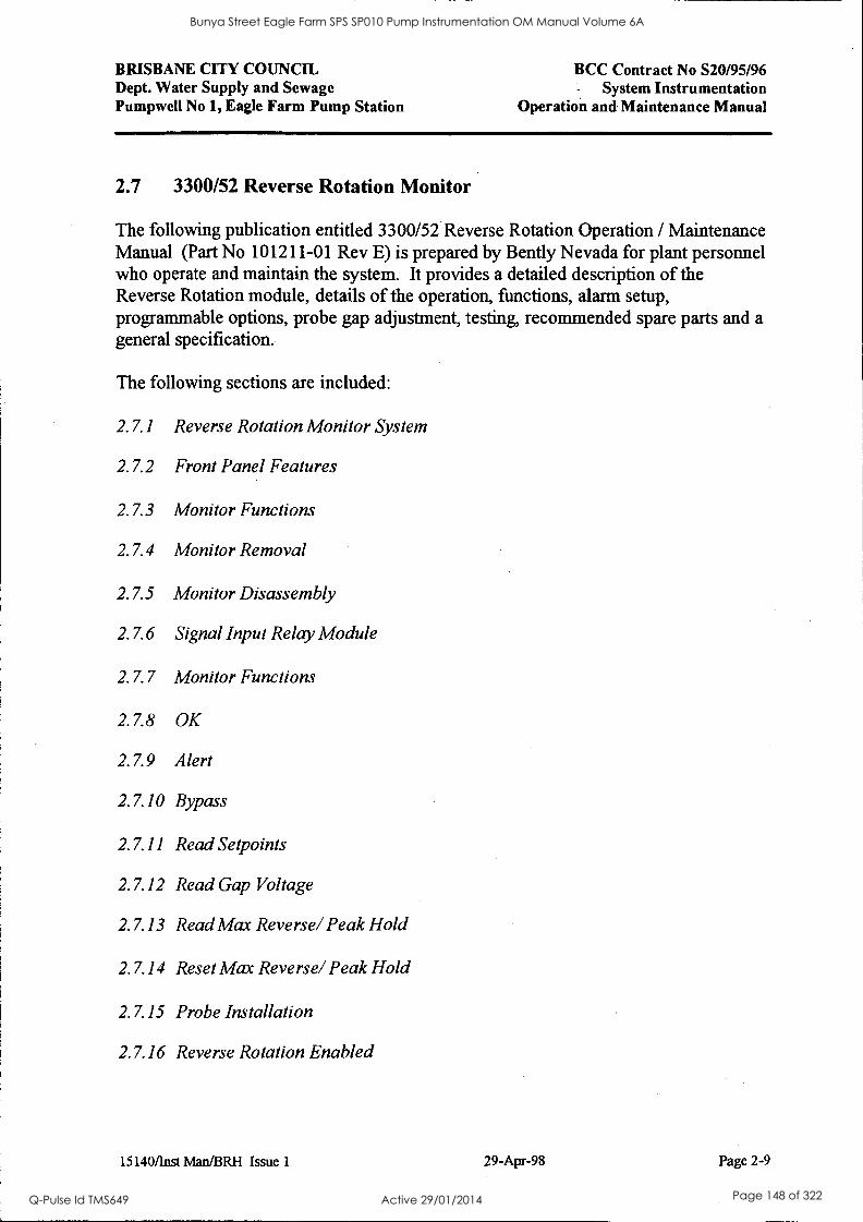
BRISBANE CITY COUNCIL Dept. Water Supply and Sewage Pumpwell No 1, Eagle Farm Pump Station
BCC Contract No S20/95/96 - System Instrumentation
Operation and Maintenance Manual
2.7 3300/52 Reverse Rotation Monitor
The following publication entitled 3300/52 Reverse Rotation Operation / Maintenance Manual (Part No 101211-01 Rev E) is prepared by Bent ly Nevada for plant personnel who operate and maintain the system. It provides a detailed description of the Reverse Rotation module, details of the operation, functions, alarm setup, programmable options, probe gap adjustment, testing, recommended spare parts and a general specification.
The following sections are included:
2.7.1 Reverse Rotation Monitor System
2.7.2 Front Panel Features
2.7.3 Monitor Functions
2.7.4 Monitor Removal
2.7.5 Monitor Disassembly
2.7.6 Signal Input Relay Module
2.7.7 Monitor Functions
2.7.8 OK
2.7.9 Alert
2.7.10 Bypass
2.7.11 Read Setpoints
2.7.12 Read Gap Voltage
2.7.13 Read Max Reverse/ Peak Hold
2.7.14 Reset Max Reverse/ Peak Hold
2.7.15 Probe Installation
2.7.16 Reverse Rotation Enabled
15140/Inst Man/BRH Issue 1 29-Apr-98 Page 2-9
Bunya Street Eagle Farm SPS SP010 Pump Instrumentation OM Manual Volume 6A
Q-Pulse Id TMS649 Active 29/01/2014 Page 148 of 322
3300/52_ REVERSE ROTATION MONITOR
OPERATION / MAINTENANCE MANUAL
BENTLY NEVADA
PART NO. 101211-01 REVISION E,
JANUARY 1995
Bunya Street Eagle Farm SPS SP010 Pump Instrumentation OM Manual Volume 6A
Q-Pulse Id TMS649 Active 29/01/2014 Page 149 of 322
Reverse Rotation Monitor 101211-01
NOTICE
Bent ly Nevada Corporation has attempted to identify areas of risk created by improper installation and/or operation of this product. These areas of information are noted as WARNING or CAUTION for your protection and for the safe and effective operation of this equipment. Read all instructions before installing or operating this product. Pay particular attention to those areas designated by the following symbols.
A\ WARNING
High voltage present. Contact could cause shocks, burns, or death.
Do not touch exposed wires or terminals.
A\ CAUTION
Machine protection provided by this monitor will be lost while the monitor Is removed from the rack.
Keyphasore and Proximitore are registered trademarks of Bent ly Nevada Corporation.
©Copyright Bent ly Nevada Corporation 1992, 1993, 1994, 1995
All Rights Reserved
No part of this publication may be reproduced, transmitted, stored in a retrieval system or translated into any human or computer language, in any form or by any means, electronic, mechanical, magnetic, optical, chemical, manual, or otherwise, without the prior written permission of the copyright owner,
Bent ly Nevada Corporation P.O. Box 157
Minden, Nevada 89423 USA Telephone 800-227-5514 702-782-3611
Telex 354437 Telemall 7400983 BNC UC
Fax 702-782-9253 Copyright infringement is a serious matter under
United States of America and foreign copyright taws.
ii
Bunya Street Eagle Farm SPS SP010 Pump Instrumentation OM Manual Volume 6A
Q-Pulse Id TMS649 Active 29/01/2014 Page 150 of 322
Reverse Rotation Monitor 101211-01
NOTICE
WARNING !
Bently Nevada Reverse Rotation Monitors are not designed for use independently as, or a component of, .a speed control or overspeed protection system.
Bently Nevada Reverse Rotation Monitors do not provide protective redundancy and the response speed needed for reliable operation as a speed control or overspeed protection system.
Where provided, the analog proportional output is suitable for data logging or chart recording purposes only. Also, where provided, speed Alert setpoints are suitable for annunciation purposes only.
Failure to take the above warnings into account constitutes a misuse of the product and may result in property damage and/or bodily injury.
Bunya Street Eagle Farm SPS SP010 Pump Instrumentation OM Manual Volume 6A
Q-Pulse Id TMS649 Active 29/01/2014 Page 151 of 322

Reverse Rotation Monitor 101211-01
FOREWORD
Related Documents
DOCUMENT BENTLY NEVADA PART NUMBER
3300 System Overview, Installation Instructions and 80170-01 Troubleshooting 89602-01 3300/12 AC Power Supply 101256-01 3300/14 DC Power Supply 89604-01 3300/03 System Monitor 88837-01 3300 Internal Barrier Manual
This manual uses these symbols to indicate actions in the step-by-step procedures.
PRESS FLASHING CONNECT DISCastsECT CatERVE SCREWORNER ALARM
iv
Bunya Street Eagle Farm SPS SP010 Pump Instrumentation OM Manual Volume 6A
Q-Pulse Id TMS649 Active 29/01/2014 Page 152 of 322
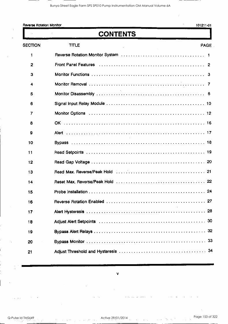
Reverse Rotation Monitor 101211-01
CONTENTS
SECTION TITLE PAGE
1 Reverse Rotation Monitor System 1
2 Front Panel Features 2
3 Monitor Functions 3
4 Monitor Removal 7
5 Monitor Disassembly 8
6 Signal Input Relay Module 10
7 Monitor Options 12
8 OK 16
9 Alert 17
10 Bypass 18
11 Read Setpoints 19
12 Read Gap Voltage 20
13 Read Max. Reverse/Peak Hold 21
14 Reset Max. Reverse/Peak Hold 22
15 Probe Installation 24
16 Reverse Rotation Enabled 27
17 Alert Hysteresis 28
18 Adjust Alert Setpoints 30
19 Bypass Alert Relays 32
20 Bypass Monitor 33
21 Adjust Threshold and Hysteresis 34
Bunya Street Eagle Farm SPS SP010 Pump Instrumentation OM Manual Volume 6A
Q-Pulse Id TMS649 Active 29/01/2014 Page 153 of 322
Reverse Rotation Monitor 101211-01
CONTENTS
SECTION TITLE PAG E
22 Adjust Full Scale Range 38
23 Test Trigger OK LEDs 40
24 Test Alerts 42
25 Self Test 47
26 Error Codes 50
27 Recommended Spare Parts 52
28 Specifications 53
Index 56
Field Wiring Diagrams 59
vi
Bunya Street Eagle Farm SPS SP010 Pump Instrumentation OM Manual Volume 6A
Q-Pulse Id TMS649 Active 29/01/2014 Page 154 of 322
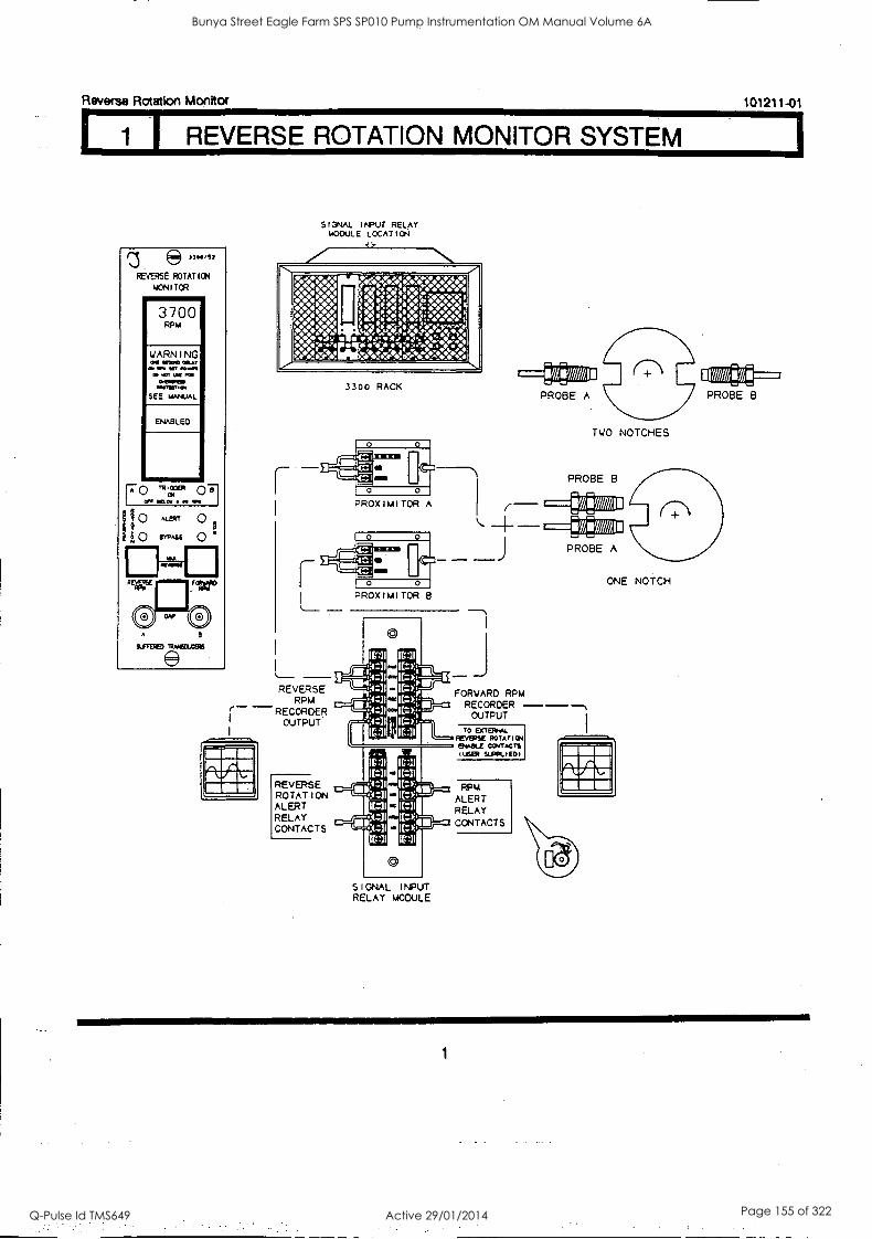
Reverse Rotation Monitor 101211-01
1 I REVERSE ROTATION MONITOR SYSTEM
33A.,72
REVERSE ROTATION
MONITOR
3700 RPM
WARNING wMOO INLAY
NIT 110.0011
KI MT MS AR
MITIRTIOt
SEE UANJAL
ENABLED
IS/TIRED TRAMSDXERS
SIGNAL INPUT RELAY MODULE LOCATION
LS
:WM V40~4 W4MOVN n440 0:444 '40:40
g4Wto 'moVdto:et&ftN,
nt;$"44:Mgg %
" :wows 4
441
3300 RACK
TWO NOTCHES
PROBE B
r
PROXIMITOR A
0 0
REVERSE RPM - RECORDER
OUTPUT
REVERSE ROTATION ALERT RELAY CONTACTS
C=1
0 0
PROXIMITOR B
J FORWARD RPM RECORDER -- OUTPUT
TO IDETERAL REVERSE ROTATION MAKE CONTACTS WSER SUPPLIED)
RPM ALERT RELAY CONTACTS
ONE NOTCH
SIGNAL I NPUT RELAY MODULE
1
Bunya Street Eagle Farm SPS SP010 Pump Instrumentation OM Manual Volume 6A
Q-Pulse Id TMS649 Active 29/01/2014 Page 155 of 322
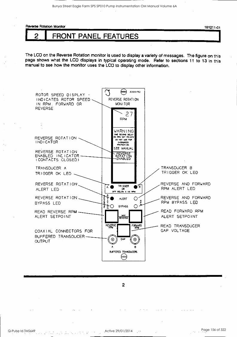
Reverse Rotation Monitor 101211-01
2 1 FRONT PANEL FEATURES
The LCD on the Reverse Rotation monitor is used to display a variety of messages. The figure on this page shows what the LCD displays in typical operating mode. Refer to sections 11 to 13 in this manual to see how the monitor uses the LCD to display other information.
ROTOR SPEED DISPLAY -
INDICATES ROTOR SPEED IN RPM. FORWARD OR REVERSE
REVERSE ROTATION INDICATOR
REVERSE ROTATION ENABLED INDICATOR (CONTACTS CLOSED)
TRANSDUCER A
TRIGGER OK LED
REVERSE ROTATION ALERT LED
REVERSE ROTATION BYPASS LED
READ REVERSE RPM ALERT SETPOINT
COAXIAL CONNECTORS FOR BUFFERED TRANSDUCER OUTPUT
3300/52
REVERSE ROTATION
MONITOR
27 RPM
WARNING ore wax) DELFT ON RPM SET POINTS
00 NOT USE FOR
OVERSPEED PROTECTION
SEE MANUAL
REVERSE ROTATION ENABLED
A TRIGGER .'B OK
OFF BELOW 0.05 RPW
R
T ALERT
BYPASS
max
REVASE
REVERSE
TRANSDUCER B
TRIGGER OK LED
REVERSE AND FORWARD RPM ALERT LED
REVERSE AND FORWARD RPM BYPASS LED
0 READ FORWARD RPM ALERT SETPOINT
A
GAP
FORWARD RFU
B
BUFFERED TRANSDUCERS
READ TRANSDUCER GAP VOLTAGE
2
Bunya Street Eagle Farm SPS SP010 Pump Instrumentation OM Manual Volume 6A
Q-Pulse Id TMS649 Active 29/01/2014 Page 156 of 322
Reverse Rotation Monitor 101211-01
I MONITOR FUNCTIONS
The Reverse Rotation Monitor continuously monitors the speed and direction of shaft rotation. It receives signals from two Keyphasor proximity probes, measures the time between Keyphasor pulses, calculates the speed and determines the direction of rotation. The monitor is designed for applications where reverse rotation would cause damage such as on a machine with dry gas seals or a process that involves flow in two directions such as hydroelectric pumped storage applications.
Alarms
This monitor has one level of alarm, alert, and has two types of alert alarms, reverse rotation and RPM (in both reverse and forward direction). The reverse RPM alert has an over alert setpoint only. The forward RPM alert has either an over or an under alert setpoint.
REVERSE ROTATION ALERT - When the monitor detects reverse rotation, the REVERSE ROTATION ALERT LED comes on and the Reverse Rotation Alert relay activates.
RPM ALERT - When the speed of the shaft equals or exceeds the setpoint levels in either the reverse or forward direction, the RPM ALERT LED comes on and the RPM Alert relay activates.
FIRST OUT ALERT -A monitor with the First Out option selected flashes an ALERT LED if that alert was the first in the rack since the last reset or rack power-up. Pressing the RESET switch on the System Monitor acknowledges the First Out and stops the ALERT LED from flashing.
OK Functions
The OK functions check that the components of the monitor are functioning properly. The OK functions of the Reverse Rotation Monitor include Trigger OK and Monitor OK.
TRIGGER OK - Trigger OK checks the validity of the Keyphasor pulses. The TRIGGER OK LEDs will go off if:
1. The Keyphasor pulses are less than 0.05 RPM or greater than 20,000 RPM if the shaft has one notch or projection or 10,000 RPM if the shaft has two notches or projections.
2. The monitor detects missing or extra keyphasor pulses. 3. The monitor detects a transducer gap reading of zero volts.
MONITOR OK - Monitor OK uses the self tests to check the integrity of the monitor. If a self test fails, the OK Relay changes state (goes not OK) and the TRIGGER OK LEDs flashes at 5 Hz.
Bunya Street Eagle Farm SPS SP010 Pump Instrumentation OM Manual Volume 6A
Q-Pulse Id TMS649 Active 29/01/2014 Page 157 of 322
Reverse Rotel Ion Monitor 101211-01
I MONITOR FUNCTIONS (CONT) Relays
ALERT RELAYS - There are two alert relays: Reverse Rotation Alert Relay and RPM Alert Relay. The alerts can be programmed individually for either latching or nonlatching mode. In the nonlatching mode, the alert resets automatically when the alert no longer exists. In the latching mode, the alert condition must be reset manually by pressing the RESET switch on the front panel of the System Monitor or by closing the external reset contacts on the Power Input Module. The alert will not reset if the alert condition still exists.
REVERSE ROTATION ALERT RELAY - This alert relay changes state whenever reverse rotation is detected. This relay can be bypassed by setting a DIP switch.
RPM ALERT RELAY - This alert relay changes state when either the Reverse RPM setpoint is exceeded or the Forward RPM setpoint is exceeded. The Reverse RPM alert is always an over alert setpoint, while the Forward RPM alert can be jumper-programmed for either an over or an under alert setpoint. This relay can be bypassed by setting a DIP switch.
OK RELAY - The OK Relay is a feature of the 3300 system and is located on the Power Input Module. Every monitor in the rack must be OK or bypassed to drive the OK Relay OK.
Bypass
The bypass functions let you disable alert alarms or the entire monitor. Bypass functions are useful to avoid alarms when you configure or test the monitor.
REVERSE ROTATION ALERT RELAY BYPASS - Use Reverse Rotation Alert Relay Bypass to disable the Reverse Rotation relay. When an alarm is bypassed, the alert relay for that alarm is disabled. The monitor continues to indicate speed, direction, and alarm status on the front panel even when Reverse Rotation Alert Relay Bypass is on.
RPM ALERT RELAY BYPASS - Use RPM Alert Relay Bypass to disable the RPM relay. When an alarm is bypassed, the alert relay for that alarm is disabled. The monitor continues to indicate speed, direction, and alarm status on the front panel even when RPM Alert Relay Bypass is on.
MONITOR BYPASS - Use Monitor Bypass to disable the entire monitor. The monitor disables any monitoring, displays 0 (zero) RPM forward on the front panel, and drives the OK relay OK
4
Bunya Street Eagle Farm SPS SP010 Pump Instrumentation OM Manual Volume 6A
Q-Pulse Id TMS649 Active 29/01/2014 Page 158 of 322
Reverse Rotation Monitor. 101211-01
1.2.1 MONITOR. FUNCTIONS (CONT)
Switches on the Front Panel
REVERSE RPM - Press this switch to display the Reverse RPM setpoint. The up arrow will be on,
indicating an over alert setpoint, and the "REVERSE ROTATION ALERT' label will be displayed on
the front panel.
FORWARD RPM - Press this switch to display the Forward RPM setpoint. The up arrow will be on
if the monitor is jumper-programmed to have an over Forward RPM setpoint, and the down arrow
will be on if the monitor is jumper-programmed to have an under Forward RPM setpoint.
PROBE GAP VOLTAGE - Display the probe gap voltage for each transducer by pressing the GAP
switch. Probe gap is measured in negative DC voltage and is directly proportional to the gap
between the face of the proximity probe and the surface being monitored.
MAX REVERSE/PEAK HOLD - The monitor stores values for maximum speed in the reverse
direction and the number of rotations in the reverse direction. You can read these values by
pressing the REVERSE RPM and FORWARD RPM switches simultaneously. The monitor retains
these values even after loss of monitor power.
Input and Output
The monitor can receive input from two sources: system Keyphasor signals from the Power Input
Module or separate Keyphasor signals from the Signal Input Relay Module. The monitor provides
outputs from the coaxial connectors on the front panel and from the Reverse RPM and Forward RPM
recorder outputs at the rear of the rack.
KEYPHASOR SIGNALS - The monitor can use System Keyphasor signals that enter the rack
through the Power Input Module and are available to all the monitors in the rack. The monitor can
also use separate Keyphasor signals from the Monitor's Signal Input Module.
BUFFERED OUTPUTS - The BUFFERED TRANSDUCER A and B coaxial cable connectors on the
front panel of the monitor provide buffered signals from the transducers. Use these connectors to
connect external equipment to the monitor.
RECORDER OUTPUT - Depending on the option selected, the recorder output levels proportional
to reverse RPM and forward RPM are 0 to -10 Vdc, +1 to +5 Vdc, or +4 to +20 mA. There are two
recorders, one for reverse RPM and another for forward RPM. For reverse rotation, the reverse RPM
recorder is driven to the proportional output level, and the forward RPM recorder is driven
downscale. For forward rotation, the forward RPM recorder is driven to the proportional output level,
and the reverse RPM recorder is driven downscale.
5
Bunya Street Eagle Farm SPS SP010 Pump Instrumentation OM Manual Volume 6A
Q-Pulse Id TMS649 Active 29/01/2014 Page 159 of 322
Reverse Rotation Monitor 101211-01
I MONITOR FUNCTIONS (CONT.)
Self Tests
The monitor has three categories of self test: Power-up, Cyclic, and User-invoked.
POWER UP -A Power-up self test, consisting of a series of basic monitor OK tests, is performed automatically each time the monitor is turned on.
CYCLIC -A Cyclic self test is performed automatically while the monitor is operating. Any error encountered during cyclic tests disables the monitor and flashes an error code on the front panel display. tf the error is intermittent, the monitor will begin operating again, and the error code will be stored for retrieval during user-invoked self tests. Stored error codes are indicated by the TRIGGER OK LEDs flashing at 5 Hz (5 times per second) provided that the monitor and the triggers are OK.
USER INVOKED -A User-invoked self test performs a Power-up self test and allows error messages stored during cyclic tests to be read and cleared. Stored errors are annunciated by flashing the TRIGGER OK LEDs at 5 Hz and displaying the error codes on the front panel LCD display.
6.
6
Bunya Street Eagle Farm SPS SP010 Pump Instrumentation OM Manual Volume 6A
Q-Pulse Id TMS649 Active 29/01/2014 Page 160 of 322
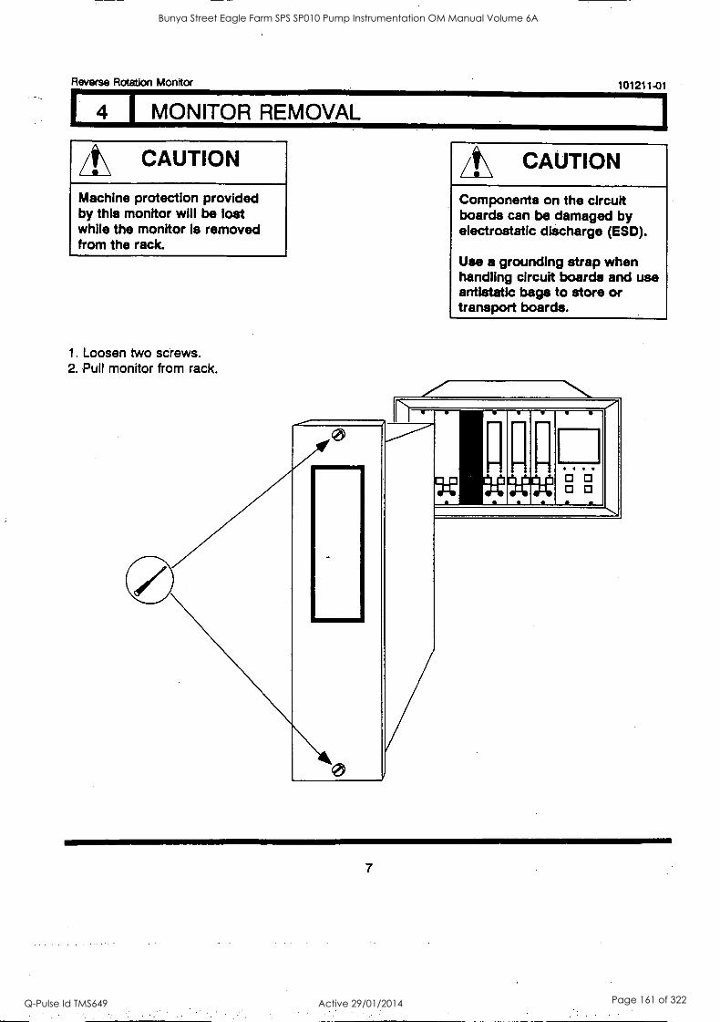
1
Reverse Rotation Monitor 101211-01
I MONITOR REMOVAL
/t\ CAUTION
Machine protection provided by this monitor will be lost while the monitor is removed from the rack.
1. Loosen two screws. 2. Pull monitor from rack.
411111111
/It\ CAUTION
Components on the circuit boards can be damaged by electrostatic discharge (ESD).
Use a grounding strap when handling circuit boards and use antistatic bags to store or transport boards.
0 0 0 0
7
Bunya Street Eagle Farm SPS SP010 Pump Instrumentation OM Manual Volume 6A
Q-Pulse Id TMS649 Active 29/01/2014 Page 161 of 322

Reverse Rotation Monitor 101211-01
I MONITOR DISASSEMBLY
A\ CAUTION
Components on the circuit boards can be damaged by electrostatic discharge (ESD).
Use a grounding strap when handling circuit boards and use antistatic bags to store or transport boards.
Side Cover Removal
Squeeze the retaining tips on each standoff, and remove the side cover from the monitor.
Front Panel Assembly Removal
1. Disconnect J2 by pressing the connector latches outward.
2. Unscrew the two sliding standoffs.
RETAI SCREW
NING
MAIN CIRCUIT BOARD STANDOFF I4 PLACES)
SPRING
YAM
WASHER SLIDING S I ANDOFF
SID COYER
RIBBON CABLE
8
Bunya Street Eagle Farm SPS SP010 Pump Instrumentation OM Manual Volume 6A
Q-Pulse Id TMS649 Active 29/01/2014 Page 162 of 322
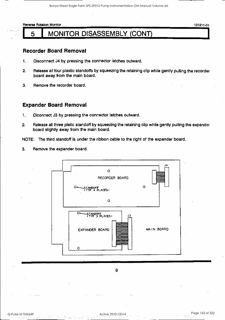
Reverse Rotation Monitor 101211-01
1 5 I MONITOR DISASSEMBLY (CONT)
Recorder Board Removal
1.. Disconnect J4 by pressing the connector latches outward.
2. Release all four plastic standoffs by squeezing the retaining clip while gently pulling the recorder board away from the main board.
3. Remove the recorder board.
Expander Board Removal
1. Diconnect J3 by pressing the connector latches outward.
2. Release all three platic standoff by squeezing the retaining clip while gently pulling the expander board slightly away from the main board.
NOTE: The third standoff is under the ribbon cable to the right of the expander board.
3. Remove the expander board.
0
RECORDER BOARD
0'---STANOOFF TYP 4 PLACES)
O
O
J4
°"----STAN F TYP 3 PLACES
EXPANDER BOARD
O
J3
MAIN BOARD
9
Bunya Street Eagle Farm SPS SP010 Pump Instrumentation OM Manual Volume 6A
Q-Pulse Id TMS649 Active 29/01/2014 Page 163 of 322
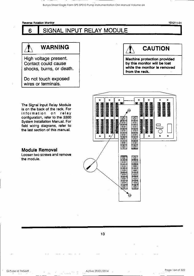
Reverse Rotation Monitor
6 1 SIGNAL INPUT RELAY MODULE
A\ WARNING
High voltage present. Contact could cause shocks, burns, or death.
Do not touch exposed wires or terminals.
The Signal Input Relay Module is on the back of the rack. For information on relay configuration, refer to the 3300 System Installation Manual. For field wiring diagrams, refer to the last section of this manual.
Module Removal Loosen two screws and remove the module.
101211-01
/t\ CAUTION
Machine protection provided by this monitor will be lost while the monitor Is removed from the rack.
-3 -3
:3'
It
e e
11
II 1
n. i
i
r I
7.1
:1
9
I I
11 1
1::3 rz) 1:1
I. II I: 11
31
:-11 11-,1
: =11
9
9
. I:11 (-3
3i
Iz:
1-1
(-3
9
r:i r: t- 3-:
0
.:1 LIi r/
'11 I-11 I-11 [71 [11.1
r:1
9 9
10
Bunya Street Eagle Farm SPS SP010 Pump Instrumentation OM Manual Volume 6A
Q-Pulse Id TMS649 Active 29/01/2014 Page 164 of 322
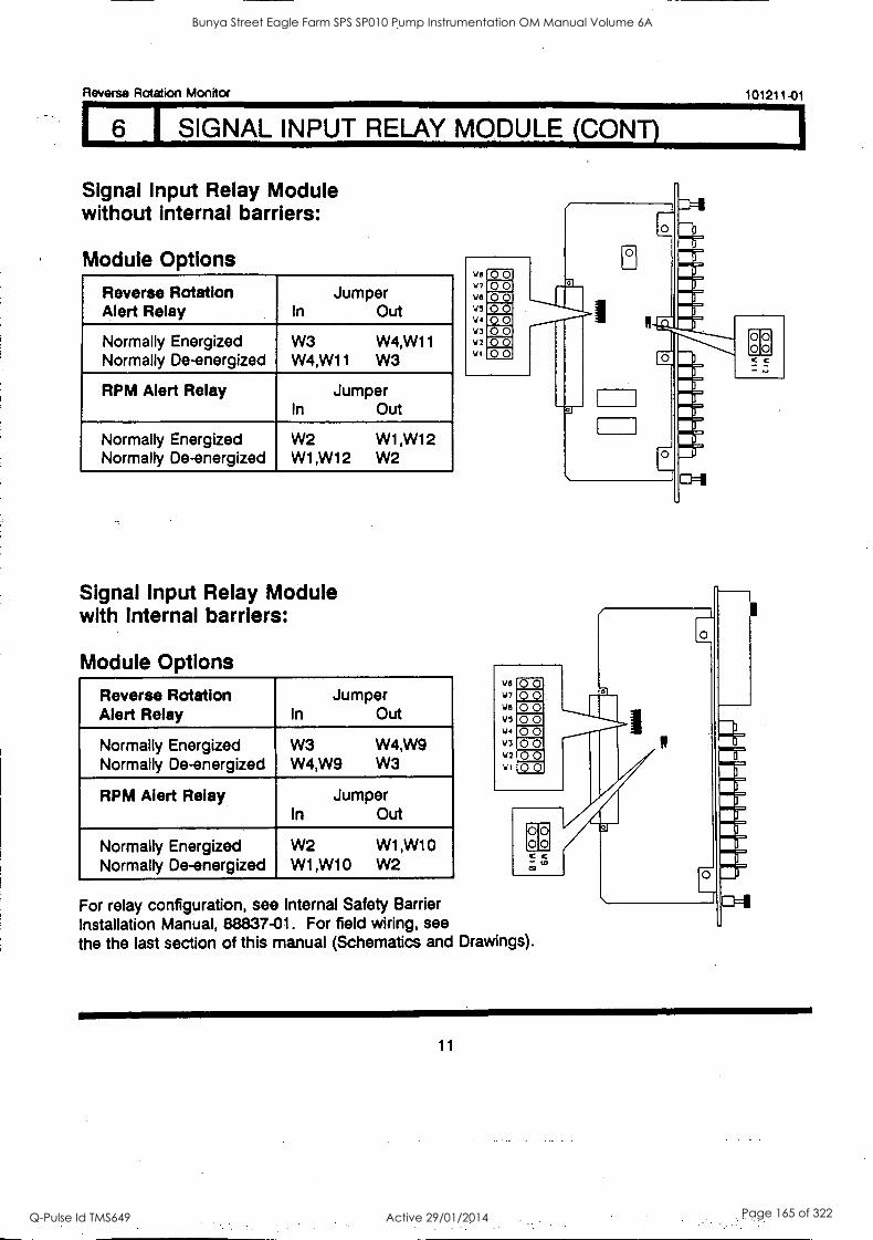
Reverse Rotation Monitor 101211-01
I 6 I SIGNAL INPUT RELAY MODULE (CONT)
Signal Input Relay Module without internal barriers:
Module Options
Reverse Rotation Alert Relay
Jumper In Out
Normally Energized Normally De-energized
W3 W4,W11
W4,W11 W3
RPM Alert Relay Jumper In Out
Normally Energized Normally De-energized
W2 W1,W12
W1,W12 W2
Signal Input Relay Module with internal barriers:
Module Options
Reverse Rotation Alert Relay
Jumper In Out
Normally Energized Normally De-energized
W3 W4,W9
W4,W9 W3
RPM Alert Relay Jumper In Out
Normally Energized Normally De-energized
W2 W1,W10
W1,W10 W2
%S vii
VS
VS
44 V3 V2 VI
00 2_2 00 00 00 00 00
we
VG
45 1./4
VI
00 00 00 00 00 00 00 00
00 00 c c - to
For relay configuration, see Internal Safety Barrier Installation Manual, 88837-01. For field wiring, see the the last section of this manual (Schematics and Drawings).
0
or00 cc
11
Bunya Street Eagle Farm SPS SP010 Pump Instrumentation OM Manual Volume 6A
Q-Pulse Id TMS649 Active 29/01/2014 Page 165 of 322
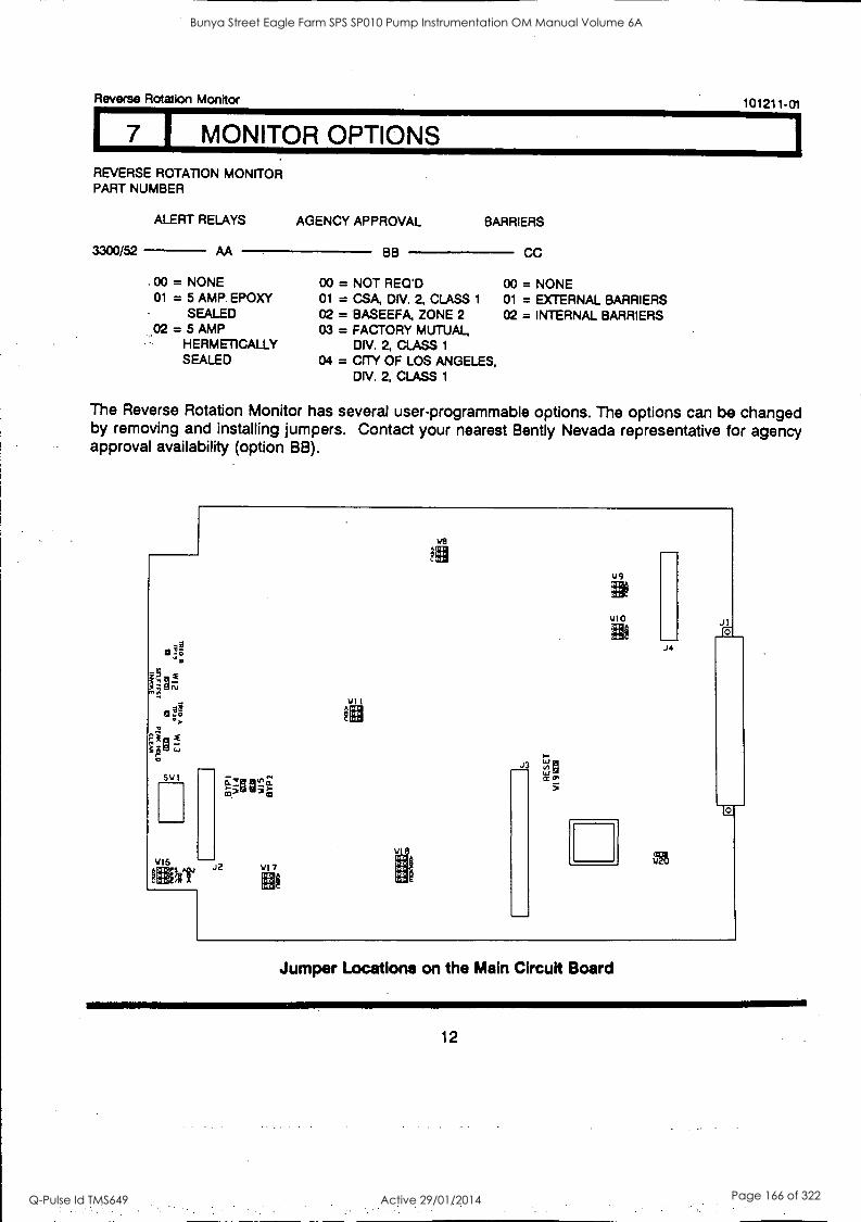
.1111
Reverse Rotation Monitor 101211-01
7 1 MONITOR OPTIONS REVERSE ROTATION MONITOR PART NUMBER
ALERT RELAYS AGENCY APPROVAL BARRIERS
CC 3300/52 AA BB
00 = NONE 00 = NOT REO'D 00 = NONE 01 = 5 AMP EPDXY 01 = CSA, DN. 2, CLASS 1 01 = EXTERNAL BARRIERS
SEALED 02 = BASEEFA, ZONE 2 02 = INTERNAL BARRIERS 02 = 5 AMP
HERMETICALLY 03 = FACTORY MUTUAL,
DIV. 2, CLASS 1
SEALED 04 = CITY OF LOS ANGELES, DIV. 2, CLASS 1
The Reverse Rotation Monitor has several user-programmable options. The options can be changed by removing and installing jumpers. Contact your nearest Bently Nevada representative for agency approval availability (option BB).
Sw 1
416 J2 153111
411
we
J3
J4
5t,
Jul
Jumper Locations on the Main Circuit Board
12
Bunya Street Eagle Farm SPS SP010 Pump Instrumentation OM Manual Volume 6A
Q-Pulse Id TMS649 Active 29/01/2014 Page 166 of 322
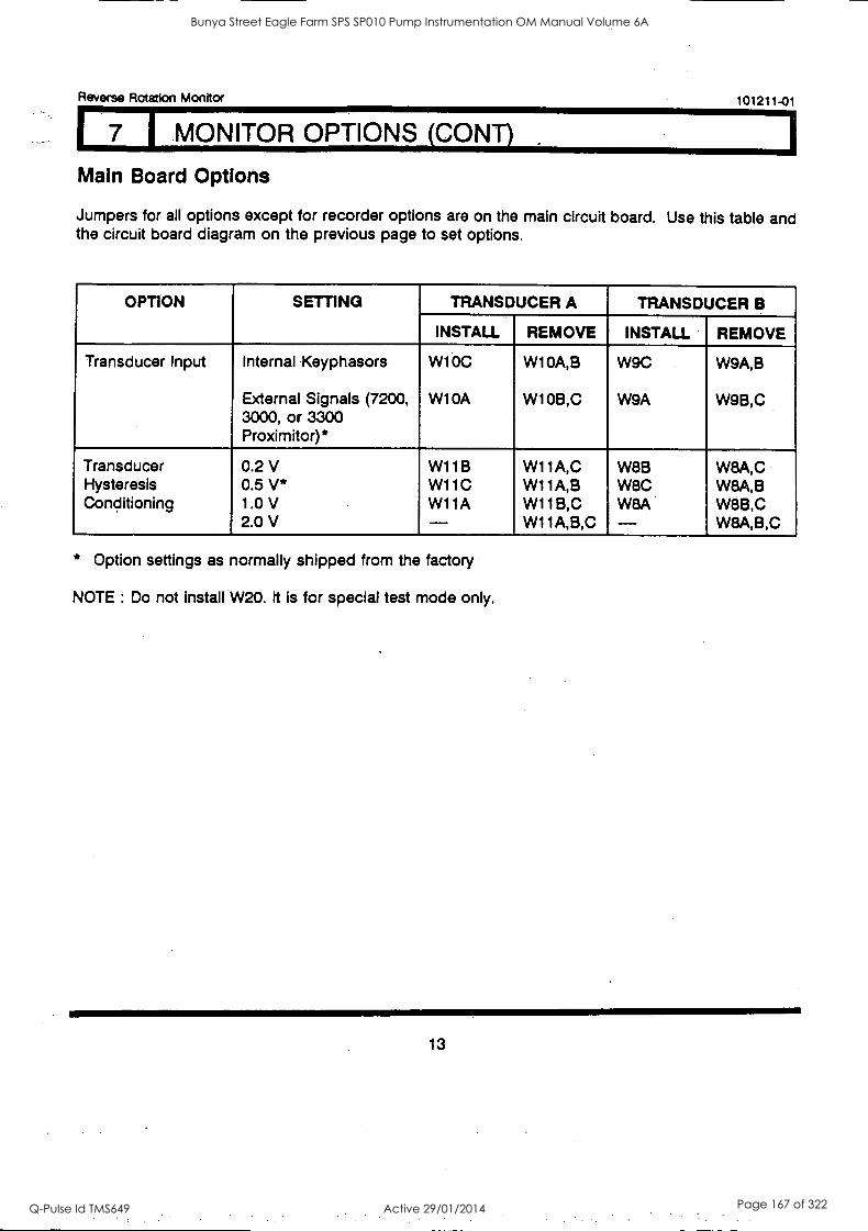
Reverse Rotation Monitor 101211-01
I MONITOR OPTIONS (CONT)
Main Board Options
Jumpers for all options except for recorder options are on the main circuit board. Use this table and the circuit board diagram on the previous page to set options.
OPTION SETTING TRANSDUCER A TRANSDUCER B
INSTALL REMOVE INSTALL REMOVE
Transducer Input Internal Keyphasors
External Signals (7200, 3000, or 3300 Proximitor)*
W10C
W10A
W10A,B
W10B,C
W9C
W9A
W9A,B
W9B,C
Transducer Hysteresis Conditioning
0.2 V 0.5 V* 1.0 V 2.0 V
W11B W11C W11A -
W11A,C W11A,B W11B,C W11A,B,C
W8B W8C W8A -
W8A,C W8A,B W8B,C W8A,B,C
* Option settings as normally shipped from the factory
NOTE : Do not install W20. It is for special test mode only.
13
Bunya Street Eagle Farm SPS SP010 Pump Instrumentation OM Manual Volume 6A
Q-Pulse Id TMS649 Active 29/01/2014 Page 167 of 322
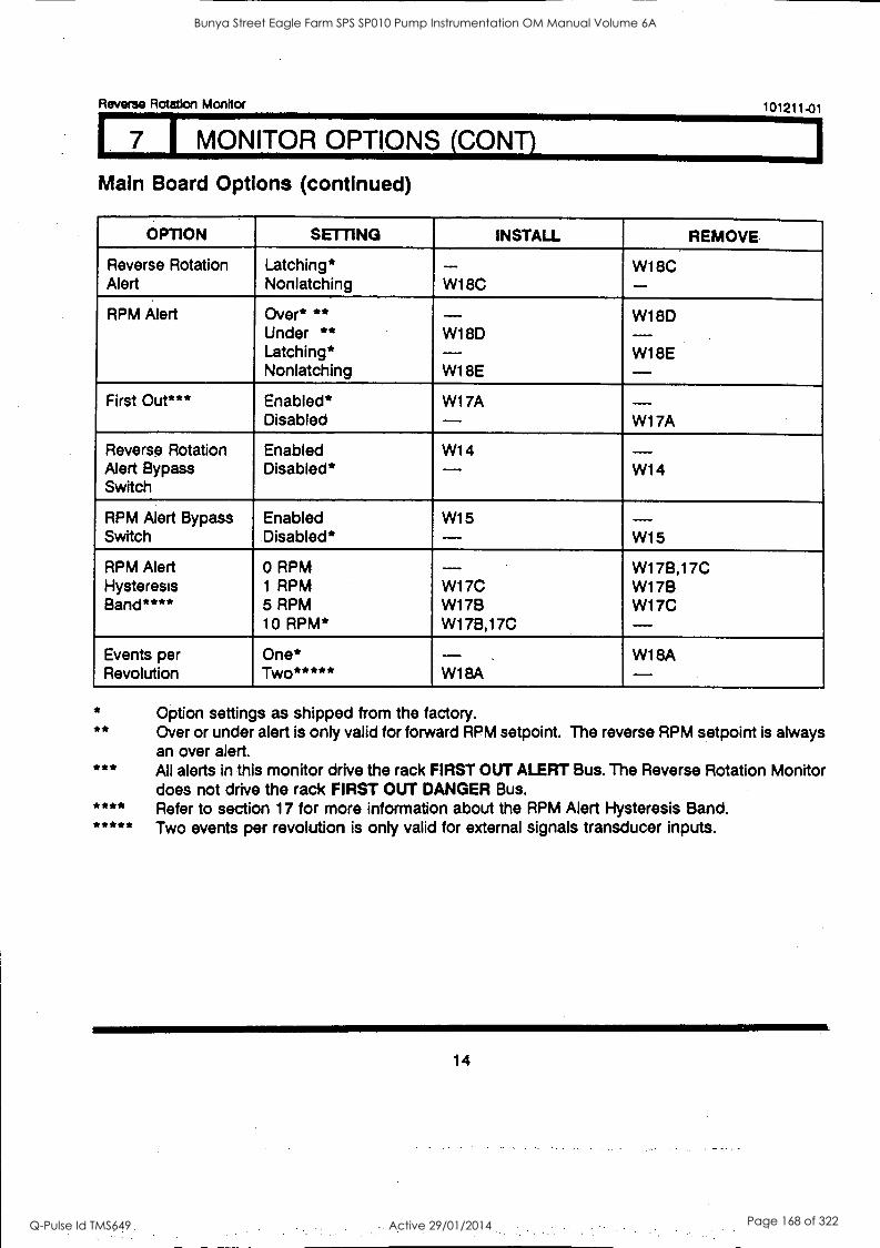
1
Reverse Rotation Monitor 101211-01
I MONITOR OPTIONS (CONT)
Main Board Options (continued)
OPTION SETTING INSTALL REMOVE
Reverse Rotation Alert
Latching* Non latching W18C
_ W18C
RPM Alert Over* ** Under ** Latching* Non latching
W18D
W1 BE
W18D
W18E
First Out*** Enabled* Disabled
W17A W17A
Reverse Rotation Alert Bypass Switch
Enabled Disabled*
W14 W14
RPM Alert Bypass Switch
Enabled Disabled*
W15 W15
RPM Alert Hysteresis Band****
0 RPM 1 RPM 5 RPM 10 RPM*
W17C W17B W17B,17C
W17B,17C W17B W17C
Events per Revolution
One* Two***** W18A
W18A
* **
***
Option settings as shipped from the factory. Over or under alert is only valid for forward RPM setpoint. The reverse RPM setpoint is always an over alert. All alerts in this monitor drive the rack FIRST OUT ALERT Bus. The Reverse Rotation Monitor does not drive the rack FIRST OUT DANGER Bus. Refer to section 17 for more information about the RPM Alert Hysteresis Band. Two events per revolution is only valid for external signals transducer inputs.
14
Bunya Street Eagle Farm SPS SP010 Pump Instrumentation OM Manual Volume 6A
Q-Pulse Id TMS649 Active 29/01/2014 Page 168 of 322

Reverse Rotation Monitor 101211-01
7 1 MONITOR OPTIONS (CONY)
Recorder Board Options RECORDER OUTPUT
To program Recorder Output Options, remove ALL jumpers in W1, W2, W3, W4, W5, W6, and W7 on the recorder board. Then install jumpers:
+4 to +20 mA* 0 to -10 Vdc +1 to +5 Vdc
W1B,C,D W2B,D,E W3A,C
W4B,D,E W5B,C,D
W1A,E W2A,G W3B,D W4A,G W5A,E
W1A,E W2C,F W3A,C W4C,F W5A,E
OPTION SETTING INSTALL REMOVE
2 mA Clamp** Enabled Disabled*
W6 W7 W6 W7
* **
Option settings as shipped from the factory. 2 mA clamp means that when the OK relay goes not OK the recorder output is driven to 2 mA
(it is only valid for the +4 to +20 mA recorder option).
NOTE: The jumpers for the recorder options are on the recorder board.
<CDCJOUJ CJ
<COUCILLIU-C, An c -MIgtca IM)
Os;
UJC1C.103.<
N141.1
J5
Jumper Locations on the Recorder Board
15
Bunya Street Eagle Farm SPS SP010 Pump Instrumentation OM Manual Volume 6A
Q-Pulse Id TMS649 Active 29/01/2014 Page 169 of 322
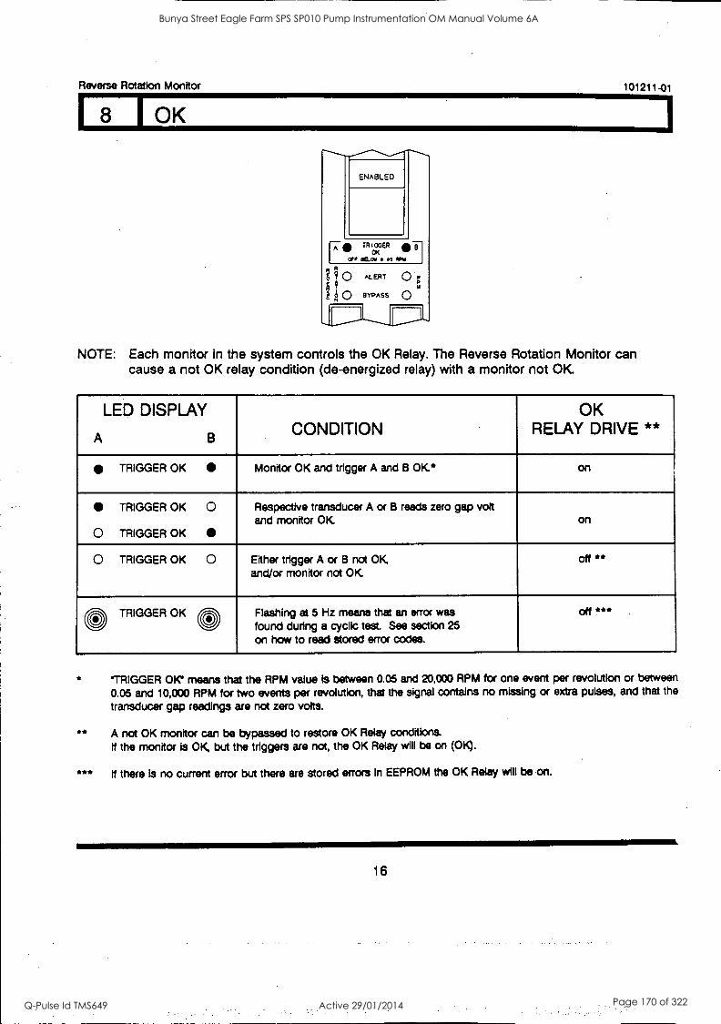
Reverse Rotation Monitor 101211-01
(8 1 OK
ENABLED
F g 0
?
H2O
TR 100ER CK
maw e.es 71
ALERT
BYPASS
0 0
NOTE: Each monitor in the system controls the OK Relay. The Reverse Rotation Monitor can cause a not OK relay condition (de-energized relay) with a monitor not OK.
LED DISPLAY
A B CONDITION
OK RELAY DRIVE **
TRIGGER OK Monitor OK and trigger A and B OK* on
TRIGGER OK 0
0 TRIGGER OK
Respective transducer A or B reads zero gap volt and monitor OK on
0 TRIGGER OK 0 Either trigger A or B not OK, and/or monitor not OK
off **
0 TRIGGER OK * Flashing at 5 Hz means that an error was found during a cyclic test. See section 25 on how to read stored error codes.
off *
**
***
'TRIGGER OK' means that the RPM value Is between 0.05 and 20,000 RPM for one event per revolution or between
0.05 and 10,000 RPM for two events per revolution, that the signal contains no missing or extra pulses, and that the
transducer gap readings are not zero volts.
A not OK monitor can be bypassed to restore OK Relay conditions. if the monitor is OK, but the triggers are not, the OK Relay will be on (OK).
If there is no current error but there are stored errors In EEPROM the OK Relay will be on.
16
Bunya Street Eagle Farm SPS SP010 Pump Instrumentation OM Manual Volume 6A
Q-Pulse Id TMS649 Active 29/01/2014 Page 170 of 322
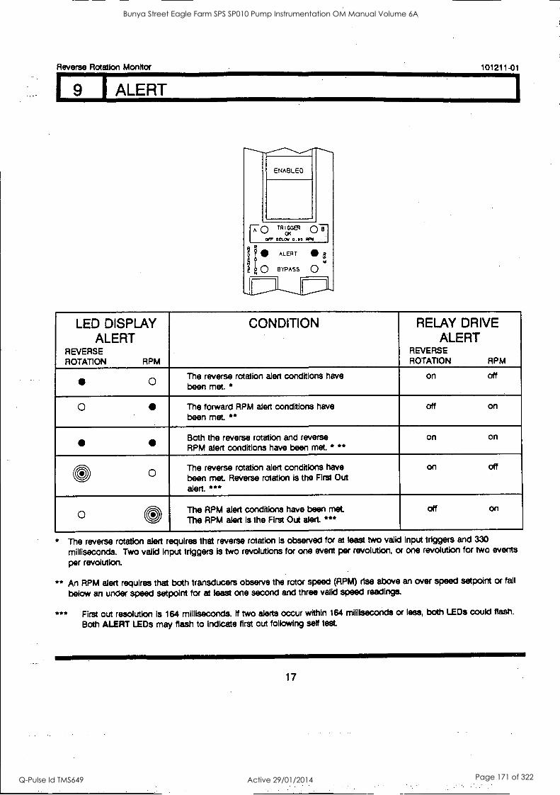
Reverse Rotation Monitor
9 I ALERT
101211-01
ENABLED
17 TRIGGER
I coy scow 0,35
ego ALERT
BYPASS o
LED DISPLAY ALERT
REVERSE ROTATION RPM
CONDITION RELAY DRIVE ALERT
REVERSE ROTATION RPM
0 The reverse rotation alert conditions have been met. *
on off
0 The forward RPM alert conditions have been met. **
off on
Both the reverse rotation and reverse RPM alert conditions have been met. * **
on on
0 The reverse rotation alert conditions have been met Reverse rotation is the First Out alert. ***
on off
0 0 The RPM alert conditions have been met The RPM alert is the First Out alert ***
off on
* The reverse rotation alert requires that reverse rotation is observed for at least two valid input triggers and 330
milliseconds. Two valid Input triggers Is two revolutions for one event per revolution, or one revolution for two events
per revolution.
** An RPM alert requires that both transducers observe the rotor speed (RPM) rise above an over speed setpoint or fall
below an under speed setpolnt for at least one second and three valid speed readings.
*** First out resolution is 164 milliseconds. If two alerts occur within 164 milliseconds or less, both LEDs could flash.
Both ALERT LEDs may flash to Indicate first out following self test.
17
Bunya Street Eagle Farm SPS SP010 Pump Instrumentation OM Manual Volume 6A
Q-Pulse Id TMS649 Active 29/01/2014 Page 171 of 322
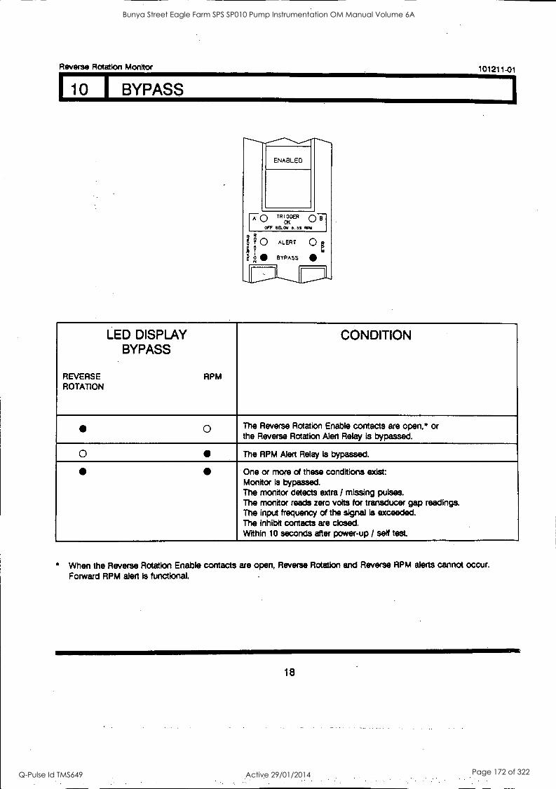
Reverse Rotation Monitor 101211-01
FIT BYPASS
ENABLED
0 TR I GGER 01 CSC
OFF BELOW O. os
ih ALERT
BYPASS
o2
REVERSE ROTATION
LED DISPLAY BYPASS
RPM
CONDITION
o The Reverse Rotation Enable contacts are open,* or the Reverse Rotation Alert Relay is bypassed.
o The RPM Alert Relay is bypassed.
One or more of these conditions exist: Monitor Is bypassed. The monitor detects extra / missing pulses. The monitor reads zero volts for transducer gap readings. The input frequency of the signal Is exceeded. The inhibit contacts are closed. Within 10 seconds after power-up / self test.
* When the Reverse Rotation Enable contacts are open, Reverse Rotation and Reverse RPM alerts cannot occur. Forward RPM alert is functional.
18
Bunya Street Eagle Farm SPS SP010 Pump Instrumentation OM Manual Volume 6A
Q-Pulse Id TMS649 Active 29/01/2014 Page 172 of 322
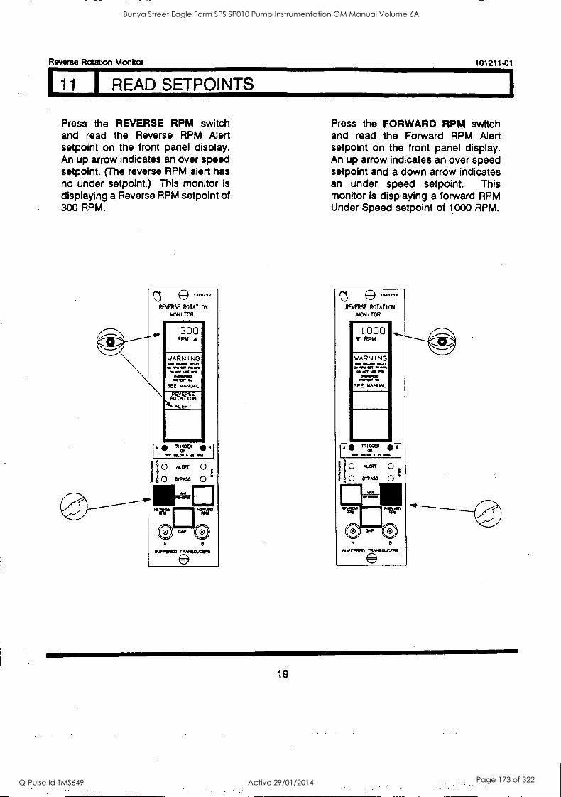
Reverse Rotation Monitor 101211-01
111 I READ SETPOINTS
Press the REVERSE RPM switch and read the Reverse RPM Alert setpoint on the front panel display. An up arrow indicates an over speed setpoint. (The reverse RPM alert has no under setpoint.) This monitor is displaying a Reverse RPM setpoint of 300 RPM.
e3300,12
REVERSE ROTATION
NCN I TOR
300 RPM
WARNING ON 1400 10, at WY WI 10 NM
10 CT UN RN 450/10) rrorecti as
SEE MANUAL
UTVAEP ITN Ilk ALERT
F. -T 1 an NOW Oft
0 ocerr 0 evAss 0
"reran TiErm5
Press the FORWARD RPM switch and read the Forward RPM Alert setpoint on the front panel display. An up arrow indicates an over speed setpoint and a down arrow indicates an under speed setpoint. This monitor is displaying a forward RPM Under Speed setpoint of 1000 RPM.
REVERSE ROTATION
NON I TOR mr 1000
V PPM
WARNING ao woo losa al all Sr 101111
CO CT POI 000004
00110101 SEE WAWA/
A
OUFFIPED IRANSOJCZRS
19
Bunya Street Eagle Farm SPS SP010 Pump Instrumentation OM Manual Volume 6A
Q-Pulse Id TMS649 Active 29/01/2014 Page 173 of 322
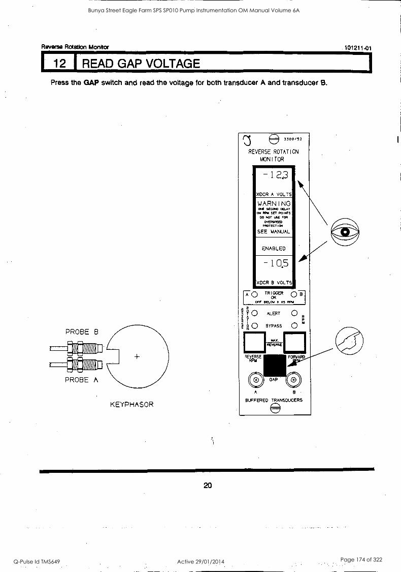
Reverse Rotation Monitor 101211-01
12 READ GAP VOLTAGE
Press the GAP switch and read the voltage for both transducer A and transducer B.
KEYPHASOR
3300/12
REVERSE ROTATION
MONITOR 1iir -12,3
XDCR A VOLTS
WARNING ONE SECOND CELAN' ON RPW SET POINTS
00 NOT USE FOR
OwERSpEED PROTECTION
SEE MANUAL
ENABLED
- 10,5
XDCR B VOLTS
F0 TRIGGER
OFF BELOW 0.00 RPU
I Ff. 0 T k0 BYPASS
ALERT
MAX.
REVERSE
O R
O 154
A
BUFFERED TRANSDUCERS
20
Bunya Street Eagle Farm SPS SP010 Pump Instrumentation OM Manual Volume 6A
Q-Pulse Id TMS649 Active 29/01/2014 Page 174 of 322
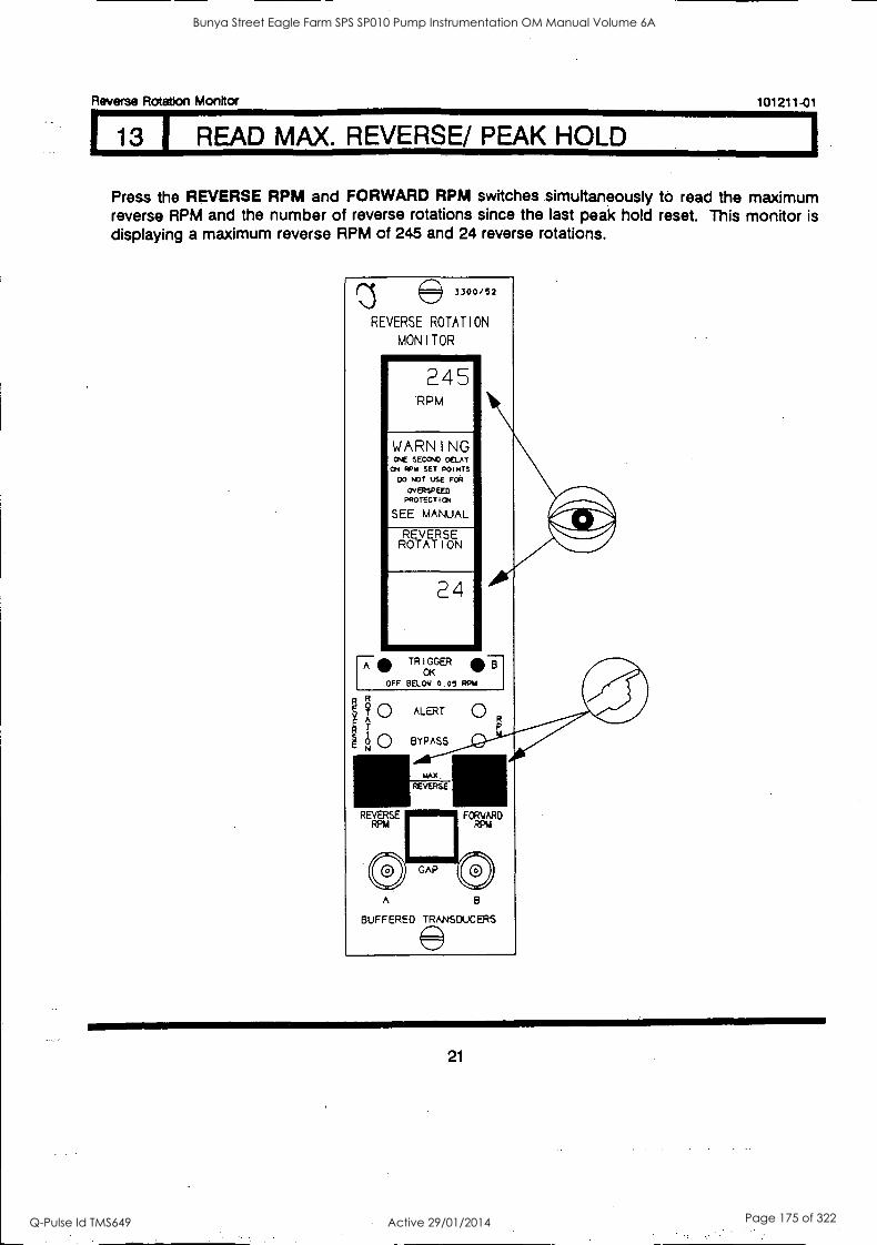
Reverse Rotation Monitor 101211-01
13 1 READ MAX. REVERSE/ PEAK HOLD
Press the REVERSE RPM and FORWARD RPM switches simultaneously to read the maximum reverse RPM and the number of reverse rotations since the last peak hold reset. This monitor is displaying a maximum reverse RPM of 245 and 24 reverse rotations.
3300/52
REVERSE ROTATION
MONITOR
245 RPM
WARNING ONE SECOND DELAY ON RPM SET POINTS
DO NOT USE FOR
OvERSPEED PROTECTION
SEE MANUAL
REVERSE ROTATION
24
TRIGGER
OFF BELOW 0.07 OK
F?4 0 ALERT OR g
0 BYPASS
MAX
REVERSE
A
BUFFERED TRANSDUCERS
21
Bunya Street Eagle Farm SPS SP010 Pump Instrumentation OM Manual Volume 6A
Q-Pulse Id TMS649 Active 29/01/2014 Page 175 of 322
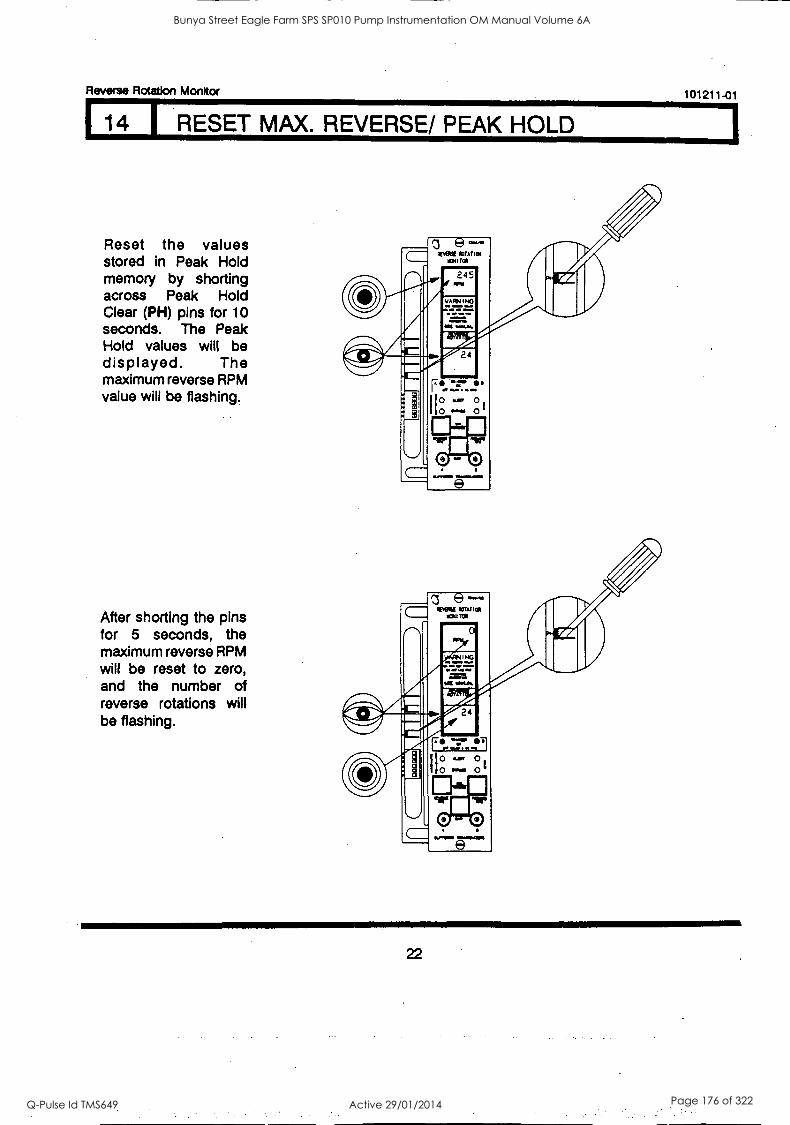
Reverse Rotation Monitor 101211-01
14 1 RESET MAX. REVERSE/ PEAK HOLD
Reset the values stored in Peak Hold memory by shorting across Peak Hold Clear (PH) pins for 10 seconds. The Peak Hold values will be displayed. The maximum reverse RPM value will be flashing.
After shorting the pins for 5 seconds, the maximum reverse RPM will be reset to zero, and the number of reverse rotations will be flashing.
22
Bunya Street Eagle Farm SPS SP010 Pump Instrumentation OM Manual Volume 6A
Q-Pulse Id TMS649 Active 29/01/2014 Page 176 of 322
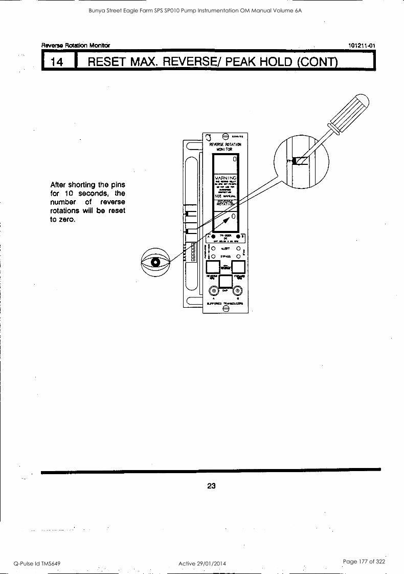
Reverse Rotation Monitof
14 RESET MAX. REVERSE/ PEAK HOLD (CONY)
After shorting the pins for 10 seconds, the number of reverse rotations will be reset to zero.
0.3 e uwse
REVERSE ROTATION
MONITOR
0
SEE 1044JAL
A . OW MAIO off O.
I0 ,LEPT
h 0 MASS 0 1:114strE:3
0 0 A
SUMMED
101211-01
111
23
Bunya Street Eagle Farm SPS SP010 Pump Instrumentation OM Manual Volume 6A
Q-Pulse Id TMS649 Active 29/01/2014 Page 177 of 322
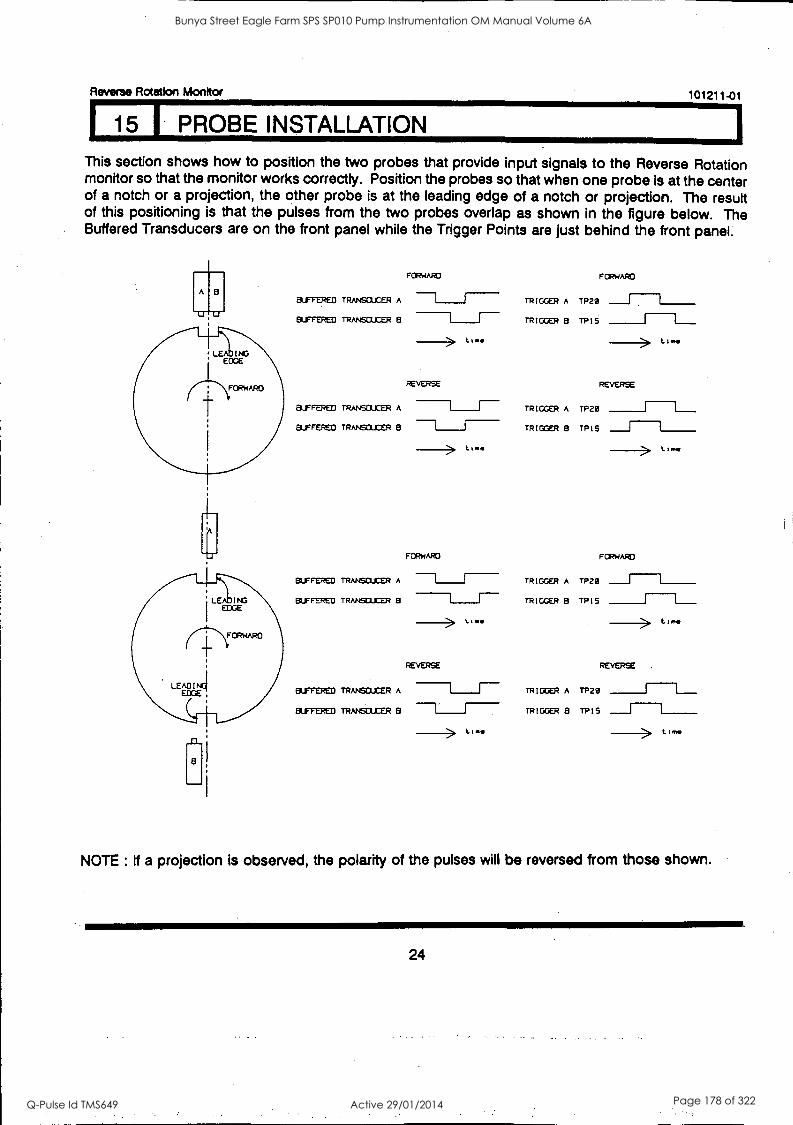
Reverse Rotation Monitor 101211-01
15 PROBE INSTALLATION
This section shows how to position the two probes that provide input signals to the Reverse Rotation monitor so that the monitor works correctly. Position the probes so that when one probe is at the center of a notch or a projection, the other probe is at the leading edge of a notch or projection. The result of this positioning is that the pulses from the two probes overlap as shown in the figure below. The Buffered Transducers are on the front panel while the Trigger Points are just behind the front panel.
A
U
FORWARD FORWARD
BUFFERED TRANSDUCER A ---1 TRIGGER A TP20 ___J L______
BUFFERED TRANSCUCER 8 I I- TRIGGER B TPI5 ______J L___
Lime time
REVERSE REVERSE
BUFFERED TRANSDUCER A TRIGGER A TP20 ______J L___
BUFFERED TRANSCUCER 8 rRIGGER B TPI5 ___J L______
Lt.. time
FORWARD FORWARD
BUFFERED TRANSDUCER A ---1 I- TRIGGER A TP20 ___J L______
BuF,tKtu TRANSDUCER B TRIGGER 8 TPI5 ______J L___
1,..
REVERSE REVERSE
BUFFERED TRANSDUCER A ------1 r--- TRIGGER A TP20 ______J L___
BUFFERED TRANSDUCER e ---1" 77 TRIGGER 8 TPIS __J
t me
NOTE : If a projection is observed, the polarity of the pulses will be reversed from those shown.
24
Bunya Street Eagle Farm SPS SP010 Pump Instrumentation OM Manual Volume 6A
Q-Pulse Id TMS649 Active 29/01/2014 Page 178 of 322

Reverse Rotation Monitor 101211-01
15 INSTALLATION (CONT)
The two alternate configurations that you can use are to have two probes observe one notch or one projection or to have two probes observe two notches or two projections. In either case, gap the probe to the surface of the shaft for a notch or to the projection for a projection.
Positioning Probes that Observe One Notch or Projection
If you position your probes to observe one notch or projection, be sure to separate the probes enough so that they do not interfere with each other. Use this figure and table to be sure that the two probes are separated adequately.
Installation Dimensions for Two Probes Observing One Notch
A=
B=
minimum keyway (notch) width / projection width. minimum keyway (notch) depth / projection height.
END VIEW
C = recommended probe gap.
D = minimum required keyway length.
- keyway
TOP VIEW
X = minimum axial separation.
Y = minimum radial separation.
25
Bunya Street Eagle Farm SPS SP010 Pump Instrumentation OM Manual Volume 6A
Q-Pulse Id TMS649 Active 29/01/2014 Page 179 of 322
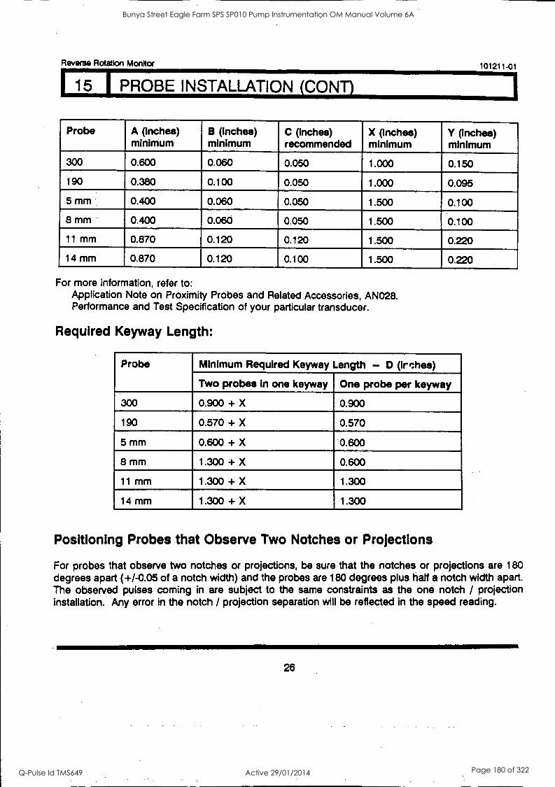
Reverse Rotation Monitor 101211-01
15 PROBE INSTALLATION (CONT)
Probe A (inches) minimum
B (inches) minimum
C (Inches) recommended
X (inches) minimum
Y (inches) minimum
300 0.600 0.060 0.050 1.000 0.150
190 0.380 0.100 0.050 1.000 0.095
5 mm 0.400 0.060 0.050 1.500 0.100
8 mm - 0.400 0.060 0.050 1.500 0.100
11 mm 0.870 0.120 0.120 1.500 0.220
14 mm 0.870 0.120 0.100 1.500 0.220
For more information, refer to: Application Note on Proximity Probes and Related Accessories, AN028. Performance and Test Specification of your particular transducer.
Required Keyway Length:
Probe Minimum Required Keyway Length - D (irches)
Two probes in one keyway One probe per keyway
300 0.900 + X 0.900
190 0.570 + X 0.570
5 mm 0.600 + X 0.600
8 mm 1.300 + X 0.600
11 mm 1.300 + X 1.300
14 mm 1.300 + X 1.300
Positioning Probes that Observe Two Notches or Projections
For probes that observe two notches or projections, be sure that the notches or projections are 180 degrees apart (+/-0.05 of a notch width) and the probes are 180 degrees plus half a notch width apart. The observed pulses coming in are subject to the same constraints as the one notch / projection installation. Any error in the notch / projection separation will be reflected in the speed reading.
26
Bunya Street Eagle Farm SPS SP010 Pump Instrumentation OM Manual Volume 6A
Q-Pulse Id TMS649 Active 29/01/2014 Page 180 of 322
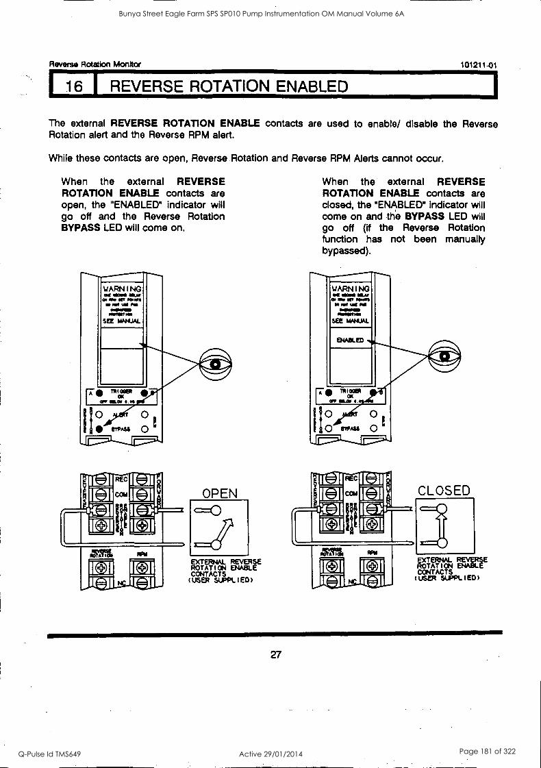
Reverse Rotation Monitor 101211 -01
16 REVERSE ROTATION ENABLED
The external REVERSE ROTATION ENABLE contacts are used to enable/ disable the Reverse Rotation alert and the Reverse RPM alert.
While these contacts are open, Reverse Rotation and Reverse RPM Alerts cannot occur.
When the external REVERSE ROTATION ENABLE contacts are open, the "ENABLED" indicator will go off and the Reverse Rotation BYPASS LED will come on.
WARNING Of IMMO I111-m%
am MIO liff POW% 00 mog
OMINIMIND MOW HMI
SEE MAN AL
MO A OM
I CA I I[ J Ira !MI
OPEN
EXTERNAL REVERSE ROTATICN ENABLE CONTACTS (USER SUPPLIED)
When the external REVERSE ROTATION ENABLE contacts are closed, the "ENABLED" indicator will come on and the BYPASS LED will go off (if the Reverse Rotation function has not been manually bypassed).
WARNING OM OMNI MAT
Os fr Off OIMOMI
MOSIRVIIMMI OmOmPOS eftriemes
SEE MANUAL
ENABLED
111t10081
OK OFF MAI I
1 0 0 O BYPASS 0
11."'.1L+.11./A.
CLOSED
I0M Oft
I EA I [0] rt-3 rfa
EXTERNAL REVERSE ROTATION ENABLE CONTACTS (USER SUPPLIED)
27
Bunya Street Eagle Farm SPS SP010 Pump Instrumentation OM Manual Volume 6A
Q-Pulse Id TMS649 Active 29/01/2014 Page 181 of 322
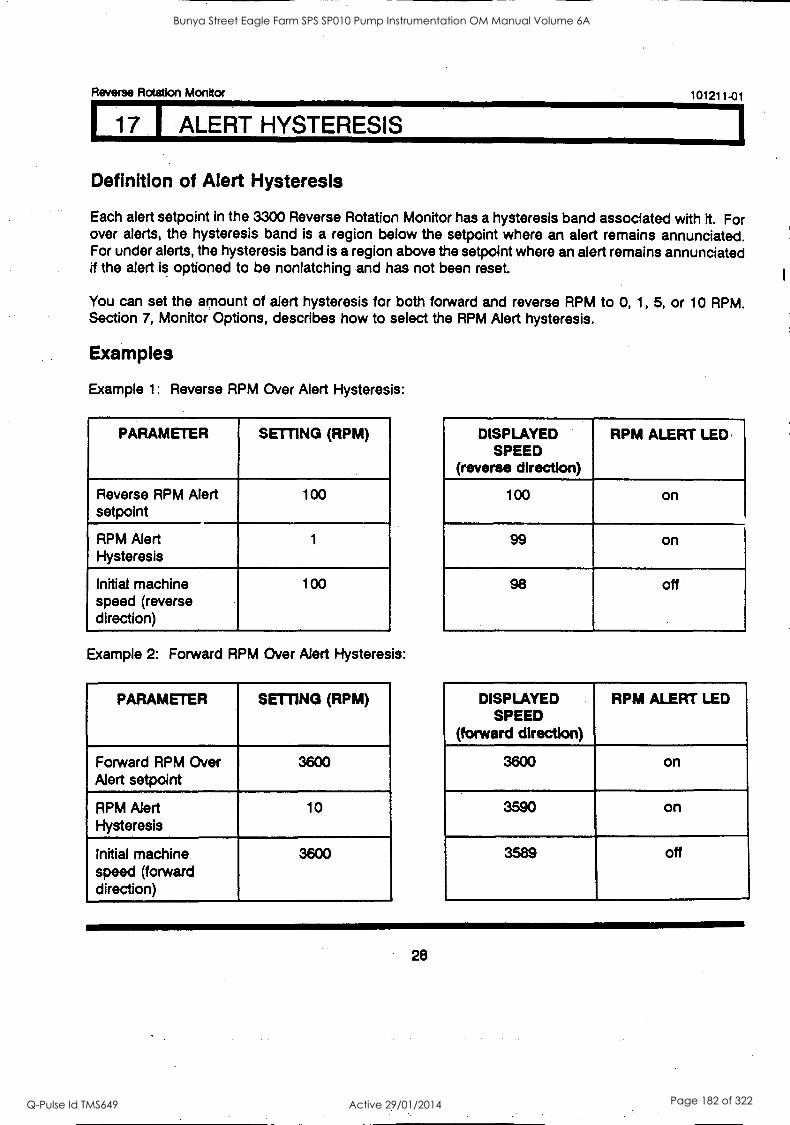
Reverse Rotation Monitor
17 ALERT HYSTERESIS
Definition of Alert Hysteresis
101211-01
Each alert setpoint in the 3300 Reverse Rotation Monitor has a hysteresis band associated with it. For over alerts, the hysteresis band is a region below the setpoint where an alert remains annunciated. For under alerts, the hysteresis band is a region above the setpoint where an alert remains annunciated if the alert is optioned to be nonlatching and has not been reset.
You can set the amount of alert hysteresis for both forward and reverse RPM to 0, 1, 5, or 10 RPM. Section 7, Monitor Options, describes how to select the RPM Alert hysteresis.
Examples
Example 1: Reverse RPM Over Alert Hysteresis:
PARAMETER SETTING (RPM)
Reverse RPM Alert setpoint
100
RPM Alert Hysteresis
1
Initial machine speed (reverse direction)
100
Example 2: Forward RPM Over Alert Hysteresis:
PARAMETER SETTING (RPM)
Forward RPM Over Alert setpoint
3600
RPM Alert Hysteresis
10
Initial machine speed (forward direction)
3600
DISPLAYED SPEED
(reverse direction)
RPM ALERT LED.
100 on
99 on
98 off
DISPLAYED SPEED
(forward direction)
RPM ALERT LED
3600 on
3590 on
3589 off
28
Bunya Street Eagle Farm SPS SP010 Pump Instrumentation OM Manual Volume 6A
Q-Pulse Id TMS649 Active 29/01/2014 Page 182 of 322
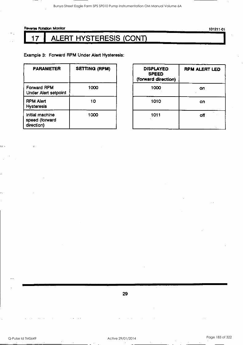
Reverse Rotation Monitor 101211-01
171 ALERT HYSTERESIS (CONT)
Example 3: Forward RPM Under Alert Hysteresis:
PARAMETER SETTING (RPM)
Forward RPM Under Alert setpoint
1000
RPM Alert Hysteresis
10
Initial machine speed (forward direction)
1000
DISPLAYED SPEED
(forward direction)
RPM ALERT LED
1000 on
1010 on
1011 off
29
Bunya Street Eagle Farm SPS SP010 Pump Instrumentation OM Manual Volume 6A
Q-Pulse Id TMS649 Active 29/01/2014 Page 183 of 322
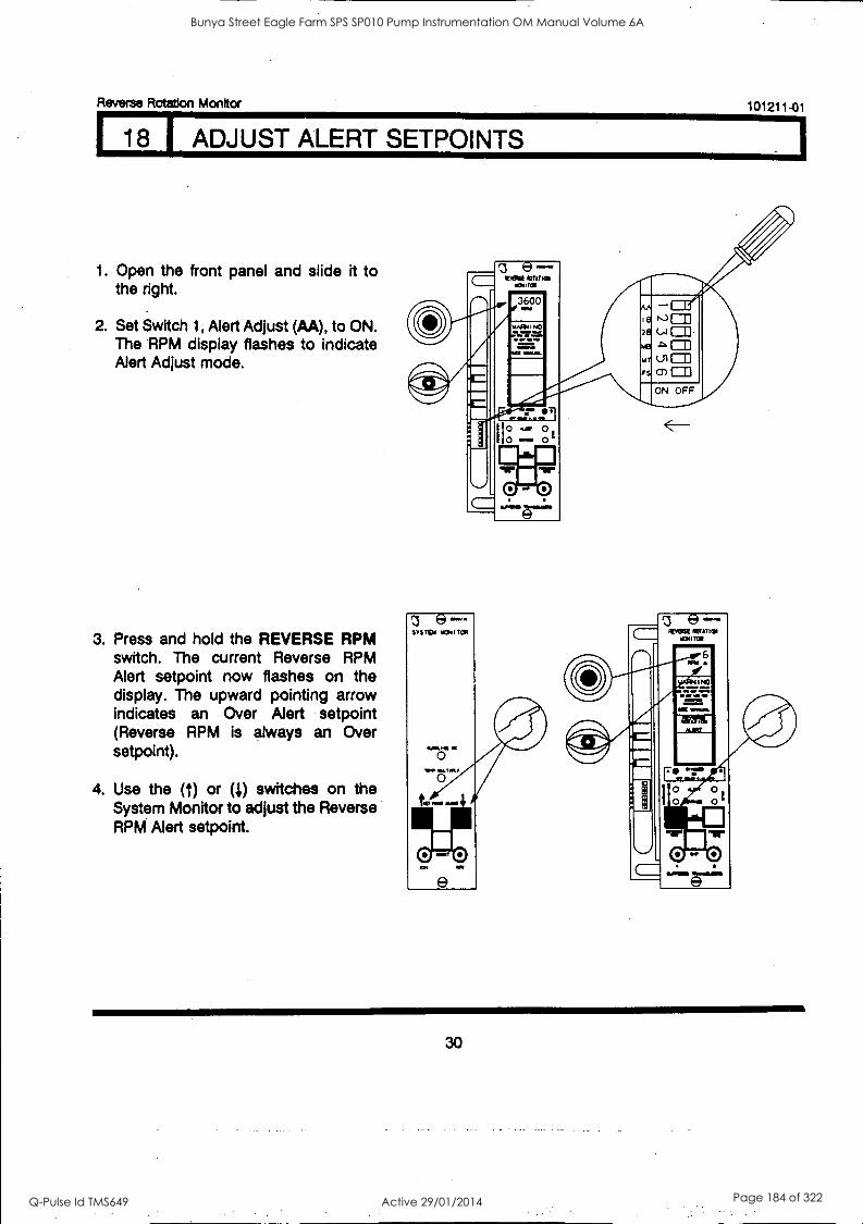
118 I ADJUST ALERT SETPOINTS
Reverse Rotation Monitor 101211-01
1. Open the front panel and slide it to the right.
2. Set Switch 1, Alert Adjust (AA), to ON. The RPM display flashes to indicate Alert Adjust mode.
3. Press and hold the REVERSE RPM switch. The current Reverse RPM Alert setpoint now flashes on the display. The upward pointing arrow indicates an Over Alert setpoint (Reverse RPM is always an Over setpoint).
4. Use the (t) or (4) switches on the System Monitor to adjust the Reverse RPM Alert setpoint.
30
Bunya Street Eagle Farm SPS SP010 Pump Instrumentation OM Manual Volume 6A
Q-Pulse Id TMS649 Active 29/01/2014 Page 184 of 322
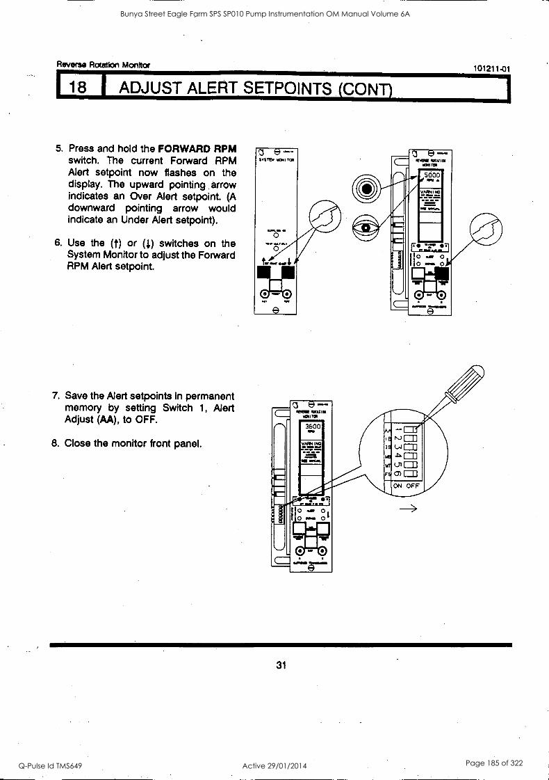
Reverse Rotation Monitor 101211-01
18 ADJUST ALERT SETPOINTS (CONT)
5. Press and hold the FORWARD RPM switch. The current Forward RPM Alert setpoint now flashes on the display. The upward pointing arrow indicates an Over Alert setpoint. (A downward pointing arrow would indicate an Under Alert setpoint).
6. Use the (f) or (I) switches on the System Monitor to adjust the Forward RPM Alert setpoint.
7. Save the Alert setpoints in permanent memory by setting Switch 1, Alert Adjust (AA), to OFF.
8. Close the monitor front panel.
e MOUE %ATM
5000
31
Bunya Street Eagle Farm SPS SP010 Pump Instrumentation OM Manual Volume 6A
Q-Pulse Id TMS649 Active 29/01/2014 Page 185 of 322
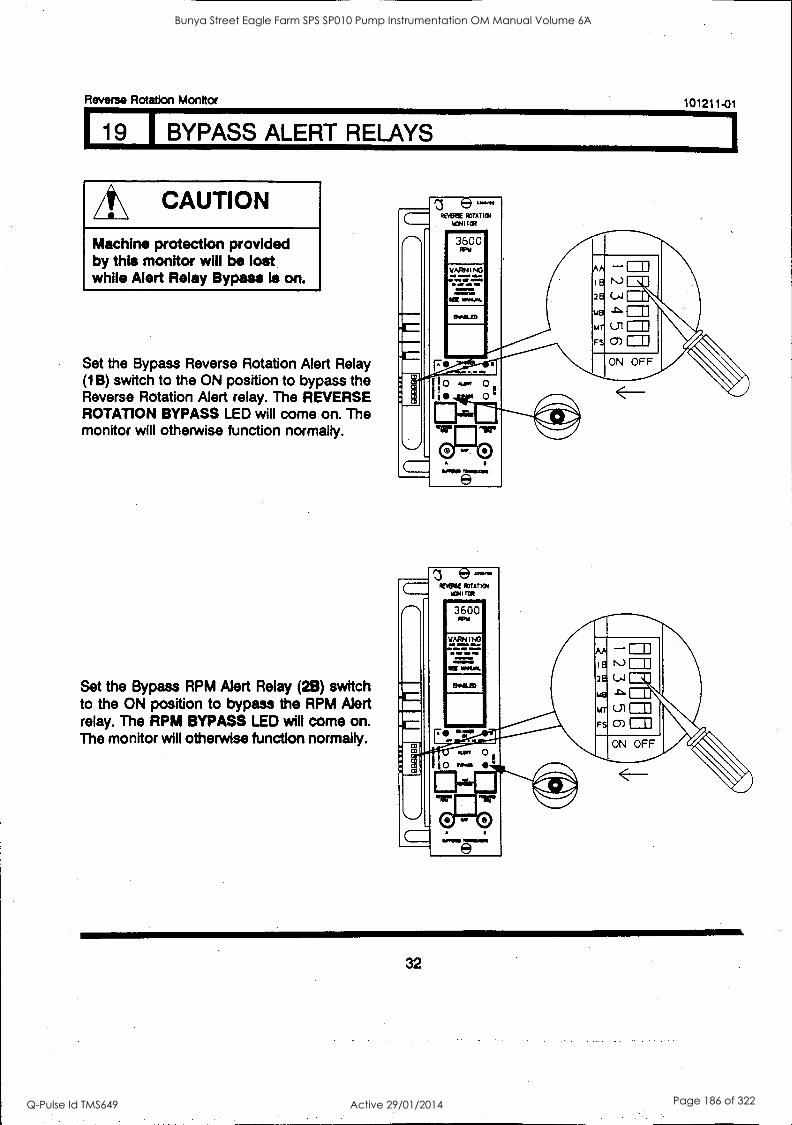
Reverse Rotation Monitor 101211-01
19 I BYPASS ALERT RELAYS
/t\ CAUTION
Machine protection provided by this monitor will be lost while Alert Relay Bypass is on.
Set the Bypass Reverse Rotation Alert Relay (1 B) switch to the ON position to bypass the Reverse Rotation Alert relay. The REVERSE ROTATION BYPASS LED will come on. The monitor will otherwise function normally.
Set the Bypass RPM Alert Relay (29) switch to the ON position to bypass the RPM Alert relay. The RPM BYPASS LED will come on. The monitor will otherwise function normally.
32
Bunya Street Eagle Farm SPS SP010 Pump Instrumentation OM Manual Volume 6A
Q-Pulse Id TMS649 Active 29/01/2014 Page 186 of 322
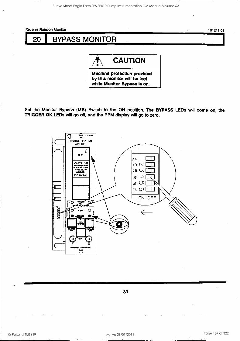
Reverse Rotation Monitor 101211-01
20 I BYPASS MONITOR
A\ CAUTION
Machine protection provided by this monitor will be lost while Monitor Bypass is on.
Set the Monitor Bypass (MB) Switch to the ON position. The BYPASS LEDs will come on, the TRIGGER OK LEDs will go off, and the RPM display will go to zero.
co
-.0'4 I co
L. CD
a3
e]l .. /!f
REVERSE ROTATION
hICN I TOR - 0
WARNING isco. MAY a M. Or .0.11
a PM MI MI OMMENI ~WM
SEE WJ,IJAL
AA
I B
28
MB
MT
FS
ON OFF TR I
ALM
S A
SOME)
33
Bunya Street Eagle Farm SPS SP010 Pump Instrumentation OM Manual Volume 6A
Q-Pulse Id TMS649 Active 29/01/2014 Page 187 of 322
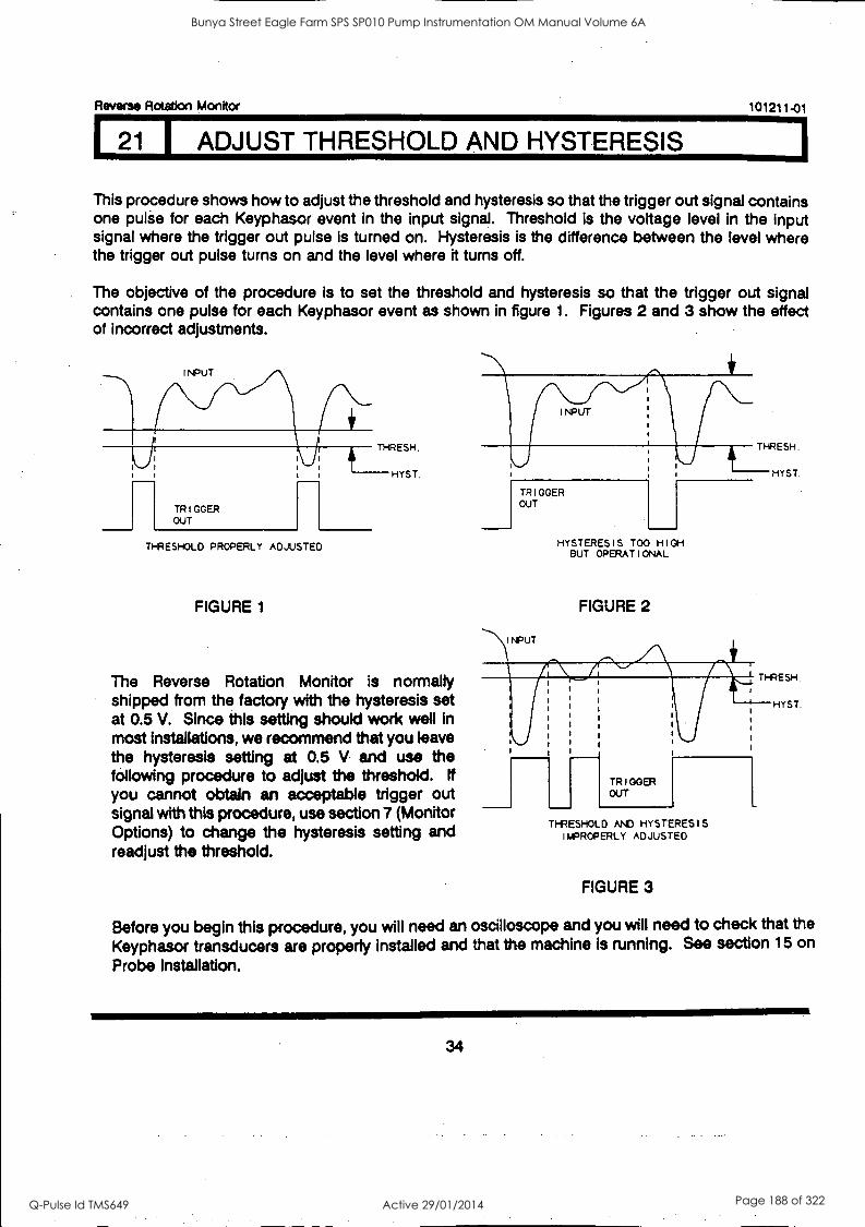
Reverse Rotation Monitor 101211-01
21 ADJUST THRESHOLD AND HYSTERESIS
This procedure shows how to adjust the threshold and hysteresis so that the trigger out signal contains one pulse for each Keyphasor event in the input signal. Threshold is the voltage level in the input signal where the trigger out pulse is turned on. Hysteresis is the difference between the level where the trigger out pulse turns on and the level where it turns off.
The objective of the procedure is to set the threshold and hysteresis so that the trigger out signal contains one pulse for each Keyphasor event as shown in figure 1. Figures 2 and 3 show the effect of incorrect adjustments.
TRIGGER OUT
THRESHOLD PROPERLY ADJUSTED
FIGURE 1
The Reverse Rotation Monitor is normally shipped from the factory with the hysteresis set at 0.5 V. Since this setting should work well in most installations, we recommend that you leave the hysteresis setting at 0.5 V and use the following procedure to adjust the threshold. tf you cannot obtain an acceptable trigger out signal with this procedure, use section 7 (Monitor Options) to change the hysteresis setting and readjust the threshold.
THRESH.
TRIGGER OUT
HYSTERESIS TOO HIGH BUT OPERATIONAL
FIGURE 2
HYST.
THRESHOLD AND HYSTERESIS IMPROPERLY ADJUSTED
FIGURE 3
Before you begin this procedure, you will need an oscilloscope and you will need to check that the
Keyphasor transducers are properly installed and that the machine is running. See section 15 on
Probe Installation.
34
Bunya Street Eagle Farm SPS SP010 Pump Instrumentation OM Manual Volume 6A
Q-Pulse Id TMS649 Active 29/01/2014 Page 188 of 322
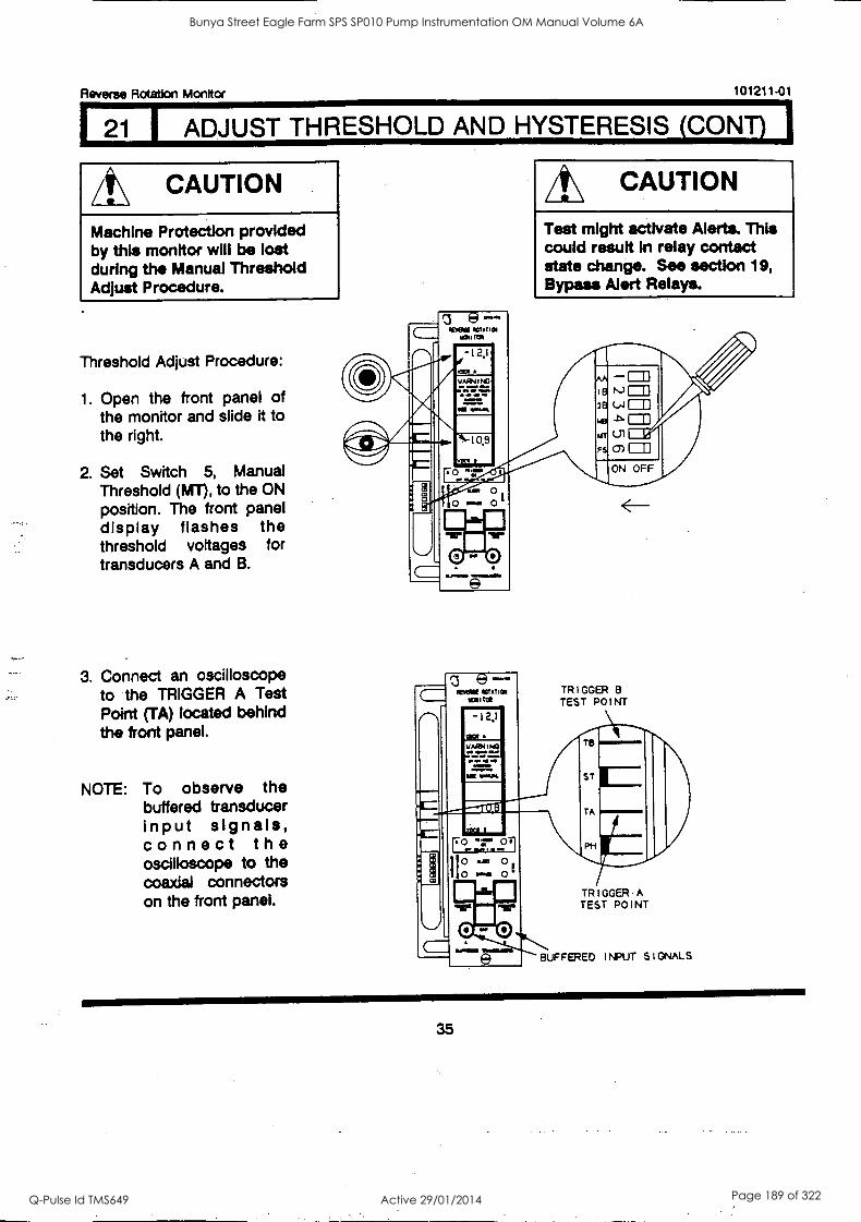
Reverse Rotation Monitor 101211 -01
21 1 ADJUST THRESHOLD AND HYSTERESIS (CONT) I
A\ CAUTION
Machine Protection provided by this monitor will be lost during the Manual Threshold Adjust Procedure.
Threshold Adjust Procedure:
1. Open the front panel of the monitor and slide it to the right.
2. Set Switch 5, Manual Threshold (MT), to the ON position. The front panel display flashes the threshold voltages for transducers A and B.
3. Connect an oscilloscope to the TRIGGER A Test Point (TA) located behind the front panel.
NOTE: To observe the buffered transducer input signals, connect the oscilloscope to the coaxial connectors on the front panel.
/t\ CAUTION
Test might activate Alerts. This could result in relay contact state change. See section 19, Bypass Alert Relays.
TRIGGER B TEST POINT
TRIGGER -A TEST POINT
BUFFERED INPUT SIGNALS
35
Bunya Street Eagle Farm SPS SP010 Pump Instrumentation OM Manual Volume 6A
Q-Pulse Id TMS649 Active 29/01/2014 Page 189 of 322
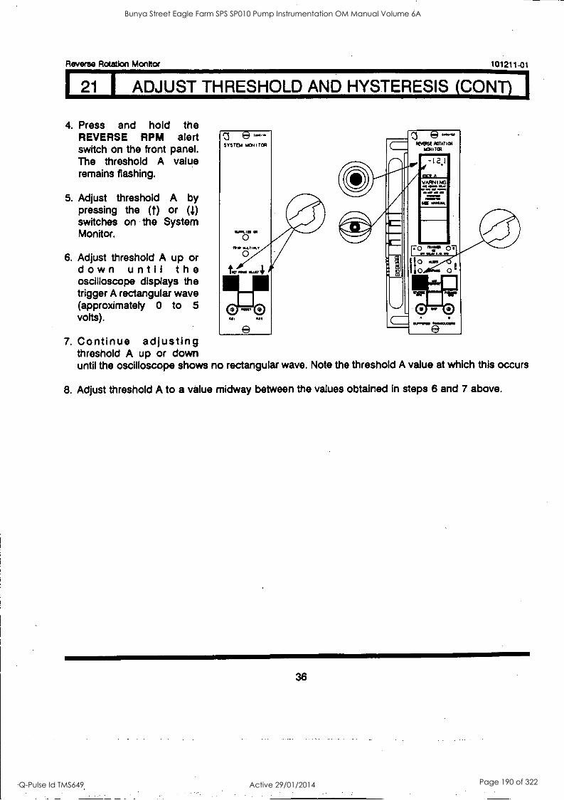
LIU ADJUST THRESHOLD AND HYSTERESIS (CONTLI Reverse Rotation Monitor 101211-01
4. Press and hold the REVERSE RPM alert switch on the front panel. The threshold A value remains flashing.
5. Adjust threshold A by pressing the (t) or a) switches on the System Monitor.
6. Adjust threshold A up or down until the oscilloscope displays the trigger A rectangular wave (approximately 0 to 5 volts).
z e - SYSTEM MONITOR REAM POTATHM
M:Mi TQt
SP111410
7. Continue adjusting threshold A up or down until the oscilloscope shows no rectangular wave. Note the threshold A value at which this occurs
8. Adjust threshold A to a value midway between the values obtained in steps 6 and 7 above.
36
Bunya Street Eagle Farm SPS SP010 Pump Instrumentation OM Manual Volume 6A
Q-Pulse Id TMS649 Active 29/01/2014 Page 190 of 322
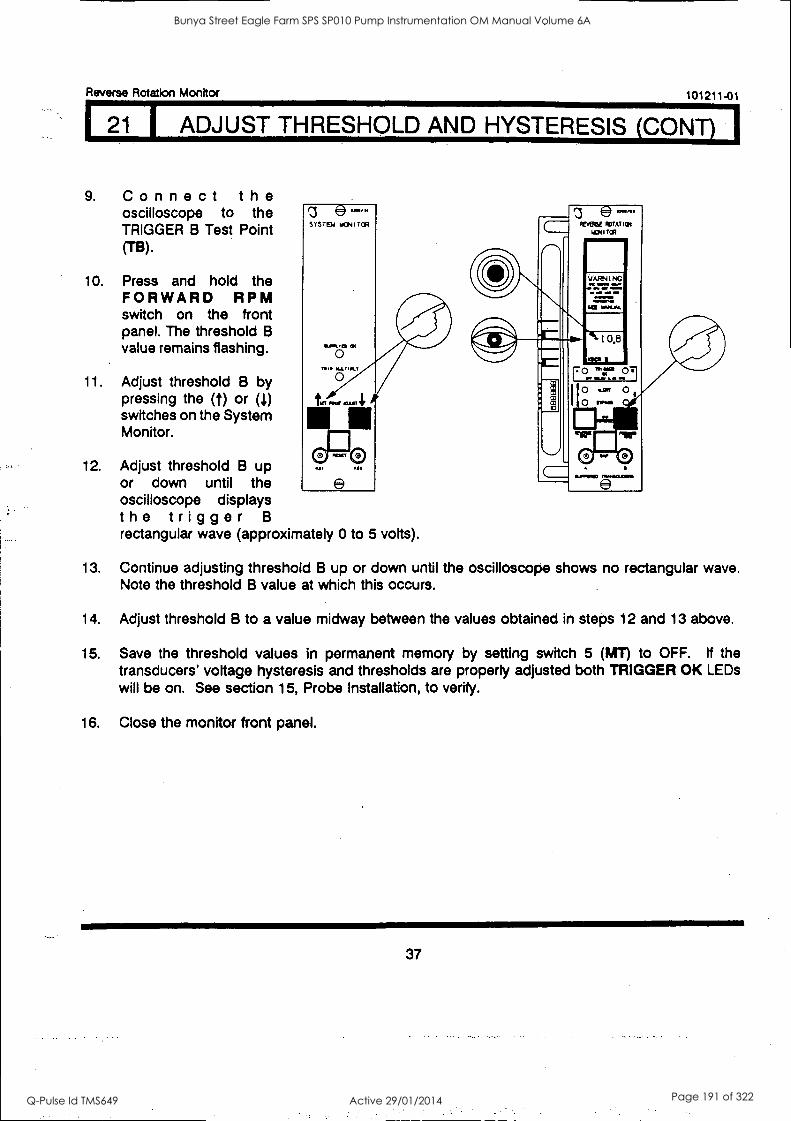
Reverse Rotation Monitor 101211-01
121 I ADJUST THRESHOLD AND HYSTERESIS (CONT.)
9. Connect the oscilloscope to the TRIGGER B Test Point M3).
10. Press and hold the FORWARD RPM switch on the front panel. The threshold B value remains flashing.
11. Adjust threshold B by pressing the (t) or (1) switches on the System Monitor.
12. Adjust threshold B up or down until the oscilloscope displays the trigger B rectangular wave (approximately 0 to 5 volts).
13. Continue adjusting threshold B up or down until the oscilloscope shows no rectangular wave. Note the threshold B value at which this occurs.
14. Adjust threshold B to a value midway between the values obtained in steps 12 and 13 above.
15. Save the threshold values in permanent memory by setting switch 5 (MT) to OFF. tf the transducers' voltage hysteresis and thresholds are properly adjusted both TRIGGER OK LEDs will be on. See section 15, Probe Installation, to verify.
16. Close the monitor front panel.
37
Bunya Street Eagle Farm SPS SP010 Pump Instrumentation OM Manual Volume 6A
Q-Pulse Id TMS649 Active 29/01/2014 Page 191 of 322
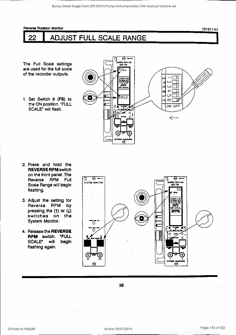
Reverse Rotation Monitor
122 I ADJUST FULL SCALE RANGE
The Full Scale settings are used for the full scale of the recorder outputs.
1. Set Switch 6 (FS) to the ON position. "FULL SCALE" will flash.
2. Press and hold the REVERSE RPM switch on the front panel. The Reverse RPM Full Scale Range will begin flashing.
3. Adjust the setting for Reverse RPM by pressing the (t) or (l) switches on the System Monitor.
4. Release the REVERSE RPM switch. "FULL SCALE" will begin flashing again.
RENESE ROIATICII
1041 TCR
WARM NO OP WO Mt 0111.
MI Mr
.111111,1=
SEE VANUM.
*1
0
3 SYSTEM 14:NITOR
O mu rarine
0
[II
e
101211-01
AA
18
28
MB
AT
FS
1
ELI
1:5)
ON OFF
38
Bunya Street Eagle Farm SPS SP010 Pump Instrumentation OM Manual Volume 6A
Q-Pulse Id TMS649 Active 29/01/2014 Page 192 of 322
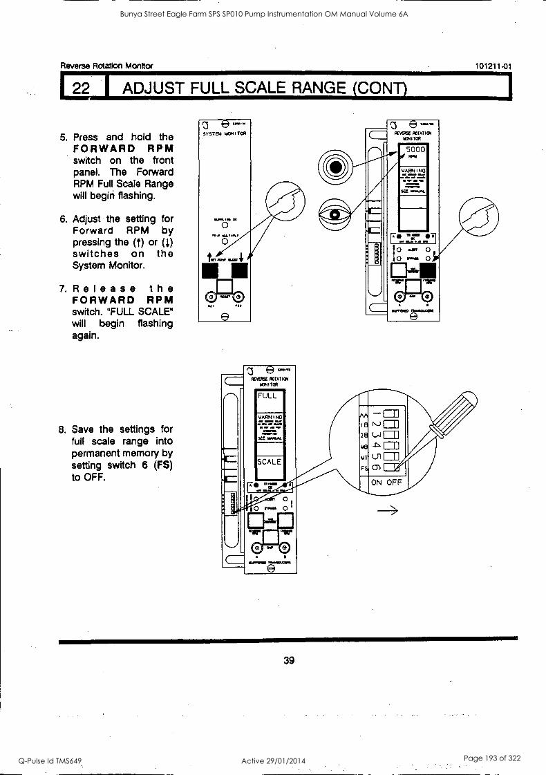
Reverse Rotation Monitor
La, ADJUST FULL SCALE RANGE (CONT)
5. Press and hold the FORWARD RPM switch on the front panel. The Forward RPM Full Scale Range will begirt flashing.
6. Adjust the setting for Forward RPM by pressing the (1) or (1) switches on the System Monitor.
7. Release the FORWARD RPM switch. "FULL SCALE" will begin flashing again.
8. Save the settings for full scale range into permanent memory by setting switch 6 (FS) to OFF.
e-- SYSTEM YON I TOR
nu .aTRr 0
fir OWE 414
Os
e
REVERSE ROTATION
KIRI TOR
FULL
WARN I NC
el OW NV OmIll 111,01,11 WM,
WIWI MI
SEC RARUN.
SCALE
101211-01
39
Bunya Street Eagle Farm SPS SP010 Pump Instrumentation OM Manual Volume 6A
Q-Pulse Id TMS649 Active 29/01/2014 Page 193 of 322
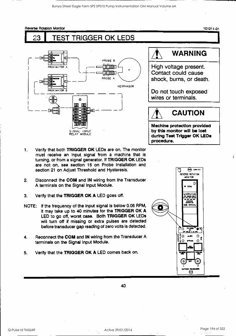
Reverse Rotation Monitor
I 23 I TEST TRIGGER OK LEDS
PROX I M I TOR A
0 0
0 0
PROX I 1.1 I TOR B
PROBE
PROBE A
101211 -01
KEYPHASOR
SIGNAL INPUT RELAY MODULE
1. Verify that both TRIGGER OK LEDs are on. The monitor must receive an input signal from a machine that is turning, or from a signal generator. if TRIGGER OK LEDs are not on, see section 15 on Probe Installation and section 21 on Adjust Threshold and Hysteresis.
2. Disconnect the COM and IN wiring from the Transducer A terminals on the Signal Input Module.
3. Verify that the TRIGGER OK A LED goes off.
NOTE: If the frequency of the input signal is below 0.05 RPM,
it may take up to 40 minutes for the TRIGGER OK A LED to go off, worst case. Both TRIGGER OK LEDs will turn off if missing or extra pulses are detected before transducer gap reading of zero volts is detected.
4. Reconnect the COM and IN wiring from the Transducer A
terminals on the Signal Input Module.
5. Verify that the TRIGGER OK A LED comes back on.
WARNING
High voltage present. Contact could cause shock, burns, or death.
Do not touch exposed wires or terminals.
A\ CAUTION
Machine protection provided by this monitor will be lost during Test Trigger OK LEDs procedure.
e1304/S3
REVERSE ROTATION
MONITOR Immmmmmmmw
0 V RPM
WARNING OS IMMO SLAT el AM OR OPOOMI
.1 MR W. PM
7 ...'"- SEE 14A14.1A1-v"
40
Bunya Street Eagle Farm SPS SP010 Pump Instrumentation OM Manual Volume 6A
Q-Pulse Id TMS649 Active 29/01/2014 Page 194 of 322
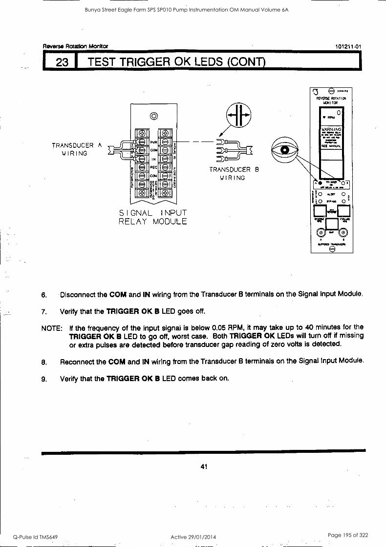
Reverse Rotation Monitor
23 1 TEST TRIGGER OK LEDS (CONS
TRANSDUCER A
WIRING
REC
cc.
4A 9
SIGNAL I NPUT RELAY MODULE
TRANSDUCER 8
WIRING
101211 -01
®334. ,1,
REVERSE ROTATION
100 TOR w4mr 0
RPM
SEE WAWA.
""433. 071 Oa. OS Oft
o ALERT 0 0 "..86 0
64:
6. Disconnect the COM and IN wiring from the Transducer B terminals on the Signal Input Module.
7. Verify that the TRIGGER OK B LED goes off.
NOTE: If the frequency of the input signal is below 0.05 RPM, it may take up to 40 minutes for the
TRIGGER OK B LED to go off, worst case. Both TRIGGER OK LEDs will turn off if missing or extra pulses are detected before transducer gap reading of zero volts is detected.
8. Reconnect the COM and IN wiring from the Transducer B terminals on the Signal Input Module.
9. Verify that the TRIGGER OK B LED comes back on.
41
Bunya Street Eagle Farm SPS SP010 Pump Instrumentation OM Manual Volume 6A
Q-Pulse Id TMS649 Active 29/01/2014 Page 195 of 322
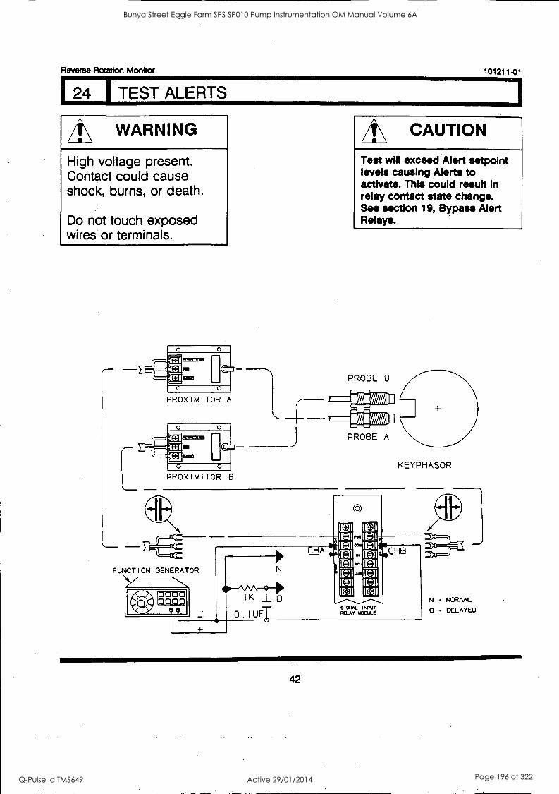
Reverse Rotation Monitor 101211-01
24 1 TEST ALERTS
A\ WARNING
High voltage present. Contact could cause shock, burns, or death.
Do not touch exposed wires or terminals.
EMCEE
MI C:3
0 0
PROXIMITOR A
EMCEES
0 0 PROXIMITOR B
CAUTION
Test will exceed Alert setpolnt levels causing Alerts to activate. This could result in relay contact state change. See section 19, Bypass Alert Relays.
KEYPHASOR
FUNCTION GENERATOR \Aimmo
IK 0
0 1UF $ I ONAL I WO RELAY MOLL E
NORML
DELAYED
42
Bunya Street Eagle Farm SPS SP010 Pump Instrumentation OM Manual Volume 6A
Q-Pulse Id TMS649 Active 29/01/2014 Page 196 of 322
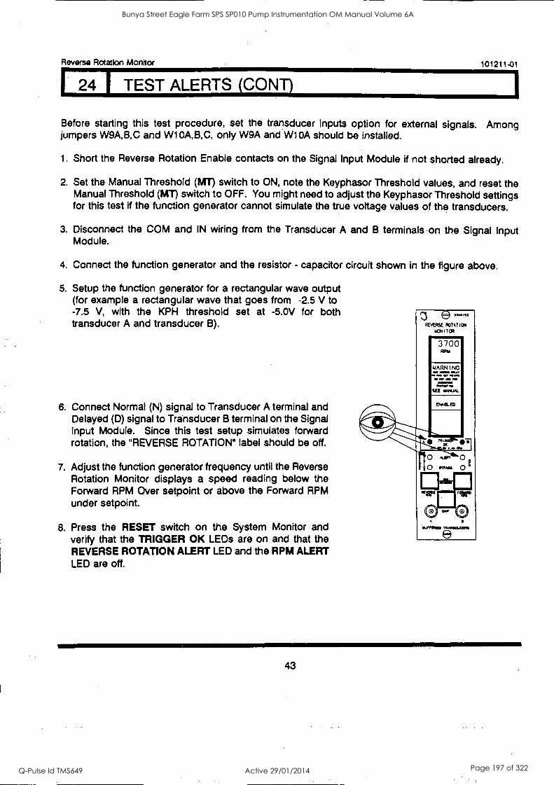
Reverse Rotation Monitor 101211-01
4 I TEST ALERTS (CONT)
Before starting this test procedure, set the transducer inputs option for external signals. Among jumpers W9A,B,C and W1 0A,B,C, only W9A and W10A should be installed.
1. Short the Reverse Rotation Enable contacts on the Signal Input Module if not shorted already.
2. Set the Manual Threshold (MT) switch to ON, note the Keyphasor Threshold values, and reset the Manual Threshold (MT) switch to OFF. You might need to adjust the Keyphasor Threshold settings for this test if the function generator cannot simulate the true voltage values of the transducers.
3. Disconnect the COM and IN wiring from the Transducer A and B terminals on the Signal Input Module.
4. Connect the function generator and the resistor - capacitor circuit shown in the figure above.
5. Setup the function generator for a rectangular wave output (for example a rectangular wave that goes from -2.5 V to -7.5 V, with the KPH threshold set at -5.0V for both transducer A and transducer B).
6. Connect Normal (N) signal to Transducer A terminal and Delayed (0) signal to Transducer B terminal on the Signal Input Module. Since this test setup simulates forward rotation, the "REVERSE ROTATION" label should be off.
7. Adjust the function generator frequency until the Reverse Rotation Monitor displays a speed reading below the Forward RPM Over setpoint or above the Forward RPM under setpoint.
8. Press the RESET switch on the System Monitor and verify that the TRIGGER OK LEDs are on and that the REVERSE ROTATION ALERT LED and the RPM ALERT LED are off.
REVERSE ROTATION
ICH I TER ININr 3700 RPM
WARNING .1111 a.. May
SIN liat PO
SEE MAHAL
Tr", ,, 11/11
,Ler, 0 o MAY 0
&WNW
43
Bunya Street Eagle Farm SPS SP010 Pump Instrumentation OM Manual Volume 6A
Q-Pulse Id TMS649 Active 29/01/2014 Page 197 of 322
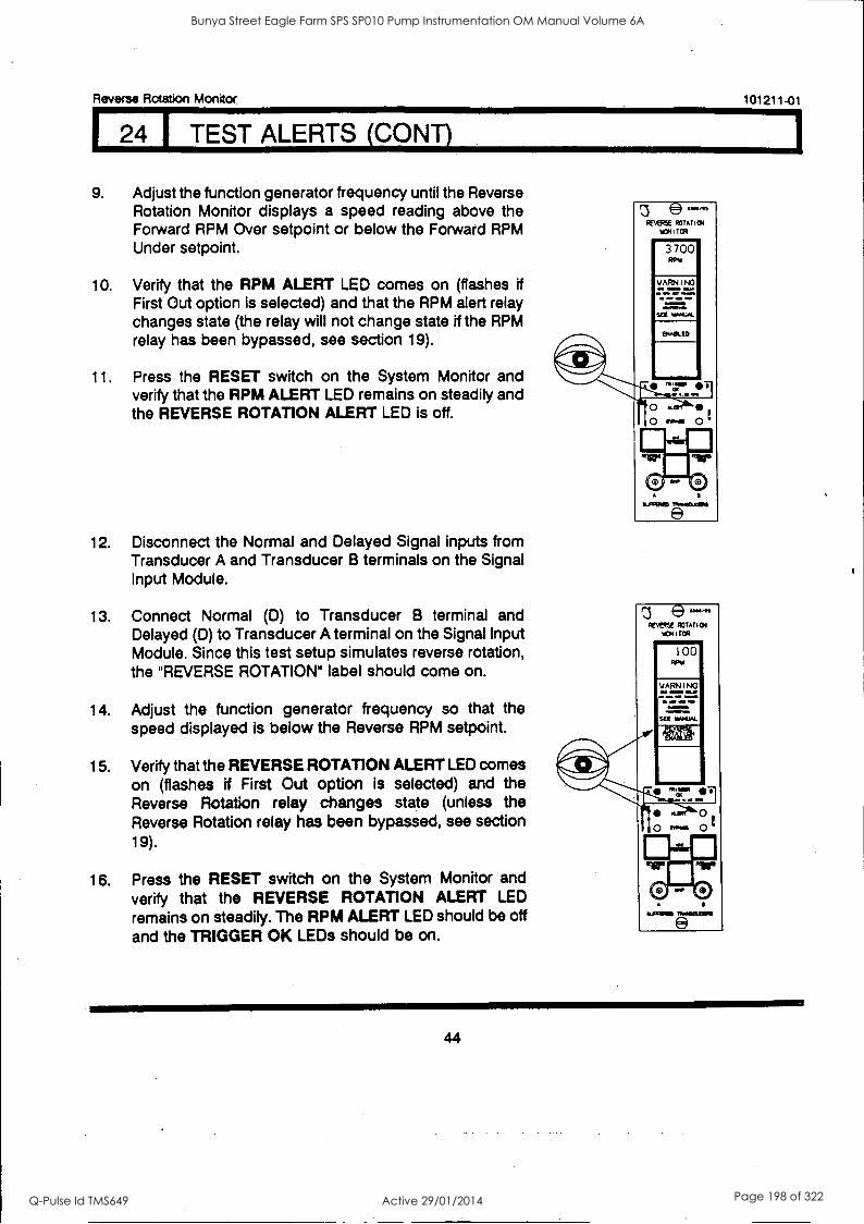
Raven(' Rotation Monitor 101211-01
4 TEST ALERTS (CONT)
9. Adjust the function generator frequency until the Reverse Rotation Monitor displays a speed reading above the Forward RPM Over setpoint or below the Forward RPM Under setpoint.
10. Verify that the RPM ALERT LED comes on (flashes if First Out option is selected) and that the RPM alert relay changes state (the relay will not change state if the RPM relay has been bypassed, see section 19).
11. Press the RESET switch on the System Monitor and verify that the RPM ALERT LED remains on steadily and the REVERSE ROTATION ALERT LED is off.
12. Disconnect the Normal and Delayed Signal inputs from Transducer A and Transducer B terminals on the Signal Input Module.
13. Connect Normal (D) to Transducer B terminal and Delayed (D) to Transducer A terminal on the Signal Input Module. Since this test setup simulates reverse rotation, the "REVERSE ROTATION" label should come on.
14. Adjust the function generator frequency so that the speed displayed is below the Reverse RPM setpoint.
15. Verify that the REVERSE ROTATION ALERT LED comes on (flashes if First Out option is selected) and the Reverse Rotation relay changes state (unless the Reverse Rotation relay has been bypassed, see section 19).
16. Press the RESET switch on the System Monitor and verify that the REVERSE ROTATION ALERT LED
remains on steadily. The RPM ALERT LED should be off and the TRIGGER OK LEDs should be on.
3700
WARN INC ea =MO War fa ag Man a al. 411
SIM MANUAL
OlOdt. ED
44
Bunya Street Eagle Farm SPS SP010 Pump Instrumentation OM Manual Volume 6A
Q-Pulse Id TMS649 Active 29/01/2014 Page 198 of 322
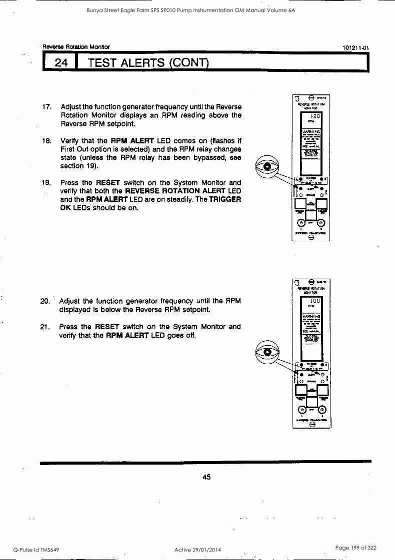
- Reverse Rotation Monitor 101211-01
24 I TEST ALERTS (CONT)
17. Adjust the function generator frequency until the Reverse Rotation Monitor displays an RPM reading above the Reverse RPM setpoint.
18. Verify that the RPM ALERT LED comes on (flashes if First Out option is selected) and the RPM relay changes state (unless the RPM relay has been bypassed, see section 19).
19. Press the RESET switch on the System Monitor and verify that both the REVERSE ROTATION ALERT LED and the RPM ALERT LED are on steadily. The TRIGGER OK LEDs should be on.
20. Adjust the function generator frequency until the RPM displayed is below the Reverse RPM setpoint.
21. Press the RESET switch on the System Monitor and verify that the RPM ALERT LED goes off.
Redftf amens W*1 I RA
120 ROw
VARN I NO IMMO mu.
no 4111
OMNI.
0 mat 0
ROMEO NCO. e
REVERSE ROTATIM 101ITCR
100 RPI
NAMPO
45
Bunya Street Eagle Farm SPS SP010 Pump Instrumentation OM Manual Volume 6A
Q-Pulse Id TMS649 Active 29/01/2014 Page 199 of 322
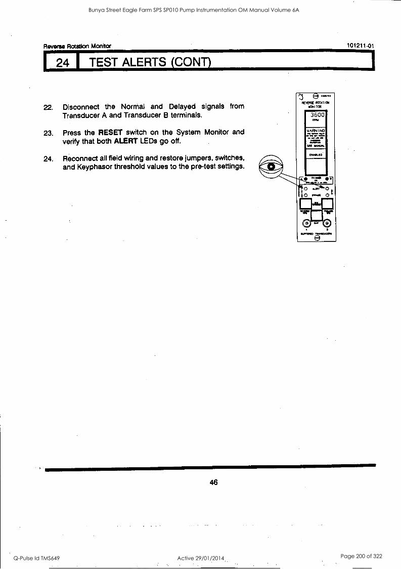
Reverse Rotation Monitor 101211-01
4 1 TEST ALERTS (CONTI
22. Disconnect the Normal and Delayed signals from Transducer A and Transducer B terminals.
23. Press the RESET switch on the System Monitor and verify that both ALERT LEDs go off.
24. Reconnect all field wiring and restore jumpers, switches, and Keyphasor threshold values to the pre-test settings.
e REVERSE ROTAT
1CNI TGA
3600 Rom
WARN I NO
IN . MOM M... OM MMINIM
SEE IMMO&
o 0 0 r..1.1 0 G
0 - 0 ILFRPED
46
Bunya Street Eagle Farm SPS SP010 Pump Instrumentation OM Manual Volume 6A
Q-Pulse Id TMS649 Active 29/01/2014 Page 200 of 322
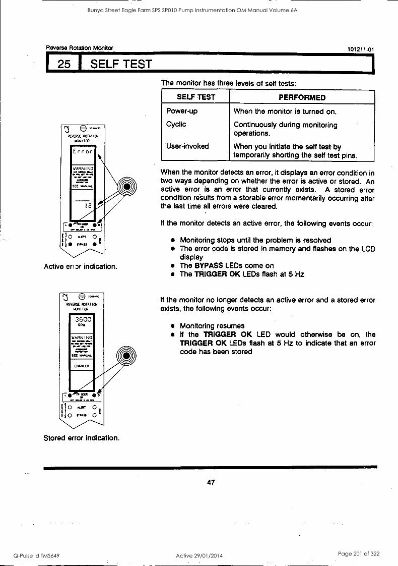
Reverse Rotation Monitor
25 SELF TEST
Active eri or indication.
REVERSE ROTATION
IA3N I TOR Imir 3600
RPAI
o &an 0 o MASS 0
Stored error indication.
101211-01
The monitor has three levels of self tests:
SELF TEST PERFORMED
Power-up
Cyclic
User-invoked
When the monitor is turned on.
Continuously during monitoring operations.
When you initiate the self test by temporarily shorting the self test pins.
When the monitor detects an error, it displays an error condition in two ways depending on whether the error is active or stored. An active error is an error that currently exists. A stored error condition results from a storable error momentarily occurring after the last time all errors were cleared.
If the monitor detects an active error, the following events occur:
Monitoring stops until the problem is resolved The error code is stored in memory and flashes on the LCD display The BYPASS LEDs come on The TRIGGER OK LEDs flash at 5 Hz
If the monitor no longer detects an active error and a stored error exists, the following events occur:
Monitoring resumes If the TRIGGER OK LED would otherwise be on, the TRIGGER OK LEDs flash at 5 Hz to indicate that an error code has been stored
47
Bunya Street Eagle Farm SPS SP010 Pump Instrumentation OM Manual Volume 6A
Q-Pulse Id TMS649 Active 29/01/2014 Page 201 of 322
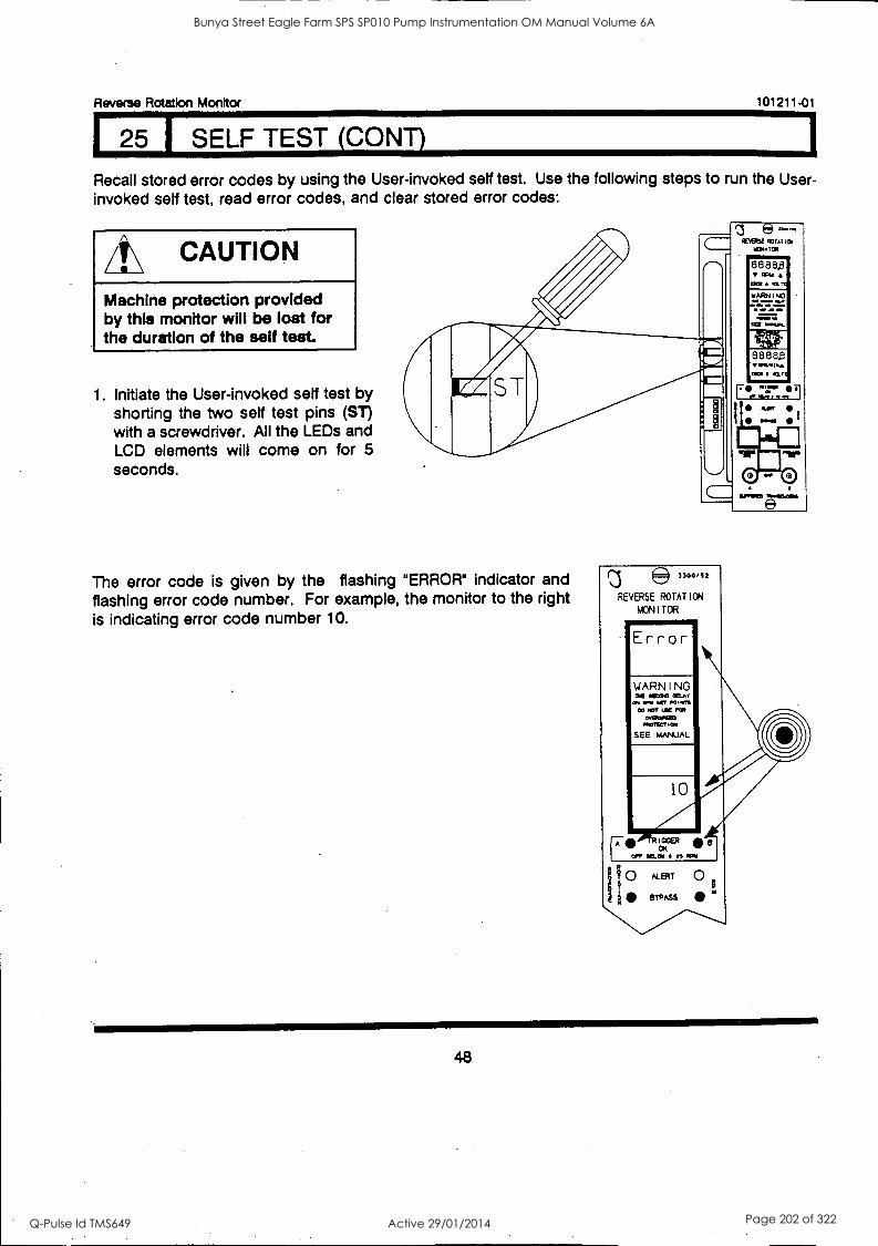
Reverse Rotation Monitor 101211-01
I 25 I SELF TEST (CONY)
Recall stored error codes by using the User-invoked self test. Use the following steps to run the User- invoked self test, read error codes, and clear stored error codes:
A\ CAUTION
Machine protection provided by this monitor will be lost for the duration of the self test.
1. Initiate the User-invoked self test by shorting the two self test pins (ST) with a screwdriver. All the LEDs and LCD elements will come on for 5 seconds.
'3 9 REVERY 904(101
The error code is given by the flashing "ERROR" indicator and flashing error code number. For example, the monitor to the right is indicating error code number 10.
® 3300 ,S 2
REVERSE ROTATION
MONITOR
Error
0- 0
ALBIT 0 BYPASS w
48
Bunya Street Eagle Farm SPS SP010 Pump Instrumentation OM Manual Volume 6A
Q-Pulse Id TMS649 Active 29/01/2014 Page 202 of 322
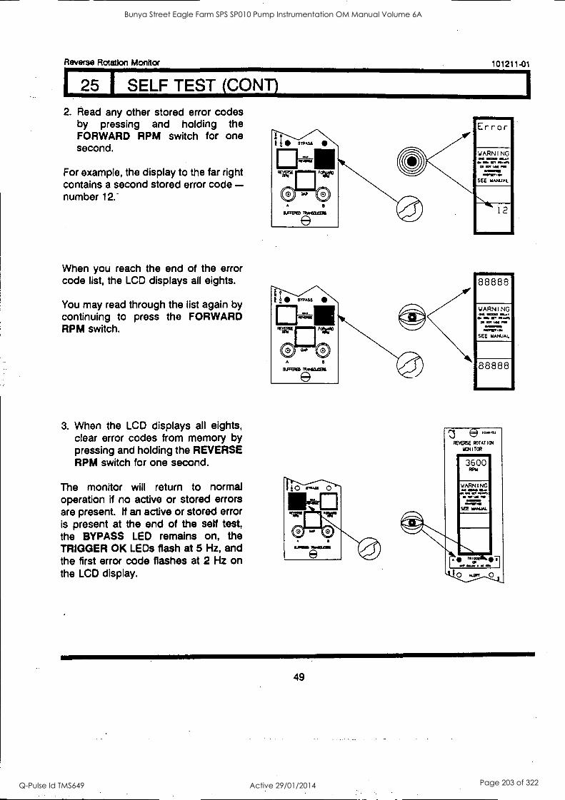
Reverse Rotation Monitor 101211-01
1 25 I SELF TEST (CONT)
2. Read any other stored error codes by pressing and holding the FORWARD RPM switch for one second.
For example, the display to the far right contains a second stored error code - number 12."
When you reach the end of the error code list, the LCD displays all eights.
You may read through the list again by continuing to press the FORWARD RPM switch.
3. When the LCD displays all eights, clear error codes from memory by pressing and holding the REVERSE RPM switch for one second.
The monitor will return to normal operation if no active or stored errors are present. tf an active or stored error is present at the end of the self test, the BYPASS LED remains on, the TRIGGER OK LEDs flash at 5 Hz, and the first error code flashes at 2 Hz on the LCD display.
WARNING CM WOO MAT
=NI 11117 111.111,
Oa Of Lel PC
MI46,101
SEE WANUAL
8 8 8 8 8
WARNING at =WO =AT
GM Ws MT 1141% CO CV SAN .70
MEMO
SEE MANUAL
8 8 8 8 8
49
Bunya Street Eagle Farm SPS SP010 Pump Instrumentation OM Manual Volume 6A
Q-Pulse Id TMS649 Active 29/01/2014 Page 203 of 322
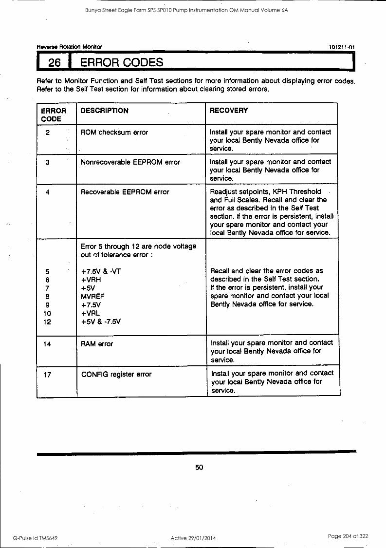
Reverse Rotation Monitor 101211-01
26 I ERROR CODES
Refer to Monitor Function and Self Test sections for more information about displaying error codes. Refer to the Self Test section for information about clearing stored errors.
ERROR. CODE
DESCRIPTION RECOVERY
2 ROM checksum error Install your spare monitor and contact your local Bent ly Nevada office for service.
3 Nonrecoverable EEPROM error Install your spare monitor and contact your local Bent ly Nevada office for service.
4 Recoverable EEPROM error Readjust setpoints, KPH Threshold and Full Scales. Recall and clear the error as described in the Self Test section. If the error is persistent, install your spare monitor and contact your local Bentty Nevada office for service.
Error 5 through 12 are node voltage out of tolerance error :
5 +7.5V & -VT Recall and clear the error codes as 6 +VRH described in the Self Test section. 7 +5V If the error is persistent, install your 8 MVREF spare monitor and contact your local 9 +7.5V Bently Nevada office for service.
10 +VRL 12 +5V & -7.5V
14 RAM error Install your spare monitor and contact your local Bently Nevada office for service.
17 CONFIG register error Install your spare monitor and contact your local Bentty Nevada office for service.
50
Bunya Street Eagle Farm SPS SP010 Pump Instrumentation OM Manual Volume 6A
Q-Pulse Id TMS649 Active 29/01/2014 Page 204 of 322
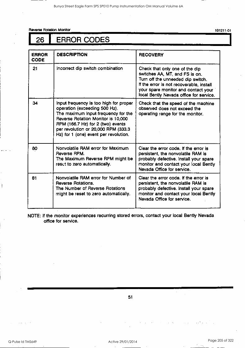
Reverse Rotation Monitor
126 ERROR CODES
101211-01
ERROR CODE
DESCRIPTION RECOVERY
21 Incorrect dip switch combination Check that only one of the dip switches AA, MT, and FS is on. Turn off the unneeded dip switch. If the error is not recoverable, install your spare monitor and contact your local Bent ly Nevada office for service.
34 Input frequency is too high for proper operation (exceeding 500 Hz). The maximum input frequency for the Reverse Rotation Monitor is 10,000 RPM (166.7 Hz) for 2 (two) events per revolution or 20,000 RPM (333.3 Hz) for 1 (one) event per revolution.
Check that the speed of the machine observed does not exceed the operating range for the monitor.
Nonvolatile RAM error for Maximum Reverse RPM. The Maximum Reverse RPM might be reset to zero automatically.
Clear the error code. If the error is persistent, the nonvolatile RAM is probably defective. Install your spare monitor and contact your local Bent ly Nevada Office for service.
81 Nonvolatile RAM error for Number of Reverse Rotations. The Number of Reverse Rotations might be reset to zero automatically.
Clear the error code. If the error is persistent, the nonvolatile RAM is probably defective. Install your spare monitor and contact your local Bent ly Nevada Office for service.
NOTE: If the monitor experiences recurring stored errors, contact your local Bent ly Nevada office for service.
51
Bunya Street Eagle Farm SPS SP010 Pump Instrumentation OM Manual Volume 6A
Q-Pulse Id TMS649 Active 29/01/2014 Page 205 of 322
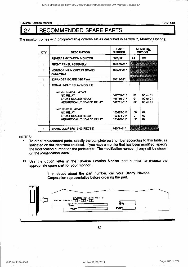
Reverse Rotation Monitor
127 I RECOMMENDED SPARE PARTS
101211-01
The monitor comes with programmable options set as described in section 7, Monitor Options.
On
1
1
DESCRIPTION
REVERSE ROTATION MONITOR
FRONT PANEL ASSEMBLY
MONITOR MAIN CIRCUIT BOARD ASSEMBLY
EXPANDER BOARD 32K PWA
SIGNAL INPUT RELAY MODULE
without Internal Barriers NO RELAY EPDXY SEALED RELAY HERMETICALLY SEALED RELAY
with Internal Barriers NO RELAY EPDXY SEALED RELAY HERMETICALLY SEALED RELAY
SPARE JUMPERS (100 PIECES)
PART NUMBER
3300/52
101708-01*
101402-01"
89611 -01'
101709-01' 101710-01' 101711 -01'
103475-01* 103474-01* 103473-01'
88708-01*
ORDERED OPTION"
AA CC
00 01
02
00 01
02
00 or 01 00 or 01
00 or 01
02 02 02
NOTES: * To order replacement parts, specify the complete part number according to this table, as
indicated on the identification decal. If you have a monitor that has been modified, specify the modification number on the parts order. The modification number (if any) will be shown on the identification decal.
** Use the option letter in the Reverse Rotation Monitor part number to choose the
appropriate spare part for your monitor.
If in doubt about the part number, call your Bently Nevada Corporation representative before ordering the part.
REVERSE ROTATION MONITOR PART PI3 3300/11 - - m
Klet 'CA MIN mUNNIPI
0.4101:11 1004
S
are
=I"
52
Bunya Street Eagle Farm SPS SP010 Pump Instrumentation OM Manual Volume 6A
Q-Pulse Id TMS649 Active 29/01/2014 Page 206 of 322
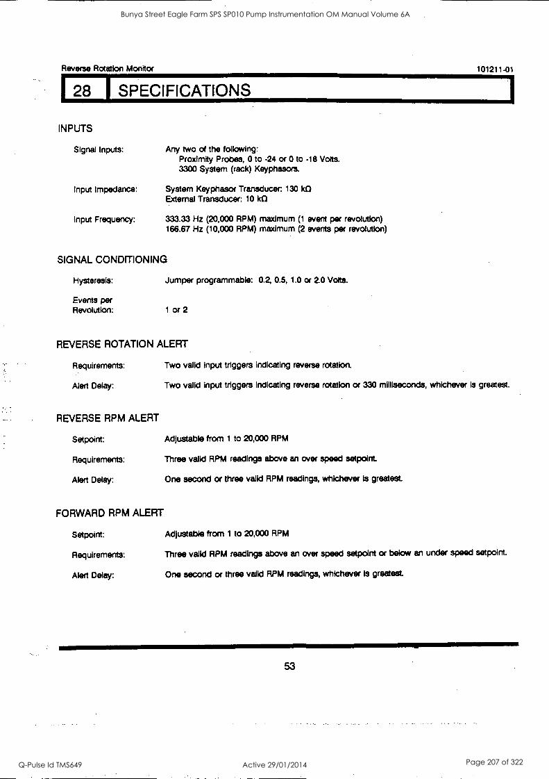
Reverse Rotation Monitor 101211-01
28 1 SPECIFICATIONS
INPUTS
Signal Inputs: Any two of the following: Proximity Probes, 0 to -24 or 0 to -18 Volts. 3300 System (rack) Keyphasors.
Input Impedance: System Keyphasor Transducer: 130 k0 External Transducer: 10 k0
Input Frequency: 333.33 Hz (20,000 RPM) maximum (1 event per revolution) 166.67 Hz (10,000 RPM) maximum (2 events per revolution)
SIGNAL CONDITIONING
Hysteresis: Jumper programmable: 0.2, 0.5, 1.0 or 2.0 Volts.
Events per Revolution: 1 or 2
REVERSE ROTATION ALERT
Requirements:
Alert Delay:
Two valid input triggers indicating reverse rotation.
Two valid input triggers indicating reverse rotation or 330 milliseconds, whichever Is greatest.
REVERSE RPM ALERT
Setpoint: Adjustable from 1 to 20,000 RPM
Requirements: Three valid RPM readings above an over speed setpoint.
Alert Delay: One second or three valid RPM readings, whichever is greatest
FORWARD RPM ALERT
Setpoint: Adjustable from 1 to 20,000 RPM
Requirements: Three valid RPM readings above an over speed setpoint or below an under speed setpoint.
Alert Delay: One second or three valid RPM readings, whichever is greatest
53
Bunya Street Eagle Farm SPS SP010 Pump Instrumentation OM Manual Volume 6A
Q-Pulse Id TMS649 Active 29/01/2014 Page 207 of 322
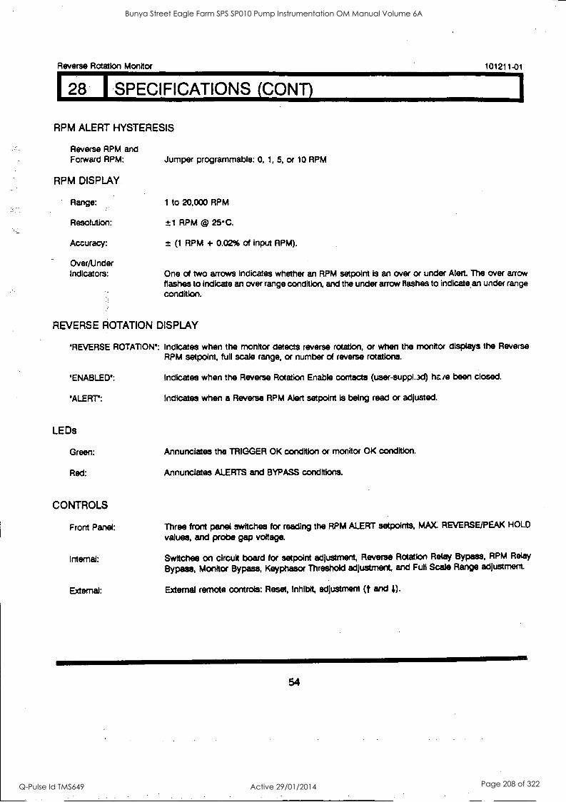
Reverse Rotation Monitor 101211-01
28 SPECIFICATIONS (CONT)
RPM ALERT HYSTERESIS
Reverse RPM and Forward RPM: Jumper programmable: 0, 1, 5, or 10 RPM
RPM DISPLAY
Range: 1 to 20,000 RPM
Resolution: ±1 RPM © 25C.
Accuracy: ± (1 RPM + 0.02% of input RPM).
Over/Under Indicators: One of two arrows Indicates whether an RPM setpoint is an over or under Alert. The over arrow
flashes to indicate an over range condition, and the under arrow flashes to indicate. an under range condition.
REVERSE ROTATION DISPLAY
' REVERSE ROTATION: Indicates when the monitor detects reverse rotation, or when the monitor displays the Reverse RPM setpoint, full scale range, or number of reverse rotations.
' ENABLED': Indicates when the Reverse Rotation Enable contacts (user-supp1.3d) hcie been closed.
' ALERT': Indicates when a Reverse RPM Alert setpoint is being read or adjusted.
LEDs
Green:
Red:
CONTROLS
Front Panel:
Internal:
External:
Annunciates the TRIGGER OK condition or monitor OK condition.
Annunciates ALERTS and BYPASS conditions.
Three front panel switches for reading the RPM ALERT setpoints, MAX REVERSE/PEAK HOLD
values, and probe gap voltage.
Switches on circuit board for setpoint adjustment, Reverse Rotation Relay Bypass, RPM Relay
Bypass, Monitor Bypass, Keyphasor Threshold adjustment, and Full Scale Range adjustment
External remote controls: Reset, Inhibit, adjustment (t and 4).
54
Bunya Street Eagle Farm SPS SP010 Pump Instrumentation OM Manual Volume 6A
Q-Pulse Id TMS649 Active 29/01/2014 Page 208 of 322
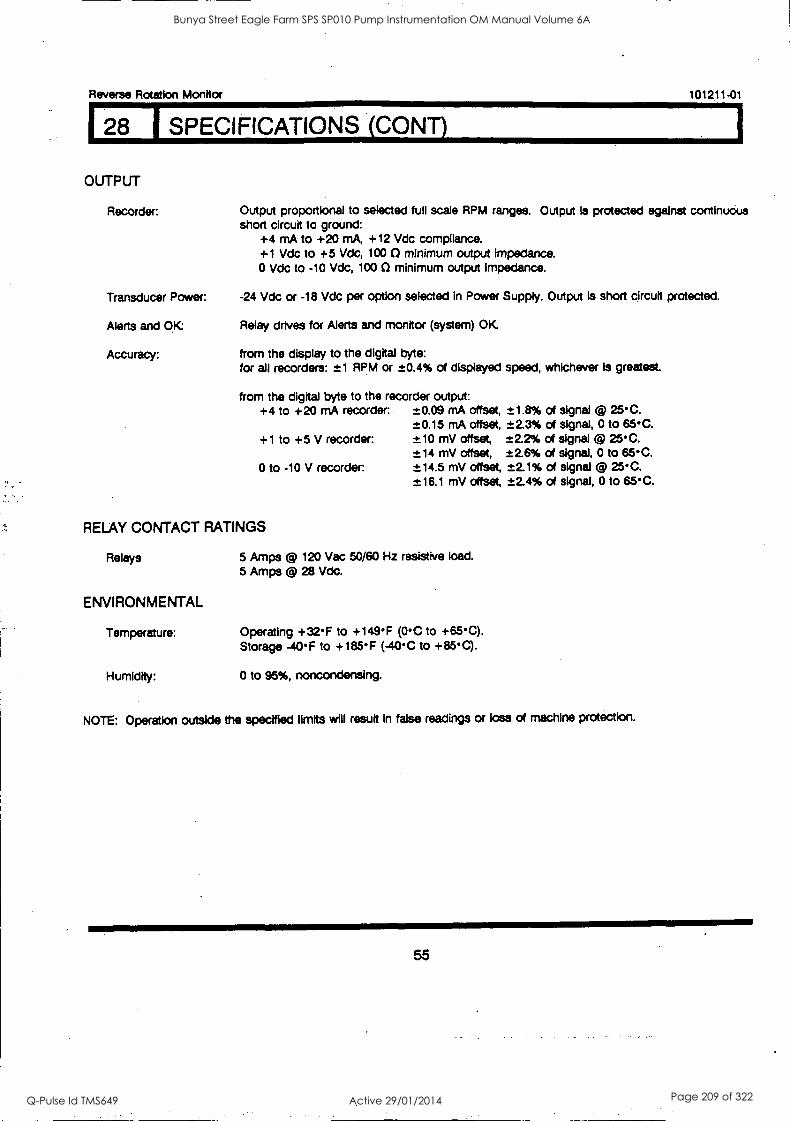
Reverse Rotation Monitor 101211.01
8 1 SPECIFICATIONS (CONS
OUTPUT
Recorder: Output proportional to selected full scale RPM ranges. Output Is protected against continuous short circuit to ground:
+4 mA to +20 mA, +12 Vdc compliance. +1 Vdc to +5 Vdc, 100 0 minimum output Impedance. 0 Vdc to -10 Vdc, 100 C) minimum output impedance.
Transducer Power: -24 Vdc or -18 Vdc per option selected In Power Supply. Output is short circuit protected.
Alerts and OK Relay drives for Alerts and monitor (system) OK
Accuracy: from the display to the digital byte: for all recorders: ±1 RPM or ±0.4% of displayed speed, whichever Is greatest.
from the digital byte to the recorder output: +4 to +20 mA recorder:. ±0.09 mA offset, ±1.8% of signal @ 25C.
±0.15 mA offset, ±2.3% of signal, 0 to 65C. +1 to +5 V recorder: ±10 mV offset, ±2.2% of signal @ 25C.
±14 mV offset, ±2.6% of signal, 0 to 65C. 0 to -10 V recorder -±14.5 mV offset, ±2.1% of signal @ 25C.
±16.1 mV offset, ±2.4% of signal, 0 to 65C.
RELAY CONTACT RATINGS
Relays 5 Amps @ 120 Vac 50/60 Hz resistive load. 5 Amps @ 28 Vdc.
ENVIRONMENTAL
Temperature: Operating +32F to +149F (0C to +65C). Storage -40F to +185F (-40C to +85C).
Humidity: 0 to 95%, noncondensing.
NOTE: Operation outside the specified limits will result In false readings or toss of machine protection.
55
Bunya Street Eagle Farm SPS SP010 Pump Instrumentation OM Manual Volume 6A
Q-Pulse Id TMS649 Active 29/01/2014 Page 209 of 322
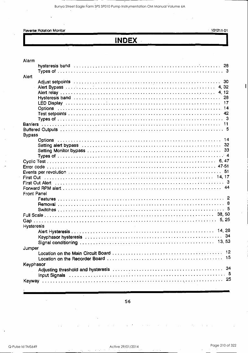
Reverse Rotation Monitor 101211-01
INDEX
Alarm hysteresis band 28 Types of 3
Alert Adjust setpoints 30 Alert Bypass 4, 32 Alert relay 4, 12 Hysteresis band 28 LED Display 17
Options 14
Test setpoints 42 Types of 3
Barriers 11
Buffered Outputs 5
Bypass Options 14
Setting alert bypass 32 Setting Monitor bypass 33 Types of 4
Cyclic Test 6, 47
Error code 47-51
Events per revolution 51
First Out 14, 17
First Out Alert 3
Forward RPM alert 44
Front Panel Features 2
Removal 8
Switches 5
Full Scale 38, 50
Gap 5, 25
Hysteresis Alert Hysteresis 14, 28
Keyphasor hysteresis 34
Signal conditioning 13, 53
Jumper Location on the Main Circuit Board 12
Location on the Recorder Board 15
Keyphasor Adjusting threshold and hysteresis 34
Input Signals 5
Keyway 25
56
Bunya Street Eagle Farm SPS SP010 Pump Instrumentation OM Manual Volume 6A
Q-Pulse Id TMS649 Active 29/01/2014 Page 210 of 322
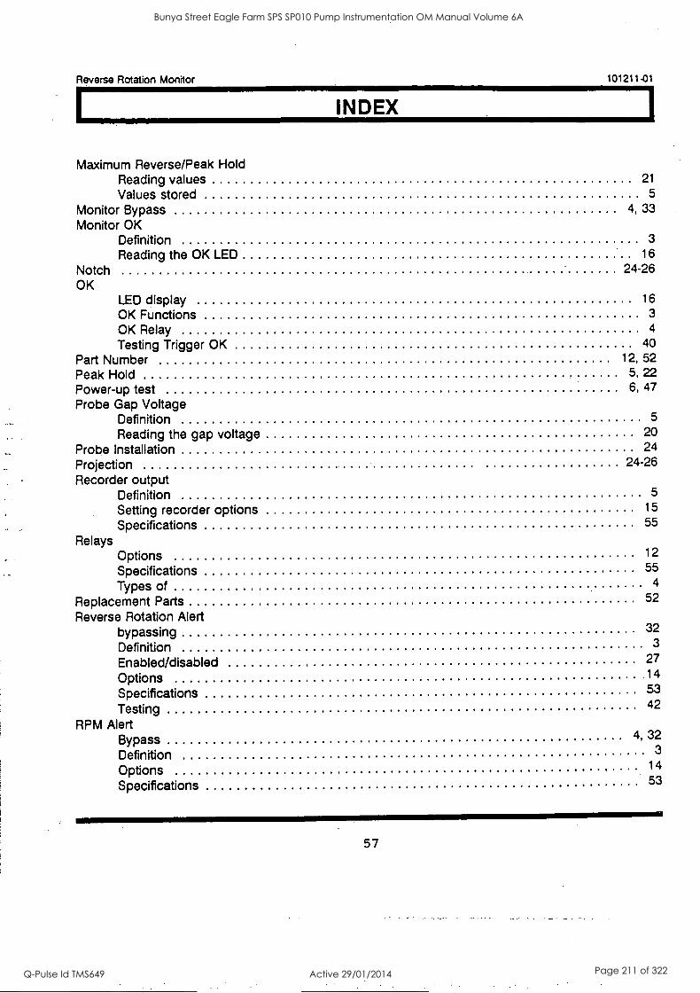
Reverse Rotation Monitor 101211-01
INDEX
Maximum Reverse/Peak Hold Reading values 21
Values stored 5
Monitor Bypass 4, 33
Monitor OK Definition 3
Reading the OK LED 16
Notch 24-26 OK
LED display OK Functions OK Relay Testing Trigger OK
Part Number Peak Hold Power-up test Probe Gap Voltage
16 3 4
40 12, 52
5, 22 6, 47
Definition 5
Reading the gap voltage 20
Probe Installation 24
Projection 24-26
Recorder output Definition 5
Setting recorder options 15
Specifications 55
Relays Options 12
Specifications 55
Types of 4
Replacement Parts 52
Reverse Rotation Alert bypassing 32
Definition 3
Enabled/disabled 27
Options 14
Specifications 53
Testing 42
RPM Alert Bypass 4, 32
Definition 3
Options 14
Specifications 53
57
Bunya Street Eagle Farm SPS SP010 Pump Instrumentation OM Manual Volume 6A
Q-Pulse Id TMS649 Active 29/01/2014 Page 211 of 322
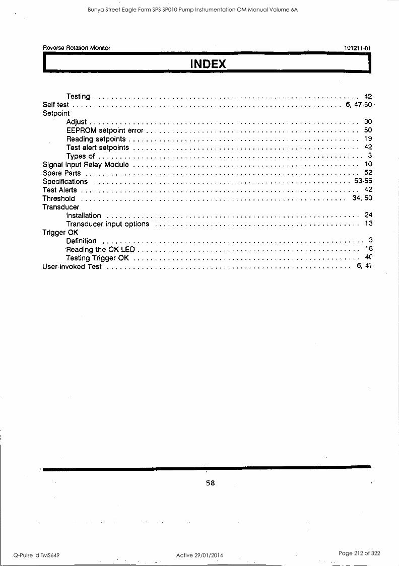
Reverse Rotation Monitor 101211-01
INDEX
Testing Self test Setpoint
Adjust EEPROM setpoint error Reading setpoints Test alert setpoints Types of
Signal Input Relay Module Spare Parts Specifications Test Alerts Threshold Transducer
Installation Transducer input options
Trigger OK Definition
'Reading the OK LED Testing Trigger OK
User-invoked Test
6, 42
47-50
30 50 19 42
3
10 52
53-55 42
34, 50
24 13
3 16
6, 4-i
58
Bunya Street Eagle Farm SPS SP010 Pump Instrumentation OM Manual Volume 6A
Q-Pulse Id TMS649 Active 29/01/2014 Page 212 of 322
Reverse Rotation Monitor 101211-01
FIELD WIRING DIAGRAMS DRAWING TITLE DRAWING NO. NO. OF SHEETS
Field Wiring Diagram Without Barriers 103625 2
Field Wiring.Diagram With External Barriers 103626 2
Field Wiring Diagram With Internal Barriers 104147 2
59
Bunya Street Eagle Farm SPS SP010 Pump Instrumentation OM Manual Volume 6A
Q-Pulse Id TMS649 Active 29/01/2014 Page 213 of 322

Reverse Rotation Monitor 101211-01
60
Bunya Street Eagle Farm SPS SP010 Pump Instrumentation OM Manual Volume 6A
Q-Pulse Id TMS649 Active 29/01/2014 Page 214 of 322
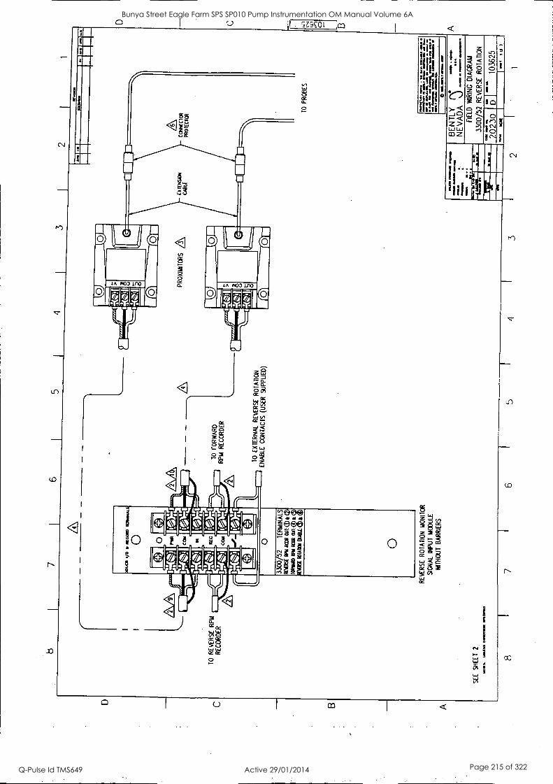
AA
TO
R
EV
ER
SE
R
PM
R
EC
OR
DE
R
SE
E
SH
EE
T
2
1.0.
S.
Wal
la 0
.1M
.M5
.1,1
10.1
11.
8
I/O
IIM
OS
IP
TO
SS
IAL
0 A
i e 0
I ri a I
eel PI
M I M
AI
WO
CC
U in
l re
el
eel - .0
Feve
.5
MN
1.
-Yel
- Ifz
*J.
Rol
if
0-1
0
3300
/52
TE
RM
INA
LS
R
ots(
;Yu
Rai
t D
JI:(
D k
(2)
rom
a ft
Ras
Oil:
(e) &
op
MS
C R
OLM
Wal
: 0
e C
ID
0
AA
RE
VE
RS
E
RO
TA
TIO
N
MO
NIT
OR
SIG
NA
L IN
PU
T
MO
DU
LE
WIT
HO
UT
B
AR
RIE
RS
7 6
TO
F
OR
WA
RD
R
PM
R
EC
OR
DE
R
TO
E
XT
ER
NA
L R
EV
ER
SE
R
OT
AT
ION
E
NA
BLE
C
ON
TA
CT
S (
US
ER
S
UP
PLI
ED
)
5
PR
OX
IMI T
OR
S A
C
CK
NE
CIa
t PR
OIE
C F
OR
oat.
0.10
.0 M
IME
D
am...
1mm
am
ain
Am
a
IL
a
TO
P
RO
BE
S
rasa
aa
Am
u A
NA
M
INfl
or
Ma
on 0
.0
0 O
A
a...a
all,8
0 am
aam
01
1 A
A ow
MIN
K 0
0.11
AA
A R
e ap
e A
an
aDa1
010
160
la L
ana
MA
MM
A
MO
M
.011
0 01
110a
a 0
arr.
coo
BE
N T
L Y
N
EV
AD
A
.)
FIE
LD
WIR
ING
D
IAG
RA
M
3300
/52
RE
VE
RS
E
RO
TA
TIO
N
2023
0 D
r
1036
25
55'
Noi
t 1 0
4 3
2 1
D Bunya Street Eagle Farm SPS SP010 Pump Instrumentation OM Manual Volume 6A
Q-Pulse Id TMS649 Active 29/01/2014 Page 215 of 322
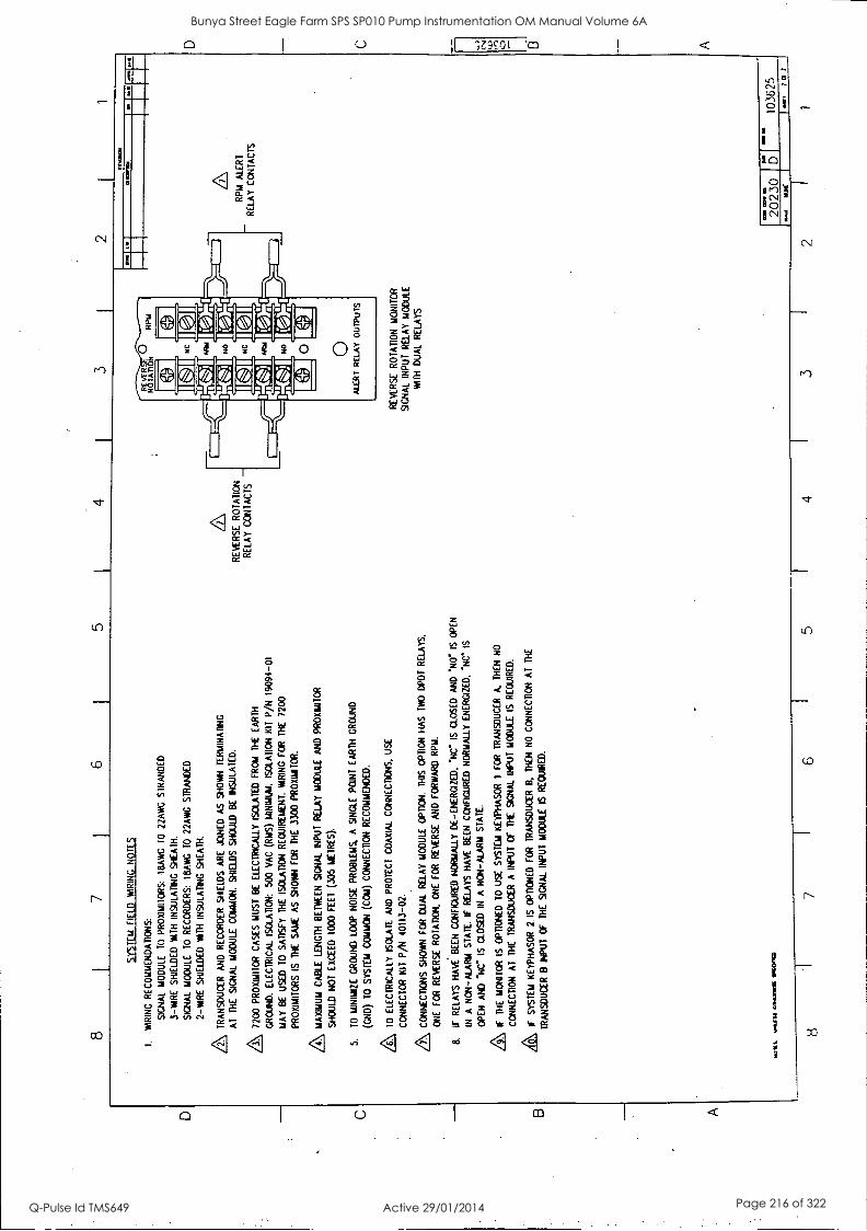
B A
8 7
6 5
2
SY
ST
EM
F
IELD
W
RIN
G
NO
TE
S
1 W
RIN
G R
EC
OM
ME
ND
AT
ION
S:
SIG
NA
L M
OD
ULE
T
O
PR
OX
IMIT
OR
S:
18A
WG
T
O
22A
WG
S
TR
AN
DE
D
3 -M
AR
E
SH
IELD
ED
W
ITH
IN
SU
LAT
ING
S
HE
AT
H.
SIG
NA
L M
OD
ULE
T
O
RE
CO
RD
ER
S:
18A
WG
T
O
22A
WG
S
TR
AN
DE
D
2-W
IRE
S
HIE
LDE
D
WT
H I
NS
ULA
TIN
G S
HE
AT
H.
A TR
AN
SD
UC
ER
A
ND
R
EC
OR
DE
R
SH
IELD
S
AR
E
JOIN
ED
A
S
SH
OW
N
TE
RM
INA
TIN
G
AT
T
HE
S
IGN
AL
MO
DU
LE C
OM
MO
N.
SH
IELD
S
SH
OU
LD
BE
IN
SU
LAT
ED
.
Z\ 7
200
PR
O/a
/411
0R
CA
SE
S M
US
T
BE
E
LEC
TR
ICA
LLY
IS
OLA
TE
D F
RO
M
TH
E
EA
RT
H
GR
OU
ND
. E
LEC
TR
ICA
L IS
OLA
TIO
N:
500
VA
C (W
S)
MIN
IMU
M.
ISO
LAT
ION
K
IT P
/N
1909
4-01
MA
Y
BE
U
SE
D
TO
S
AT
ISF
Y
TH
E
ISO
LAT
ION
R
EQ
UIR
EM
EN
T.
WR
ING
F
OR
T
HE
72
00
PR
OX
IMIT
OR
S
IS
TH
E
SA
ME
A
S
SH
OW
N
FO
R
TH
E
3300
PR
OX
IAIT
OR
.
Z\ M
AX
IMU
M
CA
BLE
LE
NG
TH
BE
TW
EE
N
SIG
NA
L IN
PU
T
RE
LAY
MO
DU
LE
AN
D
PR
OX
IMIT
OR
SH
OU
LD
NO
T
EX
CE
ED
10
00
FE
ET
(3
05 M
ET
RE
S).
5.
TO
M
INIM
IZE
G
RO
UN
D L
OO
P N
OIS
E P
RO
BLE
MS
, A
S
ING
LE
PO
INT
E
AR
TH
G
RO
UN
D
(GN
D)
TO
S
YS
TE
M
CO
MM
ON
(C
OM
) C
ON
NE
CT
ION
R
EC
OM
ME
ND
ED
.
A TO
ELE
CT
RIC
ALL
Y I
SO
LAT
E
AN
D
PR
OT
EC
T
CO
AX
IAL
CO
NN
EC
TIO
NS
, U
SE
CO
NN
EC
TO
R
KIT
P
/N
4011
3-02
.
A CO
NN
EC
TIO
NS
S
HO
WN
F
OR
D
UA
L R
ELA
Y
MO
DU
LE
OP
TIO
N.
TH
IS
OP
TIO
N
HA
S T
WO
D
PD
T R
ELA
YS
.
ON
E
FO
R
RE
VE
RS
E
RO
TA
TIO
N.
ON
E F
OR
R
EV
ER
SE
A
ND
FO
RW
AR
D R
PM
.
8.
IF
RE
LAY
S
HA
VE
B
EE
N
CO
NF
IGU
RE
D N
OR
MA
LLY
DE
- E
NE
RG
IZE
D.
'NC
' IS
C
LOS
ED
A
ND
N
O
IS
OP
EN
IN
A
NO
N-A
LAR
M
ST
AT
E.
IF
RE
LAY
S
HA
VE
B
EE
N
CO
NF
IGU
RE
D
NO
RM
ALL
Y
EN
ER
GIZ
ED
, "N
C I
S
OP
EN
A
ND
le
IS C
LOS
ED
IN
A
N
ON
-ALA
RM
S
TA
TE
.
/?\
IF
TH
E
MO
NIT
OR
IS
O
PT
ION
ED
T
O
US
E
SY
ST
EM
K
EY
PH
AS
OR
1
FO
R
TR
AN
SD
UC
ER
A
. T
HE
N
NO
CO
NN
EC
TIO
N
AT
T
HE
T
RA
NS
DU
CE
R A
IN
PU
T
OF
T
HE
S
IGN
AL
INP
UT
M
OD
ULE
IS
R
EQ
UIR
ED
.
A IF
SY
ST
EM
K
EY
PH
AS
OR
2
IS
OP
TIO
NE
D
FO
R
TR
AN
SD
UC
ER
13
, T
HE
N
NO
C
ON
NE
CT
ION
A
T
TH
E
TR
AN
SD
UC
ER
B
INP
UT
O
F
TH
E
SIG
NA
L IN
PU
T
MO
DU
LE
IS
RE
QU
IRE
D.
.0 K
t um
{ Si 00
0nS
Im
am
RE
VE
RS
E
RO
TA
TIO
N
RE
LAY
C
ON
TA
CT
S -
iltvr
0171
D
UI
IN
RP
M
ALE
RT
RE
LAY
C
ON
TA
CT
S
RE
VE
RS
E
RO
TA
TIO
N
MO
NIT
OR
SIG
NA
L IN
PU
T
RE
LAY
MO
DU
LE
WIT
H
DU
AL
RE
LAY
S
OM
co
n
2 0
2 30
M
ALI
O
at
1036
25
8 7
6 I
5 I
4 3
I 2
D
C
A
Bunya Street Eagle Farm SPS SP010 Pump Instrumentation OM Manual Volume 6A
Q-Pulse Id TMS649 Active 29/01/2014 Page 216 of 322
C
5 3
1
1/0
RE
C01
0 (V
OW
/
0
TO
R
EV
ER
SE
R
PM
R
EC
OR
DE
R
RE
C
1 IQ
SA
FE
A
RE
A
OR
Z
ON
E
2.
DIV
ISIO
N
2 H
AZ
AR
DO
US
A
RE
A
ON
O
TO
F
OR
WA
RD
RP
M
RE
CO
RD
ER
C
IA
SE
E
SH
EE
T
2
0
3300
/52
TE
RM
INA
LS
mum
RP
M
RC
OR
CIU
T:(
1)k
mitt
en e
ft R
aeat
4) &
MU
SE
101
A10
1 M
et gp
a
O
RE
VE
RS
E
RO
TA
TIO
N
MO
NIT
OR
SIG
NA
L IN
PU
T
MO
DU
LE
YM
TH
E
XT
ER
NA
L B
AR
RIE
RS
scat
W
allin
01.
1O1a
W
(171
110
CO
RR
EC
TO
R
PRO
TE
CT
OR
TO
E
XT
ER
NA
L R
EV
ER
SE
R
OT
AT
ION
EN
AB
LE
CO
NT
AC
TS
(U
SE
R
SU
PP
LIE
D)
A WA
RN
ING
IMP
RO
PE
R G
RO
UN
DIN
G O
F
SIG
NA
L C
OM
MO
N C
OU
LD
CA
US
E
EX
PLO
SIO
N
OR
F
IRE
IN
T
HE
H
AZ
AR
DO
US
AR
EA
RE
SU
LTIN
G
IN
SE
VE
RE
P
ER
SO
NA
L IN
JUR
Y
OR
D
EA
TH
. C
OM
MO
N
MU
ST
B
E
CO
NN
EC
TE
D
TO
EA
RT
H A
i T
HE
B
AR
RIE
R
RA
IL
TO
PR
OB
ES
0001
10a
Sa
ba O
a N
aaa
Min
a a
alaM
an
Ma
Wal
la C
arab
aa
era
are
al a
.. IA
. al
...
0.0
o N
atio
Oftl
iala
g 11
1701
RE
I
a.m
. Mila
no*
Mao
=
faoa
lesa
M
I.&
AI
0013
10
BE
N T
LY
r\*
NE
VA
DA
%) ''''
'' F
IELD
W
IRIN
G
DIA
GR
AM
3300
/52
RE
VE
RS
E
RO
TA
TIO
N
""
.1 m
a .
2023
0 D
f 10
3626
IS
la
1
6 5
4 I
3 2
I 1
D
Bunya Street Eagle Farm SPS SP010 Pump Instrumentation OM Manual Volume 6A
Q-Pulse Id TMS649 Active 29/01/2014 Page 217 of 322
8
EX
TE
RN
AL
BA
RR
IER
SY
ST
EM
F
IELD
W
IRIN
G
NO
TE
S
1.
WIR
ING
RE
CO
MM
EN
DA
TIO
NS
:
SIG
NA
L M
OD
ULE
T
O
BA
RR
IER
S -
BA
RR
IER
S
TO
P
RO
XIM
ITO
RS
: 16
AW
G
TO
lfl
AW
G
ST
RA
ND
ED
3-
WIR
E
SH
IELD
ED
W
ITH
IN
SU
LAT
ING
S
HE
AT
H.
SIG
NA
L M
OD
ULE
T
O R
EC
OR
DE
RS
: 18
AW
G
TO
22
AI A
t S
TR
AN
DE
D
2-W
IRE
S
HIE
LDE
D
WIT
H
INS
ULA
TIN
G
SH
EA
TH
.
A REC
OR
DE
R
SH
IELD
S
AR
E
JOIN
ED
A
S
SH
OW
N T
ER
MIN
AT
ING
A
T
TH
E
SIG
NA
L M
OD
ULE
CO
MM
ON
. S
HIE
LDS
S
HO
ULD
B
E
INS
ULA
TE
D.
5
A 720
0 P
RO
XIM
ITO
R
CA
SE
S
MU
ST
B
E
ELE
CT
RIC
ALL
Y
ISO
LAT
ED
FR
OM
T
HE
E
AR
TH
G
RO
UN
D.
ELE
CT
RIC
AL
ISO
LAT
ION
: 50
0 V
AC
(R
MS
) M
INIM
UM
. IS
OLA
TIO
N
KIT
P
/N
1909
4-01
M
AY
B
E
US
ED
T
O
SA
TIS
FY
T
HE
IS
OLA
TIO
N
RE
QU
IRE
ME
NT
. W
IRIN
G
FO
R
TH
E
7200
P
RO
XIM
ITO
R
IS
TH
E
SA
ME
A
S
SH
OW
N
FO
R
TH
E 33
00 P
RO
XIM
ITO
R.
A MAX
IMU
M
CA
BLE
LE
NG
TH
B
ET
WE
EN
BA
RR
IER
A
ND
P
RO
XIM
ITO
R S
HO
ULD
N
OT
E
XC
EE
D
1000
FE
ET
(3
05
ME
TR
ES
).
A TO
ELE
CT
RIC
ALL
Y I
SO
LAT
E
AN
D
PR
OT
EC
T
CO
AX
IAL
CO
NN
EC
TIO
NS
, U
SE
CO
NN
EC
TO
R K
IT
P/N
40
113-
02.
/6\ T
RA
NS
DU
CE
R
SH
IELD
S
AR
E
JOIN
ED
A
S
SH
OW
N
TE
RM
INA
TIN
G
AT
B
AR
RIE
R
GR
OU
ND
, O
NLY
.
SH
IELD
S
SH
OU
LD
BE
IN
SU
LAT
ED
.
A CON
NE
CT
ION
S
SH
OW
N
FO
R
DU
AL
RE
LAY
M
OD
ULE
O
PT
ION
. T
HIS
O
PT
ION
H
AS
T
WO
()P
DT
R
ELA
YS
, O
NE
F
OR
R
EV
ER
SE
R
OT
AT
ION
, O
NE
F
OR
R
EV
ER
SE
A
ND
F
OR
WA
RD
R
PM
.
8.
IF
RE
LAY
S
HA
VE
B
EE
N C
ON
FIG
UR
ED
NO
RM
ALL
Y
DE
-EN
ER
GIZ
ED
. 'N
C I
S
CLO
SE
D
AN
D
-NO
.
IS
OP
EN
IN
A
NO
N-A
LAR
M
ST
AT
E.
IF
RE
LAY
S H
AV
E
BE
EN
C
ON
FIG
UR
ED
N
OR
MA
LLY
E
NE
RG
IZE
D,
'NC
IS
O
PE
N
AN
D N
O.
IS
CLO
SE
D
IN
A
NO
N-A
LAR
M
ST
AT
E.
RE
VE
RS
E
RO
TA
TIO
N
RE
LAY
CO
NT
AC
TS
-
/9\
TY
PIC
AL
CO
NN
EC
TIO
N I
S
SH
OW
N.
SE
E
AP
PR
OV
AL
DR
AW
ING
B
A22
000
OR
C
A
2200
0.
A BAR
RIE
RS
A
RE
M
OU
NT
ED
T
O
BA
RR
IER
R
AIL
W
HIC
H
IS
TH
E
PO
TE
NT
IAL
EQ
UA
LIZ
AT
ION
B
US
B
ET
WE
EN
SY
ST
EM
G
RO
UN
D
AN
D
EA
RT
H
GR
OU
ND
. T
O
MIN
IMIZ
E
GR
OU
ND
LO
OP
P
RO
BLE
MS
, A
S
ING
LE
PO
INT
E
AR
TH
GR
OU
ND
(C
ND
) T
O
SY
ST
EM
C
OM
MO
N (
CO
M)
CO
NN
EC
TIO
N
IS
RE
QU
IRE
D A
T
TH
E
BA
RR
IER
RA
IL
TO
TA
L E
AR
TH
LO
OP
IMP
ED
AN
CE
M
US
T
NO
T
EX
CE
ED
1
OH
M.
RE
MO
VE
S
ING
LE
PO
INT
E
AR
TH
G
RO
UN
D
CO
NN
EC
TIO
N
AT
C
HA
SS
IS
GR
OU
ND
O
N
TH
E
3300
PO
WE
R I
NP
UT
M
OD
ULE
.
A IND
EP
EN
DE
NT
CO
NN
EC
TIO
N
TO
S
YS
TE
M
EA
RT
H.
A IF
TH
E
MO
NIT
OR
IS
O
PT
ION
ED
T
O
US
E
SY
ST
EM
K
EY
PH
AS
OR
1
FO
R
TR
AN
SD
UC
ER
A
, T
HE
N
NO
CO
NN
EC
TIO
N
AT
T
HE
T
RA
NS
DU
CE
R
A
INP
UT
O
F
TH
E
SIG
NA
L IN
PU
T
MO
DU
LE
IS
RE
QU
IRE
D.
A IF
SY
ST
EM
K
EY
PH
AS
OR
2
IS
OP
TIO
NE
D
FO
R
TR
AN
SD
UC
ER
B
, T
HE
N
NO
C
ON
NE
CT
ION
A
T
TH
E
TR
AN
SD
UC
ER
B
IN
PU
T
OF
T
HE
S
IGN
AL
INP
UT
M
OD
ULE
IS
R
EQ
UIR
ED
.
MO
IL
..511
011
.117
111M
RE
VE
RS
E
RO
TA
TIO
N
MO
NIT
OR
S
IGN
AL
INP
UT
R
ELA
Y
MO
DU
LE
WIT
H D
UA
L R
ELA
YS
RP
M
ALE
RT
RE
LAY
C
ON
TA
CT
S
2023
0 10
3626
8 7
6 5
4 3
foal
76
7
2 I
1
D
C 0 B
A
Bunya Street Eagle Farm SPS SP010 Pump Instrumentation OM Manual Volume 6A
Q-Pulse Id TMS649 Active 29/01/2014 Page 218 of 322
D
B
A
8 7
6 5
4 3
SH
IELD
I
CO
NN
OR
L
SO
( A
RE
A
OR
K
NE
2.
D
INS
ION
2
HA
ZA
RD
OU
S
AR
EA
TO
R
EV
ER
SE
R
PM
RE
CO
RD
ER
I
SIG
NA
L O
urP
uIS
oat
WIL
LIS
OA
LIN
II
1141
4141
1D
NE
C
CO
N
414
RE
VE
RS
E
RO
IAD
Ois
i M
ON
ITO
R
SIG
NA
L IN
PU
T
MO
DU
LE
w1H
IN
TE
RN
AL
BA
RR
IER
S
SH
IELD
CO
MM
ON
TO
F
OR
WA
RD
R
PM
RE
CO
RD
ER
NN
W
.440
4,44
4
A
WO
* 110
vi
l 10
940
0 4C
110t
40
04.0
44a
OF
MM
O
imG
oc
c 10
3 (I
C
A WA
RN
ING
MIS
CO
NN
EC
TIN
C O
R
INT
ER
MIT
TE
NT
C
ON
TA
CT
Of
TH
E
FIE
LD
WR
ING
T
O R
AC
K
TE
RM
INA
LS M
TH
H
IGH
VO
LTA
GE
PO
TE
NT
IALS
C
OU
LD C
AU
SE
A
N
EX
PLO
SIO
N
OR
F
IRE
IN
TH
E
HA
ZA
RD
OU
S
AR
EA
RE
SU
LTIN
G
IN
SE
VE
RE
PE
RS
ON
AL
INJU
RY
O
R
DE
AT
H.
RE
MO
VE
A
LL
VO
LTA
GE
P
OT
EN
TIA
LS
FR
OM
R
EA
R O
F
RA
CK
.
10 P
RO
BE
S
NO
M P
M N
OM
1
OW
YSO
.1
.
ow ..
.ow
ono
. 41
44M
iff
loom
mao
M
aw 4
4101
10 l
Co G
naw
Eno
am
.
r4.4
44 A
bow
Ina
lD
Pi
1110
41=
1
111/
. =
IMP,
A
S
BE
N
Y
NE
VA
DA
N
J ,-
^'"`
" F
IELD
W
RIN
G
DIA
GR
AM
3300
/52
RE
VE
RS
E
RO
TA
TIO
N
ao.
opot
0230
..
ON
la
1041
47
eon
to)/
8 7
6 5
4 3
2 1
Bunya Street Eagle Farm SPS SP010 Pump Instrumentation OM Manual Volume 6A
Q-Pulse Id TMS649 Active 29/01/2014 Page 219 of 322
D C B
A
8 7
6 5
4 3
INT
ER
NA
L B
AR
RIE
R
SY
ST
EM
F
IELD
W
IRIN
G N
OT
U
I W
IRIN
G
RE
CO
MM
EN
DA
TIO
NS
:
SIG
NA
L M
OD
ULE
10
P
RO
XIM
ITO
RS
: 16
AV
IG
10
MA
K S
TR
AN
DE
D
3 -W
IRE
S
HIE
LDE
D
NT
H I
NS
ULA
TIN
G
SH
EA
TH
.
SIG
NA
L M
OD
ULE
10
R
EC
OR
DE
R/R
EA
DO
UT
: ia
Avo
c T
O
22A
WG
S
TR
AN
DE
D
2-W
IRE
S
HIE
LDE
D
WIT
H
INS
ULA
TIN
G
SH
EA
TH
.
7200
PR
OX
IMIT
OR
C
AS
ES
M
US
T
BE
E
LEC
TR
ICA
LLY
IS
OLA
TE
D F
RO
M
TH
E
EA
RT
H
GR
OU
ND
.
ELE
CT
RIC
AL
ISO
LAT
ION
: 50
0 V
AC
(R
IIS)
MIN
IMU
M.
ISO
LAT
ION
K
IT P
/N
1909
4-01
MA
Y
BE
U
SE
D
10 S
AT
ISF
Y
TH
E
ISO
LAT
ION
R
EQ
UIR
EM
EN
T.
WR
ING
FO
R
TH
E
7200
PR
OX
IMIT
OR
IS
TH
E
SA
ME
A
S 94
004
FO
R
TH
E
3300
PR
OX
IBT
OR
.
AM
AX
IMU
M
CA
RLE
LE
NG
TH
BE
TW
EE
N
MO
NIT
OR
A
ND
P
RO
XIM
ITO
RS
MU
S1
NO
T
EX
CE
ED
1000
FE
ET
(3
05
ME
TR
ES
).
4.
10
MIN
IMIZ
E
GR
OU
ND
LO
OP
NO
ISE
P
RO
BLE
MS
. A
S
ING
LE
PO
INT
E
AR
TH
G
RO
UN
D
(CN
D)
TO
S
YS
TE
M
CO
MM
ON
(C
OM
) C
ON
NE
CT
ION
IS
R
EC
OM
ME
ND
ED
.
/5.
TO
E
LEC
TR
ICA
LLY
IS
OLA
TE
AN
D
PR
OT
EC
T
CO
AX
IAL
CO
NN
EC
TIC
NS
. U
SE
CO
NN
EC
TO
R
KIT
P/N
40
113-
02.
AC
ON
NE
CT
ION
S S
HO
WN
F
OR
D
UA
L R
ELA
Y M
OD
ULE
O
PT
ION
. T
HIS
O
PT
ION
H
AS
T
WO
OP
OT
R
ELA
YS
. O
NE
F
OR
R
EV
ER
SE
R
OT
AT
ICN
, O
NE
F
OR
R
EV
ER
SE
A
ND
F
OR
WA
RD
R
PM
.
AS
CR
EW
S
MU
ST
B
E
SE
CU
RE
LY
FA
ST
EN
ED
F
OR
P
RO
PE
R
GR
OU
ND
. B
AR
RIE
RS
A
RE
C
ON
NE
CT
ED
10
TH
E
INT
ER
NA
L B
AR
RIE
R
GR
OU
ND
R
AIL
A
T
TH
IS
PO
NT
. S
EE
P
OW
ER
S
UP
PLY
M
AN
UA
L F
OR
P
RO
PE
R
SIN
GLE
P
OIN
T
GR
OU
ND
CO
NN
EC
TIO
N
BE
TW
EE
N B
AR
RIE
R
GR
OU
ND
A
ND
E
AR
TH
G
RO
UN
D
AT
T
HE
PO
WE
R
INP
UT
M
OD
ULE
.
8.
IF
RE
LAY
S
HA
VE
B
EE
N C
ON
FIG
UR
ED
N
OR
MA
LLY
D
E-E
NE
RG
IZE
D.
NC
' IS
C
LOS
ED
A
ND
N
O
IS
OP
EN
IN
A
N
ON
-ALA
RM
ST
AT
E.
IF
RE
LAY
S
HA
VE
B
EE
N
CO
NF
IGU
RE
D N
OR
MA
LLY
E
NE
RG
IZE
D.
NC
"
IS
OP
EN
A
ND
N
O'
IS
CLO
SE
D
IN
A
NO
N-A
LAR
M
ST
AT
E.
AT
ER
IMA
TE
T
HE
R
EC
OR
DE
R
SH
IELD
S
AT
T
HE
S
IGN
AL
MO
DU
LE
CO
MM
ON
A
S
SH
OW
N.
SH
IELD
S
SH
OU
LD
BE
IN
SU
LAT
ED
.
AIF
11
MO
NIT
OR
IS
O
PT
ION
ED
10
U
SE
S
YS
TE
M
KE
WH
AS
OR
1
FO
R
TR
AN
SD
UC
ER
A
. T
HE
N
NO
CO
NN
EC
TIO
N
AT
T
HE
T
RA
NS
DU
CE
R
A
INP
UT
O
F
TH
E
SIG
NA
L IN
PU
T
MO
DU
LE
IS
RE
OU
IRE
D
SY
ST
EM
K
EY
PH
AS
CR
2
IS
OP
TIO
NE
D F
OR
T
RA
NS
DU
CE
R
B.
TH
EN
N
O
CO
NN
EC
TIO
N
AT
T
HE
TR
AN
SD
UC
ER
B
IN
PU
T
OF
T
HE
S
IGN
AL
INP
UT
M
OD
ULE
IS
RE
QU
IRE
D.
12.
SE
E
AP
PR
OV
AL
DR
AW
ING
B
A22
000
OR
C
A22
000.
.nat
ss o
p.u.
na
1141
0/10
RE
VE
RSE
R
OT
AT
ION
AL
ER
T
RE
LA
Y -
CO
NT
AC
TS
CC
]
IC
ICS]
)
RE
C
CO
N
NC
8
2
I
ALA
RM
R
ELA
Y
OU
TP
UT
S
RE
VE
RSE
RO
TA
TIC
N U
CN
ITO
R
SIG
NA
L N
UT
RE
LA
Y
MO
DU
LE
WIT
H
OV
AL
R
EL
AY
S
MIA
RPM
A
LE
RT
-
RE
LA
Y
CO
N T
AC
IS
A
1[10
1117
4
SEE
W
ET
1
I 1"
7721
0 10
4147
M
.4.1
bE
10
1!
7 I
6 5
I 4
I 3
I 2
1
Bunya Street Eagle Farm SPS SP010 Pump Instrumentation OM Manual Volume 6A
Q-Pulse Id TMS649 Active 29/01/2014 Page 220 of 322
BRISBANE CITY COUNCIL Dept. Water Supply and Sewage Pumpwell No 1, Eagle Farm Pump Station
BCC Contract No S20/95/96 System Instrumentation
Operation and Maintenance Manual
2.8 330525 Velometer XA Piezo Velocity Sensor
The following publication entitled 330525 Velometer XA Piezo Velocity Sensor Operation Manual (Part No 107316-01 Rev B) is prepared by Bent ly Nevada for plant personnel who operate and maintain the system. It provides a detailed description of the Velometer, application notes, installation details, maintenance procedures, and a guide to field-testing.
The following sections are included:
2.8.1 Operating Information
2.8.2 Installation
2.8.3 Maintenance
2.8.4 Field Testing and Trouble Shooting
2.8.5 Specifications
15140/Inst Man/BRH Issue 1 29-Apr-98 Page 2-11
Bunya Street Eagle Farm SPS SP010 Pump Instrumentation OM Manual Volume 6A
Q-Pulse Id TMS649 Active 29/01/2014 Page 221 of 322
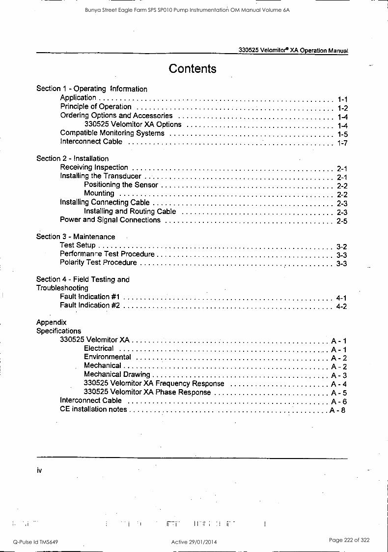
330525 Velomitore XA Operation Manual
Contents
Section 1 - Operating Information Application 1-1 Principle of Operation 1-2 Ordering Options and Accessories 1-4
330525 Velomitor XA Options 1-4 Compatible Monitoring Systems 1-5 Interconnect Cable 1-7
Section 2 - Installation Receiving Inspection 2-1 Installing the Transducer 2-1
Positioning the Sensor 2-2 Mounting 2-2
Installing Connecting Cable 2-3 Installing and Routing Cable 2-3
Power and Signal Connections 2-5
Section 3 - Maintenance Test Setup 3-2 Performance Test Procedure 3-3 Polarity Test Procedure 3-3
Section 4 - Field Testing and Troubleshooting
Fault Indication #1 4-1 Fault Indication #2 4-2
Appendix Specifications
330525 Velomitor XA A - 1
Electrical A - 1
Environmental A - 2 Mechanical A - 2 Mechanical Drawing A - 3 330525 Velomitor XA Frequency Response A - 4 330525 Velomitor XA Phase Response A - 5
Interconnect Cable A - 6 CE installation notes A - 8
iv
Bunya Street Eagle Farm SPS SP010 Pump Instrumentation OM Manual Volume 6A
Q-Pulse Id TMS649 Active 29/01/2014 Page 222 of 322
330525 Velomitor® XA Operation Manual
Foreword
This manual describes the Bently Nevada 330525 Velomitor XA, a piezo-velocity sensor, and contains instructions for its installation and maintenance. If you need additional assistance contact the nearest Bently Nevada Corporation office.
This manual is intended for use by those experienced in the use of electronic instrumentation and machinery monitoring equipment.
Section 1 describes the 330525 Velomitor XA, tells how it works, and lists applications and optional accessories. This section also includes information on the Bently Nevada machinery monitoring systems that are compatible with the 330525 Velomitor XA.
Section 2 gives instructions for receiving and inspecting the 330525 Velomitor XA, choosing the proper monitoring points, and mounting the device. This section also shows how to install connecting cables.
Section 3 tells how to maintain the 330525 Velomitor XA by describing the test procedures and equipment needed to verify that the device is operating properly.
Section 4 contains instructions for field testing and troubleshooting problems with the 330525 Velomitor XA and compatible Bently Nevada monitoring systems.
The Appendix provides detailed specifications and sensitivity curves representing typical 330525 Velomitor XA operation. It also provides instructions for installing Velomitor XA to meet CE requirements.
RELATED DOCUMENTS
3300/55 Dual Velocity Monitor Maintenance Manual, 83965-01
iii
Bunya Street Eagle Farm SPS SP010 Pump Instrumentation OM Manual Volume 6A
Q-Pulse Id TMS649 Active 29/01/2014 Page 223 of 322
330525 VelomitoeXA Operation Manual
Bent ly Nevada Corporation has attempte to identify areas of risk created by improper installation and/or operation of this produ . These areas'of information are noted as
WARNING or CAUTION for your protecti n and for the safe and effective operation of this equipment. Read all instructions before i tailing or operating this product. Pay particular attention to those areas designated by the following symbols.
A CAUTION
A piezoelectric velocity to a sudden mechanical generate a low frequency represent actual signal may change danger relays.
transducer subjected impulse may signal that does not
machinery vibration. This the state of alarm and/or
Velomitor5 is a registered ademarIc of Bently Nevada Corporation
Proximitoe is a registered irademark of Bently Nevada Corporation
©Copyright Benitly Nevada Corporation 1993
All Rights Reserved
No part of this publication may be reproduced,ltransmitted, stored in a retrieval system or translated into any human or computer language, In any form r by any means, electronic, mechanical, magnetic, optical, chemical, manual, or otherwise, without the p r written permission of the copyright owner,
Bently Nevada Corporation P.O. Box 157
Minden, Nevada 89423 USA Telephone 8C0-227-5514 702 -782 -3611.
Telex 354437 Telemail 7400983 BNC UC
Fax 702-782-9253 Copyright infringement is a serious matter under
United States of America and foreign copyright laws.
ii
Bunya Street Eagle Farm SPS SP010 Pump Instrumentation OM Manual Volume 6A
Q-Pulse Id TMS649 Active 29/01/2014 Page 224 of 322

330525 VELOMI PIEZO - VELOCI
OPERATION MANUAL
BENTLY NEVADA
PART NO. 107316-01 Revision B 19 Dec. 95
OR8XA Y SENSOR
Bunya Street Eagle Farm SPS SP010 Pump Instrumentation OM Manual Volume 6A
Q-Pulse Id TMS649 Active 29/01/2014 Page 225 of 322
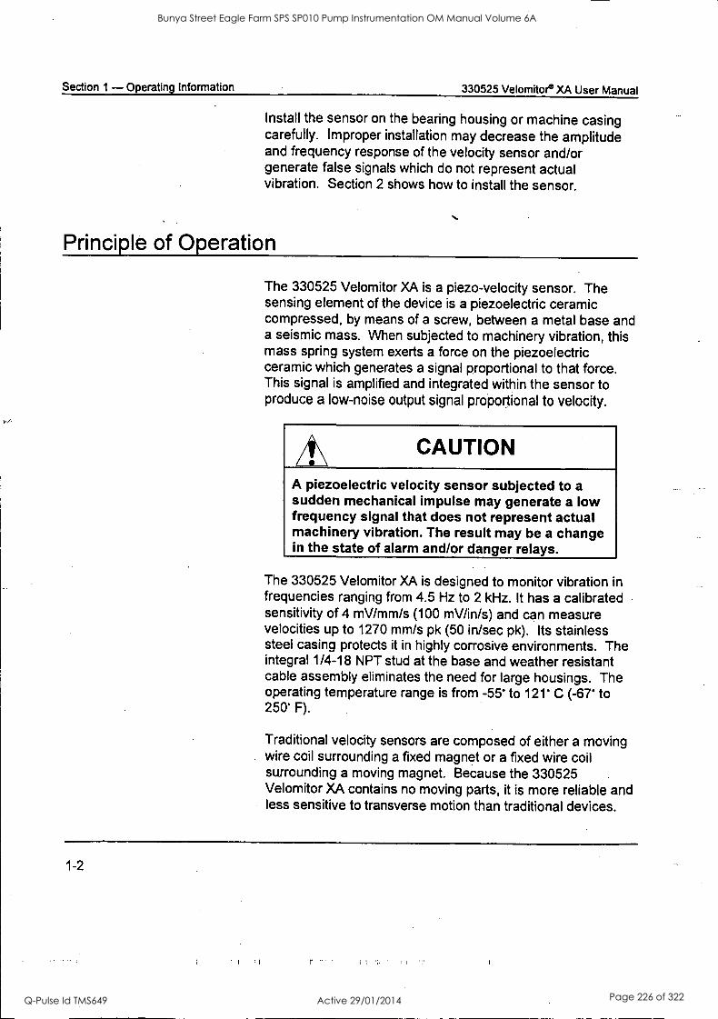
Section 1 - Operating Information 330525 Velomitor® XA User Manual
Install the sensor on the bearing housing or machine casing carefully. Improper installation may decrease the amplitude and frequency response of the velocity sensor and/or generate false signals which do not represent actual vibration. Section 2 shows how to install the sensor.
Principle of Operation
The 330525 Velomitor XA is a piezo-velocity sensor. The sensing element of the device is a piezoelectric ceramic compressed, by means of a screw, between a metal base and a seismic mass. When subjected to machinery vibration, this mass spring system exerts a force on the piezoelectric ceramic which generates a signal proportional to that force. This signal is amplified and integrated within the sensor to produce a low-noise output signal proportional to velocity.
CAUTION
A piezoelectric velocity sensor subjected to a sudden mechanical impulse may generate a low frequency signal that does not represent actual machinery vibration. The result may be a change in the state of alarm and/or danger relays.
The 330525 Velomitor XA is designed to monitor vibration in frequencies ranging from 4.5 Hz to 2 kHz. It has a calibrated sensitivity of 4 mV/mm/s (100 mV/in/s) and can measure velocities up to 1270 mm/s pk (50 in/sec pk). Its stainless steel casing protects it in highly corrosive environments. The integral 1/4-18 NPT stud at the base and weather resistant cable assembly eliminates the need for large housings. The operating temperature range is from -55' to 121 C (-67' to 250' F).
Traditional velocity sensors are composed of either a moving wire coil surrounding a fixed magnet or a fixed wire coil surrounding a moving magnet. Because the 330525 .
Velomitor XA contains no moving parts, it is more reliable and less sensitive to transverse motion than traditional devices.
1-2
Bunya Street Eagle Farm SPS SP010 Pump Instrumentation OM Manual Volume 6A
Q-Pulse Id TMS649 Active 29/01/2014 Page 226 of 322
330525 Velomitor* XA User Manual Section 1 - Operating Information
Section 1 - Operating Information
The 330525 Velomitor XA is a velocity sensor designed for applications where a transducer housing is either unecessary or not desired. This section helps you plan how to install your sensor by discussing typical applications and principles of operation and by listing accessories including compatible monitoring systems.
Application
Velocity sensors measure machinery casing vibration and are used on machines where using eddy current proximity transducers is not practical. Typical applications include machines with roller element bearings (e.g. pumps, overhung compressors, and centrifuges), gear boxes, turbine generators, electric motors, and fans.
CAUTION
Casing measurements may not be appropriate for some machinery protection applications.
If you protect a machine by measuring casing velocity, evaluate the usefulness of the measurement for each application. Most common machine malfunctions, such as unbalance or misalignment, occur on the rotor and originate as an increase (or at least a change) in rotor vibration. In order for any casing measurement alone to be effective for overall machine protection, a significant amount of rotor vibration must be faithfully transmitted to the machine casing or mounting location of the sensor.
Bunya Street Eagle Farm SPS SP010 Pump Instrumentation OM Manual Volume 6A
Q-Pulse Id TMS649 Active 29/01/2014 Page 227 of 322
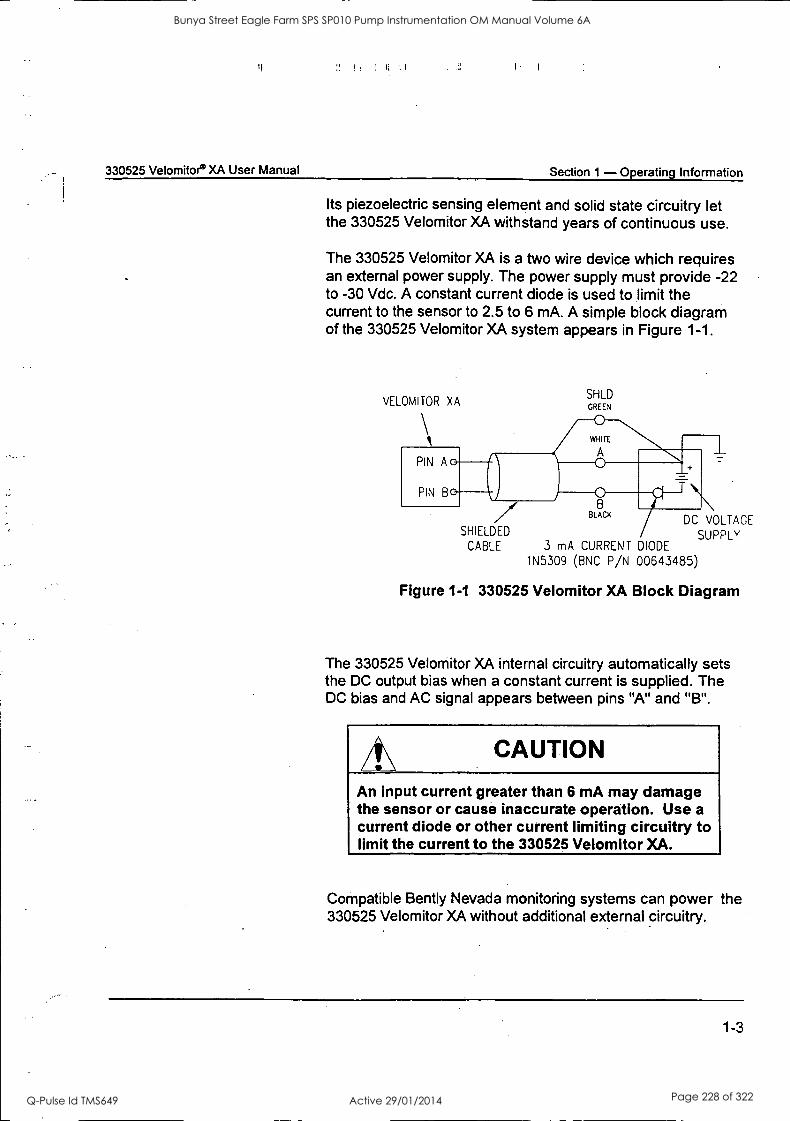
I
330525 Velomitor® XA User Manual Section 1 - Operating Information
Its piezoelectric sensing element and solid state circuitry let the 330525 Velomitor XA withstand years of continuous use.
The 330525 Velomitor XA is a two wire device which requires an external power supply. The power supply must provide -22 to -30 Vdc. A constant current diode is used to limit the current to the sensor to 2.5 to 6 mA. A simple block diagram of the 330525 Velomitor XA system appears in Figure 1-1.
VELOMITOR XA SHLD GREEN
SHIELDED
CABLE
BLACK DC VOLTAGE
SUPPLY 3 mA CURRENT DIODE
1N5309 (BNC P/N 00643485)
Figure 1-1 330525 Velomitor XA Block Diagram
The 330525 Velomitor XA internal circuitry automatically sets the DC output bias when a constant current is supplied. The DC bias and AC signal appears between pins "A" and "B".
CAUTION
An input current greater than 6 mA may damage the sensor or cause inaccurate operation. Use a current diode or other current limiting circuitry to limit the current to the 330525 Velomitor XA.
Compatible Bently Nevada monitoring systems can power the 330525 Velomitor XA without additional external circuitry.
1-3
Bunya Street Eagle Farm SPS SP010 Pump Instrumentation OM Manual Volume 6A
Q-Pulse Id TMS649 Active 29/01/2014 Page 228 of 322
Section 1 - Operating Information 330525 Velomitore XA User Manual
Ordering Options and Accessories
330525 Velomitor XA Options
When ordering a Velomitor XA, you may choose from the following list of options.
A Part Number: 330525 -
A ED Approvals o 0 None Required 01 Pending CSA Approval 0 2 Pending CENELEC Approval 0 3 Pending FM Approval
Agency approvals are currently pending, Consult with your local Bently Nevada sales representative for information regarding approvals status.
1-4
Bunya Street Eagle Farm SPS SP010 Pump Instrumentation OM Manual Volume 6A
Q-Pulse Id TMS649 Active 29/01/2014 Page 229 of 322
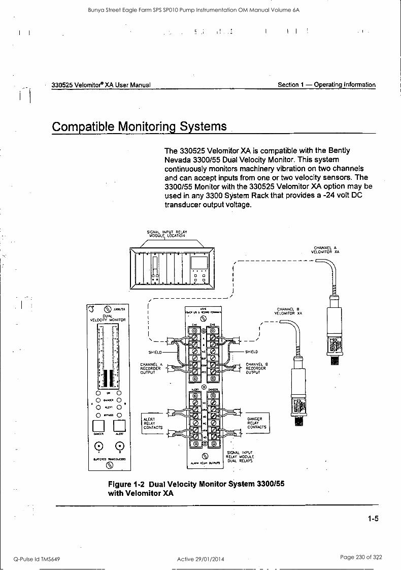
330525 Velomitor® XA User Manual Section 1 - Operating Information
Compatible Monitoring Systems
The 330525 Velomitor XA is compatible with the Bently Nevada 3300/55 Dual Velocity Monitor. This system continuously monitors machinery vibration on two channels and can accept inputs from one or two velocity sensors. The 3300/55 Monitor with the 330525 Velomitor XA option may be used in any 3300 System Rack that provides a -24 volt DC transducer output voltage.
SIGNAL INPUT RELAY MODULE LOCATION
I
88 0 O 0
13' 6) 3.100/55
DUAL VELOCITY MONITOR
1TT 1
. 4
O " O C..* 0
A
O 'LE. 0 O ...S
El DANCER ALM
0 0 IfUreCRCI) TORSO...C(4S
SHIELD
CHANNEL A RECORDER OUTPUT
ALERT RELAY CONTACTS
DAYS
444.71 VO 074044) .1:44Aus
ALERT Dub
ettAY OAITIVIS
SHIELD
CHANNEL 8 RECORDER OUTPUT
DANGER RELAY CONTACTS
SIGNAL INPUT .
RELAY MODULE DUAL RELAYS
CHANNEL B VELOMITOR XA
CHANNEL A VELOMITOR XA
Figure 1-2 Dual Velocity Monitor System 3300/55 with Velomitor XA
1-5
Bunya Street Eagle Farm SPS SP010 Pump Instrumentation OM Manual Volume 6A
Q-Pulse Id TMS649 Active 29/01/2014 Page 230 of 322

Section 1 - Operating Information 330525 Velomitor® XA User Manual
The flexibility of the 3300/55 Dual Velocity Monitor makes it ideally suited for use with piezoelectric velocity sensors. For example, you can adjust the setpoints and filtering to isolate, eliminate, or emphasize specific vibration frequencies. One channel of the monitor can be configured to integrate the other channel to provide velocity and displacement. Also, both channels of the monitor can be integrated in order to provide output in terms of displacement. OK circuitry continuously monitors field wiring and detects open circuits and sensor malfunctions.
The monitor is ready for computer interfacing. No additional hardware is required to enhance the system for computerized data access using Bent ly Nevada standard on-line computerized monitoring hardware and software.
CAUTION
Using Radio Frequency Transmitters near the Velomitor XA may result in the generation of false signals. Avoid using Radio Frequency Transmitters within 3 metres (10 feet) of the Velomitor XA when the transducer output signal is to be integrated.
1-6
Bunya Street Eagle Farm SPS SP010 Pump Instrumentation OM Manual Volume 6A
Q-Pulse Id TMS649 Active 29/01/2014 Page 231 of 322
330525 Velomitor° XA User Manual Section 1 - Operating Information
Interconnect Cable
The 330525 Velomitor XA requires the Bently Nevada splash resistant cable assembly (part number 106765-XX, sold seperately). The assembly is available in three metre increments from one metre to twenty-five metres. The cable conductors are shielded to minimize noise interference. A splash resistant boot protects the connector from moisture and the armor protects the cable.
Connecting Cable and Accessojes Table 1-2
Appplication Part Number Cable Description
Standard Temperature 106765 - AA Flexible stainless steel armored cable. Armored Cable
Bulk Cable 02173007 Two conductor shielded bulk cable. 0.382mm2 (22 AWG). Specify number of metres.
Spare Boot 03839144 Flourosilicone elastomer boot
Spare Boot Clamps 03839142 Bottom clamp 03839143 Top clamp
1-7
Bunya Street Eagle Farm SPS SP010 Pump Instrumentation OM Manual Volume 6A
Q-Pulse Id TMS649 Active 29/01/2014 Page 232 of 322
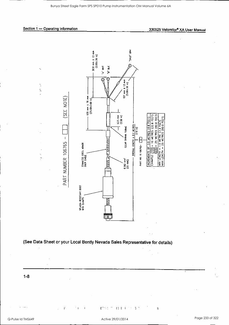
Section 1 - Operating Information 330525 Velomitoe XA User Manual
c) CO CD
IJ
tLi
>c
ea
(See Data Sheet or your Local Bently Nevada Sales Representative for details)
1-8
Bunya Street Eagle Farm SPS SP010 Pump Instrumentation OM Manual Volume 6A
Q-Pulse Id TMS649 Active 29/01/2014 Page 233 of 322
330525 Velornitor. XA Operation Manual Section 2 - Installation
Section 2 - Installation
This section shows how to mount the sensor on a machine and install the field wiring. Secton 1 contains additional information about how to order cables and other installation accessories.
Receiving Inspection
Inspect the components of the order as soon as you receive them to see if there was any damage during shipping. Keep all shipping forms and invoices. If any shipping damage is
apparent, file a claim with the carrier ar.d submit a copy to Bently Nevada Corporation. Include all model numbers and serial numbers with the claim. We will either repair or replace damaged parts according to the terms and conditions of the sale.
The velocity sensor is shipped in a foam filled package and an anti-static bag. The 330525 Velomitor XA is a sensitive instrument and these precautions help to prevent damage during shipping.
Installing the Transducer
This procedure covers the positioning and the mounting of the transducer. Proper placement and mounting of the transducer ensures optimum performance. Consider the steps outlined below when installing the transducer on the machine.
2-1
Bunya Street Eagle Farm SPS SP010 Pump Instrumentation OM Manual Volume 6A
Q-Pulse Id TMS649 Active 29/01/2014 Page 234 of 322
Section 2 - Installation 330525 Velomitor® XA Operation Manual
Positioning the Sensor
Mounting
For optimum performance and accurate measurements, place the Velomitor XA at a position on the machine casing that is most responsive to vibration. Proper placement often depends on the application. Bent ly Nevada offers Machinery Diagnostic Services which can help determine the best place to mount the sensor for your application.
Follow these steps to install the 330535 Velomitor XA:
Step 1- Check that the ambient temperature and the temperature of the installation surface is within the temperature rating of the transducer.
Step 2- Check that the mounting site will be suitable for drilling and tapping a hole for a 1/4 - 18 NPT thread. Consider the hole depth and casing thickness when selecting a mounting site for the transducer.
Step 3- Drill and tap the mounting hole to the dimensions required by the 1/4 - 18 NPT stud. Standard drill size and depth is 7/16 inch and 0.90 inch, respectively. Drill the hole so that the sensitive axis of the transducer will be perpendicular to a tangential plane on the machine casing. For the best results the perpendicularity of the hole should be no more than ± 30 minutes. When handtight, the mounting stud of the transducer will have 2 or 3 threads exposed.
Step 4- Using a crescent or socket wrench, tighten the 330525 Velomitor XA to the mounting site 1/4 to 1/2 turns after handtight engagement. This corresponds to a mounting torque of approximately 400 in-lb.
2-2
Bunya Street Eagle Farm SPS SP010 Pump Instrumentation OM Manual Volume 6A
Q-Pulse Id TMS649 Active 29/01/2014 Page 235 of 322

it _
:I _
330525 Velomitor® XA Operation Manual Section 2 - Installation
Installing Connecting Cable
Installing and Routing Cable
Bent ly Nevada Corporation supplies connecting cables with military-type circular connectors. The cable connector must be compatible with the 330525 Velomitor XA connector. The 106765-AA cable assembly includes a quick connect/disconnect connector and clamps to secure and seal the splash-resistant boot.
The cable assembly comes with the top clamp secured in position and the bottom clamp is looped around the boot. Open the clamps with a small screw driver by prying the teeth of the clamps apart. Slide the boot back to reveal the connector. The cable assembly can now be easily installed on the transducer. Once the connector is engaged, slide the boot down over the connector asssembly and top of the transducer. The groove on the inside bottom of the boot should fit neatly over the lip above the hex flats. The grooves on the outside of the boot at the top and bottom indicate the placement of the clamps. Secure the clamps with pliers. The final assembly is shown below.
Bunya Street Eagle Farm SPS SP010 Pump Instrumentation OM Manual Volume 6A
Q-Pulse Id TMS649 Active 29/01/2014 Page 236 of 322
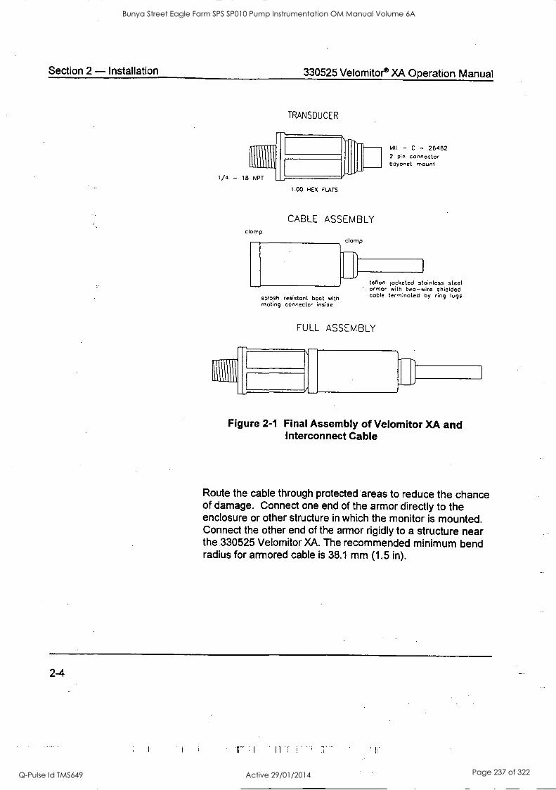
Section 2 - Installation 330525 Velomitor® XA Operation Manual
TRANSDUCER
1.00 HEX FLATS
CABLE ASSEMBLY clamp
splash resistant boot with mating connector inside
clomp
rh
MIL - C - 26482 2 pin connector bayonet mount
teflon jacketed stainless steel armor with two-wire shielded cable terminated by ring lugs
FULL ASSEMBLY
Figure 2-1 Final Assembly of Velomitor XA and Interconnect Cable
Route the cable through protected areas to reduce the chance of damage. Connect one end of the armor directly to the enclosure or other structure in which the monitor is mounted. Connect the other end of the armor rigidly to a structure near the 330525 Velomitor XA. The recommended minimum bend radius for armored cable is 38.1 mm (1.5 in).
2-4
Bunya Street Eagle Farm SPS SP010 Pump Instrumentation OM Manual Volume 6A
Q-Pulse Id TMS649 Active 29/01/2014 Page 237 of 322
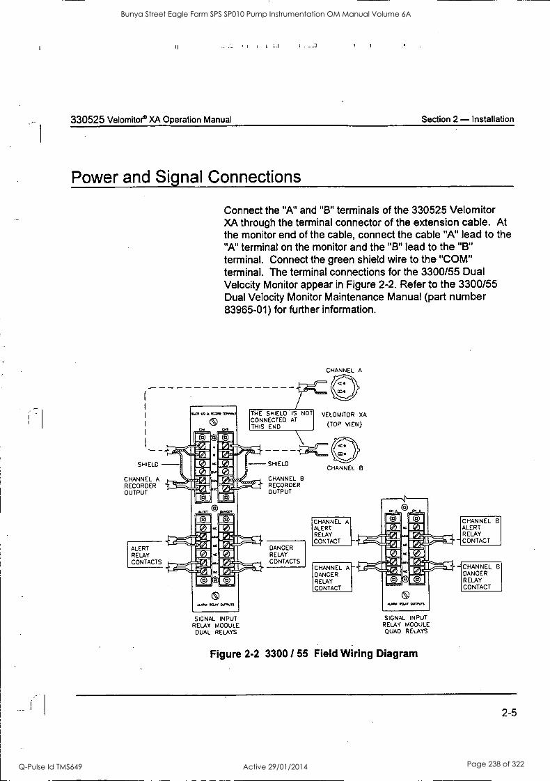
I
330525 Velomitor® XA Operation Manual Section 2 - Installation
Power and Signal Connections
Connect the "A" and "B" terminals of the 330525 Velomitor XA through the terminal connector of the extension cable. At the monitor end of the cable, connect the cable "A" lead to the "A" terminal on the monitor and the "B" lead to the "B" terminal. Connect the green shield wire to the "COM" terminal. The terminal connections for the 3300/55 Dual Velocity Monitor appear in Figure 2-2. Refer to the 3300/55 Dual Velocity Monitor Maintenance Manual (part number 83965-01) for further information.
VO ECG*, it
(S) ot
a:Iota
CHANNEL A
THE SHIELD IS NOT CONNECTED AT THIS END
N 4: . - r Iva SHIELD - CHANNEL A RECORDER OUTPUT
ALERT RELAY CONTACTS
VELOMITOR XA
(TOP VIEW)
- SHIELD ra col 7ri iv, -/ Eel La
VI [e] IL toi r=i-icza
Zot
Ucalorol
AUft. REV, CUM.'',
SIGNAL INPUT RELAY MODULE DUAL RELAYS
CHANNEL B
RECORDER OUTPUT
DANGER RELAY CONTACTS
CHANNEL B
CHANNEL A ALERT RELAY CONTACT
CHANNEL A DANGER RELAY CONTACT
SIGNAL INPUT RELAY MODULE QUAD RELAYS
Figure 2-2 3300 55 Field Wiring Diagram
CHANNEL B
ALERT RELAY CONTACT
CHANNEL B
DANGER RELAY CONTACT
2-5
Bunya Street Eagle Farm SPS SP010 Pump Instrumentation OM Manual Volume 6A
Q-Pulse Id TMS649 Active 29/01/2014 Page 238 of 322

Section 2 - Installation 330525 Velornitor XA Operation Manual
2-6
I I i iT""-1 1:i
Bunya Street Eagle Farm SPS SP010 Pump Instrumentation OM Manual Volume 6A
Q-Pulse Id TMS649 Active 29/01/2014 Page 239 of 322
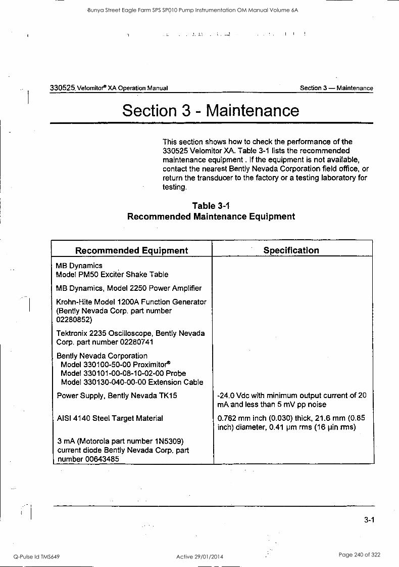
.!.
330525. Velomitor® XA Operation Manual Section 3 - Maintenance
Section 3 - Maintenance
This section shows how to check the performance of the 330525 Velomitor XA. Table 3-1 lists the recommended maintenance equipment . If the equipment is not available, contact the nearest Bently Nevada Corporation field office, or return the transducer to the factory or a testing laboratory for testing.
Table 3-1
Recommended Maintenance Equipment
Recommended Equipment Specification
MB Dynamics Model PM50 Exciter Shake Table
MB Dynamics, Model 2250 Power Amplifier
Krohn-Hite Model 1200A Function Generator (Bent ly Nevada Corp. part number 02280852)
Tektronix 2235 Oscilloscope, Bent ly Nevada Corp. part number 02280741
Bent ly Nevada Corporation Model 330100-50-00 Proximitor Model 330101-00-08-10-02-00 Probe Model 330130-040-00-00 Extension Cable
Power Supply, Bent ly Nevada TK15 -24.0 Vdc with minimum output current of 20 mA and less than 5 mV pp noise
AISI 4140 Steel Target Material 0.762 mm inch (0.030) thick, 21.6 mm (0.85 inch) diameter, 0.41 pm rms (16 pin rms)
3 mA (Motorola part number 1N5309) current diode Bent ly Nevada Corp. part number 00643485
3-1
Bunya Street Eagle Farm SPS SP010 Pump Instrumentation OM Manual Volume 6A
Q-Pulse Id TMS649 Active 29/01/2014 Page 240 of 322
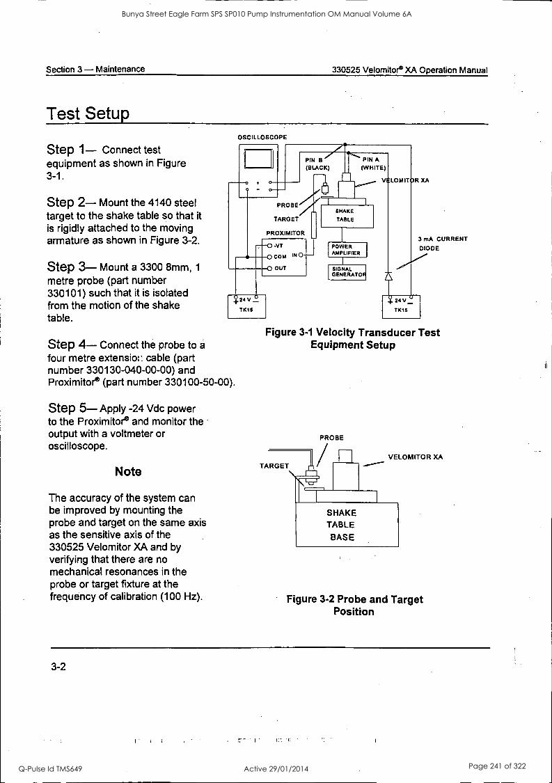
Section 3 - Maintenance 330525 Velomitor® XA Operation Manual
Test Setup
Step 1- Connect test equipment as shown in Figure 3-1.
Step 2- Mount the 4140 steel target to the shake table so that it is rigidly attached to the moving armature as shown in Figure 3-2.
Step 3- Mount a 3300 8mm, 1
metre probe (part number 330101) such that it is isolated from the motion of the shake table.
OSCILLOSCOP
o
-
PIN B 7.1'.....PINHIA (BLACK) (WHITE)
---1 V LOMITOR XA
,,C1 .
PROBE V SHAKE
TARGET TABLE
PROXIMITOR
0 .VT
0 coy! IN 0
0 OUT
+24V V
TK15
Step 4- Connect the probe to a
four metre extension cable (part number 330130-040-00-00) and Proximitore (part number 330100-50-00).
Step 5- Apply -24 Vdc power to the Proximitore and monitor the output with a voltmeter or oscilloscope.
Note
The accuracy of the system can be improved by mounting the probe and target on the same axis as the sensitive axis of the 330525 Velomitor XA and by verifying that there are no mechanical resonances in the probe or target fixture at the frequency of calibration (100 Hz).
POWER AMPLIFIER
SIGNAL GENERATOF
3 mA CURRENT
DIODE
+ 24 V U
TK15
Figure 3-1 Velocity Transducer Test Equipment Setup
PROBE
TARGET VELOMITOR XA
SHAKE TABLE
BASE
Figure 3-2 Probe and Target Position
3-2
Bunya Street Eagle Farm SPS SP010 Pump Instrumentation OM Manual Volume 6A
Q-Pulse Id TMS649 Active 29/01/2014 Page 241 of 322
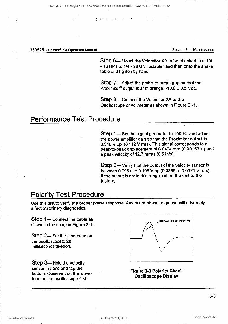
330525 Velomitoe XA Operation Manual Section 3 - Maintenance
Step 6- Mount the Velomitor XA to be checked in a 1/4 - 18 NPT to 1/4 - 28 UNF adapter and then onto the shake table and tighten by hand.
Step 7- Adjust the probe-to-target gap so that the Proximitor® output is at midrange, -10.0 ± 0.5 Vdc.
Step 8- Connect the Velomitor XA to the Oscilloscope or voltmeter as shown in Figure 3 -1.
Performance Test Procedure
Step 1- Set the signal generator to 100 Hz and adjust the power amplifier gain so that the Proximitor output is
0.318 V pp (0.112 V rms). This signal corresponds to a
peak-to-peak displacement of 0.0404 mm (0.00159 in) and a peak velocity of 12.7 mm/s (0.5 in/s).
Step 2- Verify that the output of the velocity sensor is
between 0.095 and 0.105 V pp (0.0336 to 0.0371 V rms). If the output is not in this range, return the unit to the factory.
Polarity Test Procedure Use this test to verify the proper phase response. Any out of phase response will adversely affect machinery diagnostics.
Step 1- Connect the cable as shown in the setup in Figure 3-1.
Step 2- Set the time base on the oscilloscopeto 20 milliseconds/division.
Step 3- Hold the velocity sensor in hand and tap the bottom. Observe that the wave- form on the oscilloscope first
DISPLAY GOES POSITIVE
Figure 3-3 Polarity Check Oscilloscope Display
3-3
Bunya Street Eagle Farm SPS SP010 Pump Instrumentation OM Manual Volume 6A
Q-Pulse Id TMS649 Active 29/01/2014 Page 242 of 322

Section 3 - Maintenance 330525 Velomitor® XA Operation Manual
goes positive as shown in Figure 3-3. If it goes negative first, return the unit to the factory for replacement.
3-4
Bunya Street Eagle Farm SPS SP010 Pump Instrumentation OM Manual Volume 6A
Q-Pulse Id TMS649 Active 29/01/2014 Page 243 of 322
!I
330525 Velomitor® XA Operation Manual Section 4 - Field Testing and Troubleshooting
Section 4 - Field Testing and Troubleshooting
Use the following procedure to test an installed Velomitor XA and isolate a suspected malfunction. The Velomitor XA is a
hermetically sealed unit with no adjustments or field repairable components. If you determine that the Velomitor XA is not functioning properly, contact the nearest Bently Nevada office for assistance.
When the Velomitor XA is used with a Bently Nevada monitoring system, a sensor fault is indicated when the monitor's OK LED goes OFF. A fault may be due to a sensor malfunction or a
malfunction in the field wiring. Before troubleshooting a sus- pected problem, check that the sensor has been correctly installed and that all connections are secured and in the proper locations. If the sensor is properly installed, use the following steps to help identify the problem.
Fault Indication #1 Cause/Solution Bently Nevada Monitor OK LED is off
Monitor Power is off. Check that the monitor power supply is plugged in and power is on.
Interconnect cable is disconnected, connected loosely, or connected to the wrong monitor. Verify that the sensor is connected to the correct monitor and to the correct monitor terminals. Check that the screws are tight.
Interconnect cable is not connected or connection is loose at the Sensor. Verify that the sensor is connected either visually or by discon- necting the interconnect cable from the monitor and measuring the resistance between the two conductors of the interconnect cable. If the resistance is not between 400 kn and 600 kn, the cable or sensor may be damaged.
Sensor open or shorted Disconnect the interconnect cable from the sensor and measure the resistance across sensor terminals "A" and "B". If it is less than 400 kn or greater than 600 kn, replace the sensor.
4-1
Bunya Street Eagle Farm SPS SP010 Pump Instrumentation OM Manual Volume 6A
Q-Pulse Id TMS649 Active 29/01/2014 Page 244 of 322
Section 4 - Field Testing and Troubleshooting 330525 Velomitor4 XA Operation Manual
Interconnect Cable is Damaged: Shorted Visually inspect the interconnect cable for apparent damage. Disconnect the interconnect cable at both ends and measure the resistance between the two conductors, "A" to "B". If intermittent or shorted, replace the cable.
Interconnect Cable is Damaged: Open Disconnect the interconnect cable at both ends. Then short the two conductors together at one end and measure the resistance of the cable at the other end. If open circuited, replace the cable.
Fault Indication #2 Cause/Solution Unusually low vibration with nonmachine-related low-level, broad band noise.
Sensor signal is not isolated, is shorted to the case, or has noise coupled to the signal. Measure the resistance between the "A" terminal and case and "B" terminal and case of the transducer. If the resistance is not 1 Mo or greater, replace the sensor.
Bunya Street Eagle Farm SPS SP010 Pump Instrumentation OM Manual Volume 6A
Q-Pulse Id TMS649 Active 29/01/2014 Page 245 of 322
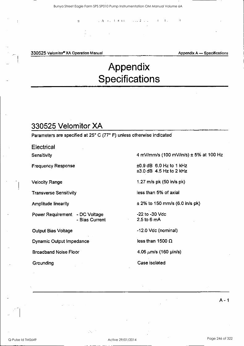
I if
330525 Velomitor° XA Operation Manual Appendix A - Specifications
Appendix Specifications
330525 Velomitor XA Parameters are specified at 25° C (77° F) unless otherwise indicated
Electrical Sensitivity
Frequency Response
Velocity Range
Transverse Sensitivity
Amplitude linearity
Power Requirement - DC Voltage - Bias Current
Output Bias Voltage
Dynamic Output Impedance
Broadband Noise Floor
Grounding
4 mV/mm/s (100 mV/in/s) ± 5% at 100 Hz
±0.9 dB 6.0 Hz to 1 kHz ±3.0 dB 4.5 Hz to 2 kHz
1.27 m/s pk (50 in/s pk)
less than 5% of axial
± 2% to 150 mm/s (6.0 in/s pk)
-22 to -30 Vdc 2.5 to 6 mA
-12.0 Vdc (nominal)
less than 1500 LI
4.06 tn/s (160 pin/s)
Case isolated
A - 1
Bunya Street Eagle Farm SPS SP010 Pump Instrumentation OM Manual Volume 6A
Q-Pulse Id TMS649 Active 29/01/2014 Page 246 of 322

Appendix A - Specifications 330525 Velomitor® XA Operation Manual
Environmental Operating Temperature Range
Shock Limit
Humidity Limit
Mechanical Weight
Diameter
Height
Case Material
Connector
Mounting Torque
Polarity
-55° to 121° C (-67° F to 250° F)
2500 g minimum
100% Relative nonsubmerged, case is hermetically sealed
150 grams (5.3 oz) Typical
28 mm (1.1 in)
71 mm (2.8 in)
316L Stainless Steel
2 pin Mil-C-26482 hermetically sealed, 304 stainless steel shell
45.3 Nrn (400 inlb)
Pin A goes positive with respect to pin B when the transducer case motion is toward the connector.
Note: Operation outside the specified limits will result in false readings or loss of machine monitoring.
A - 2
rr..-; ; :1
Bunya Street Eagle Farm SPS SP010 Pump Instrumentation OM Manual Volume 6A
Q-Pulse Id TMS649 Active 29/01/2014 Page 247 of 322
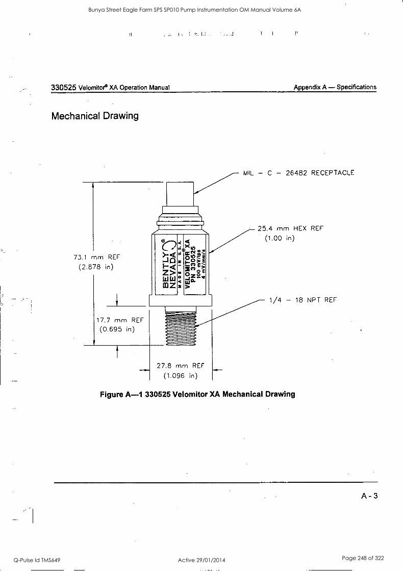
. .!. I = : I!. .
330525 Velomitor° XA Operation Manual Appendix A - Specifications
Mechanical Drawing
MIL - C - 26482 RECEPTACLE
25.4 mm HEX REF
(1.00 in)
73.1 mm REF
(2.878 in)
17.7 mm REF
(0.695 in)
t
27.8 mm REF
(1.096 in)
1/4 - 18 NPT REF
Figure A-1 330525 Velomitor XA Mechanical Drawing
A - 3
Bunya Street Eagle Farm SPS SP010 Pump Instrumentation OM Manual Volume 6A
Q-Pulse Id TMS649 Active 29/01/2014 Page 248 of 322
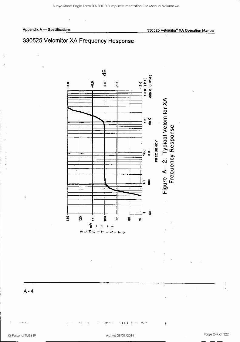
Appendix A - Specifications 330525 Velomitor® XA Operation Manual
330525 Velomitor XA Frequency Response
O co)
0 0 O
0 O 9
N 0 X
0
0 0 CNI
o o o
E
0 Of
o co 0
A -4
Bunya Street Eagle Farm SPS SP010 Pump Instrumentation OM Manual Volume 6A
Q-Pulse Id TMS649 Active 29/01/2014 Page 249 of 322
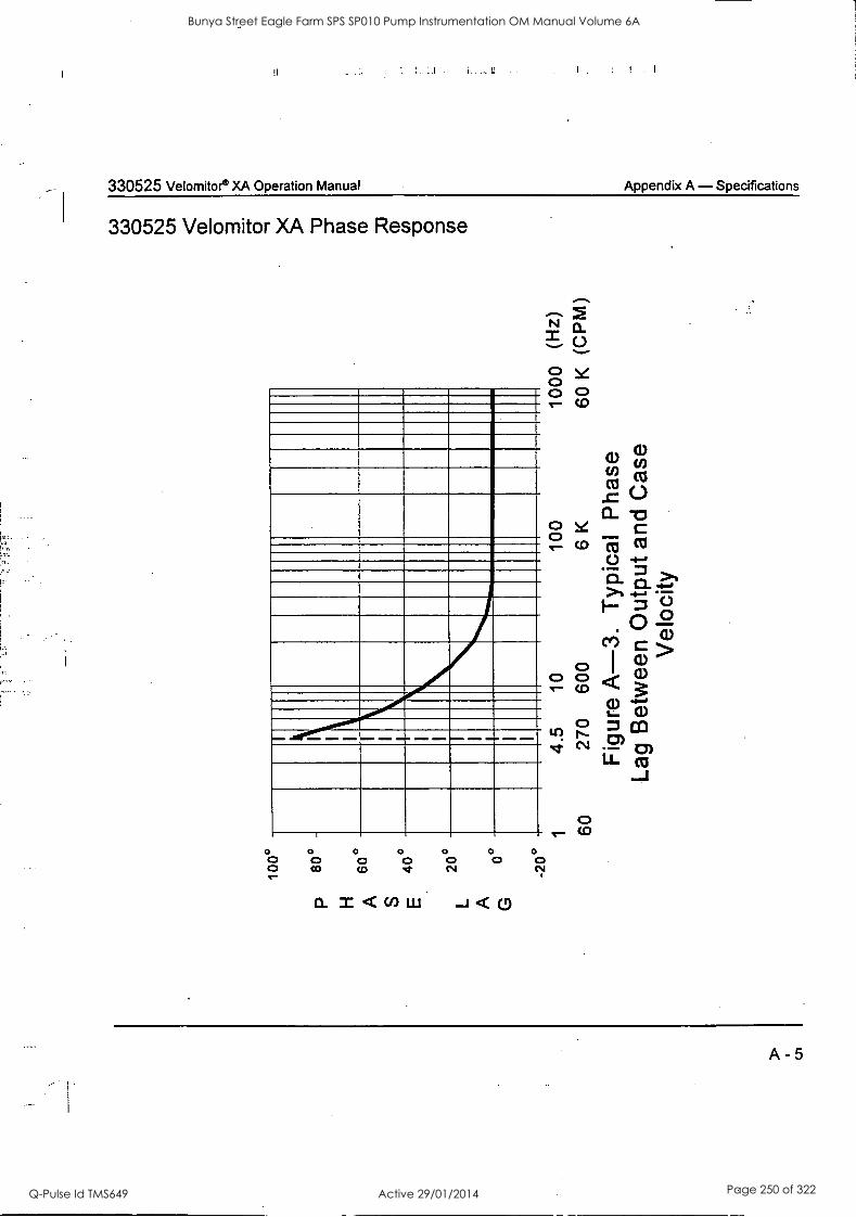
330525 Velomitor® XA Operation Manual Appendix A - Specifications
330525 Velomitor XA Phase Response
Milleil...°°61.11.1.°°°11111111.111°.1110MMINI1 11=1111M141 11
O 0 0 O 0 O 0 0 o o 0 0 0 CO CO CI
O 0
N./."*.
2
0 0 0 0 e- Co
0 CD
A - 5
Bunya Street Eagle Farm SPS SP010 Pump Instrumentation OM Manual Volume 6A
Q-Pulse Id TMS649 Active 29/01/2014 Page 250 of 322
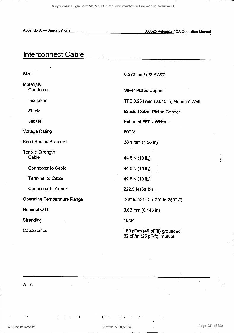
Appendix A - Specifications 330525 Velomitore XA Operation Manual
Interconnect Cable
Size 0.382 mm2 (22 AWG)
Materials Conductor Silver Plated Copper
Insulation TFE 0.254 mm (0.010 in) Nominal Wall
Shield Braided Silver Plated Copper
Jacket Extruded FEP - White
Voltage Rating 600 V
Bend Radius-Armored 38.1 mm (1.50 in)
Tensile Strength Cable 44.5 N (10 lb)
Connector to Cable 44.5 N (10 lbf)
Terminal to Cable 44.5 N (10 lb?)
Connector to Armor .222.5 N (50 llar)
Operating Temperature Range -29° to 121° C (-20° to 250° F)
Nominal O.D. 3.63 mm (0.143 in)
Stranding 19/34
Capacitance 150 pF/m (45 pF/ft) grounded 82 pF/m (25 pF/ft) mutual
A - 6
Bunya Street Eagle Farm SPS SP010 Pump Instrumentation OM Manual Volume 6A
Q-Pulse Id TMS649 Active 29/01/2014 Page 251 of 322
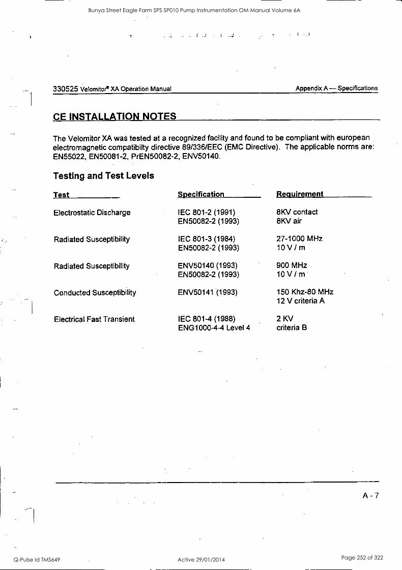
330525 Velomitor XA Operation Manual Appendix A - Specifications
CE INSTALLATION NOTES
The Velomitor XA was tested at a recognized facility and found to be compliant with european electromagnetic compatibilty directive 89/336/EEC (EMC Directive). The applicable norms are: EN55022, EN50081-2, PrEN50082-2, ENV50140.
Testing and Test Levels
Test
Electrostatic Discharge
Radiated Susceptibility
Radiated Susceptibility
Conducted Susceptibility
Electrical Fast Transient
Specification Requirement
IEC 801-2 (1991) EN50082-2 (1993)
IEC 801-3 (1984) EN50082-2 (1993)
ENV50140 (1993) EN50082-2 (1993)
ENV50141 (1993)
IEC 801-4 (1988) ENG1000-4-4 Level 4
8KV contact 8KV air
27-1000 MHz 10 V/m
900 MHz 10 V / m
150 Khz-80 MHz 12 V criteria A
2 KV criteria B
Bunya Street Eagle Farm SPS SP010 Pump Instrumentation OM Manual Volume 6A
Q-Pulse Id TMS649 Active 29/01/2014 Page 252 of 322
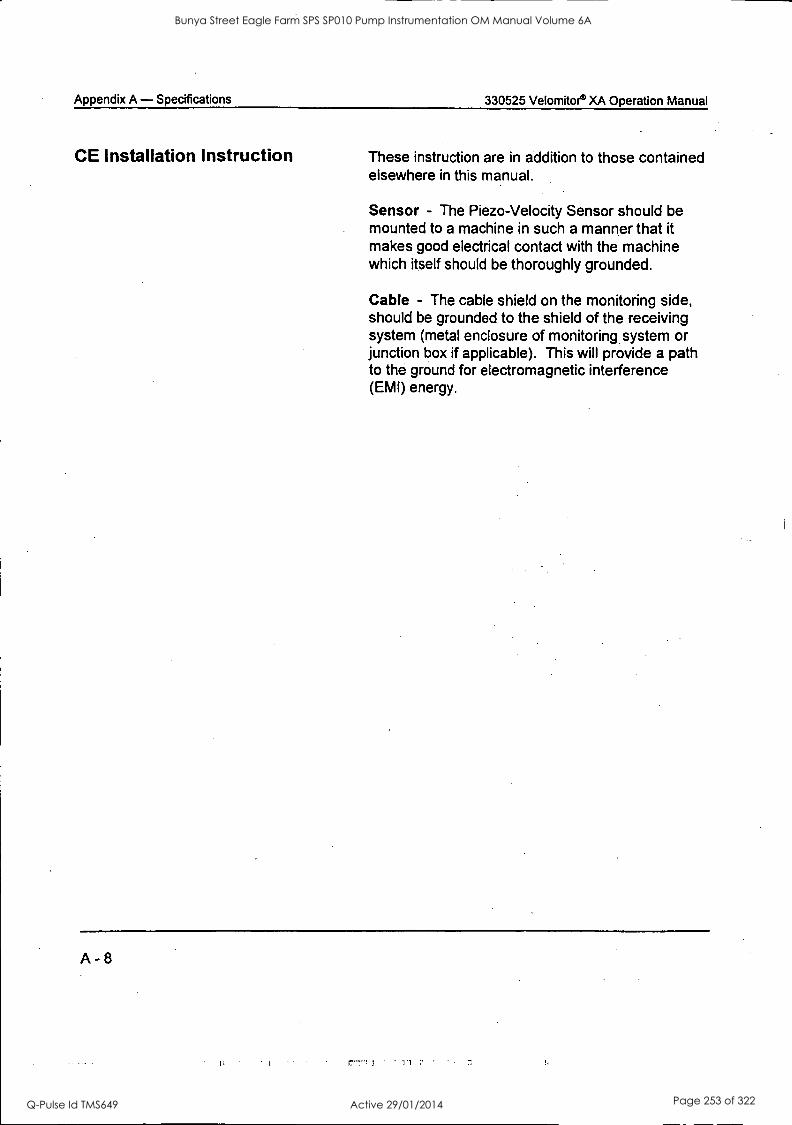
Appendix A - Specifications 330525 Velomitoe XA Operation Manual
CE Installation Instruction These instruction are in addition to those contained elsewhere in this manual.
Sensor - The Piezo-Velocity Sensor should be mounted to a machine in such a manner that it makes good electrical contact with the machine which itself should be thoroughly grounded.
Cable - The cable shield on the monitoring side, should be grounded to the shield of the receiving system (metal enclosure of monitoring. system or junction box if applicable). This will provide a path to the ground for electromagnetic interference (EMI) energy.
Bunya Street Eagle Farm SPS SP010 Pump Instrumentation OM Manual Volume 6A
Q-Pulse Id TMS649 Active 29/01/2014 Page 253 of 322

BRISBANE CITY COUNCIL Dept. Water Supply and Sewage Pumpwell No 1, Eagle Farm Pump Station
BCC Contract No S20195196 System Instrumentation
Operation and Maintenance Manual
2.9 3300 - 8 mm Proximity Transducer System
The following publication entitled 3300 8mm Proximity Transducer Manual (Part No 86130-01 Rev R) is prepared by Bent ly Nevada for plant personnel who operate and maintain the system. It provides a detailed description of the Proximity Transducer, application notes, installation details, maintenance procedures, and a guide to field- testing.
The following sections are included:
2.9.1 Operating Information
2.9.2 Installation
2.9.3 Maintenance and Troilble Shooting
2.9.4 Specifications
15140/Inst Man/BRH Issue 1 29-Apr-98 Page 2-12
Bunya Street Eagle Farm SPS SP010 Pump Instrumentation OM Manual Volume 6A
Q-Pulse Id TMS649 Active 29/01/2014 Page 254 of 322
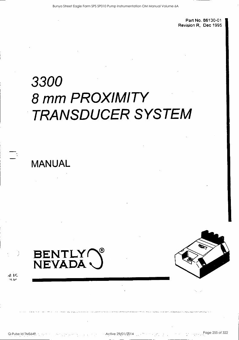
Part No. 86130-01 Revision R, Dec 1995
3300 8 mm PROXIMITY TRANSDUCER SYSTEM
MANUAL
) BENTLY NEVADA rn)
I/C '11 M
Bunya Street Eagle Farm SPS SP010 Pump Instrumentation OM Manual Volume 6A
Q-Pulse Id TMS649 Active 29/01/2014 Page 255 of 322
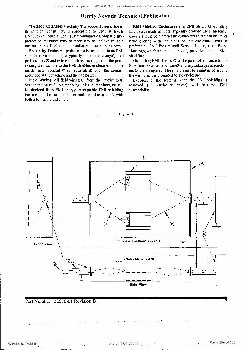
Bent ly Nevada Technical Publication
The 3300 REBAM® Proximity Transducer System, due to
its inherent sensitivity, is susceptible to EMI at levels EN50082-2. Special EMC (Electromagnetic Compatibility) protection measures may be necessary to achieve reliable measurements. Each unique installation must be considered.
Proximity Probes All probes must be mounted in an EMI shielded environment (i.e.typically a machine casing0). All probe cables 0 and extension cables, running from the point exiting the machine to the EMI shielded enclosure, must be
inside metal conduit 0 (or equivalent) with the conduit grounded at the machine and the enclosure.
Field Wiring All field wiring 0, from the Proximitor® Sensor enclosure ® to a receiving unit (i.e. monitor), must be shielded from EMI energy. Acceptable EMI shielding includes solid metal conduit or multi-conductor cable with both a foil and braid shield.
Front View
EMI Shielded Enclosures and EMI Shield Grounding Enclosures made of metal typically provide EMI shielding. Covers should be electrically connected to the enclosure or have overlap with the sides of the enclosure, both is
preferable. BNC Proximitor® Sensor Housings and Probe
Housings, which are made of metal, provide adequate EMI shielding.
Grounding EMI shields ® at the point of entrance to the
Proximitor® sensor enclosure® and any subsequent junction enclosure is required. The shield must be maintained around
the wiring as it is grounded to the enclosure. Exposure of the systems when the EMI shielding is
removed (i.e. enclosure cover) will increase EMI susceptibility.
Figure 1
Top View 1 without cover
ENCLOSURE COVER
--- -- ::=
Side View
Part Number 132556-01 Revision B 2
Bunya Street Eagle Farm SPS SP010 Pump Instrumentation OM Manual Volume 6A
Q-Pulse Id TMS649 Active 29/01/2014 Page 256 of 322
3300 8 mm Transducer Operation Manual
Contents
Related Documents iv
System Description System Overview 1
Receiving, Inspecting, and Handling the System 1
Customer Service 1
Installation General Overview 2
Installing the Probe 2
Installing and Proximitor Sensor 3
Routing the Extension Cable and Field Wiring 4
Maintenance and Troubleshooting General Overview 5
Scale Factor Verification 6
Adjustment Procedure 7
Troubleshooting 10
Specifications System 18
Proximtior Sensor 19
Probe 20
Cable 21
Bunya Street Eagle Farm SPS SP010 Pump Instrumentation OM Manual Volume 6A
Q-Pulse Id TMS649 Active 29/01/2014 Page 257 of 322
3300 8 mm Transducer Operation Manual
Related Documents The following documents contain additional information that you may find helpful when
you install the transducer. This manual refers to these documents by number.
Note: Bent ly Nevada application notes and document numbers are listed in ( ).
Installing the Transducer 1 Proximitor Probes and Related Accessories (AN028)
2 Guidelines for Grounding Bent ly Rotating Machinery Information Systems (AN013)
3 Instaltion of Electrical Equipment in Hazardous Ares (AN015)
Transducer Installation Accessories 4 3100/3200 Proximity Probe Housing Manual (124200-01)
Electrical and Mechanical Runout 5 "Glitch": Definition of and Methods for Correction, including Shaft Burnishing to
Remove Electrical Runout. (AN002)
C API 670, third edition, Section 4.1.2: Machine Shaft Requirements for Electrical
and Mechanical runout. Available from the American Petroleum Institute,
Publications and Distribution, 1220 L Street N.W., Washington D.C., 20005.
Phone: (202) 682-8375.
Reference 7 Performance Specifications for the 3300 8 mm Transducer System (155687).
8 Bent ly Nevada Glossary (L1014).
9 European CE mark of Bent ly Nevada Proximity Transducer System (AN072)
iv
Bunya Street Eagle Farm SPS SP010 Pump Instrumentation OM Manual Volume 6A
Q-Pulse Id TMS649 Active 29/01/2014 Page 258 of 322
3300 8mm Transducer System System Description
System Description The 3300 Series 8mm Proximity Transducer System measures machine vibration and the position of a shaft or other part of a machine in relation to the location of the probe tip. The system consists of a probe, an extension cable, and a Proximitore
The components'of the 3300 8mm Transducer System are designed to work as a
single unit and are calibrated for a target material that is AISI 4140 steel. The system
measures displacement by using the eddy current principle and provides a negative voltage proportional to the distance between the target and the probe tip. This voltage signal may be applied to a monitor, portable instrumentation, or diagnostic equipment.
Application Notice The 3300 8mm Proximity transducer is designed for measuring position or vibration within a frequency range from 0 to 10 kHz. Typical applications of the
system include radial vibration and position, axial position, and Keyphasore measurements.
CAUTION
Although the terminals and connector on the Proximitor have protection against electrostatic discharge, take reasonable precautions to avoid electrostatic discharge when handling the Proximitor.
Receiving, Inspecting, and Handling the System The probe, extension cable, and Proximitor are shipped as separate units and must be
interconnected at the installation site by the user. Carefully remove all equipment from
the shipping containers and inspect the equipment for shipping damage. If shipping
damage is apparent, file a claim with the carrier and submit a copy to the nearest
Bently Nevada office. Include part numbers and serial numbers on all correspondence.
If no damage is apparent and the equipment is not going to be used immediately,
return the equipment to the shipping containers and reseal until ready for use.
Store the equipment in an environment free from potentially damaging conditions such
as high temperature or a corrosive atmosphere. See Specifications, pages 19, 20, and
21, for environmental specifications.
Customer Service Bently Nevada provides product service throughout the world. If you cannot contact
your local product service representative, call the Bently Nevada corporate
headquarters: 800-227-5514 Monday through Friday, 8:00 a.m. to 5:00 p.m. Pacific time
702-782-3611 Any time
Bunya Street Eagle Farm SPS SP010 Pump Instrumentation OM Manual Volume 6A
Q-Pulse Id TMS649 Active 29/01/2014 Page 259 of 322
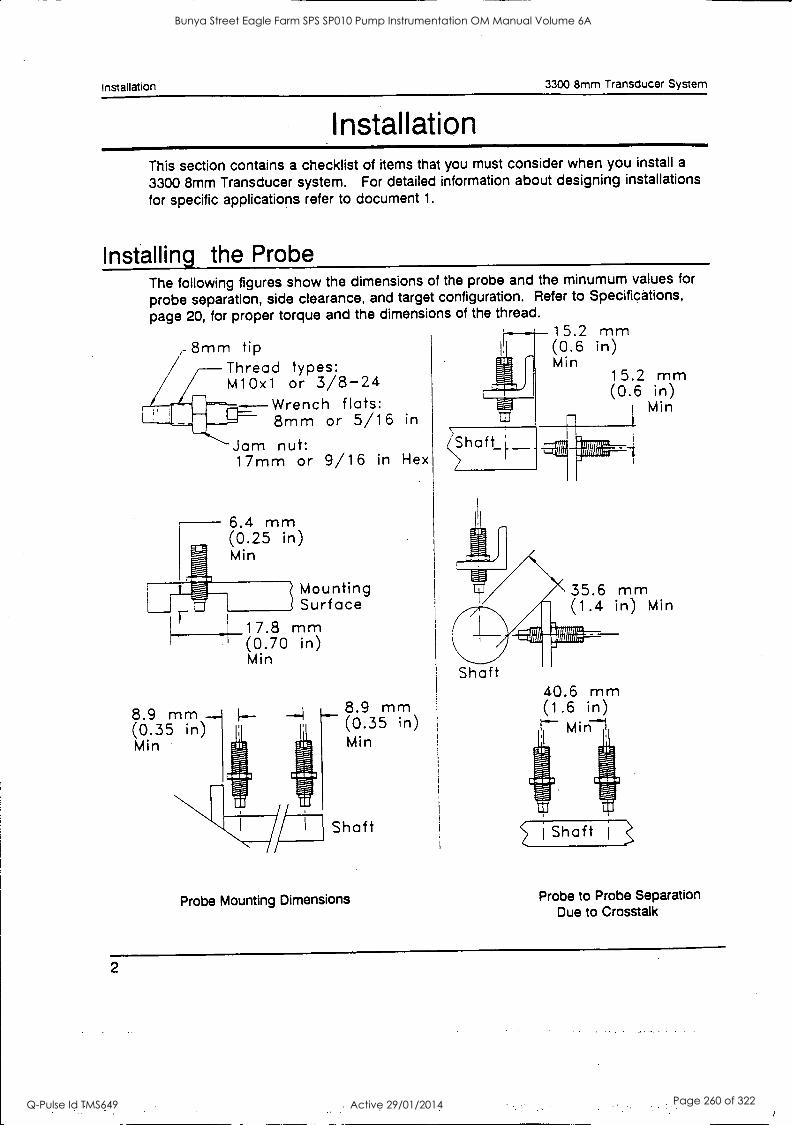
Installation 3300 8mm Transducer System
Installation This section contains a checklist of items that you must consider when you install a
3300 8mm Transducer system. For detailed information about designing installations
for specific applications refer to document 1.
Installing the Probe The following figures show the dimensions of the probe and the minumum values for
probe separation, side clearance, and target configuration. Refer to Specifications,
page 20, for proper torque and the dimensions of the thread.
8mm tip Thread types: M10x1 or 3/8-24
Wrench flats: 8mm or 5/16 in
Jam nut: 17mm or 9/16 in Hex
6.4 mm (0.25 in) Min
8.9 mm - (0.35 in) Min
Mounting Surface
17.8 mm (0.70 in) Min
8.9 mm - (0.35 in Min
Shaft
Probe Mounting Dimensions
15.2 mm (0.6 in) Min
15.2 mm (0.6 in)
Min
35.6 mm (1.4 in) Min
Shaft 40.6 mm (1.6 in)
Min-1
ii j Shaft
Probe to Probe Separation Due to Crosstalk
Bunya Street Eagle Farm SPS SP010 Pump Instrumentation OM Manual Volume 6A
Q-Pulse Id TMS649 Active 29/01/2014 Page 260 of 322
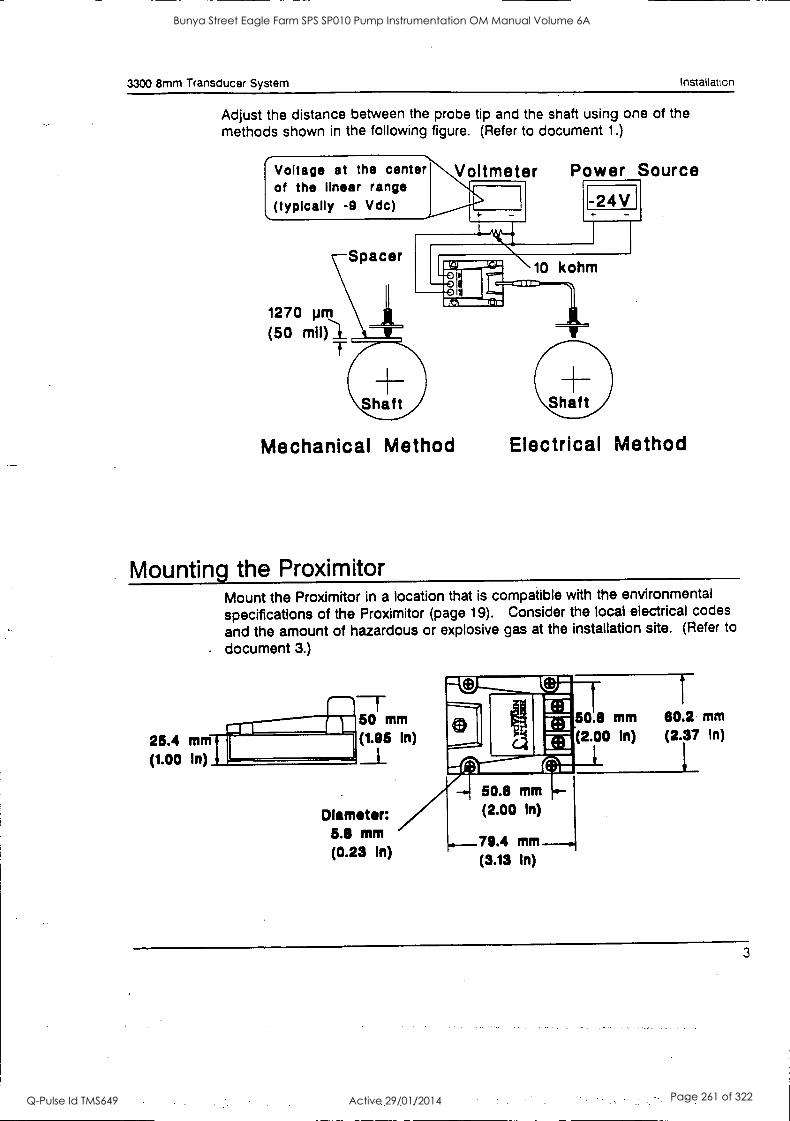
3300 8mm Transducer System Instal let=
Adjust the distance between the probe tip and the shaft using one of the methods shown in the following figure. (Refer to document 1.)
Voltage at the center of the linear range (typically -9 Vdc)
1270 pm
(50 miol
Spacer
War 1"7--11 u kohm
1 .11
Power Source
-24V
Shaft
Mechanical Method Electrical Method
Mounting the Proximitor Mount the Proximitor in a location that is compatible with the environmental
specifications of the Proximitor (page 19). Consider the local electrical codes
and the amount of hazardous or explosive gas at the installation site. (Refer to
document 3.)
25.4 mm rff (1.00 In)
f--1- 50 mm 50.8 mm 80.2 mm
(1.95 In) (2.00 In) (2.37 In)
Diameter: 5.8 mm (0.23 In)
50.8 mm
(2.00 In)
79.4 mm
(9.19 In)
3
Bunya Street Eagle Farm SPS SP010 Pump Instrumentation OM Manual Volume 6A
Q-Pulse Id TMS649 Active 29/01/2014 Page 261 of 322
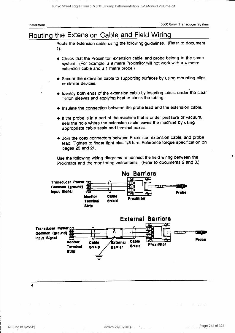
Installation 3300 8mm Transducer System
Routing the Extension Cable and Field Wiring Route the extension cable using the following guidelines. (Refer to document
) 1
Check that the Proximitor, extension cable, and probe belong to the same system. (For example, a 9 metre Proximitor will not work with a 4 metre
extension cable and a 1 metre probe.)
Secure the extension cable to supporting surfaces by using mounting clips or similar devices.
Identify both ends of the extension cable by inserting labels under the clear Teflon sleeves and applying heat to shrink the tubing.
Insulate the connection between the probe lead and the extension cable.
If the probe is in a part of the machine that is under pressure or vacuum, seal the hole where the extension cable leaves the machine by using appropriate cable seals and terminal boxes.
Join the coax connectors between Proximitor, extension cable, and probe lead. Tighten to finger tight plus 1/8 turn. Reference torque specification on
cages 20 and 21.
Use the following wiring diagrams to connect the field wiring between the
Proximitor and the monitoring instruments. (Refer to documents 2 and 3.)
Transducer Power Common (ground) Input Signal
Illordtor Terminal Strip
Transducer Power Common (ground) Input Signal
No Barriers
Cable Shield
Proximitor
External Barriers ri r
Probe
Monitor cow ternal Cable Terminal Meld Barrier Shield
Strip
Proximhor
an. Probe
4
Bunya Street Eagle Farm SPS SP010 Pump Instrumentation OM Manual Volume 6A
Q-Pulse Id TMS649 Active 29/01/2014 Page 262 of 322
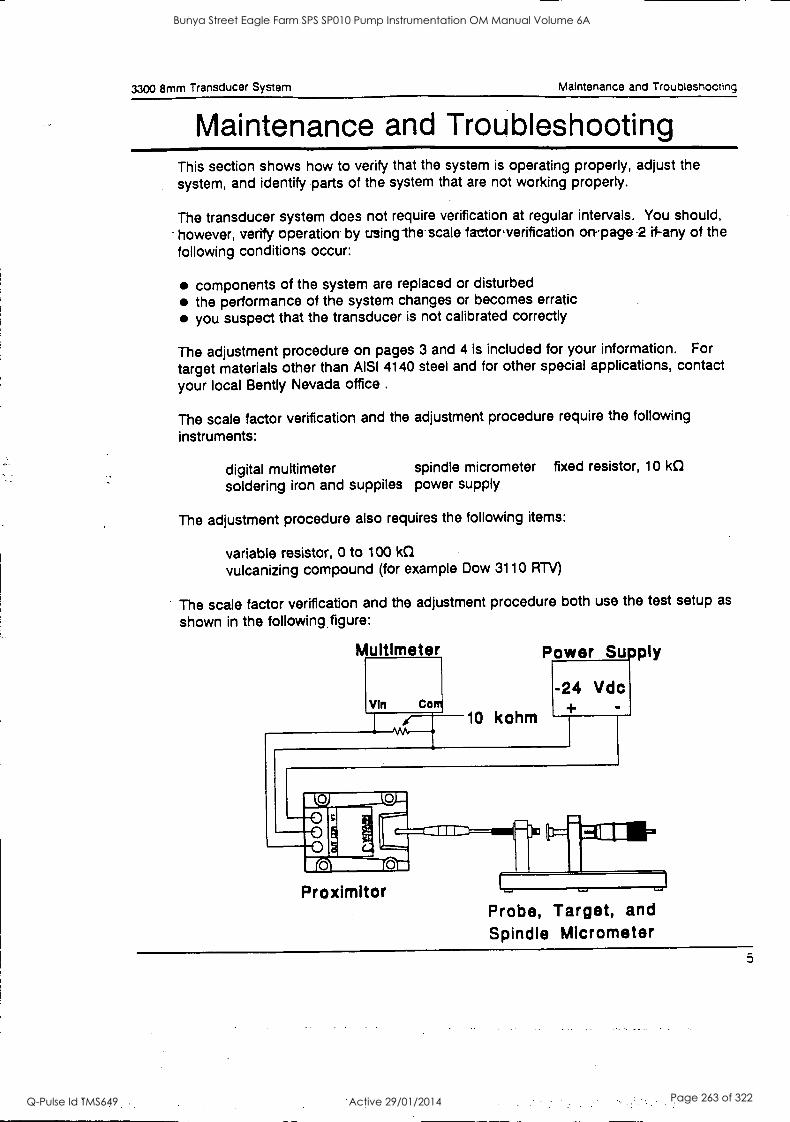
3300 8mm Transducer System Maintenance and Troubleshooting
Maintenance and Troubleshooting This section shows how to verify that the system is operating properly, adjust the system, and identify parts of the system that are not working properly.
The transducer system does not require verification at regular intervals. You should, - however, verify operation by using-the.scale factor.verification on-page -2 if-any of the
following conditions occur:
components of the system are replaced or disturbed the performance of the system changes or becomes erratic you suspect that the transducer is not calibrated correctly
The adjustment procedure on pages 3 and 4 is included for your information. For
target materials other than AISI 4140 steel and for other special applications, contact
your local Bently Nevada office .
The scale factor verification and the adjustment procedure require the following
instruments:
digital multimeter spindle micrometer fixed resistor, 10 kII soldering iron and suppiles power supply
The adjustment procedure also requires the following items:
variable resistor, 0 to 100 kC1
vulcanizing compound (for example Dow 3110 RTV)
The scale factor verification and the adjustment procedure both use the test setup as
shown in the following figure:
Multimeter
VIn Com
r 10 kohm
Power Sulply
-24 Vdc
Proximitor Probe, Target, and Spindle Micrometer
5
Bunya Street Eagle Farm SPS SP010 Pump Instrumentation OM Manual Volume 6A
Q-Pulse Id TMS649 Active 29/01/2014 Page 263 of 322
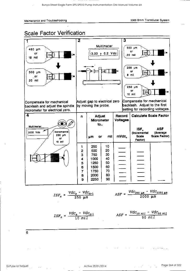
Maintenance and Troubleshooting 3300 8mm Transducer System
Scale Factor Verification
( i
460 pm
I or 18 mil
Multimeter :1
=3.00 + 0.2 Vdci
( 500 pm
Or
.,20 mil
200 pm
Or
8 mll 500 pm
Or
20 mil
(-250 pm
or 10 mil
Compensate for mechanical Adjust gap to electrical zero Compensate for mechanical
backlash and adjust the spindle by moving the probe. backlash. Adjust to the first
micrometer for electrical zero. setting for recording voltages.
4 n Adjust Micrometer
to..
or mil
Record Voltages
mVdc,,
Calculate Scale Factor
ISF ASF (Incremental (Average
Scale Scale Factor) Factor)
1
2 3 4 5 6 7 8 9
250 500 750
1000 1250 1500 1750 2000 2250
10 20 30 40 50 60 70 80 90
VdC, - VdCn_i
ISFn =
250 gm
ISFnVdCn - VdCn_t -
10 ifi11
ASF - 2000 gm
VdC2 5 0 - VdC2 2 5 0
ASF - Vdc 10 rail - Vdc 90 mil
80 mil
6
Bunya Street Eagle Farm SPS SP010 Pump Instrumentation OM Manual Volume 6A
Q-Pulse Id TMS649 Active 29/01/2014 Page 264 of 322
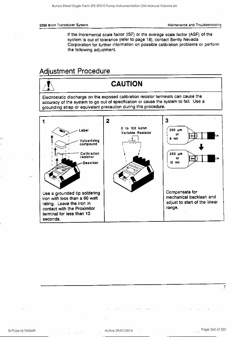
3300 8mm Transducer System Maintenance and Troubleshooting
If the incremental scale factor (ISF) or the average scale factor (ASF) of the system is out of tolerance (refer to page 18), contact Bently Nevada Corporation for further information on possible calibration problems or perform the following adjustment.
Adjustment Procedure
CAUTION
Electrostatic discharge on the exposed calibration resistor terminals can cause the
accuracy of the system to go out of specification or cause the system to fail. Use a
grounding strap or equivalent precaution during this procedure.
1
4411160,,_,--- Label
--1 !-- cVounilcpaonulznigg
ri---- Calibration resistor
2 0 to 100 kohm Variable Resistor n
3 1.
200 pm
Or
8 mil
/ i
i
250 pm Or
42411S- 4.6. - Desolder
jo.f4 .&,11
- -
10 mil
Use a grounded tip soldering Compensate for
iron with less than a 60 watt mechanical backlash and
rating. Leave the iron in adjust to start of the linear
contact with the Proximitor range.
terminal for less than 10 seconds.
7
Bunya Street Eagle Farm SPS SP010 Pump Instrumentation OM Manual Volume 6A
Q-Pulse Id TMS649 Active 29/01/2014 Page 265 of 322
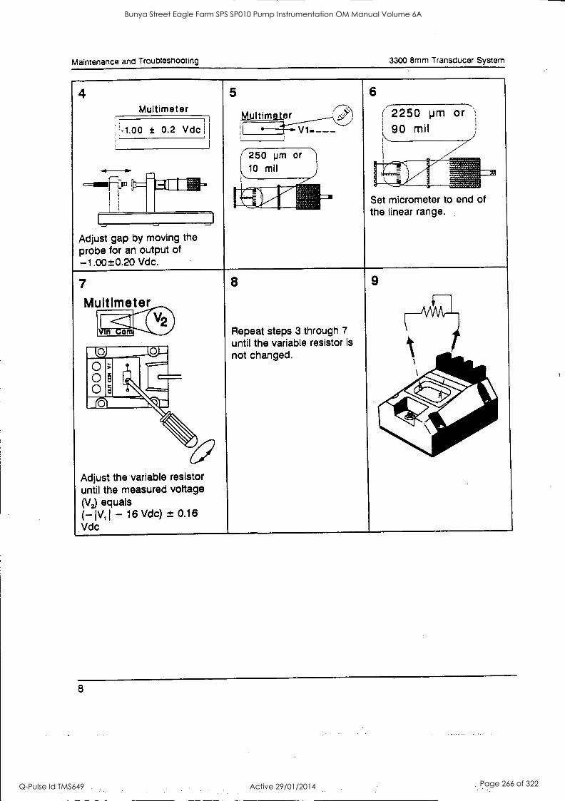
Maintenance and Troubleshooting 3300 8mm Transducer System
4 Multimeter
5 7-1=;\ Multimet)
6
( 2250 pm or ',,
190 mil H1.00 ± 0.2 Vdc ------ - :I V1-___ i I
I -. - 250 pm or 10 Mil
ruin 1111 IC Iii` - ..,
r rd.-- Set micrometer to end of the linear range.
Adjust gap by moving the probe for an output of -1.00±0.20 Vdc.
7
Multimeter
8
Repeat steps 3 through 7
until the variable resistor is
not changed.
9
ale 11.0 0 8 Ircii-.\
__C111
ACI
Adjust the variable resistor until the measured voltage (V2) equals (-1V11 - 16 Vdc) ± 0.16 Vdc
8
Bunya Street Eagle Farm SPS SP010 Pump Instrumentation OM Manual Volume 6A
Q-Pulse Id TMS649 Active 29/01/2014 Page 266 of 322
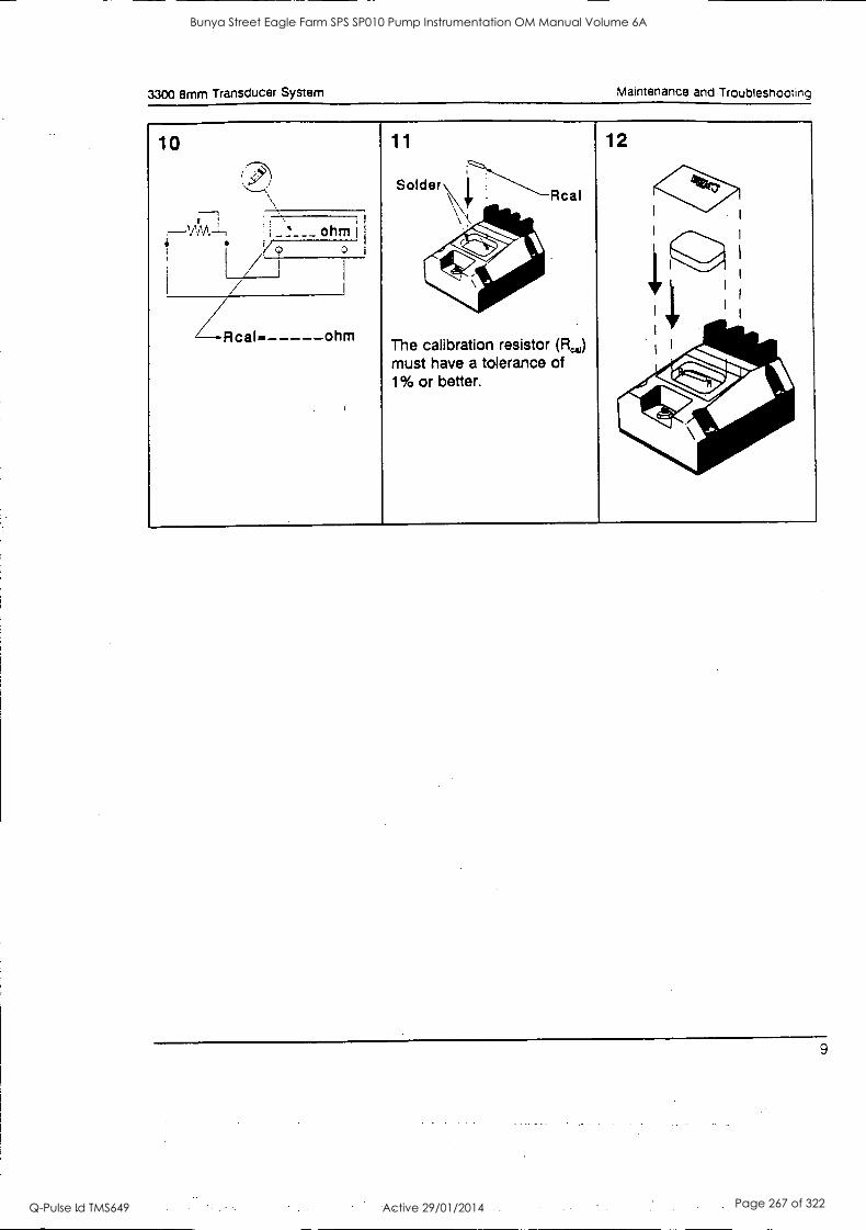
3300 8mm Transducer System Maintenance and Troubleshooting
10
---7 I ,
WA ---,
11
Solder
The calibration must have 1% or better.
Rcal
resistor (FL) a tolerance of
12
I
1
I
I
- ., ---
4600.
I
I
I
I
I
b4%0
;1: ...401ftilkip. ,4%.
ohm I
I
[ TI I
I / / ---Rcal. ohm
9
Bunya Street Eagle Farm SPS SP010 Pump Instrumentation OM Manual Volume 6A
Q-Pulse Id TMS649 Active 29/01/2014 Page 267 of 322
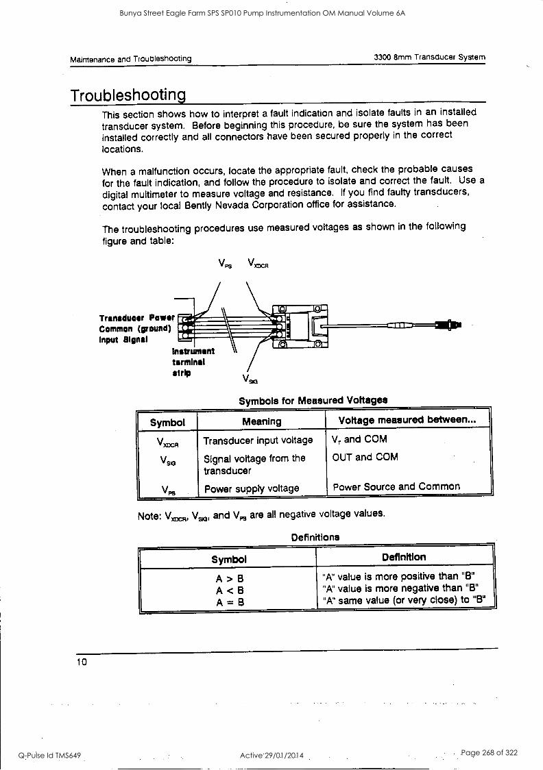
Maintenance and Troubleshooting 3300 8mm Transducer System
Troubleshooting This section shows how to interpret a fault indication and isolate faults in an installed
transducer system. Before beginning this procedure, be sure the system has been
installed correctly and all connectors have been secured properly in the correct
locations.
When a malfunction occurs, locate the appropriate fault, check the probable causes
for the fault indication, and follow the procedure to isolate and correct the fault. Use a
digital multimeter to measure voltage and resistance. If you find faulty transducers,
contact your local Bently Nevada Corporation office for assistance.
The troubleshooting procedures use measured voltages as shown in the following
figure and table:
VPs V R
Transducer Power Common (ground) Input Signal
Instrument terminal strip
VsK3
Symbols for Measured Voltages
Symbol Meaning Voltage measured between...
VxD6R
VsK3
VPs
Transducer input voltage
Signal voltage from the transducer
Power supply voltage
VT and COM
OUT and COM
Power Source and Common
Note: VwR, VsK3, and VPs are all negative voltage values.
Definitions
Symbol Definition
A > B
A < B
A = B
"A" value is more positive than "B"
"A" value is more negative than "B"
"A" same value (or very close) to "B"
10
Bunya Street Eagle Farm SPS SP010 Pump Instrumentation OM Manual Volume 6A
Q-Pulse Id TMS649 Active 29/01/2014 Page 268 of 322
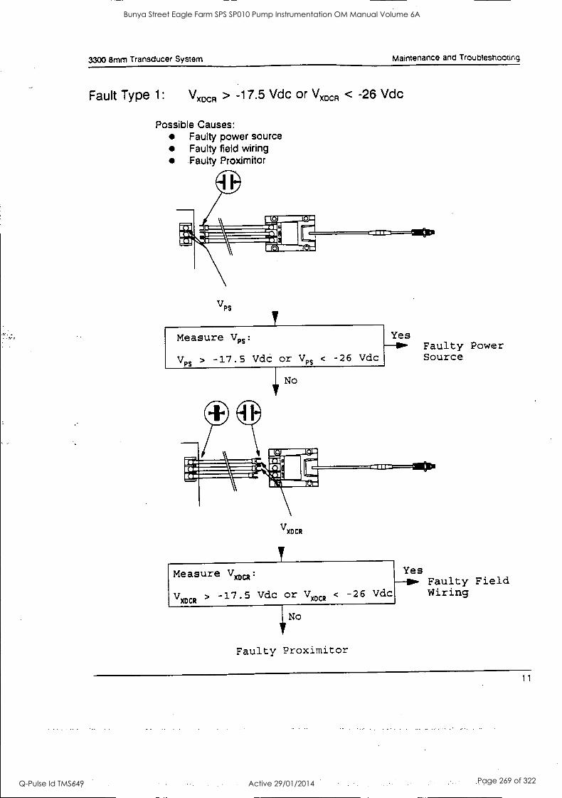
3300 8mm Transducer System Maintenance and Troubleshooting
Fault Type 1: Vxocil > -17.5 Vdc or Vx0cR < -26 Vdc
Possible Causes: Faulty power source Faulty field wiring Faulty Proximitor
VPS
Measure Vn: Yes
V PS
> -17.5 Vdc or V PS < -26 Vdc Source
Faulty Power
No
VXDCR
V CR
-17.5 Vdc or V )(O XOCR
< -26 Vdc Wiring
Yes Faulty Field
Measure Van :
117 No
Faulty Proximitor
11
Bunya Street Eagle Farm SPS SP010 Pump Instrumentation OM Manual Volume 6A
Q-Pulse Id TMS649 Active 29/01/2014 Page 269 of 322
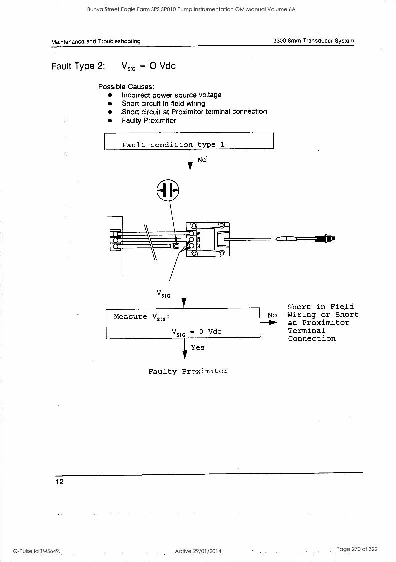
Maintenance and Troubleshooting 3300 8mm Transducer System
Fault Type 2: Vs* = 0 Vdc
Possible Causes: Incorrect power source voltage Short circuit in field wiring .Shod.circuit at Proximitor terminal connection Faulty Proximitor
Fault condition type 1
V SIG
Measure V stv
V SIG
= 0 Vdc
Tir Yes
Faulty Proximitor
Short in Field No Wiring or Short 101. at Proximitor
Terminal Connection
12
Bunya Street Eagle Farm SPS SP010 Pump Instrumentation OM Manual Volume 6A
Q-Pulse Id TMS649 Active 29/01/2014 Page 270 of 322
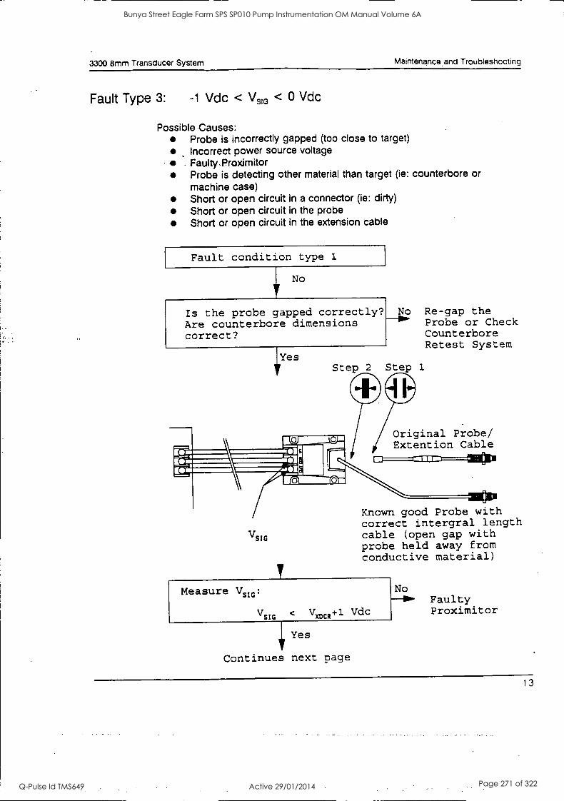
3300 8mm Transducer System Maintenance and Troubleshooting
Fault Type 3: -1 Vdc < Vs1 < 0 Vdc
Possible Causes: Probe is incorrectly gapped (too close to target) Incorrect power source voltage Faulty.Proximitor Probe is detecting other material than target (ie: counterbore or machine case) Short or open circuit in a connector (ie: dirty) Short or open circuit in the probe Short or open circuit in the extension cable
Fault condition type 1
No
Is the probe gapped correctly? Are counterbore dimensions correct?
IYes
No Re-gap the mw Probe or Check
Counterbore Retest System
Step 2 Step 1
iiOriginal Probe/ Extention Cable
V SIG
mom Known good Probe with correct intergral length cable (open gap with probe held away from conductive material)
Measure VSIG Faulty
VSIG V MCR +1 Vdc Proximitor
17 Yes
Continues next page
13
Bunya Street Eagle Farm SPS SP010 Pump Instrumentation OM Manual Volume 6A
Q-Pulse Id TMS649 Active 29/01/2014 Page 271 of 322
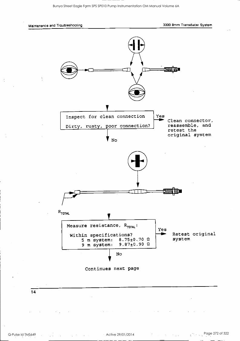
Maintenance and Troubleshooting 3300 8mm Transducer System
F-ilwInspect for clean connection Yes
Dirty, rusty, poor connection?
117 No
-TF
R TOTAL
Measure resistance, R TOTAL:
Within specifications? 5 m system: 8.7510.70 SI
9 m system: 9.87±0.90 Q
Continues next page
Clean connector, reassemble, and retest the original system
Yes Retest original system
14
Bunya Street Eagle Farm SPS SP010 Pump Instrumentation OM Manual Volume 6A
Q-Pulse Id TMS649 Active 29/01/2014 Page 272 of 322
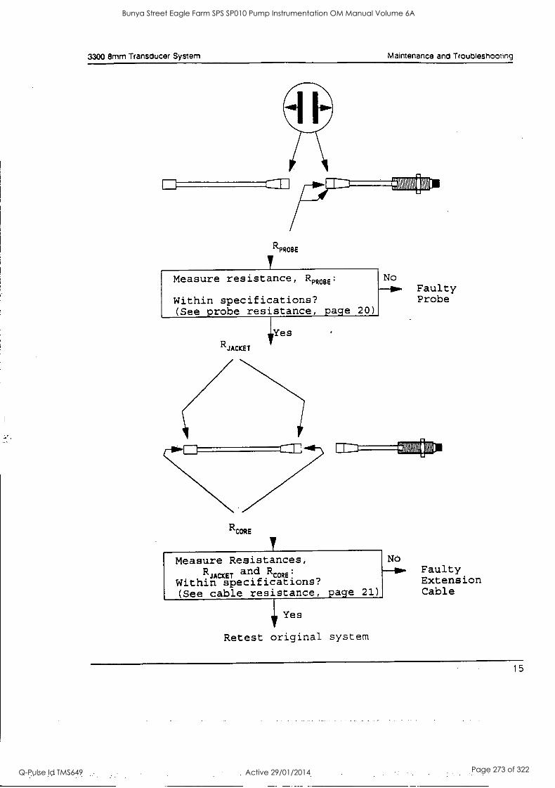
3300 8mm Transducer System Maintenance and Troubleshooting
O
RPROEIE
611111111111111114
No ow Faulty
Measure resistance, RPROBE
Within specifications? Probe (See probe resistance, page 20)
1Yes R JACKET
7=7 RCORE
Measure Resistances,
C\111111E1
No R
JACKET and R
CORE
Within specifications? (See cable resistance, page 21)
Faulty Extension Cable
Yes
Retest original system
15
Bunya Street Eagle Farm SPS SP010 Pump Instrumentation OM Manual Volume 6A
Q-Pulse Id TMS649 Active 29/01/2014 Page 273 of 322
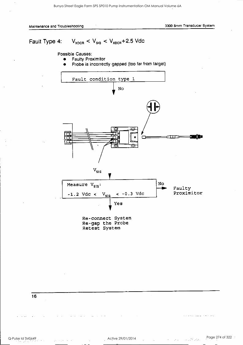
Maintenance and Troubleshooting 3300 8mm Transducer System
Fault Type 4: Vmx31 < Vs* < VxDcR+25 Vdc
Possible Causes: Faulty Proximitor Probe is incorrectly gapped (too far from target)
Fault condition type 1
No
VSIG
Measure Vsm:
-1.2 Vdc < VmG < -0.3 Vdc
Yes
Re-connect System Re-gap the Probe Retest System
Faulty Proximitor
16
Bunya Street Eagle Farm SPS SP010 Pump Instrumentation OM Manual Volume 6A
Q-Pulse Id TMS649 Active 29/01/2014 Page 274 of 322
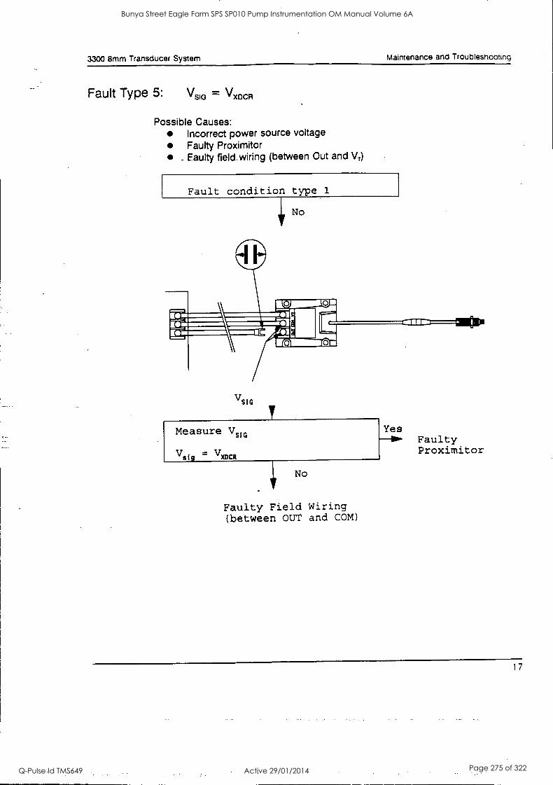
3300 8mm Transducer System Maintenance and Troubleshooting
Fault Type 5: \ism = V MCA
Possible Causes: Incorrect power source voltage Faulty Proximitor
_ Faulty field. wiring (between Out and V,)
Fault condition type 1
V SIG
Faulty Field Wiring (between OUT and COM)
Faulty Proximitor
17
Bunya Street Eagle Farm SPS SP010 Pump Instrumentation OM Manual Volume 6A
Q-Pulse Id TMS649 Active 29/01/2014 Page 275 of 322
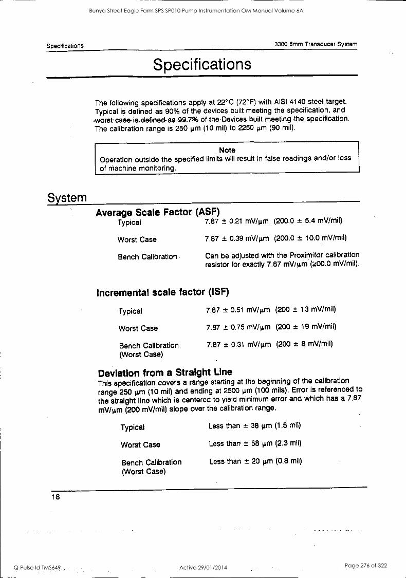
Specifications 3300 8mm Transducer System
Specifications
The following specifications apply at 22°C (72°F) with AISI 4140 steel target. Typical is defined as 90% of the devices built meeting the specification, and
-worst-case- is.defirved- as 99.7% of the Devices built meeting .the specification. The calibration range is 250 µm (10 mil) to 2250 µm (90 mil).
Note Operation outside the specified limits will result in false readings and/or loss
of machine monitoring.
System Average Scale Factor (ASF)
Typical 7.87 ± 0.21 mV /µm (200.0 ± 5.4 mV/mil)
Worst Case 7.87 ± 0.39 mV /µm (200.0 ± 10.0 mV/mil)
Bench Calibration Can be adjusted with the Proximitor calibration resistor for exactly 7.87 mV /µm (200.0 mV/mil).
Incremental scale factor (ISF)
Typical 7.87 ± 0.51 mV/pm (200 ± 13 mV/mil)
Worst Case 7.87 ± 0.75 mV /µm (200 ± 19 mV/mil)
Bench Calibration 7.87 ± 0.31 mV/4m (200 ± 8 mV/mil)
(Worst Case)
Deviation from a Straight Line This specification covers a range starting at the beginning of the calibration
range 250 gm (10 mil) and ending at 2500 4m (100 mils). Error is referenced to
the straight line which is centered to yield minimum error and which has a 7.87
mV/pm (200 mV/mil) slope over the calibration range.
Typical Less than ± 38 ILm (1.5 mil)
Worst Case Less than ± 58 gm (2.3 mil)
Bench Calibration Less than ± 20 gm (0.8 mil)
(Worst Case)
18
Bunya Street Eagle Farm SPS SP010 Pump Instrumentation OM Manual Volume 6A
Q-Pulse Id TMS649 Active 29/01/2014 Page 276 of 322
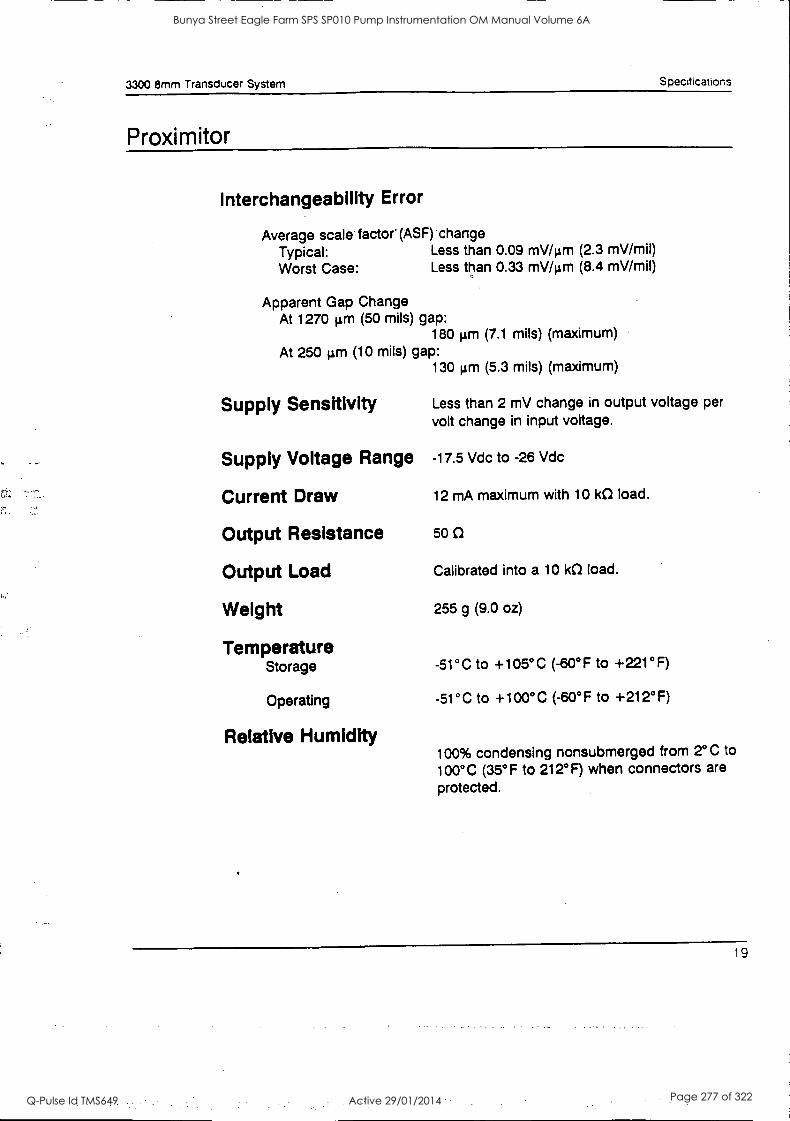
3300 8mm Transducer System Specifications
Proximitor
Interchangeability Error
Average scale factor (ASF) change Typical: Less than 0.09 mV/pm (2.3 mV/mil) Worst Case: Less than 0.33 mV/pm (8.4 mV/mil)
Apparent Gap Change At 1270 pm (50 mils) gap:
180 pm (7.1 mils) (maximum) At 250 gal (10 mils) gap:
130 pm (5.3 mils) (maximum)
Supply Sensitivity Less than 2 mV change in output voltage per
volt change in input voltage.
Supply Voltage Range -17.5 Vdc to -26 Vdc
Current Draw 12 mA maximum with 10 kO load.
Output Resistance 50
Output Load Calibrated into a 10 kO load.
Weight 255 g (9.0 oz)
Temperature Storage -51°C to +105°C (-60°F to +221°F)
Operating -51°C to +100°C (-60°F to +212°F)
Relative Humidity 100% condensing nonsubmerged from 2°C to
100°C (35°F to 212°F) when connectors are
protected.
19
Bunya Street Eagle Farm SPS SP010 Pump Instrumentation OM Manual Volume 6A
Q-Pulse Id TMS649 Active 29/01/2014 Page 277 of 322
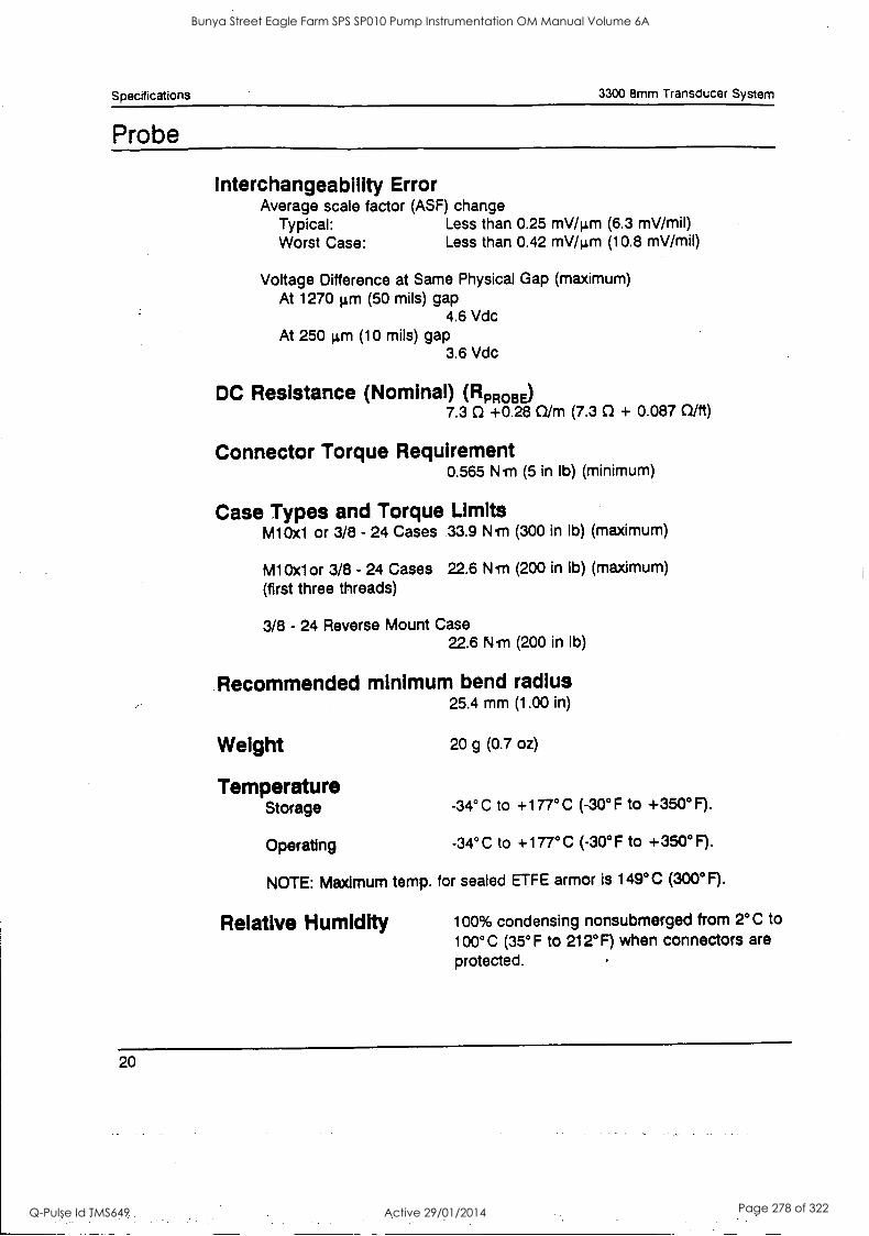
Specifications 3300 8mm Transducer System
Probe
Interchangeability Error Average scale factor (ASF) change
Typical: Less than 0.25 mV/pm (6.3 mV/mil) Worst Case: Less than 0.42 mV/pm (10.8 mV/mil)
Voltage Difference at Same Physical Gap (maximum) At 1270 pm (50 mils) gap
4.6 Vdc At 250 pm (10 mils) gap
3.6 Vdc
DC Resistance (Nominal) (RPR0BE) 7.3 0 +0.28 0/m (7.3 f1 + 0.087 0/ft)
Connector Torque Requirement 0.565 N.rn (5 in Ib) (minimum)
Case Types and Torque Limits m10x1 or 3/8 - 24 Cases 33.9 N.rn (300 in Ib) (maximum)
M10x1or 3/8 - 24 Cases 22.6 Wm (200 in Ib) (maximum)
(first three threads)
3/8 - 24 Reverse Mount Case 22.6 Ni (200 in Ib)
Recommended minimum bend radius 25.4 mm (1.00 in)
Weight
Temperature Storage
Operating
20 g (0.7 oz)
-34° C to +177°C (-30°F to +350°F).
-34° C to +177°C ( -30° F to +350°F).
NOTE: Maximum temp. for sealed ETFE armor is 149°C (300°F).
Relative Humidity 100% condensing nonsubmerged from 2°C to 100°C (35° F to 212°F) when connectors are
protected.
20
Bunya Street Eagle Farm SPS SP010 Pump Instrumentation OM Manual Volume 6A
Q-Pulse Id TMS649 Active 29/01/2014 Page 278 of 322
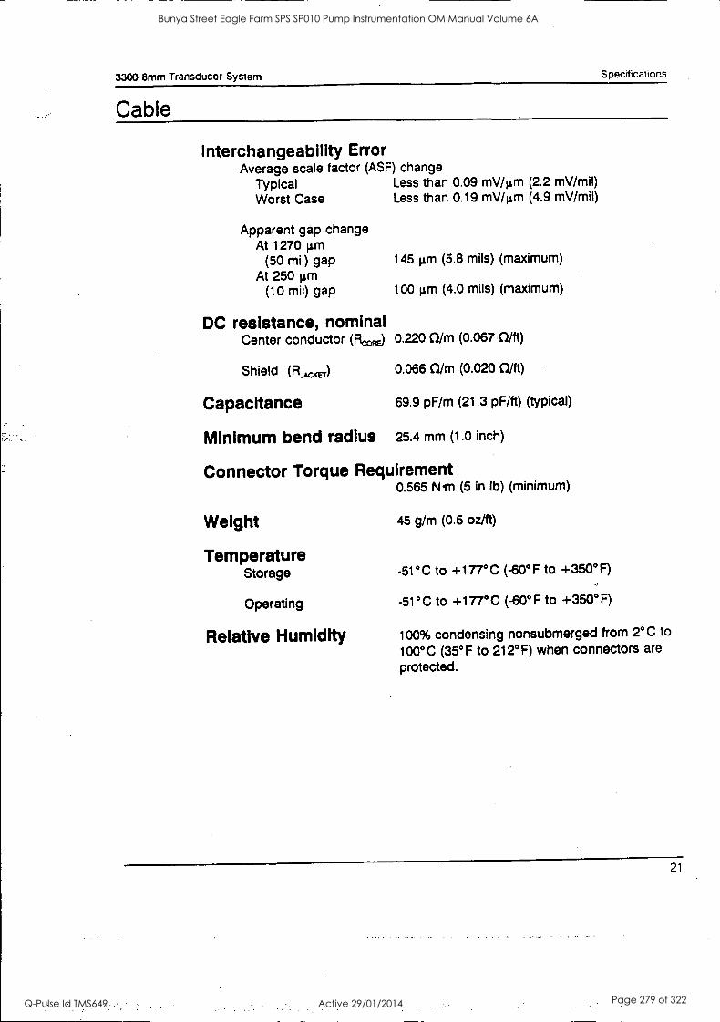
3300 8mm Transducer System Specifications
Cable
Interchangeability Error Average scale factor (ASF) change
Typical Less than 0.09 mV /µm (2.2 mV/mil) Worst Case Less than 0.19 mV/pm (4.9 mV/mil)
Apparent gap change At 1270 pm
(50 mil) gap At 250 grfl
(10 MO gap
145 gm (5.8 mils) (maximum)
100 pm (4.0 mils) (maximum)
DC resistance, nominal Center conductor (1100,e) 0.220 0/m (0.067 Cl/ft)
Shield (RJAcKET) 0.066 0/m (0.020 0/ft)
Capacitance 69.9 pF/m (21.3 pF/ft) (typical)
Minimum bend radius 25.4 mm (1.0 inch)
Connector Torque Requirement 0.565 Nm (5 in lb) (minimum)
Weight 45 g/m (0.5 oz/ft)
Temperature Storage
Operating
Relative Humidity
-51°C to +177°C (-60°F to +350°F)
-51°C to +177°C (-60°F to +350°F)
100% condensing nonsubmerged from 2°C to
100°C (35°F to 212°F) when connectors are
protected.
21
Bunya Street Eagle Farm SPS SP010 Pump Instrumentation OM Manual Volume 6A
Q-Pulse Id TMS649 Active 29/01/2014 Page 279 of 322
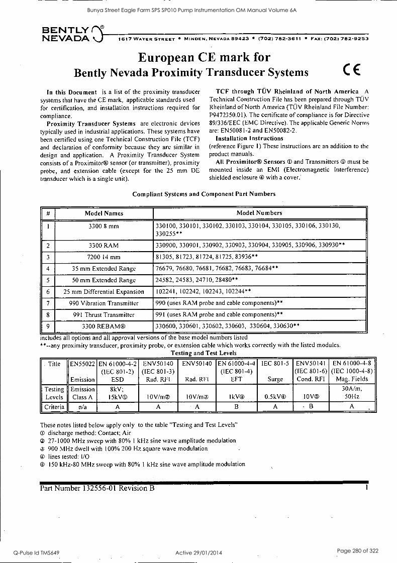
BENTLY NEVADA ..) 1617 WATER STREET MINDEN, NEVADA 89423 (702) 782-3611 FAX: (702) 782-9253
European CE mark for Bently Nevada Proximity Transducer Systems CE
In this Document is a list of the proximity transducer systems that have the CE mark, applicable standards used for certification, and installation instructions required for
compliance. Proximity Transducer Systems are electronic devices
typically used in industrial applications. These systems have been certified using one Technical Construction File (TCF) and declaration of conformity because they are similar in
design and application. A Proximity Transducer System consists of a Proximitor® sensor (or transmitter), proximity probe, and extension cable (except for the 25 mm DE
transducer which is a single unit).
TCF through TUV Rheinland of North America A
Technical Construction File has been prepared through TUV Rheinland of North America (TOV Rheinland File Number: P9472350.01). The certificate of compliance is for Directive 89/336/EEC (EMC Directive). The applicable Generic Norms are: EN50081-2 and EN50082-2.
Installation Instructions (reference Figure I) These instructions are an addition to the product manuals.
All Proximitor® Sensors ® and Transmitters 0 must be mounted inside an EMI (Electromagnetic Interference) shielded enclosure ® with a cover:
Compliant Systems and Component Part Numbers
# Model Names Model Numbers
1 3300 8 mm 330100, 330101, 330102, 330103, 330104, 330105, 330106, 330130, 330255**
2 3300 RAM 330900, 330901, 330902, 330903, 330904, 330905, 330906, 330930**
3 7200 14 mm 81305, 81723, 81724, 81725, 83936**
4 35 mm Extended Range 76679, 76680, 76681, 76682, 76683, 76684**
5 50 mm Extended Range 24582, 24583, 24710, 28480**
6 25 mm Differential Expansion 102241, 102242, 102243, 102244**
7 990 Vibration Transmitter 990 (uses RAM probe and cable components)**
8 991 Thrust Transmitter 991 (uses RAM probe and cable components)**
9 3300 REBAM® 330600, 330601, 330602, 330603, 330604, 330630**
includes all options and all approval versions of the base model numbers listed **--any proximity transducer, proximity probe, or extension cable which works correctly with the listed modules.
Testing and Test Levels
Title EN55022
Emission
EN 61000-4-2 (IEC 801-2)
ESD
ENV50140 (IEC 801-3)
Rad. RFI
ENV50140
Rad. RFI
EN 61000-4-4 (IEC 801-4)
EFT
IEC 801-5
Surge
ENV50141 (IEC 801-6) Cond. RFI
EN 61000-4-8 (IEC 1000-4-8)
Mag. Fields
Testing Levels
Emission Class A
8kV; l5kV® 10V/m0 10V/m IkV0 0.5kV® 10V0
30A/m, 50Hz
Criteria n/a A A A B A B A
These notes listed below apply only to the table "Testing and Test Levels" O discharge method: Contact; Air
27-1000 MHz sweep with 80% I kHz sine wave amplitude modulation 900 MHz dwell with 100% 200 Hz square wave modulation
® lines tested: I/O Os 150 kHz-80 MHz sweep with 80% 1 kHz sine wave amplitude modulation
Part Number 132556-01 Revision B 1
Bunya Street Eagle Farm SPS SP010 Pump Instrumentation OM Manual Volume 6A
Q-Pulse Id TMS649 Active 29/01/2014 Page 280 of 322
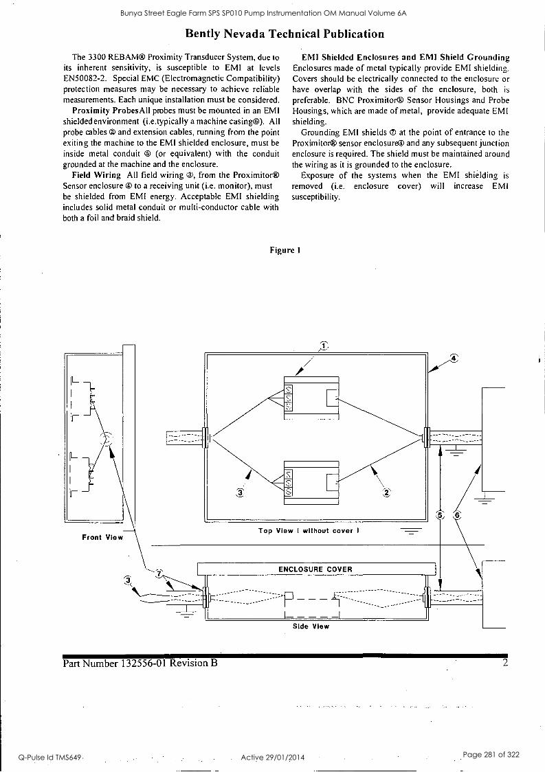
Bently Nevada Technical Publication
The 3300 REBAM® Proximity Transducer System, due to its inherent sensitivity, is susceptible to EMI at levels EN50082-2. Special EMC (Electromagnetic Compatibility) protection measures may be necessary to achieve reliable measurements. Each unique installation must be considered.
Proximity Probes All probes must be mounted in an EMI shielded environment (i.e.typically a machine casing)). All probe cables and extension cables, running from the point exiting the machine to the EMI shielded enclosure, must be
inside metal conduit 0 (or equivalent) with the conduit grounded at the machine and the enclosure.
Field Wiring All field wiring 0, from the Proximitor® Sensor enclosure ® to a receiving unit (i.e. monitor), must be shielded from EMI energy. Acceptable EMI shielding includes solid metal conduit or multi-conductor cable with both a foil and braid shield.
Front View
EMI Shielded Enclosures and EMI Shield Grounding Enclosures made of metal typically provide EMI shielding. Covers should be electrically connected to the enclosure or have overlap with the sides of the enclosure, both is
preferable. BNC Proximitor® Sensor Housings and Probe Housings, which are made of metal, provide adequate EMI shielding.
Grounding EMI shields ® at the point of entrance to the
Proximitor® sensor enclosure® and any subsequent junction enclosure is required. The shield must be maintained around the wiring as it is grounded to the enclosure.
Exposure of the systems when the EMI shielding is
removed (i.e. enclosure cover) will increase EMI susceptibility.
Figure I
Top View I without cover I
ENCLOSURE COVER
-----
- Side View
Part Number 132556-01 Revision B 2
Bunya Street Eagle Farm SPS SP010 Pump Instrumentation OM Manual Volume 6A
Q-Pulse Id TMS649 Active 29/01/2014 Page 281 of 322

BRISBANE CITY COUNCIL Dept. Water Supply and Sewage Pumpwell No 1, Eagle Farm Pump Station
BCC Contract No S20195196 System Instrumentation
Operation and Maintenance Manual
2.10 RTD Temperature Sensing Elements
The RTD temperature sensing probes used on this project are all Class A, 3 wire with a standard PT 100 characteristic as shown in the attached Reference Table for Platinum Resistance Elements. They are manufactured by Temperature Controls Pty Ltd located at 55 Henry Street, Leichhardt, NSW, 2040.
The sensing elements are mounted on the pump and motor to monitor machine bearing temperature and also the motor cooling air temperature. The bearing temperature elements are provided with a spring loaded tip to ensure a positive contact with the bearing surface.
Attached are the following details of the equipment supplied:
Drawing No 3015 Small Terminal Head, Sprung Loaded - Class A RTD
Drawing No 3015A Pipe Extension for 3015
Drawing No 3016 Small Terminal Head, Sprung Loaded - Class A RTD
Drawing No 3017 Small Terminal Head, Sliding Compression Process Connection Assembly - Class A RTD
Drawing No 3018 Small Terminal Head, Sprung Loaded - Class A RTD
Reference Table for Platinum Resistance Elements
Certificate of Compliance for PT 100 Platinum Resistance Temperature Detectors Type 1/100-30-25 Class A
15140/Inst Man/BRH Issue 1 29-Apr-98 Page 2-13
Bunya Street Eagle Farm SPS SP010 Pump Instrumentation OM Manual Volume 6A
Q-Pulse Id TMS649 Active 29/01/2014 Page 282 of 322
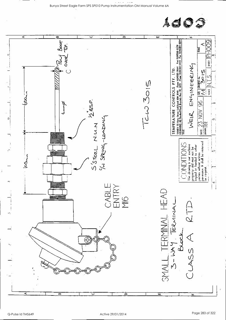
11
CA
BLE
E
NT
RY
M
I6
SM
ALL
T
ER
MIN
AL
HE
AD
3-
- w
itt
Cro
ss A
2
( D
E
111
I
f77/
777T
/
5 ts
-re:
cl__
N
I LA
N
c/
cA
Sk
_mcl
- c1
(,...
ON
DI
HO
N.)
T
his
&ow
ing
is
our
excl
usiv
e
prop
erly
ci
d m
ust
not
be
copi
ed
or
land
ed
to
othe
r pa
rtie
s w
ithou
t w
ritte
n
her
mis
sion
. It
shat
be
re
turn
ed
on r
eque
st.
10(1
(D
oor
C
oJe-
e "1
TP
.
TE
MP
ER
AT
UR
E
CO
NT
RO
LS
PT
Y.
LTD
. S
ME
Y:
55 (I
vry
Sno
w.
loiri
horc
h 11
SW
20
40.
riva
(021
9560
064
4 F
a (0
2195
60 0
339
1-1f
t001
10E
: 40
flo
telo
ld R
oad
Brt
nilic
k W
eil
NC
305
5,
Moo
s:
(031
9384
04
44
Fm
: (0
3193
84 02
04
DIL
E
VJE
I E
kci
N
DA
ZE
: 23
N
OV
96
D
RA
M( R
R 6
(_9-
.E
I
517E
C
RA
WIC
Ito
. 3
A/1
-3
c) is
A
5cA
tEjN
is.
I S
IEE
T
IP81
-100
9
Bunya Street Eagle Farm SPS SP010 Pump Instrumentation OM Manual Volume 6A
Q-Pulse Id TMS649 Active 29/01/2014 Page 283 of 322
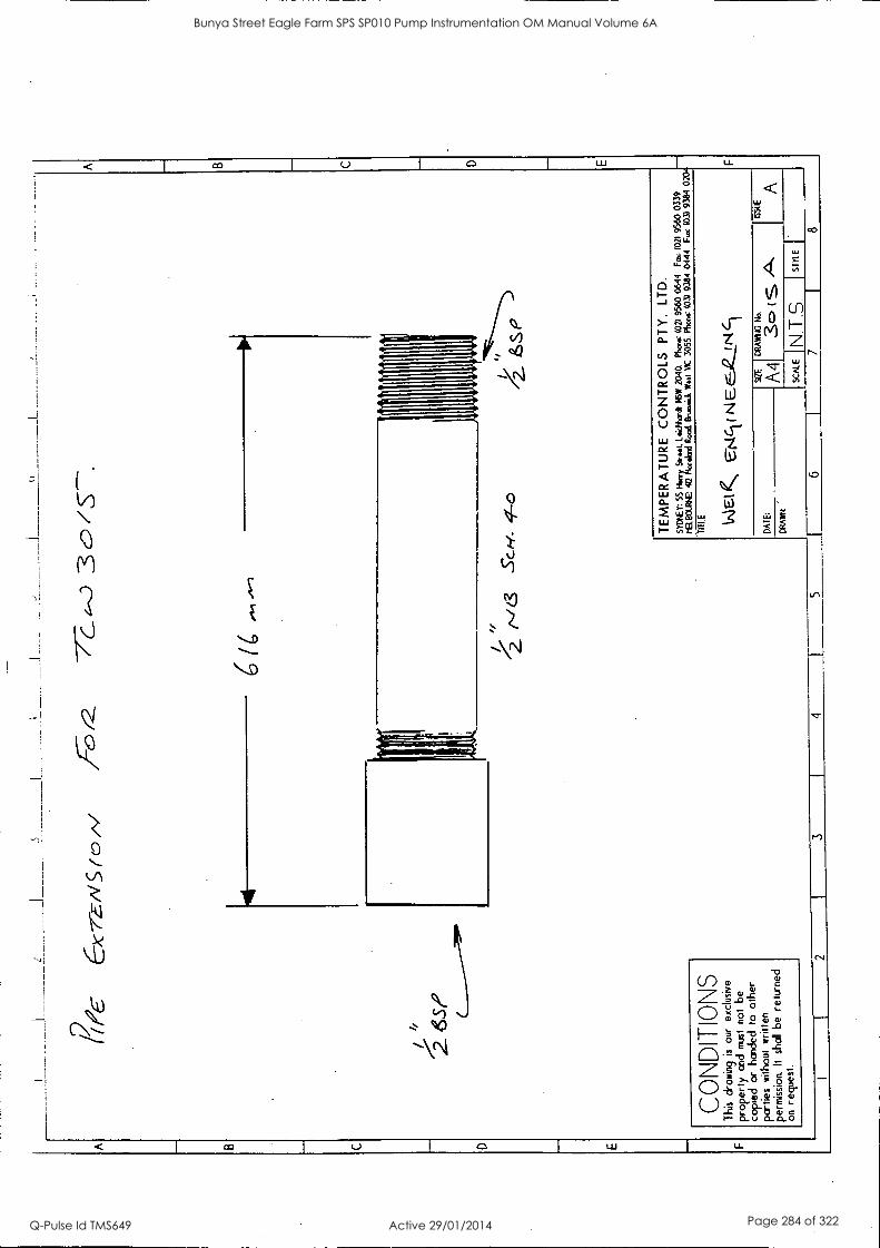
8,6
C--
)c-r
N
(0 "/
3c
"
26S
P
CO
ND
ITIO
NS
T
his
draw
ing
is
our
excl
usiv
e
prop
erty
and
MS
T
not
be
copi
ed
or h
ande
d to
oth
er
part
ies
with
out
writ
ten
perm
issi
on It
shal
l be
re
tu-n
ed
on
requ
est.
6(6
414
/ "
4-0
TE
MP
ER
AT
UR
E
CO
NT
RO
LS
PT
Y.
LTD
. S
YD
TE
Y:
55 H
enry
Sire
id.
Leah
crth
NS
W 20
40.
Pho
ne (
02)
9560
064
4 F
m:
(021
95
60 0
339
IELI
TO
LRE
: 4(
2 N
aalm
d R
ood.
P
ens.
44 W
oo
VIC
30
55.
Pho
ne (
03)
9384
04
44
Fax
031
938
4 02
04
TIT
LE W
elt
E.O
.c-t
( N
EE
,42J
_Nic
i
DA
TE
: st
ZE
A4 C
RA
MC
A1/
4
ES
TE
DR
AW
N
SC
ALE
N
T S
S
TY
LE
7 8
Bunya Street Eagle Farm SPS SP010 Pump Instrumentation OM Manual Volume 6A
Q-Pulse Id TMS649 Active 29/01/2014 Page 284 of 322
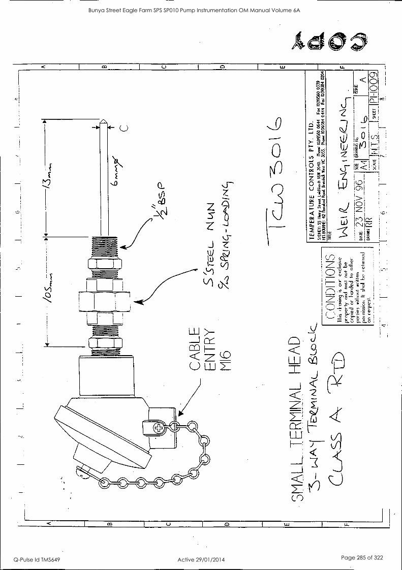
6001-1d1 Ing I
.S.-1-1\11- 3"
31SS
-11- 41
f 1/Ml1
31E
V
) 11/V
1.--)N
I-3y\
dd tam
96 A
ON
:31"
31111
PO
LO
Pef61f01:01
6143 Ilt61f01 P
uNJ
'Mc
DIA
"IA
IPIV
InAl
P°°11 P
Er"g
Z11, 30108131
09S61Z
01 'DJ
1190 095601340M
'0147K
AS
H 1P
elFrl .1"21S
"vell SS
:AN
DS
'Ald
SlO
SIN
OD
31iflIV
83dYg31
IsanbaJ uo 14311.114 0.1
ay logs
11 .tio!ssiul lad
trailym m
ow
saisiJoil
Jay° 01
papuoki padoD
ay
iou 1511 pu)
AI Jadoid
_110 si
6U1M
0.1) sell
S3N
OLLIC
JI\1OD
L-)NicN
icn - 171v Dots-
NhN
7vNikiei T
ivkis
4
- --
Bunya Street Eagle Farm SPS SP010 Pump Instrumentation OM Manual Volume 6A
Q-Pulse Id TMS649 Active 29/01/2014 Page 285 of 322
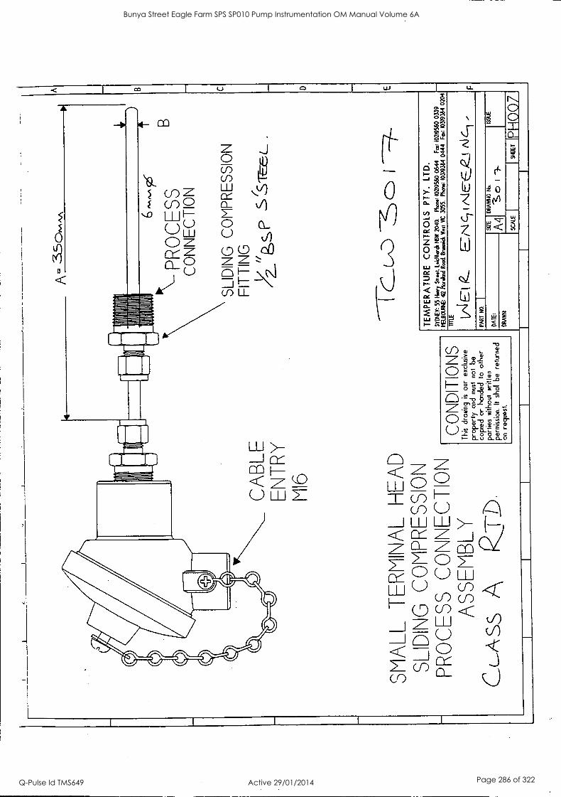
CA
BLE
E
NT
RY
V
16
SM
ALL
T
ER
IvI\A
L H
EA
D
SLI
DI\G
C
OvP
RE
SS
IO\
PR
OC
ES
S C
O\\E
CT
IO\
AS
SE
'BLY
C
c-A
ss
QT
D.
CO
ND
ITIO
NS
T
his
draw
ing
is
our
excl
usiv
e
prop
erty
and
mus
t no
t be
copi
ed
or h
orde
d to
ot
her
part
ies
with
out
writ
ten
perm
issi
on.
II sh
all
be
rett.
rned
on
re
ques
t.
A= :
90^^
^A
MO
1111
1111
1
H1111111111
'111111111111111
PR
OC
ES
S
CONNECTION
SLIDING COMPRESSION
FITTING
/2._"ppsf,
B
TE
MP
ER
AT
UR
E
CO
NT
RO
LS
PT
Y.
LTD
. S
YD
EY
: 55
Har
ry S
tr.e
. lo
ktita
dt N
SW
204
0.
Phe
w.:
102)
9560
064
4 F
at:
102)
9560
033
9 tE
LDO
IRE
: 4/
2 N
orel
aKI
Roo
d en
raid
t W
est
MC
305
5.
Kau
: 10
3/93
84 0
444
Fm
: 10
3193
64 0
204
mIE
VIE
t 2
EN
cl N
IE-E
R.!
A16
-1 -
ItI
LT L1
10.
DA
TE
:
DR
AW
N
SZE
DR
AV
ING
N
o.
-S 0
I T
IP
H 0
0 7
Bunya Street Eagle Farm SPS SP010 Pump Instrumentation OM Manual Volume 6A
Q-Pulse Id TMS649 Active 29/01/2014 Page 286 of 322
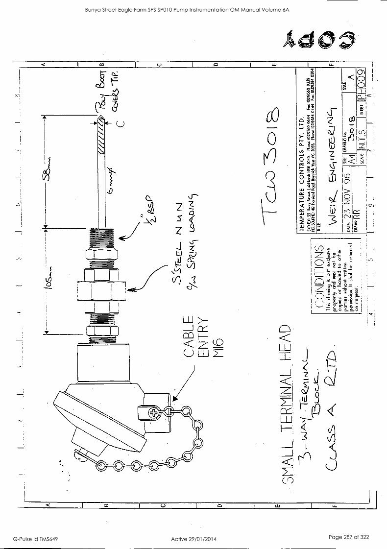
CA
BLE
E
NT
RY
M
I6
SM
ALL
.T
.EV
INA
L H
EA
D
CLA
SS
,S P
S-ra
cc_
N
N
ltDA
Z 1A
I
(72.
.01\
IDI
ION
S
Thi
s &
awin
g is
ou
r ex
clus
ive
prop
erly
or
d m
ust
not
be
copi
ed
or
hand
ed
to
othe
r F
ortie
s xi
ihou
t w
ritte
n
perin
issi
on.
II sk
ill b
e re
turn
ed
on r
eque
st.
Y// /
/f/
-4 Q
0,1
scol
C
-rI P
.
TE
MP
ER
AT
UR
E
CO
NT
RO
LS
PT
Y.
LTD
. S
YD
IEY
: 55
16
7k:w
ow.
Lek/
hach
1(5
W
2040
. M
onet
(02
)956
0 06
44
Fat
102
1956
0 03
39
IELB
OU
RS
E:
42
ekes
d R
ood
Bru
ntic
k W
est
VIC
30
55.
Nor
a: 1
03)9
364
0444
F
m:
1031
9384
02
04
IIILE
\/1 t &
Et4
6if N
EE
Z!N
e--)
GR
Aw
tt 1E
A
DA
IE:
23
NO
V 96
"E
D
""61
".
ISLE
5CA
IE1N
. .
I S
IFT
I-
6 1
1 1
a
Bunya Street Eagle Farm SPS SP010 Pump Instrumentation OM Manual Volume 6A
Q-Pulse Id TMS649 Active 29/01/2014 Page 287 of 322
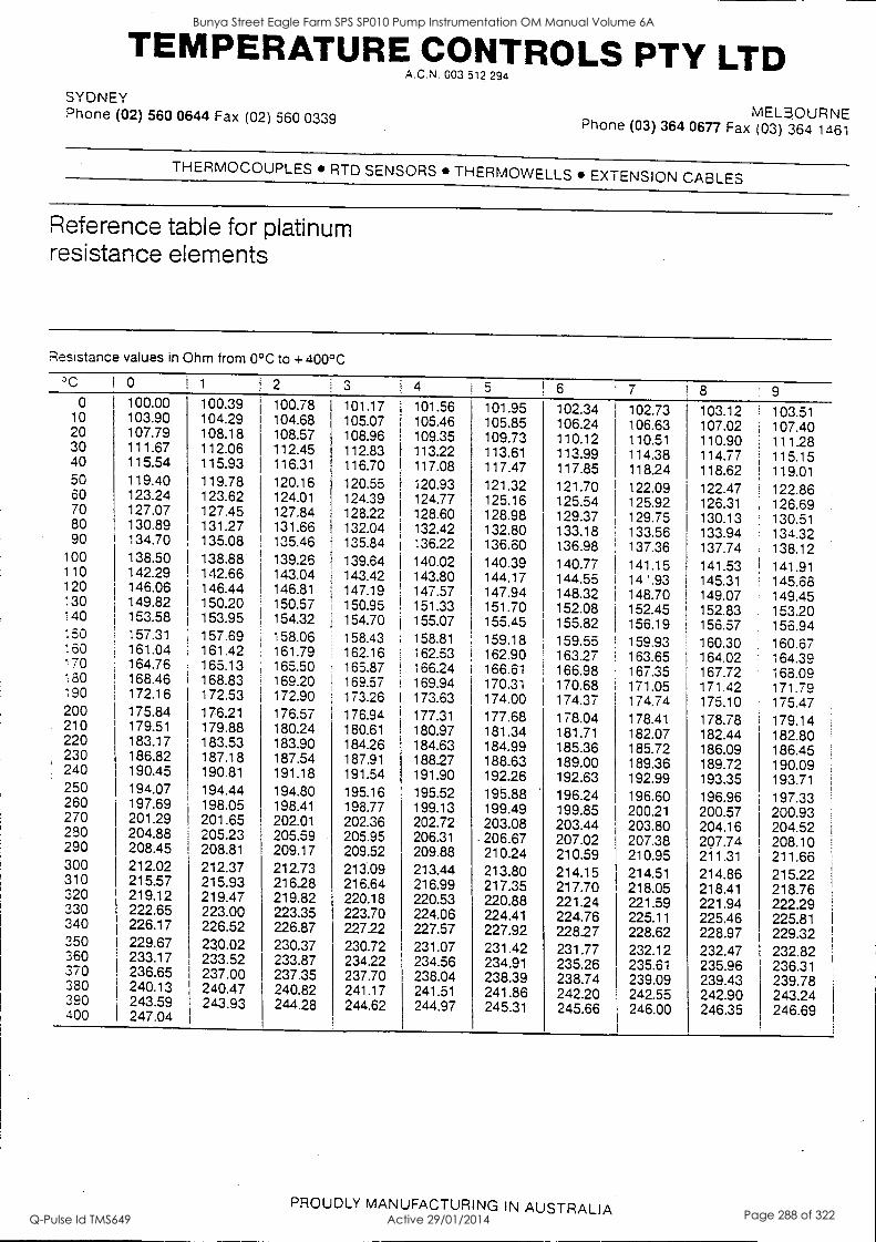
TEMPERATURE CONTROLS PTY LTD A.C.N. 003 512 294
SYDNEY MELBOURNE Phone (02) 560 0644 Fax (02) 560 0339 Phone (03) 364 0677 Fax (03) 364 1461
THERMOCOUPLES RTD SENSORS THERMOWELLS EXTENSION CABLES
Reference table for platinum resistance elements
Resistance values in Ohm from 0°C to +400°C
°C I 0 1 2 3 i 4 5 6 7 8 9 0 100.00 100.39 100.78 101.17 101.56 101.95 102.34 102.73 103.12 103.51 10 103.90 104.29 104.68 105.07 105.46 105.85 106.24 106.63 107.02 107.40 20 107.79 108.18 108.57 108.96 109.35 109.73 110.12 110.51 110.90 111.28 30 111.67 112.06 112.45 112.83 113.22 113.61 113.99 114.38 114.77 115.15 40 115.54 115.93 116.31 116.70 117.08 117.47 117.85 118.24 118.62 I 119.01
50 119.40 119.78 120.16 120.55 120.93 121.32 121.70 122.09 122.47 122.86 60 123.24 123.62 124.01 124.39 124.77 125.16 125.54 125.92 126.31 126.69 70 127.07 127.45 127.84 128.22 128.60 128.98 129.37 129.75 130.13 130.51 80 130.89 131.27 131.66 132.04 132.42 132.80 133.18 133.56 133.94 134.32 90 134.70 135.08 135.46 135.84 136.22 136.60 136.98 137.36 137.74 138.12 100 138.50 138.88 139.26 139.64 140.02 140.39 140.77 141.15 141.53 ! 141.91 110 142.29 142.66 143.04 143.42 143.80 144.17 144.55 14 ' .93 145.31 , 145.68 120 146.06 146.44 146.81 147.19 147.57 147.94 148.32 148.70 149.07 149.45 130 149.82 150.20 150.57 150.95 151.33 151.70 152.08 152.45 152.83 153.20 140 153.58 153.95 154.32 154.70 155.07 155.45 155.82 156.19 156.57 156.94 150 157.31 157.69 158.06 158.43 158.81 159.18 159.55 159.93 160.30 160.67 160 161.04 161.42 161.79 162.16 162.53 162.90 163.27 163.65 164.02 164.39 170 164.76 165.13 165.50 165.87 166.24 166.61 166.98 167.35 167.72 168.09 180 168.46 168.83 169.20 169.57 169.94 170.31 170.68 171.05 171.42 171.79 190 172.16 172.53 172.90 173.26 173.63 174.00 174.37 174.74 175.10 175.47 200 175.84 176.21 176.57 176.94 177.31 177.68 178.04 178.41 178.78 179.14 210 179.51 179.88 180.24 180.61 180.97 181.34 181.71 182.07 182.44 182.80 220 183.17 183.53 183.90 184.26 184.63 184.99 185.36 185.72 186.09 186.45 230 186.82 187.18 187.54 187.91 18827 188.63 189.00 189.36 189.72 190.09 240 190.45 190.81 191.18 191.54 191.90 192.26 192.63 192.99 193.35 193.71 250 194.07 194.44 194.80 195.16 195.52 195.88 196.24 196.60 196.96 197.33 260 197.69 198.05 198.41 198.77 199.13 199.49 199.85 200.21 200.57 200.93 270 201.29 201.65 202.01 202.36 202.72 203.08 203.44 203.80 204.16 204.52 280 204.88 205.23 205.59 205.95 206.31 206.67 207.02 207.38 207.74 208.10 290 208.45 208.81 209.17 209.52 209.88 210.24 210.59 210.95 211.31 211.66 300 212.02 212.37 212.73 213.09 213.44 213.80 214.15 214.51 214.86 215.22 310 320
215.57 219.12
215.93 219.47
216.28 219.82
216.64 220.18
216.99 220.53
217.35 220.88
217.70 221.24
218.05 221.59
218.41 221.94
218.76 222.29 1
330 222.65 223.00 223.35 223.70 224.06 224.41 224.76 225.11 225.46 225.81 340 226.17 226.52 226.87 227.22 227.57 227.92 228.27 228.62 228.97 229.32 350 229.67 230.02 230.37 230.72 231.07 231.42 231.77 232.12 232.47 232.82 360 233.17 233.52 233.87 234.22 234.56 234.91 235.26 235.61 235.96 236.31 370 236.65 237.00 237.35 237.70 238.04 238.39 238.74 239.09 239.43 239.78 380 240.13 240.47 240.82 241.17 241.51 241.86 242.20 242.55 242.90 243.24 390 243.59 243.93 244.28 244.62 244.97 245.31 245.66 246.00 246.35 246.69 400 247.04
PROUDLY MANUFACTURING IN AUSTRALIA
Bunya Street Eagle Farm SPS SP010 Pump Instrumentation OM Manual Volume 6A
Q-Pulse Id TMS649 Active 29/01/2014 Page 288 of 322

EIWGIEL.1-1411171:11-CLAIL
CERTIFICATE OF COMPLIANCE
f:EFILRENCE Lot number VU/7
GENTLEMEN We hereby certify that the Platinum Resistance Temperature Detectors Type 1/100-30-25 Class A
comply in all respects with the specifications stated.
Conforming to LEC 751
SPECIFICATION Type A 0.5 DIN ± 0.06 OHM at 00C.
YOURS
On behalf of
Platinum Sensors
JEWELRY - SILVER INDUSTRIAL PRODUCTS - PLATINUM INDUSTRIAL PRODUCTS - PLATING - REFINING - SPECIAL WIRES ENGELHARD-CLAL AUSTRALIA PTY. LTD. A.C.N. 007 082 448. I0 PROSPECT STREET, BOX HILL. VICTORIA .1123. AUSTRALIA TELEPHONE: 61-3 9899 6330 FACSIMILE: 61-3 9899 6360
Bunya Street Eagle Farm SPS SP010 Pump Instrumentation OM Manual Volume 6A
Q-Pulse Id TMS649 Active 29/01/2014 Page 289 of 322

BRISBANE CITY COUNCIL Dept. Water Supply and Sewage Pumpwell No 1, Eagle Farm Pump Station
BCC Contract No S20/95/96 System Instrumentation
Operation and Maintenance Manual
2.11 Motor Moisture Detector
Moisture detectors are located in the motor to detect water leakage from the heat exchanger. There is one in the bottom of the motor housing and one in each heat exchanger, located close to the bottom of the chamber. A Sclunersal type IFC 15-30- lOyTPD Capacitive Proximity switch has been used to sense the moisture. They are available from NHP Electrical Engineering Products Pty Ltd.
Attached is a brochure on this unit prepared by Schmersal describing the principle of operation, installation and maintenance of these switches.
15140/Inst Man/BRH Issue 1 29-Apr-98 Page 2-14
Bunya Street Eagle Farm SPS SP010 Pump Instrumentation OM Manual Volume 6A
Q-Pulse Id TMS649 Active 29/01/2014 Page 290 of 322

Bunya Street Eagle Farm SPS SP010 Pump Instrumentation OM Manual Volume 6A
Q-Pulse Id TMS649 Active 29/01/2014 Page 291 of 322

Proximity Switches, Inductive, Capacitive, and Optical
Proximity Switches, General IFL Inductive Proximity Switches The proximity switch is an electronic signal transmitter. Basically it differs from a mechanical limit switch in that it switches when it is in
proximity. that is to say without contact and operates electronically. that is to say in contactless fashion.
As there are no wearing mechanical parts such as actuating elements and contacts, the service life is practically unlimited. Contact burning and contact contamination brought about by ambient influences cannot occur. The electronic proximity switch operates silently, without chatter and non-reactively. It is insensitive to vibration. There is no uncertain contact as can occur with mechanical switching elements as a result of excessively slow actuation, insufficient switching current etc. Contact migration when switching D.C. is eliminated.
Proximity switches should be given preference over electro- mechanical limit switches if:
- Contact difficulties as a result of ambient influences, insufficient switching current etc., are expected
- No actuating force is available - High switching frequency is needed - Long service life is necessary - Considerable dirt must be expected - Severe vibration and oscillation occur - An electronic control system is connected - When switching D.C..it is necessary to prevent contact
migration - No counter force may be exerted by the switch (restoring force in
the case of electro-mechanical limit switches, magnetic force in
the case of magnetic switches).
Of course not even proximity switches are entirely free from problems. When selecting the type and location please note the following: - There is a difference as to whether the proximity switch has to
switch A.C. or D.C. - The sensors need direct or indirect supply voltage - The actuating distance differs with actuating vanes of different
materials - The actuating distance is to a slight standard dependent on the
ambient temperature - It is important to consider whether flush or non-flush mounting
will be involved - The minimum distance necessary between two proximity
switches must be taken into account - Especially in the case of high actuating frequencies the length
of the actuating vane and the distance from the next vane are important
- Inductive proximity switches react only to metals - With capacitive sensors the actuating distance is dependent to a
greater or leSser standard on the air humidity according to actuating material
- In type selection of capacitive sensors it should be taken into
account whether they come in direct contact with liquid - For optical proximity switches, a changing of the sensing range
may occur in the case of dust environment.
These points will be dealt with in greater detail in the description that follows.
The oscillator of the inductive proximity switch generates with the aid of the coil located in the open pot core a high frequency alternating electro= magnetic field which emerges at the active face. If an electrically conductive material (for example metal) is moved into this field an induced eddy voltage occurs. The eddy current flowing extracts energy from the LC resonant circuit (coil-capacitor). The load of the oscillator resonant circuit produces a reduction in
the oscillation amplitude. The oscillator is damped. (Fig. 1)
Fig. 1
The reduction in the amplitude is converted by the following electronic circuitry into a clear electrical signal. The switching state of the proximity switch is altered thereby.
When the electrically conductive material is removed from the alternating field the oscillation amplitude increases again and the original switching state of the sensor is restored via the electronic circuitry. The oscillator is undamped.
IFC Capacitive Proximity Switches The capacitive sensor operates with an RC resonant circuit (resistor-capacitor) where the capacitance is affected. To achieve this, the electrodes of the capacitor are separated. One electrode is
located in the proximity switch on the active face. The second electrode is either the actuating medium with earth or ground as
return line or ground itself whereby the actuating medium causes a
change in the dielectric (Fig. 2).
When this medium aproaches the active surface and thus the capacitor electrode in the sensor, the capacitance increases to the
extent where the value for tuning with the resistor in the resonant circuit is reached and the oscillator starts to oscillate.
Fig. 2 Capacitive prowl-Illy switch
Actuating vane
E'v,trically conductive Elect, catty nonconductive
I-d SCHNAPoc
Bunya Street Eagle Farm SPS SP010 Pump Instrumentation OM Manual Volume 6A
Q-Pulse Id TMS649 Active 29/01/2014 Page 292 of 322
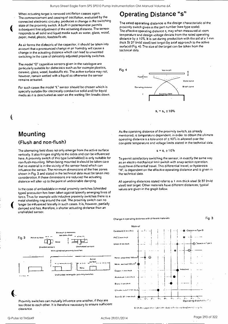
When actuating target is removed oscillation ceases again.
The commencement and ceasing of oscillation, evaluated by the
connected electronic circuitry, produces a change in the switching state of the proximity switch. A built-in potentiometer permits
subsequent fine adjustment of the actuating distance. The sensor responds to all solid and liquid media such as water, glass, wood, paper, metal, plastic, foodstuffs etc.
As air forms the dielectric of the capacitor, it should be taken into
account that a pronounced change in air humidity will cause a
change in the actuating distance which can lead to unwanted
switching in the case of delicately adjusted proximity switches.
The model "D" capacitive sensors given in the catalogue are
particularly suitable for dielectrics such as for example plastics, ceramic, glass, wood, foodstuffs etc. The active surface may not,
however, remain wetted with a liquid as otherwise the sensor remains actuated.
For such cases the model "L" sensor should be chosen which is
specially suitable (for electrically conductive solid and) for liquid media as it is deactuated as soon as the wetting film breaks down.
Mounting (Flush and non-flush)
The alternating field does not only emerge from the active surface vertically. It also fringes slightly to the sides and can be influenced here. A proximity switch of this type (unshielded) is only suitable for non-flush mounting. When being mounted it should be taken care that no material is in the vicinity of the sensor head which can influence the sensor. The minimum dimensions of the free zones
shown in Fig. 3 and stated in the technical data must be taken into consideration. If these dimensions are reduced the actuating distance will alter up to the point of undesirable damping.
In the case of embeddable-in-metal proximity switches (shielded types) precaution has been taken against laterally emerging lines of
force. Thus for example with inductive proximity switches there is a
metal shielding ring around the coil. The proximity switch can no
'onger be influenced laterally in such cases. It is, however, partially
damped and has, therefore, a shorter actuating distance than an
unshielded sensor.
Minimum dimensions
see data sheet
Fig. 3 Active surface 7' 7-
Metal
Shielded sensors Unshielded sensors
With cylindrical proximity switches
Active surface
Metal
Unshielded rectangular proximity switches
Proximity switches can mutually influence one another, if they are
too close to each other. It is therefore necessary to ensure sufficient clearance.
Operating Distance "s" The rated operating distance is the design characteristic of the proximity switch given in the part number (see type code). The effective operating distance s, may when measured at room
temperature and design voltage deviate from the rated operating distance by ± 10% It is set during production with the aid of a 1 mm
thick St 37 (mild steel) test target (by axial approach to the active surface) (Fig. 4). The size of the target can be taken from the technical data.
Fig. 4
Hysteresis
Test target
Make curve
Operating distance Break curve
s, = sn ± 10%
As the operating distance of the proximity switch, as already mentioned, is temperature dependent, in order to obtain the ultimate
operating distance s a tolerance of ± 10% is allowed over the
complete temperature and voltage limits stated in the technical data.
s = s, +10%
To permit satisfactory switching the sensor, in exactly the same way
as an electro-mechanical limit switch with snap-action operation, must have differential travel. This differential travel, or hysteresis
"Fl", is dependent on the effective operating distance and is given in
the technical data.
All operating distances stated refer to a 1 mm thick steel St 37 (mild
steel) test target. Other materials have different distances; typical values are given in the graph below.
Change in operating distance with different materials
Material
Cardboard 2 mm thick
PVC 3 mm hick
Glass 3 mm thick
Water. unearthed 100 cm
Water. earthed 100 cm2
Copper 1 mm thick
Aluminium 1 mm thick
Brass t mm thick
Chlome niche. 1 inn,
Swirl St 37 1 rem ifet.1
Fig. 3
.aJk Capacitke Type D
-
- TyPe L
I 0!
Inductive
Operating distance s / ' )
V /ilh tho caps...die .foe. thi data ref Iii owItiec) rrriw/
Bunya Street Eagle Farm SPS SP010 Pump Instrumentation OM Manual Volume 6A
Q-Pulse Id TMS649 Active 29/01/2014 Page 293 of 322
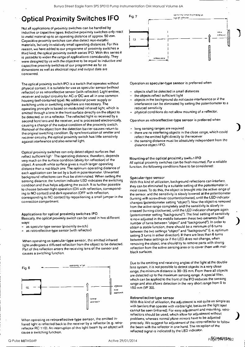
Optical Proximity Switches IFO Not all applications of proximity switches can be handled by inductive or capacitive types. Inductive proximity switches only react
to metal material up to an operating distance of approx. 50 mm.
Capacitive proximity switches can also detect non-metallic materials, but only in relatively small operating distances. For this
reason, we have added to our programme of proximity switches a
third kind, the optical proximity switch series IFO. With this series it
is possible to widen the range of applications considerably. They
were designed by us with the objective to be equal to inductive and
capacitive proximity switches of our programme as far as
dimensions as well as electrical input and output data are
concerned.
The optical proximity switch IFO is a switch that operates without physical contact, it is suitable for use as specular sensor (without reflector) or as retroreflective sensor (with reflector). Light emitter,
receiver and output circuitry for AC or DC are all in one common
housing (self-contained type). No additional power supply or
switching units or switching amplifiers are necessary. The
operating principle is based on modulated infrared light, which is
emitted through a lens in the front surface directly on the object to
be detected, or on a reflector. The reflected light is received by a
second front lens and the receiver, and is processed electronically,
causing a change of the output condition of the proximity switch.
Removal of the object from the detection barrier causes return to
the original switching. condition. By synchronization of emitter and
receiver circuitry, the optical proximity switch has little sensitivity
against interference and also external light.
Optical proximity switches can only detect object surfaces that
reflect sufficient ligh' The operating distance, therefore, depends very much on the surface condition (ability for reflection) of the
object. A smooth white surface gives a much larger operating distance than a mat-black one. The optimum operating distance of
each application can be set by a built-in potentiometer. Unwanted
background reflections can thus be elimininated. When setting the
sensing distance, the function indicator LED indicates the switching
condition and thus helps adjusting the switch. It is further possible
to choose between light-operation (ON with reflection, correspond- ing to NO contact) and dark-operation (OFF with reflection,
corresponding to NC contact) by repositioning a small jumper in the
connection compartment.
Applications for optical proximity switches IFO Basically, the optidal proximity switch can be used in two different
ways: - as specular-type sensor (proximity switch) - as retroreflective-type sensor (with reflector)
When operating as specular-type sensor, the emitted infrared
light undergoes a diffused reflection from the object to be detected.
Part of this reflection enters the receiving lens of the sensor and
causes a switching function.
Fig. 6
11111
'11
operaung ra-ge
laterai approach
<=I amal
approach
When operating as retroreflective-type sensor, the emitted in-
frared light is reflected back to the receiver by a reflector (e. g. retro-
reflector RC 110). An interruption of this light beam by an object will
cause a switching function.
1-6
Fig. 7
undue zone
nn c -se of ,ft,ior
Operation as specular-type sensor is preferred when
- objects shall be detected in small distances - the objects reflect sufficient light - objects in the background do not cause interference or if the
interference can be eliminated by setting the potentiometer to a
reduced sensitivity - physical conditions do not allow mounting of a reflector.
Operation as retroreflective-type sensor is preferred when
- long sensing ranges are required - there are no interfering objects in the close range, which could
reflect the emitted light directly to the receiver - the sensing distance must be absolutely independent from the
distance object / IFO.
Mounting of the optical proximiti switch IFO All optical proximity switches can be flush-mounted. For a reliable
function, the following conditions have to be considered:
Specular-type sensor With this kind of utilization, background reflections can interfere,
they can be eliminated by a suitable setting of the potentiometer in
most cases. To do this, the object is brought into the active range of
the sensor, and the sensitivity is slowly lowered at the potentiometer
(turning with screwdriver counterclockwise), until the LED-indicator
changes (potentiometer setting "object"). Now the object is removed
from the active range completely and the sensitivity is slowly in-
creased (turning clockwise), until the LED indicator changes again
(potentiometer setting "background"). The final setting of sensitivity
is now adjusted in the middle between these two extremes (half
number of turns between "object" and "background"). In order to
obtain a stable function, there should be a minimum of 6 turns
between the two settings "object" and "background" (i. e. optimum
setting 3 turns in either direction). If there are less than 6 turns
between these settings or if the LED does not change, when
removing the object, one should try to remove parts with strong
reflection from the active sensing area or to cover them with mat-
black surfaces.
Due to the emitting and receiving angles of the light at the double-
lens system, it is not possible to detect objects in a very close range, the minimum distance is 30-35 mm. From there all objects
are detected up to the maximum sensing range. A special filter,
which can be applied to the front of the IFO reduces the sensing
range and also allows detection in the very short range from 0 to
150 mm (VF 30).
Retroreflective-type sensor With this kind of utilization, the adjustment is not quite as simple as
with barriers that operate with visible light, because the light spot
cannot be seen (infrared). For easy adjustment and mounting. retro-
reflectors should be used, which allow for adjustment without
problems, whereas normal plane mirrors have to be adjusted
precisely. We suggest for adjustment of the retro-reflector to follow
the beam with the reflector in one hand. The reception of the
reflected signal is indicated by the LED indicator.
SCHMERSAL
Bunya Street Eagle Farm SPS SP010 Pump Instrumentation OM Manual Volume 6A
Q-Pulse Id TMS649 Active 29/01/2014 Page 294 of 322

The triple-reflector allows for an angular misalignment of approx. ±
15°.
Fig. 8 15.
For the standard version, no objects shall be in the close sensing range, roughly up to the specular-type sensor operating range, which depends on the sensitivity set at the potentiometer and on
the surface conditions of the object - otherwise direct reflection from this object can cause interference. A unit avoiding this disadvantage is Spez. 1404.
Operating distance of the optical proximity switch IFO As specular-type sensor, the IFO has an operating range which depends upon the surface condition (reflection properties) of the object, as well as its size and the degree of air pollution.
The graph in figure 9 shows the direction of motion of the object versus operating range, with different settings of the potentiometer. The object was of white mat paper with 90% reflection, size 200 x 200 mm and clean air.
Objects other than white mat paper with 90%.reflection require correction factors. The following list shows approximate factors for some materials:
Material
metal, polished aluminium, anodised black styrofoam, white PVC, grey wood, rough cardboard, mat black
Approx. Correction Factors
1.2 ... 1.6 1.1 ... 1.8
1
0.5 0.4 0.1
Tab. 1
In addition to its surface, the size of an object affects the operating range. Generally speaking, the sensing range is the shorter, the smaller the size of an object is, however, making an object larger increases the sensing range only up to a certain limit.
Fig. 10
cr-tio ArDe
Operating range
[°/°] 125 -
100
75
50
25
50 4 4 0 100 150 200 250 300
For operation as retroreflective-type sensor, the size of the reflector as well as the degree of air pollution are important. Fog. mist. dust and smoke shorten the maximum range. With our reflector RC 110 (o.d. 84 mm) and clean air, the sensing range is 7-times the one of specular-type operation with white mat paper 200 x 200 mm. The range is shorter with smaller reflectors R 101 (o.d. 21 mm) to R 104 (o.d. 47 mm).
A.C. Proximity Switches (2-Wire) The inductive, capacitive, and optical proximity switches given in the catalogue for connection to A.C. are constructed on the two con- ductor system. They can be connected in exactly the same way as mechanical limit switches, that is to say in series with the load (Fig. 11). The sensor receives its supply voltage via the load and is thus operational.
Fig. 11
Thus a low leakage or no-load current flows through the load.. When A.C. proximity switches are "on" (carrying load current) there will be a voltage drop of approximately 3 ... 8 volts depending on type.
The A.C. sensors are provided with internal protection against transient voltage peaks from the main power supply.
D.C. Proximity Switches (3- and 4-Wire) The inductive, capacitive, and optical D.C. sensors in this catalogue have a separate circuit for the supply voltage and for this reason an
additional lead for the load.
The three-conductor system proximity switches operate as either N.O. or N.C. and the 4-wire sensors have complementary outputs (one N.O. and N.C.) and can be used as changeover switches.
In selection of the electronic signal transmitters attention must be paid to the type of circuit (Fig. 12): P-type proximity switches (pnp)'switch the positive potential to the load (sourcing). N-type proximity switches (npn) switch the negative potential to the load (sinking).
Fig. 12
P-type (sourcing) D C switches
N-type (sinking) D.C. switches
Bunya Street Eagle Farm SPS SP010 Pump Instrumentation OM Manual Volume 6A
Q-Pulse Id TMS649 Active 29/01/2014 Page 295 of 322
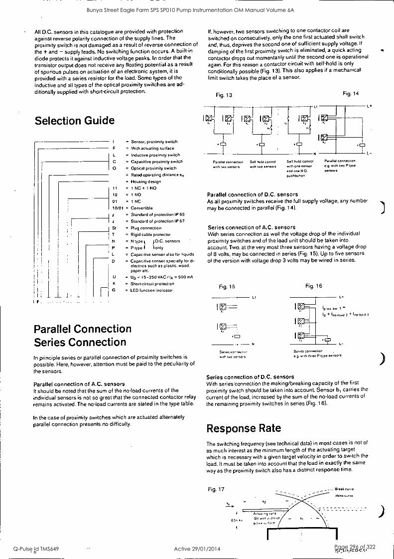
All D.C. sensors in this catalogue are provided with protection against reverse polarity connection of the supply lines. The proximity switch is not damaged as a result of reverse connection of
the + and - supply leads. No switching function occurs. A built-in
diode protects it against inductive voltage peaks. In order that the
transistor output does not receive any floating potential as a result
of spurious pulses on actuation of an electronic system, it is
provided with a series resistor for the load. Some types of the inductive and all types of the optical proximity switches are ad-
ditionally supplied with short-circuit protection.
Selection Guide
I F
F
L
c O
11
10
01
10/01 =
y
St
T
N
P
L
0
U
K
Sensor, proximity switch
With actuating surface
Inductive proximity switch
Capacitive proximity switch
Optical proximity switch
Rated operating distance sn
Housing design
1 NC + 1 NO
1 NO
1 NC
Convertible
Standard of protection IP 65
Standard of protection IP 67
Plug connection
Rigid cable protector
N-type t f D.C. sensors
P-type f t only
Capacitive sensor also for liquids
Capacitive sensor specially for di- electrics such as plastic, wood. paper etc.
UB = 15-250 VAC / IA = 500 mA
Short-circuit protection
LED function indicator
Parallel Connection Series Connection In principle series or parallel connection of proximity switches is
possible. Here, however, attention must be paid to the peculiarity of
the sensors.
Parallel connection of A.C. sensors It should be noted that the sum of the no-load currents of the individual sensors is not so great that the connected contactor relay
remains activated. The no-load currents are stated in the type table.
In the case of proximity switches which are actuated alternately parallel connection presents no difficulty.
If, however, two sensors switching to one contactor coil are
switched on consecutively, only the one first actuated shall switch
and, thus, deprives the second one of sufficient supply voltage. If
damping of the first proximity switch is eliminated, a quick acting
contactor drops out momentarily until the second one is operational
again. For this reason a contactor circuit with self-hold is only
conditionally possible (Fig. 13). This also applies if a mechanical limit switch takes the place of a sensor.
Fig. 13 Fig. 14
Parallel connection Sell-hold control with two sensors with two sensors
Self-hold control with one sensor and one N.O.
pushbutton
Parallel connection, e.g. with two P-type
sensors
Parallel connection of D.C. sensors As all proximity switches receive the full supply voltage, any number
may be connected in parallel (Fig. 14).
Series connection of A.C. sensors With series connection as well the voltage drop of the individual proximity switches and of the load unit should be taken into .
account. Two, at the very most three sensors having a voltage drop
of 8 volts, may be connected in series (Fig. 15). Up to five sensors of the version with voltage drop 3 volts may be wired in series.
Fig. 15
Series cornett on
with two sensors
L 1
N
Fig. 16
Series connection e.g. with three P-type sensors
Series connection of D.C. sensors With series'connection the making/breaking capacity of the first
proximity switch should be taken into account. Sensor b, carries the
current of the load, increased by the sum of the no-load currents of
the remaining proximity switches in series (Fig. 16).
Response Rate The switching frequency (see technical data) in most cases is not of
as much interest as the minimum length of the actuating target
which is necessary with a given target velocity in order to switch the
load. It must be taken into account that the load in exactly the same
way as the proximity switch also has a distinct response time.
Fig. 17
0,5. sn
SCI-IR,1c4C A I
Bunya Street Eagle Farm SPS SP010 Pump Instrumentation OM Manual Volume 6A
Q-Pulse Id TMS649 Active 29/01/2014 Page 296 of 322

The maximum target velocity is dependent upon:
1. The response time tE of the sensor 2. The attenuation range of the sensor 3. The length of the actuating target
4. The response time of the load
Where: tE = Response time (ms) of the proximity switch constant for all
target velocities; it is the time required for the output to re-
spond after the target reaches the specified operate point
(turn-on time).
s, = Target travel (mm) in attenuation range (see technical data)
s2 = Target length (mm)
is = Load response time (ms)
must be taken from the data sheets of the contactor or relay
manufacturer
vA = Target velocity (m/s)
s2 = VA (tE + s, $, + S2
VA - tE + tz
Example: Determine the minimum target length to operate IFL 15-30-10zTG 220 VAC, when the target velocity is 2 m/s and the load response time is 20 ms.
Given that: VA = 2 m/s, s, = 13 mm (IFL 15-30-10zTG-220 VAC tE = 18 ms, ts = 20 ms
To find: s2 = ? mm S2 = VA ' + ts) $,
S2 = VA (tE + ts) - si =2 38 - 13
s2 = 63 mm
+ ts = 38 ms
Bunya Street Eagle Farm SPS SP010 Pump Instrumentation OM Manual Volume 6A
Q-Pulse Id TMS649 Active 29/01/2014 Page 297 of 322
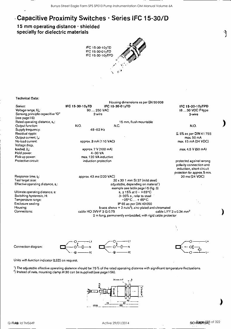
- Capacitive Proximity Switches Series IFC 15-30/D 15 mm operating distance shielded specially for dielectric materials
Technical Data:
Series: Voltage range, Ub:
Sensing principle capacitive "D" (see page 1 -5):
Rated operating distance, sd:
Output function: Supply frequency: Residual ripple: Output current, IA:
No-load current: Voltage drop, loaded, Ud:
Hold power: Pick-up power: Protective circuit:
Response time, tE:
Test target size: Effective operating distance, sr:
Ultimate operating distance, s: Switching hysteresis, H: Temperature range: Enclosure sealing: Housing: Connections:
Connection diagram:
IFC 15-30-10yTD IFC 15-30-01yTD IFC 15 -30-10yTPD
Housing dimensions as per EN 50 008 IFC 15-30-10yTD IFC 15-30-01yTD
90 ... 250 VAC 2-wire
15 mm, flush mountable N.O. N.C.
48-62 Hz
approx. 3 mA (110 VAC)
approx. 7 V (100 mA) 4-30 VA
max. 120 VA inductive induction protection
approx. 43 ms (220 VAC) 30 x 30 1 mm St 37 (mild steel)
adjustable, depending on material') example see table page 1 -5 (fig. 3)
s, ± 15% at 0 - +65°C 3-20% sr, refer to steel
-25°C + 65°C IP 65 as per DIN 40 050
brass sleeve + 2 nuts2), zinc-plated and chromated cable HO 3VV-F 3 G 0.75 cable LiYY 3 x 0.34 mm2
2 m long, permanently embedded, with rigid cable protector
IFC 15-30-10yTPD 18...30 VDC P-type
3-wire
N.O.
5% as per DIN 41 755 max. 50 mA
max. 15 mA (24 VDC)
max. 4.5 V (50 mA)
protected against wrong polarity connection and induction, short circuit
protection for approx 5 min.
20 ms (24 VDC)
- Co_ Ll
0 N
.e PE
LI
N
PE
0
"'" -I-
Units with function indicator (LED) on request.
1) The adjustable effective operating distance should be 75% of the rated operating distance with significant temperature fluctuations. 2) Instead of nuts, mounting clamp H 30 can be supplied (see page 1 -56).
36 mm A/F S
1-48
L+
L
SCHMERSAL
Bunya Street Eagle Farm SPS SP010 Pump Instrumentation OM Manual Volume 6A
Q-Pulse Id TMS649 Active 29/01/2014 Page 298 of 322

BRISBANE CITY COUNCIL Dept. Water Supply and Sewage Pumpwell No 1, Eagle Farm Pump Station
BCC Contract No S20/95/96 System Instrumentation
Operation and Maintenance Manual
Section 3 Design Criteria and Process Description
The pump instrumentation comprises monitoring equipment for the following functions:
3.1 Vibration Measurement
The vibration level on each bearing and the pump housing are monitored by Gently Nevada Velometers. The Velometer transducers were used in preference to Accelerometers because of the lower characteristic vibration frequency of larger size machines. The Velometer is accurate over a frequency range of about 8Hz to 2kHz.
The vibration measurement equipment is configured as follows:
A dual transducer/ local monitor unit is provided for each pair of vibration probes.
A local panel readout of vibration amplitude in mm/s for each bearing
A 4-20mA output for each bearing for the BCC control system
Adjustable alarm and shutdown setpoints with voltage free contacts for connection to the BCC control system.
3.2 Temperature Measurement
The temperature is monitored for the main bearings, motor stator windings and motor cooling air. They are all RTD type sensors with PT 100 platinum elements.
3.2.1 Bearing Temperature
The RTD sensors are located to monitor the outer race temperature of each anti friction bearing on the pump and motor.
The probe is fixed into the bearing housing and positioned at the centre of the outer race. A spring-loaded measurement tip is included to ensure good contact with the surface of the roller bearing outer race.
A hose proof junction box with screwed lid is fitted to each RTD to permit the connection of external wiring and screwed conduit.
All the bearing temperature signals are taken back to the Bently Nevada 6 channel temperature monitor.
15140/Inst Man/BRH Issue 1 29-Apr-98 Page 3-1
Bunya Street Eagle Farm SPS SP010 Pump Instrumentation OM Manual Volume 6A
Q-Pulse Id TMS649 Active 29/01/2014 Page 299 of 322
BRISBANE CITY COUNCIL Dept. Water Supply and Sewage Pumpwell No 1, Eagle Farm Pump Station
BCC Contract No S20/95/96 System Instrumentation
Operation and Maintenance Manual
3.2.2 Motor Cooling Air Temperature
The RTD sensors are located to monitor the motor cooling air temperature to and from each heat exchanger.
A hose proof junction box with screwed lid is fitted to each RTD to permit the connection of external wiring and screwed conduit.
All the air temperature signals are taken directly back to the BCC control system.
3.2.3 Motor Stator Winding Temperature
The RTD sensors are embedded in the motor stator windings to measure the winding temperature in each phase. There are three RTD's provided per phase.
All of the signals are taken to a junction box located on the side of the motor.
All the stator winding temperature signals are taken directly back to the BCC control system.
3.3 Speed Measurement
The motor and pump speed is measured independently via proximity sensors located on the drive shaft. A digital pulsed signal is sent back to the speed-monitoring module in the Bently Nevada system rack.
Normally both signals will be identical unless there is a sheared coupling. The signals are monitored by the BCC control system for this occurrence.
The pump speed sensor has two proximity probes, phase displaced so that the rotation direction can be determined and an alarm raised for reverse rotation.
15140/Inst Man/BRH Issue 1 29-Apr-98 Page 3-2
Bunya Street Eagle Farm SPS SP010 Pump Instrumentation OM Manual Volume 6A
Q-Pulse Id TMS649 Active 29/01/2014 Page 300 of 322

BRISBANE CITY COUNCIL Dept. Water Supply and Sewage Pumpwell No 1, Eagle Farm Pump Station
BCC Contract No S20/95/96 System Instrumentation
Operation and Maintenance Manual
3.4 3300 System Compatibility Guide
The following publication entitled 3300 System Compatibility Guide (Part No 104003-01 Rev D) is prepared by Bent ly Nevada for plant personnel who operate and maintain the system. It provides basic design information on 3300 monitoring system and a system compatibility guide.
The following sections are included:
3.4.1 Operating Information
3.4.2 Installation
3.4.3 Maintenance and Trouble Shooting
15140/111st Man/BRH Issue 1 29-Apr-98 Page 3-3
Bunya Street Eagle Farm SPS SP010 Pump Instrumentation OM Manual Volume 6A
Q-Pulse Id TMS649 Active 29/01/2014 Page 301 of 322

PART NO. 104003-01 REVISION 0,
JUNE 1994
3300 SYSTEM COMPATIBILITY GUIDE
....... .
tHi41:e
. .
$:e a o
...- ,
Bunya Street Eagle Farm SPS SP010 Pump Instrumentation OM Manual Volume 6A
Q-Pulse Id TMS649 Active 29/01/2014 Page 302 of 322
104003-01 3300 Compatibility Guide
NOTICE
Bent ly Nevada Corporation has attempted to identify areas of risk created by improper installation and/or operation of this product. These areas of information are noted as WARNING or CAUTION for your protection and for the safe and effective operation of this equipment. Read all instructions before installing or operating this system. Pay particular attention to those areas designated by the following symbols.
/WARNING
High voltage present. Contact could cause shock, burns, or death.
Do not touch exposed wires or terminals.
A\ CAUTION
Machine protection will be lost during calibration.
Keyphasor® and Proxinitor ®are registered trademarks of Bently Nevada Corporation:
Copyrighte Bently Nevada Corporation 1992, 1993, 1994
All Rights Reserved
No part of this publication, may be reproduced, transmitted, stored in a retrieval system nor translated into any human or computer language, in any form or by any means, electronic, mechanical, magnetic, optical, chemical, manual, or otherwise, without the prior written permission of the copyright owner,
Bently Nevada Corporation P.O. Box 157
Minden, Nevada 89423 USA Telephone 800-227-5514 702482-3611
Telex 354437 Telemail 7400983 BNC UC
Fax 702-782-9253 Copyright infringement is a serious matter under
United States of America and foreign copyright laws.
ii
Bunya Street Eagle Farm SPS SP010 Pump Instrumentation OM Manual Volume 6A
Q-Pulse Id TMS649 Active 29/01/2014 Page 303 of 322
3300 Compatibility Guide 104003-01
CONTENTS
Section Title Page
1 Introduction 1
2 System Identification 3
2.1 Original System 4
2.2 SDI/DDI system 5
2.3 Mixed System 6
2.4 Rack 7
2.5 Firmware 10
3 System Compatibility 13
3.1 Original System 13
3.2 SDI/DDI system 14
3.3 Mixed System 16
3.4 Other Compatibility Issues 17
List of Tables
Table No.
1 Monitor Firmware Part Numbers for SDI/DDI Compatible Firmware 10
2 Compatibility for the Original 3300 System 13
3 Compatibility for the SDI/DDI 3300 System 14
4 Computer Interface and Monitoring Software Compatibility for a SDI/DDI System 15
5 Compatibility for a Mixed System 16
Ill
Bunya Street Eagle Farm SPS SP010 Pump Instrumentation OM Manual Volume 6A
Q-Pulse Id TMS649 Active 29/01/2014 Page 304 of 322

104003-01 3300 Compatibility Guide
iv
Bunya Street Eagle Farm SPS SP010 Pump Instrumentation OM Manual Volume 6A
Q-Pulse Id TMS649 Active 29/01/2014 Page 305 of 322
3300 Compatibility Guide 104003-01
11 I INTRODUCTION
The 3300 system has been enhanced to upgrade the computer/communications interface options. The computer/communication interface options are called the Serial Data Interface/Dynamic Data Interface or SDI/DDI and were released in April 1992. The external interfaces for dynamic and transient data, DDIX and TDIX, were released in Aug 1992 and July 1993 respectively. 3300 components that have been changed to implement these interface options are the System Monitor, AC and DC Power Supply, rack backplane, and monitor firmware. 3300 systems that consist of these upgraded components are called the SDI/DDI system.
Although the upgraded components have replaced the older components, there will continue to be occasions when questions on compatibility between old and new components will come up. This compatibility guide addresses questions created by this enhancement by showing how to:
Identify the three supported configurations of the 3300 system.
Choose spare parts for use in the original and SDI/DDI system.
Choose 3300 systems that are compatible with your computer interfaces.
The information in this guide is divided into these two sections:
Section 2, System Identification, lists the three configurations of the 3300 Monitoring System which are authorized by Bent ly Nevada Corporation and shows how to identify each one. Identifying your system will help you make decisions about replacement parts and computer/communications interfaces.
Section 3, Compatibility, presents guidelines about using spare parts with different configurations of the 3300 system. It also describes the compatibility between 3300 systems, communication interfaces, and monitoring and diagnostic software.
The table on the following page shows some definitions and explanations for the part numbers and abbreviations used in this guide.
1
Bunya Street Eagle Farm SPS SP010 Pump Instrumentation OM Manual Volume 6A
Q-Pulse Id TMS649 Active 29/01/2014 Page 306 of 322
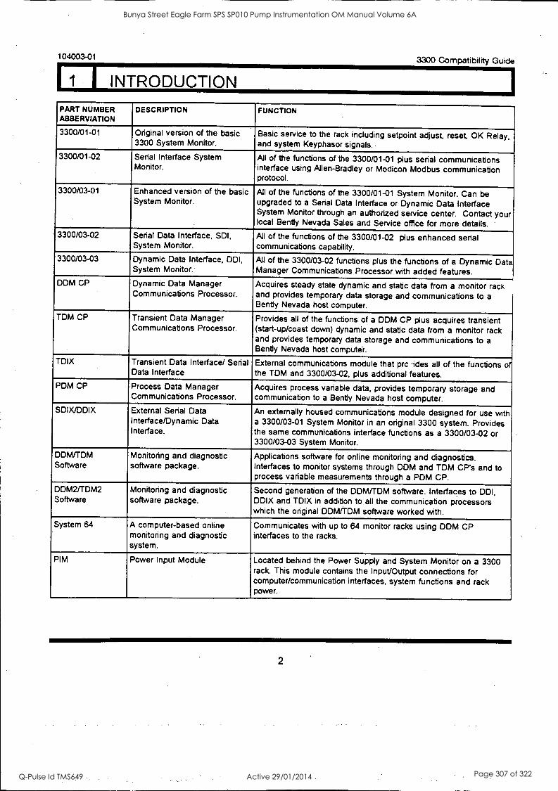
104003-01 3300 Compatibility Guide
I INTRODUCTION PART NUMBER ABBERVIATION
DESCRIPTION FUNCTION
3300/01-01 Original version of the basic 3300 System Monitor.
Basic service to the rack including setpoint adjust, reset, OK Relay, and system Keyphasor signals..
3300/01-02 Serial Interface System Monitor.
All of the functions of the 3300/01-01 plus serial communications interface using Allen-Bradley or Modicon Modbus communication protocol.
3300/03-01 Enhanced version of the basic System Monitor.
All of the functions of the 3300/01-01 System Monitor. Can be upgraded to a Serial Data Interface or Dynamic Data Interface System Monitor through an authorized service center. Contact your local Bentiy Nevada Sales and Service office for more details.
3300/03-02 Serial Data Interface, SDI, System Monitor.
All of the functions of the 3300/01-02 plus enhanced serial communications capability.
3300/03-03 Dynamic Data Interface, DOI, System Monitor.
All of the 3300/03-02 functions plus the functions of a Dynamic Data Manager Communications Processor with added features.
DDM CP Dynamic Data Manager Communications Processor.
Acquires steady state dynamic and static data from a monitor rack and provides temporary data storage and communications to a Bentiy Nevada host computer.
TDM CP Transient Data Manager Communications Processor.
Provides all of the functions of a DDM CP plus acquires transient (start-up/coast down) dynamic and static data from a monitor rack and provides temporary data storage and communications to a Bentiy Nevada host computer.
TDIX Transient Data Interface/ Serial Data Interface
External communications module that prc 'ides all of the functions of the TDM and 3300/03-02, plus additional features.
PDM CP Process Data Manager Communications Processor.
Acquires process variable data, provides temporary storage and communication to a Bentiy Nevada host computer.
SDIX/DDIX External Serial Data Interface/Dynamic Data Interface.
An externally housed communications module designed for use with a 3300/03-01 System Monitor in an original 3300 system. Provides the same communications interface functions as a 3300/03-02 or 3300/03-03 System Monitor.
DDM/TDM Software
Monitoring and diagnostic software package.
Applications software for online monitoring and diagnostics. Interfaces to monitor systems through DDM and TDM CP's and to process variable measurements through a PDM CP.
DDM2/TDM2 Software
Monitoring and diagnostic software package.
Second generation of the DDM/TDM software. Interfaces to DDI, DDIX and TDIX in addition to all the communication processors which the original DDM/TDM software worked with.
System 64 A computer-based online monitoring and diagnostic system.
Communicates with up to 64 monitor racks using DDM CP interfaces to the racks.
PIM Power Input Module Located behind the Power Supply and System Monitor on a 3300 rack. This module contains the Input/Output connections for computer/communication interfaces, system functions and rack power.
2
Bunya Street Eagle Farm SPS SP010 Pump Instrumentation OM Manual Volume 6A
Q-Pulse Id TMS649 Active 29/01/2014 Page 307 of 322
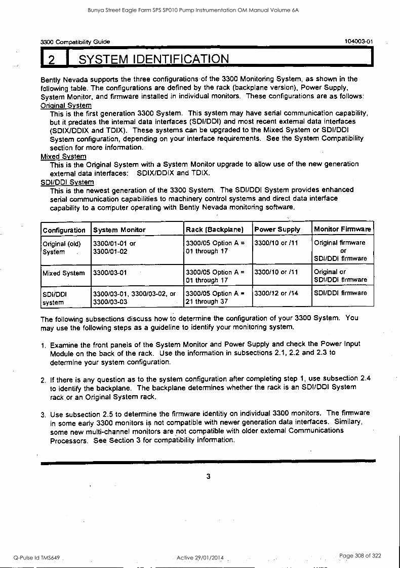
3300 Compatibility Guide 104003-01
I SYSTEM IDENTIFICATION
Bently Nevada supports the three configurations of the 3300 Monitoring System, as shown in the following, table. The configurations are defined by the rack (backplane version), Power Supply, System Monitor, and firmware installed in individual monitors. These configurations are as follows: Original System
This is the first generation 3300 System. This system may have serial communication capability, but it predates the internal data interfaces (SDI/DDI) and most recent external data interfaces (SDIX/DDIX and TDIX). These systems can be upgraded to the Mixed System or SDI/DDI System configuration, depending on your interface requirements. See the System Compatibility section for more information.
Mixed System This is the Original System with a System Monitor upgrade to allow use of the new generation external data interfaces: SDIX/DDIX and TDIX.
SDI/DDI System This is the newest generation of the 3300 System. The SDI/DDI System provides enhanced serial communication capabilities to machinery control systems and direct data interface capability to a computer operating with Bently Nevada monitoring software.
Configuration System Monitor Rack (Backplane) Power Supply Monitor Firmware
Original (old) System .
3300/01-01 or 3300/01-02
3300/05 Option A =
01 through 17 3300/10 or /11 Original firmware
or SDI/DDI firmware
Mixed System 3300/03-01 3300/05 Option A =
01 through 17 3300/10 or /11 Original or
SDI/DDI firmware
SDI/DDI system
3300/03-01, 3300/03-02, or 3300/03-03
3300/05 Option A =
21 through 37
. .
3300/12 or /14 SDI/DDI firmware
The following subsections discuss how to determine the configuration of your 3300 System. You
may use the following steps as a guideline to identify your monitoring system.
1. Examine the front panels of the System Monitor and Power Supply and check the Power Input Module on the back of the rack. Use the information in subsections 2.1, 2.2 and 2.3 to
determine your system configuration.
2. If there is any question as to the system configuration after completing step 1, use subsection 2.4
to identify the backplane. The backplane determines whether the rack is an SDI/DDI System
rack or an Original System rack.
3. Use subsection 2.5 to determine the firmware identitiy on individual 3300 monitors. The firmware
in some early 3300 monitors is not compatible with newer generation data interfaces. Similary,
some new multi-channel monitors are not compatible with older external Communications Processors. See Section 3 for compatibility information.
3
Bunya Street Eagle Farm SPS SP010 Pump Instrumentation OM Manual Volume 6A
Q-Pulse Id TMS649 Active 29/01/2014 Page 308 of 322
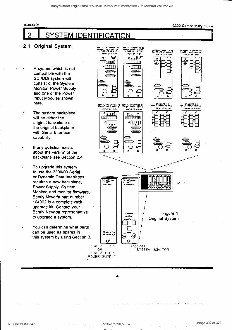
104003-01 3300 Compatibility Guide
I SYSTEM IDENTIFICATION
2.1 Original System
A system which is not compatible with the SDI/DDI system will consist of the System Monitor, Power Supply and one of the Power Input Modules shown here.
The system backplane will be either the original backplane or the original backplane with Serial Interface capability.
If any question exists about the vers,,n of the backplane see Section 2.4.
To upgrade this system to use the 3300/03 Serial or Dynamic Data Interfaces requires a new backplane, Power Supply, System Monitor, and monitor firmware. Bent ly Nevada part number 104002 is a complete rack upgrade kit. Contact your Bent ly Nevada representative to upgrade a system.
You can determine what parts can be used as spares in this system by using Section 3.
INTERFACE .c ROVER INRUI moome v4pAR.ER wpm('
IREAR OC RACK,
SERIAL INTERFACE .0 ROVER PUT ROOULE
REAR OF RACK,
SERIAL INTERFACE DC .04. ,NpUT hicomE w,SAPOiEO °Poch°
1 REM Of RAO(
1111E1111111111
sERim. INTERFACE DC DOVER PIT mCOULE
PEAR Or RACXI
INTERNAL BARRIER .0 DOVER .N01.17 ulOttE
,REM or RA/)T,
INTERNAL BARRIER OC ROVER .NPUM WOOULE
.REM OF PACK,
. STMOAK1 AC ROVER "PVT u0OULE
I.EAR OF RACK,
ST.00AFOOC ROVER Ihpu7 +COAX
(REAR Of 14.0.1
BENTL r re NEVADA
3300/10 AC OR
3300/11 DC POWER SUPPLY
Sn2e1000,
0., rimR
(9 & 3300/01
SYSTEM
RACK
Figure 1
Original System
MONITOR
4
Bunya Street Eagle Farm SPS SP010 Pump Instrumentation OM Manual Volume 6A
Q-Pulse Id TMS649 Active 29/01/2014 Page 309 of 322
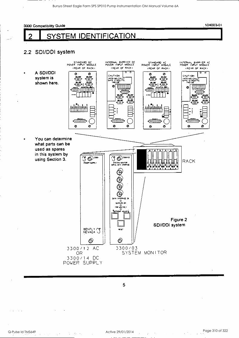
3300 Compatibility Guide
2 I SYSTEM IDENTIFICATION
.104003-01
2.2 SDI/DDI system
A SDI/DDI system is shown here.
STANDARD DC ROVER INPUT MODULE
(REAR OF RACK)
0 0 en en ens
111111111
111111111111
0 0
You can determine what parts can be used as spares in this system by using Section 3.
INTERNAL BARRIER DC ROVER INPUT MODULE
(REAR OF RAEK1
CAUTION INTRINSICALLY SAFE CIRCUITS
I NS 1 0E
0
0 0
111111111
-
-
-- 0 0
(3' di) 3300/
PNER Sums.
BENT L Y NEVADA NJ
3300/12 AC OR
3300/14 DC POWER SUPPLY
STANDARD AC ROVER INPUT MODULE
(REAR OF RACK1
111111111
Ii
111111111111
otx.;2..7-.10 0 0 0
INTERNAL BARRIER AC POWER INPUT MODULE
(REAR OF RACK1
CAUTION NIA I NS I CALL SAFE C mcw TS
(NS (DE
0
0 0
111111111 1(1
- 1
0 0 0
z r5 (5)1310,03
MIN 04TCP ugly. DOA iMTEW,CE
6j) BATA INTEWACE
0 Si .ES OT
0 TAO 14.101:1-,
tErPCPC .1:1/15T4
RESET
11 IF RACK
Figure.2 SDI/DDI system
3300/03 SYSTEM MONITOR
5
Bunya Street Eagle Farm SPS SP010 Pump Instrumentation OM Manual Volume 6A
Q-Pulse Id TMS649 Active 29/01/2014 Page 310 of 322
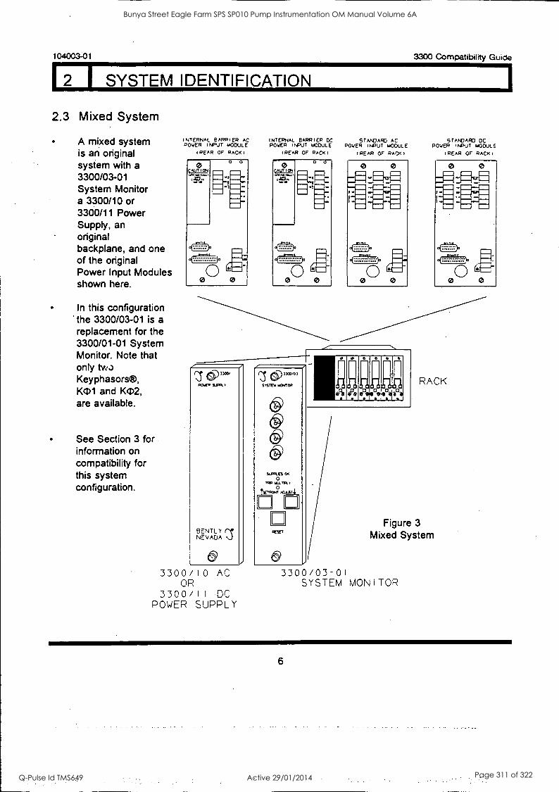
104003-01 3300 Compatibility Guide
2 1 SYSTEM IDENTIFICATION
2.3 Mixed System
A mixed system is an original system with a
3300/03-01 System Monitor a 3300/10 or 3300/11 Power Supply, an original backplane, and one of the original Power Input Modules shown here.
In this configuration the 3300/03-01 is a replacement for the 3300/01-01 System Monitor. Note that only tve..)
Keyphasors®, K(1)1 and KD2, are available.
See Section 3 for information on compatibility for this system configuration.
INTERNAL SAPPIER AC POWER INPUT MODULE
(REAR OF RACKI
INTERNAL BARRIER DC STANDARD AC POWER INPUT MODULE POWER INPUT MODULE
(REAR OF RACK) (REAR OF RACK)
BENT LT NEVADA
6 3300/10 AC
OR 3300/11 -DC
POWER SUPPLY
r\S 6)D3XW° SVSIEU 1COCCP
SURFS 0
0 t*,AatoguAY4
n
STANDARD DC POWER INPUT MODULE
(REAR OF RACK)
RACK
Figure 3
Mixed System
3300/03-01 SYSTEM MONITOR
6
Bunya Street Eagle Farm SPS SP010 Pump Instrumentation OM Manual Volume 6A
Q-Pulse Id TMS649 Active 29/01/2014 Page 311 of 322
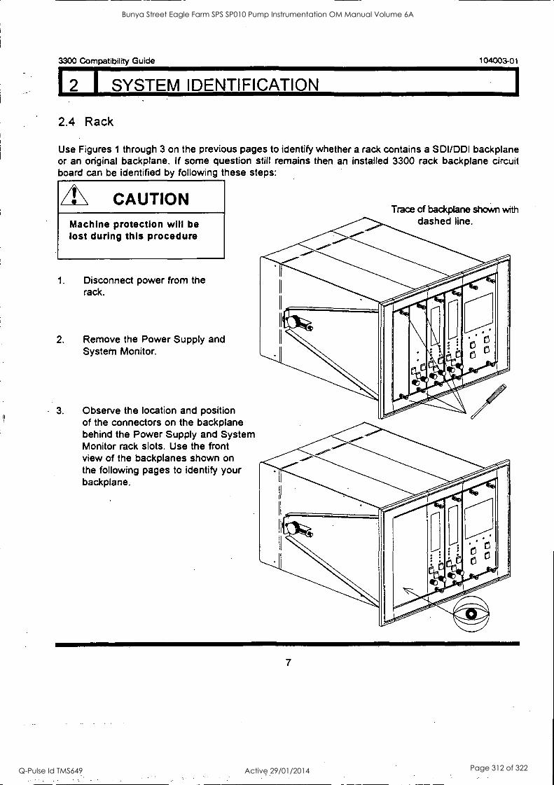
3300 Compatibility Guide 104003-01
I SYSTEM IDENTIFICATION
2.4 Rack
Use Figures 1 through 3 on the previous pages to identify whether a rack contains a SDI/DDI backplane or an original backplane. if some question stilt remains then an installed 3300 rack backplane circuit board can be identified by following these steps:
CAUTION Machine protection will be lost during this procedure
1. Disconnect power from the rack.
2. Remove the Power Supply and System Monitor.
3. Observe the location and position of the connectors on the backplane behind the Power Supply and System Monitor rack slots. Use the front view of the backplanes shown on the following pages to identify your backplane.
Trace of backplane shown with dashed line.
7
Bunya Street Eagle Farm SPS SP010 Pump Instrumentation OM Manual Volume 6A
Q-Pulse Id TMS649 Active 29/01/2014 Page 312 of 322
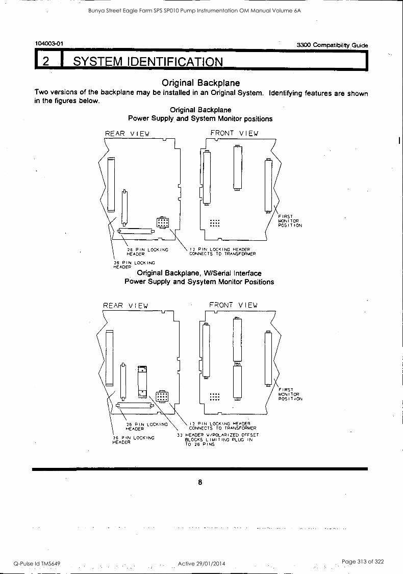
104003-01 3300 Compatibility. Guide
(2 1 SYSTEM IDENTIFICATION
Original Backplane Two versions of the backplane may be installed in an Original System. Identifying features are shown in the figures below.
Original Backplane Power Supply and System Monitor positions
REAR VIEW FRONT VIEW ---u
26 PIN LOCKING HEADER
12 PIN LOCKING HEADER CONNECTS TO TRANSFORMER
26 PIN LOCKING HEADER
Original Backplane, W/Serial Interface Power Supply and Sysytem Monitor Positions
REAR VIEW
26 PIN LOCKING HEADER
26 PIN LOCKING HEADER
FRONT VIEW
FIRST MONITOR POSITION
12 PIN LOCKING HEADER CONNECTS TO TRANSFORMER
32 HEADER M /POLARIZED OFFSET BLOCKS LIMITING PLUG IN TO 26 PINS
FIRST MONITOR POSITION
8
Bunya Street Eagle Farm SPS SP010 Pump Instrumentation OM Manual Volume 6A
Q-Pulse Id TMS649 Active 29/01/2014 Page 313 of 322
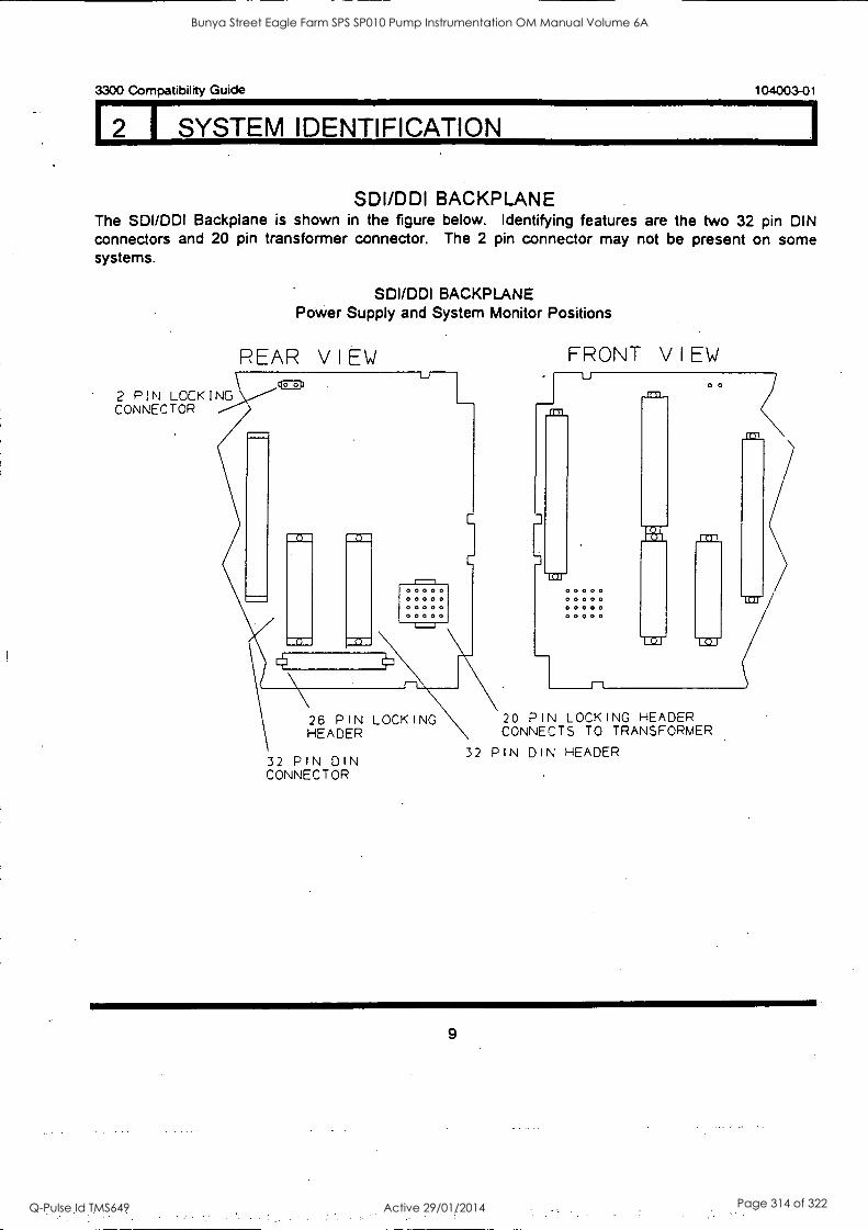
3300 Compatibility Guide 104003-01
2 1 SYSTEM IDENTIFICATION
SDI/DDI BACKPLANE The SDI/DDI Backplane is shown in the figure below. Identifying features are the two 32 pin DIN connectors and 20 pin transformer connector. The 2 pin connector may not be present on some systems.
SDI/DDI BACKPLANE Power Supply and System Monitor Positions
PEAR VIEW EDD
2 PIN LOCKING CONNECTOR
U-
C
1-1
3
FRONT VIEW
00000 00000 00000 00000 00000 00000 00000 00000
26 PIN LOCKING HEADER
32 PIN DIN CONNECTOR
0.
20 PIN LOCKING HEADER CONNECTS TO TRANSFORMER
32 PIN DIN HEADER
Bunya Street Eagle Farm SPS SP010 Pump Instrumentation OM Manual Volume 6A
Q-Pulse Id TMS649 Active 29/01/2014 Page 314 of 322
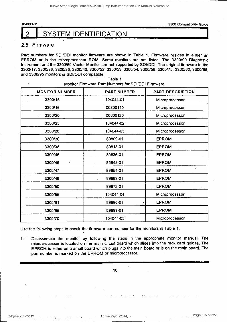
104003-01 3300 Compatibility Guide
12 1 SYSTEM IDENTIFICATION
2.5 Firmware
Part numbers for SDI/DDI monitor firmware are shown in Table 1. Firmware resides in either an EPROM or in the microprocessor ROM. Some monitors are not listed. The 3300/90 Diagnostic Instrument and the 3300/60 Vector Monitor are not supported by SDI/DDI. The original firmware in the 3300/17, 3300/36, 3300/39, 3300/40, 3300/52, 3300/53, 3300/54, 3300/56, 3300/75, 3300/80, 3300/85, and 3300/95 monitors is SDI/DDI compatible.
Table 1
Monitor Firmware Part Numbers for SDI/DDI Firmware
MONITOR NUMBER PART NUMBER PART DESCRIPTION
3300/15 .
104044-01 Microprocessor
3300/16 00800119 Microprocessor
3300/20 00800120 Microprocessor
3300/25 104044-02 Microprocessor
3300/26 104044-03 Microprocessor
3300/30 89809-01 EPROM
3300/35 89818-01 EPROM
3300/45 89836-01 EPROM
3300/46 89845-01 EPROM
3300/47 89854-01 EPROM
3300/48 89863-01 EPROM
3300/50 89872-01 EPROM
3300/55 104044-04 Microprocessor
3300/61 89890-01 .. EPROM
3300/65 89899-01 EPROM
3300/70 104044-05 Microprocessor
Use the following steps to check the firmware part number for the monitors in Table 1.
1. Disassemble the monitor by following the steps in the appropriate monitor manual. The microprocessor is located on the main circuit board which slides into the rack card guides. The EPROM is either on a small board which plugs into the main board or is on the main board. The part number is marked on the EPROM or microprocessor.
10
Bunya Street Eagle Farm SPS SP010 Pump Instrumentation OM Manual Volume 6A
Q-Pulse Id TMS649 Active 29/01/2014 Page 315 of 322
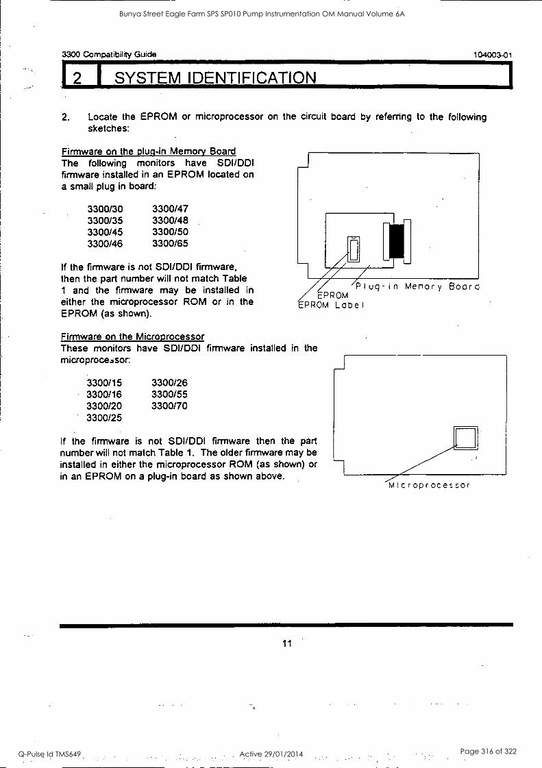
12 I SYSTEM IDENTIFICATION
3300 Compatibility Guide 104003-01
2. Locate the EPROM or microprocessor on the circuit board by referring to the following sketches:
Firmware on the plug -in Memory Board The following monitors have SDI/DDI firmware installed in an EPROM located on a small plug in board:
3300/30 3300/47 3300/35 3300/48 3300/45 3300/50 3300/46 3300/65
If the firmware is not SDI/DDI firmware, then the part number will not match Table 1 and the firmware may be installed in either the microprocessor ROM or in the EPROM (as shown).
Plug-in Menory Board EPROM
EPROM Lobel
Firmware on the Microprocessor These monitors have SDI/DDI firmware installed in the microprocessor:
3300/15 3300/26 3300/16 3300/55 3300/20 3300/70 3300/25
If the firmware is not SDI/DDI firmware then the part number will not match Table 1. The older firmware may be installed in either the microprocessor ROM (as shown) or in an EPROM on a plug-in board as shown above.
Microprocessor
Bunya Street Eagle Farm SPS SP010 Pump Instrumentation OM Manual Volume 6A
Q-Pulse Id TMS649 Active 29/01/2014 Page 316 of 322
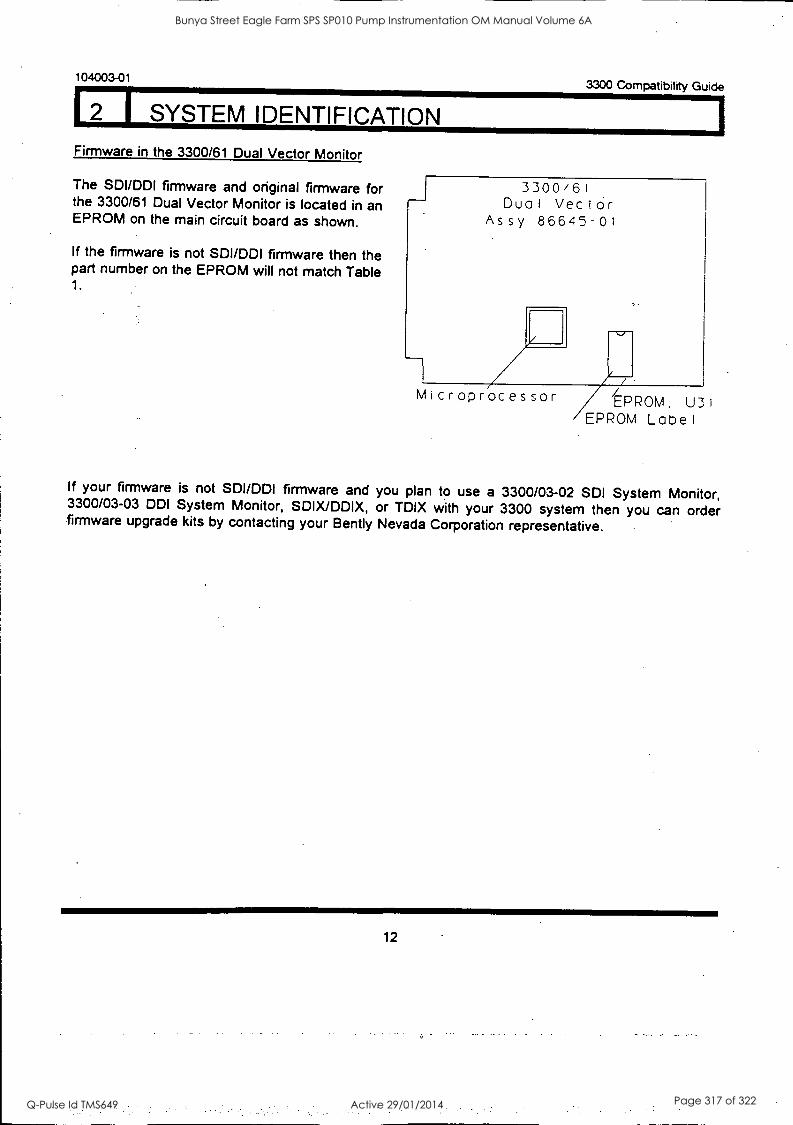
104003-01 3300 Compatibility Guide
2 I SYSTEM IDENTIFICATION Firmware in the 3300/61 Dual Vector Monitor
The SDI/DDI firmware and original firmware for the 3300/61 Dual Vector Monitor is located in an EPROM on the main circuit board as shown.
If the firmware is not SDI /DDI firmware then the part number on the EPROM will not match Table 1.
_J 3300/61 Dual VeciOr
Assy 86645-01
Microprocessor EPROM. U31 EPROM Label
If your firmware is not SDI/DDI firmware and you plan to use a 3300/03-02 SDI System Monitor, 3300/03-03 DDI System Monitor, SDIX/DDIX, or TDIX with your 3300 system then you can order firmware upgrade kits by contacting your Bently Nevada Corporation representative.
12
Bunya Street Eagle Farm SPS SP010 Pump Instrumentation OM Manual Volume 6A
Q-Pulse Id TMS649 Active 29/01/2014 Page 317 of 322
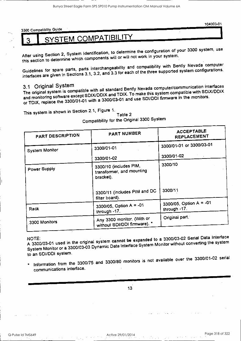
3300 Compatibility Guide
104003-01
3 I SYSTEM COMPATIBILITY
After using Section 2, System Identification, to determine the configuration of your 3300 system, use
this section to determine which components will or will not work in your system.
Guidelines for spare parts, parts interchangeability and compatibility with Bently Nevada computer
interfaces are given in Sections 3.1, 3.2, and 3.3 for each of the three supported system configurations.
3.1 Original System The original system is compatible with all standard Bently Nevada computer/communication interfaces
and monitoring software except SDIX/DDIX and TDIX. To make this system compatible with SDIX/DDIX
or TDIX, replace the 3300/01-01 with a 3300/03-01 and use SDI /DDI firmware in the monitors.
This system is shown in Section 2.1, Figure 1.
Table 2
Compatibility for the Original 3300 System
PART DESCRIPTION PART NUMBER ACCEPTABLE REPLACEMENT
System Monitor 3300/01-01
3300/01-02
3300/01-01 or 3300/03-01
3300/01-02
Power Supply 3300/10 (includes PIM,
transformer, and mounting
bracket).
3300/11 (includes PIM and DC
filter board).
3300/10
3300/11
Rack 3300/05, Option A = -01
through -17.
3300/05, Option A = -01
through -17.
3300 Monitors Any 3300 monitor. (With or
without SDUDDI firmware). * Original part.
NOTE: A 3300/03-01 used in the original system cannot be expanded to a 3300/03-02 Serial Data Interface
System Monitor or a 3300/03-03 Dynamic Data Interface System Monitor without converting the system
to an SDUDDI system.
* Information from the 3300/75 and 3300/80 monitors is not available over the 3300/01-02 serial
communications interface.
13.
Bunya Street Eagle Farm SPS SP010 Pump Instrumentation OM Manual Volume 6A
Q-Pulse Id TMS649 Active 29/01/2014 Page 318 of 322
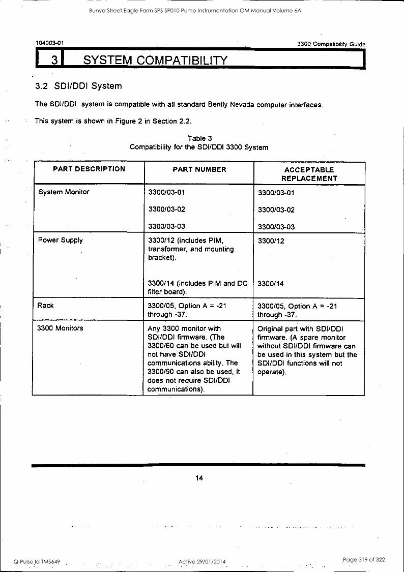
104003-01
31 SYSTEM COMPATIBILITY
3300 Compatibility Guide
3.2 SDI/DDI System
The SDI/DDI system is compatible with all standard Bently Nevada computer interfaces.
This system is shown in Figure 2 in Section 2.2.
Table 3 Compatibility for the SDI/DDI 3300 System
PART DESCRIPTION PART NUMBER ACCEPTABLE REPLACEMENT
System Monitor 3300/03-01
3300/03-02
3300/03-03
3300/03-01
3300/03-02
3300/03-03
Power Supply 3300/12 (includes PIM, transformer, and mounting bracket).
3300/14 (includes PIM and DC filter board).
3300/12
3300/14
Rack 3300/05, Option A = -21 through -37.
3300/05, Option A = -21 through -37.
3300 Monitors Any 3300 monitor with SDI/DDI firmware. (The 3300/60 can be used but will not have SDI/DDI communications ability. The 3300/90 can also be used, it
does not require SDI /DDI communications).
Original part with SDI/DDI firmware. (A spare monitor without SDI/DDI firmware can be used in this system but the SDI/DDI functions will not operate).
14
Bunya Street Eagle Farm SPS SP010 Pump Instrumentation OM Manual Volume 6A
Q-Pulse Id TMS649 Active 29/01/2014 Page 319 of 322
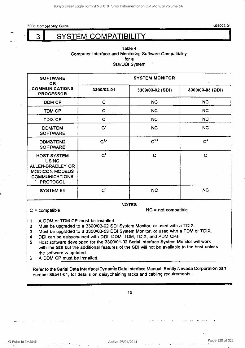
3300 Compatibility Guide 104003-01
1 3 1 SYSTEM COMPATIBILITY
Table 4 Computer Interface and Monitoring Software Compatibility
for a
SDI/DDI System
SOFTWARE OR
COMMUNICATIONS PROCESSOR
SYSTEM MONITOR - 3300/03-01 3300/03-02 (SDI)
_
3300/03-03 (DDI)
DDM CP C NC NC
TDM CP C NC NC
TDIX CP C NC NC
DDM/TDM SOFTWARE
C' NC NC
DDM2/TDM2 SOFTWARE
C3.4 C3.4 C4
HOST SYSTEM USING
ALLEN-BRADLEY OR MODICON MODBUS COMMUNICATIONS
PROTOCOL
C2 C
SYSTEM 64 C6 NC NC
NOTES C = compatible NC = not compatible
1 A DDM or TDM CP must be installed. 2 Must be upgraded to a 3300/03-02 SDI System Monitor, or used with a TDIX. 3 Must be upgraded to a 3300/03-03 DDI System. Monitor, or used with a TDM or TDIX. 4 DDI can be daisychained with DDI, DDM, TDM, TDIX, and PDM CPs. 5 Host software developed for the 3300/01-02 Serial Interface System Monitor will work
with the SDI but the additional features of the SDI will not be available to the host unless the software is updated.
6 A DDM CP must be installed.
Refer to the Serial Data Interface/Dynarriic Data Interface Manual, Bently Nevada Corporation part
number 89541-01, for details on daisychaining racks and cabling requirements.
15
Bunya Street Eagle Farm SPS SP010 Pump Instrumentation OM Manual Volume 6A
Q-Pulse Id TMS649 Active 29/01/2014 Page 320 of 322
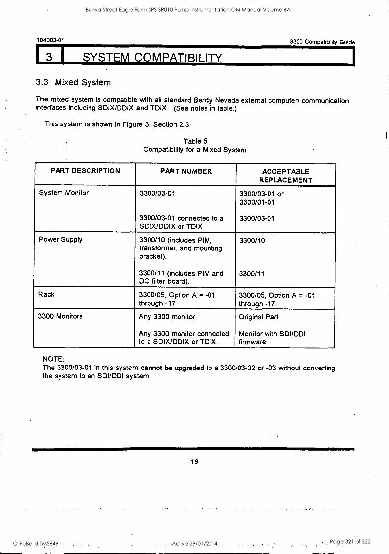
104003-01
3 1 SYSTEM COMPATIBILITY
3.3 Mixed System
3300 Compatibility Guide
The mixed system is compatible with all standard Bent ly Nevada external computer/ communication interfaces including SDIX/DDIX and TDIX. (See notes in table.)
This system is shown in Figure 3, Section 2.3.
Table 5
Compatibility for a Mixed System
PART DESCRIPTION PART NUMBER ACCEPTABLE REPLACEMENT
System Monitor 3300/03-01
3300/03-01 connected to a SDIX/DDIX or TOIX
3300/03-01 or 3300/01-01
3300/03-01
Power Supply 3300/10 (includes PIM, transformer, and mounting bracket).
3300/11 (includes PIM and DC filter board).
3300/10
3300/11
Rack 3300/05, Option A = -01 through -17
3300/05, Option A = -01 through -17.
3300 Monitors Any 3300 monitor
Any 3300 monitor connected to a SDIX/DDIX or TDIX.
Original Part
Monitor with SDI/DDI firmware.
NOTE: The 3300/03-01 in this system cannot be upgraded to a 3300/03-02 or -03 without converting the system to an SDI/DDI system.
16
Bunya Street Eagle Farm SPS SP010 Pump Instrumentation OM Manual Volume 6A
Q-Pulse Id TMS649 Active 29/01/2014 Page 321 of 322
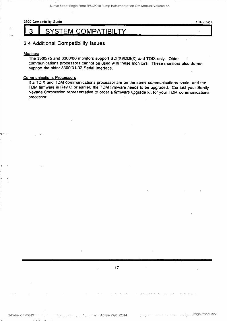
3300 Compatibility Guide 104003-01
3 I SYSTEM COMPATIBILTY
3.4 Additional Compatibility Issues
Monitors The 3300/75 and 3300/80 monitors support SDI(X)/DDI(X) and TDIX only. Older communications processors cannot be used with these monitors. These monitors also do not support the older 3300/01-02 Serial Interface.
Communications Processors If a TDIX and TDM communications processor are on the same communications chain, and the TDM firmware is Rev C or earlier, the TDM firmware needs to be upgraded. Contact your Bent ly Nevada Corporation representative to order a firmware upgrade kit for your TDM communications processor.
17
Bunya Street Eagle Farm SPS SP010 Pump Instrumentation OM Manual Volume 6A
Q-Pulse Id TMS649 Active 29/01/2014 Page 322 of 322


