Embed Size (px)
Citation preview
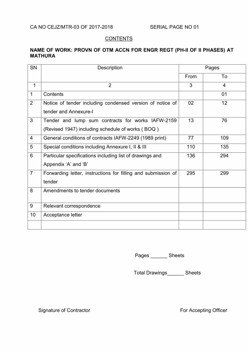
CA NO CEJZ/MTR-03 OF 2017-2018 SERIAL PAGE NO 01 CONTENTS
NAME OF WORK: PROVN OF OTM ACCN FOR ENGR REGT (PH-II OF II PHASES) AT MATHURA SN Description Pages
From To
1 2 3 4
1 Contents 01
2 Notice of tender including condensed version of notice of
tender and Annexure-I
02 12
3 Tender and lump sum contracts for works IAFW-2159
(Revised 1947) including schedule of works ( BOQ )
13 76
4 General conditions of contracts IAFW-2249 (1989 print) 77 109
5 Special conditions including Annexure I, II & III 110 135
6 Particular specifications including list of drawings and
Appendix ‘A’ and ‘B’
136 294
7 Forwarding letter, instructions for filling and submission of
tender
295 299
8 Amendments to tender documents
9 Relevant correspondence
10 Acceptance letter
Pages ______ Sheets
Total Drawings______ Sheets
Signature of Contractor For Accepting Officer
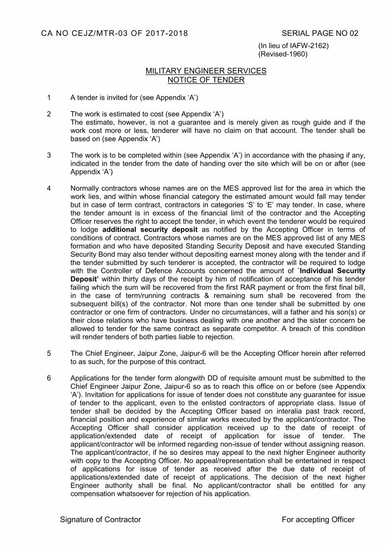
CA NO CEJZ/MTR-03 OF 2017-2018 SERIAL PAGE NO 02
(In lieu of IAFW-2162) (Revised-1960)
MILITARY ENGINEER SERVICES NOTICE OF TENDER
1 A tender is invited for (see Appendix ‘A’) 2 The work is estimated to cost (see Appendix ‘A’)
The estimate, however, is not a guarantee and is merely given as rough guide and if the work cost more or less, tenderer will have no claim on that account. The tender shall be based on (see Appendix ‘A’)
3 The work is to be completed within (see Appendix ‘A’) in accordance with the phasing if any,
indicated in the tender from the date of handing over the site which will be on or after (see Appendix ‘A’)
4 Normally contractors whose names are on the MES approved list for the area in which the
work lies, and within whose financial category the estimated amount would fall may tender but in case of term contract, contractors in categories ‘S’ to ‘E’ may tender. In case, where the tender amount is in excess of the financial limit of the contractor and the Accepting Officer reserves the right to accept the tender, in which event the tenderer would be required to lodge additional security deposit as notified by the Accepting Officer in terms of conditions of contract. Contractors whose names are on the MES approved list of any MES formation and who have deposited Standing Security Deposit and have executed Standing Security Bond may also tender without depositing earnest money along with the tender and if the tender submitted by such tenderer is accepted, the contractor will be required to lodge with the Controller of Defence Accounts concerned the amount of `Individual Security Deposit’ within thirty days of the receipt by him of notification of acceptance of his tender failing which the sum will be recovered from the first RAR payment or from the first final bill, in the case of term/running contracts & remaining sum shall be recovered from the subsequent bill(s) of the contractor. Not more than one tender shall be submitted by one contractor or one firm of contractors. Under no circumstances, will a father and his son(s) or their close relations who have business dealing with one another and the sister concern be allowed to tender for the same contract as separate competitor. A breach of this condition will render tenders of both parties liable to rejection.
5 The Chief Engineer, Jaipur Zone, Jaipur-6 will be the Accepting Officer herein after referred
to as such, for the purpose of this contract. 6 Applications for the tender form alongwith DD of requisite amount must be submitted to the
Chief Engineer Jaipur Zone, Jaipur-6 so as to reach this office on or before (see Appendix ‘A’). Invitation for applications for issue of tender does not constitute any guarantee for issue of tender to the applicant, even to the enlisted contractors of appropriate class. Issue of tender shall be decided by the Accepting Officer based on interalia past track record, financial position and experience of similar works executed by the applicant/contractor. The Accepting Officer shall consider application received up to the date of receipt of application/extended date of receipt of application for issue of tender. The applicant/contractor will be informed regarding non-issue of tender without assigning reason. The applicant/contractor, if he so desires may appeal to the next higher Engineer authority with copy to the Accepting Officer. No appeal/representation shall be entertained in respect of applications for issue of tender as received after the due date of receipt of applications/extended date of receipt of applications. The decision of the next higher Engineer authority shall be final. No applicant/contractor shall be entitled for any compensation whatsoever for rejection of his application.
Signature of Contractor For accepting Officer
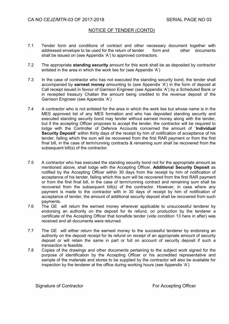
CA NO CEJZ/MTR-03 OF 2017-2018 SERIAL PAGE NO 03
NOTICE OF TENDER (CONTD)
7.1 Tender form and conditions of contract and other necessary document together with
addressed envelope to be used for the return of tender form and other documents shall be issued on (see Appendix ‘A’) to approved contractors.
7.2 The appropriate standing security amount for this work shall be as deposited by contractor enlisted in the area in which the work lies for (see Appendix ‘A’)
7.3 In the case of contractor who has not executed the standing security bond, the tender shall
accompanied by earnest money amounting to (see Appendix ‘A’) in the form of deposit at Call receipt issued in favour of Garrison Engineer (see Appendix ‘A’) by a Scheduled Bank or in receipted treasury Challan the amount being credited to the revenue deposit of the Garrison Engineer (see Appendix ‘A’)
7.4 A contractor who is not enlisted for the area in which the work lies but whose name is in the
MES approved list of any MES formation and who has deposited standing security and executed standing security bond may tender without earnest money along with the tender, but if the accepting Officer proposes to accept the tender, the contractor will be required to lodge with the Controller of Defence Accounts concerned the amount of `Individual Security Deposit’ within thirty days of the receipt by him of notification of acceptance of his tender, failing which the sum will be recovered from the first RAR payment or from the first final bill, in the case of term/running contracts & remaining sum shall be recovered from the subsequent bill(s) of the contractor.
7.5 A contractor who has executed the standing security bond not for the appropriate amount as
mentioned above, shall lodge with the Accepting Officer, Additional Security Deposit as notified by the Accepting Officer within 30 days from the receipt by him of notification of acceptance of his tender, failing which this sum will be recovered from the first RAR payment or from the first final bill, in the case of term/running contract and remaining sum shall be recovered from the subsequent bill(s) of the contractor. However, in case where any payment is made to the contractor with in 30 days of receipt by him of notification of acceptance of tender, the amount of additional security deposit shall be recovered from such payments.
7.6 The GE will return the earnest money wherever applicable to unsuccessful tenderer by endorsing an authority on the deposit for its refund, on production by the tenderer a certificate of the Accepting Officer that bonafide tender (vide condition 13 here in after) was received and all documents were returned.
7.7 The GE will either return the earnest money to the successful tenderer by endorsing an
authority on the deposit receipt for its refund on receipt of an appropriate amount of security deposit or will retain the same in part or full on account of security deposit if such a transaction is feasible.
7.8 Copies of the drawings and other documents pertaining to the subject work signed for the purpose of identification by the Accepting Officer or his accredited representative and sample of the materials and stores to be supplied by the contractor will also be available for inspection by the tenderer at the office during working hours (see Appendix ‘A’)
Signature of Contractor For Accepting Officer
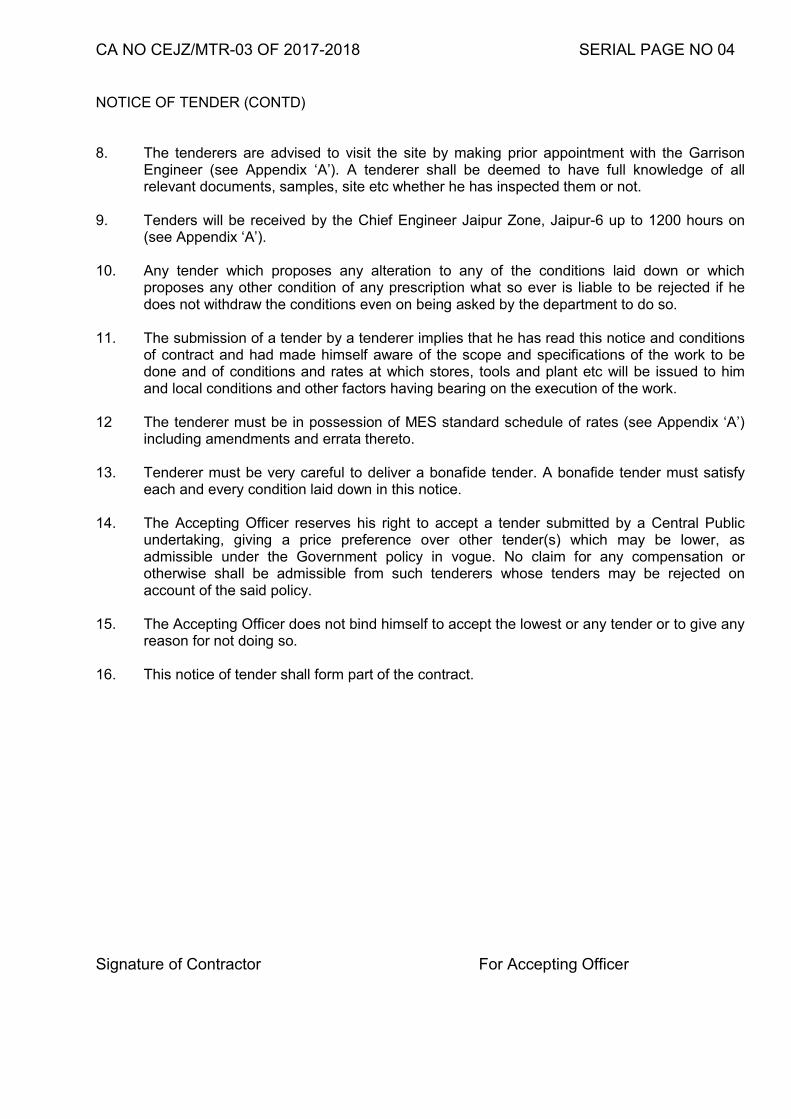
CA NO CEJZ/MTR-03 OF 2017-2018 SERIAL PAGE NO 04
NOTICE OF TENDER (CONTD) 8. The tenderers are advised to visit the site by making prior appointment with the Garrison
Engineer (see Appendix ‘A’). A tenderer shall be deemed to have full knowledge of all relevant documents, samples, site etc whether he has inspected them or not.
9. Tenders will be received by the Chief Engineer Jaipur Zone, Jaipur-6 up to 1200 hours on
(see Appendix ‘A’). 10. Any tender which proposes any alteration to any of the conditions laid down or which
proposes any other condition of any prescription what so ever is liable to be rejected if he does not withdraw the conditions even on being asked by the department to do so.
11. The submission of a tender by a tenderer implies that he has read this notice and conditions
of contract and had made himself aware of the scope and specifications of the work to be done and of conditions and rates at which stores, tools and plant etc will be issued to him and local conditions and other factors having bearing on the execution of the work.
12 The tenderer must be in possession of MES standard schedule of rates (see Appendix ‘A’)
including amendments and errata thereto. 13. Tenderer must be very careful to deliver a bonafide tender. A bonafide tender must satisfy
each and every condition laid down in this notice. 14. The Accepting Officer reserves his right to accept a tender submitted by a Central Public
undertaking, giving a price preference over other tender(s) which may be lower, as admissible under the Government policy in vogue. No claim for any compensation or otherwise shall be admissible from such tenderers whose tenders may be rejected on account of the said policy.
15. The Accepting Officer does not bind himself to accept the lowest or any tender or to give any
reason for not doing so. 16. This notice of tender shall form part of the contract. Signature of Contractor For Accepting Officer
CA NO CEJZ/MTR-03 OF 2017-2018 SERIAL PAGE NO 05
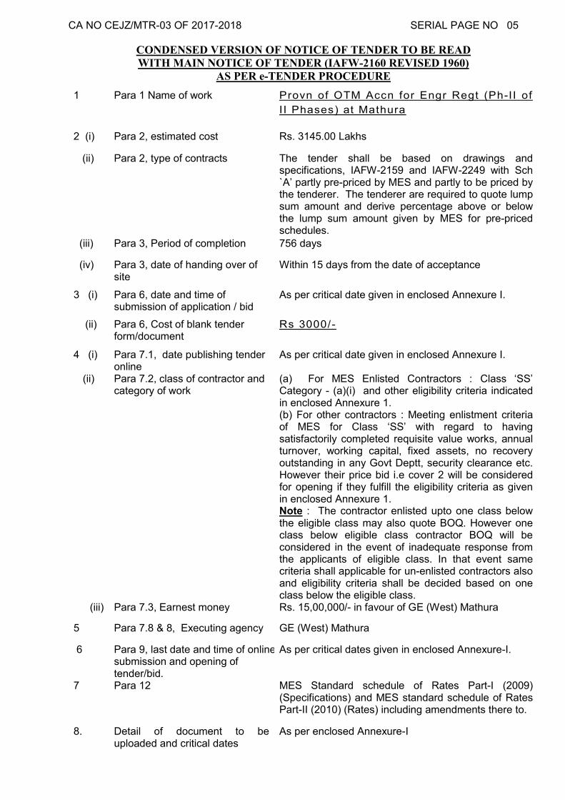
CONDENSED VERSION OF NOTICE OF TENDER TO BE READ WITH MAIN NOTICE OF TENDER (IAFW-2160 REVISED 1960)
AS PER e-TENDER PROCEDURE
1 Para 1 Name of work Provn of OTM Accn for Engr Regt (Ph-II of
I I Phases) at Mathura
2 (i) Para 2, estimated cost Rs. 3145.00 Lakhs
(ii) Para 2, type of contracts The tender shall be based on drawings and specifications, IAFW-2159 and IAFW-2249 with Sch `A’ partly pre-priced by MES and partly to be priced by the tenderer. The tenderer are required to quote lump sum amount and derive percentage above or below the lump sum amount given by MES for pre-priced schedules.
(iii) Para 3, Period of completion 756 days
(iv) Para 3, date of handing over of site
Within 15 days from the date of acceptance
3 (i) Para 6, date and time of submission of application / bid
As per critical date given in enclosed Annexure I.
(ii) Para 6, Cost of blank tender form/document
Rs 3000/-
4 (i) Para 7.1, date publishing tender online
As per critical date given in enclosed Annexure I.
(ii) Para 7.2, class of contractor and category of work
(a) For MES Enlisted Contractors : Class ‘SS’ Category - (a)(i) and other eligibility criteria indicated in enclosed Annexure 1. (b) For other contractors : Meeting enlistment criteria of MES for Class ‘SS’ with regard to having satisfactorily completed requisite value works, annual turnover, working capital, fixed assets, no recovery outstanding in any Govt Deptt, security clearance etc. However their price bid i.e cover 2 will be considered for opening if they fulfill the eligibility criteria as given in enclosed Annexure 1. Note : The contractor enlisted upto one class below the eligible class may also quote BOQ. However one class below eligible class contractor BOQ will be considered in the event of inadequate response from the applicants of eligible class. In that event same criteria shall applicable for un-enlisted contractors also and eligibility criteria shall be decided based on one class below the eligible class.
(iii) Para 7.3, Earnest money Rs. 15,00,000/- in favour of GE (West) Mathura
5 Para 7.8 & 8, Executing agency GE (West) Mathura
6 Para 9, last date and time of online submission and opening of tender/bid.
As per critical dates given in enclosed Annexure-I.
7 Para 12 MES Standard schedule of Rates Part-I (2009) (Specifications) and MES standard schedule of Rates Part-II (2010) (Rates) including amendments there to.
8. Detail of document to be uploaded and critical dates
As per enclosed Annexure-I
CA NO CEJZ/MTR-03 OF 2017-2018 SERIAL PAGE NO 06 ANNEXURE – I
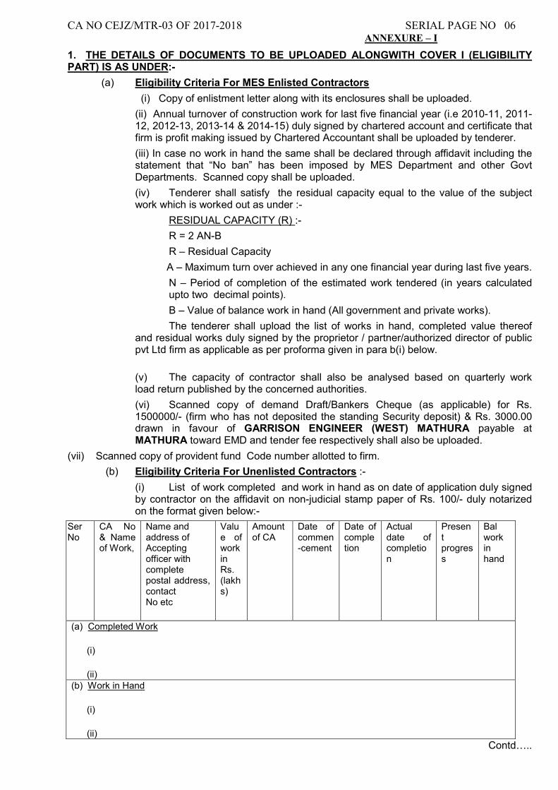
1. THE DETAILS OF DOCUMENTS TO BE UPLOADED ALONGWITH COVER I (ELIGIBILITY PART) IS AS UNDER:-
(a) Eligibility Criteria For MES Enlisted Contractors
(i) Copy of enlistment letter along with its enclosures shall be uploaded.
(ii) Annual turnover of construction work for last five financial year (i.e 2010-11, 2011-12, 2012-13, 2013-14 & 2014-15) duly signed by chartered account and certificate that firm is profit making issued by Chartered Accountant shall be uploaded by tenderer.
(iii) In case no work in hand the same shall be declared through affidavit including the statement that “No ban” has been imposed by MES Department and other Govt Departments. Scanned copy shall be uploaded.
(iv) Tenderer shall satisfy the residual capacity equal to the value of the subject work which is worked out as under :-
RESIDUAL CAPACITY (R) :-
R = 2 AN-B
R – Residual Capacity
A – Maximum turn over achieved in any one financial year during last five years.
N – Period of completion of the estimated work tendered (in years calculated upto two decimal points).
B – Value of balance work in hand (All government and private works).
The tenderer shall upload the list of works in hand, completed value thereof and residual works duly signed by the proprietor / partner/authorized director of public pvt Ltd firm as applicable as per proforma given in para b(i) below.
(v) The capacity of contractor shall also be analysed based on quarterly work load return published by the concerned authorities.
(vi) Scanned copy of demand Draft/Bankers Cheque (as applicable) for Rs. 1500000/- (firm who has not deposited the standing Security deposit) & Rs. 3000.00 drawn in favour of GARRISON ENGINEER (WEST) MATHURA payable at MATHURA toward EMD and tender fee respectively shall also be uploaded.
(vii) Scanned copy of provident fund Code number allotted to firm.
(b) Eligibility Criteria For Unenlisted Contractors :-
(i) List of work completed and work in hand as on date of application duly signed by contractor on the affidavit on non-judicial stamp paper of Rs. 100/- duly notarized on the format given below:-
Ser No
CA No & Name of Work,
Name and address of Accepting officer with complete postal address, contact No etc
Value of work in Rs. (lakhs)
Amount of CA
Date of commen-cement
Date of completion
Actual date of completion
Present progress
Bal work in hand
(a) Completed Work
(i)
(ii) (b) Work in Hand
(i)
(ii)
Contd…..
CA NO CEJZ/MTR-03 OF 2017-2018 SERIAL PAGE NO 07
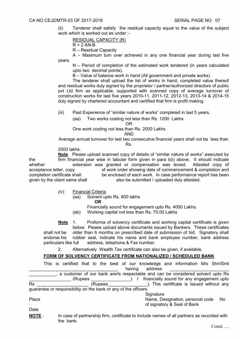
(ii) Tenderer shall satisfy the residual capacity equal to the value of the subject work which is worked out as under :-
RESIDUAL CAPACITY (R) R = 2 AN-B R – Residual Capacity A – Maximum turn over achieved in any one financial year during last five years.
N – Period of completion of the estimated work tendered (in years calculated upto two decimal points).
B – Value of balance work in hand (All government and private works). The tenderer shall upload the list of works in hand, completed value thereof and residual works duly signed by the proprietor / partner/authorized directors of public pvt Ltd firm as applicable, supported with scanned copy of average turnover of construction works for last five years 2010-11, 2011-12, 2012-13, 2013-14 & 2014-15 duly signed by chartered accountant and certified that firm is profit making.
(iii) Past Experience of “similar nature of works” completed in last 5 years.
(aa) Two works costing not less than Rs. 1200 Lakhs OR
One work costing not less than Rs. 2000 Lakhs AND
Average annual turnover for last two consecutive financial years shall not be less than Rs.
2000 lakhs. Note Please upload scanned copy of details of “similar nature of works” executed by the firm financial year wise in tabular form given in para b(i) above. It should indicate whether extension was granted or compensation was levied. Attested copy of acceptance letter, copy of work order showing date of commencement & completion and completion certificate shall be enclosed of each work. In case performance report has been given by the client same shall also be submitted / uploaded duly attested.
(iv) Financial Criteria (aa) Solvent upto Rs. 800 lakhs OR Financially sound for engagement upto Rs. 4000 Lakhs. (ab) Working capital not less than Rs. 75.00 Lakhs
Note 1. Proforma of solvency certificate and working capital certificate is given
below. Please upload above documents issued by Bankers. These certificates shall not be older than 6 months on prescribed date of submission of bid. Signatory shall endorse his rubber seal, indicate his name and bank employee number, bank address particulars like full address, telephone & Fax number.
2. Alternatively Wealth Tax certificate can also be given, if available.
FORM OF SOLVENCY CERTIFICATE FROM NATIONALIZED / SCHEDULED BANK
This is certified that to the best of our knowledge and information M/s Shri/Smt ____________________________________ having address ________________________ ___________, a customer of our bank are/is respectable and can be considered solvent upto Rs _________________ (Rupees ________________) / financially sound for any engagement upto Rs _____________________ (Rupees________________). This certificate is issued without any guarantee or responsibility on the bank or any of the officers. Signature Place Name, Designation, personal code No
of signatory & Seal of Bank Date
NOTE : In case of partnership firm, certificate to include names of all partners as recorded with the bank.
Contd…..
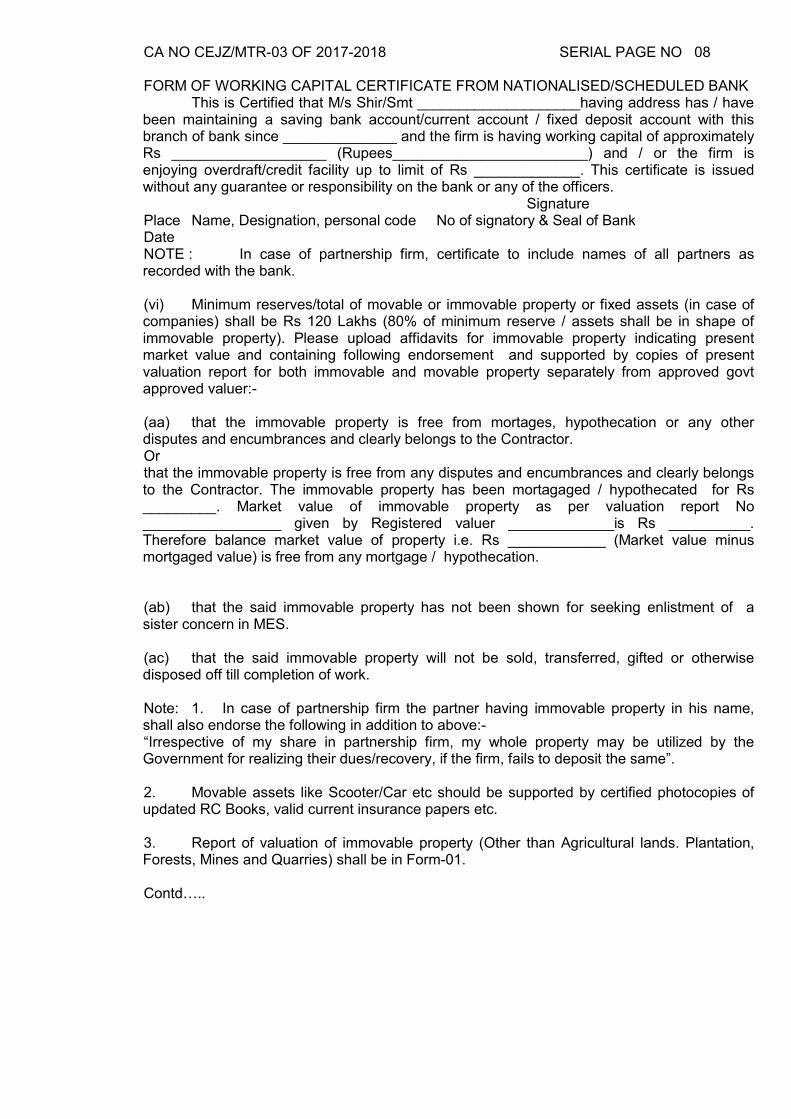
CA NO CEJZ/MTR-03 OF 2017-2018 SERIAL PAGE NO 08 FORM OF WORKING CAPITAL CERTIFICATE FROM NATIONALISED/SCHEDULED BANK This is Certified that M/s Shir/Smt ____________________having address has / have been maintaining a saving bank account/current account / fixed deposit account with this branch of bank since ______________ and the firm is having working capital of approximately Rs ___________________ (Rupees________________________) and / or the firm is enjoying overdraft/credit facility up to limit of Rs _____________. This certificate is issued without any guarantee or responsibility on the bank or any of the officers. Signature Place Name, Designation, personal code No of signatory & Seal of Bank Date NOTE : In case of partnership firm, certificate to include names of all partners as recorded with the bank. (vi) Minimum reserves/total of movable or immovable property or fixed assets (in case of companies) shall be Rs 120 Lakhs (80% of minimum reserve / assets shall be in shape of immovable property). Please upload affidavits for immovable property indicating present market value and containing following endorsement and supported by copies of present valuation report for both immovable and movable property separately from approved govt approved valuer:- (aa) that the immovable property is free from mortages, hypothecation or any other disputes and encumbrances and clearly belongs to the Contractor. Or that the immovable property is free from any disputes and encumbrances and clearly belongs to the Contractor. The immovable property has been mortagaged / hypothecated for Rs _________. Market value of immovable property as per valuation report No _________________ given by Registered valuer _____________is Rs __________. Therefore balance market value of property i.e. Rs ____________ (Market value minus mortgaged value) is free from any mortgage / hypothecation. (ab) that the said immovable property has not been shown for seeking enlistment of a sister concern in MES. (ac) that the said immovable property will not be sold, transferred, gifted or otherwise disposed off till completion of work. Note: 1. In case of partnership firm the partner having immovable property in his name, shall also endorse the following in addition to above:- “Irrespective of my share in partnership firm, my whole property may be utilized by the Government for realizing their dues/recovery, if the firm, fails to deposit the same”. 2. Movable assets like Scooter/Car etc should be supported by certified photocopies of updated RC Books, valid current insurance papers etc. 3. Report of valuation of immovable property (Other than Agricultural lands. Plantation, Forests, Mines and Quarries) shall be in Form-01. Contd…..
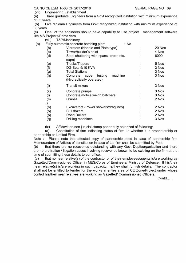
CA NO CEJZ/MTR-03 OF 2017-2018 SERIAL PAGE NO 09 (vii) Engineering Establishment (a) Three graduate Engineers from a Govt recognized institution with minimum experience of 05 years. (b) Five diploma Engineers from Govt recognized institution with minimum experience of 08 years. (c) One of the engineers should have capability to use project management software like MS Projects/Prima vera. (viii) T&P/Machinery (a) Fully automatic concrete batching plant : 1 No
(b) Vibrators (Needle and Plate type) : 20 Nos (c) Tower/builder’s hoist : 4 Nos (d) Steel shuttering with spans, props etc.
(sqm) : 6000
(e) Trucks/Tippers : 5 Nos (f) DG Sets 5/10 KVA : 3 Nos (g) Total Stations : 3 Nos (h) Concrete cube testing machine
(Hydraulically operated) : 3 Nos
(j) Transit mixers : 3 Nos
(k) Concrete pumps : 3 Nos (l) Concrete mobile weigh batchers : 3 Nos (m)
Cranes : 2 Nos
(n) Excavators (Power shovels/draglines) : 2 Nos (o) Bull dozers : 2 Nos (p) Road Rollers : 2 Nos (q) Drilling machines : 3 Nos
(ix) Affidavit on non judicial stamp paper duly notarized of following:- (a) Constitution of firm indicating status of firm i.e whether it is proprietorship or partnership or Limited Firm. Note :- Please note that attested copy of partnership deed in case of partnership firm Memorandum of Articles of constitution in case of Ltd firm shall be submitted by Post. (b) that there are no recoveries outstanding with any Govt Deptt/organization and there are no arbitration / litigation cases involving recoveries known to be existing on the firm at the time of submitting these details to our office. (c) that no near relative(s) of the contractor or of their employees/agents is/are working as Gazetted/Commissioned Officer in MES/Corps of Engineers/ Ministry of Defence. If his/their near relative(s) is/are working in such capacity, he/they shall furnish details. The contractor shall not be entitled to tender for the works in entire area of CE Zone/Project under whose control his/their near relatives are working as Gazetted/ Commissioned Officers. Contd…..
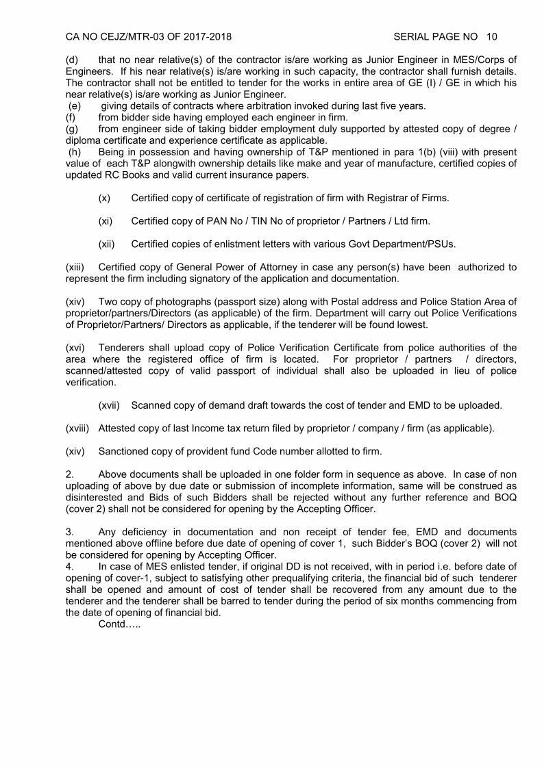
CA NO CEJZ/MTR-03 OF 2017-2018 SERIAL PAGE NO 10 (d) that no near relative(s) of the contractor is/are working as Junior Engineer in MES/Corps of Engineers. If his near relative(s) is/are working in such capacity, the contractor shall furnish details. The contractor shall not be entitled to tender for the works in entire area of GE (I) / GE in which his near relative(s) is/are working as Junior Engineer. (e) giving details of contracts where arbitration invoked during last five years. (f) from bidder side having employed each engineer in firm. (g) from engineer side of taking bidder employment duly supported by attested copy of degree / diploma certificate and experience certificate as applicable. (h) Being in possession and having ownership of T&P mentioned in para 1(b) (viii) with present value of each T&P alongwith ownership details like make and year of manufacture, certified copies of updated RC Books and valid current insurance papers. (x) Certified copy of certificate of registration of firm with Registrar of Firms. (xi) Certified copy of PAN No / TIN No of proprietor / Partners / Ltd firm. (xii) Certified copies of enlistment letters with various Govt Department/PSUs. (xiii) Certified copy of General Power of Attorney in case any person(s) have been authorized to represent the firm including signatory of the application and documentation. (xiv) Two copy of photographs (passport size) along with Postal address and Police Station Area of proprietor/partners/Directors (as applicable) of the firm. Department will carry out Police Verifications of Proprietor/Partners/ Directors as applicable, if the tenderer will be found lowest. (xvi) Tenderers shall upload copy of Police Verification Certificate from police authorities of the area where the registered office of firm is located. For proprietor / partners / directors, scanned/attested copy of valid passport of individual shall also be uploaded in lieu of police verification. (xvii) Scanned copy of demand draft towards the cost of tender and EMD to be uploaded. (xviii) Attested copy of last Income tax return filed by proprietor / company / firm (as applicable). (xiv) Sanctioned copy of provident fund Code number allotted to firm. 2. Above documents shall be uploaded in one folder form in sequence as above. In case of non uploading of above by due date or submission of incomplete information, same will be construed as disinterested and Bids of such Bidders shall be rejected without any further reference and BOQ (cover 2) shall not be considered for opening by the Accepting Officer. 3. Any deficiency in documentation and non receipt of tender fee, EMD and documents mentioned above offline before due date of opening of cover 1, such Bidder’s BOQ (cover 2) will not be considered for opening by Accepting Officer. 4. In case of MES enlisted tender, if original DD is not received, with in period i.e. before date of opening of cover-1, subject to satisfying other prequalifying criteria, the financial bid of such tenderer shall be opened and amount of cost of tender shall be recovered from any amount due to the tenderer and the tenderer shall be barred to tender during the period of six months commencing from the date of opening of financial bid. Contd…..
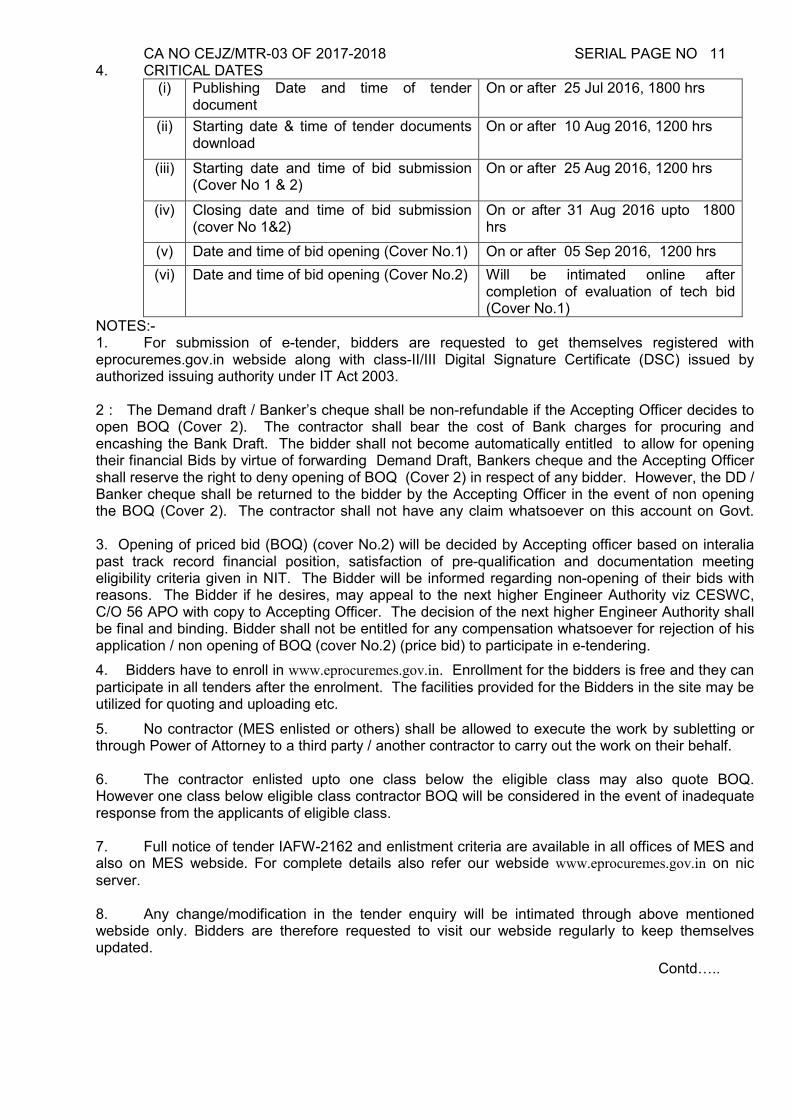
CA NO CEJZ/MTR-03 OF 2017-2018 SERIAL PAGE NO 11 4. CRITICAL DATES
(i) Publishing Date and time of tender document
On or after 25 Jul 2016, 1800 hrs
(ii) Starting date & time of tender documents download
On or after 10 Aug 2016, 1200 hrs
(iii) Starting date and time of bid submission (Cover No 1 & 2)
On or after 25 Aug 2016, 1200 hrs
(iv) Closing date and time of bid submission (cover No 1&2)
On or after 31 Aug 2016 upto 1800 hrs
(v) Date and time of bid opening (Cover No.1) On or after 05 Sep 2016, 1200 hrs
(vi) Date and time of bid opening (Cover No.2) Will be intimated online after completion of evaluation of tech bid (Cover No.1)
NOTES:- 1. For submission of e-tender, bidders are requested to get themselves registered with eprocuremes.gov.in webside along with class-II/III Digital Signature Certificate (DSC) issued by authorized issuing authority under IT Act 2003. 2 : The Demand draft / Banker’s cheque shall be non-refundable if the Accepting Officer decides to open BOQ (Cover 2). The contractor shall bear the cost of Bank charges for procuring and encashing the Bank Draft. The bidder shall not become automatically entitled to allow for opening their financial Bids by virtue of forwarding Demand Draft, Bankers cheque and the Accepting Officer shall reserve the right to deny opening of BOQ (Cover 2) in respect of any bidder. However, the DD / Banker cheque shall be returned to the bidder by the Accepting Officer in the event of non opening the BOQ (Cover 2). The contractor shall not have any claim whatsoever on this account on Govt. 3. Opening of priced bid (BOQ) (cover No.2) will be decided by Accepting officer based on interalia past track record financial position, satisfaction of pre-qualification and documentation meeting eligibility criteria given in NIT. The Bidder will be informed regarding non-opening of their bids with reasons. The Bidder if he desires, may appeal to the next higher Engineer Authority viz CESWC, C/O 56 APO with copy to Accepting Officer. The decision of the next higher Engineer Authority shall be final and binding. Bidder shall not be entitled for any compensation whatsoever for rejection of his application / non opening of BOQ (cover No.2) (price bid) to participate in e-tendering.
4. Bidders have to enroll in www.eprocuremes.gov.in. Enrollment for the bidders is free and they can participate in all tenders after the enrolment. The facilities provided for the Bidders in the site may be utilized for quoting and uploading etc.
5. No contractor (MES enlisted or others) shall be allowed to execute the work by subletting or through Power of Attorney to a third party / another contractor to carry out the work on their behalf. 6. The contractor enlisted upto one class below the eligible class may also quote BOQ. However one class below eligible class contractor BOQ will be considered in the event of inadequate response from the applicants of eligible class. 7. Full notice of tender IAFW-2162 and enlistment criteria are available in all offices of MES and also on MES webside. For complete details also refer our webside www.eprocuremes.gov.in on nic server. 8. Any change/modification in the tender enquiry will be intimated through above mentioned webside only. Bidders are therefore requested to visit our webside regularly to keep themselves updated.
Contd…..
CA NO CEJZ/MTR-03 OF 2017-2018 SERIAL PAGE NO 12 9. Applications not accompanied with requisite value of DD/Bankers cheque towards cost of tender shall not be considered. BOQ(cover No.2) (price bid) received without EMD in original (applicable as required) will not be opened. 10. All the documents submitted offline (by post/hand) by contractor shall also be signed by him or by the authorized person of the company.
11. All the affidavit shall be given on non judicial stamp paper of appropriate value (but not less then Rs 100/-) duly signed by the contractor and attested by the Magistrate / Notary public.
12. All photocopy / certified copies of documents shall be attested by Gazetted Officer / Notary public.
(Ranjit Singh) EE (SG) (QS&C)
Jt Dir (contracts) for Accepting Officer
80737/C/ /E8
Dated : 08 Jul 2016
Military Engineer Services Headquarters Chief Engineer Jaipur Zone Power House Road, Bani Park Jaipur-302006 Distribution
Signature of Contractor For Accepting Officer
CA NO CEJZ/MTR-03 OF 2017-2018 SERIAL PAGE NO 13
In l ieu of IAFW-2159
TO BE USED IN CONJUCTION WITH
GENERAL CONDITIONS OF CONTRACTS Telefax : 0141-2202517 Military Engineer Services Tele : 0141-2207174 Headquarters
Chief Engineer Jaipur Zone Power House Road, Bani Park Jaipur-302006
80737/C/48/E8 19 Apr 2017
LUMP SUM TENDER AND CONTRACT FOR WORKS REQUIRED IN THE EXECUTION OF CA NO CEJZ/MTR-03 OF 2017-2018 : PROVN OF OTM ACCN FOR
ENGR REGT (PH-II OF II PHASES) AT MATHURA TENDER ID: 2017_MES_ 116101_1
1. Shri/S’Shri______________________________________________________ of ______________ is/are hereby authorized to tender for the above work published on the NIC website MES. eprocurement portal (www.eprocuremes.gov.in). The quoted E-tender will be submitted online by 26 May 2017 up to 1800 Hrs. The E-tender technical bid (i.e. cover 1) shall be opened at the office of the Chief Engineer Jaipur Zone, Power House Road, Bani Park, Jaipur-6 by 1200 hrs on or after 31 May 2017. 2. All documents must be returned whether or not a tender has been submitted. 3. Any correspondence concerning this tender shall be addressed as indicated at the top of this sheet, quoting the reference as given. 4. THE PRESIDENT OF INDIA DOES NOT BIND HIMSELF TO ACCEPT THE LOWEST OR ANY TENDER SIGNATURE OF CONTRACTOR Signature of Officer
Issuing the documents Appointment :- Joint Dir (Contracts)
CA NO CEJZ/MTR-03 OF 2017-2018 SERIAL PAGE NO 14
SCHEDULE ‘A’ (LIST OF WORK AND PRICES) NOTES
A. GENERAL 1.1 This Schedule is divided into XVI parts as detailed below:-
(a) Part-I Building Works (b) Part-II Internal Water Supply (c) Part-III Internal Electrification (d) Part-IV Road, Path and Culvert (e) Part-V External Water Supply (f) Part-VI External Electrification (g) Part-VII Sewage Disposal (h) Part-VIII Area Drainage (I) Part-IX Fencing and Gate (j) Part X Parade Ground/Play Grounds/Courts/Hardstanding (k) Part-XI Lightning Protection (l) Part-XII Site Clearance and Earth Work (m) Part-XIII Summer Appliances (n) Part-XIV Hot Water Supply (o) Part-XV Demoltion/Dismantling of existing building/structure (p) Part-XVI Miscellaneous items (to be quoted by the contractor)
1.2 Prepriced rates inserted under column 4 of Schedule ‘A’ Part- I to XV, are deemed to be at par with the rates contained in the MES standard schedule of rates or analogous rates thereto. Contractor’s attention is invited to condition 6A(B) of IAFW-2249 where under the lump sum price shall be worked out by him independently of the prices or rates inserted by MES in the tender and irrespective of any errors or inaccuracies therein. The amount to be inserted by tenderer against a particular part of Schedule ‘A’ shall be derived by him from the amount tendered by him.
1.3 In respect of Schedule ‘A’ Part- XVI the tenderer is required to insert his rates in figure under
column 5 of BOQ for entire completion of items of work as described and specified inclusive of his overhead and profit complete. Amount column shall be generated by the system in relation to unit rate inserted by you.
1.4 The rates quoted by tenderer shall be inclusive of all type of taxes levies, octroi, excise, cess,
service tax etc as prevailing on the date of submission of tender i.e bid submission end date. However, in this connection attention is invited to Special Condition No 33 & 34.
1.5 Description of buildings, works and services given in various parts of Schedule ‘A’ are in brief’.
These are deemed to be amplified and read in conjunction with special conditions, particular specifications for materials and workmanship and conditions in relevant trade section of MES SSR Part-I MES SSR Part II and contract drawings including notes on the drawings.
1.6 (a) COMPLETION PERIOD: Entire work under this contract shall be completed within 756
days from the date of handing over the site as indicated in the first work order in three phases as under :
Signature of Contractor For Accepting Officer
CA NO CEJZ/MTR-03 OF 2017-2018 SERIAL PAGE NO 15
SCHEDULE ‘A’ (LIST OF WORK AND PRICES) NOTES (CONTD…) A. (Contd..) (i) PHASE-I APPROVAL OF LEVELS:-
Levels are to be taken before starting excavation and after clearance of vegetation / bushes etc at the intervals of 3 meters and the same shall be plotted in graph sheet duly marked with the location of the buildings / structures covered in tender along with the proposed developed ground levels if any and proposed plinth level of the various buildings / structures , drainages / disposal arrangement etc and submitted to AO duly signed by JE, contractor, Engr-in-charge and GE for approval within 60 days from the date of commencement. Permanent bench mark (which will not change in future) shall be prominently marked on the level sheet. Intermediate bench mark, such as FFL of other permanent buildings also shall be marked on the level sheet. Made up GL and FFL of the proposed buildings shall be sfixed, such that, quantity of excavated earth and filled earth shall match economically. Excavation / site clearance work at site shall commence only after written approval for the proposed levels is obtained from the Accepting Officer. (ii) PHASE-II: Sample Block i.e. construction of block of Single Living Accn for Officers serial item no. 24 of schedule A Part-I including internal services as catered in respective schedule A parts shall be completed at least six month prior to the original date of completion given in WO No 1 to determine the acceptable standard of workmanship. In this connection special condition No.9 refers. (iii) PHASE-III: Balance items of works under this contract- 756 days
(b)Completion periods for Phase-I, Phase-II i.e. Sample block and Phase-III i.e. Balance items of work will run concurrently and thus the total period for completion for this contract shall be 756 days. (c) Site(s) for item of Schedule ‘A’ Part-I shall be handed over simultaneously. Sites for other parts i.e. Schedule ‘A’ Part-II to XVI shall accordingly be deemed handed over simultaneously with items of Schedule ‘A’ Part-I irrespective of actual progress on ground. (d) For the purpose of levy of compensation due to delay in completion of work, if any, under condition 50 of IAFW-2249, the contract value of sample block shall be amount quoted by the contractor against serial item No 24 of schedule ‘A’ Part-I plus for internal services quoted amount in respective schedules.
(e)The defect liability period for Phase-II and III shall commence after completion of work against whole contract as certified by the GE in completion certificate.
(f)Site for execution of work will be available as soon as the work is awarded. In case it is not possible for the Department to make the entire site available on the award of work, the contractor will have to arrange his working program accordingly. No claim whatsoever, for not giving the entire site on award of work and for giving the site gradually will be tenable.
1.7 In case details in respect of items shown on main drawings are not given in the drawings
referred to in the main drawing, then the same shall be followed from any other drawings included in the list of drawings. Any drawing mentioned in the contract/contract drawings but not included in the list of drawings shall also be deemed to form part of contract.
1.8 In case specifications in respect of items shown on main/detailed drawings are not included in
particular specifications, then the same shall be followed as per SSR Part-I / or as directed by the GE. In case of any dispute between the GE and the contractor the same shall be referred to the Accepting Officer and decision of the Accepting Officer shall be final & binding.
Signature of Contractor For Accepting Officer
CA NO CEJZ/MTR-03 OF 2017-2018 SERIAL PAGE NO 16
SCHEDULE ‘A’ (LIST OF WORK AND PRICES) NOTES (CONTD..) A. (Contd..) 1.9 Layout of internal/external services is tentative and may be changed as per the site
requirement at the discretion of the GE. No claim on this account shall be entertained and contractor quoted rates shall be deemed to cater for the same.
1.10 Layout of buildings indicated in the site plan is tentative and this may be changed at the
discretion of the GE before commencement of work. No claim on this account shall be entertained and contract rates shall be deemed to cater for the same.
1.11 The under mentioned columns shall be deemed to have been inserted at respective places in
Schedule ‘A ’: - S.No Column No Heading Remarks (a) Column 3 Drg No Refer list of drawings
(b) Column 7 Period of completion for
individual item from date of handing over the site
Refer Note No A.1.6 of Schedule `A’ notes
(c) Column 8 Remarks Refer Schedule `A’ Notes 1.12 Wooden gutties as specified in SSR shall not be used in this work. In lieu of wooden gutties,
PVC sleeves of appropriate sizes shall be provided for fixing of fittings/fixtures to the entire satisfaction of GE.
1.13 Where Specification for any item of work are not given in Particular Specifications MES
schedule shall be referred. If the same is not available in MES SSR, specification given in relevant Indian Standard / code (as revised) of practice shall be followed as decided by GE.
B. NOTES APPLICABLE TO SCHEDULE ‘A’ PART-I 1.1 The lump sum quoted by the tenderer for work under Schedule ‘A’ Part-I shall be deemed to
include for all relevant items of works shown on the drawings, notes therein and /or specified in particular specifications complete, for entire completion of works, except works covered in Part-II to XVI of Schedule ‘A’ and or unless otherwise specifically stated elsewhere in the tender document.
1.2 lump sum of building in Schedule ‘A’ Part-I shall include cost of any cutting, leaving/forming
holes, chases etc in the walls, floors and ceilings as required and making good. No adjustment shall however, be made on variations in quantities of cuttings, leaving/forming holes, chases etc, on this account for pricing of any deviations in respect of items listed in Schedule ‘A’ Part-I and due to variation in quantities indicated as PROVISIONAL in the tender documents.
1.3 Building under Schedule ‘A’ Part-I shall have the foundation for safe bearing capacity as
specified/ shown on drawings. Variation in safe bearing capacity of soil if found at site and require redesigning of the foundation, the same shall be regularized through proper deviation order.
Signature of Contractor For Accepting Officer
CA NO CEJZ/MTR-03 OF 2017-2018 SERIAL PAGE NO 17
SCHEDULE ‘A’ (LIST OF WORK AND PRICES) NOTES (CONTD..) B. (Contd..) 1.4 Excavation in any type of soil shall be considered in lump sum quoted cost of item of schedule
`A’ Part-I. If soft/disintegrated rock or hard rock met with during excavation, same shall be measured and paid separately as a deviation. Hard rock shall become the property of contractor and recovery at the rate of rubble stone from approved quarries for hand packing (item 06123 of MES SSR Part-II) shall be made subject to quoted %age against schedule A part XII by the contractor. The contractor shall be responsible for its removal from site (from time to time) all as directed by Engineer-in-Charge.
1.5 In the event of discrepancy in the provision given in drawing of schedule of finishes and other drawings forming part of the tender, the provisions in the schedule of finishes drawing shall take precedence over the provisions in the other drawings.
1.6 In the event of discrepancy in the details/dimensions given in various drawings, the details/dimensions as per breakup details drawing & enlarge scale drawing shall take precedence over the provisions in the small scale drawings.
1.7 In the event of discrepancy in the total dimension as per room sizes and outer dimensions of any building / structure, the total dimension worked out as per room size (breakup details) shall be followed.
1.8 In case of discrepancies between the provisions / details given in architectural and structural drawings, the architectural details shall be followed from architectural drawing and structural details shall be followed structural drawing..
C. NOTES APPLICABLE TO SCHEDULE ‘A’ PART-II TO XVI 1.1 All items and quantities are provisional.
1.2 Unless otherwise specified, unit rate of each item of work is inclusive of materials and labour or supplied and fixed including testing complete.
1.3 Specifications in MES SSR Part-I and preambles to items given in MES SSR Part-II under respective trades shall be applicable. If any provision / items of Schedule ‘A’ and / or in particular specifications is at variance with the provisions in specification in MES SSR Part-I and preambles to MES Schedule items of SSR Part-II first the provision as per description of item of Schedule ‘A’ and thereafter the provision of particular specifications shall take precedence there over.
1.4 Hard rock met with during excavation shall become the property of contractor and recovery at
the rate of rubble stone from approved quarries for hand packing (item 06123 of MES SSR Part-II) shall be made subject to applicable percentage over SSR. The contractor shall be responsible for its removal from site time to time all as directed by engineer-in-charge.
1.5 Excavation and earthwork items included in the respective parts of schedule ‘A’ shall be
applicable for the items for which excavation and earth work not included in the description of items of respective schedule ‘A’.
1.6 If the layout of the proposed services / structure overlaps over the layout of the existing demolished buildings / structures and the contractor has to excavate in other than in soft & loose soil no extra payment shall be admissible irrespective to actual materials met with as site. Contractor’s quoted rates deemed inclusive of this provision and no extra payment shall be admissible to the contractor on this account.
Signature of Contractor For Accepting Officer
Sl
No
Description of building or works
Drg
No Unit Rate
Rs. Ps.
No. of
units
required
Amount in Rs Period of
completion on of
individual items
after date of
handing over the
site
Rem
ark
s
1 2 3 4 5 6 7 8
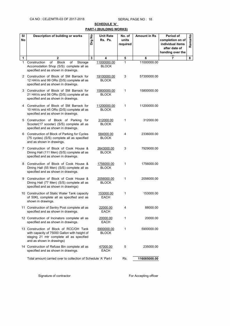
1 Construction of Block of StorageAccomodation Shop (S/S) complete all asspecified and as shown in drawings.
11000000.00 BLOCK
1 11000000.00
2 Construction of Block of SM Barrack for12 HAVs and 99 ORs (D/S) complete all asspecified and as shown in drawings.
19100000.00BLOCK
3 57300000.00
3 Construction of Block of SM Barrack for21 HAVs and 56 ORs (D/S) complete all asspecified and as shown in drawings.
15800000.00BLOCK
1 15800000.00
4 Construction of Block of SM Barrack for10 HAVs and 45 ORs (D/S) complete all asspecified and as shown in drawings.
11200000.00BLOCK
1 11200000.00
5 Construction of Block of Parking forScooter(17 scooter) (S/S) complete all asspecified and as shown in drawings.
312000.00BLOCK
1 312000.00
6 Construction of Block of Parking for Cycles(75 cycles) (S/S) complete all as specifiedand as shown in drawings.
584000.00BLOCK
4 2336000.00
7 Construction of Block of Cook House &Dining Hall (111 Men) (S/S) complete all asspecified and as shown in drawings.
2643000.00BLOCK
3 7929000.00
8 Construction of Block of Cook House &Dining Hall (55 Men) (S/S) complete all asspecified and as shown in drawings.
1756000.00BLOCK
1 1756000.00
9 Construction of Block of Cook House &Dining Hall (77 Men) (S/S) complete all asspecified and as shown in drawings)
2056000.00BLOCK
1 2056000.00
10 Construction of Static Water Tank capacityof 50KL complete all as specified and asshown in drawings.
153000.00EACH
1 153000.00
11 Construction of Sentry Post complete all asspecified and as shown in drawings.
22000.00EACH
4 88000.00
12 Construction of Incinators complete all asspecified and as shown in drawings.
20000.00EACH
1 20000.00
13 Construction of Block of RCC/OH Tankwith capacity of 75000 Gallon with height ofstaging 21 mtr complete all as specifiedand as shown in drawings)
5900000.00BLOCK
1 5900000.00
14 Construction of Refuse Bin complete all asspecified and as shown in drawings.
47000.00EACH
5 235000.00
116085000.00
CA NO : CEJZ/MTR-03 OF 2017-2018 SERIAL PAGE NO : 18
SCHEDULE 'A'
PART-I (BUILDING WORKS)
Total amount carried over to collection of Schedule ‘A’ Part-I Rs.
Signature of contractor For Accepting officer
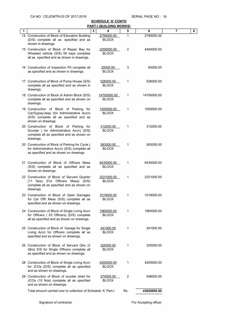
19
1 2 3 4 5 6 7 8
14 Construction of Block of Education Building(D/S) complete all as specified and asshown in drawings.
2790000.00 BLOCK
1 2790000.00
15 Construction of Block of Repair Bay forWheeled vehicle (S/S) 06 bays completeall as specified and as shown in drawings.
2200000.00 BLOCK
2 4400000.00
16 Construction of Inspection Pit complete allas specified and as shown in drawings.
20000.00 BLOCK
3 60000.00
17 Construction of Block of Pump House (S/S) complete all as specified and as shown indrawings.
526000.00 BLOCK
1 526000.00
18 Construction of Block of Admin Block (D/S)complete all as specified and as shown ondrawings.
14700000.00 BLOCK
1 14700000.00
19 Construction of Block of Parking forCar/Gypsy/Jeep (for Administrative Accn)(S/S) complete all as specified and asshown on drawings.
1500000.00 BLOCK
1 1500000.00
20 Construction of Block of Parking forScooter ( for Administrative Accn) (S/S)complete all as specified and as shown ondrawings.
312000.00 BLOCK
1 312000.00
20 Construction of Block of Parking for Cycle (for Administrative Accn) (S/S) complete allas specified and as shown on drawings.
583000.00 BLOCK
1 583000.00
21 Construction of Block of Officers Mess(S/S) complete all as specified and asshown on drawings.
8430000.00 BLOCK
1 8430000.00
22 Construction of Block of Servant Quarter(11 Nos) (For Officers Mess) (D/S)complete all as specified and as shown ondrawings.
2221000.00 BLOCK
1 2221000.00
23 Construction of Block of Open Garragesfor Car Offr Mess (S/S) complete all asspecified and as shown on drawings.
1019000.00BLOCK
1 1019000.00
24 Construction of Block of Single Living Accnfor Officers ( 03 Officers) (D/S) completeall as specified and as shown on drawings.
1965000.00BLOCK
1 1965000.00
25 Construction of Block of Garage for SingleLiving Accn for Officers complete all asspecified and as shown on drawings.
241000.00BLOCK
1 241000.00
26 Construction of Block of Servant Qtrs (2Qtrs) S/S for Single Officers complete allas specified and as shown on drawings.
325000.00BLOCK
1 325000.00
28 Construction of Block of Single Living Accnfor JCOs (D/S) complete all as specifiedand as shown on drawings.
4200000.00BLOCK
1 4200000.00
29 Construction of Block of scooter shed forJCOs (10 Nos) complete all as specifiedand as shown on drawings.
274000.00 BLOCK
2 548000.00
43820000.00Total amount carried over to collection of Schedule ‘A’ Part-I Rs.
Signature of contractor
PART-I (BUILDING WORKS)
For Accepting officer
CA NO : CEJZ/MTR-03 OF 2017-2018 SERIAL PAGE NO :
SCHEDULE 'A' CONTD
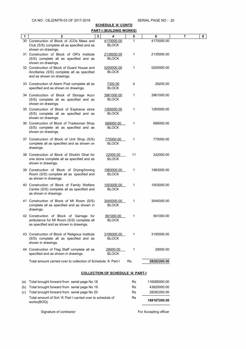
20
1 2 3 4 5 6 7 8
30 Construction of Block of JCOs Mess andClub (S/S) complete all as specified and asshown on drawings.
4170000.00BLOCK
1 4170000.00
31 Construction of Block of OR's Institute(S/S) complete all as specified and asshown on drawings.
2135000.00BLOCK
1 2135000.00
32 Construction of Block of Guard House andAncillaries (S/S) complete all as specifiedand as shown on drawings.
5200000.00BLOCK
1 5200000.00
33 Construction of Alarm Post complete all asspecified and as shown on drawings.
7300.00BLOCK
4 29200.00
34 Construction of Block of Storage Accn(S/S) complete all as specified and asshown on drawings.
3961000.00BLOCK
1 3961000.00
35 Construction of Block of Explosive store(S/S) complete all as specified and asshown on drawings.
1265000.00BLOCK
1 1265000.00
36 Construction of Block of Tradesman Shop(S/S) complete all as specified and asshown on drawings.
689000.00 BLOCK
1 689000.00
37 Construction of Block of Unit Shop (S/S)complete all as specified and as shown ondrawings.
775000.00 BLOCK
1 775000.00
38 Construction of Block of Dhobhi Ghat forone stone complete all as specified and asshown in drawings.
22000.00 BLOCK
11 242000.00
39 Construction of Block of Drying/IroningRoom (S/S) complete all as specified andas shown in drawings.
1983000.00 BLOCK
1 1983000.00
40 Construction of Block of Family WelfareCentre (S/S) complete all as specified andas shown in drawings.
1003000.00 BLOCK
1 1003000.00
41 Construction of Block of MI Room (S/S)complete all as specified and as shown indrawings.
3045000.00 BLOCK
1 3045000.00
42 Construction of Block of Garrage forambulance for MI Room (S/S) complete allas specified and as shown in drawings.
561000.00 BLOCK
1 561000.00
43 Construction of Block of Religious Institute(S/S) complete all as specified and asshown in drawings.
3195000.00 BLOCK
1 3195000.00
44 Construction of Flag Staff complete all asspecified and as shown in drawings.
29000.00 BLOCK
1 29000.00
28282200.00
(a) Rs 116085000.00
(b) Rs 43820000.00
(c) Rs 28282200.00
Rs188187200.00
SERIAL PAGE NO :
SCHEDULE 'A' CONTD
Total brought forward from serial page No 19
Total brought forward from serial page No 20
Total amount of Sch 'A' Part I carried over to schedule of works(BOQ)
Total amount carried over to collection of Schedule ‘A’ Part-I Rs.
COLLECTION OF SCHEDULE ‘A’ PART-I
Total brought forward from serial page No 18
Signature of contractor For Accepting officer
PART-I (BUILDING WORKS)
CA NO : CEJZ/MTR-03 OF 2017-2018
CA NO : CEJZ/MTR-03 OF 2017-2018
S.
No
Description of items or works
Drg
No Unit Rate
Rs. Ps.
No. of
units
require
d
Total in
Rs. Ps.
Period
of
completi
on on of
individu
al items
after
date of
handing
over the
site
Rem
ark
1 2 3 4 5 6 7 8
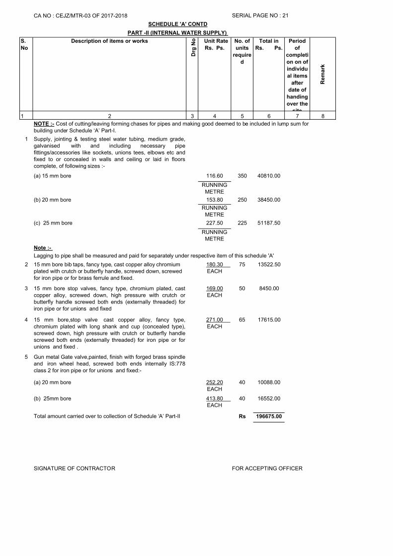
1 Supply, jointing & testing steel water tubing, medium grade,galvanised with and including necessary pipefittings/accessories like sockets, unions tees, elbows etc andfixed to or concealed in walls and ceiling or laid in floorscomplete, of following sizes :-
(a) 15 mm bore 116.60 350 40810.00
RUNNING METRE
(b) 20 mm bore 153.80 250 38450.00
RUNNING METRE
(c) 25 mm bore 227.50 225 51187.50
RUNNING METRE
2 15 mm bore bib taps, fancy type, cast copper alloy chromium plated with crutch or butterfly handle, screwed down, screwed for iron pipe or for brass ferrule and fixed.
180.30 EACH
75 13522.50
3 15 mm bore stop valves, fancy type, chromium plated, castcopper alloy, screwed down, high pressure with crutch orbutterfly handle screwed both ends (externally threaded) foriron pipe or for unions and fixed
169.00EACH
50 8450.00
4 15 mm bore,stop valve cast copper alloy, fancy type,chromium plated with long shank and cup (concealed type),screwed down, high pressure with crutch or butterfly handlescrewed both ends (externally threaded) for iron pipe or forunions and fixed .
271.00 EACH
65 17615.00
5 Gun metal Gate valve,painted, finish with forged brass spindleand iron wheel head, screwed both ends internally IS:778class 2 for iron pipe or for unions and fixed:-
(a) 20 mm bore 252.20EACH
40 10088.00
(b) 25mm bore 413.80 EACH
40 16552.00
Rs 196675.00
SCHEDULE 'A' CONTD
PART -II (INTERNAL WATER SUPPLY)
SERIAL PAGE NO : 21
SIGNATURE OF CONTRACTOR FOR ACCEPTING OFFICER
Note :-
Total amount carried over to collection of Schedule ‘A’ Part-II
NOTE :- Cost of cutting/leaving forming chases for pipes and making good deemed to be included in lump sum for building under Schedule ‘A’ Part-I.
Lagging to pipe shall be measured and paid for separately under respective item of this schedule 'A'
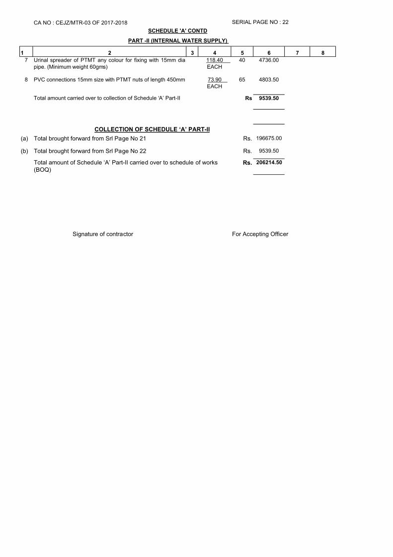
1 2 3 4 5 6 7 8
7 Urinal spreader of PTMT any colour for fixing with 15mm diapipe. (Minimum weight 60gms)
118.40 EACH
40 4736.00
8 PVC connections 15mm size with PTMT nuts of length 450mm 73.90 EACH
65 4803.50
Rs 9539.50
(a) Rs. 196675.00
(b) Rs. 9539.50
Rs. 206214.50
For Accepting Officer
SCHEDULE 'A' CONTD
PART -II (INTERNAL WATER SUPPLY)
CA NO : CEJZ/MTR-03 OF 2017-2018
Total amount of Schedule ‘A’ Part-II carried over to schedule of works (BOQ)
Signature of contractor
COLLECTION OF SCHEDULE ‘A’ PART-II
Total brought forward from Srl Page No 21
Total brought forward from Srl Page No 22
Total amount carried over to collection of Schedule ‘A’ Part-II
SERIAL PAGE NO : 22
S.
No
Description of items or works
Drg
No
Unit Rate
Rs. Ps.
No. of
units
requi-
red
Total in
Rs. Ps.
Period of
completion
on of
individual
items after
date of
handing over
the site
Re
ma
rk
1 2 3 4 5 6 7 8
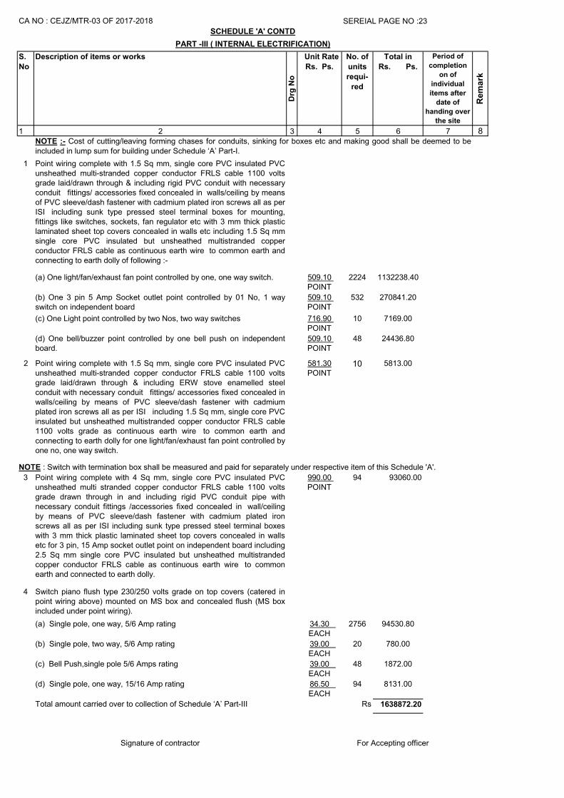
1 Point wiring complete with 1.5 Sq mm, single core PVC insulated PVCunsheathed multi-stranded copper conductor FRLS cable 1100 voltsgrade laid/drawn through & including rigid PVC conduit with necessaryconduit fittings/ accessories fixed concealed in walls/ceiling by meansof PVC sleeve/dash fastener with cadmium plated iron screws all as perISI including sunk type pressed steel terminal boxes for mounting,fittings like switches, sockets, fan regulator etc with 3 mm thick plasticlaminated sheet top covers concealed in walls etc including 1.5 Sq mmsingle core PVC insulated but unsheathed multistranded copperconductor FRLS cable as continuous earth wire to common earth andconnecting to earth dolly of following :-
(a) One light/fan/exhaust fan point controlled by one, one way switch. 509.10 POINT
2224 1132238.40
(b) One 3 pin 5 Amp Socket outlet point controlled by 01 No, 1 wayswitch on independent board
509.10 POINT
532 270841.20
(c) One Light point controlled by two Nos, two way switches 716.90 POINT
10 7169.00
(d) One bell/buzzer point controlled by one bell push on independentboard.
509.10 POINT
48 24436.80
2 Point wiring complete with 1.5 Sq mm, single core PVC insulated PVCunsheathed multi-stranded copper conductor FRLS cable 1100 voltsgrade laid/drawn through & including ERW stove enamelled steelconduit with necessary conduit fittings/ accessories fixed concealed inwalls/ceiling by means of PVC sleeve/dash fastener with cadmiumplated iron screws all as per ISI including 1.5 Sq mm, single core PVCinsulated but unsheathed multistranded copper conductor FRLS cable1100 volts grade as continuous earth wire to common earth andconnecting to earth dolly for one light/fan/exhaust fan point controlled byone no, one way switch.
581.30POINT
10 5813.00
3 Point wiring complete with 4 Sq mm, single core PVC insulated PVCunsheathed multi stranded copper conductor FRLS cable 1100 voltsgrade drawn through in and including rigid PVC conduit pipe withnecessary conduit fittings /accessories fixed concealed in wall/ceilingby means of PVC sleeve/dash fastener with cadmium plated ironscrews all as per ISI including sunk type pressed steel terminal boxeswith 3 mm thick plastic laminated sheet top covers concealed in wallsetc for 3 pin, 15 Amp socket outlet point on independent board including2.5 Sq mm single core PVC insulated but unsheathed multistrandedcopper conductor FRLS cable as continuous earth wire to commonearth and connected to earth dolly.
990.00 POINT
94 93060.00
4 Switch piano flush type 230/250 volts grade on top covers (catered inpoint wiring above) mounted on MS box and concealed flush (MS boxincluded under point wiring).
(a) Single pole, one way, 5/6 Amp rating 34.30 EACH
2756 94530.80
(b) Single pole, two way, 5/6 Amp rating 39.00 EACH
20 780.00
(c) Bell Push,single pole 5/6 Amps rating 39.00 EACH
48 1872.00
(d) Single pole, one way, 15/16 Amp rating 86.50 EACH
94 8131.00
Rs 1638872.20
Signature of contractor
SCHEDULE 'A' CONTD
NOTE : Switch with termination box shall be measured and paid for separately under respective item of this Schedule 'A'.
CA NO : CEJZ/MTR-03 OF 2017-2018 SEREIAL PAGE NO :23
PART -III ( INTERNAL ELECTRIFICATION)
NOTE :- Cost of cutting/leaving forming chases for conduits, sinking for boxes etc and making good shall be deemed to beincluded in lump sum for building under Schedule ‘A’ Part-I.
Total amount carried over to collection of Schedule ‘A’ Part-III
For Accepting officer
1 2 3 4 5 6 7 8
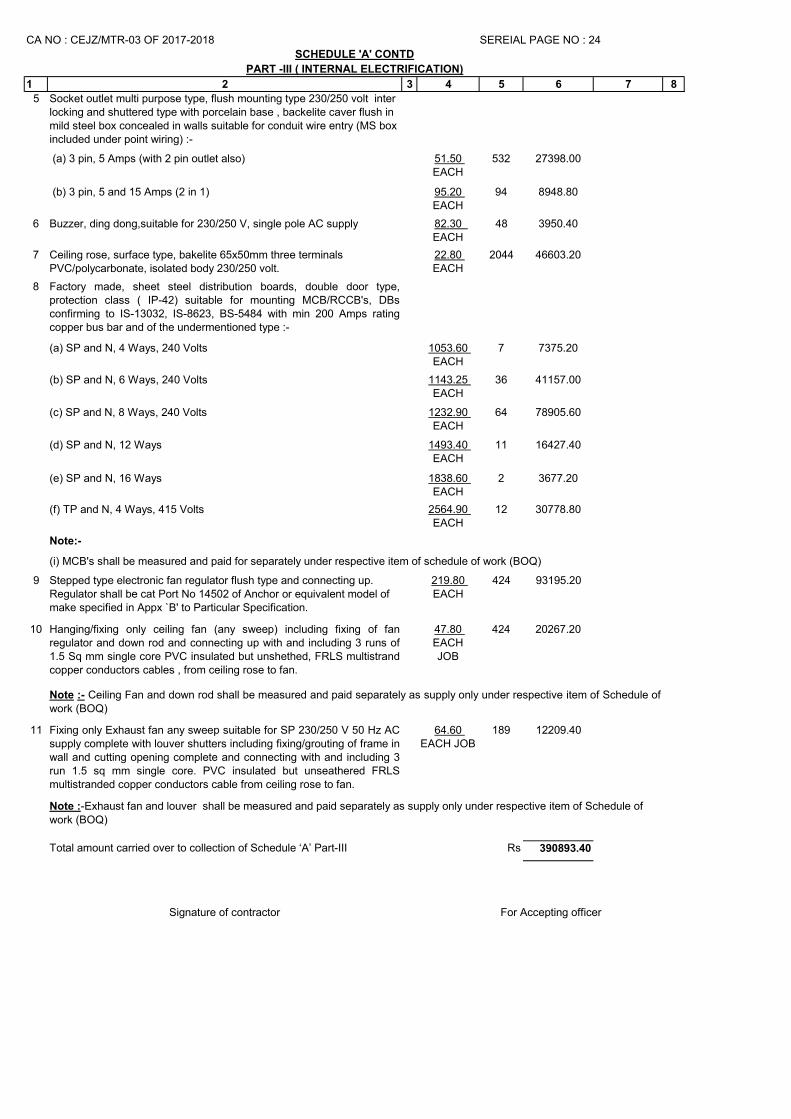
5 Socket outlet multi purpose type, flush mounting type 230/250 volt inter locking and shuttered type with porcelain base , backelite caver flush in mild steel box concealed in walls suitable for conduit wire entry (MS box included under point wiring) :-
(a) 3 pin, 5 Amps (with 2 pin outlet also) 51.50 EACH
532 27398.00
(b) 3 pin, 5 and 15 Amps (2 in 1) 95.20 EACH
94 8948.80
6 Buzzer, ding dong,suitable for 230/250 V, single pole AC supply 82.30 EACH
48 3950.40
7 Ceiling rose, surface type, bakelite 65x50mm three terminals PVC/polycarbonate, isolated body 230/250 volt.
22.80 EACH
2044 46603.20
8 Factory made, sheet steel distribution boards, double door type,protection class ( IP-42) suitable for mounting MCB/RCCB's, DBsconfirming to IS-13032, IS-8623, BS-5484 with min 200 Amps ratingcopper bus bar and of the undermentioned type :-
(a) SP and N, 4 Ways, 240 Volts 1053.60 EACH
7 7375.20
(b) SP and N, 6 Ways, 240 Volts 1143.25 EACH
36 41157.00
(c) SP and N, 8 Ways, 240 Volts 1232.90 EACH
64 78905.60
(d) SP and N, 12 Ways 1493.40 EACH
11 16427.40
(e) SP and N, 16 Ways 1838.60 EACH
2 3677.20
(f) TP and N, 4 Ways, 415 Volts 2564.90 EACH
12 30778.80
Note:-
9 Stepped type electronic fan regulator flush type and connecting up. Regulator shall be cat Port No 14502 of Anchor or equivalent model of make specified in Appx `B' to Particular Specification.
219.80 EACH
424 93195.20
10 Hanging/fixing only ceiling fan (any sweep) including fixing of fanregulator and down rod and connecting up with and including 3 runs of1.5 Sq mm single core PVC insulated but unshethed, FRLS multistrandcopper conductors cables , from ceiling rose to fan.
47.80 EACHJOB
424 20267.20
11 Fixing only Exhaust fan any sweep suitable for SP 230/250 V 50 Hz ACsupply complete with louver shutters including fixing/grouting of frame inwall and cutting opening complete and connecting with and including 3run 1.5 sq mm single core. PVC insulated but unseathered FRLSmultistranded copper conductors cable from ceiling rose to fan.
64.60 EACH JOB
189 12209.40
Rs 390893.40
Signature of contractor
SCHEDULE 'A' CONTD
SEREIAL PAGE NO : 24
PART -III ( INTERNAL ELECTRIFICATION)
(i) MCB's shall be measured and paid for separately under respective item of schedule of work (BOQ)
Total amount carried over to collection of Schedule ‘A’ Part-III
For Accepting officer
CA NO : CEJZ/MTR-03 OF 2017-2018
Note :- Ceiling Fan and down rod shall be measured and paid separately as supply only under respective item of Schedule ofwork (BOQ)
Note :-Exhaust fan and louver shall be measured and paid separately as supply only under respective item of Schedule of work (BOQ)
1 2 3 4 5 6 7 8
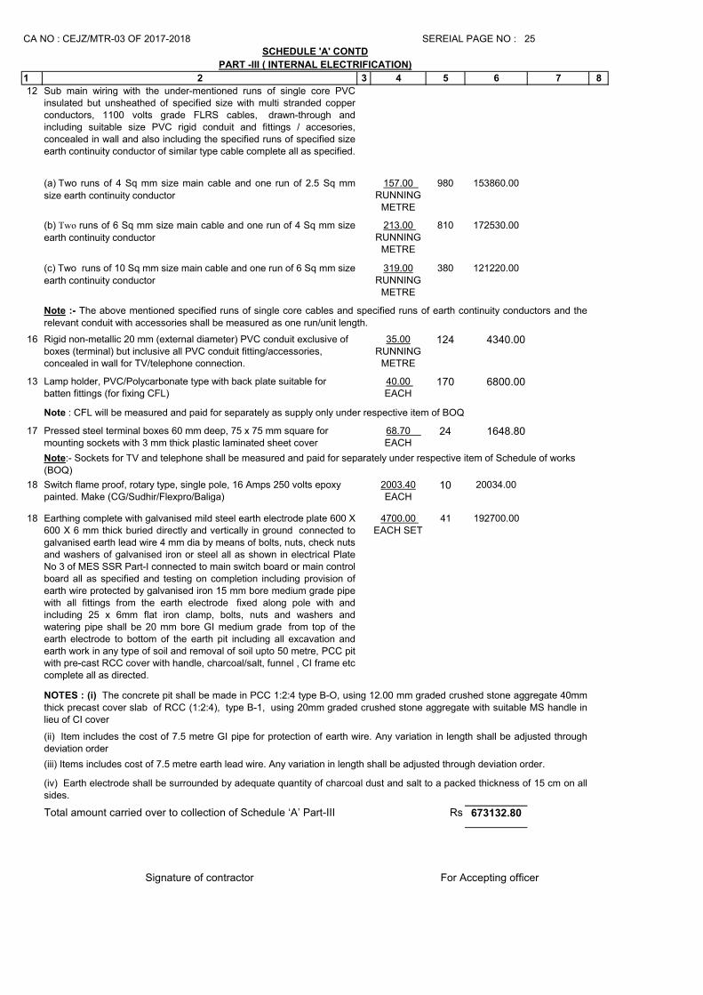
12 Sub main wiring with the under-mentioned runs of single core PVCinsulated but unsheathed of specified size with multi stranded copperconductors, 1100 volts grade FLRS cables, drawn-through andincluding suitable size PVC rigid conduit and fittings / accesories,concealed in wall and also including the specified runs of specified sizeearth continuity conductor of similar type cable complete all as specified.
(a) Two runs of 4 Sq mm size main cable and one run of 2.5 Sq mm
size earth continuity conductor
157.00 RUNNING
METRE
980 153860.00
(b) Two runs of 6 Sq mm size main cable and one run of 4 Sq mm size
earth continuity conductor
213.00 RUNNING
METRE
810 172530.00
(c) Two runs of 10 Sq mm size main cable and one run of 6 Sq mm size
earth continuity conductor
319.00RUNNING
METRE
380 121220.00
16 Rigid non-metallic 20 mm (external diameter) PVC conduit exclusive of boxes (terminal) but inclusive all PVC conduit fitting/accessories, concealed in wall for TV/telephone connection.
35.00RUNNING
METRE
124 4340.00
13 Lamp holder, PVC/Polycarbonate type with back plate suitable for batten fittings (for fixing CFL)
40.00 EACH
170 6800.00
17 Pressed steel terminal boxes 60 mm deep, 75 x 75 mm square for mounting sockets with 3 mm thick plastic laminated sheet cover
68.70 EACH
24 1648.80
18 Switch flame proof, rotary type, single pole, 16 Amps 250 volts epoxy painted. Make (CG/Sudhir/Flexpro/Baliga)
2003.40EACH
10 20034.00
18 Earthing complete with galvanised mild steel earth electrode plate 600 X600 X 6 mm thick buried directly and vertically in ground connected togalvanised earth lead wire 4 mm dia by means of bolts, nuts, check nutsand washers of galvanised iron or steel all as shown in electrical PlateNo 3 of MES SSR Part-I connected to main switch board or main controlboard all as specified and testing on completion including provision ofearth wire protected by galvanised iron 15 mm bore medium grade pipewith all fittings from the earth electrode fixed along pole with andincluding 25 x 6mm flat iron clamp, bolts, nuts and washers andwatering pipe shall be 20 mm bore GI medium grade from top of theearth electrode to bottom of the earth pit including all excavation andearth work in any type of soil and removal of soil upto 50 metre, PCC pitwith pre-cast RCC cover with handle, charcoal/salt, funnel , CI frame etccomplete all as directed.
4700.00 EACH SET
41 192700.00
Rs 673132.80
Signature of contractor
Note:- Sockets for TV and telephone shall be measured and paid for separately under respective item of Schedule of works (BOQ)
NOTES : (i) The concrete pit shall be made in PCC 1:2:4 type B-O, using 12.00 mm graded crushed stone aggregate 40mmthick precast cover slab of RCC (1:2:4), type B-1, using 20mm graded crushed stone aggregate with suitable MS handle inlieu of CI cover
(ii) Item includes the cost of 7.5 metre GI pipe for protection of earth wire. Any variation in length shall be adjusted throughdeviation order
(iii) Items includes cost of 7.5 metre earth lead wire. Any variation in length shall be adjusted through deviation order.
(iv) Earth electrode shall be surrounded by adequate quantity of charcoal dust and salt to a packed thickness of 15 cm on allsides.
SCHEDULE 'A' CONTD
Note : CFL will be measured and paid for separately as supply only under respective item of BOQ
CA NO : CEJZ/MTR-03 OF 2017-2018 SEREIAL PAGE NO : 25
PART -III ( INTERNAL ELECTRIFICATION)
Note :- The above mentioned specified runs of single core cables and specified runs of earth continuity conductors and therelevant conduit with accessories shall be measured as one run/unit length.
Total amount carried over to collection of Schedule ‘A’ Part-III
For Accepting officer
1 2 3 4 5 6 7 8
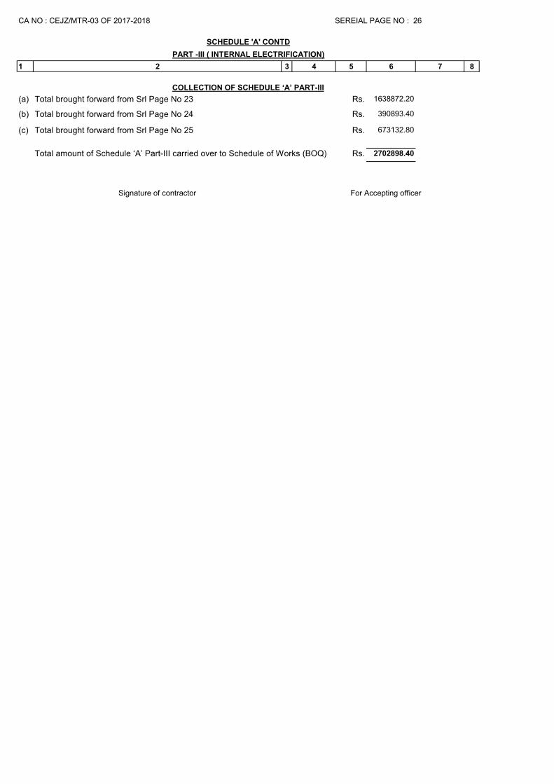
(a) Rs. 1638872.20
(b) Rs. 390893.40
(c) Rs. 673132.80
Rs. 2702898.40
Signature of contractor
SCHEDULE 'A' CONTD
SEREIAL PAGE NO : 26
Total amount of Schedule ‘A’ Part-III carried over to Schedule of Works (BOQ)
Total brought forward from Srl Page No 25
For Accepting officer
COLLECTION OF SCHEDULE ‘A’ PART-III
Total brought forward from Srl Page No 23
Total brought forward from Srl Page No 24
PART -III ( INTERNAL ELECTRIFICATION)
CA NO : CEJZ/MTR-03 OF 2017-2018
S.N
o
Description of items or works
Drg
No Unit Rate
Rs. Ps.
No. of
units
required
Total in
Rs. Ps.
Period of
completion on
of individual
items after
date of
handing over
the site
Re
mark
1 2 3 4 5 6 7 8
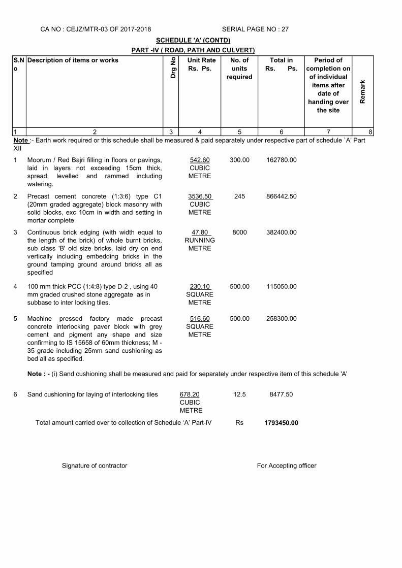
1 Moorum / Red Bajri filling in floors or pavings,laid in layers not exceeding 15cm thick,spread, levelled and rammed includingwatering.
542.60CUBIC METRE
300.00 162780.00
2 Precast cement concrete (1:3:6) type C1(20mm graded aggregate) block masonry withsolid blocks, exc 10cm in width and setting inmortar complete
3536.50 CUBIC METRE
245 866442.50
3 Continuous brick edging (with width equal tothe length of the brick) of whole burnt bricks,sub class 'B' old size bricks, laid dry on endvertically including embedding bricks in theground tamping ground around bricks all asspecified
47.80 RUNNING
METRE
8000 382400.00
4 100 mm thick PCC (1:4:8) type D-2 , using 40 mm graded crushed stone aggregate as in subbase to inter locking tiles.
230.10 SQUARE METRE
500.00 115050.00
5 Machine pressed factory made precastconcrete interlocking paver block with greycement and pigment any shape and sizeconfirming to IS 15658 of 60mm thickness; M -35 grade including 25mm sand cushioning asbed all as specified.
516.60SQUARE METRE
500.00 258300.00
6 Sand cushioning for laying of interlocking tiles 678.20CUBIC METRE
12.5 8477.50
Rs 1793450.00
Signature of contractor
SERIAL PAGE NO : 27
SCHEDULE 'A' (CONTD)
PART -IV ( ROAD, PATH AND CULVERT)
CA NO : CEJZ/MTR-03 OF 2017-2018
For Accepting officer
Note : - (i) Sand cushioning shall be measured and paid for separately under respective item of this schedule 'A'
Note :- Earth work required or this schedule shall be measured & paid separately under respective part of schedule `A' Part XII
Total amount carried over to collection of Schedule ‘A’ Part-lV
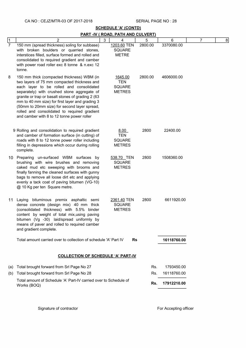
1 2 3 4 5 6 7 87 150 mm (spread thickness) soling for subbase)
with broken boulders or quarried stones,interstices filled, surface formed and rolled andconsolidated to required gradient and camberwith power road roller exc 8 tonne & n.exc 12tonne.
1203.60 TEN SQUARE METRE
2800.00 3370080.00
8 150 mm thick (compacted thickness) WBM (intwo layers of 75 mm compacted thickness andeach layer to be rolled and consolidatedseparately) with crushed stone aggregate ofgranite or trap or basalt stones of grading 2 (63mm to 40 mm size) for first layer and grading 3(50mm to 20mm size) for second layer spread,rolled and consolidated to required gradientand camber with 8 to 12 tonne power roller
1645.00TEN
SQUARE METRES
2800.00 4606000.00
9 Rolling and consolidation to required gradientand camber of formation surface (in cutting) ofroads with 8 to 12 tonne power roller includingfilling in depressions which occur during rollingcomplete.
8.00 TEN
SQUARE METRES
2800 22400.00
10 Preparing un-surfaced WBM surfaces bybrushing with wire brushes and removingcaked mud etc sweeping with brooms andfinally fanning the cleaned surfaces with gunnybags to remove all loose dirt etc and applyingevenly a tack coat of paving bitumen (VG-10)@ 10 Kg per ten Square metre.
538.70 TEN SQUARE METRES
2800 1508360.00
11 Laying bituminous premix asphaltic semidense concrete (design mix) 40 mm thick(consolidated thickness) with 5.5% bindercontent by weight of total mix,using pavingbitumen (Vg -30) laid/spread uniformly bymeans of paver and rolled to required camberand gradient complete.
2361.40 TEN SQUARE METRES
2800 6611920.00
16118760.00
(a) Rs. 1793450.00
(b) Rs. 16118760.00
Rs. 17912210.00
Signature of contractor For Accepting officer
SCHEDULE 'A' (CONTD)
Total brought forward from Srl Page No 27
Total amount carried over to collection of schedule 'A' Part IV Rs
Total amount of Schedule ‘A’ Part-IV carried over to Schedule of Works (BOQ)
Total brought forward from Srl Page No 28
COLLECTION OF SCHEDULE ‘A’ PART-IV
CA NO : CEJZ/MTR-03 OF 2017-2018 SERIAL PAGE NO : 28
PART -IV ( ROAD, PATH AND CULVERT)
S.N
o
Description of items or works
Drg
No
Unit Rate
Rs. Ps.
No. of
units
required
Total in Rs Period of
completion
on of
individual
items after
date of
handing over
Rem
ark
1 2 3 4 5 6 7 8
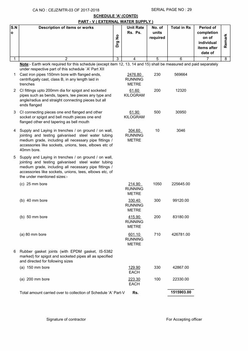
1 Cast iron pipes 150mm bore with flanged ends, centrifugally cast, class B, in any length laid in trenches
2476.80 RUNNING
METRE
230 569664
2 CI fittings upto 200mm dia for spigot and socketed pipes such as bends, tapers, tee pieces any type and angle/radius and straight connecting pieces but all ends flanged
61.60 KILOGRAM
200 12320
3 CI connecting pieces one end flanged and other socket or spigot and bell mouth pieces one end flanged other end tapering as bell mouth
61.90 KILOGRAM
500 30950
4 Supply and Laying in trenches / on ground / on wall,jointing and testing galvanised steel water tubingmedium grade, including all necessary pipe fittings /accessories like sockets, unions, tees, elbows etc of40mm bore.
304.60 RUNNING
METRE
10 3046
5 Supply and Laying in trenches / on ground / on wall,jointing and testing galvanised steel water tubingmedium grade, including all necessary pipe fittings /accessories like sockets, unions, tees, elbows etc, ofthe under mentioned sizes:-
(c) 25 mm bore 214.90 RUNNING
METRE
1050 225645.00
(b) 40 mm bore 330.40 RUNNING
METRE
300 99120.00
(b) 50 mm bore 415.90 RUNNING
METRE
200 83180.00
(a) 80 mm bore 601.10 RUNNING
METRE
710 426781.00
6 Rubber gasket joints (with EPDM gasket, IS-5382marked) for spigot and socketed pipes all as specifiedand directed for following sizes
(a) 150 mm bore 129.90EACH
330 42867.00
(a) 200 mm bore 223.30EACH
100 22330.00
1515903.00
Signature of contractor
CA NO : CEJZ/MTR-03 OF 2017-2018 SERIAL PAGE NO : 29
SCHEDULE 'A' (CONTD)
PART - V ( EXTERNAL WATER SUPPLY )
Total amount carried over to collection of Schedule ‘A’ Part-V Rs.
Note:- Earth work required for this schedule (except item 12, 13, 14 and 15) shall be measured and paid separately
under respective part of this schedule `A' Part XII
For Accepting officer
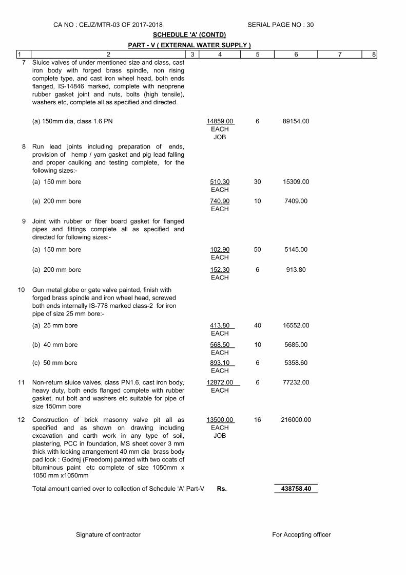
1 2 3 4 5 6 7 87 Sluice valves of under mentioned size and class, cast
iron body with forged brass spindle, non risingcomplete type, and cast iron wheel head, both endsflanged, IS-14846 marked, complete with neoprenerubber gasket joint and nuts, bolts (high tensile),washers etc, complete all as specified and directed.
(a) 150mm dia, class 1.6 PN 14859.00 EACHJOB
6 89154.00
8 Run lead joints including preparation of ends,provision of hemp / yarn gasket and pig lead fallingand proper caulking and testing complete, for thefollowing sizes:-
(a) 150 mm bore 510.30EACH
30 15309.00
(a) 200 mm bore 740.90EACH
10 7409.00
9 Joint with rubber or fiber board gasket for flangedpipes and fittings complete all as specified anddirected for following sizes:-
(a) 150 mm bore 102.90EACH
50 5145.00
(a) 200 mm bore 152.30EACH
6 913.80
10 Gun metal globe or gate valve painted, finish with forged brass spindle and iron wheel head, screwed both ends internally IS-778 marked class-2 for iron pipe of size 25 mm bore:-
(a) 25 mm bore 413.80 EACH
40 16552.00
(b) 40 mm bore 568.50 EACH
10 5685.00
(c) 50 mm bore 893.10 EACH
6 5358.60
11 Non-return sluice valves, class PN1.6, cast iron body,heavy duty, both ends flanged complete with rubbergasket, nut bolt and washers etc suitable for pipe ofsize 150mm bore
12872.00 EACH
6 77232.00
12 Construction of brick masonry valve pit all asspecified and as shown on drawing includingexcavation and earth work in any type of soil,plastering, PCC in foundation, MS sheet cover 3 mmthick with locking arrangement 40 mm dia brass bodypad lock : Godrej (Freedom) painted with two coats ofbituminous paint etc complete of size 1050mm x1050 mm x1050mm
13500.00 EACHJOB
16 216000.00
438758.40
Signature of contractor
Total amount carried over to collection of Schedule ‘A’ Part-V Rs.
For Accepting officer
SCHEDULE 'A' (CONTD)
PART - V ( EXTERNAL WATER SUPPLY )
CA NO : CEJZ/MTR-03 OF 2017-2018 SERIAL PAGE NO : 30
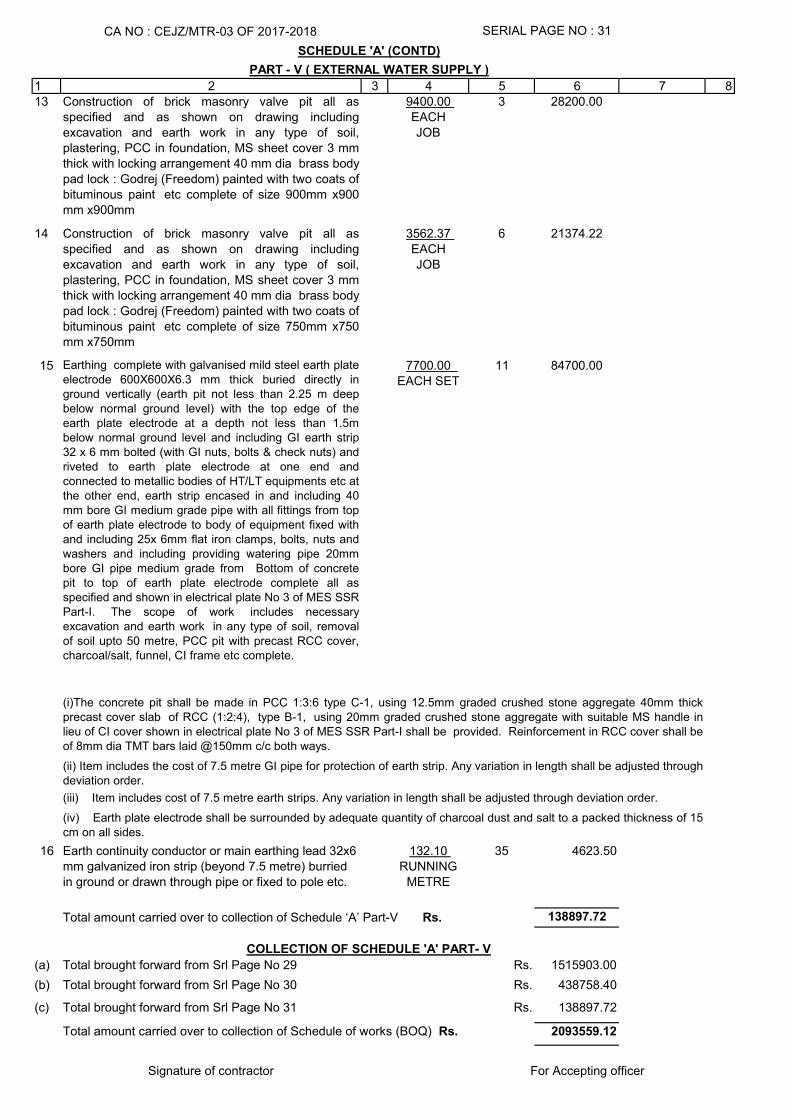
1 2 3 4 5 6 7 813 Construction of brick masonry valve pit all as
specified and as shown on drawing includingexcavation and earth work in any type of soil,plastering, PCC in foundation, MS sheet cover 3 mmthick with locking arrangement 40 mm dia brass bodypad lock : Godrej (Freedom) painted with two coats ofbituminous paint etc complete of size 900mm x900mm x900mm
9400.00 EACHJOB
3 28200.00
14 Construction of brick masonry valve pit all asspecified and as shown on drawing includingexcavation and earth work in any type of soil,plastering, PCC in foundation, MS sheet cover 3 mmthick with locking arrangement 40 mm dia brass bodypad lock : Godrej (Freedom) painted with two coats ofbituminous paint etc complete of size 750mm x750mm x750mm
3562.37 EACHJOB
6 21374.22
15 Earthing complete with galvanised mild steel earth plateelectrode 600X600X6.3 mm thick buried directly inground vertically (earth pit not less than 2.25 m deepbelow normal ground level) with the top edge of theearth plate electrode at a depth not less than 1.5mbelow normal ground level and including GI earth strip32 x 6 mm bolted (with GI nuts, bolts & check nuts) andriveted to earth plate electrode at one end andconnected to metallic bodies of HT/LT equipments etc atthe other end, earth strip encased in and including 40mm bore GI medium grade pipe with all fittings from topof earth plate electrode to body of equipment fixed withand including 25x 6mm flat iron clamps, bolts, nuts andwashers and including providing watering pipe 20mmbore GI pipe medium grade from Bottom of concretepit to top of earth plate electrode complete all asspecified and shown in electrical plate No 3 of MES SSRPart-I. The scope of work includes necessaryexcavation and earth work in any type of soil, removalof soil upto 50 metre, PCC pit with precast RCC cover,charcoal/salt, funnel, CI frame etc complete.
7700.00 EACH SET
11 84700.00
16 Earth continuity conductor or main earthing lead 32x6 mm galvanized iron strip (beyond 7.5 metre) burried in ground or drawn through pipe or fixed to pole etc.
132.10 RUNNING
METRE
35 4623.50
138897.72
(a) Rs. 1515903.00
(b) Rs. 438758.40
(c) Rs. 138897.72
2093559.12
Signature of contractor
Total amount carried over to collection of Schedule ‘A’ Part-V Rs.
Total brought forward from Srl Page No 31
PART - V ( EXTERNAL WATER SUPPLY )
(i)The concrete pit shall be made in PCC 1:3:6 type C-1, using 12.5mm graded crushed stone aggregate 40mm thickprecast cover slab of RCC (1:2:4), type B-1, using 20mm graded crushed stone aggregate with suitable MS handle inlieu of CI cover shown in electrical plate No 3 of MES SSR Part-I shall be provided. Reinforcement in RCC cover shall beof 8mm dia TMT bars laid @150mm c/c both ways.
(ii) Item includes the cost of 7.5 metre GI pipe for protection of earth strip. Any variation in length shall be adjusted throughdeviation order.
CA NO : CEJZ/MTR-03 OF 2017-2018
For Accepting officer
(iii) Item includes cost of 7.5 metre earth strips. Any variation in length shall be adjusted through deviation order.
Total amount carried over to collection of Schedule of works (BOQ) Rs.
COLLECTION OF SCHEDULE 'A' PART- V
Total brought forward from Srl Page No 29
Total brought forward from Srl Page No 30
SERIAL PAGE NO : 31
SCHEDULE 'A' (CONTD)
(iv) Earth plate electrode shall be surrounded by adequate quantity of charcoal dust and salt to a packed thickness of 15cm on all sides.
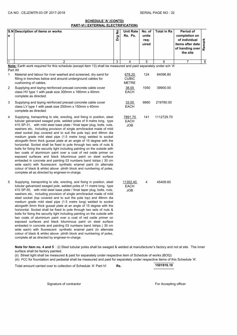
S.N
o
Description of items or works
Drg
No Unit Rate
Rs. Ps.
No. of
units
req-
uired
Total in Rs Period of
completion on
of individual
items after date
of handing over
the site
Re
ma
rk
1 2 3 4 5 6 7 8
1 Material and labour for river washed and screened, dry sand for filling in trenches below and around underground cables for cushioning of cables.
678.20 CUBIC METRE
124 84096.80
2 Supplying and laying reinforced precast concrete cable cover class HV type 1 with peak size 300mm x 180mm x 40mm complete as directed.
38.00 EACH
1050 39900.00
3 Supplying and laying reinforced precast concrete cable cover class LV type 1 with peak size 250mm x 150mm x 40mm complete as directed.
33.00 EACH
6660 219780.00
4 Supplying, transporting to site, erecting, and fixing in position, steeltubular galvanized swaged pole, welded poles of 9 metre long, type410 SP-31, with mild steel base plate / finial taper plug, bolts, nuts,washers etc, including provision of single arm/bracket made of mildsteel socket (top covered and to suit the pole top) and 48mm diamedium grade mild steel pipe (1.5 metre long) welded to socketalongwith 6mm thick gusset plate at an angle of 15 degree with thehorizontal. Socket shall be fixed to pole through two sets of nuts &bolts for fixing the security light including painting on the outside withtwo coats of aluminium paint over a coat of red oxide primer onexposed surfaces and black bituminous paint on steel surfaceembeded in concrete and painting 03 numbers band /strips ( 30 cmwide each) with fluorescent synthetic enamel paint (in alternatecolour of black & white) above plinth block and numbering of poles,complete all as directed by engineer-in-charge.
7891.70 EACHJOB
141 1112729.70
5 Supplying, transporting to site, erecting, and fixing in position, steeltubular galvanized swaged pole, welded poles of 11 metre long, type410 SP-55, with mild steel base plate / finial taper plug, bolts, nuts,washers etc, including provision of single arm/bracket made of mildsteel socket (top covered and to suit the pole top) and 48mm diamedium grade mild steel pipe (1.5 metre long) welded to socketalongwith 6mm thick gusset plate at an angle of 15 degree with thehorizontal. Socket shall be fixed to pole through two sets of nuts &bolts for fixing the security light including painting on the outside withtwo coats of aluminium paint over a coat of red oxide primer onexposed surfaces and black bituminous paint on steel surfaceembeded in concrete and painting 03 numbers band /strips ( 30 cmwide each) with fluorescent synthetic enamel paint (in alternatecolour of black & white) above plinth block and numbering of poles,complete all as directed by engineer-in-charge.
11352.40 EACHJOB
4 45409.60
1501916.10
Signature of contractor
Note for item no. 4 and 5 : (i) Steel tubular poles shall be swaged & welded at manufacturer’s factory and not at site. The inner surface shall be factory painted.(ii) Street light shall be measured & paid for separately under respective item of Schedule of works (BOQ)(iii) PCC for foundation and pedastal shall be measured and paid for separately under respective items of this Schedule 'A'.
Total amount carried over to collection of Schedule ‘A’ Part-VI Rs.
For Accepting officer
CA NO : CEJZ/MTR-03 OF 2017-2018
PART-VI ( EXTERNAL ELECTRIFICATION)
SCHEDULE 'A' (CONTD)
SERIAL PAGE NO : 32
Note: Earth work required for this schedule (except item 13) shall be measured and paid separately under sch 'A' Part XII
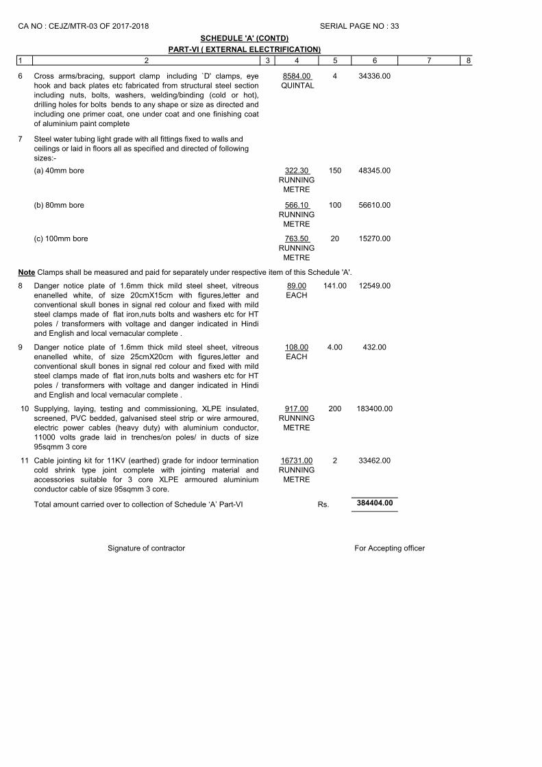
1 2 3 4 5 6 7 8
6 Cross arms/bracing, support clamp including `D' clamps, eyehook and back plates etc fabricated from structural steel sectionincluding nuts, bolts, washers, welding/binding (cold or hot),drilling holes for bolts bends to any shape or size as directed andincluding one primer coat, one under coat and one finishing coatof aluminium paint complete
8584.00 QUINTAL
4 34336.00
7 Steel water tubing light grade with all fittings fixed to walls and ceilings or laid in floors all as specified and directed of following sizes:-
(a) 40mm bore 322.30 RUNNING
METRE
150 48345.00
(b) 80mm bore 566.10 RUNNING
METRE
100 56610.00
(c) 100mm bore 763.50 RUNNING
METRE
20 15270.00
8 Danger notice plate of 1.6mm thick mild steel sheet, vitreousenanelled white, of size 20cmX15cm with figures,letter andconventional skull bones in signal red colour and fixed with mildsteel clamps made of flat iron,nuts bolts and washers etc for HTpoles / transformers with voltage and danger indicated in Hindiand English and local vernacular complete .
89.00EACH
141.00 12549.00
9 Danger notice plate of 1.6mm thick mild steel sheet, vitreousenanelled white, of size 25cmX20cm with figures,letter andconventional skull bones in signal red colour and fixed with mildsteel clamps made of flat iron,nuts bolts and washers etc for HTpoles / transformers with voltage and danger indicated in Hindiand English and local vernacular complete .
108.00EACH
4.00 432.00
10 Supplying, laying, testing and commissioning, XLPE insulated,screened, PVC bedded, galvanised steel strip or wire armoured,electric power cables (heavy duty) with aluminium conductor,11000 volts grade laid in trenches/on poles/ in ducts of size95sqmm 3 core
917.00RUNNING
METRE
200 183400.00
11 Cable jointing kit for 11KV (earthed) grade for indoor terminationcold shrink type joint complete with jointing material andaccessories suitable for 3 core XLPE armoured aluminiumconductor cable of size 95sqmm 3 core.
16731.00RUNNING
METRE
2 33462.00
384404.00
Signature of contractor
PART-VI ( EXTERNAL ELECTRIFICATION)
SERIAL PAGE NO : 33
Note Clamps shall be measured and paid for separately under respective item of this Schedule 'A'.
For Accepting officer
CA NO : CEJZ/MTR-03 OF 2017-2018
SCHEDULE 'A' (CONTD)
Total amount carried over to collection of Schedule ‘A’ Part-VI Rs.
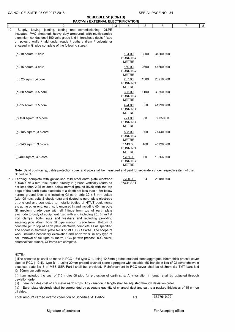
1 2 3 4 5 6 7 812 Supply, Laying, jointing, testing and commissioning XLPE
insulated, PVC sheathed, heavy duty armoured, with multistrandedaluminium conductors 1100 volts grade laid in trenches / ducts / fixedon poles / walls / laid under roads / paths / drain / culverts orencased in GI pipe complete of the following sizes:-
(a) 10 sqmm ,2 core 104.00RUNNING
METRE
3000 312000.00
(b) 16 sqmm ,4 core 160.00RUNNING
METRE
2600 416000.00
(c ) 25 sqmm ,4 core 207.00RUNNING
METRE
1300 269100.00
(d) 50 sqmm ,3.5 core 305.00RUNNING
METRE
1100 335500.00
(e) 95 sqmm ,3.5 core 494.00RUNNING
METRE
850 419900.00
(f) 150 sqmm ,3.5 core 721.00RUNNING
METRE
50 36050.00
(g) 185 sqmm ,3.5 core 893.00RUNNING
METRE
800 714400.00
(h) 240 sqmm, 3.5 core 1143.00RUNNING
METRE
400 457200.00
(i) 400 sqmm, 3.5 core 1761.00RUNNING
METRE
60 105660.00
13 Earthing complete with galvanised mild steel earth plate electrode600X600X6.3 mm thick buried directly in ground vertically (earth pitnot less than 2.25 m deep below normal ground level) with the topedge of the earth plate electrode at a depth not less than 1.5m belownormal ground level and including GI earth strip 32 x 6 mm bolted(with GI nuts, bolts & check nuts) and riveted to earth plate electrodeat one end and connected to metallic bodies of HT/LT equipmentsetc at the other end, earth strip encased in and including 40 mm boreGI medium grade pipe with all fittings from top of earth plateelectrode to body of equipment fixed with and including 25x 6mm flatiron clamps, bolts, nuts and washers and including providingwatering pipe 20mm bore GI pipe medium grade from Bottom ofconcrete pit to top of earth plate electrode complete all as specifiedand shown in electrical plate No 3 of MES SSR Part-I. The scope ofwork includes necessary excavation and earth work in any type ofsoil, removal of soil upto 50 metre, PCC pit with precast RCC cover,charcoal/salt, funnel, CI frame etc complete.
7700.00 EACH SET
34 261800.00
NOTE:-
3327610.00
Signature of contractor
PART-VI ( EXTERNAL ELECTRIFICATION)
(i)The concrete pit shall be made in PCC 1:3:6 type C-1, using 12.5mm graded crushed stone aggregate 40mm thick precast coverslab of RCC (1:2:4), type B-1, using 20mm graded crushed stone aggregate with suitable MS handle in lieu of CI cover shown inelectrical plate No 3 of MES SSR Part-I shall be provided. Reinforcement in RCC cover shall be of 8mm dia TMT bars laid@150mm c/c both ways.
(ii) Item includes the cost of 7.5 metre GI pipe for protection of earth strip. Any variation in length shall be adjusted throughdeviation order.(iii) Item includes cost of 7.5 metre earth strips. Any variation in length shall be adjusted through deviation order.
(iv) Earth plate electrode shall be surrounded by adequate quantity of charcoal dust and salt to a packed thickness of 15 cm onall sides.
Total amount carried over to collection of Schedule ‘A’ Part-VI Rs.
CA NO : CEJZ/MTR-03 OF 2017-2018
For Accepting officer
SERIAL PAGE NO : 34
SCHEDULE 'A' (CONTD)
Note: Sand cushioning, cable protection cover and pipe shall be measured and paid for separately under respective item of this
Schedule 'A'
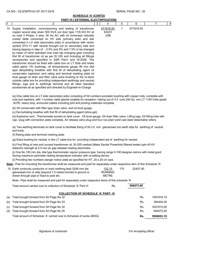
1 2 3 4 5 6 7 8
14 Supply installation, commissioning and testing of transformercopper wound step down 500 KVA out door type 11/0.433 KV atno load 3 Phase, 4 wire, 50 Hz AC with oil immersed naturallycooled delta connected on HV side (primary side) and starconnected in LV side (secondary side) in accordance with vectorsymbol DYn-11 with neutral brought out on secondary side andhaving tapping in step of - 2.5% and 5% and 7.5% to be changedby mean of hand operated over load tap changing gear includingfirst fill of transformer oil as per IS 335 and including all fittings/accessories and specified in SSR Part-I and IS-2026. Thetransformer should be fixed with cable box on LT Side and brasscable gland HV bushings, oil temperatures gauge 96 mm dialtype dehydrating breather with first fill of dehydrating agent oilconservator explosion vent rating and terminal marking plate oillevel gauge oil drain and filter valve extra bushing to the re-storeoutside cable box for providing independent earthings and neutralfittings, lugs and to earthings terminal and all other standardaccessories all as specified and directed by Engineer-in-Charge
671616.00 EACH JOB
1 671616.00
(f) Rating plate and terminal marking plate.
15 Earth continuity conductor or main earthing lead 32X6 mm dia galvanised iron or strip (beyond 7.5 metre) burried in ground or drawn through pipe or fixed to pole etc.
132.10 RUNNING
METRE
170 22457.00
694073.00
(a) Rs. 1501916.10
(b) Rs. 384404.00
(c) Rs. 3327610.00
(d) Rs. 694073.00
Rs. 5908003.10
Signature of contractor For Accepting officer
COLLECTION OF SCHEDULE ‘A’ PART- VI
Total brought forward from Srl Page No 32
Total brought forward from Srl Page No 33
Total brought forward from Srl Page No 34
Total brought forward from Srl Page No 35
Total amount of Schedule ‘A’ carried over to Schedule of works (BOQ)
(b) Oil conservator with filter type drain valve and oil level guage.
(a) One cable box on LT side (secondary side) consisting of 04 numbers porcelain bushing with copper rods, complete with nuts and washers, with 1 number cable glands suitable for reception / taking out of 3.5 core 240 Sq mm LT 1100 Volts grade ,XLPE, heavy duty, armoured cables including joint and jointing materials complete.
CA NO : CEJZ/MTR-03 OF 2017-2018
(d) Explosive vent , Thermometer pocket on tank cover, Oil level gauge, Oil drain filter valve, Lifting lugs, Oil filling hole with cap / plug with connection plate complete, Air release valve plug and four nos plain solid cast steel detachable rollers.
SERIAL PAGE NO : 35
SCHEDULE 'A' (CONTD)
PART-VI ( EXTERNAL ELECTRIFICATION)
(g) Extra bushing for neutral, in the LT cable box for providing independent set of earthing for neutral.
Note:- Pipe shall be measured and paid for seperately under respective items of this schedule 'A'
Note:- Pole for mounting the transformer shall be measured and paid for separately under respective item of this Schedule 'A'.
(j) One No 100 mm dia, dial type thermometer vapoor pressure type, having range 0-100 deegree celcivs with metal good having maximum perimeter reating temperature indicator with re-setting device.
(h) First filling of new and unused transformer oil, IS-335 marked (Make Savita/ Powerlink) filtered tested upto 40 KV dielectric strength at 2.5 mm air gap between testing electrodes.
(l) Providing two numbers danger notice plate as specified for HT, 25 x 20 cm size.
Total amount carried over to collection of Schedule ‘A’ Part-VI Rs.
(e) Two earthing terminals on tank cover to facilitate fixing of 50 x 6 mm galvanised iron earth strip for earthing of neutral and body.
(c) De-hydrating breather with first fill of dehydrating agent (silica gel).
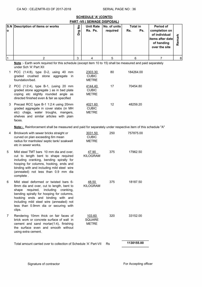
S.N
o
Description of items or works
Drg
No Unit Rate
Rs. Ps.
No. of units
required
Total in
Rs. Ps.
Period of
completion on
of individual
items after date
of handing
over the site
Rem
ark
1 2 3 4 5 6 7 8
1 PCC (1:4:8), type D-2, using 40 mmgraded crushed stone aggregate infoundation/bed.
2303.30 CUBIC METRE
80 184264.00
2 PCC (1:2:4), type B-1, (using 20 mmgraded stone aggregate ) as in bed platecoping etc slightly rounded angle asdirected finished even & fair as specified
4144.40 CUBIC METRE
17 70454.80
3 Precast RCC type B-1 1:2:4 using 20mmgraded aggregate in cover slabs (in MHetc) chajja, water troughs, mangers,shelves and similar articles with plainfaces.
4021.60 CUBIC METRE
12 48259.20
4 Brickwork with sewer bricks straight or curved on plan exceeding 6m mean radius for manholes/ septic tank/ soakwell etc in sewer works.
3031.50 CUBIC METRE
250 757875.00
5 Mild steel TMT bars 10 mm dia and over,cut to length bent to shape requiredincluding cranking, bending spirally forhooping for columns, hooking, ends andbinding with and including mild steel wire(annealed) not less than 0.9 mm diacomplete .
47.90 KILOGRAM
375 17962.50
6 Mild steel deformed or twisted bars 6-8mm dia and over, cut to length, bent toshape required, including cranking,bending spirally for hooping for columns,hooking ends and binding with andincluding mild steel wire (annealed) notless than 0.9mm dia or securing withclips.
48.50 KILOGRAM
375 18187.50
7 Rendering 10mm thick on fair faces ofbrick work or concrete surface of wall incement and sand mortar(1:4), finishingthe surface even and smooth withoutusing extra cement.
103.60 SQUARE METRE
320 33152.00
1130155.00
Signature of contractor
CA NO : CEJZ/MTR-03 OF 2017-2018 SERIAL PAGE NO : 36
SCHEDULE 'A' (CONTD)
PART -VII ( SEWAGE DISPOSAL)
For Accepting officer
Note:- Reinforcement shall be measured and paid for separately under respective item of this schedule "A"
Total amount carried over to collection of Schedule ‘A’ Part-VII Rs
Note :- Earth work required for this schedule (except item 10 to 15) shall be measured and paid separately
under Sch 'A' Part XII
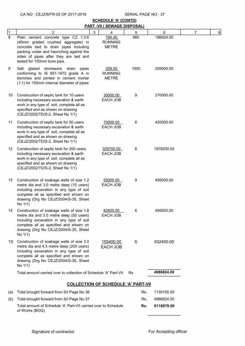
1 2 3 4 5 6 7 88 Plain cement concrete type C2 1:3:6
(40mm graded crushed aggregate) inconcrete bed to drain pipes includingpacking under and haunching against thesides of pipes after they are laid andtested for 150mm bore pipe.
194.40 RUNNING
METRE
960 186624.00
9 Salt glazed stoneware drain pipesconforming to IS 651-1972 grade A intrenches and jointed in cement mortar(1:1) for 150mm internal diameter of pipes
209.00 RUNNING
METRE
1000 209000.00
10 Construction of septic tank for 10 users including necessary excavation & earth work in any type of soil, complete all as specified and as shown on drawing (CEJZ/2002/TD/S-2, Sheet No 1/1)
30000.00 EACH JOB
9 270000.00
11 Construction of septic tank for 50 users including necessary excavation & earth work in any type of soil, complete all as specified and as shown on drawing (CEJZ/2002/TD/S-2, Sheet No 1/1)
70000.00 EACH JOB
6 420000.00
12 Construction of septic tank for 200 users including necessary excavation & earth work in any type of soil, complete all as specified and as shown on drawing (CEJZ/2002/TD/S-2, Sheet No 1/1)
329700.00 EACH JOB
6 1978200.00
13 Construction of soakage wells of size 1.2metre dia and 3.0 metre deep (10 users)including excavation in any type of soilcomplete all as specified and shown ondrawing (Drg No CEJZ/2004/S-35, SheetNo 1/1)
55000.00 EACH JOB
9 495000.00
14 Construction of soakage wells of size 1.8metre dia and 3.0 metre deep (50 users)including excavation in any type of soilcomplete all as specified and shown ondrawing (Drg No CEJZ/2004/S-35, SheetNo 1/1)
82600.00 EACH JOB
6 495600.00
15 Construction of soakage wells of size 3.0metre dia and 4.5 metre deep (200 users)including excavation in any type of soilcomplete all as specified and shown ondrawing (Drg No CEJZ/2004/S-35, SheetNo 1/1)
155400.00 EACH JOB
6 932400.00
4986824.00
(a) Rs. 1130155.00
(b) Rs. 4986824.00
Rs. 6116979.00
Signature of contractor
Total amount of Schedule ‘A’ Part-VII carried over to Schedule of Works (BOQ)
COLLECTION OF SCHEDULE ‘A’ PART-VII
SCHEDULE 'A' (CONTD)
Total amount carried over to collection of Schedule ‘A’ Part-VII Rs
For Accepting officer
PART -VII ( SEWAGE DISPOSAL)
CA NO : CEJZ/MTR-03 OF 2017-2018 SERIAL PAGE NO : 37
Total brought forward from Srl Page No 36
Total brought forward from Srl Page No 37
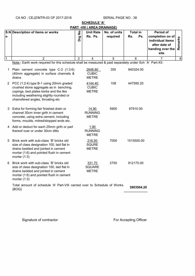
S.N
o
Description of items or works
Drg
No Unit Rate
Rs. Ps.
No. of units
required
Total in
Rs. Ps.
Period of
completion on of
individual items
after date of
handing over the
site
Rem
ark
s
1 2 3 4 5 6 7 8
1 Plain cement concrete type C-2 (1:3:6)(40mm aggregate) in surface channels &drains
2648.80 CUBIC METRE
355 940324.00
2 PCC (1:2:4) type B-1 using 20mm graded crushed stone aggregate as in benching, copings, bed plates kerbs and the like including weathering slightly rounded or chamsfered angles, throating etc
4144.40 CUBIC METRE
108 447595.20
3 Extra for forming fair finished drain or channel 30cm inner girth in cement concrete, using extra cement, including forms, moulds, mitred/stopped ends etc.
14.90 RUNNING
METRE
5900 87910.00
4 Add or deduct for each 25mm girth or part thereof over or under 30cm ditto
1.90 RUNNING
METRE
5 Brick work with sub-class `B' bricks old size of class designation 100, laid flat in drains bedded and jointed in cement mortar (1:6) and pointed flush in cement mortar (1:3)
216.50 SQURE METRE
7000 1515500.00
6 Brick work with sub-class `B' bricks old size of class designation 100, laid flat in drains bedded and jointed in cement mortar (1:6) and pointed flush in cement mortar (1:3)
331.70 SQUARE METRE
2750 912175.00
3903504.20
Signature of contractor For Accepting Officer
Total amount of schedule 'A' Part-VIII carried over to Schedule of Works(BOQ)
SERIAL PAGE NO : 38
SCHEDULE 'A'
PART -VIII ( AREA DRAINAGE)
CA NO : CEJZ/MTR-03 OF 2017-2018
Note:- Earth work required for this schedule shall be measured & paid separately under Sch `A' Part-XII.
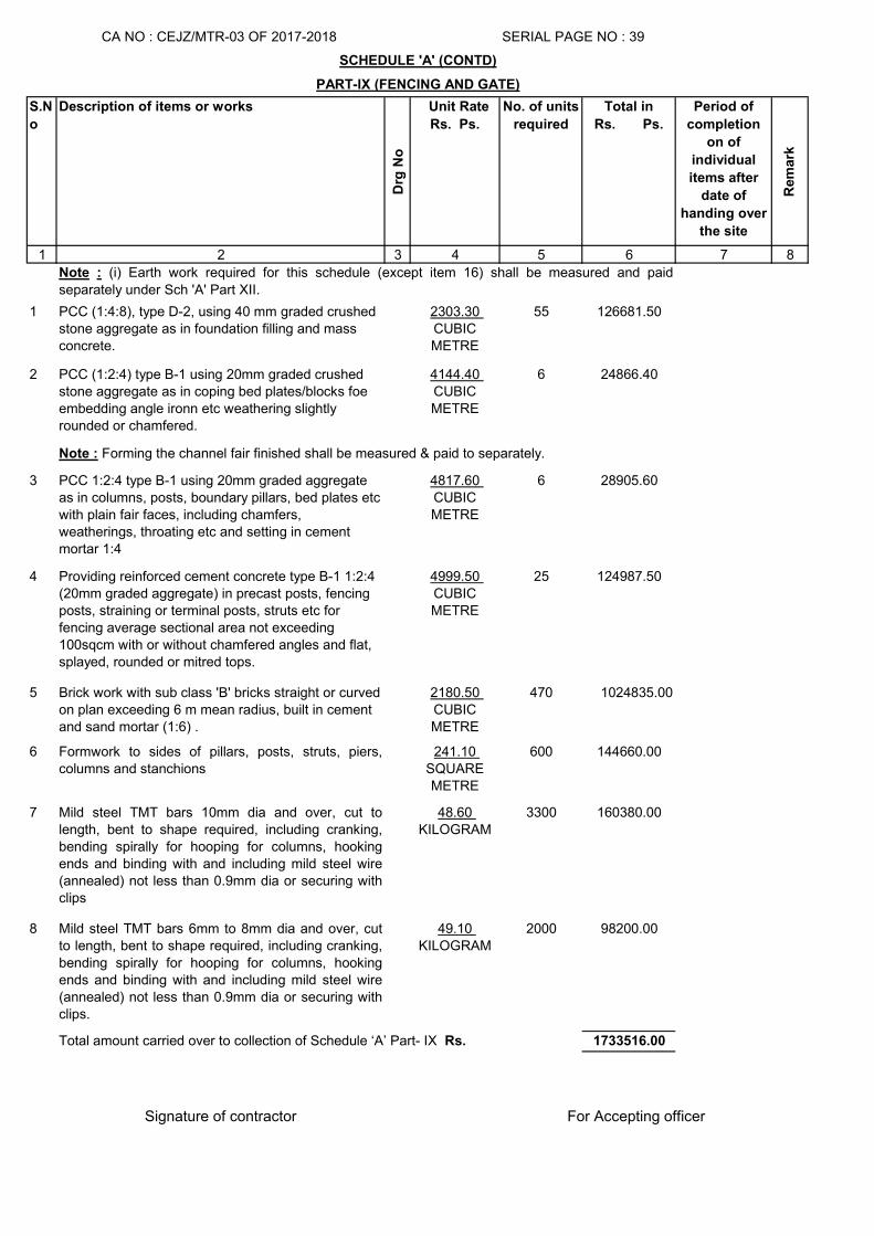
S.N
o
Description of items or works
Drg
No
Unit Rate
Rs. Ps.
No. of units
required
Total in
Rs. Ps.
Period of
completion
on of
individual
items after
date of
handing over
the site
Rem
ark
1 2 3 4 5 6 7 8
1 PCC (1:4:8), type D-2, using 40 mm graded crushed stone aggregate as in foundation filling and mass concrete.
2303.30 CUBIC METRE
55 126681.50
2 PCC (1:2:4) type B-1 using 20mm graded crushed stone aggregate as in coping bed plates/blocks foe embedding angle ironn etc weathering slightly rounded or chamfered.
4144.40 CUBIC METRE
6 24866.40
3 PCC 1:2:4 type B-1 using 20mm graded aggregate as in columns, posts, boundary pillars, bed plates etc with plain fair faces, including chamfers, weatherings, throating etc and setting in cement mortar 1:4
4817.60 CUBIC METRE
6 28905.60
4 Providing reinforced cement concrete type B-1 1:2:4 (20mm graded aggregate) in precast posts, fencing posts, straining or terminal posts, struts etc for fencing average sectional area not exceeding 100sqcm with or without chamfered angles and flat, splayed, rounded or mitred tops.
4999.50 CUBIC METRE
25 124987.50
5 Brick work with sub class 'B' bricks straight or curved on plan exceeding 6 m mean radius, built in cement and sand mortar (1:6) .
2180.50 CUBIC METRE
470 1024835.00
6 Formwork to sides of pillars, posts, struts, piers,columns and stanchions
241.10 SQUARE METRE
600 144660.00
7 Mild steel TMT bars 10mm dia and over, cut tolength, bent to shape required, including cranking,bending spirally for hooping for columns, hookingends and binding with and including mild steel wire(annealed) not less than 0.9mm dia or securing withclips
48.60 KILOGRAM
3300 160380.00
8 Mild steel TMT bars 6mm to 8mm dia and over, cutto length, bent to shape required, including cranking,bending spirally for hooping for columns, hookingends and binding with and including mild steel wire(annealed) not less than 0.9mm dia or securing withclips.
49.10 KILOGRAM
2000 98200.00
1733516.00
Signature of contractor
CA NO : CEJZ/MTR-03 OF 2017-2018 SERIAL PAGE NO : 39
SCHEDULE 'A' (CONTD)
PART-IX (FENCING AND GATE)
Total amount carried over to collection of Schedule ‘A’ Part- IX Rs.
Note : (i) Earth work required for this schedule (except item 16) shall be measured and paid
separately under Sch 'A' Part XII.
Note : Forming the channel fair finished shall be measured & paid to separately.
For Accepting officer
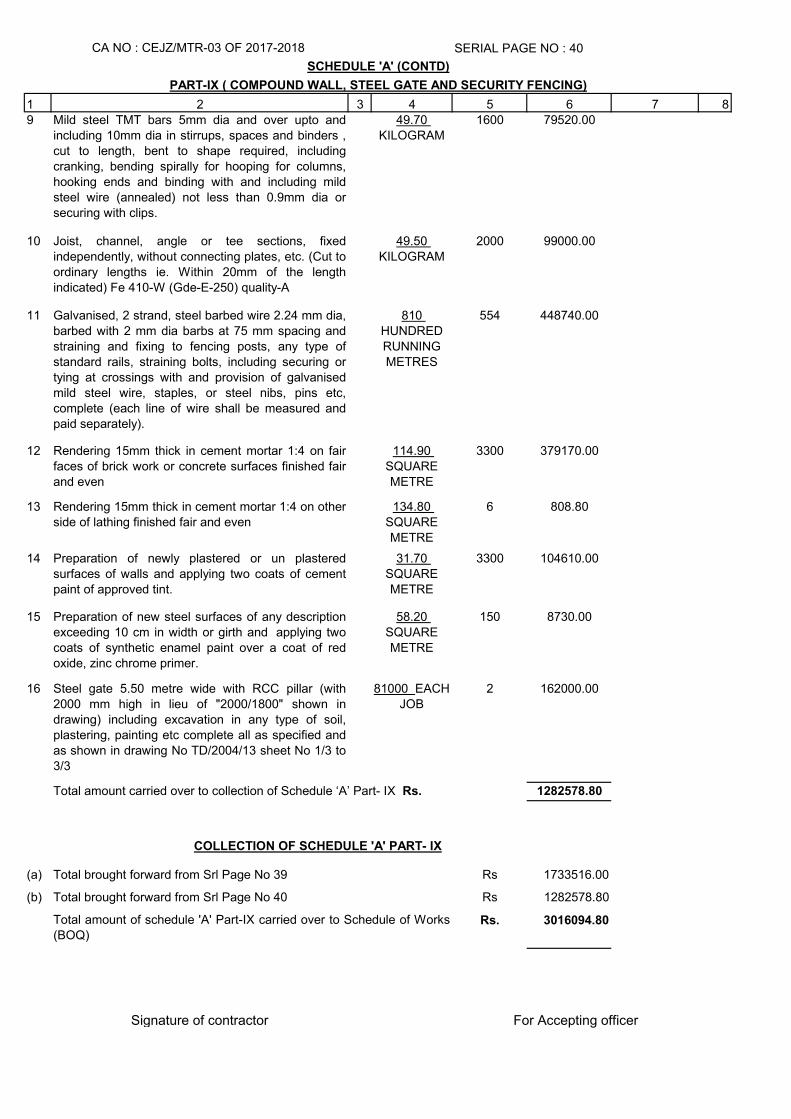
1 2 3 4 5 6 7 89 Mild steel TMT bars 5mm dia and over upto and
including 10mm dia in stirrups, spaces and binders ,cut to length, bent to shape required, includingcranking, bending spirally for hooping for columns,hooking ends and binding with and including mildsteel wire (annealed) not less than 0.9mm dia orsecuring with clips.
49.70 KILOGRAM
1600 79520.00
10 Joist, channel, angle or tee sections, fixedindependently, without connecting plates, etc. (Cut toordinary lengths ie. Within 20mm of the lengthindicated) Fe 410-W (Gde-E-250) quality-A
49.50 KILOGRAM
2000 99000.00
11 Galvanised, 2 strand, steel barbed wire 2.24 mm dia,barbed with 2 mm dia barbs at 75 mm spacing andstraining and fixing to fencing posts, any type ofstandard rails, straining bolts, including securing ortying at crossings with and provision of galvanisedmild steel wire, staples, or steel nibs, pins etc,complete (each line of wire shall be measured andpaid separately).
810 HUNDRED RUNNING METRES
554 448740.00
12 Rendering 15mm thick in cement mortar 1:4 on fairfaces of brick work or concrete surfaces finished fairand even
114.90 SQUARE METRE
3300 379170.00
13 Rendering 15mm thick in cement mortar 1:4 on otherside of lathing finished fair and even
134.80 SQUARE METRE
6 808.80
14 Preparation of newly plastered or un plasteredsurfaces of walls and applying two coats of cementpaint of approved tint.
31.70 SQUARE METRE
3300 104610.00
15 Preparation of new steel surfaces of any descriptionexceeding 10 cm in width or girth and applying twocoats of synthetic enamel paint over a coat of redoxide, zinc chrome primer.
58.20 SQUARE METRE
150 8730.00
16 Steel gate 5.50 metre wide with RCC pillar (with2000 mm high in lieu of "2000/1800" shown indrawing) including excavation in any type of soil,plastering, painting etc complete all as specified andas shown in drawing No TD/2004/13 sheet No 1/3 to3/3
81000 EACH JOB
2 162000.00
1282578.80
(a) Rs 1733516.00
(b) Rs 1282578.80
Rs. 3016094.80
Signature of contractor
Total brought forward from Srl Page No 40
Total amount carried over to collection of Schedule ‘A’ Part- IX Rs.
For Accepting officer
Total amount of schedule 'A' Part-IX carried over to Schedule of Works(BOQ)
SCHEDULE 'A' (CONTD)
CA NO : CEJZ/MTR-03 OF 2017-2018
Total brought forward from Srl Page No 39
COLLECTION OF SCHEDULE 'A' PART- IX
SERIAL PAGE NO : 40
PART-IX ( COMPOUND WALL, STEEL GATE AND SECURITY FENCING)
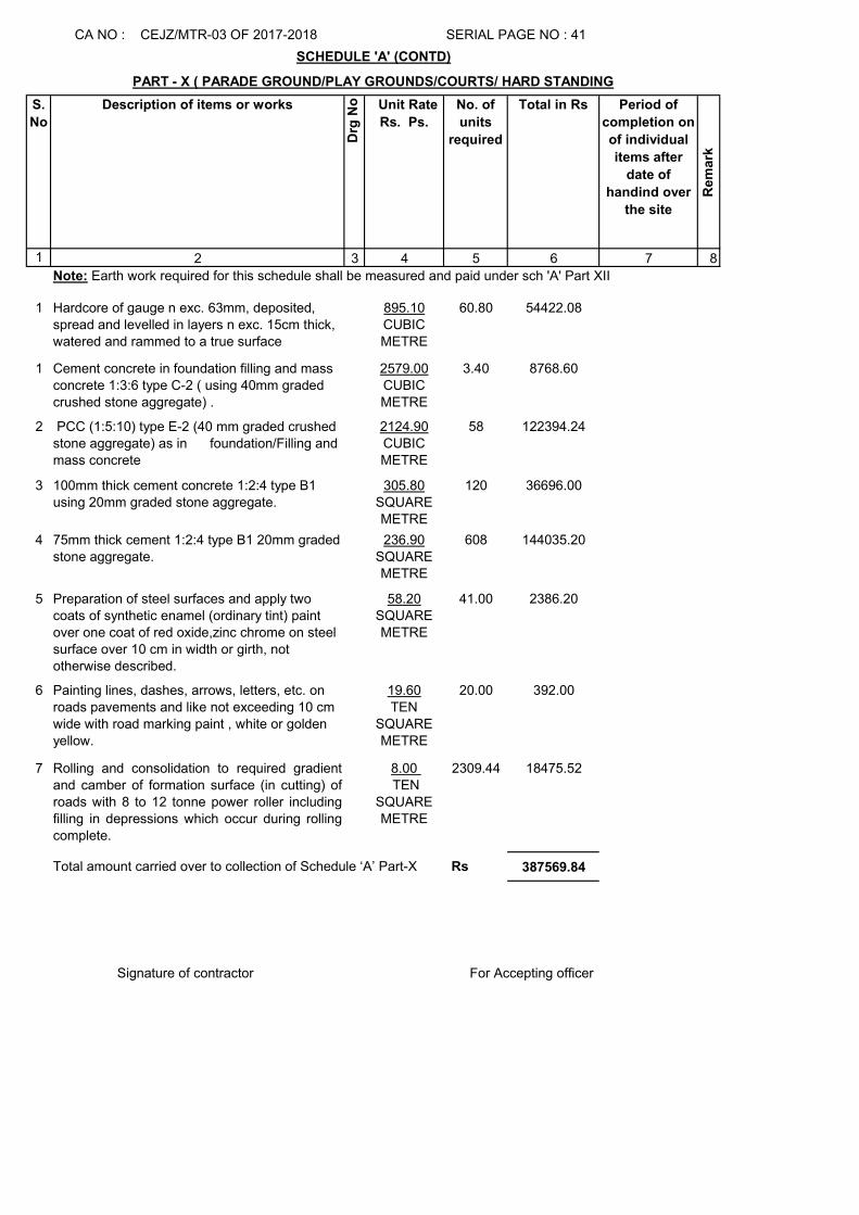
S.
No
Description of items or works
Drg
No Unit Rate
Rs. Ps.
No. of
units
required
Total in Rs Period of
completion on
of individual
items after
date of
handind over
the site
Rem
ark
1 2 3 4 5 6 7 8
1 Hardcore of gauge n exc. 63mm, deposited, spread and levelled in layers n exc. 15cm thick, watered and rammed to a true surface
895.10CUBIC METRE
60.80 54422.08
1 Cement concrete in foundation filling and mass concrete 1:3:6 type C-2 ( using 40mm graded crushed stone aggregate) .
2579.00CUBIC METRE
3.40 8768.60
2 PCC (1:5:10) type E-2 (40 mm graded crushed stone aggregate) as in foundation/Filling and mass concrete
2124.90CUBIC METRE
58 122394.24
3 100mm thick cement concrete 1:2:4 type B1 using 20mm graded stone aggregate.
305.80SQUARE METRE
120 36696.00
4 75mm thick cement 1:2:4 type B1 20mm graded stone aggregate.
236.90SQUARE METRE
608 144035.20
5 Preparation of steel surfaces and apply two coats of synthetic enamel (ordinary tint) paint over one coat of red oxide,zinc chrome on steel surface over 10 cm in width or girth, not otherwise described.
58.20SQUARE METRE
41.00 2386.20
6 Painting lines, dashes, arrows, letters, etc. on roads pavements and like not exceeding 10 cm wide with road marking paint , white or golden yellow.
19.60TEN
SQUARE METRE
20.00 392.00
7 Rolling and consolidation to required gradientand camber of formation surface (in cutting) ofroads with 8 to 12 tonne power roller includingfilling in depressions which occur during rollingcomplete.
8.00 TEN
SQUARE METRE
2309.44 18475.52
387569.84
CA NO : CEJZ/MTR-03 OF 2017-2018 SERIAL PAGE NO : 41
SCHEDULE 'A' (CONTD)
Note: Earth work required for this schedule shall be measured and paid under sch 'A' Part XII
Total amount carried over to collection of Schedule ‘A’ Part-X Rs
Signature of contractor For Accepting officer
PART - X ( PARADE GROUND/PLAY GROUNDS/COURTS/ HARD STANDING
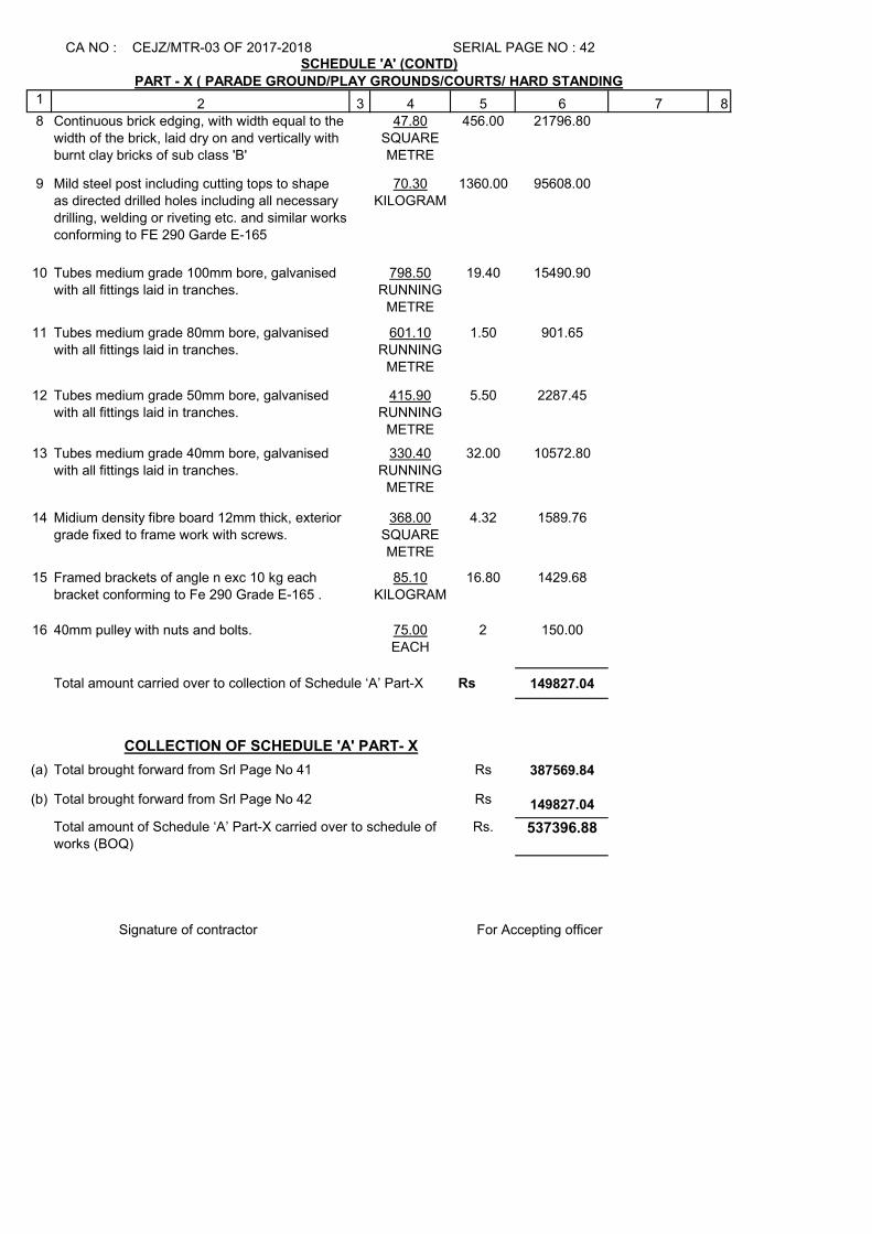
1 2 3 4 5 6 7 88 Continuous brick edging, with width equal to the
width of the brick, laid dry on and vertically with burnt clay bricks of sub class 'B'
47.80SQUARE METRE
456.00 21796.80
9 Mild steel post including cutting tops to shape as directed drilled holes including all necessary drilling, welding or riveting etc. and similar works conforming to FE 290 Garde E-165
70.30KILOGRAM
1360.00 95608.00
10 Tubes medium grade 100mm bore, galvanised with all fittings laid in tranches.
798.50RUNNING
METRE
19.40 15490.90
11 Tubes medium grade 80mm bore, galvanised with all fittings laid in tranches.
601.10RUNNING
METRE
1.50 901.65
12 Tubes medium grade 50mm bore, galvanised with all fittings laid in tranches.
415.90RUNNING
METRE
5.50 2287.45
13 Tubes medium grade 40mm bore, galvanised with all fittings laid in tranches.
330.40RUNNING
METRE
32.00 10572.80
14 Midium density fibre board 12mm thick, exterior grade fixed to frame work with screws.
368.00SQUARE METRE
4.32 1589.76
15 Framed brackets of angle n exc 10 kg each bracket conforming to Fe 290 Grade E-165 .
85.10KILOGRAM
16.80 1429.68
16 40mm pulley with nuts and bolts. 75.00EACH
2 150.00
149827.04
(a) Rs 387569.84
(b) Rs 149827.04
Rs. 537396.88
Total brought forward from Srl Page No 42
Total amount of Schedule ‘A’ Part-X carried over to schedule of works (BOQ)
Signature of contractor For Accepting officer
CA NO : CEJZ/MTR-03 OF 2017-2018 SERIAL PAGE NO : 42SCHEDULE 'A' (CONTD)
PART - X ( PARADE GROUND/PLAY GROUNDS/COURTS/ HARD STANDING
Total amount carried over to collection of Schedule ‘A’ Part-X Rs
COLLECTION OF SCHEDULE 'A' PART- X
Total brought forward from Srl Page No 41
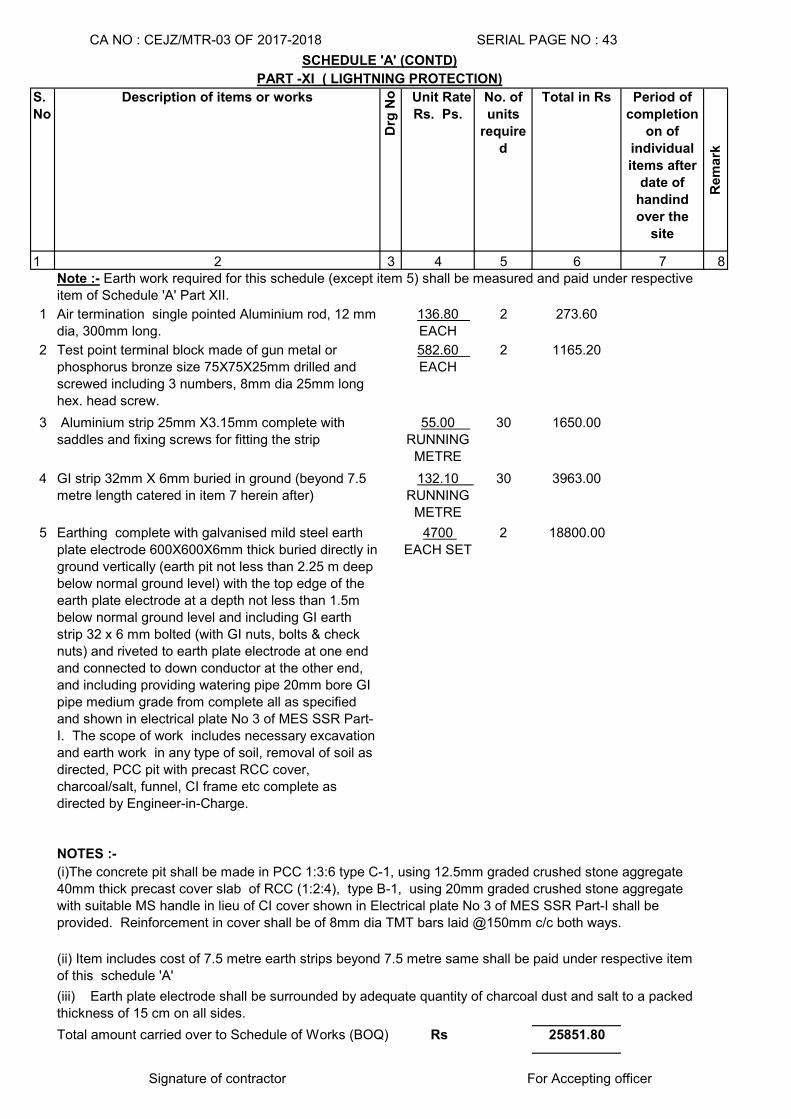
S.
No
Description of items or works
Drg
No Unit Rate
Rs. Ps.
No. of
units
require
d
Total in Rs Period of
completion
on of
individual
items after
date of
handind
over the
site
Rem
ark
1 2 3 4 5 6 7 8
1 Air termination single pointed Aluminium rod, 12 mm dia, 300mm long.
136.80 EACH
2 273.60
2 Test point terminal block made of gun metal or phosphorus bronze size 75X75X25mm drilled and screwed including 3 numbers, 8mm dia 25mm long hex. head screw.
582.60 EACH
2 1165.20
3 Aluminium strip 25mm X3.15mm complete with saddles and fixing screws for fitting the strip
55.00 RUNNING
METRE
30 1650.00
4 GI strip 32mm X 6mm buried in ground (beyond 7.5 metre length catered in item 7 herein after)
132.10 RUNNING
METRE
30 3963.00
5 Earthing complete with galvanised mild steel earth plate electrode 600X600X6mm thick buried directly in ground vertically (earth pit not less than 2.25 m deep below normal ground level) with the top edge of the earth plate electrode at a depth not less than 1.5m below normal ground level and including GI earth strip 32 x 6 mm bolted (with GI nuts, bolts & check nuts) and riveted to earth plate electrode at one end and connected to down conductor at the other end, and including providing watering pipe 20mm bore GI pipe medium grade from complete all as specified and shown in electrical plate No 3 of MES SSR Part-I. The scope of work includes necessary excavation and earth work in any type of soil, removal of soil as directed, PCC pit with precast RCC cover, charcoal/salt, funnel, CI frame etc complete as directed by Engineer-in-Charge.
4700 EACH SET
2 18800.00
NOTES :-
25851.80
Signature of contractor For Accepting officer
(ii) Item includes cost of 7.5 metre earth strips beyond 7.5 metre same shall be paid under respective item of this schedule 'A'
(iii) Earth plate electrode shall be surrounded by adequate quantity of charcoal dust and salt to a packed thickness of 15 cm on all sides.
Total amount carried over to Schedule of Works (BOQ) Rs
(i)The concrete pit shall be made in PCC 1:3:6 type C-1, using 12.5mm graded crushed stone aggregate 40mm thick precast cover slab of RCC (1:2:4), type B-1, using 20mm graded crushed stone aggregate with suitable MS handle in lieu of CI cover shown in Electrical plate No 3 of MES SSR Part-I shall be provided. Reinforcement in cover shall be of 8mm dia TMT bars laid @150mm c/c both ways.
CA NO : CEJZ/MTR-03 OF 2017-2018 SERIAL PAGE NO : 43
SCHEDULE 'A' (CONTD)
PART -XI ( LIGHTNING PROTECTION)
Note :- Earth work required for this schedule (except item 5) shall be measured and paid under respective item of Schedule 'A' Part XII.
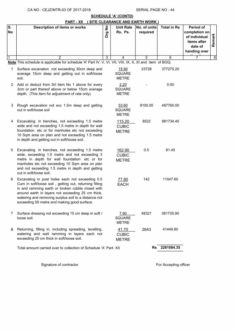
S.
No
Description of items or works
Drg
No Unit Rate
Rs. Ps.
No. of units
required
Total in Rs Period of
completion on
of individual
items after
date of
handing over
the site
Rem
ark
1 2 3 4 5 6 7 8
1 Surface excavation not exceeding 30cm deep andaverage 15cm deep and getting out in soft/loosesoil.
15.90SQUARE METRE
23728 377275.20
2 Add or deduct from Srl item No 1 above for every3cm or part thereof above or below 15cm averagedepth. (This item for adjustment of rate only).
2.20SQUARE METRE
- 0.00
3 Rough excavation not exc 1.5m deep and gettingout in soft/loose soil
53.60SQUARE METRE
9100.00 487760.00
4 Excavating in trenches, not exceeding 1.5 metrewide and not exceeding 1.5 metre in depth for wallfoundation etc or for manholes etc not exceeding10 Sqm area on plan and not exceeding 1.5 metrein depth and getting out in soft/loose soil.
115.20 CUBIC METRE
8522 981734.40
5 Excavating in trenches, not exceeding 1.5 metrewide, exceeding 1.5 metre and not exceeding 3metre in depth for wall foundation etc or formanholes etc not exceeding 10 Sqm area on planand not exceeding 1.5 metre in depth and gettingout in soft/loose soil.
162.90 CUBIC METRE
0.5 81.45
6 Excavating in post holes each not exceeding 0.5Cum in soft/loose soil , getting out, returning fillingin and ramming earth or broken rubble mixed witharound earth in layers not exceeding 25 cm thick,watering and removing surplus soil to a distance notexceeding 50 metre and making good surface.
77.80EACH
142 11047.60
7 Surface dressing not exceeding 15 cm deep in soft /loose soil.
7.90 SQUARE METRE
48321 381735.90
8 Returning, filling in, including spreading, levelling,watering and well ramming in layers each notexceeding 25 cm thick in soft/loose soil.
41.70 CUBIC METRE
2643 41449.80
Rs 2281084.35
Signature of contractor
SCHEDULE 'A' (CONTD)
PART - XII ( SITE CLEARANCE AND EARTH WORK )
SERIAL PAGE NO : 44
For Accepting officer
Total amount carried over to collection of Schedule ‘A’ Part- XII
Note This schedule is applicable for schedule 'A' Part IV, V, VI, VII, VIII, IX, X, XI and item of BOQ.
CA NO : CEJZ/MTR-03 OF 2017-2018
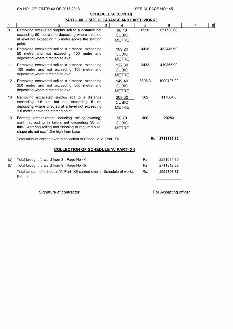
1 2 3 4 5 6 7 89 Removing excavated surplus soil to a distance not
exceeding 50 metre and depositing where directedat level not exceeding 1.5 metre above the startingpoint.
96.10 CUBIC METRE
6990 671739.00
10 Removing excavated soil to a distance exceeding50 metre and not exceeding 100 metre anddepositing where directed at level
109.20 CUBIC METRE
4418 482445.60
11 Removing excavated soil to a distance exceeding100 metre and not exceeding 150 metre anddepositing where directed at level
122.30 CUBIC METRE
3433 419855.90
12 Removing excavated soil to a distance exceeding250 metre and not exceeding 500 metre anddepositing where directed at level
149.40 CUBIC METRE
6696.3 1000427.22
13 Removing excavated surplus soil to a distanceexceeding 1.5 km but not exceeding 5 kmdepositing where directed at a level not exceeding1.5 metre above the starting point.
208.30 CUBIC METRE
562 117064.6
13 Forming ambankment including raising(lowering)earth, spreading in layers not exceeding 30 cmthick, watering rolling and finishing to required size,shape etc not exc 1.5m high from base
50.70 CUBIC METRE
400 20280
Rs 2711812.32
(a) Rs 2281084.35
(b) Rs 2711812.32
Rs. 4992896.67
Signature of contractor
Total amount of schedule 'A' Part- XII carried over to Schedule of works(BOQ)
For Accepting officer
SERIAL PAGE NO : 45
Total brought forward from Srl Page No 44
Total brought forward from Srl Page No 45
SCHEDULE 'A' (CONTD)
PART - XII ( SITE CLEARANCE AND EARTH WORK )
Total amount carried over to collection of Schedule ‘A’ Part- XII
CA NO : CEJZ/MTR-03 OF 2017-2018
COLLECTION OF SCHEDULE 'A' PART- XII
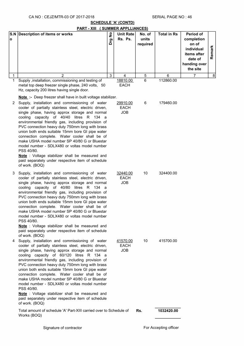
S.N
o
Description of items or works
Drg
No Unit Rate
Rs. Ps.
No. of
units
required
Total in Rs Period of
completion
on of
individual
items after
date of
handing over
the site
Rem
ark
1 2 3 4 5 6 7 81 Supply ,installation, commissioning and testing of
metal top deep freezer single phase, 240 volts, 50 Hz, capacity 200 litres having single door.
18810.00 EACH
6 112860.00
2 Supply, installation and commissioning of watercooler of partially stainless steel, electric driven,single phase, having approx storage and normalcooling capacity of 40/40 litres R 134 aenvironmental friendly gas, including provision ofPVC connection heavy duty 750mm long with brassunion both ends suitable 15mm bore GI pipe waterconnection complete. Water cooler shall be ofmake USHA model number SP 40/80 G or Bluestarmodel number - SDLX480 or voltas model numberPSS 40/80.
Note : Voltage stabilizer shall be measured and
paid separately under respective item of scheduleof work. (BOQ)
29910.00 EACHJOB
6 179460.00
3 Supply, installation and commissioning of watercooler of partially stainless steel, electric driven,single phase, having approx storage and normalcooling capacity of 40/80 litres R 134 aenvironmental friendly gas, including provision ofPVC connection heavy duty 750mm long with brassunion both ends suitable 15mm bore GI pipe waterconnection complete. Water cooler shall be ofmake USHA model number SP 40/80 G or Bluestarmodel number - SDLX480 or voltas model numberPSS 40/80.
Note : Voltage stabilizer shall be measured and
paid separately under respective item of scheduleof work. (BOQ)
32440.00 EACHJOB
10 324400.00
4 Supply, installation and commissioning of watercooler of partially stainless steel, electric driven,single phase, having approx storage and normalcooling capacity of 60/120 litres R 134 aenvironmental friendly gas, including provision ofPVC connection heavy duty 750mm long with brassunion both ends suitable 15mm bore GI pipe waterconnection complete. Water cooler shall be ofmake USHA model number SP 40/80 G or Bluestarmodel number - SDLX480 or voltas model numberPSS 40/80.
Note : Voltage stabilizer shall be measured and
paid separately under respective item of scheduleof work. (BOQ)
41570.00 EACHJOB
10 415700.00
Rs. 1032420.00
Signature of contractor For Accepting officer
SERIAL PAGE NO : 46
SCHEDULE 'A' (CONTD)
PART - XIII ( SUMMER APPLLIANCES)
Note :- Deep freezer shall have in built voltage stabilizer.
Total amount of schedule 'A' Part-XIII carried over to Schedule of Works (BOQ)
CA NO : CEJZ/MTR-03 OF 2017-2018
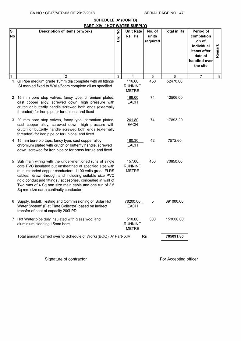
S.
No
Description of items or works
Drg
No Unit Rate
Rs. Ps.
No. of
units
required
Total in Rs Period of
completion
on of
individual
items after
date of
handind over
the site
Rem
ark
1 2 3 4 5 6 7 81 GI Pipe medium grade 15mm dia complete with all fittings
ISI marked fixed to Walls/floors complete all as specified116.60
RUNNING METRE
450 52470.00
2 15 mm bore stop valves, fancy type, chromium plated,cast copper alloy, screwed down, high pressure withcrutch or butterfly handle screwed both ends (externallythreaded) for iron pipe or for unions and fixed
169.00EACH
74 12506.00
3 20 mm bore stop valves, fancy type, chromium plated,cast copper alloy, screwed down, high pressure withcrutch or butterfly handle screwed both ends (externallythreaded) for iron pipe or for unions and fixed
241.80EACH
74 17893.20
4 15 mm bore bib taps, fancy type, cast copper alloy chromium plated with crutch or butterfly handle, screwed down, screwed for iron pipe or for brass ferrule and fixed.
180.30 EACH
42 7572.60
5 Sub main wiring with the under-mentioned runs of singlecore PVC insulated but unsheathed of specified size withmulti stranded copper conductors, 1100 volts grade FLRScables, drawn-through and including suitable size PVCrigid conduit and fittings / accesories, concealed in wall ofTwo runs of 4 Sq mm size main cable and one run of 2.5Sq mm size earth continuity conductor.
157.00 RUNNING
METRE
450 70650.00
6 Supply, Install, Testing and Commissioning of 'Solar Hot Water System' (Flat Plate Collector) based on indirect transfer of heat of capacity 200LPD
78200.00 EACH
5 391000.00
7 Hot Water pipe duly insulated with glass wool and aluminium cladding 15mm bore.
510.00 RUNNING
METRE
300 153000.00
705091.80
Signature of contractor For Accepting officer
CA NO : CEJZ/MTR-03 OF 2017-2018 SERIAL PAGE NO : 47
SCHEDULE 'A' (CONTD)
PART -XIV ( HOT WATER SUPPLY)
Total amount carried over to Schedule of Works(BOQ) ‘A’ Part- XIV Rs
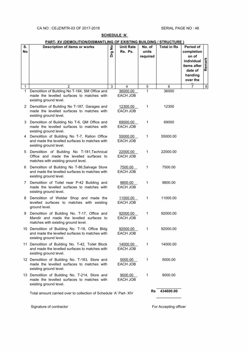
S.
No
Description of items or works
Drg
No Unit Rate
Rs. Ps.
No. of
units
required
Total in Rs Period of
completion
on of
individual
items after
date of
handing
over the
site
Re
ma
rk
1 2 3 4 5 6 7 81 Demolition of Building No T-184, SM Office and
made the levelled surfaces to matches withexisting ground level.
36000.00 EACH JOB
1 36000
2 Demolition of Building No T-187, Garages andmade the levelled surfaces to matches withexisting ground level.
12300.00 EACH JOB
1 12300
3 Demolition of Building No T-6, QM Office andmade the levelled surfaces to matches withexisting ground level.
69000.00 EACH JOB
1 69000
4 Demolition of Building No T-7, Ration Officeand made the levelled surfaces to matches withexisting ground level.
55000.00 EACH JOB
1 55000.00
5 Demolition of Building No T-181,TechnicalOffice and made the levelled surfaces tomatches with existing ground level.
22000.00 EACH JOB
1 22000.00
6 Demolition of Building No T-86,Salvage Storeand made the levelled surfaces to matches withexisting ground level.
7500.00 EACH JOB
1 7500.00
7 Demolition of Toilet near P-42 Building andmade the levelled surfaces to matches withexisting ground level.
9800.00 EACH JOB
1 9800.00
8 Demolition of Welder Shop and made thelevelled surfaces to matches with existingground level.
11000.00 EACH JOB
1 11000.00
9 Demolition of Building No. T-17, Office andMandir and made the levelled surfaces tomatches with existing ground level.
92000.00 EACH JOB
1 92000.00
10 Demolition of Building No. T-18, Office Bldgand made the levelled surfaces to matches withexisting ground level.
92000.00 EACH JOB
1 92000.00
11 Demolition of Building No. T-42, Toilet Blockand made the levelled surfaces to matches withexisting ground level.
14000.00 EACH JOB
1 14000.00
12 Demolition of Building No. T-183, Store andmade the levelled surfaces to matches withexisting ground level.
5000.00 EACH JOB
1 5000.00
13 Demolition of Building No. T-214, Store andmade the levelled surfaces to matches withexisting ground level.
9000.00 EACH JOB
1 9000.00
Rs 434600.00
For Accepting officer
SCHEDULE ‘A’
PART- XV (DEMOLITION/DISMANTLING OF EXISTING BUILDING / STRUCTURE )
CA NO : CEJZ/MTR-03 OF 2017-2018 SERIAL PAGE NO : 48
Total amount carried over to collection of Schedule ‘A’ Part- XIV
Signature of contractor
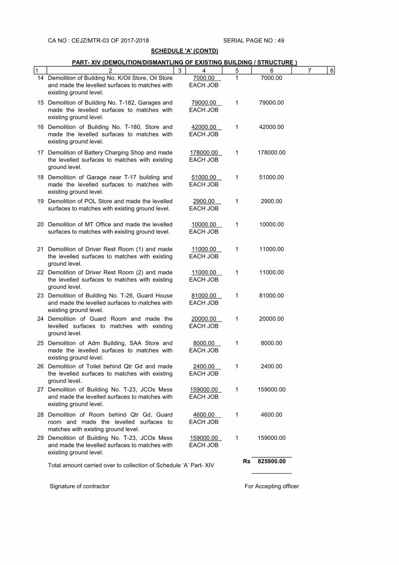
1 2 3 4 5 6 7 814 Demolition of Building No. K/Oil Store, Oil Store
and made the levelled surfaces to matches withexisting ground level.
7000.00 EACH JOB
1 7000.00
15 Demolition of Building No. T-182, Garages andmade the levelled surfaces to matches withexisting ground level.
79000.00 EACH JOB
1 79000.00
16 Demolition of Building No. T-180, Store andmade the levelled surfaces to matches withexisting ground level.
42000.00 EACH JOB
1 42000.00
17 Demolition of Battery Charging Shop and madethe levelled surfaces to matches with existingground level.
178000.00 EACH JOB
1 178000.00
18 Demolition of Garage near T-17 building andmade the levelled surfaces to matches withexisting ground level.
51000.00 EACH JOB
1 51000.00
19 Demolition of POL Store and made the levelledsurfaces to matches with existing ground level.
2900.00 EACH JOB
1 2900.00
20 Demolition of MT Office and made the levelledsurfaces to matches with existing ground level.
10000.00 EACH JOB
1 10000.00
21 Demolition of Driver Rest Room (1) and madethe levelled surfaces to matches with existingground level.
11000.00 EACH JOB
1 11000.00
22 Demolition of Driver Rest Room (2) and madethe levelled surfaces to matches with existingground level.
11000.00 EACH JOB
1 11000.00
23 Demolition of Building No. T-26, Guard Houseand made the levelled surfaces to matches withexisting ground level.
81000.00 EACH JOB
1 81000.00
24 Demolition of Guard Room and made thelevelled surfaces to matches with existingground level.
20000.00 EACH JOB
1 20000.00
25 Demolition of Adm Building, SAA Store andmade the levelled surfaces to matches withexisting ground level.
8000.00 EACH JOB
1 8000.00
26 Demolition of Toilet behind Qtr Gd and madethe levelled surfaces to matches with existingground level.
2400.00 EACH JOB
1 2400.00
27 Demolition of Building No. T-23, JCOs Messand made the levelled surfaces to matches withexisting ground level.
159000.00 EACH JOB
1 159000.00
28 Demolition of Room behind Qtr Gd, Guardroom and made the levelled surfaces tomatches with existing ground level.
4600.00 EACH JOB
1 4600.00
29 Demolition of Building No. T-23, JCOs Messand made the levelled surfaces to matches withexisting ground level.
159000.00 EACH JOB
1 159000.00
Rs 825900.00
For Accepting officer
SCHEDULE 'A' (CONTD)
PART- XIV (DEMOLITION/DISMANTLING OF EXISTING BUILDING / STRUCTURE )
Total amount carried over to collection of Schedule ‘A’ Part- XIV
Signature of contractor
CA NO : CEJZ/MTR-03 OF 2017-2018 SERIAL PAGE NO : 49
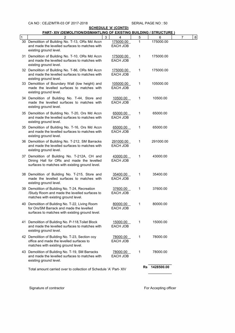
1 2 3 4 5 6 7 830 Demolition of Building No. T-13, ORs Md Accn
and made the levelled surfaces to matches withexisting ground level.
175000.00 EACH JOB
1 175000.00
31 Demolition of Building No. T-10, ORs Md Accnand made the levelled surfaces to matches withexisting ground level.
175000.00 EACH JOB
1 175000.00
32 Demolition of Building No. T-86, ORs Md Accnand made the levelled surfaces to matches withexisting ground level.
175000.00 EACH JOB
1 175000.00
33 Demolition of Boundary Wall (low height) andmade the levelled surfaces to matches withexisting ground level.
105000.00 EACH JOB
1 105000.00
34 Demolition of Building No. T-44, Store andmade the levelled surfaces to matches withexisting ground level.
10500.00 EACH JOB
1 10500.00
35 Demolition of Building No. T-20, Ors Md Accnand made the levelled surfaces to matches withexisting ground level.
65000.00 EACH JOB
1 65000.00
35 Demolition of Building No. T-16, Ors Md Accnand made the levelled surfaces to matches withexisting ground level.
65000.00 EACH JOB
1 65000.00
36 Demolition of Building No. T-212, SM Barracksand made the levelled surfaces to matches withexisting ground level.
291000.00 EACH JOB
1 291000.00
37 Demolition of Building No. T-212A, CH andDining Hall for ORs and made the levelledsurfaces to matches with existing ground level.
43000.00 EACH JOB
1 43000.00
38 Demolition of Building No. T-215, Store andmade the levelled surfaces to matches withexisting ground level.
35400.00 EACH JOB
1 35400.00
39 Demolition of Building No. T-24, Recreation /Study Room and made the levelled surfaces to matches with existing ground level.
37600.00 EACH JOB
1 37600.00
40 Demolition of Building No. T-22, Living Room for Ors/SM Barrack and made the levelled surfaces to matches with existing ground level.
80000.00 EACH JOB
1 80000.00
41 Demolition of Building No. P-118,Toilet Block and made the levelled surfaces to matches with existing ground level.
15000.00 EACH JOB
1 15000.00
42 Demolition of Building No. T-23, Section coy office and made the levelled surfaces to matches with existing ground level.
78000.00 EACH JOB
1 78000.00
43 Demolition of Building No. T-19, SM Barracks and made the levelled surfaces to matches with existing ground level.
78000.00 EACH JOB
1 78000.00
Rs 1428500.00
For Accepting officer
SCHEDULE 'A' (CONTD)
PART- XIV (DEMOLITION/DISMANTLING OF EXISTING BUILDING / STRUCTURE )
CA NO : CEJZ/MTR-03 OF 2017-2018 SERIAL PAGE NO : 50
Total amount carried over to collection of Schedule ‘A’ Part- XIV
Signature of contractor
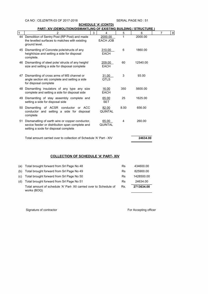
1 2 3 4 5 6 7 844 Demolition of Sentry Post (RP Post) and made
the levelled surfaces to matches with existing ground level.
2000.00 EACH JOB
1 2000.00
45 Dismantling of Concrete pole/structs of any height/size and setting a side for disposal complete.
310.00 EACH
6 1860.00
46 Dismantling of steel pole/ structs of any height/ size and setting a side for disposal complete
209.00 EACH
60 12540.00
47 Dismantling of cross arms of MS channel or angle section etc complete and setting a side for disposal complete
31.00 QTLS
3 93.00
48 Dismantling insulators of any type any sizecomplete and setting a side for disposal side
16.00EACH
350 5600.00
49 Dismantling of stay assembly complete andsetting a side for disposal side
65.00SET
25 1625.00
50 Dismantling of ACSR conductor or ACCconductor and setting a side for disposalcomplete
82.00 QUINTAL
8.00 656.00
51 Dismanatling of earth wire or copper conductor,sevice feeder or distribution span complete andsetting a sode for disposal complete
65.00 QUINTAL
4 260.00
24634.00
(a) Rs 434600.00
(b) Rs 825900.00
(c) Rs 1428500.00
(d) Rs 24634.00
Rs. 2713634.00
For Accepting officer
COLLECTION OF SCHEDULE 'A' PART- XIV
Total brought forward from Srl Page No 48
Total brought forward from Srl Page No 49
Total amount of schedule 'A' Part- XII carried over to Schedule ofworks (BOQ)
Total brought forward from Srl Page No 50
Total brought forward from Srl Page No 51
Total amount carried over to collection of Schedule 'A' Part - XIV
Signature of contractor
CA NO : CEJZ/MTR-03 OF 2017-2018 SERIAL PAGE NO : 51
SCHEDULE 'A' (CONTD)
PART- XIV (DEMOLITION/DISMANTLING OF EXISTING BUILDING / STRUCTURE )
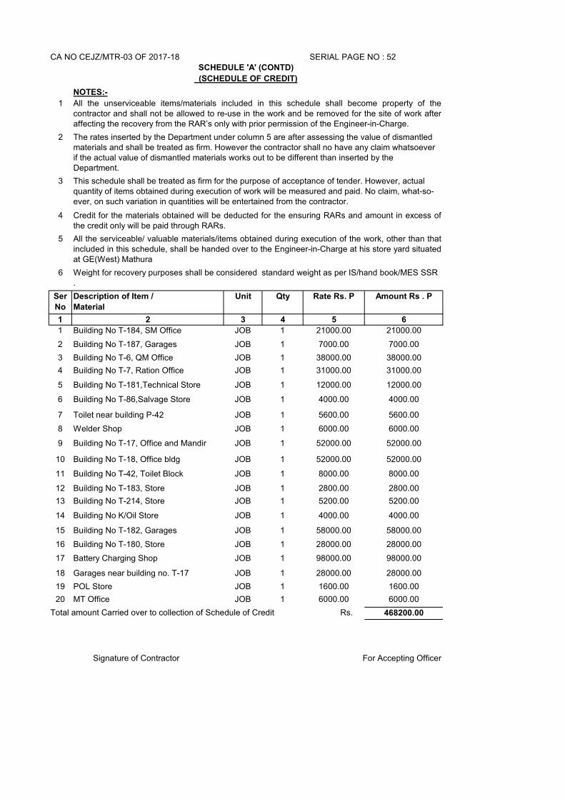
CA NO CEJZ/MTR-03 OF 2017-18
NOTES:-
1
2
3
4
5
6
Ser
No
Description of Item /
Material
Unit Qty Rate Rs. P Amount Rs . P
1 2 3 4 5 6
1 Building No T-184, SM Office JOB 1 21000.00 21000.00
2 Building No T-187, Garages JOB 1 7000.00 7000.00
3 Building No T-6, QM Office JOB 1 38000.00 38000.00
4 Building No T-7, Ration Office JOB 1 31000.00 31000.00
5 Building No T-181,Technical Store JOB 1 12000.00 12000.00
6 Building No T-86,Salvage Store JOB 1 4000.00 4000.00
7 Toilet near building P-42 JOB 1 5600.00 5600.00
8 Welder Shop JOB 1 6000.00 6000.00
9 Building No T-17, Office and Mandir JOB 1 52000.00 52000.00
10 Building No T-18, Office bldg JOB 1 52000.00 52000.00
11 Building No T-42, Toilet Block JOB 1 8000.00 8000.00
12 Building No T-183, Store JOB 1 2800.00 2800.00
13 Building No T-214, Store JOB 1 5200.00 5200.00
14 Building No K/Oil Store JOB 1 4000.00 4000.00
15 Building No T-182, Garages JOB 1 58000.00 58000.00
16 Building No T-180, Store JOB 1 28000.00 28000.00
17 Battery Charging Shop JOB 1 98000.00 98000.00
18 Garages near building no. T-17 JOB 1 28000.00 28000.00
19 POL Store JOB 1 1600.00 1600.00
20 MT Office JOB 1 6000.00 6000.00
468200.00
SERIAL PAGE NO : 52
SCHEDULE 'A' (CONTD)
(SCHEDULE OF CREDIT)
All the unserviceable items/materials included in this schedule shall become property of thecontractor and shall not be allowed to re-use in the work and be removed for the site of work afteraffecting the recovery from the RAR’s only with prior permission of the Engineer-in-Charge.
The rates inserted by the Department under column 5 are after assessing the value of dismantled materials and shall be treated as firm. However the contractor shall no have any claim whatsoever if the actual value of dismantled materials works out to be different than inserted by the Department.
Total amount Carried over to collection of Schedule of Credit Rs.
Weight for recovery purposes shall be considered standard weight as per IS/hand book/MES SSR .
This schedule shall be treated as firm for the purpose of acceptance of tender. However, actual quantity of items obtained during execution of work will be measured and paid. No claim, what-so-ever, on such variation in quantities will be entertained from the contractor.
Credit for the materials obtained will be deducted for the ensuring RARs and amount in excess ofthe credit only will be paid through RARs.
All the serviceable/ valuable materials/items obtained during execution of the work, other than thatincluded in this schedule, shall be handed over to the Engineer-in-Charge at his store yard situatedat GE(West) Mathura
Signature of Contractor For Accepting Officer
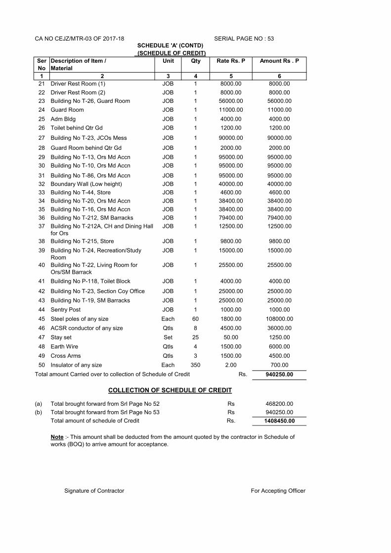
CA NO CEJZ/MTR-03 OF 2017-18
Ser
No
Description of Item /
Material
Unit Qty Rate Rs. P Amount Rs . P
1 2 3 4 5 6
21 Driver Rest Room (1) JOB 1 8000.00 8000.00
22 Driver Rest Room (2) JOB 1 8000.00 8000.00
23 Building No T-26, Guard Room JOB 1 56000.00 56000.00
24 Guard Room JOB 1 11000.00 11000.00
25 Adm Bldg JOB 1 4000.00 4000.00
26 Toilet behind Qtr Gd JOB 1 1200.00 1200.00
27 Building No T-23, JCOs Mess JOB 1 90000.00 90000.00
28 Guard Room behind Qtr Gd JOB 1 2000.00 2000.00
29 Building No T-13, Ors Md Accn JOB 1 95000.00 95000.00
30 Building No T-10, Ors Md Accn JOB 1 95000.00 95000.00
31 Building No T-86, Ors Md Accn JOB 1 95000.00 95000.00
32 Boundary Wall (Low height) JOB 1 40000.00 40000.00
33 Building No T-44, Store JOB 1 4600.00 4600.00
34 Building No T-20, Ors Md Accn JOB 1 38400.00 38400.00
35 Building No T-16, Ors Md Accn JOB 1 38400.00 38400.00
36 Building No T-212, SM Barracks JOB 1 79400.00 79400.00
37 Building No T-212A, CH and Dining Hall for Ors
JOB 1 12500.00 12500.00
38 Building No T-215, Store JOB 1 9800.00 9800.00
39 Building No T-24, Recreation/Study Room
JOB 1 15000.00 15000.00
40 Building No T-22, Living Room for Ors/SM Barrack
JOB 1 25500.00 25500.00
41 Building No P-118, Toilet Block JOB 1 4000.00 4000.00
42 Building No T-23, Section Coy Office JOB 1 25000.00 25000.00
43 Building No T-19, SM Barracks JOB 1 25000.00 25000.00
44 Sentry Post JOB 1 1000.00 1000.00
45 Steel poles of any size Each 60 1800.00 108000.00
46 ACSR conductor of any size Qtls 8 4500.00 36000.00
47 Stay set Set 25 50.00 1250.00
48 Earth Wire Qtls 4 1500.00 6000.00
49 Cross Arms Qtls 3 1500.00 4500.00
50 Insulator of any size Each 350 2.00 700.00
940250.00
(a) Rs 468200.00
(b) Rs 940250.00
Rs. 1408450.00
Total brought forward from Srl Page No 52
SERIAL PAGE NO : 53SCHEDULE 'A' (CONTD)
(SCHEDULE OF CREDIT)
Total brought forward from Srl Page No 53
Total amount of schedule of Credit
For Accepting OfficerSignature of Contractor
Note :- This amount shall be deducted from the amount quoted by the contractor in Schedule of
works (BOQ) to arrive amount for acceptance.
Total amount Carried over to collection of Schedule of Credit Rs.
COLLECTION OF SCHEDULE OF CREDIT
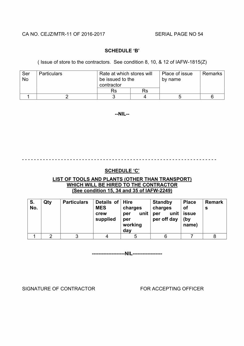
CA NO. CEJZ/MTR-11 OF 2016-2017 SERIAL PAGE NO 54
SCHEDULE ‘B’
( Issue of store to the contractors. See condition 8, 10, & 12 of IAFW-1815(Z)
Ser No
Particulars Rate at which stores will be issued to the contractor
Place of issue by name
Remarks
Rs Rs 1 2 3 4 5 6
--NIL--
- - - - - - - - - - - - - - - - - - - - - - - - - - - - - - - - - - - - - - - - - - - - - - - - - - - - - - - - - - - - - - - - -
SCHEDULE ‘C’
LIST OF TOOLS AND PLANTS (OTHER THAN TRANSPORT) WHICH WILL BE HIRED TO THE CONTRACTOR
(See condition 15, 34 and 35 of IAFW-2249)
S. No.
Qty Particulars Details of MES crew supplied
Hire charges per unit per working day
Standby charges per unit per off day
Place of issue (by name)
Remarks
1 2 3 4 5 6 7 8
--------------------NIL------------------
SIGNATURE OF CONTRACTOR FOR ACCEPTING OFFICER
CA NO : CEJZ/MTR-11 OF 2016-2017 SERIAL PAGE NO 55
SCHEDULE ‘D’
TRANSPORT TO BE HIRED TO THE CONTRACTOR (See condition 16 & 35 of IAFW-2249)
SN Qty Particulars Rate per unit per working day
Place of issue (by name)
Remarks
1 2 3 4 5 6
---------------- NIL ----------------
SIGNATURE OF CONTRACTOR FOR ACCEPTING OFFICER
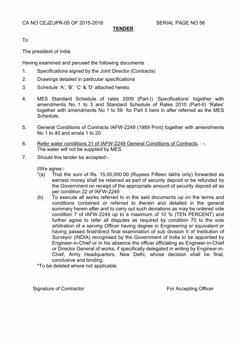
CA NO CEJZ/JPR-05 OF 2015-2016 SERIAL PAGE NO 56 TENDER
To The president of India Having examined and perused the following documents
1. Specifications signed by the Joint Director (Contracts)
2. Drawings detailed in particular specifications
3 Schedule ‘A’, ‘B’, ‘C’ & ‘D’ attached hereto 4. MES Standard Schedule of rates 2009 (Part-I) ‘Specifications’ together with
amendments No 1 to 3 and Standard Schedule of Rates 2010 (Part-II) ‘Rates’ together with amendments No 1 to 59 for Part II here in after referred as the MES Schedule.
5. General Conditions of Contracts IAFW-2249 (1989 Print) together with amendments
No 1 to 40 and errata 1 to 20
6. Refer water conditions 31 of IAFW-2249 General Conditions of Contracts. : -. The water will not be supplied by MES
7. Should this tender be accepted:-
I/We agree:- *(a) That the sum of Rs. 15,00,000.00 (Rupees Fifteen lakhs only) forwarded as
earnest money shall be retained as part of security deposit or be refunded by the Government on receipt of the appropriate amount of security deposit all as per condition 22 of IAFW-2249
(b) To execute all works referred to in the said documents up on the terms and conditions contained or referred to therein and detailed in the general summary herein after and to carry out such deviations as may be ordered vide condition 7 of IAFW-2249 up to a maximum of 10 % (TEN PERCENT) and further agree to refer all disputes as required by condition 70 to the sole arbitration of a serving Officer having degree in Engineering or equivalent or having passed final/direct final examination of sub division II of Institution of Surveyor (INDIA) recognised by the Government of India to be appointed by Engineer-in-Chief or in his absence the officer officiating as Engineer-in-Chief or Director General of works, if specifically delegated in writing by Engineer-in-Chief, Army Headquarters, New Delhi, whose decision shall be final, conclusive and binding.
*To be deleted where not applicable.
Signature of Contractor For Accepting Officer
CA NO CEJZ/MTR-11 OF 2016-2017 SERIAL PAGE NO 57 to 75
Page No 57 to 75 BOQ
Signature of Contractor For Accepting Officer
CA NO CEJZ/MTR-11 OF 2016-2017 SERIAL PAGE NO 76
In lieu of IAFW-2159
Brought forward lump sum Rs ______________________ (Rupees
___________________________________________________________________
__________________________________________________________________)
Signature _____________________ Name ___________________________in the
capacity of ______________________duly authorised to sign the tender for and on
behalf of M/S ___________________________________________________
________________________________________(IN BLOCK CAPITAL)
Witness ___________________________ Dated _______________________
Address ___________________________ Postal Address ________________
_________________________________ ____________________________
__________________________________ Telephone No __________________
ACCEPTANCE
Alterations have been made in these documents and as evidence that these alterations were made before the execution of the contract agreement, they have been initialled by the contractor and Shri Ranjit Singh EE(QS&C) (SG), Jt Dir (C) The said officer (s) is/are hereby authorised to sign and initial on my behalf of the documents forming part of this contract. The above tender was accepted by me on ___________ day of
__________________ on behalf of the PRESIDENT OF INDIA for the lump sum of
Rs ___________________________ (Rupees________________________
___________________________________________________________________
___________________________________________________________________
____________________________only)
Signature ____________________ dated this _______________ day of_____ 2017
Appointment Chief Engineer Jaipur Zone,
Power House Road, Bani Park Jaipur-302006
FOR AND ON BEHALF OF THE PRESIDENT OF INDIA
CA NO CEJZ/MTR-11 OF 2016-2017 SERIAL PAGE NO 77 TO 109
GENERAL CONDITIONS OF CONTRACTS
FOR
LUMPSUM CONTRACTS (IAFW-2159)
1. A copy of the General Conditions of Contracts) (IAFW-2249-1989 Print) with errata 1 to 20 and amendments No 1 to 40 has been supplied to me/us and is in my/our possession. I/We have read and understood the provisions contained in the aforesaid general conditions of contracts before submission of this tender and I/We agree that I/We shall abide by the terms and conditions therefore, as modified, if any, elsewhere in these tender documents. 2 It is hereby further agreed and declared by me/us, that the General Conditions of Contracts (IAFW-2249-1989 Print) including Condition 70 thereof pertaining to settlement of disputes by arbitration, containing 33 pages (Serial Page No 77 to 109), with errata 1 to 20 and amendments Nos 1 to 40 Form part of these tender documents. Note:-
The documents mentioned above can also be seen in the office of the Chief Engineer, Jaipur Zone, Jaipur-302 006 or in any other MES (CWE/GE) office during working hours. In case of difference in interpretation due to wordings of English and Hindi Versions, the English version will prevail as per Article 348 of Constitution of India.
For Accepting Officer Signature of Contractor
CA NO : CEJZ/MTR-03 OF 2017-2018 SERIAL PAGE NO 110
Signature of Contractor for Accepting officer
SPECIAL CONDITIONS 1. GENERAL These special conditions shall be read in conjunction with the general conditions of
contracts (IAFW-2249) and IAFW-2159 including errata and amendments thereto. Any provision in these special conditions if at variance with the provision in the above mentioned documents the provisions made hereinafter shall be deemed to take precedence there over.
2. INSPECTION OF SITE BY THE TENDERER Reference Para 8 and 11 of notice of tender (IAFW-2162) and condition 4 of IAFW-
2249.
(a) The tenderer is advised to contact the Garrison Engineer for the purpose of inspection of site (s) and relevant documents other than those sent herewith, who will give reasonable facilities for the purpose. The tenderer shall also make themselves familiar with the working conditions, accessibility of site (s), availability of materials and other cogent conditions, which may affect the entire completion of work under this contract.
(b) The tenderer shall be deemed to have inspected the site (s) and made themselves familiar with the working conditions, whether they have actually inspected the site (s) or not.
3. COORDINATION WITH OTHER AGENCIES Contractor’s attention is invited to the fact that during the currency of this contract, works
on other services which are outside the scope of work of this contract may be entrusted for execution to other agencies. The contractor shall permit free access and afford normal facilities and usual convenience to other agencies or departmental workmen to carryout connected works of services under separate arrangements. The contractor shall not be allowed any extra payment on this account.
4. EMPLOYMENT OF PERSONNEL
(a) Contractor shall employ only Indian Nationals as his representatives, servants and workmen after verifying their antecedents and loyalty. He shall ensure that no person of doubtful antecedents and nationality is in any way, associated with the work. If for the reasons of technical collaboration or other considerations the employment of foreign national (s) is unavoidable, the contractor shall furnish full particulars to this effect to the Accepting Officer at the time of submission of the tender. As a proof, that the contractor has employed only Indian Nationals, he shall render a certificate to GE within one month from the date of acceptance of tender to this effect. In case the GE desires, contractor will have the police verification done of personnel employed by him.
(b) The GE shall have full powers and without giving any reason to order the contractor immediately to cease to employ, in connection with this contract, any agent, servant or employee whose continued employment is, in his opinion, undesirable. The contractor shall not be allowed any compensation on this account.
(c) In this connection, the contractor’s attention is also drawn to condition 25 of
IAFW-2249.
CA NO : CEJZ/MTR-03 OF 2017-2018 SERIAL PAGE NO 111
Signature of Contractor for Accepting officer
SPECIAL CONDITIONS (CONTD…….) (d) Verification of antecedents of contractor’s representations / labour deployed at
site in connection with execution of work under the contract as per security requirement of user unit / installation shall be the responsibility of the contractor and all expenses in connection with verification of antecedents by police authority / security agency shall be borne by the contractor.
5. SECURITY OF CLASSIFIED DOCUMENTS Contractor’s special attention is drawn to condition 2-A and 3 of General Conditions of
Contracts (IAFW-2249). The contractor shall not communicate any classified information regarding works either to sub contractors or others without prior approval of the Engineer-in-Charge. The contractor shall also not make copies of the design/drawings and other documents furnished to him in respect of works and he shall return all documents on completion of the works or on earlier determination of the contract. The contractor shall along with final bill attach a receipt from the Engineer-in-Charge in respect of his having returned the classified documents as per condition 3 of General Conditions of Contracts (IAFW-2249).
6. ACCEPTANCE OF TENDER The tender shall remain open for acceptance for a clear period of 90 days clear
(excluding the bid submission end date ) from the bid submission end date specified. 7. CRITICAL PATH METHOD CPM NETWORK
(a) The time and progress chart to be prepared as per condition 11 of General Conditions of Contracts (IAFW-2249) and shall consist of detailed network analysis and a time schedule. The critical path network will be drawn jointly by the GE and the contractor soon after acceptance of tender. The time scheduling of the activities will be done by the contractor so as to finish the work within the stipulated time. On completion of the time schedule a firm calendar date schedule will be prepared and submitted by the contractor to GE, who will approve it after due scrutiny. The schedule will be submitted in four copies within two weeks from the date of handing over the site.
(b) During currency of the work the contractor is expected to adhere to the time
schedule and this adherence will be a part of the contractor’s performance under the contract. During the execution of work, the contractor is expected to participate in the reviews and updating of the network, undertaken by the GE. These reviews may be undertaken at the discretion of the GE either as a periodic appraisal measure or when the quantum of work ordered on the contractor is substantially changed through deviation orders or amendments. Any revision of the schedule as a result of the review, will be submitted by the contractor to GE within a week who will approve it after due scrutiny. The contractor will adhere to the revised schedule thereafter. In case of contractor disagreeing with the revised schedule, the same will be referred to the Accepting Officer whose decision will be final, conclusive and binding. GEs approval to the revised schedule resulting in a completion date beyond the stipulated date of completion shall not automatically amount to a grant of extension of time. Extension of time shall be considered and decided by the appropriate authority mentioned in condition 11 of IAFW-2249 and separately regulated.
CA NO : CEJZ/MTR-03 OF 2017-2018 SERIAL PAGE NO 112
Signature of Contractor for Accepting officer
SPECIAL CONDITIONS (CONTD…….) (c) The Contractor shall mobilise and employ sufficient resources to achieve the
detailed schedule within the broad framework of the accepted methods of working and safety.
(d) No additional payment will be made to the contractor for any multiple shift work or other incentive method contemplated by him in his work schedule even though the time schedule is approved by the Department.
8. RECORD OF MATERIALS AND PURCHASE VOUCHERS: -
(a) The quantity of materials such as cement, steel, paints, water proofing compound, chemicals for anti termite treatment and the like, as directed by the Engineer-in – Charge (the quantity of which cannot be checked after incorporation in the works), shall be recorded in measurement books and signed by the contractor and the Engineer-in-charge as a check to ensure that the required quantity has been brought to site for incorporation in the work.
(b) Materials brought to site shall be stored as directed by the Engineer-in-Charge and those already recorded in Measurement book shall be suitably marked for identification.
(c) Contractor shall produce vouchers/invoices from the manufacturers and/or their authorised agents for the full quantity of the following materials, as applicable as a pre-requisite before submitting claims for payment for advances on account of the work done and/or materials collected in accordance with condition 64 of General Conditions of contracts-IAFW-2249. (i) Water proofing compound.
(ii) Chemicals for Anti-termite Treatment. (iii) Paints, distempers, cement base paints and like. (iv) Cast iron pipes and fittings. (v) Sanitary fittings. (vi) Steel windows/ventilators. (vii) Factory made door shutters/ PVC doors. (viii) Floor/Wall tiles. (ix) Iron mongery. (x) Salt glazed stoneware pipes/Reinforced concrete pipes. (xi) Electrical and water supply fittings/fixtures where names of
manufacturers/brands are specified or approved. (xii) Cables. (xiii) Cement. (xiv) Steel.
(d) The contractor shall, on demand, produce to the GE, original receipted
vouchers/invoices in respect of the materials other than as stated in sub-Para (c). Vouchers/invoices so produced and verified shall be stamped by Engineer-in-Charge indicating contract number. The contractor shall ensure that the materials are brought to site, in original sealed containers/packing, bearing manufacturer’s marking except in the case of the requirement of materials (s) being less than smallest packing.
CA NO : CEJZ/MTR-03 OF 2017-2018 SERIAL PAGE NO 113
Signature of Contractor for Accepting officer
SPECIAL CONDITIONS (CONTD…….)
(e) Bitumen shall be purchased directly from manufacturer’s stockist or their authorised dealers only. These vouchers/invoices shall be defaced by the GE/Engineer-in-Charge, indicating reference to the contract number, under his dated signature, and CTC thereof shall be kept on record so as to avoid their being used again.
(f) The vouchers/invoices will clearly indicate the contract number, the IS No, specific alternative to which the material conforms in case of various alternative in IS.
9. APPROVAL OF SAMPLE OF WORKMANSHIP IN BUILDING.
(a) To determine the acceptable standard of workmanship, one building (or portion of the bldg, to be decided by the GE) shall be completed by the contractor well in advance as directed by GE under close supervision of the Engineer-in-Charge and shall be got approved from the GE. The workmanship of various trades and finishes of this building shall serve as guiding sample for work in the remaining quarter/buildings.
(b) The Sample Quarter shall be completed in all respects as per time of completion specified in Schedule ‘A’ notes.
10. MATERIALS AND SAMPLES
(a) Refer condition 10 of IAFW-2249.
(b) The materials and articles, which have been specified from certain makes/manufacturers, shall be of makes/manufactures as specified. If the manufacturers specified in tender documents make both ISI marked and conforming to IS specifications, the materials/articles shall be ISI marked.
(c) The materials and articles, which have not been specified in tender documents by makes/manufacturers, shall be as under :-
(i) If ISI marked materials are being manufactured the same shall be ISI marked. For list of ISI marked manufacturers refer website BIS i.e., www.bis.org.in.
(ii) If ISI marked materials are not being manufactured the same shall be conforming to IS specifications.
(d) Materials of local origin shall be as specified and conforming to samples kept in GE’s office. The tenderer is advised to inspect sample of materials which are displayed in the office of GE, before submitting his tender. The tenderer shall be deemed to have inspected the samples and satisfied himself as to the nature and quality of materials, he is required to incorporate in the work irrespective of whether he has actually inspected them or not.
(e) The contractor shall not procure materials and articles unless the samples are first got approved by the GE.
11. HANDING OVER OF SITE
Site for execution of work will be available as soon as the work is awarded. In case it is not possible to make the entire site available on the award of work, the contractor will have to arrange his working programme accordingly. No claim whatsoever, for not giving entire site on award of work and for giving site gradually, will be tenable.
CA NO : CEJZ/MTR-03 OF 2017-2018 SERIAL PAGE NO 114
Signature of Contractor for Accepting officer
SPECIAL CONDITIONS (CONTD…….) 12. DAMAGE TO THE EXISTING STRUCTURES
Any damage to the existing structures, any existing road etc., during the execution of work shall be made good by the contractor at his own expense. Rectification, replacement, making good and touching up etc. shall be carried out, conforming to the materials and workmanship originally provided and to the satisfaction of the Engineer-in-Charge. In case of any dispute on this account, the decision of the GE shall be final, binding and conclusive.
13. APPROACHES
The contractors shall make arrangements for and provide at his own cost all temporary approaches, if required to the site(s), after obtaining approval in writing of the GE to the layout of such approaches.
14. QUARRIES ON DEFENCE LAND
Reference to condition 14 of IAFW-2249. Quarries are not available on Defence land for use by the contractor, to remove materials for use in the works.
15. RELEASE OF ADDITIONAL SECURITY DEPOSIT
(Refer condition 22 and 68 of IAFW-2249) The contractor in case he has to deposit additional security for the contract, is advised to deposit the additional security in two equal parts so as to facilitate release of additional security in accordance with condition 68 of IAFW-2249.
16. ADVANCES ON ACCOUNT AGAINST MATERIALS
Refer condition 64 of IAFW-2249 – Advance on account
(a) Add the following in continuation of Para 8 “Provided further, the Contractor may be paid advance on account to the full value of the under mentioned materials only, brought on the site, on his furnishing Guarantee Bond (s) from a scheduled bank for the amount of the retention money which should otherwise be recoverable from him under Contract :
(i) GI pipe and fittings for water supply (ii) CI pipe and fittings for Soil / waste / vent pipes.
(iii) CI/DI pipe and fittings for water supply. (iv) Factory made steel window and ventilators. (v) Factory made pressed steel frame for doors. (vi) Factory made cub board steel frame and steel shutters. (vii) Transformer. (viii) Steel lockers. (ix) Ceiling and exhaust fan. (x) Steel poles (xi) Electrical light fittings. (xii) Split type air conditioner. (xiii) Solar water heater. (xiv) Water cooler.
(xv) Desert cooler. (xvi) Pumps (xvii) DG Set
(b) It will be noted that advance on account to the full value to materials brought on the site is permissible only in respect of fittings and fixtures
and other manufactured items which do not loose their identity.
CA NO : CEJZ/MTR-03 OF 2017-2018 SERIAL PAGE NO 115
Signature of Contractor for Accepting officer
SPECIAL CONDITIONS (CONTD…….) (c) The bank Guarantee Bond (s) shall be executed for a period and on a form as
directed by the Accepting officer. The contractor shall further arrange to extend the period of Guarantee Bond (s) if and when necessary as directed by the Accepting officer or shall furnish fresh guarantee bonds of similar value in lieu.
17. ALLOTMENT OF LAND FOR STORAGE OF MATERIALS INCLUDING TEMPORARY
SHEDS (Refer condition 24 of IAFW-2249) Delete the following in Para 1 of condition 24 of IAFW-2249, “In the event of ……………areas of land allotted to him” and following shall be read in conjunction with condition 24 of IAFW-2249. The contractor shall be permitted to store his materials including erecting temporary sheds thereof at the areas of land as shown by GE free of rent if it is on class A1 land. For other types of land he shall pay a licence fee of Re 1/- per year or part thereof in respect of each and every separate area of land allotted to him.
18. ALLOTMENT OF LAND FOR ACCOMMODATION OF LABOUR, CANTEEN, FABRICATING WORKSHOP ETC
(Refer condition 24 of IAFW-2249). The Contractor shall be permitted to erect his labour camp, temporary workshops, and the like at the area of land marked for this purpose on the site plan and he shall pay a licence fee Re 1/- per year or part thereof in respect of each and every separate area of land allotted to him
19. MINIMUM WAGES PAYABLE
Refer condition 58 of IAFW-2249 (a) The Contractor shall not pay wages lower than minimum wages for labour as fixed
by the Government of India/State Govt/Union territory, whichever is higher. (b) Contractor’s attention is also drawn, amongst other things to the ‘explanations’ to
the schedule of minimum wages referred to above. (c) The fair wages referred to in condition 58 of IAFW-2249 will be deemed to be the
same as the minimum wages, referred to above as upto date from time to time. (d) Schedule of minimum wages are not enclosed along with tender documents.
However contractor shall be deemed to have verified the minimum fair wages payable as on the last due date of receipt of tender.
(e) The contractor shall have no claim whatsoever, if on account of local factor
and/or regulations, he is required to pay the wages in excess of minimum wages as described above during the execution of work.
20. ELECTRIC SUPPLY
Electricity will not be supplied by the MES. The tenderer are advised to visit the site of works to ascertain availability of electric supply from civil sources or from nearby natural sources outside Ministry of Defence land.
CA NO : CEJZ/MTR-03 OF 2017-2018 SERIAL PAGE NO 116
Signature of Contractor for Accepting officer
SPECIAL CONDITIONS (CONTD…….)
21. WATER
Refer to condition 31 of IAFW-2249. (a Water will not be supplied by the MES. The tenderer are advised to visit the site of works to ascertain availability of water from civil sources or from nearby natural sources outside Ministry of Defence land. The contractor shall be allowed, if he so desires, to install hand pumps, submersible pump tube wells at site of work at places as approved by Engineer-in-Charge under his own arrangements and cost and nothing shall be charged from the contractor. The contractor shall remove the hand pumps, submersible pumps tube well as and when ordered to do so by Engineer-in-Charge/GE and in any case on completion of the work and before issue of completion certificate, unless GE desires that these hand pumps, tube well be left in position and the contractor agrees to do so without claiming cost thereof from department. No compensation whatsoever shall be admissible to the contractor, if he is required to remove the pump (s), tube wells before completion of work. Use of water from such sources shall only be permitted if, found after testing potable and fit for use in the work. The water from such sources shall be got tested by the contractor from laboratory approved by the GE, who shall after satisfying himself permit the contractor to use the water from such sources. Testing charges shall be borne by the contractor. (b) Contractor shall not have any claim, in case permission not given due to any reasons what so ever or if the water frm the bore is not suitable for construction work and not permitted for use.
22. REIMBURSEMENT/REFUND ON VARIATION IN PRICES-WAGES OF LABOUR (REFER CONDITION 63 OF IAFW –2249)
Increase or decrease in prices consequent on variation in wages of labour shall be adjusted on the basis stipulated hereinafter irrespective of the actual variation in price-wages of labour to the contractor.
The labour component for the work under the contract as whole shall be taken a KL of the value of the work executed under the contract. Variation in labour wages shall be worked out by applying the following formula:- EL = KL x Vg1 x L1 - LO 100 LO
EL = Variation in wages of Labour reimbursement to be made to the Contractor or refund to be made by the Contractor. KL = Constant representing the percentage cost of labour element as compared to the total of the work under the contract as a whole. The value of KL for the work shall be 20 (twenty only). Vg1 = Gross value of work done at contract rates during the period of reckoning less value of work paid or payable to the contractor based on actual cost (eg star rate (s), work executed under prime cost sum etc.) during the period of reckoning. L1 = Minimum wage in rupees of an unskilled adult male mazdoor as fixed under any law, Statutory rule or order as on the date of commencement of the period of reckoning.
LO = As for L1 but the minimum wage in rupees of an unskilled adult male mazdoor as on the last due date for receipt of tenders i.e. bid submission end date specified. If labour wage on last due date for receipt of tenders i.e. bid submission end date specified are increased afterward with retrospective effect the value of LO shall be fixed keeping in view the following aspects:-
CA NO : CEJZ/MTR-03 OF 2017-2018 SERIAL PAGE NO 117
Signature of Contractor for Accepting officer
SPECIAL CONDITIONS (CONTD…….)
(a) If the increase/decrease in wages of labour are made known to the public by any means of media before receipt date of tender but the same is officially notified thereafter giving retrospective effect, the value of “Lo” shall be as per notification though made subsequently.
(b) If a net wage comprises a fixed basic wage and the living allowance revised from time to time based on consumer price index (CPI) and increase CPI is made known to the public by any means before the date of receipt of tender, the “Lo” will be revised wages corresponding to revised CPI, though the formal notification for the net wage (considering the revised living allowance corresponding to revised CPI) is made subsequent to date of receipt of tender.
(c) In case the labour enforcement officer makes the announcement before date of receipt of tender i.e. bid submission end date specified but gazette notification is made subsequently making wages applicable with retrospective effect, the value of “LO” shall be as per Gazette Notification subsequently made.
(d) If the increase/decrease in wages of labours is notified/announced subsequent to receipt of tender with retrospective effect without making the same publicly known by means of publicity/media prior to the date of receipt of tender, then, the value of “LO” shall be as per wage known at the time of receipt of tender.
Note : 1. The contractor shall within reasonable time of his becoming aware of any alteration to the payment of wages of labour consequent on fixation of minimum wages under any laws, statutory rule or order, give written notice thereof to the GE stating that the same is given pursuant to this special condition together with all information relating thereto which he may be in a position to supply.
2. Irrespective of the variation in minimum wages for any category of labour, for the purpose of adjustment under this special condition, the variation in minimum wage fixed under any law, statutory rule or order for an unskilled adult male mazdoor, if any, shall only form the basis. 3. Periodicity of working out the variation in wages of labour will be three months commencing from the last due date for receipt of tenders. The last adjustment for variation in wages of labour shall however, be done for the period upto the date of completion or extended date of completion. Valuation of price adjustment due to increase/decrease in minimum wages under any law, statutory rule or order for the purpose of making reimbursement/refund in RARs, will be timed in such manner that relevant data required for quarterly calculation under this special condition is available from the RARs. The first price adjustment in respect of variation in wages of labour will be worked out for the relevant quarter during which alteration to the wages of labour took place. For implementing this provision, the period of reckoning in such quarter will have to be divided into two periods i.e., the first period up to the RAR payable immediately after the date of variation and the other up to the end of the quarter. Value of L1 at the beginning of the other period shall be the altered wage. If there are more than one change in wages in a quarter there will be more than two periods of reckoning on similar basis. Amount payable relevant to work done for any quarter will be worked out after the minimum wage of an unskilled adult male mazdoor as fixed under any law, statutory rule or order for the relevant quarter is available. Once the amount adjustable for any quarter is worked out, the same shall be adjusted in subsequent RAR as “advance on account” adjustments alongwith adjustment for ‘Materials’ and ‘Fuel’.
CA NO : CEJZ/MTR-03 OF 2017-2018 SERIAL PAGE NO 118
Signature of Contractor for Accepting officer
SPECIAL CONDITIONS (CONTD…….)
4. No adjustment in prices shall be made for any work done after the due date of completion or extension of time granted under condition 11 of IAFW-2249 (whichever is later) for the work under the contract.
5. No adjustment, whatsoever, due to variation in wages of labour on account of coming into force of any fresh law or statuary rule or order as provided in condition 63 of IAFW-2249 or otherwise, than provided in this special condition shall be made.
6. Any dispute arising out of interpretation or application of this special condition shall be referred to the Accepting Officer whose decision shall be final and binding.
7. For purposes of calculation of retention money, liquidated damages, sales tax/service tax on works contracts, deduction of income tax at source and recovery of water charges (in case of unmetered supply) the value of contract as revised by the above price variation will be taken into account.
23 REIMBURSEMENT/REFUND ON VARIATION IN PRICES OF MATERIALS AND FUEL
Note (a) The periodicity for working out the variations will be three months. The
first variation would be for the period of three months reckoned from the last due date for receipt of tenders.
(b) Wholesale Price Index for all commodities are published every month. Thus the Index applicable for any day shall be the one applicable for the preceding month.
(c) As the adjustments are to be made on a quarterly basis, commencing from the last due date for receipt of tender. RARs should be timed in such a manner that the gross value of work done up to the corresponding date is readily available.
(d) The monthly Index numbers of wholesale prices for all commodities published by the Economic Advisor to Govt. of India, in the first instance, are generally termed ‘Provisional’. Final Index Numbers for the corresponding weeks are published subsequently, say after an interval of 6 to 8 weeks or so. It is to be ensured that the variations are worked out based on the ‘Final’ Index numbers. These are available on website http://eaindustry.nic.in.
(e) Latest base years of index are specified in conditions herein after.
(f) The term “fresh law or statutory rule or order” used in the aforesaid conditions includes not only Central law or Central rule or order but also the State law or State rule or order.
23.1 Re-Imbursement Refund On Variation In Price Refer condition 63 of the General Condition of Contracts (IAFW-2249). Re-
imbursement/refund on variation of prices. The condition 63 of the General Conditions of contracts shall be deemed to be modified to the extent mentioned hereinafter. Increase or decrease in prices of materials and fuel shall be adjusted on the basis stipulated hereinafter irrespective of the actual variation in prices (to the contractor) :
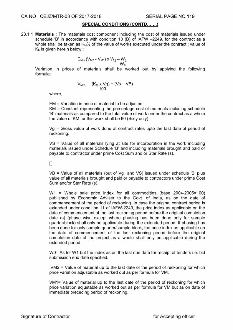
CA NO : CEJZ/MTR-03 OF 2017-2018 SERIAL PAGE NO 119
Signature of Contractor for Accepting officer
SPECIAL CONDITIONS (CONTD…….)
23.1.1 Materials : The materials cost component including the cost of materials issued under schedule ‘B’ in accordance with condition 10 (B) of IAFW –2249, for the contract as a whole shall be taken as KM% of the value of works executed under the contract ; value of KM is given herein below :
EM = (VM2 - VM1) x W1 – W0
W0 Variation in prices of materials shall be worked out by applying the following
formula:
VM = (KM x Vg) + (Vs – VB) 100
where, EM = Variation in price of material to be adjusted.
KM = Constant representing the percentage cost of materials including schedule ‘B’ materials as compared to the total value of work under the contract as a whole the value of KM for this work shall be 60 (Sixty only).
Vg = Gross value of work done at contract rates upto the last date of period of reckoning.
VS = Value of all materials lying at site for incorporation in the work including materials issued under Schedule ‘B’ and including materials brought and paid or payable to contractor under prime Cost Sum and or Star Rate (s).
[[ VB = Value of all materials (out of Vg and VS) issued under schedule ‘B’ plus value of all materials brought and paid or payable to contractors under prime Cost Sum and/or Star Rate (s). W1 = Whole sale price index for all commodities (base 2004-2005=100) published by Economic Adviser to the Govt. of India, as on the date of commencement of the period of reckoning. In case the original contract period is extended under condition 11 of IAFW-2249, the price index as applicable on the date of commencement of the last reckoning period before the original completion date (s) (phase wise except where phasing has been done only for sample quarter/block) shall only be applicable during the extended period. If phasing has been done for only sample quarter/sample block, the price index as applicable on the date of commencement of the last reckoning period before the original completion date of the project as a whole shall only be applicable during the extended period.
W0= As for W1 but the index as on the last due date for receipt of tenders i.e. bid submission end date specified. VM2 = Value of material up to the last date of the period of reckoning for which price variation adjustable as worked out as per formula for VM.
VM1= Value of material up to the last date of the period of reckoning for which price variation adjustable as worked out as per formula for VM but as on date of immediate preceding period of reckoning.
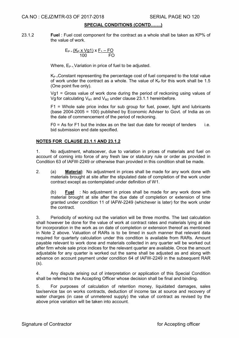
CA NO : CEJZ/MTR-03 OF 2017-2018 SERIAL PAGE NO 120
Signature of Contractor for Accepting officer
SPECIAL CONDITIONS (CONTD…….)
23.1.2 Fuel : Fuel cost component for the contract as a whole shall be taken as KP% of the value of work.
EP = (KP x Vg1) x F1 – FO
100 FO
Where, EP = Variation in price of fuel to be adjusted.
KP =Constant representing the percentage cost of fuel compared to the total value of work under the contract as a whole. The value of KP for this work shall be 1.5 (One point five only).
Vg1 = Gross value of work done during the period of reckoning using values of Vg for calculating VM1 and VM2 under clause 23.1.1 hereinbefore.
F1 = Whole sale price index for sub group for fuel, power, light and lubricants (base 2004-2005 = 100) published by Economic Adviser to Govt. of India as on the date of commencement of the period of reckoning.
F0 = As for F1 but the index as on the last due date for receipt of tenders i.e. bid submission end date specified.
NOTES FOR CLAUSE 23.1.1 AND 23.1.2
1. No adjustment, whatsoever, due to variation in prices of materials and fuel on account of coming into force of any fresh law or statutory rule or order as provided in Condition 63 of IAFW-2249 or otherwise than provided in this condition shall be made. 2. (a) Material: No adjustment in prices shall be made for any work done with
materials brought at site after the stipulated date of completion of the work under contract except as contemplated under definition of W1.
(b) Fuel : No adjustment in prices shall be made for any work done with material brought at site after the due date of completion or extension of time granted under condition 11 of IAFW-2249 (whichever is later) for the work under the contract.
3. Periodicity of working out the variation will be three months. The last calculation shall however be done for the value of work at contract rates and materials lying at site for incorporation in the work as on date of completion or extension thereof as mentioned in Note 2 above. Valuation of RARs is to be timed in such manner that relevant data required for quarterly calculation under this condition is available from RARs. Amount payable relevant to work done and materials collected in any quarter will be worked out after firm whole sale price indices for the relevant quarter are available. Once the amount adjustable for any quarter is worked out the same shall be adjusted as and along with advance on account payment under condition 64 of IAFW-2249 in the subsequent RAR (s). 4. Any dispute arising out of interpretation or application of this Special Condition shall be referred to the Accepting Officer whose decision shall be final and binding.
5. For purposes of calculation of retention money, liquidated damages, sales tax/service tax on works contracts, deduction of income tax at source and recovery of water charges (in case of unmetered supply) the value of contract as revised by the above price variation will be taken into account.
CA NO : CEJZ/MTR-03 OF 2017-2018 SERIAL PAGE NO 121
Signature of Contractor for Accepting officer
SPECIAL CONDITIONS (CONTD…….)
6. In cases, “where value of VM2 – VM1 works out to minus on account of higher utilization of schedule B stores (i.e. value of Sch. B stores under contract as a whole is higher than KM value) and the reimbursement on account of variation in prices of materials works out to be negative in spite of the whole sale price index for all commodities published by Economic Adviser to Government of India going up from W0”, reimbursement on account of variation in prices of materials shall be treated as “NIL”.
24. QUALIFIED TRADESMEN (APPLICABLE FOR WORKS COSTING RUPEES ONE
CRORE OR MORE)
In compliance with the condition 26 of IAFW-2249 (General Conditions of Contracts), the contractor shall employ skilled/semi skilled tradesmen who are qualified and possessing certificate in particular trade from Industrial Training Institute (ITI)/National Institute of Construction Management and Research (NICMAR)/ National Academy of Construction (NAC) Hyderabad/Construction Industry Development Council (CIDC), similar reputed and recognized Institutes by State/Central Government, to execute the works of their respective trade. The number of such qualified tradesmen shall not be less then 25% of total skilled/semi skilled tradesmen required in each trade. The contractor shall submit the list of such tradesmen along with requisite certificates to Garrison Engineer for verification and approval. Notwithstanding the approval of such tradesmen by GE, if the tradesmen are found to have inadequate skill to execute the work of their trades, leading to un-satisfactory workmanship, the contractor shall remove such tradesmen within a week after written notice to this effect by the GE and shall engage other qualified tradesmen after prior approval of GE. GE’s decision whether a particular tradesmen possesses requisite qualification, skill and expertise commensurate with nature of work, shall be final and binding. No compensation whatsoever on this account shall be admissible.
25. CONDITIONS FOR WORKING IN RESTRICTED AREA
Work under this contract lies in restricted Area. The restrictions for entry to work site and conditions of working in restricted area shall be as under:-
(a) ENTRY AND EXIT
The contractor/his agent(s) representatives/workmen etc and his materials , carts, trucks or other means of transports, machineries etc will be allowed to enter through and leave only from such gate or gates and at such times as the GE or authorities in charge of the restricted area may at their sole discretion permits. The contractor’s authorized representative is required to be present at the places of entry and exit for the purpose of identifying his carts, trucks, machineries etc to the person in charge of the security of the restricted area and shall stick to only the specific route directed for them to follow.
CA NO : CEJZ/MTR-03 OF 2017-2018 SERIAL PAGE NO 122
Signature of Contractor for Accepting officer
SPECIAL CONDITIONS (CONTD…….)
(b) IDENTITY OF WORKMAN
(i) Every workmen shall be in possession of an identity card. The identity card shall be issued after a thorough investigation of the antecedents of the labourers by the contractor and attested by Office-in-charge of the unit concerned in accordance with the standing rules and regulations of the unit. Contractor shall be responsible for conduct of his workmen, agents or representatives.
(ii) The contractor, his agents and representatives are required individually to be in
possession of an identity card or pass. The identity card or pass will be examined by the security staff at the time of entry into or exit from the restricted area at any time or number of times inside restricted area.
(iii) Passes may also be issued for the transport engaged by the contractor. Contractor shall submit the list of transport with the name of driver and licence No to the Engineer-in-Charge well in time for issue of passes. The transport, its driver and crew and the consignment carried shall also be subjected to search at entry as well as at exit.
(iv) Passes shall be surrendered at any time on demand by Engineer-in- Charge and in any case immediately after completion of work or termination of cancellation of contract.
(c) SEARCH Thorough search of all persons and transport shall be carried out at each gate and for as many times the gate is used for entry or exit and may also be carried out any time or any number of times within the restricted area.
(d) FEMALE SEARCHER If the contractor desires to employ female labour for works to be carried out inside the restricted area of factory, depot, park etc, and a female searcher is not borne on the authorized strength of the factory, depot, part etc at the time of submission of tender, he shall be deemed to have allowed in his tender for pay and allowances etc for a female searcher (Class IV servant) calculated for the period female labourers during any month and female’s searcher(s) has/have to be employed in addition to the authorized strength of the factory, depot, part etc the salary and allowances paid to the additional female. searchers shall be distributed on equitable basis between the contractors employing female labour taking into consideration the value and period of completion of their contracts. The GE’s decision in regard to the amount payable on his account by any contractor shall be final and binding.
(e) WORKING HOURS
(i) The unit controlling restricted area, usually work during six days in a week (Monday to Saturday) and remain closed on the 7th day (Sunday). The working hours available to the contractor’s labour and staff are however appreciably reduced because of the time taken in security check, procedures observed at the time of entry, exit and during working hours, No claim whatsoever, shall be admissible on this account.
(ii) The exact working hours, working days and non-working days observed for the restricted area, where works are to be carried out, shall be deemed to have been ascertained by contractor before submitting his tender. The tenderer’s attention is invited to the fact that the number of working hours for a unit are prescribed in regulations and that they cannot be increased by the GE or authorities controlling the restricted area.
CA NO : CEJZ/MTR-03 OF 2017-2018 SERIAL PAGE NO 123
Signature of Contractor for Accepting officer
SPECIAL CONDITIONS (CONTD…….)
(iii) The definition of ‘working days’ as given under Condition 1 (t) of IAFW- 2249 does not apply in case where the works are carried out in restricted area.
(iv) Contractor’s labour/tradesman, materials, transport etc shall normally be permitted to come in/go out of the restricted area between 0830 hours to 1700 hours on Monday to Friday and 0800 hours to 1400 hours on Saturday.
(f) WORKING ON HOLIDAYS
The contractor shall not carry out any work on gazette holidays, weekly holidays and other non working days except when he is specially authorized in writing to do so by the GE. The GE may at his sole discretion declare any day as holiday or non working day without assigning any reason for such declaration.
(g) FIRE PRECAUTIONS
(i) The contractor, his agents, representatives, workmen etc shall strictly observed the order(s) pertaining to fire precautions prevailing within the restricted area.
(ii) Motor transport vehicles, if allowed by the authorities to enter the restricted
area, must be fitted with serviceable fire extinguishers. (iii) No entry of any explosive, inflammable material, matchboxes, cigarettes etc
will be permitted.
(iv) No excavation work by blasting or using explosives of any kind will be permitted.
(v) Welding without adequate fire fighting precautions will not be permitted.
(vi) There will be no use of naked flame in project site. (vii) At site no inflammable material is to be left behind unattended.
(viii) Against the outbreak of fire he shall provide amongst other things,
adequate self contained fire fighting arrangements to the entire satisfaction of the GE. No extra amount shall be admissible to the contractor on this account.
(ix) Notwithstanding to the above, the site is liable to be inspected by
representative of Depot to verify that the precaution is being strictly observed.
(x) No claim whatsoever, shall be admissible for any loss of man-hours, idling
of machineries & transport etc on account of observance of the above restrictions.
26. LOCATION OF BUILDINGS AND WORKS
There may be some changes in location/siting of building shown in site (layout) plan(s) to suit local conditions and/or departmental requirements. The contractor shall have no claim what so ever consequent to such changes in the location/siting of works.
CA NO : CEJZ/MTR-03 OF 2017-2018 SERIAL PAGE NO 124
Signature of Contractor for Accepting officer
SPECIAL CONDITIONS (CONTD…….)
27. WATCH/LIGTHING The contractor shall at his own cost take all possible precautions to ensure safety of life and property by providing necessary fencing, barrier, light, watchmen etc., during the progress of work and as directed by the Engineer-in-Charge.
28. CONCILIATION 28.1 Scope of Conciliation 28.1.1 This is applicable to contract concluded by Zonal/Project Chief Engineer. 28.1.2 The scope of conciliation shall be restricted to the following types of disputes with financial limits as indicated therein: -
(a) Dispute relating to levy of compensation for delay in completion-actual
amount of compensation. (b) Disputes relating to technical examination of works. (c) Disputes relating to interpretation of the provisions of the contract with
reference to their application to parties. (d) Dispute relating to non-return of Schedule `B’ stores over-issued to
contractor. (e) Any other dispute having fair chances of being resolved by conciliation
and considered fit to be referred to conciliation by the parties. For item (b), (c), (d) and (e) each as stated above the financial limit shall be Rupees two Lakhs or one percent of the contract amount whichever is less.
28.2 Commencement of Conciliation Proceedings 28.2.1 The party initiating conciliation shall send to the other party a written invitation to conciliate, briefly identifying the subject of the dispute. 28.2.2 Conciliation proceedings shall commence when the other party accepts in writing the invitation to conciliate. 28.2.3 If the other party rejects the invitation, there will be no conciliation proceedings. If the
party initiating conciliation does not receive a reply within 30 days from the date on which he sends or within such other periods of time as specified in the invitation, he may elect to treat this as a rejection of the invitation to conciliate and if he so elects, he shall inform in writing the other party accordingly.
28.3 Number of Conciliators : There shall be a Sole conciliator.
28.4 Appointment of Conciliator : All disputes brought out in Clause 28.1.2(a) to (e) herein before shall be referred to the sole conciliator viz Serving Officer not below the rank of Superintending Engineer/ Superintending Engineer (QS&C) having degree in Engineering or equivalent or having passed final/direct final examination of sub division-II of Institution of Surveyors (India) to be appointed by the Engineer-in Chief, Army HQ, New Delhi or in his absence the officer officiating as Engineer-in Chief or Director General of Works specifically delegated by the Engineer-in-Chief in writing.
28.5 Status of Effect of Settlement Agreement : The settlement agreement signed by the
parties as a result of conciliation proceedings shall have the same status and effect as it is an arbitral award on agreed terms.
CA NO : CEJZ/MTR-03 OF 2017-2018 SERIAL PAGE NO 125
Signature of Contractor for Accepting officer
SPECIAL CONDITIONS (CONTD…….) 29. CLEANING DOWN Refer condition 49 of IAFW-2249
The contractor shall clean all floors, remove cement, lime or paint drops, clean joinery, glass panels etc., Touch up all paint work and carry out all necessary items of work in connection therewith and have the whole premises clean and tidy to the entire satisfaction of Engineer-in-Charge before handling the items/works. No extra payment shall be admissible to the contractor for this operation.
30. OUTPUT OF ROAD ROLLERS
Refer condition 15 of IAFW-2249.
30.1 Where road rollers are hired by the Department to the contractor, a logbook for each road roller shall be maintained by the Department recording hours of working of the road roller. In case, however, when the contractor procures road roller from, sources other than the Department, a logbook for each road roller shall be maintained by him for recording hours of work of the road roller. Entries in the log book shall be signed by the contractor or his authorised representative and by the Engineer-in-Charge.
30.2 To ensure proper consolidation roller must work for at least number of days assessed on
the basis of output given here-in-after. If the roller has not worked for the number of days so assessed, recovery shall be effected from the contractor for the number of days falling short of the days assessed on the basis of output stipulated. The recovery shall be effected as under:-
(i) Where road roller is hired out only by the Department to the contractor at rates given in Schedule ‘C’ (ii) Where road roller is hired by the contractor only from sources other than the Department
at rate of Rs 2000/- per working day of 8 hours for static power roller and at the rate of Rs4000/- per working day of 8 hours. for tandem vibratory roller.
(iii) Where road roller is hired by the contractor from the Department and also from sources other than the Department, at higher of the two rates given in Schedule ‘C’ of the contract and para (ii) above.
30.3 The above provisions shall not, however, absolve the contractor of his responsibility of
properly consolidating surface as required under the provisions of contract.
OUTPUT PER DAY OF 8 HOURS WORK (i) Consolidation of formation surface/sub grade - 1850 Sqm (ii) Consolidation of stone soling 23 cm thick with 8 to 10
tonnes Roller - 518 Sqm
(iii) Consolidation of stone soling 15 cm thick - ditto - 800 Sqm
(iv) Consolidation of water bound macadam (stone metal) including spreading and consolidation with binding material 7.5 cm (spread thickness)
- 372 Sqm
(v) Ditto but 11cm (spread thickness) ditto - 248 Sqm
(vi) Consolidation of single coat surface dressing - 774 Sqm
CA NO : CEJZ/MTR-03 OF 2017-2018 SERIAL PAGE NO 126
Signature of Contractor for Accepting officer
SPECIAL CONDITIONS (CONTD…….)
(vii) Ditto but two coat surface dressing - 558 Sqm (viii) Consolidation of premixed carpet including seal coat - (aa) 2 cm thick - 744 Sqm (ab) 2.5 cm thick - 600 Sqm (ac) 4.0 cm thick - 500 Sqm (ix) Consolidation of bituminous mixture 2 parts of broken
stone metal and one part of sand and bitumen, consolidated thickness 4 cm
- 372 Sqm
NOTE:- Regarding output of Road roller in respect of other items catered in CA, GE shall order a board of officers and ascertain the required output of road roller to achieved the desired/specified compaction over a trial area which will be the basis for the reaming corresponding works.
30.4 Road roller shall not be issued by the Department under Schedule ‘C’ and shall be arranged by the contractor under his own arrangements. Provision of condition here-in-before shall be deemed amended accordingly. 31. TESTING OF MATERIALS
(i) ‘A’ Level Tests for works Costing Rs 100 Lakh and Above:- The contractor shall set up site laboratory for testing of materials (Except Sch ‘B’ materials) for ‘A’ level tests as listed in Annexure-I hereto. The contractor shall arrange all equipment/machines for the tests specified in Annexure-I as ‘A’ level tests at his own cost with prior approval of GE. This cost shall be included in the lump sum costs quoted by the contractor. The contractor shall employ a competent technical representative as approved by the GE for the purpose of testing and all such tests shall be carried out in the presence of Engineer-in-Charge. The successful tests result thereof shall be recorded and signed jointly by the contractor and the Engineer-in-Charge. The charges for these tests i.e. ‘A’ level tests carried out in site laboratory of the contractor shall not be recovered. In case, the contractor fail to set up the site laboratory and the tests are carried out side department the recovery rate shall be actual payment made by GE to the concerned laboratory. However if the tests are carried out in departmental laboratory the recovery rate shall be at the rates as applicable i.e. as given in Annexure-I. The following tools / equipments are mandatory for site laboratory for ‘A’ level test:- (a) Electronic balance 10 Kg cap-01 No (0.1 % accuracy) (b) Balance with wt set of 5gm to 20.00kg.
(c) Sieve set 300mm dia for Coarse aggregate (size 80mm, 50mm, 40mm, 31.5mm or 25mm, 20mm, 16mm or 12.5mm, 10mm, 6.3mm, 4.75mm, 3.35mm)-01 No
(d) Sieve set 200mm dia for fine aggregate (size 4.75mm, 2.36mm, 1.18mm, 600micron, 300micron, 150micron, 75micron)-01 No
(e) Steel cube mould (size 150mm x 150mmx150mm) – 24 Nos (min) (f) Steel tamping rod 16mm dia 300mm long-02 Nos
(g) Slump cone with steel tamping rod of 16mm dia 0.6m long- 02Nos
(h) Steel scale 300mm long – 01 No (j) Glass/porcelain or glazed stone ware dish (square) size 180mm x 180mm
x 40mm – 03 Nos
(k) Sprit level good quality – 01No (l) Plumb bob – 02 Nos
CA NO : CEJZ/MTR-03 OF 2017-2018 SERIAL PAGE NO 127
Signature of Contractor for Accepting officer
SPECIAL CONDITIONS (CONTD…….)
31(i) Contd.. (m) Metal gauge to determine flakiness Index – 01 No (n) Metal gauge to determine Elongation Index-01 No (o) Acrylic graduated Jar – 01 No (p) Ventilated Electric oven up to 200oC temp – 01 No (q) Digital veneer calliper – 01 No (r) Digital micrometer – 01 No (s) Sheet metal gauge – 01 No (t) Concrete rebound hammer – 01 No (u) Steel tapes 3m, 5m, 20m – 01 No each (v) Moisture meter for wood – 01 No (w) Sand paper - 12 Nos (x) Nitrol (Nitric acid 2% & alcohol 98%) – 01 Bottle (y) Necessary NDT tools- 01 Set (z) Total Station- 01 No (aa) Cube testing machine – 01 No (ab) Le Chateliar Equipment – 01 No
“Relevant IS code shall be kept by the contractor in site laboratory”. Note : Any other equipment required for ‘A’ level test though not mentioned in the above list shall also be provided by contractor at site lab. (ii) ‘A’ level Tests for Works Costing upto Rs 100 Lakh: The contractor may set up site laboratory at his option for works costing upto Rs 100 lakh. The other stipulations will be same as specified in preceding Para (i). However in case the contractor has not set up the site laboratory and tests are carried out side department the recovery rate shall be actual payment made by GE to the concerned laboratory. However if the tests are carried out in department laboratory the recovery rate shall be double the rates as applicable i.e. as given in Annexure-I.
(iii) ‘B’ and ‘C’ Level Tests: For tests of ‘B’ and ‘C’ level as indicated in Annexure-II and III, the contractor shall provide all facilities for testing of materials at Command testing lab (CTL)/ NABL Govt. approved laboratories or test house/Govt.Engg. Colleges at his own cost. The lump sum/rates quoted by the contractor shall deemed to be inclusive of these tests. The rates of various tests conducted in Laboratory of MES are indicated in Annexure-II respectively. The contractor shall bear the actual charges of ‘C’ level tests (to be done in labs other than MES labs) irrespective of rates indicated in Annexure-III. Wherever it is convenient to get ‘B’ level test done at NABL approved test house/Govt Engg college, the same can be done at the cost of the contractor and no separate recoveries will be made by the Department for the same.
(iv) The recoveries on account of testing charges wherever applicable shall be effected from the running account payments due to the contractor payable after completion of the respective tests or whenever the test is due whichever is earlier.
32. RETENTION MONEY/COMPENSATION FOR DELAY Refer condition 64 and 50 of IAFW-2249.
For the purpose of calculating retention money under condition 64 of IAFW-2249, and compensation for delay under condition 50 of IAFW-2249, the value of contract as revised by price variation shall be taken in to account.
CA NO : CEJZ/MTR-03 OF 2017-2018 SERIAL PAGE NO 128
Signature of Contractor for Accepting officer
SPECIAL CONDITIONS (CONTD…….)
33. REIMBURSEMENT/REFUND ON VARIATION IN “TAXES DIRECTLY RELATED TO
CONTRACT VALUE” (a) The rates quoted by the contractor shall be deemed to be inclusive of all taxes (including Sales tax/VAT on materials, sales tax/VAT on works contracts, turnover tax, service tax, Labour welfare cess/tax etc), duties, Royalties, Octroi and Other levies payable under the respective statutes. No reimbursement/refund for variation in rates of taxes, duties, Royalties, Octroi and other levies, and /or imposition/abolition of any new/existing taxes, duties, Royalties, Octroi and other levies shall be made except as provided in sub Para (b) herein below.
(b)(i) The taxes which are levied Government at certain percentage rates of contract sum/amount shall be termed as “taxes directly related to contract value” such as sales tax/VAT on works contracts, turnover tax, service tax, Labour welfare cess/tax and like but excluding income tax. The tendered rates shall be deemed to be inclusive of all “taxes directly related to contract value” with existing percentage rates as prevailing on last due date of receipt of tenders. Any increase in percentage rates of “taxes directly related to contract value” with reference to prevailing rates on last due date for receipt of tenders i.e. bid submission end date specified shall be reimbursed to the contractor and any decrease in percentage rates of “taxes directly related to contract value” with reference to prevailing rates on last due date for receipt of tenders i.e. bid submission end date specified shall be refunded by the contractor to the Govt/deducted by the Govt from any payments due to the contractor. Similarly, imposition of any new “taxes directly related to contract value” after the last due date for receipt of tenders i.e. bid submission end date specified shall be reimbursed to the contractor and abolition of any “taxes directly related to contract value” prevailing on last due date for receipt of tenders i.e. bid submission end date specified shall be refunded by the contractor to the Govt/deducted by the Govt from the payments due to the contractor.
(ii) The contractors shall within a reasonable time of his becoming aware of variation in percentage rates and/ or imposition of any further “taxes directly related to contract value” give written notice thereof to the GE stating that the same is given pursuant to this Special Condition, together with all information relating there to which he may be in a position to supply. The contractors shall also submit the other documentary proof/information as the GE may require.
(iii) The Contractor shall, for the purpose of this condition keep such books of account and other documents as are necessary and shall allow inspection of the same by a duly authorised representative of Government, and shall further, at the request of the GE furnish, verified in such a manner as the GE may require, any documents so kept and such other information as the GE may require.
(iii) Reimbursement for increase in percentage rates/imposition of “taxes
directly related to contract value” shall be made only if contractors necessarily and properly pays additional “taxes directly related to contract value” to the Government, without getting the same adjusted against any other tax liability or without getting the same refunded from the concerned Government Authority and submits documentary proof for the same as the GE may require.
CA NO : CEJZ/MTR-03 OF 2017-2018 SERIAL PAGE NO 129
Signature of Contractor for Accepting officer
SPECIAL CONDITIONS (CONTD…….) 34 SERVICE TAX 34.1 Bidders are advised to take note of Govt. of India, Ministry of Finance and Dept of
Revenue Notification No. 6 /2015-service tax dated 01 Mar 2015. 34.2 Service tax is applicable for this work and quoted rates are deemed to be inclusive of
service tax subject to the following exemptions:- (a) The items pertaining to the work of pipeline, conduit or plant for the following fall under exemption list of service tax::-
(i) Water Supply (ii) Water treatment
(iii) Sewage treatment or disposal
(b) Service tax shall not be applicable on supply of new furniture being categorized as supply of goods. However, repair of furniture shall attract service tax.
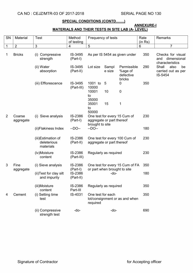
CA NO : CEJZ/MTR-03 OF 2017-2018 SERIAL PAGE NO 130
Signature of Contractor for Accepting officer
SPECIAL CONDITIONS (CONTD…….) ANNEXURE-I
MATERIALS AND THEIR TESTS IN SITE LAB (A- LEVEL)
SN Material Test Method of testing
Frequency of tests Rate (in Rs)
Remarks
1 2 3 4 5 6 7
1 Bricks (i) Compressive strength
IS-3495 (Part-I)
As per IS 5454 as given under 350 Checks for visual and dimensional characteristics
(ii) Water absorption
IS-3495 (Part-II)
Lot size Sample size
Permissible %age of defective bricks
290 Shall also be carried out as per IS-5454
(iii) Efflorescence IS-3495 (Part-III)
1001 to 10000
5 0 350
10001 to 35000
10 0
35001 to 50000
15 1
2 Coarse aggregate
(i) Sieve analysis IS-2386 (Part-I)
One test for every 15 Cum of aggregate or part thereof brought to site
230
(ii)Flakiness Index --DO-- --DO-- 180
(iii)Estimation of deleterious materials
IS-2386 (Part-II)
One test for every 100 Cum of aggregate or part thereof
230
(iv)Moisture content
IS-2386 (Part-III)
Regularly as required 230
3 Fine aggregate
(i) Sieve analysis IS-2386 (Part-I)
One test for every 15 Cum of FA or part when brought to site
350
(ii)Test for clay silt and impurity
IS-2386 (Part-II)
-do-
180
(iii)Moisture content
IS-2386 Part-III
Regularly as required 350
4 Cement (i) Setting time test
IS-4031 One test for each lot/consignment or as and when required
350
(ii) Compressive strength test
-do- -do- 690
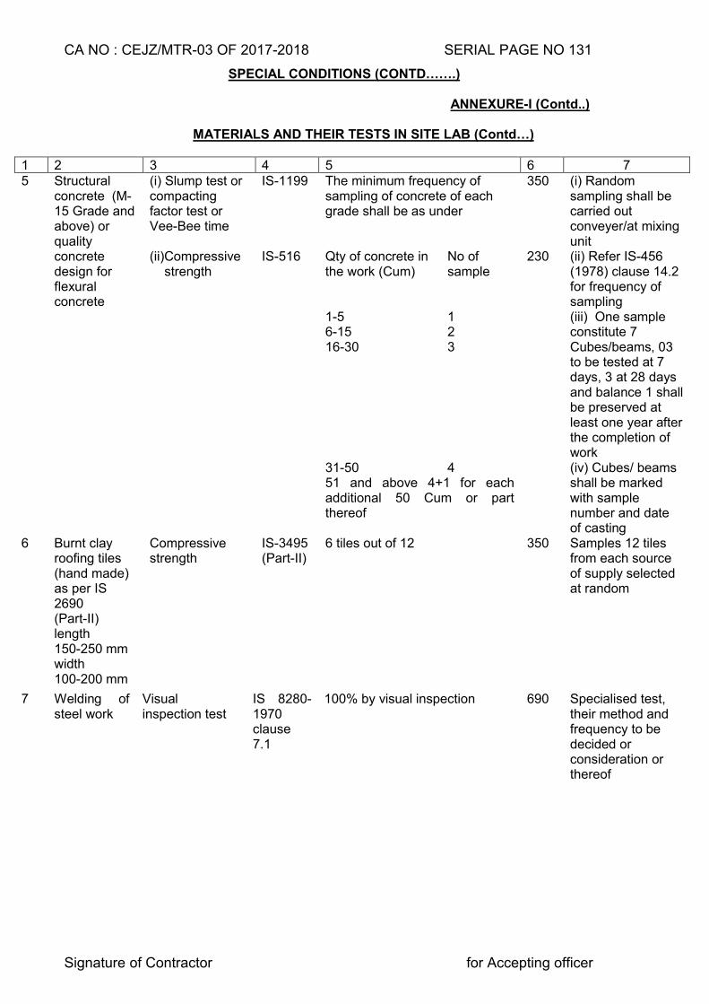
CA NO : CEJZ/MTR-03 OF 2017-2018 SERIAL PAGE NO 131
Signature of Contractor for Accepting officer
SPECIAL CONDITIONS (CONTD…….)
ANNEXURE-I (Contd..)
MATERIALS AND THEIR TESTS IN SITE LAB (Contd…)
1 2 3 4 5 6 7 5 Structural
concrete (M-15 Grade and above) or quality concrete design for flexural concrete
(i) Slump test or compacting factor test or Vee-Bee time
IS-1199 The minimum frequency of sampling of concrete of each grade shall be as under
350 (i) Random sampling shall be carried out conveyer/at mixing unit
(ii)Compressive strength
IS-516 Qty of concrete in the work (Cum)
No of sample
230 (ii) Refer IS-456 (1978) clause 14.2 for frequency of sampling
1-5 1 (iii) One sample constitute 7 Cubes/beams, 03 to be tested at 7 days, 3 at 28 days and balance 1 shall be preserved at least one year after the completion of work
6-15 2 16-30 3
31-50 4 (iv) Cubes/ beams shall be marked with sample number and date of casting
51 and above 4+1 for each additional 50 Cum or part thereof
6 Burnt clay roofing tiles (hand made) as per IS 2690 (Part-II) length 150-250 mm width 100-200 mm
Compressive strength
IS-3495 (Part-II)
6 tiles out of 12 350 Samples 12 tiles from each source of supply selected at random
7 Welding of steel work
Visual inspection test
IS 8280-1970 clause 7.1
100% by visual inspection 690 Specialised test, their method and frequency to be decided or consideration or thereof
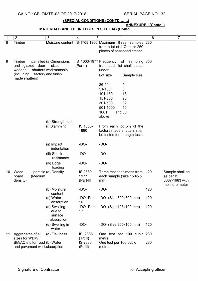
CA NO : CEJZ/MTR-03 OF 2017-2018 SERIAL PAGE NO 132
Signature of Contractor for Accepting officer
(SPECIAL CONDITIONS (CONTD…….) ANNEXURE-I (Contd..)
MATERIALS AND THEIR TESTS IN SITE LAB (Contd…)
1 2 3 4 5 6 7
8 Timber Moisture content IS-1708 1960 Maximum three samples from a lot of 4 Cum or 250 pieces of seasoned timber
230
9 Timber panelled and glazed door wooden shutters (including factory made shutters)
(a)Dimensions sizes, workmanship and finish
IS 1003-1977 (Part-I)
Frequency of sampling from each lot shall be as under
350
Lot size Sample size
26-50 5 51-100 8 101-150 13 151-300 20
301-500 32 501-1000 50 1001 and
above 80
(b) Strength test (i) Slamming IS 1303-
1990 From each lot 5% of the factory made shutters shall be tested for strength tests
(ii) Impact indentation
-DO- -DO-
(iii) Shock resistance
-DO- -DO-
(iv) Edge loading
-DO- -DO-
10 Wood particle board (Medium density)
(a) Density IS 2380 1977 (Part-III)
Three test specimens from each sample (size 150x75 mm)
120 Sample shall be as per IS 3087-1983 with moisture meter
(b) Moisture content
-DO- -DO- 120
(c) Water absorption
-DO- Part-16
-DO- (Size 300x300 mm) 120
(d) Swelling due to surface absorption
-DO- Part-17
-DO- (Size 125x100 mm) 120
(e) Swelling in water
-DO- -DO- (Size 200x100 mm) 120
11 Aggregates of all sizes for WBM/ BM/AC etc for road and pavement work
(a) Flakiness (b) Water absorption
IS: 2386 ( Pt II) IS:2386 (Pt III)
One test per 100 cubic metre One test per 100 cubic metre
230 230
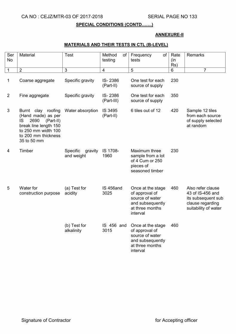
CA NO : CEJZ/MTR-03 OF 2017-2018 SERIAL PAGE NO 133
Signature of Contractor for Accepting officer
SPECIAL CONDITIONS (CONTD…….) ANNEXURE-II MATERIALS AND THEIR TESTS IN CTL (B-LEVEL)
Ser No
Material Test Method of testing
Frequency of tests
Rate (in Rs)
Remarks
1 2 3 4 5 6 7 1
Coarse aggregate
Specific gravity
IS- 2386 (Part-II)
One test for each source of supply
230
2 Fine aggregate Specific gravity IS- 2386 (Part-III)
One test for each source of supply
350
3 Burnt clay roofing (Hand made) as per IS 2690 (Part-II) break line length 150 to 250 mm width 100 to 200 mm thickness 35 to 50 mm
Water absorption IS 3495 (Part-II)
6 tiles out of 12 420 Sample 12 tiles from each source of supply selected at random
4 Timber Specific gravity and weight
IS 1708-1960
Maximum three sample from a lot of 4 Cum or 250 pieces of seasoned timber
230
5 Water for construction purpose
(a) Test for acidity
IS 456and 3025
Once at the stage of approval of source of water and subsequently at three months interval
460 Also refer clause 43 of IS-456 and its subsequent sub clause regarding suitability of water
(b) Test for alkalinity
IS 456 and 3015
Once at the stage of approval of source of water and subsequently at three months interval
460
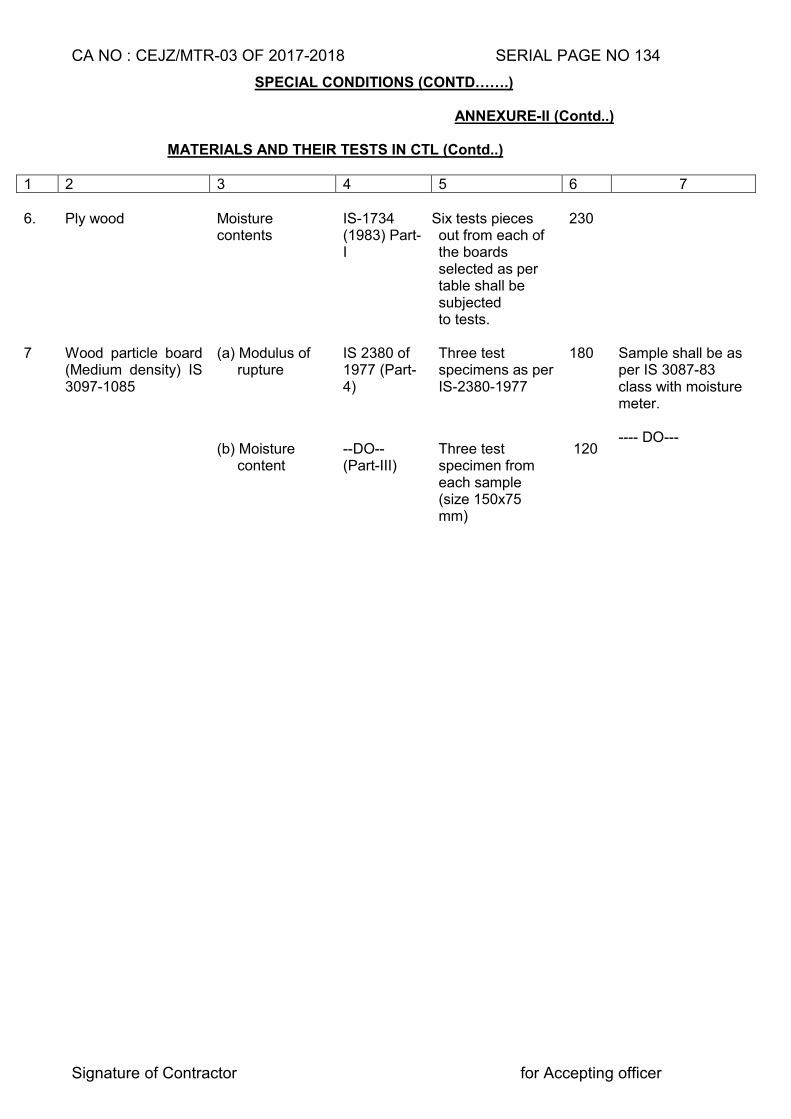
CA NO : CEJZ/MTR-03 OF 2017-2018 SERIAL PAGE NO 134
Signature of Contractor for Accepting officer
SPECIAL CONDITIONS (CONTD…….) ANNEXURE-II (Contd..)
MATERIALS AND THEIR TESTS IN CTL (Contd..)
1 2 3 4 5 6 7
6. Ply wood Moisture
contents IS-1734 (1983) Part-I
Six tests pieces out from each of the boards selected as per table shall be subjected to tests.
230
7 Wood particle board (Medium density) IS 3097-1085
(a) Modulus of rupture
IS 2380 of 1977 (Part-4)
Three test specimens as per IS-2380-1977
180 Sample shall be as per IS 3087-83 class with moisture meter. ---- DO---
(b) Moisture content
--DO-- (Part-III)
Three test specimen from each sample (size 150x75 mm)
120
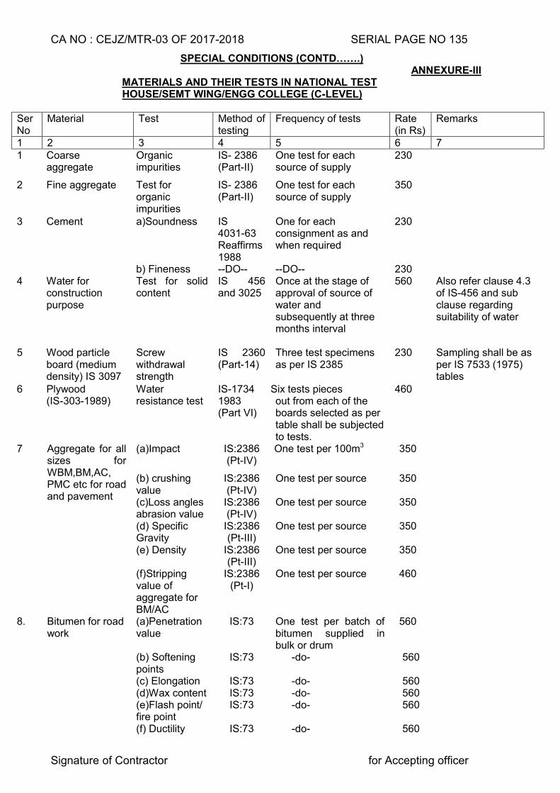
CA NO : CEJZ/MTR-03 OF 2017-2018 SERIAL PAGE NO 135
Signature of Contractor for Accepting officer
SPECIAL CONDITIONS (CONTD…….) ANNEXURE-III
MATERIALS AND THEIR TESTS IN NATIONAL TEST HOUSE/SEMT WING/ENGG COLLEGE (C-LEVEL)
Ser No
Material Test Method of testing
Frequency of tests Rate (in Rs)
Remarks
1 2 3 4 5 6 7 1 Coarse
aggregate Organic impurities
IS- 2386 (Part-II)
One test for each source of supply
230
2 Fine aggregate Test for organic impurities
IS- 2386 (Part-II)
One test for each source of supply
350
3 Cement a)Soundness IS 4031-63 Reaffirms 1988
One for each consignment as and when required
230
b) Fineness --DO-- --DO-- 230 4 Water for
construction purpose
Test for solid content
IS 456 and 3025
Once at the stage of approval of source of water and subsequently at three months interval
560 Also refer clause 4.3 of IS-456 and sub clause regarding suitability of water
5 Wood particle board (medium density) IS 3097
Screw withdrawal strength
IS 2360 (Part-14)
Three test specimens as per IS 2385
230 Sampling shall be as per IS 7533 (1975) tables
6 Plywood (IS-303-1989)
Water resistance test
IS-1734 1983 (Part VI)
Six tests pieces out from each of the boards selected as per table shall be subjected to tests.
460
7 Aggregate for all sizes for WBM,BM,AC, PMC etc for road and pavement
(a)Impact
IS:2386 (Pt-IV)
One test per 100m3 350
(b) crushing value
IS:2386 (Pt-IV)
One test per source 350
(c)Loss angles abrasion value
IS:2386 (Pt-IV)
One test per source 350
(d) Specific Gravity
IS:2386 (Pt-III)
One test per source 350
(e) Density IS:2386 (Pt-III)
One test per source 350
(f)Stripping value of aggregate for BM/AC
IS:2386 (Pt-I)
One test per source 460
8. Bitumen for road work
(a)Penetration value
IS:73 One test per batch of bitumen supplied in bulk or drum
560
(b) Softening points
IS:73 -do- 560
(c) Elongation IS:73 -do- 560 (d)Wax content IS:73 -do- 560 (e)Flash point/
fire point IS:73 -do- 560
(f) Ductility IS:73 -do- 560
CA NO : CEJZ/MTR-03 OF 2017-2018 SERIAL PAGE NO 136
Signature of Contractor for Accepting officer
PARTICULAR SPECIFICATIONS
1. GENERAL 1.1 The following specifications shall be read in conjunction with SSR Part-I of 2009 and Part-II of 2010(herein after called MES Schedule). The term ‘General Specifications’ referred to herein after as well as referred to in IAFW-2249 (General conditions of contracts) shall mean the specifications contained in the MES Schedule. General Rules, specifications, special conditions and all preambles in the MES Schedule shall be deemed to apply to the work under this contract, unless mentioned otherwise in these documents, in which case, the provision in these documents shall take precedence over the aforesaid provisions in the MES Schedule. 1.2 Rate quoted for a particular item and/or lump sum quoted by the tenderer shall be deemed to include for any minor details/items of work and /or construction which are obviously and fairly intended and which may not have been included in these documents but which are essential for the execution and entire completion of the work. 1.2.1 Decision of the Accepting Officer as to whether any minor details of work and/or construction is obviously and fairly intended to be included in the contract or not shall be final, conclusive and binding. However, some minor details, items which shall be deemed to be essential for execution and entire completion of work are detailed as under:-
(i) Reinforcement for any RCC member not indicated in the drawings but required as per structural or codal requirement.
(ii) Dwarf wall or plinth beam in situations like verandah, passage, ramp, platform etc not indicated in drawings.
(iii) Lintels over doors, windows, ward robe/cup board and opening not indicated in drawings.
(iv) Fittings to doors, windows, ward robe/cup board and such other built-in furniture (v) Items not shown. (v) PCC benching at the junction of chajjas and walls not shown in drawings. (vi) Finishing of concrete surfaces after removal of form work with 5mm thick
cement plaster in cement and sand mortar (1:3) wherever surfaces to be white washed/colour washed/distempered/painted.
1.2.2 In all the above and similar cases, the details indicated elsewhere in the drawings which
are similar or near to the missed out item of work shall be followed. In the absence of any other similar or near similar details, minimum essential requirement for completion of the work from structural and utility point of view shall be deemed to be included in the lump sum quoted. In the event of any dispute, decision of the Accepting Officer thereon shall be final, conclusive and binding.
1.3 The contractor shall quote his rates considering the provisions in Schedule ‘A’, Particular
Specifications, Special Condition, drawings etc reading them as mutually explanatory to each other. However, the contractor and the GE shall ensure economy in construction (but not on the cost of structural safety), safety of men, material and works and execution of work as per best engineering practice and local practices. For this, contractor and GE shall initiate requisite changes to contract provisions for approval of competent authority well in advance during currency of contract so as to ensure that progress is not hampered on this account.
1.4 Irrespective whether shown on drawing or not built in furniture items shall be provided as
shown in drawings. Location of items if not shown in main plan, location shall be as decided by GE.
CA NO : CEJZ/MTR-03 OF 2017-2018 SERIAL PAGE NO 137
Signature of Contractor for Accepting officer
PARTICULAR SPECIFICATIONS (CONTD...)
2. SAMPLES OF MATERIALS AND INDIAN STANDARDS
2.1 In case where materials are specified to conform to samples the tenderer is advised to inspect samples of the materials which are displayed in the office of the GE before submitting his tender. The tenderer shall be deemed to have inspected the samples and satisfied himself about the nature and quality of materials he is required to incorporate in the work irrespective of whether he has actually inspected them or not. The materials to be incorporated in the work by the contractor, shall conform to or shall be superior in quality to the sample displayed and shall comply with the specifications given herein after.
2.2 The contractor shall produce sample of materials and get them approved by the GE before commencement/incorporation in the work.
2.3 The contractor shall procure materials from following sources:-
(a) Local materials - Materials as listed in Appendix ‘A’ to particular specifications. (b) ISI marked materials - From any make / brand listed in Appendix ‘B’ to particular specifications.
(c) Items not covered in - Written approval of GE shall be Appendix ‘A’ and ‘B’ to obtained. Particular Specifications and
BIS certification.
2.4 For obtaining sample approval, contractor will download list of BIS marked manufacturers from BIS site www.bis.org.in. He will select manufacturer (s) meeting contract specifications criteria and handover the report with a request letter to Engineer-in-charge with his signatures. The Engineer-in-charge will verify its correctness by visiting the BIS site and process it to GE with his recommendations. AE/JE (Q.S and C) of GE will recheck the same from internet endorse his recommendation and put up for approval of GE.
2.5 The printout having signature of all concerned including GE will be kept on record and approval will be conveyed within 7 days of contractor’s request.
2.6 After sample approval GE shall send an e-mail to manufacturer (not the authorized dealer) intimating him name of firm, approx quantity of material being procured by the contractor and request the manufacturer to ensure that his product only is purchased by the contractor from proper authorised source. A printout of the e-mail sent to manufacturer shall be kept on record duly signed by the GE and a copy thereof will be sent by post to the manufacturer.
2.7 In cases involving suspected procurement of spurious material purchase vouchers shall be verified through the manufacturer and proof of payment shall be obtained from the contractor by Engineer-in-charge.
2.8 Where no licensee exists for a particular item as per BIS web site, GE will permit procurement of materials confirming to IS from manufacturer to be decided by GE.
3. EXCAVATION AND EARTH WORK
3.1 EXCAVATION IN GENERAL 3.1.1 Excavation and earthwork involved in Schedule ‘A’ Part-I has been priced at the rate any
type of soil (without the use of timbering). Cost of all excavation and earthwork shall be deemed to be included in the lump sum cost of items listed in Schedule ‘A’ Part-I. In case during excavation hard/dense soil or soft/hard rock is met with, shall be ordered through deviation.
CA NO : CEJZ/MTR-03 OF 2017-2018 SERIAL PAGE NO 138
Signature of Contractor for Accepting officer
PARTICULAR SPECIFICATIONS (CONTD...) 3.1.2 In case hard rock is met with, the contractor shall immediately notify the same to GE
under intimation to Accepting Officer and prior approval of Accepting Officer shall be obtained by the GE before ordering work of excavation in hard rock on the contractor. Where hard rock is met with during the excavation, foundation design is likely to be changed which may entail delay in finalisation of drawings. The contractor shall mobilise his resources accordingly in consultation with GE and shall have no claims of what so ever nature for delay in finalisation of revised details shall be entertained. CEs decision in this regard will be final and binding.
3.1.3 Hard rock met during excavation shall be entered (in stacks) in the measurement book
duly signed by the GE and the contractor and the same shall become the property of contractor for which recovery at the rate rubble stone from approved quarries for hand packing (Item 01623) of MES SSR Part-II) shall be made subject to applicable percentage over SSR from contractors advance on account payment.
3.1.4 The hard rock so obtained may be allowed to be used in the work by the GE provided it
meets the specified requirements, location (s) etc where it is to be used shall also be as decided by the GE. If hard rock obtained from excavation is not fit to use in the work the contractor shall remove the same outside MD land without any extra cost to the Government with approval of AO.
3.1.5 Surplus excavated soil shall be removed to a distance exceeding 250 metre but not
exceeding 500 metres deposited, spread and levelled as directed. Lump sum cost quoted by the contractor shall include for cost of this lead and removal.
3.2 SITE CLEARANCE, SURFACE EXCAVATION AND SURFACE DRESSING 3.2.1 Before the work is started, Site clearance shall be carried out for the area covered by the building as per clause 3.6 of MES SSR Part I. Further Surface excavation for averaging depth shall be carried out for the area covered by the buildings as per clause no 3.32 of MES SSR Part I. Prior to completion of work surface dressing up to 3 metre around the building from the external walls including apron/hard standing (except road side portion of apron) shall be carried out as per clause 3.6 and 3.10 of MES SSR Part-I. All rubbish obtained from site clearance, surface excavation and surplus soil obtained from surface dressing shall be removed, spread and levelled as directed by Engineer-in-Charge to a distance exceeding 250 metre but not exceeding 500 metre from external face of building. 3.2.2 Depth of foundation shown in drawings for the buildings is depth after surface excavation. GL/NGL marked on the drawings shall be average GL/NGL as fixed by GE after surface excavation. 3.3 EXCAVATION IN TRENCHES AND OVER AREAS
3.3.1 Excavation in trenches and over area shall be carried out as described in clause 3.13 of MES SSR Part-I. Bailing and pumping of water, if required will be done as described in clause 3.17 of MES SSR Part-I. No extra payment shall be admissible for the above-mentioned operation. If however, an inflow of water in to excavation is caused by powerful springs or river seepage, broken water mains or drains and the like (other than those broken through the contractors negligence) the contractor shall inform the GE. If in the opinion of the GE the inflow is due to any of these causes, he shall issue instructions in writing as to the method to be employed in clearing the excavation of water and additional payment shall be allowed as deviation order.
CA NO : CEJZ/MTR-03 OF 2017-2018 SERIAL PAGE NO 139
Signature of Contractor for Accepting officer
PARTICULAR SPECIFICATIONS (CONTD...)
3.4 FILLING IN TRENCHES, PLINTH, UNDER FLOORS APRON/RAMP ETC.
3.4.1 Filling in foundation trenches, plinth, under floors, and in other situations shall be done with approved earth. It shall be ensured that turf, peat vegetable and other organic and deleterious matter is removed from the soil used for filling. Black cotton soil shall not be used for filling. Filling shall be done as specified in clause 3.19 of MES SSR Part-I, and filling in trenches for pipes, drains, cables etc shall be done as per clause 3.20 of MES SSR Part-I. Earth filling in embankments and earthen traverses shall be done all as specified in clause 3.22 of MES SSR Part-I.
3.4.1A COMPACTION OF FILLED EARTH The compaction of filled earth under floors inside the plinth area and foundation trenches etc. of the building shall be done with diesel operated earth Compactor/Rammer in layers not exceeding 25cm thick duly watered. Each layer shall be approved by GE after compaction and photographical record to be maintained. Compaction of each layers shall be entered in stage passing register and shall be approved by GE.
3.4.2 (a) Earth obtained from excavation shall be used for filling only after approval of Engineer–in-Charge.
(b) For the purpose of unit rate of building/structure in schedule `A’ Part-I the whole soil (except soil obtained from surface dressing and surface excavation and black cotton soil) obtained from excavation of item of schedule `A’ Part-I shall be considered suitable for filling. No charges shall be levied from contractor for use of soil obtained from excavation for filling. (c) If soil obtained from excavation is not adequate for filling in trenches, plinth, under floor etc additional approved earth required for filling shall be obtained by the contractor from outside MOD land at his own resources and no extra payment on this account shall be admissible.
3.5 In case of deviation, the approved earth obtained shall be priced at the rate applicable for rough excavation in any type of soil not exceeding 1.5 metre in depth and getting out and removal to a distance exceeding 500 metre but not exceeding 1.5 Km adjusted by the contractor percentage as applicable irrespective of actual lead/cost involved.
3.6 HARD CORE Refer clause 3.27 of MES SSR Part-I.
3.6.1 The material for hard core shall be broken hard stone approved by GE, obtained from the source as per Appendix ‘A’ to particular specifications.
[
3.6.2 The hard core shall be watered and rammed. The thickness of hard core shown in drawings or specified in particular specifications is the consolidated thickness.
3.7 PRECONSTRUCTION ANTITERMITE CHEMICAL TREATMENT Ant termite treatment shall be carried out to (buildings as per clause 3.7.1 here in below) all as specified in clause 3.26 of MES SSR Part-I except that termite mound treatment if required to be provided shall be ordered as deviation.
3.7.1 The work of ant termite treatment to the buildings in against serial item No 1 to 11, 13 to 16 and 21 of Schedule ‘A’ Part-I shall be carried out through a specialist firm. The firm shall meet the following requirements to be approved by the GE before anti termite treatment work is taken in hand: - (a) The firm executing the work shall have valid licence for carrying antitermite treatment as per insecticide act 1962 (as amended from time to time).
(b) The firm shall be a member of IPCA or shall have a satisfactory record of performance.
(c) The person carrying out ant termite treatment shall be qualified as per rule 10 promulgated under insecticide rule 1971.
3.7.2 Daily record shall be maintained duly signed by the contractor and Engineer-in-Charge giving the following details:-
CA NO : CEJZ/MTR-03 OF 2017-2018 SERIAL PAGE NO 140
Signature of Contractor for Accepting officer
PARTICULAR SPECIFICATIONS (CONTD...)
(i) Location of work done
(ii) Name of chemical and its concentration used
(iii) Items of the treatment work done (bottom and sides of excavation of masonry wall, back fill, under plinth protection, top of filling and along external perimeter of building/plinth protection) and area covered under each item.
(iv) Quantity of chemical required for work done during the day and quantity of chemical actually used.
3.7.3 The contractor shall give a guarantee of 10 years for the ant termite treatment. The aforesaid guarantee period of 10 years shall reckon from the certified date of completion of work.
3.7.4 The amount so calculated as per table given below shall be retained out of the contractor’s bill as security deposit for the guarantee period of 10 years which shall be refunded to him after expiry of the guarantee period satisfactorily. Alternatively, contractor may give a separate interest bearing security deposit or bank guarantee bond to GE valid for 10 years for the sum mentioned above. Security deposit/bank guarantee bond shall be released after expiry of defects liability period of 10 years as specified. The contractor may at his discretion furnish fixed deposit receipt for the above amount in lieu of the security for guarantee period as mentioned:-
Srl No
Amount of anti-termite treatment work at contract rate
Amount to be retained from contractor’s dues rounded to nearest thousand rupees
1 2 3 (i) Up to Rs 50 Lakh 2% of amount subject to minimum of Rs
5000/- and enhanced by 25%. (ii) Over Rs 50Lakh and upto Rs 100
Lakh Rs 100000/-+ 1.5% of amount exceeding Rs 50 Lakh and enhanced by 25%.
(iii) Over Rs 100 Lakh Rs 175000/-+ 1 % of amount exceeding Rs 100 Lakh and enhanced by 25%.
3.7.5 Should the GE at any time during construction or prior to the expiration of the guarantee
period of 10 years find that the buildings have been infested with termites, the contractor shall on demand in writing from GE, specifying the building(s) complained of, notwithstanding that same may have been inadvertently passed, certified and paid for, forthwith undertake to carry out such treatment as may be necessary to render the said building(s) free from termite infestation at his own expenses for the guarantee period of 10 years and in event of his failing to do so within a period to be specified by the GE in his demand aforesaid, the GE may undertake such treatment at the risk and expense, in all respect, of the contractor. The liability of the contractor under this condition shall not extend beyond the guarantee period of 10 years unless the GE had previously given notice to the contractor. The security deposit referred to in condition 3.7.4 herein before may be refunded to the contractor after the expiry of the period of ten years from the certified date of completion by the GE provided always that the contractor shall first have been paid the final bill and have rendered a no demand certificate (IAFA-451). Condition 10, 46 and 68 of the General Conditions of Contracts (IAFW-2249) shall be deemed to be amended to the extent mentioned above.
3.7.6 Chemicals for ant termite treatment shall be purchased by the contractor from the
manufacturers or their authorised agents only and brought to site in manufacturer’s sealed containers. Name of the authorised agent shall be verified from the manufacturer by the GE before approval.
CA NO : CEJZ/MTR-03 OF 2017-2018 SERIAL PAGE NO 141
Signature of Contractor for Accepting officer
PARTICULAR SPECIFICATIONS (CONTD...) 3.7.7 Regarding chemical for antitermite treatment, provisions of special condition No 8
(Record of materials) shall strictly be complied with.
3.7.8 The chemical for ant termite treatment brought to site shall be inspected by the Engineer-in-Charge and the quantity brought to site shall be recorded in the measurement book and signed by the contractor and the Engineer-in-Charge as a check to ensure that the required quantity has been brought to site for incorporation in the work.
3.7.9 The chemical brought to site shall be stored as directed by the Engineer-in-Charge and
those already recorded in the MBs shall be marked for identification.
3.7.10 Refer clause 3.26.1 of MES SSR Part-I. Chemical for ant termite treatment shall be Chloropyriophos (20% EC) ISI 8944 marked.
4. CEMENT 4.1.1 GENERAL : Cement required for the work under the contract shall be procured, supplied
and incorporated in the works by the contractor under his own arrangement. Cement shall be of tested quality and shall comply with the requirements mentioned in the drawings, MES SSR, IS specifications as amended and particular specifications given here-in-after.
4.1.2 TYPE OF CEMENT : Type of cement for subject work shall be Ordinary Portland
Cement (OPC) 43 (forty three) grade in accordance with IS-8112 unless otherwise mentioned in structural drawings forming part of the tender documents.
4.1.3 USE OF PPC : Following requirements are to be ascertained before using the PPC :-
(a) PPC meets the strength criteria of 43 Grade OPC as laid down in IS-8112-1989. (b) The minimum period before striking formwork given in clause 11.3.1 of IS-456- 2000 is to be suitability modified at site by the GE. (c) Mixing of OPC and PPC shall not be allowed for use in the same building except
for plaster and mortar. (d) While procuring PPC, the following requirements are to be ensured and certificate to that effect is to be rendered by the contractor for each batch from the manufacturer:-
(i) The quality of fly ash is strictly as per IS-14989 (Part-I).
(ii) Fly ash is inter-ground with clinker not mixed with clinker.
(iii) Dry fly ash is transported in closed containers and stored in silos. Only pneumatic pumping should be used.
(iv ) The fly ash is received from thermal power plants using high temperature combustion above 10000 C.
(v )The fly ash content in PPC shall be as per IS 1489 (Pt-I).
CA NO : CEJZ/MTR-03 OF 2017-2018 SERIAL PAGE NO 142
Signature of Contractor for Accepting officer
PARTICULAR SPECIFICATIONS (CONTD...) 4.2 SOURCE OF PROCUREMENT
4.2.1 Cement shall be procured by the contractor from any approved main producers of
cement listed in Appendix `B’ to particular specifications and other manufacturer of cement approved by E-in-C’s Branch (up to schedule date of receipt of tender) and not from their authorised dealers. However if the quantity of cement required in a work is less than 1200 bags, same can be procured from the authorised distributors/ dealers of the main producer but the contractor will have to submit test certificates of the batch issued by the main producers.
4.2.2 GE shall verify the valid BIS certification of the firm before giving approval of
manufacturer/firm and CTC copy thereof shall be kept on record. 4.2.3 The contractor shall furnish particulars of the manufacturer of cement along with date of manufacture to the GE for every lot of cement separately. The cement so brought shall be fresh and in no case older than 60 days from the date of manufacturing. The documents in support of the purchase of the cement shall be verified by the Engineer-in-Charge and GE. Before placing the order for supply of cement by the contractor, he shall obtain written approval from the GE regarding name of manufacturer, quantity of cement etc. Cement shall be procured for minimum requirement of one month and not exceeding the requirement of the same for more than two months at a time. The cement shall be consumed in the work within three months after receipt. Cement shall conform to the requirement of the Indian Standard Specifications and each bag of cement shall bear ISI mark and date of manufacture. The weight of each consignment shall be verified by the Garrison Engineer and recorded. The content of cement shall be checked at random to verify the actual weight of cement per bag. However, the content of cement per bag shall be 50 Kg only, subject to tolerance given in clause 9.2 of IS-8112.
4.3 TESTING OF CEMENT
4.3.1 The manufacturer is to carry out inspections and testing of cement in accordance with the relevant BIS provisions. The contractor shall submit the manufacturer’s test certificate in original along with test sheets giving the results of each physical test as applicable in accordance with relevant IS provisions and the chemical composition of cement or authenticated copy thereof duly signed by the manufacturer with each consignment, as per the following IS provisions:
(a) Method of sampling hydraulic cement as per IS-3535
(b) Methods of physical test for hydraulic cement as per IS-4031
(c) Method of chemical analysis of hydraulic cement as per IS-4032
The test certificate and test sheet shall be furnished with each batch of cement. The Engineer-in-Charge shall record these details in ‘cement supply and acceptance register’ after due verification to be maintained by him which will be signed by JE (Civil), Engineer-in-Charge, GE and the contractor as given in the format here-in-after for verification:-
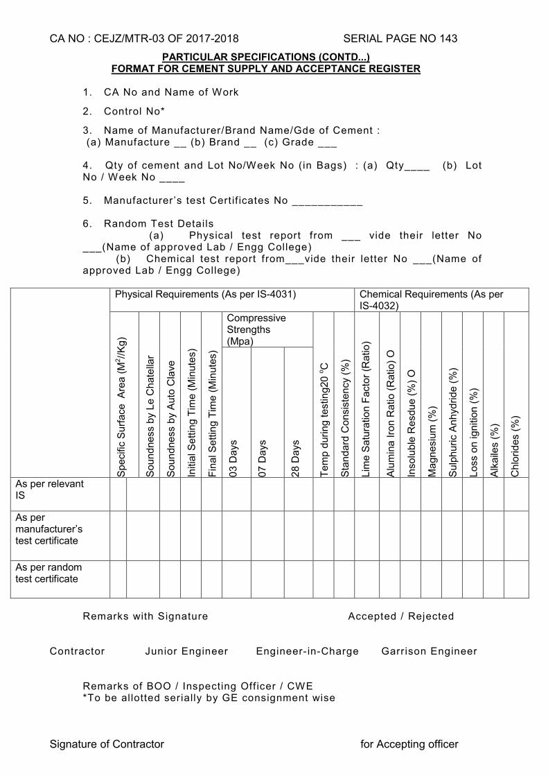
CA NO : CEJZ/MTR-03 OF 2017-2018 SERIAL PAGE NO 143
Signature of Contractor for Accepting officer
PARTICULAR SPECIFICATIONS (CONTD...) FORMAT FOR CEMENT SUPPLY AND ACCEPTANCE REGISTER
1. CA No and Name of Work
2. Control No*
3. Name of Manufacturer/Brand Name/Gde of Cement : (a) Manufacture __ (b) Brand __ (c) Grade ___ 4. Qty of cement and Lot No/Week No (in Bags) : (a) Qty____ (b) Lot No / Week No ____ 5. Manufacturer’s test Cert if icates No ___________ 6. Random Test Details (a) Physical test report from ___ vide their letter No ___(Name of approved Lab / Engg College) (b) Chemical test report from___vide their letter No ___(Name of approved Lab / Engg College)
Physical Requirements (As per IS-4031) Chemical Requirements (As per IS-4032)
Sp
eci
fic S
urf
ace
A
rea
(M
2//
Kg
)
So
un
dne
ss b
y L
e C
hate
llar
So
un
dne
ss b
y A
uto
Cla
ve
Initi
al S
ett
ing T
ime
(M
inu
tes)
Fin
al S
ett
ing
Tim
e (
Min
ute
s)
Compressive Strengths (Mpa)
Te
mp
durin
g t
est
ing
20
oC
Sta
nd
ard
Co
nsi
ste
ncy
(%
)
Lim
e S
atu
ratio
n F
act
or
(Ra
tio)
Alu
min
a I
ron R
atio
(R
atio
) O
Inso
lub
le R
esd
ue
(%
) O
Ma
gn
esi
um
(%
)
Su
lph
uric
An
hyd
rid
e (
%)
Lo
ss o
n ig
niti
on
(%
)
Alk
aile
s (%
)
Ch
lorid
es
(%)
03
Da
ys
07
Da
ys
28
Da
ys
As per relevant IS
As per manufacturer’s test certificate
As per random test certificate
Remarks with Signature Accepted / Rejected
Contractor Junior Engineer Engineer- in-Charge Garrison Engineer Remarks of BOO / Inspecting Off icer / CWE *To be allotted serially by GE consignment wise
CA NO : CEJZ/MTR-03 OF 2017-2018 SERIAL PAGE NO 144
Signature of Contractor for Accepting officer
PARTICULAR SPECIFICATIONS (CONTD...)
4.3.2 The contractor shall, however, organise setting time and a compressive strength test of cement through designated laboratory on samples collected from the lot brought at site before incorporation in the work. The contractor will be allowed to use the cement only after satisfactory compressive strength of 7 days. To meet this requirement, contractor is required to keep minimum 10 days stock before any new lot brought at site which can be used in the work. The contractor shall be required to remove the cement not meeting the requirement from site within 24 hours. 7 days strength test will be relied upon to accept the lot of cement to commence the work. 28 days compressive strength test will be the final criteria to accept /reject the lot.
4.3.3 The GE shall also carry out independent testing as per the tests mentioned in the
‘FORMAT FOR CEMENT SUPPLY AND ACCEPTANCE REGISTER’ of random samples of cement drawn from various lots if sample fails in 7 days compressive strength. The testing shall be carried out through National Test House, SEMT, CME, Regional Research Laboratories, NABL laboratories ,IITs, Government Engineering colleges ,National Institutes of Tech Government approved laboratories as approved by GE as per IS-3535 (Method of sampling hydraulic cement), IS-4031 (Method of physical test for hydraulic cement) and IS-4032 (Method of chemical analysis of hydraulic cement) referred to above. The decision as to where the testing of cement is to be done shall be taken by GE. In case the cement is not of requisite standard despite manufacturers test certificate, the contractor shall remove the total consignment from the site at his own cost after written rejection order of the consignment by the GE. The cost of test shall be borne by the contractor irrespective of the results of testing.
4.3.4 Cost of transportation of samples to the approved laboratory / test house and all testing
charges including cost of samples shall be borne by the contractor.
4.3.5 The random samples as per relevant IS shall be selected by GE before carrying out testing. The record of such samples selected by the GE for testing shall be properly maintained in the cement testing register giving cross reference to relevant consignment of cement and quantity received etc.
4.3.6 The contractor shall be required to set up adequate testing facilities at site to the entire
satisfaction of GE for conducting setting time test and compressive strength test as per IS codes referred to here-in-before for the samples collected from the lot brought at site. These tests shall be carried out within 7 days of receipt of cement at site. The test can alternatively be carried out at the Command testing laboratory (CTL), or any other recognised laboratory so designated by GE.
4.3.7 The contractor shall submit original purchase vouchers for the total quantity of cement
supplied under each consignment to be incorporated in the work. All consignment received at the work site shall be inspected by the GE along with the relevant documents to ensure the requirements as mentioned here-in-before, before acceptance. The original purchase vouchers and the test certificates shall be verified for subject contract and defaced by the Engineer-in-Charge and kept on record in the office of the GE duly authenticated and with cross reference to the consignment / control number recorded in the cement acceptance register. The cement acceptance register shall be signed by the JE (Civil), Engineer-in-Charge, GE and the contractor. The contractor shall maintain schedule of supply of cement for each consignment.
4.3.8 The Accepting Officer may order a board of officers for random check of cement and
verification of connected documents during the currency of contract.
CA NO : CEJZ/MTR-03 OF 2017-2018 SERIAL PAGE NO 145
Signature of Contractor for Accepting officer
PARTICULAR SPECIFICATIONS (CONTD...) 4.4 STORAGE / ACCOUNTING / PRESERVATION OF CEMENT
4.4.1 Cement bags shall be stored in covered godown over dry platform at least 20cm high in such a manner as to prevent deterioration due to moisture or intrusion of foreign matter. In case of store room, the stack should be at least 20 cm away from floors and walls. The stacking of cement shall be done as specified in relevant IS. The storage accounting and preservation of cement supplied by the contractor shall be done as per standard engineering practice till the same is incorporated in the work and the cost of the same shall be deemed to be included in the unit rate/amount quoted by the tenderer. The Engineer-in-Charge shall inspect once a week to verify that cement lying at site is stored, accounted, preserved and maintained as per the norms. The cement shall be stored so as to differentiate each tested and untested consignment separately with distinct identification. If the GE is not satisfied with the storage/preservation of cement, he may order for any test(s) of cement as applicable for that consignment to ensure its conformity to the quality mentioned in the manufacturer’s test certificate. The contractor shall bear the cost of necessary testing(s) in this regard and no claim whatsoever shall be entertained.
4.4.2 Stacking of cement shall be done as per relevant IS and as under:-
(i) Each cement consignment shall be stacked separately and removal shall be
made on the basis of `First in First out`.
(ii) Adequate top cover will be provided.
(iii) Stacks in no case shall be higher than 10 bags. The maximum width of each stack shall be 3metre. If the stack is to be more than 7 or 8 bags high, the bags shall be arranged in header and stretcher fashion i.e alternatively length wise and cross wise so as to tie the piles together and avoid damage or topping over.
(iv) Adequate space shall be kept between two stacks. 4. 4.3 Cement go down shall be provided with two locks on each door. The key of one lock at
each door shall remain with the Engineer-in-Charge or his representative and that of the other lock with the contractor’s authorised agent at site of works so that cement is removed from the go down only according to daily requirement with the knowledge of both the parties. During the period of storage, if any cement bag is found to be in damaged condition due to whatsoever reason, the same shall be removed from the cement go down on written orders of the GE and suitable replacement for the cement bags so removed shall be made and no claim whatsoever shall be admissible on this account.
4.4.4 Cement shall be removed from the store only according to daily requirement with the
knowledge of both the parties and daily consumption of cement shall be recorded in cement consumption register which shall be signed by the Engineer-in-Charge and the contractor. Calculation of cement consumption will be as per the quantity of cement approved in design mix for RCC works. For other items of work, cement constants given in Appendix `A’ to E-in-C’s Branch letter No 19280/E8 dated 03 May 1976 shall be the basis of consumption of cement.
4.4.5 In case the consumption of cement as per cement consumption register is found
to be more than the estimated quantity of cement due to whatsoever reason, the contractor shall not have any claim whatsoever for such excess consumption of cement.
CA NO : CEJZ/MTR-03 OF 2017-2018 SERIAL PAGE NO 146
Signature of Contractor for Accepting officer
PARTICULAR SPECIFICATIONS (CONTD...) 4.5 SCHEDULE OF SUPPLY
The contractor shall procure the cement timely as required in accordance with CPM network agreed between GE and the contractor. The contractor will forfeit his right to demand extension of time if the supply of cement is delayed due to his failure in placing order in time to the manufacturer.
4.6 MEASUREMENT AND PAYMENT OF CEMENT
4.6.1 The entire quantity of cement as brought at site, from time to time shall also be suitably recorded in the Measurement book for record purposes as ‘Not to be abstracted’ before incorporation in the work and shall be signed by the Engineer-in- Charge and the contractor.
4.6.2 The payment shall only be allowed after production of original purchase vouchers, certified copies of test certificates from manufacturer for each consignment and if results of testing carried out in laboratory on receipt of cement (7 days compressive test) are found satisfactory after testing as specified herein before. Cement shall be paid as material lying at site as per condition 64 of IAFW-2249. Rate of cement given in SSR shall be applicable for cement irrespective of grade of cement specified for use in the work (only OPC).
4.6.3 For the purpose of pricing deviation for the items involving cement, the rates given in
MES SSR shall be applicable.
4.7 CONCRETE
4.7.1 All plain and reinforced cement concrete shall be as per IS-456 (2000)
4.7.2 AGGREGATE
Coarse aggregate for all cement concrete work shall be crushed or broken and graded hard stone. Coarse aggregate and fine aggregate (sand) shall be from the source as mentioned in Appendix ‘A’ to particular specifications as approved by the GE and shall conform to IS-383 and to the sample kept in GEs office.
4.7.3 WATER
Quality of water to be used for mixing and curing of concrete work shall conform to the requirement of clause No 5.4 of IS-456 (2000). The GE and contractor will ensure that testing of water is carried out in any government laboratory/government college at three months interval to ensure that the water used for making concrete or mortar and for curing conform to IS-456.
4.7.4 CEMENT CONCRETE
4.7.4.1 Type of cement concrete required for works in various situation shall be as follows unless otherwise indicated on drawings or specially specified here-in-after:-
Sl No LOCATION THICKNESS and TYPE OF MIX 1 2 3
(a) Lean concrete below RCC column footing/plinth beam.
PCC (1:4:8) type D-2 using 40 mm graded crushed stone aggregate.
(b) Foundation concrete for masonry walls/pillars
PCC (1:4:8) type D-2 using 40 mm graded crushed stone aggregate.
(c) (i) Sub base to floor for MT/LUBRICANT
150mm thick PCC (1:4:8) type D-2 using 40mm graded crushed stone aggregate.
(ii)
Sub base to floor (except mentioned at Ser No (c) (i) above (c) (iii) below
75 mm / 100 mm thick PCC (1:4:8) type D-2 using 40 mm graded crushed stone aggregate. Thickness of sub base to floor shall be as given in respective schedule of finishes drg. However, in case where thickness is not shown, 100mm thickness shall be provided.
CA NO : CEJZ/MTR-03 OF 2017-2018 SERIAL PAGE NO 147
Signature of Contractor for Accepting officer
PARTICULAR SPECIFICATIONS (CONTD...)
4.7.4.1(CONTD.)
Srl No LOCATION THICKNESS and TYPE OF MIX
1 2 3
(iii) Sub base to floor (except mentioned at Ser No (c) (i)and (ii) above),for repair bays, garages and their ramp/aprons/platform for B vehicles
150mm thick Hard core all as specified
(d) RCC works (Except water retaining structure)
M-25 grade (Design mix concrete) as per IS 456-2000 using graded crushed stone aggregate
(e) RCC works in water retaining structure( Irrespective to whatever has been specified in tender documents and drawings)
M-30 grade (Design mix concrete) as per IS : 456-2000 using graded crushed stone aggregate.
(f) PCC in floors work shall be as follows :-
(i) 40 mm thick and above PCC (1:2:4) type B-1 using 20 mm graded
crushed stone aggregate (ii) Thickness less than 40 mm PCC (1:2:4) type B-0 using 12.5 mm graded
crushed stone aggregate
(g) PCC bed blocks PCC (1:2:4) type B-1 using 20 mm graded crushed stone aggregate of size as technically required.
(h) PCC coping and benching PCC (1:3:6) type C-1 using 20 mm graded crushed stone aggregate
(j) Surroundings to surface of gully traps, padding under nahani traps/floor traps/deep seal traps/ surrounding of WC seats/Sunken portion etc.
Lean concrete PCC (1:5:10) type E-2 using 40 mm graded brick aggregate
4.7.5 SPECIFICATION FOR DESIGN MIX CONCRETE
4.7.5.1 CEMENT Cement shall be as per clause 4.1.2 here in before.
4.7.5.2 AGGREGATE (a) Aggregate shall conform to IS 383 and shall be of type basalt/trap/sand stone.
Aggregate shall be non porous, hard, strong, durable, clean and free from various impurities and adherent coating and shall not contain any deleterious materials exceeding the limits specified in the above referred IS. When required by the Engineer-in-Charge, the contractor shall at his own expense carry out any test laid down in IS: 383 and IS:2386 to verify that the aggregate complies with the requirements of the IS. The test will be carried out in any laboratory approved by the GE.
(b) Coarse aggregate shall consist of crushed stone aggregates.
(c) Fine aggregate shall consist of naturally occurring coarse sand. Fine aggregate shall conform to Zone-II and Zone-III of table IV of IS-383.
CA NO : CEJZ/MTR-03 OF 2017-2018 SERIAL PAGE NO 148
Signature of Contractor for Accepting officer
PARTICULAR SPECIFICATIONS (CONTD...) (d) Samples of the aggregate proposed to be used shall be approved by GE, prior to
bulk delivery of the same at site of work. Field tests for determining the contents of silt, clay etc for fine aggregate shall be carried out by the Engineer-in-Charge from time to time to ensure that material brought to site are in conformity with the samples approved by the GE.
(e) GRADING OF AGGREGATE
The grading of coarse and fine aggregate shall be as per MES Schedule. Fine aggregate shall have grading as per grading Zone-II. The grading of coarse and fine aggregate shall be checked as frequently as possible. The frequency for the aggregate testing shall be as per Annexure – I to special condition here-in-before, which may be increased at cost to contractor by Engineer-in-Charge to ensure that the specified grading is being maintained.
4.7.5.3 BATCHING
(a) The mixing of cement and aggregate for cement concrete for all grades and type of RCC work shall be done by weigh batching.
(b) The batching shall be as per clause 10.2 of IS 456:2000 and clause 4.11.3
(Excluding provision vide sub clause 4.11.3.1) of MES SSR Part-I. (c) CONCRETE WEIGH BATCHING PLANT
The concrete will be mixed in automatic concrete weigh batching plant. The plant will have a capacity of 12-13 cum/hr (Approximate) with auto feeding system of cement and aggregate. It will have handle for manual ejection in case of power failure. However smaller / bigger capacity plant manufactured by any reputed company capable of giving required output to commensurate the desired progress will be brought by contractor at his own cost.
4.7.5.4 MIX PROPORTION AND STRENGTH
(i) Strength to be achieved As per IS-456-2000
(ii) Type of cement As per clause 4.1.2 herein before
(iii) Target mean strength of cement concrete
To be taken as per mix designed as per IS-10262 clause 2.2
(iv) Aggregate/cement ratio by weight
As per mix design based on IS 10262 and IS-456-2000
(v) Workability As per clause 7.1 of IS-456-2000 slump shall be 25 mm to 75 mm compaction factor 0.85 to 0.92
(vi) Water cement ratio As per mix design based on IS-10262 and IS-456-2000
(vii) Degree of quality control Good (Refer Appendix `A’ of IS-10262)
(viii) Durability Exposure - Moderate for M-25 and severe for M-30
(ix) Cement content As per IS-456-2000 but not less than quantity given below in NOTE.
(x) Type of aggregate Crushed stone aggregate Maximum size of aggregate 20mm or as specified.
CA NO : CEJZ/MTR-03 OF 2017-2018 SERIAL PAGE NO 149
Signature of Contractor for Accepting officer
PARTICULAR SPECIFICATIONS (CONTD...)
NOTES : (i) The minimum quantity of cement for M-25 (design mix) and M-30 (design mix)
shall be 350 Kg/cum and 370 Kg/Cum respectively. In case cement quantity as per actual design mix works out less than the above quantity, minimum cement as 350 kg/cum or 370 Kg/Cum as applicable of concrete will be used without any extra cost to Govt. In case quantity of cement as per actual design mix is more than the above quantity, the actual quantity as per design mix shall be used in the work without any extra cost to Govt. The contractor will take into account this aspect while quoting the tender.
(ii) The rates given in MES schedule for design mix shall be applicable irrespective
of the quantity of cement approved/used in the execution of design mix work. The contractor is required to keep this aspect in mind while quoting his rates.
(iii) Mix design shall be prepared based on SP-23, handbook on concrete mixes and
IS-10262 Recommended guide lines for concrete mix design. No element of wastage of cement shall be allowed while working out the cement consumption details for design mix concrete work.
4.7.5.5 Approval of Design Mix
(a) Soon after commencement of work, contractor shall arrange the design mix for concrete of applicable grade. Design mix concrete shall be got carried out from National Test House, SEMT, CME, and Regional Research Laboratories or from any Govt labs such as IIT Delhi, NIT Kurushetra, MNIT Jaipur, Engineering College Kota, MBM Engineering College Jodhpur and shall be got approved from GE before implementation in the work. In case contractor fails to submit the samples of design mix soon after commencement of work, the delay shall solely be attributable to the contractor and no claim of whatsoever nature shall be admissible on this account. (b) As soon as possible after receiving the design mix from the above agency same shall be verified at site by casting and testing the final cubes by GE.
(c) For each design mix seven numbers of preliminary test cubes of size 15x15x15
cm shall be made as per clause 2.8, 2.9 and 2.10 of IS-516. The concrete cube shall be tested as per IS-516 at site laboratory. Out of seven cubes three will be tested after seven days (on 8th day) from the date of casting, three cubes after 28 days from the date of casting and remaining one cube shall be preserved by the GE for one year after certified date of completion of the work for any subsequent check.
(d) The test after seven days (i.e on 8th days) is intended only to give an early
indication of the strength likely to be achieved. The strength thus achieved should be comparable with the above design mix report with specified design parameter as specified in clause 4.7.5.4
(e) Frequency of sampling shall be as per clause 15 of IS-456. On the result of the
above test the mix actually to be used shall be agreed to and approved by the GE. The approval of the GE shall not relieve the contractor of his responsibility for obtaining the required minimum strength of concrete in the work.
CA NO : CEJZ/MTR-03 OF 2017-2018 SERIAL PAGE NO 150
Signature of Contractor for Accepting officer
PARTICULAR SPECIFICATIONS (CONTD...) 4.7.5.6 ACCEPTANCE CRITERIA.
(a) The contractor shall be deemed to comply with the strength requirement as per clause 16 of IS- 456.
(b) Whenever there is any change in the type of grading of material, the mix shall be rechecked and modified suitably to the desired compressive strength.
(c) Actual standard deviation for each grade of concrete is to be calculated after
collecting the test results of actual concrete work (compressive strength actually achieved at site for 1st 30 samples) as laid down in IS-456-2000 (Table-II) to review the Design Mix.
4.7.6 Testing of cubes shall be carried out at the site laboratory as per Annexure-I of
special condition. 4.7.7 MIXING AND COMPACTION OF CEMENT CONCRETE
4.7.7.1 All cement concrete shall be mixed in approved mechanical mixer. The mixer must also have a water container with a water meter for adding measured quantity of water in each batch. Mixing of concrete shall be as per clause 4.11.5 of MES SSR Part-I
4.7.7.2 All RCC work shall be consolidated with approved mechanical vibrators except
where not practicable in the opinion of the Engineer-in-Charge, RCC in slabs shall be compacted with plate/surface type vibrator and in beams/columns with needle/pin vibrator.
4.7.8 HOT WEATHER CONCRETING
Para 14.1 of IS-456 specifies that during hot and cold weather, the concreting should be done as per the procedure set out in IS 7861 (Part-I) and IS 7861 (Part-II). Provision contained in IS 7861), reaffirmed 1990 shall be taken into account and the Dept shall pay nothing extra on this account.The procedure/combination of procedures to be followed for bringing down the temperature of concrete shall be decided by the GE as per site requirement.
4.7.9 CILL TO WINDOWS/VENTS
Provide 20 to 25 mm thick polished Kota stone cill (Single piece to full length and width) having 05 cm (min) bearing on either side of opening to all windows/vents, bedded in 15 mm thick cement and sand mortar (1:4). Cill shall be projected 25mm from wall and rounded edges on both side with 5mmx5mm groves drip mould. The portion between two frame shall be filled with cement and sand mortar (1:3).
4.7.10 PRECAST ARTICLES/RCC LINTELS
(a) RCC lintels over door, windows and clear openings up to 1.5 metre clear span may be precast or cast in situ at the discretion of the contractor
(b) All precast articles shall be set in the cement and sand mortar (1:3)
(c) In the event of deviation, pricing shall be done at SSR rates for cast in situ work, adjusted by applicable contractor’s percentage.
CA NO : CEJZ/MTR-03 OF 2017-2018 SERIAL PAGE NO 151
Signature of Contractor for Accepting officer
PARTICULAR SPECIFICATIONS (CONTD...) 4.7.11 FINISH TO CONCRETE SURFACE
4.7.11.1 Exposed surfaces of concrete (other than in contact with casing and of precast concrete) shall be finished to a fair and even surface without using extra cement.
4.7.11.2 Exposed faces of RCC/concrete surfaces (except surfaces of over head reservoirs) which are ultimately required to be finished by application of white/colour washing/ distempering/ painting etc in the drawings of schedule of finishes or in particular specifications here in after, shall be plastered with a thin layer of cement and sand mortar (1:3), 5 mm thick and finished even and smooth without using extra cement after removal of form work.
4.7.11.3 Exposed surfaces of RCC lintels, beams, and columns etc, which are continuous with the plastered surfaces of walls, shall be finished as for adjoining walls.
4.7.11.4 Exposed surfaces of concrete other than those referred to in clause 4.7.11.2 and 4.7.11.3 above, shall be finished even and fair without application of any plaster after removing irregularities and protruding formwork marks and stopping air holes with cement and sand mortar (1:3) (refer clause 4.11.16.2(a) and (c) of MES SSR Part I).
4.7.11.5 Top surface of PCC ramp shall be finished with chequered finish achieved by making impressions of expanded metal, while concrete is green.
4.7.11.6 Use of mortar/plaster shall not be permissible for correcting levels, unevenness or elevation etc.
4.7.12 PLASTIC COVER BLOCKS
Contractor may use at his discretion plastic cover blocks in lieu of cement and sand mortar for concrete cover blocks to ensure proper cover for the reinforcement. In the event of deviation, the rates given in the MES SSR Part-II for reinforced cement concrete shall be applicable without any adjustment for the type of cover blocks.
4.7.13 BEARING PLASTER AND POLYTHENE SHEET
(a) All RCC lintel bearing shall be provided as specified in Drg No CEJZ/2004/TD/S-12 sheet No 2/2.
[ [
(b) Two layer of 100 micron thick polythene sheet shall be provided over the floor band/roof band as shown in the Drawing No CEJZ/2004/TD/S-7 sheet 1/6 to 6/6.
(c) Two layers of stout waterproofing paper type I weighing not less than 100 Grams per Sqm conforming to IS-1308 shall be provided over 20mm thick rendering in cement and sand mortar (1:3) under the bearing of slabs, beams and the like in contact with surfaces of brick masonry.
4.7.14 MASONRY STEPS/ RCC STAIR CASE
(a) At places where no finishes for masonry steps / RCC stair case are
mentioned, the finish of steps (treads / risers) shall be as that of the respective building / room / varandah / corridor adjacent to steps / stair case shown on drawing.
(b) Sides of masonry step shall be finished with 10 mm thick plaster in cement and sand mortar (1:4).
CA NO : CEJZ/MTR-03 OF 2017-2018 SERIAL PAGE NO 152
Signature of Contractor for Accepting officer
PARTICULAR SPECIFICATIONS (CONTD...) (c) In case kota/marble/granite stone finishes is specified in Tread and Risers
of RCC stair case/masonry step the same shall be provided with 20 to 25 mm thick polished kota/marble/granite stone in single piece to full length and width. The nosing of treads shall be rounded off and two parallel grooves 2mm x 2mm immediately behind the nosing edge shall be provided to avoid skidding. In Treads kota/marble/granite stone slab shall be laid over 20mm thick screed in cement and sand mortar[1:3] and in Risers same shall be provided over 10mm thick plaster in cement and sand mortar [1:3]. Holes shall be made carefully to accommodate balusters in position where railing is to be provided.
4.7.15 PCC RAMP (other than Garages)
PCC ramp shall be provided all as shown on drawings at the location marked on drawings. All exposed surfaces of masonry shall be plastered to match the finish of adjoining wall of the buildings. Whether shown on drawings or not the top surface of ramp shall be provided with chequered finish achieved by making impression of expanded metal/IRC fabric as decided by GE, while concrete is green.
4.7.16 COPING
50 mm thick PCC coping as specified herein before shall be provided on top of masonry parapet walls.
5. BRICK WORK
(All work for building work below plinth beam level and work below GL for services as in provisional schedules shall be carried out through normal brick work as under)
5.1 The thickness of the brick wall indicated as 11.5 cm shall be taken as half brick wall. 23 cm thick brick wall shall be taken as one brick wall and constructed from locally available bricks. Bricks shall be sub class ‘B’ bricks, old size, with class designation 75 (75 Kg/cm2 compressive strength).
5.2 One brick walls shall be built in cement and sand mortar (1:6) and half bricks wall shall be built in cement and sand mortar (1:4).
5.3 Chases and recesses in walls where required or where directed by Engineer-in-Charge shall as far as possible be provided during construction to avoid cutting afterwards.
5.4 Half brick wall shall rest on plinth beams as specified in structural drawing, in case plinth beam is not specified in structural drawing, half brick thick walls in ground floor shall rest on sub base of the floor and on RCC floor slab/beam in other than ground floor except in sunken portion. In sunken portion wall shall rest on lean concrete filled for water proofing treatment.
5.5 In case of variation in dimension of wall thickness indicated in drawings and thickness obtained from locally available bricks, centre line dimension shall be maintained without any financial adjustment.
5.6 10 cm thick wall (other than RCC walls) wherever shown on drawings, shall be amended to read as half brick wall using bricks.
5.7 In the event of deviation involving brick work the rates for brick work, with sub class ‘B’ bricks given in MES SSR shall be applicable subject to applicable contractor’s percentage.
5.8 RCC bands shall be provided at lintel level for entire length and width of half brick thick wall (including over opening). Unless otherwise shown on drawings, the RCC bands shall be of size 115 x 150mm with 4 Nos of 10 mm dia TMT steel bars longitudinal bars and 8 mm dia TMT bars stirrups at 100 mm C/C.
CA NO : CEJZ/MTR-03 OF 2017-2018 SERIAL PAGE NO 153
Signature of Contractor for Accepting officer
PARTICULAR SPECIFICATIONS (CONTD...)
5.9 2 Nos 8 mm dia TMT bars at every fourth course shall be provided (to the full length of
wall) in half brick thick wall. The bars shall be provided 150 mm bearing at each end into adjoining wall/columns.
5.10 If length of brick wall exceeds 4 metre in plan which is unsupported in perpendicular direction, the vertical RCC band of size230x250 or 115x250 mm reinforced with 4 Nos 10 mm dia TMT steel bars as longitudinal bars and 8 mm dia TMT steel bars stirrups at 150 mm centre to centre shall be provided. This band shall be anchored in slab/beam/sub base.
5.11 At partition walls resting over RCC slabs shall be provided concealed beam if partition wall is provided without any beam underneath in RCC slab along the direction of wall as per drawing No CEJZ/2015/TD/S-1 Sheet No 2/4.
5.12 Efflorescence treatment shall be carried out to brick work as per IS-1212 (1991) and as specified here-in-under:-
(a) After initial curing of brick work the same shall be left to dry for 21 days. The efflorescence appearing on brick work shall be brushed and thoroughly washed with water.
(b) The brick surfaces then again be left to dry for 30 days and again brushed and washed with water and again the same process is repeated after 45 days.
(c) Finally tamarind solution of the concentration as approved by GE shall be applied on the brick work before plastering.
5.A PULVERISED FUEL ASH LIME BRICKS (All work for building work above plinth beam level shall be carried out through pulverised fuel fly brick work as under)
5.A.1 The pulverised fuel ash lime bricks shall conform to IS-12894 (Specifications for pulverized fuel ash lime bricks). The bricks shall be sound, compact and uniform in shape and colour. Bricks shall have smooth rectangular faces with free lime and organic matter. The bricks shall be hand or machine moulded. General requirement tolerance, materials, physical characteristics sampling and criteria for conformity etc shall be compiled as per IS: 12894. Fly ash shall conform to grade 1 or grade 2 of IS: 3812. Specification for fly ash for use as pozzolana and admixture (First Revision). The pulverized fuel ash lime bricks shall be crushing strength 75kg/cm2 (minimum).
6. DAMP PROOF COURSE
6.1 Irrespective whether shown on drawing or not damp proof course with 40 mm thick rough dressed kota stone slab embedded in 20 mm thick cement and sand mortar (1:3) shall be provided (except where the top of plinth beam/band is at plinth level or 50 mm or thickness of floor topping (whichever is more) i.e up to and including 150 mm below finished floor level) over full width of all external and internal walls except dwarf wall and 115 mm thick partition walls. DPC shall be provided to all openings as specified in clause 5.42 of MES SSR Part-I. In this connection also refer note 18 of drawing number CEJZ/2015/TD/S-1 sheet No 1/4(R).
CA NO : CEJZ/MTR-03 OF 2017-2018 SERIAL PAGE NO 154
Signature of Contractor for Accepting officer
PARTICULAR SPECIFICATIONS (CONTD...)
7. WOOD WORK
7.1 TIMBER
7.1.1 Timber required for all the items of work under this contract except factory made door shutters shall be first class hard wood ‘TEAK’ (Tectona grandis) well seasoned and conforming to the sample kept in the GE’s office.
7.1.2 Timber for all wood work shall be as per specifications given in clause 7.3 of MES SSR Part-I and shall be within the permissible limits of defects as defined in clause 7.4 and 7.5 of MES SSR Part-I.
7.1.3 Timber shall be well seasoned (whether air or kiln dried at the discretion of the contractor but without any price adjustment). Maximum permissible moisture content in timber for various purposes shall be as stipulated in clause 7.7 of MES SSR Part-I. For clarification of zones for the moisture content, this contract shall be deemed to fall under climatic Zone-I and II.
7.1.4 PRESERVATION OF TIMBER
Preservation/anti-termite treatment shall be carried out to all wood work and joinery fabricated by the contractor at site. Factory made ply/boards are not to be treated with any chemical at site. Chemical used for anti-termite treatment to wood work and joinery shall be COPPER NEPTHENATE or any other chemical specified in the IS-401 applied in any one of the manner specified in the IS.
7.2 TOLERANCE 7.2.1 All wood work both carpenter and joinery, shall hold full dimensions shown on drawings
except that an allowance of 1.5 mm shall be allowed for each wrought face. Wooden beads and fillets shall however hold the full dimensions as shown on drawings. The contractor shall also maintain the overall size of the doors etc as shown on drawings.
7.2.2 Timber members up to 3.0 metre length shall be in one piece 7.3 SURFACE FINISH
Surface finish of timber in contact with or buried in masonry/concrete/plaster and surfaces of timber hidden from the view shall be clean sawn. All other surface shall be wrought.
7.4 PELLETING Counter sunk holes for bolts and screws on wrought surfaces shall be plugged with tightly fitting plugs and plane finished with surrounding surfaces.
7.5 PLUGGING Plugging to walls shall be as per Clause 7.29 of MES SSR Part-I.
7.6 SCREWING ETC Use of nails is prohibited. To fix planks/shelves, fillets, moulding and the like with screws, the minimum length of screws and their material shall be as specified in Clause 7.21 of MES SSR Part-I. The wood screws shall be bright finished. The size and designation shall be as specified in IS/MES SSR. Wherever it is not specified the same shall be as directed by the Engineer-in-Charge.
CA NO : CEJZ/MTR-03 OF 2017-2018 SERIAL PAGE NO 155
Signature of Contractor for Accepting officer
PARTICULAR SPECIFICATIONS (CONTD...)
.FORM WORK 7.7.1 Form work shall be as per clause 7.15 of MES SSR Part-I and shall comply with
requirement of clause 4.11.6 of MES SSR Part-I and notes given in drawing No CEJZ/2004/TD/S-8 sheet 1/6 to 6/6. However period of striking off formwork using PPC shall be as under and if required GE shall increase the striking off form work period as per site requirement: - Sl No Location Minimum striking period
1 2 3
(i) Striking off formwork from walls, columns and vertical sides of beams.
3 to 4 days
(ii) Striking off formwork from Slabs (Props left under)
14 days
(iii) Striking off formwork from Beams soffits (Props left under)
14 days
(iv) Striking off formwork, Removal of props to slab/beam
(aa) Spanning up to 6 m 21 days
(bb) Spanning beyond 6 metre to 10 metre (excluding 10 metre)
28 days
(v) Striking off formwork from for cantilever portion of slab, form work with support shall be retained until the completion of the casting of the entire frame work of the building
7.7.2 Only steel formwork both vertical props and other surfaces shall be used.
7.7.3 Deviation with regards to form work shall however be based on timber form work rates
given in MES SSR Part II as applicable for rough finished surfaces. 8. JOINERY
(a) Dimensions of various parts of joinery as shown on drawings shall supersede those stipulated in MES SSR. However, rates for joinery (except for factory made fly proof shutters) as given in MES SSR shall apply to the joinery as shown in drawings in the event of deviations.
(b) Use of nails in joinery work, unless otherwise specified or shown on drawings is prohibited. Wooden screws of appropriate size shall be used.
(c) Thickness of any wooden door shutters where not shown on drawings or specified shall be minimum 35 mm.
(d) Only hammer marked doors as specified in IS shall be used in the work.
(e) Primer shall be applied at site and shutters shall be procured without primer being applied in factory to facilitate visual check of timber species and inserts.
(f) Panelled and fly proof door shutters shall be factory made second-class hard wood (Non coniferous) Bonsum (Phoebe species)/ Chap lash (Artocarpus chaplasha)/Hollock (Terminalia myriocarpa) kiln seasoned and chemically treated.
CA NO : CEJZ/MTR-03 OF 2017-2018 SERIAL PAGE NO 156
Signature of Contractor for Accepting officer
PARTICULAR SPECIFICATIONS (CONTD...)
8.1 FACTORY MADE PANELLED DOOR SHUTTERS
Factory made paneled door shutters shall be made of kiln seasoned as per IS 1141 and chemically treated as per IS-401 second-class hard wood (Non coniferous) Bonsum (Phoebe species)/ Chaplash (Artocarpus chaplasha)/ Hollock (Terminalia myriocarpa) for styles and rails. Panels shall be of 12 mm thick particle board veneered commercial (both faces) BWP grade bonded with liquid phenol formaldehyde synthetic resin adhesive conforming to IS-3097 (ISI marked) for all type of doors except in case of external doors directly exposed to weather. Panels for external doors directly exposed to weather shall be 9 mm thick BWP marine grade ply wood bonded with high quality liquid phenol formaldehyde conforming to IS : 710 (ISI marked).
8.2 FACTORY MADE FLY PROOF DOOR SHUTTERS
Factory made fly proof door shutters shall be made of kiln seasoned as per IS-1141 and chemically treated as per IS-401 second class hard wood (Non coniferous) Bonsum (Phoebe species)/ Chaplash (Artocarpus chaplasha)/Hollock (Terminalia myriocarpa) fixed with stain less steel wire cloth as specified hereinafter as well as in MES SSR Part-1.
8.3 The overall sizes and dimensions of door shall be as indicated on drawings for wooden doors.
8.4 The overall door shutters shall conform to the IS-1003
8.5 Factory made wooden doors shutter shall be obtained from any of the manufacturer given in Appendix ‘B’ to particular specifications. Contractor will produce manufacturer’s test certificate as per BIS code and original purchase vouchers along with each consignment
NOTE
In the event of deviation arising for fly proof factory made doors shutters, the pricing shall be done at the rate decided in terms of condition 62(G) of IAFW-2249.
8.6 VENEERED PARTICLE BOARD
All veneered particle board shall be ISI marked conform to the requirement of IS 3097 all as specified in Clause 8.9 of MES SSR Part I The board shall be exterior grade (Grade-I) bonded with BWP synthetic resin. Particle board shall be procured from any of the manufacturers listed in Appendix ‘B’ to particular specifications.
8.7 PLYWOOD All plywood except for paneled door/panels shall be BWP grade conforming to IS-303 and shall be ISI marked. Plywood shall be procured from any manufactures listed in Appendix ‘B’ to particular specification.
8.8 PARTICLE BOARD Particle board shall conform to requirements of IS-3087(specification for wood particle boards (medium density) for general purpose) and all as specified in Clause 8.8 of MES SSR Part I. Adhesive used for bonding shall be BWP type synthetic resin. Particle board shall be procured from any of the manufacturers listed in Appendix ‘B’ to particular specifications.
CA NO : CEJZ/MTR-03 OF 2017-2018 SERIAL PAGE NO 157
Signature of Contractor for Accepting officer
PARTICULAR SPECIFICATIONS (CONTD...) 8.9 PRELAMINATED PARTICLE BOARD
Where pre-laminated particle board or particle board with laminated sheet is shown on drawings, pre-laminated particle board of thickness as specified in drawings. BWP grade (exterior grade ) bonded with phenol formaldehyde synthetic resin shall be used. Particle board shall be procured from any of the manufacturers listed in Appendix ‘B’ to particular specifications.
8.10 TEAK WOOD EDGING
8.10.1 All sides of the particle board shall be provided with the teak wood edging (except panel of doors). Thickness of edging shall be as specified in respective drawing if not specified same shall be 6mm. 8.10.2 Edging shall be fixed by using the synthetic resin adhesive and with appropriate size of
headless mild steel nails@ 300mm c/c dipped in synthetic resin adhesive. 8.11 FACTORY MADE SOLID PVC DOOR SHUTTERS AND FRAMES 8.11.1 GENERAL
(a) Workmanship of Door Frame and Shutters shall be as per manufacturers instructions.
(b) The solid PVC frame and shutter laminate shall be self pigment in colour as approved by GE.
(c) The contractor shall produce the manufacturers test certificate and original purchase vouchers along with the supply of shutters to Engineer-in-Charge.
(d) Size of shutter and builders hardware (except hinges) shall be as per the respective drawing. Hinges shall be of stainless steel (S-304 grade)
8.11.2 PVC DOOR SHUTTER
Shutter shall be provided all as specified in respective drawings and as specified in clause 8.34 of MES SSR Part I.
8.11.3 SOLID PVC DOOR FRAMES
Solid PVC door frame of size 50 x 47 mm shall be as specified in clause 8B.3.1 of MES SSR Part-II and Clause 8.34.3.1 of MES SSR Part I.
8.11.4 Factory made shutter and frame shall be obtained from any of the manufacturers listed in Appendix ‘B’ to Particular Specifications.
CA NO : CEJZ/MTR-03 OF 2017-2018 SERIAL PAGE NO 158
Signature of Contractor for Accepting officer
PARTICULAR SPECIFICATIONS (CONTD...)
8.12 PANELLED WOODEN DOOR SHUTTERS
8.12.1 Wooden door whereas specified to be provided as per drawing No : TD/2012/16 Sheet No 1R/1, rails styles and beading shall be made out of first class hard wood (MP teak).
8.12.2 Panels shall be 12 mm thick both side pre-laminated particle board (exterior grade)/ 8mm thick toughened glass as specified in drawing. Colour of pre-laminated board shall be coffee brown as approved by GE.
8.12.3 High gloss polish (Coffee brown) shall be provided to wooden surfaces of shutters
8.12.4 Builders hardware (Iron mongery) as specified herein after is not applicable. The builder hardware shall be Brass as specified in drawing.
9. BUILDERS HARDWARE
9.1 Unless otherwise specified in the particular specifications or indicated in the drawings, butt hinges shall be cold rolled mild steel of medium weight conforming to IS-1341 and all as specified in clause 9.7.2 of MES SSR Part-I (except for PVC and Aluminium doors/windows ). Stainless steel (S-304 grade) butt hinges shall provided to PVC and Aluminium doors/windows . Spring hinges shall be of mild steel stove enamelled black regulating type with steel coil/spring ISI marked all as per clause 9.7.7 of MES SSR Part-I.
9.2 Hardware fittings shall be provided according to the schedule of fittings (mongry) on the relevant drawings read in conjunction with notes appearing on particular drawings.
9.3 All drop bolt shall be 300 mm long.
9.4 All builders hardware’s shall be fixed with screws/bolts to match the fittings. However anodised aluminium fittings shall be fixed with cadmium plated steel screws.
9.5 Shoot of aldrop bolt shall be not less than 19 mm and shall be provided on external panelled door shutters one on each door even if not is shown marked on drawings.
9.6 Hasp and staples required in the work shall be safety type all as specified in clause 9.10 of MES SSR Part-I.
9.7 Catch ball spring required in the work shall be of brass and all as specified in clause 9.14 of MES SSR Part-I.
9.8 All builders hardware shall conform to relevant IS and shall be of make as specified in Appendix ‘B’ to particular specifications. Builder hardware’s except hinges unless otherwise specified shall be as under:-
(a) Garages/Repair bays/Storage Accn (except PVC doors):- Mild Steel/Stove enamelled black.
(b) Other than (a) above & PVC door:-Aluminium anodized.

CA NO : CEJZ/MTR-03 OF 2017-2018 SERIAL PAGE NO 159
Signature of Contractor for Accepting officer
PARTICULAR SPECIFICATIONS (CONTD...) 9.9 STAINLESS STEEL WIRE CLOTH: -
(a) The term wire gauge/fly proofing/mosquito proofing/wire mesh shall mean the ‘woven wire cloth’ and shall be conforming to relevant IS and sample as approved by the GE.
(b) Wire cloth shall be stainless steel with not less than 0.36 mm nominal dia of wire and 1.40 mm average width of aperture. Grade of steel to be used in manufacturing the wire cloth shall be S-304. Workmanship shall be as specified in clause 9.32 of MES SSR Part-I. Irrespective to whatever specified in drawings, stainless steel wire mesh shall be used in aluminium/ steel / wooden fly proof shutters for doors and windows/vents wherever shown on drawings.
10 STEEL AND IRON WORK
10.1 QUALITY AND GRADE OF STEEL: - The steel to be used in the work shall be of quality and grade as specified in drawings and here in after.
10.1.1 REINFORCEMENT STEEL
Irrespective to whatever grade has been mentioned in drawings and/or in tender documents, reinforcement steel shall be high strength deformed steel bars produced by Thermo Mechanical Treatment (TMT) process and of grade Fe 500D meeting all other requirement of IS: 1786 and the elongation shall be minimum 18%.
10.1.2 STRUCTURAL STEEL E-250 (FOR DYNAMIC LOADING)
Definit ion of structural steel as given in clause 10.4.1 of MES SSR Part-I shall be applicable. Steel shall be Grade E 250 (Fe - 410W) quality `A’ or ‘B’ ISI marked (IS-2062).
10.1.3 STRUCTURAL STEEL E-165
Structural steel Grade E165 (Fe-290) ISI marked (IS-2062) shall be used for general purpose such as chowkhat, guard bars, hold fasts, gate, grills, hand rails, fencing posts, tie bars etc all as specified in clause No 10.4.2 of MES SSR Part-I.
10.1.4 GI SHEETS AND FABRIC REINFORCEMENT
(a) GI sheets (plain and corrugated) shall be ISI marked (IS: 277-2003 : Sixth Revision). GI sheets shall be of Gde `O’ (classified based on grade of raw material). Unless otherwise specified, thickness and grade of zinc coating shall be 0.63mm and 275 gm/sqm (minimum) respectively. For CGI sheets, the depth of corrugation shall be 12.5mm and pitch of corrugation 75mm (Grade `B’ as per IS-277: 2003 – Sixth Revision).
(b) Fabric reinforcement for concrete shall be ISI marked (IS- 1566).
10.2 PROCUREMENT OF STEEL
10.2.1 REINFORCEMENT STEEL
TMT steel bars of all sizes shall directly be procured from storage depots of SAIL/RINL/TISCO/ M/s Jindal Steels and Power Ltd Gurgaon / M/s Jai Balaji Industries Ltd New Delhi/ M/s SPS Steel Rolling Mills Ltd Kolkata / M/s Steel Exchange India Ltd Hyderabad / M/s Shyam Steel Industries Ltd Kotkata / M/s SRMB Srijan Ltd Kolkata, and other primary steel (TMT) producers approved by E-in-C’s Branch (up to scheduled date of receipt of tender) and not from their authorised dealers.
CA NO : CEJZ/MTR-03 OF 2017-2018 SERIAL PAGE NO 160
Signature of Contractor for Accepting officer
PARTICULAR SPECIFICATIONS (CONTD...)
10.2.2 STRUCTURAL STEEL E-250
Structural steel sections shall directly be procured from the storage depot of SAIL/RINL/TISCO/TATA STEEL/M/s Jindal Steels and power Ltd Gurgaon/other primary structural steel producers approved by E-in-C’s Branch (up to scheduled date of receipt of tender) not from their authorised agent/ dealers. However, in case of non-availability of any sections of structural steel with above said producers, same shall be procured from approved secondary producers listed in Appendix “B” to particular specifications with necessary adjustment on minus side 5% (Five Percent) of the accepted rates (i.e. SSR rate + CP) of Structural Steel in contract in case of pre-priced Schedule ‘A’. In other cases for working out the accepted rate, the Deviation percentage inserted in contract shall be considered as contractor percentage (CP). In case the desired section of structural steel is not rolled/manufactured by Primary producers also there shall be no price adjustment for use of structural steel procured from approved secondary producers. However, the prior written approval of CWE shall be obtained i.e. before procurement of Structural Steel from secondary producer. The CWE and GE shall keep the proof of non availability on record as obtained from manufacturers and down loaded from their Web sides. Contractor shall have to obtain and render a non availability/manufacturer certificate from SAIL/RINL/TISCO/other primary structural steel producers approved by E-in-C’s Branch, duly signed by authorised signatory of these producers for obtaining permission and approval for procurement of the same from the secondary producers lised in Appendix “B” to particular specification.
10.2.3 STRUCTURAL STEEL E-165 Steel sections for railing, gate, fencing, guard bars,
grills, steel chowkhat, holdfast, hand rails, tie bars etc which do not constitute structural members, can be procured from main producers/ secondary producers listed in Appendix `B’ to particular specifications or their authorised dealers or BIS marked manufacturers at the option of contractor without any price adjustment.
10.2.4 GALVANISED STEEL SHEETS and FABRIC REINFORCEMENT FOR CONCRETE :-
These shall be procured directly from main producers/BIS marked manufacturers at the option of contractor without any minus price adjustment.
10.3 TESTING
10.3.1 Independent testing of steel by the GE shall be optional at the discretion of the GE in case of procurement of steel from main producers and testing charges shall be borne in accordance with Condition 10 A of IAFW 2249 i.e. testing charges shall be borne by the Department if the test results are found in order otherwise these shall be borne by the contractor.
10.3.2 Independent testing of steel by the GE shall be mandatory in case of procurement of
steel from secondary producers and testing charges shall be borne by the contractor irrespective of the outcome of test results.
10.3.3 In both the above cases, the contractor at his cost shall provide all facilities required for the testing and cost of materials consumed in tests shall also be borne by the contractor.
CA NO : CEJZ/MTR-03 OF 2017-2018 SERIAL PAGE NO 161
Signature of Contractor for Accepting officer
PARTICULAR SPECIFICATIONS (CONTD...) 10.3.4 Tests shall not be insisted upon for non structural steel. 10.3.5 Frequency for normal mass, tensile, bend and rebend test of steel shall be as under :- STEEL FOR REINFORCEMENT
(a) Bars size (nominal size) less
than 10 mm 1 sample (3 specimen) for each test for every 25 tonne or part thereof
(b) Bar size (nominal size) 10 mm to 16 mm
1 sample (3 specimen) for each test for every 35 tonne or part thereof
(c) Bar size (nominal size) more than 16 mm
1 sample (3 specimen) for each test for every 45 tonne or part thereof
STRUCTURAL STEEL
(a) Tensile test 1 test for every 25 tonne of steel or part thereof
(b) Bend test 1 test for every 10 tonne of steel or part thereof
NOTE (i) For various test, acceptance criteria, tolerances etc refer to relevant BIS codes
and steel supply and acceptance register. (ii) Samples from each lot should be tested for quality and elongation. The
elongation shall not be less than 18%. (iii) For TMT bars bend dia shall be 2D up to and including 20 mm bars and 3D for
over 20 mm dia bars. (iv) For TMT bars rebend dia shall be 4D up to and including 10 mm dia bars and 6D
for over 10 mm dia bars. 10.3.6 High strength deformed TMT steel bars which are brought at site in coils shall be got
checked by a board of officers appointed by GE in the presence of contractor to determine the actual weight per unit length by getting a suitable length (not less than three metre) from each coil of respective section weighed which shall be recorded in the MB.
10.3.7 No consignment or part thereof shall be allowed to be incorporated in the work until and
unless the manufacture’s test certificate in original along with the test sheet giving the results of each mechanical test as applicable and the chemical composition of the steel or authent icat ion copy these of , ful ly s igned by the manufactures are obtained and the consignment is passed by GE. Schedule of procurement shall be prepared keeping in view the time lost for testing etc.
10.3.8 Three samples of pieces (3.0 metre long) of each section of each consignment shall be
retained at the project site till completion of the work. These samples shall be suitably marked and properly preserved.
10.3.9 Besides above TMT steel will be tested by GE/CWE in person, before incorporation in
the work by simple field test and record shall be maintained. Simple field test involves sand papering the cross section of the TMT bar and dipping the same in chemical solution (Nitral) (consisting of Nitric acid 2% and Alcohol 98%) to give a clearly defined annular ring of tempered steel.
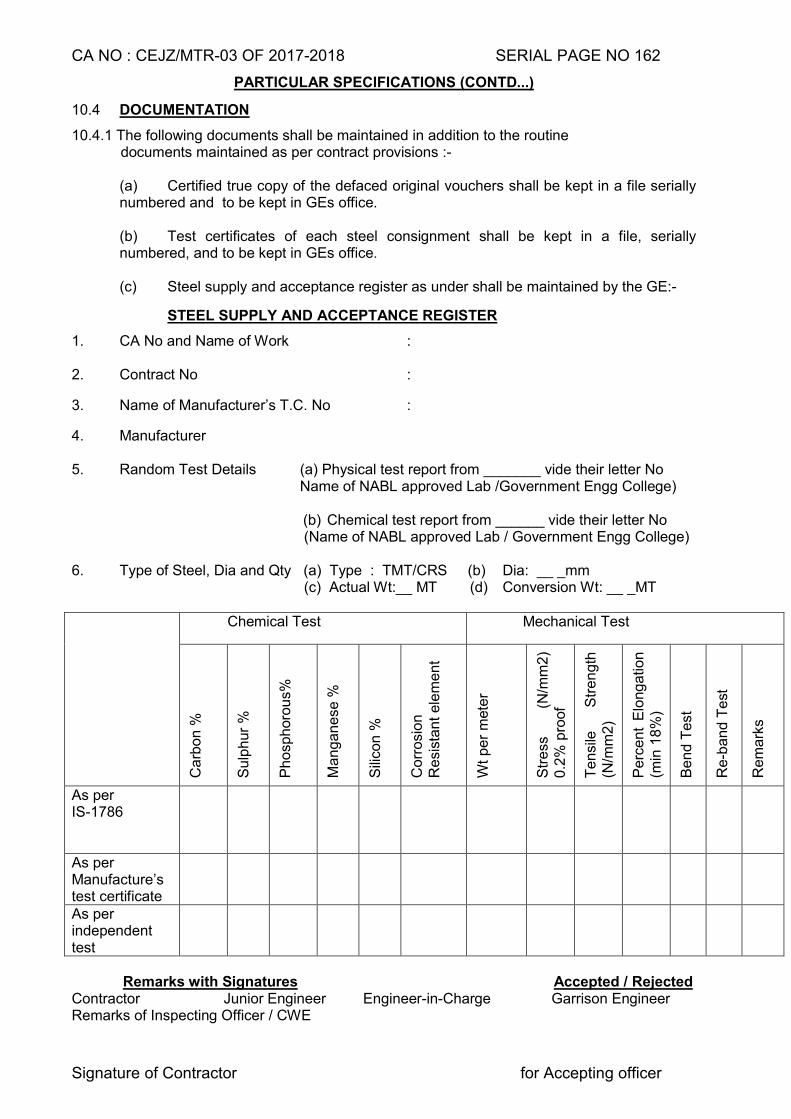
CA NO : CEJZ/MTR-03 OF 2017-2018 SERIAL PAGE NO 162
Signature of Contractor for Accepting officer
PARTICULAR SPECIFICATIONS (CONTD...)
10.4 DOCUMENTATION
10.4.1 The following documents shall be maintained in addition to the routine documents maintained as per contract provisions :-
(a) Certified true copy of the defaced original vouchers shall be kept in a file serially numbered and to be kept in GEs office.
(b) Test certificates of each steel consignment shall be kept in a file, serially numbered, and to be kept in GEs office.
(c) Steel supply and acceptance register as under shall be maintained by the GE:-
STEEL SUPPLY AND ACCEPTANCE REGISTER
1. CA No and Name of Work : 2. Contract No :
3. Name of Manufacturer’s T.C. No :
4. Manufacturer 5. Random Test Details (a) Physical test report from _______ vide their letter No Name of NABL approved Lab /Government Engg College)
(b) Chemical test report from ______ vide their letter No (Name of NABL approved Lab / Government Engg College)
6. Type of Steel, Dia and Qty (a) Type : TMT/CRS (b) Dia: __ _mm
(c) Actual Wt:__ MT (d) Conversion Wt: __ _MT Chemical Test Mechanical Test
Ca
rbo
n %
Su
lph
ur
%
Ph
osp
horo
us%
Ma
ng
an
ese
%
Sili
con
%
Co
rro
sio
n
Re
sist
an
t e
lem
en
t
Wt
pe
r m
ete
r
Str
ess
(N
/mm
2)
0.2
% p
roof
Te
nsi
le
Str
en
gth
(N
/mm
2)
Pe
rce
nt
Elo
ng
atio
n
(min
18
%)
Be
nd
Te
st
Re-b
an
d T
est
Re
ma
rks
As per IS-1786
As per Manufacture’s test certificate
As per independent test
Remarks with Signatures Accepted / Rejected
Contractor Junior Engineer Engineer-in-Charge Garrison Engineer Remarks of Inspecting Officer / CWE
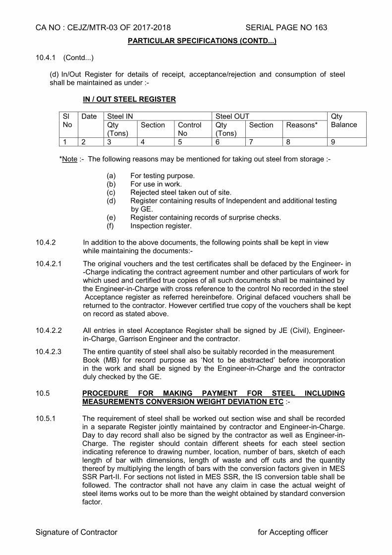
CA NO : CEJZ/MTR-03 OF 2017-2018 SERIAL PAGE NO 163
Signature of Contractor for Accepting officer
PARTICULAR SPECIFICATIONS (CONTD...) 10.4.1 (Contd...)
(d) In/Out Register for details of receipt, acceptance/rejection and consumption of steel shall be maintained as under :-
IN / OUT STEEL REGISTER Sl No
Date Steel IN Steel OUT Qty Balance Qty
(Tons) Section Control
No Qty (Tons)
Section Reasons*
1 2 3 4 5 6 7 8 9 *Note :- The following reasons may be mentioned for taking out steel from storage :- (a) For testing purpose. (b) For use in work.
(c) Rejected steel taken out of site. (d) Register containing results of Independent and additional testing
by GE. (e) Register containing records of surprise checks. (f) Inspection register.
10.4.2 In addition to the above documents, the following points shall be kept in view while maintaining the documents:-
10.4.2.1 The original vouchers and the test certificates shall be defaced by the Engineer- in -Charge indicating the contract agreement number and other particulars of work for
which used and certified true copies of all such documents shall be maintained by the Engineer-in-Charge with cross reference to the control No recorded in the steel
Acceptance register as referred hereinbefore. Original defaced vouchers shall be returned to the contractor. However certified true copy of the vouchers shall be kept on record as stated above.
10.4.2.2 All entries in steel Acceptance Register shall be signed by JE (Civil), Engineer-
in-Charge, Garrison Engineer and the contractor.
10.4.2.3 The entire quantity of steel shall also be suitably recorded in the measurement Book (MB) for record purpose as ‘Not to be abstracted’ before incorporation in the work and shall be signed by the Engineer-in-Charge and the contractor duly checked by the GE.
10.5 PROCEDURE FOR MAKING PAYMENT FOR STEEL INCLUDING
MEASUREMENTS CONVERSION WEIGHT DEVIATION ETC :- 10.5.1 The requirement of steel shall be worked out section wise and shall be recorded
in a separate Register jointly maintained by contractor and Engineer-in-Charge. Day to day record shall also be signed by the contractor as well as Engineer-in-Charge. The register should contain different sheets for each steel section indicating reference to drawing number, location, number of bars, sketch of each length of bar with dimensions, length of waste and off cuts and the quantity thereof by multiplying the length of bars with the conversion factors given in MES SSR Part-II. For sections not listed in MES SSR, the IS conversion table shall be followed. The contractor shall not have any claim in case the actual weight of steel items works out to be more than the weight obtained by standard conversion factor.
CA NO : CEJZ/MTR-03 OF 2017-2018 SERIAL PAGE NO 164
Signature of Contractor for Accepting officer
PARTICULAR SPECIFICATIONS (CONTD...) 10.5.2 On completion of work, the Register will be in the custody of the Engineer-in- Charge
and contractor may keep a copy for his record if he so desires.
10.6 STORAGE AND SAFETY OF STEEL
10.6.1 Steel of different grades and sizes shall be stacked separately. For each classification of steel separate areas shall be earmarked. Steel shall be marked
with distinct painting marks for easy identification,
10.6.2 Steel shall be stored in a manner that it is always at least 15cm above GL, so as to prevent distortion and corrosion. Any section that has deteriorated and corroded or if considered defective for any other reason the same shall be removed from site by contractor at his cost.
10.6.3 Steel sections which are not likely to be used before onset of monsoon shall be given cement slurry wash so as to ensure steel free from scale and rust. Also steel sections which are procured during monsoon and are not likely to be used within a week from the date of procurement shall be given cement slurry wash immediately.
10.6.4 It shall be responsibility of contractor to make sure that all possible arrangements are made for safe custody of the steel. In case of any loss of steel, only contractor will be responsible and the loss shall be made good without any delay or claim what so ever. 10.7 WELDING 10.7.1 Welding of iron and steel work shall be metal arc welding and shall be done as
specified in clause 10.15 of MES SSR Part-I and in approved manner with electricity. Special attention is drawn to clause 10.15.13.2 of MES SSR Part-I with regard to qualification tests for welder as well as test for approval of electrodes which will be of Oxygen Ltd or Advanic or Linkon makes. Gas welding however may by allowed by GE in case of structural steel without any price adjustment.
10.7.2 Welding of stainless steel works shall be done either the electric process or by the oxy-acetylene method. 10.8 STEEL ROLLING SHUTTERS
(a) Steel rolling shutter shall be approved by the GE and shall conform to the requirement of IS 6248. The size of rolling shutter shall be as indicated on drawing and as specified in clause 10.23 of MES SSR Part I.
(b) Rolling shutters shall be self coiling type with ball bearing / gear operated with
ball bearing bevel gear box and crank handle as per Clause 10.23.1 of MES SSR Part I.
(c) Safety lever lock:- Whether indicated on drawing or not shutter shall be provided with one pair of safety lever lock of approved quality fitted on either ends of bottom lock plate.
(d) The curtain shall be built up of interlocking lath sections formed from cold rolled steel strips 1.2mm thick and hood cover shall be made of mild steel 1.00mm thick.
(e) All structural steel (standard quality) shall confirm to Gde E-250 (Fe-410-W) quality ‘A’ conforming to IS-2062.
(f) All steel surfaces shall be finished with two coats of synthetic enamel paint over a
coat of red oxide zinc chrome primer as specified here in after.
CA NO : CEJZ/MTR-03 OF 2017-2018 SERIAL PAGE NO 165
Signature of Contractor for Accepting officer
PARTICULAR SPECIFICATIONS (CONTD...) 10.9 COLLAPSIBLE STEEL GATE
(a) Collapsible steel gate shall be of approved design. These shall be with single or double leaves as directed by Engineer-in-Charge and as specified in clause 10.24 MES SSR Part I
(b) All dimension and other particulars shall generally be of standard trades pattern unless otherwise indicated on drawing. The gate shall be cleaned off all rust and mill scales etc. The wheel shall be fitted with ball bearing.
(c) All structural steel (standard quality) shall conforming to IS 2062.
(d) All steel surfaces shall be finished with 2 coats of synthetic enamel paint over a coat of red oxide zinc chrome primer as specified here in after.
(e) Bolts and Nuts shall be of grade ‘Black’ (B) conforming to the relevant requirement of IS specifications. Rivets use for fabrication shall be made out of mild steel rivet bar conforming to IS for structural purpose. Head of rivets shall be as directed by Engineer-in-Charge.
10.10 FAN HOOKS
Fan hook shown in drawings shall be provided (at the time laying reinforcement itself) wherever ceiling fan/fan hook is indicated in drawings provided the same all as specified in clause 10.35 of MES SSR Part-I. The lump sum tendered by the contractor for the building under schedule ‘A’ Part 1 shall be deemed to include for the cost of the same.
10.11 PRESSED STEEL DOOR FRAMES
10.11.1 Pressed steel door frames shall be fabricated with 1.25 mm thick MS plain sheet. Pressed steel door frames shall conform to IS-4351. Tolerance over profile shall be 2 mm.
10.11.2 Pressed steel door frames shall be procured from any of the manufacturers given in Appendix ‘B’ to particular specifications. 10.11.3 Space in pressed steel door frames shall be filled with PCC (1:3:6) type C-0 using 10/12.5 mm graded crushed stone aggregate.
10.11.4 Frames shall be supplied by manufacturers with a shop coat of zinc chrome primer.
10.11.5 12 mm square mild steel bar shall be welded horizontally at the bottom of frame. The 12 mm square bar shall be embedded in floors. In case of double shutter i.e panelled door and gauzed door shutter, two Nos 12 mm square bar shall be provided at bottom of frame.
10.11A MS ANGLE IRON DOOR FRAME
10.11A.1 Mild steel angle iron of size 40x40x6 mm (if not shown otherwise) door frame shall be mitred at corner and welded to form a solid fused welded joint. The process of
welding adopted may be any suitable method, which gives a continuous and solid joint
along the place of meeting the members. 10.11A.2 Hinges shall be fixed to steel frame as shown on drawings/as directed by Engineer -in-Charge. Staple for barrel/tower bolts shall be as directed by Engineer-in-Charge. Suitable holes in floor/masonry/frames shall be made for functioning of door fittings. Proper care shall be taken to avoid breakage of holes.
CA NO : CEJZ/MTR-03 OF 2017-2018 SERIAL PAGE NO 166
Signature of Contractor for Accepting officer
PARTICULAR SPECIFICATIONS (CONTD...)
10.11A.3 12 mm dia mild steel bar shall be welded horizontally at the bottom of MS angle iron frame. The 12 mm dia bar shall be embedded in floors. In case of double frame, ie for panelled door and guazed door, 2 Nos 12 mm dia bar shall be
provided at bottom of frame.
10.12 HOLDFAST/LUGS 10.12.1 Flat iron holdfast/lug shall be provided by welding as and where shown on drawings
except those to be provided to wooden chowkhat, which shall be fixed with screws as per details shown on drawings.
10.12.2 Flat iron holdfast shall be embedded in PCC (1:3:6) type C-1 block of size 15 cm (height of block) x30 cm (length of block) x width of masonry wall.
10.12.3 Hold fast/lug shall be hot tarred and sanded before fixing.
10.12.4 Wherever door frame and window frame side coming in contact with RCC column, dash fasteners shall be provided in lieu of holdfast.
10.13 STEEL WINDOW AND VENTILATOR (BOX SECTION)
10.13.1 The term steel windows used in the particular specifications shall mean ‘Steel windows & Ventilators. The windows and ventilators wherever specified to be provided as per drawing No. TD/2013/01 Sheet 1/3 to 3/3, windows/ventilators shall be factory made and shall be procured from any of the manufacturer listed in Appendix ‘B’ to particular specifications.
10.13.2 Windows, Ventilators shall be fabricated from roll formed sections made of Galvanised
steel colour coated/powder coated (Base steel as per IS 513 “D” quality, Galvanised as per IS 277 with zinc of minimum 120 grams/Sq metre) with total coated thickness of 0.80 mm.
10.13.3 Coated section shall be with primer coat of epoxy primer of 5-7 microns thick, finish
painted with polyester paint of 12-16 microns thick and back coated with Alkyd backer of 5-7microns, or pure polyester powder coated up to 50-60 micron thick.
10.13.4 Section for frame, glazed shutter and mesh shutter shall be cut to length and mitred,
joined with Polypropylene corner brackets, Mullion section should be joined with frame/mullion using mullion cap.
10.13.5 Ethyl propylene Demine Monomer (EDPM) gasket shall be provided all around glass and fly proof mesh in shutter.
10.13.6 Each Glazed shutter and mesh shutter shall be provided with Pivot hinges, handle,
tower bolt and Peg stay as specified in drawings. 10.13.7 Glazed shutter and fixed glass portion should be provided with 4mm thick plain float
glass.
10.13.8 Mesh shutter shall be provided with stainless steel wire cloth as specified in clause 9.9 herein before.
10.13.9 Window & Ventilator frame shall be fixed to brick/concrete masonry by using Nylon self- expanding cap and driving mild steel electroplated 80mm long screws into the caps through frames.
10.13.10 Type of window shall be provided as shown on drawings.
CA NO : CEJZ/MTR-03 OF 2017-2018 SERIAL PAGE NO 167
Signature of Contractor for Accepting officer
PARTICULAR SPECIFICATIONS (CONTD...) 10.14. GRILL AND BARS TO STEEL WINDOWS AND VENTILATORS (BOX SECTION) 10.14.1 Window & Vent shall be provided with grill made of 10mm square mild steel bars
welded at 150mm centre to centre on 6mm x 12mm mild steel flat. Grill unit shall be powder coated (pure polyester)(minimum thickness 50 micron) and fixed to frame with screws.
10.15 STEEL WINDOWS AND VENTILATORS (USING ‘Z’ SECTIONS)
10.15.1 The term steel window use in the particular specifications shall mean ‘steel windows and ventilators’. Steel window shall be factory made ISI marked IS-1038-1983. Reaffirmed 1996 (IIIrd revision) and all as specified as clause 10.25 of MES SSR Part-I.
10.15.2 Steel windows (glazed) shall be provided with horizontal glazing bars as shown in drawings. Fixing and glazing of windows shall be in accordance with IS 1081 and shall be tennoned and riveted to the frame
10.15.3 Hinges for side-hung shutters (glazed) shall be friction hinges, projecting type and hinges for gauzed shutters shall be non-projecting type hinges (box type) with peg stay. Non projecting type hinges (box type) shall be provided in all side/top hung shutters for windows and ventilators, except windows opening directly into corridor/passage/verandah, for which projecting type friction hinges to be provided.
10.15.4 Steel windows shall be fixed to concrete/masonry with lugs. Lugs shall not be provided for fixing to lintels and cills even though shown in the drawings.
10.15.5 Centre hung windows shall be mounted on antifriction brass pivots.
10.15.6 Steel windows shall be procured from any of the manufacturers listed in Appendix ‘B’ to particular specifications factory made ISI marked (IS-1038-1983). Peg stay shall be of mild steel as per IS, specification. Handle to fly proof windows shall be pressed type.
10.15.7 All factory made steel windows / Vents shall be provided with manufacturers name tag as per IS-1038.
10.16 GUARD BARS TO STEEL WINDOWS AND VENTILATORS
10.16.1 The term ‘window’ used in the particular specifications shall mean ‘windows/ventilators’.
10.16.2 All steel windows shall be provided with guard bars/grills as shown on drawings. However, in case of double windows in the same opening guard bars shall be provided to glazed windows only.
10.16.2.1 Guard bars to steel windows unless otherwise shown on drawings shall be 12 mm mild steel square bars. The guard bars shall be integrated during the manufacture of the windows.
10.17 ALUMINIUM DOORs, WINDOWS, VENTILATORS AND FIXED GLAZING (USING ‘Z’ SECTION)
10.17.1 Aluminium doors, windows, vents, fixed glazing and partition shall be provided at location shown on drawings and all as specified in clause 10.37 of MES SSR Part-I and as specified/shown on drawings. In case the thickness of aluminium section is not indicated in drawing, same shall be minimum 2.5mm thick.
10.17.2 Aluminium section for doors/windows/ventilators/fixed glazing /partition shall be heavy duty and be procured by the contractor from one of the manufacturer as listed in Appendix ‘B’ to particular specifications.
CA NO : CEJZ/MTR-03 OF 2017-2018 SERIAL PAGE NO 168
Signature of Contractor for Accepting officer
PARTICULAR SPECIFICATIONS (CONTD...)
10.17.3 Aluminium windows shall be provided with aluminium grill weight not less than 3.776 kg per square metre with outer frame.
10.17.4 Thickness and type of glass panes for doors and windows / fixed glazing/partition shall be as specified/shown in respective drawings. If thickness of glass panes for doors and windows/fixed glazing/partition is not specified in the drawing same shall be 8 mm thick and 6 mm thick respectively of selected quality.
10.17.5 Glass panes shall be provided with rubber packing and beading of standard glazing clip as per manufacturer’s instructions.
10.17.6 All aluminium doors/ windows/ ventilators/fixed glazing/partition section, grills and builder’s hardware (except hinges) shall be powder coated in approved colour. Thickness of coating if not specified in respective drawings same shall not be less than 60 micron.
10.17.7 Double action floor door spring hydraulically regulated (ISI marked) shall be provided to each open able door shutters.
10.17.8 Each door shall be provided with necessary locking arrangement as specified in drawings.
11 ROOF COVERING
11.1 RCC SLAB
11.1.1 Intermediate slab shall be laid to level.
11.1.2 RCC roof slab shall be laid to slope as indicated in drawings.
11.1.3 Roof slab shall be projected as shown in respective drawings.
11.1.4 Exposed surfaces of soffit of RCC slabs shall be plastered in cement and sand
mortar (1:3), 5 mm thick and finished even and smooth.
11.1.5 RCC slab shall be provided with full bearing.
11.1.6 RCC roof slab shall be prepared as described in clause 11.39.3 of MES SSR Part-I.
11.1.7 After the RCC slab are laid, cured and fully set. Ponding shall be done over RCC roof slab by filling water to a depth of minimum 75mm. It shall be kept for 48 hours and the process of water proofing treatment shall be started if no seepage or leakage is observed. In case of even slightest indication of seepage/leakage the same shall be rectified before application of further treatment.
11.2 WATER PROOFING TREATMENT
11.2.1 Water proofing treatment to RCC roof slab of building/structure at serial No. 1 to 16 and 21 of Schedule ‘A’ Part-I shall be carried out as follows :-
(a) The surface shall be painted with hot paving bitumen grade Vg40 conforming to IS-73 @ 1.20 Kg/Sqm over a coat of bituminous primer conforming to IS-3384 applied @0.30 Ltr/Sqm.
(b) Heavy duty polythene film (white) of 150 micron thickness weighing 135 gms/Sqm (approx) having tensile strength not less than 140 Kg/Square metre in machine direction and 110 Kg/Sq cm in transverse direction, conforming to IS-2508 shall be laid with overlaps & bonded with cold cutback adhesive, overlaps being not less than 150 mm. Polythene film shall be tucked in parapet wall to a depth of 65 mm as per figure shown in IS-7290.
CA NO : CEJZ/MTR-03 OF 2017-2018 SERIAL PAGE NO 169
Signature of Contractor for Accepting officer
PARTICULAR SPECIFICATIONS (CONTD...)
(c) Brown craft paper of weight not less than 100 gms/Sqm laminated over the film with semi hot layer of paving bitumen grade Vg40 conforming to IS-73 @ 0.60 Kg/Sqm shall be painted on the paper, paper reversed and pasted on the film.
(d) Semi hot paving bitumen grade Vg40 conforming to IS-73 applied @ 1.20 Kg/ Sqm on the surface and the entire surface shall be dusted with fine sand [
(e) Topping will be done with burnt clay brick tiles 20mm thick laid over 15mm thick CM(1:3) mixed with powder integral water proofing compound at 01 KG per bag of cement (of 50 Kg). The tiles shall be jointed and pointed in CM (1:3) mixed with powder integral water proofing compound at 01 KG per bag of cement (of 50 Kg). After laying the brick tiles, the work shall be cured with water by ponding.
(f) Coved fillet in PCC (1:2:4) type B-0 with terrazzo finishing layer at top of radius 75 mm shall be provided at the junction of roof and parapet wall/chimney/other vertical surface and surface painted with a hot paving bitumen grade Vg40, conforming to IS-73 @ 1.20 Kg per Square metre over a coat of bituminous primer conforming to IS-3384 applied @ 0.30 litre per square metre.
11.2.2 WATER PROOFING TREATMENT TO SUNKEN FLOORS
Water proofing treatment to sunken floor slabs of schedule `A’ Part-I (where applicable) shall be as under:-
(a) The top of sunken floor slabs shall be laid to a slope of 1:40. The surface of RCC slab shall be made even and smooth using extra cement, while the concrete is still green. Coved fillet in PCC (1:2:4) type B-0 using 12.5 mm graded crushed stone aggregate of radius 75 mm shall be provided at the junctions of RCC slab and adjoining walls.
(b) Floor and side walls up to the finished floor level shall be plastered with 15 mm thick in cement and sand mortar (1:4), mixed with water proofing compound at the rate of 3% by weight of cement.
(c) One coat of cold applied bituminous primer @0.40litres/Sqm shall be applied on plastered surfaces including sidewalls. Thereafter a layer of APP based polymeric membrane reinforced with polyester non woven fabric (weighing not less than 150 gm/Sqm), weighing 3 Kg/Sqm (minimum) and 3 mm (minimum) thickness shall be laid on primed surface by torch application. Side over laps shall be 75 mm and at the ends overlaps shall be 100 mm. All overlaps and the joints shall be sealed properly as per manufacturer’s instructions. A cushion layer of coarse sand of thickness 25 mm shall be provided to protect polymeric membrane.
(d) The sunken portion shall be filled with PCC (1:5:10) type E-2 using 40 mm brick aggregate after carrying out satisfactory testing of CI pipes/joints and slab/walls by filling water for 72 hours. Sunken portion of Nahani/floor trap and pipe joints shall be embedded in PCC (1:3:6) type C-1 blocks.
(e) 32 mm bore GI spout (light grade) shall be provided 30 cm beyond wall surface to drain out leakage if any. The mouth of GI pipe shall have gravel to avoid chocking. Top of sunken portion of RCC slab to be finished such that its slope is towards spout.
CA NO : CEJZ/MTR-03 OF 2017-2018 SERIAL PAGE NO 170
Signature of Contractor for Accepting officer
PARTICULAR SPECIFICATIONS (CONTD...)
NOTE
(i) Water tightness to be tested by ponding water (for 72 hours) before filling the sunken floor.
(ii) Water proofing treatment as above shall be carried out only after laying plumbing /water supply/soil waste pipes.
(iii) Application of membrane shall be done by the authorised applicator of the specialized firm / manufacturer listed in Appendix ‘B’ to Particular Specifications.
11.2.3 WATER PROOFING TREATMENT TO UNDERGROUND SUMP, GARRAGES FOR ‘B’VEHICLES AND CHHAJJA ETC. Unless otherwise indicated on schedule of finishes drawings, provide 20mm thick plaster in cement and sand mortar (1:3) mixed with water proofing compound as per manufacturer’s instructions on RCC slab/chajjas while the concrete is still green and finished even and smooth without using extra cement. For the purpose of deviation, WPC shall be taken as 3% by weight of cement.
11.2.4 SPECIAL PROVISION TO CURB LEAKAGE/SEEPAGE IN ROOF SLAB
Sufficient Nos of chairs as shown in drg No CEJZ/2004/TD/S-8 sheet 5/8 shall be provided, so as to ensure the top reinforcement of slab remains in position and effective depth of slab as envisaged in the design is maintained.
(a) The chairs shall be provided in two rows.
(b) The first row shall be at a distance of 30 cm from the edge of beam and second row shall be at a distance of 90cm from the edge of beam.
(c) Distance between two chairs within a row shall be 60cm centre of one chair to the centre of next chair.
(d) Cover blocks of hard natural stone viz broken pieces from slabs of basalt / Kota stone/ Granite etc) of requisite thickness shall be provided below the bottom face reinforcement at a spacing of 60 cm centre to centre.
GE shall ensure and approve the provision of chairs before casting of slab. The room wise photographic record clearly showing the chairs shall be taken and shall be forwarded to Accepting Officer. GE/Offg GE shall be seen in the photograph and distance of chair from the edge of beam and the distance between two chairs in a row shall be shown in the photos with a tape. Quoted lump sump is deemed to include for the cost for provision of chairs and photographic record (two copies) as above.
11.3 PCC BENCHING : - At the junction of RCC facia, brick parapet, chajjas with wall, PCC benching of 75 mm radius in PCC (1:2:4) type B0 using 12.5 graded crushed stone aggregate shall be provided.
11.4 SECURITY DEPOSIT TOWARDS WATER PROOFING TREATMENT TO ROOF COVERED UNDER 11.2.1 AND 11.2.2 HERE IN BEFORE
11.4.1 Should the GE at any time during constructions or reconstruction or prior to the expiration of a period of ten years after the certified date of completion of buildings or group of buildings find that the building shown leakage dampness or any sign of defective water proofing treatment the contractor shall on demand in writing from the GE specifying the building complained of notwithstanding the fact that the same may have been inadvertently passed certified and paid for, forthwith undertake to carry out such treatment as may be necessary to render the said buildings water proof at his own expense for a period of ten years from the certified date of completion of said buildings and in the event of his failing to do so within a period to be specified by the GE, in his demand as aforesaid the GE may undertake such treatment at his risk and expense in all respects of the contractor, the liability of the contractor under the condition shall not extend beyond the period of 10 years from the certified date of completion unless the GE had previously given the notice to the contractor.
CA NO : CEJZ/MTR-03 OF 2017-2018 SERIAL PAGE NO 171
Signature of Contractor for Accepting officer
PARTICULAR SPECIFICATIONS (CONTD...)
11.4.2 The amount so calculated as per table given below shall be retained from the
contractors final bill amount as security deposit for the water proofing treatment and the same shall be released after satisfactory completion of guarantee period as stated above. The contractor may alternatively submit fixed deposit receipt for the said sum from a scheduled Bank in lieu of the sum to be retained out of the final bill :-
Amount of water proofing treatment to roof at contract rate
Amount to be retained from contractors dues rounded to nearest thousand rupees
1 2 (i) Up to Rs 50 lakh 2% of amount subject to minimum of Rs 5000/- and
enhanced by 25% (ii) Over Rs 50 lakh and up to
Rs 100 lakh Rs 100000/- +1.5% of amount exceeding Rs50 Lakhs and enhanced by 25%
(iii) Over Rs 100lakh Rs 175000/- +1.5% of amount exceeding Rs100 Lakhs and enhanced by 25%
11.4.3 The security deposit referred to in clause 11.4.2 herein before may be refunded to the
contractor after expiry of the period of 10 years from the certified date of completion by the GE, provided always that the contractor shall first have been paid the final bill and have rendered ‘No demand certificate’ IAFA-451 condition 10, 48 and 68 of General Conditions of Contracts (IAFW-2249) shall be deemed to be amended to the extent mentioned above.
11.5 Materials required for waterproofing shall be purchased by the contractor from the
manufacturers listed in Appendix ‘B’ to Particular Specifications or their authorised agent only and brought to site. The GE before approval shall verify name of authorised agent from the manufacturer.
12 BLANK
13 FLOORING
13.1 GENERAL
13.1.1 Floors shall be laid to levels and to falls as indicated in drawings and as directed by Engineer-in-Charge. Floors shall be sunk to required depth where shown in drawings.
13.1.2 Floors shall be carried out through threshold of all openings in walls ie in case of Kota
stone flooring thresholds of all openings in walls shall be finished with Kota stone floors.
13.1.3 In case of first floor, flooring as indicated in drawing shall be laid directly over RCC slab after applying cement slurry as specified in MES SSR Part-I.
13.1.4 Type and pattern of flooring shall be as per drawing of schedule of finishes, respective
TD drawing and as specified. If type of flooring is not indicated for any location it shall be same as in other similar locations. No extra claim shall be admissible to the contractor on this account.
CA NO : CEJZ/MTR-03 OF 2017-2018 SERIAL PAGE NO 172
Signature of Contractor for Accepting officer
PARTICULAR SPECIFICATIONS (CONTD...) 13.1.5 Before placing the concrete mix for topping, neat cement slurry as specified in clause 13.32.5.2.2 of MES SSR Part I shall be brushed on hardened concrete base/surface. 13.2 SUB BASE TO FLOOR
13.2.1 Bay system of use of glass dividing strips not to be adopted in case of PCC sub base. Thickness of PCC sub base shall be 75 mm or 100 mm or 150mm thick as specified in schedule of finishes drawings.
13.2.2 Where hardcore has been shown on drawings to sub base of floor, the same shall be provided as specified herein before. Thickness of hardcore sub base where not shown /specified shall be 150 mm compacted thickness..
13.3 CEMENT CONCRETE FLOOR
13.3.1 PCC floor up to 50 mm thick shall be laid adopting panel dimension not exceeding 1200 mm x 1200 mm with 3 mm thick (nominal thickness) sheet glass as dividing strips. The width of strips shall be 2 mm less than the thickness of the floor and these strips shall be visible in the finished floor.
13.3.2 Wherever 75 mm PCC (1:2:4) type B-1 using 20 mm graded crushed stone aggregate in flooring is shown in schedule of finishes drawing with aluminium dividing strip, the panel dimension shall not be exceeding 1200 mm x 1200 mm with 1.5 mm thick (nominal thickness) aluminium strip. The width of strip shall be 2 mm less than the thickness of floor and those strips shall be visible in finished floor.
13.3.3 Where specification of floor is not shown on drawing the same shall be 40 mm thick PCC (1:2:4) type B-1
13.3.4 Unless otherwise specified / shown on drawings, top of PCC floor shall be finished even and smooth without using extra cement while PCC is still green. Plaster is prohibited.
13.3.5 PCC floor except 13.3.1 and 13.3.2 here in before shall be laid in alternate bay system with panel dimension not exceeding 2 m x 2 m. Glass dividing strips shall not be provided.
13.4 VITRIFIED PORCELAIN TILE FLOORING. 13.4.1 Vitrified tile shall be laid over 10 mm screed in cement and sand mortar (1:4) over 30 mm
thick PCC (1:2:4) type B0 using 10/12.5 mm graded crushed stone aggregate laid in alternate bays over 75 mm thick PCC (1:4:8) type D2 sub base over rammed approved earth wherever indicated in schedule of finishes drawings all as specified in clause 13.41 of MES SSR Part-I. Tiles shall be jointed / pointed in white cement using pigment to match the colour of tiles.
CA NO : CEJZ/MTR-03 OF 2017-2018 SERIAL PAGE NO 173
Signature of Contractor for Accepting officer
PARTICULAR SPECIFICATIONS (CONTD...)
13.4.2 Quality of tiles shall conform to minimum international standard ISO-13006/Europeon standard EN:176 Group B1a first quality all as specified in clause 13.15 of MES SSR Part-I. Make of tile shall be as listed in Appendix ‘B’ to particular specifications. However the make (out of Appendix ‘B’ to particular specifications) decided by GE shall be final.
13.4.3 Vitrified tiles shall be provided of size and thickness as specified in schedule of finishes
drawing. Colour/texture of tiles shall be as approved by GE. Size of tiles if not specified in Schedule of finishes drawing same shall be 605x 605 mm (minimum) and thickness shall not be less than 10mm.
13.4.4 Floor pattern with boarder tiles as specified in Drawing No TD/2004/86 Sheet No 1/1 shall be followed. However no extra payment shall be admissible for change in floor pattern
13.4.5 Tiles shall be provided all as specified in Clause 13.41 of MES SSR Part I. 13.5 SPARKABLE MASTIC FLOORING 13.5.1 Mastic flooring shall be provided all as specified in schedule of finishes drawing over 75
mm thick sub base of PCC (1:4:8) type D-2 using 40 mm graded crushed stone aggregate over 100 mm thick hard core over .
13.5.2 Bitumen mastic flooring shall be carried out all as specified in “ IS : 13026. The bitumen
contents shall be 13 percent by mass of the total mastic. Thickness of mastic shall be 25 mm if not specified in schedule of finishes drawings. IS : 13026 shall be read in conjunction with IS : 8374, IS : 1196 and IS : 13974. Schedule of finishes drawings shall deemed to be amended accordingly.”
13.6 BLANK
13.7 POLISHED KOTA STONE SLAB TILE FLOORING 13.7.1 Kota stone slab/tile flooring shall be laid all as specified in clause 13.47 of MES SSR
Part-I and as directed by the Engineer-in-Charge. Thickness of stone slab shall be 20 to 25 mm if not specified anywhere in the tender documents.
13.7.2 In ground floor Kota stone tile/slab of size 550 x 550mm shall be laid over 20 mm thick
bedding (screed) layer in cement and sand mortar (1:3) over 75 mm thick sub base of PCC (1:4:8) type D-2 using 40 mm graded crushed stone aggregate over rammed approved earth. In case of first floor tiles/slab shall be laid over 20 mm thick screed (bedding) in cement and sand mortar (1:3). The grinding and polishing shall be done after laying of tiles / slab also.
13.7.3 MIRROR POLISHING
Wherever mirror polished Kota-stone flooring is mentioned in schedule of finishes or drawing, provide readymade machine cut polished Kota-stone tiles 18 to 20 mm thick as approved by GE.
13.7.4 Floor pattern with jaisalmer border wherever mentioned in schedule of finishes drawing
same shall be followed as shown / specified in drawing No TD/2004/76 sheet 1/1. However for change of floors pattern no extra amount shall be payable.
CA NO : CEJZ/MTR-03 OF 2017-2018 SERIAL PAGE NO 174
Signature of Contractor for Accepting officer
PARTICULAR SPECIFICATIONS (CONTD...) 13.8 ACID RESISTANT TILE FLOORING
13.8.1 The acid resistant tiles in floor shall be provided as per clause 13.23 and 13.46 of MES SSR Part-I. The tiles of size 200 x 200 x 15 mm (minimum) shall be used in the work unless otherwise specified in the schedule of finishes drawing.
13.8.2 Tiles shall set, jointed and pointed in chemical/acid resistant cement resin/sulphur/ epoxy type as per recommendation of manufacturer’s over 75 mm thick PCC (1:4:8) type D-2 using 40 mm graded crushed stone aggregate sub base over rammed earth.
13.9 NON SKID CERAMIC COLOURED TILE FLOORING
13.9.1 Non-skid ceramic tiles wherever shown in schedule of finishes drawing shall be got approved from GE before incorporation in the work. Quality of tiles shall conform to IS-15622 (2006) (Group B II). Make of tile shall be as listed in Appendix `B’ to particular specifications.
13.9.2 In case of ground floor tiles shall be laid over 10 mm thick bedding layer in cement and sand mortar (1:3) over 30 mm thick in PCC (1:2:4) type B-0 using 10/12.5 mm graded crushed stone aggregate laid in alternate bays without using glass dividing strip over 75 mm thick sub base PCC (1:4:8) type D-2 using 40 mm graded crushed stone aggregate over rammed approved earth. In case of first floor (except sunken portion of toilet) tiles shall be laid over 10 mm thick bedding layer in cement and sand mortar (1:3) over 30 mm thick in PCC (1:2:4) type B-0 using 10/12.5 mm graded crushed stone aggregate. In sunken portion of toilet floor tiles shall be laid over 10 mm thick bedding layer in cement and sand mortar (1:3) over 30 mm thick in PCC (1:2:4) type B-0 using 10/12.5 mm graded crushed stone aggregate over WPT all as specified.
13.9.3 Tiles shall be provided all as specified in clause 13.40 of MES SSR Part-I.
13.9.4 Size and thickness of tile shall be all as specified in schedule of finishes drawings, if not specified, the size of tile shall be 300 x 300 mm and thickness shall not be less than 7mm.
13.9.5 Shade of tiles wherever not indicated in schedule of finishes drawings shall be as
approved by GE.
13.9.6 Floor pattern as specified in drawing TD/2004/86 Sheet No 1/1 shall be followed. However no extra payment shall be admissible for change of floor pattern.
13.10 CERAMIC TILE FLOORING.
13.10.1 Ceramic tiles shall conform to IS: 15622(2006)(Group B1b) and all as specified in clause 13.14 of MES SSR Part-I. Make of tile shall be as listed in Appendix ‘B’ to particular specifications. However the make (out of Appendix ‘B’ to particular specifications) decided by GE shall be final.
13.10.2 In case of ground floor tiles shall be laid over 10 mm screed in cement and sand mortar (1:3) over 30 mm thick PCC (1:2:4) type BO using 10/12.5 mm graded crushed stone aggregate laid in alternate bays without using glass dividing strips over 75 mm thick PCC (1:4:8) type D2 sub base over rammed approved earth. In case of first floor tiles shall be laid over 20 mm thick screed bed layer in cement and sand mortar (1:4) all as specified in clause 13 of MES SSR Part-I. Tiles shall be jointed / pointed in white cement using pigment to match the colour of tiles.
13.10.3 Ceramic tiles shall be provided of size and thickness as specified in schedule of finishes drawing. Colour/texture of tiles shall be as approved by GE. Size of tiles if not specified in Schedule of finishes drawing same shall be 605 x 605 mm and thickness shall not be less than 10mm.
CA NO : CEJZ/MTR-03 OF 2017-2018 SERIAL PAGE NO 175
Signature of Contractor for Accepting officer
PARTICULAR SPECIFICATIONS (CONTD...)
13.10.4 Floor pattern with boarder tiles as specified in Drawing No TD/2004/86 Sheet No 1/1 for vitrified tile shall be followed. However no extra payment shall be admissible for change in floor pattern
13.10.5 Tiles shall be provided all as specified in Clause 13.40 of MES SSR Part I.
13.11 FLOORING IN GARAGES FOR B VEHICLE AND C VEHICLE INCLUDING APRON 13.11.1 Flooring in garages and apron shall be provided with 100mm thick PCC(1:2:4) type B-2
using 40 mm graded crushed stone aggregate laid in panel not exceeding 3 x 3 metre in alternate bay, finished even and fair without using extra cement over 150 mm thick hard core sub base over rammed approved earth.
13.11.2 Joints shall be provided as shown in drawing No CEJZ/97/TD/S-1 sheet No 1/1. Filling in joint shall be done with the mixture of bitumen and sand (1:3). 13.11.3 Top surface of floor shall be broomed finish all as specified in clause 20.B.7.12.3 of MES
SSR Part I.
13.12 PLINTH PROTECTION 13.12.1 Plinth protection (750 mm wide if not shown otherwise in drawings) shall be provided
to the buildings as shown (except open to court yard area) in main plan or any drawing without drain. However in court yard portion of building where plinth protection with drain is specified same shall be provided with the drain as per drawing: TD/2004/35, Sheet No 3/4. Surface of drain shall be even and smooth using extra cement.
13.12.2 The plinth protection shall be with 50 mm thick PCC (1:3:6) type C-1 using 20 mm graded crushed stone aggregate over 75 mm thick hard core over rammed earth. Plinth protection laid to slope 1 in 30 in bays not exceeding 2 metre in length. Exposed surfaces shall be finished even and fair without using extra cement.
13.12.3 Joints of 6 mm wide and 10 mm deep shall be provided along the wall and bays and same shall be filled with bitumen mastic (1:3).
13.13. PRECAST INTERLOCKING PAVERS BLOCK (TILES)
13.13.1 Precast concrete inter locking paver blocks (tiles) flooring wherever specified in Schedule of finishes drawing shall be provided minimum with 80 mm thick inter locking paver blocks of compressive strength not less than 400 Kg/Sqcm (M-40 grade concrete). Block shall be placed over 25 mm thick dry screened sand over 100 mm thick PCC (1:4:8) type D2 using 40mm graded crushed stone aggregates over rammed earth. Pavers shall confirm to IS:15658 and all as specified in clause 13.18 of MES SSR Part I. Make of Paver shall be as given in Appendix ‘B’ to particular specifications.
13.13.2 Pavers shall be placed over screened compacted sand layer one by one. The pavers shall be packed by hammering and placed at proper angle so that gap at interfaces is kept minimum. After placing the pavers put vibrating plate on them and add sieved fine aggregate to fill the gaps.
13.13.3 Shape, size and colour of inter locking pavers block shall be as approved by GE and
edges shall be chamfered with smooth finish.
13.13.4 Inter locking pavers block shall be factory made and cast under desired hydraulic pressure
CA NO : CEJZ/MTR-03 OF 2017-2018 SERIAL PAGE NO 176
Signature of Contractor for Accepting officer
PARTICULAR SPECIFICATIONS (CONTD...)
13.14 CHEQUERED CEMENT CONCRETE FLOORING TILES
13.14.1 Chequered cement concrete tiles flooring wherever specified in schedule of finishes drawing shall be provided all as specified in clause 13.17 and 13.39 of MES SSR
Part-I. Colour of tiles shall be approved by GE.
14. PLASTERING
14.1 GENERAL 14.1.1 Prepare surface to be plastered, wet the surface thoroughly. 14.1.2 Curing of plasterwork shall be properly done. The contractor may use a spray pump
or similar device without any price adjustment taking precaution against damage to plaster due to impact of splicing water.
14.1.3 The contractor shall take every precaution right from the commencement of
plasterwork to prevent any craziness that may appear on the surface of plaster and shall be responsible to make good any portion of plasterwork which in the opinion of the GE require removal and redoing.
14.1.4 External plaster surfaces shall be finished to fair and even surfaces and internal plastered surfaces shall be finished to even and smooth surface without using extra cement.
14.1.5 The thickness of plaster/dado/skirting is the finished thickness (exclusive of dubbing) over proudest portion.
14.1.6 Plastering at the junction of walls and floors and to all internal and external angles shall meet at right angle as directed by Engineer-in-Charge. Plastering shall be returned in openings involved.
14.1.7 Internal plastering shall be carried out to the full width of jambs for the door, windows and openings ie up to external edge of the wall.
14.1.8 Sand for plastering shall be from the source mentioned in Appendix ‘A’ to particular Specifications as approved by the GE.
14.1.9 Proper ‘V’ shape grooves, shall be provided in plaster (external/internal) at the junction
of column/ wall / beams / and masonry wall at external and internal faces as per SP-25 of bureau of Indian standards.
14.1.10 External plastering shall be carried out up to 150 mm below the ground level.
14.1.11 Joint of masonry to be plastered shall be raked out as the work proceeds as specified
in the MES SSR Part I. 14.1.12. TWO COAT PLASTER WORK
14,1,12.1. FIRST COAT : The first coat of the specified thickness shall be applied in a manner similar to one coat plaster work. Before the first coat hardens, the surface of the cement plaster shall be scored to provide key for second coat. The rendering coat shall be kept damp for at least two days. It shall then be allowed to become thoroughly dry.
CA NO : CEJZ/MTR-03 OF 2017-2018 SERIAL PAGE NO 177
Signature of Contractor for Accepting officer
PARTICULAR SPECIFICATIONS (CONTD...) 14.1.12.2 SECOND COAT: Before starting to apply second coat, the surface of the
rendering coat shall be damped evenly. The second coat shall be completed to the specified thickness in exactly the same manner as the one coat plaster work.
14.2 CEMENT PLASTER (INTERNAL)
Internal plaster unless otherwise indicated on drawings shall be 5mm thick in cement and sand mortar (1:3) on ceiling including RCC beam and 10 mm thick in cement and sand mortar (1:6) on brick surfaces and finished even and smooth without using extra cement.
14.3 CEMENT PLASTER (EXTERNAL)
External plaster unless otherwise indicated in drawings shall consist of 10 mm thick plaster in cement and sand mortar (1:6) without using water proofing compound followed by top layer of 5 mm thick plaster in cement and sand mortar (1:4) using water proofing compound ISI marked and mixed in proportion as per manufacturer’s instructions. For the purpose of deviation water proofing compound shall be taken @ 3% by weight of cement. Cement plaster shall be finished fair and even.
14.3.1 Unless otherwise shown in drawings, vertical exposed surfaces of parapet walls both
side shall be provided with finish as that for external walls and internal surface of wall towards roof shall be plastered as specified in clause 14.3 here-in-before.
14.4 Rough cast plaster:- Rough cast plaster finish shall be carried out at the locations shown on drawing/as directed by Engineer-in-Charge and all as specified in clause 14.22 of MES SSR Part I. Type of sand and curing shall be all as specified here-in-before. 14.5 POLISHED KOTA STONE TILES IN SKIRTING/DADO
(a) Kota stone tiles finish wherever indicated in drawings shall be laid all as specified in MES SSR Part-I and as directed by Engineer-in-Charge. (b) Kota stone slab/ tiles of specified size shall be provided over 10 mm thick cement screed/rendering in cement and sand mortar (1:3) length of stone slab shall be match with the joint of floor tile/slab.
14.6 CEMENT PLASTER IN SKIRTING
Cement plaster in skirting shall consist of 15 mm thick in two layers of 10 mm thick rendering coat in cement and sand mortar (1:4) and 5 mm thick setting coat in cement and sand mortar (1:3) troweled to a smooth and even finish using extra cement. It shall be in line with plastering and separated with groove. Junction of floor and skirting shall be rounded to minimum radius of 5 mm.
14.7 ACID RESISTANT TILES IN SKIRTING/DADO
(a) The acid resistant tiles shall be provided as per clause 13.23 and 13.46 of MES SSR Part-I. The tiles of size 200 x 200 x 15 mm (minimum) shall be used in the work unless otherwise specified in the schedule of finishes drawing.
(b) Tiles shall set, jointed and pointed in chemical/acid resistant mortar, resin/sulphur/epoxy type as per recommendation of manufacturer over 10mm thick rendering / screed in cement and sand mortar (1:3).
CA NO : CEJZ/MTR-03 OF 2017-2018 SERIAL PAGE NO 178
Signature of Contractor for Accepting officer
PARTICULAR SPECIFICATIONS (CONTD...)
14.8 CERAMIC TILES SKIRTING/DADO
(a) Tiles as specified in schedule of finishes drawings shall be provided over cement and sand mortar screed in cement and sand mortar (1:3) 10 mm thick. Size and thickness of tile if not specified in schedule of finishes drawings, the size of tile shall be 300 x 450 mm and thickness shall not be less than 7 mm.
(b) Quality of tiles shall conform to IS-15622 (2006) (Group II).Make of tiles shall be as specified in Appendix `B’ to particular specifications.
(c) Shade of tiles shall be as approved by GE.
14.9 VITRIFIED PORCELAIN TILES SKIRTING
(a) Vitrified tiles skirting as indicated in schedule of finishes drawing shall be provided over 10 mm thick screed in cement and sand mortar (1:3). The tiles shall be jointed/pointed in white cement using pigment to match the joints.
(b) Quality of tiles shall conform to minimum international standard ISO: 13006/
European standards EN 176, Group B1A first quality. Colour of tiles shall be as approved by GE. Make of tiles shall be as specified in Appendix ‘B’ to particular specifications.
(c) Thickness of tiles if not specified in the schedule of finishes drawings, the
thickness shall not be less than 10 mm .
14.10 HEAT RESISTANCE TILES SKIRTING/DADO (a) Heat resist tiles as indicated in drawings shall be provided over 10 mm thick
Screed / rendering in cement and sand mortar (1:3) (b) Tiles shall set, jointed and pointed as per recommendation of tile manufacturer over cement rendering.
14.11 SKIRTING / DADO (a) If height of skirting/dado have not been shown in drgs the same shall be as under :-
(i) Skirting -100mm (ii) Dado in Toilet/Bath room -Up to lintel level (iii) Dado in WC -Up to lintel level (iv) Dado in Kitchen -up to 600mm above platform
(v) Acid resistance work - Dado up to to cill level including over platforms
(b) Colour of ceramic / vitrified tiles shall be as approved by GE. NOTE. (APPLICABLE TO WHOLE WORK)
(i) Dado/skirting shall be carried out to full width of Jambs of doors/windows unless otherwise shown on drawing. (ii) Kota stone/Marble stone/Granite stone wherever shown in Drawing shall be machine cut, polished as specified in MES SSR Part-I. Mirror polishing shall be provided wherever specifically mentioned in drawings or elsewhere. (iii) Joints in floor and skirting shall be match each other and accordingly length of tiles/slab shall be adjusted. If the specification of Dado / Skirting not shown same shall be as per floor finish. (iv) Ceramic / vitrified tiles shall be premium quality (First quality).
CA NO : CEJZ/MTR-03 OF 2017-2018 SERIAL PAGE NO 179
Signature of Contractor for Accepting officer
PARTICULAR SPECIFICATIONS (CONTD...)
15. WHITE WASHING/COLOUR WASHING/CEMENT PAINT/DRY DISTEMPER/ OIL EMULSION DISTEMPER ETC
15.1 Surface finishes visualising white wash, colour wash etc shall be provided all as indicated in respective schedule of finishes drawings.
15.2 Where whitewash is indicated in drawings, apply three coat of whitewash including
preparation of surfaces. Where colour washing is indicated in drawings, apply two coats of colour wash over a coat of white wash. Tint of colour wash shall be approved by GE.
15.3 White washing and colour washing shall be applied with proper brushes as specified in
clause 15.12 of MES SSR Part-I, contractor may, at his discretion, do the same by means of spray pump without any extra cost to the Government.
15.4 Where oil emulsion distemper and/or dry distemper is indicated in drawing, apply two
coats of oil emulsion distemper and/or dry distemper (as the case may be) of the tint approved by the GE. Prepare surfaces and apply primer as per clause 15.13 and 15.14 of MES SSR Part-I before applying two coats of distemper. Make of distemper shall be as specified in Appendix `B’ to particular specifications.
15.5 Where cement paint is indicated on drawings, apply two coats of cement paint. The tint
shall be approved by GE. Preparation, application and other instructions shall be followed as stipulated in clause 15.15 of MES SSR Part-I. Make of paint shall be as specified in Appendix `B’ to particular specifications.
15.6 At places where no finish has been shown in drawings, internal plastered surfaces and
ceiling shall be provided with three coats of white wash and external plastered surfaces shall be provided with two coats of cement paint of approved tint.
16. GLAZING TO STEEL WINDOWS/VENTILATORS (Z SECTION) 16.1 Unless otherwise specified or indicated in the drawing, glazing shall be of plain sheet
glass (ordinary glazing quality), 4mm thick (nominal thickness) except toilet/ bath/ WC windows/ vents where 4mm thick figured glass, pin head type shall be used.
16.2 Glazing to metal frames shall be with putty conforming to IS-419 and steel clips and as
specified in clause 16.5 to 16.10 of MES SSR Part-I. 17 PAINTING 17.1 TARRING
Prepare surface and apply two coats of tar mixture to the mild steel and timber surface in contact with or buried in ground / masonry work / concrete / plaster.
17.2 PAINTING GENERAL
17.2.1 Members specified to be painted shall first be passed by the Engineer-in-Charge and marked as such before commencement of painting work. Each coat of paint shall be passed by the Engineer-in Charge before successive coat is applied.
CA NO : CEJZ/MTR-03 OF 2017-2018 SERIAL PAGE NO 180
Signature of Contractor for Accepting officer
PARTICULAR SPECIFICATIONS (CONTD...) 17.2.2 If the under coat of paint is not executed within 06 months after applying the priming
coat, the priming coat shall be redone by the contractor without any extra cost to the Government.
17.2.3 Surface inaccessible for applying further coats shall be painted before fixing.
17.2.4 Make and specific brand of paint (of manufacturer) as specified in Appendix ‘B’ to Particular Specifications shall be used in the work.
17.2.5 The primer and paint shall be of the same manufacturer. Pink primer shall be used for wooden surfaces and red oxide zinc chrome for steel surface.
17.3 PAINTING TO IRON AND STEEL WORK
17.3.1 Unless otherwise shown on drawings all exposed steel work (except ESHs sheds) and E/M exposed steel items shall be painted with two coats of synthetic enamel paint over a coat of zinc chrome primer after preparation of surface.
17.3.2 All galvanised iron articles (except CGI sheet in fire point) and reinforcement bars shall not be painted.
17.3.3 Priming coat shall be applied before fixing in position.
17.4 PAINTING TO TIMBER SURFACES
17.4.1 Unless otherwise shown of schedule of finishes or specified in these specifications, prepare surfaces and apply two coats of synthetic enamel paint over one coat of pink wood primer all as specified in clause 17.6 of MES SSR Part-I.
17.4.2 Priming coat shall be applied before fixing.
17.4.3 All surfaces of timber exposed to view and for which type of finish is not specifically catered for either in drawings or in these particular specifications shall be treated with three coats of paints as mentioned in clause 17.4.1 here in before.
17.5 CREOSOTING
Surfaces of timber hidden from view (such as wood work below flooring/above ceiling/ back side of wall panelling) shall be treated with two coats of creosoting all as specified in clause 17.11 of MES SSR SSR Part-I.
17.6 FRENCH POLISHING
French polish wherever indicated on drawings shall be provided all as per clause 17.7.4 of MES SSR Part-I.
17.7 ALUMINIUM PAINT
Wherever indicated on drawings, the aluminium paint shall conform to IS-2339 and shall be applied on surface as per the direction of Engineer-in-Charge.
17.8 PLASTIC EMULSION PAINT
Wherever plastic emulsion point in specified in schedule of finishes drawings, apply two coats of plastic emulsion point over one coat of primer as per manufacture’s instructions. Preparation of surfaces and application shall be carried out all as per clause 17.16 of MES SSR Part I
CA NO : CEJZ/MTR-03 OF 2017-2018 SERIAL PAGE NO 181
Signature of Contractor for Accepting officer
PARTICULAR SPECIFICATIONS (CONTD...) 18. PLUMBING AND SANITARY FITTINGS
The lump sum tendered by the tenderer for the buildings shall include for the cost of supplying, fixing and testing as specified of the following sanitary fittings/fixtures for the respective buildings as shown in drawings including all accessories and plumbing to the extent mentioned herein after. All sanitary fittings shall be white glazed vitreous china, first quality, ISI marked. Make of fittings shall be as per Appendix ‘B’ to particular specifications: -
(a) Water closet, (pedestal pattern) with plastic seat and cover, low level flushing cistern and toilet paper holder.
(b) Water closet, squat pattern (Orissa pattern) and low level flushing cistern
(c) Urinal with flush valve
(d) Flush valve 40 mm bore (wheel type)
(e) Wash hand basin with pillar tap
(f) Kitchen sink with draining board
(g) Peg sets
(h) Mirrors
(j) Soil , waste, vent and rain water pipes
(k) Gully traps, nahani traps and floor traps
(l) Water tanks
(m) Soap niche
(n) Towel rail
(o) Toilet paper holder
(p) Switch / meter box
(q) Sink
(r) Plate rack
(s) All other fixtures/fittings as shown on drawings
(t) Water closet squat pan (long pan) with flush valve 40 mm bore (wheel type)
(u) Laboratory sink with drainage board
CA NO : CEJZ/MTR-03 OF 2017-2018 SERIAL PAGE NO 182
Signature of Contractor for Accepting officer
PARTICULAR SPECIFICATIONS (CONTD...) 18.1. WATER CLOSET (PEDESTAL PATTERN)
Pedestal pattern wash down apparatus shall be of pattern 2 of IS-2556 Part-II (2004) and shall comprise of the following:-
18.1.1 Wash down water closet pan complete with integral ‘P’ or ‘S’ trap. The closet shall be
fixed to floor all as specified in clause 18.87.1 of MES SSR Part -1. 18.1.2 Closet seat and cover shall be moulded synthetic material as specified in clause
18.36.2 of MES SSR Part -1. The underside of seat shall be recessed type with chromium plated brass hinges.
18.1.3 Low level flushing cistern 10 litre capacity body moulded from virgin quality high impact
polystyrenes all as specified in clause 18.99 of MES SSR Part 1 of make as per Appendix ‘B’ to Particular Specifications complete.
18.1.4 40 mm (nominal diameter) PVC flush pipe with necessary fittings 18.1.5 15 mm bore PVC connection heavy duty 600 mm long with brass union at both ends.
18.1.6 Chromium plated brass angular valve, fancy type suitable for connection from 15mm bore GI pipe water mains.
18.1A.1 WATER CLOSET LONG PAN PATTERN
18.1A.1 Squatting pan long pan pattern size 630 mm long with foot rest, vitreous china front or back inlet with P or S trap with long outlet so that joints falls out of building. The trap shall be of cast iron.
18.1A.2 Provide 40 mm bore wheel type indigenous make, heavy weight, brass flush cock of approved pattern conforming to IS-2256 shall be provided to each W.C.
18.1A.3 32 mm dia GI flush pipe commencing from 45 cm above FFL shall be connected in galvanised steel tubing with galvanised steel reducer, joint between GI flush pipe of
WC shall be cement and sand mortar joint.
18.2 WATER CLOSET ORISSA PATTERN
18.2.1 Squatting pan Orissa pattern size 580 mm x 440 mm with integral foot rest, vitreous china front or back inlet with P or S trap with long outlet so that joints falls out of building. The trap shall be of cast iron.
18.2.2 Low level flushing cistern 10 litre capacity body moulded from virgin quality high impact polystyrenes all as specified in clause 18.99 of MES SSR Part 1 of make as per Appendix ‘B’ to Particular Specifications complete.
18.2.3 40 mm (nominal diameter) PVC flush pipe with necessary fittings
18.2.4 15 mm bore PVC connection heavy duty 600 mm long with brass union at both ends
18.2.5 Chromium plated brass angular valve, fancy type suitable for connection from 15mm bore GI pipe water mains.
18.3 SOAP NICHE
Provide soap niche as per details shown on drawings with same finish on all the surfaces as that for adjoining dado. In case the dado is to be of glazed tiles the soap niche shall be finished with glazed tiles with same specifications as that of dado.
CA NO : CEJZ/MTR-03 OF 2017-2018 SERIAL PAGE NO 183
Signature of Contractor for Accepting officer
PARTICULAR SPECIFICATIONS (CONTD...)
18.4 URINALS :- urinal shall comprises the following :-
18.4.1 Urinal pot shall be flat back of size 430 x 260 x 350mm (minimum) vitreous china, all as specified in clause 18.32.7 of MES SSR Part-I.
18.4.2 Each urinal shall be provided with 15mm bore brass chromium plated half turn flushing valve ISI marked, CP waste coupling, 32mm bore GI light grade waste pipe upto outlet drain and 15mm bore GI medium grade flush pipe.
18.4.3 Urinal pot shall be fixed with brass screws on wooden plugs embedded on wall in CM (1:2).
18.4.4 Partition wall required in between the two consecutive urinal and at end urinals if not specified in drawings, same shall be of 15-17 mm thick marble (Makrana Dungri) (white) both side polished.
18.4.5 Channel and platform shall be finished with same finished as specified for adjoining floor.
18.5 NAHANI TRAPS
Nahani traps shall be provided in locations as shown on drawings. Nahani trap shall be of cast iron as per IS-3989 and shall have outlet of nominal diameter of 75 mm. Traps which are adjacent to outer wall shall be provided with long outlet so that joints falls out of buildings.
18.6 GULLY TRAPS
Gully traps shall be salt glazed stone ware quality rebated top square body size 150 mm trap type ‘P’ round mouth 100 mm bore outlet jointed to drain pipe in cement and sand mortar (1:1) including cement concrete (1:5:10) type E-2 bedding square RCC cover with 50 mm projection on either side as shown on the drawings.
18.7 WASH HAND BASIN
(a) Wash hand basin shall be vitreous china glazed ware, size and pattern shall be as shown on drawing. Size of flat back wash hand basin and oval type wash hand basin if not specified in drawing shall be 550 x 400 mm (normal size) and 480 x 375 mm (normal size) respectively. Oval type wash hand basin shall be provided with 20 mm thick polished granite (telephone black) platform as shown in drawing number TD/2004/86/ sheet 1/1 or as specified in respective drawing
(b) Wash basin shall have the following :-
(i) Single trap hole with brass grating and coupling and comprising of CP brass with check nut with internal over flow.
(ii) Chromium plated brass chain and plug and waste fittings.
(iii) Waste pipe with chromium plated brass coupling with check nut fixed to wash hand basin (In case of officers mess and single officer accommodation brass chromium plated bottle trap shall be provided).
(iv) One pair of stout, painted cast iron brackets screwed to and including wooden plugs.
(v) For waste pipe connecting from wash hand basin refer PS clause 18.13.4 hereinafter.
(vi) 15mm bore PVC pipe connection, white 45 cm long with 2 Nos brass coupling for each pillar tap and mixture valve
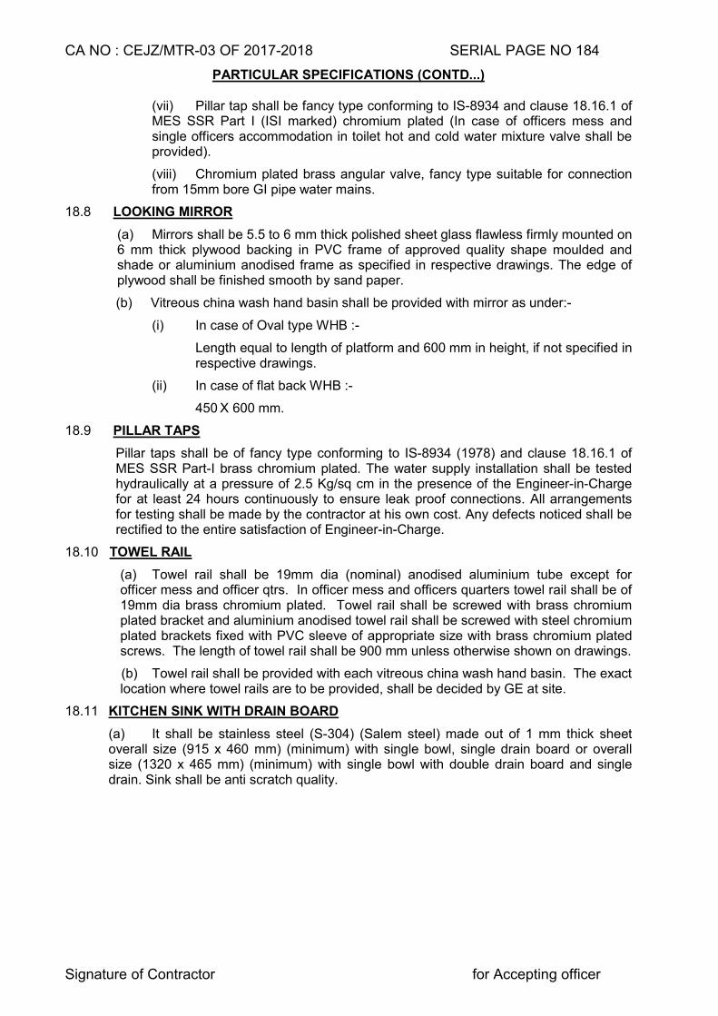
CA NO : CEJZ/MTR-03 OF 2017-2018 SERIAL PAGE NO 184
Signature of Contractor for Accepting officer
PARTICULAR SPECIFICATIONS (CONTD...)
(vii) Pillar tap shall be fancy type conforming to IS-8934 and clause 18.16.1 of MES SSR Part I (ISI marked) chromium plated (In case of officers mess and single officers accommodation in toilet hot and cold water mixture valve shall be provided).
(viii) Chromium plated brass angular valve, fancy type suitable for connection from 15mm bore GI pipe water mains.
18.8 LOOKING MIRROR
(a) Mirrors shall be 5.5 to 6 mm thick polished sheet glass flawless firmly mounted on 6 mm thick plywood backing in PVC frame of approved quality shape moulded and shade or aluminium anodised frame as specified in respective drawings. The edge of plywood shall be finished smooth by sand paper.
(b) Vitreous china wash hand basin shall be provided with mirror as under:-
(i) In case of Oval type WHB :-
Length equal to length of platform and 600 mm in height, if not specified in respective drawings.
(ii) In case of flat back WHB :-
450 X 600 mm.
18.9 PILLAR TAPS
Pillar taps shall be of fancy type conforming to IS-8934 (1978) and clause 18.16.1 of MES SSR Part-I brass chromium plated. The water supply installation shall be tested hydraulically at a pressure of 2.5 Kg/sq cm in the presence of the Engineer-in-Charge for at least 24 hours continuously to ensure leak proof connections. All arrangements for testing shall be made by the contractor at his own cost. Any defects noticed shall be rectified to the entire satisfaction of Engineer-in-Charge.
18.10 TOWEL RAIL
(a) Towel rail shall be 19mm dia (nominal) anodised aluminium tube except for officer mess and officer qtrs. In officer mess and officers quarters towel rail shall be of 19mm dia brass chromium plated. Towel rail shall be screwed with brass chromium plated bracket and aluminium anodised towel rail shall be screwed with steel chromium plated brackets fixed with PVC sleeve of appropriate size with brass chromium plated screws. The length of towel rail shall be 900 mm unless otherwise shown on drawings.
(b) Towel rail shall be provided with each vitreous china wash hand basin. The exact location where towel rails are to be provided, shall be decided by GE at site.
18.11 KITCHEN SINK WITH DRAIN BOARD
(a) It shall be stainless steel (S-304) (Salem steel) made out of 1 mm thick sheet overall size (915 x 460 mm) (minimum) with single bowl, single drain board or overall size (1320 x 465 mm) (minimum) with single bowl with double drain board and single drain. Sink shall be anti scratch quality.
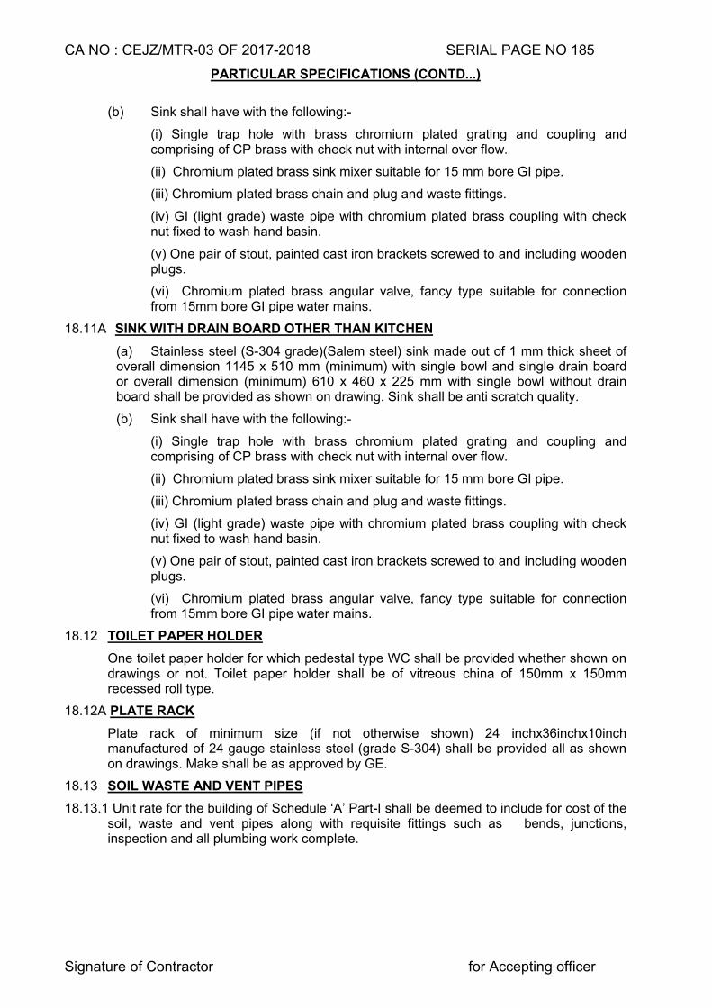
CA NO : CEJZ/MTR-03 OF 2017-2018 SERIAL PAGE NO 185
Signature of Contractor for Accepting officer
PARTICULAR SPECIFICATIONS (CONTD...)
(b) Sink shall have with the following:-
(i) Single trap hole with brass chromium plated grating and coupling and comprising of CP brass with check nut with internal over flow.
(ii) Chromium plated brass sink mixer suitable for 15 mm bore GI pipe.
(iii) Chromium plated brass chain and plug and waste fittings.
(iv) GI (light grade) waste pipe with chromium plated brass coupling with check nut fixed to wash hand basin.
(v) One pair of stout, painted cast iron brackets screwed to and including wooden plugs.
(vi) Chromium plated brass angular valve, fancy type suitable for connection from 15mm bore GI pipe water mains.
18.11A SINK WITH DRAIN BOARD OTHER THAN KITCHEN
(a) Stainless steel (S-304 grade)(Salem steel) sink made out of 1 mm thick sheet of overall dimension 1145 x 510 mm (minimum) with single bowl and single drain board or overall dimension (minimum) 610 x 460 x 225 mm with single bowl without drain board shall be provided as shown on drawing. Sink shall be anti scratch quality.
(b) Sink shall have with the following:-
(i) Single trap hole with brass chromium plated grating and coupling and comprising of CP brass with check nut with internal over flow.
(ii) Chromium plated brass sink mixer suitable for 15 mm bore GI pipe.
(iii) Chromium plated brass chain and plug and waste fittings.
(iv) GI (light grade) waste pipe with chromium plated brass coupling with check nut fixed to wash hand basin.
(v) One pair of stout, painted cast iron brackets screwed to and including wooden plugs.
(vi) Chromium plated brass angular valve, fancy type suitable for connection from 15mm bore GI pipe water mains.
18.12 TOILET PAPER HOLDER
One toilet paper holder for which pedestal type WC shall be provided whether shown on drawings or not. Toilet paper holder shall be of vitreous china of 150mm x 150mm recessed roll type.
18.12A PLATE RACK
Plate rack of minimum size (if not otherwise shown) 24 inchx36inchx10inch manufactured of 24 gauge stainless steel (grade S-304) shall be provided all as shown on drawings. Make shall be as approved by GE.
18.13 SOIL WASTE AND VENT PIPES
18.13.1 Unit rate for the building of Schedule ‘A’ Part-I shall be deemed to include for cost of the soil, waste and vent pipes along with requisite fittings such as bends, junctions, inspection and all plumbing work complete.
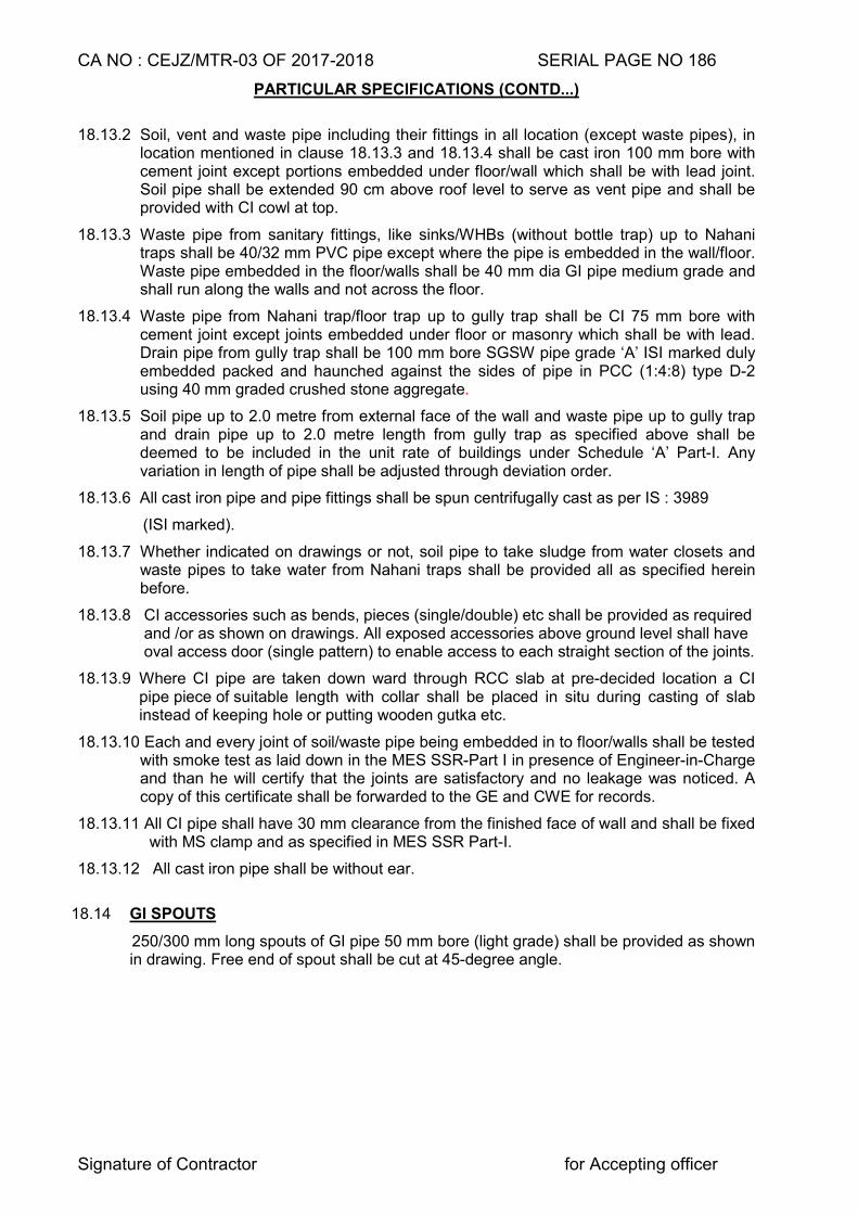
CA NO : CEJZ/MTR-03 OF 2017-2018 SERIAL PAGE NO 186
Signature of Contractor for Accepting officer
PARTICULAR SPECIFICATIONS (CONTD...)
18.13.2 Soil, vent and waste pipe including their fittings in all location (except waste pipes), in location mentioned in clause 18.13.3 and 18.13.4 shall be cast iron 100 mm bore with cement joint except portions embedded under floor/wall which shall be with lead joint. Soil pipe shall be extended 90 cm above roof level to serve as vent pipe and shall be provided with CI cowl at top.
18.13.3 Waste pipe from sanitary fittings, like sinks/WHBs (without bottle trap) up to Nahani traps shall be 40/32 mm PVC pipe except where the pipe is embedded in the wall/floor. Waste pipe embedded in the floor/walls shall be 40 mm dia GI pipe medium grade and shall run along the walls and not across the floor.
18.13.4 Waste pipe from Nahani trap/floor trap up to gully trap shall be CI 75 mm bore with cement joint except joints embedded under floor or masonry which shall be with lead. Drain pipe from gully trap shall be 100 mm bore SGSW pipe grade ‘A’ ISI marked duly embedded packed and haunched against the sides of pipe in PCC (1:4:8) type D-2 using 40 mm graded crushed stone aggregate.
18.13.5 Soil pipe up to 2.0 metre from external face of the wall and waste pipe up to gully trap and drain pipe up to 2.0 metre length from gully trap as specified above shall be deemed to be included in the unit rate of buildings under Schedule ‘A’ Part-I. Any variation in length of pipe shall be adjusted through deviation order.
18.13.6 All cast iron pipe and pipe fittings shall be spun centrifugally cast as per IS : 3989
(ISI marked).
18.13.7 Whether indicated on drawings or not, soil pipe to take sludge from water closets and waste pipes to take water from Nahani traps shall be provided all as specified herein before.
18.13.8 CI accessories such as bends, pieces (single/double) etc shall be provided as required and /or as shown on drawings. All exposed accessories above ground level shall have oval access door (single pattern) to enable access to each straight section of the joints.
18.13.9 Where CI pipe are taken down ward through RCC slab at pre-decided location a CI pipe piece of suitable length with collar shall be placed in situ during casting of slab instead of keeping hole or putting wooden gutka etc.
18.13.10 Each and every joint of soil/waste pipe being embedded in to floor/walls shall be tested with smoke test as laid down in the MES SSR-Part I in presence of Engineer-in-Charge and than he will certify that the joints are satisfactory and no leakage was noticed. A copy of this certificate shall be forwarded to the GE and CWE for records.
18.13.11 All CI pipe shall have 30 mm clearance from the finished face of wall and shall be fixed with MS clamp and as specified in MES SSR Part-I.
18.13.12 All cast iron pipe shall be without ear.
18.14 GI SPOUTS
250/300 mm long spouts of GI pipe 50 mm bore (light grade) shall be provided as shown in drawing. Free end of spout shall be cut at 45-degree angle.
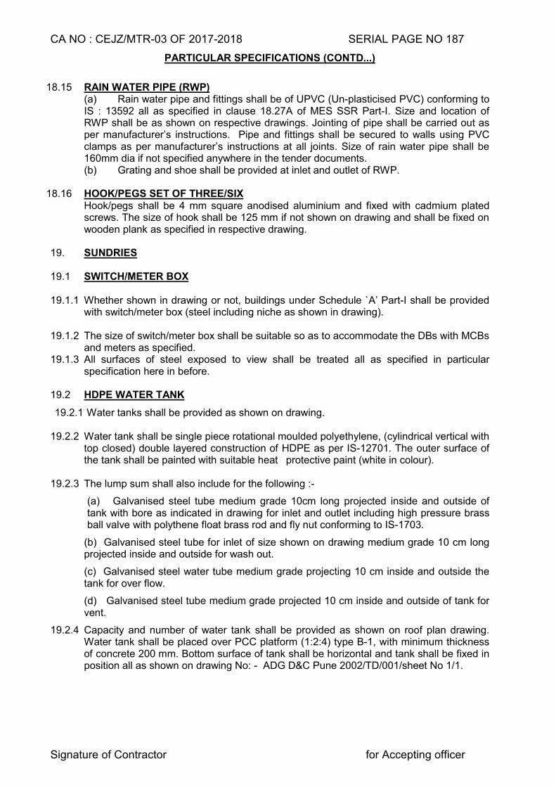
CA NO : CEJZ/MTR-03 OF 2017-2018 SERIAL PAGE NO 187
Signature of Contractor for Accepting officer
PARTICULAR SPECIFICATIONS (CONTD...)
18.15 RAIN WATER PIPE (RWP)
(a) Rain water pipe and fittings shall be of UPVC (Un-plasticised PVC) conforming to IS : 13592 all as specified in clause 18.27A of MES SSR Part-I. Size and location of RWP shall be as shown on respective drawings. Jointing of pipe shall be carried out as per manufacturer’s instructions. Pipe and fittings shall be secured to walls using PVC clamps as per manufacturer’s instructions at all joints. Size of rain water pipe shall be 160mm dia if not specified anywhere in the tender documents. (b) Grating and shoe shall be provided at inlet and outlet of RWP.
18.16 HOOK/PEGS SET OF THREE/SIX
Hook/pegs shall be 4 mm square anodised aluminium and fixed with cadmium plated screws. The size of hook shall be 125 mm if not shown on drawing and shall be fixed on wooden plank as specified in respective drawing.
19. SUNDRIES 19.1 SWITCH/METER BOX 19.1.1 Whether shown in drawing or not, buildings under Schedule `A’ Part-I shall be provided
with switch/meter box (steel including niche as shown in drawing).
19.1.2 The size of switch/meter box shall be suitable so as to accommodate the DBs with MCBs and meters as specified.
19.1.3 All surfaces of steel exposed to view shall be treated all as specified in particular specification here in before.
19.2 HDPE WATER TANK
19.2.1 Water tanks shall be provided as shown on drawing.
19.2.2 Water tank shall be single piece rotational moulded polyethylene, (cylindrical vertical with top closed) double layered construction of HDPE as per IS-12701. The outer surface of the tank shall be painted with suitable heat protective paint (white in colour).
19.2.3 The lump sum shall also include for the following :-
(a) Galvanised steel tube medium grade 10cm long projected inside and outside of tank with bore as indicated in drawing for inlet and outlet including high pressure brass ball valve with polythene float brass rod and fly nut conforming to IS-1703.
(b) Galvanised steel tube for inlet of size shown on drawing medium grade 10 cm long projected inside and outside for wash out.
(c) Galvanised steel water tube medium grade projecting 10 cm inside and outside the tank for over flow.
(d) Galvanised steel tube medium grade projected 10 cm inside and outside of tank for vent.
19.2.4 Capacity and number of water tank shall be provided as shown on roof plan drawing. Water tank shall be placed over PCC platform (1:2:4) type B-1, with minimum thickness of concrete 200 mm. Bottom surface of tank shall be horizontal and tank shall be fixed in position all as shown on drawing No: - ADG D&C Pune 2002/TD/001/sheet No 1/1.
CA NO : CEJZ/MTR-03 OF 2017-2018 SERIAL PAGE NO 188
Signature of Contractor for Accepting officer
PARTICULAR SPECIFICATIONS (CONTD...)
19.2.5 If capacity of water tank is not shown in roof plan drawing, 500 litres capacity water tank shall be provided for each toilet.
19.3 GROUND SINK
The floor of ground sink shall be as that of surrounding floor. PCC kerb shall be of PCC (1:3:6) type C-1 with same finish as that of floor.
19.4 NUMBER PLAQUE
All building / structures shall be provided with a diamond square 30 cm x 30 cm x 20 mm thick plaster plaque in cement and sand mortar (1:2) finished smooth using extra cement duly painted in black (three coats) of synthetic enamel paint including priming coat and number letter (each of 12 cm height) as directed by Engineer-in-Charge. The number of each quarters on main entrance door shall also be painted as directed by Engineer-in-Charge.
19.5 PLAQUE OF PRIDE
The contractor shall provide black (telephone black) granite slab 20 mm thick, 750 mm x 600 mm size in one building of the project as directed by GE. Plaque of pride will bear name of work with date of commencement and actual date of completion, name of CWE, GE, Senior Architect associated with the project and contractor/firm who were associated with the project as per drg No TD/2012/15 sheet No 1/1.
19.6 INFORMATION PLAQUE (TABLET)
19.6.1 Building /structure specified in clause 3.7.1 here in before shall be provided with plaque (tablet) furnishing the following information in plaster engraving in and painted as directed by GE :-
(a) Job No, CA No, Year and name of work
(b) Name of contractor, GE and Engineer-in-Charge
(c) Date of commencement, completion phase wise and expiry of ` maintenance period.
(d) Date of expiry of warranty period against ATT and water proofing treatment.
19.6.2 Plaster shall be 20 mm thick in cement and sand mortar (1:4).
19.6.3 Location and size of plaque shall be as decided by the GE.
19.7 RCC JALLI :- Type of RCC jalli if not specified anywhere in the tender documents same shall be TYPE-I as per Drg No TD/2004/49 Sheet No 1/3 to 3/3.
19.8 REINFORCED CEMENT MORTAR JALLI
Reinforced cement mortar jallies shall be procured from market and not be cast at site. Jalli shall be best locally available and of size 30 x 35 cm as directed by the GE. The mix of mortar shall be in cement and sand mortar (1:3) (1 cement : 3 coarse sand), reinforced with 3 mm dia GI wire. Thickness of jalli if not specified in drawings same shall be 50 mm. The pattern shall be as approved by GE and set and jointed in cement and sand mortar (1:4) and at every third unit 6mm dia mild steel wire shall be provided all as directed by Engineer-in-Charge.
CA NO : CEJZ/MTR-03 OF 2017-2018 SERIAL PAGE NO 189
Signature of Contractor for Accepting officer
PARTICULAR SPECIFICATIONS (CONTD...)
19.9 EXPANSION AND CRUMPLE JOINTS
19.9.1 Expansion/crumple section shall be provided where indicated on drawings as per the details given in the drawings. The portion where aluminium sheet is to be fixed on walls, the surfaces below the sheet shall be plastered 15 mm thick in cement and sand mortar (1:4) in lieu of keyed pointing.
19.9.2 Gap shall be filled with compressible material as specified in respective drawings.
19.9.3 Filling material shall be non-extruding and resilient type (bitumen impregnated fibre) preformed bituminous filler conforming to IS 1838, ISI marked.
19.9.4 PVC water bar or sealant shall be provided to prevent rain water penetration as directed by Engineer-in-Charge.
19.10 COOKING PLATFORM AND SHELVES (EXCEPT COOK HOUSES)
(a) Platform and shelves shall be provided all as shown on drawing.
(b) Type of Kitchen platform if not specified in the drawing same shall be provided with 20 mm thick polished granite (telephone black) stone/slab and shall be laid over RCC slab as shown on drawing and as specified in MES SSR Part I. Thickness of screed below Kota stone slab shall be 15 mm thick in cement and sand mortar (1:3). Kota stone shall be machine cut on all faces and edges. Length of Granite stone shall not be less than 1.50 metre. Provide ceramic tiles (coloured) as specified for dado in schedule of finishes drawings, if height is not specified provide ceramic glazed coloured tiles above cooking platform up to 600 mm high.
(c) Kota stone in shelves indicated in drawings shall be machine cut (Edges, top and bottom) and polished and shall be laid as specified in SSR Part-I. Thickness if not shown in drawing shall be 25 mm. Kota stone shall be in one piece in width and length between two adjacent supports.
(d) Kota stone shelves shall be embedded 50 mm in walls.
(e) Edges exposed in view of Stone platform and shelves shall be chamfered (rounded) two adjacent supports.
19.11 PREPARATION PLATFORM/COOKING PLATFORM/PLATFORM /SERVICE
COUNTER FOR COOK HOUSES
(a) Platforms shall be provided all as specified and as per details given in drawings
(b) 20 mm thick mirror polished granite (telephone black) stone slab in single piece in width shall be provided over 15 mm thick screed in cement and sand mortar (1:3) over RCC slab. Exposed edges of slab shall be bevelled /chamfered (rounded), platform having length up to 2 metre shall be provided with single piece and for platform having length more than 2 metre the granite slab shall be in two pieces.
(c) PCC in platform shall 1:2:4 type B-1. Top and side finish of platform shall match with the finishes of adjacent floor finish.
(d) Glazed/ceramic tiles as specified in dado shall be provided below platform as shown on drawing.
(e) Cooking plat form and chapatti preparation platform details as specified in main drawings. Heat resistance tiles dado shall be provided to chapati preparation platform and cooking platform all as specified herein before. Size and colour of tiles shall be as decided by GE.
CA NO : CEJZ/MTR-03 OF 2017-2018 SERIAL PAGE NO 190
Signature of Contractor for Accepting officer
PARTICULAR SPECIFICATIONS (CONTD...) 19.12 OPENING FOR EXHAUST FAN
Opening for exhaust fan shall be provided all as specified and shown on drawings with arrangement of mosquito proofing.
19.13 MEAT HOOK
Meat hook (stainless steel) (S-318) shall be provided all as shown on drawings. Number of hook if not specified in the drawing same shall be considered ten number.
19.14 PELMET BOX INCLUDING CURTAIN ROD
(a) The pelmet boxes shall be as shown in drawing. (b) Timber to be used shall be 1st class hard wood (teak).
(c) Exposed surfaces of timber shall be French polished.
(d) 19 / 20 mm dia aluminium anodised conduit( 2 mm wall thickness ) with socket screws shown on drawing shall fit to side planks.
19.15 HATCH WINDOW
(a) Hatch window shall be provided all as specified and as per details given in drawing No TD/2004/04 sheet No 1/1.
(b) Wooden frame : First class hard wood (MP Teak) with wrought faces.
(c) Shutter : Pre-laminated particle board 18/19 mm thick (both side laminated) all as specified hereinbefore. Edges of particle board shall be provided with teak wood edging 20 mm thick. Hinges shall be mild steel electro galvanised continuous (Piano) type.
(d) Handle shall be 150 mm long, aluminium anodised.
(e) 25 mm thick mirror polished granite stone slab (green) in single piece shall be provided over 15 mm thick screed in cement and sand mortar (1:3) over RCC slab counter. Exposed edges of granite slab shall be chamfered (rounded)
(f) PCC in platform shall 1:2:4 type B-1 using 20 mm graded crushed stone aggregate, top and side finish of platform shall match with the finishes of adjacent floor.
CA NO : CEJZ/MTR-03 OF 2017-2018 SERIAL PAGE NO 191
Signature of Contractor for Accepting officer
PARTICULAR SPECIFICATIONS (CONTD...)
19.16 NOTICE BOARD
(a) Notice board shall be provided all as specified and as per details given in drawing No TD/2004/16 sheet No 1/3 at location indicated in the main plan drawings.
(b) Timber shall be first class hard wood (MP Teak).
(c) Soft board shall be in single piece over 6 mm thick ply wood BWR grade.
(d) 5mm thick sheet glass shall be fixed with 10mm x 10mm wooden beads.
(e) Butt hinges shall be 50mm size and shall be medium grade mild steel as specified hereinbefore.
(f) Hasp and staple shall be of 75mm size safety pattern of aluminium anodised.
(g) French polish shall be provided on all exposed surfaces of timber.
(h) All wooden members in contact with masonry shall be treated with hot tar.
(j) The overall size of notice board shall be as specified in plan of building. If size is not specified same shall be followed as 2440x1220mm.
(k) Green baize cloth shall be as shown on drawings of best quality as approved by GE.
19.17 STEEL LOCKERS
(a) Steel lockers wherever shown on drawing shall be provided all as per details shown in drawing No TD/2004/71 sheet 1/2 and 2/2. External/internal steel surface shall be spray painted with two coats of stove enamel paint over one coat of Zinc chromate primer. Lockers shall be provided with Godrej pattern lock complete with locking arrangements including 12mm dia vertical rod and standard chromium plated steel handle. Rubber sheet support of size minimum 110 x 90 x 25 mm shall be fixed in bottom of legs with help of flat iron 25 x 3 mm (minimum) support two numbers of appropriate length welded to legs and screw (two numbers) in four corner.
(b) Locker shall be factory made and shall be obtained from any of the manufacturer’s given in Appendix ‘B’ to particular specifications.
CA NO : CEJZ/MTR-03 OF 2017-2018 SERIAL PAGE NO 192
Signature of Contractor for Accepting officer
PARTICULAR SPECIFICATIONS (CONTD...) 19.18 WRITING SHELF AND BOOK SHELF
(a) Writing shelf and bookshelf shall be as per details shown in drawing No TD/2004/71 Sheet No 1/2 and 2/2. Teak wood edging shall be provided all round the particle board all as specified here in before.
(b) Tube light with reflector and lamp as specified in drawing mentioned in clause (a) above shall be provided and cost of same shall be deemed to be included in the lump sum cost of respective building included in schedule A Part- 1. However point wiring for same shall be measured and paid for separately under respective item of Schedule A Part-III.
19.19 PARTITION WALL (FOR SM BARRACK)
19.19.1 Partition wall shall be provided all as shown on drawing No TD/2012/13 sheet No 1/1
19.19.2 72X32X32X0.6mm GI channel shall be provided all as specified and as shown on
drawings.
19.19.3 12 mm thick Calcium silicate shall be provided all as specified and as shown on
drawings.
19.19.4 These wall shall be rest on sub base in ground floor and in first floor on RCC slab.
19.19.5 Studs made with GI channel 70X48X50X6mm shall be provided all as specified and as shown on drawings.
19.20 CURTAIN ROD
(i) 19 / 20 mm dia MS Chromium plated conduit (1.6mm wall thickness) with socket screwed shall be fitted to veneered particle board sides as shown in drawings. Teak wood edging shall be provided all round the particle board all as specified here in before
( i i) Steel and wooden surfaces shall be painted as specif ied herein before.
19.21 DRAPERY ROD (DR)
(a) DR wherever mentioned in plan, powder coated aluminium drapery rod shall be provided as per details given in TD drawings NO. TD/2004/64 Sheet No 1/4”.
(b) Drapery rod 20 mm inner dia shall be supported on the aluminium powder coated bracket fixed with rawl plug or screw on walls/beam. Drapery rod shall be provided with finial at ends as approved by Garrison Engineer.
(c) Colour of drapery rod, rings, finial and bracket shall be as approved by Garrison Engineer.
(d) Rings for hanging the curtain shall be as per manufacturer’s instructions and shall be provided at the rate of one ring per 10 cm length of rod.
(e) Make of drapery rod, finial shall be as specified in drawings.
19.22 MEAT SAFE
a) Meat safe shall be provided all as specified and as shown in drawing No TD/2004/38 Sheet 1/4 to 4/4.
(b) All woodwork in meat safe shall be first class hard wood (Teak).
(c) Stainless steel wire mesh of 12 mesh, 20 gauge shall be provided in the shutter.
(d) Particle board shall be provided with teak wood edging.
(e) All wood surfaces shall be treated with two coats of synthetic enamel paint (White) over a coat of pink primer.
CA NO : CEJZ/MTR-03 OF 2017-2018 SERIAL PAGE NO 193
Signature of Contractor for Accepting officer
PARTICULAR SPECIFICATIONS (CONTD...)
19.23 CUP BOARD
(a) Cup board shall be provided all as specified and as shown on drawing No TD/2004/29 sheet No 1/3 to 3/3.
(b) Frame shall be of 1.25 mm thick pressed steel and shall conforming to IS-4351. Frame shall be of approved make.
(c) Shutters shall be of 1mm thick pressed steel.
(d) Shelves shall be of 20 to 25 mm thick Kota stone machine cut and polished both side. Shelves shall have minimum 50 mm bearing on walls on all the sides. However the partition and shelves location can be shifted to provide the space as per requirement, if ordered by GE without FE.
(e) 03 Nos of 3.15mm thick and 100mm long steel hinges shall be provided for each shutter. The cupboard shall have Godrej pattern lock with complete locking arrangement including 12mm dia vertical rod.
(f) One tie hanger of 10 mm dia aluminium conduit pipe and 2 Nos coat hooks shall be fixed to shutters. 19mm dia hanging rod of aluminium tube shall be fixed as shown on drawings. All fittings shall be of anodised aluminium except hinges.
(g) All internal plastered surface of cupboard shall be provided with 2 coats of synthetic enamelled paint over a coat of primer after preparation of surfaces as specified.
(h) Steel surface shall be spray painted with two coat of synthetic enamel paint over one coat of zinc chromate primer.
(j) Hollow space in pressed steel frame shall be filled with PCC (1:3:6) type C-0 using 12.5 mm graded crushed stone aggregate.
Note :- (i) Make of pressed steel frame and shutters shall be as indicated in Appendix ‘B’ to particular specifications.
(ii) Where width cupboard is not shown in main plan maximum width as specified in the above mentioned drawing shall be followed.
19.24 CUP BOARD (CB-A and CB-B)
(a) Cupboard (CB-A and CB-B) shall be provided all as specified and as per details given in drawing No TD/2004/33 sheet No 1/2 to 2/2.
(b) Frame shall be of angle iron 40x40x6 mm and shutters shall be factory made with particle board panel all as specified in clause 8.1 hereinbefore. Shutter shall be procured from the manufacturer as listed in Appendix ‘C’ to particular specifications.
(c) Shelves shall be of 20 to 25 mm thick Kota stone machine cut and polished both side.
(d) RCC shall be M-25 (design mix) all as specified hereinbefore.
(e) All internal plastered surface of cupboard and RCC partition shall be provided with 2 coats of synthetic enamel paint over a coat of primer after preparation of surfaces as specified.
(f) Steel and wooden surfaces shall be treated by two coat of synthetic enamel paint over a coat of primer all as specified here-in-before.
(g) Where width of cupboard is not shown in main plan, maximum width as
specified in the above mentioned drawing shall be followed.
CA NO : CEJZ/MTR-03 OF 2017-2018 SERIAL PAGE NO 194
Signature of Contractor for Accepting officer
PARTICULAR SPECIFICATIONS (CONTD...) 19.25 CUPBOARD (CB)
(a) Cupboard shall be provided all as specified and as per details given in drawing No TD/2009/105(R), sheet No 1/1
(b) Frame shall be of 1.25 mm thick pressed steel and shall conform to IS-4351. Frame shall be of approved make. (c) Shutters shall be of 1mm thick pressed steel.
(d) Shelves shall be of 20 to 25 mm thick Kota stone machine cut and polished both side. Shelves shall have minimum 50 mm bearing on walls on all the sides. However the partition and shelves location can be shifted to provide the space as per requirement, if ordered by GE without FE.
(e) 03 Nos of 3.15mm thick and 100mm long steel hinges shall be provided for each shutter. The cupboard shall have Godrej pattern lock with complete locking arrangement including 12mm dia vertical rod.
(f) One tie hanger of 10 mm dia aluminium conduit pipe and 2 Nos coat hooks shall be fixed to shutters. 19mm dia hanging rod of aluminium tube shall be fixed as shown on drawings. All fittings shall be of anodised aluminium except hinges. (g) All internal plastered surface of cupboard shall be provided with 2 coats of synthetic enamelled paint over a coat of primer after preparation of surfaces as specified. (h) Steel surface shall be spray painted with two coat of synthetic enamel paint over one coat of zinc chromate primer. (j) Hollow space in pressed steel frame shall be filled with PCC (1:3:6) type C-0 using 12.5 mm graded crushed stone aggregate.
Note: - (i) Make of pressed steel frame and shutters shall be as indicated in Appendix ‘B’ to particular specifications.
(ii) Where width cupboard is not shown in main plan maximum width as specified in the above mentioned drawing shall be followed.
19.26 RAILING AND HAND RAIL OF BALCONY AND STAIR CASES
(a) Railing and hand rails wherever shown on drawing shall be all as shown on respective drawings and shall be painted (except stainless steel railing) all as specified here-in-before.
(b) Stainless steel railing shall be of grade (S-304) and thickness of pipe shall be minimum 2mm upto 19 mm outer dia metre and 2.3mm for above 19mm outer dia.
(c) Mild steel pipe specified in railing shall be of made out of medium grade.
(d) Galvanized surfaces wherever specified in respective drawings shall having zinc coating type heavy as laid down in IS , hot dipped galvanized coating.
19.27 THREE/TWO TIER RCC SHELVING
19.27.1 These shall be provided as shown on drawing. The surface shall be finished fair and smooth with using extra cement.
19.27.2 Bottom, top and front edge shall be provided with 5 mm thick rendering in cement mortar (1:3) finished even and smooth without using extra cement.
19.27.3 Bottom surface of shelves shall be treated with three coats of white washing all as specified hereinbefore.
CA NO : CEJZ/MTR-03 OF 2017-2018 SERIAL PAGE NO 195
Signature of Contractor for Accepting officer
PARTICULAR SPECIFICATIONS (CONTD...)
19.28 COOLER REST
Cooler rest shall be provided along with cooler window as per details given in drawing No TD/2004/47 Sheet No 3/5. Size of cooler rest platform shall as specified in relevant drawing if not specified same shall be 650 x 650 mm, however length of lintel/beam shall be as per drawing mentioned herein before i.e with bearing at both end of opening.
19.29 THREE OR TWO TIER KOTA STONE SHELVES (3 KSS) OR (2KSS)
(a) These shall be provided as shown on drawing and supported with 115 thick brick walling as specified.
(b) Shelves shall be of 25 mm thick kota stone machine cut and polished both side. Shelves shall have minimum 50 mm bearing on walls on all the sides.
(c) Surface of brick walling shall be provided with 10 mm thick plaster in cement and sand mortar (1:6) finished even and smooth without using extra cement unless otherwise finishes specified in schedule of finishes drawings.
(d) All plastered surfaces shall be finished with same finish as specified for respective room/location.
(e) Bottom platform shall be of PCC (1:2:4) type B-1 using 20 mm graded crushed stone aggregate and side/top shall be finished to match with adjacent floor of room.
19.30 BAR COUNTER AND SHOW CASE
(a) Bar counter and show case shall be as specified and as shown on drawings
(b) All brick wall shall be built in cement and sand mortar (1:4) and shall be plastered 10mm thick in cement and sand mortar (1:4) and finished with two coats of synthetic enamel paint over a coat of primer.
(c) Exposed edges of glass shelf, cudappah stone, granite stone slab shall be chamfered(rounded).
(d) Granite slab (telephone black) in top, shelving and lining shall be bedded in 15mm thick cement and sand mortar (1:3), over RCC slab/masonry.
(e) Granite slab (telephone black) shall be single piece in width on top slab and shall be machine cut and mirror polished. Edges of top slab shall be chamfered (rounded/bevelled).
(f) Prelaminated particle board exterior grade, both face laminated shall be provided with teak wood edging all as specified here in before.
(g) All exposed wooden surfaces shall be French polished.
(h) Size and colour of glass mosaic shall be as approved by GE
(j) PCC platform shall be PCC (1:2:4) type B1 using 20 mm graded crushed stone aggregate, Top and sides of platform shall be finished to match with the adjacent floor of room.
19.31 FULL SIZE MIRROR
(a) Full size mirror shall be provided at the locations shown on drawings and shall be provided all as per details shown on drawing No :- TD/2004/16 Sheet No 3/3.
(b) Mirror shall be 5.5 to 6 mm thick polished sheet glass flawless firmly mounted on 6 mm thick plywood backing in wooden frame with key plate etc complete as shown on drawings. The edge of plywood shall be finished smooth by sand paper.
(c) Exposed surfaces of timber shall be French polished as specified herein before
CA NO : CEJZ/MTR-03 OF 2017-2018 SERIAL PAGE NO 196
Signature of Contractor for Accepting officer
PARTICULAR SPECIFICATIONS (CONTD...)
19.32 HAT STAND WITH MIRROR
(a) Hat stand wherever indicated in the drawing shall be provided as specified in drawing FD-2 Sheet 1/1.
(b) Timber shall be 1st class hard wood (teak)
(c) Exposed surface of timber shall be French polished all as specified herein before (d) Unless otherwise not shown, the size of mirror shall be 300 x 450 x 5 mm thick.
19.37 FIXED GLAZING (FG/FG-1/FG-2)
(a) Fixed glazing wherever shown in the drawing shall be provided with 5.5mm thick (min) glass panes fixed with glazing clip and putty to the frame.
(b) Size, type and quality of glass panes shall be all as specified in the respective drawings. If not specified, same shall be 6 mm thick plain glass of selective quality.
(c) Aluminium section of size as shown on drawings used in the work shall be of make as specified in Appendix ‘B’ to particular specifications.
19.38 BLACK BOARD
(i) Board shall be provided all as specified and as shown on drawing No TD/2008/103 sheet 1/1.
(ii) Black boards wherever shown on drawing shall be green board with vitreous enamelled steel sheet top surface. The writing top surface of board shall be made of CRC steel sheet of thickness 0.3 to 0.4mm. It shall have vitreous enamel coating of 0.095mm minimum thickness on top and 0.03mm minimum on the back. The top shall be free from waviness and shall show excellent eras-ability. Board suitable for writing with chalk having gloss level of 02 degree minimum. Steel board shall be mounted 9mm thick on medium density fibre (MDF) board. Grade-I as per IS:12406 with electro galvanized backing steel sheet (0.25mm minimum thickness). Both the top and the backing sheet shall be properly fixed with the MDF board using suitable adhesive to avoid moisture absorption. The board shall have all round framing of anodized extruded aluminium alloy hollow section, Designation 63400 as per IS:1285 or IS:733. The frame section shall be front 20mm, side 16mm and wall thickness 1.2mm (minimum).
(iii) Fluorescent luminaries shown in drawings shall be provided as per cat No. TMC 501/136 HPF of PHILIPS make or equivalent model of Crompton greaves make. Lump sum quoted amount against respective building shall be deemed to be included for provision of fluorescent luminaries including lamp however point wiring shall be measured and paid for separately.
(iv) Prelaminated board shall be exterior grade both side laminated. Shade of lamination shall be as approved by GE.
(v) Board shall be ‘WHITE MARK’/ALKOSIGN brand
19.39 Detail of shelves with glass sliding shutters
(a) Shelves with glass sliding shutter shall be provided all as specified as per details given in drawing No TD/2004/60 sheet No 1/1
(b) Prelaminated particle board both side laminated shall be exterior grade all as specified herein before.
(c) Particle board shall be provided with 6mm thick teak wood edging.
(d) All wood work shall be first class hard wood (MP teak).
CA NO : CEJZ/MTR-03 OF 2017-2018 SERIAL PAGE NO 197
Signature of Contractor for Accepting officer
PARTICULAR SPECIFICATIONS (CONTD...)
(e) All steel surfaces shall be treated with two coat of synthetic enamel paint (White) over a coat of red oxide zinc chrome primer.
(f) Minimum thickness of sliding glass sheet shutter shall be 5.5mm.
19.40 GLAZED SHOW CASE
(a) Glazed show case shall be provided all as specified as per details given in drawing No TD/2004/48 sheet No 1/1.
(b) Shelves shall be of 25mm thick green marble (Makrana) slab machine cut, polished both side. Slab shall be in one piece. Marble slab over PCC/RCC platform shall be bedded in cement and sand mortar (1:3) 15mm thick. Vertical support shall be 25mm thick kota stone slab machine cut, polished both side slab in single piece.
(c) All internal surfaces of wall shall be plastered in cement and sand mortar (1:4) finished even and smooth without using extra cement.
(d) All internal surface of wall and bottom of RCC platform shall be treated with two coats of synthetic enamel paint (White) over a coat of primer.
(e) Minimum thickness of sliding glass sheet shutter shall be 5.5mm.
19.41 WICKET GATE
(a) Brick pillar shown in drawing shall be built in cement and sand mortar (1:4) and
shall be plastered all as specified here in before. (b) PCC in coping and blocks for hold fast shall be in type 1:3:6 type C-1 using 20
mm graded crushed stone aggregate. (c) All steel and iron work surfaces shall be finished with two coats of synthetic
enamel paint over a coat of red oxide primer as specified here-in-before.
CA NO : CEJZ/MTR-03 OF 2017-2018 SERIAL PAGE NO 198
Signature of Contractor for Accepting officer
PARTICULAR SPECIFICATIONS (CONTD...) 19.42 RIFLE RACK
(a) Rifle rack shall be provided all as specified and as per details given in drg No TD/2004/42 sheet 1/1.
(b) All wooden work shall be first class hard wood (MP teak).
(c) All exposed wooden work shall be French polished.
(d) All exposed steel member shall be treated with two coat of synthetic enamel paint over one coat of Zinc Chrome primer.
(e) Fixing arrangement shall be made as shown in the drg and all as directed by GE.
(f) Exact position of rifle rack in the Guard house building shall be as decided by GE during execution of the work and cost of same shall be deemed to be included in the lump sum cost of the building.
19.43 MIRROR WITH SHELVES :-
(a) Mirror with shelves shall be provided all as specified and as shown on drawing No FD-52(M) sheet 1/1
(b) All woodwork shall be first class hard wood (MP Teak).
(c) Mirror shall be 5.5 to 6 mm thick polished sheet glass flawless firmly mounted on 6 mm thick plywood backing in wooden frame with key plate etc complete as shown on drawings. The edge of plywood shall be finished smooth by sand paper. Particle board shall be provided with teak wood edging.
(d) All wood surfaces of timber shall be French polished as specified herein before
19.44 (BOX KEY) KEY BOARD
(a) Mirror with shelves shall be provided all as specified and as shown on drawing No FD-101(M) sheet 1/1
(b) All woodwork shall be first class hard wood (MP Teak).
(c) All wood surfaces of timber shall be French polished as specified herein before
19.45 TABLE LABORATORY WORK BENCH
(a) All wood work shall be of first class hard wood (MP Teak).
(b) White glazed fine clay sink of minimum size 600x450x200mm of first quality ISI marked shall be provided with three way laboratory brass chromium plated tap suitable for 15 mm bore GI pipe, GI waste coupling and bottle trap.
(c) 6 mm thick teak veneered finish one side and 6 mm thick commercial ply shall be provided at the locations shown on drawing.
(d) Table top shall be 25 mm thick particle board commercial face covered with stainless steel sheet thickness not less than 26 gauge.
CA NO : CEJZ/MTR-03 OF 2017-2018 SERIAL PAGE NO 199
Signature of Contractor for Accepting officer
PARTICULAR SPECIFICATIONS (CONTD...)
(e) 18/19 mm thick particle board with teak veneered finish one side shall be provided to sides of CB, shutters and drawer front.
(f) 18/19 mm thick particle board with commercial face shall be provided to partition in CB and base of side CB.
(g) 12 mm thick particle board both side commercial with 6 mm thick teak wood edging shall be provided to the shelf.
(h) Irrespective of what is shown on drg, 4 mm thick teak wood edging all-round the edges of particle board shall be provided.
(j) Edges of glass shelf shall be grounded.
(k) Brass piano type hinges.
(l) Brass ball catcher.
(m) Aluminium anodised handle 75 mm long.
(n) All exposed wood work and teak veneered surfaces shall be French polished with high glass finish.
(o) Rest all as shown on drawing.
19.46 BOOK CASE STEEL
(a) 1.00 mm thick MS sheet for sides, sliding shutters, shelves, top & bottom and 1.25 mm thick MS Sheet for channel as a guide rail.
(b) Glass panes shall be 3mm thick plain sheet glass.
(c) Sliding shutters shall be provided with inside lock and two stainless steel handle.
(d) 2 coats of synthetic enamel paint of approved shade over a coat of red oxide primer all over internal & external surfaces with spray machine.
(e) Rubber sheet support of size minimum 110 x 90 x 25 mm shall be fixed in bottom of legs with help of flat iron 25 x 3 mm (minimum) support two numbers of appropriate length welded to legs and screw (two numbers) in four corner.
(f) All as shown on drawing
19.47 HAT STAND WITH MIRROR
(a) Hat stand wherever indicated in the drawing shall be provided as specified in drawing FD-362 Sheet 1/1.
(b) Timber shall be 1st class hard wood (teak)
(c) Exposed surface of timber shall be French polished all as specified herein before
19.48 SAFE (CHEST)
The safe shall be of Make:- Godrej(Model No. 26) or equivalent model of make Mehtodex system’s limited. Safe (Chest) shall be of as per manufacturer’s instructions. The outside dimensions and inside dimensions of safe shall not be less than 662x531x576 and 462x331x295mm respectively. The minimum weight of safe shall not be less than 382 kg. All steel surfaces shall be powder coated.
19.49 STEEL LADDER
Steel ladder (one number each building ) shall be provided as per details given in drawing No CEJZ/2004/TD/S-26 Sheet No 1/1 to the buildings included in schedule A Part 1 in which provision of water storage tank (HDPE) is shown in roof plan .Exposed steel surfaces shall be painted with two coats of synthetic enamel paint over a coat of zinc chrome primer and steel surfaces in contract with masonry/concrete shall be treated with hot tar as specified here-in –before.
CA NO : CEJZ/MTR-03 OF 2017-2018 SERIAL PAGE NO 200
Signature of Contractor for Accepting officer
PARTICULAR SPECIFICATIONS (CONTD...)
20 RAMP
(a) Ramp shall be provided all as specified and as per details given in drawings No TD/2004/02 sheet No 1/4 to 4/4.
(b) Excavation and earth work shall be soft/loose of soil and surplus soil shall be removed to distance exceeding 200 metres but not exceeding 250 meters all as specified here-in- before.
(c) Brick masonry shall be all as specified in MES SSR Part-I and here-in-before built in cement and sand mortar (1:4).
(d) Hardcore shall be as specified here in before.
(e) All surfaces of masonry shall be plastered in cement and sand mortar (1:4) 10 mm thick finished fair and even. Plastered surface shall be provided 2 coats of cement paint.
(f) PCC foundation shall be 1:4:8 type D-2 using 40mm graded crushed stone aggregate. All other plain cement concrete shall be PCC (1:2:4) type B1 using 20mm graded crushed stone aggregate. Surfaces of PCC floor shall be finished even and smooth using extra cement. Top surfaces of ramp shall be chequered finished.
(g) All reinforced cement concrete work shall be M-25 (Design mix) all as specified here-in-before.
(h) 30mm thick PCC (1:2:4) type B0 using 12.5 mm graded crushed stone aggregate levelling course followed by two layers of 100 micron polythene sheet shall be provided over walls under RCC slab.
20A INCINERATOR
(a) Incinerator shall be provided all as specified and as per details given in drawing NO TD/2004/22 Sheet No 1/2 and 2/2.
(b) Excavation and earth work shall be in any type of soil and surplus soil shall be removed to distance exceeding 200 metres but not exceeding 250 meters all as specified here-in- before.
(c) Brick masonry shall be all as specified here in before and same shall be built in cement and sand mortar (1:4) using burnt brick.
(d) XPM required in the work shall have weight not less than 3 kg/Sqm.
(e) All steel and iron work shall be painted with two coat of synthetic enamel paint over a coat of zinc chrome primer all as specified here in before.
(f) 10mm thick plaster in cement and sand mortar (1:4) on internal surfaces and 15mm thick plastering in cement and sand mortar (1:4) on external surfaces (both finished fair and even) shall be provided. External surface shall be provided 3 coats of white wash.
20B ALARM POST
(a) Alarm post shall be provided all as specified and as per details given in drawing No TD/2004/28 sheet 1/1.
(b) Excavation and earth work shall be in any type of soil and surplus soil shall be removed to distance exceeding 200 metres but not exceeding 250 metres as specified in before.
CA NO : CEJZ/MTR-03 OF 2017-2018 SERIAL PAGE NO 201
Signature of Contractor for Accepting officer
PARTICULAR SPECIFICATIONS (CONTD...) (c) Brick masonry shall be all as specified in MES SSR Part-I and here in before,
built in Cement and sand mortar (1:4).
(d) Sand shall be all as specified here in before.
(e) All plain cement concrete for coping shall be (1:2:4) type B-1 using 20mm graded crushed stone aggregate.
(f) All masonry surfaces shall be plastered in cement and sand mortar (1:4) 15mm thick finished fair and even. Plastered surface shall be provided 3 coats of white wash
20C FLAG MAST
(a) Flag mast shall be provided all as specified and as per details given in drawing No TD/2004/31 sheet 1/2 and 2/2.
(b) Excavation and earth work shall be in any type of soil and surplus soil shall be removed to distance exceeding 200 metres but not exceeding 250 metres all as specified here-in- before.
(c) Brick masonry shall be built in cement and sand mortar (1:4) all as specified here in before and MES SSR Part-I.
(d) Granite stone tile flooring shall be provided in place of PCC flooring where mentioned in the drawing. Granite tiles shall be laid over 20 mm thick screed in CM (1:4) over PCC (1:2:4) type B-1 using 20 mm graded crushed stone aggregate 30 mm thick over sub base (1:4:8) type D-2 using 40 mm graded crushed stone aggregate 75mm thick over rammed earth.
(e) Masonry surface shall be provided with granite (black) stone slab cladding. Granite stone slab shall be laid over 10mm thick screed in cement and sand mortar (1:4).
(f) Granite stone slab shall be in two pieces in each side of flag mast and in one piece in each side of flooring. Colour of the slab shall be black machine cut and mirror polished. Thickness of granite stone slab shall be 16 to 18mm thick. Joints between granite stone slab in sides of flag mast shall be horizontal.
(g) GI pipe shall be medium grade 80 mm bore.
20D FIRE POINT
(a) Fire point shall be provided all as specified and as per detail given in drawing No TD/2004/43 sheet No 1/1.
(b) Excavation and earth work shall be in any type of soil and surplus soil shall be removed to distance exceeding 200 metres but not exceeding 250 meters all as specified here-in- before.
(c) PCC in foundation shall be 1:4:8 type D2 using 40 mm graded crushed stone aggregate, thickness if not specified shall be 100mm.
(d) PCC above GL shall be in PCC 1:3:6 type C1 using 20 mm graded crushed stone aggregate.
(e) Brick masonry shall be all as specified in MES SSR Part-I and here in before, built in cement and sand mortar (1:4).
(f) All masonry surfaces shall be provided with 15mm thick cement plaster in cement and sand mortar (1:4) finished fair and even. Plastered surface shall be provided 3 coats of white wash
(g) MS work shall be with welded joints.
CA NO : CEJZ/MTR-03 OF 2017-2018 SERIAL PAGE NO 202
Signature of Contractor for Accepting officer
PARTICULAR SPECIFICATIONS (CONTD...) (h) CGI sheet roofing shall be provided as shown on drgs and shall be 0.80mm thick.
(i) All MS work including CGI sheet shall be painted with 2 coats of synthetic enamel paint (Red colour) over a coat of primer. Preparation of MS work and sheet shall be as specified in SSR.
(j) Writing of letters i.e. “FIRE POINT” shall be 200mm high and shall be with white colour paint at the location as directed by Engineer-in-Charge.
21. STATIC TANK
21.1 RCC static tank shall be provided all as specified and shown in the drawing No: .CEJZ/2004/TD/S-32 Sheet No 1/2 and 2/2.
21.2 Excavation and earth work shall be in any type of soil and surplus spoil shall be removed to a distance exceeding 200 metre not exceeding 250 metres all as specified hereinbefore.
21.3 PCC (1:3:6) type C-2 using 40mm graded crushed stone aggregate shall be provided as lean concrete/foundation bed.
21.4 All RCC work wherever indicated in the drawing shall be of M-30 (Design mix) as specified here-in-before.
21.5 Plaster
(i) Internal surface of : 10mm thick cement plaster shall be
walls and flooring done in cement and sand mortar (1:3), mixed with ISI marked water proofing compound as per manufacturer’s instructions.
(ii) External surfaces : 10mm thick in cement and sand mortar (1:3)
of walls mixed with approved water proofing
compound ISI marked mixed as per
manufacturer’s instructions and provide
one coat of industrial bitumen 85/25 @1.2 Kg per Sqm on plastered surfaces from bottom to up to GL even though not shown on drawing.
Note:- In case of deviation WPC shall be taken 3% by weight of cement. The plastered surfaces shall be finished to even and smooth surfaces without using extra cement.
21.6 Steel and Iron work : As indicated in the drawing including painting and tarring steel surfaces as specified 21.7 Finish : All exposed external plastered surfaces shall be applied two coats of cement base paint. For workmanship refer clause 15.15 of MES SSR Part-I. Shade shall be as directed by Engineer- In-Charge. 21.8 Tarring : Portion of MS rungs etc built into wall shall be tarred and sanded before being built in.
CA NO : CEJZ/MTR-03 OF 2017-2018 SERIAL PAGE NO 203
Signature of Contractor for Accepting officer
PARTICULAR SPECIFICATIONS (CONTD...) 21.9 Plinth protection : Plinth protection shall be provided at location
shown on drawing and as specified in PS here-in-before. Width of the plinth protection shall be as shown on drawings.
21.10 The unit rate in Schedule ‘A’ Part I for static tank shall include for the following also:-
(i) RCC (M-30 Design mix) post with copper alloy bib tap 25mm dia. PCC in foundation of RCC post shall be of PCC (1:2:4), type B-2 using 20 mm graded crushed stone aggregate.
(ii) Plinth protection 75 mm thick, PCC (1:3:6) type C-1 using 20 mm graded crushed stone aggregate over 75 mm thick hard core finished even and smooth without using extra cement.
(iii) High pressure brass valve conforming to IS-1703 with 25mm dia GI pipe medium grade.
(iv) PVC water bar shown in drawing shall be 150 mm wide ribbed PVC bar.
Note :- Valve chamber, 25 mm dia GI pipe, sluice valve and DI pipe (now amended to GI pipe) shown on drawing shall be measured and paid for separately under respective items of schedule ‘A’ Part V
21.11 TEST OF WATER TIGHTNESS OF STATIC TANK :-
(a) All arrangements for testing shall be made by the contractor as directed by the Engineer-in-Charge. Testing shall be carried out immediately after the removal of form work and before application of internal water proof plaster. The cost of testing shall be deemed to be included in the lump sum cost quoted by the contractor against item of schedule ‘A’ Part I.
(b) Water shall be supplied slowly at the rate of 300mm to 450mm depth per day and the result closely observed both from the angle of structural stability whether any crack is being noticed in the structures at any time and from the point of view of water tightness. At the end of the operation that is when full supply level is reached all valves shall be closed tightly. Water level shall be properly marked on the wall and leakage shall be thoroughly checked and it will be ensured that there is no drop of water level. After 24 hours, 48 hours and 72 hours the water level shall be checked and the drop in level shall be recorded for water tightness. The drop in water level in 24 hours shall not exc 6mm.
(c) The work shall be treated as completed only after satisfactory test is carried out and a certificate of testing duly signed by GE is issued. The period of completion shall be deemed to include the period required for testing.
22.1 SENTRY BOX
(a) Sentry Box shall be provided all as specified and as per details given in drawing No TD/2004/25 sheet No 1/2 and 2/2.
(b) Excavation and earth work shall be in any type of soil and removing surplus soil all as specified here in before.
(c) Concrete below wall shall be PCC (1:4:8) type D-2 using 40mm graded crushed stone aggregate.
(d) Brick masonry shall be all as specified in MES SSR Part-I and here-in-before, built in Cement and sand mortar (1:4).
(e) All plain cement concrete shall be (1:2:4) type B-1 using 20mm graded crushed stone aggregate.
CA NO : CEJZ/MTR-03 OF 2017-2018 SERIAL PAGE NO 204
Signature of Contractor for Accepting officer
PARTICULAR SPECIFICATIONS (CONTD...) (f) All RCC work shall be M-25 (design Mix) as specified here-in-before.
(g) Internal surfaces shall be plastered in cement and sand mortar (1:6) 10mm thick finished even and smooth without using extra cement. External surfaces including RCC roof and wall shall be plastered in cement and sand mortar (1:4) 15mm thick finished fair and even using water proofing compound as per manufacturer’s instructions. However in case of deviation the same shall be taken as 3% by weight of cement.
(h) Internal surfaces shall be treated with 3 coat of white wash and external surfaces shall be treated with 2 coats of cement paint all specified here-in-before.
(i) Stone rubble filling shall be done with aggregate of gauge 63 to 90mm as shown in drawing.
22A GARBAGE BIN
(a) Garbage bin shall be provided as specified and as per details given in drawing No TD/2004/27 sheet No 1/2 and 2/2.
(b) Excavation and earth work shall be in any type of soil and removing surplus soil all as specified here in before.
(c) Brick masonry shall be all as specified and here-in-before, built in cement and sand mortar (1:4).
(d) Flooring shall be 40mm thick PCC (1:2:4) type B1 using 20mm graded crushed stone aggregate over 75mm thick PCC 1:4:8 type D-2, using 40mm graded crushed stone aggregate sub base over rammed earth. Exposed (top) surface shall be finished even and smooth without using extra cement.
(e) Surfaces of masonry shall be plastered with 15mm thick in cement and sand mortar (1:4) finished fair and even and shall be treated with three coats of white wash.
(f) All exposed surfaces of steel and iron work shall be given two coats of bituminous paint over a coat of red oxide primer. Surface in contact with masonry/PCC shall be tarred.
(g) DPC shall be 40mm thick PCC (1:2:4) type B-1 mixed with W.P.C as per manufacturer’s instruction.
22B. WASHING PLATFORM
(a) Washing plat form shall be provided all as specified and as per details given in drawing No TD/2013/03 sheet No 1/1,.
(b) Excavation and earth work shall be in any type of soil and surplus soil shall be removed to distance exceeding 200 metre but not exceeding 250 metre all as specified here-in- before.
(c) Hard core shall be all as specified here in before.
(d) All plain cement concrete shall be (1:2:4) type B-1 using 20mm graded crushed stone aggregate except wall foundation. For wall foundation mix of concrete shall be 1:4:8 type D-2 wing 40 mm graded crushed stone aggregate.
(e) Floor shall be finished even and smooth using extra cement and top surface shall be broomed finished all as specified in MES SSR Part-I.
(f) Brick masonry shall be all as specified here in before but built in cement and sand mortar (1:4). Wall shall be provided all-around the platform.
(g) Inner surface of drain shall be finished even and smooth using extra cement.
CA NO : CEJZ/MTR-03 OF 2017-2018 SERIAL PAGE NO 205
Signature of Contractor for Accepting officer
PARTICULAR SPECIFICATIONS (CONTD...) (h) Mild steel perforated plate shall be provided on both side of platform as cover
of drain.
(j) Angle iron support for pipe and tap shall be provided all as specified and shown on the drawings. However GI pipe and tap shall be measured and paid separately under Sch ‘A’ Part II for internal water supply.
(k) All steel surfaces shall be painted all as specified here in before. 22C DHOBI GHAT
(a) Dhobi Ghat shall be provided all as specified and as shown in drawing No TD/2004/21 sheet No 1/6 to 6/6.
(b) Flooring shall be 75mm thick PCC (1:2:4 ) type B-2 using 40 mm graded crushed stone aggregate laid over 75 mm thick PCC(1:4:8) type D-2 using 40 mm graded crushed stone aggregate over 150 mm thick hard core over rammed earth.
(c) Drain shall be constructed in flooring with surfaces finished even and smooth using extra cement.
(d) Brick work shall rest on PCC sub base and shall be built in cement and sand mortar (1:4). 15mm thick cement plaster shall be provided to brick work in cement and sand mortar (1:4) using water proofing compound as per manufacturer’s instruction. In case of deviation WPC shall be taken 3% by weight of cement. The plastered surfaces shall be finished even and smooth without using extra cement on the surface wherever shown in the drawings.
(e) GI pipe shall be medium grade and quoted rate shall be deemed to be included the provision of GI pipe(2 metre in length) valve and valve box.
(f) All steel surfaces shall be painted with two coat of anticorrosive paint over a coat of zinc chrome primer.
23 RCC UNDER GROUND SUMP 23.1 RCC sump shall be provided all as specified in Schedule ‘A’ Part-1 , as shown in the
respective drawings and as specified in relevant para of particular specifications.
23.2 PCC (1:3:6) type C-2 using 40mm graded crushed stone aggregate shall be provided as lean concrete/foundation bed.
23.3 All RCC work wherever indicated in the drawing shall be of M-30 (Design Mix) as specified here in before.
23.4 Water proof treatment to underground sump (Internal wall, columns, floor, roof beam, ceiling etc) shall be carried out as under:-
(i) Clean the RCC surfaces with wire brush /coir brush to free from all loose materials like dust, dirt etc. Seal all honeycombs, pin holes, joints with Polymer Modified Mortar as per manufacture instructions.
(ii) Apply first coat of Dr Fixitpidifin2K or any other equivalent product of BASF/SIKA INDIA LTD /STP (the proposed product shall be equal to or superior to than the Dr Fixitpidifin2K and all necessary documents/ evidences to prove quality and technical aspect shall be submitted by the contractor at the time of approval) on cleaned RCC surface with brush as per manufacturer instructions and allow it to dry for 6-8 hrs. After drying of first coat apply second coat and sprinkled coarse screened sand on vertical surface. Thickness of coating shall not be less than 1mm. Allow 24 hrs for full cure. Provide waterproof plaster i.e. cement and sand mortar (1:3) admixed with Dr Fixit
CA NO : CEJZ/MTR-03 OF 2017-2018 SERIAL PAGE NO 206
Signature of Contractor for Accepting officer
PARTICULAR SPECIFICATIONS (CONTD...) 23.4 Contd...
Pidiproof LW + or equivalent any other product of BASF/ SIKA INDIA LTD /STP (the proposed product shall be equal to or superior to than the Dr FixitPidiproof LW+ and all necessary documents/ evidences to prove quality and technical aspect shall be submitted by the contractor at the time of approval) as per manufacturer instructions as under :-
(a) Inside surfaces of external walls and the floor, in two coat, the first coat 12mm thick and the next 10mm thick . The second coat should be applied after allowing a time interval of at least 24 hours.
(b) Columns, beams, intermediate walls and soffit of roof slab, in single coat 10mm thick.
(iii) Cure the surface with water.
(iv) Clean the surface with wire brush to remove all loose dust, dirt etc . Saturate the surface with water.
(v) Apply two coats of Dr Fixit Safeguard or equivalent product of BASF/ SIKA INDIA LTD /STP (the proposed product shall be equal to or superior to than the Dr Fixitsafeguard and all necessary documents/ evidences to prove quality and technical aspect shall be submitted by the contractor at the time of approval) by brush as per manufacturer instructions on surface on an interval of 6-8 hrs in between 2 coats. Allow the surface for full cure of 24 hours before use.
23.4.1 Application of the materials in the work shall be got executed through any of the authorized applicators of the manufacturer mentioned here in before. Contractors can choose any authorized applicator of the company at his discretion. The Contractor shall furnish the following :-
(i) Quality confirmation certificate from the manufacture clearly mentioning the quantity. (ii) Manufacturers test certificate (iii) Authorization letter in respect of applicator from the manufacturer. (iv) Certificate from authorized applicator stating that the work is completed as per Specifications.
23.4.2 The contractor shall produce original paid vouchers of the materials from the manufacturers or authorized dealers after verification of same by Garrison Engineer.
23.4.3 Make and brand shall be got approved by GE before bulk procurement of materials.
23.5 WATER PROOFING TREATMENT TO BASE SLAB
Water proofing treatment to base slab shall be carried out all as specified in drawing No CEJZ/83/TD/S-5 Sheet No 1/1 as under:-
23.5.1 Surfaces of lean concrete of shall be prepared all as specified in clause 11.39.3 of MES SSR Part-I. 23.5.2 One coat of cold applied bituminous primer @ 0.40 kg / sq.m shall be applied on
Concrete surfaces all as specified in clause 11.40.1.1 of MES SSR Part-I. There after a coat of bonding materials as specified in clause 11.40.1.3 shall be provided. Over this layer of glass fibre base bitumen felt (first layer) as specified in drawing shall be laid all as specified in clause 11.40.4 of MES SSR Part-1.Further apply a coat of bonding materials as specified in clause 11.40.1.3 of MES SSR Part-I over felt and thereafter a layer of glass fibre base bitumen felt & (second layer)as specified in drawings shall be laid all as specified clause 11.40.4 of MES SSR Part-I. Apply a coat of bonding materials over second layer of felt as specified in clause 11.40.1.3 before laying sand cement screed 50mm thick as specified in drawing to protect the felt.
CA NO : CEJZ/MTR-03 OF 2017-2018 SERIAL PAGE NO 207
Signature of Contractor for Accepting officer
PARTICULAR SPECIFICATIONS (CONTD...) 23.5 Contd... 23.5.3 The work as specified above shall be executed through authorised applicators of the
manufacturers of glass fibre base bitumen felt as listed in Appendix 'B' to particular specifications. However the contractor shall furnish the following :- (i) Quality confirmation certificate from the manufacturer clearly mentioning the quantity. (ii) Manufacturers test certificate. (iii) Authorization letter in respect of applicator from the manufacturer. (iv) Certificate from authorized applicator stating that the work is completed as per Specifications
23.5.4 Adequate precautions to be taken by the contractor to ensure that the felt does not get punctured during execution. 23.5.5 SECURITY DEPOSIT TOWARDS WATER PROOFING TREATMENT TO BASESLAB
(i) Should the GE at any time during constructions or reconstruction or prior to the expiration of a period of ten years after the certified date of completion of buildings or group of buildings find that the building shown leakage dampness or any sign of defective water proofing treatment the contractor shall on demand in writing from the GE specifying the building complained of notwithstanding the fact that the same may have been inadvertently passed certified and paid for, forthwith undertake to carry out such treatment as may be necessary to render the said buildings water proof at his own expense for a period of ten years from the certified date of completion of said buildings and in the event of his failing to do so within a period to be specified by the GE, in his demand as aforesaid the GE may undertake such treatment at his risk and expense in all respects of the contractor, the liability of the contractor under the condition shall not extend beyond the period of 10 years from the certified date of completion unless the GE had previously given the notice to the contractor. (ii) The amount so calculated as per table given below shall be retained from the contractors final bill amount as security deposit for the water proofing treatment and the same shall be released after satisfactory completion of guarantee period as stated above. The contractor may alternatively submit fixed deposit receipt for the said sum from a scheduled Bank in lieu of the sum to be retained out of the final bill :-
Amount of water proofing treatment to roof at contract rate
Amount to be retained from contractors dues rounded to nearest thousand rupees
1 2 (i) Up to Rs 50 lakh 2% of amount subject to minimum of Rs 5000/- and
enhanced by 25%
(ii) Over Rs 50 lakh and up to Rs 100 lakh
Rs 100000/- +1.5% of amount exceeding Rs50 Lakhs and enhanced by 25%
(iii) Over Rs 100lakh Rs 175000/- +1.5% of amount exceeding Rs100 Lakhs and enhanced by 25%
(iii) The security deposit referred to in clause 22.5.5(ii) herein before may be refunded to the contractor after expiry of the period of 10 years from the certified date of completion by the GE, provided always that the contractor shall first have been paid the final bill and have rendered ‘No demand certificate’ IAFA-451 condition 10, 48 and 68 of General Conditions of Contracts (IAFW-2249) shall be deemed to be amended to the extent mentioned above.
CA NO : CEJZ/MTR-03 OF 2017-2018 SERIAL PAGE NO 208
Signature of Contractor for Accepting officer
PARTICULAR SPECIFICATIONS (CONTD...) 23.6 Materials required for waterproofing shall be purchased by the contractor from the
manufacturers listed in Appendix ‘B’ to Particular Specifications or their authorised agent only and brought to site. The GE before approval shall verify name of authorised agent from the manufacturer.
22.6 Water proofing treatment to external walls, shall be all as specified in Note 18 included in drawing No CEJZ/83/TD/S-5 and bitumen coat @ 1.70kg/square metre of bitumen 85/25 grade up to top of plinth protection shall be provided over plaster surfaces buried in ground.
23.7 Water proofing to roof shall be all as specified in clause11.2.2 here in before. 23.8 Steel and iron work shall be painted with two coat of anticorrosive bituminous paint over a coat of red oxide, zinc chrome primer as indicated in drawing. 23.9 All exposed external plastered surfaces and top of roof slab shall be applied two coats of cement paint all as specified here in before. Shade shall be as approved by GE. 23.10 Portion of rungs/ladder etc built into wall/floor shall be tarred and sanded before being built in all as specified here in before. 23.11 CI cover shall be heavy duty.
NOTE:-
(a) For the purpose of deviation integral water proofing compound shall be taken @3% by weight of cement.
(b) The location of inlet, outlet pipe, over flow pipe and wash out shall be decided by GE. However special CI flanged of suitable size and length shall be embedded in RCC walls for these pipes at the time of casting of RCC and deemed be included in the quoted lump sum cost.
(c) Stone steps shown in drawing shall be provided using fly ash brick(old Size)as specified here in before.
23.12 TEST OF WATER TIGHTNESS FOR RCC SUMP
(i) All arrangements for testing shall be made by the contractor as directed by the Engineer-in-charge. Testing shall be carried out immediately after the removal of formwork and before application of internal water proof plaster. The cast of testing shall be deemed to included in the lump sum cost quotes by contractor against Schedule ‘A’ Part-I.
(ii) Water shall be supplied slowly at the rate of 300mm to 450mm depth per day and the result closely observed both from the angle of structural stability whether any crack is being noticed in the structures at any time and from the point of view of water tightness. At the end of the operation that is when full supply level is reached all valves shall be closed tightly. Water shall be properly marked on the wall and leakage shall be thoroughly checked and it will be ensured that there is no drop of water level. After 24 hours, 48 hours and 72 hours the water level shall be checked and the drop in level shall be recorded for water tightness. The drop of water level in 24 hours shall not exceeding 6mm.
CA NO : CEJZ/MTR-03 OF 2017-2018 SERIAL PAGE NO 209
Signature of Contractor for Accepting officer
PARTICULAR SPECIFICATIONS (CONTD...)
24 INTERNAL WATER SUPPLY
24.1 Pipes and pipe fittings shall be provided by the contractor for approval of GE before orders for supply.
24.2 Pipe and pipe fittings shall be galvanised steel medium grade.
24.3 Screw down bib taps and stop cocks shall be of brass polished body bright finish.
24.4 The water supply installation shall be tested hydraulically at a pressure of 2.5 Kg/Sq cm in the presence of Engineer-in-Charge for at least 24 hours continuously to ensure leak proof connections. All arrangements for testing shall be made by the contractor at his own cost. Any defects noticed shall be rectified to the entire satisfaction of Engineer-in-Charge.
24.5 The mounting height of various fittings shall be as directed by Engineer-in-Charge.
24.6 As far as possible joints shall be avoided in the pipes laid under floor.
24.7 (a) As far as possible water supply pipe line shall be run exposed on
external face of walls of the buildings. Water supply pipe line inside the buildings in toilets, bath, WC and kitchen for all type of accommodation shall be concealed.
(b) Necessary cuttings/leaving/ forming holes, chases etc in walls, floor and ceiling and making good involved shall be deemed to have been included in the unit rate quoted by the contractor for respective buildings under Schedule ‘A’ Part-I. No adjustment shall however, be made on this account for pricing any deviation in quantities indicated as provisional items under Schedule ‘A’ Part-II (Internal water supply).
24.8 Make of materials shall be as given in Appendix ‘B’ to particular specifications.
25. INTERNAL ELECTRIFICATION
25.1 SCOPE OF WORK
The scope of work includes internal electrification to buildings all as described in Schedule ‘A’, shown on relevant drawings, specified in the particular specifications here-in-after including testing and commissioning and also includes any other connected items of work required for entire completion including testing and commissioning but not specifically mentioned.
25.2 GENERAL
25.2.1 Particular specifications given here-in-after are brief and are only to particularise, amend and emphasize the specifications of MES Schedule (where are not repeated).
25.2.2 The IS mentioned in the MES Schedule and in the tender documents shall be deemed to be changed/modified as per latest amendments issued to IS upto date of receipt of tender.
25.2.3
The installation shall strictly comply with the provisions contained in the latest edition of the Indian Electricity Rules and Code of practice and IS-732 for electrical wiring and fittings in buildings (as applicable to these works) except where such regulations and rules are modified by these specifications.
25.2.4 All electrical works shall be executed properly by skilled and licensed electricians under the supervision of suitable, qualified electrical supervisors. The contractor shall produce to GE evidence of such qualifications of his workmen and supervisor(s) at the time of commencement of the work and if required by the department at any time thereafter during contract period, on demand by Engineer-in-Charge.
CA NO : CEJZ/MTR-03 OF 2017-2018 SERIAL PAGE NO 210
Signature of Contractor for Accepting officer
PARTICULAR SPECIFICATIONS (CONTD...) 25.2.5 The layout of internal electrification network and system shown in plants/drawings are
tentative and may need modification on ground. The work shall finally be executed as per approval of GE in writing and no price-adjustment what so ever shall be admissible to the contractor on this account.
25.2.6 The wire runs shall be marked on the walls and soffits of roofs/floors slabs and approval of the Engineer-in-Charge shall be obtained in writing before fixing plugs, cables and fittings etc.
25.2.7 All electrical fittings and wiring shall be laid/fixed clear of doors and windows and other openings.
25.2.8 Wiring shall be done strictly in conformity with IS rules, specifications and lay outs shall be in conformity with modern engineer practice. Loop-in type of wiring shall invariably be adopted throughout the installation.
25.2.9 No twisting/jointing in earth wire is allowed. All continuous earth wires shall be connected to main earth/switch boxes/DBs/MCCB, socket outlets, fitting etc by use of suitable size lugs/sockets and application of crimping tools only.
25.2.10 Cables shall be connected to a terminal only by crimped lugs using suitable sleeve, lugs or ferrules and application of proper crimping tools. In case where this is not feasible, the ends may be soldered together. Cables in each circuit shall be bunched together.
25.2.11 Proper phase identification code should clearly be provided at the main in-coming switch.
25.2.12 The name of functions of each distribution board like ‘POWER’ ‘LIGHT’ or ‘SUB MAIN DB’ as applicable shall be clearly and neatly painted on the distribution boards with white synthetic enamel paint.
25.2.13 The height of the incoming and distribution switch boards and various electrical fittings/sockets outlets/switch boards etc shall be as per E-in-C’s TI. However, the height of the distribution boards shall not be less than one metre. Socket outlets may be installed at the height of one metre from the finished floor level.
25.2.14 The contractor shall submit, within two weeks from the date of placement of work order to commence the work, the wiring diagram to the Engineer-in-Charge for his approval. Approval of the Engineer-in-Charge shall be obtained in writing for the purposed run of wires and exact positions of fittings before resorting to the fixing of conduits, cable, fittings etc.
25.2.15 General conditions and specifications as given in clause 19.2 of MES SSR (Part-I) shall be complied.
25.2.16 The main supply in the buildings shall be LT AC –50 Hz single phase (230V) or three phase (415 V).
CA NO : CEJZ/MTR-03 OF 2017-2018 SERIAL PAGE NO 211
Signature of Contractor for Accepting officer
PARTICULAR SPECIFICATIONS (CONTD...) 25.3 MATERIAL AND SAMPLES
25.3.1 The main items to be incorporated in work like cables, switches, sockets, fittings,
MCBs. DBs etc shall invariably be ISI marked. Where IS marked products are not available in the country, these shall conform to relevant BS specifications.
25.3.2 Approval of GE referred to in clause 19.2 of MES SSR (Part-I) shall be in writing.
25.3.3 Samples of all materials, fittings and fixtures to be supplied by the contractor shall be submitted to GE for his approval. The contractor shall procure the items in bulk and commence the work only after the samples are approved in writing by the GE. The contractor shall ensure that all the materials incorporated in the work are identical in all respects. Samples approved and samples destroyed in testing shall be returned to the contractor after completion of contract. No payment shall be made for samples destroyed in testing.
25.3.4 Make of materials shall be as given in Appendix `B’, to particulars specifications.
25.3.5 All manufactured articles required for incorporation in work shall be brought to site in the manufacturer’s original packing with the seal intact. The materials shall be procured from the manufacturers or their authorised dealers only and original purchase vouchers (duly machine numbered and bearing the ST/CST/TIN number) and manufacture’s test certificates shall be submitted by the contractor to the deptt for inspection and perusal before approval of material. Incorporation shall be done after material is approved by GE in writing.
25.3.6 Executives and the contractor are to clearly understand the “sample approval” and “material approval” are two distinct activities and phase and proper record for both these activities in a proper sample and material approval register is to be kept.
25.3.7 Notwithstanding, the fact that an equipment has passed the inspection carried out during the stage of manufacture, the contractor is not relieved from his obligations to conform to the quality, workmanship, guarantee of performance etc.
25.3.8 Any defective materials, equipment or workmanship which may come to the notice of the GE or his representative after installation shall be liable for rejection and the contractor shall to replace such materials, equipments etc or rectify the defects at his own cost.
25.4 WIRING.
25.4.1 SCREWS AND NAILS ETC
All screws and nails used in the point/sub main wiring work shall be cadmium plated steel. Screws which are visible such as over switch boxes, laminated sheet top covers etc shall be of brass chromium plated.
CA NO : CEJZ/MTR-03 OF 2017-2018 SERIAL PAGE NO 212
Signature of Contractor for Accepting officer
PARTICULAR SPECIFICATIONS (CONTD...) 25.4.2 SYSTEM OF WIRING
25.4.2.1 Wiring shall be of the type with conductor size as described in Schedule ‘A’.
25.4.2.2
Cables used for point and sub main wiring shall be of FRLS variety with multi standard copper conductors and invariably be IS : 694 marked.
25.4.2.3 Wiring shall be done without any junction or connection boxes on line.
25.4.2.4 Special attention is drawn to termination of cable ends of point and sub main wiring cables. All exposed ends of multistranded cables, whether terminating at MCBs or switches (including piano switches) or at electrical fittings shall be crimped together with suitable lugs using proper crimping tools. In exceptional cases where the Engineer-in-Charge is convinced that crimping/provision of lugs is not possible these ends shall be soldered together.
25.4.2.5 Proper colour coding viz red/yellow/blue wire for phases, black wire for neutral and green wire for earthing shall be adopted strictly in point wiring.
25.4.2.6 The conduits shall be ISI marked and proper accessories at junctions, bends and successive lengths shall be provided. For fixing of conduits and their accessories etc, PVC sleeves and cadmium plated screws shall invariably be used.
25.4.2.7 Joint between conduits and accessories shall be securely made to ensure earth continuity.
25.4.2.8 All the fan boxes shall be covered with 3mm thick plastic laminated sheet white and contractor’s rate for the point wiring for fan shall included this provisions.
25.5 CIRCUITS
25.5.1 Each circuit shall have its separate neutral conductor originating from neutral bus bar in DBs.
25.5.2 IS-732 provides that in a lighting circuit not more than 10 points shall be connected and maximum load shall be 800 watts. Similarly two power lugs may be connected to one circuit with a maximum load of 2 Kw and power and light sub-circuits should be separate.
25.5.3 (a) All circuits and sub-circuits shall be designed by making a provision of 20 percent increase in load due to any future modification.
(b) Not more than 8 light/fan points (etc) shall be connected to one circuit within the maximum load ceiling. This will allow scope of extension without over-loading and piecemeal changes. The incoming MCB should be a closely graduated one instead of indiscriminately putting a 6 Amps SP MCB in a lighting circuit. A spare way shall be kept in the DB to cater for extension.
(c) The power circuits with 2 normal power plugs be controlled by a 10 Amps SP MCB, thereby limiting the load to 2 kw approximately.
CA NO : CEJZ/MTR-03 OF 2017-2018 SERIAL PAGE NO 213
Signature of Contractor for Accepting officer
PARTICULAR SPECIFICATIONS (CONTD...) (d)
In case of equipment like geyser, air-conditioners, water coolers etc only one power plug shall be connected to the circuit and protected by a suitable graded MCB.
(e) Lights and fans may be wired on a common circuit. In installations requiring the use of group control for switching operations, circuits for socket-outlets shall be kept separate from lights and fans. Even these may be wired to separate circuits if further separate group control is required on ground.
25.5.4 Cable markers/identification sleeves shall be provided in DBs to identify the cable leading to a particular circuit to avoid trial and error method for circuit identification during fault rectification. Proper colour code shall be followed so that phase, neutral and earth conductors can easily be identified.
25.5.5 In case of single phase circuits, it shall be ensured that the phase conductor is taken on the single pole switches so that with switches in ‘OFF’ position there should be no live conductor at the outlet controlled by that switch.
25.5.6 Power circuit and lighting circuit which have three pin type socket outlets shall have a separate earth wire for each circuit brought up to the earth terminals on the control boards from where the circuit originate.
25.5.7 Sub bus bar chambers shall be connected with two distinct cables with lugs and nuts/bolts.
25.5.8 All circuits shall be planned in advance and got approved from the Engineer-in-Charge before execution and fixing the controls and fittings.
25.5.9 PVC insulated copper conductor cable as mentioned in Schedule shall be run in the conduit as continuous earthing and connected to all light fittings, ceiling fans, sockets points and regulators. The cost of the same shall be deemed to be included in the unit rates of point wiring.
25.6 TERMINAL BOXES
The terminal points for switches, sockets outlets etc for all wiring shall terminate in sunk type mild steel sheet terminal boxes (made as per IS 5133), fixed flush with wall surface and covered with 3 mm thick plastic laminated sheet (white) with brass screws. The cost of the above arrangement is deemed included in rates for respective items of point wiring.
25.7. LIGHT FITTINGS/FIXTURES.
25.7.1 Light fittings as specified in schedule ‘A’.
25.7.2 Fittings shall be procured form the manufacturers or their authorised dealer only. GE shall verify the name of authorized dealer from the manufacture before incorporating into the works.
25.8 SWITCHES, SOCKET-OUTLETS, BUZZER/BELL PUSH
Switches, socket-outlet, bell push and buzzer shall be flush piano type, white finish
and shall be of the makes specified in the tender. Switches shall have marking for ‘LIGHT’, ‘FAN’ ‘BELL’ etc and shall invariably be ISI marked.
CA NO : CEJZ/MTR-03 OF 2017-2018 SERIAL PAGE NO 214
Signature of Contractor for Accepting officer
PARTICULAR SPECIFICATIONS (CONTD...)
25.9 EARTHING
25.9.1 Earthing shall be provided of the types as mentioned in Schedule ‘A’ and shall be executed as per IS-3043 and clause 19.137 to 19.146 of MES SSR Part-I. The overall earth resistance of the earthing system (electrode) shall not exceed one ohm. Earthing shall be done in a manner that the inner edge of earth pit is at least 2 metre from the building foundation (extreme outside end) and the minimum distance between two earth electrodes shall be regulated as per IS-3043. All pipes used shall be of medium grade. IS-1239 marked.
25.9.2 It shall be ensured that as per NEC-85, the size of earth continuity conductor shall not be less than half the size of main current carrying conductor subject to a minimum of 1.5 sq mm for copper and 2.5 sqmm for aluminium.
25.9.3 For checking the efficiency of earthing, the following test shall be carried out :-
(a) The earth resistance of each electrode is measured.
(b) The earth resistance of earthing grid is measured.
(c) All electrodes are connected to the grid and the earth resistance of the entire earthing system is measured.
These tests shall preferably be done during the summer months.
25.9.4 RCC COVER FOR EARTH PIT
25.9.4.1
RCC cover for earth pit shall be 40 mm thick mix of concrete for cover shall be (1:2:4) type B-1 using 20 mm graded crushed stone aggregate and reinforced with 8 mm dia high strength TMT steel bars @ 150 mm c/c both ways. Handle shall be of 8 mm dia high strength deformed TMT steel bars and shall be fixed in such as way that the gap between cover and handle is at least 150 mm. Cover shall be placed on cast iron frame embedded in concrete.
25.9.4.2 Concrete chamber shall be PCC (1:3:6) type C-1 using 20 mm graded crushed stone aggregate. All internal surfaces of the chamber shall be given 15 mm thick plaster in cement and sand mortar (1:4). Funnel in chamber shall be made out of CI. It shall be leak proof and provided with wire gauge duly soldered.
25.9.4.3 Charcoal dust and salt filling shall be done in layers as shown in electrical plate. Surplus soil shall be disposed off and site left clean and tidy on completion.
25.10 MCBs and DBs MCBs shall be of 10 KA breaking capacity, curve ‘C’ duly IS-8828 marked. DBs shall be manufacturer’s factory made and shall be of the same make as the MCB.
25.11
SWITCH DISCONNECTOR FUSE These shall be of standard construction and makes as per tender.
25.12 TESTING ON COMPLETION
On completion, the electrical installation shall be tested jointly by the contractor and the Engineer-in-Charge as per IS-732 and the results, duly signed by both shall be submitted to GE for approval. Completion shall not be issued till testing is done and results approved by GE. The following tests shall invariably be done :-
(a) Insulation resistance.
(b) Earth resistance.
(c) Testing of earth continuity path.
(d) Testing of polarity of non-linked, single pole switches.
CA NO : CEJZ/MTR-03 OF 2017-2018 SERIAL PAGE NO 215
Signature of Contractor for Accepting officer
PARTICULAR SPECIFICATIONS (CONTD...) All arrangements including labour, material and equipment required for testing
shall be made by the contractor and no extra shall be admissible to him on this account since his quoted rates are deemed to include for these.
25.13 RECORDS DRAWINGS. The contractor shall, after successful completion and testing, submit record drawings prepared by Auto CAD software (2 CDs + 2 hard copies (A2 size) indicating the complete electrical network and circuitry to facilitate reference and maintenance.
26 ROAD, PATH AND CULVERT 26.1 EXCAVATION AND EARTH WORK
Before commencement of excavation or earth filling, the representative of the GE and the contractor will be required to take the levels jointly of existing ground surface at intervals decided by the GE (The decision of the GE shall be final and binding in this respect) and plot the same on longitudinal and cross sections to be prepared by the Engineer-in-Charge. These cross sections shall also show the proposed formation level after consolidation and shall be signed by the GE and the contractor in token of their acceptance and sent to CWE Office for record within two months from the date of commencement.
26.2 ROLLING FORMATION SURFACES
(a) The formation surfaces shall be rolled to the required gradient and camber with power roller including sprinkling the surfaces with water as required.
(b) Where rolling is not feasible, prior permission of GE shall be obtained in writing for hand ramming. The laying of base course will commence only after the earth formation is approved by the GE.
26.3 DRAINAGE OF EARTH FORMATION At all times, the formation surface shall be kept drained by the contractor. The contractor shall provide such temporary open drain as may be necessary to prevent accumulation of water from any cause whatsoever.
26.4 Stone metal for soling, WBM and premix carpet shall be from the sources as per
Appendix ‘A’ to particular specifications and as approved by GE.
26.5 The grading of crushed or broken stone aggregate for WBM shall conform to grading No 2 as specified in clause 20.A.3 of MES SSR Part-I.
26.6 Screening for WBM shall be of grading ‘B’
26.7 Binder for tack coat and bituminous semi dense asphaltic concrete shall be paving
bitumen (VG-10) and VG-30 as specified in schedule ‘A’ as per IS-73-2006. Bitumen shall not be issued under Schedule ‘B’. Paving bitumen VG-10/VG-30 shall be procured by contractor at his own from manufacturers or their authorised outlets and shall be brought at site of work in manufacturer’s sealed containers all as per clause 20A.11.4 of MES SSR Part-I.
26.8 Workmanship shall be in accordance with relevant clauses of MES SSR Part-I. 26.9 Measurement of material and finished work shall be done in accordance with clause
20.A.21.13 of MES SSR Part-I.
CA NO : CEJZ/MTR-03 OF 2017-2018 SERIAL PAGE NO 216
Signature of Contractor for Accepting officer
PARTICULAR SPECIFICATIONS (CONTD...) 26.10 The compaction of approved filled earth shall be carried out as specified in clause 3.22
of MES SSR Part-I (Specification). The compaction of earth filling in embankments shall be carried out under optimum moisture conditions so as to obtain at least 95% of standard proctor density for each layer.
26.11 PCC inter locking block (pavers) (Grade M-35) shall be factory made and casted under
desired hydraulic pressure having compressive strength not less than 350 Kg per square centimetre. Block (pavers) shall be placed over dry screened sand over PCC sub base as specified in schedule ‘A’. Paver shall be placed over screened compacted sand layer one by one. The pavers shall be packed by hammering and placed at proper angle so that gap at interfaces is kept minimum. After placing the paver put vibrating plate on them and adds sieved fine aggregates to fill the gaps. Shape, size and colour of paver shall as approved by GE. . Make of Paver shall be as given in Appendix ‘B’ to particular specifications.
26.12 PRE-MIXED SEMI DENSE ASPHALTIC CONCRETE 26.12.1 Material, for semi dense asphaltic concrete shall be all as described in clause
20.B.2 of MES SSR Part-I. 26.12.2 Preparation of under lying course, application of tack coat, job mix formula, spreading of mix and quality control shall be all as specified in clause 20 B.4 of MES SSR Part-I. 26.12.3 Filler shall be of 43 grade cement. 26.12.4 RATE For the purpose of tendering, the contractor may base his rate on the assumption
that the bitumen content of the mixture shall be 5.5% for semi dense asphaltic concrete by weight of total mix compacted to 100% density in Marshall mould. If the actual quantity of bitumen required to be used as a result of the laboratory test is found to be less than the quantity of bitumen i.e. assumed above, necessary minus adjustment in the cost of less bitumen used shall be made at the rate quoted in schedule : A”. However if the bitumen content required to be used as a result of the laboratory test is found to be more than the specified content, the same shall be provided without any extra cost to the Govt. Except adjustment in cost due to variation in bitumen consumption as stated above, no other factor whatsoever shall be considered for adjustment in quoted rates.
26.12.5 Contractor shall submit their job mix formula obtained from CRRI/IIT/NIT/Govt Engineering College to GE giving following details :- (a) Source and location of all materials. (b) Proportion of all materials expressed as follows where each in applicable :-
(c) Binder : As percentage of weight of total mix. (d) Coarse Aggregate : As percentage by weight of fine aggregate and total
aggregates. (e) Test results of physical characteristics of the aggregates in the form of
parameters specified. (f) A single definite percentage passing each sieve for the mixed aggregate. (g) The results of test for job mix formula in the form of parameters specified.
26.12.6 Based on this mix, design samples will be prepared and checked for there practical feasibility at site and most appropriate and practical design will be approved by GE.
CA NO : CEJZ/MTR-03 OF 2017-2018 SERIAL PAGE NO 217
Signature of Contractor for Accepting officer
PARTICULAR SPECIFICATIONS (CONTD...) 26.12.7 In the event of change in materials available at site due to unforeseen agencies, a fresh job mix formula shall be arrived at within the specified limits in the laboratory as approved by GE. Nothing extra is payable due to this. 26.12.8 Laboratory charges for the job mix formula design, cost of materials, it’s cartage and
other incidental expenses shall be borne by the contractor and nothing extra shall be paid on this account.
27. SEWAGE DISPOSAL 27.1 The work of sewage disposal shall be executed as specified in items of respective
Schedule ‘A’ (Sewage disposal) and as shown in drawings.
27.2 Reinforced concrete drain pipe shall be of class NP-2 (ISI marked) as specified in clause 18.29 of MES SSR Part-I.
27.3 Laying and jointing of reinforced concrete pipes shall be done as specified in clause
18.74 of MES SSR Part-I.
27.4 SEPTIC TANK
(a) Septic tank shall be provided all as specified and as shown on drawing No
CEJZ/2002/TD/S-2 sheet No 1/1
(b) EXCAVATION AND EARTH WORK
Excavation and earthwork shall be in any type of soil. Surplus excavated material
shall be removed up to distance exceeding 200 metres but not exceeding 250
metre all as specified.
(c) CEMENT CONCRETE
(i) Cement concrete in foundation and sub base below flooring of septic tank
shall be provided all as shown on drawings. The mix of concrete shall be (1:5:10)
type E-2 using 40 mm graded crushed stone aggregate
(ii) All other plain cement concrete shall be PCC (1:2:4) type B-1 using 20
mm graded crushed stone aggregate. Surfaces of PCC floor shall be finished
even and smooth using extra cement
(iii) All reinforced cement concrete work shall be M-25 (Design mix) as
specified herein before.
(d) Brick masonry shall be all as described herein before. Brick masonry shall be
built in cement and sand mortar (1:4).
(e) PLASTERING
(i) All plaster shall be 12 mm thick in cement and sand mortar (1:3). (ii) Plaster to all internal surfaces of walls of septic tank shall be with an
admixture of integral water proofing powder conforming to IS specifications and bearing ISI mark on container. Quantities of water proofing powder to be used shall be as per manufacturer’S instructions. Deviations, if any shall be priced taking waterproofing
CA NO : CEJZ/MTR-03 OF 2017-2018 SERIAL PAGE NO 218
Signature of Contractor for Accepting officer
PARTICULAR SPECIFICATIONS (CONTD...)
powder as 3% by weight of cement. All internal plastered surfaces shall be
finished even and smooth without using extra cement.
(iii) Plaster to surfaces of top of slab and external faces of walls up to 15 cm
below ground level all-round shall be without adding waterproofing powder to the
cement finished fair and even.
(f) PAINTING
All steel and iron work shall be painted three coats (primer under and finishing
coat). Under and finishing coat shall be of bituminous paint of the approved
brand.
(g) TARRING
Portion of MS rungs etc built into wall shall be tarred and sanded before being
built in.
(h) CI PIPES
Irrespective of what is indicated in the drawings, vent and air inlet pipes for septic
tank shall be 100 mm dia cast iron. Pipe and fittings/accessories shall be spun
centrifugally cast ISI marked (IS : 3989). The pipe shall project 200 cm high
above top of roof slab of septic tank. Top of vent pipes shall be provided with CI
cowl with cement joint and fittings shall be ISI marked (IS:3989).
(j) GLAZED STONE WARE PIPES
(i) SWG pipes and fittings shall be all as specified herein after.
(ii) SWG vertical inlet and outlet pipes in septic tank shall be fixed to walls as
shown on drawing each with 2 Nos 40 mm x 6 mm MS flat iron holder bats with
tails embedded 15 cm in to the walls.
(k) Manhole covers shall be 50 mm thick Precast RCC set in CM (1:4).
(l) Septic tank shall be filled with water and tested by the contractor to the entire
satisfaction of the Garrison Engineer before handing over the work.
(m) Unit rate quoted by the contractor for septic tank shall include for 150 mm bore
reinforced concrete pipe class NP-2 (ISI marked) inlet and outlet pipes up to and
including 1 metre beyond the external face of wall. Pipe shall be bedded with
PCC (1:4:8) type D-2 using 40 mm graded crushed stone aggregate.
(n) Depth of TWL shall be 600 mm as shown in drawings. Any variation in depth of
TWL as per site requirement shall be adjusted through deviation order.
27. 5 SOAK WELL :-
(a) Soak well shall be provided all as specified and as shown on drawing No
CEJZ/2004/TD/S-35 sheet No 1/1.
(b) Excavation and earth work shall be in any type of soil and shall be deposited to a
distance exceeding 200 metres but not exceeding 250 metres.
(c) Concrete below wall shell be PCC 1:4:8 type E-2 using 40 mm graded crushed
stone aggregate.
(d) Brick masonry below invert level shall be laid dry, well bonded and built in cement
and sand mortar (1:6) all as specified in MES SSR Part I
CA NO : CEJZ/MTR-03 OF 2017-2018 SERIAL PAGE NO 219
Signature of Contractor for Accepting officer
PARTICULAR SPECIFICATIONS (CONTD...)
(e) Masonry above invert level shall be brick masonry, built in cement and sand
mortar (1:6) all as specified in MES SSR Part-I.
(f) Depth of bottom of inlet pipe shall be taken 1.20 metre from GL for quoting lump
sum under schedule `A’ Part-I. Any variation in depth of inlet pipe shall be regularised
through deviation order.
(g) Vent pipe shall be spun centrifugally cast iron 100 mm bore ISI marked (IS-3989).
Top of CI pipe shall be provided with CI cowl with cement joint.
(h) Plain cement concrete shall be (1:2:4 )type B-1, using 20 mm graded crushed
stone aggregate and reinforced cement concrete shall be M-25 design mix all as
specified here-in-before.
(j) Manhole cover shall be precast RCC cover set in cement and sand mortar (1:4).
(k) Filling shall be done with brick aggregate of gauge 80 to 150 mm.
(l) Inlet pipe shall be 150 mm bore reinforced concrete pipe class NP-2 and cost of
pipe up to 1 m beyond external face of wall shall be included in lump sum cost under
schedule `A’ item. Bedding and haunching to pipe shall be PCC (1:4:8) type D-2 using
40 mm graded crushed stone aggregate 28. AREA DRAINAGE
The work of area drainage shall be executed all as specified in items of respective schedule ‘A’ and as shown on drawings.
29. SECURITY FENCING COMPOUND WALL AND STEEL GATE 29.1 The work in security fencing, compound wall and steel gate shall be carried out all as
described in items of respective schedule ‘A’ and as shown on drawings. 29.2 CHAIN LINK FENCING 29.2.1 Chain link fencing shall be provided as specified in schedule ‘A’. Galvanised steel wire
confirming to IS 280 having zinc coating type heavy as laid down in IS 4826, hot dipped Galvanised coatings steel wires. Tensile strength of the wire shall within 500 to 500 MPa. All as specified in clause 10.34 of MES SSR Part-I
29.2.2 Chain link fencing shall be fixed to the fencing post as specified in Sch ‘A’
29.2.3 For payment purpose weight of chain link fencing shall be ascertained through board of the officers as ordered by GE and copy of same shall be forwarded to accepting officer.
29.3 The joints of masonry covered with earth filling shall be flushed pointed with same
mortar as the work proceeds without any extra cost.
29.4 The work of compound wall shown along with respective building plan shall not be measured under this schedule and cost of same shall be deemed to be included in the quote rate against that building..
29.5 Steel gate shall be of following specifications
(a) Excavation and earth work in any type of soil with removal of surplus soil not exceeding 50 metre. (b) PCC (1:4:8) type D-2 in foundation (lean concrete), using 40 mm graded crushed stone aggregate.
CA NO : CEJZ/MTR-03 OF 2017-2018 SERIAL PAGE NO 220
Signature of Contractor for Accepting officer
PARTICULAR SPECIFICATIONS (CONTD...) (c) RCC in base of columns and in columns shall be M-25 (Design mix) all as specified herein before. RCC pillar shall be provided with 5 mm thick rendering in cement and sand mortar (1:3). (d) PCC in paving (as specified in item of schedule A), blocks for holdfast and wheel track shall be (1:2:4) type B-1 using 20 mm graded crushed stone aggregate. (e) RCC pillars shall be finished with two coats of cement paint all as specified herein before.
(f) Moorum filling as shown in drawing is out site the scope of this work..
(g) All steel and ironwork surfaces shall be finished with two coats of synthetic
enamel paint over a coat of red / Zinc chrome primer.
30. SITE CLEARANCE Before commencement of excavation or earth filling, the representative of the GE and the contractor will be required to take the levels jointly of existing ground surface at intervals decided by the GE (The decision of the GE shall be final and binding in this respect) and plot the same on longitudinal and cross sections to be prepared by the Engineer-in-Charge. These cross sections shall also show the proposed formation level after cutting and shall be signed by the GE and the contractor in token of their acceptance and sent to CE Office for record within two months from the date of commencement.
31.. HOT WATER APPLIANCES The work of Hot Water Appliances shall be executed all as specified in items of respective schedule ‘A’ and as specified in MES SSR Part-I. Exact location of Solar Water heater shall be as decided by GE.
32. EXTERNAL WATER SUPPLY
32.1 SCOPE OF WORKS
The scope of work in this tender covers external water supply to various buildings included in the tender, includes all items of work like pipeline network, valves, and their related panels etc all as specified in Schedule ‘A’, Particulars Specifications and as shown on drawings.
32.2.
GENERAL
32.2.1 The layout of various water supply pipelines, valves, equipment and fittings/
accessories etc shown on various drawings attached with this tender are tentative. The exact layout shall be as directed/approved by GE in writing to suit the site requirements. Contractor shall obtain written approval before taking up work in hand. No price adjustment, whatsoever, shall be admissible to the contractor on this account.
32.2.2 Specifications of materials and workmanship in these external water supply services shall be as specified in MES SSR except where specifically mentioned in Schedule ‘A’ and these documents. General Rules, preambles to various section rates, special conditions, method of measurements etc given in MES SSR shall apply to this contract unless otherwise specified in these documents.
CA NO : CEJZ/MTR-03 OF 2017-2018 SERIAL PAGE NO 221
Signature of Contractor for Accepting officer
PARTICULAR SPECIFICATIONS (CONTD...) 32.2.3 Particular specifications given hereinafter are brief and are only to particularise,
amend or emphasize, the aforesaid specifications which are not repeated here. In case of any discrepancy between the two, specifications mentioned herein shall taken precedence over SSR.
32.2.4 The tenderer shall be responsible for supplying, installing/laying, connecting, testing and commissioning of the items covered in the tender all as specified and directed by Garrison Engineer. The work shall be of high standard and executed as per code of practice, SSR/IS/Manual on Water Supply and Treatment of Min of Wks and Housing and sound engineering practice. IS-3114 and IS-2065 shall specifically be read and adopted strictly. The tendered rates shall be deemed to include all connected works required for supplying, erecting, testing and commissioning of the entire equipments, fittings and items like foundation for equipments, supplying laying and connecting of water pipelines, various valves, fittings, hydrants etc. Minor connected items of work for proper execution and functioning of equipments though not specifically mentioned in the tender are deemed to be included in the rates quoted. The joints shall be tested before burying and as the work progress.
32.2.5 The water supply work shall be carried out by properly skilled and licensed fitters/plumbers under the supervision of qualified supervisors/engineers. The contractor shall produce to GE evidence of such qualifications of his workmen/supervisors/engineers at the time of commencement of work and if required by the deptt, at any time thereafter/during the currency of work on demand by Engineer-in-Charge
32.2.6 Before laying the pipes, detailed map of the area showing pipe alignment, sluice valves, scour valves, air valves and fire hydrants along with the existing intercepting sewers, telephone and electric cables and gas pipes will have to be studied. Care should be taken to avoid the existing sewer, telephone and electric cable and gas pipes. The pipe lines shall be laid on the side of the street where the population is dense.
32.2.7 32.3
All the pipes to be laid will be cleaned thoroughly before being lowered into trenches with the help of chain-pully block, taking care to see that earth does not get into the pipe. PROTECTION AGAINST POLLUTION NEAR SEWERS AND DRAINS
32.3.1 Para 9.11.1 of the Manual of Water Supply and Treatment of the Min of Wks and Housing shall be referred to and adopted.
32.3.2 Unless otherwise specified, civil engineering works required for installation of the equipments such as grouting of panels and equipments, trench cutting and back filling in ground and in road crossing etc, shall be deemed as included.
32.3.3 Wherever the pipe line crosses the existing path/road, the contractor shall dig only half the width of path/road at a time. If required, necessary diversion shall be provided. Proper warning sign and red lights shall be displayed and watchmen posted to prevent any accident at crossing and diversions. After the pipes are laid, tested and trenches refilled, the road/path disturbed shall be made good to conform to the original specifications. No extra payment shall be made to the contractor for the aforesaid incidents. The contractor shall be deemed to have visited the site of works and made himself familiar.
CA NO : CEJZ/MTR-03 OF 2017-2018 SERIAL PAGE NO 222
Signature of Contractor for Accepting officer
PARTICULAR SPECIFICATIONS (CONTD...) 32.3.4
The items covered in this tender and incorporated in work shall be capable of delivering satisfactory service/operation without detriment to its life under the climate conditions of site.
32.3.5 Before taking up any items of work of this tender in an area not belonging to Min of Def, the contractor shall give adequate notice to the local authorities through MES. He shall be responsible for making adequate arrangements for lighting, watching and guarding excavation which might be a source of danger to the public.
32.4
TESTING 32.4.1 The contractor will be responsible for the arrangement and carrying out of testing. All
the equipment, testing material etc will be arranged by the contractor at no extra cost.
32.4.2 During the currency of work and also on completion of work, testing shall be carried out for all items and installation as a whole as per SSR/IS/Manual on Water Supply and Treatment of Min of Wks and Housing to the entire satisfaction of GE and a record shall be maintained, duly signed by the Engineer-in-Charge and the contractor. For testing of pipe lines para 5.4 and Appendix 10 of Manual on Water Supply and Treatment of Min of Wks and Housing shall strictly be followed.
32.4.3 The entire installation shall be run continuously for 72 hours under normal operating conditions and contractors engineer, fully familiar with the system and equipment, shall be available at the site during this period for proper rectifications of any defects.
32.4.4 Completion shall be issued only after satisfactory testing and commissioning and approval of the same by the GE.
32.5 SAMPLES AND MATERIALS
32.5.1 All the materials (equipments, pipes, valves, fittings, accessories etc) to be incorporated in the work shall invariably be ISI marked and of the makes specified in Appendix ‘B’ to particular specifications. Material shall be procured of the best available make as approved by GE in writing. In case any ISI marked item is not available in the country, this shall be of the make approved by GE.
32.5.2 Amendments to IS issued till the date of receipt of tender are deemed included.
32.5.3 In case IS does not exist for any item, it shall conform to current BS/DIN/ASTM specifications, in which case a copy of relevant standard shall be submitted by tenderer.
32.5.4 Samples of all materials, fittings and fixtures to be supplied by the contractor shall be submitted to GE for his approval. The contractor shall procure the items in bulk and commence the work only after the samples are approved in writing by the GE. The contractor shall ensure that all the materials incorporated in the work are identical in all respects. Samples approved and samples destroyed in testing shall be returned to the contractor after completion of contract. No payment shall be made for samples destroyed in testing.
32.5.5
All manufactured articles required for incorporation in work shall be brought to site in the manufacturer’s original packing with the seal intact. The materials shall be procured from the manufacturer(s) or their authorized dealer(s) only and original purchase vouchers duly machine numbered and bearing the ST/CST number and manufacture’s test certificate (duly cross linked in the purchase voucher) shall be submitted by the contractor to the deptt for inspection and perusal before approval of material. Incorporation shall be done after material is approved by GE in writing.
CA NO : CEJZ/MTR-03 OF 2017-2018 SERIAL PAGE NO 223
Signature of Contractor for Accepting officer
PARTICULAR SPECIFICATIONS (CONTD...)
32.5.6 In addition to the above, the contractor shall have to produce the following for
verification :-
(a) Excise gate passes (bearing eqpt Nos) for items like CI pipe and sluice valves.
(b) Routine test certificates, for the CI pipe, sluice and other valves.
32.5.7 Executives and the contractor are to clearly understand that “sample approval” and “material approval” are two distinct activities and phases and proper record for both these activities in a proper sample and material approval register is to be kept.
32.6 TIMELY PLANNING/PROCUREMENT ACTION BY CONTRACTOR
32.6.1 The contractor shall have to submit detailed catalogues/pamphlets/drawings of major water supply equipment/fittings like pumps (and motor), chloronomes, valve etc to the GE for approval within one month of placement of work order. The GE would convey his decision within two weeks and thereafter procurement action would be organised by the contractor and latest within twelve weeks of placement of work order, the contractor shall produce documentary evidence to the effect that he has placed orders for various equipments of makes specified in the tender on the manufacturer or his authorised dealer to the GE and the Accepting Officer.
32.6.2 No foreign exchange shall be made available by the department.
32.6.3 Manufacturers test certificates as per ISS test procedures for items to be incorporated in work shall be submitted by the contractor.
32.7 SLUICE VALVES
32.7.1 These shall be of CI body (flanged and drilled ends), non-rising type, with high tensile forged brass spindle and nut and bronze face rings. These shall be class PNI/PN 1.6 as specified in Schedule ‘A’ and be IS-14846 marked.
32.7.2 TESTING SLUICE VALVE
32.7.3 The sluice valve shall be tested by the contractor hydraulically to withstand, without, leakage, pressure equivalent to double the maximum working pressure. The testing may be carried out in stretches as directed by Engineer-in-Charge. All defects in joints and leakage, if any, shall be rectified by the contractor to the satisfaction of the GE and the sluice valves retested if ordered. GE’s approval shall be final and binding on the contractor.
32.7.4 Materials, labour and equipments required for the test shall be provided by the contractor at his own cost and the rates in the schedule ‘A’ are deemed include for the same.
32.8 REFLUX VALVE
Reflux valve for rising mains shall be of the specified makes and as described in Schedule ‘A’ and unit rate of the item shall include two flanged joints complete. The valve shall with stand hydraulic pressure test as per relevant class of pipe.
CA NO : CEJZ/MTR-03 OF 2017-2018 SERIAL PAGE NO 224
Signature of Contractor for Accepting officer
PARTICULAR SPECIFICATIONS (CONTD...) 32.9 GATE VALVE/BIB COCKS
Gate valves shall be IS-778 marked and bib cock shall be IS-781 marked.
32.10 GI PIPES AND PIPE FITTINGS
These shall invariably be ISI marked suitable for the class/grade of the pipe.
32.11 VALVE PIT
32.11.1 Cement concrete required for foundation shall be PCC (1:4: 8), type D-2, using 40
mm graded crushed stone aggregate and for coping shall be PCC (1:2:4) B-1 using 20mm graded crushed stone aggregate.
32.11.2 Walls of valve chamber shall be built in cement and sand mortar (1:4).
32.11.3 Internal and external (exposed) surfaces of valve chamber as specified in MES SSR Part-I. (Concrete and brick masonry surfaces) shall be plastered with cement and sand mortal (1:4), 15mm thick, finished even and smooth without using extra cement.
32.11.4 MS sheet cover with MS angle iron frame work for valve chamber shall be provided all as shown on drawings. The thickness of MS sheet for cover shall be 3 mm. Frame shall be 40x40x6mm thick (with hold fasts) and given a thick coat of bitumen/tar before embedding in concrete. Cover shall be painted all as specified hereinafter for iron and steel works.
32.11.5 Excavation and earth work shall be in any type of soil and removed to a distance not exceeding 50 metres all as directed by Engineer-in-Charge.
32.11.6 Thickness of walls of brick masonry shall be as per drawings.
32.12 TYTON RUBBER GASKETS and JOINTING TYTON PIPES
32.12.1. Tyton rubber gaskets shall be made of SBR and conform to IS-5382. Jointing of pipes shall be done strictly as per manufacturer’s instructions. The joints and surface of each pipe shall be neatly dressed and treated as necessary to make them smooth for accurate jointing. Gasket shall be procured from the pipe/pipe fitting manufacturer’s only.
32.13 JOINTING OF PIPE FITTINGS/VALVES ETC WITH FLANGED ENDS
32.13.1 The pipes and fittings shall be aligned and jointed as specified in MES SSR (Part I) using approved neoprene rubber rings/gaskets, high tensile bolts and nuts (all supplied by the contractor).
32.14 WORKMANSHIP OF STEEL WATER TUBING (GI PIPES).
The contractor shall use proper bends, elbows, tees at turning/corners. Bending of pies is not permitted except where the pipe has to follow the contour masonry/brick work or where a fitting cannot be inserted. The bends shall be gradual and firm with the written permission of the Engineer-in-Charge.
CA NO : CEJZ/MTR-03 OF 2017-2018 SERIAL PAGE NO 225
Signature of Contractor for Accepting officer
PARTICULAR SPECIFICATIONS (CONTD...) 32.15 ANCHORAGES/THRUST BLOCKS
32.15.1
Thrust blocks of the shape, size and design as directed by GE shall be provided at abrupt changes in direction/gradient. Location of thrust blocks shall be as ordered by GE in writing.
32.15.2 Anchorages for valves/fittings shall be provided as per design/size approved/ordered by GE.
32.16 CAST IRON PIPES and PIPE FITTINGS/SPECIALS
32.16.1 CI pipes socket and spigot type shall be centrifugally cast (spun) type, of class mentioned in Schedule ‘A’, suitable for tyton joints and shall be IS –1536 marked.
32.16.2 All CI pipe fittings/specials shall conform to grade to match the pipe and bear ISI mark.
32.17 CHALK LEAD
Pig lead and wool shall conform to IS-782.
32.18 STEEL AND IRON WORK FOR EXTERNAL WATER SUPPLY
32.18.1 All structural steel shall conform to Gde E-250 (Fe 410W) quality ‘A’ ISI marked (IS – 2062) and shall be cut to length as required. Workmanship shall be as stipulated in MES SSR (Part-I).
32.18.2 All exposed surfaces of steel/iron work shall be painted with two coats of bituminous paint, unless stated otherwise in the description of the Schedule ‘A’ item.
32.19 RECORD DRAWINGS The contractor shall, after successful completion and testing, submit record drawings prepared by Auto CAD software (2 CDs + 2 hard copies (A2 size) indicating the complete water supply network and circuitry to facilitate reference and maintenance, as under and as applicable to the scope of work :-
(a) Actual position of pipe lines, valves etc with details.
(b) The following record for all buried pipelines :-
(i) Position and depth of all cables, sewers, ducts etc which are met as obstructions to the pipe routes.
(ii) Size and type of the pipe.
(iii) Location of the pipe in relation to buildings, roads etc with depth.
(iv) Cross section showing where pipes are laid in culverts or ducts giving their sizes, type and depth.
(v) Location of other pipes which run along with or across the pipe route.
CA NO : CEJZ/MTR-03 OF 2017-2018 SERIAL PAGE NO 226
Signature of Contractor for Accepting officer
PARTICULAR SPECIFICATIONS (CONTD...)
33. EXTERNAL ELECTRIFICATION
33.1 SCOPE OF WORK
The scope of work includes external electrification to buildings all as described in
Schedule ‘A’, shown on relevant drawings and specified in the particular specifications here-in-after including testing and commissioning and also includes any other connected items of work required for entire completion, testing and commissioning, but not specifically mentioned.
33.2 GENERAL
33.2.1
Particular specifications given here-in-after are brief and are only to particularise, amend and emphasize the specifications of MES Schedule (which are not repeated). General Rules, preambles to various section rates, special conditions, method of measurements etc given in SSR shall apply to this tender unless otherwise specified in these documents.
33.2.2 The IS mentioned in the MES Schedule and in the tender documents shall deemed last changed/modified as per latest amendments issued to IS up to date of receipt of tender.
33.2.3 The installation shall strictly comply with the provisions contained in the latest edition of the Indian Electricity Rules, Code of Practice for electrification and IS-732 (as applicable to these works) excerpt where such regulations and rules are modified by these specifications.
33.2.4 All electrical works shall be executed properly by skilled and licensed electricians under the supervision of suitable, qualified electrical supervisors and engineer. The contractor shall produce to GE, evidence of such qualifications of his workmen and supervisors (s)/engineer at the time of commencement of the work and if required by the department, at any time thereafter during contract period, on demand by Engineer-in-Charge.
33.2.5 The layout of external electrification network and system shown in plans/drawings is tentative and may need modification on ground. The work shall finally be executed as per approval of GE in writing and no price-adjustment what so ever shall be admissible to the contractor on this account.
33.2.6 The tenderer shall be responsible for supplying installing, laying, connection, testing and commissioning of the items covered in the tender all as specified and directed by Engineer-in-Charge.
33.2.7 (a) The tenderer shall include all requisite components, accessories like cable glands, cables, CTs selector switches, shrouds, indication lamps, auxiliary relays contractors, toggle switches, handles, cable indicating disc, brackets and clamps of all kinds, instrument wiring, instrument fuses, interlocks and all such other requirements for completion of the entire work though not specifically brought out in Schedule ‘A’ and in these specifications. The tenderer rates shall be deemed to include all connected works required for supplying, erecting, testing and commissioning of the entire equipments fittings and items like foundation for equipments supplying and connecting of cables in ducts etc.
(b) Unless otherwise specified, civil engineering works required for installation of the equipments such as grouting of poles and equipments, trench cutting and back filling in ground and in road crossings etc shall be deemed as included.
CA NO : CEJZ/MTR-03 OF 2017-2018 SERIAL PAGE NO 227
Signature of Contractor for Accepting officer
PARTICULAR SPECIFICATIONS (CONTD...)
(c) Wherever the cable crosses the existing path/road, the contractor shall dig only half the width of path/road at a time. If required, necessary diversion shall be provided. Proper warning signs and red lights shall be displayed and watchman posted to prevent any accident at crossing and diversions. After the cables are laid, tested and trenches refilled, the road/path disturbed shall be made good to conform to the original specifications. No extra payment shall be made to the contractor for the aforesaid incidentals. The contractor shall be deemed to have visited site of works made himself familiar.
33.2.8 (a) The entire installation shall run continuously for 24 hours under normal operating conditions and contractor’s engineer, fully familiar with the system and equipment, shall be available at the site during this period for proper setting of relays, instruments etc and rectification of any defect.
(b) All arrangements and equipments required for testing of individual equipments and the installation as a whole, shall be the responsibility of the contractor. His quoted rates are deemed to include for the same and no extras shall be admissible to him on this account.
33.2.9 Before laying of cables or excavating for poles/earthing etc, the detailed map of the area showing existing underground services alignment of water/gas/sewage pipes, telephone and electric cable shall be studied. Care shall be taken to avoid infringing on or intercepting the existing network and damage thereto.
33.2.10 The items covered in this tender and incorporated in work shall be capable of delivering satisfactory service/operation without detriment to its life under the climatic conditions of the proposed site.
33.2.11 Before taking up any item of work of this tender in an area not belonging of Min of
Defence, the contractor shall give adequate notice to the local authorities through MES. He shall be responsible for making adequate arrangements for lighting, watching and guarding the excavation etc which might be a source of danger to the public.
33.2.12 TIMELY PLANNING/PROCUREMENT ACTION BY CONTRACTORS
The contractor shall submit catalogues/pamphlets/drgs of major equipment like transformers, VCBs, LT/HT poles, LT/HT cables, ACSR, Lightning Arrestors, Luminaries etc to the GE for approval within one month of placing of work order. GE would give his decision within two weeks and thereafter procurement would be organised by contractor and within twelve weeks after acceptance of tender the contractor shall procure documents/evidence to the effect that he has placed orders for various equipments of makes specified in the tender on the manufacturer or his authorised dealers, to the Garrison Engineer and Accepting Officer.
33.2.13
SAFETY PROCEDURES AND PRACTICES
In all major electrical installations such as sub-stations, workshops, transmission and distribution lines and cable networks, safety procedures and instructions for working on low, medium and high voltage mains and apparatus and safety practices listed in IS-5216 (Guide for safety procedures and practices in electrical works) shall be followed to the extent applicable. The contractor shall provide his workmen with all requisite safety devices and appliances.
33.2.14
FIRE SAFETY All electrical equipment shall satisfy the requirements laid down in IS 1446 ‘Code of practice for fire safety of buildings (general) electrical installations’ and IS-3034 ‘Code of practice for fire safety of industrial buildings, electrical generating and distributing stations’ to the extent applicable.
CA NO : CEJZ/MTR-03 OF 2017-2018 SERIAL PAGE NO 228
Signature of Contractor for Accepting officer
PARTICULAR SPECIFICATIONS (CONTD...)
33.2.15 PHASE SEQUENCE Proper phase sequence will be ensured in the entire LT electrical system during and by testing for commissioning. Proper phase sequence and colour coding/marking will be maintained throughout the installation and suitable marking/pointing (cable markers) will be provided.
33.3 SAMPLES AND MATERIALS
33.3.1
The main items to be incorporated in work like transformers, panels, cables, ACSR conductors, switch gear, insulators, lightning arrestors etc shall invariably be ISI marked. Where IS marked products are not available in the country, these shall conform to relevant BIS specifications.
33.3.2
Approval of GE referred to in clause 19.2 of MES SSR (Part-I) shall be in writing.
33.3.3
Samples of all materials, fittings, and fixtures to be supplied by the contractor shall be submitted to GE for his approval. The contractor shall procure the items in bulk and commence the work only after the samples are approved in writing by GE. The contractor shall ensure that all the materials incorporated in the work are identical in all respects. Samples approved and samples destroyed in testing shall be returned to the contractor after completion of contract. No payment shall be made for samples destroyed in testing.
33.3.4
Out of the makes specified in the Appendix ‘B’ to particular specifications, materials shall be arranged of the best available make as approved by the GE.
33.3.5 Amendments to IS issued till the date of issuing of tender are deemed to be included.
33.3.6 All manufactured articles required for incorporation in work shall be brought to site in the manufacturer’s original packing with the seal intact. The materials shall be procured from the manufacturer(s) or their authorized dealer(s) only and original purchase vouchers duly machine numbered and bearing the ST/SC number and manufacture’s test certificates (duly cross linked in the purchase voucher) shall be submitted by the contractor to the deptt for inspection and perusal before approval of material. Incorporation shall be done after material is approved by GE in writing.
33.3.7 In addition to the above, the contractor shall have to produce the following for verification :-
(a) Excise gate passes (bearing eqpt Nos) for items like transformers, VCB, LT/ HT panels, cables and ACSR conductors (if qty is more than a drum).
(b) Type test certificate for the prototype of transformer, LT/HT panels as per IS.
(c) Routine test certificates, for the transformers, LT/HT panels, cables, ACSR, GOD, lightning arrestors.
33.3.8 Executives and the contractor are to clearly understand that “sample approval” and “material approval” are two distinct activities and phases and proper record for both these activities in a proper sample and material approval register is to be kept.
33.3.9 No foreign exchange shall be made available by the deptt.
CA NO : CEJZ/MTR-03 OF 2017-2018 SERIAL PAGE NO 229
Signature of Contractor for Accepting officer
PARTICULAR SPECIFICATIONS (CONTD...) 33.4 CROSS ARMS
33.4.1 MES SSR Pt-I, clauses 10.9, 19.9 and 19.53.3 shall be referred and followed.
33.4.2 Mild steel sections for manufacturing of cross-arms shall conform to IS-2062.
33.4.3 Cross arms shall be made of rolled MS sections suitable to withstand the load of the
conductors drawn over it and shall be min ISMC-100 for HT lines and min ISMC-75/ISMA-75 for LT lines. Clamps shall be made to shape out of 50x6mm mild steel flat and 16mm dia bolt, nuts and washers shall be used for fitment. Steel shall be E-250 / Fe 410 quality ‘A’. The edges of cross-arms and flat iron shall be filed smooth. Holes for insulators etc shall be drilled. MS round 6mm dia hook made to shape for suitable clamp shall be provided for running earths.
33.4.4 All exposed surfaces of cross-arms, channels, angles and the clamps, bolts, nuts washers shall be painted with two coats of aluminium paint over one coat of red oxide primer. The cost of this treatment shall be deemed to be included in unit rates and no extra payment shall be allowed on this account.
33.5 ‘D’ IRON CLAMPS
33.5.1 Refer para 19.9.1 of SSR Part-I.
33.5.2 ‘D’ iron clamps shall be made out of MS flat iron 50x6mm having of specified dimensions and shall be painted with two coats of aluminium paint over one coat of red oxide primer. The cost of painting also shall be deemed included in unit rates. Clamps shall be of suitable size to hold the shackle insulators and shall be complete with pole clamps, necessary bolts, nuts, washers and insulator bolt holes.
33.6
OVER HEAD LINES
33.6.1 Refer para 19.10, 19.53.2, 19.56 to 19.66 and 19.96 of MES SSR Part-I.
33.6.2 Aluminium conductor steel reinforced (ACSR) shall be IS-398 marked. The various fittings for these conductors to be laid in overhead lines shall conform to IS-2121.
33.6.3 The design (incl sag) of over head lines shall be calculated on the basis of ground data subject to a min of the following :-
(a) Max wind pressure : 15 lbs/sq ft.
(b) Max temperature : 60 degree Celsius
(c) Min temperature : 5 degree Celsius
33.6.4 While straining the conductors, it should be ensured that no kinking occurs. The conductors should be secured to the insulators by means of solid aluminium binding wire.
33.6.5 The following accessories shall be used/provided without any extra cost to the department, wherever required :-
(a) Sleeves (Compression/twisting) : These shall be used for splicing/jointing the conductors. The size of these sleeves shall be as recommended by the manufacturer and as approved by the GE.
(b) Dead end clamps. These shall be used to seize the end of a piece of conductor or to hold it without injury against full tension, which may be ensured/necessary to permit attachment to the insulators in supporting structures.
CA NO : CEJZ/MTR-03 OF 2017-2018 SERIAL PAGE NO 230
Signature of Contractor for Accepting officer
PARTICULAR SPECIFICATIONS (CONTD...)
(c) Connectors/parallel/groove clamps. These shall be designed for heavy duty service and shall be used to connect aluminium conductors to copper and shall be made of aluminium. Every care shall be taken to avoid use of improperly designed tools and it shall be ensured that special tools, as specified by the manufacturers, are used while installing twisted sleeves and compression type splices. The use of sub-standard sleeves, either too short or made of under gauged material, shall not be permitted. It is of utmost importance that these are installed exactly as per the manufacturer’s recommendations, both for the size and type of devices and application of specifically recommended tools. This splice/joint shall not be located within 3 meters of a point of support and the splice/joint shall be aligned properly with conductor to avoid bending stresses in conductor at the end of splice.
33.6.6 A good jointing compound shall be used on electrical connections to aluminium, regardless of the metals. This shall also be used in all joints provided in the over head conductors. The jointing compound shall be liberally applied on the surface of conductors.
33.6.7 Trimming of branches of trees, wherever required to ensure a 1.5 metre clear area all around the overhead lines, shall be carried out as directed by Engineer-in-Charge. No extra amount shall be payable on this account.
33.7 POWER CABLES
33.7.1 (a) HT cables shall be XLPE insulated and PVC sheathed with multistranded aluminium conductors, heavy duty armoured and IS-7098 marked.
(b) LT cables PVC insulated and PVC sheathed shall be with multistranded aluminium conductors, heavy duty armoured and IS-1556 marked.
(c) LT cables, XLPE insulated and PVC sheathed shall be with multistranded aluminium conductors, heavy duty armoured and IS-7098 marked.
(d) LT copper cables shall be PVC insulated, FRLS, IS-694 marked.
33.7.2 The tenderer shall submit the manufacturer’s test certificates giving full particulars/specifications of cable, the drum number etc (which shall be co-related with details in the purchase voucher), constructional details and maximum continuous current carrying capacities in ground, air and in duct along with standard design conditions. It shall be guaranteed by the tenderer that the cables offered by him shall be of specified sizes/makes and shall carry normal load as well as short circuit current in the event of any fault at ground conditions.
33.7.3 All cables shall be as mentioned in Schedule ‘A’ and shall be laid/fixed and tested strictly in accordance as specified in clause 19.73 to 19.86, 19.88 and 19.95 of MES SSR Part-I
33.7.4 Wherever cables will be crossing or running parallel to existing telephone cables, suitable measures will be taken and inter-separating distance will be as per latest IS on the subject.
33.7.5
The cable shall be tested before laying and also after laying and jointing, as specified in clause 19.93 of MES SSR Part-I. All the expenses incurred on tests shall be borne by the contractor without any extra cost the the Government. If the result of tests are not found satisfactory, the contractor shall at his own expense, rectify/replace the defective equipments/materials or any part thereof as directed by the Engineer-in-Charge. The decision of the Accepting Officer shall be final, conclusive and binding.
CA NO : CEJZ/MTR-03 OF 2017-2018 SERIAL PAGE NO 231
Signature of Contractor for Accepting officer
PARTICULAR SPECIFICATIONS (CONTD...) 33.7.6
Cable path indicators shall be provided at distance of every 100 metre and at cable joints and turning of all cables and cables sizes and voltage written on it. The CI path indicator 100mm dia, 6mm thick duly embossed with lettering “MES HT cable or MES LT cable (as applicable) shall be fixed on MS round bar 20mm dia, 1000 mm long embedded in concrete block 300x300x300 mm type C-1 using 20mm graded stone aggregate. The cable path indicators shall be erected at the time of refilling the trenches and the cable path indicator shall be painted “BROWN” for HT 11 KV cables and “BLUE’ for LT cables. Cost of cable path indicator shall be deemed to be included in the quoted rate/amount of respective items of schedule “A” if separate item is not included in schedules.
33.7.7
HT/LT underground cables of quantity more than 500 metre of one size , inspection & testing by representative of the accepting officer shall be carried out in the premises of the manufacturer’s factory premises before dispatch. Contractor shall be responsible for intimation to the accepting officer and GE well in advance so that representative of the accepting officer can be detailed timely.
33.7.8
CABLE TERMINATION AND STRAIGHT THROUGH JOINTS Joints shall be all as specified in schedule ‘A’. Contractor shall produce the test certificates as specified in clause 19.85.2.5 of MES SSR Part I to GE before incorporating in the work.
33.8 33.8.1 33.8.2
MCCB’s These shall be provided all as specified in schedule ‘A’ and clause 19.100.14.1 of MES SSR Part I The tripping mechanism, overload release and short circuit release of MCCBs shall be as specified in clause 19.1000.14.5 of MES SSR Part I
33.9 INSULATOR AND INSULATOR FITTINGS 33.9.1
Clause 19.6 and 19.54 of MES SSR Part-I shall be referred and followed. All insulators shall invariably be ISI marked.
33.9.2
Insulators used on HT shall be brown in colour and that on LT shall be white in colour.
33.9.3
These shall comply with the requirement of IS-731, IS-1465, IS-2486 and IS-3188.
33.10
ANTI-CLIMBING DEVICE.
33.10.1 These shall be provided as mentioned in. The clamp shall be made out of flat iron 50x6mm of required shape and size to suit the pole. The spikes shall be of mild steel round bars of 12 mm dia.
33.11 DANGER NOTICE BOARDS
These shall be provided as mentioned in Schedule ‘A’ and all as specified in clause 19.18 of MES SSR Part-I. The danger notice plate shall comply with IS-2551.
33.12 CABLE PROTECTION COVERS
33.12.1 LT cable protection shall be as specified in Schedule ‘A’. Bricks shall be provided as mentioned in Schedule ‘A’ and as specified in chapter 5 of MES SSR Part-I.
CA NO : CEJZ/MTR-03 OF 2017-2018 SERIAL PAGE NO 232
Signature of Contractor for Accepting officer
PARTICULAR SPECIFICATIONS (CONTD...) 33.12.2 For HT cable protection only PCC covers of sizes as specified in Schedule ‘A’ shall be
provided. These shall conform to IS-5820.
33.13 MILD STEEL GALVANISED TUBING.
33.13.1 These shall be provided as mentioned in Schedule ‘A’ and as directed by the Engineer-in-Charge. Mild steel galvanised pipes and also their fittings shall be marked.
33.13.2 33.13.3 33.14.1
Ends of pipes shall be properly sealed with wooden bush and bitumen Compound after drawing the cable through pipes.
Where cables are to be fixed alongwith poles there shall be drawn through pipes. The pipes shall be fixed to poles by providing proper clamps. EARTHING
Earthing shall be provided of the types as mentioned in Schedule ‘A’ and shall be executed as per IS-3043 and clause 19.137 to 19.146 of MES SSR Part-I. The overall earth resistance of the earthing system (electrode) shall not exceed one ohm. Earthing shall be done in a manner that the inner edges of earth pit is at least 2 metre from the foundation (extreme outside end) of building/poles etc and the minimum distance between any two earth electrodes shall be regulated as per IS-3043. All pipes used in earthing shall be of medium grade.
33.14.2 Concrete pit chamber, RCC cover and charcoal shall be as specified in PS clause No 25.10.4 here in before. Surplus soil shall be disposed off and site left clean and tidy on completion.
33.14.3 For checking the efficiency of earthing, the following test shall be carried out, preferably during the summer months:-
(a) The earth resistance of each electrode is measured.
(b) The earth resistance of earthing grid is measured.
(c) All electrodes are connected to the grid and the earth resistance of the entire earthing system is measured.
33.15 PCC/POLES STRUTS AND STAY ASSEMBLES
(a) The poles shall be erected with due care so that they are truly vertical and shall be suitably stayed till the concrete in foundation is set.
The contractor shall produce certificate from the manufacturer to establish that the poles conform to and have been produced as per the IS specifications.
(c) Unless otherwise specified in Schedule ‘A’ the concrete in foundation of pole/strut shall be at bottom PCC (1:4;8) type D-2 and PCC (1:3:6) type C-2, using 40 mm graded crushed stone aggregate surrounding the plant depth of pole and above GL muffs/plinth PCC (1:3:6) type C-1 using 20 mm graded crushed stone aggregate. The plinth blocks/muffs shall be finished even and smooth without using extra cement.
(d) Location of poles and strut shall be decided by Engineer-in-Charge but average distance between the two poles shall not exceed 40 metres in case of LT and 50 metres in case of HT. In any case the distance between the poles and strut shall not be less than 1.8 metres at ground level.
CA NO : CEJZ/MTR-03 OF 2017-2018 SERIAL PAGE NO 233
Signature of Contractor for Accepting officer
PARTICULAR SPECIFICATIONS (CONTD...) 33.16 LIGHTNING ARRESTORS
33.16.1 These shall be provided as specified in Schedule ‘A’ and as laid down in clause 19.12
and 19.67 of MES SSR Part-I. Only non-linear resistor type Las, IS 3070 marked shall be used. Expulsion type lightning arrestors shall not be used.
33.17 AIR BREAK GANG OPERATRED SWITCHES.
33.17.1 These shall be provided as mentioned in Schedule ‘A’ and as specified in clause 19.69 of MES SSR Part-I. A Godrej (Freedom) 65 mm, 7 lever lock shall also be provided by the contractor, cost of which is deemed to be included in quoted rates.
33.18 HT INSULATORS
HT insulators shall be porcelain vitreous brown in colour free from any defects and shall conform to IS-731. They shall bear the certifications marks of the IS as regards their quality and soundness in all respects. Dimensions of parts of insulators shall conform to IS-2486 (Part-Iand II). Disc insulators shall conform to IS-3188. Manufacturers test certificate shall be provided for approval.
33.19 LT INSULATORS These shall be vitreous white in colour and shall conform to IS-1445 and shall be free from any defects
33.20 PAINTING OF STEEL WORKS
33.20.1 All steel part and other accessories shall have undergone a rigorous rust proofing process before painting.
33.20.2 They shall be treated with high corrosion resistant primer and finally painted with synthetic enamel paint of grey tint for panels etc.
33.20.3 Exposed surfaces of the steel works in cross arms and OH line network shall be painted with two coats of aluminium paint over a coat of red oxide Zinc Chromate primer.
33.21 TRANSFORMER
33.21.1 These shall be as mentioned in Schedule ‘A’ and as specified in clause 19.14 and 19.97 of MES SSR Part-I and shall be of IS-2026 marked . Transformer fittings and accessories shall conform to IS-39 and transformer oil shall be IS-335 marked, except as modified hereinafter.
33.21.2 The transformer shall have continuous maximum rating as specified in Schedule ‘A’ at the specified normal pressure, ratio frequency and temperature rise.
33.21.3 The transformer shall be AC, 3 phase, 50 Hz, oil immersed, naturally cooled with external cooling tubes (ONAN type), core type, suitable for indoor/outdoor installation as specified in Schedule ‘A’ and shall be insulated with high class materials with high dielectric strength and slow ageing characteristics, able to withstand the impulse voltage as laid down in IS. The winding shall be of double copper wound.
CA NO : CEJZ/MTR-03 OF 2017-2018 SERIAL PAGE NO 234
Signature of Contractor for Accepting officer
PARTICULAR SPECIFICATIONS (CONTD...) 33.21.4 The insulation and magnetic induction shall be suitable for operating the transformer
continuously at a voltage 10% more than that specified in Schedule ‘A’. The windings of transformer shall be fully insulated.
33.21.5 The transformer shall be provided with hand operated ‘off-load’ tap change on HV side for constant KVA output so as to alter secondary voltage of the transformer in two stages viz (+) 2.5% and (+) 5%. The off load tap changing gear shall be suitable for external operation without removing the transformer cover or lowering the oil level and shall be complete with locking arrangements.
33.21.6 The transformer tank shall be sufficiently strong to allow transformer complete with tank and oil, to be transported by rail, road, jacked or lifted without causing deformation and leakage and shall be provided with external cooling tubes/radiators. Case shall be taken to ensure that the joints between tubes and body of the tank are oil tight. The transformer shall be provided with four solid cast steel detachable rollers from its point of installation. Transformer shall be provided with approved arrangement of lugs suitable for lifting the transformer when necessary.
33.21.7 The transformer tank cover shall be designed so as to prevent collection of moisture on any part. The tank cover shall also be fitted with thermometer pockets.
33.21.8 The transformer shall be provided with an explosion vent fitted with diaphragm of standard material at the tank as well as the free end and shall be connected directly to main tank top and designed for certain and rapid release of any excessive pressure in the tank due to internal fault that may be generated in the transformer or in the cooling equipment. The pipe should be fitted with a wire net at the free and to prevent any dirt or insect entry.
33.21.9 All valves shall be of standard type and make. Means should be provided to lock the valve. Every valve shall be provided with an indicator to show clearly purpose of the valve and direction of rotation for/to ‘OPEN’ or ‘CLOSE’.
33.21.10 The transformer shall be fitted with disconnection chamber complete with HT/LT cable boxes and their bushing disconnecting chamber bushing for indoor transformer and in case of outdoor transformer the HT side shall have bushings (and not cable box), jumpers etc so that if the transformer becomes faulty, it can be taken out without opening the connections from cable boxes and healthy transformer replaced and connected in minimum possible time. The tenderer shall submit, along with the tender, constructional details of disconnecting chamber proposed by him or provided by him in the tender.
33.21.11 The transformer shall be fitted with conservator with a filling cap, sump and suitable means of drawing oil.
33.21.12 The dehydrating breather shall be fitted to each conservator vessel and shall be complete with first fill of dehydrating agent.
33.21.13 All steel work of transformer, not immersed under oil, shall be painted with a coat of anticorrosive paint. The transformer shall be painted with a weather and heat resistant paint of composition and tint as approved by the GE.
33.21.14 Earthing terminals shall be provided on the tank cover and on the tank for earthing purposes and shall be suitable for connections to the earthing strip of GI of 50 x 6 mm thick sections.
CA NO : CEJZ/MTR-03 OF 2017-2018 SERIAL PAGE NO 235
Signature of Contractor for Accepting officer
PARTICULAR SPECIFICATIONS (CONTD...) 33.21.15
An oil gauge shall be provided for indicating clearly, to an observer standing on ground for indoor transformers and on the platform in case of pole mounted transformers, the oil level in the conservator tank. A tap shall be fitted with oil gauge for the purpose of drawing out quantity of oil for sampling.
33.21.16 The unit rate inserted in Schedule ‘A’ shall be deemed to include for the cost of jointing of cable box, including cable end joints, provision of all materials, cable box etc. The transformer shall be deemed to have undergone satisfactory tests as prescribed in IS. A test report shall be submitted, in original to the EIC before incorporating the transformer in the work. The cost of connecting the transformers of HT side and LT side as well as connecting the existing earthing is deemed to be included in the unit rate of transformer.
33.21.17 The cost of first fill of transformer oil shall be deemed to be included in the rate inserted in Schedule ‘A’ for transformers. This oil shall have a dielectric strength not less than 40 KV at 2.5mm gap.
33.21.18 The tenderer shall submit complete technical details and specifications alongwith make and illustrated pamphlet and test report of transformer to the GE for obtaining his approval of the make prior to incorporation in the work.
33.21.19 TEST CERTIFICATE and EXCISE GATE PASSES ETC
(a) Manufacturer’s test certificates for routine test shall be furnished by the tenderer in respect of transformer. If deemed necessary by the deptt, these routine tests may be conducted at the manufacturers workshop in presence of the GE’s representative. A 15 days notice shall be given by the contractor to the deptt before ordering dispatch from the factory, so that the GE can consider the issue and convey his decision to have it inspected or otherwise. All tests shall be carried out in accordance with relevant Indian Standards (or British Standards where Indian Standards do not exist).
(b) All routine tests as per IS 2026, shall be carried out at manufacturer works before the despatch of transformer. In addition, copies of test certificates for temperature rise test, impulse test, pressured test, test for bushing and test for short circuit etc carried out at manufacturer’s workshop shall be supplied alongwith the transformer. However test results of winding resistance, impulse voltage, no load loss full load losses and insulation resistance will be reflected on test sheet of transformer.
(c) In addition to the above, the type tests certificate from CPRI, for the prototype of the transformer shall also be submitted.
(d) The contractor shall submit to the GE original purchase vouchers, test certificate and excise gate pass of transformers or any other equipments/items as considered necessary by the GE, wherever asked for.
CA NO : CEJZ/MTR-03 OF 2017-2018 SERIAL PAGE NO 236
Signature of Contractor for Accepting officer
PARTICULAR SPECIFICATIONS (CONTD...) 33.21.20 SITE TESTS
(a) The following tests shall be carried out at site :-
(i) Insulation resistance test.
(ii) Ratio test.
(iii) Dielectric strength of transformer.
(iv) Magnetic balancing test.
(b) For transformers above 400 KVA involving VCBs etc, the following site tests shall
be done :-
(i) Primary Inspection Tests.
Test on all protection relays.
Test on operation and stability of earth-fault relays on HV side.
Tests on line directional elements of high voltage line relays.
Tests on high speed neutral circuit breaker, if provided.
Tests on over current relays on HV side.
Tests on operation of standby of earth fault relays on HV.
(ii) Ratio Test
With 415 applied on HV side, measure the voltage between all phases on the HV side for every tap position.
(iii) Tripping Tests
High voltage side breaker and winding temperature trips.
(iv) Buchholz Relay
Test for angle air injection etc.
Check that there is no air in protector before commissioning.
(v) Alarm Circuits
Buchholz relay, oil and winding temperature thermometer, cooling gear failure.
(vi) Insulation Tests (Reduced voltage)
On IIV windings and on current and voltage transformer circuit etc.
(vii) Check oil levels and dielectric strength of oil.
(viii) Magnetic Balancing of Transformer.
With 230 V AC applied between HV side of transformer measure voltage between neutral and other phases.
CA NO : CEJZ/MTR-03 OF 2017-2018 SERIAL PAGE NO 237
Signature of Contractor for Accepting officer
PARTICULAR SPECIFICATIONS (CONTD...) 33.22
LT PANELS (Indoor and Outdoor)
33.22.1 These shall be factory made and CPRI type tested and shall be cubicle type, front opening type. Manufacturer’s name plate, danger boards and feeder details shall be provided. Neoprene rubber gasket shall be provided for proper sealing. The internal wiring shall be min 4 Sq mm thick solid copper conductor FRLS cables. The outdoor panel shall be mounted on platform with150mm PCC (1:4:8) type D2 using 40mm graded crushed stone aggregate in foundation concrete with brick work below NGL (minimum 600mm) and above NGL shall be in cement sand mortar (1:6). Wall shall be provided with 15mm thick plaster in cement and sand mortar (1:4)with PCC (1:3:6) type C1 using 20mm graded crushed stone aggregate 40mm thick copping on top with MS foundation bolts. The platform height shall be such made that bottom of panel is at least 450mm above road level. The indoor panel shall be floor mounted on 40mm thick PCC 1:2:4 (type B1) using 20mm graded crushed stone aggregate padding with foundation bolts.
33.22.2 The panel shall be suitable for 415 volts 3 phase 4 wire 50 Hz supply and having rupturing capacity as specified in schedule ‘A’. These shall have powder coated finish all as specified in clause 19.100.11 of MES SSR Part I. Thickness of powder coating shall not be ten than 50 micron.
33.22.3 The outdoor panels shall be factory fabricated, fully weather proof, leak proof and vermin proof, protection class as specified in schedule ‘A’ and MS angle 40 x 40 x 6mm thick. The top of the outdoor panel shall have a slope of 1:2 and have an overhang of at least 20 cm clear from the ground level and shall be provided with suitable apron and cable glands for entry/exit. Shutters shall be provided to open in the front and shall have locking arrangements. Each shutter shall be hinged at minimum 3 points. Danger boards in English, Hindi and predominant vernacular language indicating the voltage shall be provided. Internal dimension shall be such that generous clearances are available for all electrical components.
33.22.4
LT indoor panel shall be factory fabricated, dust and vermin proof, front opening type protection class as specified in schedule ‘A’ and 40 x40 x 6mm thick MS angle. Danger boards in English, Hindi and predominant vernacular language, indicating the voltage shall be fixed at the front. Internal dimension shall be such that generous clearances are available for all electrical components.
33.22.5 The bus bars and their electrical connections shall be of electrolytic and copper. The air insulated bus bars, connections and their insulated bus bars, connections and their insulated supports shall be of standard construction, mechanically strong and shall withstand all the stresses which may be imposed upon them in ordinary working due to fixing vibrations, fluctuations in temperature, short circ uit or other causes. The ends of the bus bars should be drilled to facilitate future expansion/extension of the switch board.
33.22.6 Panel shall be tested for the following and test result for the same from manufacturer shall be submitted by contractor to GE :-
(a) Electrical and Mechanical operation test.
(b) Insulation test at 2.5 KV for one minute.
(c) Heat run test at rated current.
(d) Megger test by 1000V megger
CA NO : CEJZ/MTR-03 OF 2017-2018 SERIAL PAGE NO 238
Signature of Contractor for Accepting officer
PARTICULAR SPECIFICATIONS (CONTD...)
.33.23 RECORD DRAWINGS
The contractor shall, after successful completion and testing, submit record drawings prepared by Auto CAD software (2 CDs + 2 hard copies (A2 size) indicating the complete electrical network and circuitry to facilitate reference and maintenance, as under and as applicable to the scope of work :-
(a) Actual position of transformers, cable runs, HT/LT poles, overhead lines etc with details.
(b) Detailed schematic diagram and S/S layouts, with equipment details.
(c) Schematic circuit and control wiring diagram for LT panels.
(d) The following record for all buried cables:-
(i) Size and type of cable and manufacturer’s drum number.
(ii) Location of the cables in relation to buildings, roads etc with depth.
(iii) Cross section showing where cables are laid in pipes or ducts giving their sizes, type and depth together with and indication of any spare ways available.
(iv) Position and type of all joints.
(v) Location of other cables which run alongwith or across the cable route.
(vi) Position and depths of all pipes, ducts etc which are met as obstruction to the cable route.
(vii) Accurate lengths from joint to joint.
(e) Record of service lines as per clause 19.96 of MES SSR Part-I.
34. LIGHTNING PROTECTION
(a) Lighting protection work shall be carried out all as specified in IS-2309 and MES SSR Part I Para 19.147 to 19.147.9 in case of any discrepancy, IS-2309 shall take precedence. It shall be done by laying a network of horizontal conductors on roof in a cross/across manner to from a grid of 5 to 7 metres spacing. Each down conductors shall be connected to earth electrode and there electrode shall be interconnected.
(b) After completion of work the system shall be tested by the contractor in presence of Engineer-in-Charge, and the result of such test shall be recorded or duly signed by both parties.
CA NO : CEJZ/MTR-03 OF 2017-2018 SERIAL PAGE NO 239
Signature of Contractor for Accepting officer
PARTICULAR SPECIFICATIONS (CONTD...) 35 BORE WELL
35.1.1 Bring at site contractor's drilling, boring plant and equipment assembly, erecting' it for work, dismantling and transportation of same back, including site clearance.
35.1.2 Boring for tube well at approved site and carrying yield test of the same. 35.2 DEVELOPING OF SUCCESSFUL BORE HOLE INTO TUBE WELL AS UNDER 35.2.1 Supply, lowering, ERW MS casing pipes conforming to IS:4270 , Grade Fe 450 and
other accessories as per Schedule of works (BOQ). 35.2.2 Supply, lowering, ERW MS slotted and strained pipes and other accessories all as
per Schedule of works (BOQ). 35.2.3 Providing 'Pea gravel' in the wells around the casing slotted pipe all as per Schedule
of works (BOQ). 35.2.4 Developing by compressed air of bore well. 35.3 YIELD TEST AND WATER TEST FOR POTABILITY
Yield test and water test for pot-ability of bore well as directed by GE will be carried out by the contractor for each bore well without any extra cost to the Govt. 35.4 GENERAL
35.4.1 The contractor shall not remove the boring machine from the site until the measurements of the bore are recorded. The spoils of trial bore and boring shall be disposed off by spreading the same over the ground out side MD Land. :
35.4.2 No payment will be made to the contractor 'for drilling / boring in case any loss or damage occurs to the bores during drilling or lowering casing pipes / strainer pipes or /and slotted pipes etc.
35.4.3 All risk of accident, jamming and breakage of drilling equipment etc will be contractors own liability. No extra payment will be made on this account in any cases.
35.4.4 The contractor shall have no claim whatsoever for any precious materials as decided by GE recovered from the bores during process of boring or developing.
35.4.5 All work shall be carried out to the entire satisfaction of Engineer-in- Charge/GE. 35.4.6 Sample of all the materials shall be got approved by the contractor from GE in
writing before incorporating in the work. 35.5 BORING HOLES (DRILLING OF BORE AND COLLECTION OF SAMPLES) 35.5.1 The drilling shall be carried out by approved method so that samples of bore holes
will be obtained in crushed form and not come as obtained in clay drilling. Bore hole of suitable for tube well shall be drilled up to 90 metre as ordered by GE below ground level or up to the bottom of basement/metamorphic rock, whichever is encountered at a lesser depth.
35.5.2 During the drilling operations representative sample of the sediments shall he collected for every 6 metre or at the change of litho logy whichever is earlier. The time taken for every 6 metre of drilling shall also be recorded.
35.5.3 The unit rate quoted by the tenderer shall be deemed to include collection and Supplying in the samples in suitable polythene Jars duly labelled as stated above to the entire satisfaction of GE and as directed by him.
CA NO : CEJZ/MTR-03 OF 2017-2018 SERIAL PAGE NO 240
Signature of Contractor for Accepting officer
PARTICULAR SPECIFICATIONS (CONTD...)
35.6 CASING AND SLOTTED PIPE ETC
35.6.1 Casing and slotted pipes shall be ERW MS pipes conforming to IS-4270-2001 as given in respective items of Schedule of works (BOQ).
35.6.2 The pipes of size and as approved depths chart mentioned in Schedule of works (BOQ)
shall be lowered in the bore hole centrally and vertically so that gravel packing in the annular space is of uniform thickness all-round. The contractor will ensure that the entire housing casing/slotted pipe are fixed in perfectly vertical position.
35.6.3 Casing pipes may be cut down to suitable lengths and welded to facilitated in lowering the casing and connecting to strainer and casing pipes. 35.6.4 The bail plug specified shall be provided at the bottom of the bore well casing and
fixed securely. MS Screwed caps shall be provided at the top of the casing pipe 750mm above the ground level.
35.6.5 The MS casing pipe plug and strainer pipe etc shall be given out side two coats of
approved bituminous anticorrosive paint before lowering in the bore. The surface of the pipe shall thoroughly cleaned with wire brush and made free from rust before painting. The Engineer-in-Charge shall approve the surface before paint is applied.
35.7 DEVELOPMENTOF WELLS
35.7.1 The contractor will develop the well by compressor to ensure that the well is fully developed by developing the well for a period as specified in Schedule of works (BOQ)
normally, Thedischarge during development shall be measured at an interval of one hour and recordthereof shall be kept by the contractor. The exact time of development shall be noted and paid under respective items of Schedule of works (BOQ). Additional pea gravel as specified shall be added as the development proceeds. The development process shall be continued as specified in Schedule of works (BOQ) and if so ordered by the GE taking into consideration the following :-
(i) Discharge ceases to improve at a fixed depression and alternatively depression ceases to improved at constant discharge or the well ceases to absorbs more gravel.
(ii) The water is free of sand and suspended matter. The water shall be considered
sand free if the sand content or suspended matter are not more than five parts in million parts of water by volume within ten minutes of the start of pumping.
(iii) The discharge will be measured with a suitable 90° 'V' notch. An approved
channel or the flow of water shall be provided over the ground with suitable baffles to eliminate the turbulence completely before the water is allowed to flow over the 'V' notch. The rear level and working level of water shall be recorded before commencement and during progress of well development. .
35.8 VERTICALITY TEST
35.8.1 The entire assembly shall be installed in true vertical position. The verticality of the well shall be tested upto a depth of 5 metre above from the bottom of bore well with latest Engineering practice with plump bob, steel circular gauge etc. Tolerance to confirm to provisions as per latest IS. Further verticality of bore well shall suit recommendation of pump manufactures. The tube well not conforming to this specification will be rejected.
CA NO : CEJZ/MTR-03 OF 2017-2018 SERIAL PAGE NO 241
Signature of Contractor for Accepting officer
PARTICULAR SPECIFICATIONS (CONTD...)
35.9 PEA GRAVEL PACKING AND MEASUREMENT
35.9.1 The pea gravel used will be of sizes between 8mm to 4.6mm. The gravel will be screened thoroughly and washed with water and shall be cleaned, free from any vegetables ,kanker or foreign matter and then poured into the space between the casing pipe and well of the bores. The gravel will be added allowing it to fill in the cavities around the casing/strainer pipe. While pumping out the water during development pea gravel will be further added to make up the loss due to development until further gravel adding is not possible.
35.9.2 The pea gravel of specified sizes shall be brought to the site and neatly stacked. Before using the screened gravel for packing purpose, it shall be measured in boxes on level ground at the work site and recorded in MB duly signed by both Engineer-in-Charge and the contractor. The payment shall be made for the actual quantities utilised from these stacks in filling the wells.
35.10 STRATA SAMPLES AND RECORD GENERAL
35.10.1 The Contractor shall be deemed to have himself full acquainted with the scope of the proposed works nature of soil and all matters effecting the execution of work. No claim whatsoever shall be entertained for want of knowledge on part of contractor to do so.
35.10.2 All work shall be carried out in accordance with the latest Engineering practice to the entire satisfaction of the GE.
35.10.3 The contractor shall supply to the Engineer-in-Charge on completion of the tube wells a completion chart for the tube well in a standard tracing cloth showing the following:-
(a) Strata change encountered with description and depths with particular reference to size and grain of sand and the water bearing strata.
(b) Spring level below ground level (aquifers with water bearing strata) opposite which strainer and slotted pipes have been located.
(c) Strata against which blind plain pipe have been located.
(d) Position of joints in slotted/blind pipes /housing pipes.
(e) Diameter of the bores and reduced sizes with depth if any.
(f) Diameter and length of each section of bore well casing and strainer pipes.
(g) The quantity of gravel initially poured in the well and quantity of gravel added during development depression.
(h) Yield test and duration of development operation and working level, prevalence of sand etc.
35.11 PIPES AND FITTINGS (SAMPLES AND MATERIALS FOR WELLS)
35.11.1 All materials and fittings used for this work shall conform to latest IS specifications as applicable.
35.11.2 The casing pipe shall be of plain iron welded pipe not less than 6.4 mm thick, welded in standard length conforming to clause 10.13 herein before longitudinally and circumferentially with suitable sockets.
35.11.3 200 mm dia plain iron welded pipe shall be 5.4 mm thick weld in standard length
conforming to clause10.13 herein before longitudinally and circumferentially having made and female three.
CA NO : CEJZ/MTR-03 OF 2017-2018 SERIAL PAGE NO 242
Signature of Contractor for Accepting officer
PARTICULAR SPECIFICATIONS (CONTD...) 35.11.4 SLOTTED/STRAINER PIPES
35.11.4.1 These shall made out of MS plate not less than 6.4 mm thick and slots cut.
35.11.4.2 The slot shall be 1.59mm wide and 3" long as ordered. The number of slot
per 25mm of circumference an vertical spacing between the slots shall be all as decided and directed by the GE.
35.11.4.3 The slotted pipes shall be of standard length and connected to the plain MS pipe by suitable welds. The rates for the slotted pipe quoted by the contractor shall be deemed to include the cost of weld and nothing extra shall be admissible to the contractor on this account.
35.12 ABANDONMENT OF BORE WELLS
The bore well shall be abandoned due to carving scouring during drilling or lowering the assembly or packing gravel. No payment whatsoever will be made to the contractor on this account.
35.13 FILLING OF BORE WELLS
The abandoned bore hole shall be filled with spoil, obtained from the drilling of this bore hole and compacted thoroughly all as directed by Engineer-in-Charge and upto his entire satisfaction.
35.14 TENTATIVE LAYOUT FOR LOWERING OF CASING, STRAINER PIPEI
ASSEMBLY IN BORE HOLE
Before lowering length of pipe in the tube well, the contractor shall submit a tentative layout plan on a paper with his recommendations for location of MS pipe and strainers, bail plug and the casing pipes which in his opinion would give the desired yield and obtained: approval of the Engineer-in-Charge/GE in writing which shall be the basis of the final drawing on tracing cloth as specified in clause above which shall be signed by both the contractor and the Engineer-in-Charge.
35.15 COMPLETION CERTIFICATE
The work under this contract shall not deemed to be completed until the verticality and yield tests are carried out to the entire satisfaction of the GE and correctness are certified by him.
35.16 CATALOGUES
35.16.1 The contractor shall submit 3 copies of manufacturers illustrative technical catalogues separately indicating exhaustive instructions for installation, maintenance operation and also spare parts number of diagrams for each type of plant I equipment within seven days from the date of acceptance.
35.17 SUBMISSION OF MANUFACTURER'S TEST CERTIFICATE
35.17. The contractor shall submit manufacturers test certificate for plant I equipments etc to GE without any extra cost.
35.18 GUARANTEE
35.18.1 The tenderer shall guarantee all items of equipment including electrical machinery and wiring for a period of 12 (twelve) months after completion I installation and taking over by the GE.
CA NO : CEJZ/MTR-03 OF 2017-2018 SERIAL PAGE NO 243
Signature of Contractor for Accepting officer
PARTICULAR SPECIFICATIONS (CONTD...) 35.19 TESTING
35.19.1 After the installation is ready in all respects 8 hours duration test shall be conducted by the contractor before installation is finally taken over by the GE. Testing procedure will be as per relevant IS and test details shall be recorded and signed by both the parties.
35.19.2 If the test results are not satisfactory, contractor shall rectify I replace the defective installation of any part thereof as directed by the GE at his own expense. Installation shall be taken over only after satisfactory test result of the installation. Work shall be treated as completed after such satisfactory testing.
35.19.3 All materials labour equipment etc required for carrying out testing of the installation shall be arranged by the contractor without any extra cost to department.
36 DIESEL ENGINE DRIVEN GENERATING SET Diesel engine generating set (Srl item No. 16.81 of Schedule of Works (BOQ)) comprising with following accessories & equipment :- (a) Diesel Driven Engine : Multi cylinder, vertical 4 stroke cycle, water-cooled diesel engine, self starting suitable to develop matching BHP at 1500 RPM as per latest ISS/BSS capable of talking 10 % over load for any one hour in any 12 hour running, complete with and including following accessories
(i) Heavy fly wheel and fly wheel housing complete with starting gear ring and to suit flexible coupling duly covered with mud guard.
(ii) Radiator with cooling fan and guard. (iii) Governor. (iv) Fuel injector pump. (v) Water temperature gauge.
(vi) Dynamo of suitable capacity . (vii) Lubricant oil pump. (viii) Oil pressure Gauge. (ix) Lubricant oil cooler. (x) Fuel fitter. (xi) Lubricant of fitter. (xii) Air Cleaner. (xiii) Complete set of battery with lead & lugs as recommended by manufacturer. (xiv) Microprocessor based genset controller for metering, monitoring, protecting and electronic governing of the engine. (xv) MS channel fabricated frame rigidly welded suitable for receiving the diesel engine and alternator and anti vibration pads. (xvi) Coupling guard. (xvii) Exhaust pipe fully extended to exhaust gases outside the Accoustic enclosures for DG set including silencer and necessary insulation all as per manufactures recommendations. (xviii) Integral fuel tank of sheet steel of capacity required riot less 12 hrs running of DG set or full load with inlet and outlet connection, filling cap, rain calve, air vent drain plug, level all as per manufacturers. (xix) RPM meter with hour meter. (xx) Self starter of suitable size.
CA NO : CEJZ/MTR-03 OF 2017-2018 SERIAL PAGE NO 244
Signature of Contractor for Accepting officer
PARTICULAR SPECIFICATIONS (CONTD...) (xxi) Engine instrument control panel shall comprise of starting switch with key, water temp gauge lube oil pressure gauge. Ammeter for battery charging indication lamp, safety alarm against high water temp, lubricating oil pressure, emergency stop button & MCCB adjustable type TPN 250Amp, 36KA. (xxii) Illumination inside canopy/enclosure. (xxiii) Electric starting with battery charging alternator including one number of high capacity maintenance free lead acid battery 12 Volt, 180 AH including connection leads cables & terminals complete. (xxiv) Integral acoustic enclosure to control noise limit of 75 DBA of 1 m at 75% load under free field conditions as specified by central pollution board & manufactured by company or authorized OEM of company. Air Intel louvers specially designed to operate at rated load even at 500 C r inlet temp. Made on special purpose CNC machines for-consistency in quality and workmanship power coated for long lasting service life and superior finish with environments, Insulation material shall meets exacting IS 8183 specs for better alteration. (xxv) Any other parts as prescribed by manufacturer for making it functional.
(b) Alternator : Alternator of 100 KVA at 415 volt, 3 phase, 50Hz, 1500 RPM, 4 wire, alternator, self excited, self regulated, brushless AC synchronous alternator 3 phase system with dustproof advance electronic voltage regulator to ensure high voltage accuracy within 1% at full toad and capable of taking 10% overload for any one hour of 12 hour running, enclosure directly coupled with the engine through flexible coupling and confirming to IS 4722-1952. (c) AMF PANEL : AMF control panel in door type made out of MS sheet of 3.15mm thick with duly powder coated & mounted on angle iron frame made out of size 50x50x6mm, 90 cm high consisting of the following accessories :-
(i) Aluminium bus bar of 300Amp for three phases and of 150Amp for neutral. (ii) MCCB TPN 415 volts 250Amp, 36 KA adjustable type - 02 Nos (incoming for Main & DC set). (iii) Change over switch four poles 415 volts, 50Hz AC of capacity 200Amp front operated - 0-2 Nos (For bypass arrangement). (iv) Power contractor Three poles 415 volts, 250Amp with 2No+2NC auxiliary contacts -02 Nos. (For DG) (v) Under/over voltage relay 415 volts - 02 Nos (For DG & Main). (vi) AC timer 230 volts AC with 2No+2NC – 01 Nos. (vii) DC timer 12 volts DC – 01 Nos. (viii) Engine star relay 12 volts DC – 01 Nos. (ix) Step down transformer 230/12 volts – 01 Nos. (x) Rectifier of suitable rating – 01 Nos. (xi) LED indicating lamp cluster type set of three in RED/BLUE/GREEN colour – 02 Sets (For DG). (xii) LED indicating tight for DC & Main – 02 Nos. (xiii) LED indicating light for battery charger – 01 Nos. (xiv) Digital multifunction meter with voltmeter (0-500V), Amp metre (0-250) & frequency metre – 01Nos. (xv) CT coil 200/5 Amp – 03 Nos. (xvi) Digital type DC voltmeter (0-30V) – 01 Nos. (xvii) Digital type DC Ammeter (0-15A) – 01 Nos. (xviii) Ticket/Boost switch – 01 Nos. (xix) Auto/Manual switch – 01 Nos.
CA NO : CEJZ/MTR-03 OF 2017-2018 SERIAL PAGE NO 245
Signature of Contractor for Accepting officer
PARTICULAR SPECIFICATIONS (CONTD...)
(xx) Start/stop push button – 02 Nos. (xxi) Digital type frequency meter – 01 Nos. (xxii) Control relays – 01 Nos. (xxiii) Over load relays – 01 Nos. (xxiv) Hooter 12 V DC – 01 Nos. (xxv) Control MCB SP 6Amp 203V – 06 Nos. (xxvi) Grouting of panel 60cm above GL, embedded in PCC (1:2:4) using 20mm graded stone aggregate up to 30 cm all as directed.
(d) RCC plate form of required size and height to install DG set as per manufacturer instruction/ recommendation on and deemed to be included in rate quoted.
(e) Manufacturers maintenance and operation manual of Gen Set – 01 Set to be supplied.
(f) Testing of Gen Set all as specified and directed.
36.1 PRIME MOVER It shall be water turbocharged and after cooled, diesel engine as specified in Schedule ‘A’
of makes Kirloskar/Cummins/Greaves as per IS-10002 (Rating A) or BS-649, four stroke, continuous rating, developing the required BHP at 1500 RPM under NTP conditions, complete with initial fill of engine lubricating oil, as required, and capable of handling and overload of 10% for one hour for every 12 hours of continuous running. The engine shall be directly coupled to the alternator suitably in order to form a compact arrangement and both the units including the radiator will be mounted on a rigid fabricated bed plate. The engine shall have the standard fittings/ accessories, as per manufacturing practice, salient ones being specified below :-
(a) Engine control panel consisting of start push button, lub oil pressure gauge, lub oil temp gauge, water temperature gauge, RPM gauge, battery charging ammeter, cut out etc.
(ii) Fuel oil tank 08 hrs supply (capacity), with supply line to engine. (iii) Electric starting with DC self starter, cut out with wiring, requisite batteries
and its leads, battery charging alternator etc. (iv) Fuel filters and lub oil filter. (v) Air cleaner (vi) Exhaust silence-cum-manifold with adequate dia and length of smoke flu
pipe to exhaust the emitted smoke out side the Generator room. (vii) Engine stop lever (Hand operated) (viii) Lub oil cooler. (ix) Fuel lift pump (x) Belt guard and automatic belt tension unit. (xi) Fuel lift pump (xii) Belt guard and automatic belt tension unit (xiii) Fuel pump, injectors and governor. (xiv) Other standard fittings/fixtures relevant the model No of engine.
36.2 ALTERNATOR This shall be Kirloskar/Greaves/Jyoti/Stamford/ Alstom make and rated at 415 volts, 3
phase 4 wire, 50 Hz AC supply having PF min 0.8 at 1500 RPM. It shall be self excited, self regulated and enclosed in drip proof enclosure and shall be conforming to IS-4722 or BS-2613. The diesel engine and alternator shall be a matched set so as to deliver the rated KVA without any over loading of the engine.
CA NO : CEJZ/MTR-03 OF 2017-2018 SERIAL PAGE NO 246
Signature of Contractor for Accepting officer
PARTICULAR SPECIFICATIONS (CONTD...)
36.3 Foundation for generator set shall be provided as per instructions and installation drawing of the manufacturer. The coupled unit of engine and alternator shall be mounted on a ruggedly designed MS channel frame work and the coupled set shall be mounted on Dunlop metallastik anti-vibration pads and then installed in the CPCB approved enclosure (as specified in schedule ‘A’) to restrict sound level to CPCB/MOE norms.
36.4 ENGINE CONTROL PANEL
36.4.1 It shall be factory made, CPRI type test certified, cubicle type, front opening, floor mounting type or mounted on enclosure. It shall be dust & vermin proof, protection class IP41(min), made of MS angle frame work and 16 gauge CRCA MS sheet duly fitted following :-
(a) MCB, TP&N (suitable rating), 35 KA rupturing capacity with microprocessor based overhead, short-circuit and under voltage protection. Startin push button and “ON-OFF” key switch. Copper bus bars/wiring. Voltmeter 0-500 volts with selector switch. Ammeter 0-750A with CTs & selector switch. Frequency meter digital type. Automatic mains failure (AMF) control panel fabricated from minimum 16 gauge CRCA steel sheet (including CPRI type certified), dust & vermin proof, protection class IP-54 suitable for 415 volts, 3 phase, 4 wire, 50 Hz, AC supply system with adequate layers of powder coating floor mounting type with front opening & panel shall comprises of the following indicated instruments & switches :- One - AC voltmeter One - Voltmeter selector switch OFF/RY/YB/BR One - Frequency meter One - AC voltmeter of suitable scale One - Ammeter selector switch OFF/R/Y/B One - Current transformers of suitable ratio One - Battery charger consisting of Transformer/Rectifier unit DC ammeter / DC voltmeter Charging rate selector switch OFF/Trickle/Boost One - Mains supply air break conductor, 3 pole of suitable rating One - Alternator air break conductor, 3 pole of suitable rating and provided with a separate overload relay for overload protection One - Mains supply voltage monitor One - Set of DC control relays and timers One - Mode selector switch OFF/Auto/Main/Test One - Set odf push buttons, START, STOP. ACKNOWLEDGE, RESET, MAINS BREAKER, COSE/TRIP, ALTERNATOR BREAKER CLOSE/TRIP One set of indicating lamps for the following :- LOAD ON MAINS, LOAD ON SET, SET FAILS TO START, LOW OIL PRESSURE, HIGH TEMPERATURE ALARM, HIGH TEMPERATURE TRIP, ALTERNATOER OVERLOAD. One - Audio-alarm hooter One - KWH meter One - KW meter (160 KVA and above) One - Set of bus bars
36.5 ENCLOSURES
Provision of an integral type approved /certified acoustic enclosure as per CPCB norms, for the DG set to restrict the nosie level to 75 dB at one metre and temperature rise within the canopy shall not exceed 5-7 Deg C. Enclosures shall be made of 16 SWG CRCA MS sheet with powder coated finish on outside and provided with non igniting fire retardant foam as acoustic material and within 4 hinge doors, out of which one shall be with a glass window. The base frame shall be of ISMC of suitable size. It shall also included the following :-
CA NO : CEJZ/MTR-03 OF 2017-2018 SERIAL PAGE NO 247
Signature of Contractor for Accepting officer
PARTICULAR SPECIFICATIONS (CONTD...)
(i) Silencer Absorption type non resistance residential. (ii) Internal Wiring : with PVC copper conductor cable IS: 694 marked FRLS in as specified in particular ass separate conduit and fluorescent lamp fittings.
36.6
PAINTING
The DG set shall be painted with two coats of approved tint of synthetic enamel paint over a coat of red oxide paint. The LT panel and DG set enclosure shall be powder coated finished over a coat of red oxide primer.
36.7 CABLES
Cables for instrument wiring shall be of solid copper conductor, PVC insulated, FRLS, IS-694 marked and cables for power connections shall be XLPE insulated and PVC sheathed, heavy duty armoured with multi-stranded aluminium conductors, IS-7098 marked.
36.8
PLATFORM
(a) Excavation shall be all as specified here in before in any type of soil. (b) Brick masonry shall be all as specified here in before built in CM(1:4) (c) PCC floor shall be 100mm thick 1:2:4 type B-2 using 40mm graded stone aggregate laid over 150mm thick hardcore over approved rammed earth. (d) External surfaces shall be plastered as specified in clause 14.3 here in before. (e) External plastered surface shall be treated with two coat of cement paint all as specified here in before
36.9 TESTING AND ARRANGEMENTS THEREOF All arrangements/equipments required for testing and also the oil and fuel required for testing and commissioning of the Diesel Generating set to the entire satisfaction of Garrison Engineer shall be provided by the contractor without any extra cost to the deptt. The unit rates quoted under schedule of works (BOQ) for the DG set shall be deemed to include for provn of oil and fuel for satisfactory completion of phase I & II tests.
36.10 The Accepting Officer, at his discretion, may detail his representative to witness the factory testing (routine tests as per IS) before despatch from the manufacturer’s factory. For this the contractor shall give one month notice to the GE for consideration by AO and detailing the rep.
36.11 ACCEPTANCE TEST (PHASE I TEST)
36.11.1 Prior to completion of work of Gen set, the following test shall be carried out by contractor to the entire satisfaction of the Garrison Engineer.
(i) IR test – Sectional and overall. (ii) Continuity test – Sectional and overall. (iii) Earth resistance test. (iv) No load test for period of one hour confirming that the engine, alternator and other accessories are functioning properly.
36.12 LOAD TEST (PHASE-II TEST)
36.12.1 This test shall be carried out by the contactor in the presence of rep of Accepting Officer or any person nominated by him, on satisfactory completion of acceptance tests and confirmation thereof by GE. The load test shall be as follows:-
CA NO : CEJZ/MTR-03 OF 2017-2018 SERIAL PAGE NO 248
Signature of Contractor for Accepting officer
PARTICULAR SPECIFICATIONS (CONTD...)
(i) Run the Generating set for a continuous period of 12 hours, out of which, 1 hour each shall be at 25% , 50% & 75% load, 8 hours should be at the rated load and for a period of one hour at 10% of excess of the rated load. (ii) While running the set, the following observations shall be recorded:-
(aa) Inlet air temperature by using 2 or 3 mercury thermometers over
the air inlet. (ab) Ambient temperature of the test by fixing 3 or 4 thermometers at
different convenient places.
(ac) Relative humidity of the test bed by hygrometer. (ad) Lubricating oil pressure and temperature. (ae) Cooling water temperature. (af) Speed of the engine at various load conditions. (ag) Fuel consumption reading at various load. (ah) Condition of exhaust gases at various load. (aj) Reading of ammeter, voltmeter, frequency meter, PF meter and KWH metre at various load/timings
(iii) After completion of the load running test, the insulation resistance test on the alternator and the control panel shall be done and values recorded.
(iv) Carry out high voltage test as per BS-2512, clause 33, on the alternator when still hot.
(v) Test result shall be recorded at an interval of one hour in the test sheet as per performa given in Appendix ‘C’ to particular specifications and performance will be assessed/ evaluated.
36.12.2 The contractor shall intimate the Garrison Engineer in writing, at leat one month in
advance, before the date of completion of the installation so that the inspection of installation and Phase II Test (Load Test) by rep of the Accepting Officer or IEM could be arranged.
36.13 RECODS OF INSTALLATION On completion of the work, the contractor shall submit to the Engineer-in-Charge
complete diagram for the installation giving equipment details and schematic diagram and connection for installations.
36.14 EARTHING
Earthing shall be provided of the types as mentioned in schedule ‘A’ and shall be executed as per IS-3043 and clause 19.137 to 19.146 of MES schedule Part-I. The overall earth resistance of the earthing system (electrode) shall not exceed one ohm. Earthing shall be done in a manner that the inner edges of earth pit is at least 2 metre from the foundation (extreme outside end) of building etc and the minimum distance between any two earth electrodes shall be regulated as per IS-3043.
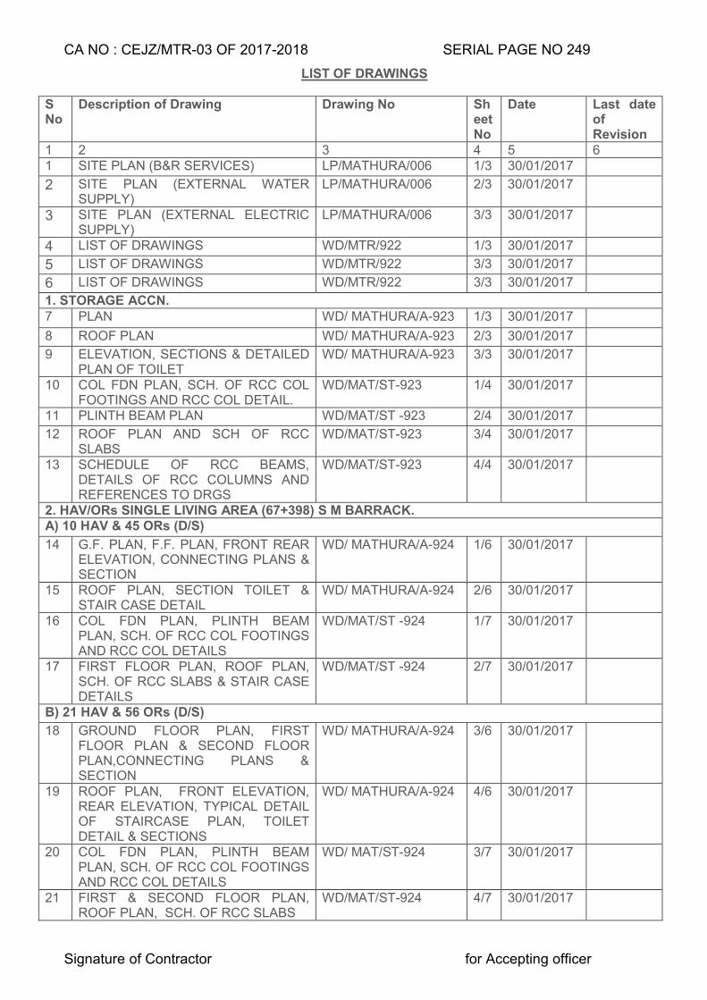
CA NO : CEJZ/MTR-03 OF 2017-2018 SERIAL PAGE NO 249
Signature of Contractor for Accepting officer
LIST OF DRAWINGS
S No
Description of Drawing Drawing No Sheet No
Date Last date of Revision
1 2 3 4 5 6 1 SITE PLAN (B&R SERVICES) LP/MATHURA/006 1/3 30/01/2017
2 SITE PLAN (EXTERNAL WATER SUPPLY)
LP/MATHURA/006 2/3 30/01/2017
3 SITE PLAN (EXTERNAL ELECTRIC SUPPLY)
LP/MATHURA/006 3/3 30/01/2017
4 LIST OF DRAWINGS WD/MTR/922 1/3 30/01/2017
5 LIST OF DRAWINGS WD/MTR/922 3/3 30/01/2017
6 LIST OF DRAWINGS WD/MTR/922 3/3 30/01/2017 1. STORAGE ACCN. 7 PLAN WD/ MATHURA/A-923 1/3 30/01/2017
8 ROOF PLAN WD/ MATHURA/A-923 2/3 30/01/2017 9 ELEVATION, SECTIONS & DETAILED
PLAN OF TOILET WD/ MATHURA/A-923 3/3 30/01/2017
10 COL FDN PLAN, SCH. OF RCC COL FOOTINGS AND RCC COL DETAIL.
WD/MAT/ST-923 1/4 30/01/2017
11 PLINTH BEAM PLAN WD/MAT/ST -923 2/4 30/01/2017 12 ROOF PLAN AND SCH OF RCC
SLABS WD/MAT/ST-923 3/4 30/01/2017
13 SCHEDULE OF RCC BEAMS, DETAILS OF RCC COLUMNS AND REFERENCES TO DRGS
WD/MAT/ST-923 4/4 30/01/2017
2. HAV/ORs SINGLE LIVING AREA (67+398) S M BARRACK. A) 10 HAV & 45 ORs (D/S)
14 G.F. PLAN, F.F. PLAN, FRONT REAR ELEVATION, CONNECTING PLANS & SECTION
WD/ MATHURA/A-924 1/6 30/01/2017
15 ROOF PLAN, SECTION TOILET & STAIR CASE DETAIL
WD/ MATHURA/A-924 2/6 30/01/2017
16 COL FDN PLAN, PLINTH BEAM PLAN, SCH. OF RCC COL FOOTINGS AND RCC COL DETAILS
WD/MAT/ST -924 1/7 30/01/2017
17 FIRST FLOOR PLAN, ROOF PLAN, SCH. OF RCC SLABS & STAIR CASE DETAILS
WD/MAT/ST -924 2/7 30/01/2017
B) 21 HAV & 56 ORs (D/S)
18 GROUND FLOOR PLAN, FIRST FLOOR PLAN & SECOND FLOOR PLAN,CONNECTING PLANS & SECTION
WD/ MATHURA/A-924 3/6 30/01/2017
19 ROOF PLAN, FRONT ELEVATION, REAR ELEVATION, TYPICAL DETAIL OF STAIRCASE PLAN, TOILET DETAIL & SECTIONS
WD/ MATHURA/A-924 4/6 30/01/2017
20 COL FDN PLAN, PLINTH BEAM PLAN, SCH. OF RCC COL FOOTINGS AND RCC COL DETAILS
WD/ MAT/ST-924 3/7 30/01/2017
21 FIRST & SECOND FLOOR PLAN, ROOF PLAN, SCH. OF RCC SLABS
WD/MAT/ST-924 4/7 30/01/2017
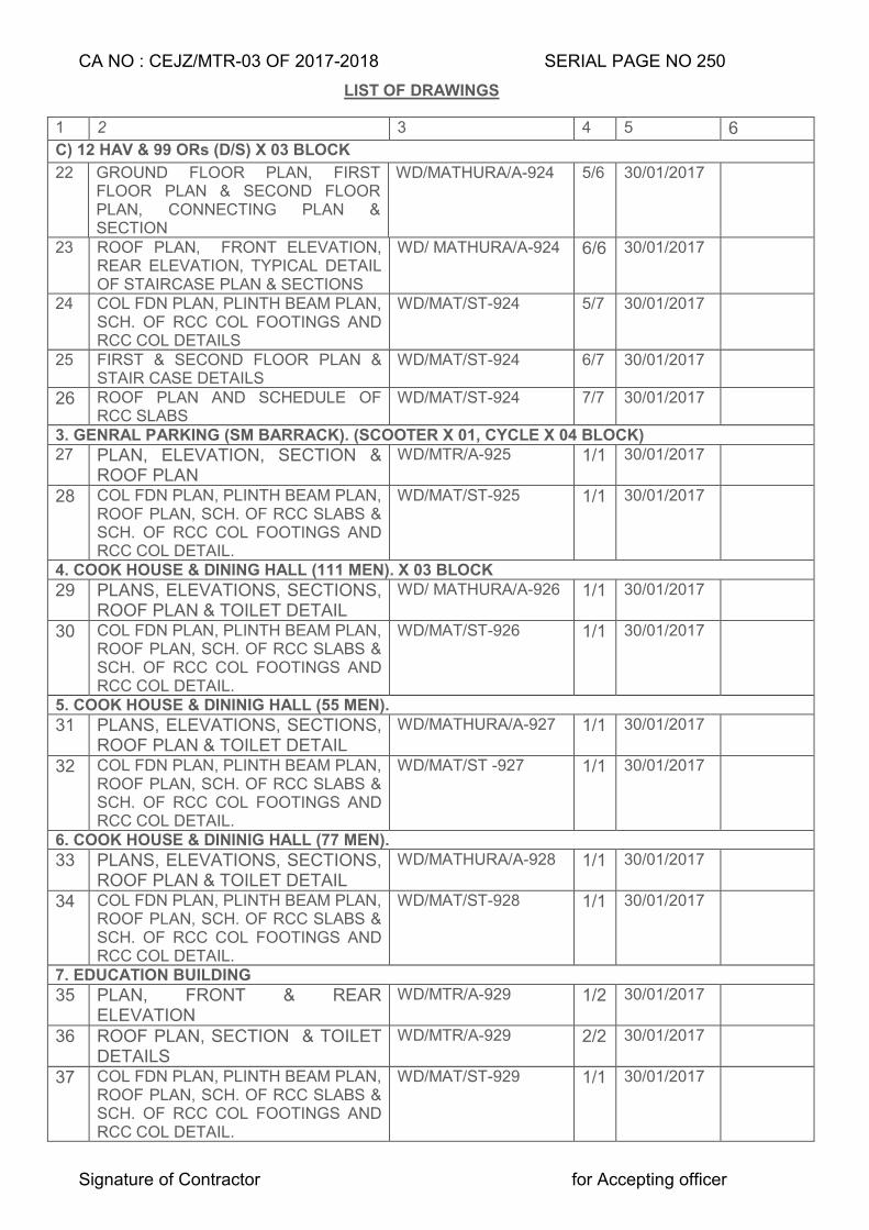
CA NO : CEJZ/MTR-03 OF 2017-2018 SERIAL PAGE NO 250
Signature of Contractor for Accepting officer
LIST OF DRAWINGS
1 2 3 4 5 6 C) 12 HAV & 99 ORs (D/S) X 03 BLOCK
22 GROUND FLOOR PLAN, FIRST FLOOR PLAN & SECOND FLOOR PLAN, CONNECTING PLAN & SECTION
WD/MATHURA/A-924 5/6 30/01/2017
23 ROOF PLAN, FRONT ELEVATION, REAR ELEVATION, TYPICAL DETAIL OF STAIRCASE PLAN & SECTIONS
WD/ MATHURA/A-924 6/6 30/01/2017
24 COL FDN PLAN, PLINTH BEAM PLAN, SCH. OF RCC COL FOOTINGS AND RCC COL DETAILS
WD/MAT/ST-924 5/7 30/01/2017
25 FIRST & SECOND FLOOR PLAN & STAIR CASE DETAILS
WD/MAT/ST-924 6/7 30/01/2017
26 ROOF PLAN AND SCHEDULE OF RCC SLABS
WD/MAT/ST-924 7/7 30/01/2017
3. GENRAL PARKING (SM BARRACK). (SCOOTER X 01, CYCLE X 04 BLOCK) 27 PLAN, ELEVATION, SECTION &
ROOF PLAN WD/MTR/A-925 1/1 30/01/2017
28 COL FDN PLAN, PLINTH BEAM PLAN, ROOF PLAN, SCH. OF RCC SLABS & SCH. OF RCC COL FOOTINGS AND RCC COL DETAIL.
WD/MAT/ST-925 1/1 30/01/2017
4. COOK HOUSE & DINING HALL (111 MEN). X 03 BLOCK 29 PLANS, ELEVATIONS, SECTIONS,
ROOF PLAN & TOILET DETAIL WD/ MATHURA/A-926 1/1 30/01/2017
30 COL FDN PLAN, PLINTH BEAM PLAN, ROOF PLAN, SCH. OF RCC SLABS & SCH. OF RCC COL FOOTINGS AND RCC COL DETAIL.
WD/MAT/ST-926 1/1 30/01/2017
5. COOK HOUSE & DININIG HALL (55 MEN). 31 PLANS, ELEVATIONS, SECTIONS,
ROOF PLAN & TOILET DETAIL WD/MATHURA/A-927 1/1 30/01/2017
32 COL FDN PLAN, PLINTH BEAM PLAN, ROOF PLAN, SCH. OF RCC SLABS & SCH. OF RCC COL FOOTINGS AND RCC COL DETAIL.
WD/MAT/ST -927 1/1 30/01/2017
6. COOK HOUSE & DININIG HALL (77 MEN). 33 PLANS, ELEVATIONS, SECTIONS,
ROOF PLAN & TOILET DETAIL WD/MATHURA/A-928 1/1 30/01/2017
34 COL FDN PLAN, PLINTH BEAM PLAN, ROOF PLAN, SCH. OF RCC SLABS & SCH. OF RCC COL FOOTINGS AND RCC COL DETAIL.
WD/MAT/ST-928 1/1 30/01/2017
7. EDUCATION BUILDING 35 PLAN, FRONT & REAR
ELEVATION WD/MTR/A-929 1/2 30/01/2017
36 ROOF PLAN, SECTION & TOILET DETAILS
WD/MTR/A-929 2/2 30/01/2017
37 COL FDN PLAN, PLINTH BEAM PLAN, ROOF PLAN, SCH. OF RCC SLABS & SCH. OF RCC COL FOOTINGS AND RCC COL DETAIL.
WD/MAT/ST-929 1/1 30/01/2017
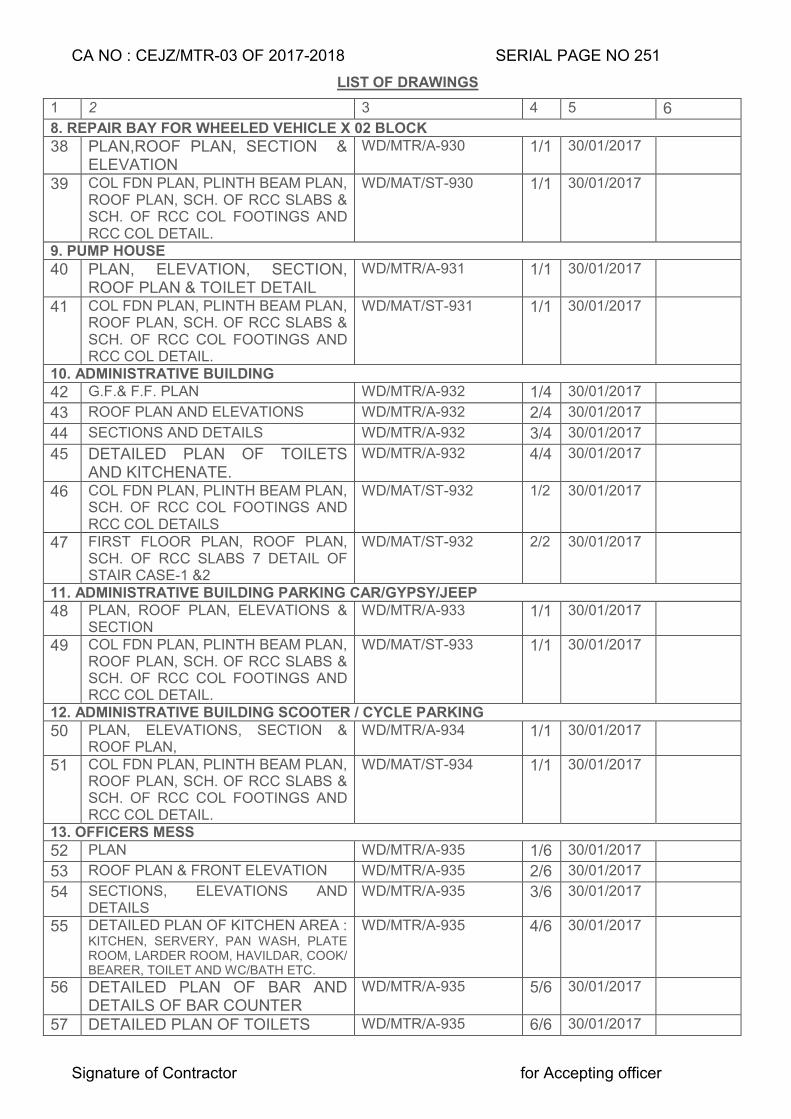
CA NO : CEJZ/MTR-03 OF 2017-2018 SERIAL PAGE NO 251
Signature of Contractor for Accepting officer
LIST OF DRAWINGS
1 2 3 4 5 6 8. REPAIR BAY FOR WHEELED VEHICLE X 02 BLOCK 38 PLAN,ROOF PLAN, SECTION &
ELEVATION WD/MTR/A-930 1/1 30/01/2017
39 COL FDN PLAN, PLINTH BEAM PLAN, ROOF PLAN, SCH. OF RCC SLABS & SCH. OF RCC COL FOOTINGS AND RCC COL DETAIL.
WD/MAT/ST-930 1/1 30/01/2017
9. PUMP HOUSE 40 PLAN, ELEVATION, SECTION,
ROOF PLAN & TOILET DETAIL WD/MTR/A-931 1/1 30/01/2017
41 COL FDN PLAN, PLINTH BEAM PLAN, ROOF PLAN, SCH. OF RCC SLABS & SCH. OF RCC COL FOOTINGS AND RCC COL DETAIL.
WD/MAT/ST-931 1/1 30/01/2017
10. ADMINISTRATIVE BUILDING 42 G.F.& F.F. PLAN WD/MTR/A-932 1/4 30/01/2017
43 ROOF PLAN AND ELEVATIONS WD/MTR/A-932 2/4 30/01/2017
44 SECTIONS AND DETAILS WD/MTR/A-932 3/4 30/01/2017
45 DETAILED PLAN OF TOILETS AND KITCHENATE.
WD/MTR/A-932 4/4 30/01/2017
46 COL FDN PLAN, PLINTH BEAM PLAN, SCH. OF RCC COL FOOTINGS AND RCC COL DETAILS
WD/MAT/ST-932 1/2 30/01/2017
47 FIRST FLOOR PLAN, ROOF PLAN, SCH. OF RCC SLABS 7 DETAIL OF STAIR CASE-1 &2
WD/MAT/ST-932 2/2 30/01/2017
11. ADMINISTRATIVE BUILDING PARKING CAR/GYPSY/JEEP 48 PLAN, ROOF PLAN, ELEVATIONS &
SECTION WD/MTR/A-933 1/1 30/01/2017
49 COL FDN PLAN, PLINTH BEAM PLAN, ROOF PLAN, SCH. OF RCC SLABS & SCH. OF RCC COL FOOTINGS AND RCC COL DETAIL.
WD/MAT/ST-933 1/1 30/01/2017
12. ADMINISTRATIVE BUILDING SCOOTER / CYCLE PARKING 50 PLAN, ELEVATIONS, SECTION &
ROOF PLAN, WD/MTR/A-934 1/1 30/01/2017
51 COL FDN PLAN, PLINTH BEAM PLAN, ROOF PLAN, SCH. OF RCC SLABS & SCH. OF RCC COL FOOTINGS AND RCC COL DETAIL.
WD/MAT/ST-934 1/1 30/01/2017
13. OFFICERS MESS 52 PLAN WD/MTR/A-935 1/6 30/01/2017
53 ROOF PLAN & FRONT ELEVATION WD/MTR/A-935 2/6 30/01/2017
54 SECTIONS, ELEVATIONS AND DETAILS
WD/MTR/A-935 3/6 30/01/2017
55 DETAILED PLAN OF KITCHEN AREA : KITCHEN, SERVERY, PAN WASH, PLATE ROOM, LARDER ROOM, HAVILDAR, COOK/ BEARER, TOILET AND WC/BATH ETC.
WD/MTR/A-935 4/6 30/01/2017
56 DETAILED PLAN OF BAR AND DETAILS OF BAR COUNTER
WD/MTR/A-935 5/6 30/01/2017
57 DETAILED PLAN OF TOILETS WD/MTR/A-935 6/6 30/01/2017
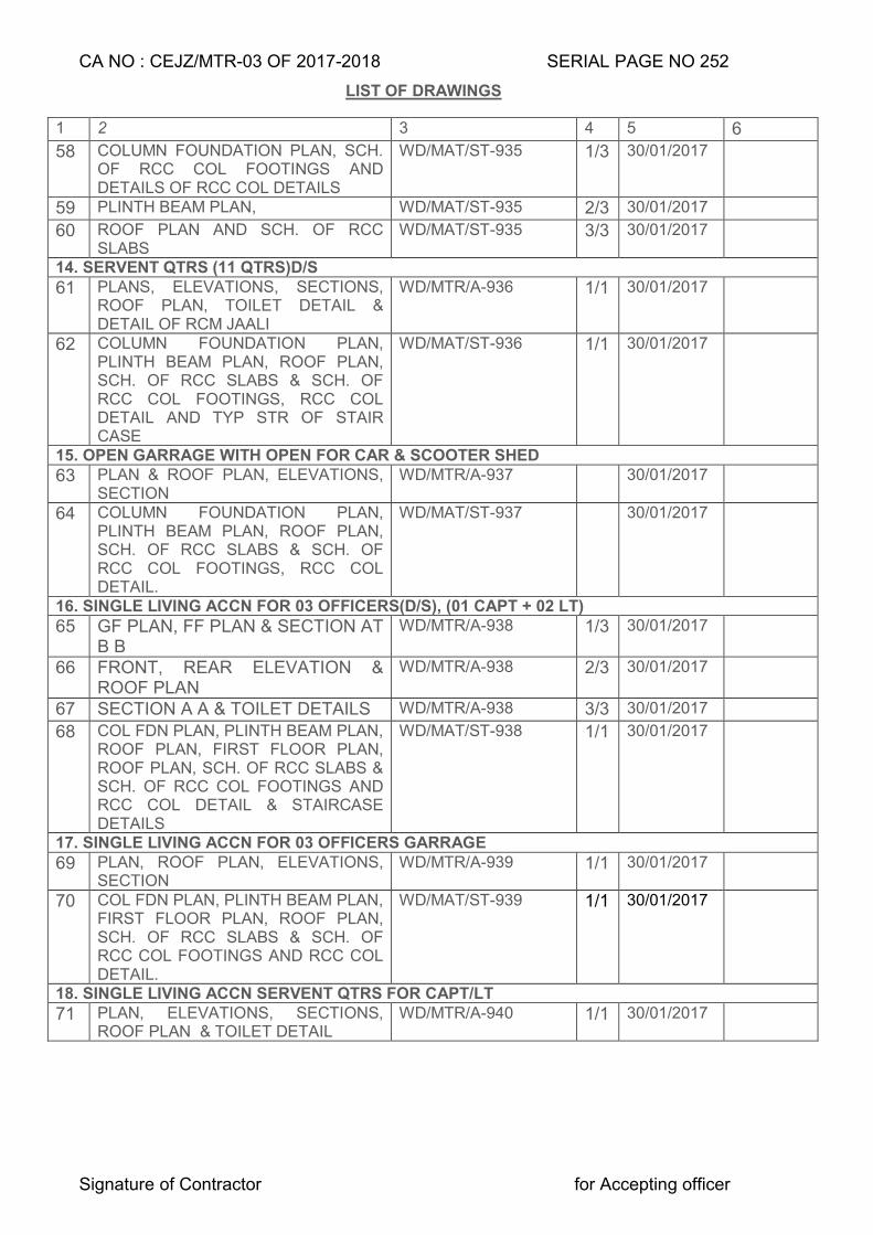
CA NO : CEJZ/MTR-03 OF 2017-2018 SERIAL PAGE NO 252
Signature of Contractor for Accepting officer
LIST OF DRAWINGS
1 2 3 4 5 6
58 COLUMN FOUNDATION PLAN, SCH. OF RCC COL FOOTINGS AND DETAILS OF RCC COL DETAILS
WD/MAT/ST-935 1/3 30/01/2017
59 PLINTH BEAM PLAN, WD/MAT/ST-935 2/3 30/01/2017
60 ROOF PLAN AND SCH. OF RCC SLABS
WD/MAT/ST-935 3/3 30/01/2017
14. SERVENT QTRS (11 QTRS)D/S 61 PLANS, ELEVATIONS, SECTIONS,
ROOF PLAN, TOILET DETAIL & DETAIL OF RCM JAALI
WD/MTR/A-936 1/1 30/01/2017
62 COLUMN FOUNDATION PLAN, PLINTH BEAM PLAN, ROOF PLAN, SCH. OF RCC SLABS & SCH. OF RCC COL FOOTINGS, RCC COL DETAIL AND TYP STR OF STAIR CASE
WD/MAT/ST-936 1/1 30/01/2017
15. OPEN GARRAGE WITH OPEN FOR CAR & SCOOTER SHED 63 PLAN & ROOF PLAN, ELEVATIONS,
SECTION WD/MTR/A-937 30/01/2017
64 COLUMN FOUNDATION PLAN, PLINTH BEAM PLAN, ROOF PLAN, SCH. OF RCC SLABS & SCH. OF RCC COL FOOTINGS, RCC COL DETAIL.
WD/MAT/ST-937 30/01/2017
16. SINGLE LIVING ACCN FOR 03 OFFICERS(D/S), (01 CAPT + 02 LT) 65 GF PLAN, FF PLAN & SECTION AT
B B WD/MTR/A-938 1/3 30/01/2017
66 FRONT, REAR ELEVATION & ROOF PLAN
WD/MTR/A-938 2/3 30/01/2017
67 SECTION A A & TOILET DETAILS WD/MTR/A-938 3/3 30/01/2017
68 COL FDN PLAN, PLINTH BEAM PLAN, ROOF PLAN, FIRST FLOOR PLAN, ROOF PLAN, SCH. OF RCC SLABS & SCH. OF RCC COL FOOTINGS AND RCC COL DETAIL & STAIRCASE DETAILS
WD/MAT/ST-938 1/1 30/01/2017
17. SINGLE LIVING ACCN FOR 03 OFFICERS GARRAGE 69 PLAN, ROOF PLAN, ELEVATIONS,
SECTION WD/MTR/A-939 1/1 30/01/2017
70 COL FDN PLAN, PLINTH BEAM PLAN, FIRST FLOOR PLAN, ROOF PLAN, SCH. OF RCC SLABS & SCH. OF RCC COL FOOTINGS AND RCC COL DETAIL.
WD/MAT/ST-939 1/1 30/01/2017
18. SINGLE LIVING ACCN SERVENT QTRS FOR CAPT/LT 71 PLAN, ELEVATIONS, SECTIONS,
ROOF PLAN & TOILET DETAIL WD/MTR/A-940 1/1 30/01/2017
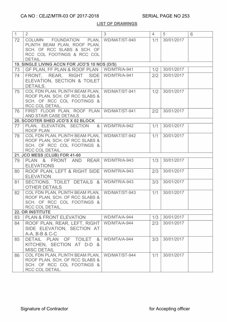
CA NO : CEJZ/MTR-03 OF 2017-2018 SERIAL PAGE NO 253
Signature of Contractor for Accepting officer
LIST OF DRAWINGS
1 2 3 4 5 6
72 COLUMN FOUNDATION PLAN, PLINTH BEAM PLAN, ROOF PLAN, SCH. OF RCC SLABS & SCH. OF RCC COL FOOTINGS & RCC COL DETAIL.
WD/MAT/ST-940 1/1 30/01/2017
19. SINGLE LIVING ACCN FOR JCO’S 10 NOS (D/S) 73 GF PLAN, FF PLAN & ROOF PLAN WD/MTR/A-941 1/2 30/01/2017
74 FRONT, REAR, RIGHT SIDE ELEVATION, SECTION & TOILET DETAILS.
WD/MTR/A-941 2/2 30/01/2017
75 COL FDN PLAN, PLINTH BEAM PLAN, ROOF PLAN, SCH. OF RCC SLABS & SCH. OF RCC COL FOOTINGS & RCC COL DETAIL.
WD/MAT/ST-941 1/2 30/01/2017
76 FIRST FLOOR PLAN, ROOF PLAN AND STAIR CASE DETAILS
WD/MAT/ST-941 2/2 30/01/2017
20. SCOOTER SHED JCO’S X 02 BLOCK 77 PLAN, ELEVATION, SECTION &
ROOF PLAN WD/MTR/A-942 1/1 30/01/2017
78 COL FDN PLAN, PLINTH BEAM PLAN, ROOF PLAN, SCH. OF RCC SLABS & SCH. OF RCC COL FOOTINGS & RCC COL DETAIL.
WD/MAT/ST-942 1/1 30/01/2017
21. JCO MESS (CLUB) FOR 41-60 79 PLAN & FRONT AND REAR
ELEVATIONS WD/MTR/A-943 1/3 30/01/2017
80 ROOF PLAN, LEFT & RIGHT SIDE ELEVATION
WD/MTR/A-943 2/3 30/01/2017
81 SECTIONS, TOILET DETAILS & OTHER DETAILS
WD/MTR/A-943 3/3 30/01/2017
82 COL FDN PLAN, PLINTH BEAM PLAN, ROOF PLAN, SCH. OF RCC SLABS & SCH. OF RCC COL FOOTINGS & RCC COL DETAIL.
WD/MAT/ST-943 1/1 30/01/2017
22. OR INSTITUTE 83 PLAN & FRONT ELEVATION WD/MTA/A-944 1/3 30/01/2017
84 ROOF PLAN, REAR, LEFT, RIGHT SIDE ELEVATION, SECTION AT A-A, B-B & C-C
WD/MTA/A-944 2/3 30/01/2017
85 DETAIL PLAN OF TOILET & KITCHEN, SECTION AT D-D & MISC DETAIL
WD/MTA/A-944 3/3 30/01/2017
86 COL FDN PLAN, PLINTH BEAM PLAN, ROOF PLAN, SCH. OF RCC SLABS & SCH. OF RCC COL FOOTINGS & RCC COL DETAIL.
WD/MAT/ST-944 1/1 30/01/2017
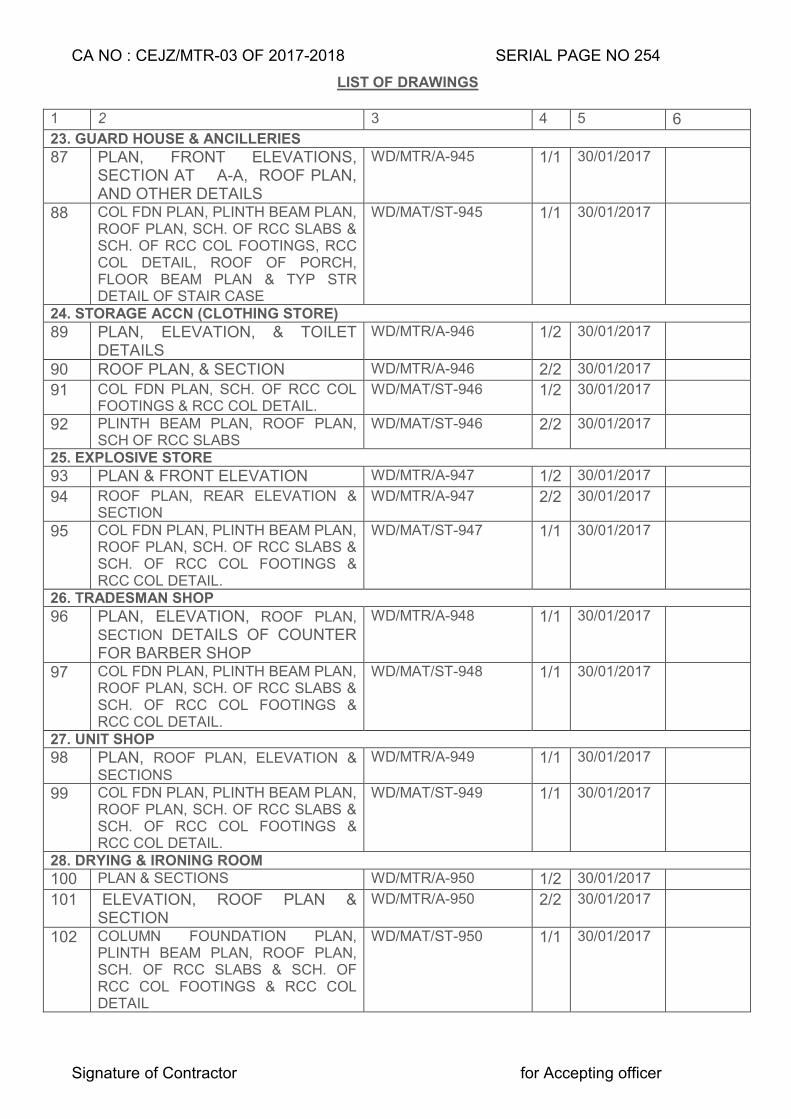
CA NO : CEJZ/MTR-03 OF 2017-2018 SERIAL PAGE NO 254
Signature of Contractor for Accepting officer
LIST OF DRAWINGS
1 2 3 4 5 6 23. GUARD HOUSE & ANCILLERIES 87 PLAN, FRONT ELEVATIONS,
SECTION AT A-A, ROOF PLAN, AND OTHER DETAILS
WD/MTR/A-945 1/1 30/01/2017
88 COL FDN PLAN, PLINTH BEAM PLAN, ROOF PLAN, SCH. OF RCC SLABS & SCH. OF RCC COL FOOTINGS, RCC COL DETAIL, ROOF OF PORCH, FLOOR BEAM PLAN & TYP STR DETAIL OF STAIR CASE
WD/MAT/ST-945 1/1 30/01/2017
24. STORAGE ACCN (CLOTHING STORE) 89 PLAN, ELEVATION, & TOILET
DETAILS WD/MTR/A-946 1/2 30/01/2017
90 ROOF PLAN, & SECTION WD/MTR/A-946 2/2 30/01/2017
91 COL FDN PLAN, SCH. OF RCC COL FOOTINGS & RCC COL DETAIL.
WD/MAT/ST-946 1/2 30/01/2017
92 PLINTH BEAM PLAN, ROOF PLAN, SCH OF RCC SLABS
WD/MAT/ST-946 2/2 30/01/2017
25. EXPLOSIVE STORE 93 PLAN & FRONT ELEVATION WD/MTR/A-947 1/2 30/01/2017
94 ROOF PLAN, REAR ELEVATION & SECTION
WD/MTR/A-947 2/2 30/01/2017
95 COL FDN PLAN, PLINTH BEAM PLAN, ROOF PLAN, SCH. OF RCC SLABS & SCH. OF RCC COL FOOTINGS & RCC COL DETAIL.
WD/MAT/ST-947 1/1 30/01/2017
26. TRADESMAN SHOP 96 PLAN, ELEVATION, ROOF PLAN,
SECTION DETAILS OF COUNTER FOR BARBER SHOP
WD/MTR/A-948 1/1 30/01/2017
97 COL FDN PLAN, PLINTH BEAM PLAN, ROOF PLAN, SCH. OF RCC SLABS & SCH. OF RCC COL FOOTINGS & RCC COL DETAIL.
WD/MAT/ST-948 1/1 30/01/2017
27. UNIT SHOP 98 PLAN, ROOF PLAN, ELEVATION &
SECTIONS WD/MTR/A-949 1/1 30/01/2017
99 COL FDN PLAN, PLINTH BEAM PLAN, ROOF PLAN, SCH. OF RCC SLABS & SCH. OF RCC COL FOOTINGS & RCC COL DETAIL.
WD/MAT/ST-949 1/1 30/01/2017
28. DRYING & IRONING ROOM 100 PLAN & SECTIONS WD/MTR/A-950 1/2 30/01/2017
101 ELEVATION, ROOF PLAN & SECTION
WD/MTR/A-950 2/2 30/01/2017
102 COLUMN FOUNDATION PLAN, PLINTH BEAM PLAN, ROOF PLAN, SCH. OF RCC SLABS & SCH. OF RCC COL FOOTINGS & RCC COL DETAIL
WD/MAT/ST-950 1/1 30/01/2017
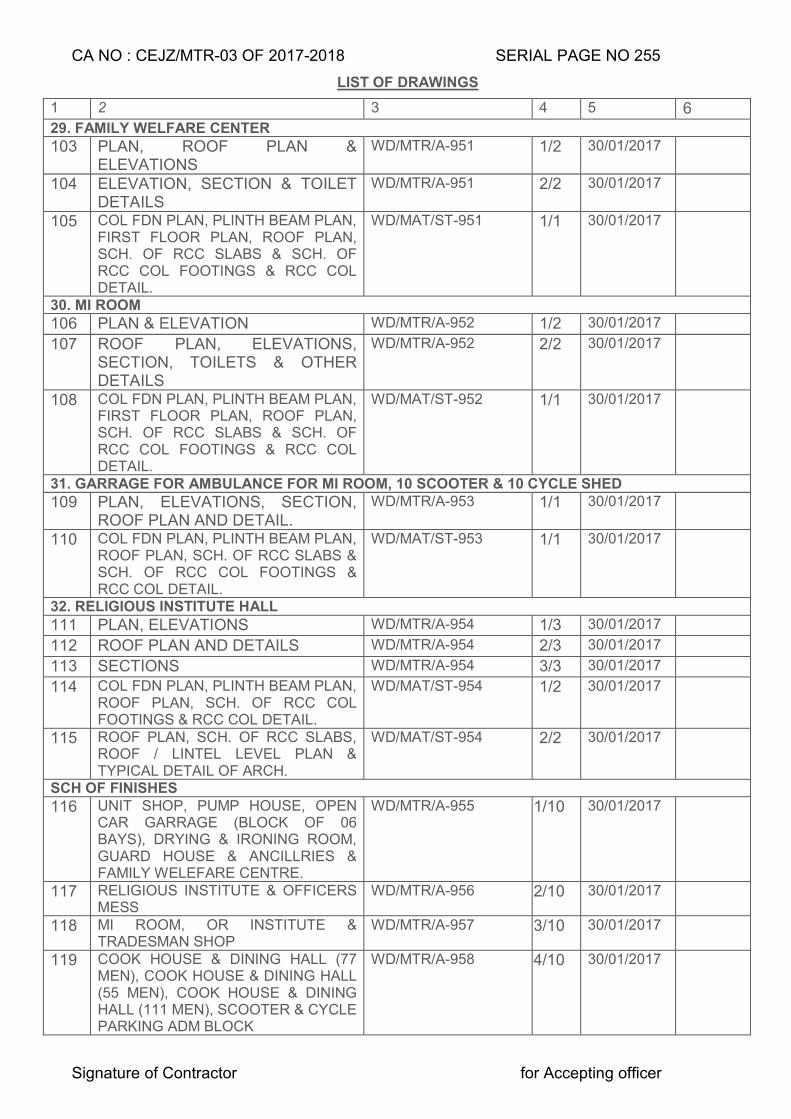
CA NO : CEJZ/MTR-03 OF 2017-2018 SERIAL PAGE NO 255
Signature of Contractor for Accepting officer
LIST OF DRAWINGS
1 2 3 4 5 6 29. FAMILY WELFARE CENTER 103 PLAN, ROOF PLAN &
ELEVATIONS WD/MTR/A-951 1/2 30/01/2017
104 ELEVATION, SECTION & TOILET DETAILS
WD/MTR/A-951 2/2 30/01/2017
105 COL FDN PLAN, PLINTH BEAM PLAN, FIRST FLOOR PLAN, ROOF PLAN, SCH. OF RCC SLABS & SCH. OF RCC COL FOOTINGS & RCC COL DETAIL.
WD/MAT/ST-951 1/1 30/01/2017
30. MI ROOM 106 PLAN & ELEVATION WD/MTR/A-952 1/2 30/01/2017
107 ROOF PLAN, ELEVATIONS, SECTION, TOILETS & OTHER DETAILS
WD/MTR/A-952 2/2 30/01/2017
108 COL FDN PLAN, PLINTH BEAM PLAN, FIRST FLOOR PLAN, ROOF PLAN, SCH. OF RCC SLABS & SCH. OF RCC COL FOOTINGS & RCC COL DETAIL.
WD/MAT/ST-952 1/1 30/01/2017
31. GARRAGE FOR AMBULANCE FOR MI ROOM, 10 SCOOTER & 10 CYCLE SHED 109 PLAN, ELEVATIONS, SECTION,
ROOF PLAN AND DETAIL. WD/MTR/A-953 1/1 30/01/2017
110 COL FDN PLAN, PLINTH BEAM PLAN, ROOF PLAN, SCH. OF RCC SLABS & SCH. OF RCC COL FOOTINGS & RCC COL DETAIL.
WD/MAT/ST-953 1/1 30/01/2017
32. RELIGIOUS INSTITUTE HALL 111 PLAN, ELEVATIONS WD/MTR/A-954 1/3 30/01/2017
112 ROOF PLAN AND DETAILS WD/MTR/A-954 2/3 30/01/2017
113 SECTIONS WD/MTR/A-954 3/3 30/01/2017
114 COL FDN PLAN, PLINTH BEAM PLAN, ROOF PLAN, SCH. OF RCC COL FOOTINGS & RCC COL DETAIL.
WD/MAT/ST-954 1/2 30/01/2017
115 ROOF PLAN, SCH. OF RCC SLABS, ROOF / LINTEL LEVEL PLAN & TYPICAL DETAIL OF ARCH.
WD/MAT/ST-954 2/2 30/01/2017
SCH OF FINISHES 116 UNIT SHOP, PUMP HOUSE, OPEN
CAR GARRAGE (BLOCK OF 06 BAYS), DRYING & IRONING ROOM, GUARD HOUSE & ANCILLRIES & FAMILY WELEFARE CENTRE.
WD/MTR/A-955 1/10 30/01/2017
117 RELIGIOUS INSTITUTE & OFFICERS MESS
WD/MTR/A-956 2/10 30/01/2017
118 MI ROOM, OR INSTITUTE & TRADESMAN SHOP
WD/MTR/A-957 3/10 30/01/2017
119 COOK HOUSE & DINING HALL (77 MEN), COOK HOUSE & DINING HALL (55 MEN), COOK HOUSE & DINING HALL (111 MEN), SCOOTER & CYCLE PARKING ADM BLOCK
WD/MTR/A-958 4/10 30/01/2017
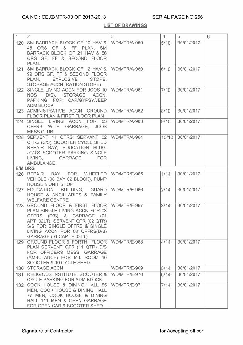
CA NO : CEJZ/MTR-03 OF 2017-2018 SERIAL PAGE NO 256
Signature of Contractor for Accepting officer
LIST OF DRAWINGS
1 2 3 4 5 6
120 SM BARRACK BLOCK OF 10 HAV & 45 ORS GF & FF PLAN, SM BARRACK BLOCK OF 21 HAV & 56 ORS GF, FF & SECOND FLOOR PLAN.
WD/MTR/A-959 5/10 30/01/2017
121 SM BARRACK BLOCK OF 12 HAV & 99 ORS GF, FF & SECOND FLOOR PLAN, EXPLOSIVE STORE, STORAGE ACCN (RATION STORE)
WD/MTR/A-960 6/10 30/01/2017
122 SINGLE LIVING ACCN FOR JCOS 10 NOS (D/S), STORAGE ACCN, PARKING FOR CAR/GYPSY/JEEP ADM BLOCK
WD/MTR/A-961 7/10 30/01/2017
123 ADMINISTRATIVE ACCN GROUND FLOOR PLAN & FIRST FLOOR PLAN
WD/MTR/A-962 8/10 30/01/2017
124 SINGLE LIVING ACCN FOR 03 OFFRS WITH GARRAGE, JCOS MESS CLUB
WD/MTR/A-963 9/10 30/01/2017
125 SERVENT 11 QTRS, SERVANT 02 QTRS (S/S), SCOOTER CYCLE SHED REPAIR BAY, EDUCATION BLDG, JCO’S SCOOTER PARKING SINGLE LIVING, GARRAGE FOR AMBULANCE
WD/MTR/A-964 10/10 30/01/2017
E/M DRG 126 REPAIR BAY FOR WHEELED
VEHICLE (06 BAY 02 BLOCK), PUMP HOUSE & UNIT SHOP
WD/MTR/E-965 1/14 30/01/2017
127 EDUCATION BUILDING, GUARD HOUSE & ANCILLARIES & FAMILY WELFARE CENTRE
WD/MTR/E-966 2/14 30/01/2017
128 GROUND FLOOR & FIRST FLOOR PLAN SINGLE LIVING ACCN FOR 03 OFFRS (D/S) & GARRAGE (01 APT+02LT), SERVENT QTR (02 QTR) S/S FOR SINGLE OFFRS & SINGLE LIVING ACCN FOR 03 OFFRS(D/S) GARRAGE (01 CAPT + 02LT)
WD/MTR/E-967 3/14 30/01/2017
129 GROUND FLOOR & FORTH FLOOR PLAN SERVENT QTR (11 QTR) D/S FOR OFFICERS MESS, GARRAGE (AMBULANCE) FOR M.I. ROOM 10 SCOOTER & 10 CYCLE SHED
WD/MTR/E-968 4/14 30/01/2017
130 STORAGE ACCN WD/MTR/E-969 5/14 30/01/2017
131 RELIGIOUS INSTITUTE, SCOOTER & CYCLE PARKING FOR ADM BLOCK.
WD/MTR/E-970 6/14 30/01/2017
132 COOK HOUSE & DINING HALL 55 MEN, COOK HOUSE & DINING HALL 77 MEN, COOK HOUSE & DINING HALL 111 MEN & OPEN GARRAGE FOR OPEN CAR & SCOOTER SHED
WD/MTR/E-971 7/14 30/01/2017
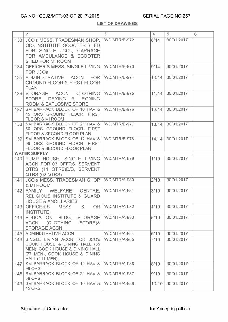
CA NO : CEJZ/MTR-03 OF 2017-2018 SERIAL PAGE NO 257
Signature of Contractor for Accepting officer
LIST OF DRAWINGS
1 2 3 4 5 6
133 JCO’s MESS, TRADESMAN SHOP, ORs INSTITUTE, SCOOTER SHED FOR SINGLE JCOs, GARRAGE FOR AMBULANCE & SCOOTER SHED FOR MI ROOM
WD/MTR/E-972 8/14 30/01/2017
134 OFFICER’S MESS, SINGLE LIVING FOR JCOs
WD/MTR/E-973 9/14 30/01/2017
135 ADMINISTRATIVE ACCN FOR GROUND FLOOR & FIRST FLOOR PLAN.
WD/MTR/E-974 10/14 30/01/2017
136 STORAGE ACCN CLOTHING STORE, DRYING & IRONING ROOM & EXPLOSIVE STORE.
WD/MTR/E-975 11/14 30/01/2017
137 SM BARRACK BLOCK OF 10 HAV & 45 ORS GROUND FLOOR, FIRST FLOOR & MI ROOM
WD/MTR/E-976 12/14 30/01/2017
138 SM BARRACK BLOCK OF 21 HAV & 56 ORS GROUND FLOOR, FIRST FLOOR & SECOND FLOOR PLAN
WD/MTR/E-977 13/14 30/01/2017
139 SM BARRACK BLOCK OF 12 HAV & 99 ORS GROUND FLOOR, FIRST FLOOR & SECOND FLOOR PLAN
WD/MTR/E-978 14/14 30/01/2017
WATER SUPPLY 140 PUMP HOUSE, SINGLE LIVING
ACCN FOR 03 OFFRS, SERVENT QTRS (11 QTRS)D/S, SERVENT QTRS (02 QTRS)
WD/MTR/A-979 1/10 30/01/2017
141 JCO’s MESS, TRADESMAN SHOP & MI ROOM
WD/MTR/A-980 2/10 30/01/2017
142 FAMILY WELFARE CENTRE, RELIGIOUS INSTITUTE & GUARD HOUSE & ANCILLARIES
WD/MTR/A-981 3/10 30/01/2017
143 OFFICER’S MESS, & OR INSTITUTE
WD/MTR/A-982 4/10 30/01/2017
144 EDUCATION BLDG, STORAGE ACCN (CLOTHING STORE)& STORAGE ACCN
WD/MTR/A-983 5/10 30/01/2017
145 ADMINISTRATIVE ACCN WD/MTR/A-984 6/10 30/01/2017
146 SINGLE LIVING ACCN FOR JCO’s COOK HOUSE & DINING HALL (55 MEN), COOK HOUSE & DINING HALL (77 MEN), COOK HOUSE & DINING HALL (111 MEN),
WD/MTR/A-985 7/10 30/01/2017
147 SM BARRACK BLOCK OF 12 HAV & 99 ORS
WD/MTR/A-986 8/10 30/01/2017
148 SM BARRACK BLOCK OF 21 HAV & 56 ORS
WD/MTR/A-987 9/10 30/01/2017
149 SM BARRACK BLOCK OF 10 HAV & 45 ORS
WD/MTR/A-988 10/10 30/01/2017
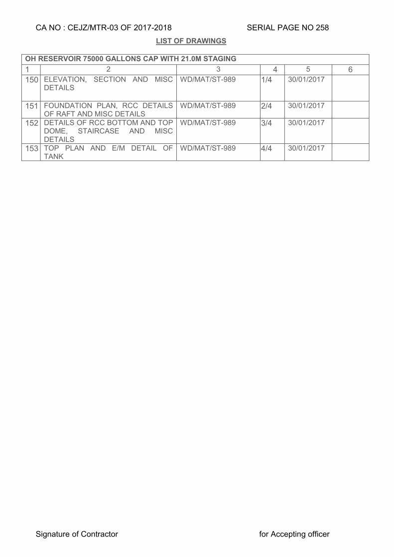
CA NO : CEJZ/MTR-03 OF 2017-2018 SERIAL PAGE NO 258
Signature of Contractor for Accepting officer
LIST OF DRAWINGS
OH RESERVOIR 75000 GALLONS CAP WITH 21.0M STAGING
1 2 3 4 5 6
150 ELEVATION, SECTION AND MISC DETAILS
WD/MAT/ST-989 1/4 30/01/2017
151 FOUNDATION PLAN, RCC DETAILS OF RAFT AND MISC DETAILS
WD/MAT/ST-989 2/4 30/01/2017
152 DETAILS OF RCC BOTTOM AND TOP DOME, STAIRCASE AND MISC DETAILS
WD/MAT/ST-989 3/4 30/01/2017
153 TOP PLAN AND E/M DETAIL OF TANK
WD/MAT/ST-989 4/4 30/01/2017
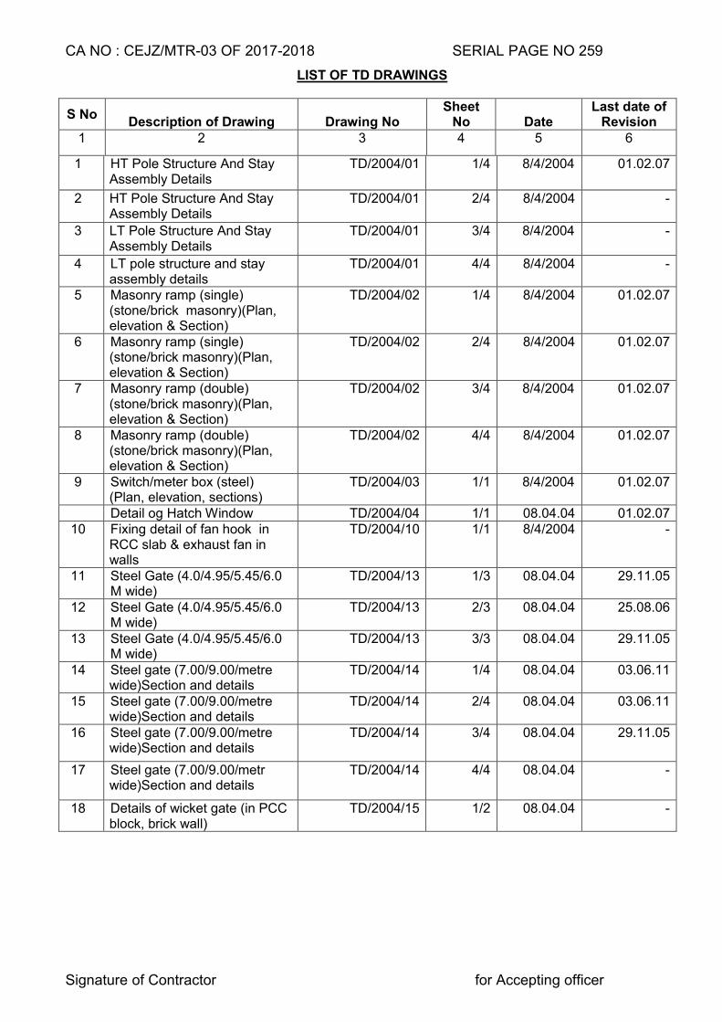
CA NO : CEJZ/MTR-03 OF 2017-2018 SERIAL PAGE NO 259
Signature of Contractor for Accepting officer
LIST OF TD DRAWINGS
S No Description of Drawing Drawing No
Sheet No Date
Last date of Revision
1 2 3 4 5 6
1 HT Pole Structure And Stay Assembly Details
TD/2004/01 1/4 8/4/2004 01.02.07
2 HT Pole Structure And Stay Assembly Details
TD/2004/01
2/4 8/4/2004 -
3 LT Pole Structure And Stay Assembly Details
TD/2004/01 3/4 8/4/2004 -
4 LT pole structure and stay assembly details
TD/2004/01 4/4 8/4/2004 -
5 Masonry ramp (single) (stone/brick masonry)(Plan, elevation & Section)
TD/2004/02 1/4 8/4/2004 01.02.07
6 Masonry ramp (single) (stone/brick masonry)(Plan, elevation & Section)
TD/2004/02 2/4 8/4/2004 01.02.07
7 Masonry ramp (double) (stone/brick masonry)(Plan, elevation & Section)
TD/2004/02 3/4 8/4/2004 01.02.07
8 Masonry ramp (double) (stone/brick masonry)(Plan, elevation & Section)
TD/2004/02 4/4 8/4/2004 01.02.07
9 Switch/meter box (steel) (Plan, elevation, sections)
TD/2004/03 1/1 8/4/2004 01.02.07
Detail og Hatch Window TD/2004/04 1/1 08.04.04 01.02.07 10 Fixing detail of fan hook in
RCC slab & exhaust fan in walls
TD/2004/10 1/1 8/4/2004 -
11 Steel Gate (4.0/4.95/5.45/6.0 M wide)
TD/2004/13 1/3 08.04.04 29.11.05
12 Steel Gate (4.0/4.95/5.45/6.0 M wide)
TD/2004/13 2/3 08.04.04 25.08.06
13 Steel Gate (4.0/4.95/5.45/6.0 M wide)
TD/2004/13 3/3 08.04.04 29.11.05
14 Steel gate (7.00/9.00/metre wide)Section and details
TD/2004/14 1/4 08.04.04 03.06.11
15 Steel gate (7.00/9.00/metre wide)Section and details
TD/2004/14 2/4 08.04.04 03.06.11
16 Steel gate (7.00/9.00/metre wide)Section and details
TD/2004/14 3/4 08.04.04 29.11.05
17 Steel gate (7.00/9.00/metr wide)Section and details
TD/2004/14 4/4 08.04.04 -
18 Details of wicket gate (in PCC block, brick wall)
TD/2004/15 1/2 08.04.04 -
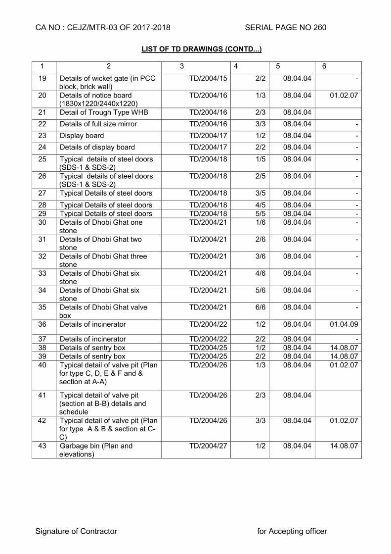
CA NO : CEJZ/MTR-03 OF 2017-2018 SERIAL PAGE NO 260
Signature of Contractor for Accepting officer
LIST OF TD DRAWINGS (CONTD...)
1 2 3 4 5 6
19 Details of wicket gate (in PCC block, brick wall)
TD/2004/15 2/2 08.04.04 -
20 Details of notice board (1830x1220/2440x1220)
TD/2004/16 1/3 08.04.04 01.02.07
21 Detail of Trough Type WHB TD/2004/16 2/3 08.04.04
22 Details of full size mirror TD/2004/16 3/3 08.04.04 -
23 Display board TD/2004/17 1/2 08.04.04 -
24 Details of display board TD/2004/17 2/2 08.04.04 -
25 Typical details of steel doors (SDS-1 & SDS-2)
TD/2004/18 1/5 08.04.04 -
26 Typical details of steel doors (SDS-1 & SDS-2)
TD/2004/18 2/5 08.04.04 -
27 Typical Details of steel doors TD/2004/18 3/5 08.04.04 -
28 Typical Details of steel doors TD/2004/18 4/5 08.04.04 - 29 Typical Details of steel doors TD/2004/18 5/5 08.04.04 - 30 Details of Dhobi Ghat one
stone TD/2004/21 1/6 08.04.04 -
31 Details of Dhobi Ghat two stone
TD/2004/21 2/6 08.04.04 -
32 Details of Dhobi Ghat three stone
TD/2004/21 3/6 08.04.04 -
33 Details of Dhobi Ghat six stone
TD/2004/21 4/6 08.04.04 -
34 Details of Dhobi Ghat six stone
TD/2004/21 5/6 08.04.04 -
35 Details of Dhobi Ghat valve box
TD/2004/21 6/6 08.04.04 -
36 Details of incinerator TD/2004/22 1/2 08.04.04 01.04.09
37 Details of incinerator TD/2004/22 2/2 08.04.04 - 38 Details of sentry box TD/2004/25 1/2 08.04.04 14.08.07 39 Details of sentry box TD/2004/25 2/2 08.04.04 14.08.07 40 Typical detail of valve pit (Plan
for type C, D, E & F and & section at A-A)
TD/2004/26 1/3 08.04.04 01.02.07
41 Typical detail of valve pit (section at B-B) details and schedule
TD/2004/26 2/3 08.04.04
42 Typical detail of valve pit (Plan for type A & B & section at C-C)
TD/2004/26 3/3 08.04.04 01.02.07
43 Garbage bin (Plan and elevations)
TD/2004/27 1/2 08.04.04 14.08.07
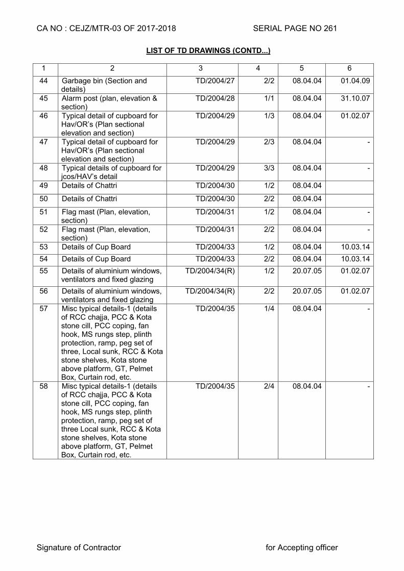
CA NO : CEJZ/MTR-03 OF 2017-2018 SERIAL PAGE NO 261
Signature of Contractor for Accepting officer
LIST OF TD DRAWINGS (CONTD...)
1 2 3 4 5 6
44 Garbage bin (Section and details)
TD/2004/27 2/2 08.04.04 01.04.09
45 Alarm post (plan, elevation & section)
TD/2004/28 1/1 08.04.04 31.10.07
46 Typical detail of cupboard for Hav/OR’s (Plan sectional elevation and section)
TD/2004/29 1/3 08.04.04 01.02.07
47 Typical detail of cupboard for Hav/OR’s (Plan sectional elevation and section)
TD/2004/29 2/3 08.04.04 -
48 Typical details of cupboard for jcos/HAV’s detail
TD/2004/29 3/3 08.04.04 -
49 Details of Chattri TD/2004/30 1/2 08.04.04
50 Details of Chattri TD/2004/30 2/2 08.04.04
51 Flag mast (Plan, elevation, section)
TD/2004/31 1/2 08.04.04 -
52 Flag mast (Plan, elevation, section)
TD/2004/31 2/2 08.04.04 -
53 Details of Cup Board TD/2004/33 1/2 08.04.04 10.03.14
54 Details of Cup Board TD/2004/33 2/2 08.04.04 10.03.14
55 Details of aluminium windows, ventilators and fixed glazing
TD/2004/34(R) 1/2 20.07.05 01.02.07
56 Details of aluminium windows, ventilators and fixed glazing
TD/2004/34(R) 2/2 20.07.05 01.02.07
57 Misc typical details-1 (details of RCC chajja, PCC & Kota stone cill, PCC coping, fan hook, MS rungs step, plinth protection, ramp, peg set of three, Local sunk, RCC & Kota stone shelves, Kota stone above platform, GT, Pelmet Box, Curtain rod, etc.
TD/2004/35 1/4 08.04.04 -
58 Misc typical details-1 (details of RCC chajja, PCC & Kota stone cill, PCC coping, fan hook, MS rungs step, plinth protection, ramp, peg set of three Local sunk, RCC & Kota stone shelves, Kota stone above platform, GT, Pelmet Box, Curtain rod, etc.
TD/2004/35 2/4 08.04.04 -
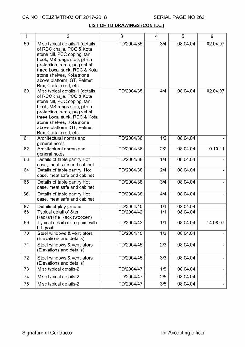
CA NO : CEJZ/MTR-03 OF 2017-2018 SERIAL PAGE NO 262
Signature of Contractor for Accepting officer
LIST OF TD DRAWINGS (CONTD...)
1 2 3 4 5 6
59 Misc typical details-1 (details of RCC chajja, PCC & Kota stone cill, PCC coping, fan hook, MS rungs step, plinth protection, ramp, peg set of three Local sunk, RCC & Kota stone shelves, Kota stone above platform, GT, Pelmet Box, Curtain rod, etc.
TD/2004/35 3/4 08.04.04 02.04.07
60 Misc typical details-1 (details of RCC chajja, PCC & Kota stone cill, PCC coping, fan hook, MS rungs step, plinth protection, ramp, peg set of three Local sunk, RCC & Kota stone shelves, Kota stone above platform, GT, Pelmet Box, Curtain rod, etc.
TD/2004/35 4/4 08.04.04 02.04.07
61 Architectural norms and general notes
TD/2004/36 1/2 08.04.04 -
62 Architectural norms and general notes
TD/2004/36 2/2 08.04.04 10.10.11
63 Details of table pantry Hot case, meat safe and cabinet
TD/2004/38 1/4 08.04.04 -
64 Details of table pantry, Hot case, meat safe and cabinet
TD/2004/38 2/4 08.04.04 -
65 Details of table pantry Hot case, meat safe and cabinet
TD/2004/38 3/4 08.04.04 -
66 Details of table pantry Hot case, meat safe and cabinet
TD/2004/38 4/4 08.04.04 -
67 Details of play ground TD/2004/40 1/1 08.04.04 - 68 Typical detail of Sten
Racks/Rifle Rack (wooden) TD/2004/42 1/1 08.04.04
69 Typical detail of fire point with L.I. post
TD/2004/43 1/1 08.04.04 14.08.07
70 Steel windows & ventilators (Elevations and details)
TD/2004/45 1/3 08.04.04 -
71 Steel windows & ventilators (Elevations and details)
TD/2004/45 2/3 08.04.04 -
72 Steel windows & ventilators (Elevations and details)
TD/2004/45 3/3 08.04.04 -
73 Misc typical details-2 TD/2004/47 1/5 08.04.04 -
74 Misc typical details-2 TD/2004/47 2/5 08.04.04 -
75 Misc typical details-2 TD/2004/47 3/5 08.04.04 -
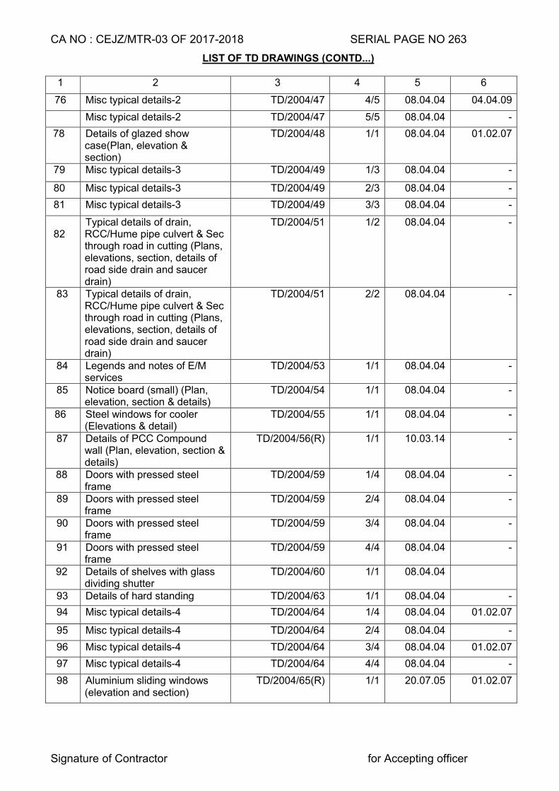
CA NO : CEJZ/MTR-03 OF 2017-2018 SERIAL PAGE NO 263
Signature of Contractor for Accepting officer
LIST OF TD DRAWINGS (CONTD...)
1 2 3 4 5 6
76 Misc typical details-2 TD/2004/47 4/5 08.04.04 04.04.09
Misc typical details-2 TD/2004/47 5/5 08.04.04 -
78 Details of glazed show case(Plan, elevation & section)
TD/2004/48 1/1 08.04.04 01.02.07
79 Misc typical details-3 TD/2004/49 1/3 08.04.04 -
80 Misc typical details-3 TD/2004/49 2/3 08.04.04 -
81 Misc typical details-3 TD/2004/49 3/3 08.04.04 -
82
Typical details of drain, RCC/Hume pipe culvert & Sec through road in cutting (Plans, elevations, section, details of road side drain and saucer drain)
TD/2004/51 1/2 08.04.04 -
83 Typical details of drain, RCC/Hume pipe culvert & Sec through road in cutting (Plans, elevations, section, details of road side drain and saucer drain)
TD/2004/51 2/2 08.04.04 -
84 Legends and notes of E/M services
TD/2004/53 1/1 08.04.04 -
85 Notice board (small) (Plan, elevation, section & details)
TD/2004/54 1/1 08.04.04 -
86 Steel windows for cooler (Elevations & detail)
TD/2004/55 1/1 08.04.04 -
87 Details of PCC Compound wall (Plan, elevation, section & details)
TD/2004/56(R) 1/1 10.03.14 -
88 Doors with pressed steel frame
TD/2004/59 1/4 08.04.04 -
89 Doors with pressed steel frame
TD/2004/59 2/4 08.04.04 -
90 Doors with pressed steel frame
TD/2004/59 3/4 08.04.04 -
91 Doors with pressed steel frame
TD/2004/59 4/4 08.04.04 -
92 Details of shelves with glass dividing shutter
TD/2004/60 1/1 08.04.04
93 Details of hard standing TD/2004/63 1/1 08.04.04 -
94 Misc typical details-4 TD/2004/64 1/4 08.04.04 01.02.07
95 Misc typical details-4 TD/2004/64 2/4 08.04.04 -
96 Misc typical details-4 TD/2004/64 3/4 08.04.04 01.02.07
97 Misc typical details-4 TD/2004/64 4/4 08.04.04 -
98 Aluminium sliding windows (elevation and section)
TD/2004/65(R) 1/1 20.07.05 01.02.07
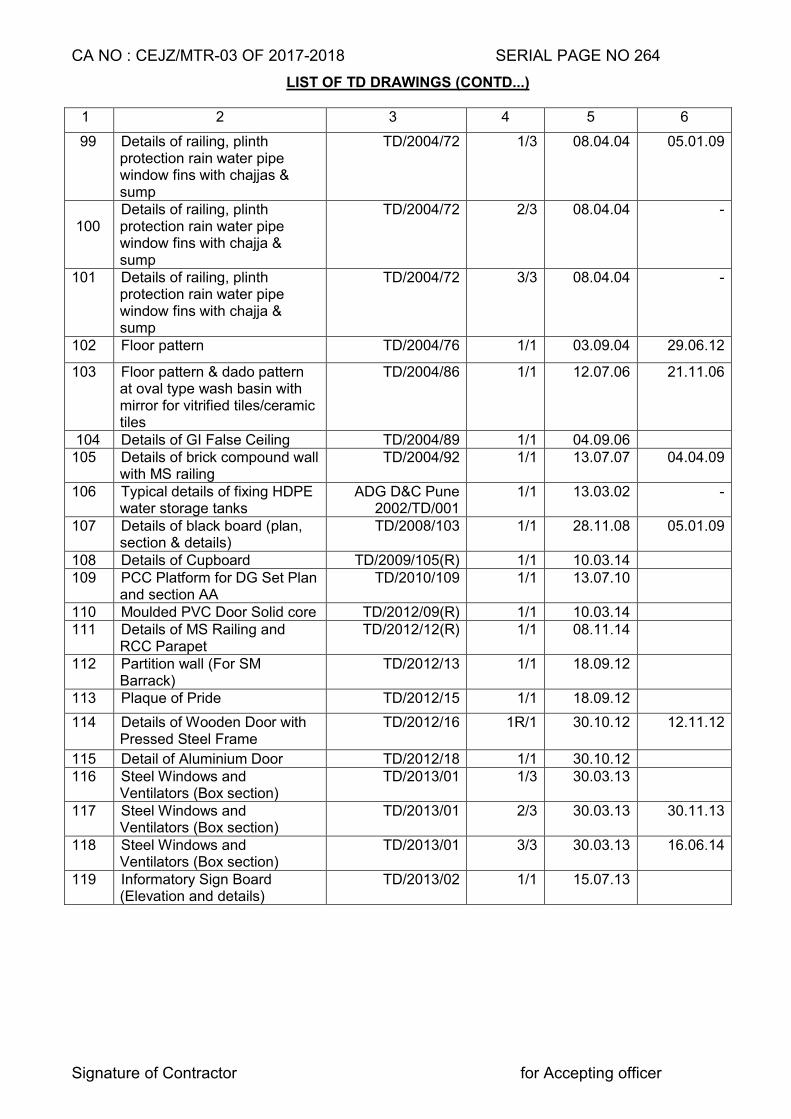
CA NO : CEJZ/MTR-03 OF 2017-2018 SERIAL PAGE NO 264
Signature of Contractor for Accepting officer
LIST OF TD DRAWINGS (CONTD...)
1 2 3 4 5 6
99 Details of railing, plinth protection rain water pipe window fins with chajjas & sump
TD/2004/72 1/3 08.04.04 05.01.09
100 Details of railing, plinth protection rain water pipe window fins with chajja & sump
TD/2004/72 2/3 08.04.04 -
101 Details of railing, plinth protection rain water pipe window fins with chajja & sump
TD/2004/72 3/3 08.04.04 -
102 Floor pattern TD/2004/76 1/1 03.09.04 29.06.12
103 Floor pattern & dado pattern at oval type wash basin with mirror for vitrified tiles/ceramic tiles
TD/2004/86 1/1 12.07.06 21.11.06
104 Details of GI False Ceiling TD/2004/89 1/1 04.09.06 105 Details of brick compound wall
with MS railing TD/2004/92 1/1 13.07.07 04.04.09
106 Typical details of fixing HDPE water storage tanks
ADG D&C Pune 2002/TD/001
1/1 13.03.02 -
107 Details of black board (plan, section & details)
TD/2008/103 1/1 28.11.08 05.01.09
108 Details of Cupboard TD/2009/105(R) 1/1 10.03.14 109 PCC Platform for DG Set Plan
and section AA TD/2010/109 1/1 13.07.10
110 Moulded PVC Door Solid core TD/2012/09(R) 1/1 10.03.14 111 Details of MS Railing and
RCC Parapet TD/2012/12(R) 1/1 08.11.14
112 Partition wall (For SM Barrack)
TD/2012/13 1/1 18.09.12
113 Plaque of Pride TD/2012/15 1/1 18.09.12
114 Details of Wooden Door with Pressed Steel Frame
TD/2012/16 1R/1 30.10.12 12.11.12
115 Detail of Aluminium Door TD/2012/18 1/1 30.10.12 116 Steel Windows and
Ventilators (Box section) TD/2013/01 1/3 30.03.13
117 Steel Windows and Ventilators (Box section)
TD/2013/01 2/3 30.03.13 30.11.13
118 Steel Windows and Ventilators (Box section)
TD/2013/01 3/3 30.03.13 16.06.14
119 Informatory Sign Board (Elevation and details)
TD/2013/02 1/1 15.07.13
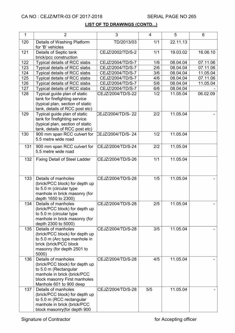
CA NO : CEJZ/MTR-03 OF 2017-2018 SERIAL PAGE NO 265
Signature of Contractor for Accepting officer
LIST OF TD DRAWINGS (CONTD...)
1 2 3 4 5 6
120 Details of Washing Platform for ‘B’ vehicles
TD/2013/03 1/1 22.11.13
121 Details of Septic tank brick/pcc construction
CEJZ/2002/TD/S-2 1/1 19.03.02 16.06.10
122 Typical details of RCC slabs CEJZ/2004/TD/S-7 1/6 08.04.04 07.11.06 123 Typical details of RCC slabs CEJZ/2004/TD/S-7 2/6 08.04.04 07.11.06 124 Typical details of RCC slabs CEJZ/2004/TD/S-7 3/6 08.04.04 11.05.04 125 Typical details of RCC slabs CEJZ/2004/TD/S-7 4/6 08.04.04 07.11.06 126 Typical details of RCC slabs CEJZ/2004/TD/S-7 5/6 08.04.04 11.05.04 127 Typical details of RCC slabs CEJZ/2004/TD/S-7 6/6 08.04.04 - 128 Typical guide plan of static
tank for firefighting service (typical plan, section of static tank, details of RCC post etc)
CEJZ/2004/TD/S-22 1/2 11.05.04 06.02.09
129 Typical guide plan of static tank for firefighting service (typical plan, section of static tank, details of RCC post etc)
CEJZ/2004/TD/S- 22 2/2 11.05.04 -
130 900 mm span RCC culvert for 5.5 metre wide road
CEJZ/2004/TD/S- 24 1/2 11.05.04
131 900 mm span RCC culvert for 5.5 metre wide road
CEJZ/2004/TD/S-24 2/2 11.05.04
132 Fixing Detail of Steel Ladder CEJZ/2004/TD/S-26 1/1 11.05.04
133 Details of manholes (brick/PCC block) for depth up to 5.0 m (circular type manhole in brick masonry (for depth 1650 to 2300)
CEJZ/2004/TD/S-28 1/5 11.05.04 -
134 Details of manholes (brick/PCC block) for depth up to 5.0 m (circular type manhole in brick masonry (for depth 2300 to 5000)
CEJZ/2004/TD/S-28 2/5 11.05.04 -
135 Details of manholes (brick/PCC block) for depth up to 5.0 m (Arc type manhole in brick (brick/PCC block masonry (for depth 2501 to 5000)
CEJZ/2004/TD/S-28 3/5 11.05.04 -
136 Details of manholes (brick/PCC block) for depth up to 5.0 m (Rectangular manhole in brick (brick/PCC block masonry First manholes Manhole 601 to 900 deep
CEJZ/2004/TD/S-28 4/5 11.05.04 -
137 Details of manholes (brick/PCC block) for depth up to 5.0 m (RCC rectangular manhole in brick (brick/PCC block masonry(for depth 900
CEJZ/2004/TD/S-28 5/5 11.05.04 -
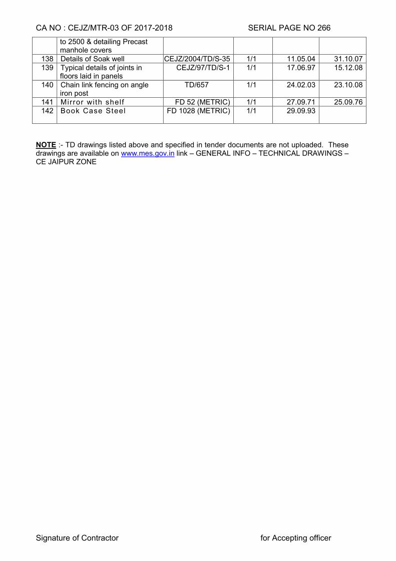
CA NO : CEJZ/MTR-03 OF 2017-2018 SERIAL PAGE NO 266
Signature of Contractor for Accepting officer
to 2500 & detailing Precast manhole covers
138 Details of Soak well CEJZ/2004/TD/S-35 1/1 11.05.04 31.10.07 139 Typical details of joints in
floors laid in panels CEJZ/97/TD/S-1 1/1 17.06.97 15.12.08
140 Chain link fencing on angle iron post
TD/657 1/1 24.02.03 23.10.08
141 Mirror with shelf FD 52 (METRIC) 1/1 27.09.71 25.09.76 142
Book Case Steel FD 1028 (METRIC) 1/1 29.09.93
NOTE :- TD drawings listed above and specified in tender documents are not uploaded. These drawings are available on www.mes.gov.in link – GENERAL INFO – TECHNICAL DRAWINGS – CE JAIPUR ZONE
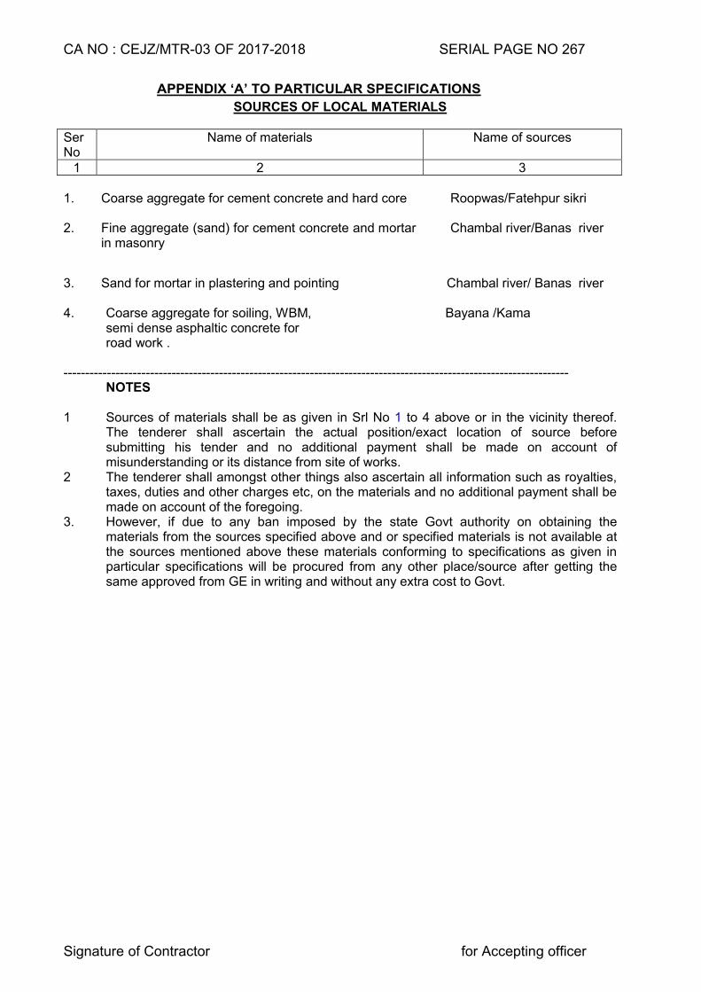
CA NO : CEJZ/MTR-03 OF 2017-2018 SERIAL PAGE NO 267
Signature of Contractor for Accepting officer
APPENDIX ‘A’ TO PARTICULAR SPECIFICATIONS
SOURCES OF LOCAL MATERIALS Ser No
Name of materials Name of sources
1 2 3 1. Coarse aggregate for cement concrete and hard core
Roopwas/Fatehpur sikri
2. Fine aggregate (sand) for cement concrete and mortar in masonry
Chambal river/Banas river
3. Sand for mortar in plastering and pointing
Chambal river/ Banas river
4. Coarse aggregate for soiling, WBM, Bayana /Kama semi dense asphaltic concrete for road work . ---------------------------------------------------------------------------------------------------------------------
NOTES 1 Sources of materials shall be as given in Srl No 1 to 4 above or in the vicinity thereof.
The tenderer shall ascertain the actual position/exact location of source before submitting his tender and no additional payment shall be made on account of misunderstanding or its distance from site of works.
2 The tenderer shall amongst other things also ascertain all information such as royalties, taxes, duties and other charges etc, on the materials and no additional payment shall be made on account of the foregoing.
3. However, if due to any ban imposed by the state Govt authority on obtaining the materials from the sources specified above and or specified materials is not available at the sources mentioned above these materials conforming to specifications as given in particular specifications will be procured from any other place/source after getting the same approved from GE in writing and without any extra cost to Govt.
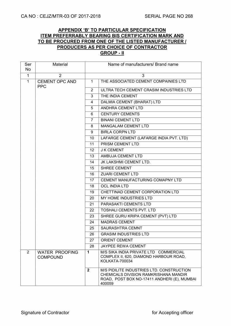
CA NO : CEJZ/MTR-03 OF 2017-2018 SERIAL PAGE NO 268
Signature of Contractor for Accepting officer
APPENDIX ‘B’ TO PARTICULAR SPECIFICATION
ITEM PREFERRABLY BEARING BIS CERTIFICATION MARK AND TO BE PROCURED FROM ONE OF THE LISTED MANUFACTURER /
PRODUCERS AS PER CHOICE OF CONTRACTOR GROUP - II
Ser No
Material Name of manufacturers/ Brand name
1 2 3
1 CEMENT OPC AND PPC
1 THE ASSOCIATED CEMENT COMPAINIES LTD
2 ULTRA TECH CEMENT CRASIM INDUSTRIES LTD
3 THE INDIA CEMENT
4 DALMIA CEMENT (BHARAT) LTD
5 ANDHRA CEMENT LTD
6 CENTURY CEMENTS
7 BINANI CEMENT LTD
8 MANGALAM CEMENT LTD
9 BIRLA CORPN LTD
10 LAFARGE CEMENT (LAFARGE INDIA PVT. LTD)
11 PRISM CEMENT LTD
12 J K CEMENT
13 AMBUJA CEMENT LTD
14 JK LAKSHMI CEMENT LTD.
15 SHREE CEMENT
16 ZUARI CEMENT LTD
17 CEMENT MANUFACTURING COMAPNY LTD
18 OCL INDIA LTD
19 CHETTINAD CEMENT CORPORATION LTD
20 MY HOME INDUSTRIES LTD
21 PARASAKTI CEMENTS LTD
22 TOSHALI CEMENTS PVT. LTD
23 SHREE GURU KRIPA CEMENT (PVT) LTD
24 MADRAS CEMENT
25 SAURASHTRA CEMNT
26 GRASIM INDUSTRIES LTD
27 ORIENT CEMENT
28 JAYPEE REWA CEMENT
2 WATER PROOFING COMPOUND
1 M/S SIKA INDIA PRIVATE LTD COMMERCIAL COMPLEX II, 620, DIAMOND HARBOUR ROAD, KOLKATA-700034
2 M/S PIDILITE INDUSTRIES LTD. CONSTRUCTION CHEMICALS DIVISION RAMKRISHANA MANDIR ROAD, POST BOX NO-17411 ANDHERI (E), MUMBAI 400059
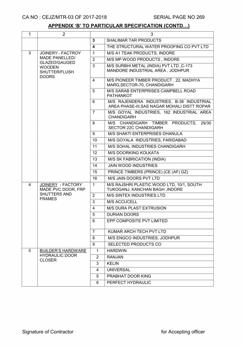
CA NO : CEJZ/MTR-03 OF 2017-2018 SERIAL PAGE NO 269
Signature of Contractor for Accepting officer
APPENDIX ‘B’ TO PARTICULAR SPECIFICATION (CONTD…)
1 2 3
3 SHALIMAR TAR PRODUCTS
4 THE STRUCTURAL WATER PROOFING CO PVT LTD
3 JOINERY - FACTROY MADE PANELLED/ GLAZED/GAUGED WOODEN SHUTTER/FLUSH DOORS
1 M/S A1 TEAK PRODUCTS, INDORE
2 M/S MP WOOD PRODUCTS , INDORE
3 M/S SURBHI METAL (INDIA) PVT LTD ,C-173 MANDORE INDUSTRIAL AREA , JODHPUR
4 M/S PIONEER TIMBER PRODUCT , 22, MADHYA MARG,SECTOR-70, CHANDIGARH
5 M/S SARAB ENTERPRISES CAMPBELL ROAD PATHANKOT
6 M/S RAJENDERA INDUSTRIES, B-38 INDUSTRIAL AREA PHASE-III,SAS NAGAR MOHALI DISTT ROPAR
7 M/S GOYAL INDUSTRIES, 162 INDUSTRIAL AREA CHANDIGARH
8 M/S CHANDIGARH TIMBER PRODUCTS, 29/30 SECTOR 22C CHANDIGARH
9 M/S SHAKTI ENTERPRISES DHANULA
10 M/S GOYALA INDUSTRIES, FARIDABAD
11 M/S SOHAL INDUSTRIES CHANDIGARH
12 M/S DOORKING KOLKATA
13 M/S SK FABRICATION (INDIA)
14 JAIN WOOD INDUSTRIES
15 PRINCE TIMBERS (PRINCE) (CE (AF) GZ)
16 M/S JAIN DOORS PVT LTD
4 JOINERY - FACTORY MADE PVC DOOR, FRP SHUTTERS AND FRAMES
1 M/S RAJSHRI PLASTIC WOOD LTD, 10/1, SOUTH TUKOGANJ, KANCHAN BAGH ,INDORE
2 M/S SINTEX INDUSTRIES LTD
3 M/S ACCUCELL
4 M/S DURA PLAST EXTRUSION
5 DURIAN DOORS
6 EPP COMPOSITE PVT LIMITED
7 KUMAR ARCH TECH PVT LTD
8 M/S ENGCO INDUSTRIES, JODHPUR
9 SELECTED PRODUCTS CO
5 BUILDER’S HARDWARE HYDRAULIC DOOR CLOSER
1 HARDWIN
2 RANJAN
3 KELIN
4 UNIVERSAL
5 PRABHAT DOOR KING
6 PERFECT HYDRAULIC
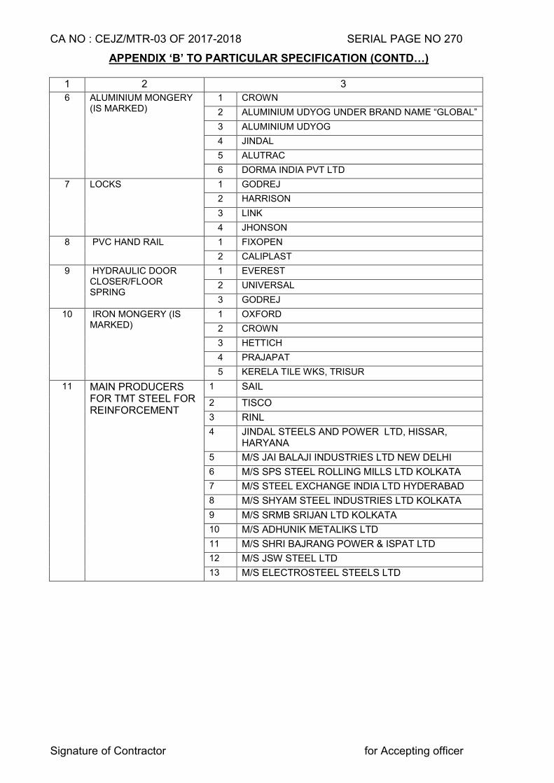
CA NO : CEJZ/MTR-03 OF 2017-2018 SERIAL PAGE NO 270
Signature of Contractor for Accepting officer
APPENDIX ‘B’ TO PARTICULAR SPECIFICATION (CONTD…)
1 2 3
6 ALUMINIUM MONGERY (IS MARKED)
1 CROWN
2 ALUMINIUM UDYOG UNDER BRAND NAME “GLOBAL”
3 ALUMINIUM UDYOG
4 JINDAL
5 ALUTRAC
6 DORMA INDIA PVT LTD
7 LOCKS 1 GODREJ
2 HARRISON
3 LINK
4 JHONSON
8 PVC HAND RAIL 1 FIXOPEN
2 CALIPLAST
9 HYDRAULIC DOOR CLOSER/FLOOR SPRING
1 EVEREST
2 UNIVERSAL
3 GODREJ
10 IRON MONGERY (IS MARKED)
1 OXFORD
2 CROWN
3 HETTICH
4 PRAJAPAT
5 KERELA TILE WKS, TRISUR
11 MAIN PRODUCERS FOR TMT STEEL FOR REINFORCEMENT
1 SAIL
2 TISCO
3 RINL
4 JINDAL STEELS AND POWER LTD, HISSAR, HARYANA
5 M/S JAI BALAJI INDUSTRIES LTD NEW DELHI
6 M/S SPS STEEL ROLLING MILLS LTD KOLKATA
7 M/S STEEL EXCHANGE INDIA LTD HYDERABAD
8 M/S SHYAM STEEL INDUSTRIES LTD KOLKATA
9 M/S SRMB SRIJAN LTD KOLKATA
10 M/S ADHUNIK METALIKS LTD
11 M/S SHRI BAJRANG POWER & ISPAT LTD
12 M/S JSW STEEL LTD
13 M/S ELECTROSTEEL STEELS LTD
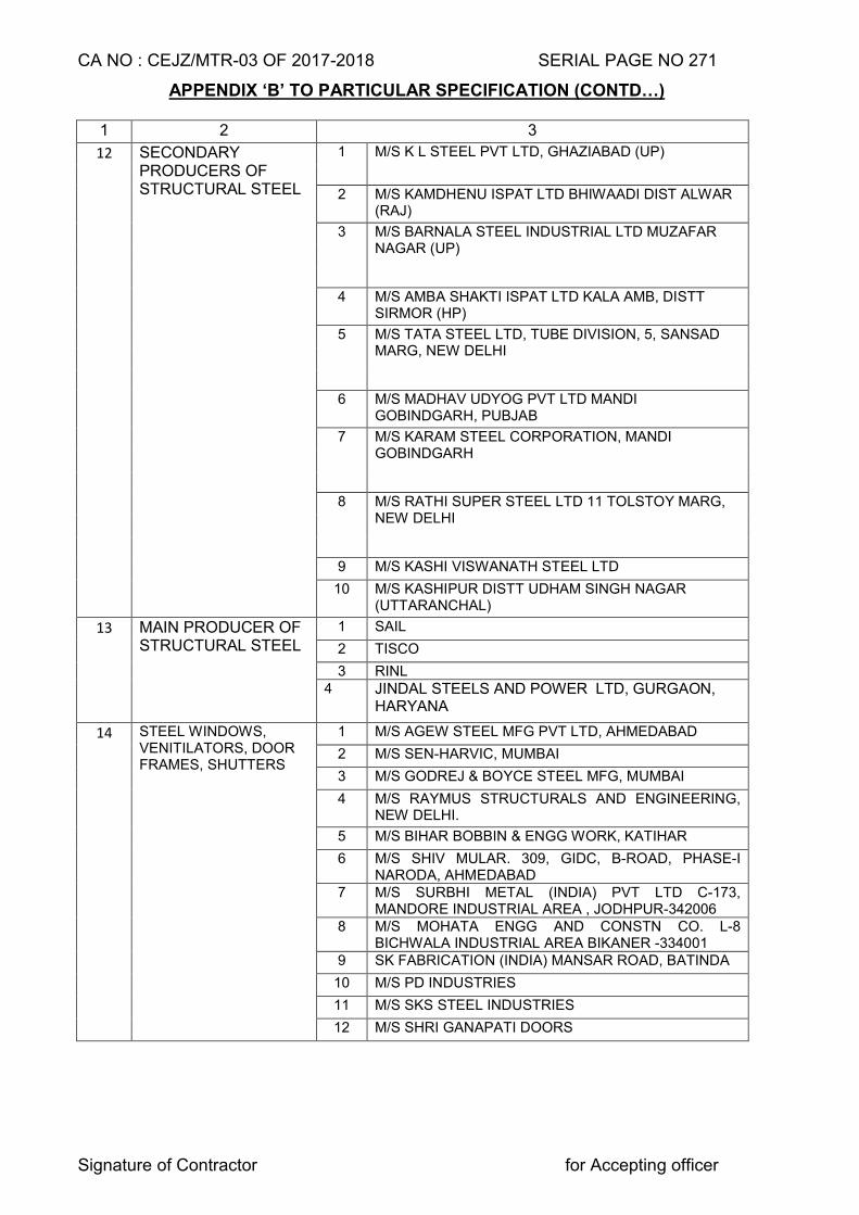
CA NO : CEJZ/MTR-03 OF 2017-2018 SERIAL PAGE NO 271
Signature of Contractor for Accepting officer
APPENDIX ‘B’ TO PARTICULAR SPECIFICATION (CONTD…)
1 2 3
12 SECONDARY PRODUCERS OF STRUCTURAL STEEL
1 M/S K L STEEL PVT LTD, GHAZIABAD (UP)
2 M/S KAMDHENU ISPAT LTD BHIWAADI DIST ALWAR (RAJ)
3 M/S BARNALA STEEL INDUSTRIAL LTD MUZAFAR NAGAR (UP)
4 M/S AMBA SHAKTI ISPAT LTD KALA AMB, DISTT SIRMOR (HP)
5 M/S TATA STEEL LTD, TUBE DIVISION, 5, SANSAD MARG, NEW DELHI
6 M/S MADHAV UDYOG PVT LTD MANDI GOBINDGARH, PUBJAB
7 M/S KARAM STEEL CORPORATION, MANDI GOBINDGARH
8 M/S RATHI SUPER STEEL LTD 11 TOLSTOY MARG, NEW DELHI
9 M/S KASHI VISWANATH STEEL LTD
10 M/S KASHIPUR DISTT UDHAM SINGH NAGAR (UTTARANCHAL)
13 MAIN PRODUCER OF STRUCTURAL STEEL
1 SAIL
2 TISCO
3 RINL 4 JINDAL STEELS AND POWER LTD, GURGAON,
HARYANA
14 STEEL WINDOWS, VENITILATORS, DOOR FRAMES, SHUTTERS
1 M/S AGEW STEEL MFG PVT LTD, AHMEDABAD
2 M/S SEN-HARVIC, MUMBAI
3 M/S GODREJ & BOYCE STEEL MFG, MUMBAI
4 M/S RAYMUS STRUCTURALS AND ENGINEERING, NEW DELHI.
5 M/S BIHAR BOBBIN & ENGG WORK, KATIHAR
6 M/S SHIV MULAR. 309, GIDC, B-ROAD, PHASE-I NARODA, AHMEDABAD
7 M/S SURBHI METAL (INDIA) PVT LTD C-173, MANDORE INDUSTRIAL AREA , JODHPUR-342006
8 M/S MOHATA ENGG AND CONSTN CO. L-8 BICHWALA INDUSTRIAL AREA BIKANER -334001
9 SK FABRICATION (INDIA) MANSAR ROAD, BATINDA
10 M/S PD INDUSTRIES
11 M/S SKS STEEL INDUSTRIES
12 M/S SHRI GANAPATI DOORS
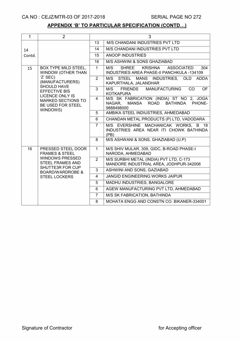
CA NO : CEJZ/MTR-03 OF 2017-2018 SERIAL PAGE NO 272
Signature of Contractor for Accepting officer
APPENDIX ‘B’ TO PARTICULAR SPECIFICATION (CONTD…)
1 2 3
14 Contd.
13 M/S CHANDANI INDUSTRIES PVT LTD
14 M/S CHANDANI INDUSTRIES PVT LTD
15 ANOOP INDUSTRIES
16 M/S ASHWINI & SONS GHAZIABAD
15 BOX TYPE MILD STEEL, WINDOW (OTHER THAN ‘Z’ SEC) (MANUFACTURERS) SHOULD HAVE EFFECTIVE BIS LICENCE ONLY IS MARKED SECTIONS TO BE USED FOR STEEL WINDOWS)
1 M/S SHREE KRISHNA ASSOCIATED 304 INDUSTRIES AREA PHASE-II PANCHKULA -134109
2 M/S STEEL MANS INDUSTRIES, OLD ADDA KAPURTHALA, JALANDHAR
3 M/S FRIENDS MANUFACTURING CO OF KOTKAPURA
4 M/S SK FABRICATION (INDIA) ST NO 2, JOGA NAGAR, MANSA ROAD BATHINDA PHONE-9888498000
5 AMBIKA STEEL INDIUSTRIES, AHMEDABAD
6 CHANDAN METAL PRODUCTS (P) LTD, VADODARA
7 M/S EVERSHINE MACHANICAK WORKS, B 18 INDUSTRIES AREA NEAR ITI CHOWK BATHINDA (PB)
8 M/S ASHWANI & SONS, GHAZIABAD (U.P)
16 PRESSED STEEL DOOR FRAMES & STEEL WINDOWS PRESSED STEEL FRAMES AND SHUTTE3R FOR CUP BOARD/WARDROBE & STEEL LOCKERS
1 M/S SHIV MULAR, 309, GIDC, B-ROAD PHASE-I NARODA, AHMEDABAD
2 M/S SURBHI METAL (INDIA) PVT LTD, C-173 MANDORE INDUSTRIAL AREA, JODHPUR-342006
3 ASHWINI AND SONS, GAZIABAD
4 JANGID ENGINEERING WORKS JAIPUR
5 MADHU INDUSTRIES, BANGALORE
6 AGEW MANUFACTURING PVT LTD, AHMEDABAD
7 M/S SK FABRICATION, BATHINDA
8 MOHATA ENGG AND CONSTN CO. BIKANER-334001
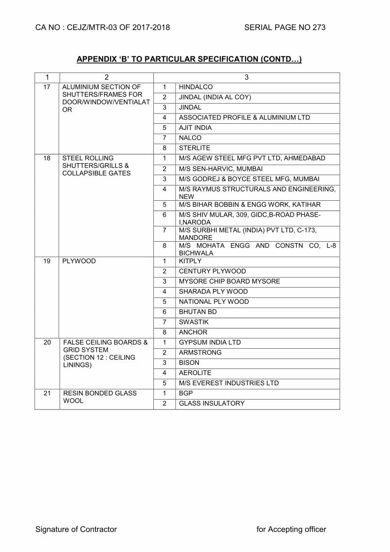
CA NO : CEJZ/MTR-03 OF 2017-2018 SERIAL PAGE NO 273
Signature of Contractor for Accepting officer
APPENDIX ‘B’ TO PARTICULAR SPECIFICATION (CONTD…)
1 2 3
17 ALUMINIUM SECTION OF SHUTTERS/FRAMES FOR DOOR/WINDOW/VENTIALAT OR
1 HINDALCO
2 JINDAL (INDIA AL COY)
3 JINDAL
4 ASSOCIATED PROFILE & ALUMINIUM LTD
5 AJIT INDIA
7 NALCO
8 STERLITE
18 STEEL ROLLING SHUTTERS/GRILLS & COLLAPSIBLE GATES
1 M/S AGEW STEEL MFG PVT LTD, AHMEDABAD
2 M/S SEN-HARVIC, MUMBAI
3 M/S GODREJ & BOYCE STEEL MFG, MUMBAI
4 M/S RAYMUS STRUCTURALS AND ENGINEERING, NEW
5 M/S BIHAR BOBBIN & ENGG WORK, KATIHAR
6 M/S SHIV MULAR, 309, GIDC,B-ROAD PHASE-I,NARODA
7 M/S SURBHI METAL (INDIA) PVT LTD, C-173, MANDORE
8 M/S MOHATA ENGG AND CONSTN CO, L-8 BICHWALA
19 PLYWOOD 1 KITPLY
2 CENTURY PLYWOOD
3 MYSORE CHIP BOARD MYSORE
4 SHARADA PLY WOOD
5 NATIONAL PLY WOOD
6 BHUTAN BD
7 SWASTIK
8 ANCHOR
20 FALSE CEILING BOARDS & GRID SYSTEM (SECTION 12 : CEILING LININGS)
1 GYPSUM INDIA LTD
2 ARMSTRONG
3 BISON
4 AEROLITE
5 M/S EVEREST INDUSTRIES LTD
21 RESIN BONDED GLASS WOOL
1 BGP
2 GLASS INSULATORY
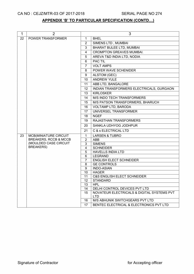
CA NO : CEJZ/MTR-03 OF 2017-2018 SERIAL PAGE NO 274
Signature of Contractor for Accepting officer
APPENDIX ‘B’ TO PARTICULAR SPECIFICATION (CONTD…)
1 2 3 22 POWER TRANSFORMER 1 BHEL
2 SIMENS LTD , MUMBAI
3 BHARAT BIJLEE LTD, MUMBAI
4 CROMPTON GREAVES MUMBAI.
5 AREVA T&D INDIA LTD, NODIA
6 PAC TIL
7 VOLT AMPS
8 POWER WAVE SCHENIDER
9 ALSTOM (GEC)
10 ANDREW YULE
11 ABB LTD, BANGALORE
12 INDIAN TRANSFORMERS ELECTRICALS, GURGAON
13 KIRLOSKER
14 M/S INDO TECH TRANSFORMERS
15 M/S PATSON TRANSFORMERS, BHARUCH
16 VOLTAMP LTD, BARODA
17 UNIVERSEL TRANSFORMER
18 NGEF
19 RAJASTHAN TRANSFORMERS
20 SANKLA UDHYOG JODHPUR
21 C & s ELECTRICAL LTD
23
MCB(MINIATURE CIRCUIT BREAKERS, RCCB & MCCB (MOULDED CASE CIRCUIT BREAKERS)
1 LARSEN & TUBRO
2 ABB
3 SIMENS
4 SCHNEIDER
5 HAVELLS INDIA LTD
6 LEGRAND
7 ENGLISH ELECT SCHNEIDER
8 GE CONTROLS
9 INDO-ASIAN
10 HAGER
11 C&S ENGLISH ELECT SCHNEIDER
12 STANDARD
13 HPL
14 DELHI CONTROL DEVICES PVT LTD
15 NOVATEUR ELECTRICALS & DIGITAL SYSTEMS PVT LTD
16 M/S ABHUNIK SWITCHGEARS PVT LTD
17 BENTEC ELECTRICAL & ELECTRONICS PVT LTD
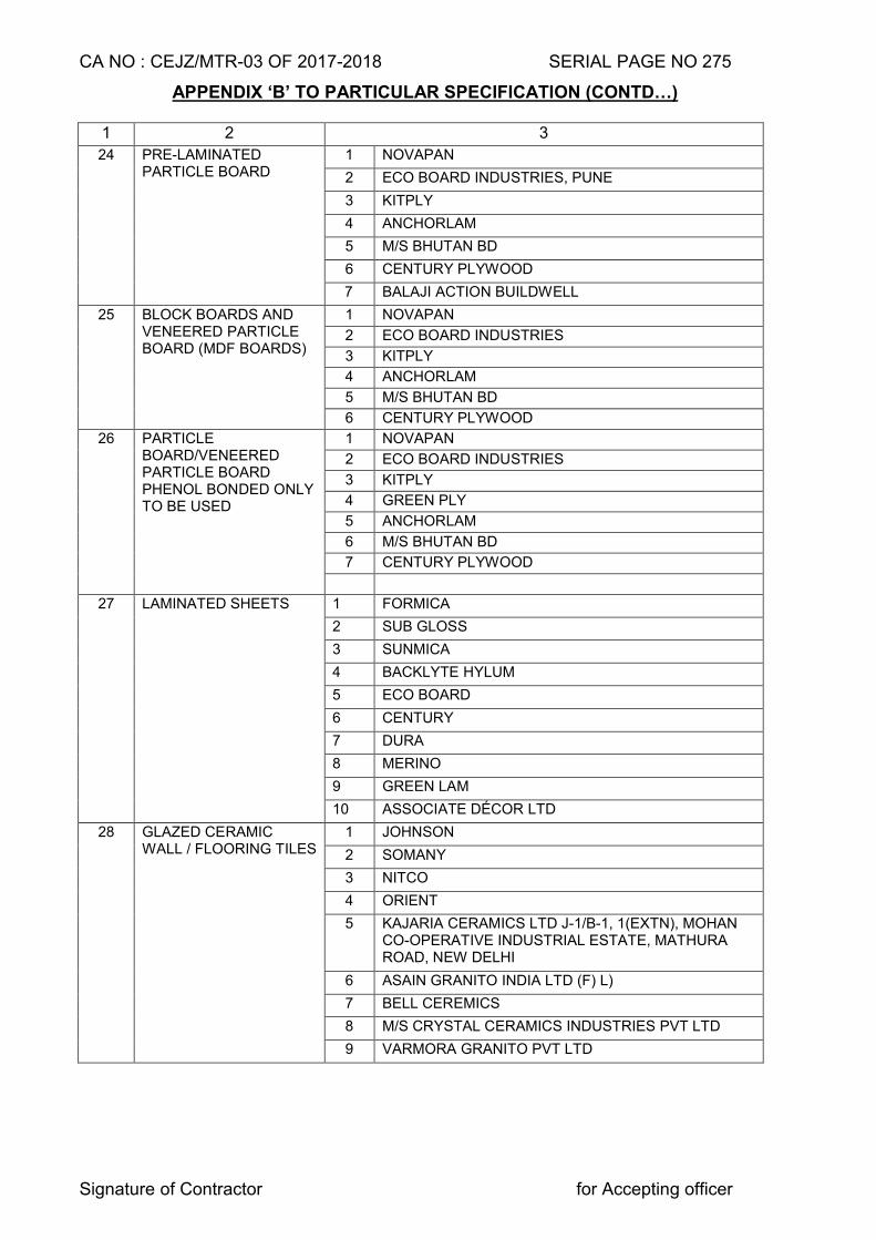
CA NO : CEJZ/MTR-03 OF 2017-2018 SERIAL PAGE NO 275
Signature of Contractor for Accepting officer
APPENDIX ‘B’ TO PARTICULAR SPECIFICATION (CONTD…)
1 2 3
24 PRE-LAMINATED PARTICLE BOARD
1 NOVAPAN
2 ECO BOARD INDUSTRIES, PUNE
3 KITPLY
4 ANCHORLAM
5 M/S BHUTAN BD
6 CENTURY PLYWOOD
7 BALAJI ACTION BUILDWELL
25 BLOCK BOARDS AND VENEERED PARTICLE BOARD (MDF BOARDS)
1 NOVAPAN
2 ECO BOARD INDUSTRIES
3 KITPLY
4 ANCHORLAM
5 M/S BHUTAN BD
6 CENTURY PLYWOOD
26 PARTICLE BOARD/VENEERED PARTICLE BOARD PHENOL BONDED ONLY TO BE USED
1 NOVAPAN
2 ECO BOARD INDUSTRIES
3 KITPLY
4 GREEN PLY
5 ANCHORLAM
6 M/S BHUTAN BD
7 CENTURY PLYWOOD
27 LAMINATED SHEETS 1 FORMICA
2 SUB GLOSS
3 SUNMICA
4 BACKLYTE HYLUM
5 ECO BOARD
6 CENTURY
7 DURA
8 MERINO
9 GREEN LAM
10 ASSOCIATE DÉCOR LTD
28 GLAZED CERAMIC WALL / FLOORING TILES
1 JOHNSON
2 SOMANY
3 NITCO
4 ORIENT
5 KAJARIA CERAMICS LTD J-1/B-1, 1(EXTN), MOHAN CO-OPERATIVE INDUSTRIAL ESTATE, MATHURA ROAD, NEW DELHI
6 ASAIN GRANITO INDIA LTD (F) L)
7 BELL CEREMICS
8 M/S CRYSTAL CERAMICS INDUSTRIES PVT LTD
9 VARMORA GRANITO PVT LTD
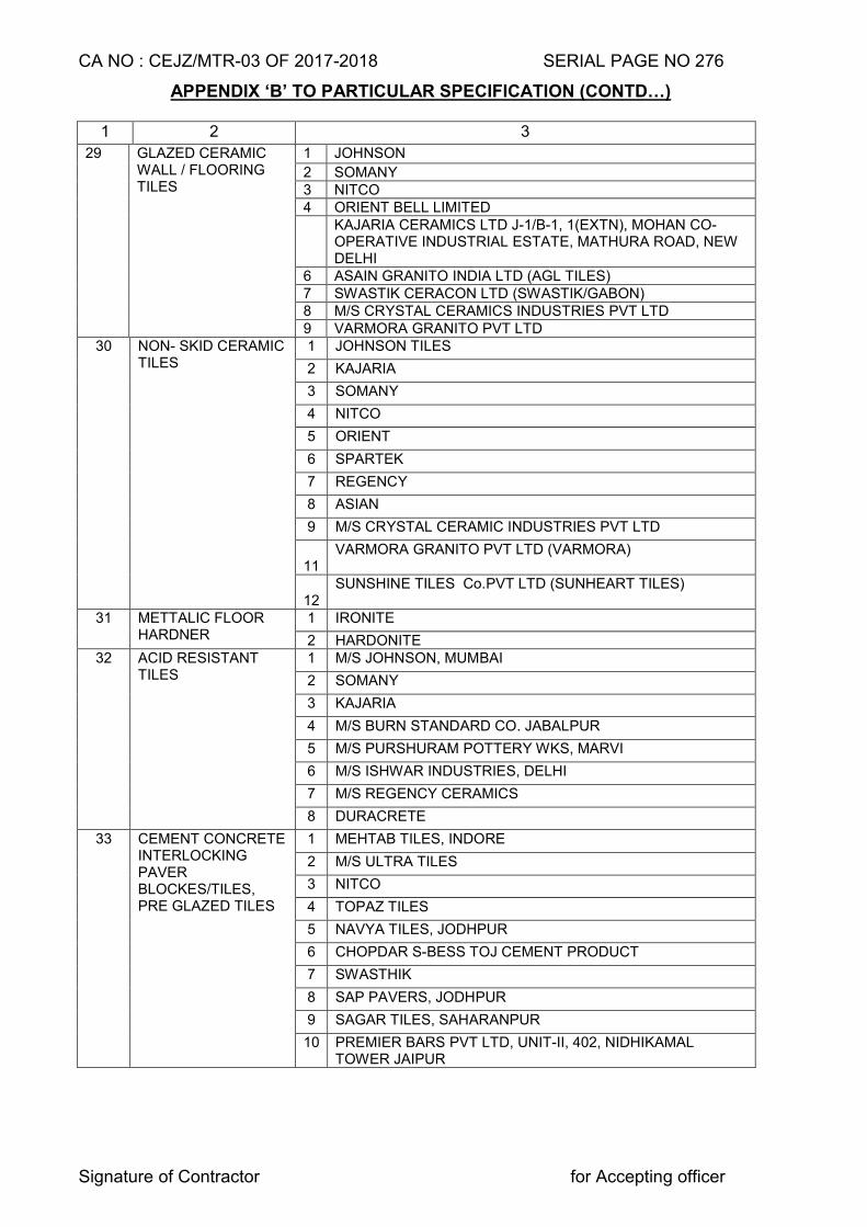
CA NO : CEJZ/MTR-03 OF 2017-2018 SERIAL PAGE NO 276
Signature of Contractor for Accepting officer
APPENDIX ‘B’ TO PARTICULAR SPECIFICATION (CONTD…)
1 2 3
29 GLAZED CERAMIC WALL / FLOORING TILES
1 JOHNSON
2 SOMANY 3 NITCO 4 ORIENT BELL LIMITED KAJARIA CERAMICS LTD J-1/B-1, 1(EXTN), MOHAN CO-
OPERATIVE INDUSTRIAL ESTATE, MATHURA ROAD, NEW DELHI
6 ASAIN GRANITO INDIA LTD (AGL TILES) 7 SWASTIK CERACON LTD (SWASTIK/GABON) 8 M/S CRYSTAL CERAMICS INDUSTRIES PVT LTD 9 VARMORA GRANITO PVT LTD
30 NON- SKID CERAMIC TILES
1 JOHNSON TILES
2 KAJARIA
3 SOMANY
4 NITCO
5 ORIENT
6 SPARTEK
7 REGENCY
8 ASIAN
9 M/S CRYSTAL CERAMIC INDUSTRIES PVT LTD
11
VARMORA GRANITO PVT LTD (VARMORA)
12
SUNSHINE TILES Co.PVT LTD (SUNHEART TILES)
31 METTALIC FLOOR HARDNER
1 IRONITE
2 HARDONITE 32 ACID RESISTANT
TILES 1 M/S JOHNSON, MUMBAI
2 SOMANY
3 KAJARIA
4 M/S BURN STANDARD CO. JABALPUR
5 M/S PURSHURAM POTTERY WKS, MARVI
6 M/S ISHWAR INDUSTRIES, DELHI
7 M/S REGENCY CERAMICS
8 DURACRETE
33 CEMENT CONCRETE INTERLOCKING PAVER BLOCKES/TILES, PRE GLAZED TILES
1 MEHTAB TILES, INDORE
2 M/S ULTRA TILES
3 NITCO
4 TOPAZ TILES
5 NAVYA TILES, JODHPUR
6 CHOPDAR S-BESS TOJ CEMENT PRODUCT
7 SWASTHIK
8 SAP PAVERS, JODHPUR
9 SAGAR TILES, SAHARANPUR
10 PREMIER BARS PVT LTD, UNIT-II, 402, NIDHIKAMAL TOWER JAIPUR
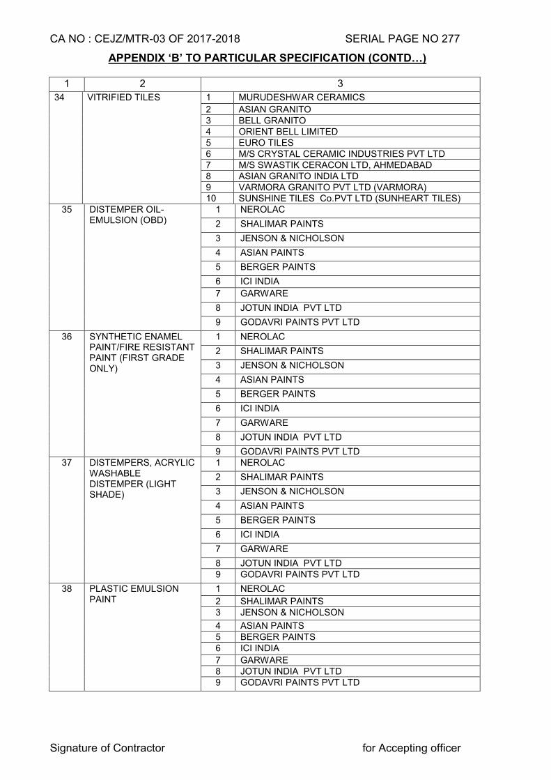
CA NO : CEJZ/MTR-03 OF 2017-2018 SERIAL PAGE NO 277
Signature of Contractor for Accepting officer
APPENDIX ‘B’ TO PARTICULAR SPECIFICATION (CONTD…)
1 2 3
34 VITRIFIED TILES 1 MURUDESHWAR CERAMICS
2 ASIAN GRANITO 3 BELL GRANITO 4 ORIENT BELL LIMITED 5 EURO TILES 6 M/S CRYSTAL CERAMIC INDUSTRIES PVT LTD 7 M/S SWASTIK CERACON LTD, AHMEDABAD 8 ASIAN GRANITO INDIA LTD 9 VARMORA GRANITO PVT LTD (VARMORA) 10 SUNSHINE TILES Co.PVT LTD (SUNHEART TILES)
35 DISTEMPER OIL-EMULSION (OBD)
1 NEROLAC
2 SHALIMAR PAINTS
3 JENSON & NICHOLSON
4 ASIAN PAINTS
5 BERGER PAINTS
6 ICI INDIA
7 GARWARE
8 JOTUN INDIA PVT LTD
9 GODAVRI PAINTS PVT LTD
36 SYNTHETIC ENAMEL PAINT/FIRE RESISTANT PAINT (FIRST GRADE ONLY)
1 NEROLAC
2 SHALIMAR PAINTS
3 JENSON & NICHOLSON
4 ASIAN PAINTS
5 BERGER PAINTS
6 ICI INDIA
7 GARWARE
8 JOTUN INDIA PVT LTD
9 GODAVRI PAINTS PVT LTD 37 DISTEMPERS, ACRYLIC
WASHABLE DISTEMPER (LIGHT SHADE)
1 NEROLAC
2 SHALIMAR PAINTS
3 JENSON & NICHOLSON
4 ASIAN PAINTS
5 BERGER PAINTS
6 ICI INDIA
7 GARWARE
8 JOTUN INDIA PVT LTD 9 GODAVRI PAINTS PVT LTD
38 PLASTIC EMULSION PAINT
1 NEROLAC
2 SHALIMAR PAINTS 3 JENSON & NICHOLSON
4 ASIAN PAINTS 5 BERGER PAINTS 6 ICI INDIA
7 GARWARE 8 JOTUN INDIA PVT LTD 9 GODAVRI PAINTS PVT LTD
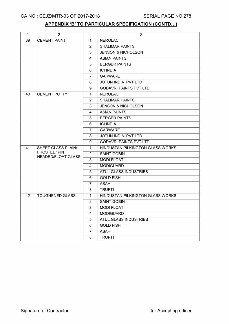
CA NO : CEJZ/MTR-03 OF 2017-2018 SERIAL PAGE NO 278
Signature of Contractor for Accepting officer
APPENDIX ‘B’ TO PARTICULAR SPECIFICATION (CONTD…)
1 2 3
39 CEMENT PAINT 1 NEROLAC
2 SHALIMAR PAINTS
3 JENSON & NICHOLSON
4 ASIAN PAINTS
5 BERGER PAINTS
6 ICI INDIA
7 GARWARE
8 JOTUN INDIA PVT LTD
9 GODAVRI PAINTS PVT LTD
40 CEMENT PUTTY 1 NEROLAC
2 SHALIMAR PAINTS
3 JENSON & NICHOLSON
4 ASIAN PAINTS
5 BERGER PAINTS
6 ICI INDIA
7 GARWARE
8 JOTUN INDIA PVT LTD
9 GODAVRI PAINTS PVT LTD
41 SHEET GLASS PLAIN/ FROSTED/ PIN HEADED/FLOAT GLASS
1 HINDUSTAN PILKINGTON GLASS WORKS
2 SAINT GOBIN
3 MODI FLOAT
4 MODIGUARD
5 ATUL GLASS INDUSTRIES
6 GOLD FISH
7 ASAHI
8 TRUPTI
42 TOUGHENED GLASS 1 HINDUSTAN PILKINGTON GLASS WORKS
2 SAINT GOBIN
3 MODI FLOAT
4 MODIGUARD
5 ATUL GLASS INDUSTRIES
6 GOLD FISH
7 ASAHI
8 TRUPTI
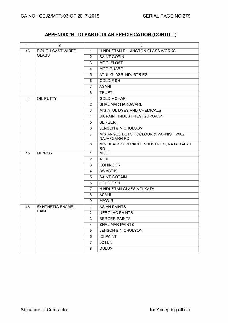
CA NO : CEJZ/MTR-03 OF 2017-2018 SERIAL PAGE NO 279
Signature of Contractor for Accepting officer
APPENDIX ‘B’ TO PARTICULAR SPECIFICATION (CONTD…)
1 2 3
43 ROUGH CAST WIRED GLASS
1 HINDUSTAN PILKINGTON GLASS WORKS
2 SAINT GOBIN
3 MODI FLOAT
4 MODIGUARD
5 ATUL GLASS INDUSTRIES
6 GOLD FISH
7 ASAHI
8 TRUPTI
44 OIL PUTTY 1 GOLD MOHAR
2 SHALIMAR HARDWARE
3 M/S ATUL DYES AND CHEMICALS
4 UK PAINT INDUSTRIES, GURGAON
5 BERGER
6 JENSON & NICHOLSON
7 M/S ANGLO DUTCH COLOUR & VARNISH WKS, NAJAFGARH RD
8 M/S BHAGSSON PAINT INDUSTRIES, NAJAFGARH RD
45 MIRROR 1 MODI
2 ATUL
3 KOHINOOR
4 SWASTIK
5 SAINT GOBAIN
6 GOLD FISH
7 HINDUSTAN GLASS KOLKATA
8 ASAHI
9 MAYUR
46 SYNTHETIC ENAMEL PAINT
1 ASIAN PAINTS
2 NEROLAC PAINTS
3 BERGER PAINTS
4 SHALIMAR PAINTS
5 JENSON & NICHOLSON
6 ICI PAINT
7 JOTUN
8 DULUX
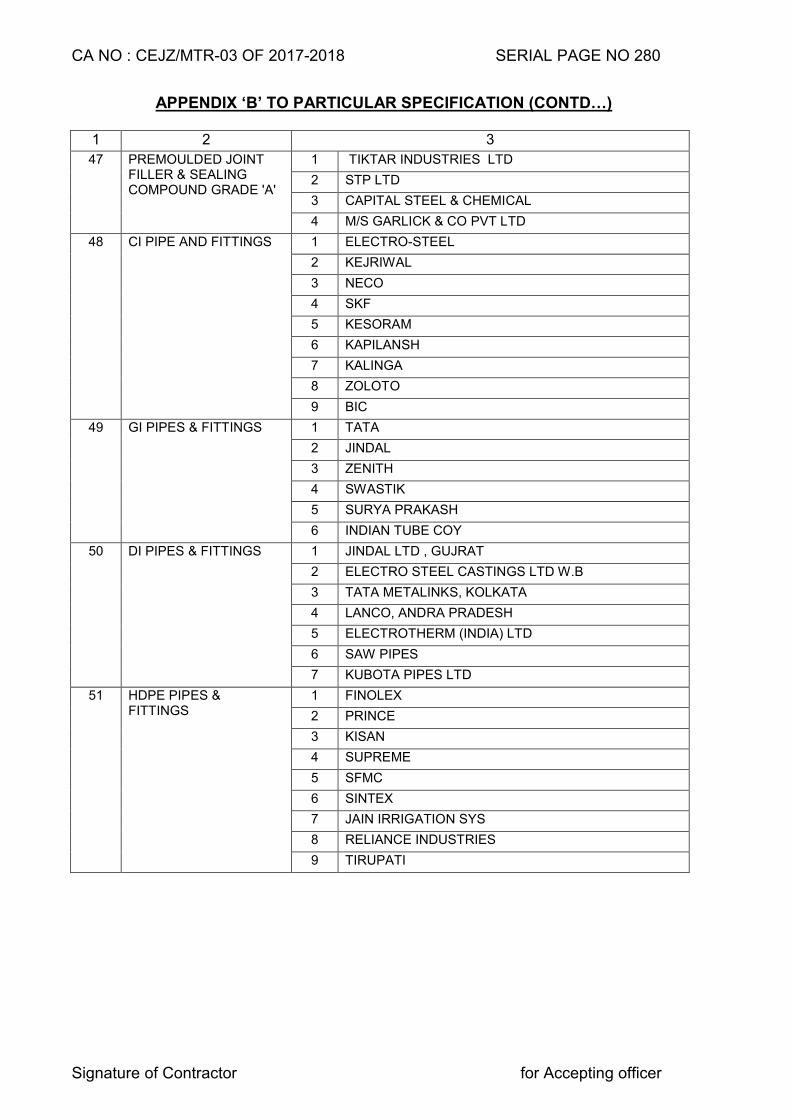
CA NO : CEJZ/MTR-03 OF 2017-2018 SERIAL PAGE NO 280
Signature of Contractor for Accepting officer
APPENDIX ‘B’ TO PARTICULAR SPECIFICATION (CONTD…)
1 2 3
47 PREMOULDED JOINT FILLER & SEALING COMPOUND GRADE 'A'
1 TIKTAR INDUSTRIES LTD
2 STP LTD
3 CAPITAL STEEL & CHEMICAL
4 M/S GARLICK & CO PVT LTD
48 CI PIPE AND FITTINGS 1 ELECTRO-STEEL
2 KEJRIWAL
3 NECO
4 SKF
5 KESORAM
6 KAPILANSH
7 KALINGA
8 ZOLOTO
9 BIC
49 GI PIPES & FITTINGS 1 TATA
2 JINDAL
3 ZENITH
4 SWASTIK
5 SURYA PRAKASH
6 INDIAN TUBE COY
50 DI PIPES & FITTINGS 1 JINDAL LTD , GUJRAT
2 ELECTRO STEEL CASTINGS LTD W.B
3 TATA METALINKS, KOLKATA
4 LANCO, ANDRA PRADESH
5 ELECTROTHERM (INDIA) LTD
6 SAW PIPES
7 KUBOTA PIPES LTD
51 HDPE PIPES & FITTINGS
1 FINOLEX
2 PRINCE
3 KISAN
4 SUPREME
5 SFMC
6 SINTEX
7 JAIN IRRIGATION SYS
8 RELIANCE INDUSTRIES
9 TIRUPATI
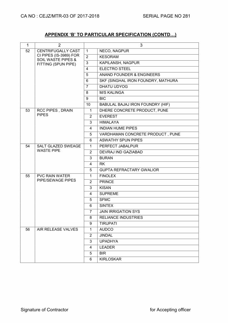
CA NO : CEJZ/MTR-03 OF 2017-2018 SERIAL PAGE NO 281
Signature of Contractor for Accepting officer
APPENDIX ‘B’ TO PARTICULAR SPECIFICATION (CONTD…)
1 2 3
52 CENTRIFUGALLY CAST CI PIPES (IS-3989) FOR SOIL WASTE PIPES & FITTING (SPUN PIPE)
1 NECO, NAGPUR
2 KESORAM
3 KAPILANSH, NAGPUR
4 ELECTRO STEEL
5 ANAND FOUNDER & ENGINEERS
6 SKF (SINGHAL IRON FOUNDRY, MATHURA
7 DHATU UDYOG
8 M/S KALINGA
9 BIC
10 BABULAL BAJAJ IRON FOUNDRY (HIF)
53 RCC PIPES , DRAIN PIPES
1 DHERE CONCRETE PRODUCT, PUNE
2 EVEREST
3 HIMALAYA
4 INDIAN HUME PIPES
5 VARDHAMAN CONCRETE PRODUCT , PUNE
6 ASWATHY SPUN PIPES
54 SALT GLAZED SWEAGE WASTE PIPE
1 PERFECT JABALPUR
2 DEVRAJ IND GAZIABAD
3 BURAN
4 RK
5 GUPTA REFRACTARY GWALIOR
55 PVC RAIN WATER PIPE/SEWAGE PIPES
1 FINOLEX
2 PRINCE
3 KISAN
4 SUPREME
5 SFMC
6 SINTEX
7 JAIN IRRIGATION SYS
8 RELIANCE INDUSTRIES
9 TIRUPATI
56 AIR RELEASE VALVES 1 AUDCO
2 JINDAL
3 UPADHYA
4 LEADER
5 BIR
6 KIRLOSKAR
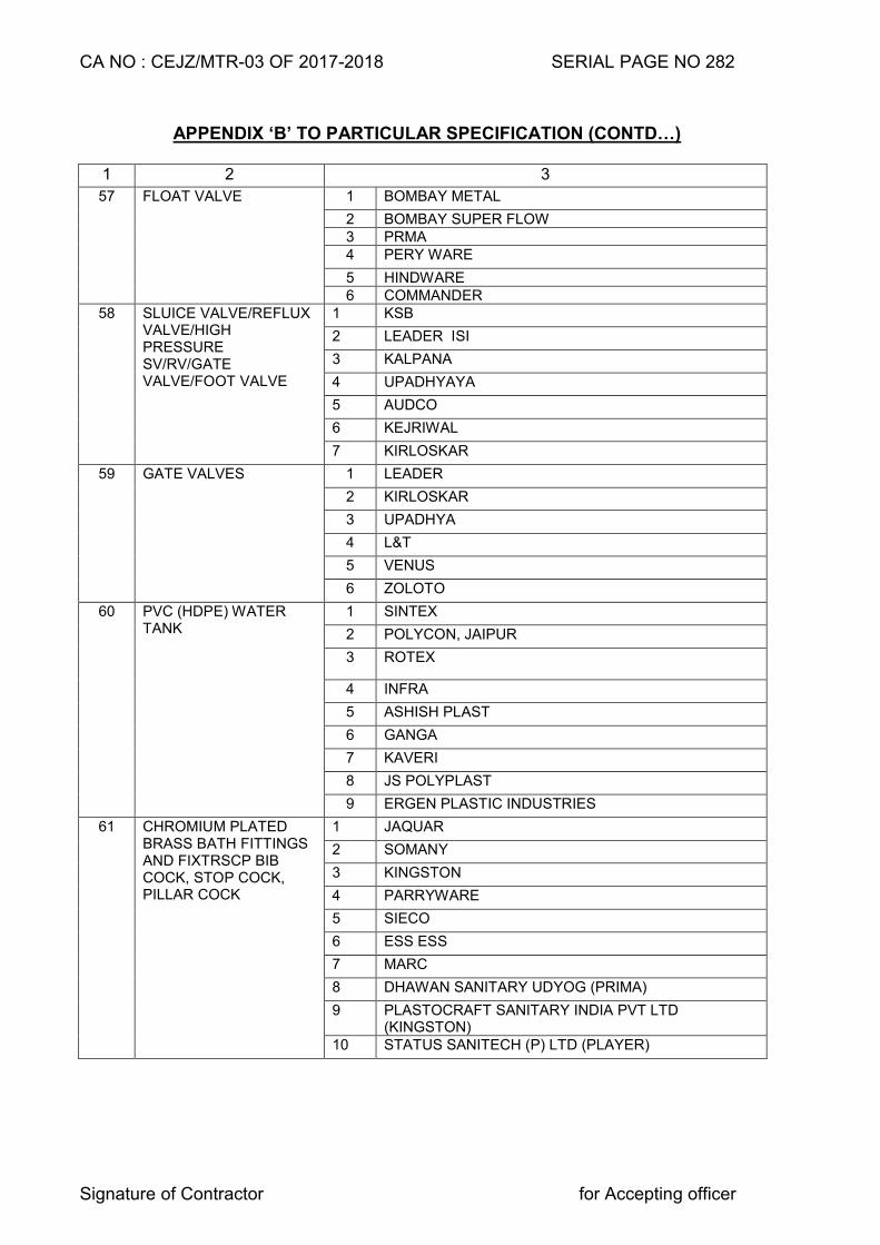
CA NO : CEJZ/MTR-03 OF 2017-2018 SERIAL PAGE NO 282
Signature of Contractor for Accepting officer
APPENDIX ‘B’ TO PARTICULAR SPECIFICATION (CONTD…)
1 2 3
57 FLOAT VALVE 1 BOMBAY METAL
2 BOMBAY SUPER FLOW 3 PRMA 4 PERY WARE
5 HINDWARE 6 COMMANDER
58 SLUICE VALVE/REFLUX VALVE/HIGH PRESSURE SV/RV/GATE VALVE/FOOT VALVE
1 KSB
2 LEADER ISI
3 KALPANA
4 UPADHYAYA
5 AUDCO
6 KEJRIWAL
7 KIRLOSKAR
59 GATE VALVES 1 LEADER
2 KIRLOSKAR
3 UPADHYA
4 L&T
5 VENUS
6 ZOLOTO
60 PVC (HDPE) WATER TANK
1 SINTEX
2 POLYCON, JAIPUR
3 ROTEX
4 INFRA
5 ASHISH PLAST
6 GANGA
7 KAVERI
8 JS POLYPLAST
9 ERGEN PLASTIC INDUSTRIES
61 CHROMIUM PLATED BRASS BATH FITTINGS AND FIXTRSCP BIB COCK, STOP COCK, PILLAR COCK
1 JAQUAR
2 SOMANY
3 KINGSTON
4 PARRYWARE
5 SIECO
6 ESS ESS
7 MARC
8 DHAWAN SANITARY UDYOG (PRIMA)
9 PLASTOCRAFT SANITARY INDIA PVT LTD (KINGSTON)
10 STATUS SANITECH (P) LTD (PLAYER)
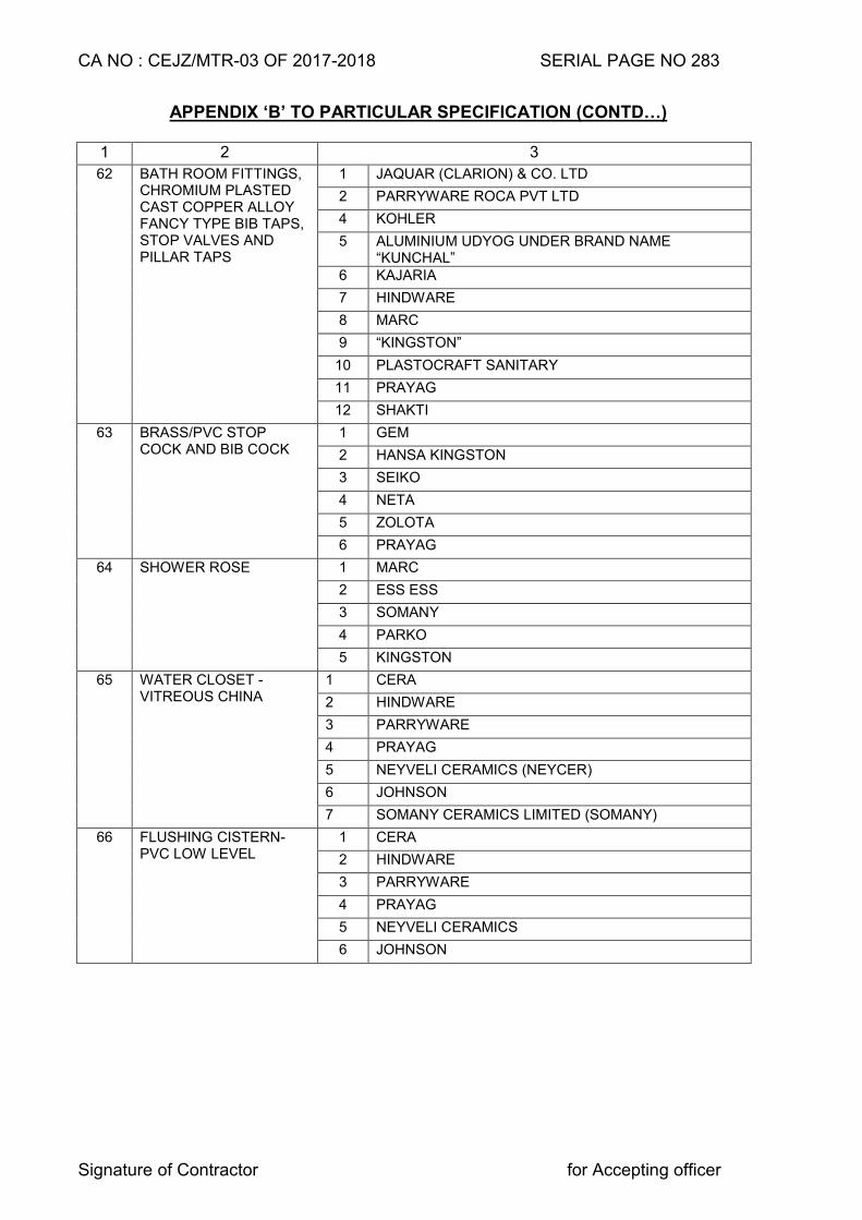
CA NO : CEJZ/MTR-03 OF 2017-2018 SERIAL PAGE NO 283
Signature of Contractor for Accepting officer
APPENDIX ‘B’ TO PARTICULAR SPECIFICATION (CONTD…)
1 2 3
62 BATH ROOM FITTINGS, CHROMIUM PLASTED CAST COPPER ALLOY FANCY TYPE BIB TAPS, STOP VALVES AND PILLAR TAPS
1 JAQUAR (CLARION) & CO. LTD
2 PARRYWARE ROCA PVT LTD
4 KOHLER
5 ALUMINIUM UDYOG UNDER BRAND NAME “KUNCHAL”
6 KAJARIA
7 HINDWARE
8 MARC
9 “KINGSTON”
10 PLASTOCRAFT SANITARY
11 PRAYAG
12 SHAKTI
63 BRASS/PVC STOP COCK AND BIB COCK
1 GEM
2 HANSA KINGSTON
3 SEIKO
4 NETA
5 ZOLOTA
6 PRAYAG
64 SHOWER ROSE 1 MARC
2 ESS ESS
3 SOMANY
4 PARKO
5 KINGSTON
65 WATER CLOSET -VITREOUS CHINA
1 CERA
2 HINDWARE
3 PARRYWARE
4 PRAYAG
5 NEYVELI CERAMICS (NEYCER)
6 JOHNSON
7 SOMANY CERAMICS LIMITED (SOMANY)
66 FLUSHING CISTERN- PVC LOW LEVEL
1 CERA
2 HINDWARE
3 PARRYWARE
4 PRAYAG
5 NEYVELI CERAMICS
6 JOHNSON
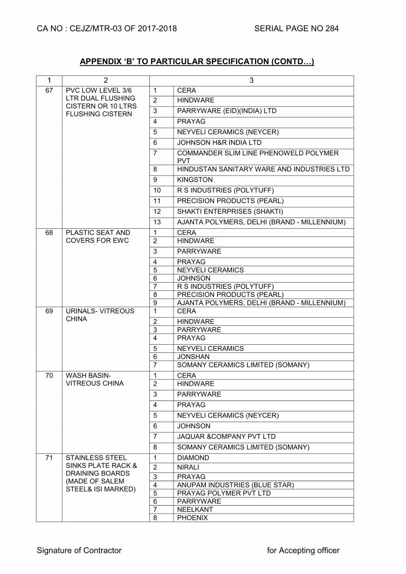
CA NO : CEJZ/MTR-03 OF 2017-2018 SERIAL PAGE NO 284
Signature of Contractor for Accepting officer
APPENDIX ‘B’ TO PARTICULAR SPECIFICATION (CONTD…)
1 2 3
67 PVC LOW LEVEL 3/6 LTR DUAL FLUSHING CISTERN OR 10 LTRS FLUSHING CISTERN
1 CERA
2 HINDWARE
3 PARRYWARE (EID)(INDIA) LTD
4 PRAYAG
5 NEYVELI CERAMICS (NEYCER)
6 JOHNSON H&R INDIA LTD
7 COMMANDER SLIM LINE PHENOWELD POLYMER PVT
8 HINDUSTAN SANITARY WARE AND INDUSTRIES LTD
9 KINGSTON
10 R S INDUSTRIES (POLYTUFF)
11 PRECISION PRODUCTS (PEARL)
12 SHAKTI ENTERPRISES (SHAKTI)
13 AJANTA POLYMERS, DELHI (BRAND - MILLENNIUM)
68 PLASTIC SEAT AND COVERS FOR EWC
1 CERA 2 HINDWARE
3 PARRYWARE
4 PRAYAG 5 NEYVELI CERAMICS 6 JOHNSON 7 R S INDUSTRIES (POLYTUFF) 8 PRECISION PRODUCTS (PEARL) 9 AJANTA POLYMERS, DELHI (BRAND - MILLENNIUM)
69 URINALS- VITREOUS CHINA
1 CERA
2 HINDWARE 3 PARRYWARE 4 PRAYAG
5 NEYVELI CERAMICS 6 JONSHAN 7 SOMANY CERAMICS LIMITED (SOMANY)
70 WASH BASIN- VITREOUS CHINA
1 CERA 2 HINDWARE
3 PARRYWARE
4 PRAYAG
5 NEYVELI CERAMICS (NEYCER)
6 JOHNSON
7 JAQUAR &COMPANY PVT LTD
8 SOMANY CERAMICS LIMITED (SOMANY)
71 STAINLESS STEEL SINKS PLATE RACK & DRAINING BOARDS (MADE OF SALEM STEEL& ISI MARKED)
1 DIAMOND
2 NIRALI
3 PRAYAG 4 ANUPAM INDUSTRIES (BLUE STAR) 5 PRAYAG POLYMER PVT LTD 6 PARRYWARE 7 NEELKANT 8 PHOENIX
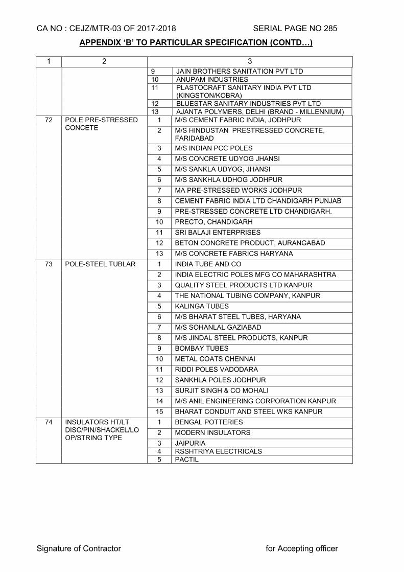
CA NO : CEJZ/MTR-03 OF 2017-2018 SERIAL PAGE NO 285
Signature of Contractor for Accepting officer
APPENDIX ‘B’ TO PARTICULAR SPECIFICATION (CONTD…)
1 2 3
9 JAIN BROTHERS SANITATION PVT LTD 10 ANUPAM INDUSTRIES 11 PLASTOCRAFT SANITARY INDIA PVT LTD
(KINGSTON/KOBRA) 12 BLUESTAR SANITARY INDUSTRIES PVT LTD 13 AJANTA POLYMERS, DELHI (BRAND - MILLENNIUM)
72 POLE PRE-STRESSED CONCETE
1 M/S CEMENT FABRIC INDIA, JODHPUR
2 M/S HINDUSTAN PRESTRESSED CONCRETE, FARIDABAD
3 M/S INDIAN PCC POLES
4 M/S CONCRETE UDYOG JHANSI
5 M/S SANKLA UDYOG, JHANSI
6 M/S SANKHLA UDHOG JODHPUR
7 MA PRE-STRESSED WORKS JODHPUR
8 CEMENT FABRIC INDIA LTD CHANDIGARH PUNJAB
9 PRE-STRESSED CONCRETE LTD CHANDIGARH.
10 PRECTO, CHANDIGARH
11 SRI BALAJI ENTERPRISES
12 BETON CONCRETE PRODUCT, AURANGABAD
13 M/S CONCRETE FABRICS HARYANA
73 POLE-STEEL TUBLAR 1 INDIA TUBE AND CO
2 INDIA ELECTRIC POLES MFG CO MAHARASHTRA
3 QUALITY STEEL PRODUCTS LTD KANPUR
4 THE NATIONAL TUBING COMPANY, KANPUR
5 KALINGA TUBES
6 M/S BHARAT STEEL TUBES, HARYANA
7 M/S SOHANLAL GAZIABAD
8 M/S JINDAL STEEL PRODUCTS, KANPUR
9 BOMBAY TUBES
10 METAL COATS CHENNAI
11 RIDDI POLES VADODARA
12 SANKHLA POLES JODHPUR
13 SURJIT SINGH & CO MOHALI
14 M/S ANIL ENGINEERING CORPORATION KANPUR
15 BHARAT CONDUIT AND STEEL WKS KANPUR
74 INSULATORS HT/LT DISC/PIN/SHACKEL/LOOP/STRING TYPE
1 BENGAL POTTERIES
2 MODERN INSULATORS
3 JAIPURIA 4 RSSHTRIYA ELECTRICALS 5 PACTIL
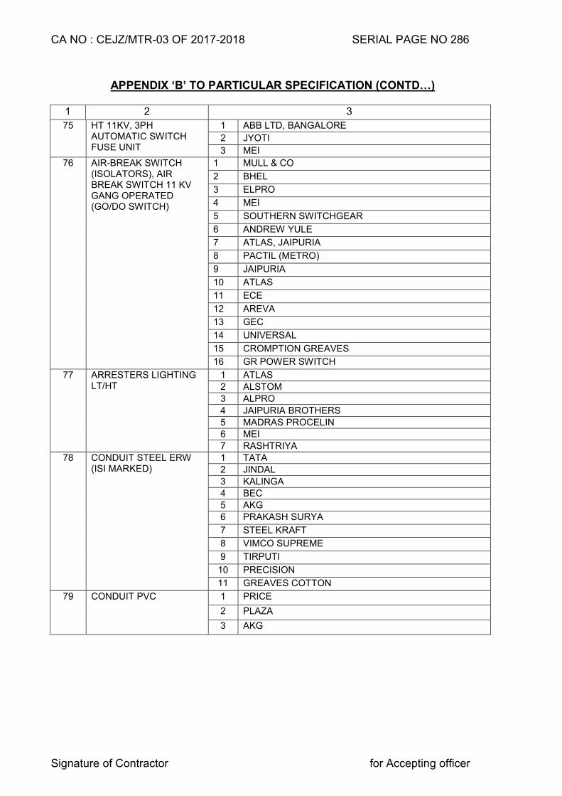
CA NO : CEJZ/MTR-03 OF 2017-2018 SERIAL PAGE NO 286
Signature of Contractor for Accepting officer
APPENDIX ‘B’ TO PARTICULAR SPECIFICATION (CONTD…)
1 2 3
75 HT 11KV, 3PH AUTOMATIC SWITCH FUSE UNIT
1 ABB LTD, BANGALORE
2 JYOTI
3 MEI
76 AIR-BREAK SWITCH (ISOLATORS), AIR BREAK SWITCH 11 KV GANG OPERATED (GO/DO SWITCH)
1 MULL & CO
2 BHEL
3 ELPRO
4 MEI
5 SOUTHERN SWITCHGEAR
6 ANDREW YULE
7 ATLAS, JAIPURIA
8 PACTIL (METRO)
9 JAIPURIA
10 ATLAS
11 ECE
12 AREVA
13 GEC
14 UNIVERSAL
15 CROMPTION GREAVES
16 GR POWER SWITCH
77 ARRESTERS LIGHTING LT/HT
1 ATLAS
2 ALSTOM
3 ALPRO
4 JAIPURIA BROTHERS
5 MADRAS PROCELIN
6 MEI
7 RASHTRIYA
78 CONDUIT STEEL ERW (ISI MARKED)
1 TATA
2 JINDAL
3 KALINGA
4 BEC
5 AKG
6 PRAKASH SURYA
7 STEEL KRAFT
8 VIMCO SUPREME
9 TIRPUTI
10 PRECISION
11 GREAVES COTTON
79 CONDUIT PVC 1 PRICE
2 PLAZA
3 AKG
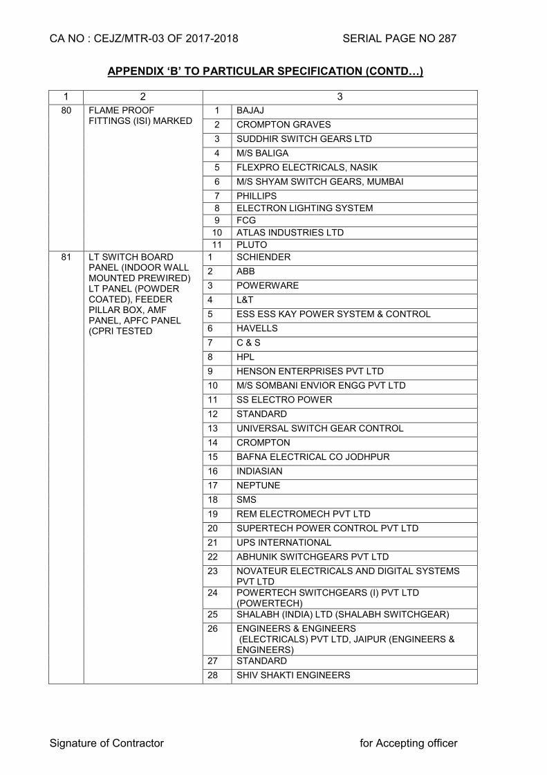
CA NO : CEJZ/MTR-03 OF 2017-2018 SERIAL PAGE NO 287
Signature of Contractor for Accepting officer
APPENDIX ‘B’ TO PARTICULAR SPECIFICATION (CONTD…)
1 2 3
80 FLAME PROOF FITTINGS (ISI) MARKED
1 BAJAJ
2 CROMPTON GRAVES
3 SUDDHIR SWITCH GEARS LTD
4 M/S BALIGA
5 FLEXPRO ELECTRICALS, NASIK
6 M/S SHYAM SWITCH GEARS, MUMBAI
7 PHILLIPS
8 ELECTRON LIGHTING SYSTEM
9 FCG
10 ATLAS INDUSTRIES LTD
11 PLUTO
81 LT SWITCH BOARD PANEL (INDOOR WALL MOUNTED PREWIRED) LT PANEL (POWDER COATED), FEEDER PILLAR BOX, AMF PANEL, APFC PANEL (CPRI TESTED
1 SCHIENDER
2 ABB
3 POWERWARE
4 L&T
5 ESS ESS KAY POWER SYSTEM & CONTROL
6 HAVELLS
7 C & S
8 HPL
9 HENSON ENTERPRISES PVT LTD
10 M/S SOMBANI ENVIOR ENGG PVT LTD
11 SS ELECTRO POWER
12 STANDARD
13 UNIVERSAL SWITCH GEAR CONTROL
14 CROMPTON
15 BAFNA ELECTRICAL CO JODHPUR
16 INDIASIAN
17 NEPTUNE
18 SMS
19 REM ELECTROMECH PVT LTD
20 SUPERTECH POWER CONTROL PVT LTD
21 UPS INTERNATIONAL
22 ABHUNIK SWITCHGEARS PVT LTD
23 NOVATEUR ELECTRICALS AND DIGITAL SYSTEMS PVT LTD
24 POWERTECH SWITCHGEARS (I) PVT LTD (POWERTECH)
25 SHALABH (INDIA) LTD (SHALABH SWITCHGEAR)
26 ENGINEERS & ENGINEERS (ELECTRICALS) PVT LTD, JAIPUR (ENGINEERS & ENGINEERS)
27 STANDARD
28 SHIV SHAKTI ENGINEERS
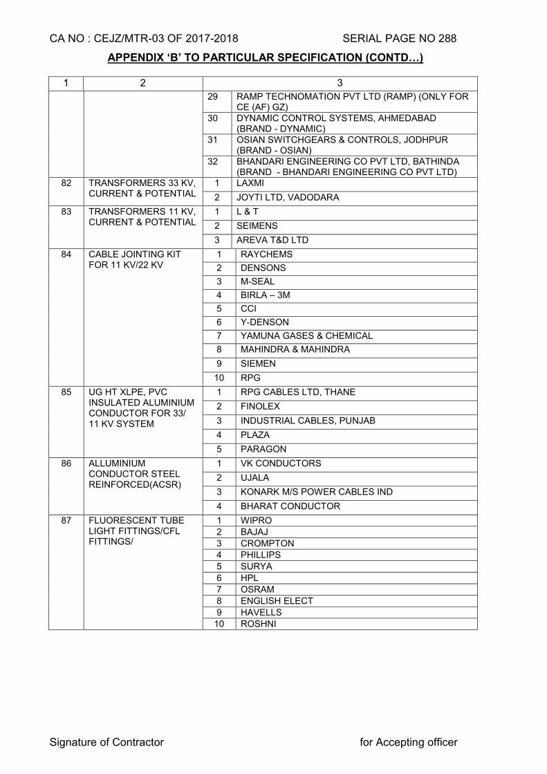
CA NO : CEJZ/MTR-03 OF 2017-2018 SERIAL PAGE NO 288
Signature of Contractor for Accepting officer
APPENDIX ‘B’ TO PARTICULAR SPECIFICATION (CONTD…)
1 2 3
29 RAMP TECHNOMATION PVT LTD (RAMP) (ONLY FOR CE (AF) GZ)
30 DYNAMIC CONTROL SYSTEMS, AHMEDABAD (BRAND - DYNAMIC)
31 OSIAN SWITCHGEARS & CONTROLS, JODHPUR (BRAND - OSIAN)
32 BHANDARI ENGINEERING CO PVT LTD, BATHINDA (BRAND - BHANDARI ENGINEERING CO PVT LTD)
82 TRANSFORMERS 33 KV, CURRENT & POTENTIAL
1 LAXMI
2 JOYTI LTD, VADODARA
83 TRANSFORMERS 11 KV, CURRENT & POTENTIAL
1 L & T
2 SEIMENS
3 AREVA T&D LTD
84 CABLE JOINTING KIT FOR 11 KV/22 KV
1 RAYCHEMS
2 DENSONS
3 M-SEAL
4 BIRLA – 3M
5 CCI
6 Y-DENSON
7 YAMUNA GASES & CHEMICAL
8 MAHINDRA & MAHINDRA
9 SIEMEN
10 RPG
85 UG HT XLPE, PVC INSULATED ALUMINIUM CONDUCTOR FOR 33/ 11 KV SYSTEM
1 RPG CABLES LTD, THANE
2 FINOLEX
3 INDUSTRIAL CABLES, PUNJAB
4 PLAZA
5 PARAGON
86 ALLUMINIUM CONDUCTOR STEEL REINFORCED(ACSR)
1 VK CONDUCTORS
2 UJALA
3 KONARK M/S POWER CABLES IND
4 BHARAT CONDUCTOR
87 FLUORESCENT TUBE LIGHT FITTINGS/CFL FITTINGS/
1 WIPRO
2 BAJAJ
3 CROMPTON
4 PHILLIPS
5 SURYA
6 HPL
7 OSRAM
8 ENGLISH ELECT
9 HAVELLS
10 ROSHNI
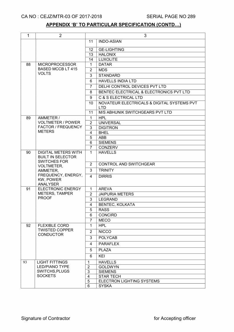
CA NO : CEJZ/MTR-03 OF 2017-2018 SERIAL PAGE NO 289
Signature of Contractor for Accepting officer
APPENDIX ‘B’ TO PARTICULAR SPECIFICATION (CONTD…)
1 2 3
11 INDO-ASIAN
12 GE-LIGHTING
13 HALONIX
14 LUXOLITE
88 MICROPROCESSOR BASED MCCB LT 415 VOLTS
1 DATAR
2 MDS
3 STANDARD
6 HAVELLS INDIA LTD
7 DELHI CONTROL DEVICES PVT LTD
8 BENTEC ELECTRICAL & ELECTRONICS PVT LTD
9 C & S ELECTRICAL LTD
10 NOVATEUR ELECTRICALS & DIGITAL SYSTEMS PVT LTD
11 M/S ABHUNIK SWITCHGEARS PVT LTD
89 AMMETER / VOLTMETER / POWER FACTOR / FREQUENCY METERS
1 HPL
2 UNIVERSAL
3 DIGITRON
4 BHEL
5 ABB
6 SIEMENS
7 CONZERV
90 DIGITAL METERS WITH BUILT IN SELECTOR SWITCHES FOR VOLTMETER, AMMETER, FREQUENCY, ENERGY, KW, POWER ANALYSER
1 HAVELLS
2 CONTROL AND SWITCHGEAR
3 TRINITY
4 DIRRIS
91
ELECTRONIC ENERGY METERS, TAMPER PROOF
1 AREVA
2 JAIPURIA METERS
3 LEGRAND
4 BENTEC, KOLKATA
5 RASS
6 CONCIRD
7 MECO
92 FLEXIBLE CORD TWISTED COPPER CONDUCTOR
1 HPL
2 NICCO
3 POLYCAB
4 PARAFLEX
5 PLAZA
6 KEI
93 LIGHT FITTINGS LED/PIANO TYPE SWITCHS,PLUGS SOCKETS
1 HAVELLS 2 GOLDWYN 3 SIEMENS 4 STAR TECH 5 ELECTRON LIGHTING SYSTEMS 6 SYSKA
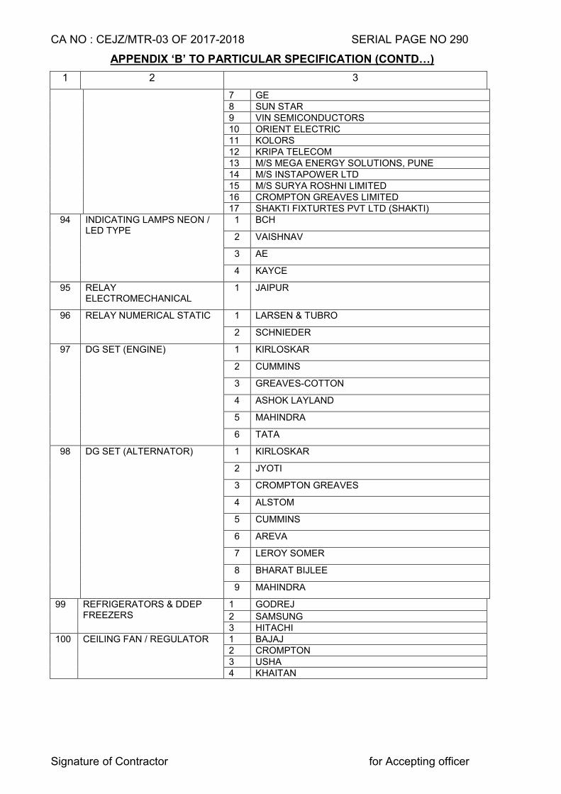
CA NO : CEJZ/MTR-03 OF 2017-2018 SERIAL PAGE NO 290
Signature of Contractor for Accepting officer
APPENDIX ‘B’ TO PARTICULAR SPECIFICATION (CONTD…)
1 2 3
7 GE 8 SUN STAR 9 VIN SEMICONDUCTORS 10 ORIENT ELECTRIC 11 KOLORS 12 KRIPA TELECOM 13 M/S MEGA ENERGY SOLUTIONS, PUNE 14 M/S INSTAPOWER LTD 15 M/S SURYA ROSHNI LIMITED 16 CROMPTON GREAVES LIMITED 17 SHAKTI FIXTURTES PVT LTD (SHAKTI)
94 INDICATING LAMPS NEON / LED TYPE
1 BCH
2 VAISHNAV
3 AE
4 KAYCE
95 RELAY ELECTROMECHANICAL
1 JAIPUR
96 RELAY NUMERICAL STATIC 1 LARSEN & TUBRO
2 SCHNIEDER
97 DG SET (ENGINE) 1 KIRLOSKAR
2 CUMMINS
3 GREAVES-COTTON
4 ASHOK LAYLAND
5 MAHINDRA
6 TATA
98 DG SET (ALTERNATOR) 1 KIRLOSKAR
2 JYOTI
3 CROMPTON GREAVES
4 ALSTOM
5 CUMMINS
6 AREVA
7 LEROY SOMER
8 BHARAT BIJLEE
9 MAHINDRA
99 REFRIGERATORS & DDEP FREEZERS
1 GODREJ
2 SAMSUNG 3 HITACHI
100 CEILING FAN / REGULATOR 1 BAJAJ 2 CROMPTON 3 USHA 4 KHAITAN
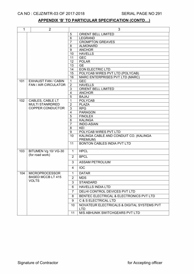
CA NO : CEJZ/MTR-03 OF 2017-2018 SERIAL PAGE NO 291
Signature of Contractor for Accepting officer
APPENDIX ‘B’ TO PARTICULAR SPECIFICATION (CONTD…)
1 2 3
5 ORIENT BELL LIMITED 6 LEGRAND 7 CROMPTON GREAVES 8 ALMONARD 9 ANCHOR 10 HAVELLS 11 GEC 12 POLAR 13 GE 14 EON ELECTRIC LTD 15 POLYCAB WIRES PVT LTD (POLYCAB) 16 MARC ENTERPRISES PVT LTD (MARC)
101 EXHAUST FAN / CABIN FAN / AIR CIRCULATOR
1 GEC 2 HAVELLS 3 ORIENT BELL LIMITED 4 ANCHOR 5 BAJAJ
102 CABLES, CABLE LT MULTI STANRDRED COPPER CONDUCTOR
1 POLYCAB 2 PLAZA 3 RPG 4 PARAGON 5 FINOLEX 6 KALINGA 7 INDO-ASIAN 8 KEI 9 POLYCAB WIRES PVT LTD 10 KALINGA CABLE AND CONDUIT CO. (KALINGA
PREMIUM) 11 BONTON CABLES INDIA PVT LTD
103 BITUMEN Vg 10/ VG-30
(for road work) 1 HPCL
2 BPCL
3 ASSAM PETROLIUM
4 IOC
104 MICROPROCESSOR BASED MCCB LT 415 VOLTS
1 DATAR
2 MDS
3 STANDARD
6 HAVELLS INDIA LTD
7 DELHI CONTROL DEVICES PVT LTD
8 BENTEC ELECTRICAL & ELECTRONICS PVT LTD
9 C & S ELECTRICAL LTD
10 NOVATEUR ELECTRICALS & DIGITAL SYSTEMS PVT LTD
11 M/S ABHUNIK SWITCHGEARS PVT LTD
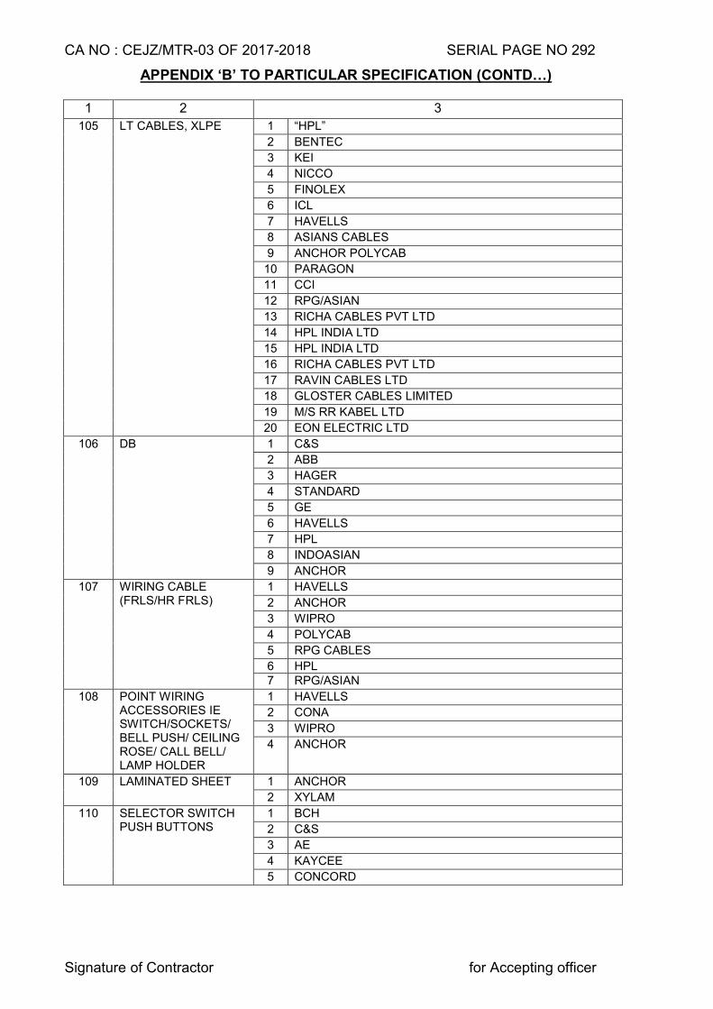
CA NO : CEJZ/MTR-03 OF 2017-2018 SERIAL PAGE NO 292
Signature of Contractor for Accepting officer
APPENDIX ‘B’ TO PARTICULAR SPECIFICATION (CONTD…)
1 2 3
105 LT CABLES, XLPE 1 “HPL”
2 BENTEC
3 KEI
4 NICCO
5 FINOLEX
6 ICL
7 HAVELLS
8 ASIANS CABLES
9 ANCHOR POLYCAB
10 PARAGON
11 CCI
12 RPG/ASIAN
13 RICHA CABLES PVT LTD
14 HPL INDIA LTD
15 HPL INDIA LTD
16 RICHA CABLES PVT LTD
17 RAVIN CABLES LTD
18 GLOSTER CABLES LIMITED
19 M/S RR KABEL LTD
20 EON ELECTRIC LTD
106 DB 1 C&S
2 ABB
3 HAGER
4 STANDARD
5 GE
6 HAVELLS
7 HPL
8 INDOASIAN
9 ANCHOR
107 WIRING CABLE (FRLS/HR FRLS)
1 HAVELLS
2 ANCHOR
3 WIPRO
4 POLYCAB
5 RPG CABLES
6 HPL 7 RPG/ASIAN
108 POINT WIRING ACCESSORIES IE SWITCH/SOCKETS/ BELL PUSH/ CEILING ROSE/ CALL BELL/ LAMP HOLDER
1 HAVELLS
2 CONA
3 WIPRO
4 ANCHOR
109 LAMINATED SHEET 1 ANCHOR
2 XYLAM
110 SELECTOR SWITCH PUSH BUTTONS
1 BCH
2 C&S
3 AE
4 KAYCEE
5 CONCORD
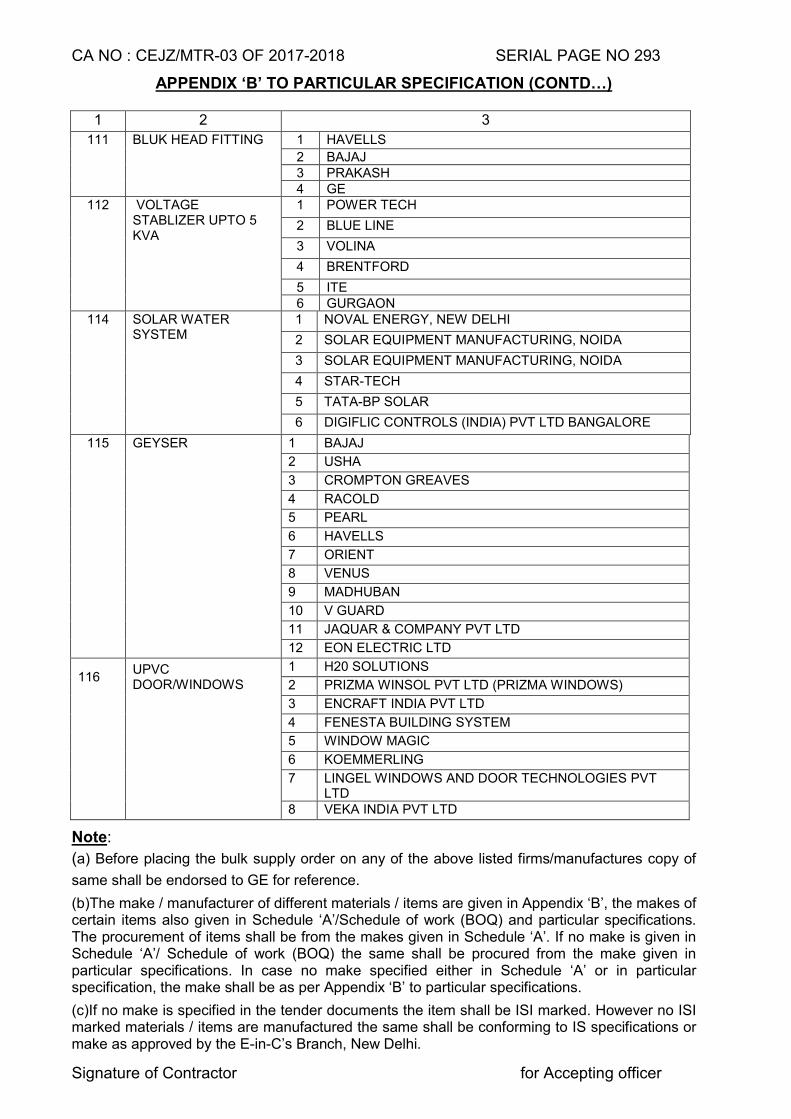
CA NO : CEJZ/MTR-03 OF 2017-2018 SERIAL PAGE NO 293
Signature of Contractor for Accepting officer
APPENDIX ‘B’ TO PARTICULAR SPECIFICATION (CONTD…)
1 2 3
111 BLUK HEAD FITTING 1 HAVELLS
2 BAJAJ 3 PRAKASH 4 GE
112 VOLTAGE STABLIZER UPTO 5 KVA
1 POWER TECH
2 BLUE LINE
3 VOLINA
4 BRENTFORD
5 ITE 6 GURGAON
114 SOLAR WATER SYSTEM
1 NOVAL ENERGY, NEW DELHI
2 SOLAR EQUIPMENT MANUFACTURING, NOIDA
3 SOLAR EQUIPMENT MANUFACTURING, NOIDA
4 STAR-TECH
5 TATA-BP SOLAR
6 DIGIFLIC CONTROLS (INDIA) PVT LTD BANGALORE
115 GEYSER 1 BAJAJ
2 USHA
3 CROMPTON GREAVES
4 RACOLD
5 PEARL
6 HAVELLS
7 ORIENT
8 VENUS
9 MADHUBAN
10 V GUARD
11 JAQUAR & COMPANY PVT LTD
12 EON ELECTRIC LTD
116 UPVC DOOR/WINDOWS
1 H20 SOLUTIONS
2 PRIZMA WINSOL PVT LTD (PRIZMA WINDOWS)
3 ENCRAFT INDIA PVT LTD
4 FENESTA BUILDING SYSTEM
5 WINDOW MAGIC
6 KOEMMERLING
7 LINGEL WINDOWS AND DOOR TECHNOLOGIES PVT LTD
8 VEKA INDIA PVT LTD
Note:
(a) Before placing the bulk supply order on any of the above listed firms/manufactures copy of
same shall be endorsed to GE for reference.
(b)The make / manufacturer of different materials / items are given in Appendix ‘B’, the makes of certain items also given in Schedule ‘A’/Schedule of work (BOQ) and particular specifications. The procurement of items shall be from the makes given in Schedule ‘A’. If no make is given in Schedule ‘A’/ Schedule of work (BOQ) the same shall be procured from the make given in particular specifications. In case no make specified either in Schedule ‘A’ or in particular specification, the make shall be as per Appendix ‘B’ to particular specifications.
(c)If no make is specified in the tender documents the item shall be ISI marked. However no ISI marked materials / items are manufactured the same shall be conforming to IS specifications or make as approved by the E-in-C’s Branch, New Delhi.
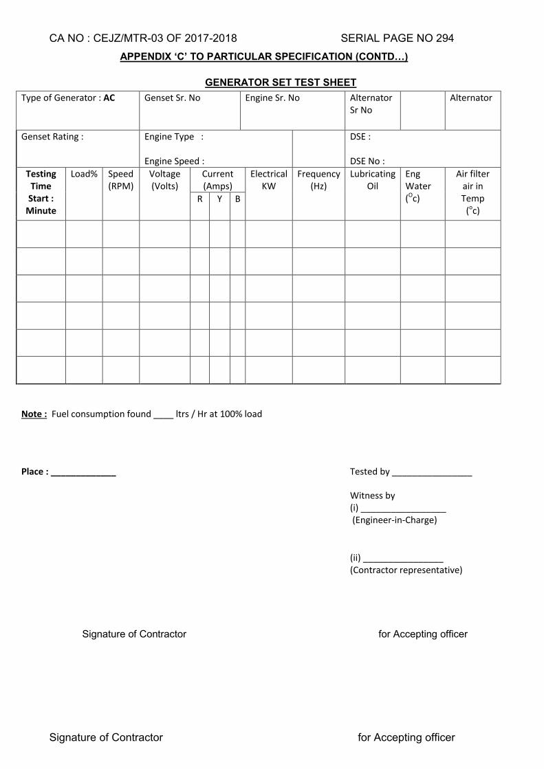
CA NO : CEJZ/MTR-03 OF 2017-2018 SERIAL PAGE NO 294
Signature of Contractor for Accepting officer
APPENDIX ‘C’ TO PARTICULAR SPECIFICATION (CONTD…)
GENERATOR SET TEST SHEET
Type of Generator : AC Genset Sr. No Engine Sr. No Alternator Sr No
Alternator
Genset Rating : Engine Type : Engine Speed :
DSE : DSE No :
Testing Time
Start : Minute
Load% Speed (RPM)
Voltage (Volts)
Current (Amps)
Electrical KW
Frequency (Hz)
Lubricating Oil
Eng Water (Oc)
Air filter air in Temp
(oc) R Y B
Note : Fuel consumption found ____ ltrs / Hr at 100% load
Place : _____________ Tested by ________________
Witness by (i) _________________
(Engineer-in-Charge)
(ii) ________________ (Contractor representative)
Signature of Contractor for Accepting officer
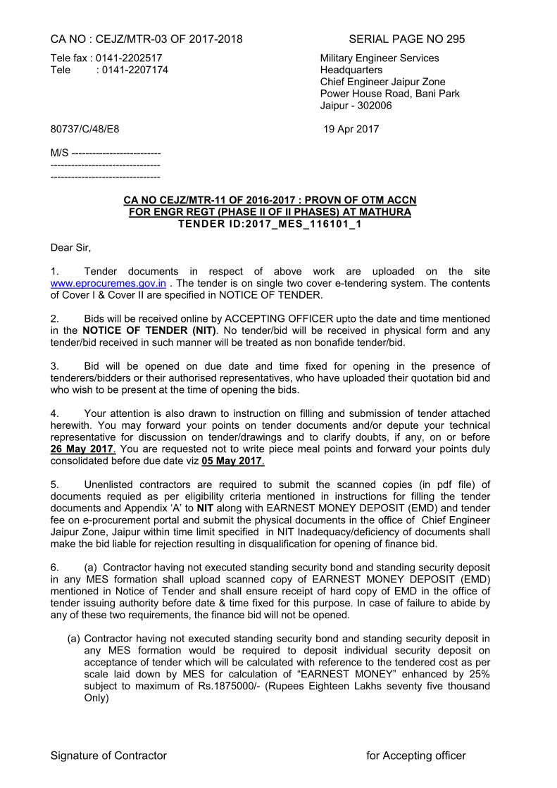
CA NO : CEJZ/MTR-03 OF 2017-2018 SERIAL PAGE NO 295
Signature of Contractor for Accepting officer
Tele fax : 0141-2202517 Military Engineer Services Tele : 0141-2207174 Headquarters Chief Engineer Jaipur Zone Power House Road, Bani Park Jaipur - 302006 80737/C/48/E8 19 Apr 2017 M/S -------------------------- -------------------------------- --------------------------------
CA NO CEJZ/MTR-11 OF 2016-2017 : PROVN OF OTM ACCN FOR ENGR REGT (PHASE II OF II PHASES) AT MATHURA
TENDER ID:2017_MES_116101_1
Dear Sir, 1. Tender documents in respect of above work are uploaded on the site www.eprocuremes.gov.in . The tender is on single two cover e-tendering system. The contents of Cover I & Cover II are specified in NOTICE OF TENDER. 2. Bids will be received online by ACCEPTING OFFICER upto the date and time mentioned in the NOTICE OF TENDER (NIT). No tender/bid will be received in physical form and any tender/bid received in such manner will be treated as non bonafide tender/bid. 3. Bid will be opened on due date and time fixed for opening in the presence of tenderers/bidders or their authorised representatives, who have uploaded their quotation bid and who wish to be present at the time of opening the bids. 4. Your attention is also drawn to instruction on filling and submission of tender attached herewith. You may forward your points on tender documents and/or depute your technical representative for discussion on tender/drawings and to clarify doubts, if any, on or before 26 May 2017. You are requested not to write piece meal points and forward your points duly consolidated before due date viz 05 May 2017. 5. Unenlisted contractors are required to submit the scanned copies (in pdf file) of documents requied as per eligibility criteria mentioned in instructions for filling the tender documents and Appendix ‘A’ to NIT along with EARNEST MONEY DEPOSIT (EMD) and tender fee on e-procurement portal and submit the physical documents in the office of Chief Engineer Jaipur Zone, Jaipur within time limit specified in NIT Inadequacy/deficiency of documents shall make the bid liable for rejection resulting in disqualification for opening of finance bid. 6. (a) Contractor having not executed standing security bond and standing security deposit in any MES formation shall upload scanned copy of EARNEST MONEY DEPOSIT (EMD) mentioned in Notice of Tender and shall ensure receipt of hard copy of EMD in the office of tender issuing authority before date & time fixed for this purpose. In case of failure to abide by any of these two requirements, the finance bid will not be opened.
(a) Contractor having not executed standing security bond and standing security deposit in any MES formation would be required to deposit individual security deposit on acceptance of tender which will be calculated with reference to the tendered cost as per scale laid down by MES for calculation of “EARNEST MONEY” enhanced by 25% subject to maximum of Rs.1875000/- (Rupees Eighteen Lakhs seventy five thousand Only)
CA NO : CEJZ/MTR-03 OF 2017-2018 SERIAL PAGE NO 296
Signature of Contractor for Accepting officer
7. Enlisted contractors of MES shall submit the scanned copies (pdf file) of enlistment letter, tender fee and such other documents as mentioned in Appx ‘ A’ to NIT on e-procurement portal and submit physical documents in the office of HQ Chief Engineer Jaipur Zone, Jaipur before date and time fixed for this purpose. 8. The contractor must ensure that the tender/bid on the proper form is uploaded in time as the Accepting Officer will take no congnizance of any quotations/offer received in any other electronic or phsical form like email/fax/by hand /through post form tenderer/bidder even if they are received in time. 9. In view of delays due to system failure or other communication related failures, it is suggested that the tender/bid be uploaded, if necessary, sufficiently in advance of the last due date and time fixed. 10. General Conditions of Contracts (IAFW-2249) (1989 Print) and errata and amendments thereto, Schedule of minimum fair wages and MES SSR (Part –I and Part –II) are not enclosed with these documents. There are available for perusal in the office of GE concerned and this office. 11. ANY TENDERER, WHICH PROPOSES ALTERATIONS TO ANY OF THE CONDITION, SPECIFICATIONS LAID DOWN IN THE TENDER DOCUMENTS OR ANY NEW CONDITION, WHAT SO EVER IS LIABLE TO BE REJECTED. Yours faithfully,
(________________) _____________________
Encls:- (As above) For Accepting Officer Signature of Contractor
CA NO : CEJZ/MTR-03 OF 2017-2018 SERIAL PAGE NO 297
Signature of Contractor for Accepting officer
INSTRUCTION ON FILLING AND SUBMISSION OF TENDER
1. EARNEST MONEY DEPOSIT (EMD) Contractor (s) who are not enlisted with MES/ who are enlisted but have not executed the standing security bond shall submit Earnest Money Deposit as detailed in Notice of Tender in one of the following forms, alongwith their tender/bid :-
(a) Deposit at call receipt form a Scheduled Band in favour of Garrison Engineer concerned. (b) Receipted Treasury Challan, the amount being credited to the Revenue Deposit of
Garrison Engineer.
It is advisable that Earnest Money is deposited in the form of deposit call receipt from an approved Schedule Bank for easy refund. In case the tenderer/bidder wants to lodge ‘EARNEST MONEY DEPOSIT’ in any other from allowed by MES, a confirmation about its acceptability will be obtained from the Accepting Officer well in advance of the bid submission end date and time. Earnest Money Deposit shall be submitted in the name of concerned GE. NOTES: Earnest Money Deposit (EMD) in the form of cheque/Bank Guarantee etc will not be accepted. NON- SUBMISSION OF EARNEST MONEY DEPOSIT (EMD) ( scanned copy alongwith Technical Bid and hard copy before the date and time fixed for opening of BOQ) WILL RENDER THE BID DISQUALIFIED FOR OPENING OF COVER II (FINANCE BID). 2. SECURITY DEPOSIT In case the tender/bid submitted by such contractor who is not enlisted with MES is accepted, the contractor will be required to lodge with the Controller of Defence Accounts INDIVIDUAL SECURITY DEPOSIT calculated with reference to TENDERED COST as notified by the Accepting Officer subject to a maximum of Rs 18,75,000/-. The amount is required to be lodged within 30(Thirty) days of the receipt by the contractor of notification of acceptance of tender/bid, failing which the sum shall be recovered from the 1st RAR payment or from the Final bill (See Condition 22 of GCC (IAFW-2249). 3. CONTRACTORS ENLISTED WITH CHIEF ENGINEER SOUTH WEST COMMAND AND WHO HAVE EXECUTED STANDING SECURITY BOND AND DEPOSITED STANDING SECURITY DEPOSIT BUT OF LOWER CLASS In case the tender/bid is accepted, the amount of Additional Security Deposit will be as notified by the Accepting Officer. The amount will be the difference between the “Individual Security Deposit” calculated with reference to the “TENDERED COST” and ‘Standing Security Deposit’ lodged. The amount is required to be lodged within 30(Thirty) days of the ereciept by the contractor of notification of acceptance of tender/bid, falling which the sum shall be recovered from the 1st RAR payment or from the Final bill (Refer Condition 22 of GCC (IAFW-2249). 4. CONTRACTORS ENLISTED IN MES FORMATIONAS OTHER THAN CE SOUTH WEST COMMAND Contractors whose names are on the approved list of any MES formation i.e. other than CE SOUTH WEST Command and who have deposited Standing Security and have executed Standing Security Bond may tender/bid without depositing Earnest Money with the bid and if the Accepting Officer decides to accept the tender/bid, such tenders will be required to lodge security Deposit as notified by the Accepting officer. The amount is required to be lodged within 30 days of receipt by the contractor of notification of acceptance of tender/bid, failing which the sum shall be recovered from the 1st RAR payment or from the Final bill.
CA NO : CEJZ/MTR-03 OF 2017-2018 SERIAL PAGE NO 298
Signature of Contractor for Accepting officer
5. GENERAL INSTRUCTION FOR COMPLIANCE 5.1 The bids received only in the electronic form will be considered. All bids shall be submitted on ‘eprocuremes.gov.in’ portal. Documents should be scanned and forwarded in ‘pdf’ form and ‘xls’ form as indicated. 5.2 Bids shall be uploaded on ‘eprocuemes.gov.in’ portal on or before the bid closing date mentioned in the tender. NO tender/bid in any other electronic or physical form like email/fax/by hand/through post will be considered. 5.3 Bid should be DIGITALLY signed using valid DSC. All pages of tender documents, corrections/alterations shall be signed/initialed by the lowest bidder after acceptance. 5.4 Drawings if issued in physical form, must be returned duly initialed by the tenderer/bidder in separate envelope indicating his name and address. 5.5 The tender shall be signed, dated and witnessed at all places provided for in the documents after acceptance. All corrections shall be initialed. The contractor shall initial every page of tender and shall sign all drawings forming part of the tender. Any tender/bid, which propose alterations to any of the conditions whatsoever, is liable to be rejected. 5.6 In the technical bid, a scanned copy of power of Attorney in favour of the person uploading the bid using his/her DSC shall be uploaded. In case the digital signatory himself is the sole proprietor, scanned copy of an affidavit on stamp paper of appropriate value to this effect stating that he has authority to bind the firm in all matters pertaining to contract including the Arbitration Clause, shall be attached in ‘pdf’ form. In case of partnership concern or a limited company, digital signatory of the bid/tender shall ensure that he is competent to bind the contractor (through partnership deed, general power of attorney es or Memorandum and Articles of Association of the Company) in all the matters pertaining to the contracts with Union of India including arbitration clause. A scanned copy to the documents confirming of such authority shall be attached with the tender/bid in ‘pdf’ form, if not submitted earlier. The person uploading the bid on behalf of another partner (S) or on behalf of a firm or company using his DSC shall upload with the tender/bid a scanned copy ( in ‘pdf’ form) of Power of Attorney duly executed in his favour by such other or all of the Partner(s) or in accordance with constitution of the company in case of company, stating that he has authority to bind such other person of the firm or the company, as the case may be, in all matters pertaining to the contract including the Arbitration Clause. 5.7 Even in case of firms or companies which has already given power of attorney to an individual authorizing him to sigh tender in pursuance of which bids are being uploaded by such person as a routine, fresh power of attorney duly executed in his favour stating specifically that the said person has authority to bind such partners of the firm, or the company as the case may be, including the condition relating to Arbitration clause, should be uploaded in ‘pdf’ form with the tender/bid : unless such authority has already been given to him by the firm or the company.. it shall be ensured that power of attorney shall be executed in accordance with the constitution of the company as laid down in its Memorandum and Article of Association. 5.8 Hard copies of all above documents should be sent by the contractor to the Tender issuing authority well in advance to be received before the date & time fixed for the same. 5.9 Bid (Cover 1&2) shall be uploaded online well in time. 5.10 The contractor shall employ Indian Nationals after verifying their antecedents and loyalty. Attention is also drawn to special condition 3 referred hereinafter and also conditions 24&25 of IAFW-2249 (General conditions of contract). 5.11 Tenderers/bidders who uploaded their priced tenders/bids and are desirous of being present at the time of opening of the tenders/bids, may do so at the appointed time.
CA NO : CEJZ/MTR-03 OF 2017-2018 SERIAL PAGE NO 299
Signature of Contractor for Accepting officer
5.12 The tenderer/bidder shall quote his rate on the BOQ file only. No alternation to the format will be accepted, else the bid will be disqualified and summarily rejected. 5.13 In case the tenderer/bidder has to revise /modify the rates quoted in the BOQ (exce sheet) he can do so only in the BOQ, through eprocuremes.gov.in site only before the bid closing time and date. 6. REVOCATION/REVISON OF OFFER UPWARD/ OFFERING VOLUNATARY REDUCTION, AFTER OPENING OF FINANICIAL BIDS BY LOWEST BIDDER In the event of lowest tenderer/bidder revoking his offer or revising his rates upward/ offering voluntary reduction, after closing of bid submission date & time, his offer will be treated as revoked and the Earnest Money deposited by him shall be forfeited. In case of MES enlisted Contractors, the amount equal to the Earnest Money stipulated in the Notice of tender, shall be notified to the tenderer/ bidder for depositing the amount through MRO. Bidds of such Contractors/bidders shall not be opened till the aforesaid amount equal to the earnest money is deposited by him in Govt Treasury. In addition, bids of such tender/bidder and his related firm shall not be opened in second call or subsequent calls. Reduction offered by the tenderer/ bidder on the freak high rates referred for review shall not be treaterd as voluntary reduction. 7. CPM(Critical Path Method) 7.1 The projected planning for work covers in the scope of tender is based on CPM. 7.2 The tenderer/bidder is expected to be fully conversant with the CPM technique and employ technical staff who can use the technique in sufficient details. Sufficient books and other literature on the subject are widely available in the market which the tenderer/Bidder may make use of. 7.3 The tenderer’s/bidder’s attention drawn to special condition of the tender regarding preparation of the detailed network analysis and the schedule for the work and his liability for employing sufficient resources to adhere to this schedule. Any inability on the part of the tenderer/bidder in using the technique will be taken as his technical inefficiency and will affect his class of enlistment and future prospect/ invitation to tender for future works. 7.4. Department may issue amendments/errata in form of CORRIGENDUM to tender /revised BOQ to the tender documents. The tenderer /bidder is requested to read the tender document in conjunction with all the errata/ amendment, corrigendum, if any, issued by the department. 8. These instructions shall form part of the contract documents. __________________ ______________ Signature of Contractor For Accepting Officers


![CHEMISTRY (03] - SelfStudys](https://img.pdfslide.net/doc/110x75/633b6094de4afcade601ddb5/chemistry-03-selfstudys.jpg)


