Embed Size (px)
Citation preview

Seediscussions,stats,andauthorprofilesforthispublicationat:https://www.researchgate.net/publication/13310963
CalculationsofthegeometryandopticalpropertiesofFMgcentersanddimer(F2-type)centersincorundumcrystals.
ARTICLEinPHYSICALREVIEW.B,CONDENSEDMATTER·MAY1995
ImpactFactor:3.66·Source:PubMed
CITATIONS
5
READS
47
7AUTHORS,INCLUDING:
EugeneA.Kotomin
UniversityofLatvia
494PUBLICATIONS6,467CITATIONS
SEEPROFILE
LevKantorovich
King'sCollegeLondon
214PUBLICATIONS3,981CITATIONS
SEEPROFILE
AnatoliIPopov
UniversityofLatvia
139PUBLICATIONS1,287CITATIONS
SEEPROFILE
IvarsTale
UniversityofLatvia
44PUBLICATIONS373CITATIONS
SEEPROFILE
Availablefrom:AnatoliIPopov
Retrievedon:03February2016

PHYSICAL REVIEW 8 VOLUME 51, NUMBER 14 1 APRIL 1995-II
Calculations of the geometry and optical properties of FMI centersand dimer (F&-type) centers in corundum crystals
E. A. Kotomin, * A. Stashans, L. N. Kantorovich, A. I. Lifshitz, A. I. Popov, and I. A. TaleUniversity ofLatvia, 19Rainis Blvd , R.iga, LV 1050-, Latvia
J.-L. CalaisDepartment of Quantum Chemistry, Uppsala University, Box 518, S-57120, Uppsala, Sweden
(Received 19 July 1994)
Results of the defect calculations in u-A1&03 (corundum) crystals using the semiempirical method ofintermediate neglect of di8'erential overlap and large, 65-atom-stoichiometric quantum clusters are re-
ported. The geometry and the electronic density distribution are simultaneously and self-consistentlyoptimized for both the ground and excited states of the electronic FMg FMg single centers and two kindsof dimer (F2, F2+, F2+ ) centers where two oxygen vacancies belong to the same basic oxygen triangleand are next nearest neighbors on adjacent basal planes, respectively. Their optical absorption andluminescence energies are compared with available experimental data; absorption bands are predicted.Positions of dimer-center local levels within the gap of the perfect crystal are calculated.
I. INTRODUCTION
Corundum (a-A1203) is an important technologicalmaterial which is utilized as a host material for solid-state lasers, fusion reactors, ceramics, y dosimetry, '
etc. This is why the nature of point defects and how theyaffect the optical properties of corundum have stimulatedlarge number of experimental studies. ' The basic elec-tronic point defects in corundum are single-vacancy F+and F centers (one and two electrons in an oxygen vacan-cy) and dimer F2+, F2+, and F2 centers [two nearest-neighbor (NN) or next-NN (NNN) oxygen vacanciestrapping from 2 to 4 electrons; the superscript shows thedefect effective charge with respect to the perfect lat-ticej. ' Only a few theoretical attempts have beenmade up to now to understand the properties of F-typecenters; ' ' and there are no theoretical studies of dimercenters so far to our knowledge. In our previous shortpaper' a semiempirical quantum-chemical method wasused for cluster calculations of F+ and F centers. We fo-cused there on self-consistent calculations of single-vacancy-defect geometry and optical properties. Goodagreement with the experimental data on both absorptionand luminescence energies encouraged us to extend thesecalculations now to a detailed study of impurity-relatedcenters, the so-called FM centers, and a family of intrin-sic dimer centers. We are fully aware of the limitationsof our computational methods but would like to stressthat (i) they have yielded good results in defect studies inboth semiconductors' and a series of wide-gap oxides'(MgO, Li20, Si02); (ii) due to time-saving semiempiricalmethods we are able to sift through the vast number ofpossible models until one or two prospective models arecaught for more detailed study by first-principlesmethods; (iii) we focus more on qualitative understandingof the physical effects and underlying physical processes.In particular, in Ref. 14 we have demonstrated in a very
simple way that the considerable splitting of the absorp-tion bands observed in the F+ center and the lack ofsplitting in the F center come out directly from the local-ized and delocalized nature of their excited states, respec-tively. Section II of this paper contains a description ofthe computational procedure, in Sec. III we give ourmain results, whereas Sec. IV presents discussion andconclusions.
II. COMPUTATIONAL METHOD
The semiempirical quantum-chemical method of theintermediate neglect of differential overlap (INDO) wasused here its modification for defect studies in ionicand semi-ionic solids is described in detail in Refs. 16. Alarge stoichiometric cluster of 65 atoms was used asshown in Fig. 1. This cluster was embedded into the elec-trostatic field of a nonpoint-ion rigid lattice. The valencebasis set included 3s and 3p atomic orbitals (AO's) on Aland 2s and 2p on 0 atoms. The INDO parameters werefirst calibrated to reproduce correctly the basic propertiesof 12 small Al- and 0-containing molecules (A10, A1C1,A10z, AlzO, Alz, A1203, Oz, etc.), as well as the bandstructure and lattice parameters of a pure corundumcrystal. These parameters were used already successfullyin the INDO studies of small-radius hole polarons incorundum crystals. ' For perfect corundum the effectivecharges on the ions are: +2.34e (Al) and —1.56e (0),which confirm previous experimental' and theoreticalconclusions about the semi-ionic nature of its chemicalbonding. The upper valence band is mixed and formedmainly by the 0 (2p) and Al (3p) AO's. We recall thatthe structure of perfect corundum is hexagonal closepacking of 0 ions with Al ions occupying —, of the octa-hedral interstices. Each Al ion has three nearest-
0neighboring 0 ions at a distance 1.86 A and three next-
0NN 0 ions at a distance 1.97 A. Each 0 ion is surround-
0163-1829/95/51(14)/8770(9)/$06. 00 51 8770 1995 The American Physical Society

CALCULATIONS OF THE GEOMETRY AND OPTICAL. . . 8771
ed by four Al ions, two at each of these distances.I owdin's population analysis shows that the O-O bondsin our pure-corundum calculations are not populated butthe two kinds of Al-0 short and long bonds just men-tioned are populated by 0.28e and 0.17e, respectively.Cfood illustrations of the corundum structure are given inRefs. 6 and 20; its top view is shown in Fig. 1.
In F-center-type calculations we extended the basis setby centering at the 0 vacancy additional AO's (ls and 2pfor the ground and excited states, respectively). Their pa-rameters are given in Ref. 14; note here that the onlyfitting used was done for the orbital exponents of the F+wave function in order to reproduce the experimental en-ergy of the central absorption band at 5.5 eV (1A ~23transition). The same basis set has been used successfullyin the same paper for F-center calculations and is used inthis paper for impurity-induced FM and dimer centers.The absorption and luminescence energies are obtained as
C& symmetryJky
~ 0 atom
(I two Al atoms
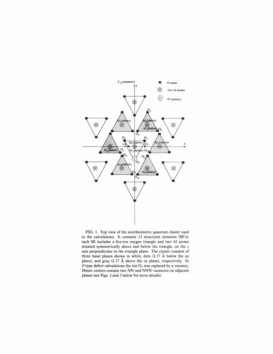
FICx. 1. Top view of the stoichiometric quantum cluster usedin the calculations. It contains 13 structural elements (SE's);each SE includes a five-ion oxygen triangle. and two Al atomssituated symmetrically above and below the triangle, on the zaxis perpendicular to the triangle plane. The cluster consists ofthree basal planes shown in white, dots (2.17 A below the xyplane), and gray (2.17 A above the xy plane), respectively. InF-type defect calculations the ion 03 was replaced by a vacancy.Dimer centers contain two NN and NNN vacancies on adjacentplanes (see Figs. 2 and 3 below for more details).
the difference of total energies for the self-consistent-fieldground and excited states for optimized defect geometry(hSCF method). That is, the potential-energy curves arecalculated for the ground and excited states of defects;then according to the Frank-Condon principle the ab-sorption energy is that for the vertical transition from theminimum of the relaxed ground state to the SCF excitedstate (i.e., for a fixed atomic configuration). The lumines-cence energy is calculated as the vertical transition fromthe minimum of the relaxed excited state to the ground-state curve. Note that these ASCF energies do not coin-cide. with the diff'erence of the relevant one-electron (or-bital) energies, which usually give only rough estimatesfor the absorption and luminescence energies. For sim-plicity we use notations for one-electron energies in tablespresenting results of SCF calculations.
For low-symmetric and complicated structures likecorundum crystals (Ii centers have only Cz symmetry) itis important (i) to use as much as possible an automatedsearch for the optimal defect geometry, which is usuallyfar from self-evident, as in alkali halides, where F centershave 0& symmetry; (ii) to use maximally the point sym-metry of defects (as well as of the periodic crystal) in or-der to calculate quantum clusters as large as possible,where defects in the center would not be affected by thecluster boundary effects. Both these conditions are metin the SYM-SYM INDO computer code used in. this pa-per 21s22
In calculations of the excited states of low-symmetrydefects there is a potential danger that SCF calculationsconverge to the ground state due to the nonorthogonalityof the wave functions of the ground and excited states(the effect called "the variational collapse" and observedby us more than once). However, this was not observedin the present calculations since (i) even in the worst caseof dimer (E2) NNN centers discussed below and havingno point symmetry at all, their ground-state and excited-state wave functions are still well orthogonal, being of sand p nature, respectively; (ii) the energy gap between therelevant energy levels during the SCF procedure remainsconsiderable ()4 eV) whereas the collapse usually occurswhen, after a certain number of SCF iterations, the one-electron energy of the excited state critically approachesthat of the (virtual) ground state. Therefore the reliabili-ty of the excited-state energy calculations in our particu-lar case is not affected by their low symmetry.
Although physically equivalent to our previous sem-iempirical INDO code cLUsTER described elsewhere, '
the SYM-SYM code has the advantage of being much moreefticient in both the electronic structure and geometry op-timization calculations, because of the complete accountof the point symmetry built into the code. ' Themodified version of the INDO method used by us di5'ersfrom the "standard" one by Pople and Beveridge' main-ly in the facts that (i) atomic orbitals of different atomicshells (s, p, and d types) may have different principalquantum numbers which allows us to treat, for example,d elements, such as Ag, Ti, and Zr and (ii) the interactionof electrons with atomic cores is described by a specialkind of pseudopotential containing additional adjustableparameters. The residual part of the crystal located out

of the molecular cluster (MC) is considered in thenonpoint-charge approximation: the Coulomb interac-tion of the MC electrons with adjacent boundary atoms isconsidered in the same manner as that for the atoms ly-ing inside the MC (i.e., using the density matrix of theperfect crystal obtained in a separate calculation and tak-ing into account explicitly the AO s of the outside atoms),whereas atoms which are far away from the MC are con-sidered as point-charge-like. The contribution of thein6nite number of the latter atoms is calculated exactlymaking use of the Ewald method. The matrix elementsof the total Coulomb field produced by the nonpoint-charge outer region, as described above, are added to thediagonal elements of the Fock matrix of the MC.
The self-consistent procedure (SCP) is performed in thefollowing way. Based on the point group 6 of the MCspecified in the input, the code constructs the symmetry-adapted orbitals (SAO's) as corresponding linear com-binations of AQ's of symmetry-related atoms; the latterwill be called Orbits hereafter. Note that all MC atomscan be unambiguously split into orbits with respect to thesymmetry adopted. Using the transformation matrixAQ~SAQ, the corresponding similar transformation isperformed for the Fock matrix which in the SAQ repre-sentation is obtained for every irreducible representation(IR) I of the group G. These Fock matrices are usuallyIlot of very large dimensions RIid Rlc diagoIlalizcd I'Rpid-
ly. Making usc of thc cigcnvcctors thus obtalIlcd foI'every IR, the density matrix (=bond-order matrix) of theMC in the SAO representation is calculated, which (onthe next step) is transformed to the AO representation bythe same similarity transformation as described above.Then the new portion of the Fock matrix is calculatedand the cycle is repeated unless convergency is achieved.
Several comments have to be made here. First of all,we note that it was found to be less convenient and muchmore expensive to use the expression for the Fock matrixdirectly in the SAQ representation. Instead, it turned outto be more C%cient to perform AQ ~SAQ andSAQ~AQ transformations, as described above. This isbecause of the fact that in the SAQ representation thePock matrix has in general a complicated expression inspite of the INDQ method applied here. Another pointis that all matrices needed for the calculations and usedin the AO representation (the Fock, overlap, density ma-trices, and two-center Coulomb integrals) are stored inportions which are related to the first atoms of orbits.This allows us to save substantially in the required com-puter memory.
A special procedure was developed in the code in orderto make the geometry optimization process as fast andCKcient as possible. First of all, the symmetry allows usto reduce the optimizing space to that spanned by thecoordinates of the erst atoms of all orbits. Moreover, de-pending on the positions of these atoms with respect tothe symmetry elements, we have a limited number of de-grees of freedom for every orbit: (i) 0 if the atom is locat-ed in the center of symmetry, i.e., when inversion takesplace; (ii) 1 if the atom is on an axis; (iii) 2 if it is on aplane; (iv) 3, a general position. In order to develop anautomated algorithm combining all the cases mentioned
The above-written formulas allow us to solve Eq. (1) withrespect to the displacement vector u&& of the first atom ofan arbitrary orbit g:
0 1+flu + (la+ g ~(f la+gff
(4)
The total number of A&f's gives the minimal possiblenumber of independent coordinates of the system. Equa-tion (4) can be used as the desired link between the actualoptimization variables A&f and the real coordinates of theatoms in the system, R &&, used in the input of the com-puter (all other atoms of every orbit are produced by thegroup oper atlons).
Then we have found that the usual optimization stra-tegy to minimize the system energy with respect to allvariables [ A&& J simultaneously turned out to beineKcient for most of the cases considered here. Anoth-er, more efficient algorithm has been developed. Thecode performs a loop over orbits g and carries out in-dependent optimization for every orbit, which is neverlarger than a three-dimensional optimization. At everystep (every calculation of the system energy) the bond-order matrix found on the previous step is used as the ini-tial guess; in addition, only such integrals are actually re-calculated which are connected with the current orbit gunder question. These two circumstances substantiallyaccelerate energy calculations. The loop is repeated untilconvergency with respect to the system coordinates isachieved. In addition, we have found that it is quite use-ful to specify di6'erent levels of optimization for every or-bit in question. Indeed, let us consider an orbit g lyingfar away from the defect (on the periphery of the MC).Ions of this orbit are shifted only slightly and theirinhuence on the defect electronic density is not verygreat. This means that we can ignore the SCP while ob-
above, we have to construct the normal coordinates Agffor every IR I of the group 6 for every orbit g (f distin-guishes equivalent IR's):
+gf X X ~rf, Aa+(Aa &
(&)— (&)
AC/ a
where the elements [ W&&'~ ) represent the correspond-ing transformation matrix, and the summation in Eq. (1)is carried out over all atoms A from the orbit g and alsoover all Cartesian components o.'=x,y, z of the atomicdisplacement vectors u&A
=R&A
—R&A. The coe%cients8'gf'A. can easily be found by means of group theory forevery IR P. ' They can always be chosen in such a waythat the matrix 8'is orthogonal, i.e.,
X X II'jy, ~~~gy, ~'a &~~ &ca(r) (r)
r uIn order to maintain the system symmetry unchangedduring the geometry optimization process, we must set allnormal coordinates A&f' to vanish except ones belongingto the unique symmetrical IR 2
&
..

51 CALCULATIONS OF THE GEOMETRY AND OPTICAL. . . 8773
taining the cluster energy during the optimization pro-cedure of the orbit g. Thus for these orbits we can limitourselves to the calculation of the system's energy basedon the bond-order matrix found on the previous self-consistent step. In addition, all two-center integrals con-nected with this orbit must be recalculated (their numberis not very large). Therefore this energy calculation pro-cedure can be performed very economically as an in-dependent part of the code.
Then, if an orbit g is considered which is closer to thedefect region but still is out of it, the SCP can still be ig-nored during the individual orbit optimization as in theprevious case. However, after the end of the optimiza-tion the complete SCP is performed in order to renew thedensity matrix.
Lastly, if an orbit lies directly in the defect region, thecomplete SCP has to be done for every energy calculationduring the optimization since any (sometimes even small)shift of ions may result in substantial electronic densityredistribution.
The optimization strategy described above leads to alarger number of optimization steps and to a larger num-ber of individual calculations of the cluster energy. How-ever, every such calculation demands, on average, lesscomputer time than the complete SCP. That is why wehave considerable gain in computational time.
III. RKSUI,TS
A. Mg-related Ecenters
Several experimental studies ' ' were devoted to theF-type centers in Mg-doped corundum. Since there aretwo kinds of Al-0 bonds, two kinds of F(Mg) centers witha Mg + ion substituting for an Al + ion near an oxygenvacancy could also exist. However, since the difference intheir bond lengths is small, we calculated properties ofF(Mg) centers for the shortest Al-0 bonds which corre-
TABLE I. Relaxation of ions surrounding FMg and FMIcenters (in % of the interatomic distances) (Mg atom substitutesfor A17; see Fig. 1). FMg and FMg centers are F+ and F centershaving in their nearest vicinity the Mg + ion substituting for aregular Al ion. The + sign denotes displacements of atomstowards and —away from a vacancy; the angles a& and a2 areshown in Fig. 1. GS and ES denote the ground and excitedstates, respectively.
1A ~2A1A~3A1A ~4AExpt. (Ref. 9)Expt. (Refs. 26,27)
Expt. (Ref. 9)Expt. (Ref. 26)
Absorption5.1 6.355.3 6.45.9 6.5
4.95, 5.7Luminescence
4.2 3.5
4.1
5.05.1
5.44.1
4.54.64.73.5
4.1
4.24.32.7
4.4 3.9 3.53.85 3.27 2.25
spond to the pair 03-A17 in Fig. l. Another problem iswhat is the net charge of this defect, i.e., is it Mg + nearthe F+ center (neutral pair) or near the F center (denotedhereafter FMs and FMs, respectively).
Table I gives the optimized geometry for both centers,FMg and FMg whereas Tab 1e II summarizes calculatedabsorption and luminescence energies. The atomic relax-ations for these two defects are quite different, very likelydue to the negative net charge of the FMg center. In theneutral FMg center the 0& and 02 ions are displacedslightly more than in the F center (2.2%) but less than inF+ (4.6%), ' and by quite different angles. Ali and A12displacements are slightly larger due to the Coulombrepulsion from the 0 vacancy. The Mg ion itself is dis-placed towards the F+ center, since it is oppositelycharged with respect to the perfect crystal lattice.
Inspection of the calculated absorption energies showsthat definitely only the FM center fits the experimentalvalues. Thus we predict a third absorption band to exist.In the FM absorption the transitions 1A ~23, 3A, and4A occur between the electronic states predominantlyconsisting of s AO's centered on a vacancy and p„p,and p states [coefficients in the molecular orbitals(Mo's) are 0.97 for the ground state and 0.72, 0.46, and0.54 for the three excited states, respectively]. The
TABLE II. Absorption and luminescence energies (in eV) forMg-related centers and dimer centers in the case when the oxy-gen vacancies lie in different oxygen planes (in both cases thepoint group symmetry is C& ). These energies are calculated us-ing the hSCF procedure.
FMg
FMg center FMg center TABLE III. Absorption and luminescence (ASCF) energies(in eV) for F+and Fcenters (Ref. 14).
O2
All, A1q
A17,A18
GSESGSESGSESGSESGSES
+4.3,+4.7,+2.5,+3.8,—8.9
—10.8—2.4—3.2+4.1
+6.7
a2= 14'ag= 16'al =23al =22
+0.7,+0.7,—0.5,—O.S,—3.7—5.4+0.8+0.3
+ 10.3+ 12.5
a2=25a2=25a(=12al =12 1A ~1B
1A ~2A1A ~2B1A —+2A
1B—+1 A2A~1A
INDO
Absorption5.25.55.85.9
Luminescence4.02.8
Expt. (Refs. 5,6)
4.85.46.06.1
3.83.0

8774 E. A. KOTOMIN et a1. 51
TABLE IV. EfFective charges of ions (in units of e) surrounding Mg-related F centers and dimercenters (both oxygen vacancies lie in the same triangle) (see Fig. 2).
O),02,03Al), A12
A13,A14,A15,A16
A17,A18Number of trappedelectrons, in avacancyMg'
Perfect crystal
—1.572.352.362.36
FMg
—1.542.272.29
—0.94
1.93
FM
—1.532.312.32
—1.82
1.94
—1.542.322.322.16
—1.68
F—1.50
2.342.35
—1.75
—1.512.272.34
1.37
Fz+2
—1.502.212.30
—0.94
'Mg substitutes for A17; see Fig. 1.
relevant absorption and luminescence energies for F+and F centers are given in Table III. Here the states 1A,1B, 2A, and 2B consist mainly of s AQ's centered on thevacancy and ofp„p,and p excited AQ's, respectively.
The charge distribution analysis shown in Table IV in-dicates that in both centers the Mg ion has the effectivecharge =1.9 eV, the oxygen vacancy trapped 0.9e and1.8e, respectively, and the charges of the surroundingions are close to those in perfect corundum, i.e., we havea purely Coulomb effect of Mg +-F+ interaction, shiftingthe FMg ground-state level to 3.7 eV above the top of thevalence band (as compared to 3.1 eV for the isolated F+center). Since the ground state of the FM center lies con-siderably higher than that for the FM center, 4.8 eVabove the top of the valence band [similarly to the case ofthe F center, 5.3 eV (Ref. 14)], the excited states of FMfall into the conduction band and due to their delocalizednature no longer reveal splitting into three bands as F+or FM centers do; see Sec. IV and Ref. 14 for more de-tails.
are plotted in Table VI. One can see that an increase ofthe dimer-center net charge from zero to +2 (in theseries F2 ~F@+~F&+ ) leads to a considerable increase ofthe ionic displacements, due to the Coulomb interactionbetween surrounding ions. These centers have not beenstudied experimentally so far to our knowledge, but basedon calculations we predict the same trend in the absorp-
&h
B. Dimer centers with oxygen vacancies lyingin the same oxygen triangle (NN case)
The relaxations of ions surrounding dimer centerswhen two oxygen vacancies are NN's and lie in the samebasic oxygen triangle (whose plane is perpendicular to thez axis) are drawn schematically in Fig. 2 and given nu-merically in Table V whereas their absorption energies
1.8
TABLE V. Relaxation of surrounding ions (in % of the in-teratomic distances) for dimer centers, if two oxygen vacanciesare NN's, i.e., belong to the same oxygen triangle (see Fig. 2).The + sign denotes displacements of atoms towards and the-sign away from a vacancy; GS and ES are the ground and excit-ed states, respectively.
1.86
O3
Ali, A12
A13,A14,A15,A16
GSESCjrS
ESGSES
F+9.0
+ 11.2—6.2—8.8—2.8—3.5
F+
+ 14.4+ 17.8—9.2
—12.4503
—7.9
F2+2
+ 19.6+22.3—12.8—15.5—7.7
—10.2
Al4
FIG. 2. Calculated relaxations of ions surrounding a dimercenter where two vacancies are NN's within the basic oxygentriangle.

8775CALCULATIONS OF THE GEOMETRY AND OPTICAL. . .
1A —+1B (x,z)1A ~2A (y)1A —+2B (x,z)
1B—+1A (x,z)
Absorption4.65.45.5
Luminescence4.2
3.83.94.3
3.5
2.9a
3.0
'No convergence achieved.
a)
E, eVCONDUCTION BAND
-8.0—
-13.0-
2818
1A k
2.9 eV
282A18
1AulAs') )( J&
4.3eV 3.0eV
k
5.7 eV
282A181A
4.2 eU
TABLE VI. Calculated absorption and luminescence ener-gies ( , in ehSCF '
eV) for dimer centers in the case when both oxy-e
'metrgen vacancies be ong o el t the same oxygen triangle (symme ry
C2). Optical transitions are allowed (in the dipole approxima-tion) only for light polarized along the directions given in theparentheses. The two vacancies lie on the y axis.
F2+2
tion and luminescence energies as is observe fo~ ~
for anotherf dimer centers discussed in Sec. IIIC; namely,type o imer
their decrease in the series F2~F2 ~ 2 a eThe strong conformation e6ects in corundum are seen
h 1 d' lacements of the atoms surroundingvacancies when they belong to the same oxygen triang e,in comparison o s it h'fts of the corresponding atoms insimilar centers w enh the vacancies lie in two adjacentbasal planes. n eI th first case the structural elementAl 0 f the perfect corundum structure is destroye a-
rom themost completely by removing two 0 atoms rom ebasic oxygen riang e,t iangle which leads to considerable is-placements occurring due to the broken bonds. In con-
in the NNN case only a few bonds within each oftrast, in t e che ox en triangles entering the SE were bro en
the SE's themselves have not been destroyed;ed thus the re-laxation of atoms within the two SE's is smaller.
A simple group-theoretical analysis o t e se ec'
rules for absorption and luminescence of these centers(C symmetry without a center of symmetry) shows that2 symin the dipole approximation only some opticatical transitionsare allowed; the related light polarization is indicated inTable VI in parentheses. This could be used for discrim-
02+
F F2
b)
E, eVCONDUCTION BAND
-13.0-
4A3A===2A
k1A
3.7 eV
4A=:—=3A2A
1A„"'. &„iA,"
5.1eV 39
k . .16
6.0 eV
4A3A2A
1A
4.6 eV
F2+2 F2
03FIG. 3. Positions of the one-electron dimimer levels within the
corundum gap or t e casesf h s when the two vacancies are N'sner ies or thend NNN's (b). Dashed lines denote SCF energies or t e
excited states with the geometry correspon ingground state. The bold arrow shows the M-type transition ob-served earlier for F2 centers in alkali halides (see text).
FIG. 4. Ionic relaxation for the dimer cecenter where two va-cancies are NNN's belonging to the nearest basal planes.
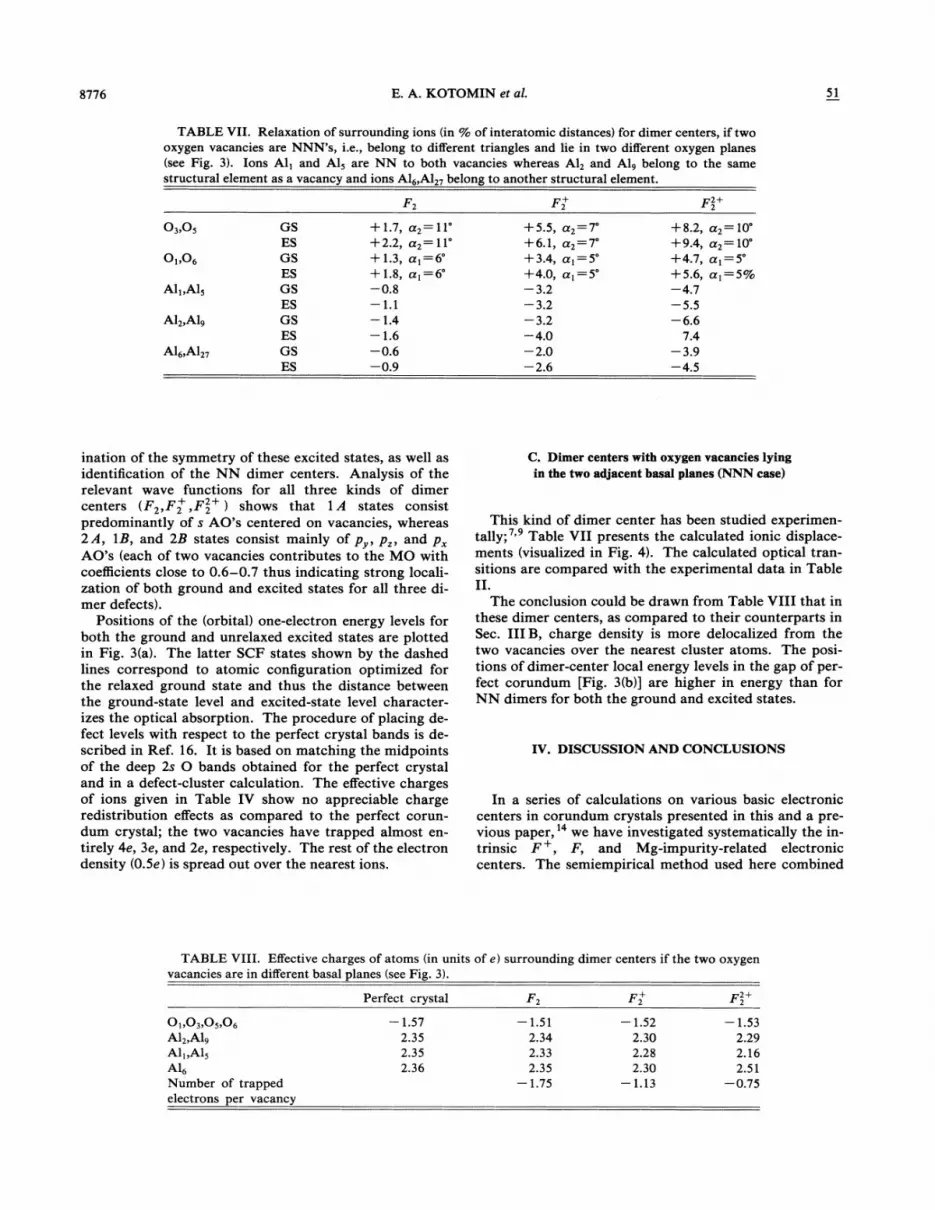
8776 E. A. KOTOMIN et al. 51
TABLE VII. Relaxation of surrounding ions (in % of interatomic distances) for dimer centers, if twooxygen vacancies are NNN s, i.e., belong to different triangles and lie in two different oxygen planes(see Fig. 3). Ions Al, and A15 are NN to both vacancies whereas A12 and A19 belong to the samestructural element as a vacancy and ions A16,A1» belong to another structural element.
F F+ F2+2
03,05
O„o,
Ali, A15
A12,A19
A16,A127
GSESGSESGSESGSESGSES
+ 1.7,+2.2,+ 1.3,+ 1.8,—0.8—F 1—1.4—1.6—0.6—0.9
a2= 11'a2= 11'a)=6a( =6'
+5.5,+6.1,+3.4,+4.0,—3.2—3.2—3.2—4.0—2.0—2.6
a2 —7a2 —7a)=5
+8.2,+9.4,+4.7,+5.6,—4.7—5.5—6.6
7.4—3.9—4.5
a2= 10a2= 10'
a) =5'a) =5%
ination of the symmetry of these excited states, as well asidentification of the NN dimer centers. Analysis of therelevant wave functions for all three kinds of dimercenters (F2,Fz+, F2+ ) shows that l A states consistpredominantly of s AO's centered on vacancies, whereas2A, 1B, and 2B states consist mainly of p, p„and pAO's (each of two vacancies contributes to the MO withcoeKcients close to 0.6—0.7 thus indicating strong locali-zation of both ground and excited states for all three di-mer defects).
Positions of the (orbital) one-electron energy levels forboth the ground and unrelaxed excited states are plottedin Fig. 3(a). The latter SCF states shown by the dashedlines correspond to atomic configuration optimized forthe relaxed ground state and thus the distance betweenthe ground-state level and excited-state level character-izes the optical absorption. The procedure of placing de-fect levels with respect to the perfect crystal bands is de-scribed in Ref. 16. It is based on matching the midpointsof the deep 2s 0 bands obtained for the perfect crystaland in a defect-cluster calculation. The effective chargesof ions given in Table IV show no appreciable chargeredistribution effects as compared to the perfect corun-dum crystal; the two vacancies have trapped almost en-tirely 4e, 3e, and 2e, respectively. The rest of the electrondensity (0.5e) is spread out over the nearest ions.
C. Dimer centers with oxygen vacancies lyingin the two adjacent basal planes (NNN case)
This kind of dimer center has been studied experimen-tally; ' Table VII presents the calculated ionic displace-ments (visualized in Fig. 4). The calculated optical tran-sitions are compared with the experimental data in TableII.
The conclusion could be drawn from Table VIII that inthese dimer centers, as compared to their counterparts inSec. IIIB, charge density is more delocalized from thetwo vacancies over the nearest cluster atoms. The posi-tions of dimer-center local energy levels in the gap of per-fect corundum [Fig. 3(b)] are higher in energy than forNN dimers for both the ground and excited states.
IV. DISCUSSION AND CONCLUSIONS
In a series of calculations on various basic electroniccenters in corundum crystals presented in this and a pre-vious paper, ' we have investigated systematically the in-trinsic F+, F, and Mg-impurity-related electroniccenters. The semiempirical method used here combined
TABLE VIII. EfFective charges of atoms I,'in units of e) surrounding dimer centers if the two oxygen
vacancies are in different basal planes (see Fig. 3).
O),03,05,06A12,A19
All, A15
A16Number of trappedelectrons per vacancy
Perfect crystal
—1.572.352.352.36
F—1.51
2.342.332.35
—1.75
F+—1.52
2.302.282.30
—1.13
F2+2
—1.532.292.162.51
—0.75

CALCULATIONS OF THE GEOMETRY AND OPTICAL. . . 8777
with an automated search for the optimal geometry of de-fects turned out to be a very useful tool for defect simula-tions in corundum aimed to check theoretically theirmodels and optical properties. The absorption and emis-sion energies for single-electron centers E+ and F werefound in Ref. 14 to be in very good agreement with theexperimental data, and the same is true for the activationenergy for thermal quenching of E+ luminescence.
We demonstrated there that the observation of the tri-ple splitting of the excited state of the E+ center and itsabsence for the E and hypothetical E~z centers aredirectly related to the degree of spatial localization of theexcited state. It might be easily demonstrated that thelow-symmetry crystalline field V(r) has a much smallereffect on the excited electronic states 4, when its matrixelements (%'~ V~%) are smaller. This is the case when Ftype excited wave functions centered on the anion vacan-cy start to extend over the region of the nearest cationswhere V(r) changes its sign.
Along with F+ and F centers which are well studiedexperimentally, we have simulated in our previous pa-per' the hypothetical F center (an oxygen vacancywith three trapped electrons) and concluded that it reallycould exist; the third electron occupies a local stateroughly 1 eV below the conduction band. In this paperwe optimized its ground-state geometry and found thatthe two ions 0& and 02 of the same basic 0 triangle shift-ed slightly towards the vacancy by ~2&o of the O-O dis-tance in a perfect crystal (2 49 A) and at an angle of 30'with respect to the O-O line (Fig. 1). The nearest cationsAl& and A12 are displaced outwards from the triangleplane by 4%%uo and A17 and A18 by 2%%uo of the initial Al-0distances in these long and short pairs.
The analysis of the electron density distribution showsthat two electrons are well localized inside the 0 vacancyand occupy a deep local level whereas the third one isdelocalized mainly over the nearest A17 and A18 ions andoccupies the above-mentioned level close to the conduc-tion band. This level is split off from the band statessince the effective charges (and energy states) of A17 andA18 cations are considerably altered by a third F elec-tron. Qualitatively similar F centers (which are nega-tively charged with respect to the perfect lattice) areknown also in alkali halides. '
Using a simple relation between the energies of optical,Eo, and thermal, Ez, ionizations, ED=@0/e„Er, whereeo and e„arestatic and high-frequency dielectric con-stants, we arrive at Ez =3.1/9. 3 X 1 eV=0.33 eV. In or-der to estimate roughly the delocalization temperatureT&, one could use the following simple relation:
'=voexp(Er/kTd ), where vo is the F frequency fac-tor and ~ is the lifetime of this electron center undere@cient destruction. For Ez-=0.33 eV, v0=10' s ', andr=10 s we estimate the value of Td-—125 K (unlike the260 K suggested in Ref. 25). For comparison, in alkalihalides F centers are stable up to the temperatures of140 K in KBr and 200 K in KCl.
We have tried to detect F centers experimentally us-ing the stimulation spectra of recombination lumines-cence. The two main candidates are low-temperature
peaks at 60 and around 100 K. Samples were excited by6 eV photons from a 250 W deuterium recharge lamp at80 K during 1 h. However, no photostimulation was ob-served at 80 K using ir stimulating light with X & 0.9 pm.At the same time, such photostimulation has indeed beenobserved in the interval 3—5 eV, which corresponds toelectron release after E-center excitation from the centersresponsible for the 260 and 430 K peaks. More detailedstudies are planned now, including investigation of de-fects destroyed at 60 K. (There are no electron and holecenters between 100 and 200 K.)
Calculations of Mg-related Fcenters support the modelof a neutral F~ =F+(Mg ) defect rather than a nega-tively charged F(Mg ) defect. The effect of a Mg atomsubstituting for an Al nearest to the E+ center is to lowerthe absorption and luminescence energies by -0.2 eV; athird absorption band is expected to be around 6 eV.
Up to now only one type of dimer center has been stud-ied, having the two next-nearest-neighbor oxygen vacan-cies on adjacent basal oxygen planes and thus revealing ahigh optical anisotropy ( A =a~~/a~ =3). Another kindof dimer center, with the two oxygen vacancies belongingto the same oxygen triangle (i.e., nearest-neighbor vacan-cies) has not been studied experimentally yet to ourknowledge. For both kinds of dimers we found the ab-sorption and luminescence energies to decrease consider-ably in the series F2~F2+ +Fz+ (fou—r, three, and twoelectrons in the two vacancies, respectively). We expectE2 centers to have more than the one absorption band ob-served so far. The agreement of our calculations for theNNN dimer centers with the relevant experimentaldata, especially for absorption energies, is only qualita-tive, very likely due to the use of a cluster not big enoughfor these simulations; even our relatively large 65-atomcluster has three basal planes and thus one of two vacan-cies lies already at the cluster boundary. Moreover, theeffects of electronic polarization are known to be underes-timated in the INDO approximation used. Nevertheless,our calculations suggest several important qualitativeconclusions on dimer centers. (i) In the seriesF2+ ~F2+ ~F2 the ground-state levels move monotoni-cally up and their excited states are closer and closer tothe conduction band. However, for the F2+ and F2+ di-mers the excited states are still well localized, whereas theF2 excited state moves quite close to the conductionband. (ii) Charge distribution analysis for the groundstate of NN dimer centers shows that only 0.5e of fourelectrons is delocalized over atoms nearest to the F2center, 0.3e for the Fz+ center, and -0.1e for the F2+center. That is, the ground-state wave functions of allthree centers are well localized. For NNN dimers wehave larger values of delocalized electron density —0.5e,0.75e, and 0.5e, respectively. The corresponding valuesfor the excited states are 0.9e, 0.8e, and 0.3e for F2, F2+,and F2+ NN dimer centers and 1.1e, 0.8e, and 0.6e forF2, F2+, and F2+ NNN dimer centers, respectively. Thecharge distribution analysis shows the increase of elec-tron density delocalization for excited states in compar-ison to the ground states. (iii) Along with optical transi-tions in dimer centers whose energies are close to those of

8778 E. A. KOTOMIN et al. 51
single-vacancy defects (ca. 5.6 eV for F+, F, and F2centers), we expect also for F2+ the so-called "M-type"transitions observed earlier in alkali halides andMgO, * ' and corresponding to the transition betweenthe two molecular orbitals s (1)ks(2) which are even andodd with respect to coordinate inversion at the midpointbetween vacancies. These energies fall into the ir energyinterval ( + 1 eV) and correspond to the transition shownfor F2+ centers in Fig. 3 by a bold arrow. In KC1, for ex-ample, the absorption energy of the 2
&g—+ 22„transition
is 1.5 eV, to be compared to the F-center absorption ob-served at 2.35 eV.
ACKNQ%'LKDGMENTS
This work has been supported financially by the Inter-national Science Foundation (Grant No. LB 2000) andpartly (E.K.) through Grant No. 11-0530-1 by DanishResearch Council and (A.P.) through the Danish colla-borative grant. A.S. thanks also the Nordic council ofMinisters for financial support and the members of theQuantum Chemistry Department at Uppsala Universityfor warm hospitality during his stay there. Numerousdiscussions with S. Chernov, P. W. M. Jacobs, P. Kulis,and M. Springis are greatly appreciated.
'Present address: Institute of Physics, Aarhus University, Den-mark.
tPresent address: Department of Quantum Chemistry, UppsalaUniversity, Box 518, S-751 20 Uppsala, Sweden.
E. F. Martynovich, V. I. Baryshnikov, and V. A. Grigorov,Opt. Commun. 53, 257 (1985); Sov. Tech. Phys. Lett. 11, 81(1985).
E. R. Hodgson, in Defects in Insulating Materials, edited by O.Kanert and J.-M. Spaeth (World Scientific, Singapore, 1993),p. 332.
M. S. Akselrod, V. S. Kortov, D. Ya. Kravetskii, and V. I.Gotlib, Radiat. Protection Dosimetry 32, 15 (1990).
~Structure and Properties ofMgO and A120s Ceramics, edited byW. D. Kingery, Advances in Ceramics Vol. 10 (AmericanCeramic Society, Columbus, OH, 1983).
~J. H. Crawford, Jr., Semicond. Insul. 5, 599 (1983); Nucl. In-strum. Methods Phys. Res. Sect. B 1, 159 (1984).
J. Valbis and N. Itoh, Radiat. Eff. Defects Solids 116, 171(1991).
7L. S. Welch, A. E. Hughes, and G. P. Pells, J. Phys. C 13, 1805(1980).
E. Sonder and W. A. Sibley, in Point Defects in Solids, editedby J. H. Crawford and L. M. Slifkin (Plenum, New York,1972), Vol. 1, p. 208.
G. J. Pogatshnik, Y. Chen, and B. D. Evans, IEEE Trans.Nucl. Sci. NS-34, 1709 (1987).K. H. Lee and J. H. Crawford, Jr., Phys. Rev. B 15, 4065(1977).
~~S. Y. La, R. H. Bartram, and R. T. Cox, J. Phys. Chem. Solids34, 1079 (1973).R. C. DuVarney, A. K. Garrison, J. R. Niklas, and J.-M.Spaeth, Phys. Rev. B 24, 3693 (1981).S. I. Choi and T. Takeuchi, Phys. Rev. Lett. 50, 1474 (1983).
' A. Stashans, E. Kotornin, and J.-L. Calais, Phys. Rev. B 49,14 854 (1994).
P. Deak, J. Giber, and H. Oechsner, Surf. Sci. 250, 287 (1991);P. Deak, C. R. Ortiz, L. C. Snyder, and J. W. Corbett, Physi-ca 8 170, 223 (1991);P. Deak, L. C. Snyder, and J. W. Cor-bett, Phys. Rev. 8 45, 11 612 (1992); P. Deak, B. Schroder, A.Annen, and A. Scholz, ibid. 48, 1924 (1993).
6E. Stefanovich, E. Shidlovskaya, A. Shluger, and M. Za-kharov, Phys. Status Solidi B 160, 529 (1990); A. L. Shluger,R. W. Grimes, C. R. A. Catlow, and N. Itoh, J. Phys. Con-
dens. Matter 3, 8027 (1991); A. L. Shluger, E. A. Kotomin,and L. N. Kantorovich, J. Phys. C 19, 4183 (1986); A. L.Shluger and E. A. Stefanovich, Phys. Rev. B 42, 9646 (1990);A. L. Shluger, N. Itoh, and K. Noda, J. Phys. Condens.Matter 3, 9895 (1991).
~7J. A. Pople and D. L. Beveridge, Approximate Molecular Or-bital Theory (McGraw-Hill, New York, 1970).P. W. M. Jacobs, E. A. Kotomin, A. Stashans, E. Stefanovich,and I. Tale, J. Phys. Condens. Matter 4, 7531 (1992);P. W. M.Jacobs and E. A. Kotomin, Phys. Rev. Lett. 69, 1411 (1992);P. W. M. Jacobs, E. A. Kotomin, A. Stashans, and I. Tale,Philos. Mag. B 67, 557 (1993); L. N. Kantorovich, A.Stashans, E. A. Kotomin, and P. W. M. Jacobs, Int. J. Quan-tum Chem. 52, 1177 (1994).J. Lewis, D. Schwarzenbach, and H. D. Flack, Acta Crystal-logr. Sect. A 38, 733 (1982).M. Causa, , R. Dovesi, C. Roetti, E. Kotomin, and V. Saunders,Chem. Phys. Lett. 140, 120 (1987).L. Kantorovich and A. Livshicz, Phys. Status Solidi B 174, 79(1992).L. Kantorovich, E. Heifets, A. Livshicz, M. Kuklja, and P.Zapol, Phys. Rev. B 47, 14 875 (1993).
23M. Born and K. Huang, Dynamic Theory of Crystalline Lattices (Oxford University Press, London, 1954).P. A. Kulis, M. J. Springis, I. A. Tale, V. S. Vainer, and J. A.Valbis, Phys. Status Solidi B 104, 719 (1981);P. A. Kulis, M.J. Springis, I. A. Tale, and J. A. Valbis, Phys. Status Solidi A53, 113 (1979); M. J. Springis and J. A. Valbis, Phys. StatusSolidi B 123, 335 (1984).
~5V. S. Kortov, T. S. Bessonova, M. S. Akselrod, and I. I. Mil-man, Phys. Status Solidi A 87, 629 (1985).
~6M. Hirai, M. Ikezawa, and M. Ueta, J. Phys. Soc. Jpn. 17, 724(1962); 17, 1483 (1962).
~ M. Hirai and A. B.Scott, J. Chem. Phys. 44, 1753 (1966).28N. F. Mott and R. W. Gurney, Electronic Processes in Ionic
Crystals (Oxford University Press, Oxford, 1940).R. A. Evarestov, Opt. Spectrosc. 16, 198 (1964); Phys. StatusSolidi 8 31, 401 (1969); A. D. Kashkai, A. A. Berezin, A. N.Arsenjeva-Geil, and M. S. Matveev, ibid. 54, 113 (1972).
3oJ. H. Crawford, Jr., and L. M. Slifkin, in Point Defects inSolids (Ref. 8), p. 381.B.Henderson, Crit. Rev. Solid State Mater. Sci. 9, 1 (1980).