Embed Size (px)
Citation preview
CANAL REGULATORS
03-04-2020 16CE310 IE / UNIT 4 / NK & MI 1
N.KARTHIKEYAN, AP/CE
M.INDUMATHI, AP/CEP
Instructional objectives
On completion of this lesson, the student shall be able to learn:
1. The necessity of providing regulating structures in canals. 2. The basics of canal drops and falls. 3. The importance of canal regulators. 4. The need for Groyne Walls, Curved Wings and Skimming Platforms. 5. The functions of escapes in a canal.
Introduction
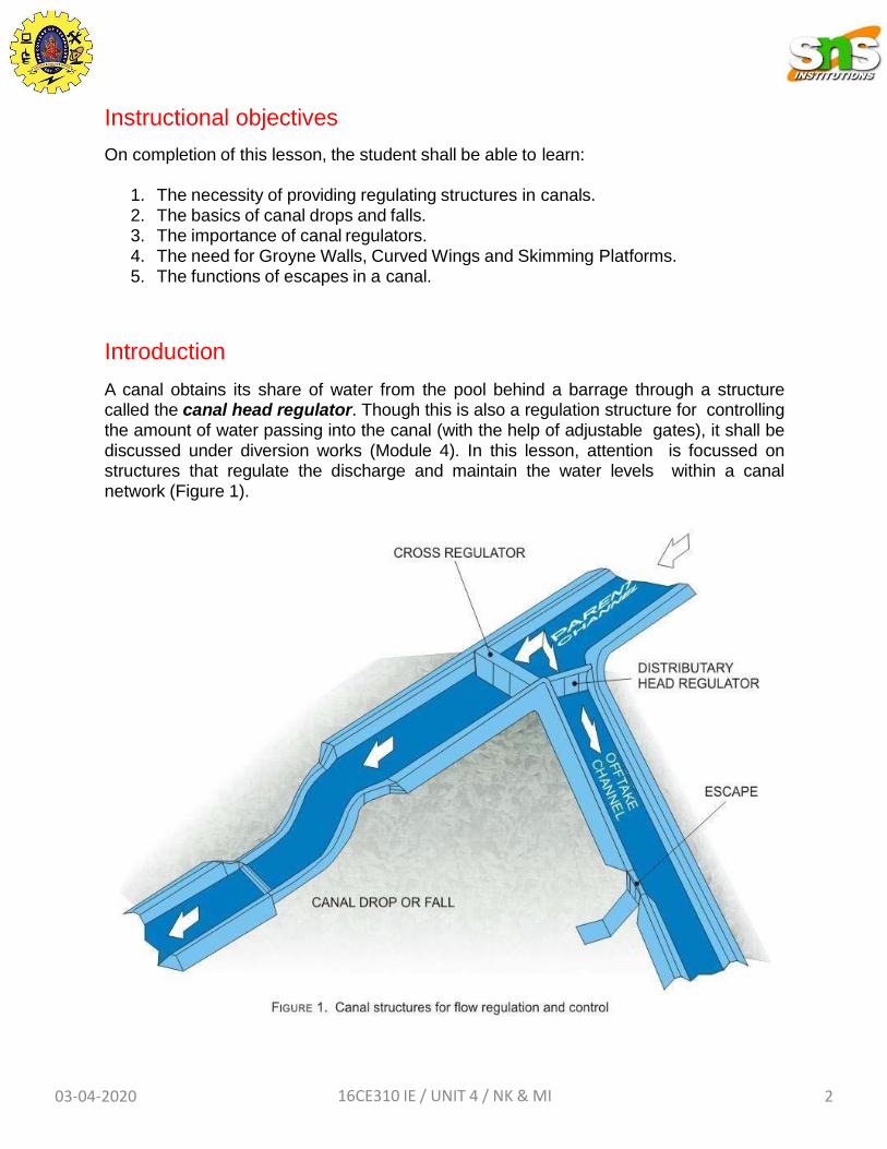
A canal obtains its share of water from the pool behind a barrage through a structure called the canal head regulator. Though this is also a regulation structure for controlling the amount of water passing into the canal (with the help of adjustable gates), it shall be discussed under diversion works (Module 4). In this lesson, attention is focussed on structures that regulate the discharge and maintain the water levels within a canal network (Figure 1).
03-04-2020 16CE310 IE / UNIT 4 / NK & MI 2
Canal regulators
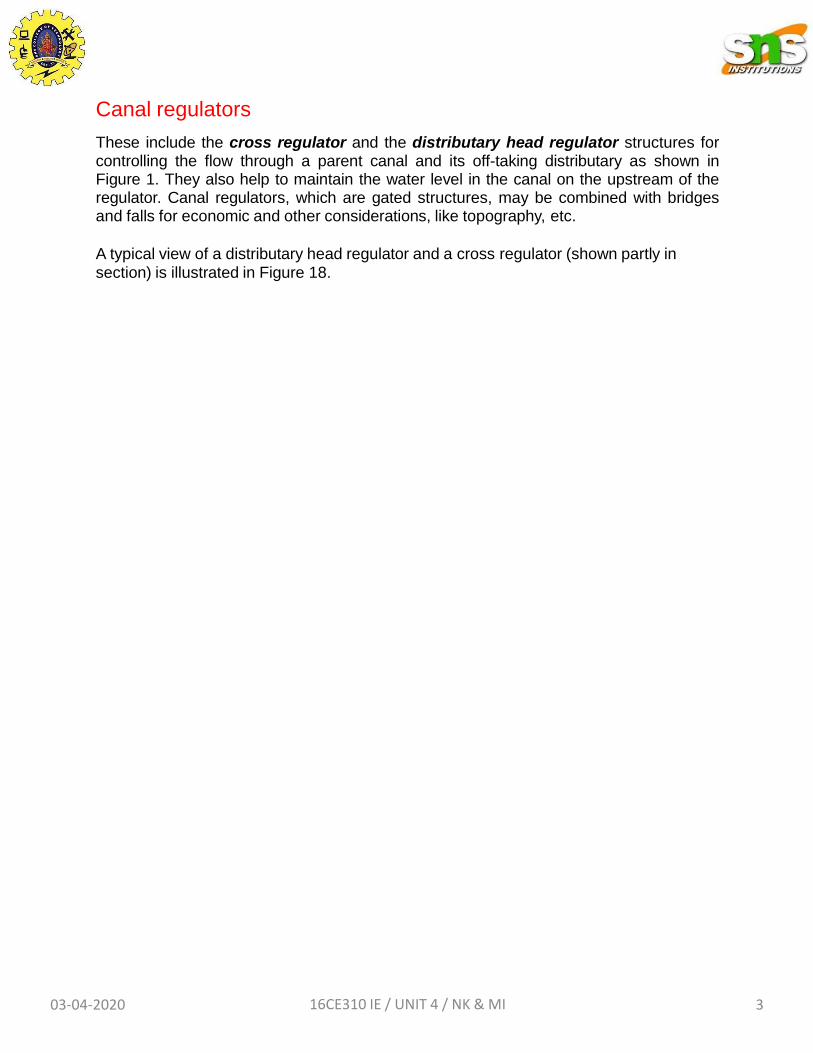
These include the cross regulator and the distributary head regulator structures for controlling the flow through a parent canal and its off-taking distributary as shown in Figure 1. They also help to maintain the water level in the canal on the upstream of the regulator. Canal regulators, which are gated structures, may be combined with bridges and falls for economic and other considerations, like topography, etc.
A typical view of a distributary head regulator and a cross regulator (shown partly in
section) is illustrated in Figure 18.
03-04-2020 16CE310 IE / UNIT 4 / NK & MI 3
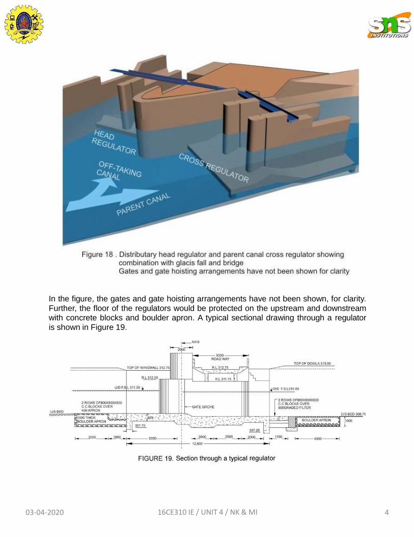
In the figure, the gates and gate hoisting arrangements have not been shown, for clarity. Further, the floor of the regulators would be protected on the upstream and downstream with concrete blocks and boulder apron. A typical sectional drawing through a regulator is shown in Figure 19.
03-04-2020 16CE310 IE / UNIT 4 / NK & MI 4
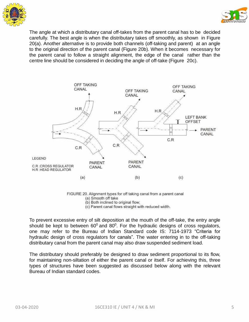
The angle at which a distributary canal off-takes from the parent canal has to be decided carefully. The best angle is when the distributary takes off smoothly, as shown in Figure 20(a). Another alternative is to provide both channels (off-taking and parent) at an angle to the original direction of the parent canal (Figure 20b). When it becomes necessary for the parent canal to follow a straight alignment, the edge of the canal rather than the centre line should be considered in deciding the angle of off-take (Figure 20c).
To prevent excessive entry of silt deposition at the mouth of the off-take, the entry angle should be kept to between 600 and 800. For the hydraulic designs of cross regulators, one may refer to the Bureau of Indian Standard code IS: 7114-1973 “Criteria for
hydraulic design of cross regulators for canals”. The water entering in to the off-taking distributary canal from the parent canal may also draw suspended sediment load.
The distributary should preferably be designed to draw sediment proportional to its flow, for maintaining non-siltation of either the parent canal or itself. For achieving this, three types of structures have been suggested as discussed below along with the relevant Bureau of Indian standard codes.
03-04-2020 16CE310 IE / UNIT 4 / NK & MI 5
Silt vanes
(Please refer to IS: 6522-1972 “Criteria for design of silt vanes for sediment control in off-taking canals” for more details)
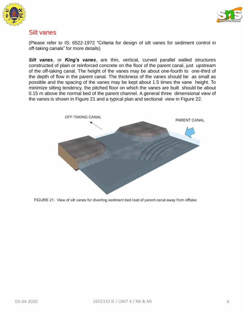
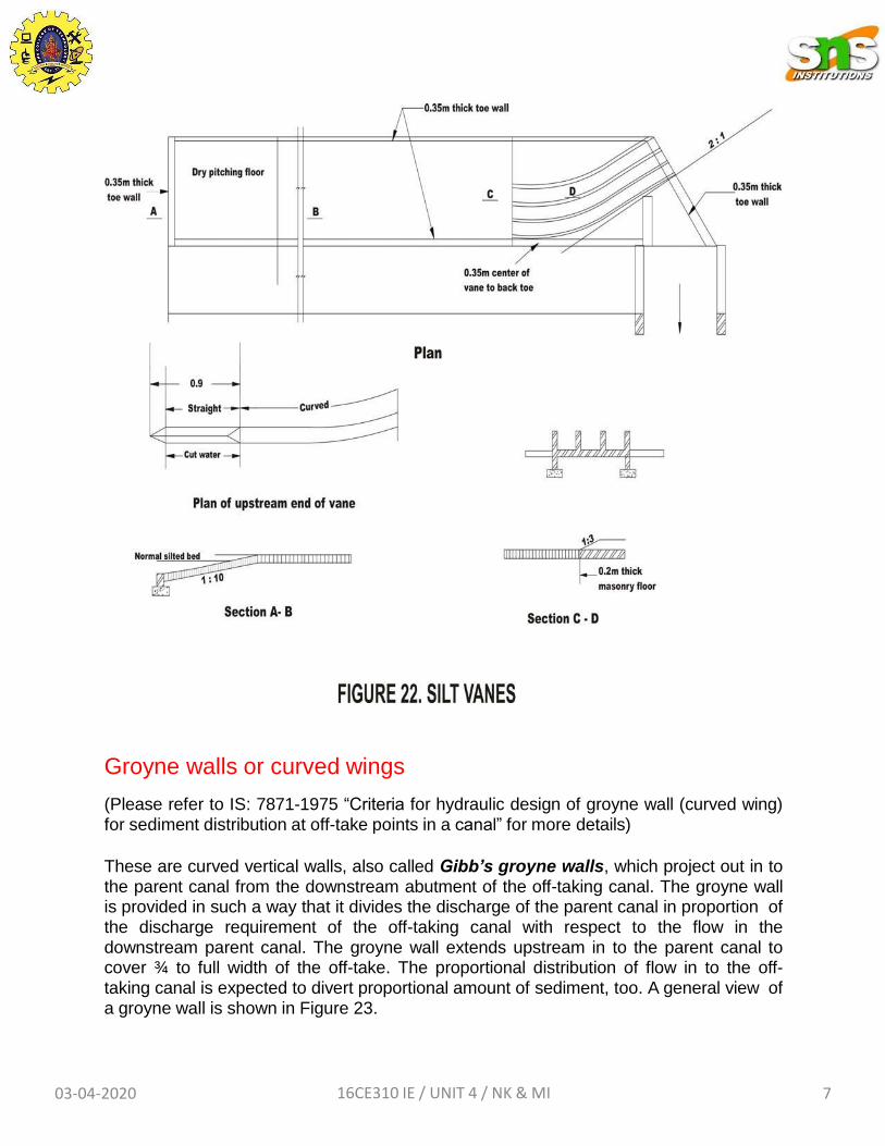
Silt vanes, or King’s vanes, are thin, vertical, curved parallel walled structures constructed of plain or reinforced concrete on the floor of the parent canal, just upstream of the off-taking canal. The height of the vanes may be about one-fourth to one-third of the depth of flow in the parent canal. The thickness of the vanes should be as small as possible and the spacing of the vanes may be kept about 1.5 times the vane height. To minimize silting tendency, the pitched floor on which the vanes are built should be about 0.15 m above the normal bed of the parent channel. A general three dimensional view of the vanes is shown in Figure 21 and a typical plan and sectional view in Figure 22.
03-04-2020 16CE310 IE / UNIT 4 / NK & MI 6
Groyne walls or curved wings
(Please refer to IS: 7871-1975 “Criteria for hydraulic design of groyne wall (curved wing) for sediment distribution at off-take points in a canal” for more details)
These are curved vertical walls, also called Gibb’s groyne walls, which project out in to the parent canal from the downstream abutment of the off-taking canal. The groyne wall is provided in such a way that it divides the discharge of the parent canal in proportion of the discharge requirement of the off-taking canal with respect to the flow in the downstream parent canal. The groyne wall extends upstream in to the parent canal to cover ¾ to full width of the off-take. The proportional distribution of flow in to the off- taking canal is expected to divert proportional amount of sediment, too. A general view of a groyne wall is shown in Figure 23.
03-04-2020 16CE310 IE / UNIT 4 / NK & MI 7
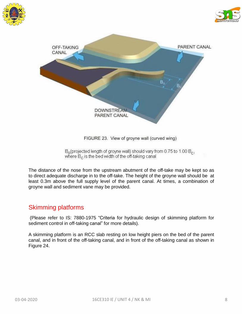
The distance of the nose from the upstream abutment of the off-take may be kept so as to direct adequate discharge in to the off-take. The height of the groyne wall should be at least 0.3m above the full supply level of the parent canal. At times, a combination of groyne wall and sediment vane may be provided.
Skimming platforms
(Please refer to IS: 7880-1975 “Criteria for hydraulic design of skimming platform for sediment control in off-taking canal” for more details).
A skimming platform is an RCC slab resting on low height piers on the bed of the parent canal, and in front of the off-taking canal, and in front of the off-taking canal as shown in Figure 24.
03-04-2020 16CE310 IE / UNIT 4 / NK & MI 8
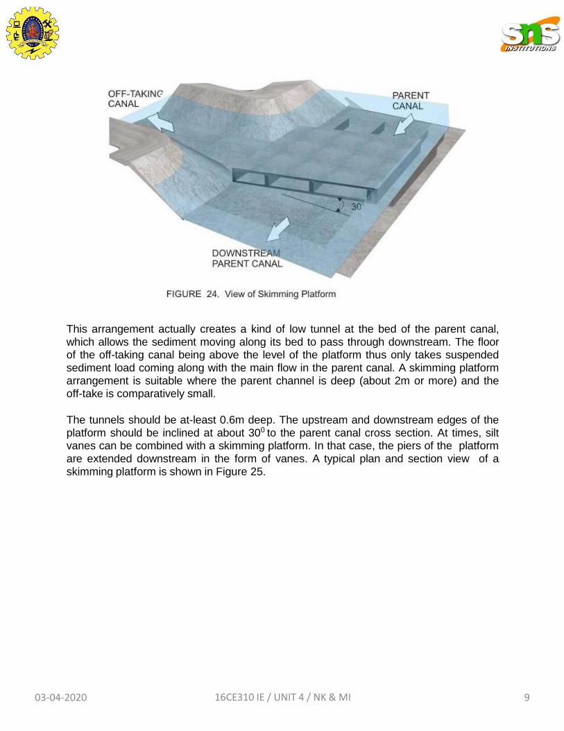
This arrangement actually creates a kind of low tunnel at the bed of the parent canal, which allows the sediment moving along its bed to pass through downstream. The floor of the off-taking canal being above the level of the platform thus only takes suspended sediment load coming along with the main flow in the parent canal. A skimming platform arrangement is suitable where the parent channel is deep (about 2m or more) and the off-take is comparatively small.
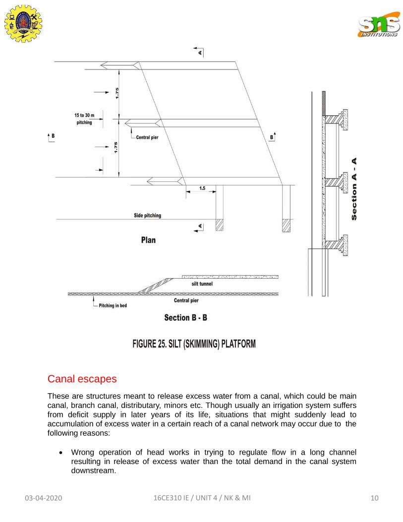
The tunnels should be at-least 0.6m deep. The upstream and downstream edges of the platform should be inclined at about 300 to the parent canal cross section. At times, silt vanes can be combined with a skimming platform. In that case, the piers of the platform are extended downstream in the form of vanes. A typical plan and section view of a skimming platform is shown in Figure 25.
03-04-2020 16CE310 IE / UNIT 4 / NK & MI 9
Canal escapes
These are structures meant to release excess water from a canal, which could be main canal, branch canal, distributary, minors etc. Though usually an irrigation system suffers from deficit supply in later years of its life, situations that might suddenly lead to accumulation of excess water in a certain reach of a canal network may occur due to the following reasons:
Wrong operation of head works in trying to regulate flow in a long channel resulting in release of excess water than the total demand in the canal system downstream.
03-04-2020 16CE310 IE / UNIT 4 / NK & MI 10
Excessive rainfall in the command area leading to reduced demand and consequent closure of downstream gates.
Sudden closure of control gates due to a canal bank breach.
The excess water in a canal results in the water level rising above the full supply level which, if allowed to overtop the canal banks, may cause erosion and subsequent breaches. Hence, canal escapes help in releasing the excess water from a canal at times of emergency. Moreover, when a canal is required to be emptied for repair works, the water may be let off through the escapes.
Escapes as also built at the tail end of minors at the far ends of a canal network. These are required to maintain the required full supply level at the tail end of the canal branch.
The construction feature of escapes allows it to be classified in to two types, as described below.
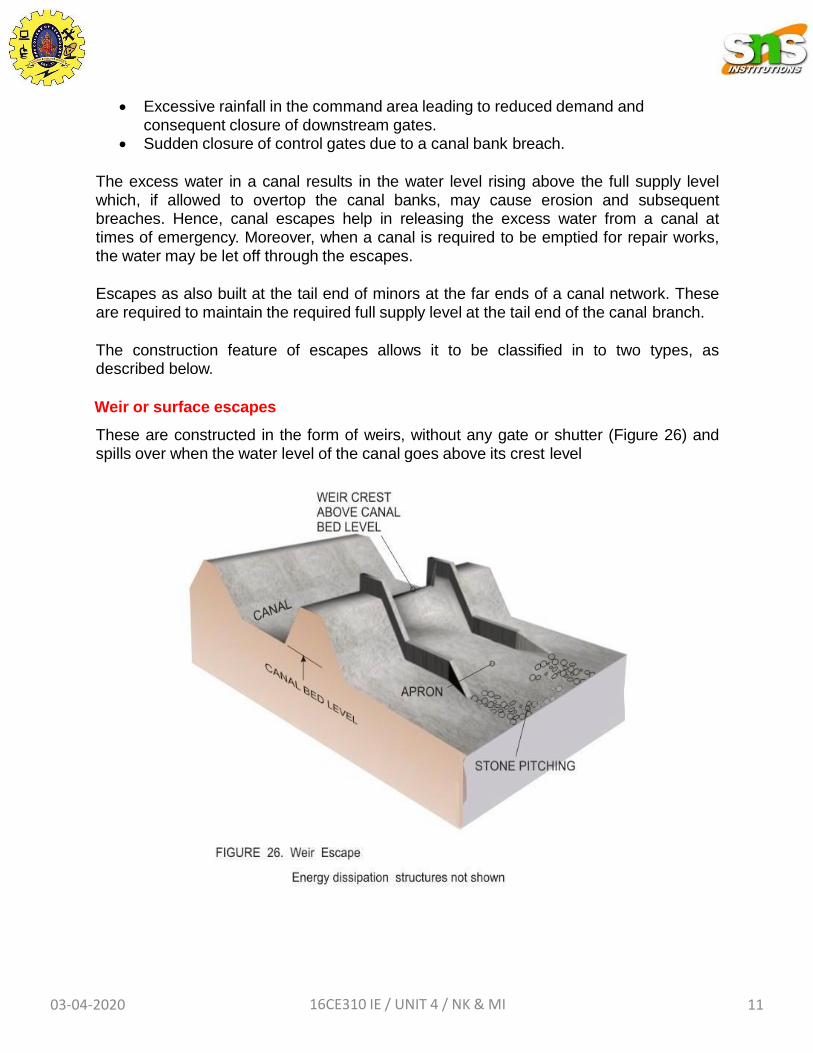
Weir or surface escapes
These are constructed in the form of weirs, without any gate or shutter (Figure 26) and
spills over when the water level of the canal goes above its crest level
03-04-2020 16CE310 IE / UNIT 4 / NK & MI 11
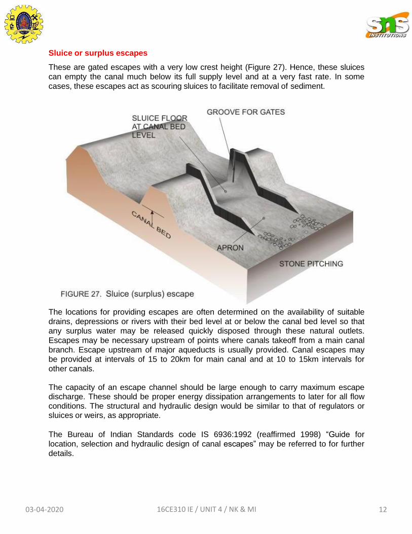
Sluice or surplus escapes
These are gated escapes with a very low crest height (Figure 27). Hence, these sluices can empty the canal much below its full supply level and at a very fast rate. In some cases, these escapes act as scouring sluices to facilitate removal of sediment.
The locations for providing escapes are often determined on the availability of suitable drains, depressions or rivers with their bed level at or below the canal bed level so that any surplus water may be released quickly disposed through these natural outlets. Escapes may be necessary upstream of points where canals takeoff from a main canal branch. Escape upstream of major aqueducts is usually provided. Canal escapes may be provided at intervals of 15 to 20km for main canal and at 10 to 15km intervals for other canals.
The capacity of an escape channel should be large enough to carry maximum escape discharge. These should be proper energy dissipation arrangements to later for all flow conditions. The structural and hydraulic design would be similar to that of regulators or sluices or weirs, as appropriate.
The Bureau of Indian Standards code IS 6936:1992 (reaffirmed 1998) “Guide for
location, selection and hydraulic design of canal escapes” may be referred to for further details.
03-04-2020 16CE310 IE / UNIT 4 / NK & MI 12


