Embed Size (px)
Citation preview
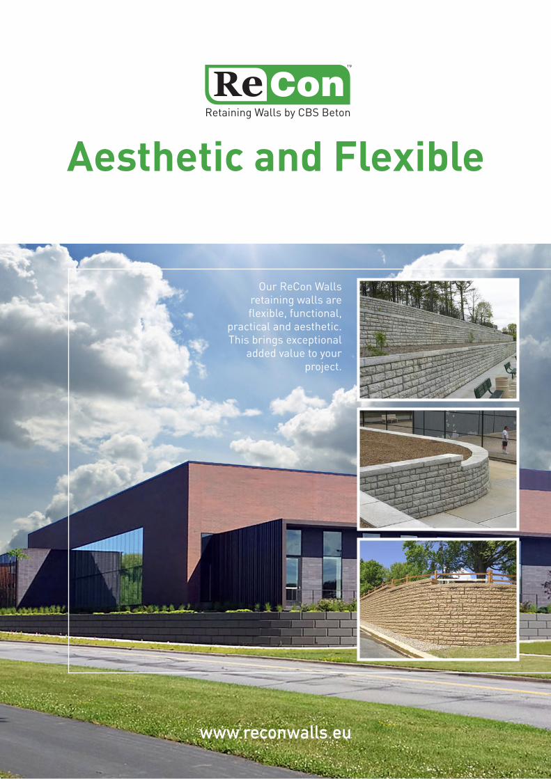
Aesthetic and Flexible
www.reconwalls.eu
Our ReCon Walls retaining walls are flexible, functional,
practical and aesthetic. This brings exceptional
added value to your project.
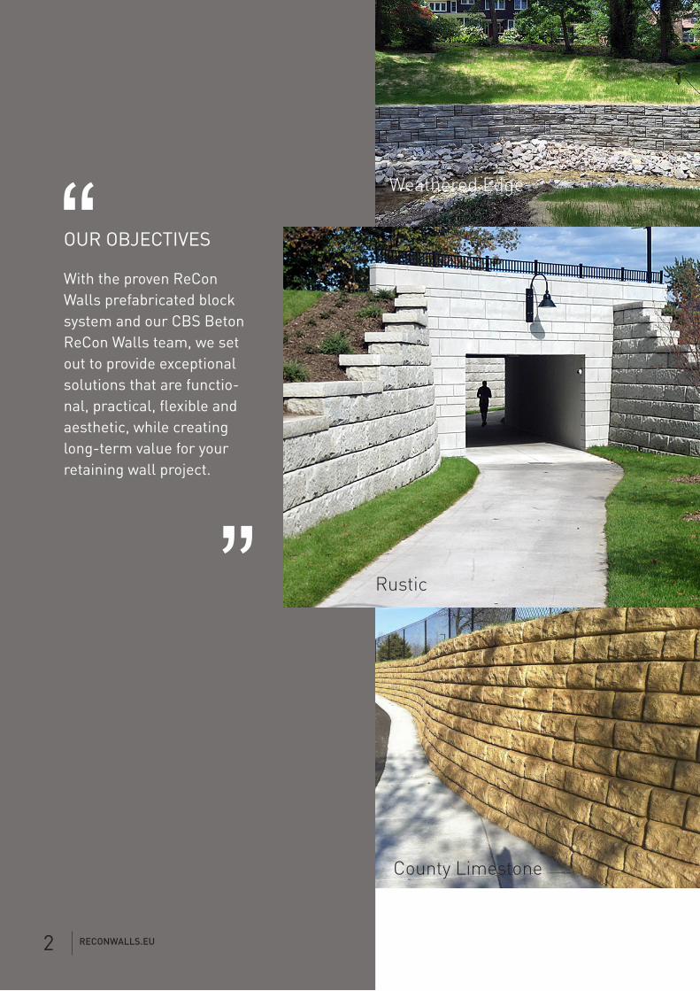
OUR OBJECTIVES
With the proven ReCon Walls prefabricated block system and our CBS Beton ReCon Walls team, we set out to provide exceptional solutions that are functio-nal, practical, flexible and aesthetic, while creating long-term value for your retaining wall project.
“
“Rustic
County Limestone
Weathered Edge
RECONWALLS.EU2
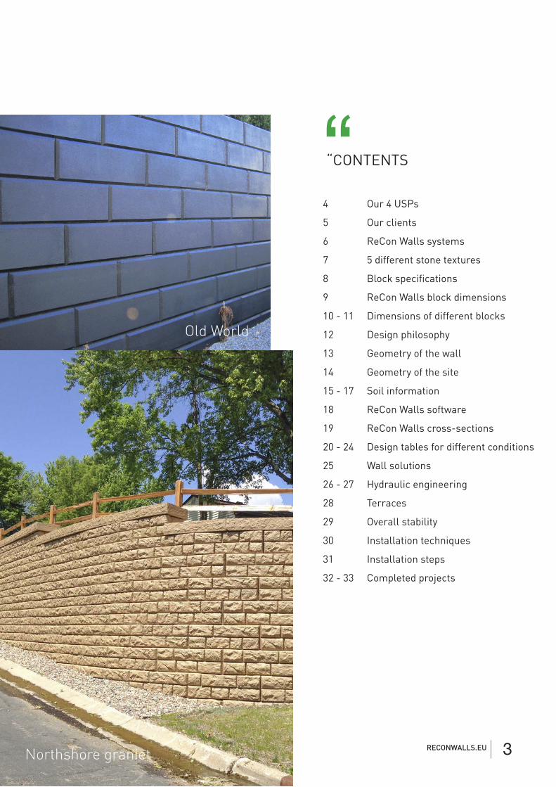
“CONTENTS“
Northshore graniet
Weathered Edge
Old World
4 Our 4 USPs
5 Our clients
6 ReCon Walls systems
7 5 different stone textures
8 Block specifications
9 ReCon Walls block dimensions
10 - 11 Dimensions of different blocks
12 Design philosophy
13 Geometry of the wall
14 Geometry of the site
15 - 17 Soil information
18 ReCon Walls software
19 ReCon Walls cross-sections
20 - 24 Design tables for different conditions
25 Wall solutions
26 - 27 Hydraulic engineering
28 Terraces
29 Overall stability
30 Installation techniques
31 Installation steps
32 - 33 Completed projects
RECONWALLS.EU 3

Performance level you need.
Retaining walls are designed with one goal: performance. ReCon Walls has the leading system in the area of self-supporting retaining walls. ReCon Walls large retaining wall blocks can be used for non-reinforced self-supporting retaining walls up to 6 m. Thanks to geogrid retaining walls, we can go to heights of 20 m and more on any type of soil.
Value you expect.
If durability is important for you, choose retaining wall blocks made from wet-cast concrete. ReCon Walls concrete blocks for retaining walls are made of wet-cast concrete and are specially designed to withstand adverse influences over the long term.
Flexibility you can rely on.
Thanks to the flexible concept, the possibilities for use are almost unlimited, even in complex and difficult circumstances. Whether we are talking about infrastructure projects in road construction, railways, hydraulic engineering or residential projects, we always succeed in implementing your wishes in an efficient way.
Aesthetics you’ll love. Retaining walls should emphasise the beauty of the natural environment and add value to a property. ReCon Walls currently offers 5 different textures: Granite, Limestone, Old World, Rustic and Weathered Edge.
Our 4 USPs“
RECONWALLS.EU4

OUR CLIENTS“Engineering
Structural engineers and/or engineering firms.
We know that the good design of a prefabricated retaining wall made of modular concrete blocks is a crucial step in the completion of a successful retaining wall. Most commercial and government projects require a successful design that has been validated by a specialised and/or accredited engineering firm. ReCon Walls has the required technical expertise and can provide engineers with the information they need to design retaining walls in accordance with currently accepted design standards. We provide the following tools and active support: wall analysis and layout software, design and construction details, specification and installation instructions.
Project developers
Project developers/retaining wall specialists/architects
At ReCon Walls, we know the importance of providing the right information and resources. Architects and engineers can get advice from our teams of specialists. When it comes to design, we think along with you about the specific needs of the customer in order to develop a joint solution with the aim of “customer satisfaction”. We can build very complex and durable retaining walls that optimise the usable area in real estate and infrastructure projects. Thanks to our “natural stone look”, we can integrate our walls perfectly into a natural environment.
Installers/Contractors
As retaining wall specialists, ReCon Walls wants you, the customer, to experience the benefits our products can bring to your project. ReCon Walls blocks are stacked dry. Traditional tools such as adhesives, silicones, mortar or other bonding agents are superfluous here. This ensures fast and efficient assembly on site.
As for design and construction, we are your specialists with our well-honed technical concept. We help you professionally with product specification, installation, instructions and manuals, including customised technical details.
RECONWALLS.EU 5
ReCon Walls systems“What are ReCon Walls retaining systems?
ReCon Walls systems are aesthetic and structural retaining wall solutions where we focus on delivering absolute added value to our customers, including:
• In-depth engineering and proven designs. • Solutions that meet specific wall requirements such as loads and overloads, special soil situations and wall heights, looking for the best possible solution for each specific situation rather than an imposed design. • Durability. • Five types of textures. • Product shape/design and size choices that work.
1) Large format/high mass All our elements have a sufficiently large size and high mass to speed up the assembly of retaining walls and to ensure the necessary stability of the entire retaining wall structure. All elements are very easy to handle individually.
2) High gravity walls These use a unique design with an interlocking tongue and groove system combined with a large size and high mass. This allows us to construct walls up to 6 m high without using geogrid reinforcement. This saves time and money. Of course, if we employ the tried and tested geogrid system, much higher wall heights (20 m and more) can achieved. This system provides the necessary stability, even under exceptional loads and in the most demanding situations.
3) Durability The wet-cast concrete quality used allows us to give our retaining walls the necessary durability, even in more aggressive environments where they are subject to frost/thaw cycles, road salt or seawater.
5) Faster installation Our retaining walls can be assembled with the usual hoisting hooks/manipulators available on the market. The modular concept and the absence of mortar and/or additional anchors, reduces manual labour to a minimum, making assembly fast and keeping costs down.
6) Designed and tested Every ReCon Walls retaining wall can be professionally engineered and designed using ReCon Walls know-how and specific data.
7) Customised design and aesthetics At ReCon Walls, we have a variety of textures at our disposal and can avoid the repetition of identical patterns. This gives the whole structure a natural look. It is also always possible to choose an additional colour to suit the customer’s wishes. The prefab blocks make it possible to create various shapes such as bends and 90° inside or outside corners. The tops of the walls can also be finished as desired.
Features and benefits:
RECONWALLS.EU6
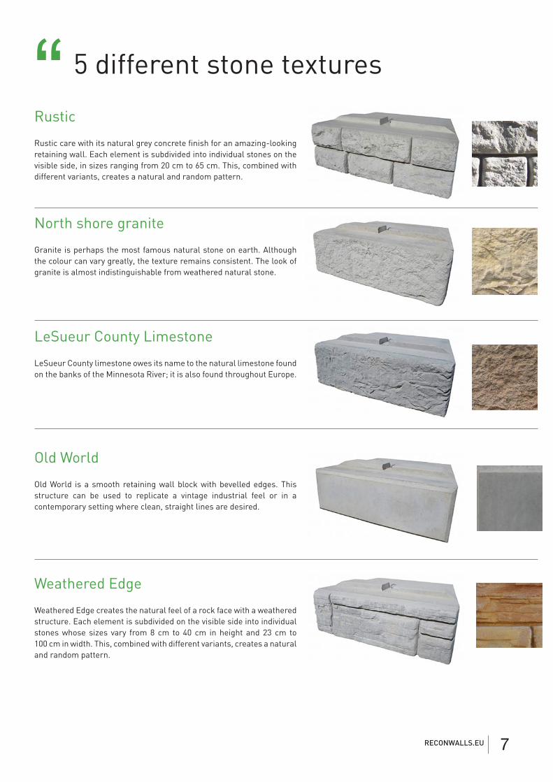
North shore granite
Granite is perhaps the most famous natural stone on earth. Although the colour can vary greatly, the texture remains consistent. The look of granite is almost indistinguishable from weathered natural stone.
LeSueur County Limestone
LeSueur County limestone owes its name to the natural limestone found on the banks of the Minnesota River; it is also found throughout Europe.
Old World
Old World is a smooth retaining wall block with bevelled edges. This structure can be used to replicate a vintage industrial feel or in a contemporary setting where clean, straight lines are desired.
Rustic
Rustic care with its natural grey concrete finish for an amazing-looking retaining wall. Each element is subdivided into individual stones on the visible side, in sizes ranging from 20 cm to 65 cm. This, combined with different variants, creates a natural and random pattern.
Weathered Edge
Weathered Edge creates the natural feel of a rock face with a weathered structure. Each element is subdivided on the visible side into individual stones whose sizes vary from 8 cm to 40 cm in height and 23 cm to 100 cm in width. This, combined with different variants, creates a natural and random pattern.
5 different stone textures“
RECONWALLS.EU 7
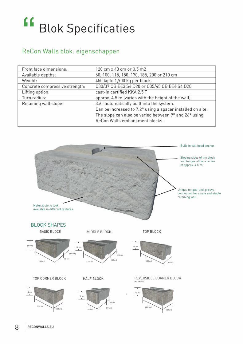
Blok Specificaties“ReCon Walls blok: eigenschappen
Front face dimensions: 120 cm x 40 cm or 0.5 m2Available depths: 60, 100, 115, 150, 170, 185, 200 or 210 cmWeight: 450 kg to 1,900 kg per block.Concrete compressive strength: C30/37 OB EE3 S4 D20 or C35/45 OB EE4 S4 D20Lifting option: cast-in certified KKA 2.5 TTurn radius: approx. 4.5 m (varies with the height of the wall)Retaining wall slope: 3.6° automatically built into the system. Can be increased to 7.2° using a spacer installed on site. The slope can also be varied between 9° and 26° using ReCon Walls embankment blocks.
BLOCK SHAPESBASIC BLOCK MIDDLE BLOCK TOP BLOCK
REVERSIBLE CORNER BLOCKTOP CORNER BLOCK HALF BLOCK
Natural stone look,available in different textures.
Unique tongue-and-groove connection for a safe and stable retaining wall.
Built-in ball head anchor
Sloping sides of the block and tongue allow a radius of approx. 4.5 m.
(90° corners)
(60 cm)
(210 cm)
(60 cm)
(210 cm)
(120 cm) (120 cm) (120 cm)
(120 cm)(120 cm)
(100 cm)
(60 cm)(60 cm)(60 cm) (60 cm)
(60 cm)
(40 cm) (40 cm)
(40 cm)(40 cm)
(40 cm) (
(40 cm)
RECONWALLS.EU8
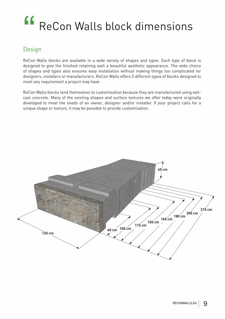
ReCon Walls block dimensions“Design
ReCon Walls blocks are available in a wide variety of shapes and types. Each type of block is designed to give the finished retaining wall a beautiful aesthetic appearance. The wide choice of shapes and types also ensures easy installation without making things too complicated for designers, installers or manufacturers. ReCon Walls offers 5 different types of blocks designed to meet any requirement a project may have.
ReCon Walls blocks lend themselves to customisation because they are manufactured using wet-cast concrete. Many of the existing shapes and surface textures we offer today were originally developed to meet the needs of an owner, designer and/or installer. If your project calls for a unique shape or texture, it may be possible to provide customisation.
120 cm
40 cm
215 cm200 cm
180 cm160 cm
150 cm115 cm
100 cm60 cm
RECONWALLS.EU 9
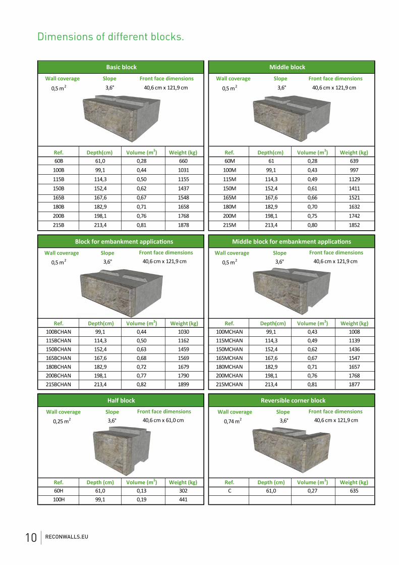
Wall coverage Slope Wall coverage Slope
0,5 m2 3,6° 0,5 m2 3,6°
Ref. Depth(cm) Volume (m3) Weight (kg) Ref. Depth(cm) Volume (m3) Weight (kg)60B 61,0 0,28 660 60M 61 0,28 639
100B 99,1 0,44 1031 100M 99,1 0,43 997115B 114,3 0,50 1155 115M 114,3 0,49 1129150B 152,4 0,62 1437 150M 152,4 0,61 1411165B 167,6 0,67 1548 165M 167,6 0,66 1521180B 182,9 0,71 1658 180M 182,9 0,70 1632200B 198,1 0,76 1768 200M 198,1 0,75 1742215B 213,4 0,81 1878 215M 213,4 0,80 1852
Wall coverage Slope Wall coverage Slope
0,5 m2 3,6° 0,5 m2 3,6°
Ref. Depth(cm) Volume (m3) Weight (kg) Ref. Depth (cm) Volume (m3) Weight (kg)100BCHAN 99,1 0,44 1030 100MCHAN 99,1 0,43 1008115BCHAN 114,3 0,50 1162 115MCHAN 114,3 0,49 1139150BCHAN 152,4 0,63 1459 150MCHAN 152,4 0,62 1436165BCHAN 167,6 0,68 1569 165MCHAN 167,6 0,67 1547180BCHAN 182,9 0,72 1679 180MCHAN 182,9 0,71 1657200BCHAN 198,1 0,77 1790 200MCHAN 198,1 0,76 1768215BCHAN 213,4 0,82 1899 215MCHAN 213,4 0,81 1877
Wall coverage Slope Wall coverage Slope
0,25 m2 3,6° 0,74 m2 3,6°
Ref. Depth (cm) Volume (m3) Weight (kg) Ref. Depth (cm) Volume (m )3 Weight (kg)60H 61,0 0,13 302 C 61,0 0,27 635100H 99,1 0,19 441
Half block
Front face dimensions40,6 cm x 61,0 cm
Reversible corner block
Front face dimensions40,6 cm x 121,9 cm
Basic block
Front face dimensions 40,6 cm x 121,9 cm
Middle block
Front face dimensions40,6 cm x 121,9 cm
Block for embankment applications
Front face dimensions40,6 cm x 121,9 cm
Middle block for embankment applications
Front face dimensions40,6 cm x 121,9 cm
Dimensions of different blocks.
RECONWALLS.EU10
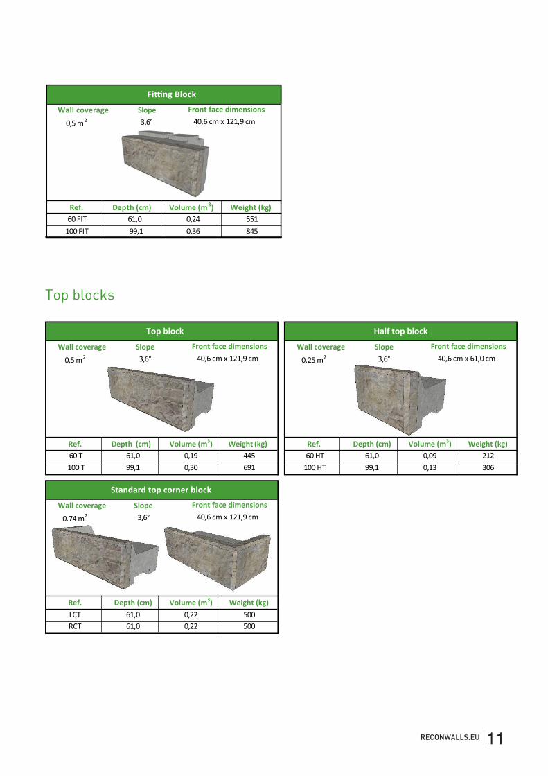
Wall coverage
0,5 m2 3,6°
Ref. Depth (cm) Volume (m3) Weight (kg)60 FIT 61,0 0,24 551
100 FIT 99,1 0,36 845
40,6 cm x 121,9 cm
Fitting Block
Front face dimensionsSlope
Wall coverage Slope Wall coverage Slope
0,5 m2 3,6° 0,25 m2 3,6°
Ref. Depth (cm) Volume (m3) Weight (kg) Ref. Depth (cm) Volume (m3) Weight (kg)60 T 61,0 0,19 445 60 HT 61,0 0,09 212100 T 99,1 0,30 691 100 HT 99,1 0,13 306
Wall coverage Slope
0,74 m2 3,6°
Ref. Depth (cm) Volume (m3) Weight (kg)LCT 61,0 0,22 500RCT 61,0 0,22 500
Standard top corner block
Front face dimensions 40,6 cm x 121,9 cm
Top block
Front face dimensions 40,6 cm x 121,9 cm
Half top block
Front face dimensions 40,6 cm x 61,0 cm
Top blocks
RECONWALLS.EU 11
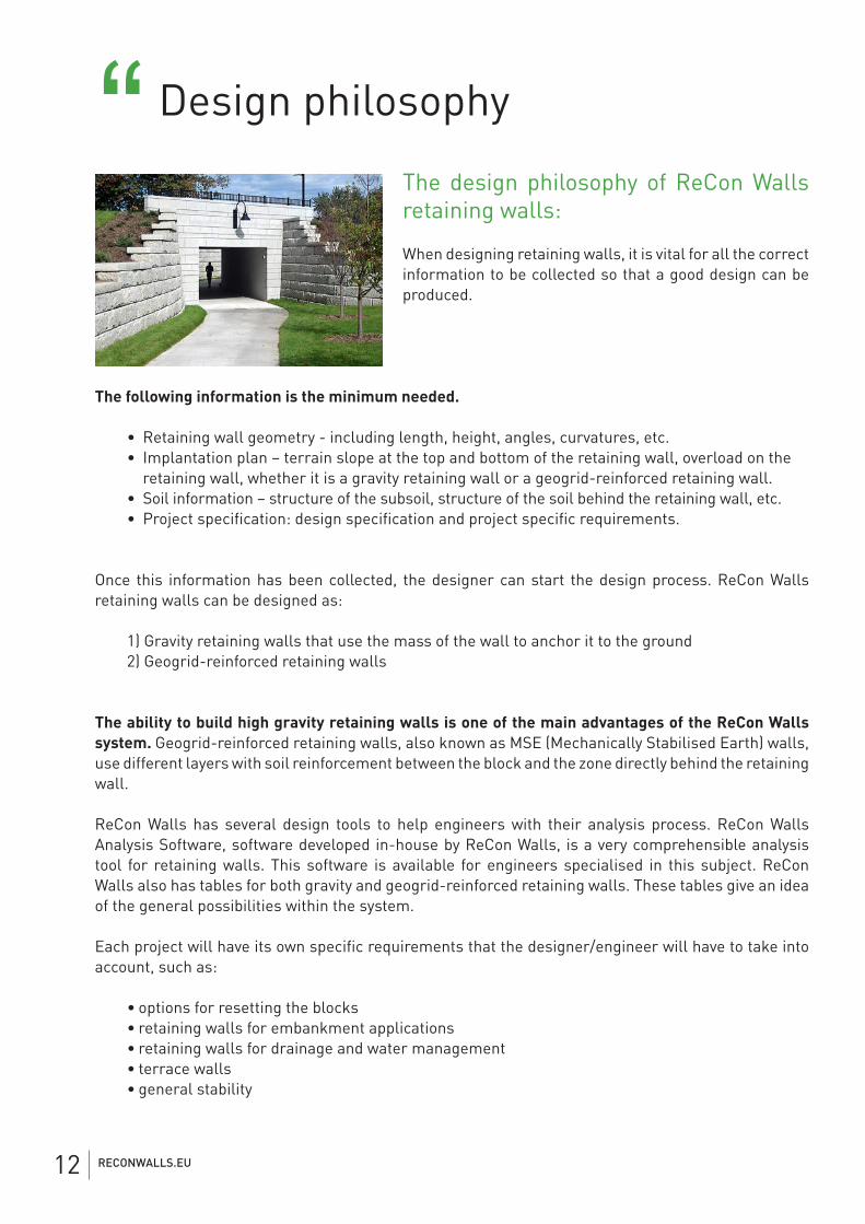
Design philosophy“The design philosophy of ReCon Walls retaining walls:
When designing retaining walls, it is vital for all the correct information to be collected so that a good design can be produced.
The following information is the minimum needed.
• Retaining wall geometry - including length, height, angles, curvatures, etc. • Implantation plan – terrain slope at the top and bottom of the retaining wall, overload on the retaining wall, whether it is a gravity retaining wall or a geogrid-reinforced retaining wall. • Soil information – structure of the subsoil, structure of the soil behind the retaining wall, etc. • Project specification: design specification and project specific requirements.
Once this information has been collected, the designer can start the design process. ReCon Walls retaining walls can be designed as:
1) Gravity retaining walls that use the mass of the wall to anchor it to the ground 2) Geogrid-reinforced retaining walls
The ability to build high gravity retaining walls is one of the main advantages of the ReCon Walls system. Geogrid-reinforced retaining walls, also known as MSE (Mechanically Stabilised Earth) walls, use different layers with soil reinforcement between the block and the zone directly behind the retaining wall.
ReCon Walls has several design tools to help engineers with their analysis process. ReCon Walls Analysis Software, software developed in-house by ReCon Walls, is a very comprehensible analysis tool for retaining walls. This software is available for engineers specialised in this subject. ReCon Walls also has tables for both gravity and geogrid-reinforced retaining walls. These tables give an idea of the general possibilities within the system.
Each project will have its own specific requirements that the designer/engineer will have to take into account, such as:
• options for resetting the blocks • retaining walls for embankment applications • retaining walls for drainage and water management • terrace walls • general stability
RECONWALLS.EU12
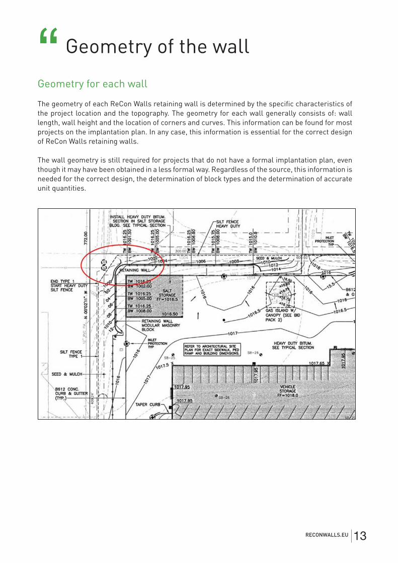
Geometry of the wall“Geometry for each wall
The geometry of each ReCon Walls retaining wall is determined by the specific characteristics of the project location and the topography. The geometry for each wall generally consists of: wall length, wall height and the location of corners and curves. This information can be found for most projects on the implantation plan. In any case, this information is essential for the correct design of ReCon Walls retaining walls.
The wall geometry is still required for projects that do not have a formal implantation plan, even though it may have been obtained in a less formal way. Regardless of the source, this information is needed for the correct design, the determination of block types and the determination of accurate unit quantities.
RECONWALLS.EU 13
1) Overloads
In most cases, retaining walls are subject to different types of loads, either permanent or temporary. Here we are talking about loads caused by buildings, bike paths, roads, etc. This must be taken into account in the design of the retaining wall. The knowledge and software of ReCon Walls integrate all these parameters seamlessly into your design.
2) Back slope
A back slope is defined as an inclined slope at the top of a retaining wall. The mass of the inclined slope is considered technically to be a dead load. It is crucial to include the back slope during the analysis process. This is taken into account in the analysis of ReCon Walls.
3) Base slope
A base slope is defined as a slope at the base of a retaining wall. Generally, the base slope has little impact on the direct loads on the retaining wall, but can affect the overall stability of the wall. This is also taken into account in the analysis of ReCon Walls.
4) Cut or fill application
1) In the case of a cut, part of the ground is removed at the foot of the slope and replaced by the retaining wall. This increases the useful surface area at the front of the wall. The ReCon Walls gravity retaining wall is ideal here.
2) In a fill application, the space behind the retaining wall is filled so that the useful area at the back of the wall is increased. The ReCon Walls geogrid-reinforced wall is the most suitable solution in this case.
However, the type of wall used, gravity or geogrid-reinforced, can vary depending on local conditions.
Geometry of the site“
RECONWALLS.EU14
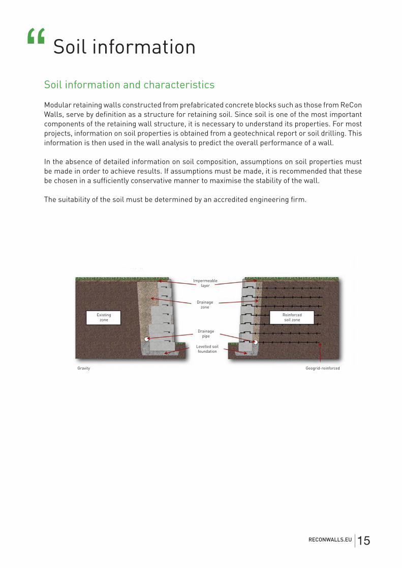
Impermeable layer
Drainage zone
Existing zone
Reinforced soil zone
Drainage pipe
Levelled soil foundation
Geogrid-reinforcedGravity
Soil information and characteristics
Modular retaining walls constructed from prefabricated concrete blocks such as those from ReCon Walls, serve by definition as a structure for retaining soil. Since soil is one of the most important components of the retaining wall structure, it is necessary to understand its properties. For most projects, information on soil properties is obtained from a geotechnical report or soil drilling. This information is then used in the wall analysis to predict the overall performance of a wall.
In the absence of detailed information on soil composition, assumptions on soil properties must be made in order to achieve results. If assumptions must be made, it is recommended that these be chosen in a sufficiently conservative manner to maximise the stability of the wall.
The suitability of the soil must be determined by an accredited engineering firm.
Soil information“
RECONWALLS.EU 15
5 important zones in the soil around the retaining wall
When it comes to the characteristics that are important for a wall designer, the soil around the finished retaining wall is divided into five basic zones.
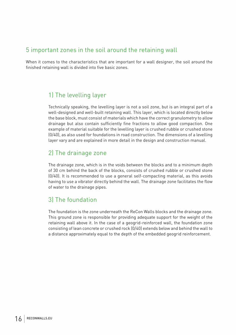
1) The levelling layer
Technically speaking, the levelling layer is not a soil zone, but is an integral part of a well-designed and well-built retaining wall. This layer, which is located directly below the base block, must consist of materials which have the correct granulometry to allow drainage but also contain sufficiently fine fractions to allow good compaction. One example of material suitable for the levelling layer is crushed rubble or crushed stone (0/40), as also used for foundations in road construction. The dimensions of a levelling layer vary and are explained in more detail in the design and construction manual.
2) The drainage zone
The drainage zone, which is in the voids between the blocks and to a minimum depth of 30 cm behind the back of the blocks, consists of crushed rubble or crushed stone (0/40). It is recommended to use a general self-compacting material, as this avoids having to use a vibrator directly behind the wall. The drainage zone facilitates the flow of water to the drainage pipes.
3) The foundation
The foundation is the zone underneath the ReCon Walls blocks and the drainage zone. This ground zone is responsible for providing adequate support for the weight of the retaining wall above it. In the case of a geogrid-reinforced wall, the foundation zone consisting of lean concrete or crushed rock (0/40) extends below and behind the wall to a distance approximately equal to the depth of the embedded geogrid reinforcement.
RECONWALLS.EU16
4) The reinforced soil zone
The reinforced soil zone is only relevant for geogrid-reinforced retaining walls. This zone extends from the back of the drainage zone to the furthest point where the geogrid soil reinforcement is located. In some cases, material available on site can be used for this purpose. If this material is not suitable, a suitable filling material must be supplied. The properties of this material have a strong influence on the performance characteristics of the reinforced soil mass. They have an important effect on the design of the reinforced soil zone and the entire retaining wall structure.
5) The embedded ground zone
The embedded soil zone is the material located behind the reinforced soil zone in a geogrid-reinforced retaining wall, or behind the drainage zone in a gravity retaining wall. Soil properties within this zone also have an important influence on the design of the finished retaining wall, just as the reinforced soil zone does.
Project specification
The aim of a project specification is to outline detailed requirements with regard to materials, products, installation procedures, design guidelines and quality aspects. We can give you advice if you want help with your project.
RECONWALLS.EU 17
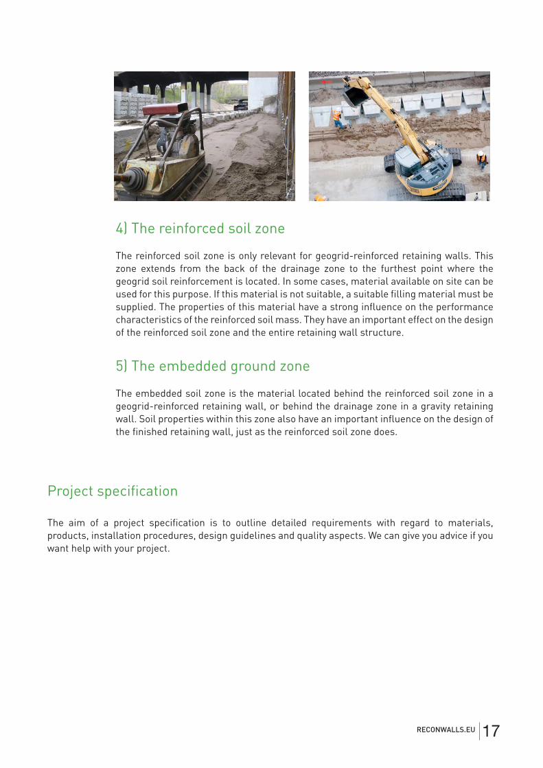
ReCon Walls software“ ReCon Walls analysis and layouyt software for professionals
The ReCon Walls analysis software is available for industry professionals and engineers speciali-sing in the design of retaining walls. This powerful and easy-to-use software enables the user to analyse both gravity and geogrid-reinforced retaining walls.
Here are just a few of the advanced and extensive features of the software:
• Hydraulic analysis, buoyancy and fast uptake • Overall stability analysis • Seismic analysis • Possibility of entering multiple soil zones • Possibilities to enter data on overloads, back and base slope • Comprehensive and detailed report • Comprehensive user manual
The ReCon Walls layout software enables the user, after engineering through the analysis software, to design the complete retaining wall in detail. This is done according to, among other things, bills of materials that are used for production and assembly purposes.
For a copy of the ReCon Walls Analysis and layout software, please visit our website at www.recon-walls.eu
RECONWALLS.EU18
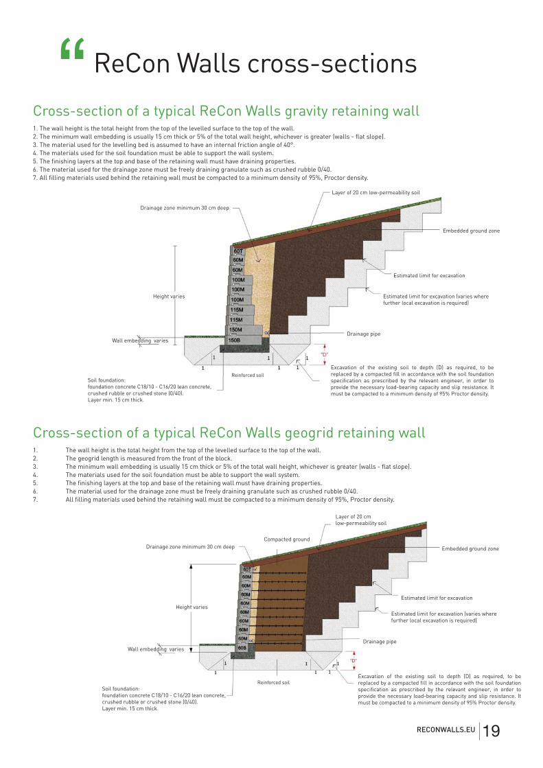
ReCon Walls cross-sections“Cross-section of a typical ReCon Walls gravity retaining wall1. The wall height is the total height from the top of the levelled surface to the top of the wall.2. The minimum wall embedding is usually 15 cm thick or 5% of the total wall height, whichever is greater (walls - flat slope).3. The material used for the levelling bed is assumed to have an internal friction angle of 40°.4. The materials used for the soil foundation must be able to support the wall system.5. The finishing layers at the top and base of the retaining wall must have draining properties.6. The material used for the drainage zone must be freely draining granulate such as crushed rubble 0/40.7. All filling materials used behind the retaining wall must be compacted to a minimum density of 95%, Proctor density.
Drainage zone minimum 30 cm deep
Layer of 20 cm low-permeability soil
Estimated limit for excavation
Estimated limit for excavation (varies where further local excavation is required)
Excavation of the existing soil to depth (D) as required, to be replaced by a compacted fill in accordance with the soil foundation specification as prescribed by the relevant engineer, in order to provide the necessary load-bearing capacity and slip resistance. It must be compacted to a minimum density of 95% Proctor density.
Wall embedding varies
Height varies
Soil foundation:foundation concrete C18/10 - C16/20 lean concrete, crushed rubble or crushed stone (0/40).Layer min. 15 cm thick.
Drainage pipe
Reinforced soil
Cross-section of a typical ReCon Walls geogrid retaining wall1. The wall height is the total height from the top of the levelled surface to the top of the wall.2. The geogrid length is measured from the front of the block.3. The minimum wall embedding is usually 15 cm thick or 5% of the total wall height, whichever is greater (walls - flat slope).4. The materials used for the soil foundation must be able to support the wall system.5. The finishing layers at the top and base of the retaining wall must have draining properties.6. The material used for the drainage zone must be freely draining granulate such as crushed rubble 0/40.7. All filling materials used behind the retaining wall must be compacted to a minimum density of 95%, Proctor density.
Embedded ground zone
Compacted ground
Excavation of the existing soil to depth (D) as required, to be replaced by a compacted fill in accordance with the soil foundation specification as prescribed by the relevant engineer, in order to provide the necessary load-bearing capacity and slip resistance. It must be compacted to a minimum density of 95% Proctor density.
Drainage zone minimum 30 cm deep
Layer of 20 cm low-permeability soil
Estimated limit for excavation
Estimated limit for excavation (varies where further local excavation is required)
Height varies
Drainage pipe
Reinforced soil
Embedded ground zone
Wall embedding varies
Soil foundation:foundation concrete C18/10 - C16/20 lean concrete, crushed rubble or crushed stone (0/40).Layer min. 15 cm thick.
RECONWALLS.EU 19
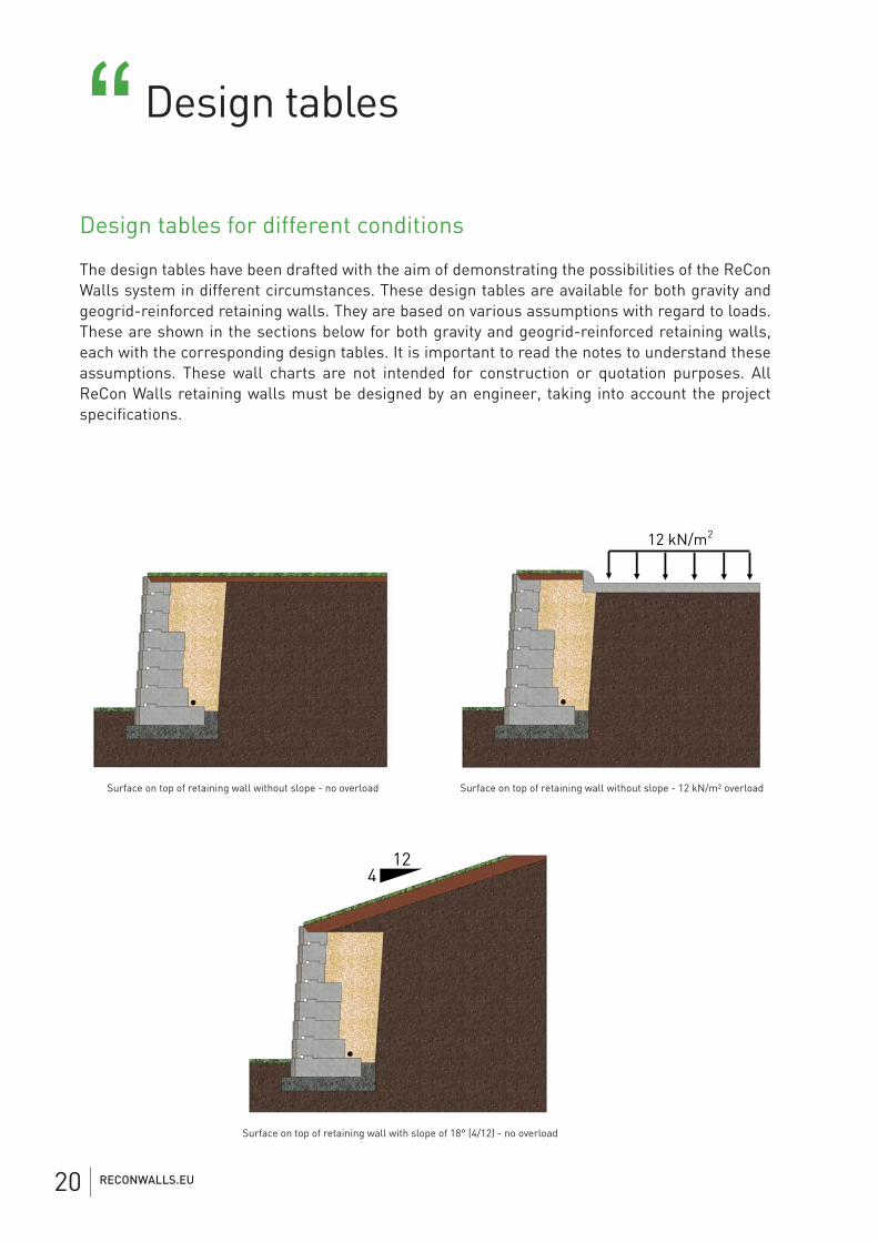
Design tables for different conditions
The design tables have been drafted with the aim of demonstrating the possibilities of the ReCon Walls system in different circumstances. These design tables are available for both gravity and geogrid-reinforced retaining walls. They are based on various assumptions with regard to loads. These are shown in the sections below for both gravity and geogrid-reinforced retaining walls, each with the corresponding design tables. It is important to read the notes to understand these assumptions. These wall charts are not intended for construction or quotation purposes. All ReCon Walls retaining walls must be designed by an engineer, taking into account the project specifications.
12 kN/m2
124
Surface on top of retaining wall without slope - no overload
Surface on top of retaining wall with slope of 18° (4/12) - no overload
Surface on top of retaining wall without slope - 12 kN/m² overload
Design tables“
RECONWALLS.EU20
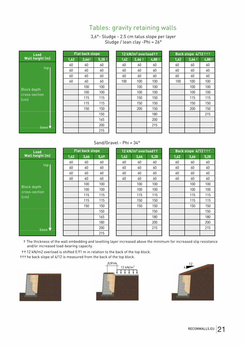
1,62 3,66† 5,28 † 1,62 3,66 † 4,88 † 1,62 3,66 † 4,88†
top60 60 60 60 60 60 60 60 6060 60 60 60 60 60 60 60 6060 60 60 60 60 60 60 60 6060 60 60 100 100 100 100 100 100
100 100 100 100 100 100100 100 100 100 100 100115 115 150 150 115 115115 115 150 150 150 150150 150 200 150 200 150
150 180 215165 200200 215base215
1,62 3,66 5,69 1,62 3,66 5,28 1,62 3,66 5,28
top60 60 60 60 60 60 60 60 6060 60 60 60 60 60 60 60 6060 60 60 60 60 60 60 60 6060 60 60 60 60 60 60 60 60
100 100 100 100 100 100100 100 100 100 100 100115 115 115 115 115 115115 115 150 150 115 115150 150 150 150 150 150
150 150 150165 180 180180 200 200200 215 215215
†† 12 kN/m2 overload is shifted 0.91 m in relation to the back of the top block.††† he back slope of 4/12 is measured from the back of the top block.
Back slope 4/12 †††
3,6°- Sludge - 2.5 cm talus slope per layerSludge / lean clay -Phi = 26°
Sand/Gravel - Phi = 34°
† The thickness of the wall embedding and levelling layer increased above the minimum for increased slip resistance and/or increased load-bearing capacity.
Flat back slope
Block depth cross-section (cm)
12 kN/m2 overload††
Load Wall height (m)
12 kN/m2
Tables: gravity retaining walls
124
0,91m
base
Block depth cross-section (cm)
Load Wall height (m)
Back slope 4/12 †††Flat back slope 12 kN/m2 overload††
RECONWALLS.EU 21
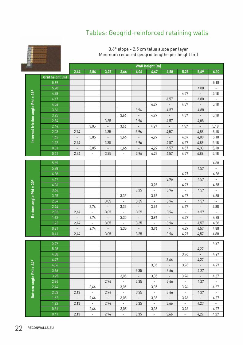
Tables: Geogrid-reinforced retaining walls
3.6° slope - 2.5 cm talus slope per layerMinimum required geogrid lengths per height (m)
2,44 2,84 3,25 3,66 4,06 4,47 4,88 5,28 5,69 6,10Grid height (m)
5,69 5,185,28 4,88 -4,88 4,57 - 5,184,47 4,57 - 4,88 -4,06 4,27 - 4,57 - 5,183,66 3,96 - 4,57 - 4,88 -3,25 3,66 - 4,27 - 4,57 - 5,182,84 3,35 - 3,96 - 4,57 - 4,88 -2,44 3,05 - 3,66 - 4,27 - 4,57 - 5,182,03 2,74 - 3,35 - 3,96 - 4,57 - 4,88 5,181,62 - 3,05 - 3,66 - 4,27 - 4,57 4,88 5,181,22 2,74 - 3,35 - 3,96 - 4,57 4,57 4,88 5,180,81 - 3,05 - 3,66 - 4,27 4,57 4,57 4,88 5,180,41 2,74 - 3,35 - 3,96 4,27 4,57 4,57 4,88 5,18
5,69 4,885,28 4,57 -4,88 4,27 - 4,884,47 3,96 - 4,57 -4,06 3,96 - 4,27 - 4,883,66 3,35 - 3,96 - 4,57 -3,25 3,35 - 3,96 - 4,27 - 4,882,84 3,05 - 3,35 - 3,96 - 4,57 -2,44 2,74 - 3,35 - 3,96 - 4,27 - 4,882,03 2,44 - 3,05 - 3,35 - 3,96 - 4,57 -1,62 - 2,74 - 3,35 - 3,96 - 4,27 - 4,881,22 2,44 - 3,05 - 3,35 - 3,96 - 4,57 4,880,81 - 2,74 - 3,35 - 3,96 - 4,27 4,57 4,880,41 2,44 - 3,05 - 3,35 - 3,96 4,27 4,57 4,88
5,69 4,275,28 4,27 -4,88 3,96 - 4,274,47 3,66 - 4,27 -4,06 3,35 - 3,96 - 4,273,66 3,35 - 3,66 - 4,27 -3,25 3,05 - 3,35 - 3,96 - 4,272,84 2,74 - 3,35 - 3,66 - 4,27 -2,44 2,44 - 3,05 - 3,35 - 3,96 - 4,272,03 2,13 - 2,74 - 3,35 - 3,66 - 4,27 -1,62 - 2,44 - 3,05 - 3,35 - 3,96 - 4,271,22 2,13 - 2,74 - 3,35 - 3,66 - 4,27 -0,81 - 2,44 - 3,05 - 3,35 - 3,96 - 4,270,41 2,13 - 2,74 - 3,35 - 3,66 - 4,27 4,27
Bot
tom
ang
le P
hi =
34°
Inte
rnal
fric
tion
ang
le P
hi =
26°
Bot
tom
ang
le P
hi =
30°
Wall height (m)
RECONWALLS.EU22
2,44 2,84 3,25 3,66 4,06 4,47 4,88 5,28 5,69 6,10Grid Elevation (m)
5,69 5,795,28 5,48 -4,88 5,18 - 5,794,47 4,88 - 5,48 -4,06 4,57 - 5,18 - 5,793,66 4,27 - 4,88 - 5,48 -3,25 3,96 - 4,57 - 5,18 - 5,792,84 3,66 - 4,27 - 4,88 - 5,48 5,792,44 3,35 - 3,96 - 4,57 - 5,18 5,48 5,792,03 3,05 - 3,66 - 4,27 - 4,88 5,18 5,48 5,791,62 - 3,35 - 3,96 - 4,57 4,88 5,18 5,48 5,791,22 3,05 - 3,66 - 4,27 4,57 4,88 5,18 5,48 5,79 0,81 - 3,35 - 3,96 4,27 4,57 4,88 5,18 5,48 5,790,41 3,05 - 3,66 3,96 4,27 4,57 4,88 5,18 5,48 5,79
5,69 4,885,28 4,88 -4,88 4,57 - 4,884,47 4,27 - 4,88 -4,06 3,96 - 4,57 - 4,883,66 3,66 - 4,27 - 4,88 -3,25 3,35 - 3,96 - 4,57 - 4,882,84 3,05 - 3,66 - 4,27 - 4,88 -2,44 2,74 - 3,35 - 3,96 - 4,57 - 4,882,03 2,74 - 3,05 - 3,66 - 4,27 - 4,88 4,881,62 - 2,74 - 3,35 - 3,96 - 4,57 4,88 4,881,22 2,74 - 3,05 - 3,66 - 4,27 4,57 4,88 4,880,81 - 2,74 - 3,35 - 3,96 4,27 4,57 4,88 4,880,41 2,74 - 3,05 - 3,66 3,96 4,27 4,57 4,88 4,88
5,69 4,575,28 4,27 -4,88 3,96 - 4,574,47 3,66 - 4,27 -4,06 3,66 - 3,96 - 4,573,66 3,35 - 3,66 - 4,27 -3,25 3,05 - 3,66 - 3,96 - 4,572,84 2,74 - 3,35 - 3,66 - 4,27 -2,44 2,74 - 3,05 - 3,66 - 3,96 - 4,572,03 2,44 - 2,74 - 3,35 - 3,66 - 4,27 -1,62 - 2,74 - 3,05 - 3,66 - 3,96 - 4,571,22 2,44 - 2,74 - 3,35 - 3,66 - 4,27 -0,81 - 2,74 - 3,05 - 3,66 - 3,96 - 4,570,41 2,44 - 2,74 - 3,35 - 3,66 - 4,27 4,57
Inte
rnal
fric
tion
ang
le P
hi =
26°
Bot
tom
ang
le P
hi =
30°
Bot
tom
ang
le P
hi =
34°
Wall height (m)
12 kN/m2
RECONWALLS,EU6
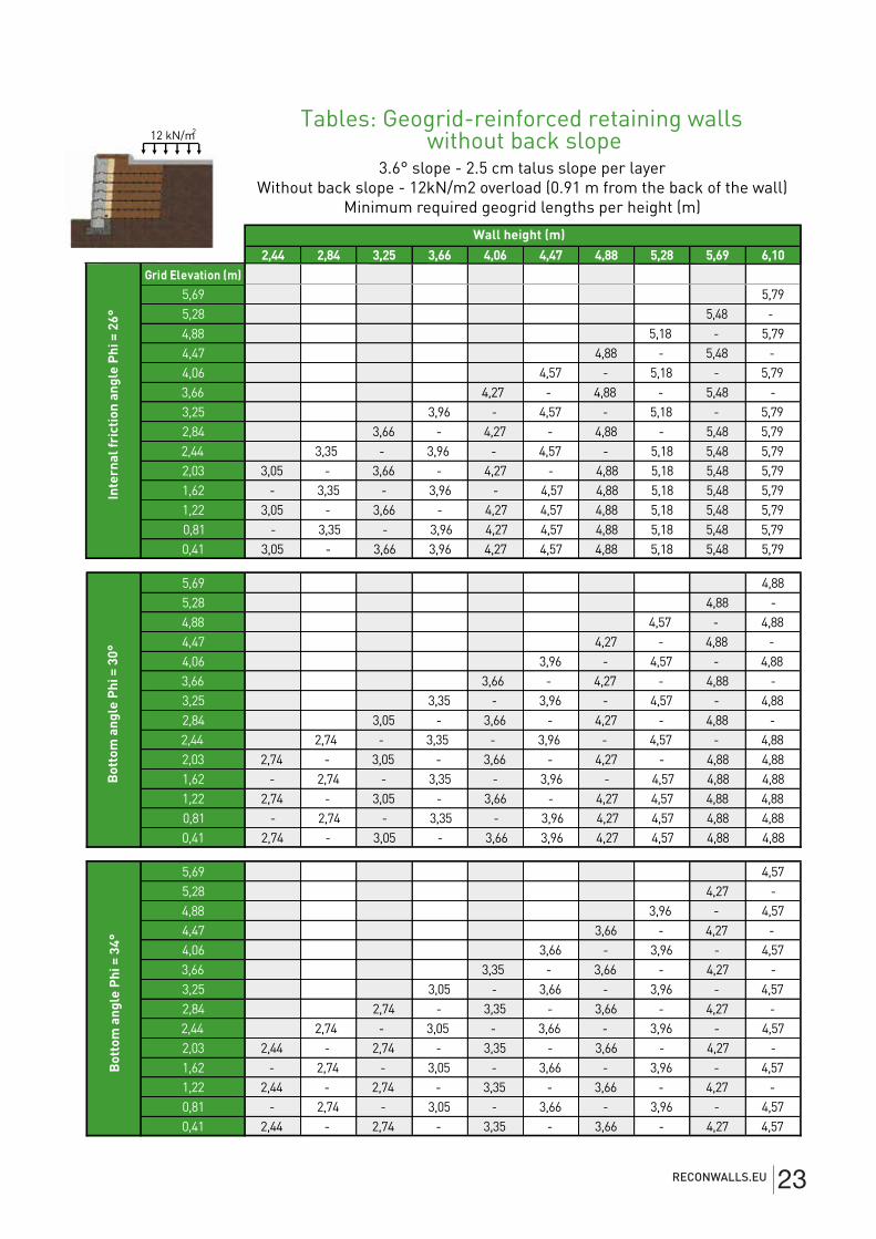
Tables: Geogrid-reinforced retaining walls without back slope
3.6° slope - 2.5 cm talus slope per layerWithout back slope - 12kN/m2 overload (0.91 m from the back of the wall)
Minimum required geogrid lengths per height (m)
RECONWALLS.EU 23
2,44 2,84 3,25 3,66 4,06 4,47 4,88 5,28 5,69 6,10
5,69 6,715,28 6,40 -4,88 5,79 - 6,714,47 5,48 - 6,40 -4,06 5,18 - 5,79 - 6,713,66 4,57 - 5,48 - 6,40 6,713,25 4,27 - 5,18 - 5,79 6,40 6,712,84 3,96 - 4,57 - 5,48 5,79 6,40 6,712,44 3,35 - 4,27 - 5,18 5,48 5,79 6,40 6,712,03 3,05 - 3,96 - 4,57 5,18 5,48 5,79 6,40 6,711,62 - 3,35 - 4,27 4,57 5,18 5,48 5,79 6,40 6,711,22 3,05 - 3,96 4,27 4,57 5,18 5,48 5,79 6,40 6,710,81 - 3,35 3,96 4,27 4,57 5,18 5,48 5,79 6,40 6,710,41 3,05 3, 35 3,96 4,27 4,57 5,18 5,48 5,79 6,40 6,71
5,69 5,795,28 5,48 -4,88 5,18 - 5,794,47 4,88 - 5,48 -4,06 4,27 - 5,18 - 5,793,66 3,96 - 4,88 - 5,48 -3,25 3,66 - 4,27 - 5,18 - 5,792,84 3,35 - 3,96 - 4,88 - 5,48 5,792,44 3,05 - 3,66 - 4,27 - 5,18 5,48 5,792,03 2,74 - 3,35 - 3,96 - 4,88 5,18 5,48 5,791,62 - 3,05 - 3,66 - 4,27 4,88 5,18 5,48 5,791,22 2,74 - 3,35 - 3,96 4,27 4,88 5,18 5,48 5,790,81 - 3,05 - 3,66 3,96 4,27 4,88 5,18 5,48 5,790,41 2,74 - 3,35 3,66 3,96 4,27 4,88 5,18 5,48 5,79
5,69 5,185,28 4,88 -4,88 4,57 - 5,184,47 4,27 - 4,88 -4,06 3,96 - 4,57 - 5,183,66 3,66 - 4,27 - 4,88 -3,25 3,35 - 3,96 - 4,57 - 5,182,84 3,05 - 3,66 - 4,27 - 4,88 -2,44 2,74 - 3,35 - 3,96 - 4,57 - 5,182,03 2,44 - 3,05 - 3,66 - 4,27 - 4,88 -1,62 - 2,74 - 3,35 - 3,96 - 4,57 - 5,181,22 2,44 - 3,05 - 3,66 - 4,27 - 4,88 5,180,81 - 2,74 - 3,35 - 3,96 - 4,57 4,88 5,180,41 2,44 - 3,05 - 3,66 - 4,27 4,57 4,88 5,18
Inte
rnal
fric
tion
ang
le P
hi =
26°
Bot
tom
ang
le P
hi =
30°
Bot
tom
ang
le P
hi =
34°
Grid Elevation (m)
Wall height (m)
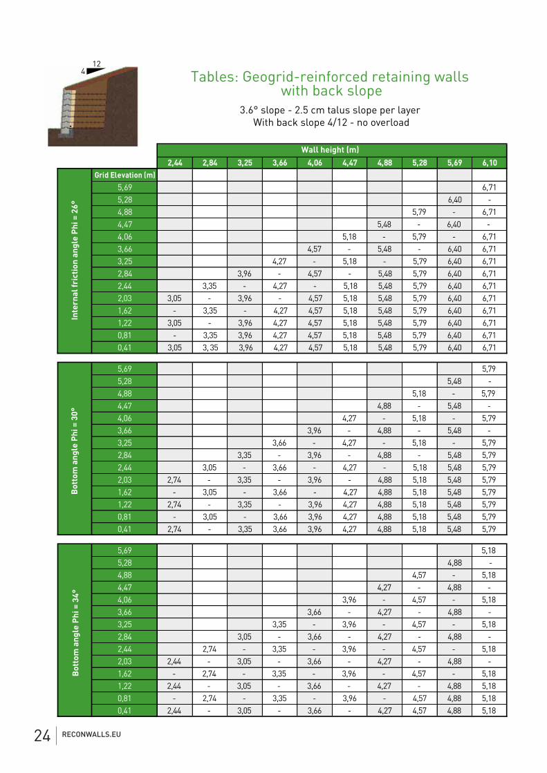
Tables: Geogrid-reinforced retaining walls with back slope
3.6° slope - 2.5 cm talus slope per layer With back slope 4/12 - no overload
124
RECONWALLS.EU24
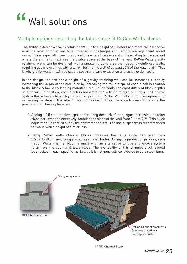
Wall solutions “Multiple options regarding the talus slope of ReCon Walls blocks
The ability to design a gravity retaining wall up to a height of 6 meters and more can help solve even the most complex and location-specifi c challenges and can provide signifi cant added value. This is especially true for applications where there is a cut in the existing landscape and where the aim is to maximise the usable space at the base of the wall. ReCon Walls gravity retaining walls can be designed with a smaller ground area than geogrid-reinforced walls, requiring geogrid gratings with a length behind the wall of at least 60% of the wall height. That is why gravity walls maximise usable space and save excavation and construction costs.
In the design, the attainable height of a gravity retaining wall can be increased either by increasing the depth of the blocks or by increasing the talus slope of each block in relation to the block below. As a leading manufacturer, ReCon Walls has eight different block depths as standard. In addition, each block is manufactured with an integrated tongue-and-groove system that allows a talus slope of 2.5 cm per layer. ReCon Walls also offers two options for increasing the slope of the retaining wall by increasing the slope of each layer compared to the previous one. These options are:
Fiberglass spacer bar
OPTION: spacer bar
OPTIE: Channel Block
ReCon Channel block with 8-inches of setback (26-degree batter)
Adding a 2.5 cm fi breglass spacer bar along the back of the tongue, increasing the talusslope per layer and effectively doubling the slope of the wall from 3.6° to 7.2°. This quick adjustment is carried out by the contractor on site. The use of spacers is recommendedfor walls with a height of 4 m or less.
Using ReCon Walls channel blocks increases the talus slope per layer from 2.5 cm to 20 cm, result-ing 26-degrees of wall batter. During the production process, each ReCon Walls channel block is made with an alternative tongue and groove systemto achieve the additional talus slope. The availability of this channel block shouldbe checked in each specifi c market, as it is not generally considered to be a stock item.
1.
2.
RECONWALLS.EU 25
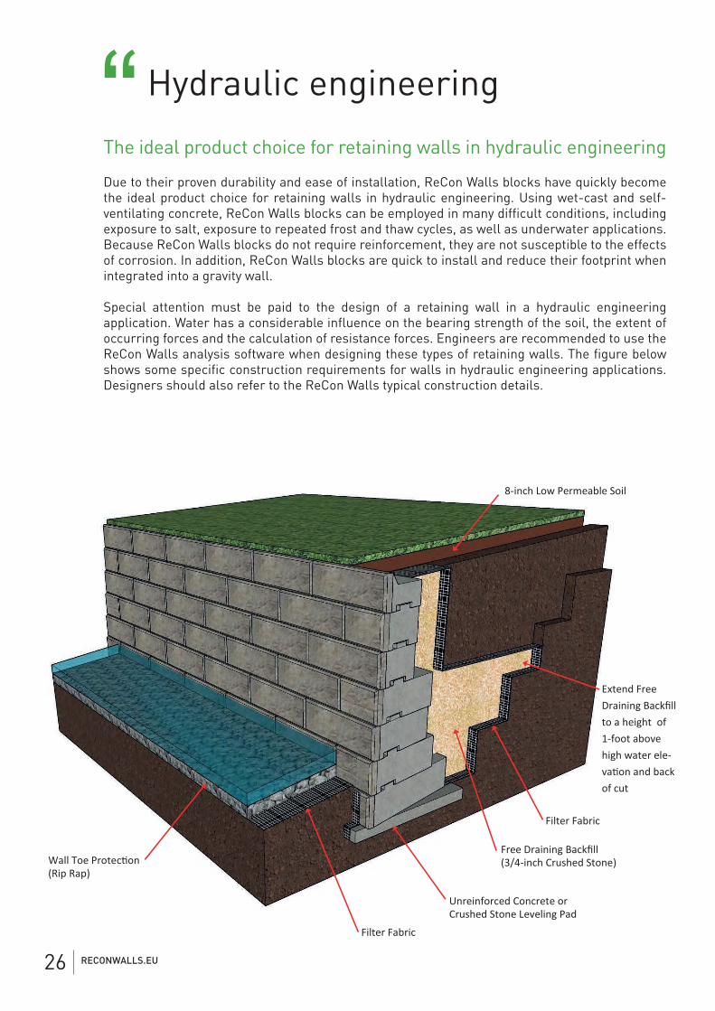
Hydraulic engineering“The ideal product choice for retaining walls in hydraulic engineering
Due to their proven durability and ease of installation, ReCon Walls blocks have quickly become the ideal product choice for retaining walls in hydraulic engineering. Using wet-cast and self-ventilating concrete, ReCon Walls blocks can be employed in many difficult conditions, including exposure to salt, exposure to repeated frost and thaw cycles, as well as underwater applications. Because ReCon Walls blocks do not require reinforcement, they are not susceptible to the effects of corrosion. In addition, ReCon Walls blocks are quick to install and reduce their footprint when integrated into a gravity wall.
Special attention must be paid to the design of a retaining wall in a hydraulic engineering application. Water has a considerable influence on the bearing strength of the soil, the extent of occurring forces and the calculation of resistance forces. Engineers are recommended to use the ReCon Walls analysis software when designing these types of retaining walls. The figure below shows some specific construction requirements for walls in hydraulic engineering applications. Designers should also refer to the ReCon Walls typical construction details.
Filter Fabric
(Rip Rap)
Filter Fabric
Unreinforced Concrete or Crushed Stone Leveling Pad
Free Draining Backfill (3/4-inch Crushed Stone)
8-inch Low Permeable Soil
Extend Free Draining Backfill to a height of 1-foot abovehigh water ele-
of cut
Drainage column on heel
Drainage pipe, heel
Drainage layer
Standard Chimney Drain
Standard Drain TileLeveling Pad
Drainage channel
RECONWALLS.EU26
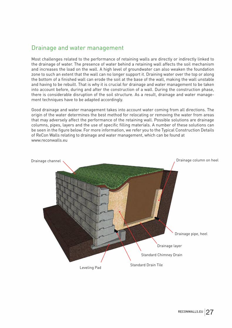
Drainage and water management
Most challenges related to the performance of retaining walls are directly or indirectly linked to the drainage of water. The presence of water behind a retaining wall affects the soil mechanism and increases the load on the wall. A high level of groundwater can also weaken the foundation zone to such an extent that the wall can no longer support it. Draining water over the top or along the bottom of a finished wall can erode the soil at the base of the wall, making the wall unstable and having to be rebuilt. That is why it is crucial for drainage and water management to be taken into account before, during and after the construction of a wall. During the construction phase, there is considerable disruption of the soil structure. As a result, drainage and water manage-ment techniques have to be adapted accordingly.
Good drainage and water management takes into account water coming from all directions. The origin of the water determines the best method for relocating or removing the water from areas that may adversely affect the performance of the retaining wall. Possible solutions are drainage columns, pipes, layers and the use of specific filling materials. A number of these solutions can be seen in the figure below. For more information, we refer you to the Typical Construction Details of ReCon Walls relating to drainage and water management, which can be found at www.reconwalls.eu
Drainage column on heel
Drainage pipe, heel
Drainage layer
Standard Chimney Drain
Standard Drain TileLeveling Pad
Drainage channel
RECONWALLS.EU 27
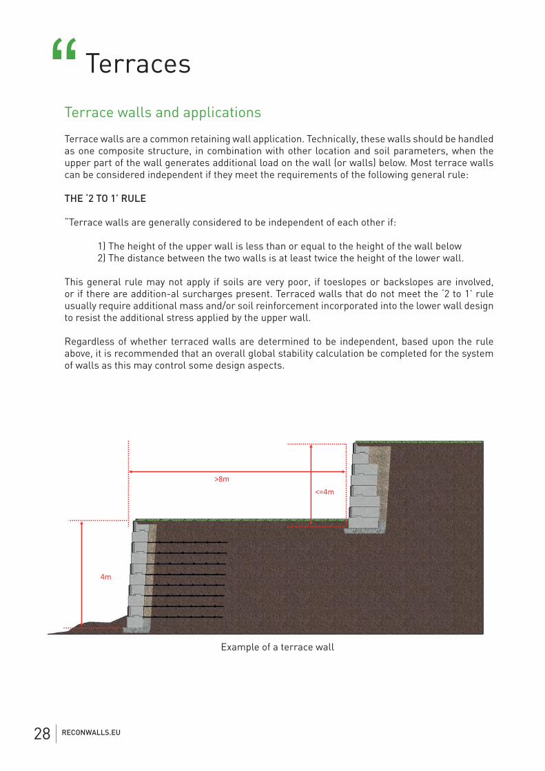
Terraces“Terrace walls and applications
Terrace walls are a common retaining wall application. Technically, these walls should be handled as one composite structure, in combination with other location and soil parameters, when the upper part of the wall generates additional load on the wall (or walls) below. Most terrace walls can be considered independent if they meet the requirements of the following general rule:
THE ‘2 TO 1’ RULE
“Terrace walls are generally considered to be independent of each other if:
1) The height of the upper wall is less than or equal to the height of the wall below 2) The distance between the two walls is at least twice the height of the lower wall.
This general rule may not apply if soils are very poor, if toeslopes or backslopes are involved, or if there are addition-al surcharges present. Terraced walls that do not meet the ‘2 to 1’ rule usually require additional mass and/or soil reinforcement incorporated into the lower wall design to resist the additional stress applied by the upper wall.
Regardless of whether terraced walls are determined to be independent, based upon the rule above, it is recommended that an overall global stability calculation be completed for the system of walls as this may control some design aspects.
4m
>8m <=4m
Voorbeeld van een terrasmuurExample of a terrace wall
RECONWALLS.EU28
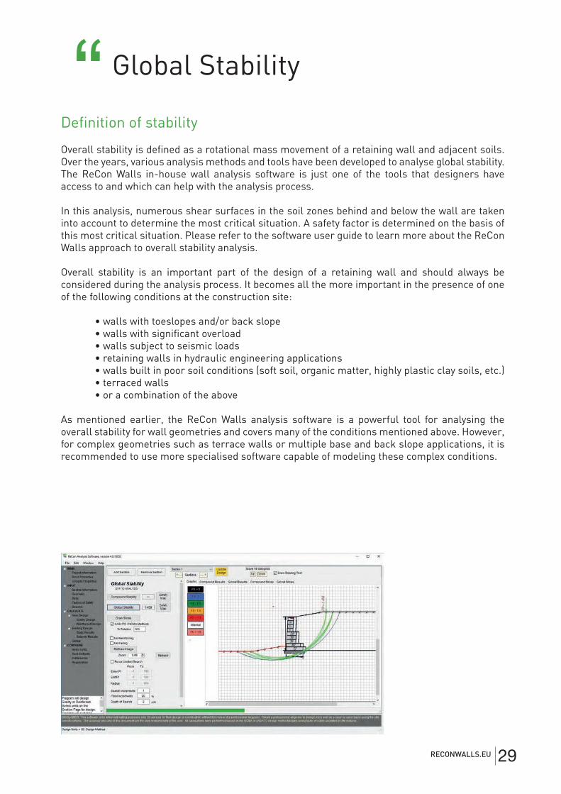
Global Stability“Definition of stability
Overall stability is defined as a rotational mass movement of a retaining wall and adjacent soils. Over the years, various analysis methods and tools have been developed to analyse global stability. The ReCon Walls in-house wall analysis software is just one of the tools that designers have access to and which can help with the analysis process.
In this analysis, numerous shear surfaces in the soil zones behind and below the wall are taken into account to determine the most critical situation. A safety factor is determined on the basis of this most critical situation. Please refer to the software user guide to learn more about the ReCon Walls approach to overall stability analysis.
Overall stability is an important part of the design of a retaining wall and should always be considered during the analysis process. It becomes all the more important in the presence of one of the following conditions at the construction site:
• walls with toeslopes and/or back slope • walls with significant overload • walls subject to seismic loads • retaining walls in hydraulic engineering applications • walls built in poor soil conditions (soft soil, organic matter, highly plastic clay soils, etc.) • terraced walls • or a combination of the above
As mentioned earlier, the ReCon Walls analysis software is a powerful tool for analysing the overall stability for wall geometries and covers many of the conditions mentioned above. However, for complex geometries such as terrace walls or multiple base and back slope applications, it is recommended to use more specialised software capable of modeling these complex conditions.
RECONWALLS.EU 29
Installation techniques ““Technical guidelines and installation
A ReCon Walls retaining wall requires a custom design for each location and an analysis. ReCon Walls has an extensive set of tools to help architects and engineers with the specifi cation and design of a ReCon Walls retaining wall.
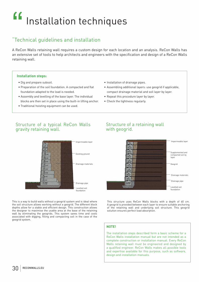
Structure of a typical ReCon Walls gravity retaining wall.
Structure of a retaining wall with geogrid.
• Dig and prepare subsoil.
• Preparation of the soil foundation. A compacted and fl at
foundation adapted to the load is needed.
• Assembly and levelling of the base layer. The individual
blocks are then set in place using the built-in lifting anchor.
• Traditional hoisting equipment can be used.
• Installation of drainage pipes.
• Assembling additional layers: use geogrid if applicable,
compact drainage material and soil layer by layer.
• Repeat this procedure layer by layer.
• Check the tightness regularly.
This is a way to build walls without a geogrid system and is ideal where the soil structure allows working without a geogrid. The different block depths allow for a stable and effi cient design. This construction allows the designer to maximise the usable area at the base of the retaining wall by eliminating the geogrids. This system saves time and costs associated with digging, fi lling and compacting soil in the case of the geogrid system.
Impermeable layer Impermeable layer
Supplemented and compacted soil by layer
GeogridDrainage materials
Drainage materials
Existing ground
Drainage pipeDrainage pipe
Levelled soil foundation
Levelled soil foundation
This structure uses ReCon Walls blocks with a depth of 60 cm. A geogrid is provided between each layer to ensure suitable anchoring of the retaining wall and underlying soil structure. This geogrid solution ensures perfect load absorption.
NOTE!
The installation steps described form a basic scheme for a ReCon Walls installation manual but are not intended as a complete construction or installation manual. Every ReCon Walls retaining wall must be engineered and designed by a qualifi ed engineer. ReCon Walls makes all possible tools and expertise available for this purpose, such as software, design and installation manuals.
Installation steps:
RECONWALLS.EU30
Installation steps “11
3
5
7
9
2
4
6
8
10
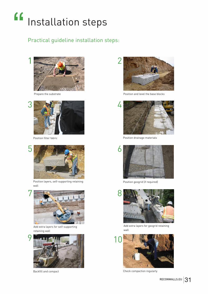
Practical guideline installation steps:
Prepare the substrate Position and level the base blocks
Position filter fabric
Position layers, self-supporting retaining wall
Position geogrid (if required)
Backfill and compact
Position drainage materials
Add extra layers for self-supporting retaining wall
Add extra layers for geogrid retaining wall
Check compaction regularly
RECONWALLS.EU 31

ReCon Walls by CBS beton
Hooiemeersstraat 8, 8710 Wielsbeke, Belgium.T +32 (0)56 60 50 37 - F +32 (0) 56 61 75 39


