Embed Size (px)
Citation preview
APRIL 2006 I JLC I 93
Seismic Retrofit for Cripple WallsSeismic Retrofit for Cripple Walls
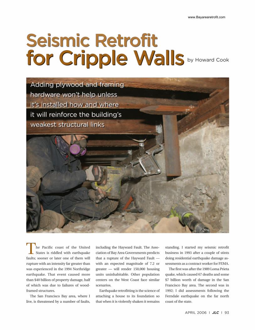
Adding plywood and framing
hardware won’t help unless
it’s installed how and where
it will reinforce the building’s
weakest structural links
Adding plywood and framing
hardware won’t help unless
it’s installed how and where
it will reinforce the building’s
weakest structural links
by Howard Cook
The Pacific coast of the United
States is riddled with earthquake
faults; sooner or later one of them will
rupture with an intensity far greater than
was experienced in the 1994 Northridge
earthquake. That event caused more
than $40 billion of property damage, half
of which was due to failures of wood-
framed structures.
The San Francisco Bay area, where I
live, is threatened by a number of faults,
including the Hayward Fault. The Asso-
ciation of Bay Area Governments predicts
that a rupture of the Hayward Fault —
with an expected magnitude of 7.2 or
greater — will render 150,000 housing
units uninhabitable. Other population
centers on the West Coast face similar
scenarios.
Earthquake retrofitting is the science of
attaching a house to its foundation so
that when it is violently shaken it remains
standing. I started my seismic retrofit
business in 1993 after a couple of stints
doing residential earthquake damage as-
sessments as a contract worker for FEMA.
The first was after the 1989 Loma Prieta
quake, which caused 67 deaths and some
$7 billion worth of damage in the San
Francisco Bay area. The second was in
1992; I did assessments following the
Ferndale earthquake on the far north
coast of the state.
www.Bayarearetrofit.com
94 I JLC I APRIL 2006
Seismic Retrofit for Cripple Walls
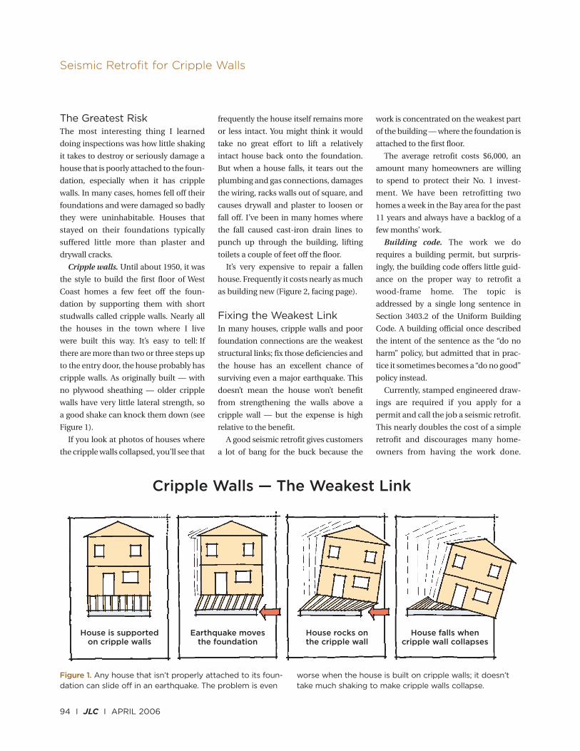
Cripple Walls — The Weakest Link
House is supportedon cripple walls
Earthquake movesthe foundation
House rocks onthe cripple wall
House falls whencripple wall collapses
The Greatest RiskThe most interesting thing I learned
doing inspections was how little shaking
it takes to destroy or seriously damage a
house that is poorly attached to the foun-
dation, especially when it has cripple
walls. In many cases, homes fell off their
foundations and were damaged so badly
they were uninhabitable. Houses that
stayed on their foundations typically
suffered little more than plaster and
drywall cracks.
Cripple walls. Until about 1950, it was
the style to build the first floor of West
Coast homes a few feet off the foun-
dation by supporting them with short
studwalls called cripple walls. Nearly all
the houses in the town where I live
were built this way. It’s easy to tell: If
there are more than two or three steps up
to the entry door, the house probably has
cripple walls. As originally built — with
no plywood sheathing — older cripple
walls have very little lateral strength, so
a good shake can knock them down (see
Figure 1).
If you look at photos of houses where
the cripple walls collapsed, you’ll see that
frequently the house itself remains more
or less intact. You might think it would
take no great effort to lift a relatively
intact house back onto the foundation.
But when a house falls, it tears out the
plumbing and gas connections, damages
the wiring, racks walls out of square, and
causes drywall and plaster to loosen or
fall off. I’ve been in many homes where
the fall caused cast-iron drain lines to
punch up through the building, lifting
toilets a couple of feet off the floor.
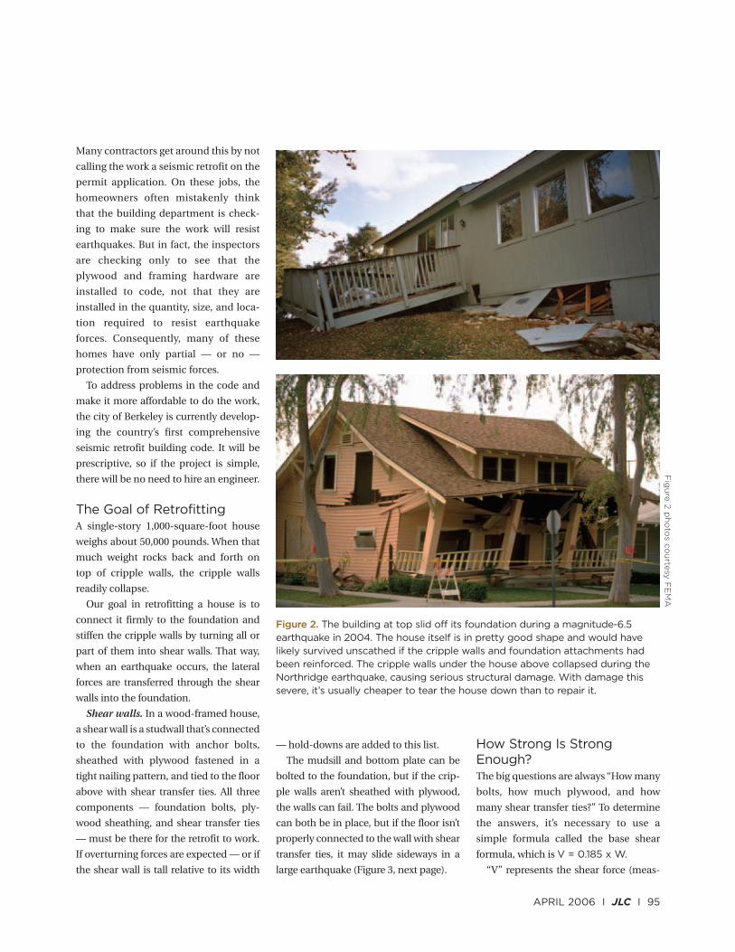
It’s very expensive to repair a fallen
house. Frequently it costs nearly as much
as building new (Figure 2, facing page).
Fixing the Weakest LinkIn many houses, cripple walls and poor
foundation connections are the weakest
structural links; fix those deficiencies and
the house has an excellent chance of
surviving even a major earthquake. This
doesn’t mean the house won’t benefit
from strengthening the walls above a
cripple wall — but the expense is high
relative to the benefit.
A good seismic retrofit gives customers
a lot of bang for the buck because the
work is concentrated on the weakest part
of the building — where the foundation is
attached to the first floor.
The average retrofit costs $6,000, an
amount many homeowners are willing
to spend to protect their No. 1 invest-
ment. We have been retrofitting two
homes a week in the Bay area for the past
11 years and always have a backlog of a
few months’ work.
Building code. The work we do
requires a building permit, but surpris-
ingly, the building code offers little guid-
ance on the proper way to retrofit a
wood-frame home. The topic is
addressed by a single long sentence in
Section 3403.2 of the Uniform Building
Code. A building official once described
the intent of the sentence as the “do no
harm” policy, but admitted that in prac-
tice it sometimes becomes a “do no good”
policy instead.
Currently, stamped engineered draw-
ings are required if you apply for a
permit and call the job a seismic retrofit.
This nearly doubles the cost of a simple
retrofit and discourages many home-
owners from having the work done.
Figure 1. Any house that isn’t properly attached to its foun-dation can slide off in an earthquake. The problem is even
worse when the house is built on cripple walls; it doesn’ttake much shaking to make cripple walls collapse.
Many contractors get around this by not
calling the work a seismic retrofit on the
permit application. On these jobs, the
homeowners often mistakenly think
that the building department is check-
ing to make sure the work will resist
earthquakes. But in fact, the inspectors
are checking only to see that the
plywood and framing hardware are
installed to code, not that they are
installed in the quantity, size, and loca-
tion required to resist earthquake
forces. Consequently, many of these
homes have only partial — or no —
protection from seismic forces.
To address problems in the code and
make it more affordable to do the work,
the city of Berkeley is currently develop-
ing the country’s first comprehensive
seismic retrofit building code. It will be
prescriptive, so if the project is simple,
there will be no need to hire an engineer.
The Goal of RetrofittingA single-story 1,000-square-foot house
weighs about 50,000 pounds. When that
much weight rocks back and forth on
top of cripple walls, the cripple walls
readily collapse.
Our goal in retrofitting a house is to
connect it firmly to the foundation and
stiffen the cripple walls by turning all or
part of them into shear walls. That way,
when an earthquake occurs, the lateral
forces are transferred through the shear
walls into the foundation.
Shear walls. In a wood-framed house,
a shear wall is a studwall that’s connected
to the foundation with anchor bolts,
sheathed with plywood fastened in a
tight nailing pattern, and tied to the floor
above with shear transfer ties. All three
components — foundation bolts, ply-
wood sheathing, and shear transfer ties
— must be there for the retrofit to work.
If overturning forces are expected — or if
the shear wall is tall relative to its width
— hold-downs are added to this list.
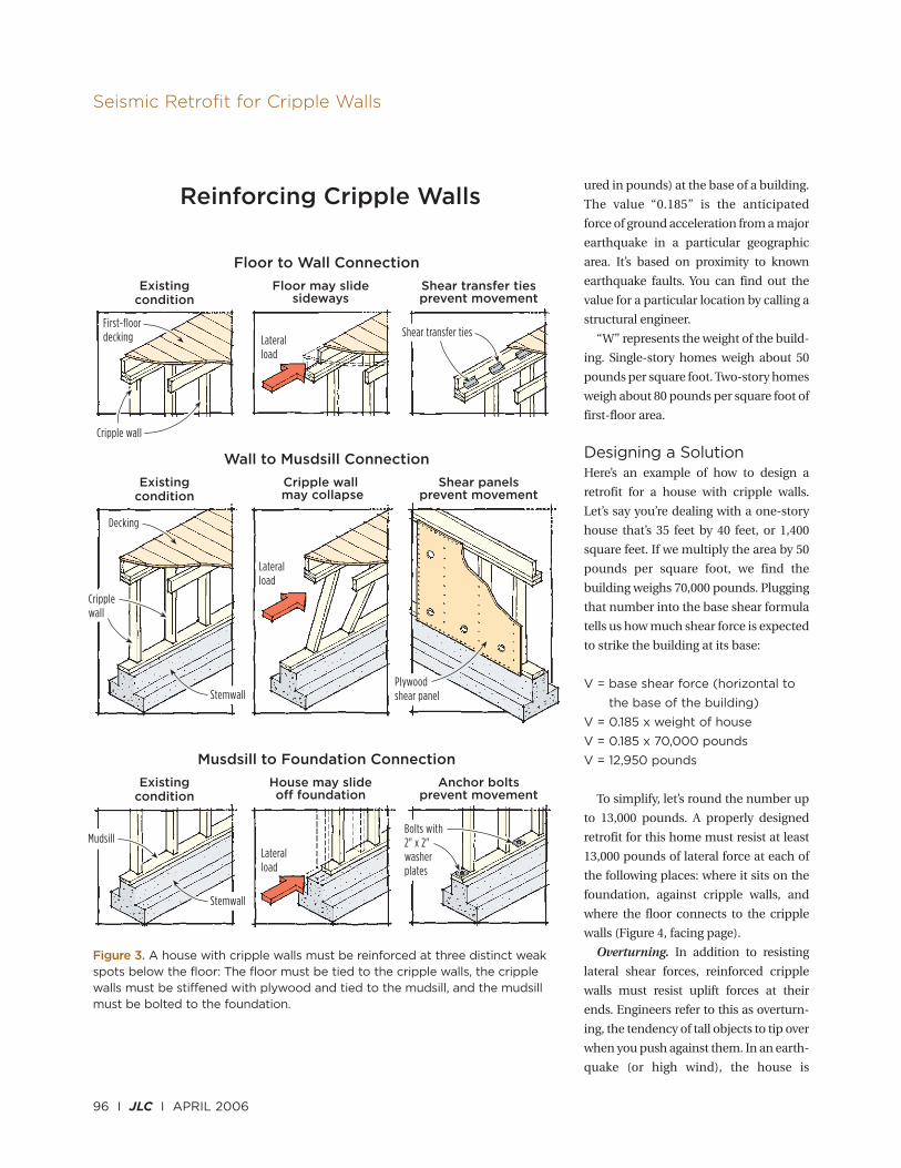
The mudsill and bottom plate can be
bolted to the foundation, but if the crip-
ple walls aren’t sheathed with plywood,
the walls can fail. The bolts and plywood
can both be in place, but if the floor isn’t
properly connected to the wall with shear
transfer ties, it may slide sideways in a
large earthquake (Figure 3, next page).
How Strong Is StrongEnough?The big questions are always “How many
bolts, how much plywood, and how
many shear transfer ties?” To determine
the answers, it’s necessary to use a
simple formula called the base shear
formula, which is V = 0.185 x W.
“V” represents the shear force (meas-
APRIL 2006 I JLC I 95
Figure 2. The building at top slid off its foundation during a magnitude-6.5earthquake in 2004. The house itself is in pretty good shape and would havelikely survived unscathed if the cripple walls and foundation attachments hadbeen reinforced. The cripple walls under the house above collapsed during theNorthridge earthquake, causing serious structural damage. With damage thissevere, it’s usually cheaper to tear the house down than to repair it.
Fig
ure
2 p
ho
tos c
ou
rtesy
FE
MA
ured in pounds) at the base of a building.
The value “0.185” is the anticipated
force of ground acceleration from a major
earthquake in a particular geographic
area. It’s based on proximity to known
earthquake faults. You can find out the
value for a particular location by calling a
structural engineer.
“W” represents the weight of the build-
ing. Single-story homes weigh about 50
pounds per square foot. Two-story homes
weigh about 80 pounds per square foot of
first-floor area.
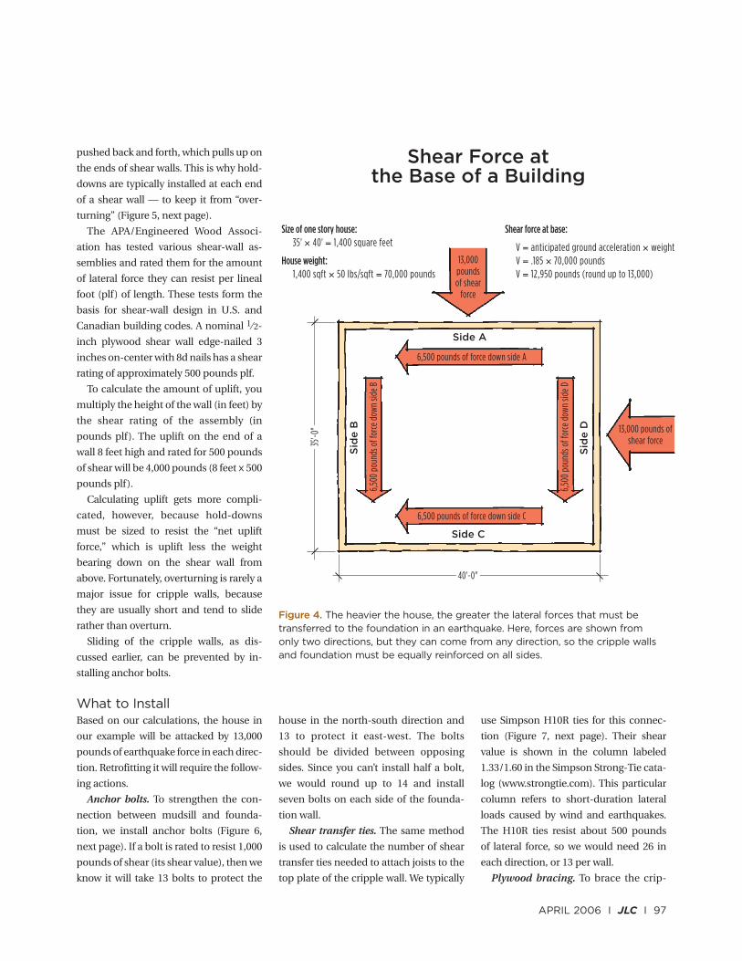
Designing a SolutionHere’s an example of how to design a
retrofit for a house with cripple walls.
Let’s say you’re dealing with a one-story
house that’s 35 feet by 40 feet, or 1,400
square feet. If we multiply the area by 50
pounds per square foot, we find the
building weighs 70,000 pounds. Plugging
that number into the base shear formula
tells us how much shear force is expected
to strike the building at its base:
V = base shear force (horizontal to
the base of the building)
V = 0.185 x weight of house
V = 0.185 x 70,000 pounds
V = 12,950 pounds
To simplify, let’s round the number up
to 13,000 pounds. A properly designed
retrofit for this home must resist at least
13,000 pounds of lateral force at each of
the following places: where it sits on the
foundation, against cripple walls, and
where the floor connects to the cripple
walls (Figure 4, facing page).
Overturning. In addition to resisting
lateral shear forces, reinforced cripple
walls must resist uplift forces at their
ends. Engineers refer to this as overturn-
ing, the tendency of tall objects to tip over
when you push against them. In an earth-
quake (or high wind), the house is
96 I JLC I APRIL 2006
Seismic Retrofit for Cripple Walls
Floor to Wall Connection
Existingcondition
Floor may slidesideways
Shear transfer tiesprevent movement
First-floordecking
Cripple wall
Stemwall
Wall to Musdsill Connection
Existingcondition
Cripple wall may collapse
Shear panelsprevent movement
Musdsill to Foundation Connection
Existingcondition
House may slideoff foundation
Anchor boltsprevent movement
Shear transfer tiesLateralload
Lateralload
Lateralload
Decking
Cripplewall
Mudsill
Stemwall
Bolts with2" x 2"washerplates
Plywoodshear panel
Reinforcing Cripple Walls
Figure 3. A house with cripple walls must be reinforced at three distinct weakspots below the floor: The floor must be tied to the cripple walls, the cripplewalls must be stiffened with plywood and tied to the mudsill, and the mudsillmust be bolted to the foundation.
pushed back and forth, which pulls up on
the ends of shear walls. This is why hold-
downs are typically installed at each end
of a shear wall — to keep it from “over-
turning” (Figure 5, next page).
The APA/Engineered Wood Associ-
ation has tested various shear-wall as-
semblies and rated them for the amount
of lateral force they can resist per lineal
foot (plf) of length. These tests form the
basis for shear-wall design in U.S. and
Canadian building codes. A nominal 1⁄2-
inch plywood shear wall edge-nailed 3
inches on-center with 8d nails has a shear
rating of approximately 500 pounds plf.
To calculate the amount of uplift, you
multiply the height of the wall (in feet) by
the shear rating of the assembly (in
pounds plf). The uplift on the end of a
wall 8 feet high and rated for 500 pounds
of shear will be 4,000 pounds (8 feet x 500
pounds plf).
Calculating uplift gets more compli-
cated, however, because hold-downs
must be sized to resist the “net uplift
force,” which is uplift less the weight
bearing down on the shear wall from
above. Fortunately, overturning is rarely a
major issue for cripple walls, because
they are usually short and tend to slide
rather than overturn.
Sliding of the cripple walls, as dis-
cussed earlier, can be prevented by in-
stalling anchor bolts.
What to InstallBased on our calculations, the house in
our example will be attacked by 13,000
pounds of earthquake force in each direc-
tion. Retrofitting it will require the follow-
ing actions.
Anchor bolts. To strengthen the con-
nection between mudsill and founda-
tion, we install anchor bolts (Figure 6,
next page). If a bolt is rated to resist 1,000
pounds of shear (its shear value), then we
know it will take 13 bolts to protect the
house in the north-south direction and
13 to protect it east-west. The bolts
should be divided between opposing
sides. Since you can’t install half a bolt,
we would round up to 14 and install
seven bolts on each side of the founda-
tion wall.
Shear transfer ties. The same method
is used to calculate the number of shear
transfer ties needed to attach joists to the
top plate of the cripple wall. We typically
use Simpson H10R ties for this connec-
tion (Figure 7, next page). Their shear
value is shown in the column labeled
1.33/1.60 in the Simpson Strong-Tie cata-
log (www.strongtie.com). This particular
column refers to short-duration lateral
loads caused by wind and earthquakes.
The H10R ties resist about 500 pounds
of lateral force, so we would need 26 in
each direction, or 13 per wall.
Plywood bracing. To brace the crip-
APRIL 2006 I JLC I 97
Shear Force atthe Base of a Building
Side A
Side C
Sid
e D
Sid
e B
6,500 pounds of force down side A
6,500 pounds of force down side C
6,50
0 po
unds
of f
orce
dow
n sid
e D
6,50
0 po
unds
of f
orce
dow
n sid
e B
35'-0
"
Size of one story house:35' × 40' = 1,400 square feet
House weight:1,400 sqft × 50 lbs/sqft = 70,000 pounds
13,000 pounds ofshear force
40'-0"
13,000poundsof shear
force
Shear force at base:
V = anticipated ground acceleration × weightV = .185 × 70,000 poundsV = 12,950 pounds (round up to 13,000)
Figure 4. The heavier the house, the greater the lateral forces that must betransferred to the foundation in an earthquake. Here, forces are shown fromonly two directions, but they can come from any direction, so the cripple wallsand foundation must be equally reinforced on all sides.
ple walls, we typically sheath them with
plywood from inside the crawlspace
(Figure 8, facing page). If the shear-wall
configuration (plywood and nailing
pattern) is rated to resist 500 pounds
plf, then we need 26 lineal feet of
plywood on the east-west and north-
south walls. Since this bracing is
divided between opposing walls, each
side gets 13 feet of plywood.
If the calculations showed net uplift
from the overturning force, we would
install a hold-down at each end of all
shear walls. However, the strength of the
hold-down is rarely an issue. The weak
link is usually the old unreinforced con-
crete foundation; if the uplift force is
large enough (more than 2,000 pounds)
it may pull out the retrofit hold-down
bolt, rendering it useless. One solution
— an expensive one — is to shore up the
building and replace that section of
foundation, but it’s often simpler to pour
a new footing alongside the old one and
install the hold-downs in it (Figure 9,
facing page).
Anchor-bolt spacing. It’s a common
mistake to space new anchor bolts
evenly around the building. That
approach is fine when joists land on the
mudsill, but when you turn a cripple wall
into a shear wall, those bolts need to be
installed where the plywood panels are.
We install them every 2 feet at shear-wall
locations. The shear transfer ties can be
anywhere along the wall; we install them
near the plywood because we’re already
working there.
Types of Foundation BoltsThere are two kinds of bolts for retro-
fitting: mechanical wedge anchors and
epoxy bolts. Testing has shown that they
are equally effective in resisting lateral
shear forces.
Wedge anchors. Wedge anchors are
cheaper and easier to install, so that’s
what we use — unless the concrete is so
porous the anchors won’t grab. If that’s
the case, we switch to epoxy bolts. Our
favorite wedge anchors are Hilti’s 7-
98 I JLC I APRIL 2006
Seismic Retrofit for Cripple Walls
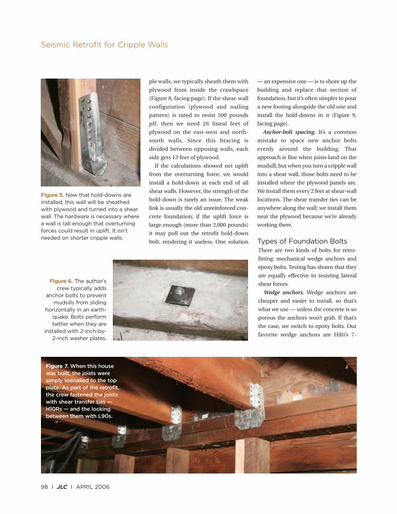
Figure 5. Now that hold-downs areinstalled, this wall will be sheathedwith plywood and turned into a shearwall. The hardware is necessary wherea wall is tall enough that overturningforces could result in uplift. It isn’tneeded on shorter cripple walls.
Figure 6. The author’screw typically adds
anchor bolts to preventmudsills from sliding
horizontally in an earth-quake. Bolts performbetter when they are
installed with 2-inch-by-2-inch washer plates.
Figure 7. When this housewas built, the joists weresimply toenailed to the topplate. As part of the retrofit,the crew fastened the joistswith shear transfer ties —H10Rs — and the lockingbetween them with L90s.
inch-long Kwik Bolts. They’re simple and
easy to install: Drill a hole in the
concrete, hammer in the bolt, and
tighten it with a wrench.
Epoxy anchors. Epoxy anchors are
more complicated. The holes they go
into must be brushed clean with a
bottlebrush and blown out with
compressed air before the bolt can be
installed (Figure 10, next page). We use1⁄ 2-inch all-thread for the bolt and glue
it in with Hilti’s HY 150 epoxy. The all-
thread must penetrate at least 4 inches
into the concrete — more if the
concrete is weak. The HY 150 cures
quickly (in about an hour), so you can
tighten the nuts and install plywood
right away.
Epoxy bolts resist withdrawal better
than wedge anchors, which is why hold-
down bolts are always epoxied in.
The building code does not permit1⁄ 2-inch anchor bolts in new construc-
tion, but we find they are a superior
product for retrofit work. They’re almost
as strong as 5⁄ 8-inch bolts, but they’re
easier to install and — since there are
more of them — they distribute loads
more evenly.
Whatever the bolt size, use 2-inch-by-
2-inch plate washers; they greatly
increase bolt performance.
Alternate fastening method. If the
crawlspace is high enough, we make
holes for anchor bolts by drilling down
through the mudsill with a rotary
hammer. When space is tight, we make
the connection from the side using
Simpson UFP10 retrofit foundation
plates. These plates are rated for 1,340
pounds of shear resistance and require
five screws into the mudsill and two
anchor bolts into the foundation (Figure
11, page 101).
Many contractors worry that old con-
crete is weak because it contains no
reinforcing steel. The Structural Engi-
APRIL 2006 I JLC I 99
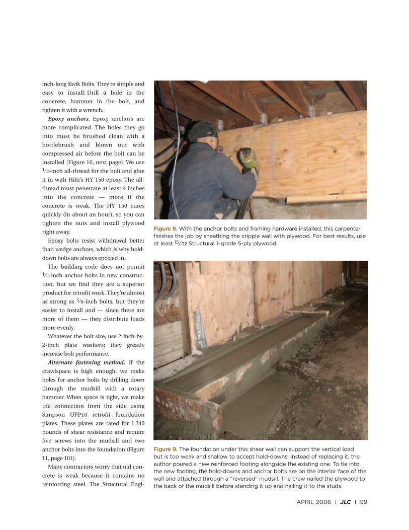
Figure 9. The foundation under this shear wall can support the vertical load but is too weak and shallow to accept hold-downs. Instead of replacing it, theauthor poured a new reinforced footing alongside the existing one. To tie intothe new footing, the hold-downs and anchor bolts are on the interior face of thewall and attached through a “reversed” mudsill. The crew nailed the plywood tothe back of the mudsill before standing it up and nailing it to the studs.
Figure 8. With the anchor bolts and framing hardware installed, this carpenterfinishes the job by sheathing the cripple wall with plywood. For best results, useat least 15⁄32 Structural 1–grade 5-ply plywood.
neers Association of Northern California
did some tests in 1992 and discovered
that even 1,500-psi unreinforced con-
crete performed just fine against shear.
In the tests it was always the wood that
failed in shear — not the concrete.
Installing Shear Transfer TiesWe install shear transfer ties to connect
the top of the cripple wall to the joists
above. The ties go on before the
plywood so that we can attach them
directly to framing.
When the joists are perpendicular to
cripple walls, we attach them with
Simpson H10Rs. When the joists are
parallel, we use Simpson L90s. Whenever
possible, we use a metal connector nailer
to drive the fasteners. Since space is often
tight, we frequently use palm nailers.
Prepping the Cripple WallsThere’s a glitch in most model codes:
When shear capacity exceeds 350 pounds
plf, they require 3-inch nominal studs at
panel edges. We typically sister on a
second stud where panel edges land be-
cause it’s easier than installing 3x4s; also,
APA testing has shown that a double 2x4
is just as strong. For more on this, see
Technical Topic TT-076 on the APA Web
site (www.apawood.org).
Flush cutting. In most APA tests of
shear walls, the sheathing is nailed onto
top plates, 2x4 studs, and a continuous
2x4 bottom plate. But older cripple walls
are built with 2x4 studs on a 2x6 mudsill,
which is also the bottom plate.
To provide nailing for the bottom edge
of the plywood, most retrofit contractors
run 2x4 blocks between the studs and nail
them like crazy to the mudsill. The prob-
lem is that the APA has never tested this
configuration, and the short blocks tend
to split when you put in a lot of nails.
Our solution is to trim the mudsill
back so it’s flush with the studs (Figure
12, facing page). This is hard to do with
a framing saw because the studs get in
the way, so we use a saw equipped
with a $100 flush-cutting attachment
called a FlusSa, which is available from
Clemenson Enterprises Inc. (CEI,
800/333-5234, www.cei-clem.com).
The company also sells a complete
saw, the CloseCut, for $150.
Staples. Sometimes there is no alterna-
tive to adding blocks. For example, in the
old days mudsills (which were made from
redwood) were occasionally embedded
100 I JLC I APRIL 2006
Seismic Retrofit for Cripple Walls
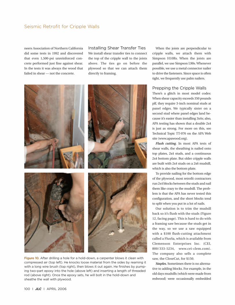
Figure 10. After drilling a hole for a hold-down, a carpenter blows it clean withcompressed air (top left). He knocks loose material from the sides by reaming itwith a long wire brush (top right), then blows it out again. He finishes by pump-ing two-part epoxy into the hole (above left) and inserting a length of threadedrod (above right). Once the epoxy sets, he will bolt in the hold-down andsheathe the wall with plywood.
in the concrete flush with the top of the
foundation. Under these circumstances,
we block between studs but fasten the
blocks with 21⁄2-inch 15-gauge staples.
Each staple will resist about 80 pounds of
lateral force.
It takes a lot of staples, but they won’t
split the blocks.
Putting Up PlywoodTo complete the shear wall, we nail
plywood to selected segments of the
cripple wall with 8d nails in a specific
nailing pattern. It’s important to use the
correct plywood. The former head of the
Los Angeles retrofit program said that
after Northridge he saw houses in which
cheap three-ply material actually tore.
For strong shear walls, use 15⁄ 32 Struc-
tural 1 5-ply plywood. If you install this
material with 8d common nails (0.131
inch by 21⁄ 2 inches) 2 inches o.c. at the
edges and 12 inches o.c. in the field, it has
a shear rating of 730 pounds plf.
You can get an even stronger wall (with
the same nailing) using 3⁄4-inch plywood.
Howard Cook owns Bay Area Retrofit in
Berkeley, Calif.
APRIL 2006 I JLC I 101
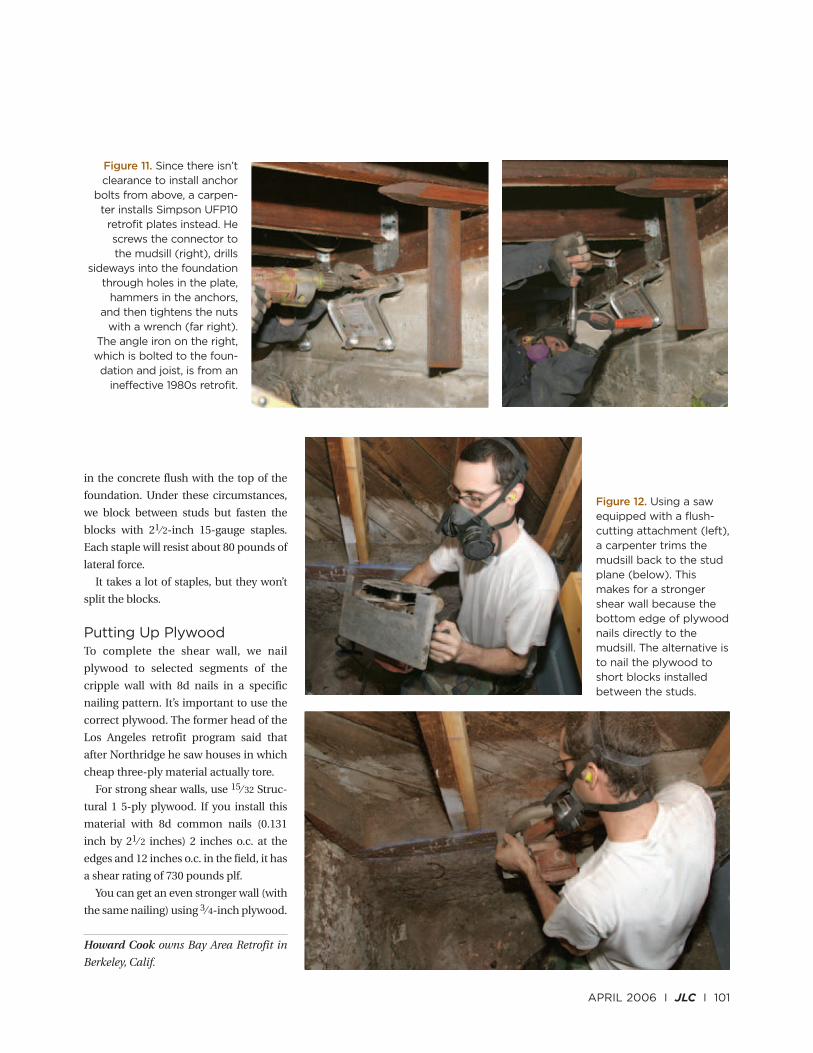
Figure 12. Using a sawequipped with a flush-cutting attachment (left),a carpenter trims themudsill back to the studplane (below). Thismakes for a strongershear wall because thebottom edge of plywoodnails directly to themudsill. The alternative isto nail the plywood toshort blocks installedbetween the studs.
Figure 11. Since there isn’tclearance to install anchor
bolts from above, a carpen-ter installs Simpson UFP10
retrofit plates instead. Hescrews the connector to the mudsill (right), drills
sideways into the foundationthrough holes in the plate,
hammers in the anchors, and then tightens the nuts
with a wrench (far right).The angle iron on the right,which is bolted to the foun-dation and joist, is from an
ineffective 1980s retrofit.