Embed Size (px)
Citation preview
Catheter autoreconstruction in computed tomography based brachytherapytreatment planning
N. Milickovica) and S. GiannouliDepartment of Medical Physics & Engineering, Strahlenklinik, Sta¨dtische Kliniken Offenbach,63069 Offenbach, Germany and Department of Electrical & Computer Engineering,National Technical University of Athens, 15773 Zografou, Athens, Greece
D. BaltasDepartment of Medical Physics & Engineering, Strahlenklinik, Sta¨dtische Kliniken Offenbach,63069 Offenbach, Germany and Institute of Communication & Computer Systems,National Technical University of Athens, 15773 Zografou, Athens, Greece
M. LahanasDepartment of Medical Physics & Engineering, Strahlenklinik, Sta¨dtische Kliniken Offenbach,63069 Offenbach, Germany
C. Kolotas and N. ZamboglouDepartment of Medical Physics & Engineering, Strahlenklinik, Sta¨dtische Kliniken Offenbach,63069 Offenbach, Germany and Institute of Communication & Computer Systems,National Technical University of Athens, 15773 Zografou, Athens, Greece
N. UzunogluDepartment of Electrical and Computer Engineering and Institute of Communication and ComputerSystems, National Technical University of Athens, 15773 Zografou, Athens, Greece
~Received 9 August 1999; accepted for publication 11 February 2000!
The aim of this study is to develop an automatic reconstruction of brachytherapy catheters using CT~computed tomography! data. Previously no such automatic facility has existed in any treatmentplanning software. To achieve this facility we have developed tools for the automatic reconstruction~which we termautoreconstruction! of plastic and metallic catheters. These algorithms overcome anumber of difficulties which arise when a large number of catheters are present. These includesituations with intersecting catheters and with loop techniques. The time required for the catheterreconstruction process using our autoreconstruction method is significantly reduced. The accuracyof our autoreconstruction is at least as high as the classical manual slice-by-slice method. ©2000American Association of Physicists in Medicine.@S0094-2405~00!01205-0#
Key words: catheter reconstruction, image based brachytherapy, treatment planning
oetcp
g.C
slhi
ae
nifiino
g-
inr ofnualhansison-tales
on-ngeper
eentionost-
nt
I. INTRODUCTION
In clinical brachytherapy the most time consuming and errsensitive part of the treatment planning procedure is cathreconstruction. This is because the number of cathetersbe very large as in the case of interstitial brachytherawhere greater than 30 are possible.
Modern brachytherapy treatment planning is imabased1–20 with CT playing an increasingly important roleCT based reconstruction accuracy depends mainly on theimaging parameters such as the slice thickness and interdistance. In addition, accuracy also depends on the grapresolution of the CT image~this is the number of pixels inxandy direction! and the observational ability of the user~thisis the ability of the user to manually identify a catheter onCT slice!. The overall reconstruction accuracy of a CT bastreatment planning system can be as low as 1.0 mm.1
Imaging based treatment planning methods can sigcantly reduce the time required for the treatment plannprocess, when compared to the use of projectional recstruction methods~PRM! using radiographs. Even so, a si
1047 Med. Phys. 27 „5…, May 2000 0094-2405Õ2000Õ27„5…
r-erany,
e
Ticecal
d
-gn-
nificant part of the treatment planning time is still spentthe reconstruction of the catheters. For a large numbecatheters and for complicated catheter geometries the macatheter reconstruction method can account for more thalf of the total treatment planning time. From the analywe made on 30 clinical implants the manual catheter recstruction procedure took an average of 43.4% of the totreatment planning time: range of 22.6%–71%. These timdo not include image processing and contouring. The recstruction time per catheter was an average of 151.2 s: raof 42.9–312 s, and the reconstruction time per catheterCT image was an average of 4.4 s: range of 1.2–10.0 s.
II. METHODS
A. Introduction
This paper describes the algorithms that we have bdeveloped for the automatic reconstruction and recogniof implanted catheters. The process is based on pimplantation acquired CT images with the cathetersin situ intheir final positions. This includes the relevant patie
1047Õ1047Õ11Õ$17.00 © 2000 Am. Assoc. Phys. Med.
sn-ickesauretdu
etndif-
co
/
ctth
alhe
a
thC
oplicCd.tica
19xo
wiallnn
thte
nicalgo-
e’s
eterof
herre.es:
urthe
rts,that
andg
1048 Milickovic et al. : Catheter autoreconstruction 1048
anatomy, target volume~s!, organs at risk, and the catheterCatheter searching is made on a sequence of CT slices abased on the Hounsfield number~HU! of the catheter material, catheter outer diameter, interslice distance, slice thness and geometry of the catheter shape on the CT slic
The slice thickness and interslice distance must beequately selected in order to take into account the curvatof the catheters. We must therefore avoid loss of catharea contrast in the smoothing process which is applieding CT slice acquisition.
In general a 3 mmslice thickness and a 3 mminterslicedistance are satisfactory especially in cases when cathentirely or almost entirely lie on only a single CT slice athe neighboring region has very similar or significantly dferent ~more than 2000 HU! HU properties to that of thecatheters. The interslice distance does not have to bestant between all CT slices.
The algorithms are written in ANSI C11 language andthe graphical user interface~GUI! was developed using OSFMotif, Open GL and Open Inventor graphics libraries.
1. Definitions
The area on a CT image that represents a cross sethrough the catheter volume within the slice is termedcatheter area. The termscatheter pointand catheter pixelare used to describe any point or pixel that is automaticrecognized by the algorithm or is manually identified by tuser, and belongs to a givencatheter area.
The set of image pixels recognized by the algorithmbelonging to thecatheter areaon a CT slice is termed thecatheter recognized area. Any pixel or point that belongs tothis area is termed acatheter recognized pixelor point. Froma catheter area one central point or pixel is consideredrepresent thecatheter describing point1 on the CT slice.Each catheter is considered to be a geometrical entitycan be described by a set of arbitrary points lying on theslices.1 We term these points thecatheter describing points.
2. Hounsfield number properties of the catheters
The HU profile of the catheters depends on the HU prerties of the neighboring tissues or materials, on the sthickness, and on the angle with which catheter enters theslice. This occurs because the CT images are smootheding the reconstruction process of the CT slice acquisition
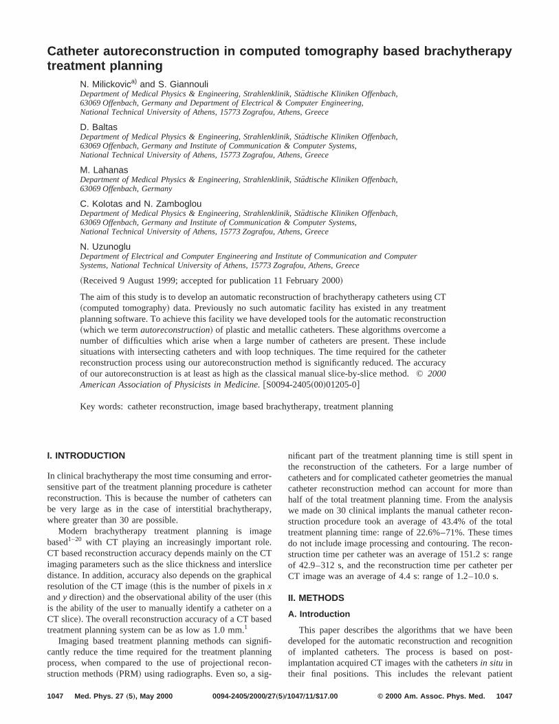
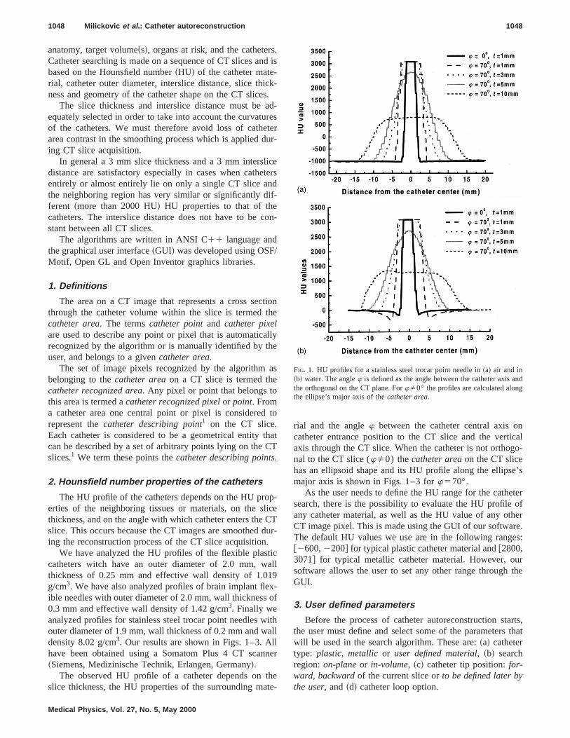
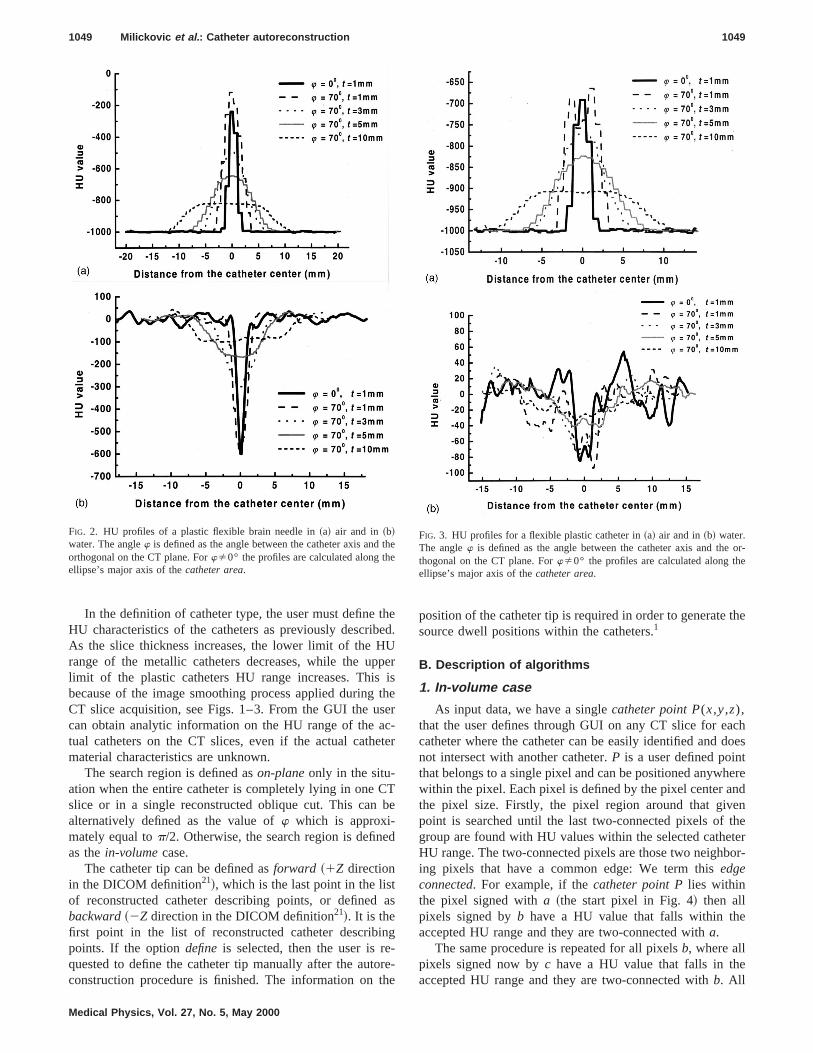
We have analyzed the HU profiles of the flexible plascatheters witch have an outer diameter of 2.0 mm, wthickness of 0.25 mm and effective wall density of 1.0g/cm3. We have also analyzed profiles of brain implant fleible needles with outer diameter of 2.0 mm, wall thickness0.3 mm and effective wall density of 1.42 g/cm3. Finally weanalyzed profiles for stainless steel trocar point needlesouter diameter of 1.9 mm, wall thickness of 0.2 mm and wdensity 8.02 g/cm3. Our results are shown in Figs. 1–3. Ahave been obtained using a Somatom Plus 4 CT sca~Siemens, Medizinische Technik, Erlangen, Germany!.
The observed HU profile of a catheter depends onslice thickness, the HU properties of the surrounding ma
Medical Physics, Vol. 27, No. 5, May 2000
.d is
-.d-eserr-
ers
n-
ione
ly
s
to
atT
-eT
ur-
ll
-f
thll
er
e-
rial and the anglew between the catheter central axis ocatheter entrance position to the CT slice and the vertaxis through the CT slice. When the catheter is not orthonal to the CT slice (wÞ0) thecatheter areaon the CT slicehas an ellipsoid shape and its HU profile along the ellipsmajor axis is shown in Figs. 1–3 forw570°.
As the user needs to define the HU range for the cathsearch, there is the possibility to evaluate the HU profileany catheter material, as well as the HU value of any otCT image pixel. This is made using the GUI of our softwaThe default HU values we use are in the following rang@2600,2200# for typical plastic catheter material and@2800,3071# for typical metallic catheter material. However, osoftware allows the user to set any other range throughGUI.
3. User defined parameters
Before the process of catheter autoreconstruction stathe user must define and select some of the parameterswill be used in the search algorithm. These are:~a! cathetertype: plastic, metallicor user defined material, ~b! searchregion:on-planeor in-volume, ~c! catheter tip position:for-ward, backwardof the current slice orto be defined later bythe user, and~d! catheter loop option.
FIG. 1. HU profiles for a stainless steel trocar point needle in~a! air and in~b! water. The anglew is defined as the angle between the catheter axisthe orthogonal on the CT plane. ForwÞ0° the profiles are calculated alonthe ellipse’s major axis of thecatheter area.
theU
ppit
sec
et
CTb
ed
t
inge-orth
the
chdoestere
ndentheteror-
the
or-e
1049 Milickovic et al. : Catheter autoreconstruction 1049
In the definition of catheter type, the user must defineHU characteristics of the catheters as previously describAs the slice thickness increases, the lower limit of the Hrange of the metallic catheters decreases, while the ulimit of the plastic catheters HU range increases. Thisbecause of the image smoothing process applied duringCT slice acquisition, see Figs. 1–3. From the GUI the ucan obtain analytic information on the HU range of the atual catheters on the CT slices, even if the actual cathmaterial characteristics are unknown.
The search region is defined ason-planeonly in the situ-ation when the entire catheter is completely lying in oneslice or in a single reconstructed oblique cut. This canalternatively defined as the value ofw which is approxi-mately equal top/2. Otherwise, the search region is definas thein-volumecase.
The catheter tip can be defined asforward ~1Z directionin the DICOM definition21!, which is the last point in the lisof reconstructed catheter describing points, or definedbackward~2Z direction in the DICOM definition21!. It is thefirst point in the list of reconstructed catheter describpoints. If the optiondefine is selected, then the user is rquested to define the catheter tip manually after the autconstruction procedure is finished. The information on
FIG. 2. HU profiles of a plastic flexible brain needle in~a! air and in ~b!water. The anglew is defined as the angle between the catheter axis andorthogonal on the CT plane. ForwÞ0° the profiles are calculated along thellipse’s major axis of thecatheter area.
Medical Physics, Vol. 27, No. 5, May 2000
ed.
ersher-er
e
as
e-e
position of the catheter tip is required in order to generatesource dwell positions within the catheters.1
B. Description of algorithms
1. In-volume case
As input data, we have a singlecatheter point P(x,y,z),that the user defines through GUI on any CT slice for eacatheter where the catheter can be easily identified andnot intersect with another catheter.P is a user defined pointhat belongs to a single pixel and can be positioned anywhwithin the pixel. Each pixel is defined by the pixel center athe pixel size. Firstly, the pixel region around that givpoint is searched until the last two-connected pixels ofgroup are found with HU values within the selected catheHU range. The two-connected pixels are those two neighbing pixels that have a common edge: We term thisedgeconnected. For example, if thecatheter point Plies withinthe pixel signed witha ~the start pixel in Fig. 4! then allpixels signed byb have a HU value that falls within theaccepted HU range and they are two-connected witha.
The same procedure is repeated for all pixelsb, where allpixels signed now byc have a HU value that falls in theaccepted HU range and they are two-connected withb. All
eFIG. 3. HU profiles for a flexible plastic catheter in~a! air and in~b! water.The anglew is defined as the angle between the catheter axis and thethogonal on the CT plane. ForwÞ0° the profiles are calculated along thellipse’s major axis of thecatheter area.
e
d
ter
thee
ible
icutee
an
de-
t areon
1050 Milickovic et al. : Catheter autoreconstruction 1050
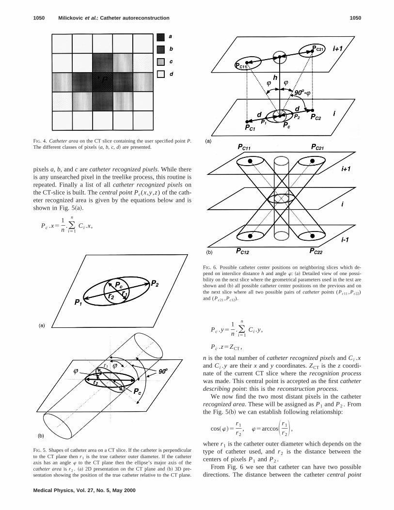
pixelsa, b, andc arecatheter recognized pixels. While thereis any unsearched pixel in the treelike process, this routinrepeated. Finally a list of allcatheter recognized pixelsonthe CT-slice is built. Thecentral point Pc(x,y,z) of the cath-eter recognized area is given by the equations below anshown in Fig. 5~a!.
Pc .x51
n.(i 51
n
Ci .x,
FIG. 4. Catheter areaon the CT slice containing the user specified pointP.The different classes of pixels~a, b, c, d! are presented.
FIG. 5. Shapes of catheter area on a CT slice. If the catheter is perpendto the CT plane thenr 1 is the true catheter outer diameter. If the catheaxis has an anglew to the CT plane then the ellipse’s major axis of thcatheter areais r 2 . ~a! 2D presentation on the CT plane and~b! 3D pre-sentation showing the position of the true catheter relative to the CT pl
Medical Physics, Vol. 27, No. 5, May 2000
is
is
Pc .y51
n.(i 51
n
Ci .y,
Pc .z5ZCT,
n is the total number ofcatheter recognized pixelsandCi .xandCi .y are theirx andy coordinates.ZCT is thez coordi-nate of the current CT slice where therecognition processwas made. This central point is accepted as the firstcatheterdescribing point: this is thereconstruction process.
We now find the two most distant pixels in the catherecognized area. These will be assigned asP1 andP2 . Fromthe Fig. 5~b! we can establish following relationship:
cos~w!5r 1
r 2, w5arccosS r 1
r 2D ,
wherer 1 is the catheter outer diameter which depends ontype of catheter used, andr 2 is the distance between thcenters of pixelsP1 andP2 .
From Fig. 6 we see that catheter can have two possdirections. The distance between the cathetercentral point
larr
e.
FIG. 6. Possible catheter center positions on neighboring slices whichpend on interslice distanceh and anglew: ~a! Detailed view of one possi-bility on the next slice where the geometrical parameters used in the texshown and~b! all possible catheter center positions on the previous andthe next slice where all two possible pairs ofcatheter points(Pc11 ,Pc22)and (Pc21 ,Pc12).
s.
th
ne
e
s
ehe
te
e
-es
ng
tht
ethio
er
,c-
x-
-
nexta,
1051 Milickovic et al. : Catheter autoreconstruction 1051
Pc and the projection of the possible cathetercentral point,Pc1 or Pc2 , from the next~and also previous! CT slice onthe current slice is given by
d5dist~Pc ,Pc1!5dist~Pc ,Pc2!5h•tan~w!,
whereh is the distance between the two successive sliceWe now search for the next twocatheter describing
points, on the previous and on the next slice, based oncalculated distanced, the anglew and direction of linel (Pc ,Pc1), andl (Pc ,Pc2) in the second case, Fig. 6~a!. Wefirst find the coordinates of two pointsPc1 and Pc2 . Thepossible catheter centers on the previous and on theslices will be pointsPc11 and Pc22 in the first case, orPc21
andPc12 in the second case, Fig. 6~b!. PointsPc11 andPc12
have the samex andy coordinates as the pointPc1 , and theircoordinatez is the coordinatez of the next and previous slicrespectively. PointsPc21 and Pc22 have the samex and ycoordinates as the pointPc2 , and their coordinatez is thecoordinatez of the next and previous slice respectively. Awe now have all possiblecatheter central pointswe neednext to find which of these two point pairs (Pc11,Pc22) and(Pc12,Pc21) will determine the true catheter direction.
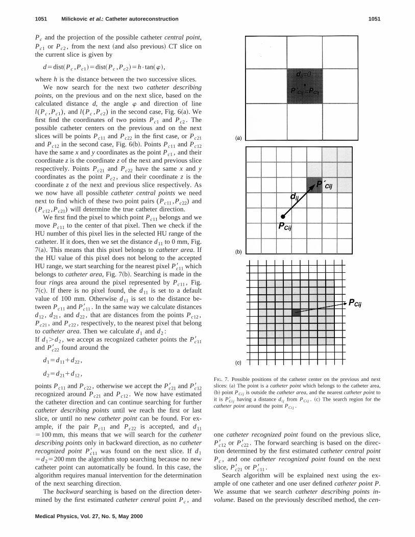
We first find the pixel to which pointPc11 belongs and wemove Pc11 to the center of that pixel. Then we check if thHU number of this pixel lies in the selected HU range of tcatheter. If it does, then we set the distanced11 to 0 mm, Fig.7~a!. This means that this pixel belongs tocatheter area. Ifthe HU value of this pixel does not belong to the accepHU range, we start searching for the nearest pixelPc118 whichbelongs tocatheter area, Fig. 7~b!. Searching is made in thfour rings area around the pixel represented byPc11, Fig.7~c!. If there is no pixel found, thed11 is set to a defaultvalue of 100 mm. Otherwised11 is set to the distance betweenPc11 andPc118 . In the same way we calculate distancd12, d21, andd22, that are distances from the pointsPc12,Pc21, andPc22, respectively, to the nearest pixel that beloto catheter area. Then we calculated1 andd2 :If d1.d2 , we accept as recognized catheter points thePc118andPc228 found around the
d15d111d22,
d25d211d12,
pointsPc11 andPc22, otherwise we accept thePc218 andPc128recognized aroundPc21 and Pc12. We now have estimatedthe catheter direction and can continue searching for furcatheter describing pointsuntil we reach the first or lasslice, or until no newcatheter pointcan be found. For ex-ample, if the pair Pc11 and Pc22 is accepted, andd11
5100 mm, this means that we will search for thecatheterdescribing pointsonly in backward direction, as nocatheterrecognized point Pc118 was found on the next slice. Ifd1
5d25200 mm the algorithm stop searching because no ncatheter point can automatically be found. In this case,algorithm requires manual intervention for the determinatof the next searching direction.
The backwardsearching is based on the direction detmined by the first estimatedcatheter centralpoint Pc , and
Medical Physics, Vol. 27, No. 5, May 2000
e
xt
d
er
we
n
-
one catheter recognized pointfound on the previous slicePc128 or Pc228 . The forward searching is based on the diretion determined by the first estimatedcatheter central pointPc , and onecatheter recognized pointfound on the nextslice, Pc218 or Pc118 .
Search algorithm will be explained next using the eample of one catheter and one user definedcatheter point P.We assume that we searchcatheter describing points involume. Based on the previously described method, thecen-
FIG. 7. Possible positions of the catheter center on the previous andslices:~a! The point is acatheter pointwhich belongs to the catheter are~b! point PCi j is outside thecatheter area, and the nearestcatheter pointtoit is PCi j8 having a distancedi j from PCi j . ~c! The search region for thecatheter pointaround the pointPCi j .
en rd
1052 Milickovic et al. : Catheter autoreconstruction 1052
tral catheter point Pc and the first catheter direction arfound. The algorithm consists of searching backward aforward from the given catheter point in the2z and 1z
te
aruches
twe
rewpa
ershea
ng
Medical Physics, Vol. 27, No. 5, May 2000
ddirection according to the DICOM definition.21 Only thebackward searching algorithm is given below. The forwasearching algorithm is similar.
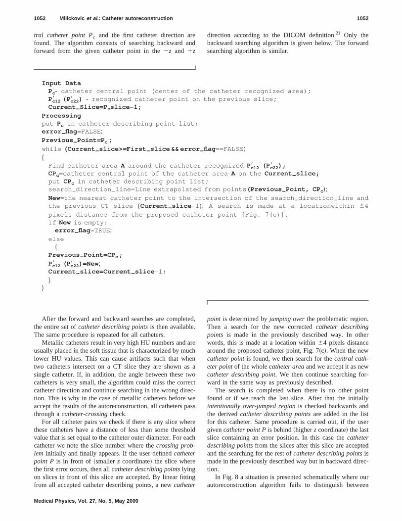
Input DataPc- catheter central point (center of the catheter recognized area);Pc128 (Pc228 ) - recognized catheter point on the previous slice;Current –Slice=P cslice−1;
Processingput Pc in catheter describing point list;error –flag =FALSE;Previous –Point=P c ;
while (Current –slice>=First –slice && error –flag ==FALSE)
$Find catheter area A around the catheter recognized Pc128 (P c228 );CPc=catheter central point of the catheter area A on the Current –slice;put CPc in catheter describing point list;search –direction –line=Line extrapolated from points (Previous –Point, CP c!;New=the nearest catheter point to the intersection of the search –direction –line andthe previous CT slice (Current –slice −1). A search is made at a locationwithin 64
pixels distance from the proposed catheter point [Fig. 7(c)].If New is empty:
error –flag =TRUE;else
$Previous –Point=CP c ;
Pc128 (P c228 )=New;Current –slice=Current –slice −1;
%%
er
-
intlyd
ser
ed
ec-
ouren
After the forward and backward searches are complethe entire set ofcatheter describing pointsis then available.The same procedure is repeated for all catheters.
Metallic catheters result in very high HU numbers andusually placed in the soft tissue that is characterized by mlower HU values. This can cause artifacts such that wtwo catheters intersect on a CT slice they are shown asingle catheter. If, in addition, the angle between thesecatheters is very small, the algorithm could miss the corrcatheter direction and continue searching in the wrong dition. This is why in the case of metallic catheters beforeaccept the results of the autoreconstruction, all cathetersthrough acatheter-crossingcheck.
For all catheter pairs we check if there is any slice whthese catheters have a distance of less than some threvalue that is set equal to the catheter outer diameter. Forcatheter we note the slice number where thecrossing prob-lem initially and finally appears. If the user definedcatheterpoint P is in front of ~smallerz coordinate! the slice wherethe first error occurs, then allcatheter describing pointslyingon slices in front of this slice are accepted. By linear fittifrom all accepted catheter describing points, a newcatheter
d,
ehnao
ctc-ess
eoldch
point is determined byjumping overthe problematic region.Then a search for the new correctedcatheter describingpoints is made in the previously described way. In othwords, this is made at a location within64 pixels distancearound the proposed catheter point, Fig. 7~c!. When the newcatheter pointis found, we then search for thecentral cath-eter pointof the wholecatheter areaand we accept it as newcatheter describing point. We then continue searching forward in the same way as previously described.
The search is completed when there is no other pofound or if we reach the last slice. After that the initialintentionally over-jumped regionis checked backwards anthe derivedcatheter describing pointsare added in the listfor this catheter. Same procedure is carried out, if the ugivencatheter point Pis behind~higherz coordinate! the lastslice containing an error position. In this case thecatheterdescribing pointsfrom the slices after this slice are acceptand the searching for the rest ofcatheter describing pointsismade in the previously described way but in backward dirtion.
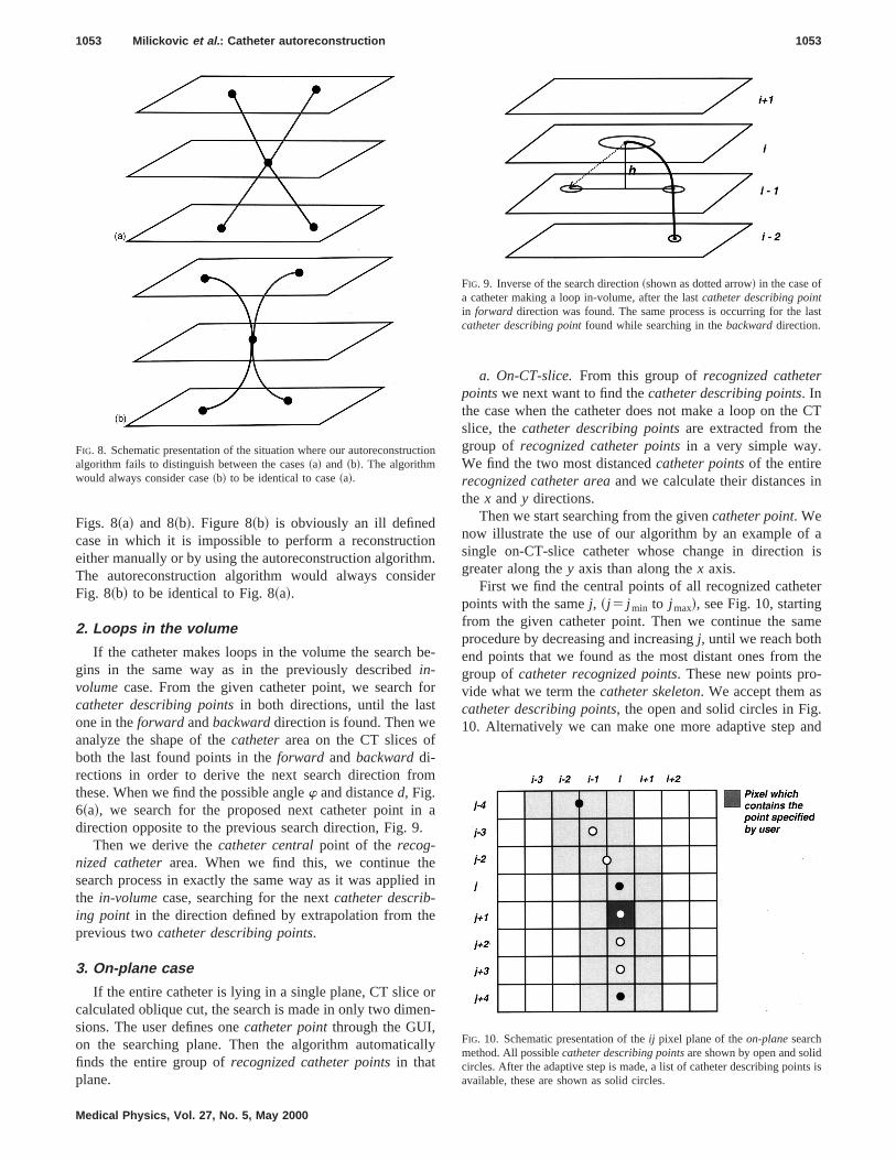
In Fig. 8 a situation is presented schematically whereautoreconstruction algorithm fails to distinguish betwe
ionm
de
b
fot
f
om
n.
ed
e
oen
al
CT
in
f ais
ter
me
the-
.and
cti
last
ts is
1053 Milickovic et al. : Catheter autoreconstruction 1053
Figs. 8~a! and 8~b!. Figure 8~b! is obviously an ill definedcase in which it is impossible to perform a reconstructeither manually or by using the autoreconstruction algorithThe autoreconstruction algorithm would always consiFig. 8~b! to be identical to Fig. 8~a!.
2. Loops in the volume
If the catheter makes loops in the volume the searchgins in the same way as in the previously describedin-volumecase. From the given catheter point, we searchcatheter describing pointsin both directions, until the lasone in theforward andbackwarddirection is found. Then weanalyze the shape of thecatheterarea on the CT slices oboth the last found points in theforward and backwarddi-rections in order to derive the next search direction frthese. When we find the possible anglew and distanced, Fig.6~a!, we search for the proposed next catheter point idirection opposite to the previous search direction, Fig. 9
Then we derive thecatheter centralpoint of the recog-nized catheterarea. When we find this, we continue thsearch process in exactly the same way as it was appliethe in-volumecase, searching for the nextcatheter describ-ing point in the direction defined by extrapolation from thprevious twocatheter describing points.
3. On-plane case
If the entire catheter is lying in a single plane, CT slicecalculated oblique cut, the search is made in only two dimsions. The user defines onecatheter pointthrough the GUI,on the searching plane. Then the algorithm automaticfinds the entire group ofrecognized catheter pointsin thatplane.
FIG. 8. Schematic presentation of the situation where our autoreconstrualgorithm fails to distinguish between the cases~a! and ~b!. The algorithmwould always consider case~b! to be identical to case~a!.
Medical Physics, Vol. 27, No. 5, May 2000
.r
e-
r
a
in
r-
ly
a. On-CT-slice.From this group ofrecognized catheterpointswe next want to find thecatheter describing points. Inthe case when the catheter does not make a loop on theslice, thecatheter describing pointsare extracted from thegroup of recognized catheter pointsin a very simple way.We find the two most distancedcatheter pointsof the entirerecognized catheter areaand we calculate their distancesthe x andy directions.
Then we start searching from the givencatheter point. Wenow illustrate the use of our algorithm by an example osingle on-CT-slice catheter whose change in directiongreater along they axis than along thex axis.
First we find the central points of all recognized cathepoints with the samej, ~j 5 j min to j max!, see Fig. 10, startingfrom the given catheter point. Then we continue the saprocedure by decreasing and increasingj, until we reach bothend points that we found as the most distant ones fromgroup ofcatheter recognized points. These new points provide what we term thecatheter skeleton. We accept them ascatheter describing points, the open and solid circles in Fig10. Alternatively we can make one more adaptive step
on
FIG. 9. Inverse of the search direction~shown as dotted arrow! in the case ofa catheter making a loop in-volume, after the lastcatheter describing pointin forward direction was found. The same process is occurring for thecatheter describing pointfound while searching in thebackwarddirection.
FIG. 10. Schematic presentation of theij pixel plane of theon-planesearchmethod. All possiblecatheter describing pointsare shown by open and solidcircles. After the adaptive step is made, a list of catheter describing poinavailable, these are shown as solid circles.
ubolbe
m
eo
e
he
Tth
to
otio
heth
p-og
ar
ein
um
r
p
ts
ed
thf
n
e
ted
slye
ing
ington.
e-
de-licean
ops-ews.tionpro-. Foreteron-
ac-tiveand
1054 Milickovic et al. : Catheter autoreconstruction 1054
choose from this group, only the points at the ends of sgroups found to belong to the same line segment: The scircles in Fig. 10. In this way the catheter curvature willadequately described and the number ofcatheter describingpointswill be optimized. The process is completely the saif the change of direction is larger along thex axis.
b. On-oblique plane.The same method for deriving thcatheter skeleton on a single CT slice from the grouprecognized catheter pointsis used in this case. Since thcatheter describing pointsper definition belong to CT slices1
we distinguish between the following three cases:
~a! If the oblique cut lies on a CT plane thecatheter de-scribing pointsare obtained in the same way as for ton-CT-slice case.
~b! If the oblique plane is perpendicular to thez axis andlies between two CT slices, thecatheter describingpointsare obtained in the same way as for the on-Cslice case where they are assumed to belong tonearer slice. Theirz coordinates are set to be equalthe nearer slicez coordinate.
~c! In the general case, the oblique plane cuts the CT vume and has six degrees of freedom, three rotaangles and three translations. In this case thecatheterdescribing pointsare defined as the intersections of tsequential segments of the catheter skeleton withCT slices.
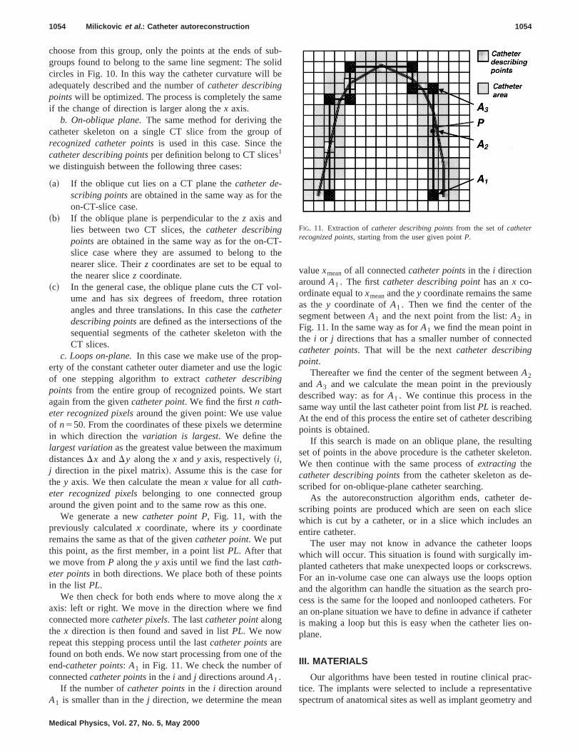
c. Loops on-plane.In this case we make use of the proerty of the constant catheter outer diameter and use the lof one stepping algorithm to extractcatheter describingpoints from the entire group of recognized points. We stagain from the givencatheter point. We find the firstn cath-eter recognized pixelsaround the given point: We use valuof n550. From the coordinates of these pixels we determin which direction thevariation is largest. We define thelargest variationas the greatest value between the maximdistancesDx andDy along thex andy axis, respectively~i,j direction in the pixel matrix!. Assume this is the case fothe y axis. We then calculate the meanx value for allcath-eter recognized pixelsbelonging to one connected grouaround the given point and to the same row as this one.
We generate a newcatheter point P, Fig. 11, with thepreviously calculatedx coordinate, where itsy coordinateremains the same as that of the givencatheter point. We putthis point, as the first member, in a point listPL. After thatwe move fromP along they axis until we find the lastcath-eter pointsin both directions. We place both of these poinin the list PL.
We then check for both ends where to move along thxaxis: left or right. We move in the direction where we finconnected morecatheter pixels. The lastcatheter pointalongthe x direction is then found and saved in listPL. We nowrepeat this stepping process until the lastcatheter pointsarefound on both ends. We now start processing from one ofend-catheter points: A1 in Fig. 11. We check the number oconnectedcatheter pointsin the i andj directions aroundA1 .
If the number ofcatheter pointsin the i direction aroundA1 is smaller than in thej direction, we determine the mea
Medical Physics, Vol. 27, No. 5, May 2000
-id
e
f
-e
l-n
e
ic
t
e
e
valuexmeanof all connectedcatheter pointsin the i directionaroundA1 . The firstcatheter describing pointhas anx co-ordinate equal toxmeanand they coordinate remains the samas they coordinate ofA1 . Then we find the center of thesegment betweenA1 and the next point from the list:A2 inFig. 11. In the same way as forA1 we find the mean point inthe i or j directions that has a smaller number of conneccatheter points. That will be the nextcatheter describingpoint.
Thereafter we find the center of the segment betweenA2
and A3 and we calculate the mean point in the previoudescribed way: as forA1 . We continue this process in thsame way until the last catheter point from listPL is reached.At the end of this process the entire set of catheter describpoints is obtained.
If this search is made on an oblique plane, the resultset of points in the above procedure is the catheter skeleWe then continue with the same process ofextracting thecatheter describing pointsfrom the catheter skeleton as dscribed for on-oblique-plane catheter searching.
As the autoreconstruction algorithm ends, catheterscribing points are produced which are seen on each swhich is cut by a catheter, or in a slice which includesentire catheter.
The user may not know in advance the catheter lowhich will occur. This situation is found with surgically implanted catheters that make unexpected loops or corkscrFor an in-volume case one can always use the loops opand the algorithm can handle the situation as the searchcess is the same for the looped and nonlooped cathetersan on-plane situation we have to define in advance if cathis making a loop but this is easy when the catheter liesplane.
III. MATERIALS
Our algorithms have been tested in routine clinical prtice. The implants were selected to include a representaspectrum of anatomical sites as well as implant geometry
FIG. 11. Extraction ofcatheter describing pointsfrom the set ofcatheterrecognized points, starting from the user given pointP.
timtsa
res
v25
mofithm
oi
aro
pho
3th
be
beth.a
ea
-.3llo-yi
ows0sFor
ithm-tionnd-
ticdur-
ctionhe
re-con-
on-
1055 Milickovic et al. : Catheter autoreconstruction 1055
different catheter types and materials. The accuracy andanalysis have been done for 30 different clinical implanprostate, breast, cervix, brain, chest, scapula, skin, neck,glioblastoma implants, and one phantom implant with thlooped plastic catheters. The geometrical characteristicthese implants are as follows.
~a! Number of catheters: 2–10.~b! number of CT images: 16–70,~c! slice thickness: 2–5 mm,~d! CT image pixel size: 0.4–0.77 mm,~e! CT image resolution: 2563256 and 5123512,~f! catheter material: flexible plastic catheters which ha
an outer diameter of 2.0 mm, wall thickness of 0.mm and effective wall density of 1.019 g/cm3, brainimplant flexible needles with outer diameter of 2.0 mwall thickness of 0.3 mm and effective wall density1.42 g/cm3 and stainless steel trocar point needles wouter diameter of 1.9 mm, wall thickness of 0.2 mand wall density 8.02 g/cm3.
~g! PTV ~planning target volume! is from 14.22 to 293.83cm3 and number of catheters per cm3 is from 0.024 to0.47.
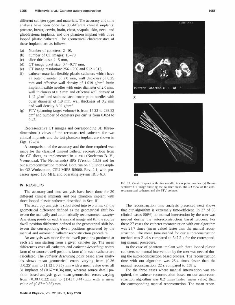
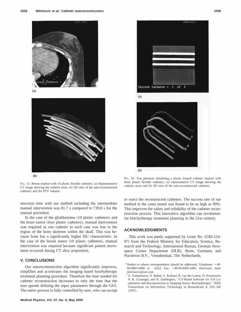
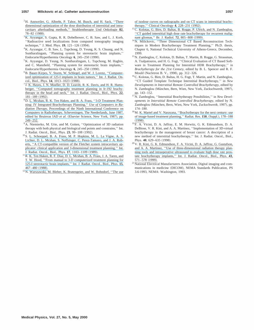
Representative CT images and corresponding 3D~three-dimensional! views of the reconstructed catheters for twclinical implants and the test phantom implant are shownFigs. 12–14.
A comparison of the accuracy and the time required wmade for the classical manual catheter reconstruction fthe CT slices, as implemented inPLATO ~Nucletron B. V.,Veenendaal, The Netherlands! BPS ~Version 13.5! and forour autoreconstruction method. Both run on a Silicon Graics O2 Workstation, CPU MIPS R5000. Rev. 2.1, with prcessor speed 180 MHz and operating system IRIS 6.3.
IV. RESULTS
The accuracy and time analysis have been done fordifferent clinical implants and one phantom implant withree looped plastic catheters described in Sec. III.
The accuracy analysis is subdivided into two arms:~a! thegeometrical difference defined as the geometrical shifttween the manually and automatically reconstructedcatheterdescribing pointson each transaxial image and~b! the sourcedwell position difference defined as the geometrical shifttween the corresponding dwell positions generated bymanual and automatic catheter reconstruction procedure
An analysis was made for the dwell positions producedeach 2.5 mm starting from a given catheter tip. The mdifferences over all catheters andcatheter describing points~arma! or source dwell positions~armb! in each catheter arecalculated. Thecatheter describing pointbased error analysis shows mean geometrical errors varying from (060.25) mm to (1.1260.35) mm with a mean value over a31 implants of (0.6760.36) mm, whereas source dwell psition based analysis gave mean geometrical errors varfrom (0.3860.22) mm to (1.4160.44) mm with a meanvalue of (0.8760.36) mm.
Medical Physics, Vol. 27, No. 5, May 2000
e:ndeof
e
,
n
sm
--
0
-
-e
tn
6
ng
The reconstruction time analysis presented next shthat our algorithm is extremely time-efficient. In 27 of 3clinical cases~90%! no manual intervention by the user waneeded during the autoreconstruction based process.these 27 cases the catheter reconstruction with our algorwas 25.7 times~mean value! faster than the manual reconstruction. The mean time needed for our autoreconstrucmethod was 21.4 s compared to 547.2 s for the correspoing manual procedure.
In the case of phantom implant with three looped plascatheters no manual intervention by the user was neededing the autoreconstruction based process. The reconstrutime with our algorithm was 25.4 times faster than tmanual reconstruction: 22 s compared to 558 s.
For the three cases where manual intervention wasquired, the catheter reconstruction based on our autorestruction algorithm was 8.2 times faster~mean value! thanthe corresponding manual reconstruction. The mean rec
FIG. 12. Cervix implant with nine metallic trocar point needles.~a! Repre-sentative CT image showing the catheter areas.~b! 3D view of the auto-reconstructed catheters and the PTV volume.
teth
te.
v
sra
ftU
e
f our0%.
on-n-
.
e-ero-
:
ris,o-EE
ithe
1056 Milickovic et al. : Catheter autoreconstruction 1056
struction time with our method including the intermediamanual intervention was 81.7 s compared to 739.8 s formanual procedure.
In the case of the glioblastoma~10 plastic catheters! andthe brain tumor~four plastic catheters!, manual interventionwas required as one catheter in each case was lost inregion of the bony skeleton within the skull. This was bcause bone has a significantly higher HU characteristicthe case of the breast tumor~10 plastic catheters!, manualintervention was required because significant patient moment occurred during CT slice acquisition.
V. CONCLUSIONS
Our autoreconstruction algorithm significantly improvesimplifies and accelerates the imaging based brachythetreatment planning procedure. Therefore the time neededcatheter reconstruction decreases to only the time thatuser spends defining the input parameters through the GThe entire process is fully controlled by user, who can acc
FIG. 13. Breast implant with 10 plastic flexible catheters.~a! RepresentativeCT image showing the catheter areas.~b! 3D view of the auto-reconstructedcatheters and the PTV volume.
Medical Physics, Vol. 27, No. 5, May 2000
e
he-In
e-
,pyorheI.
pt
or reject the reconstructed catheters. The success rate omethod in the cases tested was found to be as high as 9This improves the safety and reliability of the catheter recstruction process. This innovative algorithm can revolutioize brachytherapy treatment planning in the 21st century
ACKNOWLEDGMENTS
This work was partly supported by Grant No.~GRI-154-97! from the Federal Ministry for Education, Science, Rsearch and Technology, International Bureau, German Aspace Center Department~DLR!, Bonn, Germany andNucletron B.V., Veendendaal, The Netherlands.
a!Author to whom correspondence should be addressed. Telephone:149-69-8405-4480 or24522; Fax: 149-69-8405-4481. Electronic [email protected]. Tsalpatouros, D. Baltas, C. Kolotas, R. van der Laarse, D. KoutsouN. K. Uzunoglu, and N. Zamboglou, ‘‘CT-Based Software for 3-D Lcalization and Reconstruction in Stepping Source Brachytherapy,’’ IETransactions on Information Technology in Biomedicine1, 229–242~1997!.
FIG. 14. Test phantom simulating a plastic looped catheter implant wthree plastic flexible catheters.~a! representative CT image showing thcatheter areas and~b! 3D view of the auto-reconstructed catheters.
eera
rbin
Ns,’
ins,’
ern-
s-hy
n
on19
In
S.obapnt.
nfor
se
chy-
u,lig-
h-sis,ber,
an,ft-in.
u,
se
.lof al.,
,n-ros-
m-
1057 Milickovic et al. : Catheter autoreconstruction 1057
2H. Annweiler, G. Albreht, P. Tabor, M. Busch, and H. Sack, ‘‘Thrdimensional optimization of the dose distribution of interstitial and intcavitary afterloading methods,’’ Strahlentherapie Und Onkologie82,78–82~1988!.
3K. Ayyangar, S. Gupta, R. R. Dobelbower, C. B. Saw, and L. J. Ko‘‘Radioactive seed localizations from computed tomography imagtechnique,’’ J. Med. Phys.19, 121–126~1994!.
4K. Ayyangar, C. B. Saw, L. Tupchong, D. Yeung, K. S. Chuang, andSuntharalingam, ‘‘Planning system for stereotactic brain implantEndocurie/Hyperthermia Oncology6, 245–250~1990!.
5K. Ayyangar, D. Yeung, N. Suntharalingam, L. Tupchong, M. Hagband C. Mansfield, ‘‘Planning system for stereotactic brain implantEndocurie/Hyperthermia Oncology6, 245–250~1990!.
6B. Bauer-Kirpes, V. Sturm, W. Schlegel, and W. J. Lorenz, ‘‘Computized optimization of 125-I implants in brain tumors,’’ Int. J. Radiat. Ocol., Biol., Phys.14, 1013–1023~1988!.
7J. K. Hayes, J. N. Moeller, D. D. Leavitt, R. K. Davis, and H. R. Hamberger, ‘‘Computed tomography treatment planning in Ir-192 bractherapy in the head and neck,’’ Int. J. Radiat. Oncol., Biol., Phys.22,181–189~1992!.
8D. L. Mcshan, R. K. Ten Haken, and B. A. Frass, ‘‘3-D Treatment Planing: IV Integrated Brachytherapy Planning,’’Use of Computers in Ra-diation Therapy, Proceedings of the Ninth International ConferenceComputers in Radiotherapy, Scheveningen, The Neederlands, Juneedited by Bruinvas IADet al. ~Elsevier Science, New York, 1987!, pp.249–252.
9A. Niemierko, M. Urie, and M. Goiten, ‘‘Optimization of 3D radiationtherapy with both physical and biological end points and constrains,’’J. Radiat. Oncol., Biol., Phys.23, 99–108~1992!.
10S. L. Schoeppel, B. A. Frass, M. P. Hopkins, M. L. La Vigne, A.Lichter, D. L. Mcshan, S. Noffsinger, C. Perez-Tamayo, and J. A. Rerts, ‘‘A CT-compatible version of the Fletcher system intracavitaryplicator: clinical application and 3-dimensional treatment planning,’’ IJ. Radiat. Oncol., Biol., Phys.17, 1103–1109~1989!.
11R. K. Ten Haken, R. F. Diaz, D. L. Mcshan, B. A. Frass, J. A. Taren, aT. W. Hood, ‘‘From manual to 3-D computerized treatment planning125-I stereotactic brain implants,’’ Int. J. Radiat. Oncol., Biol., Phys.15,467–480~1988!.
12N. Warszawski, M. Bleher, K. Bratengeier, and W. Bohndorf, ‘‘The u
Medical Physics, Vol. 27, No. 5, May 2000
-
,g
.’
,’
-
-
-
87,
t.
--
d
of isodose curves on radiographs and on CT scans in interstitial bratherapy,’’ Clinical Oncology4, 228–231~1992!.
13C. Kolotas, G. Birn, D. Baltas, B. Rogge, P. Ulrich, and N. Zamboglo‘‘CT guided interstitial high dose rate brachytherapy for recurrent manant gliomas,’’ Br. J. Radiol.72, 805–808~1999!.
14N. Milickovic, ‘‘Three Dimensional CT Based Reconstruction Tecniques in Modern Brachytherapy Treatment Planning,’’ Ph.D. theChapter 6, National Technical University of Athens-Greece, Decem1999.
15N. Zamboglou, C. Kolotas, D. Baltas, T. Martin, B. Rogge, G. StrassmA. Tsalpatouros, and H. G. Fogt, ‘‘Clinical Evaluation of CT Based Soware in Treatment Planning for Interstitial HDR Brachytherapy,’’Brachytherapy for the 21st Century, edited by B. L. Spencer and R. FMould ~Nucletron B. V., 1998!, pp. 312–326.
16C. Kolotas, G. Birn, D. Baltas, H. G. Fogt, T. Martin, and N. Zamboglo‘‘CT Guided Template Technique Interstitial Brachytherapy,’’ inNewDevelopments in Interstitial Remote Controlled Brachytherapy, edited byN. Zamboglou~Munchen, Bern, Wien, New York, Zuckschwerdt, 1997!,pp. 143–152.
17N. Zamboglou, ‘‘Interstitial Brachytherapy Possibilities,’’ inNew Devel-opments in Interstitial Remote Controlled Brachytherapy, edited by N.Zamboglou~Munchen, Bern, Wien, New York, Zuckschwerdt, 1997!, pp.174–180.
18M. K. Martel and V. Narayana, ‘‘Brachytherapy for the next century: uof image-based treatment planning,’’ Radiat. Res.150, ~Suppl.!, 178–188~1998!.
19F. A. Vicini, D. A. Jaffray, E. M. Horwitz, G. K. Edmundson, D. ADeBiose, V. R. Kini, and A. A. Martinez, ‘‘Implementation of 3D-virtuabrachytherapy in the management of breast cancer: A descriptionnew method of interstitial brachytherapy,’’ Int. J. Radiat. Oncol., BioPhys.40, 629–635~1998!.
20V. R. Kini, G. K. Edmundson, F. A. Vicini, D. A. Jaffray, G. Gustafsonand A. A. Martinez, ‘‘Use of three-dimensional radiation therapy planing tools and intraoperative ultrasound to evaluate high dose rate ptate brachytherapy implants,’’ Int. J. Radiat. Oncol., Biol., Phys.43,571–578~1999!.
21National Electrical Manufacturers Association, Digital imaging and comunications in medicine~DICOM!, NEMA Standards Publication, PS3.6-1993, NEMA: Washington, 1993.


