Embed Size (px)
Citation preview
1
CCNA Voice PrimerDeveloped for the Cisco Networking Academy Community by: Bernard Brunet, Anil Datta, Ben Franske, and Brent Seiling
2
Voice Primer
Table of Contents1. Understanding Traditional Telephony2. Introducing Analog Circuits 3. Introducing Digital Circuits 4. Understanding Packetization5. Introducing VoIP Signaling Protocols6. Preparing the Network to Support Voice7. Introducing Cisco Unified Communications Manager Express (CME)8. Global Telephony Commands9. Defining Ephone‐dn and Ephone10. Configuring CME to Support Endpoints11. Dial Peers and Destination Patterns
3
1. Understanding Traditional Telephony
4
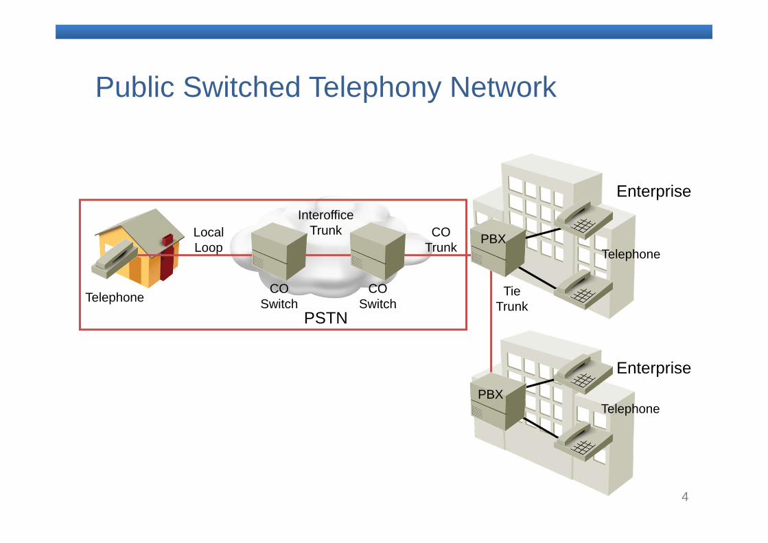
Public Switched Telephony Network
Telephone
PBX
PBX
COSwitch
COSwitch
Telephone
Telephone
InterofficeTrunk CO
Trunk
Tie Trunk
LocalLoop
PSTN
Enterprise
Enterprise
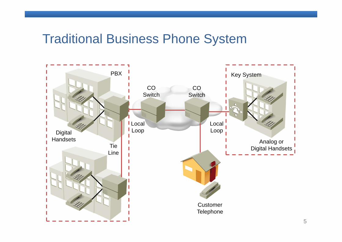
5
Traditional Business Phone System
COSwitch
PBX Key System
COSwitch
Analog or Digital Handsets
Digital Handsets
Local Loop
Local Loop
Tie Line
CustomerTelephone
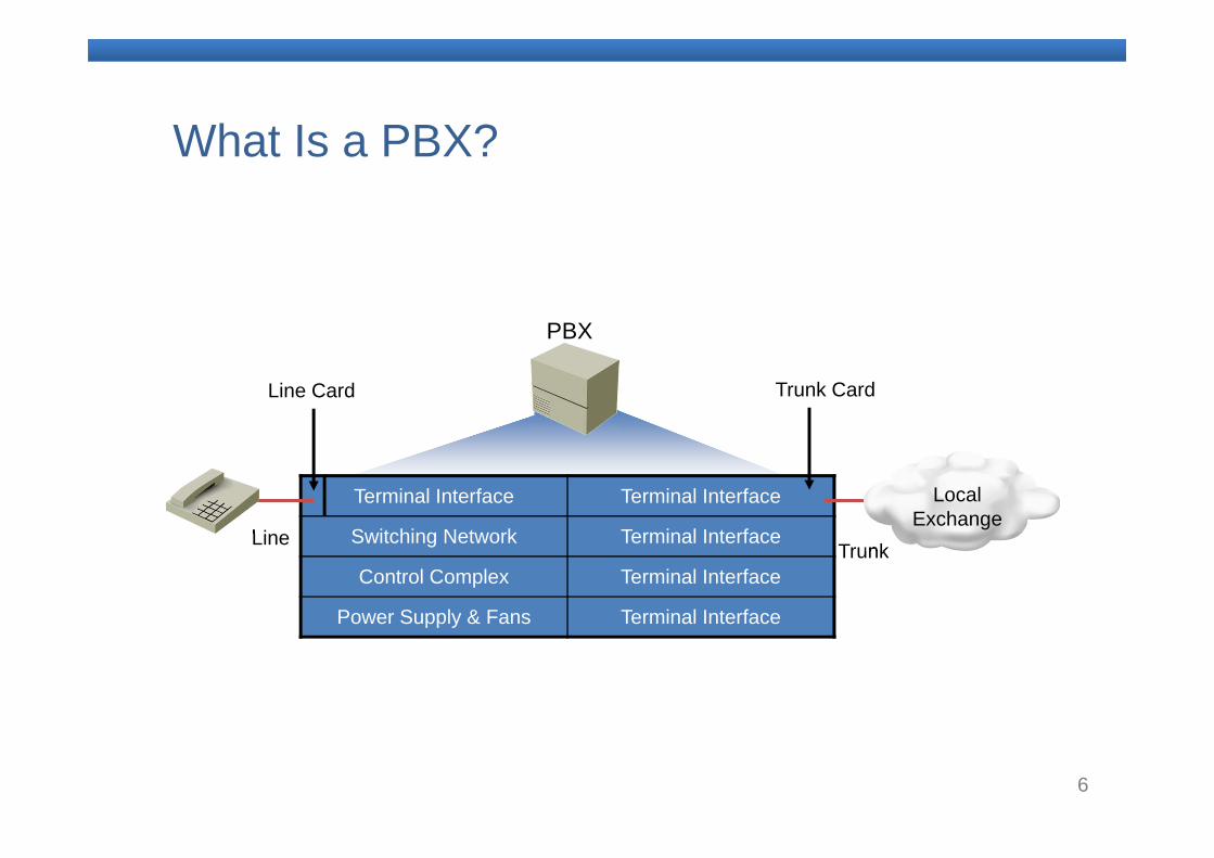
6
What Is a PBX?
Terminal Interface Terminal Interface
Switching Network Terminal Interface
Control Complex Terminal Interface
Power Supply & Fans Terminal Interface
PBX
Line Card Trunk Card
Line Trunk
LocalExchange
7
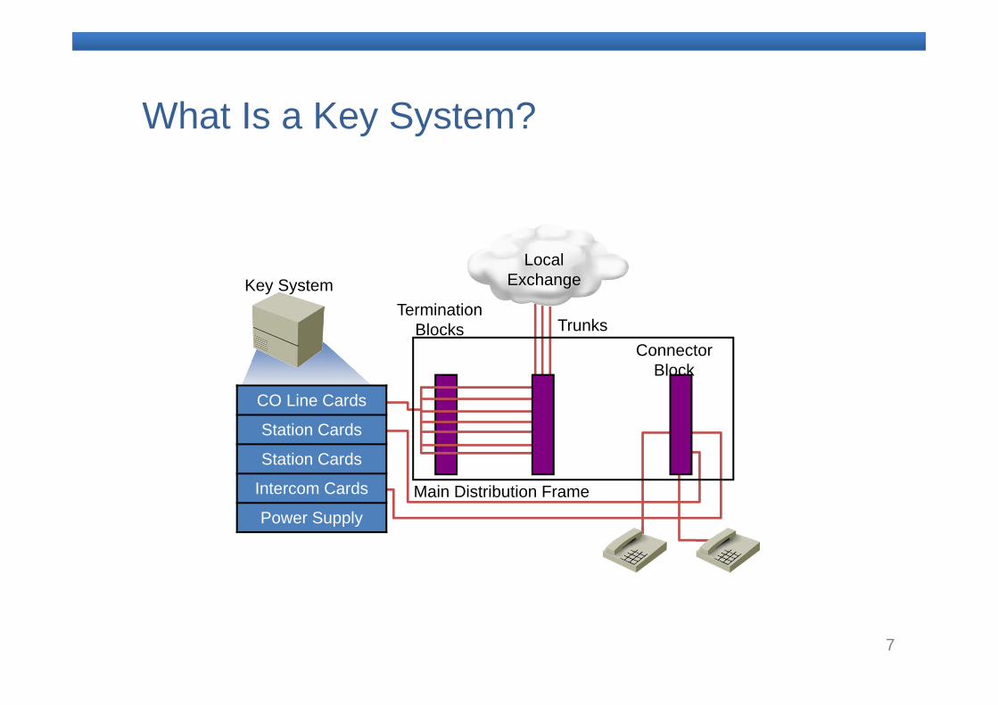
What Is a Key System?
CO Line Cards
Station Cards
Station Cards
Intercom Cards
Power Supply
Key SystemTermination
BlocksConnector
Block
Trunks
Main Distribution Frame
LocalExchange
8
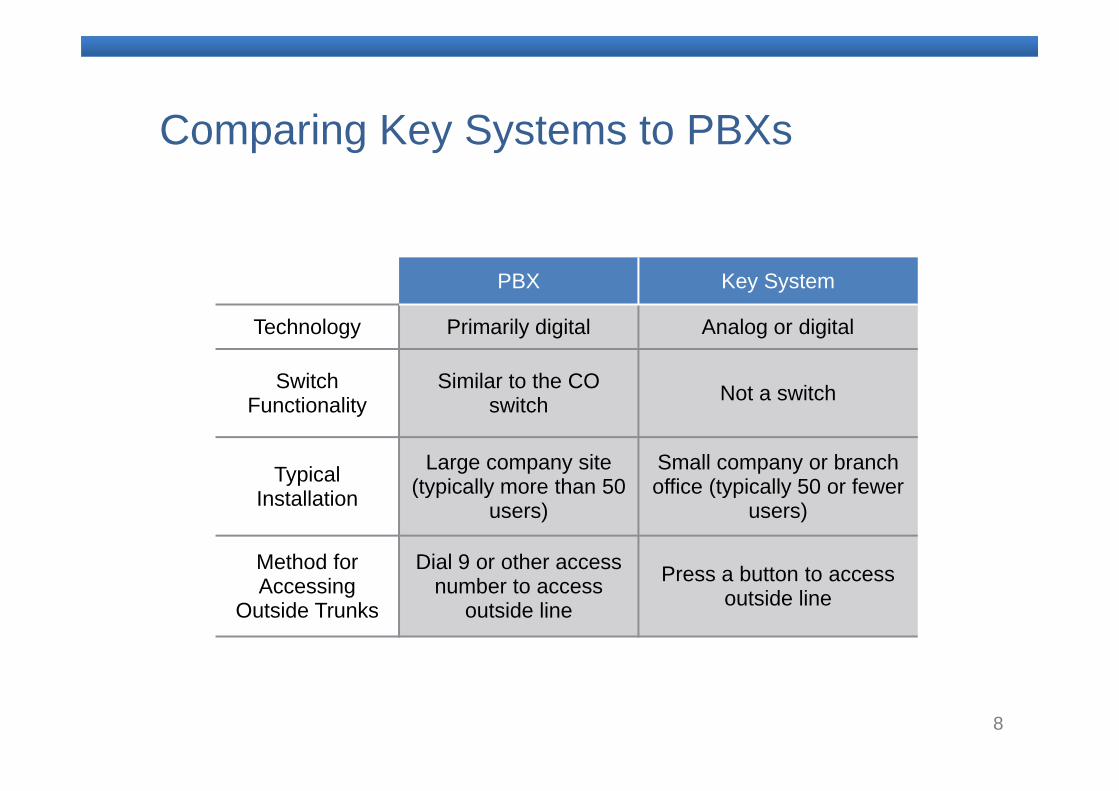
Comparing Key Systems to PBXs
PBX Key System
Technology Primarily digital Analog or digital
Switch Functionality
Similar to the CO switch Not a switch
Typical Installation
Large company site (typically more than 50
users)
Small company or branch office (typically 50 or fewer
users)
Method for Accessing
Outside Trunks
Dial 9 or other access number to access
outside line
Press a button to access outside line
9
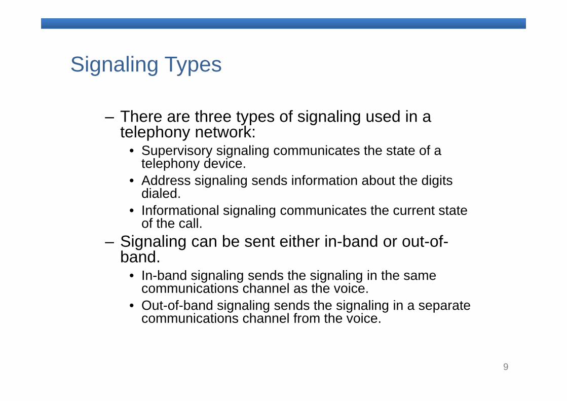
Signaling Types
– There are three types of signaling used in a telephony network:
• Supervisory signaling communicates the state of a telephony device.
• Address signaling sends information about the digits dialed.
• Informational signaling communicates the current state of the call.
– Signaling can be sent either in-band or out-of-band.
• In-band signaling sends the signaling in the same communications channel as the voice.
• Out-of-band signaling sends the signaling in a separate communications channel from the voice.
10
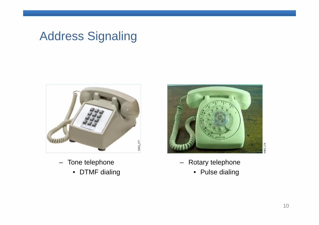
Address Signaling
– Tone telephone• DTMF dialing
– Rotary telephone• Pulse dialing
11
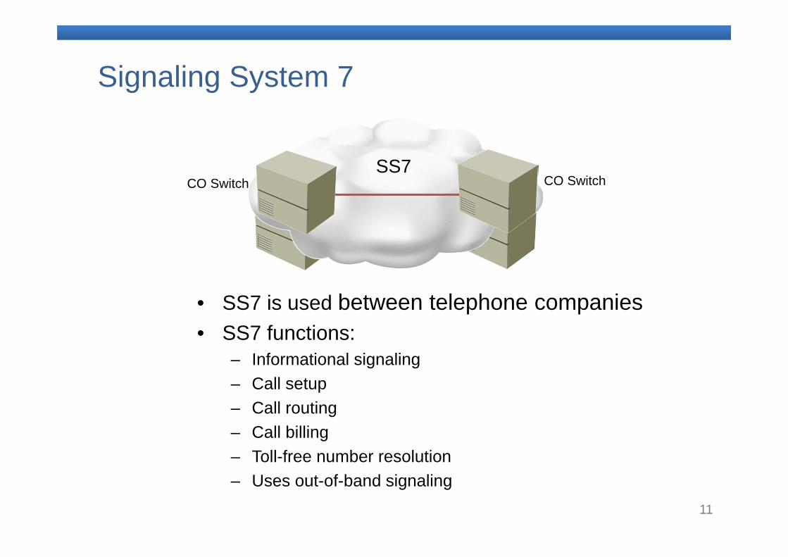
Signaling System 7
• SS7 is used between telephone companies• SS7 functions:
– Informational signaling– Call setup– Call routing– Call billing– Toll-free number resolution– Uses out-of-band signaling
SS7CO Switch CO Switch
SS7
12
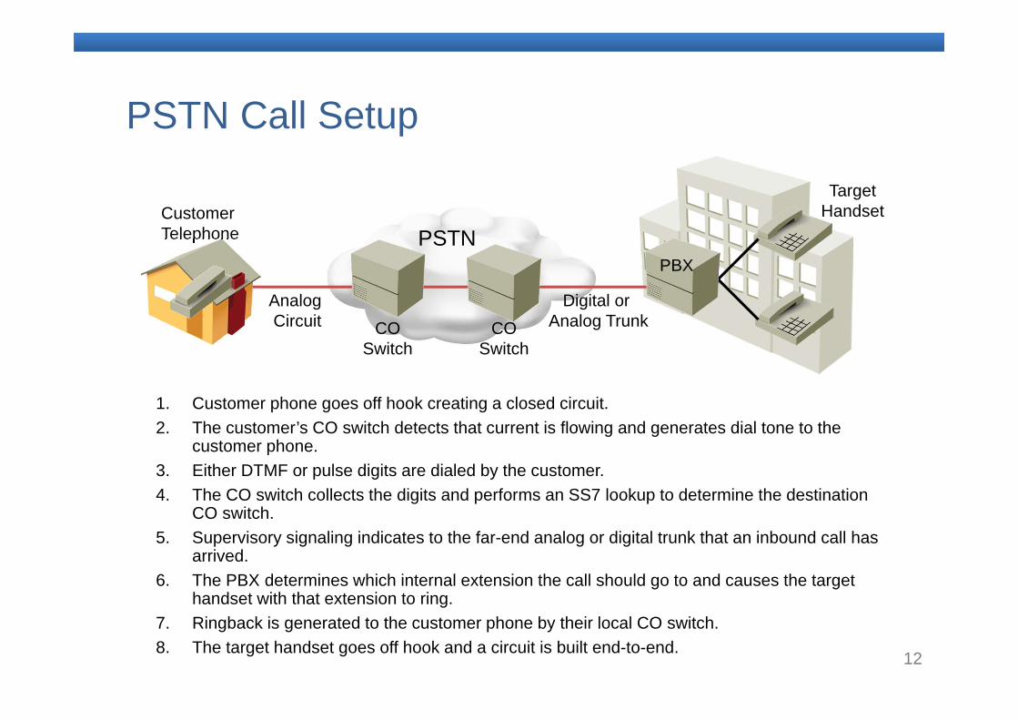
PSTN Call Setup
1. Customer phone goes off hook creating a closed circuit. 2. The customer’s CO switch detects that current is flowing and generates dial tone to the
customer phone.3. Either DTMF or pulse digits are dialed by the customer.4. The CO switch collects the digits and performs an SS7 lookup to determine the destination
CO switch.5. Supervisory signaling indicates to the far-end analog or digital trunk that an inbound call has
arrived.6. The PBX determines which internal extension the call should go to and causes the target
handset with that extension to ring.7. Ringback is generated to the customer phone by their local CO switch.8. The target handset goes off hook and a circuit is built end-to-end.
PSTNCustomerTelephone
Analog Circuit
Digital or Analog Trunk
PBX
TargetHandset
COSwitch
COSwitch
13
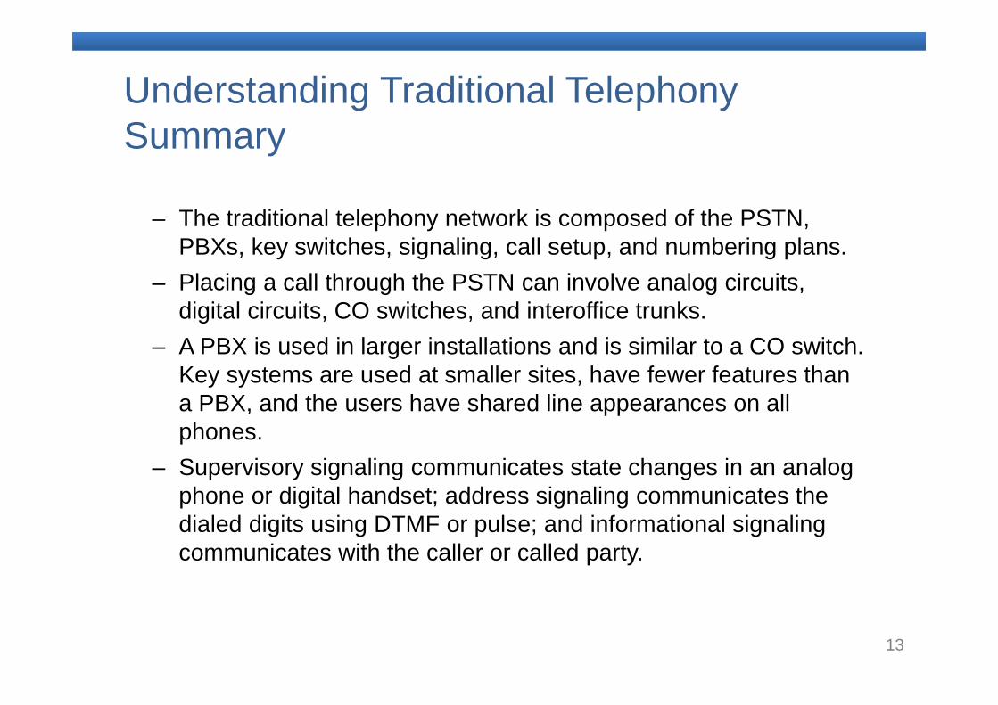
Understanding Traditional Telephony Summary
– The traditional telephony network is composed of the PSTN, PBXs, key switches, signaling, call setup, and numbering plans.
– Placing a call through the PSTN can involve analog circuits, digital circuits, CO switches, and interoffice trunks.
– A PBX is used in larger installations and is similar to a CO switch. Key systems are used at smaller sites, have fewer features than a PBX, and the users have shared line appearances on all phones.
– Supervisory signaling communicates state changes in an analog phone or digital handset; address signaling communicates the dialed digits using DTMF or pulse; and informational signaling communicates with the caller or called party.

14
2. Introducing Analog Circuits
15
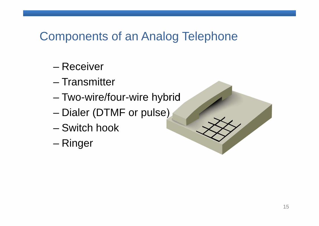
Components of an Analog Telephone
– Receiver– Transmitter– Two-wire/four-wire hybrid– Dialer (DTMF or pulse)– Switch hook– Ringer
16
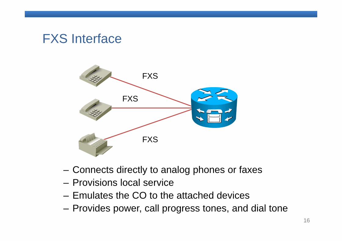
FXS Interface
– Connects directly to analog phones or faxes– Provisions local service– Emulates the CO to the attached devices– Provides power, call progress tones, and dial tone
FXS
FXS
FXS
17
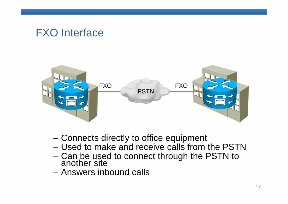
FXO Interface
– Connects directly to office equipment– Used to make and receive calls from the PSTN– Can be used to connect through the PSTN to
another site– Answers inbound calls
FXO FXOPSTN
18
Analog Circuits Summary
– Analog phones have a receiver, transmitter, two-wire/four-wire hybrid, dialer, switch hook, and ringer.
– FXS ports simulate a CO to an analog phone or fax that is attached to the port.
– FXO ports connect a Cisco voice gateway to a CO switch or to an analog port on a PBX.
– Analog circuits include FXS, FXO, and E&Mcircuits.
19
3. Introducing Digital Circuits
20
Digitizing Analog Signals
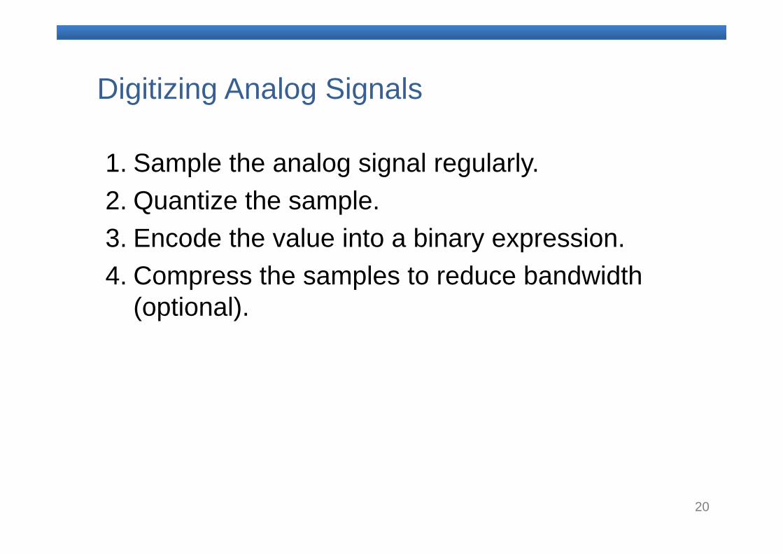
1. Sample the analog signal regularly.2. Quantize the sample.3. Encode the value into a binary expression.4. Compress the samples to reduce bandwidth
(optional).
21
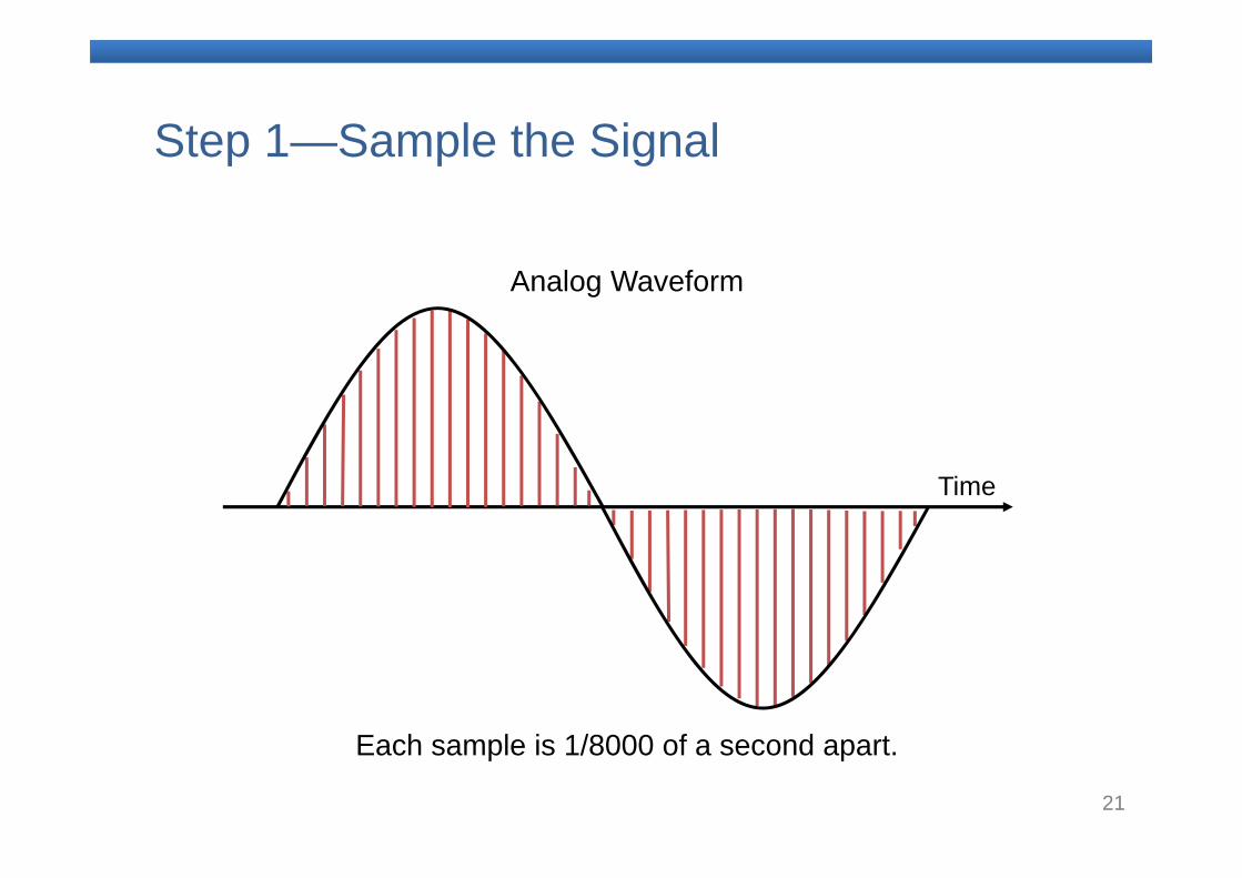
Step 1—Sample the Signal
Each sample is 1/8000 of a second apart.
Time
Analog Waveform
22
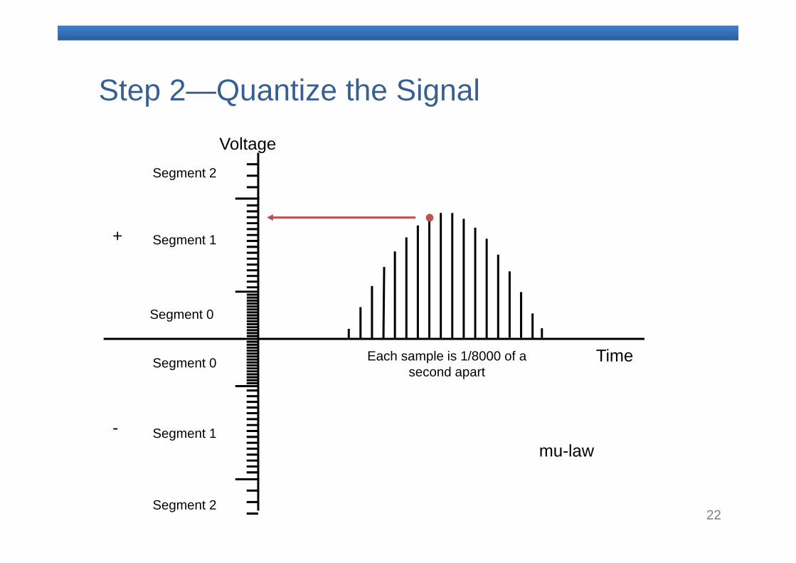
Step 2—Quantize the Signal
Segment 0
Segment 0
Segment 1
Segment 2
Segment 2
Segment 1
Time
Voltage
Each sample is 1/8000 of a second apart
+
-mu-law
23
Digital Circuits Summary
– To digitize an analog signal, samples must be taken regularly, quantized to a binary value, and may optionally be compressed
– T1 and E1 circuits are the most common digital circuits.
24
4. Understanding Packetization
25
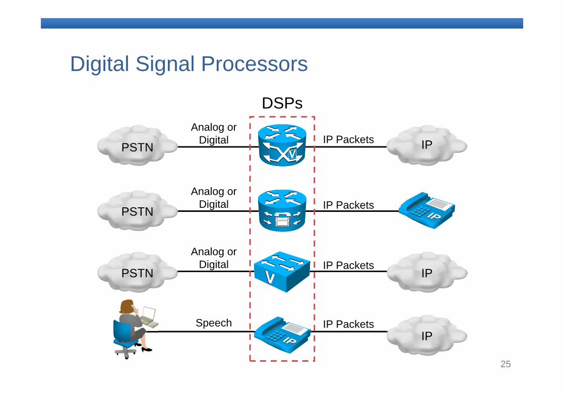
Digital Signal Processors
PSTN
PSTN
PSTN
IP
IP
IP
Analog or Digital
Analog or Digital
Analog or Digital
Speech IP Packets
IP Packets
IP Packets
IP Packets
DSPs
26
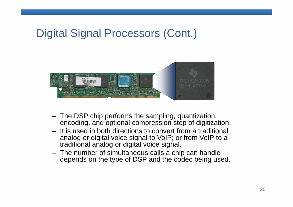
Digital Signal Processors (Cont.)
– The DSP chip performs the sampling, quantization, encoding, and optional compression step of digitization.
– It is used in both directions to convert from a traditional analog or digital voice signal to VoIP; or from VoIP to a traditional analog or digital voice signal.
– The number of simultaneous calls a chip can handle depends on the type of DSP and the codec being used.
27
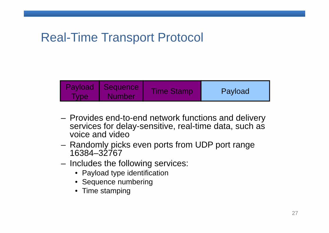
Real-Time Transport Protocol
– Provides end-to-end network functions and delivery services for delay-sensitive, real-time data, such as voice and video
– Randomly picks even ports from UDP port range 16384–32767
– Includes the following services:• Payload type identification• Sequence numbering• Time stamping
Payload Type
Sequence Number Time Stamp Payload
28
RTP Control Protocol
– Can be used to monitor the quality of the data distribution and provide control information
– Provides feedback on current network conditions– Allows hosts that are involved in an RTP session to
exchange information about monitoring and controlling the session:
• Packet count• Packet delay• Octet count• Packet loss• Jitter (variation in delay)
– Provides a separate flow from RTP for UDPtransport use
– Is paired with its RTP stream and uses the same port as the RTP stream plus 1 (odd-numbered port)
29
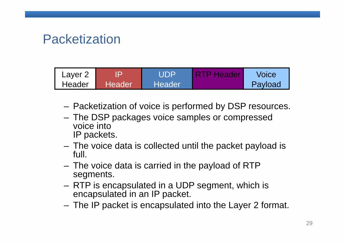
Packetization
– Packetization of voice is performed by DSP resources.– The DSP packages voice samples or compressed
voice into IP packets.
– The voice data is collected until the packet payload is full.
– The voice data is carried in the payload of RTPsegments.
– RTP is encapsulated in a UDP segment, which is encapsulated in an IP packet.
– The IP packet is encapsulated into the Layer 2 format.
Layer 2 Header
IP Header
UDP Header
Voice Payload
RTP Header
30
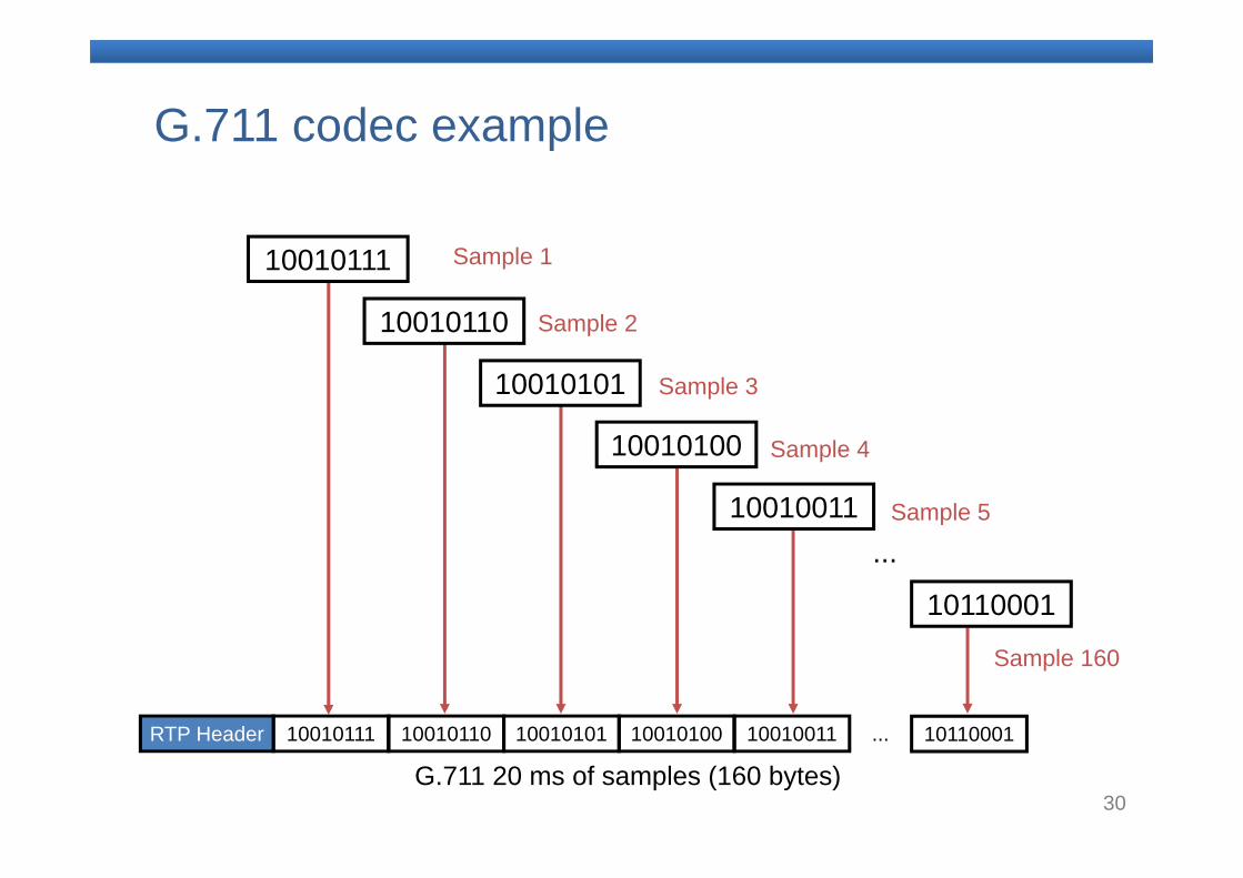
G.711 codec example
...
10010111 10010110 10010101 10010100 10010011 ... 10110001RTP Header
Sample 1
Sample 2
Sample 3
Sample 4
Sample 5
Sample 160
G.711 20 ms of samples (160 bytes)
10010111
10010110
10010101
10010100
10010011
10110001
31
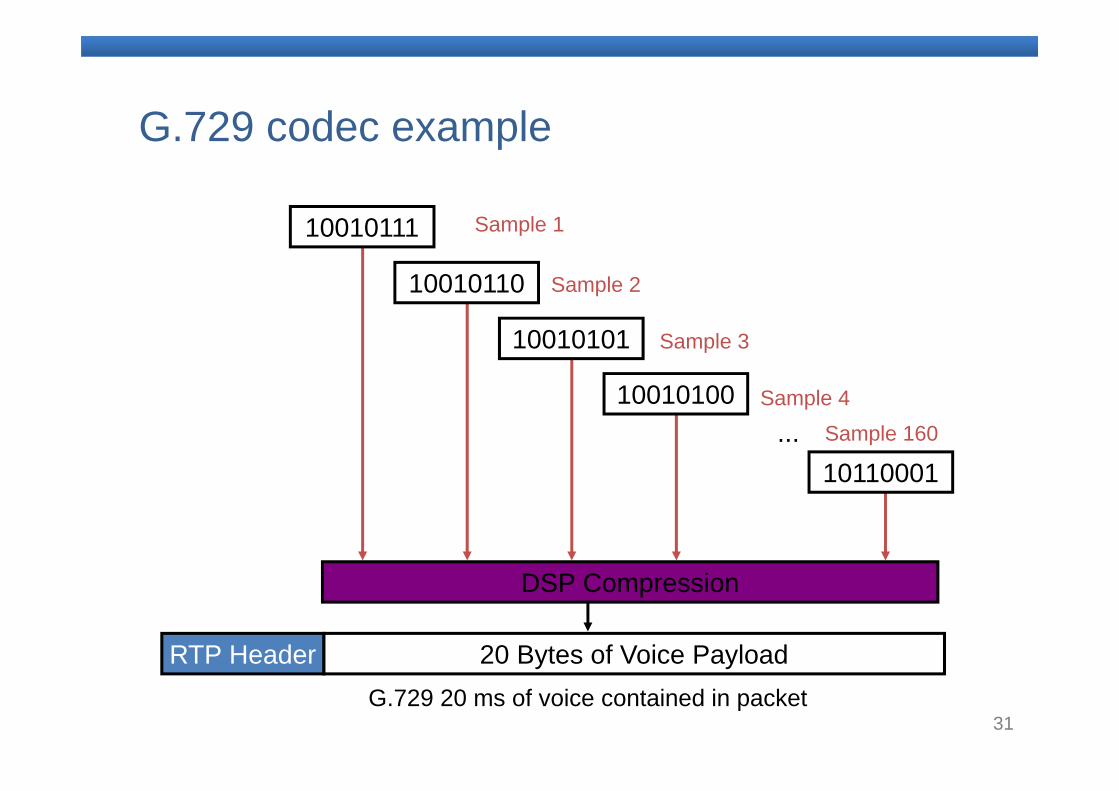
G.729 codec example
...
20 Bytes of Voice PayloadRTP Header
Sample 1
Sample 2
Sample 3
Sample 4Sample 160
G.729 20 ms of voice contained in packet
DSP Compression
10010111
10010110
10010101
10010100
10110001
32
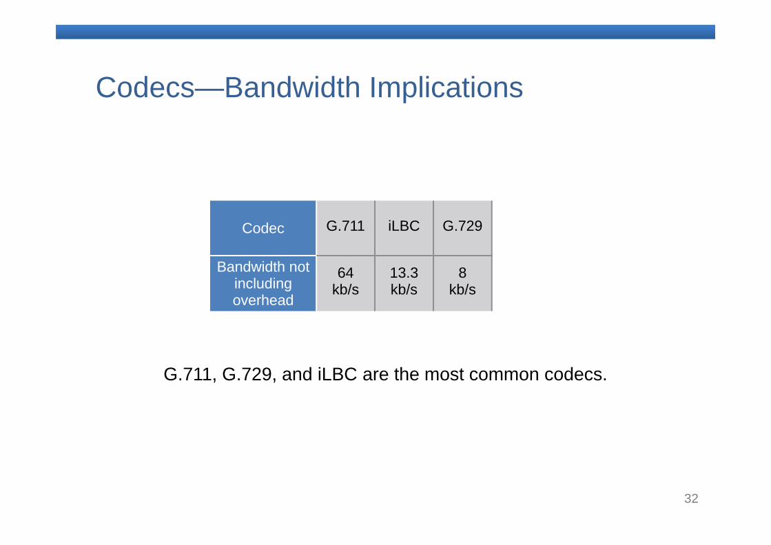
Codecs—Bandwidth Implications
G.711, G.729, and iLBC are the most common codecs.
Codec G.711 iLBC G.729
Bandwidth not including overhead
64kb/s
13.3kb/s
8kb/s
33
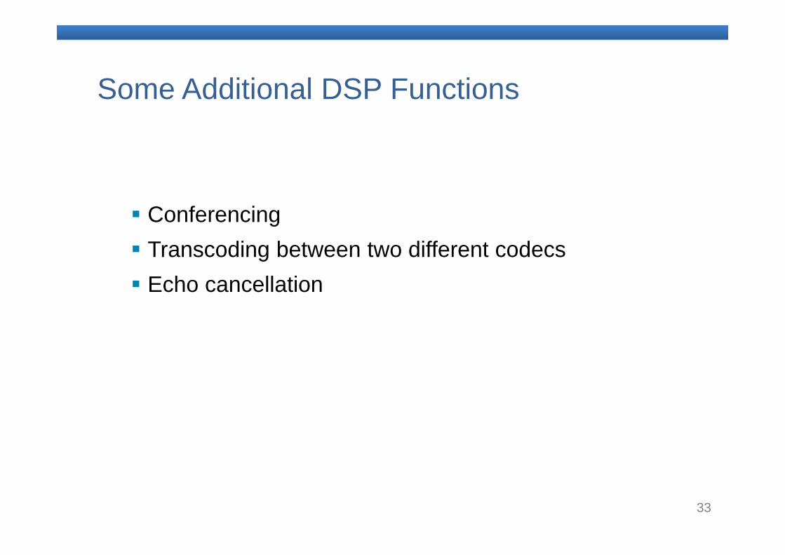
Some Additional DSP Functions
Conferencing Transcoding between two different codecs Echo cancellation
34
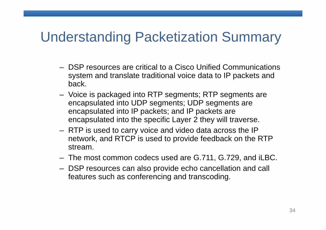
Understanding Packetization Summary
– DSP resources are critical to a Cisco Unified Communications system and translate traditional voice data to IP packets and back.
– Voice is packaged into RTP segments; RTP segments are encapsulated into UDP segments; UDP segments are encapsulated into IP packets; and IP packets are encapsulated into the specific Layer 2 they will traverse.
– RTP is used to carry voice and video data across the IP network, and RTCP is used to provide feedback on the RTP stream.
– The most common codecs used are G.711, G.729, and iLBC. – DSP resources can also provide echo cancellation and call
features such as conferencing and transcoding.
35
5. Introducing VoIP Signaling Protocols
36
VoIP Signaling Protocols
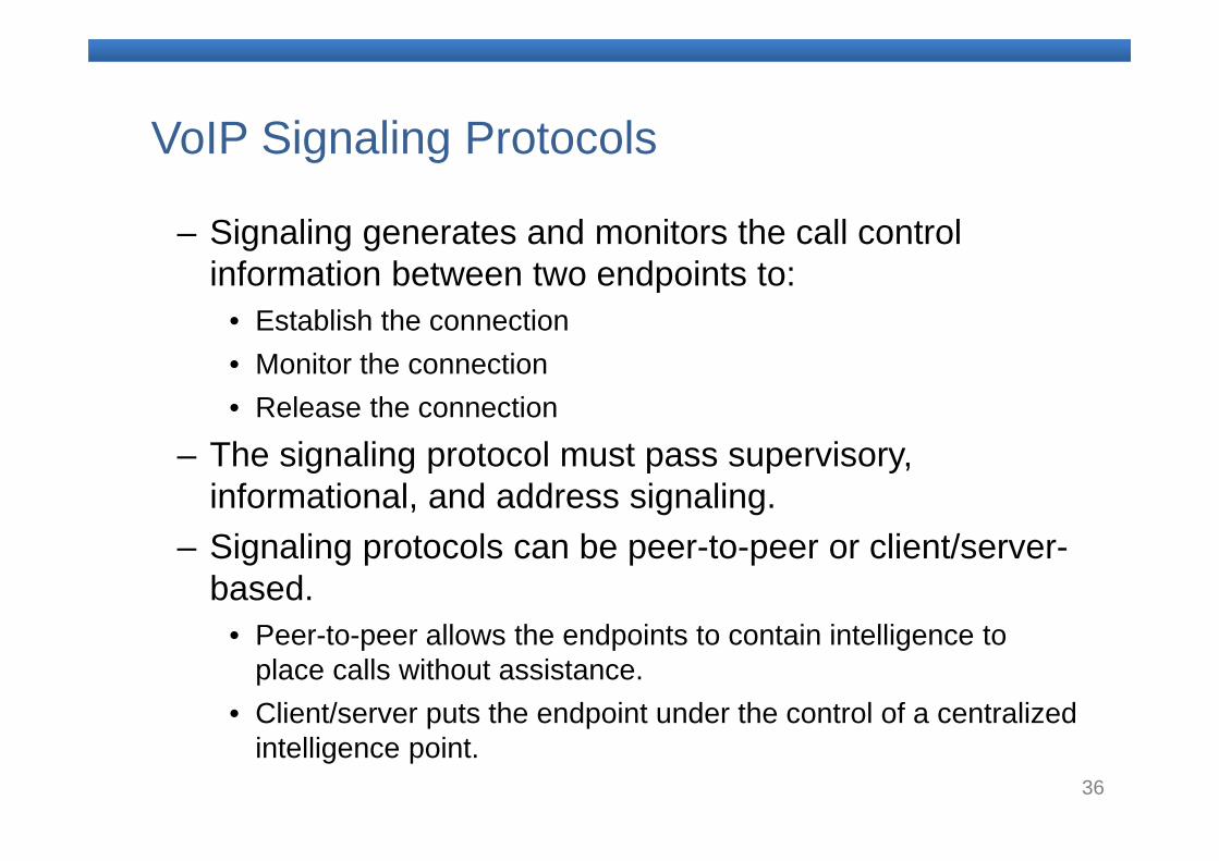
– Signaling generates and monitors the call control information between two endpoints to:
• Establish the connection• Monitor the connection• Release the connection
– The signaling protocol must pass supervisory, informational, and address signaling.
– Signaling protocols can be peer-to-peer or client/server-based.
• Peer-to-peer allows the endpoints to contain intelligence to place calls without assistance.
• Client/server puts the endpoint under the control of a centralized intelligence point.
37
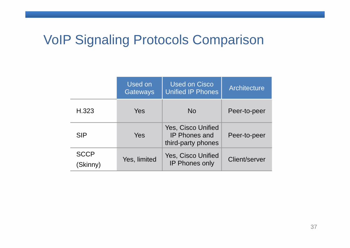
VoIP Signaling Protocols Comparison
Used on Gateways
Used on Cisco Unified IP Phones Architecture
H.323 Yes No Peer-to-peer
SIP YesYes, Cisco Unified
IP Phones and third-party phones
Peer-to-peer
SCCP(Skinny)
Yes, limited Yes, Cisco Unified IP Phones only Client/server
38
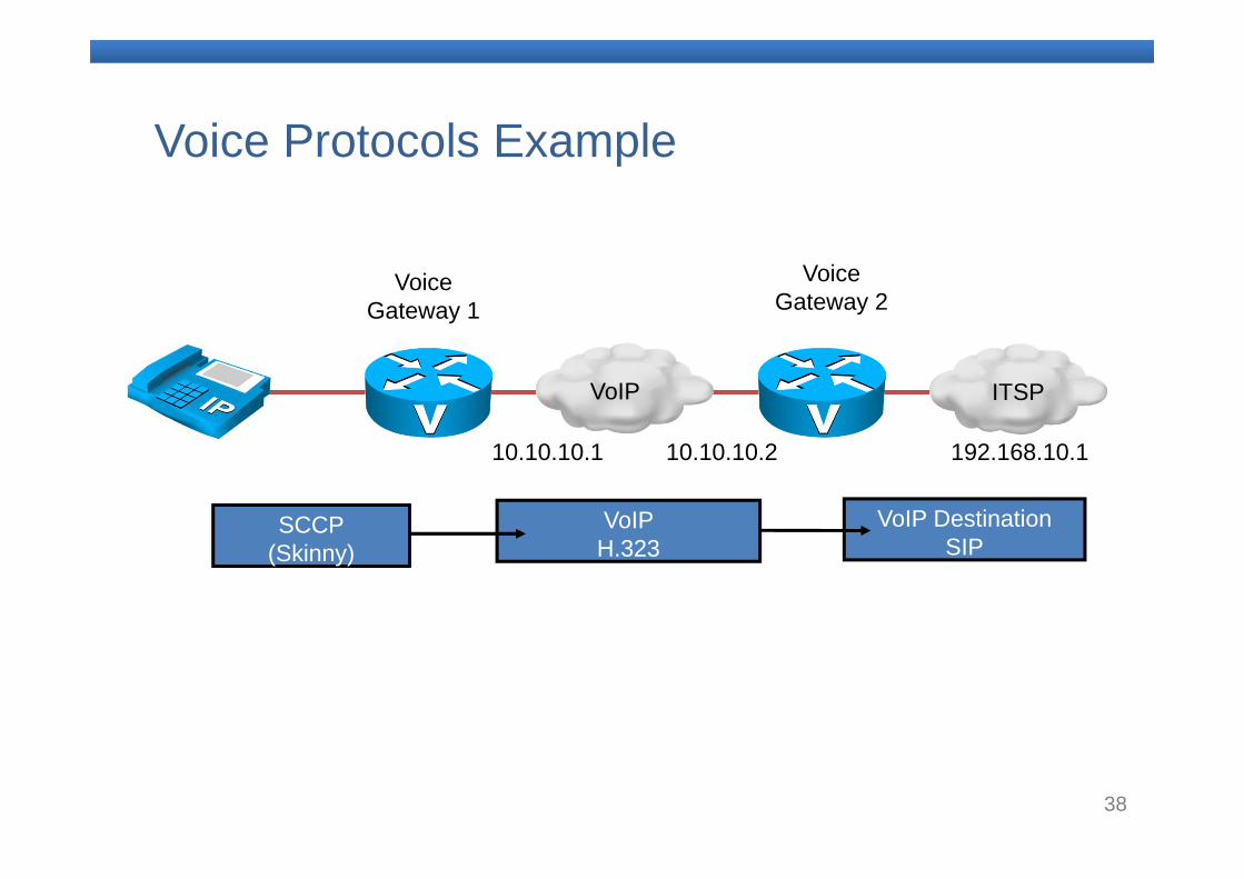
Voice Protocols Example
VoIP
10.10.10.210.10.10.1
Voice Gateway 1
Voice Gateway 2
ITSP
VoIP DestinationSIP
192.168.10.1
VoIP H.323
SCCP(Skinny)
39
Introducing VoIP Signaling Protocols Summary
– Signaling protocols are used in VoIP networks to set up new calls, monitor current calls, tear down calls, pass informational signaling, pass supervisory signaling, and pass address signaling.
– SCCP is a proprietary protocol used between Cisco Unified IP Phones and Cisco Unified Communications call control products.
– H.323 is a stable, mature, vendor-neutral protocol that is widely deployed.
– SIP is an emerging protocol based on parts of existing protocols. It is still evolving.
40
6. Preparing the Network to Support Voice
41
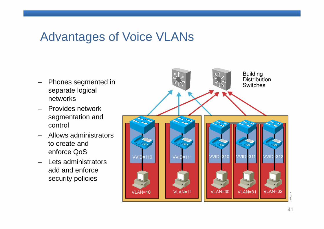
Advantages of Voice VLANs
– Phones segmented in separate logical networks
– Provides network segmentation and control
– Allows administrators to create and enforce QoS
– Lets administrators add and enforce security policies
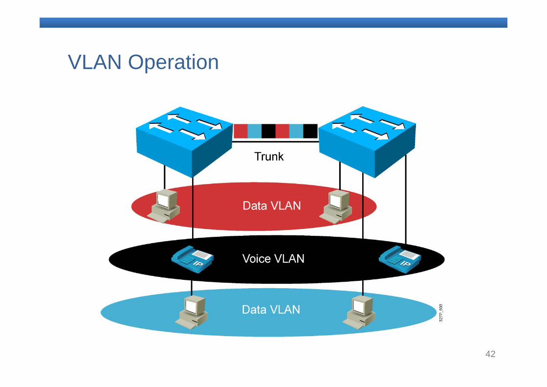
42
VLAN Operation
43
Voice VLANs
– Separates voice and data traffic – Prevents unnecessary IP address renumbering– Simplifies QoS configurations – Requires two VLANs: one for data traffic and one for
voice traffic – Requires only one Ethernet cable drop for the Cisco
IP phone and the PC that is plugged into the phone
– Requires two IP subnets: one for the data VLAN and one for the voice VLAN
44
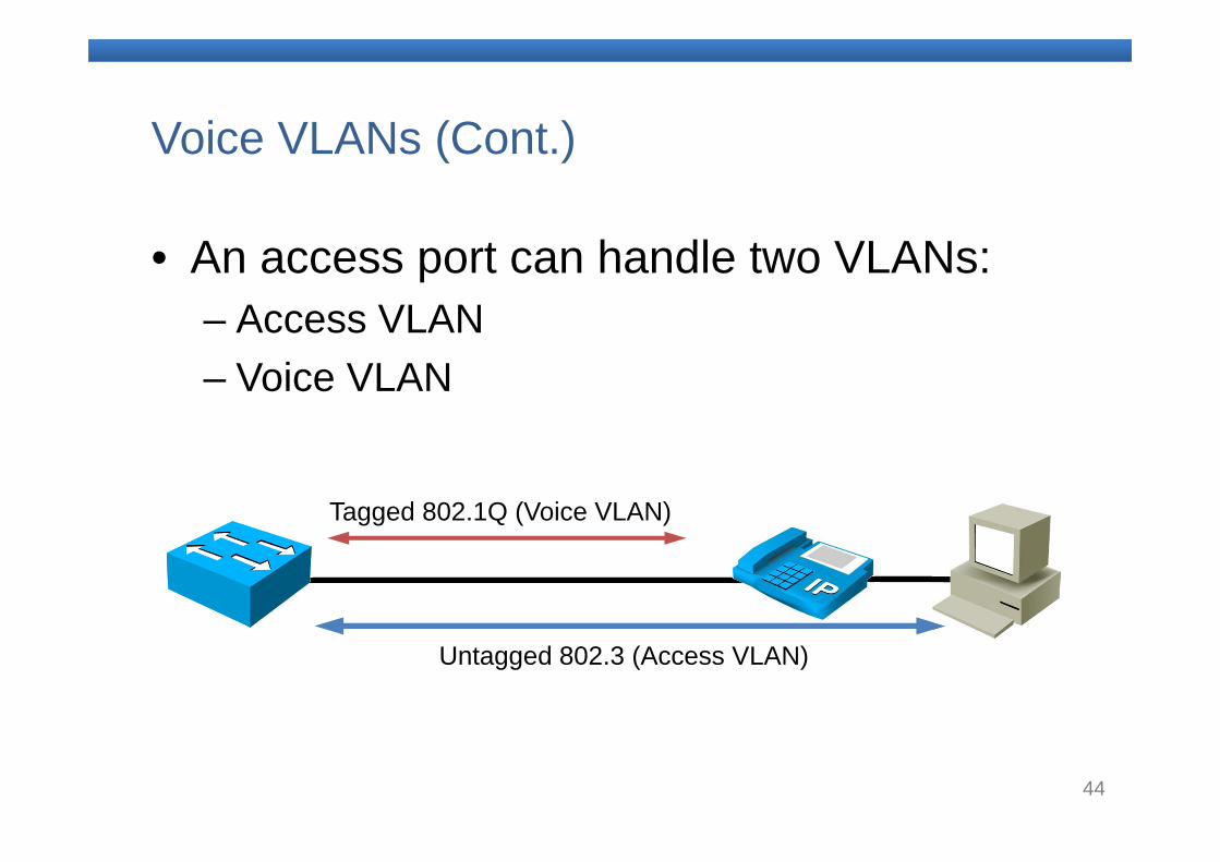
Voice VLANs (Cont.)
• An access port can handle two VLANs:– Access VLAN– Voice VLAN
Tagged 802.1Q (Voice VLAN)
Untagged 802.3 (Access VLAN)
45
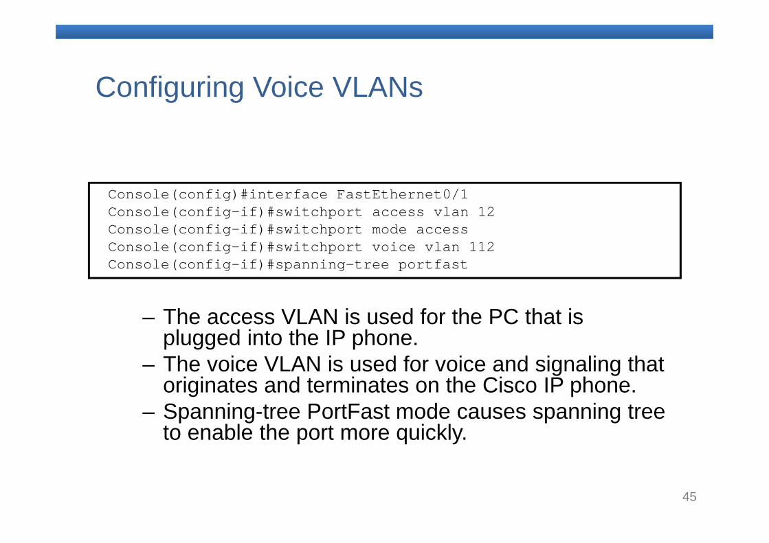
Configuring Voice VLANs
– The access VLAN is used for the PC that is plugged into the IP phone.
– The voice VLAN is used for voice and signaling that originates and terminates on the Cisco IP phone.
– Spanning-tree PortFast mode causes spanning tree to enable the port more quickly.
Console(config)#interface FastEthernet0/1 Console(config-if)#switchport access vlan 12 Console(config-if)#switchport mode access Console(config-if)#switchport voice vlan 112 Console(config-if)#spanning-tree portfast
46
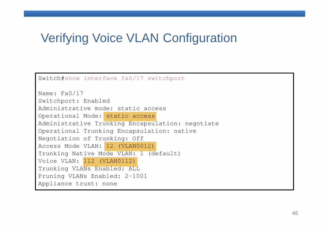
Verifying Voice VLAN Configuration
Switch#show interface fa0/17 switchport
Name: Fa0/17Switchport: EnabledAdministrative mode: static accessOperational Mode: static accessAdministrative Trunking Encapsulation: negotiateOperational Trunking Encapsulation: nativeNegotiation of Trunking: OffAccess Mode VLAN: 12 (VLAN0012)Trunking Native Mode VLAN: 1 (default)Voice VLAN: 112 (VLAN0112)Trunking VLANs Enabled: ALLPruning VLANs Enabled: 2-1001Appliance trust: none
47
DHCP Service
– Assigns IP addresses and subnet masks for one or more subnets
– Assigns a default gateway– Assigns DNS servers (optional)– Assigns other commonly used servers
(optional) – Needs to be customized to assign a TFTP
server to the voice VLAN that IP phones are on– Configure a separate DHCP scope for the IP
phones as a best practice
48
Phone Bootup
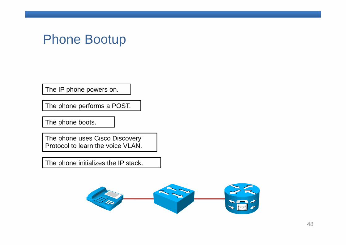
The IP phone powers on.
The phone performs a POST.
The phone uses Cisco Discovery Protocol to learn the voice VLAN.
The phone initializes the IP stack.
The phone boots.
49
Phone Bootup (Cont.)
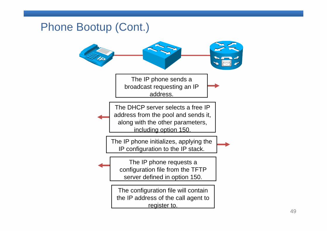
The IP phone sends a broadcast requesting an IP
address.
The DHCP server selects a free IP address from the pool and sends it,
along with the other parameters, including option 150.
The IP phone initializes, applying the IP configuration to the IP stack.
The configuration file will contain the IP address of the call agent to
register to.
The IP phone requests a configuration file from the TFTP
server defined in option 150.
50
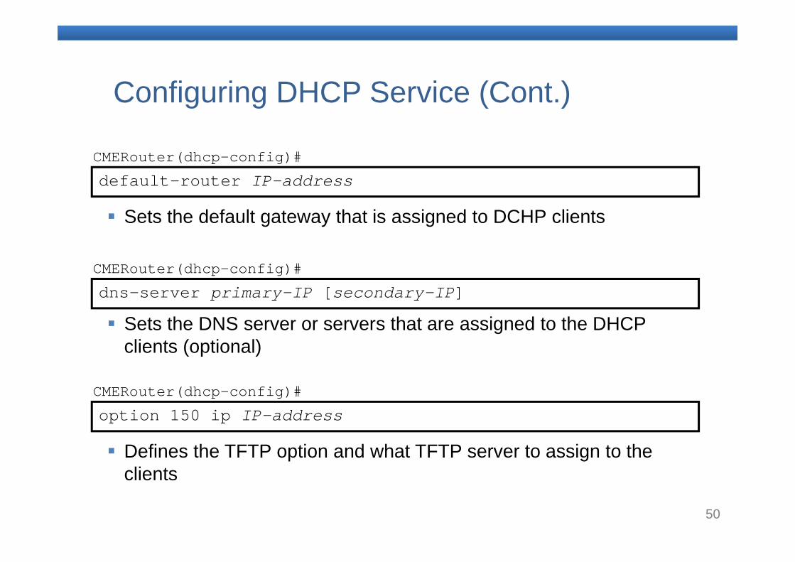
default-router IP-addressCMERouter(dhcp-config)#
Sets the default gateway that is assigned to DCHP clients
dns-server primary-IP [secondary-IP]CMERouter(dhcp-config)#
Sets the DNS server or servers that are assigned to the DHCP clients (optional)
Configuring DHCP Service (Cont.)
option 150 ip IP-addressCMERouter(dhcp-config)#
Defines the TFTP option and what TFTP server to assign to the clients
51
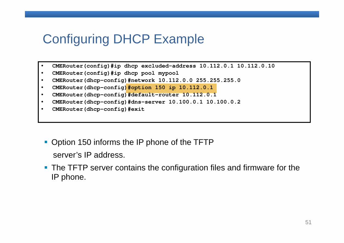
Configuring DHCP Example
Option 150 informs the IP phone of the TFTP server’s IP address.
The TFTP server contains the configuration files and firmware for the IP phone.
• CMERouter(config)#ip dhcp excluded-address 10.112.0.1 10.112.0.10• CMERouter(config)#ip dhcp pool mypool• CMERouter(dhcp-config)#network 10.112.0.0 255.255.255.0• CMERouter(dhcp-config)#option 150 ip 10.112.0.1 • CMERouter(dhcp-config)#default-router 10.112.0.1• CMERouter(dhcp-config)#dns-server 10.100.0.1 10.100.0.2• CMERouter(dhcp-config)#exit
52
Network Time Protocol
– Correct clock synchronization is important for performance, troubleshooting, and CDRs.
– Each Cisco device has an internal system clock that can be set from a number of sources, such as an internal calendar system and NTP.
– NTP allows network devices to synchronize to a clock master.
– The local NTP server can have an attached clock or can synchronize with a more authoritative source.
– There are free NTP servers available on the Internet.
53
Network Time Protocol (Cont.)
– The IP phone gets its displayed time from the call control platform to which is registers.
• Cisco Unified Communications Manager • Cisco Unified Communications Manager Express
– The time of the internal clock of the Cisco Unified Communications call control platform should be synchronized with an NTP server.
– The time of the Cisco Unified Communications call control platform is used to stamp all syslogand trace messages.
54
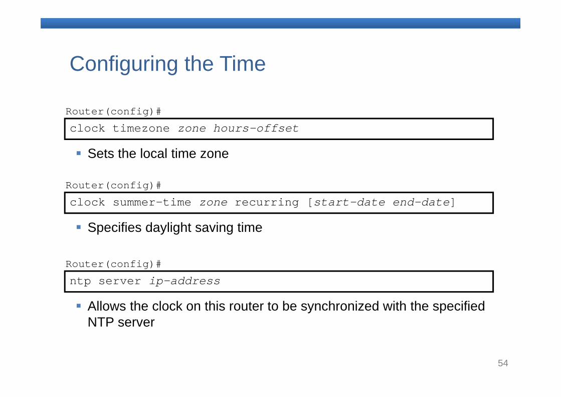
clock timezone zone hours-offsetRouter(config)#
Sets the local time zone
clock summer-time zone recurring [start-date end-date] Router(config)#
Specifies daylight saving time
ntp server ip-addressRouter(config)#
Allows the clock on this router to be synchronized with the specified NTP server
Configuring the Time
55
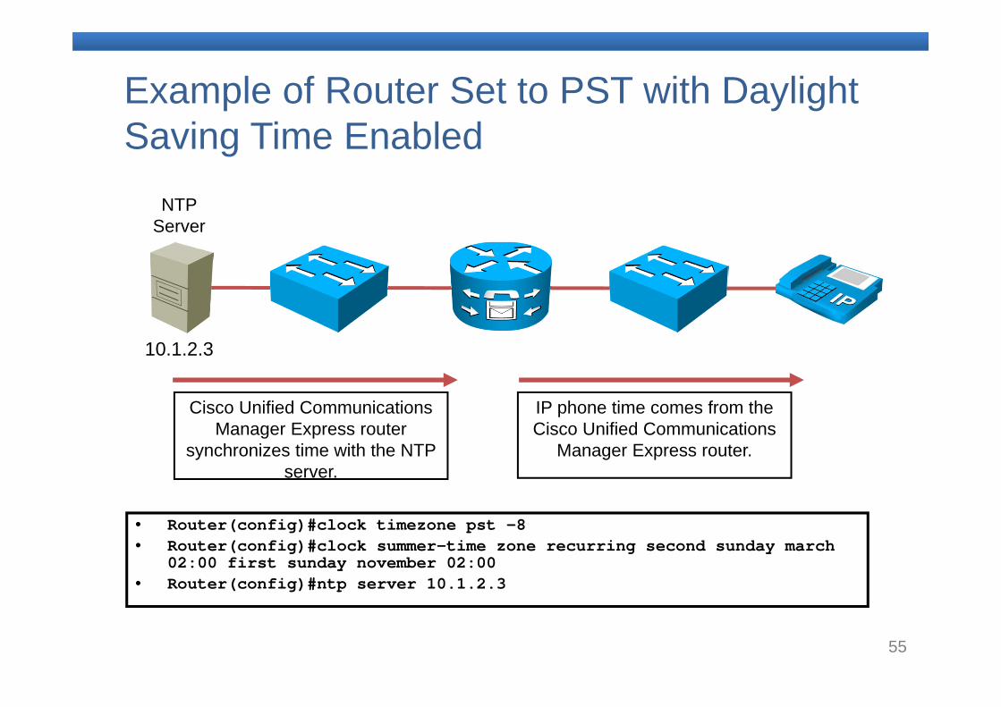
Example of Router Set to PST with Daylight Saving Time Enabled
• Router(config)#clock timezone pst -8 • Router(config)#clock summer-time zone recurring second sunday march
02:00 first sunday november 02:00• Router(config)#ntp server 10.1.2.3
NTP Server
10.1.2.3
IP phone time comes from the Cisco Unified Communications
Manager Express router.
Cisco Unified Communications Manager Express router
synchronizes time with the NTP server.
56
Preparing the Network to Support Voice Summary
– Voice VLANs are used to separate voice traffic from data traffic.
– Voice VLANs are configured on the interfaces of the switch into which the IP phone connects.
– NTP allows you to synchronize your Cisco Unified Communications Manager Express router to a single clock on the network.
57
Summary (Cont.)
– The IP phone requests the firmware, configuration, and language files when it boots.
– The IP phone uses TFTP DHCP option 150 to download the configuration file which is needed to register with the call control device. The IP phone uses its MAC address as part of a created filename which uniquely identifies the phone. This configuration file contains the version of firmware to use and the IP address and port to which the phone will register.
58
7. Introducing Cisco Unified Communications Manager Express (CME)
59
CME Key Features and Benefits
– Supports deployments of up to 240 phones on a single router
– Extends capabilities to the small office that were previously available only to larger enterprises
– Is based on Cisco IOS Software– Can be administered by GUI or CLI
60
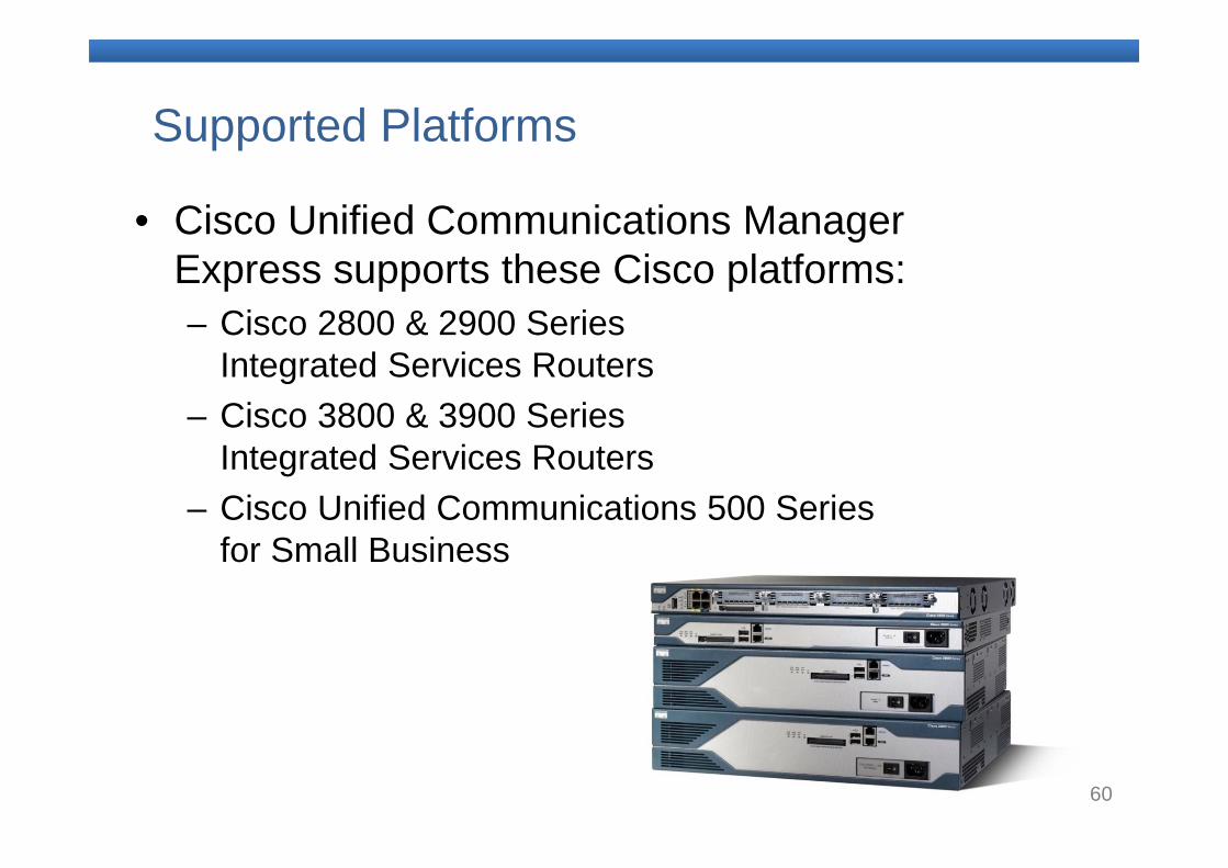
Supported Platforms
• Cisco Unified Communications Manager Express supports these Cisco platforms:– Cisco 2800 & 2900 Series
Integrated Services Routers– Cisco 3800 & 3900 Series
Integrated Services Routers– Cisco Unified Communications 500 Series
for Small Business
61
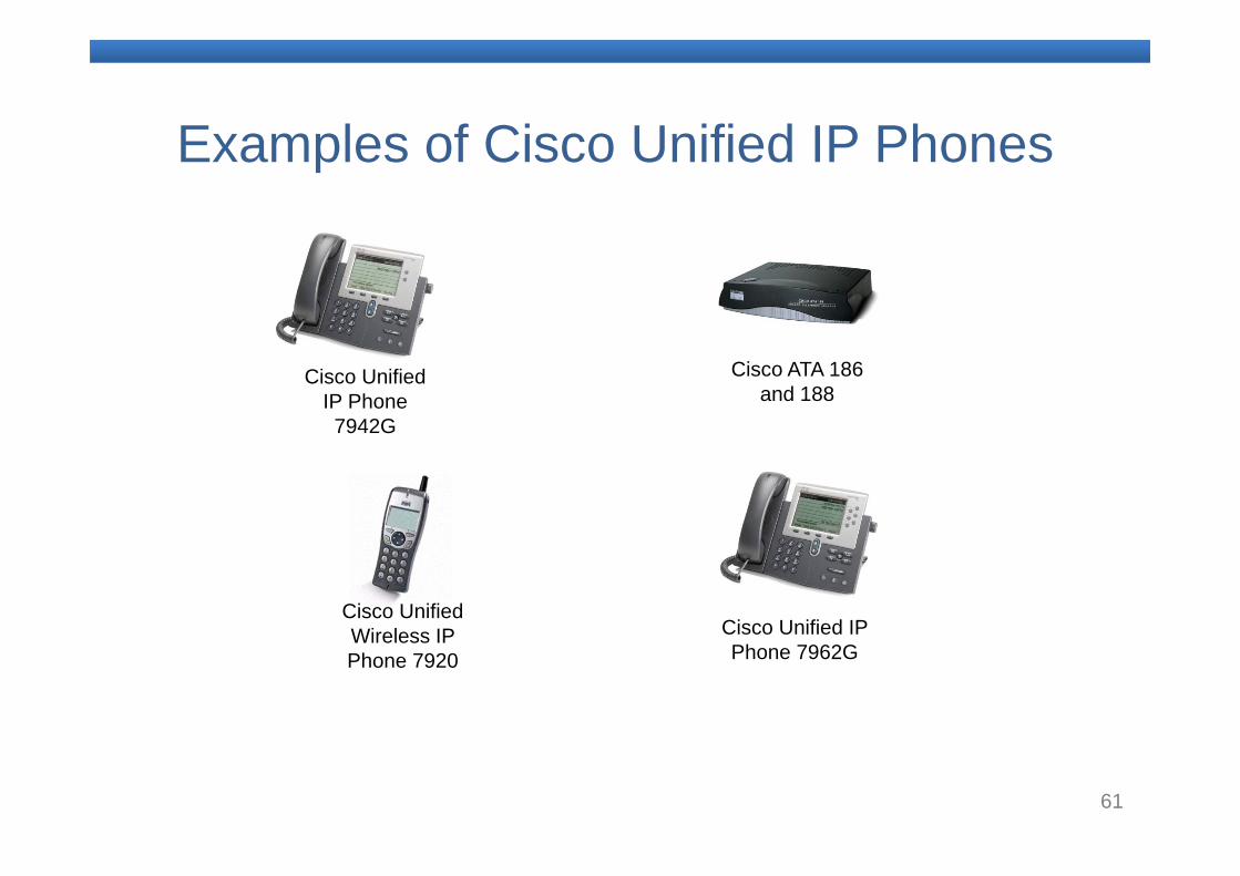
Examples of Cisco Unified IP Phones
Cisco Unified IP Phone 7942G
Cisco Unified Wireless IP Phone 7920
Cisco Unified IP Phone 7962G
Cisco ATA 186 and 188
62
8. Global Telephony Commands
63
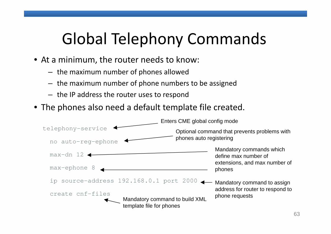
Global Telephony Commands• At a minimum, the router needs to know:
– the maximum number of phones allowed– the maximum number of phone numbers to be assigned– the IP address the router uses to respond
• The phones also need a default template file created.
telephony-service
no auto-reg-ephone
max-dn 12
max-ephone 8
ip source-address 192.168.0.1 port 2000
create cnf-files
Mandatory commands which define max number of extensions, and max number of phones
Mandatory command to assign address for router to respond to phone requests
Enters CME global config mode
Mandatory command to build XML template file for phones
Optional command that prevents problems with phones auto registering
64
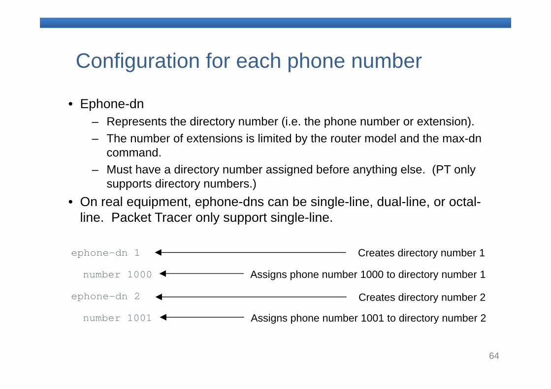
Configuration for each phone number
• Ephone-dn– Represents the directory number (i.e. the phone number or extension).– The number of extensions is limited by the router model and the max-dn
command.– Must have a directory number assigned before anything else. (PT only
supports directory numbers.)• On real equipment, ephone-dns can be single-line, dual-line, or octal-
line. Packet Tracer only support single-line.
ephone-dn 1
number 1000
ephone-dn 2
number 1001
Creates directory number 1
Assigns phone number 1000 to directory number 1
Creates directory number 2
Assigns phone number 1001 to directory number 2
65
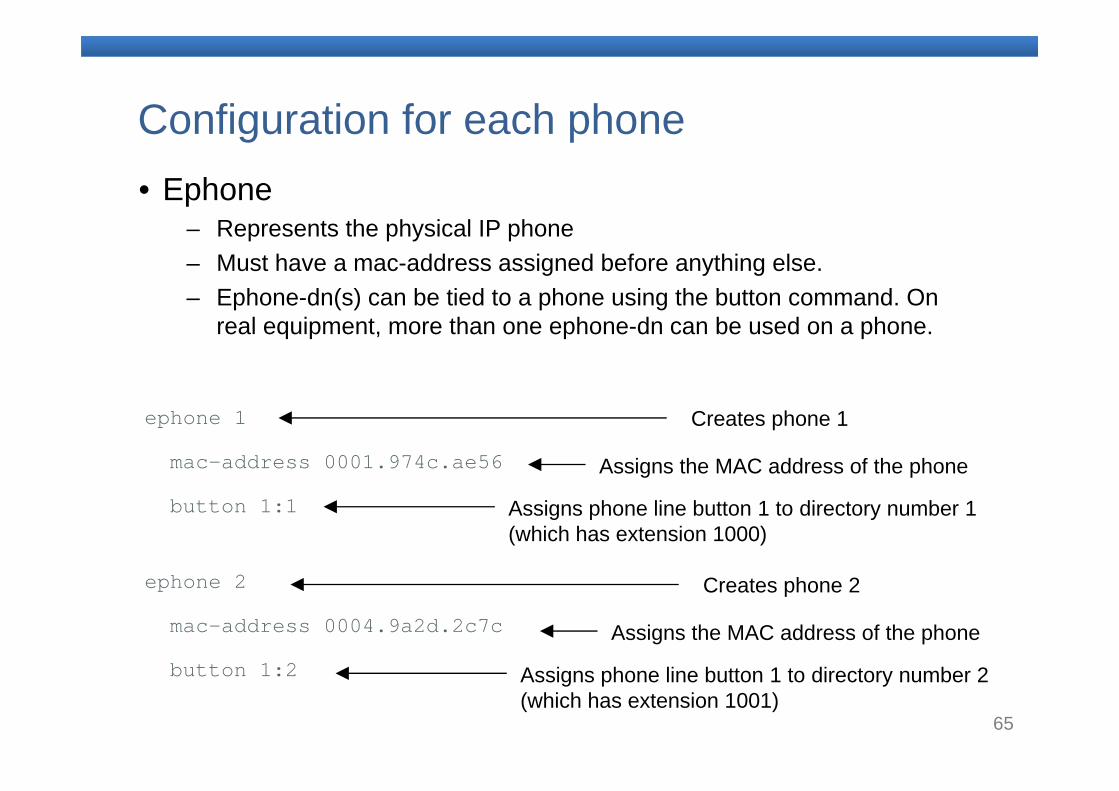
Configuration for each phone• Ephone
– Represents the physical IP phone– Must have a mac-address assigned before anything else.– Ephone-dn(s) can be tied to a phone using the button command. On
real equipment, more than one ephone-dn can be used on a phone.
ephone 1
mac-address 0001.974c.ae56
button 1:1
ephone 2
mac-address 0004.9a2d.2c7c
button 1:2
Creates phone 1
Assigns phone line button 1 to directory number 1 (which has extension 1000)
Assigns the MAC address of the phone
Creates phone 2
Assigns phone line button 1 to directory number 2 (which has extension 1001)
Assigns the MAC address of the phone
66
9. Defining Ephone-dn and Ephone
67
Ephone and Ephone-dn Concepts
– Ephones and ephone-dns are modular Cisco IOS Software constructs.
– An ephone represents the configuration and setting of the physical phone.
– The maximum number of supported ephones is determined by the license and hardware platform. Cisco Unified Communications Manager Express supports a maximum of 240 ephones.
– An ephone-dn is a numeric destination that can be associated with one or more ephones.
– An ephone can have more than one ephone-dn associated with it.
– The maximum number of extensions is the same as the maximum number of ephone-dns.
68
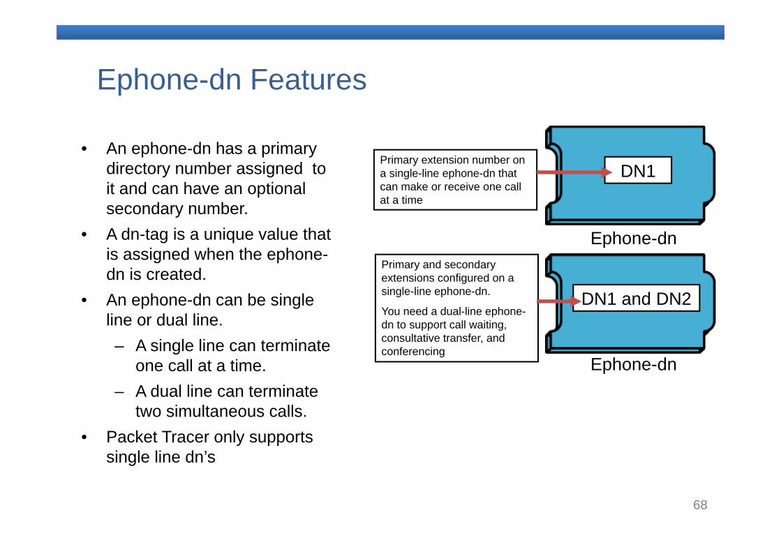
Ephone-dn Features
DN1 and DN2
Primary and secondary extensions configured on a single-line ephone-dn.
You need a dual-line ephone-dn to support call waiting, consultative transfer, and conferencing
DN1Primary extension number on a single-line ephone-dn that can make or receive one call at a time
Ephone-dn
Ephone-dn
• An ephone-dn has a primary directory number assigned to it and can have an optional secondary number.
• A dn-tag is a unique value that is assigned when the ephone-dn is created.
• An ephone-dn can be single line or dual line.– A single line can terminate
one call at a time.– A dual line can terminate
two simultaneous calls.• Packet Tracer only supports
single line dn’s
69
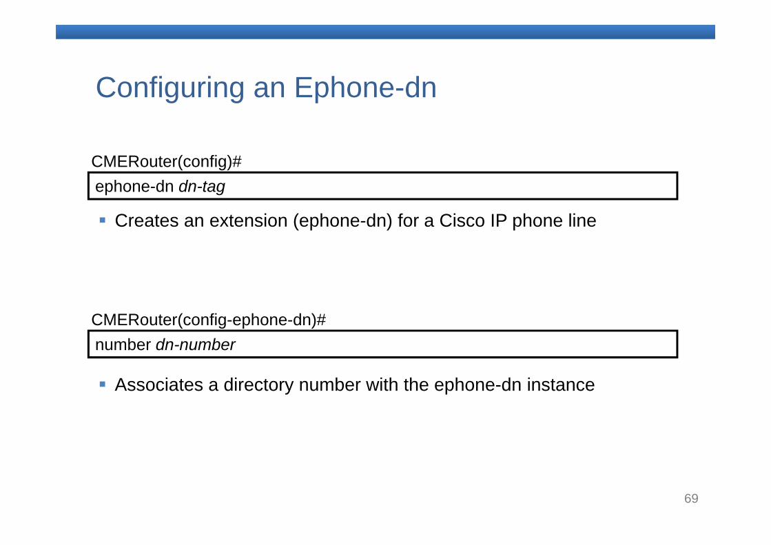
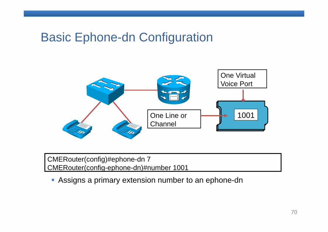
ephone-dn dn-tag CMERouter(config)#
Creates an extension (ephone-dn) for a Cisco IP phone line
number dn-number CMERouter(config-ephone-dn)#
Associates a directory number with the ephone-dn instance
Configuring an Ephone-dn
70
Basic Ephone-dn Configuration
CMERouter(config)#ephone-dn 7 CMERouter(config-ephone-dn)#number 1001
One Virtual Voice Port
Assigns a primary extension number to an ephone-dn
1001One Line or Channel
71
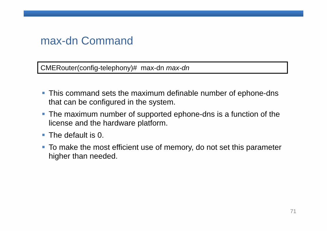
CMERouter(config-telephony)# max-dn max-dn
This command sets the maximum definable number of ephone-dns that can be configured in the system.
The maximum number of supported ephone-dns is a function of the license and the hardware platform.
The default is 0. To make the most efficient use of memory, do not set this parameter
higher than needed.
max-dn Command
72
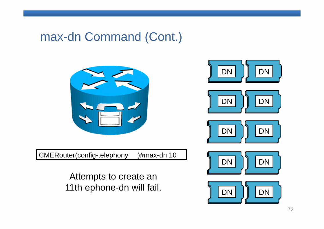
max-dn Command (Cont.)
DN
DN
DN
DN
DN
DN
DN
DN
DN
DN
CMERouter(config-telephony )#max-dn 10
Attempts to create an 11th ephone-dn will fail.
73
Ephone Features
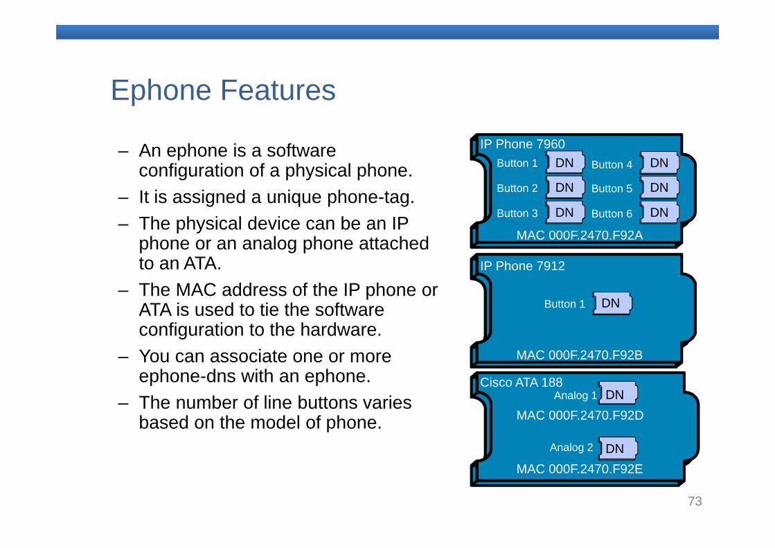
– An ephone is a software configuration of a physical phone.
– It is assigned a unique phone-tag.– The physical device can be an IP
phone or an analog phone attached to an ATA.
– The MAC address of the IP phone or ATA is used to tie the software configuration to the hardware.
– You can associate one or more ephone-dns with an ephone.
– The number of line buttons varies based on the model of phone.
MAC 000F.2470.F92A
MAC 000F.2470.F92E
MAC 000F.2470.F92B
IP Phone 7960
IP Phone 7912
Cisco ATA 188
Button 1
Analog 1
Analog 2
Button 1
Button 2
Button 3
Button 4
Button 5
Button 6
DN
DN
DN
MAC 000F.2470.F92D
DN
DN
DN
DN
DN
DN
74
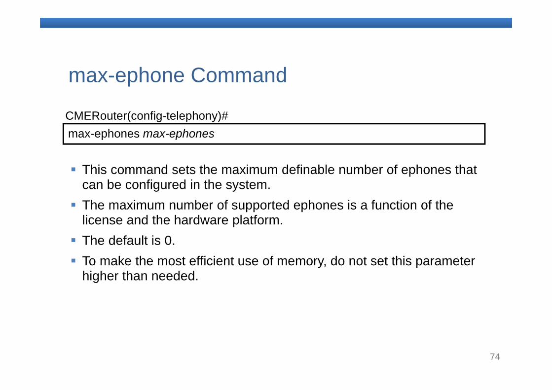
max-ephones max-ephonesCMERouter(config-telephony)#
This command sets the maximum definable number of ephones that can be configured in the system.
The maximum number of supported ephones is a function of the license and the hardware platform.
The default is 0. To make the most efficient use of memory, do not set this parameter
higher than needed.
max-ephone Command
75
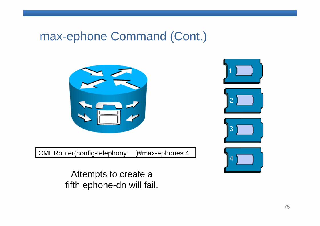
max-ephone Command (Cont.)
CMERouter(config-telephony )#max-ephones 4
Attempts to create afifth ephone-dn will fail.
1
2
3
4
76
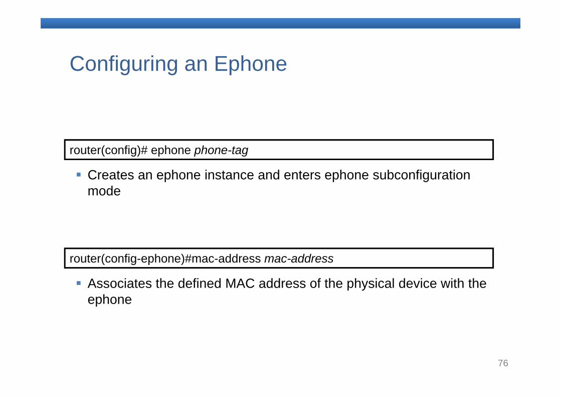
router(config)# ephone phone-tag
Creates an ephone instance and enters ephone subconfiguration mode
router(config-ephone)#mac-address mac-address
Associates the defined MAC address of the physical device with the ephone
Configuring an Ephone
77
Configuring an Ephone (Cont.)
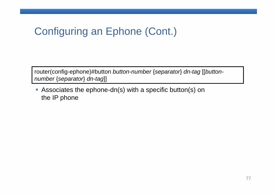
router(config-ephone)#button button-number {separator} dn-tag [[button-number {separator} dn-tag]]
Associates the ephone-dn(s) with a specific button(s) on the IP phone
78
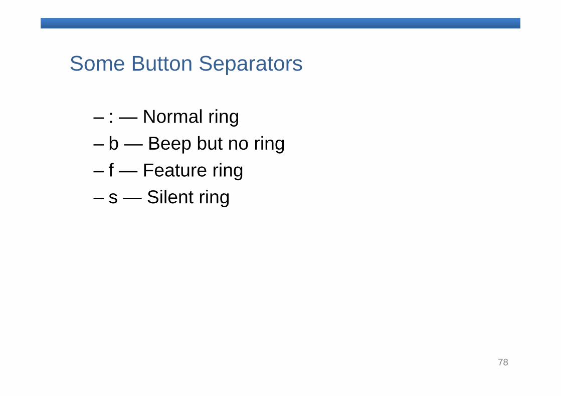
Some Button Separators
– : — Normal ring– b — Beep but no ring– f — Feature ring– s — Silent ring
79
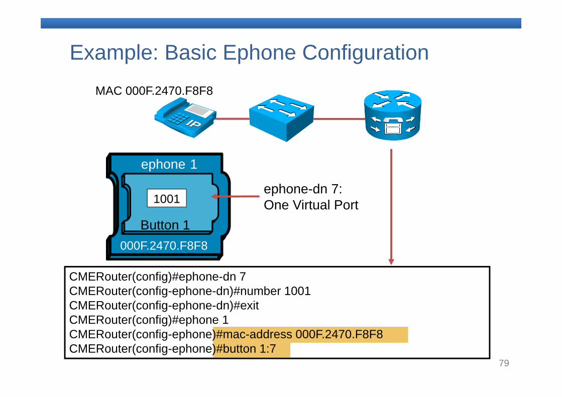
Example: Basic Ephone Configuration MAC 000F.2470.F8F8
ephone 1
Button 1
ephone-dn 7: One Virtual Port
000F.2470.F8F8
1001
CMERouter(config)#ephone-dn 7 CMERouter(config-ephone-dn)#number 1001CMERouter(config-ephone-dn)#exitCMERouter(config)#ephone 1CMERouter(config-ephone)#mac-address 000F.2470.F8F8CMERouter(config-ephone)#button 1:7
80
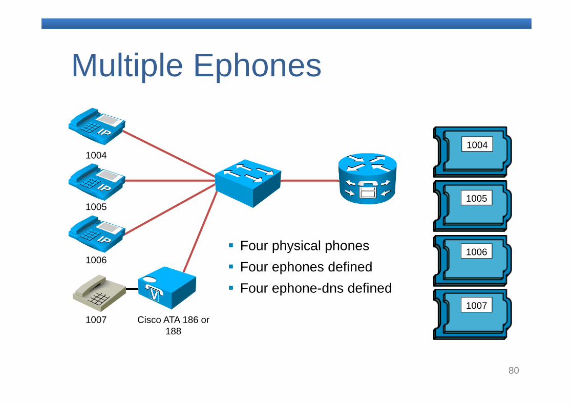
Multiple Ephones
Cisco ATA 186 or 188
Four physical phones Four ephones defined Four ephone-dns defined
1004
1005
1006
1007
1004
1005
1006
1007
81
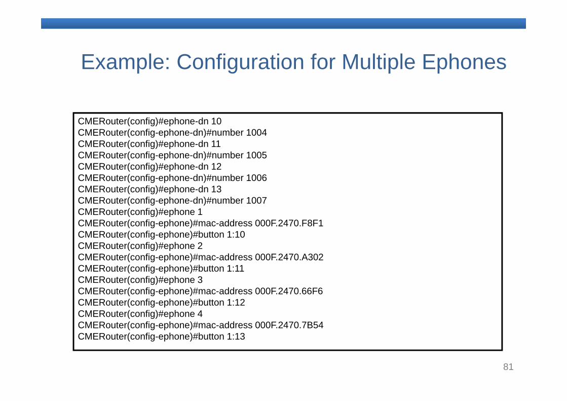
CMERouter(config)#ephone-dn 10 CMERouter(config-ephone-dn)#number 1004CMERouter(config)#ephone-dn 11 CMERouter(config-ephone-dn)#number 1005CMERouter(config)#ephone-dn 12 CMERouter(config-ephone-dn)#number 1006CMERouter(config)#ephone-dn 13 CMERouter(config-ephone-dn)#number 1007CMERouter(config)#ephone 1CMERouter(config-ephone)#mac-address 000F.2470.F8F1CMERouter(config-ephone)#button 1:10CMERouter(config)#ephone 2CMERouter(config-ephone)#mac-address 000F.2470.A302CMERouter(config-ephone)#button 1:11CMERouter(config)#ephone 3CMERouter(config-ephone)#mac-address 000F.2470.66F6CMERouter(config-ephone)#button 1:12CMERouter(config)#ephone 4CMERouter(config-ephone)#mac-address 000F.2470.7B54CMERouter(config-ephone)#button 1:13
Example: Configuration for Multiple Ephones
82
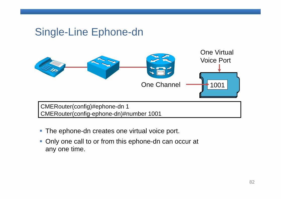
Single-Line Ephone-dn
CMERouter(config)#ephone-dn 1 CMERouter(config-ephone-dn)#number 1001
1001One Channel
One Virtual Voice Port
The ephone-dn creates one virtual voice port. Only one call to or from this ephone-dn can occur at
any one time.
83
Defining Ephone-dnand Ephone Summary
– Ephone-dns and ephones are two key components of the Cisco Unified Communications Manager Express system.
– An ephone-dn is a single instance of an extension (directory) number.
– An ephone is a single instance of the configuration of the physical instrument.
84
10.Configuring CME to Support Endpoints
85
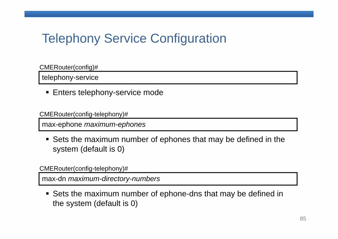
telephony-serviceCMERouter(config)#
Enters telephony-service mode
max-ephone maximum-ephonesCMERouter(config-telephony)#
Sets the maximum number of ephones that may be defined in the system (default is 0)
max-dn maximum-directory-numbersCMERouter(config-telephony)#
Sets the maximum number of ephone-dns that may be defined in the system (default is 0)
Telephony Service Configuration
86
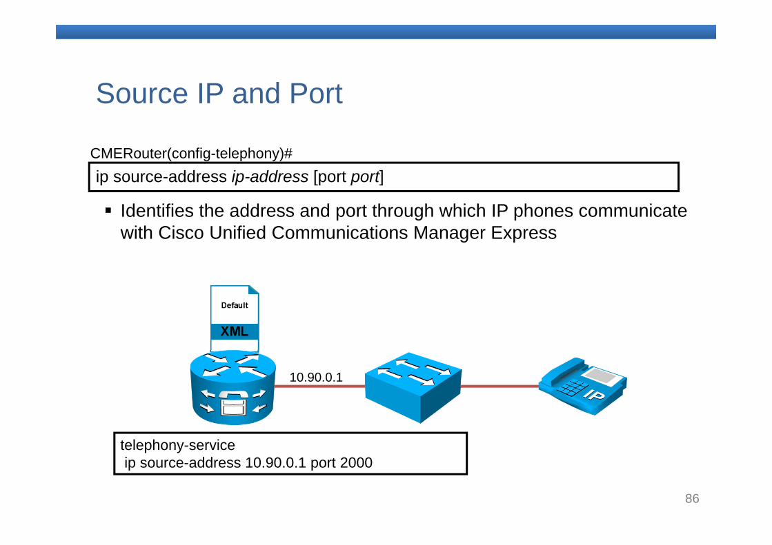
ip source-address ip-address [port port]CMERouter(config-telephony)#
Identifies the address and port through which IP phones communicate with Cisco Unified Communications Manager Express
Source IP and Port
telephony-serviceip source-address 10.90.0.1 port 2000
10.90.0.1
87
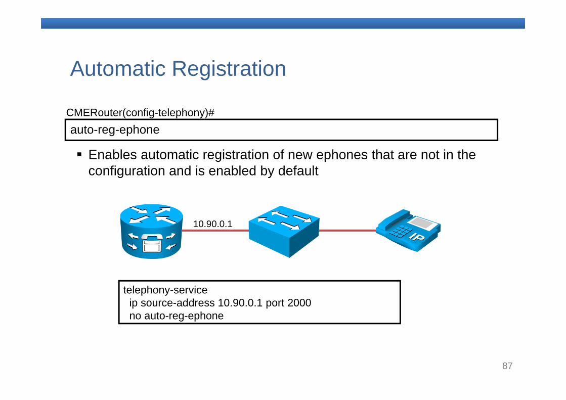
auto-reg-ephoneCMERouter(config-telephony)#
Enables automatic registration of new ephones that are not in the configuration and is enabled by default
Automatic Registration
telephony-serviceip source-address 10.90.0.1 port 2000 no auto-reg-ephone
10.90.0.1
88
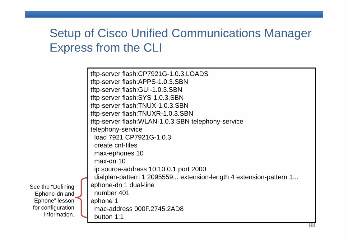
Setup of Cisco Unified Communications Manager Express from the CLI
tftp-server flash:CP7921G-1.0.3.LOADStftp-server flash:APPS-1.0.3.SBNtftp-server flash:GUI-1.0.3.SBNtftp-server flash:SYS-1.0.3.SBNtftp-server flash:TNUX-1.0.3.SBNtftp-server flash:TNUXR-1.0.3.SBNtftp-server flash:WLAN-1.0.3.SBN telephony-servicetelephony-service
load 7921 CP7921G-1.0.3create cnf-filesmax-ephones 10max-dn 10ip source-address 10.10.0.1 port 2000dialplan-pattern 1 2095559... extension-length 4 extension-pattern 1...
ephone-dn 1 dual-linenumber 401
ephone 1mac-address 000F.2745.2AD8button 1:1
See the “Defining Ephone-dn and Ephone” lesson for configuration
information.
89
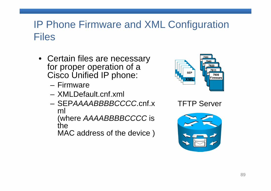
IP Phone Firmware and XML Configuration Files
• Certain files are necessary for proper operation of a Cisco Unified IP phone:– Firmware– XMLDefault.cnf.xml– SEPAAAABBBBCCCC.cnf.x
ml(where AAAABBBBCCCC is the MAC address of the device )
TFTP Server
90
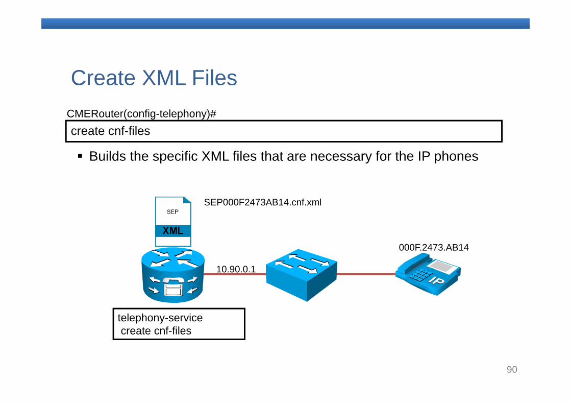
create cnf-filesCMERouter(config-telephony)#
Builds the specific XML files that are necessary for the IP phones
Create XML Files
telephony-servicecreate cnf-files
10.90.0.1
000F.2473.AB14
SEP000F2473AB14.cnf.xml
91
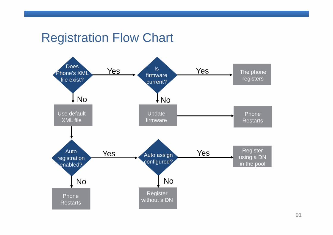
Registration Flow Chart
Does Phone’s XML
file exist?
Use default XML file
Auto registration enabled?
Phone Restarts
Yes
No
No
Yes Auto assign configured?
Register using a DN in the pool
Register without a DN
No
Yes
Is firmware current?
The phone registers
Update firmware
Yes
No
Phone Restarts
92
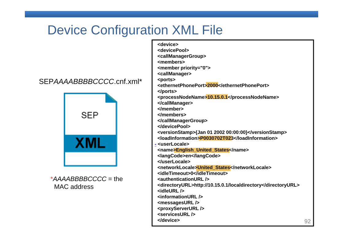
Device Configuration XML File
SEPAAAABBBBCCCC.cnf.xml*
*AAAABBBBCCCC = the MAC address
<device><devicePool><callManagerGroup><members><member priority="0"><callManager><ports><ethernetPhonePort>2000</ethernetPhonePort> </ports><processNodeName>10.15.0.1</processNodeName> </callManager></member></members></callManagerGroup></devicePool><versionStamp>{Jan 01 2002 00:00:00}</versionStamp> <loadInformation>P0030702T023</loadInformation>
- <userLocale><name>English_United_States</name> <langCode>en</langCode> </userLocale><networkLocale>United_States</networkLocale> <idleTimeout>0</idleTimeout> <authenticationURL /> <directoryURL>http://10.15.0.1/localdirectory</directoryURL> <idleURL /> <informationURL /> <messagesURL /> <proxyServerURL /> <servicesURL /> </device>
93
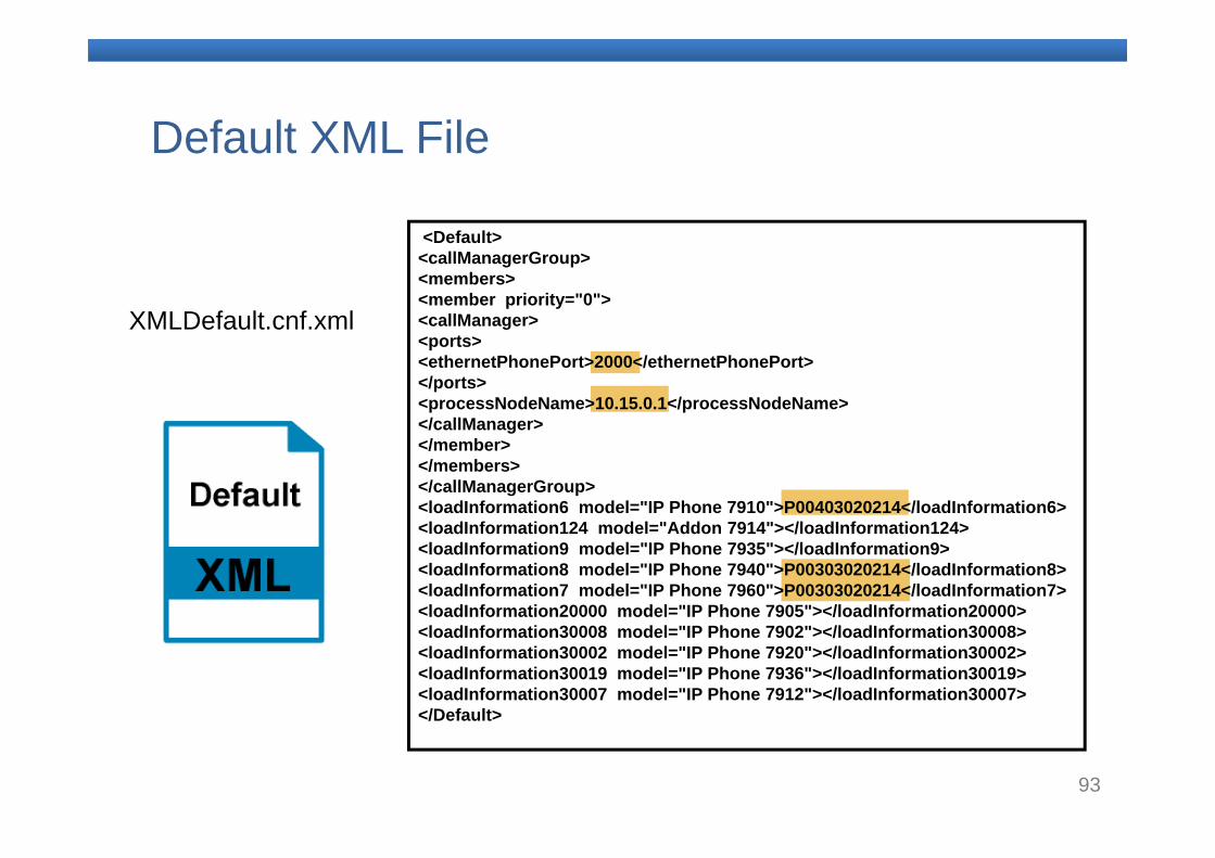
Default XML File
XMLDefault.cnf.xml
<Default><callManagerGroup><members><member priority="0"><callManager><ports><ethernetPhonePort>2000</ethernetPhonePort></ports><processNodeName>10.15.0.1</processNodeName></callManager></member></members></callManagerGroup><loadInformation6 model="IP Phone 7910">P00403020214</loadInformation6><loadInformation124 model="Addon 7914"></loadInformation124><loadInformation9 model="IP Phone 7935"></loadInformation9><loadInformation8 model="IP Phone 7940">P00303020214</loadInformation8><loadInformation7 model="IP Phone 7960">P00303020214</loadInformation7><loadInformation20000 model="IP Phone 7905"></loadInformation20000><loadInformation30008 model="IP Phone 7902"></loadInformation30008><loadInformation30002 model="IP Phone 7920"></loadInformation30002><loadInformation30019 model="IP Phone 7936"></loadInformation30019><loadInformation30007 model="IP Phone 7912"></loadInformation30007></Default>
94
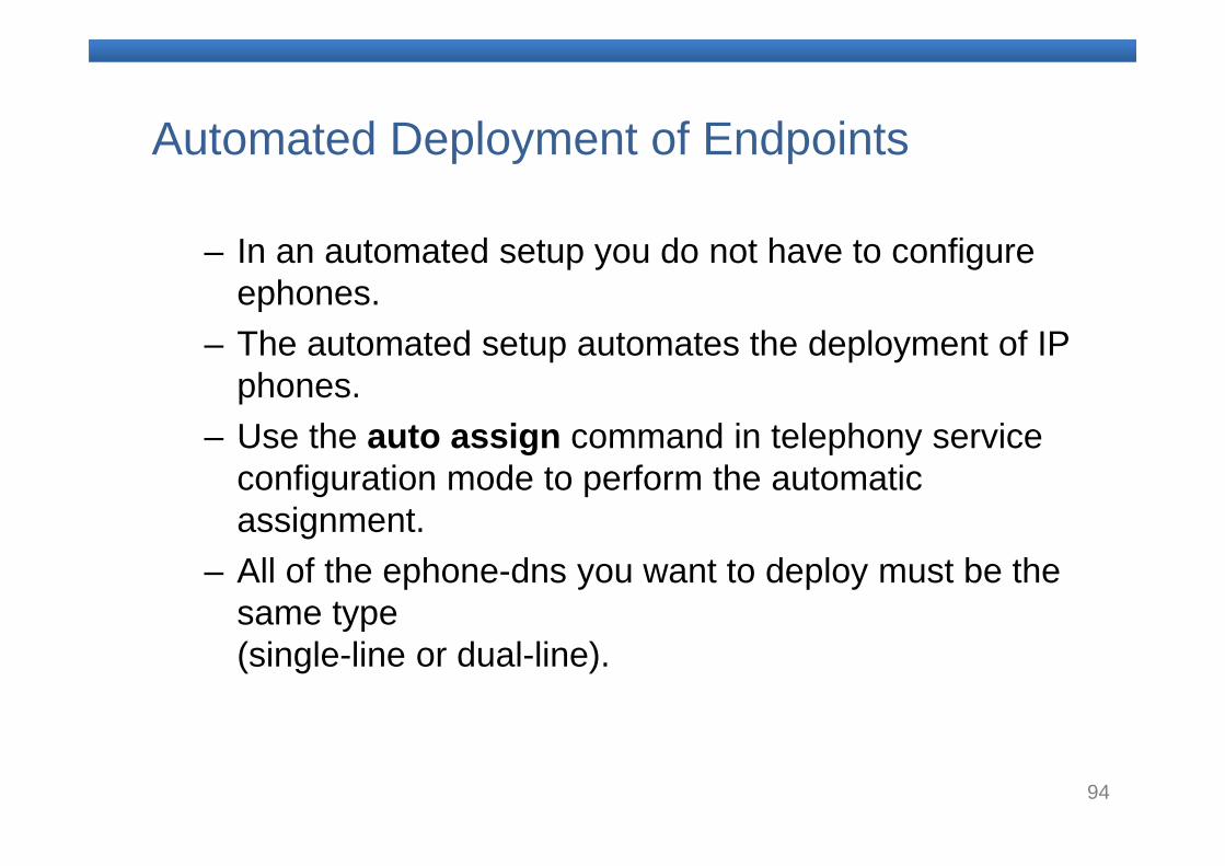
Automated Deployment of Endpoints
– In an automated setup you do not have to configure ephones.
– The automated setup automates the deployment of IP phones.
– Use the auto assign command in telephony service configuration mode to perform the automatic assignment.
– All of the ephone-dns you want to deploy must be the same type (single-line or dual-line).
95
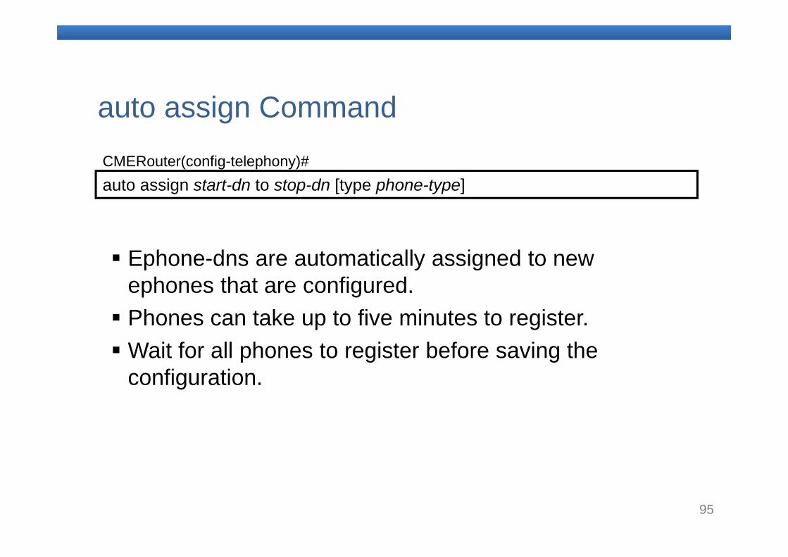
auto assign start-dn to stop-dn [type phone-type] CMERouter(config-telephony)#
Ephone-dns are automatically assigned to new ephones that are configured. Phones can take up to five minutes to register. Wait for all phones to register before saving the
configuration.
auto assign Command
96
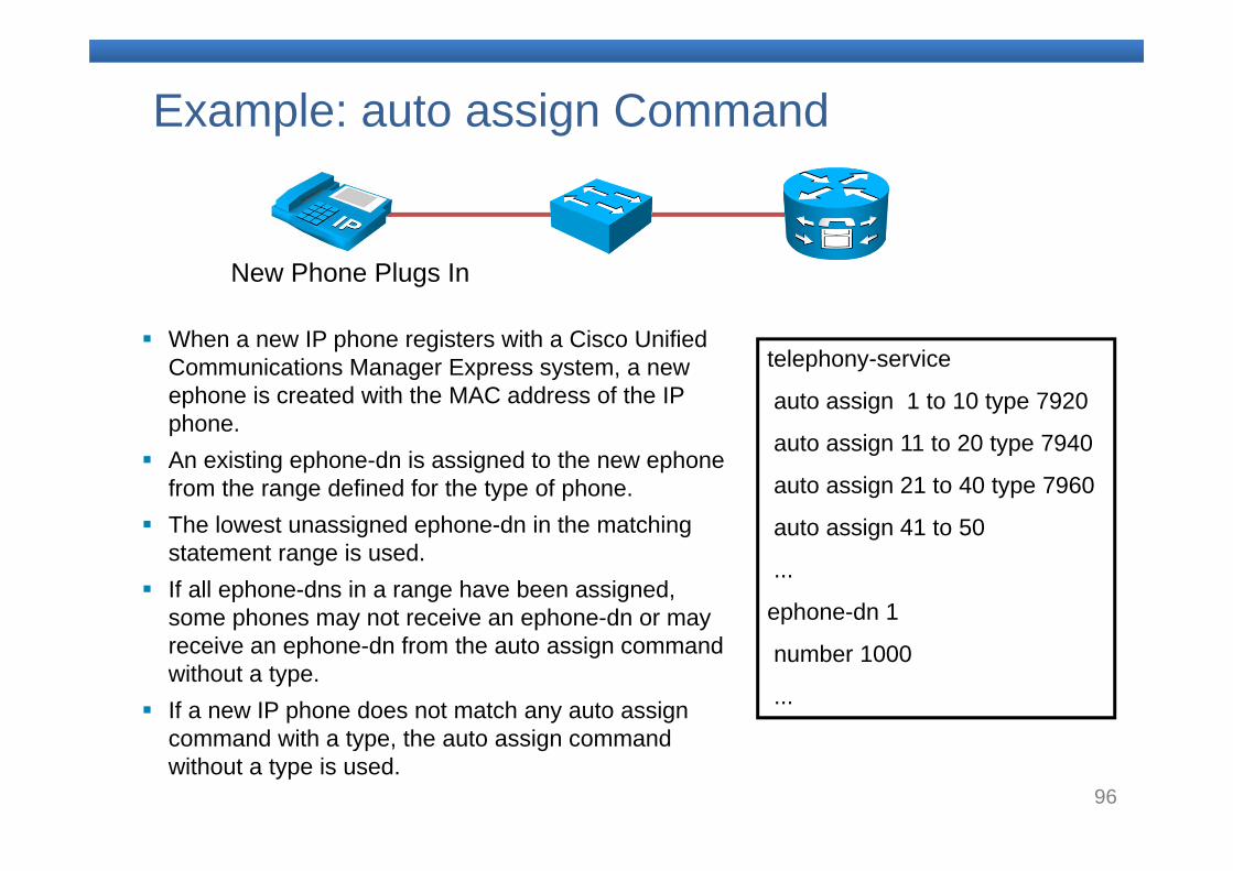
Example: auto assign Command
New Phone Plugs In
telephony-service
auto assign 1 to 10 type 7920
auto assign 11 to 20 type 7940
auto assign 21 to 40 type 7960
auto assign 41 to 50
...
ephone-dn 1
number 1000
...
When a new IP phone registers with a Cisco Unified Communications Manager Express system, a new ephone is created with the MAC address of the IP phone.
An existing ephone-dn is assigned to the new ephonefrom the range defined for the type of phone.
The lowest unassigned ephone-dn in the matching statement range is used.
If all ephone-dns in a range have been assigned, some phones may not receive an ephone-dn or may receive an ephone-dn from the auto assign command without a type.
If a new IP phone does not match any auto assign command with a type, the auto assign command without a type is used.
97
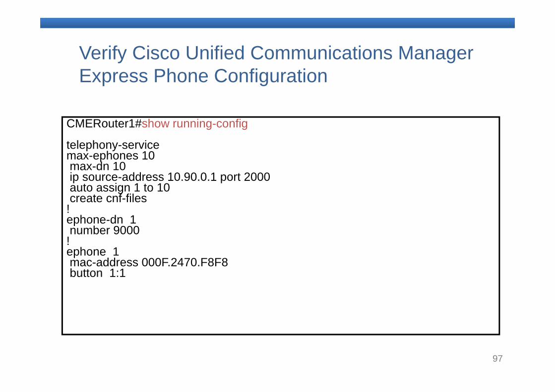
Verify Cisco Unified Communications Manager Express Phone Configuration
CMERouter1#show running-config
telephony-servicemax-ephones 10max-dn 10ip source-address 10.90.0.1 port 2000auto assign 1 to 10create cnf-files!ephone-dn 1 number 9000!ephone 1mac-address 000F.2470.F8F8button 1:1
98
11.Dial Peers and Destination Patterns
99
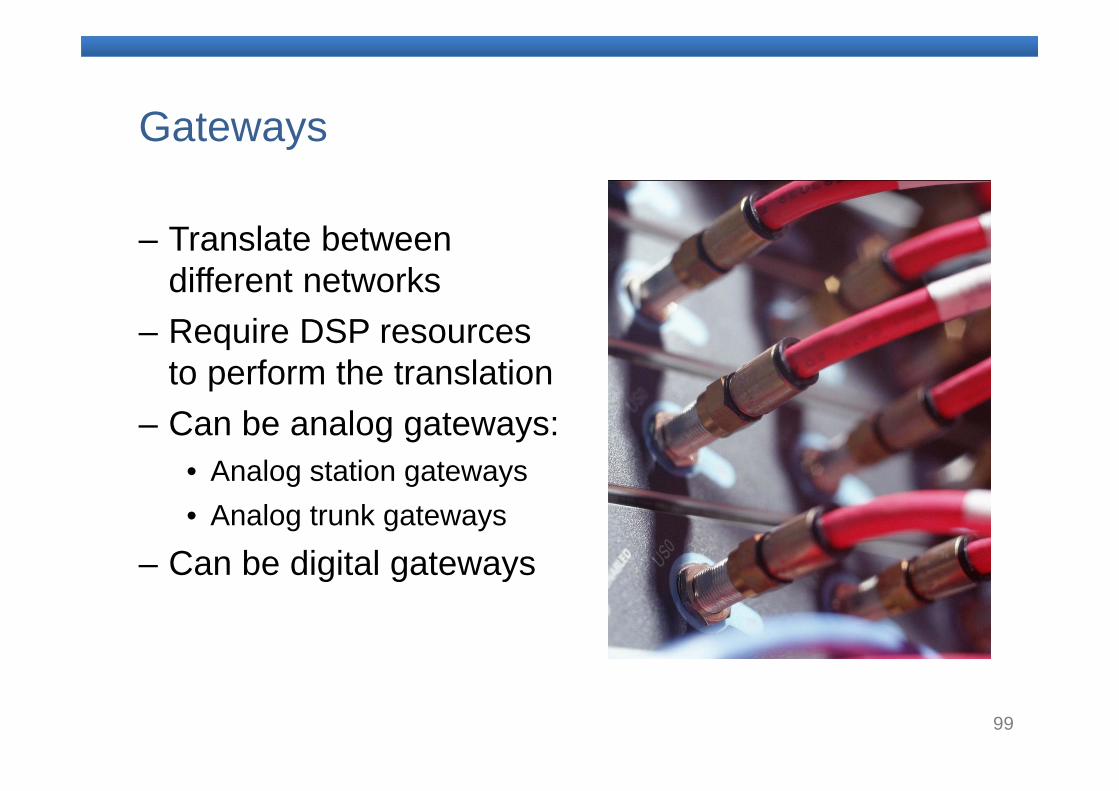
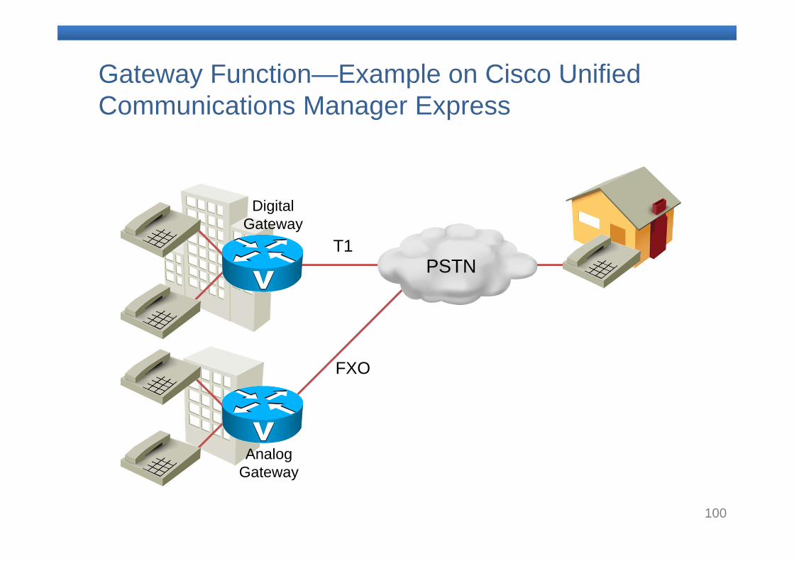
Gateways
– Translate between different networks
– Require DSP resources to perform the translation
– Can be analog gateways:• Analog station gateways• Analog trunk gateways
– Can be digital gateways
100
PSTN
Analog Gateway
Digital Gateway
T1
FXO
Gateway Function—Example on Cisco Unified Communications Manager Express
101
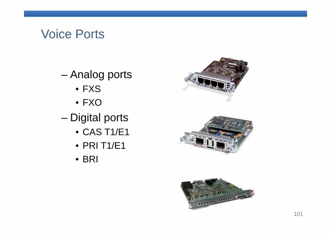
Voice Ports
– Analog ports• FXS• FXO
– Digital ports• CAS T1/E1• PRI T1/E1• BRI
102
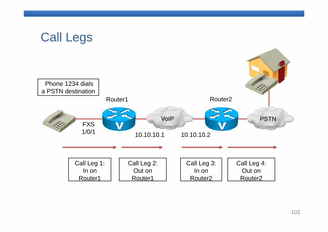
FXS 1/0/1
VoIP
10.10.10.210.10.10.1
Router1 Router2
PSTN
Phone 1234 dials a PSTN destination
Call Leg 1: In on
Router1
Call Leg 3: In on
Router2
Call Leg 4: Out on Router2
Call Leg 2: Out on Router1
Call Legs
103
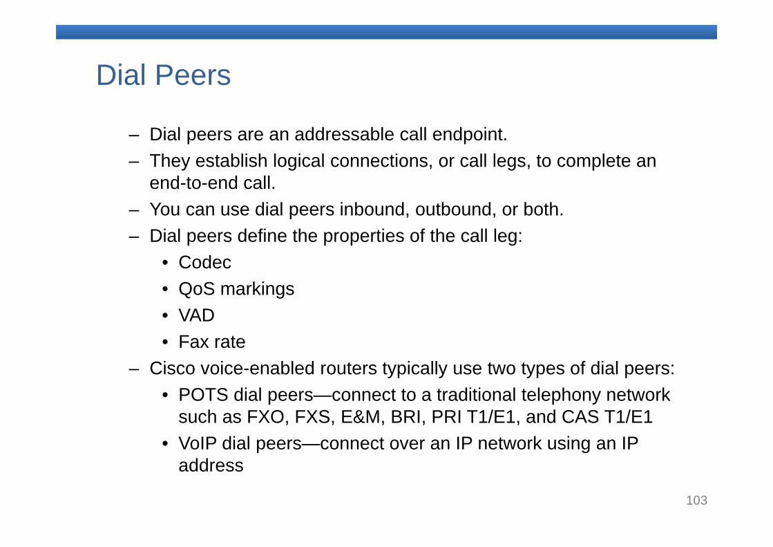
Dial Peers
– Dial peers are an addressable call endpoint.– They establish logical connections, or call legs, to complete an
end-to-end call.– You can use dial peers inbound, outbound, or both.– Dial peers define the properties of the call leg:
• Codec• QoS markings• VAD• Fax rate
– Cisco voice-enabled routers typically use two types of dial peers:• POTS dial peers—connect to a traditional telephony network
such as FXO, FXS, E&M, BRI, PRI T1/E1, and CAS T1/E1• VoIP dial peers—connect over an IP network using an IP
address
104
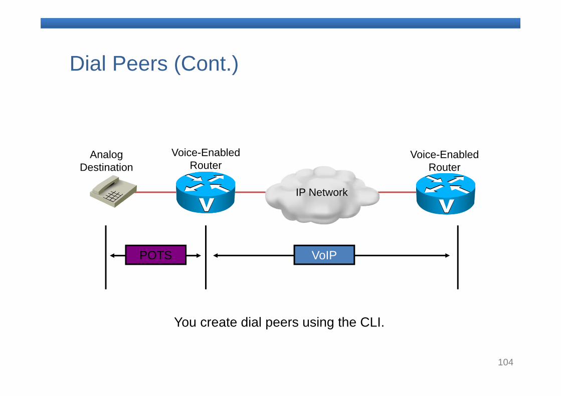
Dial Peers (Cont.)
IP Network
Voice-Enabled Router
Voice-EnabledRouter
AnalogDestination
POTS VoIP
You create dial peers using the CLI.
105
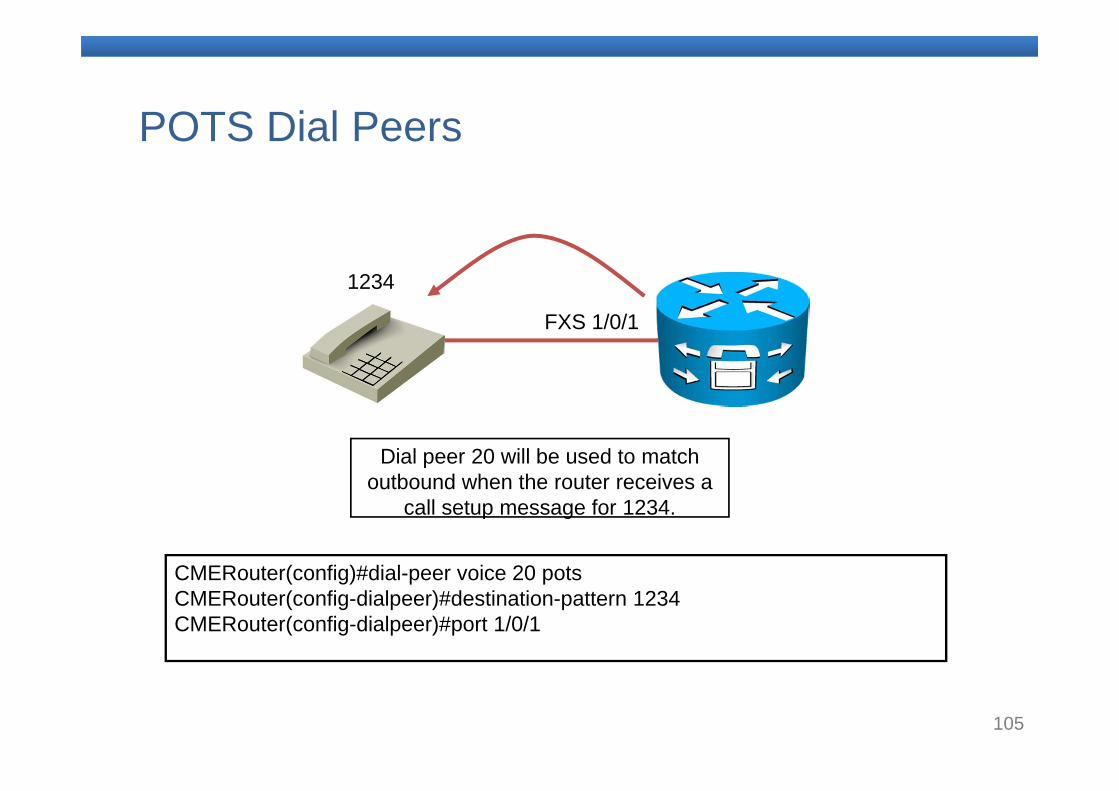
POTS Dial Peers
CMERouter(config)#dial-peer voice 20 potsCMERouter(config-dialpeer)#destination-pattern 1234CMERouter(config-dialpeer)#port 1/0/1
FXS 1/0/1
1234
Dial peer 20 will be used to match outbound when the router receives a
call setup message for 1234.
106
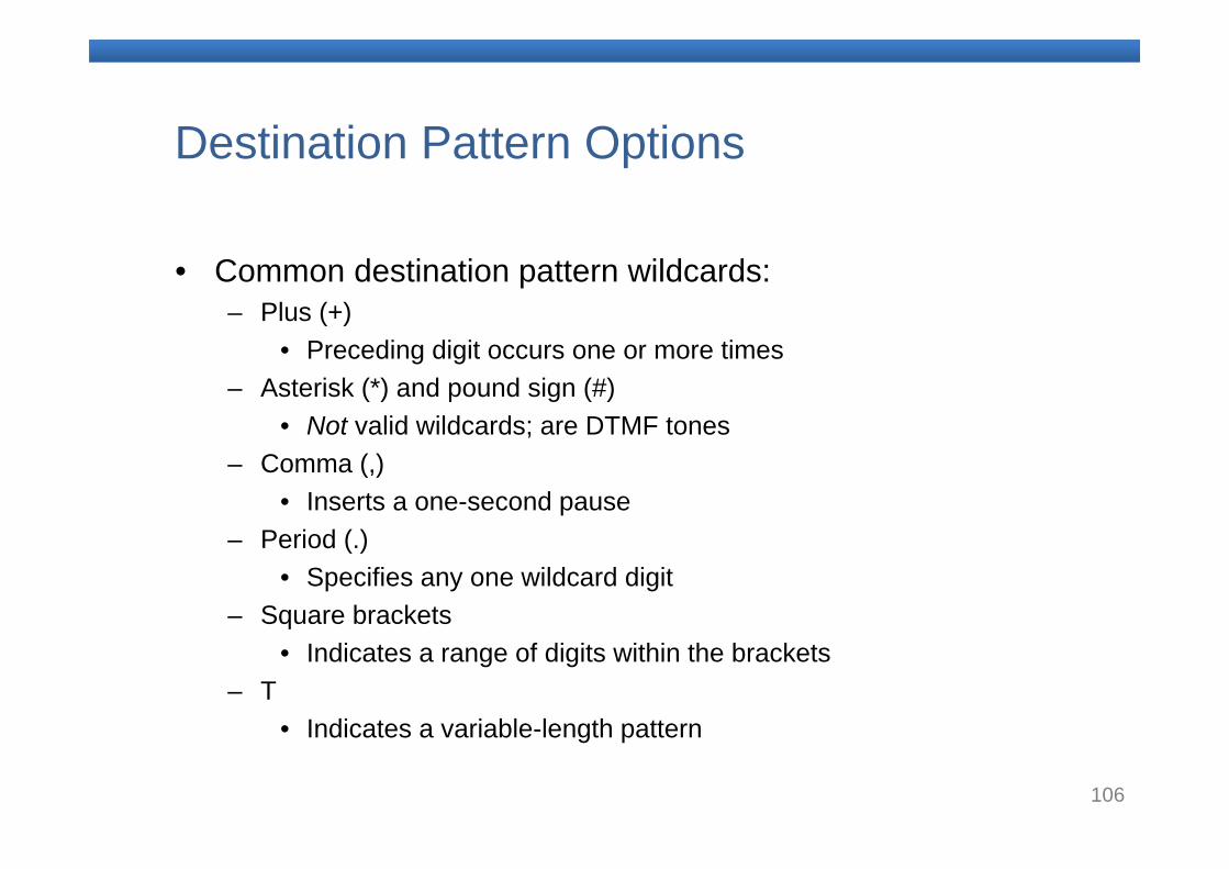
Destination Pattern Options
• Common destination pattern wildcards:– Plus (+)
• Preceding digit occurs one or more times– Asterisk (*) and pound sign (#)
• Not valid wildcards; are DTMF tones– Comma (,)
• Inserts a one-second pause– Period (.)
• Specifies any one wildcard digit– Square brackets
• Indicates a range of digits within the brackets– T
• Indicates a variable-length pattern
107
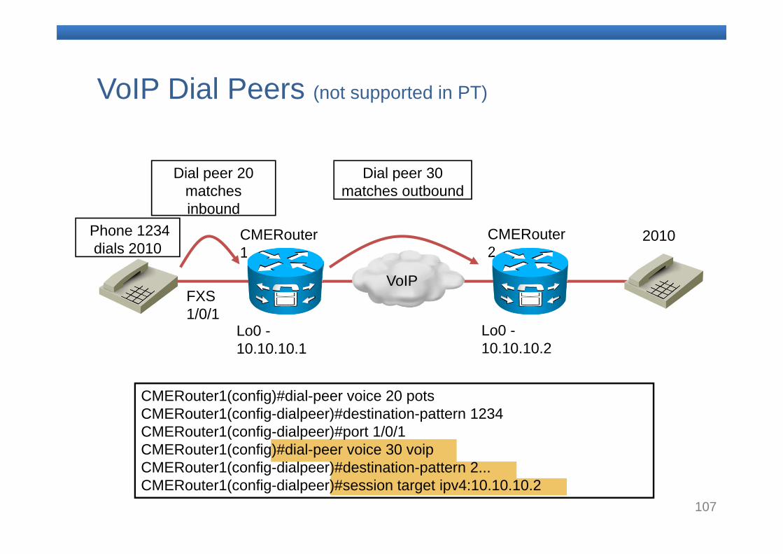
VoIP Dial Peers (not supported in PT)
FXS 1/0/1
VoIP
Lo0 -10.10.10.2
Lo0 -10.10.10.1
CMERouter1
CMERouter2
2010Phone 1234 dials 2010
Dial peer 20 matches inbound
Dial peer 30 matches outbound
CMERouter1(config)#dial-peer voice 20 potsCMERouter1(config-dialpeer)#destination-pattern 1234CMERouter1(config-dialpeer)#port 1/0/1CMERouter1(config)#dial-peer voice 30 voipCMERouter1(config-dialpeer)#destination-pattern 2...CMERouter1(config-dialpeer)#session target ipv4:10.10.10.2
108
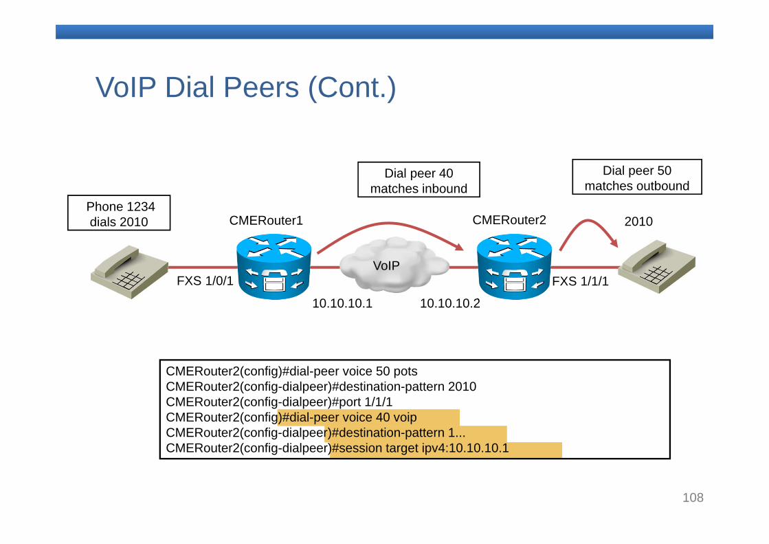
VoIP Dial Peers (Cont.)
FXS 1/0/1VoIP
10.10.10.210.10.10.1
CMERouter1 CMERouter2 2010Phone 1234 dials 2010
Dial peer 40 matches inbound
Dial peer 50 matches outbound
FXS 1/1/1
CMERouter2(config)#dial-peer voice 50 potsCMERouter2(config-dialpeer)#destination-pattern 2010CMERouter2(config-dialpeer)#port 1/1/1CMERouter2(config)#dial-peer voice 40 voipCMERouter2(config-dialpeer)#destination-pattern 1...CMERouter2(config-dialpeer)#session target ipv4:10.10.10.1
109
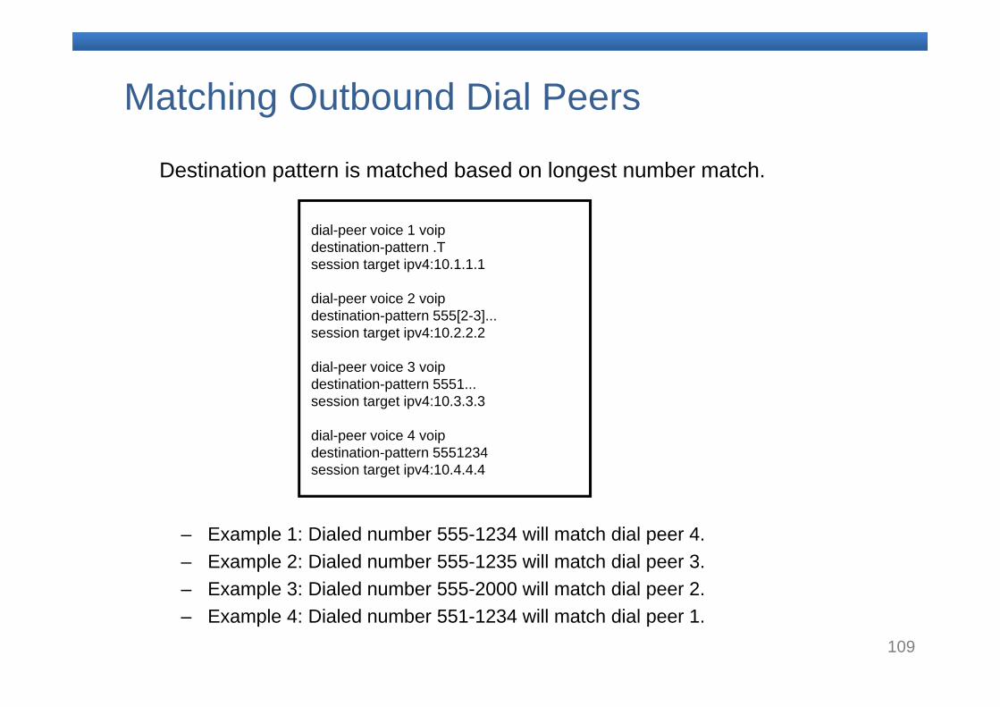
Matching Outbound Dial Peers
– Example 1: Dialed number 555-1234 will match dial peer 4.– Example 2: Dialed number 555-1235 will match dial peer 3.– Example 3: Dialed number 555-2000 will match dial peer 2.– Example 4: Dialed number 551-1234 will match dial peer 1.
Destination pattern is matched based on longest number match.
dial-peer voice 1 voipdestination-pattern .Tsession target ipv4:10.1.1.1
dial-peer voice 2 voipdestination-pattern 555[2-3]...session target ipv4:10.2.2.2
dial-peer voice 3 voipdestination-pattern 5551...session target ipv4:10.3.3.3
dial-peer voice 4 voipdestination-pattern 5551234session target ipv4:10.4.4.4
110
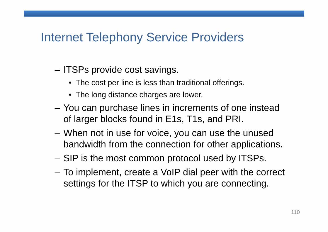
Internet Telephony Service Providers
– ITSPs provide cost savings.• The cost per line is less than traditional offerings.• The long distance charges are lower.
– You can purchase lines in increments of one instead of larger blocks found in E1s, T1s, and PRI.
– When not in use for voice, you can use the unused bandwidth from the connection for other applications.
– SIP is the most common protocol used by ITSPs.– To implement, create a VoIP dial peer with the correct
settings for the ITSP to which you are connecting.
111
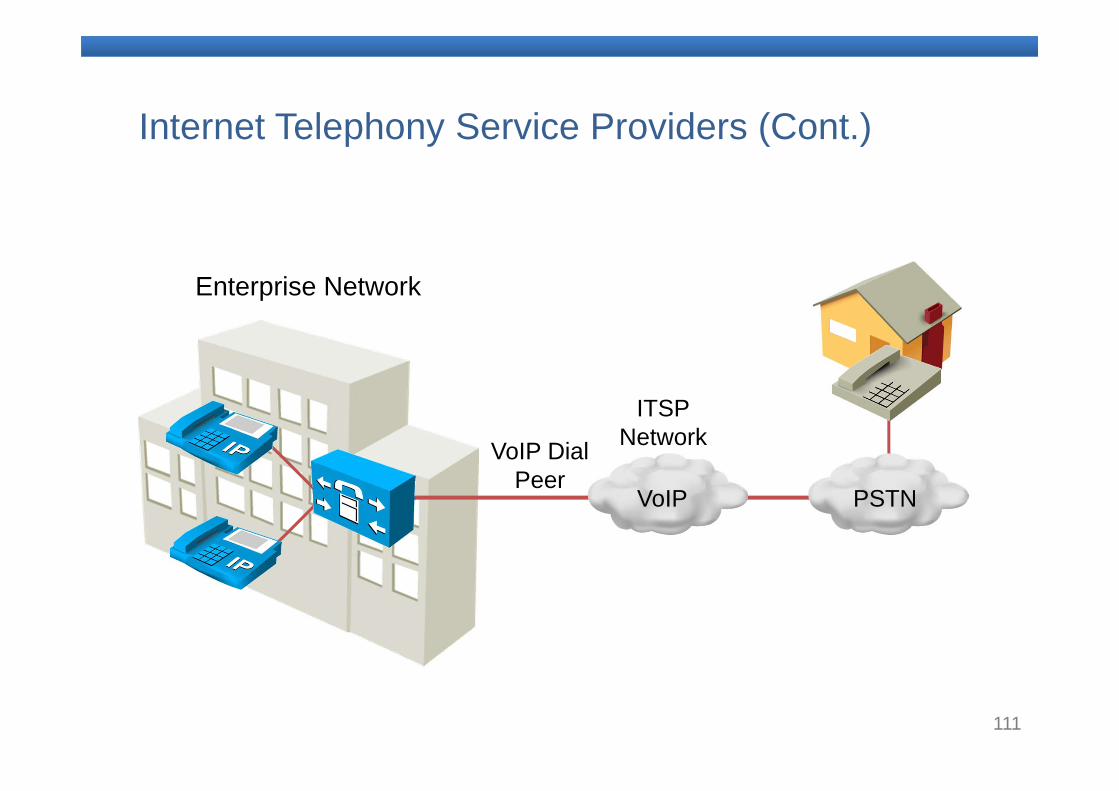
Internet Telephony Service Providers (Cont.)
VoIP
ITSPNetwork
Enterprise Network
VoIP Dial Peer
PSTN
112
Dial Peers and Destination Patterns Summary
– Gateways translate between two different networks. They can be analog or digital.
– Voice ports are used to terminate a traditional telephony interface on the voice gateway.
– Call legs represent segments in the call path that connect two devices.
– Dial peers represent programming on the voice gateway that defines what to do when a call setup message is received.
– An ITSP trunk is an IP connection to the carrier for PSTNcalls.
– You can use show commands to verify dial peer and dial plan configurations.
113
References
• Implementing Cisco IOS Unified Communications, © 2008 Cisco Systems, Inc. (source of most of the graphics)
114
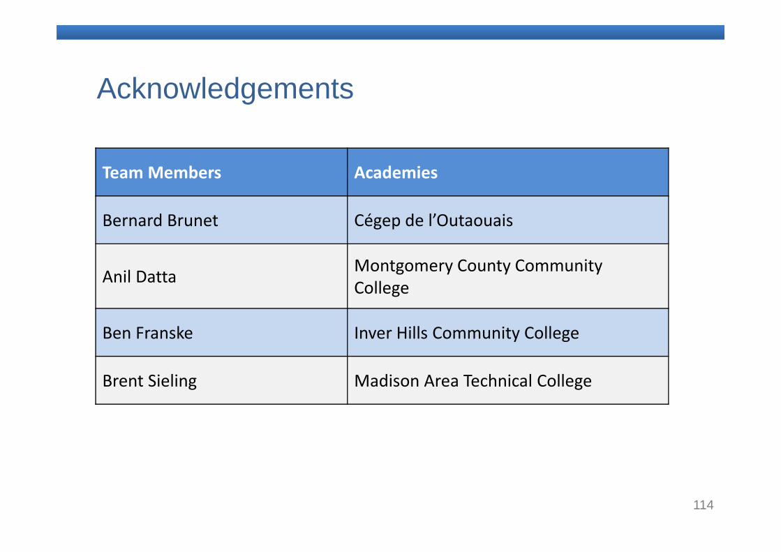
Acknowledgements
Team Members Academies
Bernard Brunet Cégep de l’Outaouais
Anil Datta Montgomery County Community College
Ben Franske Inver Hills Community College
Brent Sieling Madison Area Technical College

115
Thank you


