Embed Size (px)
Citation preview

Challenger MT6X5C Series, Massey Ferguson 86X0 Series and AGCO
DT-B Series SmarTrax™ Installation Manual
P/N 016-5033-004 Rev. B 08/15 E24297
Copyright 2015

Chapter 1 Important Safety Information ..................................... 1
Hydraulic Safety ........................................................................................................................ 2Electrical Safety ........................................................................................................................ 2
Chapter 2 Introduction ........................................................................ 3
Preparing for Installation ........................................................................................................... 3Recommendations .............................................................................................................. 4Point of Reference ............................................................................................................... 4
Updates ..................................................................................................................................... 4Kit Contents ............................................................................................................................... 5
Chapter 3 Hydraulic System Installation .................................. 11
Install Fittings in the SmarTrax Valve ...................................................................................... 12Prepare for Installation ............................................................................................................ 12Install the Left and Right Steering Hoses ................................................................................ 15Install the Pressure and Tank Hoses ....................................................................................... 15Install the Load Sense Hoses .................................................................................................. 16Mount the SmarTrax Valve ...................................................................................................... 17Install the Hydraulic Hoses on the SmarTrax Valve ................................................................ 18Hydraulic Diagram ................................................................................................................... 20
Chapter 4 Wheel Angle Sensor (WAS) Installation ............... 21
Assemble the Wheel Angle Sensor (WAS) ............................................................................. 21Install the WAS ........................................................................................................................ 23
Chapter 5 Cab Component Installation ..................................... 27
Install the SmarTrax Node ....................................................................................................... 27Mount the SmarTrax Node ................................................................................................ 27Node Mounting Locations .................................................................................................. 29
Install the Foot Switch ............................................................................................................. 30Install the Valve Harness ......................................................................................................... 30Install the Chassis Cable - SmarTrax-Only Systems (If Applicable) ........................................ 33Connect SmarTrax to an Existing Chassis Cable (If Applicable) ............................................ 33Complete the SmarTrax System Installation ........................................................................... 33System Diagrams .................................................................................................................... 34
Chapter 6 Startup Procedures ....................................................... 41
Verify SmarTrax System Installation ....................................................................................... 41Calibrate the SmarTrax System .............................................................................................. 42
P/N 016-5033-004 Rev. B i

Chapter 1
ii Challenger MT6X5C Series, Massey Ferguson 86X0 Series and AGCO DT-B Series SmarTrax™ Installation Manual
CHAPTER
1
P/N 016-5033-004 Rev. B
Chapter 1Important Safety Information
Read this manual and the operation and safety instructions included with your implement and/or controller carefully before installing the SmarTrax™ system.
• Follow all safety information presented within this manual.
• If you require assistance with any portion of the installation or service of your Raven equipment, contact your local Raven dealer for support.
• Follow all safety labels affixed to the SmarTrax system components. Be sure to keep safety labels in good condition and replace any missing or damaged labels. To obtain replacements for missing or damaged safety labels, contact your local Raven dealer.
When operating the machine after installing SmarTrax, observe the following safety measures:
• Be alert and aware of surroundings.
• Do not operate SmarTrax or any agricultural equipment while under the influence of alcohol or an illegal substance.
• Remain in the operator’s position in the machine at all times when SmarTrax is engaged.
• Disable SmarTrax when exiting the operator’s seat and machine.
• Do not drive the machine with SmarTrax enabled on any public road.
• Determine and remain a safe working distance from other individuals. The operator is responsible for disabling SmarTrax when the safe working distance has diminished.
• Ensure SmarTrax is disabled prior to starting any maintenance work on SmarTrax or the machine.
• When starting the machine for the first time after installing SmarTrax, be sure that all persons stand clear in case a hose has not been properly tightened.
• The machine must remain stationary and switched off during SmarTrax installation or maintenance.
NOTICE
WARNING
1

Chapter 1
Hydraulic Safety• Raven Industries recommends that appropriate protective equipment be worn at all times when working on
the hydraulic system.
• Never attempt to open or work on a hydraulic system with the equipment running. Use caution when opening a system that has been previously pressurized.
• Exercise caution when disconnecting the hydraulic hoses or purging is required, be aware that the hydraulic fluid may be extremely hot and under high pressure.
• Any work performed on the hydraulic system must be done in accordance with the machine manufacturer’s approved maintenance instructions.
• When installing SmarTrax hydraulics or performing diagnostics, maintenance, or routine service, use caution to prevent foreign material or contaminants from being introduced into the machine’s hydraulic system. Objects or materials that are able to bypass the machine’s hydraulic filtration system will reduce performance and possibly damage the SmarTrax valve.
Electrical Safety• Always verify that the power leads are connected to the correct polarity as marked. Reversing the power
leads could cause severe damage to the equipment.
• Connect the power cable last.
CAUTION
2 Challenger MT6X5C Series, Massey Ferguson 86X0 Series and AGCO DT-B Series SmarTrax™ Installation Manual
CHAPTER
2
P/N 016-5033-004 Rev. B
Chapter 2Introduction
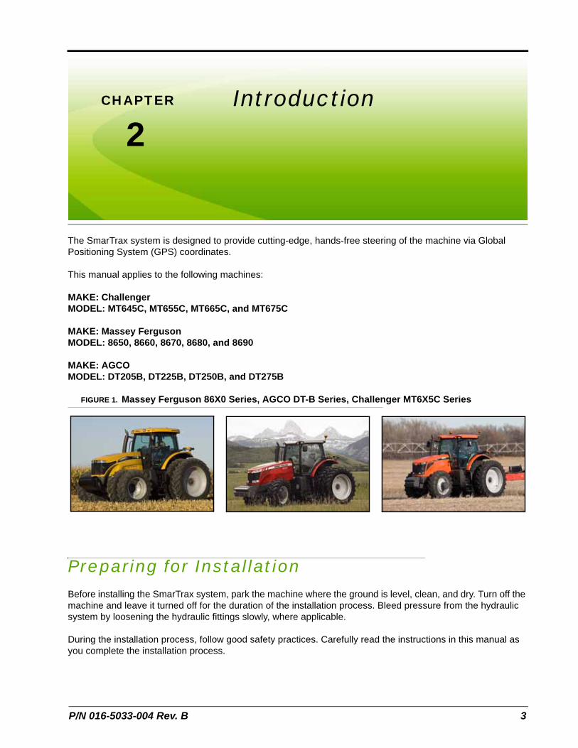
The SmarTrax system is designed to provide cutting-edge, hands-free steering of the machine via Global Positioning System (GPS) coordinates.
This manual applies to the following machines:
MAKE: Challenger MODEL: MT645C, MT655C, MT665C, and MT675C
MAKE: Massey Ferguson MODEL: 8650, 8660, 8670, 8680, and 8690
MAKE: AGCO MODEL: DT205B, DT225B, DT250B, and DT275B
FIGURE 1. Massey Ferguson 86X0 Series, AGCO DT-B Series, Challenger MT6X5C Series
Preparing for InstallationBefore installing the SmarTrax system, park the machine where the ground is level, clean, and dry. Turn off the machine and leave it turned off for the duration of the installation process. Bleed pressure from the hydraulic system by loosening the hydraulic fittings slowly, where applicable.
During the installation process, follow good safety practices. Carefully read the instructions in this manual as you complete the installation process.
3
Chapter 2
Recommendations
Raven Industries recommends the following best practices when installing or operating the SmarTrax system for the first time, at the start of the season, or when moving the SmarTrax system to another machine:
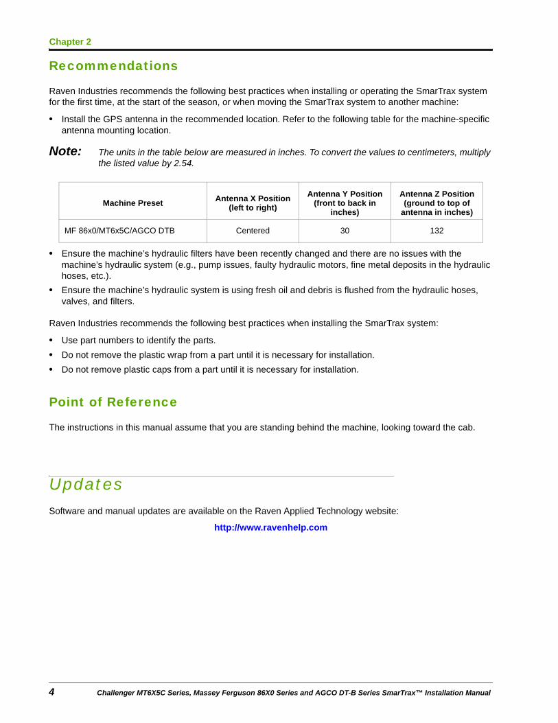
• Install the GPS antenna in the recommended location. Refer to the following table for the machine-specific antenna mounting location.
Note: The units in the table below are measured in inches. To convert the values to centimeters, multiply the listed value by 2.54.
• Ensure the machine’s hydraulic filters have been recently changed and there are no issues with the machine’s hydraulic system (e.g., pump issues, faulty hydraulic motors, fine metal deposits in the hydraulic hoses, etc.).
• Ensure the machine’s hydraulic system is using fresh oil and debris is flushed from the hydraulic hoses, valves, and filters.
Raven Industries recommends the following best practices when installing the SmarTrax system:
• Use part numbers to identify the parts.
• Do not remove the plastic wrap from a part until it is necessary for installation.
• Do not remove plastic caps from a part until it is necessary for installation.
Point of Reference
The instructions in this manual assume that you are standing behind the machine, looking toward the cab.
UpdatesSoftware and manual updates are available on the Raven Applied Technology website:
http://www.ravenhelp.com
Machine Preset Antenna X Position (left to right)
Antenna Y Position (front to back in
inches)
Antenna Z Position (ground to top of
antenna in inches)
MF 86x0/MT6x5C/AGCO DTB Centered 30 132
4 Challenger MT6X5C Series, Massey Ferguson 86X0 Series and AGCO DT-B Series SmarTrax™ Installation Manual
2
Introduction
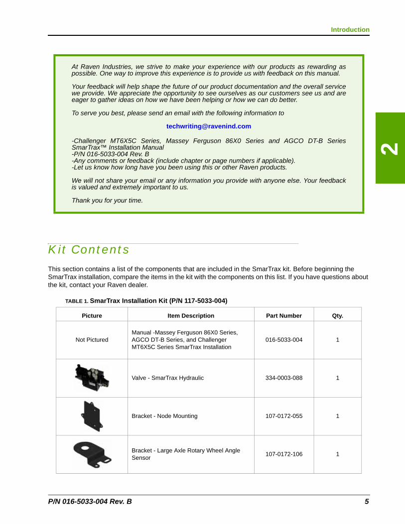
Kit ContentsThis section contains a list of the components that are included in the SmarTrax kit. Before beginning the SmarTrax installation, compare the items in the kit with the components on this list. If you have questions about the kit, contact your Raven dealer.
At Raven Industries, we strive to make your experience with our products as rewarding as possible. One way to improve this experience is to provide us with feedback on this manual.
Your feedback will help shape the future of our product documentation and the overall service we provide. We appreciate the opportunity to see ourselves as our customers see us and are eager to gather ideas on how we have been helping or how we can do better.
To serve you best, please send an email with the following information to
-Challenger MT6X5C Series, Massey Ferguson 86X0 Series and AGCO DT-B Series SmarTrax™ Installation Manual -P/N 016-5033-004 Rev. B -Any comments or feedback (include chapter or page numbers if applicable). -Let us know how long have you been using this or other Raven products.
We will not share your email or any information you provide with anyone else. Your feedback is valued and extremely important to us.
Thank you for your time.
TABLE 1. SmarTrax Installation Kit (P/N 117-5033-004)
Picture Item Description Part Number Qty.
Not PicturedManual -Massey Ferguson 86X0 Series, AGCO DT-B Series, and Challenger MT6X5C Series SmarTrax Installation
016-5033-004 1
Valve - SmarTrax Hydraulic 334-0003-088 1
Bracket - Node Mounting 107-0172-055 1
Bracket - Large Axle Rotary Wheel Angle Sensor
107-0172-106 1
P/N 016-5033-004 Rev. B 5
Chapter 2
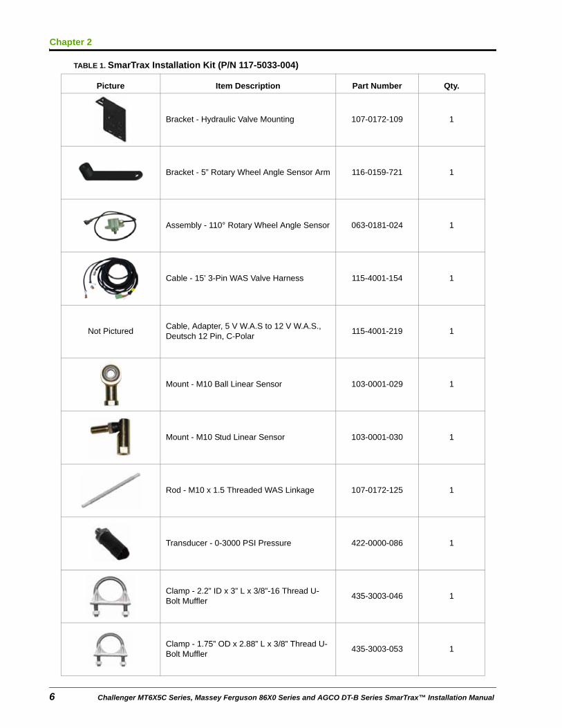
Bracket - Hydraulic Valve Mounting 107-0172-109 1
Bracket - 5” Rotary Wheel Angle Sensor Arm 116-0159-721 1
Assembly - 110° Rotary Wheel Angle Sensor 063-0181-024 1
Cable - 15’ 3-Pin WAS Valve Harness 115-4001-154 1
Not PicturedCable, Adapter, 5 V W.A.S to 12 V W.A.S., Deutsch 12 Pin, C-Polar
115-4001-219 1
Mount - M10 Ball Linear Sensor 103-0001-029 1
Mount - M10 Stud Linear Sensor 103-0001-030 1
Rod - M10 x 1.5 Threaded WAS Linkage 107-0172-125 1
Transducer - 0-3000 PSI Pressure 422-0000-086 1
Clamp - 2.2” ID x 3” L x 3/8”-16 Thread U-Bolt Muffler
435-3003-046 1
Clamp - 1.75” OD x 2.88” L x 3/8” Thread U-Bolt Muffler
435-3003-053 1
TABLE 1. SmarTrax Installation Kit (P/N 117-5033-004)
Picture Item Description Part Number Qty.
6 Challenger MT6X5C Series, Massey Ferguson 86X0 Series and AGCO DT-B Series SmarTrax™ Installation Manual
2
Introduction
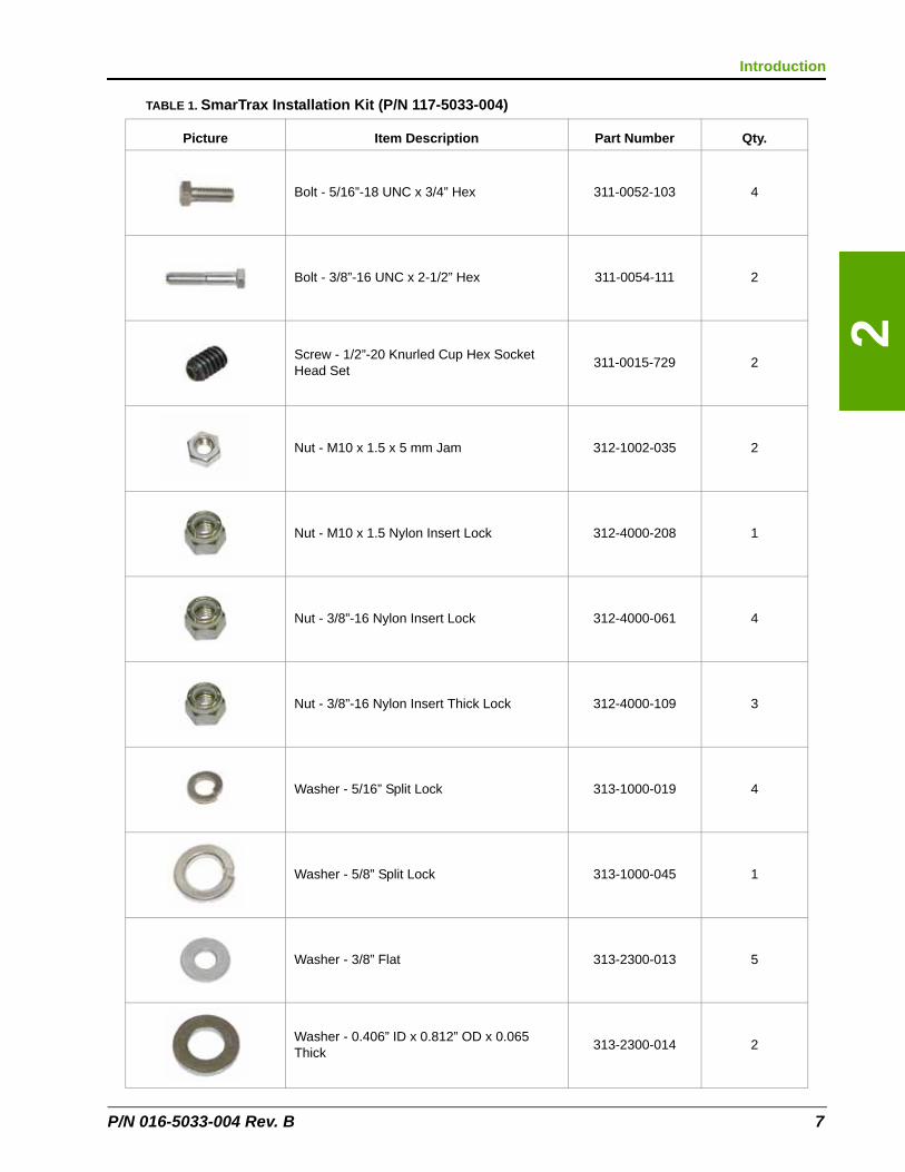
Bolt - 5/16”-18 UNC x 3/4” Hex 311-0052-103 4
Bolt - 3/8”-16 UNC x 2-1/2” Hex 311-0054-111 2
Screw - 1/2”-20 Knurled Cup Hex Socket Head Set
311-0015-729 2
Nut - M10 x 1.5 x 5 mm Jam 312-1002-035 2
Nut - M10 x 1.5 Nylon Insert Lock 312-4000-208 1
Nut - 3/8”-16 Nylon Insert Lock 312-4000-061 4
Nut - 3/8”-16 Nylon Insert Thick Lock 312-4000-109 3
Washer - 5/16” Split Lock 313-1000-019 4
Washer - 5/8” Split Lock 313-1000-045 1
Washer - 3/8” Flat 313-2300-013 5
Washer - 0.406” ID x 0.812” OD x 0.065 Thick
313-2300-014 2
TABLE 1. SmarTrax Installation Kit (P/N 117-5033-004)
Picture Item Description Part Number Qty.
P/N 016-5033-004 Rev. B 7
Chapter 2
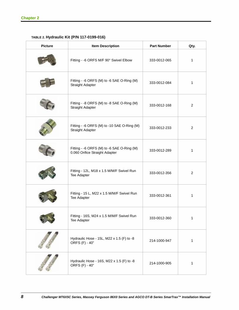
TABLE 2. Hydraulic Kit (P/N 117-0199-016)
Picture Item Description Part Number Qty.
Fitting - -6 ORFS M/F 90° Swivel Elbow 333-0012-065 1
Fitting - -6 ORFS (M) to -6 SAE O-Ring (M) Straight Adapter
333-0012-084 1
Fitting - -8 ORFS (M) to -8 SAE O-Ring (M) Straight Adapter
333-0012-168 2
Fitting - -6 ORFS (M) to -10 SAE O-Ring (M) Straight Adapter
333-0012-233 2
Fitting - -6 ORFS (M) to -6 SAE O-Ring (M) 0.060 Orifice Straight Adapter
333-0012-289 1
Fitting - 12L, M18 x 1.5 M/M/F Swivel Run Tee Adapter
333-0012-356 2
Fitting - 15 L, M22 x 1.5 M/M/F Swivel Run Tee Adapter
333-0012-361 1
Fitting - 16S, M24 x 1.5 M/M/F Swivel Run Tee Adapter
333-0012-360 1
Hydraulic Hose - 15L, M22 x 1.5 (F) to -8 ORFS (F) - 40”
214-1000-947 1
Hydraulic Hose - 16S, M22 x 1.5 (F) to -8 ORFS (F) - 40”
214-1000-905 1
8 Challenger MT6X5C Series, Massey Ferguson 86X0 Series and AGCO DT-B Series SmarTrax™ Installation Manual
2
Introduction
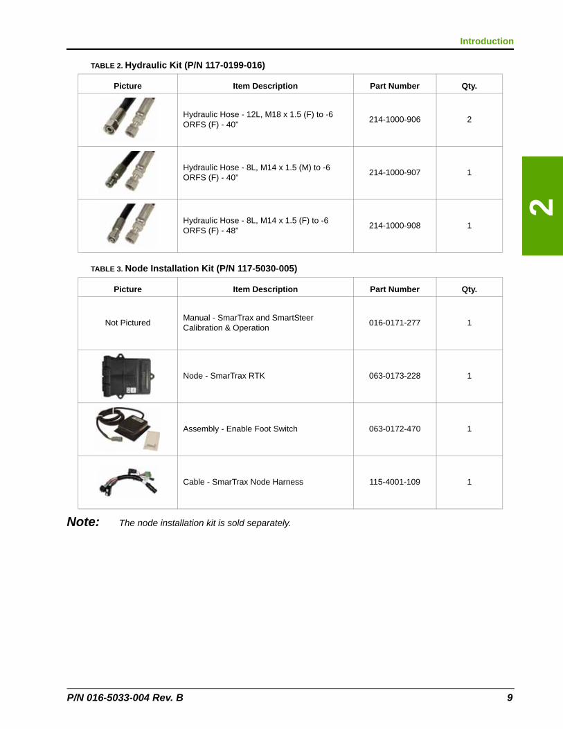
Note: The node installation kit is sold separately.
Hydraulic Hose - 12L, M18 x 1.5 (F) to -6 ORFS (F) - 40”
214-1000-906 2
Hydraulic Hose - 8L, M14 x 1.5 (M) to -6 ORFS (F) - 40”
214-1000-907 1
Hydraulic Hose - 8L, M14 x 1.5 (F) to -6 ORFS (F) - 48”
214-1000-908 1
TABLE 3. Node Installation Kit (P/N 117-5030-005)
Picture Item Description Part Number Qty.
Not PicturedManual - SmarTrax and SmartSteer Calibration & Operation
016-0171-277 1
Node - SmarTrax RTK 063-0173-228 1
Assembly - Enable Foot Switch 063-0172-470 1
Cable - SmarTrax Node Harness 115-4001-109 1
TABLE 2. Hydraulic Kit (P/N 117-0199-016)
Picture Item Description Part Number Qty.
P/N 016-5033-004 Rev. B 9

Chapter 2
10 Challenger MT6X5C Series, Massey Ferguson 86X0 Series and AGCO DT-B Series SmarTrax™ Installation Manual
CHAPTER
3
P/N 016-5033-004 Rev. B
Chapter 3Hydraulic System Installation
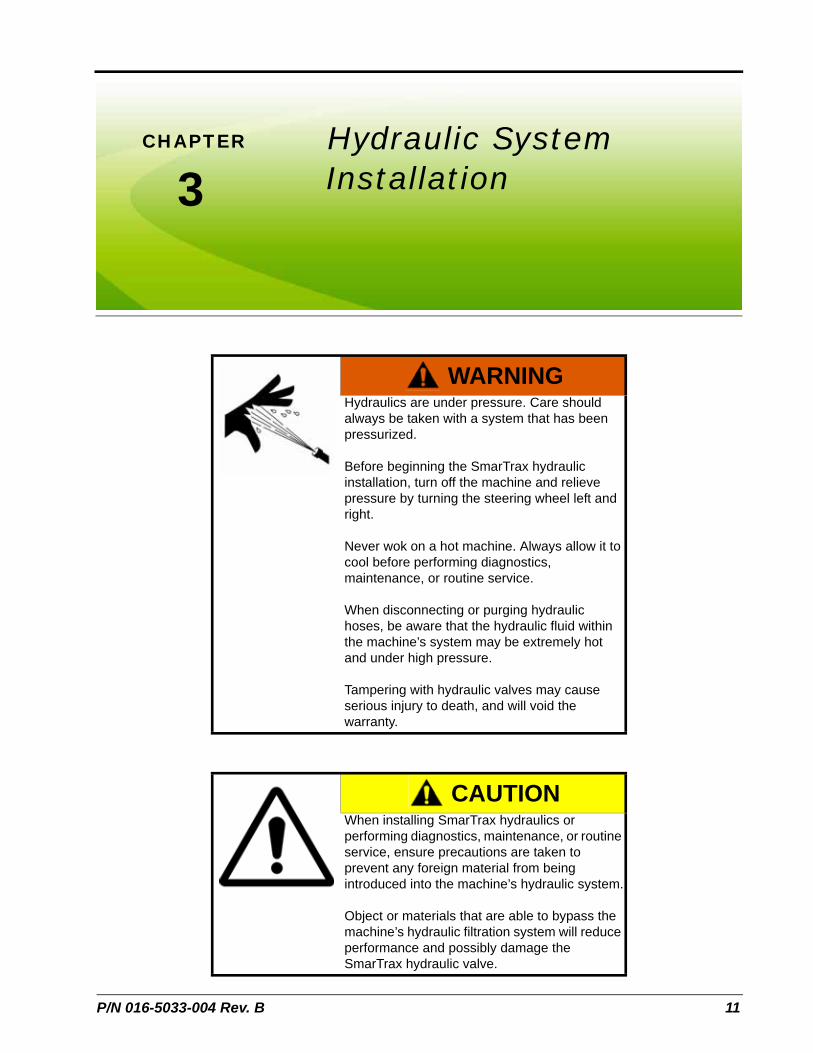
WARNINGHydraulics are under pressure. Care should always be taken with a system that has been pressurized.
Before beginning the SmarTrax hydraulic installation, turn off the machine and relieve pressure by turning the steering wheel left and right.
Never wok on a hot machine. Always allow it to cool before performing diagnostics, maintenance, or routine service.
When disconnecting or purging hydraulic hoses, be aware that the hydraulic fluid within the machine’s system may be extremely hot and under high pressure.
Tampering with hydraulic valves may cause serious injury to death, and will void the warranty.
CAUTIONWhen installing SmarTrax hydraulics or performing diagnostics, maintenance, or routine service, ensure precautions are taken to prevent any foreign material from being introduced into the machine’s hydraulic system.
Object or materials that are able to bypass the machine’s hydraulic filtration system will reduce performance and possibly damage the SmarTrax hydraulic valve.
11
Chapter 3
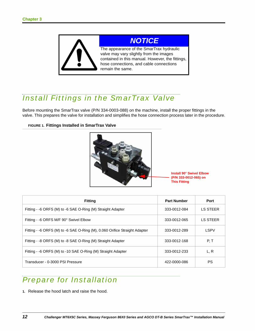
Install Fittings in the SmarTrax ValveBefore mounting the SmarTrax valve (P/N 334-0003-088) on the machine, install the proper fittings in the valve. This prepares the valve for installation and simplifies the hose connection process later in the procedure.
FIGURE 1. Fittings Installed in SmarTrax Valve
Prepare for Installation1. Release the hood latch and raise the hood.
NOTICEThe appearance of the SmarTrax hydraulic valve may vary slightly from the images contained in this manual. However, the fittings, hose connections, and cable connections remain the same.
Fitting Part Number Port
Fitting - -6 ORFS (M) to -6 SAE O-Ring (M) Straight Adapter 333-0012-084 LS STEER
Fitting - -6 ORFS M/F 90° Swivel Elbow 333-0012-065 LS STEER
Fitting - -6 ORFS (M) to -6 SAE O-Ring (M), 0.060 Orifice Straight Adapter 333-0012-289 LSPV
Fitting - -8 ORFS (M) to -8 SAE O-Ring (M) Straight Adapter 333-0012-168 P, T
Fitting - -6 ORFS (M) to -10 SAE O-Ring (M) Straight Adapter 333-0012-233 L, R
Transducer - 0-3000 PSI Pressure 422-0000-086 PS
Install 90° Swivel Elbow (P/N 333-0012-065) on This Fitting
12 Challenger MT6X5C Series, Massey Ferguson 86X0 Series and AGCO DT-B Series SmarTrax™ Installation Manual
3
Hydraulic System Installation
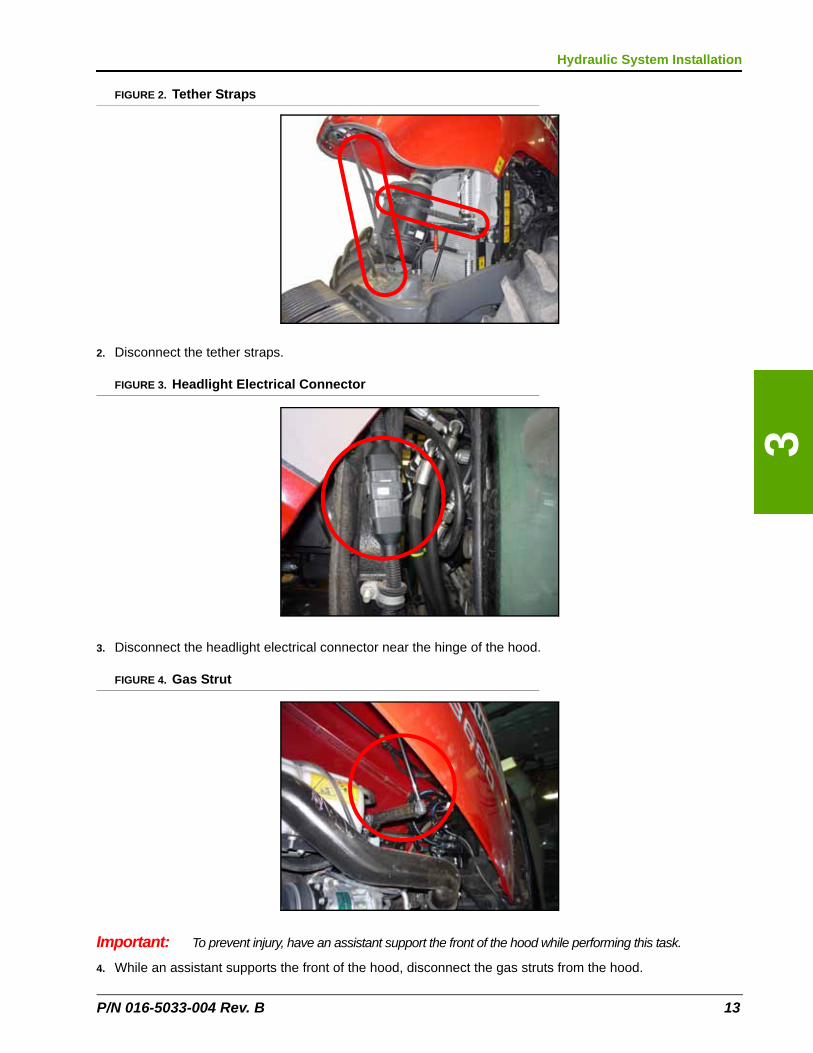
FIGURE 2. Tether Straps
2. Disconnect the tether straps.
FIGURE 3. Headlight Electrical Connector
3. Disconnect the headlight electrical connector near the hinge of the hood.
FIGURE 4. Gas Strut
Important: To prevent injury, have an assistant support the front of the hood while performing this task.
4. While an assistant supports the front of the hood, disconnect the gas struts from the hood.
P/N 016-5033-004 Rev. B 13
Chapter 3
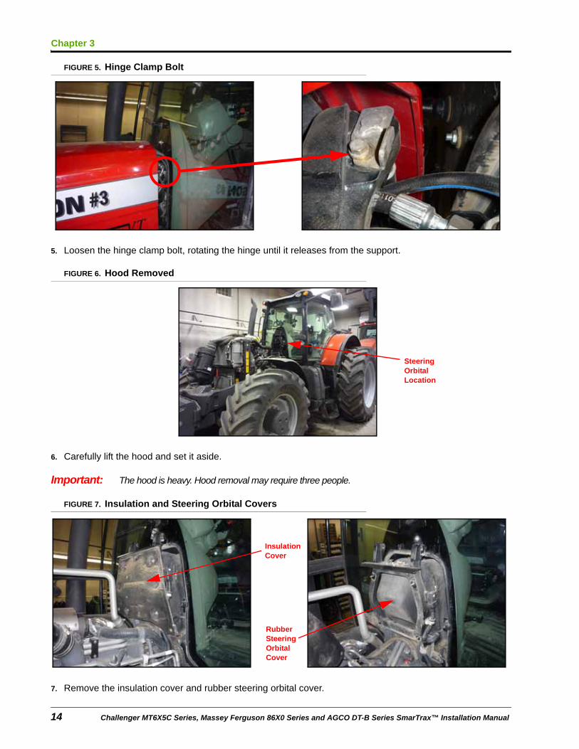
FIGURE 5. Hinge Clamp Bolt
5. Loosen the hinge clamp bolt, rotating the hinge until it releases from the support.
FIGURE 6. Hood Removed
6. Carefully lift the hood and set it aside.
Important: The hood is heavy. Hood removal may require three people.
FIGURE 7. Insulation and Steering Orbital Covers
7. Remove the insulation cover and rubber steering orbital cover.
Steering Orbital Location
Insulation Cover
Rubber Steering Orbital Cover
14 Challenger MT6X5C Series, Massey Ferguson 86X0 Series and AGCO DT-B Series SmarTrax™ Installation Manual

3
Hydraulic System Installation
Install the Left and Right Steering Hoses1. Locate and disconnect the left and right steering hoses connected to the steering orbital.
FIGURE 8. Left and Right Steering Hoses Installed
2. Install a 12L, M18 x 1.5 M/M/F swivel run tee adapter fitting (P/N 333-0012-356) in the “R” port of the steering orbital.
3. Install the 12L end of the supplied hydraulic hose (P/N 214-1000-906) on the 90° end of the installed tee fitting.
4. Label the opposite end of the installed hydraulic hose with a “B.”
Note: The installed hydraulic hose will be connected to the SmarTrax valve (P/N 334-0003-088) later in the installation procedure.
5. Connect the machine’s right steering hose to the remaining end of the installed tee fitting.
6. Install a 12L, M18 x 1.5 M/M/F swivel run tee adapter fitting (P/N 333-0012-356) in the “L” port of the steering orbital.
7. Install the 12L end of the supplied hydraulic hose (P/N 214-1000-906) on the 90° end of the installed tee fitting.
8. Label the opposite end of the installed hydraulic hose with an “A.”
Note: The installed hydraulic hose will be connected to the SmarTrax valve later in the installation procedure.
9. Connect the machine’s left steering hose to the remaining end of the installed tee fitting.
Install the Pressure and Tank Hoses1. Locate and disconnect the pressure and tank hoses connected to the steering orbital.
P/N 016-5033-004 Rev. B 15
Chapter 3
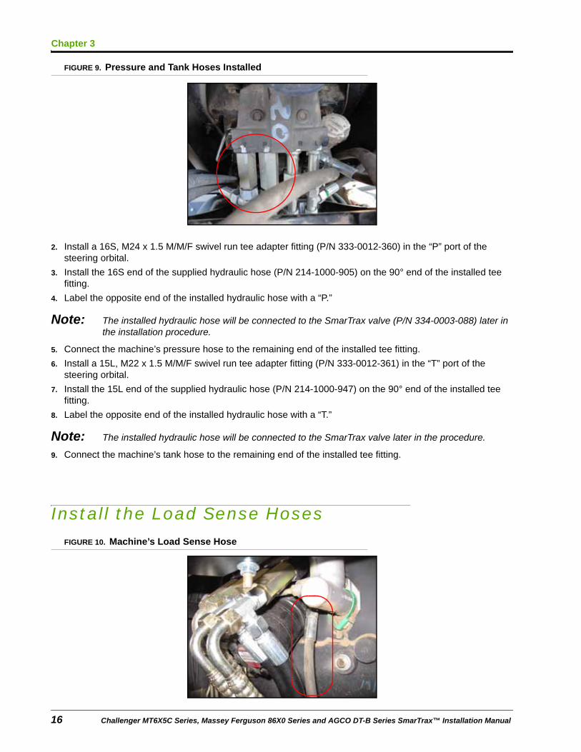
FIGURE 9. Pressure and Tank Hoses Installed
2. Install a 16S, M24 x 1.5 M/M/F swivel run tee adapter fitting (P/N 333-0012-360) in the “P” port of the steering orbital.
3. Install the 16S end of the supplied hydraulic hose (P/N 214-1000-905) on the 90° end of the installed tee fitting.
4. Label the opposite end of the installed hydraulic hose with a “P.”
Note: The installed hydraulic hose will be connected to the SmarTrax valve (P/N 334-0003-088) later in the installation procedure.
5. Connect the machine’s pressure hose to the remaining end of the installed tee fitting.
6. Install a 15L, M22 x 1.5 M/M/F swivel run tee adapter fitting (P/N 333-0012-361) in the “T” port of the steering orbital.
7. Install the 15L end of the supplied hydraulic hose (P/N 214-1000-947) on the 90° end of the installed tee fitting.
8. Label the opposite end of the installed hydraulic hose with a “T.”
Note: The installed hydraulic hose will be connected to the SmarTrax valve later in the procedure.
9. Connect the machine’s tank hose to the remaining end of the installed tee fitting.
Install the Load Sense HosesFIGURE 10. Machine’s Load Sense Hose
16 Challenger MT6X5C Series, Massey Ferguson 86X0 Series and AGCO DT-B Series SmarTrax™ Installation Manual
3
Hydraulic System Installation
1. Locate and disconnect the machine’s load sense hose from the side of the steering orbital.
2. Install the male 8L end of the supplied hydraulic hose (P/N 214-1000-907) on the end of the machine’s load sense hose.
3. Label the opposite end of the installed hydraulic hose “LSPV.”
Note: The installed hydraulic hose will be connected to the SmarTrax valve (P/N 334-0003-088) later in the installation procedure.
4. Install the female 8L end of the supplied hydraulic hose (P/N 214-1000-908) in the open load sense port on the steering orbital.
5. Label the opposite end of the installed hydraulic hose “LS STEER.”
Note: The installed hydraulic hose will be connected to the SmarTrax valve later in the installation procedure.
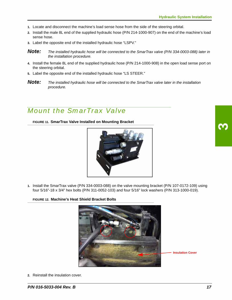
Mount the SmarTrax ValveFIGURE 11. SmarTrax Valve Installed on Mounting Bracket
1. Install the SmarTrax valve (P/N 334-0003-088) on the valve mounting bracket (P/N 107-0172-109) using four 5/16”-18 x 3/4” hex bolts (P/N 311-0052-103) and four 5/16” lock washers (P/N 313-1000-019).
FIGURE 12. Machine’s Heat Shield Bracket Bolts
2. Reinstall the insulation cover.
Insulation Cover
P/N 016-5033-004 Rev. B 17
Chapter 3
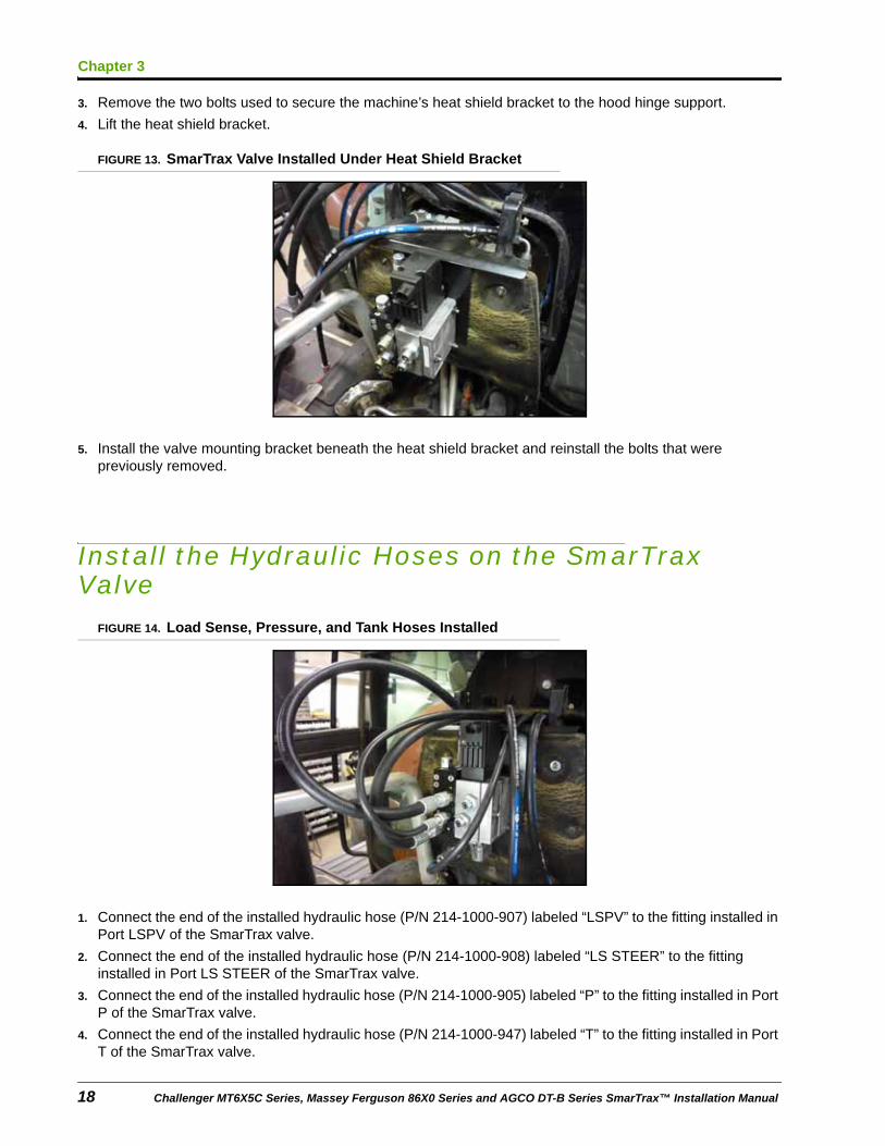
3. Remove the two bolts used to secure the machine’s heat shield bracket to the hood hinge support.
4. Lift the heat shield bracket.
FIGURE 13. SmarTrax Valve Installed Under Heat Shield Bracket
5. Install the valve mounting bracket beneath the heat shield bracket and reinstall the bolts that were previously removed.
Install the Hydraulic Hoses on the SmarTrax Valve
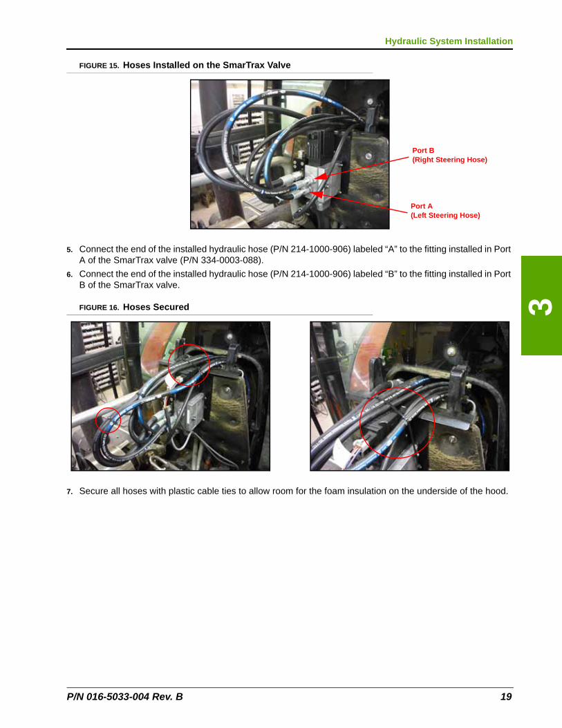
FIGURE 14. Load Sense, Pressure, and Tank Hoses Installed
1. Connect the end of the installed hydraulic hose (P/N 214-1000-907) labeled “LSPV” to the fitting installed in Port LSPV of the SmarTrax valve.
2. Connect the end of the installed hydraulic hose (P/N 214-1000-908) labeled “LS STEER” to the fitting installed in Port LS STEER of the SmarTrax valve.
3. Connect the end of the installed hydraulic hose (P/N 214-1000-905) labeled “P” to the fitting installed in Port P of the SmarTrax valve.
4. Connect the end of the installed hydraulic hose (P/N 214-1000-947) labeled “T” to the fitting installed in Port T of the SmarTrax valve.
18 Challenger MT6X5C Series, Massey Ferguson 86X0 Series and AGCO DT-B Series SmarTrax™ Installation Manual
3
Hydraulic System Installation
FIGURE 15. Hoses Installed on the SmarTrax Valve
5. Connect the end of the installed hydraulic hose (P/N 214-1000-906) labeled “A” to the fitting installed in Port A of the SmarTrax valve (P/N 334-0003-088).
6. Connect the end of the installed hydraulic hose (P/N 214-1000-906) labeled “B” to the fitting installed in Port B of the SmarTrax valve.
FIGURE 16. Hoses Secured
7. Secure all hoses with plastic cable ties to allow room for the foam insulation on the underside of the hood.
Port B (Right Steering Hose)
Port A (Left Steering Hose)
P/N 016-5033-004 Rev. B 19
Chapter 3
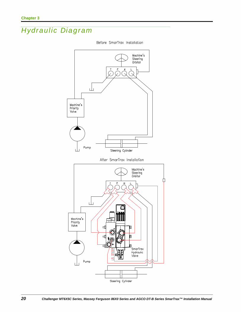
Hydraulic Diagram
20 Challenger MT6X5C Series, Massey Ferguson 86X0 Series and AGCO DT-B Series SmarTrax™ Installation Manual
CHAPTER
4
P/N 016-5033-004 Rev. B
Chapter 4Wheel Angle Sensor (WAS) Installation
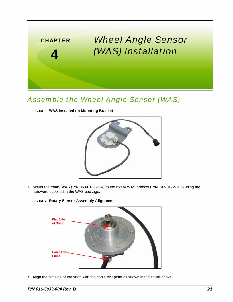
Assemble the Wheel Angle Sensor (WAS)FIGURE 1. WAS Installed on Mounting Bracket
1. Mount the rotary WAS (P/N 063-0181-024) to the rotary WAS bracket (P/N 107-0172-106) using the hardware supplied in the WAS package.
FIGURE 2. Rotary Sensor Assembly Alignment
2. Align the flat side of the shaft with the cable exit point as shown in the figure above.
Flat Side of Shaft
Cable Exit Point
21

Chapter 4
FIGURE 3. Arm Bracket Installed
3. Mount the arm bracket (P/N 116-0159-721) on the WAS shaft by installing the 1/4”-20 knurled cup hex socket head set screw (P/N 311-0015-729) through the hole in the arm bracket and tighten against the flat spot on the sensor shaft.
FIGURE 4. WAS Linkage Rod Assembly
4. Install the M10 jam nut (P/N 312-1001-035) and M10 stud linear sensor mount (P/N 103-0001-030) on one end of the WAS linkage rod (P/N 107-0172-125).
Note: Do not fully tighten the nut.
5. Install the other M10 jam nut and the M10 ball linear sensor mount (P/N 103-0001-029) on the other end of the WAS linkage rod.
Note: Do not fully tighten the nut.
22 Challenger MT6X5C Series, Massey Ferguson 86X0 Series and AGCO DT-B Series SmarTrax™ Installation Manual
4
Wheel Angle Sensor (WAS) Installation
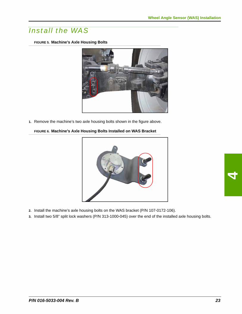
Install the WASFIGURE 5. Machine’s Axle Housing Bolts
1. Remove the machine’s two axle housing bolts shown in the figure above.
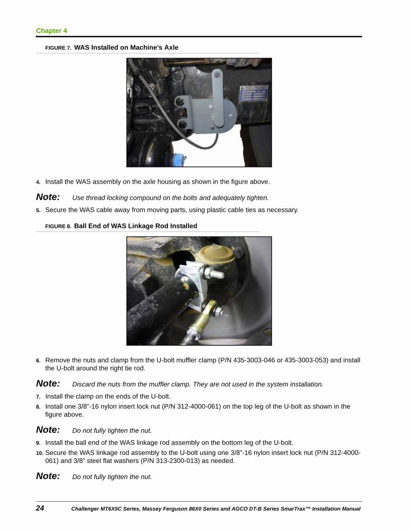
FIGURE 6. Machine’s Axle Housing Bolts Installed on WAS Bracket
2. Install the machine’s axle housing bolts on the WAS bracket (P/N 107-0172-106).
3. Install two 5/8” split lock washers (P/N 313-1000-045) over the end of the installed axle housing bolts.
P/N 016-5033-004 Rev. B 23
Chapter 4
FIGURE 7. WAS Installed on Machine’s Axle
4. Install the WAS assembly on the axle housing as shown in the figure above.
Note: Use thread locking compound on the bolts and adequately tighten.
5. Secure the WAS cable away from moving parts, using plastic cable ties as necessary.
FIGURE 8. Ball End of WAS Linkage Rod Installed
6. Remove the nuts and clamp from the U-bolt muffler clamp (P/N 435-3003-046 or 435-3003-053) and install the U-bolt around the right tie rod.
Note: Discard the nuts from the muffler clamp. They are not used in the system installation.
7. Install the clamp on the ends of the U-bolt.
8. Install one 3/8”-16 nylon insert lock nut (P/N 312-4000-061) on the top leg of the U-bolt as shown in the figure above.
Note: Do not fully tighten the nut.
9. Install the ball end of the WAS linkage rod assembly on the bottom leg of the U-bolt.
10. Secure the WAS linkage rod assembly to the U-bolt using one 3/8”-16 nylon insert lock nut (P/N 312-4000-061) and 3/8” steel flat washers (P/N 313-2300-013) as needed.
Note: Do not fully tighten the nut.
24 Challenger MT6X5C Series, Massey Ferguson 86X0 Series and AGCO DT-B Series SmarTrax™ Installation Manual
4
Wheel Angle Sensor (WAS) Installation
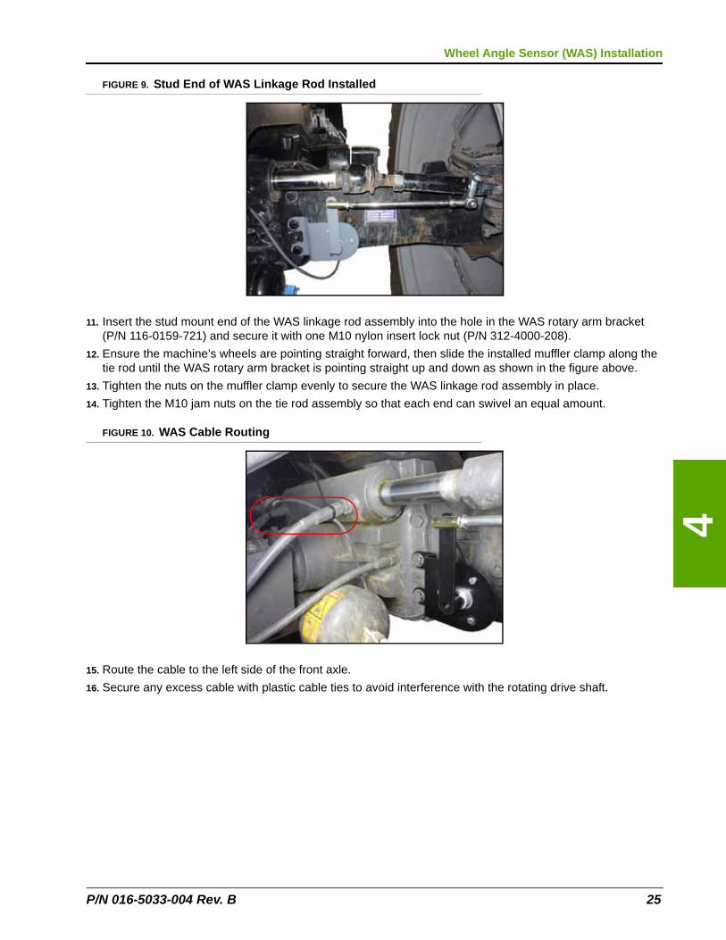
FIGURE 9. Stud End of WAS Linkage Rod Installed
11. Insert the stud mount end of the WAS linkage rod assembly into the hole in the WAS rotary arm bracket (P/N 116-0159-721) and secure it with one M10 nylon insert lock nut (P/N 312-4000-208).
12. Ensure the machine’s wheels are pointing straight forward, then slide the installed muffler clamp along the tie rod until the WAS rotary arm bracket is pointing straight up and down as shown in the figure above.
13. Tighten the nuts on the muffler clamp evenly to secure the WAS linkage rod assembly in place.
14. Tighten the M10 jam nuts on the tie rod assembly so that each end can swivel an equal amount.
FIGURE 10. WAS Cable Routing
15. Route the cable to the left side of the front axle.
16. Secure any excess cable with plastic cable ties to avoid interference with the rotating drive shaft.
P/N 016-5033-004 Rev. B 25

Chapter 4
26 Challenger MT6X5C Series, Massey Ferguson 86X0 Series and AGCO DT-B Series SmarTrax™ Installation Manual
CHAPTER
5
P/N 016-5033-004 Rev. B
Chapter 5Cab Component Installation
Install the SmarTrax Node
Mount the SmarTrax Node
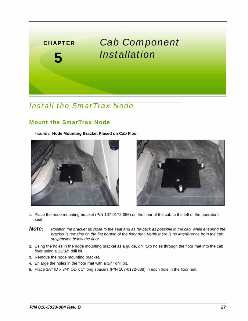
FIGURE 1. Node Mounting Bracket Placed on Cab Floor
1. Place the node mounting bracket (P/N 107-0172-055) on the floor of the cab to the left of the operator’s seat.
Note: Position the bracket as close to the seat and as far back as possible in the cab, while ensuring the bracket is remains on the flat portion of the floor mat. Verify there is no interference from the cab suspension below the floor.
2. Using the holes in the node mounting bracket as a guide, drill two holes through the floor mat into the cab floor using a 13/32” drill bit.
3. Remove the node mounting bracket.
4. Enlarge the holes in the floor mat with a 3/4” drill bit.
5. Place 3/8” ID x 3/4” OD x 1” long spacers (P/N 107-0172-038) in each hole in the floor mat.
27
Chapter 5
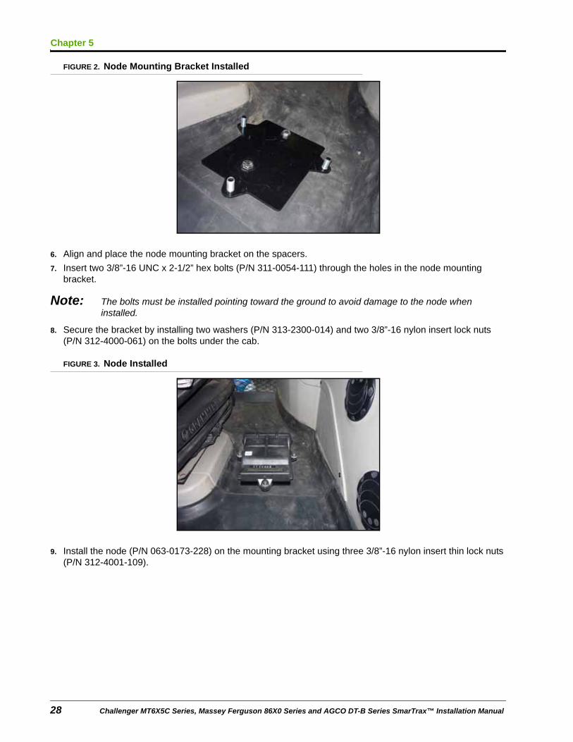
FIGURE 2. Node Mounting Bracket Installed
6. Align and place the node mounting bracket on the spacers.
7. Insert two 3/8”-16 UNC x 2-1/2” hex bolts (P/N 311-0054-111) through the holes in the node mounting bracket.
Note: The bolts must be installed pointing toward the ground to avoid damage to the node when installed.
8. Secure the bracket by installing two washers (P/N 313-2300-014) and two 3/8”-16 nylon insert lock nuts (P/N 312-4000-061) on the bolts under the cab.
FIGURE 3. Node Installed
9. Install the node (P/N 063-0173-228) on the mounting bracket using three 3/8”-16 nylon insert thin lock nuts (P/N 312-4001-109).
28 Challenger MT6X5C Series, Massey Ferguson 86X0 Series and AGCO DT-B Series SmarTrax™ Installation Manual
5
Cab Component Installation
FIGURE 4. Node Harness Connected to Node
10. Install the two large, rectangular connectors of the node harness (P/N 115-4001-109) into the correct ports of the node.
11. Tighten the bolts on the connectors to secure the connections.
Node Mounting Locations
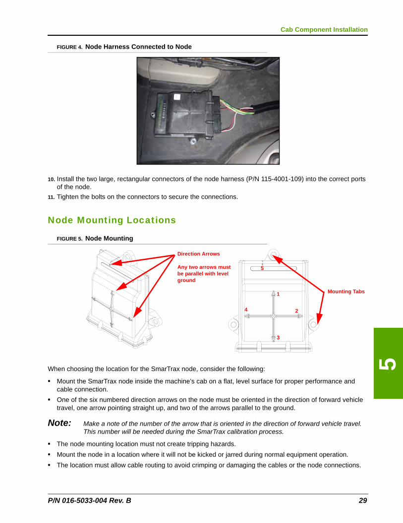
FIGURE 5. Node Mounting
When choosing the location for the SmarTrax node, consider the following:
• Mount the SmarTrax node inside the machine’s cab on a flat, level surface for proper performance and cable connection.
• One of the six numbered direction arrows on the node must be oriented in the direction of forward vehicle travel, one arrow pointing straight up, and two of the arrows parallel to the ground.
Note: Make a note of the number of the arrow that is oriented in the direction of forward vehicle travel. This number will be needed during the SmarTrax calibration process.
• The node mounting location must not create tripping hazards.
• Mount the node in a location where it will not be kicked or jarred during normal equipment operation.
• The location must allow cable routing to avoid crimping or damaging the cables or the node connections.
Direction Arrows
Any two arrows must be parallel with level ground
Mounting Tabs1
2
3
4
5
P/N 016-5033-004 Rev. B 29
Chapter 5
• Securely fasten the node using bolts or screws through at least two of the three mounting holes. When mounted properly, the node should not become loose or rotate.
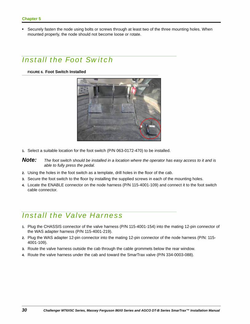
Install the Foot SwitchFIGURE 6. Foot Switch Installed
1. Select a suitable location for the foot switch (P/N 063-0172-470) to be installed.
Note: The foot switch should be installed in a location where the operator has easy access to it and is able to fully press the pedal.
2. Using the holes in the foot switch as a template, drill holes in the floor of the cab.
3. Secure the foot switch to the floor by installing the supplied screws in each of the mounting holes.
4. Locate the ENABLE connector on the node harness (P/N 115-4001-109) and connect it to the foot switch cable connector.
Install the Valve Harness1. Plug the CHASSIS connector of the valve harness (P/N 115-4001-154) into the mating 12-pin connector of
the WAS adapter harness (P/N 115-4001-219).
2. Plug the WAS adapter 12-pin connector into the mating 12-pin connector of the node harness (P/N: 115-4001-109).
3. Route the valve harness outside the cab through the cable grommets below the rear window.
4. Route the valve harness under the cab and toward the SmarTrax valve (P/N 334-0003-088).
30 Challenger MT6X5C Series, Massey Ferguson 86X0 Series and AGCO DT-B Series SmarTrax™ Installation Manual
5
Cab Component Installation
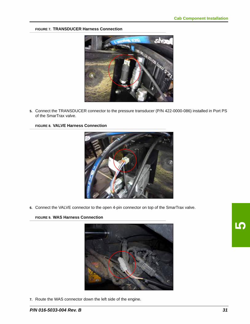
FIGURE 7. TRANSDUCER Harness Connection
5. Connect the TRANSDUCER connector to the pressure transducer (P/N 422-0000-086) installed in Port PS of the SmarTrax valve.
FIGURE 8. VALVE Harness Connection
6. Connect the VALVE connector to the open 4-pin connector on top of the SmarTrax valve.
FIGURE 9. WAS Harness Connection
7. Route the WAS connector down the left side of the engine.
P/N 016-5033-004 Rev. B 31
Chapter 5
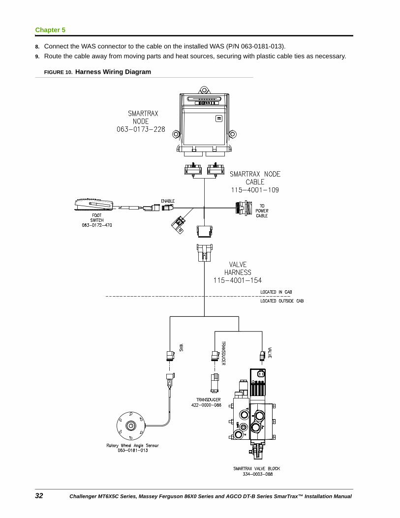
8. Connect the WAS connector to the cable on the installed WAS (P/N 063-0181-013).
9. Route the cable away from moving parts and heat sources, securing with plastic cable ties as necessary.
FIGURE 10. Harness Wiring Diagram
32 Challenger MT6X5C Series, Massey Ferguson 86X0 Series and AGCO DT-B Series SmarTrax™ Installation Manual

5
Cab Component Installation
Install the Chassis Cable - SmarTrax-Only Systems (If Applicable)If the machine does not contain an existing chassis power system (such as AutoBoom, product control, etc.), it is necessary to install the chassis power cable to operate the SmarTrax system. If a CAN system already exists on the machine, refer to Connect SmarTrax to an Existing Chassis Cable (If Applicable) below to connect power to the SmarTrax system.
Note: The chassis cable is sold separately. Contact your local Raven dealer for ordering information.
1. Locate the SmarTrax chassis cable (P/N 115-4001-085).
2. Connect the TO SMARTRAX NODE connector from the chassis cable to the round 16-pin connector on the node harness (P/N 115-4001-109).
3. Connect the TO CONSOLE CABLE connector to the Raven console cable.
4. Install a terminator (P/N 063-0172-369) on the CAN cable connector.
5. Loop and tie-off the REMOTE SWITCH cable connection, securing it with plastic cable ties as necessary.
Note: The REMOTE SWITCH connector is not used in the SmarTrax system. Ensure the cable is secured away from moving parts and heat sources.
6. Connect the ring terminals to the battery.
Note: The positive connectors are fused.
Connect SmarTrax to an Existing Chassis Cable (If Applicable)Note: The SmarTrax interface tee is sold separately. Contact your local Raven dealer for ordering
information.
1. Locate and disconnect the connection between the Raven console cable and chassis cable on the machine’s existing CAN system.
2. Install the SmarTrax interface tee cable (P/N 115-4001-070 or 115-4001-071) between the chassis and Raven console harness.
3. Connect the SmarTrax node harness (P/N 115-4001-109) to the remaining SmarTrax interface tee.
Complete the SmarTrax System Installation1. Reinstall the hood.
Important: The hood is heavy. Hood installation may require three people.
2. Tighten the hinge clamp bolt.
3. Reconnect the gas struts.
4. Reconnect the headlight electrical connector.
5. Reconnect the tether straps.
P/N 016-5033-004 Rev. B 33
Chapter 5
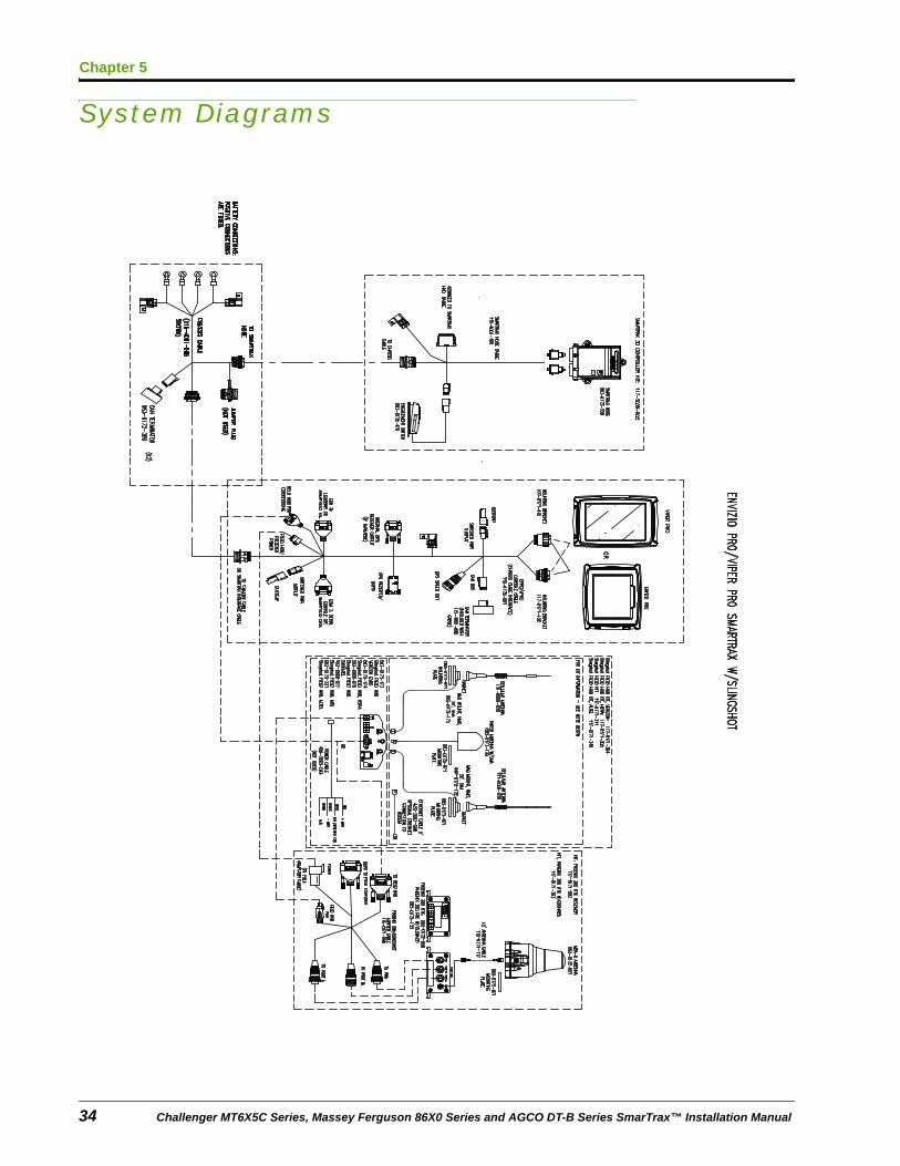
System Diagrams
34 Challenger MT6X5C Series, Massey Ferguson 86X0 Series and AGCO DT-B Series SmarTrax™ Installation Manual
5
Cab Component Installation
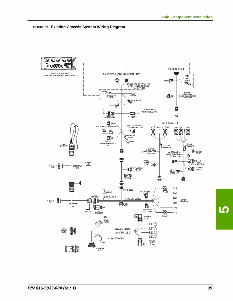
FIGURE 11. Existing Chassis System Wiring Diagram
P/N 016-5033-004 Rev. B 35
Chapter 5
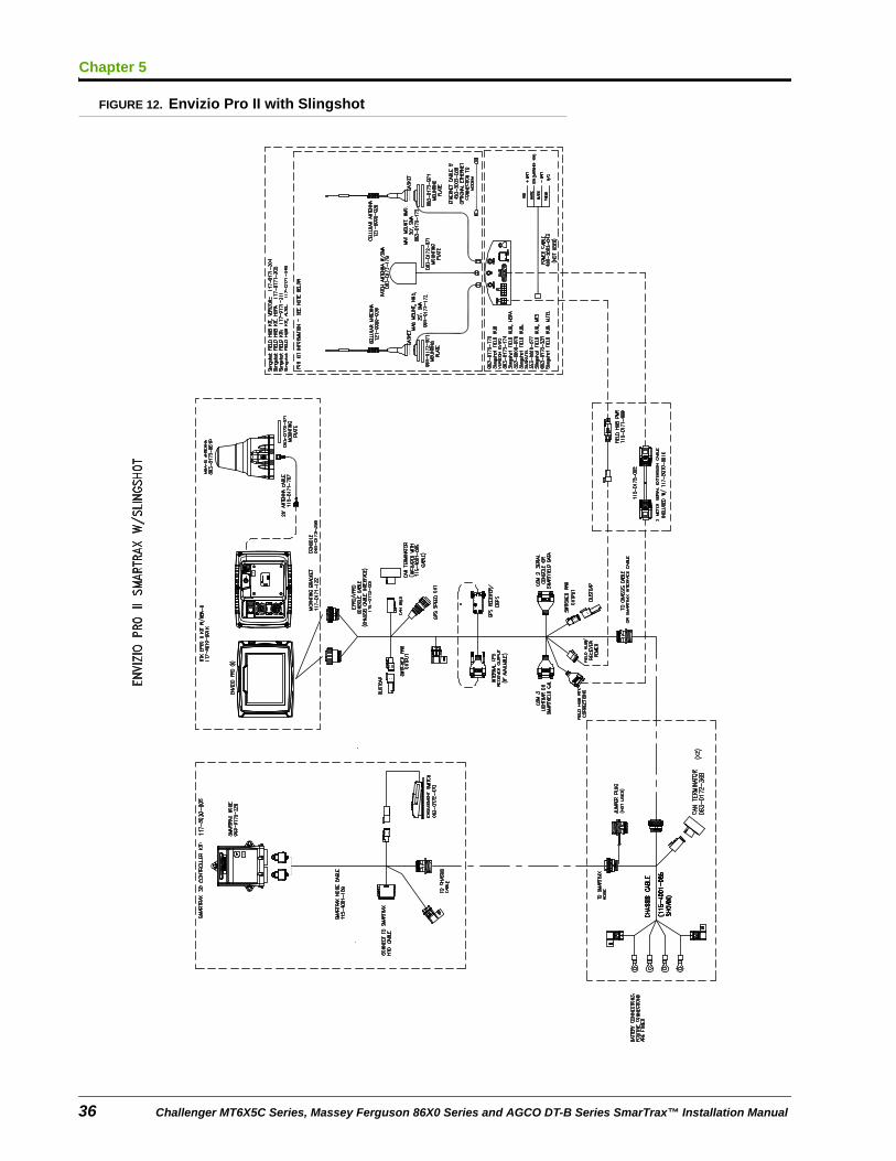
FIGURE 12. Envizio Pro II with Slingshot
36 Challenger MT6X5C Series, Massey Ferguson 86X0 Series and AGCO DT-B Series SmarTrax™ Installation Manual
5
Cab Component Installation
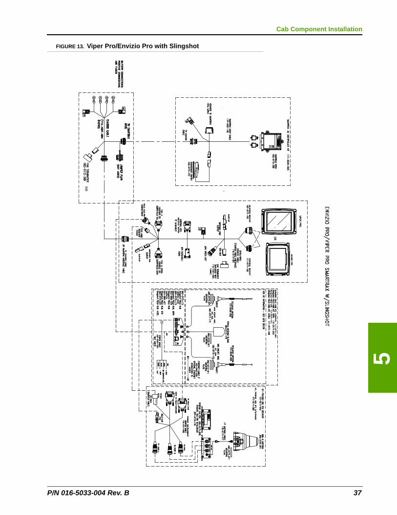
FIGURE 13. Viper Pro/Envizio Pro with Slingshot
P/N 016-5033-004 Rev. B 37
Chapter 5
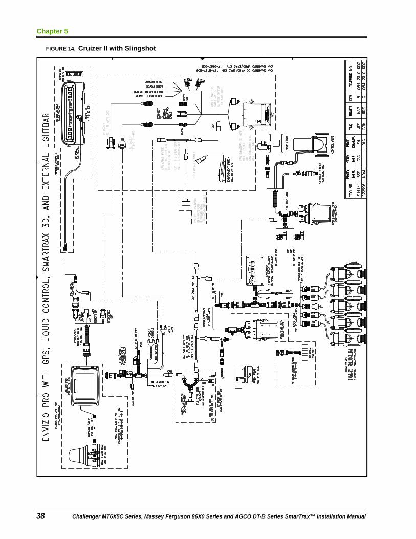
FIGURE 14. Cruizer II with Slingshot
38 Challenger MT6X5C Series, Massey Ferguson 86X0 Series and AGCO DT-B Series SmarTrax™ Installation Manual
CHAPTER
6
P/N 016-5033-004 Rev. B
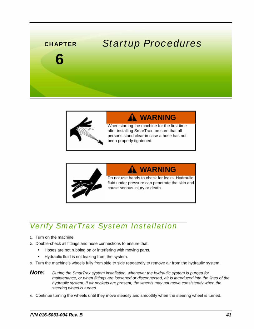
Chapter 6Startup Procedures
Verify SmarTrax System Installation1. Turn on the machine.
2. Double-check all fittings and hose connections to ensure that:
• Hoses are not rubbing on or interfering with moving parts.
• Hydraulic fluid is not leaking from the system.
3. Turn the machine’s wheels fully from side to side repeatedly to remove air from the hydraulic system.
Note: During the SmarTrax system installation, whenever the hydraulic system is purged for maintenance, or when fittings are loosened or disconnected, air is introduced into the lines of the hydraulic system. If air pockets are present, the wheels may not move consistently when the steering wheel is turned.
4. Continue turning the wheels until they move steadily and smoothly when the steering wheel is turned.
WARNINGWhen starting the machine for the first time after installing SmarTrax, be sure that all persons stand clear in case a hose has not been properly tightened.
WARNINGDo not use hands to check for leaks. Hydraulic fluid under pressure can penetrate the skin and cause serious injury or death.
41
Chapter 6
5. Access the System Diagnostic screen by selecting the MACHINE TEST option on the Machine Type screen and turn the wheels using the Raven console.
Note: If there are issues with the SmarTrax system, turn off the machine and correct them immediately. For additional assistance, refer to the SmarTrax and SmartSteer Calibration & Operation Manual (P/N 016-0171-277) or contact your local Raven dealer.
Calibrate the SmarTrax SystemRefer to the SmarTrax & SmartSteer Calibration and Operation Manual (P/N 016-0171-277) for instructions on calibrating the SmarTrax system, adjusting system settings, and system operation.
42 Challenger MT6X5C Series, Massey Ferguson 86X0 Series and AGCO DT-B Series SmarTrax™ Installation Manual
P/N 016-5033-004 Rev. B 43
063-0181-024CCab Component Installation
Completing the SmarTrax System Installation 33Connecting SmarTrax to an Existing Chassis Cable 33Installing the Chassis Cable - SmarTrax-Only Systems 33Installing the Foot Switch 30Installing the SmarTrax Node 27
Mounting the Node 27
Node Mounting Locations 29Installing the Valve Harness 30
HHydraulic Installation
Hydraulic Diagram 20Installing Fittings in the SmarTrax Valve 12Installing the Hydraulic Hoses on the SmarTrax Valve 18Installing the Left and Right Steering Hoses 15Installing the Load Sense Hoses 16Installing the Pressure and Tank Hoses 15Mounting the SmarTrax Valve 17Preparing for Installation 12
IImportant Safety Information
Electrical Safety 2Hydraulic Safety 2
IntroductionKit Contents 5Preparing for Installation 3
Point of Reference 4
Recommendations 4
KKit Contents 5
SStartup Procedures
Calibrating the SmarTrax System 42Engaging the SmarTrax System 42Verifying the SmarTrax System Installation 41