Embed Size (px)
Citation preview
Progress in Aerospace Sciences 47 (2011) 369–391
Contents lists available at ScienceDirect
Progress in Aerospace Sciences
0376-04
doi:10.1
� Corr
E-m
journal homepage: www.elsevier.com/locate/paerosci
Challenges of future aircraft propulsion: A review of distributedpropulsion technology and its potential application for the allelectric commercial aircraft
Amir S. Gohardani �, Georgios Doulgeris, Riti Singh
Department of Power and Propulsion, School of Engineering, Cranfield University, Bedfordshire MK43 0AL, United Kingdom
a r t i c l e i n f o
Available online 13 October 2010
Keywords:
Distributed propulsion
All electric aircraft
More electric aircraft
Future commercial aircraft
21/$ - see front matter & 2010 Elsevier Ltd. A
016/j.paerosci.2010.09.001
esponding author. Tel.: +44 1234 754 666; fa
ail address: [email protected] (A
a b s t r a c t
This paper highlights the role of distributed propulsion technology for future commercial aircraft. After
an initial historical perspective on the conceptual aspects of distributed propulsion technology and a
glimpse at numerous aircraft that have taken distributed propulsion technology to flight, the focal point
of the review is shifted towards a potential role this technology may entail for future commercial
aircraft. Technological limitations and challenges of this specific technology are also considered in
combination with an all electric aircraft concept, as means of predicting the challenges associated with
the design process of a next generation commercial aircraft.
& 2010 Elsevier Ltd. All rights reserved.
Contents
1. Introduction . . . . . . . . . . . . . . . . . . . . . . . . . . . . . . . . . . . . . . . . . . . . . . . . . . . . . . . . . . . . . . . . . . . . . . . . . . . . . . . . . . . . . . . . . . . . . . . . . . . . . . 370
2. Historical review of distributed propulsion technology. . . . . . . . . . . . . . . . . . . . . . . . . . . . . . . . . . . . . . . . . . . . . . . . . . . . . . . . . . . . . . . . . . . . 371
2.1. A few conceptual milestones of aircraft distributed propulsion . . . . . . . . . . . . . . . . . . . . . . . . . . . . . . . . . . . . . . . . . . . . . . . . . . . . . . . 371
2.2. A few milestones of aircraft distributed propulsion. . . . . . . . . . . . . . . . . . . . . . . . . . . . . . . . . . . . . . . . . . . . . . . . . . . . . . . . . . . . . . . . . 372
2.3. Historical trends of distributed propulsion for selected commercial aircraft . . . . . . . . . . . . . . . . . . . . . . . . . . . . . . . . . . . . . . . . . . . . . 373
2.3.1. Year of first flight. . . . . . . . . . . . . . . . . . . . . . . . . . . . . . . . . . . . . . . . . . . . . . . . . . . . . . . . . . . . . . . . . . . . . . . . . . . . . . . . . . . . . 374
2.3.2. Historical evolution of flight cruise speed . . . . . . . . . . . . . . . . . . . . . . . . . . . . . . . . . . . . . . . . . . . . . . . . . . . . . . . . . . . . . . . . . 376
2.3.3. Historical evolution of MTOW and OWE . . . . . . . . . . . . . . . . . . . . . . . . . . . . . . . . . . . . . . . . . . . . . . . . . . . . . . . . . . . . . . . . . . 376
2.3.4. Historical evolution of aircraft range . . . . . . . . . . . . . . . . . . . . . . . . . . . . . . . . . . . . . . . . . . . . . . . . . . . . . . . . . . . . . . . . . . . . . 376
2.3.5. Historical evolution of propulsive power . . . . . . . . . . . . . . . . . . . . . . . . . . . . . . . . . . . . . . . . . . . . . . . . . . . . . . . . . . . . . . . . . . 377
2.3.6. Commercial aircraft payload and weight considerations for distributed propulsion technology . . . . . . . . . . . . . . . . . . . . . . . 377
2.4. Data reliability for commercial aircraft employing distributed propulsion technology . . . . . . . . . . . . . . . . . . . . . . . . . . . . . . . . . . . . . 378
3. A glimpse of past research endeavors in distributed propulsion technology . . . . . . . . . . . . . . . . . . . . . . . . . . . . . . . . . . . . . . . . . . . . . . . . . . . 379
4. The electric aircraft . . . . . . . . . . . . . . . . . . . . . . . . . . . . . . . . . . . . . . . . . . . . . . . . . . . . . . . . . . . . . . . . . . . . . . . . . . . . . . . . . . . . . . . . . . . . . . . . 381
4.1. Selected milestones of the all electric aircraft . . . . . . . . . . . . . . . . . . . . . . . . . . . . . . . . . . . . . . . . . . . . . . . . . . . . . . . . . . . . . . . . . . . . . 382
4.2. The more electric aircraft and related systems . . . . . . . . . . . . . . . . . . . . . . . . . . . . . . . . . . . . . . . . . . . . . . . . . . . . . . . . . . . . . . . . . . . . 383
4.3. Electric motors for airborne applications . . . . . . . . . . . . . . . . . . . . . . . . . . . . . . . . . . . . . . . . . . . . . . . . . . . . . . . . . . . . . . . . . . . . . . . . . 385
5. A proposed framework for future commercial aircraft employing distributed propulsion . . . . . . . . . . . . . . . . . . . . . . . . . . . . . . . . . . . . . . . . 386
5.1. Aircraft characteristics . . . . . . . . . . . . . . . . . . . . . . . . . . . . . . . . . . . . . . . . . . . . . . . . . . . . . . . . . . . . . . . . . . . . . . . . . . . . . . . . . . . . . . . . 386
5.2. Aircraft propulsion system . . . . . . . . . . . . . . . . . . . . . . . . . . . . . . . . . . . . . . . . . . . . . . . . . . . . . . . . . . . . . . . . . . . . . . . . . . . . . . . . . . . . 387
5.3. Aircraft operations . . . . . . . . . . . . . . . . . . . . . . . . . . . . . . . . . . . . . . . . . . . . . . . . . . . . . . . . . . . . . . . . . . . . . . . . . . . . . . . . . . . . . . . . . . . 387
6. A few challenges for an all electric future commercial aircraft employing distributed propulsion . . . . . . . . . . . . . . . . . . . . . . . . . . . . . . . . . . 388
7. Conclusions . . . . . . . . . . . . . . . . . . . . . . . . . . . . . . . . . . . . . . . . . . . . . . . . . . . . . . . . . . . . . . . . . . . . . . . . . . . . . . . . . . . . . . . . . . . . . . . . . . . . . . 388
References . . . . . . . . . . . . . . . . . . . . . . . . . . . . . . . . . . . . . . . . . . . . . . . . . . . . . . . . . . . . . . . . . . . . . . . . . . . . . . . . . . . . . . . . . . . . . . . . . . . . . . . 388
ll rights reserved.
x: +44 1234 751 232.
.S. Gohardani).
Nomenclature
E maximum cargo range (km)P power output for each individual engine unit (kW)R aircraft range (km)T engine thrust (kN)V aircraft speed (km/h)OWE operating empty weight (kg)PAY payload (kg)MTOW maximum take-off weight (kg)NoE number of enginesf piston/propeller unit engine power (kW)x number of engine unitsAC alternating currentAEA all electric aircraftAEE all electric engineAPU auxiliary power unitBLI boundary layer ingestionBWB blended wing bodyCESTOL cruise efficient short take-off and landingCMF common-core multi-fansCMP common-core multi-propulsorsdB decibelDC direct currentDEN distributed enginesDEX distributed exhaustDFRC NASA Dryden Flight Research CenterECS environmental control systemERAST environmental research aircraft and sensor technologyESTOL extreme short take-off and landing
ETOPS extended range operation with two-engine airplanesFAA Federal Aviation AdministrationHALE high altitude long enduranceHP horse powerHTS high temperature superconductiveHALSOL high-altitude solar energyHWB hybrid wing bodyIDG integrated drive generatorLP low pressureMDO multi-disciplinary optimizationMEA more electric aircraftMEE more electric engineNASA National Aeronautics and Space AdministrationPAI propulsion-airframe-integrationPFCC power factor correction numberPM permanent magnetPPS primary power systemsPWM pulse width modulatorRAT ram air turbineRPM revolutions per minuteSFC specific fuel consumptionSPS secondary power systemsSR switched reluctanceSTOL short take-off and landingTRU transformer rectifier unitTV thrust vectoringUHBR ultra high bypass ratioVF variable frequencyVTOL vertical take-off and landingVSCF variable speed constant frequency
A.S. Gohardani et al. / Progress in Aerospace Sciences 47 (2011) 369–391370
1. Introduction
The intricate challenges of meeting future environmental goalsin commercial aviation require a cross-disciplinary effort thatfocuses on: feasible propulsion systems, reduced fuel consump-tion, aviation safety and reliability, noise reduction, and opti-mized aircraft design to achieve desirable flight attributes. With aconstant increase of air passengers, and the demands fortechnological innovation to reduce harmful emissions and jetnoise, the impact of commercial propulsion systems becomeseven more pronounced. Contemporary trends of intelligentengines raise a fundamental question that addresses the mostpromising propulsion system for commercial aviation and inretrospect, conceptual inventive engine systems are system-atically investigated. The technical lessons learned from aviationhistory are important venues for future technical progress. One ofthe many intriguing subjects regarding future aircraft is thevisions aviation enthusiasts anticipate for the future. Kuchemann’searly approach to recognize the need for additional efforts in theaerodynamics of propulsion is noteworthy as prior advances inpropulsion technology were indeed extended far beyond therealm of airfoil theory [1]. Kuchemann and Weber’s comprehen-sive aircraft performance study at subsonic, supersonic andhypersonic speeds has further served as a gateway for improvedunderstanding of aerodynamic shape and its evolution [2].Challenges within the hypersonic flight regime are, however,particularly difficult to overcome, as strong shockwaves ordisturbances are caused in response to lift generation and othermeans to provide volume and propulsion [3]. From a generalperspective, it is possible to draw parallels between Kuchemann’senvisioned differences in the design procedures for variousaircraft [4] and this study, as both seek to examine at least one
particular mode of propulsion in further detail. Air transport ofthe 21st century is no longer limited to technological constraints,but also to environmental restraints that in combination withincreased flight safety, dictate the nature of future flight regimesand flight missions. Aircraft distributed propulsion is one of thepromising propulsion systems currently considered for integra-tion into a wide number of future air transport models. As withany promising system, the limitations and weak points of thistechnology are identified in light of its strengths and advantages.The aim of this paper is to make an assessment of aircraftdistributed propulsion, with a mindset of environmental aware-ness. Throughout the scope of this study, an All Electric Aircraftconcept is also considered in combination with the distributedpropulsion technology, as the electric aircraft trend displays oneof the environmental friendly propulsion options for futurecommercial aircraft.
Distributed propulsion is based on dividing up the thrust forthe beneficiary gain of noise reduction, shorter take-off andlanding, enhanced specific fuel consumption and flight range. Thisis particularly true if the complete aircraft history is to beincluded in this definition, dating back to the early days of flight,where the means of propulsion were different from those of thejet engine era. Fig. 1 depicts a few historical milestones of aircraftdistributed propulsion. The planes above and below the time axiscategorize aircraft distributed propulsion into a conceptualdomain and a manufactured domain, respectively. The conceptualdomain revisits a few hypothetical ideas that have contributed tothe implementation of aircraft distributed propulsion arrange-ments. Variation among these different configurations covers,however, a substantial portion of different propulsion systemdesigns that have made it to the manufacturing phase. Many ofthe known aircraft incorporating distributed propulsion systems
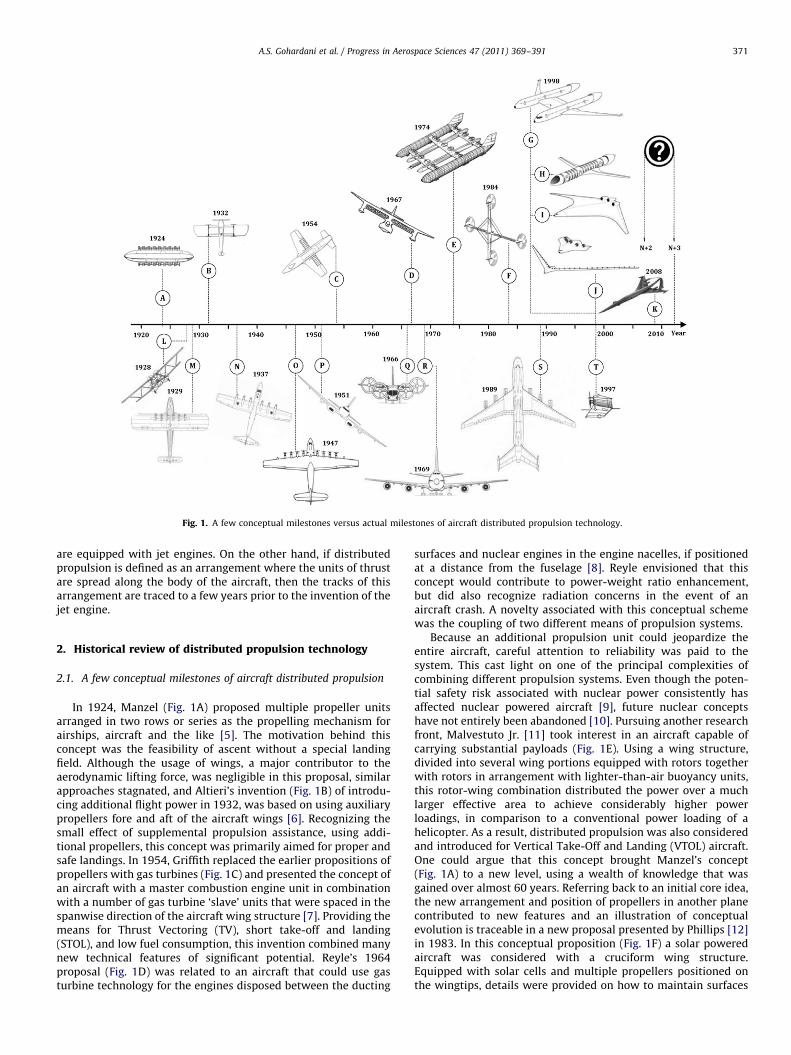
Fig. 1. A few conceptual milestones versus actual milestones of aircraft distributed propulsion technology.
A.S. Gohardani et al. / Progress in Aerospace Sciences 47 (2011) 369–391 371
are equipped with jet engines. On the other hand, if distributedpropulsion is defined as an arrangement where the units of thrustare spread along the body of the aircraft, then the tracks of thisarrangement are traced to a few years prior to the invention of thejet engine.
2. Historical review of distributed propulsion technology
2.1. A few conceptual milestones of aircraft distributed propulsion
In 1924, Manzel (Fig. 1A) proposed multiple propeller unitsarranged in two rows or series as the propelling mechanism forairships, aircraft and the like [5]. The motivation behind thisconcept was the feasibility of ascent without a special landingfield. Although the usage of wings, a major contributor to theaerodynamic lifting force, was negligible in this proposal, similarapproaches stagnated, and Altieri’s invention (Fig. 1B) of introdu-cing additional flight power in 1932, was based on using auxiliarypropellers fore and aft of the aircraft wings [6]. Recognizing thesmall effect of supplemental propulsion assistance, using addi-tional propellers, this concept was primarily aimed for proper andsafe landings. In 1954, Griffith replaced the earlier propositions ofpropellers with gas turbines (Fig. 1C) and presented the concept ofan aircraft with a master combustion engine unit in combinationwith a number of gas turbine ‘slave’ units that were spaced in thespanwise direction of the aircraft wing structure [7]. Providing themeans for Thrust Vectoring (TV), short take-off and landing(STOL), and low fuel consumption, this invention combined manynew technical features of significant potential. Reyle’s 1964proposal (Fig. 1D) was related to an aircraft that could use gasturbine technology for the engines disposed between the ducting
surfaces and nuclear engines in the engine nacelles, if positionedat a distance from the fuselage [8]. Reyle envisioned that thisconcept would contribute to power-weight ratio enhancement,but did also recognize radiation concerns in the event of anaircraft crash. A novelty associated with this conceptual schemewas the coupling of two different means of propulsion systems.
Because an additional propulsion unit could jeopardize theentire aircraft, careful attention to reliability was paid to thesystem. This cast light on one of the principal complexities ofcombining different propulsion systems. Even though the poten-tial safety risk associated with nuclear power consistently hasaffected nuclear powered aircraft [9], future nuclear conceptshave not entirely been abandoned [10]. Pursuing another researchfront, Malvestuto Jr. [11] took interest in an aircraft capable ofcarrying substantial payloads (Fig. 1E). Using a wing structure,divided into several wing portions equipped with rotors togetherwith rotors in arrangement with lighter-than-air buoyancy units,this rotor-wing combination distributed the power over a muchlarger effective area to achieve considerably higher powerloadings, in comparison to a conventional power loading of ahelicopter. As a result, distributed propulsion was also consideredand introduced for Vertical Take-Off and Landing (VTOL) aircraft.One could argue that this concept brought Manzel’s concept(Fig. 1A) to a new level, using a wealth of knowledge that wasgained over almost 60 years. Referring back to an initial core idea,the new arrangement and position of propellers in another planecontributed to new features and an illustration of conceptualevolution is traceable in a new proposal presented by Phillips [12]in 1983. In this conceptual proposition (Fig. 1F) a solar poweredaircraft was considered with a cruciform wing structure.Equipped with solar cells and multiple propellers positioned onthe wingtips, details were provided on how to maintain surfaces
A.S. Gohardani et al. / Progress in Aerospace Sciences 47 (2011) 369–391372
normal to the sun’s rays to utilize the direct solar energy. Thisconcept, amongst others, served as a crucial step towards thedevelopment of solar airplanes, such as the first generation High-Altitude Long Endurance (HALE) vehicle, Pathfinder [13]. Thediscovery of the Antarctic Ozone Hole, earlier that decade, alsoboosted the need for further stratospheric research programsrelated to high-altitude aircraft, under the Environmental Re-search Aircraft and Sensor Technology (ERAST) [14] alliance,initiated by NASA and the industry. In 1988, NASA proposed anumber of detailed concepts [15] for airframe and propulsioninteractions and integrations. A commonality between theseconcepts (Fig. 1G–J) is the employment of different propulsionsystems. SnAPII (Fig. 1G) featured twin fuselages separated by acirculation-control wing that contributed to high lift coefficientsduring takeoff and landing. Using two tail-mounted engines at theend of each fuselage with TV and reversing, fuselage BoundaryLayer Ingestion (BLI), and smart inlet and nozzle technology,SnAPII also used a device to power flow control on the outerportions of the wing. Wing tip turbines could further reduce thewake hazard at takeoff and landing. This concept merged twoindividual fuselages with their propulsive units into one mainbody. A hypothetical scenario of total engine failure for either oneof the combined fuselages was simplified in the subsequentproposal for a distributed engine (Fig. 1H) regional STOL aircraft.This airplane made use of an array of wing-integrated mini-engines to provide lift augmentation and distribution withincreased redundancy. Employing another array of mini-enginesat the tail, integrated with inlet and nozzle, deflectors enabled theCoanda effect for TV. Using a similar circulation-control wingsimilar to SnAPII, a blended forward-swept wing body conceptwas envisioned (Fig. 1I). This aircraft used three aft-mountedhigh-bypass ratio turbofans with BLI, TV and reversing, smartinlet, nozzle technology and flow control systems. Trans-OceanicAir-Train, (Fig. 1J) was characterized by two vehicles, the Lead andthe Mule. These vehicles rendezvous to complete the cruiseconfiguration of a long range transport of cargo. Although thedesign was aimed at freight flight in the low transonic regime, infavor of high aspect ratio wings and span loading for minimal fuelconsumption, parts of this concept could potentially also beapplied to commercial aviation. Equipped with TV-technology foroptimal take-off performance, the Lead vehicle was designated asthe primary fuel carrier and responsible for flight control activitiesof all Mule vehicles. All unmanned Mule vehicles incorporatedpylon structures with morphing technology and powered byadvanced ducted prop pylons, carrying enough fuel for takeoff,rendezvous, connection, abort and landing. Rendezvous betweendifferent aircraft that would transport future air travelers frompoint A to B, pose new unexplored propulsion challenges.Nonetheless, these concepts cannot be disregarded because oftheir levels of complexity. Most of the proposals, presented in thisshort journey throughout the conceptual milestones of aircraftdistributed propulsion, have dealt with the subsonic flight regime.However, this does not imply that supersonic concepts wereneglected or never proposed. In fact, the perspectives anddemands for rapid air travel also point to the supersonic flightregime. 2008 marks the year when Lockheed Martin, in collabora-tion with other industrial partners and academic institutions,envisaged a future aviation concept, operational between theyears of 2030 and 2035 [16]. Implementing synergistic combina-tions to tackle flight emissions, fuels and airport noise, the artist’srendering of this concept shows a (Fig. 1K) distributed propulsionsystem and an environmentally friendly airframe system aimedfor supersonic operation. However, it can also be argued that thissupersonic concept only features four engines. Since a distinctdefinition regarding the distributed propulsion terminology is notreadily available, a placement of an aircraft with four engines
within the distributed propulsion category would only hold if thedefinition of this technology indeed referred to an aircraftemploying three engines or more. The short glimpses ofimplemented technologies in the conceptual milestones of air-craft distributed propulsion have revealed the use of hydrogen,piston engines, gas turbines, solar cells, electrical units andnuclear power, in various arrangements for aircraft propulsion.Despite the random chosen order of these concepts, these multi-faceted propulsion tools exhibit many configurations that havebeen integrated into a variety of manufactured aircraft. Thus, it isimportant to revisit a few milestones of aircraft distributedpropulsion that have partially been the fruit of thought from thesereferred concepts.
2.2. A few milestones of aircraft distributed propulsion
A common theme instilling the conceptual time line ofdistributed propulsion marks the dawn of various aircraft thatemployed available propulsion units of their time for newtechnical arrangements. For the purpose of elucidating ideas thatbecame reality, a short visit is made along the historical axis oftime, to point out some aircraft that implemented three or moreunits of propulsion and were chosen for commercial, experi-mental, cargo, research and military applications. Unlike the earlydays of conceptual aviation where distributed propulsion wasintroduced in the airship industry, many promising proposals thatwould have progressed into production were never funded. Onepossible cause for this, at least in the latter part of the 20thcentury, emerged from the misconception that hydrogen was theprimary cause of the Hindenburg catastrophe [17]. Doubtlessly,the term ‘Hindenburg syndrome’ [18] had a negative influence onthe general public and the airship industry, but regardless of thissignificant impact, the aviation industry embraced many differentdesigns featuring distributed propulsion. In 1929, Dornier Do X(Fig. 1M), the world’s largest aircraft at the time, flew for the firsttime [19]. Intended for transatlantic flights, this aircraft leftFriedrichshafen, Germany, on 2 November 1930 with 17 passen-gers and crew for the USA. After eventful flights via a fewEuropean cities, Brazil, the West Indies, and Miami, the aircraftreached New York on 27 August 1931. Equipped with faired-inengine supports for its 12 engines, Dornier Do X also sufferedmany delays en route to New York and many of these wererelated to technical difficulties. Early long range flight attemptswith distributed propulsion revealed many unforeseen para-meters that could not be efficiently addressed or investigatedduring the conceptual design phase. Engine cooling was one ofthese problems. Using multiple engines without any coolingmeasures caused a thrust reduction for the rear engines.Conversely, the combination of distributed propulsion andcommercial aviation appeared to have its own advantages. Thesame year the Dornier Do X aircraft left Friedrichshafen, HandleyPage H.P.42 (Fig. 1L), made its first flight [20]. Intended for thepurpose of linking various parts of the British Empire, this aircraftused two engines on each of the large unequal-span biplanes,leaving a brilliant record of safety with no fatal accidents after adecade of service. An innovative part of H.P.42’s design was toposition the propulsion units on different wings. Seemingly asuccessful trend for long-range missions, multiple engine solu-tions were chosen more often and this involved also two historicalflying boats. The first aircraft, Blohm und Voss BV 222 Wiking(Fig. 1N), the largest operational flying-boat during World War II,was specifically designed for long-range passenger transport inthe late 1930s and was equipped with six vertically opposedengines distributed over the wing [21]. Following this success, ahistorical flight was made by Howard Hughes’ famous H-4
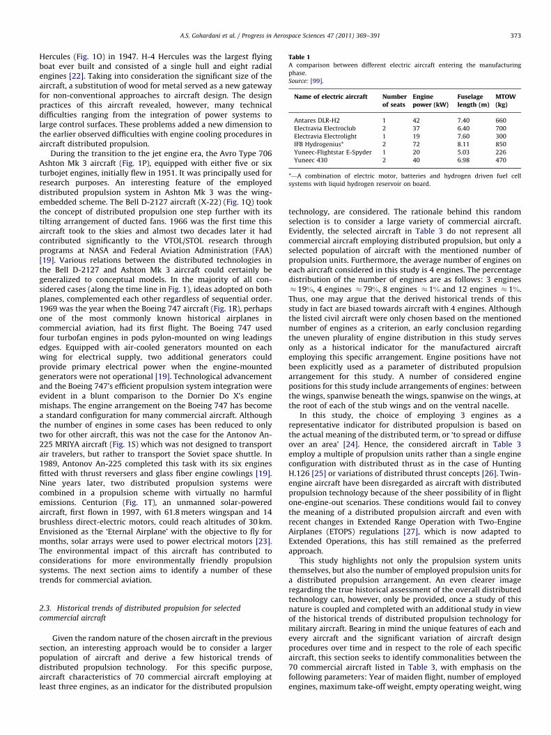
Table 1A comparison between different electric aircraft entering the manufacturing
phase.
Source: [99].
Name of electric aircraft Numberof seats
Enginepower (kW)
Fuselagelength (m)
MTOW(kg)
Antares DLR-H2 1 42 7.40 660
Electravia Electroclub 2 37 6.40 700
Electravia Electrolight 1 19 7.60 300
IFB Hydrogenius* 2 72 8.11 850
Yuneec-Flightstar E-Spyder 1 20 5.03 226
Yuneec 430 2 40 6.98 470
*—A combination of electric motor, batteries and hydrogen driven fuel cell
systems with liquid hydrogen reservoir on board.
A.S. Gohardani et al. / Progress in Aerospace Sciences 47 (2011) 369–391 373
Hercules (Fig. 1O) in 1947. H-4 Hercules was the largest flyingboat ever built and consisted of a single hull and eight radialengines [22]. Taking into consideration the significant size of theaircraft, a substitution of wood for metal served as a new gatewayfor non-conventional approaches to aircraft design. The designpractices of this aircraft revealed, however, many technicaldifficulties ranging from the integration of power systems tolarge control surfaces. These problems added a new dimension tothe earlier observed difficulties with engine cooling procedures inaircraft distributed propulsion.
During the transition to the jet engine era, the Avro Type 706Ashton Mk 3 aircraft (Fig. 1P), equipped with either five or sixturbojet engines, initially flew in 1951. It was principally used forresearch purposes. An interesting feature of the employeddistributed propulsion system in Ashton Mk 3 was the wing-embedded scheme. The Bell D-2127 aircraft (X-22) (Fig. 1Q) tookthe concept of distributed propulsion one step further with itstilting arrangement of ducted fans. 1966 was the first time thisaircraft took to the skies and almost two decades later it hadcontributed significantly to the VTOL/STOL research throughprograms at NASA and Federal Aviation Administration (FAA)[19]. Various relations between the distributed technologies inthe Bell D-2127 and Ashton Mk 3 aircraft could certainly begeneralized to conceptual models. In the majority of all con-sidered cases (along the time line in Fig. 1), ideas adopted on bothplanes, complemented each other regardless of sequential order.1969 was the year when the Boeing 747 aircraft (Fig. 1R), perhapsone of the most commonly known historical airplanes incommercial aviation, had its first flight. The Boeing 747 usedfour turbofan engines in pods pylon-mounted on wing leadingsedges. Equipped with air-cooled generators mounted on eachwing for electrical supply, two additional generators couldprovide primary electrical power when the engine-mountedgenerators were not operational [19]. Technological advancementand the Boeing 747’s efficient propulsion system integration wereevident in a blunt comparison to the Dornier Do X’s enginemishaps. The engine arrangement on the Boeing 747 has becomea standard configuration for many commercial aircraft. Althoughthe number of engines in some cases has been reduced to onlytwo for other aircraft, this was not the case for the Antonov An-225 MRIYA aircraft (Fig. 1S) which was not designed to transportair travelers, but rather to transport the Soviet space shuttle. In1989, Antonov An-225 completed this task with its six enginesfitted with thrust reversers and glass fiber engine cowlings [19].Nine years later, two distributed propulsion systems werecombined in a propulsion scheme with virtually no harmfulemissions. Centurion (Fig. 1T), an unmanned solar-poweredaircraft, first flown in 1997, with 61.8 meters wingspan and 14brushless direct-electric motors, could reach altitudes of 30 km.Envisioned as the ‘Eternal Airplane’ with the objective to fly formonths, solar arrays were used to power electrical motors [23].The environmental impact of this aircraft has contributed toconsiderations for more environmentally friendly propulsionsystems. The next section aims to identify a number of thesetrends for commercial aviation.
2.3. Historical trends of distributed propulsion for selected
commercial aircraft
Given the random nature of the chosen aircraft in the previoussection, an interesting approach would be to consider a largerpopulation of aircraft and derive a few historical trends ofdistributed propulsion technology. For this specific purpose,aircraft characteristics of 70 commercial aircraft employing atleast three engines, as an indicator for the distributed propulsion
technology, are considered. The rationale behind this randomselection is to consider a large variety of commercial aircraft.Evidently, the selected aircraft in Table 3 do not represent allcommercial aircraft employing distributed propulsion, but only aselected population of aircraft with the mentioned number ofpropulsion units. Furthermore, the average number of engines oneach aircraft considered in this study is 4 engines. The percentagedistribution of the number of engines are as follows: 3 engines� 19%, 4 engines � 79%, 8 engines � 1% and 12 engines � 1%.Thus, one may argue that the derived historical trends of thisstudy in fact are biased towards aircraft with 4 engines. Althoughthe listed civil aircraft were only chosen based on the mentionednumber of engines as a criterion, an early conclusion regardingthe uneven plurality of engine distribution in this study servesonly as a historical indicator for the manufactured aircraftemploying this specific arrangement. Engine positions have notbeen explicitly used as a parameter of distributed propulsionarrangement for this study. A number of considered enginepositions for this study include arrangements of engines: betweenthe wings, spanwise beneath the wings, spanwise on the wings, atthe root of each of the stub wings and on the ventral nacelle.
In this study, the choice of employing 3 engines as arepresentative indicator for distributed propulsion is based onthe actual meaning of the distributed term, or ‘to spread or diffuseover an area’ [24]. Hence, the considered aircraft in Table 3employ a multiple of propulsion units rather than a single engineconfiguration with distributed thrust as in the case of HuntingH.126 [25] or variations of distributed thrust concepts [26]. Twin-engine aircraft have been disregarded as aircraft with distributedpropulsion technology because of the sheer possibility of in flightone-engine-out scenarios. These conditions would fail to conveythe meaning of a distributed propulsion aircraft and even withrecent changes in Extended Range Operation with Two-EngineAirplanes (ETOPS) regulations [27], which is now adapted toExtended Operations, this has still remained as the preferredapproach.
This study highlights not only the propulsion system unitsthemselves, but also the number of employed propulsion units fora distributed propulsion arrangement. An even clearer imageregarding the true historical assessment of the overall distributedtechnology can, however, only be provided, once a study of thisnature is coupled and completed with an additional study in viewof the historical trends of distributed propulsion technology formilitary aircraft. Bearing in mind the unique features of each andevery aircraft and the significant variation of aircraft designprocedures over time and in respect to the role of each specificaircraft, this section seeks to identify commonalities between the70 commercial aircraft listed in Table 3, with emphasis on thefollowing parameters: Year of maiden flight, number of employedengines, maximum take-off weight, empty operating weight, wing
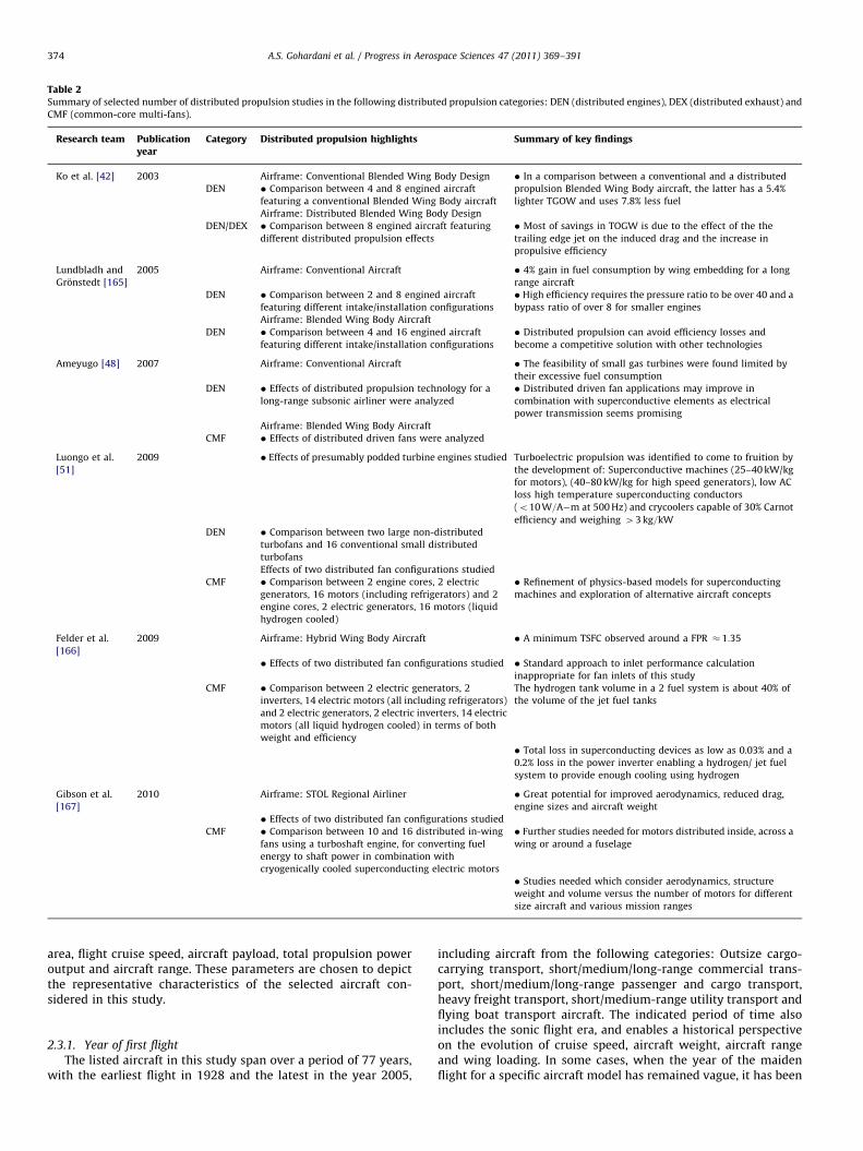
Table 2Summary of selected number of distributed propulsion studies in the following distributed propulsion categories: DEN (distributed engines), DEX (distributed exhaust) and
CMF (common-core multi-fans).
Research team Publicationyear
Category Distributed propulsion highlights Summary of key findings
Ko et al. [42] 2003 Airframe: Conventional Blended Wing Body Design � In a comparison between a conventional and a distributed
DEN � Comparison between 4 and 8 engined aircraft propulsion Blended Wing Body aircraft, the latter has a 5.4%
featuring a conventional Blended Wing Body aircraft lighter TGOW and uses 7.8% less fuel
Airframe: Distributed Blended Wing Body Design
DEN/DEX � Comparison between 8 engined aircraft featuring
different distributed propulsion effects
� Most of savings in TOGW is due to the effect of the the
trailing edge jet on the induced drag and the increase in
propulsive efficiency
Lundbladh and
Gronstedt [165]
2005 Airframe: Conventional Aircraft � 4% gain in fuel consumption by wing embedding for a long
range aircraft
DEN � Comparison between 2 and 8 engined aircraft
featuring different intake/installation configurations
� High efficiency requires the pressure ratio to be over 40 and a
bypass ratio of over 8 for smaller engines
Airframe: Blended Wing Body Aircraft
DEN � Comparison between 4 and 16 engined aircraft
featuring different intake/installation configurations
� Distributed propulsion can avoid efficiency losses and
become a competitive solution with other technologies
Ameyugo [48] 2007 Airframe: Conventional Aircraft � The feasibility of small gas turbines were found limited by
their excessive fuel consumption
DEN � Effects of distributed propulsion technology for a
long-range subsonic airliner were analyzed
� Distributed driven fan applications may improve in
combination with superconductive elements as electrical
power transmission seems promising
Airframe: Blended Wing Body Aircraft
CMF � Effects of distributed driven fans were analyzed
Luongo et al.
[51]
2009 � Effects of presumably podded turbine engines studied Turboelectric propulsion was identified to come to fruition by
the development of: Superconductive machines (25–40 kW/kg
for motors), (40–80 kW/kg for high speed generators), low AC
loss high temperature superconducting conductors
(o10 W=A�m at 500 Hz) and crycoolers capable of 30% Carnot
efficiency and weighing 43 kg=kW
DEN � Comparison between two large non-distributed
turbofans and 16 conventional small distributed
turbofans
Effects of two distributed fan configurations studied
CMF � Comparison between 2 engine cores, 2 electric
generators, 16 motors (including refrigerators) and 2
engine cores, 2 electric generators, 16 motors (liquid
hydrogen cooled)
� Refinement of physics-based models for superconducting
machines and exploration of alternative aircraft concepts
Felder et al.
[166]
2009 Airframe: Hybrid Wing Body Aircraft � A minimum TSFC observed around a FPR � 1:35
� Effects of two distributed fan configurations studied � Standard approach to inlet performance calculation
inappropriate for fan inlets of this study
CMF � Comparison between 2 electric generators, 2
inverters, 14 electric motors (all including refrigerators)
and 2 electric generators, 2 electric inverters, 14 electric
motors (all liquid hydrogen cooled) in terms of both
weight and efficiency
The hydrogen tank volume in a 2 fuel system is about 40% of
the volume of the jet fuel tanks
� Total loss in superconducting devices as low as 0.03% and a
0.2% loss in the power inverter enabling a hydrogen/ jet fuel
system to provide enough cooling using hydrogen
Gibson et al.
[167]
2010 Airframe: STOL Regional Airliner � Great potential for improved aerodynamics, reduced drag,
engine sizes and aircraft weight
� Effects of two distributed fan configurations studied
CMF � Comparison between 10 and 16 distributed in-wing
fans using a turboshaft engine, for converting fuel
energy to shaft power in combination with
cryogenically cooled superconducting electric motors
� Further studies needed for motors distributed inside, across a
wing or around a fuselage
� Studies needed which consider aerodynamics, structure
weight and volume versus the number of motors for different
size aircraft and various mission ranges
A.S. Gohardani et al. / Progress in Aerospace Sciences 47 (2011) 369–391374
area, flight cruise speed, aircraft payload, total propulsion poweroutput and aircraft range. These parameters are chosen to depictthe representative characteristics of the selected aircraft con-sidered in this study.
2.3.1. Year of first flight
The listed aircraft in this study span over a period of 77 years,with the earliest flight in 1928 and the latest in the year 2005,
including aircraft from the following categories: Outsize cargo-carrying transport, short/medium/long-range commercial trans-port, short/medium/long-range passenger and cargo transport,heavy freight transport, short/medium-range utility transport andflying boat transport aircraft. The indicated period of time alsoincludes the sonic flight era, and enables a historical perspectiveon the evolution of cruise speed, aircraft weight, aircraft rangeand wing loading. In some cases, when the year of the maidenflight for a specific aircraft model has remained vague, it has been
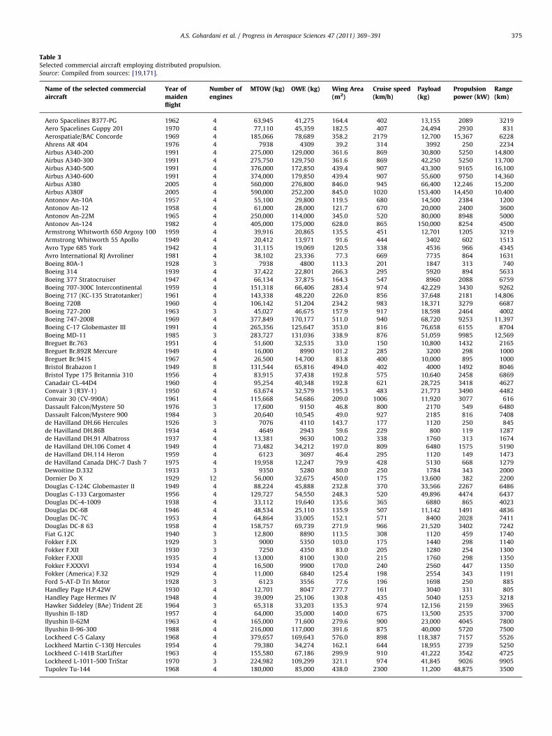
Table 3Selected commercial aircraft employing distributed propulsion.
Source: Compiled from sources: [19,171].
Name of the selected commercialaircraft
Year ofmaidenflight
Number ofengines
MTOW (kg) OWE (kg) Wing Area(m2)
Cruise speed(km/h)
Payload(kg)
Propulsionpower (kW)
Range(km)
Aero Spacelines B377-PG 1962 4 63,945 41,275 164.4 402 13,155 2089 3219
Aero Spacelines Guppy 201 1970 4 77,110 45,359 182.5 407 24,494 2930 831
Aerospatiale/BAC Concorde 1969 4 185,066 78,689 358.2 2179 12,700 15,367 6228
Ahrens AR 404 1976 4 7938 4309 39.2 314 3992 250 2234
Airbus A340-200 1991 4 275,000 129,000 361.6 869 30,800 5250 14,800
Airbus A340-300 1991 4 275,750 129,750 361.6 869 42,250 5250 13,700
Airbus A340-500 1991 4 376,000 172,850 439.4 907 43,300 9165 16,100
Airbus A340-600 1991 4 374,000 179,850 439.4 907 55,600 9750 14,360
Airbus A380 2005 4 560,000 276,800 846.0 945 66,400 12,246 15,200
Airbus A380F 2005 4 590,000 252,200 845.0 1020 153,400 14,450 10,400
Antonov An-10A 1957 4 55,100 29,800 119.5 680 14,500 2384 1200
Antonov An-12 1958 4 61,000 28,000 121.7 670 20,000 2400 3600
Antonov An-22M 1965 4 250,000 114,000 345.0 520 80,000 8948 5000
Antonov An-124 1982 4 405,000 175,000 628.0 865 150,000 8254 4500
Armstrong Whitworth 650 Argosy 100 1959 4 39,916 20,865 135.5 451 12,701 1205 3219
Armstrong Whitworth 55 Apollo 1949 4 20,412 13,971 91.6 444 3402 602 1513
Avro Type 685 York 1942 4 31,115 19,069 120.5 338 4536 966 4345
Avro International RJ Avroliner 1981 4 38,102 23,336 77.3 669 7735 864 1631
Boeing 80A-1 1928 3 7938 4800 113.3 201 1847 313 740
Boeing 314 1939 4 37,422 22,801 266.3 295 5920 894 5633
Boeing 377 Stratocruiser 1947 4 66,134 37,875 164.3 547 8960 2088 6759
Boeing 707-300C Intercontinental 1959 4 151,318 66,406 283.4 974 42,229 3430 9262
Boeing 717 (KC-135 Stratotanker) 1961 4 143,338 48,220 226.0 856 37,648 2181 14,806
Boeing 720B 1960 4 106,142 51,204 234.2 983 18,371 3279 6687
Boeing 727-200 1963 3 45,027 46,675 157.9 917 18,598 2464 4002
Boeing 747-200B 1969 4 377,849 170,177 511.0 940 68,720 9253 11,397
Boeing C-17 Globemaster III 1991 4 265,356 125,647 353.0 816 76,658 6155 8704
Boeing MD-11 1985 3 283,727 131,036 338.9 876 51,059 9985 12,569
Breguet Br.763 1951 4 51,600 32,535 33.0 150 10,800 1432 2165
Breguet Br.892R Mercure 1949 4 16,000 8990 101.2 285 3200 298 1000
Breguet Br.941S 1967 4 26,500 14,700 83.8 400 10,000 895 1000
Bristol Brabazon I 1949 8 131,544 65,816 494.0 402 4000 1492 8046
Bristol Type 175 Britannia 310 1956 4 83,915 37,438 192.8 575 10,640 2458 6869
Canadair CL-44D4 1960 4 95,254 40,348 192.8 621 28,725 3418 4627
Convair 3 (R3Y-1) 1950 4 63,674 32,579 195.3 483 21,773 3490 4482
Convair 30 (CV-990A) 1961 4 115,668 54,686 209.0 1006 11,920 3077 616
Dassault Falcon/Mystere 50 1976 3 17,600 9150 46.8 800 2170 549 6480
Dassault Falcon/Mystere 900 1984 3 20,640 10,545 49.0 927 2185 816 7408
de Havilland DH.66 Hercules 1926 3 7076 4110 143.7 177 1120 250 845
de Havilland DH.86B 1934 4 4649 2943 59.6 229 800 119 1287
de Havilland DH.91 Albatross 1937 4 13,381 9630 100.2 338 1760 313 1674
de Havilland DH.106 Comet 4 1949 4 73,482 34,212 197.0 809 6480 1575 5190
de Havilland DH.114 Heron 1959 4 6123 3697 46.4 295 1120 149 1473
de Havilland Canada DHC-7 Dash 7 1975 4 19,958 12,247 79.9 428 5130 668 1279
Dewoitine D.332 1933 3 9350 5280 80.0 250 1784 343 2000
Dornier Do X 1929 12 56,000 32,675 450.0 175 13,600 382 2200
Douglas C-124C Globemaster II 1949 4 88,224 45,888 232.8 370 33,566 2267 6486
Douglas C-133 Cargomaster 1956 4 129,727 54,550 248.3 520 49,896 4474 6437
Douglas DC-4-1009 1938 4 33,112 19,640 135.6 365 6880 865 4023
Douglas DC-6B 1946 4 48,534 25,110 135.9 507 11,142 1491 4836
Douglas DC-7C 1953 4 64,864 33,005 152.1 571 8400 2028 7411
Douglas DC-8 63 1958 4 158,757 69,739 271.9 966 21,520 3402 7242
Fiat G.12C 1940 3 12,800 8890 113.5 308 1120 459 1740
Fokker F.IX 1929 3 9000 5350 103.0 175 1440 298 1140
Fokker F.XII 1930 3 7250 4350 83.0 205 1280 254 1300
Fokker F.XXII 1935 4 13,000 8100 130.0 215 1760 298 1350
Fokker F.XXXVI 1934 4 16,500 9900 170.0 240 2560 447 1350
Fokker (America) F.32 1929 4 11,000 6840 125.4 198 2554 343 1191
Ford 5-AT-D Tri Motor 1928 3 6123 3556 77.6 196 1698 250 885
Handley Page H.P.42W 1930 4 12,701 8047 277.7 161 3040 331 805
Handley Page Hermes IV 1948 4 39,009 25,106 130.8 435 5040 1253 3218
Hawker Siddeley (BAe) Trident 2E 1964 3 65,318 33,203 135.3 974 12,156 2159 3965
Ilyushin Il-18D 1957 4 64,000 35,000 140.0 675 13,500 2535 3700
Ilyushin Il-62M 1963 4 165,000 71,600 279.6 900 23,000 4045 7800
Ilyushin Il-96-300 1988 4 216,000 117,000 391.6 875 40,000 5720 7500
Lockheed C-5 Galaxy 1968 4 379,657 169,643 576.0 898 118,387 7157 5526
Lockheed Martin C-130J Hercules 1954 4 79,380 34,274 162.1 644 18,955 2739 5250
Lockheed C-141B StarLifter 1963 4 155,580 67,186 299.9 910 41,222 3542 4725
Lockheed L-1011-500 TriStar 1970 3 224,982 109,299 321.1 974 41,845 9026 9905
Tupolev Tu-144 1968 4 180,000 85,000 438.0 2300 11,200 48,875 3500
A.S. Gohardani et al. / Progress in Aerospace Sciences 47 (2011) 369–391 375
0
100
200
300
400
500
600
700
1900
MTOW OWE Linear (MTOW) Linear (OWE)
MTO
W, O
WE
[kg
x 10
3 ]
Year of First Flight19
1019
2019
3019
4019
5019
6019
7019
8019
9020
0020
10
Fig. 3. Historical MTOW and OWE trends for commercial aircraft employing
distributed propulsion technology.
6.0
8.0
10.0
12.0
14.0
16.0
18.0
R [k
m x
103 ]
A.S. Gohardani et al. / Progress in Aerospace Sciences 47 (2011) 369–391376
replaced by the indicated first flight year of the aircraft program.Limitations of the availability of accurate historical data reveal inan exemplary case for the Boeing 80A-1 aircraft that, as anambiguous year of maiden flight for this specific model type washighlighted, this aircraft was listed under the first flight of theBoeing Model 80 aircraft instead.
2.3.2. Historical evolution of flight cruise speed
Cruise speed has always been treated as an important topic incivil aviation. Ever since the birth of aviation itself, overcoming thechallenges of flying from point A to B, as quickly as possible, hasbeen included in the visions of flight. Cruise speed defines a crucialaircraft characteristic, closely related to the aircraft propulsionsystem. A historical viewpoint incorporating cruise speed maycontribute to the role this specific parameter has had for aircraftwith distributed propulsion arrangements. Fig. 2 depicts a historicaltrend of commercial aircraft employing distributed propulsiontechnology. Interestingly enough, only two aircraft have cruised atsupersonic speed in this study. Aerospatiale/BAC Concorde andTupolev Tu-144’s presence in the supersonic domain is unlike themajor population of aircraft, confined within the subsonic region.The fastest cruising aircraft for the selected aircraft is about 15 timesfaster than the slowest cruising aircraft. Moreover, it should also benoted that even though the indicated trend line suggests anincreasing flight cruise speed, further progress to fly at transonicspeed has stagnated for aircraft flying with distributed propulsiontechnology. Nevertheless, the average cruise speed has steadilyincreased from mid 1920s according to Fig. 2, and still the averageflight cruise speed in this study corresponds to Mach � 0:5. A moredetailed discussion regarding different flight regimes and a fewcomplexities associated with the transonic and supersonic regimewill be discussed in a separate section about flight regimeconsiderations for future commercial aircraft.
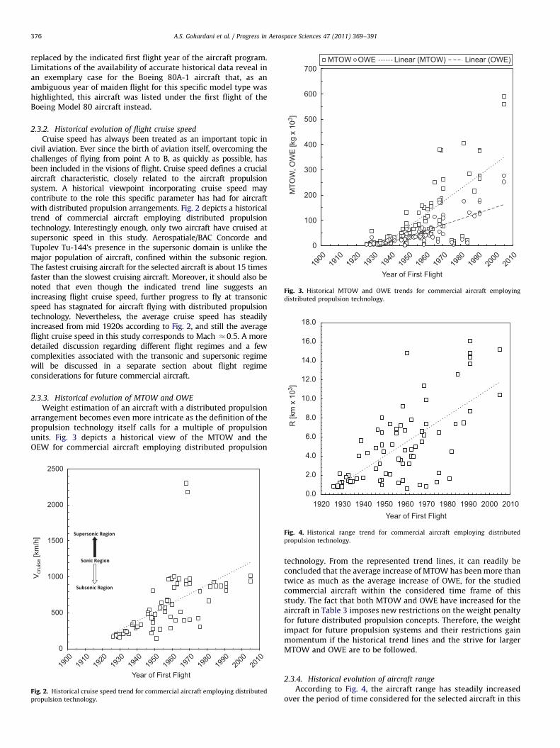
2.3.3. Historical evolution of MTOW and OWE
Weight estimation of an aircraft with a distributed propulsionarrangement becomes even more intricate as the definition of thepropulsion technology itself calls for a multiple of propulsionunits. Fig. 3 depicts a historical view of the MTOW and theOEW for commercial aircraft employing distributed propulsion
0
500
1000
1500
2000
2500
1900
1910
1920
1930
1940
1950
1960
1970
1980
1990
2000
2010
Vcr
uise
[km
/h]
Year of First Flight
Fig. 2. Historical cruise speed trend for commercial aircraft employing distributed
propulsion technology.
0.0
2.0
4.0
1920Year of First Flight
1930 1940 1950 1960 1970 1980 1990 2000 2010
Fig. 4. Historical range trend for commercial aircraft employing distributed
propulsion technology.
technology. From the represented trend lines, it can readily beconcluded that the average increase of MTOW has been more thantwice as much as the average increase of OWE, for the studiedcommercial aircraft within the considered time frame of thisstudy. The fact that both MTOW and OWE have increased for theaircraft in Table 3 imposes new restrictions on the weight penaltyfor future distributed propulsion concepts. Therefore, the weightimpact for future propulsion systems and their restrictions gainmomentum if the historical trend lines and the strive for largerMTOW and OWE are to be followed.
2.3.4. Historical evolution of aircraft range
According to Fig. 4, the aircraft range has steadily increasedover the period of time considered for the selected aircraft in this
0.3
0.4
T/O
WE
[W/g
]
0.5
0.6
0.7
0.8
0.9
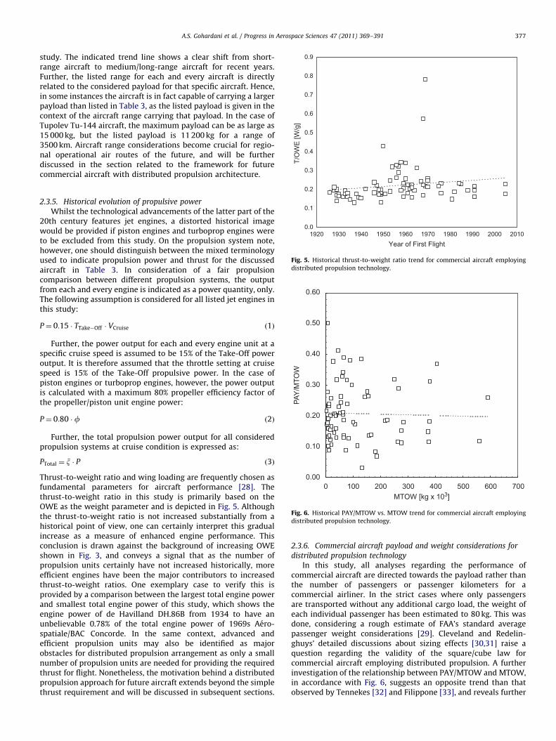
A.S. Gohardani et al. / Progress in Aerospace Sciences 47 (2011) 369–391 377
study. The indicated trend line shows a clear shift from short-range aircraft to medium/long-range aircraft for recent years.Further, the listed range for each and every aircraft is directlyrelated to the considered payload for that specific aircraft. Hence,in some instances the aircraft is in fact capable of carrying a largerpayload than listed in Table 3, as the listed payload is given in thecontext of the aircraft range carrying that payload. In the case ofTupolev Tu-144 aircraft, the maximum payload can be as large as15 000 kg, but the listed payload is 11 200 kg for a range of3500 km. Aircraft range considerations become crucial for regio-nal operational air routes of the future, and will be furtherdiscussed in the section related to the framework for futurecommercial aircraft with distributed propulsion architecture.
0.0
0.1
0.2
1920 1930 1940 1950 1960Year of First Flight
1970 1980 1990 2000 2010
Fig. 5. Historical thrust-to-weight ratio trend for commercial aircraft employing
distributed propulsion technology.
0.00
0.10
0.20
0.30
0.40
0.50
0.60
0
PAY
/MTO
W
MTOW [kg x 103]100 200 300 400 500 600 700
Fig. 6. Historical PAY/MTOW vs. MTOW trend for commercial aircraft employing
distributed propulsion technology.
2.3.5. Historical evolution of propulsive power
Whilst the technological advancements of the latter part of the20th century features jet engines, a distorted historical imagewould be provided if piston engines and turboprop engines wereto be excluded from this study. On the propulsion system note,however, one should distinguish between the mixed terminologyused to indicate propulsion power and thrust for the discussedaircraft in Table 3. In consideration of a fair propulsioncomparison between different propulsion systems, the outputfrom each and every engine is indicated as a power quantity, only.The following assumption is considered for all listed jet engines inthis study:
P¼ 0:15 � TTake�Off � VCruise ð1Þ
Further, the power output for each and every engine unit at aspecific cruise speed is assumed to be 15% of the Take-Off poweroutput. It is therefore assumed that the throttle setting at cruisespeed is 15% of the Take-Off propulsive power. In the case ofpiston engines or turboprop engines, however, the power outputis calculated with a maximum 80% propeller efficiency factor ofthe propeller/piston unit engine power:
P¼ 0:80 �f ð2Þ
Further, the total propulsion power output for all consideredpropulsion systems at cruise condition is expressed as:
PTotal ¼ x � P ð3Þ
Thrust-to-weight ratio and wing loading are frequently chosen asfundamental parameters for aircraft performance [28]. Thethrust-to-weight ratio in this study is primarily based on theOWE as the weight parameter and is depicted in Fig. 5. Althoughthe thrust-to-weight ratio is not increased substantially from ahistorical point of view, one can certainly interpret this gradualincrease as a measure of enhanced engine performance. Thisconclusion is drawn against the background of increasing OWEshown in Fig. 3, and conveys a signal that as the number ofpropulsion units certainly have not increased historically, moreefficient engines have been the major contributors to increasedthrust-to-weight ratios. One exemplary case to verify this isprovided by a comparison between the largest total engine powerand smallest total engine power of this study, which shows theengine power of de Havilland DH.86B from 1934 to have anunbelievable 0.78% of the total engine power of 1969s Aero-spatiale/BAC Concorde. In the same context, advanced andefficient propulsion units may also be identified as majorobstacles for distributed propulsion arrangement as only a smallnumber of propulsion units are needed for providing the requiredthrust for flight. Nonetheless, the motivation behind a distributedpropulsion approach for future aircraft extends beyond the simplethrust requirement and will be discussed in subsequent sections.
2.3.6. Commercial aircraft payload and weight considerations for
distributed propulsion technology
In this study, all analyses regarding the performance ofcommercial aircraft are directed towards the payload rather thanthe number of passengers or passenger kilometers for acommercial airliner. In the strict cases where only passengersare transported without any additional cargo load, the weight ofeach individual passenger has been estimated to 80 kg. This wasdone, considering a rough estimate of FAA’s standard averagepassenger weight considerations [29]. Cleveland and Redelin-ghuys’ detailed discussions about sizing effects [30,31] raise aquestion regarding the validity of the square/cube law forcommercial aircraft employing distributed propulsion. A furtherinvestigation of the relationship between PAY/MTOW and MTOW,in accordance with Fig. 6, suggests an opposite trend than thatobserved by Tennekes [32] and Filippone [33], and reveals further
1000
1500
2000
2500
3000
3500
4000
4500
E [k
m]
A.S. Gohardani et al. / Progress in Aerospace Sciences 47 (2011) 369–391378
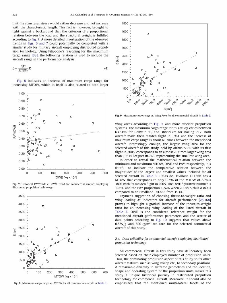
that the structural stress would rather decrease and not increasewith the characteristic length. This fact is, however, brought tolight against a background that the criterion of a proportionalrelation between the load and the structural weight is fulfilledaccording to Fig. 7. A more detailed investigation of the observedtrends in Figs. 6 and 7 could potentially be completed with asimilar study for military aircraft employing distributed propul-sion technology. Using Filippone’s reasoning for the maximumcargo range [33], the following relation is used to include theaircraft range in the performance analysis:
E¼PAY
MTOWR ð4Þ
Fig. 8 indicates an increase of maximum cargo range forincreasing MTOW, which in itself is also related to both larger
0
500
1000
1500
2000
2500
3000
3500
4000
4500
0
E [k
m]
MTOW [kg x 103]100 200 300 400 500 600 700
Fig. 8. Maximum cargo range vs. MTOW for all commercial aircraft in Table 3.
0.00
0.10
0.20
0.30
0.40
0.50
0.60
0.70
0.80
0.90
1.00
0
PAY
/OW
E
OWE [kg x 103]50 100 150 200 250 300
Fig. 7. Historical PAY/OWE vs. OWE trend for commercial aircraft employing
distributed propulsion technology.
0
500
S [m2]10
0.020
0.030
0.040
0.050
0.060
0.070
0.080
0.090
0.0
1000
.00.0
Fig. 9. Maximum cargo range vs. Wing Area for all commercial aircraft in Table 3.
wing areas according to Fig. 9, and more efficient propulsionsystems. The maximum cargo range for this study varies between63.5 km for Convair 30, and 3888.9 km for Boeing 717. Bothaircraft made their maiden flight in 1961 and the increase ofmaximum cargo range is about 61 times between the mentionedaircraft. Interestingly enough, the largest wing area for theselected aircraft of this study, held by Airbus A380 with its firstflight in 2005, corresponds to an almost 26 times larger wing areathan 1951s Breguet Br.763, representing the smallest wing area.
In order to reveal the mathematical relation between theminimum and maximum MTOW, OWE and PAY, respectively, it isfruitful to indicate the comparative relation between themagnitudes of the largest and smallest values included for allselected aircraft in Table 3. 1934s de Havilland DH.86B has aMTOW that corresponds to only 0.79% of the MTOW of Airbus380F with its maiden flight in 2005. The OWE figurative number is1.06%, and the PAY proportion, 0.52% when 2005s Airbus A380 iscompared to de Havilland DH.86B from 1934.
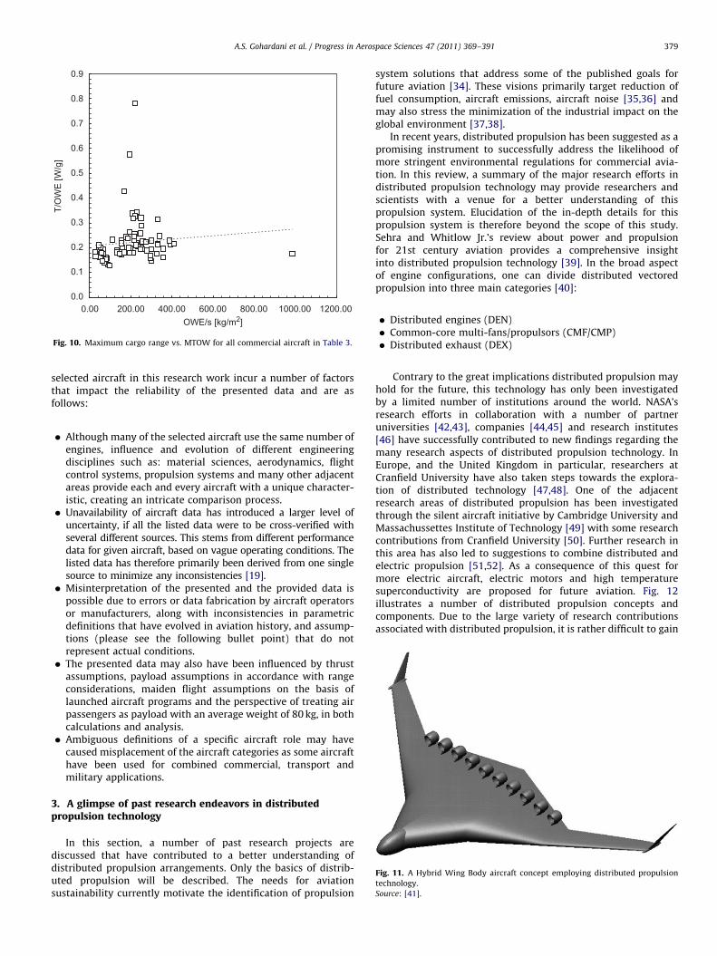
Raymer’s suggestion of choosing thrust-to-weight ratio andwing loading as indicators for aircraft performance [28,168]proves to highlight a gradual increase of the thrust-to-weightratio for an increasing wing loading of the listed aircraft inTable 3. OWE is the considered reference weight for thementioned aircraft performance parameters and the scatter ofdata points according to Fig. 10 suggests that values above0.5 W/g and 600 kg/m2 are rare for the selected commercialaircraft of this study.
2.4. Data reliability for commercial aircraft employing distributed
propulsion technology
All commercial aircraft in this study have deliberately beenselected based on their employed number of propulsion units.Thus, the dominating propulsion aspect of this study shifts otheraircraft features such as wing sweep etc., to secondary positions.A remarkable diversity in airframe geometries and the location,shape and operating system of the propulsion units makes thisstudy a unique historical journey in distributed propulsiontechnology for commercial aircraft. Moreover, it should also beemphasized that the mentioned multi-lateral facets of the
0.0
0.1
0.2
0.3
0.4
0.5
0.6
0.7
0.8
0.9
0.00
T/O
WE
[W/g
]
OWE/s [kg/m2]200.00 400.00 600.00 800.00 1000.00 1200.00
Fig. 10. Maximum cargo range vs. MTOW for all commercial aircraft in Table 3.
A.S. Gohardani et al. / Progress in Aerospace Sciences 47 (2011) 369–391 379
selected aircraft in this research work incur a number of factorsthat impact the reliability of the presented data and are asfollows:
�
Although many of the selected aircraft use the same number ofengines, influence and evolution of different engineeringdisciplines such as: material sciences, aerodynamics, flightcontrol systems, propulsion systems and many other adjacentareas provide each and every aircraft with a unique character-istic, creating an intricate comparison process. � Unavailability of aircraft data has introduced a larger level ofuncertainty, if all the listed data were to be cross-verified withseveral different sources. This stems from different performancedata for given aircraft, based on vague operating conditions. Thelisted data has therefore primarily been derived from one singlesource to minimize any inconsistencies [19].
� Misinterpretation of the presented and the provided data ispossible due to errors or data fabrication by aircraft operatorsor manufacturers, along with inconsistencies in parametricdefinitions that have evolved in aviation history, and assump-tions (please see the following bullet point) that do notrepresent actual conditions.
� The presented data may also have been influenced by thrustassumptions, payload assumptions in accordance with rangeconsiderations, maiden flight assumptions on the basis oflaunched aircraft programs and the perspective of treating airpassengers as payload with an average weight of 80 kg, in bothcalculations and analysis.
�Fig. 11. A Hybrid Wing Body aircraft concept employing distributed propulsion
technology.
Source: [41].
Ambiguous definitions of a specific aircraft role may havecaused misplacement of the aircraft categories as some aircrafthave been used for combined commercial, transport andmilitary applications.
3. A glimpse of past research endeavors in distributedpropulsion technology
In this section, a number of past research projects arediscussed that have contributed to a better understanding ofdistributed propulsion arrangements. Only the basics of distrib-uted propulsion will be described. The needs for aviationsustainability currently motivate the identification of propulsion
system solutions that address some of the published goals forfuture aviation [34]. These visions primarily target reduction offuel consumption, aircraft emissions, aircraft noise [35,36] andmay also stress the minimization of the industrial impact on theglobal environment [37,38].
In recent years, distributed propulsion has been suggested as apromising instrument to successfully address the likelihood ofmore stringent environmental regulations for commercial avia-tion. In this review, a summary of the major research efforts indistributed propulsion technology may provide researchers andscientists with a venue for a better understanding of thispropulsion system. Elucidation of the in-depth details for thispropulsion system is therefore beyond the scope of this study.Sehra and Whitlow Jr.’s review about power and propulsionfor 21st century aviation provides a comprehensive insightinto distributed propulsion technology [39]. In the broad aspectof engine configurations, one can divide distributed vectoredpropulsion into three main categories [40]:
�
Distributed engines (DEN) � Common-core multi-fans/propulsors (CMF/CMP) � Distributed exhaust (DEX)Contrary to the great implications distributed propulsion mayhold for the future, this technology has only been investigatedby a limited number of institutions around the world. NASA’sresearch efforts in collaboration with a number of partneruniversities [42,43], companies [44,45] and research institutes[46] have successfully contributed to new findings regarding themany research aspects of distributed propulsion technology. InEurope, and the United Kingdom in particular, researchers atCranfield University have also taken steps towards the explora-tion of distributed technology [47,48]. One of the adjacentresearch areas of distributed propulsion has been investigatedthrough the silent aircraft initiative by Cambridge University andMassachussettes Institute of Technology [49] with some researchcontributions from Cranfield University [50]. Further research inthis area has also led to suggestions to combine distributed andelectric propulsion [51,52]. As a consequence of this quest formore electric aircraft, electric motors and high temperaturesuperconductivity are proposed for future aviation. Fig. 12illustrates a number of distributed propulsion concepts andcomponents. Due to the large variety of research contributionsassociated with distributed propulsion, it is rather difficult to gain
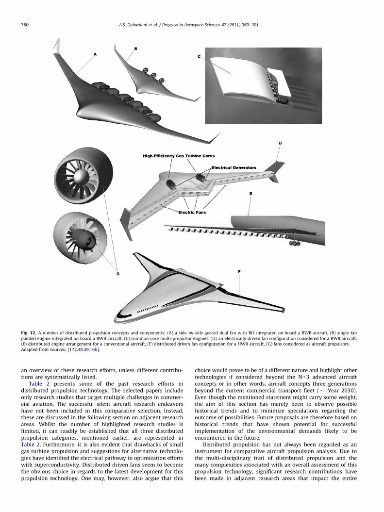
Fig. 12. A number of distributed propulsion concepts and components: (A) a side-by-side geared dual fan with BLI integrated on board a BWB aircraft, (B) single-fan
podded engine integrated on board a BWB aircraft, (C) common-core multi-propulsor engines, (D) an electrically driven fan configuration considered for a BWB aircraft,
(E) distributed engine arrangement for a conventional aircraft, (F) distributed driven fan configuration for a HWB aircraft, (G) fans considered as aircraft propulsors.
Adapted from sources: [172,48,39,166].
A.S. Gohardani et al. / Progress in Aerospace Sciences 47 (2011) 369–391380
an overview of these research efforts, unless different contribu-tions are systematically listed.
Table 2 presents some of the past research efforts indistributed propulsion technology. The selected papers includeonly research studies that target multiple challenges in commer-cial aviation. The successful silent aircraft research endeavorshave not been included in this comparative selection. Instead,these are discussed in the following section on adjacent researchareas. Whilst the number of highlighted research studies islimited, it can readily be established that all three distributedpropulsion categories, mentioned earlier, are represented inTable 2. Furthermore, it is also evident that drawbacks of smallgas turbine propulsion and suggestions for alternative technolo-gies have identified the electrical pathway to optimization effortswith superconductivity. Distributed driven fans seem to becomethe obvious choice in regards to the latest development for thispropulsion technology. One may, however, also argue that this
choice would prove to be of a different nature and highlight othertechnologies if considered beyond the N+3 advanced aircraftconcepts or in other words, aircraft concepts three generationsbeyond the current commercial transport fleet (� Year 2030).Even though the mentioned statement might carry some weight,the aim of this section has merely been to observe possiblehistorical trends and to minimize speculations regarding theoutcome of possibilities. Future proposals are therefore based onhistorical trends that have shown potential for successfulimplementation of the environmental demands likely to beencountered in the future.
Distributed propulsion has not always been regarded as aninstrument for comparative aircraft propulsion analysis. Due tothe multi-disciplinary trait of distributed propulsion and themany complexities associated with an overall assessment of thispropulsion technology, significant research contributions havebeen made in adjacent research areas that impact the entire
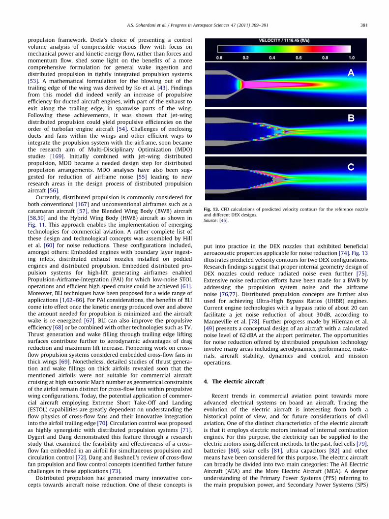
Fig. 13. CFD calculations of predicted velocity contours for the reference nozzle
and different DEX designs.
Source: [45].
A.S. Gohardani et al. / Progress in Aerospace Sciences 47 (2011) 369–391 381
propulsion framework. Drela’s choice of presenting a controlvolume analysis of compressible viscous flow with focus onmechanical power and kinetic energy flow, rather than forces andmomentum flow, shed some light on the benefits of a morecomprehensive formulation for general wake ingestion anddistributed propulsion in tightly integrated propulsion systems[53]. A mathematical formulation for the blowing out of thetrailing edge of the wing was derived by Ko et al. [43]. Findingsfrom this model did indeed verify an increase of propulsiveefficiency for ducted aircraft engines, with part of the exhaust toexit along the trailing edge, in spanwise parts of the wing.Following these achievements, it was shown that jet-wingdistributed propulsion could yield propulsive efficiencies on theorder of turbofan engine aircraft [54]. Challenges of enclosingducts and fans within the wings and other efficient ways tointegrate the propulsion system with the airframe, soon becamethe research aim of Multi-Disciplinary Optimization (MDO)studies [169]. Initially combined with jet-wing distributedpropulsion, MDO became a needed design step for distributedpropulsion arrangements. MDO analyses have also been sug-gested for reduction of airframe noise [55] leading to newresearch areas in the design process of distributed propulsionaircraft [56].
Currently, distributed propulsion is commonly considered forboth conventional [167] and unconventional airframes such as acatamaran aircraft [57], the Blended Wing Body (BWB) aircraft[58,59] and the Hybrid Wing Body (HWB) aircraft as shown inFig. 11. This approach enables the implementation of emergingtechnologies for commercial aviation. A rather complete list ofthese design and technological concepts was assembled by Hillet al. [60] for noise reductions. These configurations included,amongst others: Embedded engines with boundary layer ingest-ing inlets, distributed exhaust nozzles installed on poddedengines and distributed propulsion. Embedded distributed pro-pulsion systems for high-lift generating airframes enabledPropulsion-Airframe-Integration (PAI) for which low-noise STOLoperations and efficient high speed cruise could be achieved [61].Moreover, BLI techniques have been proposed for a wide range ofapplications [1,62–66]. For PAI considerations, the benefits of BLIcome into effect once the kinetic energy produced over and abovethe amount needed for propulsion is minimized and the aircraftwake is re-energized [67]. BLI can also improve the propulsiveefficiency [68] or be combined with other technologies such as TV.Thrust generation and wake filling through trailing edge liftingsurfaces contribute further to aerodynamic advantages of dragreduction and maximum lift increase. Pioneering work on cross-flow propulsion systems considered embedded cross-flow fans inthick wings [69]. Nonetheless, detailed studies of thrust genera-tion and wake fillings on thick airfoils revealed soon that thementioned airfoils were not suitable for commercial aircraftcruising at high subsonic Mach number as geometrical constraintsof the airfoil remain distinct for cross-flow fans within propulsivewing configurations. Today, the potential application of commer-cial aircraft employing Extreme Short Take-Off and Landing(ESTOL) capabilities are greatly dependent on understanding theflow physics of cross-flow fans and their innovative integrationinto the airfoil trailing edge [70]. Circulation control was proposedas highly synergistic with distributed propulsion systems [71].Dygert and Dang demonstrated this feature through a researchstudy that examined the feasibility and effectiveness of a cross-flow fan embedded in an airfoil for simultaneous propulsion andcirculation control [72]. Dang and Bushnell’s review of cross-flowfan propulsion and flow control concepts identified further futurechallenges in these applications [73].
Distributed propulsion has generated many innovative con-cepts towards aircraft noise reduction. One of these concepts is
put into practice in the DEX nozzles that exhibited beneficialaeroacoustic properties applicable for noise reduction [74]. Fig. 13illustrates predicted velocity contours for two DEX configurations.Research findings suggest that proper internal geometry design ofDEX nozzles could reduce radiated noise even further [75].Extensive noise reduction efforts have been made for a BWB byaddressing the propulsion system noise and the airframenoise [76,77]. Distributed propulsion concepts are further alsoused for achieving Ultra-High Bypass Ratios (UHBR) engines.Current engine technologies with a bypass ratio of about 20 canfacilitate a jet noise reduction of about 30 dB, according toManneville et al. [78]. Further progress made by Hileman et al.[49] presents a conceptual design of an aircraft with a calculatednoise level of 62 dBA at the airport perimeter. The opportunitiesfor noise reduction offered by distributed propulsion technologyinvolve many areas including aerodynamics, performance, mate-rials, aircraft stability, dynamics and control, and missionoperations.
4. The electric aircraft
Recent trends in commercial aviation point towards moreadvanced electrical systems on board an aircraft. Tracing theevolution of the electric aircraft is interesting from both ahistorical point of view, and for future considerations of civilaviation. One of the distinct characteristics of the electric aircraftis that it employs electric motors instead of internal combustionengines. For this purpose, the electricity can be supplied to theelectric motors using different methods. In the past, fuel cells [79],batteries [80], solar cells [81], ultra capacitors [82] and othermeans have been considered for this purpose. The electric aircraftcan broadly be divided into two main categories: The All ElectricAircraft (AEA) and the More Electric Aircraft (MEA). A deeperunderstanding of the Primary Power Systems (PPS) referring tothe main propulsion power, and Secondary Power Systems (SPS)
A.S. Gohardani et al. / Progress in Aerospace Sciences 47 (2011) 369–391382
referring to the distributed power around the airframe and theengine systems can cast light on the AEA or MEA concepts [83,84].
4.1. Selected milestones of the all electric aircraft
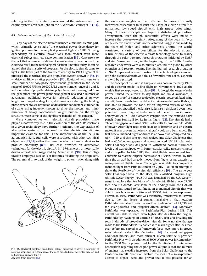
Early days of the electric aircraft included a minimal electric part,which primarily consisted of the electrical power dependency forignition purposes for the very first powered flights in 1903. Growingdependency on electrical power was soon evident with moreelectrical subsystems, eg. radio communication [85]. Conversely tothe fact that a number of different considerations have boosted theelectric aircraft to the technological position it retains today, it can beargued that the majority of proposals for the electric aircraft came tolight in the latter part of the twentieth century. In 1943 Kilgore et al.proposed the electrical airplane propulsion system shown in Fig. 14to drive multiple rotating propellers [86]. Equipped with one or asmall number of poly-phase synchronous generators in the speedrange of 10,000 RPM to 20,000 RPM, a pole-number range of 4 and 8,and a number of propeller driving poly-phase motors energized fromthe generators, this power plant arrangement revealed a number ofadvantages. Additional power for take-off, reduction of runwaylength and propeller drag force, skid avoidance during the landingphase, wheel brakes, reduction of detachable conductors, eliminationof sparks using induction-motors to drive the motors, and mini-mization of heavy concentrated weight burden on the wing-structure, were some of the significant benefits of this concept.
Many complexities with electric aircraft propulsion haveplayed a noteworthy role in the evolution of the AEA. Restrictionsin a given technology have further motivated the exploration ofalternative systems to be used in the electric aircraft. Animportant example for this is the introduction of fuel cells inaeronautics. Early fuel cells were associated with other technicalobjectives [87,88] rather than used as electrochemical devices toproduce electricity [89]. Fuel cells provided an alternativetechnology for the electric aircraft. In 1974, an electro-motoricallydriven aircraft was suggested by Meier et al. [90]. This config-uration employed fuel cells or batteries for driving the propellers.The perennial drawback of the weight to power ratio, along with
Fig. 14. Electrical airplane propulsion patent proposed to drive a plurality of
rotating propellers in recognition of the need for additional power for take-off and
reduction of runway length.
Adapted from source: [86].
the excessive weights of fuel cells and batteries, constantlymotivated researchers to restrict the usage of electric aircraft tounmanned, low speed aircraft with high aspect ratios wings.Many of these concepts employed a distributed propulsionarrangement. Even though substantial efforts were made toincrease the power-to-weight ratios, many of the goals in favorof the electric aircraft could not be achieved. Suggestions made bythe team of Meier, and other scientists around the world,considered a variety of possibilities for the electric aircraft.A true display of the electric aircraft technology came to realitythrough the solar-powered research programs initiated by NASAand AeroVironment, Inc., in the beginning of the 1970s. Similarresearch endeavors were also pursued around the globe by otherscientists and research teams. The highlighted research programsat NASA represent a small portion of the technologies involvedwith the electric aircraft, and thus a few milestones of this specificera will be revisited.
The concept of the Sunrise I airplane was born in the early 1970sand this aircraft made its first flight on November 4, 1974 as theworld’s first solar-powered airplane [91]. Although the usage of solarpower limited the aircraft to day flight and cloud avoidance, itserved as a proof-of-concept to develop electric-powered fixed-wingaircraft. Even though Sunrise did not attain extended solar flights, itwas able to provide the tools for an improved version of solar-powered aircraft, called the Sunrise II. Sunrise II displayed even morepotential to reach high altitudes and could benefit from improvedaerodynamics. In 1980, Gossamer Penguin used the removed solarpanels from Sunrise II for its initial flights [92]. The aircraft had a71-foot wingspan, and used 3,920 solar cells to produce 541 Wattsof power. After flight tests with solar cells, batteries and an electricmotor, it was proven that electric aircraft could also be manned. Thefirst official manned flight of direct solar power was completed on 7April 1980, and this concept was evolved into Solar Challenger thathad a 46.5-foot wingspan and accommodated 16,128 solar cells.Solar Challenger was designed to withstand normal turbulencelevels and was equipped with batteries, solar cells, an electric motorand a propeller. In late 1980, the initial flights were moved fromCalifornia to Marana Airpark, northwest of Tucson, Arizona. By thattime the aircraft had already moved from flights using batteries tosolar-powered flights. Solar Challenger was able to complete amanned flight from Paris to London on 7 July 1981 in an attempt toshow the feasibility of the aircraft’s efficiency [93]. The same yearSolar Challenger took to the skies, the classified program HighAltitude SOLar Energy (HALSOL) was launched by the U.S. Govern-ment to explore the feasibility of solar-electric flight above 65,000feet. About a decade later some of the findings from the HALSOLprogram contributed to Pathfinder, an unmanned aircraft that wasable to reach a record altitude of 50,500 feet for solar-poweredaircraft. In 1997, Pathfinder was eventually transferred to Hawaii,due to the high levels of sunlight available in that location.Pathfinder was able to reach a world altitude record of 71,530 feetfor solar-powered and propeller-driven aircraft [13]. Moreover,Pathfinder was upgraded to Pathfinder-Plus during 1988. Thisaircraft was able to reach even higher altitudes than the originalPathfinder by reaching an altitude of 80,210 feet and breaking therecord altitude of propeller-driven aircraft. Some notable changesmade to the Pathfinder Plus enabled it to reach higher altitudes thanever before and served as a framework for an even more improvedsolar aircraft called the Centurion [94]. Increased wingspan,additional motors, and more efficient silicon solar cells providedPathfinder Plus with an additional 5000 Watts power in comparisonto the 7500 Watts power used for the Pathfinder. An interestingobservation regarding the engine power output is that the numberof engines has steadily increased from the Solar Challenger to theCenturion aircraft. Centurion evolved the ideas of a solar-poweredaircraft to higher levels and proved that it was possible for an
A.S. Gohardani et al. / Progress in Aerospace Sciences 47 (2011) 369–391 383
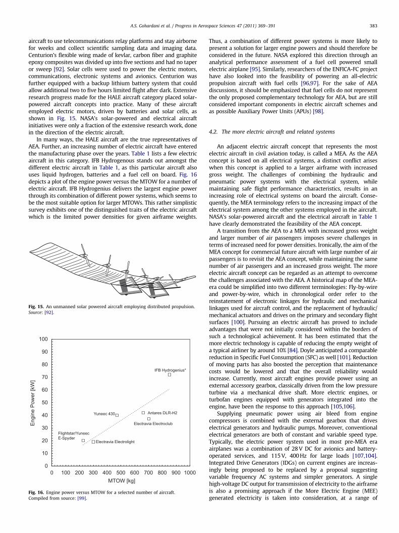
aircraft to use telecommunications relay platforms and stay airbornefor weeks and collect scientific sampling data and imaging data.Centurion’s flexible wing made of kevlar, carbon fiber and graphiteepoxy composites was divided up into five sections and had no taperor sweep [92]. Solar cells were used to power the electric motors,communications, electronic systems and avionics. Centurion wasfurther equipped with a backup lithium battery system that couldallow additional two to five hours limited flight after dark. Extensiveresearch progress made for the HALE aircraft category placed solar-powered aircraft concepts into practice. Many of these aircraftemployed electric motors, driven by batteries and solar cells, asshown in Fig. 15. NASA’s solar-powered and electrical aircraftinitiatives were only a fraction of the extensive research work, donein the direction of the electric aircraft.
In many ways, the HALE aircraft are the true representatives ofAEA. Further, an increasing number of electric aircraft have enteredthe manufacturing phase over the years. Table 1 lists a few electricaircraft in this category. IFB Hydrogenous stands out amongst thedifferent electric aircraft in Table 1, as this particular aircraft alsouses liquid hydrogen, batteries and a fuel cell on board. Fig. 16depicts a plot of the engine power versus the MTOW for a number ofelectric aircraft. IFB Hydrogenius delivers the largest engine powerthrough its combination of different power systems, which seems tobe the most suitable option for larger MTOWs. This rather simplisticsurvey exhibits one of the distinguished traits of the electric aircraftwhich is the limited power densities for given airframe weights.
Fig. 15. An unmanned solar powered aircraft employing distributed propulsion.
Source: [92].
0
10
20
30
40
50
60
70
80
90
100
0
Electravia Electrolight
Flightstar/YuneecE-Spyder
Yuneec 430
Electravia Electroclub
Antares DLR-H2
IFB Hydrogenius*
Eng
ine
Pow
er [k
W]
MTOW [kg]100 200 300 400 500 600 700 800 900 1000
Fig. 16. Engine power versus MTOW for a selected number of aircraft.
Compiled from source: [99].
Thus, a combination of different power systems is more likely topresent a solution for larger engine powers and should therefore beconsidered in the future. NASA explored this direction through ananalytical performance assessment of a fuel cell powered smallelectric airplane [95]. Similarly, researchers of the ENFICA-FC projecthave also looked into the feasibility of powering an all-electricpropulsion aircraft with fuel cells [96,97]. For the sake of AEAdiscussions, it should be emphasized that fuel cells do not representthe only proposed complementary technology for AEA, but are stillconsidered important components in electric aircraft schemes andas possible Auxiliary Power Units (APUs) [98].
4.2. The more electric aircraft and related systems
An adjacent electric aircraft concept that represents the mostelectric aircraft in civil aviation today, is called a MEA. As the AEAconcept is based on all electrical systems, a distinct conflict ariseswhen this concept is applied to a larger airframe with increasedgross weight. The challenges of combining the hydraulic andpneumatic power systems with the electrical system, whilemaintaining safe flight performance characteristics, results in anincreasing role of electrical systems on board the aircraft. Conse-quently, the MEA terminology refers to the increasing impact of theelectrical system among the other systems employed in the aircraft.NASA’s solar-powered aircraft and the electrical aircraft in Table 1have clearly demonstrated the feasibility of the AEA concept.
A transition from the AEA to a MEA with increased gross weightand larger number of air passengers imposes severe challenges interms of increased need for power densities. Ironically, the aim of theMEA concept for commercial future aircraft with large number of airpassengers is to revisit the AEA concept, while maintaining the samenumber of air passengers and an increased gross weight. The moreelectric aircraft concept can be regarded as an attempt to overcomethe challenges associated with the AEA. A historical map of the MEA-era could be simplified into two different terminologies: Fly-by-wireand power-by-wire, which in chronological order refer to thereinstatement of electronic linkages for hydraulic and mechanicallinkages used for aircraft control, and the replacement of hydraulic/mechanical actuators and drives on the primary and secondary flightsurfaces [100]. Pursuing an electric aircraft has proved to includeadvantages that were not initially considered within the borders ofsuch a technological achievement. It has been estimated that themore electric technology is capable of reducing the empty weight ofa typical airliner by around 10% [84]. Doyle anticipated a comparablereduction in Specific Fuel Consumption (SFC) as well [101]. Reductionof moving parts has also boosted the perception that maintenancecosts would be lowered and that the overall reliability wouldincrease. Currently, most aircraft engines provide power using anexternal accessory gearbox, classically driven from the low pressureturbine via a mechanical drive shaft. More electric engines, orturbofan engines equipped with generators integrated into theengine, have been the response to this approach [105,106].
Supplying pneumatic power using air bleed from enginecompressors is combined with the external gearbox that driveselectrical generators and hydraulic pumps. Moreover, conventionalelectrical generators are both of constant and variable speed type.Typically, the electric power system used in most pre-MEA eraairplanes was a combination of 28 V DC for avionics and battery-operated services, and 115 V, 400 Hz for large loads [107,104].Integrated Drive Generators (IDGs) on current engines are increas-ingly being proposed to be replaced by a proposal suggestingvariable frequency AC systems and simpler generators. A singlehigh-voltage DC output for transmission of electricity to the airframeis also a promising approach if the More Electric Engine (MEE)generated electricity is taken into consideration, at a range of
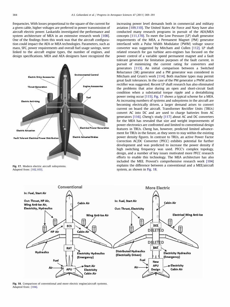
A.S. Gohardani et al. / Progress in Aerospace Sciences 47 (2011) 369–391384
frequencies. With losses proportional to the square of the current fora given cable, higher voltages are preferred in power transmission ofaircraft electric power. Laskaridis investigated the performance andsystem architecture of MEA in an extensive research work [108].One of the findings from this work was that the aircraft configura-tion could impact the AEA or MEA technologies. Parameters, such asmass, SFC, power requirements and overall fuel usage savings, werelinked to the aircraft engine types, the number of engines, anddesign specifications. MEA and AEA designers have recognized the
Fig. 18. Comparison of conventional and more electric engine/aircraft systems.
Adapted from: [104].
Fig. 17. Modern electric aircraft subsystems.
Adapted from: [102,103].
increasing power level demands both in commercial and militaryaviation [109,110]. The United States Air Force and Navy have alsoconducted many research programs in pursuit of the AEA/MEAconcepts [111,170]. To meet the Low Pressure (LP) shaft generatorrequirements of the MEA, a Permanent Magnet (PM) generatorinterfaced with a Pulse Width Modulator (PWM) voltage sourceconverter was suggested by Mitcham and Cullen [112]. LP shaftrelated research for gas turbine aero-engines has focused on thepower control of a variable speed permanent magnet and a faulttolerant generator for limitation purposes of the fault current, inpursuit of minimizing the current rating for converters andgenerators [113]. An initial comparison between a SwitchedReluctance (SR) generator and a PM generator was considered inMitcham and Grum’s work [114]. Both machine types may permitgreat fault tolerances. In the case of the PM generator a PWM activerectifier was suggested. Recent LP shaft research has also eliminatedthe problems that arise during an open and short-circuit faultcondition when a substantial torque ripple and a destabilizingpower swing occur [115]. Fig. 17 shows a typical scheme for a MEA.As increasing numbers of systems and subsystems in the aircraft arebecoming electrically driven, a larger demand arises to convertcurrent on board the aircraft. Transformer Rectifier Units (TRUs)convert AC into DC and are used to charge batteries from ACgenerators [116]. Cheng’s study [117] about AC and DC convertersfor the MEA has revealed that size and weight improvements ofpower electronics are confronted and limited to conventional designfeatures in TRUs. Cheng has, however, predicted limited advance-ment for TRUs in the future, as they seem to stay within the existingpower density figures. In contrast to TRUs, an active Power FactorCorrection AC/DC Converter (PFCC) exhibits potential for furtherdevelopment and was predicted to increase the power density ifhigh switching frequency was used. PFCC’s complex topology,design, and a number of key issues motivated more PFCC researchefforts to enable this technology. The MEA architecture has alsoincluded the MEE. Provost’s comprehensive research work [104]explains the difference between a conventional and a MEE/aircraftsystem, as shown in Fig. 18.
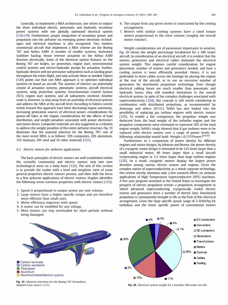
A.S. Gohardani et al. / Progress in Aerospace Sciences 47 (2011) 369–391 385
Generally, to implement a MEA architecture, one strives to replacethe three individual electric, pneumatic and hydraulic secondarypower systems with one globally optimized electrical system[118,119]. Furthermore, proper integration of secondary power andpropulsion into the airframe via emerging power electronic technol-ogies and electrical machines is also recognized. Two moderncommercial aircraft that implement a MEA scheme are the Boeing787 and Airbus A380. A number of smaller systems, horizontalstabilizer backup, thrust reverser actuation on the Airbus A380function electrically. Some of the electrical system features on theBoeing 787 are brakes, ice protection, engine start, environmentalcontrol systems and electro-hydraulic pumps for actuation. Further,hydraulic devices will not pressurize subsystems such as landing gearsthroughout the entire flight, and only activate them as needed. Faleiro[120] points out that one MEA approach is to optimize individualsystems on board an aircraft. The systems of interest can potentiallyconsist of actuation systems, pneumatic systems, aircraft electricalsystems, wing protection systems, Environmental Control System(ECS), engine start systems, and all subsystems involved. Anotherroute is, however, to step away from an assembly of electrical systemsand address the MEA at the aircraft level. According to Faleiro currenttrends toward this approach have been decreasing engine autonomy,increasing generation sources of electrical power, considerations forpower-off takes at the engine, considerations for the effects of loaddistribution, and weight penalties associated with power electronicsand motor drives. Composite materials are also suggested as a solutionto address the weight penalties of the entire airframe structure. Fig. 19illustrates that the material selection for the Boeing 787, one ofthe most recent MEA, is as follows: 50% composites, 20% alumnium,15% titanium, 10% steel and 5% other materials [121].
4.3. Electric motors for airborne applications
The basic principles of electric motors are well established withinthe scientific community and electric motors step into newtechnological areas on a daily basis [122]. The aim of this sectionis to provide the reader with a brief and simplistic view of somegeneral properties electric motors possess, and then shift the focusto a few airborne applications of electric motors. Hughes identifiesthe following seven common properties with electric motors [123]:
1.
FigAda
Speed is proportional to output power per unit volume.
2. Large motors have a higher specific torque and are thereforemore efficient than small ones.
3. Motor efficiency improves with speed. 4. A motor can be modified for any voltage. 5. Most motors can stay overloaded for short periods withoutbeing damaged.
Carbon laminateCarbon sandwichFiberglassAluminumAluminum/steel/titanium pylons
. 19. Material selections for the Boeing 787 Dreamliner.
pted from source: [121].
6.
The output from any given motor is constrained by the coolingarrangement.7.
Motors with similar cooling systems have a rated torquealmost proportional to the rotor volume (roughly the overallmotor volume).Weight considerations are of paramount importance in aviation.Fig. 20 shows the weight percentage breakdown for a 300 seateraircraft. In consideration of an electrical aircraft, it is evident that themotors, generators and electrical cables dominate the electricalsystem weight. This imposes careful consideration for engineplacement, number of motors and generators needed, and how acooling system is more efficiently provided. Hence, it is notpreferable to draw cables across the fuselage by placing the engineat the rear of the aircraft, or to use an excessive number ofgenerators for distributed propulsion technology. Even thoughelectrical cabling losses are much smaller than pneumatic andhydraulic losses, they still manifest limitations to the overallelectrical system. In spite of the complex challenges associated withsuperconductivity [124], this concept is still worth considering incombination with distributed propulsion, as recommended byAmeyugo and others [47,51]. NASA has also looked into thepossibility of replacing gas turbine engines with electric motors[125]. To enable a fair comparison, the propulsor weight wasdeducted from the total weight of the turbofan engine and thepropulsor components were estimated to represent 30% of the totalengine weight. NASA’s study showed that if gas turbines were to bereplaced with electric motors over a range of power levels thefollowing relationship would hold: Weight¼0.137(Power)0.9249.
Furthermore, in a comparison of power density for differentengines and motor designs, by Johnson and Brown, the power densityof a cryogenic motor design is estimated to be 125 times larger than asmall industrial motor, 40 times larger than a small aircraftreciprocating engine or 3.3 times larger than large turbine engines[125]. As a result, cryogenic motors display the largest powerdensities among various electric motors and engines. Given thecomplex nature of superconductivity as a whole separate technology,this review merely mentions only a few research efforts on airborneapplications of High Temperature Superconductive (HTS) machines.A five year program launched in the United States to investigate theprospect of electric propulsion revisits a propulsion arrangement inwhich advanced superconducting, cryogenically cooled electricmotors and generators drive a number of electric fans. Distributedpropulsion is consequently brought to life as the fruit of this electricalarrangement. Given the large specific power range of 3–8 kW/kg forturbofans and the lower specific power of conventional motors
Fig. 20. Electrical system weight for a baseline 300-seater aircraft.
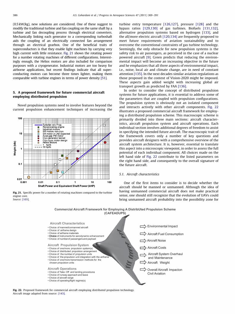
A.S. Gohardani et al. / Progress in Aerospace Sciences 47 (2011) 369–391386
(0.5 kW/kg), new solutions are considered. One of these suggest tomodify the traditional turbine and fan coupling on the same shaft by aturbine and fan decoupling process through electrical converters.Mechanically linking each generator to a corresponding turboshaftaids the coupling of an electrically connected fan arrangementthrough an electrical gearbox. One of the beneficial traits ofsuperconductors is that they enable light machines by carrying veryhigh current with little resistance. Fig. 21 shows the rotating powerfor a number rotating machines of different configurations. Interest-ingly enough, the Helios motors are also included for comparisonpurposes with a cryogenerator. Industrial motors are too heavy forairborne applications, but recent findings indicate that all super-conducting motors can become three times lighter, making themcomparable with turbine engines in terms of power density [51].
5. A proposed framework for future commercial aircraftemploying distributed propulsion
Novel propulsion systems need to involve features beyond thecurrent propulsion enhancement techniques of increasing the
Commercial Aircraft Framework for Employ(CAFEAD
• Choice of manned/unmanned aircraft• Choice of airframe design• Choice of airframe materials• Choice of instruments for aerodynamic enhancementChoice• Choice of numberof passengersand payload
Aircraft Propulsion System• Choice of one/more propulsion system(s)• Choice of distributed propulsion arrangement• Choice of the number of propulsion units• Choice of the propulsion unit integration with the airframe• Choice of one/more transmission methods for the
chosen propulsion units
Aircraft Operations• Choice of Take Off and landing procedures• Choice of runway approach and leave• Choice of aircraft range• Choice of operating flight regime(s)
Aircraft Characteristics
Fig. 22. Proposed framework for commercial aircraft employing distributed propulsion
Aircraft image adapted from source: [143].
Fig. 21. Specific power for a number of rotating machines compared to the turbine
engine core.
Source: [103].
turbine entry temperature [126,127], pressure [128] and thebypass ratios [129,130] of gas turbines. Biofuels [131,132],alternative propulsion systems based on hydrogen [133], andthe all/more electric aircraft [120,134] are frequently proposed tomeet future requirements of aviation sustainability and toovercome the conventional constraints of gas turbine technology.Seemingly, the only obstacle for new propulsion systems is thesafety risk to air passengers, as perceived in the case of a nuclearpowered aircraft [9]. Green predicts that reducing the environ-mental impact will become an increasing objective in the futureand he emphasizes that all three aspects of environmental impact,i.e., noise, local air and climate change, are in need of constantattention [135]. In the next decades similar aviation regulations asthose proposed in the context of Vision-2020 might be imposed.These aspects gain added weight with increasing global airtransport growth as predicted by FAA [136].
In order to consider the concept of distributed propulsionsystems for future applications, it is essential to address some ofthe parameters that are coupled with propulsion configurations.The propulsion system is obviously not an isolated componentand interacts actively with other aircraft components. Fig. 22illustrates a proposed commercial aircraft framework for employ-ing a distributed propulsion scheme. This macroscopic scheme isprimarily divided into three main sections: aircraft character-istics, aircraft propulsion system and aircraft operations. Eachindividual section involves additional degrees of freedom to assistin specifying the intended future aircraft. The macroscopic trait ofthe framework covers only a number of key questions andprovides aircraft designers with a comprehensive overview of theaircraft system architecture. It is, however, essential to translatethis aspect into a microscopic viewpoint, in order to assess the fullpotential of each individual component. All choices made on theleft hand side of Fig. 22 contribute to the listed parameters onthe right hand side, and consequently to the overall signature ofthe future aircraft.
5.1. Aircraft characteristics
One of the first items to consider is to decide whether theaircraft should be manned or unmanned. Although the idea ofhaving unmanned commercial aircraft does not make practicalsense, one should still recognize that the evolution of UAVs couldbring unmanned aircraft probability into the possibility zone for
ing A DistribUted Propulsion SchemeUPS)
Environmental Impact
Aircraft Fuel Consumption
Aircraft Noise
Aircraft Costs
Aircraft System Overhauland MaintenanceAircraft Weight
Overall Aircraft ImpactonCivil Aviation
technology.
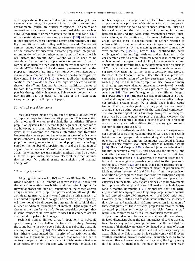
A.S. Gohardani et al. / Progress in Aerospace Sciences 47 (2011) 369–391 387
other applications. If commercial aircraft are used only for aircargo transportation, all systems related to cabin pressure andenvironmental control are drastically impacted. The choice of aconventional airframe or other unconventional airframes, such asa BWB/HWB aircraft, primarily affects the lift-to-drag ratio [137].Aircraft materials are also constantly reviewed [138] with respectto their properties, preset airframe design requirements, and theflight conditions in which they will be operated. The aircraftdesigner should consider the impact distributed propulsion hason the airframe for successful airframe-propulsion integration.A combination of aircraft design/geometry and airframe materialswill dictate the aircraft OWE. Weight will also need to beconsidered for the number of passengers or amount of payloadcarried, in addition to other weight parameters that contribute toaircraft MTOW. Many of the discussed parameters within theproposed framework are directly or indirectly interlinked. Aero-dynamic enhancement could, for instance, involve active/passiveflow control [139–141], TV [142] as well as all other engineeringsolutions that provide the means for high-lift devices to enableshorter take-off and landing. Further, an additional degree offreedom for aircraft operation from smaller airports is madepossible through this enhancement. This reduces congestions athub airports, but this detail is not part of the macroscopicviewpoint adopted in the present paper.
5.2. Aircraft propulsion system
Decisions regarding one or a multiple of propulsion systems isan important topic for future aircraft propulsion. This new optionadds another dimension to the flexibility of utilizing differentpropulsion systems for different flight segments. Opportunitiesdo, however, also bring challenges, in which novel combinedcycles must overcome the complex interaction and transitionbetween the chosen propulsion systems in view of safe opera-tional standards. In earlier sections we have analyzed differentpropulsion arrangements for distributed propulsion technology.Based on the number of propulsion units, and the integration ofengines/motors/propulsors/fans/exhaust units, in/above/around/across the wing/fuselage, transmission methods should be chosenin terms of pneumatic/mechanical/electrical or other alterna-tive methods for optimal energy transmission and minimalenergy loss.
5.3. Aircraft operations
Using high-lift devices for STOL or Cruise Efficient Short Take-Off and Landing (CESTOL) aircraft, as shown in Fig. 22, does affectthe aircraft operating possibilities and the noise footprint forrunway approach and take-off. Dependent on the chosen aircraftdesign characteristics, propulsion power and aircraft weight, theaircraft range may vary, as shown from the historical aspects ofdistributed propulsion technology. The operating flight regime(s)will intentionally be discussed in a greater detail to highlight anumber of adjacent technologies of interest. Flight regimes arechosen as the main fountain of different propulsion concepts, thatin some respect could give birth to ideas that compete againstdistributed propulsion technology.
Technical hurdles limited aircraft operations to subsonicspeeds during the first half of the twentieth century. Breakingthe sound barrier in 1947 opened the skies to subsonic, transonicand supersonic flight [144]. Nevertheless, commercial aviationhas hitherto concentrated the majority of its activities in thesubsonic and transonic regimes. Given that more than half acentury has passed since the supersonic flight regime first wasinvestigated, one might question why commercial aviation has
not been exposed to a larger number of airplanes for supersonicair passenger transport. One of the drawbacks of air transport inthe subsonic regime is said to be its speed limitation. Prior to ahistorical race for the first supersonic commercial airlinerbetween Russia and the West, some researchers praised super-sonic efforts, while pointing out the many challenges that layahead. Among these, a special need for further research toenhance lift to drag ratio at supersonic speeds, and specificpropulsion problems such as matching engine flow to inlet flowwere emphasized [145,146]. Davies [147] identified the severechallenges of supersonic flight early on, and emphasized that theconsiderable costs to ensure technical readiness in combinationwith economic and operational viability for a supersonic airlinershould not be underestimated. In the aftermath of the oil crisis in1973, many major economical issues associated with commercialsupersonic aviation had still not been successfully addressed. Inthe case of the Concorde aircraft fleet the elusive profit wascaused by a combination of too few passengers over too shortroutes. [155]. On the subsonic propulsion side, however, manyfascinating steps were taken. A comprehensive review of the earlyprop-fan propulsion technology was presented by Gatzen andAdamson [149]. The prop-fan engine has many different designs.In a NASA study [148], the prop-fan was represented as a three-spool shaft engine, where the high spool was an axial/centrifugalcompression system driven by a single-stage high-pressureturbine. This specific design also used a pipe diffuser and mateda single-stage aerating burner with the centrifugal compressor.The low-pressure spool had a four-stage, low-pressure compres-sor driven by a single-stage low-pressure turbine. Moreover, thepower turbine operated at high efficiencies and the propellerswere driven by an in-line differential planetary gearbox withcounter-rotating output shafts.
During the small-scale models phase, prop-fan designs wereconsidered for a cruising Mach number of 0.6–0.85. This specificNASA sponsored program demonstrated significant fuel savingspotential, and verified different techniques that could influencethe cabin noise comfort level, such as direction synchro-phasing[149]. Black and Murphy [150] addressed jet noise reduction forthe first generation aircraft. Neitzel reviewed the potential andcost effectiveness of conventional turbo fans with optimizedthermodynamic cycles [151]. Moreover, a merger between the re-fan and the re-engine approach contributed to the open rotortechnology. Blythe [152] concluded that contra-rotating propel-lers provided one of the most efficient means of propulsion forMach numbers between 0.6 and 0.8. Apart from the propulsionrevolution of jet engines, a transition from the turboprop engineto a new open rotor technology placed advanced powerplantcategories on the table. Early bypass engines led to improvementsin propulsive efficiency, and were followed up by high bypassratio turbofans. Borradaile [153] emphasized that the UHBRengine could be employed for a long range large aircraft becauseit had offered cruise SFC improvements and DOC reductions.However, there is still a need to understand better the associatedflow physics and mechanical airframe-propulsion-integration ofthese configurations. These historical prop-fan milestones identifyadvanced prop-fan technology as a possible future aircraftpropulsion competitor to distributed propulsion technology.
Speed considerations for a commercial aircraft have alwaysinitiated discussions about the real importance of saving travelingtime. Today, any airline passenger is aware of the fact that theelements of flight delay are usually dominated by a range of factorsbefore take-off and after touchdown, and not necessarily during theactual flight time. This assumption is certainly only valid if severeweather conditions, aircraft malfunction circumstances, air trafficissues or other unforeseen events that may delay the flight journeydo not occur. As mentioned, the push for higher flight Mach
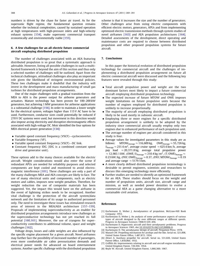
A.S. Gohardani et al. / Progress in Aerospace Sciences 47 (2011) 369–391388
numbers is driven by the chase for faster air travel. As for thesupersonic flight regime, the fundamental question remainswhether the technical complexities, caused by sustained operationat high temperatures with high-pressure inlets and high-velocityexhaust systems [154], make supersonic commercial transporteconomically and environmentally viable [155].
6. A few challenges for an all electric future commercialaircraft employing distributed propulsion
The number of challenges associated with an AEA featuringdistributed propulsion is so great that a systematic approach isadvisable. However, listing all possible challenges in such a multi-faceted framework is beyond the aim of this section and thus onlya selected number of challenges will be outlined. Apart from thetechnical challenges, attitudinal challenges also play an importantrole given the likelihood of stringent environmental policies.These two challenges make it doubtful that the industry willinvest in the development and mass manufacturing of small gasturbines for distributed propulsion arrangements.
One of the major challenges with a gradual transition from theMEA to AEA is the power output for airborne generators andactuators. Mature technology has been proven for 100–200 kWgenerators, but achieving 1 MW generators for airborne applicationsis a substantial challenge [156]. In order to maintain a lower weightfor the electrical system, voltages higher than 115 V AC have to beused. Furthermore, conductor sizes could potentially be reduced if270 V DC systems were used, but movement in this direction wouldalso impose arcing electricity and disruptive electromagnetic effectsassociated with high-voltage DC. Moir identified the four options forMEA electrical power generation [134]:
�
Variable speed constant frequency (VSCF)—cycloconverter. � Variable frequency (VF). � Variable speed constant frequency (VSCF)—DC link. � Constant frequency IDG (IDG is a combined constant speeddrive and generator unit).
These options add to the many choices available for the electricaircraft. Weight considerations would also enter the scene ifredundant APUs are needed for reliability purposes and selectedcomponents are kept cooled and monitored to avoid electro-magnetic interference [101]. These challenges are only a part ofthe many challenges MEA and AEA concepts are likely to face. Theuse of many electrical units and components, such as electricmotors and cables, imposes new weight penalties. Therefore, forweight reduction the use of composite materials has beensuggested. Yet, the impact this would have on the airframe inthe event of lightning strikes needs to be recognized. Anothervital challenge is the protection of the aircraft system/datanetwork and the limitation of its usage to authorized personnelonly. The need to investigate these issues has stimulated researchareas of interest in the MEA/AEA architecture [157–159].Proposals of implementing superconductivity as an enabler fordistributed propulsion arrangements introduce new challenges asthe superconductive technology has not yet reached its fullpotential [160,161]. Moreover, the use of cryogens for super-conductivity contributes to additional volume, space and weightchallenges [162].
Voltage drops, losses and cable weights are also influenced bythe specific engine placement for a given aircraft. Novel airframesmay further face the possibility of increased number of passengers,even more comfortable air cabin pressurization demands andelectrical power needs for advanced on board entertainmentsystems. Another specific challenge with the distributed propulsion
scheme is that it increases the size and the number of generators.Other challenges arise from sizing electric components withefficient electric motors, generators, APUs and from implementingoptimized electric transmission methods through system studies ofnovel airframes [163] and AEA propulsion architectures [164].Detailed assessments of the development, direct operating andmaintenance costs are required to choose between distributedpropulsion and other proposed propulsion systems for futureaircraft.
7. Conclusions
In this paper the historical evolution of distributed propulsiontechnology for commercial aircraft and the challenges of im-plementing a distributed propulsion arrangement on future allelectric commercial aircraft were discussed and the following keyfeatures were revealed through this study:
�
Total aircraft propulsive power and weight are the twodominant factors most likely to impact a future commercialaircraft employing distributed propulsion technology. � The expected increase of future MTOW and OWE imposesweight limitations on future propulsive units because thenumber of engines employed for distributed propulsion isunlikely to increase proportionally.
� The majority of aircraft employing distributed propulsion islikely to be used mostly in subsonic aircraft.
� Employing three or more engines for a specific distributedpropulsion arrangement is unlikely to be adopted by theindustry since commercial aircraft usually employ only twoengines due to enhanced performance of each propulsion unit.
� The average number of engines per aircraft considered in thisstudy is four.
� Average values for investigated parameters in this study are asfollows: MTOWAverage � 116,609 kg, OWEAverage � 55,726 kg,SAverage � 231:6 m2, average cruise speed � 625:6 km=h, averagepay load � 20,371:8 kg, average total propulsive power� 12,983:1 kW, ðOWE=SÞAverage � 210:4 kg=m2, ðT=OWEÞAverage �
0:23 kW=kg, ðPAY=OWEÞAverage � 0:37, ðPAY=MTOWÞAverage � 0:19and average range � 5179:5 km.
� A more clearly defined distributed propulsion terminology isdesirable to permit engineers, scientists and researchers todiscuss this emerging technology more efficiently.
� Further studies are needed to identify an optimized frameworkfor an AEA. These studies should focus on the weight andnumber of propulsion units, aircraft size, aircraft range andmission, as well as needed power densities to evolve acommercial AEA as a game changing alternative to a moresustainable civil aviation.
References
[1] Kuchemann D, Weber J. Aerodynamics of propulsion. McGraw-Hill BookCompany; 1953.
[2] Kuchemann D, Weber J. An analysis of some performance aspects of varioustypes of aircraft designed to fly over different ranges at different speeds.Progress in Aerospace Sciences 1968;9:329–456.
[3] Kuchemann D. Hypersonic aircraft and their aerodynamic problems. Progressin Aerospace Sciences 1965, doi:10.1016/0376-0421(65)90006-0.
[4] Kuchemann D. The aerodynamic design of aircraft. Pergamon Press; 1978.[5] Manzel CW. Propelling mechanism for airships and the like. Serial no. 321,008,
United States Patent Office, 1,487,872; 1924.[6] Altieri A. Auxiliary propeller for aircraft. Serial no. 531,020, United States
Patent Office, 1,850,066; 1932.[7] Griffith AA. Improvements relating to aircraft and aircraft engine installations.
United Kingdom Patent, 720,394; 1954.[8] Reyle W. Aircraft. United Kingdom Patent, 1,066,360; 1967.
A.S. Gohardani et al. / Progress in Aerospace Sciences 47 (2011) 369–391 389
[9] Rom FE. Status of nuclear powered aircraft. Journal of Aircraft: 0021-86691971;8(1):26–33.
[10] Gochnur GR. Fusion energy system and plasma propulsion aircraft to produceelectricity from a controlled nuclear fusion reaction. United States PatentOffice, Pub. no.: US 2005/0254613 A1; 2005.
[11] Malvestuto Jr FS. Aircraft transporter. United States Patent Office, 3,856,238;1974.
[12] Phillips WH. Solar powered aircraft. United States Patent Office, 4,415,133;1983.
[13] Flittie K, Curtin B. Pathfinder solar-powered aircraft flight performance. AIAAPaper 1998-4446; 1998.
[14] Langford J. High altitude UAVs for atmospheric science: a decade ofexperience. AIAA Paper 2002-3467; 2002.
[15] Yaros SF, Sexstone MG, Huebner LD, Lamar JE, McKinley Jr RE, Torres AO, et al.Synergistic airframe–propulsion interactions and integrations: a white paperprepared by the 1996–1997 Langley Aeronautics Technical Committee.NASA/TM-1998-207644; 1998.
[16] NASA Aeronautics Research Mission Directorate: ARMD advanced conceptstudies awardees. NASA N+3 supersonic-three generations forward inaviation technology (awardee abstract), team lead: Lockheed MartinCorporation. National Aeronautics and Space Administration website. Inter-net: /www.nasa.govS; accessed on: 15/3/2009.
[17] Bain A, Van Vorst WD. The Hindenburg tragedy revisited: the fatal flawfound. International Journal of Hydrogen Energy 1999;24(5):399–403,doi:10.1016/S0360-3199(98)00176-1.
[18] Goltsov VA, Veziroglu TN. A step on the road to hydrogen civilization.International Journal of Hydrogen Energy 2002;27(7–8):719–23,doi:10.1016/S0360-3199(01)00122-7.
[19] Eden P, Moeng S. The complete encyclopedia of world aircraft. London,United Kingdom: Barnes & Noble Books/Amber Books Ltd.; 2002. ISBN:0760734321.
[20] Jackson A. British civil aircraft since 1919, vol. 2, 2nd ed. London, UnitedKingdom: Putnam & Company; 1973. ISBN: 0-370-10010-7.
[21] Smith JR, Kay A. German aircraft of the second world war. London, UnitedKingdom: Putnam; 1990. ISBN: 851778364.
[22] McDonald JJ. Howard Hughes and the Spruce goose. Blue Ridge Summit, PA:Tab Books Inc.; 1981. ISBN 0-8306-2320-5.
[23] NASA. Centurion—reaching the new century on solar power. NASA fact sheet:FS-1998-10-056 DFRC; 1988.
[24] Grow HB. Aircraft wing with internal flow control propulsion. United StatesPatent Office 4,026,500; May 31, 1997.
[25] Hunting H. 126 Jet-flap research aircraft: details of the British AircraftCorporation Research Aircraft designed to a Ministry of Aviation specificationwhich recently made its first. Aircraft Engineering and Aerospace Technology1963;35(6), doi:10.1108/eb033738.
[26] Grow HB. Aircraft wing with internal flow control propulsion. United StatesPatent Office 4,026,500; May 31, 1997.
[27] FAA InFO: New ETOPS regulations. Information for Operators 07004: FederalAviation Administration; 1/26/2007.
[28] Raymer DP. Aircraft design: a conceptual approach. American Institute ofAeronautics and Astronautics Inc.; 1989. p. 76–100.
[29] FAA advisory circular. Aircraft weight and balance Control. AC no. 120-27C,US Department of Transportation, Federal Aviation Administration; 11/7/1995.
[30] Cleveland FA. Size effects in conventional aircraft design. Journal of AircraftPaper 1970;7:483–512.
[31] Redelinghuys C. Proposed measures for invention gain in engineering design.Journal of Engineering Design 2000;11(3):245–63, doi:10.1080/095448200750021012.
[32] Tennekes H. The simple science of flight. Cambridge: The MIT Press; 1993.[33] Filippone A. Data and performances of selected aircraft and rotorcraft.
Program in Aerospace Science 2000;36(8):629–54, doi:10.1016/S0376-0421(00)00011-7.
[34] Executive Office of The President. Goals for a national partnership inaeronautics research and technology. Report no. A245823, National Scienceand Technology Council, Washington, DC 20500; 1995.
[35] NASA Subsonic Airliner Performance Goals. NRA: NNH08ZEA001N; 07/03/2008.
[36] ACARE. Advisory Council For Aeronautics Research in Europe—2008Addendum to the strategic research agenda; 2008.
[37] ACARE. Advisory Council For Aeronautics Research in Europe—2002 strategicresearch agenda, vol. 1, 2002.
[38] ACARE. Advisory Council For Aeronautics Research in Europe—2001European aeronautics: a vision for 2020; 2001.
[39] Sehra AK, Whitlow Jr W. Propulsion and power for 21st century aviation.Program in Aerospace Science 2004;40(4–5):199–235, doi:10.1016/j.paer-osci.2004.06.003.
[40] Campbell D. Revolutionary power and propulsion for 21st century aviation.AIAA Paper 2003-2561; 2003.
[41] Dippold V III, Ko A, Hosder S, Arieli R, Grossman B, Haftka R, et al. MDOinvestigations of advanced design concepts applied to the blended wing-bodyconfiguration. Six month progress review presentation, NASA LangleyResearch Center, Hampton, VA; 24/06/2002.
[42] Ko A, Leifsson L, Schetz JA, Mason W, Grossman B, Haftka R. MDO of ablended-wing-body transport aircraft with distributed propulsion. AIAAPaper 2003-6732; 2003.
[43] Ko A, Schetz JA, Mason WH. Assessment of the potential advantages ofdistributed propulsion for aircraft. In: 16th international symposium on airbreathing engines (ISABE), ISABE Paper 2003-1094; 2003.
[44] Ahuja KK, Gaeta RJ, Hellman B, Schein DB, Solomon Jr WD. Distributedexhaust nozzles for jet noise reduction. GTRI Report A6221/2001-1; 31/12/2001.
[45] Kinzie KW, Schein DB, Solomon Jr WD. Experiments and analyses ofdistributed exhaust nozzles. AIAA Paper 2002-2555; 2002.
[46] Kim HD, Saunders JD. Embedded wing propulsion conceptual study. NATORTA symposium on vehicle propulsion integration. RTO-MP-AVT-100; 2003.
[47] Ameyugo G, Singh R, Taylor M. Distributed propulsion feasibility studies. In:Proceedings of the 25th international congress of the aeronautical sciences,Hamburg, 2006.
[48] Ameyugo G. Distributed propulsion and future aerospace technologies.Eng.D. thesis, Cranfield University, United Kingdom; 2007.
[49] Hileman J, Spakovszky Z, Drela M, Sargeant M. Airframe design for silentaircraft. AIAA Paper 2007-0453; 2007.
[50] Hileman J, Reynolds TG, de la Rosa Blanco E, Law T, Thomas S. Developmentof approach procedures for silent aircraft. AIAA Paper 2007-0451; 2007.
[51] Luongo CA, Masson PJ, Nam T, Mavris D, Kim HD, Brown GV, et al. Nextgeneration more-electric aircraft: a potential application for HTS super-conductors. IEEE Transactions on Applied Superconductivity 2009;19(3)1055–68, doi:10.1109/TASC.2009.2019021.
[52] Wickenheiser T, Sehra A, Seng G, Freeh J, Berton J. Emissionless air-craft—requirements and challenges. AIAA Paper 2003-2810; 2003.
[53] Drela M. Power balance in aerodynamic flows. AIAA Journal Paper 0001-14522009;47(7):1761–71, doi:10.2514/1.42409.
[54] Dippold V III, Hosder S, Schetz J. Analysis of jet-wing distributed propulsionfrom thick wing trailing edges. AIAA Paper 2004-1205; 2004.
[55] Leifsson L, Mason W, Schetz J, Haftka R, Grossman B. Multidisciplinary designoptimization of low-airframe-noise transport aircraft. AIAA Paper 2006-230;2006.
[56] Diedrich A, Hileman J, Tan D, Willcox K, Spakovszky Z. Multidisciplinarydesign and optimization of the silent aircraft. AIAA Paper 2006-1323; 2006.
[57] Posey J, Tinetti A, Dunn M. The low-noise potential of distributed propulsionon a catamaran aircraft. AIAA Paper 2006-2622; 2006.
[58] Liebeck R. Design of the blended wing-body subsonic transport. AIAA Paper2002-0002; 2002.
[59] Vicroy D. Blended-wing-body low-speed flight dynamics: summary ofground tests and sample results (invited). AIAA Paper 2009-933; 2009.
[60] Hill G, Brown S, Geiselhart K, Burg C. Integration of propulsion–airframe-aeroacoustic technologies and design concepts for a quiet blended-wing-body transport. AIAA Paper 2004-6403; 2004.
[61] Kim HD, Berton J, Jones S. Low noise cruise efficient short take-off andlanding transport vehicle study. AIAA Paper 2006-7738; 2006.
[62] Gorton S, Owens L, Jenkins L, Allan B, Schuster E. Active flow control onboundary-layer-ingesting inlet. AIAA Paper 2004-1203; 2004.
[63] Smith AMO, Roberts HE. The jet airplane utilizing boundary layer air forpropulsion. Journal of the Aeronautical Sciences 1947;14(2):97–109.
[64] Smith LH. Wake ingestion propulsion benefit. Journal of Propulsion andPower 1993;9(1):74–82.
[65] Harrison N, Anderson J, Fleming J, Ng Wing. Experimental investigation ofactive flow control of a boundary layer ingesting serpentine inlet diffuser.AIAA Paper 2007-843; 2007.
[66] Allan B, Owens L. Numerical modeling of flow control in a boundary-layer-ingesting offset inlet diffuser at transonic mach numbers. AIAA Paper 2006-845; 2006.
[67] Plas AP, Madani V, Sargeant MA, Greitzer EM, Hall CA, Hynes TP. Performanceof a boundary layer ingesting (BLI) propulsion system. AIAA Paper 2007-0450; 2007.
[68] Rodriguez D. Multidisciplinary optimization method for designing boundary-layer-ingesting inlets. Journal of Aircraft, 0021-8669 2009;46(3):883–94.
[69] Kummer J, Dang T. High-lift propulsive airfoil with integrated crossflow fan.Journal of Aircraft, 0021-8669 2006;43(4):1059–68, doi:10.2514/1.17610.
[70] Gologan C, Mores S, Steiner H, Seitz A. Potential of the cross-flow fan forpowered-lift regional aircraft applications. AIAA Paper 2009-7098; 2009.
[71] Sellers W, Singer B, Leavitt L. Aerodynamics for revolutionary air vehicles.AIAA Paper 2003-3785; 2003.
[72] Dygert R, Dang T. Experimental investigation of embedded crossflow fan forairfoil propulsion/circulation control. Journal of Propulsion and Power, 0748-4658 2009;25(1):196–203, doi:10.2514/1.37110.
[73] Tang TQ, Bushnell PR. Aerodynamics of cross-flow fans and their applicationto aircraft propulsion and flow control. Progress in Aerospace Sciences2009;45(January–April):1–29.
[74] Kinzie KW, Brown MC, Schein DB, Solomon Jr WD. Measurements andpredictions for a distributed exhaust nozzle. AIAA Paper 2001-2236; 2001.
[75] Gaeta R, Ahuja K, Murdock B, Combier R. Noise reduction from a distributedexhaust nozzle with forward velocity effects. AIAA Paper 2004-2970; 2004.
[76] Hall C, Schwartz E, Hileman J. Assessment of technologies for the silentaircraft initiative. Journal of Propulsion and Power, 0748-4658 2009;25(6):1153–62, doi:10.2514/1.43079.
[77] Stone J, Krejsa E, Berton J, Kim HD. Initial noise assessment of an embedded-wing-propulsion concept vehicle. AIAA Paper 2006-4979; 2006.
[78] Manneville A, Pilczer D, Spakovszky Z. Noise reduction assessments andpreliminary design implications for a functionally-silent aircraft. AIAA Paper2004-2925; 2004.
A.S. Gohardani et al. / Progress in Aerospace Sciences 47 (2011) 369–391390
[79] Krok M, de Bedout J, Gjini O. Exploring the role of fuel cell electric powersystems for commercial aviation applications. AIAA Paper 2007-1389; 2007.
[80] Avanzini G, D’Angelo S, De Matteis G. Development of a shrouded-fan UAV forenvironmental monitoring. AIAA Paper 2004-6383; 2004.
[81] Rizzo E, Frediani A. A model for solar powered aircraft preliminary design.The Aeronautical Journal 2008;112.
[82] Maclay J, Brouwer J, Samuelsen G. Dynamic modeling of hybrid energystorage systems coupled to photovoltaic generation in residential applica-tions. Journal of Power Sources 2006;163(2):916–25, doi:10.1016/j.jpowsour.2006.09.086.
[83] Jones R. The more electric aircraft—assessing the benefits. Proceedings of theInstitution of Mechanical Engineers Part G: Journal of Aerospace Engineering2002;216(5/2002):259–69, doi:10.1243/095441002321028775.
[84] Hoffman A, Hansen I, Beach R, Plencner R, Dengler R, Jefferies K, et al.Advanced secondary power system for transport aircraft. NASA PublicationTechnical Paper: 2463, N85-28944; 1985.
[85] Hyder AK. A century of aerospace electrical power technology. Journal ofPropulsion and Power, 0748-4658 2003;19(6):1155–79, doi:10.2514/2.6949.
[86] Kilgore LA, Godsey Jr FW, Rose BA, Powers FB. Electrical airplane propulsion.United States Patent: 2,462,201; 1949.
[87] Aspelin LL. Airplane fuel system. United States Patent: 2,547,246; 1951.[88] Pepersack FJ. Aircraft fuel storage system. United States Patent: 2,653,780; 1953.[89] Bacon FT, Alkaline primary cells. United States Patent: 2,716,670; 1955.[90] Meier HJ, Sadowski H, Stampa U. Electrically powered aircraft. United States
Patent: 3,937,424; 1976.[91] Boucher R. Sunrise the world’s first solar-powered airplane. Journal of
Aircraft 0021-8669 1985;22(10):840–6, doi:10.2514/3.452131985.[92] NASA. NASA Dryden Homepage—fact sheet sections on solar powered aircraft.
Internet: /www.nasa.gov/centers/drydenS; accessed on: 27/01/2010.[93] Maccready PB, Lissaman PBS, Morgan WR, Burke JD. Sun powered aircraft
design. AIAA Paper 1981-916; 1981.[94] Wegener S, Schoenung S. Lessons learned from NASA UAV science
demonstration program missions. AIAA Paper 2003-6616; 2003.[95] Berton JJ, Freeh JE, Wickenheiser TJ. An analytical performance assessment of a
fuel cell-powered, small electric airplane. NASA Publication/TM-2003-212393;2003.
[96] Romeo G, Moraglio I, Novarese C. ENFICA-FC: preliminary survey & design ofa 2-seat aircraft powered by fuel cells electric propulsion. AIAA Paper 2007-7754; 2007.
[97] Romeo G, Borello F, Cestino E, Moraglio I, Novarese C. ENFICA-FC environ-mental friendly inter-city aircraft and 2-seat aircraft powered by fuel cellselectric propulsion. In: AIRTEC second international conference, Frankfurt,Germany, 2007.
[98] Pratt J, Brouwer J, Samuelsen GS. Performance of proton exchange membranefuel cell at high-altitude conditions. Journal of Propulsion and Power, 0748-4658 2007;23(2):437–44, doi:10.2514/1.20535.
[99] Jane’s All The World’s Aircraft Homepage: All sections search engine.Internet: /www.janes.comS; accessed on: 27/01/2010.
[100] Green S, Atkinson DJ, Mecrow BC, Jack AG, Green B. Fault tolerant, variablefrequency unity power factor converters for safety critical PM drives. ElectricPower Applications IEE Proceedings 2003;150(6):663–72. ISSN: 1350-2352.
[101] Doyle A. More and more electric. Flight International; 28/08/96.[102] Honeywell homepage: section about honeywell’s more electric aircraft
vision. Internet: /www.honeywell.comS; accessed on: 27/01/2010.[103] Masson P, Luongo C. HTS machines for applications in all-electric aircraft.
Panel session presentation: power engineering society general meeting2007, Tampa, Florida; 2007.
[104] Provost M. The more electric aero-engine: a general overview from anengine manufacturer. In: International conference on power electronics,machines and drives, conference publication no. 487, 2002. p. 246–51, ISSN:0537-9989.
[105] Ensign T. Sensitivity studies of electric systems on business jet range. AIAAPaper 2008-147; 2008.
[106] Rued K. Technology preparation for green aero engines. AIAA Paper 2003-2790;2003.
[107] Raimondi G, Sawata T, Holme M, Barton A, White G, Coles J, et al. Aircraftembedded generation systems. IEE conference publication, 217, 2002.p. 217–22, doi:10.1049/cp:20020117.
[108] Laskaridis P. Performance investigations and systems architectures for themore electric aircraft. PhD thesis, Cranfield University, United Kingdom; 2004.
[109] Weimer JA. Electrical power technology for the more electric aircraft. In:Digital avionics systems conference, 12th DASC, AIAA/IEEE, 1993, doi:10.1109/DASC.1993.283509.
[110] Homeyer W, Bowles E, Lupan S, Rodriguez C, Walia P, Shah N, et al.Advanced power converters for more electric aircraft applications. In:Energy conversion engineering conference, IECEC 96, Proceedings of the31st intersociety, 1996, doi:10.1109/IECEC.1996.552860.
[111] Cloyd J. A status of the United States Air Force’s more electric aircraftinitiative. In: Energy conversion engineering conference IECEC-97: proceed-ings of the 32nd Intersociety, vol. 1; 1997. p. 681–6, doi:10.1109/IECEC.1997.659272.
[112] Mitcham AJ, Cullen JJA. Permanent magnet generator options for the moreelectric aircraft. In: International conference on power electronics, machinesand drivers, conference publication no. 487, 2002.
[113] Hill J, Mountain S. Control of a variable-speed, fault-tolerant permanentmagnet generator. In: International conference on power electronics,machines and drivers, conference publication no. 487, 2002.
[114] Mitcham A, Grum N. An integrated LP shaft generator for the more electricaircraft. All electric aircraft (digest no. 1998/260), IEE colloquium, 17/06/1998.
[115] Sun Z, Ede D, Wang J, Jewell G, Cullen J, Mitcham A. Testing of a 250-kiloWattfault-tolerant permanent magnet power generation system for aeroengines.Journal of Power and Propulsion, 0748-4658 2008;24(2), doi:10.2514/1.32158.
[116] Tooley M, Wyatt D. Aircraft electrical and electronic systems: principles,maintenance and operation. Butterworth–Heinemann; 2008. ISBN-13:978-0750686952.
[117] Cheng K. Comparative study of AC/DC converters for more electric aircraft.In: Seventh international conference on power electronics and variablespeed drives, conference publication no. 456, 1998.
[118] Cronin MJ. The all electric aircraft as an energy efficient transport. Paper801113 (Society of Automotive Engineers), SAE Aerospace Congress &exposition, Los Angeles; 1980.
[119] Weimer J. The role of electric machines and drives in the more electricaircraft. In: IEEE international electric machines and drives conference,IEMDC’03, vol. 1, 2003, ISBN: 0-7803-7817-2.
[120] Faleiro L. Beyond the more electric aircraft. Aerospace America; September2005.
[121] Hawk J. The boeing 787 dreamliner: more than an airplane. Presentation toAIAA/AAAF aircraft noise and emissions reduction symposium, Americaninstitute of Aeronautics and Astronautics and Association, Aeronautique etAstronautique de France; 25/05/2005.
[122] Gottlieb I. Practical electric motor handbook. Butterworth–Heinemann;1997. ISBN: 0 75063638 2.
[123] Hughes A. Electric motors and drives. 3rd ed.. Elsevier; 2006. ISBN: 978-0-7506-4718-2.
[124] Lynn JW, editor. High temperature superconductivity. Series: graduate textsin contemporary physics, subseries: maryland subseries: based on lecturesat the University of Maryland, vol. XV, College Park, 1990, ISBN: 978-0-387-96770-7.
[125] Johnson D, Brown G. NASA research & technology 2004. NASA Publication,TM-2005-213419; 2004. p. 144–5.
[126] Wright LM, Gohardani AS. Effect of coolant ejection in rectangular andtrapezoidal trailing edge cooling passages. Journal of Thermophysics andHeat Transfer 0887-8722 2009;23(2):316–26, doi:10.2514/1.38426.
[127] Wright LM, Gohardani AS. Effect of turbulator width and spacing on thethermal performance of angled ribs in a rectangular channel (AR ¼ 3:1).ASME Paper no. IMECE2008-66842; 2008, doi:10.1115/IMECE2008-66842.
[128] Nguyen NT, Bright MM, Culley D. Adaptive feedback optimal control of flowseparation on stators by air injection. AIAA Journal Paper 0001-14522007;45(6):1393–405, doi:10.2514/1.18226.
[129] Owens RE, Hasel KL, Mapes DE. Ultra high bypass turbofan technologies forthe twenty-first century. AIAA Paper 1990-2397; 1990.
[130] Stephens JR. NASA’s HITEMP program for UHBR engines. AIAA Paper 1990-2395;1990.
[131] Habib Z, Parthasarathy R, Gollahalli S. Effects of biofuel on the performance andemissions characteristics of a small scale gas turbine. AIAA Paper 2009-827;2009.
[132] Esler D. Alternative fuels for jet engines. Aviation Week; 17/9/2007.[133] Haglind F, Hasselrot A, Singh R. Potential of reducing the environmental
impact of aviation by using hydrogen, part I: background, prospects andchallenges. The Aeronautical Journal 2006;110(1110):533–65.
[134] Moir I. The all-electric aircraft—major challenges. All electric aircraft (digestno. 1998/260), IEE colloquium, 17/06/1998.
[135] Green J. Civil aviation & the environmental challenge. The AeronauticalJournal 2003;107(1072).
[136] ICAO GIACC. U.S. fuel trends analysis and comparison to GIACC/4-IP/1.International civil aviation organization, group on international aviation andclimate change, fourth meeting, Montreal, 2009.
[137] Qin N, Vavalle A, Le Moigne A. Spanwise lift distribution for blended wing bodyaircraft. Journal of Aircraft, 0021-8669 2005;42(2):356–65, doi:10.2514/1.4229.
[138] Wingert AL. Material shortages—effect on the commercial aircraft industry.AIAA Paper 1981-508; 1981.
[139] Bower W, Kibens V. An overview of active flow control applications at theboeing company. AIAA Paper 2004-2624; 2004.
[140] Hale C, Amir M, Kontis K, Shah N, Wong C. Active and passive flow controlstudies at subsonic speeds at the university of manchester. AIAA Paper2008-283; 2008.
[141] Owens L, Allan B, Gorton S. Boundary-layer-ingesting inlet flow control.AIAA Paper 2006-839; 2006.
[142] Visser HG. Windshear recovery using thrust vectoring. Aircraft Engineering andAerospace Technology 1999;71(4):329–37, doi:10.1108/00022669910276884.
[143] Kim HD. Cruise efficient short take-off and landing (CESTOL) subsonictransport system (revolutionary system concepts for aeronautics ’05).Presentation at: NASA Glenn Research Center; 26/01/2006.
[144] Anderson Jr JD. History of high-speed and its technical development. AIAAPaper 2000-2; 2000.
[145] Oswald WB. Applied aerodynamics and flight mechanics. Journal ofAeronautical Sciences 1956;23(5):469–84.
A.S. Gohardani et al. / Progress in Aerospace Sciences 47 (2011) 369–391 391
[146] Dugan Jr JF, Koenig RW, Whitlow Jr JB, McAuliffe TB. Turbojet andturbofan engines for a Mach 3 supersonic transport. AIAA Paper 1964-244;1964.
[147] Davies R. Air transport directions in the 21st century (The lesson of history).AIAA Paper 2003-2550; 2003.
[148] Newton FC, Liebeck RH, Mitchell GH, Mooiweer A, Platte MM, Toogood TL,et al. Multiple application propfan study (MAPS) advanced tacticaltransport. NASA Paper CR 175003; 1984.
[149] Gatzen BS, Adamson WM. Prop-fan technical progress leading to technologyreadiness. AIAA Paper 1981-810; 1981.
[150] Black RE, Murphy DG. Advanced technology applications to presentand future transport aircraft. Journal of Aircraft, 0021-8869 1973;10(5):266–95.
[151] Neitzel RE. Future subsonic transport engine technology improvements andresultant propulsion alternatives. Journal of Energy, 0146-0412 1977;1(3):145–50.
[152] Blythe A. Potential application of advanced propulsion systems to civilaircraft. Journal of Aircraft, 0021-8669 1988;25(2):141–6.
[153] Borradaile JA. Towards the optimum ducted UHBR engine. AIAA Paper1998-2954; 1988.
[154] Maclin H, Krause F. Propulsion technology for future commercial aircraft.AIAA-2003-2544; 2003.
[155] Chudoba B, Coleman G, Oza A, Czysz PA. What price supersonic speed? Adesign anatomy of supersonic transportation: part 1 The AeronauticalJournal 2008;112(1129):141–51.
[156] Flight International Editors. Research realities. Flight International; 01/01/2000.
[157] Robinson R, Sampigethaya K, Li M, Lintelman S, Poovendran R, von OheimbD. Challenges for it infrastructure supporting secure network-enabledcommercial airplane operations. In: Proceedings of AIAA infotech ataerospace conference, 2007.
[158] Alomair B, Sampigethaya K, Clark A, Poovendran R. Towards trustworthycryptographic protection of airplane information assets. AIAA Paper 2009-1822;2009.
[159] Poovendran R, Sampigethaya K, Bushnell L. Security of future eenabledaircraft AD HOC networks. AIAA Paper 2008-8894; 2008.
[160] Edick JD, Schiferl RF, Jordan HE. High temperature superconductivityapplied to electric motors. IEEE Transactions on Applied Superconductivity1992;2(4):189–94, doi:10.1109/77.182730.
[161] Ashkenazi J, Eremin MV, Cohn JL, Eremin I, Manske D, Pavuna D, et al., editors.New challenges in superconductivity: experimental advances and emergingtheories, series: NATO science series II: mathematics, physics and chemistry,vol. 183. Proceedings of the NATO advanced research workshop, vol. XVII,Miami, Florida, 11–14 January 2004, 2005, ISBN: 978-1-4020-3083-3.
[162] Maniaci D. Relative performance of a liquid hydrogen-fueled commercialtransport. AIAA Paper 2008-152; 2008.
[163] Nickol C, Mccullers L. Hybrid wing body configuration system studies. AIAAPaper 2009-931; 2009.
[164] Choi T, Nam T, Soban D. Utilizing novel synthesis and analysis methodstowards the design of revolutionary electric propulsion and aircraftarchitectures. AIAA Paper 2005-7188; 2005.
[165] Lundbladh A, Gronstedt T. Distributed propulsion and turbofan scale effects.In: 17th international symposium on airbreathing engines, ISABE-2005-1122, Munich, Germany, 2005.
[166] Felder J, Kim HD, Brown G. Turboelectric distributed propulsion engine cycle
analysis for hybrid-wing-body aircraft. AIAA Paper 2009-1132; 2009.[167] Gibson A, Hall D, Waters M, Masson P, Schiltgen B, Foster T. The potential
and challenge of turboelectric propulsion for subsonic transport aircraft.AIAA Paper 2010-276; 2010.
[168] Andersson Jr JD. Aircraft performance and design. Aerospace science/technology series. WCB/McGraw-Hill; 1999, ISBN: 0-07-116010-8.
[169] Qiu Y. Middleware in distributed multidisciplinary optimization (MDO).AIAA Paper 2006-7085; 2006.
[170] Pearson W. The more electric/all electric aircraft—a military fast jetperspective. All electric aircraft (digest no. 1998/260), IEE colloquium, 17/
06/1998.[171] Airbus Homepage—Technical specification sections on A340 and A380.
Internet: /www.airbus.comS; accessed on: 27/01/2010.[172] Perkins D., Steps toward a practical ultra-high bypass ratio propulsion
system design. Presentation at national institute of aerospace; 06/07/2007.


