Embed Size (px)
Citation preview

Chapter 5MASS, BERNOULLI AND ENERGY
EQUATIONS
Copyright © The McGraw‐Hill Companies, Inc. Permission required for reproduction or display.
Fluid Mechanics: Fundamentals and Applications, 2nd EditionYunus A. Cengel, John M. Cimbala
McGraw-Hill, 2010
1
Prof. Dr. Ali PINARBAŞIYildiz Technical University
Mechanical Engineering DepartmentYildiz, ISTANBUL

Chapter 5: MASS, BERNOULLI AND ENERGY EQUATIONSProf. Dr. Ali PINARBAŞI2
5–1 IntroductionConservation of Mass, Momentum and Energy
5–2 Conservation of Mass Mass and Volume Flow Rates Conservation of Mass Principle Moving or Deforming Control Volumes Mass Balance for Steady‐Flow Processes
5–3 Mechanical Energy and Efficiency 5–4 The Bernoulli Equation
Acceleration of a Fluid Particle Derivation of the Bernoulli Equation Force Balance across Streamlines Unsteady, Compressible FlowStatic, Dynamic, and Stagnation Pressures Limitations on the Use of the Bernoulli Equation Hydraulic Grade Line (HGL) and Energy Grade Line (EGL)
5–5 Applications of the Bernoulli Equation 5–6 General Energy Equation
Energy Transfer by Heat, Q Energy Transfer by Work, W
5–7 Energy Analysis of Steady Flows Incompressible Flow with no mechanical work Devices and Negligible FrictionKinetic Energy Correction Factor
MASS, BERNOULLI, AND ENERGY EQUATIONS

Chapter 5: MASS, BERNOULLI AND ENERGY EQUATIONSProf. Dr. Ali PINARBAŞI
Wind turbine “farms” are being constructed all over the world to extract kinetic energy from the wind and convert it to electrical energy. The mass, energy, momentum, and angular momentum balances are utilized in the design of a wind turbine. The Bernoulli equation is also useful in the preliminary design stage.
3

Chapter 5: MASS, BERNOULLI AND ENERGY EQUATIONSProf. Dr. Ali PINARBAŞI
• Apply the conservation of mass equation to balance the incoming and outgoing flow rates in a flow system.
• Recognize various forms of mechanical energy, and work with energy conversion efficiencies.
• Understand the use and limitations of the Bernoulli equation, and apply it to solve a variety of fluid flow problems.
• Work with the energy equation expressed in terms of heads, and use it to determine turbine power output and pumping power requirements.
Objectives
4

Chapter 5: MASS, BERNOULLI AND ENERGY EQUATIONSProf. Dr. Ali PINARBAŞI
5–1 INTRODUCTION
You are already familiar with numerous conservation laws such as the laws of
• conservation of mass
• conservation of energy, and
• conservation of momentum.
Historically, the conservation laws are first applied to a fixed quantity of matter called a closed system or just a system, and then extended to regions in space called control volumes.
The conservation relations are also called balance equations since any conserved quantity must balance during a process.
Many fluid flow devices such as this Peltonwheel hydraulic turbine are analyzed by applying the conservation of mass, momentum, and energy principles.
5

Chapter 5: MASS, BERNOULLI AND ENERGY EQUATIONSProf. Dr. Ali PINARBAŞI
Conservation of Mass
The conservation of mass relation for a closed system undergoing a change is expressed as msys=Const. or dmsys/dt =0, which is the statement that the mass of the system remains constant during a process.
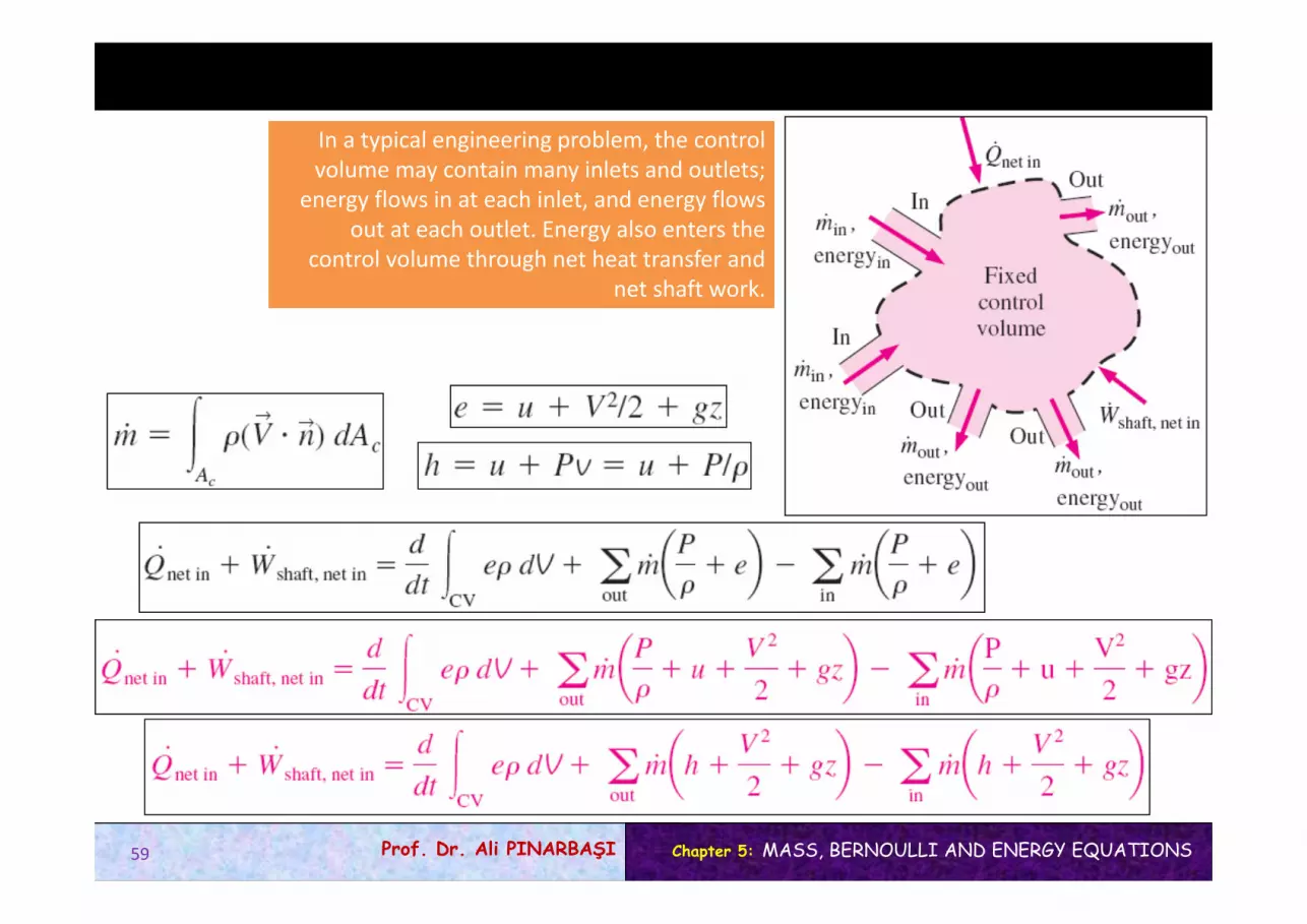
Mass balance for a control volume (CV) in rate form:
the total rates of mass flow into and out of the control volume
the rate of change of mass within the control volume boundaries.
Continuity equation: In fluid mechanics, the conservation of mass relation written for a differential control volume is usually called the continuity equation.
6

Chapter 5: MASS, BERNOULLI AND ENERGY EQUATIONSProf. Dr. Ali PINARBAŞI
Conservation of momentum
Linear momentum: The product of the mass and the velocity of a body is called the linearmomentum or just the momentum of the body.
The momentum of a rigid body of mass m moving with a velocity V is mV.
Newton’s second law: The acceleration of a body is proportional to the net force acting on it and is inversely proportional to its mass, and that the rate of change of the momentum of a body is equal to the net force acting on the body.
Conservation of momentum principle: The momentum of a system remains constant only when the net force acting on it is zero, and thus the momentum of such systems is conserved. Linear momentum equation: In fluid mechanics, Newton’s second law is usually referred to as the linear momentum equation.
Conservation of Momentum
7

Chapter 5: MASS, BERNOULLI AND ENERGY EQUATIONSProf. Dr. Ali PINARBAŞI
Conservation of Energy
The conservation of energy principle (the energy balance): The net energy transfer to or from a system during a process be equal to the change in the energy content of the system.
Energy can be transferred to or from a closed system by heat or work.
Control volumes also involve energy transfer via mass flow.
the rate of change of energywithin the control volume boundaries
In fluid mechanics, we usually limit our consideration to mechanical forms of energy only.
the total rates of energy transfer into and out of the control volume
8

Chapter 5: MASS, BERNOULLI AND ENERGY EQUATIONSProf. Dr. Ali PINARBAŞI
5–2 CONSERVATION OF MASS
Mass is conserved even during chemical reactions.
Conservation of mass: Mass, like energy, is a conserved property, and it cannot be created or destroyed during a process. Closed systems: The mass of the system remain constant during a process. Control volumes: Mass can cross the boundaries, and so we must keep track of the amount of mass entering and leaving the control volume.
Mass m and energy E can be converted to each other:
c is the speed of light in a vacuum, c = 2.9979108 m/s The mass change due to energy change is negligible.
9

Chapter 5: MASS, BERNOULLI AND ENERGY EQUATIONSProf. Dr. Ali PINARBAŞI
Mass and Volume Flow Rates
The normal velocity Vn for a surface is the component of velocity perpendicular to the surface.
Point functions have exact differentials
Path functions have inexact differentials
The differential mass flow rate
Mass flow rate: The amount of mass flowing through a cross section per unit time.
10

Chapter 5: MASS, BERNOULLI AND ENERGY EQUATIONSProf. Dr. Ali PINARBAŞI
The average velocity Vavg is defined as the average speed through a cross section.
The volume flow rate is the volume of fluid flowing through a cross section per unit time.
Average velocity
Mass flow rate
Volume flow rate
11

Chapter 5: MASS, BERNOULLI AND ENERGY EQUATIONSProf. Dr. Ali PINARBAŞI
Conservation of Mass Principle
Conservation of mass principle for an ordinary bathtub.
The conservation of mass principle for a control volume: The net mass transfer to or from a control volume during a time interval t is equal to the net change (increase or decrease) in the total mass within the control volume during t.
the total rates of mass flow into and out of the control volume
the rate of change of mass withinthe control volume boundaries.
Mass balance is applicable to any control volumeundergoing any kind of process.
12

Chapter 5: MASS, BERNOULLI AND ENERGY EQUATIONSProf. Dr. Ali PINARBAŞI
The differential control volume dV and the differential control surface dA used in the
derivation of the conservation of mass relation.
13

Chapter 5: MASS, BERNOULLI AND ENERGY EQUATIONSProf. Dr. Ali PINARBAŞI
The conservation of mass equation is obtained by replacing B in the Reynolds transport theorem by mass m, and b by 1
The time rate of change of mass within the control volume plus the net mass flow rate through the control surface is equal to zero.
A control surface should always be selected normal to the flow at all locations where it crosses the fluid flow to avoid
complications, even though the result is the same.
14
General Conservation of Mass

Chapter 5: MASS, BERNOULLI AND ENERGY EQUATIONSProf. Dr. Ali PINARBAŞI
Moving or Deforming Control Volumes
The absolute velocity V is replaced by the relative velocity Vr , which is the fluid velocity relative to the control surface. In the case of a nondeforming control volume, relative velocity is the fluid velocity observed by a person moving with the control volume and is expressed as;
Some practical problems (such as the injection of medication through the needle of a syringe by the forced motion of the plunger) involve deforming control volumes. The conservation of mass relations developed can still be used for such deforming control volumes provided that the velocity of the fluid crossing a deforming part of the control surface is expressed relative to the control surface (that is, the fluid velocity should be expressed relative to a reference frame attached to the deforming part of the control surface).
The conservation of mass equation are also valid for moving or deforming controlvolumes provided that;
15

Chapter 5: MASS, BERNOULLI AND ENERGY EQUATIONSProf. Dr. Ali PINARBAŞI
Mass Balance for Steady‐Flow Processes
Conservation of mass principle for a two‐inlet–one‐outlet steady‐flow system.
During a steady‐flow process, the total amount of mass contained within a control volume does not change with time (mCV = constant). Then the conservation of mass principle requires that the total amount of mass entering a control volume equal the total amount of mass leaving it.
For steady‐flow processes, we are interested in the amount of mass flowing per unit time, that is, the mass flow rate.
Multiple inlets and exits
Single stream
Many engineering devices such as nozzles, diffusers, turbines, compressors, and pumps involve a single stream (only one inlet and one outlet).
16

Chapter 5: MASS, BERNOULLI AND ENERGY EQUATIONSProf. Dr. Ali PINARBAŞI
Special Case: Incompressible Flow
During a steady‐flow process, volume flow rates are not necessarily conserved although mass flow rates are.
The conservation of mass relations can be simplified even further when the fluid is incompressible, which is usually the case for liquids.
Steady, incompressible
Steady, incompressible flow (single stream)
There is no such thing as a “conservation of volume” principle.However, for steady flow of liquids, the volume flow rates, as well as the mass flow rates, remain constant since liquids are essentially incompressible substances.
The conservation of mass principle is based on experimental observations and requires every bit of mass to be accounted for during a process. If you can balance your checkbook (by keeping track of deposits and withdrawals, or by simply observing the “conservation of money” principle), you should have no difficulty applying the conservation of mass principle to engineeringsystems.
17

Chapter 5: MASS, BERNOULLI AND ENERGY EQUATIONSProf. Dr. Ali PINARBAŞI
EXAMPLE 5–1A garden hose attached with a nozzle is used to fill a 10-gal bucket. The inner diameter of the hose is 2 cm, and it reduces to 0.8 cm at the nozzle exit. If it takes 50 s to fill the bucket with water, determine (a) the volume and mass flow rates of water through the hose, and (b) the average velocity of water at the nozzle exit.
EXAMPLE 5–1A garden hose attached with a nozzle is used to fill a 10-gal bucket. The inner diameter of the hose is 2 cm, and it reduces to 0.8 cm at the nozzle exit. If it takes 50 s to fill the bucket with water, determine (a) the volume and mass flow rates of water through the hose, and (b) the average velocity of water at the nozzle exit.
Solution A garden hose is used to fill a water bucket. The volume andmass flow rates of water and the exit velocity are to be determined.Assumptions 1 Water is an incompressible substance. 2 Flow through the hose is steady. 3 There is no waste of water by splashing.
(b) The cross-sectional area of the nozzle exit is
(a) the volume and mass flow rates
Discussion It can be shown that the average velocity in the hose is 2.4 m/s. Therefore, the nozzle increases the water velocity by over six times.
18
Chapter 5: MASS, BERNOULLI AND ENERGY EQUATIONSProf. Dr. Ali PINARBAŞI
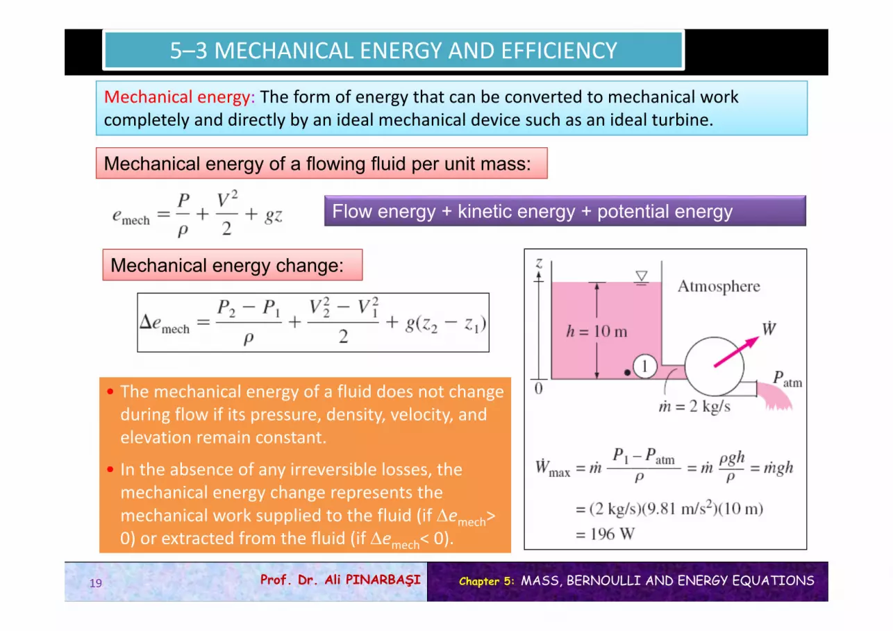
5–3 MECHANICAL ENERGY AND EFFICIENCY
Mechanical energy: The form of energy that can be converted to mechanical work completely and directly by an ideal mechanical device such as an ideal turbine.
Mechanical energy of a flowing fluid per unit mass:
Flow energy + kinetic energy + potential energy
Mechanical energy change:
• The mechanical energy of a fluid does not change during flow if its pressure, density, velocity, and elevation remain constant.
• In the absence of any irreversible losses, the mechanical energy change represents the mechanical work supplied to the fluid (if emech>0) or extracted from the fluid (if emech< 0).
19

Chapter 5: MASS, BERNOULLI AND ENERGY EQUATIONSProf. Dr. Ali PINARBAŞI
Mechanical energy is a useful concept for flows that do not involve significant heat transfer or energy conversion, such as the flow of gasoline from anunderground tank into a car.
20

Chapter 5: MASS, BERNOULLI AND ENERGY EQUATIONSProf. Dr. Ali PINARBAŞI
Mechanical energy is illustrated by an ideal hydraulic turbine coupled with an ideal generator. In the absence of irreversible losses, the maximum produced power is proportional to (a) the change in water surface elevation from the upstream to the downstream reservoir or (b) (close‐up view) the drop in water pressure from just upstream to just downstream of the turbine.
21
Chapter 5: MASS, BERNOULLI AND ENERGY EQUATIONSProf. Dr. Ali PINARBAŞI
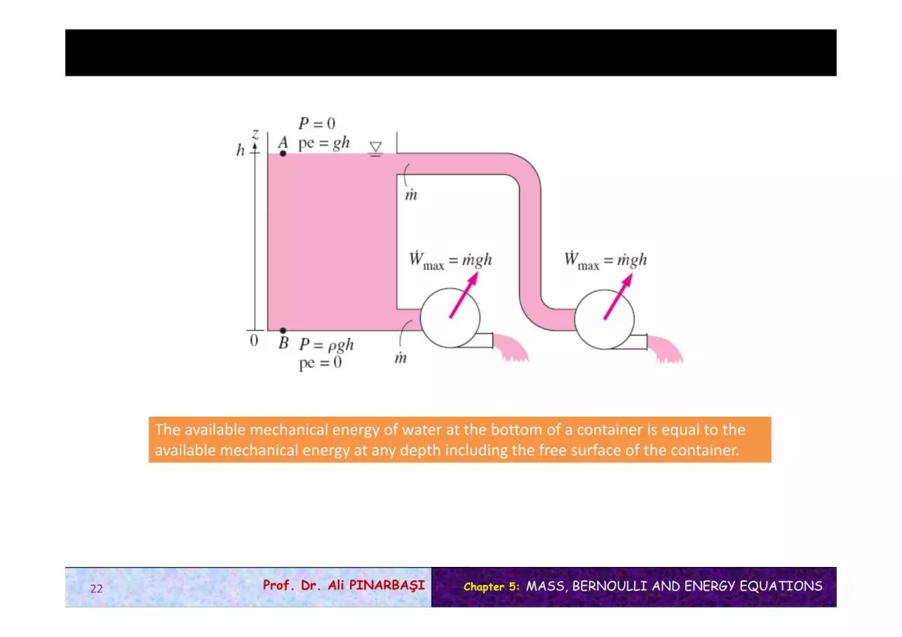
The available mechanical energy of water at the bottom of a container is equal to the available mechanical energy at any depth including the free surface of the container.
22
Chapter 5: MASS, BERNOULLI AND ENERGY EQUATIONSProf. Dr. Ali PINARBAŞI
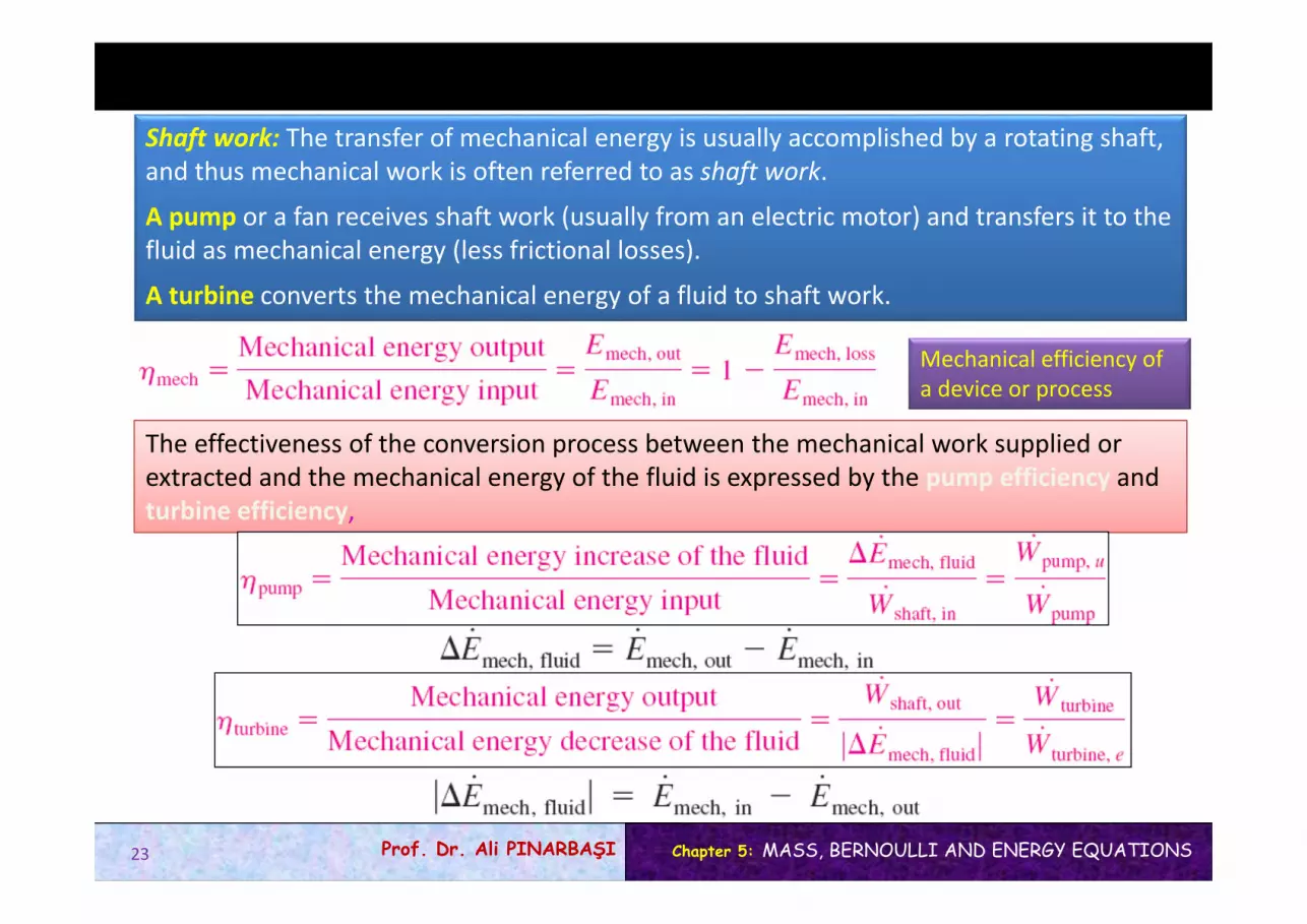
The effectiveness of the conversion process between the mechanical work supplied or extracted and the mechanical energy of the fluid is expressed by the pump efficiency and turbine efficiency,
Mechanical efficiency of a device or process
23
Shaft work: The transfer of mechanical energy is usually accomplished by a rotating shaft, and thus mechanical work is often referred to as shaft work.
A pump or a fan receives shaft work (usually from an electric motor) and transfers it to the fluid as mechanical energy (less frictional losses).
A turbine converts the mechanical energy of a fluid to shaft work.

Chapter 5: MASS, BERNOULLI AND ENERGY EQUATIONSProf. Dr. Ali PINARBAŞI
The mechanical efficiency of a fan is the ratio of the kinetic energy of air at the fan exit to the mechanical power input.
24
Chapter 5: MASS, BERNOULLI AND ENERGY EQUATIONSProf. Dr. Ali PINARBAŞI
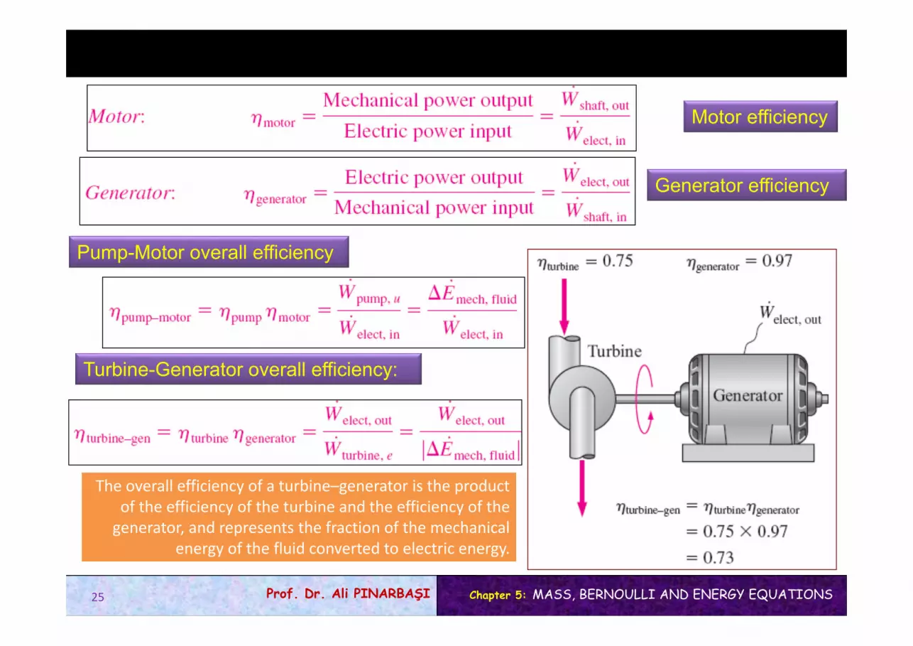
Generator efficiency
Pump-Motor overall efficiency
Turbine-Generator overall efficiency:
The overall efficiency of a turbine–generator is the product of the efficiency of the turbine and the efficiency of the generator, and represents the fraction of the mechanical
energy of the fluid converted to electric energy.
Motor efficiency
25

Chapter 5: MASS, BERNOULLI AND ENERGY EQUATIONSProf. Dr. Ali PINARBAŞI
Many fluid flow problems involvemechanical forms of energy only, and
such problems are conveniently solvedby using a mechanical energy balance.
For systems that involve only mechanical forms of energy and its transfer as shaft work, the conservation of energy is
Emech, loss : The conversion of mechanical energy to thermalenergy due to irreversibilities such as friction.
The efficiencies just defined range between 0 and 100%.0% corresponds to the conversion of the entire mechanical or electric energy input to thermal energy, and the device in this case functions like a resistance heater. 100% corresponds to the case of perfect conversion with no friction or other irreversibilities, and thus no conversion of mechanical or electric energy to thermal energy (no losses).
26

Chapter 5: MASS, BERNOULLI AND ENERGY EQUATIONSProf. Dr. Ali PINARBAŞI
EXAMPLE 5–3The water in a large lake is to be used to generate electricity by the installationof a hydraulic turbine–generator at a location where the depth of the water is 50 m. Water is to be supplied at a rate of 5000 kg/s. If the electric power generated is measured to be 1862 kW and the generator efficiency is 95 percent, determine (a) The overall efficiency of the turbine–generator, (b) The mechanical efficiency of the turbine, and (c) The shaft power supplied by the turbine to the generator.
EXAMPLE 5–3The water in a large lake is to be used to generate electricity by the installationof a hydraulic turbine–generator at a location where the depth of the water is 50 m. Water is to be supplied at a rate of 5000 kg/s. If the electric power generated is measured to be 1862 kW and the generator efficiency is 95 percent, determine (a) The overall efficiency of the turbine–generator, (b) The mechanical efficiency of the turbine, and (c) The shaft power supplied by the turbine to the generator.
Solution A hydraulic turbine–generator is to generate electricity from the water of a lake. The overall efficiency, the turbine efficiency, and the shaft power are to be determined.Assumptions 1 The elevation of the lake remains constant. 2 The mechanical energy of water at the turbine exit is negligible.
27

Chapter 5: MASS, BERNOULLI AND ENERGY EQUATIONSProf. Dr. Ali PINARBAŞI
(b) Knowing the overall and generator efficiencies, the mechanical efficiency of the turbine is determined from
(c) The shaft power output is determined from the definition of mechanical efficiency
(a) the overall efficiency of the turbine–generator
Discussion Note that the lake supplies 2455 kW of mechanical energy to the turbine, which converts 1964 kW of it to shaft work that drives the generator, which generates 1862 kW of electric power. There are irreversible losses through each component.
28

Chapter 5: MASS, BERNOULLI AND ENERGY EQUATIONSProf. Dr. Ali PINARBAŞI
EXAMPLE 5–4The motion of a steel ball in a hemispherical bowl of radius h shown in Figure is to be analyzed. The ball is initially held at the highest location at point A, and then it is released. Obtain relations for the conservation of energy of the ball for the cases of frictionless and actual motions.
EXAMPLE 5–4The motion of a steel ball in a hemispherical bowl of radius h shown in Figure is to be analyzed. The ball is initially held at the highest location at point A, and then it is released. Obtain relations for the conservation of energy of the ball for the cases of frictionless and actual motions.
Solution A steel ball is released in a bowl. Relations for the energy balance are to be obtainedAssumptions The motion is frictionless, and thus friction between the ball, the bowl, and the air is negligible.
There is no energy transfer by heat or mass and no change in the internal energy of the ball (the heat generated by frictional heating is dissipated to the surrounding air). The frictional work term wfriction is often expressed as eloss to represent the loss (conversion) of mechanical energy into thermal energy. For the idealized case of frictionless motion, the last relation reduces to
29

Chapter 5: MASS, BERNOULLI AND ENERGY EQUATIONSProf. Dr. Ali PINARBAŞI
5–4 THE BERNOULLI EQUATION
Bernoulli equation: An approximate relation between pressure, velocity, and elevation, and is valid in regions of steady, incompressible flow where net frictional forces are negligible.
Despite its simplicity, it has proven to be a very powerful tool in fluid mechanics.
The Bernoulli approximation is typically useful in flow regions outside of boundary layersand wakes, where the fluid motion is governed by the combined effects of pressure and gravity forces.
The Bernoulli equation is an approximate equation that is valid only in inviscid regions of flow where net viscous forces are negligibly smallcompared to inertial, gravitational, or pressure forces. Such regions occuroutside of boundary layers and wakes.
30

Chapter 5: MASS, BERNOULLI AND ENERGY EQUATIONSProf. Dr. Ali PINARBAŞI
Acceleration of a Fluid Particle
During steady flow, a fluid may notaccelerate in time at a fixed point, but it may accelerate in space.
In 2‐D flow, the acceleration can be decomposed into two componentsstreamwise acceleration as along the streamline and normal acceleration an in the direction normal to the streamline, which is given as
an = V2/R. Streamwise acceleration is due to a change in speed along a streamline, and normal acceleration is due to a change in direction. For particles that move along a straight path, an = 0 since the radius of curvature is infinity and thus there is no change in direction. The Bernoulli equation results from aforce balance along a streamline.
Acceleration in steady flow is due to the change of velocity with position.
31

Chapter 5: MASS, BERNOULLI AND ENERGY EQUATIONSProf. Dr. Ali PINARBAŞI
Derivation of the Bernoulli Equation
The forces acting on a fluid particlealong a streamline.
Steady, incompressible flow:
The sum of the kinetic, potential, and flow energies of a fluid particle is constant along a streamline during steady flow when compressibility and frictional effects are negligible.
The Bernoulli equation between any two points on the same streamline:
Steady flow:
32

Chapter 5: MASS, BERNOULLI AND ENERGY EQUATIONSProf. Dr. Ali PINARBAŞI
The incompressible Bernoulli equation is derived assumingincompressible flow, and thus it should not be used for flows with significant compressibility effects.
33

Chapter 5: MASS, BERNOULLI AND ENERGY EQUATIONSProf. Dr. Ali PINARBAŞI
The Bernoulli equation states that the sum of the kinetic, potential, and flowenergies of a fluid particle is constant along a streamline during steady flow when the compressibility and frictional effects are negligible.
• The Bernoulli equation can be viewed as the “conservation of mechanical energy principle.” The work done by the pressure and gravity forces on the fluid particle is equal to the increase in the kinetic energy of the particle
• This is equivalent to the general conservation of energy principle for systems that do not involve any conversion of mechanical energy and thermal energy to each other, and thus the mechanical energy and thermal energy are conserved separately.
• The Bernoulli equation states that during steady, incompressible flow with negligible friction, the various forms of mechanical energy are converted to each other, but their sum remains constant.
• There is no dissipation of mechanical energy during such flows since there is no friction that converts mechanical energy to sensible thermal (internal) energy.
• The Bernoulli equation is commonly used in practice since a variety of practical fluid flow problems can be analyzed to reasonable accuracy with it.
34

Chapter 5: MASS, BERNOULLI AND ENERGY EQUATIONSProf. Dr. Ali PINARBAŞI
Force Balance across Streamlines
Pressure decreases towards the center of curvature when streamlines are curved (a), but the variation of pressure
with elevation in steady, incompressible flow along a straight line (b) is the same as that in stationary fluid.
For flow along a straight line, R → and thisequation reduces to P/ + gz = constant or P = gz + constant, which is an expression for the variation of hydrostatic pressure with vertical distance for a stationary fluid body.
35
Force balance in the direction n normal to the streamline yields the following relation applicable across the streamlines for steady, incompressible flow:

Chapter 5: MASS, BERNOULLI AND ENERGY EQUATIONSProf. Dr. Ali PINARBAŞI
Unsteady, Compressible Flow
The Bernoulli equation for unsteady, compressible flow:
Unsteady Flow
36

Chapter 5: MASS, BERNOULLI AND ENERGY EQUATIONSProf. Dr. Ali PINARBAŞI
Static, Dynamic, and Stagnation Pressures
The kinetic and potential energies of the fluid can be converted to flow energy (and vice versa) during flow, causing the pressure to change. Multiplying the Bernoulli equation by the density gives;
Total pressure: The sum of the static, dynamic, and hydrostatic pressures. Therefore, the Bernoulli equation states that the total pressure along a streamline is constant.
P is the static pressure: It does not incorporate any dynamic effects; it represents the actual thermodynamic pressure of the fluid. This is the same as the pressure used in thermodynamics and property tables.
V2/2 is the dynamic pressure: It represents the pressure rise when the fluid in motion is brought to a stop isentropically.
gz is the hydrostatic pressure: It is not pressure in a real sense since its value depends on the reference level selected; it accounts for the elevation effects, i.e., fluid weight on pressure. (Be careful of the sign—unlike hydrostatic pressure gh which increases with fluid depth h, the hydrostatic pressure term gz decreases with fluid depth.)
37

Chapter 5: MASS, BERNOULLI AND ENERGY EQUATIONSProf. Dr. Ali PINARBAŞI
Stagnation pressure: The sum of the static and dynamic pressures. It represents the pressure at a point where the fluid is brought to a complete stop isentropically.
Close‐up of a Pitot‐static probe, showing the stagnation pressure hole and two of the five static circumferential pressure holes.
The static, dynamic, andstagnation pressures measured using piezometer tubes.
38

Chapter 5: MASS, BERNOULLI AND ENERGY EQUATIONSProf. Dr. Ali PINARBAŞI
Streaklines produced by colored fluid introduced upstream of an airfoil; since the flow is steady, the streaklines are the same as streamlines and pathlines. The stagnation streamline is marked.
Careless drilling of the static pressuretap may result in an erroneous reading of the static pressure head.
Pitot Static tube
39
Chapter 5: MASS, BERNOULLI AND ENERGY EQUATIONSProf. Dr. Ali PINARBAŞI
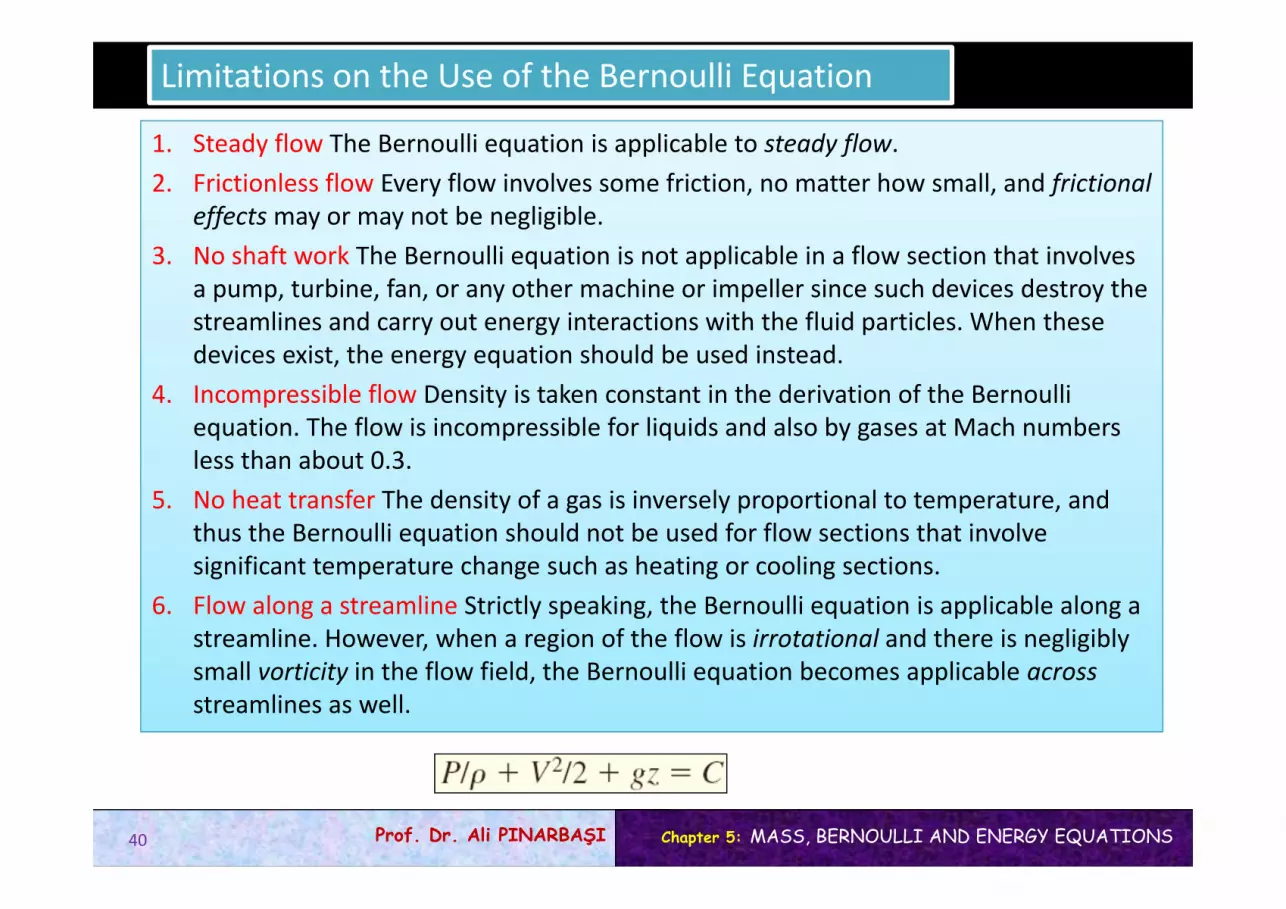
Limitations on the Use of the Bernoulli Equation
1. Steady flow The Bernoulli equation is applicable to steady flow.2. Frictionless flow Every flow involves some friction, no matter how small, and frictional
effects may or may not be negligible.3. No shaft work The Bernoulli equation is not applicable in a flow section that involves
a pump, turbine, fan, or any other machine or impeller since such devices destroy the streamlines and carry out energy interactions with the fluid particles. When these devices exist, the energy equation should be used instead.
4. Incompressible flow Density is taken constant in the derivation of the Bernoulli equation. The flow is incompressible for liquids and also by gases at Mach numbers less than about 0.3.
5. No heat transfer The density of a gas is inversely proportional to temperature, and thus the Bernoulli equation should not be used for flow sections that involve significant temperature change such as heating or cooling sections.
6. Flow along a streamline Strictly speaking, the Bernoulli equation is applicable along a streamline. However, when a region of the flow is irrotational and there is negligibly small vorticity in the flow field, the Bernoulli equation becomes applicable across streamlines as well.
40

Chapter 5: MASS, BERNOULLI AND ENERGY EQUATIONSProf. Dr. Ali PINARBAŞI
Frictional effects, heat transfer, and components that disturb the streamlined structure of flow make the Bernoulli equation invalid. It should not be used in any of the flows shown here.
When the flow is irrotational, the Bernoulli equation becomes applicable between any two points along the flow (not just on the same streamline).
41

Chapter 5: MASS, BERNOULLI AND ENERGY EQUATIONSProf. Dr. Ali PINARBAŞI
Hydraulic Grade Line (HGL) and Energy Grade Line (EGL)
It is often convenient to represent the level of mechanical energy graphically using heights to facilitate visualization of the various terms of the Bernoulli equation. Dividing each term of the Bernoulli equation by g gives
An alternative form of the Bernoulli equation is expressed in terms of heads as: The sum of the pressure, velocity, and elevation heads is constant along a streamline.
P/g is the pressure head; it represents the height of a fluid column that produces the static pressure P.V2/2g is the velocity head; it represents the elevation needed for a fluid to reach the velocity V during frictionless free fall.z is the elevation head; it represents the potential energy of the fluid.
42

Chapter 5: MASS, BERNOULLI AND ENERGY EQUATIONSProf. Dr. Ali PINARBAŞI
The hydraulic grade line (HGL) and the energy grade line (EGL) for free discharge from a reservoir through a horizontal pipe with a diffuser.
Hydraulic grade line (HGL), P/g + z The line that represents the sum of the static pressure and the elevation heads.Energy grade line (EGL), P/g + V2/2g + z The line that represents the total head of the fluid.Dynamic head, V2/2g The difference between the heights of EGL and HGL.
43

Chapter 5: MASS, BERNOULLI AND ENERGY EQUATIONSProf. Dr. Ali PINARBAŞI
• For stationary bodies such as reservoirs or lakes, the EGL and HGL coincide with the free surface of the liquid.
• The EGL is always a distance V2/2g above the HGL. These two curves approach each other as the velocity decreases, and they diverge as the velocity increases.
• In an idealized Bernoulli‐type flow, EGL is horizontal and its height remains constant. • For open‐channel flow, the HGL coincides with the free surface of the liquid, and the
EGL is a distance V2/2g above the free surface.• At a pipe exit, the pressure head is zero (atmospheric pressure) and thus the HGL
coincides with the pipe outlet.• The mechanical energy loss due to frictional effects (conversion to thermal energy)
causes the EGL and HGL to slope downward in the direction of flow. The slope is a measure of the head loss in the pipe. A component, such as a valve, that generates significant frictional effects causes a sudden drop in both EGL and HGL at that location.
• A steep jump/drop occurs in EGL and HGL whenever mechanical energy is added orremoved to or from the fluid (pump, turbine).
• The (gage) pressure of a fluid is zero at locations where the HGL intersects the fluid. The pressure in a flow section that lies above the HGL is negative, and the pressure in a section that lies below the HGL is positive.
Notes on HGL and EGL
44

Chapter 5: MASS, BERNOULLI AND ENERGY EQUATIONSProf. Dr. Ali PINARBAŞI
In an idealized Bernoulli‐type flow, EGL is horizontal and its height remains constant. But this is not the case for HGL when the flowvelocity varies along the flow.
A steep jump occurs in EGL and HGLwhenever mechanical energy is added to the fluid by a pump, and a steep dropoccurs whenever mechanical energy isremoved from the fluid by a turbine.
The gage pressure of a fluid is zero at locations where the HGL intersects the fluid, and the pressure is negative (vacuum) in a flow section that lies above the HGL.
45

Chapter 5: MASS, BERNOULLI AND ENERGY EQUATIONSProf. Dr. Ali PINARBAŞI
EXAMPLE 5–5Water is flowing from a hose attached to a water main at 400 kPa gage. A child places his thumb to cover most of the hose outlet, causing a thin jet of high-speed water to emerge. If the hose is held upward, what is the maximum height that the jet could achieve?
EXAMPLE 5–5Water is flowing from a hose attached to a water main at 400 kPa gage. A child places his thumb to cover most of the hose outlet, causing a thin jet of high-speed water to emerge. If the hose is held upward, what is the maximum height that the jet could achieve?
Solution Water from a hose attached to the water main is sprayed into the air. The maximum height the water jet can rise is to be determined.Assumptions 1 The flow exiting into the air is steady incompressible, and irrotational (so that the Bernoulli equation is applicable). 2 The water pressure in the hose near the outlet is equal to the water main pressure. 3 The surface tension effects are negligible. 4 The friction between the water and air is negligible. 5 The irreversibilities that may occur at the outlet of the hose due to abrupt expansion are negligible.
46

Chapter 5: MASS, BERNOULLI AND ENERGY EQUATIONSProf. Dr. Ali PINARBAŞI
EXAMPLE 5–6A large tank open to the atmosphere is filled with water to a height of 5 m from the outlet tap. A tap near the bottom of the tank is now opened, and water flows out from the smooth and rounded outlet. Determine the water velocity at the outlet.
EXAMPLE 5–6A large tank open to the atmosphere is filled with water to a height of 5 m from the outlet tap. A tap near the bottom of the tank is now opened, and water flows out from the smooth and rounded outlet. Determine the water velocity at the outlet.
Solution A tap near the bottom of a tank is opened. The exit velocity of water from the tank is to be determined.Assumptions 1 The flow is incompressible and irrotational(except very close to the walls). 2 The water drains slowly enough that the flow can be approximated as steady (actually quasi-steady when the tank begins to drain).
Toricelli equation
Discussion If the orifice were sharp-edged instead of rounded, then the flowwould be disturbed, and the velocity would be less than 9.9 m/s, especially near the edges. Care must be exercised when attempting to apply the Bernoulli equation to situations where abrupt expansions or contractions occur since the friction and flow disturbance in such cases may not be negligible.
47

Chapter 5: MASS, BERNOULLI AND ENERGY EQUATIONSProf. Dr. Ali PINARBAŞI
EXAMPLE 5–7During a trip to the beach (Patm=1 atm=101.3 kPa), a car runs out of gasoline, and it becomes necessary to siphon gas out of the car of a Good Samaritan. The siphon is a small-diameter hose, and to start the siphon it is necessary to insert one siphon end in the full gas tank, fill the hose with gasoline via suction, and then place the other end in a gas can below the level of the gas tank. The difference in pressure between point 1 (at the free surface of the gasoline in the tank) and point 2 (at the outlet ofthe tube) causes the liquid to flow from the higher to the lower elevation. Point 2 is located 0.75 m below point 1 in this case, and point 3 is located 2 m above point 1. The siphon diameter is 5 mm, and frictional losses in the siphon are to be disregarded. Determine (a) the minimum time to withdraw 4 L of gasoline from the tank to the can and (b) the pressure at point 3. The density of gasoline is 750 kg/m3.
EXAMPLE 5–7During a trip to the beach (Patm=1 atm=101.3 kPa), a car runs out of gasoline, and it becomes necessary to siphon gas out of the car of a Good Samaritan. The siphon is a small-diameter hose, and to start the siphon it is necessary to insert one siphon end in the full gas tank, fill the hose with gasoline via suction, and then place the other end in a gas can below the level of the gas tank. The difference in pressure between point 1 (at the free surface of the gasoline in the tank) and point 2 (at the outlet ofthe tube) causes the liquid to flow from the higher to the lower elevation. Point 2 is located 0.75 m below point 1 in this case, and point 3 is located 2 m above point 1. The siphon diameter is 5 mm, and frictional losses in the siphon are to be disregarded. Determine (a) the minimum time to withdraw 4 L of gasoline from the tank to the can and (b) the pressure at point 3. The density of gasoline is 750 kg/m3.
Solution Gasoline is to be siphoned from a tank. The minimum time it takes to withdraw 4 L of gasoline and the pressure at the highest point in the system are to be determined.Assumptions 1 The flow is steady and incompressible. 2 Even though the Bernoulli equation is not valid through the pipe because of frictional losses, we employ the Bernoulli equation anyway in order to obtain a best-case estimate. 3 The change in the gasoline surface level inside the tank is negligible compared to elevations z1 and z2 during the siphoning period.
48

Chapter 5: MASS, BERNOULLI AND ENERGY EQUATIONSProf. Dr. Ali PINARBAŞI
Discussion The siphoning time is determined by neglecting frictional effects, and thus this is the minimum time required. In reality, the time will be longer than 53.1 s because of friction between the gasoline and the tube surface. Also, the pressure at point 3 is below the atmospheric pressure. If the elevation difference between points 1 and 3 is too high, the pressure at point 3 may drop below the vapor pressure of gasoline at the gasoline temperature, and some gasoline may evaporate (cavitate). The vapor then may form a pocket at the top and halt the flow of gasoline.
49

Chapter 5: MASS, BERNOULLI AND ENERGY EQUATIONSProf. Dr. Ali PINARBAŞI
Solution The static and stagnation pressures in a horizontal pipe are measured. The velocity at the center of the pipe is to be determined.Assumptions 1 The flow is steady and incompressible. 2 Points 1 and 2 are close enough together that the irreversible energy loss between these two points is negligible, and thus we can use the Bernoulli equation.
Discussion Note that to determine the flow velocity, all we need is to measure the height of the excess fluid column in the Pitot tube.
EXAMPLE 5–8A piezometer and a Pitot tube are tapped into a horizontal water pipe to measure static and stagnation (static + dynamic) pressures. For the indicated water column heights, determine the velocity at the center of the pipe.
EXAMPLE 5–8A piezometer and a Pitot tube are tapped into a horizontal water pipe to measure static and stagnation (static + dynamic) pressures. For the indicated water column heights, determine the velocity at the center of the pipe.
50

Chapter 5: MASS, BERNOULLI AND ENERGY EQUATIONSProf. Dr. Ali PINARBAŞI
Example: The Rise of the Ocean Due to a Hurricane
The eye of hurricane Linda (1997 in the Pacific Ocean near Baja California) is clearly visible in this satellite photo.
51

Chapter 5: MASS, BERNOULLI AND ENERGY EQUATIONSProf. Dr. Ali PINARBAŞI
EXAMPLE 5–10Derive the Bernoulli equation when the compressibility effects are not negligible for an ideal gas undergoing (a) an isothermal process and (b) an isentropic process.
EXAMPLE 5–10Derive the Bernoulli equation when the compressibility effects are not negligible for an ideal gas undergoing (a) an isothermal process and (b) an isentropic process.
Solution The Bernoulli equation for compressible flow is to be obtained for an ideal gas for isothermal and isentropic processes.Assumptions 1 The flow is steady and frictional effects are negligible. 2 The fluid is an ideal gas. 3 The specific heats are constant so that P/rk constant during an isentropic process.
(a) Isothermal process
(b) Isentropic process
The flow of an ideal gas can be considered to be incompressible when Ma 0.3.
52

Chapter 5: MASS, BERNOULLI AND ENERGY EQUATIONSProf. Dr. Ali PINARBAŞI
5–5 GENERAL ENERGY EQUATION
The first law of thermodynamics (the conservation of energy principle) Energy cannot be created or destroyed during a process; it can only change forms.
The energy change of a system during a process is equal to the net work and heat transfer between thesystem and its surroundings.
53

Chapter 5: MASS, BERNOULLI AND ENERGY EQUATIONSProf. Dr. Ali PINARBAŞI
Energy Transfer by Heat, Q
Temperature difference is the driving force for heat transfer. The larger the temperature difference, the higher is the rate of heat transfer.
Thermal energy: The sensible and latent forms of internal energy. Heat Transfer: The transfer of energy from one system to another as a result of a temperature difference.The direction of heat transfer is always from the higher-temperature body to the lower-temperature one.Adiabatic process: A process during which there is no heat transfer.Heat transfer rate: The time rate of heat transfer.
54

Chapter 5: MASS, BERNOULLI AND ENERGY EQUATIONSProf. Dr. Ali PINARBAŞI
Energy Transfer by Work, W
• Work: The energy transfer associated with a force acting through a distance.
• A rising piston, a rotating shaft, and an electric wire crossing the system boundaries are all associated with work interactions.
• Power: The time rate of doing work.• Car engines and hydraulic, steam, and gas turbines produce work;
compressors, pumps, fans, and mixers consume work.
Wshaft The work transmitted by a rotating shaft Wpressure The work done by the pressure forces on the control surfaceWviscous The work done by the normal and shear components of viscous forces on the control surfaceWother The work done by other forces such as electric, magnetic, and surface tension
55

Chapter 5: MASS, BERNOULLI AND ENERGY EQUATIONSProf. Dr. Ali PINARBAŞI
Energy transmission through rotating shafts is commonly encountered in practice.
Shaft work is proportional to the torque applied and the number of revolutions of the shaft.
A force F acting through a moment arm r generates a torque T
This force acts through a distance s
The power transmitted through the shaft is the shaft work done per unit time:
Shaft work
Shaft Work
56

Chapter 5: MASS, BERNOULLI AND ENERGY EQUATIONSProf. Dr. Ali PINARBAŞI
Work Done by Pressure Forces
The moving boundary of a system in a piston-cylinder device,
The differential surface area of a system of arbitrary shape.
57

Chapter 5: MASS, BERNOULLI AND ENERGY EQUATIONSProf. Dr. Ali PINARBAŞI
The conservation of energy equation is obtained by replacing B in the Reynolds transport theorem by
energy E and b by e.
58
Chapter 5: MASS, BERNOULLI AND ENERGY EQUATIONSProf. Dr. Ali PINARBAŞI
In a typical engineering problem, the control volume may contain many inlets and outlets;
energy flows in at each inlet, and energy flows out at each outlet. Energy also enters the
control volume through net heat transfer and net shaft work.
59

Chapter 5: MASS, BERNOULLI AND ENERGY EQUATIONSProf. Dr. Ali PINARBAŞI
5–6 ENERGY ANALYSIS OF STEADY FLOWS
A control volume with only one inletand one outlet and energy
interactions.
The net rate of energy transfer to a control volume by heat transfer and work during steady flow is equal to the difference between the rates of outgoing and incoming energy flows by mass flow.
single‐stream devices
60
Chapter 5: MASS, BERNOULLI AND ENERGY EQUATIONSProf. Dr. Ali PINARBAŞI
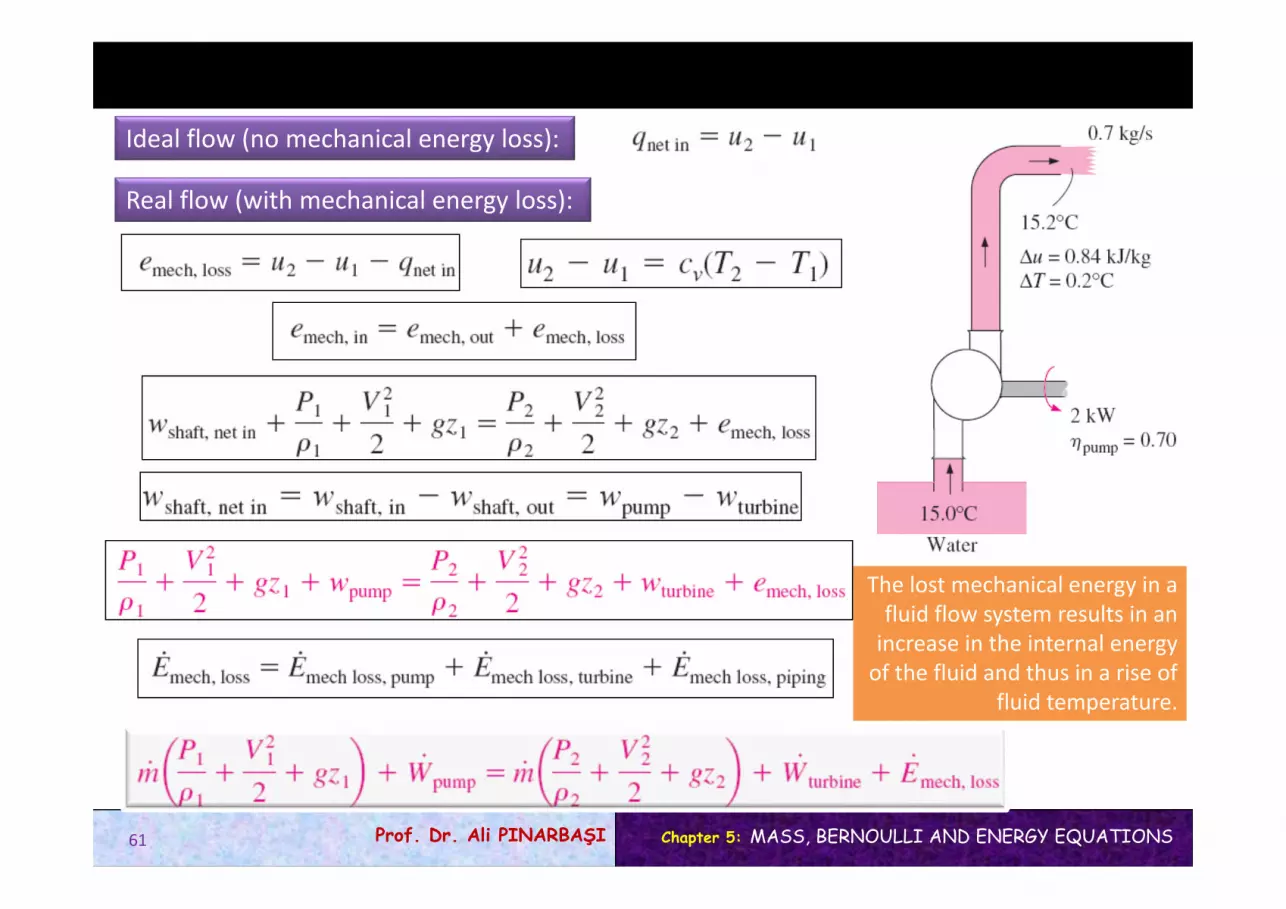
Ideal flow (no mechanical energy loss):
Real flow (with mechanical energy loss):
The lost mechanical energy in a fluid flow system results in an increase in the internal energy of the fluid and thus in a rise of
fluid temperature.
61

Chapter 5: MASS, BERNOULLI AND ENERGY EQUATIONSProf. Dr. Ali PINARBAŞI
A typical power plant has numerous pipes, elbows, valves, pumps, andturbines, all of which have irreversible losses.
62

Chapter 5: MASS, BERNOULLI AND ENERGY EQUATIONSProf. Dr. Ali PINARBAŞI
Energy equation in terms of heads
useful head delivered to the fluid by the pump
extracted head removed from the fluid by the turbine
irreversible head loss
63
Chapter 5: MASS, BERNOULLI AND ENERGY EQUATIONSProf. Dr. Ali PINARBAŞI
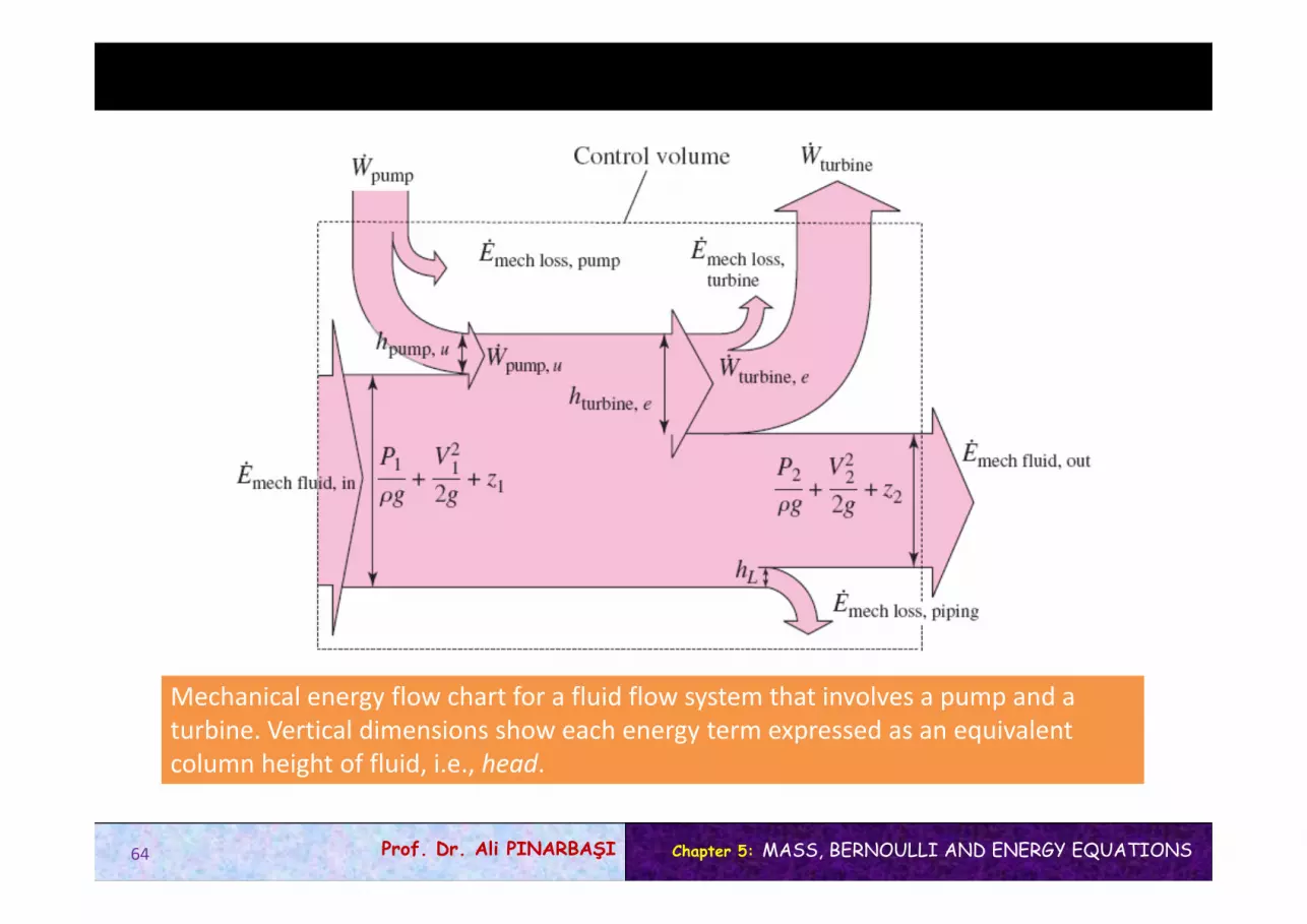
Mechanical energy flow chart for a fluid flow system that involves a pump and a turbine. Vertical dimensions show each energy term expressed as an equivalentcolumn height of fluid, i.e., head.
64

Chapter 5: MASS, BERNOULLI AND ENERGY EQUATIONSProf. Dr. Ali PINARBAŞI
Special Case: Incompressible Flow with No Mechanical Work Devices and Negligible Friction
When piping losses are negligible, there is negligible dissipation of mechanical energy into thermal energy, and thus hL = emech loss, piping /g ≅ 0. Also, hpump, u = hturbine, e = 0 when there are no mechanical work devices such as fans, pumps, or turbines. Then energy eqoationreduces to
This is the Bernoulli equation derived earlier using Newton’s second law of motion. Thus, the Bernoulli equation can be thought of as a degenerate form of the energy equation.
65

Chapter 5: MASS, BERNOULLI AND ENERGY EQUATIONSProf. Dr. Ali PINARBAŞI
Kinetic Energy Correction Factor,
The determination of the kineticenergy correction factor
The kinetic energy of a fluid stream obtained from V2/2 is not the same as the actual kinetic energy of the fluid stream since the square of a sum is not equal to the sum of the squares of its components. This error can be corrected by replacing the kinetic energy terms V2/2 in the energy equation by Vavg
2/2, where is the kinetic energy correction factor.
The correction factor is 2.0 for fully developed laminar pipe flow, and it ranges between 1.04 and 1.11 for fully developed turbulent flow in a round pipe.
66

Chapter 5: MASS, BERNOULLI AND ENERGY EQUATIONSProf. Dr. Ali PINARBAŞI
EXAMPLE 5–11Show that during steady and incompressible flow of a fluid in an adiabatic flow section(a) the temperature remains constant and there is no head loss when friction is ignored and (b) the temperature increases and some head loss occurs when frictional effects are considered. Discuss if it is possible for the fluid temperature to decrease during such flow.
EXAMPLE 5–11Show that during steady and incompressible flow of a fluid in an adiabatic flow section(a) the temperature remains constant and there is no head loss when friction is ignored and (b) the temperature increases and some head loss occurs when frictional effects are considered. Discuss if it is possible for the fluid temperature to decrease during such flow.
Solution Steady and incompressible flow through an adiabatic section is considered. The effects of friction on the temperature and the heat loss are to be determined.Assumptions 1 The flow is steady and incompressible. 2 The flow section is adiabatic and thus there is no heat transfer, qnet in =0.
67

Chapter 5: MASS, BERNOULLI AND ENERGY EQUATIONSProf. Dr. Ali PINARBAŞI
(b) When irreversibilities such as friction are taken into account, the entropychange is positive and thus we have:
Discussion It is impossible for the fluid temperature to decrease during steady, incompressible, adiabatic flow since this would require the entropy of an adiabatic system to decrease, which would be a violation of the second law of thermodynamics.
68

Chapter 5: MASS, BERNOULLI AND ENERGY EQUATIONSProf. Dr. Ali PINARBAŞI
EXAMPLE 5–12The pump of a water distribution system is powered by a 15-kW electric motor whose efficiency is 90 percent. The water flow rate through the pump is 50 L/s. The diameters of the inlet and outlet pipes are the same, and the elevation difference across the pump is negligible. If the pressures at the inlet and outlet of the pump are measured to be 100 kPa and 300 kPa (absolute), respectively, determine (a) the mechanical efficiency of the pump and (b) the temperature rise of water as it flows through the pump due to the mechanical inefficiency.
EXAMPLE 5–12The pump of a water distribution system is powered by a 15-kW electric motor whose efficiency is 90 percent. The water flow rate through the pump is 50 L/s. The diameters of the inlet and outlet pipes are the same, and the elevation difference across the pump is negligible. If the pressures at the inlet and outlet of the pump are measured to be 100 kPa and 300 kPa (absolute), respectively, determine (a) the mechanical efficiency of the pump and (b) the temperature rise of water as it flows through the pump due to the mechanical inefficiency.
Solution The pressures across a pump are measured. The mechanical efficiency of the pump and the temperature rise of water are to be determined.Assumptions 1 The flow is steady and incompressible. 2 The pump is driven by an external motor so that the heat generated by the motor is dissipated to the atmosphere. 3 The elevation difference between the inlet and outlet ofthe pump is negligible, z1= z2. 4 The inlet and outlet diameters are the same and thus the inlet and outlet velocities and kinetic energy correction factors are equal, V1 = V2 and 1=2.
69

Chapter 5: MASS, BERNOULLI AND ENERGY EQUATIONSProf. Dr. Ali PINARBAŞI
(a) The mass flow rate of water through the pump is
The motor draws 15 kW of power and is 90 percent efficient. Thus the mechanical (shaft) power it delivers to the pump is
70

Chapter 5: MASS, BERNOULLI AND ENERGY EQUATIONSProf. Dr. Ali PINARBAŞI
(b) Of the 13.5-kW mechanical power supplied by the pump, only 10 kW isimparted to the fluid as mechanical energy. The remaining 3.5 kW is convertedto thermal energy due to frictional effects, and this “lost” mechanical energy manifests itself as a heating effect in the fluid,
Discussion In an actual application, the temperature rise of water will probablybe less since part of the heat generated will be transferred to the casing of the pump and from the casing to the surrounding air. If the entire pump motor were submerged in water, then the 1.5 kW dissipated to the air due to motor inefficiency would also be transferred to the surrounding water as heat. This would cause the water temperature to rise more.
71

Chapter 5: MASS, BERNOULLI AND ENERGY EQUATIONSProf. Dr. Ali PINARBAŞI
Solution The available head, flow rate, head loss, and efficiency of a hydroelectric turbine are given. The electric power output is to be determined.Assumptions 1 The flow is steady and incompressible. 2 Water levels at the reservoir and the discharge site remain constant.
EXAMPLE 5–13In a hydroelectric power plant, 100 m3/s of water flows from an elevation of 120 m to a turbine, where electric power is generated. The total irreversible head loss in the piping system from point 1 to point 2 (excluding the turbine unit) is determined to be 35 m. If the overall efficiency of the turbine-generator is 80% estimate the electric power output
EXAMPLE 5–13In a hydroelectric power plant, 100 m3/s of water flows from an elevation of 120 m to a turbine, where electric power is generated. The total irreversible head loss in the piping system from point 1 to point 2 (excluding the turbine unit) is determined to be 35 m. If the overall efficiency of the turbine-generator is 80% estimate the electric power output
72

Chapter 5: MASS, BERNOULLI AND ENERGY EQUATIONSProf. Dr. Ali PINARBAŞI
EXAMPLE 5–14A fan is to be selected to cool a computer case whose dimensions are 12 cmx 40 cm x 40 cm. Half of the volume in the case is expected to be filled with components and the other half to be air space. A 5-cm diameter hole is available at the back of the case for the installation of the fan that is to replace the air in the void spaces of the case once every second. Small low-power fan–motor combined units are available in the market and their efficiency is estimated to be 30%. Determine (a) the wattage of the fan–motor unit to be purchased and (b) the pressure difference across the fan. Take the air density to be 1.20 kg/m3
EXAMPLE 5–14A fan is to be selected to cool a computer case whose dimensions are 12 cmx 40 cm x 40 cm. Half of the volume in the case is expected to be filled with components and the other half to be air space. A 5-cm diameter hole is available at the back of the case for the installation of the fan that is to replace the air in the void spaces of the case once every second. Small low-power fan–motor combined units are available in the market and their efficiency is estimated to be 30%. Determine (a) the wattage of the fan–motor unit to be purchased and (b) the pressure difference across the fan. Take the air density to be 1.20 kg/m3
Solution A fan is to cool a computer case by completely replacing the air inside once every second. The power of the fan and the pressure differenceacross it are to be determined.Assumptions 1 The flow is steady and incompressible. 2 Losses other than those due to the inefficiency of the fan–motor unit are negligible (hL=0).3 The flow at the outlet is fairly uniform except near the center (due to the wake of the fan motor), and the kinetic energy correction factor at the outlet is 1.10.
73

Chapter 5: MASS, BERNOULLI AND ENERGY EQUATIONSProf. Dr. Ali PINARBAŞI
(a) Noting that half of the volume of the case is occupied by the components, the air volume in the computer case is
74

Chapter 5: MASS, BERNOULLI AND ENERGY EQUATIONSProf. Dr. Ali PINARBAŞI
(b) To determine the pressure difference across the fan unit, we take points 3 and 4 to be on the two sides of the fan on a horizontal line. This time again z3=z4 and V3=V4 since the fan is a narrow cross section, and the energy equation reduces to
Discussion The efficiency of the fan–motor unit is given to be 30%, which means 30% of the electric power Welectric consumed by the unit is converted to useful mechanical energy while the rest (70%) is “lost” and converted to thermal energy. Also, a more powerful fan is required in an actual system to overcome frictional losses inside the computer case. Note that if we had ignored the kinetic energy correction factor at the outlet, the required electrical power and pressure rise would have been 10% lower in this case (0.460 W and 14.4 Pa, respectively).
75

Chapter 5: MASS, BERNOULLI AND ENERGY EQUATIONSProf. Dr. Ali PINARBAŞI
EXAMPLE 5–15Water is pumped from a lower reservoir to a higher reservoir by a pump that provides 20 kW of useful mechanical power to the water. The free surface of the upper reservoir is 45 m higher than the surface of the lower reservoir. If the flow rate of water is measured to be 0.03 m3/s, deter-mine the irreversible head loss of the system and the lost mechanical power during this process.
EXAMPLE 5–15Water is pumped from a lower reservoir to a higher reservoir by a pump that provides 20 kW of useful mechanical power to the water. The free surface of the upper reservoir is 45 m higher than the surface of the lower reservoir. If the flow rate of water is measured to be 0.03 m3/s, deter-mine the irreversible head loss of the system and the lost mechanical power during this process.
Solution Water is pumped from a lower reservoir to a higher one. The head and power loss associated with this process are to be determined.Assumptions 1 The flow is steady and incompressible. 2 The elevation difference between the reservoirs is constant.
76

Chapter 5: MASS, BERNOULLI AND ENERGY EQUATIONSProf. Dr. Ali PINARBAŞI
Summary
• Introduction – Conservation of Mass – The Linear Momentum Equation – Conservation of Energy
• Conservation of Mass– Mass and Volume Flow Rates– Conservation of Mass Principle– Moving or Deforming Control Volumes– Mass Balance for Steady‐Flow Processes– Special Case: Incompressible Flow
• Mechanical Energy and Efficiency
77
Chapter 5: MASS, BERNOULLI AND ENERGY EQUATIONSProf. Dr. Ali PINARBAŞI
• The Bernoulli Equation– Acceleration of a Fluid Particle– Derivation of the Bernoulli Equation– Force Balance across Streamlines– Unsteady, compressible flow– Static, Dynamic, and Stagnation Pressures– Limitations on the Use of the Bernoulli Equation– Hydraulic Grade Line (HGL) and Energy Grade Line (EGL)– Applications of the Bernoulli Equation
• General Energy Equation– Energy Transfer by Heat, Q– Energy Transfer by Work, W– Shaft Work– Work Done by Pressure Forces
• Energy Analysis of Steady Flows– Special Case: Incompressible Flow with No Mechanical Work Devices and
Negligible Friction– Kinetic Energy Correction Factor,
78