Embed Size (px)
Citation preview

TABLE OF CONTENTS
Table of Contents .............................................................................................................................1
List of Figures ..................................................................................................................................9
51-1A Minimum Number of Accessible Spaces for Handicapped Users .................................9
51-1B Handicapped Parking Stall Dimensions, Off-Street Parking .........................................9
51-1C Handicapped On-Street Parking .....................................................................................9
51-1D Allowable Ramp Dimensions, New Construction .........................................................9
51-1E Allowable Ramp Dimensions for Existing Site, Building, or Facility ...........................9
51-1F Types of Curb Ramps at Marked Crossings ...................................................................9
51-1G Summary of Curb-Ramp Geometrics ............................................................................9
51-1H Length of Perpendicular Curb Ramp .............................................................................9
51-2A Design Guide for Freeway Rest-Area Facilities ............................................................9
51-2B Designs for Angle Parking Based on WB-20 Design Vehicle .......................................9
51-2C Guidelines for Comfort Facilities ..................................................................................9
51-3A Typical Truck Weigh Station .........................................................................................9
51-4A Parking-Stall Dimensions ..............................................................................................9
51-4B Recommended Length for Bus-Loading Area in Park-and-Ride Lot ............................9
51-5A On-Street Bus Stop ........................................................................................................9
51-5B Bus Turnout Designs ......................................................................................................9
51-6A Recreational-Road Network ..........................................................................................9
51-6B Geometric Design Criteria for Recreational Road .........................................................9
51-7A User-Type Dimensions and Speeds ...............................................................................9
51-7B Bicyclist Operating Space ..............................................................................................9
51-7C Shared-Use-Path Separation from Roadway with No Curb ...........................................9
51-7D Shared-Use-Path Separation Width From Roadway With No Curb ..............................9
51-7E Shared-Use-Path Separation from Roadway with Curb .................................................9
51-7F Shared-Use-Path Separation Width From Roadway With Curb ....................................9
51-7G Path Pavement Width Based on Path-Use Travel Composition ....................................9
51-7H Grade Restriction for Shared-Use Path ..........................................................................9
51-7 I Desirable Minimum Radius of Horizontal Curvature for Paved Shared-Use Path Based on Lean Angle of 15 Deg ....................................................................................9
51-7J Lateral Clearance at Horizontal Curve ............................................................................9
51-7K Minimum Lateral Clearance, M (m), for Horizontal Curve ..........................................9
51-7L Minimum Stopping Sight Distance vs. Grade Based on Design Speed .........................9
51-7M Minimum Length of Crest Vertical Curve, L, Based on Stopping Sight Distance .......9
51-7N Stopping Sight Distance for Downgrade .......................................................................9
51-7 O Recommended Treatment of Shared-Use-Path and Roadway Intersection ..................9
51-7P Midblock Type Crossing ................................................................................................9
51-7Q Typical Realignment of Diagonal Shared-Use-Path Crossing at Roadway Intersection9
51-7R Adjacent Shared-Use Path to Roadway Intersection with Another Roadway ...............9
51-7S Narrow-Wheeled-Vehicle-Safe Railroad Crossing ......................................................10
2009

51-7T Refuge Island at Roadway Intersection ........................................................................10
51-7U Striping at Motor-Vehicle Barrier Post ........................................................................10
51-7V Minimum Average Maintained Illumination Level .....................................................10
51-9A Sound-Barrier Placement .............................................................................................10
51-9B Sound-Barrier Protrusions............................................................................................10
51-11A Suggested Guidelines for Lateral Placement of Mailboxes .......................................10
51-12A Roundabout Elements ................................................................................................10
51-12B Mini-Roundabout .......................................................................................................10
51-12C Compact Roundabout.................................................................................................10
51-12D Single-Lane Roundabout ...........................................................................................10
51-12E Multilane Roundabout, One-Lane Entries .................................................................10
51-12F Multilane Roundabout, Two-Lane Entries .................................................................10
51-12G Teardrop Roundabouts ...............................................................................................10
51-12H Daily Service Volume for 4-Leg Roundabout ...........................................................10
51-12 I Hourly Service Volume for 4-Leg Roundabout .........................................................10
51-12J Design-Values Ranges ................................................................................................10
51-12K Basic Design Characteristics .....................................................................................10
51-12L Key Design Parameters ..............................................................................................10
51-12M Key Design-Parameters Descriptions ........................................................................10
51-12N Geometric Design Parameters ...................................................................................10
51-12 O Capacity vs. Inscribed-Circle Diameter ....................................................................10
51-12P Right-Turn Bypass Lanes ...........................................................................................10
51-12Q Traffic-Flow Worksheet ............................................................................................10
51-12R Lane-Configuration Options Example .......................................................................10
51-12S Lane-Configuration Sketch Example .........................................................................10
51-12T Lane Markings ............................................................................................................10
51-12U Advantages and Disadvantages for Pedestrians .........................................................10
51-12V Roundabout Features .................................................................................................10
51-12W Bicycle-Ramp Entrance and Exit ..............................................................................10
51-12X Evaluation and Design Process ..................................................................................10
51-12Y Effects of Design Elements on Safety and Capacity ..................................................10
51-12Z Vehicle-Patch Radii....................................................................................................10
51-12AA Roundabout-Radii Descriptions ..............................................................................10
51-12BB [figure deleted] ........................................................................................................10
51-12CC Offsets for Fastest Path ...........................................................................................10
51-12DD Spline-Curve Through Movement ..........................................................................10
51-12EE [figure deleted] .........................................................................................................10
51-12FF Spline Curve Between Curb Offset and Curb ..........................................................10
51-12GG [figure deleted] ........................................................................................................10
51-12HH [figure deleted] ........................................................................................................10
51-12 I I R5 Spline Example ...................................................................................................10
51-12JJ Entry Deflection ........................................................................................................11
2009

51-12KK Typical Splitter Island ..............................................................................................11
51-12LL Determination of Entry-Path Curvature ...................................................................11
51-12MM Entry-Path Overlap ................................................................................................11
51-12NN Path-Overlap Check Method...................................................................................11
51-12 OO Path-Overlap Avoidance Techniques ....................................................................11
51-12PP Multi-Lane Entry Design ..........................................................................................11
51-12QQ High-Speed Roundabout Approach ........................................................................11
51-12RR Regulatory Signs .....................................................................................................11
51-12SS Warning Signs ..........................................................................................................11
51-12TT Destination Signs .....................................................................................................11
51-12UU Side-by-Side Overhead Lane Guide Signs ..............................................................11
51-12 V V Exit Signs ..............................................................................................................11
51-12WW Minimum Visibility Distance ................................................................................11
51-12XX Illuminated Bollards ................................................................................................11
51-12YY The Facts About Roundabouts ................................................................................11
51-12ZZ Background ..............................................................................................................11
Chapter Fifty-one ...........................................................................................................................12
51-1.0 ACCESSIBILITY FOR HANDICAPPED INDIVIDUALS..............................................12
51-1.01 Building .....................................................................................................................12
51-1.02 Bus Stop .....................................................................................................................12
51-1.03 Parking .......................................................................................................................13
51-1.03(01) Off-Street Parking .........................................................................................13
51-1.03(02) On-Street Parking ..........................................................................................14
51-1.04 Accessible Route .......................................................................................................15
51-1.05 Sidewalk ....................................................................................................................16
51-1.05(01) Sidewalk on Accessible Route ......................................................................16
51-1.05(02) Sidewalk on Public Right of Way .................................................................17
51-1.06 Stairway .....................................................................................................................17
51-1.07 Ramp ..........................................................................................................................18
51-1.08 Sidewalk Curb Ramp .................................................................................................19
51-1.08(01) Location ........................................................................................................20
51-1.08(02) Types of Sidewalk Curb Ramps ....................................................................21
51-1.08(03) Selection Guidelines .....................................................................................24
51-1.08(04) Curb-Ramp Lengths and Slopes ...................................................................25
51-1.08(05) Algebraic Difference Between Curb Ramp and Gutter Slope ......................25
51-1.08(06) Detectable Warning Device ..........................................................................26
51-1.08(07) Pedestrian Signal Control .............................................................................26
51-2.0 REST AREA......................................................................................................................26
51-2.01 Location .....................................................................................................................27
51-2.01(01) Spacing on an Interstate Route ......................................................................27
51-2.01(02) Site Considerations .......................................................................................27
2009

51-2.02 Design ........................................................................................................................28
51-2.02(01) Exit and Entrance ..........................................................................................28
51-2.02(02) Buffer Separation ..........................................................................................29
51-2.02(03) Rest-Area Usage ...........................................................................................29
51-2.02(04) Parking ..........................................................................................................29
51-2.02(05) Pavement Design...........................................................................................30
51-2.02(06) Cross Slopes ..................................................................................................30
51-2.02(07) Facilities ........................................................................................................30
51-2.02(08) Utilities ..........................................................................................................31
51-2.02(09) Landscaping ..................................................................................................32
51-2.02(10) Accessibility for the Handicapped ................................................................32
51-3.0 WEIGH STATION ............................................................................................................32
51-3.01 Location .....................................................................................................................33
51-3.02 Design ........................................................................................................................33
51-4.0 OFF-STREET PARKING .................................................................................................35
51-4.01 Location of Park-and-Ride Lot ..................................................................................35
51-4.02 Layout ........................................................................................................................36
51-4.03 Design Elements ........................................................................................................37
51-4.04 Maintenance Considerations ......................................................................................38
51-5.0 BUS STOP AND BUS TURNOUT ..................................................................................39
51-5.01 Location .....................................................................................................................39
51-5.01(01) Bus Stop ........................................................................................................39
51-1.01(02) Bus Turnout ..................................................................................................40
51-5.01(03) Selection ........................................................................................................40
51-5.02 Design ........................................................................................................................40
51-5.02(01) Bus Stop ........................................................................................................40
51-5.02(02) Bus Turnout ..................................................................................................41
51-5.02(03) Bus-Stop Pad .................................................................................................41
51-5.02(04) Shelter ...........................................................................................................41
51-6.0 RECREATIONAL ROAD ................................................................................................42
51-6.01 Functional Classification ...........................................................................................42
51-6.02 Design ........................................................................................................................42
51-6.02(01) Design Vehicle ..............................................................................................43
51-6.02(02) Stopping Sight Distance ................................................................................43
51-6.02(03) Vertical Alignment ........................................................................................43
51-6.02(04) Horizontal Alignment ...................................................................................43
51-6.02(05) Cross Section ................................................................................................44
51-6.02(06) Roadside Safety .............................................................................................44
51-7.0 NONMOTORIZED-VEHICLE-USE FACILITY .............................................................45
51-7.01 Definitions .................................................................................................................45
2009

51-7.02 Local Public Agency Coordination ............................................................................47
51-7.03 General Design Factors to be Considered..................................................................47
51-7.03(01) Bicycle Operating Space and Characteristics ................................................47
51-7.03(02) Types of Bicyclists ........................................................................................48
51-7.03(03) Share-Use-Path Type Selection .....................................................................49
51-7.03(04) Accessibility Design......................................................................................49
51-7.04 Types of Bicycle Facilities .........................................................................................50
51-7.04(01) Bikeway.........................................................................................................51
51-7.04(02) Bicycle Lane ..................................................................................................51
51-7.04(03) Shared Roadway............................................................................................52
51-7.04(04) Signed Shared Roadway ...............................................................................53
51-7.05 Shared-Use Path ........................................................................................................53
51-7.05(01) Shared-Use-Path Special Guidelines ............................................................53
51-7.05(02) Shared-Use-Path Design Considerations ......................................................54
51-7.06 Pavement Section ......................................................................................................59
51-7.07 Drainage .....................................................................................................................60
51-7.07(01) Culvert ...........................................................................................................60
51-7.07(02) Bridge Structure ............................................................................................60
51-7.08 Grade-Separation Structure .......................................................................................61
51-7.09 Path-Roadway Intersection Treatment Selection and Design ....................................62
51-7.09(01) Intersection Types .........................................................................................63
51-7.09(02) General Guidelines for Intersection of Shared-Use Path with Road .............65
51-7.09(03) Other Intersection-Design Issues ..................................................................66
51-7.09(04) Restriction of Motor-Vehicle Traffic ............................................................68
51-7.10 Signing and Marking .................................................................................................68
51-7.11 Lighting ......................................................................................................................69
51-7.12 Bicycle-Parking Facility ............................................................................................70
51-8.0 LANDSCAPING ...............................................................................................................71
51-8.01 General .......................................................................................................................71
51-8.01(01) Responsibility................................................................................................71
51-8.01(02) References .....................................................................................................71
51-8.02 Benefits ......................................................................................................................71
51-8.03 Landscaping Considerations ......................................................................................72
51-8.04 INDOT Landscaping Policy ......................................................................................73
51-8.04(01) Plant-Establishment Policy ...........................................................................73
51-8.04(02) Protection of Existing Vegetation .................................................................73
51-8.04(03) Disturbed Area ..............................................................................................74
51-8.04(04) Wildlife-Habitat Replacement ......................................................................74
51-9.0 SOUND BARRIER ...........................................................................................................74
51-9.01 Types ..........................................................................................................................75
51-9.02 Design ........................................................................................................................75
2009

51-10.0 HAZARDOUS MATERIALS .........................................................................................79
51-10.01 Responsibility ..........................................................................................................79
51-10.02 Location ...................................................................................................................79
51-10.03 Cleanup ....................................................................................................................80
51-11.0 MAILBOXES ..................................................................................................................80
51-11.01 Location ...................................................................................................................80
51-11.02 Design ......................................................................................................................81
51-12.0 ROUNDABOUTS [Added Dec. 2009] ..........................................................................82
51-12.01 Introduction..............................................................................................................82
51-12.02 Definitions ...............................................................................................................83
51-12.03 Roundabout Types ...................................................................................................85
51-12.03(01) Mini-Roundabout ........................................................................................85
51-12.03(02) Urban Compact Roundabout .......................................................................86
51-12.03(03) Single-Lane Roundabout .............................................................................86
51-12.03(04) Multilane Roundabout ................................................................................86
51-12.03(05) Teardrop Roundabout .................................................................................86
51-12.04 Planning ...................................................................................................................86
51-12.04(01) Introduction .................................................................................................87
51-12.04(02) Planning Process .........................................................................................87
51-12.04(03) Required Data .............................................................................................87
51-12.04(04) Evaluation Criteria ......................................................................................88
51-12.04(05) Capacity Limitations ...................................................................................89
51-12.04(06) Beneficial Location and Applications .........................................................89
51-12.04(07) Non-Beneficial Locations and Applications ...............................................90
51-12.04(08) Comparison of Roundabout Categories ......................................................91
51-12.05 Roundabout Operation .............................................................................................91
51-12.05(01) Introduction .................................................................................................91
51-12.05(02) Operational-Analysis Tools ........................................................................92
51-12.05(03) Single-Lane Roundabout Entry Capacity ....................................................92
51-12.05(04) Single-Lane Exit Capacity ..........................................................................93
51-12.05(05) Multilane-Roundabout Capacity .................................................................93
51-12.05(06) Pedestrian and Truck Effects on Entry and Exit Capacity ..........................93
51-12.05(07) Key Roundabout Parameters Affecting Operating Capacity.......................94
51-12.05(08) Lane Balance ...............................................................................................94
51-12.05(09) Bypass Lane ................................................................................................95
51-12.05(10) Peak-Hour Factor ........................................................................................95
51-12.05(11) Diameter ......................................................................................................95
51-12.05(12) Effective Width ...........................................................................................95
51-12.05(13) Simulation Tools .........................................................................................96
51-12.05(14) Entry Width .................................................................................................96
51-12.05(15) Operations and Entry-Lane Pavement Markings .........................................97
2009

51-12.06 Roundabout Safety ...................................................................................................98
51-12.06(01) Introduction .................................................................................................98
51-12.06(02) Evaluation Process ......................................................................................98
51-12.06(03) Follow-Up Monitoring ................................................................................99
51-12.07 Multimodal Considerations .....................................................................................99
51-12.07(01) Introduction ................................................................................................100
51-12.07(02) Pedestrians .................................................................................................100
51-12.07(03) Bicyclists ...................................................................................................101
51-12.08 Principle-Based Design Guidance .........................................................................102
51-12.08(01) Introduction ...............................................................................................102
51-12.08(02) Roundabout-Design Process .....................................................................103
51-12.08(03) General Design Steps ................................................................................104
51-12.08(04) Design Principles ......................................................................................107
51-12.08(05) Design Composition ..................................................................................108
51-12.09 Geometric Design ..................................................................................................108
51-12.09(01) Design Speed.............................................................................................108
51-12.09(02) Vehicle Path ..............................................................................................108
51-12.09(03) Creating a Fastest-Speed Path, or Spline Curve .......................................109
51-12.09(04) Speed Consistency ....................................................................................111
51-12.09(05) Design Vehicle ..........................................................................................111
51-12.09(06) Considerations for Large Vehicles ............................................................112
51-12.09(07) Non-Motorized Vehicles ...........................................................................113
51-12.09(08) Alignment of Approaches and Entries ......................................................113
51-12.09(09) Entry Width ...............................................................................................114
51-12.09(10) Circulatory-Roadway Width .....................................................................114
51-12.09(11) Central Island ............................................................................................114
51-12.09(12) Inscribed-Circle Diameter .........................................................................115
51-12.09(13) Splitter Island ............................................................................................115
51-12.09(14) Entry Radius, Right-Turn Bypass Lane, Path Overlap, and Deflection ....115
51-12.09(15) Lane-Drop Taper and Exit Design ............................................................118
51-12.09(16) Vertical-Alignment Considerations ..........................................................118
51-12.09(17) Clear Zone ..................................................................................................118
51-12.09(18) Approach Curbs ........................................................................................120
51-12.09(19) Sight Distance ...........................................................................................121
51-12.09(20) Landscaping Considerations .....................................................................122
51-12.09(21) Bicycle Provisions .....................................................................................122
51-12.10 Traffic-Control Design ..........................................................................................122
51-12.10(01) Signage .......................................................................................................122
51-12.10(02) Pavement Markings...................................................................................127
51-12.10(03) Lighting ......................................................................................................129
51-12.10(04) Work-Zone Traffic Control ........................................................................131
51-12.11 Public Involvement ................................................................................................131
2009

51-12.11(01) Introduction ...............................................................................................131
51-12.11(02) Educating the Public ...................................................................................132
51-12.11(03) Public-Involvement Techniques .................................................................132
2009

LIST OF FIGURES Figure
Title
51-1A Minimum Number of Accessible Spaces for Handicapped Users 51-1B Handicapped Parking Stall Dimensions, Off-Street Parking 51-1C Handicapped On-Street Parking 51-1D Allowable Ramp Dimensions, New Construction 51-1E Allowable Ramp Dimensions for Existing Site, Building, or Facility 51-1F Types of Curb Ramps at Marked Crossings 51-1G Summary of Curb-Ramp Geometrics 51-1H Length of Perpendicular Curb Ramp 51-2A Design Guide for Freeway Rest-Area Facilities 51-2B Designs for Angle Parking Based on WB-20 Design Vehicle 51-2C Guidelines for Comfort Facilities 51-3A Typical Truck Weigh Station 51-4A Parking-Stall Dimensions 51-4B Recommended Length for Bus-Loading Area in Park-and-Ride Lot 51-5A On-Street Bus Stop 51-5B Bus Turnout Designs 51-6A Recreational-Road Network 51-6B Geometric Design Criteria for Recreational Road 51-7A User-Type Dimensions and Speeds 51-7B Bicyclist Operating Space 51-7C Shared-Use-Path Separation from Roadway with No Curb 51-7D Shared-Use-Path Separation Width From Roadway With No Curb 51-7E Shared-Use-Path Separation from Roadway with Curb 51-7F Shared-Use-Path Separation Width From Roadway With Curb 51-7G Path Pavement Width Based on Path-Use Travel Composition 51-7H Grade Restriction for Shared-Use Path 51-7 I Desirable Minimum Radius of Horizontal Curvature for Paved Shared-Use Path
Based on Lean Angle of 15 Deg 51-7J Lateral Clearance at Horizontal Curve 51-7K Minimum Lateral Clearance, M (m), for Horizontal Curve 51-7L Minimum Stopping Sight Distance vs. Grade Based on Design Speed 51-7M Minimum Length of Crest Vertical Curve, L, Based on Stopping Sight Distance 51-7N Stopping Sight Distance for Downgrade 51-7 O Recommended Treatment of Shared-Use-Path and Roadway Intersection 51-7P Midblock Type Crossing 51-7Q Typical Realignment of Diagonal Shared-Use-Path Crossing at Roadway
Intersection 51-7R Adjacent Shared-Use Path to Roadway Intersection with Another Roadway
2009

51-7S Narrow-Wheeled-Vehicle-Safe Railroad Crossing 51-7T Refuge Island at Roadway Intersection 51-7U Striping at Motor-Vehicle Barrier Post 51-7V Minimum Average Maintained Illumination Level 51-9A Sound-Barrier Placement 51-9B Sound-Barrier Protrusions 51-11A Suggested Guidelines for Lateral Placement of Mailboxes 51-12A Roundabout Elements 51-12B Mini-Roundabout 51-12C Compact Roundabout 51-12D Single-Lane Roundabout 51-12E Multilane Roundabout, One-Lane Entries 51-12F Multilane Roundabout, Two-Lane Entries 51-12G Teardrop Roundabouts 51-12H Daily Service Volume for 4-Leg Roundabout 51-12 I Hourly Service Volume for 4-Leg Roundabout 51-12J Design-Values Ranges 51-12K Basic Design Characteristics 51-12L Key Design Parameters 51-12M Key Design-Parameters Descriptions 51-12N Geometric Design Parameters 51-12 O Capacity vs. Inscribed-Circle Diameter 51-12P Right-Turn Bypass Lanes 51-12Q Traffic-Flow Worksheet 51-12R Lane-Configuration Options Example 51-12S Lane-Configuration Sketch Example 51-12T Lane Markings 51-12U Advantages and Disadvantages for Pedestrians 51-12V Roundabout Features 51-12W Bicycle-Ramp Entrance and Exit 51-12X Evaluation and Design Process 51-12Y Effects of Design Elements on Safety and Capacity 51-12Z Vehicle-Patch Radii 51-12AA Roundabout-Radii Descriptions 51-12BB [figure deleted] 51-12CC Offsets for Fastest Path 51-12DD Spline-Curve Through Movement 51-12EE [figure deleted] 51-12FF Spline Curve Between Curb Offset and Curb 51-12GG [figure deleted] 51-12HH [figure deleted] 51-12 I I R5 Spline Example
2009
51-12JJ Entry Deflection 51-12KK Typical Splitter Island 51-12LL Determination of Entry-Path Curvature 51-12MM Entry-Path Overlap 51-12NN Path-Overlap Check Method 51-12 OO Path-Overlap Avoidance Techniques 51-12PP Multi-Lane Entry Design 51-12QQ High-Speed Roundabout Approach 51-12RR Regulatory Signs 51-12SS Warning Signs 51-12TT Destination Signs 51-12UU Side-by-Side Overhead Lane Guide Signs 51-12 V V Exit Signs 51-12WW Minimum Visibility Distance 51-12XX Illuminated Bollards 51-12YY The Facts About Roundabouts 51-12ZZ Background
2009

CHAPTER FIFTY-ONE
SPECIAL DESIGN ELEMENTS 51-1.0 ACCESSIBILITY FOR HANDICAPPED INDIVIDUALS Many highway elements can affect the accessibility and mobility of handicapped individuals. These include sidewalks, parking lots, buildings at transportation facilities, overpasses, or underpasses. The Department’s accessibility criteria comply with the 1990 Americans with Disabilities Act (ADA). The following provides accessibility criteria which are based on information presented in the ADA Accessibility Guidelines for Buildings and Facilities (ADA Guidelines). If local public agencies or local codes require standards which exceed the ADA Guidelines, the stricter criteria may be required. This will be determined as required. 51-1.01 Building For interior accessibility criteria, the following will apply: 1. New
. Each new building, airport terminal, rest area, weigh station, or transit station (e.g., station for rapid rail, light rail, commuter rail, intercity bus, intercity rail, high-speed rail, or other fixed guideway systems) shall meet the accessibility criteria set forth in the ADA Guidelines. The designer should review the ADA Guidelines to determine the appropriate accessibility requirements for the building interior, including rest rooms, drinking fountains, elevators, telephones, etc.
2. Existing
. For alterations made to an existing building or facility, the design must meet the accessibility requirements for the alteration made to the facility, unless it is prohibitively expensive to do so. The designer should review the ADA Guidelines to determine the appropriate criteria and, if required, where exceptions may be permitted.
51-1.02 Bus Stop The following accessibility criteria apply to the construction of a bus stop. 1. Bus-Stop Pad
. A new bus-stop pad constructed to be used in conjunction with a lift or ramp should be in accordance with the following:
a. A firm, stable surface must be provided.
2009

b. It must have a minimum clear length of 8 ft measured from the curb or roadway
edge, and a minimum clear width of 5 ft measured parallel to the roadway, depending on the legal or site constraints.
c. It must be connected to the street, sidewalk, or pedestrian path by at least one
accessible route. d. The slope of pad parallel to the roadway must be the same as that of the roadway to
the maximum extent practical. e. For drainage purposes, a maximum cross slope of 2% perpendicular to the roadway
is allowable. 2. Bus Shelter
. Where a new or replacement bus shelter is provided, it must be installed or positioned to permit a wheelchair user to enter from the public way and reach a location within the shelter having a minimum clear floor area of 2.5 ft by 4 ft. An accessible route shall be provided from the shelter to the boarding area.
3. Signage
. Each new bus-route identification sign should be sized based on the maximum dimensions permitted by federal, State, or local regulations or ordinances. The sign shall have an eggshell, matte, or other non-glare finish. The characters or symbols shall contrast with the background (i.e., light characters on a dark background or dark characters on a light background).
51-1.03 Parking 51-1.03(01) Off-Street Parking The following criteria apply to off-street handicapped-parking spaces. 1. Minimum Number
. Figure 51-1A, Minimum Number of Accessible Spaces for Handicapped Users provides this criterion. A typical handicapped-user stall layout is shown in Figure 51-1B.
One of every eight accessible spaces, but not less than one, shall have an access aisle of 8 ft wide and must be designated as van-accessible.
2. Location. Parking spaces for disabled individuals and an accessible passenger loading zone
that serve a particular building should be the spaces or zone closest to the nearest accessible entrance on an accessible route. In a separate parking structure or lot that does not serve a
2009

particular building, parking spaces for disabled individuals should be located on the shortest possible circulation route to an accessible pedestrian entrance of the parking facility. In a building with multiple access entrances with adjacent parking, accessible parking spaces shall be dispersed and located closest to the accessible entrances.
3. Signage
. Each parking space for the handicapped should be designated with a sign with white lettering against a blue background. The sign should bear the international symbol of access (see the MUTCD). The sign should not be obscured by a vehicle parked in the space. A van-accessible space should have a supplemental “Van Accessible” sign below the symbol of accessibility.
4. Dimensions
. Each parking space designated for the handicapped should be of 8 ft minimum width or 9 ft desirable width. It should include an additional access aisle of minimum width of 5 ft. For a van-accessible space, the access aisle should be of 8 ft width. Or, the space should be parallel to a public roadway’s sidewalk (see Figure 51-1B). Each parking-access aisle should be part of an accessible route to the building or facility entrance. Overhangs on a parked vehicle should not reduce the clear width of an accessible circulation route. A parking space and its access aisle should be level, with surface slopes not exceeding 2% in all directions. A parking garage or terminal should have a 9.5 ft vertical clearance at its entrance, exit, and along the route to and from at least two parking spaces which have a 9.5 ft vertical clearance.
5. Passenger-Loading Zone
. A passenger-loading zone should provide an access aisle at least 5 ft wide and 20 ft long, adjacent and parallel to the vehicular pull-up space. If there is a curb between the access aisle and the vehicular pull-up space, a curb ramp in accordance with Section 51-1.08 should be provided. A vehicular standing space and its access aisle should be level. Surface slopes should not exceed 2% in all directions.
51-1.03(02) On-Street Parking Where new on-street paid or time-limited parking is provided and designated in an area zoned for business use, the on-street parking design shall be in accordance with the accessibility criteria as follows. 1. Minimum Number
. Figure 51-1A provides the criteria for the minimum number of on-street accessibility spaces.
2. Location
. On-street accessibility parking spaces should be dispersed throughout the project area. To the maximum extent feasible, accessible on-street parking should be located in a level area.
2009

3. Dimensions
. A parking space of minimum 8 ft width with an access aisle of 5 ft width should be provided. This is illustrated in Figure 51-1C, Handicapped On-Street Parking. The travel lane should not encroach into the access aisle.
4. Signage
. Each parking area for the handicapped should be designated with a sign with white lettering against a blue background. The sign should bear the international symbol of access (see the MUTCD). The signs should be located to be visible from a driver's seat.
5. Curb Ramp
. If there is a curb adjacent to an on-street handicapped-accessible parking space, a curb ramp in accordance with Section 51-1.08 should be provided. A parking space adjacent to an intersection may be served by the sidewalk curb ramp at the intersection, provided that the path of travel from the access aisle to the curb ramp is within the pedestrian crossing area.
6. Parking Meter
. A firm, stable, and slip-resistant area of 2.5 ft by 4 ft, with the least possible slope, should be provided at the meter-controls location. It should be connected to the sidewalk with a continuous passage that is a minimum of 3 ft wide. The parking meter should be located at or near the head or foot of the parking space so that there is no interference with the operation of a vehicle side lift or a passenger-side transfer.
51-1.04 Accessible Route An accessible route is a continuous, unobstructed path connecting all accessible elements and spaces in a building, facility, or site. A site is defined as a parcel of land bounded by a property line or a designated portion of a public right of way. A facility is defined as all portions of a building, structure, site improvement, complex, equipment, road, walk, passageway, parking lot, or other real or personal property on a site. An interior accessible route may include a corridor, floor, ramp, elevator, lift, or clear floor space at a fixture. An exterior accessible route may include parking access aisle, curb ramp, crosswalk at vehicular way, walk, ramp, or and lift. An accessible route should be provided as follows. 1. At least one accessible route within the boundary of the site should be provided from each
public-transportation stop, accessible parking, accessible passenger-loading zone, or public street or sidewalk to the accessible-building-entrance it serves. The accessible route should, to the maximum extent feasible, coincide with the route for the general public.
2. At least one accessible route should connect accessible buildings, facilities, elements, or
spaces that are on the same site.
2009

3. At least one accessible route should connect accessible buildings or facility entrances with all accessible spaces and elements and with all accessible dwelling units within each building or facility.
The application of the accessible-route criteria applies to definitive sites which are related to highway purposes. These include a rest area, recreational area, park-and-ride lot, etc. Sections 51-1.05 and 45-1.06 provide the accessibility requirements for a sidewalk. 51-1.05 Sidewalk Each sidewalk must comply with the ADA Guidelines as described as follows.. 51-1.05(01) Sidewalk on Accessible Route 1. Width
. The minimum clear width should be 3 ft, except at a door, where the minimum width should be 5 ft.
2. Passing Space
. If a sidewalk has less than 5 ft clear width, passing spaces of at least 5 ft by 5 ft should be located at an interval not to exceed 200 ft. A T-intersection between two walks is an acceptable passing space.
3. Surface
. The sidewalk surface should be stable, firm, and slip-resistant. The longitudinal gradient should be flush and free of abrupt changes. However, a change in level of up to 1/4 in. may be vertical and without edge treatment. A change in level of 1/4 in. and 1/2 in. should be beveled with a slope not greater than 50%. A change in level of 1/2 in. or greater should be accommodated with a ramp (see Section 51-1.07).
Gratings should not be placed within the walking surface. If, however, gratings are located in the walking surface, they should have openings of not greater than 1/2 in. in one direction. If gratings have elongated openings, they should be placed so that the long dimension is perpendicular to the dominant direction of travel.
4. Slope
. The cross slope should not exceed 2%. If the longitudinal gradient exceeds 5%, the sidewalk must be in accordance with the accessibility criteria for a ramp (see Section 51-1.07).
5. Protruding Object. An object projecting from a wall (e.g., sign, telephone, canopy) with its leading edge between 2 ft and 6.5 ft above the finished sidewalk should not protrude more than 4 in. into any portion of the sidewalk. A freestanding object mounted on posts or pylons may overhang its mountings up to a maximum of 1 ft if located between 2 ft and 6.5
2009

ft above the sidewalk or ground surface. An object of less than 2 ft or greater than 6.5 ft may protrude to any distance provided that the effective width of the sidewalk is maintained. Where the vertical clearance is less than 6.5 ft, a barrier should be provided to warn a visually-impaired person.
6. Separation
. A sidewalk should be separated from roadways with a curb, planted parkway or other barrier, which should be continuous except where interrupted by a drive, alley, or connection to a handicapped-accessible element.
7. Bus Stop
. Where a bus-passenger loading area or bus shelter is provided on or adjacent to a sidewalk, it should be in accordance with the criteria described in Section 51-1.02.
8. Curb Ramp
. Each curb ramp on an accessible route should be in accordance with the criteria described in Section 51-1.08.
51-1.05(02) Sidewalk on Public Right of Way Each such sidewalk should be in accordance with the criteria described in Section 51-1.05(01). However, the ADA Guidelines provide some flexibility to meet the adjacent roadway conditions and to provide a practical design. The criteria described in Section 51-1.05(01) should used, with the additional requirements as follows: 1. Slope
. The flattest longitudinal slope practical should be provided. Preferably, the longitudinal slope should not be steeper than 8% or the longitudinal slope of the adjacent street. A sidewalk slope of 5% or flatter does not require the use of handrails as defined in Section 51-1.07.
2. Separation
. A sidewalk adjacent to the curb or roadway may be offset to avoid a non-conforming cross slope at a drive apron by diverting the sidewalk around the apron.
3. Street Furniture
. Street furniture such as a signal-controller cabinet, light standard, strain pole, utility pole, mailbox, sign support, etc., should not be placed within the required sidewalk width. In a location where it is impractical to provide the minimum sidewalk width, an accessible width of 3 ft should be maintained.
51-1.06 Stairway A stairway should not be part of an exterior accessible route or a sidewalk on public right of way because it cannot be safely negotiated by an individual in a wheelchair. Where a stairway is used as part of an access route to a building or facility not subject to the ADA requirements, it should be
2009

designed to be accessible by other handicapped individuals. Therefore, the design of a stairway should be in accordance with ADA Guidelines Section 4.9. This includes, for example, providing handrails. The designer should review the INDOT Standard Drawings for additional details on the design of a stairway. 51-1.07 Ramp A part of an accessible route with a slope steeper than 5% should be considered a ramp and should be in accordance with the ADA Guidelines. This includes providing handrails. The following criteria apply to a ramp on an accessible route. 1. Slope and Rise
. The flattest possible slope should be used. Figure 51-1D, Allowable Ramp Dimensions, New Construction, provides the maximum allowable ramp slope for new construction. A curb ramp or ramp to be constructed on an existing site or in an existing building or facility may have the slope and rise shown in Figure 51-1E, Allowable Ramp Dimensions for Existing Site, Building, or Facility, if space limitations prohibit the use of a slope of 8% or flatter.
2. Width
. The minimum clear width should be 3 ft.
3. Landing
. A ramp should have a level landing at the bottom and top of each run. A landing should be in accordance with the following.
a. It should be at least as wide as the ramp run leading to it. b. The clear length should be a minimum of 5 ft. c. If a ramp changes direction at a landing, the minimum landing size should be 5 ft by
5 ft. 4. Handrail
. If a ramp run has a rise greater than 0.5 ft or a horizontal projection greater than 6 ft, it should have handrails on both sides. A handrail is not required for a curb ramp. A handrail should be in accordance with the following.
a. Handrails shall be provided along both sides of a ramp segment. The inside handrail on a switchback or dogleg ramp should be continuous.
b. If a handrail is not continuous, it should extend at least 1 ft beyond the top and
bottom of the ramp segment and should be parallel with the floor or ground surface. c. The clear space between the handrail and the wall should be 1½ in.
2009

d. The gripping surface should be continuous. e. The top of the gripping surface should be mounted between 2.8 ft and 3.2 ft above
the ramp surface. f. The end should be either rounded or returned smoothly to the floor, wall, or post. g. A handrail should not rotate within its fittings. 5. Cross Slope and Surface
. The cross slope of a ramp surface should not be steeper than 2%. The ramp surface should be in accordance with the sidewalk-surface criteria described in Section 51-1.05.
6. Edge Protection
. A ramp or landing with a drop-off should have a curb, wall, railing, or projecting surface that prevents people from slipping off the ramp. A curb should be of minimum height of 2 in.
7. Outdoor Conditions
. An outdoor ramp and its approaches should be designed so that water will not accumulate on the walking surface.
51-1.08 Sidewalk Curb Ramp Highway or street resurface, rehabilitation, or improvement work in a suburban, intermediate, or urban (built-up) area in a city or town often requires the providing of adjacent curbs and sidewalks, or the repair or replacement of these facilities. In such an area, especially an urban (built-up) area, the faces of commercial or public buildings are often constructed on or in close proximity to the right-of-way or property line. The Department, along with each local public agency, under Americans with Disabilities Act (ADA) Title II, is required to provide ADA-accessible facilities within the public right of way where a public facility such as a public building, curb and sidewalk, a rest area, a weigh station, etc., are currently located or are to be provided. Each private business which is considered to be a place of public accommodation such as a retail business, restaurant, doctor’s office, law office, etc., is required under ADA Act Title III to provide an ADA-accessible facility on its private property. Curb or sidewalk repair or replacement may require a change in the sidewalk elevation within the public right of way. INDOT is responsible for ascertaining that ADA requirements are addressed on INDOT right of way. A business that serves the public and has a building with the building
2009

face on or nearly on the right-of-way or property line is responsible for ensuring that each building entrance or walk, etc., is ADA-compliant and compatible with the adjacent public right-of-way sidewalk. A project which includes curbs and sidewalks at pedestrian crosswalks will require sidewalk curb ramps to eliminate physical barriers for ease of access to such crosswalks. A pedestrian crosswalk is defined as the portion of a street ordinarily included within the prolongation or connection of lateral lines of sidewalks at an intersection. It also includes any portion of a highway or street distinctly indicated as a crossing for pedestrians by means of lines or other markings on the pavement surface. A curb ramp provides a sloped area within a public sidewalk that allows pedestrians to accomplish a change from sidewalk level to street level. A curb ramp typically includes the ramp and flared sides and specific surface treatments, but does not include the landings at the top and bottom of the ramp. A curb ramp should be placed at each crosswalk which extends from a paved sidewalk in each intersection with a curbed public roadway or curbed signalized commercial drive. A curb ramp should not be used at a private drive, alley, or unsignalized commercial drive. Instead, a sidewalk elevation transition as shown on the INDOT Standard Drawings should be placed. At a T-intersection, the designer should ensure that curb ramps are located on the side opposite the minor intersecting road if a sidewalk is present or is to be provided. For a partial 3R project, curb ramps should be considered as described in Chapter Fifty-six. Curb ramps should not be considered for a signing, pavement marking, or roadway lighting project. 51-1.08(01) Location In determining the location of a curb ramp, the designer should consider the following. 1. Curb ramps should be located directly opposite one another for each crosswalk, and should
be placed within the transverse limits of crosswalk lines, where crosswalk lines are used.
The placement of curb ramps affects the placement of crosswalk lines and vehicle stop lines. Conversely, the location of existing crosswalk lines and stop lines affect the placement of curb ramps. Some of the crosswalk-line constraints are shown in Figure 51-1F, Types of Curb Ramps at Marked Crossings, and on the INDOT Standard Drawings. The Manual on Uniform Traffic Control Devices contains additional constraints on crosswalk- and stop-line placement.
2009

2. Each curb ramp should be designed and placed to provide continuity of the sidewalk corridor direction of travel while providing pedestrians the shortest but most direct route across a street.
3. The designer should ensure that the landing area at the bottom of each curb ramp does not
encroach upon through-lane vehicle traffic which has the right of way at the same time a pedestrian is attempting to use the crosswalk parallel to it.
4. The curb ramp and associated landings should not be compromised by other highway
features (e.g., guardrail, catch basin, utility pole, fire hydrant, sign or signal support, etc.). 5. There should be full continuity of use throughout. Opposing curb ramps should always be
provided in all required intersection quadrants, including an intersection with some quadrants outside the project limits.
6. A curb ramp should be located or protected to prevent its obstruction by a parked vehicle. 7. Approval of a Level One waiver of the accessibility requirements for physically-impaired
individuals is required for each location where there are valid reasons to restrict or prohibit pedestrian access. Such waiver is described in Section 40-8.04(01) Item 2.
8. The normal gutter flow line should be maintained through the curb-ramp area. Appropriate
drainage structures should be placed as needed to intercept the flow prior to the curb-ramp area. Positive drainage should be provided to carry water away from the intersection of the curb ramp and the gutter line, thus minimizing the depth of flow across the crosswalk.
9. If modifications to the details shown on the INDOT Standard Drawings are required so that
a curb ramp can be better accommodated, such details and the required pay quantities should be shown on the plans.
10. The impact of utility location on curb-ramp placement and construction should be
minimized. The designer is responsible for being aware of potential utility conflicts. If utilities are present, coordination should be in accordance with Section 10-2.0.
51-1.08(02) Types of Sidewalk Curb Ramps Details for placement of curb ramps and an illustration showing appropriate locations for each curb ramp type are shown on the INDOT Standard Drawings. Determining which curb ramp is most appropriate depends on the exact conditions of the site. Curb ramps are categorized below by their structural design and how they are positioned to the sidewalk or street.
2009

1. Perpendicular Curb Ramp
. This curb ramp is perpendicular to the curb and requires a wide-enough sidewalk to provide an 8% running slope. This is the preferred design. The length of the ramp depends on the height of the curb where the ramp is to be located. Details of a ramp with an integral curb and of a ramp with a separate curb are shown on the INDOT Standard Drawings. A landing should be provided at the top of the ramp. If site infeasibility precludes construction as shown on the INDOT Standard Drawings, the level landing width my be decreased from 4 ft to 3 ft, and the running slope may be steepened to 10% for a maximum 6-in. rise. New construction should provide adequate right of way for a perpendicular curb ramp. Some portion of the curb ramp, typically one of the flared sides, may appear within the curved intersection corner. See the INDOT Standard Drawings for details of improved access to a perpendicular curb ramp.
The standard perpendicular curb ramps are as follows:
a. Type A. This type should be specified where a curb ramp is required entirely within the pedestrian walkway. It is the preferred type where the sidewalk is adjacent to the curb.
b. Type C. This type should be specified where a curb ramp is required outside the
pedestrian walkway, in the utility strip. It is the preferred type where there is a utility strip between the sidewalk and the curb.
c. Type D. This type should be specified where a curb ramp is required near an
obstruction which can not be removed. It is the preferred type for this situation, and may be used with or without a utility strip present.
2. Diagonal Curb Ramp
. A diagonal curb ramp is a single curb ramp that is located at the apex of the corner at an intersection, and serves two intersecting crossing directions. Since the ramp is diagonal to the path of travel, it is only accessible if level landing or maneuvering spaces are provided at both the top and bottom of the ramp. If creating a level landing is too difficult or a 4-ft clear space cannot be provided, a diagonal curb ramp should not be considered. If site infeasibility precludes construction as shown on the INDOT Standard Drawings, the landing width may be decreased from 4 ft to 3 ft and the running slope may be steepened to 10% for a maximum 6 in. rise.
A diagonal curb ramp should only be used where perpendicular or parallel curb ramps are infeasible and no other option is available, or if a field investigation warrants its use for alterations affecting existing sidewalks.
If a diagonal curb ramp is to be used, durable crosswalk markings are required on the street pavement. Specific constraints for crosswalk markings and stop-lines placement are shown on Figure 51-1F, Types of Curb Ramps at Marked Crossings. Each diagonal curb ramp
2009

should be wholly contained within the crosswalk lines, including any flared sides. There should be at least 4 ft between the gutter line and the corner of the two intersecting crosswalk lines as delineated within the intersection pavement area. See Figure 51-1F for an illustration of these criteria.
The standard diagonal curb ramps are as follows:
a. Type B. This type should be specified where a curb ramp is required entirely
within the pedestrian walkway, the corner radius is greater than 10 ft, and placement of a Type A ramp is infeasible. At the bottom of the ramp, the perimeter length is 8 ft, regardless of the corner radius.
b. Type E. This type should be specified where a curb ramp is required outside the
pedestrian walkway in the utility strip, the corner radius is greater than 10 ft, and placement of a Type B ramp is infeasible.
This type should also be specified where a curb ramp is required outside the pedestrian walkway in the utility strip, the corner radius is greater than 10 ft, an obstruction which cannot be removed is present, and placement of a Type C ramp is infeasible.
At the bottom of the ramp, the perimeter length is 8 ft, regardless of the corner radius.
3. Parallel Curb Ramp
. A parallel curb ramp has two ramps leading down towards a center level landing at the bottom between both ramps and has level landings at the top of each ramp. A parallel curb ramp may be specified for a narrow sidewalk, steep terrain, or at a location with a high curb, as the ramp can easily be lengthened to reduce the grades. A parallel curb ramp should not be installed where it is possible to install two perpendicular curb ramps. A wall or curb may be required along the back edge of the ramp as shown on the INDOT Standard Drawings. The designer should show details for such wall or curb on the plans and include a unique special provision.
A parallel curb ramp should only be used where a perpendicular curb ramp is infeasible and no other option is available.
The standard parallel curb ramp is type F. This type should be specified where the corner radius at least 15 ft but less than 25 ft, and only if a field investigation warrants its use for alterations affecting existing sidewalks.
4. Depressed-Corners Curb Ramp. Depressed corners gradually lower the level of the
sidewalk to meet the grade of the road, street, or signalized approach. This curb ramp
2009

should be specified only at a corner where the sidewalk parallels only one of the intersecting roadways.
The standard depressed-corners curb ramps are as follows:
a. Type H. This type should be specified where the sidewalk is adjacent to the curb.
b. Type G. This type should be specified where there is a utility strip between the
sidewalk and the curb. 5. Mid-Block Curb Ramp, Type K
. This type should be specified at a mid-block location. It may be used where the sidewalk is adjacent to the curb or where there is a utility strip between the sidewalk and the curb.
6. Median Curb Ramp, Type L
. This type should be specified where a raised paved or unpaved median of 8 ft or wider obstructs the crosswalk. Where the median is narrower than 8 ft, a detail should be shown on the plans.
51-1.08(03) Selection Guidelines The following provides guidelines for selecting the appropriate curb ramp. 1. Sidewalk or Utility-Strip Width
. The INDOT Standard Drawings show minimum sidewalk widths and utility-strip widths. These minimum widths are intended for new construction and reconstruction, typically to construct a perpendicular curb ramp. A parallel curb ramp type F may be used where an existing sidewalk cannot be widened to the minimum width.
2. Obstruction
. It is desirable to move an obstruction wherever practical. Where it is not practical to move the obstruction, the direction of traffic relative to the placement of the curb ramp should be considered. It is important that drivers can see a physically-impaired person using a curb ramp. Where an obstruction is present, such as a signal controller box, planter, signal pole base, etc., a perpendicular curb ramp type D should be used. No obstruction should be permitted within flared paved curb-ramp sides.
3. Best Practices
. The following should be considered.
a. A level maneuvering area or landing should be provided at the top of each curb ramp.
2009

b. The ramp slope should be perpendicular to the curb, with a maximum steepness of 8.33%. Details regarding curb-ramp slope are shown on the INDOT Standard Drawings.
c. The counterslope of the gutter area or street at the flat of a curb ramp should be a
5% or flatter.
d. Curb-ramp geometrics to be used are summarized in Figure 51-1G. 51-1.08(04) Curb-Ramp Lengths and Slopes A curb ramp should be designed with a steepest slope of 8.33%. See Figure 51-1H, Lengths of Perpendicular Curb Ramps, to determine the length of a curb ramp which is perpendicular to the curb. The figure assumes a 2% sidewalk cross slope and a level longitudinal grade. For a curb ramp which is not perpendicular to the curb, the following formula should be used to determine its length. The formula assumes a 2% sidewalk cross slope and a level longitudinal grade.
( )SRCR
GGhL−
=θcos
[Equation 51-1.1]
Where:
LCR = Curb-ramp length, ft H = Change in elevation, ft GR = Curb ramp grade, % / 100 GS = Sidewalk cross grade, % / 100 θ = Angle to which the curb ramp is out of perpendicular to the curb 51-1.08(05) Algebraic Difference Between Curb Ramp and Gutter Slope The algebraic difference between a curb ramp slope and the gutter or pavement slope should be 11% or flatter. If this is not possible, a 2-ft wide level strip should be provided between the grades. See the INDOT Standard Drawings.
2009

∆G = |GR - GG| [Equation 51-1.2] Where: ∆G = Algebraic grade difference, % GR = Ramp grade, % GG = Gutter grade, % |GR - GG| = Absolute value of grade difference, % A level strip is required if ∆G is steeper than 11%. 51-1.08(06) Detectable Warning Device Each sidewalk curb ramp is to include a detectable warning device. This consists of a standardized surface feature to warn people with vision impairments that they are approaching a street or drive. The color and texture of the device must contrast visually with adjoining surfaces. Details and explanations are shown on the INDOT Standard Drawings and the INDOT Standard Specifications, respectively. 51-1.08(07) Pedestrian Signal Control If a pedestrian crosswalk and curb ramp are present at an intersection with a traffic signal that has pedestrian-signal-activating pushbuttons, the following will apply. 1. Location
. A pushbutton control should be located as close as practical to the curb ramp and, to the maximum extent feasible, should permit operation from a level area immediately adjacent to the controls. The control should be placed so as not to create an obstruction to the curb ramp.
2. Surface
. A sidewalk area of 4 ft by 4 ft should be provided to allow a forward or parallel approach to the control. In a restricted area, such sidewalk area may be reduced to 3 ft by 3 ft.
51-2.0 REST AREA
2009

A rest area, information center, or scenic overlook is functional and desirable element of the complete highway development and is provided for the safety and convenience of the highway user. Many have been constructed along freeways and other major arterials. The location and design of a rest area is based on individual highway facility and site needs. The need for a new rest area will be determined by the Office of Environmental Services in conjunction with the district office. 51-2.01 Location A rest area may be located on a freeway or other major arterial. Along a freeway, two are usually paired together (i.e., one on each side of the freeway). At a State line, only one rest area or welcome center for the incoming traffic may be provided. The following provides additional information in determining the need and location of a rest area. 51-2.01(01) Spacing on an Interstate Route The recommended average spacing of rest areas is approximately one hour of driving time or 50 to 60 mi. It may be desirable to provide closer spacing for special conditions (e.g., scenic view, information center). Local conditions may warrant spacing which is greater than 50 to 60 mi (e.g., through a major metropolitan area). 51-2.01(02) Site Considerations Once it has been determined that a rest area is required and the general area has been selected, the actual location of the rest area is selected based upon the following considerations. 1. Appeal
. A rest area is a showplace for out-of-State visitors. If practical, it should be placed to take advantage of natural features (e.g., lakes, scenic views, points of special or historic interest).
2. Welcome Center
. It is desirable to locate this facility close to a State line. This location provides the opportunity to personally present information on the State along with local attractions. A rest area located well within the State may only provide information racks for literature distribution.
3. Geometrics
. The site should be located away from any other interference, such as an interchange or a bridge. The rest-area entrance should desirably be at least 3 miles from the nearest interchange.
2009

4. Environmental Considerations
. The site should be located or designed so that surface runoff or treatment-plant discharges will not adversely affect streams, lakes, wetlands, etc.
5. Median
. A rest area should not be located in a median unless it can be serviced via a left-hand exit and entrance.
6. Size
. The rest area should be large enough to provide sufficient parking capacity, needed facilities, picnic and stretch areas, and to retain existing landscaping features.
7. Right of Way
. Right-of-way costs should be factored into the location decision. To allow for future expansion, a 40-year design life should be considered based on a straight-line traffic projection.
8. Topography
. A rest area should be located where the natural topography is favorable to its development.
9. Development
. A rest area should not be placed adjacent to or near an area which has been zoned as residential.
10. Emergency
. The location choice should consider the proximity to emergency services.
11. Water and Sewer
. The rest area should have an adequate water supply. Water availability should be determined during the site selection process prior to the development of plans. If a commercial sanitary-treatment plant is unavailable, the site must be large enough to provide for adequate sewage-treatment facilities. Recreational-vehicle dumping facilities may be provided.
12. Other Utilities
. Other utilities, such as telephone and electricity, should always be provided.
51-2.02 Design 51-2.02(01) Exit and Entrance The access to and from the rest area should be designed in accordance with Section 48-4.0. Reverse curves should not be used. If deemed necessary, they should be designed in accordance with Section 43-3.07. Full-depth shoulders should be provided along both exit and entrance ramps to the ramp extremities (i.e., the ends of the ramp tapers). Adequate signing and pavement markings must be provided. These traffic-control devices should be placed in accordance with Part VII, the INDOT Standard Drawings, and the MUTCD.
2009

51-2.02(02) Buffer Separation The separation between the rest area facility and the highway mainline should be wide enough to discourage individuals from stopping on the mainline and crossing over to the facility. At a minimum, a 35-ft buffer area should be provided between the mainline pavement and parking areas. A buffer separation of 175 ft or more is preferable. Fencing should be provided in the buffer area between the ramps and should desirably be located beyond the mainline clear zone. 51-2.02(03) Rest-Area Usage Predicting rest area usage is the key factor in determining the location and sizing of a rest area. The designer must first determine the proportion of mainline traffic that will be using the rest area. This determination is dependent upon rest-area spacing, trip length, rest-area location, time of year, traffic composition, highway classification, etc. The designer should use data from nearby or similar rest areas to estimate the expected traffic entering the rest area. In the absence of historical data, Figure 51-2A, Design Guide for Rest-Area Facility (Interstate Route or Freeway), and the following may be used. 1. Design Year
. The design year for traffic projection should be 20 years.
2. Highway Characteristics
. A rest area on a highway that passes though recreational or historic areas tends to have fewer trucks and a higher percentage of passenger cars and RVs with trailers. Where the general purpose of the highway is to move commercial traffic between cities, a rest area tends to have a higher truck usage.
3. Trip Length
. On a highway where the trip length is typically less than 100 mi (e.g., between two major cities), there is a significant reduction in the proportion of the passing traffic using the facility.
4. Temporal Factors
. In a recreational area, rest-area usage is the highest during a summer weekend. During the day, passenger cars tend to make up a higher percentage of the rest-area usage. At night, trucks and RVs tend to make up the higher percentage of rest-area usage.
51-2.02(04) Parking Rest-area parking capacity depends upon the type of usage expected for the rest area. Figure 51-2A, Design Guide for Freeway Rest-Area Facility, provides the formula and other factors to consider when determining the appropriate design hourly volume for passenger cars, passenger cars
2009

with trailers, and trucks. Consideration should be given to adding additional truck parking spaces if the rest area is located close to major delivery or distribution centers. Parking areas for passenger cars and trucks should be separated from each other within the rest area. This should be accomplished by providing separate parking areas on opposite sides of the building. However, a separator (e.g., curbing) or pavement markings may be used in a restrictive location. Figure 45-1B illustrates typical parking designs for a passenger car. Angular parking is preferred to parallel parking because it requires less time to enter and exit. Figure 51-2B illustrates a typical angle-parking design for a truck or recreational vehicle. The design vehicle for angular truck parking is the WB-20 vehicle. 51-2.02(05) Pavement Design Pavements for exit and entrance ramps, truck parking area, and truck connector roadway should be designed using a 14-in. portland cement concrete pavement on 3 in. of coarse aggregate No. 8 on 6 in. of compacted aggregate No. 53. The pavement area to be used only by passenger cars may be designed using a 10-in. portland cement concrete pavement on 3 in. of coarse aggregate No. 8 on 6 in. of compacted aggregate No. 53. 51-2.02(06) Cross Slopes All ramps and connector routes should have a 2% cross slope. Parking areas typically should be designed with a 2% cross slope. A 5% maximum grade may be used. If practical, handicapped parking areas should not exceed 1%. 51-2.02(07) Facilities A rest area provides a building with rest rooms and public information services, picnic tables and shelters, benches, sidewalks, drinking fountains, and trash collectors. It may also include vending machines, provided the machines are accessible from outside the building. The designer should ensure that sufficient facilities are available to accommodate the expected usage of the rest area. Figure 51-2A, Design Guide for Freeway Rest-Area Facility, provides the recommended total number of comfort facilities. Figure 51-2C, Guidelines for Comfort Facilities, should be used to determine the recommended number and types of fixtures. Dual men’s and women’s facilities (minimum of 2 each) should be provided to allow for cleaning, maintenance, etc. The total number of fixtures should be divided equally between the rest rooms. If practical, the designer should also consider providing exclusive unisex rest rooms for handicapped individuals. The building should be adequately sized to provide 120 ft2 of floor area for each sanitary facility plus an additional 200
2009

ft2
of floor space. The rest-area building must be in accordance with all Indiana Department of Fire Prevention and Public Safety building codes.
51-2.02(08) Utilities Where permanent facilities are provided, an adequate drinking-water supply, a wastewater disposal system, and a power supply will be required. These are required to bring the facilities into accordance with federal, Indiana Administrative Code (IAC), and Indiana Department of Environmental Management (IDEM) regulations, and local ordinances. Where practical, connection to existing wastewater treatment facilities and drinking-water supplies is the most desirable option. A dedicated drinking-water treatment system will require a security system, ozone addition for deposition of iron, chlorine treatment, phosphate treatment, and backflow prevention to prevent contamination of the stored water and the water from the well. The drinking-water treatment system structure should be placed at least 4 ft horizontally clear of other structures. For a purchased-water system, automated chlorine testing and addition will also be required. Drinking-water treatment should otherwise be in accordance with IAC 327. A dedicated wastewater disposal system will require a testing laboratory. Wastewater treatment units will require protection from exposure to direct sunlight, covers, or other means that prevent animals, bird feces, or external debris from entering the system, and shelter or other means that keeps the wastewater temperature within a specified range. A standby electric generator, surge control tank with dissolved oxygen sensor, trash collection tank, fixed film media filters, sand filters, ultraviolet disinfection, diffusers, and a splitter box are also required. The wastewater disposal system trash collection tank should be placed upstream of the surge control tank. Wastewater treatment should otherwise be in accordance with IAC 327 and 329. A remote telemetry system will be required for the drinking-water and wastewater treatment facilities, lift stations, and locations where the water is purchased. As a minimum, the telemetry system should include the following: 1. A portable laptop computer for data access and system interaction, including an operator
training manual. 2. The computer software should be compatible with and be able to enter data onto IDEM’s
report forms. The forms are accessible through IDEM’s website, at http://www.in.gov/idem/5157.htm#waterforms.
2009

3. The interaction shall include an alarm to alert the plant operator (when the operator is both on-site and off-site) when the system’s conditions are not within the required parameter limits.
4. A digital flow monitor. 5. The interaction shall include the ability to automatically add treatment chemicals. The designer should develop appropriate specifications and call for appropriate pay items for this additional work. The specifications should comply with the Ten State Standards requirements. The Office of Environmental Services’ Environmental Policy Team will review and approve the specifications. The IDEM is responsible for approval of the final wastewater treatment and drinking-water supply options. Telephones are usually also included. Proper lighting provides the patron an added sense of security and safety. Chapter Seventy-eight provides additional information on lighting design. 51-2.02(09) Landscaping The rest area should be landscaped to take advantage of existing natural features and vegetation (see Section 51-8.0). Paths, sidewalks, and architectural style should fit naturally into the existing surroundings. The designer should coordinate the landscaping plan with the Services and Cultural Resources Team. A chain link fence should be placed between the parking areas and the adjacent roadway to enhance pedestrian safety. 51-2.02(10) Accessibility for the Handicapped A rest area must be designed to properly accommodate physically handicapped individuals; including grounds, picnic areas, ramps to picnic areas, buildings, automatic door openers, sidewalk ramps, and signage. The designer must realize that an accessible route is required between the truck and RV parking area to the rest-area facilities. Section 51-1.0 provides the handicapped accessibility criteria for exterior features within a rest area. The ADA Accessibility Guidelines for Buildings and Facilities provides the handicapped-accessibility criteria for interior features. 51-3.0 WEIGH STATION A truck weigh station installation is used to weigh trucks, to provide for vehicular safety inspection, or to provide a source of data for planning and research. The determination of the need for a truck
2009

weigh station is a combined effort of INDOT, the Indiana State Police, the Department of Revenue, and the Bureau of Motor Vehicles. 51-3.01 Location Indiana has adopted the Point-of-Entry concept for locating a new weigh station. A weigh station is to be located only at or near a State line for inbound trucks on an Interstate route. The actual selection of a truck weigh station site is controlled by right of way limitations and by geometric and topographic features (i.e., at the crest of a hill). It is desirable to select a site in a location where there is adequate right of way and where geometric, topographic, or environmental features lend themselves to the most economical development without undue site preparation and expense. The possibility of truck traffic circumventing the facility is also considered in locating the site of the weigh station. 51-3.02 Design Figure 51-3A illustrates a typical truck weigh-station layout. In addition, the following should be considered. 1. Exit and Entrance Junctions. Desirably, the exit and entrance should be designed for large
trucks. Section 48-4.0 provides design criteria for these elements, including truck acceleration and deceleration lengths.
2. Exit and Entrance Ramps. The minimum paved width is 28 ft, including a 4-ft left shoulder
and 8-ft right shoulder. The shoulders should be designed with a full-depth pavement structure along both exit and entrance ramps to the ramp extremities (i.e., the ends of the ramp tapers). The cross slope will typically be 2% for the entire width, including shoulders.
3. Pavement Design. Pavements for ramps and the scale area should be designed using a 14-
in. portland cement concrete pavement on 4 in. of coarse aggregate No. 8 on 3 in. of compacted aggregate No. 53. The parking area should have 12 in. portland cement concrete pavement on 4 in. of coarse aggregate No. 8 on 3 in. of compacted aggregate No. 53.
4. Geometrics. The weigh station area should be designed so that backing maneuvers are not
required (e.g., pull-through parking). All pavement geometrics should be designed to accommodate off-tracking for a WB-20 design vehicle (Indiana Design Vehicle).
5. Maximum Grade. A short upgrade of as much as 5% does not unduly interfere with truck
or bus operations. Consequently, for new construction it is desirable to limit the maximum
2009

grade to 5%. The grades across a weigh-in-motion scale must be 0% for 100 ft before and after the weigh-in-motion scale.
6. Buffer Separation. There should be a 30-ft minimum buffer strip between the weigh station
facility and the mainline pavement. A wider separation is desirable. 7. Storage Length for Scale. There should be sufficient space to queue trucks waiting for the
scale without backing up onto the mainline. This distance will be based on the number of trucks on the mainline, length of trucks, expected hours of operation, and time required for actual weighing. For design considerations, the design vehicle can be assumed to be the WB-20 truck. With the rapid advance in research on scales (e.g., weigh-in-motion), the designer should check with other Department entities or other agencies to determine the most appropriate time factor.
8. Safety Inspection. A weigh station will also be used by the Indiana State Police as a safety-
inspection station. Therefore, a separate inspection building will be required. This building should be designed to accommodate a total of two WB-20 design vehicles, one in each of the adjacent bays.
9. Violation Storage. A space should be provided to store trucks that are either overweight or
which have failed the safety inspection. These areas should be designed to accommodate the WB-20 design vehicle. Figure 51-2A, Design Guide for Freeway Rest-Area Facility, provides the design criteria for a WB-20 angular truck storage area.
10. Traffic Control Devices. Adequate signing and pavement markings should be provided
prior to and at the truck weigh station. These traffic control devices should be designed and placed in accordance with the MUTCD and the INDOT Standard Drawings. The designer should contact the Production Management Division’s Traffic Design Team for information regarding design for an electronic “Open / Closed” sign. Special signing will also be necessary for the internal traffic flow through the weigh station, such as at the weigh-control area and the inspection building.
11. Lighting. Chapter Seventy-eight provides information on lighting design. 12. Inspection Building. An inspection building should be designed for year-round use with
sufficient space for computer operations, a service counter for permit issuances, and an emergency shower facility for hazardous-material removal. The inspection building should be in accordance with all local building codes and OSHA criteria.
13. Hazardous Materials. A 1600-gal. tank is required on site for the storage of hazardous
materials from leaking or overflowing trucks. A detention basin with flow-release controls is required to contain surface runoff from the parking area.
2009

14. Landscaping. The weigh station should be designed to minimize the effect on existing
vegetation. The designer should also ensure that any new or existing plants will not affect the driver’s sight distance to the weigh station or any critical point within the weigh station. Section 51-8.0 provides additional information on the Department’s landscaping policy.
51-4.0 OFF-STREET PARKING A proposed highway project may incorporate some form of off-street parking. Typical applications may include the following: 1. providing off-street parking to replace on-street parking which will be removed as part of a
proposed project; 2. the construction of a park-and-ride lot for commuters; or 3. the construction of a new rest area or improvement to an existing rest area. The following provides criteria specifically for an off-street parking lot. Section 51-2.0 discusses that for a rest area. 51-4.01 Location of Park-and-Ride Lot The Office of Environmental Services, in conjunction with the district office, determines the location of a park-and-ride lot during the planning stage. However, the designer usually has some control over the best placement of the lot when considering layout details, entrance and exit locations, and traffic flow patterns. A park-and-ride lot should be located at a strategic point where transfers can conveniently be made from auto to carpooling or transit modes. Considerations that will affect the location of the parking facility are as follows. 1. Accessibility. The lot should be convenient to residential areas, bus and rail transit routes,
and the major highways used by commuters. 2. Congestion. The location should precede any points of congestion on the major commuting
highway to maximize its benefits. 3. Connections. There should be sufficient capacity on connections between the lot and the
major commuting highway.
2009
4. Design. The site location must be compatible with the design and construction of the lot.
The designer should consider property costs, terrain, drainage, sub-grade soil conditions, and available space in relation to the required lot size, visibility, and access.
5. Land Use. The location of the lot should be consistent with the present and future adjacent
land use. Visual and other impacts on surrounding areas should be considered. Where necessary, site sizing and design should allow for buffer landscaping to minimize the visual impact.
6. Size. The lot must be large enough to accommodate its expected usage. Studies by the
Office of Environmental Services will determine the size of the lot and will determine the number of bus-loading areas.
51-4.02 Layout The following should be considered when laying out a park-and-ride facility. 1. Entrances and Exits. Entrances and exits should be located to have the least disruption to
existing traffic (e.g., away from intersections) and still provide the maximum storage space. A combined entrance and exit should preferably be as close to mid-block as practical. Where entrances and exits are separated, the entrance should be on the upstream side of the traffic flow nearest the lot and the exit on the downstream side. There should be at least one exit and entrance for each 500 spaces in a lot.
Each entrance or exit should be designed as a commercial drive according to the design
criteria described in Chapter Forty-six. The typical design vehicle will be a BUS or SU. 2. Drop-off and Pick-up Zone. Drop-off and pick-up zones for buses and autos should be
clearly separated from each other and from the parking area to avoid as many internal traffic conflicts as possible. The bus loading and unloading zone should be serviced by the innermost parking lanes. Therefore this zone should be adjacent to the terminal loading and unloading area. Handicapped parking and the separate kiss-and-ride area should be serviced by the next closest parking lane. The number of parking spaces for a drop-off zone is between 20 and 60.
3. Traffic Circulation. Traffic circulation should be arranged to provide maximum visibility
and minimum conflict between small vehicles (autos and taxis) and large vehicles (large vans and buses). Also, adequate maneuvering room must be provided for larger vehicles. A counterclockwise circulation of one-way traffic is preferred. This allows vehicles to unload from the right side.
2009

4. Pedestrian and Bicyclist Considerations. The designer should consider pedestrian and
bicycle routes when laying out a park-and-ride lot. Entrance and exit points in an area with high pedestrian volume should be avoided, if practical. Sidewalks should be provided between the parking area and the modal transfer points.
Crosswalks should be provided where necessary and clearly marked and signed. In a high-
volume lot, fencing may be warranted to channel pedestrians to appropriate crossing points. A crossing at a major two-way traffic circulation lane should have a refuge island separating the travel directions.
A bicycle parking area should be provided with stalls that allow the use of locking devices.
If a large volume of bicycle traffic is expected, a designated bicycle lane to and from the bicycle parking area should be provided.
5. Accessibility for Handicapped Individuals. Section 51-1.0 discusses the accessibility
criteria for handicapped individuals, which also apply to a park-and-ride lot. 51-4.03 Design Elements The following elements should be considered in the design of a park-and-ride facility. 1. Parking-Stall Dimensions. Parking-stall dimensions vary with the angle at which the stall is
arranged relative to the aisle. Figure 51-4A, Parking-Stall Dimensions, provides the design dimensions for a 9 ft x 18 ft parking stall based on one-way circulation and angle parking. The typical stall width (measured perpendicular to the vehicle when parked) ranges from 8.5 ft to 9.5 ft. The recommended minimum stall width for self-parking of long-term duration is 8.5 ft. For higher-turnover self-parking, a stall width of 9 ft is recommended. Stall width at a supermarket or other similar parking facility, where large packages are prevalent, should desirably be 9.5 ft to 10 ft.
2. Bus Loading Area. A bus loading and unloading area should be designed to provide for
continuous counterclockwise circulation and for curb parking without backing maneuvers. The traffic lanes and the curb loading area should each be 12-ft wide. Figure 51-4B provides criteria for the recommended length of a bus loading area.
3. Sidewalk Dimensions. The sidewalk should be at least 6 ft wide. In a loading area, the
width should be at least 12 ft. The accessibility criteria for the handicapped must be met for a new lot (see Section 51-1.0).
2009
4. Cross Slope. To provide proper drainage, the minimum cross slope on the parking lot should be 2%. The maximum, cross slope should not exceed 5%.
The lot should be designed directing runoff into existing drainage systems. If water
impoundment cannot be avoided along a pedestrian route, bicycle route, or standing area, drop inlets and underground drainage should be provided. In a parking area, drainage should be designed to avoid standing water. Part IV provides additional information for the proper hydraulic design of drainage elements.
5. Pavement. A typical pavement design for the parking area is 3 in. of hot asphaltic concrete
on 6 in. of aggregate base. For a bus route, the minimum pavement section should be 3½ in. of hot asphaltic concrete on 10 in. of aggregate base. For additional information on pavement design, see Chapter Fifty-two.
6. Lighting. The lot should be lighted for pedestrian safety and lot security. Chapter Seventy-
eight provides information on lighting design. 7. Shelter. A pedestrian shelter is desirable if loading areas for buses or trains are provided.
The shelter should provide approximately 5.5 ft2
of covered area per person. As a minimum, the shelter should provide lighting, benches, and trash receptacles. Routing information signs and a telephone should also be considered. For handicapped-accessibility requirements, see Section 51-1.0.
8. Fencing. The need for fencing around a parking lot will be determined as required. 9. Signs. Signs should be provided to direct drivers and pedestrians to appropriate loading
zones, parking areas, bicycle facilities, handicapped parking, or entrances and exits. 10. Landscaping. Landscaping may be provided to minimize the visual impact of the parking
lot by providing a buffer zone around the perimeter of the lot or to improve the aesthetics of the lot itself. Space should be provided for a 10-ft to 20-ft buffer zone around the lot to accommodate vegetation screens. Traffic islands and parking-lot separators provide suitable locations for shrubs and trees. Landscaping should include low-maintenance vegetation which does not cause visibility or security problems. For information on appropriate vegetation selections, the designer should contact the Services and Cultural Resources Team.
51-4.04 Maintenance Considerations Maintenance should be considered in the design, including the following.
2009

1. A 10-ft to 20-ft snow shelf should be provided around the perimeter of the lot, at least on two sides, to provide storage space during snow removal. This area can coincide with the buffer zone around the lot, provided that the entire area is not filled with shrubs or trees. Fencing should be placed outside the snow shelf.
2. Raised traffic islands should be kept to a minimum. Raised corrugated islands are
preferred. 51-5.0 BUS STOP AND BUS TURNOUT 51-5.01 Location 51-5.01(01) Bus Stop If local bus routes are located on an urban or suburban highway, the designer should consider their impact on normal traffic operations. The stop-and-go pattern of local buses will disrupt traffic flow, but certain measures can minimize this disruption. The location of a bus stop is particularly important. It is determined not only by convenience to patrons but also by the design and operational characteristics of the highway and the roadside environment. If the bus must make a left turn, for example, a bus stop should not be located in the block preceding the left turn. Common bus-stop locations are shown in Figure 51-5A, On-Street Bus Stop. Some considerations in selecting an appropriate bus-stop location are as follows. 1. Far-Side Stop. The far side of an at-grade intersection is superior to a near-side or mid-
block bus stop. A far-side stop produces fewer impediments to through and right-turning traffic, it does not interfere as much with intersection sight distance, and it lends itself better to a bus turnout.
2. Mid-Block Stop. A mid-block bus stop may be advantageous where the distance between
intersections is large or where there is a fairly heavy and continuous transit demand throughout the block. It may be desirable if there is a high bus-stop demand located at mid-block. A mid-block bus stop may also be considered if right turns at an intersection are frequent (250 in peak hour) and a far-side stop is not practical.
3. Near-Side Stop. A near-side stop allows easier vehicle re-entry into the traffic stream where
curb parking is allowed. At an intersection where there is a high volume of right-turning vehicles, a near-side stop can result in traffic conflicts and should be avoided. However, a near-side stop should be used where the bus will make a right turn at the intersection.
2009

51-1.01(02) Bus Turnout Interference between buses and other traffic can be reduced significantly by providing a bus turnout. A turnout helps remove stopped buses from the through lanes and provide a well-defined user area for a bus stop. A turnout should be considered under the following conditions. 1. The street provides arterial service with high traffic speeds and volumes and high-volume
bus patronage. 2. Right-of-way width is sufficient to prevent adverse impact on sidewalk pedestrian
movements. 3. Curb parking is permitted but is prohibited during peak hours. 4. There are at least 500 vehicles per hour in the curb lane during peak-hour traffic. 5. Bus volume does not justify an exclusive bus lane, but there are at least 100 buses per day
and at least 10 to 15 buses during the peak hour. 6. The average bus dwell time exceeds 10 s per stop. 7. At a location where specially-equipped buses are used to load and unload handicapped
individuals. 51-5.01(03) Selection The Office of Environmental Services, in conjunction with the district office and the local transit agency, will determine the location of a bus stop or bus turnout. However, the designer usually has some control over the best placement of a bus stop or turnout location when considering layout details, intersection design, and traffic-flow patterns. 51-5.02 Design 51-5.02(01) Bus Stop Figure 51-5A provides the recommended distance for the prohibition of on-street parking near a bus stop. Where articulated buses are expected to use a stop, an additional 20 ft should be added to this distance. An additional 50 ft of length should be provided for each additional bus expected to stop simultaneously at any given bus-stop area. This allows for the length of the extra bus (40 ft) plus 6 ft between buses. Changes in parking restrictions will require Official Action by INDOT.
2009

51-5.02(02) Bus Turnout The following design criteria will apply. 1. The desirable width is 12 ft, and the minimum width is 10 ft. 2. The full-width area of the turnout should be at least 50 ft long. Where articulated buses are
expected, the turnout should be 70 ft. For a two-bus turnout, add 50 ft. 3. Figure 51-5B illustrates the design details for a bus turnout. In the transition areas, an
entering taper not sharper than 5:1 and an exit taper not sharper than 3:1 should be provided. As an alternative, a horizontal curve of 100 ft radius may be used on the entry end and a horizontal curve of 50 ft to 100 ft radius may be used on the exit end. When a turnout is located at a far-side or near-side location, the cross-street area can be assumed to fulfill the need for the entry or exit area, whichever applies.
51-5.02(03) Bus-Stop Pad Each new bus stop which is constructed for use with lifts or ramps must be in accordance with the handicapped-accessibility criteria set forth in Section 51-1.0. 51-5.02(04) Shelter The need for a bus-stop shelter will be determined by the Office of Environmental Services in conjunction with the local transit agency. The designer should consider the following in the design of a shelter. 1. Visibility. To enhance passenger safety, the shelter sides should provide maximum
transparency as practical. The shelter should not be placed such that it limits the general public’s view of the shelter interior.
2. Selection. The local transit agency should be contacted to determine if it uses a
standardized shelter design. 3. Appearance. The shelter should be pleasing and blend with its surroundings. The shelter
should also be clearly identified with transit-company logo symbols.
2009
4. Handicapped Accessibility. A new shelter must be designed to be in accordance with the accessibility criteria set forth in Section 51-1.02.
5. Placement. The shelter should not be placed where it will restrict vehicular sight distance,
pedestrian flow, or handicapped accessibility. It should also be placed so that waste and debris are not able to accumulate around the shelter.
6. Responsibility. The local transit agency is responsible for providing and maintaining the
shelter. 7. Capacity. The maximum shelter size is based upon the maximum expected passenger
accumulation at a bus stop between bus runs. The designer can assume approximately 5.5 ft2
per person to determine the appropriate shelter size. See Section 51-1.02 for minimum handicapped-accessibility requirements.
51-6.0 RECREATIONAL ROAD Recreational-road design criteria are applicable to a road on a scenic drive or a Department of Natural Resources property such as a State park or other recreational area. The objective for this type of facility is to provide a safe highway and still retain the aesthetic, ecological, environmental, and cultural amenities of the area. 51-6.01 Functional Classification A recreational road is functionally classified as a primary access road, circulation road, or area road. A primary access road provides access between a general-public-use highway and the recreational facility. A circulation road provides for the movement between activity sites within the recreational facility. An area road allows for the direct access to individual activity areas such as a campground, park area, boat-launching ramp, picnic area, scenic overlook, or historic site. Figure 51-6A illustrates a typical recreational-road functional-classification network. 51-6.02 Design Strict adherence to highway criteria for this type of road is usually inappropriate and unwarranted. Design speed is usually low and driver expectancy is such that the reduction of design criteria does not produce serious safety concerns. Therefore, the designer should use engineering judgment to ensure that the design criteria fit the terrain and expected usage of the highway. Figure 51-6B provides the recommended geometric design criteria for a recreational road. However, for a primary access road which is a part of the county or State highway system, the geometric design
2009

criteria as described in Chapter Fifty-three or Fifty-five for the appropriate functional classification should be used. In addition to Figure 51-6B, the designer should consider the following. 51-6.02(01) Design Vehicle Depending on the nature of the recreational area, the most common design vehicle may be a passenger car, passenger car with a travel trailer, passenger car with a boat trailer, motor home, a motor home with a boat trailer, or possibly a bus. Where garbage pickup or other maintenance vehicles are required, an SU may be the most appropriate design vehicle. The selected design vehicle should be used to determine lane widths, vertical clearances, intersection design, etc. 51-6.02(02) Stopping Sight Distance Figure 51-6B provides the minimum stopping sight distances for a 2-lane or a 1-lane road. On a 2-directional 1-lane road, sufficient sight distance must be provided to allow one vehicle to reach a turnout or for both vehicles to stop before colliding. This distance is considered to be twice the stopping sight distance. 51-6.02(03) Vertical Alignment Figure 51-6B provides the recommended K values for vertical curves, maximum grades, and vertical clearances. Chapter Forty-four provides additional information on vertical-alignment design. 51-6.02(04) Horizontal Alignment Straight tangent sections are often aesthetically undesirable and often physically impractical. Figure 51-6B provides the recommended minimum radius based on an emax of 4%. However, on a primary access road, an emax of 6% may be used. For a design speed of 20 mph or lower, superelevation is often unnecessary and impractical. Chapter Forty-three provides additional information on horizontal alignment for a paved roadway. An unpaved roadway is not superelevated. For a narrow roadway with minimum radii, it may be necessary to provide travelway widening on the inside of a sharp curve. AASHTO A Policy on Geometric Design of Highways and Streets
2009

provides information for the design of pavement widening. The design vehicle for pavement widening will be the motor home with a boat trailer (MH/B). 51-6.02(05) Cross Section Figure 51-6B provides the recommended cross-section widths for travel lanes, shoulders, and auxiliary lanes. The use of wider pavements is often aesthetically objectionable and often unwarranted. The designer must balance the safety benefits of a wider roadway with those of aesthetic and environmental concerns. Where traffic volumes are less than 100 vehicles per day, it may be feasible to use a 2-directional, 1-lane roadway. This roadway type is often desirable from an economic and environmental standpoint. Where a 1-lane roadway with 2-directional traffic is used, turnouts for passing should be provided. Traffic convenience requires that such turnouts be intervisible, provided on each blind curves, and supplemented as necessary so that the maximum distance between turnouts is not more than 1000 ft. A turnout should be a minimum of 10 ft wide for a length of 50 ft and should have a 30-ft taper on each end. For an extra-long or extra-wide vehicle, these dimensions may need to be adjusted. On a primary access road, the foreslopes and backslopes should be 4:1 or flatter. However, on a circulation or area road this criterion is often aesthetically undesirable. At a lower speed, steep slopes typically do not present a problem. However, maintenance operations may be better facilitated by the use of flatter slopes. The ditch section, typically a V ditch, should be deep enough to satisfactorily accommodate the expected design flow and provide for satisfactory drainage of the pavement base and sub base. 51-6.02(06) Roadside Safety On a primary access road, an obstruction-free zone of 10 ft should be provided from the edge of the travel lane. However, use of a smaller width is appropriate where economic or environmental concerns dictate. The use of an obstruction-free zone on a circulation or area road is less critical due to its lower speed and traffic volume. Nevertheless, the designer should provide as wide an obstruction-free zone as practical where the accident potential is greater than normal (e.g., a sharp horizontal curve at the end of a long, steep downgrade). Section 55-5.0 provides additional information on the application of obstruction-free zone. Roadside barriers should only be installed at points of unusual danger. Where barriers are installed, they should blend in naturally with the surrounding environment (e.g., wood rails on wood posts). For information on acceptable roadside barriers along a recreational road, the designer should contact the Indiana Department of Natural Resources’ Engineering Division.
2009

51-7.0 NONMOTORIZED-VEHICLE-USE FACILITY This Section provides a source of guidance to implement the Indiana Trails, Greenways, and Bikeways plan. A safe, convenient, and well-designed facility is essential to encourage public use. This Section provides information on the development of facilities to enhance and encourage safe nonmotorized-vehicle, pedestrian, and bicycle travel. The majority of bicycling takes place on ordinary roads with no dedicated space for a bicyclist. A bicyclist can expect to ride on most roadways, as well as separated shared-use paths or sidewalks, where permitted, if conditions warrant. This Section provides information to accommodate bicycle and pedestrian shared-use traffic in most environments. It provides guidelines that are valuable in attaining a facility design that is sensitive to the needs of the bicyclist or other user. This Section should be used in conjunction with the remainder of this Manual, the Manual on Uniform Traffic Control Devices (MUTCD), and the AASHTO Guide for the Development of Bicycle Facilities. This Section is
consistent with, and similar to, typical engineering practices which are described elsewhere in this Manual and the MUTCD.
51-7.01 Definitions The following definitions will apply. 1. Barrier. A containment device used to separate a shared-use path from an adjacent roadway
where motor-vehicle speeds are high. A pedestrian/bicycle-type barrier is appropriate for placement along a facility where motor vehicles are not present.
2. Bicycle. Every vehicle propelled solely by human power upon which a person can ride,
having two tandem wheels, except for a scooter or similar device. The term also includes a three- or four-wheeled human-powered vehicle, but not a tricycle for a child.
3. Bicycle Facility. An improvement or provision made by a public agency to accommodate
or encourage bicycling, including a shared roadway not specifically designated for bicycle use, or a parking and storage facility.
4. Bicycle Lane. A portion of a roadway which has been designated by means of signing,
striping, or other pavement markings for the preferential or exclusive use of bicyclists. It is
2009

distinguished from the motor-vehicle travel portion of the roadway by means of a physical barrier or pavement marking. A bicycle lane can also assume varying forms but it can be either of the following:
a. bicycle lane between parking lane and travel lane; or b. bicycle lane between roadway edge and travel lane, where parking is prohibited. 5. Bikeway. A road, path, or way which is specifically designed for bicycle travel, regardless
of whether such facility is designated for the exclusive use of bicyclists or is shared with other non-motorized transportation modes.
6. Rail-Trail. A shared-use path, either paved or unpaved, built within the right of way of an
abandoned railroad. 7. Trail. This term can have different meanings depending on the context, but it does not
have the same meaning as the term shared-use path. A trail can be used for exercise, transportation, recreation, or education. A trail user can be a hiker, bicyclist, skater, equestrian, snowmobiler, pedestrian, or other user. A trail that is designed to provide a bicycle-transportation function while supporting multiple users is called a shared-use path. Where a trail is designated as a bicycle facility, the design criteria for a shared-use-path should be satisfied.
8. Greenway. This is a linear space established along a corridor, such as a riverfront, stream
valley, or other natural or landscaped system. A greenway can connect open spaces, parks, nature reserves, cultural features, historic sites with populated areas, or with one another. A greenway can or cannot include a bikeway or shared-use path.
9. Roadway. The portion of a highway, including shoulders, intended for vehicular use. 10. Shared Roadway. A roadway which is open to both bicycle and motor-vehicle travel. It can
be an existing roadway or street with a wide curb lane or a road with paved shoulders. 11. Shared-Use Path. A facility that is physically separated from motorized-vehicular traffic
with an open space or barrier and either within the highway right of way or within an independent right of way. A shared-use path can also be used by pedestrians, skaters, wheelchair users, joggers, or other non-motorized users. A shared-use path may assume a different form as conditions warrant. It may be a 2-direction, multilane facility, or where it parallels a roadway with limited right of way, a single lane on each side of the roadway.
12. Sidewalk. The portion of a street or highway right of way designed for preferential or
exclusive use by pedestrians.
2009

13. Signed Shared Roadway. A shared roadway which has been designated by means of
signing as a preferred route for bicycle use. 51-7.02 Local Public Agency Coordination A local public agency will determine the type of bicycle facility and its location during the planning stages. If it is determined that a bicycle facility is feasible and can be properly funded, the designer should coordinate with the agency in the design of the facility. 51-7.03 General Design Factors to be Considered The Department’s goals include encouraging and accommodating safe bicycling. From a design perspective, these goals are achieved by first having an understanding of the dimensions of a bicycle and bicyclist and the operational characteristics. These design considerations are critical in planning and designing an on-road or off-road shared-use facility. 51-7.03(01) Bicycle Operating Space and Characteristics Users other than bicyclists must be considered in the design of a shared-use path or greenway. Such other users include inline skaters, adult tricyclists, bicyclists with trailers, recumbent bicyclists, pedestrians (including runners, walkers, joggers, etc.), or wheelchair users. Other user types that are allowed to share the same space as a bicyclist should be integrated into the initial planning stages and the design and selection of the type of shared-use facility. See Figure 51-7A, User-Type Dimensions and Speeds. To ensure the safety of the bicyclist and promote efficient bicycling, the dimensions of the bicycle and bicyclist must be considered, along with the amount of lateral and vertical clearance needed, in the planning and design of a shared-use facility. The bicycle and bicyclist dimensions and the lateral and vertical clearance have a direct bearing on the amount of right of way required to accommodate bicycle traffic. The dimensions of a typical bicycle are a handlebar height of 0.8 to 1.1 m, handlebar width of 0.6 m, and bicycle length of 1.5 to 1.8 m. A tandem or recumbent bicycle can have different dimensions. A typical bicycle with an attached trailer is 1.2 to 1.4 ft wide and 2.6 to 2.8 m long. A moving bicyclist requires a horizontal corridor at least 1 m width to maintain balance if riding at a low speed or against a crosswind. To ride comfortably and to avoid a fixed object such as a sidewalk, shrub, pothole, sign, signal, etc., or another user such as a pedestrian or in-line skater, a
2009

bicyclist requires at least an additional 0.3 m of lateral clearance on each side, to make the total operating width of a one-way corridor as 1.5 m. If space is restricted, such as in a tunnel or bridge, a width of at least 3 m is recommended for two opposing bicyclists to comfortably pass each other. See Figure 51-7B, Bicyclist Operating Space. More width may be required to accommodate an in-line skater, bicycle with trailer, etc. Space is necessary for a bicyclist to react to an unexpected maneuver of another bicyclist or other user. Other users and their dimensions and operational characteristics should be considered in addition to bicyclists in designing the facility. Pedestrians often walk or jog on paths or trails in pairs, side by side. A bicyclist can maintain a cruising speed of 20 to 40 km/h and can maintain a speed of 30 km/h or higher on flat terrain and with windless conditions. In a descent with a tailwind, a bicyclist can reach a speed in excess of 50 km/h. A shared-use facility should be designed with the gentlest slopes practical to encourage its use. However, facility design and the bicyclist’s behavior can be adjusted to compensate for steep terrain. Elevation changes can appeal to some bicyclists. Stopping distance and lack of traction can influence the design of a curve on a shared-use facility. A motorist may not see, or expect to see, a bicyclist, especially after dark or in inclement weather. Each intersection or roadside requires adequate sightlines and lighting to help increase the motorist’s visibility of the bicyclist. 51-7.03(02) Types of Bicyclists Bicyclists’ skills, confidence, and preferences vary significantly. A shared-use facility should be planned to provide continuity and consistency for all types of bicyclists. 1. Advanced Bicyclist. An advanced bicyclist is experienced, and uses his or her bicycle as he
or she does a motor vehicle. He or she is cycling for convenience and speed and wants direct access to the destination with minimum detour or delay. He or she rides with motor-vehicle traffic, on the roadway, but needs sufficient operating space to eliminate potential conflicts with passing motor vehicles.
2. Basic Bicyclist. A basic bicyclist is an adult or teenager, new or casual to cycling, who is
less willing or able to ride in motor-vehicle traffic without a feature such as a bike lane, paved shoulder, or road with lower motorized-vehicle speeds or traffic volume. He or she prefers to avoid a road with higher motor-vehicle speeds or traffic volume unless there is ample roadway width to allow motor vehicles to pass. He or she prefers direct access to the
2009

destination using a road with low motor-vehicle speeds or traffic volume, a bike lane, a wide paved shoulder, or a shared-use path.
3. Child Bicyclist. A child is a teenager or younger, who rides with or without adult
supervision. A child’s cycling can be initially monitored by an adult. The child is eventually allowed independent access to the road system. A child still requires access to each destination relative to a residential area, including school, recreational facility, or shopping area. A residential street with low motor-vehicle speeds, linked with shared-use paths and other streets with pavement markings between bicycles and motor vehicles, can accommodate a child bicyclist. A child needs supervision, a basic knowledge of traffic laws, and better than basic bicycle-operating skills before he or she can safely use an on-road bicycle lane with high motor-vehicle speeds or traffic volume.
The selection of the facility type suited for a travel corridor depends on bicyclists’ abilities, corridor conditions, current and future land use, topography, population growth, roadway characteristics, and the cost to build and maintain the facility. Within a travel corridor, more than one option may be needed to serve all bicyclists or other users as appropriate. However, no single type of shared-use facility or road design suits every bicyclist. For a basic or child bicyclist as described above, key travel corridors should be identified through a planning process, and bicycle accommodation should be provided through such corridors. However, roads and shared-use paths that are not on the bicycle-network plan that link residential areas to schools, libraries, shopping areas, employment centers, or parks are also critical in serving the basic or child bicyclist. Development of a facility that includes wide curb lanes or paved shoulders to accommodate bicyclists will help build the continuity of the bicycle network. 51-7.03(03) Share-Use-Path Type Selection Guidelines are provided herein for the design of a shared-use path that accommodates the operating characteristics of a bicyclist as described in Section 51-7.03(01). Modifications to a facility (e.g., width, curve radius, superelevation, etc.) that are necessary to accommodate an adult tricyclist, bicyclist with trailer, tandem bicyclist, recumbent bicyclist, or other special-purpose human-powered vehicle user and accessories should be made in accordance with the expected use, using engineering judgment. 51-7.03(04) Accessibility Design A transportation facility such as a path, sidewalk, or bicycle facility shared with pedestrians is required to comply with the Americans with Disabilities Act of 1990 (ADA) so that it is functional for all users, both with and without disabilities. ADA is a law that protects the civil rights of
2009

persons with disabilities. New construction with a bicycle or pedestrian facility must incorporate accessible pedestrian features in accordance with ADA. To optimize design for a person with a disability, surface cross slope, surface material treatment, minimum path width, maximum grade, curb-ramp locations and design, or other elements must be addressed that can create localized obstructions affecting the facility’s use. Removal of all accessibility barriers will maximize opportunities for the largest number of people. The Access Board, the federal body responsible for drafting accessibility guidelines, is working to supplement such guidelines that it has issued for the built environment and will address unique constraints specific to public rights of way. Once finalized, such guidelines will become a part of the ADA Accessibility Guidelines for Buildings and Facilities (ADAAG). The guidelines being developed include surface treatment, minimum path width, passing space, and changes in the level surface. 51-7.04 Types of Bicycle Facilities Each type of facility has advantages and disadvantages. The following guidelines are provided to assist in making decisions regarding bicycle-facility type. The use of definite, numerical limits for warrants should be avoided. Placing emphasis on a single concern should be avoided. Each route is unique and must be evaluated individually. This Section is organized based on the classifications of bikeways as follows: 1. bikeway; 2. bicycle lane; 3. shared roadway; 4. signed shared roadway; 5. trail or greenway; 6. shared-use path; or 7. path for other use. Where guidelines overlap across classifications, reference is made to the appropriate Section herein.
2009

51-7.04(01) Bikeway A bikeway is constructed explicitly for the use of bicyclists. The cyclist is provided with a clear-cut route and is protected from hazardous conflicts. However, this type of facility is expensive to construct due to right-of-way and construction costs compared to a bicycle lane, shared roadway, or signed shared roadway. A bicycle lane, shared roadway, or signed shared roadway does not typically require the acquisition of the extra right of way. Justifications for a bikeway include the following: 1. vehicular speed of 80 km/h or higher on adjacent roadway; 2. AADT of higher than 2000 on adjacent roadway; 3. trucks 10% DHV or higher than on the adjacent roadway; 4. high bicycle-traffic volume; 5. substantial anticipated increase in vehicular- or bicycle-traffic volume; 6. absence of suitable alternate routes; 7. demonstration that the facility can serve a definite purpose; 8. a large number of curb cuts on the adjacent roadway vs. a low number of curb cuts or
intersecting streets on the bikeway; or 9. reasonable indication that a bicycle path is the safest and most economical method of
providing a bicycle facility. Items 1, 2, and 3 above are subject to the accepted roadway values for high speed, high traffic volume, or high percent trucks for a specific roadway type or locations. 51-7.04(02) Bicycle Lane The occupation of a portion of a roadway by a bicycle lane implies a reasonable degree of safety for the cyclist. Conditions must be less severe than those which recommend a bicycle path. The use of a bicycle lane is normally restricted to bicycles, but exceptions may be made. A physical or symbolic barrier must be used to delineate the bicycle portion of the roadway. This is ordinarily a non-skid painted stripe on the roadway surface.
2009

An advantage of a bicycle lane is the relatively minor right-of-way requirement. It can be provided where the construction of a bicycle path is impractical. A bicycle lane, although not ideal, may be the most practical means of developing a bikeway. Justifications for a bicycle lane include the following: 1. vehicular speed of lower than 80 km/h on the adjacent roadway; 2. AADT of 2000 or lower on the adjacent roadway; 3. moderate bicycle-traffic volume; 4. sufficient land to construct bicycle lane without major disruptions on the surroundings; 5. demonstration that the facility serves a definite purpose; or 6. indication that a bicycle lane is safe and feasible. 51-7.04(03) Shared Roadway Having bicyclists and motorists share the same lane can be a practical method of establishing a bikeway if some of the justifications listed below can be satisfied. Because a shared roadway is designated only by means of Bike Route signs, it is implied that the roadway provides safe conditions for both cyclist and motorist. Where a bikeway is warranted, a shared roadway should be permitted only where the existing conditions either do not justify the greater expense of a higher type facility or prevent its installation. Justifications for a shared roadway include the following: 1. vehicular speed of lower than 80 km/h on the roadway; 2. AADT of 2000 or lower on the roadway; 3. trucks 10% DHV or less on the roadway; 4. moderate bicycle-traffic volume; 5. demonstration that the facility serves a definite purpose; 6. a higher-grade facility is not warranted for bicycles, or
2009

7. indication that a shared roadway is a safe and feasible method of providing this type of bikeway.
51-7.04(04) Signed Shared Roadway A signed shared roadway is designated with “Bike Route” signs. It serves either to provide continuity to other bicycle facilities (usually bike lanes), or to designate a preferred route through a high-demand corridor. As with a bike lane, signing of a shared roadway can indicate to a bicyclist that particular advantages exist to using such a route compared with an alternative route. Signing also serves to advise vehicle drivers that bicyclists are present. 51-7.05 Shared-Use Path Shared-use path is a term that has been incorporated into the AASHTO Guide for the Development of Bicycle Facilities in recognition that such a facility is used by multiple non-motorized users. A shared-use path is located on exclusive right of way, with no fixed objects in it and minimal cross flow by motor vehicles. Portions of a shared-use path may be within the road’s right of way but physically separated from the road by means of a barrier or landscaping. Users include bicyclists, in-line skaters, wheelchair users (both non-motorized and motorized), and pedestrians including walkers, runners, or people with baby strollers or dogs. In order to provide a sense of security and safety to pedestrians, bicyclists, or wheelchair users as well as other shared-use path users, equestrian use should not be permitted on a paved shared-use path as horses can behave unpredictably, and become uncontrollable. This type of incident can become a safety hazard to the users. 51-7.05(01) Shared-Use-Path Special Guidelines The guidelines described below are intended to be applied using a flexible design approach. Design speed; path width; structural capacity for a new, rehabilitated, or existing bridge to remain in place; bridge-railing safety performance; and accessibility requirements for handicapped individuals are the only Level One design criteria. All other design features are considered to be Level Two design criteria. Where the Level One design criteria cannot be satisfied, the designer should submit a design exception request to the Roadway Services Office manager for review and approval. Where the Level Two design criteria cannot be satisfied, the designer should document in the project file that such design criteria have not been satisfied, and should provide a brief rationale for not satisfying the Level Two design criteria. An in-depth documentation to justify a design decision involving failure to satisfy minimum design standards
2009

is not necessary. The designer may review, for general information, Sections 40-8.0, which provides a discussion of Level One and Level Two design criteria and the design exception process for highways and streets where the design standards cannot be satisfied due to limited availability of right of way or other constraints. A shared-use path is designed for two-way travel except under certain conditions. The guidance described herein is for a two-way facility unless otherwise stated. 51-7.05(02) Shared-Use-Path Design Considerations 1. Separation Between Path and Roadway. Where a two-way shared-use path is located
adjacent to a roadway, a wide separation between the shared-use path and adjacent highway is desirable, demonstrating to both the path user and the motorist that it functions as an independent facility. The factors in determining how far away a shared-use path should be separated from the roadway include the posted speed limit of the road, the types of signs between the path and roadway, the amount of space available, and whether the roadway has a rural shoulder-and-ditch cross section or an urban curb-and-gutter cross section.
The separation distance between a path and a roadway depends primarily on the posted speed limit of the road. The recommended separation for a rural shoulder-and-ditch road cross section is identified in Figures 51-7C and 51-7D. The recommended separation for an urban curb-and-gutter road cross section is identified in Figures 51-7E and 51-7F.
Where space is limited or a constraint exists and the recommended separation distances between a path and a roadway cannot be attained, the Level Two design-criteria requirements as described in Section 51-7.05(01) will apply.
A traffic barrier is desirable for path-user safety if the separation distance between the edges of the roadway and shared-use-path shoulders is less that indicated in Figure 51-7D or 51-7F. The appropriate type of traffic barrier will depend on motor-vehicle speed. Where a concrete traffic barrier is adjacent to a shared-use path, a minimum clearance, paved width of 0.3 m, is recommended, or a desirable width of 1 m can be provided. For guardrail supported on posts, a clearance of 1 m
or greater from the edge of the shared-use path’s pavement is recommended because of the greater risk of injury to a path user striking a post. The back sides of posts next to or parallel to a shared-use path should be provided with a rubrail to minimize the possibility of a path user snagging on a post. Bridge railing must satisfy the guidelines provided in Section 61-6.0 or as otherwise required. See Section 51-7.07 for additional information regarding bridge railing or barrier.
2009

2. Snow Storage in Separation Area. Where snow storage is an issue, the designer should contact the district Office of Roadway Services. The separation area between a road and a shared-use path may be used to store snow that has been removed from both the roadway and the path. The separation-area width should be 5.5 m
. Where space is limited, the likely amount of removed snow, the space needed to store it, and how stored snow will be managed should be considered in the overall road cross-section design. If snow is stored in the separation area, at least 75% of the path’s width should remain usable.
3. Design Speed. A bicycle minimum design speed of 25 km/h is required. A bicycle design speed of 30 km/h is desirable. For a descending grade of 150 m or longer and 4% or steeper, a bicycle design speed of 50 km/h is desirable. The selected design speed should be maintained throughout the length of shared-use path. Alternating design speeds are not recommended. If site conditions will not allow the appropriate path geometrics for the selected design speed, a lower design speed should be selected for the path except where a portion of it is in a rural area and another portion is in an urban area.
4. Width and Lateral Clearance. The overall width of a shared-use path includes the
pavement width, graded shoulders on both sides, and an additional clear width beyond the shoulders. Determining an appropriate pavement width requires project-specific evaluation, as discussed below.
Width, pavement design, and clearances should accommodate a maintenance or emergency vehicle, such as a pickup truck, mower, ambulance, etc. The paved path should be wider than the widest anticipated vehicle to avoid pavement-edge deterioration.
The desired paved width is 3 m. The minimum paved width is 2.4 m. It may be necessary or desirable to increase the width to 3.6 m or 4.2 m; see Figure 51-7G, Path Pavement Width Based on Path-User Travel Composition. A clear width of at least 3 ft is desirable beyond the edge of the paved portion to provide clearance from trees, poles, walls, fences, guardrails, or other lateral obstructions.
A minimum clear graded shoulder width of 0.6 m beyond the edge of the shared-use-path pavement with a maximum slope of 6:1 should be maintained adjacent to both sides of the path. Where the path is adjacent to a canal, ditch, or embankment downslope which is steeper than 3:1, a wider graded shoulder should be considered. A clear width of 1.5 m minimum from the edge of the pavement to the shoulder break point is desirable. A physical barrier such as a railing, fence, or dense shrubbery may be required near the outer edge of the graded shoulder at the top of the embankment slope if obstacles are present on at the bottom of the embankment. Where such clear width is less than 1.5 m, the embankment slopes and associated dropoffs where a physical barrier should be considered are as follows:
2009

a. the slope is 3:1 or steeper and the dropoff is at least 1.8 m; b. the slope is 2:1 or steeper and the dropoff is at least 1.2 m; or c. the slope is 1:1 or steeper and the dropoff is at least 0.6 m.
The standard safety-railing height is 1220 mm. For parameters greater than those listed above, a 1370-mm safety-railing height should be considered. The railing should not present an injury hazard to the shared-use path user.
5. Vertical Clearance. The design vertical height for a bicyclist is 2.4 ft. Though a tall
individual will not reach this height if seated on a bicycle, extra clearance must be allowed for a bicyclist pedaling upright or passing under an overpass. Vertical clearance should be a minimum of 3 m to allow for the clearance of a maintenance or emergency vehicle in an underpass or tunnel, and to allow for overhead signing. A shared-use-path structure over a vehicular roadway should have a minimum vertical clearance of 5.3 m plus 0.05 m for future resurfacing of the vehicular roadway. For additional information on vertical clearance, see Figure 44- 4A.
Where an existing bridge structure, such as that on an abandoned railroad corridor, is to be utilized in a shared-use path to overpass another feature, the vertical clearance should satisfy the criteria shown in Figure 44-4A, Figures 53-1 through 53-9, Figure 54-2A, Figures 55-3A through 55-3H, or Figure 56-4E, as applicable.
6. Profile Grade
. The profile grade should be kept to a minimum, especially on a long incline. A grade of steeper than 5% is undesirable because an ascent is difficult for many bicyclists to climb and a descent causes some bicyclists to exceed the speed at which they are competent or comfortable. Where terrain dictates, the 5% grade may be exceeded for short lengths of the shared-use path.
The AASHTO Guide for the Development of Bicycle Facilities acknowledges that on a recreational route, a 5% grade may be exceeded for a short length. The methods for mitigation of a steep grade are as follows:
a. eliminate hazards to the path user near the end of a steep downgrade or ramp;
b. warn the path user by means of signage ahead of a steep downgrade hazard; c. provide signage stating the recommended descent speed; d. exceed the minimum stopping sight distance; or
2009

e. provide a series of short switchbacks near the top of a descent to contain the speed
of a descending bicyclist, or consider a portion of 3 to 6 m length with a 1 to 2% grade at the point of direction change on the switchbacks to provide a resting area for the path user.
f. A grade steeper than 8.3% exceeds the ADA Accessibility Guidelines for a
pedestrian facility, and should be avoided on a shared-use path unless significant physical constraints exist.
See Figure 51-7H, Grade Restriction for Paved Shared-Use Path.
7. Horizontal Curvature and Superelevation. Unlike an automobile, a bicycle must be
leaned while cornering to prevent it from falling outward due to the generation of centrifugal force. The balance of centrifugal force due to cornering, and the bicycle’s downward force due to its weight, act through the bicycle and the cyclist’s combined center of mass and must intersect a line that connects the front- and rear-tire contact points.
If a bicyclist pedals through a sharp curve and leans too far, a pedal will strike the ground due to a sharp lean angle. Although pedal heights are different for different bicycles, a pedal will strike the ground once the lean angle reaches about 25 deg. However, a basic bicyclist does not want to lean too drastically, therefore 15 deg is considered the maximum desirable lean angle. The maximum 20-deg lean angle shown in Figure 51-7 I is applicable only if the bicyclist’s speed is 50 km/h or higher. For a bicyclist who sits straight and firmly in the seat, and whose body is aligned with the vertical axis of the bicycle while pedaling through a curve, the minimum curve radius can be determined from the equation as follows:
θtan
067.0 2VR = (Equation 51-7.1)
Where: R = minimum radius of curvature (m) V = design speed (km/h) θ = lean angle from the vertical (deg) For the desirable maximum lean angle of 15 deg, R = 0.25V 2
.
The cross slope should not exceed 2 to 3% to satisfy the ADA requirements. Therefore, the maximum superelevation rate is 3%. In transitioning a 3% superelevation, a minimum 8-m transition distance should be provided between the end and the beginning of consecutive horizontal curves or reverse horizontal curves.
2009

The minimum curve radius for a paved shared-use path can be determined from Figure 51-7 I, based on a desirable maximum lean angle of 15 deg
.
The coefficient of friction depends on speed; surface type, roughness and condition; tire type and condition; and whether the surface is wet or dry. The coefficient of friction should be selected based upon the point at which centrifugal force causes the bicyclist to recognize a feeling of discomfort and instinctively act to avoid higher speed. The coefficient of friction can vary from 0.31 at 20 km/h to 0.21 at 50 km/h.
Where a curve radius shorter than that shown in Figure 51-7 I must be used due to limited right of way, topographical features, or other considerations, a lower design speed should be used. Curve warning signs and supplemental pavement markings should be installed in accordance with the MUTCD.
The amount of lateral clearance required on the inside of a horizontal curve is a function of the design speed, the radius of curvature, and the grade. The centerline of the inside lane is used in measuring the length of the bicyclist’s field of vision. Lateral clearance should be calculated based on the sum of the stopping sight distances for bicyclists traveling in opposite directions around the curve. If this sight distance cannot be provided, the path should be widened or a continuous centerline should be placed between the lanes for the entire length of the curve plus 9 m beyond the curve at each end. See Figure 51-7J, Lateral Clearance at Horizontal Curve.
Figure 51-7K indicates the minimum lateral clearance that should be used to avoid line-of-sight obstructions for a horizontal curve.
8. Vertical Curvature and Stopping Sight Distance
. To provide a path user with an opportunity to see and react to the unexpected, a shared-use path should be designed with adequate stopping sight distances. The distance required to bring a bicycle to a full controlled stop is a function of the bicyclist’s perception and brake reaction time, the initial speed of the bicycle, the coefficient of friction between the tires and the pavement, temperature and moisture conditions, the braking ability of the bicycle, the grade, and the bicyclist’s weight and equipment.
Figure 51-7L indicates the minimum stopping sight distance for the appropriate design speed and profile grade based on a total perception and brake reaction time of 2.5 s and a coefficient of friction of 0.25 to account for the poor wet-weather braking characteristics of many bicycles. For a two-way shared-use path, the sight distance in the descending direction, where G is negative, will control the design.
2009

Sight distance at a grade crest can be checked using Figure 51-7M, Minimum Crest Vertical Curve Minimum Length, L, Based on Stopping Sight Distance, S, or its associated equations.
A longer vertical curve should be provided where practical. The equations are based on an eye height of 1.37 m and an object height of zero. An object as small as gravel on the surface can be hazardous to a bicyclist.
Figure 51-7N provides the stopping sight distance for a downgrade.
51-7.06 Pavement Section A hard, all-weather pavement surface is preferred to that of crushed aggregate, sand, clay or stabilized earth, since these materials provide a much lower level of service and require higher maintenance. In an area that is subjected to frequent or occasional flooding or drainage problems, or in an area of steep terrain, an unpaved surface will often erode, so therefore it is not recommended. A quality all-weather pavement structure can be constructed of hot-mix asphalt or portland-cement concrete. It is not practical to provide specific or recommended typical pavement sections that are applicable statewide, due to variations in soils, loads, materials, construction practices, or varying costs of pavement materials. Designing and selecting the pavement section for a shared-use path is similar to designing and selecting a highway pavement section. The pavement section for a shared-use path should be designed with consideration given to the quality of the subsoil and anticipated loads. The principal loads will be from maintenance or emergency vehicles. These vehicles should be restricted to axle loads of less than 4 Mg, especially in the spring. The subgrade and pavement-section recommendations are subject to the approval of the Office of Pavement Engineering. Such approval should be included in the project’s design documentation. A smooth riding surface should be constructed and maintained on a shared-use path. For a portland-cement-concrete pavement, the transverse joints necessary to control cracking should be saw cut to provide a smooth ride. However, skid-resistance qualities should not be sacrificed for the sake of smoothness. A broom-finished or burlap-dragged concrete surface is preferred. If a motor vehicle is driven on a shared-use path, its wheels will often be at or near the edges of the path. This can cause edge damage that, in turn, will reduce the effective operating width of the path. A pavement width of less than 3 m is not recommended. If a facility width of less than 3 m is necessary; only narrower-track-width motor vehicles should be permitted on it.
2009

At an unpaved roadway or drive crossing with a shared-use path, the roadway or drive should be paved for a minimum of 3 m on each side of the crossing to reduce the amount of gravel being scattered onto the path by motor vehicles. The pavement structure at the crossing should be adequate to sustain the expected loading at that location. 51-7.07 Drainage The recommended minimum pavement cross slope of 2% adequately provides for drainage. Sloping in one direction instead of crowning is preferred, and simplifies the drainage and surface construction. A smooth surface is essential to prevent water ponding or ice formation. Where a shared-use path is constructed on the side of a hill, a ditch of suitable dimensions should be placed on the uphill side to intercept the hillside drainage. Such ditch should be designed so that an undue obstacle cannot interfere with bicycle traffic. Where necessary, a catch basin with drains should be provided to carry the intercepted water under the path. Drainage grates or manhole covers should be located outside the path. Each drainage-structure grate should have openings sufficiently narrow and short to prevent bicycle or wheelchair tires from dropping into it regardless of the direction of travel. To assist in preventing erosion in the area adjacent to the shared-use path, the design should include considerations for preserving the natural ground cover. Seeding, mulching, or sodding of adjacent slopes, swales, or other erodible areas should be shown on the plans. 51-7.07(01) Culvert The minimum diameter of a culvert which conveys flow under a shared-use path is 375 mm. Each culvert should be designed to pass a minimum 2-year event. The 100-year event is the design storm for backwater. The INDOT backwater policy will apply. 51-7.07(02) Bridge Structure A structure crossing a stream with a drainage area of at least 2.5 km2
is considered a bridge, as an IDNR Construction in a Floodway Permit will be required. A bridge should be designed to pass a minimum 10-year event through the structure. The 100-year event is the design storm for backwater. The INDOT backwater policy will apply.
A trail crossing a stream should be designed so as not to create additional backwater for a 100-year event. A hydraulics model which satisfies the INDOT requirements will be required for the
2009

existing and proposed conditions. The trail crossing should be designed to prevent erosion and scour. 51-7.08 Grade-Separation Structure A grade-separation structure can be necessary to provide continuity for a shared-use path. This can either be stand-alone or in conjunction with a vehicular bridge. For a new structure, it is desirable to match the approaching path width plus a 0.6-m clear width on each side of the path. The minimum path width is 2.4 m. If the minimum cannot be provided, a design-exception request should be prepared. Compromise in desirable design criteria can be inevitable due to the number of variables involved in retrofitting a shared-use path onto an existing grade-separation structure. Therefore, the clear-structure width to be provided is best determined by the designer for each structure. The following should be considered in determining the structure width: 1. it provides a minimum horizontal shy distance from a railing or barrier; 2. it provides needed maneuvering space to avoid a conflict with a pedestrian or other
bicyclist who is stopped on the structure; and 3. it provides access by an emergency, patrol, or maintenance vehicle. Vertical clearance is determined based on a motor vehicle’s use of the path. Where practical, a vertical clearance of 10 ft is desirable for adequate shy distance. A railing, fence, or barrier on each side of a structure should be of at least 1070 mm height. Consideration should be giving to increasing the barrier height to 1370 mm where conditions warrant. Compromise in desirable design criteria can be inevitable due to the number of variables involved in retrofitting a shared-use path onto an existing grade-separation structure. Therefore, the clear-structure width to be provided is best determined by the designer for each structure, after considering the following. 1. Where a shared-use path is to be carried on a structure which is also used by motorists,
and the motor-vehicle speed limit is at least 45 mph, a traffic barrier is required between the shared-use path and the motor-vehicle travel lanes, with a bicycle/pedestrian railing or combination railing on the outside edge of the structure. The type of required traffic barrier will depend on the speed of vehicular traffic. Additional considerations in
2009

selecting a barrier type include aesthetics, vehicular-traffic volume, or and the expected bicycle- and pedestrian-traffic volume.
2. Where a shared-use path on a raised sidewalk, or in a lane striped on the roadway next to
a raised sidewalk, is to be carried on a structure which is also used by motorists, and the motor-vehicle speed limit is 40 mph or lower, a combination railing may be used on the outside edge of the structure without a traffic barrier between the roadway and the shared-use path. The sidewalk curb height should be 200 mm. If there is no sidewalk, and the shared-use path is at the same elevation as the roadway, a traffic barrier or combination railing should be used between the roadway and the path, with a bicycle/pedestrian railing or combination railing at the outside edge of the structure.
51-7.09 Path-Roadway Intersection Treatment Selection and Design A path-roadway intersection is among the most critical issues in shared-use-path design. According to the National Highway Traffic Safety Administration, more that half of all bicycle crashes occur at such intersections. At an intersection, a bicyclist on a path faces many of the same conflicts as on a roadway, complicated by integration with pedestrians. Problems associated with an at-grade crossing often relate to the motorist’s expectation that crosswalk users will be traveling at pedestrian speeds rather than bicycle speeds. For a motorist entering a path-roadway intersection, the motor-vehicle stopping sight distance requirements described in Section 46-10.0 must be satisfied. A path intersection with a roadway offers many risks. If approaching a free right turn, a motorist does not anticipate a conflict on the right, and is looking to the left for traffic entering the intersection, so he or she may not see a bicyclist approaching the intersection on a parallel path. A turning motorist may not consider that a bicyclist will be traveling off the road, yet will be within the right of way. In encountering a motorist, a bicyclist is often compelled to stop and yield to a left- or right-turning vehicle. To account for this, an appropriate balance is found by locating the crossing close enough to the intersection to allow adequate motorist visibility, yet far enough away to allow sufficient motorist reaction time, but not so far away that an approaching motorist is unaware of the crossing bikeway. A one-way path at a signalized intersection can increase visibility and safety, especially regarding a right-turning motorist and a through-traveling bicyclist. Figure 51-7 O indicates the treatment for a path-roadway intersection based on roadway speed and AADT, based on either Good or Satisfactory crossing-safety class. The Good class should be used if the roadway cross section is wider than 23 m or the path is part of a main bicycle route,
2009

or if future land development is likely to result in a significant increase of bicycle traffic or motor-vehicle traffic. Figure 51-7 O lists guidelines, not absolute requirements, for intersection treatment. Each intersection is unique and will require engineering judgment as to the appropriate solution. The following should be considered in using Figure 51-7 O
to select an intersection treatment.
1. The type of crossing used for bicycle or pedestrian traffic at an intersection between a main road and a secondary road is usually the same as for the main road.
2. If the number of lanes to be crossed is greater than 3 in each direction, or the total
intersection width is greater than 23 m, the intersection should have a pedestrian refuge or median island. Where a path user must wait on an island, a push button or bicycle-sensitive traffic detection device should be considered.
3. At an intersection of two high-traffic-volume roads, grade separation of pedestrian and
bicycle traffic from both roads, rather than traffic-signal control, should be considered. 4. If the speed limit for a section of road without traffic signals is 45 mph or higher and it is
not practical to provide a grade separation, reduction of the speed limit to 40 mph before the crossing, along with proper signing and lighting, is satisfactory.
5. In determining a location for a grade separation, the ramp grades on the path should be
minimized, and the location should fit in with the rest of the path network. 6. At an interchange for motor vehicles, pedestrians and bicyclists may cross roadway ramp
terminals along a minor road, or at a diamond interchange at grade. However, an intersection with high motorized-traffic volume should be signalized.
7. For a crossing of a shared-use path with a low-AADT roadway, the crossing treatment to be
considered is as follows:
a. Bicycle Crossing warning signs on the roadway, with “Stop” signs on the path;
b. Bicycle Crossing warning signs on the roadway, plus user-actuated warning signals, with “Stop” signs on the path; or
c. painted crosswalk markings.
51-7.09(01) Intersection Types
2009

Each intersection type may cross a number of roadway lanes, divided or undivided, with varying motor-vehicle speed and traffic volume, and may be uncontrolled or sign- or signal-controlled. The types of path-roadway intersections are described below. 1. Midblock Crossing
. Figure 51-7P shows an example of a midblock crossing. A midblock crossing should be far enough away from existing roadway intersections to be separated from an activity that can occur as a motorist approaches such an intersection, such as a merging movement, acceleration/deceleration, or preparation to enter a turn lane. Other considerations include right-of-way needs, traffic-control devices, sight distance for the path user and motorist, refuge-island use, access control, and pavement markings. These considerations are discussed below.
2. Skewed Crossing. A skewed crossing can be realigned to eliminate most or all of the skew. Figure 51-7Q
shows a path realignment to achieve a 90-deg crossing. A maximum crossing angle of 45 deg is acceptable to minimize right-of-way requirements.
3. Adjacent-Path Crossing. An adjacent-path crossing occurs where a path crosses a roadway near an existing intersection of two roadways, whether it is a T-intersection including driveways, or a four-legged intersection, as shown in Figure 51-7R.
This type of crossing should be located close to the roadway intersection so as to allow the motorist and path user to be able to recognize each other as intersecting traffic. With this configuration, the path user is faced with potential conflicts with a motorist turning left (movement A) or right (movement B) from the parallel roadway, and across or onto the crossing roadway (movements C, D, and E).
The major road may be either the parallel or crossing roadway. Right-of-way assignment, traffic control devices, and separation distance between the roadway and the path can affect the design of this intersection type. A further complication is the possibility of a conflict being unexpected by both the path user and the motorist. Sight lines across corners should be unobstructed.
For turning movement type A as shown in Figure 51-7R
, left turns should be prohibited on a high-volume parallel roadway at a high-use-path crossing. For turning movement type B, the smallest practical turning radius may be required to reduce the motor-vehicle speed. A right turn on red should be prohibited for turning movement type B or D, with a stop line in advance of the path crossing.
4. Complex Crossing
. A complex crossing consists of a configuration in which the path crosses directly through an existing intersection of two or more roadways, and there may be a number of motor-vehicle turning movements.
2009

The treatments which may be considered include the following:
a. move the crossing;
b. install a traffic signal;
c. change the signalization timing; or
d. provide a refuge island to effect a two-step crossing for the path user.
Each situation should be treated as a unique challenge which requires creativity as well as engineering judgment. The safe passage of all modes of traffic through the intersection is the goal to be achieved.
5. At-Grade Railroad Crossing. Where a shared-use path crosses a railroad track, the safety of
the path user should be ensured. The path should be straight and at a right angle to the rails. The more the crossing deviates from 90 deg, the greater the potential for a bicyclist’s front wheel to be trapped in the flangeway (the open space next to the rail) causing loss of control. If it is not practical for the crossing to be at 60 to 90 deg, the shared-use path should be widened to allow the user to cross as close to 90 deg as practical. See Figure 51-7S, Narrow-Wheeled-Vehicle-Safe Railroad Crossing
.
Narrow-wheeled vehicles, such as bicycles, wheelchairs, skateboards, etc., crossing rails at an angle of 30 deg or less are considered hazardous. The surface between the rails should be based on the planned uses of the roadway. A hot-mix asphalt or rubber surface is acceptable for an at-grade crossing.
The flangeways can be a safety concern and should be minimized. The field flangeway, or gap on the outside of a rail, can be reduced. A filler material of rubber or polymer can be installed to nearly eliminate the field flangeway and provide a level surface. The gauge flangeway, or the gap on the inside of the rail where the train wheel’s flange must travel, must be kept open. The minimum gauge-flangeway width for a public crossing is 2½ in., per American Railway Engineering and Maintenance Association regulations.
51-7.09(02) General Guidelines for Intersection of Shared-Use Path with Road The following should be considered. 1. The shared-use path should intersect the road at a 90-deg angle. 2. The path width should be increased at the intersection approach to reduce user conflicts.
2009
3. Clear sight lines should be provided for both the motorist and the path user. 4. Signage should be provided to alert the motorist of the path crossing. 5. A visible crosswalk should be provided across the roadway to increase path-user and
motorist awareness. 6. Signs, both on the road and the path, should indicate whether the motorist or the path user
has the right of way. 7. Curb ramps with detectable-warning devices are required to alert a path user with vision
impairments of the street crossing. 8. An overpass, underpass, or facility on a highway bridge requires engineering feasibility
and cost analysis to determine the most economical and effective means to provide continuity for a share-use path.
51-7.09(03) Other Intersection-Design Issues Considerations to be made without regard to the type of path-roadway intersection described in Section 51-7.06 are as follows. 1. Approach Treatment. The shared-use path approaches to a roadway intersection should
be on relatively flat grades. Stopping sight distance at an intersection should be evaluated. Adequate warning signs should be provided to allow a path user to stop before reaching the intersection, especially on a downgrade.
2. Curb Ramps. Sidewalk-type curb ramps should be the same width as the path. Curb cuts
and ramps should provide a smooth transition between the path and the roadway.
A 1.5-m minimum or 3-m desirable radius or flare should be considered to facilitate a right turn for a bicyclist. This consideration should also be applied to an intersection of two shared-use paths.
3. Traffic-Control Devices. A regulatory traffic-control device should be installed at each
path-roadway intersection. The warrants described in the MUTCD, combined with engineering judgment should be considered in determining the type of traffic-control device to be installed.
2009

a. Traffic Signal. A traffic signal may be warranted. The MUTCD lists warrants for a traffic signal. It does not address a bikeway-roadway crossing. However, path traffic should be functionally classified as vehicular traffic, and each warrant should be applied accordingly.
For a manually-operated signal-activation mechanism, the path-user signal button should be located where is easily accessible from the path and 1.2 m above the ground so that a bicyclist need not dismount to activate the signal. For a signalized divided-roadway intersection, a push button should also be located in the median to account for a path user who is trapped in the refuge area.
b. “Stop” Sign. A “Stop” sign should be placed as close to the intended stopping
point as possible and should be supplemented with a stop line. A four-way stop is not recommended due to frequent confusion about, or disregard for, path-user or motorist right-of-way rules. Sign type, size, and location should be in accordance with the MUTCD. A shared-use-path “Stop” sign should be located such that a motorist is not led to stop at such a sign. A roadway “Stop” sign should be located such that a path user is not led to stop at such a sign.
4. Transition Zone at Path Termination. Where a shared-use path terminates at an existing
road, it should be integrated into the existing system of roadways. The path terminal should be designed to transition path traffic into a safe merging or diverging situation. Appropriate signage is necessary to warn and direct both the path user and the motorist regarding the transition zone.
5. Refuge Island. A refuge island should be considered for a path-roadway intersection in
which one or more conditions apply as follows:
a. a high roadway traffic volume or speed creates unacceptable conditions for the path user;
b. the roadway is wider than 23 m, or a pedestrian walking at 0.8 m/s cannot
completely cross the street during the green traffic-signal phase;
c. a mid-block shared-use-path crossing or a path-roadway intersection is located where there are limited gaps in traffic; or
d. the crossing will be used by a number of people who cross relatively slowly, such
as the elderly, schoolchildren, persons with disabilities, etc. The refuge area should be large enough to accommodate platoons of users, including groups of pedestrians, groups of bicyclists, individual tandem bicycles which are longer than standard
2009

bicycles, wheelchair users, or people with baby strollers. The area may be designed with the storage aligned across the island or longitudinally. See the example in Figure 51-7T, Refuge Island at Roadway Intersection
. Adequate space should be provided so that those in the refuge area do not feel threatened by passing motor vehicles while waiting to finish crossing the roadway.
A refuge island allows a path user to cross one direction of driving lanes, then rest and assess when he or she is able to complete the roadway crossing. A refuge island provides a sense of security to a pedestrian crossing a busy roadway with few gaps in traffic. A refuge island is typically used at a mid-block crossing, but is also acceptable to use at a path-roadway intersection. A raised island should be cut through level with the roadway, or have curb ramps at both sides to comply with ADA, and a level area of at least 4 ft width between the curb ramps. A refuge island should be of at least 2.4 m width where used by a path user. There should be at least 2 m on each side of the cut-through. A path user should have a clear line of visibility on the island and should not be obstructed nor restricted by poles, sign posts, utility boxes, etc. The desirable width of the island and the width of the crosswalk equal to the shared-use-path width at the island are illustrated in Figure 51-7T. 51-7.09(04) Restriction of Motor-Vehicle Traffic A shared-use path requires a physical barrier at a highway intersection to prevent an unauthorized motor vehicle from using the facility. A lockable, removable, or reclining barrier post can be used to permit entrance by an authorized motor vehicle. Each post or bollard should be set back outside the intersecting-highway clear zone or be of a breakaway design. The post should be reflectorized for nighttime visibility and painted a bright color for improved daytime visibility. Striping an envelope around the post is recommended as shown in Figure 51-7U. Where more than one post is used, an odd number of posts at 1.5 m spacing is desirable. A wider spacing can allow entry by a motor vehicle, but a narrower spacing can prevent entry by an adult tricyclist, wheelchair user, tandem bicyclist, recumbent bicyclist, or bicyclist with a trailer. Another method of restricting motor-vehicle entry is to split the entryway into 1.5-m sections separated by low landscaping. An authorized motor vehicle can still enter if necessary by straddling the landscaping. The higher maintenance costs associated with landscaping should be considered before this method is selected. 51-7.10 Signing and Marking
2009

Adequate signing and marking are essential on a shared-use path, especially to alert the user to potential conflicts and to convey regulatory messages to both the path user and motorist at a highway intersection. Guide signing to indicate direction, destination, distance, or route number or name of intersecting street, should be used in the same manner as on a highway. A uniform application of traffic-control devices, as described in the MUTCD, provides minimum traffic-control measures which should be applied. A yellow center line of 100 mm width should be considered to separate opposite directions of travel. The stripe should be broken where adequate passing sight distance exists, and solid elsewhere, or where passing by bicycles is to be discouraged, as follows: 1. for high traffic volume of bicyclists or other path users; 2. on a horizontal or vertical curve with restricted sight distance; or 3. on an unlighted path where nighttime riding is expected. White edge lines are beneficial where bicycle traffic is expected during early-morning or early-evening hours. Further guidance on signing and marking is provided in the MUTCD. 51-7.11 Lighting Lighting should be considered where night usage is expected, including an area serving college students or commuters, or at a highway intersection. Fixed-source lighting reduces crashes along a shared-use path or at an intersection with a roadway, and allows the user to see the path’s direction, surface condition, or obstacles. Lighting a shared-use path permits some freedom in system and luminaire design. Lighting should be provided that fits the site’s needs and satisfies the recommendations described below. The lighting system as a whole should provide adequate horizontal and vertical illumination along the entire length and width of the facility without significant variations in luminous intensity to which a path user or motorist can experience difficulty adjusting to. Horizontal illumination, measured at pavement level, enables a path user to understand pavement markings and to be able to easily follow the path. Vertical lighting, with illumination level measured 6 ft above the pavement, is most effective for illuminating the path and obstacles. To avoid sharp differences in brightness, the uniformity ratio of illumination is determined by dividing the average illumination level by the minimum illumination level.
2009

At a roadway intersection, illuminating the shared-use path for 23 m on either side of the roadway is desirable. Transitional lighting is recommended on an unlit roadway crossed by a shared-use path. Figure 51-7V indicates the average maintained luminance level and should be considered a minimum, particularly if security or the ability to identify path users from a distance is important. Figure 51-7V should be used for a shared-use path that is straight and level or has only minor curves or grade changes. Additional illumination is required where visibility is limited or where complex maneuvering can occur (i.e., abrupt curve, grade, roadway intersection, interchange, overpass, or underpass). A shared-use path which crosses a roadway in the middle of a long block or at an intersection of two roadways should receive additional illumination. Lighting should be provided at each warning-sign location where electricity is accessible. A light pole must satisfy the recommended horizontal and vertical clearances as outlined for other obstructions along the path. Lighting fixtures should be to a scale appropriate for a shared-use path. 51-7.12 Bicycle-Parking Facility Providing a bicycle-parking facility is an essential element in an overall effort to promote bicycling. Some people are discouraged from bicycling unless adequate parking is available. A bicycle-parking facility should be provided at both the trip origin and trip destination and should offer protection from theft and damage. Bicycle parking can be long-term or short-term. The minimum requirements for each differ in their placement and protection. A short-term facility is for decentralized parking where the bicycle is left for a short period of time and is visible and convenient to a building entrance. A bicycle rack should be provided if it satisfies the following: 1. does not bend wheels or damage other bicycle parts; 2. accommodates a high-security U-shaped bicycle lock; 3. is visible to passers-by to promote usage and enhance security; and 4. has as few moving parts as possible. A parking facility should be able to accommodate a wide range of bicycle shapes and sizes, including tricycles or trailers if used locally. A facility should be easy to operate. If possible, signs depicting how to operate the facility should be posted.
2009

51-8.0 LANDSCAPING 51-8.01 General Roadside landscaping can greatly enhance the aesthetic value of a highway. Landscaping treatments should be considered early in project development so that they can be easily and inexpensively incorporated into the project design. This may require the acquisition of additional right of way to implement these treatments. Landscaping treatments are typically not included with other project types, but are generally completed as a separate project. Landscaping treatments will be considered on a project-by-project assessment. 51-8.01(01) Responsibility The Production Management Division’s Services and Cultural Resources Team has the primary responsibility for determining or reviewing landscaping treatment. During the final field check, a landscape architect will attend to determine the landscaping treatment. The Services and Cultural Resources Team or landscape consultant will submit recommendations and landscaping details to the designer for incorporation into the project design. 51-8.01(02) References For information on landscaping procedures and plants, the designer should contact the Services and Cultural Resources Team for their expertise. The designer should review the INDOT Standard Drawings, the AASHTO A Guide for Transportation Landscape and Environmental Design, and the Team’s reference library for more information on landscaping. 51-8.02 Benefits Roadside landscaping can be designed advantageously to yield several benefits. The most important objective is to naturally fit the highway into the existing terrain. The existing landscape should be retained to the maximum extent practical. The following is a brief discussion of the benefits of proper landscaping. 1. Aesthetics. Gentle slopes, hills, parks, bodies of water and vegetation have an obvious
aesthetic appeal to the highway user. Landscaping techniques can be used effectively to enhance the view from the highway. In a rural area, the landscaping should be natural and
2009

should eliminate construction scars. The planting shape and spacing should be irregular to avoid a cosmetic appearance.
In an urban area, the smaller details of the landscape predominate and plantings become
more formal. The interaction between the occupants of slow-moving vehicles and pedestrians with the landscape determines the scale of the aesthetic details. The designer may be able to provide walking areas, small parks, etc. Landscaping should be pleasant, neat, and sometimes ornamental, and it should require low maintenance.
2. Erosion. Landscaping and erosion control are strongly interrelated. Flat and rounded slopes
and vegetation serve to both prevent erosion and provide aesthetic value. Chapter Thirty-seven provides additional information on erosion control.
3. Maintenance. Landscaping decisions will greatly affect roadside maintenance.
Maintenance activities for mowing, fertilizing, or using herbicides should be considered when designing the roadside landscape. Involvement by other public or private groups (except on an Interstate route) should be encouraged to enhance the roadside landscape (e.g., Adopt-A-Highway Program).
4. Screening for Headlight Glare. Depending upon roadway alignment and the selected type
of vegetation, landscaping features may be used to effectively screen headlight glare, for example, in a freeway median.
5. Screening for Noise Abatement. Although the effect may be more psychological than real,
landscaping features may have some masking benefits to sensitive receptors. 6. Screening of Undesirable View. Screening of a junkyard or other undesirable view may be
enhanced through the use of landscaping features. 7. Snow Drift. Landscaping features may assist in preventing snow from drifting and
accumulating on the roadway. 51-8.03 Landscaping Considerations All landscaping activities should be properly coordinated with other project design elements. The objectives are that other design elements should not be compromised by landscaping, and secondary benefits may be gained by the proper application of the landscaping features. Examples of coordination between landscaping and project design are briefly discussed below. 1. Geometric Design. On a new-construction or reconstruction project, the geometric design
of the highway should be blended to fit the natural topography and landscaping features of
2009

the area. As practical, existing landscaping elements should be preserved and enhanced. The roadway alignment and cross-section design should be compatible with the landscaping objectives. The landscaping treatment should not be made to interfere with the driver’s horizontal and intersection sight distances.
2. Roadside Safety. The introduction of landscaping features should not compromise the
objectives of roadside safety. Chapter Forty-nine provides the Department’s criteria for roadside-safety design. The most significant roadside-safety element relative to the use of landscaping features is the clear-zone concept. Roadside hazards should not be located within the designated clear zone. A tree is considered a roadside hazard.
3. Environmental. Every effort should be made to use vegetation that will survive in the area
with minimum maintenance. The selection of the vegetation will depend upon the soil conditions, drainage, amount of sun exposure, diseases and insects, road deicing chemicals, temperature, and pollution.
4. Economics. Plant selection, availability, quantity, and size greatly affect the cost of
landscaping. The selection of the plantings should be so as to provide a cost-effective design.
51-8.04 INDOT Landscaping Policy 51-8.04(01) Plant-Establishment Policy A project which includes plantings may include a special provision which requires the contractor to be responsible for a plant-establishment period of at least one year. A longer establishment period may be required where survival is considered essential to the function of the plantings (e.g., junkyard screening, urban landscaping). 51-8.04(02) Protection of Existing Vegetation Wherever practical, existing trees or other landscaping features should not be removed. This objective, however, must be compatible with other considerations such as roadside safety, geometric design, utilities, terrain, public acceptance, and costs. The plans should clearly designate all existing landscape features which will be retained. If the existing plant material conflicts with these considerations, where applicable, the plant material should be evaluated by a landscape architect for possible relocation to a more suitable portion of the right of way.
2009

51-8.04(03) Disturbed Area In an area disturbed by construction work, the designer should specify that the turf be reestablished. Turf establishment refers to the revegetation of a disturbed area. The designer should use the following guidance to determine the appropriate turf establishment, depending upon individual site conditions. 1. Topsoil. Topsoil is placed in a disturbed area to a depth of 6 in. or greater depending upon
the underlying soil conditions. 2. Planting of Grass. Each area disturbed by construction, except exposed rock surfaces and
areas to be sodded, should be seeded, fertilized, and mulched. 3. Sodding. Where developed properties or areas of intensive mowing abut the project, each
areas disturbed by construction should be sodded and watered sufficiently to establish growth.
The INDOT Standard Specifications and Chapter Seventeen provide additional details on turf establishment. 51-8.04(04) Wildlife-Habitat Replacement To some extent, existing wildlife habitat will be disturbed due to project work. Wildlife habitats may include woodlands, overgrown fields, and pastures and wetlands. The Department’s policy is to replace any disturbed wetland. This will often require the purchase of additional right of way. To determine the project’s effect on plants and animals, the designer should review the Design and Location Study Report or, where provided, the Environmental Impact Statement or Environmental Assessment. These reports may also provide recommendations on the type and quantities of habitat to be replaced. The designer is responsible for incorporating the mitigation of the wildlife habitat into the plans. This may include revegetation with special grasses and woody species, wetlands grading, seed mixtures, etc. However, wetland revegetation with aquatic and woody species is usually administered in a separate contract once the plans have been completed. The Office of Environmental Services will assist in coordinating habitat types and quantities. The Services and Cultural Resources Team will assist in the development of plans and specifications. 51-9.0 SOUND BARRIER
2009

A sound barrier is designed and erected to reduce the sound level of traffic adjacent to existing properties to an acceptable level as determined by Federal guidelines. A barrier is considered the most practical option to reduce sound when compared to other mitigating options (e.g., wider buffer zone, reducing speed, eliminating or restricting traffic or vehicular types). The Office of Environmental Services is responsible for determining the longitudinal limits of the barrier, the lateral location from the roadway, and the required height. The designer is responsible for the type selection, design of the sound barrier, and evaluating the impacts of the sound barrier on the highway design and complying with the project intent of the Office of Environmental Services. 51-9.01 Types An absorptive or reflective sound barrier is effective in reducing the environmental impact of noise from the highway. The sound-barrier types that may be used are as follows. 1. Earth Berm. An earth berm is a graded mound of soil which redirects the highway sound
from nearby sensitive areas. 2. Masonry Wall. A masonry wall is constructed from concrete blocks or bricks. Very
pleasing architectural designs can be developed with this type of wall. 3. Concrete Wall. A concrete wall may be poured in place or precast. The advantage of s
concrete wall is that decorative designs can be added to the face of the wall. 4. Wood Wall. A wood wall is less costly than a masonry or concrete wall and is often
preferred by local residents. However, its life expectancy is typically less than that of a masonry or concrete wall.
5. Metal Wall. A metal wall is constructed using galvanized or treated steel panels. Concerns
relative to cost and corrosion have generally limited the use of steel walls. 6. Other Materials. New sound barrier materials are continuously being developed, such as
recycled plastic, fiberglass, composites, etc. Prior to their use, they should be reviewed by the New Products Evaluation Committee to ensure that each will meet INDOT criteria.
7. Combination Wall. This type uses a combination of an earth berm and one of the other
material types. A combination wall is used to reduce the height of another wall type and for aesthetic purposes.
51-9.02 Design
2009

1. Line of Sight. Noise waves travel in a straight line. A barrier which breaks the line of sight between the source and receiver will provide some attenuation. For roadway sources, the line of sight is drawn perpendicular to the roadway. The sound source for cars and medium-sized trucks is assumed to be the roadway surface and, for large trucks, it is 8 ft high. For the receiver, the line of sight is terminated at the expected ear height of the receiver (e.g., 8 ft). The designer must also consider that the receiver may be in a multi-storied building.
2. Structural Design. A sound barrier should either be in accordance with the AASHTO
Standard Specifications for Highway Bridges or the AASHTO Guide Specifications for Structural Design of Sound Barriers. See Chapter Seventy-three.
3. Length. To block the roadway noise from the sides, the ends of the barrier should exceed
the receiver by four times the distance from the barrier to the receiver; see Figure 51-9A, Sound-Barrier Placement , detail (a).
4. Location. Moving the barrier closer to the receiver or source will increase the effectiveness
of the barrier. 5. Gap. A gap in the barrier for pedestrian access, cross-streets, or maintenance purposes can
compromise the barrier performance. Where practical, the effects of a gap should be minimized by providing tight-fitting access doors, curving the ends of the barrier to shield nearby receivers, or overlapping sections of barrier. Figure 51-9A detail (b) illustrates the minimum distance required to maintain the acoustical effectiveness of the wall for overlapping barriers.
6. Right of Way. Additional right of way may be required for the installation and maintenance
of the sound barrier. 7. Roadside Safety. a. Clear Zone. Section 49-2.0 provides the Department’s design criteria for clear zone.
If practical, a sound barrier should be placed outside of the clear zone. If the barrier is within the clear zone, an integral concrete barrier shape or a metal barrier rail should be considered to shield a run-off-the-road vehicle from the barrier.
b. Terminal. A sound barrier should be terminated outside the clear zone. However, if
the end of the barrier is within the clear zone, the designer should consider protecting the end with guardrail or an appropriate impact attenuator. Section 49-6.0 discusses the design of impact attenuators.
c. Traversability. If the sound barrier is an earth berm, the toe of the barrier should be
traversable by a run-off-the-road vehicle (see Section 49-3.02).
2009

d. Protrusion. A protrusion may become a safety hazard if it are struck or is dislodged
by a vehicle. Figure 51-9B, Sound-Barrier Protrusions, illustrates the preferred practice for placing barrier protrusions and decorative facing.
8. Emergency Access. Where sound barriers are placed relatively close to the roadway (e.g., at
the edge of shoulder), sufficient escape routes must be provided in the wall to allow individuals to quickly leave the roadway in an emergency. These escape routes may be provided by inserting doors or overlapping walls. Item 5 above discusses the preferred methods for providing gaps in the barrier design. Where provided, access to fire hydrants should also be incorporated into the wall design.
9. Sight Distance. a. At-Grade Intersection. A sound barrier should not be located in the triangle required
for intersection sight distance. Section 46-10.0 provides the criteria to determine the required sight-distance triangle.
b. Entrance Ramp. A sound barrier should not block the line of sight between the
vehicle on a ramp and an approaching vehicle on the major roadway. Therefore, a sound barrier should not be located in the gore area between an entrance ramp and freeway mainline.
c. Horizontal Sight Distance. A sound barrier can also restrict sight distance along the
inside of a horizontal curve. Section 43-4.0 provides the criteria to determine the middle ordinate value which will yield the necessary sight distance. The location of the sound barrier should be outside this sight line.
10. Interference with Roadside Appurtenances. The proposed location of a sound barrier can
interfere with proposed or existing roadside features, including signs, sign supports, utilities, or lighting facilities. The designer must determine if these features are in conflict with the sound barrier.
11. Sound Considerations. The noise reduction provided by a barrier depends upon the
diffraction of sound over the top and flanking around the sides of the barrier, the transmission of sound through the barrier, and the multiple reflection caused by double barriers. Some barrier types can absorb some of the sound energy. The contribution of this absorption depends on the barrier surface, shape, and material type. A hard, smooth surface will generally reflect the noise off the wall. If barriers are to be placed on both sides of the roadway, the designer also should consider the impact of the reflected noise on the receiver.
2009
12. Drainage. Drainage may be accomplished by leaving a gap on the bottom and backfilling with gravel, by providing a hinged flap, by providing a closed drainage system, etc. The barrier’s acoustical design should be maintained (i.e., no open holes in the wall).
13. Landscaping. Consideration should be given to providing landscaping treatments that will
enhance the aesthetics and design of a sound barrier. Plantings should be provided, where practical, both in front of and behind the barrier. Low-maintenance plantings should be used behind the wall.
14. Aesthetics. Appearance plays a critical role in the acceptance of the sound barrier. The
barrier should either be blended into the background or made aesthetically pleasing. Various types of materials, texture, and color should be considered. Smooth surfaces are not recommended.
Due to the size of a sound barrier, the designer should strive to reduce the tunnel effect by
using variations of form, wall types, and surface treatments. From both a visual and safety standpoint, a sound barrier should not begin or end abruptly.
It should be transitioned from the ground line to its full height. This can be accomplished by using earth berms, curving the wall back, sloping the wall downward, or stepping the wall down.
15. Public Involvement. Early community participation in the selection of various sound barrier
options is encouraged to ensure community acceptance of the wall. 16. Maintenance Considerations. The location and design of a sound barrier should reflect the
following maintenance factors. a. The sound barrier must be located so maintenance crews can easily access the wall
for routine repairs. b. The sound barrier should be constructed of materials that discourage vandalism
(e.g., graffiti) and allow for easy cleaning. The maintenance of barrier materials is less costly if unpainted surfaces such as weathering steel, concrete, pressure-treated wood, or naturally weathered cedar or redwood are used.
c. The sound barrier should be designed so that damage can be easily repaired. The
barrier materials should be commercially available to reduce the need for keeping large stocks of material on hand.
d. The sound barrier should be located so that other maintenance operations can be
reasonably performed (e.g., mowing, light-bulb replacement, sign cleaning,
2009

spraying). If the barrier is located near the shoulder, access for maintenance behind the wall should be provided from local streets or through overlapping gaps.
e. The sound barrier should be located so that it will not impact snow removal
operations. A barrier located at the edge of the shoulder will require manual removal of snow from the roadway.
51-10.0 HAZARDOUS MATERIALS Hazardous-waste sites can impact all phases of highway activities, including project development, design, right of way, construction, and maintenance. These impacts can increase costs and delay a highway project. Ownership of a site from which there has been a release, or threat of a release of a hazardous substance, may indicate liability whether the contamination is the result of the agency’s actions or those of others. 51-10.01 Responsibility The Office of Environmental Services is responsible for ensuring that the initial site assessment is performed during the environmental stage. If the initial site assessment and coordination with other agencies identifies the need for additional work, a consultant will be used to conduct a preliminary site assessment. The Production Management Division and Office of Real Estate will be provided with summaries or copies of the information gathered on hazardous waste by the Office of Environmental Services, typically at the time of environmental-document approval. If high levels of contamination have been detected, the Office of Environmental Services will forward the initial site assessment and the preliminary site investigation to the appropriate section of the Indiana Department of Environmental Management (IDEM), and it will request that they become involved with the property owner to characterize the site and develop a remedial plan to clean the site. This will be concurrent with the development of the preliminary plans. The Office of Environmental Services will monitor the progress of IDEM. At the time of the preliminary field check, the Office of Environmental Services should be able to inform both the Production Management Division and Office of Real Estate on the status of the efforts of IDEM. At this stage, decisions can be made for the site. This may include redesigning the project to avoid the site, considering various land-acquisition strategies, or delaying or dropping the project from further development due to significant hazardous-waste considerations. 51-10.02 Location
2009

Hazardous materials can emerge from almost anywhere. Common possible locations include abandoned or active storage tanks, oil lines, illegal dumping sites, abandoned chemical plants, service stations, paint companies, machine shops, metal processing plants, electronic facilities, dry cleaning establishments, old railroad yards, auto junkyards, landfills, or bridges with lead base paints. Early indicators of contamination include groundwater contamination of nearby wells, discarded barrels, soil discolorations, liquid discharges, odors, abnormalities in vegetation, and extensive filling and regrading. If there is a chance that a site may contain hazardous materials, the Office of Environmental Services should be contacted to determine if detailed testing of the site is warranted. If hazardous materials are suspected on a property, no attempt should be made to enter the property until the site has been cleared by IDEM. 51-10.03 Cleanup Once the hazardous-material location is known, its location must be shown on the plans. The type of contamination, if known, must also be provided. The specifications or special provisions should include detailed instructions on the procedure for removing the material and properly disposing of the wastes. For example, on a bridge with lead-based paint, waste materials from sandblasting will not be permitted into the air or onto the ground, but instead must be collected and properly disposed. Certain cleanup sites and materials may require a specialist contractor to determine the location and size of the contaminated site and to provide for the proper removal and disposal of the contaminated materials. The specialist contractor will be required to complete the cleanup prior to construction. 51-11.0 MAILBOXES A mailbox or newspaper tube that is serviced by a carrier in a vehicle may constitute a safety hazard, depending upon its placement. Therefore, the designer should make every reasonable effort to replace all each non-conforming mailbox with one that is in accordance with the INDOT Standard Drawings and the AASHTO A Guide for Erecting Mailboxes on Highways. Removal and replacement of a mailbox can be a sensitive issue and should be reviewed with the postage patron prior to its removal or replacement. 51-11.01 Location A mailbox should be placed for maximum convenience to its patron, consistent with safety considerations for highway traffic, the carrier, and the patron. Consideration should be given to the minimum walking distance in advance of the mailbox site and possible restrictions to intersection
2009

sight distance at an intersection or drive entrance. A new installation should, where feasible, be located on the far right side of an intersection with a public road or drive entrance. A box should be placed only on the right-hand side of the highway in the direction of travel of the carrier, except on a one-way street where it may be placed on the left-hand side. It is undesirable to require pedestrian travel along the shoulder. However, this may be the preferred solution for a distance of up to 200 ft when compared to constructing a turnout in a deep cut, placing a mailbox just beyond a sharp crest vertical curve with poor sight distance, or constructing two or more closely-spaced turnouts. Placing a mailbox along a high-speed, high-volume highway should be avoided if other practical locations are available. A mailbox should not be located where access is from a freeway or where access, stopping, or parking is otherwise prohibited by law or regulation. A mailbox should not be at a location that would require a patron to cross the lanes of a divided highway to deposit or retrieve mail. Placing a mail stop near an intersection will have an effect on the operation of the intersection. The nature and magnitude of this impact depends on traffic speed and volume on each of the intersecting roadways, the number of mailboxes at the stop, type of traffic control, how the stop is located relative to the traffic control, and the distance the stop is from the intersection. The INDOT Standard Drawings show the possible location of a mail stop at a rural intersection. A mailbox should be located such that a vehicle stopped adjacent to it is clear of the adjacent traveled way. This need not apply to a low-volume, low-speed street or road. However, a vehicle stopped at a mailbox should be clear of the travelway. The higher the traffic volume or speed, the greater the clearance should be. Figure 51-11A provides guidelines for the lateral placement of a mailbox. A turnout should be provided if a useable shoulder of 10 ft or wider is unavailable. The INDOT Standard Drawings provide additional details for the design of a turnout for a mail stop. 51-11.02 Design The INDOT Standard Drawings provide the design criteria for the proper placement of a mailbox. The designer should also consider the following. 1. Height. A mailbox is located such that the bottom of the box is 3 ft to 4 ft above the mail-
stop surface. 2. Multiple Mailboxes. To reduce the possibility of ramping, multiple mailboxes should be
separated by a distance of at least three-fourths of their height above the ground.
2009

4. Neighborhood Delivery and Collection Box Unit. This consists of a cluster of 8 to 16
locked boxes mounted on a pedestal or within a framework. One cluster can weigh from 100 lbs to 200 lbs and may be a roadside hazard. It should be located outside the clear zone or only on a low-speed curbed facility. It is located in a trailer park, apartment complex, or new residential subdivision.
51-12.0 ROUNDABOUTS [ADDED DEC. 2009] 51-12.01 Introduction This Section is intended to assist the designer in the study, design, and construction of a modern roundabout. The principles and direction identified herein should be used for each roundabout being planned, designed, or constructed on an INDOT-maintained route. This Section is a supplement to FHWA RD-00-067, Roundabouts: An Informational Guide, which is available from http://www.tfhrc.gov/safety/00068.htm. Throughout this Section, such document is identified as FHWA Roundabout Guide, and is cited. Other supplemental information is provided where relevant. This Section is not intended to serve as a comprehensive and rigid set of design standards. Rather, it is intended to provide general guidance and identify considerations related to some roundabout-design issues. The designer should recognize that roundabout design does not entail a strict pre-defined process with repeated application of the same rules at each intersection considered. Instead, it requires the judicious application of roundabout design principles that help to reach the optimal geometric design at each individual location. This process often involves trade-offs between competing objectives to reach the best solution. Roundabout design requires the use of engineering judgment and thought on the part of the designer. The use of sound engineering principles and common sense are also vital to successful roundabout design. The use of this Section does not relieve the designer of his or her personal responsibility to produce a design for a roundabout that functions safely and efficiently within the context of a given location. This Section does not address all of the specific situations which can arise during the course of roundabout design. If a unique situation arises, the designer should see the FHWA Roundabout Guide and contact experienced roundabout designers. This Section includes information regarding roundabout planning, safety, geometric design, pavement markings, lighting, landscaping, signage, public involvement, and other design or operational considerations. For each topic or issue, guidance is provided regarding goals and objectives, the location of relevant available standards, and related factors that should be considered. Rather than repeat information that is included elsewhere, e.g., the FHWA Roundabout Guide, the MUTCD, AASHTO Policy on Geometric Design of Highways and Streets, etc., references are provided so that information can be obtained from each source.
2009

51-12.02 Definitions The following definitions will apply. 1. Approach Design Speed. The design speed of the roadway leading into the roundabout. 2. Bicycle Treatment. This provides a bicyclist the option of traveling through the roundabout either as a vehicle operator or by using a shared-use path around the exterior of the intersection. 3. Bypass Lane. A lane that separates right-turn movements from the roundabout-circulating
traffic (see Figure 51-12P). 4. Central Island. The area of the roundabout inside the circulatory roadway including the
truck apron. 5. Central-Island Diameter. The diameter of the central island, including the truck apron (see
Figure 51-12A). 6. Circulatory Lane. A lane used by vehicles circulating in the roundabout. 7. Circulatory Roadway. The travel lanes adjacent to the central island and outside the truck
apron, including the entire circumference of the circle. 8. Circulatory-Roadway Width. The width between the outer edge of the inscribed diameter at
the curb face of this roadway and the central island curb face. It is typically 1 to 1.2 times the width of the widest entry width. It does not include the width of a traversable apron, which is defined to be part of the central island. The circulatory roadway width defines the roadway width, curb face to curb face, for vehicle circulation around the central island (see Figure 51-12A).
9. Conflict Point. A point where traffic streams cross, merge, or diverge. 10. Deflection. The change in the path of a vehicle imposed by the geometric features of a
roundabout, resulting in a slowing of vehicles (see Figure 51-12JJ). 11. Entry Angle. The angle between the entry roadway and the circulating roadway, measured
at the yield line. See Ourston Roundabout Engineering. 12. Entry Lane. The lane or set of lanes for traffic approaching the roundabout (see Figure
2009

51-12A). 13. Entry Radius. The radius of curvature of the outside curb face at the exit. 14. Entry Width. The width of the roadway where it enters the roundabout. It is measured
perpendicularly from the outside curb face to the inside curb face at the splitter-island point nearest the inscribed circle.
15. Exit Lane. The lane or set of lanes for traffic leaving the roundabout (see Figure 51-12A). 16. Exit Radius. The radius of curvature of the outside curb at the exit. 17. Exit Width
. This defines the width of the exit where it meets the inscribed circle. It is measured perpendicularly from the right curb-face edge of the exit to the intersection point of the left curb-face edge and the inscribed circle (see Figure 51-12A).
18. Fastest Path. The shortest possible route that a single vehicle can travel through a roundabout in the absence of other traffic, and ignoring all lane markings. The fastest path determines the fastest possible entering, exiting, and circulating speeds within a roundabout.
19. Flare Length. The distance over which the approach roadway widens to the entry width, if
such flaring is present. 20. Half Width, V. The width of the existing approach roadway before it starts to widen, if
flaring is present. 21. Inscribed Circle. The outer edge of the circulatory roadway. 22. Inscribed-Circle Diameter, ICD. The outside diameter of the inscribed circle measured
from face of curb to face of curb (see Figure 51-12A). 23. Landscaping Buffer. Often provided to separate vehicular and pedestrian traffic and to
encourage pedestrians to cross only at the designated crossing locations. A landscaping buffer can also improve the aesthetics of the intersection.
24. Natural Vehicle Path. The path that a driver will navigate a vehicle given the layout of the
intersection and the ultimate destination. 25. Path Overlap. This occurs where the natural path of a vehicle traveling through a
roundabout overlaps the path of an adjacent vehicle. See the FHWA Roundabout Guide, Section 6.4.2.
2009

26. Pedestrian Crossing. This is typically located about 3 m before the yield line and is usually
a painted crosswalk. A pedestrian crossing allows a pedestrian to cross in one direction of vehicle travel at a time and provides median refuge in the splitter island.
27. Roundabout. A circular at-grade intersection with yield control of all entering traffic,
channelized approaches with raised splitter islands, counterclockwise circulation, and appropriate geometric curvature.
28. Splitter Island. The raised island at each two-way leg between entering and exiting
vehicles, designed primarily to control entry and exit speeds by providing deflection. It also prevents wrong-way movements and provides pedestrian refuge.
29. Truck Apron. The paved portion of the central island located adjacent to the circulating
roadway. It is defined by a sloping curb on the outside and helps accommodate large trucks. 30. Yield-at-Entry. The requirement that vehicles on all entry lanes must yield to vehicles
within the circulatory roadway. 31. Yield Line. A pavement marking used to mark the point of entry from an approach into
the circulatory roadway and is marked along the inscribed circle. 51-12.03 Roundabout Types 51-12.03(01) Mini-Roundabout A mini-roundabout is a small roundabout used in an urban environment, with a posted speed limit of 30 mph or lower. Figure 51-12B provides an example of a typical mini-roundabout. It can be useful where conventional roundabout design is precluded due to right-of-way constraints. In a retrofit application, a mini-roundabout is relatively inexpensive because it typically requires minimal additional pavement at the intersecting roads, such as minor widening at the corner curbs. It should be used where there is insufficient right of way for an urban compact roundabout. Because it is small, it is perceived as pedestrian-friendly with short crossing distances and low vehicle speeds on approaches and exits. The mini-roundabout is designed to accommodate passenger cars without requiring them to be driven over the central island consisting of a dome of asphalt painted white. To maintain its perceived compactness and low-speed characteristics, the yield lines are positioned just outside the swept path of the largest expected vehicle. However, the central island is mountable, and larger vehicles can cross over the central island, but not to the left of it. Speed control around the mountable central island should be provided by means of
2009

horizontal deflection. Capacity for this type of roundabout is expected to be similar to that of the urban compact roundabout. For design assistance, see Mini-Roundabouts, A Definitive Guide by Clive Sawers. 51-12.03(02) Urban Compact Roundabout Like a mini-roundabout, this roundabout type is intended to be pedestrian- and bicyclist-friendly because its perpendicular approach legs require low vehicle speed to make a distinct right turn into and out of the circulatory roadway. All legs have single-lane entries. However, the urban compact treatment satisfies all of the design requirements of an effective roundabout. The geometric design includes raised splitter islands that incorporate at-grade pedestrian storage areas, and a non-mountable central island. There is an apron surrounding the non-mountable part of the compact central island to accommodate larger vehicles. Figure 51-12C provides an example of a typical urban compact roundabout. 51-12.03(03) Single-Lane Roundabout A single-lane roundabout has single-lane entries at all legs and one circulating lane. It has non-mountable raised splitter islands, a mountable truck apron, and a non-mountable central island (see Figure 51-12D). Right-turn bypass/slip lanes can be added as required. 51-12.03(04) Multilane Roundabout A multilane roundabout has at least one entry or exit with two or more lanes and more than one circulatory lane (see Figures 51-12E and 51-12F). To balance the needs of passenger cars and trucks and to provide safety, trucks should encroach on adjacent lanes within the circulating roadway. However, the district or local public agency’s preference should be sought prior to assuming truck encroachment on adjacent lanes for design purposes. 51-12.03(05) Teardrop Roundabout A teardrop roundabout is used at an interchange. See Figure 51-12G for possible configurations of such a roundabout. 51-12.04 Planning
2009

51-12.04(01) Introduction A roundabout should be considered as one potential intersection option within an INDOT-sponsored or -funded planning study or project since it offers improved safety, cost savings, and enhanced traffic operations. This includes a proposed freeway interchange where an at-grade intersection currently exists or will be created at the ramp terminals. A comparison of roundabout practicality or feasibility versus other intersection types should be conducted, considering safety, traffic operations, capacity, right-of-way impacts, and cost. Other factors as described below can also be included in the evaluation if desired and deemed appropriate. In conducting such comparisons, a roundabout is not always the optimal solution, but it can often offer significant benefits. 51-12.04(02) Planning Process The typical planning process includes consideration of the following: 1. data collection including recent adverse-accident history and types of crashes; 2. development of 20-year traffic projections; 3. capacity analysis to analyze traffic operations and geometry; 4. preparation of a roundabout-concept design; 5. public involvement; 6. comparison to other intersection types including the do-nothing alternative; 7. documentation via a report or memorandum; 8. selection of preferred option; and 9. analysis of causes of a large number of crashes or potential for them. The goal of the planning process is to make a sound decision regarding whether a roundabout is feasible, whether it is a better solution than other intersection types, and whether it should be advanced into the preliminary design phase. Early and ongoing coordination with the Production Management Division’s Office of Roadway Services, the Planning Division’s Safety Team, or the applicable local public agency should be carried out throughout the duration of the project at key milestones. The FHWA Roundabout Guide, Chapters 2 and 3, provide additional information regarding planning for a roundabout. 51-12.04(03) Required Data Data that is typically required in order to evaluate a roundabout includes the following: 1. existing morning and afternoon peak-hour turning-movement counts; 2, major traffic generators, if present, with shift changes that occur during off-peak hours; 3. INDOT-approved design-year morning and afternoon peak-hour turning-movement
2009

projections; 4. design vehicle to be accommodated; 5. base mapping, either aerial photograph, aerial mapping, or survey; 6. right-of-way mapping; 7. crash data for the most recent three-year period available, though 5 years is preferred; 8. location of nearby intersections and signal timing information, if applicable; 9. location of major constraints near the intersection, i.e., right of way, major utilities,
structures, railroad crossings, bodies of water; 10. existing and future planned bicycle and pedestrian facilities; 11, truck percentages; and 12. accommodation of disabled persons. Data that is desirable to obtain, though not necessarily required for each situation, includes the following: 1. existing pedestrian counts; 2. previously prepared construction plans or as-built plans showing the existing intersection;
and 3. utilities information. 51-12.04(04) Evaluation Criteria In assessing the desirability of a roundabout relative to other intersection types, evaluation criteria should include the following: 1. safety; 2. capacity; 3. traffic operations; 4. cost; 5. design life of 20 years; less than this is undesirable; 6. right-of-way impacts; 7. safe accommodation of pedestrians and bicyclists; 8. aesthetics; 9. proximity to other intersections; 10. drive accommodation and access-management opportunities; 11. public input; 12. constructability; 13. traffic maintenance; or 14. social, economic, noise, and environmental impacts.
2009

51-12.04(05) Capacity Limitations As discussed further in Section 51-12.05, a roundabout’s capacity is determined based on its geometry and peak-hour traffic volume and turning patterns. Because geometry and peak-hour traffic volume can vary considerably within a single-lane, two-lane, or three-lane roundabout, it is not possible to develop a precise capacity that applies to each category. However, Figures 51-12H and 51-12 I provide approximate maximum daily and hourly service-volume capacities, respectively, for each category. The capacities provided in Figures 51-12H and 51-12 I are only a general guide. There is no substitute for an intersection-specific capacity analysis. 51-12.04(06) Beneficial Location and Applications Implementation of a roundabout can be beneficial to the traveling public in a number of situations. The following identifies some of the most common locations or applications where installation of a roundabout can be advantageous. However, the designer or other decision-maker should recognize that this list is general and will not apply to every situation. There are useful applications of a roundabout that are not included below. The applications shown below may not always be appropriate. Site-specific analysis of roundabout feasibility should be conducted at each individual location, as follows. 1. High-Speed Rural Intersection. Studies and experience show that a roundabout is an
exceptional safety countermeasure at this type of location. Other states that have installed roundabouts at such locations have reported reductions in total crashes, injury crashes, and fatal crashes. This is consistent with the experiences of other countries.
2. Intersection with Crash History. Studies and experience show that a roundabout can
provide reductions in injury crashes and fatal crashes. The specific types of crashes which can be reduced include left-turn head-on and angled crashes.
3. Intersection with Traffic-Operational Problems. A properly designed roundabout can be
effective in eliminating congestion and delays. 4. Closely-Spaced Intersections. A roundabout can eliminate traffic queuing from one
intersection into another. It can also eliminate problems related to coordination of traffic-signal timing between closely-spaced intersections.
5. Intersection Near a Structure. A roundabout most often does not require as many
approach lanes as a signalized intersection for vehicle storage. Where a bridge structure is located near an intersection, installing a roundabout can allow the use of a shorter or narrower bridge structure, resulting in significant cost savings. The most common situation is at a freeway interchange.
2009

6. Freeway Interchange. A roundabout can be beneficial at the ramp terminals of a freeway
interchange. Random spacing of vehicles exiting a roundabout can be beneficial as they merge from an on-ramp into the stream of traffic of a freeway mainline. This is similar to the effect achieved through ramp metering in a congested urban area.
7. As a Part of an Access-Management Program. Since a roundabout can accommodate U-
turns, it can be implemented as a part of an overall access management plan, especially at an intersection that displays other characteristics that make a roundabout desirable, such as crash problems or traffic-operational problems. For this situation, a roundabout can function as a median turnaround.
8. Intersection with Unusual Geometry. Since roundabout geometry is relatively flexible, an intersection with unusual geometrics can be improved with the installation of a roundabout. 9. Intersection at a Gateway or Entry Point to a Campus, Neighborhood, Commercial development, or Urban Area. 10. Intersection where Community Enhancement May Be Desirable. 11. Intersection Near a School. 51-12.04(07) Non-Beneficial Locations and Applications There are locations or applications where a roundabout may not be beneficial. The listing provided below is general and will not apply to each situation. A roundabout may still be a beneficial solution though the location includes some of the characteristics listed below. Each situation should be independently analyzed. Some of the circumstances listed below cause potential concerns at a traffic-signalized intersection. 1. Intersection Within a System of Coordinated Traffic Signals. If a corridor includes
multiple traffic signals with a functioning progression, a roundabout may not be the best overall solution. For this situation, a roundabout can result in the disruption of traffic platoons.
2. Intersection with Steep Grade. It is undesirable to construct a roundabout where the
grade through the intersection is steeper than 5%. Potential concerns include the ability for a driver to stop where the road is snow-covered or icy, or the potential for a truck to tip over. This applies a roundabout and an intersection with traffic signals. A roundabout can be constructed where the approach grades are steeper than 5% if the approaches’
2009

grades within about 30 m of their intersection with the roundabout are 5% or flatter. 3. Intersection Where Stopping Sight Distance Cannot Be Achieved. A driver should be
able to identify an intersection as such, and have adequate time to stop if necessary. This concern is due to either a vertical or horizontal curve, with or without superelevation.
4. Intersection Near Railroad Crossing. If a roundabout is being considered near a railroad
crossing, it should be designed to ensure that traffic will not queue from the roundabout onto the railroad tracks or vice versa. Traffic queuing from a railroad crossing into the circulatory roadway of a roundabout can result in gridlock with the result being that motorists cannot enter or exit the roundabout from any direction.
5. Closely-Spaced Intersections. A roundabout should be designed to ensure that traffic in
adjacent intersections will not back up into a roundabout. This should be considered where a roundabout is installed to mitigate an existing congested intersection. In this situation, the roundabout can usually process traffic more efficiently than the previous intersection, with the result being that traffic in downstream intersections can back up into the roundabout.
51-12.04(08) Comparison of Roundabout Categories Figures 51-12J and 51-12K summarize and compare the fundamental design and operational elements for each roundabout category. The following provides a qualitative discussion of each category. 51-12.05 Roundabout Operation 51-12.05(01) Introduction A roundabout brings together conflicting traffic streams and allows the streams to safely cross paths, traverse the roundabout, and exit to their desired directions at reduced speeds. A modern roundabout does not have merging or weaving between conflicting traffic streams. Compactness of circle size and geometric speed control make it possible to establish priority to circulating traffic. The geometric elements of the roundabout reinforce the rule of circulating traffic priority and provide guidance to drivers approaching, entering, and traveling through a roundabout. Drivers approaching a roundabout must slow to a speed that will allow them to safely interact with other users and negotiate the roundabout. The width of the approach roadway, the curvature of the roadway, and the volume of traffic present on the approach govern this speed. As drivers approach the yield point, they must first yield to pedestrians and then to conflicting vehicles
2009

already in the circulatory roadway. The widths of the approach roadway and entry determine the number of vehicle streams that can form side-by-side at the yield point and influence the rate at which vehicles can enter the circulatory roadway. The size of the inscribed circle affects the radius of the driver’s path, which in turn determines the speed at which the driver travels in the roundabout. The width of the circulatory roadway determines the number of vehicles that can travel side-by-side in the roundabout. A capacity analysis is required prior to concept design. To determine the required geometry and corresponding queues and delays for a roundabout, a capacity analysis should be conducted. INDOT does not mandate use of a particular software for capacity analysis. There are a number of roundabout-capacity-analysis softwares available such as RODEL, SIDRA, ARCADY, VISSIM, PARAMICS, etc. The designer has the discretion to utilize the most appropriate software for analysis based on his or her own research and knowledge. Unless otherwise directed, INDOT-approved 20-year traffic projections for morning and afternoon peak hours should be used for the capacity analysis. In conducting a capacity analysis, geometric parameters may require adjustment through an iterative process, i.e., numerous adjustments, to achieve the desired delays and LOS in each peak hour. During this optimization process, site constraints should be considered, such as major issues with regard to right of way, nearby bridges, utilities, etc., and other roundabout-design principles related to speed control. 51-12.05(02) Operational-Analysis Tools A roundabout-intersection analysis model can be empirical or analytical. An empirical model relies on field data to develop relationships between geometric design features and performance measures such as capacity and delay. An analytical model is based on the concept of gap-acceptance theory. Extensive research by TRL conducted in England supports the empirical-formula method over the gap-acceptance method. RODEL is a software program that is based on this research and the empirical-formula method. RODEL permits expedient testing of what-if scenarios, thus allowing optimization of design rather than the one that satisfies minimum criteria. Small changes in roundabout geometry such as entry width or flare length may increase the probability that the roundabout will perform well at a high v/c ratio. ARCADY is another empirical software. Softwares such as VISSIM and SIDRA are based on gap-acceptance techniques. 51-12.05(03) Single-Lane Roundabout Entry Capacity Roundabout capacity is site-specific, since it is related to the geometric features of each site. For planning purposes, a single-lane roundabout can be expected to handle an AADT of up to approximately 25,000 and peak-hour flow between 2,000 vph and 2,500 vph. These are the total
2009

entering volumes from all entries combined. RODEL assumes that an entry as wide as 5.5 to 6 m to accommodate trucks can represent two narrow lanes instead of one wide lane. Where only one entering and one circulatory lane are present with such a width, this can result in overprediction of capacity and underprediction of delays and queues. Therefore, a single-lane entry, if modeled using RODEL, should be evaluated for a width of 5 m or less, with 4 to 4.5 m being more conservative. This capacity analysis procedure is reasonably conservative and should be used if the actual entry geometry is designed to be wider to accommodate trucks. 51-12.05(04) Single-Lane Exit Capacity It is difficult to achieve an exit flow on a single lane with a DHV of higher than 1,400 vph, under operating conditions for vehicles which include tangential alignment, and no pedestrians or bicyclists. Under normal urban conditions, the exit-lane capacity will be in the range of 1,200 vph to 1,300 vph. Therefore, exit flow exceeding 1,200 vph can indicate a lower LOS or the need for a multilane exit. 51-12.05(05) Multilane-Roundabout Capacity For planning purposes, a multilane roundabout can be expected to handle an AADT of 25,000 to 55,000 and a peak-hour flow of 2,500 vph to 5,500 vph. However, peak-hour traffic for each individual location should be evaluated before final conclusions are reached. The expected capacity can be higher with the implementation of bypass lanes. 51-12.05(06) Pedestrian and Truck Effects on Entry and Exit Capacity A pedestrian crossing at a marked crosswalk that has priority over entering motor vehicles can have an effect on the entry capacity. Where pedestrian volume is relatively high, the effect on capacity is assessed by using the pedestrian-capacity reduction factors shown in the FHWA Roundabout Guide, Exhibits 4-7 and 4-8. These factors should be considered in the capacity analysis. For example, these can be entered into the capacity factor field in using RODEL for each leg of the roundabout. A similar concern can occur at the roundabout exit where pedestrians cross that cannot be modeled in RODEL. The use of microsimulation models should be considered where high pedestrian volume is anticipated. Microsimulation models are further discussed in Section 51-12.05(14). High truck volume can also reduce roundabout capacity and should be considered in the analysis. In using RODEL, truck percentage should be represented by modifying the Passenger Car Units
2009

(PCU) field. 51-12.05(07) Key Roundabout Parameters Affecting Operating Capacity The key roundabout-design parameters are shown in Figure 51-12L and defined in Figure 51-12M
.
Figure 51-12N shows typical relationships between the six geometric design parameters and roundabout capacity. Figure 51-12 O
shows that the inscribed-circle diameter has less impact on roundabout capacity than other geometric parameters. These figures are shown for reference only and are based on the capacity results using RODEL software. Other softwares may depict different results.
Research indicates that approach width, entry width, effective flare length, and entry angle have the most significant effect on entry capacity. Where circulating flow is high, increasing the inscribed-circle diameter (ICD) will also substantially increase capacity. Figure 51-12 O
shows that the capacity on one leg of the roundabout is increased by 401 vph if the ICD is increased from 40 to 60 m. This increased capacity can occur on more than one leg.
The entry radius has little effect on capacity provided that it is 20 m or longer. Using an entry radius shorter than 14 m reduces capacity with increasing severity. A small entry radius tends to produce a large entry angle and vice versa. A perpendicular entry of 70 deg or greater, and an entry radius of less than 15 m will reduce capacity. Thus, the geometric elements of a roundabout, together with the volume of traffic desiring to use a roundabout at a given time, determine the efficiency of the roundabout’s operation. 51-12.05(08) Lane Balance Lane balance and utilization is tested at a multilane roundabout for both peak hours after the geometry has initially been identified. Incorrect lane assignments, i.e., right, through, left, will sometimes affect lane utilization enough to result in significant unbalanced lane use, long delays, and long queues. Therefore, once roundabout geometry is identified at a multilane roundabout, lane usage should be analyzed in performing the capacity analysis. For example, this can be done by manipulating the capacity factor function in the RODEL software. This will result in identification of proper lane assignments and should be reflected in the concept design. In using RODEL software, the user should toggle from the flow factor to the capacity factor to test lane balance and identify lane assignments. Once the capacity factor has been enabled, this value should be changed from the default 1.00 to 0.50 for a two-lane entry, or 0.33 for a three-lane entry, for the leg to be analyzed. This allows the capacity of one lane to be tested with the
2009

peak-hour traffic volume for a specific turning movement, i.e., right, through, left. The movement to be analyzed should be isolated by zeroing out the other two movements. If the predicted queues and delays for the movement are acceptable using one lane, the lane can either assigned only for that movement, e.g., left only, right only, etc., or as a combined use which includes that movement, e.g., left or through, etc. More than one lane may be needed for the movement, e.g., double left, etc., if queues and delays are not acceptable. This process can be repeated for each movement and each leg to determine lane assignments for the intersection. Based on these results, the geometry and pavement markings can be adjusted. Other software can also include the provision to evaluate the lane balance and lane assignments, which is recommended for multilane-roundabout analysis. 51-12.05(09) Bypass Lane A bypass lane allows vehicles to circumvent a roundabout, providing additional capacity. It is used where a high percentage of turning movements are right turns. A bypass lane should be used only if other geometric layouts fail to provide acceptable traffic operations. The decision to use a bypass lane should consider pedestrian and right-of-way constraints. A bypass lane can provide significant benefits. The types of bypass lanes are a free-flow lane which allows vehicles to bypass the roundabout and then merge into the exiting stream of traffic, or a semi-bypass lane which requires approaching vehicles to yield to traffic leaving the adjacent exit. For more information, see Section 51-12.09(14) and Figure 51-12P. 51-12.05(10) Peak-Hour Factor A peak-hour factor, or flow ratio in the RODEL software, should be considered for capacity analysis and for calculating queues and delays. This factor represents the rise and fall of traffic during a peak hour, which can impact the roundabout’s capacity and operations. 51-12.05(11) Diameter The ICD used for the capacity analysis must satisfy speed-control criteria, as further discussed below. 51-12.05(12) Effective Width The geometry used for capacity analysis should be measured curb face to curb face, or effective width.
2009

51-12.05(13) Simulation Tools A number of simulation tools are available to visualize the operation of a roundabout that are helpful for a complex situation. The purpose of performing a microsimulation is for visualization and to provide the ability to visualize multiple intersection operations along an arterial with integrated signalized, stop-controlled, and roundabout intersections. Simulation tools can be effective for showing general roundabout traffic operations to the public. 51-12.05(14) Entry Width The range of design values for roundabout geometrics are shown in Figure 51-12J. These values are intended for general guidance only, as each roundabout design is unique with respect to location, design criteria, traffic flow, and other site specifics. 1. Roundabout Performance Measures. The measures that are used to estimate the
performance of a roundabout design are delay and queue length. Each measure provides a unique perspective on the quality of service of a roundabout under a given set of traffic and geometric conditions.
Delay is a standard parameter used to measure the performance of an intersection or approach. The Highway Capacity Manual identifies delay as the primary measure of effectiveness for both signalized and un-signalized intersections, with level of service determined from the delay estimate.
Queue length is used in assessing the adequacy of the geometric design of the roundabout approaches. The approach roadway should have adequate storage capacity so that the queue does not obstruct driveway access or another intersection. Depending on location, a queue of 10 vehicles may be unacceptable at one site while a queue of 50 vehicles at another site may be acceptable.
2. Volume Diagram and Lane Configuration Sketch. Use Figure 51-12Q to determine
traffic volume; existing peak-hour turning volume for the morning, afternoon, or weekend; and design-year peak-hour turning volume. Compare the design-year flow with existing flow and check for anomalies. The design-year flow should not exceed the capacity of the surrounding network. Figure 51-12Q provides a format for a 3 or 4-leg intersection, or interchange ramp with a roundabout. Place the existing or projected peak-hour traffic volume, by movement, where indicated on the spreadsheet and it will calculate the circulating-traffic volume in the circulatory roadway adjacent to each splitter island, the exit volume, and entrance volume. Circulating flow will be shown in the boxes in the center of the diagram. These are used in the initial analysis of the roundabout. The spreadsheet will also provide the correct input placement and values for performing the
2009

capacity analysis.
U-turn traffic will be 1% of the entering traffic volume and can be much greater where there is no median opening between roundabouts. The U-turn volume should be included in the traffic analysis.
A lane configuration for each entry should accompany the volume diagram to facilitate the selection of the number of lanes and the lane assignments. This step precedes the roundabout capacity analysis and the layout process since it affects the geometry. In Figure 51-12R
, the assessment of lane assignments for the north leg, Leg 1, can include three different options.
Depending on the option, a spiral marking treatment to spiral out the westbound left turn may be required. Spiral markings are discussed in Section 51-12.10(02) item 3. The southbound exit may need to become a single lane. Option 1 is the preferred and simplified lane configuration that works for both peak and off-peak periods. Figure 51-12S
shows an example of the final roundabout layout.
51-12.05(15) Operations and Entry-Lane Pavement Markings A multilane roundabout should include entry-lane markings. These markings have the potential to slightly increase capacity and decrease delays or queues. However, these variations in capacity are relatively minor and are not quantifiable. For this reason, the geometry should not be changed based on this assumed increase in capacity. The correct use of lane arrows can be beneficial to help approaching traffic achieve a desirable distribution of traffic between lanes. Inappropriate use of lane arrows can also reduce capacity, if placed incorrectly. The reduction in capacity arising from the incorrect use of lane arrows can be severe if a high proportion of the approach volume uses one exit. For example, assume an approach on a 4-leg roundabout has three lanes, with arrows pointing left, straight, and right. If 60% of the approach flow is straight ahead, it is constrained to the middle lane, which only has one third of the approach capacity. The resulting queues can quickly expand beyond the beginning of the flare preventing access to the left and right turn lanes, further reducing capacity. The use of appropriate lane arrows should encourage balanced lane use, thus improving capacity. Traffic often has a bias towards the right-most lane. Lane arrows can either encourage this bias, or can encourage lane balance. Figure 51-12S shows an alternative pavement marking. The best approach markings will depend on the turning volume. The markings that produce the most balanced lane utilization are preferred. The configuration shown in Figure 51-12T diagram (a) should be utilized for frequent right-turn and through movements. The configuration shown in Figure 51-12T diagram (b) should be utilized for frequent left-turn and through movements.
2009
Lane arrows can produce subtle problems that can reduce capacity and cause accidents. The design of pavement markings is further discussed in Section 51-12.10(02). 51-12.06 Roundabout Safety 51-12.06(01) Introduction Section 51-12.09 provides information regarding geometric design including information regarding sight distance, grades, cross slopes, etc. Following the guidance provided therein ensures the safest possible geometric design. The FHWA Roundabout Guide, Chapters 5 and 6, provides additional information regarding roundabout safety. The principles regarding geometry that will maximize roundabout safety are as follows. 1. Minimize entry and circulatory-roadway widths, inscribed-circle diameter (ICD), and
number of lanes. 2, Keep entry and exit radii within the appropriate range. Therefore, avoid very small exit
and entry radii and very large entry radii. 3, Vehicle speeds should be within an acceptable range based on roundabout type along the
fastest path prior to the yield line. This is further discussed in Section 51-12.09 and the FHWA Roundabout Guide, Chapter 6.
4. Keep the entry angle for each entrance between 20 deg and 30 deg. 5. Where practical, increase capacity by using a longer flare length as opposed to a wider
entry. 6. Maximize the angle between adjacent legs of the intersection. This is different than the
entry angle. 7. Avoid entry and exit path overlap at a multilane roundabout. These principles should most-often apply, but there are exceptions and circumstances where they will not apply. For additional information regarding these principles and their application, see TRL Laboratory Report 1120, Accidents at 4-Arm Roundabouts, 1984. 51-12.06(02) Evaluation Process
2009

Evaluating a roundabout as a potential safety countermeasure can be accomplished by means of a cost/benefit (C/B) ratio, or examination of existing crashes versus anticipated reductions based on roundabout-safety studies. The potential safety benefits of a roundabout can also be evaluated by means of identifying the crash frequencies and types presently occurring at an intersection and determining whether these will likely be eliminated or reduced by use of a roundabout, assuming that average crash reductions will be realized. The crash types that are of the most concern at an intersection are those that result in serious injuries and fatalities. Left turn head-on crashes and angled crashes are the most dangerous types. The potential for both of these crash types is essentially eliminated through the installation of a roundabout. Traffic at an intersection with approach speeds higher than 70 km/h is likely to experience a significant safety benefit since crash severity is often high at such an intersection. Roundabouts in other states have been shown to be an effective safety countermeasure at such an intersection. However, implementation of a roundabout should not be limited only to an intersection that experiences head-on and angled crashes, since other types of crashes are also reduced or eliminated where a roundabout is installed. In evaluating the feasibility of a roundabout, at least three years of crash data should be collected and analyzed, with five years’ worth as preferable, if available. Crash frequencies, patterns, types, and severity should be identified. Once this information is analyzed, it can be determined whether a placement of a roundabout is likely to reduce crashes. If another type of intersection control, i.e., traffic signal, four-way stop, two-way stop, is being considered and compared to a roundabout, typical crash frequencies, severities, and rates can be estimated based on the performance of the same intersection-control type at other existing intersections in the area. Throughout the evaluation process, variables other than intersection type that are not substantially contributing to crashes should be considered. 51-12.06(03) Follow-Up Monitoring Once a roundabout is constructed, follow-up monitoring should be conducted periodically to determine safety performance after implementation. Data for the first three to 12 months of operation should be excluded from consideration, as it should be expected that motorists are adjusting to the new intersection during this time frame. Adjustments to pavement markings and signing may be warranted based on crash patterns after implementation. The district Office of Traffic or the local public agency is responsible for monitoring the operations at a roundabout located within its service area. The procedure for conducting a before-and-after safety-benefits evaluation is included in NCHRP Report 572. 51-12.07 Multimodal Considerations
2009

51-12.07(01) Introduction Accommodating non-motorized users is a Department priority. Therefore, consideration should be given to non-motorized use as follows: 1. pedestrian volume is high; 2. there is a presence of young, elderly, or visually impaired citizens wanting to cross the
road; and 3. pedestrians are experiencing particular difficulty in crossing and are being excessively
delayed. The adjacent land uses near a proposed roundabout location should be considered. Land use such as a school, playground, hospital, or residential neighborhood can warrant additional treatments as described below. If it is determined that bicyclist or pedestrian concerns will be a factor in the design of the roundabout, the Production Management Division’s Office of Roadway Services should be contacted for input. 51-12.07(02) Pedestrians Research shown in the FHWA Roundabout Guide indicates that fewer pedestrian accidents with less severity are occurring at roundabout intersections when compared to signalized or unsignalized intersections with comparable volume. Relatively low-speed entries and exits should be provided to maximize pedestrian safety. Due to relatively low operating speeds of 25 to 30 km/h, pedestrian safety is improved in a roundabout than in other intersection types. Figure 51-12U
lists advantages and disadvantages of a roundabout as related to pedestrians.
The pedestrian crossing should be located approximately 8 ft upstream from the yield point. This helps to reduce decision-making problems for drivers. For pedestrian safety, the crossing should not be located too far from the yield line such that entering vehicle speeds are not yet sufficiently reduced or exiting vehicles are accelerating. It may be appropriate to design the pedestrian crossing at 15 to 22 m from the yield point at a multi-lane entry. The crossing should be placed perpendicular to the direction of traffic in entrances and exits to minimize pedestrian travel and exposure time. At a roundabout with high traffic volume or high pedestrian volume, the pedestrian crossing can be enhanced with features such as crosswalk pavement markings, colored concrete with patterned borders, lighted bollards at entries and exits, and activated push-button or automatic-detection warning signals. Where pedestrian volume is very high, consider accommodating pedestrians with an overpass or underpass. Contact the district Office of Traffic or the local public agency in determining the appropriate pedestrian treatment.
2009

Pedestrians are faced with the continual movement of motor traffic, and their possible inability to judge gaps in an oncoming travel stream. This is true of children, the elderly, the disabled, or the visually impaired. These pedestrians often prefer larger gaps in the traffic stream, and walk at slower speeds than other pedestrians. A pedestrian crossing should be designed in accordance with the Americans with Disabilities Act (ADA). See the FHWA Roundabout Guide, Section 5.3.3, and the MUTCD. The pedestrian hybrid signal should be considered where there is an identified or demonstrated need to accommodate the visually impaired. This signal is currently experimental, therefore it requires a formal request from FHWA for installation. 51-12.07(03) Bicyclists The operation of a bicycle through a roundabout can be a challenge to a bicyclist similar to that of a signalized intersection, especially for turning movements. As with a pedestrian, one of the difficulties in accommodating a bicyclist is the wide range of skills and comfort levels in mixing with vehicular traffic. The complexity of vehicle interactions within a roundabout can leave a cyclist vulnerable. Designated bicycle-lane markings within the circulatory roadway should not be used. A design that constrains motor vehicles to speeds more compatible with bicycle speeds is preferred. Features such as proper entry curvature and entry widths to slow traffic entering the roundabout should be integrated into the roundabout design. The addition of a ramp from a bicycle lane to a shared-use path prior to the intersection as shown in Figure 51-12V allows a bicyclist to exit the roadway and proceed around the intersection safely through the use of crosswalks if the bicyclist is uncomfortable with mixing with motor vehicles. For additional information on bicycle-ramp design, see Section 51-12.09(21). Bicyclists are often less visible and more vulnerable when merging into and diverging from a multilane roundabout. A wider, shared-use pedestrian-bicycle path should be provided separate from the circulatory roadway where significant bicycle volume is expected. While this will likely be more comfortable for the casual bicyclist, the experienced bicyclist will be slowed down by having to cross at the crosswalk and may choose to traverse a multilane roundabout in the same manner as a motor vehicle. The following guidance is intended for a shared-use path at a roundabout. 1. Construct a widened sidewalk, or separate shared-use path around the outside of a
roundabout to accommodate bicyclists who prefer not to travel through the roundabout. 2. Begin and end the shared-use path 15 to 45 m upstream of the yield point to allow the
2009
bicyclist an opportunity to transition onto the path. More space may be needed if a flared entrance is provided.
3. Right-turn bypass lanes for motor vehicles may be problematic for bicyclists. The use of
bypass lanes should be avoided in a high-bicycle-volume area if possible. 4. Provide a ramp or other suitable connection between the sidewalk or path and the bicycle
lane, shoulders, or roadway surface on the approaching and departing roadway. The bicycle exit ramp should have a 25- to 35-deg departure angle away from the roadway. A bicycle entrance ramp should have a 25- to 35-deg angle range toward the roadway. See Figure 51-12W
. The bicycle-ramp entrance should be relatively flat such that bicyclists are not directed into the travel lane for motorized vehicles, but parallel to the bicycle lane.
A grade-separation overpass or underpass for bicyclists should be considered for a high-motor-vehicle-volume roundabout also with high bicyclist volume. For information on a permanent public trail crossing a rural public road, see
Section 51-7.08.
51-12.08 Principle-Based Design Guidance 51-12.08(01) Introduction Roundabout design, due to the dynamic balancing of competing objectives and the effect that manipulation of geometric elements can have on roundabout performance tends to be iterative by its nature. Roundabout design can require numerous iterations to achieve the desired balance between geometric, operational, and safety factors. Though a design process is provided herein, the designer should understand that accordance with design principles and understanding of the inherent design tradeoffs are the central points of design regardless of the design procedure followed. The FHWA Roundabout Guide foreword states the following: Roundabout operation and safety performance are particularly sensitive to geometric design elements. Uncertainty regarding evaluation procedures can result in over-design and less safety. The ‘design problem’ is essentially one of determining a design that will accommodate the traffic demand while minimizing some combination of delay, crashes, and cost to all users, including motor vehicles, pedestrians, and bicyclists. Evaluation procedures are suggested, or information is provided, to quantify cost and how well a design achieves each of these aims. Since there is absolutely no optimum design, this guide is not intended as an inflexible ‘rule book,’ but rather attempts to explain some principles of good design and indicate potential tradeoffs. In this respect, the ‘design space’ consists of performance evaluation models and design principles such as those provided in this guide, combined with the expert heuristic
2009

knowledge of a design. Adherence to these principles still does not ensure good design, which remains the responsibility of the designer. Moreso than for a conventional intersection or other design form, the geometric design of a roundabout intersection dictates its capacity and operational performance. The geometric and operational analyses, considered as distinct disciplinary pieces of project design and often performed separately for each project, are inseparable in roundabout design. Therefore, much of the information included herein invokes traffic-engineering terms and subject matter that centers on achieving operational goals while balancing them with safety and other considerations. 51-12.08(02) Roundabout-Design Process As discussed previously, the general nature of the roundabout-design process is an iterative one. It is also a process in which minor adjustments in geometric attributes can have effects on the performance of the design. In the execution of this process, there must be an awareness of this iterative nature as well as an understanding that the designer may need to revert back to an earlier step for adjustment. Due to the iterative process and the fact that the optimal position of the roundabout may not be finally determined until preliminary geometrics can be investigated, initial layout options should be prepared as rough concept drawings. This method allows an investigation of feasibility and compatibility of individual components before significant effort is invested in determining design elements. Designing a roundabout can range from easy to complex. There is no easy process for the intersection design. A roundabout is not homogeneous in nature and cannot be standardized. There are many different types of roundabouts, such as single-lane, two-lanes, three-lanes, circles, ellipses, bypass lanes, snagged bypass lanes, double roundabouts, spirals, etc, in which a number of combinations or multiple combinations of the above can appear in one roundabout. Each roundabout is unique, with each potential type applied in different situations in which site-specific problems require distinct solutions. The major differences in design techniques and complexity appear between a single-lane roundabout and a multi-lane roundabout where different principles apply. Roundabout design is fundamentally holistic. The whole is more important than the parts. How the intersection functions as a single traffic-control device is more important than the actual values of the specific design components, e.g., a radius. However, how the parts interact with each other is also important. Although individual geometric values are not as important as the intersection operation as a whole, the values should be within ranges that succeed. Figure 51-12X provides an example of a holistic flowchart that guides a designer through the entire roundabout-design process.
2009

51-12.08(03) General Design Steps The following will most often apply. However, each roundabout requires a different design and thought process that is dependent on the unique design constraints, traffic volume, roadway speeds, topography, and alignments of the roadways. Not all aspects of design or the design process are included herein. However, the general design steps provided should be sufficient. 1. Review of Existing Conditions
. Review the most recent site plans and roadway alignment information in an electronic format. Review existing roadways with respect to surrounding topography, centerlines, curb faces, edge of pavement, roadway lane markings, existing or proposed bicycle lanes, nearby crosswalks, environmental constraints, buildings, drainage structures, adjacent access points, multi-use paths, railroad crossings, school zones, and right-of-way constraints. This should include design constraints such as specific properties that may not be encroached upon or desired lane widths. Review available traffic studies, which should include projected design-year volume and assumptions for the proposed intersection or corridor project.
These should provide adequate background regarding traffic conditions as well as the level of detail, design parameters, right-of-way constraints, and location for the proposed roundabout.
2. Review of Future Conditions
. The future-intersection traffic operations and flows should be reviewed and discussed with the lead jurisdiction for the project. Possible issues including excessive delays should be considered in the design process and geometric criteria. Relevant future site plans, access points, and roadway cross-sections that can affect the roundabout design should be provided, reviewed, and incorporated into the analysis and design.
Depending on the area, review the future projected morning, afternoon, off-peak, or mid-day peak-hour turning-movement volumes at the intersection. Use Figure 51-12Q,
Traffic-Flow Worksheet, and a schematic diagram consisting of the future peak-hour turning-movement volumes at the intersection. To accurately identify the roundabout geometric and capacity needs, the information to be acquired prior to starting the capacity analysis or roundabout design is as follows:
a. future morning, afternoon, off-peak, or mid-day peak-hour turning-movement volumes, as deemed appropriate for the study area;
b. future percent trucks by approach for each peak hour; c design-vehicle type by turning movement, i.e., WB-50, WB-65, or special design
vehicle;
2009

d. vertical-alignment constraints; e. right-of-way constraints; f. base map, either aerial photo/mapping or topographic survey; g. pedestrian volume, if significantly high; and h. need for bicycle lanes or sidewalks. 3. Understanding of Specific Design Concerns
. Prior to commencing a design, the designer must first understand the design concerns listed above and incorporate the needs into the roundabout design. After evaluating the traffic volumes, the designer should have an understanding of the number of lanes that will initially be required.
An approximate roundabout diameter can be determined based on the traffic needs, proximity to constraints, design vehicle, and the relative speeds of the roadways entering the intersection.
4. Performance of Capacity Analysis. After all of the pertinent information regarding the
roadways, site, and traffic volumes have been obtained and an approximate roundabout diameter has been identified, a geometric analysis of the proposed roundabout should be performed using a roundabout capacity analysis software. See Figure 51-12Q,
Traffic-Flow Worksheet, for assistance in inputting the traffic-volume data.
This will set the design requirements for the conceptual roundabout design. The morning and afternoon traffic volumes, or possibly a weekend peak depending on the study area, should be analyzed for the intersection. This will maximize the likelihood that the roundabout operates appropriately under all peak-hour traffic conditions. The final results of this analysis will produce key information to include in the roundabout design, as follows:
a. initial estimated roundabout diameter; b. entry-lane configurations at each approach; c. future capacity for each approach; d. minimum approach widths and entry radii; e. delay in each approach and the overall delay for the intersection; f. queue length for each approach; and g. future level of service. 5. Lane Configuration and Roundabout Placement. Once the minimum design requirements
have been established, a roundabout can be sketched by initially identifying the flow of traffic, lane configuration, approach-lane assignment requirements, the circulatory roadway width, and the exit lanes. This includes the placement of the roundabout’s circle to roughly determine the lane configuration and location of the proposed roundabout. A skewed intersection angle or right-of way constraints should be considered.
2009

6. Planning Initial Layout
. Once the capacity requirements have been identified, the initial conceptual layout should be refined further to satisfy the site’s specific design constraints. The concept should then be refined iteratively to develop a final concept drawing, without the use of exact values such as radii. Visual inspection of the concept can then further identify fastest path, right of way, deflection, leg angles, and other issues. The ability for the design vehicle to maneuver the roundabout should be checked. The roundabout geometry should be adjusted accordingly at this stage of the design process.
7. Formalization of Roundabout Geometrics
. Once the general location and roundabout configuration have been preliminarily developed and all of the design issues have been resolved, a conceptual roundabout design can be completed. A roundabout design should be completed with respect to the face of curb for the intersection. For a multi-lane roundabout, the lane striping is as critical as the face-of-curb location to minimize entry- and exit-path overlap, provide proper lane widths and widening, and communicate the lane markings and possible spiral markings.
The horizontal geometry should be in accordance with relevant safety and capacity parameters. The design should incorporate the geometric roundabout parameters of entry-width, E; average effective flare length, L’; V; entry angle, φ; entry radius, R; and inscribed-circular diameter, ICD. The values of E, L’, φ, R, and ICD all directly relate to the capacity and safety of a modern roundabout.
8. Design-Vehicle Check and Modifications
. Verify that the specific design vehicle is accommodated within the roundabout design. A software program such as AutoTurn should be used to verify proper truck turning radii through the roundabout for each movement. The truck-apron size, or width, should be identified. See Section 51-12.09(06) for assistance in sizing the truck apron. The information provided therein should be used for guidance purposes only, and should not be considered as a standard sizing chart. Each truck movement should provide a buffer space of 0.6 m between the swept path of the truck and the face of curb.
9. Safety and Fastest-Path Review
. Fastest-path design speed and other safety factors and design features such as φ should be checked. The specific fastest-path design should be developed and reviewed as adequate and reasonable, based on speed and deflection. If deficiencies or deviations in the design features and safety factors appear, the roundabout should be reanalyzed and redesigned either with small changes or by completely shifting alignments and geometry or the placement of the circle with an entire redesign effort, as an iterative process. See Section 51-12.09(03) for assistance in determining the fastest path.
10. Accessorizing the Design. Once a preliminary design with respect to the face of curb, and
2009

striping, if a multi-lane roundabout, has been completed, additional amenities should be considered at this stage. These include crosswalks, detached sidewalks, bicycle paths, and curb ramps.
At this stage of the design process, a form of approval or review consultation should be performed if desired. Once a roundabout has been properly designed with respect to horizontal geometry, other geometric and non-geometric design components must be completed for a roundabout to function as it was designed. These design components are key to the public driving the roundabout as it was intended without further safety or operational issues. These other elements include vertical profiles, signage, pavement marking, landscaping, lighting, and materials. 51-12.08(04) Design Principles Provision should be made for an operationally-adequate facility with desirable safety performance. In the geometric design, these are often competing goals, as geometric elements that promote higher traffic flow often allow higher speeds into and through the roundabout. Issues relating to overall speed and speed consistency, between different traffic streams or between successive elements within the same traffic stream, are the most prevalent cause of safety problems. The speed, capacity, and safety relationship should be in balance. The design process can require considerable iteration among geometric design, operational analysis, and safety evaluation. Minor adjustments in geometry can result in significant changes in safety or operational performance. Thus, the initial design will likely require revision and refinement to enhance the roundabout’s capacity and safety. Since roundabout design is an iterative process, the initial concept drawings should be sketched. The individual components should be compatible with each other so that the roundabout will satisfy its overall performance objectives. Before the geometric details are finalized, the fundamental elements to be determined in the Scoping and Feasibility stage are as follows: 1. optimal size; 2. optimal position; and 3. optimal alignment and arrangement of the approach legs. The following should also be incorporated into the roundabout design. 1. Fastest-Speed Path. This restricts operating speed by deflecting the paths of entering and
circulating vehicles. See the FHWA Roundabout Guide, Chapter 6 and Exhibit 6-12, for additional information on vehicle-path curvature.
2009

2. Circulatory-Roadway Width
. This is the width between the outer edge of the inscribed diameter at the curb face of the roadway and the central-island-curb face. It is 1.0 to 1.2 times the widest entry width. It does not include the width of a traversable apron, which is defined to be part of the central island. The circulatory-roadway width defines the roadway width, curb face to curb face, for vehicle circulation around the central island.
3. Exit Radius
. This is the radius of curvature of the outside curb face at the exit.
4. Exit Width
. This defines the width of the exit where it meets the inscribed circle. It is measured perpendicularly from the right curb-face edge of the exit to the intersection point of the left curb-face edge and the inscribed circle.
51-12.08(05) Design Composition Design composition consists of the selection and arrangement of geometric design elements and their relationships to one another. In composing a design, the tradeoffs of safety, capacity, and cost should be recognized and assessed throughout the design process. The effect of adding to one component of design often impacts another. Figure 51-12Y
identifies such tradeoffs.
51-12.09 Geometric Design See the FHWA Roundabout Guide, Chapter 6, for fundamental design principles as guidance. This Section provides guidelines and details for geometric design which do not appear in the Guide. This Section also provides information specific to a two-lane roundabout’s entries. 51-12.09(01) Design Speed See the FHWA Roundabout Guide, Section 6.2.1.2. 51-12.09(02) Vehicle Path Determine the smoothest, fastest path, using a spline, possible for a single passenger car, in the absence of other traffic, without regard to lane pavement markings, traversing through the entry, around the central island, and out the exit. The critical fastest path is most often the through movement, but can be a right-turn movement. Use the FHWA Roundabout Guide, Exhibits 6-5 and 6-7, for a single-lane design with low
2009

pedestrian activity. Use Exhibit 6-5 to determine the radius values for the R1, R2, and R3 fastest-speed paths. Use Exhibit 6-7 to determine the radius value for R5 fastest-speed path. Do not use Exhibit 6-6, as the lane lines should not be considered in a multi-lane roundabout for fastest-speed analysis. See Section 51-12.09(03) for evaluating fastest-speed paths for a multilane roundabout. The R4 value does not control the fastest-speed path but should be checked to determine speed consistency. The vehicle-path offset of 1.5 m as shown in Exhibits 6-5 and 6-7 is measured from the concrete curb face, and not the edge of the pavement line. If the approach to the roundabout has a centerline pavement marking on the left side and no curb face, the offset should be 0.9 m from the centerline pavement marking. Figures 51-12Z and 51-12AA describe the vehicle-path radii. The entry-path curvature is measured on a curved path near the yield point over which the tightest radius occurs. See Figure 51-12LL for determination of the entry-path curvature. 51-12.09(03) Creating a Fastest-Speed Path, or Spline Curve 1. Curb Offsets
. Use the curb offsets shown in Figure 51-12CC. To determine the speed, the fastest path allowed by the geometry should be as shown in Figure 51-12CC. This is the smoothest, flattest path possible for a single vehicle, in the absence of other traffic and without regard to lane markings, traversing through the entry, around the central island and out the exit.
2. Draw the Spline Curve
.
See Figure 51-12DD, Spline Curve Through Movement, for the locations of the points described below.
a. Choose points A through C on the first 1.5-m curb offset from the splitter island.
Choose three points that are approximately 1.5-m apart that will approximate the path of an approaching vehicle. Choose a point outside the 50-m line, and another inside the 50-m line.
b. Choose point D on the 1.5-m curb offset from the entry curve.
c. Choose point E on the 1.5-m curb offset from the central island.
d. Choose point F on the 1.5-m curb offset from exit curve.
e. Choose points G through I, or G1 through I1, on the 1.5-m offset from the right
side exit curb. It can be appropriate to check the left side instead of the right side. The side is dependent on the anticipated driving path of the vehicle and the
2009

roadway alignment. Choose three points that are approximately 1.5 m apart that will approximate the path of an exiting vehicle. Choose a point outside the 50-m line, and another inside the 50-m line.
f. Establish a point just upstream from the start of the spline at point J. The
beginning of the spline will be tangent to the 1.5-m curb offset.
g. Establish a point just downstream from the end of the spline at point K. The end of the spline will be tangent to the 1.5-m curb offset.
3. Modify the Spline Curve
. Check the spline created in item 2 above to determine if it violates the 1.5-m curb offsets. Measure the distance between the face of curb and the spline curve at points A through I, or visually inspect whether the spline curve violates the curb offsets.
The spline will likely slightly violate the 1.5-m curb offset. Use engineering judgment to determine if the spline should be modified.
If the spline is between the curb offset and the curb or outside of the curb offset, as shown in Figure 51-12FF, it should be modified.
Evaluate the spline as a whole to determine if it appears to be a path that a vehicle will use. The beginning or end of the spline should likely be pulled farther away from the roundabout itself.
4. Measure R Values
.
a. Once an acceptable spline is created, fit arcs to the spline to measure the R values.
b. Fit an arc onto the spline at a point that appears to be the tightest portion of the spline. This should occur prior to the yield line and not more than 50 m from the yield line.
c. Check the arc length. If the arc length is not 20 to 25 m, recreate it to try to obtain an arc length within this range.
d. Measure the radius of the arc.
e. Repeat to find values for R1, R2, and R3.
f. To find R4, measure the radius of the 1.5-m curb offset from the central island.
2009

g. To find R5, create a spline that is tangent to the three curb offsets. These are the
1.5-m splitter-island offset on the entry, the 1.5-m offset on the inside of the right turn, and the 1.5-m splitter-island offset on the exit that define the R5 path, as illustrated in Figure 51-12 I I. Check that the arc does not cross the curb offsets.
51-12.09(04) Speed Consistency In addition to achieving the appropriate design speed for the fastest movements, the relative difference in speeds between consecutive geometric elements should be minimized. The relative difference in the speeds between conflicting traffic streams should also be minimized. The maximum speed differential between movements should be not more than 20 km/h as shown in the FHWA Roundabout Guide, Section 6.2.1.5. The R2 values for radius and speed are lower than the R1 values for a single-lane entry. However, this is seldom achievable for a multi-lane entry. For either a single- or multi-lane entry, the R2 values should be lower than the R3 values. The R1 and R2 values should be used to control exit speed. For the through path, R1 should be greater than R2. R2 should be less than R3, but R3 should not be less than R1. For the left-turning path, R1 should be greater than R4. The R1 to R4 relationship will most often be the most restrictive for speed differential at each entry. However, the R1, R2, and R3 relationship should also be reviewed, to ensure that the exit design is not overly restrictive in regard to speed. Design criteria in the past advocated relatively tight exit radii to minimize exit speeds. The current best practice suggests a more relaxed exit radius for improved drivability. Speeds at roundabout exits are still low due to R2 speeds and the short distance between R2 and the exit leg, rendering R3 practically irrelevant as a speed control. For calculation of the exit speed at R3, NCHRP Report 572, Equation 5-4A should be used. 51-12.09(05) Design Vehicle The standard design vehicle is the WB-20. Community-sensitive design considerations can suggest that larger or smaller vehicle accommodations are warranted. The appropriate jurisdiction should be consulted for selecting a design vehicle. Use of the facility by unconventional vehicles, e.g., farm vehicles, oversized loads, should be researched. The design should be modified accordingly so that such vehicles can be accommodated. The design vehicle can have an impact on the truck-apron width. The inscribed-circle diameter, the width of the circulatory roadway, and the central-island diameter are interdependent. Once two of these are established, the remaining measurement can be determined. However, the circulatory-roadway width, entry and exit widths, entry and exit radii, and entry and exit angles should also be
2009

considered in accommodating the design vehicle and providing deflection. To ensure that smaller vehicles encounter sufficient entry deflection at a normal roundabout, a truck apron, or a raised low-profile area around the central island, is usually necessary. It should be capable of being mounted by a large truck’s trailer, but should be uncomfortable for a car or SUV to traverse. The roundabout should be designed such that select vehicles, usually a school or transit bus, will not require use of the truck apron. However, to keep entering and circulating speeds to a minimum, a vehicle larger than the select vehicle type may have to track onto the truck apron. The width of the circulatory roadway should be determined from the width of the entries and the turning requirements of the proposed design vehicle. It should always be at least as wide as the maximum entry width, and can be up to 1.2 times the maximum entry width. A multilane roundabout can be designed to accommodate large trucks. The most common method is to assume that a truck will use two lanes, by tracking into the adjacent lane, to enter, circulate, and exit the roundabout. Alternatively, a roundabout can be designed so that a truck can remain in one lane as it traverses the intersection. This approach is less commonly used, since the roundabout must be larger, possibly resulting in increased right-of-way needs, higher cost, and a potential for increases in certain types of crashes. It can be applicable where truck volume represents a high percentage of the overall traffic. As with a single-lane roundabout, the left- or U-turn movements will determine the width of the truck apron. In determining the apron width, a worst-case scenario should be assumed, where a truck’s cab and front tires stay completely within the inside circulatory lane. Vehicle turning-path templates or turning-path softwares can be used. 51-12.09(06) Considerations for Large Vehicles Field observations have shown that most semi-trucks entering a multi-lane roundabout take up two lanes at the entry, therefore not allowing another vehicle to travel beside the truck on a two-lane circulatory roadway. Depending on the angle of entry and the size of the roundabout, a truck can travel completely in the outside lane with sufficient space for another vehicle to travel next to the truck. Where truck volume is high, it may be necessary to post a warning sign. No other vehicles should drive next to or pass a truck in a roundabout, unless the roundabout has been designed to specifically allow for trucks to travel side-by-side with another vehicle. Field observations have shown that where a car and truck enter a roundabout side-by-side, the smaller vehicle tends to accelerate ahead of the truck or slows to avoid driving beside the larger vehicle. A secondary consideration associated with a large truck in a roundabout is the potential for overturning or shifting loads. There is no simple solution in relation to geometry to completely
2009

prevent load shifting or rollover. Load shifting or load shedding can lead to property damage, congestion, and delay. A vehicle whose load has shifted or has been shed is expensive to clear, especially if it occurs at a roundabout with high traffic volume. Where such problems persist, combinations of geometric features often exist, as follows: 1. long, straight high-speed approach; 2. inadequate entry deflection or too much entry deflection; 3. low circulating flow combined with excessive visibility to the right; 4. significant reduction of the turning radius on the circulatory roadway, due to spirals with
arcs that are too short or elliptical geometries with too large a difference in the major and minor axes;
5. cross-slope changes on the circulatory roadway or the exit; and 6. outward sloping cross-slope on the inside lane of the circulatory roadway. A problem for some vehicles can occur if speeds are low due to a combination of grades, geometry, sight distance, and driver responsiveness. An articulated large-load vehicle with a center of gravity at 2.5 m above the ground can overturn in a 20-m-radius curve at a speed as low as 25 km/h. See TRL Report LR788. A layout designed to mitigate the characteristics describe above will be less prone to load shifting or load shedding. Abrupt changes in the cross-slope should be avoided. Pavement-surface tolerances should be complied with. 51-12.09(07) Non-Motorized Vehicles The splitter island’s desirable width from face of curb to face of curb is 2.5 m, and the minimum width is 2 m, within the pedestrian-refuge area. The desirable crosswalk width in the splitter island, from outside to outside of white edge lines, is 3 m, and the minimum width is 2 m. See the FHWA Roundabout Guide, Exhibit 6-26, for more information. 51-12.09(08) Alignment of Approaches and Entries A key factor is deflection at entry, which is independent of roadway centerlines. Entry deflection should not be generated by sharply curving the approach road to the left close to the roundabout, then sharply to the right at entry.
2009

The FHWA Roundabout Guide Exhibit 6-18 and accompanying text do not represent current policy for roundabout design. The centerline of roadway should not pass through the center of the inscribed circle. An offset should be provided in a multi-lane roundabout to the left of the center of the central island. An offset of 12 to 20 m can be provided between opposing entries, or the distance shown in Figure 51-12JJ can be provided to achieve proper deflection and appropriate fastest-path R1 speeds. 51-12.09(09) Entry Width Entry width is measured perpendicularly from the outside curb face to the inside curb face at the splitter-island point nearest to the inscribed circle. A narrow entry tends to promote safety. However, a WB-20 design vehicle will require a 6- to 7-m width entry path for a single-lane approach, depending on skew angle, to be able to make a right turn. A wide entry can cause confusion about whether the entry should be marked as multi-lane or single-lane. Increasing the effective flare length or entry width will increase capacity, or increasing both can produce a dramatic increase in capacity. Effective flare length of an approach can be as short as 5 m or as long as 100 m. Where the effective flare length exceeds 100 m, its impact on capacity can become minimal. Therefore, a full approach should be added. 51-12.09(10) Circulatory-Roadway Width The circulatory-roadway width need not need remain constant. A variable circulatory-roadway width should be used where a multi-lane entry is appropriate for the major road, but only single lane approaches are necessary on the minor road. 51-12.09(11) Central Island The central island is always a raised, non-traversable area encircled by the circulatory roadway. This area should also include a traversable truck apron, if necessary. The island should be raised and can be landscaped to enhance driver recognition of the roundabout upon approach and to limit the ability of the approaching driver to see through to the other side of the roundabout. The inability to see through the roundabout also reduces or can eliminate headlight glare at night and driver distraction caused by other vehicles in the circulatory roadway. The center or highest portion of the central island’s ground-surface should be raised. The ground slope in the central island should not be steeper than 6:1. Concrete, stone, wood, or other material used to make a wall within the central island may be prohibited in certain speed zones.
2009

Use of such treatments should be discussed with the Office of Traffic Safety or the local municipality prior to design. Landscaping in the central island is further addressed in the FHWA Roundabout Guide, Section 7.5. The outside 1.8 m of the central island, excluding the truck apron, should be a low-cut grass surface or other low-maintenance surface to maintain visibility to the left upon entry, and forward and circulatory visibility within the circulatory roadway. 51-12.09(12) Inscribed-Circle Diameter For the recommended inscribed-circle-diameter range, see Section 51-12.04(08), and Figures 51-12K and 51-12J. Also see the FHWA Roundabout Guide, Section 6.3.1. 51-12.09(13) Splitter Island The maximum overall height of a splitter island’s landscaping or hardscaping above the top of the curb should be approximately 0.5 m. See the FHWA Roundabout Guide, Section 6.3.8. See Figure 51-12KK for details for a typical splitter island. 51-12.09(14) Entry Radius, Right-Turn Bypass Lane, Path Overlap, and Deflection The minimum entry radius should be as shown on Figure 51-12LL. Capacity will increase with increased entry radius, but entry speed will also increase. Entry radius is not the same as R1. R1 should be greater than R2, and not less than R2 as stated in the FHWA Roundabout Guide. A bypass lane allows vehicles to circumvent a roundabout, providing additional capacity. A bypass lane should be used only if other geometric layouts fail to provide acceptable traffic operations. The decision to use a bypass lane should consider pedestrian and right-of-way constraints. A bypass lane can provide significant benefits to a roundabout’s function. Provision for a large amount of right-turn demand can be made by means of a free-flow bypass lane, which allows vehicles to bypass the roundabout and merge into the exiting stream of traffic. It can also be made by means of a semi-bypass or partial bypass lane, which can or cannot include a vane island, which requires approaching vehicles to yield to traffic leaving the adjacent exit. Choosing the proper alternative is determined from the volume of right turns and the available space. Capacity analysis with or without the right-turn flows will confirm the best choice. If
2009

there is high pedestrian volume, the use of a full-bypass lane should be avoided. The FHWA Roundabout Guide’s Figures 6-42 and 6-43 illustrate two types of layouts for a bypass lane. The layout shown in Figure 6-43 is not recommended because right-turning drivers must look to the left at an angle of greater than 90 deg. The layout shown in Figure 6-42 is preferred for a full-bypass because the right-turning traffic has an exclusive exit without conflicts between other exiting traffic if the merge distance is sufficient where the auxiliary lane must be dropped downstream. An alternative that can be superior to that shown in Guide Figure 6-43 is a partial right turn that still keeps the right-turning vehicle from making a through movement while preserving adequate sight to the left for circulating or exiting traffic. A vane island or pavement markings can be used depending on space, alignment, entry angle, and the need to improve the vehicle-retention effect of the geometry. Figure 51-12P shows the addition of a partial or vehicle-retaining bypass lane at the upper leg of a roundabout. There are other features that can accompany this treatment. Two such features are shown in the figure. One is the narrowing of the downstream circulatory roadway by having the adjacent splitter island protrude into the circulatory roadway. The other is to pull the far right-hand curb on the north approach off the inscribed circle to aid the separation between entering or circulating traffic and right-turning traffic. The addition of conflicts with multiple traffic streams entering, circulating, and exiting the roundabout in adjacent lanes, should be considered in designing a multi-lane roundabout. The natural path of a vehicle is the path a driver will take based on the speed and orientation imposed by the roundabout’s geometry. While the fastest path assumes that a vehicle intentionally cuts across lane markings to maximize speed, the natural path assumes that there are other vehicles present, and all drivers will attempt to stay within their proper lanes. The natural path should be determined by assuming that a vehicle will stay within its lane to the yield point. At the yield point, the vehicle will maintain its natural trajectory into the circulatory roadway, continue into the circulatory roadway, and exit with no sudden changes in curvature or speed. Roundabout geometry that tends to lead a vehicle into the wrong lane can result in operational or safety deficiencies. Path overlap occurs where the natural paths of vehicles in adjacent lanes overlap or cross one another. It most commonly occurs at an entry where geometry of the right-hand entry lane tends to lead vehicles into the left-hand circulatory lane. However, vehicle-path overlap can also occur at an exit where exit geometry or striping tends to lead vehicles from the left-hand circulatory lane into the right-hand exit lane. Figure 51-12MM illustrates an example of entry-path overlap at a multi-lane roundabout. The left-lane geometry directs the approach vehicle into the central island, and the right-lane geometry directs the approach vehicle toward the inside circulatory lane, creating entry-path overlap.
2009
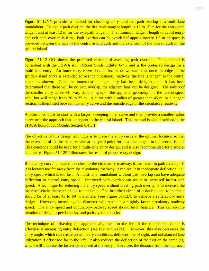
Figure 51-12NN provides a method for checking entry- and exit-path overlap at a multi-lane roundabout. To avoid path overlap, the desirable tangent length is 12 to 15 m for the entry-path tangent and at least 12 m for the exit-path tangent. The minimum tangent length to avoid entry- and exit-path overlap is 8 m. Path overlap can be avoided if approximately 1.5 m of space is provided between the face of the central-island curb and the extension of the face of curb on the splitter island. Figure 51-12 OO shows the preferred method of avoiding path overlap. This method is consistent with the FHWA Roundabout Guide Exhibit 6-46, and is the preferred design for a multi-lane entry. An inner entry curve should first be drawn such that once the edge of the splitter-island curve is extended across the circulatory roadway, the line is tangent to the central island as shown. Once the innermost-lane geometry has been designed, and it has been determined that there will be no path overlap, the adjacent lane can be designed. The radius of the smaller entry curve will vary depending upon the approach geometry and the fastest-speed path, but will range from 20 to 35 m. A curve with a radius of greater than 45 m, or a tangent section, is then fitted between the entry curve and the outside edge of the circulatory roadway. Another method is to start with a larger, sweeping inner curve and then provide a smaller-radius curve near the approach that is tangent to the central island. This method is also described in the FHWA Roundabout Guide, Section 6.4.3.1. The objective of this design technique is to place the entry curve at the optimal location so that the extension of the inside entry lane at the yield point forms a line tangent to the central island. This concept should be used for a multi-lane entry design, and is also recommended for a single-lane entry. Figure 51-12PP illustrates the result of proper entry design. If the entry curve is located too close to the circulatory roadway, it can result in path overlap. If it is located too far away from the circulatory roadway, it can result in inadequate deflection, i.e., entry speed which is too fast. A multi-lane roundabout without path overlap can have adequate deflection to control entry speed. Improved path overlap can result in increased fastest-path speed. A technique for reducing the entry speed without creating path overlap is to increase the inscribed-circle diameter of the roundabout. The inscribed circle of a double-lane roundabout should be of at least 43 to 60 m diameter (see Figure 51-12J), to achieve a satisfactory entry design. However, increasing the diameter will result in a slightly faster circulatory-roadway speed. The entry speed and circulatory-roadway speed should be in balance. This can require iteration of design, speed checks, and path-overlap checks. The technique of offsetting the approach alignment to the left of the roundabout center is effective at increasing entry deflection (see Figure 51-12JJ). However, this also decreases the entry angle, which can create unsafe entry conditions, deficient line of sight, and unbalanced lane utilization if offset too far to the left. It also reduces the deflection of the exit on the same leg, which will increase the fastest-path speed at the entry. Therefore, the distance from the approach
2009

offset to the roundabout center should be kept to a minimum to maximize its effectiveness in design and safety for pedestrians. A typical offset is 6 to 9 m from the center of the inscribed circle. 51-12.09(15) Lane-Drop Taper and Exit Design At a multi-lane roundabout, it is common to drop one travel lane downstream of an exit. A vehicle leaving a roundabout is typically traveling between 25 and 40 km/h and is accelerating away from the intersection. The taper should not start until after the exit radius is complete. There should also be a short parallel section before beginning the taper, if practical. An exit taper should be designed assuming a 60-km/h design speed using the appropriate formula for a lane drop at lower than 70 km/h. If a different design speed is determined to be applicable, contact the Production Management Division’s Roadway Standards Team. The right, or outside, lane should be dropped. The likely traffic volume exiting the roundabout on each individual exit lane should be evaluated. If there is a substantially higher traffic volume that will be using the outside lane, it is beneficial to drop the left, or inside, lane instead. The exit lane should be designed to promote a smooth natural drive path for a right-turning vehicle. The exit curve should start at the central island where the entry curve to the left ends, and extends past the pedestrian refuge to delineate the edge of the splitter island (see Figure 51-12KK). The lane will narrow from the circulating roadway width past the pedestrian refuge to match with the departing lane. The radius of the exit curve is larger than the entry curve to improve the ease of exit. A design that reduces the probability of a vehicle braking in the circulating lane or at the exit will minimize the likelihood of a crash at the exit. This larger radius does not translate into a faster speed where the exit speed is controlled by the circulating speed, R4, plus acceleration to the exit crosswalk. Where a free-flow right-turn bypass lane is utilized, the design of the merge should consider the relative speeds of the two conflicting streams of traffic, and provide the necessary lengths for the parallel section and merge section. 51-12.09(16) Vertical-Alignment Considerations See the FHWA Roundabout Guide, Section 6.3.11. 51-12.09(17) Clear Zone Clear-zone guidance for a roundabout installation requires consideration of the approach speed,
2009

fastest-path speed, adjacent side slopes leading into and through the roundabout, and AADT. Guidance for determination of the clear-zone width is provided in Section 49-2.0 and the AASHTO Roadside Design Guide. The speed of a vehicle approaching an intersection and the speed allowed through an intersection, along with the AADT and side slopes, will determine the required clear-zone width. A stop-controlled intersection located in a high-speed rural area will require less clear-zone width than a traffic-signal-controlled intersection, as drivers are required to slow down to stop. As an approaching vehicle reduces speed, it can be appropriate and desirable to reduce the corresponding clear-zone width. The need for a clear zone and right-of-way acquisition should be balanced. The yield condition for a roundabout is similar to that for the stop-controlled intersection. The horizontal geometry of the roundabout requires a driver to slow down on the approach and through the roundabout. The approaching speed transition distance is determined from the posted speed limit and the deceleration needed to enter the roundabout in accordance with the fastest-speed path calculation, R1 value. Section 51-12.09(18) and Figure 51-12QQ describe how to determine the roundabout’s approach layout for a high-speed highway. The design speed used to determine the clear-zone width around the perimeter of the roundabout is the average of the entry speed, measured at R1, and the circulatory-roadway speed, measured at R2. The average fastest-path speed, (R1 + R2)/2, of 40 to 50 km/h, will produce a clear-zone width of 2 to 5.5 m, depending on AADT. The exit ramps of an interchange are also considered to be low speed in close proximity of the approach to the roundabout. In an urban area, lateral clearance is used rather than clear-zone width to determine the minimum distance to a fixed object such as a utility pole, fire hydrant, tree, etc. In a rural area, the clear-zone width is used, based on the design speed, AADT, and sideslopes. The sideslopes adjacent to a roundabout are relatively flat to accommodate a small terrace and a multi-use path around the perimeter. If the multi-use path is not installed at the same time as the roundabout, the area can be graded so that a path can be installed in the future with minimal regrading. On an approach where vehicle speeds are 70 km/h or lower, and on the perimeter of the roundabout beyond the multi-use path, the sideslopes should be 4:1 or flatter. They may be steeper if clear-zone requirements can be satisfied, or local impacts preclude the use of such gentle slopes. Central-island clear-zone width is considered to be within a low-speed environment, and therefore should be in accordance with the lateral-clearance requirements for an urban street, 0.6 m back from the face of curb. Certain landscaping materials and treatments which are dependent upon the approach speed should be considered in the central-island landscaping design. See the FHWA Roundabout Guide, Section 7.5, for additional guidance on central-island landscaping.
2009

51-12.09(18) Approach Curbs A low-speed approach requires vertical-face curbs of 150 mm height in the area of the splitter island on both sides of the roadway and on the splitter island. The purpose of the vertical-face curbs is to control the fastest-speed paths at the roundabout entrances and exits. A high-speed approach is used with a rural cross section. A rural cross section for an undivided highway has shoulders without curbs on the outside. On a divided highway, the cross section has shoulders without curbs on both the inside and outside leading up to the roundabout. A high-speed approach requires a transition section to the roundabout, where the shoulders will narrow and vertical curbs will be introduced. See Figure 51-12QQ for an example of the high-speed approach layout. The figure
shows the layout of the gore area for the beginning of the splitter island and the curb-and-gutter layout as the driver approaches the yield line. The painted gore area transitions into a raised concrete center curb type C followed by a sloping curb and gutter of 100 mm height for a short distance as shown. The curb transitions both horizontally and vertically as it approaches the roundabout. At the nose where the curb and gutter begins, the curb face is 1.2 to 1.8 m from the driving lane, or has a shoulder of 1.2 to 1.8 m width on the left side of the approach.
In a rural area, the painted gore and the curbs serve to alert a driver approaching a roundabout of changing roadway conditions, and that travel speed should be reduced. Driver awareness that conditions are changing is accomplished through the use of roadway curvature, channelization, lighting, landscaping, or signage. Total curb length starting from the yield line should be the deceleration distance required to reduce from the approach speed to the fastest-path design speed measured at R1.
* * * * * * * * Example 51-12.1. The posted speed limit is 55 mph, or 88 km/h, and deceleration to approximately 40 km/h produces a desirable total raised-curb length distance of approximately 120 m for the splitter-island side of the roadway. Approximately 70 m of the 120 m should include a sloping curb of 100 mm height. The remaining 50 m should include a vertical curb of 150 mm height. If the posted speed limit instead is 40 mph, , or 64 km/h, deceleration to 40 km/h will produce a desirable total raised-curb length of approximately 56 m, all of which should be vertical curb of 150 mm height. Deceleration-distance is provided in the AASHTO Policy on Geometric Design of Highways and Streets, Exhibit 10-73. In using this exhibit, the approach speed limit should be used as the design speed. Differing approach conditions can produce different deceleration distances. On the roundabout approach, the minimum length of vertical curb on the right side of the travelway should be the greater of 8 m prior to the bicycle-path ramp or 30 m prior to the yield
2009

line. The vertical-curb installation will enforce the fastest-speed path geometry. On the exit, the curb on the right-hand side also should be long enough to control exit speed and minimally should be the greater of 8 m past the bicycle-path ramp or 30 m past the exit measured from the ICD. Drainage should be considered in the area of the curb and gutter by providing curb turnouts or inlet structures.
* * * * * * * * 51-12.09(19) Sight Distance Stopping sight distance should be provided so that a motorist can recognize the need to slow down and stop, if necessary. The FHWA Roundabout Guide, Section 6.3.9, should be followed in calculating stopping sight distances for the approaches, circulatory roadway, and crosswalks. Regarding intersection sight distance, the FHWA Roundabout Guide, Section 6.3.10, provides one method for calculating required visibility to the left as a vehicle approaches a roundabout. However, the section recommends that an approaching driver should be able to see a considerable distance up the preceding approach, based on a conservative methodology for calculating sight distance, which can sometimes be undesirable. An alternative method for calculating sight distance to the left requires that a driver approaching a roundabout should be able to see only to the yield line of the entry to the left once the driver approximately 15 m ahead of the yield line. Either of these two methods is acceptable for calculating sight distance to the left. Restricting visibility to the left until a driver is approximately 15 m ahead of the yield line on an approach reduces the possibility of a crash. Restricting vision in this manner does not interfere with intersection stopping sight distance. There are benefits to making the central island more visible and reducing sight lines through the central island to the opposite side of the roundabout. See the FHWA Roundabout Guide, Section 7.5, for landscaping within the central island and approaches. Where practical, visibility should be restricted through the central island so that the roadway on the opposite side of the island will not be visible to a motorist approaching the roundabout. Signs should be located such that they will not block clear-sight areas. However, chevron signs located in the central island will likely be located within a sight area. In calculating the sight lines, adequate sight distance should be provided for snow of up to 0.3 m depth in the central island. If the roundabout is within or near a horizontal curve, adequate sight distance should also be provided.
2009

51-12.09(20) Landscaping Considerations See the FHWA Roundabout Guide, Section 7.5. 51-12.09(21) Bicycle Provisions The minimum bicycle-ramp width should be 1.2 m between the roadway and the multi-use path, such that they angle 25 to 35 deg toward the path where the bicyclist exits the roadway, as shown in Figure 51-12W. Where a bicyclist re-enters the roadway, the ramp should likewise angle 25 to 35 deg toward the roadway. For applications pertinent to a multi-use path, see Section 51-7.0 and 51-12.07(03). A perpendicular ramp should not be provided between the multi-use path and the roadway that will require a bicyclist to stop or nearly stop forward motion to enter one facility or the other. Each roundabout location should include a bicycle ramp between the roadway and a shared-use path. Where the shared-use path is not installed with the initial construction, the designer should determine whether or not the perimeter of the roundabout should be graded for future path installation. 51-12.10 Traffic-Control Design 51-12.10(01) Signage The overall concept for roundabout signage is similar to that for other intersection types’ signage. Proper regulatory control, advance warning, and directional guidance are required to provide positive guidance to the roadway user. Signs should be located where roadway users can easily see them when they need the information in advance of the condition. Signs should not obscure pedestrians, motorcyclists, or bicyclists. Urban and rural applications require different signs or sign spacing. For the connecting highways, sign selection should be coordinated with the district Office of Traffic and the local public agency to maintain consistency on the facility. The MUTCD governs the design and placement of signs. Also see the FHWA Standard Highway Signs manual and the INDOT Sign Design Guide for more information. 1. Regulatory Signs. The appropriate regulatory signs shown Figure 51-12RR are described
below.
a. “Yield” Sign, R-2A. This should be placed both in the splitter island, and on the
2009

right side of each approach. If sight distance is limited, a “One Way” sign, R6-2R, should be placed under the splitter-island side’s “Yield” sign on each approach to establish the direction of traffic flow within the roundabout. A “To Traffic From Left” sign, may be placed under the right-side “Yield” sign on each approach to reinforce that the circulating traffic has the right of way.
b. “One Way” Sign, R6-1R. This should be placed in the central island opposite
each entrance and mounted above the chevron sign to emphasize the direction of travel within the circulatory roadway. A single sign along with four chevrons is recommended.
c. “Keep Right” sign, R4-7. This should be placed at the nose of each raised-curb
splitter island.
A lane-use sign, such as R3-8, should not be used for a single-lane entry. For a multi-lane entry, operational requirements will dictate where the R3-8 sign should be used.
The preferred R3-8 sign is modified to show a fishhook symbol to better identify roundabout-lane designations. This sign incorporates the placement of a dot under the left-pointing arrow, if present, which graphically depicts the presence of the central island. A dot under or beside the arrow should be used only for the left-most lane.
2. Warning Signs. The appropriate warning signs shown Figure 51-12SS are described
below. The amount of warning a motorist needs is related to site-specific intersection conditions and the vehicular speeds on the approach roadways.
a. Circular Intersection Sign, W2-6. This should be placed on each approach in
advance of the roundabout. An optional “Ahead” educational plate, W16-9p, should be placed below the W2-6 sign. Below the W16-9p plate, if placed, but below theW2-6 sign if not, an advisory-speed plate, W13-1, should be placed. The speed shown on the advisory-speed plate should not be higher than the design speed of the circulatory roadway. For closely spaced roundabouts, these signs may be omitted. See item 4 below for guidance as to where these signs may be omitted.
b. “Yield Ahead” sign, W3-2. This should be placed on each approach. For closely-
spaced roundabouts, this sign may be omitted. See item 4 below for guidance as to where these signs should be omitted.
c. “Pedestrian Crossing” Sign. Use of this sign should be coordinated with the
district Office of Traffic or the local public agency. If there is a school crossing at the roundabout, the school advance-warning sign assembly with arrow, S1-1 and
2009

W16-7p, is required at the crosswalk location, and in advance of the school crosswalk. If there is no school crossing at the roundabout, the pedestrian-crossing sign assembly, W11-2 and W16-7p, or the school-crossing sign assembly should be placed in front of the crosswalk on the approach and on the exit. A rural roundabout will not have pedestrian accommodations, and will not require pedestrian-sign assemblies. However, if pedestrians are anticipated, the pedestrian-sign assemblies described above are required. If the crosswalk is not considered to be part of the intersection because of its distance from the circulatory roadway, pedestrian-crossing accommodations and their design should be in accordance with the MUTCD and the Americans with Disabilities Act guidelines for a mid-block crossing.
Pedestrian-crossing signs should be located so as to not obstruct an approaching driver’s view of the “Yield” sign or pedestrians standing at the crosswalk.
d. Bicycle Sign Assembly, D11-1 and M7-4. This may be required to designate the
exit to the bicycle path.
Flashing beacons may be used with some warning signs as a long-term awareness technique for an area with approach speeds of 70 km/h or higher, or for an area with limited sight distance where an emphasis on advance warning is deemed necessary.
3. Guide Signs. These provide drivers with needed navigational information. They are
particularly needed at roundabouts to reduce driver confusion. Overhead guide signs can be considered at a high-capacity multi-lane roundabout approach to guide motorists into the proper travel lane to navigate the roundabout properly and help avoid lane changing within the roundabout. The appropriate guide signs are described below.
a. Intersection Destination and Direction Sign. This should be placed at each
approach in a rural location. It should be considered in an urban or suburban location where space allows, and its use is not determined to be inappropriate. The decision to install this sign is based on available right of way, agency preference, roadway speed, and type. This sign should be used only where necessary, and where it does not cause sign clutter. This sign may not be necessary at a local-street roundabout or in an urban setting where there are no significant destinations and the majority of users are familiar with the site.
The diagrammatic style is preferred over the text style, since the diagrammatic style reinforces the form and shape of the approaching intersection, and clarifies to the driver how to navigate the intersection. Examples of both styles are shown in Figure 51-12TT. If space is limited, or sign spacing becomes an issue, a text-style sign or overhead diagrammatic guide sign may be used.
2009

b. Overhead Lane-Use Sign. This should be used at high-traffic-capacity location on
a National Highway System route, or at an interchange location with multiple approach lanes. By providing destination guidance to the driver in advance, the vehicle will more likely be in the correct lane at the roundabout approach. The driver will be discouraged from making a lane change within the roundabout.
Qualifying criteria include two or more approach lanes, higher AADT, lane splits approaching the roundabout, dual turn lanes, a major route that turns instead of continuing straight through the roundabout, closely-spaced roundabouts, unfamiliarity of drivers, and documented crash patterns related to improper lane usage. All arrows should point up. Each individual sign is placed over each travel lane. See the urban roundabout layout example in Figure 51-12UU
. The arrow is placed over the center of the lane. Sign placement should be coordinated with the district Office of Operations, the Production Management Division’s Traffic Review team, and the local public agency. If overhead lane-use signs are used on an approach, the diagrammatic-style sign is not required. The diagrammatic-style sign shows destinations and directions, but it does not depict proper lane assignments. See the MUTCD for the appropriate font style, vertical clearance, letter sizing, and other design and placement elements.
See the AASHTO Standard Specifications for Structural Support for Highway Signs, Luminaires and Traffic Signals
for overhead-sign support design guidance.
c. Exit Guide Sign in Splitter Island. This reduces the potential for driver confusion. It is used to designate the destination of each exit from the roundabout. It is a conventional-intersection direction sign. An exit guide sign with a route-number sign should include the cardinal direction and arrow. The arrow should point to the right at 45 deg. For a freeway ramp, the route continuation should be shown on the exit guide sign, as shown in Figure 51-12VV.
d. Route Confirmation Sign. For an intersection of one or more numbered routes, a
route-sign assembly should be placed after the roundabout exit to reassure drivers that they have selected the correct exit at the roundabout. A confirmation assembly should be placed not more than 150 m beyond the intersection. The assembly should be placed close enough to the intersection so that it can be seen by a driver in the circulatory roadway.
A junction assembly consisting of a “Jct”, M2-1, auxiliary sign should be
considered with the appropriate route-number sign in advance of the roundabout. See the MUTCD for additional guidance.
2009

4. Urban Signage Considerations. An urban intersection tends to exhibit lower speeds. Consequently, fewer and smaller signs can be placed than in a rural setting. However, some indication of street names in the form of exit guide signs or street-name signs should be included. The proposed signage layout should be reviewed to ensure that sign clutter will not reduce its effectiveness. Sign clutter can be avoided by prioritizing signage and eliminating or relocating lower-priority signs. A sample signage plan for an urban application is shown in the FHWA Roundabout Guide, Exhibit 7-15.
5. Rural and Suburban Signage Considerations
. Route guidance emphasizes destinations and numbered routes rather than street names. The exit guide sign should be visible but discrete from within the roundabout. A sample signage plan for a rural application is shown in the FHWA Roundabout Guide, Exhibit 7-16.
6. Closely-Spaced Roundabouts. Roundabouts can be installed less than 0.2 km apart. This situation can cause signage challenges due to longitudinal space constraints between the roundabouts. As a result, some signs may be eliminated between the roundabouts. Visibility distance is based on stopping sight distance. The roundabout warning assembly signs W2-6, W2-6p, and W13-1, and “Yield Ahead”, W3-2, may be eliminated between roundabouts if the visibility distance between the roundabouts exceeds the minimum visibility distance shown in Figure 51-12WW. Other signs may be eliminated after review with the district Office of Operations and the local public agency. The warning assembly signs and “Yield Ahead” sign should be placed at the approaches to the first roundabout in the series.
7. Roundabout in Close Proximity to Railroad Crossing. This can present signage
challenges due to safety concerns and the installation of additional signs where a number of signs are already required. Since each railroad-crossing situation is unique, the Production Management Division’s Railroads Team, the district Office of Operations, and the local public agency should be contacted for approval of the signage and marking layout if the railroad crossing is 230 m or less from the roundabout.
8. Short-Term Awareness Techniques. Once a roundabout is first installed, there can be a
need to raise driver awareness of geometric features or signs. There can be a need to mitigate a certain situation, such as a driver failing to yield on a certain approach, after a roundabout has been in operation. The district traffic engineer should be contacted for guidance. Traffic-control devices are not expected to accomplish what the geometric design cannot. Available mitigation measures to increase driver awareness include providing portable changeable-message signs or installing orange flags on top of the “Yield” signs during the first six months of operation.
9. Illuminated Bollard. An illuminated bollard, as shown in Figure 51-12XX, has proven
beneficial to roundabout safety. Its use has thus far been limited as it is not shown in the
2009

MUTCD as a traffic-control device in the form shown in Figure 51-12XX. It is installed at the nose of the splitter island, or the end of the island farthest away from the circulatory road, aiding drivers during periods of low visibility. The use of an illuminated bollard which displays a traffic-control message is considered experimental and requires the necessary approvals for each project. An illuminated bollard without a sign displayed on it is permitted.
51-12.10(02) Pavement Markings Pavement markings for a single-lane roundabout are discussed in FHWA Roundabout Guide, Section 7.2, and the MUTCD. The FHWA Roundabout Guide and the MUTCD do not address pavement markings for a multi-lane roundabout, therefore, guidance is provided below. Figures 51-12E and 51-12F show the terminology that is used for such pavement markings. 1. Markings for a Multi-Lane Roundabout. The objective of using such markings is to
provide direction to motorists so that they can traverse a roundabout without changing lanes. This improves safety and traffic operations, and educates drivers about proper lane use. They can be critical to the successful functioning of a roundabout. This is true where unusual peak hour turning patterns, i.e., double right turn, double left turn, occur. Pavement markings can also be used as a low-cost option to retrofit an older roundabout or traffic circle with problematic geometry.
Pavement-marking principles include the following.
a. Turning patterns or volumes should be accommodated without inconsistencies.
The marking scheme should accommodate all of the individual movements without requiring drivers to change lanes inside the roundabout during different peak hours. This can be accomplished by tracking each movement through the intersection for both peak hours. If conflicts within the same peak hour or between different peak hours cannot be resolved after trying different pavement-marking schemes, the designer should consider either of the following:
(1) partial spiral markings that accommodate the major traffic streams as long
as they do not create conflicts; or (2) markings not placed in the circulatory roadway.
b. Lane-use control arrows should designate and reinforce correct lane usage. The
lane-designation pavement markings should match the lane designation signs used at the approaches. The fishhook sign style and pavement marking should be used.
2009

c. Lane changing within the circulatory roadway should be discouraged.
Discouragement is achieved by directing drivers into the correct lane before they reach the yield line and maintaining lane consistency throughout the intersection. Providing relatively long approach lanes facilitates this objective by allowing drivers more time to get into the correct lane as they approach the yield line. Lane-use control arrows can be repeated on the approaches, with two or three sets of arrows being desirable.
d. Approach arrows should be oriented relative to and should define the exit road
that can be accessed from each specific approach lane, and should be consistent with lane-use signs. Approach arrows or stripes should be consistent with circulatory-roadway arrows, stripes, and signs. Unbalanced lane use, i.e., most vehicles using one lane instead of balancing out evenly on two or three lanes, should be discouraged by means of the selection of proper lane designations which achieve the most-even distribution of traffic possible.
e. For a flared approach, where one or more lanes are added, lane stripes should
extend back from the yield line as far as reasonably possible.
f. Line types should convey the correct message. A 2:1 ratio of 100-mm-width line to gap should be used with a 3.6-m line and 1.8-m gap for lane lines on the approaches, circulatory roadway, and exits. The approach and circulatory-roadway marking may be a solid white line instead to discourage lane-change behavior.
g. The yield line should be broken white, with a width of 300 to 600 mm, with 0.6 m
of line and 0.6 m of gap.
h. Pavement markings and signs should be an integral part of the geometric design and should be developed concurrently with a concept’s design.
i. Concentric-circles markings should not be used in the circulatory road. These
markings cause indecision, lane-use imbalance, decreased capacity, and the potential for exit crashes.
j. Markings at closely-spaced roundabouts should function as one integrated system.
This provides guidance for drivers to select the lane they must use for their ultimate destination before entering the system and to be able to traverse multiple intersections without changing lanes. Extra lanes that are not needed solely for capacity purposes may be added for lane continuity.
2009

k. Guide dots should be used to direct motorists from the yield line into the proper circulating lane. A dotted white line of 150 mm width should be used, with a 0.3-m line and a 3- to 4.5-m gap.
l. The triangles markings or the word “Yield” placed at each approach can be
integrated into the pavement-marking layout to enhance the safety and visibility of the yield on entry. These should be placed perpendicular to the lane at the yield line.
2. NCUTCD Guidelines. The National Committee on Uniform Traffic Control Devices
(NCUTCD) has approved draft guidelines regarding pavement markings at a roundabout. While this information has not yet been formally adopted for use, it can be used if it does not conflict with the principles defined above or in the FHWA Roundabout Guide. Otherwise, there is no pavement-marking guidance regarding a multi-lane roundabout. The circulatory-road markings of a combination of a solid line and a short dashed line shown in the NCUTCD draft should not be used. Instead, a 3.6-m line with a 1.8-m gap should be used for the circulatory road. Adoption of the NCUTCD draft is subject to FHWA approval prior to implementation. The designer should verify with INDOT or the local public agency prior to implementation.
3. Spiral Hatching. Where one lane of the circulatory road is to be spiraled out away from
the central island, a spiral hatching near the central island should be used. However, drivers often ignore these markings, drive over them, and do not transition into the desired lane. Therefore, an irregularly-shaped central island with the curbed island at the same location should be placed instead of the spiral hatching. If an irregularly-shaped central island is used, the design vehicle should still be able to circulate adjacent to the central island without overrunning the innermost curb.
4. Curb Faces. These may be painted with reflective paint. This is used to aid drivers in
identifying curb locations at night. 51-12.10(03) Lighting 1. Introduction. A driver should be able to perceive the general layout and operation of an
intersection in time to make appropriate maneuvers. If a facility is designed for use by a high volume of motor vehicles, pedestrians and bicycles, or mopeds, it should be illuminated. Additional illumination guidance is available in Chapter 78, and the IESNA Publication DG-19-08, Design Guide for Roundabout Lighting.
2. Need for Illumination. The need varies depending on the location of the roundabout.
2009
a. Urban Area.
An urban roundabout should be illuminated if all or most of its approaches are illuminated as necessary to improve the visibility of pedestrians and bicyclists, or if the facility is intended for use as a transition speed zone.
b. Suburban Area. I
llumination should be considered for safe traffic flow if the conditions are present as follows:
(1) one or more approaches is illuminated;
(2) competing non-roadway illumination in the vicinity can distract a driver's attention, e.g., parking lot, car-dealership lot, or filling station;
(3) high nighttime traffic volume is anticipated; or
(4) pedestrian traffic is anticipated, or approaches have sidewalks.
A continuity of illumination level should be provided between the approaches and the roundabout to avoid distracting drivers and to minimize the need for drivers’ eyes to adjust to changing lighting levels.
c. Rural Area.
A rural roundabout should be illuminated. Retroreflective pavement markings and signs should be placed whether or not illumination is provided.
3. General Recommendations. Illumination enables drivers to see and navigate the geometric features of the roundabout at night. Lighting also facilitates mutual visibility among the users.
Illumination should be provided on the approach nose of each splitter island, at all conflict areas where traffic is entering the circulating stream, and where the traffic streams separate to exit the roundabout.
The roundabout should be illuminated from the outside in toward the center to improve the visibility of the central island and the visibility of circulating vehicles to vehicles approaching the roundabout. Illumination from the central island outward should not be used, since vehicles become shadows against the light, and thus, less visible. If it is desired to illuminate specific objects in the central island, ground-level lighting should be used within the central island that shines upward toward objects and away from the nearest roadway. Accent lighting and roadway lighting should be placed on separate electrical disconnects for the purpose of blackout protection.
Pedestrian crossings should be illuminated. Illumination of bicycle merging areas should be considered.
2009

4. Light-Pole Placement. The placement of a light pole relative to the curb should be
determined from the speed environment in which the roundabout is located and the potential speed of an errant vehicle that can be expected. The lateral placement of a light pole should be in accordance with the AASHTO Roadside Design Guide requirements for clearance, clear zone, or obstruction-free zone.
The crosswalks should be illuminated so that pedestrians are in positive contrast. A light pole should be placed 3 to 9 m ahead of the crosswalk. A pole should be offset 3 m from the roadway to allow adequate spacing for large vehicles such as trucks and farm equipment to safely maneuver the roundabout.
Where pedestrian facilities do not exist, a layout that assumes a future multi-use path should be considered. The layout should consider longitudinal light-pole placement as described above, and lateral offset to avoid major facility relocations where pedestrian or bicycle paths are provided in the future.
Light supports or other poles or hazards should not be placed within a splitter island, or on the right-hand perimeter immediately downstream of an exit point.
51-12.10(04) Work-Zone Traffic Control Traffic maintenance can be accomplished by means of partial-width construction or intersection closure. If partial-width construction is used, traffic should be routed through the roundabout in a counterclockwise direction to train drivers as to the proper direction of travel at the intersection, especially during the final stages of construction prior to opening the intersection. 51-12.11 Public Involvement 51-12.11(01) Introduction Although it is not always possible to achieve, the goal regarding public involvement should be to build consensus and support for the road improvements under consideration. This Section provides information about educating the public and obtaining public input regarding a roundabout. Figure 52-12ZZ includes example materials that can be used in the public-involvement process. See the Public Involvement Manual for more information. The designer should coordinate with the local public agency.
2009

51-12.11(02) Educating the Public Public acceptance of a roundabout is required where it appears to be an acceptable technical solution. Misconceptions still exist due to unfamiliarity and failure to distinguish a roundabout from an old-style traffic circle. Therefore, public involvement and roundabout education should be the first steps in leading the public toward acceptance of a roundabout. Public resistance has been common prior to construction of a roundabout. Once the roundabout has been constructed and is operating, public opinion has most often been favorable. Due to public misunderstandings about roundabouts, a public-involvement campaign should include roundabout education for elected officials, staff members, and the general public. These types of public-involvement processes allow local governments to partner with INDOT. In educating the public, topics for consideration are as follows: 1. basic roundabout concepts and terminology; 2. differentiation between a modern roundabout and a traffic circle (see Figure 51-12YY); 3. data showing the increased safety benefits of a roundabout in comparison to other
intersection types; 4. existing accepted locations within the State; 5. use at a high-speed intersection; 6. cost and right-of-way impacts compared to other options; 7. older or inexperienced drivers; 8. how to maneuver a roundabout, or the understanding of how a roundabout operates; 9. efficiency compared to other intersection types; 10. trucks; 11. snow removal; 12. proximate drives; 13. safe accommodation of pedestrians while in accordance with ADA requirements; and 14. bicycles. 51-12.11(03) Public-Involvement Techniques These are similar to those utilized for another type of road project. Input should be sought after initial investigations have been conducted, and a roundabout has been determined feasible by INDOT, but before design commences. Before design, consideration of public input should consider the degree to which public education has occurred. Public-involvement processes should be adapted to each individual project based on coordination with local officials, the project manager, and the Public Information Division.
2009

A public-information meeting can be used to educate the public about a roundabout and to hear their feedback. Such a meeting provides the opportunity to dispel roundabout myths, and it permits the public to be involved in the planning process and have its questions and concerns addressed. Informational materials at a public meeting can include the following: 1. exhibits mounted on foamcore boards; 2. brochures; 3. video photography from before and after; 4. still photography from before and after; 5. project-specific materials; or 6. public-comment forms. Websites can also be used to provide the public with roundabout information.
2009

Total No. of Parking Spaces
Minimum Number of Accessible Spaces
1 through 25 1
26 through 50 2
51 through 75 3
76 through 100 4
101 through 125 5
151 through 200 6
201 through 300 7
301 through 400 8
401 through 500 9
501 through 1000 2% of Total
1001 and Over 20 plus 1 for each 100 over 1000
Notes:
a. If one or more passenger loading zones are provided, then at least one passenger loading zone should comply with Section 51-1.03(01) Item 5.
b. Parking spaces for side-lift vans are accessible parking spaces and may be used to
meet the requirements of Section 51-1.03(01).
c. The total number of accessible parking spaces may be distributed among closely spaced parking lots, if greater accessibility is achieved.
MINIMUM NUMBER OF ACCESSIBLE SPACES FOR PHYSICALLY-CHALLENGED USERS
Figure 51-1A
2009

2009

2009

Slope Maximum Rise Maximum Run
Steeper than 16:1 but not steeper than 12:1
760 mm 9,000 mm
Steeper than 20:1 but not steeper than 16:1
760 mm 12,000 mm
Note: A slope steeper than 12:1 is not permitted.
ALLOWABLE RAMP DIMENSIONS, NEW CONSTRUCTION
Figure 51-1D
2009

Slope Maximum Rise Maximum Run
Steeper than 10:1 but not steeper than 8:1
75 mm 600 mm
Steeper than 12:1 but not steeper than 10:1
150 mm 1,500 mm
Note: A slope steeper than 12.5% is not allowed.
ALLOWABLE RAMP DIMENSIONS FOR EXISTING SITE, BUILDING, OR FACILITY
Figure 51-1E
2009

2009

Type Ramp Width
(m) Ramp Slope
Landing Width (m)
Landing Depth (m)
Flare Slope
Clear Space (m)
PERPENDICULAR A 1.2 1 12:1 2 1.2 1.2 1 12:1, Pvmt. n/a C 1.2 1 12:1 2 1.2 1.2 1 12:1, Pvmt. n/a D 1.2 1 12:1 2 1.2 1.2 1 12:1, Pvmt. n/a
DIAGONAL B 1.2 1 to 2.4 12:1 2 n/a 1.2 top & bot 12:1, Pvmt. 1.2 E 1.6 to Vari. 12:1 2 0 to 1.6 1.2 12:1, Sod 1.2
PARALLEL F Sdwk. 12:1 Sdwk. 1.2 n/a 1.2
DEPRESSED-CORNERS H 1.8 12:1 1.8 1.8 12:1, Sod 3 1.2 G 1.5 12:1 1.5 1.5 12:1, Sod 3 1.2
MID-BLOCK K 1.2 12:1 1.2 1 Sdwk. n/a n/a
MEDIAN L 1.6 50:1 1.6 n/a 12:1, MM 4 n/a
1 If 1.2-m width or depth is site-infeasible, it may be reduced to 0.9 m. 2 If 12:1 slope is site-infeasible, it may be steepened to 10:1 for a rise of not more than 150 mm. 3 If 1.8-m depth is site-infeasible, this may be steepened or replaced with a vertical curb. 4 MM = median material. 5. The landing cross slope should be 50:1, but if it is site-infeasible, it may be steepened. 6. The landing slope should be 50:1, the maximum longitudinal gutter slope should be 20:1, and the width of the area with detectable warning devices should be 0.6 m.
SUMMARY OF CURB-RAMP GEOMETRICS
Figure 51-1G
2009

Change in Elevation, mm
Ramp Length, m
100 1.6 125 2.0 150 2.4 175 2.8 200 3.2
LENGTH OF PERPENDICULAR CURB RAMP
Figure 51-1H
2009

Design Element Factor Cars Cars/
Trailers Trucks Total
Mainline Traffic Data 20 Year AADT (A) 20 Year AADT, Directional (B) 0.60A DHV, Directional (DHV) 0.135B (1) Traffic Composition (20-year projected) Cars (D1) ...................1-(D2+D3) Cars/Trailers (D2)................. 5% Trucks (D3)............................. %
(D1) ___ Cars (D2) ___ Cars/Trailers (D3) ___ Trucks
C1=DHV x D1 C2=DHV x D2 C3=DHV x D3 C=C1+C2+C3
Vehicles Per Hour at Rest Area (VPH) Cars Stopping (E1) Urban Route Near Commercial or Metro Area ..............0.09 Rural Route Near Commercial or Metro Area ..............0.12 Tourist Route.....................0.13 Information and Welcome Center ..........0.15 Cars/Trailers (E2) Normal Stopping ...............0.15 Trucks (E3) Normal Stopping ...............0.15
(E1) ___ Cars (E2) ___ Cars/Trailers (E3) ___ Trucks
VPH1=E1 x C1 VPH2=E2 x C2 VPH3=E3 x C3 VPH=VPH1+
VPH2 + VPH3
Parking Spaces (P) Cars (T1) – Average Stop......0.25 to 0.33 h at Info. Center ....0.33 to 0.50 h Cars/Trailers (T2) = ..............0.50 h Trucks (T3) (2) .......................0.50 h
(T1) ___ Cars (T2) ___ Cars/Trailers (T3) ___ Trucks
P1=VPH1 x T1 P2=VPH2 x T2 P3=VPH3 x T3
x PF (3) P=P1+P2 + P3
Rest Room Requirements Persons / Hour (PH) VPH x 3.0 persons/veh x 0.75 h use Number of Comfort Facilities – Men’s Room (M) 0.5 PH
Number of Comfort Facilities – Women’s Room (W) 0.5 PH
Notes: (1) Assume 13.5% or the 20-year projected DHV, whichever is greater. (2) Maximum of 80 truck and recreational vehicle parking spaces. (3) PF = Peak Factor, ratio of average-day usage during May through September compared with average-day usage during the entire year, normally taken as 1.8, from AASHTO Guide for Development of Rest Areas on Major Arterials and Freeways.
DESIGN GUIDE FOR FREEWAY REST-AREA FACILITIES
Figure 51-2A
2009

2009

Number of Facilities – Men’s Room (2) (M) Persons/Hour
Using Rest Room During Design Hours (1) Urinals
(3) Toilets
(3)
Wash Basins
(3)
Hand Air Dryers
(3) 0-105
106-225 226-315 316-375 376-435 436-500
2 4 6 8 10 12
2 4 6 6 6 8
2 4 6 6 8 10
2 4 6 6 8 10
Number of Facilities – Women’s Room (2) (W) Persons/Hour
Using Rest Room During Design Hours (1) Toilets
(3)
Wash Basins
(3)
Hand Air Dryers
(3) 0-105
106-225 226-315 316-375 376-435 436-500
6 10 14 18 20 24
4 6 8 10 12 14
4 6 8 10 12 14
Notes: (1) See Figure 51-2A to determine the number of persons/hours. (2) Dual men’s/women’s facilities (minimum of 2 each) should be provided. The number of
fixtures should be divided equally among the rest rooms. (3) At least one fixture should be handicapped accessible in each rest room provided. For
additional criteria, see ADA Guidelines.
GUIDELINES FOR COMFORT FACILITIES
Figure 51-2C
2009

2009

Parking Angle Dimension Diagram
Location 45˚ 60˚ 75˚ 90˚ Stall width, parallel to aisle A 3.8 3.2 2.8 2.7 Stall length of line B 8.4 7.2 6.4 5.6 Stall depth to wall C 5.9 6.2 6.1 5.6 Aisle width between stall lines D 3.7 3.9 7.0 7.9 Stall depth, interior E 5.0 5.6 5.8 5.6 Module, wall to interior F 14.6 16.8 18.9 19.2 Module, interior G 13.7 16.2 18.6 19.2 Module, interior to curb face H 14.0 16.0 18.1 18.4 Bumper overhang (typical) I 0.6 0.7 0.8 0.8 Offset J 2.0 0.8 0.2 0 Setback K 4.0 2.8 1.5 0 Cross aisle, one-way L 4.3 4.3 4.3 4.3 Cross aisle, two-way --- 7.3 7.3 7.3 7.3
2009

2009

2009

2009

2009

Area Road Circulation Road Primary Access Road Design Element Manual
Section 1-Lane (1a) 2-Lanes (1b) 2-Lanes (1b) 2-Lanes (1b) Design-Year Traffic (Current AADT) 40-2.0 < 100 ≥ 100 ≥ 100 ≥ 100 Design Forecast Year 40-2.0 Current Design Speed (km/h) 40-3.0 20-30 20-30 40-60 50-70 Access Control 40-5.0 None (2)
Design Controls
Level of Service 40-2.0 Desirable: B; Minimum: D Width 3.6 to 4.2 m (3) 2.7 to 3.6 m 3.0 or 3.3 m 3.3 or 3.6 m Travel Lane
Typical Surface Type 51-6.02(05),
45-1.0 HMA / Aggregate HMA HMA
Width (4) 0.3 m
Aggregate/Earth
0.6 m 0.6 to 1.2m 0.6 to 1.2 m Shoulder
Typical Surface Type
51-6.02(05), 45-1.0
Aggregate/Earth Travel Lane 2% if HMA; 6% if Aggregate
Cross Slopes Shoulder
45-1.0 6% if Aggregrate; 8% if Earth
Lane Width Desirable: 3.0 m Auxillary Lane
Shoulder Width 51-6.02(05),
45-1.0 Desirable: 0.6 m; Minimum: 0.3 m Obstruction-Free Zone (5) 51-6.02(06) Desirable: 1.0 m Desirable: 2.0 m Desirable: 3.0 m
Foreslope Desirable: 4.1; Maximum: 1½:1 Ditch Width Minimum: 0 m (V-Ditch) Cut
Baclslope Desirable: 4:1; Maximum: 1½:1
Cross Section Elements
Side Slopes
Fill
51-6.02(05), 45-3.0
Desirable: 4:1; Maximum: 1½:1
Structural Capacity Part VI HS-20 New or Reconstructed Bridge Clear-Roadway Width 45-4.0 Travelway + 1.5 m Travelway + Shoulders
Structural Capacity Part VI HS-15 Existing Bridge to Remain in Place Clear-Roadway Width 45-4.0 Minimum: Travelway
New or Replaced Overpassing Bridge 4.45 m Vertical Clearance
(Recreational Road Under) Existing Overpassing Bridge
44-4.0 4.30 m
Bridges
Vertical Clearance (Recreational Road Over Railroad) (6) Ch. 69 7.00 m
GEOMETRIC DESIGN CRITERIA FOR RECREATIONAL ROAD
Figure 51-6B
2009

Design Element Manual Section 20 km/h 30 km/h 40 km/h 50 km/h 60 km/h 70 km/h
2-Lane (1b) 20 m 35 m 50 m 65 m 85 m 105 m Stopping Sight Distance
1-Lane (1a)
51-6.02(02), 42-1.0 40 m 70 m n/a n/a n/a n/a
Passing Sight Distance 42-3.0 n/a n/a n/a 345 m 410 m 485 m
Intersection Sight Distance 46-10.0 45 m 65 m 85 m 105 m 130 m 150 m
Minimum Radius (e=4%) 51-6.02(04), 43-2.0
15 m 35 m 60 m 100 m 150 m 215 m
Superelevation Rate 51-6.02(04), 43-3.0
n/a emax = 4%
Horizontal Sight Distance 51-6.02(04), 43-4.0
(7)
2-Lane (1b) 1 2 4 7 11 17 Crest
1-Lane (1a) 2 7 n/a n/a n/a n/a
2-Lane (1b) 3 6 9 13 18 23
Vertical Curvature (K-value)
Sag 1-Lane (1a)
44-3.0
6 13 n/a n/a n/a n/a
Level 8% 8% 7% 7% 7% 7% Maximum Grade
Rolling 44-1.02
12% 11% 10% 10% 9% 8.5%
Alignment Elements
Minimum Grade 44-1.03 Desirable: 0.5%; Minimum: 0.0%
GEOMETRIC DESIGN CRITERIA FOR RECREATIONAL ROAD
Figure 51-6B (Continued)
2009

GEOMETRIC DESIGN CRITERIA FOR RECREATIONAL ROAD Footnotes to Figure 51-6B
1. 1-Lane/2-Lanes. For Section 51-6.0 only, the following will apply: a. The criteria for one-lane refer to two-directional traffic on a one-lane road. b. The criteria for two-lanes refer to two-lane roads or a one-way roadway with either one or two lanes. 2. Access Control. Access to private individuals is not provided within the recreational area. However, access may be provided on the primary
access road. 3. Travel Lane Width. A total roadway width greater than 4.2 m is not recommended for a one-lane road. For a one-lane road, the travel lane
width is predicated upon the type of vehicle expected to use the facility. 4. Shoulder Width. Where a barrier is used, the graded width of shoulder should desirably be increased by 0.6 m. 5. Obstruction-Free Zone. The minimum obstruction-free zone will be the shoulder width. 6. Vertical Clearance (Recreational Road Over Railroad). See Chapter Sixty-nine for additional information on railroad clearance under a
highway. 7. Horizontal Sight Distance. For a given design speed, the necessary middle ordinate will be determined by the minimum radius and the
stopping sight distance which applies at the site.
2009

Vehicle Type Average Width (m)
Average Length (m)
Average Eye Height (m)
Average Speed (km/h)
Bicycle 0.6 1.7 1.57 17 Bicycle with Trailer 1.2 2.8 1.60 17 Hand Cycle 0.6 1.8 0.96 15 Inline Skates 0.5 0.5 1.68 16 Kick Scooter 0.4 0.7 1.47 13 Manual Wheelchair 0.6 1.0 1.21 7 Power Scooter 0.6 1.2 1.32 10 Power Wheelchair 0.6 1.3 1.24 10 Power wheelchair & dog 1.2 1.2 1.17 7 Recumbent Bicycle 0.6 1.9 1.26 22 Segway5 0.6 0.6 1.88 15 Skateboard 0.3 0.8 1.55 13 Stroller 0.5 1.2 1.33 5
USER-TYPE DIMENSIONS AND SPEEDS
Figure 51-7A
2009

2009

2009

Roadway Speed
Limit (km/h) Separation * (m)
≤ 70 6, desirable 3, minimum
≥ 80 7 to 11
* or roadway clear-zone width, whichever is greater
SHARED-USE-PATH SEPARATION WIDTH FROM ROADWAY WITH NO CURB
Figure 51-7D
2009
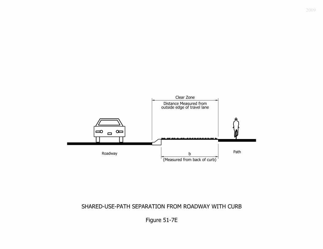
2009

Roadway Speed
Limit (km/h) Separation * (m)
≤ 50 1.5, minimum
0.9, minimum if parking permitted
60 1.5, minimum ≥ 70 3, minimum
* or roadway clear-zone width, whichever is greater
SHARED-USE-PATH SEPARATION WIDTH FROM ROADWAY WITH CURB
Figure 51-7F
2009

Bicycle and Pedestrian Traffic Composition Recommended
Pavement Width Bicycle use with low-volume pedestrian use Bicycle use with high-volume pedestrian use, segment length ≤ 90 m where right-of-way is restricted
3 m (Standard width)
Bicycle use where pedestrian use is likely to be infrequent Bicycle use with low-volume pedestrian use, segment length ≤ 90 m where right-of-way is restricted
2.4 m
Bicycle use with high-volume pedestrian use High-volume bicycle use with low-volume pedestrian use
3.6 m
High-volume bicycle and pedestrian use Bicycle-facility segment where queuing occurs, such as a road crossing
≥ 4.2 m
PATH PAVEMENT WIDTH BASED ON PATH-USE TRAVEL COMPOSITION
Figure 51-7G
2009

Grade (%) Maximum Length of Segment (m)
5 or 6 250 7 120 8 90 9 60
GRADE RESTRICTION FOR SHARED-USE PATH
Figure 51-7H
2009

Design Speed (km/h)
Radius (m)
20 11 25 17 30 30 40 48 50 79 *
* radius is based on a lean angle of 20 deg
DESIRABLE MINIMUM RADIUS OF HORIZONTAL CURVATURE FOR PAVED SHARED-USE PATH
BASED ON LEAN ANGLE OF 15 DEG
Figure 51-7 I
2009

2009
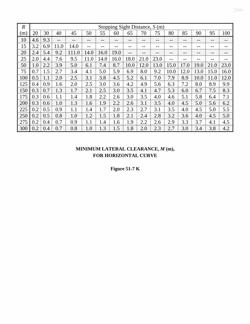
MINIMUM LATERAL CLEARANCE, M (m), FOR HORIZONTAL CURVE
Figure 51-7 K
Stopping Sight Distance, S (m) R (m) 20 30 40 45 50 55 60 65 70 75 80 85 90 95 10010 4.6 9.3 -- -- -- -- -- -- -- -- -- -- -- -- -- 15 3.2 6.9 11.0 14.0 -- -- -- -- -- -- -- -- -- -- -- 20 2.4 5.4 9.2 111.0 14.0 16.0 19.0 -- -- -- -- -- -- -- -- 25 2.0 4.4 7.6 9.5 11.0 14.0 16.0 18.0 21.0 23.0 -- -- -- -- -- 50 1.0 2.2 3.9 5.0 6.1 7.4 8.7 10.0 12.0 13.0 15.0 17.0 19.0 21.0 23.075 0.7 1.5 2.7 3.4 4.1 5.0 5.9 6.9 8.0 9.2 10.0 12.0 13.0 15.0 16.0100 0.5 1.1 2.0 2.5 3.1 3.8 4.5 5.2 6.1 7.0 7.9 8.9 10.0 11.0 12.0125 0.4 0.9 1.6 2.0 2.5 3.0 3.6 4.2 4.9 5.6 6.3 7.2 8.0 8.9 9.9 150 0.3 0.7 1.3 1.7 2.1 2.5 3.0 3.5 4.1 4.7 5.3 6.0 6.7 7.5 8.3 175 0.3 0.6 1.1 1.4 1.8 2.2 2.6 3.0 3.5 4.0 4.6 5.1 5.8 6.4 7.1 200 0.3 0.6 1.0 1.3 1.6 1.9 2.2 2.6 3.1 3.5 4.0 4.5 5.0 5.6 6.2 225 0.2 0.5 0.9 1.1 1.4 1.7 2.0 2.3 2.7 3.1 3.5 4.0 4.5 5.0 5.5 250 0.2 0.5 0.8 1.0 1.2 1.5 1.8 2.1 2.4 2.8 3.2 3.6 4.0 4.5 5.0 275 0.2 0.4 0.7 0.9 1.1 1.4 1.6 1.9 2.2 2.6 2.9 3.3 3.7 4.1 4.5 300 0.2 0.4 0.7 0.8 1.0 1.3 1.5 1.8 2.0 2.3 2.7 3.0 3.4 3.8 4.2
2009

2009

If S > L, A
SL 2802 −=
If S < L, 280
2ASL =
where A = Algebraic Grade Difference (%). The shaded area represents S = L. Height of cyclist’s eye = 1.4 m. Height of object = 0 m.
MINIMUM LENGTH OF CREST VERTICAL CURVE, L, BASED ON STOPPING SIGHT DISTANCE
Figure 51-7M
S = Stopping Sight Distance (m) A (%) 20 30 40 45 50 55 60 65 70 75 80 85 90 95 100 2 -- -- -- -- -- -- -- -- -- 10 20 30 40 50 60 3 -- -- -- -- 7 17 27 37 47 57 67 77 87 97 107 4 -- -- 10 20 30 40 50 60 70 80 91 103 116 129 143 5 -- 4 24 34 44 54 64 75 88 100 114 129 145 161 179 6 13 33 43 54 65 77 91 105 121 137 155 174 193 214 7 20 40 51 63 76 90 106 123 141 160 181 203 226 250 8 5 25 46 58 71 86 103 121 140 161 183 206 231 258 286 8 9 29 51 65 80 97 116 136 158 181 206 232 260 290 321
10 12 32 57 72 89 108 129 151 175 201 229 258 289 322 357 11 15 35 63 80 98 119 141 166 193 221 251 284 318 355 393 12 17 39 69 87 107 130 154 181 210 241 274 310 347 387 429 13 18 42 74 94 116 140 167 196 228 261 297 335 376 419 464 14 20 45 80 101 125 151 180 211 245 281 320 361 405 451 500 15 21 48 86 108 134 162 193 226 263 301 343 387 434 483 536 16 23 51 91 116 143 173 206 241 280 321 366 413 463 516 571 17 24 55 97 123 152 184 219 257 298 342 389 439 492 548 607 18 26 58 103 130 161 194 231 272 315 362 411 464 521 580 643 19 27 61 109 137 170 205 244 287 333 382 434 490 550 612 679 20 29 64 114 145 179 216 257 302 350 402 457 516 579 645 714 21 30 68 120 152 188 227 270 317 368 422 480 542 608 677 750 22 31 71 126 159 196 238 283 332 385 442 503 568 636 709 786 23 33 74 131 166 205 248 296 347 403 462 526 593 665 741 821 24 34 77 137 174 214 259 309 362 420 482 549 619 694 774 857 25 36 80 143 181 223 270 321 377 438 502 571 645 723 806 893
2009

Stopping Sight Distance, m Design Speed, km/h 0% Grade 5% Grade 10% Grade
15 15 16 18 20 19 21 23 25 26 28 32 30 39 43 49 40 54 60 70 50 70 79 95
STOPPING SIGHT DISTANCE FOR DOWNGRADE
Figure 51-7N
2009

Motor- Vehicle Speed
AADT Intersection Treatment
Grade Separation (Good) 80 km/h Any
Traffic Signal and 40-mph Speed Zone (Satisfactory) Grade Separation (Good) 70 km/h Any Traffic Signals (Satisfactory) Grade Separation (Good)
≥ 7,000 Traffic Signals (Satisfactory) Traffic Signals (Good)
60 km/h < 7,000
Crosswalk and Median Refuge Island (Satisfactory) Grade Separation (Good) ≥ 9,000 Traffic Signals (Satisfactory) Traffic Signals (Good) 5,000 ≤ AADT
< 9,000 Crosswalk and Median Refuge Island (Satisfactory) Crosswalk and Median Refuge Island (Good)
50 km/h
< 5,000 Crosswalk (Satisfactory)
RECOMMENDED TREATMENT OF SHARED-USE PATH AND ROADWAY INTERSECTION
Figure 51-7 O
2009

2009

2009

2009
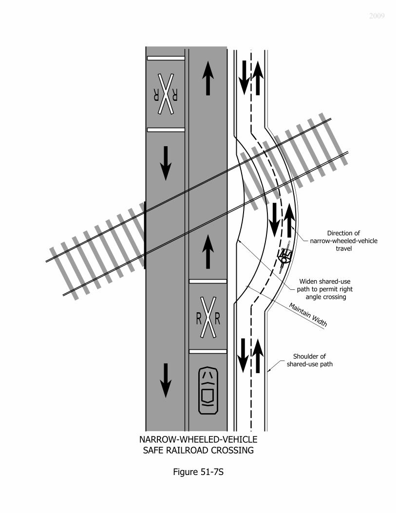
2009

2009

2009

Pavement
Classification R1 R2 or R3 R4
Eh (lx) 15 22 19
Notes: R1 = portland-cement concrete R2 = asphalt, aggregate consists of minimum 60% gravel passing 9.5-mm. sieve R3 = asphalt, rough texture (typical highway) R4 = asphalt, smooth texture The maximum uniformity ratio is 3:1. Source: AASHTO Roadway Lighting Design Guide, October 2005
MINIMUM AVERAGE MAINTAINED ILLUMINATION, Eh, BASED ON PAVEMENT CLASSIFICATION
Figure 51-7V
2009

2009

2009

Width, W, of All-Weather Surface of Turnout or Available Shoulder at
Mailbox (m)
Distance Roadside Face of Mailbox is to be Offset Behind Edge of
Turnout or Usable Shoulder (mm)
Highway Type and
Traffic Conditions
Preferred Minimum Preferred Minimum
Rural highway AADT >10,000 > 3.6 3.6
Rural highway 1,500 < AADT ≤ 10,000 3.6 3.0
Rural highway 400 < AADT ≤ 1500 3.0 2.4
Rural road AADT ≤ 400 2.4 1.8
0
Residential street without curb or all-weather shoulder 1.8 0
200 to 300
200 *
Curbed residential street Not Applicable
200 to 300 Behind Traffic
Face of Curb
150 Behind Traffic
Face of Curb
AADT = Average Annual Daily Traffic vpd = vehicles per day * If a turnout is provided, this may be reduced to zero.
SUGGESTED GUIDELINES FOR LATERAL PLACEMENT OF MAILBOXES
Figure 51-11A
2009

2009

2009

2009

2009

2009

2009

2009

Number of Lanes Design-Year AADT Single < 25,000 Two 40,000 < AADT < 45,000 Three < 60,000
DAILY SERVICE VOLUME FOR 4-LEG ROUNDABOUT
Figure 51-12H
2009

Number of Lanes Combined Vehicles per Hour
For All Approaches Single ≤ 2,000 Two ≤ 4,000 Three ≤ 7,000
HOURLY SERVICE VOLUME FOR 4-LEG ROUNDABOUT
Figure 51-12 I
2009

Geometric Parameter
Single-Lane Entry
Two-Lane Entry
Three-Lane Entry
Entry Width, E (m) 5.5 to 6.5 7.5 to 8.5 10.5 to 12 Effective Flare Length, L’ (m)
5 to 100, if required for capacity
Half Width, V (m) Travel-lane width approaching roundabout prior to
flared section, or width between lane markings Entry Radius, R (m) 17 to 27 17 to 30 20 to 30 Entry Angle, φ (deg) 16 to 30 Circulatory- Roadway Width
1.0 to 1.2 times the width of the widest roundabout entry
Exit Radius (m) 60 to 300. Exit-curve radius should be longer than entry- curve radius. R3 speed should be higher than R2 speed.
DESIGN-VALUES RANGES
Figure 51-12J
2009

Design Element
Mini- Roundabout
Urban Area Rural Area Compact Single-Lane Two-Lane Three-Lane Single-Lane Two-Lane Three-Lane
ICD, m 15 to 35 25 to 35 30 to 40 40 to 55 65 to 85 35 to 55 40 to 60 65 to 100 Splitter- Island Treatment
Raised if poss., crosswalk cut
if raised Raised, with crosswalk cut Raised and extended, with crosswalk cut
BASIC DESIGN CHARACTERISTICS
Figure 51-12K
2009

2009

Parameter Description Half Width, V (m) Width of the roadway used by approaching traffic
upstream of changes in width associated with the roundabout. It is not more than half of the total roadway width. If the facility has a marked bicycle lane, this width is to the white line. If there is no marked bicycle lane, this width is from the right-side curb face to the splitter-island curb face or marked centerline on the left side.
Entry Width, E (m) Width where it meets the inscribed circle. It is measured perpendicularly from the outside-curb face to the inside-curb face at the splitter island’s nearest point to the yield line.
Effective Flare Length, L’ (m)
Half the total distance between V and E. At L’ the approach-roadway width equals the average of V and E. The flare should be developed uniformly, without a sharp break where it starts. Full flare length equals 2L’.
Entry Radius, R (m) The outside curbs’ minimum radius of curvature at the entry.
Entry Angle, φ, (deg) Used in the empirical formula. Inscribed-Circle Diameter, ICD (m)
The basic parameter used to define a roundabout’s size. It is measured between the outer edges of the circulatory roadway.
KEY ROUNDABOUT-DESIGN PARAMETERS
Figure 51-12M
2009
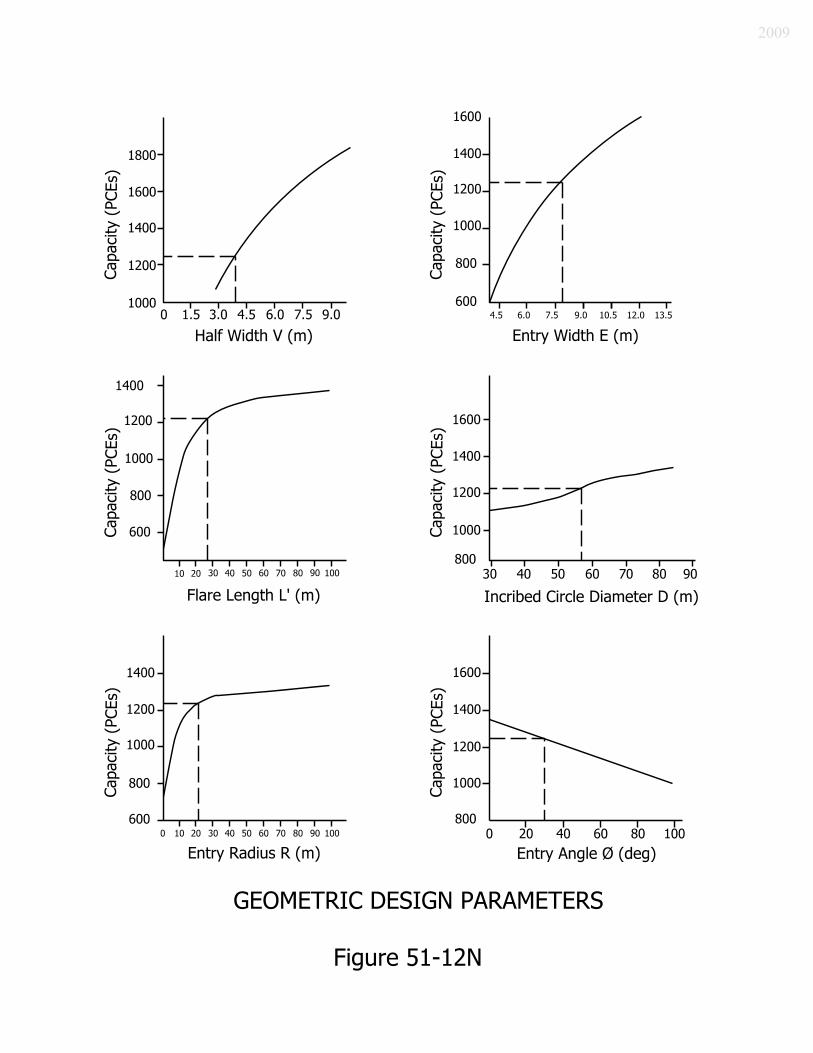
2009

2009

2009

2009

2009

2009

2009

ADVANTAGES DISADVANTAGES Vehicle speed is reduced, compared to that for another intersection type.
Vehicle traffic is yield controlled, so it does not necessarily come to a full stop. Therefore, a pedestrian can be hesitant at first to use the crosswalk.
A pedestrian has fewer conflict points that at another intersection type.
A roundabout can be unsettling to a pedestrian, depending on age, mobility, visual impairment, or ability to judge gaps in traffic.
A pedestrian is responsible for judging crossing opportunity. This is still regarded as an advantage, though it requires more alertness.
A pedestrian, at first glance, can have to adjust to roundabout operation. This includes the crosswalk location, which is behind the first stopped vehicle, or 6 m from the yield point.
The splitter-island refuge allows a pedestrian to cross entering and exiting traffic flows separately, and thus simplifies the task of crossing the roadway.
Crossing can be accomplished with less waiting time than at a signalized intersection.
ROUNDABOUT ADVANTAGES AND DISADVANTAGES FOR PEDESTRIANS
Figure 51-12U
2009

2009

2009

2009

ELEMENT SAFETY CAPACITY Wider entry Reduced Increased Longer entry radius Reduced Increased Smaller entry angle Reduced Increased Larger angle between entries Reduced Increased Longer flare length Increased Reduced Wider circulatory roadway Reduced Increased Larger inscribed-circle diameter No Change Increased
EFFECTS OF DESIGN ELEMENTS ON SAFETY AND CAPACITY
Figure 51-12Y
2009

2009

RADIUS DESCRIPTION Entry-path, R1 Minimum radius on the fastest through path prior to the yield line.
This is not the same as the entry radius. Circulating-path, R2 Minimum radius on the fastest through path around the central island. Exit-path, R3 Minimum radius on the fastest through path into the exit. Left-turn path, R4 Minimum radius on the path of a conflicting left-turn movement. Right-turn path, R5 Minimum radius on the fastest path for a right-turning vehicle.
ROUNDABOUT-RADII DESCRIPTIONS
Figure 51-12AA
2009

2009

2009

2009

2009

2009

2009

2009

2009

2009

2009

2009

2009

2009

2009

2009

2009

2009

Posted or 85th- Percentile Speed
(km/h)
Minimum- Visibility
Distance (m) 40 48 50 61 60 93 70 110 80 130 90 150
MINIMUM VISIBILITY DISTANCE
Figure 51-12WW
2009

ILLUMINATED BOLLARDS
Figure 51-12XX
2009

In considering the modern roundabout as an intersection alternative, a number of common misconceptions are too-often presumed by the public, elected officials, consultants, or transportation experts who are unfamiliar with this type of intersection control. Some facts concerning the modern roundabout are as follows: 1. The modern roundabout is significantly different than an old-style traffic circle or rotary. 2. If designed properly, a modern roundabout is safer than a traffic circle or a traditional
signalized intersection, and is often used as a calming effect to slow traffic. 3. A roundabout increases a road’s capacity as it can handle high traffic volume. It can also
require fewer lanes or reduced median width as it can reduce congestion or backups. 4. A roundabout is an effective treatment for a rural intersection where signalization may
not be appropriate. 5. A roundabout can provide adequate downstream gaps for motorists entering the roadway
from side streets or drives. 6. A roundabout is inexpensive to operate, is easily modifiable, and is low-maintenance. 7. A roundabout safely accommodates high volumes of pedestrians and bicyclists. 8. A roundabout reduces speed and causes fewer backups than stop-and-go traffic. 9. A roundabout can be landscaped to be aesthetically attractive.
THE FACTS ABOUT ROUNDABOUTS
Figure 51-12YY
2009
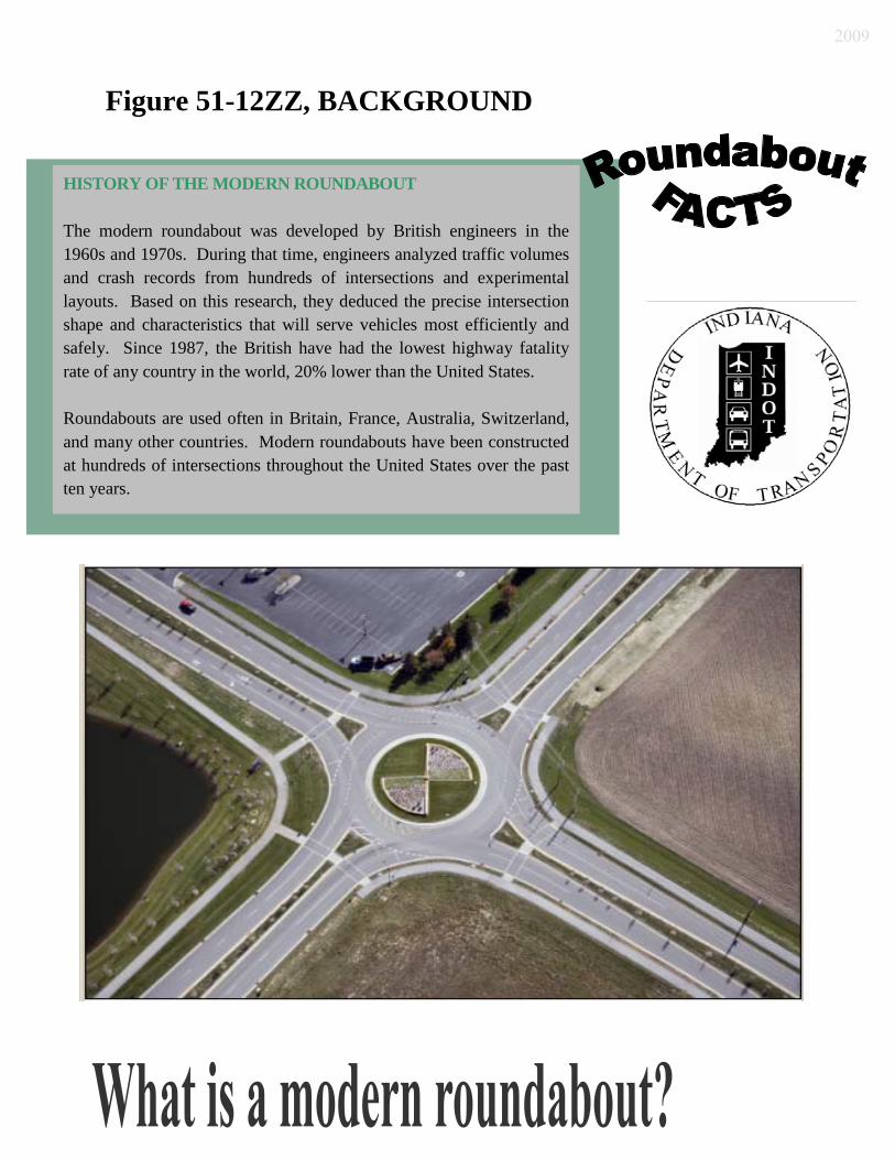
Figure 51-12ZZ, BACKGROUND
HISTORY OF THE MODERN ROUNDABOUT The modern roundabout was developed by British engineers in the 1960s and 1970s. During that time, engineers analyzed traffic volumes and crash records from hundreds of intersections and experimental layouts. Based on this research, they deduced the precise intersection shape and characteristics that will serve vehicles most efficiently and safely. Since 1987, the British have had the lowest highway fatality rate of any country in the world, 20% lower than the United States. Roundabouts are used often in Britain, France, Australia, Switzerland, and many other countries. Modern roundabouts have been constructed at hundreds of intersections throughout the United States over the past ten years.
2009

elatively new to the United States, modern roundabouts have been common throughout other parts of the world for several decades as an alternative to stop-controlled and signalized intersections. The main characteristic of a modern
roundabout is the yield-at-entry rule, meaning that traffic entering a roundabout must yield to the traffic already within the roundabout. Studies show a roundabout to be one of the safest types of intersections available compared to a signalized intersection. The introduction of a roundabout in lieu of a typical intersection, stop-controlled or signalized, has resulted in the following: 1. 40% reduction in total crashes; 2. 80% reduction in injury crashes; 3. 90% reduction in less serious injury or fatality crashes; and 4. 50% reduction in vehicle-pedestrian crashes. The vehicular crashes that do occur at a roundabout tend to be low-speed sideswipes or rear-end collisions versus typically, more serious head-on, left-turn and high-speed broadside collisions that are more frequently experienced at a signalized intersection. How does a roundabout differ from a traditional signalized intersection? A roundabout maintains efficient traffic operations by keeping vehicles moving. This results in less delay, fuel consumption, and pollution. The use of a roundabout saves money used to maintain signal equipment and provide electricity. A traffic signal tends to encourage drivers to accelerate their vehicles through the intersection in order to beat the red light, and thus results in speeds averaging as high as 60 km/h, which can ultimately increase the number of crashes, injuries, or fatalities. The comparison charts shown below show the difference in conflict points that motorists can encounter at a typical signalized intersection versus at a roundabout.
2009

How does a roundabout differ from a traffic circle? Although a traffic circle, sometimes referred to as a rotary, and a modern roundabout each utilize round circulating roadways, there are major differences in the design and operation of each type of intersection. A modern single-lane roundabout is typically smaller in diameter than a traffic circle. This can result in lower speeds and safer conditions. A single-lane roundabout’s outer diameter is 30 to 50 m, as opposed to that of a traffic circle, of 50 to 100 m or larger. Because a traffic circle is larger, it can move more vehicles at higher speeds ranging from 50 to 70 km/h. A roundabout is smaller, and thus, forces vehicles to slow to speeds ranging from 25 to 30 km/h. This difference is significant due to the following. 1. Vehicles enter a roundabout more easily due to lower speeds of 25 to 30 km/h on the
circulating roadway. 2. A traffic circle permits higher speeds making entering the circle more difficult, which can
result in more frequent and severe traffic crashes. 3. Higher speeds on a traffic circle make crossing for pedestrians more dangerous. 4. The flared approach and proper entry angle on a roundabout allows vehicles to safely
yield at the entry when merging into the circulating traffic. This allows for shorter delays as vehicles easily merge into the circle by slowing for circulating traffic, and not stopping.
5. A properly planned roundabout is designed using rigorous standards based on specific
traffic turning volume. However, the size of a traffic circle is based on land availability and distance needed to accommodate high-speed weave movements.
2009

6. A roundabouts can accommodate large vehicles, including fire trucks and other emergency vehicles.
7. Since a roundabout is smaller than a traffic circle, this results in cost savings for
construction and maintenance.
2009


