Embed Size (px)
Citation preview

Wear 266 (2009) 417–423
Contents lists available at ScienceDirect
Wear
journa l homepage: www.e lsev ier .com/ locate /wear
Characterisation of ZrO2 layers deposited on Al2O3 coating
Suzana Jakovljevic a,∗, Willy Hendrixb, Danny Havermansb, Jan Meneveb
a Faculty of Mechanical Engineering and Naval Architecture, Ivana Lucica 1, 10000 Zagreb, Croatiab VITO Materials Technology Centre, Mol, Belgium
a r t i c l e i n f o
Article history:Received 1 October 2007Received in revised form 29 February 2008Accepted 7 April 2008Available online 13 June 2008
Keywords:
a b s t r a c t
The paper describes a method of coating combining two different layer types. The first layer is Al2O3
produced by plasma spraying with a thickness of around 200 �m which was deposited on a stainless steelsubstrate. Subsequently, ZrO2 layers were deposited on to the Al2O3 coating by a sol–gel process using adip coating technique. The dip coating process was repeated in order to see the influence of the numberof ZrO2 layers. Moreover, the effect of annealing temperature was investigated. In order to study theirtribological behaviour, the coatings were subjected to micro-scale abrasion, scratch testing and ball-on-disc tests. The result shows that sol–gel ZrO2 top layers reduce friction and enhance the wear resistance
AbrasionSol–gelThermal spray coatingsWS
of the coating system.© 2008 Elsevier B.V. All rights reserved.
1
fiacruiipifstsmp
ctstt
ppaictawtomrtre
apmb
0d
ear testingcratch testing
. Introduction
Plasma spraying is a well-established and versatile techniqueor producing coatings. It is commonly used in applications requir-ng wear and corrosion resistant surfaces, i.e., bearings, valve seats,ircraft engines, mining machinery and farm equipment [1]. Oxideeramics such as Al2O3 ceramic coatings are widely used as wear-esistant coatings. Atmospheric plasma spraying is a commonlysed method for preparing alumina coatings [2–4]. Plasma spray-
ng utilizes an electric arc to melt the coating material and to propelt as a high-velocity spray on to the substrate. In this process gasesassing through the nozzle are ionised by an electric arc produc-
ng a high temperature stream of plasma. The coating material ised to the plasma flame where it melts and is propelled to the sub-trate. The very high particle velocity in plasma spraying comparedo flame spraying results in very good adhesion of the coating to theubstrate and high coating density. A sprayed alumina coating nor-ally has a highly lamellar microstructure with small interlamellar
ores and some larger pores [1,5].Several techniques have been developed for the deposition of
eramic thin films [6]. These are generally classified into three
ypes: physical vapour deposition (PVD), chemical vapour depo-ition (CVD), and chemical solution deposition (CSD). The CSDechniques have some advantages compared to the PVD and CVDechniques in terms of simplicity, composition control, low cost, low∗ Corresponding author. Tel.: +385 1 6168391; fax: +385 1 6157126.E-mail address: [email protected] (S. Jakovljevic).
2
2
(s
043-1648/$ – see front matter © 2008 Elsevier B.V. All rights reserved.oi:10.1016/j.wear.2008.04.041
rocessing temperature, etc. For these reasons, ceramic thin filmsrepared by CSD techniques are being used in many technologicalpplications [7–9]. The most popular amongst the CSD techniquess the sol–gel method. This method involves the synthesis of a pre-ursor solution followed by the deposition of the solution on tohe substrate, and finally a sintering step to promote densification,dhesion, and crystallisation. The sol–gel method has been usedith success for the processing of a wide variety of oxide ceramic
hin films. In this context, there has been great interest in the devel-pment of thin films made of Y2O3-stabilised ZrO2 (YSZ), one of theost widely used structural ceramics. One of the objectives is to
eproduce the mechanical properties of the bulk YSZ ceramics inhe thin film architecture. The coatings (ZrO2) can be effective ineducing the high temperature oxidation and resistance to thermalxposure in harsh environment.
The target of this work is to verify if sol–gel coating may beviable method to seal the pores in sprayed ceramic coatings. Inarticular, the effect of treatment procedures on tribological andechanical properties is studied using a selection of different tri-
ological tests.
. Experimental
.1. Materials and specimen preparation
In this work, eight stainless steel samples EN X22Cr MoV12125 mm × 18 mm × 18 mm, hardness 263HV0.2) were used as a sub-trate for the application of Al2O3 and ZrO2 coatings.

418 S. Jakovljevic et al. / Wear 266 (2009) 417–423
Fig. 1. Morphology of samples annealed at three different temperatures (a) 400 ◦C, (b) 700 ◦C, and (c) 1000 ◦C.
F : poret
2
ca
i
--
TT
D
AAAA
-
ig. 2. Cross-section of coated samples and pores at the surface of the Al2O3 coatinghat are not completely covered (sample annealed at 1000 ◦C and 4 layers of ZrO2).
.1.1. Plasma sprayingThe complete procedure of plasma coating on the substrate was
arried out at the Swiss Federal Laboratories for Materials Testingnd Research - EMPA THUN, Switzerland.
Conditions of plasma spraying for all samples were the follow-ng:
powder: Al2O3particle size:
able 1hickness of ZrO2 top-coatings
escription Thickness of ZrO2 coating (�m)
l2O3 + 4 layers of ZrO2 coating, 1000 ◦C 0.4l2O3 + 4 layers of ZrO2 coating, 700 ◦C 0.5l2O3 + 8 layers of ZrO2 coating, 700 ◦C 1.2l2O3 + 4 layers of ZrO2 coating, 400 ◦C 0.6
----
TH
S
4771
s covered by the ZrO2 layers (sample annealed at 700 ◦C and 4 layers of ZrO2), pores
D90 = − 25 �m (90% of all particles are below (i.e., −) 25 �m);D10 = + 5 �m (all particles, except 10%, are above (i.e., +) 5 �m);
substrate pre-treatment: roughness Ra = 5.5–6 �m (before spray-ing);
spraying parameters: spraying distance d = 100 mm;electrical energy: P = 45.3 kW;plasma gas: argon and hydrogen (∼1:4);chamber pressure: = atmospheric;able 2ardness and elastic modulus of ZrO2 coating
ample Hardness H (GPa) Elastic modulus E (GPa)
00 ◦C, 4 layers of ZrO2 coating 2.8 ± 1.0 78 ± 2500 ◦C, 4 layers of ZrO2 coating 3.7 ± 1.6 90 ± 4200 ◦C, 8 layers of ZrO2 coating 4.5 ± 1.5 106 ± 39000 ◦C, 4 layers of ZrO2 coating 3.1 ± 1.2 82 ± 42

S. Jakovljevic et al. / Wear 266 (2009) 417–423 419
he F–h
-
--
f
2
tMt
ltayA
fcp
FZ
ipTm(iuaitrl
2
toc
Fig. 3. T
thermal history during spraying: preheating passages (2×) up to330 ◦C;coating passages (50×) up to 400–450 ◦C;coating thickness: t = approx. 200 �m.
The roughness has been measured using laboratory equipmentor measuring roughness with probe.
.1.2. Preparation of ZrO2 gelThe complete procedure of preparing the gel and depositing of
he coating on the substrate was carried out at the Department ofaterials, Faculty of Mechanical Engineering and Naval Architec-
ure, University of Zagreb.In this work, Zr-n-butoxide, Zr(O-nC4H9)4, stabilised with acety-
acetone was used as the Zr-precursor, and partial stabilisation ofhe tetragonic, i.e., cubic modification of ZrO2 was promoted bydding 3%Y2O3 which was added to the system in the form ofttrium acetate hydrate, Y(CH3COO)3·4H2O, dissolved in propanol.n aqueous solution of nitric acid was added as well.
The substrates with Al2O3 coating were polished to attain a sur-ace roughness (Ra) of around 0.15 �m. Then, samples were dipoated by being immersed in the solution for 5 min, and thenulled out at a constant rate of 2 mm/s. Subsequently, the cur-
ig. 4. The scratch track of ZrO2 coating (sample annealed at 700 ◦C, 8 layers ofrO2).
e
dat
Fs
curve.
ng was performed in air and at a temperature of 120 ◦C over aeriod of 1 h, causing the volatile media to escape from the gel.he crystallisation of the ZrO2 was performed by means of ther-al treatment at three temperatures 400 ◦C, 700 ◦C and 1000 ◦C
non-controlled atmosphere), over a period of 2 h each in anneal-ng furnace with digital regulation. The temperature was rampedp at a rate of approximately 6 ◦C/min, and subsequent cooling atrate of approximately 2 ◦C/min. The procedures of dipping, dry-
ng and thermal treatment at each temperature were repeated fourimes. At 700 ◦C the procedures were repeated four and eight times,espectively, in order to determine the influence of the number ofayers.
.2. Characterisation
All coatings have been characterised using the scanning elec-ron microscopy (SEM). The coating morphology was studied bothn plane surfaces as well as on ground and polished coatingross-sections. The porosity as well as the coating thickness was
stimated using the ground and polished coating cross-sections.The coating hardness and elastic modulus were assessed usingepth-sensing indentation (NanoTest 600 Micro Materials Ltd. withBerkovich indenter), on the olane coating surfaces. As the top layer
hickness was only 400–500 nm, the tests were carried out using a
ig. 5. Start of ZrO2 coating delamination from the underlying Al2O3 coating for theystem annealed at 400 ◦C, 4 layers.
420 S. Jakovljevic et al. / Wear 266 (2009) 417–423
Table 3Scratch test results on the different coating systems (typical scratching errors amount to 20%)
Sample LC1 (N) LC2 (N) LC3 (N)
Without ZrO2 coating 48 ± 2.8 50 ± 1.1 95 ± 1.5400 ◦C, 4 layers of ZrO2 coating 10 ± 1.1 55 ± 6.1 92 ± 3.1400 ◦C, 4 layers of ZrO2 coating 3 ± 1.6 47 ± 4.8 –700 ◦C, 4 layers of ZrO2 coating 45 ± 1.2 54 ± 0.5 83 ± 4.0700 ◦C, 4 layers of ZrO2 coating 43 ± 1.5 60 ± 1.9 78 ± 0.9700 ◦C, 8 layers of ZrO2 coating 43 ± 3.6 57 ± 2.5 85 ± 3.1700 ◦C, 8 layers of ZrO2 coating 44 ± 5.3 58 ± 0.6 79 ± 0.51000 ◦C, 4 layers of ZrO2 coating 33 ± 1.8 57 ± 4.3 84 ± 3.91
W d critil
sT
Rolttpmu
uwr6
Fs
woffo
aIs1aa
000 ◦C, 4 layers of ZrO2 coating 41 ± 2.8
here LC1 - first critical load, N, corresponding to first cracking events, LC2 - seconoad, N, corresponding to transverse semi-circular cracks.
et limit indentation depth of 50 nm to minimise substrate effects.he applied load (Fmax) varied in the range of 0.25–1 mN.
Scratch testing of the coatings was performed using a CSEMevetest scratch tester with a Rockwell indenter having a radiusf 200 �m. Testing was performed on coating surfaces withoads continuously increasing from 0 to 100 N and the indenterransverse speed was 10 mm/min. The test was repeated threeimes on each sample. The critical loads were determined byost-test examination with an optical microscope. In order to deter-ine the exact locus of interfacial failure, SEM examination was
sed.Micro-abrasion resistance has been determined by ball cratering
sing a TE66 Plint, Micro-scale abrasion tester. The test conditionsere: normal load of 0.2 N; ball diameter of 25 mm; ball mate-
ial - 100Cr6 steel; ball rotational speed of 30 revolutions/min;�m SiC in H2O abrasive slurry. Abrasive wear tests of specimens
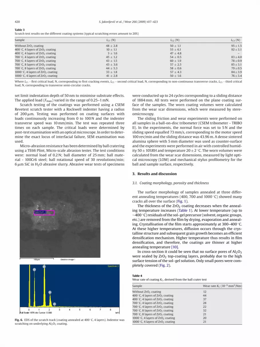
ig. 6. EDS of the scratch track (coating annealed at 400 ◦C, 4 layers). Indentor wascratching on underlying Al2O3 coating.
iccb
3
3
ec
i∼eiAtdda
wsp
TW
S
W44777711
50 ± 1.6 76 ± 3.4
cal load, N, corresponding to non-continuous transverse cracks, LC3 - third critical
ere conducted up to 24 cycles corresponding to a sliding distancef 1884 mm. All tests were performed on the plane coating sur-ace of the samples. The worn coating volumes were calculatedrom the wear scar dimensions, which were measured by stere-microscopy.
The sliding friction and wear experiments were performed onll samples in a ball-on-disc tribometer (CSEM tribometer – TRIBOI). In the experiments, the normal force was set to 5 N and theliding speed equalled 73 mm/s, corresponding to the motor speed00 rev/min and the sliding distance was 43.96 m. A dense sinteredlumina sphere with 5 mm diameter was used as counter-surfacend the experiments were performed in air with controlled humid-ty 50 ± 10%RH and temperature 20 ± 2 ◦C. The worn volumes werealculated from the wear scar dimensions, measured by light opti-al microscopy (LOM) and mechanical stylus profilometry for theall and sample surface, respectively.
. Results and discussion
.1. Coating morphology, porosity and thickness
The surface morphology of samples annealed at three differ-nt annealing temperatures (400, 700 and 1000 ◦C) showed manyracks all over the surface (Fig. 1).
The thickness of the ZrO2 coating decreases when the anneal-ng temperature increases (Table 1). At lower temperature (up to400 ◦C) residuals of the sol–gel precursor (solvent, organic groups,tc.) are removed from the film by drying, evaporation and anneal-ng. Crystallisation of the film starts approximately at 300–400 ◦C.t these higher temperatures, diffusion occurs through the crys-
alline structure and subsequent grain growth becomes an efficientensification mechanism. Higher temperature thus results in filmensification, and therefore, the coatings are thinner at higher
nnealing temperature [10].In cross-section it could be seen that no surface pores of Al2O3ere sealed by ZrO2 top-coating layers, probably due to the high
urface tension of the sol–gel solution. Only small pores were com-letely covered (Fig. 2).
able 4ear rate of coating KC, derived from the ball crater test
ample Wear rate KC (10−9 mm3/Nm)
ithout ZrO2 coating 1200 ◦C, 4 layers of ZrO2 coating 4400 ◦C, 4 layers of ZrO2 coating 3700 ◦C, 4 layers of ZrO2 coating 2800 ◦C, 4 layers of ZrO2 coating 2200 ◦C, 8 layers of ZrO2 coating 3200 ◦C, 8 layers of ZrO2 coating 21000 ◦C, 4 layers of ZrO2 coating 20000 ◦C, 4 layers of ZrO2 coating 21

S. Jakovljevic et al. / Wear 266 (2009) 417–423 421
nd de
3
tg
ntTcnsbd
3
ws
yd
w
Fig. 7. The wear scar (a) a
.2. Nanoindentation
Nanoindentation results of all samples are shown in Table 2 andhe curve F–h (force versus penetration depth) of one sample isiven in Fig. 3.
Observing the samples with four layers of ZrO2, the lowest hard-ess value was obtained for the sample annealed at 400 ◦C, whilehe sample annealed at 700 ◦C showed the highest hardness value.he difference between these two values is ∼24%. The sample thatontains eight layers of ZrO2 coating has the highest value of hard-
ess and the difference in hardness between this sample and theample with four layers of ZrO2 is ∼19%. Similar conclusions cane made for the elastic modulus. These results match the usualissipation of this method [11].Fig. 8. Worn surface of the alumina ball, with surrounding ZrO2 debr.
uoiAf
tail A from wear scar (b).
.3. Scratch testing
Examination of the scratched surfaces showed that crackingith subsequent delamination occurred along the edges of all
cratches (Fig. 4). The results are shown in Table 3.For the samples annealed at 400 ◦C, the first critical load LC1
ielded the lowest value and at that load the upper layer (ZrO2)elaminated from the underlying Al2O3 coating (Fig. 5).
The first critical load LC1 is higher for other samples and it isithin the same range for these other samples. Moreover, the val-es of LC2 and LC3 are very similar for all samples. SEM examinationf the scratched surfaces, including the sample without ZrO2 coat-ng, revealed that the corresponding failure events occurred at the
l2O3/substrate interface instead of the ZrO2/Al2O3 coating inter-ace (Fig. 6).
Fig. 9. The ball height segment.

422 S. Jakovljevic et al. / Wear 266 (2009) 417–423
urve
3
cd
(
S
wtK
TR
S
W44777711
W
Fig. 10. Representative friction coefficient c
.4. Micro-abrasion
A ball is used to produce a spherical crater in the surface ofoating and the crater volume is estimated from measuring theiameter using an optical microscope, Fig. 7.
By assuming the Archard’s low for a coating–substrate systemin this case coating–coating) one can use [12]:
N = VC
KC+ VS
KS, (1)
olTs
able 5esults of ball-on-disc friction and wear test
ample Wk (10−6 mm3/Nm)
ithout ZrO2 coating 0.0900 ◦C, 4 layers of ZrO2 coating 0.3000 ◦C, 4 layers of ZrO2 coating 0.1000 ◦C, 4 layers of ZrO2 coating 0.0400 ◦C, 4 layers of ZrO2 coating 0.1300 ◦C, 8 layers of ZrO2 coating 0.1000 ◦C, 8 layers of ZrO2 coating 0.46000 ◦C, 4 layers of ZrO2 coating 0.11000 ◦C, 4 layers of ZrO2 coating 0.61
here Wk - wear rate of ball, Wu - wear rate of disc (sample), t∗C - time for getting trough
for samples annealed at 400 ◦C and 700 ◦C.
here S is the sliding distance, m; N the applied load, N; VC and VShe wear volumes of coating and substrate, mm3, respectively, andC and KS are specific wear rates of coating and substrate.
Results of all samples in micro-abrasion test are given in Table 4.The lowest value of wear rate is observed for the sample with-
ut ZrO2 coating. Comparing the samples with ZrO2 coating, theowest value of wear rate was for the samples annealed at 1000 ◦C.he surface of coating annealed at this temperature is more cohe-ive than the surface of coatings annealed at 400 and 700 ◦C, and
Wu (10−6 mm3/Nm) � t∗C (min)
8 0.65 –31 0.22 7.0061 0.22 0.50
132 – 0.00134 0.25 0.05
76 0.23 0.1095 – 0.0022 0.23 6.0046 0.22 0.50
coating.

ear 2
taisso
3
looataT[
D
B
wpos
a
K
wa
t
wpsttlancyo6
4
2
3
4
A
rfft
R
[
[
S. Jakovljevic et al. / W
herefore, has lower wear rate. However, the ZrO2 coating waslmost immediately worn out in these tests. Clearly, this methods too aggressive to study the abrasive wear behaviour of such thinol–gel ZrO2 top layers. Better results might be obtained using aofter abrasive like SiO2, with lower hardness comparable to thatf ZrO2.
.5. Ball-on-disc
In sliding of all samples with ZrO2 top-coating against mono-ithic Al2O3 a significant decrease in coefficient of friction wasbtained. The friction coefficient was higher for the samples with-ut ZrO2 coating—Table 5. The surface of the alumina ball as wells the surface of samples was worn in all cases. At the edges ofhe ball wear scar debris of the ZrO2 coating were found (Fig. 8),nd they were removed from the sliding track as wear fragments.he disc volume loss and the ball volume loss are calculated by13]:
isc volume loss = 2�RA (mm3) (2)
all volume loss = �h2(
r − h
3
)(mm3) (3)
here A is cross-sectional area of the wear track measured in fourlaces around the track by stylus profilometer, mm2; R is radiusf wear track, mm; r the ball radius, mm; and h the ball heightegment, mm (Fig. 9).
The wear rate of the ball and the wear rate of the disc (sample)re calculated by the standard method for sliding wear:
= V
2r�N(mm3/Nm) (4)
here V is disc volume loss or the ball volume loss, mm3; and N thepplied load, N.
All results are given in Table 5, and two representative frictionracks are given in Fig. 10.
The higher wear rate was obtained for the samples coatedith ZrO2 layers than for the sample without it. It is not sur-rising in view of the results from abrasion which featured theame condition. All samples have almost identical values of fric-ion, only for the samples annealed at 700 ◦C the ball worehrough the coating immediately after the start of the test regard-ess of sol–gel coating parameters (see Fig. 10b). The samplennealed at 400 ◦C was the only sample in which the ball did
ot wear through the coating and the value of friction coeffi-ient stood at 0.22 (see Fig. 10a). All samples with ZrO2 layersielded a lower friction coefficient than did the sample with-ut ZrO2 layers. The difference in friction amounted to over0%.[
[
66 (2009) 417–423 423
. Conclusions
The following conclusions can be drawn from the present work.
1. Stainless steel substrates can be duplex coated with Al2O3plasma spray coatings base layers and sol–gel ZrO2 top-coating.
. ZrO2 top-coatings have to be annealed at sufficiently high tem-perature to insure better integrity of coating.
. ZrO2 coatings decrease the wear resistance in micro-abrasiontests and ball-on-disc test.
. The coefficient of friction is lower for Al2O3 samples top-coatedwith ZrO2 layers.
cknowledgements
The authors gratefully acknowledge the Swiss Federal Laborato-ies for Materials Testing and Research - EMPA THUN, Switzerlandor plasma spraying of samples and VITO, the Flemish Instituteor Technological Research, Mol, Belgium for characterisation andribological testing.
eferences
[1] K. Holmberg, H. Ronkainen, A. Matthews, Tribology of thin coatings, CeramicsInternational 26 (2000) 787–795.
[2] R. Westergard, S. Hogmark, P. Vuoristo, Tribological properties of sprayed alu-mina coatings sealed by electro-deposition of Cu, Wear 256 (2004) 1163–1175.
[3] http://www.sulzermetco.com/eprise/Sulzermetco/Sites/Products/About-ThermalSpray/airplasma.html.
[4] C.J. Li, G.J. Yang, A. Ohmori, Relationship between particle erosion and lamel-lar microstructure for plasma-sprayed alumina coatings, Wear 260 (2006)1166–1172.
[5] R. Westergard, L.C. Erickson, N. Axen, H.M. Hawthorne, S. Hogmark, The ero-sion and abrasion characteristics of alumina coatings plasma sprayed underdifferent spraying conditions, Tribology International 31 (1998) 271–279.
[6] A.L. Ortiz, A. Diaz-Parralejo, O. Borrero-Lopez, F. Guiberteau, Effect of ion nitrid-ing on the crystal structure of 3 mol% Y2O3-doped ZrO2thin-films prepared bythe sol–gel method, Applied Surface Science 252 (2006) 6018–6021.
[7] S. Ahmaniemi, P. Vuoristo, T. Mantyla, C. Gualco, A. Bonadei, R. Di Maggio, Ther-mal cycling resistance of modified thick thermal barrier coatings, Surface andCoatings Technology 190 (2005) 378–387.
[8] Y. Chen, W. Liu:, Preparation and tribological properties of sol–gel zirconia thinfilms stabilized with ceria, Materials Letters 55 (2002) 407–413.
[9] P. Lenormand, D. Caravaca, C. Laberty-Robert, F. Anasart, Thick films of YSZelectrolytes by dip-coating process, Journal of European Ceramic Society 25(2005) 2643–2646.
10] A. Dıaz-Parralejo, R. Caruso, A.L. Ortiz, F. Guiberteau, Densification and porosityevaluation of ZrO2-3 mol% Y2O3 sol–gel thin films, Thin Solid Films 458 (2004)92–97.
11] K. Jang, H. Matsubara, Hardness and Young’s modulus of nanoporous EB-PVD
YSZ coatings by nanoindentation, Journal of Alloys and Compounds 402 (2005)237–241.12] M.G. Gee, A. Gant, I. Hutchings, R. Bethke, K. Schiffman, K. Van Acker, S. Poulat, Y.Gachon, J. von Stebut, Progress towards standardisation of ball cratering, Wear255 (2003) 1–13.
13] http://www.csm-instruments.com/frames/bullet/app18/appbull18.pdf.html.


