Embed Size (px)
Citation preview

Chemical & Industrial Piping Systems
For over 60 years NOV Fiber Glass Systems has been the industry leader in the Chemical & Industrial market with composite piping systems designed to provide chemical and abrasion resistance. Our extensive line of products has grown to include the leading trade names in this market, creating an unequaled worldwide offering to battle corrosion and erosion.
This globally manufactured group of products has become the world’s most widely trusted product offering founded upon two essential elements: third party verified ASTM qualifications and decades of experience in tough services. The third party testing provides our customers with confidence that the physical properties we publish are based on test data, not theory. The wide scope of applications within such a diverse market provides our customers confidence that the products’ reliability extends beyond rigorous testing into the real world of actual long-term performance in applications where upset conditions and thermal cycling are reality.
Typical applications range from potable water to brine and from harsh chemical feed, waste and vent applications to process lines in nearly every sector of industry imaginable: power generation, metals & minerals, food service, LNG, automotive, aerospace & defense, biotech and pharmaceutical, university and district heating and cooling, general, fine & specialty chemical process industry, petroleum refining, pulp & paper, municipal and industrial waste water treatment.
Filament Wound Piping Systems
For more than 40 years, Green Thread®, Red Thread® and Bondstrand® products have been used in potable water, firewater mains, saltwater cooling, saltwater disposal, heating & cooling water systems and wastewater systems across the auto-motive, power generation, municipal, institutional and aerospace applications.
Centrifugally Cast Piping Systems
With a 100% resin corrosion barrier, Centricast® pip-ing systems provide the most chemically resistant pipe in the market. These products have 60 years of successful history in the steel pickling, chloro-alkali, pharmaceutical, power generation and chemical processing industries.
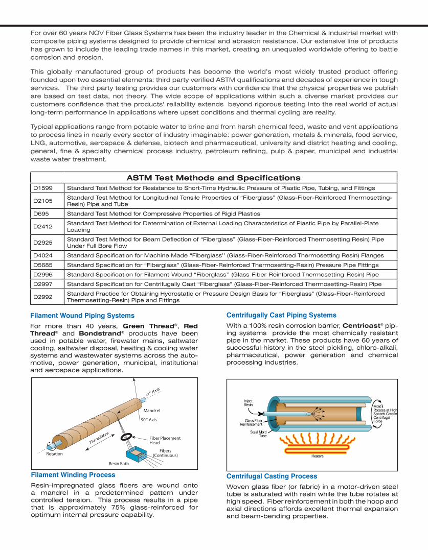
Filament Winding Process
Resin-impregnated glass fibers are wound onto a mandrel in a predetermined pattern under controlled tension. This process results in a pipe that is approximately 75% glass-reinforced for optimum internal pressure capability.
Translates
Resin Bath
Fibers(Continuous)Rotation
Fiber PlacementHead
90° Axis
Mandr el
0° Axis
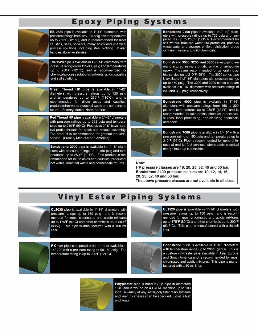
Centrifugal Casting Process
Woven glass fiber (or fabric) in a motor-driven steel tube is saturated with resin while the tube rotates at high speed. Fiber reinforcement in both the hoop and axial directions affords excellent thermal expansion and beam-bending properties.
ASTM Test Methods and SpecificationsD1599 Standard Test Method for Resistance to Short-Time Hydraulic Pressure of Plastic Pipe, Tubing, and Fittings
D2105Standard Test Method for Longitudinal Tensile Properties of “Fiberglass” (Glass-Fiber-Reinforced Thermosetting-Resin) Pipe and Tube
D695 Standard Test Method for Compressive Properties of Rigid Plastics
D2412Standard Test Method for Determination of External Loading Characteristics of Plastic Pipe by Parallel-Plate Loading
D2925Standard Test Method for Beam Deflection of “Fiberglass” (Glass-Fiber-Reinforced Thermosetting Resin) Pipe Under Full Bore Flow
D4024 Standard Specification for Machine Made “Fiberglass’’ (Glass-Fiber-Reinforced Thermosetting Resin) Flanges
D5685 Standard Specification for “Fiberglass” (Glass-Fiber-Reinforced Thermosetting-Resin) Pressure Pipe Fittings
D2996 Standard Specification for Filament-Wound “Fiberglass’’ (Glass-Fiber-Reinforced Thermosetting-Resin) Pipe
D2997 Standard Specification for Centrifugally Cast “Fiberglass” (Glass-Fiber-Reinforced Thermosetting-Resin) Pipe
D2992Standard Practice for Obtaining Hydrostatic or Pressure Design Basis for “Fiberglass” (Glass-Fiber-Reinforced Thermosetting-Resin) Pipe and Fittings
Red Thread HP pipe is available in 2”-42” diameters with pressure ratings up to 362 psig and tempera-tures up to 210°F (99°C) Pipe sizes 2”-6” have spe-cial profile threads for quick and reliable assembly. The product is recommended for general industrial service. (Primary Market-North America)
RB-2530 pipe is available in 1”-14” diameters, with pressure ratings from 125-300 psig and temperatures up to 250°F (121°C), and is recommended for most caustics, salts, solvents, many acids and chemical process solutions, including steel pickling. It also handles abrasive slurries.
RB-1520 pipe is available in 1½”-14” diameters, with pressure ratings from 125-300 psig and temperatures up to 250°F (121°C), and is recommended for chemical process solutions, solvents, acids, caustics and salt solutions.
Green Thread HP pipe is available in 1”-42” diameters with pressure ratings up to 725 psig and temperatures up to 230°F (110°C), and is recommended for dilute acids and caustics, produced/hot water, industrial waste and condensate return. (Primary Market-North America)
Bondstrand 4000 pipe is available in 1”-16” diameters with pressure ratings from 150 to 300 psi and temperatures up to 250°F (121°C) and is recommended for acid drains, chemical processes, slurries, food processing, non-oxidizing chemicals and acids.
Bondstrand 3000, 3200, and 3300 series piping are manufactured using aromatic amine or anhydride epoxy. They are recommended for general indus-trial service up to 210°F (99°C). The 3000 series pipe is available in 2”-16” diameters with pressure ratings up to 450 psig. The 3200 and 3300 series pipe are available in 8”-16” diameters with pressure ratings of 200 and 300 psig, respectively.
E p o x y P i p i n g S y s t e m s
V i n y l E s t e r P i p i n g S y s t e m s
CL2030 pipe is available in 1”-14” diameters with pressure ratings up to 150 psig and is recom-mended for most chlorinated and acidic mixtures up to 175°F (80°C) and other chemicals up to 200°F (93°C). This pipe is manufactured with a 100 mil liner.
F-Chem pipe is a special order product available in 14”-72” with a pressure rating of 50-150 psig. The temperature rating is up to 225°F (121°C).
Bondstrand 5000 is available in 1”-16” diameters with temperature range up to 200°F (93°C). This is a custom vinyl ester pipe available in Asia, Europe and South America and is recommended for most chlorinated and acidic mixtures. This pipe is manu-factured with a 50 mil liner.
Polyplaster pipe is hand lay up pipe in diameters 1”-8” and is wound on a C.A.M. machine up to 100 inch. A variety of vinyl ester/polyester resin systems and liner thicknesses can be specified. Joint is butt and wrap.
CL1520 pipe is available in 1”-14” diameters with pressure ratings up to 150 psig and is recom-mended for most chlorinated and acidic mixtures up to 175°F (80°C) and other chemicals up to 200°F (93.3°C). This pipe is manufactured with a 50 mil liner.
Note: HP pressure classes are 16, 20, 25, 32, 40 and 50 bar. Bondstrand 2400 pressure classes are 10, 12, 14, 16, 20, 25, 32, 40 and 50 bar. The above pressure classes are not available in all sizes.
Bondstrand 7000 pipe is available in 2”-16” with a pressure rating of 150 psig and temperatures up to 210°F (99°C). Pipe is recommended for general in-dustrial and jet fuel services where static electrical charge build-up is possible.
Bondstrand 2000 pipe is available in 1”-16” diam-eters with pressure ratings up to 450 psig and tem-peratures up to 250°F (121°C). This product is rec-ommended for dilute acids and caustics, produced/hot water, industrial waste and condensate returns.
Bondstrand 2400 pipe is available in 2”-40” diam-eters with pressure ratings up to 725 psig and tem-peratures up to 250°F (121°C). Recommended for salt waters, brackish water, fire protection, potable/ waste water and sewage, oil field reinjection, crude oil transmission and mild chemicals.
A d v a n c e d P e r f o r m a n c e S p e c i a l t y P r o d u c t s
Z-Core products are a propriety thermosetting resin capable of enduring severe environments such as concentrated sulfuric acid, hydrochloric acid, hot caustic and mixtures of acids, solvents and bases. Z-Core is an excellent alternative to fluoropolymer lined pipe and expensive alloys. Temperature ratings up to 275°F and diameters from 1” to 8”.
Ceram Core products are made from high-alumina ceramic with an epoxy exterior making it an ideal material for extreme abrasive and corrosive environ-ments. Applications include bottom ash, ore slurries, mine tailings, salt slurries, dredge lines, wood pulp, concrete slurries and Diatomaceous Earth. Diam-eters are available from 6” to 16”.
Silver Streak products are made for tough abra-sive applications such as Flue Gas Desulfuriza-tion. This product is available from 1” through 48” diameters with a pressure rating up to 225 psig and a temperature rating up to 225°F (107°C).
Down Hole Tubing & Casing products are capable of pressures up to 3500 psi and temperatures of 210° F for corrosive applications like CO2, saltwa-ter/brine and other such services for methane gas, chemical disposal or simply brackish water wells. Diameters are available from 1 ½” through 9” for pressures up to 3500 psi and diameters up to 24” for lower pressure brackish/RO water wells.
Fiberspar LinePipe products are continuous spoolable piping systems with HDPE liners over wrapped with a glass fiber epoxy thermoset ma-trix for corrosive and abrasive applications up to 2500 psi and up to 180°F. Diameters are available in 2 ½” through 6 ½ “ and continuous lengths up to 2 miles. A down hole version is also available.
High Pressure products are available in sizes rang-ing from 1½” through 36” for pressures of 150 psi up to 4000 psi at temperatures up to 210°F. Typical applications include water, hydraulic fluid, and other difficult industrial applications in a variety of indus-tries including severe elevation changes.
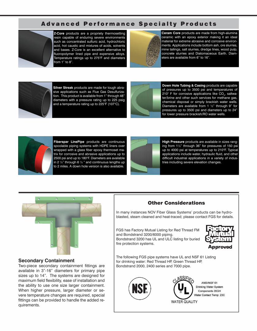
Secondary ContainmentTwo-piece secondary containment fittings are available in 3”-16” diameters for primary pipe sizes up to 14”. The systems are designed for maximum field flexibility, ease of installation and the ability to use one size larger containment. When higher pressure, larger diameter or se-vere temperature changes are required, special fittings can be provided to handle the added re-quirements.
Other Considerations
In many instances NOV Fiber Glass Systems’ products can be hydro- blasted, steam cleaned and heat-traced; please contact FGS for details.
FGS has Factory Mutual Listing for Red Thread FM and Bondstrand 3200/6000 piping. Bondstrand 3200 has UL and ULC listing for buried fire protection systems.
The following FGS pipe systems have UL and NSF 61 Listing for drinking water: Red Thread HP, Green Thread HP, Bondstrand 2000, 2400 series and 7000 pipe.
J o i n i n g S y s t e m s
Taper x Taper - Matched taper joint secured with epoxy adhesive. Self-locking feature resists movement, facilitating joining on RT/GT HP 16/20/25 bar piping without await-ing adhesive cure.
T.A.B.™ - Threaded and bonded joining system. Double-lead threads provide quick and secure adhe-sive connections. Available for 2” through 6” Red Thread pipe sizes.
Flanged - Available for all pip-ing systems and diameters; factory assembled or shipped loose for assembly in the field.
Butt & Wrap - Plain end pipe or pipe and fittings butted together and wrapped with multiple layers of resin-saturated mat or woven rov-ing. Use with all piping systems.
Socket Joint - Adhesive bond-ed straight socket joint with positive stops. This is the standard for Centricast piping systems.
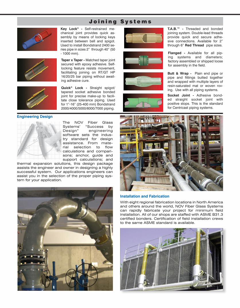
Installation and Fabrication
With eight regional fabrication locations in North America and others around the world, NOV Fiber Glass Systems can rapidly fabricate your project for minimum field installation. All of our shops are staffed with ASME B31.3 certified bonders. Certification of field installation crews to the same ASME standard is available.
Engineering Design
The NOV Fiber Glass Systems’ “Success by Design” engineering software sets the indus-try standard for design assistance. From mate-rial selection to flow calculations and compari-sons; anchor, guide and support calculations; and
thermal expansion solutions, this design package assists the engineer and owner in designing a highly successful system. Our applications engineers can assist you in the selection of the proper piping sys-tem for your application.
Key Lock® - Self-restrained me-chanical joint provides quick as-sembly by means of locking keys inserted between bell and spigot. Used to install Bondstrand 2400 se-ries pipe in sizes 2” through 40” (50 - 1000 mm).
Quick® Lock - Straight spigot/tapered socket adhesive bonded joint for precise make-up to facili-tate close tolerance piping. Used for 1”-16” (25-400 mm) Bondstrand 2000/4000/5000/6000/7000 piping.
Middle EastDubai, United Arab EmiratesPhone: 971 4 886 5660
Asia, Pacific RimSingaporePhone: 65 6861 6118
Harbin ChinaPhone: 86 451 8709 1718
Shanghai, ChinaPhone: 86 21 5888 1677
Suzhou, ChinaPhone: 86 512 8518 0099
Europe, Africa, CaspianGeldermalsen, The NetherlandsPhone: 31 345 587 587
MANUFACTURINGFACILITIESBurkburnett, Texas, USAMineral Wells, Texas, USALittle Rock, Arkansas ,USASan Antonio, Texas, USASand Springs, Oklahoma, USAWichita, Kansas, USAJohnstown, Colorado, USAHouston, Texas USABetim, BrazilRecife, BrazilHarbin, ChinaSuzhou, ChinaMalaysiaSingaporeSohar, Oman
National Oilwell Varco has produced this brochure for general information only, and it is not intended for design purposes. Although every effort has been made to maintain the accuracy and reliability of its contents, National Oilwell Varco in no way assumes responsibility for liability for any loss, damage or injury resulting from the use of information and data herein. All applications for the material described are at the user’s risk and are the user’s responsibility.All brands listed are trademarks of National Oilwell Varco.
One Company . . . Unlimited Solutions
[email protected] w w w . f g s p i p e . c o m
Downhole Solutions
Drilling Solutions
Engineering and Project Management Solutions
Lifting and Handling Solutions
Production Solutions
Supply Chain Solutions
Tubular and Corrosion Control Solutions
Well Service and Completion Solutions
© 2013 National Oilwell Varco. All rights reserved.CI1000 February 2013
Headquarters
17115 San Pedro Avenue Suite 200 San Antonio, Texas 78232 USAPhone: 210 477 7500
SALES OFFICESUnited StatesSan Antonio, Texas Oilfield ProductsPhone: 210 477 7500
Little Rock, ArkansasC&I/Fuel Handling ProductsPhone: 501 568 4010
Burkburnett, TexasMarine Offshore & Fuel HandlingPhone: 940 569 1471
Mineral Wells, TexasCentron ProductsPhone: 940 325 1341
Houston, TexasFiberspar ProductsPhone: 713 849 2609
Johnstown, ColoradoFiberspar ProductsPhone: 970 578 2000
CanadaUse U.S.A. Contacts
Mexico, Caribbean,Central AmericaUse U.S.A. Contacts South AmericaRecife, Pernambuco, BrazilPhone: 55 81 3501 0023
Central Asia / RussiaAktau, KazakhstanPhone: 7 701 5141087
[email protected] nov.com/fgs
Product Name 14/15 Red Thread™ HP16(Product Data) O I L & G A S C H E M I C A L
& I N D U S T R I A LO F F S H O R EM A R I N E M I N I N GF U E L
H A N D L I N G
Applications• Chemical Processing Liquids• Food Processing Liquids• Potable Water• Cooling Water
• Condensate Return• Industrial Wastewater• Mildly Corrosive Liquids• Crude Oil & Gas
• Produced Water• Saltwater• CO2
Bell & Spigot
Materials and ConstructionRed Thread HP16 pipe is manufactured by the filament winding process using aromatic amine-cured epoxy thermosetting resin to impregnate strands of continuous glass filaments. The pipe is rated up to 435 psig in accordance with API 15LR, 20 year design life at 200°F (93°C), serviceable up to 210°F (99°C) by applying a derating factor of 0.92 to all component ratings.
ASTM D-2996 Classification: RTRP-11AW1-3110 for static design basis.
FittingsFittings are manufactured with the same chemical and temperature capabilities as the pipe. Depending on the configurations and size, the fittings construction method will be compression molded, contact molded, fabricated or filament wound. Fittings details are in two documents. Use CI1350 for sizes 2”-16” (50-400 mm) and CI1351 for 18”-42” (450-1050 mm). All fittings may not have the same pressure rating as the pipe. System rating is governed by the lowest rated component used.
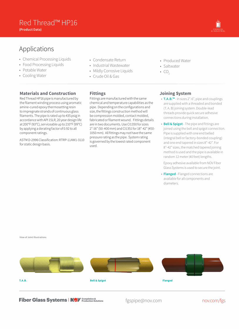
Joining System• T.A.B.™ - In sizes 2”-6”, pipe and couplings
are supplied with a threaded and bonded (T. A. B) joining system. Double-lead threads provide quick secure adhesive connections during installation.
• Bell & Spigot - The pipe and fittings are joined using the bell and spigot connection. Pipe is supplied with one end belled (integral bell or factory-bonded coupling) and one end tapered in sizes 8”-42”. For 8”-42” sizes, the matched tapered joining method is used and the pipe is available in random 12 meter (40 feet) lengths.
Epoxy adhesive available from NOV Fiber Glass Systems is used to secure the joint.
• Flanged - Flanged connections are available for all components and diameters.
View of Joint Illustrations
FlangedT.A.B.
2 Red Thread HP 16 - Product Data
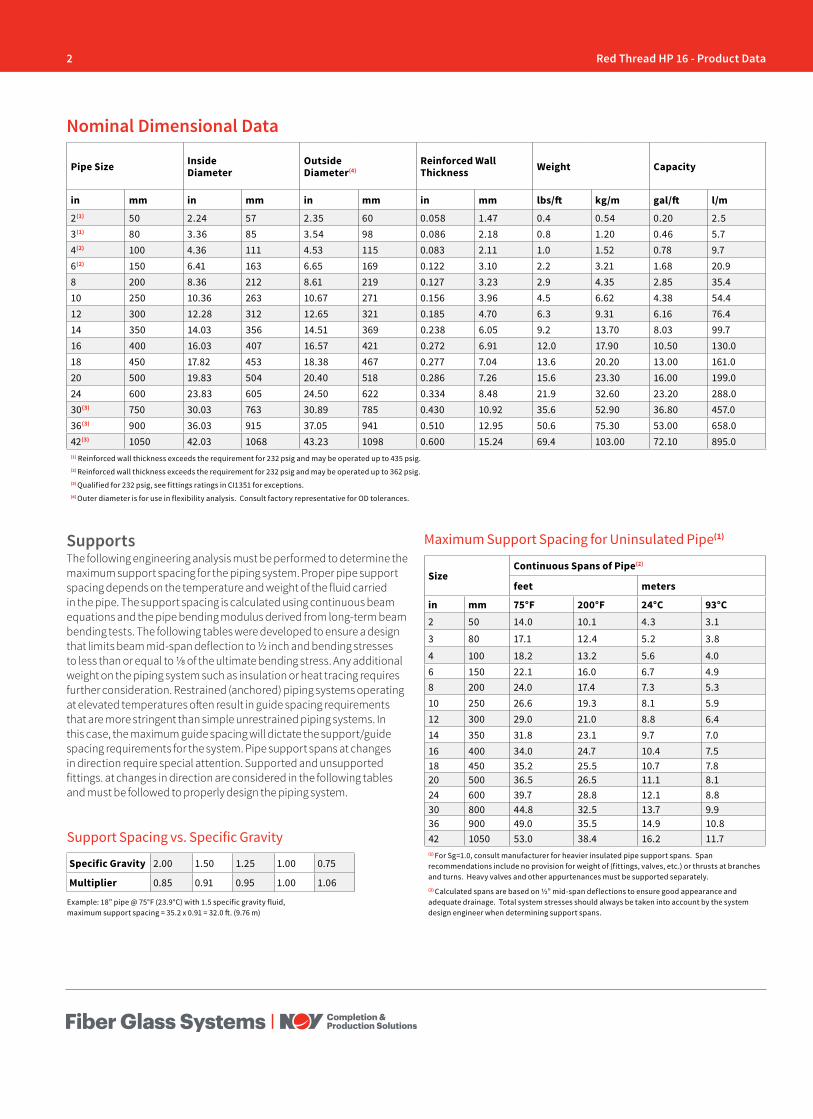
Pipe Size Inside Diameter
Outside Diameter(4)
Reinforced Wall Thickness Weight Capacity
in mm in mm in mm in mm lbs/ft kg/m gal/ft l/m
2(1) 50 2.24 57 2.35 60 0.058 1.47 0.4 0.54 0.20 2.53(1) 80 3.36 85 3.54 98 0.086 2.18 0.8 1.20 0.46 5.74(2) 100 4.36 111 4.53 115 0.083 2.11 1.0 1.52 0.78 9.76(2) 150 6.41 163 6.65 169 0.122 3.10 2.2 3.21 1.68 20.98 200 8.36 212 8.61 219 0.127 3.23 2.9 4.35 2.85 35.410 250 10.36 263 10.67 271 0.156 3.96 4.5 6.62 4.38 54.412 300 12.28 312 12.65 321 0.185 4.70 6.3 9.31 6.16 76.414 350 14.03 356 14.51 369 0.238 6.05 9.2 13.70 8.03 99.716 400 16.03 407 16.57 421 0.272 6.91 12.0 17.90 10.50 130.018 450 17.82 453 18.38 467 0.277 7.04 13.6 20.20 13.00 161.020 500 19.83 504 20.40 518 0.286 7.26 15.6 23.30 16.00 199.024 600 23.83 605 24.50 622 0.334 8.48 21.9 32.60 23.20 288.030(3) 750 30.03 763 30.89 785 0.430 10.92 35.6 52.90 36.80 457.036(3) 900 36.03 915 37.05 941 0.510 12.95 50.6 75.30 53.00 658.042(3) 1050 42.03 1068 43.23 1098 0.600 15.24 69.4 103.00 72.10 895.0(1) Reinforced wall thickness exceeds the requirement for 232 psig and may be operated up to 435 psig. (2) Reinforced wall thickness exceeds the requirement for 232 psig and may be operated up to 362 psig.(3) Qualified for 232 psig, see fittings ratings in CI1351 for exceptions.(4) Outer diameter is for use in flexibility analysis. Consult factory representative for OD tolerances.
Nominal Dimensional Data
SizeContinuous Spans of Pipe(2)
feet meters
in mm 75°F 200°F 24°C 93°C2 50 14.0 10.1 4.3 3.1
3 80 17.1 12.4 5.2 3.8
4 100 18.2 13.2 5.6 4.06 150 22.1 16.0 6.7 4.98 200 24.0 17.4 7.3 5.310 250 26.6 19.3 8.1 5.912 300 29.0 21.0 8.8 6.414 350 31.8 23.1 9.7 7.016 400 34.0 24.7 10.4 7.518 450 35.2 25.5 10.7 7.820 500 36.5 26.5 11.1 8.124 600 39.7 28.8 12.1 8.830 800 44.8 32.5 13.7 9.936 900 49.0 35.5 14.9 10.842 1050 53.0 38.4 16.2 11.7(1) For Sg=1.0, consult manufacturer for heavier insulated pipe support spans. Span recommendations include no provision for weight of (fittings, valves, etc.) or thrusts at branches and turns. Heavy valves and other appurtenances must be supported separately.(2) Calculated spans are based on ½” mid-span deflections to ensure good appearance and adequate drainage. Total system stresses should always be taken into account by the system design engineer when determining support spans.
Maximum Support Spacing for Uninsulated Pipe(1)
Example: 18” pipe @ 75°F (23.9°C) with 1.5 specific gravity fluid, maximum support spacing = 35.2 x 0.91 = 32.0 ft. (9.76 m)
SupportsThe following engineering analysis must be performed to determine the maximum support spacing for the piping system. Proper pipe support spacing depends on the temperature and weight of the fluid carried in the pipe. The support spacing is calculated using continuous beam equations and the pipe bending modulus derived from long-term beam bending tests. The following tables were developed to ensure a design that limits beam mid-span deflection to ½ inch and bending stresses to less than or equal to 1/8 of the ultimate bending stress. Any additional weight on the piping system such as insulation or heat tracing requires further consideration. Restrained (anchored) piping systems operating at elevated temperatures often result in guide spacing requirements that are more stringent than simple unrestrained piping systems. In this case, the maximum guide spacing will dictate the support/guide spacing requirements for the system. Pipe support spans at changes in direction require special attention. Supported and unsupported fittings. at changes in direction are considered in the following tables and must be followed to properly design the piping system.
Support Spacing vs. Specific Gravity
Specific Gravity 2.00 1.50 1.25 1.00 0.75
Multiplier 0.85 0.91 0.95 1.00 1.06
3Red Thread HP 16 - Product Data
[email protected] nov.com/fgs
There are seven basic rules to follow when designing piping system supports, anchors, and guides:
1. Do not exceed the recommended support span.2. Support valves and heavy in-line equipment independently.
This applies to both vertical and horizontal piping.3. Protect pipe from external abrasion.4. Avoid point contact loads5. Avoid excessive bending. This applies to handling, transporting,
initial layout, and final installed position.6. Avoid excessive vertical run loading. Vertical loads should be
supported sufficiently to minimize bending stresses at outlets or changes in direction.
7. Provide adequate axial and lateral restraint to ensure line stability during rapid changes in flow.
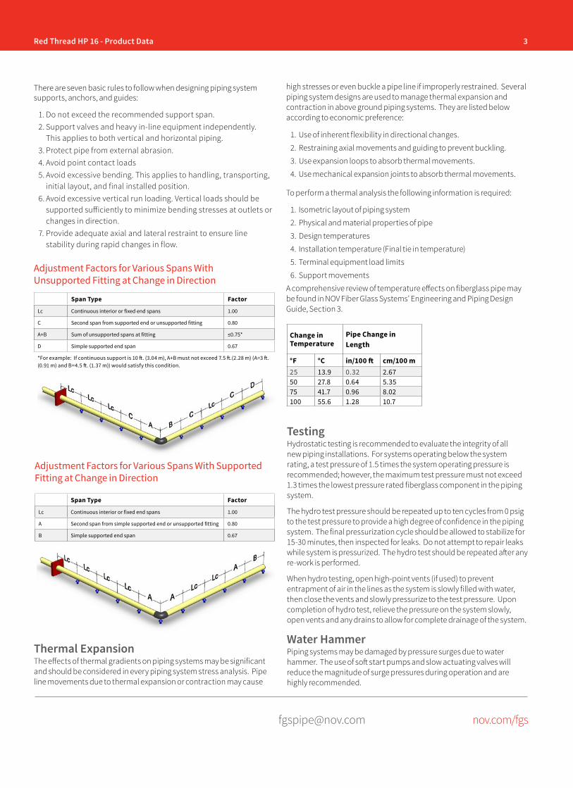
Adjustment Factors for Various Spans With Unsupported Fitting at Change in Direction
Span Type Factor
Lc Continuous interior or fixed end spans 1.00
C Second span from supported end or unsupported fitting 0.80
A+B Sum of unsupported spans at fitting ≤0.75*
D Simple supported end span 0.67
*For example: If continuous support is 10 ft. (3.04 m), A+B must not exceed 7.5 ft.(2.28 m) (A=3 ft. (0.91 m) and B=4.5 ft. (1.37 m)) would satisfy this condition.
Span Type Factor
Lc Continuous interior or fixed end spans 1.00
A Second span from simple supported end or unsupported fitting 0.80
B Simple supported end span 0.67
Adjustment Factors for Various Spans With Supported Fitting at Change in Direction
Thermal ExpansionThe effects of thermal gradients on piping systems may be significant and should be considered in every piping system stress analysis. Pipe line movements due to thermal expansion or contraction may cause
Change in Temperature
Pipe Change in Length
°F °C in/100 ft cm/100 m25 13.9 0.32 2.6750 27.8 0.64 5.3575 41.7 0.96 8.02100 55.6 1.28 10.7
TestingHydrostatic testing is recommended to evaluate the integrity of all new piping installations. For systems operating below the system rating, a test pressure of 1.5 times the system operating pressure is recommended; however, the maximum test pressure must not exceed 1.3 times the lowest pressure rated fiberglass component in the piping system.
The hydro test pressure should be repeated up to ten cycles from 0 psig to the test pressure to provide a high degree of confidence in the piping system. The final pressurization cycle should be allowed to stabilize for 15-30 minutes, then inspected for leaks. Do not attempt to repair leaks while system is pressurized. The hydro test should be repeated after any re-work is performed.
When hydro testing, open high-point vents (if used) to prevent entrapment of air in the lines as the system is slowly filled with water, then close the vents and slowly pressurize to the test pressure. Upon completion of hydro test, relieve the pressure on the system slowly, open vents and any drains to allow for complete drainage of the system.
Water HammerPiping systems may be damaged by pressure surges due to water hammer. The use of soft start pumps and slow actuating valves will reduce the magnitude of surge pressures during operation and are highly recommended.
high stresses or even buckle a pipe line if improperly restrained. Several piping system designs are used to manage thermal expansion and contraction in above ground piping systems. They are listed below according to economic preference:
1. Use of inherent flexibility in directional changes.
2. Restraining axial movements and guiding to prevent buckling.
3. Use expansion loops to absorb thermal movements.
4. Use mechanical expansion joints to absorb thermal movements.
To perform a thermal analysis the following information is required:
1. Isometric layout of piping system
2. Physical and material properties of pipe
3. Design temperatures
4. Installation temperature (Final tie in temperature)
5. Terminal equipment load limits
6. Support movements
A comprehensive review of temperature effects on fiberglass pipe may be found in NOV Fiber Glass Systems’ Engineering and Piping Design Guide, Section 3.
4 Red Thread HP 16 - Product Data
[email protected] nov.com/fgs
Fiber Glass Systems17115 San Pedro Avenue, Ste 200San Antonio, Texas 78232 USAPhone: 210 477 7500Fax: 210 477 7560
National Oilwell Varco has produced this brochure for general information only, and it is not intended for design purposes. Although every effort has been made to maintain the accuracy and reliability of its contents, National Oilwell Varco in no way assumes responsibility for liability for any loss, damage or injury resulting from the use of information and data herein nor is any warranty expressed or implied. Always cross-reference the bulletin date with the most current version listed at the web site noted in this literature.
© 2017 National Oilwell Varco All rights reservedCI1200ENG March 2017
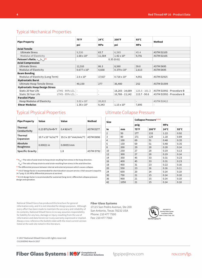
Ultimate Collapse Pressure
Pipe Property75°F 24°C 200°F 93°C
Methodpsi MPa psi MPa
Axial TensileUltimate Stress 9,530 65.7 6,585 45.4 ASTM D2105Modulus of Elasticity 1.68 x 10⁶ 11,584 1.42 x 10⁶ 9,791 ASTM D2105
Poisson’s Ratio, νah (νha)(1) 0.35 (0.61)Axial Compression
Ultimate Stress 12,510 86.3 8,560 59.0 ASTM D695Modulus of Elasticity 0.677 x 10⁶ 4,668 0.379 x 10⁶ 2,613 ASTM D695
Beam BendingModulus of Elasticity (Long Term) 2.6 x 10⁶ 17,927 0.718 x 10⁶ 4,951 ASTM D2925
Hydrostatic BurstUltimate Hoop Tensile Stress 40,150 277 36,480 252 ASTM D1599
Hydrostatic Hoop Design StressStatic 20 Year Life LTHS - 95% LCL - - 18,203 - 14,689 125.5 - 101.3 ASTM D2992 - Procedure BStatic 50 Year Life LTHS - 95% LCL - - 16,788 - 13,142 115.7 - 90.6 ASTM D2992 - Procedure B
Parallel PlateHoop Modulus of Elasticity 3.02 x 10⁶ 20,822 - - ASTM D2412
Shear Modulus 1.36 x 10⁶ 9,343 1.15 x 10⁶ 7,895 -
Pipe Property Value Value Method
Thermal Conductivity 0.23 BTU/hr•ft•°F 0.4 W/m°C ASTM D177
Thermal Expansion 10.7 x 10⁻⁶ in/in/°F 19.3 x 10⁻⁶ mm/mm/°C ASTM D696
Absolute Roughness 0.00021 in 0.00053 mm
Specific Gravity 1.8 ASTM D792
Typical Mechanical Properties
Typical Physical Properties
SizeCollapse Pressure(2,3,4)
psig MPa
In mm 75°F 200°F 24°C 93°C2 50 177 133 1.22 0.923 80 171 129 1.18 0.894 100 69 51 0.48 0.356 150 69 51 0.48 0.358 200 29 20 0.20 0.1410 250 27 20 0.19 0.1312 300 27 20 0.19 0.1414 350 45 33 0.31 0.2316 400 45 33 0.31 0.2318 450 31 23 0.22 0.1620 550 23 16 0.16 0.1124 600 20 14 0.14 0.1030 750 21 15 0.14 0.1036 900 21 15 0.14 0.1042 1050 21 15 0.14 0.10
(1) νha = The ratio of axial strain to hoop strain resulting from stress in the hoop direction.
νah= The ratio of hoop strain to axial strain resulting from stress in the axial direction.(2) The differential pressure between internal and external pressure which causes collapse. (3) A 0.67 design factor is recommended for short duration vacuum service. A full vacuum is equal to 14.7 psig (0.101 MPa) differential pressure at sea level. (4) A 0.33 design factor is recommended for sustained (long-term) differential collapse pressure design and operation.
[email protected] nov.com/fgs
Product Name 14/15 Red Thread™ HP16 Piping System(Specification Guide) O I L & G A S C H E M I C A L
& I N D U S T R I A LO F F S H O R EM A R I N E M I N I N GF U E L
H A N D L I N G
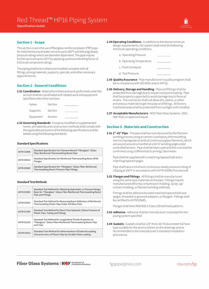
Section 1 - ScopeThis section covers the use of fiberglass reinforced plastic (FRP) pipe for mild chemical and water services up to 200°F and 435 psig steady pressure ratings which are diameter dependent. The pipe may be further serviced up to 210°F by applying a pressure derating factor of 0.92 to all component ratings.
The piping shall be furnished and installed complete with all fittings, joining materials, supports, specials, and other necessary appurtenances.
Section 2 - General Conditions2.01 Coordination - Material furnished and work performed under this
section shall be coordinated with related work and equipment specified under other sections.
Valves Section _________
Supports Section _________
Equipment Section _________
2.02 Governing Standards - Except as modified or supplemented herein, all materials and construction methods shall comply with the applicable provisions of the following specifications and be tested using the following standards.
ASTM D2996 Standard Specification for Filament-Wound “Fiberglass” (Glass-Fiber-Reinforced-Thermosetting Resin) Pipe
ASTM D4024 Standard Specification for Reinforced Thermosetting Resin (RTR) Flanges
ASTM D5685 Standard Specification for “Fiberglass” (Glass-Fiber-Reinforced-Thermosetting-Resin) Pressure Pipe Fittings
Standard Test Methods
ASTM D2992Standard Test Method for Obtaining Hydrostatic or Pressure Design Basis for “Fiberglass” (Glass-Fiber-Reinforced-Thermosetting Resin) Pipe and Fittings
ASTM D2925 Standard Test Method for Measuring Beam Deflection of Reinforced Thermosetting Plastic Pipe Under Full Bore Flow
ASTM D1599 Standard Test Method for Short-Time Hydraulic Failure Pressure of Plastic Pipe, Tubing and Fittings
ASTM D2105Standard Test Method for Longitudinal Tensile Properties of “Fiberglass” (Glass-Fiber-Reinforced-Thermosetting Resin) Pipe and Tube
ASTM D2412Standard Test Method for Determination of External Loading Characteristics of Plastic Pipe by Parallel-Plate Loading
Standard Specifications
2.04 Operating Conditions - In addition to the above minimum design requirements, the system shall meet the following minimum operating conditions:
a. Operating Pressure _________
b. Operating Temperature _________
c. Fluid Conveyed _________
d. Test Pressure _________
2.05 Quality Assurance - Pipe manufacturer’s quality program shall be in compliance with ISO 9001 and/or API Q1.
2.06 Delivery, Storage and Handling - Pipe and fittings shall be protected from damage due to impact and point loading. Pipe shall be properly supported to avoid damage due to flexural strains. The contractor shall not allow dirt, debris, or other extraneous materials to get into pipe and fittings. All factory machined areas shall be protected from sunlight until installed.
2.07 Acceptable Manufacturers - NOV Fiber Glass Systems, (501) 568-4010, or approved equal.
Section 3 - Materials and Construction3.01 2"-42" Pipe - The pipe shall be manufactured by the filament
winding process using an amine cured epoxy thermosetting resin to impregnate strands of continuous glass filaments, which are wound around a mandrel at a 54 3/4° winding angle under controlled tension. Pipe shall be heat cured and the cure shall be confirmed using a Differential Scanning Calorimeter.
Pipe shall be supplied with a matching tapered bell and a matching tapered spigot.
Pipe shall have a minimum continuous steady pressure rating of 232psig at 200°F in accordance with ASTM D2992 Procedure B.
3.02 Flanges and Fittings - All fittings shall be manufactured using the same type materials as the pipe. Fittings may be manufactured either by compression molding, spray-up/contact molding, or filament winding methods.
Fittings shall be adhesive bonded matched tapered bell and spigot, threaded or grooved adapters, or flanged. Fittings shall be certified to ASTM D5685.
Flanges shall have ANSI B16.5 Class 150 bolt hole patterns.
3.03 Adhesive - Adhesive shall be manufacturer’s standard for the piping system specified.
3.04 Gaskets - Gaskets shall be 1/8" thick, 60-70 durometer full-face type suitable for the service shown on the drawings and as recommended in the manufacturer’s standard installation procedures.
2 Red Thread HP16 Specification Guide
[email protected] nov.com/fgs
Fiber Glass Systems17115 San Pedro Avenue, Ste 200San Antonio, Texas 78232 USAPhone: 210 477 7500Fax: 210 477 7560
National Oilwell Varco has produced this brochure for general information only, and it is not intended for design purposes. Although every effort has been made to maintain the accuracy and reliability of its contents, National Oilwell Varco in no way assumes responsibility for liability for any loss, damage or injury resulting from the use of information and data herein nor is any warranty expressed or implied. Always cross-reference the bulletin date with the most current version listed at the web site noted in this literature.
© 2016 National Oilwell Varco All rights reservedCI1201ENG August 2016
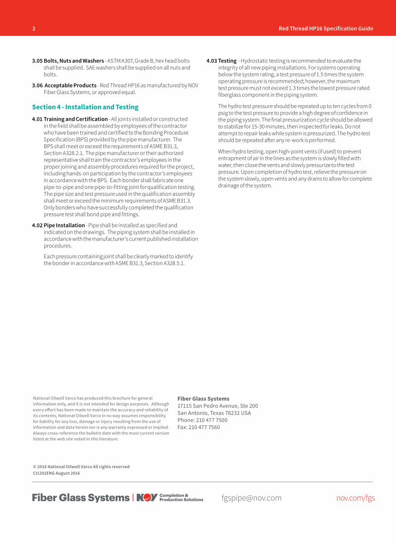
3.05 Bolts, Nuts and Washers - ASTM A307, Grade B, hex head bolts shall be supplied. SAE washers shall be supplied on all nuts and bolts.
3.06 Acceptable Products - Red Thread HP16 as manufactured by NOV Fiber Glass Systems, or approved equal.
Section 4 - Installation and Testing4.01 Training and Certification - All joints installed or constructed
in the field shall be assembled by employees of the contractor who have been trained and certified to the Bonding Procedure Specification (BPS) provided by the pipe manufacturer. The BPS shall meet or exceed the requirements of ASME B31.3, Section A328.2.1. The pipe manufacturer or their authorized representative shall train the contractor’s employees in the proper joining and assembly procedures required for the project, including hands-on participation by the contractor’s employees in accordance with the BPS. Each bonder shall fabricate one pipe-to-pipe and one pipe-to-fitting joint for qualification testing. The pipe size and test pressure used in the qualification assembly shall meet or exceed the minimum requirements of ASME B31.3. Only bonders who have successfully completed the qualification pressure test shall bond pipe and fittings.
4.02 Pipe Installation - Pipe shall be installed as specified and indicated on the drawings. The piping system shall be installed in accordance with the manufacturer’s current published installation procedures.
Each pressure containing joint shall be clearly marked to identify the bonder in accordance with ASME B31.3, Section A328.5.1.
4.03 Testing - Hydrostatic testing is recommended to evaluate the integrity of all new piping installations. For systems operating below the system rating, a test pressure of 1.5 times the system operating pressure is recommended; however, the maximum test pressure must not exceed 1.3 times the lowest pressure rated fiberglass component in the piping system.
The hydro test pressure should be repeated up to ten cycles from 0 psig to the test pressure to provide a high degree of confidence in the piping system. The final pressurization cycle should be allowed to stabilize for 15-30 minutes, then inspected for leaks. Do not attempt to repair leaks while system is pressurized. The hydro test should be repeated after any re-work is performed.
When hydro testing, open high-point vents (if used) to prevent entrapment of air in the lines as the system is slowly filled with water, then close the vents and slowly pressurize to the test pressure. Upon completion of hydro test, relieve the pressure on the system slowly, open vents and any drains to allow for complete drainage of the system.
[email protected] nov.com/fgs
Product Name 14/15 Red Thread™ HP25 Piping System(Specification Guide) O I L & G A S C H E M I C A L
& I N D U S T R I A LO F F S H O R EM A R I N E M I N I N GF U E L
H A N D L I N G
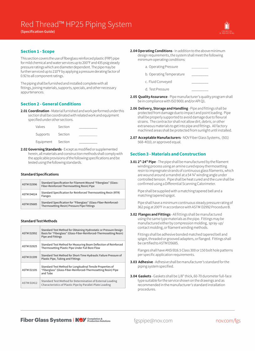
Section 1 - ScopeThis section covers the use of fiberglass reinforced plastic (FRP) pipe for mild chemical and water services up to 200°F and 435 psig steady pressure ratings which are diameter dependent. The pipe may be further serviced up to 210°F by applying a pressure derating factor of 0.92 to all component ratings.
The piping shall be furnished and installed complete with all fittings, joining materials, supports, specials, and other necessary appurtenances.
Section 2 - General Conditions2.01 Coordination - Material furnished and work performed under this
section shall be coordinated with related work and equipment specified under other sections.
Valves Section __________
Supports Section __________
Equipment Section __________
2.02 Governing Standards - Except as modified or supplemented herein, all materials and construction methods shall comply with the applicable provisions of the following specifications and be tested using the following standards.
ASTM D2996 Standard Specification for Filament-Wound “Fiberglass” (Glass-Fiber-Reinforced-Thermosetting Resin) Pipe
ASTM D4024 Standard Specification for Reinforced Thermosetting Resin (RTR) Flanges
ASTM D5685 Standard Specification for “Fiberglass” (Glass-Fiber-Reinforced-Thermosetting-Resin) Pressure Pipe Fittings
Standard Test Methods
ASTM D2992Standard Test Method for Obtaining Hydrostatic or Pressure Design Basis for “Fiberglass” (Glass-Fiber-Reinforced-Thermosetting Resin) Pipe and Fittings
ASTM D2925 Standard Test Method for Measuring Beam Deflection of Reinforced Thermosetting Plastic Pipe Under Full Bore Flow
ASTM D1599 Standard Test Method for Short-Time Hydraulic Failure Pressure of Plastic Pipe, Tubing and Fittings
ASTM D2105Standard Test Method for Longitudinal Tensile Properties of “Fiberglass” (Glass-Fiber-Reinforced-Thermosetting Resin) Pipe and Tube
ASTM D2412Standard Test Method for Determination of External Loading Characteristics of Plastic Pipe by Parallel-Plate Loading
Standard Specifications
2.04 Operating Conditions - In addition to the above minimum design requirements, the system shall meet the following minimum operating conditions:
a. Operating Pressure _________
b. Operating Temperature _________
c. Fluid Conveyed _________
d. Test Pressure _________
2.05 Quality Assurance - Pipe manufacturer’s quality program shall be in compliance with ISO 9001 and/or API Q1.
2.06 Delivery, Storage and Handling - Pipe and fittings shall be protected from damage due to impact and point loading. Pipe shall be properly supported to avoid damage due to flexural strains. The contractor shall not allow dirt, debris, or other extraneous materials to get into pipe and fittings. All factory machined areas shall be protected from sunlight until installed.
2.07 Acceptable Manufacturers - NOV Fiber Glass Systems, (501) 568-4010, or approved equal.
Section 3 - Materials and Construction3.01 2"-24" Pipe - The pipe shall be manufactured by the filament
winding process using an amine cured epoxy thermosetting resin to impregnate strands of continuous glass filaments, which are wound around a mandrel at a 54 3/4° winding angle under controlled tension. Pipe shall be heat cured and the cure shall be confirmed using a Differential Scanning Calorimeter.
Pipe shall be supplied with a matching tapered bell and a matching tapered spigot.
Pipe shall have a minimum continuous steady pressure rating of 362 psig at 200°F in accordance with ASTM D2992 Procedure B.
3.02 Flanges and Fittings - All fittings shall be manufactured using the same type materials as the pipe. Fittings may be manufactured either by compression molding, spray-up/contact molding, or filament winding methods.
Fittings shall be adhesive bonded matched tapered bell and spigot, threaded or grooved adapters, or flanged. Fittings shall be certified to ASTM D5685.
Flanges shall have ANSI B16.5 Class 300 or 150 bolt hole patterns per specific application requirements.
3.03 Adhesive - Adhesive shall be manufacturer’s standard for the piping system specified.
3.04 Gaskets - Gaskets shall be 1/8" thick, 60-70 durometer full-face type suitable for the service shown on the drawings and as recommended in the manufacturer’s standard installation procedures.

2 Red Thread HP25 Specification Guide
[email protected] nov.com/fgs
Fiber Glass Systems17115 San Pedro Avenue, Ste 200San Antonio, Texas 78232 USAPhone: 210 477 7500Fax: 210 477 7560
National Oilwell Varco has produced this brochure for general information only, and it is not intended for design purposes. Although every effort has been made to maintain the accuracy and reliability of its contents, National Oilwell Varco in no way assumes responsibility for liability for any loss, damage or injury resulting from the use of information and data herein nor is any warranty expressed or implied. Always cross-reference the bulletin date with the most current version listed at the web site noted in this literature.
© 2016 National Oilwell Varco All rights reservedCI1266ENG August 2016
3.05 Bolts, Nuts and Washers - ASTM A307, Grade B, hex head bolts shall be supplied. SAE washers shall be supplied on all nuts and bolts.
3.06 Acceptable Products - Red Thread HP25 as manufactured by NOV Fiber Glass Systems, or approved equal.
Section 4 - Installation and Testing4.01 Training and Certification - All joints installed or constructed
in the field shall be assembled by employees of the contractor who have been trained and certified to the Bonding Procedure Specification (BPS) provided by the pipe manufacturer. The BPS shall meet or exceed the requirements of ASME B31.3, Section A328.2.1. The pipe manufacturer or their authorized representative shall train the contractor’s employees in the proper joining and assembly procedures required for the project, including hands-on participation by the contractor’s employees in accordance with the BPS. Each bonder shall fabricate one pipe-to-pipe and one pipe-to-fitting joint for qualification testing. The pipe size and test pressure used in the qualification assembly shall meet or exceed the minimum requirements of ASME B31.3. Only bonders who have successfully completed the qualification pressure test shall bond pipe and fittings.
4.02 Pipe Installation - Pipe shall be installed as specified and indicated on the drawings. The piping system shall be installed in accordance with the manufacturer’s current published installation procedures.
Each pressure containing joint shall be clearly marked to identify the bonder in accordance with ASME B31.3, Section A328.5.1.
4.03 Testing - Hydrostatic testing is recommended to evaluate the integrity of all new piping installations. For systems operating below the system rating, a test pressure of 1.5 times the system operating pressure is recommended; however, the maximum test pressure must not exceed 1.3 times the lowest pressure rated fiberglass component in the piping system.
The hydro test pressure should be repeated up to ten cycles from 0 psig to the test pressure to provide a high degree of confidence in the piping system. The final pressurization cycle should be allowed to stabilize for 15-30 minutes, then inspected for leaks. Do not attempt to repair leaks while system is pressurized. The hydro test should be repeated after any re-work is performed.
When hydro testing, open high-point vents (if used) to prevent entrapment of air in the lines as the system is slowly filled with water, then close the vents and slowly pressurize to the test pressure. Upon completion of hydro test, relieve the pressure on the system slowly, open vents and any drains to allow for complete drainage of the system.
[email protected] nov.com/fgs
Product Name 14/15 Green Thread™ HP16 Piping System(Specification Guide) O I L & G A S C H E M I C A L
& I N D U S T R I A LO F F S H O R EM A R I N E M I N I N GF U E L
H A N D L I N G
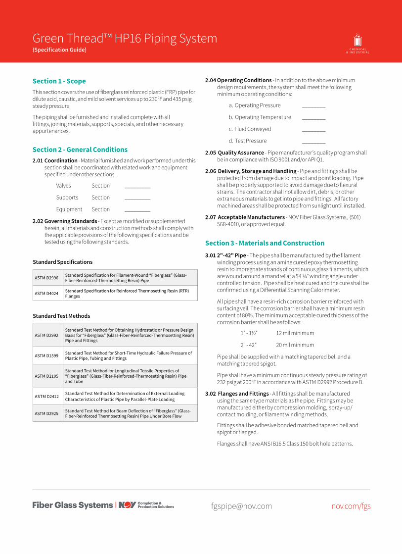
Section 1 - ScopeThis section covers the use of fiberglass reinforced plastic (FRP) pipe for dilute acid, caustic, and mild solvent services up to 230°F and 435 psig steady pressure.
The piping shall be furnished and installed complete with all fittings, joining materials, supports, specials, and other necessary appurtenances.
Section 2 - General Conditions2.01 Coordination - Material furnished and work performed under this
section shall be coordinated with related work and equipment specified under other sections.
Valves Section _________
Supports Section _________
Equipment Section _________
2.02 Governing Standards - Except as modified or supplemented herein, all materials and construction methods shall comply with the applicable provisions of the following specifications and be tested using the following standards.
ASTM D2996 Standard Specification for Filament-Wound “Fiberglass” (Glass-Fiber-Reinforced-Thermosetting Resin) Pipe
ASTM D4024 Standard Specification for Reinforced Thermosetting Resin (RTR) Flanges
Standard Test Methods
ASTM D2992Standard Test Method for Obtaining Hydrostatic or Pressure Design Basis for “Fiberglass” (Glass-Fiber-Reinforced-Thermosetting Resin) Pipe and Fittings
ASTM D1599 Standard Test Method for Short-Time Hydraulic Failure Pressure of Plastic Pipe, Tubing and Fittings
ASTM D2105Standard Test Method for Longitudinal Tensile Properties of “Fiberglass” (Glass-Fiber-Reinforced-Thermosetting Resin) Pipe and Tube
ASTM D2412Standard Test Method for Determination of External Loading Characteristics of Plastic Pipe by Parallel-Plate Loading
ASTM D2925 Standard Test Method for Beam Deflection of “Fiberglass” (Glass-Fiber-Reinforced Thermosetting Resin) Pipe Under Bore Flow
Standard Specifications
2.04 Operating Conditions - In addition to the above minimum design requirements, the system shall meet the following minimum operating conditions:
a. Operating Pressure ________
b. Operating Temperature ________
c. Fluid Conveyed ________
d. Test Pressure ________
2.05 Quality Assurance - Pipe manufacturer’s quality program shall be in compliance with ISO 9001 and/or API Q1.
2.06 Delivery, Storage and Handling - Pipe and fittings shall be protected from damage due to impact and point loading. Pipe shall be properly supported to avoid damage due to flexural strains. The contractor shall not allow dirt, debris, or other extraneous materials to get into pipe and fittings. All factory machined areas shall be protected from sunlight until installed.
2.07 Acceptable Manufacturers - NOV Fiber Glass Systems, (501) 568-4010, or approved equal.
Section 3 - Materials and Construction3.01 2"-42" Pipe - The pipe shall be manufactured by the filament
winding process using an amine cured epoxy thermosetting resin to impregnate strands of continuous glass filaments, which are wound around a mandrel at a 54 3/4° winding angle under controlled tension. Pipe shall be heat cured and the cure shall be confirmed using a Differential Scanning Calorimeter.
All pipe shall have a resin-rich corrosion barrier reinforced with surfacing veil. The corrosion barrier shall have a minimum resin content of 80%. The minimum acceptable cured thickness of the corrosion barrier shall be as follows:
1" - 1½" 12 mil minimum
2" - 42" 20 mil minimum
Pipe shall be supplied with a matching tapered bell and a matching tapered spigot.
Pipe shall have a minimum continuous steady pressure rating of 232 psig at 200°F in accordance with ASTM D2992 Procedure B.
3.02 Flanges and Fittings - All fittings shall be manufactured using the same type materials as the pipe. Fittings may be manufactured either by compression molding, spray-up/contact molding, or filament winding methods.
Fittings shall be adhesive bonded matched tapered bell and spigot or flanged.
Flanges shall have ANSI B16.5 Class 150 bolt hole patterns.

2 Green Thread HP16 Specification Guide
[email protected] nov.com/fgs
Fiber Glass Systems17115 San Pedro Avenue, Ste 200San Antonio, Texas 78232 USAPhone: 210 477 7500Fax: 210 477 7560
National Oilwell Varco has produced this brochure for general information only, and it is not intended for design purposes. Although every effort has been made to maintain the accuracy and reliability of its contents, National Oilwell Varco in no way assumes responsibility for liability for any loss, damage or injury resulting from the use of information and data herein nor is any warranty expressed or implied. Always cross-reference the bulletin date with the most current version listed at the web site noted in this literature.
© 2016 National Oilwell Varco All rights reservedCI1301ENG August 2016
3.03 Adhesive - Adhesive shall be manufacturer’s standard for the piping system specified.
3.04 Gaskets - Gaskets shall be 1/8" thick, 60-70 durometer full-face type suitable for the service shown on the drawings and as recommended in the manufacturer’s standard installation procedures.
3.05 Bolts, Nuts and Washers - ASTM F593, 304 stainless steel hex head bolts shall be supplied. SAE washers shall be supplied on all nuts and bolts.
3.06 Acceptable Products - Green Thread HP16 as manufactured by NOV Fiber Glass Systems, or approved equal.
Section 4 - Installation and Testing4.01 Training and Certification - All joints installed or constructed
in the field shall be assembled by employees of the contractor who have been trained by the pipe manufacturer. The pipe manufacturer or their authorized representative shall train the contractor’s employees in the proper joining and assembly procedures required for the project, including hands-on participation by the contractor’s employees. Each bonder shall fabricate one pipe-to-pipe and one pipe-to-fitting joint that shall pass the minimum pressure test for the application as stated in section 2.03.d without leaking.
Only bonders who have successfully completed the pressure test shall bond pipe and fittings.
Certification by the manufacturer shall be in compliance with ASME B31.3, Section A328.2 for the type of joint being made.
4.02 Pipe Installation - Pipe shall be installed as specified and indicated on the drawings.
The piping system shall be installed in accordance with the manufacturer’s current published installation procedures.
4.03 Testing - Hydrostatic testing is recommended to evaluate the integrity of all new piping installations. For systems operating below the system rating, a test pressure of 1.5 times the system operating pressure is recommended; however, the maximum test pressure must not exceed 1.3 times the lowest pressure rated fiberglass component in the piping system.
The hydro test pressure should be repeated up to ten cycles from 0 psig to the test pressure to provide a high degree of confidence in the piping system. The final pressurization cycle should be allowed to stabilize for 15-30 minutes, then inspected for leaks. Do not attempt to repair leaks while system is pressurized. The hydro test should be repeated after any re-work is performed.
When hydro testing, open high-point vents (if used) to prevent entrapment of air in the lines as the system is slowly filled with water, then close the vents and slowly pressurize to the test pressure. Upon completion of hydro test, relieve the pressure on the system slowly, open vents and any drains to allow for complete drainage of the system.
[email protected] nov.com/fgs
Product Name 14/15 Green Thread™ HP25 Piping System(Specification Guide) O I L & G A S C H E M I C A L
& I N D U S T R I A LO F F S H O R EM A R I N E M I N I N GF U E L
H A N D L I N G
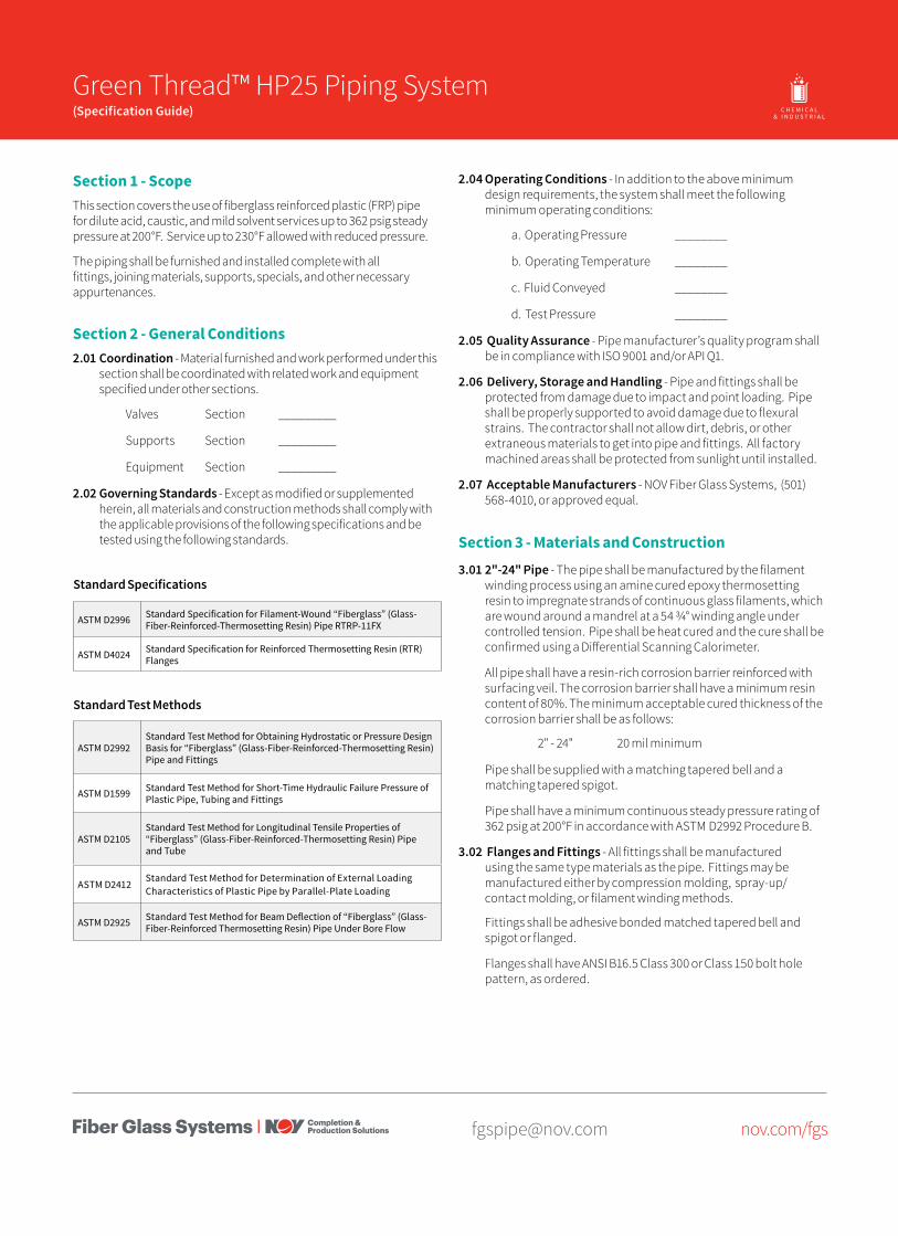
Section 1 - ScopeThis section covers the use of fiberglass reinforced plastic (FRP) pipe for dilute acid, caustic, and mild solvent services up to 362 psig steady pressure at 200°F. Service up to 230°F allowed with reduced pressure.
The piping shall be furnished and installed complete with all fittings, joining materials, supports, specials, and other necessary appurtenances.
Section 2 - General Conditions2.01 Coordination - Material furnished and work performed under this
section shall be coordinated with related work and equipment specified under other sections.
Valves Section _________
Supports Section _________
Equipment Section _________
2.02 Governing Standards - Except as modified or supplemented herein, all materials and construction methods shall comply with the applicable provisions of the following specifications and be tested using the following standards.
ASTM D2996 Standard Specification for Filament-Wound “Fiberglass” (Glass-Fiber-Reinforced-Thermosetting Resin) Pipe RTRP-11FX
ASTM D4024 Standard Specification for Reinforced Thermosetting Resin (RTR) Flanges
Standard Test Methods
ASTM D2992Standard Test Method for Obtaining Hydrostatic or Pressure Design Basis for “Fiberglass” (Glass-Fiber-Reinforced-Thermosetting Resin) Pipe and Fittings
ASTM D1599 Standard Test Method for Short-Time Hydraulic Failure Pressure of Plastic Pipe, Tubing and Fittings
ASTM D2105Standard Test Method for Longitudinal Tensile Properties of “Fiberglass” (Glass-Fiber-Reinforced-Thermosetting Resin) Pipe and Tube
ASTM D2412Standard Test Method for Determination of External Loading Characteristics of Plastic Pipe by Parallel-Plate Loading
ASTM D2925 Standard Test Method for Beam Deflection of “Fiberglass” (Glass-Fiber-Reinforced Thermosetting Resin) Pipe Under Bore Flow
Standard Specifications
2.04 Operating Conditions - In addition to the above minimum design requirements, the system shall meet the following minimum operating conditions:
a. Operating Pressure ________
b. Operating Temperature ________
c. Fluid Conveyed ________
d. Test Pressure ________
2.05 Quality Assurance - Pipe manufacturer’s quality program shall be in compliance with ISO 9001 and/or API Q1.
2.06 Delivery, Storage and Handling - Pipe and fittings shall be protected from damage due to impact and point loading. Pipe shall be properly supported to avoid damage due to flexural strains. The contractor shall not allow dirt, debris, or other extraneous materials to get into pipe and fittings. All factory machined areas shall be protected from sunlight until installed.
2.07 Acceptable Manufacturers - NOV Fiber Glass Systems, (501) 568-4010, or approved equal.
Section 3 - Materials and Construction3.01 2"-24" Pipe - The pipe shall be manufactured by the filament
winding process using an amine cured epoxy thermosetting resin to impregnate strands of continuous glass filaments, which are wound around a mandrel at a 54 3/4° winding angle under controlled tension. Pipe shall be heat cured and the cure shall be confirmed using a Differential Scanning Calorimeter.
All pipe shall have a resin-rich corrosion barrier reinforced with surfacing veil. The corrosion barrier shall have a minimum resin content of 80%. The minimum acceptable cured thickness of the corrosion barrier shall be as follows:
2" - 24" 20 mil minimum
Pipe shall be supplied with a matching tapered bell and a matching tapered spigot.
Pipe shall have a minimum continuous steady pressure rating of 362 psig at 200°F in accordance with ASTM D2992 Procedure B.
3.02 Flanges and Fittings - All fittings shall be manufactured using the same type materials as the pipe. Fittings may be manufactured either by compression molding, spray-up/contact molding, or filament winding methods.
Fittings shall be adhesive bonded matched tapered bell and spigot or flanged.
Flanges shall have ANSI B16.5 Class 300 or Class 150 bolt hole pattern, as ordered.
2 Green Thread HP25 Specification Guide
[email protected] nov.com/fgs
Fiber Glass Systems17115 San Pedro Avenue, Ste 200San Antonio, Texas 78232 USAPhone: 210 477 7500Fax: 210 477 7560
National Oilwell Varco has produced this brochure for general information only, and it is not intended for design purposes. Although every effort has been made to maintain the accuracy and reliability of its contents, National Oilwell Varco in no way assumes responsibility for liability for any loss, damage or injury resulting from the use of information and data herein nor is any warranty expressed or implied. Always cross-reference the bulletin date with the most current version listed at the web site noted in this literature.
© 2017 National Oilwell Varco All rights reservedCI1326ENG January 2017
3.03 Adhesive - Adhesive shall be manufacturer’s standard for the piping system specified.
3.04 Gaskets - Gaskets shall be 1/8" thick, 60-70 durometer full-face type suitable for the service shown on the drawings and as recommended in the manufacturer’s standard installation procedures.
3.05 Bolts, Nuts and Washers - ASTM F593, 304 stainless steel hex head bolts shall be supplied. SAE washers shall be supplied on all nuts and bolts.
3.06 Acceptable Products - Green Thread HP25 as manufactured by NOV Fiber Glass Systems, or approved equal.
Section 4 - Installation and Testing4.01 Training and Certification - All joints installed or constructed
in the field shall be assembled by employees of the contractor who have been trained by the pipe manufacturer. The pipe manufacturer or their authorized representative shall train the contractor’s employees in the proper joining and assembly procedures required for the project, including hands-on participation by the contractor’s employees. Each bonder shall fabricate one pipe-to-pipe and one pipe-to-fitting joint that shall pass the minimum pressure test for the application as stated in section 2.03.d without leaking.
Only bonders who have successfully completed the pressure test shall bond pipe and fittings.
Certification by the manufacturer shall be in compliance with ASME B31.3, Section A328.2 for the type of joint being made.
4.02 Pipe Installation - Pipe shall be installed as specified and indicated on the drawings.
The piping system shall be installed in accordance with the manufacturer’s current published installation procedures.
4.03 Testing - Hydrostatic testing is recommended to evaluate the integrity of all new piping installations. For systems operating below the system rating, a test pressure of 1.5 times the system operating pressure is recommended; however, the maximum test pressure must not exceed 1.3 times the lowest pressure rated fiberglass component in the piping system.
The hydro test pressure should be repeated up to ten cycles from 0 psig to the test pressure to provide a high degree of confidence in the piping system. The final pressurization cycle should be allowed to stabilize for 15-30 minutes, then inspected for leaks. Do not attempt to repair leaks while system is pressurized. The hydro test should be repeated after any re-work is performed.
When hydro testing, open high-point vents (if used) to prevent entrapment of air in the lines as the system is slowly filled with water, then close the vents and slowly pressurize to the test pressure. Upon completion of hydro test, relieve the pressure on the system slowly, open vents and any drains to allow for complete drainage of the system.
[email protected] nov.com/fgs
Product Name 14/15 Red Thread™ HP 25(Product Data) O I L & G A S C H E M I C A L
& I N D U S T R I A LO F F S H O R EM A R I N E M I N I N GF U E L
H A N D L I N G
Applications• Chemical Processing Liquids• Food Processing Liquids• Potable Water• Cooling Water
• Condensate Return• Industrial Wastewater• Mildly Corrosive Liquids• Crude Oil & Gas
• Produced Water• Saltwater• CO2
Bell & Spigot
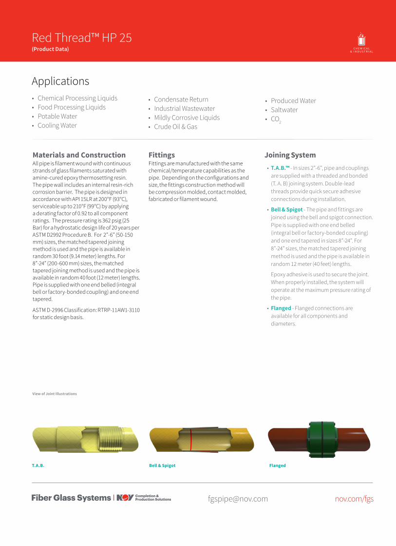
Materials and ConstructionAll pipe is filament wound with continuous strands of glass filaments saturated with amine-cured epoxy thermosetting resin. The pipe wall includes an internal resin-rich corrosion barrier. The pipe is designed in accordance with API 15LR at 200°F (93°C), serviceable up to 210°F (99°C) by applying a derating factor of 0.92 to all component ratings. The pressure rating is 362 psig (25 Bar) for a hydrostatic design life of 20 years per ASTM D2992 Procedure B. For 2”-6” (50-150 mm) sizes, the matched tapered joining method is used and the pipe is available in random 30 foot (9.14 meter) lengths. For 8”-24” (200-600 mm) sizes, the matched tapered joining method is used and the pipe is available in random 40 foot (12 meter) lengths. Pipe is supplied with one end belled (integral bell or factory-bonded coupling) and one end tapered.
ASTM D-2996 Classification: RTRP-11AW1-3110 for static design basis.
FittingsFittings are manufactured with the same chemical/temperature capabilities as the pipe. Depending on the configurations and size, the fittings construction method will be compression molded, contact molded, fabricated or filament wound.
Joining System• T.A.B.™ - In sizes 2”-6”, pipe and couplings
are supplied with a threaded and bonded (T. A. B) joining system. Double-lead threads provide quick secure adhesive connections during installation.
• Bell & Spigot - The pipe and fittings are joined using the bell and spigot connection. Pipe is supplied with one end belled (integral bell or factory-bonded coupling) and one end tapered in sizes 8”-24”. For 8”-24” sizes, the matched tapered joining method is used and the pipe is available in random 12 meter (40 feet) lengths.
Epoxy adhesive is used to secure the joint. When properly installed, the system will operate at the maximum pressure rating of the pipe.
• Flanged - Flanged connections are available for all components and diameters.
View of Joint Illustrations
FlangedT.A.B.
2 Red Thread HP 25 - Product Data
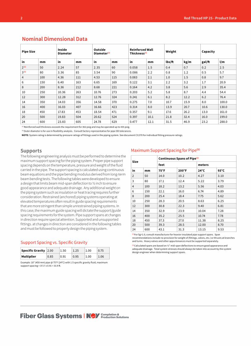
Pipe Size Inside Diameter
Outside Diameter(2)
Reinforced Wall Thickness(1) Weight Capacity
in mm in mm in mm in mm lbs/ft kg/m gal/ft l/m
2(1) 50 2.24 57 2.35 60 0.058 1.5 0.4 0.7 0.2 2.53(1) 80 3.36 85 3.54 90 0.086 2.2 0.8 1.2 0.5 5.74 100 4.36 111 4.53 115 0.083 2.1 1.0 1.5 0.8 9.76 150 6.40 163 6.65 169 0.122 3.1 2.2 3.2 1.7 20.98 200 8.36 212 8.68 221 0.164 4.2 3.8 5.6 2.9 35.410 250 10.36 263 10.76 273 0.203 5.2 5.8 8.7 4.4 54.412 300 12.28 312 12.76 324 0.241 6.1 8.2 12.2 6.2 76.414 350 14.03 356 14.58 370 0.275 7.0 10.7 15.9 8.0 100.016 400 16.03 407 16.66 423 0.314 8.0 13.9 20.7 10.6 130.018 450 17.83 453 18.54 471 0.357 9.1 17.6 26.2 13.0 161.020 500 19.83 504 20.62 524 0.397 10.1 21.8 32.4 16.0 199.024 600 23.83 605 24.78 629 0.477 12.1 31.5 46.9 23.2 288.0(1) Reinforced wall thickness exceeds the requirement for 362 psig and may be operated up to 435 psig. (2) Outer diameter is for use in flexibility analysis. Consult factory representative for pipe OD tolerances.
NOTE: System rating is determined by pressure ratings of fittings used in the piping system. See document CI1370 for individual fitting pressure ratings.
Nominal Dimensional Data
SizeContinuous Spans of Pipe(2)
feet meters
in mm 75°F 200°F 24°C 93°C2 50 14.0 10.2 4.27 3.10
3 80 17.1 12.4 5.22 3.79
4 100 18.2 13.2 5.56 4.036 150 22.1 16.0 6.74 4.898 200 25.4 18.4 7.75 5.6210 250 28.3 20.5 8.63 6.2512 300 30.8 22.3 9.40 6.8114 350 32.9 23.9 10.04 7.2816 400 35.2 25.5 10.74 7.7818 450 37.3 27.0 11.38 8.2520 500 39.3 28.5 12.00 8.7024 600 43.1 31.3 13.15 9.53(1) For Sg=1.0, consult manufacturer for heavier insulated pipe support spans. Span recommendations include no provision for weight of (fittings, valves, etc.) or thrusts at branches and turns. Heavy valves and other appurtenances must be supported separately.(2) Calculated spans are based on ½” mid-span deflections to ensure good appearance and adequate drainage. Total system stresses should always be taken into account by the system design engineer when determining support spans.
Maximum Support Spacing for Pipe(1)
Example: 18” (450 mm) pipe @ 75°F (24°C) with 1.5 specific gravity fluid, maximum support spacing = 37.3’ x 0.91 = 33.9 ft.
SupportsThe following engineering analysis must be performed to determine the maximum support spacing for the piping system. Proper pipe support spacing depends on the temperature, pressure and weight of the fluid carried in the pipe. The support spacing is calculated using continuous beam equations and the pipe bending modulus derived from long-term beam bending tests. The following tables were developed to ensure a design that limits beam mid-span deflection to ½ inch to ensure good appearance and adequate drainage. Any additional weight on the piping system such as insulation or heat tracing requires further consideration. Restrained (anchored) piping systems operating at elevated temperatures often result in guide spacing requirements that are more stringent than simple unrestrained piping systems. In this case, the maximum guide spacing will dictate the support/guide spacing requirements for the system. Pipe support spans at changes in direction require special attention. Supported and unsupported fittings. at changes in direction are considered in the following tables and must be followed to properly design the piping system.
Support Spacing vs. Specific Gravity
Specific Gravity 2.00 1.50 1.25 1.00 0.75
Multiplier 0.85 0.91 0.95 1.00 1.06

3Red Thread HP 25 - Product Data
[email protected] nov.com/fgs
Change in Temperature
Pipe Change in Length
°F °C in/100 ft cm/100 m25 13.9 0.32 2.6750 27.8 0.64 5.3575 41.7 0.96 8.02100 55.6 1.28 10.7
There are seven basic rules to follow when designing piping system supports, anchors, and guides:
1. Do not exceed the recommended support span.2. Support valves and heavy in-line equipment independently.
This applies to both vertical and horizontal piping.3. Protect pipe from external abrasion.4. Avoid point contact loads5. Avoid excessive bending. This applies to handling, transporting,
initial layout, and final installed position.6. Avoid excessive vertical run loading. Vertical loads should be
supported sufficiently to minimize bending stresses at outlets or changes in direction.
7. Provide adequate axial and lateral restraint to ensure line stability during rapid changes in flow.
Adjustment Factors for Various Spans With Unsupported Fitting at Change in Direction
Span Type Factor
Lc Continuous interior or fixed end spans 1.00
C Second span from supported end or unsupported fitting 0.80
A+B Sum of unsupported spans at fitting ≤0.75*
D Simple supported end span 0.67
*For example: If continuous support is 10 ft. (3.04 m), A+B must not exceed 7.5 ft.(2.28 m) (A=3 ft. (0.91 m) and B=4.5 ft. (1.37 m)) would satisfy this condition.
Span Type Factor
Lc Continuous interior or fixed end spans 1.00
A Second span from simple supported end or unsupported fitting 0.80
B Simple supported end span 0.67
Adjustment Factors for Various Spans With Supported Fitting at Change in Direction
Thermal ExpansionThe effects of thermal gradients on piping systems may be significant and should be considered in every piping system stress analysis. Pipe line movements due to thermal expansion or contraction may cause
TestingHydrostatic testing is recommended to evaluate the integrity of all new piping installations. For systems operating below the system rating, a test pressure of 1.5 times the system operating pressure is recommended; however, the maximum test pressure must not exceed 1.3 times the lowest pressure rated fiberglass component in the piping system.
The hydro test pressure should be repeated up to ten cycles from 0 psig to the test pressure to provide a high degree of confidence in the piping system. The final pressurization cycle should be allowed to stabilize for 15-30 minutes, then inspected for leaks. Do not attempt to repair leaks while system is pressurized. The hydro test should be repeated after any re-work is performed.
When hydro testing, open high-point vents (if used) to prevent entrapment of air in the lines as the system is slowly filled with water, then close the vents and slowly pressurize to the test pressure. Upon completion of hydro test, relieve the pressure on the system slowly, open vents and any drains to allow for complete drainage of the system.
Water HammerPiping systems may be damaged by pressure surges due to water hammer. The use of soft start pumps and slow actuating valves will reduce the magnitude of surge pressures during operation and are highly recommended.
high stresses or even buckle a pipe line if improperly restrained. Several piping system designs are used to manage thermal expansion and contraction in above ground piping systems. They are listed below according to economic preference:
1. Use of inherent flexibility in directional changes.
2. Restraining axial movements and guiding to prevent buckling.
3. Use expansion loops to absorb thermal movements.
4. Use mechanical expansion joints to absorb thermal movements.
To perform a thermal analysis the following information is required:
1. Isometric layout of piping system
2. Physical and material properties of pipe
3. Design temperatures
4. Installation temperature (Final tie in temperature)
5. Terminal equipment load limits
6. Support movements
A comprehensive review of temperature effects on fiberglass pipe may be found in NOV Fiber Glass Systems’ Engineering and Piping Design Guide, Section 3.
4 Red Thread HP 25 - Product Data
[email protected] nov.com/fgs
Fiber Glass Systems17115 San Pedro Avenue, Ste 200San Antonio, Texas 78232 USAPhone: 210 477 7500Fax: 210 477 7560
National Oilwell Varco has produced this brochure for general information only, and it is not intended for design purposes. Although every effort has been made to maintain the accuracy and reliability of its contents, National Oilwell Varco in no way assumes responsibility for liability for any loss, damage or injury resulting from the use of information and data herein nor is any warranty expressed or implied. Always cross-reference the bulletin date with the most current version listed at the web site noted in this literature.
© 2017 National Oilwell Varco All rights reservedCI1265ENG February 2017
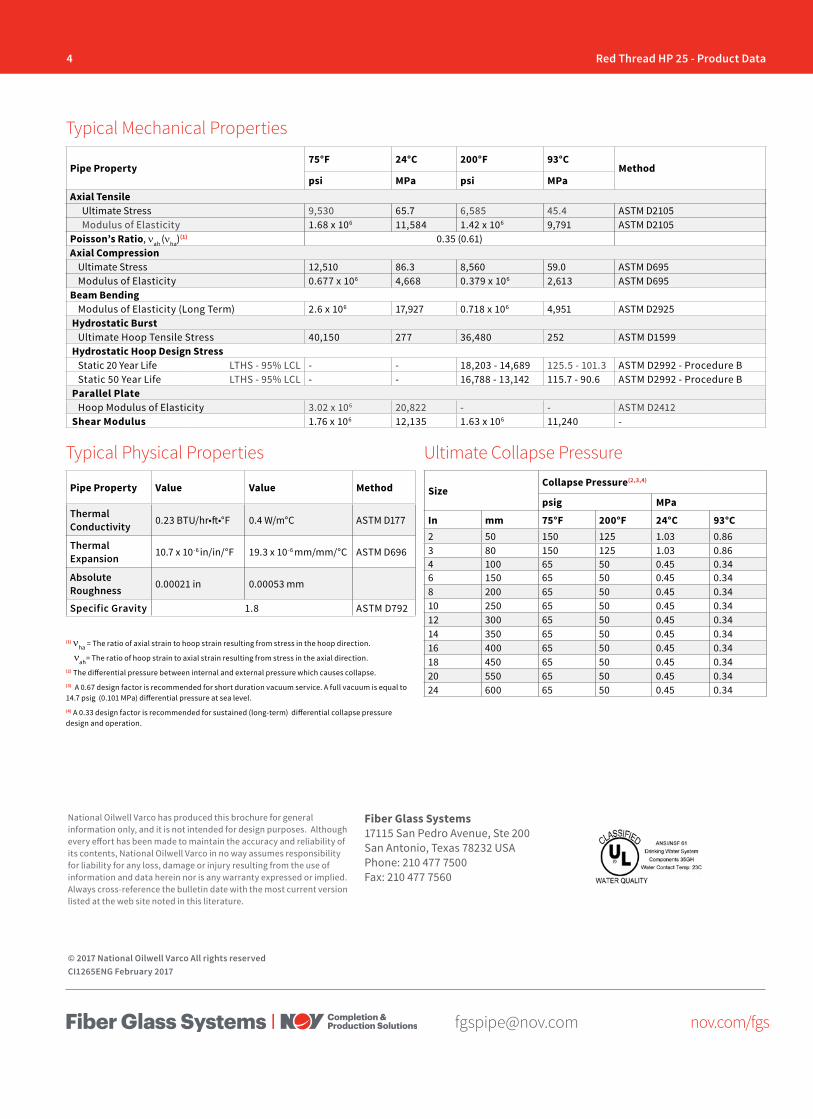
Ultimate Collapse Pressure
Pipe Property75°F 24°C 200°F 93°C
Methodpsi MPa psi MPa
Axial TensileUltimate Stress 9,530 65.7 6,585 45.4 ASTM D2105Modulus of Elasticity 1.68 x 10⁶ 11,584 1.42 x 10⁶ 9,791 ASTM D2105
Poisson’s Ratio, νah (νha)(1) 0.35 (0.61)Axial Compression
Ultimate Stress 12,510 86.3 8,560 59.0 ASTM D695Modulus of Elasticity 0.677 x 10⁶ 4,668 0.379 x 10⁶ 2,613 ASTM D695
Beam BendingModulus of Elasticity (Long Term) 2.6 x 10⁶ 17,927 0.718 x 10⁶ 4,951 ASTM D2925
Hydrostatic BurstUltimate Hoop Tensile Stress 40,150 277 36,480 252 ASTM D1599
Hydrostatic Hoop Design StressStatic 20 Year Life LTHS - 95% LCL - - 18,203 - 14,689 125.5 - 101.3 ASTM D2992 - Procedure BStatic 50 Year Life LTHS - 95% LCL - - 16,788 - 13,142 115.7 - 90.6 ASTM D2992 - Procedure B
Parallel PlateHoop Modulus of Elasticity 3.02 x 10⁶ 20,822 - - ASTM D2412
Shear Modulus 1.76 x 10⁶ 12,135 1.63 x 10⁶ 11,240 -
Pipe Property Value Value Method
Thermal Conductivity 0.23 BTU/hr•ft•°F 0.4 W/m°C ASTM D177
Thermal Expansion 10.7 x 10⁻⁶ in/in/°F 19.3 x 10⁻⁶ mm/mm/°C ASTM D696
Absolute Roughness 0.00021 in 0.00053 mm
Specific Gravity 1.8 ASTM D792
Typical Mechanical Properties
Typical Physical Properties
SizeCollapse Pressure(2,3,4)
psig MPa
In mm 75°F 200°F 24°C 93°C2 50 150 125 1.03 0.863 80 150 125 1.03 0.864 100 65 50 0.45 0.346 150 65 50 0.45 0.348 200 65 50 0.45 0.3410 250 65 50 0.45 0.3412 300 65 50 0.45 0.3414 350 65 50 0.45 0.3416 400 65 50 0.45 0.3418 450 65 50 0.45 0.3420 550 65 50 0.45 0.3424 600 65 50 0.45 0.34
(1) νha = The ratio of axial strain to hoop strain resulting from stress in the hoop direction.
νah= The ratio of hoop strain to axial strain resulting from stress in the axial direction.(2) The differential pressure between internal and external pressure which causes collapse. (3) A 0.67 design factor is recommended for short duration vacuum service. A full vacuum is equal to 14.7 psig (0.101 MPa) differential pressure at sea level. (4) A 0.33 design factor is recommended for sustained (long-term) differential collapse pressure design and operation.
[email protected] nov.com/fgs
Product Name 14/15 Green Thread™ HP 16(Product Data) O I L & G A S C H E M I C A L
& I N D U S T R I A LO F F S H O R EM A R I N E M I N I N GF U E L
H A N D L I N G
Bell & Spigot
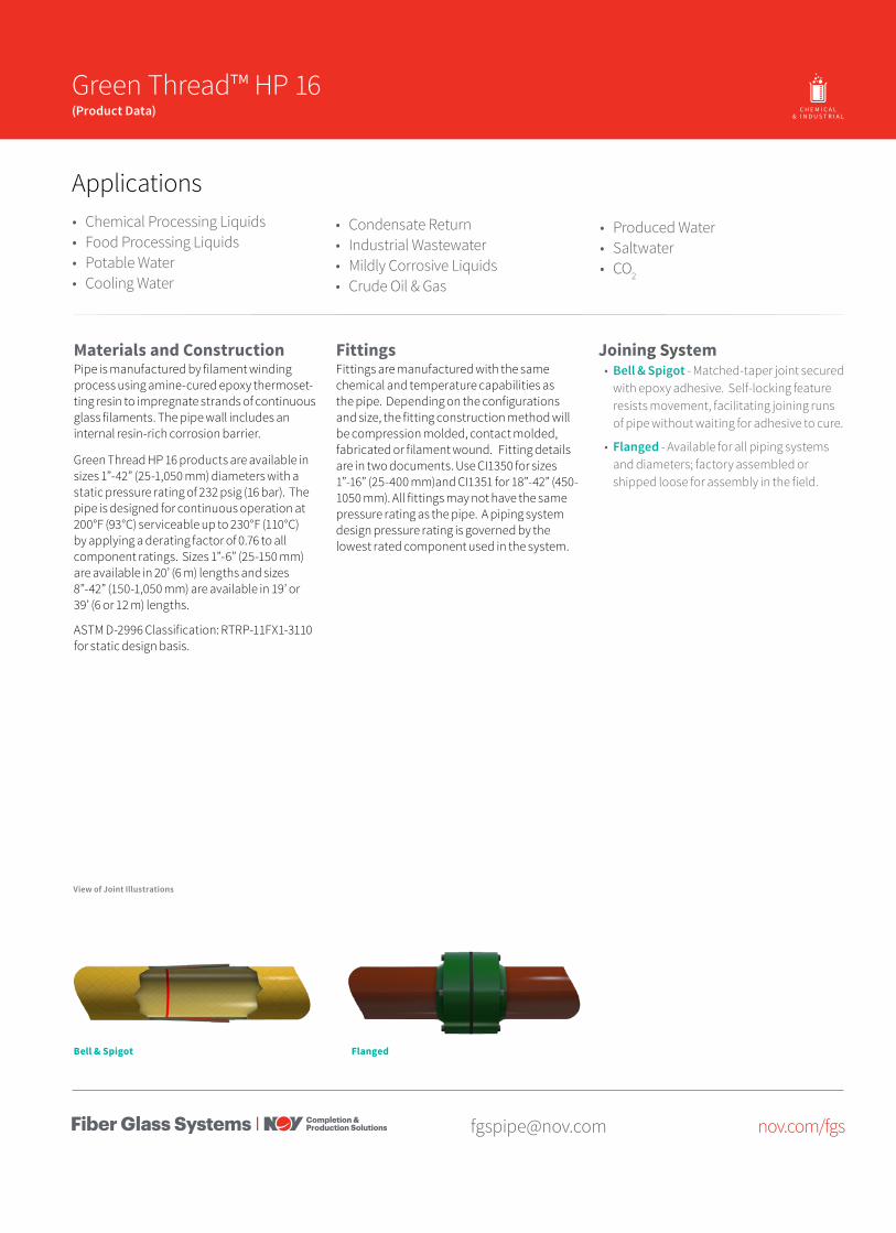
Materials and ConstructionPipe is manufactured by filament winding process using amine-cured epoxy thermoset-ting resin to impregnate strands of continuous glass filaments. The pipe wall includes an internal resin-rich corrosion barrier.
Green Thread HP 16 products are available in sizes 1”-42” (25-1,050 mm) diameters with a static pressure rating of 232 psig (16 bar). The pipe is designed for continuous operation at 200°F (93°C) serviceable up to 230°F (110°C) by applying a derating factor of 0.76 to all component ratings. Sizes 1”-6” (25-150 mm) are available in 20’ (6 m) lengths and sizes 8”-42” (150-1,050 mm) are available in 19’ or 39’ (6 or 12 m) lengths.
ASTM D-2996 Classification: RTRP-11FX1-3110 for static design basis.
FittingsFittings are manufactured with the same chemical and temperature capabilities as the pipe. Depending on the configurations and size, the fitting construction method will be compression molded, contact molded, fabricated or filament wound. Fitting details are in two documents. Use CI1350 for sizes 1”-16” (25-400 mm)and CI1351 for 18”-42” (450-1050 mm). All fittings may not have the same pressure rating as the pipe. A piping system design pressure rating is governed by the lowest rated component used in the system.
Applications• Chemical Processing Liquids• Food Processing Liquids• Potable Water• Cooling Water
• Condensate Return• Industrial Wastewater• Mildly Corrosive Liquids• Crude Oil & Gas
Joining System• Bell & Spigot - Matched-taper joint secured
with epoxy adhesive. Self-locking feature resists movement, facilitating joining runs of pipe without waiting for adhesive to cure.
• Flanged - Available for all piping systems and diameters; factory assembled or shipped loose for assembly in the field.
• Produced Water• Saltwater• CO2
View of Joint Illustrations
Flanged
2 Green Thread HP 16 - Product Data
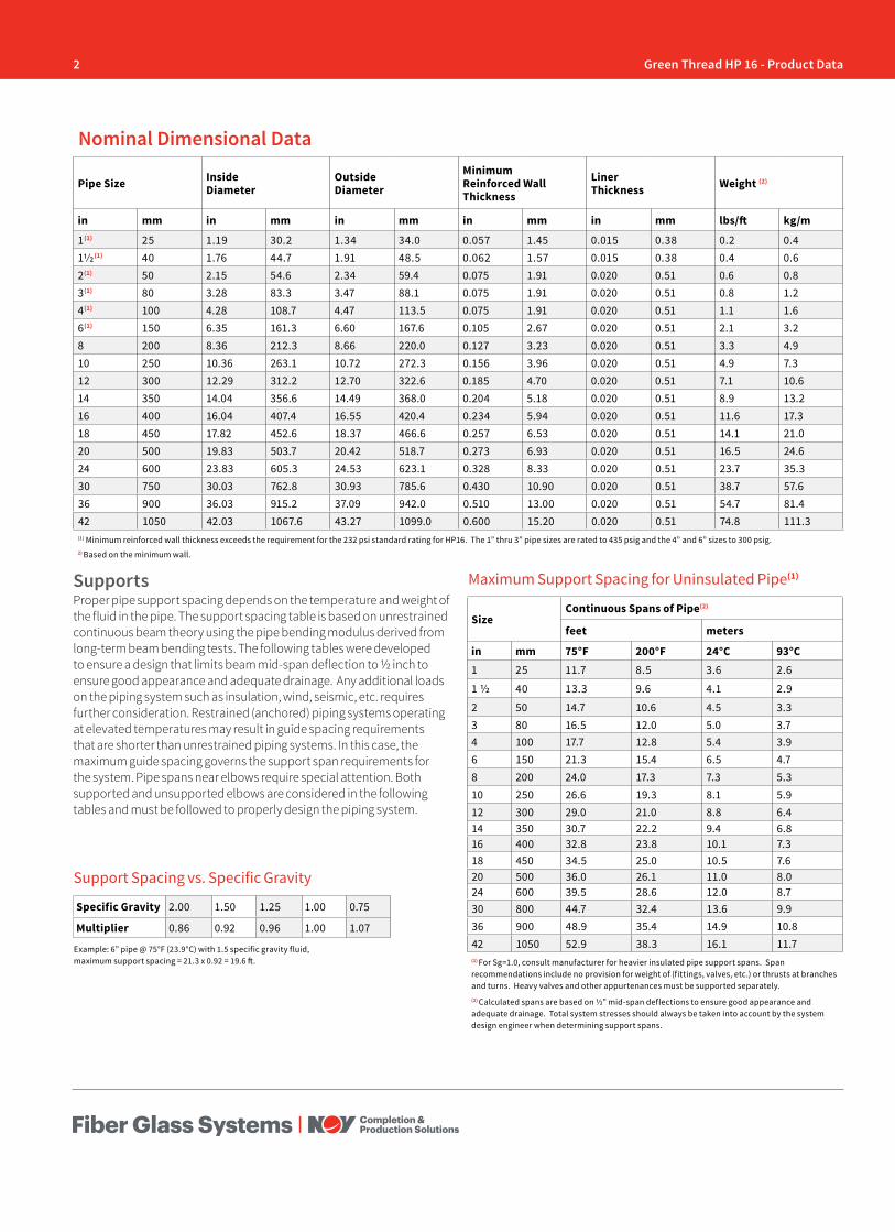
Pipe Size Inside Diameter
Outside Diameter
Minimum Reinforced Wall Thickness
Liner Thickness Weight (2)
in mm in mm in mm in mm in mm lbs/ft kg/m
1(1) 25 1.19 30.2 1.34 34.0 0.057 1.45 0.015 0.38 0.2 0.411/2(1) 40 1.76 44.7 1.91 48.5 0.062 1.57 0.015 0.38 0.4 0.62(1) 50 2.15 54.6 2.34 59.4 0.075 1.91 0.020 0.51 0.6 0.83(1) 80 3.28 83.3 3.47 88.1 0.075 1.91 0.020 0.51 0.8 1.24(1) 100 4.28 108.7 4.47 113.5 0.075 1.91 0.020 0.51 1.1 1.66(1) 150 6.35 161.3 6.60 167.6 0.105 2.67 0.020 0.51 2.1 3.28 200 8.36 212.3 8.66 220.0 0.127 3.23 0.020 0.51 3.3 4.910 250 10.36 263.1 10.72 272.3 0.156 3.96 0.020 0.51 4.9 7.312 300 12.29 312.2 12.70 322.6 0.185 4.70 0.020 0.51 7.1 10.614 350 14.04 356.6 14.49 368.0 0.204 5.18 0.020 0.51 8.9 13.216 400 16.04 407.4 16.55 420.4 0.234 5.94 0.020 0.51 11.6 17.318 450 17.82 452.6 18.37 466.6 0.257 6.53 0.020 0.51 14.1 21.020 500 19.83 503.7 20.42 518.7 0.273 6.93 0.020 0.51 16.5 24.624 600 23.83 605.3 24.53 623.1 0.328 8.33 0.020 0.51 23.7 35.330 750 30.03 762.8 30.93 785.6 0.430 10.90 0.020 0.51 38.7 57.636 900 36.03 915.2 37.09 942.0 0.510 13.00 0.020 0.51 54.7 81.442 1050 42.03 1067.6 43.27 1099.0 0.600 15.20 0.020 0.51 74.8 111.3(1) Minimum reinforced wall thickness exceeds the requirement for the 232 psi standard rating for HP16. The 1” thru 3” pipe sizes are rated to 435 psig and the 4” and 6” sizes to 300 psig.2) Based on the minimum wall.
Nominal Dimensional Data
SizeContinuous Spans of Pipe(2)
feet meters
in mm 75°F 200°F 24°C 93°C1 25 11.7 8.5 3.6 2.6
1 ½ 40 13.3 9.6 4.1 2.9
2 50 14.7 10.6 4.5 3.33 80 16.5 12.0 5.0 3.74 100 17.7 12.8 5.4 3.96 150 21.3 15.4 6.5 4.78 200 24.0 17.3 7.3 5.310 250 26.6 19.3 8.1 5.912 300 29.0 21.0 8.8 6.414 350 30.7 22.2 9.4 6.816 400 32.8 23.8 10.1 7.318 450 34.5 25.0 10.5 7.620 500 36.0 26.1 11.0 8.024 600 39.5 28.6 12.0 8.730 800 44.7 32.4 13.6 9.936 900 48.9 35.4 14.9 10.842 1050 52.9 38.3 16.1 11.7(1) For Sg=1.0, consult manufacturer for heavier insulated pipe support spans. Span recommendations include no provision for weight of (fittings, valves, etc.) or thrusts at branches and turns. Heavy valves and other appurtenances must be supported separately.(2) Calculated spans are based on ½” mid-span deflections to ensure good appearance and adequate drainage. Total system stresses should always be taken into account by the system design engineer when determining support spans.
Maximum Support Spacing for Uninsulated Pipe(1)
Example: 6” pipe @ 75°F (23.9°C) with 1.5 specific gravity fluid, maximum support spacing = 21.3 x 0.92 = 19.6 ft.
SupportsProper pipe support spacing depends on the temperature and weight of the fluid in the pipe. The support spacing table is based on unrestrained continuous beam theory using the pipe bending modulus derived from long-term beam bending tests. The following tables were developed to ensure a design that limits beam mid-span deflection to ½ inch to ensure good appearance and adequate drainage. Any additional loads on the piping system such as insulation, wind, seismic, etc. requires further consideration. Restrained (anchored) piping systems operating at elevated temperatures may result in guide spacing requirements that are shorter than unrestrained piping systems. In this case, the maximum guide spacing governs the support span requirements for the system. Pipe spans near elbows require special attention. Both supported and unsupported elbows are considered in the following tables and must be followed to properly design the piping system.
Support Spacing vs. Specific Gravity
Specific Gravity 2.00 1.50 1.25 1.00 0.75
Multiplier 0.86 0.92 0.96 1.00 1.07
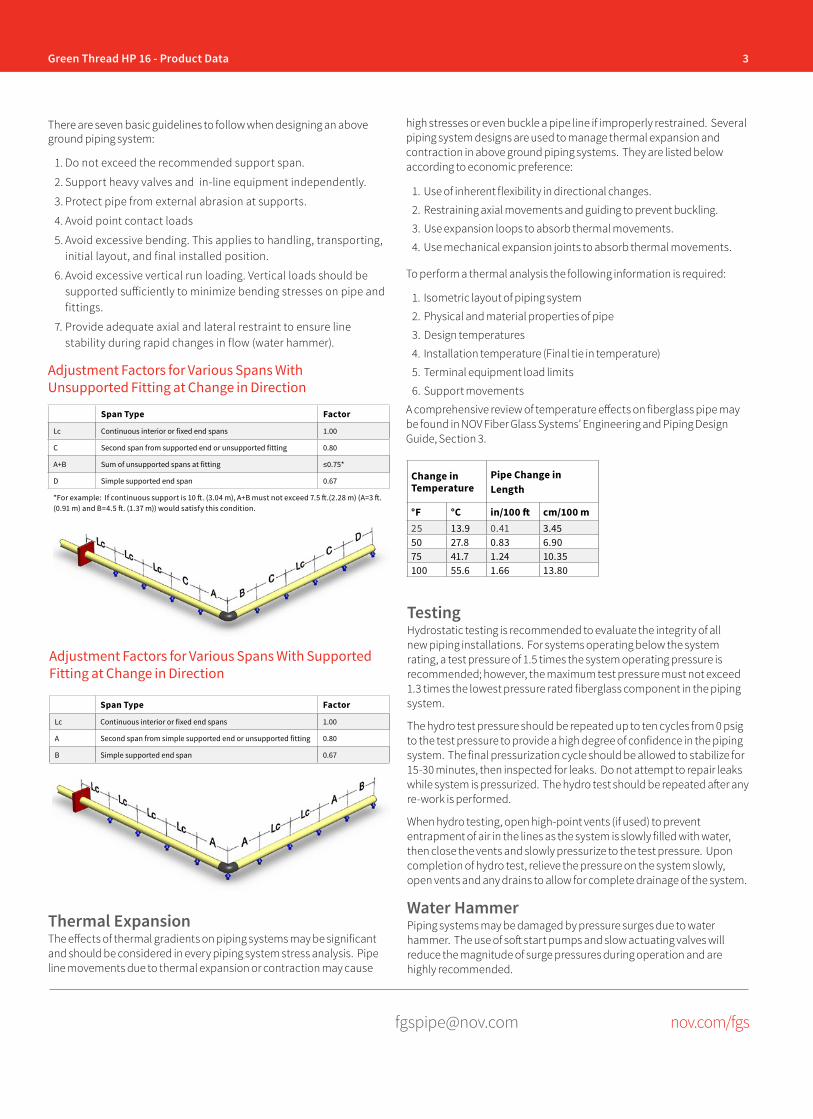
3Green Thread HP 16 - Product Data
[email protected] nov.com/fgs
There are seven basic guidelines to follow when designing an above ground piping system:
1. Do not exceed the recommended support span.
2. Support heavy valves and in-line equipment independently.
3. Protect pipe from external abrasion at supports.
4. Avoid point contact loads
5. Avoid excessive bending. This applies to handling, transporting, initial layout, and final installed position.
6. Avoid excessive vertical run loading. Vertical loads should be supported sufficiently to minimize bending stresses on pipe and fittings.
7. Provide adequate axial and lateral restraint to ensure line stability during rapid changes in flow (water hammer).
Adjustment Factors for Various Spans With Unsupported Fitting at Change in Direction
Span Type Factor
Lc Continuous interior or fixed end spans 1.00
C Second span from supported end or unsupported fitting 0.80
A+B Sum of unsupported spans at fitting ≤0.75*
D Simple supported end span 0.67
*For example: If continuous support is 10 ft. (3.04 m), A+B must not exceed 7.5 ft.(2.28 m) (A=3 ft. (0.91 m) and B=4.5 ft. (1.37 m)) would satisfy this condition.
Span Type Factor
Lc Continuous interior or fixed end spans 1.00
A Second span from simple supported end or unsupported fitting 0.80
B Simple supported end span 0.67
Adjustment Factors for Various Spans With Supported Fitting at Change in Direction
Thermal ExpansionThe effects of thermal gradients on piping systems may be significant and should be considered in every piping system stress analysis. Pipe line movements due to thermal expansion or contraction may cause
Change in Temperature
Pipe Change in Length
°F °C in/100 ft cm/100 m25 13.9 0.41 3.4550 27.8 0.83 6.9075 41.7 1.24 10.35100 55.6 1.66 13.80
TestingHydrostatic testing is recommended to evaluate the integrity of all new piping installations. For systems operating below the system rating, a test pressure of 1.5 times the system operating pressure is recommended; however, the maximum test pressure must not exceed 1.3 times the lowest pressure rated fiberglass component in the piping system.
The hydro test pressure should be repeated up to ten cycles from 0 psig to the test pressure to provide a high degree of confidence in the piping system. The final pressurization cycle should be allowed to stabilize for 15-30 minutes, then inspected for leaks. Do not attempt to repair leaks while system is pressurized. The hydro test should be repeated after any re-work is performed.
When hydro testing, open high-point vents (if used) to prevent entrapment of air in the lines as the system is slowly filled with water, then close the vents and slowly pressurize to the test pressure. Upon completion of hydro test, relieve the pressure on the system slowly, open vents and any drains to allow for complete drainage of the system.
Water HammerPiping systems may be damaged by pressure surges due to water hammer. The use of soft start pumps and slow actuating valves will reduce the magnitude of surge pressures during operation and are highly recommended.
high stresses or even buckle a pipe line if improperly restrained. Several piping system designs are used to manage thermal expansion and contraction in above ground piping systems. They are listed below according to economic preference:
1. Use of inherent flexibility in directional changes.
2. Restraining axial movements and guiding to prevent buckling.
3. Use expansion loops to absorb thermal movements.
4. Use mechanical expansion joints to absorb thermal movements.
To perform a thermal analysis the following information is required:
1. Isometric layout of piping system
2. Physical and material properties of pipe
3. Design temperatures
4. Installation temperature (Final tie in temperature)
5. Terminal equipment load limits
6. Support movements
A comprehensive review of temperature effects on fiberglass pipe may be found in NOV Fiber Glass Systems’ Engineering and Piping Design Guide, Section 3.
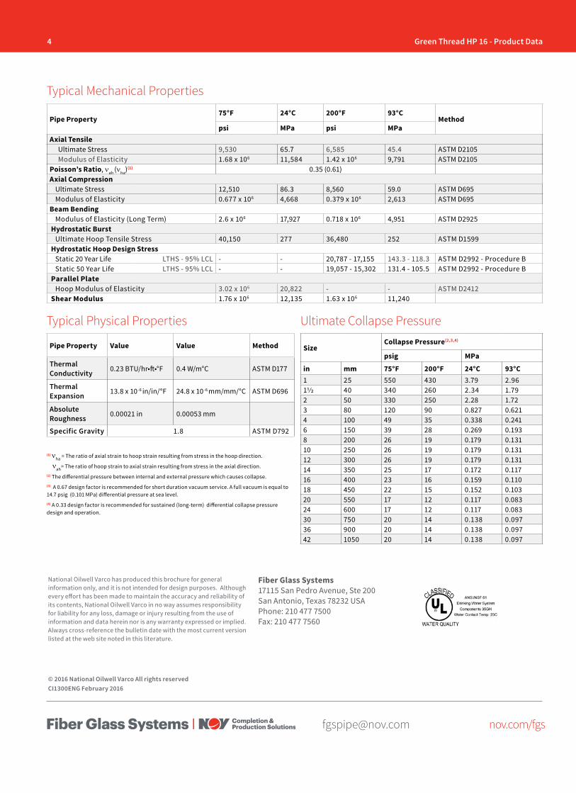
4 Green Thread HP 16 - Product Data
[email protected] nov.com/fgs
Fiber Glass Systems17115 San Pedro Avenue, Ste 200San Antonio, Texas 78232 USAPhone: 210 477 7500Fax: 210 477 7560
National Oilwell Varco has produced this brochure for general information only, and it is not intended for design purposes. Although every effort has been made to maintain the accuracy and reliability of its contents, National Oilwell Varco in no way assumes responsibility for liability for any loss, damage or injury resulting from the use of information and data herein nor is any warranty expressed or implied. Always cross-reference the bulletin date with the most current version listed at the web site noted in this literature.
© 2016 National Oilwell Varco All rights reservedCI1300ENG February 2016
Pipe Property75°F 24°C 200°F 93°C
Methodpsi MPa psi MPa
Axial TensileUltimate Stress 9,530 65.7 6,585 45.4 ASTM D2105Modulus of Elasticity 1.68 x 10⁶ 11,584 1.42 x 10⁶ 9,791 ASTM D2105
Poisson’s Ratio, νah (νha)(1) 0.35 (0.61)Axial Compression
Ultimate Stress 12,510 86.3 8,560 59.0 ASTM D695Modulus of Elasticity 0.677 x 10⁶ 4,668 0.379 x 10⁶ 2,613 ASTM D695
Beam BendingModulus of Elasticity (Long Term) 2.6 x 10⁶ 17,927 0.718 x 10⁶ 4,951 ASTM D2925
Hydrostatic BurstUltimate Hoop Tensile Stress 40,150 277 36,480 252 ASTM D1599
Hydrostatic Hoop Design StressStatic 20 Year Life LTHS - 95% LCL - - 20,787 - 17,155 143.3 - 118.3 ASTM D2992 - Procedure BStatic 50 Year Life LTHS - 95% LCL - - 19,057 - 15,302 131.4 - 105.5 ASTM D2992 - Procedure B
Parallel PlateHoop Modulus of Elasticity 3.02 x 10⁶ 20,822 - - ASTM D2412
Shear Modulus 1.76 x 10⁶ 12,135 1.63 x 10⁶ 11,240
Pipe Property Value Value Method
Thermal Conductivity 0.23 BTU/hr•ft•°F 0.4 W/m°C ASTM D177
Thermal Expansion 13.8 x 10⁻⁶ in/in/°F 24.8 x 10⁻⁶ mm/mm/°C ASTM D696
Absolute Roughness 0.00021 in 0.00053 mm
Specific Gravity 1.8 ASTM D792
Typical Mechanical Properties
Typical Physical Properties Ultimate Collapse Pressure
SizeCollapse Pressure(2,3,4)
psig MPa
in mm 75°F 200°F 24°C 93°C1 25 550 430 3.79 2.9611/2 40 340 260 2.34 1.792 50 330 250 2.28 1.723 80 120 90 0.827 0.6214 100 49 35 0.338 0.2416 150 39 28 0.269 0.1938 200 26 19 0.179 0.13110 250 26 19 0.179 0.13112 300 26 19 0.179 0.13114 350 25 17 0.172 0.11716 400 23 16 0.159 0.11018 450 22 15 0.152 0.10320 550 17 12 0.117 0.08324 600 17 12 0.117 0.08330 750 20 14 0.138 0.09736 900 20 14 0.138 0.09742 1050 20 14 0.138 0.097
(1) νha = The ratio of axial strain to hoop strain resulting from stress in the hoop direction.
νah= The ratio of hoop strain to axial strain resulting from stress in the axial direction.(2) The differential pressure between internal and external pressure which causes collapse. (3) A 0.67 design factor is recommended for short duration vacuum service. A full vacuum is equal to 14.7 psig (0.101 MPa) differential pressure at sea level. (4) A 0.33 design factor is recommended for sustained (long-term) differential collapse pressure design and operation.
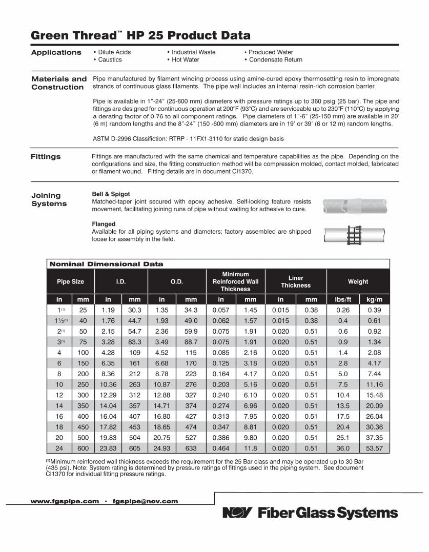
Green Thread™ HP 25 Product Data Applications • Dilute Acids
• Caustics• Industrial Waste• Hot Water
• Produced Water• Condensate Return
Materials andConstruction
Pipe manufactured by filament winding process using amine-cured epoxy thermosetting resin to impregnate strands of continuous glass filaments. The pipe wall includes an internal resin-rich corrosion barrier.
Pipe is available in 1”-24” (25-600 mm) diameters with pressure ratings up to 360 psig (25 bar). The pipe and fittings are designed for continuous operation at 200°F (93°C) and are serviceable up to 230°F (110°C) by applying a derating factor of 0.76 to all component ratings. Pipe diameters of 1”-6” (25-150 mm) are available in 20’ (6 m) random lengths and the 8”-24” (150 -600 mm) diameters are in 19’ or 39’ (6 or 12 m) random lengths.
ASTM D-2996 Classifiction: RTRP - 11FX1-3110 for static design basis
Fittings Fittings are manufactured with the same chemical and temperature capabilities as the pipe. Depending on the configurations and size, the fitting construction method will be compression molded, contact molded, fabricated or filament wound. Fitting details are in document CI1370.
Joining Systems
Bell & SpigotMatched-taper joint secured with epoxy adhesive. Self-locking feature resists movement, facilitating joining runs of pipe without waiting for adhesive to cure.
FlangedAvailable for all piping systems and diameters; factory assembled are shipped loose for assembly in the field.
www.fgspipe.com • [email protected]
Nominal Dimensional Data
Pipe Size I.D. O.D.Minimum
Reinforced Wall Thickness
Liner Thickness
Weight
in mm in mm in mm in mm in mm lbs/ft kg/m
1(1) 25 1.19 30.3 1.35 34.3 0.057 1.45 0.015 0.38 0.26 0.39
1½(1) 40 1.76 44.7 1.93 49.0 0.062 1.57 0.015 0.38 0.4 0.61
2(1) 50 2.15 54.7 2.36 59.9 0.075 1.91 0.020 0.51 0.6 0.92
3(1) 75 3.28 83.3 3.49 88.7 0.075 1.91 0.020 0.51 0.9 1.34
4 100 4.28 109 4.52 115 0.085 2.16 0.020 0.51 1.4 2.08
6 150 6.35 161 6.68 170 0.125 3.18 0.020 0.51 2.8 4.17
8 200 8.36 212 8.78 223 0.164 4.17 0.020 0.51 5.0 7.44
10 250 10.36 263 10.87 276 0.203 5.16 0.020 0.51 7.5 11.16
12 300 12.29 312 12.88 327 0.240 6.10 0.020 0.51 10.4 15.48
14 350 14.04 357 14.71 374 0.274 6.96 0.020 0.51 13.5 20.09
16 400 16.04 407 16.80 427 0.313 7.95 0.020 0.51 17.5 26.04
18 450 17.82 453 18.65 474 0.347 8.81 0.020 0.51 20.4 30.36
20 500 19.83 504 20.75 527 0.386 9.80 0.020 0.51 25.1 37.35
24 600 23.83 605 24.93 633 0.464 11.8 0.020 0.51 36.0 53.57
(1)Minimum reinforced wall thickness exceeds the requirement for the 25 Bar class and may be operated up to 30 Bar (435 psi). Note: System rating is determined by pressure ratings of fittings used in the piping system. See document CI1370 for individual fitting pressure ratings.
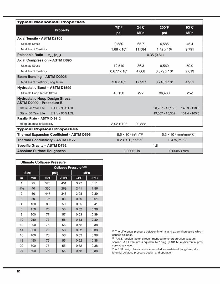
2
Typical Mechanical Properties
Property75°F 24°C 200°F 93°C
psi MPa psi MPa
Axial Tensile - ASTM D2105 Ultimate Stress 9,530 65.7 6,585 45.4 Modulus of Elasticity 1.68 x 10⁶ 11,584 1.42 x 10⁶ 9,791
Poisson’s Ratio νa/h (νh/a) 0.35 (0.61)
Axial Compression – ASTM D695 Ultimate Stress 12,510 86.3 8,560 59.0 Modulus of Elasticity 0.677 x 10⁶ 4,668 0.379 x 10⁶ 2,613
Beam Bending – ASTM D2925 Modulus of Elasticity (Long Term) 2.6 x 10⁶ 17,927 0.718 x 10⁶ 4,951
Hydrostatic Burst – ASTM D1599 Ultimate Hoop Tensile Stress 40,150 277 36,480 252
Hydrostatic Hoop Design StressASTM D2992 - Procedure B Static 20 Year Life LTHS - 95% LCL 20,787 - 17,155 143.3 - 118.3
Static 50 Year Life LTHS - 95% LCL 19,057 - 15,302 131.4 - 105.5
Parallel Plate - ASTM D 2412
Hoop Modulus of Elasticity 3.02 x 10⁶ 20,822Typical Physical Properties
Thermal Expansion Coefficient - ASTM D696 8.5 x 10⁻⁶ in/in/°F 15.3 x 10⁻⁶ mm/mm/°C
Thermal Conductivity – ASTM D177 0.23 BTU/hr-ft-°F 0.4 W/m-°C
Specific Gravity – ASTM D792 1.8
Absolute Surface Roughness 0.00021 in 0.00053 mm
Ultimate Collapse Pressure
Size
Collapse Pressure(1,2,3)
psig MPa
in mm 75°F 200°F 24°C 93°C
1 25 576 451 3.97 3.11
1½ 40 350 269 2.41 1.86
2 50 447 346 3.08 2.39
3 80 125 93 0.86 0.64
4 100 80 59 0.55 0.41
6 150 75 55 0.52 0.38
8 200 77 57 0.53 0.39
10 250 77 56 0.53 0.39
12 300 76 56 0.52 0.38
14 350 76 56 0.52 0.38
16 400 76 56 0.52 0.38
18 450 75 55 0.52 0.38
20 500 75 55 0.52 0.38
24 600 75 55 0.52 0.38
(1) The differential pressure between internal and external pressure which causes collapse. (2) A 0.67 design factor is recommended for short duration vacuum service. A full vacuum is equal to 14.7 psig (0.101 MPa) differential pres-sure at sea level. (3) A 0.33 design factor is recommended for sustained (long-term) dif-ferential collapse pressure design and operation.
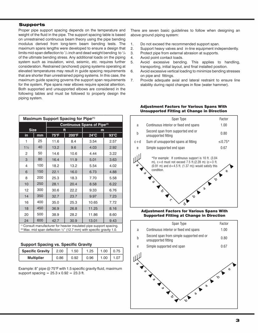
Proper pipe support spacing depends on the temperature and weight of the fluid in the pipe. The support spacing table is based on unrestrained continuous beam theory using the pipe bending modulus derived from long-term beam bending tests. The maximum spans lengths were developed to ensure a design that limits mid-span deflection to 1/2 inch and dead weight bending to 1/8 of the ultimate bending stress. Any additional loads on the piping system such as insulation, wind, seismic, etc. requires further consideration. Restrained (anchored) piping systems operating at elevated temperatures may result in guide spacing requirements that are shorter than unrestrained piping systems. In this case, the maximum guide spacing governs the support span requirements for the system. Pipe spans near elbows require special attention. Both supported and unsupported elbows are considered in the following tables and must be followed to properly design the piping system.
3
There are seven basic guidelines to follow when designing an above ground piping system:
1. Do not exceed the recommended support span.2. Support heavy valves and in-line equipment independently. 3. Protect pipe from external abrasion at supports.4. Avoid point contact loads.5. Avoid excessive bending. This applies to handling,
transporting, initial layout, and final installed position.6. Avoid excessive vertical loading to minimize bending stresses
on pipe and fittings.7. Provide adequate axial and lateral restraint to ensure line
stability during rapid changes in flow (water hammer).
Maximum Support Spacing for Pipe(1)
SizeContinuous Spans of Pipe(2)
ft min mm 75°F 200°F 24°C 93°C
1 25 11.6 8.4 3.54 2.57
1½ 40 13.2 9.6 4.03 2.92
2 50 14.6 10.6 4.44 3.22
3 80 16.4 11.9 5.01 3.63
4 100 18.2 13.2 5.54 4.02
6 150 22.1 16.0 6.73 4.88
8 200 25.3 18.3 7.70 5.58
10 250 28.1 20.4 8.58 6.22
12 300 30.6 22.2 9.33 6.76
14 350 32.7 23.7 9.97 7.23
16 400 35.0 25.3 10.65 7.72
18 450 36.9 26.8 11.25 8.16
20 500 38.9 28.2 11.86 8.60
24 600 42.7 30.9 13.01 9.43(1) Consult manufacturer for heavier insulated pipe support spacing.(2) Max. mid span deflection ½” (12.7 mm) with specific gravity 1.0.
Supports
Support Spacing vs. Specific Gravity
Specific Gravity 2.00 1.50 1.25 1.00 0.75
Multiplier 0.86 0.92 0.96 1.00 1.07
Adjustment Factors for Various Spans WithUnsupported Fitting at Change in Direction
Span Type Factor
a Continuous interior or fixed end spans 1.00
bSecond span from supported end orunsupported fitting
0.80
c+d Sum of unsupported spans at fitting ≤0.75*
e Simple supported end span 0.67
*For example: If continuous support is 10 ft. (3.04 m), c+d must not exceed 7.5 ft.(2.28 m) (c=3 ft. (0.91 m) and d=4.5 ft. (1.37 m)) would satisfy this condition.
Span Type Factor
a Continuous interior or fixed end spans 1.00
bSecond span from simple supported end or unsupported fitting
0.80
e Simple supported end span 0.67
Adjustment Factors for Various Spans WithSupported Fitting at Change in Direction
Example: 8” pipe @ 75°F with 1.5 specific gravity fluid, maximum support spacing = 25.3 x 0.92 = 23.3 ft.
Thermal ExpansionThe effects of thermal gradients on piping systems may be significant and should be considered in every piping system stress analysis. Pipe line movements due to thermal expansion or contraction may cause high stresses or even buckle a pipe line if improperly restrained. Several piping system designs are used to manage thermal expansion and contraction in above ground piping systems. They are listed below according to economic preference:
1. Use of inherent flexibility in directional changes.2. Restraining axial movements and guiding to prevent buckling.3. Use expansion loops to absorb thermal movements.4. Use mechanical expansion joints to absorb thermal movements.
To perform a thermal analysis the following information is required:1. Isometric layout of piping system2. Physical and material properties of pipe3. Design temperatures4. Installation temperature (Final tie in temperature)5. Terminal equipment load limits6. Support movements
A comprehensive review of temperature effects on fiberglass pipe may be found in NOV Fiber Glass Systems’ ENG1000 “Engineering and Piping Design Guide”, Section 3.
Testing Hydrostatic testing is recommended to evaluate the integrity of all new piping installations. For systems operating below the system rating, a test pressure of 1.5 times the system operating pressure is recommended; however, the maximum test pressure must not exceed 1.25 times the lowest pressure rated fiberglass component in the piping system. The hydro test pressure should be repeated up to ten cycles from 0 psig to the test pressure to provide a high degree of confidence in the piping system. The final pressurization cycle should be allowed to stabilize for 15-30 minutes, then inspected for leaks. Do not attempt to repair leaks while system is pressurized. The hydro test should be repeated after any re-work is performed.
When hydro testing, open high-point vents (if used) to prevent entrapment of air in the lines as the system is slowly filled with water, then close the vents and slowly pressurize to the test pressure. Upon completion of hydro test, relieve the pressure on the system slowly, open vents and any drains to allow for complete drainage of the system.
Water HammerPiping systems may be damaged by pressure surges due to water hammer. The use of soft start pumps and slow actuating valves will reduce the magnitude of surge pressures during operation and are highly recommended.
www.fgspipe.com • [email protected]
2425 SW 36th Street 2700 West 65th StreetSan Antonio, Texas 78237 USA Little Rock, Arkansas 72209 USAPhone: 1 (210) 434-5043 Phone: 1 (501) 568-4010Fax:: 1 (210) 434-7543 Fax: 1 (501) 568-4465
© 2013 National Oilwell Varco. Al rights reserved,CI1325 May 2013
National Oilwell Varco has produced this brochure for general information only, and it is not intended for design purposes. Although every effort has been made to maintain the accuracy and reliability of its contents, National Oilwell Varco in no way assumes responsibility for liability for any loss, damage or injury resulting from the use of information and data herein nor is any warranty expressed or implied. Always cross-reference the bulletin date with the most current version listed at the web site noted in this literature.
North America South America Europe Asia Pacific Middle East17115 San Pedro Ave. Suite 200 Avenida Fernando Simoes P.O. Box 6, 4190 CA No. 7A, Tuas Avenue 3 P.O. Box 17324San Antonio, Texas 78232 USA Recife, Brazil 51020-390 Geldermalsen, The Netherlands Jurong, Singapore 639407 Dubai, UAEPhone: 210 477 7500 Phone: 55 31 3501 0023 Phone: 31 345 587 587 Phone: 65 6861 6118 Phone: 971 4881 3566
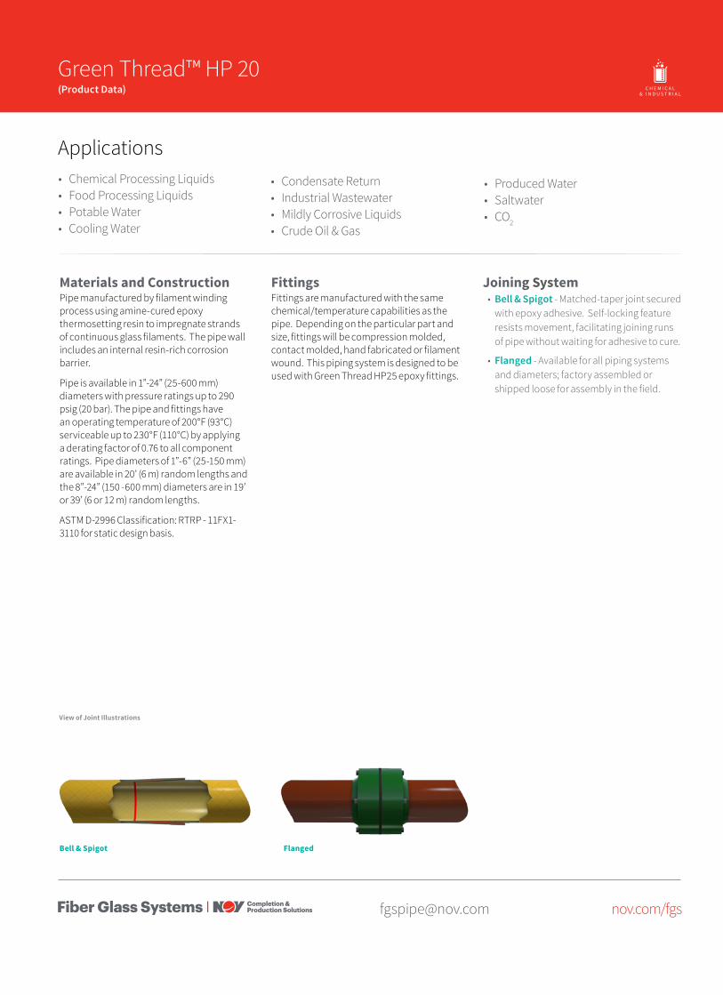
[email protected] nov.com/fgs
Product Name 14/15 Green Thread™ HP 20(Product Data) O I L & G A S C H E M I C A L
& I N D U S T R I A LO F F S H O R EM A R I N E M I N I N GF U E L
H A N D L I N G
Bell & Spigot
Materials and ConstructionPipe manufactured by filament winding process using amine-cured epoxy thermosetting resin to impregnate strands of continuous glass filaments. The pipe wall includes an internal resin-rich corrosion barrier.
Pipe is available in 1”-24” (25-600 mm) diameters with pressure ratings up to 290 psig (20 bar). The pipe and fittings have an operating temperature of 200°F (93°C) serviceable up to 230°F (110°C) by applying a derating factor of 0.76 to all component ratings. Pipe diameters of 1”-6” (25-150 mm) are available in 20’ (6 m) random lengths and the 8”-24” (150 -600 mm) diameters are in 19’ or 39’ (6 or 12 m) random lengths.
ASTM D-2996 Classification: RTRP - 11FX1-3110 for static design basis.
FittingsFittings are manufactured with the same chemical/temperature capabilities as the pipe. Depending on the particular part and size, fittings will be compression molded, contact molded, hand fabricated or filament wound. This piping system is designed to be used with Green Thread HP25 epoxy fittings.
Applications• Chemical Processing Liquids• Food Processing Liquids• Potable Water• Cooling Water
• Condensate Return• Industrial Wastewater• Mildly Corrosive Liquids• Crude Oil & Gas
Joining System• Bell & Spigot - Matched-taper joint secured
with epoxy adhesive. Self-locking feature resists movement, facilitating joining runs of pipe without waiting for adhesive to cure.
• Flanged - Available for all piping systems and diameters; factory assembled or shipped loose for assembly in the field.
• Produced Water• Saltwater• CO2
View of Joint Illustrations
Flanged
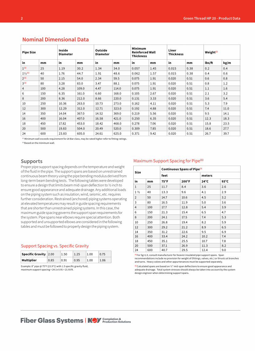
2 Green Thread HP 20 - Product Data
Pipe Size Inside Diameter
Outside Diameter
Minimum Reinforced Wall Thickness
Liner Thickness Weight(2)
in mm in mm in mm in mm in mm lbs/ft kg/m
1(1) 25 1.19 30.2 1.34 34.0 0.057 1.45 0.015 0.38 0.2 0.411/2(1) 40 1.76 44.7 1.91 48.6 0.062 1.57 0.015 0.38 0.4 0.62(1) 50 2.15 54.0 2.34 59.5 0.075 1.91 0.020 0.51 0.6 0.83(1) 80 3.28 83.0 3.47 88.1 0.075 1.91 0.020 0.51 0.8 1.24 100 4.28 109.0 4.47 114.0 0.075 1.91 0.020 0.51 1.1 1.66 150 6.35 161.0 6.60 168.0 0.105 2.67 0.020 0.51 2.1 3.28 200 8.36 212.0 8.66 220.0 0.131 3.33 0.020 0.51 3.6 5.410 250 10.36 263.0 10.73 273.0 0.162 4.11 0.020 0.51 5.3 7.912 300 12.29 312.0 12.71 323.0 0.192 4.88 0.020 0.51 7.4 11.014 350 14.04 367.0 14.52 369.0 0.219 5.56 0.020 0.51 9.5 14.116 400 16.04 407.0 16.58 421.0 0.250 6.35 0.020 0.51 12.3 18.318 450 17.82 453.0 18.42 468.0 0.278 7.06 0.020 0.51 15.8 23.520 500 19.83 504.0 20.49 520.0 0.309 7.85 0.020 0.51 18.6 27.724 600 23.83 605.0 24.61 625.0 0.371 9.42 0.020 0.51 26.7 39.7(1) Minimum wall exceeds requirement for 20 Bar class, may be rated higher refer to fitting ratings.(2) Based on the minimum wall.
Nominal Dimensional Data
SizeContinuous Spans of Pipe(2)
feet meters
in mm 75°F 200°F 24°C 93°C1 25 11.7 8.4 3.6 2.6
1 ½ 40 13.3 9.6 4.1 2.9
2 50 14.7 10.6 4.5 3.23 80 16.5 11.9 5.0 3.64 100 17.7 12.8 5.4 3.96 150 21.3 15.4 6.5 4.78 200 24.1 17.5 7.4 5.310 250 26.8 19.4 8.2 5.912 300 29.2 21.2 8.9 6.514 350 31.2 22.6 9.5 6.916 400 33.4 24.2 10.2 7.418 450 35.1 25.5 10.7 7.820 500 37.1 26.9 11.3 8.224 600 40.7 29.5 12.4 9.0(1) For Sg=1.0, consult manufacturer for heavier insulated pipe support spans. Span recommendations include no provision for weight of (fittings, valves, etc.) or thrusts at branches and turns. Heavy valves and other appurtenances must be supported separately.(2) Calculated spans are based on ½” mid-span deflections to ensure good appearance and adequate drainage. Total system stresses should always be taken into account by the system design engineer when determining support spans.
Maximum Support Spacing for Pipe(1)
Example: 8” pipe @ 75°F (23.9°C) with 1.5 specific gravity fluid, maximum support spacing = 24.1x 0.91 = 21.93 ft.
SupportsProper pipe support spacing depends on the temperature and weight of the fluid in the pipe. The support spans are based on unrestrained continuous beam theory using the pipe bending modulus derived from long-term beam bending tests. The following tables were developed to ensure a design that limits beam mid-span deflection to ½ inch to ensure good appearance and adequate drainage. Any additional loads on the piping system such as insulation, wind, seismic, etc. requires further consideration. Restrained (anchored) piping systems operating at elevated temperatures may result in guide spacing requirements that are shorter than unrestrained piping systems. In this case, the maximum guide spacing governs the support span requirements for the system. Pipe spans near elbows require special attention. Both supported and unsupported elbows are considered in the following tables and must be followed to properly design the piping system.
Support Spacing vs. Specific Gravity
Specific Gravity 2.00 1.50 1.25 1.00 0.75
Multiplier 0.85 0.91 0.95 1.00 1.06
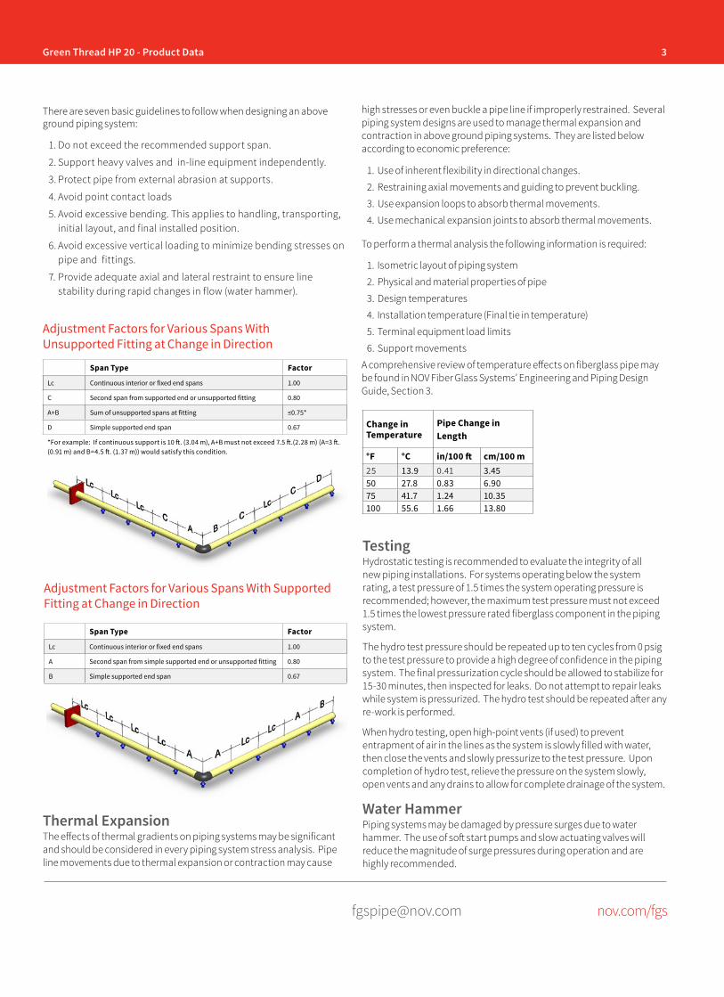
3Green Thread HP 20 - Product Data
[email protected] nov.com/fgs
There are seven basic guidelines to follow when designing an above ground piping system:
1. Do not exceed the recommended support span.
2. Support heavy valves and in-line equipment independently.
3. Protect pipe from external abrasion at supports.
4. Avoid point contact loads
5. Avoid excessive bending. This applies to handling, transporting, initial layout, and final installed position.
6. Avoid excessive vertical loading to minimize bending stresses on pipe and fittings.
7. Provide adequate axial and lateral restraint to ensure line stability during rapid changes in flow (water hammer).
Adjustment Factors for Various Spans With Unsupported Fitting at Change in Direction
Span Type Factor
Lc Continuous interior or fixed end spans 1.00
C Second span from supported end or unsupported fitting 0.80
A+B Sum of unsupported spans at fitting ≤0.75*
D Simple supported end span 0.67
*For example: If continuous support is 10 ft. (3.04 m), A+B must not exceed 7.5 ft.(2.28 m) (A=3 ft. (0.91 m) and B=4.5 ft. (1.37 m)) would satisfy this condition.
Span Type Factor
Lc Continuous interior or fixed end spans 1.00
A Second span from simple supported end or unsupported fitting 0.80
B Simple supported end span 0.67
Adjustment Factors for Various Spans With Supported Fitting at Change in Direction
Thermal ExpansionThe effects of thermal gradients on piping systems may be significant and should be considered in every piping system stress analysis. Pipe line movements due to thermal expansion or contraction may cause
TestingHydrostatic testing is recommended to evaluate the integrity of all new piping installations. For systems operating below the system rating, a test pressure of 1.5 times the system operating pressure is recommended; however, the maximum test pressure must not exceed 1.5 times the lowest pressure rated fiberglass component in the piping system.
The hydro test pressure should be repeated up to ten cycles from 0 psig to the test pressure to provide a high degree of confidence in the piping system. The final pressurization cycle should be allowed to stabilize for 15-30 minutes, then inspected for leaks. Do not attempt to repair leaks while system is pressurized. The hydro test should be repeated after any re-work is performed.
When hydro testing, open high-point vents (if used) to prevent entrapment of air in the lines as the system is slowly filled with water, then close the vents and slowly pressurize to the test pressure. Upon completion of hydro test, relieve the pressure on the system slowly, open vents and any drains to allow for complete drainage of the system.
Water HammerPiping systems may be damaged by pressure surges due to water hammer. The use of soft start pumps and slow actuating valves will reduce the magnitude of surge pressures during operation and are highly recommended.
high stresses or even buckle a pipe line if improperly restrained. Several piping system designs are used to manage thermal expansion and contraction in above ground piping systems. They are listed below according to economic preference:
1. Use of inherent flexibility in directional changes.
2. Restraining axial movements and guiding to prevent buckling.
3. Use expansion loops to absorb thermal movements.
4. Use mechanical expansion joints to absorb thermal movements.
To perform a thermal analysis the following information is required:
1. Isometric layout of piping system
2. Physical and material properties of pipe
3. Design temperatures
4. Installation temperature (Final tie in temperature)
5. Terminal equipment load limits
6. Support movements
A comprehensive review of temperature effects on fiberglass pipe may be found in NOV Fiber Glass Systems’ Engineering and Piping Design Guide, Section 3.
Change in Temperature
Pipe Change in Length
°F °C in/100 ft cm/100 m25 13.9 0.41 3.4550 27.8 0.83 6.9075 41.7 1.24 10.35100 55.6 1.66 13.80
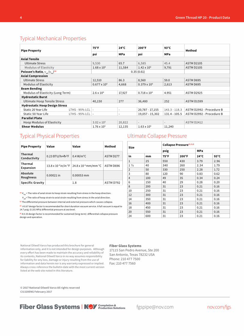
4 Green Thread HP 20 - Product Data
[email protected] nov.com/fgs
Fiber Glass Systems17115 San Pedro Avenue, Ste 200San Antonio, Texas 78232 USAPhone: 210 477 7500Fax: 210 477 7560
National Oilwell Varco has produced this brochure for general information only, and it is not intended for design purposes. Although every effort has been made to maintain the accuracy and reliability of its contents, National Oilwell Varco in no way assumes responsibility for liability for any loss, damage or injury resulting from the use of information and data herein nor is any warranty expressed or implied. Always cross-reference the bulletin date with the most current version listed at the web site noted in this literature.
© 2017 National Oilwell Varco All rights reservedCI1320ENG February 2017
Pipe Property75°F 24°C 200°F 93°C
Methodpsi MPa psi MPa
Axial TensileUltimate Stress 9,530 65.7 6,585 45.4 ASTM D2105Modulus of Elasticity 1.68 x 10⁶ 11,584 1.42 x 10⁶ 9,791 ASTM D2105
Poisson’s Ratio, νah (νha)(1) 0.35 (0.61)Axial Compression
Ultimate Stress 12,510 86.3 8,560 59.0 ASTM D695Modulus of Elasticity 0.677 x 10⁶ 4,668 0.379 x 10⁶ 2,613 ASTM D695
Beam BendingModulus of Elasticity (Long Term) 2.6 x 10⁶ 17,927 0.718 x 10⁶ 4.951 ASTM D2925
Hydrostatic BurstUltimate Hoop Tensile Stress 40,150 277 36,480 252 ASTM D1599
Hydrostatic Hoop Design StressStatic 20 Year Life LTHS - 95% LCL - - 20,787 - 17,155 143.3 - 118.3 ASTM D2992 - Procedure BStatic 50 Year Life LTHS - 95% LCL - - 19,057 - 15,302 131.4 - 105.5 ASTM D2992 - Procedure B
Parallel PlateHoop Modulus of Elasticity 3.02 x 10⁶ 20,822 - - ASTM D2412
Shear Modulus 1.76 x 10⁶ 12,135 1.63 x 10⁶ 11,240
Pipe Property Value Value Method
Thermal Conductivity 0.23 BTU/hr•ft•°F 0.4 W/m°C ASTM D177
Thermal Expansion 13.8 x 10⁻⁶ in/in °F 24.8 x 10⁻⁶ mm/mm °C ASTM D696
Absolute Roughness 0.00021 in 0.00053 mm
Specific Gravity 1.8 ASTM D792
Typical Mechanical Properties
Typical Physical Properties Ultimate Collapse Pressure
SizeCollapse Pressure(2,3,4)
psig MPa
in mm 75°F 200°F 24°C 93°C1 25 550 430 3.79 2.961 1/2 40 340 260 2.34 1.792 50 330 250 2.28 1.723 80 120 90 0.83 0.624 100 49 35 0.34 0.246 150 40 29 0.28 0.208 200 31 23 0.21 0.1610 250 31 23 0.21 0.1612 300 31 23 0.21 0.1614 350 31 23 0.21 0.1616 400 31 23 0.21 0.1618 450 31 23 0.21 0.1620 550 31 23 0.21 0.1624 600 31 23 0.21 0.16
(1) νha = The ratio of axial strain to hoop strain resulting from stress in the hoop direction.
νah= The ratio of hoop strain to axial strain resulting from stress in the axial direction.(2) The differential pressure between internal and external pressure which causes collapse. (3) A 0.67 design factor is recommended for short duration vacuum service. A full vacuum is equal to 14.7 psig (0.101 MPa) differential pressure at sea level. (4) A 0.33 design factor is recommended for sustained (long-term) differential collapse pressure design and operation.

[email protected] nov.com/fgs
Product Name 14/15 Green Thread™ HP 25(Product Data) O I L & G A S C H E M I C A L
& I N D U S T R I A LO F F S H O R EM A R I N E M I N I N GF U E L
H A N D L I N G
Bell & Spigot
Materials and ConstructionPipe manufactured by filament winding process using amine-cured epoxy thermosetting resin to impregnate strands of continuous glass filaments. The pipe wall includes an internal resin-rich corrosion barrier.
Pipe is available in 1”-24” (25-600 mm) diameters with pressure ratings up to 362 psig (25 bar). The pipe and fittings have an operating temperature of 200°F (93°C) serviceable up to 230°F (110°C) by applying a derating factor of 0.76 to all component ratings. Pipe diameters of 1”-6” (25-150 mm) are available in 20’ (6 m) random lengths and the 8”-24” (150 -600 mm) diameters are in 19’ or 39’ (6 or 12 m) random lengths.
ASTM D-2996 Classification: RTRP - 11FX1-3110 for static design basis.
FittingsFittings are manufactured with the same chemical and temperature capabilities as the pipe. Depending on the particular part and size, fittings will be compression molded, contact molded, hand fabricated or filament wound. Fitting details are in document CI1360.
Applications• Chemical Processing Liquids• Food Processing Liquids• Potable Water• Cooling Water
• Condensate Return• Industrial Wastewater• Mildly Corrosive Liquids• Crude Oil & Gas
Joining System• Bell & Spigot - Matched-taper joint secured
with epoxy adhesive. Self-locking feature resists movement, facilitating joining runs of pipe without waiting for adhesive to cure.
• Flanged - Available for all piping systems and diameters; factory assembled or shipped loose for assembly in the field.
• Produced Water• Saltwater• CO2
View of Joint Illustrations
Flanged
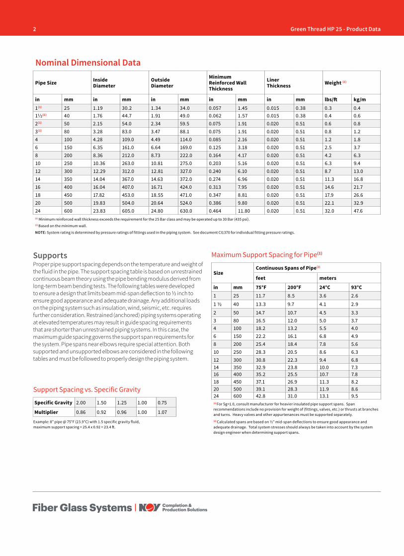
2 Green Thread HP 25 - Product Data
Pipe Size Inside Diameter
Outside Diameter
Minimum Reinforced Wall Thickness
Liner Thickness Weight (2)
in mm in mm in mm in mm in mm lbs/ft kg/m1(1) 25 1.19 30.2 1.34 34.0 0.057 1.45 0.015 0.38 0.3 0.411/2(1) 40 1.76 44.7 1.91 49.0 0.062 1.57 0.015 0.38 0.4 0.62(1) 50 2.15 54.0 2.34 59.5 0.075 1.91 0.020 0.51 0.6 0.83(1) 80 3.28 83.0 3.47 88.1 0.075 1.91 0.020 0.51 0.8 1.24 100 4.28 109.0 4.49 114.0 0.085 2.16 0.020 0.51 1.2 1.86 150 6.35 161.0 6.64 169.0 0.125 3.18 0.020 0.51 2.5 3.78 200 8.36 212.0 8.73 222.0 0.164 4.17 0.020 0.51 4.2 6.310 250 10.36 263.0 10.81 275.0 0.203 5.16 0.020 0.51 6.3 9.412 300 12.29 312.0 12.81 327.0 0.240 6.10 0.020 0.51 8.7 13.014 350 14.04 367.0 14.63 372.0 0.274 6.96 0.020 0.51 11.3 16.816 400 16.04 407.0 16.71 424.0 0.313 7.95 0.020 0.51 14.6 21.718 450 17.82 453.0 18.55 471.0 0.347 8.81 0.020 0.51 17.9 26.620 500 19.83 504.0 20.64 524.0 0.386 9.80 0.020 0.51 22.1 32.924 600 23.83 605.0 24.80 630.0 0.464 11.80 0.020 0.51 32.0 47.6(1) Minimum reinforced wall thickness exceeds the requirement for the 25 Bar class and may be operated up to 30 Bar (435 psi).(2) Based on the minimum wall.
NOTE: System rating is determined by pressure ratings of fittings used in the piping system. See document CI1370 for individual fitting pressure ratings.
Nominal Dimensional Data
SizeContinuous Spans of Pipe(2)
feet meters
in mm 75°F 200°F 24°C 93°C1 25 11.7 8.5 3.6 2.6
1 ½ 40 13.3 9.7 4.1 2.9
2 50 14.7 10.7 4.5 3.33 80 16.5 12.0 5.0 3.74 100 18.2 13.2 5.5 4.06 150 22.2 16.1 6.8 4.98 200 25.4 18.4 7.8 5.610 250 28.3 20.5 8.6 6.312 300 30.8 22.3 9.4 6.814 350 32.9 23.8 10.0 7.316 400 35.2 25.5 10.7 7.818 450 37.1 26.9 11.3 8.220 500 39.1 28.3 11.9 8.624 600 42.8 31.0 13.1 9.5(1) For Sg=1.0, consult manufacturer for heavier insulated pipe support spans. Span recommendations include no provision for weight of (fittings, valves, etc.) or thrusts at branches and turns. Heavy valves and other appurtenances must be supported separately.(2) Calculated spans are based on ½” mid-span deflections to ensure good appearance and adequate drainage. Total system stresses should always be taken into account by the system design engineer when determining support spans.
Maximum Support Spacing for Pipe(1)
Example: 8” pipe @ 75°F (23.9°C) with 1.5 specific gravity fluid, maximum support spacing = 25.4 x 0.92 = 23.4 ft.
SupportsProper pipe support spacing depends on the temperature and weight of the fluid in the pipe. The support spacing table is based on unrestrained continuous beam theory using the pipe bending modulus derived from long-term beam bending tests. The following tables were developed to ensure a design that limits beam mid-span deflection to ½ inch to ensure good appearance and adequate drainage. Any additional loads on the piping system such as insulation, wind, seismic, etc. requires further consideration. Restrained (anchored) piping systems operating at elevated temperatures may result in guide spacing requirements that are shorter than unrestrained piping systems. In this case, the maximum guide spacing governs the support span requirements for the system. Pipe spans near elbows require special attention. Both supported and unsupported elbows are considered in the following tables and must be followed to properly design the piping system.
Support Spacing vs. Specific Gravity
Specific Gravity 2.00 1.50 1.25 1.00 0.75
Multiplier 0.86 0.92 0.96 1.00 1.07
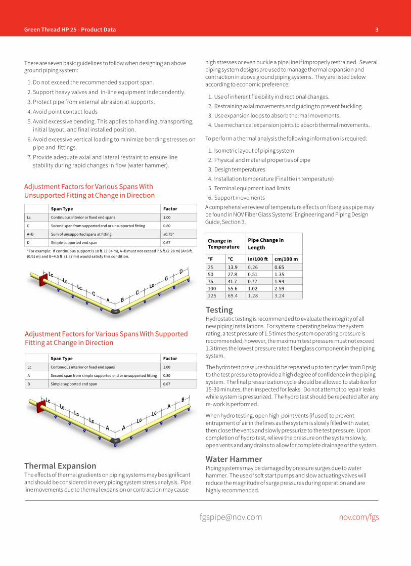
3Green Thread HP 25 - Product Data
[email protected] nov.com/fgs
There are seven basic guidelines to follow when designing an above ground piping system:
1. Do not exceed the recommended support span.
2. Support heavy valves and in-line equipment independently.
3. Protect pipe from external abrasion at supports.
4. Avoid point contact loads
5. Avoid excessive bending. This applies to handling, transporting, initial layout, and final installed position.
6. Avoid excessive vertical loading to minimize bending stresses on pipe and fittings.
7. Provide adequate axial and lateral restraint to ensure line stability during rapid changes in flow (water hammer).
Adjustment Factors for Various Spans With Unsupported Fitting at Change in Direction
Span Type Factor
Lc Continuous interior or fixed end spans 1.00
C Second span from supported end or unsupported fitting 0.80
A+B Sum of unsupported spans at fitting ≤0.75*
D Simple supported end span 0.67
*For example: If continuous support is 10 ft. (3.04 m), A+B must not exceed 7.5 ft.(2.28 m) (A=3 ft. (0.91 m) and B=4.5 ft. (1.37 m)) would satisfy this condition.
Span Type Factor
Lc Continuous interior or fixed end spans 1.00
A Second span from simple supported end or unsupported fitting 0.80
B Simple supported end span 0.67
Adjustment Factors for Various Spans With Supported Fitting at Change in Direction
Thermal ExpansionThe effects of thermal gradients on piping systems may be significant and should be considered in every piping system stress analysis. Pipe line movements due to thermal expansion or contraction may cause
Change in Temperature
Pipe Change in Length
°F °C in/100 ft cm/100 m25 13.9 0.26 0.6550 27.8 0.51 1.3575 41.7 0.77 1.94100 55.6 1.02 2.59125 69.4 1.28 3.24
TestingHydrostatic testing is recommended to evaluate the integrity of all new piping installations. For systems operating below the system rating, a test pressure of 1.5 times the system operating pressure is recommended; however, the maximum test pressure must not exceed 1.3 times the lowest pressure rated fiberglass component in the piping system.
The hydro test pressure should be repeated up to ten cycles from 0 psig to the test pressure to provide a high degree of confidence in the piping system. The final pressurization cycle should be allowed to stabilize for 15-30 minutes, then inspected for leaks. Do not attempt to repair leaks while system is pressurized. The hydro test should be repeated after any re-work is performed.
When hydro testing, open high-point vents (if used) to prevent entrapment of air in the lines as the system is slowly filled with water, then close the vents and slowly pressurize to the test pressure. Upon completion of hydro test, relieve the pressure on the system slowly, open vents and any drains to allow for complete drainage of the system.
Water HammerPiping systems may be damaged by pressure surges due to water hammer. The use of soft start pumps and slow actuating valves will reduce the magnitude of surge pressures during operation and are highly recommended.
high stresses or even buckle a pipe line if improperly restrained. Several piping system designs are used to manage thermal expansion and contraction in above ground piping systems. They are listed below according to economic preference:
1. Use of inherent flexibility in directional changes.
2. Restraining axial movements and guiding to prevent buckling.
3. Use expansion loops to absorb thermal movements.
4. Use mechanical expansion joints to absorb thermal movements.
To perform a thermal analysis the following information is required:
1. Isometric layout of piping system
2. Physical and material properties of pipe
3. Design temperatures
4. Installation temperature (Final tie in temperature)
5. Terminal equipment load limits
6. Support movements
A comprehensive review of temperature effects on fiberglass pipe may be found in NOV Fiber Glass Systems’ Engineering and Piping Design Guide, Section 3.
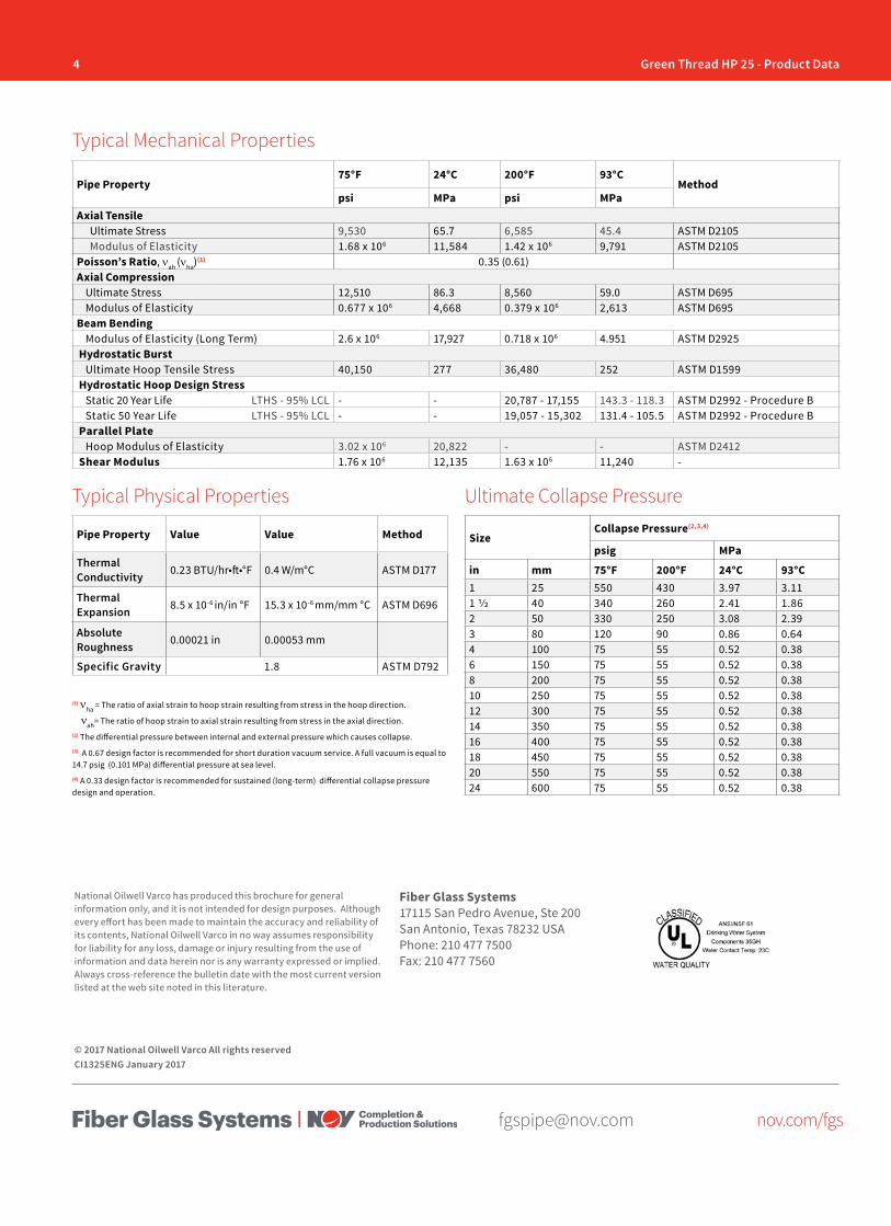
4 Green Thread HP 25 - Product Data
[email protected] nov.com/fgs
Fiber Glass Systems17115 San Pedro Avenue, Ste 200San Antonio, Texas 78232 USAPhone: 210 477 7500Fax: 210 477 7560
National Oilwell Varco has produced this brochure for general information only, and it is not intended for design purposes. Although every effort has been made to maintain the accuracy and reliability of its contents, National Oilwell Varco in no way assumes responsibility for liability for any loss, damage or injury resulting from the use of information and data herein nor is any warranty expressed or implied. Always cross-reference the bulletin date with the most current version listed at the web site noted in this literature.
© 2017 National Oilwell Varco All rights reservedCI1325ENG January 2017
Pipe Property75°F 24°C 200°F 93°C
Methodpsi MPa psi MPa
Axial TensileUltimate Stress 9,530 65.7 6,585 45.4 ASTM D2105Modulus of Elasticity 1.68 x 10⁶ 11,584 1.42 x 10⁶ 9,791 ASTM D2105
Poisson’s Ratio, νah (νha)(1) 0.35 (0.61)Axial Compression
Ultimate Stress 12,510 86.3 8,560 59.0 ASTM D695Modulus of Elasticity 0.677 x 10⁶ 4,668 0.379 x 10⁶ 2,613 ASTM D695
Beam BendingModulus of Elasticity (Long Term) 2.6 x 10⁶ 17,927 0.718 x 10⁶ 4.951 ASTM D2925
Hydrostatic BurstUltimate Hoop Tensile Stress 40,150 277 36,480 252 ASTM D1599
Hydrostatic Hoop Design StressStatic 20 Year Life LTHS - 95% LCL - - 20,787 - 17,155 143.3 - 118.3 ASTM D2992 - Procedure BStatic 50 Year Life LTHS - 95% LCL - - 19,057 - 15,302 131.4 - 105.5 ASTM D2992 - Procedure B
Parallel PlateHoop Modulus of Elasticity 3.02 x 10⁶ 20,822 - - ASTM D2412
Shear Modulus 1.76 x 10⁶ 12,135 1.63 x 10⁶ 11,240 -
Pipe Property Value Value Method
Thermal Conductivity 0.23 BTU/hr•ft•°F 0.4 W/m°C ASTM D177
Thermal Expansion 8.5 x 10⁻⁶ in/in °F 15.3 x 10⁻⁶ mm/mm °C ASTM D696
Absolute Roughness 0.00021 in 0.00053 mm
Specific Gravity 1.8 ASTM D792
Typical Mechanical Properties
Typical Physical Properties Ultimate Collapse Pressure
SizeCollapse Pressure(2,3,4)
psig MPa
in mm 75°F 200°F 24°C 93°C1 25 550 430 3.97 3.111 1/2 40 340 260 2.41 1.862 50 330 250 3.08 2.393 80 120 90 0.86 0.644 100 75 55 0.52 0.386 150 75 55 0.52 0.388 200 75 55 0.52 0.3810 250 75 55 0.52 0.3812 300 75 55 0.52 0.3814 350 75 55 0.52 0.3816 400 75 55 0.52 0.3818 450 75 55 0.52 0.3820 550 75 55 0.52 0.3824 600 75 55 0.52 0.38
(1) νha = The ratio of axial strain to hoop strain resulting from stress in the hoop direction.
νah= The ratio of hoop strain to axial strain resulting from stress in the axial direction.(2) The differential pressure between internal and external pressure which causes collapse. (3) A 0.67 design factor is recommended for short duration vacuum service. A full vacuum is equal to 14.7 psig (0.101 MPa) differential pressure at sea level. (4) A 0.33 design factor is recommended for sustained (long-term) differential collapse pressure design and operation.

[email protected] nov.com/fgs
Product Name 14/15 Green Thread™ HP 32(Product Data) O I L & G A S C H E M I C A L
& I N D U S T R I A LO F F S H O R EM A R I N E M I N I N GF U E L
H A N D L I N G
Bell & Spigot
Materials and ConstructionAll pipe manufactured by filament winding process using amine-cured epoxy thermosetting resin to impregnate strands of continuous glass filaments. Pipe wall includes a minimum 0.020” (0.50 mm) resin-rich corrosion barrier (liner).
Pipe is available in 2”-16” (50-400 mm) diameters with static pressure ratings of 464 psig (32 bar). The pipe and fittings are designed for continuous operation at 200°F (93°C) serviceable up to 230°F (110°C) by applying a derating factor of 0.76 to all component ratings. Pipe diameters of 1”-6” (25-150 mm) are available in 20’ (6 m) random lengths and the 8”-16” (200- 400 mm) diameters are in 19’ or 39’ (6 or 12 m) random lengths.
ASTM D-2996 Classification: RTRP - 11FX1-3110 for static design basis.
FittingsFittings are filament wound with the same chemical, temperature and pressure capabilities as the pipe. Reference document CI1370 for fitting dimensions. 2”-12” (50-300 mm) fittings use HP 40 dimensions. 14” and 16” (350-400 mm) fittings use HP 32 dimensions.
Applications• Chemical Processing Liquids• Food Processing Liquids• Potable Water• Cooling Water
• Condensate Return• Industrial Wastewater• Mildly Corrosive Liquids• Crude Oil & Gas
Joining System• Bell & Spigot - Matched-taper joint secured
with epoxy adhesive. Self-locking feature resists movement, facilitating joining runs of pipe without waiting for adhesive to cure.
• Flanged - Available for all piping systems and diameters; factory assembled or shipped loose for assembly in the field.
• Produced Water• Saltwater• CO2
View of Joint Illustrations
Flanged
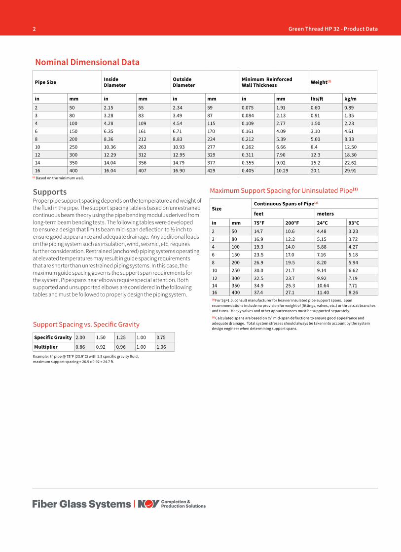
2 Green Thread HP 32 - Product Data
(2) Based on the minimum wall.
Pipe Size Inside Diameter
Outside Diameter
Minimum ReinforcedWall Thickness Weight(2)
in mm in mm in mm in mm lbs/ft kg/m
2 50 2.15 55 2.34 59 0.075 1.91 0.60 0.893 80 3.28 83 3.49 87 0.084 2.13 0.91 1.354 100 4.28 109 4.54 115 0.109 2.77 1.50 2.236 150 6.35 161 6.71 170 0.161 4.09 3.10 4.618 200 8.36 212 8.83 224 0.212 5.39 5.60 8.3310 250 10.36 263 10.93 277 0.262 6.66 8.4 12.5012 300 12.29 312 12.95 329 0.311 7.90 12.3 18.3014 350 14.04 356 14.79 377 0.355 9.02 15.2 22.6216 400 16.04 407 16.90 429 0.405 10.29 20.1 29.91
Nominal Dimensional Data
SizeContinuous Spans of Pipe(2)
feet meters
in mm 75°F 200°F 24°C 93°C2 50 14.7 10.6 4.48 3.233 80 16.9 12.2 5.15 3.724 100 19.3 14.0 5.88 4.276 150 23.5 17.0 7.16 5.188 200 26.9 19.5 8.20 5.9410 250 30.0 21.7 9.14 6.6212 300 32.5 23.7 9.92 7.1914 350 34.9 25.3 10.64 7.7116 400 37.4 27.1 11.40 8.26(1) For Sg=1.0, consult manufacturer for heavier insulated pipe support spans. Span recommendations include no provision for weight of (fittings, valves, etc.) or thrusts at branches and turns. Heavy valves and other appurtenances must be supported separately.(2) Calculated spans are based on ½” mid-span deflections to ensure good appearance and adequate drainage. Total system stresses should always be taken into account by the system design engineer when determining support spans.
Maximum Support Spacing for Uninsulated Pipe(1)
Example: 8” pipe @ 75°F (23.9°C) with 1.5 specific gravity fluid, maximum support spacing = 26.9 x 0.92 = 24.7 ft.
SupportsProper pipe support spacing depends on the temperature and weight of the fluid in the pipe. The support spacing table is based on unrestrained continuous beam theory using the pipe bending modulus derived from long-term beam bending tests. The following tables were developed to ensure a design that limits beam mid-span deflection to ½ inch to ensure good appearance and adequate drainage. Any additional loads on the piping system such as insulation, wind, seismic, etc. requires further consideration. Restrained (anchored) piping systems operating at elevated temperatures may result in guide spacing requirements that are shorter than unrestrained piping systems. In this case, the maximum guide spacing governs the support span requirements for the system. Pipe spans near elbows require special attention. Both supported and unsupported elbows are considered in the following tables and must be followed to properly design the piping system.
Support Spacing vs. Specific Gravity
Specific Gravity 2.00 1.50 1.25 1.00 0.75
Multiplier 0.86 0.92 0.96 1.00 1.06

3Green Thread HP 32 - Product Data
[email protected] nov.com/fgs
There are seven basic guidelines to follow when designing an above ground piping system:
1. Do not exceed the recommended support span.
2. Support heavy valves and in-line equipment independently.
3. Protect pipe from external abrasion at supports.
4. Avoid point contact loads
5. Avoid excessive bending. This applies to handling, transporting, initial layout, and final installed position.
6. Avoid excessive vertical loading to minimize bending stresses on pipe and fittings.
7. Provide adequate axial and lateral restraint to ensure line stability during rapid changes in flow (water hammer).
Adjustment Factors for Various Spans With Unsupported Fitting at Change in Direction
Span Type Factor
Lc Continuous interior or fixed end spans 1.00
C Second span from supported end or unsupported fitting 0.80
A+B Sum of unsupported spans at fitting ≤0.75*
D Simple supported end span 0.67
*For example: If continuous support is 10 ft. (3.04 m), A+B must not exceed 7.5 ft.(2.28 m) (A=3 ft. (0.91 m) and B=4.5 ft. (1.37 m)) would satisfy this condition.
Span Type Factor
Lc Continuous interior or fixed end spans 1.00
A Second span from simple supported end or unsupported fitting 0.80
B Simple supported end span 0.67
Adjustment Factors for Various Spans With Supported Fitting at Change in Direction
Thermal ExpansionThe effects of thermal gradients on piping systems may be significant and should be considered in every piping system stress analysis. Pipe line movements due to thermal expansion or contraction may cause
TestingHydrostatic testing is recommended to evaluate the integrity of all new piping installations. For systems operating below the system rating, a test pressure of 1.5 times the system operating pressure is recommended; however, the maximum test pressure must not exceed 1.3 times the lowest pressure rated fiberglass component in the piping system.
The hydro test pressure should be repeated up to ten cycles from 0 psig to the test pressure to provide a high degree of confidence in the piping system. The final pressurization cycle should be allowed to stabilize for 15-30 minutes, then inspected for leaks. Do not attempt to repair leaks while system is pressurized. The hydro test should be repeated after any re-work is performed.
When hydro testing, open high-point vents (if used) to prevent entrapment of air in the lines as the system is slowly filled with water, then close the vents and slowly pressurize to the test pressure. Upon completion of hydro test, relieve the pressure on the system slowly, open vents and any drains to allow for complete drainage of the system.
Water HammerPiping systems may be damaged by pressure surges due to water hammer. The use of soft start pumps and slow actuating valves will reduce the magnitude of surge pressures during operation and are highly recommended.
high stresses or even buckle a pipe line if improperly restrained. Several piping system designs are used to manage thermal expansion and contraction in above ground piping systems. They are listed below according to economic preference:
1. Use of inherent flexibility in directional changes.
2. Restraining axial movements and guiding to prevent buckling.
3. Use expansion loops to absorb thermal movements.
4. Use mechanical expansion joints to absorb thermal movements.
To perform a thermal analysis the following information is required:
1. Isometric layout of piping system
2. Physical and material properties of pipe
3. Design temperatures
4. Installation temperature (Final tie in temperature)
5. Terminal equipment load limits
6. Support movements
A comprehensive review of temperature effects on fiberglass pipe may be found in NOV Fiber Glass Systems’ Engineering and Piping Design Guide, Section 3.
Change in Temperature
Pipe Change in Length
°F °C in/100 ft cm/100 m25 13.9 0.41 3.4550 27.8 0.83 6.9075 41.7 1.24 10.35100 55.6 1.66 13.80
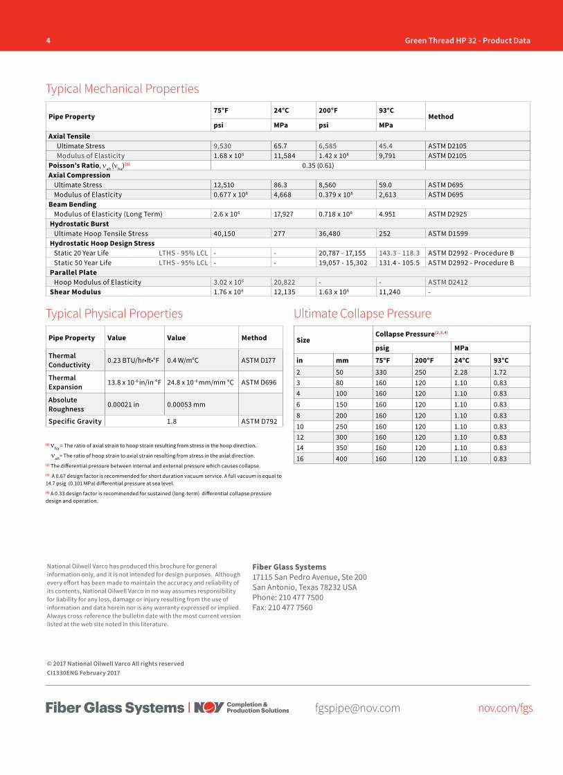
4 Green Thread HP 32 - Product Data
[email protected] nov.com/fgs
Fiber Glass Systems17115 San Pedro Avenue, Ste 200San Antonio, Texas 78232 USAPhone: 210 477 7500Fax: 210 477 7560
National Oilwell Varco has produced this brochure for general information only, and it is not intended for design purposes. Although every effort has been made to maintain the accuracy and reliability of its contents, National Oilwell Varco in no way assumes responsibility for liability for any loss, damage or injury resulting from the use of information and data herein nor is any warranty expressed or implied. Always cross-reference the bulletin date with the most current version listed at the web site noted in this literature.
© 2017 National Oilwell Varco All rights reservedCI1330ENG February 2017
Pipe Property75°F 24°C 200°F 93°C
Methodpsi MPa psi MPa
Axial TensileUltimate Stress 9,530 65.7 6,585 45.4 ASTM D2105Modulus of Elasticity 1.68 x 10⁶ 11,584 1.42 x 10⁶ 9,791 ASTM D2105
Poisson’s Ratio, νah (νha)(1) 0.35 (0.61)Axial Compression
Ultimate Stress 12,510 86.3 8,560 59.0 ASTM D695Modulus of Elasticity 0.677 x 10⁶ 4,668 0.379 x 10⁶ 2,613 ASTM D695
Beam BendingModulus of Elasticity (Long Term) 2.6 x 10⁶ 17,927 0.718 x 10⁶ 4.951 ASTM D2925
Hydrostatic BurstUltimate Hoop Tensile Stress 40,150 277 36,480 252 ASTM D1599
Hydrostatic Hoop Design StressStatic 20 Year Life LTHS - 95% LCL - - 20,787 - 17,155 143.3 - 118.3 ASTM D2992 - Procedure BStatic 50 Year Life LTHS - 95% LCL - - 19,057 - 15,302 131.4 - 105.5 ASTM D2992 - Procedure B
Parallel PlateHoop Modulus of Elasticity 3.02 x 10⁶ 20,822 - - ASTM D2412
Shear Modulus 1.76 x 10⁶ 12,135 1.63 x 10⁶ 11,240 -
Pipe Property Value Value Method
Thermal Conductivity 0.23 BTU/hr•ft•°F 0.4 W/m°C ASTM D177
Thermal Expansion 13.8 x 10⁻⁶ in/in °F 24.8 x 10⁻⁶ mm/mm °C ASTM D696
Absolute Roughness 0.00021 in 0.00053 mm
Specific Gravity 1.8 ASTM D792
Typical Mechanical Properties
Typical Physical Properties Ultimate Collapse Pressure
SizeCollapse Pressure(2,3,4)
psig MPa
in mm 75°F 200°F 24°C 93°C2 50 330 250 2.28 1.723 80 160 120 1.10 0.834 100 160 120 1.10 0.836 150 160 120 1.10 0.838 200 160 120 1.10 0.8310 250 160 120 1.10 0.8312 300 160 120 1.10 0.8314 350 160 120 1.10 0.8316 400 160 120 1.10 0.83
(1) νha = The ratio of axial strain to hoop strain resulting from stress in the hoop direction.
νah= The ratio of hoop strain to axial strain resulting from stress in the axial direction.(2) The differential pressure between internal and external pressure which causes collapse. (3) A 0.67 design factor is recommended for short duration vacuum service. A full vacuum is equal to 14.7 psig (0.101 MPa) differential pressure at sea level. (4) A 0.33 design factor is recommended for sustained (long-term) differential collapse pressure design and operation.

[email protected] nov.com/fgs
Product Name 14/15 Green Thread™ HP 40(Product Data) O I L & G A S C H E M I C A L
& I N D U S T R I A LO F F S H O R EM A R I N E M I N I N GF U E L
H A N D L I N G
Bell & Spigot
Materials and ConstructionAll pipe manufactured by filament winding process using amine-cured epoxy thermosetting resin to impregnate strands of continuous glass filaments. Pipe wall includes a minimum 0.020” (0.50 mm) resin-rich corrosion barrier (liner).
Pipe is available in 2”-12” (50-300 mm) diameters with static pressure ratings of 580 psig (40 bar). The pipe and fittings are designed for continuous operation at 200°F (93°C) serviceable up to 230°F (110°C) by applying a derating factor of 0.76 to all component ratings. Pipe diameters of 1”-6” (25-150 mm) are available in 20’ (6 m) random lengths and the 8”-12” (200- 300 mm) diameters are in 19’ or 39’ (6 or 12 m) random lengths.
ASTM D-2996 Classification: RTRP - 11FX1-3110 for static design basis.
FittingsFittings are filament wound with the same chemical, temperature and pressure capabilities as the pipe. For 2”-12” (50-300 mm)use HP32/40 Bar fittings in document CI1370.
Applications• Chemical Processing Liquids• Food Processing Liquids• Potable Water• Cooling Water
• Condensate Return• Industrial Wastewater• Mildly Corrosive Liquids• Crude Oil & Gas
Joining System• Bell & Spigot - Matched-taper joint secured
with epoxy adhesive. Self-locking feature resists movement, facilitating joining runs of pipe without waiting for adhesive to cure.
• Flanged - Available for all piping systems and diameters; factory assembled or shipped loose for assembly in the field.
• Produced Water• Saltwater• CO2
View of Joint Illustrations
Flanged
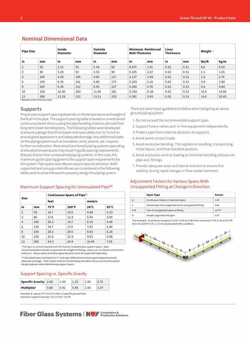
2 Green Thread HP 40 - Product Data
Pipe Size Inside Diameter
Outside Diameter
Minimum ReinforcedWall Thickness
LinerThickness Weight (1)
in mm in mm in mm in mm in mm lbs/ft kg/m
2 50 2.15 55 2.34 60 0.075 1.91 0.02 0.51 0.6 0.933 80 3.28 83 3.53 90 0.105 2.67 0.02 0.51 1.1 1.654 100 4.28 109 4.60 117 0.137 3.48 0.02 0.51 1.8 2.746 150 6.35 161 6.80 173 0.203 5.16 0.02 0.51 3.9 5.808 200 8.36 212 8.93 227 0.266 6.76 0.02 0.51 6.6 9.8410 250 10.36 263 11.06 281 0.330 8.38 0.02 0.51 10.0 14.8812 300 12.29 312 13.11 333 0.391 9.93 0.02 0.51 14.0 20.83
Nominal Dimensional Data
SizeContinuous Spans of Pipe(2)
feet meters
in mm 75°F 200°F 24°C 93°C2 50 14.7 10.6 4.48 3.233 80 17.8 12.9 5.43 3.934 100 20.3 14.7 6.19 4.486 150 24.7 17.9 7.53 5.468 200 28.3 20.6 8.63 6.2810 250 31.6 22.9 9.63 6.9812 300 34.3 24.9 10.45 7.59(1) For Sg=1.0, consult manufacturer for heavier insulated pipe support spans. Span recommendations include no provision for weight of (fittings, valves, etc.) or thrusts at branches and turns. Heavy valves and other appurtenances must be supported separately.(2) Calculated spans are based on ½” mid-span deflections to ensure good appearance and adequate drainage. Total system stresses should always be taken into account by the system design engineer when determining support spans.
Maximum Support Spacing for Uninsulated Pipe(1)
Example: 8” pipe @ 75°F (23.9°C) with 1.5 specific gravity fluid, maximum support spacing = 28.3 x 0.92 = 26.0 ft.
SupportsProper pipe support spacing depends on the temperature and weight of the fluid in the pipe. The support spacing table is based on unrestrained continuous beam theory using the pipe bending modulus derived from long-term beam bending tests. The following tables were developed to ensure a design that limits beam mid-span deflection to ½ inch to ensure good appearance and adequate drainage. Any additional loads on the piping system such as insulation, wind, seismic, etc. requires further consideration. Restrained (anchored) piping systems operating at elevated temperatures may result in guide spacing requirements that are shorter than unrestrained piping systems. In this case, the maximum guide spacing governs the support span requirements for the system. Pipe spans near elbows require special attention. Both supported and unsupported elbows are considered in the following tables and must be followed to properly design the piping system.
There are seven basic guidelines to follow when designing an above ground piping system:
1. Do not exceed the recommended support span.
2. Support heavy valves and in-line equipment independently.
3. Protect pipe from external abrasion at supports.
4. Avoid point contact loads
5. Avoid excessive bending. This applies to handling, transporting, initial layout, and final installed position.
6. Avoid excessive vertical loading to minimize bending stresses on pipe and fittings.
7. Provide adequate axial and lateral restraint to ensure line stability during rapid changes in flow (water hammer).
Adjustment Factors for Various Spans With Unsupported Fitting at Change in Direction
Span Type Factor
Lc Continuous interior or fixed end spans 1.00
C Second span from supported end or unsupported fitting 0.80
A+B Sum of unsupported spans at fitting ≤0.75*
D Simple supported end span 0.67
*For example: If continuous support is 10 ft. (3.04 m), A+B must not exceed 7.5 ft.(2.28 m) (A=3 ft. (0.91 m) and B=4.5 ft. (1.37 m)) would satisfy this condition.
Support Spacing vs. Specific Gravity
Specific Gravity 2.00 1.50 1.25 1.00 0.75
Multiplier 0.86 0.92 0.96 1.00 1.07
(1) Based on the minimum wall.
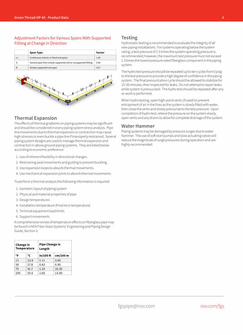
3Green Thread HP 40 - Product Data
[email protected] nov.com/fgs
Span Type Factor
Lc Continuous interior or fixed end spans 1.00
A Second span from simple supported end or unsupported fitting 0.80
B Simple supported end span 0.67
Adjustment Factors for Various Spans With Supported Fitting at Change in Direction
Thermal ExpansionThe effects of thermal gradients on piping systems may be significant and should be considered in every piping system stress analysis. Pipe line movements due to thermal expansion or contraction may cause high stresses or even buckle a pipe line if improperly restrained. Several piping system designs are used to manage thermal expansion and contraction in above ground piping systems. They are listed below according to economic preference:
1. Use of inherent flexibility in directional changes.
2. Restraining axial movements and guiding to prevent buckling.
3. Use expansion loops to absorb thermal movements.
4. Use mechanical expansion joints to absorb thermal movements.
To perform a thermal analysis the following information is required:
1. Isometric layout of piping system
2. Physical and material properties of pipe
3. Design temperatures
4. Installation temperature (Final tie in temperature)
5. Terminal equipment load limits
6. Support movements
A comprehensive review of temperature effects on fiberglass pipe may be found in NOV Fiber Glass Systems’ Engineering and Piping Design Guide, Section 3.
TestingHydrostatic testing is recommended to evaluate the integrity of all new piping installations. For systems operating below the system rating, a test pressure of 1.5 times the system operating pressure is recommended; however, the maximum test pressure must not exceed 1.3 times the lowest pressure rated fiberglass component in the piping system.
The hydro test pressure should be repeated up to ten cycles from 0 psig to the test pressure to provide a high degree of confidence in the piping system. The final pressurization cycle should be allowed to stabilize for 15-30 minutes, then inspected for leaks. Do not attempt to repair leaks while system is pressurized. The hydro test should be repeated after any re-work is performed.
When hydro testing, open high-point vents (if used) to prevent entrapment of air in the lines as the system is slowly filled with water, then close the vents and slowly pressurize to the test pressure. Upon completion of hydro test, relieve the pressure on the system slowly, open vents and any drains to allow for complete drainage of the system.
Water HammerPiping systems may be damaged by pressure surges due to water hammer. The use of soft start pumps and slow actuating valves will reduce the magnitude of surge pressures during operation and are highly recommended.
Change in Temperature
Pipe Change in Length
°F °C in/100 ft cm/100 m25 13.9 0.41 3.4550 27.8 0.83 6.9075 41.7 1.24 10.35100 55.6 1.66 13.80
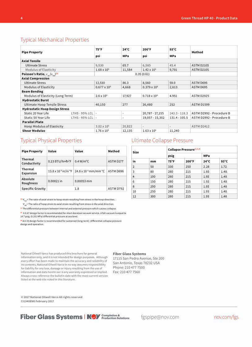
4 Green Thread HP 40 - Product Data
[email protected] nov.com/fgs
Fiber Glass Systems17115 San Pedro Avenue, Ste 200San Antonio, Texas 78232 USAPhone: 210 477 7500Fax: 210 477 7560
National Oilwell Varco has produced this brochure for general information only, and it is not intended for design purposes. Although every effort has been made to maintain the accuracy and reliability of its contents, National Oilwell Varco in no way assumes responsibility for liability for any loss, damage or injury resulting from the use of information and data herein nor is any warranty expressed or implied. Always cross-reference the bulletin date with the most current version listed at the web site noted in this literature.
© 2017 National Oilwell Varco All rights reservedCI1340ENG February 2017
Pipe Property75°F 24°C 200°F 93°C
Methodpsi MPa psi MPa
Axial TensileUltimate Stress 9,530 65.7 6,585 45.4 ASTM D2105Modulus of Elasticity 1.68 x 10⁶ 11,584 1.42 x 10⁶ 9,791 ASTM D2105
Poisson’s Ratio, νah (νha)(1) 0.35 (0.61)Axial Compression
Ultimate Stress 12,510 86.3 8,560 59.0 ASTM D695Modulus of Elasticity 0.677 x 10⁶ 4,668 0.379 x 10⁶ 2,613 ASTM D695
Beam BendingModulus of Elasticity (Long Term) 2.6 x 10⁶ 17,927 0.718 x 10⁶ 4.951 ASTM D2925
Hydrostatic BurstUltimate Hoop Tensile Stress 40,150 277 36,480 252 ASTM D1599
Hydrostatic Hoop Design StressStatic 20 Year Life LTHS - 95% LCL - - 20,787 - 17,155 143.3 - 118.3 ASTM D2992 - Procedure BStatic 50 Year Life LTHS - 95% LCL - - 19,057 - 15,302 131.4 - 105.5 ASTM D2992 - Procedure B
Parallel PlateHoop Modulus of Elasticity 3.02 x 10⁶ 20,822 - - ASTM D2412
Shear Modulus 1.76 x 10⁶ 12,135 1.63 x 10⁶ 11,240
Pipe Property Value Value Method
Thermal Conductivity 0.23 BTU/hr•ft•°F 0.4 W/m°C ASTM D177
Thermal Expansion 13.8 x 10⁻⁶ in/in °F 24.8 x 10⁻⁶ mm/mm °C ASTM D696
Absolute Roughness 0.00021 in 0.00053 mm
Specific Gravity 1.8 ASTM D792
Typical Mechanical Properties
Typical Physical Properties Ultimate Collapse Pressure
SizeCollapse Pressure(2,3,4)
psig MPa
in mm 75°F 200°F 24°C 93°C2 50 330 250 2.28 1.723 80 280 215 1.93 1.484 100 280 215 1.93 1.486 150 280 215 1.93 1.488 200 280 215 1.93 1.4810 250 280 215 1.93 1.4812 300 280 215 1.93 1.48
(1) νha = The ratio of axial strain to hoop strain resulting from stress in the hoop direction.
νah= The ratio of hoop strain to axial strain resulting from stress in the axial direction.(2) The differential pressure between internal and external pressure which causes collapse. (3) A 0.67 design factor is recommended for short duration vacuum service. A full vacuum is equal to 14.7 psig (0.101 MPa) differential pressure at sea level. (4) A 0.33 design factor is recommended for sustained (long-term) differential collapse pressure design and operation.
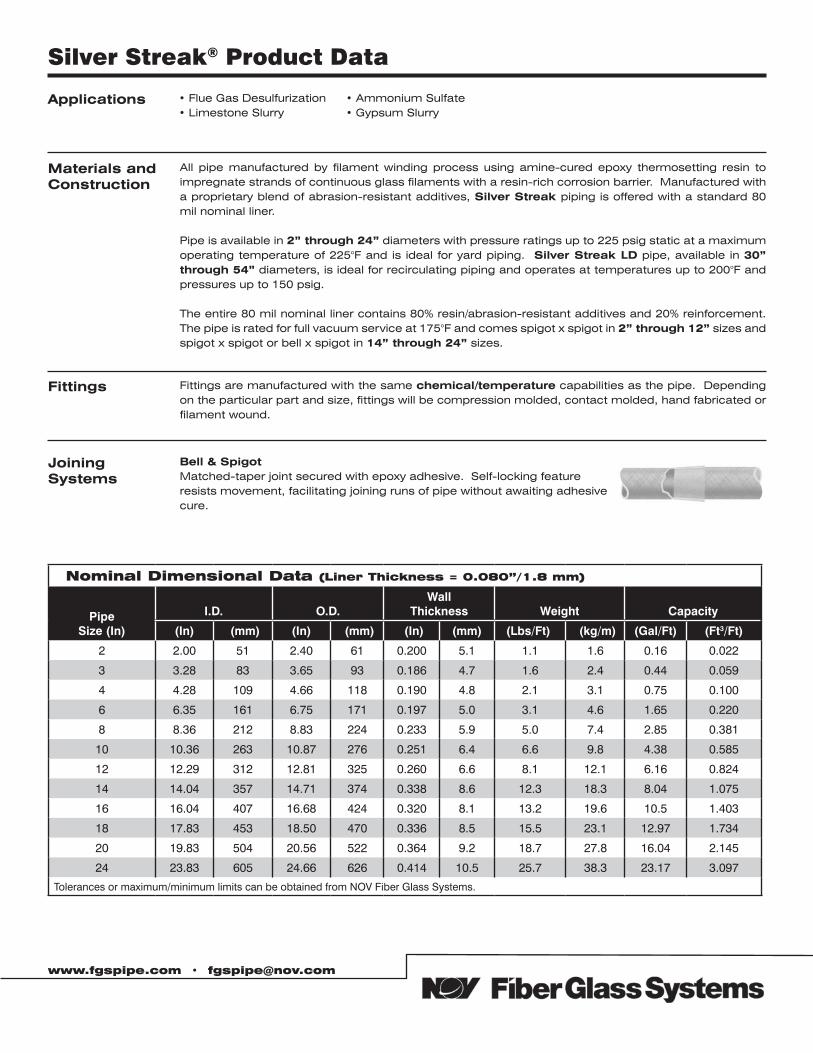
www.fgspipe.com • [email protected]
Applications • Flue Gas Desulfurization• Limestone Slurry
• Ammonium Sulfate• Gypsum Slurry
Fittings Fittings are manufactured with the same chemical/temperature capabilities as the pipe. Depending on the particular part and size, fittings will be compression molded, contact molded, hand fabricated or filament wound.
Materials andConstruction
All pipe manufactured by filament winding process using amine-cured epoxy thermosetting resin to impregnate strands of continuous glass filaments with a resin-rich corrosion barrier. Manufactured with a proprietary blend of abrasion-resistant additives, Silver Streak piping is offered with a standard 80 mil nominal liner.
Pipe is available in 2” through 24” diameters with pressure ratings up to 225 psig static at a maximum operating temperature of 225°F and is ideal for yard piping. Silver Streak LD pipe, available in 30” through 54” diameters, is ideal for recirculating piping and operates at temperatures up to 200°F and pressures up to 150 psig.
The entire 80 mil nominal liner contains 80% resin/abrasion-resistant additives and 20% reinforcement. The pipe is rated for full vacuum service at 175°F and comes spigot x spigot in 2” through 12” sizes and spigot x spigot or bell x spigot in 14” through 24” sizes.
Joining Systems
Bell & SpigotMatched-taper joint secured with epoxy adhesive. Self-locking featureresists movement, facilitating joining runs of pipe without awaiting adhesivecure.
Silver Streak® Product Data
Nominal Dimensional Data (Liner Thickness = 0.080”/1.8 mm)
Pipe Size (In)
I.D. O.D.Wall
Thickness Weight Capacity
(In) ((mm) (In) ((mm) ((In) (mm) ((Lbs/Ft)t) ((kg/m) (Gal/Ft) ((Ft3/Ft))
2 2.00 51 2.40 61 0.200 5.1 1.1 1.6 0.16 0.022
3 3.28 83 3.65 93 0.186 4.7 1.6 2.4 0.44 0.059
4 4.28 109 4.66 118 0.190 4.8 2.1 3.1 0.75 0.100
6 6.35 161 6.75 171 0.197 5.0 3.1 4.6 1.65 0.220
8 8.36 212 8.83 224 0.233 5.9 5.0 7.4 2.85 0.381
10 10.36 263 10.87 276 0.251 6.4 6.6 9.8 4.38 0.585
12 12.29 312 12.81 325 0.260 6.6 8.1 12.1 6.16 0.824
14 14.04 357 14.71 374 0.338 8.6 12.3 18.3 8.04 1.075
16 16.04 407 16.68 424 0.320 8.1 13.2 19.6 10.5 1.403
18 17.83 453 18.50 470 0.336 8.5 15.5 23.1 12.97 1.734
20 19.83 504 20.56 522 0.364 9.2 18.7 27.8 16.04 2.145
24 23.83 605 24.66 626 0.414 10.5 25.7 38.3 23.17 3.097
Tolerances or maximum/minimum limits can be obtained from NOV Fiber Glass Systems.
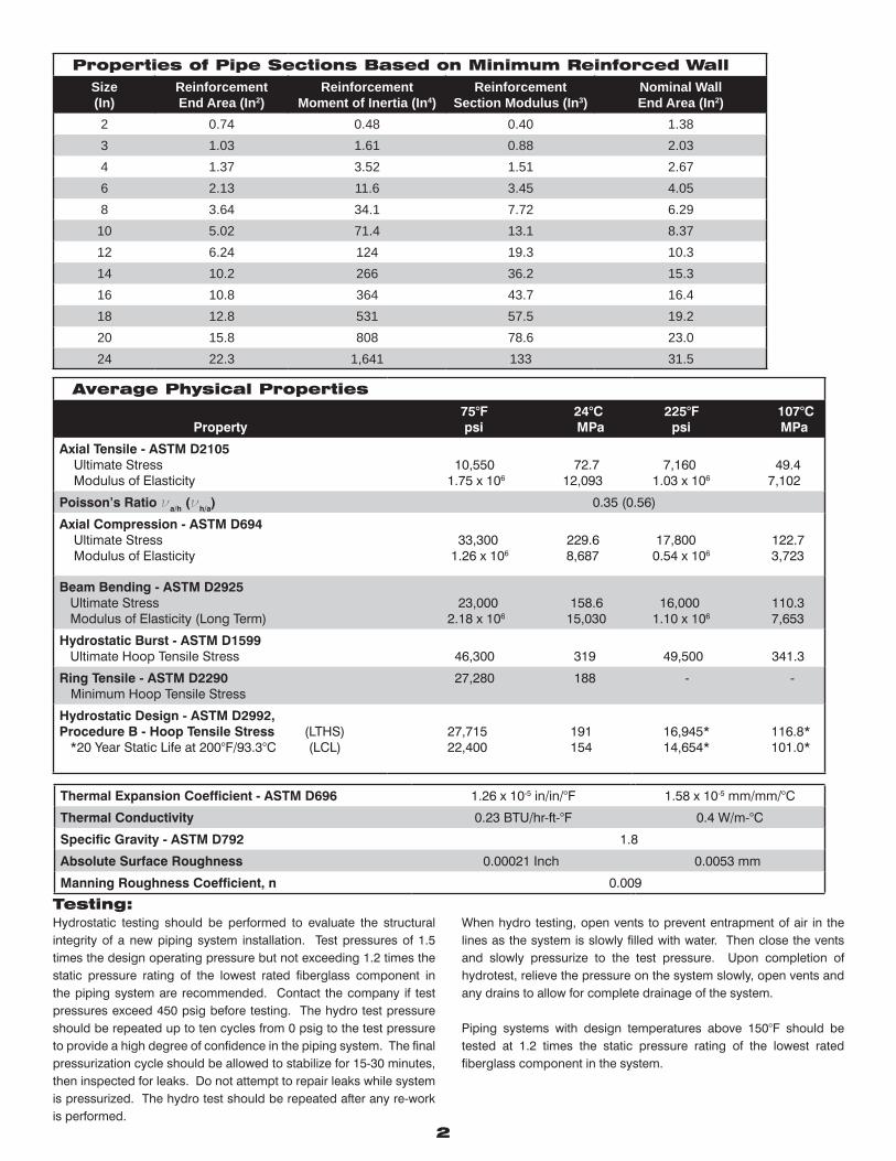
Average Physical Properties
Property 75°F 24°C psi MPa
225°F 107°C psi MPa
Axial Tensile - ASTM D2105 Ultimate Stress Modulus of Elasticity
10,550 72.7 1.75 x 10⁶ 12,093
7,160 49.4 1.03 x 10⁶ 7,102
Poisson’s Ratio νa/h (νh/a) 0.35 (0.56)
Axial Compression - ASTM D694 Ultimate Stress Modulus of Elasticity
33,300 229.6 1.26 x 10⁶ 8,687
17,800 122.7 0.54 x 10⁶ 3,723
Beam Bending - ASTM D2925 Ultimate Stress Modulus of Elasticity (Long Term)
23,000 158.6 2.18 x 10⁶ 15,030
16,000 110.3 1.10 x 10⁶ 7,653
Hydrostatic Burst - ASTM D1599 Ultimate Hoop Tensile Stress 46,300 319 49,500 341.3
Ring Tensile - ASTM D2290 Minimum Hoop Tensile Stress
27,280 188 - -
Hydrostatic Design - ASTM D2992,Procedure B - Hoop Tensile Stress (LTHS) *20 Year Static Life at 200°F/93.3°C (LCL)
27,715 191 22,400 154
16,945* 116.8* 14,654* 101.0*
Thermal Expansion Coefficient - ASTM D696 1.26 x 10⁻⁵ in/in/°F 1.58 x 10⁻⁵ mm/mm/°C
Thermal Conductivity 0.23 BTU/hr-ft-°F 0.4 W/m-°C
Specific Gravity - ASTM D792 1.8
Absolute Surface Roughness 0.00021 Inch 0.0053 mm
Manning Roughness Coefficient, n 0.009
2
Properties of Pipe Sections Based on Minimum Reinforced WallSize(In)
ReinforcementEnd Area (In2)
ReinforcementMoment of Inertia (In4)
ReinforcementSection Modulus (In3)
Nominal WallEnd Area (In2)
2 0.74 0.48 0.40 1.383 1.03 1.61 0.88 2.034 1.37 3.52 1.51 2.676 2.13 11.6 3.45 4.058 3.64 34.1 7.72 6.2910 5.02 71.4 13.1 8.3712 6.24 124 19.3 10.314 10.2 266 36.2 15.316 10.8 364 43.7 16.418 12.8 531 57.5 19.220 15.8 808 78.6 23.024 22.3 1,641 133 31.5
Testing: Hydrostatic testing should be performed to evaluate the structural integrity of a new piping system installation. Test pressures of 1.5 times the design operating pressure but not exceeding 1.2 times the static pressure rating of the lowest rated fiberglass component in the piping system are recommended. Contact the company if test pressures exceed 450 psig before testing. The hydro test pressure should be repeated up to ten cycles from 0 psig to the test pressure to provide a high degree of confidence in the piping system. The final pressurization cycle should be allowed to stabilize for 15-30 minutes, then inspected for leaks. Do not attempt to repair leaks while system is pressurized. The hydro test should be repeated after any re-work is performed.
When hydro testing, open vents to prevent entrapment of air in the lines as the system is slowly filled with water. Then close the vents and slowly pressurize to the test pressure. Upon completion of hydrotest, relieve the pressure on the system slowly, open vents and any drains to allow for complete drainage of the system.
Piping systems with design temperatures above 150°F should be tested at 1.2 times the static pressure rating of the lowest rated fiberglass component in the system.
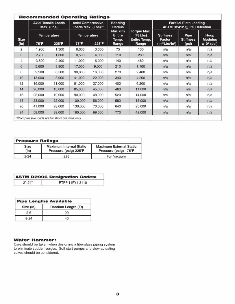
3
Water Hammer:Care should be taken when designing a fiberglass piping system to eliminate sudden surges. Soft start pumps and slow actuating valves should be considered.
Recommended Operating Ratings
Size(In)
Axial Tensile Loads Max. (Lbs)
Axial Compressive Loads Max. (Lbs)(1)
Bending Radius
Min. (Ft) Entire Temp. Range
Torque Max. (Ft Lbs)
Entire Temp. Range
Parallel Plate Loading ASTM D2412 @ 5% Defection
Temperature
75°F 225°F
Temperature
75°F 225°F
Stiffness Factor
(In3/Lbs/In2)
Pipe Stiffness
(psi)
Hoop Modulus x106 (psi)
2 1,900 1,300 6,600 3,000 75 130 n/a n/a n/a
3 2,700 1,800 8,500 4,000 110 280 n/a n/a n/a
4 3,600 2,400 11,000 6,000 140 480 n/a n/a n/a
6 5,600 3,800 17,000 9,000 210 1,100 n/a n/a n/a
8 9,500 6,500 30,000 16,000 270 2,480 n/a n/a n/a
10 13,000 8,900 41,000 22,000 340 4,200 n/a n/a n/a
12 16,000 11,000 51,000 27,000 400 6,200 n/a n/a n/a
14 26,000 18,000 85,000 45,000 460 11,000 n/a n/a n/a
16 28,000 19,000 90,000 48,000 520 14,000 n/a n/a n/a
18 33,000 22,000 100,000 56,000 580 18,000 n/a n/a n/a
20 41,000 28,000 130,000 70,000 640 25,000 n/a n/a n/a
24 58,000 39,000 180,000 99,000 770 42,000 n/a n/a n/a(1)Compressive loads are for short columns only.
ASTM D2996 Designation Codes:
2”-24” RTRP-11FY1-3110
Pipe Lengths Available
Size (In) Random Length (Ft)
2-6 20
8-24 40
Pressure Ratings
Size (In)
Maximum Internal StaticPressure (psig) 225°F
Maximum External StaticPressure (psig) 175°F
2-24 225 Full Vacuum
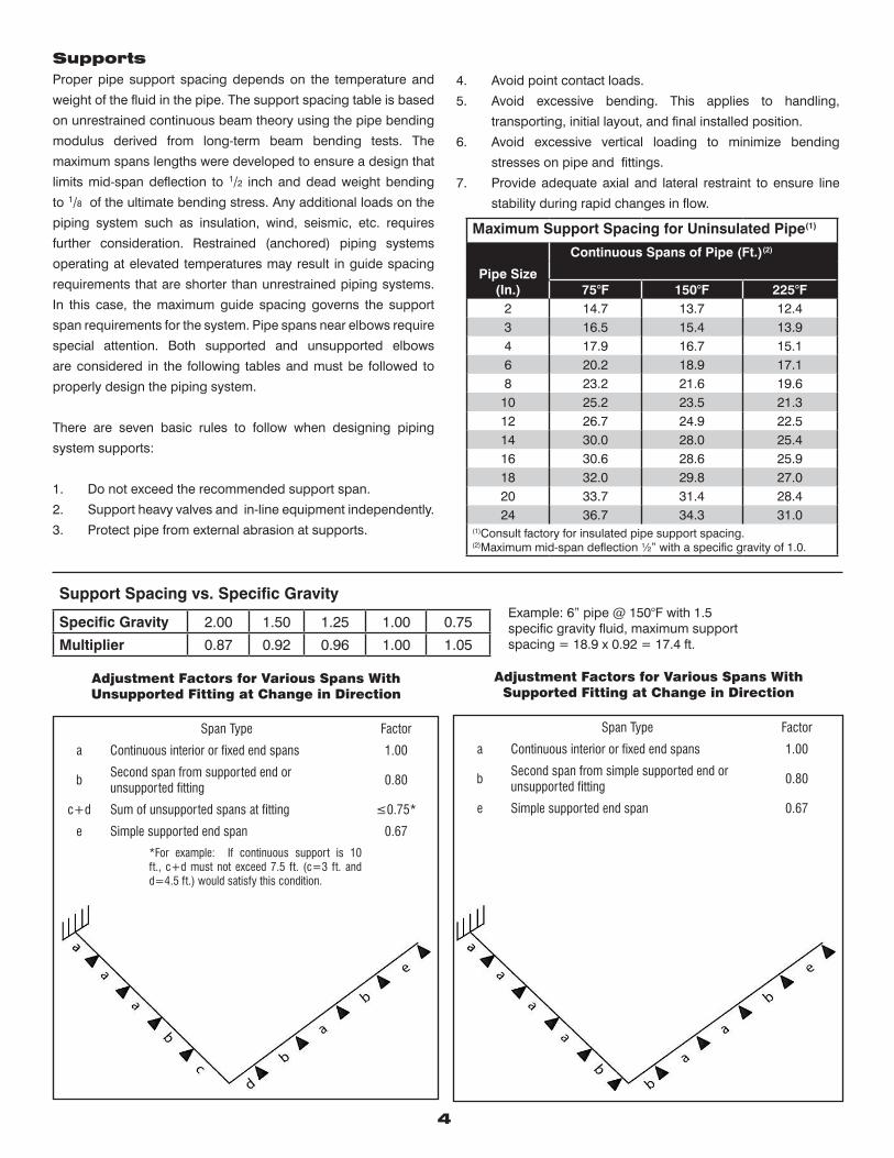
4
SupportsProper pipe support spacing depends on the temperature and
weight of the fluid in the pipe. The support spacing table is based
on unrestrained continuous beam theory using the pipe bending
modulus derived from long-term beam bending tests. The
maximum spans lengths were developed to ensure a design that
limits mid-span deflection to 1/2 inch and dead weight bending
to 1/8 of the ultimate bending stress. Any additional loads on the
piping system such as insulation, wind, seismic, etc. requires
further consideration. Restrained (anchored) piping systems
operating at elevated temperatures may result in guide spacing
requirements that are shorter than unrestrained piping systems.
In this case, the maximum guide spacing governs the support
span requirements for the system. Pipe spans near elbows require
special attention. Both supported and unsupported elbows
are considered in the following tables and must be followed to
properly design the piping system.
There are seven basic rules to follow when designing piping
system supports:
1. Do not exceed the recommended support span.
2. Support heavy valves and in-line equipment independently.
3. Protect pipe from external abrasion at supports.
4. Avoid point contact loads.
5. Avoid excessive bending. This applies to handling,
transporting, initial layout, and final installed position.
6. Avoid excessive vertical loading to minimize bending
stresses on pipe and fittings.
7. Provide adequate axial and lateral restraint to ensure line
stability during rapid changes in flow.
Maximum Support Spacing for Uninsulated Pipe(1)
Pipe Size (In.)
Continuous Spans of Pipe (Ft.)(2)
75°F 150°F 225°F2 14.7 13.7 12.43 16.5 15.4 13.94 17.9 16.7 15.16 20.2 18.9 17.18 23.2 21.6 19.6
10 25.2 23.5 21.312 26.7 24.9 22.514 30.0 28.0 25.416 30.6 28.6 25.918 32.0 29.8 27.020 33.7 31.4 28.424 36.7 34.3 31.0
(1)Consult factory for insulated pipe support spacing.(2)Maximum mid-span deflection ½” with a specific gravity of 1.0.
Support Spacing vs. Specific Gravity
Specific Gravity 2.00 1.50 1.25 1.00 0.75
Multiplier 0.87 0.92 0.96 1.00 1.05
Example: 6” pipe @ 150°F with 1.5specific gravity fluid, maximum support spacing = 18.9 x 0.92 = 17.4 ft.
Adjustment Factors for Various Spans WithSupported Fitting at Change in Direction
Span Type Factor
a Continuous interior or fixed end spans 1.00
bSecond span from simple supported end or unsupported fitting
0.80
e Simple supported end span 0.67
Adjustment Factors for Various Spans WithUnsupported Fitting at Change in Direction
Span Type Factor
a Continuous interior or fixed end spans 1.00
bSecond span from supported end orunsupported fitting
0.80
c+d Sum of unsupported spans at fitting ≤0.75*
e Simple supported end span 0.67
*For example: If continuous support is 10 ft., c+d must not exceed 7.5 ft. (c=3 ft. and d=4.5 ft.) would satisfy this condition.
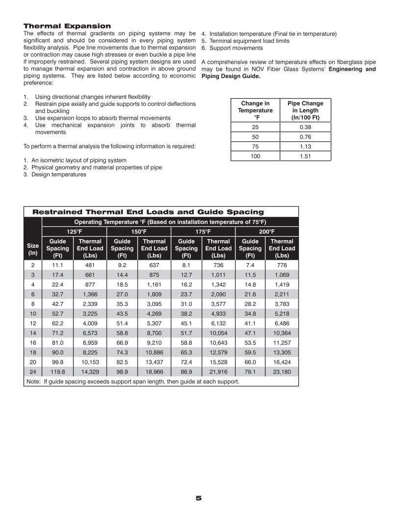
5
Change inTemperature
°F
Pipe Change in Length(In/100 Ft)
25 0.38
50 0.76
75 1.13
100 1.51
Thermal ExpansionThe effects of thermal gradients on piping systems may be significant and should be considered in every piping system flexibility analysis. Pipe line movements due to thermal expansion or contraction may cause high stresses or even buckle a pipe line if improperly restrained. Several piping system designs are used to manage thermal expansion and contraction in above ground piping systems. They are listed below according to economic preference:
1. Using directional changes inherent flexibility2. Restrain pipe axially and guide supports to control deflections
and buckling3. Use expansion loops to absorb thermal movements4. Use mechanical expansion joints to absorb thermal
movements
To perform a thermal analysis the following information is required:
1. An isometric layout of piping system2. Physical geometry and material properties of pipe3. Design temperatures
4. Installation temperature (Final tie in temperature)5. Terminal equipment load limits6. Support movements
A comprehensive review of temperature effects on fiberglass pipe may be found in NOV Fiber Glass Systems’ Engineering and Piping Design Guide.
Restrained Thermal End Loads and Guide Spacing
Size(In)
Operating Temperature °F (Based on installation temperature of 75°F)
125°F 150°F 175°F 200°F
GuideSpacing
(Ft)
ThermalEnd Load
(Lbs)
GuideSpacing
(Ft)
ThermalEnd Load
(Lbs)
GuideSpacing
(Ft)
ThermalEnd Load
(Lbs)
GuideSpacing
(Ft)
ThermalEnd Load
(Lbs)
2 11.1 481 9.2 637 8.1 736 7.4 778
3 17.4 661 14.4 875 12.7 1,011 11.5 1,069
4 22.4 877 18.5 1,161 16.2 1,342 14.8 1,419
6 32.7 1,366 27.0 1,809 23.7 2,090 21.6 2,211
8 42.7 2,339 35.3 3,095 31.0 3,577 28.2 3,783
10 52.7 3,225 43.5 4,269 38.2 4,933 34.8 5,218
12 62.2 4,009 51.4 5,307 45.1 6,132 41.1 6,486
14 71.2 6,573 58.8 8,700 51.7 10,054 47.1 10,364
16 81.0 6,959 66.9 9,210 58.8 10,643 53.5 11,257
18 90.0 8,225 74.3 10,886 65.3 12,579 59.5 13,305
20 99.8 10,153 82.5 13,437 72.4 15,528 66.0 16,424
24 119.8 14,329 98.9 18,966 86.9 21,916 79.1 23,180
Note: If guide spacing exceeds support span length, then guide at each support.
National Oilwell Varco has produced this brochure for general information only, and it is not intended for design purposes. Although every effort has been made to maintain the accuracy and reliability of its contents, National Oilwell Varco in no way assumes responsibility for liability for any loss, damage or injury resulting from the use of information and data herein nor is any warranty expressed or implied. Always cross-reference the bulletin date with the most current version listed at the web site noted in this literature.
www.fgspipe.com • [email protected]
©2012 National Oilwell Varco. All rights reserved.CI1400 - February 2011
North America South America Europe Asia Pacific Middle East17115 San Pedro Ave. Suite 200 Avenida Fernando Simoes P.O. Box 6, 4190 CA No. 7A, Tuas Avenue 3 P.O. Box 17324San Antonio, Texas 78232 USA Recife, Brazil 51020-390 Geldermalsen, The Netherlands Jurong, Singapore 639407 Dubai, UAEPhone: 210 477 7500 Phone: 55 31 3501 0023 Phone: 31 345 587 587 Phone: 65 6861 6118 Phone: 971 4881 3566
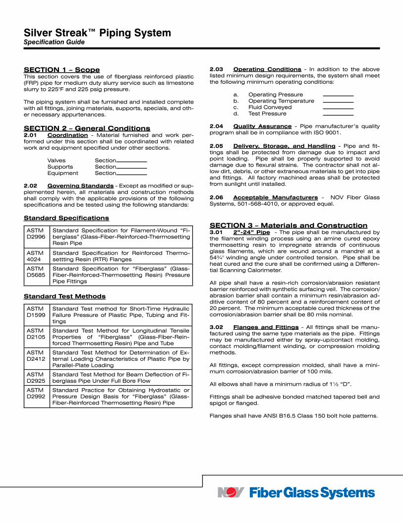
SECTION 1 – ScopeThis section covers the use of fiberglass reinforced plastic (FRP) pipe for medium duty slurry service such as limestone slurry to 225°F and 225 psig pressure.
The piping system shall be furnished and installed complete with all fittings, joining materials, supports, specials, and oth-er necessary appurtenances.
SECTION 2 – General Conditions 2.01 Coordination - Material furnished and work per-formed under this section shall be coordinated with related work and equipment specified under other sections.
Valves Section Supports Section Equipment Section
2.02 Governing Standards - Except as modified or sup-plemented herein, all materials and construction methods shall comply with the applicable provisions of the following specifications and be tested using the following standards:
Standard Specifications
Standard Test Methods
2.03 Operating Conditions - In addition to the above listed minimum design requirements, the system shall meet the following minimum operating conditions:
a. Operating Pressure b. Operating Temperature c. Fluid Conveyed d. Test Pressure
2.04 Quality Assurance - Pipe manufacturer’s quality program shall be in compliance with ISO 9001.
2.05 Delivery, Storage, and Handling - Pipe and fit-tings shall be protected from damage due to impact and point loading. Pipe shall be properly supported to avoid damage due to flexural strains. The contractor shall not al-low dirt, debris, or other extraneous materials to get into pipe and fittings. All factory machined areas shall be protected from sunlight until installed.
2.06 Acceptable Manufacturers - NOV Fiber Glass Systems, 501-568-4010, or approved equal.
SECTION 3 – Materials and Construction3.01 2”-24” Pipe - The pipe shall be manufactured by the filament winding process using an amine cured epoxy thermosetting resin to impregnate strands of continuous glass filaments, which are wound around a mandrel at a 54¾° winding angle under controlled tension. Pipe shall be heat cured and the cure shall be confirmed using a Differen-tial Scanning Calorimeter.
All pipe shall have a resin-rich corrosion/abrasion resistant barrier reinforced with synthetic surfacing veil. The corrosion/abrasion barrier shall contain a minimum resin/abrasion ad-ditive content of 80 percent and a reinforcement content of 20 percent. The minimum acceptable cured thickness of the corrosion/abrasion barrier shall be 80 mils nominal.
3.02 Flanges and Fittings - All fittings shall be manu-factured using the same type materials as the pipe. Fittings may be manufactured either by spray-up/contact molding, contact molding/filament winding, or compression molding methods.
All fittings, except compression molded, shall have a mini-mum corrosion/abrasion barrier of 100 mils.
All elbows shall have a minimum radius of 1½ “D”.
Fittings shall be adhesive bonded matched tapered bell and spigot or flanged.
Flanges shall have ANSI B16.5 Class 150 bolt hole patterns.
ASTMD2996
Standard Specification for Filament-Wound “Fi-berglass” (Glass-Fiber-Reinforced-Thermosetting Resin Pipe
ASTM 4024
Standard Specification for Reinforced Thermo-settting Resin (RTR) Flanges
ASTMD5685
Standard Specification for “Fiberglass” (Glass-Fiber-Reinforced-Thermosetting Resin) Pressure Pipe Fittings
ASTMD1599
Standard Test method for Short-Time Hydraulic Failure Pressure of Plastic Pipe, Tubing and Fit-tings
ASTMD2105
Standard Test Method for Longitudinal Tensile Properties of “Fiberglass” (Glass-Fiber-Rein-forced Thermosetting Resin) Pipe and Tube
ASTMD2412
Standard Test Method for Determination of Ex-ternal Loading Characteristics of Plastic Pipe by Parallel-Plate Loading
ASTM D2925
Standard Test Method for Beam Deflection of Fi-berglass Pipe Under Full Bore Flow
ASTMD2992
Standard Practice for Obtaining Hydrostatic or Pressure Design Basis for “Fiberglass” (Glass-Fiber-Reinforced Thermosetting Resin) Pipe
Silver Streak™ Piping SystemSpecification Guide
3.03 Adhesive - Adhesive shall be manufacturer’s stan-dard for the piping system specified.
3.04 Gaskets - Gaskets shall be 1/8” thick, 60-70 durom-eter full-face type suitable for the service shown on the draw-ings and as recommended in the manufacturer’s standard installation procedures.
3.05 Bolts, Nuts, and Washers - ASTM A307, Grade B, hex head bolts shall be supplied. SAE washers shall be sup-plied on all nuts and bolts.
3.06 Acceptable Products - Silver Streak as manufac-tured by Fiber Glass Systems, or approved equal.
SECTION 4 – Installation and Testing4.01 Training and Certification. All joints installed or constructed in the field shall be assembled by employees of the contractor who have been trained by the pipe manu-facturer. The pipe manufacturer or their authorized repre-sentative shall train the contractor’s employees in the proper joining and assembly procedures required for the project, including hands-on training by the contractor’s employees. Each bonder shall fabricate one pipe-to-pipe and one pipe-to-fitting joint that shall pass the minimum pressure test for the application without leaking.
Only bonders who have successfully completed the pressure test shall bond pipe and fittings.
Certification by the manufacturer shall be in compliance with ASME B31.3, Section A328.2 for the type of joint being made.
4.02 Pipe Installation. Pipe shall be installed as speci-fied and indicated on the drawings.
The piping system shall be installed in accordance with the manufacturer’s current published installation procedures.
4.03 Testing. Hydrostatic testing should be performed to evaluate the structural integrity of a new piping system installation. Test pressures of 1.5 times the design pressure but not exceeding 1.5 times the static pressure rating of the lowest rated fiberglass component in the piping system is recommended. The hydrotest pressure should be repeated up to ten times to provide a high degree of confidence in the piping system. The final pressurization should be allowed to stabilize for 15-30 minutes, then, inspected for leaks. Do not attempt to repair leaks while system is pressurized. The hydro test should be repeated after any re-work is performed.
When hydro testing open vents to prevent entrapment of air in the lines as the system is slowly filled with water. Then close the vents and slowly pressurize to the test pressure. Upon completion of hydro test, relieve the pressure on the system slowly, open vents and any drains to allow for com-plete drainage of the system.
Piping systems with design temperatures above 150°F should be tested at 1.5 times the static pressure rating of the lowest rated fiberglass component in the system.
North America South America Europe Asia Pacific Middle East17115 San Pedro Avenue Estrada de Acesso à Zona P.O. Box 6, 4190 CA No. 7A, Tuas Avenue 3 P.O. Box 17324Suite 200 Industrial Portuária de Suape, s/no. Geldermalsen, The Netherlands Jurong, Singapore 639407 Dubai, UAESan Antonio, TX 78232 USA Recife, PE, Brazil 55.590-000 Phone: +31 345 587 587 Phone: +65 6861 6118 Phone: +971 4881 3566 Phone: +1 210 477 7500 Phone: +55 81 3501 0023
© 2013 National Oilwell Varco. All rights reserved.CI1401 - July 2013
National Oilwell Varco has produced this brochure for general information only, and it is not intended for design purposes. Although every effort has been made to maintain the accuracy and reliability of its contents, National Oilwell Varco in no way assumes responsibility for liability for any loss, damage or injury resulting from the use of information and data herein. All applications for the material described are at the user’s risk and are the user’s responsibility.All brands listed are trademarks of National Oilwell Varco.
www.fgspipe.com • [email protected]
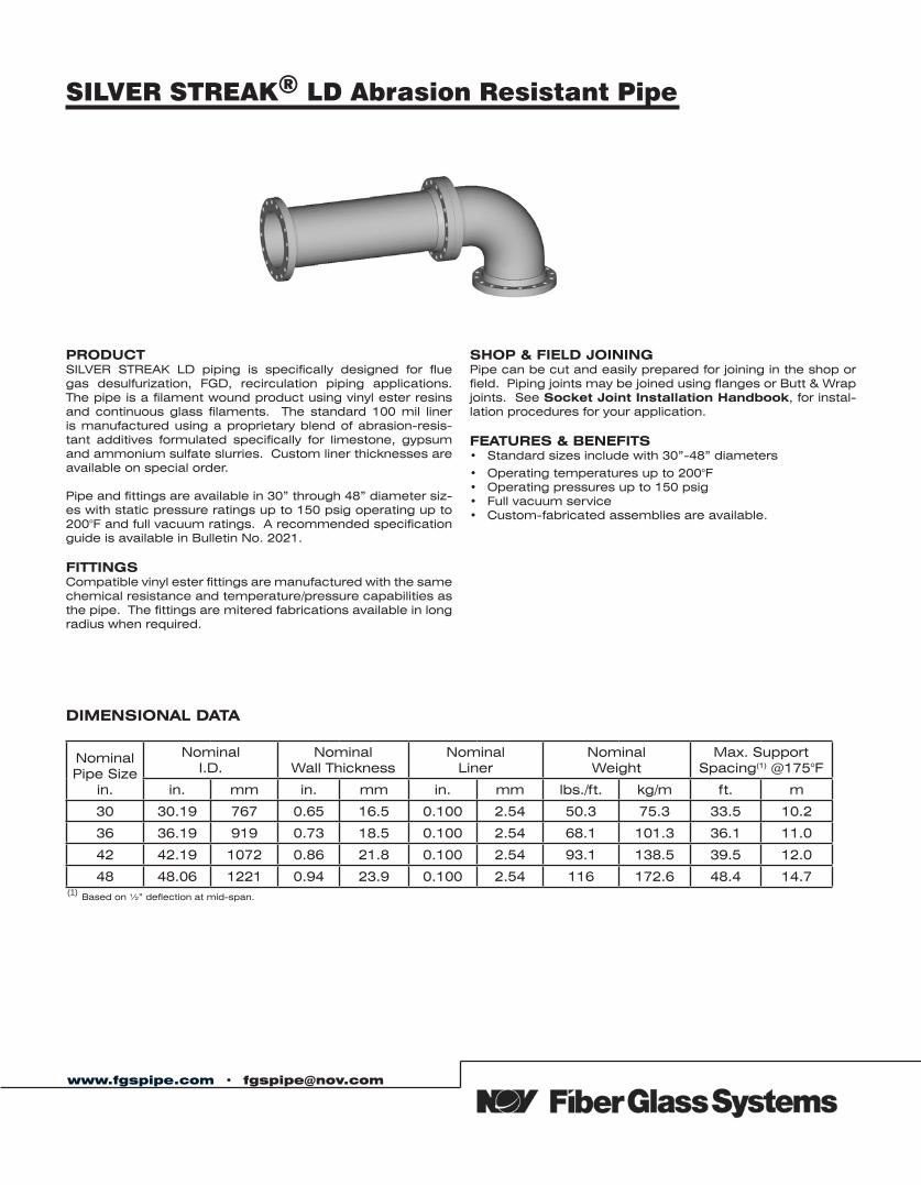
SILVER STREAK® LD Abrasion Resistant Pipe
PRODUCTSILVER STREAK LD piping is specifically designed for flue gas desulfurization, FGD, recirculation piping applications. The pipe is a filament wound product using vinyl ester resins and continuous glass filaments. The standard 100 mil liner is manufactured using a proprietary blend of abrasion-resis-tant additives formulated specifically for limestone, gypsum and ammonium sulfate slurries. Custom liner thicknesses are available on special order.
Pipe and fittings are available in 30” through 48” diameter siz-es with static pressure ratings up to 150 psig operating up to 200°F and full vacuum ratings. A recommended specification guide is available in Bulletin No. 2021.
FITTINGSCompatible vinyl ester fittings are manufactured with the same chemical resistance and temperature/pressure capabilities as the pipe. The fittings are mitered fabrications available in long radius when required.
SHOP & FIELD JOININGPipe can be cut and easily prepared for joining in the shop or field. Piping joints may be joined using flanges or Butt & Wrap joints. See Socket Joint Installation Handbook, for instal-lation procedures for your application.
FEATURES & BENEFITS• Standard sizes include with 30”-48” diameters
• Operating temperatures up to 200°F• Operating pressures up to 150 psig• Full vacuum service• Custom-fabricated assemblies are available.
DIMENSIONAL DATA
NominalPipe Size
in.
NominalI.D.
NominalWall Thickness
NominalLiner
NominalWeight
Max. SupportSpacing(1) @175°F
in. mm in. mm in. mm lbs./ft. kg/m ft. m
30 30.19 767 0.65 16.5 0.100 2.54 50.3 75.3 33.5 10.2
36 36.19 919 0.73 18.5 0.100 2.54 68.1 101.3 36.1 11.0
42 42.19 1072 0.86 21.8 0.100 2.54 93.1 138.5 39.5 12.0
48 48.06 1221 0.94 23.9 0.100 2.54 116 172.6 48.4 14.7
www.fgspipe.com • [email protected]
(1) Based on ½” deflection at mid-span.
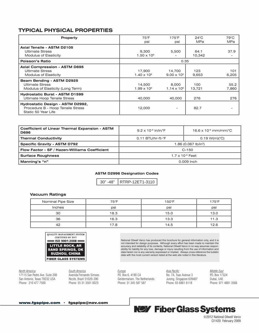
Property 75°F 175°F psi psi
24°C 79°C MPa MPa
Axial Tensile - ASTM D2105 Ultimate Stress Modulus of Elasticity
9,300 5,500 1.50 x 10⁶ -
64.1 37.9 10,342 -
Poisson’s Ratio 0.35
Axial Compression - ASTM D695 Ultimate Stress Modulus of Elasticity
17,900 14,700 1.40 x 10⁶ 9.00 x 10⁵
123 101 9,653 6,205
Beam Bending - ASTM D2925 Ultimate Stress Modulus of Elasticity (Long Term)
14,500 8,000 1.99 x 10⁶ 1.14 x 10⁶
100 55.2 13,721 7,860
Hydrostatic Burst - ASTM D1599 Ultimate Hoop Tensile Stress 40,000 40,000 276 276
Hydrostatic Design - ASTM D2992, Procedure B - Hoop Tensile Stress Static 50 Year Life
12,000 - 82.7 -
TYPICAL PHYSICAL PROPERTIES
Coefficient of Linear Thermal Expansion - ASTM D696
9.2 x 10⁻⁶ in/in/°F 16.6 x 10⁻⁶ mm/mm/°C
Thermal Conductivity 0.11 BTU/hr-ft-°F 0.19 W(m)(°C)
Specific Gravity - ASTM D792 1.86 (0.067 lb/in3)
Flow Factor - SF / Hazen-Williams Coefficient C-150
Surface Roughness 1.7 x 10⁻⁶ Feet
Manning’s “n” 0.009 Inch
Nominal Pipe Size 75°F 150°F 175°F
Inches psi psi psi
30 18.3 15.0 13.0
36 16.3 13.3 11.3
42 17.8 14.5 12.6
Vacuum Ratings
©2012 National Oilwell VarcoCI1420 February 2009
www.fgspipe.com • [email protected]
National Oilwell Varco has produced this brochure for general information only, and it is not intended for design purposes. Although every effort has been made to maintain the accuracy and reliability of its contents, National Oilwell Varco in no way assumes respon-sibility for liability for any loss, damage or injury resulting from the use of information and data herein nor is any warranty expressed or implied. Always cross-reference the bulletin date with the most current version listed at the web site noted in this literature.
North America South America Europe Asia Pacific Middle East17115 San Pedro Ave. Suite 200 Avenida Fernando Simoes P.O. Box 6, 4190 CA No. 7A, Tuas Avenue 3 P.O. Box 17324San Antonio, Texas 78232 USA Recife, Brazil 51020-390 Geldermalsen, The Netherlands Jurong, Singapore 639407 Dubai, UAEPhone: 210 477 7500 Phone: 55 31 3501 0023 Phone: 31 345 587 587 Phone: 65 6861 6118 Phone: 971 4881 3566
ASTM D2996 Designation Codes
30” -48” RTRP-12ET1-3110
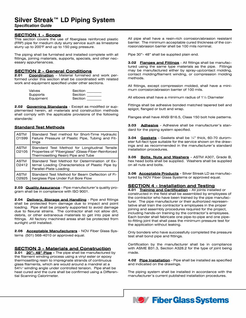
SECTION 1 - ScopeThis section covers the use of fiberglass reinforced plastic (FRP) pipe for medium duty slurry service such as limestone slurry up to 200°F and up to 150 psig pressure.
The piping shall be furnished and installed complete with all fittings, joining materials, supports, specials, and other nec-essary appurtenances.
SECTION 2 - General Conditions2.01 Coordination - Material furnished and work per-formed under this section shall be coordinated with related work and equipment specified under other sections.
Valves Section _________ Supports Section _________ Equipment Section _________
2.02 Governing Standards - Except as modified or sup-plemented herein, all materials and construction methods shall comply with the applicable provisions of the following standards:
Standard Test Methods
2.03 Quality Assurance - Pipe manufacturer’s quality pro-gram shall be in compliance with ISO 9001.
2.04 Delivery, Storage and Handling - Pipe and fittings shall be protected from damage due to impact and point loading. Pipe shall be properly supported to avoid damage due to flexural strains. The contractor shall not allow dirt, debris, or other extraneous materials to get into pipe and fittings. All factory machined areas shall be protected from sunlight until installed.
2.05 Acceptable Manufacturers - NOV Fiber Glass Sys-tems (501) 568-4010 or approved equal.
SECTION 3 - Materials and Construction3.01 30”- 48” Pipe - The pipe shall be manufactured by the filament winding process using a vinyl ester or epoxy thermosetting resin to impregnate strands of continuous glass filaments, which are would around a mandrel at a 54¾° winding angle under controlled tension. Pipe shall be heat cured and the cure shall be confirmed using a Differen-tial Scanning Calorimeter.
All pipe shall have a resin-rich corrosion/abrasion resistant barrier. The minimum acceptable cured thickness of the cor-rosion/abrasion barrier shell be 100 mils nominal.
Pipe 30”- 48” shall be supplied plain end.
3.02 Flanges and Fittings - All fittings shall be manufac-tured using the same type materials as the pipe. Fittings may be manufactured either by spray-up/contact molding, contact molding/filament winding, or compression molding methods.
All fittings, except compression molded, shall have a mini-mum corrosion/abrasion barrier of 100 mils.
All elbows shall have a minimum radius of 1½ Diameter
Fittings shall be adhesive bonded matched tapered bell and spigot, flanged or butt and wrap.
Flanges shall have ANSI B16.5, Class 150 bolt hole patterns.
3.03 Adhesive - Adhesive shall be manufacturer’s stan-dard for the piping system specified.
3.04 Gaskets - Gaskets shall be ¼” thick, 60-70 durom-eter full-fact type suitable for the service shown on the draw-ings and as recommended in the manufacturer’s standard installation procedures.
3.05 Bolts, Nuts and Washers - ASTM A307, Grade B, hex head bolts shall be supplied. Washers shall be supplied on all nuts and bolts.
3.06 Acceptable Products - Silver Streak LD as manufac-tured by NOV Fiber Glass Systems or approved equal.
SECTION 4 - Installation and Testing4.01 Training and Certification - All joints installed or constructed in the field shall be assembled by employees of the contractor who have been trained by the pipe manufac-turer. The pipe manufacturer or their authorized represen-tative shall train the contractor’s employees in the proper joining and assembly procedures required for the project, including hands-on training by the contractor’s employees. Each bonder shall fabricate one pipe-to-pipe and one pipe-to-fitting joint that shall pass the minimum pressure test for the application without leaking.
Only bonders who have successfully completed the pressure test shall bond pipe and fittings.
Certification by the manufacturer shall be in compliance with ASME B31.3, Section A328.2 for the type of joint being made.
4.02 Pipe Installation - Pipe shall be installed as specified and indicated on the drawings.
The piping system shall be installed in accordance with the manufacturer’s current published installation procedures.
ASTMD1599
Standard Test method for Short-Time Hydraulic Failure Pressure of Plastic Pipe, Tubing and Fit-tings
ASTMD2105
Standard Test Method for Longitudinal Tensile Properties of “Fiberglass” (Glass-Fiber-Reinforced Thermosetting Resin) Pipe and Tube
ASTMD2412
Standard Test Method for Determination of Ex-ternal Loading Characteristics of Plastic Pipe by Parallel-Plate Loading
ASTM D2925
Standard Test Method for Beam Deflection of Fi-berglass Pipe Under Full Bore Flow
Silver Streak™ LD Piping SystemSpecification Guide
4.03 Testing - When testing 30” and larger pipe, a steady pressure test shall be conducted on the completed piping sys-tem. The pipe shall be subjected to a steady pressure test at 1½ times the design operating pressure as shown on the drawings.
Test pressure shall not exceed 1½ times the maximum rated pressure of the lowest rated element in the system.
The system shall be filled with water at the lowest point and air bled off from the highest point. Systems shall be brought up to test pressure slowly to prevent water hammer or over-pressurization.
All pipe joints shall be water tight. All joints that are found to leak by observation or during testing shall be repaired by the contractor and retested.
North America South America Europe Asia Pacific Middle East17115 San Pedro Avenue Estrada de Acesso à Zona P.O. Box 6, 4190 CA No. 7A, Tuas Avenue 3 P.O. Box 17324Suite 200 Industrial Portuária de Suape, s/no. Geldermalsen, The Netherlands Jurong, Singapore 639407 Dubai, UAESan Antonio, TX 78232 USA Recife, PE, Brazil 55.590-000 Phone: +31 345 587 587 Phone: +65 6861 6118 Phone: +971 4881 3566 Phone: +1 210 477 7500 Phone: +55 81 3501 0023
© 2013 National Oilwell Varco. All rights reserved.CI1421 - February 2009
National Oilwell Varco has produced this brochure for general information only, and it is not intended for design purposes. Although every effort has been made to maintain the accuracy and reliability of its contents, National Oilwell Varco in no way assumes responsibility for liability for any loss, damage or injury resulting from the use of information and data herein. All applications for the material described are at the user’s risk and are the user’s responsibility.All brands listed are trademarks of National Oilwell Varco.
www.fgspipe.com • [email protected]
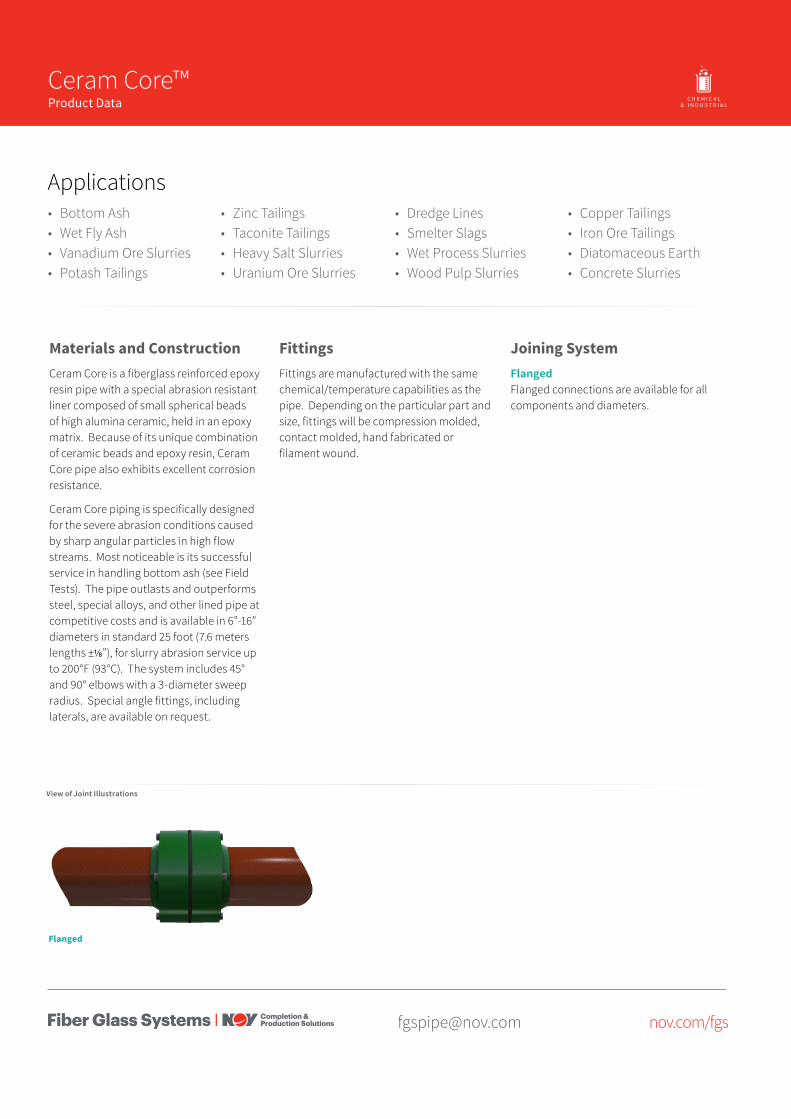
[email protected] nov.com/fgs
Product Name 14/15
Materials and ConstructionCeram Core is a fiberglass reinforced epoxy resin pipe with a special abrasion resistant liner composed of small spherical beads of high alumina ceramic, held in an epoxy matrix. Because of its unique combination of ceramic beads and epoxy resin, Ceram Core pipe also exhibits excellent corrosion resistance.
Ceram Core piping is specifically designed for the severe abrasion conditions caused by sharp angular particles in high flow streams. Most noticeable is its successful service in handling bottom ash (see Field Tests). The pipe outlasts and outperforms steel, special alloys, and other lined pipe at competitive costs and is available in 6”-16” diameters in standard 25 foot (7.6 meters lengths ±⅛”), for slurry abrasion service up to 200°F (93°C). The system includes 45° and 90° elbows with a 3-diameter sweep radius. Special angle fittings, including laterals, are available on request.
• Bottom Ash• Wet Fly Ash• Vanadium Ore Slurries• Potash Tailings
• Zinc Tailings• Taconite Tailings• Heavy Salt Slurries• Uranium Ore Slurries
• Dredge Lines• Smelter Slags• Wet Process Slurries• Wood Pulp Slurries
• Copper Tailings• Iron Ore Tailings• Diatomaceous Earth• Concrete Slurries
FittingsFittings are manufactured with the same chemical/temperature capabilities as the pipe. Depending on the particular part and size, fittings will be compression molded, contact molded, hand fabricated or filament wound.
Flanged
O I L & G A S C H E M I C A L& I N D U S T R I A L
O F F S H O R EM A R I N E M I N I N GF U E LH A N D L I N G
Ceram Core™Product Data
Applications
View of Joint Illustrations
Joining SystemFlangedFlanged connections are available for all components and diameters.
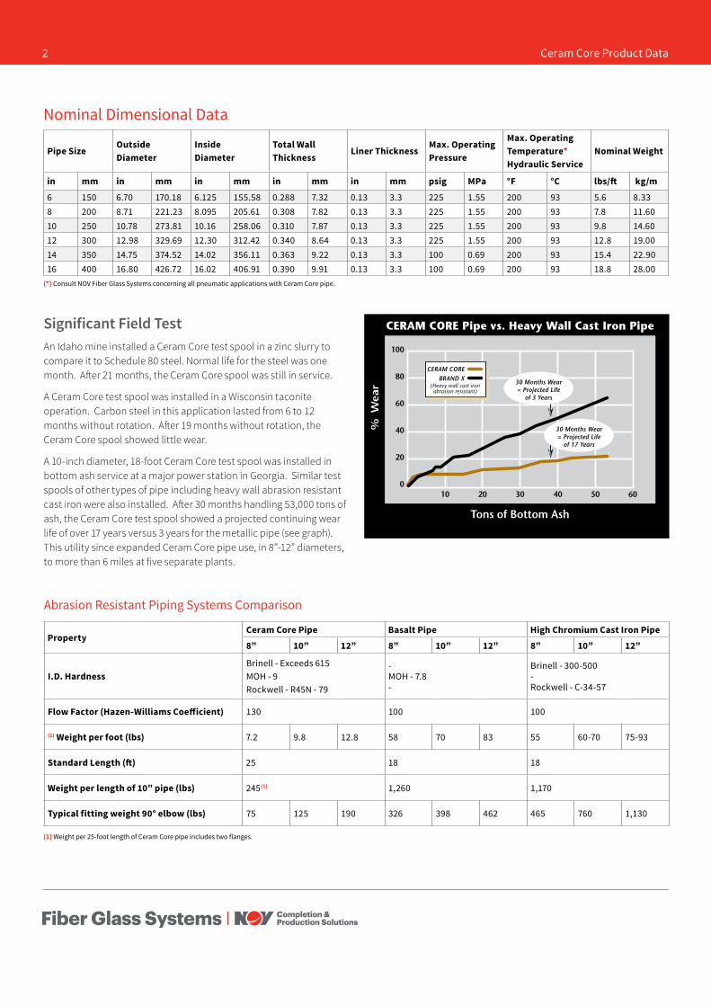
Pipe SizeOutside Diameter
Inside Diameter
Total Wall Thickness
Liner ThicknessMax. Operating Pressure
Max. Operating Temperature* Hydraulic Service
Nominal Weight
in mm in mm in mm in mm in mm psig MPa °F °C lbs/ft kg/m
6 150 6.70 170.18 6.125 155.58 0.288 7.32 0.13 3.3 225 1.55 200 93 5.6 8.338 200 8.71 221.23 8.095 205.61 0.308 7.82 0.13 3.3 225 1.55 200 93 7.8 11.6010 250 10.78 273.81 10.16 258.06 0.310 7.87 0.13 3.3 225 1.55 200 93 9.8 14.6012 300 12.98 329.69 12.30 312.42 0.340 8.64 0.13 3.3 225 1.55 200 93 12.8 19.0014 350 14.75 374.52 14.02 356.11 0.363 9.22 0.13 3.3 100 0.69 200 93 15.4 22.9016 400 16.80 426.72 16.02 406.91 0.390 9.91 0.13 3.3 100 0.69 200 93 18.8 28.00
Nominal Dimensional Data
(*) Consult NOV Fiber Glass Systems concerning all pneumatic applications with Ceram Core pipe.
Abrasion Resistant Piping Systems Comparison
(1) Weight per 25-foot length of Ceram Core pipe includes two flanges.
Significant Field TestAn Idaho mine installed a Ceram Core test spool in a zinc slurry to compare it to Schedule 80 steel. Normal life for the steel was one month. After 21 months, the Ceram Core spool was still in service.
A Ceram Core test spool was installed in a Wisconsin taconite operation. Carbon steel in this application lasted from 6 to 12 months without rotation. After 19 months without rotation, the Ceram Core spool showed little wear.
A 10-inch diameter, 18-foot Ceram Core test spool was installed in bottom ash service at a major power station in Georgia. Similar test spools of other types of pipe including heavy wall abrasion resistant cast iron were also installed. After 30 months handling 53,000 tons of ash, the Ceram Core test spool showed a projected continuing wear life of over 17 years versus 3 years for the metallic pipe (see graph). This utility since expanded Ceram Core pipe use, in 8”-12” diameters, to more than 6 miles at five separate plants.
PropertyCeram Core Pipe Basalt Pipe High Chromium Cast Iron Pipe
8” 10” 12” 8” 10” 12” 8” 10” 12”
I.D. HardnessBrinell - Exceeds 615MOH - 9Rockwell - R45N - 79
-MOH - 7.8-
Brinell - 300-500-Rockwell - C-34-57
Flow Factor (Hazen-Williams Coefficient) 130 100 100
(1) Weight per foot (lbs) 7.2 9.8 12.8 58 70 83 55 60-70 75-93
Standard Length (ft) 25 18 18
Weight per length of 10” pipe (lbs) 245(1) 1,260 1,170
Typical fitting weight 90° elbow (lbs) 75 125 190 326 398 462 465 760 1,130
2 Ceram Core Product Data
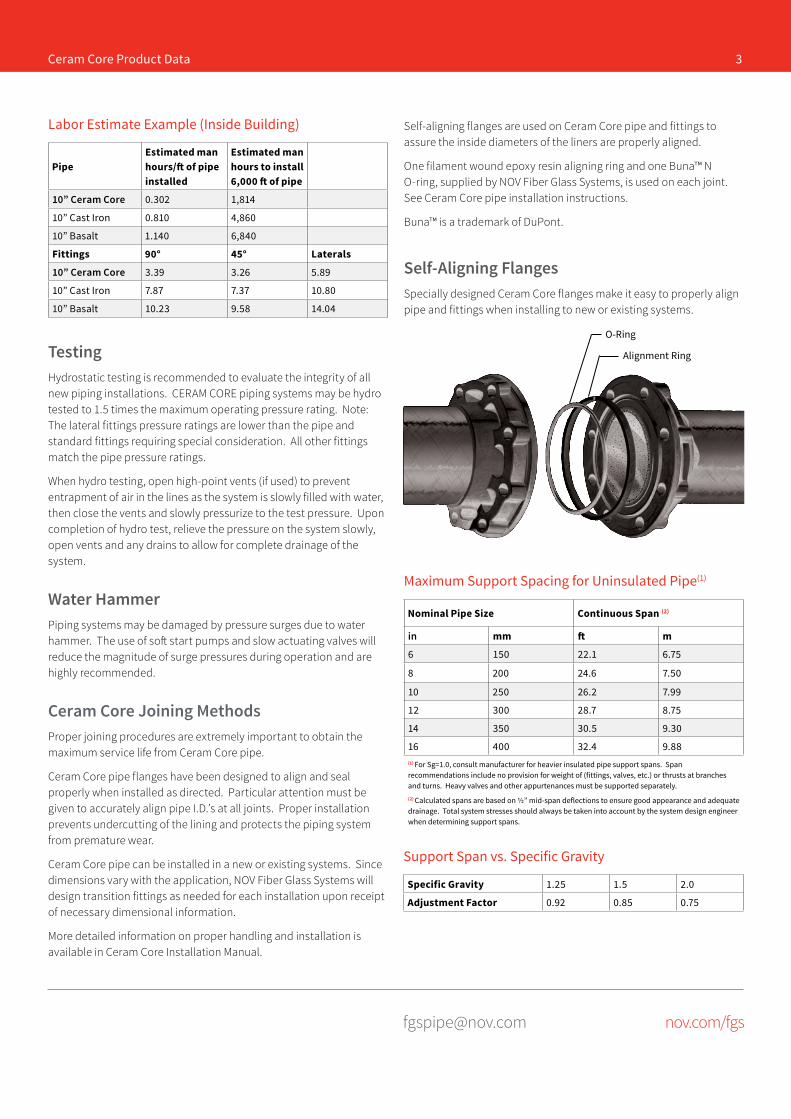
[email protected] nov.com/fgs
TestingHydrostatic testing is recommended to evaluate the integrity of all new piping installations. CERAM CORE piping systems may be hydro tested to 1.5 times the maximum operating pressure rating. Note: The lateral fittings pressure ratings are lower than the pipe and standard fittings requiring special consideration. All other fittings match the pipe pressure ratings.
When hydro testing, open high-point vents (if used) to prevent entrapment of air in the lines as the system is slowly filled with water, then close the vents and slowly pressurize to the test pressure. Upon completion of hydro test, relieve the pressure on the system slowly, open vents and any drains to allow for complete drainage of the system.
Water HammerPiping systems may be damaged by pressure surges due to water hammer. The use of soft start pumps and slow actuating valves will reduce the magnitude of surge pressures during operation and are highly recommended.
Ceram Core Joining MethodsProper joining procedures are extremely important to obtain the maximum service life from Ceram Core pipe.
Ceram Core pipe flanges have been designed to align and seal properly when installed as directed. Particular attention must be given to accurately align pipe I.D.’s at all joints. Proper installation prevents undercutting of the lining and protects the piping system from premature wear.
Ceram Core pipe can be installed in a new or existing systems. Since dimensions vary with the application, NOV Fiber Glass Systems will design transition fittings as needed for each installation upon receipt of necessary dimensional information.
More detailed information on proper handling and installation is available in Ceram Core Installation Manual.
Ceram Core Product Data 3
Labor Estimate Example (Inside Building)
PipeEstimated man hours/ft of pipe installed
Estimated man hours to install 6,000 ft of pipe
10” Ceram Core 0.302 1,814
10” Cast Iron 0.810 4,860
10” Basalt 1.140 6,840
Fittings 90° 45° Laterals
10” Ceram Core 3.39 3.26 5.89
10” Cast Iron 7.87 7.37 10.80
10” Basalt 10.23 9.58 14.04
Self-Aligning FlangesSpecially designed Ceram Core flanges make it easy to properly align pipe and fittings when installing to new or existing systems.
O-Ring
Alignment Ring
Maximum Support Spacing for Uninsulated Pipe(1)
Nominal Pipe Size Continuous Span (2)
in mm ft m
6 150 22.1 6.75
8 200 24.6 7.50
10 250 26.2 7.99
12 300 28.7 8.75
14 350 30.5 9.30
16 400 32.4 9.88(1) For Sg=1.0, consult manufacturer for heavier insulated pipe support spans. Span recommendations include no provision for weight of (fittings, valves, etc.) or thrusts at branches and turns. Heavy valves and other appurtenances must be supported separately.(2) Calculated spans are based on ½” mid-span deflections to ensure good appearance and adequate drainage. Total system stresses should always be taken into account by the system design engineer when determining support spans.
Support Span vs. Specific Gravity
Specific Gravity 1.25 1.5 2.0
Adjustment Factor 0.92 0.85 0.75
Self-aligning flanges are used on Ceram Core pipe and fittings to assure the inside diameters of the liners are properly aligned.
One filament wound epoxy resin aligning ring and one Buna™ N O-ring, supplied by NOV Fiber Glass Systems, is used on each joint. See Ceram Core pipe installation instructions.
Buna™ is a trademark of DuPont.
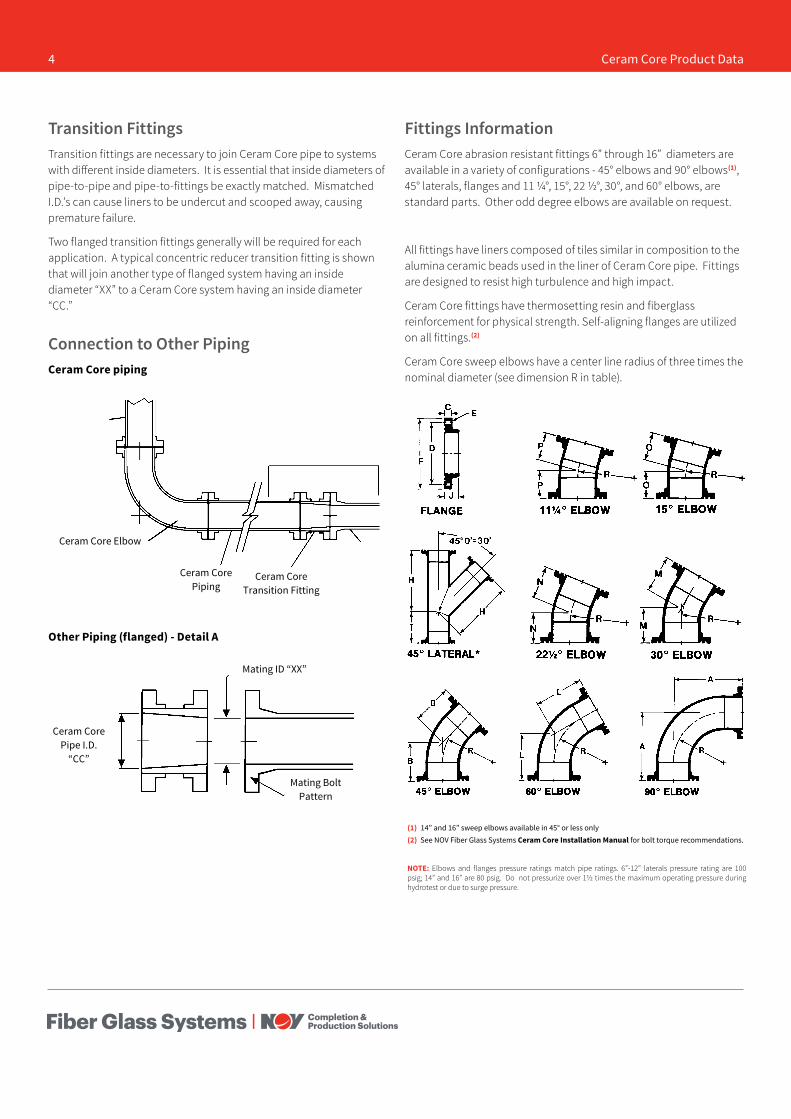
Mating Bolt Pattern
Transition FittingsTransition fittings are necessary to join Ceram Core pipe to systems with different inside diameters. It is essential that inside diameters of pipe-to-pipe and pipe-to-fittings be exactly matched. Mismatched I.D.’s can cause liners to be undercut and scooped away, causing premature failure.
Two flanged transition fittings generally will be required for each application. A typical concentric reducer transition fitting is shown that will join another type of flanged system having an inside diameter “XX” to a Ceram Core system having an inside diameter “CC.”
Connection to Other PipingCeram Core piping
Ceram Core Elbow
Ceram Core Piping
Ceram Core Transition Fitting
Other Piping (flanged) - Detail A
Mating ID “XX”
Ceram Core Pipe I.D.
“CC”
Fittings InformationCeram Core abrasion resistant fittings 6” through 16” diameters are available in a variety of configurations - 45° elbows and 90° elbows(1), 45° laterals, flanges and 11 ¼°, 15°, 22 ½°, 30°, and 60° elbows, are standard parts. Other odd degree elbows are available on request.
All fittings have liners composed of tiles similar in composition to the alumina ceramic beads used in the liner of Ceram Core pipe. Fittings are designed to resist high turbulence and high impact.
Ceram Core fittings have thermosetting resin and fiberglass reinforcement for physical strength. Self-aligning flanges are utilized on all fittings.(2)
Ceram Core sweep elbows have a center line radius of three times the nominal diameter (see dimension R in table).
(1) 14” and 16” sweep elbows available in 45° or less only(2) See NOV Fiber Glass Systems Ceram Core Installation Manual for bolt torque recommendations.
NOTE: Elbows and flanges pressure ratings match pipe ratings. 6”-12” laterals pressure rating are 100 psig; 14” and 16” are 80 psig. Do not pressurize over 1½ times the maximum operating pressure during hydrotest or due to surge pressure.
4 Ceram Core Product Data
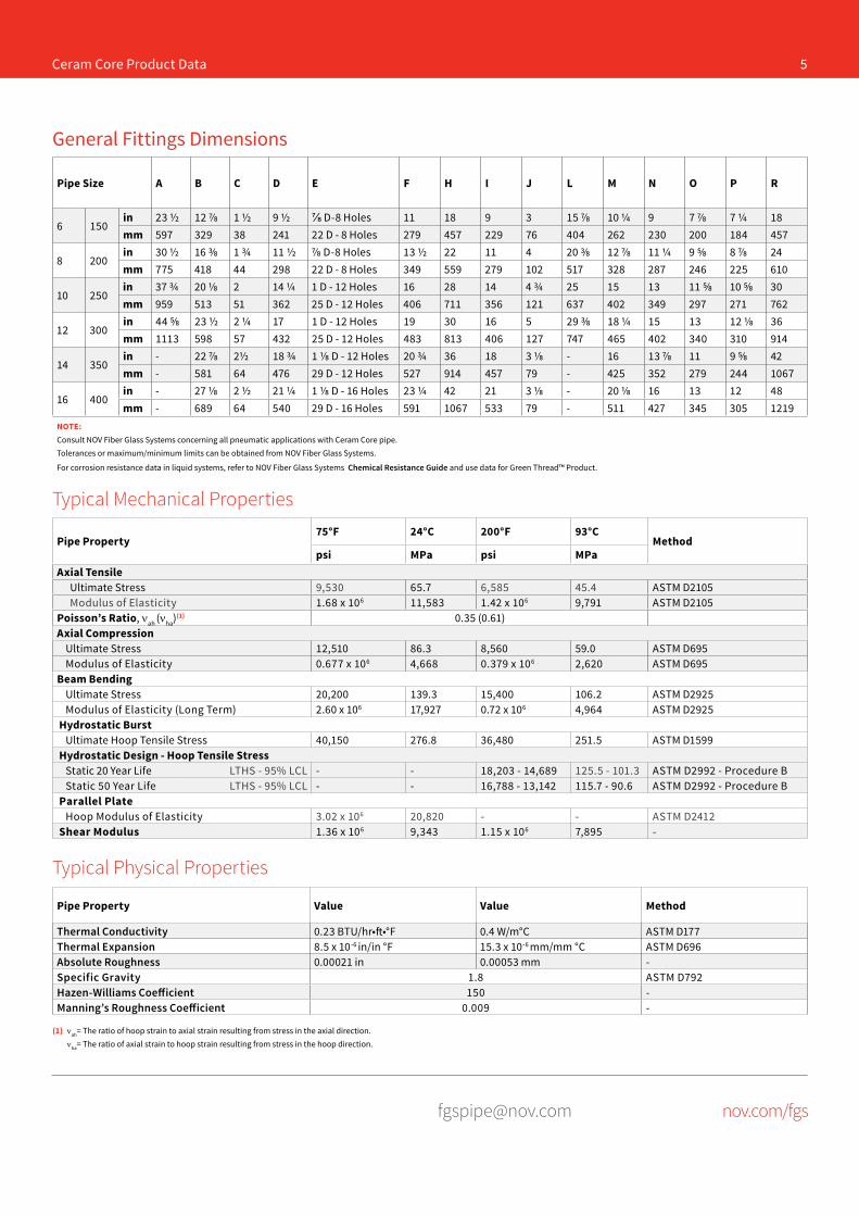
[email protected] nov.com/fgs
Pipe Property75°F 24°C 200°F 93°C
Methodpsi MPa psi MPa
Axial TensileUltimate Stress 9,530 65.7 6,585 45.4 ASTM D2105Modulus of Elasticity 1.68 x 10⁶ 11,583 1.42 x 10⁶ 9,791 ASTM D2105
Poisson’s Ratio, νah (νha)(1) 0.35 (0.61)Axial Compression
Ultimate Stress 12,510 86.3 8,560 59.0 ASTM D695Modulus of Elasticity 0.677 x 10⁶ 4,668 0.379 x 10⁶ 2,620 ASTM D695
Beam BendingUltimate Stress 20,200 139.3 15,400 106.2 ASTM D2925Modulus of Elasticity (Long Term) 2.60 x 10⁶ 17,927 0.72 x 10⁶ 4,964 ASTM D2925
Hydrostatic BurstUltimate Hoop Tensile Stress 40,150 276.8 36,480 251.5 ASTM D1599
Hydrostatic Design - Hoop Tensile StressStatic 20 Year Life LTHS - 95% LCL - - 18,203 - 14,689 125.5 - 101.3 ASTM D2992 - Procedure BStatic 50 Year Life LTHS - 95% LCL - - 16,788 - 13,142 115.7 - 90.6 ASTM D2992 - Procedure B
Parallel PlateHoop Modulus of Elasticity 3.02 x 10⁶ 20,820 - - ASTM D2412
Shear Modulus 1.36 x 10⁶ 9,343 1.15 x 10⁶ 7,895 -
Pipe Property Value Value Method
Thermal Conductivity 0.23 BTU/hr•ft•°F 0.4 W/m°C ASTM D177Thermal Expansion 8.5 x 10⁻⁶ in/in °F 15.3 x 10⁻⁶ mm/mm °C ASTM D696Absolute Roughness 0.00021 in 0.00053 mm -Specific Gravity 1.8 ASTM D792Hazen-Williams Coefficient 150 -Manning’s Roughness Coefficient 0.009 -
Typical Mechanical Properties
Typical Physical Properties
Ceram Core Product Data 5
Pipe Size A B C D E F H I J L M N O P R
6 150in 23 ½ 12 ⅞ 1 ½ 9 ½ ⅞ D-8 Holes 11 18 9 3 15 ⅞ 10 ¼ 9 7 ⅞ 7 ¼ 18mm 597 329 38 241 22 D - 8 Holes 279 457 229 76 404 262 230 200 184 457
8 200in 30 ½ 16 ⅜ 1 ¾ 11 ½ ⅞ D-8 Holes 13 ½ 22 11 4 20 ⅜ 12 ⅞ 11 ¼ 9 ⅝ 8 ⅞ 24mm 775 418 44 298 22 D - 8 Holes 349 559 279 102 517 328 287 246 225 610
10 250in 37 ¾ 20 ⅛ 2 14 ¼ 1 D - 12 Holes 16 28 14 4 ¾ 25 15 13 11 ⅝ 10 ⅝ 30mm 959 513 51 362 25 D - 12 Holes 406 711 356 121 637 402 349 297 271 762
12 300in 44 ⅝ 23 ½ 2 ¼ 17 1 D - 12 Holes 19 30 16 5 29 ⅜ 18 ¼ 15 13 12 ⅛ 36mm 1113 598 57 432 25 D - 12 Holes 483 813 406 127 747 465 402 340 310 914
14 350in - 22 ⅞ 2½ 18 ¾ 1 ⅛ D - 12 Holes 20 ¾ 36 18 3 ⅛ - 16 13 ⅞ 11 9 ⅝ 42mm - 581 64 476 29 D - 12 Holes 527 914 457 79 - 425 352 279 244 1067
16 400in - 27 ⅛ 2 ½ 21 ¼ 1 ⅛ D - 16 Holes 23 ¼ 42 21 3 ⅛ - 20 ⅛ 16 13 12 48mm - 689 64 540 29 D - 16 Holes 591 1067 533 79 - 511 427 345 305 1219
NOTE: Consult NOV Fiber Glass Systems concerning all pneumatic applications with Ceram Core pipe. Tolerances or maximum/minimum limits can be obtained from NOV Fiber Glass Systems.
For corrosion resistance data in liquid systems, refer to NOV Fiber Glass Systems Chemical Resistance Guide and use data for Green Thread™ Product.
General Fittings Dimensions
(1) νah= The ratio of hoop strain to axial strain resulting from stress in the axial direction. νha= The ratio of axial strain to hoop strain resulting from stress in the hoop direction.

[email protected] nov.com/fgs
Fiber Glass Systems17115 San Pedro Avenue, Ste 200San Antonio, Texas 78232 USAPhone: 210 477 7500Fax: 210 477 7560
National Oilwell Varco has produced this brochure for general information only, and it is not intended for design purposes. Although every effort has been made to maintain the accuracy and reliability of its contents, National Oilwell Varco in no way assumes responsibility for liability for any loss, damage or injury resulting from the use of information and data herein nor is any warranty expressed or implied. Always cross-reference the bulletin date with the most current version listed at the web site noted in this literature.
© 2016 National Oilwell Varco All Rights ReservedCI1500ENG February 2016
6 Ceram Core Product Data
www.fgspipe.com • [email protected]
CERAM CORE® Piping System
SECTION 1 – ScopeThis section covers the use of fiberglass reinforced plastic (FRP) pipe for severe abrasion conditions caused by sharp angular particles in high flow streams services up to 210˚F and 225 psig steady pressure.
The piping system shall be furnished and installed com-
plete with all fittings, joining materials, supports, specials,
and other necessary appurtenances.
SECTION 2 – General Conditions2.01 Coordination - Material furnished and work per-formed under this section shall be coordinated with related work and equipment specified under other sections.
Valves Section __________
Supports Section __________
Equipment Section __________
2.02 Governing Standards - Except as modified
or supplemented herein, all materials and construction
methods shall comply with the applicable provisions of the
following specifications and be tested using the following
standards:
Standard Specifications
ASTMD2996
Standard Specification for Filament-Wound “Fiberglass” (Glass-Fiber-Reinforced-Ther-mosetting Resin) Pipe
ASTMD4024
Standard Specification for Reinforced Ther-mosetting Resin (RTR) Flanges
Standard Test Methods
ASTMD2992
Standard Practice for Obtaining Hydrostatic or Pressure Design Basis for “Fiberglass” (Glass-Fiber-Reinforced-Thermosetting Res-in) Pipe and Fittings
ASTMD2925
Standard Practice for Measuring Beam De-flection of Reinforced Thermosetting Plastic Pipe Under Full Bore Flow
ASTMD1599
Standard Test Method for Short-Time Hy-draulic Failure Pressure of Plastic Pipe, Tub-ing and Fittings
ASTMD2105
Standard Test method for Longitudinal Ten-sile Properties of “Fiberglass” (Glass-Fiber-Reinforced-Thermosetting Resin) Pipe and Tube
ASTMD2412
Standard Test Method for Determination of External Loading Characteristics of Plastic PIpe by Parallel-Plate Loading
2.03 Operating Conditions - In addition to the above
listed minimum design requirements, the system shall
meet the following minimum operating conditions:
a. Operating Pressure __________
b. Operating Temperature __________
c. Fluid Conveyed __________
d. Test Pressure __________
2.04 Quality Assurance - Pipe manufacturer’s qual-
ity program shall be in compliance with ISO 9001.
2.05 Delivery, Storage, and Handling - Pipe and fit-
tings shall be protected from damage due to impact and
point loading. Pipe shall be properly supported to avoid
damage due to flexural strains. The contractor shall not
allow dirt, debris, or other extraneous materials to get into
pipe and fittings. All factory machined areas shall be pro-
tected from sunlight until installed.
2.06 Acceptable Manufacturers - NOV Fiber Glass
Systems, 501-568-4010, or approved equal.
SECTION 3 – Materials and Construction3.01 6"-16" Pipe - The pipe shall be manufactured by
the filament winding process using an amine cured epoxy
thermosetting resin to impregnate strands of continuous
glass filaments, which are wound around a mandrel at a
541/4˚ winding angle under controlled tension. Pipe shall
be heat cured and the cure shall be confirmed using a
Differential Scanning Calorimeter.
All pipe shall have a liner consisting of ceramic beads sus-
pended in an epoxy matrix. The minimum liner thickness
shall be 130 mil nominal.
Pipe shall be supplied with self-aligning flanges to assure
the inside diameters of the liners are properly aligned.
Pipe shall have a continuous steady pressure rating at
200˚F as follows 6”-12” at 225 psig and 14”-16” at 100
psig in accordance with ASTM D2992 Procedure B.
All pipe shall be 100% hydrotested at the factory before
shipment at a minimum pressure of 100 psig.
Specification Guide
www.fgspipe.com • [email protected]
©2012 National Oilwell Varco. All rights reserved. CI1501 February 2009
3.02 Flanges and Fittings - Abrasion resistant el-
bows shall be three diameter sweep radius and have self-
aligning flanged ends. They shall be glass reinforced ther-
mosetting resin with abrasion resistant ceramic tile liner.
Flanges shall have ANSI B16.5 Class 150 bolt hole pat-
terns. It is recommended that a protective coating be used
on the bolts to facilitate removal for rotation.
3.04 O-Ring Seals - O-Rings shall be 60-70 durom-
eter Shore A hardness elastomeric material. O-rings for
the self-aligning flanged joints will be supplied by manufac-
turer.
3.05 Bolts, Nuts, and Washers - ASTM A307, Grade
B, hex head bolts shall be supplied. SAE washers shall be
supplied on all nuts and bolts.
3.06 Acceptable Products - Ceram Core as manufac-
tured by NOV Fiber Glass Systems, or approved equal.
SECTION 4 – Installation and Testing4.01 Training and Certification - All joints installed
or constructed in the field shall be assembled by employ-
ees of the contractor who have been trained by the pipe
manufacturer. The pipe manufacturer or their authorized
representative shall train the contractor’s employees in the
proper joining and assembly procedures required for the
project, including hands-on participation by the contrac-
tor’s employees.
4.02 Pipe Installation - Pipe shall be installed as
specified and indicated on the drawings.
The piping system shall be installed in accordance with the
manufacturer’s current published installation procedures.
4.03 Testing - A hydrostatic pressure test shall be conducted on the completed piping system. The piping system should be pressurized to 1½ times the operating design pressure, and inspected. Then the pressurization should be maintained for 1-8 hours and the line inspected for leaks.
Field test pressures are limited to 1½ times the maximum cyclic rating of the lowest rated component in the system. The maximum test pressure should not exceed 338 psig. The system shall be filled with water at the lowest point
and air bled off from the highest point. Systems shall be
brought up to test pressure slowly to prevent water ham-
mer or over-pressurization.
All pipe joints shall be water tight. All joints that are found
to leak by observation or during testing shall be repaired
by the contractor and retested.
National Oilwell Varco has produced this brochure for general information only, and it is not intended for design purposes. Although every effort has been made to maintain the accuracy and reliability of its contents, National Oilwell Varco in no way assumes responsibility for liability for any loss, damage or injury resulting from the use of information and data herein nor is any warranty expressed or implied. Always cross-reference the bulletin date with the most current version listed at the web site noted in this literature.
North America South America Europe Asia Pacific Middle East17115 San Pedro Ave. Suite 200 Avenida Fernando Simoes P.O. Box 6, 4190 CA No. 7A, Tuas Avenue 3 P.O. Box 17324San Antonio, Texas 78232 USA Recife, Brazil 51020-390 Geldermalsen, The Netherlands Jurong, Singapore 639407 Dubai, UAEPhone: 210 477 7500 Phone: 55 31 3501 0023 Phone: 31 345 587 587 Phone: 65 6861 6118 Phone: 971 4881 3566
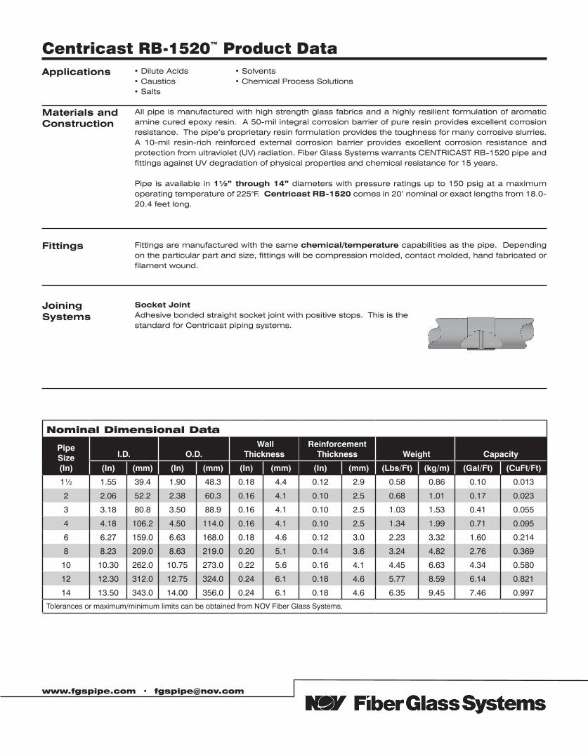
Applications • Dilute Acids• Caustics• Salts
• Solvents• Chemical Process Solutions
Fittings Fittings are manufactured with the same chemical/temperature capabilities as the pipe. Depending on the particular part and size, fittings will be compression molded, contact molded, hand fabricated or filament wound.
Materials andConstruction
All pipe is manufactured with high strength glass fabrics and a highly resilient formulation of aromatic amine cured epoxy resin. A 50-mil integral corrosion barrier of pure resin provides excellent corrosion resistance. The pipe’s proprietary resin formulation provides the toughness for many corrosive slurries. A 10-mil resin-rich reinforced external corrosion barrier provides excellent corrosion resistance and protection from ultraviolet (UV) radiation. Fiber Glass Systems warrants CENTRICAST RB-1520 pipe and fittings against UV degradation of physical properties and chemical resistance for 15 years.
Pipe is available in 1½” through 14” diameters with pressure ratings up to 150 psig at a maximum operating temperature of 225°F. Centricast RB-1520 comes in 20’ nominal or exact lengths from 18.0-20.4 feet long.
Centricast RB-1520™ Product Data
www.fgspipe.com • [email protected]
Joining Systems
Socket JointAdhesive bonded straight socket joint with positive stops. This is thestandard for Centricast piping systems.
Nominal Dimensional Data
Pipe Size (In)
I.D. O.D. Wall
ThicknessReinforcement
Thickness Weight Capacity
(In) (mm) (In) (mm) (In) (mm) (In) (mm) (Lbs/Ft) (kg/m) (Gal/Ft) (CuFt/Ft)
1½ 1.55 39.4 1.90 48.3 0.18 4.4 0.12 2.9 0.58 0.86 0.10 0.013
2 2.06 52.2 2.38 60.3 0.16 4.1 0.10 2.5 0.68 1.01 0.17 0.023
3 3.18 80.8 3.50 88.9 0.16 4.1 0.10 2.5 1.03 1.53 0.41 0.055
4 4.18 106.2 4.50 114.0 0.16 4.1 0.10 2.5 1.34 1.99 0.71 0.095
6 6.27 159.0 6.63 168.0 0.18 4.6 0.12 3.0 2.23 3.32 1.60 0.214
8 8.23 209.0 8.63 219.0 0.20 5.1 0.14 3.6 3.24 4.82 2.76 0.369
10 10.30 262.0 10.75 273.0 0.22 5.6 0.16 4.1 4.45 6.63 4.34 0.580
12 12.30 312.0 12.75 324.0 0.24 6.1 0.18 4.6 5.77 8.59 6.14 0.821
14 13.50 343.0 14.00 356.0 0.24 6.1 0.18 4.6 6.35 9.45 7.46 0.997
Tolerances or maximum/minimum limits can be obtained from NOV Fiber Glass Systems.
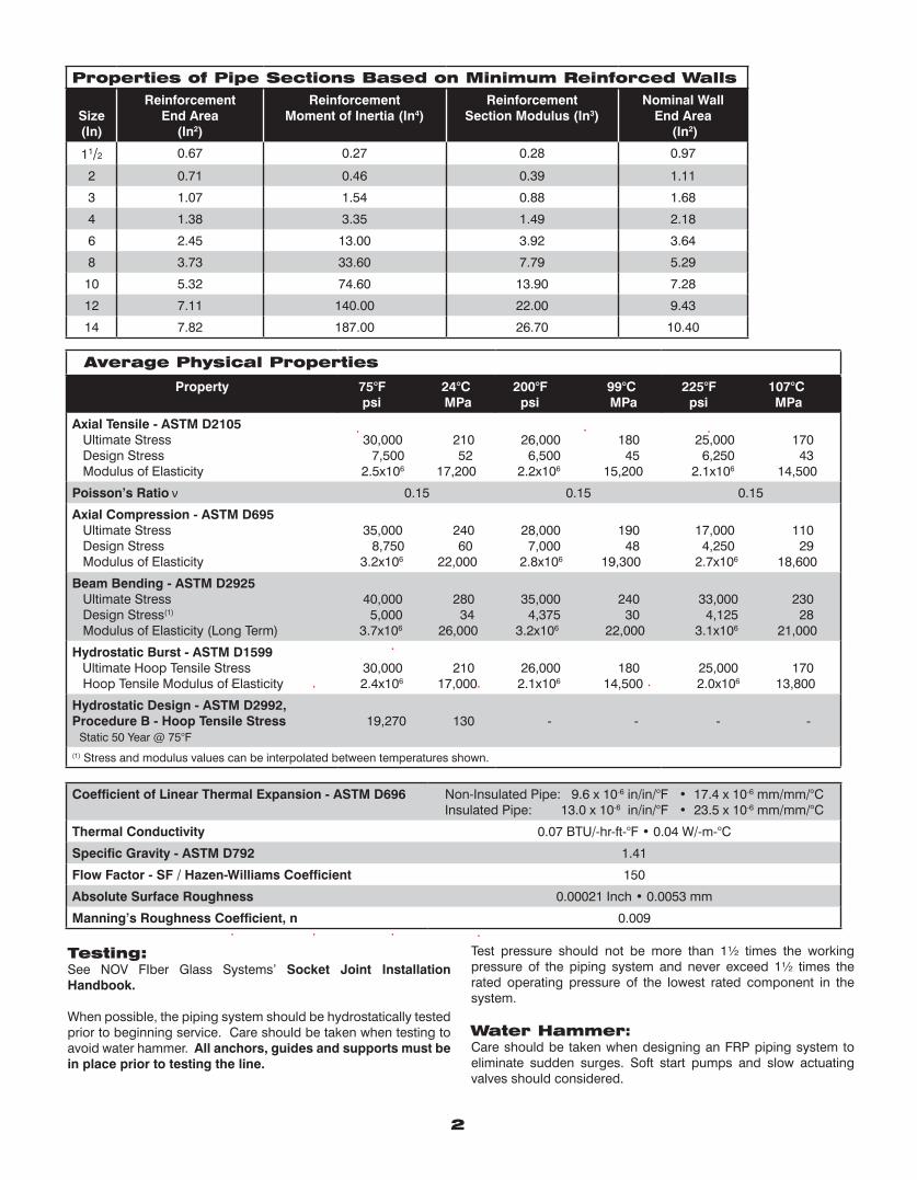
Average Physical Properties
Property 75°F 24°C psi MPa
200°F 99°C psi MPa
225°F 107°C psi MPa
Axial Tensile - ASTM D2105 Ultimate Stress Design Stress Modulus of Elasticity
30,000 210 7,500 52 2.5x10⁶ 17,200
26,000 180 6,500 45 2.2x10⁶ 15,200
25,000 170 6,250 43 2.1x10⁶ 14,500
Poisson’s Ratio ν 0.15 0.15 0.15
Axial Compression - ASTM D695 Ultimate Stress Design Stress Modulus of Elasticity
35,000 240 8,750 60
3.2x10⁶ 22,000
28,000 190 7,000 48 2.8x10⁶ 19,300
17,000 110 4,250 29 2.7x10⁶ 18,600
Beam Bending - ASTM D2925 Ultimate Stress Design Stress(1)
Modulus of Elasticity (Long Term)
40,000 280 5,000 34 3.7x10⁶ 26,000
35,000 240 4,375 30
3.2x10⁶ 22,000
33,000 230 4,125 28 3.1x10⁶ 21,000
Hydrostatic Burst - ASTM D1599 Ultimate Hoop Tensile Stress Hoop Tensile Modulus of Elasticity
30,000 210 2.4x10⁶ 17,000
26,000 180 2.1x10⁶ 14,500
25,000 170 2.0x10⁶ 13,800
Hydrostatic Design - ASTM D2992,Procedure B - Hoop Tensile Stress Static 50 Year @ 75°F
19,270 130 - - - -
(1) Stress and modulus values can be interpolated between temperatures shown.
Coefficient of Linear Thermal Expansion - ASTM D696 Non-Insulated Pipe: 9.6 x 10⁻⁶ in/in/°F • 17.4 x 10⁻⁶ mm/mm/°CInsulated Pipe: 13.0 x 10⁻⁶ in/in/°F • 23.5 x 10⁻⁶ mm/mm/°C
Thermal Conductivity 0.07 BTU/-hr-ft-°F • 0.04 W/-m-°C
Specific Gravity - ASTM D792 1.41
Flow Factor - SF / Hazen-Williams Coefficient 150
Absolute Surface Roughness 0.00021 Inch • 0.0053 mm
Manning’s Roughness Coefficient, n 0.009
2
Properties of Pipe Sections Based on Minimum Reinforced Walls
Size(In)
ReinforcementEnd Area
(In2)
ReinforcementMoment of Inertia (In4)
ReinforcementSection Modulus (In3)
Nominal WallEnd Area
(In2)
11/2 0.67 0.27 0.28 0.97
2 0.71 0.46 0.39 1.11
3 1.07 1.54 0.88 1.68
4 1.38 3.35 1.49 2.18
6 2.45 13.00 3.92 3.64
8 3.73 33.60 7.79 5.29
10 5.32 74.60 13.90 7.28
12 7.11 140.00 22.00 9.43
14 7.82 187.00 26.70 10.40
Testing:See NOV FIber Glass Systems’ Socket Joint Installation Handbook.
When possible, the piping system should be hydrostatically tested prior to beginning service. Care should be taken when testing to avoid water hammer. All anchors, guides and supports must be in place prior to testing the line.
Test pressure should not be more than 1½ times the working pressure of the piping system and never exceed 1½ times the rated operating pressure of the lowest rated component in the system. Water Hammer:Care should be taken when designing an FRP piping system to eliminate sudden surges. Soft start pumps and slow actuating valves should considered.
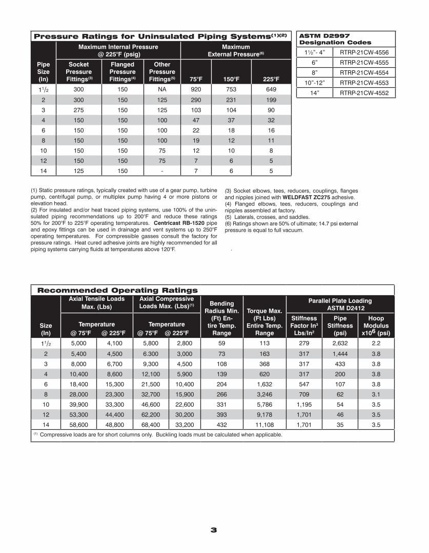
3
ASTM D2997 Designation Codes
1½”- 4” RTRP-21CW-4556
6” RTRP-21CW-4555
8” RTRP-21CW-4554
10”-12” RTRP-21CW-4553
14” RTRP-21CW-4552
(1) Static pressure ratings, typically created with use of a gear pump, turbine pump, centrifugal pump, or multiplex pump having 4 or more pistons or elevation head.(2) For insulated and/or heat traced piping systems, use 100% of the unin- sulated piping recommendations up to 200°F and reduce these ratings 50% for 200°F to 225°F operating temperatures. Centricast RB-1520 pipe and epoxy fittings can be used in drainage and vent systems up to 250°F operating temperatures. For compressible gasses consult the factory for pressure ratings. Heat cured adhesive joints are highly recommended for all piping systems carrying fluids at temperatures above 120°F.
(3) Socket elbows, tees, reducers, couplings, flanges and nipples joined with WELDFAST ZC275 adhesive.(4) Flanged elbows, tees, reducers, couplings and nipples assembled at factory.(5) Laterals, crosses, and saddles.(6) Ratings shown are 50% of ultimate; 14.7 psi external pressure is equal to full vacuum.
Pressure Ratings for Uninsulated Piping Systems(1)(2)
Pipe Size(In)
Maximum Internal Pressure @ 225°F (psig)
Maximum External Pressure(6)
Socket Pressure Fittings(3)
FlangedPressureFittings(4)
OtherPressureFittings(5) 75°F 150°F 225°F
11/2 300 150 NA 920 753 649
2 300 150 125 290 231 199
3 275 150 125 103 104 90
4 150 150 100 47 37 32
6 150 150 100 22 18 16
8 150 150 100 19 12 11
10 150 150 75 12 10 8
12 150 150 75 7 6 5
14 125 150 - 7 6 5
Recommended Operating Ratings
Size(In)
Axial Tensile Loads Max. (Lbs)
Axial Compressive Loads Max. (Lbs)(1) Bending
Radius Min. (Ft) En-
tire Temp. Range
Torque Max. (Ft Lbs)
Entire Temp. Range
Parallel Plate Loading ASTM D2412
Temperature @ 75°F @ 225°F
Temperature @ 75°F @ 225°F
Stiffness Factor In3
Lbs/In2
Pipe Stiffness
(psi)
Hoop Modulus x106 (psi)
11/2 5,000 4,100 5,800 2,800 59 113 279 2,632 2.2
2 5,400 4,500 6.300 3,000 73 163 317 1,444 3.8
3 8,000 6,700 9,300 4,500 108 368 317 433 3.8
4 10,400 8,600 12,100 5,900 139 620 317 200 3.8
6 18,400 15,300 21,500 10,400 204 1,632 547 107 3.8
8 28,000 23,300 32,700 15,900 266 3,246 709 62 3.1
10 39,900 33,300 46,600 22,600 331 5,786 1,195 54 3.5
12 53,300 44,400 62,200 30,200 393 9,178 1,701 46 3.5
14 58,600 48,800 68,400 33,200 432 11,108 1,701 35 3.5(1) Compressive loads are for short columns only. Buckling loads must be calculated when applicable.
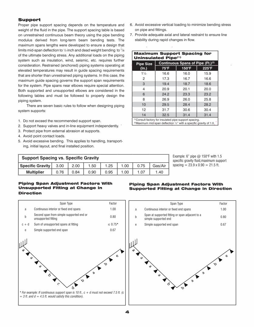
Support Spacing vs. Specific Gravity
Specific Gravity 3.00 2.00 1.50 1.25 1.00 0.75 Gas/Air
Multiplier 0.76 0.84 0.90 0.95 1.00 1.07 1.40
Example: 6” pipe @ 150°F with 1.5 specific gravity fluid,maximum support spacing = 23.9 x 0.90 = 21.5 ft.
4
SupportProper pipe support spacing depends on the temperature and weight of the fluid in the pipe. The support spacing table is based on unrestrained continuous beam theory using the pipe bending modulus derived from long-term beam bending tests. The maximum spans lengths were developed to ensure a design that limits mid-span deflection to ½ inch and dead weight bending to 1/8 of the ultimate bending stress. Any additional loads on the piping system such as insulation, wind, seismic, etc. requires further consideration. Restrained (anchored) piping systems operating at elevated temperatures may result in guide spacing requirements that are shorter than unrestrained piping systems. In this case, the maximum guide spacing governs the support span requirements for the system. Pipe spans near elbows require special attention. Both supported and unsupported elbows are considered in the following tables and must be followed to properly design the piping system. There are seven basic rules to follow when designing piping system supports:
1. Do not exceed the recommended support span.2. Support heavy valves and in-line equipment independently.3. Protect pipe from external abrasion at supports.4. Avoid point contact loads.5. Avoid excessive bending. This applies to handling, transport- ing, initial layout, and final installed position.
6. Avoid excessive vertical loading to minimize bending stress on pipe and fittings.7. Provide adequate axial and lateral restraint to ensure line stability during rapid changes in flow.
Maximum Support Spacing for Uninsulated Pipe(1)
Pipe Size (In.)
Continuous Spans of Pipe (Ft.)(2) 75°F 150°F 225°F
1½ 16.6 16.0 15.92 17.3 16.7 16.63 19.4 18.7 18.64 20.9 20.1 20.06 24.2 23.3 23.28 26.9 26.0 25.8
10 29.5 28.4 28.212 31.7 30.6 30.414 32.5 31.4 31.4
(1)Consult factory for insulated pipe support spacing.(2)Maximum mid-span deflection ½” with a specific gravity of 1.0.
Piping Span Adjustment Factors With Unsupported Fitting at Change in Direction
Span Type Factor
a Continuous interior or fixed end spans 1.00
bSecond span from simple supported end or unsupported fitting
0.80
c + d Sum of unsupported spans at fitting ≤ 0.75*
e Simple supported end span 0.67
* For example: If continuous support span is 10 ft., c + d must not exceed 7.5 ft. (c = 3 ft. and d = 4.5 ft. would satisfy this condition).
Piping Span Adjustment Factors With Supported Fitting at Change in Direction
Span Type Factor
a Continuous interior or fixed end spans 1.00
bSpan at supported fitting or span adjacent to a simple supported end
0.80
e Simple supported end span 0.67
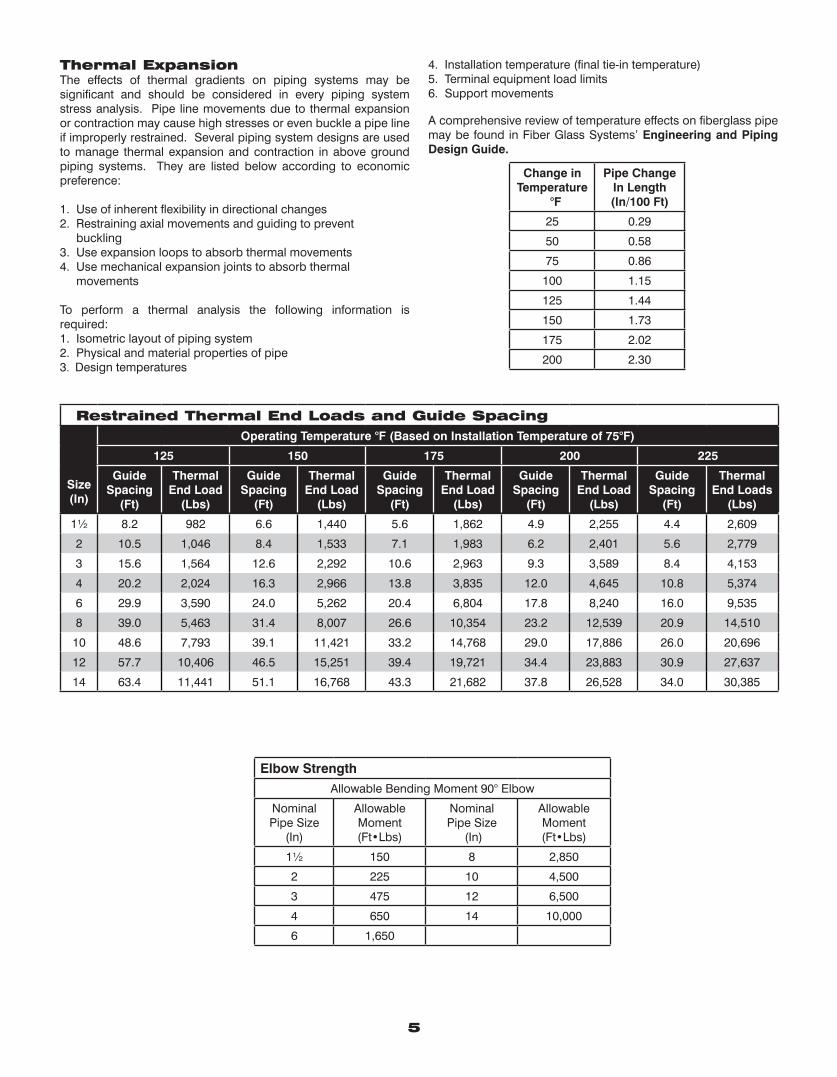
Thermal ExpansionThe effects of thermal gradients on piping systems may be significant and should be considered in every piping system stress analysis. Pipe line movements due to thermal expansion or contraction may cause high stresses or even buckle a pipe line if improperly restrained. Several piping system designs are used to manage thermal expansion and contraction in above ground piping systems. They are listed below according to economic preference:
1. Use of inherent flexibility in directional changes2. Restraining axial movements and guiding to prevent buckling3. Use expansion loops to absorb thermal movements4. Use mechanical expansion joints to absorb thermal movements
To perform a thermal analysis the following information is required:1. Isometric layout of piping system2. Physical and material properties of pipe3. Design temperatures
4. Installation temperature (final tie-in temperature)5. Terminal equipment load limits6. Support movements
A comprehensive review of temperature effects on fiberglass pipe may be found in Fiber Glass Systems’ Engineering and Piping Design Guide.
Change inTemperature
°F
Pipe Change In Length(In/100 Ft)
25 0.29
50 0.58
75 0.86
100 1.15
125 1.44
150 1.73
175 2.02
200 2.30
5
Restrained Thermal End Loads and Guide Spacing
Size(In)
Operating Temperature °F (Based on Installation Temperature of 75°F)
125 150 175 200 225
GuideSpacing
(Ft)
ThermalEnd Load
(Lbs)
GuideSpacing
(Ft)
ThermalEnd Load
(Lbs)
GuideSpacing
(Ft)
ThermalEnd Load
(Lbs)
GuideSpacing
(Ft)
ThermalEnd Load
(Lbs)
GuideSpacing
(Ft)
ThermalEnd Loads
(Lbs)
1½ 8.2 982 6.6 1,440 5.6 1,862 4.9 2,255 4.4 2,609
2 10.5 1,046 8.4 1,533 7.1 1,983 6.2 2,401 5.6 2,779
3 15.6 1,564 12.6 2,292 10.6 2,963 9.3 3,589 8.4 4,153
4 20.2 2,024 16.3 2,966 13.8 3,835 12.0 4,645 10.8 5,374
6 29.9 3,590 24.0 5,262 20.4 6,804 17.8 8,240 16.0 9,535
8 39.0 5,463 31.4 8,007 26.6 10,354 23.2 12,539 20.9 14,510
10 48.6 7,793 39.1 11,421 33.2 14,768 29.0 17,886 26.0 20,696
12 57.7 10,406 46.5 15,251 39.4 19,721 34.4 23,883 30.9 27,637
14 63.4 11,441 51.1 16,768 43.3 21,682 37.8 26,528 34.0 30,385
Elbow StrengthAllowable Bending Moment 90° Elbow
Nominal Pipe Size
(In)
AllowableMoment(Ft•Lbs)
Nominal Pipe Size
(In)
AllowableMoment(Ft•Lbs)
1½ 150 8 2,850
2 225 10 4,500
3 475 12 6,500
4 650 14 10,000
6 1,650
© 2012 National Oilwell Varco. All rights reserved.CI1610 -June 2010
www.fgspipe.com • [email protected]
North America South America Europe Asia Pacific Middle East17115 San Pedro Ave. Suite 200 Avenida Fernando Simoes P.O. Box 6, 4190 CA No. 7A, Tuas Avenue 3 P.O. Box 17324San Antonio, Texas 78232 USA Recife, Brazil 51020-390 Geldermalsen, The Netherlands Jurong, Singapore 639407 Dubai, UAEPhone: 210 477 7500 Phone: 55 31 3501 0023 Phone: 31 345 587 587 Phone: 65 6861 6118 Phone: 971 4881 3566
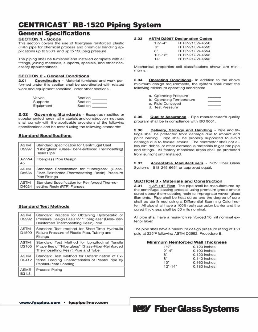
www.fgspipe.com • [email protected]
CENTRICAST™ RB-1520 Piping SystemGeneral SpecificationsSECTION 1 - ScopeThis section covers the use of fiberglass reinforced plastic (FRP) pipe for chemical process and chemical handling ap-plications up to 250°F and up to 150 psig pressure.
The piping shall be furnished and installed complete with all fittings, joining materials, supports, specials, and other nec-essary appurtenances.
SECTION 2 - General Conditions2.01 Coordination - Material furnished and work per-formed under this section shall be coordinated with related work and equipment specified under other sections.
Valves Section _________ Supports Section _________ Equipment Section _________
2.02 Governing Standards - Except as modified or supplemented herein, all materials and construction methods shall comply with the applicable provisions of the following specifications and be tested using the following standards:
Standard Specifications
Standard Test Methods
2.03 ASTM D2997 Designation Codes 1½”-4” RTRP-21CW-4556 6” RTRP-21CW-4555 8” RTRP-21CW-4554 10”-12” RTRP-21CW-4553 14” RTRP-21CW-4552
Mechanical properties cell classifications shown are mini-mums.
2.04 Operating Conditions- In addition to the above minimum design requirements, the system shall meet the following minimum operating conditions:
a. Operating Pressure ________ b. Operating Temperature ________ c. Fluid Conveyed ________ d. Test Pressure ________ 2.05 Quality Assurance - Pipe manufacturer’s quality program shall be in compliance with ISO 9001.
2.06 Delivery, Storage and Handling - Pipe and fit-tings shall be protected from damage due to impact and point loading. Pipe shall be properly supported to avoid damage due to flexural strains. The contractor shall not al-low dirt, debris, or other extraneous materials to get into pipe and fittings. All factory machined areas shall be protected from sunlight until installed.
2.07 Acceptable Manufacturers - NOV Fiber Glass Systems - 918-245-6651 or approved equal.
SECTION 3 - Materials and Construction3.01 1½”-14” Pipe The pipe shall be manufactured by the centrifugal casting process using premium grade amine cured epoxy thermosetting resin to impregnate woven glass filaments. Pipe shall be heat cured and the degree of cure shall be confirmed using a Differential Scanning Calorime-ter. All pipe shall have a 100% resin corrosion barrier and the cured thickness shall be 50 mils nominal.
All pipe shall have a resin-rich reinforced 10 mil nominal ex-terior layer.
The pipe shall have a minimum design pressure rating of 150 psig at 225°F following ASTM D2992, Procedure B.
Minimum Reinforced Wall Thickness 1½” 0.120 inches 2”-4” 0.100 inches 6” 0.120 inches 8” 0.140 inches 10” 0.160 inches 12”-14” 0.180 inches
ASTMD2997
Standard Specification for Centrifugal Cast “Fiberglass” (Glass-Fiber-Reinforced Thermosetting) Resin Pipe
AWWA 45
Fiberglass Pipe Design
ASTMD5685
Standard Specification for “Fiberglass” (Glass-Fiber-Reinforced-Thermosetting Resin) Pressure Pipe Fittings
ASTMD4024
Standard Specification for Reinforced Thermo-setting Resin (RTR) Flanges
ASTMD2992
Standard Practice for Obtaining Hydrostatic or Pressure Design Basis for “Fiberglass” (Glass-Fiber-Reinforced Thermosetting Resin) Pipe
ASTMD1599
Standard Test method for Short-Time Hydraulic Failure Pressure of Plastic Pipe, Tubing and Fittings
ASTMD2105
Standard Test Method for Longitudinal Tensile Properties of “Fiberglass” (Glass-Fiber-Reinforced Thermosetting Resin) Pipe and Tube
ASTMD2412
Standard Test Method for Determination of Ex-ternal Loading Characteristics of Plastic Pipe by Parallel-Plate Loading
ASME B31.3
Process Piping
www.fgspipe.com • [email protected]
© 2012 National Oilwell Varco. All rights reserved. CI1611 February 2009
3.02 Flanges and Fittings - All fittings shall be manufac-tured either by compression molding or contact molding. Fit-ting joints shall be either adhesive bonded socket or flanged. Flanges shall have ANSI B16.5 Class 150 bolt hold patterns.
3.03 Adhesive - Adhesive shall be manufacturer’s stan-dard for the piping system specified. All adhesive bonded joints shall be cured according to the manufacturer’s instruc-tions for maximum strength and corrosion resistance.
3.04 Gaskets - Gaskets shall be 3/16” thick, 60-70 du-rometer full-face type suitable for the service shown on the drawings and as recommended in the manufacturer’s stan-dard installation procedures.
3.05 Bolts, Nuts and Washers - ASTM F593, 304 stain-less steel hex head bolts shall be supplied. Two each SAE size washers shall be supplied on all nuts and bolts.
3.06 Acceptable Products Centricast RB-1520 as man-ufactured by NOV Fiber Glass Systems or approved equal.
SECTION 4 - Installation and Testing4.01 Training and Certification - All joints installed or constructed in the field shall be assembled by employees of the contractor who have been trained by the pipe manufac-turer. The pipe manufacturer or their authorized representa-tive shall train the contractor’s employees in the proper joining and assembly procedures required for the project, including hands-on participation by the contractor’s employees. Each bonder shall fabricate one pipe-to-pipe and one pipe-to-fitting joint that shall pass the minimum pressure test for the applica-tion as stated in Section 2.04.d without leaking.
Only bonders who have successfully completed the pressure test shall bond pipe and fittings.
Certification by the manufacturer shall be in compliance with ASME B31.3, Section A328.2.
4.02 Pipe Installation Pipe shall be installed as speci-fied and indicated on the drawings and in accordance with the manufacturer’s current published installation procedures.
4.03 Testing - A hydrostatic pressure test shall be con-ducted on the completed piping system. The piping shall be subjected to a steady pressure at 1½ times the design operating pressure as stated in Section 2.04d. The pres-sure shall be held on the system for a minimum of one hour and the line inspected for leaks.
The test pressure should not exceed 1½ times the maximum rated operating pressure for the lowest rated element in the system.
The system shall be filled with water at the lowest point and air bled off from all the highest points. Systems shall be brought up to test pressure slowly to prevent water hammer or over pressurization.
All pipe joints shall be water tight. All joints that are found to leak by observation or during testing shall be repaired by the contractor and retested.
National Oilwell Varco has produced this brochure for general information only, and it is not intended for design purposes. Although every effort has been made to maintain the accuracy and reliability of its contents, National Oilwell Varco in no way assumes respon-sibility for liability for any loss, damage or injury resulting from the use of information and data herein nor is any warranty expressed or implied. Always cross-reference the bulletin date with the most current version listed at the web site noted in this literature.
North America South America Europe Asia Pacific Middle East17115 San Pedro Ave. Suite 200 Avenida Fernando Simoes P.O. Box 6, 4190 CA No. 7A, Tuas Avenue 3 P.O. Box 17324San Antonio, Texas 78232 USA Recife, Brazil 51020-390 Geldermalsen, The Netherlands Jurong, Singapore 639407 Dubai, UAEPhone: 210 477 7500 Phone: 55 31 3501 0023 Phone: 31 345 587 587 Phone: 65 6861 6118 Phone: 971 4881 3566
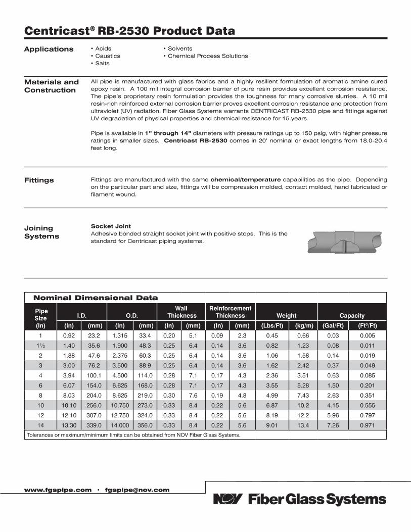
Applications • Acids• Caustics• Salts
• Solvents• Chemical Process Solutions
Centricast® RB-2530 Product Data
Materials andConstruction
All pipe is manufactured with glass fabrics and a highly resilient formulation of aromatic amine cured epoxy resin. A 100 mil integral corrosion barrier of pure resin provides excellent corrosion resistance. The pipe’s proprietary resin formulation provides the toughness for many corrosive slurries. A 10 mil resin-rich reinforced external corrosion barrier proves excellent corrosion resistance and protection from ultraviolet (UV) radiation. Fiber Glass Systems warrants CENTRICAST RB-2530 pipe and fittings against UV degradation of physical properties and chemical resistance for 15 years.
Pipe is available in 1” through 14” diameters with pressure ratings up to 150 psig, with higher pressure ratings in smaller sizes. Centricast RB-2530 comes in 20’ nominal or exact lengths from 18.0-20.4 feet long.
Fittings Fittings are manufactured with the same chemical/temperature capabilities as the pipe. Depending on the particular part and size, fittings will be compression molded, contact molded, hand fabricated or filament wound.
Joining Systems
Socket JointAdhesive bonded straight socket joint with positive stops. This is the standard for Centricast piping systems.
Nominal Dimensional Data
Pipe Size (In)
I.D. O.D.Wall
ThicknessReinforcement
Thickness Weight Capacity
(In) ((mm) (In) ((mm) (In) (mm) ((In) (mm) ((Lbs/Ft)t ((kg/m) (Gal/Ft) ((Ft3/Ft))
1 0.92 23.2 1.315 33.4 0.20 5.1 0.09 2.3 0.45 0.66 0.03 0.005
1½ 1.40 35.6 1.900 48.3 0.25 6.4 0.14 3.6 0.82 1.23 0.08 0.011
2 1.88 47.6 2.375 60.3 0.25 6.4 0.14 3.6 1.06 1.58 0.14 0.019
3 3.00 76.2 3.500 88.9 0.25 6.4 0.14 3.6 1.62 2.42 0.37 0.049
4 3.94 100.1 4.500 114.0 0.28 7.1 0.17 4.3 2.36 3.51 0.63 0.085
6 6.07 154.0 6.625 168.0 0.28 7.1 0.17 4.3 3.55 5.28 1.50 0.201
8 8.03 204.0 8.625 219.0 0.30 7.6 0.19 4.8 4.99 7.43 2.63 0.351
10 10.10 256.0 10.750 273.0 0.33 8.4 0.22 5.6 6.87 10.2 4.15 0.555
12 12.10 307.0 12.750 324.0 0.33 8.4 0.22 5.6 8.19 12.2 5.96 0.797
14 13.30 339.0 14.000 356.0 0.33 8.4 0.22 5.6 9.01 13.4 7.26 0.971
Tolerances or maximum/minimum limits can be obtained from NOV Fiber Glass Systems.
www.fgspipe.com • [email protected]
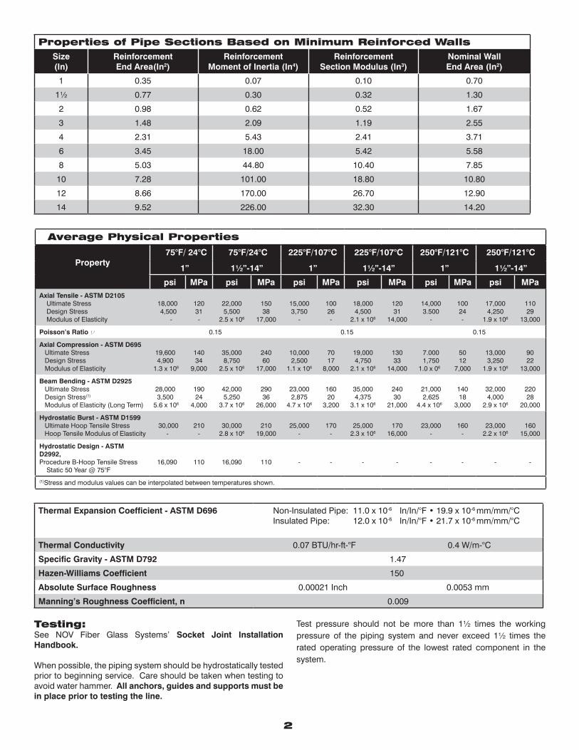
Thermal Expansion Coefficient - ASTM D696 Non-Insulated Pipe: 11.0 x 10⁻⁶
Insulated Pipe: 12.0 x 10⁻⁶In/In/°F • 19.9 x 10⁻⁶ mm/mm/°CIn/In/°F • 21.7 x 10⁻⁶ mm/mm/°C
Thermal Conductivity 0.07 BTU/hr-ft-°F 0.4 W/m-°C
Specific Gravity - ASTM D792 1.47
Hazen-Williams Coefficient 150
Absolute Surface Roughness 0.00021 Inch 0.0053 mm
Manning’s Roughness Coefficient, n 0.009
Properties of Pipe Sections Based on Minimum Reinforced WallsSize(In)
ReinforcementEnd Area(In2)
ReinforcementMoment of Inertia (In4)
ReinforcementSection Modulus (In3)
Nominal WallEnd Area (In2)
1 0.35 0.07 0.10 0.70
1½ 0.77 0.30 0.32 1.30
2 0.98 0.62 0.52 1.67
3 1.48 2.09 1.19 2.55
4 2.31 5.43 2.41 3.71
6 3.45 18.00 5.42 5.58
8 5.03 44.80 10.40 7.85
10 7.28 101.00 18.80 10.80
12 8.66 170.00 26.70 12.90
14 9.52 226.00 32.30 14.20
2
Average Physical Properties
Property 75°F/ 24°C 75°F/24°C 225°F/107°C 225°F/107°C 250°F/121°C 250°F/121°C
1” 1½”-14” 1” 1½”-14” 1” 1½”-14”
psi MPa psi MPa psi MPa psi MPa psi MPa psi MPaAxial Tensile - ASTM D2105 Ultimate Stress Design Stress Modulus of Elasticity
18,000 4,500
-
12031-
22,0005,500
2.5 x 10⁶
15038
17,000
15,0003,750
-
10026-
18,0004,500
2.1 x 10⁶
12031
14,000
14,0003.500
-
10024-
17,0004,250
1.9 x 10⁶
11029
13,000
Poisson’s Ratio ν 0.15 0.15 0.15
Axial Compression - ASTM D695 Ultimate Stress Design Stress Modulus of Elasticity
19,600 4,9001.3 x 106
14034
9,000
35,0008,750
2.5 x 10⁶
24060
17,000
10,0002,500
1.1 x 10⁶
7017
8,000
19,0004,750
2.1 x 10⁶
13033
14,000
7.0001,750
1.0 x 06
5012
7,000
13,0003,250
1.9 x 10⁶
9022
13,000
Beam Bending - ASTM D2925 Ultimate Stress Design Stress(1)
Modulus of Elasticity (Long Term)
28,000 3,5005.6 x 106
19024
4,000
42,0005,250
3.7 x 10⁶
29036
26,000
23,0002,875
4.7 x 10⁶
16020
3,200
35,0004,375
3.1 x 10⁶
24030
21,000
21,0002,625
4.4 x 10⁶
14018
3,000
32,0004,000
2.9 x 10⁶
22028
20,000
Hydrostatic Burst - ASTM D1599 Ultimate Hoop Tensile Stress Hoop Tensile Modulus of Elasticity
30,000 -
210-
30,0002.8 x 106
21019,000
25,000-
170-
25,0002.3 x 106
17016,000
23,000-
160-
23,0002.2 x 106
16015,000
Hydrostatic Design - ASTM D2992,Procedure B-Hoop Tensile Stress Static 50 Year @ 75°F
16,090 110 16,090 110
- - - - - - - -
(1)Stress and modulus values can be interpolated between temperatures shown.
Testing: See NOV Fiber Glass Systems’ Socket Joint Installation Handbook.
When possible, the piping system should be hydrostatically tested prior to beginning service. Care should be taken when testing to avoid water hammer. All anchors, guides and supports must be in place prior to testing the line.
Test pressure should not be more than 1½ times the working pressure of the piping system and never exceed 1½ times the rated operating pressure of the lowest rated component in the system.
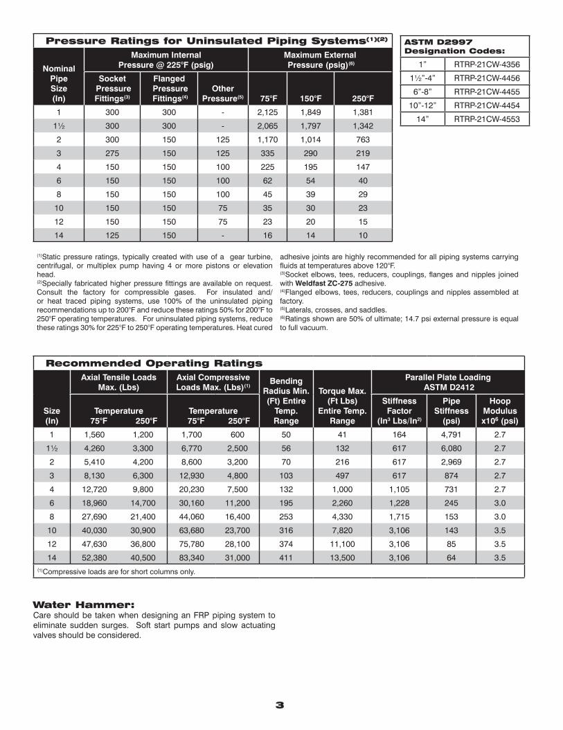
Water Hammer:Care should be taken when designing an FRP piping system to eliminate sudden surges. Soft start pumps and slow actuating valves should be considered.
ASTM D2997Designation Codes:
1” RTRP-21CW-4356
1½”-4” RTRP-21CW-4456
6”-8” RTRP-21CW-4455
10”-12” RTRP-21CW-4454
14” RTRP-21CW-4553
3
Pressure Ratings for Uninsulated Piping Systems(1)(2)
NominalPipeSize(In)
Maximum InternalPressure @ 225°F (psig)
Maximum External Pressure (psig)(6)
Socket Pressure Fittings(3)
Flanged Pressure Fittings(4)
Other Pressure(5) 75°F 150°F 250°F
1 300 300 - 2,125 1,849 1,381
1½ 300 300 - 2,065 1,797 1,342
2 300 150 125 1,170 1,014 763
3 275 150 125 335 290 219
4 150 150 100 225 195 147
6 150 150 100 62 54 40
8 150 150 100 45 39 29
10 150 150 75 35 30 23
12 150 150 75 23 20 15
14 125 150 - 16 14 10
(1)Static pressure ratings, typically created with use of a gear turbine, centrifugal, or multiplex pump having 4 or more pistons or elevation head.(2)Specially fabricated higher pressure fittings are available on request. Consult the factory for compressible gases. For insulated and/or heat traced piping systems, use 100% of the uninsulated piping recommendations up to 200°F and reduce these ratings 50% for 200°F to 250°F operating temperatures. For uninsulated piping systems, reduce these ratings 30% for 225°F to 250°F operating temperatures. Heat cured
adhesive joints are highly recommended for all piping systems carrying fluids at temperatures above 120°F.(3)Socket elbows, tees, reducers, couplings, flanges and nipples joined with Weldfast ZC-275 adhesive.(4)Flanged elbows, tees, reducers, couplings and nipples assembled at factory.(5)Laterals, crosses, and saddles.(6)Ratings shown are 50% of ultimate; 14.7 psi external pressure is equal to full vacuum.
Recommended Operating Ratings
Size(In)
Axial Tensile Loads Max. (Lbs)
Axial Compressive Loads Max. (Lbs)(1)
Bending Radius Min. (Ft) Entire
Temp. Range
Torque Max. (Ft Lbs)
Entire Temp. Range
Parallel Plate Loading ASTM D2412
Temperature 75°F 250°F
Temperature 75°F 250°F
Stiffness Factor
(In3 Lbs/In2)
Pipe Stiffness
(psi)
Hoop Modulus x106 (psi)
1 1,560 1,200 1,700 600 50 41 164 4,791 2.7
1½ 4,260 3,300 6,770 2,500 56 132 617 6,080 2.7
2 5,410 4,200 8,600 3,200 70 216 617 2,969 2.7
3 8,130 6,300 12,930 4,800 103 497 617 874 2.7
4 12,720 9,800 20,230 7,500 132 1,000 1,105 731 2.7
6 18,960 14,700 30,160 11,200 195 2,260 1,228 245 3.0
8 27,690 21,400 44,060 16,400 253 4,330 1,715 153 3.0
10 40,030 30,900 63,680 23,700 316 7,820 3,106 143 3.5
12 47,630 36,800 75,780 28,100 374 11,100 3,106 85 3.5
14 52,380 40,500 83,340 31,000 411 13,500 3,106 64 3.5(1)Compressive loads are for short columns only.
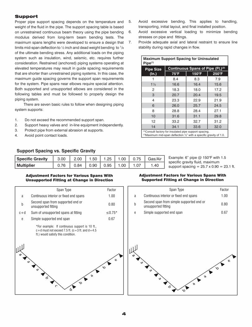
Support Proper pipe support spacing depends on the temperature and weight of the fluid in the pipe. The support spacing table is based on unrestrained continuous beam theory using the pipe bending modulus derived from long-term beam bending tests. The maximum spans lengths were developed to ensure a design that limits mid-span deflection to ½ inch and dead weight bending to 1/8
of the ultimate bending stress. Any additional loads on the piping system such as insulation, wind, seismic, etc. requires further consideration. Restrained (anchored) piping systems operating at elevated temperatures may result in guide spacing requirements that are shorter than unrestrained piping systems. In this case, the maximum guide spacing governs the support span requirements for the system. Pipe spans near elbows require special attention. Both supported and unsupported elbows are considered in the following tables and must be followed to properly design the piping system. There are seven basic rules to follow when designing piping system supports:
1. Do not exceed the recommended support span.2. Support heavy valves and in-line equipment independently. 3. Protect pipe from external abrasion at supports.4. Avoid point contact loads.
4
5. Avoid excessive bending. This applies to handling, transporting, initial layout, and final installed position.
6. Avoid excessive vertical loading to minimize bending stresses on pipe and fittings.
7. Provide adequate axial and lateral restraint to ensure line stability during rapid changes in flow.
Maximum Support Spacing for Uninsulated Pipe(1)
Pipe Size (In.)
Continuous Spans of Pipe (Ft.)(2) 75°F 150°F 250°F
1 8.4 8.3 7.91½ 16.6 16.4 15.62 18.3 18.0 17.23 20.7 20.4 19.54 23.3 22.9 21.96 26.0 25.7 24.58 28.8 28.4 27.1
10 31.6 31.1 29.812 33.2 32.7 31.214 34.1 33.6 32.0
(1)Consult factory for insulated pipe support spacing.(2)Maximum mid-span deflection ½” with a specific gravity of 1.0.
Support Spacing vs. Specific Gravity
Specific Gravity 3.00 2.00 1.50 1.25 1.00 0.75 Gas/Air
Multiplier 0.76 0.84 0.90 0.95 1.00 1.07 1.40
Example: 6” pipe @ 150°F with 1.5 specific gravity fluid, maximum support spacing = 25.7 x 0.90 = 23.1 ft.
Adjustment Factors for Various Spans WithUnsupported Fitting at Change in Direction
Span Type Factor
a Continuous interior or fixed end spans 1.00
bSecond span from supported end orunsupported fitting
0.80
c+d Sum of unsupported spans at fitting ≤0.75*
e Simple supported end span 0.67
*For example: If continuous support is 10 ft., c+d must not exceed 7.5 ft. (c=3 ft. and d=4.5 ft.) would satisfy this condition.
Adjustment Factors for Various Spans WithSupported Fitting at Change in Direction
Span Type Factor
a Continuous interior or fixed end spans 1.00
bSecond span from simple supported end or unsupported fitting
0.80
e Simple supported end span 0.67
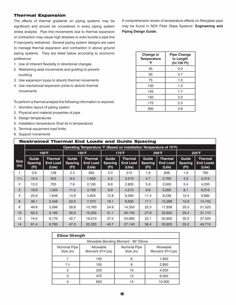
5
Restrained Thermal End Loads and Guide Spacing
Size(In)
Operating Temperature °F (Based on Installation Temperature of 75°F)
100°F 150°F 175°F 200°F 225°F
GuideSpacing
(Ft)
ThermalEnd Load
(Lbs)
GuideSpacing
(Ft)
ThermalEnd Load
(Lbs)
GuideSpacing
(Ft)
ThermalEnd Load
(Lbs)
GuideSpacing
(Ft)
ThermalEnd Load
(Lbs)
GuideSpacing
(Ft)
ThermalEnd Loads
(Lbs)
1 3.9 128 2.3 383 2.0 510 1.8 638 1.6 765
1½ 10.4 553 6.0 1,658 5.2 2,210 4.7 2,763 4.3 3,315
2 13.2 700 7.6 2,100 6.6 2,800 5.9 3,500 5.4 4,200
3 19.9 1,053 11.5 3,158 9.9 4,210 8.9 5,263 8.1 6,315
4 25.6 1,648 14.8 4,943 12.8 6,590 11.4 8,238 10.4 9,885
6 38.1 2,458 22.0 7,373 19.1 9,830 17.1 12,288 15.6 14,745
8 49.8 3,588 28.8 10,763 24.9 14,350 22.3 17,938 20.3 21,525
10 62.2 5,185 35.9 15,555 31.1 20,740 27.8 25,925 25.4 31,110
12 74.0 6,170 42.7 18,510 37.0 24,680 33.1 30,850 30.2 37,020
14 81.4 6,785 47.0 20,355 40.7 27,140 36.4 33,925 33.2 40,710
Elbow StrengthAllowable Bending Moment - 90° Elbow
Nominal PipeSize (In)
AllowableMoment (Ft•Lbs)
Nominal PipeSize (In)
AllowableMoment (Ft•Lbs)
1 100 6 1,650
1½ 150 8 2,850
2 225 10 4,500
3 475 12 6,500
4 650 14 10,000
Thermal ExpansionThe effects of thermal gradients on piping systems may be
significant and should be considered in every piping system
stress analysis. Pipe line movements due to thermal expansion
or contraction may cause high stresses or even buckle a pipe line
if improperly restrained. Several piping system designs are used
to manage thermal expansion and contraction in above ground
piping systems. They are listed below according to economic
preference:
1. Use of inherent flexibility in directional changes
2. Restraining axial movements and guiding to prevent
buckling
3. Use expansion loops to absorb thermal movements
4. Use mechanical expansion joints to absorb thermal
movements
To perform a thermal analysis the following information is required:
1. Isometric layout of piping system
2. Physical and material properties of pipe
3. Design temperatures
4. Installation temperature (final tie in temperature)
5. Terminal equipment load limits
6. Support movements
A comprehensive review of temperature effects on fiberglass pipe
may be found in NOV Fiber Glass Systems’ Engineering and
Piping Design Guide.
Change inTemperature
°F
Pipe Change in Length(In/100 Ft)
25 0.3
50 0.7
75 1.0
100 1.3
125 1.7
150 2.0
175 2.3
200 2.6
www.fgspipe.com • [email protected]
©2012 National Oilwell VarcoCI1600 - September 2012
ANSI/NSF 61Drinking Water System
Components 35GHWater Contact Temp: 23°C
National Oilwell Varco has produced this brochure for general information only, and it is not intended for design purposes. Although every effort has been made to maintain the accuracy and reliability of its contents, National Oilwell Varco in no way assumes responsibility for liability for any loss, damage or injury resulting from the use of information and data herein nor is any warranty expressed or implied. Always cross-reference the bulletin date with the most current version listed at the web site noted in this literature.
North America South America Europe Asia Pacific Middle East17115 San Pedro Ave. Suite 200 Avenida Fernando Simoes P.O. Box 6, 4190 CA No. 7A, Tuas Avenue 3 P.O. Box 17324San Antonio, Texas 78232 USA Recife, Brazil 51020-390 Geldermalsen, The Netherlands Jurong, Singapore 639407 Dubai, UAEPhone: 210 477 7500 Phone: 55 31 3501 0023 Phone: 31 345 587 587 Phone: 65 6861 6118 Phone: 971 4881 3566
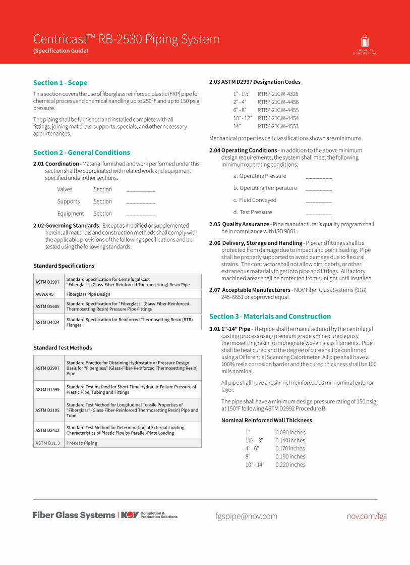
[email protected] nov.com/fgs
Product Name 14/15 Centricast™ RB-2530 Piping System(Specification Guide) O I L & G A S C H E M I C A L
& I N D U S T R I A LO F F S H O R EM A R I N E M I N I N GF U E L
H A N D L I N G
Section 1 - ScopeThis section covers the use of fiberglass reinforced plastic (FRP) pipe for chemical process and chemical handling up to 250°F and up to 150 psig pressure.
The piping shall be furnished and installed complete with all fittings, joining materials, supports, specials, and other necessary appurtenances.
Section 2 - General Conditions2.01 Coordination - Material furnished and work performed under this
section shall be coordinated with related work and equipment specified under other sections.
Valves Section _________
Supports Section _________
Equipment Section _________
2.02 Governing Standards - Except as modified or supplemented herein, all materials and construction methods shall comply with the applicable provisions of the following specifications and be tested using the following standards.
ASTM D2997 Standard Specification for Centrifugal Cast “Fiberglass” (Glass-Fiber-Reinforced Thermosetting) Resin Pipe
AWWA 45 Fiberglass Pipe Design
ASTM D5685 Standard Specification for “Fiberglass” (Glass-Fiber-Reinforced-Thermosetting Resin) Pressure PIpe Fittings
ASTM D4024 Standard Specification for Reinforced Thermosetting Resin (RTR) Flanges
Standard Test Methods
ASTM D2997Standard Practice for Obtaining Hydrostatic or Pressure Design Basis for “Fiberglass” (Glass-Fiber-Reinforced Thermosetting Resin) Pipe
ASTM D1599 Standard Test method for Short-Time Hydraulic Failure Pressure of Plastic Pipe, Tubing and Fittings
ASTM D2105Standard Test Method for Longitudinal Tensile Properties of “Fiberglass” (Glass-Fiber-Reinforced Thermosetting Resin) Pipe and Tube
ASTM D2412 Standard Test Method for Determination of External Loading Characteristics of Plastic Pipe by Parallel-Plate Loading
ASTM B31.3 Process Piping
Standard Specifications
2.03 ASTM D2997 Designation Codes
1" - 1½" RTRP-21CW-4326 2" - 4" RTRP-21CW-4456 6" - 8" RTRP-21CW-4455 10" - 12" RTRP-21CW-4454 14" RTRP-21CW-4553
Mechanical properties cell classifications shown are minimums.
2.04 Operating Conditions - In addition to the above minimum design requirements, the system shall meet the following minimum operating conditions:
a. Operating Pressure ________
b. Operating Temperature ________
c. Fluid Conveyed ________
d. Test Pressure ________
2.05 Quality Assurance - Pipe manufacturer’s quality program shall be in compliance with ISO 9001.
2.06 Delivery, Storage and Handling - Pipe and fittings shall be protected from damage due to impact and point loading. Pipe shall be properly supported to avoid damage due to flexural strains. The contractor shall not allow dirt, debris, or other extraneous materials to get into pipe and fittings. All factory machined areas shall be protected from sunlight until installed.
2.07 Acceptable Manufacturers - NOV Fiber Glass Systems (918) 245-6651 or approved equal.
Section 3 - Materials and Construction3.01 1"-14" Pipe - The pipe shall be manufactured by the centrifugal
casting process using premium grade amine cured epoxy thermosetting resin to impregnate woven glass filaments. Pipe shall be heat cured and the degree of cure shall be confirmed using a Differential Scanning Calorimeter. All pipe shall have a 100% resin corrosion barrier and the cured thickness shall be 100 mils nominal.
All pipe shall have a resin-rich reinforced 10 mil nominal exterior layer.
The pipe shall have a minimum design pressure rating of 150 psig at 150°F following ASTM D2992 Procedure B.
Nominal Reinforced Wall Thickness
1" 0.090 inches 1½" - 3" 0.140 inches 4" - 6" 0.170 inches 8" 0.190 inches 10" - 14" 0.220 inches
2 RB-2530 Specification Guide
[email protected] nov.com/fgs
Fiber Glass Systems17115 San Pedro Avenue, Ste 200San Antonio, Texas 78232 USAPhone: 210 477 7500Fax: 210 477 7560
National Oilwell Varco has produced this brochure for general information only, and it is not intended for design purposes. Although every effort has been made to maintain the accuracy and reliability of its contents, National Oilwell Varco in no way assumes responsibility for liability for any loss, damage or injury resulting from the use of information and data herein nor is any warranty expressed or implied. Always cross-reference the bulletin date with the most current version listed at the web site noted in this literature.
© 2016 National Oilwell Varco All rights reservedCI1601ENG July 2016
3.02 Flanges and Fittings - All fittings shall be manufactured either by compression molding or contact molding. Fitting joints shall be either adhesive bonded socket or flanged. Flanges shall have ANSI B16.5 Class 150 bolt hole patterns.
3.03 Adhesive - Adhesive shall be manufacturer’s standard for the piping system specified. All adhesive bonded joints shall be cured according to the manufacturer’s instructions for maximum strength and corrosion resistance.
3.04 Gaskets - Gaskets shall be 3/16" thick, 60-70 durometer full-fact type suitable for the service shown on the drawings and as recommended in the manufacturer’s standard installation procedures.
3.05 Bolts, Nuts and Washers - ASTM F593, 304 stainless steel hex head bolts shall be supplied. Two each SAE size washers shall be supplied on all nuts and bolts.
3.06 Acceptable Products - Centricast RB-2530 as manufactured by NOV Fiber Glass Systems or approved equal.
Section 4 - Installation and Testing4.01 Training and Certification - All joints installed or constructed
in the field shall be assembled by employees of the contractor who have been trained by the pipe manufacturer. The pipe manufacturer or their authorized representative shall train the contractor’s employees in the proper joining and assembly procedures required for the project, including hands-on participation by the contractor’s employees. Each bonder shall fabricate one pipe-to-pipe and one pipe-to-fitting joint that shall pass the minimum pressure test for the application as stated in Section 2.04.d without leaking.
Only bonders who have successfully completed the pressure test shall bond pipe and fittings.
Certification by the manufacturer shall be in compliance with ASME B31.3, Section A328.2.
4.02 Pipe Installation - Pipe shall be installed as specified and indicated on the drawings and in accordance with the manufacturer’s current published installation procedures.
4.03 Testing A hydrostatic pressure test shall be conducted on the completed piping system. The pipe shall be subjected to a steady pressure at 1½ times the design operating pressure as stated in Section 2.04d. The pressure shall be held on the system for a minimum of one hour and the line inspected for leaks.
The test pressure should not exceed 1½ times the maximum rated operating pressure for the lowest rated element in the system.
The system shall be filled with water at the lowest point and air bled off from all the highest points. Systems shall be brought up to test pressure slowly to prevent water hammer or over pressurization.
All pipe joints shall be water tight. All joints that are found to leak by observation or during testing shall be repaired by the contractor and retested.
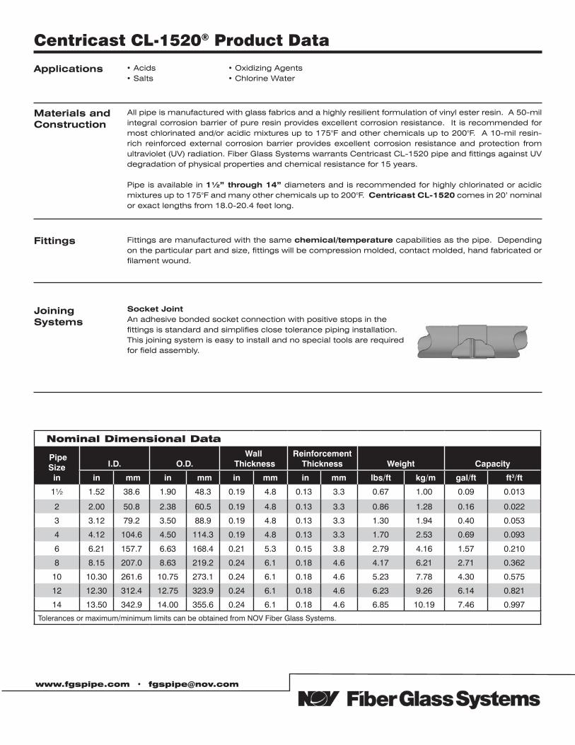
Applications • Acids• Salts
• Oxidizing Agents• Chlorine Water
Fittings Fittings are manufactured with the same chemical/temperature capabilities as the pipe. Depending on the particular part and size, fittings will be compression molded, contact molded, hand fabricated or filament wound.
Materials andConstruction
All pipe is manufactured with glass fabrics and a highly resilient formulation of vinyl ester resin. A 50-mil integral corrosion barrier of pure resin provides excellent corrosion resistance. It is recommended for most chlorinated and/or acidic mixtures up to 175°F and other chemicals up to 200°F. A 10-mil resin-rich reinforced external corrosion barrier provides excellent corrosion resistance and protection from ultraviolet (UV) radiation. Fiber Glass Systems warrants Centricast CL-1520 pipe and fittings against UV degradation of physical properties and chemical resistance for 15 years.
Pipe is available in 1½” through 14” diameters and is recommended for highly chlorinated or acidic mixtures up to 175°F and many other chemicals up to 200°F. Centricast CL-1520 comes in 20’ nominal or exact lengths from 18.0-20.4 feet long.
Centricast CL-1520® Product Data
Joining Systems
Socket JointAn adhesive bonded socket connection with positive stops in thefittings is standard and simplifies close tolerance piping installation.This joining system is easy to install and no special tools are requiredfor field assembly.
Nominal Dimensional Data
Pipe Size
in
I.D. O.D.Wall
ThicknessReinforcement
Thickness Weight Capacity
in (mm in (mm in mm (in mm (lbs/ftt (kg/m gal/ft (ft3/ft)
1½ 1.52 38.6 1.90 48.3 0.19 4.8 0.13 3.3 0.67 1.00 0.09 0.013
2 2.00 50.8 2.38 60.5 0.19 4.8 0.13 3.3 0.86 1.28 0.16 0.022
3 3.12 79.2 3.50 88.9 0.19 4.8 0.13 3.3 1.30 1.94 0.40 0.053
4 4.12 104.6 4.50 114.3 0.19 4.8 0.13 3.3 1.70 2.53 0.69 0.093
6 6.21 157.7 6.63 168.4 0.21 5.3 0.15 3.8 2.79 4.16 1.57 0.210
8 8.15 207.0 8.63 219.2 0.24 6.1 0.18 4.6 4.17 6.21 2.71 0.362
10 10.30 261.6 10.75 273.1 0.24 6.1 0.18 4.6 5.23 7.78 4.30 0.575
12 12.30 312.4 12.75 323.9 0.24 6.1 0.18 4.6 6.23 9.26 6.14 0.821
14 13.50 342.9 14.00 355.6 0.24 6.1 0.18 4.6 6.85 10.19 7.46 0.997
Tolerances or maximum/minimum limits can be obtained from NOV Fiber Glass Systems.
www.fgspipe.com • [email protected]
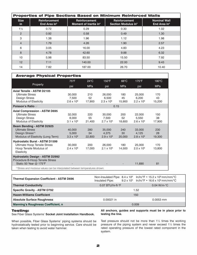
Thermal Expansion Coefficient - ASTM D696 Non-Insulated Pipe: 8.4 x 10⁶
Insulated Pipe: 9.2 x 10⁶In/In/°F • 15.2 x 106 mm/mm/°CIn/In/°F • 16.6 x 106 mm/mm/°C
Thermal Conductivity 0.07 BTU/hr-ft-°F 0.04 W/m-°C
Specific Gravity - ASTM D792 1.52
Hazen-Williams Coefficient 150
Absolute Surface Roughness 0.00021 in 0.0053 mm
Manning’s Roughness Coefficient, n 0.009
Average Physical Properties
Property 75°F 24°C 150°F 66°C 175°F 180°C
psi MPa psi MPa psi MPa
Axial Tensile - ASTM D2105 Ultimate Stress Design Stress Modulus of Elasticity
30,000 7,500 2.6 x 10⁶
21052
17,900
26,000 6,500
2.3 x 10⁶
18045
15,900
25,0006,200
2.2 x 10⁶
17043
15,200
Poisson’s Ratio ν 0.15
Axial Compression - ASTM D695 Ultimate Stress Design Stress Modulus of Elasticity
32,000 8,000 3.1 x 10⁶
22055
21,400
30,0007,500
2.7 x 10⁶
20052
18,600
22,0005,550
2.6 x 10⁶
15038
17,900
Beam Bending - ASTM D2925 Ultimate Stress Design Stress(1)
Modulus of Elasticity (Long Term)
40,000 5,000 3.3 x 10⁶
28034
22,800
35,0004,375
2.9 x 10⁶
24030
20,000
33,0004,125
2.8 x 10⁶
23028
19,300
Hydrostatic Burst - ASTM D1599 Ultimate Hoop Tensile Stress Hoop Tensile Modulus of Elasticity
30,000 2.4 x 10⁶
20017,000
26,000 2.1 x 10⁶
18014,500
25,0002.0 x 106
17013,800
Hydrostatic Design - ASTM D2992Procedure B-Hoop Tensile Stress Static 50 Year @ 175°F
- -
- - 11,690 81
(1)Stress and modulus values can be interpolated between temperatures shown.
2
Properties of Pipe Sections Based on Minimum Reinforced WallsSize
inReinforcementEnd Area in2
ReinforcementMoment of Inertia in4
ReinforcementSection Modulus in3
Nominal WallEnd Area in2
1½ 0.72 0.29 0.30 1.02
2 0.92 0.58 0.49 1.30
3 1.38 1.96 1.12 1.98
4 1.79 4.26 1.90 2.57
6 3.05 16.00 4.83 4.23
8 4.78 42.60 9.88 6.32
10 5.98 83.50 15.50 7.92
12 7.11 140.00 22.00 9.43
14 7.82 187.00 26.70 10.40
Testing: See Fiber Glass Systems’ Socket Joint Installation Handbook.
When possible, Fiber Glass Systems’ piping systems should be hydrostatically tested prior to beginning service. Care should be taken when testing to avoid water hammer.
All anchors, guides and supports must be in place prior to testing the line.
Test pressure should not be more than 1½ times the working pressure of the piping system and never exceed 1½ times the rated operating pressure of the lowest rated component in the system.
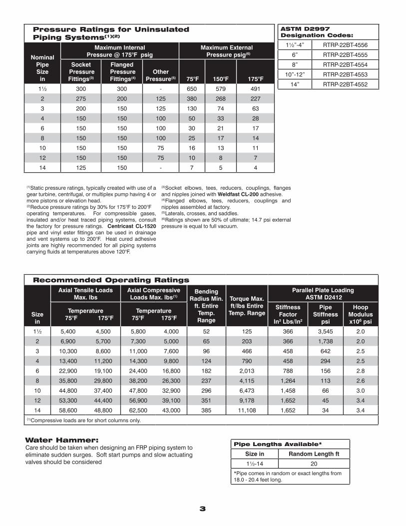
3
(1)Static pressure ratings, typically created with use of a gear turbine, centrifugal, or multiplex pump having 4 or more pistons or elevation head.(2)Reduce pressure ratings by 30% for 175°F to 200°F operating temperatures. For compressible gases, insulated and/or heat traced piping systems, consult the factory for pressure ratings. Centricast CL-1520 pipe and vinyl ester fittings can be used in drainage and vent systems up to 200°F. Heat cured adhesive joints are highly recommended for all piping systems carrying fluids at temperatures above 120°F.
(3)Socket elbows, tees, reducers, couplings, flanges and nipples joined with Weldfast CL-200 adhesive.(4)Flanged elbows, tees, reducers, couplings and nipples assembled at factory.(5)Laterals, crosses, and saddles.(6)Ratings shown are 50% of ultimate; 14.7 psi external pressure is equal to full vacuum.
Pressure Ratings for Uninsulated Piping Systems(1)(2)
NominalPipeSize
in
Maximum InternalPressure @ 175°F psig
Maximum External Pressure psig(6)
Socket Pressure Fittings(3)
Flanged Pressure Fittings(4)
Other Pressure(5) 75°F 150°F 175°F
1½ 300 300 - 650 579 491
2 275 200 125 380 268 227
3 200 150 125 130 74 63
4 150 150 100 50 33 28
6 150 150 100 30 21 17
8 150 150 100 25 17 14
10 150 150 75 16 13 11
12 150 150 75 10 8 7
14 125 150 - 7 5 4
ASTM D2997Designation Codes:
1½”-4” RTRP-22BT-4556
6” RTRP-22BT-4555
8” RTRP-22BT-4554
10”-12” RTRP-22BT-4553
14” RTRP-22BT-4552
Recommended Operating Ratings
Sizein
Axial Tensile Loads Max. lbs
Axial Compressive Loads Max. lbs(1)
Bending Radius Min.
ft. Entire Temp. Range
Torque Max. ft/lbs Entire
Temp. Range
Parallel Plate Loading ASTM D2412
Temperature 75°F 175°F
Temperature 75°F 175°F
Stiffness Factor
In3 Lbs/In2
Pipe Stiffness
psi
Hoop Modulus x106 psi
1½ 5,400 4,500 5,800 4,000 52 125 366 3,545 2.0
2 6,900 5,700 7,300 5,000 65 203 366 1,738 2.0
3 10,300 8,600 11,000 7,600 96 466 458 642 2.5
4 13,400 11,200 14,300 9,800 124 790 458 294 2.5
6 22,900 19,100 24,400 16,800 182 2,013 788 156 2.8
8 35,800 29,800 38,200 26,300 237 4,115 1,264 113 2.6
10 44,800 37,400 47,800 32,900 296 6,473 1,458 66 3.0
12 53,300 44,400 56,900 39,100 351 9,178 1,652 45 3.4
14 58,600 48,800 62,500 43,000 385 11,108 1,652 34 3.4(1)Compressive loads are for short columns only.
Water Hammer:Care should be taken when designing an FRP piping system to eliminate sudden surges. Soft start pumps and slow actuating valves should be considered
Pipe Lengths Available*
Size in Random Length ft
1½-14 20
*Pipe comes in random or exact lengths from 18.0 - 20.4 feet long.
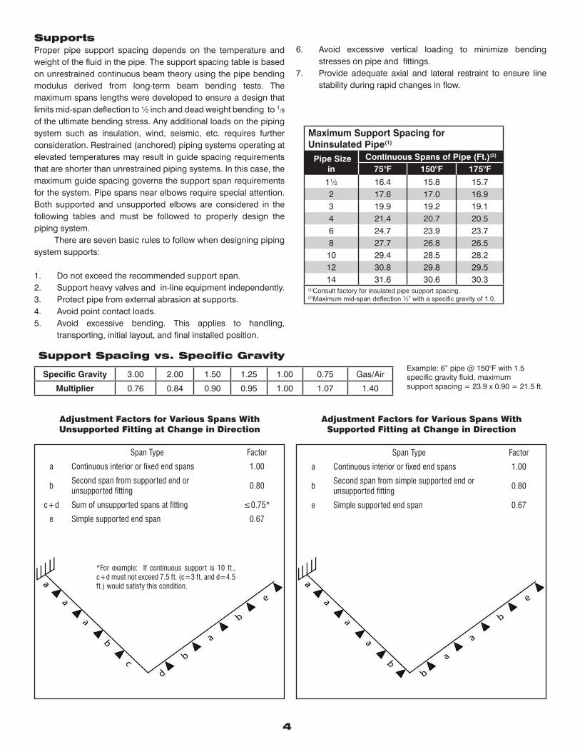
Adjustment Factors for Various Spans WithUnsupported Fitting at Change in Direction
Span Type Factor
a Continuous interior or fixed end spans 1.00
bSecond span from supported end orunsupported fitting
0.80
c+d Sum of unsupported spans at fitting ≤0.75*
e Simple supported end span 0.67
Span Type Factor
a Continuous interior or fixed end spans 1.00
bSecond span from simple supported end or unsupported fitting
0.80
e Simple supported end span 0.67
*For example: If continuous support is 10 ft., c+d must not exceed 7.5 ft. (c=3 ft. and d=4.5 ft.) would satisfy this condition.
SupportsProper pipe support spacing depends on the temperature and weight of the fluid in the pipe. The support spacing table is based on unrestrained continuous beam theory using the pipe bending modulus derived from long-term beam bending tests. The maximum spans lengths were developed to ensure a design that limits mid-span deflection to ½ inch and dead weight bending to 1/8
of the ultimate bending stress. Any additional loads on the piping system such as insulation, wind, seismic, etc. requires further consideration. Restrained (anchored) piping systems operating at elevated temperatures may result in guide spacing requirements that are shorter than unrestrained piping systems. In this case, the maximum guide spacing governs the support span requirements for the system. Pipe spans near elbows require special attention. Both supported and unsupported elbows are considered in the following tables and must be followed to properly design the piping system. There are seven basic rules to follow when designing piping system supports:
1. Do not exceed the recommended support span.2. Support heavy valves and in-line equipment independently. 3. Protect pipe from external abrasion at supports.4. Avoid point contact loads.5. Avoid excessive bending. This applies to handling,
transporting, initial layout, and final installed position.
4
6. Avoid excessive vertical loading to minimize bending stresses on pipe and fittings.
7. Provide adequate axial and lateral restraint to ensure line stability during rapid changes in flow.
Maximum Support Spacing for Uninsulated Pipe(1)
Pipe Size in
Continuous Spans of Pipe (Ft.)(2) 75°F 150°F 175°F
1½ 16.4 15.8 15.72 17.6 17.0 16.93 19.9 19.2 19.14 21.4 20.7 20.56 24.7 23.9 23.78 27.7 26.8 26.5
10 29.4 28.5 28.212 30.8 29.8 29.514 31.6 30.6 30.3
(1)Consult factory for insulated pipe support spacing.(2)Maximum mid-span deflection ½” with a specific gravity of 1.0.
Support Spacing vs. Specific Gravity
Specific Gravity 3.00 2.00 1.50 1.25 1.00 0.75 Gas/Air
Multiplier 0.76 0.84 0.90 0.95 1.00 1.07 1.40
Example: 6” pipe @ 150°F with 1.5 specific gravity fluid, maximum support spacing = 23.9 x 0.90 = 21.5 ft.
Adjustment Factors for Various Spans WithSupported Fitting at Change in Direction
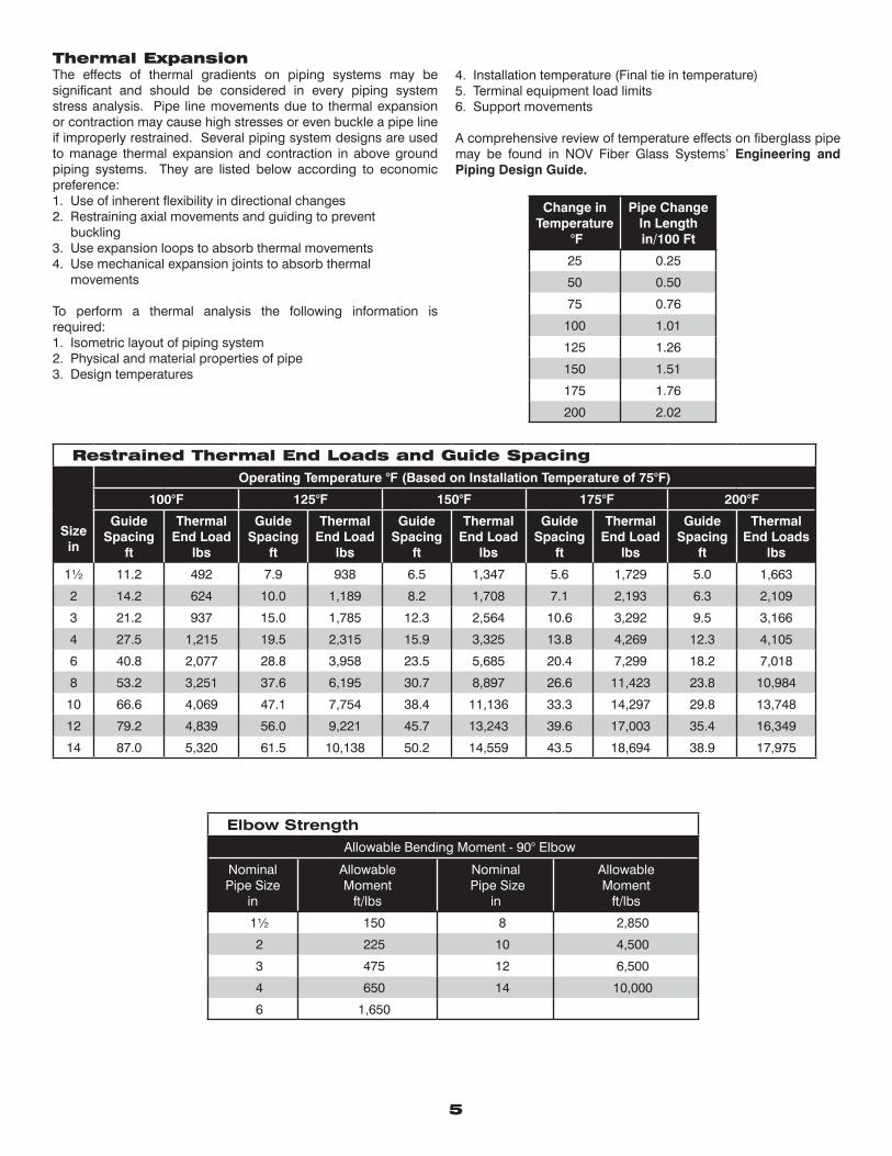
5
Change inTemperature
°F
Pipe Change In Lengthin/100 Ft
25 0.25
50 0.50
75 0.76
100 1.01
125 1.26
150 1.51
175 1.76
200 2.02
Thermal ExpansionThe effects of thermal gradients on piping systems may be significant and should be considered in every piping system stress analysis. Pipe line movements due to thermal expansion or contraction may cause high stresses or even buckle a pipe line if improperly restrained. Several piping system designs are used to manage thermal expansion and contraction in above ground piping systems. They are listed below according to economic preference:1. Use of inherent flexibility in directional changes2. Restraining axial movements and guiding to prevent buckling3. Use expansion loops to absorb thermal movements4. Use mechanical expansion joints to absorb thermal movements
To perform a thermal analysis the following information is required:1. Isometric layout of piping system2. Physical and material properties of pipe3. Design temperatures
4. Installation temperature (Final tie in temperature)5. Terminal equipment load limits6. Support movements
A comprehensive review of temperature effects on fiberglass pipe may be found in NOV Fiber Glass Systems’ Engineering and Piping Design Guide.
Restrained Thermal End Loads and Guide Spacing
Sizein
Operating Temperature °F (Based on Installation Temperature of 75°F)
100°F 125°F 150°F 175°F 200°F
GuideSpacing
ft
ThermalEnd Load
lbs
GuideSpacing
ft
ThermalEnd Load
lbs
GuideSpacing
ft
ThermalEnd Load
lbs
GuideSpacing
ft
ThermalEnd Load
lbs
GuideSpacing
ft
ThermalEnd Loads
lbs
1½ 11.2 492 7.9 938 6.5 1,347 5.6 1,729 5.0 1,663
2 14.2 624 10.0 1,189 8.2 1,708 7.1 2,193 6.3 2,109
3 21.2 937 15.0 1,785 12.3 2,564 10.6 3,292 9.5 3,166
4 27.5 1,215 19.5 2,315 15.9 3,325 13.8 4,269 12.3 4,105
6 40.8 2,077 28.8 3,958 23.5 5,685 20.4 7,299 18.2 7,018
8 53.2 3,251 37.6 6,195 30.7 8,897 26.6 11,423 23.8 10,984
10 66.6 4,069 47.1 7,754 38.4 11,136 33.3 14,297 29.8 13,748
12 79.2 4,839 56.0 9,221 45.7 13,243 39.6 17,003 35.4 16,349
14 87.0 5,320 61.5 10,138 50.2 14,559 43.5 18,694 38.9 17,975
Elbow StrengthAllowable Bending Moment - 90° Elbow
Nominal Pipe Size
in
AllowableMoment
ft/lbs
Nominal Pipe Size
in
AllowableMoment
ft/lbs
1½ 150 8 2,850
2 225 10 4,500
3 475 12 6,500
4 650 14 10,000
6 1,650
National Oilwell Varco has produced this brochure for general information only, and it is not intended for design purposes. Although every effort has been made to maintain the accuracy and reliability of its contents, National Oilwell Varco in no way assumes responsibility for liability for any loss, damage or injury resulting from the use of information and data herein nor is any warranty expressed or implied. Always cross-reference the bulletin date with the most current version listed at the web site noted in this literature.
www.fgspipe.com • [email protected]
©2012 National Oilwell Varco. All rights reserved.CL1700 - September 2012
North America South America Europe Asia Pacific Middle East17115 San Pedro Ave. Suite 200 Avenida Fernando Simoes P.O. Box 6, 4190 CA No. 7A, Tuas Avenue 3 P.O. Box 17324San Antonio, Texas 78232 USA Recife, Brazil 51020-390 Geldermalsen, The Netherlands Jurong, Singapore 639407 Dubai, UAEPhone: 210 477 7500 Phone: 55 31 3501 0023 Phone: 31 345 587 587 Phone: 65 6861 6118 Phone: 971 4881 3566
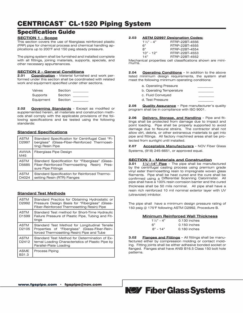
www.fgspipe.com • [email protected]
SECTION 1 – ScopeThis section covers the use of fiberglass reinforced plastic (FRP) pipe for chemical process and chemical handling ap-plications up to 200°F and 150 psig steady pressure.
The piping system shall be furnished and installed complete with all fittings, joining materials, supports, specials, and other necessary appurtenances.
SECTION 2 – General Conditions2.01 Coordination - Material furnished and work per-formed under this section shall be coordinated with related work and equipment specified under other sections.
Valves Section __________
Supports Section __________
Equipment Section __________
2.02 Governing Standards - Except as modified or supplemented herein, all materials and construction meth-ods shall comply with the applicable provisions of the fol-lowing specifications and be tested using the following standards:
Standard Specifications
Standard Test Methods
2.03 ASTM D2997 Designation Codes: 1½” - 4” RTRP-22BT-4556 6” RTRP-22BT-4555 8” RTRP-22BT-4554 10” - 12” RTRP-22BT-4553 14” RTRP-22BT-4552Mechanical properties cell classifications shown are mini-mums.
2.04 Operating Conditions - In addition to the above listed minimum design requirements, the system shall meet the following minimum operating conditions:
a. Operating Pressure __________
b. Operating Temperature __________
c. Fluid Conveyed __________
d. Test Pressure __________
2.05 Quality Assurance - Pipe manufacturer’s quality program shall be in compliance with ISO 9001.
2.06 Delivery, Storage, and Handling - Pipe and fit-tings shall be protected from damage due to impact and point loading. Pipe shall be properly supported to avoid damage due to flexural strains. The contractor shall not allow dirt, debris, or other extraneous materials to get into pipe and fittings. All factory machined areas shall be pro-tected from sunlight until installed.
2.07 Acceptable Manufacturers - NOV Fiber Glass
Systems, (918) 245-6651, or approved equal.
SECTION 3 – Materials and Construction3.01 1½"-14” Pipe - The pipe shall be manufactured by the centrifugal casting process using premium grade vinyl ester thermosetting resin to impregnate woven glass filaments. Pipe shall be heat cured and the cure shall be confirmed using a Differential Scanning Calorimeter. All pipe shall have a 100% resin corrosion barrier and the cured thickness shall be 50 mils nominal. All pipe shall have a resin rich reinforced 10 mil nominal exterior layer with UV (ultraviolet) inhibitor.
The pipe shall have a minimum design pressure rating of 150 psig @ 175°F following ASTM D2992, Procedure B.
Minimum Reinforced Wall Thickness 1½” - 4” 0.130 inches 6” 0.150 inches 8” - 14” 0.180 inches
3.02 Flanges and Fittings - All fittings shall be manu-factured either by compression molding or contact mold-ing. Fitting joints shall be either adhesive bonded socket or flanged. Flanges shall have ANSI B16.5 Class 150 bolt hole patterns.
Specification GuideCENTRICAST™ CL-1520 Piping System
ASTMD2997
Standard Specification for Centrifugal Cast “Fi-berglass” (Glass-Fiber-Reinforced Thermoset-ting) Resin Pipe
AWWA M45
Fiberglass Pipe Design
ASTMD5685
Standard Specification for “Fiberglass” (Glass-Fiber-Reinforced-Thermosetting Resin) Pres-sure PIpe Fittings
ASTM D4024
Standard Specification for Reinforced Thermo-setting Resin (RTR) Flanges
ASTMD2992
Standard Practice for Obtaining Hydrostatic or Pressure Design Basis for “Fiberglass” (Glass-Fiber-Reinforced Thermosetting Resin) Pipe
ASTMD1599
Standard Test method for Short-Time Hydraulic Failure Pressure of Plastic Pipe, Tubing and Fit-tings
ASTMD2105
Standard Test Method for Longitudinal Tensile Properties of “Fiberglass” (Glass-Fiber-Rein-forced Thermosetting Resin) Pipe and Tube
ASTMD2412
Standard Test Method for Determination of Ex-ternal Loading Characteristics of Plastic Pipe by Parallel-Plate Loading
ASME B31.3
Process Piping
www.fgspipe.com • [email protected]
©2012 National Oilwell Varco. All rights reserved.CI1701 February 2009
3.03 Adhesive - Adhesive shall be manufacturer’s stan-dard for the piping system specified. All adhesive bonded joints shall be cured according to the manufacturer’s instruc-tions for maximum strength and corrosion resistance.
3.04 Gaskets - Gaskets shall be 3/16” thick, 60-70 durom-eter full-face type suitable for the service shown on the draw-ings and as recommended in the manufacturer’s standard installation procedures.
3.05 Bolts, Nuts and Washers - ASTM F593, 304 stain-less steel hex head bolts shall be supplied. Two each SAE size washers shall be supplied on all nuts and bolts.
3.06 Acceptable Products - Centricast CL-1520 as man-ufactured by NOV Fiber Glass Systems or approved equal.
SECTION 4 - Installation and Testing4.01 Training and Certification - All joints installed or constructed in the field shall be assembled by employees of the contractor who have been trained by the pipe manufac-turer. The pipe manufacturer or their authorized representa-tive shall train the contractor’s employees in the proper joining and assembly procedures required for the project, including hands-on participation by the contractor’s employees. Each bonder shall fabricate one pipe-to-pipe and one pipe-to-fitting joint that shall pass the minimum pressure test for the applica-tion as stated in Section 2.04.d without leaking.
Only bonders who have successfully completed the pressure test shall bond pipe and fittings.
Certification by the manufacturer shall be in compliance with ASME B31.3 Section A328.2.
4.02 Pipe Installation - Pipe shall be installed as speci-fied and indicated on the drawings and in accordance with the manufacturer’s current published installation procedures.
4.03 Testing - A hydrostatic pressure test shall be con-ducted on the completed piping system. The pipe shall be subjected to a steady pressure at 1½ times the design operating pressure as stated in Section 2.04a. The pres-sure shall be held on the system for a minimum of 1 hour and the line inspected for leaks.
The test pressure should not exceed 1½ times the maximum rated operating pressure for the lowest rated element in the system.
The system shall be filled with water at the lowest point and air bled off from all the highest points. Systems shall be brought up to test pressure slowly to prevent water hammer or over pressurization.
All pipe joints shall be water tight. All joints that are found to leak by observation or during testing shall be repaired by the contractor and retested.
National Oilwell Varco has produced this brochure for general information only, and it is not intended for design purposes. Although every effort has been made to maintain the accuracy and reliability of its contents, National Oilwell Varco in no way assumes respon-sibility for liability for any loss, damage or injury resulting from the use of information and data herein nor is any warranty expressed or implied. Always cross-reference the bulletin date with the most current version listed at the web site noted in this literature.
North America South America Europe Asia Pacific Middle East17115 San Pedro Ave. Suite 200 Avenida Fernando Simoes P.O. Box 6, 4190 CA No. 7A, Tuas Avenue 3 P.O. Box 17324San Antonio, Texas 78232 USA Recife, Brazil 51020-390 Geldermalsen, The Netherlands Jurong, Singapore 639407 Dubai, UAEPhone: 210 477 7500 Phone: 55 31 3501 0023 Phone: 31 345 587 587 Phone: 65 6861 6118 Phone: 971 4881 3566
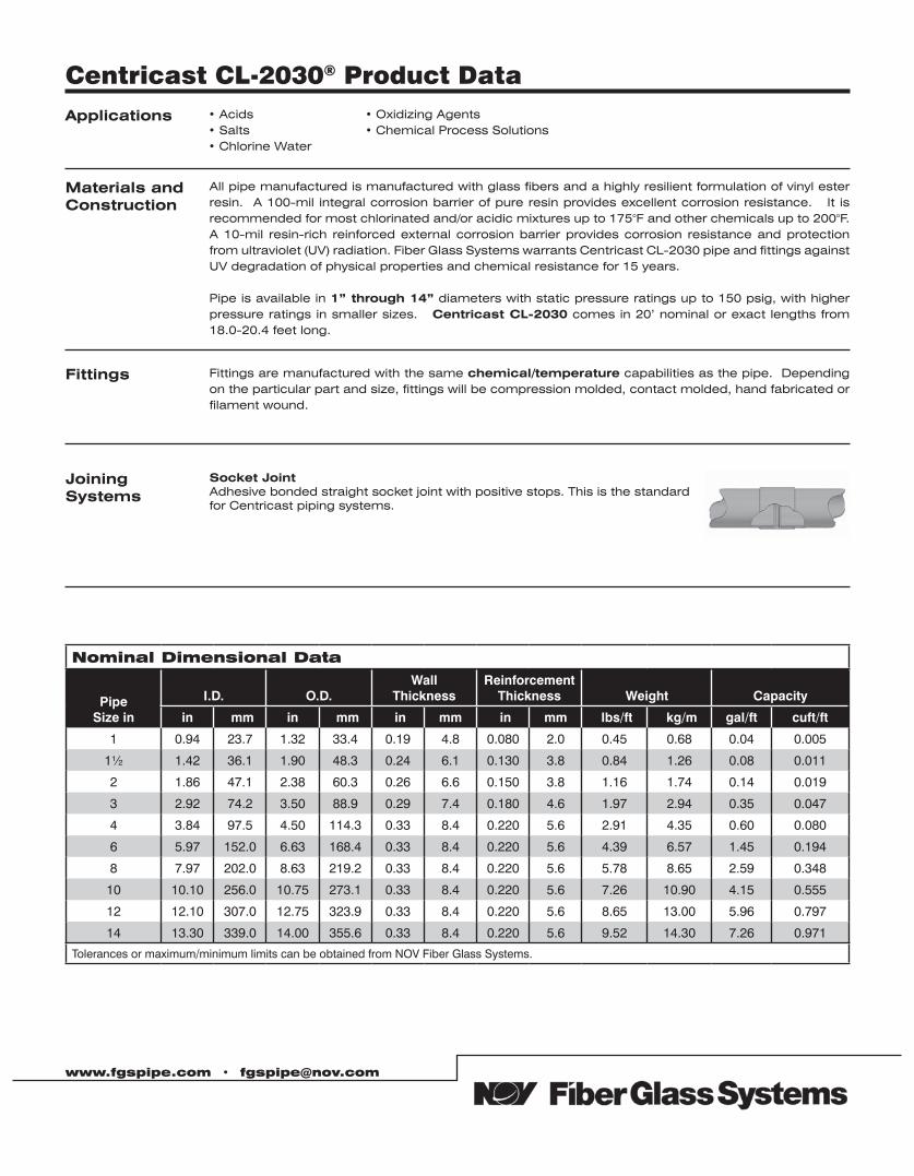
www.fgspipe.com • [email protected]
Centricast CL-2030® Product Data Applications • Acids
• Salts• Chlorine Water
• Oxidizing Agents• Chemical Process Solutions
Fittings Fittings are manufactured with the same chemical/temperature capabilities as the pipe. Depending on the particular part and size, fittings will be compression molded, contact molded, hand fabricated or filament wound.
Materials andConstruction
All pipe manufactured is manufactured with glass fibers and a highly resilient formulation of vinyl ester resin. A 100-mil integral corrosion barrier of pure resin provides excellent corrosion resistance. It is recommended for most chlorinated and/or acidic mixtures up to 175°F and other chemicals up to 200°F. A 10-mil resin-rich reinforced external corrosion barrier provides corrosion resistance and protection from ultraviolet (UV) radiation. Fiber Glass Systems warrants Centricast CL-2030 pipe and fittings against UV degradation of physical properties and chemical resistance for 15 years.
Pipe is available in 1” through 14” diameters with static pressure ratings up to 150 psig, with higher pressure ratings in smaller sizes. Centricast CL-2030 comes in 20’ nominal or exact lengths from 18.0-20.4 feet long.
Joining Systems
Socket JointAdhesive bonded straight socket joint with positive stops. This is the standard for Centricast piping systems.
Nominal Dimensional Data
Pipe Size in
I.D. O.D.Wall
ThicknessReinforcement
Thickness Weight Capacity
in (mm in (mm (in mm (in mm (lbs/ft (kg/m gal/ft (cuft/ft)
1 0.94 23.7 1.32 33.4 0.19 4.8 0.080 2.0 0.45 0.68 0.04 0.005
1½ 1.42 36.1 1.90 48.3 0.24 6.1 0.130 3.8 0.84 1.26 0.08 0.011
2 1.86 47.1 2.38 60.3 0.26 6.6 0.150 3.8 1.16 1.74 0.14 0.019
3 2.92 74.2 3.50 88.9 0.29 7.4 0.180 4.6 1.97 2.94 0.35 0.047
4 3.84 97.5 4.50 114.3 0.33 8.4 0.220 5.6 2.91 4.35 0.60 0.080
6 5.97 152.0 6.63 168.4 0.33 8.4 0.220 5.6 4.39 6.57 1.45 0.194
8 7.97 202.0 8.63 219.2 0.33 8.4 0.220 5.6 5.78 8.65 2.59 0.348
10 10.10 256.0 10.75 273.1 0.33 8.4 0.220 5.6 7.26 10.90 4.15 0.555
12 12.10 307.0 12.75 323.9 0.33 8.4 0.220 5.6 8.65 13.00 5.96 0.797
14 13.30 339.0 14.00 355.6 0.33 8.4 0.220 5.6 9.52 14.30 7.26 0.971
Tolerances or maximum/minimum limits can be obtained from NOV Fiber Glass Systems.
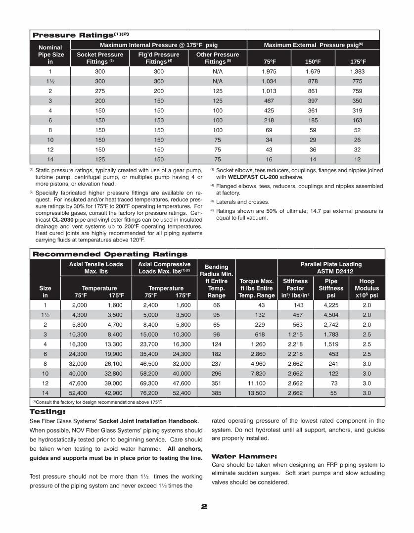
Pressure Ratings(1)(2)
Nominal Pipe Size
in
Maximum Internal Pressure @ 175°F psig Maximum External Pressure psig(6) Socket Pressure
Fittings (3)Flg’d Pressure
Fittings (4)Other Pressure
Fittings (5) 75ºF 150ºF 175°F1 300 300 N/A 1,975 1,679 1,383
1½ 300 300 N/A 1,034 878 775
2 275 200 125 1,013 861 759
3 200 150 125 467 397 350
4 150 150 100 425 361 319
6 150 150 100 218 185 163
8 150 150 100 69 59 52
10 150 150 75 34 29 26
12 150 150 75 43 36 32
14 125 150 75 16 14 12
(1) Static pressure ratings, typically created with use of a gear pump, turbine pump, centrifugal pump, or multiplex pump having 4 or more pistons, or elevation head.
(2) Specially fabricated higher pressure fittings are available on re-quest. For insulated and/or heat traced temperatures, reduce pres-sure ratings by 30% for 175°F to 200°F operating temperatures. For compressible gases, consult the factory for pressure ratings. Cen-tricast CL-2030 pipe and vinyl ester fittings can be used in insulated drainage and vent systems up to 200°F operating temperatures. Heat cured joints are highly recommended for all piping systems carrying fluids at temperatures above 120°F.
(3) Socket elbows, tees reducers, couplings, flanges and nipples joined with WELDFAST CL-200 adhesive.
(4) Flanged elbows, tees, reducers, couplings and nipples assembled at factory.
(5) Laterals and crosses.(6) Ratings shown are 50% of ultimate; 14.7 psi external pressure is
equal to full vacuum.
Recommended Operating RatingsAxial Tensile Loads
Max. lbs Axial Compressive Loads Max. lbs(1)(2)
Bending Radius Min.
ft Entire Temp. Range
Torque Max. ft lbs Entire
Temp. Range
Parallel Plate Loading ASTM D2412
Sizein
Temperature 75°F 175°F
Temperature 75°F 175°F
Stiffness Factor
in3/ lbs/in2
Pipe Stiffness
psi
Hoop Modulus x106 psi
1 2,000 1,600 2,400 1,600 66 43 143 4,225 2.0
1½ 4,300 3,500 5,000 3,500 95 132 457 4,504 2.0
2 5,800 4,700 8,400 5,800 65 229 563 2,742 2.0
3 10,300 8,400 15,000 10,300 96 618 1,215 1,783 2.5
4 16,300 13,300 23,700 16,300 124 1,260 2,218 1,519 2.5
6 24,300 19,900 35,400 24,300 182 2,860 2,218 453 2.5
8 32,000 26,100 46,500 32,000 237 4,960 2,662 241 3.0
10 40,000 32,800 58,200 40,000 296 7,820 2,662 122 3.0
12 47,600 39,000 69,300 47,600 351 11,100 2,662 73 3.0
14 52,400 42,900 76,200 52,400 385 13,500 2,662 55 3.0(1)Consult the factory for design recommendations above 175°F.
Testing: See Fiber Glass Systems’ Socket Joint Installation Handbook.
When possible, NOV Fiber Glass Systems’ piping systems should
be hydrostatically tested prior to beginning service. Care should
be taken when testing to avoid water hammer. All anchors,
guides and supports must be in place prior to testing the line.
Test pressure should not be more than 1½ times the working
pressure of the piping system and never exceed 1½ times the
rated operating pressure of the lowest rated component in the
system. Do not hydrotest until all support, anchors, and guides are properly installed.
Water Hammer:Care should be taken when designing an FRP piping system to eliminate sudden surges. Soft start pumps and slow actuating
valves should be considered.
2
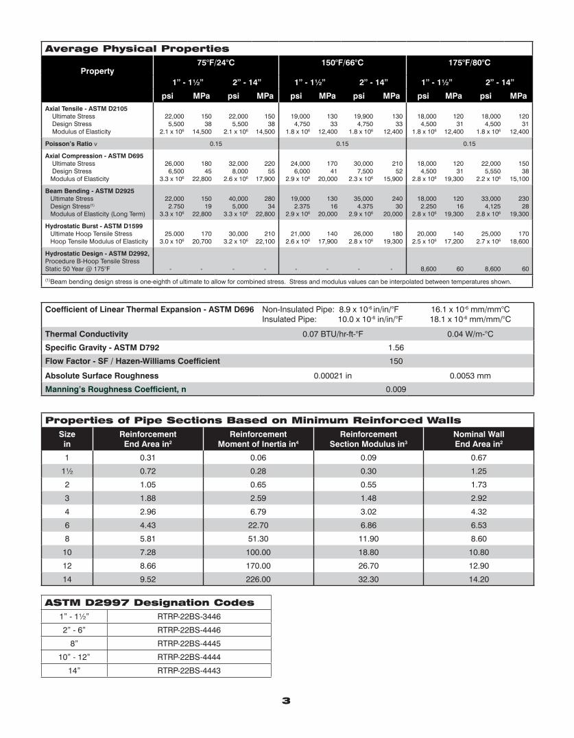
Properties of Pipe Sections Based on Minimum Reinforced WallsSize
inReinforcementEnd Area in2
ReinforcementMoment of Inertia in4
ReinforcementSection Modulus in3
Nominal WallEnd Area in2
1 0.31 0.06 0.09 0.67
1½ 0.72 0.28 0.30 1.25
2 1.05 0.65 0.55 1.73
3 1.88 2.59 1.48 2.92
4 2.96 6.79 3.02 4.32
6 4.43 22.70 6.86 6.53
8 5.81 51.30 11.90 8.60
10 7.28 100.00 18.80 10.80
12 8.66 170.00 26.70 12.90
14 9.52 226.00 32.30 14.20
Coefficient of Linear Thermal Expansion - ASTM D696 Non-Insulated Pipe: 8.9 x 10⁻⁶ in/in/°FInsulated Pipe: 10.0 x 10⁻⁶ in/in/°F
16.1 x 10⁻⁶ mm/mm°C18.1 x 10-6 mm/mm/°C
Thermal Conductivity 0.07 BTU/hr-ft-°F 0.04 W/m-°C
Specific Gravity - ASTM D792 1.56
Flow Factor - SF / Hazen-Williams Coefficient 150
Absolute Surface Roughness 0.00021 in 0.0053 mm
Manning’s Roughness Coefficient, n 0.009
Average Physical Properties
Property75°F/24°C 150°F/66°C 175°F/80°C
1” - 1½” 2” - 14” 1” - 1½” 2” - 14” 1” - 1½” 2” - 14”
psi MPa psi MPa psi MPa psi MPa psi MPa psi MPaAxial Tensile - ASTM D2105 Ultimate Stress Design Stress Modulus of Elasticity
22,0005,500
2.1 x 10⁶
15038
14,500
22,0005,500
2.1 x 10⁶
15038
14,500
19,0004,750
1.8 x 10⁶
13033
12,400
19,9004,750
1.8 x 10⁶
13033
12,400
18,0004,500
1.8 x 10⁶
12031
12,400
18,0004,500
1.8 x 10⁶
12031
12,400
Poisson’s Ratio ν 0.15 0.15 0.15
Axial Compression - ASTM D695 Ultimate Stress Design Stress Modulus of Elasticity
26,0006,500
3.3 x 10⁶
18045
22,800
32,0008,000
2.6 x 10⁶
22055
17,900
24,0006,000
2.9 x 10⁶
17041
20,000
30,0007,500
2.3 x 10⁶
21052
15,900
18,0004,500
2.8 x 10⁶
12031
19,300
22,0005,550
2.2 x 10⁶
15038
15,100
Beam Bending - ASTM D2925 Ultimate Stress Design Stress(1)
Modulus of Elasticity (Long Term)
22,0002.750
3.3 x 10⁶
15019
22,800
40,0005,000
3.3 x 10⁶
28034
22,800
19,0002.375
2.9 x 10⁶
13016
20,000
35,0004.375
2.9 x 10⁶
24030
20,000
18,0002.250
2.8 x 10⁶
12016
19,300
33,0004,125
2.8 x 10⁶
23028
19,300
Hydrostatic Burst - ASTM D1599 Ultimate Hoop Tensile Stress Hoop Tensile Modulus of Elasticity
25.0003.0 x 106
17020,700
30,0003.2 x 106
21022,100
21,0002.6 x 106
14017,900
26,0002.8 x 106
18019,300
20,0002.5 x 106
14017,200
25,0002.7 x 106
17018,600
Hydrostatic Design - ASTM D2992,Procedure B-Hoop Tensile StressStatic 50 Year @ 175°F - - - - - - - - 8,600 60 8,600 60
(1)Beam bending design stress is one-eighth of ultimate to allow for combined stress. Stress and modulus values can be interpolated between temperatures shown.
3
ASTM D2997 Designation Codes1” - 1½” RTRP-22BS-3446
2” - 6” RTRP-22BS-4446
8” RTRP-22BS-4445
10” - 12” RTRP-22BS-4444
14” RTRP-22BS-4443
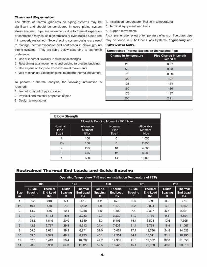
Thermal Expansion
The effects of thermal gradients on piping systems may be
significant and should be considered in every piping system
stress analysis. Pipe line movements due to thermal expansion
or contraction may cause high stresses or even buckle a pipe line
if improperly restrained. Several piping system designs are used
to manage thermal expansion and contraction in above ground
piping systems. They are listed below according to economic
preference:
1. Use of inherent flexibility in directional changes
2. Restraining axial movements and guiding to prevent buckling
3. Use expansion loops to absorb thermal movements
4. Use mechanical expansion joints to absorb thermal movement
To perform a thermal analysis, the following information is
required:
1. Isometric layout of piping system
2. Physical and material properties of pipe
3. Design temperatures
4. Installation temperature (final tie-in temperature)
5. Terminal equipment load limits
6. Support movements
A comprehensive review of temperature effects on fiberglass pipe
may be found in NOV Fiber Glass Systems’ Engineering and
Piping Design Guide.
Unrestrained Thermal Expansion Uninsulated Pipe
Change in Temperature °F
Pipe Change in Lengthin/100 ft
25 0.27
50 0.53
75 0.80
100 1.07
125 1.34
150 1.60
175 1.87
200 2.21
Elbow StrengthAllowable Bending Moment - 90° Elbow
Nominal Pipe
Size in
AllowableMoment
ft/lbs
Nominal Pipe
Size in
AllowableMoment
ft/lbs
1 100 6 1,650
1½ 150 8 2,850
2 225 10 4,500
3 475 12 6,500
4 650 14 10.000
4
Restrained Thermal End Loads and Guide Spacing
Operating Temperature °F (Based on Installation Temperature of 75°F)
100 125 150 175 200
Sizein
Guide Spacing
ft
Thermal End Load
lbs
Guide Spacing
ft
Thermal End Load
lbs
Guide Spacing
ft
Thermal End Load
lbs
Guide Spacing
ft
Thermal End Load
lbs
Guide Spacing
ft
Thermal End Load
lbs
1 7.2 248 5.1 473 4.2 675 3.6 869 3.2 776
1½ 10.4 578 7.3 1,102 6.0 1,572 5.2 2,024 4.6 1,807
2 14.7 655 10.4 1,258 8.5 1,809 7.4 2,307 6.6 2,621
3 21.9 1,173 15.5 2,253 12.7 3,239 11.0 4,130 9.8 4,694
4 28.3 1,849 20.0 3,550 16.3 5,103 14.1 6,508 12.6 7,395
6 42.3 2,767 29.9 5,312 24.4 7,636 21.1 9,739 18.9 11,067
8 55.5 3,631 39.2 6,971 32.0 10,021 27.7 12,780 24.8 14,523
10 69.5 4,549 49.1 8,733 40.1 12,554 34.7 16,011 31.1 18,195
12 82.6 5,413 58.4 10,392 47.7 14,939 41.3 19,052 37.0 21,650
14 90.9 5,953 64.3 11,429 52.5 16,429 45.4 20,953 40.6 23,810
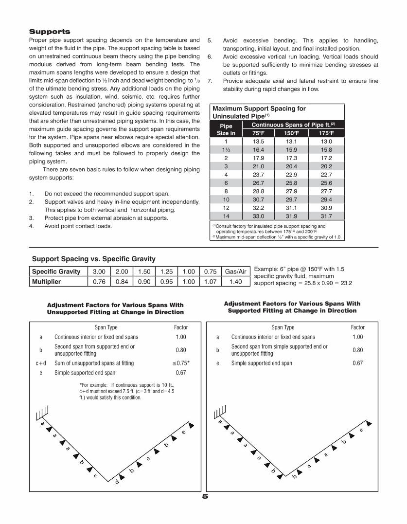
Support Spacing vs. Specific Gravity
Specific Gravity 3.00 2.00 1.50 1.25 1.00 0.75 Gas/Air
Multiplier 0.76 0.84 0.90 0.95 1.00 1.07 1.40
Example: 6” pipe @ 150°F with 1.5specific gravity fluid, maximum support spacing = 25.8 x 0.90 = 23.2
Adjustment Factors for Various Spans WithSupported Fitting at Change in Direction
Span Type Factor
a Continuous interior or fixed end spans 1.00
bSecond span from simple supported end or unsupported fitting
0.80
e Simple supported end span 0.67
Adjustment Factors for Various Spans WithUnsupported Fitting at Change in Direction
Span Type Factor
a Continuous interior or fixed end spans 1.00
bSecond span from supported end orunsupported fitting
0.80
c+d Sum of unsupported spans at fitting ≤0.75*
e Simple supported end span 0.67
*For example: If continuous support is 10 ft., c+d must not exceed 7.5 ft. (c=3 ft. and d=4.5 ft.) would satisfy this condition.
SupportsProper pipe support spacing depends on the temperature and weight of the fluid in the pipe. The support spacing table is based on unrestrained continuous beam theory using the pipe bending modulus derived from long-term beam bending tests. The maximum spans lengths were developed to ensure a design that limits mid-span deflection to ½ inch and dead weight bending to 1/8 of the ultimate bending stress. Any additional loads on the piping system such as insulation, wind, seismic, etc. requires further consideration. Restrained (anchored) piping systems operating at elevated temperatures may result in guide spacing requirements that are shorter than unrestrained piping systems. In this case, the maximum guide spacing governs the support span requirements for the system. Pipe spans near elbows require special attention. Both supported and unsupported elbows are considered in the following tables and must be followed to properly design the piping system. There are seven basic rules to follow when designing piping system supports:
1. Do not exceed the recommended support span.2. Support valves and heavy in-line equipment independently.
This applies to both vertical and horizontal piping.3. Protect pipe from external abrasion at supports.4. Avoid point contact loads.
5. Avoid excessive bending. This applies to handling, transporting, initial layout, and final installed position.
6. Avoid excessive vertical run loading. Vertical loads should be supported sufficiently to minimize bending stresses at outlets or fittings.
7. Provide adequate axial and lateral restraint to ensure line stability during rapid changes in flow.
Maximum Support Spacing for Uninsulated Pipe(1)
Pipe Size in
Continuous Spans of Pipe ft.(2)
75°F 150°F 175°F1 13.5 13.1 13.0
1½ 16.4 15.9 15.82 17.9 17.3 17.23 21.0 20.4 20.24 23.7 22.9 22.76 26.7 25.8 25.68 28.8 27.9 27.7
10 30.7 29.7 29.412 32.2 31.1 30.914 33.0 31.9 31.7
(1)Consult factory for insulated pipe support spacing and operating temperatures between 175°F and 200°F.(2 Maximum mid-span deflection ½” with a specific gravity of 1.0
5
National Oilwell Varco has produced this brochure for general information only, and it is not intended for design purposes. Although every effort has been made to maintain the accuracy and reliability of its contents, National Oilwell Varco in no way assumes responsibility for liability for any loss, damage or injury resulting from the use of information and data herein nor is any warranty expressed or implied. Always cross-reference the bulletin date with the most current version listed at the web site noted in this literature.
www.fgspipe.com • [email protected]
©2012 National Oilwell Varco. All rights reserved.CI1710 - June 2010
North America South America Europe Asia Pacific Middle East17115 San Pedro Ave. Suite 200 Avenida Fernando Simoes P.O. Box 6, 4190 CA No. 7A, Tuas Avenue 3 P.O. Box 17324San Antonio, Texas 78232 USA Recife, Brazil 51020-390 Geldermalsen, The Netherlands Jurong, Singapore 639407 Dubai, UAEPhone: 210 477 7500 Phone: 55 31 3501 0023 Phone: 31 345 587 587 Phone: 65 6861 6118 Phone: 971 4881 3566
www.fgspipe.com • [email protected]
CENTRICAST™ CL-2030 Piping SystemSpecification GuideSECTION 1 - ScopeThis section covers the use of fiberglass reinforced plastic (FRP) pipe for chemical process and chemical handling up to 200°F and up to 150 psig pressure.
The piping shall be furnished and installed complete with all fittings, joining materials, supports, specials, and other necessary appurtenances.
SECTION 2 - General Conditions2.01 Coordination - Material furnished and work per-formed under this section shall be coordinated with related work and equipment specified under other sections.
Valves Section _________ Supports Section _________ Equipment Section _________
2.02 Governing Standards - Except as modified or supplemented herein, all materials and construction meth-ods shall comply with the applicable provisions of the fol-lowing specifications and be tested using the following stan-dards:
Standard Specifications
Standard Test Methods
2.03 ASTM D2997 Designation Codes 1”-1½” RTRP-22BS-3446 2”-6” RTRP-22BS-4446 10”-12” RTRP-22BS-4444 14” RTRP-22BS-4443
Mechanical properties cell classifications shown are mini-mums.
2.04 Operating Conditions - In addition to the above minimum design requirements, the system shall meet the following minimum operating conditions:
a. Operating Pressure ________ b. Operating Temperature ________ c. Fluid Conveyed ________ d. Test Pressure ________
2.05 Quality Assurance - Pipe manufacturer’s quality program shall be in compliance with ISO 9001.
2.06 Delivery, Storage and Handling - Pipe and fit-tings shall be protected from damage due to impact and point loading. Pipe shall be properly supported to avoid damage due to flexural strains. The contractor shall not al-low dirt, debris, or other extraneous materials to get into pipe and fittings. All factory machined areas shall be protected from sunlight until installed.
2.07 Acceptable Manufacturers - NOV Fiber Glass Systems (918) 245-6651 or approved equal.
SECTION 3 - Materials and Construction3.01 1”-14” Pipe - The pipe shall be manufactured by the centrifugal casting process using premium grade vinyl ester thermosetting resin to impregnate woven glass fila-ments. Pipe shall be heat cured and the degree of cure shall be confirmed using a Differential Scanning Calorimeter. All pipe shall have a 100% resin corrosion barrier and the cured thickness shall be 100 mils nominal.
All pipe shall have a resin-rich reinforced 10 mil nominal ex-terior layer with UV (ultraviolet) inhibitor.
The pipe shall have a minimum design pressure rating of 150 psig at 175°F following ASTM D2992 Procedure B.
Minimum Reinforced Wall Thickness 1” 0.095 inches 1½” 0.120 inches 2” 0.150 inches 3” 0.180 inches 4”-14” 0.220 inches
ASTMD2992
Standard Practice for Obtaining Hydrostatic or Pressure Design Basis for “Fiberglass” (Glass-Fiber-Reinforced Thermosetting Resin) Pipe and Fittings
ASTMD1599
Standard Test method for Short-Time Hydraulic Failure Pressure of Plastic Pipe, Tubing and Fit-tings
ASTMD2105
Standard Test Method for Longitudinal Tensile Properties of “Fiberglass” (Glass-Fiber-Reinforced Thermosetting Resin) Pipe and Tube
ASTMD2412
Standard Test Method for Determination of Ex-ternal Loading Characteristics of Plastic Pipe by Parallel-Plate Loading
ASME B31.3
Process Piping
ASTMD2997
Standard Specification for Centrifugal Cast “Fi-berglass” (Glass-Fiber-Reinforced Thermosetting) Resin Pipe
AWWA M45
Fiberglass Pipe Design
ASTMD5685
Standard Specification for “Fiberglass” (Glass-Fiber-Reinforced-Thermosetting Resin) Pressure Pipe Fittings
ASTMD4024
Standard Specification for Reinforced Thermoset-ting Resin (RTR) Flanges
www.fgspipe.com • [email protected]
©2013 National Oilwell Varco. All rights reserved. CI1711 June 2013
3.02 Flanges and Fittings - All fittings shall be manufac-tured either by compression molding or contact molding. Fit-ting joints shall be either adhesive bonded socket or flanged. Flanges shall have ANSI B16.5 Class 150 bolt hole patterns.
3.03 Adhesive - Adhesive shall be manufacturer’s stan-dard for the piping system specified. All adhesive bonded joints shall be cured according to the manufacturer’s instruc-tions for maximum strength and corrosion resistance.
3.04 Gaskets - Gaskets shall be 3/16” thick, 60-70 durom-eter full-face type suitable for the service shown on the draw-ings and as recommended in the manufacturer’s standard installation procedures.
3.05 Bolts, Nuts and Washers - ASTM F593, 304 stain-less steel hex head bolts shall be supplied. Two each SAE size washers shall be supplied on all nuts and bolts.
3.06 Acceptable Products - Centricast CL-2030 as man-ufactured by NOV Fiber Glass Systems or approved equal.
SECTION 4 - Installation and Testing4.01 Training and Certification - All joints installed or constructed in the field shall be assembled by employees of the contractor who have been trained by the pipe manufac-turer. The pipe manufacturer or their authorized representa-tive shall train the contractor’s employees in the proper joining and assembly procedures required for the project, including hands-on participation by the contractor’s employees. Each bonder shall fabricate one pipe-to-pipe and one pipe-to-fitting joint that shall pass the minimum pressure test for the applica-tion as stated in Section 2.04.d without leaking.
Only bonders who have successfully completed the pressure test shall bond pipe and fittings.
Certification by the manufacturer shall be in compliance with ASME B31.3 Section A328.2.
4.02 Pipe Installation - Pipe shall be installed as speci-fied and indicated on the drawings and in accordance with the manufacturer’s current published installation procedures.
4.03 Testing - A hydrostatic pressure test shall be con-ducted on the completed piping system. The pipe shall be subjected to a steady pressure at 1½ times the design operating pressure as stated in Section 2.04a. The pres-sure shall be held on the system for a minimum of 1 hour and the line inspected for leaks.
The test pressure should not exceed 1½ times the maximum rated operating pressure for the lowest rated element in the system.
The system shall be filled with water at the lowest point and air bled off from all the highest points. Systems shall be brought up to test pressure slowly to prevent water hammer or over pressurization.
All pipe joints shall be water tight. All joints that are found to leak by observation or during testing shall be repaired by the contractor and retested.
National Oilwell Varco has produced this brochure for general information only, and it is not intended for de-sign purposes. Although every effort has been made to maintain the accuracy and reliability of its contents, National Oilwell Varco in no way assumes responsibility for liability for any loss, damage or injury resulting from the use of information and data herein nor is any warranty expressed or implied. Always cross-reference the bulletin date with the most current version listed at the web site noted in this literature.
North America South America Europe Asia Pacific Middle East17115 San Pedro Ave. Suite 200 Avenida Fernando Simoes P.O. Box 6, 4190 CA No. 7A, Tuas Avenue 3 P.O. Box 17324San Antonio, Texas 78232 USA Recife, Brazil 51020-390 Geldermalsen, The Netherlands Jurong, Singapore 639407 Dubai, UAEPhone: 210 477 7500 Phone: 55 31 3501 0023 Phone: 31 345 587 587 Phone: 65 6861 6118 Phone: 971 4881 3566
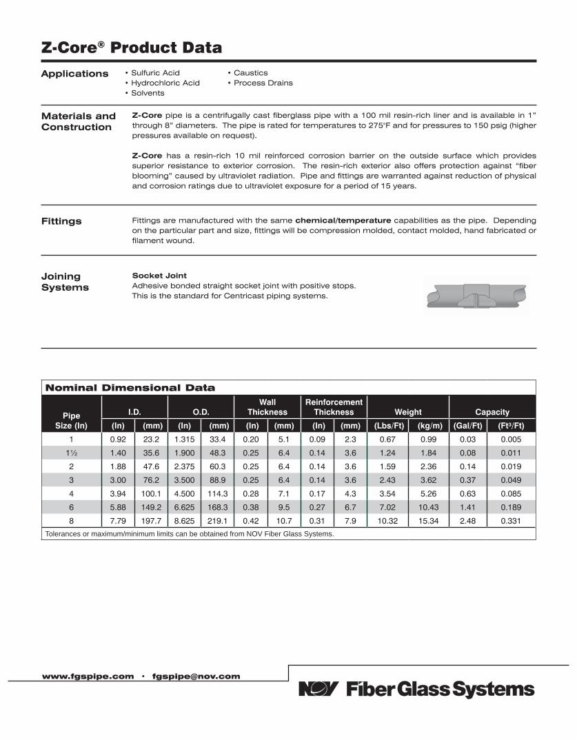
Z-Core® Product Data
Applications • Sulfuric Acid • Hydrochloric Acid• Solvents
• Caustics• Process Drains
Materials andConstruction
Z-Core pipe is a centrifugally cast fiberglass pipe with a 100 mil resin-rich liner and is available in 1” through 8” diameters. The pipe is rated for temperatures to 275°F and for pressures to 150 psig (higher pressures available on request).
Z-Core has a resin-rich 10 mil reinforced corrosion barrier on the outside surface which provides superior resistance to exterior corrosion. The resin-rich exterior also offers protection against “fiber blooming” caused by ultraviolet radiation. Pipe and fittings are warranted against reduction of physical and corrosion ratings due to ultraviolet exposure for a period of 15 years.
Fittings Fittings are manufactured with the same chemical/temperature capabilities as the pipe. Depending on the particular part and size, fittings will be compression molded, contact molded, hand fabricated or filament wound.
Joining Systems
Socket JointAdhesive bonded straight socket joint with positive stops.This is the standard for Centricast piping systems.
Nominal Dimensional Data
Pipe Size (In)
I.D. O.D.Wall
ThicknessReinforcement
Thickness Weight Capacity
(In) ((mm) (In) ((mm) ((In) (mm) ((In) (mm) ((Lbs/Ft) ((kg/m) (Gal/Ft) ((Ft³/Ft))
1 0.92 23.2 1.315 33.4 0.20 5.1 0.09 2.3 0.67 0.99 0.03 0.005
1½ 1.40 35.6 1.900 48.3 0.25 6.4 0.14 3.6 1.24 1.84 0.08 0.011
2 1.88 47.6 2.375 60.3 0.25 6.4 0.14 3.6 1.59 2.36 0.14 0.019
3 3.00 76.2 3.500 88.9 0.25 6.4 0.14 3.6 2.43 3.62 0.37 0.049
4 3.94 100.1 4.500 114.3 0.28 7.1 0.17 4.3 3.54 5.26 0.63 0.085
6 5.88 149.2 6.625 168.3 0.38 9.5 0.27 6.7 7.02 10.43 1.41 0.189
8 7.79 197.7 8.625 219.1 0.42 10.7 0.31 7.9 10.32 15.34 2.48 0.331
Tolerances or maximum/minimum limits can be obtained from NOV Fiber Glass Systems.
www.fgspipe.com • [email protected]
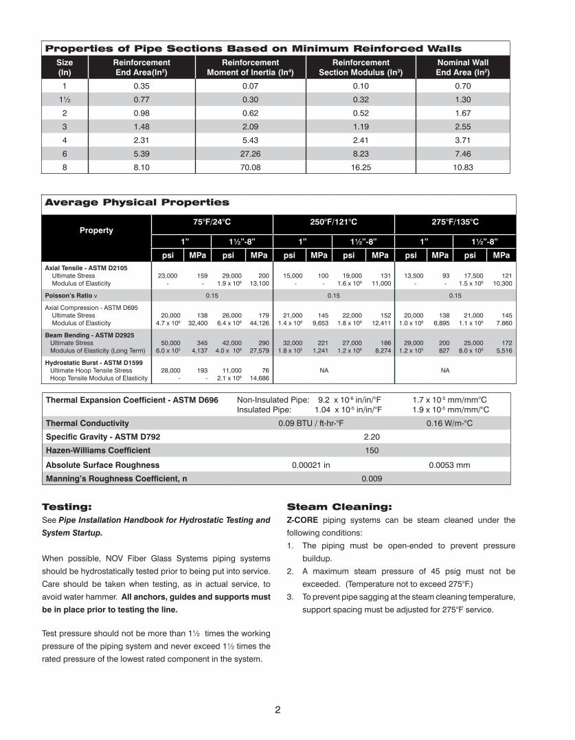
Properties of Pipe Sections Based on Minimum Reinforced WallsSize(In)
ReinforcementEnd Area(In2)
ReinforcementMoment of Inertia (In4)
ReinforcementSection Modulus (In3)
Nominal WallEnd Area (In2)
1 0.35 0.07 0.10 0.70
1½ 0.77 0.30 0.32 1.30
2 0.98 0.62 0.52 1.67
3 1.48 2.09 1.19 2.55
4 2.31 5.43 2.41 3.71
6 5.39 27.26 8.23 7.46
8 8.10 70.08 16.25 10.83
Average Physical Properties
Property75°F/24°C 250°F/121°C 275°F/135°C
1” 1½”-8” 1” 1½”-8” 1” 1½”-8”
psi MPa psi MPa psi MPa psi MPa psi MPa psi MPaAxial Tensile - ASTM D2105 Ultimate Stress Modulus of Elasticity
23,000 -
159 -
29,0001.9 x 106
20013,100
15,000 -
100 -
19,0001.6 x 106
13111,000
13,500 -
93 -
17,5001.5 x 106
12110,300
Poisson’s Ratio ν 0.15 0.15 0.15
Axial Compression - ASTM D695 Ultimate Stress Modulus of Elasticity
20,0004.7 x 106
13832,400
26,0006.4 x 106
17944,126
21,0001.4 x 106
1459,653
22,0001.8 x 106
15212,411
20,0001.0 x 106
1386,895
21,0001.1 x 106
1457.860
Beam Bending - ASTM D2925 Ultimate Stress Modulus of Elasticity (Long Term)
50,0006.0 x 105
3454,137
42,0004.0 x 106
29027,579
32,0001.8 x 105
2211,241
27,0001.2 x 106
1868,274
29,0001.2 x 105
200827
25,0008.0 x 105
1725,516
Hydrostatic Burst - ASTM D1599 Ultimate Hoop Tensile Stress Hoop Tensile Modulus of Elasticity
28,000 -
193-
11,0002.1 x 106
7614,686
NA NA
Thermal Expansion Coefficient - ASTM D696 Non-Insulated Pipe: 9.2 x 10⁻⁶ in/in/°FInsulated Pipe: 1.04 x 10⁻⁵ in/in/°F
1.7 x 10⁻⁵ mm/mm°C 1.9 x 10⁻⁵ mm/mm/°C
Thermal Conductivity 0.09 BTU / ft-hr-°F 0.16 W/m-°C
Specific Gravity - ASTM D792 2.20
Hazen-Williams Coefficient 150
Absolute Surface Roughness 0.00021 in 0.0053 mm
Manning’s Roughness Coefficient, n 0.009
Testing: See Pipe Installation Handbook for Hydrostatic Testing and
System Startup.
When possible, NOV Fiber Glass Systems piping systems
should be hydrostatically tested prior to being put into service.
Care should be taken when testing, as in actual service, to
avoid water hammer. All anchors, guides and supports must
be in place prior to testing the line.
Test pressure should not be more than 1½ times the working
pressure of the piping system and never exceed 1½ times the
rated pressure of the lowest rated component in the system.
Steam Cleaning:Z-CORE piping systems can be steam cleaned under the
following conditions:
1. The piping must be open-ended to prevent pressure
buildup.
2. A maximum steam pressure of 45 psig must not be
exceeded. (Temperature not to exceed 275°F.)
3. To prevent pipe sagging at the steam cleaning temperature,
support spacing must be adjusted for 275°F service.
2
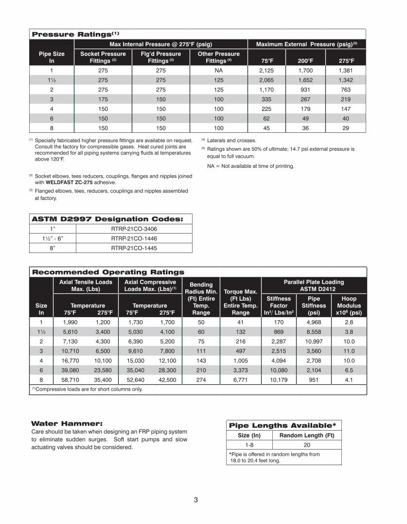
ASTM D2997 Designation Codes:1” RTRP-21CO-3406
1½” - 6” RTRP-21CO-1446
8” RTRP-21CO-1445
Pressure Ratings(1)
Pipe Size In
Max Internal Pressure @ 275°F (psig) Maximum External Pressure (psig)(5)
Socket Pressure Fittings (2)
Flg’d Pressure Fittings (3)
Other Pressure Fittings (4) 75°F 200°F 275°F
1 275 275 NA 2,125 1,700 1,381
1½ 275 275 125 2,065 1,652 1,342
2 275 275 125 1,170 931 763
3 175 150 100 335 267 219
4 150 150 100 225 179 147
6 150 150 100 62 49 40
8 150 150 100 45 36 29
(1) Specially fabricated higher pressure fittings are available on request. Consult the factory for compressible gases. Heat cured joints are recommended for all piping systems carrying fluids at temperatures above 120°F.
(2) Socket elbows, tees reducers, couplings, flanges and nipples joined with WELDFAST ZC-275 adhesive.
(3) Flanged elbows, tees, reducers, couplings and nipples assembled
at factory.
(4) Laterals and crosses.(5) Ratings shown are 50% of ultimate; 14.7 psi external pressure is
equal to full vacuum.
NA = Not available at time of printing.
Recommended Operating RatingsAxial Tensile Loads
Max. (Lbs) Axial Compressive Loads Max. (Lbs)(1)
Bending Radius Min. (Ft) Entire
Temp. Range
Torque Max. (Ft Lbs)
Entire Temp. Range
Parallel Plate Loading ASTM D2412
SizeIn
Temperature 75°F 275°F
Temperature 75°F 275°F
Stiffness Factor
In3/ Lbs/In2
Pipe Stiffness
(psi)
Hoop Modulus x106 (psi)
1 1,990 1,200 1,730 1,700 50 41 170 4,968 2.8
1½ 5,610 3,400 5,030 4,100 60 132 869 8,558 3.8
2 7,130 4,300 6,390 5,200 75 216 2,287 10,997 10.0
3 10,710 6,500 9,610 7,800 111 497 2,515 3,560 11.0
4 16,770 10,100 15,030 12,100 143 1,005 4,094 2,708 10.0
6 39,080 23,580 35,040 28,300 210 3,373 10,080 2,104 6.5
8 58,710 35,400 52,640 42,500 274 6,771 10,179 951 4.1(1)Compressive loads are for short columns only.
Water Hammer:Care should be taken when designing an FRP piping system to eliminate sudden surges. Soft start pumps and slow actuating valves should be considered.
Pipe Lengths Available*Size (In) Random Length (Ft)
1-8 20
*Pipe is offered in random lengths from 18.0 to 20.4 feet long.
3
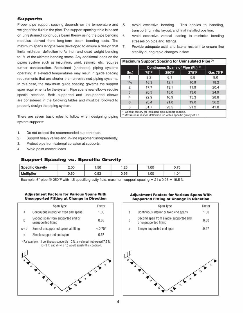
SupportsProper pipe support spacing depends on the temperature and
weight of the fluid in the pipe. The support spacing table is based
on unrestrained continuous beam theory using the pipe bending
modulus derived from long-term beam bending tests. The
maximum spans lengths were developed to ensure a design that
limits mid-span deflection to 1/2 inch and dead weight bending
to 1/8 of the ultimate bending stress. Any additional loads on the
piping system such as insulation, wind, seismic, etc. requires
further consideration. Restrained (anchored) piping systems
operating at elevated temperatures may result in guide spacing
requirements that are shorter than unrestrained piping systems.
In this case, the maximum guide spacing governs the support
span requirements for the system. Pipe spans near elbows require
special attention. Both supported and unsupported elbows
are considered in the following tables and must be followed to
properly design the piping system.
There are seven basic rules to follow when designing piping
system supports:
1. Do not exceed the recommended support span.
2. Support heavy valves and in-line equipment independently.
3. Protect pipe from external abrasion at supports.
4. Avoid point contact loads.
5. Avoid excessive bending. This applies to handling,
transporting, initial layout, and final installed position.6. Avoid excessive vertical loading to minimize bending
stresses on pipe and fittings.
7. Provide adequate axial and lateral restraint to ensure line
stability during rapid changes in flow.
Maximum Support Spacing for Uninsulated Pipe (1)
(In.) Continuous Spans of Pipe (Ft.) (2)
75°F 250°F 275°F Gas 75°F1 8.2 6.1 5.5 9.0
1½ 16.3 12.1 10.9 18.22 17.7 13.1 11.9 20.43 20.3 15.0 13.6 24.94 22.9 16.9 15.3 28.86 28.4 21.0 19.0 36.28 31.7 23.5 21.2 41.8
(1) Consult factory for insulated pipe support spacing.(2) Maximum mid-span deflection ½” with a specific gravity of 1.0
Support Spacing vs. Specific Gravity
Specific Gravity 2.00 1.50 1.25 1.00 0.75
Multiplier 0.80 0.93 0.96 1.00 1.04
Example: 6” pipe @ 250°F with 1.5 specific gravity fluid, maximum support spacing = 21 x 0.93 = 19.5 ft.
Adjustment Factors for Various Spans WithUnsupported Fitting at Change in Direction
Span Type Factor
a Continuous interior or fixed end spans 1.00
bSecond span from supported end orunsupported fitting
0.80
c+d Sum of unsupported spans at fitting <0.75*
e Simple supported end span 0.67
*For example: If continuous support is 10 ft., c+d must not exceed 7.5 ft. (c=3 ft. and d=4.5 ft.) would satisfy this condition.
Adjustment Factors for Various Spans WithSupported Fitting at Change in Direction
Span Type Factor
a Continuous interior or fixed end spans 1.00
bSecond span from simple supported end or unsupported fitting
0.80
e Simple supported end span 0.67
4
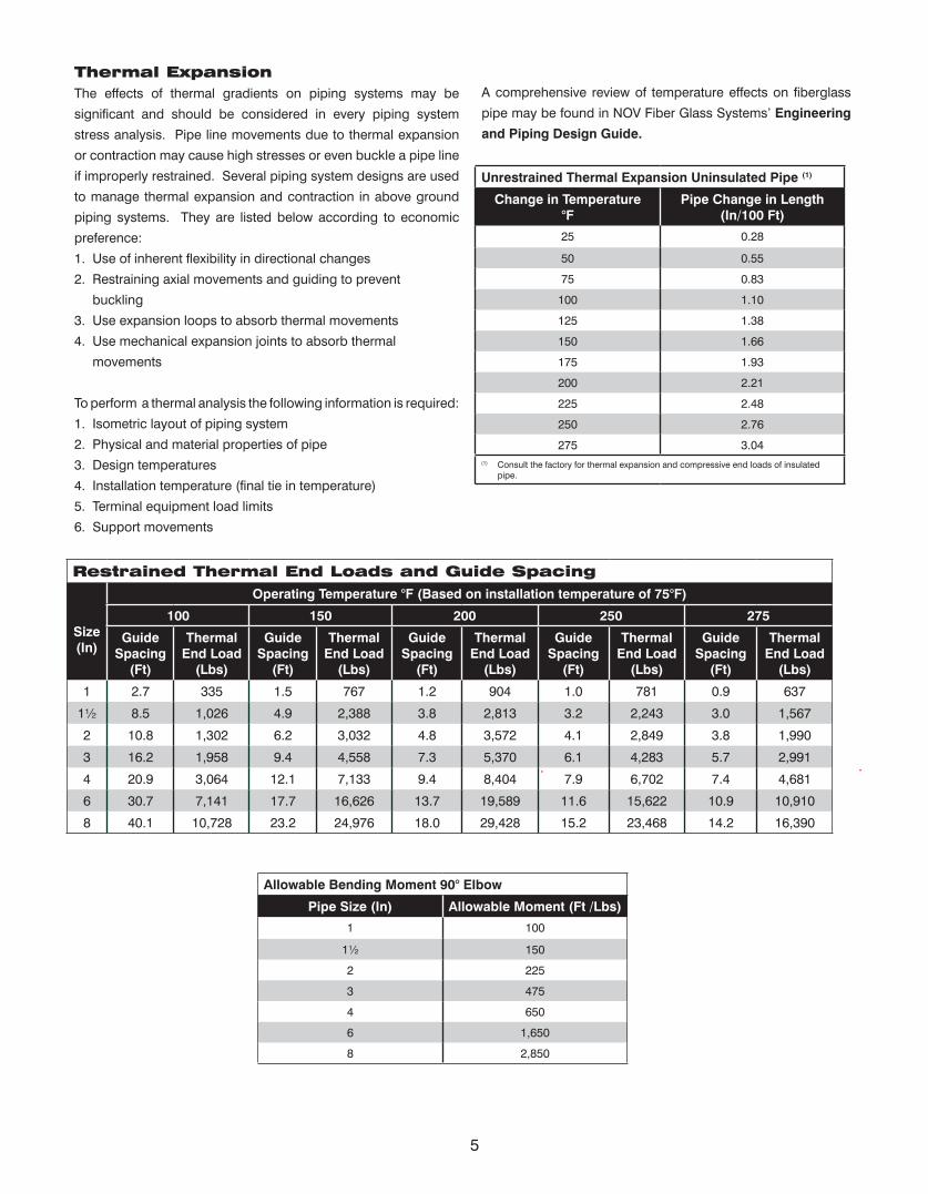
Thermal ExpansionThe effects of thermal gradients on piping systems may be
significant and should be considered in every piping system
stress analysis. Pipe line movements due to thermal expansion
or contraction may cause high stresses or even buckle a pipe line
if improperly restrained. Several piping system designs are used
to manage thermal expansion and contraction in above ground
piping systems. They are listed below according to economic
preference:
1. Use of inherent flexibility in directional changes
2. Restraining axial movements and guiding to prevent
buckling
3. Use expansion loops to absorb thermal movements
4. Use mechanical expansion joints to absorb thermal
movements
To perform a thermal analysis the following information is required:
1. Isometric layout of piping system
2. Physical and material properties of pipe
3. Design temperatures
4. Installation temperature (final tie in temperature)
5. Terminal equipment load limits
6. Support movements
A comprehensive review of temperature effects on fiberglass
pipe may be found in NOV Fiber Glass Systems’ Engineering
and Piping Design Guide.
Unrestrained Thermal Expansion Uninsulated Pipe (1)
Change in Temperature °F
Pipe Change in Length(In/100 Ft)
25 0.28
50 0.55
75 0.83
100 1.10
125 1.38
150 1.66
175 1.93
200 2.21
225 2.48
250 2.76
275 3.04(1) Consult the factory for thermal expansion and compressive end loads of insulated
pipe.
Restrained Thermal End Loads and Guide Spacing
Size(In)
Operating Temperature °F (Based on installation temperature of 75°F)
100 150 200 250 275
Guide Spacing
(Ft)
Thermal End Load
(Lbs)
Guide Spacing
(Ft)
Thermal End Load
(Lbs)
Guide Spacing
(Ft)
Thermal End Load
(Lbs)
Guide Spacing
(Ft)
Thermal End Load
(Lbs)
Guide Spacing
(Ft)
Thermal End Load
(Lbs)
1 2.7 335 1.5 767 1.2 904 1.0 781 0.9 637
1½ 8.5 1,026 4.9 2,388 3.8 2,813 3.2 2,243 3.0 1,567
2 10.8 1,302 6.2 3,032 4.8 3,572 4.1 2,849 3.8 1,990
3 16.2 1,958 9.4 4,558 7.3 5,370 6.1 4,283 5.7 2,991
4 20.9 3,064 12.1 7,133 9.4 8,404 7.9 6,702 7.4 4,681
6 30.7 7,141 17.7 16,626 13.7 19,589 11.6 15,622 10.9 10,910
8 40.1 10,728 23.2 24,976 18.0 29,428 15.2 23,468 14.2 16,390
Allowable Bending Moment 90° Elbow
Pipe Size (In) Allowable Moment (Ft /Lbs)
1 100
1½ 150
2 225
3 475
4 650
6 1,650
8 2,850
5

www.fgspipe.com • [email protected]
© 2012 National Oilwell Varco. All rights reserved.CI1800 March 2010
National Oilwell Varco has produced this brochure for general information only, and it is not intended for design purposes. Although every effort has been made to maintain the accuracy and reliability of its contents, National Oilwell Varco in no way assumes responsibility for liability for any loss, damage or injury resulting from the use of information and data herein nor is any warranty expressed or implied. Always cross-reference the bulletin date with the most current version listed at the web site noted in this literature.
North America South America Europe Asia Pacific Middle East17115 San Pedro Ave. Suite 200 Avenida Fernando Simoes P.O. Box 6, 4190 CA No. 7A, Tuas Avenue 3 P.O. Box 17324San Antonio, Texas 78232 USA Recife, Brazil 51020-390 Geldermalsen, The Netherlands Jurong, Singapore 639407 Dubai, UAEPhone: 210 477 7500 Phone: 55 31 3501 0023 Phone: 31 345 587 587 Phone: 65 6861 6118 Phone: 971 4881 3566
Z-Core™ Piping System
SECTION 1 – ScopeThis section covers the use of fiberglass reinforced plastic (FRP) pipe for severe chemical process and chemical handling applications up to 275ºF and 150 psig steady pressure.
The piping system shall be furnished and installed complete with all fittings, joining materials, supports, specials, and other necessary appurtenances.
SECTION 2 – General Conditions2.01 Coordination - Material furnished and work performed under this section shall be coordinated with related work and equipment specified under other sections.
Valves Section _______ Supports Section _______ Equipment Section _______
2.02 Governing Standards - Except as modified or supplemented herein, all materials and construction methods shall comply with the applicable provisions of the following specifications and be tested using the following standards:
Standard Specifications
Standard Test Methods
2.03 ASTM D2310 Designation Code 1”-8” RTRP-21CO
Mechanical properties cell classification shown are minimum.
2.04 Operating Conditions - In addition to the above listed minimum design requirements, the system shall meet the following minimum operating conditions:
a. Operating Pressure ________ b. Operating Temperature ________ c. Fluids Conveyed ________ d. Test Pressure ________
2.05 Quality Assurance - Pipe manufacturer’s quality program shall be in compliance with ISO 9001.
2.06 Delivery, Storage, and Handling - Pipe and fittings shall be protected from damage due to impact and point loading. Pipe shall be properly supported to avoid damage due to flexural strains. The contractor shall not allow dirt, debris, or other extraneous materials to get into pipe and fittings. All factory-machined areas shall be protected from sunlight until installed.
2.07 Acceptable Manufacturers - NOV Fiber Glass Systems (918) 245-6651, or approved equal.
SECTION 3 – Materials and Construction3.01 1”-8” Pipe - The pipe shall be manufactured by the centrifugal casting process utilizing amine cured, premium grade epoxy thermosetting resin to impregnate woven continuous glass filaments. Pipe shall be shall be heat cured and the degree of cure shall be confirmed by determining the glass transition temperature.
All pipe shall have an integral corrosion barrier of pure resin with a nominal cured thickness of 100 mils.
All pipe shall have a resin rich, reinforced 10 mil nominal exterior layer with a UV (ultraviolet) inhibitor.
The pipe shall have a minimum design pressure of 150 psig @ 275ºF following ASTM D2992 Procedure B.
Minimum Reinforced Wall Thickness: 1” 0.09” 1½”-3” 0.14” 4” 0.17” 6” 0.27” 8” 0.31”
3.02 Flanges and Fittings - All fittings shall be manufactured using the same type materials as the pipe. Fittings may be manufactured either by compression molding or contact molding methods.
Fittings shall be adhesive bonded socket joint or flanged.
Flanges shall have ANSI B16.5, Class 150 bolt hole patterns.
Specification Guide
ASTMD2992
Standard Practice for Obtaining Hydrostatic or Pressure Design Basis for “Fiberglass” (Glass-Fi-ber-Reinforced Thermosetting Resin) Pipe and Fit-tings
ASTMD1599
Standard Test method for Short-Time Hydraulic Failure Pressure of Plastic Pipe, Tubing and Fit-tings
ASTMD2105
Standard Test Method for Longitudinal Tensile Properties of “Fiberglass” (Glass-Fiber-Reinforced Thermosetting Resin) Pipe and Tube
ASTMD2412
Standard Test Method for Determination of Exter-nal Loading Characteristics of Plastic Pipe by Par-allel-Plate Loading
ASME B31.3
Process Piping
www.fgspipe.com • [email protected]
ASTMD2997
Standard Specification for Centrifugal Cast Pipe
ASTMD5685
Standard Specification for “Fiberglass” (Glass-Fiber-Reinforced-Thermosetting Resin) Pressure Pipe Fittings
ASTMD4024
Standard Specification for Reinforced Thermoset-ting Resin (RTR) Flanges
3.03 Adhesive - Adhesive shall be manufacturer’s standard for the piping system specified. All adhesive bonded joints shall be cured according to the manufacturer’s instructions for maximum structural strength and corrosion resistance.
3.04 Gaskets - Gaskets shall be 3/16” thick, 60-70 durometer full-face type suitable for the service shown on the drawings and as recommended in the manufacturer’s standard installation procedures.
3.05 Bolts, Nuts, and Washers - ASTM F593, 304, stainless steel hex head bolts shall be supplied. Two each SAE size washers shall be supplied on all nut and bolts.
3.06 Acceptable Products - Z-CORE as manufactured by NOV Fiber Glass Systems or approved equal.
SECTION 4 – Installation and Testing4.01 Training and Certification - All joints installed or constructed in the field shall be assembled by employees of the contractor who have been trained by the pipe manufacturer. The pipe manufacturer or their authorized representative shall train the contractor’s employees in the proper joining and assembly procedures required for the project, including hands-on training by the contractor’s employees. Each bonder shall fabricate one pipe-to-pipe or one pipe-to-fitting joint that shall pass the minimum pressure test for the application as stated in Section 2.04.d without leaking.
Only bonders who have successfully completed the pressure test and are certified shall bond pipe and fittings.
Certification by the manufacturer shall be in compliance with ANSI B31.3 Section A328.2.
4.02 Pipe Installation - Pipe shall be installed as specified and indicated on the drawings.
The piping system shall be installed in accordance with the manufacturer’s current published installation procedures.
4.03 Testing - A hydrostatic pressure test shall be conducted on the completed piping system. The pipe shall be subjected to a steady pressure at 1½ times the design operating pressure as stated in Section 2.04.d. The pressure shall be held on the system for a minimum of one hour and the line inspected for leaks.
Test pressure shall not exceed 1½ times the maximum rated pressure of the lowest rated element in the system.
The system shall be filled with water at the lowest point and air bled off from all the highest points. Systems shall be brought up to test pressure slowly to prevent water hammer or over-pressurization.
All pipe joints shall be watertight. All joints that are found to leak by observation or during testing shall be repaired by the contractor and retested.
www.fgspipe.com • [email protected]
© 2012 National Oilwell Varco. All rights reserved. CI1801 February 2009
National Oilwell Varco has produced this brochure for general information only, and it is not intended for design purposes. Although every effort has been made to maintain the accuracy and reliability of its contents, National Oilwell Varco in no way assumes responsibility for liability for any loss, damage or injury resulting from the use of information and data herein nor is any warranty expressed or implied. Always cross-reference the bulletin date with the most current version listed at the web site noted in this literature.
North America South America Europe Asia Pacific Middle East17115 San Pedro Ave. Suite 200 Avenida Fernando Simoes P.O. Box 6, 4190 CA No. 7A, Tuas Avenue 3 P.O. Box 17324San Antonio, Texas 78232 USA Recife, Brazil 51020-390 Geldermalsen, The Netherlands Jurong, Singapore 639407 Dubai, UAEPhone: 210 477 7500 Phone: 55 31 3501 0023 Phone: 31 345 587 587 Phone: 65 6861 6118 Phone: 971 4881 3566
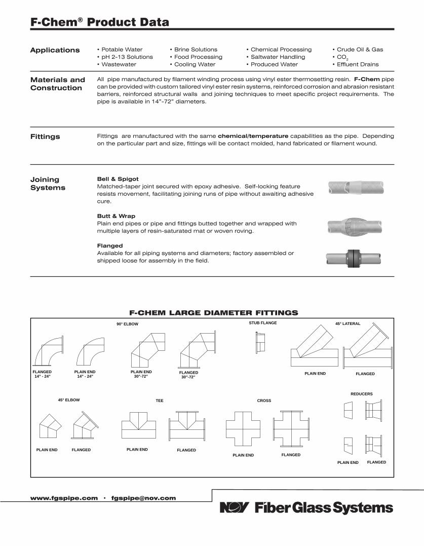
F-CHEM LARGE DIAMETER FITTINGS
FLANGED14" - 24"
PLAIN END14" - 24"
PLAIN END30"-72"
FLANGED30"-72"
PLAIN END FLANGED
PLAIN END FLANGED PLAIN END FLANGEDPLAIN END FLANGED
PLAIN END FLANGED
90° ELBOW STUB FLANGE 45° LATERAL
45° ELBOW TEE CROSSREDUCERS
F-Chem® Product Data
Applications • Potable Water• pH 2-13 Solutions• Wastewater
• Brine Solutions• Food Processing• Cooling Water
• Chemical Processing• Saltwater Handling• Produced Water
• Crude Oil & Gas• CO2
• Effluent Drains
Materials andConstruction
All pipe manufactured by filament winding process using vinyl ester thermosetting resin. F-Chem pipe can be provided with custom tailored vinyl ester resin systems, reinforced corrosion and abrasion resistant barriers, reinforced structural walls and joining techniques to meet specific project requirements. The pipe is available in 14”-72” diameters.
Fittings Fittings are manufactured with the same chemical/temperature capabilities as the pipe. Depending on the particular part and size, fittings will be contact molded, hand fabricated or filament wound.
Joining Systems
Bell & SpigotMatched-taper joint secured with epoxy adhesive. Self-locking featureresists movement, facilitating joining runs of pipe without awaiting adhesivecure.
Butt & Wrap Plain end pipes or pipe and fittings butted together and wrapped withmultiple layers of resin-saturated mat or woven roving.
FlangedAvailable for all piping systems and diameters; factory assembled orshipped loose for assembly in the field.
www.fgspipe.com • [email protected]
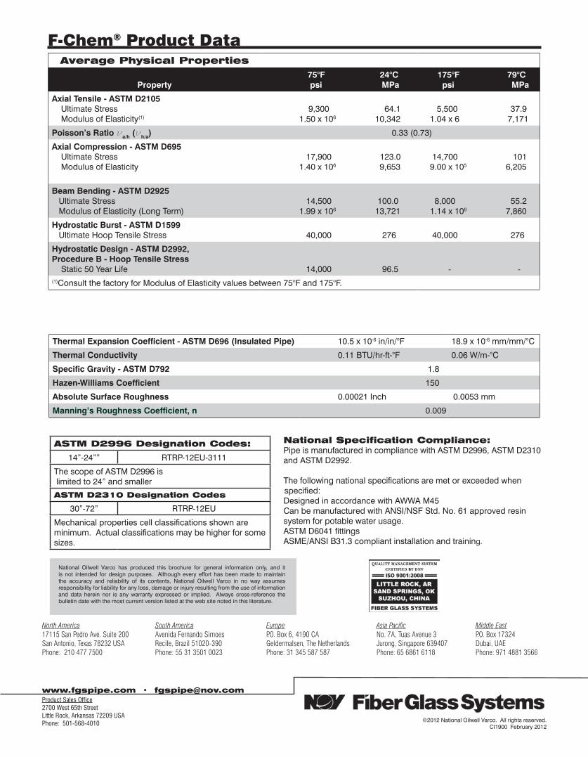
ASTM D2996 Designation Codes:
14”-24”” RTRP-12EU-3111
The scope of ASTM D2996 is limited to 24” and smaller
ASTM D2310 Designation Codes
30”-72” RTRP-12EU
Mechanical properties cell classifications shown are minimum. Actual classifications may be higher for some sizes.
Average Physical Properties
Property 75°F 24°C psi MPa
175°F 79°C psi MPa
Axial Tensile - ASTM D2105 Ultimate Stress Modulus of Elasticity(1)
9,300 64.1 1.50 x 10⁶ 10,342
5,500 37.9 1.04 x 6 7,171
Poisson’s Ratio νa/h (νh/a) 0.33 (0.73)
Axial Compression - ASTM D695 Ultimate Stress Modulus of Elasticity
17,900 123.0 1.40 x 10⁶ 9,653
14,700 101 9.00 x 10⁵ 6,205
Beam Bending - ASTM D2925 Ultimate Stress Modulus of Elasticity (Long Term)
14,500 100.0 1.99 x 10⁶ 13,721
8,000 55.2 1.14 x 10⁶ 7,860
Hydrostatic Burst - ASTM D1599 Ultimate Hoop Tensile Stress 40,000 276 40,000 276
Hydrostatic Design - ASTM D2992,Procedure B - Hoop Tensile Stress Static 50 Year Life
14,000 96.5 - -(1)Consult the factory for Modulus of Elasticity values between 75°F and 175°F.
Thermal Expansion Coefficient - ASTM D696 (Insulated Pipe) 10.5 x 10⁻⁶ in/in/°F 18.9 x 10⁻⁶ mm/mm/°C
Thermal Conductivity 0.11 BTU/hr-ft-°F 0.06 W/m-°C
Specific Gravity - ASTM D792 1.8
Hazen-Williams Coefficient 150
Absolute Surface Roughness 0.00021 Inch 0.0053 mm
Manning’s Roughness Coefficient, n 0.009
National Specification Compliance:Pipe is manufactured in compliance with ASTM D2996, ASTM D2310and ASTM D2992.
The following national specifications are met or exceeded when specified:
Designed in accordance with AWWA M45Can be manufactured with ANSI/NSF Std. No. 61 approved resinsystem for potable water usage.ASTM D6041 fittingsASME/ANSI B31.3 compliant installation and training.
www.fgspipe.com • [email protected]
©2012 National Oilwell Varco. All rights reserved.CI1900 February 2012
National Oilwell Varco has produced this brochure for general information only, and it is not intended for design purposes. Although every effort has been made to maintain the accuracy and reliability of its contents, National Oilwell Varco in no way assumes responsibility for liability for any loss, damage or injury resulting from the use of information and data herein nor is any warranty expressed or implied. Always cross-reference the bulletin date with the most current version listed at the web site noted in this literature.
F-Chem® Product Data
North America South America Europe Asia Pacific Middle East17115 San Pedro Ave. Suite 200 Avenida Fernando Simoes P.O. Box 6, 4190 CA No. 7A, Tuas Avenue 3 P.O. Box 17324San Antonio, Texas 78232 USA Recife, Brazil 51020-390 Geldermalsen, The Netherlands Jurong, Singapore 639407 Dubai, UAEPhone: 210 477 7500 Phone: 55 31 3501 0023 Phone: 31 345 587 587 Phone: 65 6861 6118 Phone: 971 4881 3566
Product Sales Office2700 West 65th StreetLittle Rock, Arkansas 72209 USAPhone: 501-568-4010
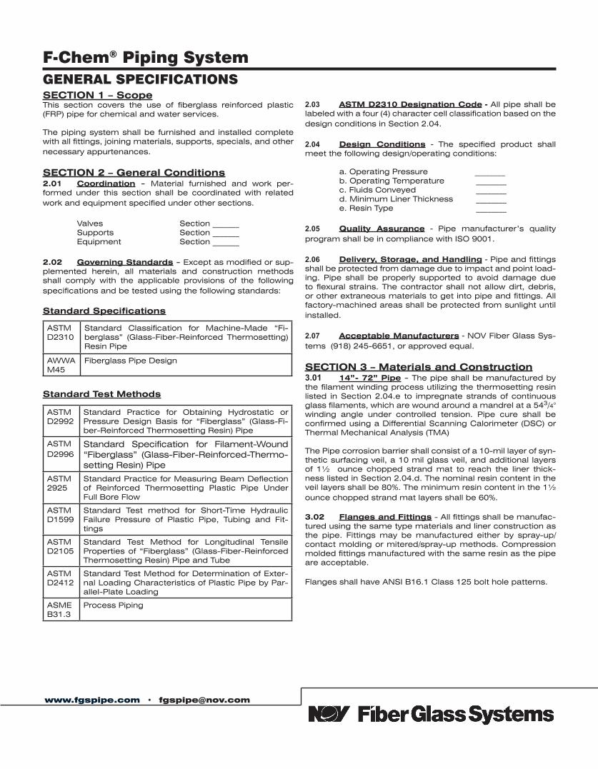
www.fgspipe.com • [email protected]
GENERAL SPECIFICATIONS
F-Chem® Piping System
SECTION 1 – ScopeThis section covers the use of fiberglass reinforced plastic (FRP) pipe for chemical and water services.
The piping system shall be furnished and installed complete with all fittings, joining materials, supports, specials, and other necessary appurtenances.
SECTION 2 – General Conditions2.01 Coordination - Material furnished and work per-formed under this section shall be coordinated with related work and equipment specified under other sections.
Valves Section _______ Supports Section _______ Equipment Section _______
2.02 Governing Standards - Except as modified or sup-plemented herein, all materials and construction methods shall comply with the applicable provisions of the following specifications and be tested using the following standards:
Standard Specifications
Standard Test Methods
2.03 ASTM D2310 Designation Code - All pipe shall be labeled with a four (4) character cell classification based on the design conditions in Section 2.04.
2.04 Design Conditions - The specified product shall meet the following design/operating conditions:
a. Operating Pressure ________ b. Operating Temperature ________ c. Fluids Conveyed ________ d. Minimum Liner Thickness ________ e. Resin Type ________
2.05 Quality Assurance - Pipe manufacturer’s quality program shall be in compliance with ISO 9001.
2.06 Delivery, Storage, and Handling - Pipe and fittings shall be protected from damage due to impact and point load-ing. Pipe shall be properly supported to avoid damage due to flexural strains. The contractor shall not allow dirt, debris, or other extraneous materials to get into pipe and fittings. All factory-machined areas shall be protected from sunlight until installed.
2.07 Acceptable Manufacturers - NOV Fiber Glass Sys-tems (918) 245-6651, or approved equal.
SECTION 3 – Materials and Construction3.01 14”- 72” Pipe - The pipe shall be manufactured by the filament winding process utilizing the thermosetting resin listed in Section 2.04.e to impregnate strands of continuous glass filaments, which are wound around a mandrel at a 543/4° winding angle under controlled tension. Pipe cure shall be confirmed using a Differential Scanning Calorimeter (DSC) or Thermal Mechanical Analysis (TMA)
The Pipe corrosion barrier shall consist of a 10-mil layer of syn-thetic surfacing veil, a 10 mil glass veil, and additional layers of 1½ ounce chopped strand mat to reach the liner thick-ness listed in Section 2.04.d. The nominal resin content in the veil layers shall be 80%. The minimum resin content in the 1½ ounce chopped strand mat layers shall be 60%.
3.02 Flanges and Fittings - All fittings shall be manufac-tured using the same type materials and liner construction as the pipe. Fittings may be manufactured either by spray-up/contact molding or mitered/spray-up methods. Compression molded fittings manufactured with the same resin as the pipe are acceptable.
Flanges shall have ANSI B16.1 Class 125 bolt hole patterns.
ASTMD2310
Standard Classification for Machine-Made “Fi-berglass” (Glass-Fiber-Reinforced Thermosetting) Resin Pipe
AWWA M45
Fiberglass Pipe Design
ASTMD2992
Standard Practice for Obtaining Hydrostatic or Pressure Design Basis for “Fiberglass” (Glass-Fi-ber-Reinforced Thermosetting Resin) Pipe
ASTM D2996
Standard Specification for Filament-Wound “Fiberglass” (Glass-Fiber-Reinforced-Thermo-setting Resin) Pipe
ASTM2925
Standard Practice for Measuring Beam Deflection of Reinforced Thermosetting Plastic Pipe Under Full Bore Flow
ASTMD1599
Standard Test method for Short-Time Hydraulic Failure Pressure of Plastic Pipe, Tubing and Fit-tings
ASTMD2105
Standard Test Method for Longitudinal Tensile Properties of “Fiberglass” (Glass-Fiber-Reinforced Thermosetting Resin) Pipe and Tube
ASTMD2412
Standard Test Method for Determination of Exter-nal Loading Characteristics of Plastic Pipe by Par-allel-Plate Loading
ASME B31.3
Process Piping
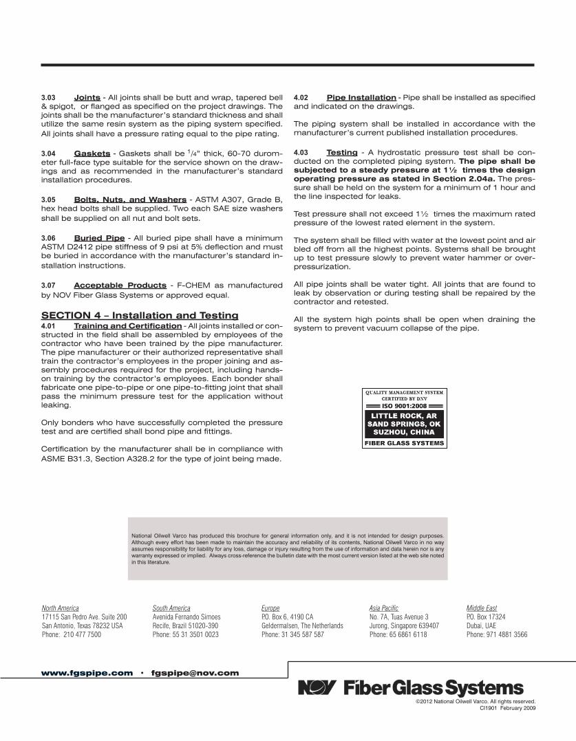
www.fgspipe.com • [email protected]
©2012 National Oilwell Varco. All rights reserved. CI1901 February 2009
National Oilwell Varco has produced this brochure for general information only, and it is not intended for design purposes. Although every effort has been made to maintain the accuracy and reliability of its contents, National Oilwell Varco in no way assumes responsibility for liability for any loss, damage or injury resulting from the use of information and data herein nor is any warranty expressed or implied. Always cross-reference the bulletin date with the most current version listed at the web site noted in this literature.
3.03 Joints - All joints shall be butt and wrap, tapered bell & spigot, or flanged as specified on the project drawings. The joints shall be the manufacturer’s standard thickness and shall utilize the same resin system as the piping system specified. All joints shall have a pressure rating equal to the pipe rating.
3.04 Gaskets - Gaskets shall be 1/4” thick, 60-70 durom-eter full-face type suitable for the service shown on the draw-ings and as recommended in the manufacturer’s standard installation procedures.
3.05 Bolts, Nuts, and Washers - ASTM A307, Grade B, hex head bolts shall be supplied. Two each SAE size washers shall be supplied on all nut and bolt sets.
3.06 Buried Pipe - All buried pipe shall have a minimum ASTM D2412 pipe stiffness of 9 psi at 5% deflection and must be buried in accordance with the manufacturer’s standard in-stallation instructions.
3.07 Acceptable Products - F-CHEM as manufactured by NOV Fiber Glass Systems or approved equal.
SECTION 4 – Installation and Testing4.01 Training and Certification - All joints installed or con-structed in the field shall be assembled by employees of the contractor who have been trained by the pipe manufacturer. The pipe manufacturer or their authorized representative shall train the contractor’s employees in the proper joining and as-sembly procedures required for the project, including hands-on training by the contractor’s employees. Each bonder shall fabricate one pipe-to-pipe or one pipe-to-fitting joint that shall pass the minimum pressure test for the application without leaking.
Only bonders who have successfully completed the pressure test and are certified shall bond pipe and fittings.
Certification by the manufacturer shall be in compliance with ASME B31.3, Section A328.2 for the type of joint being made.
4.02 Pipe Installation - Pipe shall be installed as specified and indicated on the drawings.
The piping system shall be installed in accordance with the manufacturer’s current published installation procedures.
4.03 Testing - A hydrostatic pressure test shall be con-ducted on the completed piping system. The pipe shall be subjected to a steady pressure at 1½ times the design operating pressure as stated in Section 2.04a. The pres-sure shall be held on the system for a minimum of 1 hour and the line inspected for leaks.
Test pressure shall not exceed 1½ times the maximum rated pressure of the lowest rated element in the system.
The system shall be filled with water at the lowest point and air bled off from all the highest points. Systems shall be brought up to test pressure slowly to prevent water hammer or over-pressurization.
All pipe joints shall be water tight. All joints that are found to leak by observation or during testing shall be repaired by the contractor and retested.
All the system high points shall be open when draining the system to prevent vacuum collapse of the pipe.
North America South America Europe Asia Pacific Middle East17115 San Pedro Ave. Suite 200 Avenida Fernando Simoes P.O. Box 6, 4190 CA No. 7A, Tuas Avenue 3 P.O. Box 17324San Antonio, Texas 78232 USA Recife, Brazil 51020-390 Geldermalsen, The Netherlands Jurong, Singapore 639407 Dubai, UAEPhone: 210 477 7500 Phone: 55 31 3501 0023 Phone: 31 345 587 587 Phone: 65 6861 6118 Phone: 971 4881 3566
Bondstrand™ 2000 Product Data
• Chemicalprocesspiping• Coolingwaterpiping• Deionizedwatersystems• Drainagesystems• Foodprocessingplantpiping• Jetengineairstartsystems• Jetfuel(1)andliquidpetroleumpiping• Pipingsystemsforalkalisandnon-oxidizingchemicals• Potablewaterlines• Wastewaterandsewagesystems• Generalindustrialserviceformoderatelycorrosiveliquids
(1)Thisisnotsuitableforprimarypipeconveyingjetfuelthatissecondarilycontained.
(ForGeneralIndustrialService,MaintenanceandRepair
Mil-P-29206Aforjetfuelandpetroleumliquids
U.S. Federal Regulations 21CFR175.105 and 21CFR177.2280 for conveying foodstuffs whenjoinedwithBondstrandRP6Bepoxyadhesive.
Pipedesignsto450psi(3.1MPa)usingan8000psi(41.2MPa)hydrostaticdesignstressinac-cordancewithASTMD2992(B).
Continuousoperatingtemperaturesto250°F(121°C).
Excellentcorrosionresistanceoverawidetemperaturerange.SeemostrecentreleaseofBond-strandCorrosionGuideforspecificapplications.
Weighs1/6thasmuchasSch.40steel.
Doesnotrequirethrustblocksatambienttemperatureswhenproperlyinstalledinmostsoils.
Smoothinnerliner(Hazen-WilliamsC=150)producesextremelylowfrictionallossforgreaterdischargeandreducedpumpingcosts.
Lowthermalconductivity(1/100thofsteel)minimizesheatlosses.
Individual system components may not have the same ratings as the pipe. Refer to the detailed product information for the specific components to determine the pressure rating for the system as a whole.
www.fgspipe.com • [email protected]
Uses and Applications
Listings
Performance
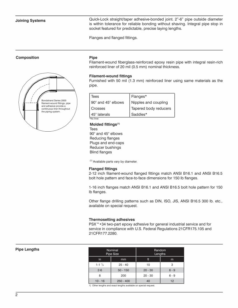
NominalPipeSize
RandomLengths
in mm ft m
1-11/2 25-40 10 3
2-6 50-150 20-30 6-9
8 200 20-30 6-9
10-16 250-400 40 12
BondstrandSeries2000filament-woundfittings,pipeandadhesiveprovideacontinuouslinerthroughoutthepipingsystem.
Quick-Lockstraight/taperadhesive-bondedjoint.2”-6”pipeoutsidediameteriswithin tolerance for reliablebondingwithoutshaving. Integralpipestop insocketfeaturedforpredictable,preciselayinglengths.
Flangesandflangedfittings.
PipeFilament-woundfiberglass-reinforcedepoxyresinpipewithintegralresin-richreinforcedlinerof20mil(0.5mm)nominalthickness.
Filament-wound fittingsFurnishedwith50mil (1.3mm)reinforced linerusingsamematerialsas thepipe.
Joining Systems
Composition
Tees Flanges*
90°and45°elbows Nipplesandcoupling
Crosses Taperedbodyreducers
45°laterals Saddles**Noliner.
Flanged fittings2-12inchfilament-woundflangedfittingsmatchANSIB16.1andANSIB16.5boltholepatternandface-to-facedimensionsfor150lbflanges.
1-16inchflangesmatchANSIB16.1andANSIB16.5boltholepatternfor150lbflanges.
OtherflangedrillingpatternssuchasDIN,ISO,JIS,ANSIB16.5300lb.etc.,availableonspecialrequest.
Thermosetting adhesivesPSX™•34two-partepoxyadhesiveforgeneralindustrialserviceandforserviceincompliancewithU.S.FederalRegulations21CFR175.105and21CFR177.2280.
Molded fittings(1)
Tees90°and45°elbowsReducingflangesPlugsandend-capsReducerbushingsBlindflanges
(1)Availablepartsvarybydiameter.
Pipe Lengths
1)Otherlengthsandexactlengthsavailableonspecialrequest.
2
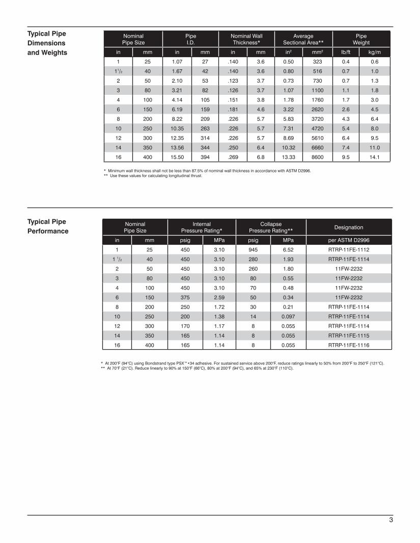
NominalPipeSize
PipeI.D.
NominalWallThickness*
AverageSectionalArea**
PipeWeight
in mm in mm in mm in2 mm2 lb/ft kg/m
1 25 1.07 27 .140 3.6 0.50 323 0.4 0.6
11/2 40 1.67 42 .140 3.6 0.80 516 0.7 1.0
2 50 2.10 53 .123 3.7 0.73 730 0.7 1.3
3 80 3.21 82 .126 3.7 1.07 1100 1.1 1.8
4 100 4.14 105 .151 3.8 1.78 1760 1.7 3.0
6 150 6.19 159 .181 4.6 3.22 2620 2.6 4.5
8 200 8.22 209 .226 5.7 5.83 3720 4.3 6.4
10 250 10.35 263 .226 5.7 7.31 4720 5.4 8.0
12 300 12.35 314 .226 5.7 8.69 5610 6.4 9.5
14 350 13.56 344 .250 6.4 10.32 6660 7.4 11.0
16 400 15.50 394 .269 6.8 13.33 8600 9.5 14.1
Typical PipeDimensions and Weights
*Minimumwallthicknessshallnotbelessthan87.5%ofnominalwallthicknessinaccordancewithASTMD2996.**Usethesevaluesforcalculatinglongitudinalthrust.
NominalPipeSize
InternalPressureRating*
CollapsePressureRating**
Designation
in mm psig MPa psig MPa perASTMD2996
1 25 450 3.10 945 6.52 RTRP-11FE-1112
11/2 40 450 3.10 280 1.93 RTRP-11FE-1114
2 50 450 3.10 260 1.80 11FW-2232
3 80 450 3.10 80 0.55 11FW-2232
4 100 450 3.10 70 0.48 11FW-2232
6 150 375 2.59 50 0.34 11FW-2232
8 200 250 1.72 30 0.21 RTRP-11FE-1114
10 250 200 1.38 14 0.097 RTRP-11FE-1114
12 300 170 1.17 8 0.055 RTRP-11FE-1114
14 350 165 1.14 8 0.055 RTRP-11FE-1115
16 400 165 1.14 8 0.055 RTRP-11FE-1116
*At200°F(94°C)usingBondstrandtypePSX™•34adhesive.Forsustainedserviceabove200°F,reduceratingslinearlyto50%from200°Fto250°F(121°C).**At70°F(21°C).Reducelinearlyto90%at150°F(66°C),80%at200°F(94°C),and65%at230°F(110°C).
Typical Pipe Performance
3
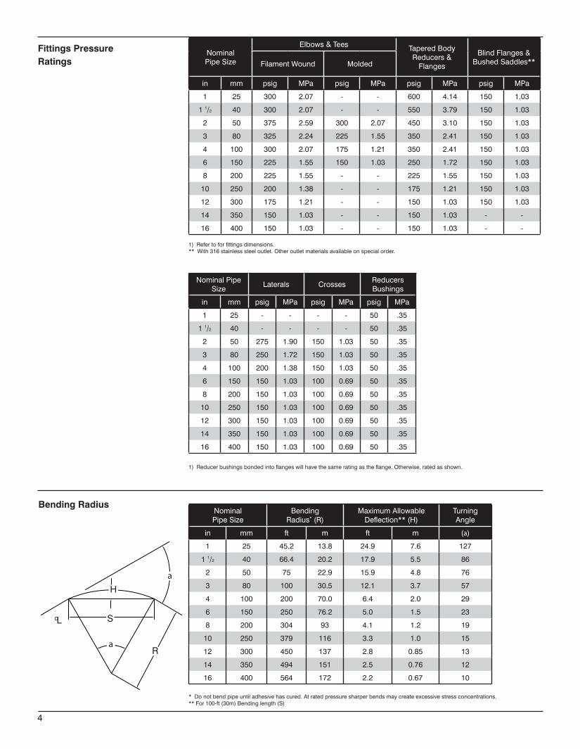
NominalPipeSize
Elbows&Tees TaperedBodyReducers&Flanges
BlindFlanges&BushedSaddles**FilamentWound Molded
in mm psig MPa psig MPa psig MPa psig MPa
1 25 300 2.07 - - 600 4.14 150 1.03
11/2 40 300 2.07 - - 550 3.79 150 1.03
2 50 375 2.59 300 2.07 450 3.10 150 1.03
3 80 325 2.24 225 1.55 350 2.41 150 1.03
4 100 300 2.07 175 1.21 350 2.41 150 1.03
6 150 225 1.55 150 1.03 250 1.72 150 1.03
8 200 225 1.55 - - 225 1.55 150 1.03
10 250 200 1.38 - - 175 1.21 150 1.03
12 300 175 1.21 - - 150 1.03 150 1.03
14 350 150 1.03 - - 150 1.03 - -
16 400 150 1.03 - - 150 1.03 - -
NominalPipeSize
Laterals CrossesReducersBushings
in mm psig MPa psig MPa psig MPa
1 25 - - - - 50 .35
11/2 40 - - - - 50 .35
2 50 275 1.90 150 1.03 50 .35
3 80 250 1.72 150 1.03 50 .35
4 100 200 1.38 150 1.03 50 .35
6 150 150 1.03 100 0.69 50 .35
8 200 150 1.03 100 0.69 50 .35
10 250 150 1.03 100 0.69 50 .35
12 300 150 1.03 100 0.69 50 .35
14 350 150 1.03 100 0.69 50 .35
16 400 150 1.03 100 0.69 50 .35
NominalPipeSize
BendingRadius*(R)
MaximumAllowableDeflection**(H)
TurningAngle
in mm ft m ft m (a)
1 25 45.2 13.8 24.9 7.6 127
11/2 40 66.4 20.2 17.9 5.5 86
2 50 75 22.9 15.9 4.8 76
3 80 100 30.5 12.1 3.7 57
4 100 200 70.0 6.4 2.0 29
6 150 250 76.2 5.0 1.5 23
8 200 304 93 4.1 1.2 19
10 250 379 116 3.3 1.0 15
12 300 450 137 2.8 0.85 13
14 350 494 151 2.5 0.76 12
16 400 564 172 2.2 0.67 10
Fittings PressureRatings
1)Refertoforfittingsdimensions.**With316stainlesssteeloutlet.Otheroutletmaterialsavailableonspecialorder.
1)Reducerbushingsbondedintoflangeswillhavethesameratingastheflange.Otherwise,ratedasshown.
*Donotbendpipeuntiladhesivehascured.Atratedpressuresharperbendsmaycreateexcessivestressconcentrations.**For100-ft(30m)Bendinglength(S)
Bending Radius
4
cL S
α
α
H
R
a
aH
S
R
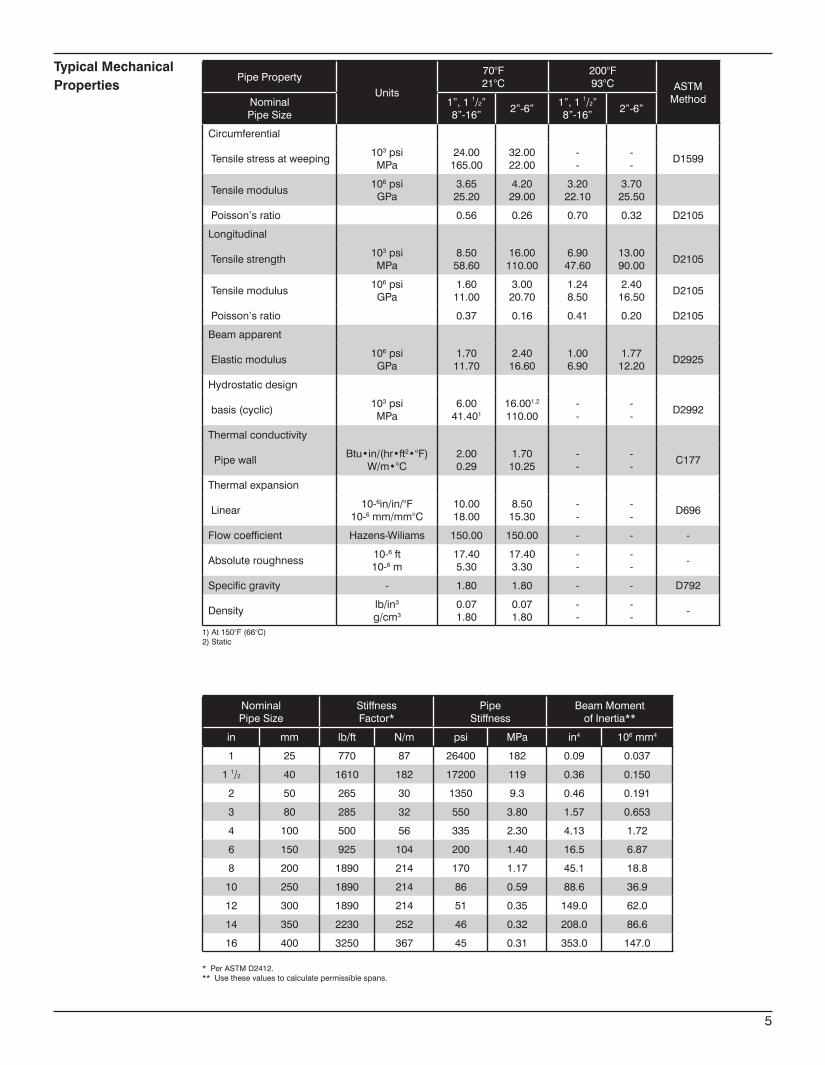
NominalPipeSize
StiffnessFactor*
PipeStiffness
BeamMomentofInertia**
in mm lb/ft N/m psi MPa in4 106mm4
1 25 770 87 26400 182 0.09 0.037
11/2 40 1610 182 17200 119 0.36 0.150
2 50 265 30 1350 9.3 0.46 0.191
3 80 285 32 550 3.80 1.57 0.653
4 100 500 56 335 2.30 4.13 1.72
6 150 925 104 200 1.40 16.5 6.87
8 200 1890 214 170 1.17 45.1 18.8
10 250 1890 214 86 0.59 88.6 36.9
12 300 1890 214 51 0.35 149.0 62.0
14 350 2230 252 46 0.32 208.0 86.6
16 400 3250 367 45 0.31 353.0 147.0
*PerASTMD2412.**Usethesevaluestocalculatepermissiblespans.
Typical MechanicalProperties
PipePropertyUnits
70°F21°C
200°F93°C ASTM
MethodNominalPipeSize
1”,11/2”8”-16”
2”-6”1”,11/2”8”-16”
2”-6”
Circumferential
Tensilestressatweeping103psiMPa
24.00165.00
32.0022.00
--
--
D1599
Tensilemodulus106psi
GPa3.6525.20
4.2029.00
3.2022.10
3.7025.50
Poisson’sratio 0.56 0.26 0.70 0.32 D2105
Longitudinal
Tensilestrength103psiMPa
8.5058.60
16.00110.00
6.9047.60
13.0090.00
D2105
Tensilemodulus106psiGPa
1.6011.00
3.0020.70
1.248.50
2.4016.50
D2105
Poisson’sratio 0.37 0.16 0.41 0.20 D2105
Beamapparent
Elasticmodulus106psi
GPa1.7011.70
2.4016.60
1.006.90
1.7712.20
D2925
Hydrostaticdesign
basis(cyclic)103psiMPa
6.0041.401
16.001,2
110.00--
--
D2992
Thermalconductivity
PipewallBtu•in/(hr•ft2•°F)
W/m•°C2.000.29
1.7010.25
--
--
C177
Thermalexpansion
Linear10-6in/in/°F
10-6mm/mm°C10.0018.00
8.5015.30
--
--
D696
Flowcoefficient Hazens-Wiliams 150.00 150.00 - - -
Absoluteroughness10-6ft10-6m
17.405.30
17.403.30
--
--
-
Specificgravity - 1.80 1.80 - - D792
Densitylb/in3
g/cm30.071.80
0.071.80
--
--
-
1)At150°F(66°C)2)Static
5
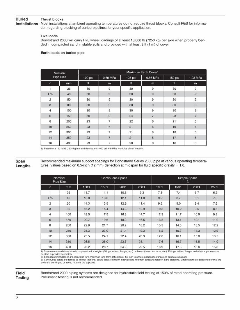
NominalPipeSize
MaximumEarthCover1
100psi 0.69MPa 125psi 0.86MPa 150psi 1.03MPa
in mm ft m ft m ft m
1 25 30 9 30 9 30 9
11/2 40 30 9 30 9 30 9
2 50 30 9 30 9 30 9
3 80 30 9 30 9 30 9
4 100 30 9 30 9 30 9
6 150 30 9 24 7 23 7
8 200 23 7 22 6 21 6
10 250 23 7 21 6 19 5
12 300 23 7 21 6 18 5
14 350 23 7 21 6 17 5
16 400 23 7 20 6 16 5
NominalPipeSize
ContinuousSpansft
SimpleSpansft
in mm 100°F 150°F 200°F 250°F 100°F 150°F 200°F 250°F
1 25 11.7 11.1 10.3 9.3 7.3 7.4 6.7 6.2
11/2 40 13.8 13.0 12.1 11.0 9.2 8.7 8.1 7.3
2 50 14.3 13.5 12.6 11.4 9.5 9.0 8.4 7.6
3 80 16.2 15.4 14.3 12.9 10.8 10.2 9.5 8.6
4 100 18.5 17.5 16.3 14.7 12.3 11.7 10.9 9.8
6 150 20.7 19.6 18.2 16.5 13.8 13.1 12.1 11.0
8 200 22.9 21.7 20.2 18.2 15.3 14.5 13.5 12.2
10 250 24.3 23.0 21.4 19.3 16.2 15.3 14.3 12.9
12 300 25.5 24.1 22.4 20.3 17.0 16.1 15.0 13.5
14 350 26.5 25.0 23.3 21.1 17.6 16.7 15.5 14.0
16 400 28.2 26.7 24.9 22.5 18.9 17.8 16.6 15.0
RecommendedmaximumsupportspacingsforBondstrandSeries2000pipeatvariousoperatingtempera-tures.Valuesbasedon0.5-inch(12mm)deflectionatmidspanforfluidspecificgravity=1.0.
1)Spanrecommendationsincludenoprovisionforweights(fittings,valves,flanges,etc.)orthrusts(branches,turns,etc.).Fittings,valves,flangesandotherappurtenancesmustbesupportedseparately.2)Spanrecommendationsarecalculatedforamaximumlong-termdeflectionof1/2inchtoensuregoodappearanceandadequatedrainage.3)Continuousspansaredefinedasinterior(notend)spansthatareuniforminlengthandfreefromstructuralrotationatthesupports.Simplespansaresupportedonlyattheendsandarehingedorfreetorotateatthesupports.
Thrust blocksMostinstallationsatambientoperatingtemperaturesdonotrequirethrustblocks.ConsultFGSforinforma-tionregardingblockingofburiedpipelinesforyourspecificapplication.
Live loadsBondstrand2000willcarryH20wheelloadingsofatleast16,000lb(7250kg)peraxlewhenproperlybed-dedincompactedsandinstablesoilsandprovidedwithatleast3ft(1m)ofcover.
Earth loads on buried pipe
1)Basedona120lb/ft3(1925kg/m3)soildensityand1000psi(6.9MPa)modulusofsoilreaction.
SpanLengths
BuriedInstallations
FieldTesting
Bondstrand2000pipingsystemsaredesignedforhydrostaticfieldtestingat150%ofratedoperatingpressure.Pneumatictestingisnotrecommended.
6
Thestructuralwalloffiberglasspipeshallhavecontinuousglassfibersinamatrixofaromaticaminecuredepoxyresin.
Theintegral,reinforcedresin-richlinershallconsistofC-glassandaresin/hardenersystemidenticaltothatofthestructuralwall,andshallhavea20milnominalthickness.
Pipein1through16-inchsizesshallberatedforaminimumof165psigat250°F.In1through6-inchsizesthepipeshallhavefullvacuumcapabilityat70°F,wheninstalledabovegroundwithasafetyfactorof3:1.
PipeshallbemanufacturedaccordingtoASTMD2996specificationforfilament-woundRein-forcedThermosettingResinPipe(RTRP).WhenclassifiedunderASTMD2310,thepipeshallmeetType1,Grade1andClassF(RTRP-11FEorW)celllimitsin1through16-inchnominalpipesizes.
Filament-woundepoxyfiberglasspipeshallbetranslucenttoallowforinspectionofdamage.
Pipein2through8-inchsizesshallbefurnishedin30or40-ft.lengthtominimizethenumberoffield-bondedjointsforrapidinstallation.
Fittingsin1through16-inchsizesshallbefilamentwoundwithareinforcedresin-richlinerof50milminimumthicknessandofthesameglassandresintypeasthepipe.Pipe,filament-woundfittingsandadhesiveshall,asanassembly,provideacontinuouslinerthroughoutthesystem.
Compression-moldedfittingsin2,3,4and6-inchnominalsizesmayalsobealloweduponagreementbetweenpurchaserandmanufacturer.
Contact-molded,spray-uporhand-layupfittingsshallnotbeallowed.Pipeandfittingsshallbejoinedusingastraightspigotbysocketwitha0.5°taperangleandapipestopinsidethesockettoallowprecisemakeup.
Thepipeandfittingsshallbefreefromalldefects,includingdelaminations,indentations,pin-holes,foreigninclusions,bubblesandresin-starvedareaswhich,duetotheirnature,degreeorextent,detrimentallyaffectthestrengthandserviceabilityofthepipeorfittings.Thepipeandfittingsshallbeasuniformascommerciallypracticableincolor,densityandotherphysicalproperties.
Samplesofpipeandcouplingsshallbetestedatrandom,basedonstandardqualitycontrolpracticestodetermineconformanceofthematerialstoAmericanSocietyforTestingandMaterialsguidelinesfortestingfiberglasspipeproducts:ASTMD1599,D2105,D2925,D2992AorD2992B.
Testsamplesmaybehydrostaticallytestedbythemanufacturerto1.5timesthepressurerat-ingforsignsofleakage.
Testing
Workmanship
Standard Fittings Construction
Pipe Construction
7
www.fgspipe.com • [email protected]
©2013,NationalOilwellVarco.Allrightsreerved.CI2000ENG-May2014
National Oilwell Varco has produced this brochure for general information only, and itis not intended for design purposes. Although every effort has beenmade tomaintainthe accuracy and reliability of its contents, National Oilwell Varco in no way assumesresponsibilityforliabilityforanyloss,damageorinjuryresultingfromtheuseofinformationanddatahereinnor is anywarranty expressedor implied. Always cross-reference thebulletindatewiththemostcurrentversionlistedatthewebsitenotedinthisliterature.
North America South America Europe Asia Pacific Middle East17115 San Pedro Ave. Suite 200 Estrada de Acesso á Zona P.O. Box 6, 4190 CA No. 7A, Tuas Avenue 3 P.O. Box 17324San Antonio, Texas 78232 USA Industrial Portuária de Suape, s/no. Geldermalsen, The Netherlands Jurong, Singapore 639407 Dubai, UAEPhone: 210 477 7500 Recife, PE, Brazil 55.590-000 Phone: 31 345 587 587 Phone: 65 6861 6118 Phone: 971 4881 3566 Phone: 55 81 3501 0023
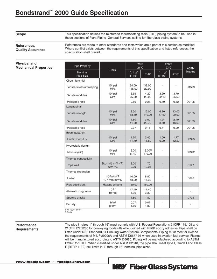
This specification defines the reinforced thermosetting resin (RTR) piping system to be used in those sections of Plant Piping–General Services calling for fiberglass piping systems.
References are made to other standards and tests which are a part of this section as modified Where conflict exists between the requirements of this specification and listed references, the specification shall prevail.
Pipe PropertyUnits
70°F21°C
200°F93°C ASTM
MethodNominal Pipe Size
1”, 1 1/2”8”-16”
2”-6”1”, 1 1/2”8”-16”
2”-6”
Circumferential
Tensile stress at weeping103 psiMPa
24.00165.00
32.0022.00
--
--
D1599
Tensile modulus106 psiGPa
3.6525.20
4.2029.00
3.2022.10
3.7025.50
Poisson’s ratio 0.56 0.26 0.70 0.32 D2105
Longitudinal
Tensile strength103 psiMPa
8.5058.60
16.00110.00
6.9047.60
13.0090.00
D2105
Tensile modulus106 psiGPa
1.6011.00
3.0020.70
1.248.50
2.4016.50
D2105
Poisson’s ratio 0.37 0.16 0.41 0.20 D2105
Beam apparent
Elastic modulus106 psi
GPa1.7011.70
2.4016.60
1.006.90
1.7712.20
D2925
Hydrostatic design
basis (cyclic)103 psiMPa
6.0041.401
16.001,2
110.00--
--
D2992
Thermal conductivity
Pipe wallBtu•in/(hr•ft2•°F)
W/m•°C2.000.29
1.7010.25
--
--
C177
Thermal expansion
Linear10-6in/in/°F
10-6 mm/mm°C10.0018.00
8.5015.30
--
--
D696
Flow coefficient Hazens-Wiliams 150.00 150.00 - - -
Absolute roughness10-6 ft10-6 m
17.405.30
17.403.30
--
--
-
Specific gravity - 1.80 1.80 - - D792
Densitylb/in3
g/cm30.071.80
0.071.80
--
--
-
1) At 150°F (66°C)2) Static
The pipe in sizes 1” through 16” must comply with U.S. Federal Regulations 21CFR 175.105 and 21CFR 177.2280 for conveying foodstuffs when joined with RP6B epoxy adhesive. Pipe shall be listed under NSF Standard 61-Drinking Water System Components. Piping must meet or exceed the requirements of MIL-P-29206A and ASTM D5677-95 when used in aviation fuel service. Fittings will be manufactured according to ASTM D5685. Piping will be manufactured according to ASTM D2996 for RTRP. When classified under ASTM D2310, the pipe shall meet Type I, Grade I and Class F (RTRP-11FE) cell limits in 1” through 16” nominal pipe sizes.
PerformanceRequirements
Physical andMechanical Properties
References, Quality Assurance
Scope
Bondstrand™ 2000 Guide Specification
www.fgspipe.com • [email protected]
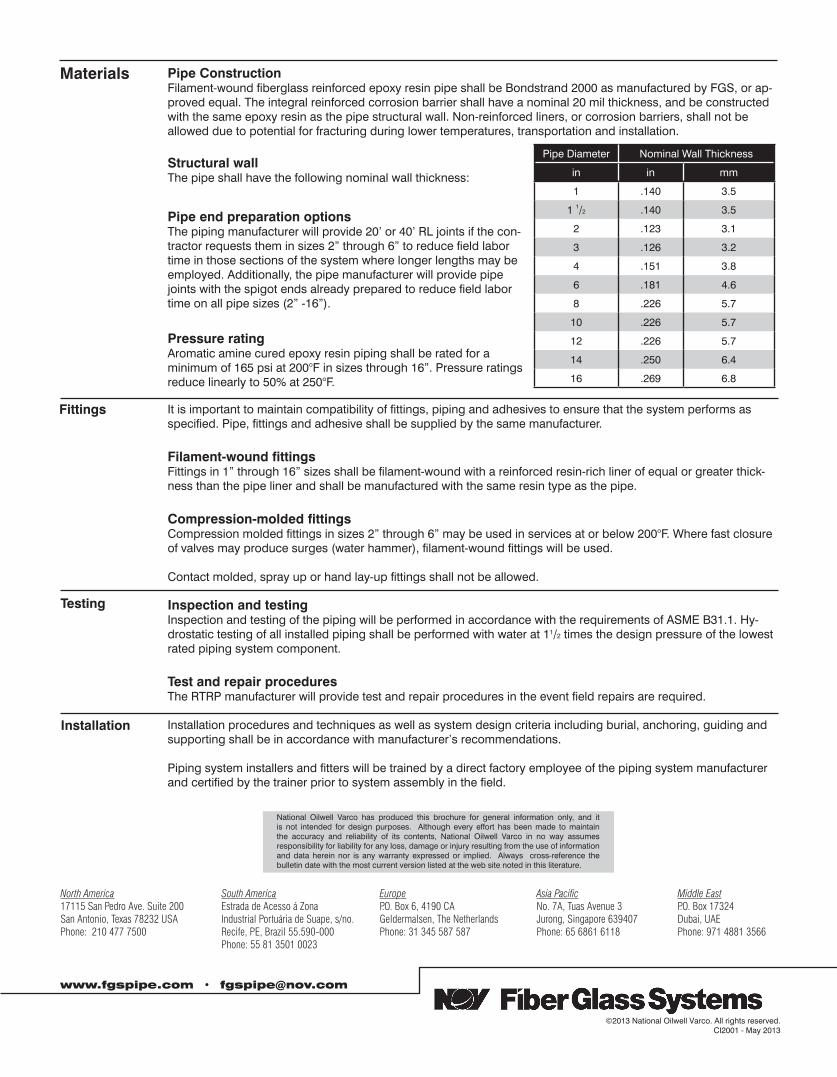
Pipe ConstructionFilament-wound fiberglass reinforced epoxy resin pipe shall be Bondstrand 2000 as manufactured by FGS, or ap-proved equal. The integral reinforced corrosion barrier shall have a nominal 20 mil thickness, and be constructed with the same epoxy resin as the pipe structural wall. Non-reinforced liners, or corrosion barriers, shall not be allowed due to potential for fracturing during lower temperatures, transportation and installation.
Structural wallThe pipe shall have the following nominal wall thickness:
Pipe end preparation optionsThe piping manufacturer will provide 20’ or 40’ RL joints if the con-tractor requests them in sizes 2” through 6” to reduce field labor time in those sections of the system where longer lengths may be employed. Additionally, the pipe manufacturer will provide pipe joints with the spigot ends already prepared to reduce field labor time on all pipe sizes (2” -16”).
Pressure ratingAromatic amine cured epoxy resin piping shall be rated for a minimum of 165 psi at 200°F in sizes through 16”. Pressure ratings reduce linearly to 50% at 250°F.
Pipe Diameter Nominal Wall Thickness
in in mm
1 .140 3.5
1 1/2 .140 3.5
2 .123 3.1
3 .126 3.2
4 .151 3.8
6 .181 4.6
8 .226 5.7
10 .226 5.7
12 .226 5.7
14 .250 6.4
16 .269 6.8
It is important to maintain compatibility of fittings, piping and adhesives to ensure that the system performs as specified. Pipe, fittings and adhesive shall be supplied by the same manufacturer.
Filament-wound fittingsFittings in 1” through 16” sizes shall be filament-wound with a reinforced resin-rich liner of equal or greater thick-ness than the pipe liner and shall be manufactured with the same resin type as the pipe.
Compression-molded fittingsCompression molded fittings in sizes 2” through 6” may be used in services at or below 200°F. Where fast closure of valves may produce surges (water hammer), filament-wound fittings will be used.
Contact molded, spray up or hand lay-up fittings shall not be allowed.
Inspection and testingInspection and testing of the piping will be performed in accordance with the requirements of ASME B31.1. Hy-drostatic testing of all installed piping shall be performed with water at 11/2 times the design pressure of the lowest rated piping system component.
Test and repair proceduresThe RTRP manufacturer will provide test and repair procedures in the event field repairs are required.
Installation procedures and techniques as well as system design criteria including burial, anchoring, guiding and supporting shall be in accordance with manufacturer’s recommendations.
Piping system installers and fitters will be trained by a direct factory employee of the piping system manufacturer and certified by the trainer prior to system assembly in the field.
www.fgspipe.com • [email protected]
©2013 National Oilwell Varco. All rights reserved. CI2001 - May 2013
National Oilwell Varco has produced this brochure for general information only, and it is not intended for design purposes. Although every effort has been made to maintain the accuracy and reliability of its contents, National Oilwell Varco in no way assumes responsibility for liability for any loss, damage or injury resulting from the use of information and data herein nor is any warranty expressed or implied. Always cross-reference the bulletin date with the most current version listed at the web site noted in this literature.
North America South America Europe Asia Pacific Middle East17115 San Pedro Ave. Suite 200 Estrada de Acesso á Zona P.O. Box 6, 4190 CA No. 7A, Tuas Avenue 3 P.O. Box 17324San Antonio, Texas 78232 USA Industrial Portuária de Suape, s/no. Geldermalsen, The Netherlands Jurong, Singapore 639407 Dubai, UAEPhone: 210 477 7500 Recife, PE, Brazil 55.590-000 Phone: 31 345 587 587 Phone: 65 6861 6118 Phone: 971 4881 3566
Phone: 55 81 3501 0023
Materials
Fittings
Testing
Installation
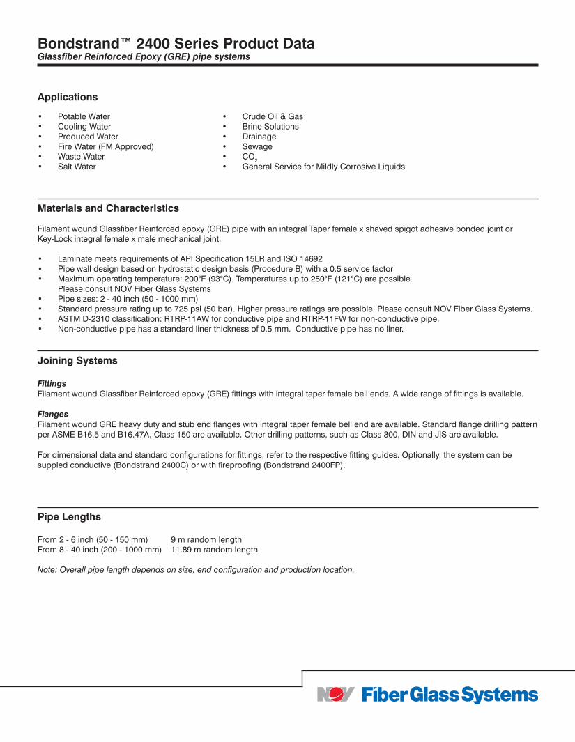
Bondstrand™ 2400 Series Product DataGlassfiber Reinforced Epoxy (GRE) pipe systems
Applications
• Potable Water • Crude Oil & Gas • Cooling Water • Brine Solutions • Produced Water • Drainage • Fire Water (FM Approved) • Sewage • Waste Water • CO2 • Salt Water • General Service for Mildly Corrosive Liquids
Materials and Characteristics
Filament wound Glassfiber Reinforced epoxy (GRE) pipe with an integral Taper female x shaved spigot adhesive bonded joint or Key-Lock integral female x male mechanical joint.
• Laminate meets requirements of API Specification 15LR and ISO 14692• Pipe wall design based on hydrostatic design basis (Procedure B) with a 0.5 service factor• Maximum operating temperature: 200°F (93°C). Temperatures up to 250°F (121°C) are possible. Please consult NOV Fiber Glass Systems • Pipe sizes: 2 - 40 inch (50 - 1000 mm) • Standard pressure rating up to 725 psi (50 bar). Higher pressure ratings are possible. Please consult NOV Fiber Glass Systems.• ASTM D-2310 classification: RTRP-11AW for conductive pipe and RTRP-11FW for non-conductive pipe.• Non-conductive pipe has a standard liner thickness of 0.5 mm. Conductive pipe has no liner.
Joining Systems
Fittings Filament wound Glassfiber Reinforced epoxy (GRE) fittings with integral taper female bell ends. A wide range of fittings is available.
FlangesFilament wound GRE heavy duty and stub end flanges with integral taper female bell end are available. Standard flange drilling pattern per ASME B16.5 and B16.47A, Class 150 are available. Other drilling patterns, such as Class 300, DIN and JIS are available.
For dimensional data and standard configurations for fittings, refer to the respective fitting guides. Optionally, the system can be suppled conductive (Bondstrand 2400C) or with fireproofing (Bondstrand 2400FP).
Pipe Lengths From 2 - 6 inch (50 - 150 mm) 9 m random length From 8 - 40 inch (200 - 1000 mm) 11.89 m random length Note: Overall pipe length depends on size, end configuration and production location.
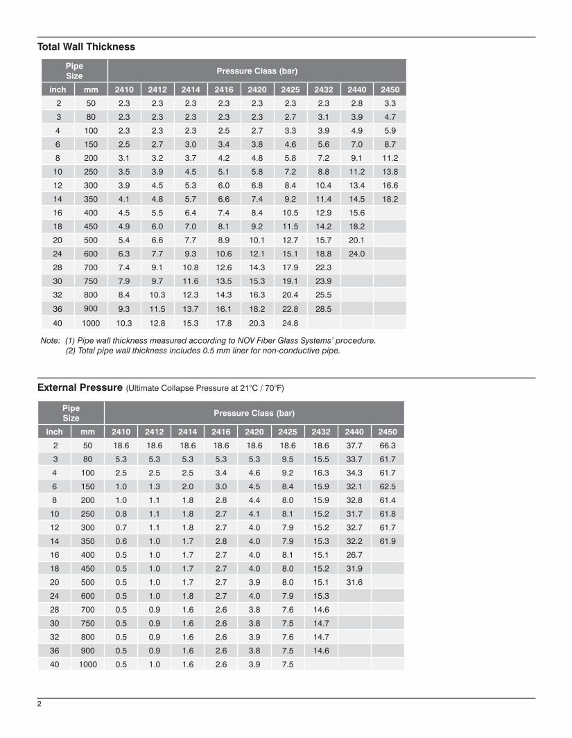
2
Note: (1) Pipe wall thickness measured according to NOV Fiber Glass Systems’ procedure. (2) Total pipe wall thickness includes 0.5 mm liner for non-conductive pipe.
Pipe Size
Pressure Class (bar)
inch mm 2410 2412 2414 2416 2420 2425 2432 2440 2450
2 50 2.3 2.3 2.3 2.3 2.3 2.3 2.3 2.8 3.3
3 80 2.3 2.3 2.3 2.3 2.3 2.7 3.1 3.9 4.7
4 100 2.3 2.3 2.3 2.5 2.7 3.3 3.9 4.9 5.9
6 150 2.5 2.7 3.0 3.4 3.8 4.6 5.6 7.0 8.7
8 200 3.1 3.2 3.7 4.2 4.8 5.8 7.2 9.1 11.2
10 250 3.5 3.9 4.5 5.1 5.8 7.2 8.8 11.2 13.8
12 300 3.9 4.5 5.3 6.0 6.8 8.4 10.4 13.4 16.6
14 350 4.1 4.8 5.7 6.6 7.4 9.2 11.4 14.5 18.2
16 400 4.5 5.5 6.4 7.4 8.4 10.5 12.9 15.6
18 450 4.9 6.0 7.0 8.1 9.2 11.5 14.2 18.2
20 500 5.4 6.6 7.7 8.9 10.1 12.7 15.7 20.1
24 600 6.3 7.7 9.3 10.6 12.1 15.1 18.8 24.0
28 700 7.4 9.1 10.8 12.6 14.3 17.9 22.3
30 750 7.9 9.7 11.6 13.5 15.3 19.1 23.9
32 800 8.4 10.3 12.3 14.3 16.3 20.4 25.5
36 900 9.3 11.5 13.7 16.1 18.2 22.8 28.5
40 1000 10.3 12.8 15.3 17.8 20.3 24.8
Pipe Size
Pressure Class (bar)
inch mm 2410 2412 2414 2416 2420 2425 2432 2440 2450
2 50 18.6 18.6 18.6 18.6 18.6 18.6 18.6 37.7 66.3
3 80 5.3 5.3 5.3 5.3 5.3 9.5 15.5 33.7 61.7
4 100 2.5 2.5 2.5 3.4 4.6 9.2 16.3 34.3 61.7
6 150 1.0 1.3 2.0 3.0 4.5 8.4 15.9 32.1 62.5
8 200 1.0 1.1 1.8 2.8 4.4 8.0 15.9 32.8 61.4
10 250 0.8 1.1 1.8 2.7 4.1 8.1 15.2 31.7 61.8
12 300 0.7 1.1 1.8 2.7 4.0 7.9 15.2 32.7 61.7
14 350 0.6 1.0 1.7 2.8 4.0 7.9 15.3 32.2 61.9
16 400 0.5 1.0 1.7 2.7 4.0 8.1 15.1 26.7
18 450 0.5 1.0 1.7 2.7 4.0 8.0 15.2 31.9
20 500 0.5 1.0 1.7 2.7 3.9 8.0 15.1 31.6
24 600 0.5 1.0 1.8 2.7 4.0 7.9 15.3
28 700 0.5 0.9 1.6 2.6 3.8 7.6 14.6
30 750 0.5 0.9 1.6 2.6 3.8 7.5 14.7
32 800 0.5 0.9 1.6 2.6 3.9 7.6 14.7
36 900 0.5 0.9 1.6 2.6 3.8 7.5 14.6
40 1000 0.5 1.0 1.6 2.6 3.9 7.5
Total Wall Thickness
External Pressure (Ultimate Collapse Pressure at 21°C / 70°F)
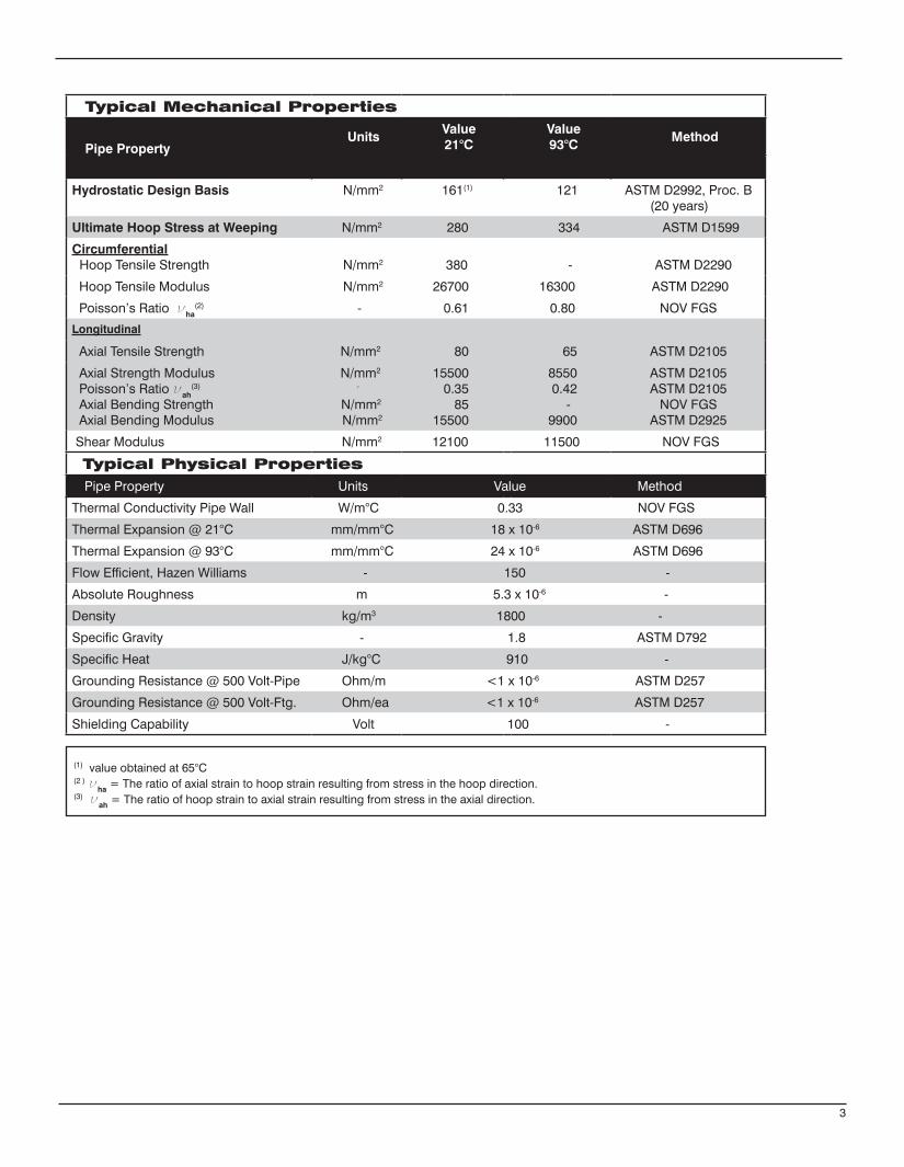
3
Typical Mechanical Properties
Pipe PropertyUnits
Value21°C
Value93°C
Method
Hydrostatic Design Basis N/mm2 161(1) 121 ASTM D2992, Proc. B (20 years)
Ultimate Hoop Stress at Weeping N/mm2 280 334 ASTM D1599
Circumferential Hoop Tensile Strength
N/mm2 380 - ASTM D2290
Hoop Tensile Modulus N/mm2 26700 16300 ASTM D2290
Poisson’s Ratio νha(2) - 0.61 0.80 NOV FGS
Longitudinal
Axial Tensile Strength N/mm2 80 65 ASTM D2105
Axial Strength Modulus Poisson’s Ratio νah
(3)
Axial Bending Strength Axial Bending Modulus
N/mm2
-
N/mm2
N/mm2
15500 0.35 85 15500
8550 0.42 - 9900
ASTM D2105ASTM D2105
NOV FGS ASTM D2925
Shear Modulus N/mm2 12100 11500 NOV FGS
Typical Physical Properties Pipe Property Units Value Method
Thermal Conductivity Pipe Wall W/m°C 0.33 NOV FGS
Thermal Expansion @ 21°C mm/mm°C 18 x 10-6 ASTM D696
Thermal Expansion @ 93°C mm/mm°C 24 x 10-6 ASTM D696
Flow Efficient, Hazen Williams - 150 -
Absolute Roughness m 5.3 x 10⁻⁶ -
Density kg/m3 1800 -
Specific Gravity - 1.8 ASTM D792
Specific Heat J/kg°C 910 -
Grounding Resistance @ 500 Volt-Pipe Ohm/m <1 x 10⁻⁶ ASTM D257
Grounding Resistance @ 500 Volt-Ftg. Ohm/ea <1 x 10⁻⁶ ASTM D257
Shielding Capability Volt 100 -
(1) value obtained at 65°C (2 ) νha = The ratio of axial strain to hoop strain resulting from stress in the hoop direction. (3) νah = The ratio of hoop strain to axial strain resulting from stress in the axial direction.
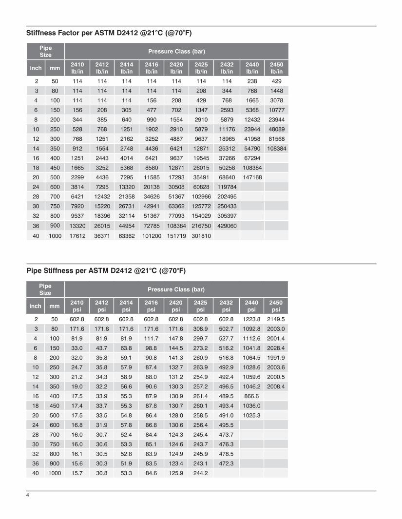
4
Pipe Size
Pressure Class (bar)
inch mm2410lb/in
2412lb/in
2414lb/in
2416lb/in
2420lb/in
2425lb/in
2432lb/in
2440lb/in
2450lb/in
2 50 114 114 114 114 114 114 114 238 429
3 80 114 114 114 114 114 208 344 768 1448
4 100 114 114 114 156 208 429 768 1665 3078
6 150 156 208 305 477 702 1347 2593 5368 10777
8 200 344 385 640 990 1554 2910 5879 12432 23944
10 250 528 768 1251 1902 2910 5879 11176 23944 48089
12 300 768 1251 2162 3252 4887 9637 18965 41958 81568
14 350 912 1554 2748 4436 6421 12871 25312 54790 108384
16 400 1251 2443 4014 6421 9637 19545 37266 67294
18 450 1665 3252 5368 8580 12871 26015 50258 108384
20 500 2299 4436 7295 11585 17293 35491 68640 147168
24 600 3814 7295 13320 20138 30508 60828 119784
28 700 6421 12432 21358 34626 51367 102966 202495
30 750 7920 15220 26731 42941 63362 125772 250433
32 800 9537 18396 32114 51367 77093 154029 305397
36 900 13320 26015 44954 72785 108384 216750 429060
40 1000 17612 36371 63362 101200 151719 301810
Pipe Size
Pressure Class (bar)
inch mm2410psi
2412psi
2414psi
2416psi
2420psi
2425psi
2432psi
2440psi
2450psi
2 50 602.8 602.8 602.8 602.8 602.8 602.8 602.8 1223.8 2149.5
3 80 171.6 171.6 171.6 171.6 171.6 308.9 502.7 1092.8 2003.0
4 100 81.9 81.9 81.9 111.7 147.8 299.7 527.7 1112.6 2001.4
6 150 33.0 43.7 63.8 98.8 144.5 273.2 516.2 1041.8 2028.4
8 200 32.0 35.8 59.1 90.8 141.3 260.9 516.8 1064.5 1991.9
10 250 24.7 35.8 57.9 87.4 132.7 263.9 492.9 1028.6 2003.6
12 300 21.2 34.3 58.9 88.0 131.2 254.9 492.4 1059.6 2000.5
14 350 19.0 32.2 56.6 90.6 130.3 257.2 496.5 1046.2 2008.4
16 400 17.5 33.9 55.3 87.9 130.9 261.4 489.5 866.6
18 450 17.4 33.7 55.3 87.8 130.7 260.1 493.4 1036.0
20 500 17.5 33.5 54.8 86.4 128.0 258.5 491.0 1025.3
24 600 16.8 31.9 57.8 86.8 130.6 256.4 495.5
28 700 16.0 30.7 52.4 84.4 124.3 245.4 473.7
30 750 16.0 30.6 53.3 85.1 124.6 243.7 476.3
32 800 16.1 30.5 52.8 83.9 124.9 245.9 478.5
36 900 15.6 30.3 51.9 83.5 123.4 243.1 472.3
40 1000 15.7 30.8 53.3 84.6 125.9 244.2
Stiffness Factor per ASTM D2412 @21°C (@70°F)
Pipe Stiffness per ASTM D2412 @21°C (@70°F)
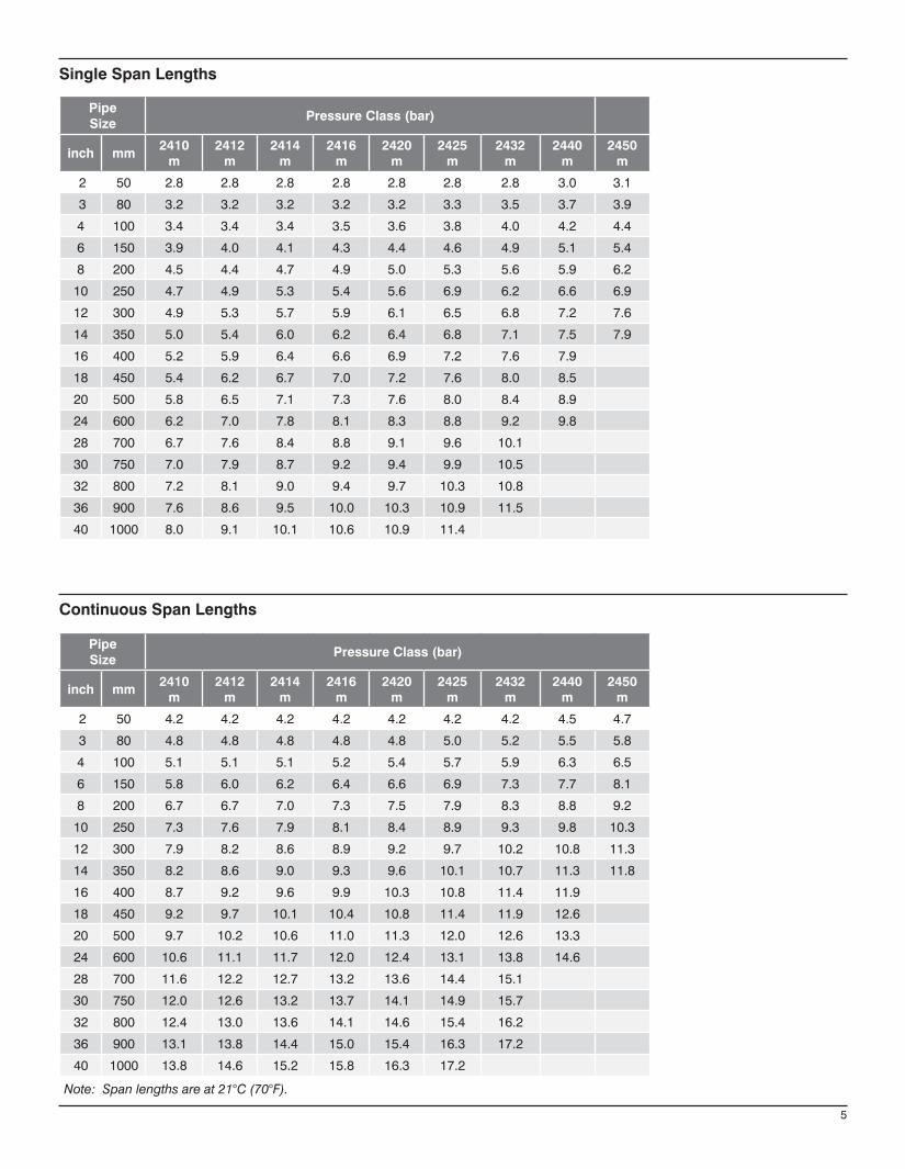
5
Pipe Size
Pressure Class (bar)
inch mm2410
m2412
m2414
m2416
m2420
m2425
m2432
m2440
m2450
m
2 50 2.8 2.8 2.8 2.8 2.8 2.8 2.8 3.0 3.1
3 80 3.2 3.2 3.2 3.2 3.2 3.3 3.5 3.7 3.9
4 100 3.4 3.4 3.4 3.5 3.6 3.8 4.0 4.2 4.4
6 150 3.9 4.0 4.1 4.3 4.4 4.6 4.9 5.1 5.4
8 200 4.5 4.4 4.7 4.9 5.0 5.3 5.6 5.9 6.2
10 250 4.7 4.9 5.3 5.4 5.6 6.9 6.2 6.6 6.9
12 300 4.9 5.3 5.7 5.9 6.1 6.5 6.8 7.2 7.6
14 350 5.0 5.4 6.0 6.2 6.4 6.8 7.1 7.5 7.9
16 400 5.2 5.9 6.4 6.6 6.9 7.2 7.6 7.9
18 450 5.4 6.2 6.7 7.0 7.2 7.6 8.0 8.5
20 500 5.8 6.5 7.1 7.3 7.6 8.0 8.4 8.9
24 600 6.2 7.0 7.8 8.1 8.3 8.8 9.2 9.8
28 700 6.7 7.6 8.4 8.8 9.1 9.6 10.1
30 750 7.0 7.9 8.7 9.2 9.4 9.9 10.5
32 800 7.2 8.1 9.0 9.4 9.7 10.3 10.8
36 900 7.6 8.6 9.5 10.0 10.3 10.9 11.5
40 1000 8.0 9.1 10.1 10.6 10.9 11.4
Pipe Size
Pressure Class (bar)
inch mm2410
m2412
m2414
m2416
m2420
m2425
m2432
m2440
m2450
m
2 50 4.2 4.2 4.2 4.2 4.2 4.2 4.2 4.5 4.7
3 80 4.8 4.8 4.8 4.8 4.8 5.0 5.2 5.5 5.8
4 100 5.1 5.1 5.1 5.2 5.4 5.7 5.9 6.3 6.5
6 150 5.8 6.0 6.2 6.4 6.6 6.9 7.3 7.7 8.1
8 200 6.7 6.7 7.0 7.3 7.5 7.9 8.3 8.8 9.2
10 250 7.3 7.6 7.9 8.1 8.4 8.9 9.3 9.8 10.3
12 300 7.9 8.2 8.6 8.9 9.2 9.7 10.2 10.8 11.3
14 350 8.2 8.6 9.0 9.3 9.6 10.1 10.7 11.3 11.8
16 400 8.7 9.2 9.6 9.9 10.3 10.8 11.4 11.9
18 450 9.2 9.7 10.1 10.4 10.8 11.4 11.9 12.6
20 500 9.7 10.2 10.6 11.0 11.3 12.0 12.6 13.3
24 600 10.6 11.1 11.7 12.0 12.4 13.1 13.8 14.6
28 700 11.6 12.2 12.7 13.2 13.6 14.4 15.1
30 750 12.0 12.6 13.2 13.7 14.1 14.9 15.7
32 800 12.4 13.0 13.6 14.1 14.6 15.4 16.2
36 900 13.1 13.8 14.4 15.0 15.4 16.3 17.2
40 1000 13.8 14.6 15.2 15.8 16.3 17.2
Note: Span lengths are at 21°C (70°F).
Single Span Lengths
Continuous Span Lengths
North America South America Europe Asia Pacific Middle East17115 San Pedro Avenue Estrada de Acesso à Zona P.O. Box 6, 4190 CA No. 7A, Tuas Avenue 3 P.O. Box 17324Suite 200 Industrial Portuária de Suape, s/no. Geldermalsen, The Netherlands Jurong, Singapore 639407 Dubai, UAESan Antonio, TX 78232 USA Recife, PE, Brazil 55.590-000 Phone: +31 345 587 587 Phone: +65 6861 6118 Phone: +971 4881 3566 Phone: +1 210 477 7500 Phone: +55 81 3501 0023
© 2013 National Oilwell Varco. All rights reserved.CI2400ENG - June 2014
National Oilwell Varco has produced this brochure for general information only, and it is not intended for design purposes. Although every effort has been made to maintain the accuracy and reliability of its contents, National Oilwell Varco in no way assumes responsibility for liability for any loss, damage or injury resulting from the use of information and data herein. All applications for the material described are at the user’s risk and are the user’s responsibility.All brands listed are trademarks of National Oilwell Varco.
www.fgspipe.com • [email protected]
Bondstrand™ Series 3000 Fiberglass Pipe for General Industrial Service
www.fgspipe.com • [email protected]
Uses andApplications
Performance Working pressure to 450 psig depending on pipe size.
Operating surge pressure to 1.25 times rated operating pressure.
No thrust blocks are required at rated system pressure for most buried piping configurations and most soil conditions.
Temperatures to 150°F (66°C) maximum.
Full vacuum capabilities when buried and properly backfilled. For above ground use, refer to collapse pressures listed below under pipe pressure performance.
Recommended burial depth: 3 to 25 feet.
Recommended for water, waste water (pH 1 to 8.5), moderately corrosive liquids and mild chemicals. Consult corrosion guide or Applications Engineering for recommendations for your particular application.
Individual system components may not have the same ratings as the pipe. Refer to the detailed product information for the specific components to determine the pressure rating for the system as a whole.
• Boiler feed water• Bridge, roof and floor drains • Brine and brackish water • Chemical process piping • Cooling water• Demineralized water• Electroplating• Fuel oil piping• General service piping• Mild chemicals
• Municipal waste• Oilfield gathering, transmission lines• Power plant, steel mill and industrial plant
piping• Sewer lines and sewer force mains• Source and recycle water• Sump discharge• Vent lines • Water mains • Water treatment
Composition Pipe
Filament-wound fiberglass reinforced epoxy pipe with integral epoxy liner and exterior coating.
Pipe Size ASTM Designation
in mm D2310 D2996
2 - 6 50 - 150 RTRP 11FX RTRP 11FX-5420
8 - 16 200 - 400 RTRP 11FW RTRP 11FW1-3210
Fittings
2 to 6 inch Compression-molded fiberglass reinforced epoxy elbows and teesFilament-wound and/or mitered crosses, wyes, laterals and reducers
8 to 16 inchFilament-wound fiberglass reinforced epoxy elbows Filament-wound and/or mitered crosses, wyes, and laterals Contact-molded reducers
Flanges
Flange rings:Molded or filament-wound fiberglass
Stub ends:Molded or centrifugally cast fiberglass
Blind flanges
Compression-molded fiberglass or epoxy-coated cast iron or steel.
Adhesive
Two-part epoxy adhesive for field fabrication. (Consult NOV Fiber Glass Systems for specifications.)
2 to 16 inchBell and spigot taper/taper adhesive-bonded joint.
Standard 20 and 39 ft. random lengths.
Other lengths available on request.
Joining Systems
Pipe Lengths
2
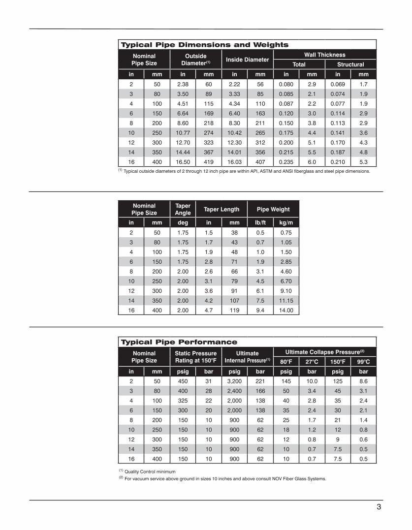
Typical Pipe Dimensions and Weights
NominalPipe Size
Outside Diameter(1) Inside Diameter
Wall Thickness
Total Structural
in mm in mm in mm in mm in mm
2 50 2.38 60 2.22 56 0.080 2.9 0.069 1.7
3 80 3.50 89 3.33 85 0.085 2.1 0.074 1.9
4 100 4.51 115 4.34 110 0.087 2.2 0.077 1.9
6 150 6.64 169 6.40 163 0.120 3.0 0.114 2.9
8 200 8.60 218 8.30 211 0.150 3.8 0.113 2.9
10 250 10.77 274 10.42 265 0.175 4.4 0.141 3.6
12 300 12.70 323 12.30 312 0.200 5.1 0.170 4.3
14 350 14.44 367 14.01 356 0.215 5.5 0.187 4.8
16 400 16.50 419 16.03 407 0.235 6.0 0.210 5.3
NominalPipe Size
TaperAngle
Taper Length Pipe Weight
in mm deg in mm lb/ft kg/m
2 50 1.75 1.5 38 0.5 0.75
3 80 1.75 1.7 43 0.7 1.05
4 100 1.75 1.9 48 1.0 1.50
6 150 1.75 2.8 71 1.9 2.85
8 200 2.00 2.6 66 3.1 4.60
10 250 2.00 3.1 79 4.5 6.70
12 300 2.00 3.6 91 6.1 9.10
14 350 2.00 4.2 107 7.5 11.15
16 400 2.00 4.7 119 9.4 14.00
Typical Pipe Performance
NominalPipe Size
Static Pressure Rating at 150°F
UltimateInternal Pressure(1)
Ultimate Collapse Pressure(2)
80°F 27°C 150°F 99°C
in mm psig bar psig bar psig bar psig bar
2 50 450 31 3,200 221 145 10.0 125 8.6
3 80 400 28 2,400 166 50 3.4 45 3.1
4 100 325 22 2,000 138 40 2.8 35 2.4
6 150 300 20 2,000 138 35 2.4 30 2.1
8 200 150 10 900 62 25 1.7 21 1.4
10 250 150 10 900 62 18 1.2 12 0.8
12 300 150 10 900 62 12 0.8 9 0.6
14 350 150 10 900 62 10 0.7 7.5 0.5
16 400 150 10 900 62 10 0.7 7.5 0.5
(1) Typical outside diameters of 2 through 12 inch pipe are within API, ASTM and ANSI fiberglass and steel pipe dimensions.
(1) Quality Control minimum(2) For vacuum service above ground in sizes 10 inches and above consult NOV Fiber Glass Systems.
3
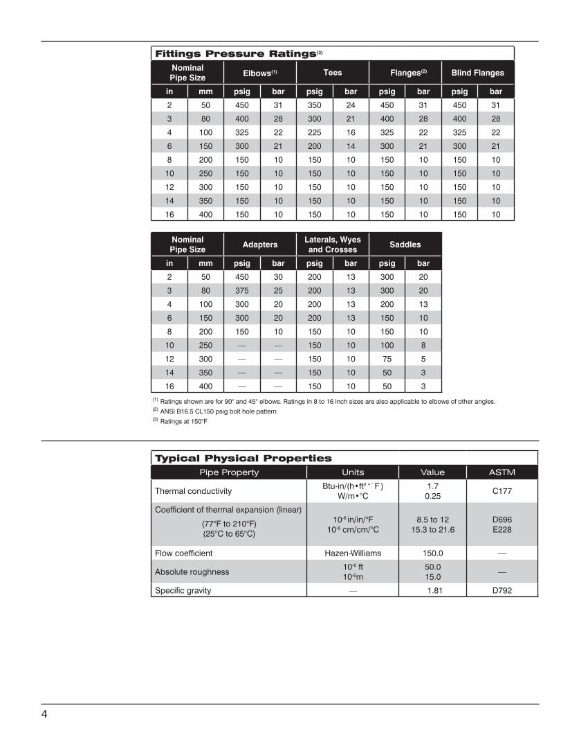
(1) Ratings shown are for 90° and 45° elbows. Ratings in 8 to 16 inch sizes are also applicable to elbows of other angles.(2) ANSI B16.5 CL150 psig bolt hole pattern(3) Ratings at 150°F
NominalPipe Size
AdaptersLaterals, Wyesand Crosses
Saddles
in mm psig bar psig bar psig bar
2 50 450 30 200 13 300 20
3 80 375 25 200 13 300 20
4 100 300 20 200 13 200 13
6 150 300 20 200 13 150 10
8 200 150 10 150 10 150 10
10 250 –– –– 150 10 100 8
12 300 –– –– 150 10 75 5
14 350 –– –– 150 10 50 3
16 400 –– –– 150 10 50 3
Typical Physical PropertiesPipe Property Units Value ASTM
Thermal conductivityBtu-in/(h•ft2•°F )
W/m•°C1.7
0.25C177
Coefficient of thermal expansion (linear)
(77°F to 210°F)(25°C to 65°C)
10-6 in/in/°F10-6 cm/cm/°C
8.5 to 1215.3 to 21.6
D696 E228
Flow coefficient Hazen-Williams 150.0 —
Absolute roughness10-6 ft10-6m
50.015.0
—
Specific gravity — 1.81 D792
4
Fittings Pressure Ratings(3)
NominalPipe Size Elbows(1) Tees Flanges(2) Blind Flanges
in mm psig bar psig bar psig bar psig bar
2 50 450 31 350 24 450 31 450 31
3 80 400 28 300 21 400 28 400 28
4 100 325 22 225 16 325 22 325 22
6 150 300 21 200 14 300 21 300 21
8 200 150 10 150 10 150 10 150 10
10 250 150 10 150 10 150 10 150 10
12 300 150 10 150 10 150 10 150 10
14 350 150 10 150 10 150 10 150 10
16 400 150 10 150 10 150 10 150 10
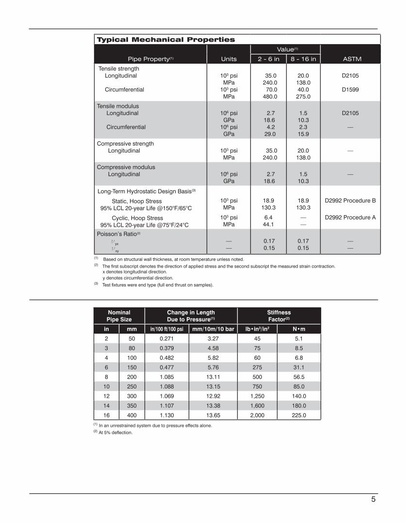
Typical Mechanical Properties
Pipe Property(1) Units
Value(1)
ASTM 2 - 6 in 8 - 16 in
Tensile strength Longitudinal
Circumferential
103 psiMPa
103 psiMPa
35.0 240.0 70.0 480.0
20.0138.040.0
275.0
D2105
D1599
Tensile modulus Longitudinal
Circumferential
106 psiGPa
106 psiGPa
2.7 18.6 4.2 29.0
1.510.32.3
15.9
D2105
—
Compressive strength Longitudinal 103 psi
MPa 35.0 240.0
20.0138.0
—
Compressive modulus Longitudinal 106 psi
GPa 2.7 18.6
1.510.3
—
103 psiMPa
103 psiMPa
18.9130.3
6.444.1
18.9130.3
——
D2992 Procedure B
D2992 Procedure A
Poisson’s Ratio(2)
νyx
νxy
——
0.17 0.15
0.170.15
——
(1) Based on structural wall thickness, at room temperature unless noted.(2) The first subscript denotes the direction of applied stress and the second subscript the measured strain contraction. x denotes longitudinal direction. y denotes circumferential direction.(3) Test fixtures were end type (full end thrust on samples).
NominalPipe Size
Change in LengthDue to Pressure(1)
Stiffness Factor(2)
in mm in/100 ft/100 psi mm/10m/10 bar lb•in3/in2 N•m
2 50 0.271 3.27 45 5.1
3 80 0.379 4.58 75 8.5
4 100 0.482 5.82 60 6.8
6 150 0.477 5.76 275 31.1
8 200 1.085 13.11 500 56.5
10 250 1.088 13.15 750 85.0
12 300 1.069 12.92 1,250 140.0
14 350 1.107 13.38 1,600 180.0
16 400 1.130 13.65 2,000 225.0(1) In an unrestrained system due to pressure effects alone.(2) At 5% deflection.
5
Long-Term Hydrostatic Design Basis(3)
Static, Hoop Stress95% LCL 20-year Life @150°F/65°C
Cyclic, Hoop Stress95% LCL 20-year Life @75°F/24°C
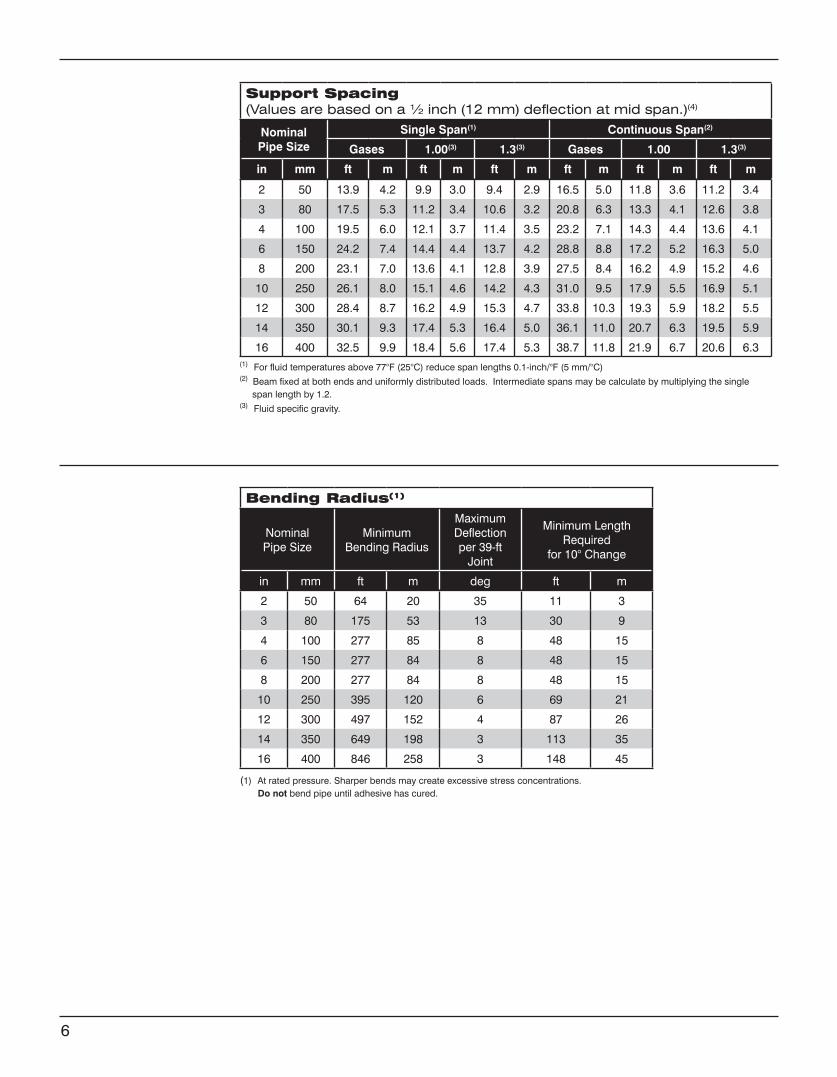
Support Spacing (Values are based on a ½ inch (12 mm) deflection at mid span.)(4)
Nominal Pipe Size
Single Span(1) Continuous Span(2)
Gases 1.00(3) 1.3(3) Gases 1.00 1.3(3)
in mm ft m ft m ft m ft m ft m ft m
2 50 13.9 4.2 9.9 3.0 9.4 2.9 16.5 5.0 11.8 3.6 11.2 3.4
3 80 17.5 5.3 11.2 3.4 10.6 3.2 20.8 6.3 13.3 4.1 12.6 3.8
4 100 19.5 6.0 12.1 3.7 11.4 3.5 23.2 7.1 14.3 4.4 13.6 4.1
6 150 24.2 7.4 14.4 4.4 13.7 4.2 28.8 8.8 17.2 5.2 16.3 5.0
8 200 23.1 7.0 13.6 4.1 12.8 3.9 27.5 8.4 16.2 4.9 15.2 4.6
10 250 26.1 8.0 15.1 4.6 14.2 4.3 31.0 9.5 17.9 5.5 16.9 5.1
12 300 28.4 8.7 16.2 4.9 15.3 4.7 33.8 10.3 19.3 5.9 18.2 5.5
14 350 30.1 9.3 17.4 5.3 16.4 5.0 36.1 11.0 20.7 6.3 19.5 5.9
16 400 32.5 9.9 18.4 5.6 17.4 5.3 38.7 11.8 21.9 6.7 20.6 6.3
(1) At rated pressure. Sharper bends may create excessive stress concentrations. Do not bend pipe until adhesive has cured.
Bending Radius(1)
NominalPipe Size
MinimumBending Radius
Maximum Deflectionper 39-ft
Joint
Minimum Length Required
for 10° Change
in mm ft m deg ft m
2 50 64 20 35 11 3
3 80 175 53 13 30 9
4 100 277 85 8 48 15
6 150 277 84 8 48 15
8 200 277 84 8 48 15
10 250 395 120 6 69 21
12 300 497 152 4 87 26
14 350 649 198 3 113 35
16 400 846 258 3 148 45
6
(1) For fluid temperatures above 77°F (25°C) reduce span lengths 0.1-inch/°F (5 mm/°C)(2) Beam fixed at both ends and uniformly distributed loads. Intermediate spans may be calculate by multiplying the single span length by 1.2.(3) Fluid specific gravity.
Pipe—The structural wall of fiberglass pipe in 2 through 16 inch nominal pipe sizes shall be con-structed of continuous glass fibers wound in a matrix of anhydride cured epoxy resin in a dual angle pattern that takes optimum advantage of the tensile strength of the filaments. Pipe produced by filament-winding shall have a smooth outer surface with an outside diametral tolerance not exceed-ing ±1.0%. The pipe shall incorporate an integral liner with a nominal thickness of 0.025 ± 0.005 inches for 2 through 16 inch nominal sizes. The pipe shall be manufactured in accordance with ASTM Standard D2996 for filament-wound reinforced thermosetting resin pipe (RTRP). When clas-sified under ASTM Standard D2310, the pipe shall be Type 1, Grade 1, and Class F for 2 through 16 inch nominal pipe sizes.
Pipe shall be provided in standard lengths up to 40 feet, and shall be available in 60 ft. lengths on special request to minimize the number of field joints for rapid installation.
Pressure rating—Pipe in 2 through 16 inch sizes shall be rated for a minimum internal pressure of 150 psig at 150°F.
Fittings in 8 through 16 inch nominal sizes shall be filament wound and incorporate a resin-rich liner of equal or greater thickness than the pipe liner and shall be constructed of the same glass and resin type for corrosion and abrasion resistance equal to that of the pipe. Fittings in 2 through 6 inch nominal sizes may be compression molded from glass and resins similar to those used in the pipe. Sprayed-up fittings shall not be permitted.
Pipe and fittings shall be joined using bell and spigot taper/taper adhesive-bonded joints or me-chanical screw-on type joints.
Values for physical and mechanical properties shall be no less than 95% of those shown tabulated above under Typical Physical Properties and Typical Mechanical Properties.
The pipe and fittings shall be free from all defects, including delamination, indentations, pinholes, foreign inclusions, bubbles and resin-starved areas which, due to their nature, degree or extent, detrimentally affect the strength and serviceability of the pipe or fittings. Pigments or dyes may be used in the resin as long as the product is sufficiently translucent to verify the structural integrity of the structural wall. The pipe and fittings shall be as uniform as commercially practicable in color, density and other physical properties.
Quality control testing—Samples of pipe and fittings shall be tested at random based on standard quality control practices to determine conformance of the materials to the following ASTM guidelines for testing fiberglass pipe products: ASTM D1599, D2105, D2925, D2992A or D2992B. Test samples may be hydrostatically tested by the manufacturer to 1.5 times the pressure rating for signs of leak-age.
Each component shall be marked to show the following: Manufacturer’s name and address Nominal pipe size Hydrostatic test pressure (if so ordered) Date and shift of manufacture (pipe only)
Pipe Construction
Fittings Construction
Physical and MechanicalRequirements
Workmanship
Testing
Marking
7
Guide Specification
www.fgspipe.com • [email protected]
©2013, National Oilwell Varco. All rights reserved.CI3000 - July 2013
National Oilwell Varco has produced this brochure for general information only, and it is not intended for design purposes. Although every effort has been made to maintain the accuracy and reliability of its contents, National Oilwell Varco in no way assumes responsibility for liability for any loss, damage or injury resulting from the use of information and data herein nor is any warranty expressed or implied. Always cross-reference the bulletin date with the most current version listed at the web site noted in this literature.
North America South America Europe Asia Pacific Middle East17115 San Pedro Ave. Suite 200 Estrada de Acesso á Zona P.O. Box 6, 4190 CA No. 7A, Tuas Avenue 3 P.O. Box 17324San Antonio, Texas 78232 USA Industrial Portuária de Suape, s/no. Geldermalsen, The Netherlands Jurong, Singapore 639407 Dubai, UAEPhone: 210 477 7500 Recife, PE, Brazil 55.590-000 Phone: 31 345 587 587 Phone: 65 6861 6118 Phone: 971 4881 3566 Phone: 55 81 3501 0023
Bondstrand™ Series 3000A Fiberglass Pipefor General Industrial Service
www.fgspipe.com • [email protected]
Uses andApplications
Performance Working pressure to 450 psig depending on pipe size.
No thrust blocks are required at rated system pressure for most buried piping configurations and most soil conditions.
Temperatures to 210°F (99°C) maximum.
For above ground use, refer to collapse pressures listed below under pipe pressure performance.
Recommended burial depth: 3 to 25 feet.
Recommended for water, waste water (pH 1 to 12), moderately corrosive liquids and mild chemicals. Consult corrosion guide or Applications Engineering for recommendations for your particular application.
Individual system components may not have the same ratings as the pipe. Refer to the detailed product information for the specific components to determine the pressure rating for the system as a whole.
• Alcohol solutions• Boiler feed water• Bridge, roof and floor drains • Brine and brackish water • Chemical process piping • Cooling water• Demineralized water• Fuel oil piping• General service piping• Mild chemicals • Municipal waste
• Oilfield piping• Potable water - NSF 61 Listed• Power plant, steel mill and industrial plant
piping• Sewer lines and sewer force mains• Source and recycle water• Sump discharge• Vent lines • Water mains • Water treatment
Composition Pipe
Filament-wound fiberglass reinforced epoxy pipe with integral epoxy liner and exterior coating.
Pipe Size ASTM Designation
in mm D2310 D2996
2 - 6 50 - 150 RTRP-11FU RTRP-11FU1-6430
8 - 16 200 - 400 RTRP-11FU RTRP-11FU1-3220
Fittings
2 to 6 inch Compression-molded fiberglass reinforced epoxy elbows and teesFilament-wound and/or mitered crosses, wyes, laterals and reducers
8 to 16 inchFilament-wound fiberglass reinforced epoxy elbows. Filament-wound and/or mitered crosses, tees, wyes, and laterals. Contact-molded reducers
Flanges
Flange rings:Molded or filament-wound fiberglass
Stub Ends:Molded or centrifugally cast fiberglass
Blind Flanges
Compression-molded fiberglass
Two-part epoxy adhesive for field fabrication. (Consult NOV Fiber Glass Systems for specifications.)
2 to 16 inchBell and spigot taper/taper.
Standard 20 and 39 ft. random lengths.
Other lengths available on request.
Joining Systems
Pipe Lengths
2
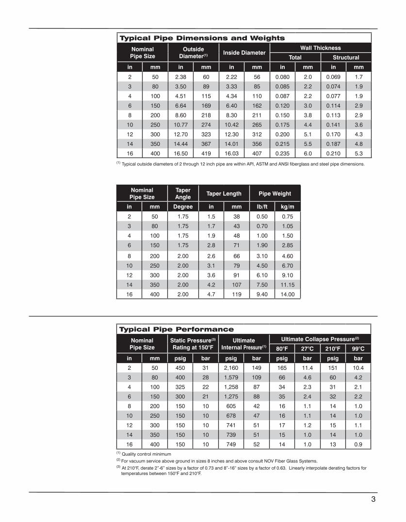
Typical Pipe Dimensions and Weights
NominalPipe Size
Outside Diameter(1) Inside Diameter
Wall Thickness
Total Structural
in mm in mm in mm in mm in mm
2 50 2.38 60 2.22 56 0.080 2.0 0.069 1.7
3 80 3.50 89 3.33 85 0.085 2.2 0.074 1.9
4 100 4.51 115 4.34 110 0.087 2.2 0.077 1.9
6 150 6.64 169 6.40 162 0.120 3.0 0.114 2.9
8 200 8.60 218 8.30 211 0.150 3.8 0.113 2.9
10 250 10.77 274 10.42 265 0.175 4.4 0.141 3.6
12 300 12.70 323 12.30 312 0.200 5.1 0.170 4.3
14 350 14.44 367 14.01 356 0.215 5.5 0.187 4.8
16 400 16.50 419 16.03 407 0.235 6.0 0.210 5.3
NominalPipe Size
TaperAngle
Taper Length Pipe Weight
in mm Degree in mm lb/ft kg/m
2 50 1.75 1.5 38 0.50 0.75
3 80 1.75 1.7 43 0.70 1.05
4 100 1.75 1.9 48 1.00 1.50
6 150 1.75 2.8 71 1.90 2.85
8 200 2.00 2.6 66 3.10 4.60
10 250 2.00 3.1 79 4.50 6.70
12 300 2.00 3.6 91 6.10 9.10
14 350 2.00 4.2 107 7.50 11.15
16 400 2.00 4.7 119 9.40 14.00
Typical Pipe Performance
NominalPipe Size
Static Pressure(3) Rating at 150°F
UltimateInternal Pressure(1)
Ultimate Collapse Pressure(2)
80°F 27°C 210°F 99°C
in mm psig bar psig bar psig bar psig bar
2 50 450 31 2,160 149 165 11.4 151 10.4
3 80 400 28 1,579 109 66 4.6 60 4.2
4 100 325 22 1,258 87 34 2.3 31 2.1
6 150 300 21 1,275 88 35 2.4 32 2.2
8 200 150 10 605 42 16 1.1 14 1.0
10 250 150 10 678 47 16 1.1 14 1.0
12 300 150 10 741 51 17 1.2 15 1.1
14 350 150 10 739 51 15 1.0 14 1.0
16 400 150 10 749 52 14 1.0 13 0.9
(1) Typical outside diameters of 2 through 12 inch pipe are within API, ASTM and ANSI fiberglass and steel pipe dimensions.
(1) Quality control minimum(2) For vacuum service above ground in sizes 8 inches and above consult NOV Fiber Glass Systems.(3) At 210°F, derate 2”-6” sizes by a factor of 0.73 and 8”-16“ sizes by a factor of 0.63. Linearly interpolate derating factors for temperatures between 150°F and 210°F.
3
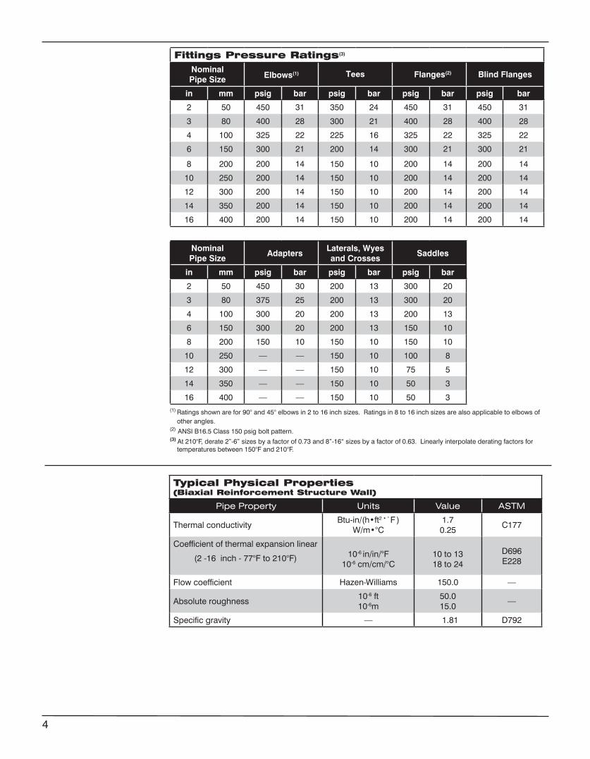
Fittings Pressure Ratings(3)
NominalPipe Size Elbows(1) Tees Flanges(2) Blind Flanges
in mm psig bar psig bar psig bar psig bar
2 50 450 31 350 24 450 31 450 31
3 80 400 28 300 21 400 28 400 28
4 100 325 22 225 16 325 22 325 22
6 150 300 21 200 14 300 21 300 21
8 200 200 14 150 10 200 14 200 14
10 250 200 14 150 10 200 14 200 14
12 300 200 14 150 10 200 14 200 14
14 350 200 14 150 10 200 14 200 14
16 400 200 14 150 10 200 14 200 14
(1) Ratings shown are for 90° and 45° elbows in 2 to 16 inch sizes. Ratings in 8 to 16 inch sizes are also applicable to elbows of other angles.(2) ANSI B16.5 Class 150 psig bolt pattern.(3) At 210°F, derate 2”-6” sizes by a factor of 0.73 and 8”-16“ sizes by a factor of 0.63. Linearly interpolate derating factors for temperatures between 150°F and 210°F.
NominalPipe Size
AdaptersLaterals, Wyesand Crosses
Saddles
in mm psig bar psig bar psig bar
2 50 450 30 200 13 300 20
3 80 375 25 200 13 300 20
4 100 300 20 200 13 200 13
6 150 300 20 200 13 150 10
8 200 150 10 150 10 150 10
10 250 –– –– 150 10 100 8
12 300 –– –– 150 10 75 5
14 350 –– –– 150 10 50 3
16 400 –– –– 150 10 50 3
Typical Physical Properties(Biaxial Reinforcement Structure Wall)
Pipe Property Units Value ASTM
Thermal conductivityBtu-in/(h•ft2•°F )
W/m•°C1.7
0.25C177
Coefficient of thermal expansion linear
(2 -16 inch - 77°F to 210°F) 10-6 in/in/°F10-6 cm/cm/°C
10 to 1318 to 24
D696E228
Flow coefficient Hazen-Williams 150.0 —
Absolute roughness10-6 ft10-6m
50.015.0
—
Specific gravity — 1.81 D792
4
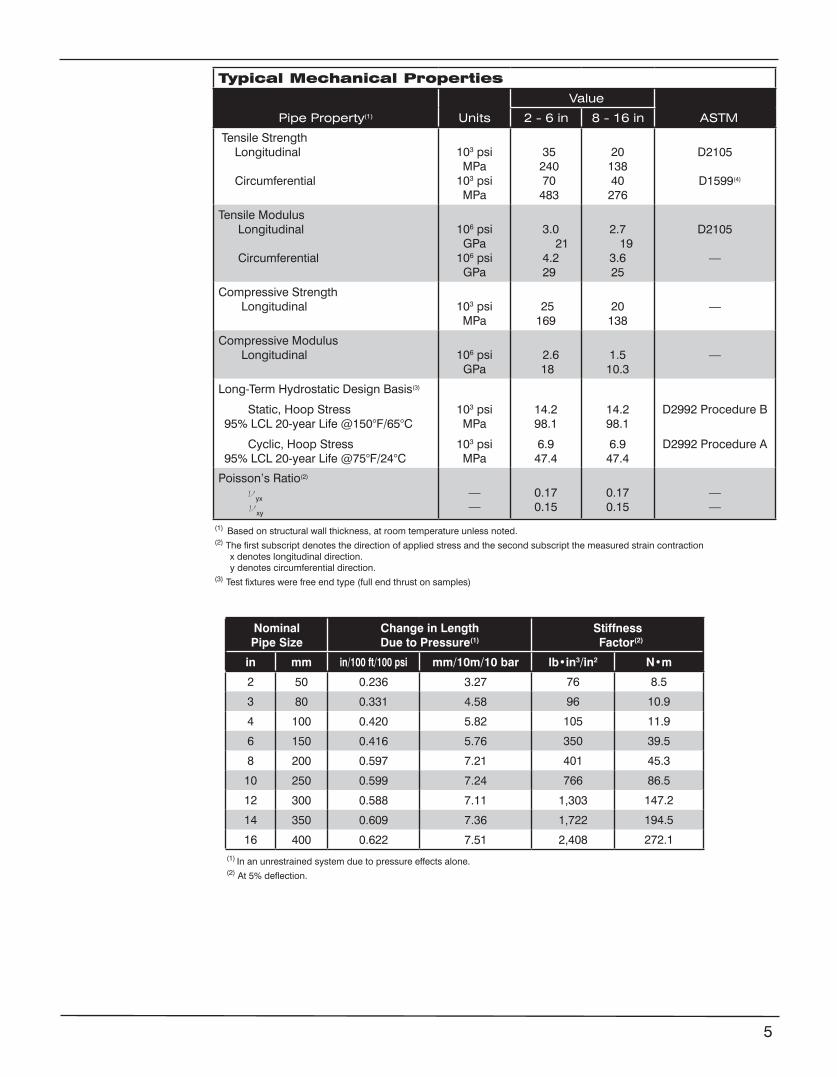
Typical Mechanical Properties
Pipe Property(1) Units
Value
ASTM 2 - 6 in 8 - 16 in
Tensile Strength Longitudinal
Circumferential
103 psiMPa
103 psiMPa
35 240 70
483
2013840
276
D2105
D1599(4)
Tensile Modulus Longitudinal
Circumferential
106 psiGPa
106 psiGPa
3.0 21
4.2 29
2.7 19
3.625
D2105
—
Compressive Strength Longitudinal 103 psi
MPa 25169
20138
—
Compressive Modulus Longitudinal 106 psi
GPa 2.6 18
1.510.3
—
Long-Term Hydrostatic Design Basis(3)
Static, Hoop Stress95% LCL 20-year Life @150°F/65°C
Cyclic, Hoop Stress95% LCL 20-year Life @75°F/24°C
103 psiMPa
103 psiMPa
14.298.1
6.947.4
14.298.1
6.947.4
D2992 Procedure B
D2992 Procedure A
Poisson’s Ratio(2)
νyx
νxy
——
0.170.15
0.170.15
——
(1) Based on structural wall thickness, at room temperature unless noted.(2) The first subscript denotes the direction of applied stress and the second subscript the measured strain contraction x denotes longitudinal direction. y denotes circumferential direction.(3) Test fixtures were free end type (full end thrust on samples)
NominalPipe Size
Change in LengthDue to Pressure(1)
Stiffness Factor(2)
in mm in/100 ft/100 psi mm/10m/10 bar lb•in3/in2 N•m
2 50 0.236 3.27 76 8.5
3 80 0.331 4.58 96 10.9
4 100 0.420 5.82 105 11.9
6 150 0.416 5.76 350 39.5
8 200 0.597 7.21 401 45.3
10 250 0.599 7.24 766 86.5
12 300 0.588 7.11 1,303 147.2
14 350 0.609 7.36 1,722 194.5
16 400 0.622 7.51 2,408 272.1(1) In an unrestrained system due to pressure effects alone.(2) At 5% deflection.
5
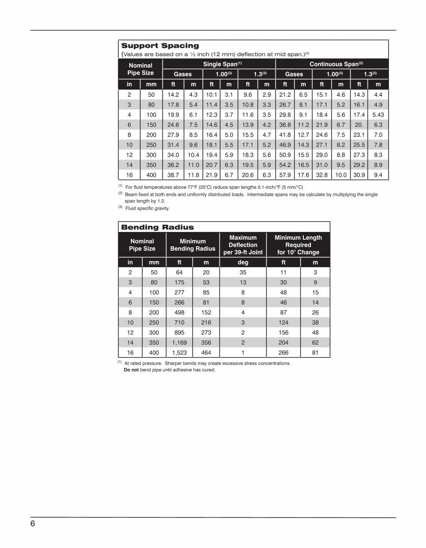
Support Spacing (Values are based on a ½ inch (12 mm) deflection at mid span.)(4)
Nominal Pipe Size
Single Span(1) Continuous Span(2)
Gases 1.00(3) 1.3(3) Gases 1.00(3) 1.3(3)
in mm ft m ft m ft m ft m ft m ft m
2 50 14.2 4.3 10.1 3.1 9.6 2.9 21.2 6.5 15.1 4.6 14.3 4.4
3 80 17.8 5.4 11.4 3.5 10.8 3.3 26.7 8.1 17.1 5.2 16.1 4.9
4 100 19.9 6.1 12.3 3.7 11.6 3.5 29.8 9.1 18.4 5.6 17.4 5.43
6 150 24.6 7.5 14.6 4.5 13.9 4.2 36.8 11.2 21.9 6.7 20. 6.3
8 200 27.9 8.5 16.4 5.0 15.5 4.7 41.8 12.7 24.6 7.5 23.1 7.0
10 250 31.4 9.6 18.1 5.5 17.1 5.2 46.9 14.3 27.1 8.2 25.5 7.8
12 300 34.0 10.4 19.4 5.9 18.3 5.6 50.9 15.5 29.0 8.8 27.3 8.3
14 350 36.2 11.0 20.7 6.3 19.5 5.9 54.2 16.5 31.0 9.5 29.2 8.9
16 400 38.7 11.8 21.9 6.7 20.6 6.3 57.9 17.6 32.8 10.0 30.9 9.4
(1) At rated pressure. Sharper bends may create excessive stress concentrations. Do not bend pipe until adhesive has cured.
Bending Radius(1)
NominalPipe Size
MinimumBending Radius
Maximum Deflection
per 39-ft Joint
Minimum Length Required
for 10° Change
in mm ft m deg ft m
2 50 64 20 35 11 3
3 80 175 53 13 30 9
4 100 277 85 8 48 15
6 150 266 81 8 46 14
8 200 498 152 4 87 26
10 250 710 216 3 124 38
12 300 895 273 2 156 48
14 350 1,169 356 2 204 62
16 400 1,523 464 1 266 81
6
(1) For fluid temperatures above 77°F (25°C) reduce span lengths 0.1-inch/°F (5 mm/°C)(2) Beam fixed at both ends and uniformly distributed loads. Intermediate spans may be calculate by multiplying the single span length by 1.2.(3) Fluid specific gravity.
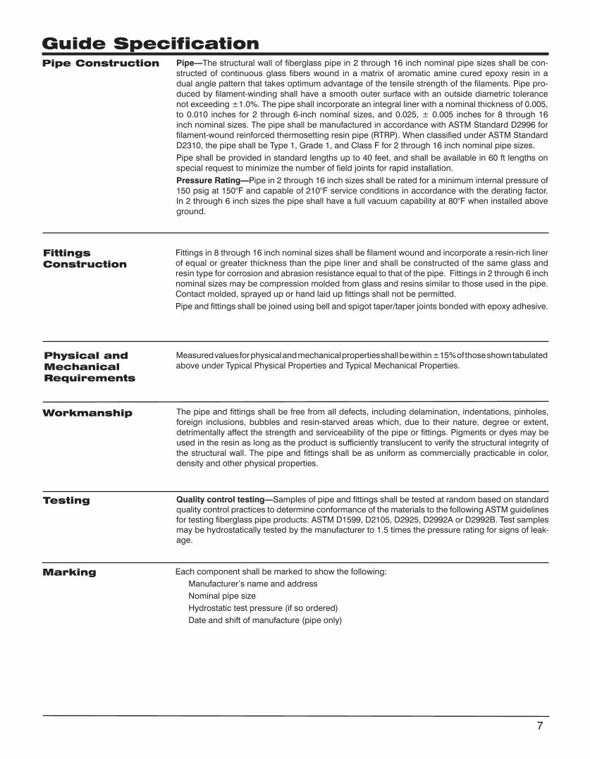
Pipe—The structural wall of fiberglass pipe in 2 through 16 inch nominal pipe sizes shall be con-structed of continuous glass fibers wound in a matrix of aromatic amine cured epoxy resin in a dual angle pattern that takes optimum advantage of the tensile strength of the filaments. Pipe pro-duced by filament-winding shall have a smooth outer surface with an outside diametric tolerance not exceeding ±1.0%. The pipe shall incorporate an integral liner with a nominal thickness of 0.005, to 0.010 inches for 2 through 6-inch nominal sizes, and 0.025, ± 0.005 inches for 8 through 16 inch nominal sizes. The pipe shall be manufactured in accordance with ASTM Standard D2996 for filament-wound reinforced thermosetting resin pipe (RTRP). When classified under ASTM Standard D2310, the pipe shall be Type 1, Grade 1, and Class F for 2 through 16 inch nominal pipe sizes.Pipe shall be provided in standard lengths up to 40 feet, and shall be available in 60 ft lengths on special request to minimize the number of field joints for rapid installation.Pressure Rating—Pipe in 2 through 16 inch sizes shall be rated for a minimum internal pressure of 150 psig at 150°F and capable of 210°F service conditions in accordance with the derating factor. In 2 through 6 inch sizes the pipe shall have a full vacuum capability at 80°F when installed above ground.
Fittings in 8 through 16 inch nominal sizes shall be filament wound and incorporate a resin-rich liner of equal or greater thickness than the pipe liner and shall be constructed of the same glass and resin type for corrosion and abrasion resistance equal to that of the pipe. Fittings in 2 through 6 inch nominal sizes may be compression molded from glass and resins similar to those used in the pipe. Contact molded, sprayed up or hand laid up fittings shall not be permitted.Pipe and fittings shall be joined using bell and spigot taper/taper joints bonded with epoxy adhesive.
Measured values for physical and mechanical properties shall be within ±15% of those shown tabulated above under Typical Physical Properties and Typical Mechanical Properties.
The pipe and fittings shall be free from all defects, including delamination, indentations, pinholes, foreign inclusions, bubbles and resin-starved areas which, due to their nature, degree or extent, detrimentally affect the strength and serviceability of the pipe or fittings. Pigments or dyes may be used in the resin as long as the product is sufficiently translucent to verify the structural integrity of the structural wall. The pipe and fittings shall be as uniform as commercially practicable in color, density and other physical properties.
Quality control testing—Samples of pipe and fittings shall be tested at random based on standard quality control practices to determine conformance of the materials to the following ASTM guidelines for testing fiberglass pipe products: ASTM D1599, D2105, D2925, D2992A or D2992B. Test samples may be hydrostatically tested by the manufacturer to 1.5 times the pressure rating for signs of leak-age.
Each component shall be marked to show the following: Manufacturer’s name and address Nominal pipe size Hydrostatic test pressure (if so ordered) Date and shift of manufacture (pipe only)
Pipe Construction
Fittings Construction
Physical and MechanicalRequirements
Workmanship
Testing
Marking
7
Guide Specification
www.fgspipe.com • [email protected]
©2013, National Oilwell Varco. All rights reserved.CI3010 - July 2013
National Oilwell Varco has produced this brochure for general information only, and it is not intended for design purposes. Although every effort has been made to maintain the accuracy and reliability of its contents, National Oilwell Varco in no way assumes responsibility for liability for any loss, damage or injury resulting from the use of information and data herein nor is any warranty expressed or implied. Always cross-reference the bulletin date with the most current version listed at the web site noted in this literature.
North America South America Europe Asia Pacific Middle East17115 San Pedro Ave. Suite 200 Estrada de Acesso á Zona P.O. Box 6, 4190 CA No. 7A, Tuas Avenue 3 P.O. Box 17324San Antonio, Texas 78232 USA Industrial Portuária de Suape, s/no. Geldermalsen, The Netherlands Jurong, Singapore 639407 Dubai, UAEPhone: 210 477 7500 Recife, PE, Brazil 55.590-000 Phone: 31 345 587 587 Phone: 65 6861 6118 Phone: 971 4881 3566 Phone: 55 81 3501 0023
NSF 61
Uses andApplications
Performance Pipe and fittings are rated at 200 psig.
Operating plus surge pressures to 1.25 times rated operating pressure occurring three times or less per 24-hour period.
Temperatures to 150°F (66°C) maximum. Sub-zero temperatures will not affect the physical properties.
Full vacuum capabilities when buried and properly backfilled. For above ground use, refer to collapse pressures listed below under pipe pressure Typical Pipe Performance.
Recommended burial depth: 3 to 25 feet.
Recommended for water, waste water (pH 1 to 8.5), and mild chemicals. Consult Chemical Resistance Guide or contact NOV Fiber Glass Systems for recommendations for your particular application.
Individual system components may not have the same ratings as the pipe. Refer to the detailed product information for the specific components to determine the pressure rating for the system as a whole.
• Boiler feed water • Brine and brackish water • Chemical process piping • Cooling water• Demineralized water• Electroplating• Fire mains• Industrial plant piping • Municipal waste
• Oilfield gathering, transmission lines• Power plant and steel mill piping• Sewer lines and sewer force mains• Source and recycle water• Sump discharge• Vent lines • Water mains • Water treatment
Bondstrand™ Series 3200 Fiberglass Pipe Class 200 Fire Protection and General Industrial Service (For 2 - 6 inch diameters, use Series 3000 pipe and Fittings)
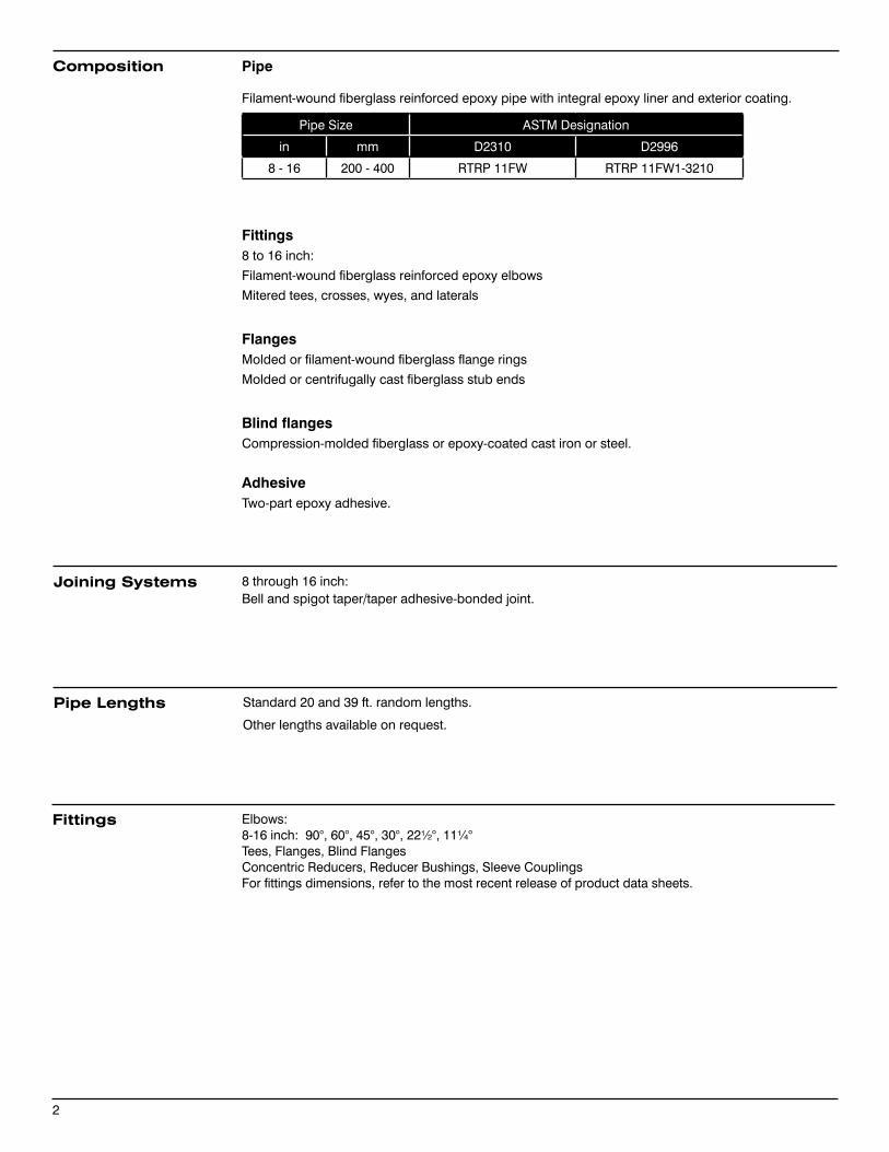
Pipe
Filament-wound fiberglass reinforced epoxy pipe with integral epoxy liner and exterior coating.
Pipe Size ASTM Designation
in mm D2310 D2996
8 - 16 200 - 400 RTRP 11FW RTRP 11FW1-3210
Fittings8 to 16 inch:
Filament-wound fiberglass reinforced epoxy elbows
Mitered tees, crosses, wyes, and laterals
FlangesMolded or filament-wound fiberglass flange rings
Molded or centrifugally cast fiberglass stub ends
Blind flangesCompression-molded fiberglass or epoxy-coated cast iron or steel.
AdhesiveTwo-part epoxy adhesive.
8 through 16 inch:Bell and spigot taper/taper adhesive-bonded joint.
Standard 20 and 39 ft. random lengths.
Other lengths available on request.
Composition
Joining Systems
Pipe Lengths
2
Elbows: 8-16 inch: 90° , 60°, 45°, 30°, 22½°, 11¼° Tees, Flanges, Blind FlangesConcentric Reducers, Reducer Bushings, Sleeve CouplingsFor fittings dimensions, refer to the most recent release of product data sheets.
Fittings
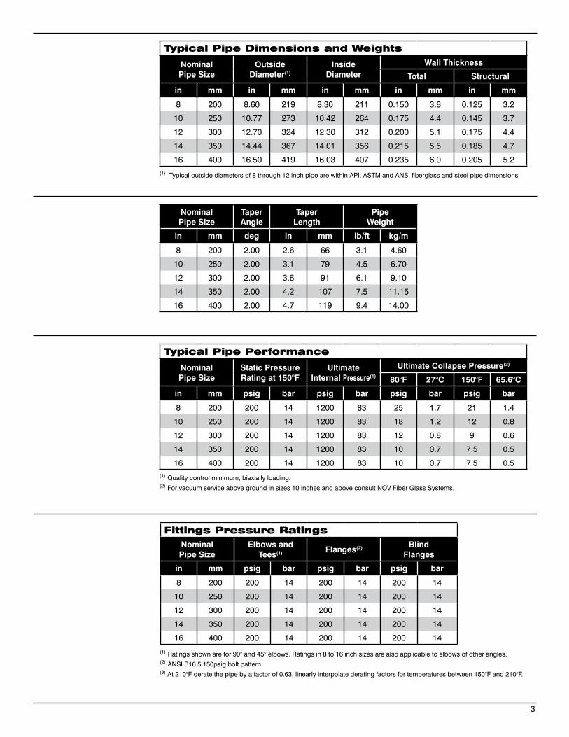
Typical Pipe Dimensions and Weights
NominalPipe Size
Outside Diameter(1)
Inside Diameter
Wall Thickness
Total Structural
in mm in mm in mm in mm in mm
8 200 8.60 219 8.30 211 0.150 3.8 0.125 3.2
10 250 10.77 273 10.42 264 0.175 4.4 0.145 3.7
12 300 12.70 324 12.30 312 0.200 5.1 0.175 4.4
14 350 14.44 367 14.01 356 0.215 5.5 0.185 4.7
16 400 16.50 419 16.03 407 0.235 6.0 0.205 5.2
NominalPipe Size
TaperAngle
Taper Length
Pipe Weight
in mm deg in mm lb/ft kg/m
8 200 2.00 2.6 66 3.1 4.60
10 250 2.00 3.1 79 4.5 6.70
12 300 2.00 3.6 91 6.1 9.10
14 350 2.00 4.2 107 7.5 11.15
16 400 2.00 4.7 119 9.4 14.00
Typical Pipe Performance
NominalPipe Size
Static Pressure Rating at 150°F
UltimateInternal Pressure(1)
Ultimate Collapse Pressure(2)
80°F 27°C 150°F 65.6°C
in mm psig bar psig bar psig bar psig bar
8 200 200 14 1200 83 25 1.7 21 1.4
10 250 200 14 1200 83 18 1.2 12 0.8
12 300 200 14 1200 83 12 0.8 9 0.6
14 350 200 14 1200 83 10 0.7 7.5 0.5
16 400 200 14 1200 83 10 0.7 7.5 0.5
(1) Typical outside diameters of 8 through 12 inch pipe are within API, ASTM and ANSI fiberglass and steel pipe dimensions.
(1) Quality control minimum, biaxially loading.(2) For vacuum service above ground in sizes 10 inches and above consult NOV Fiber Glass Systems.
3
Fittings Pressure RatingsNominalPipe Size
Elbows and Tees(1) Flanges(2) Blind
Flanges
in mm psig bar psig bar psig bar
8 200 200 14 200 14 200 14
10 250 200 14 200 14 200 14
12 300 200 14 200 14 200 14
14 350 200 14 200 14 200 14
16 400 200 14 200 14 200 14
(1) Ratings shown are for 90° and 45° elbows. Ratings in 8 to 16 inch sizes are also applicable to elbows of other angles.(2) ANSI B16.5 150psig bolt pattern(3) At 210°F derate the pipe by a factor of 0.63, linearly interpolate derating factors for temperatures between 150°F and 210°F.
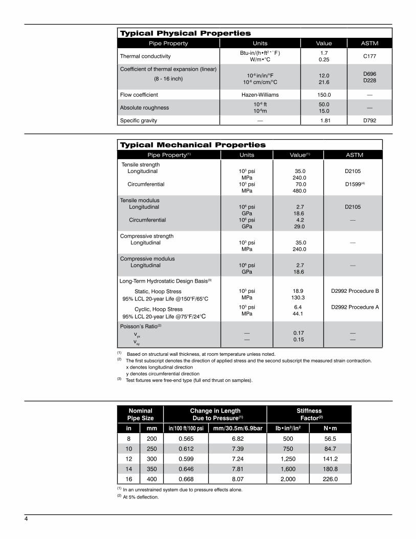
Typical Physical PropertiesPipe Property Units Value ASTM
Thermal conductivityBtu-in/(h•ft2•°F )
W/m•°C1.70.25
C177
Coefficient of thermal expansion (linear)
(8 - 16 inch) 10-6 in/in/°F10-6 cm/cm/°C
12.021.6
D696 D228
Flow coefficient Hazen-Williams 150.0 —
Absolute roughness10-6 ft10-6m
50.015.0
—
Specific gravity — 1.81 D792
4
Typical Mechanical PropertiesPipe Property(1) Units Value(1) ASTM
Tensile strength Longitudinal
Circumferential
103 psiMPa
103 psiMPa
35.0 240.0 70.0 480.0
D2105
D1599(4)
Tensile modulus Longitudinal
Circumferential
106 psiGPa
106 psiGPa
2.7 18.6 4.2 29.0
D2105
—
Compressive strength Longitudinal 103 psi
MPa 35.0 240.0
—
Compressive modulus Longitudinal 106 psi
GPa 2.7 18.6
—
103 psiMPa
103 psiMPa
18.9130.3
6.444.1
D2992 Procedure B
D2992 Procedure A
Poisson’s Ratio(2)
νyx
νxy
——
0.17 0.15
——
(1) Based on structural wall thickness, at room temperature unless noted.(2) The first subscript denotes the direction of applied stress and the second subscript the measured strain contraction. x denotes longitudinal direction y denotes circumferential direction(3) Test fixtures were free-end type (full end thrust on samples).
(1) In an unrestrained system due to pressure effects alone.(2) At 5% deflection.
NominalPipe Size
Change in Length Due to Pressure(1)
Stiffness Factor(2)
in mm in/100 ft/100 psi mm/30.5m/6.9bar lb•in3/in2 N•m
8 200 0.565 6.82 500 56.5
10 250 0.612 7.39 750 84.7
12 300 0.599 7.24 1,250 141.2
14 350 0.646 7.81 1,600 180.8
16 400 0.668 8.07 2,000 226.0
Long-Term Hydrostatic Design Basis(3)
Static, Hoop Stress95% LCL 20-year Life @150°F/65°C
Cyclic, Hoop Stress95% LCL 20-year Life @75°F/24°C
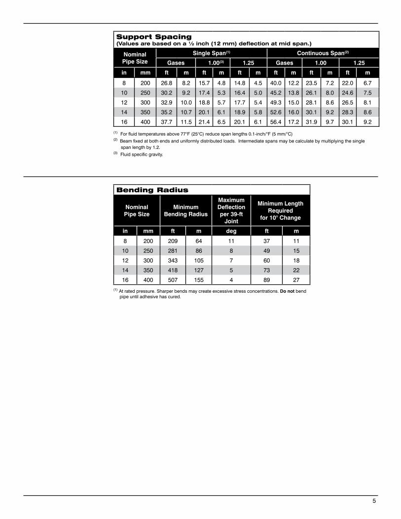
5
Support Spacing(Values are based on a ½ inch (12 mm) deflection at mid span.)
Nominal Pipe Size
Single Span(1) Continuous Span(2)
Gases 1.00(3) 1.25 Gases 1.00 1.25
in mm ft m ft m ft m ft m ft m ft m
8 200 26.8 8.2 15.7 4.8 14.8 4.5 40.0 12.2 23.5 7.2 22.0 6.7
10 250 30.2 9.2 17.4 5.3 16.4 5.0 45.2 13.8 26.1 8.0 24.6 7.5
12 300 32.9 10.0 18.8 5.7 17.7 5.4 49.3 15.0 28.1 8.6 26.5 8.1
14 350 35.2 10.7 20.1 6.1 18.9 5.8 52.6 16.0 30.1 9.2 28.3 8.6
16 400 37.7 11.5 21.4 6.5 20.1 6.1 56.4 17.2 31.9 9.7 30.1 9.2
(1) At rated pressure. Sharper bends may create excessive stress concentrations. Do not bend pipe until adhesive has cured.
Bending Radius
NominalPipe Size
MinimumBending Radius
Maximum Deflectionper 39-ft
Joint
Minimum Length Required
for 10° Change
in mm ft m deg ft m
8 200 209 64 11 37 11
10 250 281 86 8 49 15
12 300 343 105 7 60 18
14 350 418 127 5 73 22
16 400 507 155 4 89 27
(1) For fluid temperatures above 77°F (25°C) reduce span lengths 0.1-inch/°F (5 mm/°C)(2) Beam fixed at both ends and uniformly distributed loads. Intermediate spans may be calculate by multiplying the single span length by 1.2.(3) Fluid specific gravity.
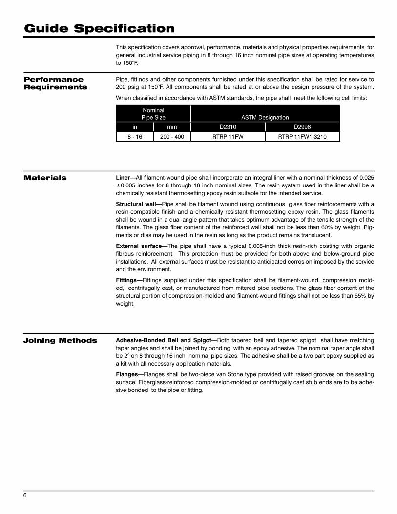
This specification covers approval, performance, materials and physical properties requirements for general industrial service piping in 8 through 16 inch nominal pipe sizes at operating temperatures to 150°F.
Pipe, fittings and other components furnished under this specification shall be rated for service to 200 psig at 150°F. All components shall be rated at or above the design pressure of the system.
When classified in accordance with ASTM standards, the pipe shall meet the following cell limits:
NominalPipe Size ASTM Designation
in mm D2310 D2996
8 - 16 200 - 400 RTRP 11FW RTRP 11FW1-3210
Liner—All filament-wound pipe shall incorporate an integral liner with a nominal thickness of 0.025 ±0.005 inches for 8 through 16 inch nominal sizes. The resin system used in the liner shall be a chemically resistant thermosetting epoxy resin suitable for the intended service.
Structural wall—Pipe shall be filament wound using continuous glass fiber reinforcements with a resin-compatible finish and a chemically resistant thermo setting epoxy resin. The glass filaments shall be wound in a dual-angle pattern that takes optimum advantage of the tensile strength of the filaments. The glass fiber content of the reinforced wall shall not be less than 60% by weight. Pig-ments or dies may be used in the resin as long as the product remains translucent.
External surface—The pipe shall have a typical 0.005-inch thick resin-rich coating with organic fibrous reinforcement. This protection must be provided for both above and below-ground pipe installations. All external surfaces must be resistant to anticipated corrosion imposed by the service and the environment.
Fittings—Fittings supplied under this specification shall be filament-wound, compression mold-ed, centrifugally cast, or manufactured from mitered pipe sections. The glass fiber content of the structural portion of compression-molded and filament-wound fittings shall not be less than 55% by weight.
Adhesive-Bonded Bell and Spigot—Both tapered bell and tapered spigot shall have matching taper angles and shall be joined by bonding with an epoxy adhesive. The nominal taper angle shall be 2° on 8 through 16 inch nominal pipe sizes. The adhesive shall be a two part epoxy supplied as a kit with all necessary application materials.
Flanges—Flanges shall be two-piece van Stone type provided with raised grooves on the sealing surface. Fiberglass-reinforced compression-molded or centrifugally cast stub ends are to be adhe-sive bonded to the pipe or fitting.
6
PerformanceRequirements
Materials
Joining Methods
Guide Specification
Pipe—Pipe shall be manufactured to steel pipe outside diameters in 8 through 12 inch nominal pipe sizes and should be based on nominal inside diameters in 14 inch sizes and above. Outside diameter tolerances shall not exceed ±1.0%. Pipe shall be provided in 40 feet random lengths (34 through 42 ft. unless otherwise specified. Up to 10% shorts may be included in any shipment unless otherwise agreed upon in writing between purchaser and manufacturer.
Wall thickness—The total wall thickness of pipe furnished to this specification shall not at any point less than 87.5 percent of the nominal thickness. Nominal wall thickness shall have dimensions as given in the manufacturer’s published literature.
Fittings and flanges—Fittings and flanges shall have dimensions as given in the manufacturer’s published literature. Flanges shall be drilled to match ANSI B16.5, Class 150 unless specified other-wise in the purchase order.
Values for physical and mechanical properties shall be no less than 95% of those shown tabulated above under Typical Physical Properties and Typical Mechanical Properties.
The pipe and fittings shall be free from all defects, including delamination, indentations, pinholes, foreign inclusions, bubbles and resin-starved areas which, due to their nature, degree or extent, detrimentally affect the strength and serviceability of the pipe or fittings. Pigments or dyes may be used in the resin as long as the product is sufficiently translucent to verify the structural integrity of the structural wall. The pipe and fittings shall be as uniform as commercially practicable in color, density and other physical properties.
Quality control testing—Samples of pipe and fittings shall be tested at random based on standard quality control practices to determine conformance of the materials to the following tests: weight, ta-per angle, short-term rupture strength, cyclic pressure performance, ring crush strength and degree of cure. Each item shall be visually inspected for workmanship.
Proof testing—All components shall be hydrostatically tested by the manufacturer to 1.5 times the pressure rating for signs of leakage or porosity.
Each component shall be marked to show the following: Manufacturer’s name and address Nominal pipe size Pressure class Hydrostatic test pressure (if so ordered) Date and shift of manufacture (pipe only)
Pipe Construction
Physical and MechanicalRequirements
Workmanship
Testing
Marking
7
North America South America Europe Asia Pacific Middle East17115 San Pedro Avenue Estrada de Acesso à Zona P.O. Box 6, 4190 CA No. 7A, Tuas Avenue 3 P.O. Box 17324Suite 200 Industrial Portuária de Suape, s/no. Geldermalsen, The Netherlands Jurong, Singapore 639407 Dubai, UAESan Antonio, TX 78232 USA Recife, PE, Brazil 55.590-000 Phone: +31 345 587 587 Phone: +65 6861 6118 Phone: +971 4881 3566 Phone: +1 210 477 7500 Phone: +55 81 3501 0023
© 2013 National Oilwell Varco. All rights reserved.CI3200 - July 2013
National Oilwell Varco has produced this brochure for general information only, and it is not intended for design purposes. Although every effort has been made to maintain the accuracy and reliability of its contents, National Oilwell Varco in no way assumes responsibility for liability for any loss, damage or injury resulting from the use of information and data herein. All applications for the material described are at the user’s risk and are the user’s responsibility.All brands listed are trademarks of National Oilwell Varco.
www.fgspipe.com • [email protected]
Bondstrand™ Series 3200A Fiberglass Pipe(General Industrial Service)(For sizes 2 through 6 inch, use Series 3000A pipe and fittings products)
www.fgspipe.com • [email protected]
Uses andApplications
Performance Pipe and fittings are rated at 200 psig.
Operating plus surge pressures to 1.25 times rated operating pressure occurring three times or less per 24-hour period.
No thrust blocks are required at rated system pressure for most buried piping configurations and most soil conditions. For above ground use, consult NOV Fiber Glass Systems.
Temperatures to 210°F (99°C) maximum. Sub-zero temperatures will not affect the physical properties. Water in pipe must not be allowed to freeze.
Vacuum to -14.7 psig when buried and properly backfilled. For above ground use, refer to collapse pressures listed below under pipe pressure Typical Pipe Performance.
Recommended burial depth: 3 to 25 feet.
Recommended for water, waste water (pH 1 to 12), and mild chemicals. Consult Bondstrand Corrosion Guide or contact NOV Fiber Glass Systems for recommendations for your particular application.
Individual system components may not have the same ratings as the pipe. Refer to the detailed product information for the specific components to determine the pressure rating for the system as a whole.
• Boiler feed water • Brine and brackish water • Chemical process piping • Cooling water• Demineralized water• Electroplating• Industrial plant piping • Municipal waste• Oilfield piping
• Potable Water - NSF 61 Listed• Power plant and steel mill piping• Sewer lines and sewer force mains• Source and recycle water• Sump discharge• Vent lines • Water mains • Water treatment
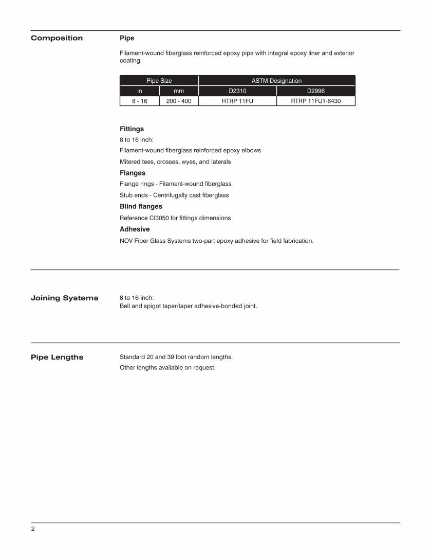
Pipe
Filament-wound fiberglass reinforced epoxy pipe with integral epoxy liner and exterior coating.
Pipe Size ASTM Designation
in mm D2310 D2996
8 - 16 200 - 400 RTRP 11FU RTRP 11FU1-6430
Fittings
8 to 16 inch:
Filament-wound fiberglass reinforced epoxy elbows
Mitered tees, crosses, wyes, and laterals
Flanges
Flange rings - Filament-wound fiberglass
Stub ends - Centrifugally cast fiberglass
Blind flanges
Reference CI3050 for fittings dimensions
Adhesive
NOV Fiber Glass Systems two-part epoxy adhesive for field fabrication.
8 to 16-inch:Bell and spigot taper/taper adhesive-bonded joint.
Standard 20 and 39 foot random lengths.
Other lengths available on request.
Composition
Joining Systems
Pipe Lengths
2
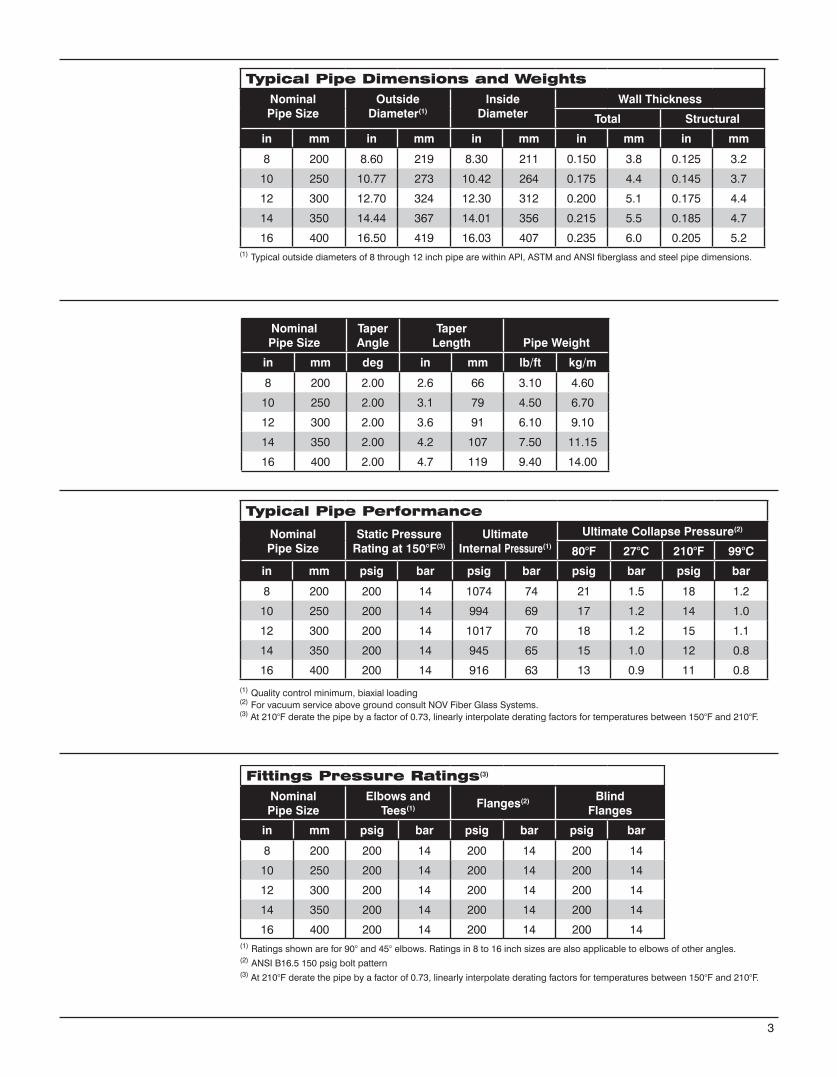
Typical Pipe Dimensions and WeightsNominalPipe Size
Outside Diameter(1)
Inside Diameter
Wall Thickness
Total Structural
in mm in mm in mm in mm in mm
8 200 8.60 219 8.30 211 0.150 3.8 0.125 3.2
10 250 10.77 273 10.42 264 0.175 4.4 0.145 3.7
12 300 12.70 324 12.30 312 0.200 5.1 0.175 4.4
14 350 14.44 367 14.01 356 0.215 5.5 0.185 4.7
16 400 16.50 419 16.03 407 0.235 6.0 0.205 5.2
NominalPipe Size
TaperAngle
Taper Length Pipe Weight
in mm deg in mm lb/ft kg/m
8 200 2.00 2.6 66 3.10 4.60
10 250 2.00 3.1 79 4.50 6.70
12 300 2.00 3.6 91 6.10 9.10
14 350 2.00 4.2 107 7.50 11.15
16 400 2.00 4.7 119 9.40 14.00
Typical Pipe Performance
NominalPipe Size
Static Pressure Rating at 150°F(3)
UltimateInternal Pressure(1)
Ultimate Collapse Pressure(2)
80°F 27°C 210°F 99°C
in mm psig bar psig bar psig bar psig bar
8 200 200 14 1074 74 21 1.5 18 1.2
10 250 200 14 994 69 17 1.2 14 1.0
12 300 200 14 1017 70 18 1.2 15 1.1
14 350 200 14 945 65 15 1.0 12 0.8
16 400 200 14 916 63 13 0.9 11 0.8
(1) Typical outside diameters of 8 through 12 inch pipe are within API, ASTM and ANSI fiberglass and steel pipe dimensions.
(1) Quality control minimum, biaxial loading(2) For vacuum service above ground consult NOV Fiber Glass Systems.(3) At 210°F derate the pipe by a factor of 0.73, linearly interpolate derating factors for temperatures between 150°F and 210°F.
3
Fittings Pressure Ratings(3))
NominalPipe Size
Elbows and Tees(1) Flanges(2) Blind
Flanges
in mm psig bar psig bar psig bar
8 200 200 14 200 14 200 14
10 250 200 14 200 14 200 14
12 300 200 14 200 14 200 14
14 350 200 14 200 14 200 14
16 400 200 14 200 14 200 14(1) Ratings shown are for 90° and 45° elbows. Ratings in 8 to 16 inch sizes are also applicable to elbows of other angles.(2) ANSI B16.5 150 psig bolt pattern(3) At 210°F derate the pipe by a factor of 0.73, linearly interpolate derating factors for temperatures between 150°F and 210°F.
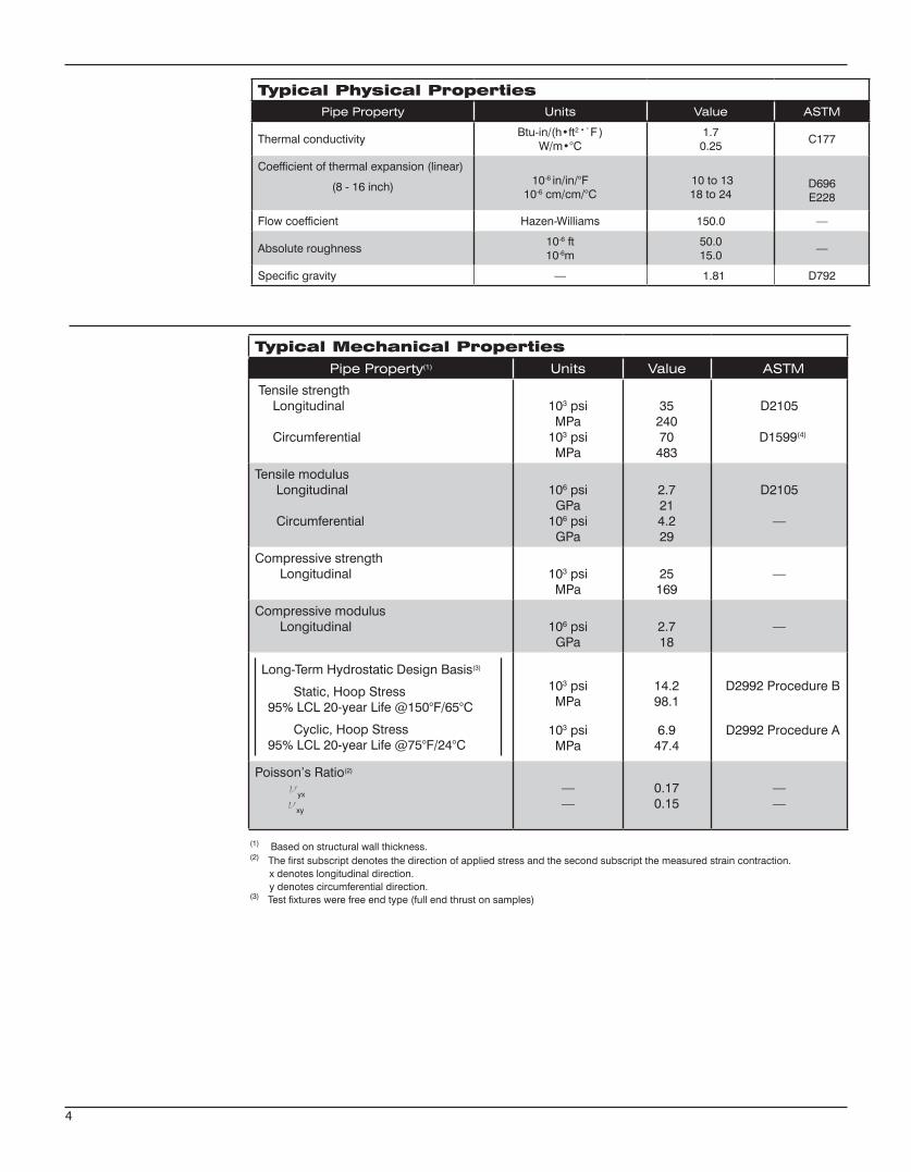
Typical Physical PropertiesPipe Property Units Value ASTM
Thermal conductivityBtu-in/(h•ft2•°F )
W/m•°C1.70.25
C177
Coefficient of thermal expansion (linear)
(8 - 16 inch) 10-6 in/in/°F10-6 cm/cm/°C
10 to 1318 to 24
D696E228
Flow coefficient Hazen-Williams 150.0 —
Absolute roughness10-6 ft10-6m
50.015.0
—
Specific gravity — 1.81 D792
4
(1) Based on structural wall thickness.(2) The first subscript denotes the direction of applied stress and the second subscript the measured strain contraction. x denotes longitudinal direction. y denotes circumferential direction.(3) Test fixtures were free end type (full end thrust on samples)
Typical Mechanical PropertiesPipe Property(1) Units Value ASTM
Tensile strength Longitudinal
Circumferential
103 psiMPa
103 psiMPa
3524070
483
D2105
D1599(4)
Tensile modulus Longitudinal
Circumferential
106 psiGPa
106 psiGPa
2.7214.229
D2105
—
Compressive strength Longitudinal 103 psi
MPa25
169—
Compressive modulus Longitudinal 106 psi
GPa2.718
—
Long-Term Hydrostatic Design Basis(3)
Static, Hoop Stress95% LCL 20-year Life @150°F/65°C
Cyclic, Hoop Stress95% LCL 20-year Life @75°F/24°C
103 psiMPa
103 psiMPa
14.298.1
6.947.4
D2992 Procedure B
D2992 Procedure A
Poisson’s Ratio(2)
νyx
νxy
——
0.170.15
——
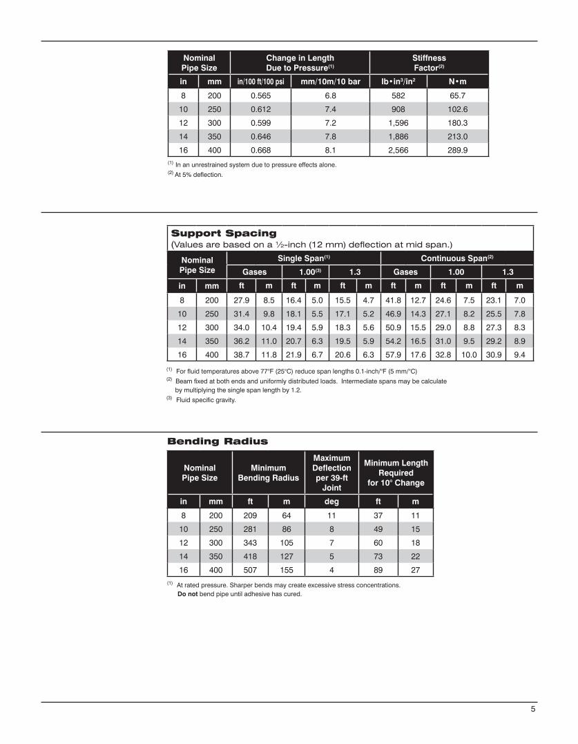
5
Support Spacing(Values are based on a ½-inch (12 mm) deflection at mid span.)
Nominal Pipe Size
Single Span(1) Continuous Span(2)
Gases 1.00(3) 1.3 Gases 1.00 1.3
in mm ft m ft m ft m ft m ft m ft m
8 200 27.9 8.5 16.4 5.0 15.5 4.7 41.8 12.7 24.6 7.5 23.1 7.0
10 250 31.4 9.8 18.1 5.5 17.1 5.2 46.9 14.3 27.1 8.2 25.5 7.8
12 300 34.0 10.4 19.4 5.9 18.3 5.6 50.9 15.5 29.0 8.8 27.3 8.3
14 350 36.2 11.0 20.7 6.3 19.5 5.9 54.2 16.5 31.0 9.5 29.2 8.9
16 400 38.7 11.8 21.9 6.7 20.6 6.3 57.9 17.6 32.8 10.0 30.9 9.4
(1) For fluid temperatures above 77°F (25°C) reduce span lengths 0.1-inch/°F (5 mm/°C)(2) Beam fixed at both ends and uniformly distributed loads. Intermediate spans may be calculate by multiplying the single span length by 1.2.(3) Fluid specific gravity.
(1) At rated pressure. Sharper bends may create excessive stress concentrations. Do not bend pipe until adhesive has cured.
NominalPipe Size
MinimumBending Radius
Maximum Deflectionper 39-ft
Joint
Minimum Length Required
for 10° Change
in mm ft m deg ft m
8 200 209 64 11 37 11
10 250 281 86 8 49 15
12 300 343 105 7 60 18
14 350 418 127 5 73 22
16 400 507 155 4 89 27
Bending Radius
(1) In an unrestrained system due to pressure effects alone.(2) At 5% deflection.
NominalPipe Size
Change in LengthDue to Pressure(1)
Stiffness Factor(2)
in mm in/100 ft/100 psi mm/10m/10 bar lb•in3/in2 N•m
8 200 0.565 6.8 582 65.7
10 250 0.612 7.4 908 102.6
12 300 0.599 7.2 1,596 180.3
14 350 0.646 7.8 1,886 213.0
16 400 0.668 8.1 2,566 289.9
This specification covers approval, performance, materials and physical properties requirements for general industrial service piping in 8 through 16 inch nominal pipe sizes at operating tempera-tures to 210°F.
Pipe, fittings and other components furnished under this specification shall be rated for ser-vice to 200 psig at 150°F and capable of 210°F service conditions in accordance with the de-rating factor. All components shall be rated at or above the design pressure of the system.
NominalPipe Size ASTM Designation
in mm D2310 D2996
8 - 16 200 - 400 RTRP 11FU RTRP 11FU-6430
Liner—All filament-wound pipe shall incorporate an integral liner with a nominal thickness of 0.025 ±0.005 inches for 8 through 16 inch nominal sizes. The resin system used in the liner shall be a chemically resistant thermosetting epoxy resin suitable for the intended service.
Structural Wall—Pipe shall be filament wound using continuous glass fiber reinforcements with a resin-compatible finish and a chemically resistant thermo setting epoxy resin. The glass filaments shall be wound in a dual-angle pattern that takes optimum advantage of the tensile strength of the filaments. The glass fiber content of the reinforced wall shall not be less than 60% by weight. Pig-ments or dies may be used in the resin as long as the product remains translucent.
External Surface—The pipe shall have a typical 0.005 inch thick resin-rich coating with organic fibrous reinforcement. This protection must be provided for both above and below-ground pipe installations. All external surfaces must be resistant to anticipated corrosion imposed by the service and the environment.
Fittings—Fittings supplied under this specification shall be filament-wound, compression mold-ed, centrifugally cast, or manufactured from mitered pipe sections. The glass fiber content of the structural portion of compression-molded and filament-wound fittings shall not be less than 55% by weight.
Adhesive-Bonded Bell and Spigot—Both tapered bell and tapered spigot shall have matching taper angles and shall be joined by bonding with an epoxy adhesive. The nominal taper angle shall be 2° on 8 through 16 inch nominal pipe sizes. The adhesive shall be a two-part epoxy supplied as a kit with all necessary application materials.
Flanges—Flanges shall be two-piece Van Stone type provided with raised grooves on the sealing surface. Fiberglass-reinforced, compression-molded or centrifugally cast stub ends are to be adhe-sive bonded to the pipe or fitting.
Adapters or Crossovers—The following adapters or crossovers shall be available on request:
Grooved end (8 inch nominal pipe sizes)
Cast iron pipe end (8 through 16 inch nominal pipe sizes)
6
PerformanceRequirements
Materials
Joining Methods
Guide Specification
Pipe—Pipe shall be manufactured to steel pipe outside diameters in 8 through 12 inch nominal pipe sizes and should be based on nominal inside diameters in 14 inch sizes and above. Outside diam-eter tolerances shall not exceed ±1.0%. Pipe shall be provided in 40 feet random lengths (34 through 42 ft) unless otherwise specified. Up to 10 percent shorts may be included in any shipment unless otherwise agreed upon in writing between purchaser and manufacturer.
Wall Thickness—The total wall thickness of pipe furnished to this specification shall not at any point be greater than 120 percent nor less than 87.5 percent of the nominal thickness. Nominal wall thick-ness shall have dimensions as given in the manufacturer’s published literature.
Fittings and Flanges—Fittings and flanges shall have dimensions as given in the manufacturer’s published literature. Flanges shall be drilled to match ANSI 816.5, Class 150 unless specified other-wise in the purchase order.
Values for physical and mechanical properties shall be within 15% of those shown tabulated above under Typical Physical Properties and Typical Mechanical Properties.
The pipe and fittings shall be free from all defects, including delamination, indentations, pinholes, foreign inclusions, bubbles and resin-starved areas which, due to their nature, degree or extent, detrimentally affect the strength and serviceability of the pipe or fittings. Pigments or dyes may be used in the resin as long as the product is sufficiently translucent to verify the structural integrity of the structural wall. The pipe and fittings shall be as uniform as commercially practicable in color, density and other physical properties.
Quality Control Testing—Samples of pipe and fittings shall be tested at random based on standard quality control practices to determine conformance of the materials to the following tests: weight, taper angle, short-term rupture strength, cyclic pressure performance, ring crush strength, Barcol hardness and degree of cure. Each item shall be visually inspected for workmanship.
Proof Testing—All components may be required to be hydrostatically tested by the manufacturer to 1.5 times the pressure rating for signs of leakage or porosity.
Each component shall be marked to show the following: Manufacturer’s name and address Nominal pipe size Pressure class Hydrostatic test pressure (if so ordered) UL Listing Mark (if so ordered) ULC Listing Mark (if so ordered) Date and shift of manufacture (pipe only)
Pipe Construction
Physical and MechanicalRequirements
Workmanship
Testing
Marking
7
www.fgspipe.com • [email protected]
©2013, National Oilwell Varco. All rights reserved.CI3210 - July 2013
National Oilwell Varco has produced this brochure for general information only, and it is not intended for design purposes. Although every effort has been made to maintain the accuracy and reliability of its contents, National Oilwell Varco in no way assumes responsibility for liability for any loss, damage or injury resulting from the use of information and data herein nor is any warranty expressed or implied. Always cross-reference the bulletin date with the most current version listed at the web site noted in this literature.
North America South America Europe Asia Pacific Middle East17115 San Pedro Ave. Suite 200 Estrada de Acesso á Zona P.O. Box 6, 4190 CA No. 7A, Tuas Avenue 3 P.O. Box 17324San Antonio, Texas 78232 USA Industrial Portuária de Suape, s/no. Geldermalsen, The Netherlands Jurong, Singapore 639407 Dubai, UAEPhone: 210 477 7500 Recife, PE, Brazil 55.590-000 Phone: 31 345 587 587 Phone: 65 6861 6118 Phone: 971 4881 3566 Phone: 55 81 3501 0023
NSF 61
Bondstrand Series 3300 Fiberglass Pipe(General Industrial Service)(For sizes 2 through 6 inch, use Series 3000 pipe and fittings products)
www.fgspipe.com • [email protected]
Uses andApplications
Performance Pipe and fittings are rated at 300 psig.
Operating plus surge pressures to 1.25 times rated operating pressure occurring three times or less per 24-hour period.
No thrust blocks are required at rated system pressure for most buried piping configurations and most soil conditions. For above ground use, consult NOV Fiber Glass Systems.
Temperatures to 150°F (66°C) maximum. Sub-zero temperatures will not affect the physical properties.
Full vacuum capability when buried and properly backfilled. For above ground use, refer to collapse pressures listed below under Typical Pipe Performance.
Recommended burial depth: 3 to 25 feet.
Recommended for water, waste water (pH 1 to 8.5), and mild chemicals. Consult Corrosion Guide or Applications Engineering for recommendations for your particular application.
Individual system components may not have the same ratings as the pipe. Refer to the detailed product information for the specific components to determine the pressure rating for the system as a whole.
• Boiler feed water • Brine and brackish water • Chemical process piping • Cooling water• Demineralized water• Electroplating• General service Class 300 piping• Industrial plant piping
• Municipal waste• Power plant and steel mill piping• Sewer lines and sewer force mains• Source and recycle water• Sump discharge• Vent lines • Water mains • Water treatment
Composition Pipe
Filament-wound fiberglass reinforced epoxy pipe with integral epoxy liner and exterior coating.
Nominal Pipe Size ASTM Designation
in mm D2310 D2996
8 - 16 200 - 400 RTRP 11FW RTRP 11FW1-3210
Fittings
8 to 16 inch: Filament-wound fiberglass reinforced epoxy elbows
Mitered tees, crosses, wyes, and laterals
Flanges
Filament-wound fiberglass flange rings
Filament wound fiberglass stub ends
Blind flanges
Compression-molded fiberglass or epoxy-coated cast iron or steel.
Adhesive
Two-part epoxy adhesive
8 to 16 inchBell and spigot taper/taper adhesive-bonded joint.
Standard 20 and 39 ft. random lengths.
Other lengths available on request.
Joining Systems
Pipe Lengths
2
Elbows:8 - 16 inch 90° 60° 45° 30° 221⁄2° 111⁄4°
Tees Flanges Blind flanges
Concentric reducers Reducer bushings Sleeve couplings
For fittings dimensions, refer to the most recent release of product data sheets.
Fittings
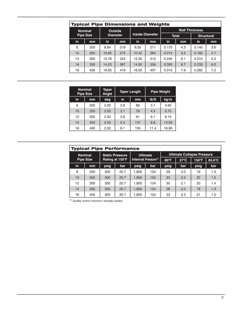
Typical Pipe Dimensions and Weights
NominalPipe Size
Outside Diameter Inside Diameter
Wall Thickness
Total Structural
in mm in mm in mm in mm in mm
8 200 8.64 219 8.30 211 0.170 4.3 0.140 3.6
10 250 10.85 273 10.42 264 0.215 5.5 0.185 4.7
12 300 12.78 324 12.30 312 0.240 6.1 0.210 5.3
14 350 14.53 367 14.00 356 0.265 6.7 0.235 6.0
16 400 16.65 419 16.03 407 0.310 7.9 0.282 7.2
NominalPipe Size
TaperAngle
Taper Length Pipe Weight
in mm deg in mm lb/ft kg/m
8 200 2.00 2.6 66 3.1 4.60
10 250 2.00 3.1 79 4.5 6.70
12 300 2.00 3.6 91 6.1 9.10
14 350 2.00 5.4 137 8.8 13.00
16 400 2.00 6.1 155 11.4 16.90
Typical Pipe Performance
NominalPipe Size
Static Pressure Rating at 150°F
UltimateInternal Pressure(1)
Ultimate Collapse Pressure
80°F 27°C 150°F 65.6°C
in mm psig bar psig bar psig bar psig bar
8 200 300 20.7 1,800 124 29 2.0 19 1.3
10 250 300 20.7 1,800 124 33 2.3 22 1.5
12 300 300 20.7 1,800 124 30 2.1 20 1.4
14 350 300 20.7 1,800 124 28 2.0 19 1.3
16 400 300 20.7 1,800 124 33 2.3 21 1.5(1) Quality control minimum, biaxially loaded.
3
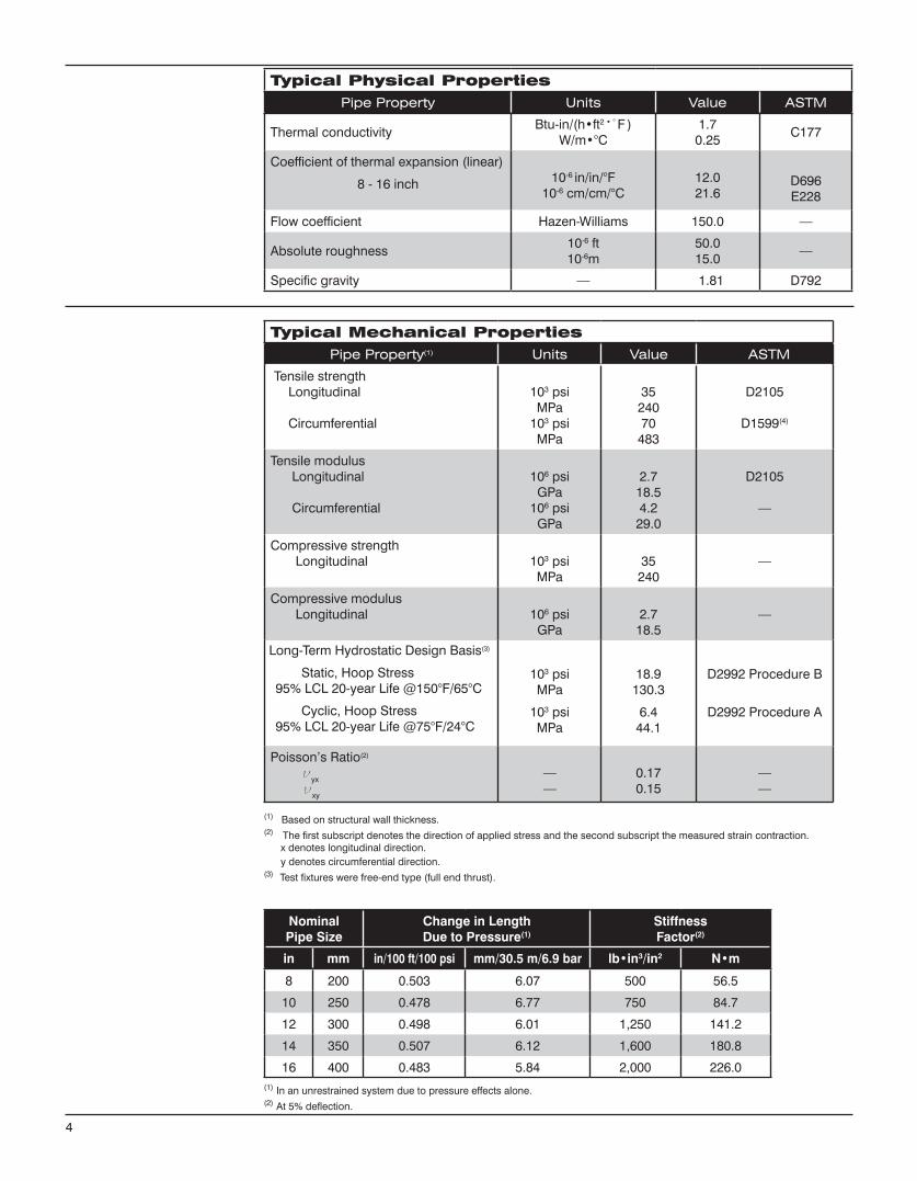
Typical Physical PropertiesPipe Property Units Value ASTM
Thermal conductivityBtu-in/(h•ft2•°F )
W/m•°C1.7
0.25C177
Coefficient of thermal expansion (linear)
8 - 16 inch 10-6 in/in/°F10-6 cm/cm/°C
12.021.6
D696E228
Flow coefficient Hazen-Williams 150.0 —
Absolute roughness10-6 ft10-6m
50.015.0
—
Specific gravity — 1.81 D792
4
Typical Mechanical PropertiesPipe Property(1) Units Value ASTM
Tensile strength Longitudinal
Circumferential
103 psiMPa
103 psiMPa
3524070
483
D2105
D1599(4)
Tensile modulus Longitudinal
Circumferential
106 psiGPa
106 psiGPa
2.718.54.2
29.0
D2105
—
Compressive strength Longitudinal 103 psi
MPa35
240—
Compressive modulus Longitudinal 106 psi
GPa2.7
18.5—
103 psiMPa
103 psiMPa
18.9130.3
6.444.1
D2992 Procedure B
D2992 Procedure A
Poisson’s Ratio(2)
νyx
νxy
——
0.170.15
——
(1) Based on structural wall thickness.(2) The first subscript denotes the direction of applied stress and the second subscript the measured strain contraction. x denotes longitudinal direction. y denotes circumferential direction.(3) Test fixtures were free-end type (full end thrust).
(1) In an unrestrained system due to pressure effects alone.(2) At 5% deflection.
NominalPipe Size
Change in LengthDue to Pressure(1)
Stiffness Factor(2)
in mm in/100 ft/100 psi mm/30.5 m/6.9 bar lb•in3/in2 N•m
8 200 0.503 6.07 500 56.5
10 250 0.478 6.77 750 84.7
12 300 0.498 6.01 1,250 141.2
14 350 0.507 6.12 1,600 180.8
16 400 0.483 5.84 2,000 226.0
Long-Term Hydrostatic Design Basis(3)
Static, Hoop Stress95% LCL 20-year Life @150°F/65°C
Cyclic, Hoop Stress95% LCL 20-year Life @75°F/24°C
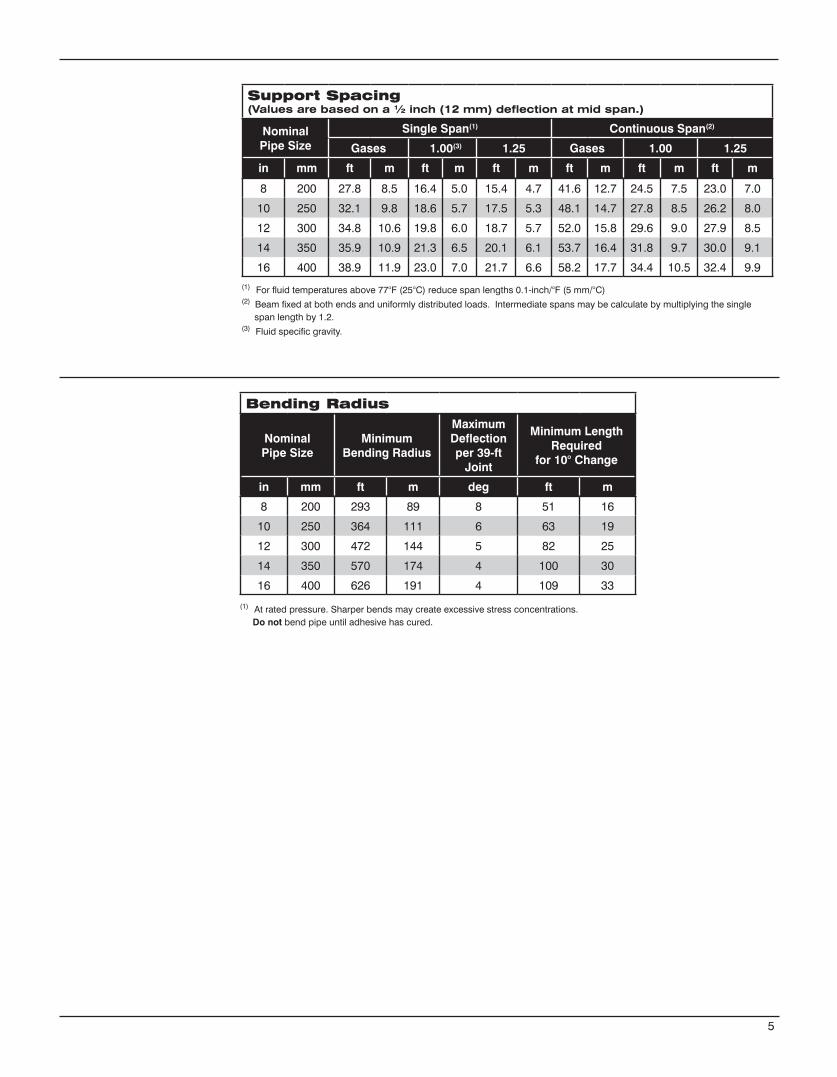
Support Spacing (Values are based on a ½ inch (12 mm) deflection at mid span.)
Nominal Pipe Size
Single Span(1) Continuous Span(2)
Gases 1.00(3) 1.25 Gases 1.00 1.25
in mm ft m ft m ft m ft m ft m ft m
8 200 27.8 8.5 16.4 5.0 15.4 4.7 41.6 12.7 24.5 7.5 23.0 7.0
10 250 32.1 9.8 18.6 5.7 17.5 5.3 48.1 14.7 27.8 8.5 26.2 8.0
12 300 34.8 10.6 19.8 6.0 18.7 5.7 52.0 15.8 29.6 9.0 27.9 8.5
14 350 35.9 10.9 21.3 6.5 20.1 6.1 53.7 16.4 31.8 9.7 30.0 9.1
16 400 38.9 11.9 23.0 7.0 21.7 6.6 58.2 17.7 34.4 10.5 32.4 9.9
(1) At rated pressure. Sharper bends may create excessive stress concentrations. Do not bend pipe until adhesive has cured.
Bending Radius
NominalPipe Size
MinimumBending Radius
Maximum Deflectionper 39-ft
Joint
Minimum Length Required
for 10° Change
in mm ft m deg ft m
8 200 293 89 8 51 16
10 250 364 111 6 63 19
12 300 472 144 5 82 25
14 350 570 174 4 100 30
16 400 626 191 4 109 33
5
(1) For fluid temperatures above 77°F (25°C) reduce span lengths 0.1-inch/°F (5 mm/°C)(2) Beam fixed at both ends and uniformly distributed loads. Intermediate spans may be calculate by multiplying the single span length by 1.2.(3) Fluid specific gravity.
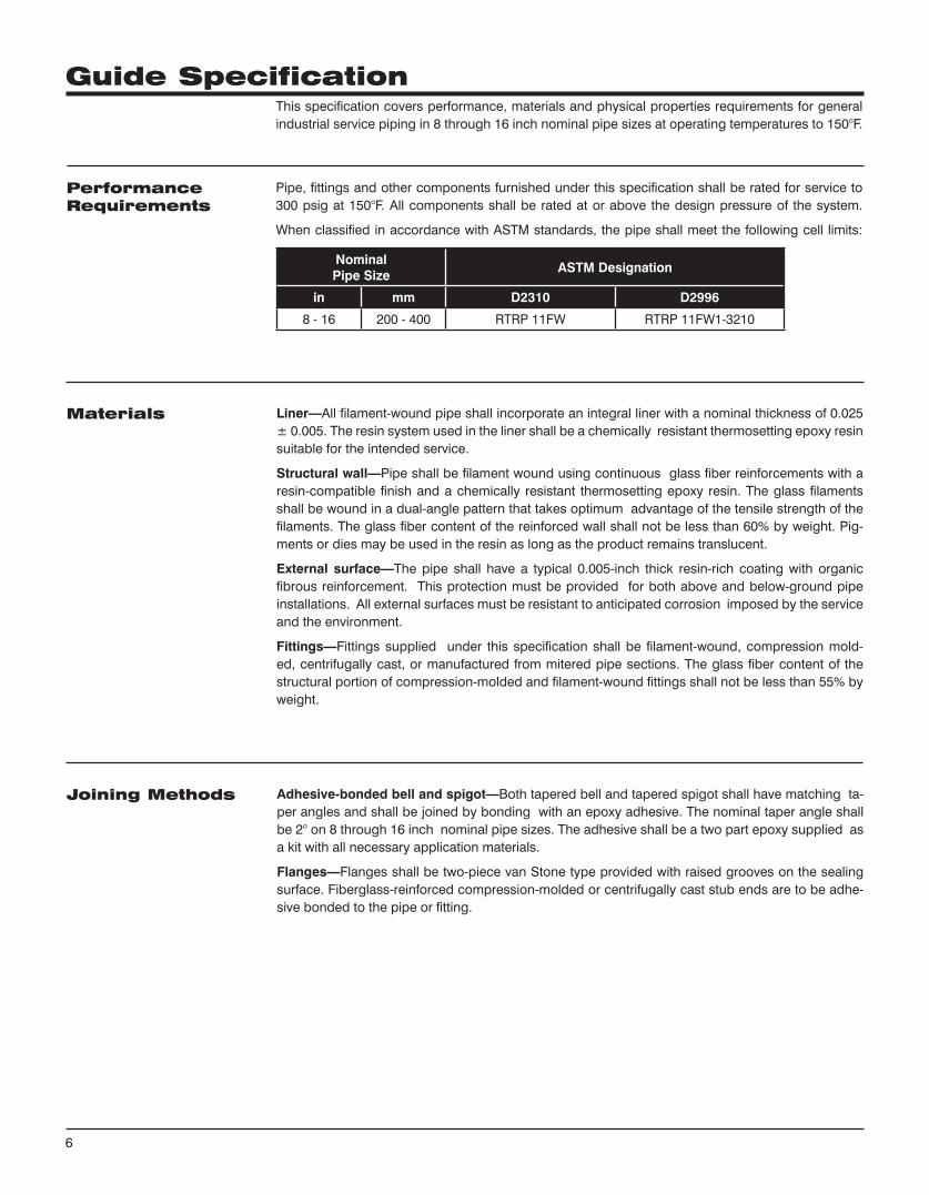
This specification covers performance, materials and physical properties requirements for general industrial service piping in 8 through 16 inch nominal pipe sizes at operating temperatures to 150°F.
Pipe, fittings and other components furnished under this specification shall be rated for service to 300 psig at 150°F. All components shall be rated at or above the design pressure of the system.
When classified in accordance with ASTM standards, the pipe shall meet the following cell limits:
NominalPipe Size
ASTM Designation
in mm D2310 D2996
8 - 16 200 - 400 RTRP 11FW RTRP 11FW1-3210
Liner—All filament-wound pipe shall incorporate an integral liner with a nominal thickness of 0.025 ± 0.005. The resin system used in the liner shall be a chemically resistant thermosetting epoxy resin suitable for the intended service.
Structural wall—Pipe shall be filament wound using continuous glass fiber reinforcements with a resin-compatible finish and a chemically resistant thermo setting epoxy resin. The glass filaments shall be wound in a dual-angle pattern that takes optimum advantage of the tensile strength of the filaments. The glass fiber content of the reinforced wall shall not be less than 60% by weight. Pig-ments or dies may be used in the resin as long as the product remains translucent.
External surface—The pipe shall have a typical 0.005-inch thick resin-rich coating with organic fibrous reinforcement. This protection must be provided for both above and below-ground pipe installations. All external surfaces must be resistant to anticipated corrosion imposed by the service and the environment.
Fittings—Fittings supplied under this specification shall be filament-wound, compression mold-ed, centrifugally cast, or manufactured from mitered pipe sections. The glass fiber content of the structural portion of compression-molded and filament-wound fittings shall not be less than 55% by weight.
Adhesive-bonded bell and spigot—Both tapered bell and tapered spigot shall have matching ta-per angles and shall be joined by bonding with an epoxy adhesive. The nominal taper angle shall be 2° on 8 through 16 inch nominal pipe sizes. The adhesive shall be a two part epoxy supplied as a kit with all necessary application materials.
Flanges—Flanges shall be two-piece van Stone type provided with raised grooves on the sealing surface. Fiberglass-reinforced compression-molded or centrifugally cast stub ends are to be adhe-sive bonded to the pipe or fitting.
PerformanceRequirements
Materials
Joining Methods
6
Guide Specification
Pipe—Outside diameter tolerances shall not exceed ±1.0%. Pipe shall be provided in 40-ft random lengths (34 through 42 ft) unless otherwise specified. Up to 10 percent shorts may be included in any shipment unless otherwise agreed upon in writing between purchaser and manufacturer.
Wall thickness—The total wall thickness of pipe furnished to this specification shall not at any point be greater than 120 percent nor less than 87.5 percent of the nominal thickness. Nominal wall thick-ness shall have dimensions as given in the manufacturer’s published literature.
Fittings and flanges—Fittings and flanges shall have dimensions as given in the manufacturer’s published literature. Flanges shall be drilled to match ANSI B16.5, Class 150 unless specified other-wise in the purchase order.
Values for physical and mechanical properties shall be no less than 95% of those shown tabulated above under Typical Physical Properties and Typical Mechanical Properties.
The pipe and fittings shall be free from all defects, including delamination, indentations, pinholes, foreign inclusions, bubbles and resin-starved areas which, due to their nature, degree or extent, detrimentally affect the strength and serviceability of the pipe or fittings. Pigments or dyes may be used in the resin as long as the product is sufficiently translucent to verify the structural integrity of the structural wall. The pipe and fittings shall be as uniform as commercially practicable in color, density and other physical properties.
Quality control testing—Samples of pipe and fittings shall be tested at random based on standard quality control practices to determine conformance of the materials to the following ASTM guidelines for testing fiberglass pipe products: ASTM D1599, D2105, D2925, D2992A or D2992B. Test samples may be hydrostatically tested by the manufacturer to 1.5 times the pressure rating for signs of leak-age.
Each component shall be marked to show the following: Manufacturer’s name and address Nominal pipe size Hydrostatic test pressure (if so ordered) Date and shift of manufacture (pipe only)
Pipe Construction
Physical and MechanicalRequirements
Workmanship
Testing
Marking
7

www.fgspipe.com • [email protected]
©2013, National Oilwell Varco. All rights reserved.CI3300 - July 2013
National Oilwell Varco has produced this brochure for general information only, and it is not intended for design purposes. Although every effort has been made to maintain the accuracy and reliability of its contents, National Oilwell Varco in no way assumes responsibility for liability for any loss, damage or injury resulting from the use of information and data herein nor is any warranty expressed or implied. Always cross-reference the bulletin date with the most current version listed at the web site noted in this literature.
North America South America Europe Asia Pacific Middle East17115 San Pedro Ave. Suite 200 Estrada de Acesso á Zona P.O. Box 6, 4190 CA No. 7A, Tuas Avenue 3 P.O. Box 17324San Antonio, Texas 78232 USA Industrial Portuária de Suape, s/no. Geldermalsen, The Netherlands Jurong, Singapore 639407 Dubai, UAEPhone: 210 477 7500 Recife, PE, Brazil 55.590-000 Phone: 31 345 587 587 Phone: 65 6861 6118 Phone: 971 4881 3566 Phone: 55 81 3501 0023
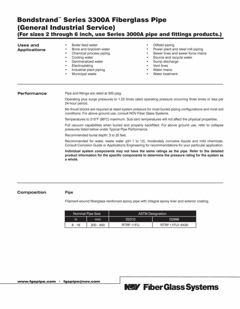
Bondstrand™ Series 3300A Fiberglass Pipe (General Industrial Service) (For sizes 2 through 6 inch, use Series 3000A pipe and fittings products.)
www.fgspipe.com • [email protected]
Uses andApplications
Performance Pipe and fittings are rated at 300 psig.
Operating plus surge pressures to 1.25 times rated operating pressure occurring three times or less per 24-hour period.
No thrust blocks are required at rated system pressure for most buried piping configurations and most soil conditions. For above ground use, consult NOV Fiber Glass Systems.
Temperatures to 210°F (99°C) maximum. Sub-zero temperatures will not affect the physical properties.
Full vacuum capabilities when buried and properly backfilled. For above ground use, refer to collapse pressures listed below under Typical Pipe Performance.
Recommended burial depth: 3 to 25 feet.
Recommended for water, waste water (pH 1 to 12), moderately corrosive liquids and mild chemicals. Consult Corrosion Guide or Applications Engineering for recommendations for your particular application.
Individual system components may not have the same ratings as the pipe. Refer to the detailed product information for the specific components to determine the pressure rating for the system as a whole.
• Boiler feed water • Brine and brackish water • Chemical process piping • Cooling water• Demineralized water• Electroplating• Industrial plant piping • Municipal waste
• Oilfield piping• Power plant and steel mill piping• Sewer lines and sewer force mains• Source and recycle water• Sump discharge• Vent lines • Water mains • Water treatment
Composition Pipe
Filament-wound fiberglass reinforced epoxy pipe with integral epoxy liner and exterior coating.
Nominal Pipe Size ASTM Designation
in mm D2310 D2996
8 - 16 200 - 400 RTRP 11FU RTRP 11FU1-6430
Fittings8 to 16 inch:
Filament-wound fiberglass reinforced epoxy elbows.
Filament wound and/or mitered tees
FlangesFilament-wound fiberglass flange rings
Filament wound fiberglass stub ends
Blind flangesCompression-molded fiberglass or epoxy-coated cast iron or steel.
NOV Fiber Glass Systems’ two-part epoxy adhesive for field fabrication.
8 to 16 inchBell and spigot taper/taper adhesive-bonded joint.
Standard 39 foot random lengths.
Other lengths available on request.
Joining Systems
Pipe Lengths
2
Adhesive
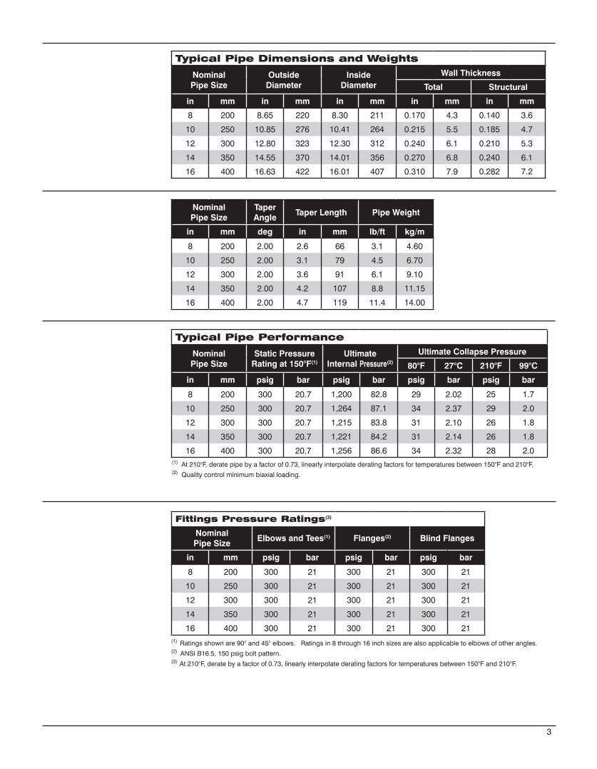
Typical Pipe Dimensions and Weights
NominalPipe Size
Outside Diameter
Inside Diameter
Wall Thickness
Total Structural
in mm in mm in mm in mm in mm
8 200 8.65 220 8.30 211 0.170 4.3 0.140 3.6
10 250 10.85 276 10.41 264 0.215 5.5 0.185 4.7
12 300 12.80 323 12.30 312 0.240 6.1 0.210 5.3
14 350 14.55 370 14.01 356 0.270 6.8 0.240 6.1
16 400 16.63 422 16.01 407 0.310 7.9 0.282 7.2
NominalPipe Size
TaperAngle
Taper Length Pipe Weight
in mm deg in mm lb/ft kg/m
8 200 2.00 2.6 66 3.1 4.60
10 250 2.00 3.1 79 4.5 6.70
12 300 2.00 3.6 91 6.1 9.10
14 350 2.00 4.2 107 8.8 11.15
16 400 2.00 4.7 119 11.4 14.00
Typical Pipe Performance
NominalPipe Size
Static Pressure Rating at 150°F(1)
UltimateInternal Pressure(2)
Ultimate Collapse Pressure
80°F 27°C 210°F 99°C
in mm psig bar psig bar psig bar psig bar
8 200 300 20.7 1,200 82.8 29 2.02 25 1.7
10 250 300 20.7 1,264 87.1 34 2.37 29 2.0
12 300 300 20.7 1,215 83.8 31 2.10 26 1.8
14 350 300 20.7 1,221 84.2 31 2.14 26 1.8
16 400 300 20.7 1,256 86.6 34 2.32 28 2.0(1) At 210°F, derate pipe by a factor of 0.73, linearly interpolate derating factors for temperatures between 150°F and 210°F.(2) Quality control minimum biaxial loading.
3
Fittings Pressure Ratings(3)
Nominal Pipe Size
Elbows and Tees(1) Flanges(2) Blind Flanges
in mm psig bar psig bar psig bar
8 200 300 21 300 21 300 21
10 250 300 21 300 21 300 21
12 300 300 21 300 21 300 21
14 350 300 21 300 21 300 21
16 400 300 21 300 21 300 21(1) Ratings shown are 90° and 45° elbows. Ratings in 8 through 16 inch sizes are also applicable to elbows of other angles.(2) ANSI B16.5, 150 psig bolt pattern.(3) At 210°F, derate by a factor of 0.73, linearly interpolate derating factors for temperatures between 150°F and 210°F.
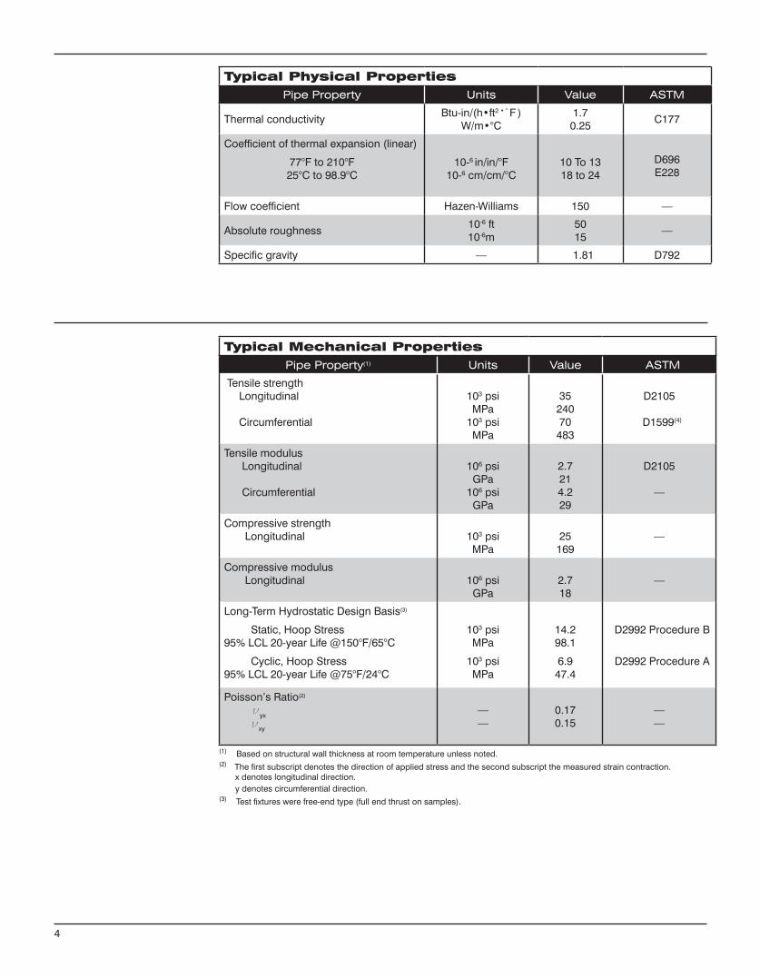
Typical Physical PropertiesPipe Property Units Value ASTM
Thermal conductivityBtu-in/(h•ft2•°F )
W/m•°C1.7
0.25C177
Coefficient of thermal expansion (linear)
77°F to 210°F25°C to 98.9°C
10-6 in/in/°F10-6 cm/cm/°C
10 To 1318 to 24
D696E228
Flow coefficient Hazen-Williams 150 —
Absolute roughness10-6 ft10-6m
5015
—
Specific gravity — 1.81 D792
4
Typical Mechanical PropertiesPipe Property(1) Units Value ASTM
Tensile strength Longitudinal
Circumferential
103 psiMPa
103 psiMPa
3524070
483
D2105
D1599(4)
Tensile modulus Longitudinal
Circumferential
106 psiGPa
106 psiGPa
2.7214.229
D2105
—
Compressive strength Longitudinal 103 psi
MPa25
169—
Compressive modulus Longitudinal 106 psi
GPa2.718
—
Long-Term Hydrostatic Design Basis(3)
Static, Hoop Stress95% LCL 20-year Life @150°F/65°C
Cyclic, Hoop Stress95% LCL 20-year Life @75°F/24°C
103 psiMPa
103 psiMPa
14.298.1
6.947.4
D2992 Procedure B
D2992 Procedure A
Poisson’s Ratio(2)
νyx
νxy
——
0.170.15
——
(1) Based on structural wall thickness at room temperature unless noted.(2) The first subscript denotes the direction of applied stress and the second subscript the measured strain contraction. x denotes longitudinal direction. y denotes circumferential direction.(3) Test fixtures were free-end type (full end thrust on samples).
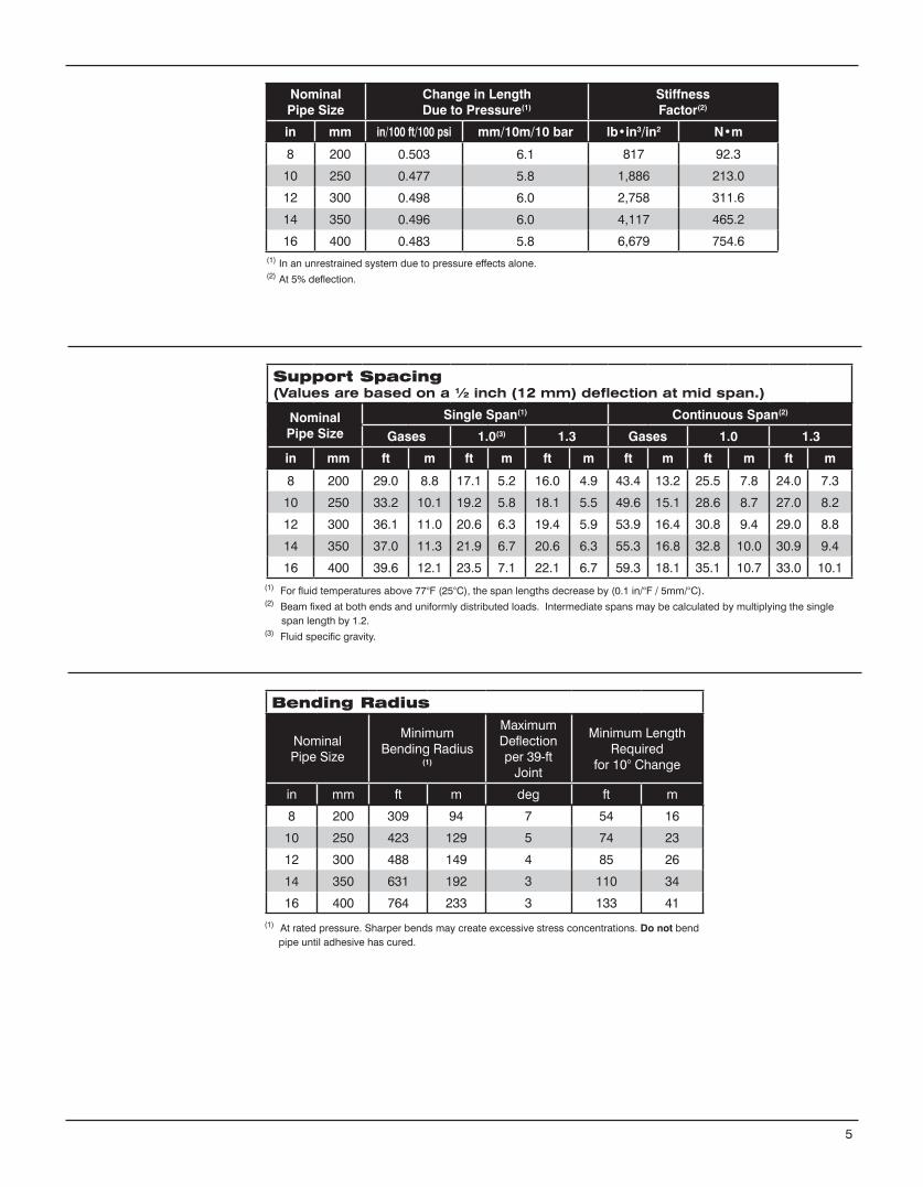
Support Spacing (Values are based on a ½ inch (12 mm) deflection at mid span.)
Nominal Pipe Size
Single Span(1) Continuous Span(2)
Gases 1.0(3) 1.3 Gases 1.0 1.3
in mm ft m ft m ft m ft m ft m ft m
8 200 29.0 8.8 17.1 5.2 16.0 4.9 43.4 13.2 25.5 7.8 24.0 7.3
10 250 33.2 10.1 19.2 5.8 18.1 5.5 49.6 15.1 28.6 8.7 27.0 8.2
12 300 36.1 11.0 20.6 6.3 19.4 5.9 53.9 16.4 30.8 9.4 29.0 8.8
14 350 37.0 11.3 21.9 6.7 20.6 6.3 55.3 16.8 32.8 10.0 30.9 9.4
16 400 39.6 12.1 23.5 7.1 22.1 6.7 59.3 18.1 35.1 10.7 33.0 10.1(1) For fluid temperatures above 77°F (25°C), the span lengths decrease by (0.1 in/°F / 5mm/°C).(2) Beam fixed at both ends and uniformly distributed loads. Intermediate spans may be calculated by multiplying the single span length by 1.2.(3) Fluid specific gravity.
(1) At rated pressure. Sharper bends may create excessive stress concentrations. Do not bend pipe until adhesive has cured.
Bending Radius
NominalPipe Size
MinimumBending Radius
(1)
Maximum Deflectionper 39-ft
Joint
Minimum Length Required
for 10° Change
in mm ft m deg ft m
8 200 309 94 7 54 16
10 250 423 129 5 74 23
12 300 488 149 4 85 26
14 350 631 192 3 110 34
16 400 764 233 3 133 41
5
NominalPipe Size
Change in LengthDue to Pressure(1)
Stiffness Factor(2)
in mm in/100 ft/100 psi mm/10m/10 bar lb•in3/in2 N•m
8 200 0.503 6.1 817 92.3
10 250 0.477 5.8 1,886 213.0
12 300 0.498 6.0 2,758 311.6
14 350 0.496 6.0 4,117 465.2
16 400 0.483 5.8 6,679 754.6(1) In an unrestrained system due to pressure effects alone.(2) At 5% deflection.
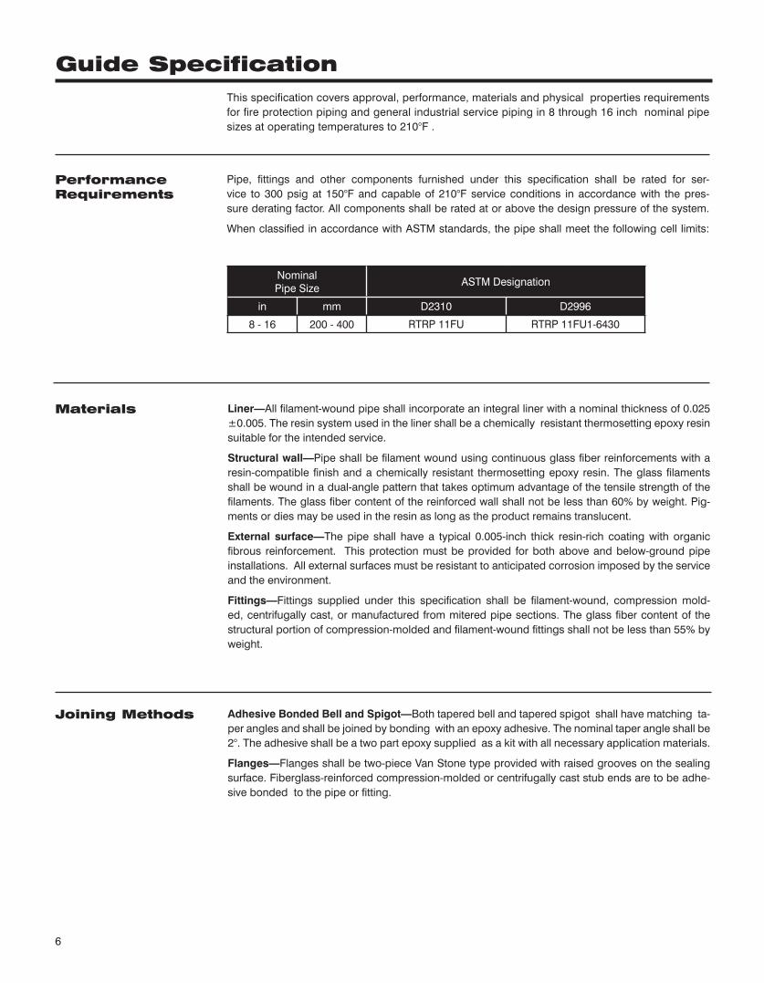
This specification covers approval, performance, materials and physical properties requirements for fire protection piping and general industrial service piping in 8 through 16 inch nominal pipe sizes at operating temperatures to 210°F .
Pipe, fittings and other components furnished under this specification shall be rated for ser-vice to 300 psig at 150°F and capable of 210°F service conditions in accordance with the pres-sure derating factor. All components shall be rated at or above the design pressure of the system.
When classified in accordance with ASTM standards, the pipe shall meet the following cell limits:
NominalPipe Size
ASTM Designation
in mm D2310 D2996
8 - 16 200 - 400 RTRP 11FU RTRP 11FU1-6430
Liner—All filament-wound pipe shall incorporate an integral liner with a nominal thickness of 0.025 ±0.005. The resin system used in the liner shall be a chemically resistant thermosetting epoxy resin suitable for the intended service.
Structural wall—Pipe shall be filament wound using continuous glass fiber reinforcements with a resin-compatible finish and a chemically resistant thermo setting epoxy resin. The glass filaments shall be wound in a dual-angle pattern that takes optimum advantage of the tensile strength of the filaments. The glass fiber content of the reinforced wall shall not be less than 60% by weight. Pig-ments or dies may be used in the resin as long as the product remains translucent.
External surface—The pipe shall have a typical 0.005-inch thick resin-rich coating with organic fibrous reinforcement. This protection must be provided for both above and below-ground pipe installations. All external surfaces must be resistant to anticipated corrosion imposed by the service and the environment.
Fittings—Fittings supplied under this specification shall be filament-wound, compression mold-ed, centrifugally cast, or manufactured from mitered pipe sections. The glass fiber content of the structural portion of compression-molded and filament-wound fittings shall not be less than 55% by weight.
Adhesive Bonded Bell and Spigot—Both tapered bell and tapered spigot shall have matching ta-per angles and shall be joined by bonding with an epoxy adhesive. The nominal taper angle shall be 2°. The adhesive shall be a two part epoxy supplied as a kit with all necessary application materials.
Flanges—Flanges shall be two-piece Van Stone type provided with raised grooves on the sealing surface. Fiberglass-reinforced compression-molded or centrifugally cast stub ends are to be adhe-sive bonded to the pipe or fitting.
PerformanceRequirements
Materials
Joining Methods
6
Guide Specification
Pipe—Outside diameter tolerances shall not exceed ±1.0%. Pipe shall be provided in 40 feet ran-dom lengths (34 through 42 ft) unless otherwise specified. Up to 10 percent shorts may be included in any shipment unless otherwise agreed upon in writing between purchaser and manufacturer.
Wall thickness—The total wall thickness of pipe furnished to this specification shall not at any point be greater than 120 percent nor less than 87.5 percent of the nominal thickness. Nominal wall thick-ness shall have dimensions as given in the manufacturer’s published literature.
Fittings and Flanges—Fittings and flanges shall have dimensions as given in the manufacturer’s published literature. Flanges shall be drilled to match ANSI B16.5, Class 150 unless specified other-wise in the purchase order.
Values for physical and mechanical properties shall be no less than ±15% of those shown tabu-lated above under Typical Physical Properties and Typical Mechanical Properties.
The pipe and fittings shall be free from all defects, including delamination, indentations, pinholes, foreign inclusions, bubbles and resin-starved areas which, due to their nature, degree or extent, detrimentally affect the strength and serviceability of the pipe or fittings. The pipe and fittings shall be as uniform as commercially practicable in color, density and other physical properties.
Quality Control Testing—Samples of pipe and fittings shall be tested at random based on standard quality control practices to determine conformance of the materials to the following tests: weight, taper angle, short-term rupture strength, cyclic pressure performance, ring crush strength, Barcol hardness and degree of cure. Each item shall be visually inspected for workmanship.
Components may be hydrostatically tested by the manufacturer to 1.5 times the pressure rating for signs of leakage or porosity at a frequency agreed upon between the manufacturer and the purchaser.
Each component shall be marked to show the following: Manufacturer’s name and address Nominal pipe size Hydrostatic test pressure (if so ordered) Date and shift of manufacture (pipe only)
Pipe Construction
Physical and MechanicalRequirements
Workmanship
Testing
Marking
7
www.fgspipe.com • [email protected]
©2013, National Oilwell Varco. All rights reserved.CI3310 - July 2013
National Oilwell Varco has produced this brochure for general information only, and it is not intended for design purposes. Although every effort has been made to maintain the accuracy and reliability of its contents, National Oilwell Varco in no way assumes responsibility for liability for any loss, damage or injury resulting from the use of information and data herein nor is any warranty expressed or implied. Always cross-reference the bulletin date with the most current version listed at the web site noted in this literature.
North America South America Europe Asia Pacific Middle East17115 San Pedro Ave. Suite 200 Estrada de Acesso á Zona P.O. Box 6, 4190 CA No. 7A, Tuas Avenue 3 P.O. Box 17324San Antonio, Texas 78232 USA Industrial Portuária de Suape, s/no. Geldermalsen, The Netherlands Jurong, Singapore 639407 Dubai, UAEPhone: 210 477 7500 Recife, PE, Brazil 55.590-000 Phone: 31 345 587 587 Phone: 65 6861 6118 Phone: 971 4881 3566 Phone: 55 81 3501 0023
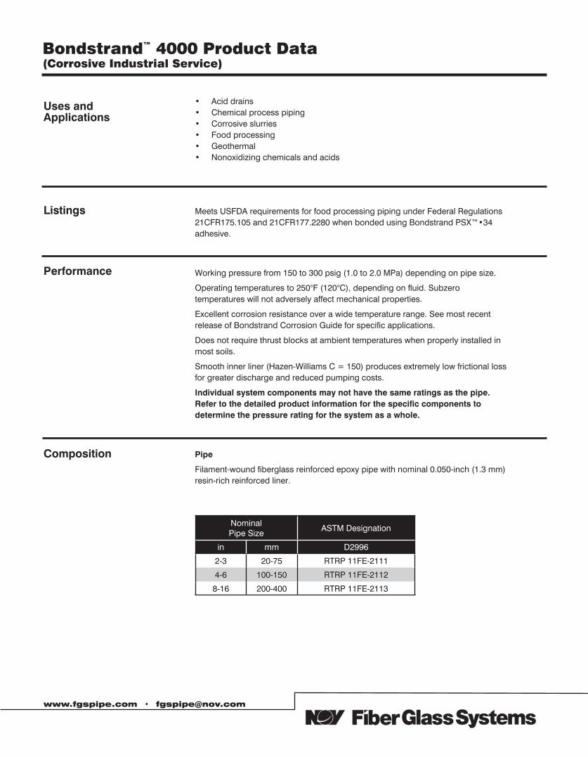
Uses and Applications
Listings Meets USFDA requirements for food processing piping under Federal Regulations 21CFR175.105 and 21CFR177.2280 when bonded using Bondstrand PSX™•34 adhesive.
Performance Working pressure from 150 to 300 psig (1.0 to 2.0 MPa) depending on pipe size.
Operating temperatures to 250°F (120°C), depending on fluid. Subzero temperatures will not adversely affect mechanical properties.
Excellent corrosion resistance over a wide temperature range. See most recent release of Bondstrand Corrosion Guide for specific applications.
Does not require thrust blocks at ambient temperatures when properly installed in most soils.
Smooth inner liner (Hazen-Williams C = 150) produces extremely low frictional loss for greater discharge and reduced pumping costs.
Individual system components may not have the same ratings as the pipe. Refer to the detailed product information for the specific components to determine the pressure rating for the system as a whole.
www.fgspipe.com • [email protected]
Composition Pipe
Filament-wound fiberglass reinforced epoxy pipe with nominal 0.050-inch (1.3 mm) resin-rich reinforced liner.
Nominal Pipe Size
ASTM Designation
in mm D2996
2-3 20-75 RTRP 11FE-2111
4-6 100-150 RTRP 11FE-2112
8-16 200-400 RTRP 11FE-2113
• Acid drains • Chemical process piping • Corrosive slurries • Food processing • Geothermal • Nonoxidizing chemicals and acids
Bondstrand™ 4000 Product Data(Corrosive Industrial Service)
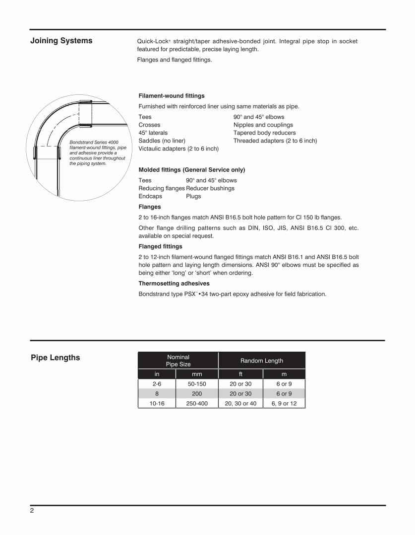
Filament-wound fittings
Furnished with reinforced liner using same materials as pipe.
Tees 90° and 45° elbows Crosses Nipples and couplings 45° laterals Tapered body reducers Saddles (no liner) Threaded adapters (2 to 6 inch) Victaulic adapters (2 to 6 inch)
Molded fittings (General Service only)
Tees 90° and 45° elbows Reducing flanges Reducer bushings Endcaps Plugs
Flanges
2 to 16-inch flanges match ANSI B16.5 bolt hole pattern for Cl 150 lb flanges.
Other flange drilling patterns such as DIN, ISO, JIS, ANSI B16.5 Cl 300, etc. available on special request.
Flanged fittings
2 to 12-inch filament-wound flanged fittings match ANSI B16.1 and ANSI B16.5 bolt hole pattern and laying length dimensions. ANSI 90° elbows must be specified as being either ‘long’ or ‘short’ when ordering.
Thermosetting adhesives
Bondstrand type PSX™•34 two-part epoxy adhesive for field fabrication.
Pipe Lengths
Bondstrand Series 4000 filament-wound fittings, pipe and adhesive provide a continuous liner throughout the piping system.
NominalPipe Size
Random Length
in mm ft m
2-6 50-150 20 or 30 6 or 9
8 200 20 or 30 6 or 9
10-16 250-400 20, 30 or 40 6, 9 or 12
Joining Systems Quick-Lock® straight/taper adhesive-bonded joint. Integral pipe stop in socket featured for predictable, precise laying length.
Flanges and flanged fittings.
2
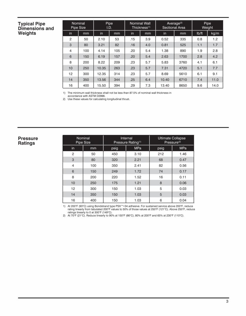
Typical PipeDimensions andWeights
PressureRatings
Nominal Pipe Size
PipeI.D.
Nominal Wall Thickness(1)
Average(2) Sectional Area
Pipe Weight
in mm in mm in mm in mm lb/ft kg/m
2 50 2.10 53 .15 3.9 0.52 335 0.8 1.2
3 80 3.21 82 .16 4.0 0.81 525 1.1 1.7
4 100 4.14 105 .20 5.4 1.38 890 1.9 2.8
6 150 6.19 157 .20 5.4 2.63 1700 2.8 4.2
8 200 8.22 209 .23 5.7 5.83 3760 4.1 6.1
10 250 10.35 263 .23 5.7 7.31 4720 5.1 7.7
12 300 12.35 314 .23 5.7 8.69 5610 6.1 9.1
14 350 13.56 344 .25 6.4 10.40 6710 7.4 11.0
16 400 15.50 394 .29 7.3 13.40 8650 9.6 14.0
1) The minimum wall thickness shall not be less than 87.5% of nominal wall thickness in accordance with ASTM D2996.
2) Use these values for calculating longitudinal thrust.
Nominal Pipe Size
Internal Pressure Rating(1)
Ultimate Collapse Pressure(2)
in mm psig MPa psig MPa
2 50 450 3.10 212 1.46
3 80 320 2.21 68 0.47
4 100 350 2.41 82 0.56
6 150 249 1.72 74 0.17
8 200 220 1.52 16 0.11
10 250 175 1.21 8 0.06
12 300 150 1.03 5 0.03
14 350 150 1.03 5 0.03
16 400 150 1.03 6 0.04
1) At 200°F (93°C) using Bondstrand type PSX™•34 adhesive. For sustained service above 200°F, reduce rating linearly from tabulated 200°F values to 50% of those values at 250°F (121°C). Above 250°F, reduce ratings linearly to 0 at 300°F (149°C).
2) At 70°F (21°C). Reduce linearly to 90% at 150°F (66°C), 80% at 200°F and 65% at 230°F (110°C).
3
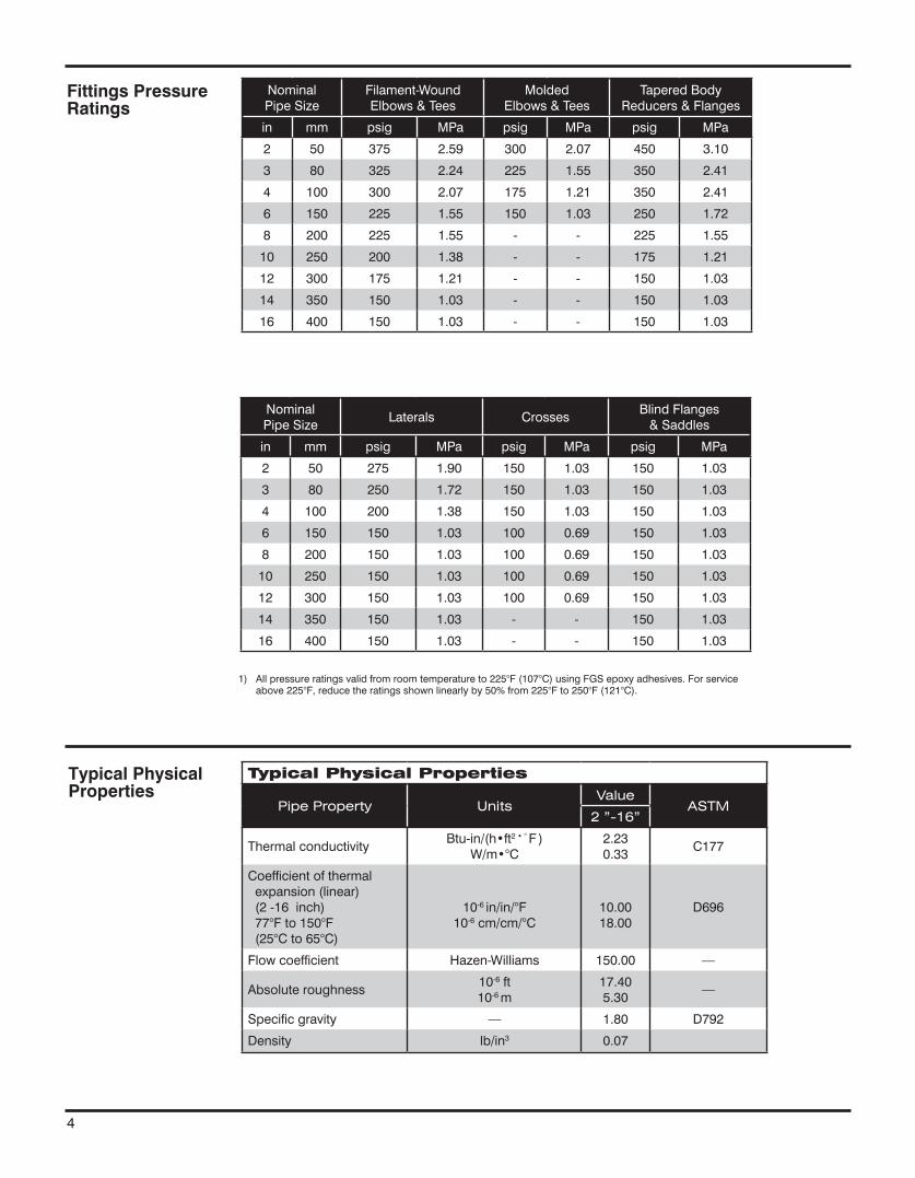
4
Fittings Pressure Ratings
Typical Physical Properties
Typical Physical Properties
Pipe Property UnitsValue
ASTM2 ”-16”
Thermal conductivityBtu-in/(h•ft2 • ° F )
W/m•°C2.230.33
C177
Coefficient of thermal expansion (linear) (2 -16 inch) 77°F to 150°F (25°C to 65°C)
10-6 in/in/°F10-6 cm/cm/°C
10.0018.00
D696
Flow coefficient Hazen-Williams 150.00 —
Absolute roughness10-6 ft10-6 m
17.405.30
—
Specific gravity — 1.80 D792
Density lb/in3 0.07
Nominal Pipe Size
Filament-Wound Elbows & Tees
Molded Elbows & Tees
Tapered Body Reducers & Flanges
in mm psig MPa psig MPa psig MPa
2 50 375 2.59 300 2.07 450 3.10
3 80 325 2.24 225 1.55 350 2.41
4 100 300 2.07 175 1.21 350 2.41
6 150 225 1.55 150 1.03 250 1.72
8 200 225 1.55 - - 225 1.55
10 250 200 1.38 - - 175 1.21
12 300 175 1.21 - - 150 1.03
14 350 150 1.03 - - 150 1.03
16 400 150 1.03 - - 150 1.03
Nominal Pipe Size
Laterals CrossesBlind Flanges
& Saddles
in mm psig MPa psig MPa psig MPa
2 50 275 1.90 150 1.03 150 1.03
3 80 250 1.72 150 1.03 150 1.03
4 100 200 1.38 150 1.03 150 1.03
6 150 150 1.03 100 0.69 150 1.03
8 200 150 1.03 100 0.69 150 1.03
10 250 150 1.03 100 0.69 150 1.03
12 300 150 1.03 100 0.69 150 1.03
14 350 150 1.03 - - 150 1.03
16 400 150 1.03 - - 150 1.03
1) All pressure ratings valid from room temperature to 225°F (107°C) using FGS epoxy adhesives. For service above 225°F, reduce the ratings shown linearly by 50% from 225°F to 250°F (121°C).
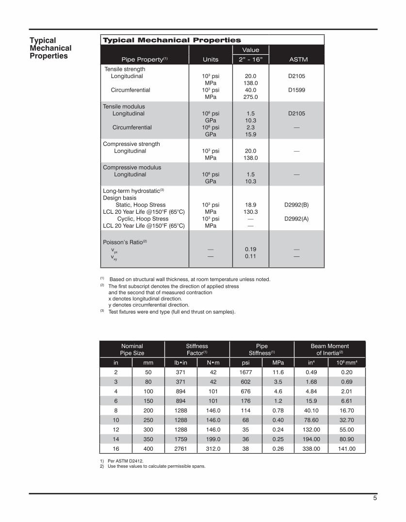
Typical Mechanical Properties
Pipe Property(1) Units
Value
ASTM 2” - 16”
Tensile strength Longitudinal
Circumferential
103 psiMPa
103 psiMPa
20.0138.040.0
275.0
D2105
D1599
Tensile modulus Longitudinal
Circumferential
106 psiGPa
106 psiGPa
1.510.32.3
15.9
D2105
—
Compressive strength Longitudinal 103 psi
MPa20.0
138.0—
Compressive modulus Longitudinal 106 psi
GPa1.5
10.3—
Long-term hydrostatic(3) Design basis Static, Hoop StressLCL 20 Year Life @150°F (65°C) Cyclic, Hoop StressLCL 20 Year Life @150°F (65°C)
103 psiMPa
103 psiMPa
18.9130.3
——
D2992(B)
D2992(A)
Poisson’s Ratio(2)
νyx
νxy
——
0.190.11
——
(1) Based on structural wall thickness, at room temperature unless noted.(2) The first subscript denotes the direction of applied stress and the second that of measured contraction x denotes longitudinal direction. y denotes circumferential direction.(3) Test fixtures were end type (full end thrust on samples).
TypicalMechanicalProperties
Nominal Pipe Size
Stiffness Factor(1)
Pipe Stiffness(1)
Beam Momentof Inertia(2)
in mm lb•in N•m psi MPa in4 106 mm4
2 50 371 42 1677 11.6 0.49 0.20
3 80 371 42 602 3.5 1.68 0.69
4 100 894 101 676 4.6 4.84 2.01
6 150 894 101 176 1.2 15.9 6.61
8 200 1288 146.0 114 0.78 40.10 16.70
10 250 1288 146.0 68 0.40 78.60 32.70
12 300 1288 146.0 35 0.24 132.00 55.00
14 350 1759 199.0 36 0.25 194.00 80.90
16 400 2761 312.0 38 0.26 338.00 141.00
1) Per ASTM D2412.2) Use these values to calculate permissible spans.
5
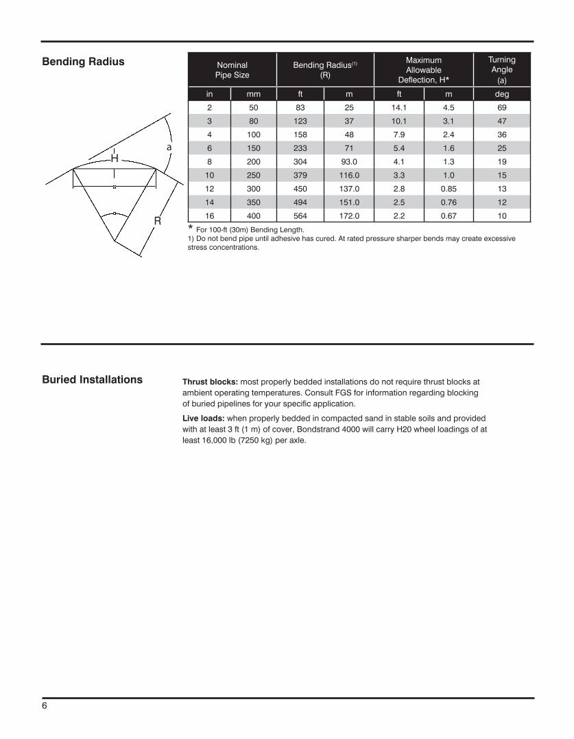
Bending Radius Nominal Pipe Size
Bending Radius(1)
(R)
Maximum Allowable
Deflection, H*
TurningAngle
(a)
in mm ft m ft m deg
2 50 83 25 14.1 4.5 69
3 80 123 37 10.1 3.1 47
4 100 158 48 7.9 2.4 36
6 150 233 71 5.4 1.6 25
8 200 304 93.0 4.1 1.3 19
10 250 379 116.0 3.3 1.0 15
12 300 450 137.0 2.8 0.85 13
14 350 494 151.0 2.5 0.76 12
16 400 564 172.0 2.2 0.67 10
* For 100-ft (30m) Bending Length.1) Do not bend pipe until adhesive has cured. At rated pressure sharper bends may create excessive stress concentrations.
c L
Buried Installations Thrust blocks: most properly bedded installations do not require thrust blocks at ambient operating temperatures. Consult FGS for information regarding blocking of buried pipelines for your specific application.
Live loads: when properly bedded in compacted sand in stable soils and provided with at least 3 ft (1 m) of cover, Bondstrand 4000 will carry H20 wheel loadings of at least 16,000 lb (7250 kg) per axle.
6
a
S
aH
R
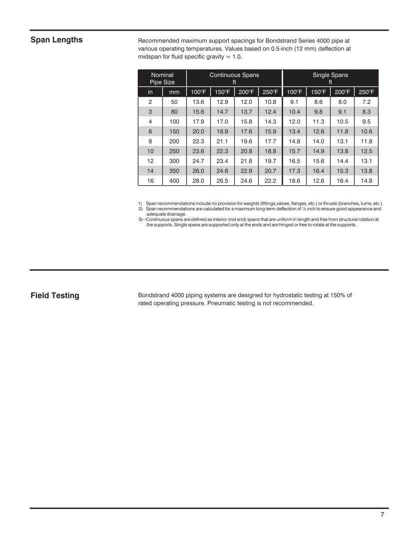
Span Lengths Recommended maximum support spacings for Bondstrand Series 4000 pipe at various operating temperatures. Values based on 0.5-inch (12 mm) deflection at midspan for fluid specific gravity = 1.0.
Field Testing Bondstrand 4000 piping systems are designed for hydrostatic testing at 150% of rated operating pressure. Pneumatic testing is not recommended.
Nominal Pipe Size
Continuous Spans ft
Single Spans ft
in mm 100°F 150°F 200°F 250°F 100°F 150°F 200°F 250°F
2 50 13.6 12.9 12.0 10.8 9.1 8.6 8.0 7.2
3 80 15.6 14.7 13.7 12.4 10.4 9.8 9.1 8.3
4 100 17.9 17.0 15.8 14.3 12.0 11.3 10.5 9.5
6 150 20.0 18.9 17.6 15.9 13.4 12.6 11.8 10.6
8 200 22.3 21.1 19.6 17.7 14.8 14.0 13.1 11.8
10 250 23.6 22.3 20.8 18.8 15.7 14.9 13.8 12.5
12 300 24.7 23.4 21.8 19.7 16.5 15.6 14.4 13.1
14 350 26.0 24.6 22.9 20.7 17.3 16.4 15.3 13.8
16 400 28.0 26.5 24.6 22.2 18.6 12.6 16.4 14.8
1) Span recommendations include no provision for weights (fittings,valves, flanges, etc.) or thrusts (branches, turns, etc.).2) Span recommendations are calculated for a maximum long-term deflection of 1/2 inch to ensure good appearance and
adequate drainage.3) Continuous spans are defined as interior (not end) spans that are uniform in length and free from structural rotation at
the supports. Single spans are supported only at the ends and are hinged or free to rotate at the supports.
7
www.fgspipe.com • [email protected]
© 2013, National Oilwell Varco. All rights reserved.CI4000 - April 2013
National Oilwell Varco has produced this brochure for general information only, and it is not intended for design purposes. Although every effort has been made to maintain the accuracy and reliability of its contents, National Oilwell Varco in no way assumes responsibility for liability for any loss, damage or injury resulting from the use of information and data herein nor is any warranty expressed or implied. Always cross-reference the bulletin date with the most current version listed at the web site noted in this literature.
North America South America Europe Asia Pacific Middle East17115 San Pedro Ave. Suite 200 Estrada de Acesso á Zona P.O. Box 6, 4190 CA No. 7A, Tuas Avenue 3 P.O. Box 17324San Antonio, Texas 78232 USA Industrial Portuária de Suape, s/no. Geldermalsen, The Netherlands Jurong, Singapore 639407 Dubai, UAEPhone: 210 477 7500 Recife, PE, Brazil 55.590-000 Phone: 31 345 587 587 Phone: 65 6861 6118 Phone: 971 4881 3566 Phone: 55 81 3501 0023
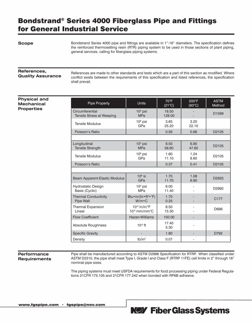
Bondstrand® Series 4000 Fiberglass Pipe and Fittingsfor General Industrial Service
Bondstrand Series 4000 pipe and fittings are available in 1”-16” diameters. The specification defines the reinforced thermosetting resin (RTR) piping system to be used in those sections of plant piping, general services, calling for fiberglass piping systems.
Scope
www.fgspipe.com • [email protected]
References,Quality Assurance
References are made to other standards and tests which are a part of this section as modified. Where conflict exists between the requirements of this specification and listed references, the specification shall prevail.
Physical andMechanicalProperties
Pipe Property Units70°F
(21°C)200°F (93°C)
ASTM Method
Circumferential Tensile Stress at Weeping
103 psiMPa
18.50128.00
--
D1599
Tensile Modulus106 psiGPa
3.6525.20
3.2022.10
Poisson’s Ratio 0.56 0.68 D2105
Longitudinal Tensile Strength
103 psiMPa
8.5058.60
6.9047.60
D2105
Tensile Modulus106 psiGPa
1.6011.10
1.248.60
D2105
Poisson’s Ratio 0.37 0.41 D2105
Beam Apparent-Elastic Modulus106 siGPa
1.7011.70
1.086.90
D2925
Hydrostatic Design Basis (Cyclic)
103 psiMPa
6.0011.40
--
D2992
Thermal Conductivity Pipe Wall
Btu•in/(hr•ft2•°F)W/m•C
1.700.25
--
C177
Thermal Expansion Linear
10-6 in/in/°F10-6 mm/mm°C
8.5015.30
--
D696
Flow Coefficient Hazen-Williams 150.00 -
Absolute Roughness 10-6 ft17.405.30
-
Specific Gravity - 1.80 - D792
Density lb/in3 0.07 -
PerformanceRequirements
Pipe shall be manufactured according to ASTM D2996 Specification for RTRP. When classified under ASTM D2310, the pipe shall meet Type I, Grade I and Class F (RTRP 11FE) cell limits in 2” through 16” nominal pipe sizes.
The piping systems must meet USFDA requirements for food processing piping under Federal Regula-tions 21CFR 175.105 and 21CFR 177.242 when bonded with RP6B adhesive.
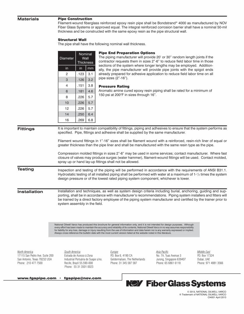
www.fgspipe.com • [email protected]
North America South America Europe Asia Pacific Middle East17115 San Pedro Ave. Suite 200 Estrada de Acesso á Zona P.O. Box 6, 4190 CA No. 7A, Tuas Avenue 3 P.O. Box 17324San Antonio, Texas 78232 USA Industrial Portuária de Suape s/no. Geldermalsen, The Netherlands Jurong, Singapore 639407 Dubai, UAEPhone: 210 477 7500 Recife, Brazil 55.590-000 Phone: 31 345 587 587 Phone: 65 6861 6118 Phone: 971 4881 3566 Phone: 55 31 3501 0023
National Oilwell Varco has produced this brochure for general information only, and it is not intended for design purposes. Although every effort has been made to maintain the accuracy and reliability of its contents, National Oilwell Varco in no way assumes responsibility for liability for any loss, damage or injury resulting from the use of information and data herein nor is any warranty expressed or implied. Always cross-reference the bulletin date with the most current version listed at the website noted in this literature.
© 2013, NATIONAL OILWELL VARCO® Trademark of NATIONAL OILWELL VARCO
CI4001 April 2013
Materials Pipe ConstructionFilament-wound fiberglass reinforced epoxy resin pipe shall be Bondstrand® 4000 as manufactured by NOV Fiber Glass Systems or approved equal. The integral reinforced corrosion barrier shall have a nominal 50-mil thickness and be constructed with the same epoxy resin as the pipe structural wall.
Structural WallThe pipe shall have the following nominal wall thickness.
Diameter Nominal
WallThickness
in in mm
2 .123 3.1
3 .126 3.2
4 .151 3.8
6 .181 4.6
8 .226 5.7
10 .226 5.7
12 .226 5.7
14 .250 6.4
16 .269 6.8
Pipe End Preparation OptionsThe piping manufacturer will provide 20’ or 30” random length joints if the contractor requests them in sizes 2”-6” to reduce field labor time in those sections of the system where longer lengths may be employed. Addition-ally, the pipe manufacturer will provide pipe joints with the spigot ends already prepared for adhesive application to reduce field labor time on all pipe sizes (2”-16”).
Pressure RatingAromatic amine cured epoxy resin piping shall be rated for a minimum of 150 psi at 200°F in sizes through 16”.
Fittings It is important to maintain compatibility of fittings, piping and adhesives to ensure that the system performs as specified. Pipe, fittings and adhesive shall be supplied by the same manufacturer.
Filament wound fittings in 1”-16” sizes shall be filament wound with a reinforced, resin-rich liner of equal or greater thickness than the pipe liner and shall be manufactured with the same resin type as the pipe.
Compression molded fittings in sizes 2”-6” may be used in some services; contact manufacturer. Where fast closure of valves may produce surges (water hammer), filament-wound fittings will be used. Contact molded, spray up or hand lay-up fittings shall not be allowed.
Inspection and testing of the piping will be performed in accordance with the requirements of ANSI B31.1. Hydrostatic testing of all installed piping shall be performed with water at a maximum of 1-1/2 times the system design pressure or of the lowest rated piping system component, whichever is lower.
Installation and techniques, as well as system design criteria including burial, anchoring, guiding and sup-porting, shall be in accordance with manufacturer’s recommendations. Piping system installers and fitters will be trained by a direct factory employee of the piping system manufacturer and certified by the trainer prior to system assembly in the field.
Testing
Installation

Bondstrand™ 5000/5000C Product Data (Severely Corrosive Industrial Service and Oxidizing Acids
• Aciddrains• Bleachprocessing• Chemicalprocesspiping• Chlorinatedwater• Chlorine• Corrosiveslurries• Foodprocessingplant• Organicchemicals• Oxidizingchemicalsandacids• Phosphoricacid• WaterTreatment/Purification• Generalindustrialserviceforseverelycorrosiveliquids
Uses and Applications
MeetsUSFDArequirementsforfoodprocessingpipingunderFederalRegulations21CFR175.105and21CFR177.2420whenassembledwithRP-105Bvinylesteradhesivefor5000andnRP-106for5000C(conductive).
Listings
Workingpressurefrom150to450psig(1to3.1MPa)dependingonpipesize.
Operatingtemperaturesto200°F(93°C).Subzerotemperatureswillnotadverselyaffectme-chanicalproperties.
Excellentcorrosionresistanceoverawidetemperaturerange.SeemostrecentreleaseofBondstrandCorrosionGuideforspecificapplications.
Doesnotrequirethrustblocksatambienttemperatureswhenproperlyinstalledinmostsoils.
Smoothinnerliner(Hazen-WilliamsC=150)producesextremelylowfrictionallossforgreat-erdischargeandreducedpumpingcosts.
Lowthermalconductivityminimizesheatlosses.
Individualsystemcomponentsmaynothavethesameratingsasthepipe.Refertothede-tailedproductinformationforthespecificcomponentstodeterminethepressureratingforthesystemasawhole.
Optional:Thesystemcanbesuppliedconductive-Bondstrand5000CForConductiveASTMD-2310Classification:RTRP-11FW forpipesorRTRP-11FEas ap-plicable.
Performance
www.fgspipe.com • [email protected]
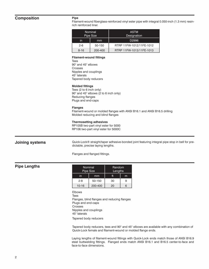
PipeFilament-woundfiberglass-reinforcedvinylesterpipewithintegral0.050-inch(1.3mm)resin-richreinforcedliner.
Filament-wound fittingsTees90°and45°elbowsCrossesNipplesandcouplings45°lateralsTaperedbodyreducers
Molded fittingsTees(2to6inchonly)90°and45°elbows(2to6inchonly)ReducingflangesPlugsandend-caps
FlangesFilament-woundormoldedflangeswithANSIB16.1andANSIB16.5drillingMoldedreducingandblindflanges
Thermosetting adhesivesRP105Btwo-partvinylesterfor5000RP106two-partvinylesterfor5000C
Composition
NominalPipeSize
ASTMDesignation
in mm D2996
2-6 50-150 RTRP11FW-1012/11FE-1012
8-16 200-400 RTRP11FW-1013/11FE-1013
Joining systems Quick-Lock®straight/taperadhesive-bondedjointfeaturingintegralpipestopinbellforpre-dictable,preciselayinglengths.
Flangesandflangedfittings.
NominalPipeSize
RandomLengths
in mm ft m
2-8 50-150 30 9
10-16 200-400 20 6
Pipe Lengths
ElbowsTeesFlanges,blindflangesandreducingflangesPlugsandend-capsCrossesNipplesandcouplings45°laterals
Taperedbodyreducers
Taperedbodyreducers,teesand90°and45°elbowsareavailablewithanycombinationofQuick-Lockfemaleandfilament-woundormoldedflangeends.
2
Layinglengthsoffilament-woundfittingswithQuick-LockendsmatchthoseofANSIB16.9steelbuttwelding fittings. FlangedendsmatchANSIB16.1andB16.5center-to-faceandface-to-facedimensions.
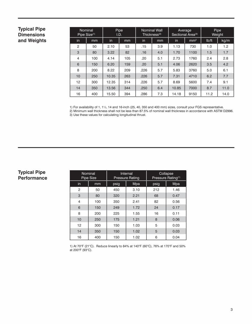
NominalPipeSize(1)
PipeI.D.
NominalWallThickness(2)
AverageSectionalArea(3)
PipeWeight
in mm in mm in mm in mm2 lb/ft kg/m
2 50 2.10 53 .15 3.9 1.13 730 1.0 1.2
3 80 3.22 82 .16 4.0 1.70 1100 1.5 1.7
4 100 4.14 105 .20 5.1 2.73 1760 2.4 2.8
6 150 6.20 159 .20 5.1 4.06 2620 3.5 4.2
8 200 8.22 209 .226 5.7 5.83 3760 5.0 6.1
10 250 10.35 263 .226 5.7 7.31 4710 6.2 7.7
12 300 12.35 314 .226 5.7 8.69 5600 7.4 9.1
14 350 13.56 344 .250 6.4 10.85 7000 8.7 11.0
16 400 15.50 394 .286 7.3 14.18 9150 11.2 14.0
NominalPipeSize
InternalPressureRating
CollapsePressureRating(1)
in mm psig Mpa psig Mpa
2 50 450 3.10 212 1.46
3 80 320 2.21 68 0.47
4 100 350 2.41 82 0.56
6 150 249 1.72 24 0.17
8 200 225 1.55 16 0.11
10 250 175 1.21 8 0.06
12 300 150 1.03 5 0.03
14 350 150 1.02 5 0.03
16 400 150 1.02 6 0.04
Typical PipeDimensionsand Weights
Typical Pipe Performance
1)Foravailabilityof1,1½,14and16-inch(25,40,350and400mm)sizes,consultyourFGSrepresentative.2)Minimumwallthicknessshallnotbelessthan87.5%ofnominalwallthicknessinaccordancewithASTMD2996.3)Usethesevaluesforcalculatinglongitudinalthrust.
1)At70°F(21°C).Reducelinearlyto84%at140°F(60°C),76%at170°Fand50%at200°F(93°C).
3

NominalPipeSize
Elbows&Tees TaperedBodyReducers&Flanges
BlindFlanges&BushedSaddlesFilament-Wound Molded
in mm psig MPa psig MPa psig MPa psig MPa
2 50 300 2.07 200 1.38 450 3.10 150 1.03
3 80 275 1.89 150 1.03 350 2.41 150 1.03
4 100 200 1.38 150 1.03 350 2.41 150 1.03
6 150 175 1.21 150 1.03 250 1.72 150 1.03
8 200 225 1.03 - - 225 1.55 150 1.03
10 250 150 1.03 - - 175 1.21 150 1.03
12 300 150 1.03 - - 150 1.03 150 1.03
14 350 150 1.03 - - 150 1.03 150 1.03
16 400 150 1.03 - - 150 1.03 150 1.03
NominalPipeSize
Laterals CrossesReducerBushing
in mm psig MPa psig MPa psig MPa
2 50 275 1.90 150 1.03 50 .35
3 80 250 1.72 150 1.03 50 .35
4 100 200 1.38 150 1.03 50 .35
6 150 150 1.03 100 0.69 50 .35
8 200 150 1.03 100 0.69 50 .35
10 250 150 1.03 100 0.69 50 .35
12 300 150 1.03 100 0.69 50 .35
14 350 150 1.03 100 0.69 50 .35
16 400 150 1.03 100 0.69 50 .35
FittingsPressureRatings
TypicalPhysical Properties
Typical Physical PropertiesPipe Property Units Value ASTM
ThermalconductivityBtu-in/(h•ft2•°F)
W/m•°C2.00.28
C177
Coefficientofthermalexpansion(linear)(2-16inch)77°Fto150°F(25°Cto65°C)
10-6in/in/°F10-6cm/cm/°C
1018
D696
Flowcoefficient Hazen-Williams 150.00 —
Absoluteroughness10-6ft10-6m
17.405.30
—
Specificgravity — 1.80 D792
Density lb/in3 0.07
1)Reducerbushingsbondedintoflangeswillhavethesameratingastheflange.Otherwise,ratedasshown.
1)UseBondstrandSeries2000epoxysaddleswith316stainlesssteeloutlet.Otheroutletmaterialsavailableonspecialorder.
4
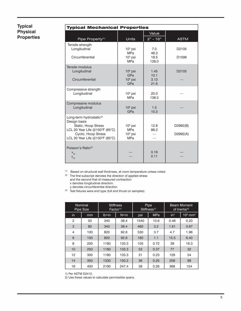
NominalPipeSize
StiffnessFactor(1)
PipeStiffness(1)
BeamMomentofInertia(2)
in mm lb•in N•m psi MPa in4 106mm4
2 50 340 38.4 1540 10.6 0.48 0.20
3 80 340 38.4 460 3.2 1.61 0.67
4 100 820 92.6 530 3.7 4.7 1.96
6 150 820 92.6 160 1.1 15.5 6.40
8 200 1180 133.3 105 0.72 39 16.3
10 250 1180 133.3 53 0.37 77 32
12 300 1180 133.3 31 0.23 129 54
14 350 1330 150.2 36 0.25 209 88
16 400 2190 247.4 38 0.26 368 154
Typical Mechanical Properties
Pipe Property(1) Units
Value
ASTM 2” - 16”
TensilestrengthLongitudinal
Circumferential
103psiMPa103psiMPa
7.048.318.5128.0
D2105
D1599
TensilemodulusLongitudinal
Circumferential
106psiGPa106psiGPa
1.4510.13.1321.6
D2105
—
CompressivestrengthLongitudinal 103psi
MPa20.0138.0
—
CompressivemodulusLongitudinal 106psi
GPa1.510.3
—
Long-termhydrostatic(3)DesignbasisStatic,HoopStressLCL20YearLife@150°F(65°C)Cyclic,HoopStressLCL20YearLife@150°F(65°C)
103psiMPa103psiMPa
12.888.2——
D2992(B)
D2992(A)
Poisson’sRatio(2)νyxνxy
——
0.190.11
——
(1)Basedonstructuralwallthickness,atroomtemperatureunlessnoted.(2)Thefirstsubscriptdenotesthedirectionofappliedstressandthesecondthatofmeasuredcontractionxdenoteslongitudinaldirection.ydenotescircumferentialdirection.(3)Testfixtureswereendtype(fullendthrustonsamples).
Typical Physical Properties
1)PerASTMD2412.2)Usethesevaluestocalculatepermissiblespans.
5
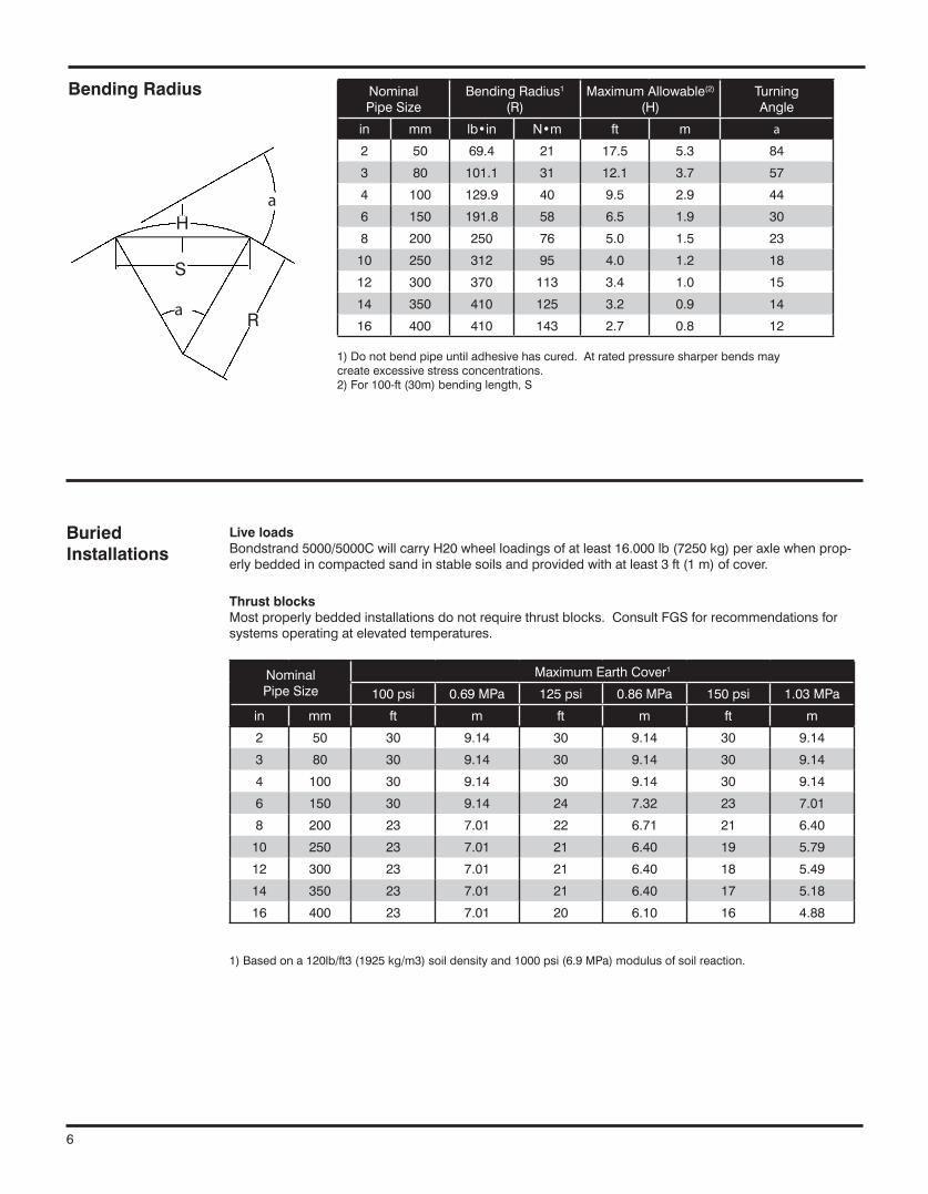
NominalPipeSize
MaximumEarthCover1
100psi 0.69MPa 125psi 0.86MPa 150psi 1.03MPa
in mm ft m ft m ft m
2 50 30 9.14 30 9.14 30 9.14
3 80 30 9.14 30 9.14 30 9.14
4 100 30 9.14 30 9.14 30 9.14
6 150 30 9.14 24 7.32 23 7.01
8 200 23 7.01 22 6.71 21 6.40
10 250 23 7.01 21 6.40 19 5.79
12 300 23 7.01 21 6.40 18 5.49
14 350 23 7.01 21 6.40 17 5.18
16 400 23 7.01 20 6.10 16 4.88
Live loadsBondstrand5000/5000CwillcarryH20wheelloadingsofatleast16.000lb(7250kg)peraxlewhenprop-erlybeddedincompactedsandinstablesoilsandprovidedwithatleast3ft(1m)ofcover.
Thrust blocksMostproperlybeddedinstallationsdonotrequirethrustblocks.ConsultFGSforrecommendationsforsystemsoperatingatelevatedtemperatures.
BuriedInstallations
NominalPipeSize
BendingRadius1
(R)MaximumAllowable(2)
(H)TurningAngle
in mm lb•in N•m ft m a
2 50 69.4 21 17.5 5.3 84
3 80 101.1 31 12.1 3.7 57
4 100 129.9 40 9.5 2.9 44
6 150 191.8 58 6.5 1.9 30
8 200 250 76 5.0 1.5 23
10 250 312 95 4.0 1.2 18
12 300 370 113 3.4 1.0 15
14 350 410 125 3.2 0.9 14
16 400 410 143 2.7 0.8 12
Bending Radius
1)Basedona120lb/ft3(1925kg/m3)soildensityand1000psi(6.9MPa)modulusofsoilreaction.
1)Donotbendpipeuntiladhesivehascured.Atratedpressuresharperbendsmaycreateexcessivestressconcentrations.2)For100-ft(30m)bendinglength,S
cL
a
aH
S
R
6

NominalPipeSize
Spans(ft)
in mm 100°F 140°F 170°F 200°F
2 50 12.1 10.8 9.4 7.5
3 80 13.7 12.3 10.7 8.6
4 100 16.1 14.5 12.6 10.0
6 150 18.1 16.1 14.2 11.2
8 200 20.1 18.1 15.5 12.6
10 250 21.4 19.2 16.6 13.5
12 300 22.3 20.2 17.5 13.9
14 350 23.1 20.7 18.1 14.4
16 400 24.3 21.6 18.9 15.0
RecommendedmaximumsupportspacingsforBondstrand5000/5000Cvinylesterpipeatvariousoperatingtemperatures.Valuesbasedon0.5-inch(12mm)deflectionatmidspanforfluidspecificgravity=1.0.Forfullycontinuousspans,valuesmaybeincreasedupto20%.Decreasevaluesby20%forsinglespans.
Span Lengths
Field Testing Bondstrand5000/5000Cpipingsystemsaredesignedforhydrostaticfieldtestingat150%ofratedoper-atingpressure.Pneumatictestingisnotrecommended.
1)Spanrecommendationsareintendedfornormalhorizontalpipingsupportarrangements,butincludenoprovi-sionforweights(fittings,valves,flanges,etc)orthrusts(branches,turns,etc.).
2)Spanrecommendationsarecalculatedforamaximumlong-termdeflectionof½inchtoensuregoodappear-anceandadequatedrainage.
7

www.fgspipe.com • [email protected]
©2013,NATIONALOILWELLVARCO®TrademarkofNATIONALOILWELLVARCO
CI5000-April2013
National Oilwell Varco has produced this brochure for general information only, and itis not intended for design purposes. Although every effort has beenmade tomaintainthe accuracy and reliability of its contents, National Oilwell Varco in no way assumesresponsibilityforliabilityforanyloss,damageorinjuryresultingfromtheuseofinformationanddatahereinnor is anywarranty expressedor implied. Always cross-reference thebulletindatewiththemostcurrentversionlistedatthewebsitenotedinthisliterature.
North America South America Europe Asia Pacific Middle East17115 San Pedro Ave. Suite 200 Estrada de Acesso á Zona P.O. Box 6, 4190 CA No. 7A, Tuas Avenue 3 P.O. Box 17324San Antonio, Texas 78232 USA Industrial Portuária de Suape, s/no. Geldermalsen, The Netherlands Jurong, Singapore 639407 Dubai, UAEPhone: 210 477 7500 Recife, PE, Brazil 55.590-000 Phone: 31 345 587 587 Phone: 65 6861 6118 Phone: 971 4881 3566 Phone: 55 81 3501 0023
Bondstrand™ 5000/5000C Product Data (Severely Corrosive Industrial Service and Oxidizing Acids
• Aciddrains• Bleachprocessing• Chemicalprocesspiping• Chlorinatedwater• Chlorine• Corrosiveslurries• Foodprocessingplant• Organicchemicals• Oxidizingchemicalsandacids• Phosphoricacid• WaterTreatment/Purification• Generalindustrialserviceforseverelycorrosiveliquids
Uses and Applications
MeetsUSFDArequirementsforfoodprocessingpipingunderFederalRegulations21CFR175.105and21CFR177.2420whenassembledwithRP-105Bvinylesteradhesivefor5000andnRP-106for5000C(conductive).
Listings
Workingpressurefrom150to450psig(1to3.1MPa)dependingonpipesize.
Operatingtemperaturesto200°F(93°C).Subzerotemperatureswillnotadverselyaffectme-chanicalproperties.
Excellentcorrosionresistanceoverawidetemperaturerange.SeemostrecentreleaseofBondstrandCorrosionGuideforspecificapplications.
Doesnotrequirethrustblocksatambienttemperatureswhenproperlyinstalledinmostsoils.
Smoothinnerliner(Hazen-WilliamsC=150)producesextremelylowfrictionallossforgreat-erdischargeandreducedpumpingcosts.
Lowthermalconductivityminimizesheatlosses.
Individualsystemcomponentsmaynothavethesameratingsasthepipe.Refertothede-tailedproductinformationforthespecificcomponentstodeterminethepressureratingforthesystemasawhole.
Optional:Thesystemcanbesuppliedconductive-Bondstrand5000CForConductiveASTMD-2310Classification:RTRP-11FW forpipesorRTRP-11FEas ap-plicable.
Performance
www.fgspipe.com • [email protected]

PipeFilament-woundfiberglass-reinforcedvinylesterpipewithintegral0.050-inch(1.3mm)resin-richreinforcedliner.
Filament-wound fittingsTees90°and45°elbowsCrossesNipplesandcouplings45°lateralsTaperedbodyreducers
Molded fittingsTees(2to6inchonly)90°and45°elbows(2to6inchonly)ReducingflangesPlugsandend-caps
FlangesFilament-woundormoldedflangeswithANSIB16.1andANSIB16.5drillingMoldedreducingandblindflanges
Thermosetting adhesivesRP105Btwo-partvinylesterfor5000RP106two-partvinylesterfor5000C
Composition
NominalPipeSize
ASTMDesignation
in mm D2996
2-6 50-150 RTRP11FW-1012/11FE-1012
8-16 200-400 RTRP11FW-1013/11FE-1013
Joining systems Quick-Lock®straight/taperadhesive-bondedjointfeaturingintegralpipestopinbellforpre-dictable,preciselayinglengths.
Flangesandflangedfittings.
NominalPipeSize
RandomLengths
in mm ft m
2-8 50-150 30 9
10-16 200-400 20 6
Pipe Lengths
ElbowsTeesFlanges,blindflangesandreducingflangesPlugsandend-capsCrossesNipplesandcouplings45°laterals
Taperedbodyreducers
Taperedbodyreducers,teesand90°and45°elbowsareavailablewithanycombinationofQuick-Lockfemaleandfilament-woundormoldedflangeends.
2
Layinglengthsoffilament-woundfittingswithQuick-LockendsmatchthoseofANSIB16.9steelbuttwelding fittings. FlangedendsmatchANSIB16.1andB16.5center-to-faceandface-to-facedimensions.

NominalPipeSize(1)
PipeI.D.
NominalWallThickness(2)
AverageSectionalArea(3)
PipeWeight
in mm in mm in mm in mm2 lb/ft kg/m
2 50 2.10 53 .15 3.9 1.13 730 1.0 1.2
3 80 3.22 82 .16 4.0 1.70 1100 1.5 1.7
4 100 4.14 105 .20 5.1 2.73 1760 2.4 2.8
6 150 6.20 159 .20 5.1 4.06 2620 3.5 4.2
8 200 8.22 209 .226 5.7 5.83 3760 5.0 6.1
10 250 10.35 263 .226 5.7 7.31 4710 6.2 7.7
12 300 12.35 314 .226 5.7 8.69 5600 7.4 9.1
14 350 13.56 344 .250 6.4 10.85 7000 8.7 11.0
16 400 15.50 394 .286 7.3 14.18 9150 11.2 14.0
NominalPipeSize
InternalPressureRating
CollapsePressureRating(1)
in mm psig Mpa psig Mpa
2 50 450 3.10 212 1.46
3 80 320 2.21 68 0.47
4 100 350 2.41 82 0.56
6 150 249 1.72 24 0.17
8 200 225 1.55 16 0.11
10 250 175 1.21 8 0.06
12 300 150 1.03 5 0.03
14 350 150 1.02 5 0.03
16 400 150 1.02 6 0.04
Typical PipeDimensionsand Weights
Typical Pipe Performance
1)Foravailabilityof1,1½,14and16-inch(25,40,350and400mm)sizes,consultyourFGSrepresentative.2)Minimumwallthicknessshallnotbelessthan87.5%ofnominalwallthicknessinaccordancewithASTMD2996.3)Usethesevaluesforcalculatinglongitudinalthrust.
1)At70°F(21°C).Reducelinearlyto84%at140°F(60°C),76%at170°Fand50%at200°F(93°C).
3
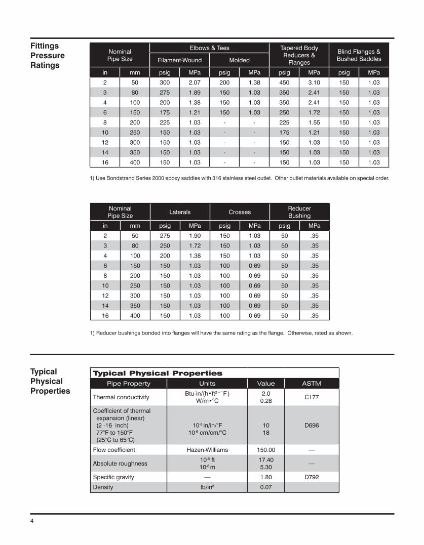
NominalPipeSize
Elbows&Tees TaperedBodyReducers&Flanges
BlindFlanges&BushedSaddlesFilament-Wound Molded
in mm psig MPa psig MPa psig MPa psig MPa
2 50 300 2.07 200 1.38 450 3.10 150 1.03
3 80 275 1.89 150 1.03 350 2.41 150 1.03
4 100 200 1.38 150 1.03 350 2.41 150 1.03
6 150 175 1.21 150 1.03 250 1.72 150 1.03
8 200 225 1.03 - - 225 1.55 150 1.03
10 250 150 1.03 - - 175 1.21 150 1.03
12 300 150 1.03 - - 150 1.03 150 1.03
14 350 150 1.03 - - 150 1.03 150 1.03
16 400 150 1.03 - - 150 1.03 150 1.03
NominalPipeSize
Laterals CrossesReducerBushing
in mm psig MPa psig MPa psig MPa
2 50 275 1.90 150 1.03 50 .35
3 80 250 1.72 150 1.03 50 .35
4 100 200 1.38 150 1.03 50 .35
6 150 150 1.03 100 0.69 50 .35
8 200 150 1.03 100 0.69 50 .35
10 250 150 1.03 100 0.69 50 .35
12 300 150 1.03 100 0.69 50 .35
14 350 150 1.03 100 0.69 50 .35
16 400 150 1.03 100 0.69 50 .35
FittingsPressureRatings
TypicalPhysical Properties
Typical Physical PropertiesPipe Property Units Value ASTM
ThermalconductivityBtu-in/(h•ft2•°F)
W/m•°C2.00.28
C177
Coefficientofthermalexpansion(linear)(2-16inch)77°Fto150°F(25°Cto65°C)
10-6in/in/°F10-6cm/cm/°C
1018
D696
Flowcoefficient Hazen-Williams 150.00 —
Absoluteroughness10-6ft10-6m
17.405.30
—
Specificgravity — 1.80 D792
Density lb/in3 0.07
1)Reducerbushingsbondedintoflangeswillhavethesameratingastheflange.Otherwise,ratedasshown.
1)UseBondstrandSeries2000epoxysaddleswith316stainlesssteeloutlet.Otheroutletmaterialsavailableonspecialorder.
4

NominalPipeSize
StiffnessFactor(1)
PipeStiffness(1)
BeamMomentofInertia(2)
in mm lb•in N•m psi MPa in4 106mm4
2 50 340 38.4 1540 10.6 0.48 0.20
3 80 340 38.4 460 3.2 1.61 0.67
4 100 820 92.6 530 3.7 4.7 1.96
6 150 820 92.6 160 1.1 15.5 6.40
8 200 1180 133.3 105 0.72 39 16.3
10 250 1180 133.3 53 0.37 77 32
12 300 1180 133.3 31 0.23 129 54
14 350 1330 150.2 36 0.25 209 88
16 400 2190 247.4 38 0.26 368 154
Typical Mechanical Properties
Pipe Property(1) Units
Value
ASTM 2” - 16”
TensilestrengthLongitudinal
Circumferential
103psiMPa103psiMPa
7.048.318.5128.0
D2105
D1599
TensilemodulusLongitudinal
Circumferential
106psiGPa106psiGPa
1.4510.13.1321.6
D2105
—
CompressivestrengthLongitudinal 103psi
MPa20.0138.0
—
CompressivemodulusLongitudinal 106psi
GPa1.510.3
—
Long-termhydrostatic(3)DesignbasisStatic,HoopStressLCL20YearLife@150°F(65°C)Cyclic,HoopStressLCL20YearLife@150°F(65°C)
103psiMPa103psiMPa
12.888.2——
D2992(B)
D2992(A)
Poisson’sRatio(2)νyxνxy
——
0.190.11
——
(1)Basedonstructuralwallthickness,atroomtemperatureunlessnoted.(2)Thefirstsubscriptdenotesthedirectionofappliedstressandthesecondthatofmeasuredcontractionxdenoteslongitudinaldirection.ydenotescircumferentialdirection.(3)Testfixtureswereendtype(fullendthrustonsamples).
Typical Physical Properties
1)PerASTMD2412.2)Usethesevaluestocalculatepermissiblespans.
5

NominalPipeSize
MaximumEarthCover1
100psi 0.69MPa 125psi 0.86MPa 150psi 1.03MPa
in mm ft m ft m ft m
2 50 30 9.14 30 9.14 30 9.14
3 80 30 9.14 30 9.14 30 9.14
4 100 30 9.14 30 9.14 30 9.14
6 150 30 9.14 24 7.32 23 7.01
8 200 23 7.01 22 6.71 21 6.40
10 250 23 7.01 21 6.40 19 5.79
12 300 23 7.01 21 6.40 18 5.49
14 350 23 7.01 21 6.40 17 5.18
16 400 23 7.01 20 6.10 16 4.88
Live loadsBondstrand5000/5000CwillcarryH20wheelloadingsofatleast16.000lb(7250kg)peraxlewhenprop-erlybeddedincompactedsandinstablesoilsandprovidedwithatleast3ft(1m)ofcover.
Thrust blocksMostproperlybeddedinstallationsdonotrequirethrustblocks.ConsultFGSforrecommendationsforsystemsoperatingatelevatedtemperatures.
BuriedInstallations
NominalPipeSize
BendingRadius1
(R)MaximumAllowable(2)
(H)TurningAngle
in mm lb•in N•m ft m a
2 50 69.4 21 17.5 5.3 84
3 80 101.1 31 12.1 3.7 57
4 100 129.9 40 9.5 2.9 44
6 150 191.8 58 6.5 1.9 30
8 200 250 76 5.0 1.5 23
10 250 312 95 4.0 1.2 18
12 300 370 113 3.4 1.0 15
14 350 410 125 3.2 0.9 14
16 400 410 143 2.7 0.8 12
Bending Radius
1)Basedona120lb/ft3(1925kg/m3)soildensityand1000psi(6.9MPa)modulusofsoilreaction.
1)Donotbendpipeuntiladhesivehascured.Atratedpressuresharperbendsmaycreateexcessivestressconcentrations.2)For100-ft(30m)bendinglength,S
cL
a
aH
S
R
6
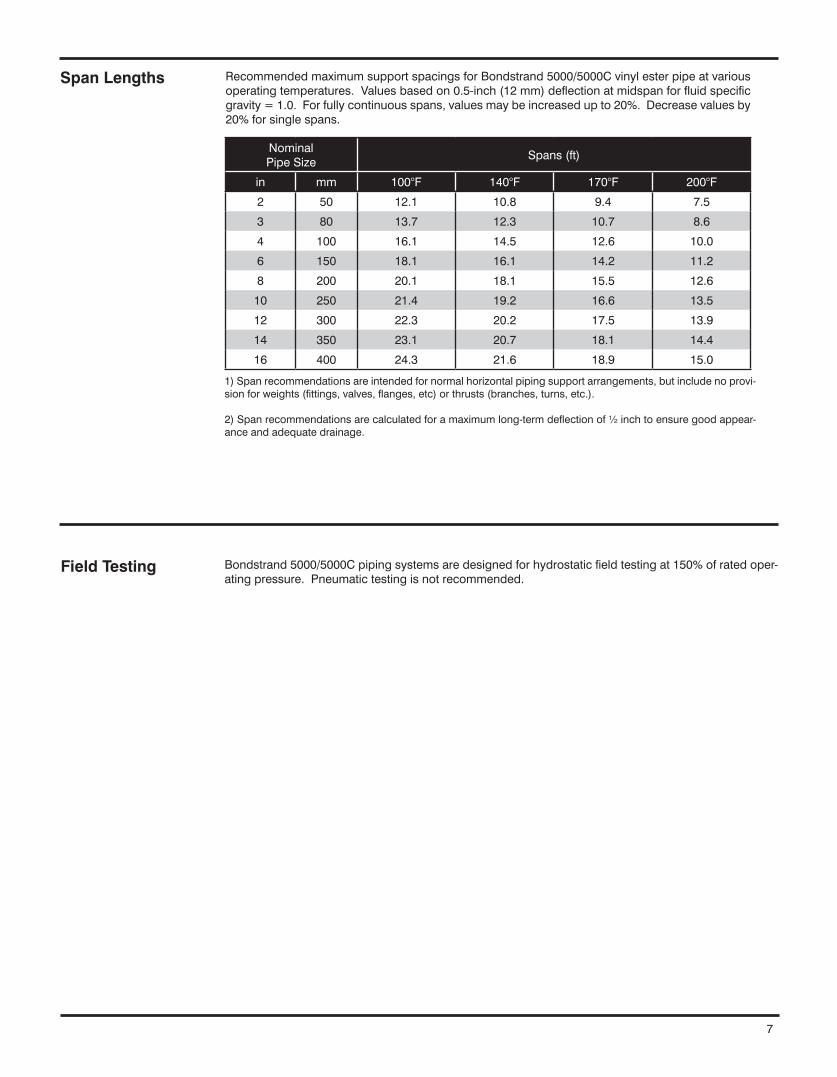
NominalPipeSize
Spans(ft)
in mm 100°F 140°F 170°F 200°F
2 50 12.1 10.8 9.4 7.5
3 80 13.7 12.3 10.7 8.6
4 100 16.1 14.5 12.6 10.0
6 150 18.1 16.1 14.2 11.2
8 200 20.1 18.1 15.5 12.6
10 250 21.4 19.2 16.6 13.5
12 300 22.3 20.2 17.5 13.9
14 350 23.1 20.7 18.1 14.4
16 400 24.3 21.6 18.9 15.0
RecommendedmaximumsupportspacingsforBondstrand5000/5000Cvinylesterpipeatvariousoperatingtemperatures.Valuesbasedon0.5-inch(12mm)deflectionatmidspanforfluidspecificgravity=1.0.Forfullycontinuousspans,valuesmaybeincreasedupto20%.Decreasevaluesby20%forsinglespans.
Span Lengths
Field Testing Bondstrand5000/5000Cpipingsystemsaredesignedforhydrostaticfieldtestingat150%ofratedoper-atingpressure.Pneumatictestingisnotrecommended.
1)Spanrecommendationsareintendedfornormalhorizontalpipingsupportarrangements,butincludenoprovi-sionforweights(fittings,valves,flanges,etc)orthrusts(branches,turns,etc.).
2)Spanrecommendationsarecalculatedforamaximumlong-termdeflectionof½inchtoensuregoodappear-anceandadequatedrainage.
7
www.fgspipe.com • [email protected]
©2013,NATIONALOILWELLVARCO®TrademarkofNATIONALOILWELLVARCO
CI5000-April2013
National Oilwell Varco has produced this brochure for general information only, and itis not intended for design purposes. Although every effort has beenmade tomaintainthe accuracy and reliability of its contents, National Oilwell Varco in no way assumesresponsibilityforliabilityforanyloss,damageorinjuryresultingfromtheuseofinformationanddatahereinnor is anywarranty expressedor implied. Always cross-reference thebulletindatewiththemostcurrentversionlistedatthewebsitenotedinthisliterature.
North America South America Europe Asia Pacific Middle East17115 San Pedro Ave. Suite 200 Estrada de Acesso á Zona P.O. Box 6, 4190 CA No. 7A, Tuas Avenue 3 P.O. Box 17324San Antonio, Texas 78232 USA Industrial Portuária de Suape, s/no. Geldermalsen, The Netherlands Jurong, Singapore 639407 Dubai, UAEPhone: 210 477 7500 Recife, PE, Brazil 55.590-000 Phone: 31 345 587 587 Phone: 65 6861 6118 Phone: 971 4881 3566 Phone: 55 81 3501 0023
The structural wall of fiberglass pipe in 2 through 16 inch sizes shall have continuous glass fibers wound at a 54¾ helical angle in a matrix of premium vinyl ester resin.
The integral, reinforced resin-rich liner shall consist of Nexus veil and a resin-/hard-ener system identical to that of the structural wall, and shall have a 50-mil nominal thickness. Non-reinforced pure resin-type corrosion barriers (liners) shall not be al-lowed due to their potential for severe fracturing during transportation, installation and operation of the pipe.
Pipe in 2 through 16 inch sizes shall be rated for a minimum of 150 psig at 200°F. In 2 through 8 inch sizes the pipe shall have full vacuum capability at 70°F, when installed above ground with a safety factor of 3:1.
Pipe shall be manufactured according to ASTM D2996 specification for filament-wound Reinforced Thermosetting Resin Pipe (RTRP). When classified under ASTM ED2310, the pipe shall meet Type 1, Grade 2 and Class E (RTRP-12ED) cell limited in 2 through 16 inch nominal pipe sizes.
Filament-wound vinyl ester fiberglass pipe shall be gray.
Pipe in 2 through 8 inch sizes shall be furnished in 30 ft length to minimize the num-ber of field-bonded joints for rapid installation.
Fittings in 2 through 16 inch sizes shall be filament wound with a reinforced resin-rich liner of equal or greater thickness than the pipe liner and of the same glass resin type as the pipe.
Compression-molded fittings in 2, 3, 4 and 6 inch nominal sizes may also be allowed upon agreement between purchaser and manufacturer. Contact-molded, spray-up or hand lay-up fittings shall not be allowed. Pipe and Fit-tings shall be joined using a straight spigot by socket with a 0.5° taper angle and a pipe stop inside the socket to allow precise makeup.
The pipe and fittings shall be free from all defects, including delaminations, indenta-tions, pinholes, foreign inclusions, bubbles and resin-starved areas which, due to their nature, degree or extent, detrimentally affect the strength and serviceability of the pipe or fittings. The pipe and fittings shall be as uniform as commercially practi-cable in color, density and other physical properties.
Samples of pipe and couplings shall be tested at random, based on standard quality control practices to determine conformance of the materials to American Society for Testing of Materials guidelines for testing fiberglass pipe products: ASTM D1599, D2105, D2925, D2992A or D2992B.
Test samples may be hydrostatically tested by the manufacturer to 1.5 times the pres-sure rating for signs of leakage.
Testing
Standard FittingsConstruction
Workmanship
Pipe Construction
Bondstrand® Guide Specification
www.fgspipe.com • [email protected]
©2013, NATIONAL OILWELL VARCO® Trademark of NATIONAL OILWELL VARCO
CI5001 - April 2013
National Oilwell Varco has produced this brochure for general information only, and it is not intended for design purposes. Although every effort has been made to maintain the accuracy and reliability of its contents, National Oilwell Varco in no way assumes responsibility for liability for any loss, damage or injury resulting from the use of information and data herein nor is any warranty expressed or implied. Always cross-reference the bulletin date with the most current version listed at the web site noted in this literature.
North America South America Europe Asia Pacific Middle East17115 San Pedro Ave. Suite 200 Estrada de Acesso á Zona P.O. Box 6, 4190 CA No. 7A, Tuas Avenue 3 P.O. Box 17324San Antonio, Texas 78232 USA Industrial Portuária de Suape, s/no. Geldermalsen, The Netherlands Jurong, Singapore 639407 Dubai, UAEPhone: 210 477 7500 Recife, PE, Brazil 55.590-000 Phone: 31 345 587 587 Phone: 65 6861 6118 Phone: 971 4881 3566 Phone: 55 81 3501 0023
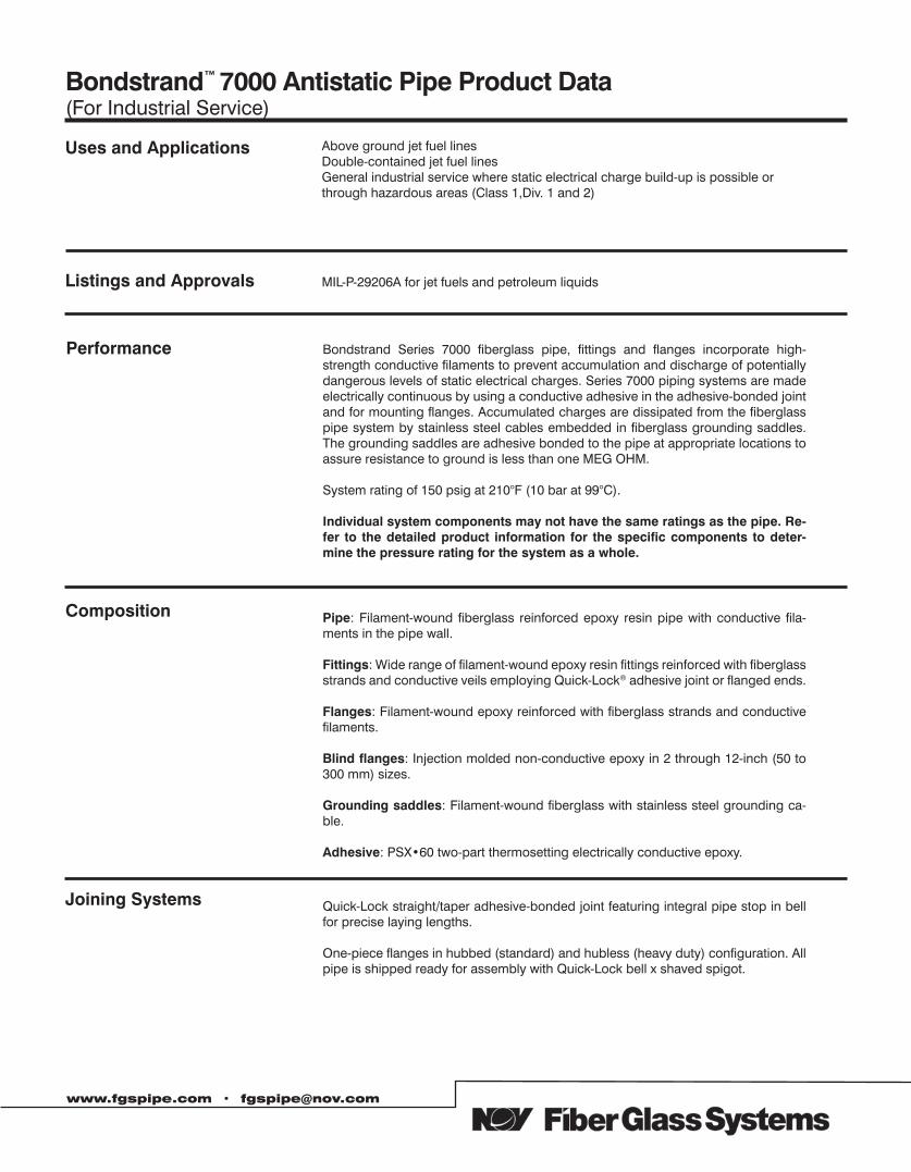
Bondstrand™ 7000 Antistatic Pipe Product Data(For Industrial Service)
www.fgspipe.com • [email protected]
Bondstrand Series 7000 fiberglass pipe, fittings and flanges incorporate high-strength conductive filaments to prevent accumulation and discharge of potentially dangerous levels of static electrical charges. Series 7000 piping systems are made electrically continuous by using a conductive adhesive in the adhesive-bonded joint and for mounting flanges. Accumulated charges are dissipated from the fiberglass pipe system by stainless steel cables embedded in fiberglass grounding saddles. The grounding saddles are adhesive bonded to the pipe at appropriate locations to assure resistance to ground is less than one MEG OHM.
System rating of 150 psig at 210°F (10 bar at 99°C).
Individual system components may not have the same ratings as the pipe. Re-fer to the detailed product information for the specific components to deter-mine the pressure rating for the system as a whole.
Pipe: Filament-wound fiberglass reinforced epoxy resin pipe with conductive fila-ments in the pipe wall.
Fittings: Wide range of filament-wound epoxy resin fittings reinforced with fiberglass strands and conductive veils employing Quick-Lock® adhesive joint or flanged ends.
Flanges: Filament-wound epoxy reinforced with fiberglass strands and conductive filaments.
Blind flanges: Injection molded non-conductive epoxy in 2 through 12-inch (50 to 300 mm) sizes.
Grounding saddles: Filament-wound fiberglass with stainless steel grounding ca-ble.
Adhesive: PSX•60 two-part thermosetting electrically conductive epoxy.
Quick-Lock straight/taper adhesive-bonded joint featuring integral pipe stop in bell for precise laying lengths.
One-piece flanges in hubbed (standard) and hubless (heavy duty) configuration. All pipe is shipped ready for assembly with Quick-Lock bell x shaved spigot.
MIL-P-29206A for jet fuels and petroleum liquids
Above ground jet fuel linesDouble-contained jet fuel linesGeneral industrial service where static electrical charge build-up is possible or through hazardous areas (Class 1,Div. 1 and 2)
Composition
Joining Systems
Performance
Listings and Approvals
Uses and Applications
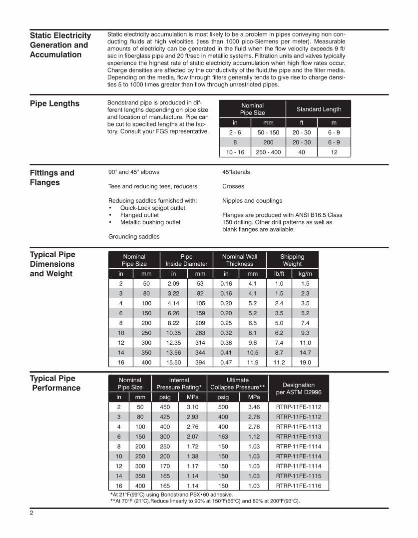
Nominal Pipe Size
Standard Length
in mm ft m
2 - 6 50 - 150 20 - 30 6 - 9
8 200 20 - 30 6 - 9
10 - 16 250 - 400 40 12
Nominal Pipe Size
PipeInside Diameter
Nominal WallThickness
Shipping Weight
in mm in mm in mm lb/ft kg/m
2 50 2.09 53 0.16 4.1 1.0 1.5
3 80 3.22 82 0.16 4.1 1.5 2.3
4 100 4.14 105 0.20 5.2 2.4 3.5
6 150 6.26 159 0.20 5.2 3.5 5.2
8 200 8.22 209 0.25 6.5 5.0 7.4
10 250 10.35 263 0.32 8.1 6.2 9.3
12 300 12.35 314 0.38 9.6 7.4 11.0
14 350 13.56 344 0.41 10.5 8.7 14.7
16 400 15.50 394 0.47 11.9 11.2 19.0
Nominal Pipe Size
Internal Pressure Rating*
UltimateCollapse Pressure** Designation
per ASTM D2996in mm psig MPa psig MPa
2 50 450 3.10 500 3.46 RTRP-11FE-1112
3 80 425 2.93 400 2.76 RTRP-11FE-1112
4 100 400 2.76 400 2.76 RTRP-11FE-1113
6 150 300 2.07 163 1.12 RTRP-11FE-1113
8 200 250 1.72 150 1.03 RTRP-11FE-1114
10 250 200 1.38 150 1.03 RTRP-11FE-1114
12 300 170 1.17 150 1.03 RTRP-11FE-1114
14 350 165 1.14 150 1.03 RTRP-11FE-1115
16 400 165 1.14 150 1.03 RTRP-11FE-1116
Bondstrand pipe is produced in dif-ferent lengths depending on pipe size and location of manufacture. Pipe can be cut to specified lengths at the fac-tory. Consult your FGS representative.
Static electricity accumulation is most likely to be a problem in pipes conveying non con-ducting fluids at high velocities (less than 1000 pico-Siemens per meter). Measurable amounts of electricity can be generated in the fluid when the flow velocity exceeds 9 ft/sec in fiberglass pipe and 20 ft/sec in metallic systems. Filtration units and valves typically experience the highest rate of static electricity accumulation when high flow rates occur. Charge densities are affected by the conductivity of the fluid,the pipe and the filter media. Depending on the media, flow through filters generally tends to give rise to charge densi-ties 5 to 1000 times greater than flow through unrestricted pipes.
90° and 45° elbows
Tees and reducing tees, reducers
Reducing saddles furnished with:• Quick-Lock spigot outlet• Flanged outlet• Metallic bushing outlet
Grounding saddles
45°laterals
Crosses
Nipples and couplings
Flanges are produced with ANSI B16.5 Class 150 drilling. Other drill patterns as well as blank flanges are available.
Fittings and Flanges
Pipe Lengths
Static Electricity Generation and Accumulation
Typical PipeDimensionsand Weight
Typical Pipe Performance
*At 21°F(99°C) using Bondstrand PSX•60 adhesive.**At 70°F (21°C).Reduce linearly to 90% at 150°F(66°C) and 80% at 200°F(93°C).
2
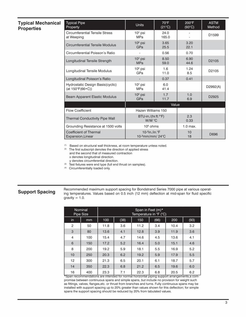
(1) Based on structural wall thickness, at room temperature unless noted.(2) The first subscript denotes the direction of applied stress and the second that of measured contraction x denotes longitudinal direction. y denotes circumferential direction.(3) Test fixtures were end type (full end thrust on samples).(4) Circumferentially loaded only.
Typical Mechanical Properties
Nominal Pipe Size
Span in Feet (m)*Temperature in °F (°C)
in mm 100 (38) 150 (66) 200 (93)
2 50 11.8 3.6 11.2 3.4 10.4 3.2
3 80 13.6 4.1 12.8 3.9 11.9 3.6
4 100 15.4 4.7 14.6 4.5 13.6 4.1
6 150 17.2 5.2 16.4 5.0 15.1 4.6
8 200 19.2 5.9 18.1 5.5 16.9 5.2
10 250 20.3 6.2 19.2 5.9 17.9 5.5
12 300 21.3 6.5 20.1 6.1 18.7 5.7
14 350 22.3 6.8 21.2 6.5 19.6 6.0
16 400 23.3 7.1 22.3 6.8 20.5 6.2*Span recommendations are intended for normal horizontal piping support arrangements,a com-promise between continuous spans and simple spans, but include no provision for weight such as fittings, valves, flanges,etc. or thrust from branches and turns. Fully continuous spans may be installed with support spacing up to 20% greater than values shown for this deflection; for simple spans the support spacing should be reduced by 20% from tabulated values.
Support SpacingRecommended maximum support spacing for Bondstrand Series 7000 pipe at various operat-ing temperatures. Values based on 0.5 inch (12 mm) deflection at mid-span for fluid specific gravity = 1.0.
3
Typical Pipe Property
Units70°F
(21°C)200°F(93°C)
ASTM Method
Circumferential Tensile Stressat Weeping
103 psiMPa
24.0165.0
--
D1599
Circumferential Tensile Modulus106 psiGPa
3.6525.5
3.2022.1
Circumferential Poisson’s Ratio - 0.56 0.70
Longitudinal Tensile Strength103 psiMPa
8.5059.0
6.9044.6
D2105
Longitudinal Tensile Modulus106 psiGPa
1.611.0
1.248.5
D2105
Longitudinal Poisson’s Ratio - 0.37 0.41
Hydrostatic Design Basis(cyclic)(at 150°F(66•C))
103 psiMPa
6.041.4
D2992(A)
Beam Apparent Elastic Modulus106 psiGPa
1.711.7
1.06.9
D2925
Value
Flow Coefficient Hazen Williams 150
Thermal Conductivity Pipe WallBTU-in./(hr.ft.2°F)
W/M °C2.3
0.33
Grounding Resistance at 1500 volts 106 ohms 1.0 max.
Coefficient of ThermalExpansion,Linear
10-6in./in.°F10-6mm/mm/ 24°C
1018
D696
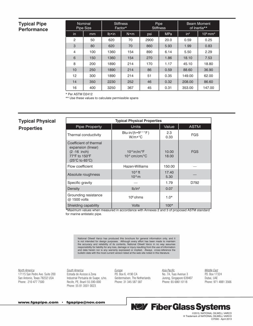
Nominal Pipe Size
Stiffness Factor*
Pipe Stiffness
Beam Momentof Inertia**
in mm lb•in N•m psi MPa in4 106 mm4
2 50 620 70 2900 20.0 0.59 0.25
3 80 620 70 860 5.93 1.99 0.83
4 100 1360 154 890 6.14 5.50 2.29
6 150 1360 154 270 1.86 18.10 7.53
8 200 1890 214 170 1.17 45.10 18.80
10 250 1890 214 86 0.59 88.60 36.90
12 300 1890 214 51 0.35 149.00 62.00
14 350 2230 252 46 0.32 208.00 86.60
16 400 3250 367 45 0.31 353.00 147.00
Typical Physical
Properties
Typical Physical Properties
Pipe Property Units Value ASTM
Thermal conductivityBtu-in/(h•ft2 • ° F )
W/m•°C2.3
0.33FGS
Coefficient of thermal expansion (linear) (2 -16 inch) 77°F to 150°F (25°C to 65°C)
10-6 in/in/°F10-6 cm/cm/°C
10.0018.00
FGS
Flow coefficient Hazen-Williams 150.00 —
Absolute roughness10-6 ft10-6 m
17.405.30
—
Specific gravity — 1.79 D792
Density lb/in3 0.07
Grounding resistance@ 1500 volts
106 ohms 1.0*
Shielding capability Volts 100**Maximum values when measured in accordance with Annexes 2 and 3 of proposed ASTM standard for marine antistatic pipe.
Typical PipePerformance
www.fgspipe.com • [email protected]
©2013, NATIONAL OILWELL VARCO® Trademark of NATIONAL OILWELL VARCO
CI7000 - April 2013
National Oilwell Varco has produced this brochure for general information only, and it is not intended for design purposes. Although every effort has been made to maintain the accuracy and reliability of its contents, National Oilwell Varco in no way assumes responsibility for liability for any loss, damage or injury resulting from the use of information and data herein nor is any warranty expressed or implied. Always cross-reference the bulletin date with the most current version listed at the web site noted in this literature.
North America South America Europe Asia Pacific Middle East17115 San Pedro Ave. Suite 200 Estrada de Acesso á Zona P.O. Box 6, 4190 CA No. 7A, Tuas Avenue 3 P.O. Box 17324San Antonio, Texas 78232 USA Industrial Portuária de Suape, s/no. Geldermalsen, The Netherlands Jurong, Singapore 639407 Dubai, UAEPhone: 210 477 7500 Recife, PE, Brazil 55.590-000 Phone: 31 345 587 587 Phone: 65 6861 6118 Phone: 971 4881 3566 Phone: 55 81 3501 0023
* Per ASTM D2412** Use these values to calculate permissible spans
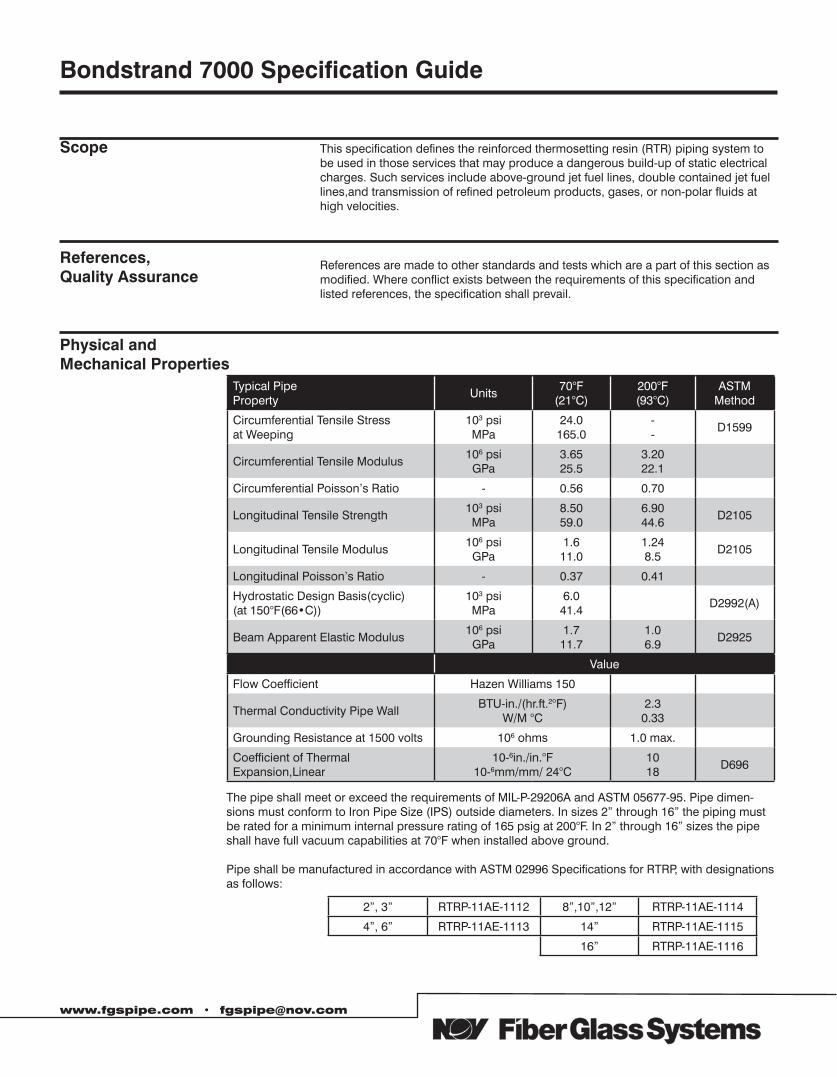
Typical Pipe Property
Units70°F
(21°C)200°F(93°C)
ASTM Method
Circumferential Tensile Stressat Weeping
103 psiMPa
24.0165.0
--
D1599
Circumferential Tensile Modulus106 psiGPa
3.6525.5
3.2022.1
Circumferential Poisson’s Ratio - 0.56 0.70
Longitudinal Tensile Strength103 psiMPa
8.5059.0
6.9044.6
D2105
Longitudinal Tensile Modulus106 psiGPa
1.611.0
1.248.5
D2105
Longitudinal Poisson’s Ratio - 0.37 0.41
Hydrostatic Design Basis(cyclic)(at 150°F(66•C))
103 psiMPa
6.041.4
D2992(A)
Beam Apparent Elastic Modulus106 psiGPa
1.711.7
1.06.9
D2925
Value
Flow Coefficient Hazen Williams 150
Thermal Conductivity Pipe WallBTU-in./(hr.ft.2°F)
W/M °C2.3
0.33
Grounding Resistance at 1500 volts 106 ohms 1.0 max.
Coefficient of ThermalExpansion,Linear
10-6in./in.°F10-6mm/mm/ 24°C
1018
D696
Scope This specification defines the reinforced thermosetting resin (RTR) piping system to be used in those services that may produce a dangerous build-up of static electrical charges. Such services include above-ground jet fuel lines, double contained jet fuel lines,and transmission of refined petroleum products, gases, or non-polar fluids at high velocities.
References, Quality Assurance
References are made to other standards and tests which are a part of this section as modified. Where conflict exists between the requirements of this specification and listed references, the specification shall prevail.
The pipe shall meet or exceed the requirements of MIL-P-29206A and ASTM 05677-95. Pipe dimen-sions must conform to Iron Pipe Size (IPS) outside diameters. In sizes 2” through 16” the piping must be rated for a minimum internal pressure rating of 165 psig at 200°F. In 2” through 16” sizes the pipe shall have full vacuum capabilities at 70°F when installed above ground.
Pipe shall be manufactured in accordance with ASTM 02996 Specifications for RTRP, with designations as follows:
2”, 3” RTRP-11AE-1112 8”,10”,12” RTRP-11AE-1114
4”, 6” RTRP-11AE-1113 14” RTRP-11AE-1115
16” RTRP-11AE-1116
Bondstrand 7000 Specification Guide
Physical andMechanical Properties
www.fgspipe.com • [email protected]
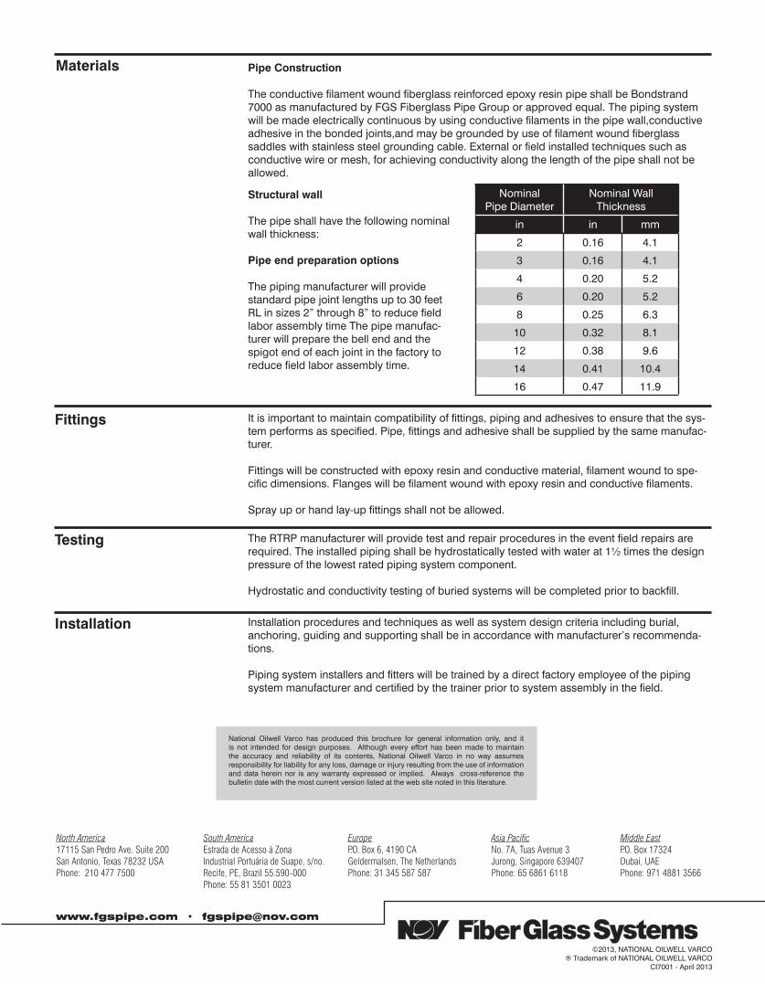
Nominal Pipe Diameter
Nominal Wall Thickness
in in mm
2 0.16 4.1
3 0.16 4.1
4 0.20 5.2
6 0.20 5.2
8 0.25 6.3
10 0.32 8.1
12 0.38 9.6
14 0.41 10.4
16 0.47 11.9
Pipe Construction
The conductive filament wound fiberglass reinforced epoxy resin pipe shall be Bondstrand 7000 as manufactured by FGS Fiberglass Pipe Group or approved equal. The piping system will be made electrically continuous by using conductive filaments in the pipe wall,conductive adhesive in the bonded joints,and may be grounded by use of filament wound fiberglass saddles with stainless steel grounding cable. External or field installed techniques such as conductive wire or mesh, for achieving conductivity along the length of the pipe shall not be allowed.
Structural wall
The pipe shall have the following nominal wall thickness:
Pipe end preparation options
The piping manufacturer will provide standard pipe joint lengths up to 30 feet RL in sizes 2” through 8” to reduce field labor assembly time The pipe manufac-turer will prepare the bell end and the spigot end of each joint in the factory to reduce field labor assembly time.
It is important to maintain compatibility of fittings, piping and adhesives to ensure that the sys-tem performs as specified. Pipe, fittings and adhesive shall be supplied by the same manufac-turer.
Fittings will be constructed with epoxy resin and conductive material, filament wound to spe-cific dimensions. Flanges will be filament wound with epoxy resin and conductive filaments.
Spray up or hand lay-up fittings shall not be allowed.
The RTRP manufacturer will provide test and repair procedures in the event field repairs are required. The installed piping shall be hydrostatically tested with water at 1½ times the design pressure of the lowest rated piping system component.
Hydrostatic and conductivity testing of buried systems will be completed prior to backfill.
Installation procedures and techniques as well as system design criteria including burial, anchoring, guiding and supporting shall be in accordance with manufacturer’s recommenda-tions.
Piping system installers and fitters will be trained by a direct factory employee of the piping system manufacturer and certified by the trainer prior to system assembly in the field.
Materials
Fittings
Testing
Installation
www.fgspipe.com • [email protected]
©2013, NATIONAL OILWELL VARCO® Trademark of NATIONAL OILWELL VARCO
CI7001 - April 2013
National Oilwell Varco has produced this brochure for general information only, and it is not intended for design purposes. Although every effort has been made to maintain the accuracy and reliability of its contents, National Oilwell Varco in no way assumes responsibility for liability for any loss, damage or injury resulting from the use of information and data herein nor is any warranty expressed or implied. Always cross-reference the bulletin date with the most current version listed at the web site noted in this literature.
North America South America Europe Asia Pacific Middle East17115 San Pedro Ave. Suite 200 Estrada de Acesso á Zona P.O. Box 6, 4190 CA No. 7A, Tuas Avenue 3 P.O. Box 17324San Antonio, Texas 78232 USA Industrial Portuária de Suape, s/no. Geldermalsen, The Netherlands Jurong, Singapore 639407 Dubai, UAEPhone: 210 477 7500 Recife, PE, Brazil 55.590-000 Phone: 31 345 587 587 Phone: 65 6861 6118 Phone: 971 4881 3566 Phone: 55 81 3501 0023
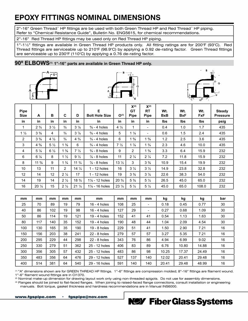
EPOXY FITTINGS NOMINAL DIMENSIONS2”-16” Green Thread™ HP fittings are be used with both Green Thread HP and Red Thread™ HP piping.Refer to “Chemical Resistance Guide”, Bulletin No. ENG5615, for chemical recommendations.
2”-16” Red Thread HP fittings may be used only on Red Thread HP piping.
1”-1½” fittings are available in Green Thread HP products only. All fitting ratings are for 200°F (93°C). Red Thread fittings are serviceable up to 210°F (98.9°C) by applying a 0.92 de-rating factor. Green Thread fittings are serviceable up to 230°F (110°C) by applying a 0.76 de-rating factor.
90º ELBOWS(1) 1”-16” parts are available in Green Thread HP only.
Pipe Size A B C D
EBolt Hole Size O(3)
X(2)
GT Pipe
X(2)
RT Pipe
Wt. BxB
Wt. BxF
Wt. FxF
SteadyPressure
in in in in in in in in in lbs lbs lbs psig1 2 ¾ 3 ½ ¾ 3 ⅛ ⅝ - 4 holes 4 ¼ 1 - 0.4 1.0 1.7 435
1 ½ 3 ⅜ 4 ¾ 3 ⅞ ⅝ - 4 holes 5 1 ⅛ - 0.6 1.5 2.4 4352 3 ⅜ 4 ½ ¾ 4 ¾ ¾ - 4 holes 6 1 ⅝ 1 ⅝ 1.2 2.5 3.6 4353 4 ⅝ 5 ½ 1 ⅜ 6 ¾ - 4 holes 7 ½ 1 ⅞ 1 ¾ 2.3 4.6 10.0 4354 5 ⅛ 6 ½ 1 ⅜ 7 ½ ¾ - 8 holes 9 2 1 ⅝ 3.3 6.4 15.9 2326 6 ⅛ 8 1 ½ 9 ½ ⅞ - 8 holes 11 2 ¼ 2 ¼ 7.2 11.8 15.9 2328 11 ⅝ 9 1 ¾ 11 ¾ ⅞ - 8 holes 13 ½ 3 3 ⅜ 10.9 15.4 19.9 232
10 13 11 2 14 ¼ 1 - 12 holes 16 3 ¼ 3 ½ 14.9 23.8 32.8 23212 14 12 2 ¼ 17 1 - 12 holes 19 3 ⅜ 3 ⅞ 22.6 38.3 54.0 23214 19 14 2 ½ 18 ¾ 1⅛ - 12 holes 20 ¾ 5 ⅜ 5 ½ 26.5 45.0 65.0 23216 20 ¼ 15 2 ½ 21 ¼ 1⅛ - 16 holes 23 ¼ 5 ½ 5 ½ 45.0 65.0 108.0 232
mm mm mm mm mm mm mm mm mm kg kg kg bar25 70 89 19 79 16 - 4 holes 108 25 - 0.18 0.45 0.77 3040 86 102 19 98 16 - 4 holes 127 29 - 0.27 0.68 1.09 3050 86 114 19 121 19 - 4 holes 152 41 41 0.54 1.13 1.63 3080 117 140 35 152 19 - 4 holes 190 48 44 1.04 2.09 4.54 30
100 130 165 35 190 19 - 8 holes 229 51 41 1.50 2.90 7.21 16150 156 203 38 241 22 - 8 holes 279 57 57 3.27 5.35 7.21 16200 295 229 44 298 22 - 8 holes 343 76 86 4.94 6.99 9.02 16250 330 279 51 362 25 - 12 holes 406 83 89 6.76 10.80 14.88 16300 356 305 57 432 25 - 12 holes 483 86 98 10.25 17.37 24.49 16350 483 356 64 476 29 - 12 holes 527 137 140 12.02 20.41 29.48 16400 514 381 64 540 29 - 16 holes 591 140 140 20.41 29.48 48.99 16
(1) ”A” dimensions shown are for GREEN THREAD HP fittings. 1”-6” fittings are compression molded; 8”-16” fittings are filament wound. 1”-6” filament wound fittings are in CI1370.(2) Nominal make-up dimension for drawing layout work only using non-threaded spigots. Do not use for assembly dimensions.(3) Flanges should be joined to flat-faced flanges. When joining to raised-faced flange connections, consult installation or engineering manuals. Bolt torque, gasket thickness and hardness recommendations are in Manual INS6000.
www.fgspipe.com • [email protected]
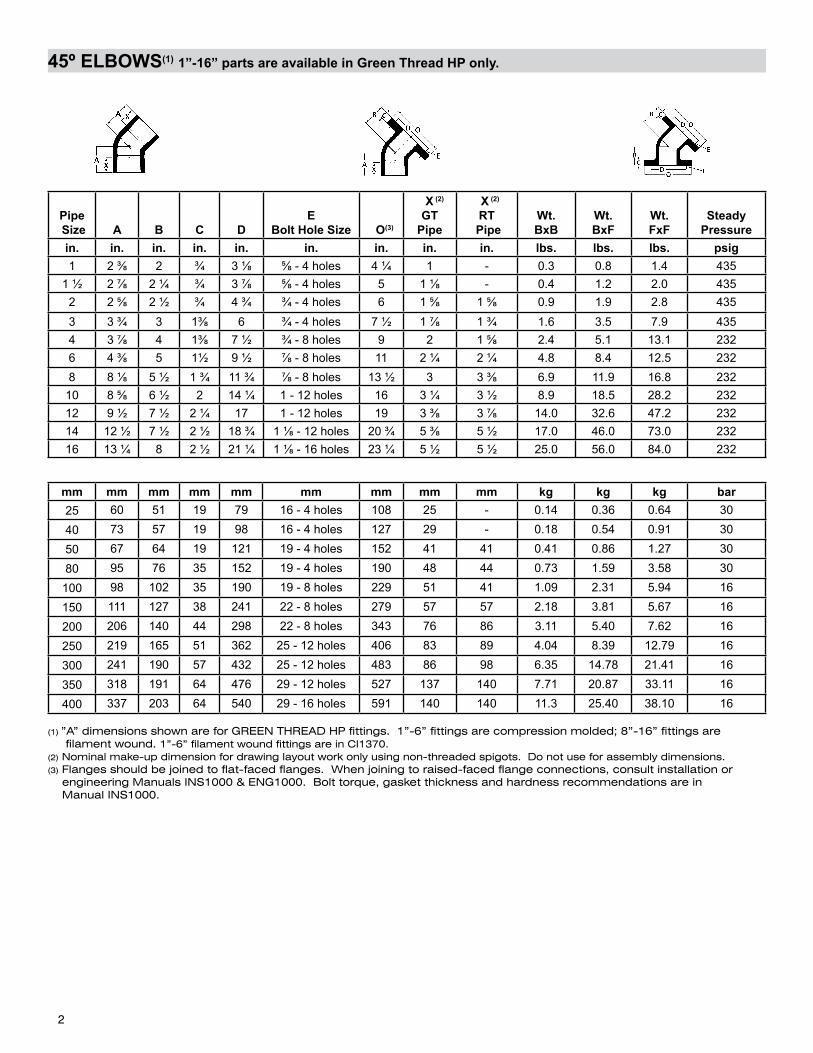
45º ELBOWS(1) 1”-16” parts are available in Green Thread HP only.
Pipe Size A B C D
EBolt Hole Size O(3)
X (2)
GT Pipe
X (2)
RT Pipe
Wt.BxB
Wt.BxF
Wt.FxF
SteadyPressure
in. in. in. in. in. in. in. in. in. lbs. lbs. lbs. psig1 2 ⅜ 2 ¾ 3 ⅛ ⅝ - 4 holes 4 ¼ 1 - 0.3 0.8 1.4 435
1 ½ 2 ⅞ 2 ¼ ¾ 3 ⅞ ⅝ - 4 holes 5 1 ⅛ - 0.4 1.2 2.0 4352 2 ⅝ 2 ½ ¾ 4 ¾ ¾ - 4 holes 6 1 ⅝ 1 ⅝ 0.9 1.9 2.8 4353 3 ¾ 3 1⅜ 6 ¾ - 4 holes 7 ½ 1 ⅞ 1 ¾ 1.6 3.5 7.9 4354 3 ⅞ 4 1⅜ 7 ½ ¾ - 8 holes 9 2 1 ⅝ 2.4 5.1 13.1 2326 4 ⅜ 5 1½ 9 ½ ⅞ - 8 holes 11 2 ¼ 2 ¼ 4.8 8.4 12.5 2328 8 ⅛ 5 ½ 1 ¾ 11 ¾ ⅞ - 8 holes 13 ½ 3 3 ⅜ 6.9 11.9 16.8 232
10 8 ⅝ 6 ½ 2 14 ¼ 1 - 12 holes 16 3 ¼ 3 ½ 8.9 18.5 28.2 23212 9 ½ 7 ½ 2 ¼ 17 1 - 12 holes 19 3 ⅜ 3 ⅞ 14.0 32.6 47.2 23214 12 ½ 7 ½ 2 ½ 18 ¾ 1 ⅛ - 12 holes 20 ¾ 5 ⅜ 5 ½ 17.0 46.0 73.0 23216 13 ¼ 8 2 ½ 21 ¼ 1 ⅛ - 16 holes 23 ¼ 5 ½ 5 ½ 25.0 56.0 84.0 232
mm mm mm mm mm mm mm mm mm kg kg kg bar25 60 51 19 79 16 - 4 holes 108 25 - 0.14 0.36 0.64 30
40 73 57 19 98 16 - 4 holes 127 29 - 0.18 0.54 0.91 30
50 67 64 19 121 19 - 4 holes 152 41 41 0.41 0.86 1.27 30
80 95 76 35 152 19 - 4 holes 190 48 44 0.73 1.59 3.58 30
100 98 102 35 190 19 - 8 holes 229 51 41 1.09 2.31 5.94 16
150 111 127 38 241 22 - 8 holes 279 57 57 2.18 3.81 5.67 16
200 206 140 44 298 22 - 8 holes 343 76 86 3.11 5.40 7.62 16
250 219 165 51 362 25 - 12 holes 406 83 89 4.04 8.39 12.79 16
300 241 190 57 432 25 - 12 holes 483 86 98 6.35 14.78 21.41 16
350 318 191 64 476 29 - 12 holes 527 137 140 7.71 20.87 33.11 16
400 337 203 64 540 29 - 16 holes 591 140 140 11.3 25.40 38.10 16
2
(1) ”A” dimensions shown are for GREEN THREAD HP fittings. 1”-6” fittings are compression molded; 8”-16” fittings are filament wound. 1”-6” filament wound fittings are in CI1370.(2) Nominal make-up dimension for drawing layout work only using non-threaded spigots. Do not use for assembly dimensions.(3) Flanges should be joined to flat-faced flanges. When joining to raised-faced flange connections, consult installation or engineering Manuals INS1000 & ENG1000. Bolt torque, gasket thickness and hardness recommendations are in Manual INS1000.
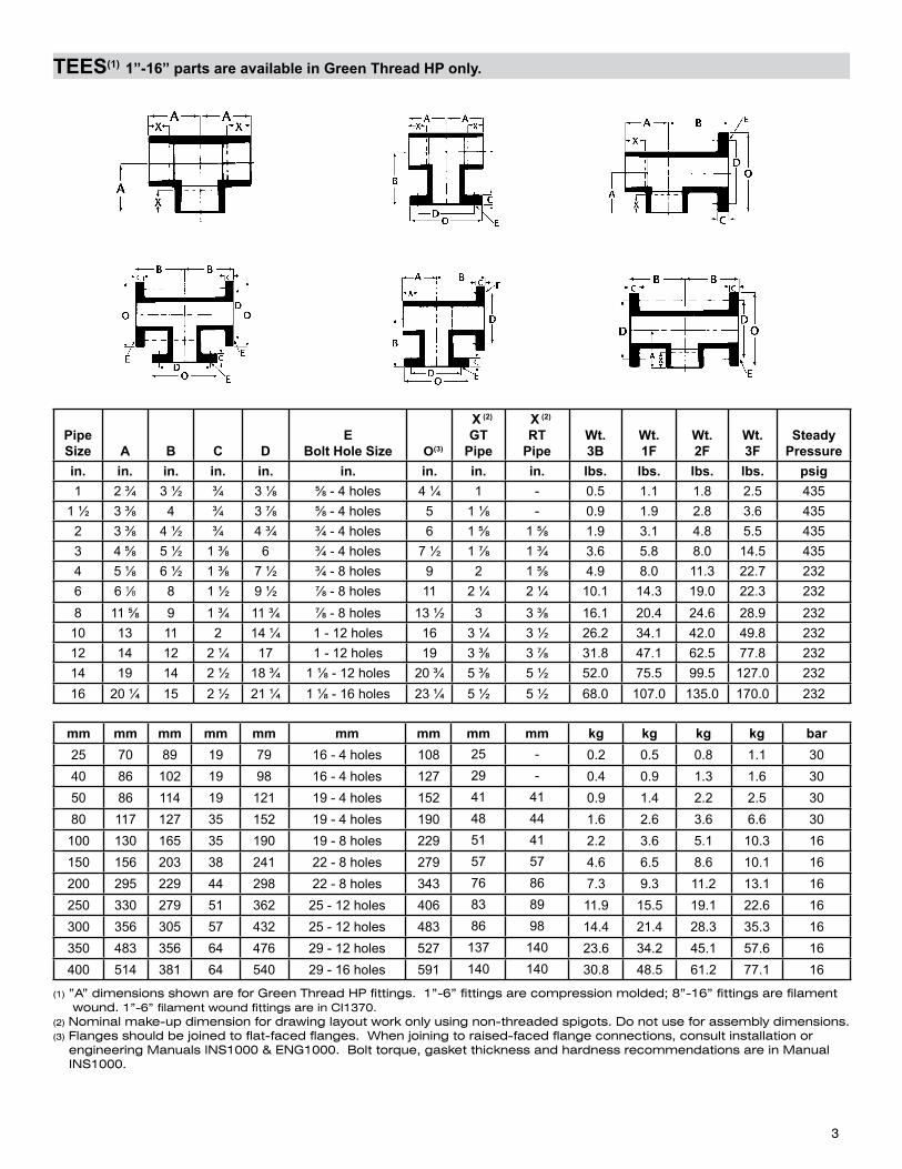
TEES(1) 1”-16” parts are available in Green Thread HP only.
Pipe Size A B C D
EBolt Hole Size O(3)
X (2)
GT Pipe
X (2)
RT Pipe
Wt.3B
Wt.1F
Wt.2F
Wt.3F
SteadyPressure
in. in. in. in. in. in. in. in. in. lbs. lbs. lbs. lbs. psig1 2 ¾ 3 ½ ¾ 3 ⅛ ⅝ - 4 holes 4 ¼ 1 - 0.5 1.1 1.8 2.5 435
1 ½ 3 ⅜ 4 ¾ 3 ⅞ ⅝ - 4 holes 5 1 ⅛ - 0.9 1.9 2.8 3.6 4352 3 ⅜ 4 ½ ¾ 4 ¾ ¾ - 4 holes 6 1 ⅝ 1 ⅝ 1.9 3.1 4.8 5.5 4353 4 ⅝ 5 ½ 1 ⅜ 6 ¾ - 4 holes 7 ½ 1 ⅞ 1 ¾ 3.6 5.8 8.0 14.5 4354 5 ⅛ 6 ½ 1 ⅜ 7 ½ ¾ - 8 holes 9 2 1 ⅝ 4.9 8.0 11.3 22.7 2326 6 1⁄8 8 1 ½ 9 ½ ⅞ - 8 holes 11 2 ¼ 2 ¼ 10.1 14.3 19.0 22.3 2328 11 ⅝ 9 1 ¾ 11 ¾ ⅞ - 8 holes 13 ½ 3 3 ⅜ 16.1 20.4 24.6 28.9 232
10 13 11 2 14 ¼ 1 - 12 holes 16 3 ¼ 3 ½ 26.2 34.1 42.0 49.8 23212 14 12 2 ¼ 17 1 - 12 holes 19 3 ⅜ 3 ⅞ 31.8 47.1 62.5 77.8 23214 19 14 2 ½ 18 ¾ 1 ⅛ - 12 holes 20 ¾ 5 ⅜ 5 ½ 52.0 75.5 99.5 127.0 23216 20 ¼ 15 2 ½ 21 ¼ 1 ⅛ - 16 holes 23 ¼ 5 ½ 5 ½ 68.0 107.0 135.0 170.0 232
mm mm mm mm mm mm mm mm mm kg kg kg kg bar25 70 89 19 79 16 - 4 holes 108 25 - 0.2 0.5 0.8 1.1 3040 86 102 19 98 16 - 4 holes 127 29 - 0.4 0.9 1.3 1.6 3050 86 114 19 121 19 - 4 holes 152 41 41 0.9 1.4 2.2 2.5 3080 117 127 35 152 19 - 4 holes 190 48 44 1.6 2.6 3.6 6.6 30
100 130 165 35 190 19 - 8 holes 229 51 41 2.2 3.6 5.1 10.3 16150 156 203 38 241 22 - 8 holes 279 57 57 4.6 6.5 8.6 10.1 16200 295 229 44 298 22 - 8 holes 343 76 86 7.3 9.3 11.2 13.1 16250 330 279 51 362 25 - 12 holes 406 83 89 11.9 15.5 19.1 22.6 16300 356 305 57 432 25 - 12 holes 483 86 98 14.4 21.4 28.3 35.3 16350 483 356 64 476 29 - 12 holes 527 137 140 23.6 34.2 45.1 57.6 16400 514 381 64 540 29 - 16 holes 591 140 140 30.8 48.5 61.2 77.1 16
3
(1) ”A” dimensions shown are for Green Thread HP fittings. 1”-6” fittings are compression molded; 8”-16” fittings are filament wound. 1”-6” filament wound fittings are in CI1370.(2) Nominal make-up dimension for drawing layout work only using non-threaded spigots. Do not use for assembly dimensions.(3) Flanges should be joined to flat-faced flanges. When joining to raised-faced flange connections, consult installation or engineering Manuals INS1000 & ENG1000. Bolt torque, gasket thickness and hardness recommendations are in Manual INS1000.
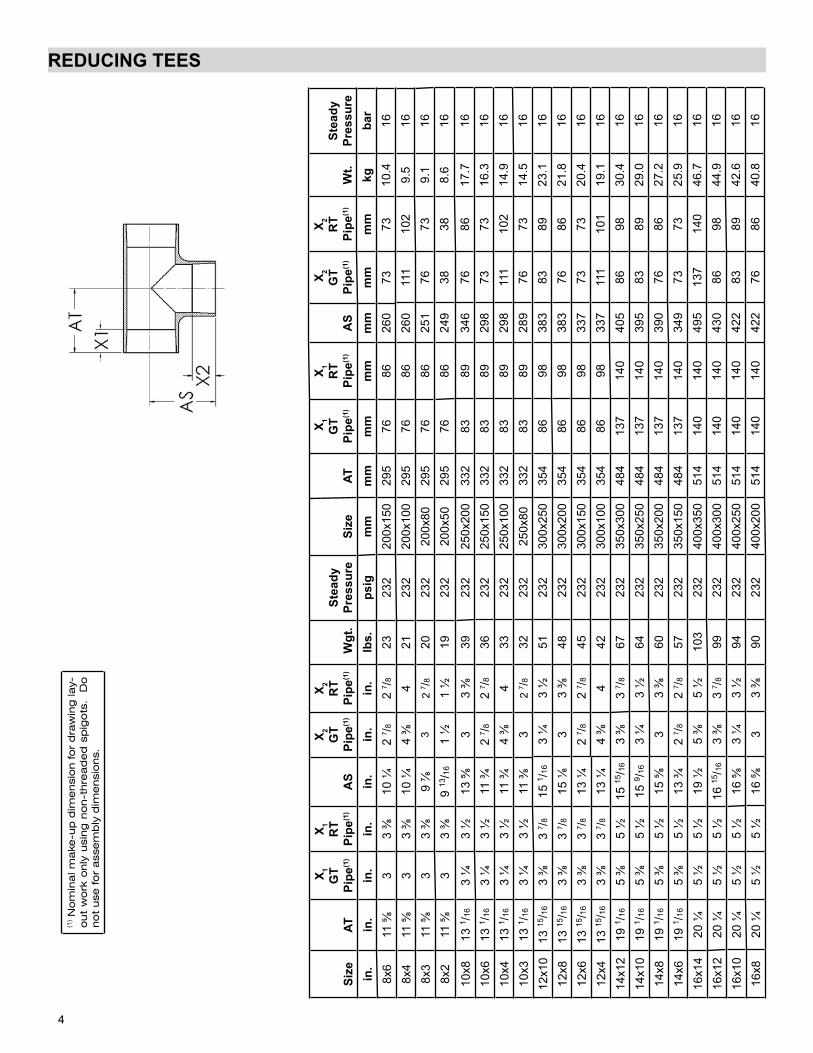
REDUCING TEES
Size
AT
X1
GT
Pipe
(1)
X 1R
T
Pipe
(1)
AS
X 2G
T Pi
pe(1
)
X 2R
T Pi
pe(1
) W
gt.
Stea
dyPr
essu
reSi
zeAT
X1
GT
Pipe
(1)
X 1R
T
Pipe
(1)
AS
X2
GT
Pipe
(1)
X 2R
T
Pipe
(1)
Wt.
Stea
dyPr
essu
rein
.in
.in
.in
.in
.in
.in
.lb
s.ps
igm
mm
mm
mm
mm
mm
mm
mkg
bar
8x6
11 ⅝
33
⅜10
¼2
7 /82
7 /823
232
200x
150
295
7686
260
7373
10.4
16
8x4
11 ⅝
33
⅜10
¼4
⅜4
2123
220
0x10
029
576
8626
011
110
29.
516
8x3
11 ⅝
33
⅜9
⅞3
2 7 /8
2023
220
0x80
295
7686
251
7673
9.1
16
8x2
11 ⅝
33
⅜9
13/16
1 ½
1 ½
1923
220
0x50
295
7686
249
3838
8.6
16
10x8
13 1 /1
63
¼3
½13
⅝3
3 ⅜
3923
225
0x20
033
283
8934
676
8617
.716
10x6
13 1 /1
63
¼3
½11
¾2
7 /82
7 /836
232
250x
150
332
8389
298
7373
16.3
16
10x4
13 1 /1
63
¼3
½11
¾4
⅜4
3323
225
0x10
033
283
8929
811
110
214
.916
10x3
13 1 /1
63
¼3
½11
⅜3
2 7 /8
3223
225
0x80
332
8389
289
7673
14.5
16
12x1
013
15/16
3 ⅜
3 7 /8
15 1 /1
63
¼3
½51
232
300x
250
354
8698
383
8389
23.1
16
12x8
13 15
/163
⅜3
7 /815
⅛3
3 ⅜
4823
230
0x20
035
486
9838
376
8621
.816
12x6
13 15
/163
⅜3
7 /813
¼2
7 /82
7 /845
232
300x
150
354
8698
337
7373
20.4
16
12x4
13 15
/163
⅜3
7 /813
¼4
⅜4
4223
230
0x10
035
486
9833
711
110
119
.116
14x1
219
1 /16
5 ⅜
5 ½
15 15
/163
⅜3
7 /867
232
350x
300
484
137
140
405
8698
30.4
16
14x1
019
1 /16
5 ⅜
5 ½
15 9 /1
63
¼3
½64
232
350x
250
484
137
140
395
8389
29.0
16
14x8
19 1 /1
65
⅜5
½15
⅝3
3 ⅜
6023
235
0x20
048
413
714
039
076
8627
.216
14x6
19 1 /1
65
⅜5
½13
¾2
7 /82
7 /857
232
350x
150
484
137
140
349
7373
25.9
16
16x1
420
¼5
½5
½19
½5
⅜5
½10
323
240
0x35
051
414
014
049
513
714
046
.716
16x1
220
¼5
½5
½16
15/16
3 ⅜
3 7 /8
9923
240
0x30
051
414
014
043
086
9844
.916
16x1
020
¼5
½5
½16
⅝3
¼3
½94
232
400x
250
514
140
140
422
8389
42.6
16
16x8
20 ¼
5 ½
5 ½
16 ⅝
33
⅜90
232
400x
200
514
140
140
422
7686
40.8
16
4
(1) N
om
ina
l ma
ke-u
p d
ime
nsi
on fo
r d
raw
ing
lay-
out
wo
rk o
nly
usi
ng
no
n-t
hre
ad
ed
sp
igo
ts.
Do
no
t use
fo
r a
sse
mb
ly d
ime
nsi
ons.
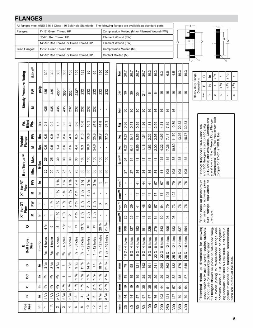
FLANGES
mm
mm
mm
mm
mm
mm
mm
mm
(1)
mm
(1)
mm
(1)
mm
(1)
N-m
(2)
kgkg
kgba
rba
rba
r
2544
1919
7916
D -
4 ho
les
108
2525
--
2734
0.27
0.27
0.36
3030
20.7
4044
1919
9816
D -
4 ho
les
127
2529
--
2734
0.41
0.41
0.41
3030
20.7
5057
1919
121
19 D
- 4
hole
s15
241
4141
4134
410.
590.
590.
5930
30(4
)20
.7
8067
3525
152
19 D
- 4
hole
s19
148
4844
4434
411.
181.
541.
3630
21(4
)20
.7
100
6735
2519
119
D -
8 ho
les
229
5160
4141
3441
1.63
2.22
1.81
1616
(4)
10.3
150
7638
2924
122
D -
8 ho
les
279
6457
5757
3441
2.00
2.95
2.99
1616
(4)
10.3
200
102
4429
298
22 D
- 8
hole
s34
360
5473
6741
135
4.22
4.99
4.81
1616
9.3
250
121
5132
362
25 D
- 12
hol
es40
698
7910
586
108
135
7.26
7.17
7.39
1616
6.5
300
127
5732
432
25 D
- 12
hol
es48
398
7310
279
108
135
10.8
911
.70
10.8
916
164.
5
350
7964
4847
628
D -
12 h
oles
527
-76
-76
108
135
-13
.93
20.3
2-
1610
.3
400
7964
5754
028
D -
16 h
oles
594
-76
-76
108
135
-16
.78
30.5
3-
1610
.3
All flanges meet ANSI B16.5 Class 150 Bolt Hole Standards. The following flanges are available as standard parts:
Flanges: 1”-12” Green Thread HP Compression Molded (M) or Filament Wound (FW)
2”-6” Red Thread HP Filament Wound (FW)
14”-16” Red Thread or Green Thread HP Filament Wound (FW)
Blind Flanges: 1”-12” Green Thread HP Compression Molded (M)
14”-16” Red Thread or Green Thread HP Contact Molded (M)
5
Pipe
Si
zeB
CC
CD
EB
olt H
ole
Size
OX(1
) for
GT
Pipe
X(1) f
or R
T Pi
peB
olt T
orqu
e (2
) W
eigh
tFl
ange
Wt.
Blin
d Fl
g.
Stea
dy P
ress
ure
Rat
ing
MFW
MFW
Min
.M
ax.
MFW
M
FWB
lind(3
)
inin
inin
inin
- no
.in
inin
inft-
lbs
lbs
lbs
lbs
psig
11
3 /4
3 /43 /4
3 1 /8
5 /8 -
4 h
oles
4 1 /4
11
--
2025
0.6
0.6
0.8
435
435
300
1 1 /2
1 3 /
43 /4
3 /43
7 /85 /8
- 4
hol
es5
11
1 /8-
-20
250.
90.
90.
943
543
530
0
22
1 /4
3 /43 /4
4 3 /4
3 /4 -
4 h
oles
61
⅝1
⅝1
⅝1
⅝25
301.
31.
31.
343
543
5(4)
300
32
5 /81
3 /81
63 /4
- 4
hol
es7
1 /21
7 /81
7 /81
¾1
¾25
302.
63.
43.
043
530
0(4)
300
42
5 /81
3 /81
7 1 /2
3 /4 -
8 h
oles
92
2 3 /8
1 ⅝
1 ⅝
2530
3.6
4.9
4.0
232
232(4
)15
0
63
1 1 /2
1 1 /8
9 1 /2
7 /8 -
8 h
oles
112
½2
¼2
¼2
¼25
304.
46.
56.
623
223
24)15
08
41
3 /41
1 /811
3 /47 /8
- 8
hol
es13
1 /22
3 /82
1 /82
7 /82
⅝80
100
9.3
11.0
10.6
232
232
135
104
3 /42
1 1 /4
14 1 /4
1 -
12 h
oles
163
7 /83
1 /84
1 /83
3 /880
100
16.0
15.8
16.3
232
232
9512
52
1 /41
1 /417
1 -
12 h
oles
193
7 /82
7 /84
3 1 /8
8010
024
.025
.824
.023
223
265
143
1 /82
1 /21
7 /818
3 /41
1 /8 -
12
hole
s20
3 /4-
3-
380
100
-30
.744
.8-
232
150
163
1 /8
2 1 /
22
1 /4
21 1
/41
1 /8 -
16
hole
s23
1/4
-3
-3
8010
0-
37.0
67.3
-23
215
0
(1) N
om
ina
l m
ake
-up
d
ime
nsi
on fo
r d
raw
ing
la
yout
wo
rk o
nly
usi
ng
no
n-t
hre
ad
ed
sp
igo
ts.
Do
no
t use
fo
r a
sse
mb
ly d
ime
nsi
on
(2) F
lang
es
sho
uld
be
jo
ine
d t
o f
lat-
face
d f
lang
-e
s. W
he
n jo
inin
g to
ra
ise
d-f
ace
d fla
ng
e co
n-
ne
ctio
ns,
co
nsu
lt F
GS
inst
alla
tio
n o
r e
ng
ine
er-
ing
Ma
nua
ls IN
S1
00
0 &
EN
G1
00
0.
Bo
lt t
orq
ue
, g
ask
et
thic
kne
ss a
nd
ha
rdne
ss r
eco
mm
end
a-
tio
ns
are
in M
anua
l IN
S1
00
0.
(3) S
tee
l b
ack-
up
pla
tes
must
b
e
use
d
to
achie
ve
pre
s-su
re
rating
s e
quiv
ale
nt
to
the
pip
e.
(4) H
ea
vy d
uty
AN
SI 1
6.5
Cla
ss 1
50
a
nd
30
0 fla
ng
es
rate
d t
o 4
50
psi
g
(3.1
0 M
Pa
) a
re a
vaila
ble
. D
ime
nsi
ons
are
sho
wn in
the
“H
ea
vy D
uty
Fla
ng
e
Dim
ensi
ons”
ta
ble
. The
ma
xim
um
bo
lt
torq
ue
fo
r 2
”-6
” is
10
0 f
t. lb
s.
Hea
vy D
uty
Flan
ge
Dim
ensi
ons
Siz
esB
C
InIn
In2
32
3 /4
33
1 /4
3
44
3 /4
3 1 /2
64
1 /4
4
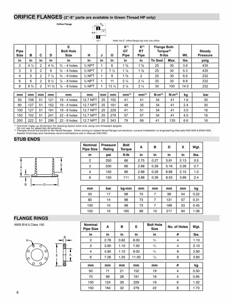
ORIFICE FLANGES (2”-8” parts are available in Green Thread HP only)
Pipe Size B C D
EBolt Hole
Size H J O
X(1) GT
Pipe
X(1) RT
Pipe
Flange Bolt-Torque(2)
ft-lbs Wt.Steady
Pressurein in in in in in in in in in To Seal Max. lbs psig2 4 ¼ 2 4 ¾ ¾ - 4 holes ½ NPT 1 6 1 ⅝ 1 ⅝ 25 30 3.6 4353 5 2 6 ¾ - 4 holes ½ NPT 1 7 ½ 1 ⅞ 1 ⅜ 25 30 5.3 4354 5 2 7 ½ ¾ - 8 holes ½ NPT 1 9 1 ⅝ 2 25 30 6.6 2326 6 2 9 ½ ⅞ - 8 holes ½ NPT 1 11 2 ¼ 2 ¼ 25 30 8.8 2328 8 ¾ 2 11 ¾ ⅞ - 8 holes ½ NPT 1 13 ½ 3 ⅛ 3 ½ 30 100 14.5 232
mm mm mm mm mm mm mm mm mm(1) mm(1) N-m(2) N-m(2) kg bar50 108 51 121 19 - 4 holes 12.7 NPT 25 152 41 41 34 41 1.6 3080 127 51 152 19 - 4 holes 12.7 NPT 25 191 48 35 34 41 2.4 30
100 127 51 191 19 - 8 holes 12.7 NPT 25 229 41 51 34 41 3.0 16150 152 51 241 22 - 8 holes 12.7 NPT 25 279 57 57 34 41 4.0 16200 222 51 298 22 - 8 holes 12.7 NPT 25 343 79 89 41 135 6.6 16
Orifice Flange
6
(1) Nominal make-up dimension for drawing layout work only using non-threaded spigots. Do not use for assembly dimensions.(2) Flanges should be joined to flat-faced flanges. When joining to raised-faced flange connections, consult installation or engineering Manuals INS1000 & ENG1000. Gasket thickness and hardness recommendations are in Manual INS1000.
Note: the 2” orifice flange has only one orifice
STUB ENDSNominal Pipe Size
Pressure Rating
Bolt Torque
A B D X Wgt.
in psi ft-lb in in in in lbs.
2 250 66 2.75 0.27 3.91 2.13 0.5
3 200 66 2.88 0.28 5.16 2.26 0.7
4 150 66 2.88 0.28 6.66 2.10 1.0
6 150 111 3.88 0.39 8.53 3.69 2.4
FLANGE RINGSNominal Pipe Size
A B EBolt Hole
SizeNo. of Holes Wgt.
in in in in in # lbs.
2 2.78 0.82 6.00 3/4 4 1.10
3 3.90 1.10 7.50 3/4 4 2.10
4 4.90 1.10 9.00 3/4 8 2.90
6 7.26 1.25 11.00 7/8 8 3.80
XA
B D
H
E A
B
ANSI B16.5 Class 150
mm mm mm mm mm # kg
50 71 21 152 19 4 0.50
70 99 28 191 19 4 0.95
100 124 28 229 19 8 1.32
150 184 32 279 22 8 1.73
mm bar kg-mm mm mm mm mm kg
50 17 98 70 7 99 54 0.22
80 14 98 73 7 131 57 0.31
100 10 98 73 7 169 53 0.45
150 10 165 99 10 217 94 1.08
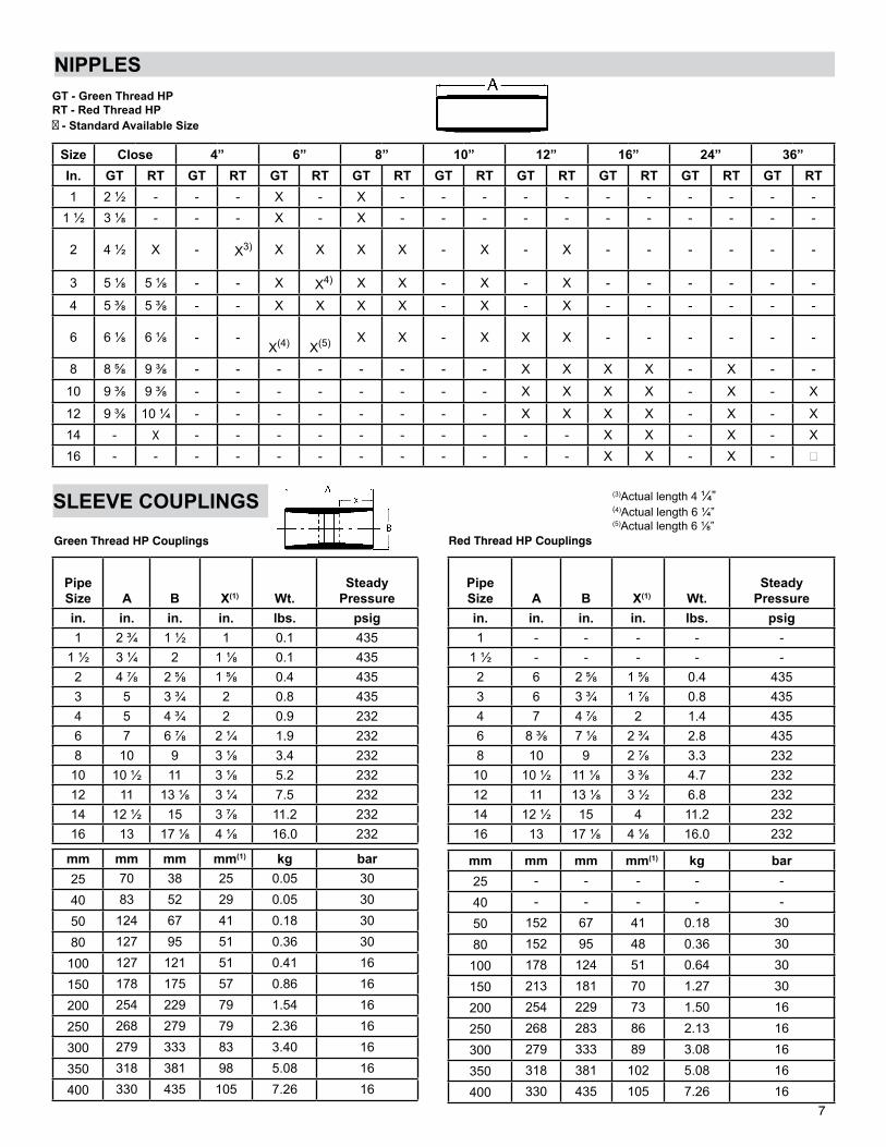
SLEEVE COUPLINGS
Pipe Size A B X(1) Wt.
SteadyPressure
in. in. in. in. lbs. psig1 2 ¾ 1 ½ 1 0.1 435
1 ½ 3 ¼ 2 1 ⅛ 0.1 4352 4 ⅞ 2 ⅝ 1 ⅝ 0.4 4353 5 3 ¾ 2 0.8 4354 5 4 ¾ 2 0.9 2326 7 6 ⅞ 2 ¼ 1.9 2328 10 9 3 ⅛ 3.4 232
10 10 ½ 11 3 ⅛ 5.2 23212 11 13 ⅛ 3 ¼ 7.5 23214 12 ½ 15 3 ⅞ 11.2 23216 13 17 ⅛ 4 ⅛ 16.0 232
Pipe Size
A B X(1) Wt.Steady
Pressurein. in. in. in. lbs. psig1 - - - - -
1 ½ - - - - -2 6 2 ⅝ 1 ⅝ 0.4 4353 6 3 ¾ 1 ⅞ 0.8 4354 7 4 ⅞ 2 1.4 4356 8 ⅜ 7 ⅛ 2 ¾ 2.8 4358 10 9 2 ⅞ 3.3 232
10 10 ½ 11 ⅛ 3 ⅜ 4.7 23212 11 13 ⅛ 3 ½ 6.8 23214 12 ½ 15 4 11.2 23216 13 17 ⅛ 4 ⅛ 16.0 232
mm mm mm mm(1) kg bar25 70 38 25 0.05 30
40 83 52 29 0.05 30
50 124 67 41 0.18 30
80 127 95 51 0.36 30
100 127 121 51 0.41 16
150 178 175 57 0.86 16
200 254 229 79 1.54 16
250 268 279 79 2.36 16
300 279 333 83 3.40 16
350 318 381 98 5.08 16
400 330 435 105 7.26 16
mm mm mm mm(1) kg bar25 - - - - -
40 - - - - -
50 152 67 41 0.18 30
80 152 95 48 0.36 30
100 178 124 51 0.64 30
150 213 181 70 1.27 30
200 254 229 73 1.50 16
250 268 283 86 2.13 16
300 279 333 89 3.08 16
350 318 381 102 5.08 16
400 330 435 105 7.26 16
Green Thread HP Couplings Red Thread HP Couplings
NIPPLES
Size Close 4” 6” 8” 10” 12” 16” 24” 36”In. GT RT GT RT GT RT GT RT GT RT GT RT GT RT GT RT GT RT1 2 ½ - - - X - X - - - - - - - - - - -
1 ½ 3 ⅛ - - - X - X - - - - - - - - - - -
2 4 ½ X - X3) X X X X - X - X - - - - - -
3 5 ⅛ 5 ⅛ - - X X4) X X - X - X - - - - - -
4 5 ⅜ 5 ⅜ - - X X X X - X - X - - - - - -
6 6 ⅛ 6 ⅛ - -
X(4)
X(5) X X - X X X - - - - - -
8 8 ⅝ 9 ⅜ - - - - - - - - X X X X - X - -
10 9 ⅜ 9 ⅜ - - - - - - - - X X X X - X - X
12 9 ⅜ 10 ¼ - - - - - - - - X X X X - X - X14 - X - - - - - - - - - - X X - X - X16 - - - - - - - - - - - - X X - X -
GT - Green Thread HPRT - Red Thread HP - Standard Available Size
(3)Actual length 4 ¼”(4)Actual length 6 ¼”(5)Actual length 6 ⅛”
7
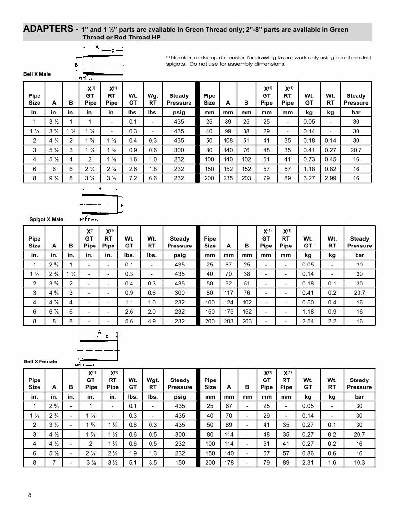
ADAPTERS - 1” and 1 ½” parts are available in Green Thread only; 2”-8” parts are available in Green Thread or Red Thread HP
Bell X Male
PipeSize A B
X(1)
GT Pipe
X(1)
RTPipe
Wt.GT
Wg.RT
SteadyPressure
PipeSize A B
X(1)
GT Pipe
X(1)
RT Pipe
Wt.GT
Wt.RT
SteadyPressure
in. in. in. in. in. lbs. lbs. psig mm mm mm mm mm kg kg bar1 3 ½ 1 1 - 0.1 - 435 25 89 25 25 - 0.05 - 30
1 ½ 3 ¾ 1 ½ 1 ⅛ - 0.3 - 435 40 99 38 29 - 0.14 - 302 4 ¼ 2 1 ⅝ 1 ⅜ 0.4 0.3 435 50 108 51 41 35 0.18 0.14 303 5 ½ 3 1 ⅞ 1 ⅜ 0.9 0.6 300 80 140 76 48 35 0.41 0.27 20.74 5 ½ 4 2 1 ⅝ 1.6 1.0 232 100 140 102 51 41 0.73 0.45 166 6 6 2 ¼ 2 ¼ 2.6 1.8 232 150 152 152 57 57 1.18 0.82 168 9 ¼ 8 3 ⅛ 3 ½ 7.2 6.6 232 200 235 203 79 89 3.27 2.99 16
PipeSize A B
X(1)
GT Pipe
X(1)
RT Pipe
Wt.GT
Wt.RT
SteadyPressure
PipeSize A B
X(1)
GTPipe
X(1)
RTPipe
Wt.GT
Wt.RT
SteadyPressure
in. in. in. in. in. lbs. lbs. psig mm mm mm mm mm kg kg bar1 2 ⅝ 1 - - 0.1 - 435 25 67 25 - - 0.05 - 30
1 ½ 2 ¾ 1 ¼ - - 0.3 - 435 40 70 38 - - 0.14 - 302 3 ⅝ 2 - - 0.4 0.3 435 50 92 51 - - 0.18 0.1 303 4 ⅝ 3 - - 0.9 0.6 300 80 117 76 - - 0.41 0.2 20.74 4 ⅞ 4 - - 1.1 1.0 232 100 124 102 - - 0.50 0.4 166 6 ⅞ 6 - - 2.6 2.0 232 150 175 152 - - 1.18 0.9 168 8 8 - - 5.6 4.9 232 200 203 203 - - 2.54 2.2 16
PipeSize A B
X(1)
GT Pipe
X(1)
RTPipe
Wt.GT
Wgt.RT
SteadyPressure
PipeSize A B
X(1)
GT Pipe
X(1)
RT Pipe
Wt.GT
Wt.RT
SteadyPressure
in. in. in. in. in. lbs. lbs. psig mm mm mm mm mm kg kg bar1 2 ⅝ - 1 - 0.1 - 435 25 67 - 25 - 0.05 - 30
1 ½ 2 ¾ - 1 ⅛ - 0.3 - 435 40 70 - 29 - 0.14 - 302 3 ½ - 1 ⅝ 1 ⅜ 0.6 0.3 435 50 89 - 41 35 0.27 0.1 303 4 ½ - 1 ⅞ 1 ⅜ 0.6 0.5 300 80 114 - 48 35 0.27 0.2 20.74 4 ½ - 2 1 ⅝ 0.6 0.5 232 100 114 - 51 41 0.27 0.2 166 5 ½ - 2 ¼ 2 ¼ 1.9 1.3 232 150 140 - 57 57 0.86 0.6 168 7 - 3 ⅛ 3 ½ 5.1 3.5 150 200 178 - 79 89 2.31 1.6 10.3
(1) Nominal make-up dimension for drawing layout work only using non-threaded spigots. Do not use for assembly dimensions.
Spigot X Male
Bell X Female
8
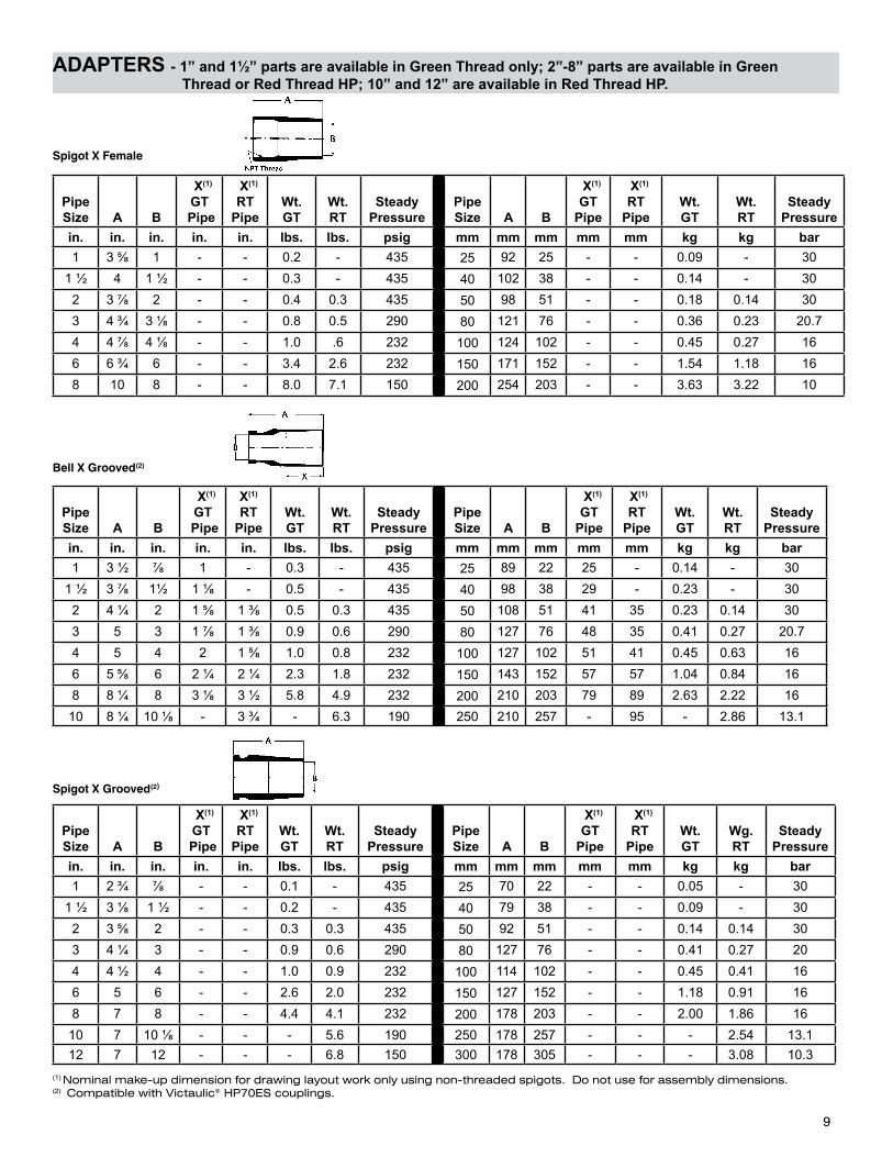
ADAPTERS - 1” and 1½” parts are available in Green Thread only; 2”-8” parts are available in Green Thread or Red Thread HP; 10” and 12” are available in Red Thread HP.
PipeSize A B
X(1)
GT Pipe
X(1)
RT Pipe
Wt.GT
Wt.RT
SteadyPressure
PipeSize A B
X(1)
GT Pipe
X(1)
RTPipe
Wt.GT
Wt.RT
SteadyPressure
in. in. in. in. in. lbs. lbs. psig mm mm mm mm mm kg kg bar1 3 ⅝ 1 - - 0.2 - 435 25 92 25 - - 0.09 - 30
1 ½ 4 1 ½ - - 0.3 - 435 40 102 38 - - 0.14 - 302 3 ⅞ 2 - - 0.4 0.3 435 50 98 51 - - 0.18 0.14 303 4 ¾ 3 ⅛ - - 0.8 0.5 290 80 121 76 - - 0.36 0.23 20.74 4 ⅞ 4 ⅛ - - 1.0 .6 232 100 124 102 - - 0.45 0.27 166 6 ¾ 6 - - 3.4 2.6 232 150 171 152 - - 1.54 1.18 168 10 8 - - 8.0 7.1 150 200 254 203 - - 3.63 3.22 10
PipeSize A B
X(1)
GT Pipe
X(1)
RT Pipe
Wt.GT
Wt.RT
SteadyPressure
PipeSize A B
X(1)
GT Pipe
X(1)
RTPipe
Wt.GT
Wt.RT
SteadyPressure
in. in. in. in. in. lbs. lbs. psig mm mm mm mm mm kg kg bar1 3 ½ ⅞ 1 - 0.3 - 435 25 89 22 25 - 0.14 - 30
1 ½ 3 ⅞ 1½ 1 ⅛ - 0.5 - 435 40 98 38 29 - 0.23 - 302 4 ¼ 2 1 ⅝ 1 ⅜ 0.5 0.3 435 50 108 51 41 35 0.23 0.14 303 5 3 1 ⅞ 1 ⅜ 0.9 0.6 290 80 127 76 48 35 0.41 0.27 20.74 5 4 2 1 ⅝ 1.0 0.8 232 100 127 102 51 41 0.45 0.63 166 5 ⅝ 6 2 ¼ 2 ¼ 2.3 1.8 232 150 143 152 57 57 1.04 0.84 168 8 ¼ 8 3 ⅛ 3 ½ 5.8 4.9 232 200 210 203 79 89 2.63 2.22 16
10 8 ¼ 10 ⅛ - 3 ¾ - 6.3 190 250 210 257 - 95 - 2.86 13.1
PipeSize A B
X(1)
GT Pipe
X(1)
RT Pipe
Wt.GT
Wt.RT
SteadyPressure
PipeSize A B
X(1)
GT Pipe
X(1)
RT Pipe
Wt.GT
Wg.RT
SteadyPressure
in. in. in. in. in. lbs. lbs. psig mm mm mm mm mm kg kg bar1 2 ¾ ⅞ - - 0.1 - 435 25 70 22 - - 0.05 - 30
1 ½ 3 ⅛ 1 ½ - - 0.2 - 435 40 79 38 - - 0.09 - 302 3 ⅝ 2 - - 0.3 0.3 435 50 92 51 - - 0.14 0.14 303 4 ¼ 3 - - 0.9 0.6 290 80 127 76 - - 0.41 0.27 204 4 ½ 4 - - 1.0 0.9 232 100 114 102 - - 0.45 0.41 166 5 6 - - 2.6 2.0 232 150 127 152 - - 1.18 0.91 168 7 8 - - 4.4 4.1 232 200 178 203 - - 2.00 1.86 16
10 7 10 ⅛ - - - 5.6 190 250 178 257 - - - 2.54 13.112 7 12 - - - 6.8 150 300 178 305 - - - 3.08 10.3
Spigot X Female
Bell X Grooved(2)
Spigot X Grooved(2)
9
(1) Nominal make-up dimension for drawing layout work only using non-threaded spigots. Do not use for assembly dimensions.(2) Compatible with Victaulic® HP70ES couplings.
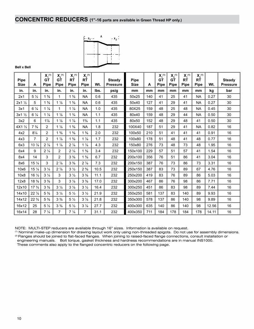
CONCENTRIC REDUCERS (1”-16 parts are available in Green Thread HP only.)
Bell x Bell
Pipe Size A
X1(1)
GT Pipe
X2(1)
GT Pipe
X1(1)
RT Pipe
X2(1)
RT Pipe Wt.
SteadyPressure
PipeSize A
X1(1)
GT Pipe
X2(1)
GT Pipe
X1(1)
RT Pipe
X2(1)
RT Pipe Wt.
SteadyPressure
in. in. in. in. in. in. lbs. psig mm mm mm mm mm mm kg bar2x1 5 ½ 1 ⅝ 1 1 ⅝ NA 0.6 435 50x25 140 41 25 41 NA 0.27 30
2x1 ½ 5 1 ⅝ 1 ⅛ 1 ⅝ NA 0.6 435 50x40 127 41 29 41 NA 0.27 303x1 6 ¼ 1 ⅞ 1 1 ⅞ NA 1.0 435 80X25 159 48 25 48 NA 0.45 30
3x1 ½ 6 ¼ 1 ⅞ 1 ⅛ 1 ¾ NA 1.1 435 80x40 159 48 29 44 NA 0.50 303x2 6 1⅞ 1 ⅛ 1 ⅞ 1⅝ 1.1 435 80x50 152 48 29 48 41 0.50 30
4X1 ½ 7 ⅜ 2 1 ⅛ 1 ⅝ NA 1.8 232 100X40 187 51 29 41 NA 0.82 164x2 8¼ 2 1 ⅝ 1 ⅝ 1 ⅝ 2.0 232 100x50 210 51 41 41 41 0.91 164x3 7 2 1 ⅞ 1 ⅝ 1 ⅞ 1.7 232 100x80 178 51 48 41 48 0.77 166x3 10 ⅞ 2 ⅞ 1 ⅞ 2 ⅞ 1 ⅞ 4.3 232 150x80 276 73 48 73 48 1.95 166x4 9 2 ¼ 2 2 ¼ 1 ⅝ 3.4 232 150x100 229 57 51 57 41 1.54 168x4 14 3 2 3 ⅜ 1 ⅝ 6.7 232 200x100 356 76 51 86 41 3.04 168x6 15 ¼ 3 2 ⅞ 3 ⅜ 2 ⅞ 7.3 232 200x150 387 76 73 86 73 3.31 16
10x6 15 ¼ 3 ¼ 2 ⅞ 3 ½ 2 ⅝ 10.5 232 250x150 387 83 73 89 67 4.76 1610x8 16 ½ 3 ¼ 3 3 ½ 3 ⅜ 11.1 232 250x200 419 83 76 89 86 5.03 1612x8 18 ⅜ 3 ⅜ 3 3 ⅞ 3 ⅜ 17.0 232 300x200 467 86 76 98 86 7.71 16
12x10 17 ¾ 3 ⅜ 3 ¼ 3 ⅞ 3 ½ 16.4 232 300x250 451 86 83 98 89 7.44 1614x10 22 ⅞ 5 ⅜ 3 ¼ 5 ½ 3 ½ 21.9 232 350x250 581 137 83 140 89 9.93 1614x12 22 ¾ 5 ⅜ 3 ⅜ 5 ½ 3 ⅞ 21.8 232 350x300 578 137 86 140 98 9.89 16
16x12 25 5 ½ 3 ⅜ 5 ½ 3 ⅞ 27.7 232 400x300 635 140 86 140 98 12.56 1616x14 28 7 ¼ 7 7 ¼ 7 31.1 232 400x350 711 184 178 184 178 14.11 16
NOTE: MULTI-STEP reducers are available through 16” sizes. Information is available on request.(1) Nominal make-up dimension for drawing layout work only using non-threaded spigots. Do not use for assembly dimensions.(2) Flanges should be joined to flat-faced flanges. When joining to raised-faced flange connections, consult installation or engineering manuals. Bolt torque, gasket thickness and hardness recommendations are in manual INS1000. These comments also apply to the flanged concentric reducers on the following page.
10
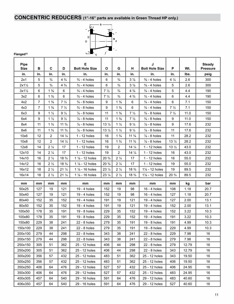
CONCENTRIC REDUCERS (1”-16” parts are available in Green Thread HP only.)
PipeSize B C D
EBolt Hole Size O G H
JBolt Hole Size P Wt.
SteadyPressure
in. in. in. in. in. in. in. in. in. in. lbs. psig2x1 5 ¾ 4 ¾ ¾ - 4 holes 6 ¾ 3 ⅞ ⅝ - 4 holes 4 ¼ 2.6 300
2x1½ 5 ¾ 4 ¾ ¾ - 4 holes 6 ¾ 3 ⅞ ⅝ - 4 holes 5 2.6 3003x1½ 6 1 ⅜ 6 ¾ - 4 holes 7 ½ ¾ 4 ¾ ¾ - 4 holes 5 4.4 1903x2 6 1 ⅜ 6 ¾ - 4 holes 7 ½ ¾ 4 ¾ ¾ - 4 holes 6 4.4 1904x2 7 1 ⅜ 7 ½ ¾ - 8 holes 9 1 ⅜ 6 ¾ - 4 holes 6 7.1 1504x3 7 1 ⅜ 7 ½ ¾ - 8 holes 9 1 ⅜ 6 ¾ - 4 holes 7 ½ 7.1 1506x3 9 1 ½ 9 ½ ⅞ - 8 holes 11 1 ⅜ 7 ½ ¾ - 8 holes 7 ½ 11.0 1506x4 9 1 ½ 9 ½ ⅞ - 8 holes 11 1 ⅜ 7 ½ ¾ - 8 holes 9 11.0 1508x4 11 1 ¾ 11 ¾ ⅞ - 8 holes 13 ½ 1 ½ 9 ½ ⅞ - 8 holes 9 17.6 232
8x6 11 1 ¾ 11 ¾ ⅞ - 8 holes 13 ½ 1 ½ 9 ½ ⅞ - 8 holes 11 17.6 23210x6 12 2 14 ¼ 1 - 12 holes 16 1 ¾ 11 ¾ ⅞ - 8 holes 11 28.2 23210x8 12 2 14 ¼ 1 - 12 holes 16 1 ¾ 11 ¾ ⅞ - 8 holes 13 ½ 28.2 23212x8 14 2 ¼ 17 1 - 12 holes 19 2 14 ¼ 1 - 12 holes 13 ½ 43.0 232
12x10 14 2 ¼ 17 1 - 12 holes 19 2 14 ¼ 1 - 12 holes 16 43.0 23214x10 16 2 ½ 18 ¾ 1 ⅛ - 12 holes 20 ¾ 2 ¼ 17 1 - 12 holes 16 55.0 23214x12 16 2 ½ 18 ¾ 1 ⅛ - 12 holes 20 ¾ 2 ¼ 17 1 - 12 holes 19 55.0 23216x12 18 2 ½ 21 ¼ 1 ⅛ - 16 holes 23 ¼ 2 ½ 18 ¾ 1⅛ - 12 holes 19 89.5 23216x14 18 2 ½ 21 ¼ 1 ⅛ - 16 holes 23 ¼ 2 ½ 18 ¾ 1⅛ - 12 holes 20 ¾ 89.5 232
mm mm mm mm mm mm mm mm mm mm kg bar50x25 127 19 121 19 - 4 holes 152 19 98 16 - 4 holes 108 1.18 20.750x40 127 19 121 19 - 4 holes 152 19 98 16 - 4 holes 127 1.18 20.780x40 152 35 152 19 - 4 holes 191 19 121 19 - 4 holes 127 2.00 13.180x50 152 35 152 19 - 4 holes 191 19 121 19 - 4 holes 152 2.00 13.1
100x50 178 35 191 19 - 8 holes 229 35 152 19 - 4 holes 152 3.22 10.3100x80 178 35 191 19 - 8 holes 229 35 152 19 - 4 holes 191 3.22 10.3150x80 229 38 241 22 - 8 holes 279 35 191 19 - 8 holes 191 4.99 10.3
150x100 229 38 241 22 - 8 holes 279 35 191 19 - 8 holes 229 4.99 10.3200x100 279 44 298 22 - 8 holes 343 38 241 22 - 8 holes 229 7.98 16200x150 279 44 298 22 - 8 holes 343 38 241 22 - 8 holes 279 7.98 16250x150 305 51 362 25 - 12 holes 406 44 298 22 - 8 holes 279 12.79 16250x200 305 51 362 25 - 12 holes 406 44 298 22 - 8 holes 343 12.79 16300x200 356 57 432 25 - 12 holes 483 51 362 25 - 12 holes 343 19.50 16300x250 356 57 432 25 - 12 holes 483 51 362 25 - 12 holes 406 19.50 16350x250 406 64 476 29 - 12 holes 527 57 432 25 - 12 holes 406 24.95 16350x300 406 64 476 29 - 12 holes 527 57 432 25 - 12 holes 483 24.95 16400x305 457 64 540 29 - 16 holes 591 64 476 29 - 12 holes 483 40.60 16406x350 457 64 540 29 - 16 holes 591 64 476 29 - 12 holes 527 40.60 16
Flanged(2)
11
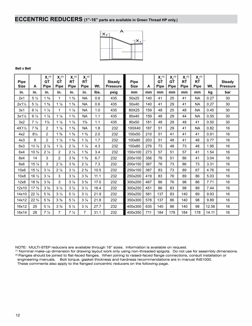
ECCENTRIC REDUCERS (1”-16” parts are available in Green Thread HP only.)
Bell x Bell
Pipe Size A
X1(1)
GT Pipe
X2(1)
GT Pipe
X1(1)
RT Pipe
X2(1)
RT Pipe Wt.
SteadyPressure
PipeSize A
X1(1)
GT Pipe
X2(1)
GT Pipe
X1(1)
RT Pipe
X2(1)
RT Pipe Wt.
SteadyPressure
in. in. in. in. in. in. lbs. psig mm mm mm mm mm mm kg bar2x1 5 ½ 1 ⅝ 1 1 ⅝ NA 0.6 435 50x25 140 41 25 41 NA 0.27 30
2x1½ 5 ½ 1 ⅝ 1 ⅛ 1 ⅝ NA 0.6 435 50x40 140 41 29 41 NA 0.27 303x1 6 ¼ 1 ⅞ 1 1 ⅞ NA 1.0 435 80X25 159 48 25 48 NA 0.45 30
3x1½ 6 ¼ 1 ⅞ 1 ⅛ 1 ¾ NA 1.1 435 80x40 159 48 29 44 NA 0.50 303x2 7 1/8 1⅞ 1 ⅛ 1 ⅞ 1⅝ 1.1 435 80x50 181 48 29 48 41 0.50 30
4X1½ 7 ⅜ 2 1 ⅛ 1 ⅝ NA 1.8 232 100X40 187 51 29 41 NA 0.82 164x2 8¼ 2 1 ⅝ 1 ⅝ 1 ⅝ 2.0 232 100x50 210 51 41 41 41 0.91 164x3 8 2 1 ⅞ 1 ⅝ 1 ⅞ 1.7 232 100x80 203 51 48 41 48 0.77 166x3 10 ⅞ 2 ⅞ 1 ⅞ 2 ⅞ 1 ⅞ 4.3 232 150x80 276 73 48 73 48 1.95 166x4 10 ¾ 2 ¼ 2 2 ¼ 1 ⅝ 3.4 232 150x100 273 57 51 57 41 1.54 168x4 14 3 2 3 ⅜ 1 ⅝ 6.7 232 200x100 356 76 51 86 41 3.04 168x6 15 ¼ 3 2 ⅞ 3 ⅜ 2 ⅞ 7.3 232 200x150 387 76 73 86 73 3.31 16
10x6 15 ¼ 3 ¼ 2 ⅞ 3 ½ 2 ⅝ 10.5 232 250x150 387 83 73 89 67 4.76 1610x8 16 ½ 3 ¼ 3 3 ½ 3 ⅜ 11.1 232 250x200 419 83 76 89 86 5.03 1612x8 18 ⅜ 3 ⅜ 3 3 ⅞ 3 ⅜ 17.0 232 300x200 467 86 76 98 86 7.71 16
12x10 17 ¾ 3 ⅜ 3 ¼ 3 ⅞ 3 ½ 16.4 232 300x250 451 86 83 98 89 7.44 1614x10 22 ⅞ 5 ⅜ 3 ¼ 5 ½ 3 ½ 21.9 232 350x250 581 137 83 140 89 9.93 1614x12 22 ¾ 5 ⅜ 3 ⅜ 5 ½ 3 ⅞ 21.8 232 350x300 578 137 86 140 98 9.89 16
16x12 25 5 ½ 3 ⅜ 5 ½ 3 ⅞ 27.7 232 400x300 635 140 86 140 98 12.56 1616x14 28 7 ¼ 7 7 ¼ 7 31.1 232 400x350 711 184 178 184 178 14.11 16
NOTE: MULTI-STEP reducers are available through 16” sizes. Information is available on request.(1) Nominal make-up dimension for drawing layout work only using non-threaded spigots. Do not use for assembly dimensions.(2) Flanges should be joined to flat-faced flanges. When joining to raised-faced flange connections, consult installation or engineering manuals. Bolt torque, gasket thickness and hardness recommendations are in manual INS1000. These comments also apply to the flanged concentric reducers on the following page.
12
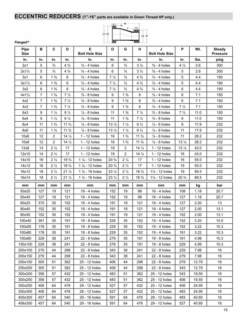
ECCENTRIC REDUCERS (1”-16” parts are available in Green Thread HP only.)
PipeSize
B C D EBolt Hole Size
O G H JBolt Hole Size
P Wt. SteadyPressure
in. in. in. in. in. in. in. in. in. in. lbs. psig2x1 5 ¾ 4 ¾ ¾ - 4 holes 6 ¾ 3 ⅞ ⅝ - 4 holes 4 ¼ 2.6 300
2x1½ 5 ¾ 4 ¾ ¾ - 4 holes 6 ¾ 3 ⅞ ⅝ - 4 holes 5 2.6 3003x1 6 1 ⅜ 6 ¾ - 4 holes 7 ½ ¾ 4 ¾ ¾ - 4 holes 5 4.4 190
3x1½ 6 1 ⅜ 6 ¾ - 4 holes 7 ½ ¾ 4 ¾ ¾ - 4 holes 5 4.4 1903x2 6 1 ⅜ 6 ¾ - 4 holes 7 ½ ¾ 4 ¾ ¾ - 4 holes 6 4.4 190
4x1½ 7 1 ⅜ 7 ½ ¾ - 8 holes 9 1 ⅜ 6 ¾ - 4 holes 6 7.1 1504x2 7 1 ⅜ 7 ½ ¾ - 8 holes 9 1 ⅜ 6 ¾ - 4 holes 6 7.1 1504x3 7 1 ⅜ 7 ½ ¾ - 8 holes 9 1 ⅜ 6 ¾ - 4 holes 7 ½ 7.1 1506x3 9 1 ½ 9 ½ ⅞ - 8 holes 11 1 ⅜ 7 ½ ¾ - 8 holes 7 ½ 11.0 1506x4 9 1 ½ 9 ½ ⅞ - 8 holes 11 1 ⅜ 7 ½ ¾ - 8 holes 9 11.0 1508x4 11 1 ¾ 11 ¾ ⅞ - 8 holes 13 ½ 1 ½ 9 ½ ⅞ - 8 holes 9 17.6 2328x6 11 1 ¾ 11 ¾ ⅞ - 8 holes 13 ½ 1 ½ 9 ½ ⅞ - 8 holes 11 17.6 232
10x6 12 2 14 ¼ 1 - 12 holes 16 1 ¾ 11 ¾ ⅞ - 8 holes 11 28.2 23210x8 12 2 14 ¼ 1 - 12 holes 16 1 ¾ 11 ¾ ⅞ - 8 holes 13 ½ 28.2 23212x8 14 2 ¼ 17 1 - 12 holes 19 2 14 ¼ 1 - 12 holes 13 ½ 43.0 232
12x10 14 2 ¼ 17 1 - 12 holes 19 2 14 ¼ 1 - 12 holes 16 43.0 23214x10 16 2 ½ 18 ¾ 1 ⅛ - 12 holes 20 ¾ 2 ¼ 17 1 - 12 holes 16 55.0 23214x12 16 2 ½ 18 ¾ 1 ⅛ - 12 holes 20 ¾ 2 ¼ 17 1 - 12 holes 19 55.0 23216x12 18 2 ½ 21 ¼ 1 ⅛ - 16 holes 23 ¼ 2 ½ 18 ¾ 1⅛ - 12 holes 19 89.5 23216x14 18 2 ½ 21 ¼ 1 ⅛ - 16 holes 23 ¼ 2 ½ 18 ¾ 1⅛ - 12 holes 20 ¾ 89.5 232
mm mm mm mm mm mm mm mm mm mm kg bar50x25 127 19 121 19 - 4 holes 152 19 98 16 - 4 holes 108 1.18 20.750x40 127 19 121 19 - 4 holes 152 19 98 16 - 4 holes 127 1.18 20.780x25 375 35 152 19 - 4 holes 191 19 121 19 - 4 holes 127 2.00 1380x40 152 35 152 19 - 4 holes 191 19 121 19 - 4 holes 127 2.00 13.180x50 152 35 152 19 - 4 holes 191 19 121 19 - 4 holes 152 2.00 13.1
100x40 391 35 191 19 - 8 holes 229 35 152 19 - 4 holes 152 3.20 10.0100x50 178 35 191 19 - 8 holes 229 35 152 19 - 4 holes 152 3.22 10.3100x80 178 35 191 19 - 8 holes 229 35 152 19 - 4 holes 191 3.22 10.3150x80 229 38 241 22 - 8 holes 279 35 191 19 - 8 holes 191 4.99 10.3
150x100 229 38 241 22 - 8 holes 279 35 191 19 - 8 holes 229 4.99 10.3200x100 279 44 298 22 - 8 holes 343 38 241 22 - 8 holes 229 7.98 16200x150 279 44 298 22 - 8 holes 343 38 241 22 - 8 holes 279 7.98 16250x150 305 51 362 25 - 12 holes 406 44 298 22 - 8 holes 279 12.79 16250x200 305 51 362 25 - 12 holes 406 44 298 22 - 8 holes 343 12.79 16300x200 356 57 432 25 - 12 holes 483 51 362 25 - 12 holes 343 19.50 16300x250 356 57 432 25 - 12 holes 483 51 362 25 - 12 holes 406 19.50 16350x250 406 64 476 29 - 12 holes 527 57 432 25 - 12 holes 406 24.95 16350x300 406 64 476 29 - 12 holes 527 57 432 25 - 12 holes 483 24.95 16400x305 457 64 540 29 - 16 holes 591 64 476 29 - 12 holes 483 40.60 16406x350 457 64 540 29 - 16 holes 591 64 476 29 - 12 holes 527 40.60 16
Flanged(2)
13
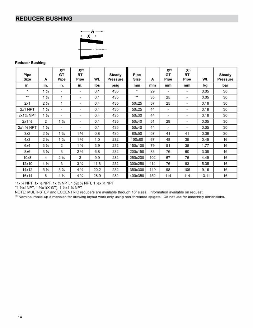
REDUCER BUSHING
PipeSize A
X(1)
GT Pipe
X(1)
RT Pipe Wt.
SteadyPressure
PipeSize A
X(1)
GT Pipe
X(1)
RT Pipe Wt.
SteadyPressure
in. in. in. in. lbs psig mm mm mm mm kg bar* 1 ⅛ - - 0.1 435 * 29 - - 0.05 30** 1 ⅜ 1 - 0.1 435 ** 35 25 - 0.05 30
2x1 2 ¼ 1 - 0.4 435 50x25 57 25 - 0.18 302x1 NPT 1 ¾ - - 0.4 435 50x25 44 - - 0.18 30
2x1¼ NPT 1 ¾ - - 0.4 435 50x30 44 - - 0.18 302x1 ½ 2 1 ⅛ - 0.1 435 50x40 51 29 - 0.05 30
2x1 ½ NPT 1 ¾ - - 0.1 435 50x40 44 - - 0.05 303x2 2 ¼ 1 ⅝ 1 ⅝ 0.8 435 80x50 57 41 41 0.36 304x3 2 ⅝ 1 ⅞ 1 ⅜ 1.0 232 100x80 67 48 35 0.45 166x4 3 ⅛ 2 1 ½ 3.9 232 150x100 79 51 38 1.77 168x6 3 ¼ 3 2 ⅜ 6.8 232 200x150 83 76 60 3.08 16
10x8 4 2 ⅝ 3 9.9 232 250x200 102 67 76 4.49 1612x10 4 ½ 3 3 ¼ 11.8 232 300x250 114 76 83 5.35 1614x12 5 ½ 3 ⅞ 4 ⅛ 20.2 232 350x300 140 98 105 9.16 1616x14 6 4 ½ 4 ½ 28.9 232 400x350 152 114 114 13.11 16
* 1x ¼ NPT, 1x ½ NPT, 1x ¾ NPT, 1 ½x ½ NPT, 1 ½x ¾ NPT**1 ½x1NPT, 1 ½x1(X-GT), 1 ½x1 ¼ NPTNOTE: MULTI-STEP and ECCENTRIC reducers are available through 16” sizes. Information available on request.(1) Nominal make-up dimension for drawing layout work only using non-threaded spigots. Do not use for assembly dimensions.
Reducer Bushing
14
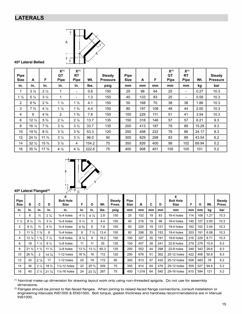
LATERALS
PipeSize A F
X(1) GT
Pipe
X(1)
RTPipe Wt.
SteadyPressure
PipeSize A F
X(1)
GT Pipe
X(1)
RTPipe Wt.
SteadyPressure
in. in. in. in. in. lbs. psig mm mm mm mm mm kg bar1 3 ⅞ 2 ½ 1 - 0.6 150 25 98 64 25 - 0.27 10.3
1 ½ 5 ¼ 3 ¼ 1 - 1.3 150 40 133 83 25 - 0.59 10.32 6 ⅝ 2 ¾ 1 ½ 1 ½ 4.1 150 50 168 70 38 38 1.86 10.33 7 ¾ 4 ¼ 1 ⅞ 1 ¾ 4.4 150 80 197 108 48 44 2.00 10.34 9 4 ⅜ 2 1 ⅝ 7.8 150 100 229 111 51 41 3.54 10.36 12 ½ 5 ¾ 2 ¼ 2 ¼ 13.7 135 150 318 146 57 57 6.21 9.38 16 ¼ 7 ⅜ 3 ⅛ 3 ½ 33.7 135 200 413 187 79 89 15.29 9.3
10 19 ⅝ 8 ¾ 3 ⅛ 3 ⅜ 53.3 120 250 498 222 79 86 24.17 8.312 24 ¾ 11 ¾ 3 ¼ 3 ½ 96.0 90 300 629 298 83 89 43.54 6.214 32 ½ 15 ¾ 3 ⅞ 4 154.2 75 350 826 400 98 102 69.94 5.216 35 ¾ 17 ¾ 4 ⅛ 4 ⅛ 222.6 75 400 908 451 105 105 101 5.2
PipeSize B C D
EBolt Hole
Size F O Wt.SteadyPress.
PipeSize B C D
EBolt Hole
Size F O Wt.SteadyPress.
in. in. in. in. in. in. in. lbs. psig mm mm mm mm mm mm mm kg bar1 6 ¾ 3 ¼ ⅝-4 holes 4 ½ 4 ¼ 2.8 150 25 152 19 83 16-4 holes 114 108 1.27 10.3
1 ½ 8 ½ ¾ 3 ⅞ ⅝-4 holes 5 ½ 5 4.4 150 40 216 19 98 16-4 holes 140 127 2.00 10.3
2 8 ⅞ ¾ 4 ¾ ¾-4 holes 6 ⅜ 6 7.8 150 50 225 19 121 19-4 holes 162 152 3.54 10.3
3 11 ¾ 1 ⅜ 6 ¾-4 holes 8 7 ½ 13.4 150 80 298 35 152 19-4 holes 203 191 6.08 10.3
4 12 ⅞ 1 ⅜ 7 ½ ¾-8 holes 8 ½ 9 19.2 150 100 327 35 191 19-8 holes 216 229 8.71 10.3
6 18 1 ½ 9 ½ ⅞-8 holes 11 11 35 135 150 457 38 241 22-8 holes 279 279 15.9 9.3
8 21 ¾ 1 ¾ 11 ¾ ⅞-8 holes 13 ¾ 13 ½ 65.3 135 200 552 44 298 22-8 holes 349 343 29.6 9.3
10 26 ⅝ 2 14 ¼ 1-12 holes 16 ⅝ 16 112 120 250 676 51 362 25-12 holes 422 406 50.8 8.3
12 32 2 ¼ 17 1-12 holes 20 19 172 90 300 813 57 432 25-12 holes 508 483 78 6.2
14 36 2 ½ 18 ¾ 1⅛-12 holes 22 20 ¾ 209 75 350 914 64 476 29-12 holes 559 527 94.6 5.2
16 40 2 ½ 21 ¼ 1⅛-16 holes 24 23 ¼ 267 75 400 1,016 64 540 29-16 holes 610 594 121 5.2
(1) Nominal make-up dimension for drawing layout work only using non-threaded spigots. Do not use for assembly dimensions.(2) Flanges should be joined to flat-faced flanges. When joining to raised-faced flange connections, consult installation or engineering Manuals INS1000 & ENG1000. Bolt torque, gasket thickness and hardness recommendations are in Manual INS1000.
45º Lateral Belled
45º Lateral Flanged(2)
15
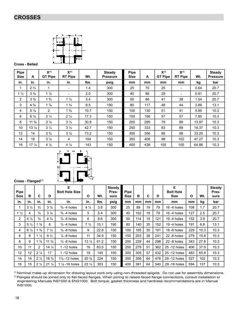
CROSSES
PipeSize A
X(1) GT Pipe
X(1)
RT Pipe Wt.Steady
PressurePipeSize A
X(1)
GT Pipe X(1)
RT Pipe Wt.Steady
Pressurein. in. in. in. lbs. psig mm mm mm mm kg bar1 2 ¾ 1 - 1.4 300 25 70 25 - 0.64 20.7
1 ½ 3 ⅜ 1 ⅛ - 2.0 300 40 86 29 - 0.91 20.72 3 ⅜ 1 ⅝ 1 ½ 3.4 300 50 86 41 38 1.54 20.73 4 ⅝ 1 ⅞ 1 ¾ 8.5 190 80 117 48 44 3.86 13.14 5 ⅛ 2 1 ⅝ 10.7 150 100 130 51 41 4.85 10.36 6 ⅛ 2 ¼ 2 ¼ 17.3 150 150 156 57 57 7.85 10.38 11 ⅝ 3 ⅛ 3 ½ 30.8 150 200 295 79 89 13.97 10.3
10 13 ⅛ 3 ¼ 3 ½ 42.7 150 250 333 83 89 19.37 10.312 14 3 ⅜ 3 ⅞ 73.2 150 300 356 86 98 33.20 10.314 16 3 ⅞ 4 104 150 350 406 98 102 47.27 10.316 17 ¼ 4 ⅛ 4 ⅛ 143 150 400 438 105 105 64.86 10.3
PipeSize B C D
EBolt Hole Size
O Wt.
SteadyPres-sure
PipeSize B C D
EBolt Hole
Size O Wt.
SteadyPres-sure
in. in. in. in. in. in. lbs. psig mm mm mm mm mm mm kg bar1 3 ½ ¾ 3 ⅛ ⅝ -4 holes 4 ¼ 3.8 300 25 89 19 79 16 -4 holes 108 1.7 20.7
1 ½ 4 ¾ 3 ⅛ ⅝ -4 holes 5 5.4 300 40 102 19 79 16 -4 holes 127 2.5 20.72 4 ½ ¾ 4 ¾ ¾ -4 holes 6 8.6 300 50 114 19 121 19 -4 holes 152 3.9 20.73 5 ½ 1 ⅜ 6 ¾ -4 holes 7 ½ 15.1 190 80 140 35 152 19 -4 holes 191 6.8 13.14 6 ½ 1 ⅜ 7 ½ ¾ -8 holes 9 22.8 150 100 165 35 191 19 -8 holes 229 10.3 10.36 8 1 ½ 9 ½ ⅞ -8 holes 11 34.9 150 150 203 38 241 22 -8 holes 279 15.8 10.38 9 1 ¾ 11 ¾ ⅞ -8 holes 13 ½ 61.2 150 200 229 44 298 22 -8 holes 343 27.8 10.3
10 11 2 14 ¼ 1 -12 holes 16 83.5 150 250 279 51 362 25 -12 holes 406 37.9 10.312 12 2 ¼ 17 1 -12 holes 19 145 150 300 305 57 432 25 -12 holes 483 65.8 10.314 14 2 ½ 18 ¾ 1⅛ -12 holes 20 ¾ 224 150 350 356 64 476 29 -12 holes 527 102 10.316 15 2 ½ 21 ¼ 1 ⅛ -16 holes 23 ¼ 303 150 400 381 64 540 29 -16 holes 594 137 10.3
(1) Nominal make-up dimension for drawing layout work only using non-threaded spigots. Do not use for assembly dimensions.(2 )Flanges should be joined only to flat-faced flanges. When joining to raised-faced flange connections, consult installation or engineering Manuals INS1000 & ENG1000. Bolt torque, gasket thickness and hardness recommendations are in Manual INS1000.
Cross - Belled
Cross - Flanged(2)
16
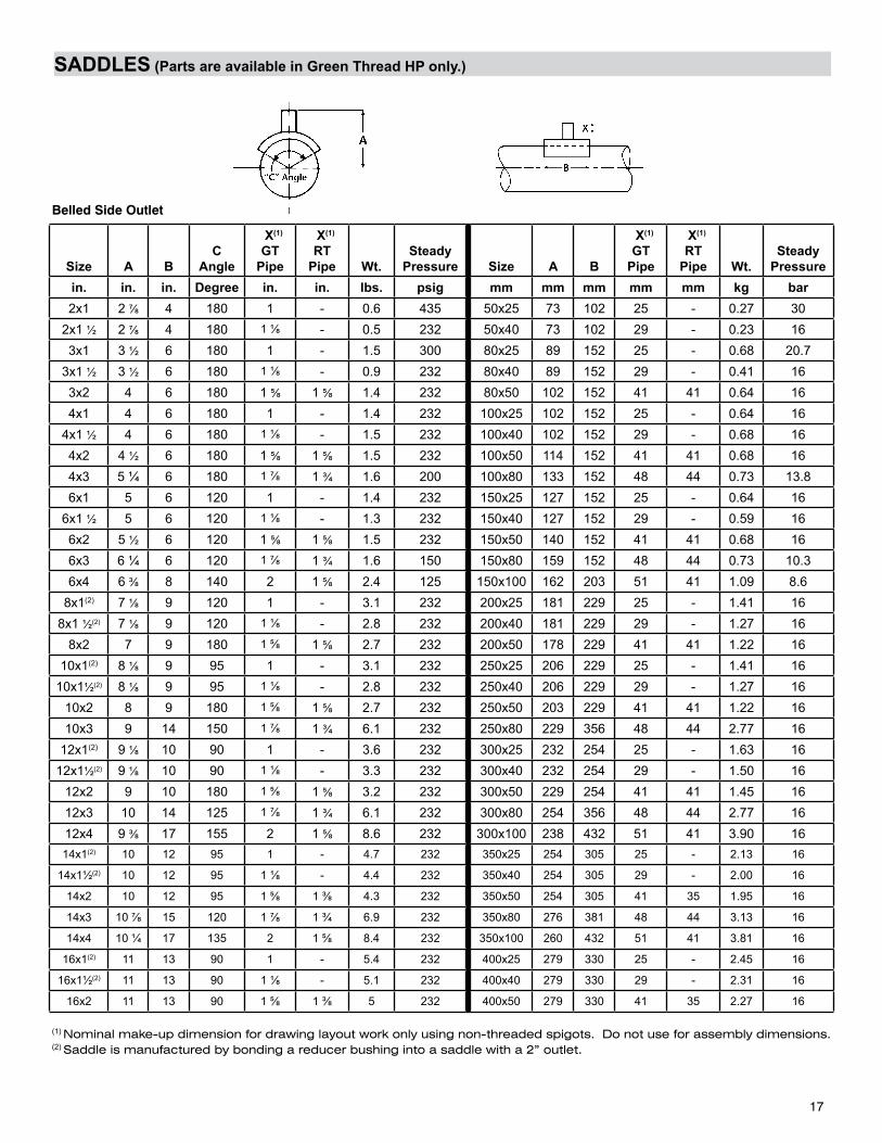
SADDLES (Parts are available in Green Thread HP only.)
Size
A BC
Angle
X(1)
GTPipe
X(1)
RTPipe Wt.
SteadyPressure Size A B
X(1)
GTPipe
X(1)
RTPipe Wt.
SteadyPressure
in. in. in. Degree in. in. lbs. psig mm mm mm mm mm kg bar2x1 2 ⅞ 4 180 1 - 0.6 435 50x25 73 102 25 - 0.27 30
2x1 ½ 2 ⅞ 4 180 1 ⅛ - 0.5 232 50x40 73 102 29 - 0.23 163x1 3 ½ 6 180 1 - 1.5 300 80x25 89 152 25 - 0.68 20.7
3x1 ½ 3 ½ 6 180 1 ⅛ - 0.9 232 80x40 89 152 29 - 0.41 163x2 4 6 180 1 ⅝ 1 ⅝ 1.4 232 80x50 102 152 41 41 0.64 164x1 4 6 180 1 - 1.4 232 100x25 102 152 25 - 0.64 16
4x1 ½ 4 6 180 1 ⅛ - 1.5 232 100x40 102 152 29 - 0.68 164x2 4 ½ 6 180 1 ⅝ 1 ⅝ 1.5 232 100x50 114 152 41 41 0.68 164x3 5 ¼ 6 180 1 ⅞ 1 ¾ 1.6 200 100x80 133 152 48 44 0.73 13.86x1 5 6 120 1 - 1.4 232 150x25 127 152 25 - 0.64 16
6x1 ½ 5 6 120 1 ⅛ - 1.3 232 150x40 127 152 29 - 0.59 166x2 5 ½ 6 120 1 ⅝ 1 ⅝ 1.5 232 150x50 140 152 41 41 0.68 166x3 6 ¼ 6 120 1 ⅞ 1 ¾ 1.6 150 150x80 159 152 48 44 0.73 10.36x4 6 ⅜ 8 140 2 1 ⅝ 2.4 125 150x100 162 203 51 41 1.09 8.6
8x1(2) 7 ⅛ 9 120 1 - 3.1 232 200x25 181 229 25 - 1.41 168x1 ½(2) 7 ⅛ 9 120 1 ⅛ - 2.8 232 200x40 181 229 29 - 1.27 16
8x2 7 9 180 1 ⅝ 1 ⅝ 2.7 232 200x50 178 229 41 41 1.22 1610x1(2) 8 ⅛ 9 95 1 - 3.1 232 250x25 206 229 25 - 1.41 16
10x1½(2) 8 ⅛ 9 95 1 ⅛ - 2.8 232 250x40 206 229 29 - 1.27 1610x2 8 9 180 1 ⅝ 1 ⅝ 2.7 232 250x50 203 229 41 41 1.22 1610x3 9 14 150 1 ⅞ 1 ¾ 6.1 232 250x80 229 356 48 44 2.77 16
12x1(2) 9 ⅛ 10 90 1 - 3.6 232 300x25 232 254 25 - 1.63 1612x1½(2) 9 ⅛ 10 90 1 ⅛ - 3.3 232 300x40 232 254 29 - 1.50 16
12x2 9 10 180 1 ⅝ 1 ⅝ 3.2 232 300x50 229 254 41 41 1.45 1612x3 10 14 125 1 ⅞ 1 ¾ 6.1 232 300x80 254 356 48 44 2.77 1612x4 9 ⅜ 17 155 2 1 ⅝ 8.6 232 300x100 238 432 51 41 3.90 1614x1(2) 10 12 95 1 - 4.7 232 350x25 254 305 25 - 2.13 16
14x1½(2) 10 12 95 1 ⅛ - 4.4 232 350x40 254 305 29 - 2.00 16
14x2 10 12 95 1 ⅝ 1 ⅜ 4.3 232 350x50 254 305 41 35 1.95 16
14x3 10 ⅞ 15 120 1 ⅞ 1 ¾ 6.9 232 350x80 276 381 48 44 3.13 16
14x4 10 ¼ 17 135 2 1 ⅝ 8.4 232 350x100 260 432 51 41 3.81 16
16x1(2) 11 13 90 1 - 5.4 232 400x25 279 330 25 - 2.45 16
16x1½(2) 11 13 90 1 ⅛ - 5.1 232 400x40 279 330 29 - 2.31 16
16x2 11 13 90 1 ⅝ 1 ⅜ 5 232 400x50 279 330 41 35 2.27 16
(1) Nominal make-up dimension for drawing layout work only using non-threaded spigots. Do not use for assembly dimensions.(2) Saddle is manufactured by bonding a reducer bushing into a saddle with a 2” outlet.
Belled Side Outlet
17
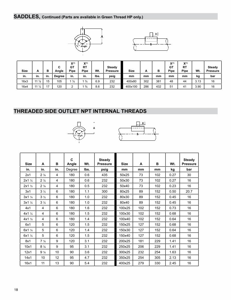
SADDLES, Continued (Parts are available in Green Thread HP only.)
Size A BC
Angle
X(1)
GTPipe
X(1)
RTPipe Wt.
SteadyPressure Size A B
X(1)
GTPipe
X(1)
RTPipe Wt.
SteadyPressure
in. in. in. Degree in. in. lbs. psig mm mm mm mm mm kg bar16x3 11 ⅞ 15 105 1 ⅞ 1 ¾ 6.9 232 400x80 302 381 48 44 3.13 16
16x4 11 ¼ 17 120 2 1 ⅝ 8.6 232 400x100 286 432 51 41 3.90 16
Size A BC
Angle
Wt.Steady
Pressure Size A B Wt.Steady
Pressurein. in. in. Degree lbs. psig mm mm mm kg bar2x1 2 ⅞ 4 180 0.6 435 50x25 73 102 0.27 30
2x1 ¼ 2 ⅞ 4 180 0.6 232 50x30 73 102 0.27 162x1 ½ 2 ⅞ 4 180 0.5 232 50x40 73 102 0.23 163x1 3 ½ 6 180 1.1 300 80x25 89 152 0.50 20.7
3x1 ¼ 3 ½ 6 180 1.0 232 80x30 89 152 0.45 163x1 ½ 3 ½ 6 180 1.0 232 80x40 89 152 0.45 164x1 4 6 180 1.6 232 100x25 102 152 0.73 16
4x1 ¼ 4 6 180 1.5 232 100x30 102 152 0.68 164x1 ½ 4 6 180 1.4 232 100x40 102 152 0.64 166x1 5 6 120 1.5 232 150x25 127 152 0.68 16
6x1 ¼ 5 6 120 1.4 232 150x30 127 152 0.64 166x1 ½ 5 6 120 1.5 232 150x40 127 152 0.68 168x1 7 ⅛ 9 120 3.1 232 200x25 181 229 1.41 16
10x1 8 ⅛ 9 95 3.1 232 250x25 206 229 1.41 1612x1 9 ⅛ 10 90 3.6 232 300x25 232 254 1.63 1614x1 10 12 95 4.7 232 350x25 254 305 2.13 1616x1 11 13 90 5.4 232 400x25 279 330 2.45 16
18
SADDLES, Continued (Parts are available in Green Thread HP only.)
THREADED SIDE OUTLET NPT INTERNAL THREADS
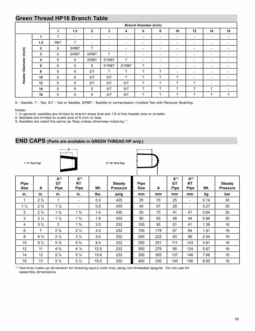
19
Green Thread HP16 Branch Table
PipeSize A
X(1)
GT Pipe
X(1)
RT Pipe Wt.
SteadyPressure
PipeSize A
X(1)
GT Pipe
X(1)
RT Pipe Wt.
SteadyPressure
in. in. in. in. lbs. psig mm mm mm mm kg bar1 2 ¾ 1 - 0.3 435 25 70 25 - 0.14 30
1 ½ 2 ⅝ 1 ⅛ - 0.6 435 40 67 29 - 0.27 302 2 ¾ 1 ⅝ 1 ⅝ 1.4 435 50 70 41 41 0.64 303 3 ¼ 1 ⅞ 1 ¾ 1.9 435 80 83 48 44 0.86 304 3 ¾ 2 1 ⅝ 3.0 232 100 95 51 41 1.36 166 7 2 ⅝ 2 ½ 4.2 232 150 178 67 64 1.91 168 8 ¾ 2 ⅞ 3 ½ 5.6 232 200 222 60 86 2.54 16
10 9 ⅞ 5 ⅜ 5 ⅝ 8.4 232 250 251 111 143 3.81 1612 11 4 ⅝ 4 7/8 12.5 232 300 279 95 124 5.67 1614 12 5 ⅞ 5 ⅞ 15.6 232 350 305 137 140 7.08 1616 13 5 ½ 5 ½ 19.5 232 400 330 140 140 8.85 16
(1) Nominal make-up dimension for drawing layout work only using non-threaded spigots. Do not use for assembly dimensions.
1”-4” End Cap 6”-16” End Cap
Branch Diameter (inch)1 1.5 2 3 4 6 8 10 12 14 16
Hea
der D
iam
eter
(inc
h)
1 T - - - - - - - - - -
1.5 RBT T - - - - - - - - -
2 S S/RBT T - - - - - - - -
3 S S/RBT S/RBT T - - - - - - -
4 S S S/RBT S*/RBT T - - - - - -
6 S S S S*/RBT S*/RBT T - - - - -
8 S S S/T T T T T - - - -
10 S S S/T S/T T T T T - - -
12 S S S/T S/T S/T T T T T - -
14 S S S S/T S/T T T T T T -
16 S S S S/T S/T T T T T T T
S - Saddle, T - Tee, S/T - Tee or Saddle, S/RBT - Saddle or compression molded Tee with Reducer Bushing.
Notes: 1. In general, saddles are limited to branch sizes that are 1/3 of the header size or smaller. 2. Saddles are limited to outlet size of 6 inch or less. 3. Saddles are rated the same as Tees unless otherwise noted by *.
END CAPS (Parts are available in GREEN THREAD HP only.)
©2014 National Oilwell Varco. All rights reserved.CI1350ENG - November 2015
National Oilwell Varco has produced this brochure for general information only, and it is not intended for design purposes. Although every effort has been made to maintain the accuracy and reliability of its contents, National Oilwell Varco in no way assumes responsibility for liability for any loss, damage or injury resulting from the use of information and data herein nor is any warranty expressed or implied. Always cross-reference the bulletin date with the most current version listed at the web site noted in this literature.
www.fgspipe.com • [email protected]
North America South America Europe Asia Pacific Middle East17115 San Pedro Ave. Suite 200 Estrada de Acesso à Zona P.O. Box 6, 4190 CA No. 7A, Tuas Avenue 3 P.O. Box 17324San Antonio, Texas 78232 USA Industrial Portuária de Suape, s/no. Geldermalsen, The Netherlands Jurong, Singapore 639407 Dubai, UAEPhone: 210 477 7500 Recife, PE, Brazil 55.590-000 Phone: 31 345 587 587 Phone: 65 6861 6118 Phone: 971 4881 3566 Phone: +55 81 3501 0023
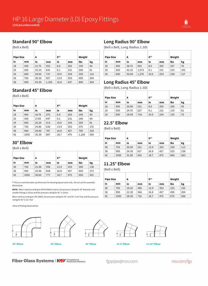
[email protected] nov.com/fgs
Standard 90° Elbow(Bell x Bell)
Pipe Size A X(1) Weight
in mm in mm in mm lbs kg18 450 21.75 552 8.0 203 140 6420 500 25.25 641 9.1 231 200 9124 600 29.00 737 10.0 254 250 11430 750 36.50 927 13.9 353 450 20436 900 43.50 1,105 16.8 427 800 364
Standard 45° Elbow(Bell x Bell)
Pipe Size A X(1) Weight
in mm in mm in mm lbs kg18 450 14.75 375 8.0 203 100 4520 500 17.60 447 9.1 231 140 6424 600 20.20 513 10.0 254 200 9130 750 24.80 630 13.9 353 375 17036 900 29.40 747 16.8 427 700 31842 1050 35.30 897 18.7 475 1,100 500
Long Radius 90° Elbow(Bell x Bell, Long Radius 1.5D)
Pipe Size A X(1) Weight
in mm in mm in mm lbs kg18 450 36.75 933 8.0 203 167 7620 500 42.25 1,073 9.1 231 225 10224 600 50.00 1,270 10.0 254 258 117
Long Radius 45° Elbow(Bell x Bell, Long Radius 1.5D)
Pipe Size A X(1) Weight
in mm in mm in mm lbs kg18 450 20.90 531 8.0 203 100 4520 500 24.70 627 9.1 231 135 6124 600 28.90 734 10.0 254 155 70
(1) This is a nominal make-up dimension for drawing layout work only. Do not use for assembly dimensions.
NOTE: When rated according to ASTM D5685 criteria, the pressure rating for 36” diameter and smaller fittings is 16 bar and the pressure rating for 42” is 14 bar.
When rated according to ISO 14692, the pressure rating for 30” and 36” is 14.7 bar and the pressure rating for 42” is 12.7 bar
30° Elbow(Bell x Bell)
Pipe Size A X(1) Weight
in mm in mm in mm lbs kg30 750 21.90 556 13.9 353 300 13636 900 25.90 658 16.8 427 600 27242 1050 30.60 777 18.7 475 950 431
22.5° Elbow(Bell x Bell)
Pipe Size A X(1) Weight
in mm in mm in mm lbs kg30 750 20.50 521 13.9 353 250 11336 900 24.30 617 16.8 427 525 23842 1050 31.90 810 18.7 475 800 363
11.25° Elbow(Bell x Bell)
Pipe Size A X(1) Weight
in mm in mm in mm lbs kg30 750 19.10 485 13.9 353 225 10236 900 22.30 566 16.8 427 450 20442 1050 28.20 716 18.7 475 675 306
O I L & G A S C H E M I C A L& I N D U S T R I A L
O F F S H O R EM A R I N E M I N I N GF U E LH A N D L I N G
HP 16 Large Diameter (LD) Epoxy Fittings(232 psi unless noted)
View of Fitting Illustrations
45° Elbow90° Elbow 30° Elbow 22.5° Elbow 11.25° Elbow
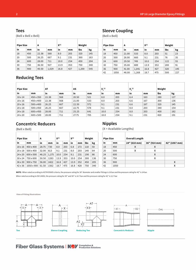
2 HP 16 Large Diameter Epoxy Fittings
Pipe Size AT AS X1(1) X2
(1) Weight
in mm in mm in mm in mm in mm lbs kg18 x 14 450 x 350 22.38 568 20.50 521 8.0 203 6.4 163 280 12718 x 16 450 x 400 22.38 568 21.00 533 8.0 203 6.6 167 300 13620 x 16 500 x 400 26.25 667 22.50 572 9.1 231 6.6 167 320 14520 x 18 500 x 450 26.25 667 22.75 578 9.1 231 8.0 203 340 15424 x 18 600 x 450 28.00 711 25.25 641 10.0 254 8.0 203 400 18224 x 20 600 x 500 28.00 711 27.75 705 10.0 254 9.1 231 420 191
Reducing Tees
Tees(Bell x Bell x Bell)
Pipe Size A X(1) Weight
in mm in mm in mm lbs kg18 450 22.38 568 8.0 203 320 14520 500 26.25 667 9.1 231 360 16324 600 28.00 711 10.0 254 450 20430 750 36.50 927 13.9 353 750 34036 900 40.50 1,029 16.8 427 1,200 545
Sleeve Coupling(Bell x Bell)
Pipe Size A X(1) Weight
in mm in mm in mm lbs kg18 450 21.00 533 8.0 203 51 2320 500 26.00 660 9.1 231 76 3524 600 29.50 749 10.0 254 122 5530 750 35.00 889 13.9 353 200 9136 900 41.00 1,041 16.8 427 320 14542 1050 46.00 1,168 18.7 475 500 227
Concentric Reducers(Bell x Bell)
Pipe Size A X(1) X(2) Weight
in mm in mm in mm in mm lbs kg18 x 16 450 x 400 28.75 730 8.0 203 6.8 173 110 5020 x 18 500 x 450 32.00 813 9.1 231 8.0 203 140 6424 x 20 600 x 500 46.25 1,175 10.0 254 9.1 231 190 8630 x 24 750 x 600 50.50 1283 13.9 353 10.0 254 300 13636 x 30 900 x 750 56.00 1422 16.8 427 13.9 352 450 20542 x 36 1050 x 900 61.50 1562 18.7 475 16.8 428 750 340
Pipe Size Overall Length
in mm 24" (610 mm) 36" (914 mm) 42" (1067 mm)18 450 X X20 500 X X24 600 X30 750 X36 900 X42 1050 X
Nipples(X = Available Lengths)
NOTE: When rated according to ASTM D5685 criteria, the pressure rating for 36” diameter and smaller fittings is 16 bar and the pressure rating for 42” is 14 bar.
When rated according to ISO 14692, the pressure rating for 30” and 36” is 14.7 bar and the pressure rating for 42” is 12.7 bar
View of Fitting Illustrations
Tee Sleeve Coupling Reducing Tee Concentric Reducer Nipple
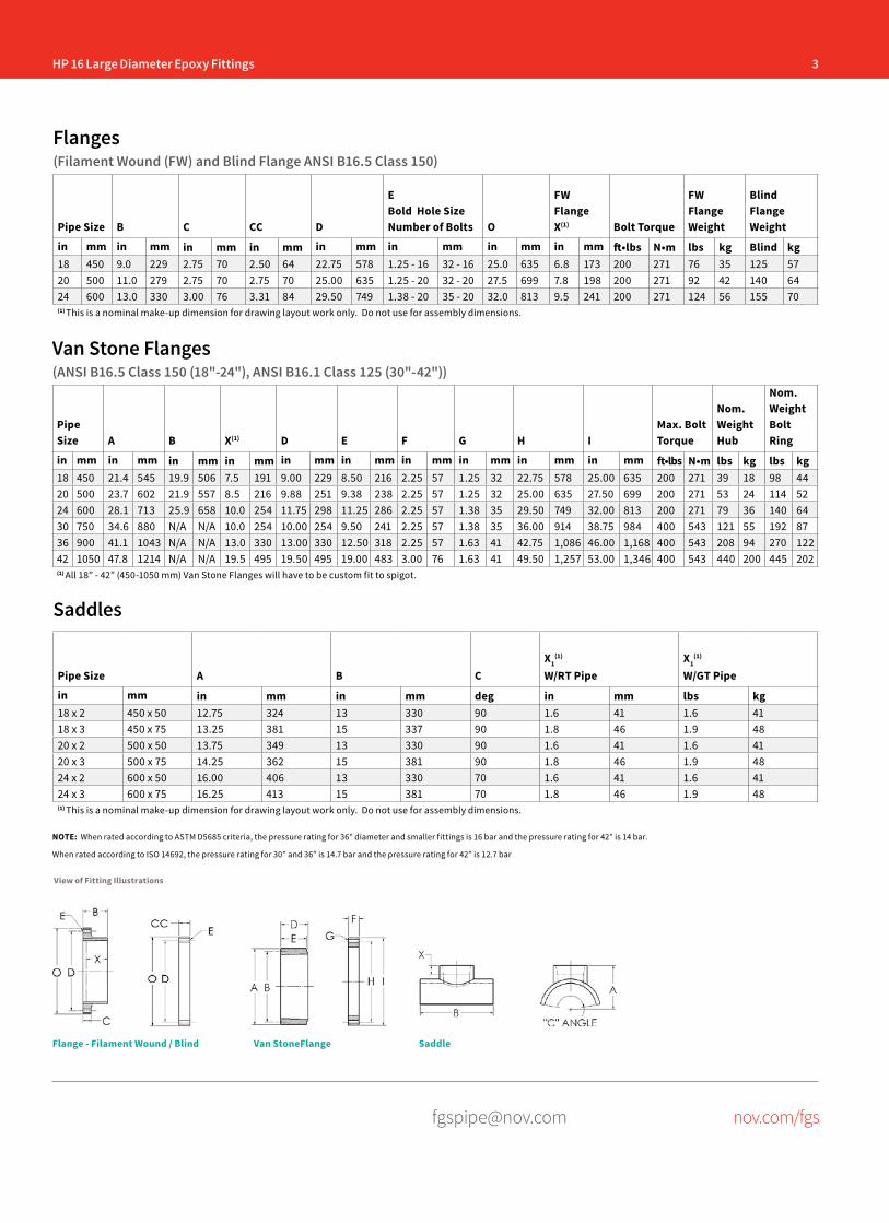
HP 16 Large Diameter Epoxy Fittings 3
[email protected] nov.com/fgs
Flanges(Filament Wound (FW) and Blind Flange ANSI B16.5 Class 150)
Pipe Size B C CC D
EBold Hole SizeNumber of Bolts O
FW Flange X(1) Bolt Torque
FW Flange Weight
Blind Flange Weight
in mm in mm in mm in mm in mm in mm in mm in mm ft•lbs N•m lbs kg Blind kg18 450 9.0 229 2.75 70 2.50 64 22.75 578 1.25 - 16 32 - 16 25.0 635 6.8 173 200 271 76 35 125 5720 500 11.0 279 2.75 70 2.75 70 25.00 635 1.25 - 20 32 - 20 27.5 699 7.8 198 200 271 92 42 140 6424 600 13.0 330 3.00 76 3.31 84 29.50 749 1.38 - 20 35 - 20 32.0 813 9.5 241 200 271 124 56 155 70(1) This is a nominal make-up dimension for drawing layout work only. Do not use for assembly dimensions.
Pipe Size A B CX1
(1)
W/RT PipeX1
(1)
W/GT Pipe
in mm in mm in mm deg in mm lbs kg18 x 2 450 x 50 12.75 324 13 330 90 1.6 41 1.6 4118 x 3 450 x 75 13.25 381 15 337 90 1.8 46 1.9 4820 x 2 500 x 50 13.75 349 13 330 90 1.6 41 1.6 4120 x 3 500 x 75 14.25 362 15 381 90 1.8 46 1.9 4824 x 2 600 x 50 16.00 406 13 330 70 1.6 41 1.6 4124 x 3 600 x 75 16.25 413 15 381 70 1.8 46 1.9 48(1) This is a nominal make-up dimension for drawing layout work only. Do not use for assembly dimensions.
Saddles
Van Stone Flanges(ANSI B16.5 Class 150 (18"-24"), ANSI B16.1 Class 125 (30"-42"))
PipeSize A B X(1) D E F G H I
Max. Bolt Torque
Nom. Weight Hub
Nom. Weight Bolt Ring
in mm in mm in mm in mm in mm in mm in mm in mm in mm in mm ft•lbs N•m lbs kg lbs kg18 450 21.4 545 19.9 506 7.5 191 9.00 229 8.50 216 2.25 57 1.25 32 22.75 578 25.00 635 200 271 39 18 98 4420 500 23.7 602 21.9 557 8.5 216 9.88 251 9.38 238 2.25 57 1.25 32 25.00 635 27.50 699 200 271 53 24 114 5224 600 28.1 713 25.9 658 10.0 254 11.75 298 11.25 286 2.25 57 1.38 35 29.50 749 32.00 813 200 271 79 36 140 6430 750 34.6 880 N/A N/A 10.0 254 10.00 254 9.50 241 2.25 57 1.38 35 36.00 914 38.75 984 400 543 121 55 192 8736 900 41.1 1043 N/A N/A 13.0 330 13.00 330 12.50 318 2.25 57 1.63 41 42.75 1,086 46.00 1,168 400 543 208 94 270 12242 1050 47.8 1214 N/A N/A 19.5 495 19.50 495 19.00 483 3.00 76 1.63 41 49.50 1,257 53.00 1,346 400 543 440 200 445 202(1) All 18” - 42” (450-1050 mm) Van Stone Flanges will have to be custom fit to spigot.
NOTE: When rated according to ASTM D5685 criteria, the pressure rating for 36” diameter and smaller fittings is 16 bar and the pressure rating for 42” is 14 bar.
When rated according to ISO 14692, the pressure rating for 30” and 36” is 14.7 bar and the pressure rating for 42” is 12.7 bar
View of Fitting Illustrations
Flange - Filament Wound / Blind Van StoneFlange Saddle

4 HP 16 Large Diameter Epoxy Fittings
[email protected] nov.com/fgs
Fiber Glass Systems17115 San Pedro Avenue, Ste 200San Antonio, Texas 78232 USAPhone: 210 477 7500Fax: 210 477 7560
National Oilwell Varco has produced this brochure for general information only, and it is not intended for design purposes. Although every effort has been made to maintain the accuracy and reliability of its contents, National Oilwell Varco in no way assumes responsibility for liability for any loss, damage or injury resulting from the use of information and data herein nor is any warranty expressed or implied. Always cross-reference the bulletin date with the most current version listed at the web site noted in this literature.
© 2016 National Oilwell Varco All Rights ReservedCI1351ENG June 2016
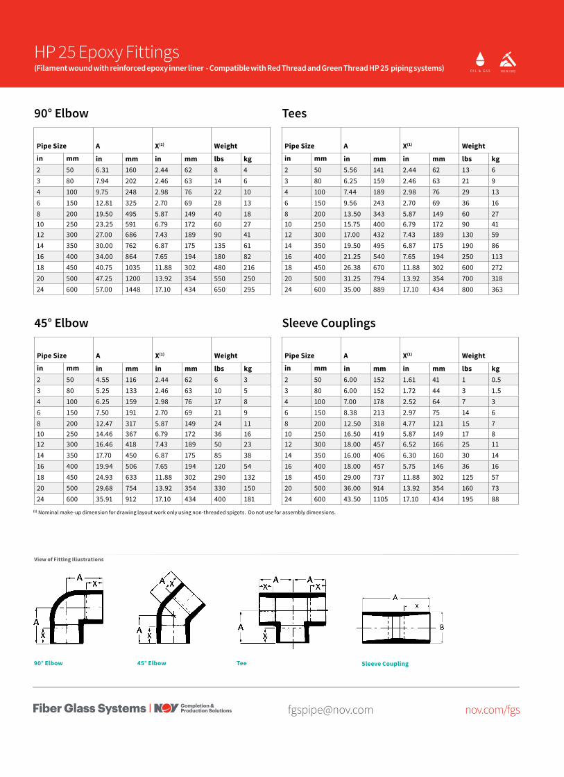
[email protected] nov.com/fgs
90° Elbow
Pipe Size A X(1) Weight
in mm in mm in mm lbs kg2 50 6.31 160 2.44 62 8 43 80 7.94 202 2.46 63 14 64 100 9.75 248 2.98 76 22 106 150 12.81 325 2.70 69 28 138 200 19.50 495 5.87 149 40 1810 250 23.25 591 6.79 172 60 2712 300 27.00 686 7.43 189 90 4114 350 30.00 762 6.87 175 135 6116 400 34.00 864 7.65 194 180 8218 450 40.75 1035 11.88 302 480 21620 500 47.25 1200 13.92 354 550 25024 600 57.00 1448 17.10 434 650 295
45° Elbow
Pipe Size A X(1) Weight
in mm in mm in mm lbs kg2 50 4.55 116 2.44 62 6 33 80 5.25 133 2.46 63 10 54 100 6.25 159 2.98 76 17 86 150 7.50 191 2.70 69 21 98 200 12.47 317 5.87 149 24 1110 250 14.46 367 6.79 172 36 1612 300 16.46 418 7.43 189 50 2314 350 17.70 450 6.87 175 85 3816 400 19.94 506 7.65 194 120 5418 450 24.93 633 11.88 302 290 13220 500 29.68 754 13.92 354 330 15024 600 35.91 912 17.10 434 400 181
Tees
Pipe Size A X(1) Weight
in mm in mm in mm lbs kg2 50 5.56 141 2.44 62 13 63 80 6.25 159 2.46 63 21 94 100 7.44 189 2.98 76 29 136 150 9.56 243 2.70 69 36 168 200 13.50 343 5.87 149 60 2710 250 15.75 400 6.79 172 90 4112 300 17.00 432 7.43 189 130 5914 350 19.50 495 6.87 175 190 8616 400 21.25 540 7.65 194 250 11318 450 26.38 670 11.88 302 600 27220 500 31.25 794 13.92 354 700 31824 600 35.00 889 17.10 434 800 363
Sleeve Couplings
Pipe Size A X(1) Weight
in mm in mm in mm lbs kg2 50 6.00 152 1.61 41 1 0.53 80 6.00 152 1.72 44 3 1.54 100 7.00 178 2.52 64 7 36 150 8.38 213 2.97 75 14 68 200 12.50 318 4.77 121 15 710 250 16.50 419 5.87 149 17 812 300 18.00 457 6.52 166 25 1114 350 16.00 406 6.30 160 30 1416 400 18.00 457 5.75 146 36 1618 450 29.00 737 11.88 302 125 5720 500 36.00 914 13.92 354 160 7324 600 43.50 1105 17.10 434 195 88
(1) Nominal make-up dimension for drawing layout work only using non-threaded spigots. Do not use for assembly dimensions.
O I L & G A S C H E M I C A L& I N D U S T R I A L
O F F S H O R EM A R I N E M I N I N GF U E LH A N D L I N GO I L & G A S C H E M I C A L
& I N D U S T R I A LO F F S H O R EM A R I N E M I N I N GF U E L
H A N D L I N G
HP 25 Epoxy Fittings(Filament wound with reinforced epoxy inner liner - Compatible with Red Thread and Green Thread HP 25 piping systems)
View of Fitting Illustrations
45° Elbow90° Elbow Tee Sleeve Coupling
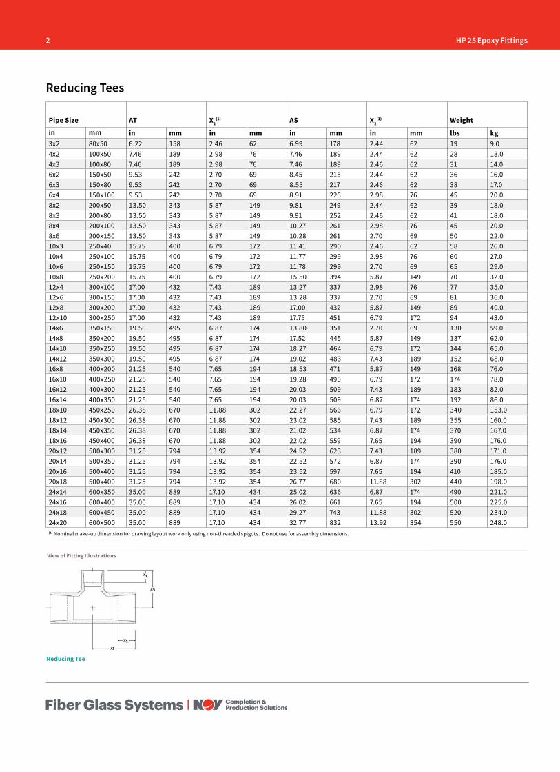
2 HP 25 Epoxy Fittings
Pipe Size AT X1(1) AS X2
(1) Weight
in mm in mm in mm in mm in mm lbs kg3x2 80x50 6.22 158 2.46 62 6.99 178 2.44 62 19 9.04x2 100x50 7.46 189 2.98 76 7.46 189 2.44 62 28 13.04x3 100x80 7.46 189 2.98 76 7.46 189 2.46 62 31 14.06x2 150x50 9.53 242 2.70 69 8.45 215 2.44 62 36 16.06x3 150x80 9.53 242 2.70 69 8.55 217 2.46 62 38 17.06x4 150x100 9.53 242 2.70 69 8.91 226 2.98 76 45 20.08x2 200x50 13.50 343 5.87 149 9.81 249 2.44 62 39 18.08x3 200x80 13.50 343 5.87 149 9.91 252 2.46 62 41 18.08x4 200x100 13.50 343 5.87 149 10.27 261 2.98 76 45 20.08x6 200x150 13.50 343 5.87 149 10.28 261 2.70 69 50 22.010x3 250x40 15.75 400 6.79 172 11.41 290 2.46 62 58 26.010x4 250x100 15.75 400 6.79 172 11.77 299 2.98 76 60 27.010x6 250x150 15.75 400 6.79 172 11.78 299 2.70 69 65 29.010x8 250x200 15.75 400 6.79 172 15.50 394 5.87 149 70 32.012x4 300x100 17.00 432 7.43 189 13.27 337 2.98 76 77 35.012x6 300x150 17.00 432 7.43 189 13.28 337 2.70 69 81 36.012x8 300x200 17.00 432 7.43 189 17.00 432 5.87 149 89 40.012x10 300x250 17.00 432 7.43 189 17.75 451 6.79 172 94 43.014x6 350x150 19.50 495 6.87 174 13.80 351 2.70 69 130 59.014x8 350x200 19.50 495 6.87 174 17.52 445 5.87 149 137 62.014x10 350x250 19.50 495 6.87 174 18.27 464 6.79 172 144 65.014x12 350x300 19.50 495 6.87 174 19.02 483 7.43 189 152 68.016x8 400x200 21.25 540 7.65 194 18.53 471 5.87 149 168 76.016x10 400x250 21.25 540 7.65 194 19.28 490 6.79 172 174 78.016x12 400x300 21.25 540 7.65 194 20.03 509 7.43 189 183 82.016x14 400x350 21.25 540 7.65 194 20.03 509 6.87 174 192 86.018x10 450x250 26.38 670 11.88 302 22.27 566 6.79 172 340 153.018x12 450x300 26.38 670 11.88 302 23.02 585 7.43 189 355 160.018x14 450x350 26.38 670 11.88 302 21.02 534 6.87 174 370 167.018x16 450x400 26.38 670 11.88 302 22.02 559 7.65 194 390 176.020x12 500x300 31.25 794 13.92 354 24.52 623 7.43 189 380 171.020x14 500x350 31.25 794 13.92 354 22.52 572 6.87 174 390 176.020x16 500x400 31.25 794 13.92 354 23.52 597 7.65 194 410 185.020x18 500x400 31.25 794 13.92 354 26.77 680 11.88 302 440 198.024x14 600x350 35.00 889 17.10 434 25.02 636 6.87 174 490 221.024x16 600x400 35.00 889 17.10 434 26.02 661 7.65 194 500 225.024x18 600x450 35.00 889 17.10 434 29.27 743 11.88 302 520 234.024x20 600x500 35.00 889 17.10 434 32.77 832 13.92 354 550 248.0(1) Nominal make-up dimension for drawing layout work only using non-threaded spigots. Do not use for assembly dimensions.
Reducing Tees
View of Fitting Illustrations
Reducing Tee
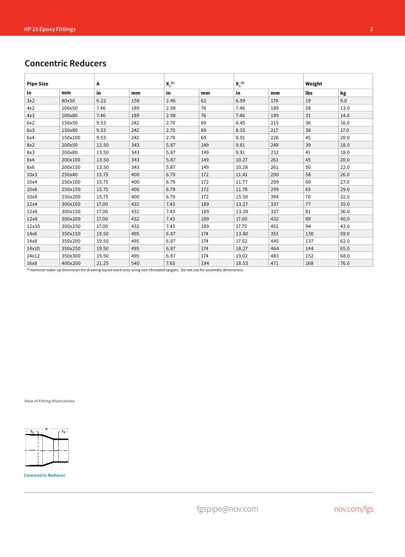
HP 25 Epoxy Fittings 3
[email protected] nov.com/fgs
Pipe Size A X1(1) X2
(1) Weight
in mm in mm in mm in mm lbs kg3x2 80x50 6.22 158 2.46 62 6.99 178 19 9.04x2 100x50 7.46 189 2.98 76 7.46 189 28 13.04x3 100x80 7.46 189 2.98 76 7.46 189 31 14.06x2 150x50 9.53 242 2.70 69 8.45 215 36 16.06x3 150x80 9.53 242 2.70 69 8.55 217 38 17.06x4 150x100 9.53 242 2.70 69 8.91 226 45 20.08x2 200x50 13.50 343 5.87 149 9.81 249 39 18.08x3 200x80 13.50 343 5.87 149 9.91 252 41 18.08x4 200x100 13.50 343 5.87 149 10.27 261 45 20.08x6 200x150 13.50 343 5.87 149 10.28 261 50 22.010x3 250x40 15.75 400 6.79 172 11.41 290 58 26.010x4 250x100 15.75 400 6.79 172 11.77 299 60 27.010x6 250x150 15.75 400 6.79 172 11.78 299 65 29.010x8 250x200 15.75 400 6.79 172 15.50 394 70 32.012x4 300x100 17.00 432 7.43 189 13.27 337 77 35.012x6 300x150 17.00 432 7.43 189 13.28 337 81 36.012x8 300x200 17.00 432 7.43 189 17.00 432 89 40.012x10 300x250 17.00 432 7.43 189 17.75 451 94 43.014x6 350x150 19.50 495 6.87 174 13.80 351 130 59.014x8 350x200 19.50 495 6.87 174 17.52 445 137 62.014x10 350x250 19.50 495 6.87 174 18.27 464 144 65.014x12 350x300 19.50 495 6.87 174 19.02 483 152 68.016x8 400x200 21.25 540 7.65 194 18.53 471 168 76.0(1) Nominal make-up dimension for drawing layout work only using non-threaded spigots. Do not use for assembly dimensions.
Concentric Reducers
View of Fitting Illustrations
Concentric Reducer
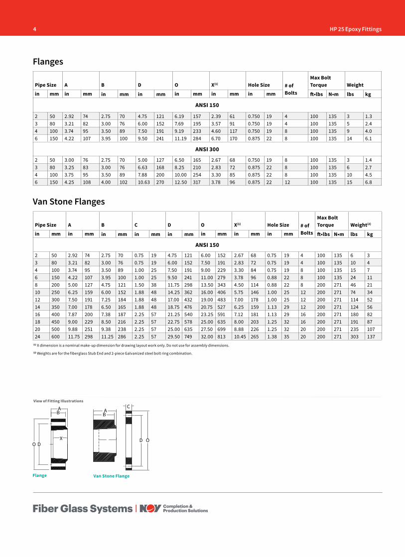
4 HP 25 Epoxy Fittings
Flanges
Pipe Size A B D O X(1) Hole Size # of Bolts
Max Bolt Torque Weight
in mm in mm in mm in mm in mm in mm in mm ft•lbs N•m lbs kg
ANSI 150
2 50 2.92 74 2.75 70 4.75 121 6.19 157 2.39 61 0.750 19 4 100 135 3 1.33 80 3.21 82 3.00 76 6.00 152 7.69 195 3.57 91 0.750 19 4 100 135 5 2.44 100 3.74 95 3.50 89 7.50 191 9.19 233 4.60 117 0.750 19 8 100 135 9 4.06 150 4.22 107 3.95 100 9.50 241 11.19 284 6.70 170 0.875 22 8 100 135 14 6.1
ANSI 300
2 50 3.00 76 2.75 70 5.00 127 6.50 165 2.67 68 0.750 19 8 100 135 3 1.43 80 3.25 83 3.00 76 6.63 168 8.25 210 2.83 72 0.875 22 8 100 135 6 2.74 100 3.75 95 3.50 89 7.88 200 10.00 254 3.30 85 0.875 22 8 100 135 10 4.56 150 4.25 108 4.00 102 10.63 270 12.50 317 3.78 96 0.875 22 12 100 135 15 6.8
Van Stone Flanges
Pipe Size A B C D O X(1) Hole Size # of Bolts
Max Bolt Torque Weight(2)
in mm in mm in mm in mm in mm in mm in mm in mm ft•lbs N•m lbs kg
ANSI 150
2 50 2.92 74 2.75 70 0.75 19 4.75 121 6.00 152 2.67 68 0.75 19 4 100 135 6 33 80 3.21 82 3.00 76 0.75 19 6.00 152 7.50 191 2.83 72 0.75 19 4 100 135 10 44 100 3.74 95 3.50 89 1.00 25 7.50 191 9.00 229 3.30 84 0.75 19 8 100 135 15 76 150 4.22 107 3.95 100 1.00 25 9.50 241 11.00 279 3.78 96 0.88 22 8 100 135 24 118 200 5.00 127 4.75 121 1.50 38 11.75 298 13.50 343 4.50 114 0.88 22 8 200 271 46 2110 250 6.25 159 6.00 152 1.88 48 14.25 362 16.00 406 5.75 146 1.00 25 12 200 271 74 3412 300 7.50 191 7.25 184 1.88 48 17.00 432 19.00 483 7.00 178 1.00 25 12 200 271 114 5214 350 7.00 178 6.50 165 1.88 48 18.75 476 20.75 527 6.25 159 1.13 29 12 200 271 124 5616 400 7.87 200 7.38 187 2.25 57 21.25 540 23.25 591 7.12 181 1.13 29 16 200 271 180 8218 450 9.00 229 8.50 216 2.25 57 22.75 578 25.00 635 8.00 203 1.25 32 16 200 271 191 8720 500 9.88 251 9.38 238 2.25 57 25.00 635 27.50 699 8.88 226 1.25 32 20 200 271 235 10724 600 11.75 298 11.25 286 2.25 57 29.50 749 32.00 813 10.45 265 1.38 35 20 200 271 303 137
View of Fitting Illustrations
Van Stone FlangeFlange
O DX
AB A
BC
D O
(1) X dimension is a nominal make-up dimension for drawing layout work only. Do not use for assembly dimensions.
(2) Weights are for the fiberglass Stub End and 2-piece Galvanized steel bolt ring combination.
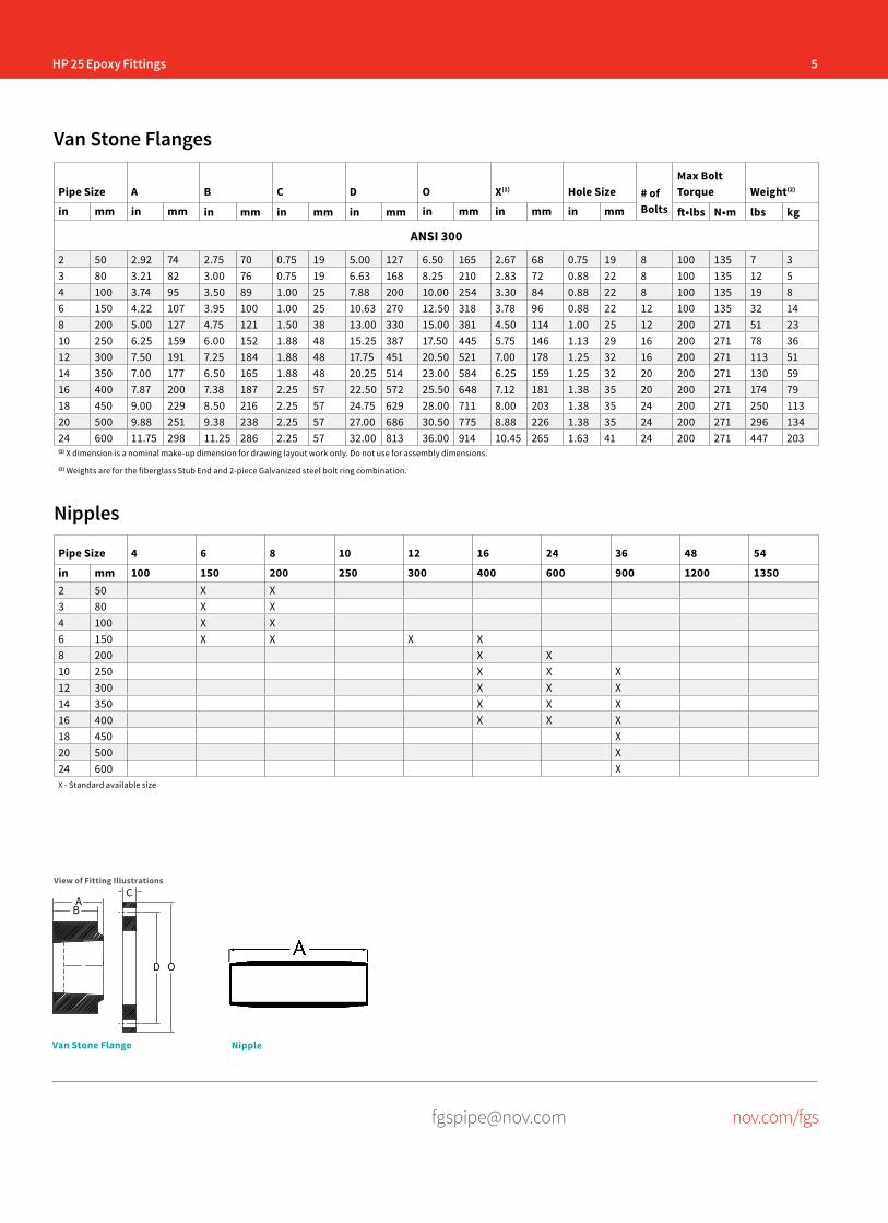
5HP 25 Epoxy Fittings
[email protected] nov.com/fgs
Nipples
Pipe Size 4 6 8 10 12 16 24 36 48 54
in mm 100 150 200 250 300 400 600 900 1200 13502 50 X X3 80 X X4 100 X X6 150 X X X X8 200 X X10 250 X X X12 300 X X X14 350 X X X16 400 X X X18 450 X20 500 X24 600 XX - Standard available size
Pipe Size A B C D O X(1) Hole Size # of Bolts
Max Bolt Torque Weight(2)
in mm in mm in mm in mm in mm in mm in mm in mm ft•lbs N•m lbs kg
ANSI 300
2 50 2.92 74 2.75 70 0.75 19 5.00 127 6.50 165 2.67 68 0.75 19 8 100 135 7 33 80 3.21 82 3.00 76 0.75 19 6.63 168 8.25 210 2.83 72 0.88 22 8 100 135 12 54 100 3.74 95 3.50 89 1.00 25 7.88 200 10.00 254 3.30 84 0.88 22 8 100 135 19 86 150 4.22 107 3.95 100 1.00 25 10.63 270 12.50 318 3.78 96 0.88 22 12 100 135 32 148 200 5.00 127 4.75 121 1.50 38 13.00 330 15.00 381 4.50 114 1.00 25 12 200 271 51 2310 250 6.25 159 6.00 152 1.88 48 15.25 387 17.50 445 5.75 146 1.13 29 16 200 271 78 3612 300 7.50 191 7.25 184 1.88 48 17.75 451 20.50 521 7.00 178 1.25 32 16 200 271 113 5114 350 7.00 177 6.50 165 1.88 48 20.25 514 23.00 584 6.25 159 1.25 32 20 200 271 130 5916 400 7.87 200 7.38 187 2.25 57 22.50 572 25.50 648 7.12 181 1.38 35 20 200 271 174 7918 450 9.00 229 8.50 216 2.25 57 24.75 629 28.00 711 8.00 203 1.38 35 24 200 271 250 11320 500 9.88 251 9.38 238 2.25 57 27.00 686 30.50 775 8.88 226 1.38 35 24 200 271 296 13424 600 11.75 298 11.25 286 2.25 57 32.00 813 36.00 914 10.45 265 1.63 41 24 200 271 447 203(1) X dimension is a nominal make-up dimension for drawing layout work only. Do not use for assembly dimensions.
(2) Weights are for the fiberglass Stub End and 2-piece Galvanized steel bolt ring combination.
Van Stone Flanges
View of Fitting Illustrations
NippleVan Stone Flange
AB
C
D O
6 HP 25 Epoxy Fittings
[email protected] nov.com/fgs
Fiber Glass Systems17115 San Pedro Avenue, Ste 200San Antonio, Texas 78232 USAPhone: 210 477 7500Fax: 210 477 7560
National Oilwell Varco has produced this brochure for general information only, and it is not intended for design purposes. Although every effort has been made to maintain the accuracy and reliability of its contents, National Oilwell Varco in no way assumes responsibility for liability for any loss, damage or injury resulting from the use of information and data herein nor is any warranty expressed or implied. Always cross-reference the bulletin date with the most current version listed at the web site noted in this literature.
© 2016 National Oilwell Varco All Rights ReservedCI1360ENG November 2016
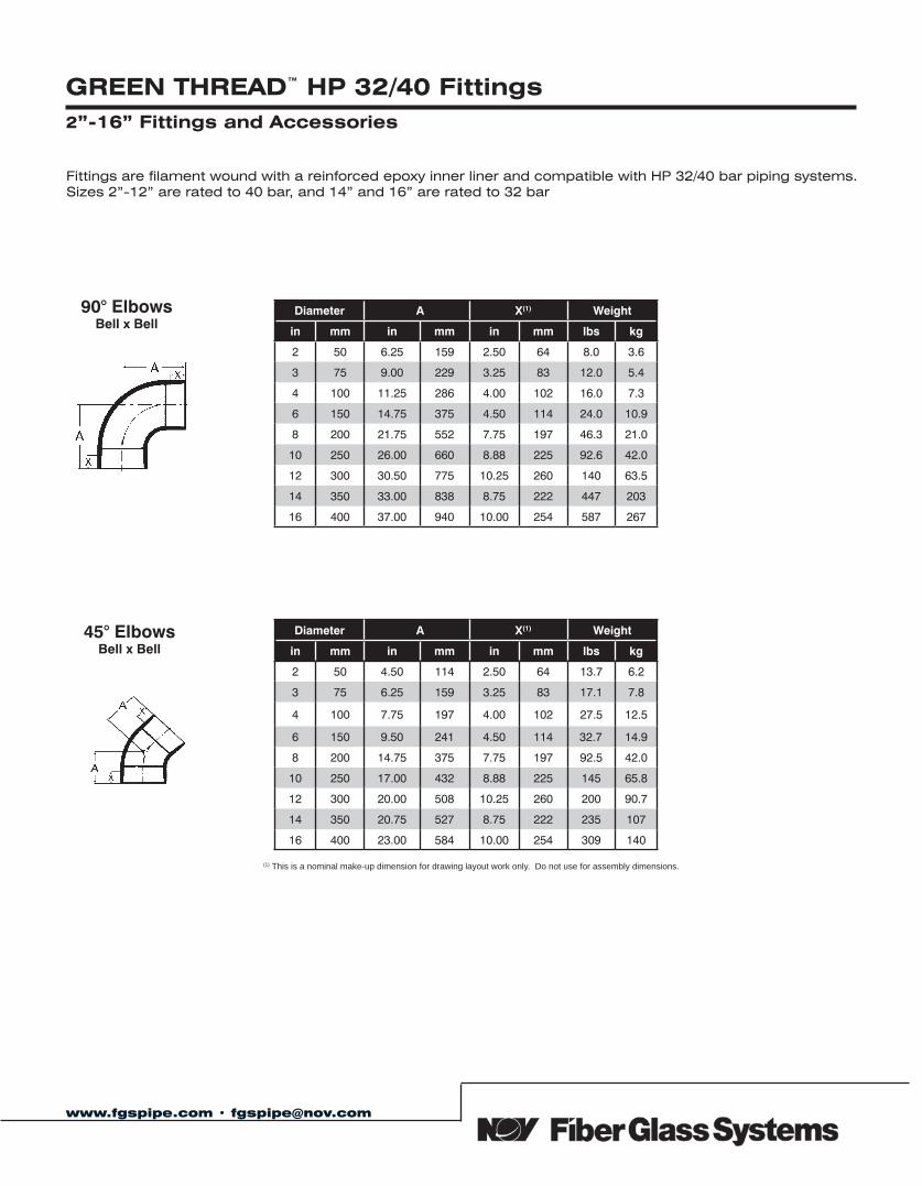
(1) This is a nominal make-up dimension for drawing layout work only. Do not use for assembly dimensions.
www.fgspipe.com • [email protected]
GREEN THREAD™ HP 32/40 Fittings 2”-16” Fittings and Accessories
90° Elbows Bell x Bell
45° ElbowsBell x Bell
Diameter A X(1) Weight
in mm in mm in mm lbs kg
2 50 6.25 159 2.50 64 8.0 3.6
3 75 9.00 229 3.25 83 12.0 5.4
4 100 11.25 286 4.00 102 16.0 7.3
6 150 14.75 375 4.50 114 24.0 10.9
8 200 21.75 552 7.75 197 46.3 21.0
10 250 26.00 660 8.88 225 92.6 42.0
12 300 30.50 775 10.25 260 140 63.5
14 350 33.00 838 8.75 222 447 203
16 400 37.00 940 10.00 254 587 267
Diameter A X(1) Weight
in mm in mm in mm lbs kg
2 50 4.50 114 2.50 64 13.7 6.2
3 75 6.25 159 3.25 83 17.1 7.8
4 100 7.75 197 4.00 102 27.5 12.5
6 150 9.50 241 4.50 114 32.7 14.9
8 200 14.75 375 7.75 197 92.5 42.0
10 250 17.00 432 8.88 225 145 65.8
12 300 20.00 508 10.25 260 200 90.7
14 350 20.75 527 8.75 222 235 107
16 400 23.00 584 10.00 254 309 140
Fittings are filament wound with a reinforced epoxy inner liner and compatible with HP 32/40 bar piping systems. Sizes 2”-12” are rated to 40 bar, and 14” and 16” are rated to 32 bar
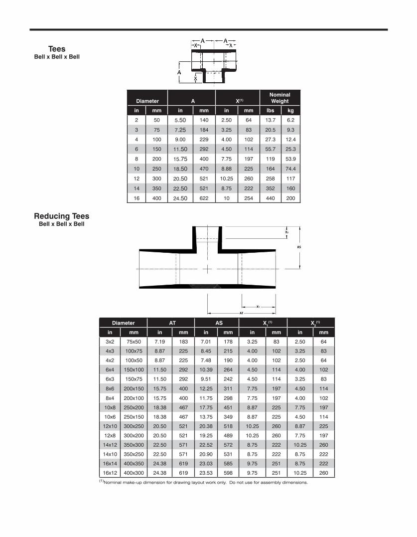
TeesBell x Bell x Bell
Diameter A X(1)Nominal Weight
in mm in mm in mm lbs kg
2 50 5.50 140 2.50 64 13.7 6.2
3 75 7.25 184 3.25 83 20.5 9.3
4 100 9.00 229 4.00 102 27.3 12.4
6 150 11.50 292 4.50 114 55.7 25.3
8 200 15.75 400 7.75 197 119 53.9
10 250 18.50 470 8.88 225 164 74.4
12 300 20.50 521 10.25 260 258 117
14 350 22.50 521 8.75 222 352 160
16 400 24.50 622 10 254 440 200
Diameter AT AS X1(1) X2
(1)
in mm in mm in mm in mm in mm
3x2 75x50 7.19 183 7.01 178 3.25 83 2.50 64
4x3 100x75 8.87 225 8.45 215 4.00 102 3.25 83
4x2 100x50 8.87 225 7.48 190 4.00 102 2.50 64
6x4 150x100 11.50 292 10.39 264 4.50 114 4.00 102
6x3 150x75 11.50 292 9.51 242 4.50 114 3.25 83
8x6 200x150 15.75 400 12.25 311 7.75 197 4.50 114
8x4 200x100 15.75 400 11.75 298 7.75 197 4.00 102
10x8 250x200 18.38 467 17.75 451 8.87 225 7.75 197
10x6 250x150 18.38 467 13.75 349 8.87 225 4.50 114
12x10 300x250 20.50 521 20.38 518 10.25 260 8.87 225
12x8 300x200 20.50 521 19.25 489 10.25 260 7.75 197
14x12 350x300 22.50 571 22.52 572 8.75 222 10.25 260
14x10 350x250 22.50 571 20.90 531 8.75 222 8.75 222
16x14 400x350 24.38 619 23.03 585 9.75 251 8.75 222
16x12 400x300 24.38 619 23.53 598 9.75 251 10.25 260
Reducing TeesBell x Bell x Bell
(1)Nominal make-up dimension for drawing layout work only. Do not use for assembly dimensions.
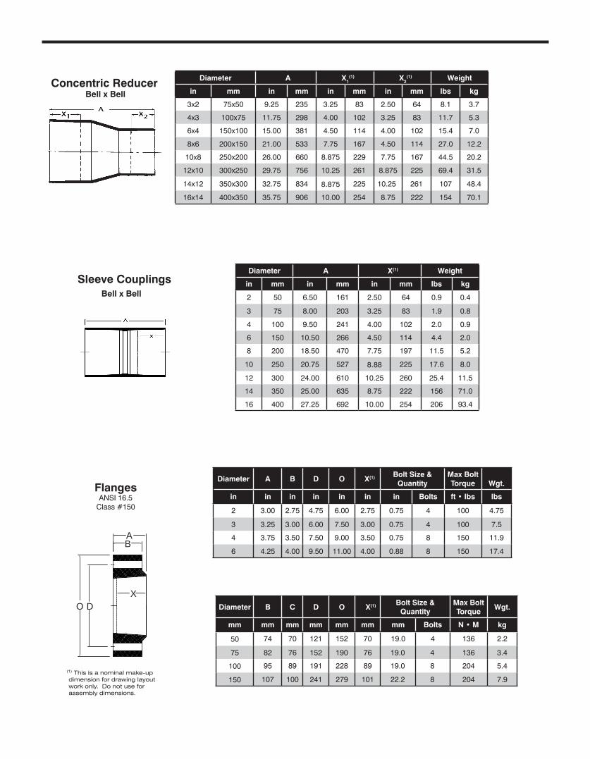
Diameter A B D O X(1) Bolt Size &Quantity
Max BoltTorque Wgt.
in in in in in in in Bolts ft • lbs lbs
2 3.00 2.75 4.75 6.00 2.75 0.75 4 100 4.75
3 3.25 3.00 6.00 7.50 3.00 0.75 4 100 7.5
4 3.75 3.50 7.50 9.00 3.50 0.75 8 150 11.9
6 4.25 4.00 9.50 11.00 4.00 0.88 8 150 17.4
Diameter A X1(1) X2
(1) Weight
in mm in mm in mm in mm lbs kg
3x2 75x50 9.25 235 3.25 83 2.50 64 8.1 3.7
4x3 100x75 11.75 298 4.00 102 3.25 83 11.7 5.3
6x4 150x100 15.00 381 4.50 114 4.00 102 15.4 7.0
8x6 200x150 21.00 533 7.75 167 4.50 114 27.0 12.2
10x8 250x200 26.00 660 8.875 229 7.75 167 44.5 20.2
12x10 300x250 29.75 756 10.25 261 8.875 225 69.4 31.5
14x12 350x300 32.75 834 8.875 225 10.25 261 107 48.4
16x14 400x350 35.75 906 10.00 254 8.75 222 154 70.1
Concentric Reducer Bell x Bell
(1) This is a nominal make-up dimension for drawing layout work only. Do not use for assembly dimensions.
Sleeve Couplings Bell x Bell
Diameter A X(1) Weight
in mm in mm in mm lbs kg
2 50 6.50 161 2.50 64 0.9 0.4
3 75 8.00 203 3.25 83 1.9 0.8
4 100 9.50 241 4.00 102 2.0 0.9
6 150 10.50 266 4.50 114 4.4 2.0
8 200 18.50 470 7.75 197 11.5 5.2
10 250 20.75 527 8.88 225 17.6 8.0
12 300 24.00 610 10.25 260 25.4 11.5
14 350 25.00 635 8.75 222 156 71.0
16 400 27.25 692 10.00 254 206 93.4
Diameter B C D O X(1) Bolt Size &Quantity
Max BoltTorque
Wgt.
mm mm mm mm mm mm mm Bolts N • M kg
50 74 70 121 152 70 19.0 4 136 2.2
75 82 76 152 190 76 19.0 4 136 3.4
100 95 89 191 228 89 19.0 8 204 5.4
150 107 100 241 279 101 22.2 8 204 7.9
FlangesANSI 16.5
Class #150
AB
XO D
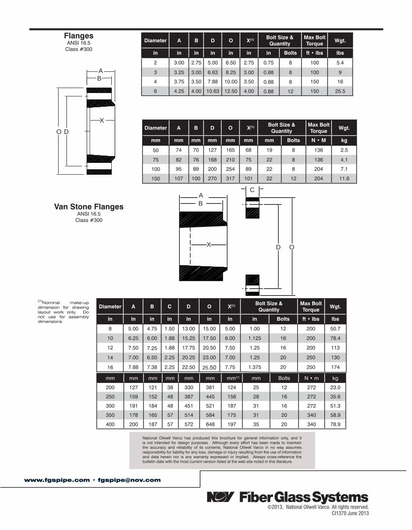
mm mm mm mm mm mm mm(1) mm Bolts N • m kg
200 127 121 38 330 381 124 25 12 272 23.0
250 159 152 48 387 445 156 28 16 272 35.6
300 191 184 48 451 521 187 31 16 272 51.3
350 178 165 57 514 584 175 31 20 340 58.9
400 200 187 57 572 648 197 35 20 340 78.9
(1)Nominal make-up dimension for drawing layout work only. Do not use for assembly dimensions.
Diameter A B C D O X(1) Bolt Size &Quantity
Max BoltTorque
Wgt.
in in in in in in in in Bolts ft • lbs lbs
8 5.00 4.75 1.50 13.00 15.00 5.00 1.00 12 200 50.7
10 6.25 6.00 1.88 15.25 17.50 6.00 1.125 16 200 78.4
12 7.50 7.25 1.88 17.75 20.50 7.50 1.25 16 200 113
14 7.00 6.50 2.25 20.25 23.00 7.00 1.25 20 250 130
16 7.88 7.38 2.25 22.50 25.50 7.75 1.375 20 250 174
Diameter A B D O X(1) Bolt Size & Quantity
Max BoltTorque
Wgt.
in in in in in in in Bolts ft • lbs lbs
2 3.00 2.75 5.00 6.50 2.75 0.75 8 100 5.4
3 3.25 3.00 6.63 8.25 3.00 0.88 8 100 9
4 3.75 3.50 7.88 10.00 3.50 0.88 8 150 16
6 4.25 4.00 10.63 12.50 4.00 0.88 12 150 25.5
Diameter A B D O X(1) Bolt Size &Quantity
Max BoltTorque
Wgt.
mm mm mm mm mm mm mm Bolts N • M kg
50 74 70 127 165 68 19 8 136 2.5
75 82 76 168 210 75 22 8 136 4.1
100 95 89 200 254 89 22 8 204 7.1
150 107 100 270 317 101 22 12 204 11.6
FlangesANSI 16.5
Class #300
Van Stone FlangesANSI 16.5
Class #300
©2013, National Oilwell Varco. All rights reserved.CI1370 June 2013
www.fgspipe.com • [email protected]
National Oilwell Varco has produced this brochure for general information only, and it is not intended for design purposes. Although every effort has been made to maintain the accuracy and reliability of its contents, National Oilwell Varco in no way assumes responsibility for liability for any loss, damage or injury resulting from the use of information and data herein nor is any warranty expressed or implied. Always cross-reference the bulletin date with the most current version listed at the web site noted in this literature.
AB
X
O D
AB
C
X D O
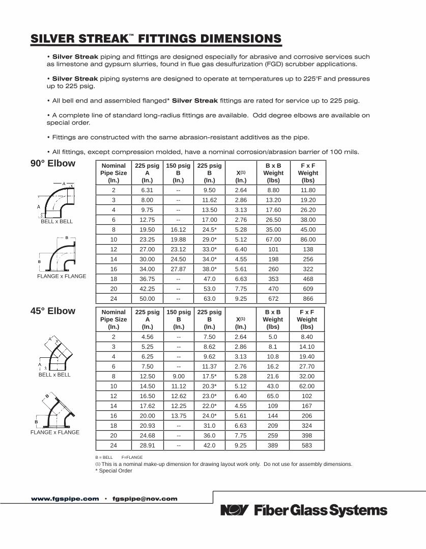
SILVER STREAK™ FITTINGS DIMENSIONS• Silver Streak piping and fittings are designed especially for abrasive and corrosive services such as limestone and gypsum slurries, found in flue gas desulfurization (FGD) scrubber applications.
• Silver Streak piping systems are designed to operate at temperatures up to 225°F and pressures up to 225 psig.
• All bell end and assembled flanged* Silver Streak fittings are rated for service up to 225 psig.
• A complete line of standard long-radius fittings are available. Odd degree elbows are available on special order.
• Fittings are constructed with the same abrasion-resistant additives as the pipe.
• All fittings, except compression molded, have a nominal corrosion/abrasion barrier of 100 mils.
90° Elbow
BELL x BELL
B
B
FLANGE x FLANGE
NominalPipe Size
(In.)
225 psigA
(In.)
150 psigB
(In.)
225 psigB
(In.)X(1)
(In.)
B x BWeight
(lbs)
F x FWeight
(lbs)2 6.31 -- 9.50 2.64 8.80 11.803 8.00 -- 11.62 2.86 13.20 19.204 9.75 -- 13.50 3.13 17.60 26.206 12.75 -- 17.00 2.76 26.50 38.008 19.50 16.12 24.5* 5.28 35.00 45.0010 23.25 19.88 29.0* 5.12 67.00 86.0012 27.00 23.12 33.0* 6.40 101 13814 30.00 24.50 34.0* 4.55 198 25616 34.00 27.87 38.0* 5.61 260 32218 36.75 -- 47.0 6.63 353 46820 42.25 -- 53.0 7.75 470 60924 50.00 -- 63.0 9.25 672 866
NominalPipe Size
(In.)
225 psigA
(In.)
150 psigB
(In.)
225 psigB
(In.)X(1)
(In.)
B x BWeight
(lbs)
F x FWeight
(lbs)2 4.56 -- 7.50 2.64 5.0 8.403 5.25 -- 8.62 2.86 8.1 14.104 6.25 -- 9.62 3.13 10.8 19.406 7.50 -- 11.37 2.76 16.2 27.708 12.50 9.00 17.5* 5.28 21.6 32.0010 14.50 11.12 20.3* 5.12 43.0 62.0012 16.50 12.62 23.0* 6.40 65.0 10214 17.62 12.25 22.0* 4.55 109 16716 20.00 13.75 24.0* 5.61 144 20618 20.93 -- 31.0 6.63 209 32420 24.68 -- 36.0 7.75 259 39824 28.91 -- 42.0 9.25 389 583
45° Elbow
BELL x BELL
B
B
FLANGE x FLANGE
B = BELL F=FLANGE(1) This is a nominal make-up dimension for drawing layout work only. Do not use for assembly dimensions.* Special Order
www.fgspipe.com • [email protected]
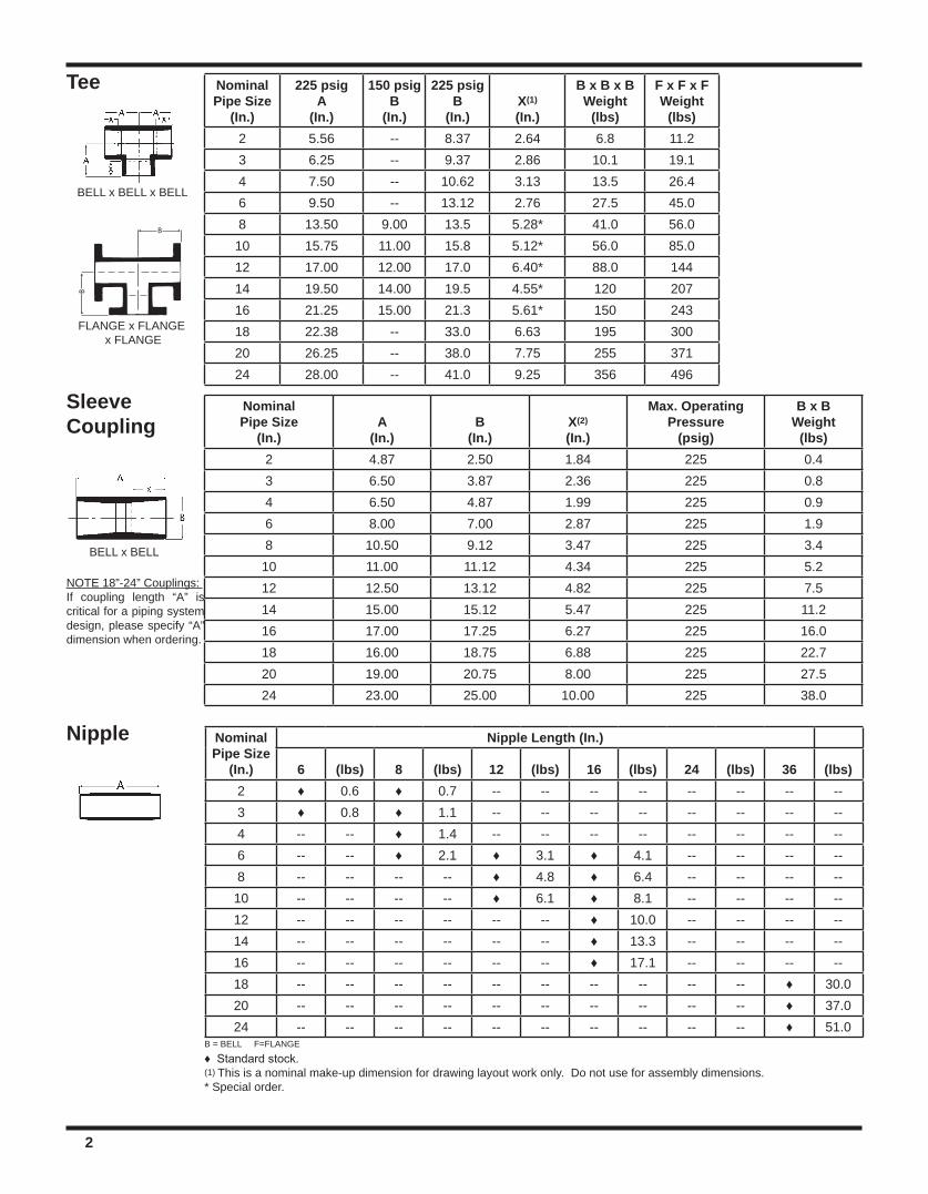
B = BELL F=FLANGE
♦ Standard stock.(1) This is a nominal make-up dimension for drawing layout work only. Do not use for assembly dimensions.* Special order.
NominalPipe Size
(In.)A
(In.)B
(In.)X(2)
(In.)
Max. OperatingPressure
(psig)
B x BWeight
(lbs)2 4.87 2.50 1.84 225 0.43 6.50 3.87 2.36 225 0.84 6.50 4.87 1.99 225 0.96 8.00 7.00 2.87 225 1.98 10.50 9.12 3.47 225 3.410 11.00 11.12 4.34 225 5.212 12.50 13.12 4.82 225 7.514 15.00 15.12 5.47 225 11.216 17.00 17.25 6.27 225 16.018 16.00 18.75 6.88 225 22.720 19.00 20.75 8.00 225 27.524 23.00 25.00 10.00 225 38.0
SleeveCoupling
BELL x BELL
NominalPipe Size
(In.)
225 psigA
(In.)
150 psigB
(In.)
225 psigB
(In.)X(1)
(In.)
B x B x BWeight
(lbs)
F x F x FWeight
(lbs)2 5.56 -- 8.37 2.64 6.8 11.23 6.25 -- 9.37 2.86 10.1 19.14 7.50 -- 10.62 3.13 13.5 26.46 9.50 -- 13.12 2.76 27.5 45.08 13.50 9.00 13.5 5.28* 41.0 56.010 15.75 11.00 15.8 5.12* 56.0 85.012 17.00 12.00 17.0 6.40* 88.0 14414 19.50 14.00 19.5 4.55* 120 20716 21.25 15.00 21.3 5.61* 150 24318 22.38 -- 33.0 6.63 195 30020 26.25 -- 38.0 7.75 255 37124 28.00 -- 41.0 9.25 356 496
Tee
BELL x BELL x BELL
B
B
FLANGE x FLANGE x FLANGE
NominalPipe Size
(In.)
Nipple Length (In.)
6 (lbs) 8 (lbs) 12 (lbs) 16 (lbs) 24 (lbs) 36 (lbs)2 ♦ 0.6 ♦ 0.7 -- -- -- -- -- -- -- --3 ♦ 0.8 ♦ 1.1 -- -- -- -- -- -- -- --4 -- -- ♦ 1.4 -- -- -- -- -- -- -- --6 -- -- ♦ 2.1 ♦ 3.1 ♦ 4.1 -- -- -- --8 -- -- -- -- ♦ 4.8 ♦ 6.4 -- -- -- --
10 -- -- -- -- ♦ 6.1 ♦ 8.1 -- -- -- --12 -- -- -- -- -- -- ♦ 10.0 -- -- -- --14 -- -- -- -- -- -- ♦ 13.3 -- -- -- --16 -- -- -- -- -- -- ♦ 17.1 -- -- -- --18 -- -- -- -- -- -- -- -- -- -- ♦ 30.020 -- -- -- -- -- -- -- -- -- -- ♦ 37.024 -- -- -- -- -- -- -- -- -- -- ♦ 51.0
Nipple
2
NOTE 18”-24” Couplings: If coupling length “A” is critical for a piping system design, please specify “A” dimension when ordering.
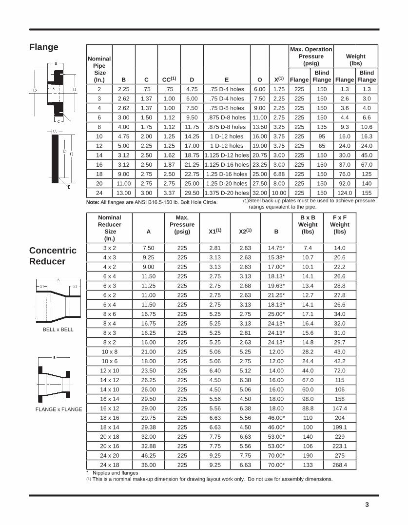
Flange
* Nipples and flanges(1) This is a nominal make-up dimension for drawing layout work only. Do not use for assembly dimensions.
NominalPipe Size(In.) B C CC(1) D E O X(1)
Max. OperationPressure
(psig)Weight
(lbs)
FlangeBlind
Flange FlangeBlind
Flange2 2.25 .75 .75 4.75 .75 D-4 holes 6.00 1.75 225 150 1.3 1.33 2.62 1.37 1.00 6.00 .75 D-4 holes 7.50 2.25 225 150 2.6 3.04 2.62 1.37 1.00 7.50 .75 D-8 holes 9.00 2.25 225 150 3.6 4.06 3.00 1.50 1.12 9.50 .875 D-8 holes 11.00 2.75 225 150 4.4 6.68 4.00 1.75 1.12 11.75 .875 D-8 holes 13.50 3.25 225 135 9.3 10.6
10 4.75 2.00 1.25 14.25 1 D-12 holes 16.00 3.75 225 95 16.0 16.312 5.00 2.25 1.25 17.00 1 D-12 holes 19.00 3.75 225 65 24.0 24.014 3.12 2.50 1.62 18.75 1.125 D-12 holes 20.75 3.00 225 150 30.0 45.016 3.12 2.50 1.87 21.25 1.125 D-16 holes 23.25 3.00 225 150 37.0 67.018 9.00 2.75 2.50 22.75 1.25 D-16 holes 25.00 6.88 225 150 76.0 12520 11.00 2.75 2.75 25.00 1.25 D-20 holes 27.50 8.00 225 150 92.0 14024 13.00 3.00 3.37 29.50 1.375 D-20 holes 32.00 10.00 225 150 124.0 155
Note: All flanges are ANSI B16.5-150 lb. Bolt Hole Circle.
ConcentricReducer
NominalReducer
Size(In.)
A
Max. Pressure
(psig) X1(1) X2(1) B
B x BWeight
(lbs)
F x FWeight
(lbs)
3 x 2 7.50 225 2.81 2.63 14.75* 7.4 14.04 x 3 9.25 225 3.13 2.63 15.38* 10.7 20.64 x 2 9.00 225 3.13 2.63 17.00* 10.1 22.26 x 4 11.50 225 2.75 3.13 18.13* 14.1 26.66 x 3 11.25 225 2.75 2.68 19.63* 13.4 28.86 x 2 11.00 225 2.75 2.63 21.25* 12.7 27.86 x 4 11.50 225 2.75 3.13 18.13* 14.1 26.68 x 6 16.75 225 5.25 2.75 25.00* 17.1 34.08 x 4 16.75 225 5.25 3.13 24.13* 16.4 32.08 x 3 16.25 225 5.25 2.81 24.13* 15.6 31.08 x 2 16.00 225 5.25 2.63 24.13* 14.8 29.710 x 8 21.00 225 5.06 5.25 12.00 28.2 43.010 x 6 18.00 225 5.06 2.75 12.00 24.4 42.212 x 10 23.50 225 6.40 5.12 14.00 44.0 72.014 x 12 26.25 225 4.50 6.38 16.00 67.0 11514 x 10 26.00 225 4.50 5.06 16.00 60.0 10616 x 14 29.50 225 5.56 4.50 18.00 98.0 15816 x 12 29.00 225 5.56 6.38 18.00 88.8 147.418 x 16 29.75 225 6.63 5.56 46.00* 110 20418 x 14 29.38 225 6.63 4.50 46.00* 100 199.120 x 18 32.00 225 7.75 6.63 53.00* 140 22920 x 16 32.88 225 7.75 5.56 53.00* 106 223.124 x 20 46.25 225 9.25 7.75 70.00* 190 27524 x 18 36.00 225 9.25 6.63 70.00* 133 268.4
BELL x BELL
FLANGE x FLANGE
3
(1)Steel back-up plates must be used to achieve pressure ratings equivalent to the pipe.
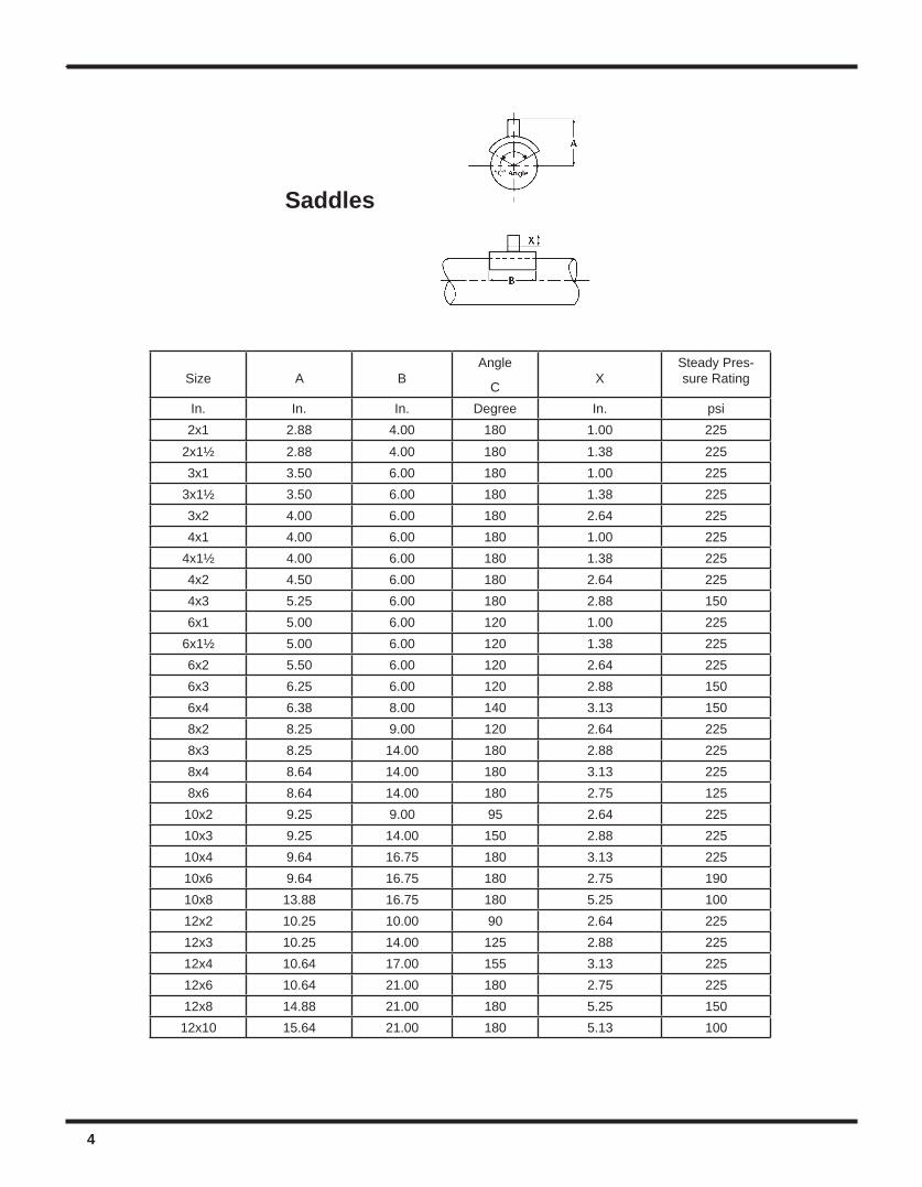
Size A BAngle
C XSteady Pres-sure Rating
In. In. In. Degree In. psi2x1 2.88 4.00 180 1.00 225
2x1½ 2.88 4.00 180 1.38 2253x1 3.50 6.00 180 1.00 225
3x1½ 3.50 6.00 180 1.38 2253x2 4.00 6.00 180 2.64 2254x1 4.00 6.00 180 1.00 225
4x1½ 4.00 6.00 180 1.38 2254x2 4.50 6.00 180 2.64 2254x3 5.25 6.00 180 2.88 1506x1 5.00 6.00 120 1.00 225
6x1½ 5.00 6.00 120 1.38 2256x2 5.50 6.00 120 2.64 2256x3 6.25 6.00 120 2.88 1506x4 6.38 8.00 140 3.13 1508x2 8.25 9.00 120 2.64 2258x3 8.25 14.00 180 2.88 2258x4 8.64 14.00 180 3.13 2258x6 8.64 14.00 180 2.75 12510x2 9.25 9.00 95 2.64 22510x3 9.25 14.00 150 2.88 22510x4 9.64 16.75 180 3.13 22510x6 9.64 16.75 180 2.75 19010x8 13.88 16.75 180 5.25 10012x2 10.25 10.00 90 2.64 22512x3 10.25 14.00 125 2.88 22512x4 10.64 17.00 155 3.13 22512x6 10.64 21.00 180 2.75 22512x8 14.88 21.00 180 5.25 15012x10 15.64 21.00 180 5.13 100
Saddles
4
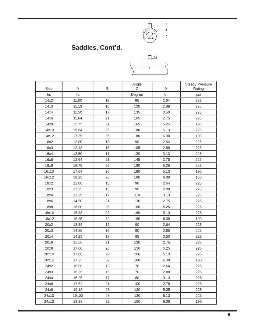
Size A BAngle
C XSteady Pressure
RatingIn. In. In. Degree In. psi
14x2 11.00 12 95 2.64 22514x3 11.13 15 120 2.88 22514x4 11.50 17 135 3.50 22514x6 11.64 21 165 2.75 22514x8 15.75 21 165 5.25 19014x10 15.64 26 180 5.13 22514x12 17.25 26 180 6.38 10016x2 12.00 13 90 2.64 22516x3 12.13 15 105 2.88 22516x4 12.50 17 120 3.13 22516x6 12.64 21 145 2.75 22516x8 16.75 26 180 5.25 22516x10 17.64 26 180 5.13 19016x12 18.25 26 180 6.38 15018x2 12.88 13 90 2.64 22518x3 13.25 15 90 2.88 22518x4 13.25 17 110 3.13 22518x6 14.50 21 130 2.75 22518x8 16.00 26 160 5.25 22518x10 15.88 28 180 5.13 22518x12 16.25 32 180 6.38 19020x2 13.88 13 90 2.64 22520x3 14.25 15 90 2.88 22520x4 14.25 17 95 3.50 22520x6 15.50 21 120 2.75 22520x8 17.00 26 150 5.25 22520x10 17.00 28 160 5.13 22520x12 17.25 32 180 6.38 19024x2 16.00 13 70 2.64 22524x3 16.25 15 70 2.88 22524x4 16.25 17 80 3.13 22524x6 17.64 21 100 2.75 22524x8 19.13 26 120 5.25 22524x10 19..00 28 130 5.13 22524x12 19.38 32 150 6.38 190
Saddles, Cont’d.
5
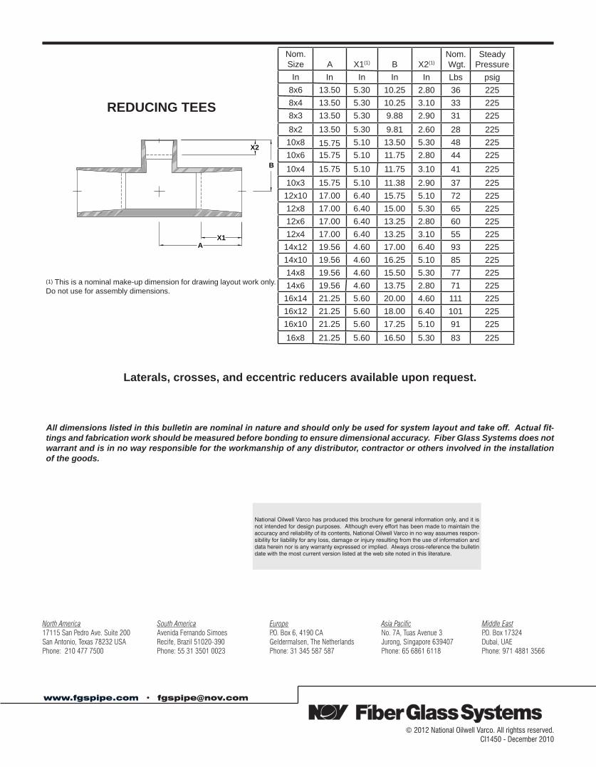
REDUCING TEES
Nom.Size A X1(1) B X2(1)
Nom. Wgt.
SteadyPressure
In In In In In Lbs psig8x6 13.50 5.30 10.25 2.80 36 2258x4 13.50 5.30 10.25 3.10 33 2258x3 13.50 5.30 9.88 2.90 31 2258x2 13.50 5.30 9.81 2.60 28 225
10x8 15.75 5.10 13.50 5.30 48 22510x6 15.75 5.10 11.75 2.80 44 22510x4 15.75 5.10 11.75 3.10 41 22510x3 15.75 5.10 11.38 2.90 37 225
12x10 17.00 6.40 15.75 5.10 72 22512x8 17.00 6.40 15.00 5.30 65 22512x6 17.00 6.40 13.25 2.80 60 22512x4 17.00 6.40 13.25 3.10 55 225
14x12 19.56 4.60 17.00 6.40 93 22514x10 19.56 4.60 16.25 5.10 85 22514x8 19.56 4.60 15.50 5.30 77 22514x6 19.56 4.60 13.75 2.80 71 225
16x14 21.25 5.60 20.00 4.60 111 22516x12 21.25 5.60 18.00 6.40 101 22516x10 21.25 5.60 17.25 5.10 91 22516x8 21.25 5.60 16.50 5.30 83 225
(1) This is a nominal make-up dimension for drawing layout work only. Do not use for assembly dimensions.
Laterals, crosses, and eccentric reducers available upon request.
All dimensions listed in this bulletin are nominal in nature and should only be used for system layout and take off. Actual fit-tings and fabrication work should be measured before bonding to ensure dimensional accuracy. Fiber Glass Systems does not warrant and is in no way responsible for the workmanship of any distributor, contractor or others involved in the installation of the goods.
X2
B
X1A
© 2012 National Oilwell Varco. All rightss reserved.CI1450 - December 2010
www.fgspipe.com • [email protected]
National Oilwell Varco has produced this brochure for general information only, and it is not intended for design purposes. Although every effort has been made to maintain the accuracy and reliability of its contents, National Oilwell Varco in no way assumes respon-sibility for liability for any loss, damage or injury resulting from the use of information and data herein nor is any warranty expressed or implied. Always cross-reference the bulletin date with the most current version listed at the web site noted in this literature.
North America South America Europe Asia Pacific Middle East17115 San Pedro Ave. Suite 200 Avenida Fernando Simoes P.O. Box 6, 4190 CA No. 7A, Tuas Avenue 3 P.O. Box 17324San Antonio, Texas 78232 USA Recife, Brazil 51020-390 Geldermalsen, The Netherlands Jurong, Singapore 639407 Dubai, UAEPhone: 210 477 7500 Phone: 55 31 3501 0023 Phone: 31 345 587 587 Phone: 65 6861 6118 Phone: 971 4881 3566
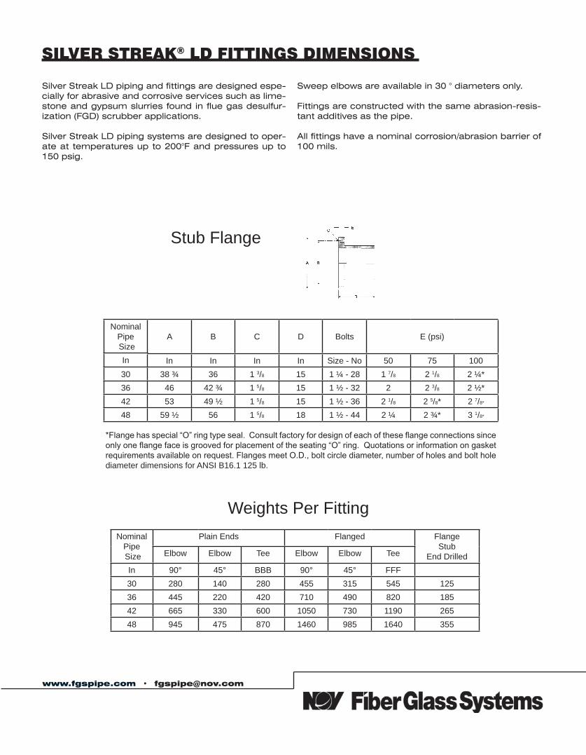
www.fgspipe.com • [email protected]
SILVER STREAK® LD FITTINGS DIMENSIONS
Silver Streak LD piping and fittings are designed espe-cially for abrasive and corrosive services such as lime-stone and gypsum slurries found in flue gas desulfur-ization (FGD) scrubber applications.
Silver Streak LD piping systems are designed to oper-ate at temperatures up to 200°F and pressures up to 150 psig.
Sweep elbows are available in 30 ° diameters only.
Fittings are constructed with the same abrasion-resis-tant additives as the pipe.
All fittings have a nominal corrosion/abrasion barrier of 100 mils.
Stub Flange
NominalPipe Size
A B C D Bolts E (psi)
In In In In In Size - No 50 75 10030 38 ¾ 36 1 3/8 15 1 ¼ - 28 1 7/8 2 1/8 2 ¼*36 46 42 ¾ 1 5/8 15 1 ½ - 32 2 2 3/8 2 ½*42 53 49 ½ 1 5/8 15 1 ½ - 36 2 1/8 2 5/8* 2 7/8*
48 59 ½ 56 1 5/8 18 1 ½ - 44 2 ¼ 2 ¾* 3 1/8*
*Flange has special “O” ring type seal. Consult factory for design of each of these flange connections since only one flange face is grooved for placement of the seating “O” ring. Quotations or information on gasket requirements available on request. Flanges meet O.D., bolt circle diameter, number of holes and bolt hole diameter dimensions for ANSI B16.1 125 lb.
Weights Per FittingNominal
Pipe Size
Plain Ends Flanged FlangeStub
End Drilled Elbow Elbow Tee Elbow Elbow Tee
In 90° 45° BBB 90° 45° FFF30 280 140 280 455 315 545 12536 445 220 420 710 490 820 18542 665 330 600 1050 730 1190 26548 945 475 870 1460 985 1640 355
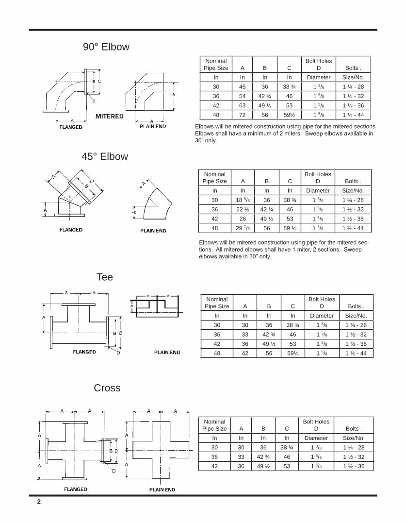
2
NominalPipe Size A B C
Bolt HolesD Bolts .
In In In In Diameter Size/No.30 45 36 38 ¾ 1 3/8 1 ¼ - 2836 54 42 ¾ 46 1 5/8 1 ½ - 3242 63 49 ½ 53 1 5/8 1 ½ - 3648 72 56 59½ 1 5/8 1 ½ - 44
90° Elbow
NominalPipe Size A B C
Bolt HolesD Bolts .
In In In In Diameter Size/No.30 18 5/8 36 38 ¾ 1 3/8 1 ¼ - 2836 22 ½ 42 ¾ 46 1 5/8 1 ½ - 3242 26 49 ½ 53 1 5/8 1 ½ - 3648 29 7/8 56 59 ½ 1 5/8 1 ½ - 44
NominalPipe Size A B C
Bolt HolesD Bolts .
In In In In Diameter Size/No.30 30 36 38 ¾ 1 3/8 1 ¼ - 2836 33 42 ¾ 46 1 5/8 1 ½ - 3242 36 49 ½ 53 1 5/8 1 ½ - 3648 42 56 59½ 1 5/8 1 ½ - 44
NominalPipe Size A B C
Bolt HolesD Bolts .
In In In In Diameter Size/No.30 30 36 38 ¾ 1 3/8 1 ¼ - 2836 33 42 ¾ 46 1 5/8 1 ½ - 3242 36 49 ½ 53 1 5/8 1 ½ - 36
Elbows will be mitered construction using pipe for the mitered sections.Elbows shall have a minimum of 2 miters. Sweep elbows available in 30” only.
45° Elbow
Elbows will be mitered construction using pipe for the mitered sec-tions. All mitered elbows shall have 1 miter, 2 sections. Sweep elbows available in 30” only.
Tee
Cross
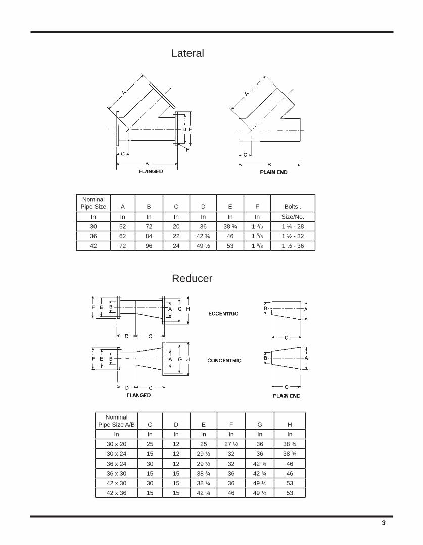
3
NominalPipe Size A B C D
E F Bolts .
In In In In In In In Size/No.30 52 72 20 36 38 ¾ 1 3/8 1 ¼ - 2836 62 84 22 42 ¾ 46 1 5/8 1 ½ - 3242 72 96 24 49 ½ 53 1 5/8 1 ½ - 36
NominalPipe Size A/B C D E F G H
In In In In In In In30 x 20 25 12 25 27 ½ 36 38 ¾30 x 24 15 12 29 ½ 32 36 38 ¾36 x 24 30 12 29 ½ 32 42 ¾ 4636 x 30 15 15 38 ¾ 36 42 ¾ 4642 x 30 30 15 38 ¾ 36 49 ½ 5342 x 36 15 15 42 ¾ 46 49 ½ 53
Lateral
Reducer

www.fgspipe.com • [email protected]
National Oilwell Varco has produced this brochure for general information only, and it is not intended for design purposes. Although every effort has been made to maintain the accuracy and reliability of its contents, National Oilwell Varco in no way assumes responsibility for liability for any loss, damage or in-jury resulting from the use of information and data herein nor is any warranty expressed or implied. Always cross-reference the bulletin date with the most current version listed at the website noted in this literature.
© 2012 National Oilwell Varco. All rights reserved.CI1440 February 2009
North America South America Europe Asia Pacific Middle East17115 San Pedro Ave. Suite 200 Avenida Fernando Simoes P.O. Box 6, 4190 CA No. 7A, Tuas Avenue 3 P.O. Box 17324San Antonio, Texas 78232 USA Recife, Brazil 51020-390 Geldermalsen, The Netherlands Jurong, Singapore 639407 Dubai, UAEPhone: 210 477 7500 Phone: 55 31 3501 0023 Phone: 31 345 587 587 Phone: 65 6861 6118 Phone: 971 4881 3566
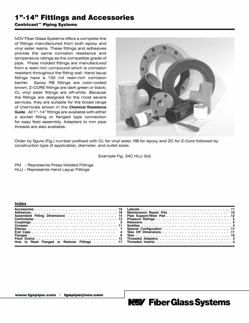
NOV Fiber Glass Systems offers a complete line of fittings manufactured from both epoxy and vinyl ester resins. These fittings and adhesives provide the same corrosion resistance and temperature ratings as the compatible grade of pipe. Press molded fittings are manufactured from a resin-rich compound which is corrosion resistant throughout the fitting wall. Hand layup fittings have a 100 mil resin-rich corrosion barrier. Epoxy RB fittings are color-coded brown; Z-CORE fittings are dark green or black; CL vinyl ester fittings are off-white. Because the fittings are designed for the most severe services, they are suitable for the broad range of chemicals shown in the Chemical Resistance Guide. All 1”-14” fittings are available with either a socket fitting or flanged type connection for easy field assembly. Adapters to iron pipe threads are also available.
IndexAccessories . . . . . . . . . . . . . . . . . . . . . . . . . . . . . . 19Adhesives. . . . . . . . . . . . . . . . . . . . . . . . . . . . . . . . 18Assembled Fitting Dimensions . . . . . . . . . . . . . . . 14Centriclamp . . . . . . . . . . . . . . . . . . . . . . . . . . . . . . 13Couplings. . . . . . . . . . . . . . . . . . . . . . . . . . . . . . . . 3Crosses . . . . . . . . . . . . . . . . . . . . . . . . . . . . . . . . . 11Elbows. . . . . . . . . . . . . . . . . . . . . . . . . . . . . . . . . . . 7End Caps . . . . . . . . . . . . . . . . . . . . . . . . . . . . . . . . 4 Flanges . . . . . . . . . . . . . . . . . . . . . . . . . . . . . . . . . . 6Floor Drains . . . . . . . . . . . . . . . . . . . . . . . . . . . . . . 12How to Read Flanged or Reducer Fittings . . . . . . .17
Laterals . . . . . . . . . . . . . . . . . . . . . . . . . . . . . . . . . . . 11Maintenance Repair Kits . . . . . . . . . . . . . . . . . . . . . .19Pipe Support/Wear Pad . . . . . . . . . . . . . . . . . . . . . . .12Pressure Ratings . . . . . . . . . . . . . . . . . . . . . . . . . . . . 2Reducers. . . . . . . . . . . . . . . . . . . . . . . . . . . . . . . . . . . 5Saddles . . . . . . . . . . . . . . . . . . . . . . . . . . . . . . . . . . . 4Special Configuration . . . . . . . . . . . . . . . . . . . . . . , .17Take Off Dimensions . . . . . . . . . . . . . . . . . . . . . . . . .17 Tees . . . . . . . . . . . . . . . . . . . . . . . . . . . . . . . . . . . . . .10Threaded Adapters. . . . . . . . . . . . . . . . . . . . . . . . . . . 3Threaded Inserts. . . . . . . . . . . . . . . . . . . . . . . . . . . . 4
Order by figure (Fig.) number prefixed with CL for vinyl ester, RB for epoxy and ZC for Z-Core followed by construction type (if applicable), diameter, and outlet sizes.
Example Fig. 34C HLU 3x2
PM - Represents Press Molded FittingsHLU - Represents Hand Layup Fittings
www.fgspipe.com • [email protected]
1”-14” Fittings and AccessoriesCentricast™ Piping Systems
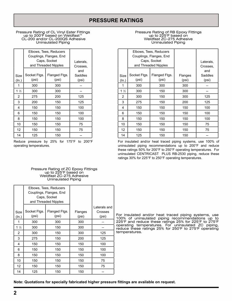
PRESSURE RATINGS
Pressure Rating of CL Vinyl Ester Fittings up to 200°F based on Weldfast™
CL-200 and/or CL-200QS AdhesiveUninsulated Piping
Pressure Rating of RB Epoxy Fittings up to 225°F based on
Weldfast ZC-275 AdhesiveUninsulated Piping
Pressure Rating of ZC Epoxy Fittings up to 225°F based on
Weldfast ZC-275 AdhesiveUninsulated Piping
For insulated and/or heat traced piping systems, use 100% of uninsulated piping recommendations up to 225°F and reduce these ratings 25% for 225°F to 275°F operating temperatures. For uninsulated ZC piping, reduce these ratings 25% for 250°F to 275°F operating temperatures.
2
Size(In.)
Elbows, Tees, Reducers Couplings, Flanges, End
Caps, Socketand Threaded Nipples
Laterals, Crosses,
andSaddles
(psi)Socket Ftgs.
(psi)Flanged Ftgs.
(psi)
1 300 300 --1 1⁄2 300 300 --2 275 200 1253 200 150 1254 150 150 1006 150 150 1008 150 150 100
10 150 150 7512 150 150 7514 125 150 --
Reduce pressure by 25% for 175°F to 200°F operating temperatures.
Size(In.)
Elbows, Tees, Reducers Couplings, Flanges, End
Caps, Socketand Threaded Nipples
Flanges(psi)
Laterals and Crosses
(psi)Socket Ftgs.
(psi)Flanged Ftgs.
(psi)
1 300 300 300 --1 1⁄2 300 150 300 --2 300 150 300 1253 275 150 200 1254 150 150 150 1006 150 150 150 1008 150 150 150 100
10 150 150 150 7512 150 150 150 7514 125 150 150 --
Size(In.)
Elbows, Tees, Reducers Couplings, Flanges, End
Caps, Socketand Threaded Nipples
Flanges(psi)
Laterals, Crosses,
andSaddles
(psi)Socket Ftgs.
(psi)Flanged Ftgs.
(psi)
1 300 300 300 --1 1⁄2 300 150 300 --2 300 150 300 1253 275 150 200 1254 150 150 150 1006 150 150 150 1008 150 150 150 100
10 150 150 150 7512 150 150 150 7514 125 150 150 --
For insulated and/or heat traced piping systems, use 100% of uninsulated piping recommendations up to 200°F and reduce these ratings 50% for 200°F to 250°F operating temperatures. For uninsulated CENTRICAST PLUS RB-2530 piping, reduce these ratings 30% for 225°F to 250°F operating temperatures.
Note: Quotations for specially fabricated higher pressure fittings are available on request.
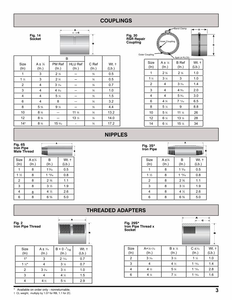
COUPLINGS
Fig. 2Iron Pipe Thread
A
B
Size(In)
A ± 3⁄16
(In.) B + 0 -1/16
(In.) Wt. †(Lb.)
1* 3 2 11⁄16 0.71 1⁄2* 4 3 1⁄8 0.7
2 3 1⁄16 3 1⁄2 1.03 4 4 1⁄2 1.54 4 1⁄2 5 3⁄4 2.9
A
B
C
Fig. 29S*Iron Pipe Thread xSocket
Size(In)
A+1⁄8-1⁄16
(In.) B ± 1⁄8(In.)
C ±1⁄16
(In.) Wt. †(Lb.)
2 3 1⁄16 3 1⁄2 1 1⁄2 1.03 4 4 1⁄2 1 13⁄16 1.44 4 1⁄2 5 3⁄4 1 13⁄16 2.86 4 1⁄4 7 1⁄4 1 13⁄16 1.6
Fig. 14Socket
A
B
C
NIPPLES
Size(In)
A ±1⁄8(In.)
B (In.)
Wt. †(Lb.)
1 8 1 5⁄16 0.51 1⁄2 8 1 15⁄16 0.82 8 2 3⁄8 1.13 8 3 1⁄2 1.94 8 4 1⁄2 2.66 8 6 5⁄8 5.0
Fig. 6SIron Pipe Male Thread
A
B
Size(In)
A ±1⁄8 (In.)
B (In.)
Wt. †(Lb.)
1 8 1 5⁄16 0.51 1⁄2 8 1 15⁄16 0.82 8 2 3⁄8 1.13 8 3 1⁄2 1.94 8 4 1⁄2 2.66 8 6 5⁄8 5.0
Fig. 3S* Iron Pipe
A
B
Size(In)
A ± 1⁄8(In.)
B Ref(In.)
Wt. †(Lb.)
1 2 5⁄8 2 3⁄8 1.01 1⁄2 3 1⁄4 3 1.02 4 3 7⁄16 1.4
3 4 4 9⁄16 2.04 4 5 9⁄16 3.06 4 3⁄4 7 11⁄16 6.58 5 1⁄4 9 8.8
10 5 3⁄4 11 1⁄8 2612 6 1⁄4 13 1⁄8 2814 6 1⁄4 15 1⁄8 34
Fig. 30RSR RepairCoupling
3* Available on order only - nonreturnable.† CL weight, multiply by 1.07 for RB, 1.1 for ZC.
Band Clamp
Inner Coupling
Outer CouplingSplit (4 PLCS)
B
A
THREADED ADAPTERS
Size(In)
A ± 1⁄8(In.)
BC Ref(In.)
Wt. †(Lb.)
PM Ref(In.)
HLU Ref(In.)
1 3 2 1⁄8 -- 5⁄8 0.51 1⁄2 3 2 3⁄4 -- 3⁄8 0.52 4 3 1⁄16 -- 3⁄8 0.73 4 4 3⁄16 -- 3⁄8 1.04 4 5 1⁄4 -- 3⁄8 1.56 4 8 -- 3⁄8 3.28 5 5⁄8 9 7⁄8 -- 3⁄8 4.4
10 8 3⁄8 -- 11 3⁄8 3⁄8 13.212 8 3⁄8 -- 13 1⁄2 3⁄8 14.0
14* 8 3⁄8 15 9⁄16 - 3⁄8 17.2
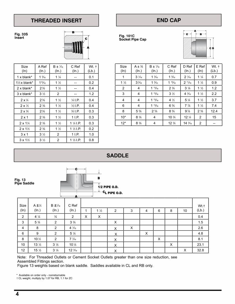
SADDLE
Fig. 13Pipe Saddle
C
A
B
1/2 PIPE O.D.CL PIPE O.D.
Size(In)
A ±1⁄4(In.)
B ±1⁄16
(In.)C Ref(In.)
Wt.†(Lb.)1 1 1⁄2 2 3 4 6 8 10
2 4 1⁄4 3⁄4 2 X X 0.43 5 3⁄4 2 3 3⁄8 X 1.54 8 2 4 1⁄16 X X 2.66 9 2 5 1⁄8 X X 4.88 10 1⁄2 2 7 7⁄16 X X 8.1
10 13 1⁄2 3 1⁄8 10 1⁄8 X X 23.112 15 1⁄2 3 1⁄8 12 3⁄16 X X 32.8
Note: For Threaded Outlets or Cement Socket Outlets greater than one size reduction, see Assembled Fittings section. Figure 13 weights based on blank saddle. Saddles available in CL and RB only.
* Available on order only - nonreturnable† CL weight, multiply by 1.07 for RB, 1.1 for ZC
4
Fig. 33SInsert
A
B
C
Size(In)
A Ref(In.)
B ± 1⁄16
(In.)C Ref(In.)
Wt. †(Lb.)
1 x blank* 1 5⁄16 1 1⁄4 -- 0.111⁄2 x blank* 115⁄16 1 1⁄2 -- 0.22 x blank* 2 3⁄8 1 1⁄2 -- 0.43 x blank* 3 1⁄2 2 -- 1.2
2 x 1⁄4 2 3⁄8 1 1⁄2 1⁄4 I.P. 0.42 x 1⁄2 2 3⁄8 1 1⁄2 1⁄2 I.P. 0.42 x 3⁄4 2 3⁄8 1 1⁄2 3⁄4 I.P. 0.3
2 x 1 2 3⁄8 1 1⁄2 1 I.P. 0.3
2 x 11⁄4 2 3⁄8 1 1⁄2 1 1⁄4 I.P. 0.32 x 11⁄2 2 3⁄8 1 1⁄2 1 1⁄2 I.P. 0.23 x 1 3 1⁄2 2 1 I.P. 1.0
3 x 11⁄2 3 1⁄2 2 1 1⁄2 I.P. 0.8
Fig. 101CSocket Pipe Cap
C D
E BA
Size(In)
A ± 3⁄8(In.)
B ± 1⁄16
(In.)C Ref(In.)
D Ref(In.)
E Ref(In)
Wt. †(Lb.)
1 3 1⁄16 1 3⁄16 1 5⁄16 2 1⁄16 1 1⁄4 0.71 1⁄2 3 3⁄16 1 5⁄16 1 15⁄16 2 11⁄16 1 1⁄2 0.92 4 1 13⁄16 2 3⁄8 3 1⁄8 1 1⁄2 1.23 4 1 13⁄16 3 1⁄2 4 3⁄16 1 1⁄2 2.2
4 4 1 13⁄16 4 1⁄2 5 1⁄4 1 1⁄2 3.76 4 1 13⁄16 6 5⁄8 7 7⁄8 1 1⁄2 7.48 5 5⁄8 2 5⁄8 8 5⁄8 9 7⁄8 2 5⁄8 12.4
10* 8 3⁄8 4 10 3⁄4 12 1⁄4 2 15
12* 8 3⁄8 4 12 3⁄4 14 3⁄16 2 --
THREADED INSERT END CAP
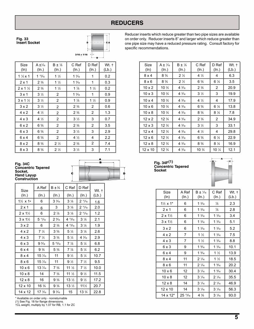
D C A
B3/16 + 1/16
3/16 + 1/16_
Reducer inserts which reduce greater than two pipe sizes are available on order only. Reducer inserts 8” and larger which reduce greater than one pipe size may have a reduced pressure rating. Consult factory for specific recommendations.
Size(In)
A ±1⁄16
(In.) B ± 1⁄8(In.)
C Ref(In.)
D Ref(In.)
Wt. †(Lb.)
1 1⁄2 x 1 1 15⁄16 1 1⁄2 1 5⁄16 1 0.22 x 1 2 3⁄8 1 1⁄2 1 5⁄16 1 0.3
2 x 1 1⁄2 2 3⁄8 1 1⁄2 1 7⁄8 1 1⁄2 0.23 x 1 3 1⁄2 2 1 5⁄16 1 0.9
3 x 1 1⁄2 3 1⁄2 2 1 7⁄8 1 1⁄2 0.93 x 2 3 1⁄2 2 2 3⁄8 2 0.64 x 2 4 1⁄2 2 2 3⁄8 2 1.3
4 x 3 4 1⁄2 2 3 1⁄2 3 0.7
6 x 2 6 5⁄8 2 2 3⁄8 2 3.56 x 3 6 5⁄8 2 3 1⁄2 3 2.96 x 4 6 5⁄8 2 4 1⁄2 4 2.28 x 2 8 5⁄8 2 1⁄2 2 3⁄8 2 7.48 x 3 8 5⁄8 2 1⁄2 3 1⁄2 3 7.1
REDUCERS
Fig. 33Insert Socket
Size(In)
A ± 1⁄16
(In.) B ± 1⁄8(In.)
C Ref(In.)
D Ref(In.)
Wt. †(Lb.)
8 x 4 8 5⁄8 2 1⁄2 4 1⁄2 4 6.38 x 6 8 5⁄8 2 1⁄2 6 5⁄8 6 1⁄8 3.5
10 x 2 10 3⁄4 4 3⁄16 2 3⁄8 2 20.910 x 3 10 3⁄4 4 3⁄16 3 1⁄2 3 19.9
10 x 4 10 3⁄4 4 3⁄16 4 1⁄2 4 17.910 x 6 10 3⁄4 4 3⁄16 6 5⁄8 6 1⁄8 13.810 x 8 10 3⁄4 4 3⁄16 8 5⁄8 8 1⁄8 7.8
12 x 2 12 3⁄4 4 3⁄16 2 3⁄8 2 34.9
12 x 3 12 3⁄4 4 3⁄16 3 1⁄2 3 33.112 x 4 12 3⁄4 4 3⁄16 4 1⁄2 4 29.812 x 6 12 3⁄4 4 3⁄16 6 5⁄8 6 1⁄8 22.912 x 8 12 3⁄4 4 3⁄16 8 5⁄8 8 1⁄8 16.9
12 x 10 12 3⁄4 4 3⁄16 10 3⁄4 10 1⁄4 12.1
Size(In)
A Ref(In.)
B ± 1⁄16
(In.)C Ref(In.)
Wt. †(Lb.)
11⁄2 x 1* 6 1 3⁄16 7⁄8 2.32 x 1 6 1 3⁄16 7⁄8 2.8
2 x 11⁄2 6 1 3⁄16 1 3⁄16 3.43 x 11⁄2 6 1 3⁄16 1 3⁄16 5.1
3 x 2 6 1 3⁄16 1 3⁄16 5.2
4 x 2 7 1 1⁄2 1 3⁄16 7.54 x 3 7 1 1⁄2 1 3⁄16 8.86 x 3 9 1 9⁄16 1 3⁄16 10.16 x 4 9 1 9⁄16 1 1⁄2 13.98 x 4 11 2 1⁄16 1 1⁄2 18.58 x 6 11 2 1⁄16 1 9⁄16 20.2
10 x 6 12 3 1⁄16 1 9⁄16 30.410 x 8 12 3 1⁄16 2 1⁄16 35.512 x 8 14 3 1⁄16 2 1⁄16 46.9
12 x 10 14 3 1⁄16 3 1⁄16 56.3 14 x 12* 25 13⁄16 4 3⁄8 3 1⁄16 93.0
Fig. 34CConcentric Tapered Socket,Hand LayupConstruction
C
B
D
AFig. 34F(1)Concentric Tapered Socket
AB C
5
* Available on order only - nonreturnable(1) See Fig. 18 for flange dimensions.†CL weight, multiply by 1.07 for RB, 1.1 for ZC
Size(In.)
A Ref B ± 3⁄8 C Ref D Ref Wt. †(Lb.)(In.) (In.) (In.) (In.)
11⁄2 x 1* 6 3 3⁄16 3 1⁄8 2 11⁄16 1.62 x 1 6 3 3 1⁄8 2 11⁄16 2.0
2 x 11⁄2 6 2 7⁄8 3 1⁄8 2 11⁄16 1.23 x 11⁄2 5 11⁄16 2 9⁄16 4 13⁄16 3 1⁄8 2.13 x 2 6 2 3⁄8 4 13⁄16 3 1⁄8 1.94 x 2 7 1⁄4 3 5⁄8 5 1⁄4 3 1⁄8 2.64 x 3 7 1⁄4 3 3⁄8 5 1⁄4 4 3⁄16 2.96 x 3 9 9⁄16 5 15⁄16 7 7⁄8 5 1⁄4 6.86 x 4 9 3⁄8 5 3⁄8 7 7⁄8 5 1⁄4 6.28 x 4 15 7⁄16 11 9 1⁄2 5 1⁄4 10.78 x 6 15 7⁄16 11 9 1⁄2 7 1⁄2 9.5
10 x 6 13 7⁄16 7 3⁄8 11 1⁄2 7 1⁄2 10.010 x 8 14 7 3⁄8 11 1⁄2 9 1⁄2 11.512 x 8 16 9 3⁄8 13 1⁄2 9 1⁄2 17.2
12 x 10 16 3⁄8 9 3⁄8 13 1⁄2 111⁄2 20.714 x 12 17 3⁄16 9 3⁄16 15 13 3⁄4 22.8
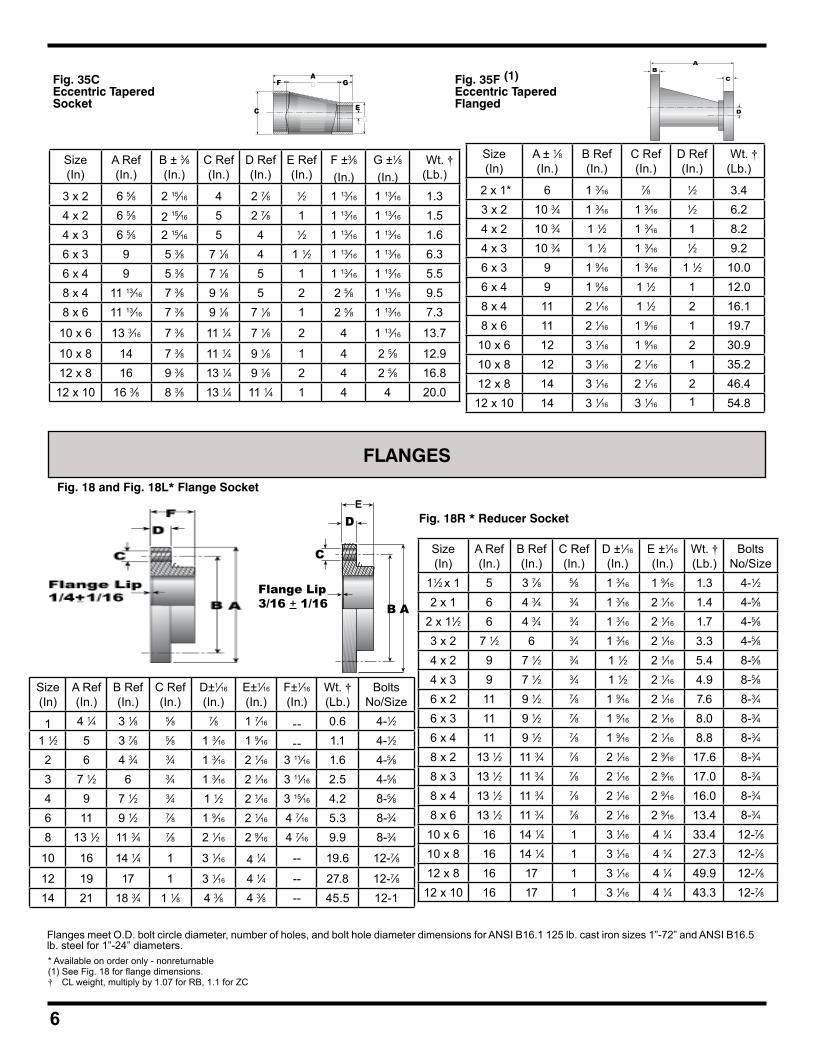
Fig. 35CEccentric Tapered Socket
6
Size(In)
A Ref(In.)
B ± 3⁄8(In.)
C Ref(In.)
D Ref(In.)
E Ref(In.)
F ±3⁄8(In.)
G ±1⁄8(In.)
Wt. †(Lb.)
3 x 2 6 5⁄8 2 15⁄16 4 2 7⁄8 1⁄2 1 13⁄16 1 13⁄16 1.34 x 2 6 5⁄8 2 15⁄16 5 2 7⁄8 1 1 13⁄16 1 13⁄16 1.54 x 3 6 5⁄8 2 15⁄16 5 4 1⁄2 1 13⁄16 1 13⁄16 1.66 x 3 9 5 3⁄8 7 1⁄8 4 1 1⁄2 1 13⁄16 1 13⁄16 6.36 x 4 9 5 3⁄8 7 1⁄8 5 1 1 13⁄16 1 13⁄16 5.58 x 4 11 13⁄16 7 3⁄8 9 1⁄8 5 2 2 5⁄8 1 13⁄16 9.58 x 6 11 13⁄16 7 3⁄8 9 1⁄8 7 1⁄8 1 2 5⁄8 1 13⁄16 7.3
10 x 6 13 3⁄16 7 3⁄8 11 1⁄4 7 1⁄8 2 4 1 13⁄16 13.7
10 x 8 14 7 3⁄8 11 1⁄4 9 1⁄8 1 4 2 5⁄8 12.912 x 8 16 9 3⁄8 13 1⁄4 9 1⁄8 2 4 2 5⁄8 16.8
12 x 10 16 3⁄8 8 3⁄8 13 1⁄4 11 1⁄4 1 4 4 20.0
C
AF G
E�
� Fig. 35F (1)Eccentric TaperedFlanged
Size(In)
A ± 1⁄8(In.)
B Ref(In.)
C Ref(In.)
D Ref(In.)
Wt. †(Lb.)
2 x 1* 6 1 3⁄16 7⁄8 1⁄2 3.43 x 2 10 3⁄4 1 3⁄16 1 3⁄16 1⁄2 6.24 x 2 10 3⁄4 1 1⁄2 1 3⁄16 1 8.24 x 3 10 3⁄4 1 1⁄2 1 3⁄16 1⁄2 9.26 x 3 9 1 9⁄16 1 3⁄16 1 1⁄2 10.06 x 4 9 1 9⁄16 1 1⁄2 1 12.08 x 4 11 2 1⁄16 1 1⁄2 2 16.18 x 6 11 2 1⁄16 1 9⁄16 1 19.7
10 x 6 12 3 1⁄16 1 9⁄16 2 30.910 x 8 12 3 1⁄16 2 1⁄16 1 35.212 x 8 14 3 1⁄16 2 1⁄16 2 46.4
12 x 10 14 3 1⁄16 3 1⁄16 1 54.8
A
D
BC
FLANGES
Fig. 18 and Fig. 18L* Flange Socket
Size(In)
A Ref(In.)
B Ref(In.)
C Ref(In.)
D±1⁄16
(In.)E±1⁄16
(In.)F±1⁄16
(In.)Wt. †(Lb.)
BoltsNo/Size
1 4 1⁄4 3 1⁄8 5⁄8 7⁄8 1 7⁄16 -- 0.6 4-1⁄21 1⁄2 5 3 7⁄8 5⁄8 1 3⁄16 1 9⁄16 -- 1.1 4-1⁄22 6 4 3⁄4 3⁄4 1 3⁄16 2 1⁄16 3 11⁄16 1.6 4-5⁄83 7 1⁄2 6 3⁄4 1 3⁄16 2 1⁄16 3 11⁄16 2.5 4-5⁄84 9 7 1⁄2 3⁄4 1 1⁄2 2 1⁄16 3 15⁄16 4.2 8-5⁄86 11 9 1⁄2 7⁄8 1 9⁄16 2 1⁄16 4 7⁄16 5.3 8-3⁄48 13 1⁄2 11 3⁄4 7⁄8 2 1⁄16 2 9⁄16 4 7⁄16 9.9 8-3⁄4
10 16 14 1⁄4 1 3 1⁄16 4 1⁄4 -- 19.6 12-7⁄8
12 19 17 1 3 1⁄16 4 1⁄4 -- 27.8 12-7⁄814 21 18 3⁄4 1 1⁄8 4 3⁄8 4 3⁄8 -- 45.5 12-1
Size(In)
A Ref(In.)
B Ref(In.)
C Ref(In.)
D ±1⁄16
(In.)E ±1⁄16
(In.)Wt. †(Lb.)
BoltsNo/Size
11⁄2 x 1 5 3 7⁄8 5⁄8 1 3⁄16 1 9⁄16 1.3 4-1⁄22 x 1 6 4 3⁄4 3⁄4 1 3⁄16 2 1⁄16 1.4 4-5⁄8
2 x 11⁄2 6 4 3⁄4 3⁄4 1 3⁄16 2 1⁄16 1.7 4-5⁄83 x 2 7 1⁄2 6 3⁄4 1 3⁄16 2 1⁄16 3.3 4-5⁄84 x 2 9 7 1⁄2 3⁄4 1 1⁄2 2 1⁄16 5.4 8-5⁄84 x 3 9 7 1⁄2 3⁄4 1 1⁄2 2 1⁄16 4.9 8-5⁄86 x 2 11 9 1⁄2 7⁄8 1 9⁄16 2 1⁄16 7.6 8-3⁄46 x 3 11 9 1⁄2 7⁄8 1 9⁄16 2 1⁄16 8.0 8-3⁄46 x 4 11 9 1⁄2 7⁄8 1 9⁄16 2 1⁄16 8.8 8-3⁄48 x 2 13 1⁄2 11 3⁄4 7⁄8 2 1⁄16 2 9⁄16 17.6 8-3⁄48 x 3 13 1⁄2 11 3⁄4 7⁄8 2 1⁄16 2 9⁄16 17.0 8-3⁄48 x 4 13 1⁄2 11 3⁄4 7⁄8 2 1⁄16 2 9⁄16 16.0 8-3⁄48 x 6 13 1⁄2 11 3⁄4 7⁄8 2 1⁄16 2 9⁄16 13.4 8-3⁄4
10 x 6 16 14 1⁄4 1 3 1⁄16 4 1⁄4 33.4 12-7⁄810 x 8 16 14 1⁄4 1 3 1⁄16 4 1⁄4 27.3 12-7⁄812 x 8 16 17 1 3 1⁄16 4 1⁄4 49.9 12-7⁄812 x 10 16 17 1 3 1⁄16 4 1⁄4 43.3 12-7⁄8
C
DF
B AFlange Lip3/16 + 1/16
Fig. 18R * Reducer Socket
Flanges meet O.D. bolt circle diameter, number of holes, and bolt hole diameter dimensions for ANSI B16.1 125 lb. cast iron sizes 1”-72” and ANSI B16.5 lb. steel for 1”-24” diameters.* Available on order only - nonreturnable(1) See Fig. 18 for flange dimensions.† CL weight, multiply by 1.07 for RB, 1.1 for ZC
E
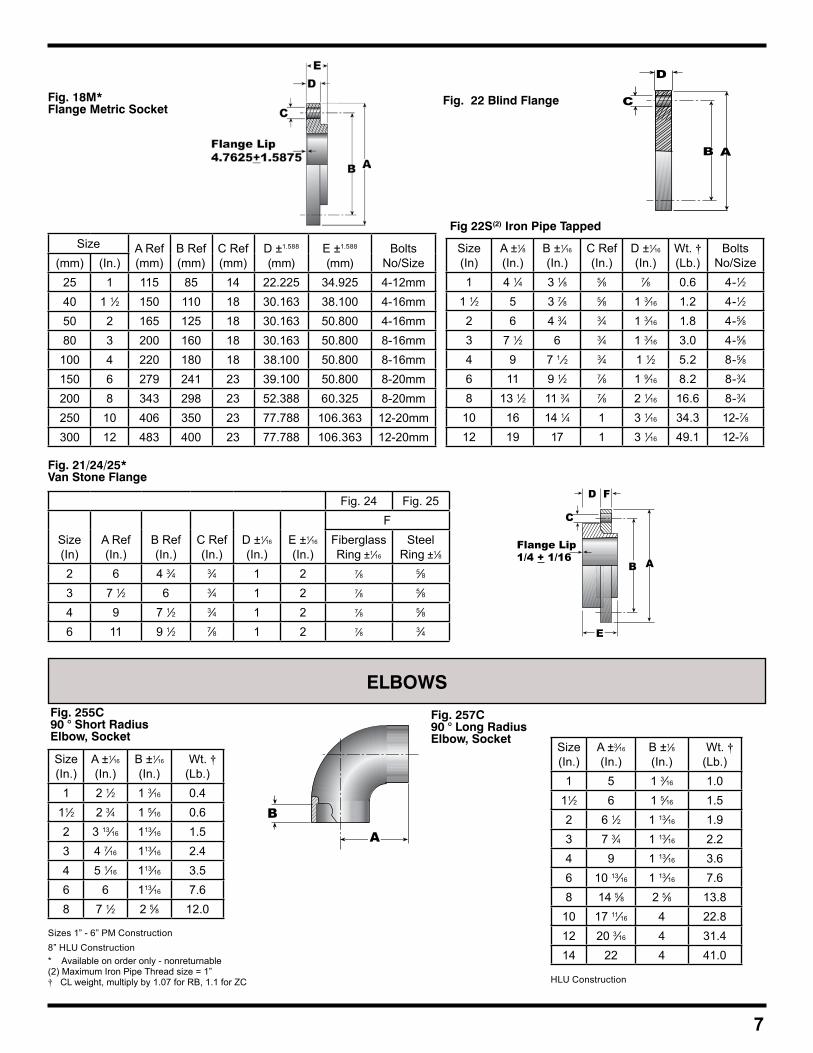
* Available on order only - nonreturnable(2) Maximum Iron Pipe Thread size = 1Ӡ CL weight, multiply by 1.07 for RB, 1.1 for ZC
7
Size A Ref(mm)
B Ref(mm)
C Ref(mm)
D ±1.588
(mm)E ±1.588
(mm)Bolts
No/Size(mm) (In.)25 1 115 85 14 22.225 34.925 4-12mm40 1 1⁄2 150 110 18 30.163 38.100 4-16mm50 2 165 125 18 30.163 50.800 4-16mm80 3 200 160 18 30.163 50.800 8-16mm
100 4 220 180 18 38.100 50.800 8-16mm150 6 279 241 23 39.100 50.800 8-20mm200 8 343 298 23 52.388 60.325 8-20mm250 10 406 350 23 77.788 106.363 12-20mm300 12 483 400 23 77.788 106.363 12-20mm
Fig. 18M*Flange Metric Socket
Size(In)
A ±1⁄8(In.)
B ±1⁄16
(In.)C Ref(In.)
D ±1⁄16
(In.)Wt. †(Lb.)
BoltsNo/Size
1 4 1⁄4 3 1⁄8 5⁄8 7⁄8 0.6 4-1⁄21 1⁄2 5 3 7⁄8 5⁄8 1 3⁄16 1.2 4-1⁄22 6 4 3⁄4 3⁄4 1 3⁄16 1.8 4-5⁄83 7 1⁄2 6 3⁄4 1 3⁄16 3.0 4-5⁄84 9 7 1 ⁄2 3⁄4 1 1⁄2 5.2 8-5⁄86 11 9 1⁄2 7⁄8 1 9⁄16 8.2 8-3⁄48 13 1⁄2 11 3⁄4 7⁄8 2 1⁄16 16.6 8-3⁄4
10 16 14 1⁄4 1 3 1⁄16 34.3 12-7⁄812 19 17 1 3 1⁄16 49.1 12-7⁄8
Fig 22S(2) Iron Pipe Tapped
Fig. 22 Blind Flange
D
A
C
B
Fig. 21/24/25*Van Stone Flange
Fig. 24 Fig. 25
Size(In)
A Ref(In.)
B Ref(In.)
C Ref(In.)
D ±1⁄16
(In.)E ±1⁄16
(In.)
FFiberglassRing ±1⁄16
SteelRing ±1⁄8
2 6 4 3⁄4 3⁄4 1 2 7⁄8 5⁄83 7 1⁄2 6 3⁄4 1 2 7⁄8 5⁄84 9 7 1⁄2 3⁄4 1 2 7⁄8 5⁄86 11 9 1⁄2 7⁄8 1 2 7⁄8 3⁄4
D F
B A
E
C
Flange Lip1/4 + 1/16
ELBOWSFig. 255C90 ° Short RadiusElbow, Socket
B
A
Size(In.)
A ±1⁄16
(In.)B ±1⁄16
(In.) Wt. †(Lb.)
1 2 1⁄2 1 3⁄16 0.411⁄2 2 3⁄4 1 5⁄16 0.62 3 13⁄16 113⁄16 1.53 4 7⁄16 113⁄16 2.44 5 1⁄16 113⁄16 3.56 6 113⁄16 7.68 7 1⁄2 2 5⁄8 12.0
Fig. 257C90 ° Long RadiusElbow, Socket
Size(In.)
A ±3⁄16
(In.)B ±1⁄8(In.)
Wt. †(Lb.)
1 5 1 3⁄16 1.011⁄2 6 1 5⁄16 1.52 6 1⁄2 1 13⁄16 1.93 7 3⁄4 1 13⁄16 2.24 9 1 13⁄16 3.66 10 13⁄16 1 13⁄16 7.68 14 5⁄8 2 5⁄8 13.8
10 17 11⁄16 4 22.812 20 3⁄16 4 31.414 22 4 41.0
HLU Construction
Sizes 1” - 6” PM Construction8” HLU Construction
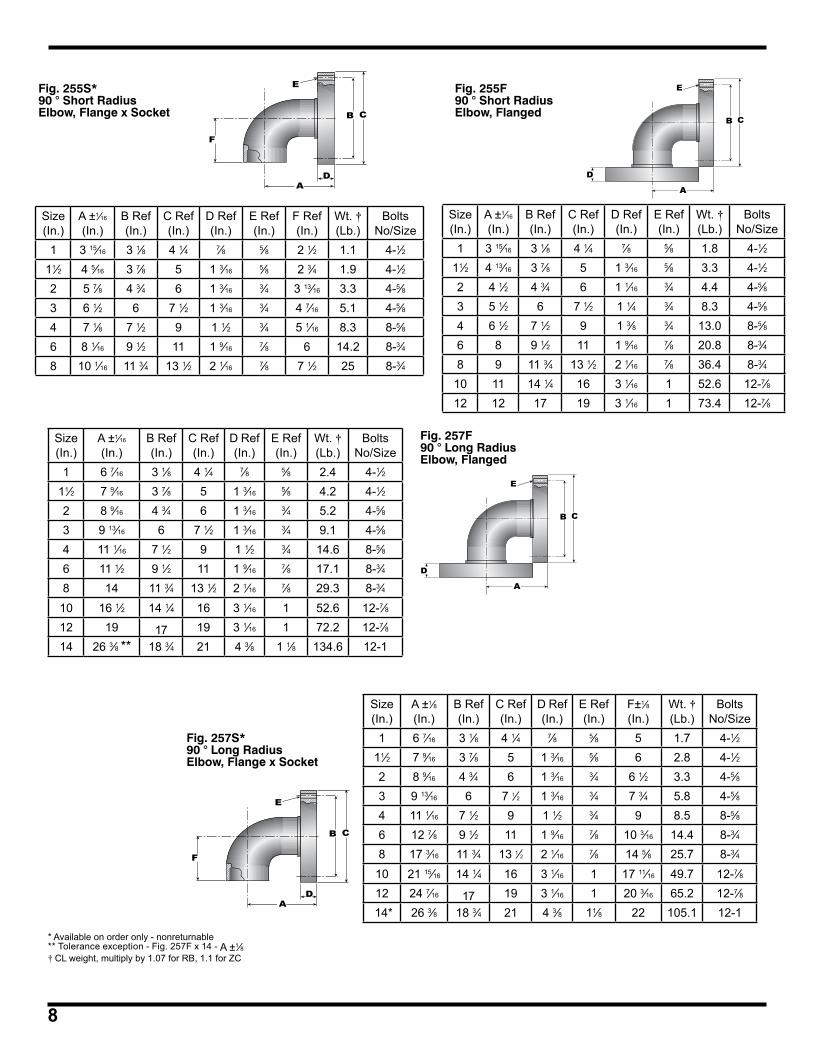
8
* Available on order only - nonreturnable** Tolerance exception - Fig. 257F x 14 - A ±1⁄8† CL weight, multiply by 1.07 for RB, 1.1 for ZC
Fig. 255F90 ° Short RadiusElbow, Flanged
E
D
CB
A
Size(In.)
A ±1⁄16
(In.)B Ref(In.)
C Ref(In.)
D Ref(In.)
E Ref(In.)
Wt. †(Lb.)
BoltsNo/Size
1 3 15⁄16 3 1⁄8 4 1⁄4 7⁄8 5⁄8 1.8 4-1⁄211⁄2 4 13⁄16 3 7⁄8 5 1 3⁄16 5⁄8 3.3 4-1⁄22 4 1⁄2 4 3⁄4 6 1 1⁄16 3⁄4 4.4 4-5⁄83 5 1⁄2 6 7 1⁄2 1 1⁄4 3⁄4 8.3 4-5⁄84 6 1⁄2 7 1⁄2 9 1 3⁄8 3⁄4 13.0 8-5⁄86 8 9 1⁄2 11 1 9⁄16 7⁄8 20.8 8-3⁄48 9 11 3⁄4 13 1⁄2 2 1⁄16 7⁄8 36.4 8-3⁄4
10 11 14 1⁄4 16 3 1⁄16 1 52.6 12-7⁄812 12 17 19 3 1⁄16 1 73.4 12-7⁄8
Fig. 255S*90 ° Short RadiusElbow, Flange x Socket
E
F
B C
AD
Size(In.)
A ±1⁄16
(In.)B Ref(In.)
C Ref(In.)
D Ref(In.)
E Ref(In.)
F Ref(In.)
Wt. †(Lb.)
BoltsNo/Size
1 3 15⁄16 3 1⁄8 4 1⁄4 7⁄8 5⁄8 2 1⁄2 1.1 4-1⁄211⁄2 4 5⁄16 3 7⁄8 5 1 3⁄16 5⁄8 2 3⁄4 1.9 4-1⁄22 5 7⁄8 4 3⁄4 6 1 3⁄16 3⁄4 3 13⁄16 3.3 4-5⁄83 6 1⁄2 6 7 1⁄2 1 3⁄16 3⁄4 4 7⁄16 5.1 4-5⁄84 7 1⁄8 7 1⁄2 9 1 1⁄2 3⁄4 5 1⁄16 8.3 8-5⁄86 8 1⁄16 9 1⁄2 11 1 9⁄16 7⁄8 6 14.2 8-3⁄48 10 1⁄16 11 3⁄4 13 1⁄2 2 1⁄16 7⁄8 7 1⁄2 25 8-3⁄4
Size(In.)
A ±1⁄16
(In.)B Ref(In.)
C Ref(In.)
D Ref(In.)
E Ref(In.)
Wt. †(Lb.)
BoltsNo/Size
1 6 7⁄16 3 1⁄8 4 1⁄4 7⁄8 5⁄8 2.4 4-1⁄211⁄2 7 9⁄16 3 7⁄8 5 1 3⁄16 5⁄8 4.2 4-1⁄22 8 9⁄16 4 3⁄4 6 1 3⁄16 3⁄4 5.2 4-5⁄83 9 13⁄16 6 7 1⁄2 1 3⁄16 3⁄4 9.1 4-5⁄84 11 1⁄16 7 1⁄2 9 1 1⁄2 3⁄4 14.6 8-5⁄86 11 1⁄2 9 1⁄2 11 1 9⁄16 7⁄8 17.1 8-3⁄48 14 11 3⁄4 13 1⁄2 2 1⁄16 7⁄8 29.3 8-3⁄4
10 16 1⁄2 14 1⁄4 16 3 1⁄16 1 52.6 12-7⁄812 19 17 19 3 1⁄16 1 72.2 12-7⁄814 26 3⁄8 ** 18 3⁄4 21 4 3⁄8 1 1⁄8 134.6 12-1
Fig. 257F90 ° Long RadiusElbow, Flanged
Size(In.)
A ±1⁄8(In.)
B Ref(In.)
C Ref(In.)
D Ref(In.)
E Ref(In.)
F±1⁄8(In.)
Wt. †(Lb.)
BoltsNo/Size
1 6 7⁄16 3 1⁄8 4 1⁄4 7⁄8 5⁄8 5 1.7 4-1⁄211⁄2 7 9⁄16 3 7⁄8 5 1 3⁄16 5⁄8 6 2.8 4-1⁄22 8 9⁄16 4 3⁄4 6 1 3⁄16 3⁄4 6 1⁄2 3.3 4-5⁄83 9 13⁄16 6 7 1⁄2 1 3⁄16 3⁄4 7 3⁄4 5.8 4-5⁄84 11 1⁄16 7 1⁄2 9 1 1⁄2 3⁄4 9 8.5 8-5⁄86 12 7⁄8 9 1⁄2 11 1 9⁄16 7⁄8 10 3⁄16 14.4 8-3⁄48 17 3⁄16 11 3⁄4 13 1⁄2 2 1⁄16 7⁄8 14 5⁄8 25.7 8-3⁄4
10 21 15⁄16 14 1⁄4 16 3 1⁄16 1 17 11⁄16 49.7 12-7⁄812 24 7⁄16 17 19 3 1⁄16 1 20 3⁄16 65.2 12-7⁄8
14* 26 3⁄8 18 3⁄4 21 4 3⁄8 11⁄8 22 105.1 12-1
Fig. 257S*90 ° Long RadiusElbow, Flange x Socket
E
F
B C
AD
E
D
CB
A
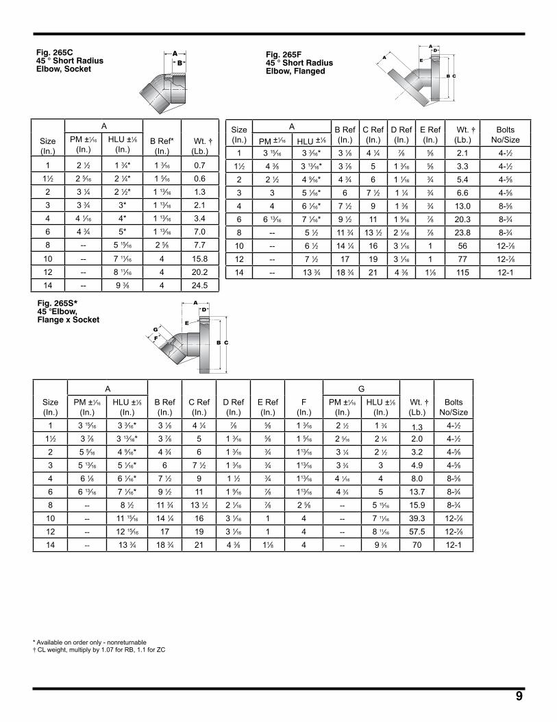
9
Fig. 265C45 ° Short RadiusElbow, Socket
AB
Size(In.)
A
B Ref*(In.)
Wt. †(Lb.)
PM ±1⁄16
(In.)HLU ±1⁄8
(In.)
1 2 1⁄2 1 3⁄4* 1 3⁄16 0.711⁄2 2 5⁄16 2 1⁄4* 1 5⁄16 0.62 3 1⁄4 2 1⁄2* 1 13⁄16 1.33 3 3⁄4 3* 1 13⁄16 2.14 4 1⁄16 4* 1 13⁄16 3.46 4 3⁄4 5* 1 13⁄16 7.08 -- 5 15⁄16 2 5⁄8 7.7
10 -- 7 11⁄16 4 15.812 -- 8 11⁄16 4 20.214 -- 9 3⁄8 4 24.5
Fig. 265F45 ° Short RadiusElbow, Flanged
Size(In.)
A B Ref(In.)
C Ref(In.)
D Ref(In.)
E Ref(In.)
Wt. †(Lb.)
BoltsNo/SizePM ±1⁄16 HLU ±1⁄8
1 3 15⁄16 3 3⁄16* 3 1⁄8 4 1⁄4 7⁄8 5⁄8 2.1 4-1⁄211⁄2 4 3⁄8 3 13⁄16* 3 7⁄8 5 1 3⁄16 5⁄8 3.3 4-1⁄22 2 1⁄2 4 9⁄16* 4 3⁄4 6 1 1⁄16 3⁄4 5.4 4-5⁄83 3 5 1⁄16* 6 7 1⁄2 1 1⁄4 3⁄4 6.6 4-5⁄84 4 6 1⁄16* 7 1⁄2 9 1 3⁄8 3⁄4 13.0 8-5⁄86 6 13⁄16 7 1⁄16* 9 1⁄2 11 1 9⁄16 7⁄8 20.3 8-3⁄48 -- 5 1⁄2 11 3⁄4 13 1⁄2 2 1⁄16 7⁄8 23.8 8-3⁄4
10 -- 6 1⁄2 14 1⁄4 16 3 1⁄16 1 56 12-7⁄812 -- 7 1⁄2 17 19 3 1⁄16 1 77 12-7⁄814 -- 13 3⁄4 18 3⁄4 21 4 3⁄8 11⁄8 115 12-1
A
A
CB
E
D
Fig. 265S*45 °Elbow, Flange x Socket
A
B C
E
D
GF
* Available on order only - nonreturnable† CL weight, multiply by 1.07 for RB, 1.1 for ZC
Size(In.)
AB Ref(In.)
C Ref(In.)
D Ref(In.)
E Ref(In.)
F(In.)
G Wt. †(Lb.)
BoltsNo/Size
PM ±1⁄16
(In.)HLU ±1⁄8
(In.)PM ±1⁄16
(In.)HLU ±1⁄8
(In.)1 3 15⁄16 3 3⁄16* 3 1⁄8 4 1⁄4 7⁄8 5⁄8 1 3⁄16 2 1⁄2 1 3⁄4 1.3 4-1⁄2
11⁄2 3 7⁄8 3 13⁄16* 3 7⁄8 5 1 3⁄16 5⁄8 1 5⁄16 2 5⁄16 2 1⁄4 2.0 4-1⁄22 5 5⁄16 4 9⁄16* 4 3⁄4 6 1 3⁄16 3⁄4 113⁄16 3 1⁄4 2 1⁄2 3.2 4-5⁄83 5 13⁄16 5 1⁄16* 6 7 1⁄2 1 3⁄16 3⁄4 113⁄16 3 3⁄4 3 4.9 4-5⁄84 6 1⁄8 6 1⁄16* 7 1⁄2 9 1 1⁄2 3⁄4 113⁄16 4 1⁄16 4 8.0 8-5⁄86 6 13⁄16 7 1⁄16* 9 1⁄2 11 1 9⁄16 7⁄8 113⁄16 4 3⁄4 5 13.7 8-3⁄48 -- 8 1⁄2 11 3⁄4 13 1⁄2 2 1⁄16 7⁄8 2 5⁄8 -- 5 15⁄16 15.9 8-3⁄4
10 -- 11 15⁄16 14 1⁄4 16 3 1⁄16 1 4 -- 7 11⁄16 39.3 12-7⁄812 -- 12 15⁄16 17 19 3 1⁄16 1 4 -- 8 11⁄16 57.5 12-7⁄814 -- 13 3⁄4 18 3⁄4 21 4 3⁄8 11⁄8 4 -- 9 3⁄8 70 12-1
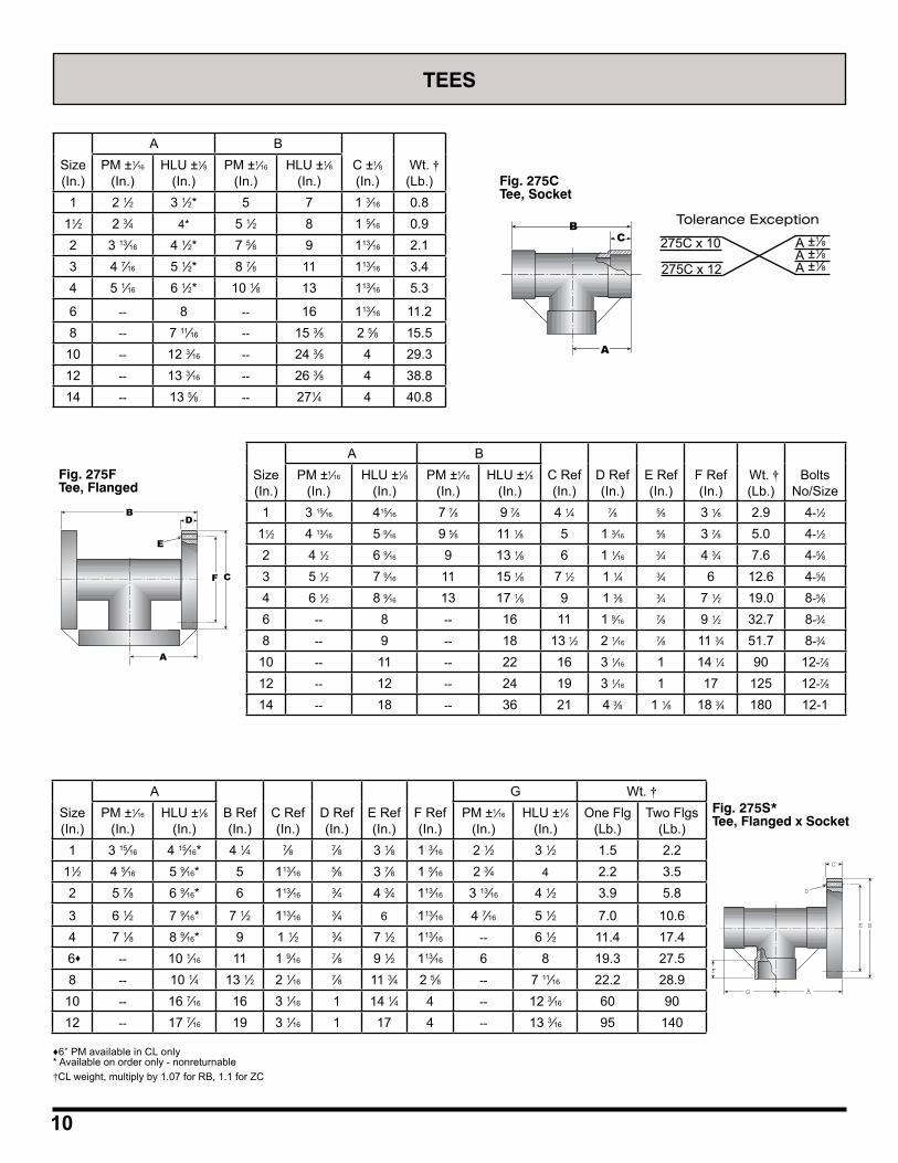
10
Fig. 275CTee, Socket
BC
A
275C x 10
275C x 12 A ±1⁄8
A ±1⁄8A ±1⁄8
Tolerance Exception
Fig. 275FTee, Flanged
Size(In.)
A BC Ref(In.)
D Ref(In.)
E Ref(In.)
F Ref(In.)
Wt. †(Lb.)
BoltsNo/Size
PM ±1⁄16
(In.)HLU ±1⁄8
(In.)PM ±1⁄16
(In.)HLU ±1⁄8
(In.)1 3 15⁄16 415⁄16 7 7⁄8 9 7⁄8 4 1⁄4 7⁄8 5⁄8 3 1⁄8 2.9 4-1⁄2
11⁄2 4 13⁄16 5 9⁄16 9 5⁄8 11 1⁄8 5 1 3⁄16 5⁄8 3 7⁄8 5.0 4-1⁄2
2 4 1⁄2 6 9⁄16 9 13 1⁄8 6 1 1⁄16 3⁄4 4 3⁄4 7.6 4-5⁄8
3 5 1⁄2 7 9⁄16 11 15 1⁄8 7 1⁄2 1 1⁄4 3⁄4 6 12.6 4-5⁄8
4 6 1⁄2 8 9⁄16 13 17 1⁄8 9 1 3⁄8 3⁄4 7 1⁄2 19.0 8-5⁄8
6 -- 8 -- 16 11 1 9⁄16 7⁄8 9 1⁄2 32.7 8-3⁄4
8 -- 9 -- 18 13 1⁄2 2 1⁄16 7⁄8 11 3⁄4 51.7 8-3⁄4
10 -- 11 -- 22 16 3 1⁄16 1 14 1⁄4 90 12-7⁄8
12 -- 12 -- 24 19 3 1⁄16 1 17 125 12-7⁄8
14 -- 18 -- 36 21 4 3⁄8 1 1⁄8 18 3⁄4 180 12-1
E
BD
F C
A
Fig. 275S*Tee, Flanged x Socket
C
AG
D
E B
F
♦6” PM available in CL only* Available on order only - nonreturnable†CL weight, multiply by 1.07 for RB, 1.1 for ZC
Size(In.)
A BC ±1⁄8(In.)
Wt. †(Lb.)
PM ±1⁄16
(In.)HLU ±1⁄8
(In.)PM ±1⁄16
(In.)HLU ±1⁄8
(In.)1 2 1⁄2 3 1⁄2* 5 7 1 3⁄16 0.8
11⁄2 2 3⁄4 4* 5 1⁄2 8 1 5⁄16 0.92 3 13⁄16 4 1⁄2* 7 5⁄8 9 113⁄16 2.13 4 7⁄16 5 1⁄2* 8 7⁄8 11 113⁄16 3.44 5 1⁄16 6 1⁄2* 10 1⁄8 13 113⁄16 5.3
6 -- 8 -- 16 113⁄16 11.28 -- 7 11⁄16 -- 15 3⁄8 2 5⁄8 15.5
10 -- 12 3⁄16 -- 24 3⁄8 4 29.312 -- 13 3⁄16 -- 26 3⁄8 4 38.814 -- 13 5⁄8 -- 271⁄4 4 40.8
Size(In.)
AB Ref(In.)
C Ref(In.)
D Ref(In.)
E Ref(In.)
F Ref(In.)
G Wt. †PM ±1⁄16
(In.)HLU ±1⁄8
(In.)PM ±1⁄16
(In.)HLU ±1⁄8
(In.)One Flg
(Lb.)Two Flgs
(Lb.)1 3 15⁄16 4 15⁄16* 4 1⁄4 7⁄8 7⁄8 3 1⁄8 1 3⁄16 2 1⁄2 3 1⁄2 1.5 2.2
11⁄2 4 5⁄16 5 9⁄16* 5 113⁄16 5⁄8 3 7⁄8 1 5⁄16 2 3⁄4 4 2.2 3.52 5 7⁄8 6 9⁄16* 6 113⁄16 3⁄4 4 3⁄4 113⁄16 3 13⁄16 4 1⁄2 3.9 5.8
3 6 1⁄2 7 9⁄16* 7 1⁄2 113⁄16 3⁄4 6 113⁄16 4 7⁄16 5 1⁄2 7.0 10.64 7 1⁄8 8 9⁄16* 9 1 1⁄2 3⁄4 7 1⁄2 113⁄16 -- 6 1⁄2 11.4 17.4
6♦ -- 10 1⁄16 11 1 9⁄16 7⁄8 9 1⁄2 113⁄16 6 8 19.3 27.58 -- 10 1⁄4 13 1⁄2 2 1⁄16 7⁄8 11 3⁄4 2 5⁄8 -- 7 11⁄16 22.2 28.9
10 -- 16 7⁄16 16 3 1⁄16 1 14 1⁄4 4 -- 12 3⁄16 60 9012 -- 17 7⁄16 19 3 1⁄16 1 17 4 -- 13 3⁄16 95 140
TEES
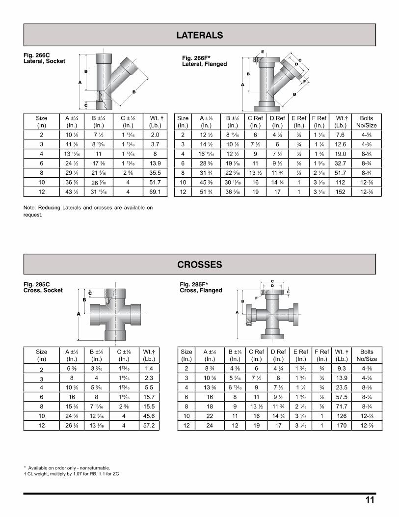
11
LATERALS
Fig. 266CLateral, Socket Fig. 266F*
Lateral, FlangedB
A
C
B
Size(In)
A ±1⁄4(In.)
B ±1⁄4(In.)
C ± 1⁄8(In.)
Wt. †(Lb.)
2 10 1⁄8 7 1⁄2 1 13⁄16 2.03 11 7⁄8 8 15⁄16 1 13⁄16 3.74 13 11⁄16 11 1 13⁄16 86 24 1⁄2 17 3⁄8 1 13⁄16 13.98 29 1⁄4 21 5⁄16 2 5⁄8 35.5
10 36 7⁄8 26 7⁄16 4 51.712 43 1⁄4 31 15⁄16 4 69.1
Size(In.)
A ±1⁄8(In.)
B ±1⁄8(In.)
C Ref(In.)
D Ref(In.)
E Ref(In.)
F Ref(In.)
Wt.†(Lb.)
BoltsNo/Size
2 12 1⁄2 8 11⁄16 6 4 3⁄4 3⁄4 1 1⁄16 7.6 4-5⁄83 14 1⁄2 10 1⁄8 7 1⁄2 6 3⁄4 1 1⁄4 12.6 4-5⁄84 16 11⁄16 12 1⁄2 9 7 1⁄2 3⁄4 1 3⁄8 19.0 8-5⁄86 28 5⁄8 19 7⁄16 11 9 1⁄2 7⁄8 1 9⁄16 32.7 8-3⁄48 31 3⁄4 22 9⁄16 13 1⁄2 11 3⁄4 7⁄8 2 1⁄16 51.7 8-3⁄4
10 45 3⁄8 30 11⁄16 16 14 1⁄4 1 3 1⁄16 112 12-7⁄812 51 3⁄4 36 3⁄16 19 17 1 3 1⁄16 152 12-7⁄8
E
B
B
A
CD
F
CROSSES
Fig. 285CCross, Socket
Size(In)
A ±1⁄4(In.)
B ±1⁄8(In.)
C ±1⁄8(In.)
Wt.†(Lb.)
2 6 3⁄8 3 3⁄16 113⁄16 1.4
3 8 4 113⁄16 2.34 10 5⁄8 5 5⁄16 113⁄16 5.56 16 8 113⁄16 15.78 15 3⁄8 7 11⁄16 2 5⁄8 15.5
10 24 3⁄8 12 3⁄16 4 45.612 26 3⁄8 13 3⁄16 4 57.2
CB
A
Fig. 285F*Cross, Flanged
A
CD
E
B
A
F
Size(In.)
A ±1⁄8(In.)
B ±1⁄8(In.)
C Ref(In.)
D Ref(In.)
E Ref(In.)
F Ref(In.)
Wt. †(Lb.)
BoltsNo/Size
2 8 3⁄4 4 3⁄8 6 4 3⁄4 1 3⁄16 3⁄4 9.3 4-5⁄83 10 3⁄8 5 3⁄16 7 1⁄2 6 1 3⁄16 3⁄4 13.9 4-5⁄84 13 5⁄8 6 13⁄16 9 7 1⁄2 1 1⁄2 3⁄4 23.5 8-5⁄86 16 8 11 9 1⁄2 1 9⁄16 7⁄8 57.5 8-3⁄48 18 9 13 1⁄2 11 3⁄4 2 1⁄16 7⁄8 71.7 8-3⁄4
10 22 11 16 14 1⁄4 3 1⁄16 1 126 12-7⁄812 24 12 19 17 3 1⁄16 1 170 12-7⁄8
Note: Reducing Laterals and crosses are available on request.
* Available on order only - nonreturnable.† CL weight, multiply by 1.07 for RB, 1.1 for ZC
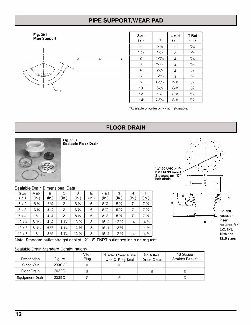
12
FLOOR DRAIN
1/4” 20 UNC x 3/8 DP 316 SS insert 3 places on “D” bolt circle
Sealable Drain Dimensional DataSize(In.)
A ±1⁄8(In.)
B(In.)
C(In.)
D(In.)
E(In.)
F ±1⁄8(In.)
G(In.)
H(In.)
I(In.)
6 x 2 6 1⁄4 2 3⁄8 2 6 3⁄8 6 8 7⁄8 5 3⁄4 7 7 3⁄46 x 3 6 1⁄4 3 1⁄2 2 6 3⁄8 6 8 7⁄8 5 3⁄4 7 7 3⁄46 x 4 6 4 1⁄2 2 6 3⁄8 6 8 7⁄8 5 3⁄4 7 7 3⁄4
12 x 4 8 11⁄16 4 1⁄2 1 9⁄16 13 3⁄8 8 15 1⁄2 12 3⁄4 14 14 1⁄212 x 6 8 11⁄16 6 5⁄8 1 9⁄16 13 3⁄8 8 15 1⁄2 12 3⁄4 14 14 1⁄212 x 8 8 8 5⁄8 1 9⁄16 13 3⁄8 8 15 1⁄2 12 3⁄4 14 14 1⁄2
Fig. 33C Reducer Insert required for 6x2, 6x3, 12x4 and 12x6 sizes.Note: Standard outlet straight socket. 2” - 6” FNPT outlet available on request.
Sealable Drain Standard Configurations
Description Figure VitonPlug
1⁄4 Solid Cover Plate with O-Ring Seal
1⁄4” Drilled Drain Grate
16 Gauge Strainer Basket
Clean Out 203CO
Floor Drain 203FD
Equipment Drain 203ED
FI
DG
C
AE
H
B
1/2 “ + 1/8 “ > 0
1/4 “
PIPE SUPPORT/WEAR PAD
Fig. 391Pipe Support
110°±10°
R
L
T
Size(In) R
L ± 1⁄8(In.)
T Ref(In.)
1 1-1⁄16 3 13⁄32
1 1⁄2 1-3⁄8 3 7⁄16
2 1-17⁄32 4 11⁄32
3 2-3⁄32 4 11⁄32
4 2-5⁄8 4 3⁄86 3-15⁄16 4 5⁄88 4-15⁄16 5-5⁄8 5⁄8
10 6-1⁄8 8-3⁄8 3⁄412 7-3⁄32 8-3⁄8 23⁄32
14* 7-25⁄32 8-3⁄8 25⁄32
Fig. 203Sealable Floor Drain
*Available on order only - nonreturnable.
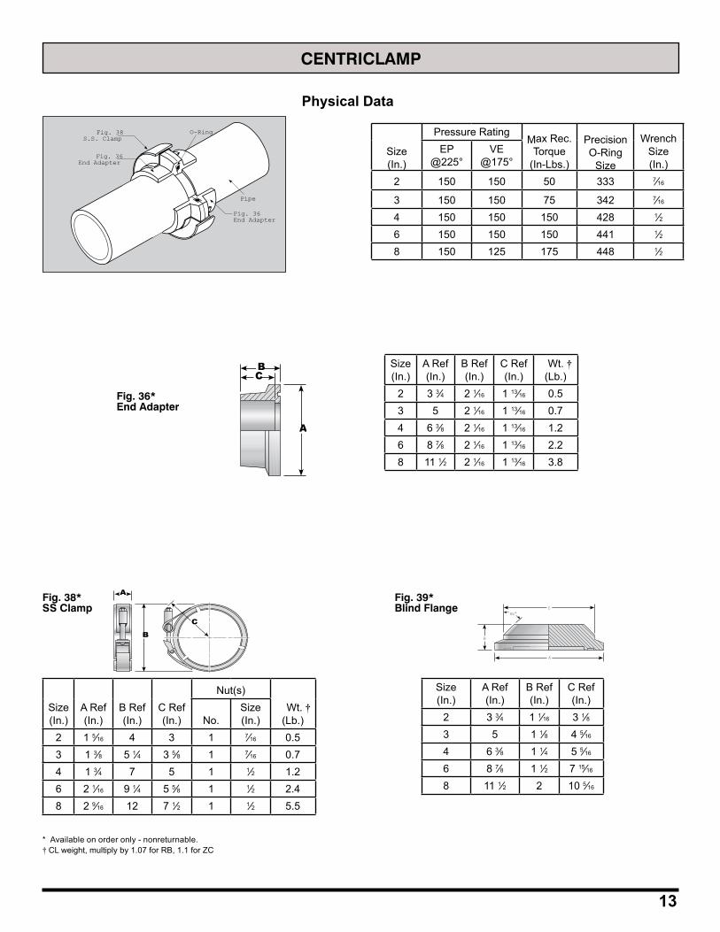
13
CENTRICLAMP
Fig. 38S.S. Clamp
Fig. 36End Adapter
Fig. 36End Adapter
O-Ring
Pipe
Size(In.)
Pressure RatingMax Rec.
Torque(In-Lbs.)
PrecisionO-Ring
Size
WrenchSize(In.)
EP@225°
VE@175°
2 150 150 50 333 7⁄16
3 150 150 75 342 7⁄16
4 150 150 150 428 1⁄26 150 150 150 441 1⁄28 150 125 175 448 1⁄2
A
CB
Fig. 36*End Adapter
Size(In.)
A Ref(In.)
B Ref(In.)
C Ref(In.)
Wt. †(Lb.)
2 3 3⁄4 2 1⁄16 1 13⁄16 0.53 5 2 1⁄16 1 13⁄16 0.74 6 3⁄8 2 1⁄16 1 13⁄16 1.26 8 7⁄8 2 1⁄16 1 13⁄16 2.28 11 1⁄2 2 1⁄16 1 13⁄16 3.8
Fig. 38*SS Clamp
B
A
C
Size(In.)
A Ref(In.)
B Ref(In.)
C Ref(In.)
Nut(s) Wt. †
(Lb.)No.Size(In.)
2 1 5⁄16 4 3 1 7⁄16 0.53 1 3⁄8 5 1⁄4 3 5⁄8 1 7⁄16 0.74 1 3⁄4 7 5 1 1⁄2 1.26 2 1⁄16 9 1⁄4 5 5⁄8 1 1⁄2 2.48 2 9⁄16 12 7 1⁄2 1 1⁄2 5.5
Physical Data
Fig. 39*Blind Flange
A
B
45°C
Size(In.)
A Ref(In.)
B Ref(In.)
C Ref(In.)
2 3 3⁄4 1 1⁄16 3 1⁄83 5 1 1⁄8 4 5⁄16
4 6 3⁄8 1 1⁄4 5 5⁄16
6 8 7⁄8 1 1⁄2 7 15⁄16
8 11 1⁄2 2 10 5⁄16
* Available on order only - nonreturnable.† CL weight, multiply by 1.07 for RB, 1.1 for ZC
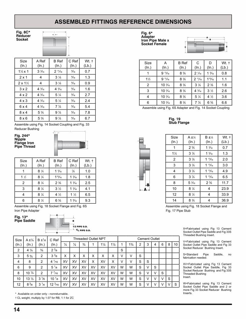
14
ASSEMBLED FITTINGS REFERENCE DIMENSIONS
Fig. 8C*ReducerSocket
A
B
C
Size(In.)
A Ref(In.)
B Ref(In.)
C Ref(In.)
Wt. †(Lb.)
11⁄2 x 1 3 3⁄16 2 11⁄16 9⁄16 0.72 x 1 4 3 1⁄8 9⁄16 1.3
2 x 11⁄2 4 3 1⁄8 9⁄16 0.93 x 2 4 3⁄16 4 3⁄16 9⁄16 1.64 x 2 4 3⁄16 5 1⁄4 9⁄16 2.74 x 3 4 3⁄16 5 1⁄4 9⁄16 2.46 x 4 4 3⁄16 7 7⁄8 9⁄16 5.48 x 4 5 5⁄8 9 7⁄8 9⁄16 7.88 x 6 5 5⁄8 9 7⁄8 9⁄16 6.7
Fig. 6*AdapterIron Pipe Male xSocket Female
AB
C D
Size(In.)
A(In.)
B Ref(In.)
C(In.)
D(In.)
Wt. †(Lb.)
1 9 13⁄16 8 5⁄8 2 1⁄16 1 5⁄16 0.811⁄2 9 11⁄16 8 3⁄8 2 11⁄16 115⁄16 1.12 10 3⁄16 8 3⁄8 3 1⁄8 2 3⁄8 1.63 10 3⁄16 8 3⁄8 4 3⁄16 3 1⁄2 2.64 10 3⁄16 8 3⁄8 5 1⁄4 4 1⁄2 3.66 10 3⁄16 8 3⁄8 7 7⁄8 6 5⁄8 6.6
Fig. 244*Nipple Flange Iron Pipe Thread
B
AC
Size(In.)
A Ref(In.)
B Ref(In.)
C Ref(In.)
Wt. †(Lb.)
1 8 1⁄4 1 5⁄16 7⁄8 1.01 1⁄2 8 1⁄4 115⁄16 1 3⁄16 1.82 8 1⁄4 2 3⁄8 1 3⁄16 2.53 8 1⁄4 3 1⁄2 1 3⁄16 4.14 8 1⁄4 4 1⁄2 1 1⁄2 6.56 8 1⁄4 6 5⁄8 1 9⁄16 9.3
Fig. 19Stub Flange
BA
Fig. 13*Pipe Saddle
C
A
B
1/2 PIPE O.D.CL PIPE O.D.
X=Fabricated using Fig 13 Cement Socket Outlet Pipe Saddle and Fig 33S Threaded Bushing Insert.
V=Fabricated using Fig 13 Cement Socket Outlet Pipe Saddle and Fig 33 Socket Reducer Bushing Insert.
S=Standard Pipe Saddle, no fabrication needed.
XV=Fabricated using Fig 13 Cement Socket Outlet Pipe Saddle, Fig 33 Socket Reducer Bushing and Fig 33S Threaded BushingInsert.
W=Fabricated using Fig 13 Cement Socket Outlet Pipe Saddle and 2 or more Fig 33 Socket Reducer Bushing Inserts.
Assemble using Fig. 14 Socket Coupling and Fig. 33Reducer Bushing
Assemble using Fig. 6S Adapter and Fig. 14 Socket Coupling
Assemble using Fig. 18 Socket Flange and Fig. 6S Iron Pipe Adapter
Assemble using Fig. 18 Socket Flange and Fig. 17 Pipe Stub
* Available on order only - nonreturnable.† CL weight, multiply by 1.07 for RB, 1.1 for ZC
Size(In.)
A ±1⁄8(In.)
B ±1⁄8(In.)
Wt. †(Lb.)
1 2 5⁄8 1 3⁄16 0.711⁄2 3 7⁄8 1 5⁄16 1.32 3 7⁄8 1 13⁄16 2.03 3 7⁄8 1 13⁄16 3.04 3 7⁄8 1 13⁄16 4.96 3 7⁄8 1 13⁄16 6.58 5 3⁄16 2 5⁄8 11.7
10 8 1⁄4 4 23.912 8 1⁄4 4 33.914 8 3⁄8 4 36.9
Size(In.)
A ±¼(In.)
B ±1⁄8
(In.)C Ref(In.)
Threaded Outlet NPT Cement Outlet
¼ ½ ¾ 1 1¼ 1½ 1 1¾ 2 3 4 6 8 10
2 4 ¼ ¾ 2 3⁄8 S
3 5 ¾ 2 3 3⁄8 X X X X X X V V S
4 8 2 4 1⁄16 XV XV XV X XV X V V S S
6 9 2 5 1⁄8 XV XV XV XV XV XV W W S V S
8 10 ½ 2 7 7⁄16 XV XV XV XV XV XV W W S V V S
10 13 ½ 3 1⁄8 10 1⁄8 XV XV XV XV XV XV W W S V V V S
12 8 3⁄8 3 1⁄8 12 3⁄16 XV XV XV XV XV XV W W S V V V V S
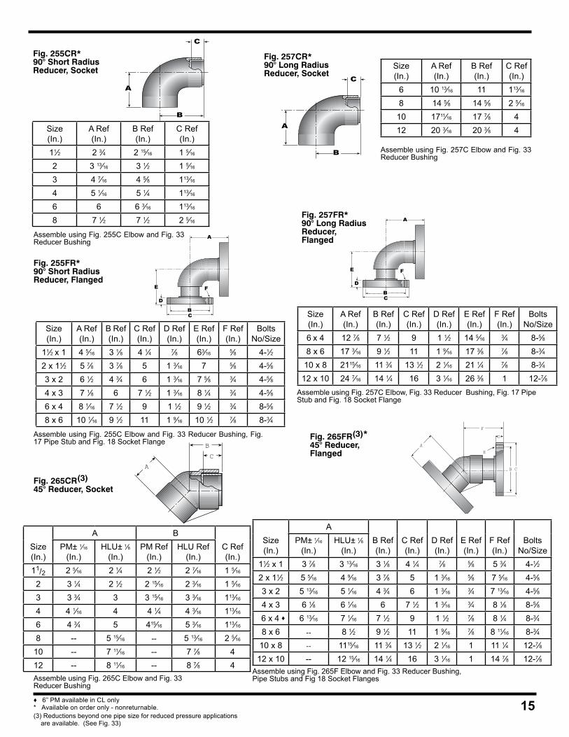
15
Assemble using Fig. 255C Elbow and Fig. 33 Reducer Bushing
Fig. 255CR*90° Short RadiusReducer, Socket
A
B
C
Size(In.)
A Ref(In.)
B Ref(In.)
C Ref(In.)
11⁄2 2 3⁄4 2 15⁄16 1 5⁄16
2 3 13⁄16 3 1⁄2 1 5⁄16
3 4 7⁄16 4 5⁄8 113⁄16
4 5 1⁄16 5 1⁄4 113⁄16
6 6 6 3⁄16 113⁄16
8 7 1⁄2 7 1⁄2 2 5⁄16
Size(In.)
A Ref(In.)
B Ref(In.)
C Ref(In.)
6 10 13⁄16 11 113⁄16
8 14 5⁄8 14 5⁄8 2 5⁄16
10 1711⁄16 17 7⁄8 412 20 3⁄16 20 3⁄8 4
Assemble using Fig. 257C Elbow and Fig. 33 Reducer Bushing
Fig. 257CR*90° Long RadiusReducer, Socket
Fig. 255FR*90° Short RadiusReducer, Flanged
Assemble using Fig. 255C Elbow and Fig. 33 Reducer Bushing, Fig. 17 Pipe Stub and Fig. 18 Socket Flange
A
E
D
CB
F
Size(In.)
A Ref(In.)
B Ref(In.)
C Ref(In.)
D Ref(In.)
E Ref(In.)
F Ref(In.)
BoltsNo/Size
11⁄2 x 1 4 5⁄16 3 1⁄8 4 1⁄4 7⁄8 63⁄16 5⁄8 4-1⁄22 x 11⁄2 5 7⁄8 3 7⁄8 5 1 3⁄16 7 5⁄8 4-5⁄83 x 2 6 1⁄2 4 3⁄4 6 1 3⁄16 7 5⁄8 3⁄4 4-5⁄84 x 3 7 1⁄8 6 7 1⁄2 1 3⁄16 8 1⁄4 3⁄4 4-5⁄86 x 4 8 1⁄16 7 1⁄2 9 1 1⁄2 9 1⁄2 3⁄4 8-5⁄88 x 6 10 1⁄16 9 1⁄2 11 1 9⁄16 10 1⁄2 7⁄8 8-3⁄4
Fig. 257FR*90° Long RadiusReducer, Flanged
Assemble using Fig. 257C Elbow, Fig. 33 Reducer Bushing, Fig. 17 Pipe Stub and Fig. 18 Socket Flange
Size(In.)
A Ref(In.)
B Ref(In.)
C Ref(In.)
D Ref(In.)
E Ref(In.)
F Ref(In.)
BoltsNo/Size
6 x 4 12 7⁄8 7 1⁄2 9 1 1⁄2 14 5⁄16 3⁄4 8-5⁄88 x 6 17 3⁄16 9 1⁄2 11 1 9⁄16 17 3⁄8 7⁄8 8-3⁄4
10 x 8 2115⁄16 11 3⁄4 13 1⁄2 2 1⁄16 21 1⁄4 7⁄8 8-3⁄412 x 10 24 7⁄16 14 1⁄4 16 3 1⁄16 26 3⁄8 1 12-7⁄8
Fig. 265CR(3)45° Reducer, Socket
Assemble using Fig. 265C Elbow and Fig. 33Reducer Bushing
CB
A
Size(In.)
A BC Ref(In.)
PM± 1⁄16
(In.)HLU± 1⁄8
(In.)PM Ref
(In.)HLU Ref
(In.)11/2 2 5⁄16 2 1⁄4 2 1⁄2 2 7⁄16 1 5⁄16
2 3 1⁄4 2 1⁄2 2 15⁄16 2 3⁄16 1 5⁄16
3 3 3⁄4 3 3 15⁄16 3 3⁄16 113⁄16
4 4 1⁄16 4 4 1⁄4 4 3⁄16 113⁄16
6 4 3⁄4 5 415⁄16 5 3⁄16 113⁄16
8 -- 5 15⁄16 -- 5 13⁄16 2 5⁄16
10 -- 7 11⁄16 -- 7 7⁄8 412 -- 8 11⁄16 -- 8 7⁄8 4
Size(In.)
AB Ref(In.)
C Ref(In.)
D Ref(In.)
E Ref(In.)
F Ref(In.)
BoltsNo/Size
PM± 1⁄16
(In.)HLU± 1⁄8
(In.)11⁄2 x 1 3 7⁄8 3 13⁄16 3 1⁄8 4 1⁄4 7⁄8 5⁄8 5 3⁄4 4-1⁄22 x 11⁄2 5 5⁄16 4 9⁄16 3 7⁄8 5 1 3⁄16 5⁄8 7 5⁄16 4-5⁄83 x 2 5 13⁄16 5 1⁄16 4 3⁄4 6 1 3⁄16 3⁄4 7 13⁄16 4-5⁄84 x 3 6 1⁄8 6 1⁄16 6 7 1⁄2 1 3⁄16 3⁄4 8 1⁄8 8-5⁄8
6 x 4 ♦ 6 13⁄16 7 1⁄16 7 1⁄2 9 1 1⁄2 7⁄8 8 1⁄4 8-3⁄48 x 6 -- 8 1⁄2 9 1⁄2 11 1 9⁄16 7⁄8 8 11⁄16 8-3⁄4
10 x 8 -- 1115⁄16 11 3⁄4 13 1⁄2 2 1⁄16 1 11 1⁄4 12-7⁄812 x 10 -- 12 15⁄16 14 1⁄4 16 3 1⁄16 1 14 7⁄8 12-7⁄8
Fig. 265FR(3)*45° Reducer,Flanged
Assemble using Fig. 265F Elbow and Fig. 33 Reducer Bushing, Pipe Stubs and Fig 18 Socket Flanges
E
A
F
D
CB
A
B
C
A
E
D
CB
F
♦ 6” PM available in CL only* Available on order only - nonreturnable.(3) Reductions beyond one pipe size for reduced pressure applications are available. (See Fig. 33)
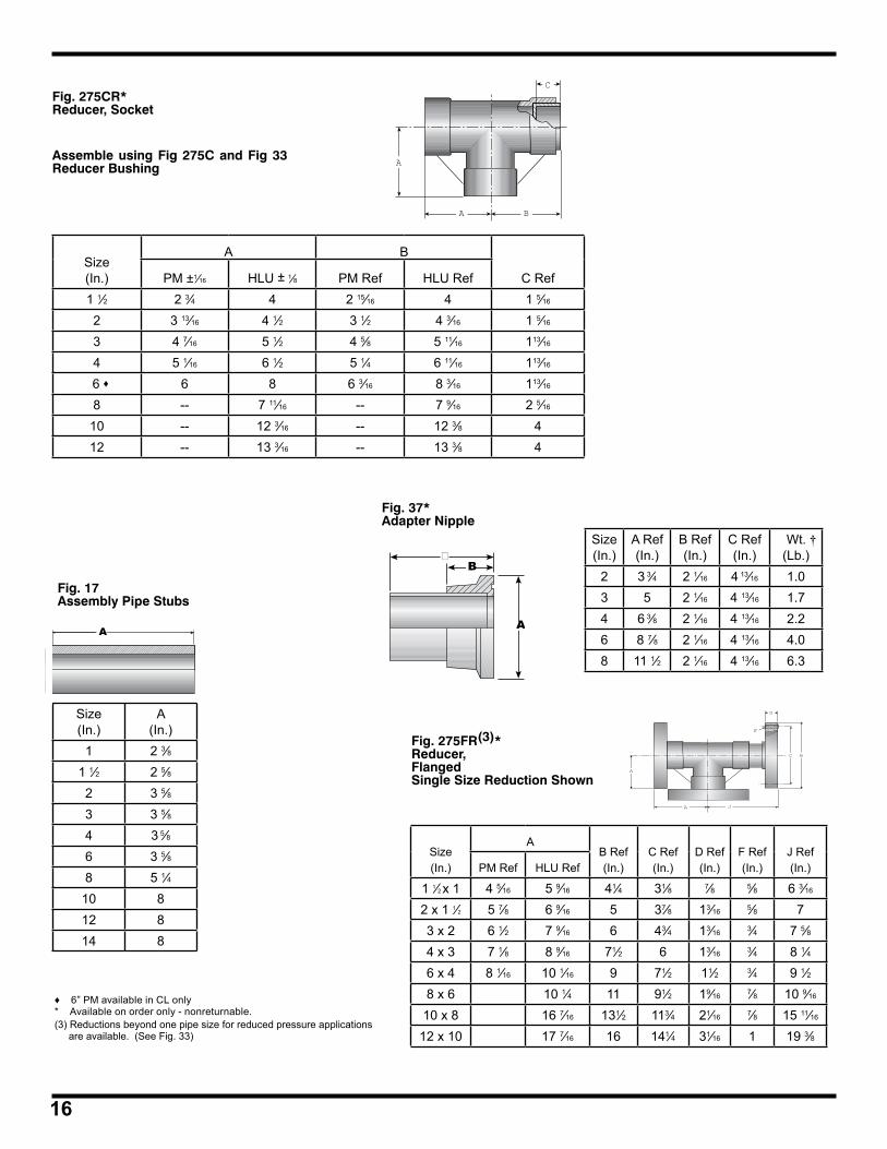
16
Fig. 275CR*Reducer, Socket
Assemble using Fig 275C and Fig 33 Reducer Bushing
C
B
A
A
Size(In.)
A B
C RefPM ±1⁄16 HLU ± 1⁄8 PM Ref HLU Ref1 1⁄2 2 3⁄4 4 2 15⁄16 4 1 5⁄16
2 3 13⁄16 4 1⁄2 3 1⁄2 4 3⁄16 1 5⁄16
3 4 7⁄16 5 1⁄2 4 5⁄8 5 11⁄16 113⁄16
4 5 1⁄16 6 1⁄2 5 1⁄4 6 11⁄16 113⁄16
6 ♦ 6 8 6 3⁄16 8 3⁄16 113⁄16
8 -- 7 11⁄16 -- 7 9⁄16 2 5⁄16
10 -- 12 3⁄16 -- 12 3⁄8 412 -- 13 3⁄16 -- 13 3⁄8 4
Size(In.)
AB Ref(In.)
C Ref(In.)
D Ref(In.)
F Ref(In.)
J Ref(In.)PM Ref HLU Ref
1 1⁄2 x 1 4 5⁄16 5 9⁄16 41⁄4 31⁄8 7⁄8 5⁄8 6 3⁄16
2 x 1 1⁄2 5 7⁄8 6 9⁄16 5 37⁄8 13⁄16 5⁄8 73 x 2 6 1⁄2 7 9⁄16 6 43⁄4 13⁄16 3⁄4 7 5⁄84 x 3 7 1⁄8 8 9⁄16 71⁄2 6 13⁄16 3⁄4 8 1⁄46 x 4 8 1⁄16 10 1⁄16 9 71⁄2 11⁄2 3⁄4 9 1⁄28 x 6 10 1⁄4 11 91⁄2 19⁄16 7⁄8 10 9⁄16
10 x 8 16 7⁄16 131⁄2 113⁄4 21⁄16 7⁄8 15 11⁄16
12 x 10 17 7⁄16 16 141⁄4 31⁄16 1 19 3⁄8
Fig. 275FR(3)*Reducer,FlangedSingle Size Reduction Shown
D
A
B
F
C
J
A
♦ 6” PM available in CL only* Available on order only - nonreturnable.(3) Reductions beyond one pipe size for reduced pressure applications are available. (See Fig. 33)
Size (In.)
A(In.)
1 2 3⁄81 1⁄2 2 5⁄82 3 5⁄83 3 5⁄84 3 5⁄86 3 5⁄88 5 1⁄4
10 812 814 8
Fig. 17Assembly Pipe Stubs
A
B
A
B�
Fig. 37*Adapter Nipple
Size(In.)
A Ref(In.)
B Ref(In.)
C Ref(In.)
Wt. †(Lb.)
2 3 3⁄4 2 1⁄16 4 13⁄16 1.03 5 2 1⁄16 4 13⁄16 1.74 6 3⁄8 2 1⁄16 4 13⁄16 2.26 8 7⁄8 2 1⁄16 4 13⁄16 4.08 11 1⁄2 2 1⁄16 4 13⁄16 6.3
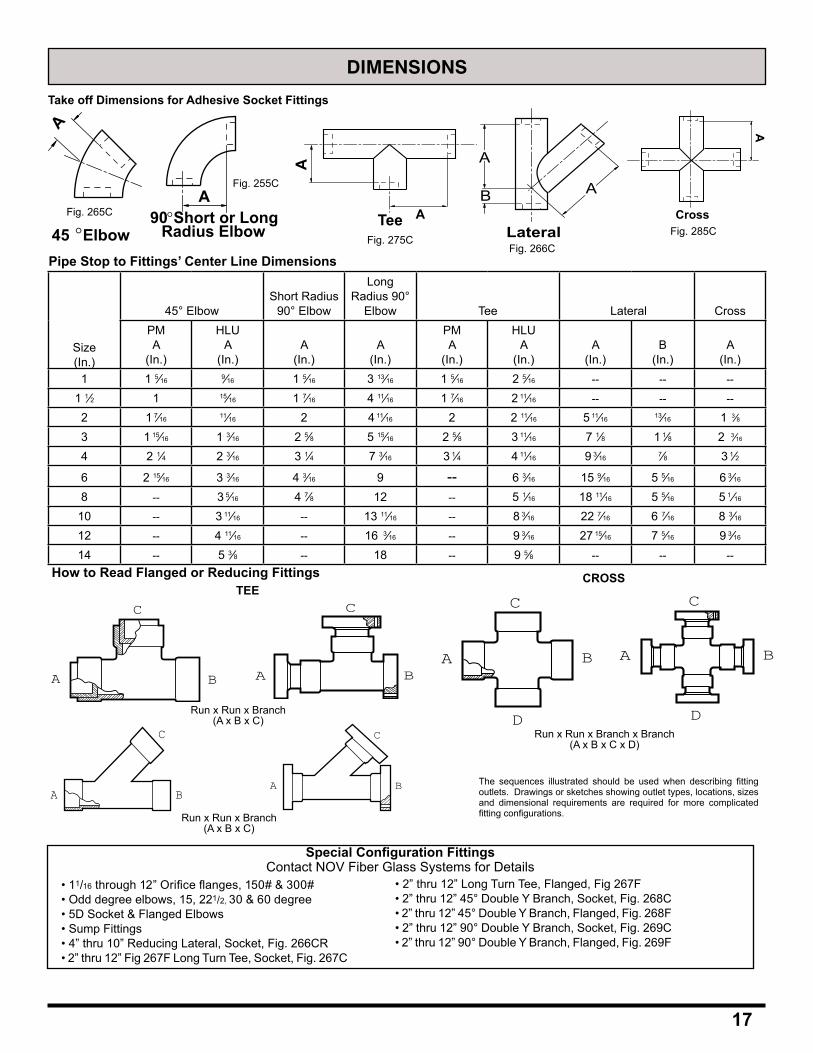
DIMENSIONS
Take off Dimensions for Adhesive Socket Fittings
Pipe Stop to Fittings’ Center Line Dimensions
How to Read Flanged or Reducing Fittings
A B
C
B
C
AA B
D
C
A B
D
CTEE
CROSS
Special Configuration FittingsContact NOV Fiber Glass Systems for Details
• 11/16 through 12” Orifice flanges, 150# & 300#• Odd degree elbows, 15, 221/2, 30 & 60 degree• 5D Socket & Flanged Elbows• Sump Fittings• 4” thru 10” Reducing Lateral, Socket, Fig. 266CR• 2” thru 12” Fig 267F Long Turn Tee, Socket, Fig. 267C
• 2” thru 12” Long Turn Tee, Flanged, Fig 267F• 2” thru 12” 45° Double Y Branch, Socket, Fig. 268C• 2” thru 12” 45° Double Y Branch, Flanged, Fig. 268F• 2” thru 12” 90° Double Y Branch, Socket, Fig. 269C• 2” thru 12” 90° Double Y Branch, Flanged, Fig. 269F
The sequences illustrated should be used when describing fitting outlets. Drawings or sketches showing outlet types, locations, sizes and dimensional requirements are required for more complicated fitting configurations.
Run x Run x Branch(A x B x C)
Run x Run x Branch x Branch(A x B x C x D)
B
C
AB
C
A
Run x Run x Branch(A x B x C)
17
Size(In.)
45° ElbowShort Radius
90° Elbow
Long Radius 90°
Elbow Tee Lateral CrossPMA
(In.)
HLUA
(In.)A
(In.)A
(In.)
PMA
(In.)
HLUA
(In.)A
(In.)B
(In.)A
(In.)1 1 5⁄16 9⁄16 1 5⁄16 3 13⁄16 1 5⁄16 2 5⁄16 -- -- --
1 1⁄2 1 15⁄16 1 7⁄16 4 11⁄16 1 7⁄16 2 11⁄16 -- -- --
2 1 7⁄16 11⁄16 2 4 11⁄16 2 2 11⁄16 5 11⁄16 13⁄16 1 3⁄8
3 1 15⁄16 1 3⁄16 2 5⁄8 5 15⁄16 2 5⁄8 3 11⁄16 7 1⁄8 1 1⁄8 2 3⁄16
4 2 1⁄4 2 3⁄16 3 1⁄4 7 3⁄16 3 1⁄4 4 11⁄16 9 3⁄16 7⁄8 3 1⁄2
6 2 15⁄16 3 3⁄16 4 3⁄16 9 -- 6 3⁄16 15 9⁄16 5 5⁄16 6 3⁄16
8 -- 3 5⁄16 4 7⁄8 12 -- 5 1⁄16 18 11⁄16 5 5⁄16 5 1 ⁄16
10 -- 3 11⁄16 -- 13 11⁄16 -- 8 3⁄16 22 7⁄16 6 7⁄16 8 3⁄16
12 -- 4 11⁄16 -- 16 3⁄16 -- 9 3⁄16 27 15⁄16 7 5⁄16 9 3⁄16
14 -- 5 3⁄8 -- 18 -- 9 5⁄8 -- -- --
45 ° Elbow
A
90° Short or LongRadius Elbow
AA
A
TeeLateral
A
A
B
A
CrossFig. 265C
Fig. 255C
Fig. 275CFig. 266C
Fig. 285C
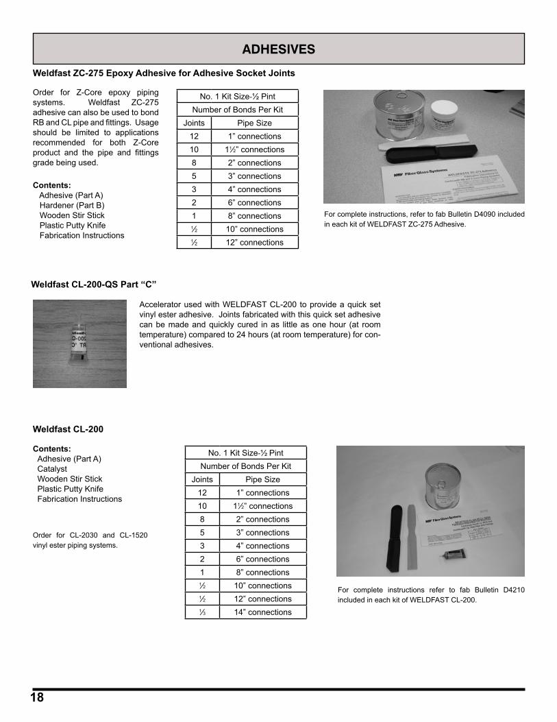
18
Weldfast ZC-275 Epoxy Adhesive for Adhesive Socket Joints
ADHESIVES
Order for Z-Core epoxy piping systems. Weldfast ZC-275 adhesive can also be used to bond RB and CL pipe and fittings. Usage should be limited to applications recommended for both Z-Core product and the pipe and fittings grade being used.
No. 1 Kit Size-½ PintNumber of Bonds Per Kit
Joints Pipe Size12 1” connections10 11⁄2” connections8 2” connections5 3” connections3 4” connections2 6” connections1 8” connections1⁄2 10” connections1⁄2 12” connections
For complete instructions, refer to fab Bulletin D4090 included in each kit of WELDFAST ZC-275 Adhesive.
Contents: Adhesive (Part A) Hardener (Part B) Wooden Stir Stick Plastic Putty Knife Fabrication Instructions
Weldfast CL-200-QS Part “C”
Accelerator used with WELDFAST CL-200 to provide a quick set vinyl ester adhesive. Joints fabricated with this quick set adhesive can be made and quickly cured in as little as one hour (at room temperature) compared to 24 hours (at room temperature) for con-ventional adhesives.
Weldfast CL-200
Order for CL-2030 and CL-1520 vinyl ester piping systems.
No. 1 Kit Size-½ PintNumber of Bonds Per Kit
Joints Pipe Size12 1” connections10 11⁄2” connections8 2” connections5 3” connections3 4” connections2 6” connections1 8” connections1⁄2 10” connections1⁄2 12” connections1⁄3 14” connections
Contents: Adhesive (Part A) Catalyst Wooden Stir Stick Plastic Putty Knife Fabrication Instructions
For complete instructions refer to fab Bulletin D4210 included in each kit of WELDFAST CL-200.
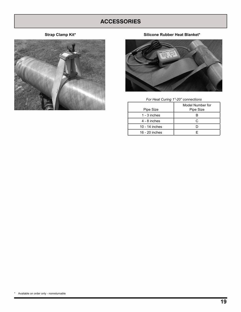
19
ACCESSORIES
Strap Clamp Kit* Silicone Rubber Heat Blanket*
For Heat Curing 1”-20” connections
Pipe SizeModel Number for
Pipe Size1 - 3 inches B4 - 8 inches C
10 - 14 inches D16 - 20 inches E
* Available on order only - nonreturnable

©2015 National Oilwell Varco. All rights reserved.CI1650 July 2015
www.fgspipe.com • [email protected]
National Oilwell Varco has produced this brochure for general information only, and it is not intended for design purposes. Although every effort has been made to maintain the accuracy and reliability of its contents, National Oilwell Varco in no way assumes responsibility for liability for any loss, damage or injury resulting from the use of information and data herein nor is any warranty expressed or implied. Always cross-reference the bulletin date with the most current version listed at the web site noted in this literature.
North America South America Europe Asia Pacific Middle East17115 San Pedro Ave. Suite 200 Estrada de Acesso á Zona P.O. Box 6, 4190 CA No. 7A, Tuas Avenue 3 P.O. Box 17324San Antonio, Texas 78232 USA Industrial Portuária de Suape, s/no. Geldermalsen, The Netherlands Jurong, Singapore 639407 Dubai, UAEPhone: 210 477 7500 Recife, PE, Brazil 55.590-000 Phone: 31 346 587 587 Phone: 65 6861 6118 Phone: 971 4881 3566 Phone: 55 31 3501 0023
Bondstrand™ 2000, 4000, 5000and 7000 Fittings Dimensions
www.fgspipe.com • [email protected]
The Quick-Lock bell end has a 1/2° taper and is the standard end configuration. All other end configurations, including size reductions, are made to order. Flanges are drilled in accordance with ANSI B16.5, Class 150. Other drilling specifica-tions are available upon request. For pressure and temperature ratings; refer to product data sheet for specific series.
Tolerance for centerline-to-face dimensions on fittings with flanged ends is ±1/8 inch; for centerline-to-face dimensions with bell-end fittings ±1/16 inch: and for angular measures is ±1°.
Shipping weights are approximate.
Introduction
Consult the following publications for installation details regarding Bondstrand Series 2000, 4000, 5000 and 7000 piping systems.
Quick-Lock Adhesive-bonded Bell and Spigot Joints, Contains instruc-tions for preparing the Quick-Lock adhesive joint, using end preparation tools, applying and curing adhesives and mounting Bondstrand flanges on fiberglass pipe. Usage instructions for the various Bondstrand adhesives are included in the adhesive kits.
Assembly Instructions for Bondstrand fiberglass flanges, Contains information pertinent to selection of gaskets, nuts, washers, and bolts when joining Bondstrand fiberglass flanges to fiberglass flanges and to flanges of other materials. Includes recommended bolt torques and bolt tightening sequence diagrams.
Maintenance Coupling Assembly for butt-end joints, Assembly instructions for the Bondstrand maintenance coupling.
Assembly Instructions
Material Applicable Fittings
Filament winding · Epoxy resin · Elbows, tees, couplings · Vinyl ester resin · Flanges, laterals, nipples · Glass fibers · Saddles, crosses, reducers · Maintenance couplings · Special angle fittings
Compression molding · Epoxy resin · Flanges, bushings, plugs · Vinyl ester resin · Caps, blind flanges · Discontinuous · Elbows, 45°, 90°; tees glass fibers · Eccentric reducers ·
Machining · 316 stainless steel · Orifice flanges · Saddles for reductions
Manufacturing Methods
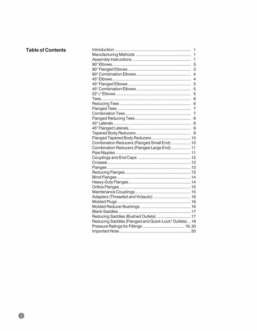
2
Introduction ...................................................................... 01Manufacturing Methods .................................................. 01Assembly Instructions ..................................................... 0190° Elbows ........................................................................ 0390° Flanged Elbows ......................................................... 0390° Combination Elbows ..................................................0445° Elbows ........................................................................ 0445° Flanged Elbows ......................................................... 0545° Combination Elbows ..................................................05221/2° Elbows .................................................................... 05Tees .................................................................................. 06Reducing Tees ................................................................. 06Flanged Tees ................................................................... 07Combination Tees ............................................................ 07Flanged Reducing Tees ................................................... 0845° Laterals ....................................................................... 0845° Flanged Laterals......................................................... 09Tapered Body Reducers .................................................. 09Flanged Tapered Body Reducers ....................................10Combination Reducers (Flanged Small End) ..................10Combination Reducers (Flanged Large End) ..................11Pipe Nipples ..................................................................... 11Couplings and End Caps ................................................12Crosses ............................................................................ 12Flanges ............................................................................ 13Reducing Flanges ............................................................ 13Blind Flanges ................................................................... 14Heavy-Duty Flanges ......................................................... 14Orifice Flanges ................................................................. 15Maintenance Couplings ................................................... 15Adapters (Threaded and Victaulic) ..................................16Molded Plugs ................................................................... 16Molded Reducer Bushings ..............................................16Blank Saddles .................................................................. 17Reducing Saddles (Bushed Outlets) ...............................17Reducing Saddles (Flanged and Quick-Lock® Outlets) ...18Pressure Ratings for Fittings ...................................... 19, 20Important Note ................................................................. 20
Table of Contents
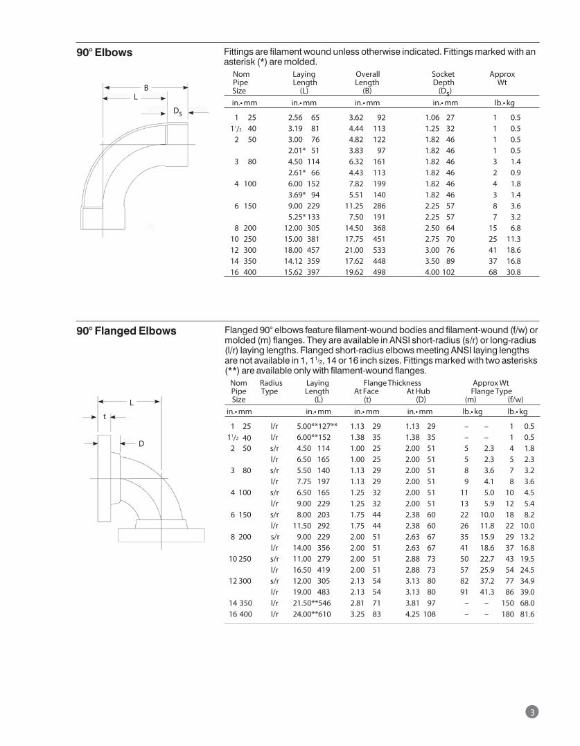
Fittings are filament wound unless otherwise indicated. Fittings marked with an asterisk (*) are molded. Nom Laying Overall Socket Approx Pipe Length Length Depth Wt Size (L) (B) (Ds) in.•mm in.•mm in.•mm in.•mm lb.•kg
01 25 2.56 65 3.62 92 1.06 27 1 0.5 11/2 40 3.19 81 4.44 113 1.25 32 1 0.5 02 50 3.00 76 4.82 122 1.82 46 1 0.5 2.01* 51 3.83 97 1.82 46 1 0.5 03 80 4.50 114 6.32 161 1.82 46 3 1.4 2.61* 66 4.43 113 1.82 46 2 0.9 04 100 6.00 152 7.82 199 1.82 46 4 1.8 3.69* 94 5.51 140 1.82 46 3 1.4 06 150 9.00 229 11.25 286 2.25 57 8 3.6 5.25* 133 7.50 191 2.25 57 7 3.2 08 200 12.00 305 14.50 368 2.50 64 15 6.8 10 250 15.00 381 17.75 451 2.75 70 25 11.3 12 300 18.00 457 21.00 533 3.00 76 41 18.6 14 350 14.12 359 17.62 448 3.50 89 37 16.8 16 400 15.62 397 19.62 498 4.00 102 68 30.8
90° Elbows
Flanged 90° elbows feature filament-wound bodies and filament-wound (f/w) or molded (m) flanges. They are available in ANSI short-radius (s/r) or long-radius (l/r) laying lengths. Flanged short-radius elbows meeting ANSI laying lengths are not available in 1, 11/2, 14 or 16 inch sizes. Fittings marked with two asterisks (**) are available only with filament-wound flanges. Nom Radius Laying Flange Thickness Approx Wt Pipe Type Length At Face At Hub Flange Type Size (L) (t) (D) (m) (f/w)in.•mm in.•mm in.•mm in.•mm lb.•kg lb.•kg
1 25 l/r 5.00** 127** 1.13 29 1.13 29 – – 1 0.5 11/2 40 l/r 6.00** 152 1.38 35 1.38 35 – – 1 0.5 2 50 s/r 4.50 114 1.00 25 2.00 51 5 2.3 4 1.8 l/r 6.50 165 1.00 25 2.00 51 5 2.3 5 2.3 3 80 s/r 5.50 140 1.13 29 2.00 51 8 3.6 7 3.2 l/r 7.75 197 1.13 29 2.00 51 9 4.1 8 3.6 4 100 s/r 6.50 165 1.25 32 2.00 51 11 5.0 10 4.5 l/r 9.00 229 1.25 32 2.00 51 13 5.9 12 5.4 6 150 s/r 8.00 203 1.75 44 2.38 60 22 10.0 18 8.2 l/r 11.50 292 1.75 44 2.38 60 26 11.8 22 10.0 8 200 s/r 9.00 229 2.00 51 2.63 67 35 15.9 29 13.2 l/r 14.00 356 2.00 51 2.63 67 41 18.6 37 16.8 10 250 s/r 11.00 279 2.00 51 2.88 73 50 22.7 43 19.5 l/r 16.50 419 2.00 51 2.88 73 57 25.9 54 24.5 12 300 s/r 12.00 305 2.13 54 3.13 80 82 37.2 77 34.9 l/r 19.00 483 2.13 54 3.13 80 91 41.3 86 39.0 14 350 l/r 21.50** 546 2.81 71 3.81 97 – – 150 68.0 16 400 l/r 24.00** 610 3.25 83 4.25 108 – – 180 81.6
90° Flanged Elbows
3
Ds
L
L
t
D
B
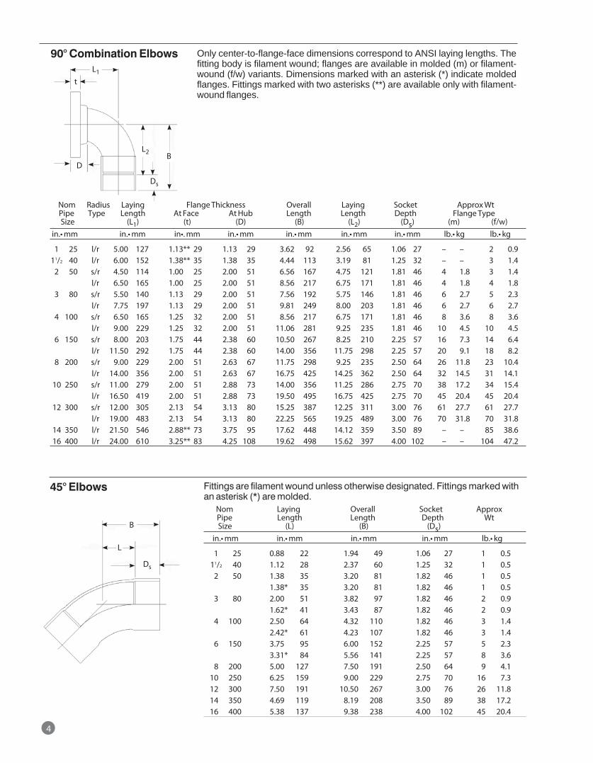
Nom Radius Laying Flange Thickness Overall Laying Socket Approx Wt Pipe Type Length At Face At Hub Length Length Depth Flange Type Size (L1) (t) (D) (B) (L2) (Ds) (m) (f/w)in.•mm in.•mm in•.mm in.•mm in.•mm in.•mm in.•mm lb.•kg lb.•kg
1 25 l/r 5.00 127 1.13** 29 1.13 29 3.62 92 2.56 65 1.06 27 – – 2 0.9 11/2 40 l/r 6.00 152 1.38** 35 1.38 35 4.44 113 3.19 81 1.25 32 – – 3 1.4 2 50 s/r 4.50 114 1.00 25 2.00 51 6.56 167 4.75 121 1.81 46 4 1.8 3 1.4 l/r 6.50 165 1.00 25 2.00 51 8.56 217 6.75 171 1.81 46 4 1.8 4 1.8 3 80 s/r 5.50 140 1.13 29 2.00 51 7.56 192 5.75 146 1.81 46 6 2.7 5 2.3 l/r 7.75 197 1.13 29 2.00 51 9.81 249 8.00 203 1.81 46 6 2.7 6 2.7 4 100 s/r 6.50 165 1.25 32 2.00 51 8.56 217 6.75 171 1.81 46 8 3.6 8 3.6 l/r 9.00 229 1.25 32 2.00 51 11.06 281 9.25 235 1.81 46 10 4.5 10 4.5 6 150 s/r 8.00 203 1.75 44 2.38 60 10.50 267 8.25 210 2.25 57 16 7.3 14 6.4 l/r 11.50 292 1.75 44 2.38 60 14.00 356 11.75 298 2.25 57 20 9.1 18 8.2 8 200 s/r 9.00 229 2.00 51 2.63 67 11.75 298 9.25 235 2.50 64 26 11.8 23 10.4 l/r 14.00 356 2.00 51 2.63 67 16.75 425 14.25 362 2.50 64 32 14.5 31 14.1 10 250 s/r 11.00 279 2.00 51 2.88 73 14.00 356 11.25 286 2.75 70 38 17.2 34 15.4 l/r 16.50 419 2.00 51 2.88 73 19.50 495 16.75 425 2.75 70 45 20.4 45 20.4 12 300 s/r 12.00 305 2.13 54 3.13 80 15.25 387 12.25 311 3.00 76 61 27.7 61 27.7 l/r 19.00 483 2.13 54 3.13 80 22.25 565 19.25 489 3.00 76 70 31.8 70 31.8 14 350 l/r 21.50 546 2.88** 73 3.75 95 17.62 448 14.12 359 3.50 89 – – 85 38.6 16 400 l/r 24.00 610 3.25** 83 4.25 108 19.62 498 15.62 397 4.00 102 – – 104 47.2
90° Combination Elbows
Fittings are filament wound unless otherwise designated. Fittings marked with an asterisk (*) are molded. Nom Laying Overall Socket Approx Pipe Length Length Depth Wt Size (L) (B) (Ds) in.•mm in.•mm in.•mm in.•mm lb.•kg
01 25 0.88 22 1.94 49 1.06 27 1 0.5 011/2 40 1.12 28 2.37 60 1.25 32 1 0.5 02 50 1.38 35 3.20 81 1.82 46 1 0.5 1.38* 35 3.20 81 1.82 46 1 0.5 03 80 2.00 51 3.82 97 1.82 46 2 0.9 1.62* 41 3.43 87 1.82 46 2 0.9 04 100 2.50 64 4.32 110 1.82 46 3 1.4 2.42* 61 4.23 107 1.82 46 3 1.4 06 150 3.75 95 6.00 152 2.25 57 5 2.3 3.31* 84 5.56 141 2.25 57 8 3.6 08 200 5.00 127 7.50 191 2.50 64 9 4.1 10 250 6.25 159 9.00 229 2.75 70 16 7.3 12 300 7.50 191 10.50 267 3.00 76 26 11.8 14 350 4.69 119 8.19 208 3.50 89 38 17.2 16 400 5.38 137 9.38 238 4.00 102 45 20.4
45° Elbows
4
Only center-to-flange-face dimensions correspond to ANSI laying lengths. The fitting body is filament wound; flanges are available in molded (m) or filament-wound (f/w) variants. Dimensions marked with an asterisk (*) indicate molded flanges. Fittings marked with two asterisks (**) are available only with filament-wound flanges.
L1
t
L2
Ds
Ds
BD
L
B
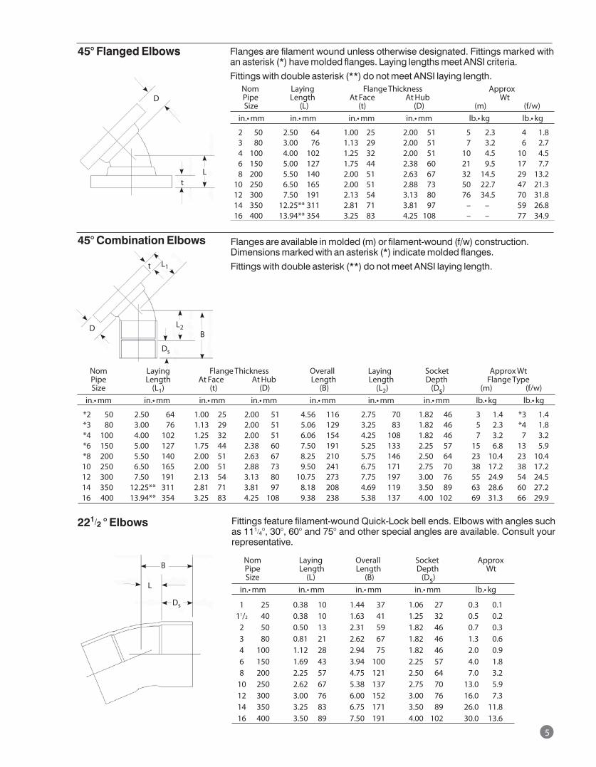
Flanges are filament wound unless otherwise designated. Fittings marked with an asterisk (*) have molded flanges. Laying lengths meet ANSI criteria.
Fittings with double asterisk (**) do not meet ANSI laying length. Nom Laying Flange Thickness Approx Pipe Length At Face At Hub Wt Size (L) (t) (D) (m) (f/w) in.•mm in.•mm in.•mm in.•mm lb.•kg lb.•kg
2 50 2.50 64 1.00 25 2.00 51 5 2.3 4 1.8 3 80 3.00 76 1.13 29 2.00 51 7 3.2 6 2.7 4 100 4.00 102 1.25 32 2.00 51 10 4.5 10 4.5 6 150 5.00 127 1.75 44 2.38 60 21 9.5 17 7.7 8 200 5.50 140 2.00 51 2.63 67 32 14.5 29 13.2 10 250 6.50 165 2.00 51 2.88 73 50 22.7 47 21.3 12 300 7.50 191 2.13 54 3.13 80 76 34.5 70 31.8 14 350 12.25** 311 2.81 71 3.81 97 – – 59 26.8 16 400 13.94** 354 3.25 83 4.25 108 – – 77 34.9
45° Flanged Elbows
Flanges are available in molded (m) or filament-wound (f/w) construction. Dimensions marked with an asterisk (*) indicate molded flanges.
Fittings with double asterisk (**) do not meet ANSI laying length.
Nom Laying Flange Thickness Overall Laying Socket Approx Wt Pipe Length At Face At Hub Length Length Depth Flange Type Size (L1) (t) (D) (B) (L2) (Ds) (m) (f/w) in.•mm in.•mm in.•mm in.•mm in.•mm in.•mm in.•mm lb.•kg lb.•kg
*2 50 2.50 64 1.00 25 2.00 51 4.56 116 2.75 70 1.82 46 3 1.4 *3 1.4 *3 80 3.00 76 1.13 29 2.00 51 5.06 129 3.25 83 1.82 46 5 2.3 *4 1.8 *4 100 4.00 102 1.25 32 2.00 51 6.06 154 4.25 108 1.82 46 7 3.2 7 3.2 *6 150 5.00 127 1.75 44 2.38 60 7.50 191 5.25 133 2.25 57 15 6.8 13 5.9 *8 200 5.50 140 2.00 51 2.63 67 8.25 210 5.75 146 2.50 64 23 10.4 23 10.4 10 250 6.50 165 2.00 51 2.88 73 9.50 241 6.75 171 2.75 70 38 17.2 38 17.2 12 300 7.50 191 2.13 54 3.13 80 10.75 273 7.75 197 3.00 76 55 24.9 54 24.5 14 350 12.25** 311 2.81 71 3.81 97 8.18 208 4.69 119 3.50 89 63 28.6 60 27.2 16 400 13.94** 354 3.25 83 4.25 108 9.38 238 5.38 137 4.00 102 69 31.3 66 29.9
45° Combination Elbows
Fittings feature filament-wound Quick-Lock bell ends. Elbows with angles such as 111/4°, 30°, 60° and 75° and other special angles are available. Consult your representative.
221/2 ° Elbows
Nom Laying Overall Socket Approx Pipe Length Length Depth Wt Size (L) (B) (Ds) in.•mm in.•mm in.•mm in.•mm lb.•kg
1 25 0.38 10 1.44 37 1.06 27 0.3 0.1 11/2 40 0.38 10 1.63 41 1.25 32 0.5 0.2 2 50 0.50 13 2.31 59 1.82 46 0.7 0.3 3 80 0.81 21 2.62 67 1.82 46 1.3 0.6 4 100 1.12 28 2.94 75 1.82 46 2.0 0.9 6 150 1.69 43 3.94 100 2.25 57 4.0 1.8 8 200 2.25 57 4.75 121 2.50 64 7.0 3.2 10 250 2.62 67 5.38 137 2.75 70 13.0 5.9 12 300 3.00 76 6.00 152 3.00 76 16.0 7.3 14 350 3.25 83 6.75 171 3.50 89 26.0 11.8 16 400 3.50 89 7.50 191 4.00 102 30.0 13.6
5
D
Lt
t
L2B
D
Ds
Ds
L
B
L1
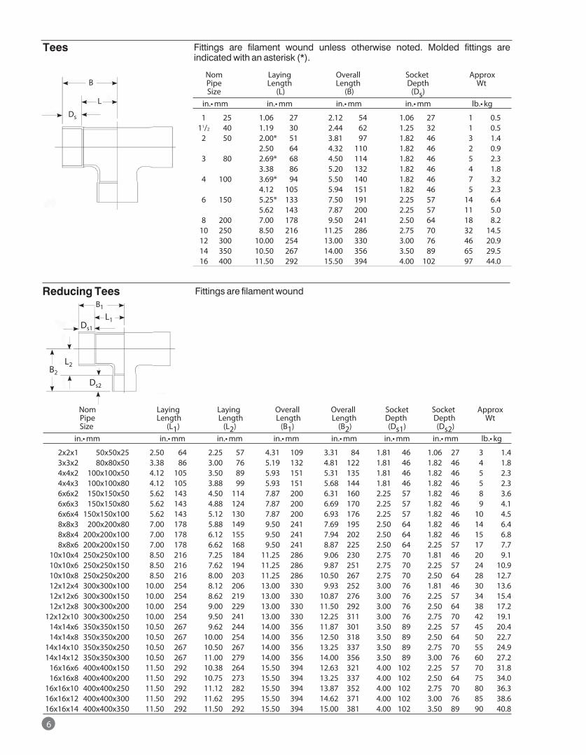
Tees
Nom Laying Laying Overall Overall Socket Socket Approx Pipe Length Length Length Length Depth Depth Wt Size (L1) (L2) (B1) (B2) (Ds1) (Ds2) in.•mm in.•mm in.•mm in.•mm in.•mm in.•mm in.•mm lb.•kg
2x2x1 50x50x25 2.50 64 2.25 57 4.31 109 3.31 84 1.81 46 1.06 27 3 1.4 3x3x2 80x80x50 3.38 86 3.00 76 5.19 132 4.81 122 1.81 46 1.82 46 4 1.8 4x4x2 100x100x50 4.12 105 3.50 89 5.93 151 5.31 135 1.81 46 1.82 46 5 2.3 4x4x3 100x100x80 4.12 105 3.88 99 5.93 151 5.68 144 1.81 46 1.82 46 5 2.3 6x6x2 150x150x50 5.62 143 4.50 114 7.87 200 6.31 160 2.25 57 1.82 46 8 3.6 6x6x3 150x150x80 5.62 143 4.88 124 7.87 200 6.69 170 2.25 57 1.82 46 9 4.1 6x6x4 150x150x100 5.62 143 5.12 130 7.87 200 6.93 176 2.25 57 1.82 46 10 4.5 8x8x3 200x200x80 7.00 178 5.88 149 9.50 241 7.69 195 2.50 64 1.82 46 14 6.4 8x8x4 200x200x100 7.00 178 6.12 155 9.50 241 7.94 202 2.50 64 1.82 46 15 6.8 8x8x6 200x200x150 7.00 178 6.62 168 9.50 241 8.87 225 2.50 64 2.25 57 17 7.7 10x10x4 250x250x100 8.50 216 7.25 184 11.25 286 9.06 230 2.75 70 1.81 46 20 9.1 10x10x6 250x250x150 8.50 216 7.62 194 11.25 286 9.87 251 2.75 70 2.25 57 24 10.9 10x10x8 250x250x200 8.50 216 8.00 203 11.25 286 10.50 267 2.75 70 2.50 64 28 12.7 12x12x4 300x300x100 10.00 254 8.12 206 13.00 330 9.93 252 3.00 76 1.81 46 30 13.6 12x12x6 300x300x150 10.00 254 8.62 219 13.00 330 10.87 276 3.00 76 2.25 57 34 15.4 12x12x8 300x300x200 10.00 254 9.00 229 13.00 330 11.50 292 3.00 76 2.50 64 38 17.2 12x12x10 300x300x250 10.00 254 9.50 241 13.00 330 12.25 311 3.00 76 2.75 70 42 19.1 14x14x6 350x350x150 10.50 267 9.62 244 14.00 356 11.87 301 3.50 89 2.25 57 45 20.4 14x14x8 350x350x200 10.50 267 10.00 254 14.00 356 12.50 318 3.50 89 2.50 64 50 22.7 14x14x10 350x350x250 10.50 267 10.50 267 14.00 356 13.25 337 3.50 89 2.75 70 55 24.9 14x14x12 350x350x300 10.50 267 11.00 279 14.00 356 14.00 356 3.50 89 3.00 76 60 27.2 16x16x6 400x400x150 11.50 292 10.38 264 15.50 394 12.63 321 4.00 102 2.25 57 70 31.8 16x16x8 400x400x200 11.50 292 10.75 273 15.50 394 13.25 337 4.00 102 2.50 64 75 34.0 16x16x10 400x400x250 11.50 292 11.12 282 15.50 394 13.87 352 4.00 102 2.75 70 80 36.3 16x16x12 400x400x300 11.50 292 11.62 295 15.50 394 14.62 371 4.00 102 3.00 76 85 38.6 16x16x14 400x400x350 11.50 292 11.50 292 15.50 394 15.00 381 4.00 102 3.50 89 90 40.8
Reducing Tees
Fittings are filament wound unless otherwise noted. Molded fittings are indicated with an asterisk (*).
Nom Laying Overall Socket Approx Pipe Length Length Depth Wt Size (L) (B) (Ds) in.•mm in.•mm in.•mm in.•mm lb.•kg
1 25 1.06 27 2.12 54 1.06 27 1 0.5 11/2 40 1.19 30 2.44 62 1.25 32 1 0.5 2 50 2.00* 51 3.81 97 1.82 46 3 1.4 2.50 64 4.32 110 1.82 46 2 0.9 3 80 2.69* 68 4.50 114 1.82 46 5 2.3 3.38 86 5.20 132 1.82 46 4 1.8 4 100 3.69* 94 5.50 140 1.82 46 7 3.2 4.12 105 5.94 151 1.82 46 5 2.3 6 150 5.25* 133 7.50 191 2.25 57 14 6.4 5.62 143 7.87 200 2.25 57 11 5.0 8 200 7.00 178 9.50 241 2.50 64 18 8.2 10 250 8.50 216 11.25 286 2.75 70 32 14.5 12 300 10.00 254 13.00 330 3.00 76 46 20.9 14 350 10.50 267 14.00 356 3.50 89 65 29.5 16 400 11.50 292 15.50 394 4.00 102 97 44.0
6
Fittings are filament wound
Ds
L
B
B2
B1
L1
L2
Ds2
Ds1
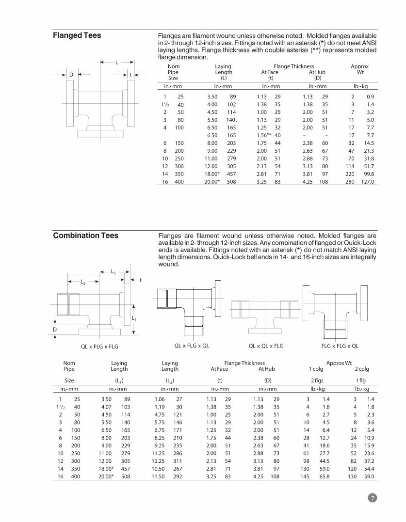
7
Nom Laying Flange Thickness Approx Pipe Length At Face At Hub Wt Size (L) (t) (D) in.•mm in.•mm in.•mm in.•mm lb.•kg
1 25 3.50 89 1.13 29 1.13 29 2 0.9 11/2 40 4.00 102 1.38 35 1.38 35 3 1.4 2 50 4.50 114 1.00 25 2.00 51 7 3.2 3 80 5.50 140 . 1.13 29 2.00 51 11 5.0 4 100 6.50 165 1.25 32 2.00 51 17 7.7 6.50 165 1.56** 40 – – 17 7.7 6 150 8.00 203 1.75 44 2.38 60 32 14.5 8 200 9.00 229 2.00 51 2.63 67 47 21.3 10 250 11.00 279 2.00 51 2.88 73 70 31.8 12 300 12.00 305 2.13 54 3.13 80 114 51.7 14 350 18.00* 457 2.81 71 3.81 97 220 99.8 16 400 20.00* 508 3.25 83 4.25 108 280 127.0
Flanged Tees
Nom Laying Laying Flange Thickness Approx Wt Pipe Length Length At Face At Hub 1 cplg 2 cplg
Size (L1) (L2) (t) (D) 2 flgs 1 flg in.•mm in.•mm in.•mm in.•mm in.•mm lb.•kg lb.•kg
1 25 3.50 89 1.06 27 1.13 29 1.13 29 3 1.4 3 1.4 11/2 40 4.07 103 1.19 30 1.38 35 1.38 35 4 1.8 4 1.8 2 50 4.50 114 4.75 121 1.00 25 2.00 51 6 2.7 5 2.3 3 80 5.50 140 5.75 146 1.13 29 2.00 51 10 4.5 8 3.6 4 100 6.50 165 6.75 171 1.25 32 2.00 51 14 6.4 12 5.4 6 150 8.00 203 8.25 210 1.75 44 2.38 60 28 12.7 24 10.9 8 200 9.00 229 9.25 235 2.00 51 2.63 67 41 18.6 35 15.9 10 250 11.00 279 11.25 286 2.00 51 2.88 73 61 27.7 52 23.6 12 300 12.00 305 12.25 311 2.13 54 3.13 80 98 44.5 82 37.2 14 350 18.00* 457 10.50 267 2.81 71 3.81 97 130 59.0 120 54.4 16 400 20.00* 508 11.50 292 3.25 83 4.25 108 145 65.8 130 59.0
Combination Tees
Flanges are filament wound unless otherwise noted. Molded flanges available in 2- through 12-inch sizes. Fittings noted with an asterisk (*) do not meet ANSI laying lengths. Flange thickness with double asterisk (**) represents molded flange dimension.
Flanges are filament wound unless otherwise noted. Molded flanges are available in 2- through 12-inch sizes. Any combination of flanged or Quick-Lock ends is available. Fittings noted with an asterisk (*) do not match ANSI laying length dimensions. Quick-Lock bell ends in 14- and 16-inch sizes are integrally wound.
D
D
t
L
t
L2
L1
L1
QL x FLG x FLG QL x FLG x QL QL x QL x FLG FLG x FLG x QL
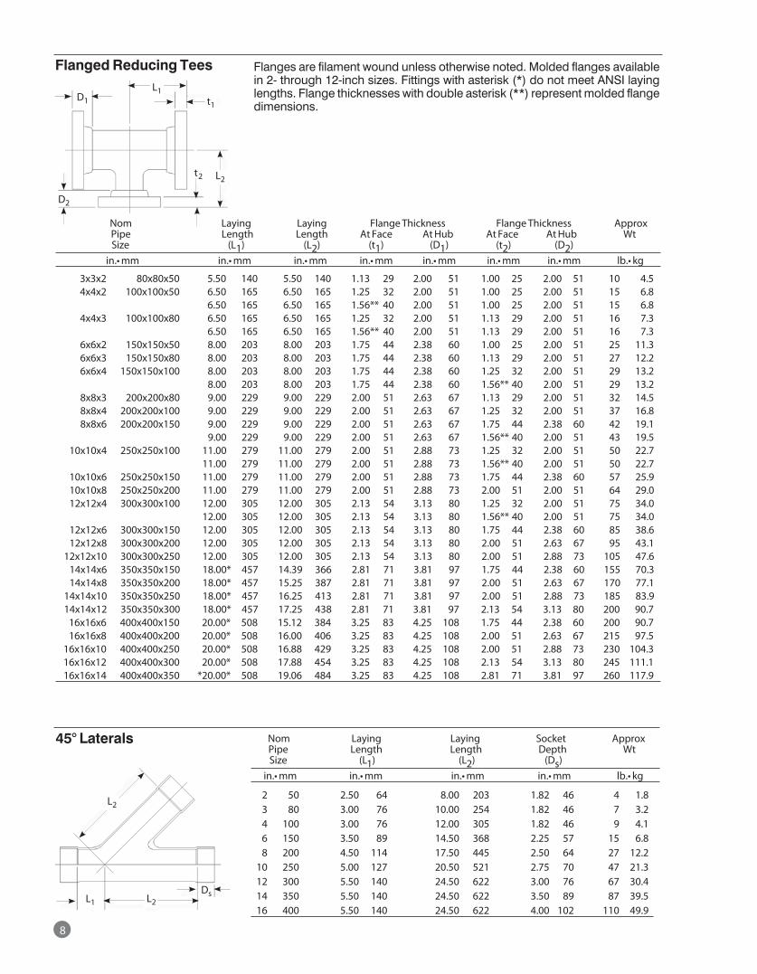
8
Nom Laying Laying Flange Thickness Flange Thickness Approx Pipe Length Length At Face At Hub At Face At Hub Wt Size (L1) (L2) (t1) (D1) (t2) (D2) in.•mm in.• mm in.•mm in.•mm in.• mm in.•mm in.•mm lb.•kg
3x3x2 80x80x50 5.50 140 5.50 140 1.13 29 2.00 51 1.00 25 2.00 51 10 4.5 4x4x2 100x100x50 6.50 165 6.50 165 1.25 32 2.00 51 1.00 25 2.00 51 15 6.8 6.50 165 6.50 165 1.56** 40 2.00 51 1.00 25 2.00 51 15 6.8 4x4x3 100x100x80 6.50 165 6.50 165 1.25 32 2.00 51 1.13 29 2.00 51 16 7.3 6.50 165 6.50 165 1.56** 40 2.00 51 1.13 29 2.00 51 16 7.3 6x6x2 150x150x50 8.00 203 8.00 203 1.75 44 2.38 60 1.00 25 2.00 51 25 11.3 6x6x3 150x150x80 8.00 203 8.00 203 1.75 44 2.38 60 1.13 29 2.00 51 27 12.2 6x6x4 150x150x100 8.00 203 8.00 203 1.75 44 2.38 60 1.25 32 2.00 51 29 13.2 8.00 203 8.00 203 1.75 44 2.38 60 1.56** 40 2.00 51 29 13.2 8x8x3 200x200x80 9.00 229 9.00 229 2.00 51 2.63 67 1.13 29 2.00 51 32 14.5 8x8x4 200x200x100 9.00 229 9.00 229 2.00 51 2.63 67 1.25 32 2.00 51 37 16.8 8x8x6 200x200x150 9.00 229 9.00 229 2.00 51 2.63 67 1.75 44 2.38 60 42 19.1 9.00 229 9.00 229 2.00 51 2.63 67 1.56** 40 2.00 51 43 19.5 10x10x4 250x250x100 11.00 279 11.00 279 2.00 51 2.88 73 1.25 32 2.00 51 50 22.7 11.00 279 11.00 279 2.00 51 2.88 73 1.56** 40 2.00 51 50 22.7 10x10x6 250x250x150 11.00 279 11.00 279 2.00 51 2.88 73 1.75 44 2.38 60 57 25.9 10x10x8 250x250x200 11.00 279 11.00 279 2.00 51 2.88 73 2.00 51 2.00 51 64 29.0 12x12x4 300x300x100 12.00 305 12.00 305 2.13 54 3.13 80 1.25 32 2.00 51 75 34.0 12.00 305 12.00 305 2.13 54 3.13 80 1.56** 40 2.00 51 75 34.0 12x12x6 300x300x150 12.00 305 12.00 305 2.13 54 3.13 80 1.75 44 2.38 60 85 38.6 12x12x8 300x300x200 12.00 305 12.00 305 2.13 54 3.13 80 2.00 51 2.63 67 95 43.1 12x12x10 300x300x250 12.00 305 12.00 305 2.13 54 3.13 80 2.00 51 2.88 73 105 47.6 14x14x6 350x350x150 18.00* 457 14.39 366 2.81 71 3.81 97 1.75 44 2.38 60 155 70.3 14x14x8 350x350x200 18.00* 457 15.25 387 2.81 71 3.81 97 2.00 51 2.63 67 170 77.1 14x14x10 350x350x250 18.00* 457 16.25 413 2.81 71 3.81 97 2.00 51 2.88 73 185 83.9 14x14x12 350x350x300 18.00* 457 17.25 438 2.81 71 3.81 97 2.13 54 3.13 80 200 90.7 16x16x6 400x400x150 20.00* 508 15.12 384 3.25 83 4.25 108 1.75 44 2.38 60 200 90.7 16x16x8 400x400x200 20.00* 508 16.00 406 3.25 83 4.25 108 2.00 51 2.63 67 215 97.5 16x16x10 400x400x250 20.00* 508 16.88 429 3.25 83 4.25 108 2.00 51 2.88 73 230 104.3 16x16x12 400x400x300 20.00* 508 17.88 454 3.25 83 4.25 108 2.13 54 3.13 80 245 111.1 16x16x14 400x400x350 *20.00* 508 19.06 484 3.25 83 4.25 108 2.81 71 3.81 97 260 117.9
Flanged Reducing Tees
Nom Laying Laying Socket Approx Pipe Length Length Depth Wt Size (L1) (L2) (Ds) in.•mm in.•mm in.•mm in.•mm lb.•kg
2 50 2.50 64 8.00 203 1.82 46 4 1.8 3 80 3.00 76 10.00 254 1.82 46 7 3.2 4 100 3.00 76 12.00 305 1.82 46 9 4.1 6 150 3.50 89 14.50 368 2.25 57 15 6.8 8 200 4.50 114 17.50 445 2.50 64 27 12.2 10 250 5.00 127 20.50 521 2.75 70 47 21.3 12 300 5.50 140 24.50 622 3.00 76 67 30.4 14 350 5.50 140 24.50 622 3.50 89 87 39.5 16 400 5.50 140 24.50 622 4.00 102 110 49.9
45° Laterals
Flanges are filament wound unless otherwise noted. Molded flanges available in 2- through 12-inch sizes. Fittings with asterisk (*) do not meet ANSI laying lengths. Flange thicknesses with double asterisk (**) represent molded flange dimensions.
D1L1
t1
t2 L2
D2
L2
L2DsL1
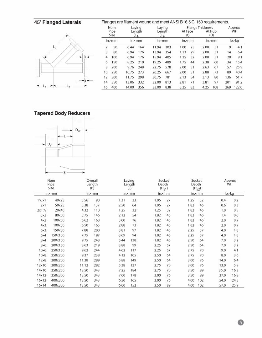
9
Flanges are filament wound and meet ANSI B16.5 Cl 150 requirements. Nom Laying Laying Flange Thickness Approx Pipe Length Length At Face At Hub Wt Size (L1) (L2) (t) (D) in.•mm in.•mm in.•mm in.•mm in.•mm lb.•kg
2 50 6.44 164 11.94 303 1.00 25 2.00 51 9 4.1 3 80 6.94 176 13.94 354 1.13 29 2.00 51 14 6.4 4 100 6.94 176 15.94 405 1.25 32 2.00 51 20 9.1 6 150 8.25 210 19.25 489 1.75 44 2.38 60 34 15.4 8 200 9.76 248 22.75 578 2.00 51 2.63 67 57 25.9 10 250 10.75 273 26.25 667 2.00 51 2.88 73 89 40.4 12 300 11.75 298 30.75 781 2.13 54 3.13 80 136 61.7 14 350 13.06 332 32.00 813 2.81 71 3.81 97 201 91.2 16 400 14.00 356 33.00 838 3.25 83 4.25 108 269 122.0
45° Flanged Laterals
Nom Overall Laying Socket Socket Approx Pipe Length Length Depth Depth Wt Size (B) (L) (Ds1) (Ds2) in.•mm in.•mm in.•mm in.•mm in.•mm lb.•kg
11/2x1 40x25 3.56 90 1.31 33 1.06 27 1.25 32 0.4 0.2 2x1 50x25 5.38 137 2.50 64 1.06 27 1.82 46 0.6 0.3 2x11/2 20x40 4.32 110 1.25 32 1.25 32 1.82 46 1.0 0.5 3x2 80x50 5.75 146 2.12 54 1.82 46 1.82 46 1.4 0.6 4x2 100x50 6.62 168 3.00 76 1.82 46 1.82 46 2.0 0.9 4x3 100x80 6.50 165 2.88 73 1.82 46 1.82 46 2.0 0.9 6x3 150x80 7.88 200 3.81 97 1.82 46 2.25 57 4.0 1.8 6x4 150x100 7.75 197 3.69 94 1.82 46 2.25 57 4.0 1.8 8x4 200x100 9.75 248 5.44 138 1.82 46 2.50 64 7.0 3.2 8x6 200x150 8.63 219 3.88 99 2.25 57 2.50 64 7.0 3.2 10x6 250x150 9.62 244 4.62 117 2.25 57 2.75 70 9.0 4.1 10x8 250x200 9.37 238 4.12 105 2.50 64 2.75 70 8.0 3.6 12x8 300x200 11.38 289 5.88 149 2.50 64 3.00 76 14.0 6.4 12x10 300x250 11.12 282 5.38 137 2.75 70 3.00 76 13.0 5.9 14x10 350x250 13.50 343 7.25 184 2.75 70 3.50 89 36 .0 16.3 14x12 350x300 13.50 343 7.00 178 3.00 76 3.50 89 37.0 16.8 16x12 400x300 13.50 343 6.50 165 3.00 76 4.00 102 54.0 24.5 16x14 400x350 13.50 343 6.00 152 3.50 89 4.00 102 57.0 25.9
Tapered Body Reducers
L2
L2
D
tL1
Ds2
Ds1
L
B
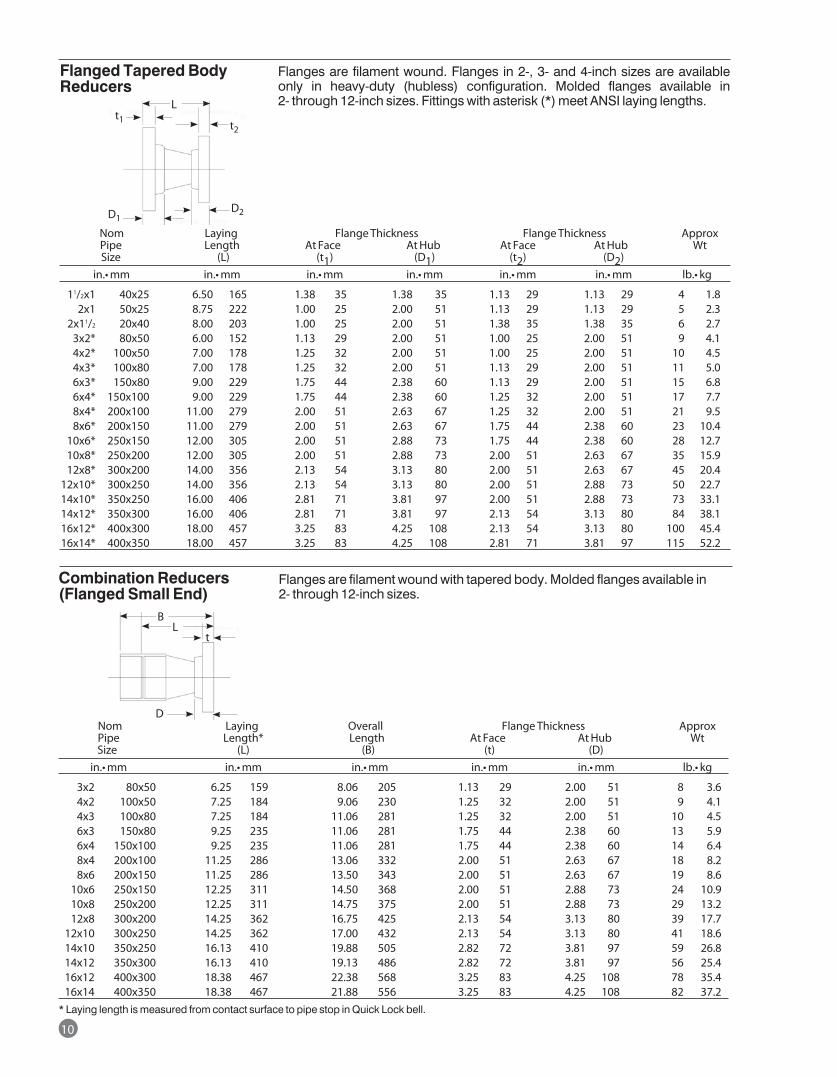
Nom Laying Flange Thickness Flange Thickness Approx Pipe Length At Face At Hub At Face At Hub Wt Size (L) (t1) (D1) (t2) (D2) in.•mm in.• mm in.•mm in.•mm in.• mm in.•mm lb.•kg
11/2x1 40x25 6.50 165 1.38 35 1.38 35 1.13 29 1.13 29 4 1.8 2x1 50x25 8.75 222 1.00 25 2.00 51 1.13 29 1.13 29 5 2.3 2x11/2 20x40 8.00 203 1.00 25 2.00 51 1.38 35 1.38 35 6 2.7 3x2* 80x50 6.00 152 1.13 29 2.00 51 1.00 25 2.00 51 9 4.1 4x2* 100x50 7.00 178 1.25 32 2.00 51 1.00 25 2.00 51 10 4.5 4x3* 100x80 7.00 178 1.25 32 2.00 51 1.13 29 2.00 51 11 5.0 6x3* 150x80 9.00 229 1.75 44 2.38 60 1.13 29 2.00 51 15 6.8 6x4* 150x100 9.00 229 1.75 44 2.38 60 1.25 32 2.00 51 17 7.7 8x4* 200x100 11.00 279 2.00 51 2.63 67 1.25 32 2.00 51 21 9.5 8x6* 200x150 11.00 279 2.00 51 2.63 67 1.75 44 2.38 60 23 10.4 10x6* 250x150 12.00 305 2.00 51 2.88 73 1.75 44 2.38 60 28 12.7 10x8* 250x200 12.00 305 2.00 51 2.88 73 2.00 51 2.63 67 35 15.9 12x8* 300x200 14.00 356 2.13 54 3.13 80 2.00 51 2.63 67 45 20.4 12x10* 300x250 14.00 356 2.13 54 3.13 80 2.00 51 2.88 73 50 22.7 14x10* 350x250 16.00 406 2.81 71 3.81 97 2.00 51 2.88 73 73 33.1 14x12* 350x300 16.00 406 2.81 71 3.81 97 2.13 54 3.13 80 84 38.1 16x12* 400x300 18.00 457 3.25 83 4.25 108 2.13 54 3.13 80 100 45.4 16x14* 400x350 18.00 457 3.25 83 4.25 108 2.81 71 3.81 97 115 52.2
Nom Laying Overall Flange Thickness Approx Pipe Length* Length At Face At Hub Wt Size (L) (B) (t) (D) in.•mm in.•mm in.•mm in.• mm in.•mm lb.•kg
3x2 80x50 6.25 159 8.06 205 1.13 29 2.00 51 8 3.6 4x2 100x50 7.25 184 9.06 230 1.25 32 2.00 51 9 4.1 4x3 100x80 7.25 184 11.06 281 1.25 32 2.00 51 10 4.5 6x3 150x80 9.25 235 11.06 281 1.75 44 2.38 60 13 5.9 6x4 150x100 9.25 235 11.06 281 1.75 44 2.38 60 14 6.4 8x4 200x100 11.25 286 13.06 332 2.00 51 2.63 67 18 8.2 8x6 200x150 11.25 286 13.50 343 2.00 51 2.63 67 19 8.6 10x6 250x150 12.25 311 14.50 368 2.00 51 2.88 73 24 10.9 10x8 250x200 12.25 311 14.75 375 2.00 51 2.88 73 29 13.2 12x8 300x200 14.25 362 16.75 425 2.13 54 3.13 80 39 17.7 12x10 300x250 14.25 362 17.00 432 2.13 54 3.13 80 41 18.6 14x10 350x250 16.13 410 19.88 505 2.82 72 3.81 97 59 26.8 14x12 350x300 16.13 410 19.13 486 2.82 72 3.81 97 56 25.4 16x12 400x300 18.38 467 22.38 568 3.25 83 4.25 108 78 35.4 16x14 400x350 18.38 467 21.88 556 3.25 83 4.25 108 82 37.2* Laying length is measured from contact surface to pipe stop in Quick Lock bell.
Combination Reducers (Flanged Small End)
Flanges are filament wound. Flanges in 2-, 3- and 4-inch sizes are available only in heavy-duty (hubless) configuration. Molded flanges available in 2- through 12-inch sizes. Fittings with asterisk (*) meet ANSI laying lengths.
Flanges are filament wound with tapered body. Molded flanges available in 2- through 12-inch sizes.
Flanged Tapered Body Reducers
L
t2t1
D1D2
D
BL
t
10
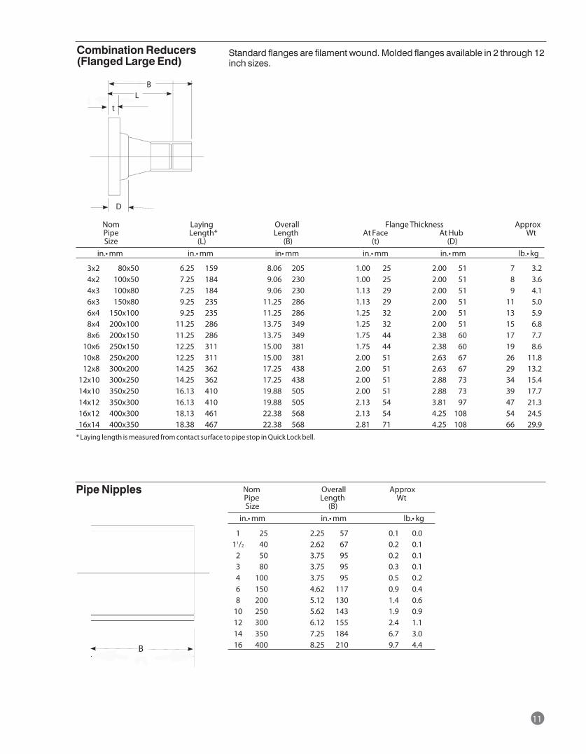
11
Nom Laying Overall Flange Thickness Approx Pipe Length* Length At Face At Hub Wt Size (L) (B) (t) (D) in.•mm in.•mm in•mm in.•mm in.•mm lb.•kg
3x2 80x50 6.25 159 8.06 205 1.00 25 2.00 51 7 3.2 4x2 100x50 7.25 184 9.06 230 1.00 25 2.00 51 8 3.6 4x3 100x80 7.25 184 9.06 230 1.13 29 2.00 51 9 4.1 6x3 150x80 9.25 235 11.25 286 1.13 29 2.00 51 11 5.0 6x4 150x100 9.25 235 11.25 286 1.25 32 2.00 51 13 5.9 8x4 200x100 11.25 286 13.75 349 1.25 32 2.00 51 15 6.8 8x6 200x150 11.25 286 13.75 349 1.75 44 2.38 60 17 7.7 10x6 250x150 12.25 311 15.00 381 1.75 44 2.38 60 19 8.6 10x8 250x200 12.25 311 15.00 381 2.00 51 2.63 67 26 11.8 12x8 300x200 14.25 362 17.25 438 2.00 51 2.63 67 29 13.2 12x10 300x250 14.25 362 17.25 438 2.00 51 2.88 73 34 15.4 14x10 350x250 16.13 410 19.88 505 2.00 51 2.88 73 39 17.7 14x12 350x300 16.13 410 19.88 505 2.13 54 3.81 97 47 21.3 16x12 400x300 18.13 461 22.38 568 2.13 54 4.25 108 54 24.5 16x14 400x350 18.38 467 22.38 568 2.81 71 4.25 108 66 29.9* Laying length is measured from contact surface to pipe stop in Quick Lock bell.
Nom Overall Approx Pipe Length Wt Size (B) in.•mm in.•mm lb.•kg
1 25 2.25 57 0.1 0.0 11/2 40 2.62 67 0.2 0.1 2 50 3.75 95 0.2 0.1 3 80 3.75 95 0.3 0.1 4 100 3.75 95 0.5 0.2 6 150 4.62 117 0.9 0.4 8 200 5.12 130 1.4 0.6 10 250 5.62 143 1.9 0.9 12 300 6.12 155 2.4 1.1 14 350 7.25 184 6.7 3.0 16 400 8.25 210 9.7 4.4
Pipe Nipples
Combination Reducers (Flanged Large End)
Standard flanges are filament wound. Molded flanges available in 2 through 12 inch sizes.
BL
D
t
B
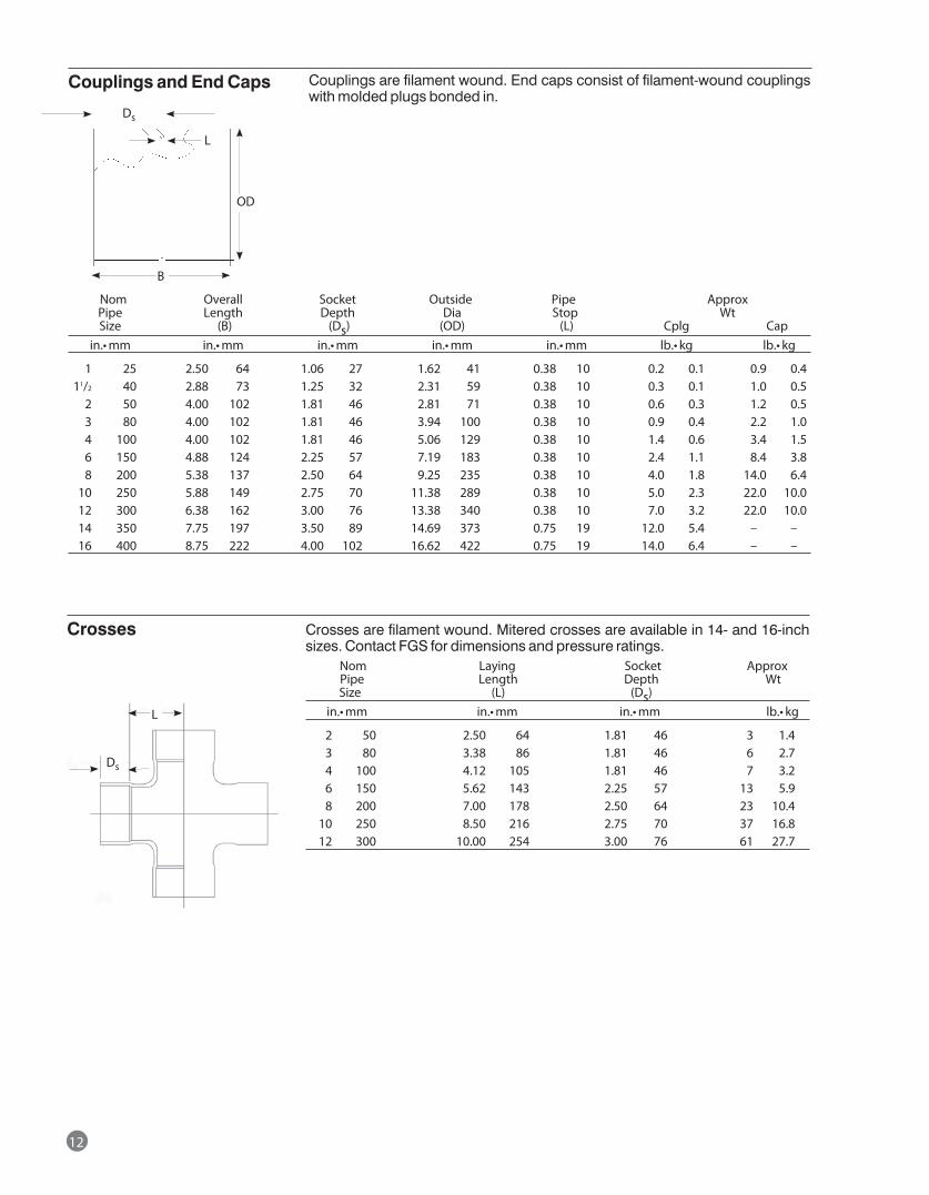
12
Crosses Crosses are filament wound. Mitered crosses are available in 14- and 16-inch sizes. Contact FGS for dimensions and pressure ratings. Nom Laying Socket Approx Pipe Length Depth Wt Size (L) (Ds) in.•mm in.•mm in.•mm lb.•kg
2 50 2.50 64 1.81 46 3 1.4 3 80 3.38 86 1.81 46 6 2.7 4 100 4.12 105 1.81 46 7 3.2 6 150 5.62 143 2.25 57 13 5.9 8 200 7.00 178 2.50 64 23 10.4 10 250 8.50 216 2.75 70 37 16.8 12 300 10.00 254 3.00 76 61 27.7
Nom Overall Socket Outside Pipe Approx Pipe Length Depth Dia Stop Wt Size (B) (Ds) (OD) (L) Cplg Cap in.•mm in.•mm in.•mm in.• mm in.•mm lb.•kg lb.•kg
1 25 2.50 64 1.06 27 1.62 41 0.38 10 0.2 0.1 0.9 0.4 11/2 40 2.88 73 1.25 32 2.31 59 0.38 10 0.3 0.1 1.0 0.5 2 50 4.00 102 1.81 46 2.81 71 0.38 10 0.6 0.3 1.2 0.5 3 80 4.00 102 1.81 46 3.94 100 0.38 10 0.9 0.4 2.2 1.0 4 100 4.00 102 1.81 46 5.06 129 0.38 10 1.4 0.6 3.4 1.5 6 150 4.88 124 2.25 57 7.19 183 0.38 10 2.4 1.1 8.4 3.8 8 200 5.38 137 2.50 64 9.25 235 0.38 10 4.0 1.8 14.0 6.4 10 250 5.88 149 2.75 70 11.38 289 0.38 10 5.0 2.3 22.0 10.0 12 300 6.38 162 3.00 76 13.38 340 0.38 10 7.0 3.2 22.0 10.0 14 350 7.75 197 3.50 89 14.69 373 0.75 19 12.0 5.4 – – 16 400 8.75 222 4.00 102 16.62 422 0.75 19 14.0 6.4 – –
Couplings and End Caps Couplings are filament wound. End caps consist of filament-wound couplings with molded plugs bonded in.
Ds
OD
B
L
Ds
L
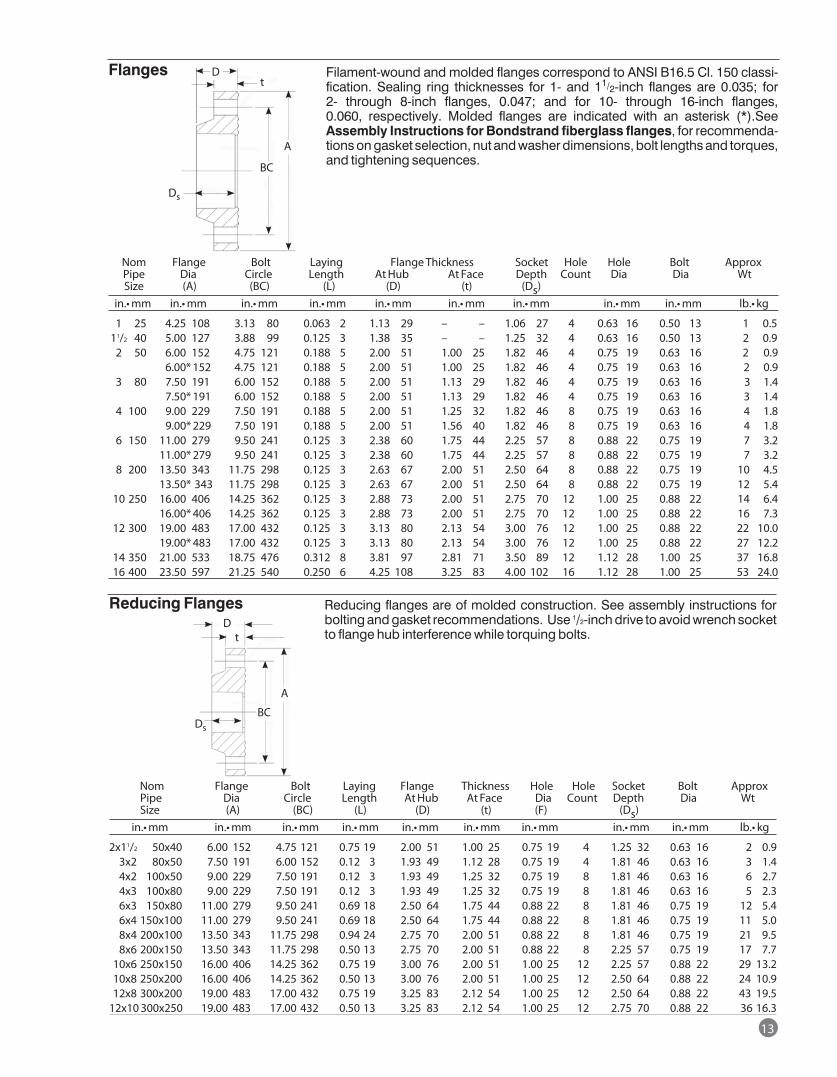
Nom Flange Bolt Laying Flange Thickness Socket Hole Hole Bolt Approx Pipe Dia Circle Length At Hub At Face Depth Count Dia Dia Wt Size (A) (BC) (L) (D) (t) (Ds) in.•mm in.•mm in.•mm in.•mm in.•mm in.•mm in.•mm in.•mm in.•mm lb.•kg
1 25 4.25 108 3.13 80 0.063 2 1.13 29 – – 1.06 27 4 0.63 16 0.50 13 1 0.5 11/2 40 5.00 127 3.88 99 0.125 3 1.38 35 – – 1.25 32 4 0.63 16 0.50 13 2 0.9 2 50 6.00 152 4.75 121 0.188 5 2.00 51 1.00 25 1.82 46 4 0.75 19 0.63 16 2 0.9 6.00* 152 4.75 121 0.188 5 2.00 51 1.00 25 1.82 46 4 0.75 19 0.63 16 2 0.9 3 80 7.50 191 6.00 152 0.188 5 2.00 51 1.13 29 1.82 46 4 0.75 19 0.63 16 3 1.4 7.50* 191 6.00 152 0.188 5 2.00 51 1.13 29 1.82 46 4 0.75 19 0.63 16 3 1.4 4 100 9.00 229 7.50 191 0.188 5 2.00 51 1.25 32 1.82 46 8 0.75 19 0.63 16 4 1.8 9.00* 229 7.50 191 0.188 5 2.00 51 1.56 40 1.82 46 8 0.75 19 0.63 16 4 1.8 6 150 11.00 279 9.50 241 0.125 3 2.38 60 1.75 44 2.25 57 8 0.88 22 0.75 19 7 3.2 11.00* 279 9.50 241 0.125 3 2.38 60 1.75 44 2.25 57 8 0.88 22 0.75 19 7 3.2 8 200 13.50 343 11.75 298 0.125 3 2.63 67 2.00 51 2.50 64 8 0.88 22 0.75 19 10 4.5 13.50* 343 11.75 298 0.125 3 2.63 67 2.00 51 2.50 64 8 0.88 22 0.75 19 12 5.4 10 250 16.00 406 14.25 362 0.125 3 2.88 73 2.00 51 2.75 70 12 1.00 25 0.88 22 14 6.4 16.00* 406 14.25 362 0.125 3 2.88 73 2.00 51 2.75 70 12 1.00 25 0.88 22 16 7.3 12 300 19.00 483 17.00 432 0.125 3 3.13 80 2.13 54 3.00 76 12 1.00 25 0.88 22 22 10.0 19.00* 483 17.00 432 0.125 3 3.13 80 2.13 54 3.00 76 12 1.00 25 0.88 22 27 12.2 14 350 21.00 533 18.75 476 0.312 8 3.81 97 2.81 71 3.50 89 12 1.12 28 1.00 25 37 16.8 16 400 23.50 597 21.25 540 0.250 6 4.25 108 3.25 83 4.00 102 16 1.12 28 1.00 25 53 24.0
Flanges Filament-wound and molded flanges correspond to ANSI B16.5 Cl. 150 classi-fication. Sealing ring thicknesses for 1- and 11/2-inch flanges are 0.035; for 2- through 8-inch flanges, 0.047; and for 10- through 16-inch flanges, 0.060, respectively. Molded flanges are indicated with an asterisk (*).See Assembly Instructions for Bondstrand fiberglass flanges, for recommenda-tions on gasket selection, nut and washer dimensions, bolt lengths and torques, and tightening sequences.
Reducing flanges are of molded construction. See assembly instructions for bolting and gasket recommendations. Use 1/2-inch drive to avoid wrench socket to flange hub interference while torquing bolts.
D
Ds
Ds
Dt
t
BC
Nom Flange Bolt Laying Flange Thickness Hole Hole Socket Bolt Approx Pipe Dia Circle Length At Hub At Face Dia Count Depth Dia Wt Size (A) (BC) (L) (D) (t) (F) (Ds) in.•mm in.•mm in.•mm in.•mm in.•mm in.•mm in.•mm in.•mm in.•mm lb.•kg
2x11/2 50x40 6.00 152 4.75 121 0.75 19 2.00 51 1.00 25 0.75 19 4 1.25 32 0.63 16 2 0.9 3x2 80x50 7.50 191 6.00 152 0.12 3 1.93 49 1.12 28 0.75 19 4 1.81 46 0.63 16 3 1.4 4x2 100x50 9.00 229 7.50 191 0.12 3 1.93 49 1.25 32 0.75 19 8 1.81 46 0.63 16 6 2.7 4x3 100x80 9.00 229 7.50 191 0.12 3 1.93 49 1.25 32 0.75 19 8 1.81 46 0.63 16 5 2.3 6x3 150x80 11.00 279 9.50 241 0.69 18 2.50 64 1.75 44 0.88 22 8 1.81 46 0.75 19 12 5.4 6x4 150x100 11.00 279 9.50 241 0.69 18 2.50 64 1.75 44 0.88 22 8 1.81 46 0.75 19 11 5.0 8x4 200x100 13.50 343 11.75 298 0.94 24 2.75 70 2.00 51 0.88 22 8 1.81 46 0.75 19 21 9.5 8x6 200x150 13.50 343 11.75 298 0.50 13 2.75 70 2.00 51 0.88 22 8 2.25 57 0.75 19 17 7.7 10x6 250x150 16.00 406 14.25 362 0.75 19 3.00 76 2.00 51 1.00 25 12 2.25 57 0.88 22 29 13.2 10x8 250x200 16.00 406 14.25 362 0.50 13 3.00 76 2.00 51 1.00 25 12 2.50 64 0.88 22 24 10.9 12x8 300x200 19.00 483 17.00 432 0.75 19 3.25 83 2.12 54 1.00 25 12 2.50 64 0.88 22 43 19.5 12x10 300x250 19.00 483 17.00 432 0.50 13 3.25 83 2.12 54 1.00 25 12 2.75 70 0.88 22 36 16.3
A
13
BC
A
Reducing Flanges
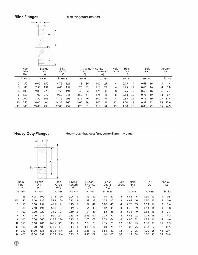
Nom Flange Bolt Flange Thickness Hole Hole Bolt Approx Pipe Dia Circle At Face At Holes Count Dia Dia Wt Size (A) (BC) (D) (t) (F) in.•mm in.•mm in.•mm in.•mm in.•mm in.•mm in.•mm lb.•kg
2 50 6.00 152 4.75 121 1.18 30 1.00 25 4 0.75 19 0.63 16 3 1.4 3 80 7.50 191 6.00 152 1.25 32 1.13 29 4 0.75 19 0.63 16 4 1.8 4 100 9.00 229 7.50 191 1.43 36 1.25 32 8 0.75 19 0.63 16 6 2.7 6 150 11.00 279 9.50 241 2.50 64 1.75 44 8 0.88 22 0.75 19 14 6.4 8 200 13.50 343 11.75 298 2.75 70 2.00 51 8 0.88 22 0.75 19 23 10.4 10 250 16.00 406 14.25 362 3.00 76 2.00 51 12 1.00 25 0.88 22 35 15.9 12 300 19.00 438 17.00 432 3.25 83 2.13 54 12 1.00 25 0.88 22 55 24.9
Blind Flanges
Nom Flange Bolt Laying Flange Socket Hole Hole Bolt Approx Pipe Dia Circle Length Thickness Depth Count Dia Dia Wt Size (A) (BC) (L) (D) (Ds) (F) in.•mm in.•mm in.•mm in.•mm in.•mm in.•mm in.•mm in.•mm lb.•kg
1 25 4.25 108 3.13 80 0.06 2 1.13 29 1.06 27 4 0.63 16 0.50 13 1 0.5 11/2 40 5.00 127 3.88 99 0.13 3. 1.38 35 1.25 32 4 0.63 16 0.50 13 2 0.9 2 50 6.00 152 4.75 121 0.19 5 1.94 49 1.82 46 4 0.75 19 0.63 16 3 1.4 3 80 7.50 191 6.00 152 0.19 5 1.94 49 1.82 46 4 0.75 19 0.63 16 4 1.8 4 100 9.00 229 7.50 191 0.19 5 1.94 49 1.82 46 8 0.75 19 0.63 16 6 2.7 6 150 11.00 279 9.50 241 0.13 3 2.38 60 2.25 57 8 0.88 22 0.75 19 10 4.5 8 200 13.50 343 11.75 298 0.13 3 2.63 67 2.50 64 8 0.88 22 0.75 19 14 6.4 10 250 16.00 406 14.25 362 0.13 3 2.88 73 2.75 70 12 1.00 25 0.88 22 21 9.5 12 300 19.00 483 17.00 432 0.13 3 3.13 80 3.00 76 12 1.00 25 0.88 22 32 14.5 14 350 21.00 533 18.75 476 0.31 8 3.81 97 3.50 89 12 1.12 28 1.00 25 45 20.4 16 400 23.50 597 21.25 540 0.25 6 4.25 108 4.00 102 16 1.12 28 1.00 25 59 26.8
Heavy-Duty Flanges
Blind flanges are molded.
Heavy-duty (hubless) flanges are filament-wound.
14
t
D
BC A
Ds
D
BC A
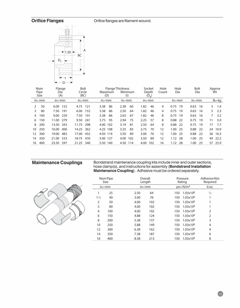
Nom Flange Bolt Flange Thickness Socket Hole Hole Bolt Approx Pipe Dia Circle Maximum Minimum Depth Count Dia Dia Wt Size (A) (BC) (D) (t) (Ds) in•.mm in.•mm in.•mm in.•mm in.•mm in.•mm in.•mm in.•mm lb.•kg
2 50 6.00 152 4.75 121 3.38 86 2.38 60 1.82 46 4 0.75 19 0.63 16 3 1.4 3 80 7.50 191 6.00 152 3.38 86 2.50 64 1.82 46 4 0.75 19 0.63 16 5 2.3 4 100 9.00 229 7.50 191 3.38 86 2.63 67 1.82 46 8 0.75 19 0.63 16 7 3.2 6 150 11.00 279 9.50 241 3.75 95 2.94 75 2.25 57 8 0.88 22 0.75 19 11 5.0 8 200 13.50 343 11.75 298 4.00 102 3.19 81 2.50 64 8 0.88 22 0.75 19 17 7.7 10 250 16.00 406 14.25 362 4.25 108 3.25 83 2.75 70 12 1.00 25 0.88 22 24 10.9 12 300 19.00 483 17.00 432 4.50 114 3.50 89 3.00 76 12 1.00 25 0.88 22 36 16.3 14 350 21.00 533 18.75 476 5.00 127 4.00 102 3.50 89 12 1.12 28 1.00 25 49 22.2 16 400 23.50 597 21.25 540 5.50 140 4.50 114 4.00 102 16 1.12 28 1.00 25 57 25.9
Orifice Flanges
Nom Pipe Overall Pressure Adhesive Kits Size Length Rating Required in.•mm in.•mm psi.•N/m2 6 oz.
1 25 2.50 64 150 1.03x10⁶ 1/2
11/2 40 3.00 76 150 1.03x10⁶ 1 2 50 4.00 102 150 1.03x10⁶ 1 3 80 4.00 102 150 1.03x10⁶ 1 4 100 4.00 102 150 1.03x10⁶ 2 6 150 4.88 124 150 1.03x10⁶ 2 8 200 5.38 137 150 1.03x10⁶ 3 10 250 5.88 149 150 1.03x10⁶ 4 12 300 6.38 162 150 1.03x10⁶ 4 14 350 7.38 187 150 1.03x10⁶ 6 16 400 8.38 213 150 1.03x10⁶ 8
Maintenance Couplings
Orifice flanges are filament-wound.
Bondstrand maintenance coupling kits include inner and outer sections, hose clamp(s), and instructions for assembly (Bondstrand Installation Maintenance Coupling). Adhesive must be ordered separately.
15
Ds
1.50BC
A
tD
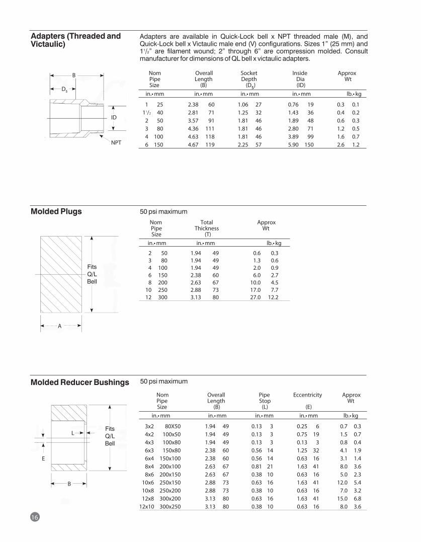
16
Nom Overall Pipe Eccentricity Approx Pipe Length Stop Wt Size (B) (L) (E) in.•mm in.•mm in.•mm in.•mm lb.•kg
3x2 80X50 1.94 49 0.13 3 0.25 6 0.7 0.3 4x2 100x50 1.94 49 0.13 3 0.75 19 1.5 0.7 4x3 100x80 1.94 49 0.13 3 0.13 3 0.8 0.4 6x3 150x80 2.38 60 0.56 14 1.25 32 4.1 1.9 6x4 150x100 2.38 60 0.56 14 0.63 16 3.1 1.4 8x4 200x100 2.63 67 0.81 21 1.63 41 8.0 3.6 8x6 200x150 2.63 67 0.38 10 0.63 16 5.0 2.3 10x6 250x150 2.88 73 0.63 16 1.63 41 12.0 5.4 10x8 250x200 2.88 73 0.38 10 0.63 16 7.0 3.2 12x8 300x200 3.13 80 0.63 16 1.63 41 15.0 6.8 12x10 300x250 3.13 80 0.38 10 0.63 16 8.0 3.6
Molded Reducer Bushings
Nom Total Approx Pipe Thickness Wt Size (T) in.•mm in.•mm lb.•kg
2 50 1.94 49 0.6 0.3 3 80 1.94 49 1.3 0.6 4 100 1.94 49 2.0 0.9 6 150 2.38 60 6.0 2.7 8 200 2.63 67 10.0 4.5 10 250 2.88 73 17.0 7.7 12 300 3.13 80 27.0 12.2
Molded Plugs 50 psi maximum
Nom Overall Socket Inside Approx Pipe Length Depth Dia Wt Size (B) (Ds) (ID) in.•mm in.•mm in.•mm in.•mm lb.•kg
1 25 2.38 60 1.06 27 0.76 19 0.3 0.1 11/2 40 2.81 71 1.25 32 1.43 36 0.4 0.2 2 50 3.57 91 1.81 46 1.89 48 0.6 0.3 3 80 4.36 111 1.81 46 2.80 71 1.2 0.5 4 100 4.63 118 1.81 46 3.89 99 1.6 0.7 6 150 4.67 119 2.25 57 5.90 150 2.6 1.2
Adapters (Threaded and Victaulic)
Adapters are available in Quick-Lock bell x NPT threaded male (M), and Quick-Lock bell x Victaulic male end (V) configurations. Sizes 1” (25 mm) and 11/2” are filament wound; 2” through 6” are compression molded. Consult manufacturer for dimensions of QL bell x victaulic adapters.
NPT
ID
B
Ds
A
Fits Q/L Bell
Fits Q/L Bell
E
B
L
50 psi maximum
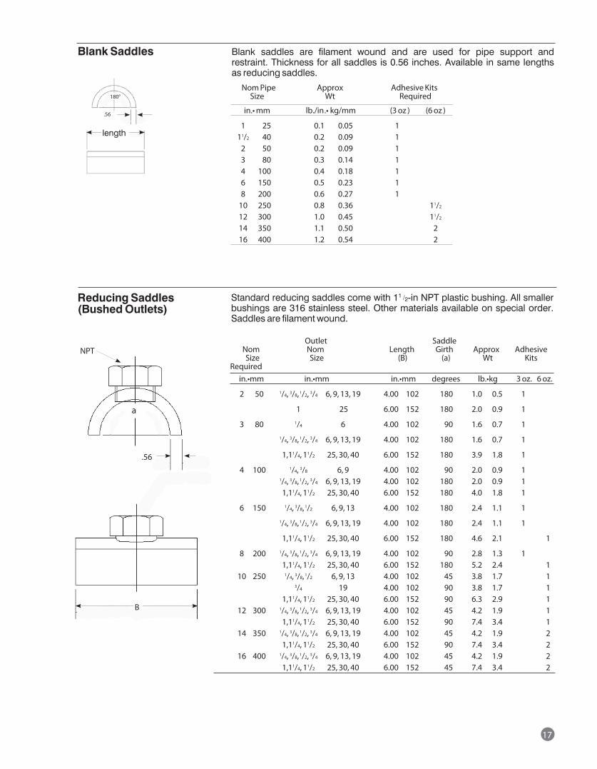
Nom Pipe Approx Adhesive Kits Size Wt Required
in.•mm lb./in.• kg/mm (3 oz ) (6 oz )
1 25 0.1 0.05 1 11/2 40 0.2 0.09 1 2 50 0.2 0.09 1 3 80 0.3 0.14 1 4 100 0.4 0.18 1 6 150 0.5 0.23 1 8 200 0.6 0.27 1 10 250 0.8 0.36 11/2
12 300 1.0 0.45 11/2
14 350 1.1 0.50 2 16 400 1.2 0.54 2
Blank Saddles Blank saddles are filament wound and are used for pipe support and restraint. Thickness for all saddles is 0.56 inches. Available in same lengths as reducing saddles.
17
.56
180°
length
Outlet Saddle Nom Nom Length Girth Approx Adhesive Size Size (B) (a) Wt Kits Required in.•mm in.•mm in.•mm degrees lb.•kg 3 oz. 6 oz.
2 50 1/4, 3/8, 1/2, 3/4 6, 9, 13, 19 4.00 102 180 1.0 0.5 1
1 25 6.00 152 180 2.0 0.9 1
3 80 1/4 6 4.00 102 90 1.6 0.7 1 1/4, 3/8, 1/2, 3/4 6, 9, 13, 19 4.00 102 180 1.6 0.7 1
1,11/4, 11/2 25, 30, 40 6.00 152 180 3.9 1.8 1
4 100 1/4, 3/8 6, 9 4.00 102 90 2.0 0.9 1 1/4, 3/8, 1/2, 3/4 6, 9, 13, 19 4.00 102 180 2.0 0.9 1 1,11/4, 11/2 25, 30, 40 6.00 152 180 4.0 1.8 1
6 150 1/4, 3/8, 1/2 6, 9, 13 4.00 102 180 2.4 1.1 1 1/4, 3/8, 1/2, 3/4 6, 9, 13, 19 4.00 102 180 2.4 1.1 1
1,11/4, 11/2 25, 30, 40 6.00 152 180 4.6 2.1 1
8 200 1/4, 3/8, 1/2, 3/4 6, 9, 13, 19 4.00 102 90 2.8 1.3 1 1,11/4, 11/2 25, 30, 40 6.00 152 180 5.2 2.4 1 10 250 1/4, 3/8, 1/2 6, 9, 13 4.00 102 45 3.8 1.7 1 3/4 19 4.00 102 90 3.8 1.7 1 1,11/4, 11/2 25, 30, 40 6.00 152 90 6.3 2.9 1 12 300 1/4, 3/8, 1/2, 3/4 6, 9, 13, 19 4.00 102 45 4.2 1.9 1 1,11/4, 11/2 25, 30, 40 6.00 152 90 7.4 3.4 1 14 350 1/4, 3/8, 1/2, 3/4 6, 9, 13, 19 4.00 102 45 4.2 1.9 2 1,11/4, 11/2 25, 30, 40 6.00 152 90 7.4 3.4 2 16 400 1/4, 3/8, 1/2, 3/4 6, 9, 13, 19 4.00 102 45 4.2 1.9 2 1,11/4, 11/2 25, 30, 40 6.00 152 45 7.4 3.4 2
Reducing Saddles (Bushed Outlets)
Standard reducing saddles come with 11 /2-in NPT plastic bushing. All smaller bushings are 316 stainless steel. Other materials available on special order. Saddles are filament wound.
a
.56
B
NPT
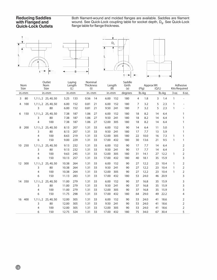
t B
18
Outlet Laying Nominal Saddle Nom Nom Length Thickness Length Girth Approx Wt Adhesive Size Size (L) (t) (B) (a) (Flg) (Q/L) Kits Required in.•mm in.•mm in.•mm in.•mm in.•mm degrees lb.•kg lb.•kg 3 oz. 6 oz.
3 80 1,11/2, 2 25, 40, 50 5.25 133 0.56 14 6.00 152 180 4 1.8 3 1.4 1 -
4 100 1,11/2, 2 25, 40, 50 6.00 152 0.81 21 6.00 152 180 7 3.2 5 2.3 1 - 3 80 6.00 152 0.81 21 9.50 241 180 7 3.2 5 2.3 1 -
6 150 1,11/2, 2 25, 40, 50 7.38 187 1.06 27 6.00 152 180 18 8.2 14 6.4 1 3 80 7.38 187 1.06 27 9.50 241 180 18 8.2 14 6.4 1 4 100 7.38 187 1.06 27 12.00 305 180 18 8.2 14 6.4 1
8 200 1,11/2, 2 25, 40, 50 8.13 207 1.31 33 6.00 152 90 14 6.4 11 5.0 1 3 80 8.13 207 1.31 33 9.50 241 180 17 7.7 13 5.9 1 4 100 8.63 219 1.31 33 12.00 305 180 22 10.0 16 7.3 1 1 6 150 9.00 229 1.31 33 17.00 432 180 30 13.6 21 9.5 1 1
10 250 1,11/2, 2 25, 40, 50 9.13 232 1.31 33 6.00 152 90 17 7.7 14 6.4 2 3 80 9.13 232 1.31 33 9.50 241 90 17 7.7 14 6.4 2 4 100 9.63 245 1.31 33 12.00 305 180 31 14.1 27 12.2 1 2 6 150 10.13 257 1.31 33 17.00 432 180 40 18.1 35 15.9 3
12 300 1,11/2, 2 25, 40, 50 10.38 264 1.31 33 6.00 152 90 27 12.2 23 10.4 1 2 3 80 10.38 264 1.31 33 9.50 241 90 27 12.2 23 10.4 1 2 4 100 10.38 264 1.31 33 12.00 305 90 27 12.2 23 10.4 1 2 6 150 11.13 283 1.31 33 17.00 432 180 53 24.0 46 20.9 3
14 350 1,11/2, 2 25, 40, 50 11.00 279 1.31 33 6.00 152 90 37 16.8 35 15.9 3 3 80 11.00 279 1.31 33 9.50 241 90 37 16.8 35 15.9 3 4 100 11.00 279 1.31 33 12.00 305 90 37 16.8 35 15.9 3 6 150 11.75 298 1.31 33 17.00 432 180 64 29.0 49 22.2 4
16 400 1,11/2, 2 25, 40, 50 12.00 305 1.31 33 6.00 152 90 53 24.0 41 18.6 2 3 80 12.00 305 1.31 33 9.50 241 90 53 24.0 41 18.6 2 4 100 12.00 305 1.31 33 12.00 305 90 53 24.0 41 18.6 2 6 150 12.75 324 1.31 33 17.00 432 180 75 34.0 67 30.4 5
Reducing Saddles with Flanged and Quick-Lock Outlets
Both filament-wound and molded flanges are available. Saddles are filament wound. See Quick-Lock coupling table for socket depth, Ds. See Quick-Lock flange table for flange thickness.
a
t
L
t
L
Ds
B
a
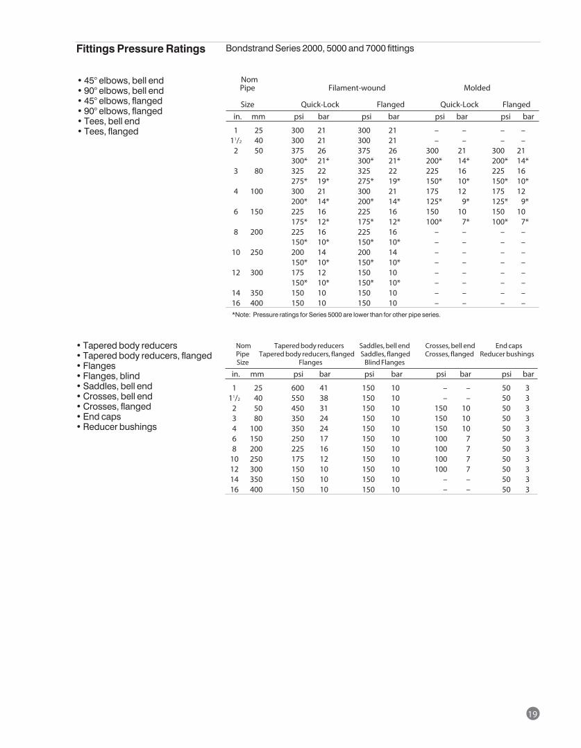
19
Nom Pipe Filament-wound Molded
Size Quick-Lock Flanged Quick-Lock Flanged in. mm psi bar psi bar psi bar psi bar
1 25 300 21 300 21 – – – – 11/2 40 300 21 300 21 – – – – 2 50 375 26 375 26 300 21 300 21 300* 21* 300* 21* 200* 14* 200* 14* 3 80 325 22 325 22 225 16 225 16 275* 19* 275* 19* 150* 10* 150* 10* 4 100 300 21 300 21 175 12 175 12 200* 14* 200* 14* 125* 9* 125* 9* 6 150 225 16 225 16 150 10 150 10 175* 12* 175* 12* 100* 7* 100* 7* 8 200 225 16 225 16 – – – – 150* 10* 150* 10* – – – – 10 250 200 14 200 14 – – – – 150* 10* 150* 10* – – – – 12 300 175 12 150 10 – – – – 150* 10* 150* 10* – – – – 14 350 150 10 150 10 – – – – 16 400 150 10 150 10 – – – – *Note: Pressure ratings for Series 5000 are lower than for other pipe series.
• 45° elbows, bell end• 90° elbows, bell end• 45° elbows, flanged• 90° elbows, flanged• Tees, bell end• Tees, flanged
Fittings Pressure Ratings Bondstrand Series 2000, 5000 and 7000 fittings
Nom Tapered body reducers Saddles, bell end Crosses, bell end End caps Pipe Tapered body reducers, flanged Saddles, flanged Crosses, flanged Reducer bushings Size Flanges Blind Flanges in. mm psi bar psi bar psi bar psi bar
1 25 600 41 150 10 – – 50 3 11/2 40 550 38 150 10 – – 50 3 2 50 450 31 150 10 150 10 50 3 3 80 350 24 150 10 150 10 50 3 4 100 350 24 150 10 150 10 50 3 6 150 250 17 150 10 100 7 50 3 8 200 225 16 150 10 100 7 50 3 10 250 175 12 150 10 100 7 50 3 12 300 150 10 150 10 100 7 50 3 14 350 150 10 150 10 – – 50 3 16 400 150 10 150 10 – – 50 3
• Tapered body reducers• Tapered body reducers, flanged• Flanges• Flanges, blind• Saddles, bell end• Crosses, bell end• Crosses, flanged• End caps• Reducer bushings
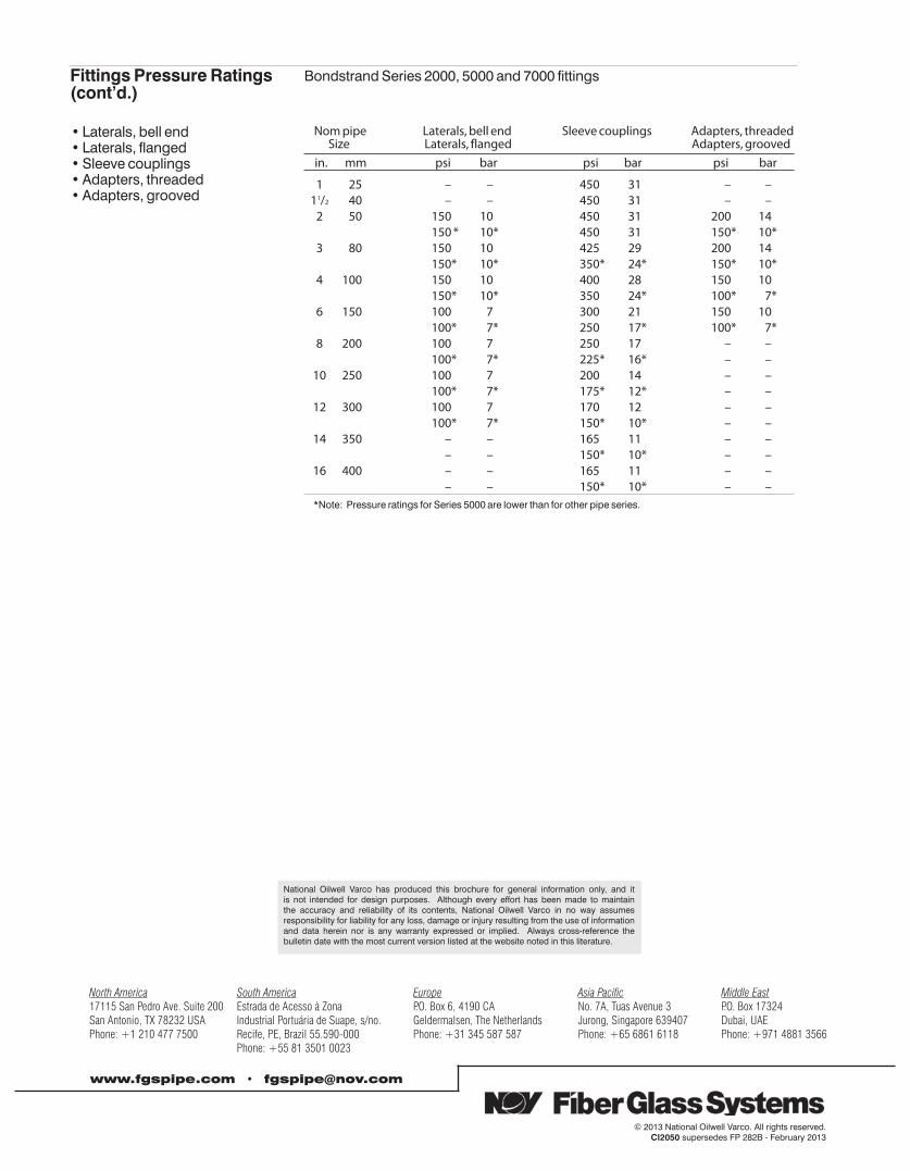
Fittings Pressure Ratings (cont’d.)
Bondstrand Series 2000, 5000 and 7000 fittings
Nom pipe Laterals, bell end Sleeve couplings Adapters, threaded Size Laterals, flanged Adapters, grooved in. mm psi bar psi bar psi bar
1 25 – – 450 31 – – 11/2 40 – – 450 31 – – 2 50 150 10 450 31 200 14 150 * 10* 450 31 150* 10* 3 80 150 10 425 29 200 14 150* 10* 350* 24* 150* 10* 4 100 150 10 400 28 150 10 150* 10* 350 24* 100* 7* 6 150 100 7 300 21 150 10 100* 7* 250 17* 100* 7* 8 200 100 7 250 17 – – 100* 7* 225* 16* – – 10 250 100 7 200 14 – – 100* 7* 175* 12* – – 12 300 100 7 170 12 – – 100* 7* 150* 10* – – 14 350 – – 165 11 – – – – 150* 10* – – 16 400 – – 165 11 – – – – 150* 10* – – *Note: Pressure ratings for Series 5000 are lower than for other pipe series.
• Laterals, bell end• Laterals, flanged• Sleeve couplings• Adapters, threaded• Adapters, grooved
North America South America Europe Asia Pacific Middle East17115 San Pedro Ave. Suite 200 Estrada de Acesso à Zona P.O. Box 6, 4190 CA No. 7A, Tuas Avenue 3 P.O. Box 17324San Antonio, TX 78232 USA Industrial Portuária de Suape, s/no. Geldermalsen, The Netherlands Jurong, Singapore 639407 Dubai, UAEPhone: +1 210 477 7500 Recife, PE, Brazil 55.590-000 Phone: +31 345 587 587 Phone: +65 6861 6118 Phone: +971 4881 3566 Phone: +55 81 3501 0023
© 2013 National Oilwell Varco. All rights reserved.CI2050 supersedes FP 282B - February 2013
National Oilwell Varco has produced this brochure for general information only, and it is not intended for design purposes. Although every effort has been made to maintain the accuracy and reliability of its contents, National Oilwell Varco in no way assumes responsibility for liability for any loss, damage or injury resulting from the use of information and data herein nor is any warranty expressed or implied. Always cross-reference the bulletin date with the most current version listed at the website noted in this literature.
www.fgspipe.com • [email protected]
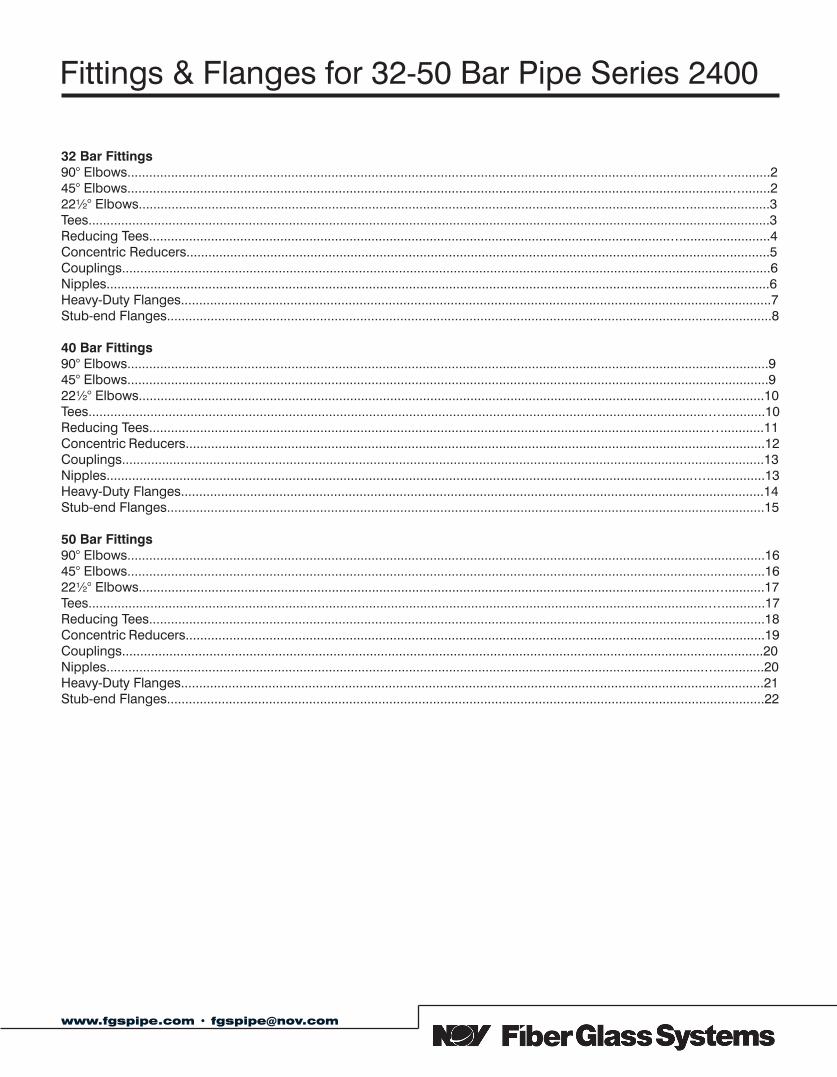
Fittings & Flanges for 32-50 Bar Pipe Series 2400
www.fgspipe.com • [email protected]
32 Bar Fittings90° Elbows................................................................................................................................................................................245° Elbows................................................................................................................................................................................222½° Elbows.............................................................................................................................................................................3Tees...........................................................................................................................................................................................3Reducing Tees..........................................................................................................................................................................4Concentric Reducers................................................................................................................................................................5Couplings..................................................................................................................................................................................6Nipples......................................................................................................................................................................................6Heavy-Duty Flanges..................................................................................................................................................................7Stub-end Flanges......................................................................................................................................................................8
40 Bar Fittings90° Elbows................................................................................................................................................................................945° Elbows................................................................................................................................................................................922½° Elbows...........................................................................................................................................................................10Tees.........................................................................................................................................................................................10Reducing Tees........................................................................................................................................................................11Concentric Reducers...............................................................................................................................................................12Couplings................................................................................................................................................................................13Nipples....................................................................................................................................................................................13Heavy-Duty Flanges................................................................................................................................................................14Stub-end Flanges....................................................................................................................................................................15
50 Bar Fittings90° Elbows...............................................................................................................................................................................1645° Elbows...............................................................................................................................................................................1622½° Elbows...........................................................................................................................................................................17Tees.........................................................................................................................................................................................17Reducing Tees.........................................................................................................................................................................18Concentric Reducers...............................................................................................................................................................19Couplings................................................................................................................................................................................20Nipples....................................................................................................................................................................................20Heavy-Duty Flanges................................................................................................................................................................21Stub-end Flanges....................................................................................................................................................................22
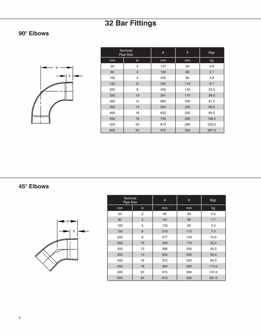
32 Bar Fittings
Nominal Pipe Size
A X Wgt.
mm in mm mm kg
50 2 137 50 0.6
80 3 190 80 2.1
100 4 235 80 3.8
150 6 350 110 8.7
200 8 455 140 24.0
250 10 561 170 39.0
300 12 663 200 61.0
350 14 594 230 66.0
400 16 632 230 84.0
450 18 732 260 168.0
500 20 813 290 230.0
600 24 975 350 367.0
Nominal Pipe Size
A X Wgt.
mm in mm mm kg
50 2 95 50 0.5
80 3 141 80 1.7
100 4 153 80 2.4
150 6 216 110 7.0
200 8 277 140 15.5
250 10 339 170 32.0
300 12 396 200 45.0
350 14 355 230 58.0
400 16 372 230 80.0
450 18 464 260 115.0
500 20 515 290 157.0
600 24 618 350 281.0
90° Elbows
45° Elbows
2
A
X
A
X
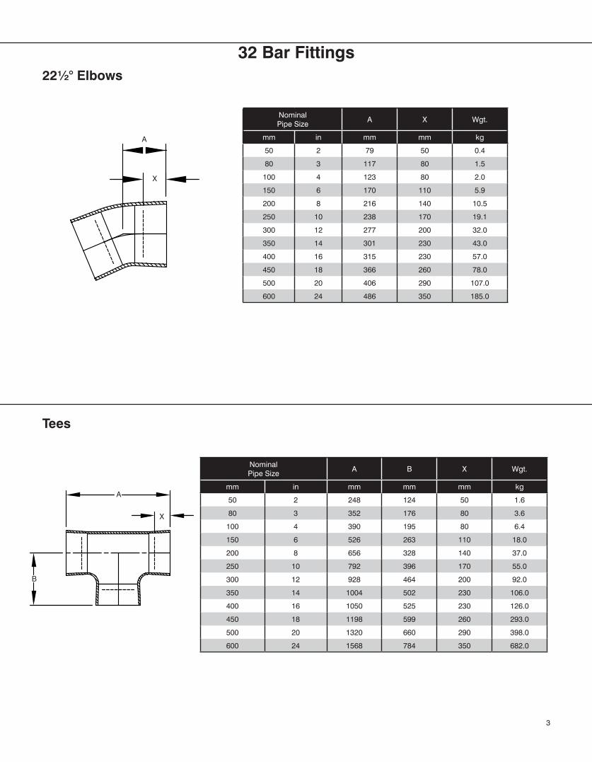
Nominal Pipe Size
A X Wgt.
mm in mm mm kg
50 2 79 50 0.4
80 3 117 80 1.5
100 4 123 80 2.0
150 6 170 110 5.9
200 8 216 140 10.5
250 10 238 170 19.1
300 12 277 200 32.0
350 14 301 230 43.0
400 16 315 230 57.0
450 18 366 260 78.0
500 20 406 290 107.0
600 24 486 350 185.0
Nominal Pipe Size
A B X Wgt.
mm in mm mm mm kg
50 2 248 124 50 1.6
80 3 352 176 80 3.6
100 4 390 195 80 6.4
150 6 526 263 110 18.0
200 8 656 328 140 37.0
250 10 792 396 170 55.0
300 12 928 464 200 92.0
350 14 1004 502 230 106.0
400 16 1050 525 230 126.0
450 18 1198 599 260 293.0
500 20 1320 660 290 398.0
600 24 1568 784 350 682.0
22½° Elbows
Tees
3
X
A
B
A
X
32 Bar Fittings
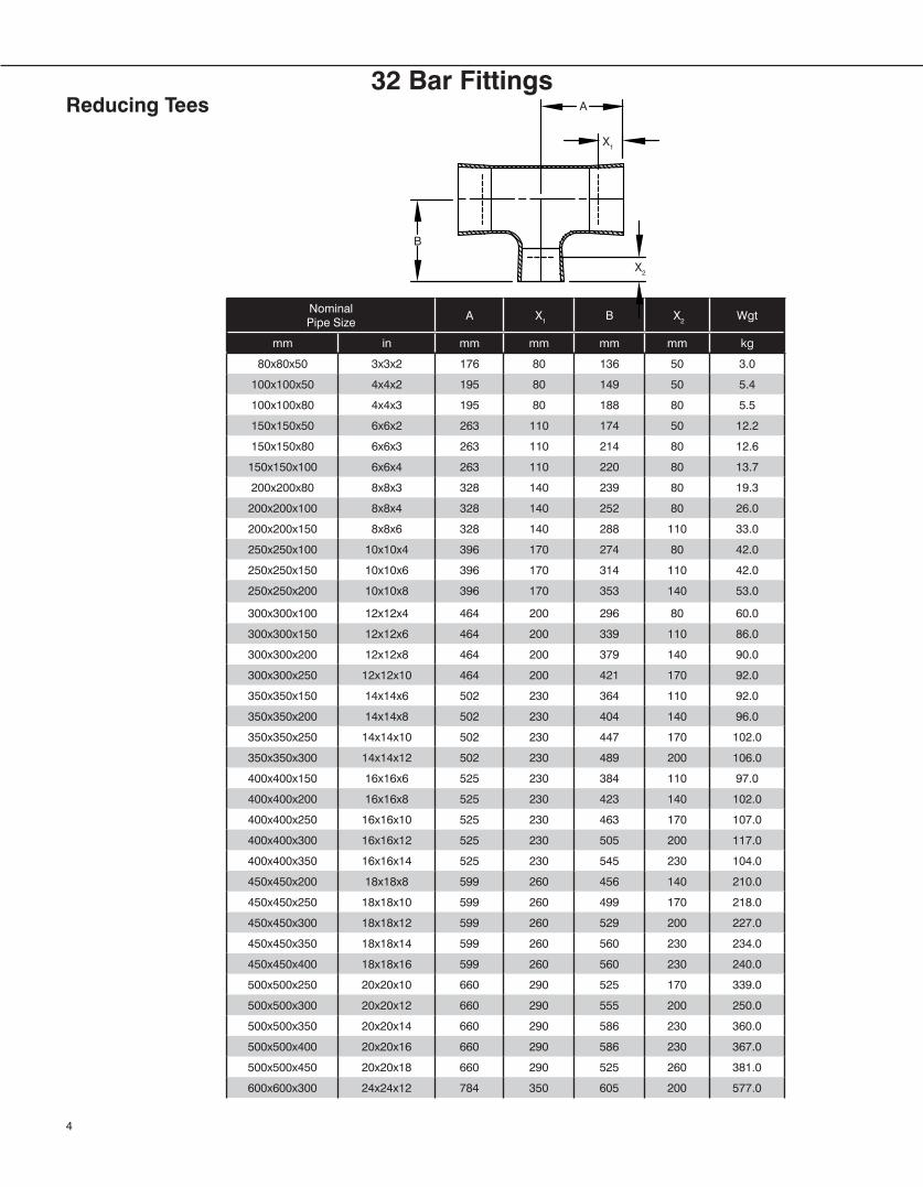
Nominal Pipe Size
A X1 B X2 Wgt
mm in mm mm mm mm kg
80x80x50 3x3x2 176 80 136 50 3.0
100x100x50 4x4x2 195 80 149 50 5.4
100x100x80 4x4x3 195 80 188 80 5.5
150x150x50 6x6x2 263 110 174 50 12.2
150x150x80 6x6x3 263 110 214 80 12.6
150x150x100 6x6x4 263 110 220 80 13.7
200x200x80 8x8x3 328 140 239 80 19.3
200x200x100 8x8x4 328 140 252 80 26.0
200x200x150 8x8x6 328 140 288 110 33.0
250x250x100 10x10x4 396 170 274 80 42.0
250x250x150 10x10x6 396 170 314 110 42.0
250x250x200 10x10x8 396 170 353 140 53.0
300x300x100 12x12x4 464 200 296 80 60.0
300x300x150 12x12x6 464 200 339 110 86.0
300x300x200 12x12x8 464 200 379 140 90.0
300x300x250 12x12x10 464 200 421 170 92.0
350x350x150 14x14x6 502 230 364 110 92.0
350x350x200 14x14x8 502 230 404 140 96.0
350x350x250 14x14x10 502 230 447 170 102.0
350x350x300 14x14x12 502 230 489 200 106.0
400x400x150 16x16x6 525 230 384 110 97.0
400x400x200 16x16x8 525 230 423 140 102.0
400x400x250 16x16x10 525 230 463 170 107.0
400x400x300 16x16x12 525 230 505 200 117.0
400x400x350 16x16x14 525 230 545 230 104.0
450x450x200 18x18x8 599 260 456 140 210.0
450x450x250 18x18x10 599 260 499 170 218.0
450x450x300 18x18x12 599 260 529 200 227.0
450x450x350 18x18x14 599 260 560 230 234.0
450x450x400 18x18x16 599 260 560 230 240.0
500x500x250 20x20x10 660 290 525 170 339.0
500x500x300 20x20x12 660 290 555 200 250.0
500x500x350 20x20x14 660 290 586 230 360.0
500x500x400 20x20x16 660 290 586 230 367.0
500x500x450 20x20x18 660 290 525 260 381.0
600x600x300 24x24x12 784 350 605 200 577.0
Reducing Tees
4
A
X2
X1
B
32 Bar Fittings
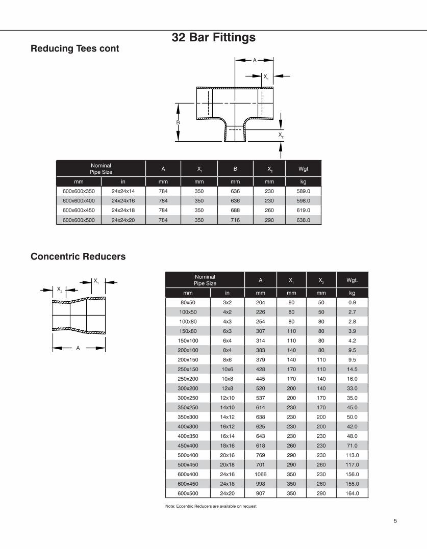
Nominal Pipe Size
A X1 X2 Wgt.
mm in mm mm mm kg
80x50 3x2 204 80 50 0.9
100x50 4x2 226 80 50 2.7
100x80 4x3 254 80 80 2.8
150x80 6x3 307 110 80 3.9
150x100 6x4 314 110 80 4.2
200x100 8x4 383 140 80 9.5
200x150 8x6 379 140 110 9.5
250x150 10x6 428 170 110 14.5
250x200 10x8 445 170 140 16.0
300x200 12x8 520 200 140 33.0
300x250 12x10 537 200 170 35.0
350x250 14x10 614 230 170 45.0
350x300 14x12 638 230 200 50.0
400x300 16x12 625 230 200 42.0
400x350 16x14 643 230 230 48.0
450x400 18x16 618 260 230 71.0
500x400 20x16 769 290 230 113.0
500x450 20x18 701 290 260 117.0
600x400 24x16 1066 350 230 156.0
600x450 24x18 998 350 260 155.0
600x500 24x20 907 350 290 164.0
Concentric Reducers
Note: Eccentric Reducers are available on request
A
X1
X2
5
Nominal Pipe Size
A X1 B X2 Wgt
mm in mm mm mm mm kg
600x600x350 24x24x14 784 350 636 230 589.0
600x600x400 24x24x16 784 350 636 230 598.0
600x600x450 24x24x18 784 350 688 260 619.0
600x600x500 24x24x20 784 350 716 290 638.0
Reducing Tees contA
X2
X1
B
32 Bar Fittings
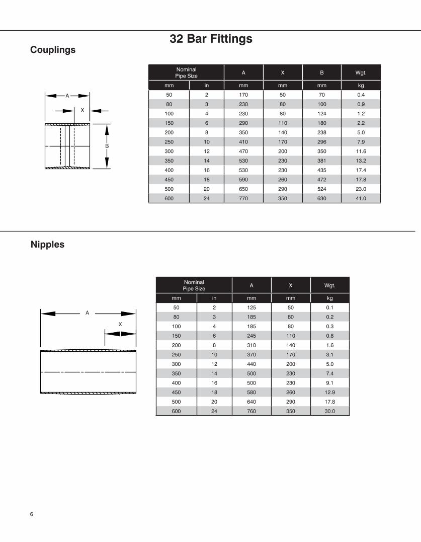
Nominal Pipe Size
A X B Wgt.
mm in mm mm mm kg
50 2 170 50 70 0.4
80 3 230 80 100 0.9
100 4 230 80 124 1.2
150 6 290 110 180 2.2
200 8 350 140 238 5.0
250 10 410 170 296 7.9
300 12 470 200 350 11.6
350 14 530 230 381 13.2
400 16 530 230 435 17.4
450 18 590 260 472 17.8
500 20 650 290 524 23.0
600 24 770 350 630 41.0
Nominal Pipe Size
A X Wgt.
mm in mm mm kg
50 2 125 50 0.1
80 3 185 80 0.2
100 4 185 80 0.3
150 6 245 110 0.8
200 8 310 140 1.6
250 10 370 170 3.1
300 12 440 200 5.0
350 14 500 230 7.4
400 16 500 230 9.1
450 18 580 260 12.9
500 20 640 290 17.8
600 24 760 350 30.0
Couplings
Nipples
6
A
X
A
X
B
32 Bar Fittings
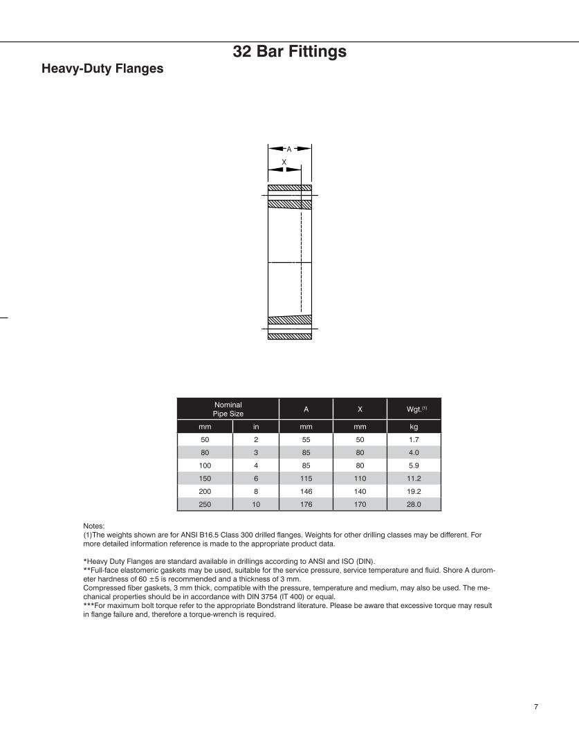
Nominal Pipe Size
A X Wgt.(1)
mm in mm mm kg
50 2 55 50 1.7
80 3 85 80 4.0
100 4 85 80 5.9
150 6 115 110 11.2
200 8 146 140 19.2
250 10 176 170 28.0
Notes:(1)The weights shown are for ANSI B16.5 Class 300 drilled flanges. Weights for other drilling classes may be different. For more detailed information reference is made to the appropriate product data.
*Heavy Duty Flanges are standard available in drillings according to ANSI and ISO (DIN).**Full-face elastomeric gaskets may be used, suitable for the service pressure, service temperature and fluid. Shore A durom-eter hardness of 60 ±5 is recommended and a thickness of 3 mm.Compressed fiber gaskets, 3 mm thick, compatible with the pressure, temperature and medium, may also be used. The me-chanical properties should be in accordance with DIN 3754 (IT 400) or equal.***For maximum bolt torque refer to the appropriate Bondstrand literature. Please be aware that excessive torque may result in flange failure and, therefore a torque-wrench is required.
Heavy-Duty Flanges
7
A
X
32 Bar Fittings
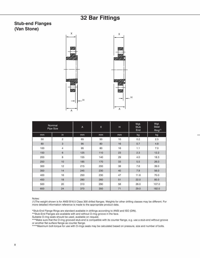
Nominal Pipe Size
A X HWgt.StubEnd
Wgt.Steel
Ring(1)
mm in mm mm mm kg kg
50 2 65 50 10 0.2 2.5
80 3 95 80 16 0.7 4.8
100 4 95 80 16 1.1 7.0
150 6 125 110 23 2.3 12.2
200 8 155 140 29 4.0 18.3
250 10 185 170 33 5.5 26.0
300 12 215 200 38 7.6 39.0
350 14 245 230 40 7.9 56.0
400 16 250 230 47 11.6 70.0
450 18 280 260 51 22.0 85.0
500 20 310 290 58 26.0 107.0
600 24 370 350 71 29.0 182.0
Notes:(1)The weight shown is for ANSI B16.5 Class 300 drilled flanges. Weights for other drilling classes may be different. For more detailed information reference is made to the appropriate product data.
*Stub-End Flange Rings are standard available in drillings according to ANSI and ISO (DIN).**Stub-End Flanges are available with and without O-ring groove in the face.Suitable O-ring seals should be used, available on request.***Make sure that the O-ring grooved stub-end is compatible with its counter flange, e.g. use a stub-end without groove or another flat surface flange as counter flange.****Maximum bolt-torque for use with O-rings seals may be calculated based on pressure, size and number of bolts.
Stub-end Flanges(Van Stone)
8
X
H
AA
H
X
32 Bar Fittings
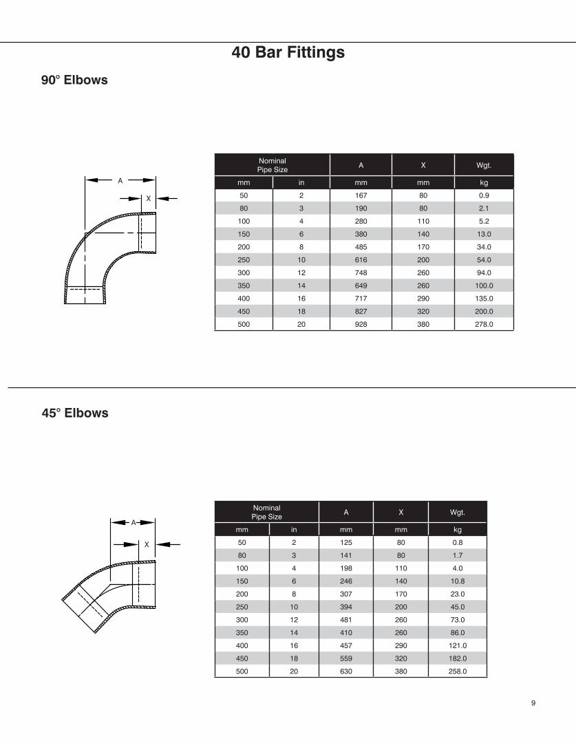
40 Bar Fittings
Nominal Pipe Size
A X Wgt.
mm in mm mm kg
50 2 167 80 0.9
80 3 190 80 2.1
100 4 280 110 5.2
150 6 380 140 13.0
200 8 485 170 34.0
250 10 616 200 54.0
300 12 748 260 94.0
350 14 649 260 100.0
400 16 717 290 135.0
450 18 827 320 200.0
500 20 928 380 278.0
Nominal Pipe Size
A X Wgt.
mm in mm mm kg
50 2 125 80 0.8
80 3 141 80 1.7
100 4 198 110 4.0
150 6 246 140 10.8
200 8 307 170 23.0
250 10 394 200 45.0
300 12 481 260 73.0
350 14 410 260 86.0
400 16 457 290 121.0
450 18 559 320 182.0
500 20 630 380 258.0
90° Elbows
45° Elbows
9
A
X
A
X
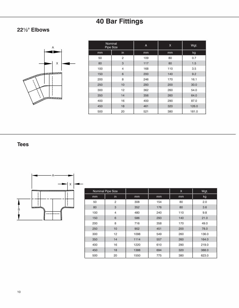
Nominal Pipe Size
A X Wgt.
mm in mm mm kg
50 2 109 80 0.7
80 3 117 80 1.5
100 4 168 110 3.5
150 6 200 140 9.2
200 8 246 170 16.1
250 10 293 200 30.0
300 12 362 260 54.0
350 14 356 260 64.0
400 16 400 290 87.0
450 18 461 320 126.0
500 20 521 380 181.0
Nominal Pipe Size X Wgt.
mm in mm mm mm kg
50 2 308 154 80 2.0
80 3 352 176 80 3.6
100 4 480 240 110 9.8
150 6 586 293 140 21.0
200 8 716 358 170 49.0
250 10 902 451 200 78.0
300 12 1098 549 260 136.0
350 14 1114 557 260 164.0
400 16 1220 610 290 219.0
450 18 1388 694 320 388.0
500 20 1550 775 380 623.0
22½° Elbows
Tees
10
X
A
B
A
X
40 Bar Fittings
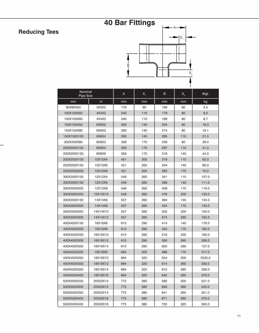
Nominal Pipe Size
A X1 B X2 Wgt.
mm in mm mm mm mm kg
80X80X50 3X3X2 176 80 166 80 3.5
100X100X50 4X4X2 240 110 179 80 8.5
100X100X80 4X4X3 240 110 188 80 8.7
150X150X50 6X6X2 293 140 204 80 18.3
150X150X80 6X6X3 293 140 214 80 19.1
150X150X100 6X6X4 293 140 265 110 21.0
200X200X80 8X8X3 358 170 239 80 39.0
200X200X100 8X8X4 358 170 297 110 41.0
200X200X150 8X8X6 358 170 318 140 44.0
250X250X100 10X10X4 451 200 319 110 62.0
250X250X150 10X10X6 451 200 344 140 66.0
250X250X200 10X10X8 451 200 383 170 70.0
300X300X100 12X12X4 549 260 341 110 107.0
300X300X150 12X12X6 549 260 369 140 111.0
300X300X200 12X12X8 549 260 409 170 116.0
300X300X250 12X12X10 549 260 476 200 125.0
350X350X150 14X14X6 557 260 394 140 134.0
350X350X200 14X14X8 557 260 434 170 140.0
350X350X250 14X14X10 557 260 502 200 150.0
350X350X300 14X14X12 557 260 574 260 163.0
400X400X150 16X16X6 610 290 414 140 176.0
400X400X200 16X16X8 610 290 453 170 182.0
400X400X250 16X16X10 610 290 518 200 193.0
400X400X300 16X16X12 610 290 590 260 206.0
400X400X350 16X16X14 610 290 600 260 137.0
450X450X200 18X18X8 694 320 486 170 317.0
450X450X250 18X18X10 694 320 554 200 3330.0
450X450X300 18X18X12 694 320 614 260 350.0
450X450X350 18X18X14 694 320 615 260 356.0
450X450X400 18X18X16 694 320 645 290 370.0
500X500X250 20X20X10 775 380 580 200 521.0
500X500X300 20X20X12 775 380 640 260 543.0
500X500X350 20X20X14 775 380 641 260 551.0
500X500X400 20X20X16 775 380 671 290 570.0
500X500X450 20X20X18 775 380 720 320 593.0
Reducing Tees
11
A
X2
X1
B
40 Bar Fittings
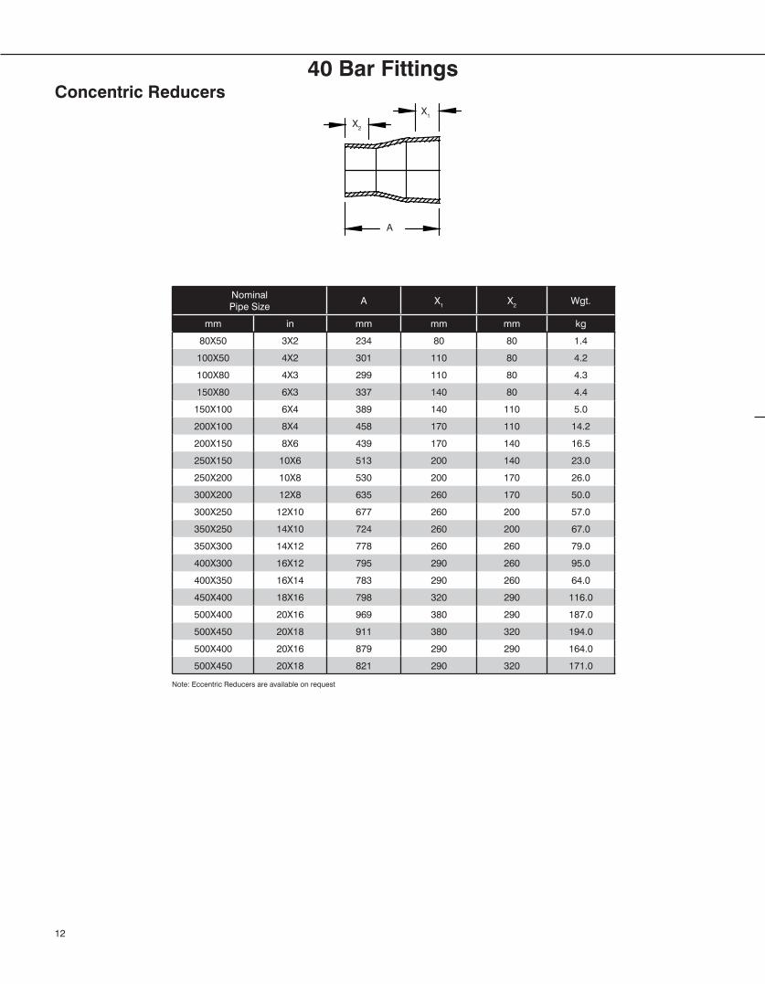
Nominal Pipe Size
A X1 X2 Wgt.
mm in mm mm mm kg
80X50 3X2 234 80 80 1.4
100X50 4X2 301 110 80 4.2
100X80 4X3 299 110 80 4.3
150X80 6X3 337 140 80 4.4
150X100 6X4 389 140 110 5.0
200X100 8X4 458 170 110 14.2
200X150 8X6 439 170 140 16.5
250X150 10X6 513 200 140 23.0
250X200 10X8 530 200 170 26.0
300X200 12X8 635 260 170 50.0
300X250 12X10 677 260 200 57.0
350X250 14X10 724 260 200 67.0
350X300 14X12 778 260 260 79.0
400X300 16X12 795 290 260 95.0
400X350 16X14 783 290 260 64.0
450X400 18X16 798 320 290 116.0
500X400 20X16 969 380 290 187.0
500X450 20X18 911 380 320 194.0
500X400 20X16 879 290 290 164.0
500X450 20X18 821 290 320 171.0
Concentric Reducers
A
X1
X2
12
Note: Eccentric Reducers are available on request
40 Bar Fittings
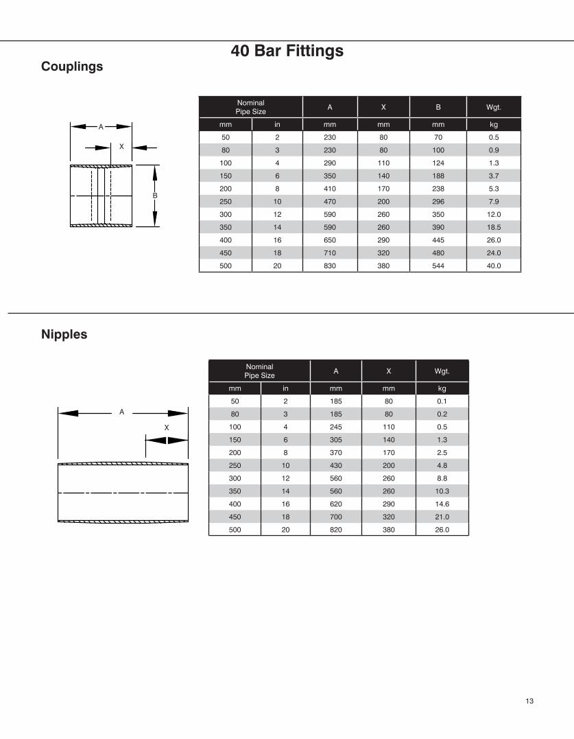
Nominal Pipe Size
A X B Wgt.
mm in mm mm mm kg
50 2 230 80 70 0.5
80 3 230 80 100 0.9
100 4 290 110 124 1.3
150 6 350 140 188 3.7
200 8 410 170 238 5.3
250 10 470 200 296 7.9
300 12 590 260 350 12.0
350 14 590 260 390 18.5
400 16 650 290 445 26.0
450 18 710 320 480 24.0
500 20 830 380 544 40.0
Nominal Pipe Size
A X Wgt.
mm in mm mm kg
50 2 185 80 0.1
80 3 185 80 0.2
100 4 245 110 0.5
150 6 305 140 1.3
200 8 370 170 2.5
250 10 430 200 4.8
300 12 560 260 8.8
350 14 560 260 10.3
400 16 620 290 14.6
450 18 700 320 21.0
500 20 820 380 26.0
Couplings
Nipples
13
A
X
A
X
B
40 Bar Fittings
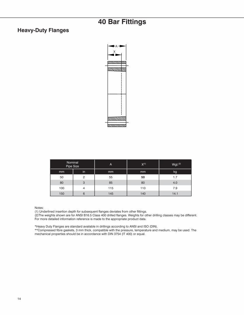
Nominal Pipe Size
A X(1) Wgt.(2)
mm in mm mm kg
50 2 55 50 1.7
80 3 85 80 4.0
100 4 115 110 7.9
150 6 145 140 14.1
Heavy-Duty Flanges
Notes:(1) Underlined insertion depth for subsequent flanges deviates from other fittings.(2)The weights shown are for ANSI B16.5 Class 400 drilled flanges. Weights for other drilling classes may be different. For more detailed information reference is made to the appropriate product data.
*Heavy Duty Flanges are standard available in drillings according to ANSI and ISO (DIN).**Compressed fibre gaskets, 3 mm thick, compatible with the pressure, temperature and medium, may be used. The mechanical properties should be in accordance with DIN 3754 (IT 400) or equal.
14
A
X
40 Bar Fittings
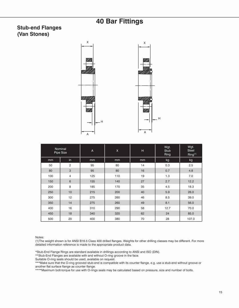
Nominal Pipe Size
A X HWgt.StubRing
Wgt.Steel
Ring(1)
mm in mm mm mm kg kg
50 2 95 80 14 0.3 2.5
80 3 95 80 16 0.7 4.8
100 4 125 110 19 1.3 7.0
150 6 155 140 27 2.7 12.2
200 8 185 170 35 4.5 18.3
250 10 215 200 40 5.9 26.0
300 12 275 260 46 8.5 39.0
350 14 275 260 49 8.1 56.0
400 16 310 290 58 12.7 70.0
450 18 340 320 62 24 85.0
500 20 400 380 70 28 107.0
Stub-end Flanges(Van Stones)
Notes:(1)The weight shown is for ANSI B16.5 Class 400 drilled flanges. Weights for other drilling classes may be different. For more detailed information reference is made to the appropriate product data.
*Stub-End Flange Rings are standard available in drillings according to ANSI and ISO (DIN).**Stub-End Flanges are available with and without O-ring groove in the face.Suitable O-ring seals should be used, available on request.***Make sure that the O-ring grooved stub-end is compatible with its counter flange, e.g. use a stub-end without groove or another flat surface flange as counter flange.****Maximum bolt-torque for use with O-rings seals may be calculated based on pressure, size and number of bolts.
15
X
H
AA
H
X
40 Bar Fittings
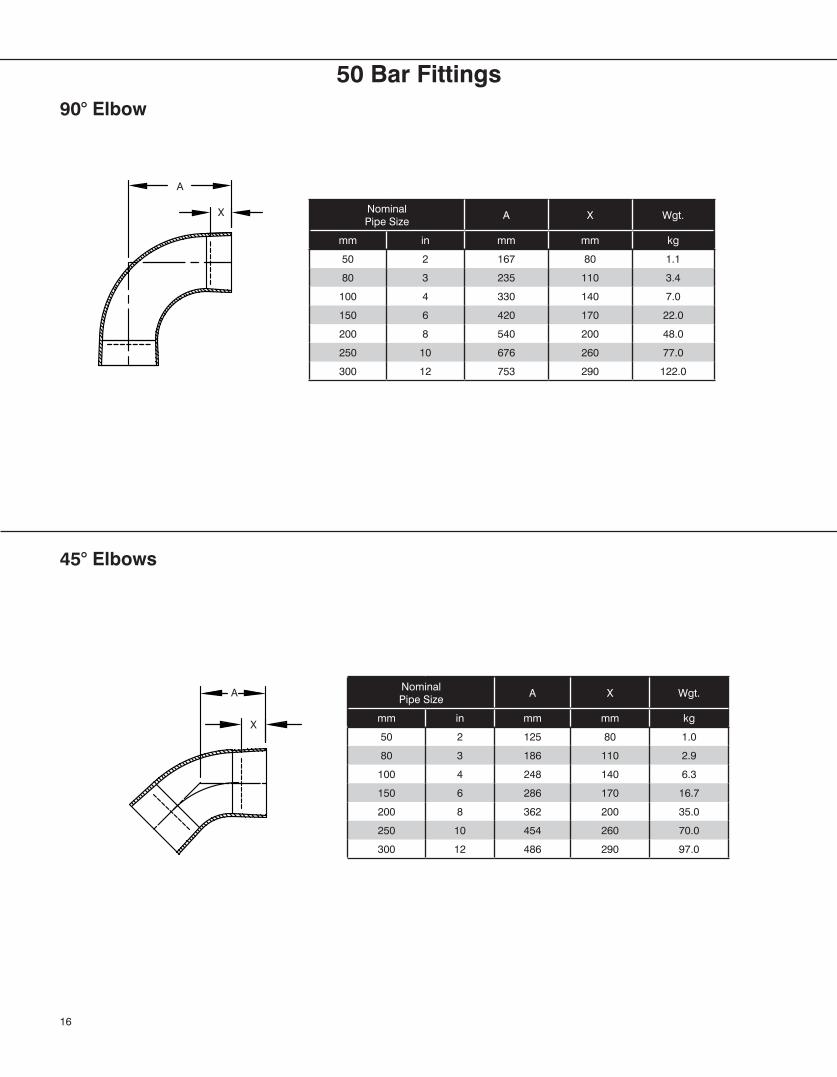
50 Bar Fittings
Nominal Pipe Size
A X Wgt.
mm in mm mm kg
50 2 167 80 1.1
80 3 235 110 3.4
100 4 330 140 7.0
150 6 420 170 22.0
200 8 540 200 48.0
250 10 676 260 77.0
300 12 753 290 122.0
Nominal Pipe Size
A X Wgt.
mm in mm mm kg
50 2 125 80 1.0
80 3 186 110 2.9
100 4 248 140 6.3
150 6 286 170 16.7
200 8 362 200 35.0
250 10 454 260 70.0
300 12 486 290 97.0
90° Elbow
45° Elbows
16
A
X
A
X
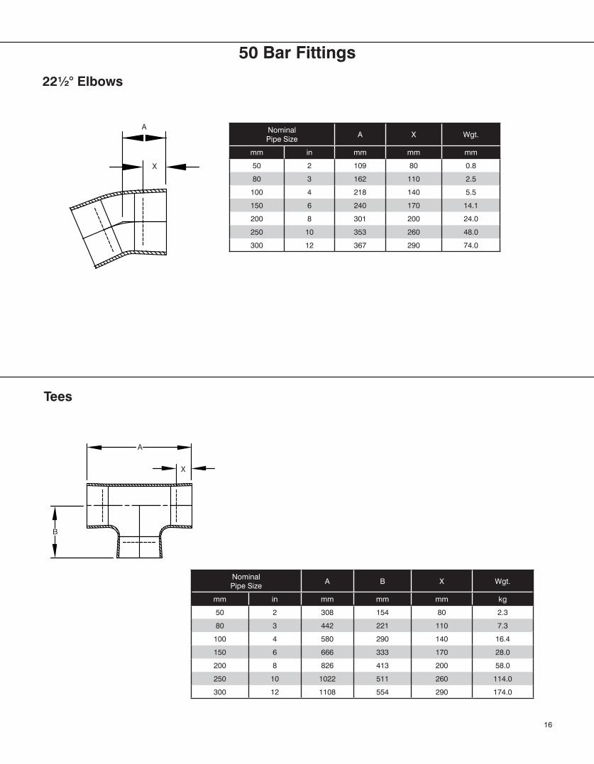
Nominal Pipe Size
A X Wgt.
mm in mm mm mm
50 2 109 80 0.8
80 3 162 110 2.5
100 4 218 140 5.5
150 6 240 170 14.1
200 8 301 200 24.0
250 10 353 260 48.0
300 12 367 290 74.0
Nominal Pipe Size
A B X Wgt.
mm in mm mm mm kg
50 2 308 154 80 2.3
80 3 442 221 110 7.3
100 4 580 290 140 16.4
150 6 666 333 170 28.0
200 8 826 413 200 58.0
250 10 1022 511 260 114.0
300 12 1108 554 290 174.0
22½° Elbows
Tees
16
X
A
B
A
X
50 Bar Fittings
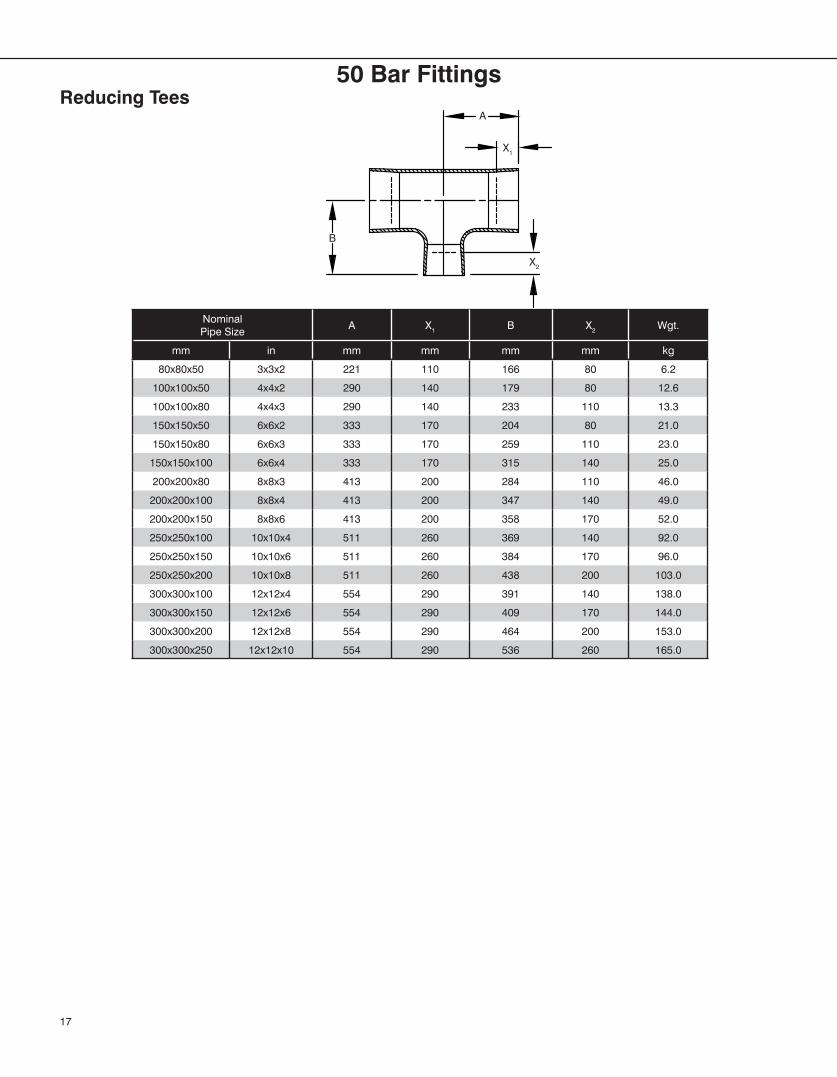
Nominal Pipe Size
A X1 B X2 Wgt.
mm in mm mm mm mm kg
80x80x50 3x3x2 221 110 166 80 6.2
100x100x50 4x4x2 290 140 179 80 12.6
100x100x80 4x4x3 290 140 233 110 13.3
150x150x50 6x6x2 333 170 204 80 21.0
150x150x80 6x6x3 333 170 259 110 23.0
150x150x100 6x6x4 333 170 315 140 25.0
200x200x80 8x8x3 413 200 284 110 46.0
200x200x100 8x8x4 413 200 347 140 49.0
200x200x150 8x8x6 413 200 358 170 52.0
250x250x100 10x10x4 511 260 369 140 92.0
250x250x150 10x10x6 511 260 384 170 96.0
250x250x200 10x10x8 511 260 438 200 103.0
300x300x100 12x12x4 554 290 391 140 138.0
300x300x150 12x12x6 554 290 409 170 144.0
300x300x200 12x12x8 554 290 464 200 153.0
300x300x250 12x12x10 554 290 536 260 165.0
Reducing Tees
17
A
X2
X1
B
50 Bar Fittings
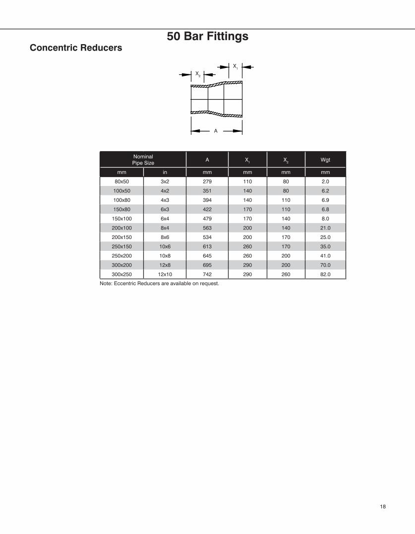
Nominal Pipe Size
A X1 X2 Wgt
mm in mm mm mm mm
80x50 3x2 279 110 80 2.0
100x50 4x2 351 140 80 6.2
100x80 4x3 394 140 110 6.9
150x80 6x3 422 170 110 6.8
150x100 6x4 479 170 140 8.0
200x100 8x4 563 200 140 21.0
200x150 8x6 534 200 170 25.0
250x150 10x6 613 260 170 35.0
250x200 10x8 645 260 200 41.0
300x200 12x8 695 290 200 70.0
300x250 12x10 742 290 260 82.0
Concentric Reducers
Note: Eccentric Reducers are available on request.
A
X1
X2
18
50 Bar Fittings
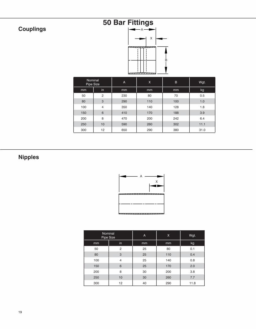
Nominal Pipe Size
A X B Wgt.
mm in mm mm mm kg
50 2 230 80 70 0.5
80 3 290 110 100 1.0
100 4 350 140 128 1.8
150 6 410 170 188 3.9
200 8 470 200 242 6.4
250 10 590 260 302 11.1
300 12 650 290 380 31.0
Nominal Pipe Size
A X Wgt.
mm in mm mm kg
50 2 25 80 0.1
80 3 25 110 0.4
100 4 25 140 0.8
150 6 25 170 2.0
200 8 30 200 3.8
250 10 30 260 7.7
300 12 40 290 11.8
Couplings
Nipples
19
A
X
A
X
B
50 Bar Fittings
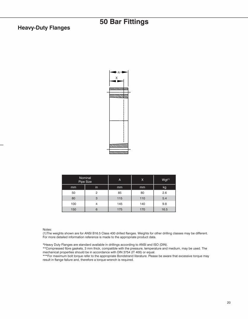
Nominal Pipe Size
A X Wgt(1)
mm in mm mm kg
50 2 85 80 2.6
80 3 115 110 5.4
100 4 145 140 9.8
150 6 175 170 16.5
Notes:(1)The weights shown are for ANSI B16.5 Class 400 drilled flanges. Weights for other drilling classes may be different. For more detailed information reference is made to the appropriate product data.
*Heavy Duty Flanges are standard available in drillings according to ANSI and ISO (DIN).**Compressed fibre gaskets, 3 mm thick, compatible with the pressure, temperature and medium, may be used. The mechanical properties should be in accordance with DIN 3754 (IT 400) or equal.***For maximum bolt torque refer to the appropriate Bondstrand literature. Please be aware that excessive torque may result in flange failure and, therefore a torque-wrench is required.
Heavy-Duty Flanges
20
A
X
50 Bar Fittings
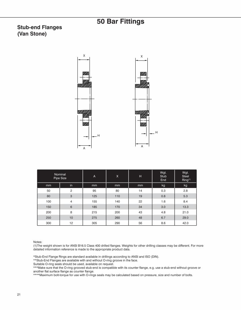
Nominal Pipe Size
A X HWgt.StubEnd
Wgt.Steel
Ring(1)
mm in mm mm mm kg kg
50 2 95 80 14 0.3 2.8
80 3 125 110 19 0.8 5.3
100 4 155 140 22 1.6 8.4
150 6 185 170 34 3.0 13.3
200 8 215 200 43 4.8 21.0
250 10 275 260 48 6.7 29.0
300 12 305 290 56 8.6 42.0
Notes:(1)The weight shown is for ANSI B16.5 Class 400 drilled flanges. Weights for other drilling classes may be different. For more detailed information reference is made to the appropriate product data.
*Stub-End Flange Rings are standard available in drillings according to ANSI and ISO (DIN).**Stub-End Flanges are available with and without O-ring groove in the face.Suitable O-ring seals should be used, available on request.***Make sure that the O-ring grooved stub-end is compatible with its counter flange, e.g. use a stub-end without groove or another flat surface flange as counter flange.****Maximum bolt-torque for use with O-rings seals may be calculated based on pressure, size and number of bolts.
Stub-end Flanges(Van Stone)
21
X
H
AA
H
X
50 Bar Fittings


©2013, National Oilwell Varco. All rights reserved.CI2450 - June 2013
www.fgspipe.com • [email protected]
North America South America Europe Asia Pacific Middle East17115 San Pedro Ave. Suite 200 Avenida Fernando Simoes P.O. Box 6, 4190 CA No. 7A, Tuas Avenue 3 P.O. Box 17324San Antonio, Texas 78232 USA Recife, Brazil 51020-390 Geldermalsen, The Netherlands Jurong, Singapore 639407 Dubai, UAEPhone: 210 477 7500 Phone: 55 31 3501 0023 Phone: 31 346 587 587 Phone: 65 6861 6118 Phone: 971 4881 3566
National Oilwell Varco has produced this brochure for general information only, and it is not intended for design purposes. Although every effort has been made to maintain the accuracy and reliability of its contents, National Oilwell Varco in no way assumes responsibility for liability for any loss, damage or injury resulting from the use of information and data herein nor is any warranty expressed or implied. Always cross-reference the bulletin date with the most current version listed at the web site noted in this literature.
Fittings Dimensions in 2” through 16”(For Bondstrand™ pipe systems 3000, 3200, 3300, 3000A, 3200A and 3300A)
Units: All dimensions are in U.S. Customary units (inches). Diametric dimensions are maximums. Insertion depths (X) are typical. All weights (Ibs.) are approximate and assume bell-end configurations.
Tolerances: Tolerance for center line to face dimensions on fittings with flange-end configurations is ±1/2 inch. Tolerance for center line to face dimensions on fittings with bell-end configurations is ±1/2
inch. Tolerance for angular dimensions is ±1°.
Standard end configurations: Bell end is standard configurations. All other end configurations, including size reductions, are made to order.
Taper angle: Taper angle on all bell x spigot end configurations is 13/4° for 2 through 6 inch nominal and 2° for sizes 8 through 16 inch pipe sizes.
Manufacturing methods: The fiberglass-reinforced epoxy resin fittings shown in this publication are manufactured by the methods as indicated - Filament winding, Compression molding, Centrifugal casting and Contact molding.
Pressure ratings: See the appropriate Bondstrand Product Data sheet for pressure ratings.
Individual system components may not have the same ratings as the pipe. Refer to the detailed product information for the specific components to determine the pressure rating for the system as a whole.
Flange rings: Bolt hole patterns are drilled in accordance with ANSI B16.5, Cl. 150.
www.nov.com/fgs • [email protected]
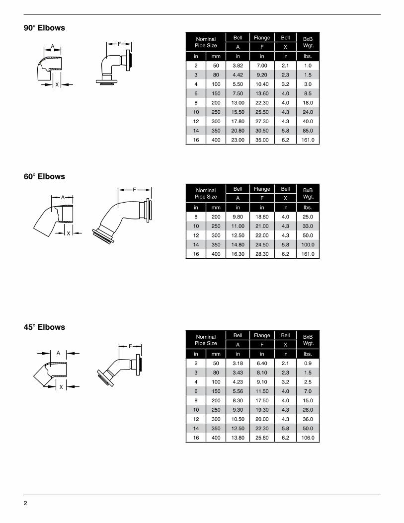
2
Nominal Pipe Size
Bell Flange Bell BxB Wgt.A F X
in mm in in in lbs.
2 50 3.82 7.00 2.1 1.0
3 80 4.42 9.20 2.3 1.5
4 100 5.50 10.40 3.2 3.0
6 150 7.50 13.60 4.0 8.5
8 200 13.00 22.30 4.0 18.0
10 250 15.50 25.50 4.3 24.0
12 300 17.80 27.30 4.3 40.0
14 350 20.80 30.50 5.8 85.0
16 400 23.00 35.00 6.2 161.0
90° Elbows
60° Elbows
Nominal Pipe Size
Bell Flange Bell BxB Wgt.A F X
in mm in in in lbs.
8 200 9.80 18.80 4.0 25.0
10 250 11.00 21.00 4.3 33.0
12 300 12.50 22.00 4.3 50.0
14 350 14.80 24.50 5.8 100.0
16 400 16.30 28.30 6.2 161.0
Nominal Pipe Size
Bell Flange Bell BxB Wgt.A F X
in mm in in in lbs.
2 50 3.18 6.40 2.1 0.9
3 80 3.43 8.10 2.3 1.5
4 100 4.23 9.10 3.2 2.5
6 150 5.56 11.50 4.0 7.0
8 200 8.30 17.50 4.0 15.0
10 250 9.30 19.30 4.3 28.0
12 300 10.50 20.00 4.3 36.0
14 350 12.50 22.30 5.8 50.0
16 400 13.80 25.80 6.2 106.0
45° Elbows
A
X
F
A
X
A
X
F
F
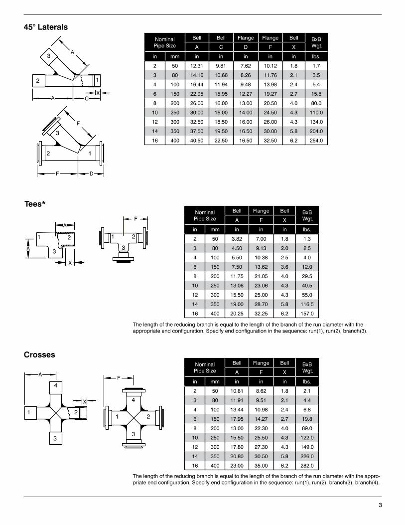
3
Nominal Pipe Size
Bell Bell Flange Flange Bell BxB Wgt.A C D F X
in mm in in in in in lbs.
2 50 12.31 9.81 7.62 10.12 1.8 1.7
3 80 14.16 10.66 8.26 11.76 2.1 3.5
4 100 16.44 11.94 9.48 13.98 2.4 5.4
6 150 22.95 15.95 12.27 19.27 2.7 15.8
8 200 26.00 16.00 13.00 20.50 4.0 80.0
10 250 30.00 16.00 14.00 24.50 4.3 110.0
12 300 32.50 18.50 16.00 26.00 4.3 134.0
14 350 37.50 19.50 16.50 30.00 5.8 204.0
16 400 40.50 22.50 16.50 32.50 6.2 254.0
45° Laterals
Crosses
Tees*Nominal Pipe Size
Bell Flange Bell BxB Wgt.A F X
in mm in in in lbs.
2 50 3.82 7.00 1.8 1.3
3 80 4.50 9.13 2.0 2.5
4 100 5.50 10.38 2.5 4.0
6 150 7.50 13.62 3.6 12.0
8 200 11.75 21.05 4.0 29.5
10 250 13.06 23.06 4.3 40.5
12 300 15.50 25.00 4.3 55.0
14 350 19.00 28.70 5.8 116.5
16 400 20.25 32.25 6.2 157.0
X
AF
FA
A
X
F
DF
CA
A
X
Nominal Pipe Size
Bell Flange Bell BxB Wgt.A F X
in mm in in in lbs.
2 50 10.81 8.62 1.8 2.1
3 80 11.91 9.51 2.1 4.4
4 100 13.44 10.98 2.4 6.8
6 150 17.95 14.27 2.7 19.8
8 200 13.00 22.30 4.0 89.0
10 250 15.50 25.50 4.3 122.0
12 300 17.80 27.30 4.3 149.0
14 350 20.80 30.50 5.8 226.0
16 400 23.00 35.00 6.2 282.0
The length of the reducing branch is equal to the length of the branch of the run diameter with the appro-priate end configuration. Specify end configuration in the sequence: run(1), run(2), branch(3), branch(4).
12
3
2
3
1
2
3
1 1
3
2
1 2
3
4
4
2
3
1
The length of the reducing branch is equal to the length of the branch of the run diameter with the appropriate end configuration. Specify end configuration in the sequence: run(1), run(2), branch(3).
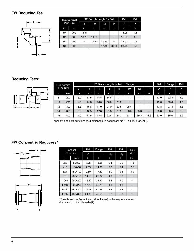
4
FW Concentric Reducers*
X2
X1
A
F
Run Nominal Pipe Size
“B” Branch Lenght for Bell Bell Bell
8 10 12 14 A X
in mm in in in in in in
10 250 12.81 -- -- -- 13.06 4.3
12 300 13.79 14.05 -- -- 15.50 4.3
14 350 -- 14.90 16.35 -- 19.00 5.8
16 400 -- -- 17.36 20.01 20.25 6.2
FW Reducing Tee
*Specify end configurations (bell or flange) in the sequence: major diameter(1), minor diameter(2).
12
Nominal Pipe Size
Bell Flange Bell Bell BxBWgt.A F X1 X2
in mm in in in in lbs.
3x2 80x50 7.05 13.65 2.4 2.2 1.5
4x3 100x80 7.35 14.05 2.8 2.4 2.6
6x4 150x100 9.80 17.60 3.0 2.8 4.9
8x6 200x150 14.18 29.34 4.0 2.7 --
10x8 250x200 15.62 34.92 4.3 4.0 --
12x10 300x250 17.25 36.75 4.3 4.3 --
14x12 350x300 21.06 40.26 5.8 4.3 --
16x14 400x350 24.88 46.58 6.2 5.8 --
A
X
B
Run Nominal Pipe Size
“B” Branch length for bell or Flange Bell Flange Bell
2 3 4 6 8 10 12 14 A F X
in mm in in in in in in in in in in in
8 200 13.0 13.5 14.8 18.8 -- -- -- -- 13.0 22.3 4.0
10 250 14.3 14.8 16.0 20.0 21.5 -- -- -- 15.5 25.5 4.3
12 300 15.3 15.8 17.0 21.0 22.5 25.5 -- -- 17.8 27.3 4.3
14 350 16.0 16.5 17.8 21.8 23.3 26.3 28.3 -- 20.8 30.5 5.8
16 400 17.0 17.5 18.8 22.8 24.3 27.3 29.3 31.3 23.0 35.0 6.2
Reducing Tees*
*Specify end configurations (bell or flanges) in sequence: run(1), run(2), branch(3).
AF
BX
1 2
3
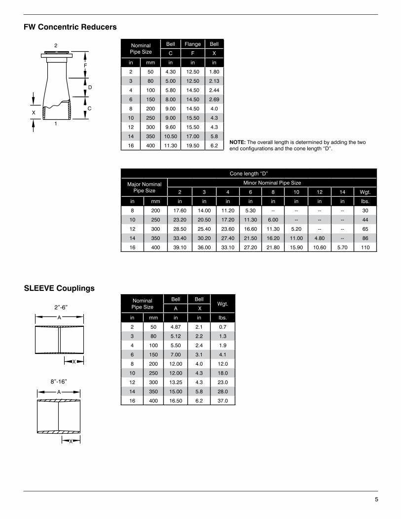
5
Cone length “D”
Major Nominal Pipe Size
Minor Nominal Pipe Size
2 3 4 6 8 10 12 14 Wgt.
in mm in in in in in in in in lbs.
8 200 17.60 14.00 11.20 5.30 -- -- -- -- 30
10 250 23.20 20.50 17.20 11.30 6.00 -- -- -- 44
12 300 28.50 25.40 23.60 16.60 11.30 5.20 -- -- 65
14 350 33.40 30.20 27.40 21.50 16.20 11.00 4.80 -- 86
16 400 39.10 36.00 33.10 27.20 21.80 15.90 10.60 5.70 110
FW Concentric Reducers
NominalPipe Size
Bell Flange Bell
C F X
in mm in in in
2 50 4.30 12.50 1.80
3 80 5.00 12.50 2.13
4 100 5.80 14.50 2.44
6 150 8.00 14.50 2.69
8 200 9.00 14.50 4.0
10 250 9.00 15.50 4.3
12 300 9.60 15.50 4.3
14 350 10.50 17.00 5.8
16 400 11.30 19.50 6.2
C
D
F
X
NOTE: The overall length is determined by adding the two end configurations and the cone length “D”.
1
2
SLEEVE CouplingsNominal Pipe Size
Bell BellWgt.
A X
in mm in in lbs.
2 50 4.87 2.1 0.7
3 80 5.12 2.2 1.3
4 100 5.50 2.4 1.9
6 150 7.00 3.1 4.1
8 200 12.00 4.0 12.0
10 250 12.00 4.3 18.0
12 300 13.25 4.3 23.0
14 350 15.00 5.8 28.0
16 400 16.50 6.2 37.0
A
X
2”-6”
A
X
8”-16”
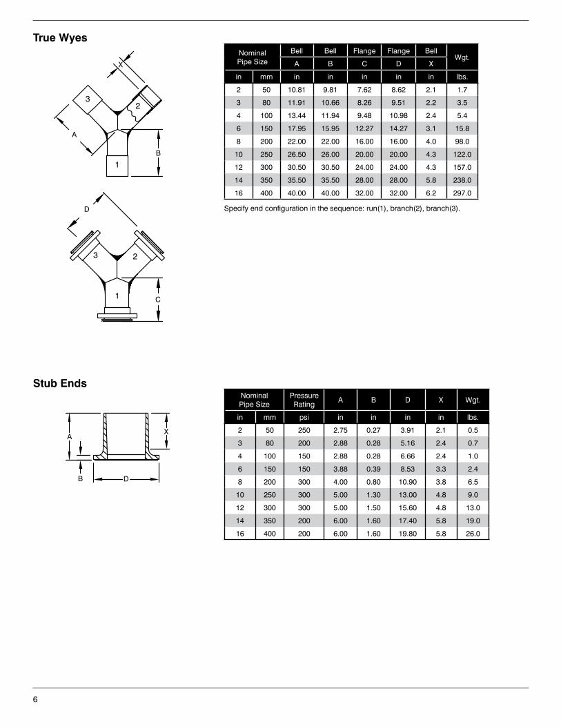
6
Stub EndsNominal Pipe Size
Pressure Rating
A B D X Wgt.
in mm psi in in in in lbs.
2 50 250 2.75 0.27 3.91 2.1 0.5
3 80 200 2.88 0.28 5.16 2.4 0.7
4 100 150 2.88 0.28 6.66 2.4 1.0
6 150 150 3.88 0.39 8.53 3.3 2.4
8 200 300 4.00 0.80 10.90 3.8 6.5
10 250 300 5.00 1.30 13.00 4.8 9.0
12 300 300 5.00 1.50 15.60 4.8 13.0
14 350 200 6.00 1.60 17.40 5.8 19.0
16 400 200 6.00 1.60 19.80 5.8 26.0
XA
B D
Nominal Pipe Size
Bell Bell Flange Flange Bell Wgt.
A B C D X
in mm in in in in in lbs.
2 50 10.81 9.81 7.62 8.62 2.1 1.7
3 80 11.91 10.66 8.26 9.51 2.2 3.5
4 100 13.44 11.94 9.48 10.98 2.4 5.4
6 150 17.95 15.95 12.27 14.27 3.1 15.8
8 200 22.00 22.00 16.00 16.00 4.0 98.0
10 250 26.50 26.00 20.00 20.00 4.3 122.0
12 300 30.50 30.50 24.00 24.00 4.3 157.0
14 350 35.50 35.50 28.00 28.00 5.8 238.0
16 400 40.00 40.00 32.00 32.00 6.2 297.0
True Wyes
A
B
X
D
C
Specify end configuration in the sequence: run(1), branch(2), branch(3).
32
1
3 2
1
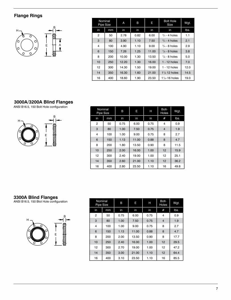
7
Flange RingsNominal Pipe Size
A B EBolt Hole
SizeWgt.
in mm in in in in lbs.
2 50 2.78 0.82 6.00 3/4 - 4 holes 1.1
3 80 3.90 1.10 7.50 3/4 - 4 holes 2.1
4 100 4.90 1.10 9.00 3/4 - 8 holes 2.9
6 150 7.26 1.25 11.00 7/8 - 8 holes 3.8
8 200 10.00 1.30 13.50 7/8 - 8 holes 5.0
10 250 12.20 1.30 16.00 1 - 12 holes 7.0
12 300 14.30 1.50 19.00 1 - 12 holes 12.0
14 350 16.30 1.60 21.00 11/8 12 holes 14.5
16 400 18.60 1.90 23.50 11/8 -16 holes 19.0
Nominal Pipe Size
B E HBolt-Holes
Wgt.
in mm in in in # lbs.
2 50 0.75 6.00 0.75 4 0.9
3 80 1.00 7.50 0.75 4 1.9
4 100 1.00 9.00 0.75 8 2.7
6 150 1.13 11.00 0.88 8 4.7
8 200 1.80 13.50 0.90 8 11.5
10 250 2.00 16.00 1.00 12 15.9
12 300 2.40 19.00 1.00 12 25.1
14 350 2.60 21.00 1.10 12 36.2
16 400 2.80 23.50 1.10 16 49.8
3000A/3200A Blind FlangesANSI B16.5, 150 Bolt Hole configuration
H
E A
B
B
E
H
Nominal Pipe Size
B E HBolt-Holes
Wgt.
in mm in in in # lbs.
2 50 0.75 6.00 0.75 4 0.9
3 80 1.00 7.50 0.75 4 1.9
4 100 1.00 9.00 0.75 8 2.7
6 150 1.13 11.00 0.88 8 4.7
8 200 2.00 13.50 0.90 8 17.7
10 250 2.40 16.00 1.00 12 29.5
12 300 2.70 19.00 1.00 12 47.2
14 350 3.00 21.00 1.10 12 64.4
16 400 3.10 23.50 1.10 16 85.5
3300A Blind FlangesANSI B16.5, 150 Blot Hole configuration
HB
E
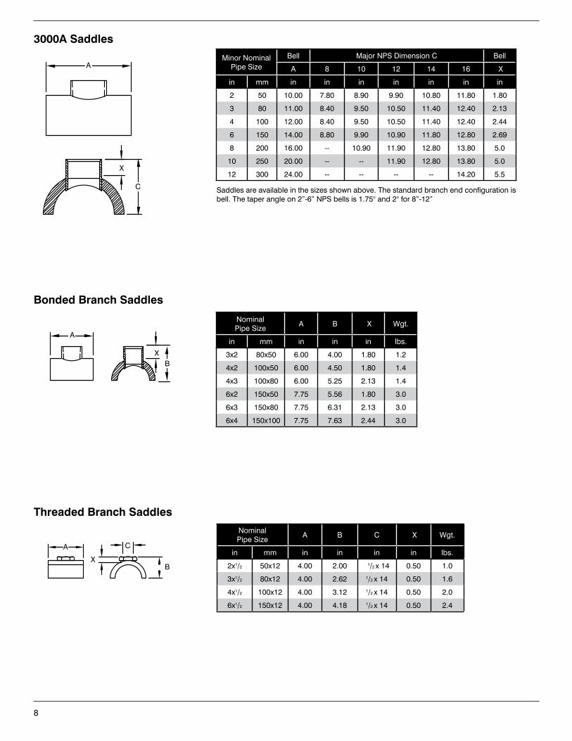
8
Nominal Pipe Size
A B C X Wgt.
in mm in in in in lbs.
2x1/2 50x12 4.00 2.00 1/2 x 14 0.50 1.0
3x1/2 80x12 4.00 2.62 1/2 x 14 0.50 1.6
4x1/2 100x12 4.00 3.12 1/2 x 14 0.50 2.0
6x1/2 150x12 4.00 4.18 1/2 x 14 0.50 2.4
Threaded Branch Saddles
A
X
C
B
Minor Nominal Pipe Size
Bell Major NPS Dimension C Bell
A 8 10 12 14 16 X
in mm in in in in in in in
2 50 10.00 7.80 8.90 9.90 10.80 11.80 1.80
3 80 11.00 8.40 9.50 10.50 11.40 12.40 2.13
4 100 12.00 8.40 9.50 10.50 11.40 12.40 2.44
6 150 14.00 8.80 9.90 10.90 11.80 12.80 2.69
8 200 16.00 -- 10.90 11.90 12.80 13.80 5.0
10 250 20.00 -- -- 11.90 12.80 13.80 5.0
12 300 24.00 -- -- -- -- 14.20 5.5
3000A Saddles
Saddles are available in the sizes shown above. The standard branch end configuration is bell. The taper angle on 2”-6” NPS bells is 1.75° and 2° for 8”-12”
Nominal Pipe Size
A B X Wgt.
in mm in in in lbs.
3x2 80x50 6.00 4.00 1.80 1.2
4x2 100x50 6.00 4.50 1.80 1.4
4x3 100x80 6.00 5.25 2.13 1.4
6x2 150x50 7.75 5.56 1.80 3.0
6x3 150x80 7.75 6.31 2.13 3.0
6x4 150x100 7.75 7.63 2.44 3.0
Bonded Branch Saddles
X
C
A
A
XB
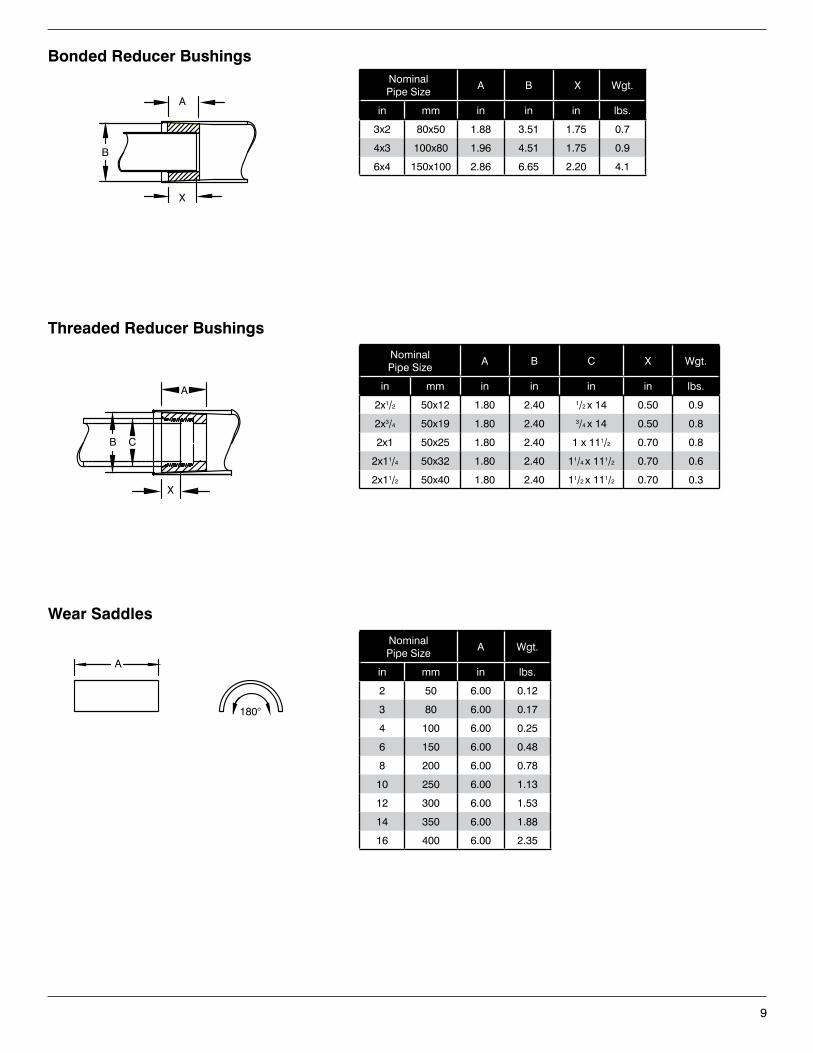
9
Nominal Pipe Size
A B X Wgt.
in mm in in in lbs.
3x2 80x50 1.88 3.51 1.75 0.7
4x3 100x80 1.96 4.51 1.75 0.9
6x4 150x100 2.86 6.65 2.20 4.1
Bonded Reducer Bushings
Wear Saddles
Nominal Pipe Size
A Wgt.
in mm in lbs.
2 50 6.00 0.12
3 80 6.00 0.17
4 100 6.00 0.25
6 150 6.00 0.48
8 200 6.00 0.78
10 250 6.00 1.13
12 300 6.00 1.53
14 350 6.00 1.88
16 400 6.00 2.35
Nominal Pipe Size
A B C X Wgt.
in mm in in in in lbs.
2x1/2 50x12 1.80 2.40 1/2 x 14 0.50 0.9
2x3/4 50x19 1.80 2.40 3/4 x 14 0.50 0.8
2x1 50x25 1.80 2.40 1 x 111/2 0.70 0.8
2x11/4 50x32 1.80 2.40 11/4 x 111/2 0.70 0.6
2x11/2 50x40 1.80 2.40 11/2 x 111/2 0.70 0.3
Threaded Reducer Bushings
X
A
B
A
180°
A
X
CB
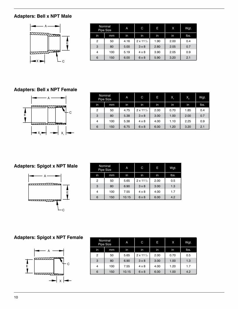
10
Nominal Pipe Size
A C E X Wgt.
in mm in in in in lbs.
2 50 5.65 2 x 111/2 2.00 0.70 0.5
3 80 6.90 3 x 8 3.00 1.00 1.3
4 100 7.55 4 x 8 4.00 1.20 1.7
6 150 10.15 6 x 8 6.00 1.00 4.2
Adapters: Spigot x NPT Female
X
C
A
E
Nominal Pipe Size
A C E Wgt.
in mm in in in lbs.
2 50 5.65 2 x 111/2 2.00 0.5
3 80 6.90 3 x 8 3.00 1.3
4 100 7.55 4 x 8 4.00 1.7
6 150 10.15 6 x 8 6.00 4.2
Adapters: Spigot x NPT Male
A
C
E
Nominal Pipe Size
A C E X1 X2 Wgt.
in mm in in in in in lbs.
2 50 4.75 2 x 111/2 2.00 0.70 1.85 0.4
3 80 5.38 3 x 8 3.00 1.00 2.00 0.7
4 100 5.38 4 x 8 4.00 1.10 2.25 0.9
6 150 6.75 6 x 8 6.00 1.20 3.20 2.1
Adapters: Bell x NPT Female
A
X1X2
EC
Nominal Pipe Size
A C E X Wgt.
in mm in in in in lbs.
2 50 4.16 2 x 111/2 1.90 2.00 0.4
3 80 5.00 3 x 8 2.80 2.05 0.7
4 100 5.19 4 x 8 3.90 2.05 0.9
6 150 6.00 6 x 8 5.90 3.20 2.1
Adapters: Bell x NPT Male
A
X
E
C
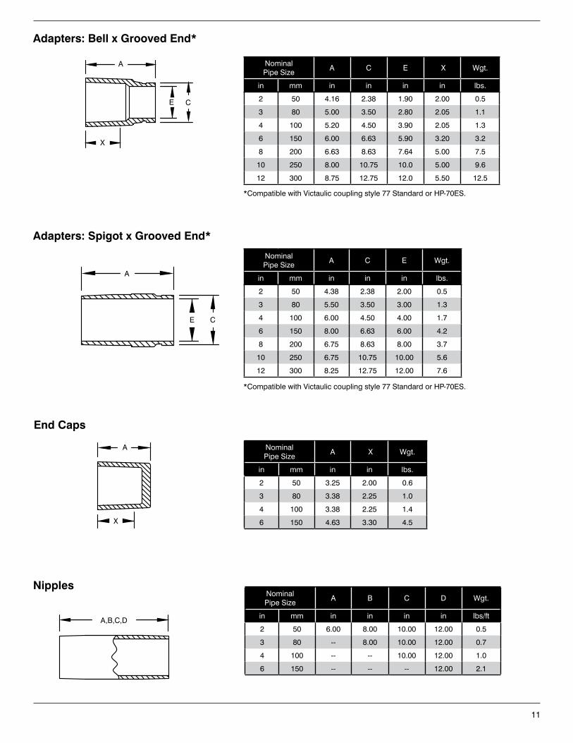
11
Nominal Pipe Size
A C E X Wgt.
in mm in in in in lbs.
2 50 4.16 2.38 1.90 2.00 0.5
3 80 5.00 3.50 2.80 2.05 1.1
4 100 5.20 4.50 3.90 2.05 1.3
6 150 6.00 6.63 5.90 3.20 3.2
8 200 6.63 8.63 7.64 5.00 7.5
10 250 8.00 10.75 10.0 5.00 9.6
12 300 8.75 12.75 12.0 5.50 12.5
Adapters: Bell x Grooved End*
Nominal Pipe Size
A C E Wgt.
in mm in in in lbs.
2 50 4.38 2.38 2.00 0.5
3 80 5.50 3.50 3.00 1.3
4 100 6.00 4.50 4.00 1.7
6 150 8.00 6.63 6.00 4.2
8 200 6.75 8.63 8.00 3.7
10 250 6.75 10.75 10.00 5.6
12 300 8.25 12.75 12.00 7.6
Adapters: Spigot x Grooved End*
Nominal Pipe Size
A X Wgt.
in mm in in lbs.
2 50 3.25 2.00 0.6
3 80 3.38 2.25 1.0
4 100 3.38 2.25 1.4
6 150 4.63 3.30 4.5
End Caps
Nominal Pipe Size
A B C D Wgt.
in mm in in in in lbs/ft
2 50 6.00 8.00 10.00 12.00 0.5
3 80 -- 8.00 10.00 12.00 0.7
4 100 -- -- 10.00 12.00 1.0
6 150 -- -- -- 12.00 2.1
Nipples
A
X
A,B,C,D
A
X
E C
A
E C
*Compatible with Victaulic coupling style 77 Standard or HP-70ES.
*Compatible with Victaulic coupling style 77 Standard or HP-70ES.
©2015, National Oilwell Varco. All rights reserved.CI3050ENG - September 2015
North America South America Europe Asia Pacific Middle East17115 San Pedro Avenue Estrada de Acesso à Zona P.O. Box 6, 4190 CA No. 7A, Tuas Avenue 3 P.O. Box 17324Suite 200 Industrial Portuária de Suape, s/no. Geldermalsen, The Netherlands Jurong, Singapore 639407 Dubai, UAESan Antonio, TX 78232 USA Recife, PE, Brazil 55.590-000 Phone: +31 345 587 587 Phone: +65 6861 6118 Phone: +971 4881 3566 Phone: +1 210 477 7500 Phone: +55 81 3501 0023
National Oilwell Varco has produced this brochure for general information only, and it is not intended for design purposes. Although every effort has been made to maintain the accuracy and reliability of its contents, National Oilwell Varco in no way assumes responsibility for liability for any loss, damage or injury resulting from the use of information and data herein nor is any warranty expressed or implied. Always cross-reference the bulletin date with the most current version listed at the web site noted in this literature.
www.nov.com/fgs • [email protected]
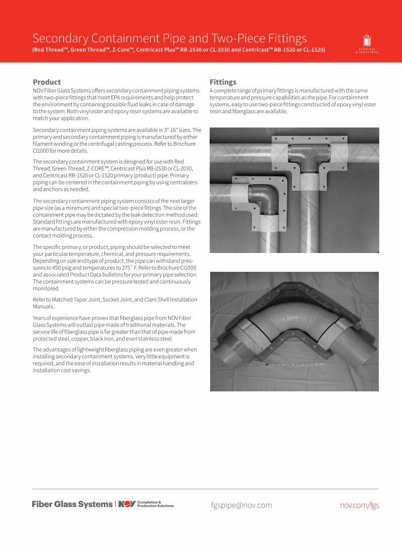
[email protected] nov.com/fgs
Product Name 14/15 Secondary Containment Pipe and Two-Piece Fittings(Red Thread™, Green Thread™, Z-Core™, Centricast Plus™ RB-2530 or CL-2030 and Centricast™ RB-1520 or CL-1520) O I L & G A S C H E M I C A L
& I N D U S T R I A LO F F S H O R EM A R I N E M I N I N GF U E L
H A N D L I N G
ProductNOV Fiber Glass Systems offers secondary containment piping systems with two-piece fittings that meet EPA requirements and help protect the environment by containing possible fluid leaks in case of damage to the system. Both vinyl ester and epoxy resin systems are available to match your application.
Secondary containment piping systems are available in 3”-16” sizes. The primary and secondary containment piping is manufactured by either filament winding or the centrifugal casting process. Refer to Brochure CI1000 for more details.
The secondary containment system is designed for use with Red Thread, Green Thread, Z-CORE™, Centricast Plus RB-2530 or CL-2030, and Centricast RB-1520 or CL-1520 primary (product) pipe. Primary piping can be centered in the containment piping by using centralizers and anchors as needed.
The secondary containment piping system consists of the next larger pipe size (as a minimum) and special two-piece fittings. The size of the containment pipe may be dictated by the leak detection method used. Standard fittings are manufactured with epoxy vinyl ester resin. Fittings are manufactured by either the compression molding process, or the contact molding process.
The specific primary, or product, piping should be selected to meet your particular temperature, chemical, and pressure requirements. Depending on size and type of product, the pipe can withstand pres-sures to 450 psig and temperatures to 275˚ F. Refer to Brochure CI1000 and associated Product Data bulletins for your primary pipe selection. The containment systems can be pressure tested and continuously monitored.
Refer to Matched Taper Joint, Socket Joint, and Clam Shell Installation Manuals..
Years of experience have proven that fiberglass pipe from NOV Fiber Glass Systems will outlast pipe made of traditional materials. The service life of fiberglass pipe is far greater than that of pipe made from protected steel, copper, black iron, and even stainless steel.
The advantages of lightweight fiberglass piping are even greater when installing secondary containment systems. Very little equipment is required, and the ease of installation results in material handling and installation cost savings.
FittingsA complete range of primary fittings is manufactured with the same temperature and pressure capabilities as the pipe. For containment systems, easy to use two-piece fittings constructed of epoxy vinyl ester resin and fiberglass are available.
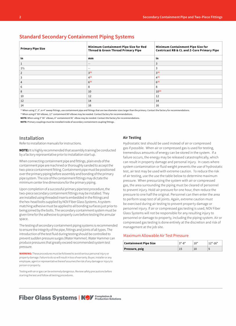
2 Secondary Containment Pipe and Two-Piece Fittings
Primary Pipe Size Minimum Containment Pipe Size for Red Thread & Green Thread Primary Pipe
Minimum Containment Pipe Size for Centricast RB & CL and Z-Core Primary Pipe
in mm in
1 -- 31½ -- 32 3(1) 3(1)
3 4(1) 4(1)
4 6(1) 6(1)
6 8 88 10 10(2)
10 12 1212 14 1414 16 16(1) When using 2”, 3”, or 4” sweep fittings, use containment pipe and fittings that are two diameter sizes larger than the primary. Contact the factory for recommendations.(2) When using 8” 90º elbows, 12” containment 90º elbows may be needed. Contact factory for recommendations.
NOTE: When using 3” 90˚ elbows, 6” containment 90˚ elbow may be needed. Contact the factory for recommendations.
NOTE: Primary couplings must be installed inside of secondary containment coupling fittings.
Standard Secondary Containment Piping Systems
InstallationRefer to installation manuals for instructions.
NOTE: It is highly recommended that assembly training be conducted by a factory representative prior to installation start up.
When connecting containment pipe and fittings, plain ends of the containment pipe are machined or thoroughly sanded to accept the two-piece containment fitting. Containment pipe must be positioned over the primary piping before assembly and bonding of the primary pipe system. The size of the containment fittings may dictate the minimum center line dimensions for the primary piping.
Upon completion of a successful primary pipe test procedure, the two-piece secondary containment fittings may be installed. They are installed using threaded inserts embedded in the fittings and the hex-head bolts supplied by NOV Fiber Glass Systems. A system- matching adhesive must be applied to all bonding surfaces just prior to being joined by the bolts. The secondary containment system must be given time for the adhesive to properly cure before testing the annular space.
The testing of secondary containment piping systems is recommended to ensure the integrity of the pipe, fittings and joints of all types. The introduction of the test fluid during testing should be controlled to prevent sudden pressure surges (Water Hammer). Water Hammer can produce pressures that greatly exceed recommended system test pressure.
WARNING: These procedures must be followed to avoid serious personal injury or property damage. Failure to do so will result in loss of warranty. Buyer, installer or any employee, agent or representative thereof assumes the risk of any damage or injury to person or property.
Testing with air or gas can be extremely dangerous. Review safety precautions before starting the test and follow all testing procedures.
Maximum Allowable Air Test Pressure
Containment Pipe Size 3"-8" 10" 12"-16"
Pressure, psig 15 10 5
Air TestingHydrostatic test should be used instead of air or compressed gas if possible. When air or compressed gas is used for testing, tremendous amounts of energy can be stored in the system. If a failure occurs, the energy may be released catastrophically, which can result in property damage and personal injury. In cases where system contamination or fluid weight prevents the use of hydrostatic test, air test may be used with extreme caution. To reduce the risk of air testing, use the use the table below to determine maximum pressure. When pressurizing the system with air or compressed gas, the area surrounding the piping must be cleared of personnel to prevent injury. Hold air pressure for one hour, then reduce the pressure to one half the original. Personnel can then enter the area to perform soap test of all joints. Again, extreme caution must be exercised during air testing to prevent property damage or personnel injury. If air or compressed gas testing is used, NOV Fiber Glass Systems will not be responsible for any resulting injury to personnel or damage to property, including the piping system. Air or compressed gas testing is done entirely at the discretion and risk of management at the job site.
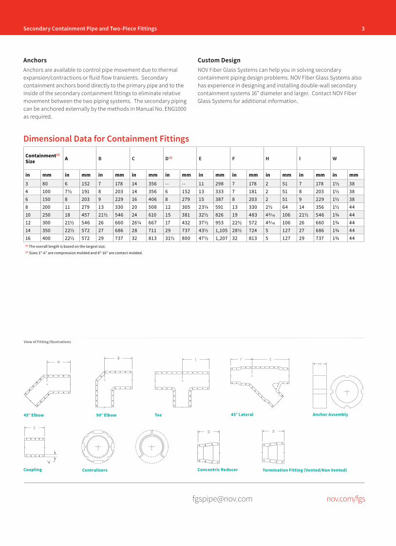
3Secondary Containment Pipe and Two-Piece Fittings
[email protected] nov.com/fgs
Containment(2) Size A B C D(1) E F H I W
in mm in mm in mm in mm in mm in mm in mm in mm in mm in mm
3 80 6 152 7 178 14 356 -- -- 11 298 7 178 2 51 7 178 1½ 384 100 7½ 191 8 203 14 356 6 152 13 333 7 181 2 51 8 203 1½ 386 150 8 203 9 229 16 406 8 279 15 387 8 203 2 51 9 229 1½ 388 200 11 279 13 330 20 508 12 305 23¼ 591 13 330 2½ 64 14 356 1½ 4410 250 18 457 21½ 546 24 610 15 381 32½ 826 19 483 43/16 106 21½ 546 1¾ 4412 300 21½ 546 26 660 26¼ 667 17 432 37½ 953 22½ 572 43/16 106 26 660 1¾ 4414 350 22½ 572 27 686 28 711 29 737 43½ 1,105 28½ 724 5 127 27 686 1¾ 4416 400 22½ 572 29 737 32 813 31½ 800 47½ 1,207 32 813 5 127 29 737 1¾ 44(1) The overall length is based on the largest size.(2) Sizes 3"-6” are compression molded and 8"-16” are contact molded.
Dimensional Data for Containment Fittings
AnchorsAnchors are available to control pipe movement due to thermal expansion/contractions or fluid flow transients. Secondary containment anchors bond directly to the primary pipe and to the inside of the secondary containment fittings to eliminate relative movement between the two piping systems. The secondary piping can be anchored externally by the methods in Manual No. ENG1000 as required.
View of Fitting Illustrations
90° Elbow45° Elbow Tee 45° Lateral Anchor Assembly
Coupling Centralizers Concentric Reducer Termination Fitting (Vented/Non Vented)
Custom DesignNOV Fiber Glass Systems can help you in solving secondary containment piping design problems. NOV Fiber Glass Systems also has experience in designing and installing double-wall secondary containment systems 16” diameter and larger. Contact NOV Fiber Glass Systems for additional information.
4 Secondary Containment Pipe and Two-Piece Fittings
[email protected] nov.com/fgs
Fiber Glass Systems17115 San Pedro Avenue, Ste 200San Antonio, Texas 78232 USAPhone: 210 477 7500Fax: 210 477 7560
National Oilwell Varco has produced this brochure for general information only, and it is not intended for design purposes. Although every effort has been made to maintain the accuracy and reliability of its contents, National Oilwell Varco in no way assumes responsibility for liability for any loss, damage or injury resulting from the use of information and data herein nor is any warranty expressed or implied. Always cross-reference the bulletin date with the most current version listed at the web site noted in this literature.
© 2016 National Oilwell Varco All rights reservedCI1352ENG April 2016
Engineering & Piping Design Guide
www.fgspipe.com
Fiberglass Reinforced Piping Systems
INTRODUCTION
NOV Fiber Glass Systems’ fiberglass reinforced epoxy and vinyl ester resin piping systems possess excellent corrosion resistance and a combination of mechanical and physical properties that offer many advantages over traditional piping systems. We are recognized worldwide as a leading supplier of piping systems for a wide range of chemical and industrial applications. This manual is provided as a reference resource for some of the specific properties of our piping systems. It is not in-tended to be a substitute for sound engineering practices as normally employed by professional design engineers. NOV Fiber Glass Systems has an international network of distributors and trained field personnel to advise on proper installation techniques. It is recommended they be consulted for assistance when installing the piping system. This not only enhances the integrity of the piping system, but also in-creases the efficiency and economy of the installation. Additional information regarding installation techniques is provided in the following installation manuals: Manual No. F6000 Pipe Installation Handbook for Tapered Bell & Spigot JointsManual No. F6080 Pipe Installation Handbook for Straight Socket Joints and Butt & Wrap JointsManual No. F6300 Pipe Installation Handbook for Marine-Offshore Piping
General Policy Statement
SaFetyThis safety alert symbol indicates an important safety message. When you see this symbol, be alert to the possibility of personal injury.
PiPinG SyStemS epoxy resin Systems: · Z-Core® (High Performance Resin) · Centricast Plus® RB-2530 · Centricast ® RB-1520 · Green Thread®
· Marine-Offshore · Green Thread 175 · Green Thread 175 Conductive · Green Thread 250 · Green Thread 250 Conductive · Green Thread 250 Fire Resistant · Red Thread® II · Red Thread II JP · Silver Streak® (FGD Piping) · Ceram Core® (Ceramic-lined Piping) · F-Chem® (Custom Piping) · HIGH PRESSURE Line Pipe and Downhole Tubing*
Vinyl ester Systems: · Centricast Plus CL-2030 · Centricast CL-1520 · F-Chem (Custom Piping)
* Available from NOV Fiber Glass Systems, San Antonio, Texas Phone: (210) 434-5043 · FAX: (210) 434-7543 Web site: http://www.fgspipe.com
NOV Fiber Glass Systems has developed a computer pro-gram specifically for our fiberglass products. This software program called Success By Design is available on our web site at http://www.fgspipe.com.
ii
National Oilwell Varco has produced this brochure for general information only,
and it is not intended for design purposes. Although every effort has been made to
maintain the accuracy and reliability of its contents, National Oilwell Varco in no way
assumes responsibility for liability for any loss, damage or injury resulting from the use
of information and data herein nor is any warranty expressed or implied. Always cross-
reference the bulletin date with the most current version listed at the web site noted in
this literature.
Introduction ....................................................................... iiPiping System Selection and Applications ..................1
Section 1 — Flow Properties ..................................2Preliminary Pipe Sizing.......................................................2Detailed Pipe Sizing A. Liquid Flow ..............................................................2 B. Loss in Pipe Fittings ................................................4 C. Open Channel Flow ................................................5 D. Gas Flow .................................................................5
Section 2 — above Ground System Design Using Supports, anchors & Guides ......................................7 Piping Support Design A. Support Design .......................................................7 B. Guide Design ..........................................................8 C. Anchor Design ........................................................9 D. Piping Support Span Design .................................11
Section 3 — temperature effects .........................12System Design .................................................................12Thermal Properties and Characteristics ...........................12Fundamental Thermal Analysis Formulas A. Thermal Expansion and Contraction .....................13 B. Anchor Restraint Load ..........................................13 C. Guide Spacing ......................................................13Flexibility Analysis and Design A. Directional Change Design ...................................13 B. Expansion Loop Design ........................................14 C. Expansion Joint Design ........................................14 D. Heat Tracing .........................................................15 E. Thermal Conductivity ............................................16 F. Thermal Expansion in Buried Pipe ........................16 G. Pipe Torque due to Thermal Expansion ...............16
Section 4 — Pipe Burial ..........................................17Pipe Flexibility...................................................................17Burial Analysis A. Soil Types .............................................................17 B. Soil Modulus ........................................................18Trench Excavation and Preparation A. Trench Size ...........................................................18 B. Trench Construction ..............................................18 C. Maximum Burial Depth ..........................................19 D. Roadway Crossing ...............................................19Bedding and Backfill A. Trench Bottom ......................................................20 B. Backfill Materials ...................................................20 C. Backfill Cover ........................................................20 D. High Water Table ..................................................20
Section 5 — other considerations ......................21A. Abrasive Fluids ...........................................................21B. Low Temperature Applications ...................................21C. Pipe Passing Through Walls or Concrete Structures ....................................................21D. Pipe Bending ..............................................................21E. Static Electricity ..........................................................22F. Steam Cleaning ..........................................................22G. Thrust Blocks ..............................................................22H. Vacuum Service ..........................................................22I. Valves ........................................................................22J. Vibration ......................................................................23K. Fluid (Water) Hammer ................................................23L. Ultraviolet (U.V.) Radiation and Weathering ...............23M. Fungal, Bacterial, and Rodent Resistance .................23
Section 6 — Specifications and approvals ..............................................................24A. Compliance with National Specifications ....................24B. Approvals, Listings, and Compliance with Regulations .........................................................24
aPPenDiceSappendix a Useful Formulas .........................................27appendix B Conversions................................................30
liSt oF taBleSTable 1.0 Typical Applications ..........................................1Table 1.1 Flow Resistance K Values for Fittings ...............4Table 1.2 Typical Liquid Properties ...................................4Table 1.3 Typical Gas Properties ......................................6Table 2.0 Minimum Support Width ....................................7Table 2.1 Saddle Length ...................................................8Table 4.0 Recommended Bedding and Backfill ..............18Table 4.1 Nominal Trench Widths ...................................18Table 6.0 ASTM D2310 Classification ............................24Table 6.1 Classifying Fiberglass Flanges to ASTM D4024 ...............................................25
Table 6.2 Classifying Fiberglass Pipe Using ASTM D2310 and Specifying Pipe Using ASTM D2996 and D2997 ............................................................26
taBle oF contentS
iii
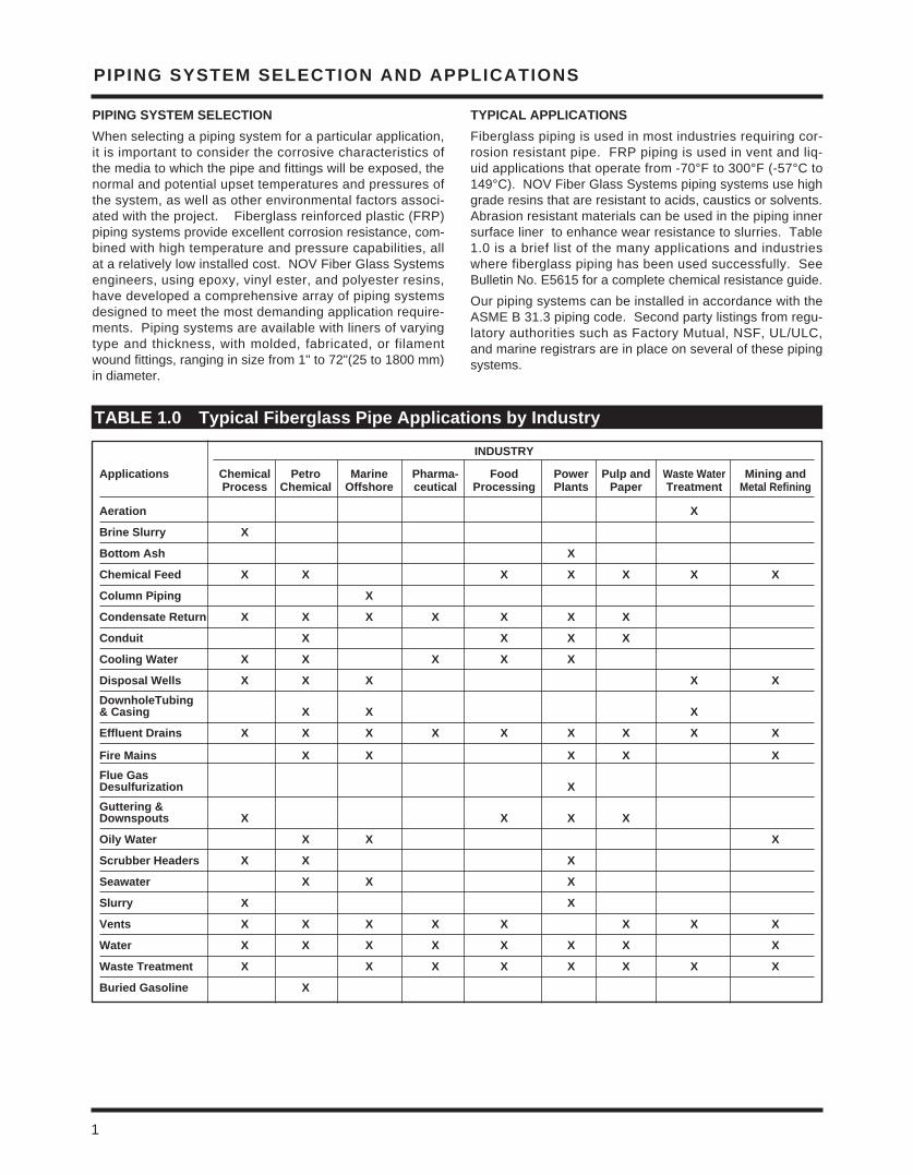
PiPinG SyStem Selection anD aPPlicationS
PiPinG SyStem Selection When selecting a piping system for a particular application, it is important to consider the corrosive characteristics of the media to which the pipe and fittings will be exposed, the normal and potential upset temperatures and pressures of the system, as well as other environmental factors associ-ated with the project. Fiberglass reinforced plastic (FRP) piping systems provide excellent corrosion resistance, com-bined with high temperature and pressure capabilities, all at a relatively low installed cost. NOV Fiber Glass Systems engineers, using epoxy, vinyl ester, and polyester resins, have developed a comprehensive array of piping systems designed to meet the most demanding application require-ments. Piping systems are available with liners of varying type and thickness, with molded, fabricated, or filament wound fittings, ranging in size from 1" to 72"(25 to 1800 mm) in diameter.
tyPical aPPlicationS Fiberglass piping is used in most industries requiring cor-rosion resistant pipe. FRP piping is used in vent and liq-uid applications that operate from -70°F to 300°F (-57°C to 149°C). NOV Fiber Glass Systems piping systems use high grade resins that are resistant to acids, caustics or solvents. Abrasion resistant materials can be used in the piping inner surface liner to enhance wear resistance to slurries. Table 1.0 is a brief list of the many applications and industries where fiberglass piping has been used successfully. See Bulletin No. E5615 for a complete chemical resistance guide.Our piping systems can be installed in accordance with the ASME B 31.3 piping code. Second party listings from regu-latory authorities such as Factory Mutual, NSF, UL/ULC, and marine registrars are in place on several of these piping systems.
taBle 1.0 typical Fiberglass Pipe applications by industry
inDUStry
applications chemical Petro marine Pharma- Food Power Pulp and Waste Water mining and Process chemical offshore ceutical Processing Plants Paper treatment metal refining
aeration X
Brine Slurry X
Bottom ash X
chemical Feed X X X X X X X
column Piping X
condensate return X X X X X X X
conduit X X X X
cooling Water X X X X X
Disposal Wells X X X X XDownholetubing& casing X X X
effluent Drains X X X X X X X X X
Fire mains X X X X XFlue Gas Desulfurization XGuttering &Downspouts X X X X
oily Water X X X
Scrubber Headers X X X
Seawater X X X
Slurry X X
Vents X X X X X X X X
Water X X X X X X X X
Waste treatment X X X X X X X X
Buried Gasoline X
1
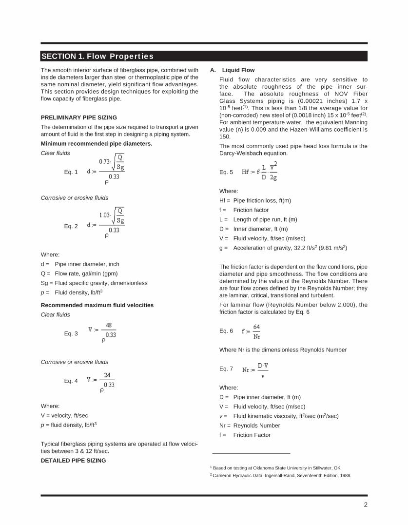
2
The smooth interior surface of fiberglass pipe, combined with inside diameters larger than steel or thermoplastic pipe of the same nominal diameter, yield significant flow advantages. This section provides design techniques for exploiting the flow capacity of fiberglass pipe.
Preliminary PiPe SizinGThe determination of the pipe size required to transport a given amount of fluid is the first step in designing a piping system.minimum recommended pipe diameters.Clear fluids
Eq. 1
Corrosive or erosive fluids
Eq. 2
Where:d = Pipe inner diameter, inch Q = Flow rate, gal/min (gpm)Sg = Fluid specific gravity, dimensionlessp = Fluid density, lb/ft3
recommended maximum fluid velocitiesClear fluids
Eq. 3
Corrosive or erosive fluids
Eq. 4
Where:V = velocity, ft/secp = fluid density, lb/ft3
Typical fiberglass piping systems are operated at flow veloci-ties between 3 & 12 ft/sec. DetaileD PiPe SizinG
a. liquid FlowFluid flow characteristics are very sensitive to the absolute roughness of the pipe inner sur-face. The absolute roughness of NOV Fiber Glass Systems piping is (0.00021 inches) 1.7 x 10⁻⁵ feet(1). This is less than 1/8 the average value for (non-corroded) new steel of (0.0018 inch) 15 x 10-5 feet(2). For ambient temperature water, the equivalent Manning value (n) is 0.009 and the Hazen-Williams coefficient is 150. The most commonly used pipe head loss formula is the Darcy-Weisbach equation. Eq. 5
Where:Hf = Pipe friction loss, ft(m)f = Friction factorL = Length of pipe run, ft (m)D = Inner diameter, ft (m)V = Fluid velocity, ft/sec (m/sec)g = Acceleration of gravity, 32.2 ft/s2 (9.81 m/s2)
The friction factor is dependent on the flow conditions, pipe diameter and pipe smoothness. The flow conditions are determined by the value of the Reynolds Number. There are four flow zones defined by the Reynolds Number; they are laminar, critical, transitional and turbulent.For laminar flow (Reynolds Number below 2,000), the friction factor is calculated by Eq. 6
Eq. 6
Where Nr is the dimensionless Reynolds Number
Eq. 7
Where: D = Pipe inner diameter, ft (m)V = Fluid velocity, ft/sec (m/sec)v = Fluid kinematic viscosity, ft2/sec (m2/sec)Nr = Reynolds Numberf = Friction Factor
Section 1. Flow Properties
1 Based on testing at Oklahoma State University in Stillwater, OK.2 Cameron Hydraulic Data, Ingersoll-Rand, Seventeenth Edition, 1988.
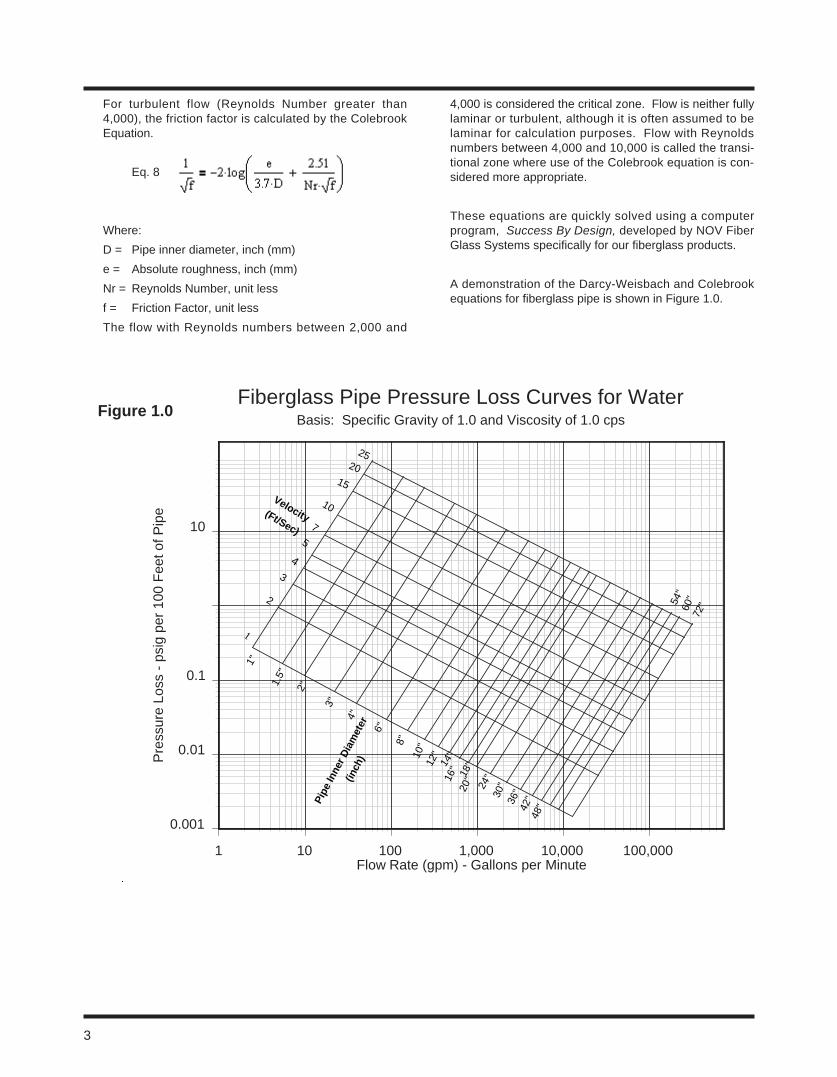
0.001
0.01
0.1
10
Pre
ssur
e Lo
ss -
psi
g pe
r 10
0 F
eet o
f Pip
e
1 10 100 1,000 10,000 100,000Flow Rate (gpm) - Gallons per Minute
Fiberglass Pipe Pressure Loss Curves for WaterBasis: Specific Gravity of 1.0 and Viscosity of 1.0 cps
Velocity(Ft/Sec)
54"
60"
72"
Pipe
Inne
r Dia
met
er
(inch
)
4
5
2
7
10
15
20
25
1
3
1"
1.5"
2"
3"
4"
6"
8"10
"12
"14
"16
" 18"
20"
24"
30"
36"
42"
48"
Figure 1.0
For turbulent flow (Reynolds Number greater than 4,000), the friction factor is calculated by the Colebrook Equation.
Eq. 8
Where:D = Pipe inner diameter, inch (mm)e = Absolute roughness, inch (mm)Nr = Reynolds Number, unit lessf = Friction Factor, unit lessThe flow with Reynolds numbers between 2,000 and
4,000 is considered the critical zone. Flow is neither fully laminar or turbulent, although it is often assumed to be laminar for calculation purposes. Flow with Reynolds numbers between 4,000 and 10,000 is called the transi-tional zone where use of the Colebrook equation is con-sidered more appropriate.
These equations are quickly solved using a computer program, Success By Design, developed by NOV Fiber Glass Systems specifically for our fiberglass products.
A demonstration of the Darcy-Weisbach and Colebrook equations for fiberglass pipe is shown in Figure 1.0.
3
4
B. loss in Pipe FittingsThe head loss through a fitting is proportional to the fluid velocity squared (V2). Equation 9 relates the head loss in fittings to the fluid velocity by incorporating a fit-ting loss factor obtained from experimental test data.
Eq. 9
Where:hf = Fitting head loss, ft (m)k = Flow resistance coefficientV = fluid velocity, ft/sec g = acceleration of gravity, 32.2 ft/s2
Typical values of k are given in Table 1.1. The most common method for determining the contribu-tion to the overall piping system of the fittings head loss is to convert the fitting head loss into an equivalent pipe length. As an example, use 60°F water as the working fluid in a 3-inch diameter piping system with an internal flow of 10 ft/sec. The equivalent pipe length for a short radius 90° elbow would be 6.9 feet for Red Thread II and 5.9 feet for Centricast Plus CL-2030 . The two pip-ing systems have different inner diameters that contrib-ute to the differences in equivalent footage. Therefore, for best accuracy it is recommended that our computer software Success By Design be used to determine fit-tings equivalent piping footage.Typical liquid properties are presented in Table 1.2.
taBle 1.1 Flow resistance coefficients for Fittings
taBle 1.2 typical liquid Properties
Fitting/Size (In.) 1 1½ 2 3 4 6 8-10 12-16 18-24
Short Radius 90º Elbow 0.75 0.66 0.57 0.54 0.51 0.45 0.42 0.39 0.36
Sweep Radius 90º Elbow 0.37 0.34 0.30 0.29 0.27 0.24 0.22 0.21 0.19
Short Radius 45º Elbow 0.37 0.34 0.30 0.29 0.27 0.24 0.22 0.21 0.19
Sweep Radius 45º Elbow 0.20 0.18 0.16 0.15 0.14 0.13 0.12 0.11 0.10
Tee Side Run 1.38 1.26 1.14 1.08 1.02 0.90 0.84 0.78 0.72
Tee Thru Branch 0.46 0.42 0.38 0.36 0.34 0.30 0.28 0.26 0.24
Type of Liquid Specific Gravity at 60ºF Viscosity at 60ºF Centipoise10% Salt WaterBrine, 25% NaClBrine, 25% CaCl230º API Crude OilAverage Fuel OilsKeroseneAuto GasolineAviation Gasoline50% Sodium Hydroxide (NaOH)
1.071.191.230.870.930.830.720.701.53
1.402.202.45
13.008.901.821.200.46
95.00Mil 5624 Jet Fuels:JP3JP5JP8
0.750.840.80
0.792.141.40
Acids:60% Sulfuric (H2SO4)98% Sulfuric (H2SO4)85% Phosphoric (H2PO4)37.5% Hydrochloric (HCl)
At 68ºF1.501.831.691.46
At 68ºF6.40
24.5012.001.94
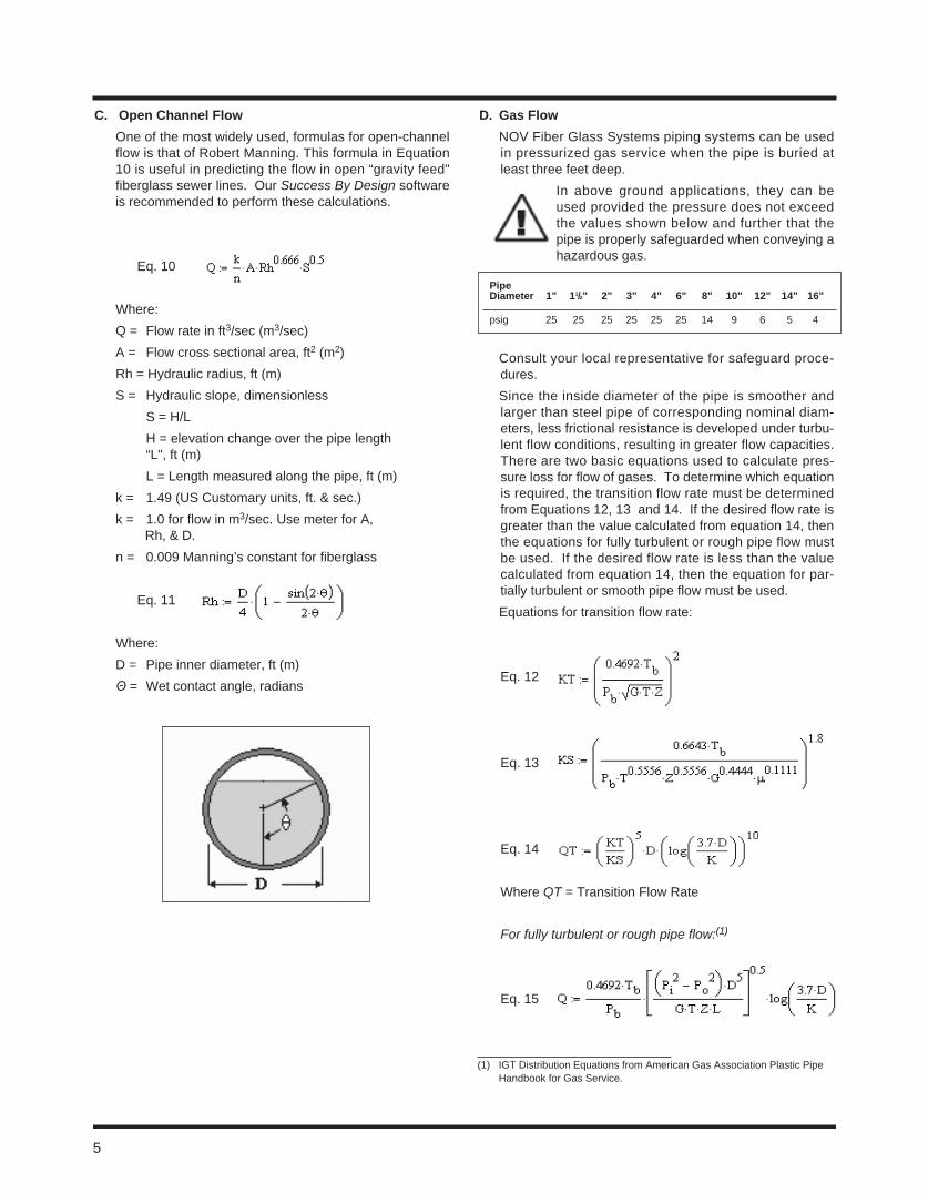
c. open channel FlowOne of the most widely used, formulas for open-channel flow is that of Robert Manning. This formula in Equation 10 is useful in predicting the flow in open “gravity feed" fiberglass sewer lines. Our Success By Design software is recommended to perform these calculations.
Eq. 10
Where:Q = Flow rate in ft3/sec (m3/sec) A = Flow cross sectional area, ft2 (m2)Rh = Hydraulic radius, ft (m)S = Hydraulic slope, dimensionless S = H/L H = elevation change over the pipe length “L", ft (m) L = Length measured along the pipe, ft (m)k = 1.49 (US Customary units, ft. & sec.)k = 1.0 for flow in m3/sec. Use meter for A, Rh, & D.n = 0.009 Manning’s constant for fiberglass
Eq. 11
Where:D = Pipe inner diameter, ft (m)Θ = Wet contact angle, radians
D. Gas Flow NOV Fiber Glass Systems piping systems can be used
in pressurized gas service when the pipe is buried at least three feet deep.
In above ground applications, they can be used provided the pressure does not exceed the values shown below and further that the pipe is properly safeguarded when conveying a hazardous gas.
Consult your local representative for safeguard proce-dures.
Since the inside diameter of the pipe is smoother and larger than steel pipe of corresponding nominal diam-eters, less frictional resistance is developed under turbu-lent flow conditions, resulting in greater flow capacities. There are two basic equations used to calculate pres-sure loss for flow of gases. To determine which equation is required, the transition flow rate must be determined from Equations 12, 13 and 14. If the desired flow rate is greater than the value calculated from equation 14, then the equations for fully turbulent or rough pipe flow must be used. If the desired flow rate is less than the value calculated from equation 14, then the equation for par-tially turbulent or smooth pipe flow must be used.
Equations for transition flow rate:
Eq. 12
Eq. 13
Eq. 14
Where QT = Transition Flow Rate
For fully turbulent or rough pipe flow:(1)
Eq. 15
(1) IGT Distribution Equations from American Gas Association Plastic Pipe Handbook for Gas Service.
5
Pipe Diameter 1" 11/2" 2" 3" 4" 6" 8" 10" 12" 14" 16"
psig 25 25 25 25 25 25 14 9 6 5 4
6
or
Eq. 16
For partially turbulent or smooth pipe flow(1)
Eq. 17
Where:
Eq. 18
D = Inside Diameter (in.)G = Specific Gravity (S.G. of air = 1.0)L = Length of Pipe Section (ft.)Pb = Base Pressure (psia)Pi = Inlet Pressure (psia)Po = Outlet Pressure (psia)Q = Flow Rate (MSCFH - thousand standard cubic ft.
per hr.)Tb = Base Temperature (°R)T = Temperature of Gas (°R)Z = Compressibility Factorm = Viscosity (lb./ft. sec.)K = Absolute Roughness of Pipe =
0.00021 (in.) for Fiber Glass Systems pipeR = Rankine (°F + 460°)m = (lb./ft. sec.) = m (centipoise) ÷ 1488 psia (Absolute) = psig (Gauge) + 14.7
You can perform computer calculations using the Success By Design program to solve gas flow problems for: pipe size, Q, Pi, or Po if the other variables are known.
taBle 1.3 typical Gas Properties
(1) All Specific Gravity based on air = 1.0 at 70° F.
Specific Gravity Viscosity at 60°F type of Gas at 60°F(1) lb./ft. sec.
Air 1.02 0.0000120 Carbon Dioxide 1.56 0.0000098 Carbon Monoxide 0.99 0.0000116 Chlorine 2.51 0.0000087 Ethane 1.06 0.0000060 Methane 0.57 0.0000071 Natural Gas 0.64 0.0000071 Nitrogen 0.99 0.0000116 Nitrous Oxide 1.56 0.0000096 Oxygen 1.13 0.0000132 Sulfur Dioxide 2.27 0.0000083
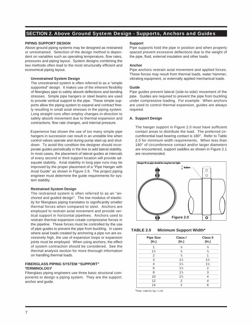
PiPinG SUPPort DeSiGnAbove ground piping systems may be designed as restrained or unrestrained. Selection of the design method is depen-dent on variables such as operating temperature, flow rates, pressures and piping layout. System designs combining the two methods often lead to the most structurally efficient and economical piping layout.
Unrestrained System Design The unrestrained system is often referred to as a “simple
supported" design. It makes use of the inherent flexibility of fiberglass pipe to safely absorb deflections and bending stresses. Simple pipe hangers or steel beams are used to provide vertical support to the pipe. These simple sup-ports allow the piping system to expand and contract free-ly resulting in small axial stresses in the piping system. Long straight runs often employ changes-in-direction to safely absorb movement due to thermal expansion and contractions, flow rate changes, and internal pressure.
Experience has shown the use of too many simple pipe hangers in succession can result in an unstable line when control valves operate and during pump start-up and shut-down. To avoid this condition the designer should incor-porate guides periodically in the line to add lateral stability. In most cases, the placement of lateral guides at intervals of every second or third support location will provide ad-equate stability. Axial stability in long pipe runs may be improved by the proper placement of a “Pipe Hanger with Axial Guide" as shown in Figure 2.6. The project piping engineer must determine the guide requirements for sys-tem stability.
restrained System Design The restrained system is often referred to as an “an-
chored and guided design". The low modulus of elastic-ity for fiberglass piping translates to significantly smaller thermal forces when compared to steel. Anchors are employed to restrain axial movement and provide ver-tical support in horizontal pipelines. Anchors used to restrain thermal expansion create compressive forces in the pipeline. These forces must be controlled by the use of pipe guides to prevent the pipe from buckling. In cases where axial loads created by anchoring a pipe run are ex-cessively high, the use of expansion loops or expansion joints must be employed. When using anchors, the effect of system contraction should be considered. See the thermal analysis section for more thorough information on handling thermal loads.
FiBerGlaSS PiPinG SyStem “SUPPort" terminoloGy Fiberglass piping engineers use three basic structural com-ponents to design a piping system. They are the support, anchor and guide.
SupportPipe supports hold the pipe in position and when properly spaced prevent excessive deflections due to the weight of the pipe, fluid, external insulation and other loads.
anchorPipe anchors restrain axial movement and applied forces. These forces may result from thermal loads, water hammer, vibrating equipment, or externally applied mechanical loads.
GuidePipe guides prevent lateral (side-to-side) movement of the pipe. Guides are required to prevent the pipe from buckling under compressive loading. For example: When anchors are used to control thermal expansion, guides are always required.
a. Support Design
The hanger support in Figure 2.0 must have sufficient contact areas to distribute the load. The preferred cir-cumferential load bearing contact is 180°. Refer to Table 2.0 for minimum width requirements. When less than 180° of circumference contact and/or larger diameters are encountered, support saddles as shown in Figure 2.1 are recommended.
*Note: Valid for Sg < 1.25
Section 2. Above Ground System Design - Supports, Anchors and Guides
Hanger �t on pipe should be snug but not tight.
Rubber1”__16
Pipe Size class i class ii (in.) (in.) (in.)
1 7/8 7/8 11/2 7/8 7/8 2 7/8 1 3 11/4 11/2 4 11/4 11/2 6 11/2 2 8 13/4 3 10 13/4 4 12 2 4 14 2 6
taBle 2.0 minimum Support Width*
7
Figure 2.0
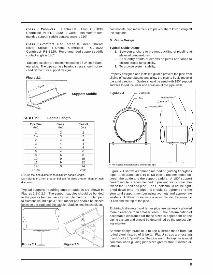
8
Class I Products: Centricast Plus CL-2030, Centricast Plus RB-2530, Z-Core. Minimum recom-mended support saddle contact angle is 110°
Class II Products: Red Thread II, Green Thread, Silver Streak, F-Chem, Centricast CL-1520, Centricast RB-1520. Recommended support saddle contact angle is 180°
Support saddles are recommended for 16-24 inch diam-eter pipe. The pipe surface bearing stress should not ex-ceed 50 lb/in2 for support designs.
Length
Contact Angle
Support Saddle
Figure 2.1
(1) Use the pipe diameter as minimum saddle length.(2) Refer to F-Chem product bulletin for sizes greater than 24-inch diameter.
Typical supports requiring support saddles are shown in Figures 2.2 & 2.3. The support saddles should be bonded to the pipe or held in place by flexible clamps. If clamped to filament wound pipe a 1/16" rubber pad should be placed between the pipe and the saddle. Saddle lengths should ac-
commodate pipe movements to prevent them from sliding off the supports.
B. Guide Design
typical Guide Usage1. Between anchors to prevent buckling of pipeline at
elevated temperatures.2. Near entry points of expansion joints and loops to
ensure proper functionality.3. To provide system stability.
Properly designed and installed guides prevent the pipe from sliding off support beams and allow the pipe to freely move in the axial direction. Guides should be used with 180° support saddles to reduce wear and abrasion of the pipe walls.
Figure 2.4 shows a common method of guiding fiberglass pipe. A clearance of 1/16 to 1/8-inch is recommended be-tween the guide and the support saddle. A 180° support “wear" saddle is recommended to prevent point contact be-tween the U-bolt and pipe. The U-bolt should not be tight-ened down onto the pipe. It should be tightened to the structural support member using two nuts and appropriate washers. A 1/8-inch clearance is recommended between the U-bolt and the top of the pipe.
Eight-inch diameter and larger pipe are generally allowed more clearance than smaller sizes. The determination of acceptable clearance for these sizes is dependent on the piping system and should be determined by the project pip-ing engineer.
Another design practice is to use U-straps made from flat rolled steel instead of U-bolts. Flat U-straps are less apt than U-bolts to “point" load the pipe wall. U-strap use is most common when guiding pipe sizes greater than 6-inches di-ameter.
Pipe Size class i class ii (in.) (in.) (in.)
1 3 2 11/2 3 2 2 4 4 3 4 4 4 4 4 6 4 6 8 6 8 10 9 10 12 9 12 14 9 14 16-24 - (1)(2)
taBle 2.1 Saddle length
U-Bolt Guide
PipeRubber
Flexible Clamp
Support Saddle
(1)
(1)
(1) Not required if support saddle is bonded to pipe.
1”16__
Figure 2.3Figure 2.2
Figure 2.4
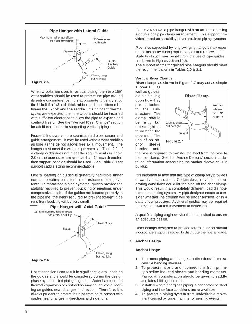
When U-bolts are used in vertical piping, then two 180° wear saddles should be used to protect the pipe around its entire circumference. It is appropriate to gently snug the U-bolt if a 1/8-inch thick rubber pad is positioned be-tween the U-bolt and the saddle. If significant thermal cycles are expected, then the U-bolts should be installed with sufficient clearance to allow the pipe to expand and contract freely. See the “Vertical Riser Clamps" section for additional options in supporting vertical piping.
Figure 2.5 shows a more sophisticated pipe hanger and guide arrangement. It may be used without wear saddles as long as the tie rod allows free axial movement. The hanger must meet the width requirements in Table 2.0. If a clamp width does not meet the requirements in Table 2.0 or the pipe sizes are greater than 14-inch diameter, then support saddles should be used. See Table 2.1 for support saddle sizing recommendations.
Lateral loading on guides is generally negligible under normal operating conditions in unrestrained piping sys-tems. In restrained piping systems, guides provide the stability required to prevent buckling of pipelines under compressive loads. If the guides are located properly in the pipeline, the loads required to prevent straight pipe runs from buckling will be very small.
Upset conditions can result in significant lateral loads on the guides and should be considered during the design phase by a qualified piping engineer. Water hammer and thermal expansion or contraction may cause lateral load-ing on guides near changes in direction. Therefore, it is always prudent to protect the pipe from point contact with guides near changes in directions and side runs.
Figure 2.6 shows a pipe hanger with an axial guide using a double bolt pipe clamp arrangement. This support pro-vides limited axial stability to unrestrained piping systems.
Pipe lines supported by long swinging hangers may expe-rience instability during rapid changes in fluid flow. Stability of such lines benefit from the use of pipe guides
as shown in Figures 2.5 and 2.6. The support widths for guided pipe hangers should meet the recommendations in Tables 2.0 & 2.1.
Vertical riser clampsRiser clamps as shown in Figure 2.7 may act as simple supports, as well as guides, d e p e n d i n g upon how they are attached to the sub-structure. The clamp should be snug but not so tight as to damage the pipe wall. The use of an an-chor sleeve bonded onto the pipe is required to transfer the load from the pipe to the riser clamp. See the “Anchor Designs" section for de-tailed information concerning the anchor sleeve or FRP buildup.
It is important to note that this type of clamp only provides upward vertical support. Certain design layouts and op-erating conditions could lift the pipe off the riser clamp. This would result in a completely different load distribu-tion on the piping system. A pipe designer needs to con-sider whether the column will be under tension, or in a state of compression. Additional guides may be required to prevent unwanted movement or deflection.
A qualified piping engineer should be consulted to ensure an adequate design.
Riser clamps designed to provide lateral support should incorporate support saddles to distribute the lateral loads.
c. anchor Design
anchor Usage
1. To protect piping at “changes-in-directions" from ex-cessive bending stresses.
2. To protect major branch connections from prima-ry pipeline induced shears and bending moments. Particular consideration should be given to saddle and lateral fitting side runs.
3. Installed where fiberglass piping is connected to steel piping and interface conditions are unavailable.
4. To protect a piping system from undesirable move-ment caused by water hammer or seismic events.
Figure 2.5
Maximum rod length allows for axial movement
Spacer
Clamp, snug but not tight
Lateral Auxiliary Guide
18" minimum rod length
Pipe Hanger with lateral Guide
Figure 2.6
18" Minimum rod length allows for lateral flexibility.
Spacer
Clamp, snug but not tight
Axial Guide
Figure 2.7
riser clamp
Anchor sleeve or FRP buildup
Snug fit
Clamp, snug but not tight
9
Pipe Hanger with axial Guide
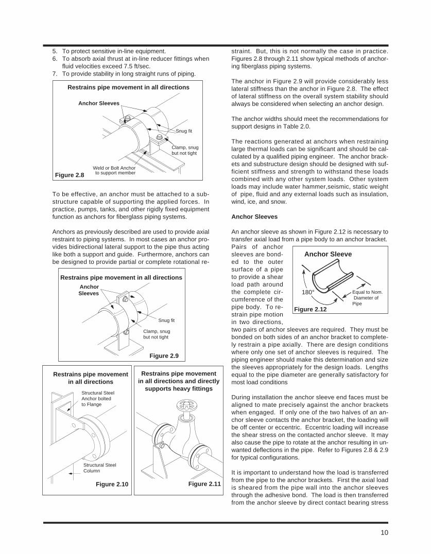
10
5. To protect sensitive in-line equipment.6. To absorb axial thrust at in-line reducer fittings when
fluid velocities exceed 7.5 ft/sec.7. To provide stability in long straight runs of piping.
To be effective, an anchor must be attached to a sub-structure capable of supporting the applied forces. In practice, pumps, tanks, and other rigidly fixed equipment function as anchors for fiberglass piping systems.
Anchors as previously described are used to provide axial restraint to piping systems. In most cases an anchor pro-vides bidirectional lateral support to the pipe thus acting like both a support and guide. Furthermore, anchors can be designed to provide partial or complete rotational re-
straint. But, this is not normally the case in practice. Figures 2.8 through 2.11 show typical methods of anchor-ing fiberglass piping systems.
The anchor in Figure 2.9 will provide considerably less lateral stiffness than the anchor in Figure 2.8. The effect of lateral stiffness on the overall system stability should always be considered when selecting an anchor design.
The anchor widths should meet the recommendations for support designs in Table 2.0.
The reactions generated at anchors when restraining large thermal loads can be significant and should be cal-culated by a qualified piping engineer. The anchor brack-ets and substructure design should be designed with suf-ficient stiffness and strength to withstand these loads combined with any other system loads. Other system loads may include water hammer,seismic, static weight of pipe, fluid and any external loads such as insulation, wind, ice, and snow.
anchor Sleeves
An anchor sleeve as shown in Figure 2.12 is necessary to transfer axial load from a pipe body to an anchor bracket. Pairs of anchor sleeves are bond-ed to the outer surface of a pipe to provide a shear load path around the complete cir-cumference of the pipe body. To re-strain pipe motion in two directions, two pairs of anchor sleeves are required. They must be bonded on both sides of an anchor bracket to complete-ly restrain a pipe axially. There are design conditions where only one set of anchor sleeves is required. The piping engineer should make this determination and size the sleeves appropriately for the design loads. Lengths equal to the pipe diameter are generally satisfactory for most load conditions
During installation the anchor sleeve end faces must be aligned to mate precisely against the anchor brackets when engaged. If only one of the two halves of an an-chor sleeve contacts the anchor bracket, the loading will be off center or eccentric. Eccentric loading will increase the shear stress on the contacted anchor sleeve. It may also cause the pipe to rotate at the anchor resulting in un-wanted deflections in the pipe. Refer to Figures 2.8 & 2.9 for typical configurations.
It is important to understand how the load is transferred from the pipe to the anchor brackets. First the axial load is sheared from the pipe wall into the anchor sleeves through the adhesive bond. The load is then transferred from the anchor sleeve by direct contact bearing stress
Figure 2.8
anchor Sleeves
Snug fit
Clamp, snug but not tight
Weld or Bolt Anchor to support member
restrains pipe movement in all directions
Figure 2.9
restrains pipe movement in all directions
Snug fit
Clamp, snug but not tight
anchor Sleeves
Figure 2.10
restrains pipe movement in all directions
Structural Steel Anchor bolted to Flange
Structural Steel Column
Figure 2.11
restrains pipe movement in all directions and directly
supports heavy fittings
Figure 2.12
180° Equal to Nom. Diameter of Pipe
anchor Sleeve
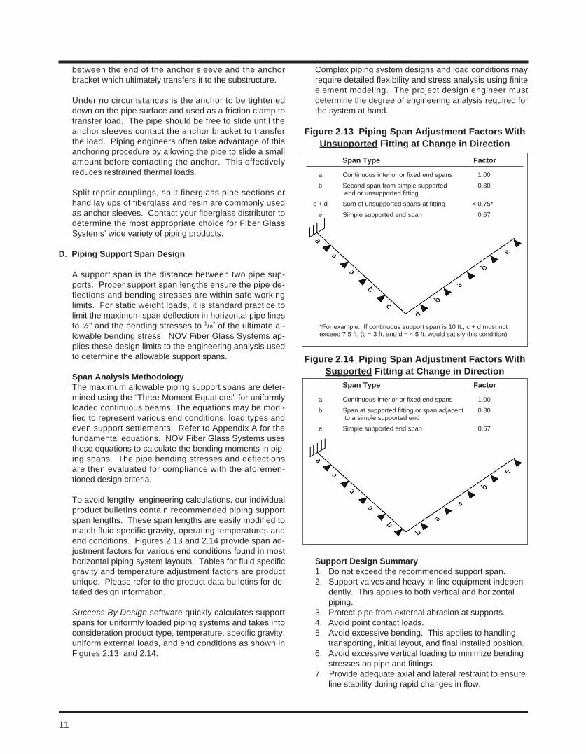
between the end of the anchor sleeve and the anchor bracket which ultimately transfers it to the substructure.
Under no circumstances is the anchor to be tightened down on the pipe surface and used as a friction clamp to transfer load. The pipe should be free to slide until the anchor sleeves contact the anchor bracket to transfer the load. Piping engineers often take advantage of this anchoring procedure by allowing the pipe to slide a small amount before contacting the anchor. This effectively reduces restrained thermal loads.
Split repair couplings, split fiberglass pipe sections or hand lay ups of fiberglass and resin are commonly used as anchor sleeves. Contact your fiberglass distributor to determine the most appropriate choice for Fiber Glass Systems’ wide variety of piping products.
D. Piping Support Span Design
A support span is the distance between two pipe sup-ports. Proper support span lengths ensure the pipe de-flections and bending stresses are within safe working limits. For static weight loads, it is standard practice to limit the maximum span deflection in horizontal pipe lines to ½" and the bending stresses to 1/8" of the ultimate al-lowable bending stress. NOV Fiber Glass Systems ap-plies these design limits to the engineering analysis used to determine the allowable support spans.
Span analysis methodologyThe maximum allowable piping support spans are deter-mined using the “Three Moment Equations" for uniformly loaded continuous beams. The equations may be modi-fied to represent various end conditions, load types and even support settlements. Refer to Appendix A for the fundamental equations. NOV Fiber Glass Systems uses these equations to calculate the bending moments in pip-ing spans. The pipe bending stresses and deflections are then evaluated for compliance with the aforemen-tioned design criteria.
To avoid lengthy engineering calculations, our individual product bulletins contain recommended piping support span lengths. These span lengths are easily modified to match fluid specific gravity, operating temperatures and end conditions. Figures 2.13 and 2.14 provide span ad-justment factors for various end conditions found in most horizontal piping system layouts. Tables for fluid specific gravity and temperature adjustment factors are product unique. Please refer to the product data bulletins for de-tailed design information.
Success By Design software quickly calculates support spans for uniformly loaded piping systems and takes into consideration product type, temperature, specific gravity, uniform external loads, and end conditions as shown in Figures 2.13 and 2.14.
Complex piping system designs and load conditions may require detailed flexibility and stress analysis using finite element modeling. The project design engineer must determine the degree of engineering analysis required forthe system at hand.
Support Design Summary1. Do not exceed the recommended support span.2. Support valves and heavy in-line equipment indepen-
dently. This applies to both vertical and horizontal piping.
3. Protect pipe from external abrasion at supports.4. Avoid point contact loads.5. Avoid excessive bending. This applies to handling,
transporting, initial layout, and final installed position. 6. Avoid excessive vertical loading to minimize bending
stresses on pipe and fittings.7. Provide adequate axial and lateral restraint to ensure
line stability during rapid changes in flow.
Span type Factor
a Continuous interior or fixed end spans 1.00 b Second span from simple supported 0.80 end or unsupported fitting c + d Sum of unsupported spans at fitting < 0.75* e Simple supported end span 0.67
Figure 2.13 Piping Span adjustment Factors With Unsupported Fitting at change in Direction
Span type Factor
a Continuous interior or fixed end spans 1.00 b Span at supported fitting or span adjacent 0.80 to a simple supported end e Simple supported end span 0.67
Figure 2.14 Piping Span adjustment Factors With Supported Fitting at change in Direction
11
*For example: If continuous support span is 10 ft., c + d must not exceed 7.5 ft. (c = 3 ft. and d = 4.5 ft. would satisfy this condition).
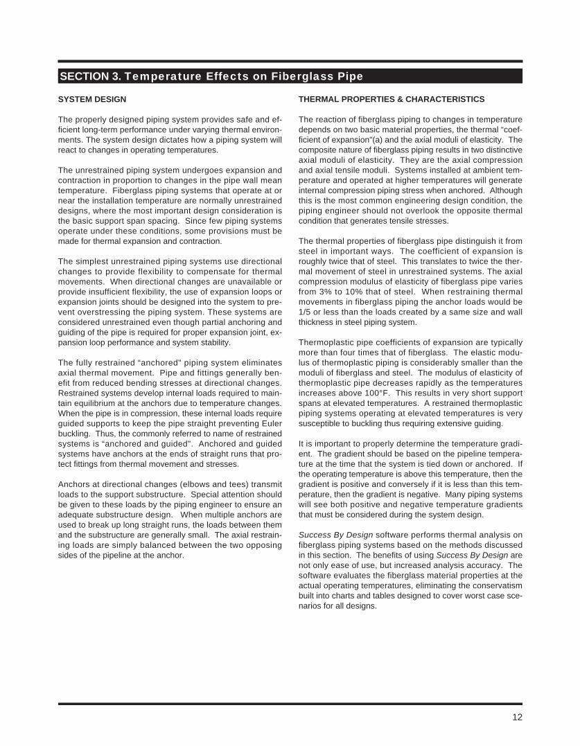
12
SyStem DeSiGn
The properly designed piping system provides safe and ef-ficient long-term performance under varying thermal environ-ments. The system design dictates how a piping system will react to changes in operating temperatures.
The unrestrained piping system undergoes expansion and contraction in proportion to changes in the pipe wall mean temperature. Fiberglass piping systems that operate at or near the installation temperature are normally unrestrained designs, where the most important design consideration is the basic support span spacing. Since few piping systems operate under these conditions, some provisions must be made for thermal expansion and contraction.
The simplest unrestrained piping systems use directional changes to provide flexibility to compensate for thermal movements. When directional changes are unavailable or provide insufficient flexibility, the use of expansion loops or expansion joints should be designed into the system to pre-vent overstressing the piping system. These systems are considered unrestrained even though partial anchoring and guiding of the pipe is required for proper expansion joint, ex-pansion loop performance and system stability.
The fully restrained “anchored" piping system eliminates axial thermal movement. Pipe and fittings generally ben-efit from reduced bending stresses at directional changes. Restrained systems develop internal loads required to main-tain equilibrium at the anchors due to temperature changes. When the pipe is in compression, these internal loads require guided supports to keep the pipe straight preventing Euler buckling. Thus, the commonly referred to name of restrained systems is “anchored and guided". Anchored and guided systems have anchors at the ends of straight runs that pro-tect fittings from thermal movement and stresses.
Anchors at directional changes (elbows and tees) transmit loads to the support substructure. Special attention should be given to these loads by the piping engineer to ensure an adequate substructure design. When multiple anchors are used to break up long straight runs, the loads between them and the substructure are generally small. The axial restrain-ing loads are simply balanced between the two opposing sides of the pipeline at the anchor.
tHermal ProPertieS & cHaracteriSticS
The reaction of fiberglass piping to changes in temperature depends on two basic material properties, the thermal “coef-ficient of expansion"(a) and the axial moduli of elasticity. The composite nature of fiberglass piping results in two distinctive axial moduli of elasticity. They are the axial compression and axial tensile moduli. Systems installed at ambient tem-perature and operated at higher temperatures will generate internal compression piping stress when anchored. Although this is the most common engineering design condition, the piping engineer should not overlook the opposite thermal condition that generates tensile stresses.
The thermal properties of fiberglass pipe distinguish it from steel in important ways. The coefficient of expansion is roughly twice that of steel. This translates to twice the ther-mal movement of steel in unrestrained systems. The axial compression modulus of elasticity of fiberglass pipe varies from 3% to 10% that of steel. When restraining thermal movements in fiberglass piping the anchor loads would be 1/5 or less than the loads created by a same size and wall thickness in steel piping system.
Thermoplastic pipe coefficients of expansion are typically more than four times that of fiberglass. The elastic modu-lus of thermoplastic piping is considerably smaller than the moduli of fiberglass and steel. The modulus of elasticity of thermoplastic pipe decreases rapidly as the temperatures increases above 100°F. This results in very short support spans at elevated temperatures. A restrained thermoplastic piping systems operating at elevated temperatures is very susceptible to buckling thus requiring extensive guiding.
It is important to properly determine the temperature gradi-ent. The gradient should be based on the pipeline tempera-ture at the time that the system is tied down or anchored. If the operating temperature is above this temperature, then the gradient is positive and conversely if it is less than this tem-perature, then the gradient is negative. Many piping systems will see both positive and negative temperature gradients that must be considered during the system design.
Success By Design software performs thermal analysis on fiberglass piping systems based on the methods discussed in this section. The benefits of using Success By Design are not only ease of use, but increased analysis accuracy. The software evaluates the fiberglass material properties at the actual operating temperatures, eliminating the conservatism built into charts and tables designed to cover worst case sce-narios for all designs.
Section 3. Temperature Effects on Fiberglass Pipe
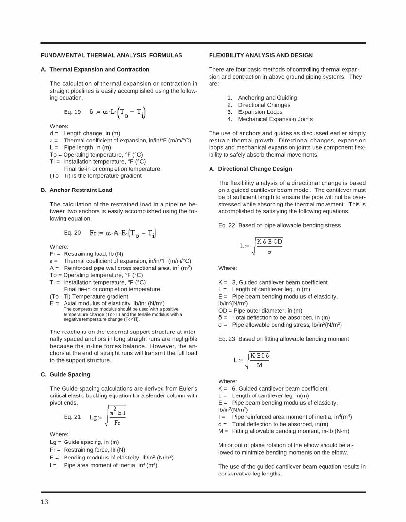
FUnDamental tHermal analySiS FormUlaS
a. thermal expansion and contraction
The calculation of thermal expansion or contraction in straight pipelines is easily accomplished using the follow-ing equation.
Eq. 19
Where:d = Length change, in (m)a = Thermal coefficient of expansion, in/in/°F (m/m/°C)L = Pipe length, in (m) To = Operating temperature, °F (°C)Ti = Installation temperature, °F (°C) Final tie-in or completion temperature.(To - Ti) is the temperature gradient
B. anchor restraint load
The calculation of the restrained load in a pipeline be-tween two anchors is easily accomplished using the fol-lowing equation.
Eq. 20
Where:Fr = Restraining load, lb (N)a = Thermal coefficient of expansion, in/in/°F (m/m/°C)A = Reinforced pipe wall cross sectional area, in2 (m2)To = Operating temperature, °F (°C)Ti = Installation temperature, °F (°C) Final tie-in or completion temperature.(To - Ti) Temperature gradientE = Axial modulus of elasticity, lb/in2 (N/m2) The compression modulus should be used with a positive temperature change (To>Ti) and the tensile modulus with a negative temperature change (To<Ti). The reactions on the external support structure at inter-nally spaced anchors in long straight runs are negligible because the in-line forces balance. However, the an-chors at the end of straight runs will transmit the full load to the support structure.
c. Guide Spacing
The Guide spacing calculations are derived from Euler’s critical elastic buckling equation for a slender column with pivot ends.
Eq. 21
Where:Lg = Guide spacing, in (m)Fr = Restraining force, lb (N)E = Bending modulus of elasticity, lb/in2 (N/m2) I = Pipe area moment of inertia, in4 (m4)
FleXiBility analySiS anD DeSiGn
There are four basic methods of controlling thermal expan-sion and contraction in above ground piping systems. They are:
1. Anchoring and Guiding 2. Directional Changes3. Expansion Loops 4. Mechanical Expansion Joints
The use of anchors and guides as discussed earlier simply restrain thermal growth. Directional changes, expansion loops and mechanical expansion joints use component flex-ibility to safely absorb thermal movements.
a. Directional change Design
The flexibility analysis of a directional change is based on a guided cantilever beam model. The cantilever must be of sufficient length to ensure the pipe will not be over-stressed while absorbing the thermal movement. This is accomplished by satisfying the following equations.
Eq. 22 Based on pipe allowable bending stress
Where:
K = 3, Guided cantilever beam coefficientL = Length of cantilever leg, in (m)E = Pipe beam bending modulus of elasticity, lb/in2(N/m2)OD = Pipe outer diameter, in (m)δ = Total deflection to be absorbed, in (m)σ = Pipe allowable bending stress, lb/in2(N/m2)
Eq. 23 Based on fitting allowable bending moment
Where:K = 6, Guided cantilever beam coefficientL = Length of cantilever leg, in(m)E = Pipe beam bending modulus of elasticity, lb/in2(N/m2)I = Pipe reinforced area moment of inertia, in4(m4)d = Total deflection to be absorbed, in(m)M = Fitting allowable bending moment, in-lb (N-m)
Minor out of plane rotation of the elbow should be al-lowed to minimize bending moments on the elbow.
The use of the guided cantilever beam equation results in conservative leg lengths.
13
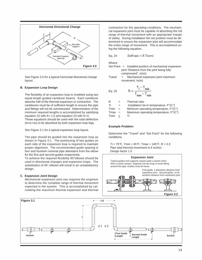
See Figure 3.0 for a typical horizontal directional change layout.
B. expansion loop Design
The flexibility of an expansion loop is modeled using two equal length guided cantilever beams. Each cantilever absorbs half of the thermal expansion or contraction. The cantilevers must be of sufficient length to ensure the pipe and fittings will not be overstressed. Determination of the minimum required lengths is accomplished by satisfying equation 22 with K= 1.5 and equation 23 with K=3. These equations should be used with the total deflection (d=d1+d2) to be absorbed by both expansion loop legs.
See Figure 3.1 for a typical expansion loop layout.
The pipe should be guided into the expansion loop as shown in Figure 3.1. The positioning of two guides on each side of the expansion loop is required to maintain proper alignment. The recommended guide spacing is four and fourteen nominal pipe diameters from the elbow for the first and second guides respectively.To achieve the required flexibility 90°elbows should be used in directional changes and expansion loops. The substitution of 45° elbows will result in an unsatisfactory design.
c. expansion Joint DesignMechanical expansion joint use requires the engineer to determine the complete range of thermal movement expected in the system. This is accomplished by cal-culating the maximum thermal expansion and thermal
contraction for the operating conditions. The mechani-cal expansion joint must be capable of absorbing the full range of thermal movement with an appropriate margin of safety. During installation the set position must be de-termined to ensure the expansion joint will accommodate the entire range of movement. This is accomplished us-ing the following equation.
Eq. 24
Where:Set Point = Installed position of mechanical expansion joint “Distance from the joint being fully compressed", in(m)Travel = Mechanical expansion joint maximum movement, in(m)
Eq. 25
R = Thermal ratioTi = Installation tie-in temperature, F°(C°)Tmin = Minimum operating temperature, F°(C°)Tmax = Maximum operating temperature, F°(C°)Tmin < Ti
Example Problem:
Determine the “Travel" and “Set Point" for the following conditions. Ti = 75°F, Tmin = 45°F, Tmax = 145°F, R = 0.3 Pipe total thermal movement is 6 inches Design factor 1.5
Figure 3.0
Horizontal Directional change
Figure 3.1
anchor anchorFirst Guide length Second Guide
length
l
l/2
d 1 d 2
Typical guides and supports require pads a shown when there is point contact. Supports can be snug or loose fitting around the pipe. Guides must be loose.
Figure 3.2
First guide, 4 diameters distance from expansion joint. Second guide, 14 di-ameters distance from expansion joint.
expansion Joint
14
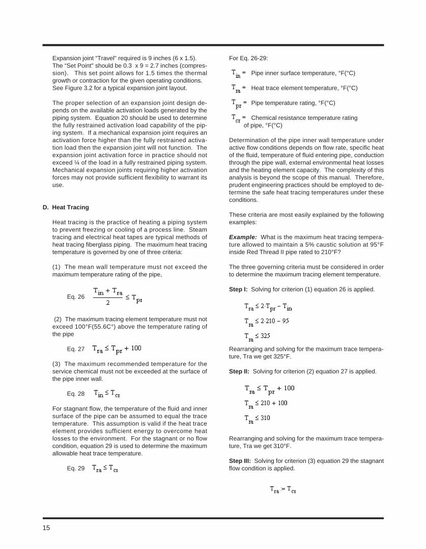
Expansion joint “Travel" required is 9 inches (6 x 1.5).The “Set Point" should be 0.3 x 9 = 2.7 inches (compres-sion). This set point allows for 1.5 times the thermal growth or contraction for the given operating conditions. See Figure 3.2 for a typical expansion joint layout.
The proper selection of an expansion joint design de-pends on the available activation loads generated by the piping system. Equation 20 should be used to determine the fully restrained activation load capability of the pip-ing system. If a mechanical expansion joint requires an activation force higher than the fully restrained activa-tion load then the expansion joint will not function. The expansion joint activation force in practice should not exceed ¼ of the load in a fully restrained piping system. Mechanical expansion joints requiring higher activation forces may not provide sufficient flexibility to warrant its use.
D. Heat tracing
Heat tracing is the practice of heating a piping system to prevent freezing or cooling of a process line. Steam tracing and electrical heat tapes are typical methods of heat tracing fiberglass piping. The maximum heat tracing temperature is governed by one of three criteria:
(1) The mean wall temperature must not exceed the maximum temperature rating of the pipe,
Eq. 26
(2) The maximum tracing element temperature must not exceed 100°F(55.6C°) above the temperature rating of the pipe
Eq. 27
(3) The maximum recommended temperature for the service chemical must not be exceeded at the surface of the pipe inner wall.
Eq. 28
For stagnant flow, the temperature of the fluid and inner surface of the pipe can be assumed to equal the trace temperature. This assumption is valid if the heat trace element provides sufficient energy to overcome heat losses to the environment. For the stagnant or no flow condition, equation 29 is used to determine the maximum allowable heat trace temperature.
Eq. 29
For Eq. 26-29:
Pipe inner surface temperature, °F(°C)
Heat trace element temperature, °F(°C)
Pipe temperature rating, °F(°C)
Chemical resistance temperature rating
of pipe, °F(°C)
Determination of the pipe inner wall temperature under active flow conditions depends on flow rate, specific heat of the fluid, temperature of fluid entering pipe, conduction through the pipe wall, external environmental heat losses and the heating element capacity. The complexity of this analysis is beyond the scope of this manual. Therefore, prudent engineering practices should be employed to de-termine the safe heat tracing temperatures under these conditions.
These criteria are most easily explained by the following examples:
Example: What is the maximum heat tracing tempera-ture allowed to maintain a 5% caustic solution at 95°F inside Red Thread II pipe rated to 210°F?
The three governing criteria must be considered in order to determine the maximum tracing element temperature.
Step i: Solving for criterion (1) equation 26 is applied.
Rearranging and solving for the maximum trace tempera-ture, Tra we get 325°F.
Step ii: Solving for criterion (2) equation 27 is applied.
Rearranging and solving for the maximum trace tempera-ture, Tra we get 310°F.
Step iii: Solving for criterion (3) equation 29 the stagnant flow condition is applied.
15
Therefore the maximum allowable heat trace temperature equals the maximum chemical resistance temperature for the piping. Referencing Chemical Resistance Guide, Bulletin No. E5615, Red Thread II pipe is rated to 100°F in 5% caustic. Therefore the maximum heat trace tem-perature is 100°F.
However, if the fluid were flowing into the pipeline at tem-peratures below 100°F, then the heat trace temperature would be higher than 100°F. A thorough heat transfer analysis would be required to determine the appropriate heat trace temperature for this condition.
The maximum heat trace temperature for stagnant flow is 100°F, the lowest temperature calculated using the three criteria.
e. thermal conductivity
The thermal conductivity of fiberglass piping is approxi-mately 1/100 that of steel, making it a poor conductor of heat compared to steel. However, the use of insulation to prevent heat loss or gain is recommended when there are economic consequences due to heat loss or gain. Typical fiberglass thermal conductivity values vary from 0.07-0.29 BTU/(Ft.)(Hr.)(°F).
F. thermal expansion in Buried Pipe
Soil restraint inherently restrains movement of buried fiberglass pipelines because these pipes develop rela-tively small forces during a temperature change. Special precautions (thrust blocks, guides, expansion joints, etc.) for handling thermal expansion are not necessary if the pipe is buried at least two to three feet and the bedding material is of a soil type capable of restraining the line. Sand, loam, clay, silt, crushed rock and gravel are suit-able bedding for restraining a pipeline; however, special precautions must be taken to properly anchor the pipe in swamps, bogs, etc. where bedding might easily shift and yield to even the low forces developed in fiberglass pipe.
G. Pipe torque Due to thermal expansion
Torsion shear stresses in piping systems containing mul-tiple elevation and directional changes normally do not have to be considered in pipe analysis. The allowable bending moments are lower than the allowable torsional moments in a pipe. Therefore, bending moments in a pipe leg reacted by torsion in a connecting pipe will be limited by the bending moment capability of the pipe not the torsional load. Computer modeling is recommended for this sophisticated level of piping system analysis.
16
introDUction
The guidelines in this section pertain to the design and burial of fiberglass pipe. The structural design process assumes the pipe will receive adequate support in typically encoun-tered soil conditions. Recommendations for trenching, se-lecting, placing and compacting backfill will be discussed.
The successful installation depends on all components work-ing together to form a sound support system. Therefore, once a pipe is selected, it is of utmost importance to carefully review the native soil conditions, select the backfill material and closely monitor the trenching and installation process. Properly positioned and compacted bedding and backfill re-duces pipe deformations maximizing long-term performance of a buried pipeline.
Detailed design and installation data for buried fiberglass pip-ing systems may be found in AWWA M45, Manual of Water Supply Practices, Fiberglass Pipe Design, First Edition. Contact NOV Fiber Glass Systems applications engineer for detailed burial calculations.
PiPe FleXiBility
The response of fiberglass pipe to burial loads is highly de-pendent on the flexibility of the pipe walls. The best measure of pipe flexibility can be found using the “pipe stiffness" value as defined and determined by ASTM D2412 tests.
Pipe with pipe stiffness values greater than 72 psi typically resist native backfill loads with minimal pipe deformation. The pipe stiffness of small diameter fiberglass pipe, 1 to 8 inch diameters, typically meets or exceeds 72 psi. Two to three feet of native backfill cover with a soil modulus greater than or equal to 1,000 psi is generally sufficient to protect this category of pipe from HS-20 vehicular and dead weight soil loads.
Pipe that is buried under concrete or asphalt roadways that support vehicular loads requires less cover. Design data and burial depth recommendation for specific piping can be found in our product bulletins and installation handbooks. Manual No. B2160 contains special installation instructions for UL Listed Red Thread IIA piping commonly used under pave-ments.
Pipe with pipe stiffness values less than 72 psi, are consid-ered flexible and are more susceptible to the effects of poor compaction or soil conditions. Because of this, larger diam-eter piping requires detailed attention during the design and installation of buried pipelines.
BUrial analySiS
Pipe burial depth calculations are based on Spangler’s de-flection equation and Von Mise’s buckling equation as out-lined in AWWA M45. Application of these methods is based on the assumption that the design values used for bedding, backfill and compaction levels will be achieved with good field practice and appropriate equipment. If these assump-tions are not met, the deflections can be higher or lower than predicted by calculation.
a. Soil types
A soil’s ability to support pipe depends on the type of soil, degree of compaction and condition of the soil, i.e. den-sity and moisture content. A stable soil is capable of pro-viding sufficient long-term bearing resistance to support a buried pipe. Unstable soils such as peat, organic soil, and highly expansive clays exhibit a significant change in volume with a change in moisture content. Special trenching and backfill requirements are necessary when the native soil is unstable. Some guidelines to aid the engineer in determining the stability at a particular site follow:
1. For cohesive soils or granular-cohesive soils, if the unconfined compressive strength per ASTM D2166 exceeds 1,500 lb/ft2, the soil will generally be stable.
2. For cohesive soils, if the shear strength of the soil per ASTM D2573 is in excess of 750 lb/ft2, the soil will generally be stable.
3. For sand, if the standard penetration “Blow" value, N, is above 10, the soil will generally be stable.
Soils types are grouped into “stiffness categories" (SC). They are designated SC1 through SC5. SC1 indicates a soil that provides the highest soil stiffness at any given Proctor density. An SC1 classified soil requires the least amount of compaction to achieve the desired soil stiff-ness. The higher numbered soil classifications (SC2-SC4) become, the more compaction is required to obtain specific soil stiffness at a given Proctor density. The SC5 soils are unstable and should not be used as backfill or bedding. Decaying organic waste and frozen materials fall in the SC5 category. Lists of recommended backfill materials are shown in Table 4.0.
Section 4. Pipe Burial
17
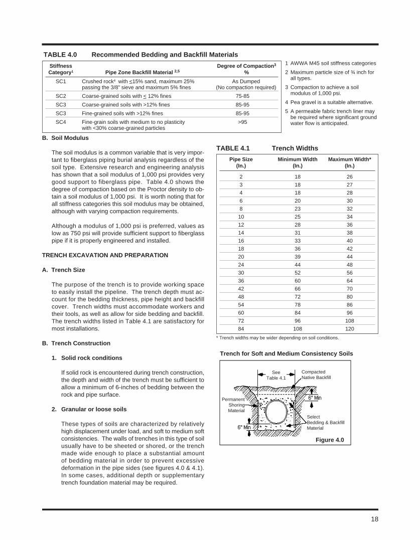
B. Soil modulus
The soil modulus is a common variable that is very impor-tant to fiberglass piping burial analysis regardless of the soil type. Extensive research and engineering analysis has shown that a soil modulus of 1,000 psi provides very good support to fiberglass pipe. Table 4.0 shows the degree of compaction based on the Proctor density to ob-tain a soil modulus of 1,000 psi. It is worth noting that for all stiffness categories this soil modulus may be obtained, although with varying compaction requirements.
Although a modulus of 1,000 psi is preferred, values as low as 750 psi will provide sufficient support to fiberglass pipe if it is properly engineered and installed.
trencH eXcaVation anD PreParation
a. trench Size
The purpose of the trench is to provide working space to easily install the pipeline. The trench depth must ac-count for the bedding thickness, pipe height and backfill cover. Trench widths must accommodate workers and their tools, as well as allow for side bedding and backfill. The trench widths listed in Table 4.1 are satisfactory for most installations.
B. trench construction
1. Solid rock conditions
If solid rock is encountered during trench construction, the depth and width of the trench must be sufficient to allow a minimum of 6-inches of bedding between the rock and pipe surface.
2. Granular or loose soils
These types of soils are characterized by relatively high displacement under load, and soft to medium soft consistencies. The walls of trenches in this type of soil usually have to be sheeted or shored, or the trench made wide enough to place a substantial amount of bedding material in order to prevent excessive deformation in the pipe sides (see figures 4.0 & 4.1). In some cases, additional depth or supplementary trench foundation material may be required.
trench for Soft and medium consistency Soils
Figure 4.0
Compacted Native Backfill
See Table 4.1
Permanent Shoring Material
Select Bedding & Backfill Material
taBle 4.0 recommended Bedding and Backfill materials1 AWWA M45 soil stiffness categories
2 Maximum particle size of ¾ inch for all types.
3 Compaction to achieve a soil modulus of 1,000 psi.
4 Pea gravel is a suitable alternative.
5 A permeable fabric trench liner may be required where significant ground water flow is anticipated.
Stiffness Degree of compaction3
category1 Pipe zone Backfill material 2,5 % SC1 Crushed rock4 with <15% sand, maximum 25% As Dumped passing the 3/8” sieve and maximum 5% fines (No compaction required) SC2 Coarse-grained soils with < 12% fines 75-85 SC3 Coarse-grained soils with >12% fines 85-95 SC3 Fine-grained soils with >12% fines 85-95 SC4 Fine-grain soils with medium to no plasticity >95 with <30% coarse-grained particles
* Trench widths may be wider depending on soil conditions.
taBle 4.1 trench Widths Pipe Size minimum Width maximum Width* (in.) (in.) (in.)
2 18 26 3 18 27 4 18 28 6 20 30 8 23 32 10 25 34 12 28 36 14 31 38 16 33 40 18 36 42 20 39 44 24 44 48 30 52 56 36 60 64 42 66 70 48 72 80 54 78 86 60 84 96 72 96 108 84 108 120
18
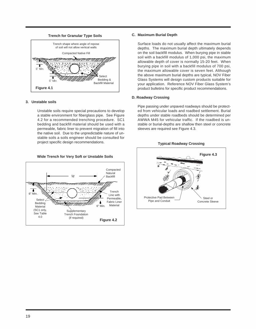
3. Unstable soils
Unstable soils require special precautions to develop a stable environment for fiberglass pipe. See Figure 4.2 for a recommended trenching procedure. SC1 bedding and backfill material should be used with a permeable, fabric liner to prevent migration of fill into the native soil. Due to the unpredictable nature of un-stable soils a soils engineer should be consulted for project specific design recommendations.
c. maximum Burial Depth
Surface loads do not usually affect the maximum burial depths. The maximum burial depth ultimately depends on the soil backfill modulus. When burying pipe in stable soil with a backfill modulus of 1,000 psi, the maximum allowable depth of cover is normally 15-20 feet. When burying pipe in soil with a backfill modulus of 700 psi, the maximum allowable cover is seven feet. Although the above maximum burial depths are typical, NOV Fiber Glass Systems will design custom products suitable for your application. Reference NOV Fiber Glass System’s product bulletins for specific product recommendations.
D. roadway crossing
Pipe passing under unpaved roadways should be protect-ed from vehicular loads and roadbed settlement. Burial depths under stable roadbeds should be determined per AWWA M45 for vehicular traffic. If the roadbed is un-stable or burial-depths are shallow then steel or concrete sleeves are required see Figure 4.3.
trench for Granular type Soils
Figure 4.1
Wide trench for Very Soft or Unstable Soils
Supplementary Trench Foundation
(if required)
Compacted Natural Backfill
Figure 4.2
6" Min.
6" Min.
Select Bedding Material
(SC1 only, See Table
4.0
Trench Line with
Permeable, Fabric Liner
Material
Select Bedding &
Backfill Material
Trench shape where angle of reposeof soil will not allow vertical walls
Compacted Native Fill
typical roadway crossing
Figure 4.3
Protective Pad Between Pipe and Conduit
Steel or Concrete Sleeve
19
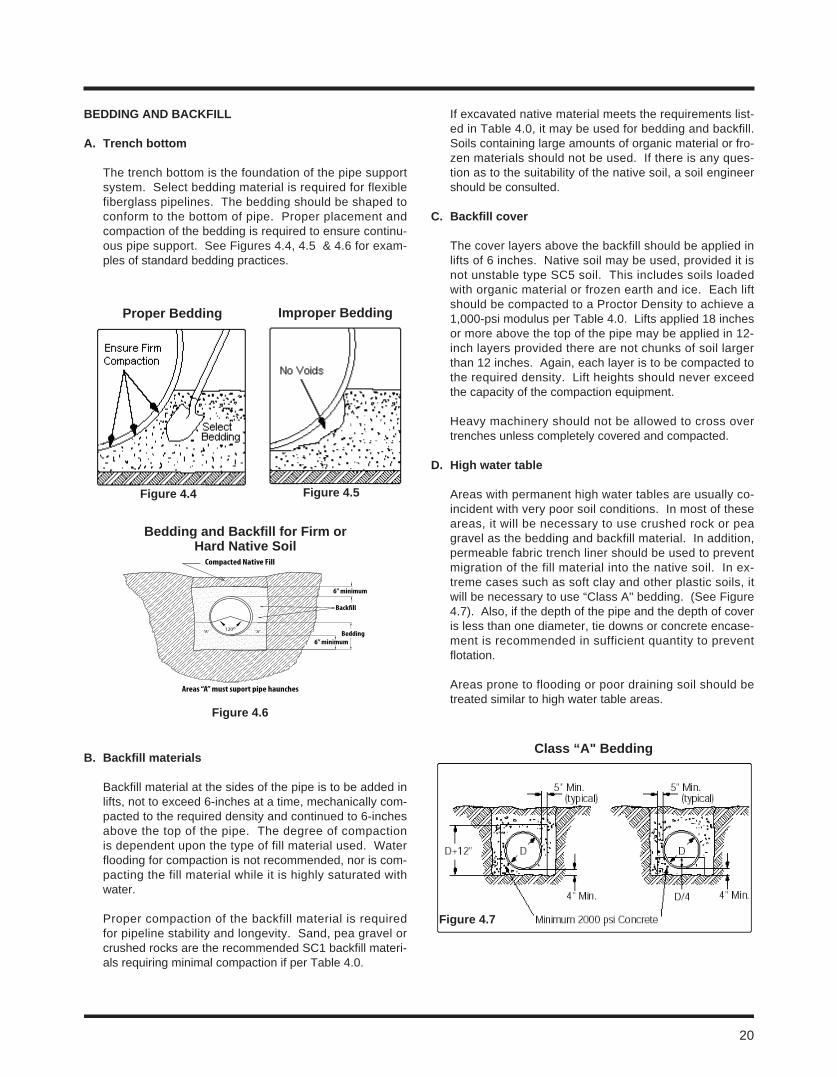
20
BeDDinG anD BacKFill
a. trench bottom
The trench bottom is the foundation of the pipe support system. Select bedding material is required for flexible fiberglass pipelines. The bedding should be shaped to conform to the bottom of pipe. Proper placement and compaction of the bedding is required to ensure continu-ous pipe support. See Figures 4.4, 4.5 & 4.6 for exam-ples of standard bedding practices.
B. Backfill materials
Backfill material at the sides of the pipe is to be added in lifts, not to exceed 6-inches at a time, mechanically com-pacted to the required density and continued to 6-inches above the top of the pipe. The degree of compaction is dependent upon the type of fill material used. Water flooding for compaction is not recommended, nor is com-pacting the fill material while it is highly saturated with water.
Proper compaction of the backfill material is required for pipeline stability and longevity. Sand, pea gravel or crushed rocks are the recommended SC1 backfill materi-als requiring minimal compaction if per Table 4.0.
If excavated native material meets the requirements list-ed in Table 4.0, it may be used for bedding and backfill. Soils containing large amounts of organic material or fro-zen materials should not be used. If there is any ques-tion as to the suitability of the native soil, a soil engineer should be consulted.
c. Backfill cover
The cover layers above the backfill should be applied in lifts of 6 inches. Native soil may be used, provided it is not unstable type SC5 soil. This includes soils loaded with organic material or frozen earth and ice. Each lift should be compacted to a Proctor Density to achieve a 1,000-psi modulus per Table 4.0. Lifts applied 18 inches or more above the top of the pipe may be applied in 12-inch layers provided there are not chunks of soil larger than 12 inches. Again, each layer is to be compacted to the required density. Lift heights should never exceed the capacity of the compaction equipment.
Heavy machinery should not be allowed to cross over trenches unless completely covered and compacted.
D. High water table
Areas with permanent high water tables are usually co-incident with very poor soil conditions. In most of these areas, it will be necessary to use crushed rock or pea gravel as the bedding and backfill material. In addition, permeable fabric trench liner should be used to prevent migration of the fill material into the native soil. In ex-treme cases such as soft clay and other plastic soils, it will be necessary to use “Class A" bedding. (See Figure 4.7). Also, if the depth of the pipe and the depth of cover is less than one diameter, tie downs or concrete encase-ment is recommended in sufficient quantity to prevent flotation.
Areas prone to flooding or poor draining soil should be treated similar to high water table areas.
Proper Bedding improper Bedding
Figure 4.4 Figure 4.5
Compacted Native Fill
6” minimum
Back�ll
Bedding6” minimum
120o“A”“A”
Areas “A” must suport pipe haunches
Figure 4.6
Bedding and Backfill for Firm or Hard native Soil
class “a" Bedding
Figure 4.7
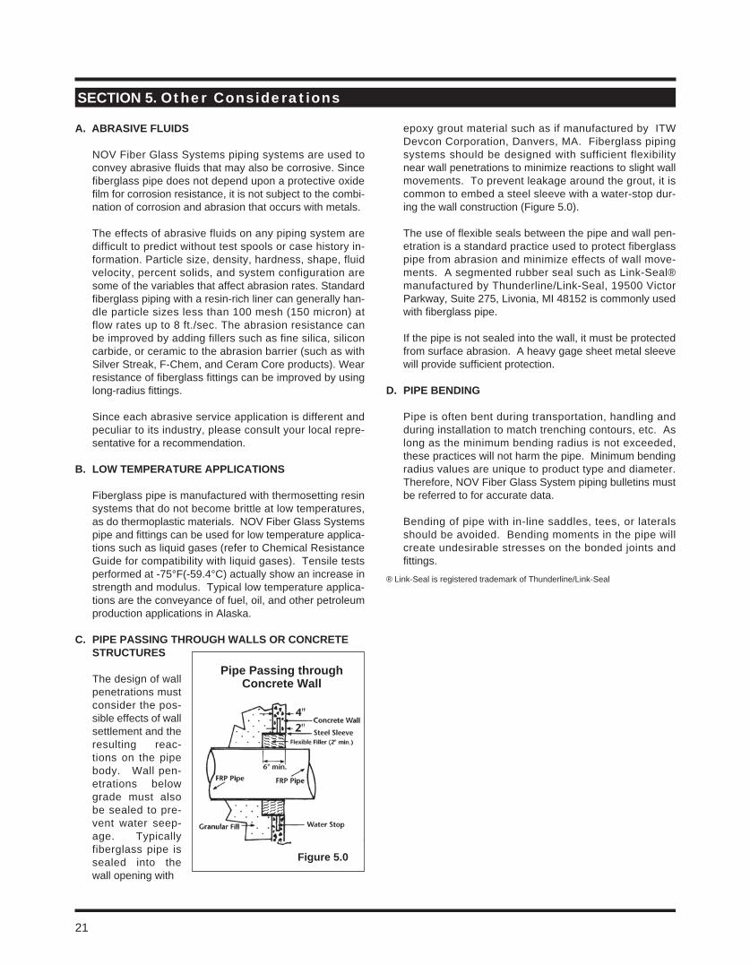
a. aBraSiVe FlUiDS
NOV Fiber Glass Systems piping systems are used to convey abrasive fluids that may also be corrosive. Since fiberglass pipe does not depend upon a protective oxide film for corrosion resistance, it is not subject to the combi-nation of corrosion and abrasion that occurs with metals.
The effects of abrasive fluids on any piping system are difficult to predict without test spools or case history in-formation. Particle size, density, hardness, shape, fluid velocity, percent solids, and system configuration are some of the variables that affect abrasion rates. Standard fiberglass piping with a resin-rich liner can generally han-dle particle sizes less than 100 mesh (150 micron) at flow rates up to 8 ft./sec. The abrasion resistance can be improved by adding fillers such as fine silica, silicon carbide, or ceramic to the abrasion barrier (such as with Silver Streak, F-Chem, and Ceram Core products). Wear resistance of fiberglass fittings can be improved by using long-radius fittings.
Since each abrasive service application is different and peculiar to its industry, please consult your local repre-sentative for a recommendation.
B. loW temPeratUre aPPlicationS
Fiberglass pipe is manufactured with thermosetting resin systems that do not become brittle at low temperatures, as do thermoplastic materials. NOV Fiber Glass Systems pipe and fittings can be used for low temperature applica-tions such as liquid gases (refer to Chemical Resistance Guide for compatibility with liquid gases). Tensile tests performed at -75°F(-59.4°C) actually show an increase in strength and modulus. Typical low temperature applica-tions are the conveyance of fuel, oil, and other petroleum production applications in Alaska.
c. PiPe PaSSinG tHroUGH WallS or concrete StrUctUreS
The design of wall penetrations must consider the pos-sible effects of wall settlement and the resulting reac-tions on the pipe body. Wall pen-etrations below grade must also be sealed to pre-vent water seep-age. Typically fiberglass pipe is sealed into the wall opening with
epoxy grout material such as if manufactured by ITW Devcon Corporation, Danvers, MA. Fiberglass piping systems should be designed with sufficient flexibility near wall penetrations to minimize reactions to slight wall movements. To prevent leakage around the grout, it is common to embed a steel sleeve with a water-stop dur-ing the wall construction (Figure 5.0).
The use of flexible seals between the pipe and wall pen-etration is a standard practice used to protect fiberglass pipe from abrasion and minimize effects of wall move-ments. A segmented rubber seal such as Link-Seal® manufactured by Thunderline/Link-Seal, 19500 Victor Parkway, Suite 275, Livonia, MI 48152 is commonly used with fiberglass pipe.
If the pipe is not sealed into the wall, it must be protected from surface abrasion. A heavy gage sheet metal sleeve will provide sufficient protection.
D. PiPe BenDinG
Pipe is often bent during transportation, handling and during installation to match trenching contours, etc. As long as the minimum bending radius is not exceeded, these practices will not harm the pipe. Minimum bending radius values are unique to product type and diameter. Therefore, NOV Fiber Glass System piping bulletins must be referred to for accurate data.
Bending of pipe with in-line saddles, tees, or laterals should be avoided. Bending moments in the pipe will create undesirable stresses on the bonded joints and fittings.
® Link-Seal is registered trademark of Thunderline/Link-Seal
Section 5. Other Considerations
Figure 5.0
Pipe Passing through concrete Wall
21
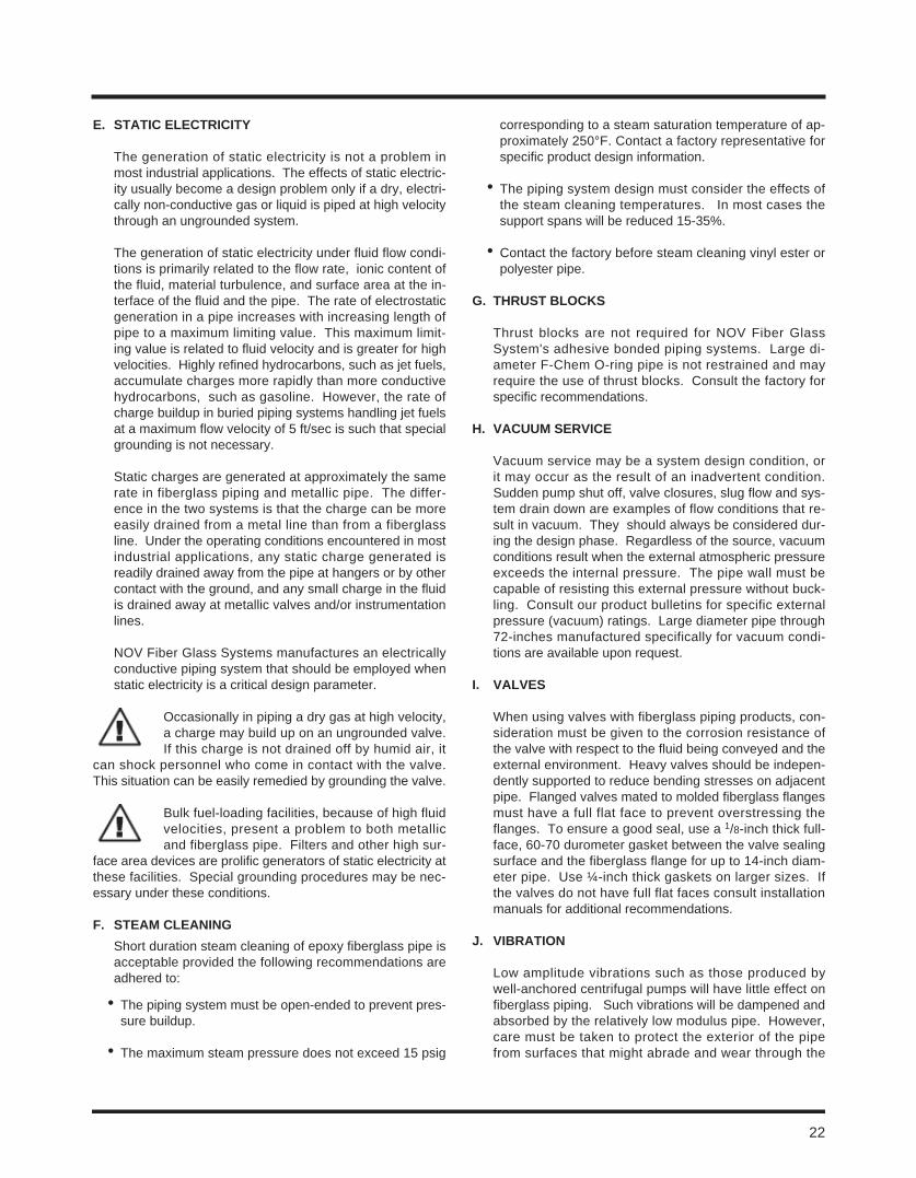
22
e. Static electricity
The generation of static electricity is not a problem in most industrial applications. The effects of static electric-ity usually become a design problem only if a dry, electri-cally non-conductive gas or liquid is piped at high velocity through an ungrounded system.
The generation of static electricity under fluid flow condi-tions is primarily related to the flow rate, ionic content of the fluid, material turbulence, and surface area at the in-terface of the fluid and the pipe. The rate of electrostatic generation in a pipe increases with increasing length of pipe to a maximum limiting value. This maximum limit-ing value is related to fluid velocity and is greater for high velocities. Highly refined hydrocarbons, such as jet fuels, accumulate charges more rapidly than more conductive hydrocarbons, such as gasoline. However, the rate of charge buildup in buried piping systems handling jet fuels at a maximum flow velocity of 5 ft/sec is such that special grounding is not necessary.
Static charges are generated at approximately the same rate in fiberglass piping and metallic pipe. The differ-ence in the two systems is that the charge can be more easily drained from a metal line than from a fiberglass line. Under the operating conditions encountered in most industrial applications, any static charge generated is readily drained away from the pipe at hangers or by other contact with the ground, and any small charge in the fluid is drained away at metallic valves and/or instrumentation lines.
NOV Fiber Glass Systems manufactures an electrically conductive piping system that should be employed when static electricity is a critical design parameter.
Occasionally in piping a dry gas at high velocity, a charge may build up on an ungrounded valve. If this charge is not drained off by humid air, it
can shock personnel who come in contact with the valve. This situation can be easily remedied by grounding the valve.
Bulk fuel-loading facilities, because of high fluid velocities, present a problem to both metallic and fiberglass pipe. Filters and other high sur-
face area devices are prolific generators of static electricity at these facilities. Special grounding procedures may be nec-essary under these conditions.
F. Steam cleaninG Short duration steam cleaning of epoxy fiberglass pipe is
acceptable provided the following recommendations are adhered to:
• The piping system must be open-ended to prevent pres-sure buildup.
• The maximum steam pressure does not exceed 15 psig
corresponding to a steam saturation temperature of ap-proximately 250°F. Contact a factory representative for specific product design information.
• The piping system design must consider the effects of the steam cleaning temperatures. In most cases the support spans will be reduced 15-35%.
• Contact the factory before steam cleaning vinyl ester or polyester pipe.
G. tHrUSt BlocKS
Thrust blocks are not required for NOV Fiber Glass System's adhesive bonded piping systems. Large di-ameter F-Chem O-ring pipe is not restrained and may require the use of thrust blocks. Consult the factory for specific recommendations.
H. VacUUm SerVice
Vacuum service may be a system design condition, or it may occur as the result of an inadvertent condition. Sudden pump shut off, valve closures, slug flow and sys-tem drain down are examples of flow conditions that re-sult in vacuum. They should always be considered dur-ing the design phase. Regardless of the source, vacuum conditions result when the external atmospheric pressure exceeds the internal pressure. The pipe wall must be capable of resisting this external pressure without buck-ling. Consult our product bulletins for specific external pressure (vacuum) ratings. Large diameter pipe through 72-inches manufactured specifically for vacuum condi-tions are available upon request.
i. ValVeS
When using valves with fiberglass piping products, con-sideration must be given to the corrosion resistance of the valve with respect to the fluid being conveyed and the external environment. Heavy valves should be indepen-dently supported to reduce bending stresses on adjacent pipe. Flanged valves mated to molded fiberglass flanges must have a full flat face to prevent overstressing the flanges. To ensure a good seal, use a 1/8-inch thick full-face, 60-70 durometer gasket between the valve sealing surface and the fiberglass flange for up to 14-inch diam-eter pipe. Use ¼-inch thick gaskets on larger sizes. If the valves do not have full flat faces consult installation manuals for additional recommendations.
J. ViBration
Low amplitude vibrations such as those produced by well-anchored centrifugal pumps will have little effect on fiberglass piping. Such vibrations will be dampened and absorbed by the relatively low modulus pipe. However, care must be taken to protect the exterior of the pipe from surfaces that might abrade and wear through the
pipe wall over a long period of time. This can be accom-plished by using support "wear" saddles at the supports or padding the supports with 1/8-inch rubber gasket ma-terial. See Section 2 for recommended support designs.
High amplitude vibration from pumps or other equipment must be isolated from the piping system by flexible con-nectors.
K. FlUiD Hammer
A moving column of fluid has momentum proportional to its mass and velocity. When flow is abruptly stopped, the fluid momentum is converted into an impulse or high-pressure surge. The higher the liquid velocity and longer the pipe line, the larger the impulse.
These impulse loads can be of sufficient magnitude to damage pipe, fittings and valves.
Accurate determination of impulse loads is very complex and typically requires computer model-ing of the piping system. However, the Talbot
equation, given in Appendix A, may be used to calculate theoretical impulses assuming an instantaneous change in velocity. Although, it is physically impossible to close a valve instantaneously, Talbot’s equation is often em-ployed to calculate worst case conditions.
In the real world quick reacting valves, reverse flow into check valves and sudden variations in pump flow rates will cause water hammer surges. Engineers typically incorporate slow operating valves, surge tanks and soft-starting pumps into piping systems to minimize fluid ham-mer. Piping systems that experience surge conditions should be restrained to prevent excessive movement.
If the system operating pressure plus the peak surge pressure exceeds the system pressure rating, then a higher pressure class piping system should be employed.
l. UltraViolet (U.V.) raDiation anD WeatHerinG
Fiberglass pipe undergoes changes in appearance when exposed to sunlight. This is a surface phenomenon caused by U.V. degradation of the resin. The degrada-tion depends upon the accumulated exposure and the intensity of the sunlight. Long-term surface degradation may expose the outer layer of glass fibers; this condition is called “fiber-blooming". These exposed glass fibers will block and reflect a significant portion of ultraviolet radiation resulting in a slower rate of degradation. This minimizes future damage to the remaining pipe wall. Because NOV Fiber Glass Systems pipe bodies are de-signed with significant safety factors, minor fiber bloom-ing does not prevent the pipe from safely performing at its published pressure rating. If service conditions are such that exposed fibers will be abraded with time, it is highly recommended that surface be protected. Painting the
pipe with a good quality acrylic or solvent-based paint is useful in blocking UV radiation.
m. FUnGal, Bacterial, anD roDent reSiStance
Some plastics (thermoplastics) are subject to fungal, bac-terial, and/or rodent attack, but fiberglass pipe offers no nourishment or attraction to these annoyances. Under stagnant conditions, some marine growths will attach to fiberglass surfaces, but they do not attack or bore into the pipe and are usually easily removed. note regard-ing zebra mussels: It was recently reported that a utility compared zebra mussel growth in similar metal and fiber-glass intake lines at the same location. Only two liters of zebra mussels were removed from the fiberglass line, while two dumpster loads of mussels were removed from a metal line.
n. FlanGe connectionS
Our flanges are designed to meet ANSI B16.5 Class 150 bolt hole standards. Alternate bolt hole standards are available. Flanges are designed for 1/8 inch thick gaskets made from materials with a 60-70 durometer Shore A hardness. The use of flat washers under nuts and bolt heads is required. Refer to the appropriate product spe-cific fittings bulletin for recommended bolt torque values.
raised Face Flange connections
Special mating requirements exist when connecting flat-face compression molded fiberglass flanges to raised-face metallic flanges or valves having partial liner facings. The addition of a metallic spacer ring placed between the raised face and the outer edge of the flange to form a full flat-face on the mating flange is recommended. The purpose of the spacer ring is to fill the gap outside the raised-face to prevent bolt loads from bending and break-ing the fiberglass flange. An alternative to the spacer ring is the use of metallic back-up rings behind molded fiberglass flanges. Filament wound flanges may be con-nected directly to raised-face flanges without the use of spacer rings. Refer to installation manual for backing ring sizes.
lug and Wafer Valves
Lined lug and wafer valves that use integral seals, require a ¼-inch steel spacer plate with an inner diameter equal to Schedule 40 steel or as required by the valve manu-facturer. The spacer plate outer diameter should match the fiberglass flange outer diameter.
Unlined lug and wafer valves without integral seals may be directly connected to fiberglass filament flanges with-out back up rings or to molded flanges with metal back-up rings. Refer to installation manual for backing ring sizes.
23
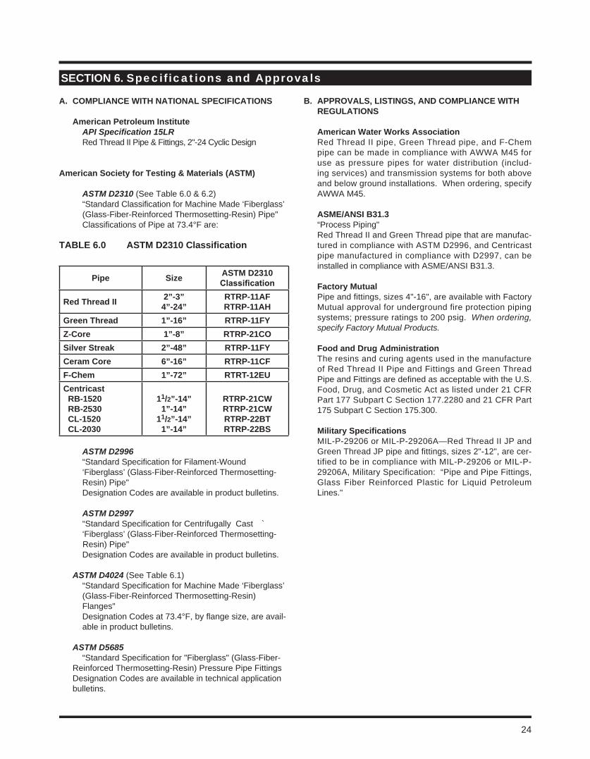
24
a. comPliance WitH national SPeciFicationS
american Petroleum institute API Specification 15LR Red Thread II Pipe & Fittings, 2"-24 Cyclic Design
american Society for testing & materials (aStm)
ASTM D2310 (See Table 6.0 & 6.2) “Standard Classification for Machine Made ‘Fiberglass’
(Glass-Fiber-Reinforced Thermosetting-Resin) Pipe" Classifications of Pipe at 73.4°F are:
ASTM D2996 “Standard Specification for Filament-Wound
‘Fiberglass’ (Glass-Fiber-Reinforced Thermosetting- Resin) Pipe"
Designation Codes are available in product bulletins.
ASTM D2997 “Standard Specification for Centrifugally Cast `
‘Fiberglass’ (Glass-Fiber-Reinforced Thermosetting- Resin) Pipe" Designation Codes are available in product bulletins.
ASTM D4024 (See Table 6.1) “Standard Specification for Machine Made ‘Fiberglass’
(Glass-Fiber-Reinforced Thermosetting-Resin) Flanges"
Designation Codes at 73.4°F, by flange size, are avail- able in product bulletins.
ASTM D5685 “Standard Specification for "Fiberglass" (Glass-Fiber-
Reinforced Thermosetting-Resin) Pressure Pipe Fittings Designation Codes are available in technical application
bulletins.
B. aPProValS, liStinGS, anD comPliance WitH reGUlationS
american Water Works association Red Thread II pipe, Green Thread pipe, and F-Chem
pipe can be made in compliance with AWWA M45 for use as pressure pipes for water distribution (includ-ing services) and transmission systems for both above and below ground installations. When ordering, specify AWWA M45.
aSme/anSi B31.3 “Process Piping" Red Thread II and Green Thread pipe that are manufac-
tured in compliance with ASTM D2996, and Centricast pipe manufactured in compliance with D2997, can be installed in compliance with ASME/ANSI B31.3.
Factory mutual Pipe and fittings, sizes 4"-16", are available with Factory
Mutual approval for underground fire protection piping systems; pressure ratings to 200 psig. When ordering, specify Factory Mutual Products.
Food and Drug administration The resins and curing agents used in the manufacture
of Red Thread II Pipe and Fittings and Green Thread Pipe and Fittings are defined as acceptable with the U.S. Food, Drug, and Cosmetic Act as listed under 21 CFR Part 177 Subpart C Section 177.2280 and 21 CFR Part 175 Subpart C Section 175.300.
military Specifications MIL-P-29206 or MIL-P-29206A—Red Thread II JP and
Green Thread JP pipe and fittings, sizes 2"-12", are cer-tified to be in compliance with MIL-P-29206 or MIL-P-29206A, Military Specification: “Pipe and Pipe Fittings, Glass Fiber Reinforced Plastic for Liquid Petroleum Lines."
Section 6. Specifications and Approvals
taBle 6.0 aStm D2310 classification
Pipe Size aStm D2310Classification
red thread ii 2”-3”4”-24”
rtrP-11aFrtrP-11aH
Green thread 1”-16” rtrP-11Fyz-core 1”-8” rtrP-21coSilver Streak 2”-48” rtrP-11Fyceram core 6”-16” rtrP-11cFF-chem 1”-72” rtrt-12eUcentricast rB-1520 rB-2530 cl-1520 cl-2030
11/2”-14”1”-14”
11/2”-14”1”-14”
rtrP-21cWrtrP-21cWrtrP-22BtrtrP-22BS
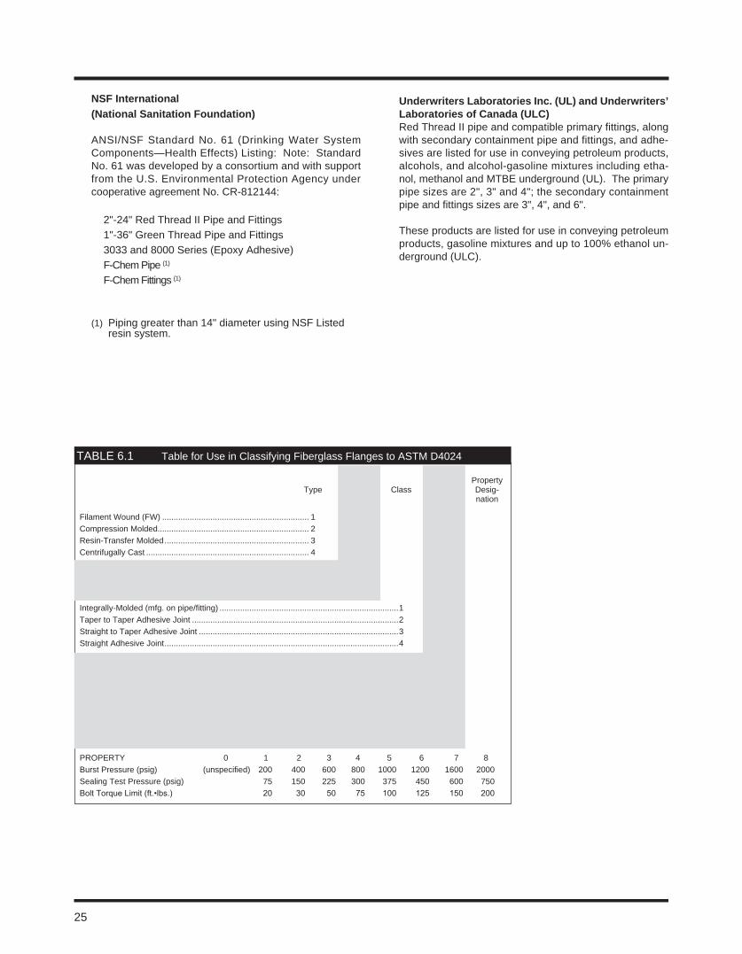
25
nSF international (national Sanitation Foundation)
ANSI/NSF Standard No. 61 (Drinking Water System
Components—Health Effects) Listing: Note: Standard No. 61 was developed by a consortium and with support from the U.S. Environmental Protection Agency under cooperative agreement No. CR-812144:
2"-24" Red Thread II Pipe and Fittings 1"-36" Green Thread Pipe and Fittings 3033 and 8000 Series (Epoxy Adhesive) F-Chem Pipe (1)
F-Chem Fittings (1)
(1) Piping greater than 14" diameter using NSF Listed resin system.
Underwriters laboratories inc. (Ul) and Underwriters’ laboratories of canada (Ulc)
Red Thread II pipe and compatible primary fittings, along with secondary containment pipe and fittings, and adhe-sives are listed for use in conveying petroleum products, alcohols, and alcohol-gasoline mixtures including etha-nol, methanol and MTBE underground (UL). The primary pipe sizes are 2", 3" and 4"; the secondary containment pipe and fittings sizes are 3", 4", and 6".
These products are listed for use in conveying petroleum products, gasoline mixtures and up to 100% ethanol un-derground (ULC).
Pressure Rating Property Type Grade Class Desig- Desig- nation* nation
Filament Wound (FW) ................................................................ 1Compression Molded.................................................................. 2Resin-Transfer Molded ............................................................... 3Centrifugally Cast ....................................................................... 4
Epoxy Resin ................................................................................................... 1Polyester Resin .............................................................................................. 2Furan Resin .................................................................................................... 3
Integrally-Molded (mfg. on pipe/fitting) ..............................................................................1Taper to Taper Adhesive Joint ..........................................................................................2Straight to Taper Adhesive Joint .......................................................................................3Straight Adhesive Joint ......................................................................................................4
*Gauge Pressure (psig) 50 ............................................................................. A(Flanges must withstand a pressure 100 ............................................................................. Bof 4 times the rating without damage 150 .............................................................................Cto the flange) 200 .............................................................................D 250 ............................................................................. E 300 ............................................................................. F 400 .............................................................................G 500 .............................................................................H
PROPERTY 0 1 2 3 4 5 6 7 8Burst Pressure (psig) (unspecified) 200 400 600 800 1000 1200 1600 2000Sealing Test Pressure (psig) 75 150 225 300 375 450 600 750Bolt Torque Limit (ft.•lbs.) 20 30 50 75 100 125 150 200
TABLE 6.1 Table for Use in Classifying Fiberglass Flanges to ASTM D4024
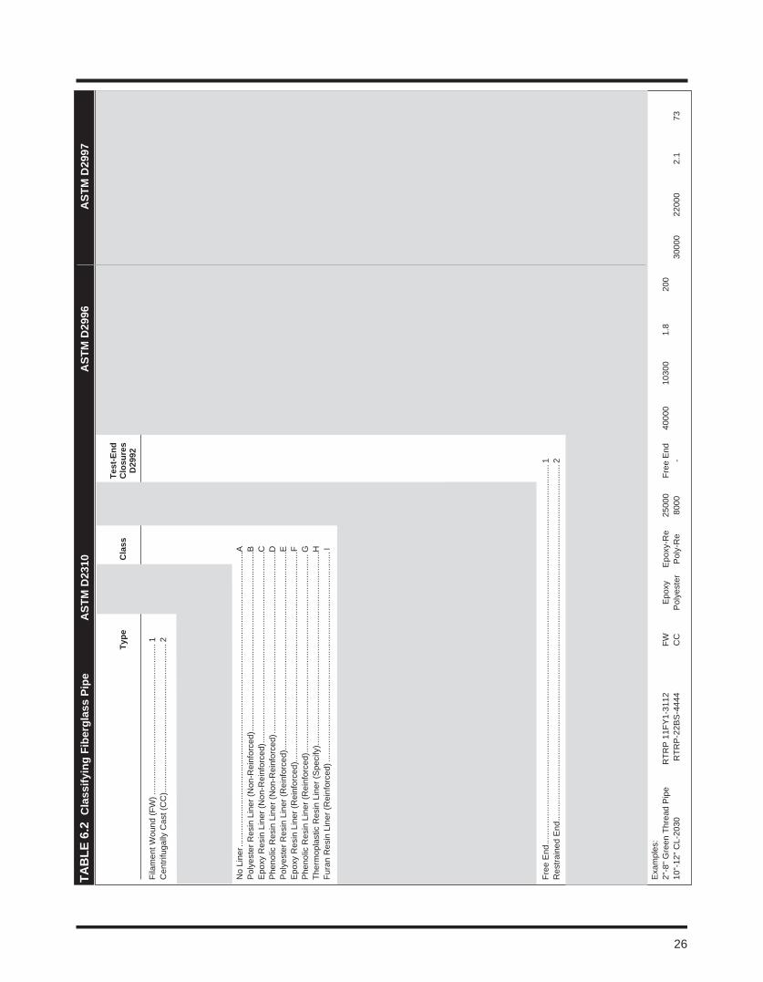
taB
le 6
.2 c
lass
ifyin
g Fi
berg
lass
Pip
e
a
Stm
D23
10
aSt
m D
2996
aSt
m D
2997
Hoo
p
Shor
t lo
ngit.
te
nsile
St
iffne
ss
Shor
t lo
ngit.
te
nsile
Pi
pe
St
ress
te
st-e
nd
term
te
nsile
m
odul
us
Fact
or @
te
rm
tens
ile
mod
ulus
St
iffne
ss
type
G
rade
c
lass
H
DB
c
losu
res
Bur
st
Stre
ngth
x
106
5%
Def
l B
urst
St
reng
th
x 10
6 5
% D
efl
D29
92
D29
92
D15
99
D21
05
D21
05
D24
12
D15
99
D21
05
D21
05
D24
12
Fila
men
t Wou
nd (F
W) .
......
......
......
......
......
......
......
......
......
......
...1
Cen
trifu
gally
Cas
t (C
C)..
......
......
......
......
......
......
......
......
......
......
.2
Gla
ss F
iber
Rei
nfor
ced
Epo
xy R
esin
......
......
......
......
......
......
......
......
......
......
..1
Gla
ss F
iber
Rei
nfor
ced
Pol
yest
er R
esin
......
......
......
......
......
......
......
......
......
...2
Gla
ss F
iber
Rei
nfor
ced
Phe
nolic
Res
in ...
......
......
......
......
......
......
......
......
......
.3G
lass
Fib
er R
einf
orce
d Fu
ran
Res
in ..
......
......
......
......
......
......
......
......
......
......
7
No
Line
r ....
......
......
......
......
......
......
......
......
......
......
......
......
......
......
......
......
......
......
......
......
.AP
olye
ster
Res
in L
iner
(Non
-Rei
nfor
ced)
......
......
......
......
......
......
......
......
......
......
......
......
....B
Epo
xy R
esin
Lin
er (N
on-R
einf
orce
d) ...
......
......
......
......
......
......
......
......
......
......
......
......
......
CP
heno
lic R
esin
Lin
er (N
on-R
einf
orce
d) ...
......
......
......
......
......
......
......
......
......
......
......
......
..DP
olye
ster
Res
in L
iner
(Rei
nfor
ced)
......
......
......
......
......
......
......
......
......
......
......
......
......
......
EE
poxy
Res
in L
iner
(Rei
nfor
ced)
......
......
......
......
......
......
......
......
......
......
......
......
......
......
.....F
Phe
nolic
Res
in L
iner
(Rei
nfor
ced)
......
......
......
......
......
......
......
......
......
......
......
......
......
......
GTh
erm
opla
stic
Res
in L
iner
(Spe
cify
).....
......
......
......
......
......
......
......
......
......
......
......
......
.....H
Fura
n R
esin
Lin
er (R
einf
orce
d) ..
......
......
......
......
......
......
......
......
......
......
......
......
......
......
...I
Cyc
lic V
alue
s 25
00 ..
......
......
......
......
......
......
......
......
......
......
......
......
...A
(Det
erm
ined
by
D29
92 P
roce
dure
A)
3150
.....
......
......
......
......
......
......
......
......
......
......
......
......
B
4000
.....
......
......
......
......
......
......
......
......
......
......
......
......
C
5000
.....
......
......
......
......
......
......
......
......
......
......
......
......
D
6300
.....
......
......
......
......
......
......
......
......
......
......
......
......
E
8000
.....
......
......
......
......
......
......
......
......
......
......
......
......
F
1000
0 ...
......
......
......
......
......
......
......
......
......
......
......
......
..G
1250
0 ...
......
......
......
......
......
......
......
......
......
......
......
......
..H
Sta
tic V
alue
s 50
00 ..
......
......
......
......
......
......
......
......
......
......
......
......
...Q
(Det
erm
ined
by
D29
92 P
roce
dure
B)
6300
.....
......
......
......
......
......
......
......
......
......
......
......
......
R
8000
.....
......
......
......
......
......
......
......
......
......
......
......
......
S
1000
0 ...
......
......
......
......
......
......
......
......
......
......
......
......
..T
12
500
......
......
......
......
......
......
......
......
......
......
......
......
.....
U
1600
0 ...
......
......
......
......
......
......
......
......
......
......
......
......
..W
2000
0 ...
......
......
......
......
......
......
......
......
......
......
......
......
..X
25
000
......
......
......
......
......
......
......
......
......
......
......
......
.....
Y
3150
0 ...
......
......
......
......
......
......
......
......
......
......
......
......
..Z
Free
End
......
......
......
......
......
......
......
......
......
......
......
......
......
......
......
......
......
......
......
......
......
......
......
......
......
......
.....
1R
estra
ined
End
......
......
......
......
......
......
......
......
......
......
......
......
......
......
......
......
......
......
......
......
......
......
......
......
......
.2
Num
ber i
n La
st F
our P
ositi
ons .
......
......
......
......
...0
......
......
......
......
......
......
......
......
......
......
......
......
......
......
......
......
.
(
Uns
peci
fied)
......
......
......
......
......
......
......
......
......
......
......
......
.....1
.....
......
......
......
......
......
......
......
......
......
......
......
......
......
......
......
..
1000
0 80
00
1 40
40
00
2000
0.
6 9
......
......
......
......
......
......
......
......
......
......
......
......
.....2
.....
......
......
......
......
......
......
......
......
......
......
......
......
......
......
......
..
3000
0 15
000
2 20
0 12
000
8000
1.
3 18
......
......
......
......
......
......
......
......
......
......
......
......
.....3
.....
......
......
......
......
......
......
......
......
......
......
......
......
......
......
......
..
4000
0 25
000
3 10
00
2200
0 16
000
1.5
36...
......
......
......
......
......
......
......
......
......
......
......
......
..4 ..
......
......
......
......
......
......
......
......
......
......
......
......
......
......
......
.....
50
000
3500
0 4
1500
30
000
2200
0 1.
9 72
......
......
......
......
......
......
......
......
......
......
......
......
.....5
.....
......
......
......
......
......
......
......
......
......
......
......
......
......
......
......
..
6000
0 45
000
5 20
00
4000
0 30
000
2.5
144
......
......
......
......
......
......
......
......
......
......
......
......
.....6
.....
......
......
......
......
......
......
......
......
......
......
......
......
......
......
......
..
7000
0 55
000
6 25
00
5000
0 40
000
3.0
288
Exa
mpl
es:
2"-8
" Gre
en T
hrea
d P
ipe
RTR
P 1
1FY
1-31
12
FW
Epo
xy
Epo
xy-R
e 25
000
Free
End
40
000
1030
0 1.
8
200
10"-
12" C
L-20
30
RTR
P-2
2BS
-444
4 C
C
Pol
yest
er
Pol
y-R
e 80
00
-
30
000
2200
0 2.
1
73
26
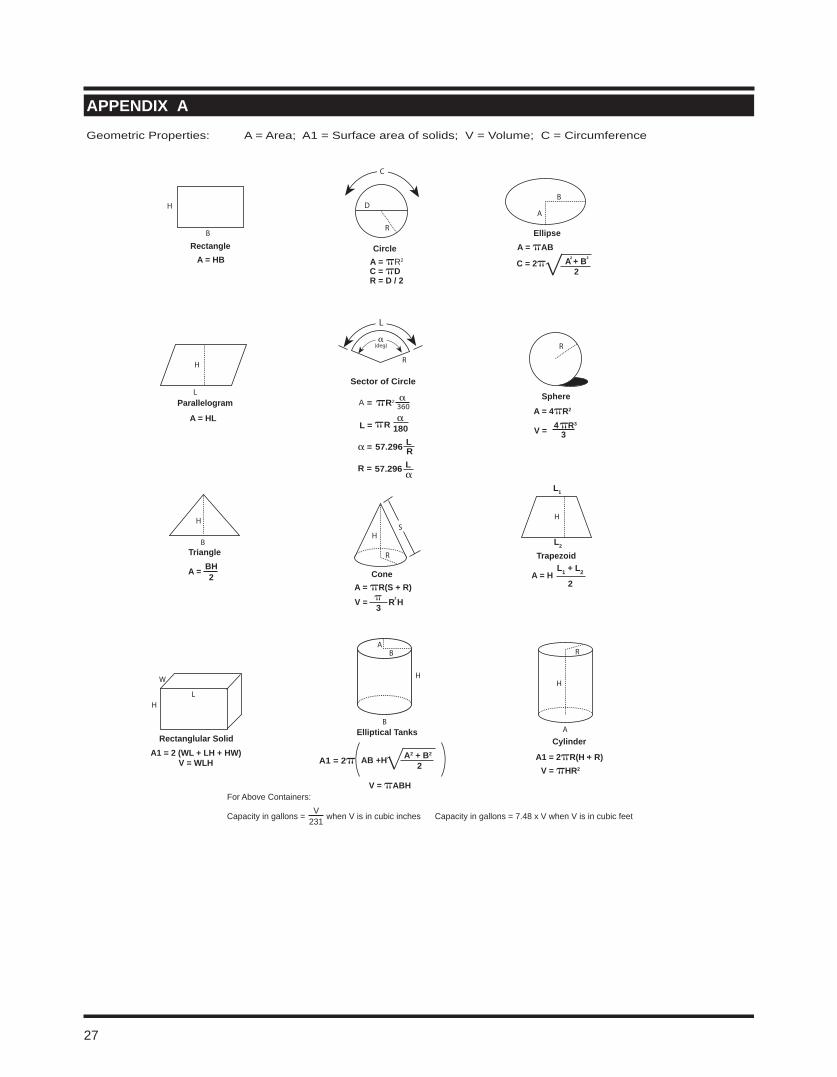
SphereA = 4πR2
V =
R
W
L
Rectanglular Solid A1 = 2 (WL + LH + HW)
V = WLH
H
H
R
S
ConeA = πR(S + R)V =
B
A
EllipseA = πAB
A + B2
C = 2π
C
D
R
Circle
C = πD R = D / 2
For Above Containers:
Capacity in gallons = when V is in cubic inches Capacity in gallons = 7.48 x V when V is in cubic feetV
231
H
B
RectangleA = HB
LParallelogram
A = HL
H
A = H
Trapezoid
H
Triangle
H
B
A =
L
L =
α
πR2 360
Sector of Circle
A =
R =
R
B
V = πABH
H
AB
Elliptical Tanks
H
R
Cylinder
A1 = 2πR(H + R) V = πHR2
A
A = πR2
π R 180 R343π
BH2
π 3 R H
L1 + L2
2
A1 = 2π A2 + B2
2AB +H .
α = R
Geometric Properties: A = Area; A1 = Surface area of solids; V = Volume; C = Circumference
2 2
2
L1
L2
α
57.296
α
α
L
L57.296
(deg)
aPPenDiX a
27
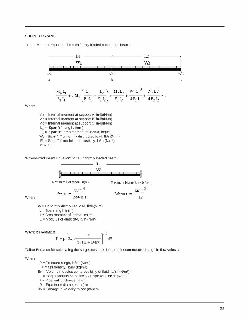
SUPPort SPanS
“Three Moment Equation" for a uniformly loaded continuous beam.
a b c
Where:
Ma = Internal moment at support A, in-lb(N-m) Mb = Internal moment at support B, in-lb(N-m) Mc = Internal moment at support C, in-lb(N-m) Ln = Span "n" length, in(m) In = Span "n" area moment of inertia, in4(m4) Wn = Span "n" uniformly distributed load, lb/in(N/m) En = Span "n" modulus of elasticity, lb/in2(N/m2) n = 1,2
“Fixed-Fixed Beam Equation" for a uniformly loaded beam.
Where:
W = Uniformly distributed load, lb/in(N/m) L = Span length in(m) I = Area moment of inertia, in4(m4) E = Modulus of elasticity, lb/in2(N/m2)
Water Hammer
Talbot Equation for calculating the surge pressure due to an instantaneous change in flow velocity. Where: P = Pressure surge, lb/in2 (N/m2) r = Mass density, lb/in3 (kg/m3) En = Volume modulus compressibility of fluid, lb/in2 (N/m2) E = Hoop modulus of elasticity of pipe wall, lb/in2 (N/m2) t = Pipe wall thickness, in (m) D = Pipe inner diameter, in (m) dV = Change in velocity, ft/sec (m/sec)
28
Maximum Deflection, in(m) Maximum Moment, in-lb (n-m)
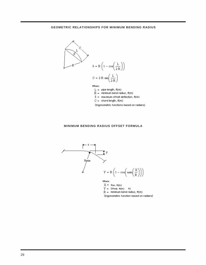
Geometric relationSHiPS For minimUm BenDinG raDiUS
minimUm BenDinG raDiUS oFFSet FormUla
29
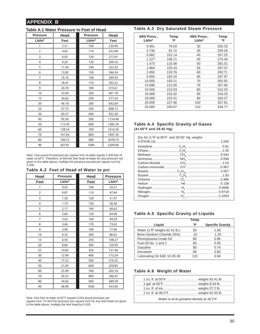
table a.2 Feet of Head of Water to psi
Note: One foot of water at 62°F equals 0.433 pound pressure persquare inch. To find the pressure per square inch for any feet head not given in the table above, multiply the feet head by 0.433.
table a.5 Specific Gravity of liquids temp liquid °F Specific Gravity
Water (1 ft3 weighs 62.41 lb.) 50 1.00Brine (Sodium Chloride 25%) 32 1.20Pennsylvania Crude Oil 80 0.85Fuel Oil No. 1 and 2 85 0.95Gasoline 80 0.74Kerosene 85 0.82Lubricating Oil SAE 10-20-30 115 0.94
Dry Air (1 ft3 at 60°F. and 29.92" Hg. weighs0.07638 Lb) ..................................................................... 1.000Acetylene ........................... C2H2 ..................................... 0.91Ethane ................................ C2H6 ......................................1.05Methane............................... CH4 ................................... 0.554Ammonia ............................. NH3 ................................... 0.596Carbon-dioxide ................... CO2 ......................................1.53Carbon-monoxide . ...............CO .....................................0.967Butane ..............................C4H10 . .................................. 2.067Butane ................................ C4H8 .....................................1.93Chlorine ............................... Cl2 .....................................2.486Helium ................................. He .................................... 0.138Hydrogen ............................. H2 .................................. 0.0696Nitrogen ................................ N2 .................................. 0.9718Oxygen ................................ O2 ....................................1.1053
table a.4 Specific Gravity of Gases(at 60°F and 29.92 Hg)
table a.6 Weight of Water
1 cu. ft. at 50°F . . . . . . . . . . . . . . . . . weighs 62.41 lb.1 gal. at 50°F . . . . . . . . . . . . . . . . . . weighs 8.34 lb.1 cu. ft. of ice . . . . . . . . . . . . . . . . . . weighs 57.2 lb.1 cu. ft. at 39.2°F . . . . . . . . . . . . . . . weighs 62.43 lb.
Water is at its greatest density at 39.2°F
aPPenDiX Btable a.3 Dry Saturated Steam Pressure
aBS Press., temp aBS Press., temp lb/in2 °F lb/in2 °F
0.491 79.03 30 250.33 0.736 91.72 35 259.28 0.982 101.14 40 267.25 1.227 108.71 45 274.44 1.473 115.06 50 281.01 1.964 125.43 55 287.07 2.455 133.76 60 292.71 5.000 162.24 65 297.97 10.000 193.21 70 302.92 14.696 212.00 75 307.60 15.000 213.03 80 312.03 16.000 216.32 85 316.25 18.000 222.41 90 320.27 20.000 227.96 100 327.81 25.000 240.07 110 334.77
Note: One pound of pressure per square inch of water equals 2.309 feet of water at 62°F. Therefore, to find the feet head of water for any pressure not given in the table above, multiply the pressure pounds per square inch by 2.309.
30
Pressure Head Pressure Headlb/in2 Feet lb/in2 Feet
1 2.31 100 230.90
2 4.62 110 253.98
3 6.93 120 277.07
4 9.24 130 300.16
5 11.54 140 323.25
6 13.85 150 346.34
7 16.16 160 369.43
8 18.47 170 392.52
9 20.78 180 415.61
10 23.09 200 461.78
15 34.63 250 577.24
20 46.18 300 692.69
25 57.72 350 808.13
30 69.27 400 922.58
40 92.36 500 1154.48
50 115.45 600 1385.39
60 138.54 700 1616.30
70 161.63 800 1847.20
80 184.72 900 2078.10
90 207.81 1000 2309.00
table a.1 Water Pressure to Feet of Head
Head Pressure Head PressureFeet lb/in2 Feet lb/in2
1 0.43 100 43.31
2 0.87 110 47.64
3 1.30 120 51.97
4 1.73 130 56.30
5 2.17 140 60.63
6 2.60 150 64.96
7 3.03 160 69.29
8 3.46 170 73.63
9 3.90 180 77.96
10 4.33 200 86.62
15 6.50 250 108.27
20 8.66 300 129.93
25 10.83 350 151.58
30 12.99 400 173.24
40 17.32 500 216.55
50 21.65 600 259.85
60 25.99 700 303.16
70 30.32 800 346.47
80 34.65 900 389.78
90 38.98 1000 433.00
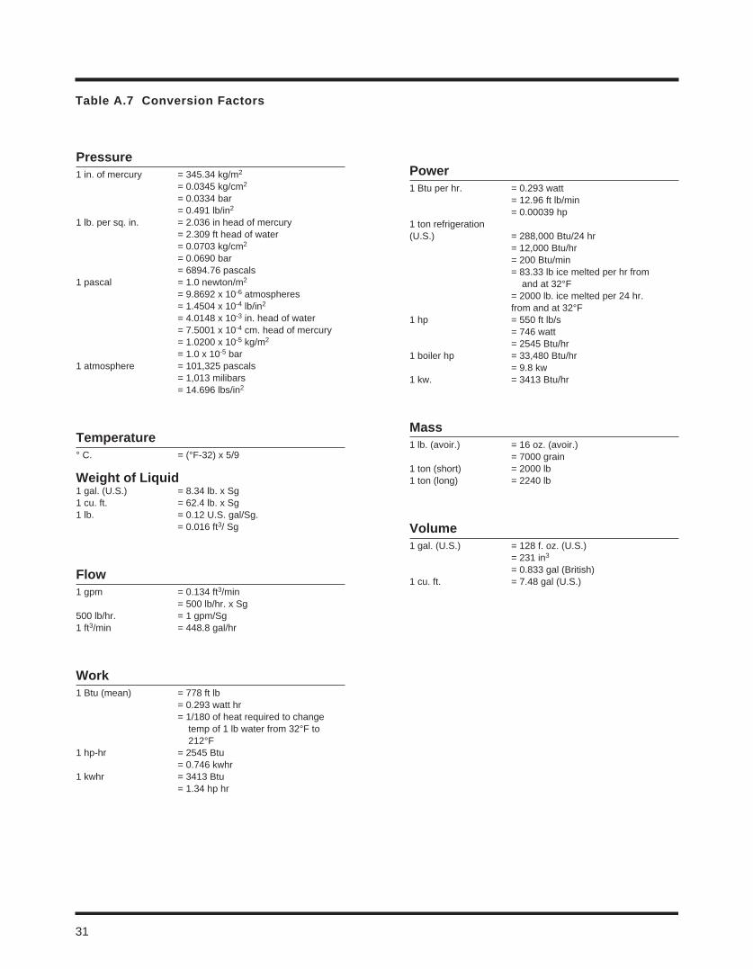
table a.7 conversion Factors
Pressure1 in. of mercury = 345.34 kg/m2
= 0.0345 kg/cm2
= 0.0334 bar = 0.491 lb/in2
1 lb. per sq. in. = 2.036 in head of mercury = 2.309 ft head of water = 0.0703 kg/cm2
= 0.0690 bar = 6894.76 pascals1 pascal = 1.0 newton/m2
= 9.8692 x 10⁻⁶ atmospheres = 1.4504 x 10⁻⁴ lb/in2
= 4.0148 x 10⁻³ in. head of water = 7.5001 x 10⁻⁴ cm. head of mercury = 1.0200 x 10⁻⁵ kg/m2
= 1.0 x 10⁻⁵ bar1 atmosphere = 101,325 pascals = 1,013 milibars = 14.696 lbs/in2
temperature° C. = (°F-32) x 5/9
Weight of liquid1 gal. (U.S.) = 8.34 lb. x Sg1 cu. ft. = 62.4 lb. x Sg1 lb. = 0.12 U.S. gal/Sg. = 0.016 ft3/ Sg
Flow1 gpm = 0.134 ft3/min = 500 lb/hr. x Sg500 lb/hr. = 1 gpm/Sg1 ft3/min = 448.8 gal/hr
Work1 Btu (mean) = 778 ft lb = 0.293 watt hr = 1/180 of heat required to change temp of 1 lb water from 32°F to 212°F1 hp-hr = 2545 Btu = 0.746 kwhr1 kwhr = 3413 Btu = 1.34 hp hr
Power1 Btu per hr. = 0.293 watt = 12.96 ft lb/min = 0.00039 hp1 ton refrigeration(U.S.) = 288,000 Btu/24 hr = 12,000 Btu/hr = 200 Btu/min = 83.33 lb ice melted per hr from and at 32°F = 2000 lb. ice melted per 24 hr. from and at 32°F1 hp = 550 ft lb/s = 746 watt = 2545 Btu/hr1 boiler hp = 33,480 Btu/hr = 9.8 kw1 kw. = 3413 Btu/hr
mass1 lb. (avoir.) = 16 oz. (avoir.) = 7000 grain1 ton (short) = 2000 lb1 ton (long) = 2240 lb
Volume1 gal. (U.S.) = 128 f. oz. (U.S.) = 231 in3
= 0.833 gal (British)1 cu. ft. = 7.48 gal (U.S.)
31

noteS
32

© 2013 National Oilwell Varco. All rights reserved.ENG 1000 March 2011
www.fgspipe.com
2700 West 65th Street 25 S. Main StreetLittle Rock, Arkansas 72209 Sand Springs, Oklahoma 74063Phone: 1 (501) 568-4010 1 (918) 245-6651
IntroductionThis guide is intended for use only as a reference in evaluating NOV Fiber Glass Systems piping systems. It should be used for a general indication of chemical resistance. NOV Fiber Glass Systems data indicates that the pipe and fittings listed are suitable for the services as recommended. However, due to varying conditions encountered in usage from plant to plant, the data should be considered as a recommendation and not as a guarantee. NOV Fiber Glass Systems offers a limited warranty of its products, which is in the Terms and Conditions of Sale. This data does not take into account chemical mixtures, thermal-mechanical or associated loading or stress combinations. Accordingly, the end-user of the fiberglass products assumes the responsibility and risk for proper evaluation, selection, use, and performance of the products in its particular application.
Basis of Chemical Resistance RecommendationsThe information contained in this literature is based on corrosion resistance testing, field experience, published information, and NOV Fiber Glass Systems engineering judgment. Corrosion resistance testing includes the pipe, fittings and adhesive used in NOV Fiber Glass Systems piping systems. There are many successful installations that form the basis of the field experience and engineering judgment recommendations. NOV Fiber Glass Systems products must be installed and used in accordance with proven practice and common sense. Corrosion barrier and total wall thickness may affect service life in aggressive chemical or abrasive applications.
General NotesNR = Not Recommended, except for very low concentrations. Contact NOV Fiber Glass Systems Application Engineering for further evaluation.
NT = Not Tested. Contact NOV Fiber Glass Systems Application Engineering for further evaluation.
When no concentration is shown, recommendations apply to any concentration to 100% or to saturation.
Spills or Upset Conditions Flush the system immediately if spills or upsets exposes the piping to chemicals that have not been recommended.
Solvent Applications Solvents may separate from the fluid stream in piping with static or low flow rates. The solvents will be concentrated and may damage piping not recommended for 100% concentrations. Flush the piping system immediately after shutdown to prevent solvent damage. Vent lines carrying solvent vapors can also have high concentrations of liquid solvent due to condensation. The condensation can affect the service life of systems not recommended for full concentrations.
Mixing Chemicals in the Piping SystemCareful consideration should be given to the by-products of mixing chemicals. By-products of chemical reactions may aggressively corrode a piping system.
Abrasive FluidPiping is used successfully in many abrasive slurry applications. Products made especially for abrasive applications are available. Products selection is dependent on particle size, percent solids, particle hardness, flow rates and continuous or intermittent usage.
Regulations & StandardsLocal, state, or federal regulations, or industry standards may govern the use of our products in particular applications and should be reviewed by the customer to assure compliance.
TrademarksBondstrandTM, Red ThreadTM, Green ThreadTM and CentricastTM piping systems and Key-LockTM joints are trademark names of NOV Fiber Glass Systems.
Unlisted Applications and Combinations of ChemicalsNOV Fiber Glass Systems piping is being used in many applications containing other chemicals, solvents, and combinations of chemicals not listed in this literature. These applications should be reviewed with the factory for evaluations of the chemicals, their concentrations, temperatures, frequency of use, and other factors that may determine our suitability to provide economic service life. Extra care should be taken when there are combinations of chemicals as some combinations may be more aggressive than their constituent parts. Trace amounts of some chemicals can affect the piping service life.
Process Drains and Combined Waste SystemsDue to the inherent chemical resistance of NOV Fiber Glass Systems piping systems, they are widely used in aggessive process drains and combined waste systems. For these systems and other intermittent conditions, the products may be used outside of the ratings published in this chemical guide. Please contact Applications Engineering for specific recommendations.
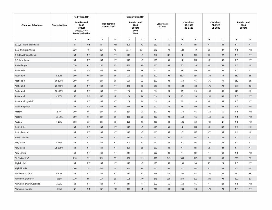
Chemical Substance Concentration
Red Thread HP
Bondstrand7000
7000M3000A 2”-6”
2400 Conductive
Bondstrand3000A 8”-16”
Green Thread HP
Bondstrand2000
2000M24004000
CentricastZ-Core
CentricastRB-1520RB-2530
CentricastCL-1520CL-2030
Bondstrand5000
5000M
°F °C °F °C °F °C °F °C °F °C °F °C °F °C
1,1,2,2-Tetrachloroethane NR NR NR NR 120 49 150 66 NT NT NT NT NT NT
1,1,1-Trichloroethane 120 49 120 49 125(2) 52(2) 175 79 120 49 80 27 NR NR
2-Butoxyethoxyethanol NT NT NT NT NT NT NR NR NR NR 80 27 NT NT
2-Chlorophenol NT NT NT NT NT NT 100 38 NR NR NR NR NT NT
Acetaldehyde 120 49 80 27 120 49 100 38 75 24 NR NR NR NR
Acetamide NR NR NR NR NR NR 100 38 NR NR NR NR NT NT
Acetic acid ≤ 10% 150 66 150 66 200 93 200 93 150(2) 66(2) 175 79 210 99
Acetic acid 10 ≤ 20% 150 66 150 66 200 93 200 93 150 66 175 79 210 99
Acetic acid 20 ≤ 50% NT NT NT NT 150 66 120 49 100 38 175 79 180 82
Acetic acid 50 ≤ 75% NT NT NT NT 75 24 75 24 75 24 150 66 110 43
Acetic acid > 75% NR NR NR NR 75 24 75 24 75 24 100 38 NT NT
Acetic acid, "glacial" NT NT NT NT 75 24 75 24 75 24 NR NR NT NT
Acetic anhydride NR NR NR NR NR NR 100 38 NR NR NR NR NR NR
Acetone ≤ 1% 150 66 150 66 150 66 200 93 150 66 150 66 NR NR
Acetone 1 ≤ 10% 150 66 150 66 150 66 200 93 150 66 150 66 NR NR
Acetone > 10% 100 38 100 38 120 49 200 93 125 52 NR NR NR NR
Acetonitrile NT NT NT NT NT NT 120 49 NR NR NR NR NR NR
Acetophenone NT NT NT NT NT NT NT NT NT NT NT NT NR NR
Acetyl chloride NT NT NT NT NT NT NT NT NT NT NT NT NT NT
Acrylic acid ≤ 25% NT NT NT NT 120 49 120 49 NT NT 100 38 NT NT
Acrylic acid 25 ≤ 95% NT NT NT NT 100 38 100 38 NT NT 75 24 NT NT
Acrylonitrile NT NT NT NT NT NT 100 38 NT NT NT NT NR NR
Air "wet or dry" 210 99 210 99 250 121 300 149 300 149 200 93 200 93
Allyl alcohol NT NT NT NT NT NT 150 66 100 38 75 24 NT NT
Allyl chloride 100 38 100 38 120 49 NT NT NT NT NT NT NR NR
Aluminum acetate ≤ 10% NT NT NT NT NT NT 275 135 250 121 150 66 150 66
Aluminum chloride (4) Sat'd 210 99 210 99 225 107 275 135 250 121 200 93 200 93
Aluminum chlorohydroxide ≤ 50% NT NT NT NT NT NT 150 66 150 66 NT NT NR NR
Aluminum fluoride Sat'd NR NR NR NR NR NR 200 93 200 93 175 79 NT NT
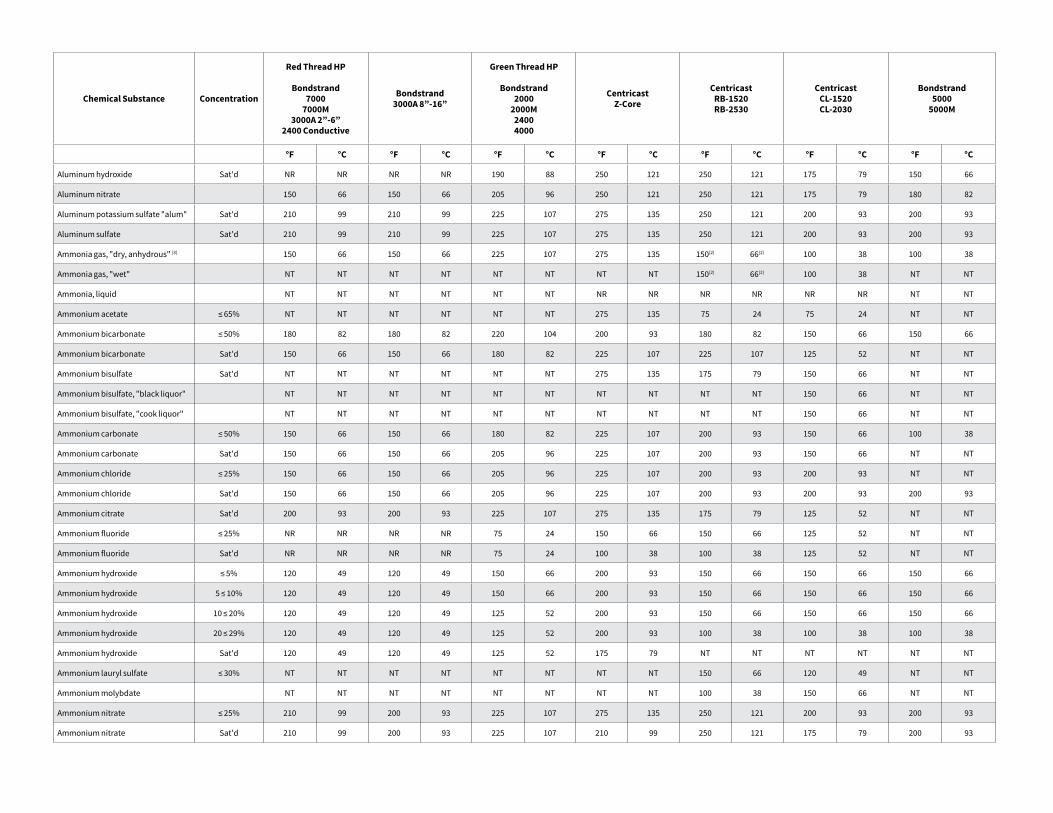
Chemical Substance Concentration
Red Thread HP
Bondstrand7000
7000M3000A 2”-6”
2400 Conductive
Bondstrand3000A 8”-16”
Green Thread HP
Bondstrand2000
2000M24004000
CentricastZ-Core
CentricastRB-1520RB-2530
CentricastCL-1520CL-2030
Bondstrand5000
5000M
°F °C °F °C °F °C °F °C °F °C °F °C °F °C
Aluminum hydroxide Sat'd NR NR NR NR 190 88 250 121 250 121 175 79 150 66
Aluminum nitrate 150 66 150 66 205 96 250 121 250 121 175 79 180 82
Aluminum potassium sulfate "alum" Sat'd 210 99 210 99 225 107 275 135 250 121 200 93 200 93
Aluminum sulfate Sat'd 210 99 210 99 225 107 275 135 250 121 200 93 200 93
Ammonia gas, "dry, anhydrous" (3) 150 66 150 66 225 107 275 135 150(2) 66(2) 100 38 100 38
Ammonia gas, "wet" NT NT NT NT NT NT NT NT 150(2) 66(2) 100 38 NT NT
Ammonia, liquid NT NT NT NT NT NT NR NR NR NR NR NR NT NT
Ammonium acetate ≤ 65% NT NT NT NT NT NT 275 135 75 24 75 24 NT NT
Ammonium bicarbonate ≤ 50% 180 82 180 82 220 104 200 93 180 82 150 66 150 66
Ammonium bicarbonate Sat'd 150 66 150 66 180 82 225 107 225 107 125 52 NT NT
Ammonium bisulfate Sat'd NT NT NT NT NT NT 275 135 175 79 150 66 NT NT
Ammonium bisulfate, "black liquor" NT NT NT NT NT NT NT NT NT NT 150 66 NT NT
Ammonium bisulfate, "cook liquor" NT NT NT NT NT NT NT NT NT NT 150 66 NT NT
Ammonium carbonate ≤ 50% 150 66 150 66 180 82 225 107 200 93 150 66 100 38
Ammonium carbonate Sat'd 150 66 150 66 205 96 225 107 200 93 150 66 NT NT
Ammonium chloride ≤ 25% 150 66 150 66 205 96 225 107 200 93 200 93 NT NT
Ammonium chloride Sat'd 150 66 150 66 205 96 225 107 200 93 200 93 200 93
Ammonium citrate Sat'd 200 93 200 93 225 107 275 135 175 79 125 52 NT NT
Ammonium fluoride ≤ 25% NR NR NR NR 75 24 150 66 150 66 125 52 NT NT
Ammonium fluoride Sat'd NR NR NR NR 75 24 100 38 100 38 125 52 NT NT
Ammonium hydroxide ≤ 5% 120 49 120 49 150 66 200 93 150 66 150 66 150 66
Ammonium hydroxide 5 ≤ 10% 120 49 120 49 150 66 200 93 150 66 150 66 150 66
Ammonium hydroxide 10 ≤ 20% 120 49 120 49 125 52 200 93 150 66 150 66 150 66
Ammonium hydroxide 20 ≤ 29% 120 49 120 49 125 52 200 93 100 38 100 38 100 38
Ammonium hydroxide Sat'd 120 49 120 49 125 52 175 79 NT NT NT NT NT NT
Ammonium lauryl sulfate ≤ 30% NT NT NT NT NT NT NT NT 150 66 120 49 NT NT
Ammonium molybdate NT NT NT NT NT NT NT NT 100 38 150 66 NT NT
Ammonium nitrate ≤ 25% 210 99 200 93 225 107 275 135 250 121 200 93 200 93
Ammonium nitrate Sat'd 210 99 200 93 225 107 210 99 250 121 175 79 200 93
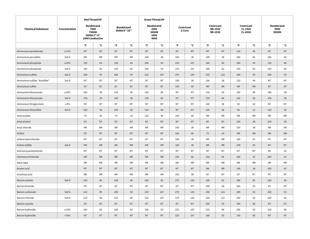
Chemical Substance Concentration
Red Thread HP
Bondstrand7000
7000M3000A 2”-6”
2400 Conductive
Bondstrand3000A 8”-16”
Green Thread HP
Bondstrand2000
2000M24004000
CentricastZ-Core
CentricastRB-1520RB-2530
CentricastCL-1520CL-2030
Bondstrand5000
5000M
°F °C °F °C °F °C °F °C °F °C °F °C °F °C
Ammonium pentaborate ≤ 12% NT NT NT NT NT NT NT NT NT NT 120 49 NT NT
Ammonium persulfate Sat'd NR NR NR NR 100 38 100 38 100 38 180 82 180 82
Ammonium phosphate ≤ 65% 150 66 150 66 200 93 225 107 180 82 200 93 150 66
Ammonium phosphate Sat'd 150 66 150 66 200 93 225 107 180 82 150 66 150 66
Ammonium sulfate Sat'd 200 93 200 93 225 107 275 135 250 121 200 93 200 93
Ammonium sulfide, "bisulfide" Sat'd NT NT NT NT NT NT 100 38 100 38 120 49 NT NT
Ammonium sulfite NT NT NT NT NT NT 150 66 NR NR NR NR NT NT
Ammonium thiocyanate ≤ 20% 100 38 100 38 150 66 NT NT 150 66 190 88 100 38
Ammonium thiocyanate Sat'd 100 38 100 38 150 66 NT NT 150 66 100 38 100 38
Ammonium thioglycolate ≤ 8% NT NT NT NT NT NT NT NT 100 38 90 32 NT NT
Ammonium thiosulfate Sat'd 100 38 100 38 150 66 NT NT 100 38 90 32 100 38
Amyl acetate 75 24 75 24 120 49 150 66 NR NR NR NR NR NR
Amyl alcohol NT NT NT NT NT NT NT NT NT NT 100 38 100 38
Amyl chloride NR NR NR NR NR NR 100 38 NR NR 100 38 NR NR
Aniline NT NT NT NT NT NT 150 66 75 24 NR NR NR NR
Aniline hydrochloride NT NT NT NT NT NT 100 38 NR NR 180 82 NT NT
Aniline sulfate Sat'd NR NR NR NR NR NR 100 38 NR NR 200 93 NT NT
Antimony pentachloride NT NT NT NT NT NT NT NT NT NT NT NT 90 32
Antimony trichloride NR NR NR NR NR NR 150 66 150 66 200 93 200 93
Aqua regia NR NR NR NR NR NR NR NR NR NR NR NR NR NR
Arsenic acid NT NT NT NT NT NT NT NT NR NR 100 38 180 82
Arsenious acid NR NR NR NR NR NR 100 38 NT NT NT NT NT NT
Barium acetate Sat'd 150 66 150 66 180 82 275 135 180 82 180 82 150 66
Barium bromide NT NT NT NT NT NT NT NT 100 38 200 93 NT NT
Barium carbonate Sat'd 210 99 200 93 225 107 275 135 250 121 200 93 200 93
Barium chloride Sat'd 210 99 210 99 225 107 275 135 250 121 200 93 200 93
Barium cyanide NT NT NT NT NT NT NT NT 200 93 150 66 NT NT
Barium hydroxide ≤ 10% 180 82 180 82 200 93 225 107 210 99 200 93 150 66
Barium hydroxide >10% NT NT NT NT NT NT 225 107 200 93 150 66 NT NT
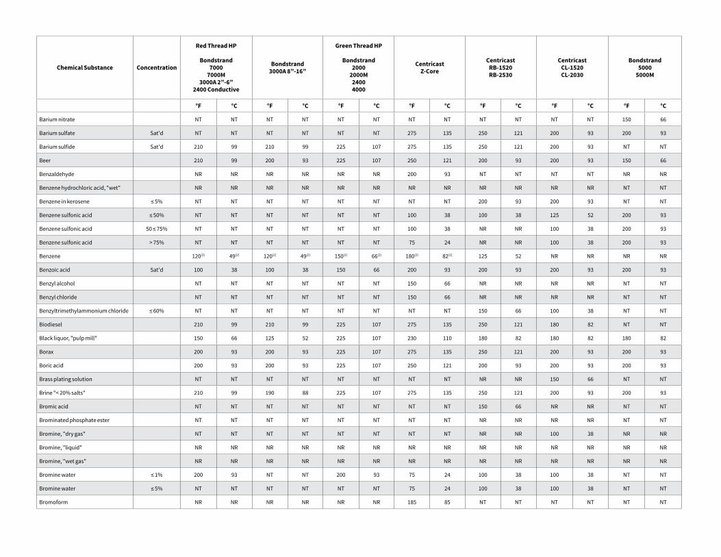
Chemical Substance Concentration
Red Thread HP
Bondstrand7000
7000M3000A 2”-6”
2400 Conductive
Bondstrand3000A 8”-16”
Green Thread HP
Bondstrand2000
2000M24004000
CentricastZ-Core
CentricastRB-1520RB-2530
CentricastCL-1520CL-2030
Bondstrand5000
5000M
°F °C °F °C °F °C °F °C °F °C °F °C °F °C
Barium nitrate NT NT NT NT NT NT NT NT NT NT NT NT 150 66
Barium sulfate Sat'd NT NT NT NT NT NT 275 135 250 121 200 93 200 93
Barium sulfide Sat'd 210 99 210 99 225 107 275 135 250 121 200 93 NT NT
Beer 210 99 200 93 225 107 250 121 200 93 200 93 150 66
Benzaldehyde NR NR NR NR NR NR 200 93 NT NT NT NT NR NR
Benzene hydrochloric acid, "wet" NR NR NR NR NR NR NR NR NR NR NR NR NT NT
Benzene in kerosene ≤ 5% NT NT NT NT NT NT NT NT 200 93 200 93 NT NT
Benzene sulfonic acid ≤ 50% NT NT NT NT NT NT 100 38 100 38 125 52 200 93
Benzene sulfonic acid 50 ≤ 75% NT NT NT NT NT NT 100 38 NR NR 100 38 200 93
Benzene sulfonic acid > 75% NT NT NT NT NT NT 75 24 NR NR 100 38 200 93
Benzene 120(2) 49(2) 120(2) 49(2) 150(2) 66(2) 180(2) 82(2) 125 52 NR NR NR NR
Benzoic acid Sat'd 100 38 100 38 150 66 200 93 200 93 200 93 200 93
Benzyl alcohol NT NT NT NT NT NT 150 66 NR NR NR NR NT NT
Benzyl chloride NT NT NT NT NT NT 150 66 NR NR NR NR NT NT
Benzyltrimethylammonium chloride ≤ 60% NT NT NT NT NT NT NT NT 150 66 100 38 NT NT
Biodiesel 210 99 210 99 225 107 275 135 250 121 180 82 NT NT
Black liquor, "pulp mill" 150 66 125 52 225 107 230 110 180 82 180 82 180 82
Borax 200 93 200 93 225 107 275 135 250 121 200 93 200 93
Boric acid 200 93 200 93 225 107 250 121 200 93 200 93 200 93
Brass plating solution NT NT NT NT NT NT NT NT NR NR 150 66 NT NT
Brine "< 20% salts" 210 99 190 88 225 107 275 135 250 121 200 93 200 93
Bromic acid NT NT NT NT NT NT NT NT 150 66 NR NR NT NT
Brominated phosphate ester NT NT NT NT NT NT NT NT NR NR NR NR NT NT
Bromine, "dry gas" NT NT NT NT NT NT NT NT NR NR 100 38 NR NR
Bromine, "liquid" NR NR NR NR NR NR NR NR NR NR NR NR NR NR
Bromine, "wet gas" NR NR NR NR NR NR NR NR NR NR NR NR NR NR
Bromine water ≤ 1% 200 93 NT NT 200 93 75 24 100 38 100 38 NT NT
Bromine water ≤ 5% NT NT NT NT NT NT 75 24 100 38 100 38 NT NT
Bromoform NR NR NR NR NR NR 185 85 NT NT NT NT NT NT
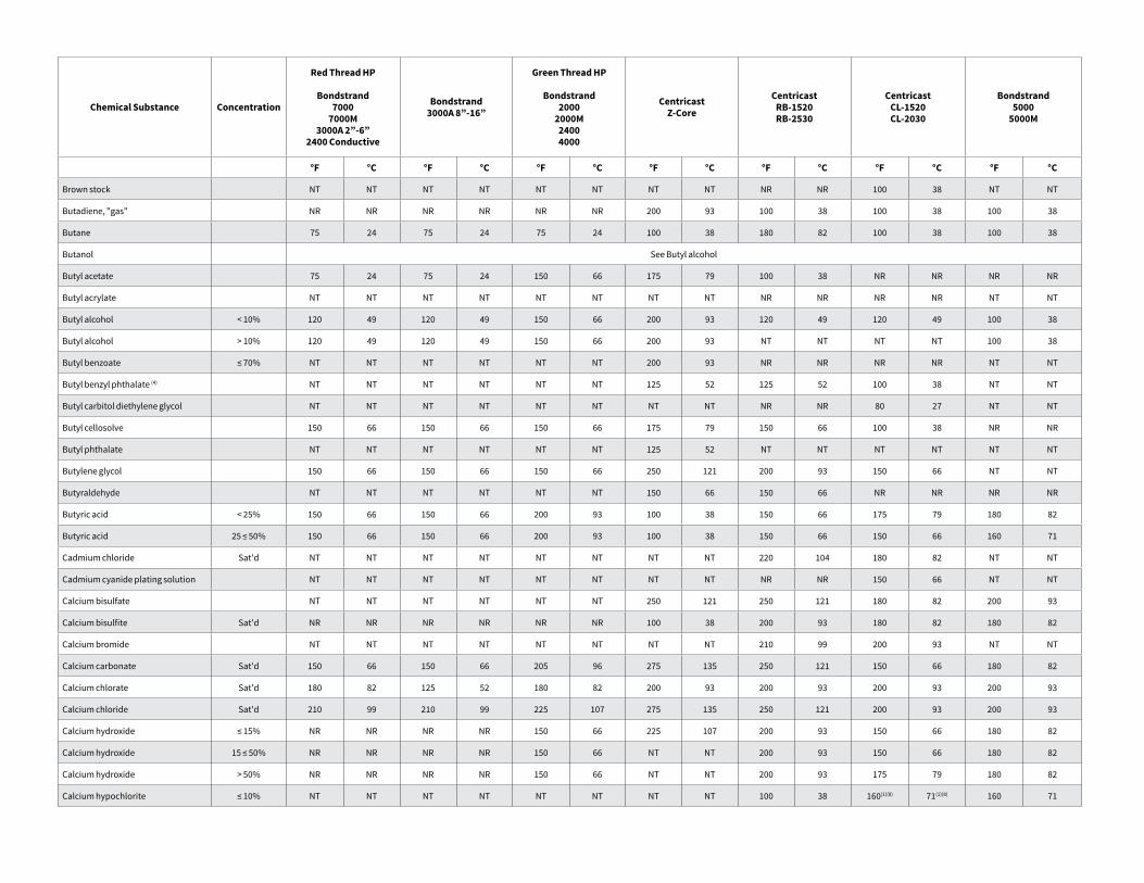
Chemical Substance Concentration
Red Thread HP
Bondstrand7000
7000M3000A 2”-6”
2400 Conductive
Bondstrand3000A 8”-16”
Green Thread HP
Bondstrand2000
2000M24004000
CentricastZ-Core
CentricastRB-1520RB-2530
CentricastCL-1520CL-2030
Bondstrand5000
5000M
°F °C °F °C °F °C °F °C °F °C °F °C °F °C
Brown stock NT NT NT NT NT NT NT NT NR NR 100 38 NT NT
Butadiene, "gas" NR NR NR NR NR NR 200 93 100 38 100 38 100 38
Butane 75 24 75 24 75 24 100 38 180 82 100 38 100 38
Butanol See Butyl alcohol
Butyl acetate 75 24 75 24 150 66 175 79 100 38 NR NR NR NR
Butyl acrylate NT NT NT NT NT NT NT NT NR NR NR NR NT NT
Butyl alcohol < 10% 120 49 120 49 150 66 200 93 120 49 120 49 100 38
Butyl alcohol > 10% 120 49 120 49 150 66 200 93 NT NT NT NT 100 38
Butyl benzoate ≤ 70% NT NT NT NT NT NT 200 93 NR NR NR NR NT NT
Butyl benzyl phthalate (4) NT NT NT NT NT NT 125 52 125 52 100 38 NT NT
Butyl carbitol diethylene glycol NT NT NT NT NT NT NT NT NR NR 80 27 NT NT
Butyl cellosolve 150 66 150 66 150 66 175 79 150 66 100 38 NR NR
Butyl phthalate NT NT NT NT NT NT 125 52 NT NT NT NT NT NT
Butylene glycol 150 66 150 66 150 66 250 121 200 93 150 66 NT NT
Butyraldehyde NT NT NT NT NT NT 150 66 150 66 NR NR NR NR
Butyric acid < 25% 150 66 150 66 200 93 100 38 150 66 175 79 180 82
Butyric acid 25 ≤ 50% 150 66 150 66 200 93 100 38 150 66 150 66 160 71
Cadmium chloride Sat'd NT NT NT NT NT NT NT NT 220 104 180 82 NT NT
Cadmium cyanide plating solution NT NT NT NT NT NT NT NT NR NR 150 66 NT NT
Calcium bisulfate NT NT NT NT NT NT 250 121 250 121 180 82 200 93
Calcium bisulfite Sat'd NR NR NR NR NR NR 100 38 200 93 180 82 180 82
Calcium bromide NT NT NT NT NT NT NT NT 210 99 200 93 NT NT
Calcium carbonate Sat'd 150 66 150 66 205 96 275 135 250 121 150 66 180 82
Calcium chlorate Sat'd 180 82 125 52 180 82 200 93 200 93 200 93 200 93
Calcium chloride Sat'd 210 99 210 99 225 107 275 135 250 121 200 93 200 93
Calcium hydroxide ≤ 15% NR NR NR NR 150 66 225 107 200 93 150 66 180 82
Calcium hydroxide 15 ≤ 50% NR NR NR NR 150 66 NT NT 200 93 150 66 180 82
Calcium hydroxide > 50% NR NR NR NR 150 66 NT NT 200 93 175 79 180 82
Calcium hypochlorite ≤ 10% NT NT NT NT NT NT NT NT 100 38 160(1)(8) 71(1)(8) 160 71
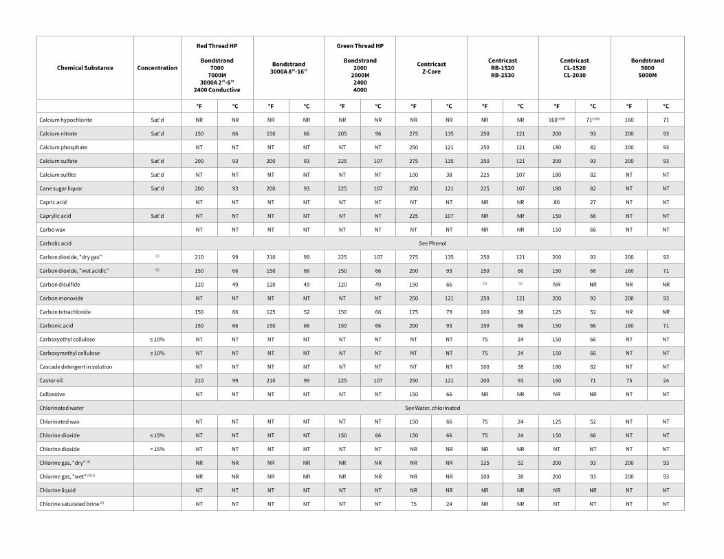
Chemical Substance Concentration
Red Thread HP
Bondstrand7000
7000M3000A 2”-6”
2400 Conductive
Bondstrand3000A 8”-16”
Green Thread HP
Bondstrand2000
2000M24004000
CentricastZ-Core
CentricastRB-1520RB-2530
CentricastCL-1520CL-2030
Bondstrand5000
5000M
°F °C °F °C °F °C °F °C °F °C °F °C °F °C
Calcium hypochlorite Sat'd NR NR NR NR NR NR NR NR NR NR 160(1)(8) 71(1)(8) 160 71
Calcium nitrate Sat'd 150 66 150 66 205 96 275 135 250 121 200 93 200 93
Calcium phosphate NT NT NT NT NT NT 250 121 250 121 180 82 200 93
Calcium sulfate Sat'd 200 93 200 93 225 107 275 135 250 121 200 93 200 93
Calcium sulfite Sat'd NT NT NT NT NT NT 100 38 225 107 180 82 NT NT
Cane sugar liquor Sat'd 200 93 200 93 225 107 250 121 225 107 180 82 NT NT
Capric acid NT NT NT NT NT NT NT NT NR NR 80 27 NT NT
Caprylic acid Sat'd NT NT NT NT NT NT 225 107 NR NR 150 66 NT NT
Carbo wax NT NT NT NT NT NT NT NT NR NR 150 66 NT NT
Carbolic acid See Phenol
Carbon dioxide, "dry gas" (1) 210 99 210 99 225 107 275 135 250 121 200 93 200 93
Carbon dioxide, "wet acidic" (1) 150 66 150 66 150 66 200 93 150 66 150 66 160 71
Carbon disulfide 120 49 120 49 120 49 150 66 (1) (1) NR NR NR NR
Carbon monoxide NT NT NT NT NT NT 250 121 250 121 200 93 200 93
Carbon tetrachloride 150 66 125 52 150 66 175 79 100 38 125 52 NR NR
Carbonic acid 150 66 150 66 150 66 200 93 150 66 150 66 160 71
Carboxyethyl cellulose ≤ 10% NT NT NT NT NT NT NT NT 75 24 150 66 NT NT
Carboxymethyl cellulose ≤ 10% NT NT NT NT NT NT NT NT 75 24 150 66 NT NT
Cascade detergent in solution NT NT NT NT NT NT NT NT 100 38 180 82 NT NT
Castor oil 210 99 210 99 225 107 250 121 200 93 160 71 75 24
Cellosolve NT NT NT NT NT NT 150 66 NR NR NR NR NT NT
Chlorinated water See Water, chlorinated
Chlorinated wax NT NT NT NT NT NT 150 66 75 24 125 52 NT NT
Chlorine dioxide ≤ 15% NT NT NT NT 150 66 150 66 75 24 150 66 NT NT
Chlorine dioxide > 15% NT NT NT NT NT NT NR NR NR NR NT NT NT NT
Chlorine gas, "dry" (3) NR NR NR NR NR NR NR NR 125 52 200 93 200 93
Chlorine gas, "wet" (3)(1) NR NR NR NR NR NR NR NR 100 38 200 93 200 93
Chlorine liquid NT NT NT NT NT NT NR NR NR NR NR NR NT NT
Chlorine saturated brine (5) NT NT NT NT NT NT 75 24 NR NR NT NT NT NT
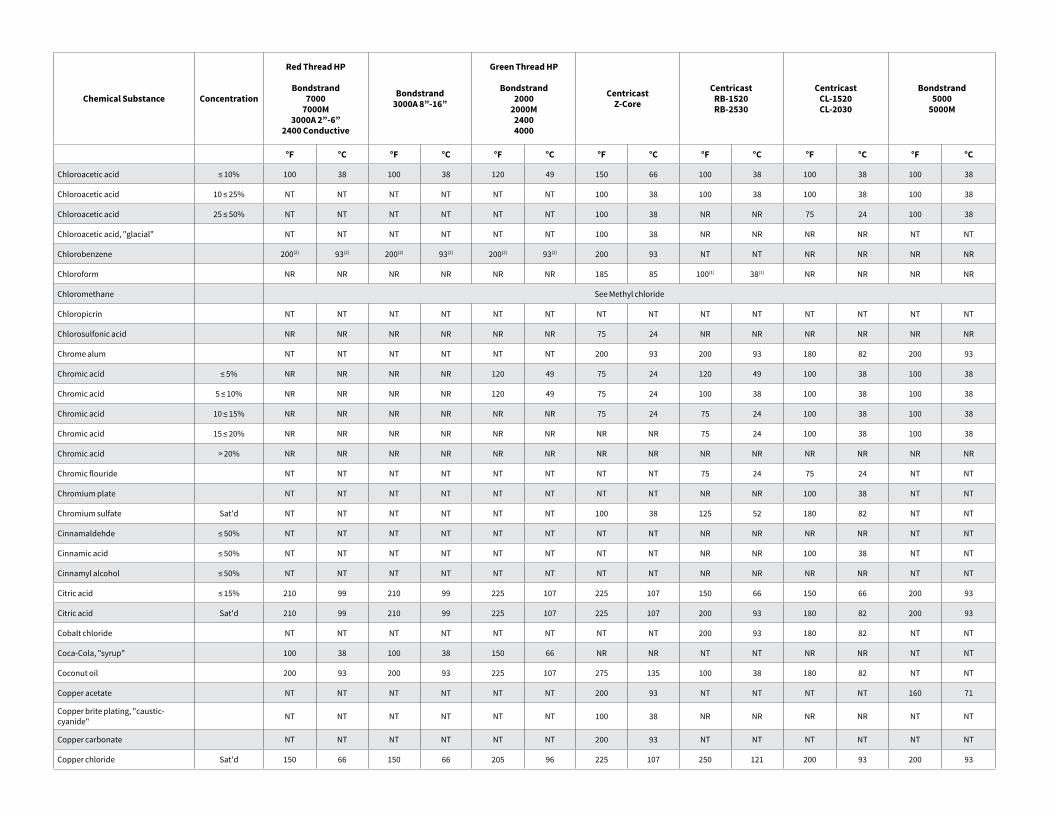
Chemical Substance Concentration
Red Thread HP
Bondstrand7000
7000M3000A 2”-6”
2400 Conductive
Bondstrand3000A 8”-16”
Green Thread HP
Bondstrand2000
2000M24004000
CentricastZ-Core
CentricastRB-1520RB-2530
CentricastCL-1520CL-2030
Bondstrand5000
5000M
°F °C °F °C °F °C °F °C °F °C °F °C °F °C
Chloroacetic acid ≤ 10% 100 38 100 38 120 49 150 66 100 38 100 38 100 38
Chloroacetic acid 10 ≤ 25% NT NT NT NT NT NT 100 38 100 38 100 38 100 38
Chloroacetic acid 25 ≤ 50% NT NT NT NT NT NT 100 38 NR NR 75 24 100 38
Chloroacetic acid, "glacial" NT NT NT NT NT NT 100 38 NR NR NR NR NT NT
Chlorobenzene 200(2) 93(2) 200(2) 93(2) 200(2) 93(2) 200 93 NT NT NR NR NR NR
Chloroform NR NR NR NR NR NR 185 85 100(1) 38(1) NR NR NR NR
Chloromethane See Methyl chloride
Chloropicrin NT NT NT NT NT NT NT NT NT NT NT NT NT NT
Chlorosulfonic acid NR NR NR NR NR NR 75 24 NR NR NR NR NR NR
Chrome alum NT NT NT NT NT NT 200 93 200 93 180 82 200 93
Chromic acid ≤ 5% NR NR NR NR 120 49 75 24 120 49 100 38 100 38
Chromic acid 5 ≤ 10% NR NR NR NR 120 49 75 24 100 38 100 38 100 38
Chromic acid 10 ≤ 15% NR NR NR NR NR NR 75 24 75 24 100 38 100 38
Chromic acid 15 ≤ 20% NR NR NR NR NR NR NR NR 75 24 100 38 100 38
Chromic acid > 20% NR NR NR NR NR NR NR NR NR NR NR NR NR NR
Chromic flouride NT NT NT NT NT NT NT NT 75 24 75 24 NT NT
Chromium plate NT NT NT NT NT NT NT NT NR NR 100 38 NT NT
Chromium sulfate Sat'd NT NT NT NT NT NT 100 38 125 52 180 82 NT NT
Cinnamaldehde ≤ 50% NT NT NT NT NT NT NT NT NR NR NR NR NT NT
Cinnamic acid ≤ 50% NT NT NT NT NT NT NT NT NR NR 100 38 NT NT
Cinnamyl alcohol ≤ 50% NT NT NT NT NT NT NT NT NR NR NR NR NT NT
Citric acid ≤ 15% 210 99 210 99 225 107 225 107 150 66 150 66 200 93
Citric acid Sat'd 210 99 210 99 225 107 225 107 200 93 180 82 200 93
Cobalt chloride NT NT NT NT NT NT NT NT 200 93 180 82 NT NT
Coca-Cola, "syrup" 100 38 100 38 150 66 NR NR NT NT NR NR NT NT
Coconut oil 200 93 200 93 225 107 275 135 100 38 180 82 NT NT
Copper acetate NT NT NT NT NT NT 200 93 NT NT NT NT 160 71
Copper brite plating, "caustic-cyanide" NT NT NT NT NT NT 100 38 NR NR NR NR NT NT
Copper carbonate NT NT NT NT NT NT 200 93 NT NT NT NT NT NT
Copper chloride Sat'd 150 66 150 66 205 96 225 107 250 121 200 93 200 93
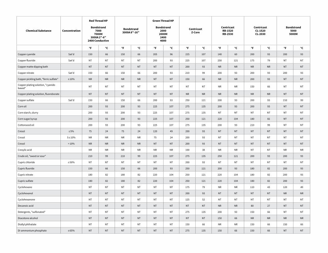
Chemical Substance Concentration
Red Thread HP
Bondstrand7000
7000M3000A 2”-6”
2400 Conductive
Bondstrand3000A 8”-16”
Green Thread HP
Bondstrand2000
2000M24004000
CentricastZ-Core
CentricastRB-1520RB-2530
CentricastCL-1520CL-2030
Bondstrand5000
5000M
°F °C °F °C °F °C °F °C °F °C °F °C °F °C
Copper cyanide Sat'd 150 66 150 66 205 96 225 107 140 60 200 93 200 93
Copper fluoride Sat'd NT NT NT NT 200 93 225 107 250 121 175 79 NT NT
Copper matte dipping bath NT NT NT NT NT NT 200 93 NR NR NR NR NT NT
Copper nitrate Sat'd 150 66 150 66 200 93 210 99 200 93 200 93 200 93
Copper pickling bath, "ferric sulfate" ≤ 10% NR NR NR NR NT NT 150 66 NR NR 200 93 NT NT
Copper plating solution, "cyanide based" NT NT NT NT NT NT NT NT NR NR 150 66 NT NT
Copper plating solution, fluoroborate NT NT NT NT NT NT NR NR NR NR NR NR NT NT
Copper sulfate Sat'd 150 66 150 66 200 93 250 121 200 93 200 93 210 99
Corn oil 200 93 200 93 225 107 275 135 200 93 200 93 NT NT
Corn starch, slurry 200 93 200 93 225 107 275 135 NT NT NT NT NT NT
Corn sugar/syrup 200 93 200 93 225 107 250 121 220 104 180 82 NT NT
Cottonseed oil 200 93 200 93 225 107 275 135 200 93 210 99 NT NT
Cresol ≤ 5% 75 24 75 24 120 49 200 93 NT NT NT NT NT NT
Cresol 5 ≤ 10% NR NR NR NR 75 24 200 93 NT NT NT NT NT NT
Cresol > 10% NR NR NR NR NT NT 200 93 NT NT NT NT NT NT
Cresylic acid NR NR NR NR NR NR 100 38 NR NR NT NT NR NR
Crude oil, "sweet or sour" 210 99 210 99 225 107 275 135 250 121 200 93 200 93
Cupric chloride ≤ 50% NT NT NT NT NT NT 200 93 NT NT NT NT NT NT
Cupric fluoride 150 66 150 66 200 93 250 121 200 93 180 82 200 93
Cupric nitrate 180 82 180 82 220 104 250 121 220 104 180 82 200 93
Cupric sulfate 180 82 180 82 220 104 250 121 220 104 180 82 200 93
Cyclohexane NT NT NT NT NT NT 175 79 NR NR 110 43 120 49
Cyclohexanol NT NT NT NT NT NT 200 93 NT NT NT NT NR NR
Cyclohexanone NT NT NT NT NT NT 125 52 NT NT NT NT NT NT
Decanoic acid NT NT NT NT NT NT NT NT NR NR 80 27 NT NT
Detergents, "sulfonated" NT NT NT NT NT NT 275 135 200 93 150 66 NT NT
Diacetone alcohol NT NT NT NT NT NT NT NT 150 66 NR NR NR NR
Diallyl phthalate NT NT NT NT NT NT 150 66 NR NR 150 66 150 66
Di-ammonium phosphate ≤ 65% NT NT NT NT NT NT 275 135 150 66 150 66 NT NT
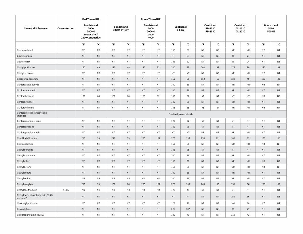
Chemical Substance Concentration
Red Thread HP
Bondstrand7000
7000M3000A 2”-6”
2400 Conductive
Bondstrand3000A 8”-16”
Green Thread HP
Bondstrand2000
2000M24004000
CentricastZ-Core
CentricastRB-1520RB-2530
CentricastCL-1520CL-2030
Bondstrand5000
5000M
°F °C °F °C °F °C °F °C °F °C °F °C °F °C
Dibromophenol NT NT NT NT NT NT 100 38 NR NR NR NR NT NT
Dibutyl carbitol NT NT NT NT NT NT NT NT NR NR 75 24 NT NT
Dibutyl ether NT NT NT NT NT NT 125 52 NR NR 75 24 NT NT
Dibutyl phthalate 120 49 120 49 180 82 200 93 200 93 175 79 180 82
Dibutyl sebacate NT NT NT NT NT NT NT NT NR NR NR NR NT NT
Dicalcium phosphate NT NT NT NT NT NT 150 66 150 66 120 49 120 49
Dichloroacetaldehyde NT NT NT NT NT NT 100 38 NR NR NR NR NR NR
Dichloroacetic acid NT NT NT NT NT NT 100 38 NR NR NR NR NT NT
Dichlorobenzene 150 66 150 66 180 82 180 82 NT NT NT NT NR NR
Dichloroethane NT NT NT NT NT NT 185 85 NR NR NR NR NT NT
Dichloroethylene NT NT NT NT NT NT 185 85 75 24 NR NR NR NR
Dichloromethane (methylene chloride) See Methylene chloride
Dichloromonomethane NT NT NT NT NT NT 125 52 NT NT NT NT NT NT
Dichloropropane NT NT NT NT NT NT 185 85 NT NT NT NT NT NT
Dichloropropionic acid NT NT NT NT NT NT NT NT NR NR NR NR NT NT
Diesel fuel/bio-diesel 210 99 210 99 225 107 275 135 250 121 180 82 150 66
Diethanolamine NT NT NT NT NT NT 150 66 NR NR NR NR NR NR
Diethyl benzene NT NT NT NT NT NT 185 85 NT NT NT NT NT NT
Diethyl carbonate NT NT NT NT NT NT 100 38 NR NR NR NR NT NT
Diethyl ether NT NT NT NT NT NT 100 38 NR NR NR NR NR NR
Diethyl ketone NT NT NT NT NT NT 150 66 NR NR NR NR NR NR
Diethyl sulfate NT NT NT NT NT NT 100 38 NR NR NR NR NT NT
Diethylamine NR NR NR NR NR NR 100 38 NR NR NR NR NT NT
Diethylene glycol 210 99 150 66 225 107 275 135 200 93 150 66 180 82
Diethylene triamine ≤ 10% NR NR NR NR NR NR 120 49 NT NT NT NT NT NT
Diethylhexyl phosphoric acid, "20% kerosene" NT NT NT NT NT NT NT NT NR NR 150 66 NT NT
Diisobutyl phthalate NT NT NT NT NT NT 175 79 NR NR 100 38 NT NT
Diisobutylene NT NT NT NT NT NT 225 107 NR NR 80 27 NT NT
Diisopropanolamine (DIPA) NT NT NT NT NT NT 120 49 NR NR 110 43 NT NT
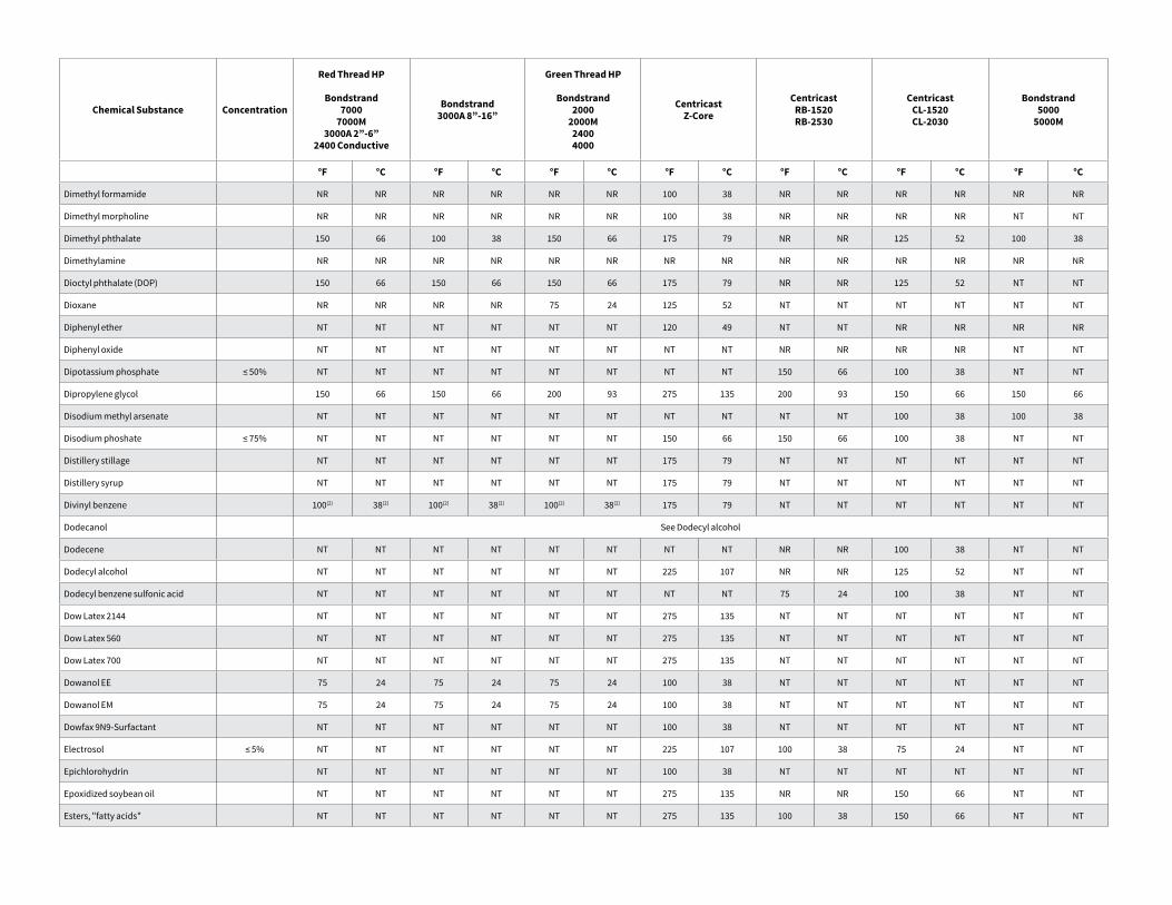
Chemical Substance Concentration
Red Thread HP
Bondstrand7000
7000M3000A 2”-6”
2400 Conductive
Bondstrand3000A 8”-16”
Green Thread HP
Bondstrand2000
2000M24004000
CentricastZ-Core
CentricastRB-1520RB-2530
CentricastCL-1520CL-2030
Bondstrand5000
5000M
°F °C °F °C °F °C °F °C °F °C °F °C °F °C
Dimethyl formamide NR NR NR NR NR NR 100 38 NR NR NR NR NR NR
Dimethyl morpholine NR NR NR NR NR NR 100 38 NR NR NR NR NT NT
Dimethyl phthalate 150 66 100 38 150 66 175 79 NR NR 125 52 100 38
Dimethylamine NR NR NR NR NR NR NR NR NR NR NR NR NR NR
Dioctyl phthalate (DOP) 150 66 150 66 150 66 175 79 NR NR 125 52 NT NT
Dioxane NR NR NR NR 75 24 125 52 NT NT NT NT NT NT
Diphenyl ether NT NT NT NT NT NT 120 49 NT NT NR NR NR NR
Diphenyl oxide NT NT NT NT NT NT NT NT NR NR NR NR NT NT
Dipotassium phosphate ≤ 50% NT NT NT NT NT NT NT NT 150 66 100 38 NT NT
Dipropylene glycol 150 66 150 66 200 93 275 135 200 93 150 66 150 66
Disodium methyl arsenate NT NT NT NT NT NT NT NT NT NT 100 38 100 38
Disodium phoshate ≤ 75% NT NT NT NT NT NT 150 66 150 66 100 38 NT NT
Distillery stillage NT NT NT NT NT NT 175 79 NT NT NT NT NT NT
Distillery syrup NT NT NT NT NT NT 175 79 NT NT NT NT NT NT
Divinyl benzene 100(2) 38(2) 100(2) 38(2) 100(2) 38(2) 175 79 NT NT NT NT NT NT
Dodecanol See Dodecyl alcohol
Dodecene NT NT NT NT NT NT NT NT NR NR 100 38 NT NT
Dodecyl alcohol NT NT NT NT NT NT 225 107 NR NR 125 52 NT NT
Dodecyl benzene sulfonic acid NT NT NT NT NT NT NT NT 75 24 100 38 NT NT
Dow Latex 2144 NT NT NT NT NT NT 275 135 NT NT NT NT NT NT
Dow Latex 560 NT NT NT NT NT NT 275 135 NT NT NT NT NT NT
Dow Latex 700 NT NT NT NT NT NT 275 135 NT NT NT NT NT NT
Dowanol EE 75 24 75 24 75 24 100 38 NT NT NT NT NT NT
Dowanol EM 75 24 75 24 75 24 100 38 NT NT NT NT NT NT
Dowfax 9N9-Surfactant NT NT NT NT NT NT 100 38 NT NT NT NT NT NT
Electrosol ≤ 5% NT NT NT NT NT NT 225 107 100 38 75 24 NT NT
Epichlorohydrin NT NT NT NT NT NT 100 38 NT NT NT NT NT NT
Epoxidized soybean oil NT NT NT NT NT NT 275 135 NR NR 150 66 NT NT
Esters, "fatty acids" NT NT NT NT NT NT 275 135 100 38 150 66 NT NT
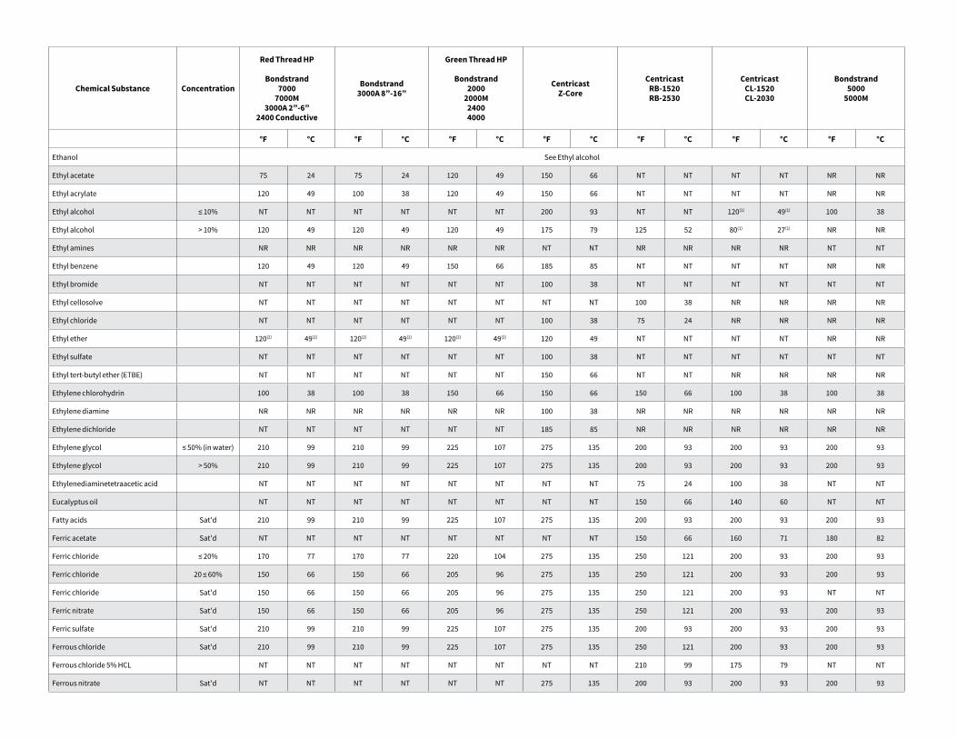
Chemical Substance Concentration
Red Thread HP
Bondstrand7000
7000M3000A 2”-6”
2400 Conductive
Bondstrand3000A 8”-16”
Green Thread HP
Bondstrand2000
2000M24004000
CentricastZ-Core
CentricastRB-1520RB-2530
CentricastCL-1520CL-2030
Bondstrand5000
5000M
°F °C °F °C °F °C °F °C °F °C °F °C °F °C
Ethanol See Ethyl alcohol
Ethyl acetate 75 24 75 24 120 49 150 66 NT NT NT NT NR NR
Ethyl acrylate 120 49 100 38 120 49 150 66 NT NT NT NT NR NR
Ethyl alcohol ≤ 10% NT NT NT NT NT NT 200 93 NT NT 120(1) 49(1) 100 38
Ethyl alcohol > 10% 120 49 120 49 120 49 175 79 125 52 80(1) 27(1) NR NR
Ethyl amines NR NR NR NR NR NR NT NT NR NR NR NR NT NT
Ethyl benzene 120 49 120 49 150 66 185 85 NT NT NT NT NR NR
Ethyl bromide NT NT NT NT NT NT 100 38 NT NT NT NT NT NT
Ethyl cellosolve NT NT NT NT NT NT NT NT 100 38 NR NR NR NR
Ethyl chloride NT NT NT NT NT NT 100 38 75 24 NR NR NR NR
Ethyl ether 120(2) 49(2) 120(2) 49(2) 120(2) 49(2) 120 49 NT NT NT NT NR NR
Ethyl sulfate NT NT NT NT NT NT 100 38 NT NT NT NT NT NT
Ethyl tert-butyl ether (ETBE) NT NT NT NT NT NT 150 66 NT NT NR NR NR NR
Ethylene chlorohydrin 100 38 100 38 150 66 150 66 150 66 100 38 100 38
Ethylene diamine NR NR NR NR NR NR 100 38 NR NR NR NR NR NR
Ethylene dichloride NT NT NT NT NT NT 185 85 NR NR NR NR NR NR
Ethylene glycol ≤ 50% (in water) 210 99 210 99 225 107 275 135 200 93 200 93 200 93
Ethylene glycol > 50% 210 99 210 99 225 107 275 135 200 93 200 93 200 93
Ethylenediaminetetraacetic acid NT NT NT NT NT NT NT NT 75 24 100 38 NT NT
Eucalyptus oil NT NT NT NT NT NT NT NT 150 66 140 60 NT NT
Fatty acids Sat'd 210 99 210 99 225 107 275 135 200 93 200 93 200 93
Ferric acetate Sat'd NT NT NT NT NT NT NT NT 150 66 160 71 180 82
Ferric chloride ≤ 20% 170 77 170 77 220 104 275 135 250 121 200 93 200 93
Ferric chloride 20 ≤ 60% 150 66 150 66 205 96 275 135 250 121 200 93 200 93
Ferric chloride Sat'd 150 66 150 66 205 96 275 135 250 121 200 93 NT NT
Ferric nitrate Sat'd 150 66 150 66 205 96 275 135 250 121 200 93 200 93
Ferric sulfate Sat'd 210 99 210 99 225 107 275 135 200 93 200 93 200 93
Ferrous chloride Sat'd 210 99 210 99 225 107 275 135 250 121 200 93 200 93
Ferrous chloride 5% HCL NT NT NT NT NT NT NT NT 210 99 175 79 NT NT
Ferrous nitrate Sat'd NT NT NT NT NT NT 275 135 200 93 200 93 200 93
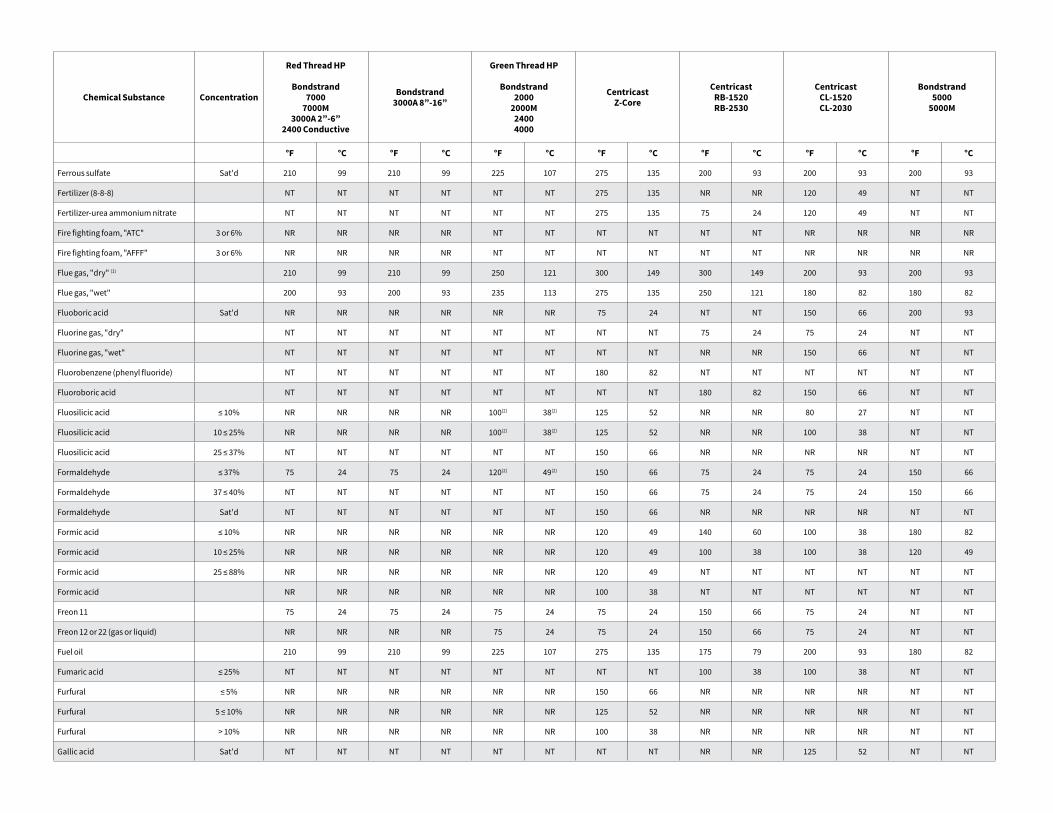
Chemical Substance Concentration
Red Thread HP
Bondstrand7000
7000M3000A 2”-6”
2400 Conductive
Bondstrand3000A 8”-16”
Green Thread HP
Bondstrand2000
2000M24004000
CentricastZ-Core
CentricastRB-1520RB-2530
CentricastCL-1520CL-2030
Bondstrand5000
5000M
°F °C °F °C °F °C °F °C °F °C °F °C °F °C
Ferrous sulfate Sat'd 210 99 210 99 225 107 275 135 200 93 200 93 200 93
Fertilizer (8-8-8) NT NT NT NT NT NT 275 135 NR NR 120 49 NT NT
Fertilizer-urea ammonium nitrate NT NT NT NT NT NT 275 135 75 24 120 49 NT NT
Fire fighting foam, "ATC" 3 or 6% NR NR NR NR NT NT NT NT NT NT NR NR NR NR
Fire fighting foam, "AFFF" 3 or 6% NR NR NR NR NT NT NT NT NT NT NR NR NR NR
Flue gas, "dry" (1) 210 99 210 99 250 121 300 149 300 149 200 93 200 93
Flue gas, "wet" 200 93 200 93 235 113 275 135 250 121 180 82 180 82
Fluoboric acid Sat'd NR NR NR NR NR NR 75 24 NT NT 150 66 200 93
Fluorine gas, "dry" NT NT NT NT NT NT NT NT 75 24 75 24 NT NT
Fluorine gas, "wet" NT NT NT NT NT NT NT NT NR NR 150 66 NT NT
Fluorobenzene (phenyl fluoride) NT NT NT NT NT NT 180 82 NT NT NT NT NT NT
Fluoroboric acid NT NT NT NT NT NT NT NT 180 82 150 66 NT NT
Fluosilicic acid ≤ 10% NR NR NR NR 100(2) 38(2) 125 52 NR NR 80 27 NT NT
Fluosilicic acid 10 ≤ 25% NR NR NR NR 100(2) 38(2) 125 52 NR NR 100 38 NT NT
Fluosilicic acid 25 ≤ 37% NT NT NT NT NT NT 150 66 NR NR NR NR NT NT
Formaldehyde ≤ 37% 75 24 75 24 120(2) 49(2) 150 66 75 24 75 24 150 66
Formaldehyde 37 ≤ 40% NT NT NT NT NT NT 150 66 75 24 75 24 150 66
Formaldehyde Sat'd NT NT NT NT NT NT 150 66 NR NR NR NR NT NT
Formic acid ≤ 10% NR NR NR NR NR NR 120 49 140 60 100 38 180 82
Formic acid 10 ≤ 25% NR NR NR NR NR NR 120 49 100 38 100 38 120 49
Formic acid 25 ≤ 88% NR NR NR NR NR NR 120 49 NT NT NT NT NT NT
Formic acid NR NR NR NR NR NR 100 38 NT NT NT NT NT NT
Freon 11 75 24 75 24 75 24 75 24 150 66 75 24 NT NT
Freon 12 or 22 (gas or liquid) NR NR NR NR 75 24 75 24 150 66 75 24 NT NT
Fuel oil 210 99 210 99 225 107 275 135 175 79 200 93 180 82
Fumaric acid ≤ 25% NT NT NT NT NT NT NT NT 100 38 100 38 NT NT
Furfural ≤ 5% NR NR NR NR NR NR 150 66 NR NR NR NR NT NT
Furfural 5 ≤ 10% NR NR NR NR NR NR 125 52 NR NR NR NR NT NT
Furfural > 10% NR NR NR NR NR NR 100 38 NR NR NR NR NT NT
Gallic acid Sat'd NT NT NT NT NT NT NT NT NR NR 125 52 NT NT
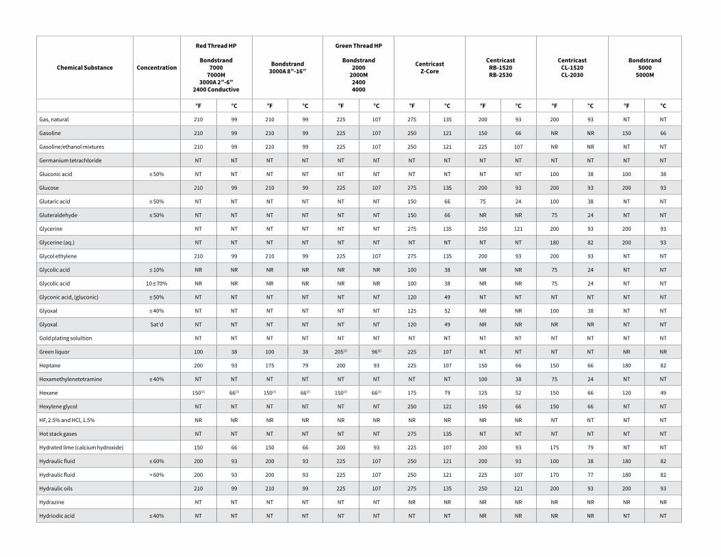
Chemical Substance Concentration
Red Thread HP
Bondstrand7000
7000M3000A 2”-6”
2400 Conductive
Bondstrand3000A 8”-16”
Green Thread HP
Bondstrand2000
2000M24004000
CentricastZ-Core
CentricastRB-1520RB-2530
CentricastCL-1520CL-2030
Bondstrand5000
5000M
°F °C °F °C °F °C °F °C °F °C °F °C °F °C
Gas, natural 210 99 210 99 225 107 275 135 200 93 200 93 NT NT
Gasoline 210 99 210 99 225 107 250 121 150 66 NR NR 150 66
Gasoline/ethanol mixtures 210 99 210 99 225 107 250 121 225 107 NR NR NT NT
Germanium tetrachloride NT NT NT NT NT NT NT NT NT NT NT NT NT NT
Gluconic acid ≤ 50% NT NT NT NT NT NT NT NT NT NT 100 38 100 38
Glucose 210 99 210 99 225 107 275 135 200 93 200 93 200 93
Glutaric acid ≤ 50% NT NT NT NT NT NT 150 66 75 24 100 38 NT NT
Gluteraldehyde ≤ 50% NT NT NT NT NT NT 150 66 NR NR 75 24 NT NT
Glycerine NT NT NT NT NT NT 275 135 250 121 200 93 200 93
Glycerine (aq.) NT NT NT NT NT NT NT NT NT NT 180 82 200 93
Glycol ethylene 210 99 210 99 225 107 275 135 200 93 200 93 NT NT
Glycolic acid ≤ 10% NR NR NR NR NR NR 100 38 NR NR 75 24 NT NT
Glycolic acid 10 ≤ 70% NR NR NR NR NR NR 100 38 NR NR 75 24 NT NT
Glyconic acid, (gluconic) ≤ 50% NT NT NT NT NT NT 120 49 NT NT NT NT NT NT
Glyoxal ≤ 40% NT NT NT NT NT NT 125 52 NR NR 100 38 NT NT
Glyoxal Sat'd NT NT NT NT NT NT 120 49 NR NR NR NR NT NT
Gold plating solultion NT NT NT NT NT NT NT NT NT NT NT NT NT NT
Green liquor 100 38 100 38 205(2) 96(2) 225 107 NT NT NT NT NR NR
Heptane 200 93 175 79 200 93 225 107 150 66 150 66 180 82
Hexamethylenetetramine ≤ 40% NT NT NT NT NT NT NT NT 100 38 75 24 NT NT
Hexane 150(2) 66(2) 150(2) 66(2) 150(2) 66(2) 175 79 125 52 150 66 120 49
Hexylene glycol NT NT NT NT NT NT 250 121 150 66 150 66 NT NT
HF, 2.5% and HCl, 1.5% NR NR NR NR NR NR NR NR NR NR NT NT NT NT
Hot stack gases NT NT NT NT NT NT 275 135 NT NT NT NT NT NT
Hydrated lime (calcium hydroxide) 150 66 150 66 200 93 225 107 200 93 175 79 NT NT
Hydraulic fluid ≤ 60% 200 93 200 93 225 107 250 121 200 93 100 38 180 82
Hydraulic fluid > 60% 200 93 200 93 225 107 250 121 225 107 170 77 180 82
Hydraulic oils 210 99 210 99 225 107 275 135 250 121 200 93 200 93
Hydrazine NT NT NT NT NT NT NR NR NR NR NR NR NR NR
Hydriodic acid ≤ 40% NT NT NT NT NT NT NT NT NR NR NR NR NT NT
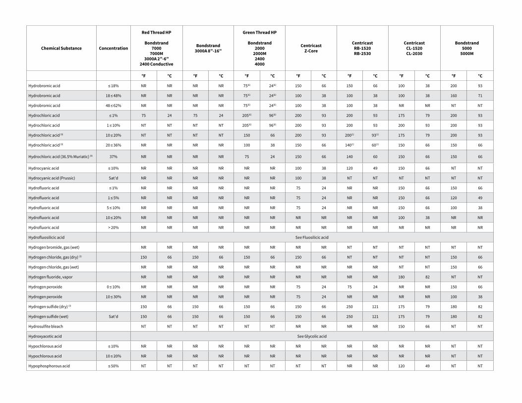
Chemical Substance Concentration
Red Thread HP
Bondstrand7000
7000M3000A 2”-6”
2400 Conductive
Bondstrand3000A 8”-16”
Green Thread HP
Bondstrand2000
2000M24004000
CentricastZ-Core
CentricastRB-1520RB-2530
CentricastCL-1520CL-2030
Bondstrand5000
5000M
°F °C °F °C °F °C °F °C °F °C °F °C °F °C
Hydrobromic acid ≤ 18% NR NR NR NR 75(6) 24(6) 150 66 150 66 100 38 200 93
Hydrobromic acid 18 ≤ 48% NR NR NR NR 75(6) 24(6) 100 38 100 38 100 38 160 71
Hydrobromic acid 48 ≤ 62% NR NR NR NR 75(6) 24(6) 100 38 100 38 NR NR NT NT
Hydrochloric acid ≤ 1% 75 24 75 24 205(6) 96(6) 200 93 200 93 175 79 200 93
Hydrochloric acid 1 ≤ 10% NT NT NT NT 205(6) 96(6) 200 93 200 93 200 93 200 93
Hydrochloric acid (9) 10 ≤ 20% NT NT NT NT 150 66 200 93 200(1) 93(1) 175 79 200 93
Hydrochloric acid (9) 20 ≤ 36% NR NR NR NR 100 38 150 66 140(1) 60(1) 150 66 150 66
Hydrochloric acid (36.5% Muriatic) (9) 37% NR NR NR NR 75 24 150 66 140 60 150 66 150 66
Hydrocyanic acid ≤ 10% NR NR NR NR NR NR 100 38 120 49 150 66 NT NT
Hydrocyanic acid (Prussic) Sat'd NR NR NR NR NR NR 100 38 NT NT NT NT NT NT
Hydrofluoric acid ≤ 1% NR NR NR NR NR NR 75 24 NR NR 150 66 150 66
Hydrofluoric acid 1 ≤ 5% NR NR NR NR NR NR 75 24 NR NR 150 66 120 49
Hydrofluoric acid 5 ≤ 10% NR NR NR NR NR NR 75 24 NR NR 150 66 100 38
Hydrofluoric acid 10 ≤ 20% NR NR NR NR NR NR NR NR NR NR 100 38 NR NR
Hydrofluoric acid > 20% NR NR NR NR NR NR NR NR NR NR NR NR NR NR
Hydrofluosilicic acid See Fluosilicic acid
Hydrogen bromide, gas (wet) NR NR NR NR NR NR NR NR NT NT NT NT NT NT
Hydrogen chloride, gas (dry) (3) 150 66 150 66 150 66 150 66 NT NT NT NT 150 66
Hydrogen chloride, gas (wet) NR NR NR NR NR NR NR NR NR NR NT NT 150 66
Hydrogen fluoride, vapor NR NR NR NR NR NR NR NR NR NR 180 82 NT NT
Hydrogen peroxide 0 ≤ 10% NR NR NR NR NR NR 75 24 75 24 NR NR 150 66
Hydrogen peroxide 10 ≤ 30% NR NR NR NR NR NR 75 24 NR NR NR NR 100 38
Hydrogen sulfide (dry) (3) 150 66 150 66 150 66 150 66 250 121 175 79 180 82
Hydrogen sulfide (wet) Sat'd 150 66 150 66 150 66 150 66 250 121 175 79 180 82
Hydrosulfite bleach NT NT NT NT NT NT NR NR NR NR 150 66 NT NT
Hydroxyacetic acid See Glycolic acid
Hypochlorous acid ≤ 10% NR NR NR NR NR NR NR NR NR NR NR NR NT NT
Hypochlorous acid 10 ≤ 20% NR NR NR NR NR NR NR NR NR NR NR NR NT NT
Hypophosphorous acid ≤ 50% NT NT NT NT NT NT NT NT NR NR 120 49 NT NT
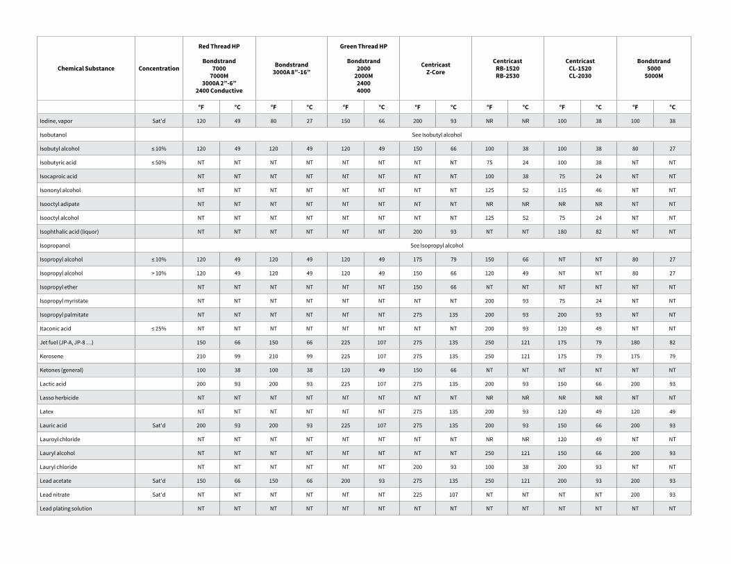
Chemical Substance Concentration
Red Thread HP
Bondstrand7000
7000M3000A 2”-6”
2400 Conductive
Bondstrand3000A 8”-16”
Green Thread HP
Bondstrand2000
2000M24004000
CentricastZ-Core
CentricastRB-1520RB-2530
CentricastCL-1520CL-2030
Bondstrand5000
5000M
°F °C °F °C °F °C °F °C °F °C °F °C °F °C
Iodine, vapor Sat'd 120 49 80 27 150 66 200 93 NR NR 100 38 100 38
Isobutanol See Isobutyl alcohol
Isobutyl alcohol ≤ 10% 120 49 120 49 120 49 150 66 100 38 100 38 80 27
Isobutyric acid ≤ 50% NT NT NT NT NT NT NT NT 75 24 100 38 NT NT
Isocaproic acid NT NT NT NT NT NT NT NT 100 38 75 24 NT NT
Isononyl alcohol NT NT NT NT NT NT NT NT 125 52 115 46 NT NT
Isooctyl adipate NT NT NT NT NT NT NT NT NR NR NR NR NT NT
Isooctyl alcohol NT NT NT NT NT NT NT NT 125 52 75 24 NT NT
Isophthalic acid (liquor) NT NT NT NT NT NT 200 93 NT NT 180 82 NT NT
Isopropanol See Isopropyl alcohol
Isopropyl alcohol ≤ 10% 120 49 120 49 120 49 175 79 150 66 NT NT 80 27
Isopropyl alcohol > 10% 120 49 120 49 120 49 150 66 120 49 NT NT 80 27
Isopropyl ether NT NT NT NT NT NT 150 66 NT NT NT NT NT NT
Isopropyl myristate NT NT NT NT NT NT NT NT 200 93 75 24 NT NT
Isopropyl palmitate NT NT NT NT NT NT 275 135 200 93 200 93 NT NT
Itaconic acid ≤ 25% NT NT NT NT NT NT NT NT 200 93 120 49 NT NT
Jet fuel (JP-A, JP-8 …) 150 66 150 66 225 107 275 135 250 121 175 79 180 82
Kerosene 210 99 210 99 225 107 275 135 250 121 175 79 175 79
Ketones (general) 100 38 100 38 120 49 150 66 NT NT NT NT NT NT
Lactic acid 200 93 200 93 225 107 275 135 200 93 150 66 200 93
Lasso herbicide NT NT NT NT NT NT NT NT NR NR NR NR NT NT
Latex NT NT NT NT NT NT 275 135 200 93 120 49 120 49
Lauric acid Sat'd 200 93 200 93 225 107 275 135 200 93 150 66 200 93
Lauroyl chloride NT NT NT NT NT NT NT NT NR NR 120 49 NT NT
Lauryl alcohol NT NT NT NT NT NT NT NT 250 121 150 66 200 93
Lauryl chloride NT NT NT NT NT NT 200 93 100 38 200 93 NT NT
Lead acetate Sat'd 150 66 150 66 200 93 275 135 250 121 200 93 200 93
Lead nitrate Sat'd NT NT NT NT NT NT 225 107 NT NT NT NT 200 93
Lead plating solution NT NT NT NT NT NT NT NT NT NT NT NT NT NT
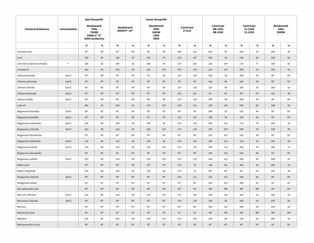
Chemical Substance Concentration
Red Thread HP
Bondstrand7000
7000M3000A 2”-6”
2400 Conductive
Bondstrand3000A 8”-16”
Green Thread HP
Bondstrand2000
2000M24004000
CentricastZ-Core
CentricastRB-1520RB-2530
CentricastCL-1520CL-2030
Bondstrand5000
5000M
°F °C °F °C °F °C °F °C °F °C °F °C °F °C
Levulinic acid NT NT NT NT NT NT 250 121 200 93 200 93 200 93
Lime 180 82 180 82 200 93 225 107 200 93 180 82 180 82
Lime slurry (abrasive media) (1) 180 82 180 82 200 93 275 135 225 107 170 77 180 82
Linseed oil 200 93 200 93 225 107 275 135 225 107 200 93 200 93
Lithium bromide Sat'd NT NT NT NT NT NT 275 135 100 38 200 93 NT NT
Lithium carbonate Sat'd NT NT NT NT NT NT NT NT 140 60 100 38 NT NT
Lithium chloride Sat'd NT NT NT NT NT NT 275 135 210 99 200 93 200 93
Lithium hydroxide Sat'd NT NT NT NT NT NT 225 107 NT NT NT NT 120 49
Lithium sulfate Sat'd NT NT NT NT NT NT 275 135 100 38 200 93 NT NT
Lube oil 200 93 200 93 225 107 250 121 220 104 180 82 180 82
Magnesium bisulfate Sat'd NT NT NT NT NT NT NT NT 200 93 150 66 NT NT
Magnesium bisulfite Sat'd NT NT NT NT NT NT 225 107 100 38 150 66 NT NT
Magnesium carbonate Sat'd 150 66 150 66 200 93 275 135 250 121 175 79 200 93
Magnesium chloride Sat'd 210 99 210 99 225 107 275 135 225 107 200 93 200 93
Magnesium fluosilicate NT NT NT NT NT NT NT NT 225 107 100 38 NT NT
Magnesium hydroxide Sat'd 120 49 120 49 205 96 275 135 250 121 150 66 150 66
Magnesium nitrate Sat'd 210 99 210 99 225 107 275 135 250 121 200 93 160 71
Magnesium phosphate NT NT NT NT NT NT NT NT 250 121 150 66 NT NT
Magnesium sulfate Sat'd 210 99 210 99 225 107 275 135 250 121 200 93 200 93
Maleic acid NT NT NT NT NT NT 175 79 150 66 200 93 200 93
Maleic anhydride 150 66 150 66 150 66 175 79 NT NT NT NT 120 49
Manganese chloride Sat'd NT NT NT NT NT NT 250 121 225 107 180 82 NT NT
Manganese sulfate NT NT NT NT NT NT NT NT 225 107 200 93 NT NT
Mercaptoacetic acid NT NT NT NT NT NT NT NT NR NR NR NR NT NT
Mercuric chloride Sat'd 210 99 210 99 225 107 275 135 150 66 200 93 200 93
Mercurous chloride Sat'd NT NT NT NT NT NT 275 135 150 66 200 93 200 93
Mercury NT NT NT NT NT NT NT NT 250 121 200 93 200 93
Methacrylic acid NT NT NT NT NT NT NT NT NR NR NR NR NR NR
Methane 210 99 210 99 235 113 275 135 150 66 140 60 200 93
Methanesulfonic acid NT NT NT NT NT NT NT NT NT NT NT NT NT NT
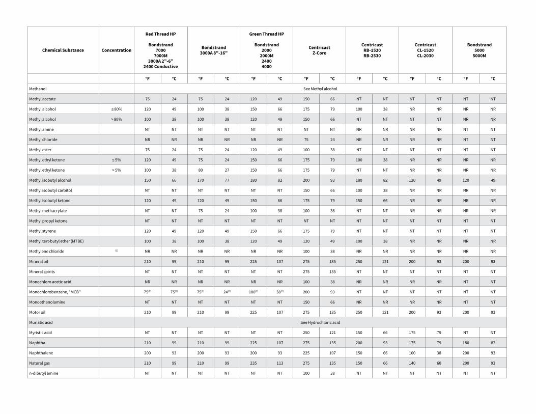
Chemical Substance Concentration
Red Thread HP
Bondstrand7000
7000M3000A 2”-6”
2400 Conductive
Bondstrand3000A 8”-16”
Green Thread HP
Bondstrand2000
2000M24004000
CentricastZ-Core
CentricastRB-1520RB-2530
CentricastCL-1520CL-2030
Bondstrand5000
5000M
°F °C °F °C °F °C °F °C °F °C °F °C °F °C
Methanol See Methyl alcohol
Methyl acetate 75 24 75 24 120 49 150 66 NT NT NT NT NT NT
Methyl alcohol ≤ 80% 120 49 100 38 150 66 175 79 100 38 NR NR NR NR
Methyl alcohol > 80% 100 38 100 38 120 49 150 66 NT NT NT NT NR NR
Methyl amine NT NT NT NT NT NT NT NT NR NR NR NR NT NT
Methyl chloride NR NR NR NR NR NR 75 24 NR NR NR NR NT NT
Methyl ester 75 24 75 24 120 49 100 38 NT NT NT NT NT NT
Methyl ethyl ketone ≤ 5% 120 49 75 24 150 66 175 79 100 38 NR NR NR NR
Methyl ethyl ketone > 5% 100 38 80 27 150 66 175 79 NT NT NR NR NR NR
Methyl isobutyl alcohol 150 66 170 77 180 82 200 93 180 82 120 49 120 49
Methyl isobutyl carbitol NT NT NT NT NT NT 150 66 100 38 NR NR NR NR
Methyl isobutyl ketone 120 49 120 49 150 66 175 79 150 66 NR NR NR NR
Methyl methacrylate NT NT 75 24 100 38 100 38 NT NT NR NR NR NR
Methyl propyl ketone NT NT NT NT NT NT NT NT NT NT NT NT NT NT
Methyl styrene 120 49 120 49 150 66 175 79 NT NT NT NT NT NT
Methyl tert-butyl ether (MTBE) 100 38 100 38 120 49 120 49 100 38 NR NR NR NR
Methylene chloride (1) NR NR NR NR NR NR 100 38 NR NR NR NR NR NR
Mineral oil 210 99 210 99 225 107 275 135 250 121 200 93 200 93
Mineral spirits NT NT NT NT NT NT 275 135 NT NT NT NT NT NT
Monochloro acetic acid NR NR NR NR NR NR 100 38 NR NR NR NR NT NT
Monochlorobenzene, "MCB" 75(2) 75(2) 75(2) 24(2) 100(2) 38(2) 200 93 NT NT NT NT NT NT
Monoethanolamine NT NT NT NT NT NT 150 66 NR NR NR NR NT NT
Motor oil 210 99 210 99 225 107 275 135 250 121 200 93 200 93
Muriatic acid See Hydrochloric acid
Myristic acid NT NT NT NT NT NT 250 121 150 66 175 79 NT NT
Naphtha 210 99 210 99 225 107 275 135 200 93 175 79 180 82
Naphthalene 200 93 200 93 200 93 225 107 150 66 100 38 200 93
Natural gas 210 99 210 99 235 113 275 135 150 66 140 60 200 93
n-dibutyl amine NT NT NT NT NT NT 100 38 NT NT NT NT NT NT
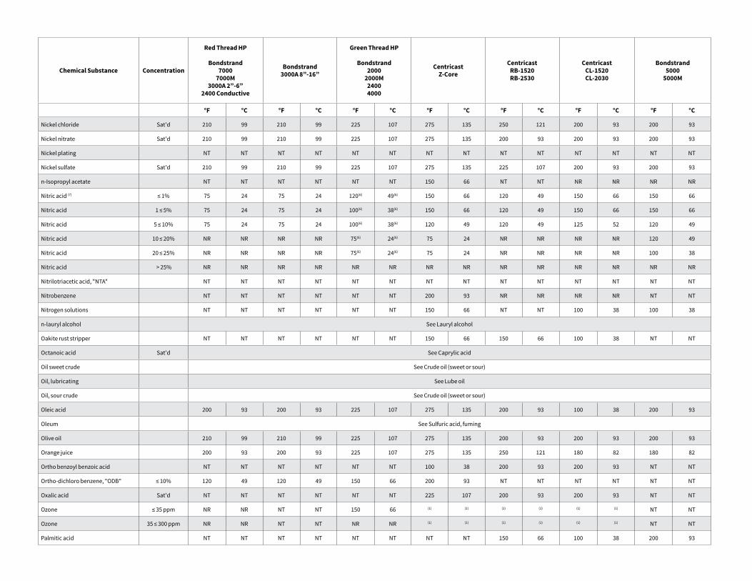
Chemical Substance Concentration
Red Thread HP
Bondstrand7000
7000M3000A 2”-6”
2400 Conductive
Bondstrand3000A 8”-16”
Green Thread HP
Bondstrand2000
2000M24004000
CentricastZ-Core
CentricastRB-1520RB-2530
CentricastCL-1520CL-2030
Bondstrand5000
5000M
°F °C °F °C °F °C °F °C °F °C °F °C °F °C
Nickel chloride Sat'd 210 99 210 99 225 107 275 135 250 121 200 93 200 93
Nickel nitrate Sat'd 210 99 210 99 225 107 275 135 200 93 200 93 200 93
Nickel plating NT NT NT NT NT NT NT NT NT NT NT NT NT NT
Nickel sulfate Sat'd 210 99 210 99 225 107 275 135 225 107 200 93 200 93
n-Isopropyl acetate NT NT NT NT NT NT 150 66 NT NT NR NR NR NR
Nitric acid (7) ≤ 1% 75 24 75 24 120(6) 49(6) 150 66 120 49 150 66 150 66
Nitric acid 1 ≤ 5% 75 24 75 24 100(6) 38(6) 150 66 120 49 150 66 150 66
Nitric acid 5 ≤ 10% 75 24 75 24 100(6) 38(6) 120 49 120 49 125 52 120 49
Nitric acid 10 ≤ 20% NR NR NR NR 75(6) 24(6) 75 24 NR NR NR NR 120 49
Nitric acid 20 ≤ 25% NR NR NR NR 75(6) 24(6) 75 24 NR NR NR NR 100 38
Nitric acid > 25% NR NR NR NR NR NR NR NR NR NR NR NR NR NR
Nitrilotriacetic acid, "NTA" NT NT NT NT NT NT NT NT NT NT NT NT NT NT
Nitrobenzene NT NT NT NT NT NT 200 93 NR NR NR NR NT NT
Nitrogen solutions NT NT NT NT NT NT 150 66 NT NT 100 38 100 38
n-lauryl alcohol See Lauryl alcohol
Oakite rust stripper NT NT NT NT NT NT 150 66 150 66 100 38 NT NT
Octanoic acid Sat'd See Caprylic acid
Oil sweet crude See Crude oil (sweet or sour)
Oil, lubricating See Lube oil
Oil, sour crude See Crude oil (sweet or sour)
Oleic acid 200 93 200 93 225 107 275 135 200 93 100 38 200 93
Oleum See Sulfuric acid, fuming
Olive oil 210 99 210 99 225 107 275 135 200 93 200 93 200 93
Orange juice 200 93 200 93 225 107 275 135 250 121 180 82 180 82
Ortho benzoyl benzoic acid NT NT NT NT NT NT 100 38 200 93 200 93 NT NT
Ortho-dichloro benzene, "ODB" ≤ 10% 120 49 120 49 150 66 200 93 NT NT NT NT NT NT
Oxalic acid Sat'd NT NT NT NT NT NT 225 107 200 93 200 93 NT NT
Ozone ≤ 35 ppm NR NR NT NT 150 66 (1) (1) (1) (1) (1) (1) NT NT
Ozone 35 ≤ 300 ppm NR NR NT NT NR NR (1) (1) (1) (1) (1) (1) NT NT
Palmitic acid NT NT NT NT NT NT NT NT 150 66 100 38 200 93
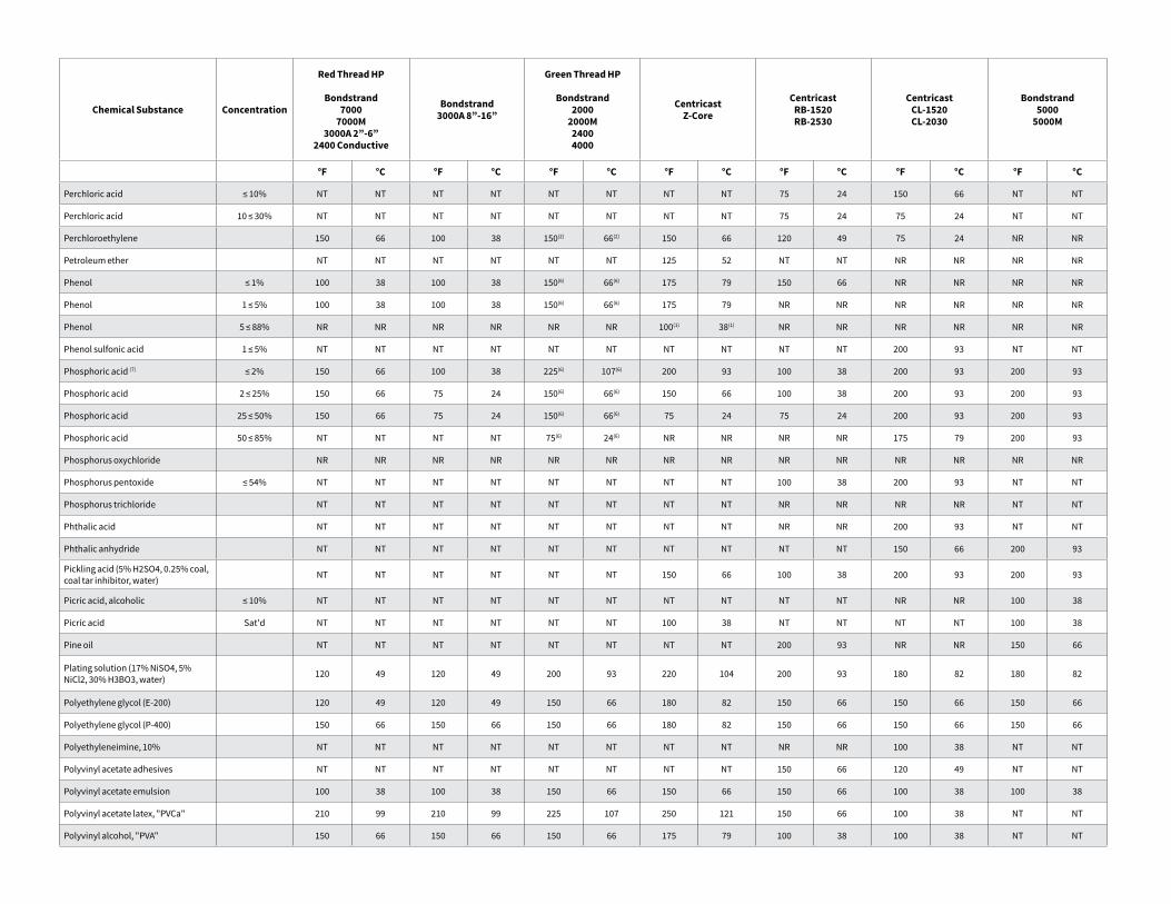
Chemical Substance Concentration
Red Thread HP
Bondstrand7000
7000M3000A 2”-6”
2400 Conductive
Bondstrand3000A 8”-16”
Green Thread HP
Bondstrand2000
2000M24004000
CentricastZ-Core
CentricastRB-1520RB-2530
CentricastCL-1520CL-2030
Bondstrand5000
5000M
°F °C °F °C °F °C °F °C °F °C °F °C °F °C
Perchloric acid ≤ 10% NT NT NT NT NT NT NT NT 75 24 150 66 NT NT
Perchloric acid 10 ≤ 30% NT NT NT NT NT NT NT NT 75 24 75 24 NT NT
Perchloroethylene 150 66 100 38 150(2) 66(2) 150 66 120 49 75 24 NR NR
Petroleum ether NT NT NT NT NT NT 125 52 NT NT NR NR NR NR
Phenol ≤ 1% 100 38 100 38 150(6) 66(6) 175 79 150 66 NR NR NR NR
Phenol 1 ≤ 5% 100 38 100 38 150(6) 66(6) 175 79 NR NR NR NR NR NR
Phenol 5 ≤ 88% NR NR NR NR NR NR 100(1) 38(1) NR NR NR NR NR NR
Phenol sulfonic acid 1 ≤ 5% NT NT NT NT NT NT NT NT NT NT 200 93 NT NT
Phosphoric acid (7) ≤ 2% 150 66 100 38 225(6) 107(6) 200 93 100 38 200 93 200 93
Phosphoric acid 2 ≤ 25% 150 66 75 24 150(6) 66(6) 150 66 100 38 200 93 200 93
Phosphoric acid 25 ≤ 50% 150 66 75 24 150(6) 66(6) 75 24 75 24 200 93 200 93
Phosphoric acid 50 ≤ 85% NT NT NT NT 75(6) 24(6) NR NR NR NR 175 79 200 93
Phosphorus oxychloride NR NR NR NR NR NR NR NR NR NR NR NR NR NR
Phosphorus pentoxide ≤ 54% NT NT NT NT NT NT NT NT 100 38 200 93 NT NT
Phosphorus trichloride NT NT NT NT NT NT NT NT NR NR NR NR NT NT
Phthalic acid NT NT NT NT NT NT NT NT NR NR 200 93 NT NT
Phthalic anhydride NT NT NT NT NT NT NT NT NT NT 150 66 200 93
Pickling acid (5% H2SO4, 0.25% coal, coal tar inhibitor, water) NT NT NT NT NT NT 150 66 100 38 200 93 200 93
Picric acid, alcoholic ≤ 10% NT NT NT NT NT NT NT NT NT NT NR NR 100 38
Picric acid Sat'd NT NT NT NT NT NT 100 38 NT NT NT NT 100 38
Pine oil NT NT NT NT NT NT NT NT 200 93 NR NR 150 66
Plating solution (17% NiSO4, 5% NiCl2, 30% H3BO3, water) 120 49 120 49 200 93 220 104 200 93 180 82 180 82
Polyethylene glycol (E-200) 120 49 120 49 150 66 180 82 150 66 150 66 150 66
Polyethylene glycol (P-400) 150 66 150 66 150 66 180 82 150 66 150 66 150 66
Polyethyleneimine, 10% NT NT NT NT NT NT NT NT NR NR 100 38 NT NT
Polyvinyl acetate adhesives NT NT NT NT NT NT NT NT 150 66 120 49 NT NT
Polyvinyl acetate emulsion 100 38 100 38 150 66 150 66 150 66 100 38 100 38
Polyvinyl acetate latex, "PVCa" 210 99 210 99 225 107 250 121 150 66 100 38 NT NT
Polyvinyl alcohol, "PVA" 150 66 150 66 150 66 175 79 100 38 100 38 NT NT
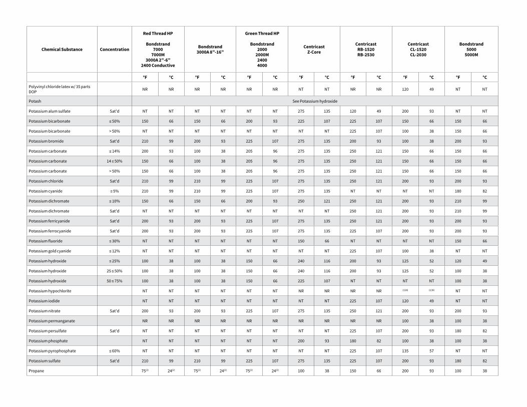
Chemical Substance Concentration
Red Thread HP
Bondstrand7000
7000M3000A 2”-6”
2400 Conductive
Bondstrand3000A 8”-16”
Green Thread HP
Bondstrand2000
2000M24004000
CentricastZ-Core
CentricastRB-1520RB-2530
CentricastCL-1520CL-2030
Bondstrand5000
5000M
°F °C °F °C °F °C °F °C °F °C °F °C °F °C
Polyvinyl chloride latex w/ 35 parts DOP NR NR NR NR NR NR NT NT NR NR 120 49 NT NT
Potash See Potassium hydroxide
Potassium alum sulfate Sat'd NT NT NT NT NT NT 275 135 120 49 200 93 NT NT
Potassium bicarbonate ≤ 50% 150 66 150 66 200 93 225 107 225 107 150 66 150 66
Potassium bicarbonate > 50% NT NT NT NT NT NT NT NT 225 107 100 38 150 66
Potassium bromide Sat'd 210 99 200 93 225 107 275 135 200 93 100 38 200 93
Potassium carbonate ≤ 14% 200 93 100 38 205 96 275 135 250 121 150 66 150 66
Potassium carbonate 14 ≤ 50% 150 66 100 38 205 96 275 135 250 121 150 66 150 66
Potassium carbonate > 50% 150 66 100 38 205 96 275 135 250 121 150 66 150 66
Potassium chloride Sat'd 210 99 210 99 225 107 275 135 250 121 200 93 200 93
Potassium cyanide ≤ 5% 210 99 210 99 225 107 275 135 NT NT NT NT 180 82
Potassium dichromate ≤ 10% 150 66 150 66 200 93 250 121 250 121 200 93 210 99
Potassium dichromate Sat'd NT NT NT NT NT NT NT NT 250 121 200 93 210 99
Potassium ferricyanide Sat'd 200 93 200 93 225 107 275 135 250 121 200 93 200 93
Potassium ferrocyanide Sat'd 200 93 200 93 225 107 275 135 225 107 200 93 200 93
Potassium fluoride ≤ 30% NT NT NT NT NT NT 150 66 NT NT NT NT 150 66
Potassium gold cyanide ≤ 12% NT NT NT NT NT NT NT NT 225 107 100 38 NT NT
Potassium hydroxide ≤ 25% 100 38 100 38 150 66 240 116 200 93 125 52 120 49
Potassium hydroxide 25 ≤ 50% 100 38 100 38 150 66 240 116 200 93 125 52 100 38
Potassium hydroxide 50 ≤ 75% 100 38 100 38 150 66 225 107 NT NT NT NT 100 38
Potassium hypochlorite NT NT NT NT NT NT NR NR NR NR (1)(8) (1)(8) NT NT
Potassium iodide NT NT NT NT NT NT NT NT 225 107 120 49 NT NT
Potassium nitrate Sat'd 200 93 200 93 225 107 275 135 250 121 200 93 200 93
Potassium permanganate NR NR NR NR NR NR NR NR NR NR 100 38 100 38
Potassium persulfate Sat'd NT NT NT NT NT NT NT NT 225 107 200 93 180 82
Potassium phosphate NT NT NT NT NT NT 200 93 180 82 100 38 100 38
Potassium pyrophosphate ≤ 60% NT NT NT NT NT NT NT NT 225 107 135 57 NT NT
Potassium sulfate Sat'd 210 99 210 99 225 107 275 135 225 107 200 93 180 82
Propane 75(2) 24(2) 75(2) 24(2) 75(2) 24(2) 100 38 150 66 200 93 100 38
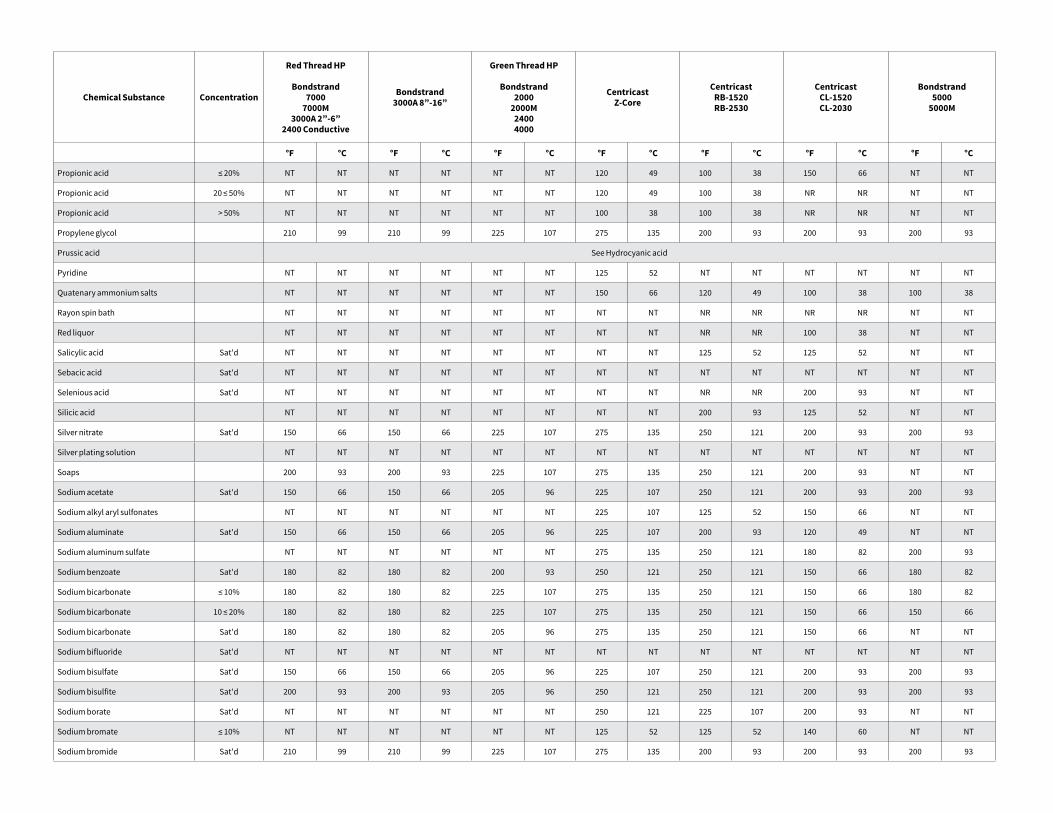
Chemical Substance Concentration
Red Thread HP
Bondstrand7000
7000M3000A 2”-6”
2400 Conductive
Bondstrand3000A 8”-16”
Green Thread HP
Bondstrand2000
2000M24004000
CentricastZ-Core
CentricastRB-1520RB-2530
CentricastCL-1520CL-2030
Bondstrand5000
5000M
°F °C °F °C °F °C °F °C °F °C °F °C °F °C
Propionic acid ≤ 20% NT NT NT NT NT NT 120 49 100 38 150 66 NT NT
Propionic acid 20 ≤ 50% NT NT NT NT NT NT 120 49 100 38 NR NR NT NT
Propionic acid > 50% NT NT NT NT NT NT 100 38 100 38 NR NR NT NT
Propylene glycol 210 99 210 99 225 107 275 135 200 93 200 93 200 93
Prussic acid See Hydrocyanic acid
Pyridine NT NT NT NT NT NT 125 52 NT NT NT NT NT NT
Quatenary ammonium salts NT NT NT NT NT NT 150 66 120 49 100 38 100 38
Rayon spin bath NT NT NT NT NT NT NT NT NR NR NR NR NT NT
Red liquor NT NT NT NT NT NT NT NT NR NR 100 38 NT NT
Salicylic acid Sat'd NT NT NT NT NT NT NT NT 125 52 125 52 NT NT
Sebacic acid Sat'd NT NT NT NT NT NT NT NT NT NT NT NT NT NT
Selenious acid Sat'd NT NT NT NT NT NT NT NT NR NR 200 93 NT NT
Silicic acid NT NT NT NT NT NT NT NT 200 93 125 52 NT NT
Silver nitrate Sat'd 150 66 150 66 225 107 275 135 250 121 200 93 200 93
Silver plating solution NT NT NT NT NT NT NT NT NT NT NT NT NT NT
Soaps 200 93 200 93 225 107 275 135 250 121 200 93 NT NT
Sodium acetate Sat'd 150 66 150 66 205 96 225 107 250 121 200 93 200 93
Sodium alkyl aryl sulfonates NT NT NT NT NT NT 225 107 125 52 150 66 NT NT
Sodium aluminate Sat'd 150 66 150 66 205 96 225 107 200 93 120 49 NT NT
Sodium aluminum sulfate NT NT NT NT NT NT 275 135 250 121 180 82 200 93
Sodium benzoate Sat'd 180 82 180 82 200 93 250 121 250 121 150 66 180 82
Sodium bicarbonate ≤ 10% 180 82 180 82 225 107 275 135 250 121 150 66 180 82
Sodium bicarbonate 10 ≤ 20% 180 82 180 82 225 107 275 135 250 121 150 66 150 66
Sodium bicarbonate Sat'd 180 82 180 82 205 96 275 135 250 121 150 66 NT NT
Sodium bifluoride Sat'd NT NT NT NT NT NT NT NT NT NT NT NT NT NT
Sodium bisulfate Sat'd 150 66 150 66 205 96 225 107 250 121 200 93 200 93
Sodium bisulfite Sat'd 200 93 200 93 205 96 250 121 250 121 200 93 200 93
Sodium borate Sat'd NT NT NT NT NT NT 250 121 225 107 200 93 NT NT
Sodium bromate ≤ 10% NT NT NT NT NT NT 125 52 125 52 140 60 NT NT
Sodium bromide Sat'd 210 99 210 99 225 107 275 135 200 93 200 93 200 93
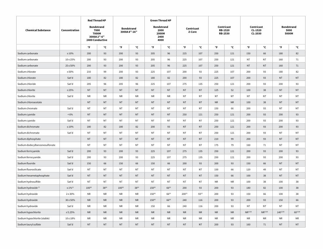
Chemical Substance Concentration
Red Thread HP
Bondstrand7000
7000M3000A 2”-6”
2400 Conductive
Bondstrand3000A 8”-16”
Green Thread HP
Bondstrand2000
2000M24004000
CentricastZ-Core
CentricastRB-1520RB-2530
CentricastCL-1520CL-2030
Bondstrand5000
5000M
°F °C °F °C °F °C °F °C °F °C °F °C °F °C
Sodium carbonate ≤ 10% 200 93 200 93 205 96 225 107 250 121 150 66 180 82
Sodium carbonate 10 ≤ 25% 200 93 200 93 205 96 225 107 250 121 NT NT 160 71
Sodium carbonate 25 ≤ 50% 200 93 200 93 205 96 225 107 250 121 NT NT 160 71
Sodium chlorate ≤ 50% 210 99 200 93 225 107 200 93 225 107 200 93 180 82
Sodium chlorate Sat'd 180 82 180 82 180 82 200 93 225 107 200 93 NT NT
Sodium chloride Sat'd 205 96 205 96 225 107 275 135 250 121 200 93 200 93
Sodium chlorite ≤ 25% NT NT NT NT NT NT NT NT 125 52 100 38 NT NT
Sodium chlorite Sat'd NR NR NR NR NR NR NT NT NT NT NT NT NT NT
Sodium chloroacetate NT NT NT NT NT NT NT NT NR NR 100 38 NT NT
Sodium chromate Sat'd NT NT NT NT NT NT NT NT 150 66 200 93 NT NT
Sodium cyanide < 6% NT NT NT NT NT NT 250 121 250 121 200 93 200 93
Sodium cyanide Sat'd NT NT NT NT NT NT NT NT 250 121 200 93 200 93
Sodium dichromate ≤ 10% 180 82 180 82 200 93 NT NT 250 121 200 93 200 93
Sodium dichromate Sat'd NT NT NT NT NT NT NT NT 250 121 200 93 NT NT
Sodium diphosphate NT NT NT NT NT NT NT NT 210 99 200 93 NT NT
Sodium dodecylbenzenesulfonate NT NT NT NT NT NT NT NT 175 79 160 71 NT NT
Sodium ferricyanide Sat'd 200 93 200 93 225 107 275 135 250 121 200 93 200 93
Sodium ferrocyanide Sat'd 200 93 200 93 225 107 275 135 250 121 200 93 200 93
Sodium fluoride Sat'd 150 66 150 66 150 66 200 93 200 93 150 66 NT NT
Sodium fluorosilicate Sat'd NT NT NT NT NT NT NT NT 150 66 120 49 NT NT
Sodium hexametaphosphate Sat'd NT NT NT NT NT NT NT NT 150 66 100 38 NT NT
Sodium hydrosulfide Sat'd NT NT NT NT NT NT NT NT NR NR 100 38 100 38
Sodium hydroxide (7) ≤ 1%(1) 100(6) 38(6) 100(6) 38(6) 150(6) 66(6) 200 93 200 93 180 82 100 38
Sodium hydroxide 2 ≤ 30% NR NR NR NR 150(6) 66(6) 200(2) 93(2) 200 93 150 66 100 38
Sodium hydroxide 30 ≤ 50% NR NR NR NR 150(6) 66(6) 240 116 200 93 200 93 150 66
Sodium hydroxide Sat'd NR NR NR NR 150 66 240 116 200 93 NT NT NT NT
Sodium hypochlorite ≤ 5.25% NR NR NR NR NR NR NR NR NR NR NR(1)(8) NR(1)(8) 140(1)(8) 60(1)(8)
Sodium hypochlorite (stable) 10 ≤ 18% NR NR NR NR NR NR NR NR NR NR NR NR NR NR
Sodium lauryl sulfate Sat'd NT NT NT NT NT NT NT NT 200 93 160 71 NT NT
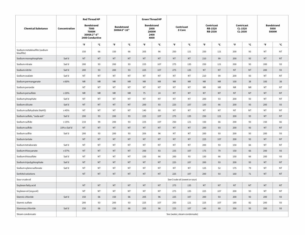
Chemical Substance Concentration
Red Thread HP
Bondstrand7000
7000M3000A 2”-6”
2400 Conductive
Bondstrand3000A 8”-16”
Green Thread HP
Bondstrand2000
2000M24004000
CentricastZ-Core
CentricastRB-1520RB-2530
CentricastCL-1520CL-2030
Bondstrand5000
5000M
°F °C °F °C °F °C °F °C °F °C °F °C °F °C
Sodium metabisulfite (sodium bisulfite) 150 66 150 66 205 96 250 121 250 121 200 93 NT NT
Sodium monophosphate Sat'd NT NT NT NT NT NT NT NT 210 99 200 93 NT NT
Sodium nitrate Sat'd 200 93 200 93 225 107 275 135 250 121 200 93 200 93
Sodium nitrite Sat'd 200 93 200 93 225 107 275 135 NT NT NT NT 200 93
Sodium oxalate Sat'd NT NT NT NT NT NT NT NT 210 99 200 93 NT NT
Sodium permanganate ≤ 60% NR NR NR NR NR NR NR NR NR NR 100 38 100 38
Sodium peroxide NT NT NT NT NT NT NT NT NR NR NR NR NT NT
Sodium persulfate ≤ 20% NR NR NR NR 75 24 NT NT NT NT NT NT NT NT
Sodium phosphate Sat'd NT NT NT NT NT NT NT NT 200 93 200 93 NT NT
Sodium silicate Sat'd NT NT NT NT 200 93 225 107 150 66 200 93 200 93
Sodium sulfahydrate (NaHS) ≤ 45% NT NT NT NT 140 60 NT NT NT NT NT NT NT NT
Sodium sulfate, "soda ash" Sat'd 200 93 200 93 225 107 275 135 250 121 200 93 NT NT
Sodium sulfide ≤ 15% 210 99 200 93 225 107 250 121 150 66 200 93 150 66
Sodium sulfide 15% ≤ Sat'd NT NT NT NT NT NT NT NT 200 93 200 93 NT NT
Sodium sulfite Sat'd 200 93 200 93 205 96 NT NT 200 93 200 93 200 93
Sodium tartate NT NT NT NT NT NT NT NT 225 107 200 93 NT NT
Sodium tetraborate Sat'd NT NT NT NT NT NT NT NT 200 93 150 66 NT NT
Sodium thiocyanate ≤ 57% NT NT NT NT 200 93 225 107 175 79 150 66 200 93
Sodium thiosulfate Sat'd NT NT NT NT 150 66 200 93 150 66 150 66 200 93
Sodium tripolyphosphate Sat'd NT NT NT NT NT NT 225 107 200 93 200 93 NT NT
Sodium xylene sulfonate Sat'd NT NT NT NT NT NT NT NT 125 52 175 79 NT NT
Sorbitol solutions NT NT NT NT NT NT 225 107 200 93 160 71 NT NT
Sour crude oil See Crude oil (sweet or sour)
Soybean fatty acid NT NT NT NT NT NT 275 135 NT NT NT NT NT NT
Soybean oil (soya oil) NT NT NT NT NT NT 275 135 225 107 200 93 NT NT
Stannic chloride Sat'd 150 66 150 66 205 96 225 107 200 93 200 93 200 93
Stannic sulfate 200 93 200 93 225 107 250 121 225 107 180 82 200 93
Stannous chloride Sat'd 150 66 150 66 205 96 225 107 140 60 200 93 200 93
Steam condensate See (water, steam condensate)
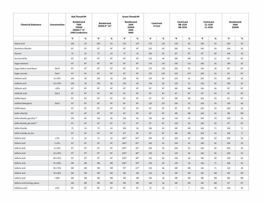
Chemical Substance Concentration
Red Thread HP
Bondstrand7000
7000M3000A 2”-6”
2400 Conductive
Bondstrand3000A 8”-16”
Green Thread HP
Bondstrand2000
2000M24004000
CentricastZ-Core
CentricastRB-1520RB-2530
CentricastCL-1520CL-2030
Bondstrand5000
5000M
°F °C °F °C °F °C °F °C °F °C °F °C °F °C
Stearic acid 200 93 200 93 225 107 275 135 150 66 200 93 200 93
Strontium chloride NT NT NT NT NT NT 225 107 200 93 200 93 200 93
Styrene 75 24 75 24 75 24 185 85 NT NT NT NT 100 38
Succinonitrile NT NT NT NT NT NT 120 49 NR NR 70 21 NT NT
Sugar solutions NT NT NT NT NT NT 275 135 250 121 180 82 180 82
Sugar, beet or cane liquor Sat'd NT NT NT NT NT NT 275 135 200 93 100 38 NT NT
Sugar, sucrose Sat'd NT NT NT NT NT NT 275 135 225 107 200 93 NT NT
Sulfamic acid 0 ≤ 10% 100 38 100 38 150 66 150 66 125 52 200 93 180 82
Sulfamic acid 10 ≤ 25% 100 38 100 38 150 66 150 66 125 52 150 66 180 82
Sulfamic acid > 25% NT NT NT NT NT NT NT NT NR NR 150 66 NT NT
Sulfanilic acid Sat'd NT NT NT NT NT NT NT NT NT NT NT NT NT NT
Sulfate liquor NT NT NT NT NT NT NT NT NR NR 200 93 NT NT
Sulfated detergents Sat'd NT NT NT NT NT NT 225 107 200 93 200 93 150 66
Sulfite liquor NT NT NT NT NT NT NT NT NT NT 200 93 200 93
Sulfur chloride NT NT NT NT NT NT NT NT NR NR 200 93 NR NR
Sulfur dioxide, gas (dry) (3) 150 66 150 66 150 66 150 66 150 66 200 93 200 93
Sulfur dioxide, gas (wet) (3) NT NT NT NT NT NT NT NT 150 66 200 93 NT NT
Sulfur trioxide 75 24 75 24 100 38 180 82 NR NR 160 71 160 71
Sulfur trioxide, air, dry NT NT NT NT NT NT NT NT NR NR 200 93 160 71
Sulfuric acid ≤ 2% 75 24 75 24 180(6) 82(6) 200 93 200 93 180 82 200 93
Sulfuric acid 2 ≤ 5% NT NT NT NT 180(6) 82(6) 200 93 200 93 180 82 200 93
Sulfuric acid 5 ≤ 10% NT NT NT NT 100(6) 38(6) 200 93 200 93 180 82 200 93
Sulfuric acid 10 ≤ 20% NT NT NT NT 100(6) 38(6) 150 66 150 66 180 82 200 93
Sulfuric acid 20 ≤ 25% NT NT NT NT 100(6) 38(6) 150 66 100 38 180 82 180 82
Sulfuric acid 25 ≤ 50% NR NR NR NR 100(6) 38(6) 150 66 100 38 160 71 180 82
Sulfuric acid 50 ≤ 70% NR NR NR NR 70(6) 21(6) 150 66 NR NR 160 71 120 49
Sulfuric acid 70 ≤ 98% NR NR NR NR NR NR 120 49 NR NR NR NR NR NR
Sulfuric acid > 98% NR NR NR NR NR NR 100 38 NR NR NR NR NR NR
Sulfuric acid, fuming, oleum NR NR NR NR NR NR 100 38 NR NR NR NR NT NT
Sulfurous acid ≤ 6% NT NT NT NT NT NT 75 24 (1) (1) 120 49 100 38
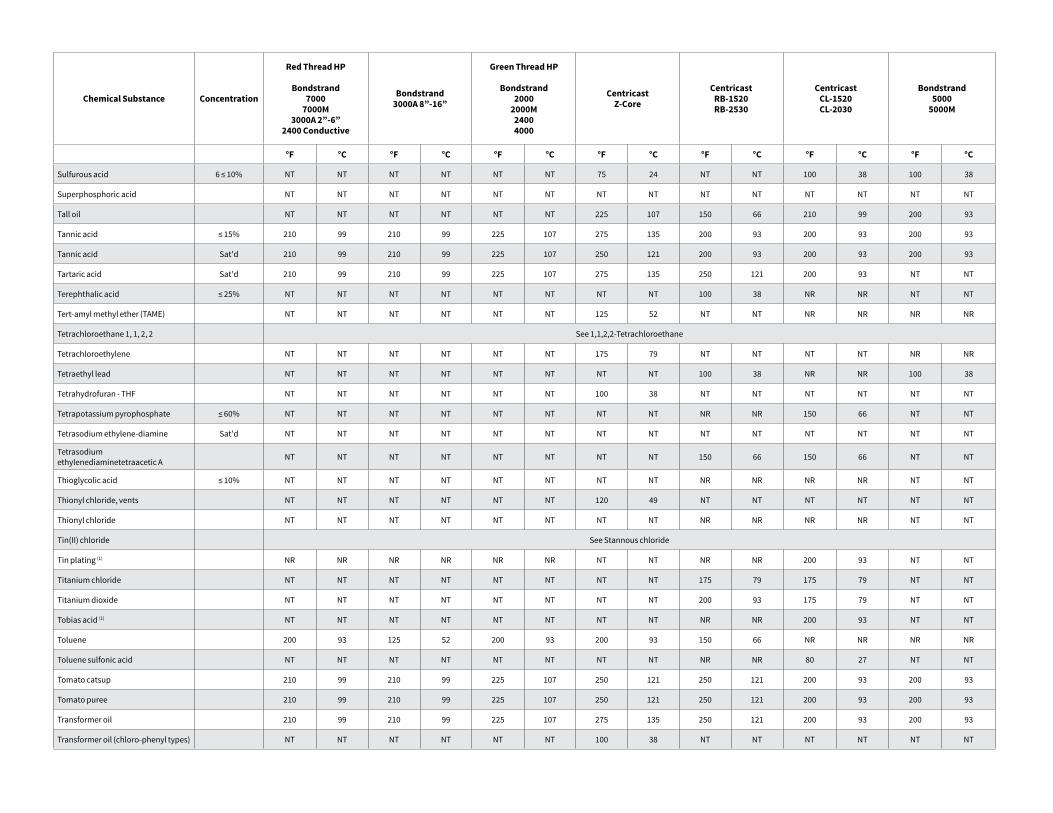
Chemical Substance Concentration
Red Thread HP
Bondstrand7000
7000M3000A 2”-6”
2400 Conductive
Bondstrand3000A 8”-16”
Green Thread HP
Bondstrand2000
2000M24004000
CentricastZ-Core
CentricastRB-1520RB-2530
CentricastCL-1520CL-2030
Bondstrand5000
5000M
°F °C °F °C °F °C °F °C °F °C °F °C °F °C
Sulfurous acid 6 ≤ 10% NT NT NT NT NT NT 75 24 NT NT 100 38 100 38
Superphosphoric acid NT NT NT NT NT NT NT NT NT NT NT NT NT NT
Tall oil NT NT NT NT NT NT 225 107 150 66 210 99 200 93
Tannic acid ≤ 15% 210 99 210 99 225 107 275 135 200 93 200 93 200 93
Tannic acid Sat'd 210 99 210 99 225 107 250 121 200 93 200 93 200 93
Tartaric acid Sat'd 210 99 210 99 225 107 275 135 250 121 200 93 NT NT
Terephthalic acid ≤ 25% NT NT NT NT NT NT NT NT 100 38 NR NR NT NT
Tert-amyl methyl ether (TAME) NT NT NT NT NT NT 125 52 NT NT NR NR NR NR
Tetrachloroethane 1, 1, 2, 2 See 1,1,2,2-Tetrachloroethane
Tetrachloroethylene NT NT NT NT NT NT 175 79 NT NT NT NT NR NR
Tetraethyl lead NT NT NT NT NT NT NT NT 100 38 NR NR 100 38
Tetrahydrofuran - THF NT NT NT NT NT NT 100 38 NT NT NT NT NT NT
Tetrapotassium pyrophosphate ≤ 60% NT NT NT NT NT NT NT NT NR NR 150 66 NT NT
Tetrasodium ethylene-diamine Sat'd NT NT NT NT NT NT NT NT NT NT NT NT NT NT
Tetrasodium ethylenediaminetetraacetic A NT NT NT NT NT NT NT NT 150 66 150 66 NT NT
Thioglycolic acid ≤ 10% NT NT NT NT NT NT NT NT NR NR NR NR NT NT
Thionyl chloride, vents NT NT NT NT NT NT 120 49 NT NT NT NT NT NT
Thionyl chloride NT NT NT NT NT NT NT NT NR NR NR NR NT NT
Tin(II) chloride See Stannous chloride
Tin plating (1) NR NR NR NR NR NR NT NT NR NR 200 93 NT NT
Titanium chloride NT NT NT NT NT NT NT NT 175 79 175 79 NT NT
Titanium dioxide NT NT NT NT NT NT NT NT 200 93 175 79 NT NT
Tobias acid (1) NT NT NT NT NT NT NT NT NR NR 200 93 NT NT
Toluene 200 93 125 52 200 93 200 93 150 66 NR NR NR NR
Toluene sulfonic acid NT NT NT NT NT NT NT NT NR NR 80 27 NT NT
Tomato catsup 210 99 210 99 225 107 250 121 250 121 200 93 200 93
Tomato puree 210 99 210 99 225 107 250 121 250 121 200 93 200 93
Transformer oil 210 99 210 99 225 107 275 135 250 121 200 93 200 93
Transformer oil (chloro-phenyl types) NT NT NT NT NT NT 100 38 NT NT NT NT NT NT
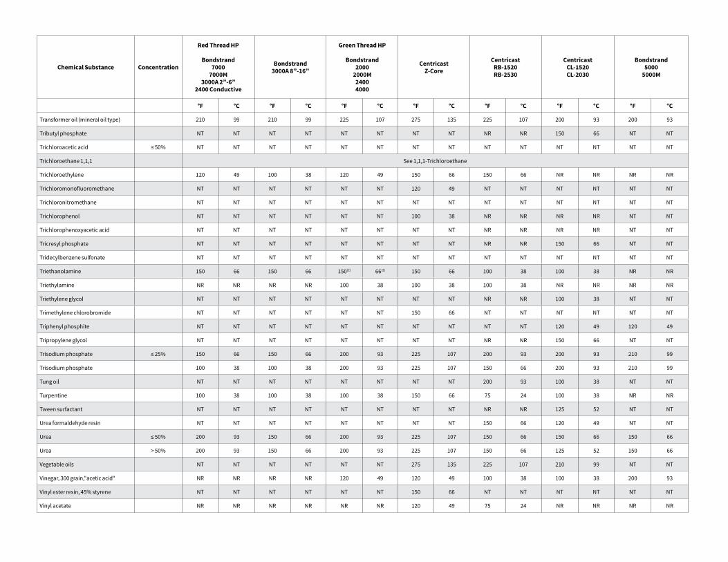
Chemical Substance Concentration
Red Thread HP
Bondstrand7000
7000M3000A 2”-6”
2400 Conductive
Bondstrand3000A 8”-16”
Green Thread HP
Bondstrand2000
2000M24004000
CentricastZ-Core
CentricastRB-1520RB-2530
CentricastCL-1520CL-2030
Bondstrand5000
5000M
°F °C °F °C °F °C °F °C °F °C °F °C °F °C
Transformer oil (mineral oil type) 210 99 210 99 225 107 275 135 225 107 200 93 200 93
Tributyl phosphate NT NT NT NT NT NT NT NT NR NR 150 66 NT NT
Trichloroacetic acid ≤ 50% NT NT NT NT NT NT NT NT NT NT NT NT NT NT
Trichloroethane 1,1,1 See 1,1,1-Trichloroethane
Trichloroethylene 120 49 100 38 120 49 150 66 150 66 NR NR NR NR
Trichloromonofluoromethane NT NT NT NT NT NT 120 49 NT NT NT NT NT NT
Trichloronitromethane NT NT NT NT NT NT NT NT NT NT NT NT NT NT
Trichlorophenol NT NT NT NT NT NT 100 38 NR NR NR NR NT NT
Trichlorophenoxyacetic acid NT NT NT NT NT NT NT NT NR NR NR NR NT NT
Tricresyl phosphate NT NT NT NT NT NT NT NT NR NR 150 66 NT NT
Tridecylbenzene sulfonate NT NT NT NT NT NT NT NT NT NT NT NT NT NT
Triethanolamine 150 66 150 66 150(2) 66(2) 150 66 100 38 100 38 NR NR
Triethylamine NR NR NR NR 100 38 100 38 100 38 NR NR NR NR
Triethylene glycol NT NT NT NT NT NT NT NT NR NR 100 38 NT NT
Trimethylene chlorobromide NT NT NT NT NT NT 150 66 NT NT NT NT NT NT
Triphenyl phosphite NT NT NT NT NT NT NT NT NT NT 120 49 120 49
Tripropylene glycol NT NT NT NT NT NT NT NT NR NR 150 66 NT NT
Trisodium phosphate ≤ 25% 150 66 150 66 200 93 225 107 200 93 200 93 210 99
Trisodium phosphate 100 38 100 38 200 93 225 107 150 66 200 93 210 99
Tung oil NT NT NT NT NT NT NT NT 200 93 100 38 NT NT
Turpentine 100 38 100 38 100 38 150 66 75 24 100 38 NR NR
Tween surfactant NT NT NT NT NT NT NT NT NR NR 125 52 NT NT
Urea formaldehyde resin NT NT NT NT NT NT NT NT 150 66 120 49 NT NT
Urea ≤ 50% 200 93 150 66 200 93 225 107 150 66 150 66 150 66
Urea > 50% 200 93 150 66 200 93 225 107 150 66 125 52 150 66
Vegetable oils NT NT NT NT NT NT 275 135 225 107 210 99 NT NT
Vinegar, 300 grain,"acetic acid" NR NR NR NR 120 49 120 49 100 38 100 38 200 93
Vinyl ester resin, 45% styrene NT NT NT NT NT NT 150 66 NT NT NT NT NT NT
Vinyl acetate NR NR NR NR NR NR 120 49 75 24 NR NR NR NR
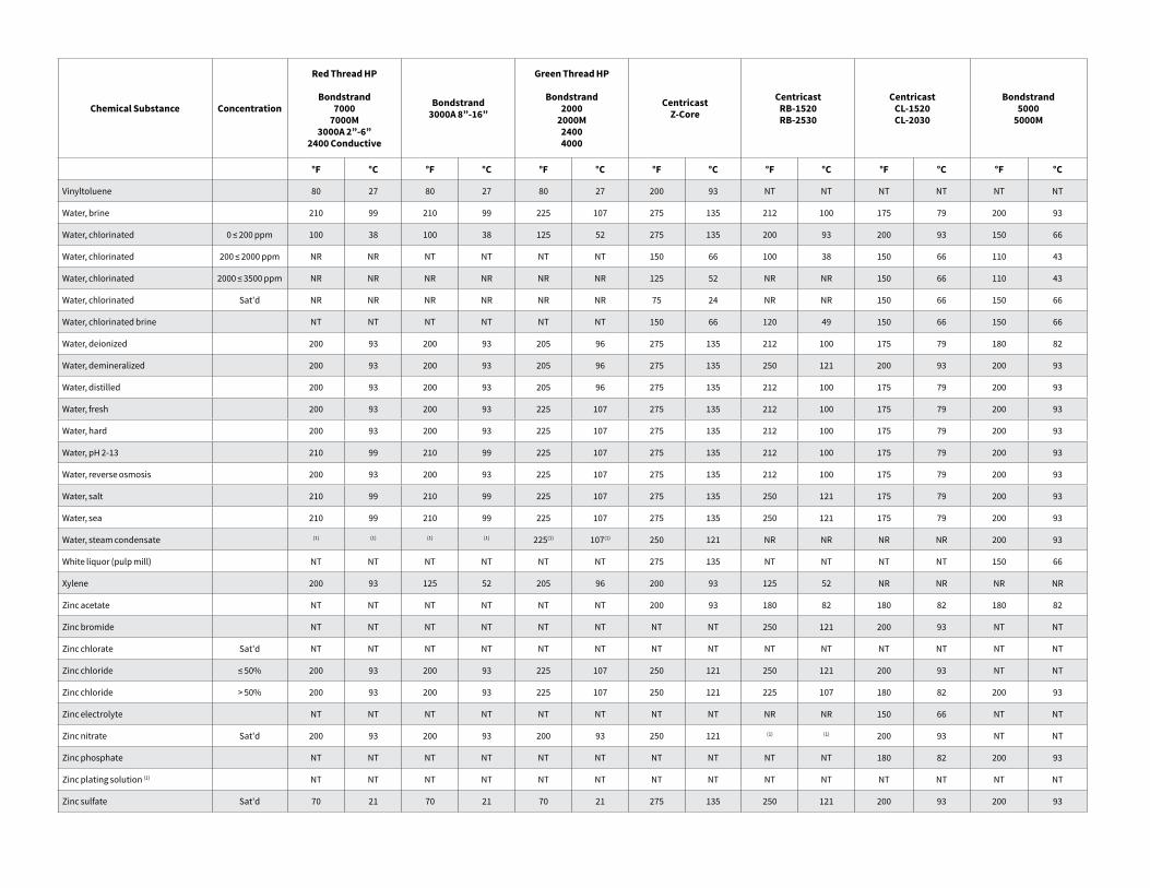
Chemical Substance Concentration
Red Thread HP
Bondstrand7000
7000M3000A 2”-6”
2400 Conductive
Bondstrand3000A 8”-16”
Green Thread HP
Bondstrand2000
2000M24004000
CentricastZ-Core
CentricastRB-1520RB-2530
CentricastCL-1520CL-2030
Bondstrand5000
5000M
°F °C °F °C °F °C °F °C °F °C °F °C °F °C
Vinyltoluene 80 27 80 27 80 27 200 93 NT NT NT NT NT NT
Water, brine 210 99 210 99 225 107 275 135 212 100 175 79 200 93
Water, chlorinated 0 ≤ 200 ppm 100 38 100 38 125 52 275 135 200 93 200 93 150 66
Water, chlorinated 200 ≤ 2000 ppm NR NR NT NT NT NT 150 66 100 38 150 66 110 43
Water, chlorinated 2000 ≤ 3500 ppm NR NR NR NR NR NR 125 52 NR NR 150 66 110 43
Water, chlorinated Sat'd NR NR NR NR NR NR 75 24 NR NR 150 66 150 66
Water, chlorinated brine NT NT NT NT NT NT 150 66 120 49 150 66 150 66
Water, deionized 200 93 200 93 205 96 275 135 212 100 175 79 180 82
Water, demineralized 200 93 200 93 205 96 275 135 250 121 200 93 200 93
Water, distilled 200 93 200 93 205 96 275 135 212 100 175 79 200 93
Water, fresh 200 93 200 93 225 107 275 135 212 100 175 79 200 93
Water, hard 200 93 200 93 225 107 275 135 212 100 175 79 200 93
Water, pH 2-13 210 99 210 99 225 107 275 135 212 100 175 79 200 93
Water, reverse osmosis 200 93 200 93 225 107 275 135 212 100 175 79 200 93
Water, salt 210 99 210 99 225 107 275 135 250 121 175 79 200 93
Water, sea 210 99 210 99 225 107 275 135 250 121 175 79 200 93
Water, steam condensate (1) (1) (1) (1) 225(1) 107(1) 250 121 NR NR NR NR 200 93
White liquor (pulp mill) NT NT NT NT NT NT 275 135 NT NT NT NT 150 66
Xylene 200 93 125 52 205 96 200 93 125 52 NR NR NR NR
Zinc acetate NT NT NT NT NT NT 200 93 180 82 180 82 180 82
Zinc bromide NT NT NT NT NT NT NT NT 250 121 200 93 NT NT
Zinc chlorate Sat'd NT NT NT NT NT NT NT NT NT NT NT NT NT NT
Zinc chloride ≤ 50% 200 93 200 93 225 107 250 121 250 121 200 93 NT NT
Zinc chloride > 50% 200 93 200 93 225 107 250 121 225 107 180 82 200 93
Zinc electrolyte NT NT NT NT NT NT NT NT NR NR 150 66 NT NT
Zinc nitrate Sat'd 200 93 200 93 200 93 250 121 (1) (1) 200 93 NT NT
Zinc phosphate NT NT NT NT NT NT NT NT NT NT 180 82 200 93
Zinc plating solution (1) NT NT NT NT NT NT NT NT NT NT NT NT NT NT
Zinc sulfate Sat'd 70 21 70 21 70 21 275 135 250 121 200 93 200 93
[email protected] nov.com/fgs
Fiber Glass Systems17115 San Pedro Avenue, Ste 200San Antonio, Texas 78232 USAPhone: 210 477 7500Fax: 210 477 7560
National Oilwell Varco has produced this brochure for general information only, and it is not intended for design purposes. Although every effort has been made to maintain the accuracy and reliability of its contents, National Oilwell Varco in no way assumes responsibility for liability for any loss, damage or injury resulting from the use of information and data herein nor is any warranty expressed or implied. Always cross-reference the bulletin date with the most current version listed at the web site noted in this literature.
© 2016 National Oilwell Varco All Rights ReservedENG1030ENG July 2016
Footnotes
1. Contact NOV Fiber Glass Systems Application Engineering for further review and recommendations.
2. Based on limited service and test data, could be serviceable at higher temperatures. Contact NOV Fiber Glass Systems Application Engineering for consideration of higher temperature service.
3. Avoid service conditions where dry gasses such as chlorine or sulfur dioxide may condense to liquids inside fiberglass piping systems. Furthermore, liquid chlorine and sulfur dioxide should not be confused with solutions mixed with water.
4. Pneumatic conveyance of dry chemicals is not recommended. Contact NOV Fiber Glass Systems Application Engineering for further review.
5. These recommendations represent chemical compound saturation concentrations at atmospheric pressure. Higher concentrations or super saturation caused by higher pressure in a closed system may increase corrosion. Contact NOV Fiber Glass Systems Application Engineering for further review.
6. All grooved adapters, Bondstrand Key-Lock connections and 8” and larger Green Thread reducer bushings are not recommended for this service. Furthermore, exposed glass fibers at machined surfaces and/or threads must be covered with a protective coating of adhesive during installation. An adhesive may be used in place of thread locking compound in these services.
7. For very low caustic and acidic concentrations in water use the recommendations under “Water, pH 2-13”.
8. Requires the use of RP-106 adhesive.
9. Not recommended for service temperatures above the chemical compounds boiling point at the operating pressure.
Pipe Installation Handbook
Red Thread™ HP,Green Thread™ HP, and Silver Streak™
Matched TaperedBell & Spigot Joints
nov.com/fgs
O I L & G A S C H E M I C A L& I N D U S T R I A L
O F F S H O R EM A R I N E M I N I N GF U E LH A N D L I N G

2
3
This fabrication manual is offered to assist you in the proper fabrication and installation procedures when assembling your NOV Fiber Glass Systems piping system.
If you do not find the answer to your questions in the manual, feel free to contact us or your local distributor.
Our products must be installed and used in accordance with sound, proven practice and common sense.
The information supplied by NOV Fiber Glass Systems in its literature must be considered as an expression of guidelines based on field experience rather than a warranty for which the company assumes responsibility. We offer a limited warranty of its products in the Terms and Conditions of Sale. The information contained in the literature and catalogs furnished cannot ensure, of itself, a successful installation and is offered to customers subject to these limitations and explanations.
Installing fiberglass pipe is easier than installing carbon steel, stainless steel, and lined steel due to its light weight. Learning the proper methods to prepare and make-up bell & spigot joints can help ensure the reliability and long-term performance of your piping system.
We offer the TQI Plus (ASME B31.3) Fabrication and Assembly certification program. Qualified Field Service Representatives train fabrication and assembly crews, conduct and supervise fabrication work, and inspect work in progress.
For complete information concerning these training seminars, contact your local distributor or NOV Fiber Glass Systems.
Matched Tapered Bell & Spigot Joints
4
SAFETYThe safety alert symbol indicates an important safety message. When you see this symbol, be alert to the possiblity of personal injury
CAUTIONAs this pipe may carry hazardous material and/or operate at a hazardous pressure level, you must follow instructions in this manual to avoid serious personal injury or property damage. In any event, improper installation can cause injury or damage. In addition, installers should read and follow all cautions and warnings on adhesive kits, heat packs, propane torches, etc. to avoid personal injury. Also, observe general safety practices with all saws, tools, etc. to avoid personal injury. Wear protective clothing when necessary. Make sure work surfaces are clean and stable and that work areas are properly ventilated.
Table of Contents
Section 1 — Pipe ProductsSection 2 — Site ConsiderationsSection 3 — General Installation InstructionsSection 4 — Fabrication of Red Thread HP, Green Thread HP and Silver Streak
Pipe and FittingsSection 5 — Installation Considerations / HydrotestingSection 6 — Helpful Information / Conversions
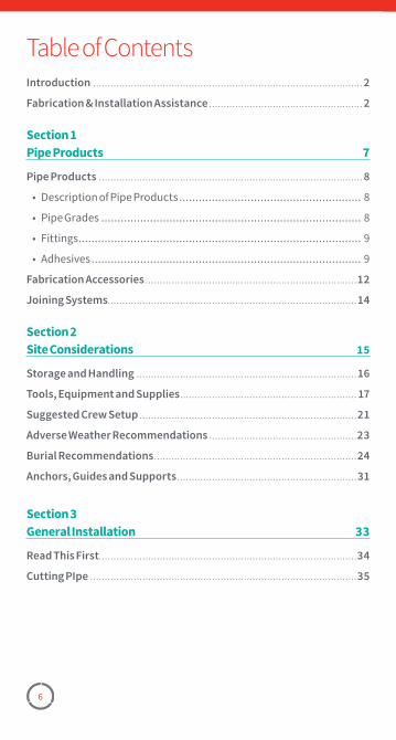
6
Table of ContentsIntroduction ............................................................................................. 2
Fabrication & Installation Assistance ..................................................... 2
Section 1Pipe Products 7
Pipe Products ........................................................................................... 8
• Description of Pipe Products �������������������������������������������������������� 8
• Pipe Grades �������������������������������������������������������������������������������� 8
• Fittings ��������������������������������������������������������������������������������������� 9
• Adhesives ����������������������������������������������������������������������������������� 9
Fabrication Accessories .........................................................................12
Joining Systems ......................................................................................14
Section 2Site Considerations 15
Storage and Handling ............................................................................16
Tools, Equipment and Supplies ............................................................. 17
Suggested Crew Setup ...........................................................................21
Adverse Weather Recommendations ...................................................23
Burial Recommendations ......................................................................24
Anchors, Guides and Supports ..............................................................31
Section 3General Installation 33
Read This First .........................................................................................34
Cutting PIpe ............................................................................................35
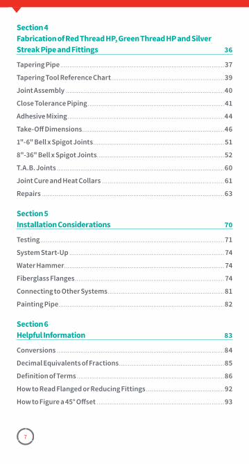
7
Section 4Fabrication of Red Thread HP, Green Thread HP and Silver Streak Pipe and Fittings 36
Tapering Pipe ..........................................................................................37
Tapering Tool Reference Chart ..............................................................39
Joint Assembly .......................................................................................40
Close Tolerance Piping ...........................................................................41
Adhesive Mixing ......................................................................................44
Take-Off Dimensions ..............................................................................46
1"-6" Bell x Spigot Joints ........................................................................51
8"-36" Bell x Spigot Joints ......................................................................52
T.A.B. Joints ............................................................................................60
Joint Cure and Heat Collars ...................................................................61
Repairs ....................................................................................................63
Section 5Installation Considerations 70
Testing .....................................................................................................71
System Start-Up ..................................................................................... 74
Water Hammer ........................................................................................ 74
Fiberglass Flanges .................................................................................. 74
Connecting to Other Systems ................................................................81
Painting Pipe ...........................................................................................82
Section 6Helpful Information 83
Conversions ............................................................................................84
Decimal Equivalents of Fractions ..........................................................85
Definition of Terms .................................................................................86
How to Read Flanged or Reducing Fittings ...........................................92
How to Figure a 45° Offset ......................................................................93
Section 1PipeProducts
Pipe GradesFittingsAdhesivesFabrication AccessoriesJoining Systems
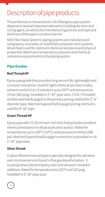
9
Description of pipe productsThe performance characteristics of a fiberglass pipe system depend on several important elements including the resin and curing agent, as well as the manufacturing process and type and thickness of the pipe’s corrosion barrier.
NOV Fiber Glass Systems' piping systems are manufactured using epoxy, vinyl ester, or isophthalic polyester resin systems. All are heat cured for optimum chemical resistance and physical properties. Match your temperature, pressure and chemical resistance requirements to the piping system.
Pipe Grades
Red Thread HP
Epoxy pipe grade that provides long service life, lightweight and corrosion resistance. Used for light chemical services in salts, solvents and pH 2 to 13 solutions up to 210°F and pressures to 25 bar (362 psig). Available in 2"-42" pipe sizes. T.A.B. (Threaded and Bonded bell & spigot) is the primary joining method for 2"-6" diameter pipe. Matched tapered bell & spigot joining method is used for 8"-42" pipe.
Green Thread HP
Epoxy pipe with 15-20 mil resin-rich liner that provides excellent chemical resistance to dilute acids and caustics. Rated for temperatures up to 230°F (110°C) and pressures to 40 bar (580 psi). Matched tapered bell & spigot connection is provided on all 1"-42" pipe sizes.
Silver Streak
Custom filament wound pipe is specially designed for abrasive and corrosive services found in flue gas desulfurization. It is a proprietary blend of epoxy resin and abrasion-resistant additives. Rated for temperatures to 225°F and 225 psig. Available in 2"-24" pipe sizes.
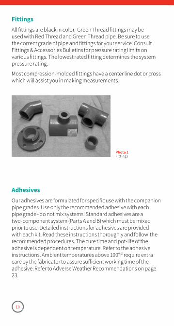
10
FittingsAll fittings are black in color. Green Thread fittings may be used with Red Thread and Green Thread pipe. Be sure to use the correct grade of pipe and fittings for your service. Consult Fittings & Accessories Bulletins for pressure rating limits on various fittings. The lowest rated fitting determines the system pressure rating.
Most compression-molded fittings have a center line dot or cross which will assist you in making measurements.
Photo 1Fittings
AdhesivesOur adhesives are formulated for specific use with the companion pipe grades. Use only the recommended adhesive with each pipe grade - do not mix systems! Standard adhesives are a two-component system (Parts A and B) which must be mixed prior to use. Detailed instructions for adhesives are provided with each kit. Read these instructions thoroughly and follow the recommended procedures. The cure time and pot-life of the adhesive is dependent on temperature. Refer to the adhesive instructions. Ambient temperatures above 100°F require extra care by the fabricator to assure sufficient working time of the adhesive. Refer to Adverse Weather Recommendations on page 23.
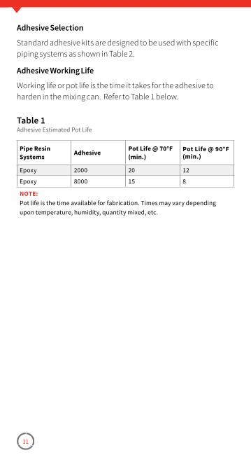
11
Adhesive Selection
Standard adhesive kits are designed to be used with specific piping systems as shown in Table 2.
Adhesive Working Life
Working life or pot life is the time it takes for the adhesive to harden in the mixing can. Refer to Table 1 below.
Pipe Resin Systems Adhesive Pot Life @ 70°F
(min.)Pot Life @ 90°F (min.)
Epoxy 2000 20 12
Epoxy 8000 15 8
NOTE:Pot life is the time available for fabrication� Times may vary depending upon temperature, humidity, quantity mixed, etc�
Table 1Adhesive Estimated Pot Life
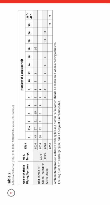
12
Use
wit
h th
ese
Pipi
ng S
yste
ms
Max
. Te
mp.
Kit #
Num
ber o
f Bon
ds p
er K
it
111
/22
34
68
1012
1416
1820
2430
36”-
42”
Red
Thre
ad H
PGr
een
Thre
ad H
PSi
lver
Str
eak
230°
F (1
10°C
)
8014
4527
2115
85
32
11⁄
2
8024
2012
96
42
1
8069
84
32
21
1⁄
21⁄
2
8036
1⁄2
1⁄2
Ambi
ent t
empe
ratu
re, a
dhes
ive
wor
king
life
and
num
ber o
f cre
wm
en s
houl
d be
con
side
red
whe
n or
derin
g ad
hesi
ve�
For l
ong
runs
of 8
” and
larg
er p
ipe,
one
kit
per j
oint
is re
com
men
ded
Tabl
e 2
Adhe
sive
Sel
ectio
n (r
efer
to B
ulle
tin A
DH40
00 fo
r mor
e in
form
atio
n)
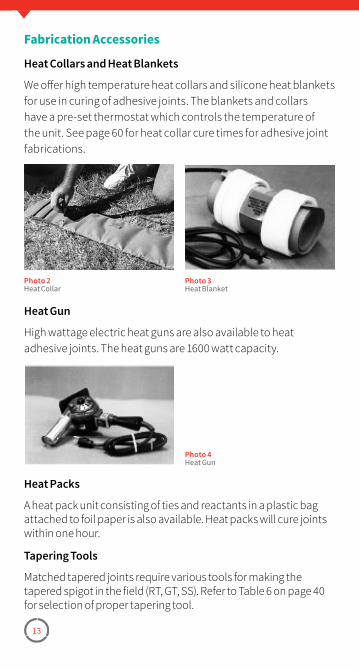
13
Fabrication Accessories
Heat Collars and Heat Blankets
We offer high temperature heat collars and silicone heat blankets for use in curing of adhesive joints. The blankets and collars have a pre-set thermostat which controls the temperature of the unit. See page 60 for heat collar cure times for adhesive joint fabrications.
Photo 2Heat Collar
Photo 3Heat Blanket
Heat Gun
High wattage electric heat guns are also available to heat adhesive joints. The heat guns are 1600 watt capacity.
Photo 4Heat Gun
Heat Packs
A heat pack unit consisting of ties and reactants in a plastic bag attached to foil paper is also available. Heat packs will cure joints within one hour.
Tapering Tools
Matched tapered joints require various tools for making the tapered spigot in the field (RT, GT, SS). Refer to Table 6 on page 40 for selection of proper tapering tool.
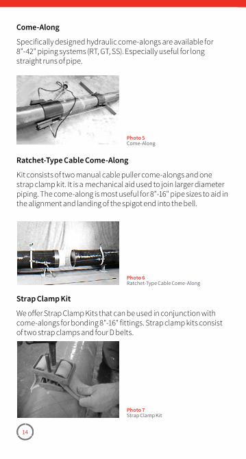
14
Come-Along
Specifically designed hydraulic come-alongs are available for 8"-42" piping systems (RT, GT, SS). Especially useful for long straight runs of pipe.
Ratchet-Type Cable Come-Along
Kit consists of two manual cable puller come-alongs and one strap clamp kit. It is a mechanical aid used to join larger diameter piping. The come-along is most useful for 8"-16" pipe sizes to aid in the alignment and landing of the spigot end into the bell.
Photo 5Come-Along
Photo 6Ratchet-Type Cable Come-Along
Strap Clamp Kit
We offer Strap Clamp Kits that can be used in conjunction with come-alongs for bonding 8"-16" fittings. Strap clamp kits consist of two strap clamps and four D belts.
Photo 7Strap Clamp Kit
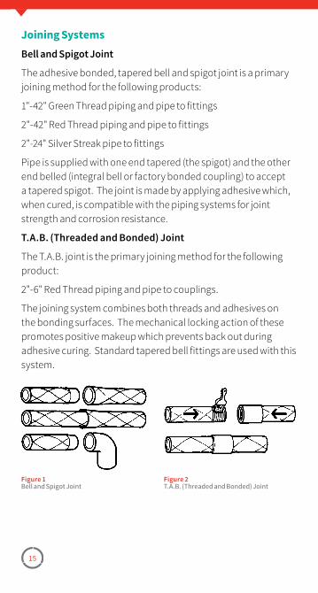
15
Joining SystemsBell and Spigot Joint
The adhesive bonded, tapered bell and spigot joint is a primary joining method for the following products:
1"-42" Green Thread piping and pipe to fittings
2"-42" Red Thread piping and pipe to fittings
2"-24" Silver Streak pipe to fittings
Pipe is supplied with one end tapered (the spigot) and the other end belled (integral bell or factory bonded coupling) to accept a tapered spigot. The joint is made by applying adhesive which, when cured, is compatible with the piping systems for joint strength and corrosion resistance.
T.A.B. (Threaded and Bonded) Joint
The T.A.B. joint is the primary joining method for the following product:
2"-6" Red Thread piping and pipe to couplings.
The joining system combines both threads and adhesives on the bonding surfaces. The mechanical locking action of these promotes positive makeup which prevents back out during adhesive curing. Standard tapered bell fittings are used with this system.
Figure 1Bell and Spigot Joint
Figure 2T�A�B� (Threaded and Bonded) Joint
Section 2Site Considerations
Storage and HandlingTools, Equipment and SuppliesSuggested Crew Setup and AssemblyRecommendations for Fabrication in Adverse Weather ConditionsBuried RecommendationsAnchors, Guides and Supports
17
Storage and Handling
Pipe and Fittings
Fiberglass reinforced pipe, fittings, and adhesives require special storage and handling. Care should be taken in transporting, unloading, handling, and storing products to prevent impact and other damage.
When transporting pipe, the spacers under and between the pipe joints must be of sufficient width to avoid point loading, which could produce cracking or buckling damage. A minimum of four spacers should be used for supporting 14" and larger 40’ long pipe joints. More spacers should be used for smaller pipe or if pipe is stacked over eight feet high.
Due to its light weight, lifting equipment is usually not required for 1" - 6" pipe. When lifting equipment is required, use nylon slings or chokers. Do not allow chains or cables to contact the pipe during transport or handling. If a pipe or fabrication is more than 20 feet long, use at least two support points.
For storage, a board (2" x 4" minimum) should be placed under each layer of pipe approximately every ten feet. The intent is to support the pipe and distribute the load evenly. The pipe should also be braced on either side of the pipe rack to prevent unnecessary pipe movement. Avoid placing pipe on sharp edges, narrow supports, or other objects that could cause damage to the pipe wall. When storing pipe directly on the ground, select a flat area free of rocks and other debris that could damage the pipe. Stack pipe a maximum of 8’. Our pipe is furnished factory packaged in compact, easy-to-handle bundles complete with protective end caps. Leave these caps in place until installation time to protect the pipe ends as well as to prevent dirt or other material from getting into the pipe. Fittings are packaged in cardboard boxes and should be stored in a dry area. If fittings are removed from the boxes, protect machined bells and spigots from exposure to direct sunlight.
If the protection on the pipe ends are damaged or removed, cover
Site Considerations
18
immediately with corrugated cardboard and/or heavy duty black plastic.
The pipe can be damaged when joints or bundles of pipe are dropped during handling or shipping. Severe localized impact blows may result in damage to the fiberglass reinforced structure in the pipe wall. Before installation, inspect the pipe’s outer surface for any damage.
Do not use damaged pipe unless inspected and approved by a NOV Fiber Glass Systems’ representative. If impact damage occurs, the damaged areas may be recognized by a star type fracture on the pipe. Pipe that has been damaged should have a length cut away approximately one foot either side of the impacted site.
NOTE: Do not allow the bell end of the pipe to support any pipe weight.Do not allow deformation of the pipe due to supports or straps.
Adhesive
Refer to adhesive instructions included in each kit for storage life recommendations.
Safety Data Sheets (SDS) are available at nov.com/fgs.
Tools, Equipment and Supplies
Requirements for Installation
For maximum efficiency, the following tools and equipment are recommended prior to any installation:
• Pipe Stands, Jacks, Chain Vise, Come-along & strap clamp kit
• Hand Tools
- Level, Marking Pen, Tape Measure, Pipe Wrap
- Hacksaw (22-28 teeth/inch)
- Tapering tool (See pages 38-40)
- Shop hammer, 3 lbs, and a 2x4 block of wood (for 1"-6" RT, GT, SS)
19
• Power Tools
- Power tapering tools (See pages 38-40)
- Circular power saw with a grit edge abrasive blade aluminum oxide, carbide or diamond
- Jigsaw with carbide abrasive blade or fine-tooth metal cutting blade
- Heat gun, heat blanket or collar
- T.A.B. wrenches (for 2"-6" T.A.B. joint piping systems)
• Expendables
- Clean, Dry, Lint-Free Shop Cloths
- Sandpaper Disc/Emery Cloth (80-120 grit for RT, GT, SS)
- Impermeable gloves
- Chemical splash goggles
NOTE: You must use the proper tool for tapering each size and type of pipe (see pages 38-40).
Equipment for Cool Weather (Below 70°F) pipe assembly:
• Heat source
- Portable torch with spreader tip, or
- Portable electric heat lamp, or
- Industrial hot air gun
• A means of maintaining adhesive kits at 70°-80°F:
- A box with a 25 watt light bulb, or
- Inside of a warm vehicle with the heat running.
• Heat assisted curing
- Electric heating collars or blankets
- Chemical heat packs
WARNING: Be sure there are no flammable material or gas present when using any type of heating device.
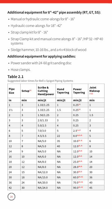
20
Additional equipment for 8"-42" pipe assembly (RT, GT, SS):
• Manual or hydraulic come-alongs for 8" - 16"
• Hydraulic come-alongs for 18"- 42"
• Strap clamp kit for 8" - 16"
• Strap Clamp kit and manual come alongs 8" - 16" /HP 32 - HP 40 systems
• Sledge hammer, 10-16 lbs., and a 4 x 4 block of wood
Additional equipment for applying saddles:
• Power sander with 24-60 grit sanding disc
• Hose clamps.
Pipe Size Setup(1)
Scribe & CuttingHand/power
HandTapering
Power Tapering
Joint Makeup(7,8)
in min min/jt min/jt min/jt min1 3 1�33/1�25 1 0�25(2) 1
11⁄2 3 1�33/1�25 1�5 0�25(2) 1
2 3 1�50/1�25 2 0�25 1�5
3 3 2�0/1�33 3 0�25 2
4 4 5�0/2�5 4 0�25 3
6 5 7�0/3�0 5 2�5(2,3) 4
8 7 4�5/3�5 22 8�0(4,5,9) 5
10 7 NA/5�0 35 10�0(5, 9) 6
12 8 NA/5�0 40 12�0(5, 9) 8
14 9 NA/5�0 NA 12�0(5,9) 10
16 10 NA/6�0 NA 12�0(5,9) 14
18 12 NA/8�0 NA 25�0(6,9) 14
20 12 NA/8�0 NA 28�0(6,9) 20
24 15 NA/12�0 NA 30�0(6,9) 30
30 18 NA/15�0 NA 60�0(9,11) 36
36 24 NA/20�0 NA 70�0(9,11) 40
42 30 NA/24�0 NA 90�0(9,11) 45
Table 2.1Suggested labor times for Bell x Spigot Piping Systems
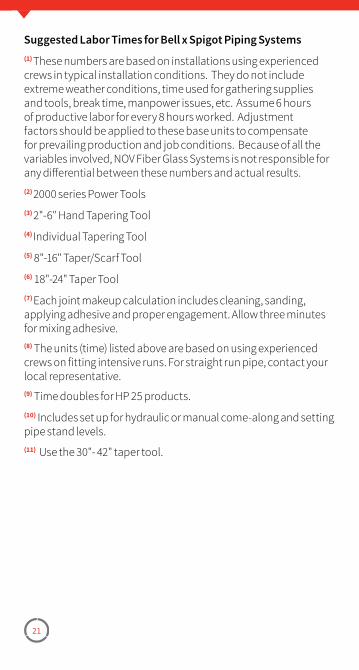
21
Suggested Labor Times for Bell x Spigot Piping Systems(1) These numbers are based on installations using experienced crews in typical installation conditions. They do not include extreme weather conditions, time used for gathering supplies and tools, break time, manpower issues, etc. Assume 6 hours of productive labor for every 8 hours worked. Adjustment factors should be applied to these base units to compensate for prevailing production and job conditions. Because of all the variables involved, NOV Fiber Glass Systems is not responsible for any differential between these numbers and actual results.(2) 2000 series Power Tools(3) 2"-6" Hand Tapering Tool(4) Individual Tapering Tool(5) 8"-16" Taper/Scarf Tool(6) 18"-24" Taper Tool(7) Each joint makeup calculation includes cleaning, sanding, applying adhesive and proper engagement. Allow three minutes for mixing adhesive.(8) The units (time) listed above are based on using experienced crews on fitting intensive runs. For straight run pipe, contact your local representative.(9) Time doubles for HP 25 products.(10) Includes set up for hydraulic or manual come-along and setting pipe stand levels.(11) Use the 30"- 42" taper tool.
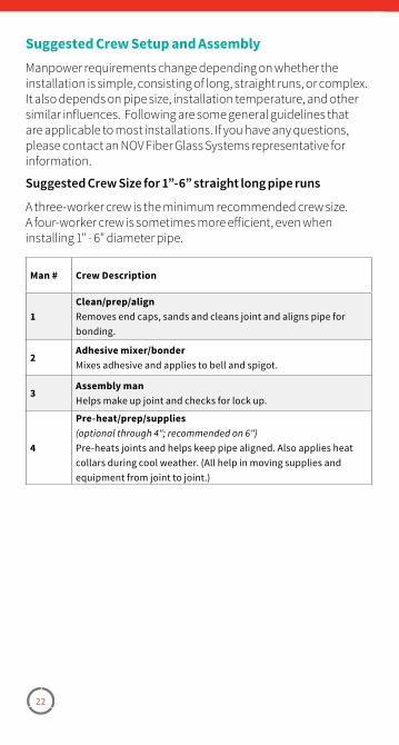
22
Suggested Crew Setup and AssemblyManpower requirements change depending on whether the installation is simple, consisting of long, straight runs, or complex. It also depends on pipe size, installation temperature, and other similar influences. Following are some general guidelines that are applicable to most installations. If you have any questions, please contact an NOV Fiber Glass Systems representative for information.
Suggested Crew Size for 1”-6” straight long pipe runs
A three-worker crew is the minimum recommended crew size. A four-worker crew is sometimes more efficient, even when installing 1" - 6" diameter pipe.
Man # Crew Description
1Clean/prep/alignRemoves end caps, sands and cleans joint and aligns pipe for bonding�
2Adhesive mixer/bonderMixes adhesive and applies to bell and spigot�
3Assembly manHelps make up joint and checks for lock up�
4
Pre-heat/prep/supplies(optional through 4"; recommended on 6")Pre-heats joints and helps keep pipe aligned� Also applies heat collars during cool weather� (All help in moving supplies and equipment from joint to joint�)
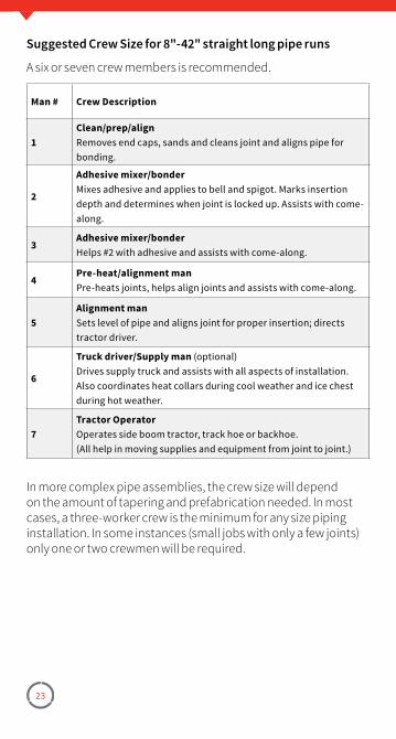
23
Suggested Crew Size for 8"-42" straight long pipe runs
A six or seven crew members is recommended.
Man # Crew Description
1Clean/prep/alignRemoves end caps, sands and cleans joint and aligns pipe for bonding�
2
Adhesive mixer/bonderMixes adhesive and applies to bell and spigot� Marks insertion depth and determines when joint is locked up� Assists with come-along�
3Adhesive mixer/bonderHelps #2 with adhesive and assists with come-along�
4Pre-heat/alignment manPre-heats joints, helps align joints and assists with come-along�
5Alignment manSets level of pipe and aligns joint for proper insertion; directs tractor driver�
6
Truck driver/Supply man (optional)Drives supply truck and assists with all aspects of installation� Also coordinates heat collars during cool weather and ice chest during hot weather�
7Tractor OperatorOperates side boom tractor, track hoe or backhoe�(All help in moving supplies and equipment from joint to joint�)
In more complex pipe assemblies, the crew size will depend on the amount of tapering and prefabrication needed. In most cases, a three-worker crew is the minimum for any size piping installation. In some instances (small jobs with only a few joints) only one or two crewmen will be required.
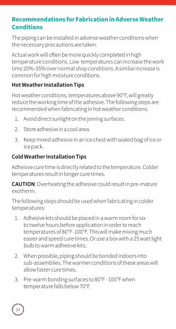
24
Recommendations for Fabrication in Adverse Weather ConditionsThe piping can be installed in adverse weather conditions when the necessary precautions are taken.
Actual work will often be more quickly completed in high temperature conditions. Low temperatures can increase the work time 20%-35% over normal shop conditions. A similar increase is common for high moisture conditions.
Hot Weather Installation Tips
Hot weather conditions, temperatures above 90°F, will greatly reduce the working time of the adhesive. The following steps are recommended when fabricating in hot weather conditions:
1. Avoid direct sunlight on the joining surfaces.
2. Store adhesive in a cool area.
3. Keep mixed adhesive in an ice chest with sealed bag of ice or ice pack.
Cold Weather Installation Tips
Adhesive cure time is directly related to the temperature. Colder temperatures result in longer cure times.
CAUTION: Overheating the adhesive could result in pre-mature exotherm.
The following steps should be used when fabricating in colder temperatures:
1. Adhesive kits should be placed in a warm room for six to twelve hours before application in order to reach temperatures of 80°F -100°F. This will make mixing much easier and speed cure times. Or use a box with a 25 watt light bulb to warm adhesive kits.
2. When possible, piping should be bonded indoors into sub-assemblies. The warmer conditions of these areas will allow faster cure times.
3. Pre-warm bonding surfaces to 80°F - 100°F when temperature falls below 70°F.
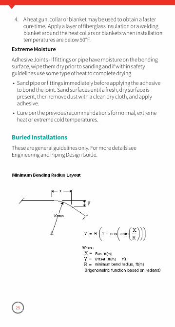
25
4. A heat gun, collar or blanket may be used to obtain a faster cure time. Apply a layer of fiberglass insulation or a welding blanket around the heat collars or blankets when installation temperatures are below 50°F.
Extreme Moisture
Adhesive Joints - If fittings or pipe have moisture on the bonding surface, wipe them dry prior to sanding and if within safety guidelines use some type of heat to complete drying.
• Sand pipe or fittings immediately before applying the adhesive to bond the joint. Sand surfaces until a fresh, dry surface is present, then remove dust with a clean dry cloth, and apply adhesive.
• Cure per the previous recommendations for normal, extreme heat or extreme cold temperatures.
Buried InstallationsThese are general guidelines only. For more details see Engineering and Piping Design Guide.
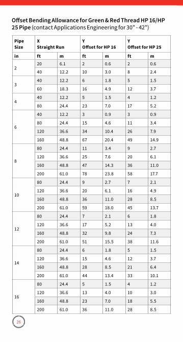
26
Pipe Size
XStraight Run
YOffset for HP 16
YOffset for HP 25
in ft m ft m ft m
220 6�1 2 0�6 2 0�6
40 12�2 10 3�0 8 2�4
340 12�2 6 1�8 5 1�5
60 18�3 16 4�9 12 3�7
440 12�2 5 1�5 4 1�2
80 24�4 23 7�0 17 5�2
6
40 12�2 3 0�9 3 0�9
80 24�4 15 4�6 11 3�4
120 36�6 34 10�4 26 7�9
160 48�8 67 20�4 49 14�9
8
80 24�4 11 3�4 9 2�7
120 36�6 25 7�6 20 6�1
160 48�8 47 14�3 36 11�0
200 61�0 78 23�8 58 17�7
10
80 24�4 9 2�7 7 2�1
120 36�6 20 6�1 16 4�9
160 48�8 36 11�0 28 8�5
200 61�0 59 18�0 45 13�7
12
80 24�4 7 2�1 6 1�8
120 36�6 17 5�2 13 4�0
160 48�8 32 9�8 24 7�3
200 61�0 51 15�5 38 11�6
14
80 24�4 6 1�8 5 1�5
120 36�6 15 4�6 12 3�7
160 48�8 28 8�5 21 6�4
200 61�0 44 13�4 33 10�1
16
80 24�4 5 1�5 4 1�2
120 36�6 13 4�0 10 3�0
160 48�8 23 7�0 18 5�5
200 61�0 36 11�0 28 8�5
Offset Bending Allowance for Green & Red Thread HP 16/HP 25 Pipe (contact Applications Engineering for 30" - 42")
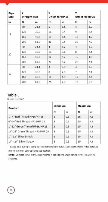
27
Pipe Size
XStraight Run
YOffset for HP 16
YOffset for HP 25
in ft m ft m ft m
18
80 24�4 5 1�5 4 1�2
120 36�6 11 3�4 9 2�7
160 48�8 19 5�8 16 4�9
200 61�0 31 9�5 25 7�6
20
80 24�4 4 1�2 4 1�2
120 36�6 10 3�0 8 2�4
160 48�8 17 5�2 15 4�6
200 61�0 27 8�2 23 7�0
24
80 24�4 3 0�9 3 0�9
120 36�6 8 2�4 7 2�1
160 48�8 16 4�9 12 3�7
200 61�0 25 7�6 19 5�8
ProductMinimum Maximum
ft m ft m1"-4" Red Thread HP16/HP 25 2 0�6 15 4�6
6"-24" Red Thread HP16/HP 25 3 0�9 15 4�6
1"-12" Green Thread HP16/HP 25 2 0�6 15 4�6
14"-24" Green Thread HP16/HP 25 3 0�9 15 4�6
1" - 12" Silver Streak 2 0�6 15 4�6
14" - 24" Silver Streak 3 0�9 15 4�6
* Based on a 1000 psi composite constrained modulus� Contact the factory for detailed
information for your specific application�
NOTE: Contact NOV Fiber Glass Systems’ Applications Engineering for HP 32 & HP 40
systems�
Table 3Burial Depths*
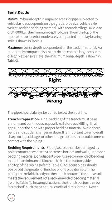
28
Burial Depth:
Minimum burial depth in unpaved areas for pipe subjected to vehicular loads depends on pipe grade, pipe size, vehicle axle weight, and the bedding material. With a standard legal axle load of 34,000 lbs., the minimum depth of cover (from the top of the pipe to the surface) for moderately compacted non-clay bearing soils is shown in Table 3.
Maximum burial depth is dependent on the backfill material. For moderately compacted soils that do not contain large amounts of highly expansive clays, the maximum burial depth is shown in Table 3.
The pipe should always be buried below the frost line.
Trench Preparation - Final bedding of the trench must be as uniform and continuous as possible. Before backfilling, fill all gaps under the pipe with proper bedding material. Avoid sharp bends and sudden changes in slope. It is important to remove all sharp rocks, cribbage, or other foreign objects that could come in contact with the piping.
Bedding Requirements - Fiberglass pipe can be damaged by point contact or wear with the trench bottom and walls, improper bedding materials, or adjacent pipe. Use recommended bedding material a minimum of 6 inches thick at the bottom, sides, and top of the piping (refer to Table 4). Adjacent pipes should be spaced the greater of 6 inches or one pipe diameter. The piping can be laid directly on the trench bottom if the native soil meets the requirements of a recommended bedding material (refer to Table 4). In some situations, the trench bottom can be “scratched” such that a natural cradle of dirt is formed. Never
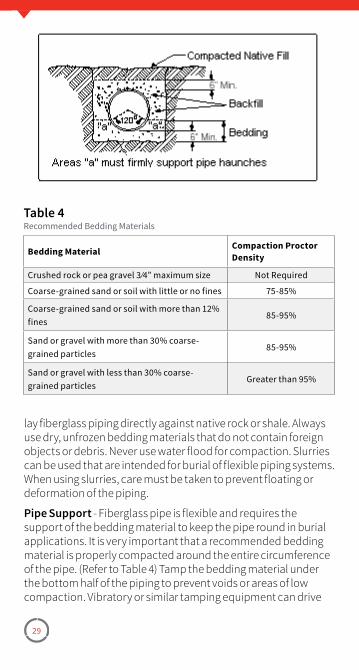
29
Bedding Material Compaction Proctor Density
Crushed rock or pea gravel 3 ⁄4” maximum size Not Required
Coarse-grained sand or soil with little or no fines 75-85%
Coarse-grained sand or soil with more than 12% fines
85-95%
Sand or gravel with more than 30% coarse-grained particles
85-95%
Sand or gravel with less than 30% coarse-grained particles
Greater than 95%
Table 4Recommended Bedding Materials
lay fiberglass piping directly against native rock or shale. Always use dry, unfrozen bedding materials that do not contain foreign objects or debris. Never use water flood for compaction. Slurries can be used that are intended for burial of flexible piping systems. When using slurries, care must be taken to prevent floating or deformation of the piping.
Pipe Support - Fiberglass pipe is flexible and requires the support of the bedding material to keep the pipe round in burial applications. It is very important that a recommended bedding material is properly compacted around the entire circumference of the pipe. (Refer to Table 4) Tamp the bedding material under the bottom half of the piping to prevent voids or areas of low compaction. Vibratory or similar tamping equipment can drive
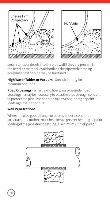
30
small stones or debris into the pipe wall if they are present in the bedding material. Avoid striking the pipe with tamping equipment as the pipe may be fractured.
High Water Tables or Vacuum - Consult factory for recommendations.
Road Crossings - When laying fiberglass pipe under road crossings, it may be necessary to pass the pipe through conduit to protect the pipe. Pad the pipe to prevent rubbing or point loads against the conduit.
Wall Penetrations
Where the pipe goes through or passes under a concrete structure, precautions must be taken to prevent bending or point loading of the pipe due to settling. A minimum 2” thick pad of
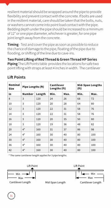
31
resilient material should be wrapped around the pipe to provide flexibility and prevent contact with the concrete. If bolts are used in the resilient material, care should be taken that the bolts, nuts, or washers cannot come into point load contact with the pipe. Bedding depth under the pipe should be increased to a minimum of 12" or one pipe diameter, whichever is greater, for one pipe joint length away from the concrete.
Timing - Test and cover the pipe as soon as possible to reduce the chance of damage to the pipe, floating of the pipe due to flooding, or shifting of the line due to cave-ins.
Two Point Lifting of Red Thread & Green Thread HP Series Piping The Lift Points table provides the locations for safe two point lifting with straps at least 4 inches in width. The cantilever
Nominal Size Pipe Lengths (ft) Cantilever
Lengths (ft)Mid-Span Lengths (ft)
in Number Length Min. Max. Min. Max.8 3 120 24 26 68 72
10 3 120 20 28 64 80
12 3 120 22 31 58 76
14 3 120 22 31 58 76
16 3 120 20 35 50 80
18 3 120 19 36 48 82
20 4* 160 31 37 86 98
24 4* 160 30 40 80 100
30 4* 160 30 40 80 100
36 4* 160 30 40 80 100
42 4* 160 30 40 80 100
* The same cantilever length applies for 3 pipe lengths�
Lift Points
Lift Point Lift Point
MinMax
MinMax
Mid-Span Length Cantilever LengthCantilever Length
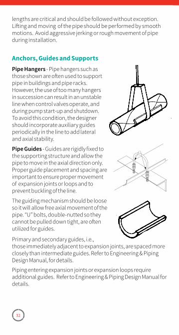
32
lengths are critical and should be followed without exception. Lifting and moving of the pipe should be performed by smooth motions. Avoid aggressive jerking or rough movement of pipe during installation.
Anchors, Guides and SupportsPipe Hangers - Pipe hangers such as those shown are often used to support pipe in buildings and pipe racks. However, the use of too many hangers in succession can result in an unstable line when control valves operate, and during pump start-up and shutdown. To avoid this condition, the designer should incorporate auxiliary guides periodically in the line to add lateral and axial stability.
Pipe Guides - Guides are rigidly fixed to the supporting structure and allow the pipe to move in the axial direction only. Proper guide placement and spacing are important to ensure proper movement of expansion joints or loops and to prevent buckling of the line.
The guiding mechanism should be loose so it will allow free axial movement of the pipe. “U” bolts, double-nutted so they cannot be pulled down tight, are often utilized for guides.
Primary and secondary guides, i.e., those immediately adjacent to expansion joints, are spaced more closely than intermediate guides. Refer to Engineering & Piping Design Manual, for details.
Piping entering expansion joints or expansion loops require additional guides. Refer to Engineering & Piping Design Manual for details.
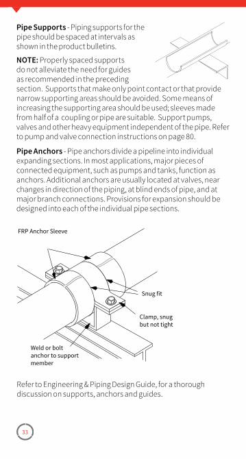
33
Pipe Supports - Piping supports for the pipe should be spaced at intervals as shown in the product bulletins.
NOTE: Properly spaced supports do not alleviate the need for guides as recommended in the preceding section. Supports that make only point contact or that provide narrow supporting areas should be avoided. Some means of increasing the supporting area should be used; sleeves made from half of a coupling or pipe are suitable. Support pumps, valves and other heavy equipment independent of the pipe. Refer to pump and valve connection instructions on page 80.
Pipe Anchors - Pipe anchors divide a pipeline into individual expanding sections. In most applications, major pieces of connected equipment, such as pumps and tanks, function as anchors. Additional anchors are usually located at valves, near changes in direction of the piping, at blind ends of pipe, and at major branch connections. Provisions for expansion should be designed into each of the individual pipe sections.
FRP Anchor Sleeve
Snug fit
Clamp, snug but not tight
Weld or bolt anchor to support member
Refer to Engineering & Piping Design Guide, for a thorough discussion on supports, anchors and guides.
34
Section 3General Installation Instructions
Read This FirstCutting Fiberglass Pipe
35
Important - Read this First
Before beginning the actual assembly procedures, read and make sure all installers thoroughly understand the following instructions.
All bonding surfaces must be clean, dry and factory fresh in appearance before applying adhesive. When end caps have been lost, surfaces will weather and result in loss of bond strength. When surfaces are weathered, re-taper (RT, GT, SS) spigots to achieve a factory fresh appearance. (Note: T.A.B. couplings that have weathered must be replaced.)
Matching tapered bell and spigot joints require a very thin adhesive bond line for maximum strength and durability. The adhesive used with tapered joints is very strong when used in bond lines a few thousandths of an inch thick. The same adhesive may be brittle in thick sections resulting in poor bond strength. To achieve a thin bond line, the matched tapered angles of the joint are designed to mechanically “lock-up” when wedged together.
Using mechanical force assures “lock up” and a thin bond line. Hammering a wooden block placed against the bell end of pipe, or using mechanical devices such as come-alongs should be used to “lock up” the joint.
NOTE: For T.A.B. joints, special T.A.B. wrenches are required to achieve the mechanical lock up in the joint.
Adverse weather conditions require special precautions when bonding pipe. (See page 24, Recommendations for Fabrication in Adverse Weather Conditions) The adhesive is very viscous (thick) when cool or when applied to cool pipe. The thick adhesive can actually be stiff enough to prevent joint “lock up.” When the adhesive is hot or when it is applied to hot pipe, the available working time may be significantly reduced. For Installers new to fiberglass it is strongly recommended that the system be hydrotested within the first 2500’ or 50 joints.
Matched tapered bell and spigot joints that are not “locked up” can fail prematurely.
Installation Statement
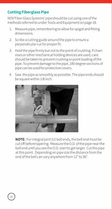
36
Cutting Fiberglass PipeNOV Fiber Glass Systems’ pipe should be cut using one of the methods referred to under Tools and Equipment on page 18.
1. Measure pipe, remembering to allow for spigot and fitting dimensions.
2. Scribe a cutting guide around the pipe to ensure a perpendicular cut for proper fit.
3. Hold the pipe firmly but not to the point of crushing. If chain vises or other mechanical holding devices are used, care should be taken to prevent crushing or point loading of the pipe. To prevent damage to the pipe, 180 degree sections of pipe can be used for protective covers.
4. Saw the pipe as smoothly as possible. The pipe ends should be square within 1 ⁄8 inch.
NOTE: For integral joint (IJ) bell ends, the bell end must be cut off before tapering. Measure the O.D. of the pipe near the bell end until you see the O.D. start to get larger. Cut the pipe at this point. Depending on pipe size the distance from the end of the bell can vary anywhere from 12" to 36".
37
Section 4Fabrication of Red Thread HP, Green Thread HP and Silver Streak Pipe and Fittings
Tapering PipeTapering Tool Reference ChartJoint AssemblyClose Tolerance PipingJoint PrepAdhesive Mixing
Take-Off Dimensions1"x6" Bell x Spigot Joints8"x36" Bell x Spigot JointsT�A�B� JointsJoint Cure and Heat CollarsRepairs
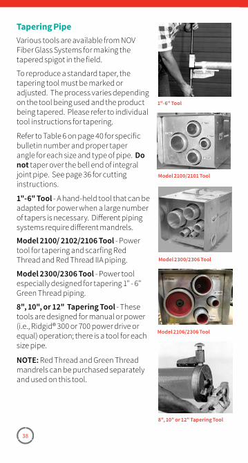
38
Tapering PipeVarious tools are available from NOV Fiber Glass Systems for making the tapered spigot in the field.
To reproduce a standard taper, the tapering tool must be marked or adjusted. The process varies depending on the tool being used and the product being tapered. Please refer to individual tool instructions for tapering.
Refer to Table 6 on page 40 for specific bulletin number and proper taper angle for each size and type of pipe. Do not taper over the bell end of integral joint pipe. See page 36 for cutting instructions.
1"-6" Tool - A hand-held tool that can be adapted for power when a large number of tapers is necessary. Different piping systems require different mandrels.
Model 2100/ 2102/2106 Tool - Power tool for tapering and scarfing Red Thread and Red Thread IIA piping.
Model 2300/2306 Tool - Power tool especially designed for tapering 1" - 6" Green Thread piping.
8", 10", or 12" Tapering Tool - These tools are designed for manual or power (i.e., Ridgid® 300 or 700 power drive or equal) operation; there is a tool for each size pipe.
NOTE: Red Thread and Green Thread mandrels can be purchased separately and used on this tool.
1"-6" Tool
Model 2100/2101 Tool
Model 2300/2306 Tool
8", 10" or 12" Tapering Tool
Model 2106/2306 Tool
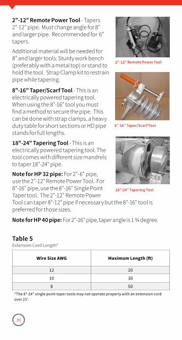
39
2"-12" Remote Power Tool - Tapers 2"-12" pipe. Must change angle for 8" and larger pipe. Recommended for 6" tapers.
Additional material will be needed for 8" and larger tools: Sturdy work bench (preferably with a metal top) or stand to hold the tool. Strap Clamp kit to restrain pipe while tapering.
8"-16" Taper/Scarf Tool - This is an electrically powered tapering tool. When using the 8"-16" tool you must find a method to secure the pipe. This can be done with strap clamps, a heavy duty table for short sections or HD pipe stands for full lengths.
18"-24" Tapering Tool - This is an electrically powered tapering tool. The tool comes with different size mandrels to taper 18"-24" pipe.
Note for HP 32 pipe: For 2"-6" pipe, use the 2"-12" Remote Power Tool. For 8"-16" pipe, use the 8"-16" Single Point Taper tool. The 2"-12" Remote Power Tool can taper 8"-12" pipe if necessary but the 8"-16" tool is preferred for those sizes.
Note for HP 40 pipe: For 2"-16" pipe, taper angle is 1 3/4 degree.
2”-12” Remote Power Tool
8”-16” Taper/Scarf Tool
18”-24” Tapering Tool
Wire Size AWG Maximum Length (ft)
12 20
10 30
8 50*The 8"-24" single point taper tools may not operate properly with an extension cord over 25'�
Table 5Extension Cord Length*
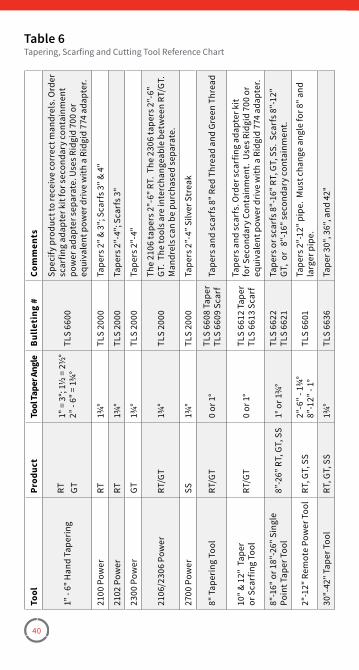
40
Tool
Prod
uct
Tool
Tape
r Ang
leBu
lleti
ng #
Com
men
ts
1" -
6" H
and
Tape
ring
RT GT1"
= 3
°; 1½
= 2
½°
2” -
6" =
1¾
°TL
S 66
00
Spec
ify p
rodu
ct to
rece
ive
corr
ect m
andr
els�
Ord
er
scar
fing
adap
ter k
it fo
r sec
onda
ry c
onta
inm
ent
pow
er a
dapt
er s
epar
ate�
Use
s Rid
gid
700
or
equi
vale
nt p
ower
dri
ve w
ith a
Rid
gid
774
adap
ter�
2100
Pow
erRT
1¾°
TLS
2000
Tape
rs 2
" & 3
"; S
carf
s 3" &
4"
2102
Pow
erRT
1¾°
TLS
2000
Tape
rs 2
"-4"
; Sca
rfs 3
"
2300
Pow
erGT
1¾°
TLS
2000
Tape
rs 2
"-4"
2106
/230
6 Po
wer
RT/G
T1¾
°TL
S 20
00Th
e 21
06 ta
pers
2"-
6" R
T� T
he 2
306
tape
rs 2
"-6"
GT
� Th
e to
ols a
re in
terc
hang
eabl
e be
twee
n RT
/GT�
M
andr
els c
an b
e pu
rcha
sed
sepa
rate
�
2700
Pow
erSS
1¾°
TLS
2000
Tape
rs 2
”-4”
Silv
er S
trea
k
8" T
aper
ing
Tool
RT/G
T0
or 1
°TL
S 66
08 T
aper
TLS
6609
Sca
rfTa
pers
and
sca
rfs 8
" Red
Thr
ead
and
Gree
n Th
read
10" &
12"
Tap
eror
Sca
rfin
g To
olRT
/GT
0 or
1°
TLS
6612
Tap
erTL
S 66
13 S
carf
Tape
rs a
nd s
carf
s� O
rder
sca
rfin
g ad
apte
r kit
for S
econ
dary
Con
tain
men
t� U
ses R
idgi
d 70
0 or
eq
uiva
lent
pow
er d
rive
with
a R
idgi
d 77
4 ad
apte
r�
8"-1
6" o
r 18"
-26"
Sin
gle
Poin
t Tap
er T
ool
8”-2
6” R
T, G
T, S
S1°
or 1
¾°
TLS
6622
TLS
6621
Tape
rs o
r sca
rfs 8
"-16
" RT,
GT,
SS�
Sca
rfs 8
"-12
" GT
, or
8"-
16" s
econ
dary
con
tain
men
t�
2"-1
2" R
emot
e Po
wer
Too
lRT
, GT,
SS
2"-6
" - 1
¾°
8"-1
2" -
1°TL
S 66
01Ta
pers
2"-
12" p
ipe�
Mus
t cha
nge
angl
e fo
r 8" a
nd
larg
er p
ipe�
30"-
42" T
aper
Too
lRT
, GT,
SS
1¾°
TLS
6636
Tape
r 30"
, 36"
, and
42"
Table 6Tapering, Scarfing and Cutting Tool Reference Chart
41
Joint Prep for Red Thread, Green Thread and Silver StreakAll bonding surfaces must be clean and dry before bonding.
• For T.A.B. joints, clean with an acceptable solvent and clean rag. Wire brushes may also be used for cleaning T.A.B. surfaces; however, they must be clean and free of oily contaminates.
• All bonding surfaces must be clean and dry before bonding. For T.A.B. joints clean with an acceptable solvent and a clean rag. Never sand T.A.B. X T.A.B. surfaces.
• For smooth tapers, sandpaper or solvent (or both) may be used. Sand just light enough to remove any contaminates.
• Use caution as over-sanding can change the taper angle or end dimension, and create flat spots on the spigot.
• When surfaces have weathered, sand or retaper spigots and sand bells to achieve a factory fresh appearance. Cut at least 1" from spigots before retapering. T.A.B. couplings must be replaced.
• Bonding surfaces must be dry, so be sure all solvent has evaporated before applying adhesive.
When ambient temperature is below 70°F, pre warm the bonding surfaces. Use a hot air gun, propane torch or other clean burning heat source that has a spreader type tip, and apply heat uniformly to bell and spigot until warm to the touch. Check temperature by touching bonding surfaces with the back of your hand. Do not touch with the front of your hand as this may contaminate the joint. If hot to the touch, let cool before applying adhesive. When using a torch to preheat, warm the bell first. It is thicker and will hold heat longer. If an electric heating collar is used to pre warm, place the joint together dry, then heat the O.D. of the bell to avoid contaminating the spigot. Do not use chemical heat packs to pre warm. Warning: Do not use propane torch around flammable gases or liquids.
NOTE: Use of a solvent as a cleaning method is optional.
WARNING: Before using heating devices or open flames be sure all safety checks and regulations are followed. Do not use if flammable gases or liquids are present.
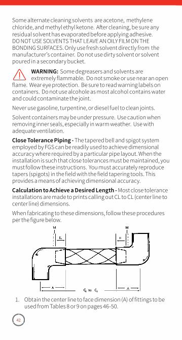
42
Some alternate cleaning solvents are acetone, methylene chloride, and methyl ethyl ketone. After cleaning, be sure any residual solvent has evaporated before applying adhesive. DO NOT USE SOLVENTS THAT LEAVE AN OILY FILM ON THE BONDING SURFACES. Only use fresh solvent directly from the manufacturer’s container. Do not use dirty solvent or solvent poured in a secondary bucket.
WARNING: Some degreasers and solvents are extremely flammable. Do not smoke or use near an open
flame. Wear eye protection. Be sure to read warning labels on containers. Do not use alcohole as most alcohol contains water and could contaminate the joint.
Never use gasoline, turpentine, or diesel fuel to clean joints.
Solvent containers may be under pressure. Use caution when removing inner seals, especially in warm weather. Use with adequate ventilation.
Close Tolerance Piping - The tapered bell and spigot system employed by FGS can be readily used to achieve dimensional accuracy where required by a particular pipe layout. When the installation is such that close tolerances must be maintained, you must follow these instructions. You must accurately reproduce tapers (spigots) in the field with the field tapering tools. This provides a means of achieving dimensional accuracy.
Calculation to Achieve a Desired Length - Most close tolerance installations are made to prints calling out CL to CL (center line to center line) dimensions.
When fabricating to these dimensions, follow these procedures per the figure below.
1. Obtain the center line to face dimension (A) of fittings to be used from Tables 8 or 9 on pages 46-50.
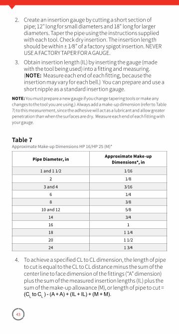
43
2. Create an insertion gauge by cutting a short section of pipe; 12" long for small diameters and 18" long for larger diameters. Taper the pipe using the instructions supplied with each tool. Check dry insertion. The insertion length should be within ± 1 ⁄8” of a factory spigot insertion. NEVER USE A FACTORY TAPER FOR A GAUGE.
3. Obtain insertion length (IL) by inserting the gauge (made with the tool being used) into a fitting and measuring. (NOTE: Measure each end of each fitting, because the insertion may vary for each bell.) You can prepare and use a short nipple as a standard insertion gauge.
NOTE: You must prepare a new gauge if you change tapering tools or make any changes to the tool you are using.) Always add a make-up dimension (refer to Table 7) to this measurement, since the adhesive will act as a lubricant and allow greater penetration than when the surfaces are dry. Measure each end of each fitting with your gauge.
Pipe Diameter, in Approximate Make-up Dimensions*, in
1 and 1 1 ⁄2 1 ⁄16
2 1 ⁄8
3 and 4 3 ⁄16
6 1 ⁄4
8 3 ⁄8
10 and 12 5 ⁄8
14 3 ⁄4
16 1
18 1 1 ⁄4
20 1 1 ⁄2
24 1 3 ⁄4
Table 7Approximate Make-up Dimensions HP 16/HP 25 (M)*
4. To achieve a specified CL to CL dimension, the length of pipe to cut is equal to the CL to CL distance minus the sum of the center line to face dimension of the fittings (“A” dimension) plus the sum of the measured insertion lengths (IL) plus the sum of the make-up allowance (M), or length of pipe to cut = (CL to CL ) - (A + A) + (IL + IL) + (M + M).
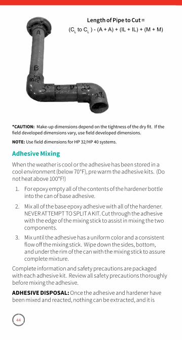
44
Length of Pipe to Cut =(CL to CL ) - (A + A) + (IL + IL) + (M + M)
*CAUTION: Make-up dimensions depend on the tightness of the dry fit� If the field developed dimensions vary, use field developed dimensions�
NOTE: Use field dimensions for HP 32/HP 40 systems�
Adhesive MixingWhen the weather is cool or the adhesive has been stored in a cool environment (below 70°F), pre warm the adhesive kits. (Do not heat above 100°F!)
1. For epoxy empty all of the contents of the hardener bottle into the can of base adhesive.
2. Mix all of the base epoxy adhesive with all of the hardener. NEVER ATTEMPT TO SPLIT A KIT. Cut through the adhesive with the edge of the mixing stick to assist in mixing the two components.
3. Mix until the adhesive has a uniform color and a consistent flow off the mixing stick. Wipe down the sides, bottom, and under the rim of the can with the mixing stick to assure complete mixture.
Complete information and safety precautions are packaged with each adhesive kit. Review all safety precautions thoroughly before mixing the adhesive.
ADHESIVE DISPOSAL: Once the adhesive and hardener have been mixed and reacted, nothing can be extracted, and it is
45
classified as non-hazardous material. Dispose of in a normal manner as other solid waste. Excess adhesive and hardener can be mixed, allowed to react, and disposed of as above. If extra jars of adhesive or hardener have accumulated without the other component to mix and react, contact your regional manager. Hardener jars, when empty are not subject to EPA regulation and can be disposed of in a normal manner. These guidelines are based on federal regulations. State and local regulations and ordinances should be reviewed.
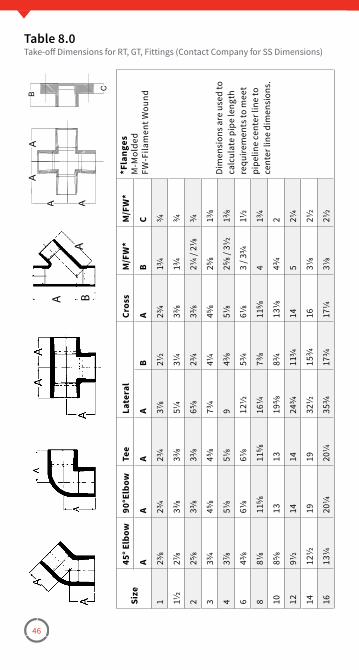
46
Size
45° E
lbow
90°E
lbow
Tee
Late
ral
Cros
sM
/FW
*M
/FW
**F
lang
esM
-Mol
ded
FW-F
ilam
ent W
ound
AA
AA
BA
BC
123
⁄823
⁄423
⁄437
⁄821
⁄223
⁄413
⁄43⁄4
Dim
ensi
ons a
re u
sed
to
calc
ulat
e pi
pe le
ngth
re
quire
men
ts to
mee
t pi
pelin
e ce
nter
line
to
cent
er li
ne d
imen
sion
s�
11⁄2
27⁄8
33⁄8
33⁄8
51⁄4
31⁄4
33⁄8
13⁄4
3⁄4
225
⁄833
⁄833
⁄865
⁄823
⁄433
⁄821
⁄4 / 2
1⁄83⁄4
333
⁄445
⁄845
⁄873
⁄441
⁄445
⁄825
⁄813
⁄8
437
⁄851
⁄851
⁄89
43⁄8
51⁄8
25⁄8
/ 31⁄2
13⁄8
643
⁄861
⁄861
⁄812
1⁄253
⁄461
⁄83
/ 33⁄4
11⁄2
881
⁄811
5⁄811
5⁄816
1⁄473
⁄811
5⁄84
13⁄4
1085
⁄813
1319
5⁄883
⁄413
1⁄843
⁄42
1291
⁄214
1424
3⁄411
3⁄414
521
⁄4
1412
1⁄219
1932
1⁄215
3⁄416
31⁄8
21⁄2
1613
1⁄420
1⁄420
1⁄435
3⁄417
3⁄417
1⁄431
⁄821
⁄2
Table 8.0Take-off Dimensions for RT, GT, Fittings (Contact Company for SS Dimensions)
A
A B
AA
A A
B
C
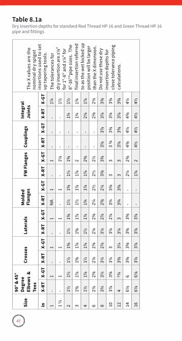
47
Size
90° &
45°
Degr
eeEl
bow
s &
Te
es
Cros
ses
Late
rals
Mol
ded
Flan
ges
FW F
lang
esCo
uplin
gsIn
tegr
al
Join
tsTh
e X
valu
es a
re th
e no
min
al d
ry s
pigo
t in
sert
ions
use
d to
set
up
tape
ring
tool
s�in
X-RT
X-GT
X-RT
X-GT
X-RT
X-GT
X-RT
X-GT
X-RT
X-GT
X-RT
X-GT
X-RT
X-GT
1-
1-
1-
1N
A1
-1
--
-1¼
The
tole
ranc
es fo
r dr
y in
sert
ion
are
±⅛"
for 1
"-6"
and
±¼
" for
8"
-16”
"pip
e si
zes�
The
fin
al in
sert
ion
refe
rred
to
as t
he w
et lo
cked
up
posi
tion
will
be
larg
er
than
the
X di
men
sion
� Do
not
use
thes
e dr
y in
sert
ion
dept
hs fo
r cl
ose
tole
ranc
e pi
ping
ca
lcul
atio
ns�
1 ½
-1
-1
-1
-1
-1⅛
--
-1½
21½
1½1½
1⅝1½
1⅝1½
1⅝1½
1⅝-
-1¾
1½
31⅝
1⅞1⅝
1⅞
1⅝1⅞
1½
1⅞1⅞
2-
-1¾
1¾
41½
1⅞1½
1⅞
1½1⅞
1¾
1⅞1⅞
2⅝-
-2⅛
1⅞
62⅛
2⅜2⅛
2⅜2⅛
2⅜2¼
2½2½
2½-
-2⅜
2⅛
83¾
3¼3¼
2⅞3¼
2⅞2⅝
2¼3⅜
3⅜3⅞
3⅞3⅞
3⅜
103⅞
3⅝3¼
33⅛
2⅞3¾
3⅜3
33
¾3⅜
3¾3⅜
124
3¾3⅝
3¼3¼
33¾
3⅜3
33⅞
3⅝3⅞
3⅝
146⅛
63⅝
3⅝3⅝
3⅝-
-2¼
2⅜4⅜
4¼4⅜
4¼
166⅛
6⅛3⅞
3⅞
3⅞
3⅞
-
-1⅞
24½
4½4½
4½
Table 8.1aDry insertion depths for standard Red Thread HP 16 and Green Thread HP 16 pipe and fittings
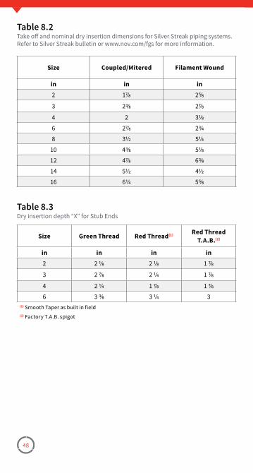
48
Size Coupled/Mitered Filament Wound
in in in2 1⅞ 2⅝
3 2⅜ 2⅞
4 2 3⅛
6 2⅞ 2¾
8 3½ 5¼
10 4⅜ 5⅛
12 4⅞ 6⅜
14 5½ 4½
16 6¼ 5⅝
Table 8.2Take off and nominal dry insertion dimensions for Silver Streak piping systems� Refer to Silver Streak bulletin or www�nov�com/fgs for more information�
Size Green Thread Red Thread(1) Red Thread T.A.B.(2)
in in in in2 2 ⅛ 2 ⅛ 1 ⅞
3 2 ⅞ 2 ¼ 1 ⅞
4 2 ¼ 1 ⅞ 1 ⅞
6 3 ⅜ 3 ¼ 3(1) Smooth Taper as built in field(2) Factory T�A�B� spigot
Table 8.3Dry insertion depth “X” for Stub Ends
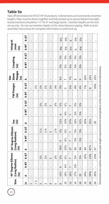
49
Size
45° D
egre
e El
bow
s(L
ong
Radi
us)
(in)
90° D
egre
e El
bow
s(L
ong
Radi
um)
(in)
Tee
(in)
FW F
lang
es
(in)
Van
Ston
e Fl
ange
s (in
)
Coup
ling
(in)
Inte
gral
Jo
int
(in)
inA
X-RT
X-GT
AX-
RTX-
GTA
X-RT
X-GT
X-RT
X-GT
AX-
RTX-
GTX-
RTX-
GT
1-
--
--
--
--
--
--
1 ½
--
--
--
-1⅛
--
--
-
2-
-2½
--
2 ½
--
2½-
1¾-
--
--
3-
-2¾
--
2 ¾
--
2¾-
2⅞-
--
--
4-
-3
--
3-
-3
-3¼
--
--
-
6-
-2¾
--
2 ¾
--
2¾-
3⅝-
--
--
812
½6
5⅛19
½6
5⅛13
½6
5⅛-
3⅜6¼
5¾5¼
4⅝4⅛
1014
½6½
6½23
¼6½
6½15
¾6½
6½-
57
5½5¼
5¾5⅜
1216
½7
727
77
17¾
77
-5⅝
7¾6⅛
5⅞6¼
6
1417
¾5¾
5¾30
5¾5¾
19½
5¾5¾
-4⅝
85¾
5¼6
5⅜
1620
-5¾
345¾
5¾21
½5¾
5¾-
4½9
6⅜5⅛
6⅜5⅛
1824
⅞-
10⅞
40-
-26
⅜-
--
7⅜10
½-
--
-
2029
⅝-
12⅝
47¼
--
31¼
--
-8
12½
--
--
2435
⅞-
15⅝
57-
-35
--
-10
⅜15
½-
--
-Di
men
sion
s are
use
d to
cal
cula
te p
ipe
leng
th re
quire
men
ts to
mee
t pip
elin
e ce
nter
line
to c
ente
r lin
e di
men
sion
s�
Table 9aTake off dimensions for RT/GT HP 25 products� X dimensions are nominal dry insertion lengths� Pipe must be driven together and fully locked up to assure full joint strength� Actual insertions should be +¼" for 8" and larger joints� Insertion depths are for tool set up only� Do not use insertion depths (x) for close tolerance piping� Refer to joint assembly instructions for complete information on joint lock up
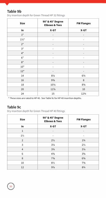
50
Size 90° & 45° Degree Elbows & Tees FW Flanges
in X-GT X-GT1* - -
1½* - -
2* - -
3* - -
4* - -
6* - -
8* - -
10* - -
12* - -
14 8⅛ 6¾
16 9⅝ 8
18 10⅛ 8⅜
20 11⅞ 10
24 15 12¾* These sizes are rated to HP 40� See Table 9c for HP 40 insertion depths�
Table 9bDry insertion depth for Green Thread HP 32 fittings
Size 90° & 45° Degree Elbows & Tees FW Flanges
in X-GT X-GT1 - -
1½ - -
2 2½ 1¾
3 3⅛ 2½
4 3¾ 3⅛
6 4⅜ 3⅝
8 7⅜ 6⅝
10 8½ 7⅝
12 9⅞ 8¾
Table 9cDry insertion depth for Green Thread HP 40 fittings
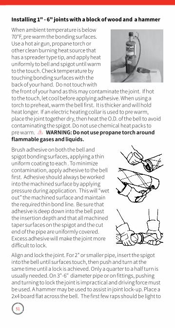
51
Installing 1" - 6" joints with a block of wood and a hammer
When ambient temperature is below 70°F, pre warm the bonding surfaces. Use a hot air gun, propane torch or other clean burning heat source that has a spreader type tip, and apply heat uniformly to bell and spigot until warm to the touch. Check temperature by touching bonding surfaces with the back of your hand. Do not touch with the front of your hand as this may contaminate the joint. If hot to the touch, let cool before applying adhesive. When using a torch to preheat, warm the bell first. It is thicker and will hold heat longer. If an electric heating collar is used to pre warm, place the joint together dry, then heat the O.D. of the bell to avoid contaminating the spigot. Do not use chemical heat packs to pre warm. WARNING: Do not use propane torch around flammable gases and liquids.
Brush adhesive on both the bell and spigot bonding surfaces, applying a thin uniform coating to each . To minimize contamination, apply adhesive to the bell first. Adhesive should always be worked into the machined surface by applying pressure during application. This will “wet out” the machined surface and maintain the required thin bond line. Be sure that adhesive is deep down into the bell past the insertion depth and that all machined taper surfaces on the spigot and the cut end of the pipe are uniformly covered. Excess adhesive will make the joint more difficult to lock.
Align and lock the joint. For 2" or smaller pipe, insert the spigot into the bell until surfaces touch, then push and turn at the same time until a lock is achieved. Only a quarter to a half turn is usually needed. On 3"-6" diameter pipe or on fittings, pushing and turning to lock the joint is impractical and driving force must be used. A hammer may be used to assist in joint lock-up. Place a 2x4 board flat across the bell. The first few raps should be light to
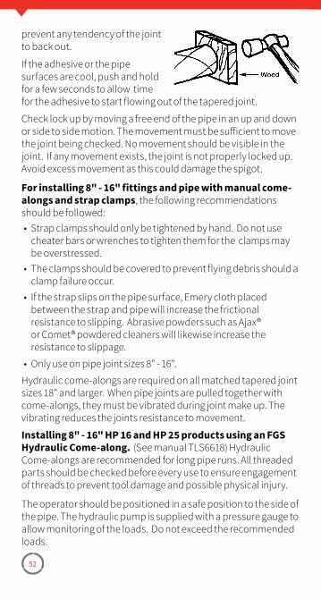
52
prevent any tendency of the joint to back out.
If the adhesive or the pipe surfaces are cool, push and hold for a few seconds to allow time for the adhesive to start flowing out of the tapered joint.
Check lock up by moving a free end of the pipe in an up and down or side to side motion. The movement must be sufficient to move the joint being checked. No movement should be visible in the joint. If any movement exists, the joint is not properly locked up. Avoid excess movement as this could damage the spigot.
For installing 8" - 16" fittings and pipe with manual come-alongs and strap clamps, the following recommendations should be followed:• Strap clamps should only be tightened by hand. Do not use
cheater bars or wrenches to tighten them for the clamps may be overstressed.
• The clamps should be covered to prevent flying debris should a clamp failure occur.
• If the strap slips on the pipe surface, Emery cloth placed between the strap and pipe will increase the frictional resistance to slipping. Abrasive powders such as Ajax® or Comet® powdered cleaners will likewise increase the resistance to slippage.
• Only use on pipe joint sizes 8" - 16".
Hydraulic come-alongs are required on all matched tapered joint sizes 18" and larger. When pipe joints are pulled together with come-alongs, they must be vibrated during joint make up. The vibrating reduces the joints resistance to movement.
Installing 8" - 16" HP 16 and HP 25 products using an FGS Hydraulic Come-along. (See manual TLS6618) Hydraulic Come-alongs are recommended for long pipe runs. All threaded parts should be checked before every use to ensure engagement of threads to prevent tool damage and possible physical injury.
The operator should be positioned in a safe position to the side of the pipe. The hydraulic pump is supplied with a pressure gauge to allow monitoring of the loads. Do not exceed the recommended loads.
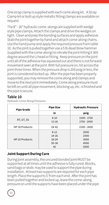
53
One strap clamp is supplied with each come along kit. A Strap Clamp kit or bolt up style metallic fitting clamps are available on request.
The 8" - 16" hydraulic come -alongs are supplied with wedge style pipe clamps. Attach the clamps and drive the wedges on tight. Clean and prep the bonding surfaces and apply adhesive. Stab the joint together by hand and attach come-along chains. Use the hand pump and apply the required pressure from table 10. As the joint is pulled together use a 5 lb dead blow hammer (supplied with the come-along) to vibrate the joint hitting it 360 degree around the IJ head or fitting. Keep pressure on the joint until all of the adhesive has squeezed out and there is not forward movement seen at the joint. With full pressure on, hit across the joint three times. When the pressure drop is 200 psig or less, the joint is considered locked up. After the pipe has been properly supported, you may remove the come along and clamps and move to the next joint immediately. Come along pressure must be left on until all pipe movement, blocking up, etc. is finished and the pipe is secure.
Pipe GradePipe Size Hydraulic Pressure
in psig
RT, GT, SS8-10
12-161500 - 17501750 - 2000
HP 16 Products 18-42 1500 - 2600
HP 25 Products
8-1214-1618-2430-36
42
20002500300045005000
Table 10Hydraulic Come-Along Pressures
Joint Support During CureDuring joint assembly, the uncured bonded joint MUST be supported at all times until the adhesive is fully cured. Blocks, sand bags or skids may be used to support the pipe during installation. At least two supports are required for each pipe length. Place the supports 5’ from each end. After the joint has been pulled together and locked up, leave the come-along pressure on until the supports have been placed under the pipe
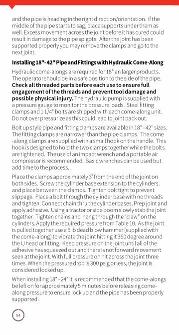
54
and the pipe is heading in the right direction/orientation. If the middle of the pipe starts to sag, place supports under them as well. Excess movement across the joint before it has cured could result in damage to the pipe spigots. After the joint has been supported properly you may remove the clamps and go to the next joint.
Installing 18"- 42" Pipe and Fittings with Hydraulic Come-AlongHydraulic come-alongs are required for 18" an larger products. The operator should be in a safe position to the side of the pipe. Check all threaded parts before each use to ensure full engagement of the threads and prevent tool damage and possible physical injury. The hydraulic pump is supplied with a pressure gauge to monitor the pressure loads. Steel fitting clamps and 1 1/4" bolts are shipped with each come-along unit. Do not over pressurize as this could lead to joint back out.
Bolt up style pipe and fitting clamps are available in 18" - 42" sizes. The fitting clamps are narrower than the pipe clamps. The come -along clamps are supplied with a small hook on the handle. This hook is designed to hold the two clamps together while the bolts are tightened. The use of an impact wrench and a portable air compressor is recommended. Basic wrenches can be used but add time to the process.
Place the clamps approximately 3’ from the end of the joint on both sides. Screw the cylinder base extension to the cylinders. and place between the clamps. Tighten bolt tight to prevent slippage. Place a bolt through the cylinder base with no threads and tighten. Connect chain thru the cylinder bases. Prep joint and apply adhesive. Using a tractor or side boom slowly stab the joint together. Tighten chains and hang through the “claw” on the cylinders. Apply the required pressure from Table 10. As the joint is pulled together use a 5 lb dead blow hammer (supplied with the come-along) to vibrate the joint hitting it 360 degree around the IJ head or fitting. Keep pressure on the joint until all of the adhesive has squeezed out and there is not forward movement seen at the joint. With full pressure on hit across the joint three times. When the pressure drop is 300 psig or less, the joint is considered locked up.
When installing 18" - 24" it is recommended that the come-alongs be left on for approximately 5 minutes before releasing come-along pressure to ensure lock up and the pipe has been properly supported.
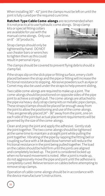
55
When installing 30" - 42" joint the clamps must be left on until the joint is fully cured per the required cure time.
Ratchet-Type Cable Come-alongs are recommended when it is not practical to use hydraulic come alongs. Strap clamp kits or special fitting collars are available for use with the manual come alongs. Only use on 8" - 16"products.
Strap clamps should only be tightened by hand. DO NOT use cheater bars or wrenches to tighten them as this could result in personal injury.
The clamps should be covered to prevent flying debris should a clamp fail.
If the straps slip on the slick pipe or fitting surface, emery cloth placed between the strap and the pipe or fitting will increase the frictional resistance to slipping. Abrasive powders such as Ajax or Comet may also be used under the straps to help prevent sliding. Two cable come-alongs are required to make up a joint. The come-alongs should be positioned on opposite sides of the pipe joint to achieve a straight pull. The come-alongs are attached to the pipe via heavy-duty strap clamp kits or metallic pipe clamps.. These straps/clamps should be placed far enough away from the joint to allow the positioning and use of the come-alongs. They are generally placed 24" - 36" away from the joint, one on each side of the joint but actual placement requirements will be governed by the size of the come-alongs.
Clean and prep the joint and apply the adhesive. Gently stab the joint together. The two come-alongs should be tightened at the same time to maintain a straight joint while pulling the joint together. Vibrating of the pipe by rapping the fitting bell or coupling surface with a 5# dead blow hammer will reduce the frictional resistance in the joint being pulled together. The load on the cables should be held firm until the joints are aligned and completely locked up. The joint is considered locked up when no forward movement is noted. After a joint is made up, do not aggressively move the pipe and joint until the adhesive is completely cured. Relieve tension on cables before attempting to remove strap clamps.Operation of cable come-alongs should be in accordance with the device manufacturer’s instructions.
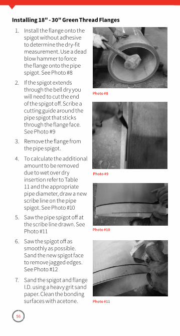
56
Installing 18" - 30" Green Thread Flanges
1. Install the flange onto the spigot without adhesive to determine the dry-fit measurement. Use a dead blow hammer to force the flange onto the pipe spigot. See Photo #8
2. If the spigot extends through the bell dry you will need to cut the end of the spigot off. Scribe a cutting guide around the pipe spigot that sticks through the flange face. See Photo #9
3. Remove the flange from the pipe spigot.
4. To calculate the additional amount to be removed due to wet over dry insertion refer to Table 11 and the appropriate pipe diameter, draw a new scribe line on the pipe spigot. See Photo #10
5. Saw the pipe spigot off at the scribe line drawn. See Photo #11
6. Saw the spigot off as smoothly as possible. Sand the new spigot face to remove jagged edges. See Photo #12
7. Sand the spigot and flange I.D. using a heavy grit sand paper. Clean the bonding surfaces with acetone.
Photo #8
Photo #9
Photo #10
Photo #11
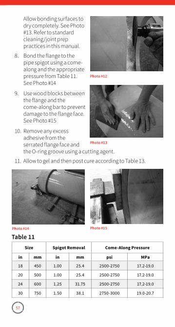
57
Allow bonding surfaces to dry completely. See Photo #13. Refer to standard cleaning/joint prep practices in this manual.
8. Bond the flange to the pipe spigot using a come-along and the appropriate pressure from Table 11. See Photo #14
9. Use wood blocks between the flange and the come-along bar to prevent damage to the flange face. See Photo #15
10. Remove any excess adhesive from the serrated flange face and the O-ring groove using a cutting agent.
11. Allow to gel and then post cure according to Table 13.
Size Spigot Removal Come-Along Pressure
in mm in mm psi MPa
18 450 1�00 25�4 2500-2750 17�2-19�0
20 500 1�00 25�4 2500-2750 17�2-19�0
24 600 1�25 31�75 2500-2750 17�2-19�0
30 750 1�50 38�1 2750-3000 19�0-20�7
Photo #12
Photo #13
Photo #14 Photo #15
Table 11
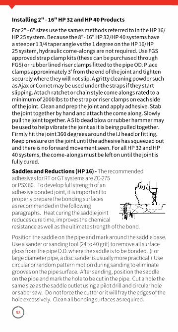
58
Installing 2" - 16" HP 32 and HP 40 Products
For 2" - 6" sizes use the sames methods referred to in the HP 16/HP 25 system� Because the 8"- 16" HP 32/HP 40 systems have a steeper 1 3/4 taper angle vs the 1 degree on the HP 16/HP 25 system, hydraulic come-alongs are not required� Use FGS approved strap clamp kits (these can be purchased through FGS) or rubber lined riser clamps fitted to the pipe OD� Place clamps approximately 3’ from the end of the joint and tighten securely where they will not slip� A gritty cleaning powder such as Ajax or Comet may be used under the straps if they start slipping� Attach ratchet or chain style come alongs rated to a minimum of 2000 lbs to the strap or riser clamps on each side of the joint� Clean and prep the joint and apply adhesive� Stab the joint together by hand and attach the come along� Slowly pull the joint together� A 5 lb dead blow or rubber hammer may be used to help vibrate the joint as it is being pulled together� Firmly hit the joint 360 degrees around the IJ head or fitting� Keep pressure on the joint until the adhesive has squeezed out and there is no forward movement seen� For all HP 32 and HP 40 systems, the come-alongs must be left on until the joint is fully cured�
Saddles and Reductions (HP 16) - The recommended adhesives for RT or GT systems are ZC-275 or PSX 60. To develop full strength of an adhesive bonded joint, it is important to properly prepare the bonding surfaces as recommended in the following paragraphs. Heat curing the saddle joint reduces cure time, improves the chemical resistance as well as the ultimate strength of the bond.
Position the saddle on the pipe and mark around the saddle base. Use a sander or sanding tool (24 to 40 grit) to remove all surface gloss from the pipe O.D. where the saddle is to be bonded. (For large diameter pipe, a disc sander is usually more practical.) Use circular or random pattern motion during sanding to eliminate grooves on the pipe surface. After sanding, position the saddle on the pipe and mark the hole to be cut in the pipe. Cut a hole the same size as the saddle outlet using a pilot drill and circular hole or saber saw. Do not force the cutter or it will fray the edges of the hole excessively. Clean all bonding surfaces as required.
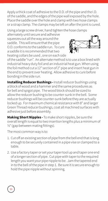
59
Apply a thick coat of adhesive to the O.D. of the pipe and the I.D. of the saddle, and the edges of the pipe wall exposed by the hole. Place the saddle over the hole and clamp with two hose clamps or a strap clamp. The clamps may be left on after the joint is cured.
Using a large screw driver, hand tighten the hose clamps alternately until secure and adhesive squeezes out all the way around the saddle. This will ensure that the pipe O.D. conforms to the saddle run. To cure a saddle it is recommended that two heating collars be used , one on each side of the saddle “run”. An alternate method is to use a box lined with industrial heavy duty foil and an industrial heat gun. When using the foil method cut a 12" section of 2" pipe and insert heat gun in the end to prevent over heating. Allow adhesive to cure before bonding in the side run.
Installing Reducer Bushings - Install reducer bushings using a block of wood and a hammer and the same procedures as for bell and spigot pipe. The wood block should be sized to allow the reducer bushing to be counter-sunk in the bell. Some reducer bushings will be counter-sunk before they are actually locked up. For maximum chemical resistance with 8" and larger Green Thread reducer bushings, coat all machined surfaces with adhesive just before assembly.
Making Short Nipples - To make short nipples, be sure the overall length is equal to two insertion lengths plus a minimum of ½" (gap between mating fittings).
The most common way is to:
1. Cut off an existing section of pipe from the bell end that is long enough to be securely contained in a pipe vise or clamped to a table.
2. Use a factory taper or set your taper tool up and taper one end of a longer section of pipe. Cut pipe with taper to the required length you want your pipe nipple to be. Jam the tapered end in to the bell of the pipe in step 1. Be sure it is secure enough to hold the pipe nipple without spinning.
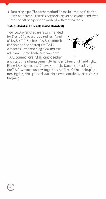
60
3. Taper the pipe. The same method “loose bell method" can be used with the 2000 series box tools. Never hold your hand over the end of the pipe when working with the box tools.”
T.A.B. Joints (Threaded and Bonded)
Two T.A.B. wrenches are recommended for 2" and 3" and are required for 4" and 6" T.A.B. x T.A.B. joints. T.A.B to smooth connections do not require T.A.B. wrenches. Prep bonding area and mix adhesive. Spread adhesive over both T.A.B. connections. Stab joint together and start thread engagement by hand and turn until hand tight. Place T.A.B. wrenches 12" away from the bonding area. Using the T.A.B. wrenches screw together until firm. Check lock up by moving the joint up and down. No movement should be visible at the joint.
61
Joint CureAmbient Cure - Cure time is the time required for the adhesive in the assembled joint to harden. Cure time depends on the type of adhesive and the ambient temperature, as shown in Table 12.
You can shorten cure time by applying heat. Although all of the adhesives will cure at ambient temperatures above 70°F, it is recommended they be heat-cured at temperatures of at least 275°F to maximize physical properties and corrosion resistance. See page 43 for instructions for using heat collars for heat-curing joints.
High Temperature Heat Collar (Table 13) - Refer to bulletin for complete operating instructions.
NOTE: Do not bend or fold heating collar as this may break the heating elements and cause the collar to work improperly or not at all.
Pipe and Fittings:1. Use the same size heating collar as the pipe size you are
installing, with the exception of flanges. Do not use a heating collar that is designed for a larger size pipe.
2. With the uninsulated flap on the bottom (next to the fitting), carefully wrap the heating collar around the joint. Feed the strap through the square ring. CAUTION: The uninsulated flap is extremely hot when the collar is on. DO NOT TOUCH with bare hands.
3. Tighten the straps until the heating collar is snug against the joint.
Flanges:1. For 1", 11⁄2" and 2" flanges, an industrial heat gun may be used
to cure the joint. Be sure that the end of the gun is at least six inches from the opening of the flange.
2. For 3" through 16" flange joints, use a heating collar that is one pipe size smaller. Remove the straps from the heating collar.
3. Carefully turn the collar inside out with the heated area facing the I.D. of the pipe. Place the heating collar in the I.D. of the flange. A split ring of pipe may be used to hold the collar in place while the joint is curing.
Allow the joint to return to ambient temperature before applying stress to the joint.
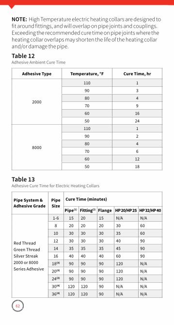
62
NOTE: High Temperature electric heating collars are designed to fit around fittings, and will overlap on pipe joints and couplings. Exceeding the recommended cure time on pipe joints where the heating collar overlaps may shorten the life of the heating collar and/or damage the pipe.
Adhesive Type Temperature, °F Cure Time, hr
2000
110 1
90 3
80 4
70 9
60 16
50 24
8000
110 1
90 2
80 4
70 6
60 12
50 18
Table 12Adhesive Ambient Cure Time
Pipe System & Adhesive Grade
Pipe Size
Cure Time (minutes)
Pipe(1) Fitting(2) Flange HP 20/HP 25 HP 32/HP 40
Red ThreadGreen ThreadSilver Streak2000 or 8000 Series Adhesive
1-6 15 20 15 N/A N/A
8 20 20 20 30 60
10 30 30 30 35 60
12 30 30 30 40 90
14 35 35 35 45 90
16 40 40 40 60 90
18(3) 90 90 90 120 N/A
20(3) 90 90 90 120 N/A
24(3) 90 90 90 120 N/A
30(4) 120 120 90 N/A N/A
36(4) 120 120 90 N/A N/A
Table 13Adhesive Cure Time for Electric Heating Collars
63
The use of insulation is required below 40°F to prevent heat loss.
NOTE: These cure times are for environments warmer than 70°F. If cooler, see “Cold Weather Installation Tips” or consult NOV Fiber Glass Systems. Adhesives will cure in 24 hours at ambient temperatures of 70-100°F.(1) Includes sleeve couplings.(2) 1", 1 1/2" & 2" flanges require the use of an industrial heat gun. Air
temperatures inside the flange should be no greater than 400°F and no less than 250°F.
(3) Below 50°F, the heating collars should be wrapped in insulation to reduce heat loss and are required below 40F.
(4) 18" and larger heat collars require multiple plug 20 amp power outlets.
Heat Packs - Heat packs that cure joints in approximately one hour are also available. Refer to bulletin for complete instructions that are included with each kit. Observe all safety precautions listed on the instruction sheets that accompany the heat packs.
CAUTION: The adhesive bead will cure faster than the adhesive in the joint. It is important that the joint not be pressurized until it has been subjected to the proper time-temperature cycle. A temperature versus time to pressure curve is indicated in the instructions packaged with each adhesive kit.
Repairs for Red Thread, Green Thread & Silver Streak Piping SystemsContact a NOV Fiber Glass Systems field service rep for HP 32/HP 40 repairs.Fiberglass piping systems HP 16/HP 25 are repaired by cutting out a fitting or a damaged section of pipe and replacing it with new material.
CAUTION: Always determine exactly what fluid has been in the piping system as it may be flammable. Contact may be harmful to humans. Take necessary precautions.
Always use the same pipe grade, fittings, and adhesive on new parts as is in the existing system. Do not mix pipe grades.
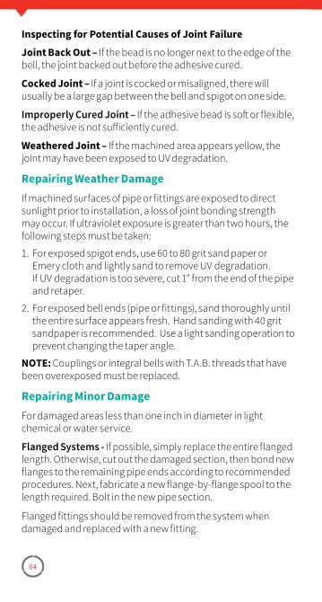
64
Inspecting for Potential Causes of Joint Failure
Joint Back Out – If the bead is no longer next to the edge of the bell, the joint backed out before the adhesive cured.
Cocked Joint – If a joint is cocked or misaligned, there will usually be a large gap between the bell and spigot on one side.
Improperly Cured Joint – If the adhesive bead is soft or flexible, the adhesive is not sufficiently cured.
Weathered Joint – If the machined area appears yellow, the joint may have been exposed to UV degradation.
Repairing Weather DamageIf machined surfaces of pipe or fittings are exposed to direct sunlight prior to installation, a loss of joint bonding strength may occur. If ultraviolet exposure is greater than two hours, the following steps must be taken:
1. For exposed spigot ends, use 60 to 80 grit sand paper or Emery cloth and lightly sand to remove UV degradation. If UV degradation is too severe, cut 1" from the end of the pipe and retaper.
2. For exposed bell ends (pipe or fittings), sand thoroughly until the entire surface appears fresh. Hand sanding with 40 grit sandpaper is recommended. Use a light sanding operation to prevent changing the taper angle.
NOTE: Couplings or integral bells with T.A.B. threads that have been overexposed must be replaced.
Repairing Minor DamageFor damaged areas less than one inch in diameter in light chemical or water service.
Flanged Systems - If possible, simply replace the entire flanged length. Otherwise, cut out the damaged section, then bond new flanges to the remaining pipe ends according to recommended procedures. Next, fabricate a new flange-by-flange spool to the length required. Bolt in the new pipe section.
Flanged fittings should be removed from the system when damaged and replaced with a new fitting.
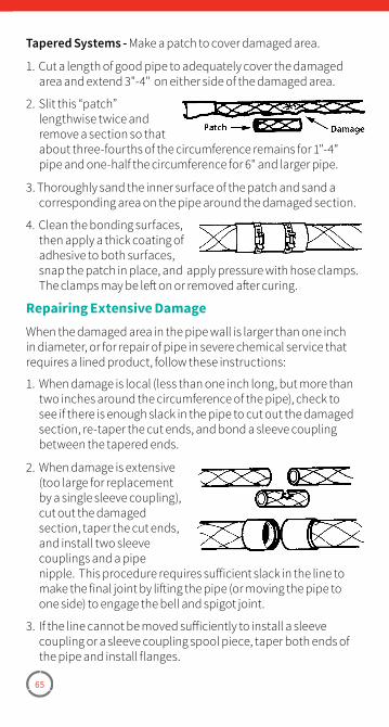
65
Tapered Systems - Make a patch to cover damaged area.
1. Cut a length of good pipe to adequately cover the damaged area and extend 3"-4" on either side of the damaged area.
2. Slit this “patch” lengthwise twice and remove a section so that about three-fourths of the circumference remains for 1"-4" pipe and one-half the circumference for 6" and larger pipe.
3. Thoroughly sand the inner surface of the patch and sand a corresponding area on the pipe around the damaged section.
4. Clean the bonding surfaces, then apply a thick coating of adhesive to both surfaces, snap the patch in place, and apply pressure with hose clamps. The clamps may be left on or removed after curing.
Repairing Extensive DamageWhen the damaged area in the pipe wall is larger than one inch in diameter, or for repair of pipe in severe chemical service that requires a lined product, follow these instructions:
1. When damage is local (less than one inch long, but more than two inches around the circumference of the pipe), check to see if there is enough slack in the pipe to cut out the damaged section, re-taper the cut ends, and bond a sleeve coupling between the tapered ends.
2. When damage is extensive (too large for replacement by a single sleeve coupling), cut out the damaged section, taper the cut ends, and install two sleeve couplings and a pipe nipple. This procedure requires sufficient slack in the line to make the final joint by lifting the pipe (or moving the pipe to one side) to engage the bell and spigot joint.
3. If the line cannot be moved sufficiently to install a sleeve coupling or a sleeve coupling spool piece, taper both ends of the pipe and install flanges.
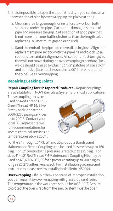
66
4. If it is impossible to taper the pipe in the ditch, you can install a new section of pipe by over wrapping the plain cut ends.
a. Clean an area large enough for installers to work on both sides and under the pipe. Cut out the damaged section of pipe and measure the gap. Cut a section of good pipe that is not more than one-half inch shorter than the length to be replaced (1 ⁄4" maximum gap on each end).
b. Sand the ends of the pipe to remove all resin gloss. Align the replacement pipe section with the pipeline and block up all sections to maintain alignment. All sections must be rigid so they will not move during the over wrapping procedure. Tack welds should be used by placing 1" x 2" patches of glass cloth and adhesive (four patches spaced at 90° intervals around the pipe). See Overwrapping.
Repairing Leaking JointsRepair Coupling for HP Tapered Products – Repair couplings are available from NOV Fiber Glass Systems for most applications. These couplings may be used on Red Thread HP 16, Green Thread HP 16, Silver Streak and Bondstrand 3000/3200 piping services up to 200°F. Contact your local FGS representative for recommendations for severe chemical services or temperatures above 200°F.
For the 2” through 10” RT, GT and SS products Bondstrand Maintenance Repair Couplings can be used for services up to 150 psig. For 12” products the pressure is rated up to 125 psig. For sizes 4” – 12” Red Thread FM Maintenance Coupling Kits may be used on RT, RTFM, GT, SS for a pressure rating up to 200 psig as long as ZC 275 adhesive is used. For installation guidance and instructions please review installation bulletin INS2004.
Overwrapping – If a joint leaks because of improper installation, you can repair it by over wrapping with glass cloth and resin. The temperature in the work area should be 70°F- 90°F. Be sure to protect the over wrap from the sun. System must be open
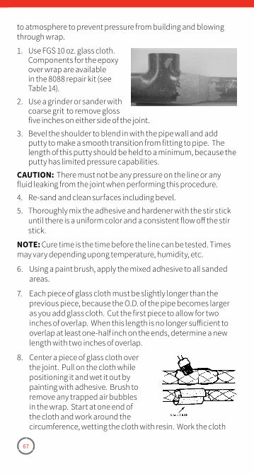
67
to atmosphere to prevent pressure from building and blowing through wrap.
1. Use FGS 10 oz. glass cloth. Components for the epoxy over wrap are available in the 8088 repair kit (see Table 14).
2. Use a grinder or sander with coarse grit to remove gloss five inches on either side of the joint.
3. Bevel the shoulder to blend in with the pipe wall and add putty to make a smooth transition from fitting to pipe. The length of this putty should be held to a minimum, because the putty has limited pressure capabilities.
CAUTION: There must not be any pressure on the line or any fluid leaking from the joint when performing this procedure.
4. Re-sand and clean surfaces including bevel.
5. Thoroughly mix the adhesive and hardener with the stir stick until there is a uniform color and a consistent flow off the stir stick.
NOTE: Cure time is the time before the line can be tested. Times may vary depending upong temperature, humidity, etc.
6. Using a paint brush, apply the mixed adhesive to all sanded areas.
7. Each piece of glass cloth must be slightly longer than the previous piece, because the O.D. of the pipe becomes larger as you add glass cloth. Cut the first piece to allow for two inches of overlap. When this length is no longer sufficient to overlap at least one-half inch on the ends, determine a new length with two inches of overlap.
8. Center a piece of glass cloth over the joint. Pull on the cloth while positioning it and wet it out by painting with adhesive. Brush to remove any trapped air bubbles in the wrap. Start at one end of the cloth and work around the circumference, wetting the cloth with resin. Work the cloth
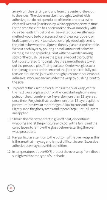
68
away from the starting end and from the center of the cloth to the sides. The cloth must be thoroughly wetted with adhesive, but do not spend a lot of time in one area as the cloth will wet out (lose its shiny, white appearance) with time. By the time the cloth has been worked down smoothly with no air beneath it, most of it will be wetted out. An alternate method would be to place a section of clean cardboard or kraft paper on a work table/section of plywood adjacent to the joint to be wrapped. Spread the dry glass out on the table. Wet out each layer by pouring a small amount of adhesive on the glass and spreading it out with the wooden mixing stick or the brush. Be sure the glass is wet out thoroughly but not saturated (dripping). Use the same adhesive to wet out the prepped pipe/fitting surface. Center wet glass over the damaged area or the center of the joint and carefully pull tension around the joint with enough pressure to squeeze out adhesive. Work out any air under the wrap by pushing it out to the side.
9. To prevent thick sections or humps in the over wrap, center the next piece of glass cloth on the joint starting from a new point on the circumference. Never do more than 12 layers at once time. For joints that require more than 12 layers split the procedure into two or more stages. Allow to cure and cool. Lightly sand the glossy areas and repeat Step 8 until all layers are applied.
10. Should the over wrap start to give off heat, discontinue wrapping and let the joint cure and cool with a fan. Sand the cured layers to remove the gloss before restarting the over wrap procedure.
11. Pay particular attention to the bottom of the over wrap as this is the area that may sag and is most difficult to see. Excessive adhesive use may cause this condition.
12. In temperatures above 90°F, protect the over wrap from direct sunlight with some type of sun shade.
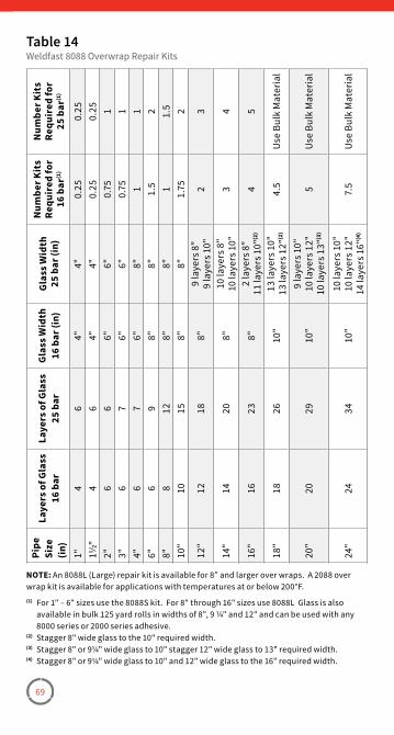
69
Pipe
Size
(in)
Laye
rs o
f Gla
ss16
bar
Laye
rs o
f Gla
ss25
bar
Gla
ss W
idth
16 b
ar (i
n)G
lass
Wid
th25
bar
(in)
Num
ber K
its
Requ
ired
for
16 b
ar(1
)
Num
ber K
its
Requ
ired
for
25 b
ar(1
)
1"4
64"
4"0�
250�
2511
/2"4
64"
4"0�
250�
252"
66
6"6"
0�75
13"
67
6"6"
0�75
14"
67
6"8"
11
6"6
98"
8"1�
52
8"8
128"
8"1
1�5
10"
1015
8"8"
1�75
2
12"
1218
8"9
laye
rs 8
"9
laye
rs 1
0"2
3
14"
1420
8"10
laye
rs 8
"10
laye
rs 1
0"3
4
16"
1623
8"2
laye
rs 8
"11
laye
rs 1
0"(2
)4
5
18"
1826
10"
13 la
yers
10"
13 la
yers
12"
(2)
4�5
Use
Bul
k M
ater
ial
20"
2029
10"
9 la
yers
10"
10 la
yers
12"
10 la
yers
13"
(3)
5U
se B
ulk
Mat
eria
l
24"
2434
10"
10 la
yers
10"
10 la
yers
12"
14 la
yers
16"
(4)
7�5
Use
Bul
k M
ater
ial
Table 14Weldfast 8088 Overwrap Repair Kits
NOTE: An 8088L (Large) repair kit is available for 8” and larger over wraps� A 2088 over wrap kit is available for applications with temperatures at or below 200°F�(1) For 1" – 6" sizes use the 8088S kit� For 8" through 16" sizes use 8088L Glass is also
available in bulk 125 yard rolls in widths of 8", 9 ¼" and 12" and can be used with any 8000 series or 2000 series adhesive�
(2) Stagger 8" wide glass to the 10" required width�(3) Stagger 8" or 9¼" wide glass to 10" stagger 12" wide glass to 13" required width�(4) Stagger 8" or 9¼" wide glass to 10" and 12" wide glass to the 16" required width�

70
Section 5Installation Considerations
Hydrotesting
TestingSystem Start-UpWater HammerFliberglass FlangesConnecting to Other SystemsPainting PIpe
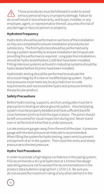
71
These procedures must be followed in order to avoid serious personal injury or property damage. Failure to
do so will result in loss of warranty, and buyer, installer, or any employee, agent, or representative thereof, assumes the risk of any damage or injury to person or property.
Hydrotest Frequency
Hydro tests should be performed on sections of the installation as they are completed to ensure installation procedures are satisfactory. The first hydro test should be performed early during a system assembly to ensure installation techniques are providing the performance required. Long pipe line installations should be hydro tested before 2,500 feet have been installed. Fitting intensive systems as found in industrial systems should be hydro tested before 50 joints have been installed.
Hydrostatic testing should be performed to evaluate the structural integrity of a new or modified piping system. Hydro test pressures must meet any local jurisdiction or code requirements and not exceed the hydro test pressure limits for the particular product.
Safety Precautions
Before hydro testing, supports, anchors and guides must be in place prior to testing an above ground system. A buried piping system must be properly bedded and have sufficient backfill cover between joints to hold the pipe in place. The joints should be left uncovered for visual inspection during test. Never stand over or at the end of a line that is under pressure.
Locate pressure gauges away from the end of the pipe. A pressure gauge with the test pressure at midscale is recommended. When filling the system for hydro testing, open vents to prevent entrapment of air in the system. Then close the vents and slowly pressurize to the test pressure.
Hydro Test Procedures
In order to provide a high degree confidence in the piping system, FGS recommends a 10 cycle hydro test at 1.5 times the design operating pressure not to exceed the recommendations in the product data bulletins ranging from 1.25 to 1.5. Be sure you do not exceed the maximum rating of any other element in the
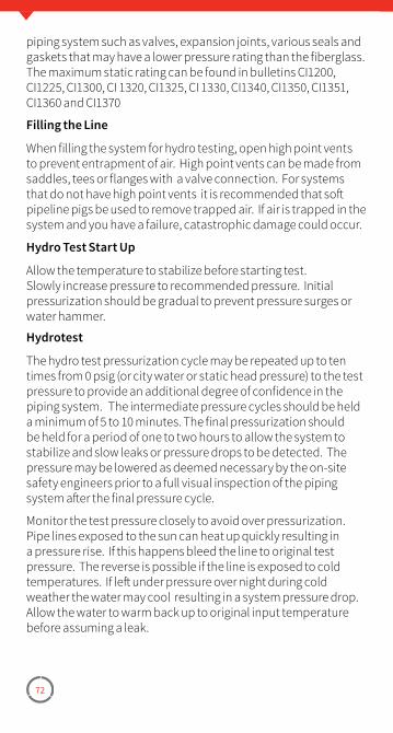
72
piping system such as valves, expansion joints, various seals and gaskets that may have a lower pressure rating than the fiberglass. The maximum static rating can be found in bulletins CI1200, CI1225, CI1300, CI 1320, CI1325, CI 1330, CI1340, CI1350, CI1351, CI1360 and CI1370
Filling the Line
When filling the system for hydro testing, open high point vents to prevent entrapment of air. High point vents can be made from saddles, tees or flanges with a valve connection. For systems that do not have high point vents it is recommended that soft pipeline pigs be used to remove trapped air. If air is trapped in the system and you have a failure, catastrophic damage could occur.
Hydro Test Start Up
Allow the temperature to stabilize before starting test. Slowly increase pressure to recommended pressure. Initial pressurization should be gradual to prevent pressure surges or water hammer.
Hydrotest
The hydro test pressurization cycle may be repeated up to ten times from 0 psig (or city water or static head pressure) to the test pressure to provide an additional degree of confidence in the piping system. The intermediate pressure cycles should be held a minimum of 5 to 10 minutes. The final pressurization should be held for a period of one to two hours to allow the system to stabilize and slow leaks or pressure drops to be detected. The pressure may be lowered as deemed necessary by the on-site safety engineers prior to a full visual inspection of the piping system after the final pressure cycle.
Monitor the test pressure closely to avoid over pressurization. Pipe lines exposed to the sun can heat up quickly resulting in a pressure rise. If this happens bleed the line to original test pressure. The reverse is possible if the line is exposed to cold temperatures. If left under pressure over night during cold weather the water may cool resulting in a system pressure drop. Allow the water to warm back up to original input temperature before assuming a leak.
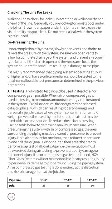
73
Checking The Line For Leaks
Walk the line to check for leaks. Do not stand or walk near the top or end of the line. Generally you are looking for moist spots under the joints. Brown kraft paper under the joints can help ease the visual ability to spot a leak. Do not repair a leak while the system is pressurized.
De-Pressuring The Line
Upon completion of hydro test, slowly open vents and drains to relieve the pressure on the system. Be sure you open vents to allow for complete drainage of the system and prevent a vacuum type failure . If the drain is open and the vents are closed the system could create a vacuum resulting in damage to the pipe.
It is highly recommended that piping systems operating at 150°F or higher and/or have a critical medium, should be tested to the maximum allowable test pressures as determined in the previous paragraphs.
Air Testing: Hydrostatic test should be used instead of air or compressed gas if possible. When air or compressed gas is used for testing, tremendous amounts of energy can be stored in the system. If a failure occurs, the energy may be released catastrophically, which can result in property damage and personal injury. In cases where system contamination or fluid weight prevents the use of hydrostatic test, an air test may be used with extreme caution. To reduce the risk of air testing, use the table below to determine maximum pressure. When pressurizing the system with air or compressed gas, the area surrounding the piping must be cleared of personnel to prevent injury. Hold air pressure for one hour, then reduce the pressure to one half the original. Personnel can then enter the area to perform soap test of all joints. Again, extreme caution must be exercised during air testing to prevent property damage or personnel injury. If air or compressed gas testing is used, NOV Fiber Glass Systems will not be responsible for any resulting injury to personnel or damage to property, including the piping system. Air or compressed gas testing is done entirely at the discretion and risk of management at the job site.
Pipe Size 1"-6" 8"-12" 14"-42"
psig 25 15 10
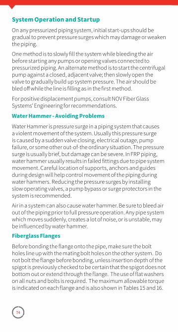
74
System Operation and StartupOn any pressurized piping system, initial start-ups should be gradual to prevent pressure surges which may damage or weaken the piping.
One method is to slowly fill the system while bleeding the air before starting any pumps or opening valves connected to pressurized piping. An alternate method is to start the centrifugal pump against a closed, adjacent valve; then slowly open the valve to gradually build up system pressure. The air should be bled off while the line is filling as in the first method.
For positive displacement pumps, consult NOV Fiber Glass Systems' Engineering for recommendations.
Water Hammer - Avoiding Problems
Water Hammer is pressure surge in a piping system that causes a violent movement of the system. Usually this pressure surge is caused by a sudden valve closing, electrical outage, pump failure, or some other out-of-the ordinary situation. The pressure surge is usually brief, but damage can be severe. In FRP piping, water hammer usually results in failed fittings due to pipe system movement. Careful location of supports, anchors and guides during design will help control movement of the piping during water hammers. Reducing the pressure surges by installing slow operating valves, a pump bypass or surge protectors in the system is recommended.
Air in a system can also cause water hammer. Be sure to bleed air out of the piping prior to full pressure operation. Any pipe system which moves suddenly, creates a lot of noise, or is unstable, may be influenced by water hammer.
Fiberglass Flanges
Before bonding the flange onto the pipe, make sure the bolt holes line up with the mating bolt holes on the other system. Do not bolt the flange before bonding, unless insertion depth of the spigot is previously checked to be certain that the spigot does not bottom out or extend through the flange. The use of flat washers on all nuts and bolts is required. The maximum allowable torque is indicated on each flange and is also shown in Tables 15 and 16.
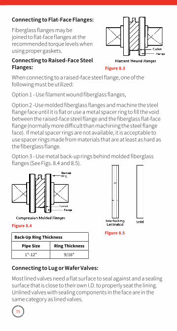
75
Connecting to Flat-Face Flanges:
Fiberglass flanges may be joined to flat-face flanges at the recommended torque levels when using proper gaskets.
Connecting to Raised-Face Steel Flanges:
When connecting to a raised-face steel flange, one of the following must be utilized:
Option 1 - Use filament wound fiberglass flanges,
Option 2 -Use molded fiberglass flanges and machine the steel flange face until it is flat or use a metal spacer ring to fill the void between the raised-face steel flange and the fiberglass flat-face flange (normally more difficult than machining the steel flange face). If metal spacer rings are not available, it is acceptable to use spacer rings made from materials that are at least as hard as the fiberglass flange.
Option 3 - Use metal back-up rings behind molded fiberglass flanges (See Figs. 8.4 and 8.5).
Figure 8.3
Figure 8.4Figure 8.5
Back-Up Ring Thickness
Pipe Size Ring Thickness
1"-12" 9/16"
Connecting to Lug or Wafer Valves:
Most lined valves need a flat surface to seal against and a sealing surface that is close to their own I.D. to properly seat the lining. Unlined valves with sealing components in the face are in the same category as lined valves.
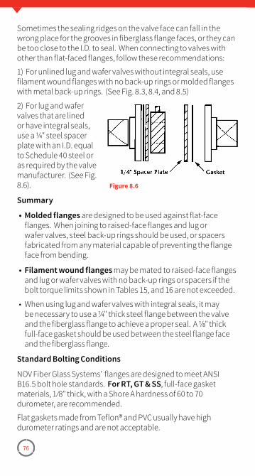
76
Sometimes the sealing ridges on the valve face can fall in the wrong place for the grooves in fiberglass flange faces, or they can be too close to the I.D. to seal. When connecting to valves with other than flat-faced flanges, follow these recommendations:
1) For unlined lug and wafer valves without integral seals, use filament wound flanges with no back-up rings or molded flanges with metal back-up rings. (See Fig. 8.3, 8.4, and 8.5)
2) For lug and wafer valves that are lined or have integral seals, use a ¼" steel spacer plate with an I.D. equal to Schedule 40 steel or as required by the valve manufacturer. (See Fig. 8.6).
Summary
• Molded flanges are designed to be used against flat-face flanges. When joining to raised-face flanges and lug or wafer valves, steel back-up rings should be used, or spacers fabricated from any material capable of preventing the flange face from bending.
• Filament wound flanges may be mated to raised-face flanges and lug or wafer valves with no back-up rings or spacers if the bolt torque limits shown in Tables 15, and 16 are not exceeded.
• When using lug and wafer valves with integral seals, it may be necessary to use a ¼" thick steel flange between the valve and the fiberglass flange to achieve a proper seal. A ⅛" thick full-face gasket should be used between the steel flange face and the fiberglass flange.
Standard Bolting Conditions
NOV Fiber Glass Systems' flanges are designed to meet ANSI B16.5 bolt hole standards. For RT, GT & SS, full-face gasket materials, 1 ⁄8" thick, with a Shore A hardness of 60 to 70 durometer, are recommended.
Flat gaskets made from Teflon® and PVC usually have high durometer ratings and are not acceptable.
Figure 8.6
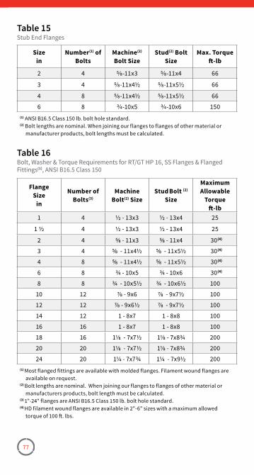
77
Sizein
Number(1) of Bolts
Machine(2) Bolt Size
Stud(2) Bolt Size
Max. Torqueft-lb
2 4 5⁄8-11x3 5⁄8-11x4 66
3 4 5⁄8-11x4½ 5⁄8-11x5½ 66
4 8 5⁄8-11x4½ 5⁄8-11x5½ 66
6 8 3⁄4-10x5 3⁄4-10x6 150(1) ANSI B16�5 Class 150 lb� bolt hole standard�(2) Bolt lengths are nominal� When joining our flanges to flanges of other material or
manufacturer products, bolt lengths must be calculated�
Table 15Stub End Flanges
FlangeSize
in
Number of Bolts(3)
MachineBolt(2) Size
Stud Bolt (2) Size
Maximum Allowable
Torqueft-lb
1 4 ½ - 13x3 ½ - 13x4 25
1 ½ 4 ½ - 13x3 ½ - 13x4 25
2 4 ⅝ - 11x3 ⅝ - 11x4 30(4)
3 4 ⅝ - 11x4½ ⅝ - 11x5½ 30(4)
4 8 ⅝ - 11x4½ ⅝ - 11x5½ 30(4)
6 8 ¾ - 10x5 ¾ - 10x6 30(4)
8 8 ¾ - 10x5½ ¾ - 10x6½ 100
10 12 ⅞ - 9x6 ⅞ - 9x7½ 100
12 12 ⅞ - 9x6½ ⅞ - 9x7½ 100
14 12 1 - 8x7 1 - 8x8 100
16 16 1 - 8x7 1 - 8x8 100
18 16 1⅛ - 7x7½ 1⅛ - 7x8¾ 200
20 20 1⅛ - 7x7½ 1⅛ - 7x8¾ 200
24 20 1¼ - 7x7¾ 1¼ - 7x9½ 200(1) Most flanged fittings are available with molded flanges� Filament wound flanges are
available on request�(2) Bolt lengths are nominal� When joining our flanges to flanges of other material or
manufacturers products, bolt length must be calculated�(3) 1"-24" flanges are ANSI B16�5 Class 150 lb� bolt hole standard�(4) HD filament wound flanges are available in 2"-6" sizes with a maximum allowed
torque of 100 ft� lbs�
Table 16Bolt, Washer & Torque Requirements for RT/GT HP 16, SS Flanges & Flanged Fittings(1), ANSI B16�5 Class 150
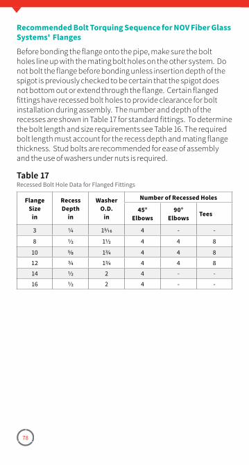
78
Recommended Bolt Torquing Sequence for NOV Fiber Glass Systems' Flanges
Before bonding the flange onto the pipe, make sure the bolt holes line up with the mating bolt holes on the other system. Do not bolt the flange before bonding unless insertion depth of the spigot is previously checked to be certain that the spigot does not bottom out or extend through the flange. Certain flanged fittings have recessed bolt holes to provide clearance for bolt installation during assembly. The number and depth of the recesses are shown in Table 17 for standard fittings. To determine the bolt length and size requirements see Table 16. The required bolt length must account for the recess depth and mating flange thickness. Stud bolts are recommended for ease of assembly and the use of washers under nuts is required.
FlangeSize
in
Recess Depth
in
Washer O.D.
in
Number of Recessed Holes
45°Elbows
90°Elbows Tees
3 1⁄4 15⁄16 4 - -
8 1⁄2 11⁄2 4 4 8
10 5⁄8 13⁄4 4 4 8
12 3⁄4 13⁄4 4 4 8
14 1⁄2 2 4 - -
16 1⁄2 2 4 - -
Table 17Recessed Bolt Hole Data for Flanged Fittings
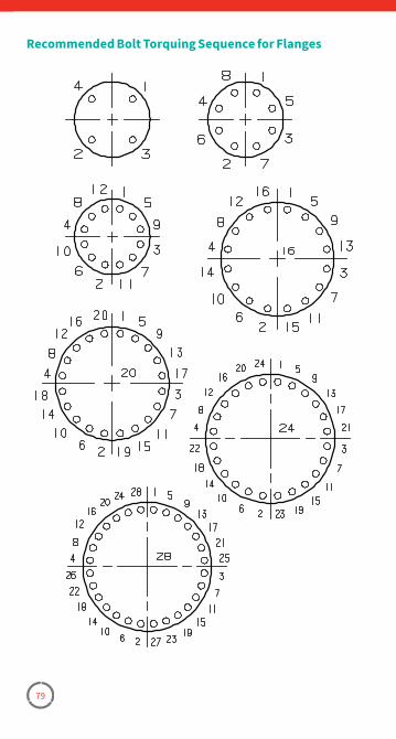
79
Recommended Bolt Torquing Sequence for Flanges
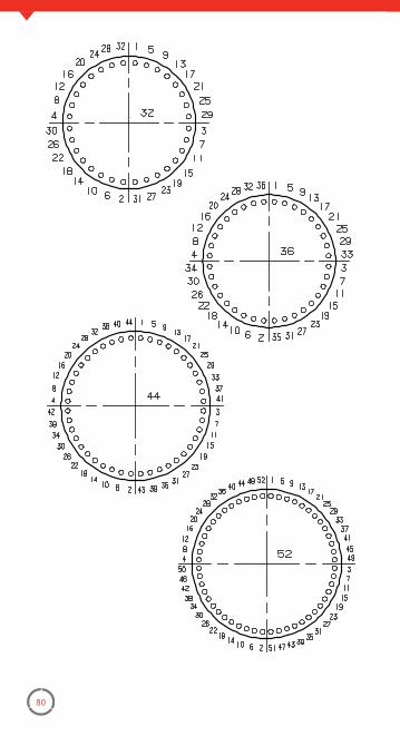
80
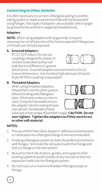
81
Connecting to Other SystemsIt is often necessary to connect a fiberglass piping to another piping system or make a connection that will not be possible using flanges. Two types of adapters are available: bell or spigot by grooved ends and bell or spigot by threaded ends.
AdaptersNOTE: When using adapters with spigot ends, it may be necessary to cut off a portion of the factory pipe bell if the groove or threads are not fully exposed.
A. Grooved Adapters RT, GT, SS Product: Do not use
couplings designed for plastic or cement-lined steel as they can leak due to a difference in groove dimensions. Grooved adapters are machined to ES Cut Groove dimensions. Use standard high pressure (Victaulic Style HP70ES) coupling or equivalent.
B. Threaded Adapters When using threaded adapters,
thread them into the other system before bonding onto fiberglass pipe. Otherwise, unless a union is used, it may be impossible to turn the adapter into the mating thread. Use soft set, nonmetallic thread lubricant or two wraps of plumber's tape. CAUTION: Do not over-tighten. Tighten the adapters as if they were brass or other soft material.
NOTES:1. The use of NOV Fiber Glass Systems' adhesive to bond a steel
or metal pipe into a fiberglass flange is not recommended.
2. If mating a fiberglass system to steel, the preferred method is with flanges. Terminate the old system with their flange and bolt our flange on the new system.
3. Be sure to check the anchors, guides, and supports of an existing system to avoid transfer of any stresses or thermal expansion loads into the fiberglass system.
4. Do not try to cut or machine threads in fiberglass pipe or fittings.
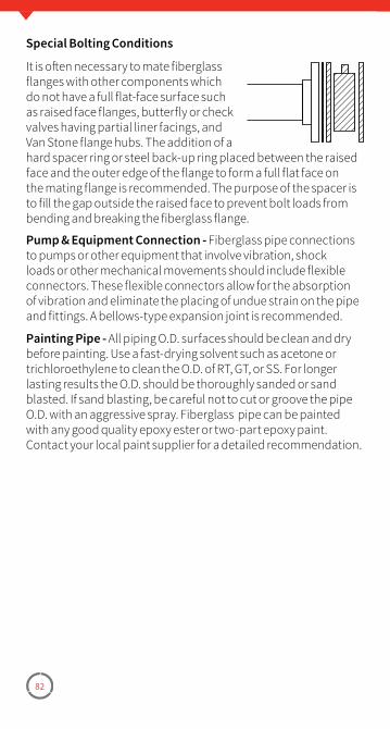
82
Special Bolting Conditions
It is often necessary to mate fiberglass flanges with other components which do not have a full flat-face surface such as raised face flanges, butterfly or check valves having partial liner facings, and Van Stone flange hubs. The addition of a hard spacer ring or steel back-up ring placed between the raised face and the outer edge of the flange to form a full flat face on the mating flange is recommended. The purpose of the spacer is to fill the gap outside the raised face to prevent bolt loads from bending and breaking the fiberglass flange.
Pump & Equipment Connection - Fiberglass pipe connections to pumps or other equipment that involve vibration, shock loads or other mechanical movements should include flexible connectors. These flexible connectors allow for the absorption of vibration and eliminate the placing of undue strain on the pipe and fittings. A bellows-type expansion joint is recommended.
Painting Pipe - All piping O.D. surfaces should be clean and dry before painting. Use a fast-drying solvent such as acetone or trichloroethylene to clean the O.D. of RT, GT, or SS. For longer lasting results the O.D. should be thoroughly sanded or sand blasted. If sand blasting, be careful not to cut or groove the pipe O.D. with an aggressive spray. Fiberglass pipe can be painted with any good quality epoxy ester or two-part epoxy paint. Contact your local paint supplier for a detailed recommendation.
83
Section 6Helpful InformationConversions
ConversionsDecimal Equivalents of FractionsDefinition of TermsHow to Read Flanged or Reducing FittingsHow to Figure a 45° Offset
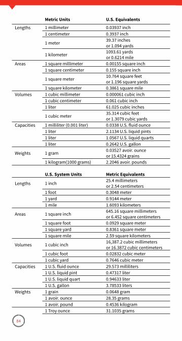
84
Metric Units U.S. Equivalents
Lengths 1 millimeter 0�03937 inch1 centimeter 0�3937 inch
1 meter 39�37 inchesor 1�094 yards
1 kilometer 1093�61 yardsor 0�6214 mile
Areas 1 square millimeter 0�00155 square inch1 square centimeter 0�155 square inch
1 square meter 10�764 square feetor 1�196 square yards
1 square kilometer 0�3861 square mile Volumes 1 cubic millimeter 0�000061 cubic inch
1 cubic centimeter 0�061 cubic inch1 liter 61�025 cubic inches
1 cubic meter 35�314 cubic feetor 1�3079 cubic yards
Capacities 1 milliliter (0�001 liter) 0�0338 U�S� fluid ounce1 liter 2�1134 U�S� liquid pints1 liter 1�0567 U�S� liquid quarts1 liter 0�2642 U�S� gallon
Weights 1 gram 0�03527 avoir� ounceor 15�4324 grains
1 kilogram(1000 grams) 2�2046 avoir� pounds
U.S. System Units Metric Equivalents
Lengths 1 inch 25�4 millimetersor 2�54 centimeters
1 foot 0�3048 meter1 yard 0�9144 meter1 mile 1�6093 kilometers
Areas 1 square inch 645�16 square millimetersor 6�452 square centimeters
1 square foot 0�0929 square meter1 square yard 0�8361 square meter1 square mile 2�59 square kilometers
Volumes 1 cubic inch 16,387�2 cubic millimetersor 16�3872 cubic centimeters
1 cubic foot 0�02832 cubic meter1 cubic yard 0�7646 cubic meter
Capacities 1 U�S� fluid ounce 29�573 milliliters1 U�S� liquid pint 0�47317 liter1 U�S� liquid quart 0�94633 liter1 U�S� gallon 3�78533 liters
Weights 1 grain 0�0648 gram1 avoir� ounce 28�35 grams1 avoir� pound 0�4536 kilogram1 Troy ounce 31�1035 grams
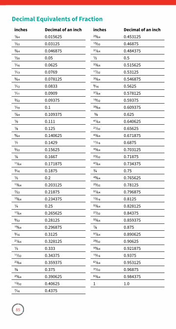
85
inches Decimal of an inch1⁄64 0�0156251⁄32 0�031253⁄64 0�0468751⁄20 0�051⁄16 0�06251⁄13 0�07695⁄64 0�0781251⁄12 0�08331⁄11 0�09093⁄32 0�093751⁄10 0�17⁄64 0�1093751⁄9 0�1111⁄8 0�1259⁄64 0�1406251⁄7 0�14295⁄32 0�156251⁄6 0�166711⁄64 0�1718753⁄16 0�18751⁄5 0�213⁄64 0�2031257⁄32 0�2187515⁄64 0�2343751⁄4 0�2517⁄64 0�2656259⁄32 0�2812519⁄64 0�2968755⁄16 0�312521⁄64 0�3281251⁄3 0�33311⁄32 0�3437523⁄64 0�3593753⁄8 0�37525⁄64 0�39062513⁄32 0�406257⁄16 0�4375
inches Decimal of an inch29⁄64 0�45312515⁄32 0�4687531⁄64 0�4843751⁄2 0�533⁄64 0�51562517⁄32 0�5312535⁄64 0�5468759⁄16 0�562537⁄64 0�57812519⁄32 0�5937539⁄64 0�609375 5⁄8 0�62541⁄64 0�64062521⁄32 0�6562543⁄64 0�67187511⁄16 0�687545⁄64 0�70312523⁄32 0�7187547⁄64 0�7343753⁄4 0�7549⁄64 0�76562525⁄32 0�7812551⁄64 0�79687513⁄16 0�812553⁄64 0�82812527⁄32 0�8437555⁄64 0�8593757⁄8 0�87557⁄64 0�89062529⁄32 0�9062559⁄64 0�92187515⁄16 0�937561⁄64 0�95312531⁄32 0�9687563⁄64 0�9843751 1�0
Decimal Equivalents of Fraction
86
Definition of TermsAdapter – A fitting used to join two pieces of pipe, or two fittings, which have different joining systems.
Adhesive – A material formulated to bond together pipe and fittings resulting in high strength and corrosion resistant fabrications.
Anchors – Device to positively restrain the movement of the pipe against all lateral and axial forces.
Bell and Spigot – A joining system in which two truncated conical surfaces come together and bond adhesively. The bell is the female end. The spigot is the male end.
Bushing – A fitting used to join two different sizes of pipe by reducing the size of the female end of the joint. Joints may come threaded or tapered.
Catalyst – See hardener.
Collar – See coupling.
Compressive Force – The force that occurs when a pipe is subjected to crushing loads. Axial compressive forces occur when a piping system is anchored to restrain thermal growth.
Compression Molding – A process for making fittings in which a molding compound is formed and cured into the finished part configuration through pressure and heat in a die.
Concentric Reducer – A pipe fitting used to join two different sizes of pipe while maintaining the same center line.
Contact Molding – A process for making fittings in which cut pieces of fiberglass reinforcement are laid on a mold, saturated with resin, and cured to the finished part shape.
Coupling (collar) – A short heavy wall cylindrical fitting used to join two pieces of the same size pipe in a straight line. The coupling always has female connection ends which can be bell, threaded or a mechanical joining method.
Cure – The hardening of a thermoset resin system by the action of heat or chemical action.
Cure Stages – Stages describe the degree to which a thermoset resin has cross-linked. Three stages, in order of increasing cross linking, include B stage, gelled, fully cured.
87
Cure Time – The time required for a thermoset material to react and develop full strength. The time is dependent upon the temperature of the material.
Curing Agent – See hardener.
Cut and Mitered Fittings – Fittings manufactured by cutting, assembling and bonding pipe sections into a desired configuration. The assembled product is then over wrapped with resin-impregnated roving or glass cloth, to provide added strength.
Epoxy Resin – A thermosetting resin, usually made from Bisphenol A and epichlorhydrin, cured by a variety of agents such as anhydrides and amines. These resins contain cyclic ether groups. See thermoset.
FRP – Fiberglass Reinforced Plastic.
Filament Wound – A manufacturing method for pipe and fittings in which resin impregnated continuous strand roving wraps around a mandrel to achieve high reinforcement concentration and precise filament placement.
Fillers (extender, pigments, inerts; i.e., sand, etc.) – Materials added to a resin which do not affect the cure of the resin but may influence the physical properties of the resin system.
Fitting Types – The classification of fittings by the method of manufacture; i.e., molded, cut and mitered, filament wound, contact molded.
Gel Time – The time it takes for a resin system to harden to a rubber-like state.
Guide – Device that allows free axial movement of the pipe, but restrains lateral movement.
Hand Lay-Up – The forming of resin and fiberglass into finished pipe products or fittings by manual procedures. These procedures include over wrap techniques, contact molding, hand molding and others.
Hardener (accelerator, catalyst, curing agent, promoter) – Chemicals added to the resin, single or in combination, which speed up the hardening process, or cause hardening to occur.
88
Heat Blanket or Heat Collar – An electrical device used to heat a fabrication to reduce cure time.
Hydrostatic Test – A pressure test of a completed fabrication to confirm good quality. Typically, the system is filled with water and held at the selected pressure while checking for leaks.
Impact Resistance – The ability of a part to absorb a striking blow without damage.
Joining (connecting systems) – Any of a variety of methods for connecting two separate components of a piping system together. Included are bell and spigot, threaded and coupled, mechanical devices, etc.
Joint – A term used to describe an individual length of pipe or the actual joining mechanism; i.e., adhesive bonded bell and spigot, threaded and coupled, etc.)
Liner – A generic term used to describe the interior surface in pipe. Generally, liners are resin-rich regions from 0.005 to 0.100 in. thick. Liners may be reinforced with fibrous material such as veil or mat. Liners can provide extra corrosion protection for severe chemical service. They also form a leak barrier (elastomer bladder). The manufacturer may add a liner before, during, or after construction of the pipe wall depending on the manufacturing process.
Lock-Up –A bell and spigot joint engaged sufficiently to eliminate pivot action in the joint.
Matrix – The material used to bind reinforcement and fillers together. This material may be thermoplastic or thermosetting and dictates to a large extent the temperature and chemical service conditions allowable for a pipe or fitting.
Mechanical Force – Physical exertion of power used to achieve lock-up in tapered bell and spigot joints.
Molded Fittings – Pipe fittings formed by compressing resin, chopped fiber and other ingredients in a mold under heat and pressure.
Molding – Any of several manufacturing methods where pressure or compression molding shapes resin and reinforcing materials into final products.
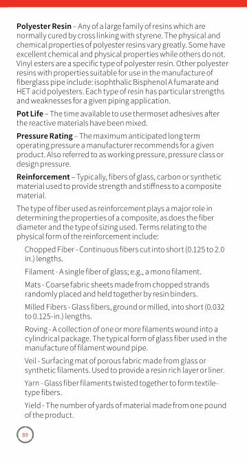
89
Polyester Resin – Any of a large family of resins which are normally cured by cross linking with styrene. The physical and chemical properties of polyester resins vary greatly. Some have excellent chemical and physical properties while others do not. Vinyl esters are a specific type of polyester resin. Other polyester resins with properties suitable for use in the manufacture of fiberglass pipe include: isophthalic Bisphenol A fumarate and HET acid polyesters. Each type of resin has particular strengths and weaknesses for a given piping application.
Pot Life – The time available to use thermoset adhesives after the reactive materials have been mixed.
Pressure Rating – The maximum anticipated long term operating pressure a manufacturer recommends for a given product. Also referred to as working pressure, pressure class or design pressure.
Reinforcement – Typically, fibers of glass, carbon or synthetic material used to provide strength and stiffness to a composite material.
The type of fiber used as reinforcement plays a major role in determining the properties of a composite, as does the fiber diameter and the type of sizing used. Terms relating to the physical form of the reinforcement include:
Chopped Fiber - Continuous fibers cut into short (0.125 to 2.0 in.) lengths.
Filament - A single fiber of glass; e.g., a mono filament.
Mats - Coarse fabric sheets made from chopped strands randomly placed and held together by resin binders.
Milled Fibers - Glass fibers, ground or milled, into short (0.032 to 0.125-in.) lengths.
Roving - A collection of one or more filaments wound into a cylindrical package. The typical form of glass fiber used in the manufacture of filament wound pipe.
Veil - Surfacing mat of porous fabric made from glass or synthetic filaments. Used to provide a resin rich layer or liner.
Yarn - Glass fiber filaments twisted together to form textile-type fibers.
Yield - The number of yards of material made from one pound of the product.
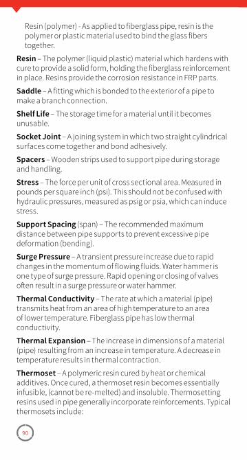
90
Resin (polymer) - As applied to fiberglass pipe, resin is the polymer or plastic material used to bind the glass fibers together.
Resin – The polymer (liquid plastic) material which hardens with cure to provide a solid form, holding the fiberglass reinforcement in place. Resins provide the corrosion resistance in FRP parts.
Saddle – A fitting which is bonded to the exterior of a pipe to make a branch connection.
Shelf Life – The storage time for a material until it becomes unusable.
Socket Joint – A joining system in which two straight cylindrical surfaces come together and bond adhesively.
Spacers – Wooden strips used to support pipe during storage and handling.
Stress – The force per unit of cross sectional area. Measured in pounds per square inch (psi). This should not be confused with hydraulic pressures, measured as psig or psia, which can induce stress.
Support Spacing (span) – The recommended maximum distance between pipe supports to prevent excessive pipe deformation (bending).
Surge Pressure – A transient pressure increase due to rapid changes in the momentum of flowing fluids. Water hammer is one type of surge pressure. Rapid opening or closing of valves often result in a surge pressure or water hammer.
Thermal Conductivity – The rate at which a material (pipe) transmits heat from an area of high temperature to an area of lower temperature. Fiberglass pipe has low thermal conductivity.
Thermal Expansion – The increase in dimensions of a material (pipe) resulting from an increase in temperature. A decrease in temperature results in thermal contraction.
Thermoset – A polymeric resin cured by heat or chemical additives. Once cured, a thermoset resin becomes essentially infusible, (cannot be re-melted) and insoluble. Thermosetting resins used in pipe generally incorporate reinforcements. Typical thermosets include:
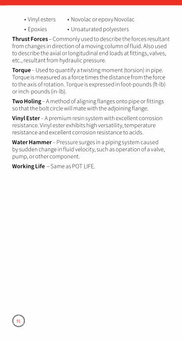
91
• Vinyl esters • Novolac or epoxy Novolac
• Epoxies • Unsaturated polyesters
Thrust Forces – Commonly used to describe the forces resultant from changes in direction of a moving column of fluid. Also used to describe the axial or longitudinal end loads at fittings, valves, etc., resultant from hydraulic pressure.
Torque – Used to quantify a twisting moment (torsion) in pipe. Torque is measured as a force times the distance from the force to the axis of rotation. Torque is expressed in foot-pounds (ft-lb) or inch-pounds (in-lb).
Two Holing – A method of aligning flanges onto pipe or fittings so that the bolt circle will mate with the adjoining flange.
Vinyl Ester – A premium resin system with excellent corrosion resistance. Vinyl ester exhibits high versatility, temperature resistance and excellent corrosion resistance to acids.
Water Hammer – Pressure surges in a piping system caused by sudden change in fluid velocity, such as operation of a valve, pump, or other component.
Working Life – Same as POT LIFE.
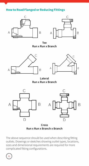
92
How to Read Flanged or Reducing Fittings
TeeRun x Run x Branch
LateralRun x Run x Branch
CrossRun x Run x Branch x Branch
The above sequence should be used when describing fitting outlets. Drawings or sketches showing outlet types, locations, sizes and dimensional requirements are required for more complicated fitting configurations.
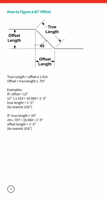
93
How to Figure a 45° Offset
OffsetLength
OffsetLength
TrueLength
45˚
True Length = offset x 1�414Offset = true length x �707
Examples:IF: offset = 12"12" x 1�414 = 16�968 = 1'-5"true length = 1'-5"(to nearest 1⁄16")
IF: true length = 24"24 x �707 = 16�968 = 1'-5"offset length = 1'-5"(to nearest 1⁄16")
94
Notes: _____________________ ___________________________ ___________________________ ___________________________ ___________________________ ___________________________ ___________________________ ___________________________ ___________________________ ___________________________ ___________________________ ___________________________ ___________________________ ___________________________ ___________________________ ___________________________ ___________________________ ___________________________ ___________________________ ___________________________ ___________________________

95
Notes: _____________________ ___________________________ ___________________________ ___________________________ ___________________________ ___________________________ ___________________________ ___________________________ ___________________________ ___________________________ ___________________________ ___________________________ ___________________________ ___________________________ ___________________________ ___________________________ ___________________________ ___________________________ ___________________________ ___________________________ ___________________________

96
National Oilwell Varco has produced this brochure for general information only, and it is not intended for design purposes� Although every effort has been made to maintain the accuracy and reliability of its contents, National Oilwell Varco in no way assumes responsibility for liability for any loss, damage or injury resulting from the use of information and data herein nor is any warranty expressed or implied� Always cross-reference the bulletin date with the most current version listed at the web site noted in this literature�
© 2017 National Oilwell Varco All Rights ReservedINS1000ENG March 2017
Fiber Glass Systems17115 San Pedro Avenue, Ste 200San Antonio, Texas 78232 USAPhone: 210 477 7500 | Fax: 210 477 7560
nov.com/fgs

Pipe InstallationHandbook
Straight Socket and
Butt & Wrap Joints
• CENTRICAST™ PRODUCTSCL-1520CL-2030
RB-1520RB-2530
• F-CHEM™ • Z-CORE™
www.nov.com/fgs

NOV FIBER GLASS SYSTEMS PIPEINSTALLATION HANDBOOK
Straight Socket Joints and Butt & Wrap Joints
This fabrication manual is offered to assist you in the proper fabrication and installation procedures when assembling your NOV Fiber Glass Systems piping system.
If you do not find the answer to your questions in the manual, feel free to contact your Regional Manager, local distributor, or the factory.
The products must be installed and used in accordance with sound, proven practice and common sense.
The information supplied in our literature must be con-sidered as an expression of guidelines based on field experience rather than a warranty for which we assume responsibility. NOV Fiber Glass Systems offers a limited warranty of its products in the Terms and Conditions of Sale. The information contained in the literature and catalogs furnished cannot ensure, of itself, a successful installation and is offered to customers subject to these limitations and explanations.
It is our policy to improve its products continually. Therefore, the company reserves the right, without notice, to change specifications and/or design at any time without incurring an obligation for equipment previously sold. Descriptions contained in this catalog are for the purpose of identification and neither limit nor extend the standard product limited warranty set forth in the Terms and Conditions of Sale and Trade Customs.
i
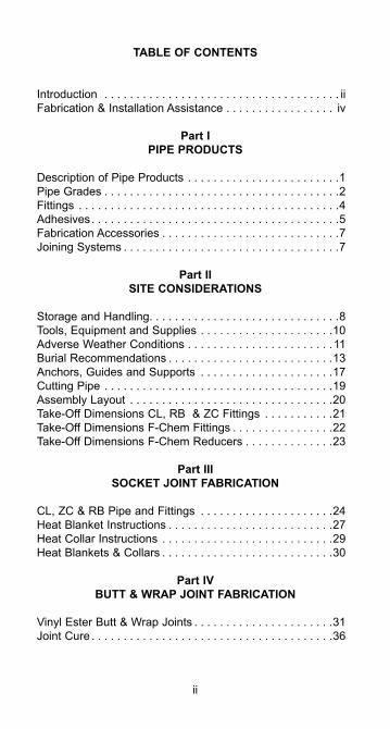
TABLE OF CONTENTS
Introduction . . . . . . . . . . . . . . . . . . . . . . . . . . . . . . . . . . . . . iiFabrication & Installation Assistance . . . . . . . . . . . . . . . . . iv
Part IPIPE PRODUCTS
Description of Pipe Products . . . . . . . . . . . . . . . . . . . . . . . .1Pipe Grades . . . . . . . . . . . . . . . . . . . . . . . . . . . . . . . . . . . . .2Fittings . . . . . . . . . . . . . . . . . . . . . . . . . . . . . . . . . . . . . . . . .4Adhesives. . . . . . . . . . . . . . . . . . . . . . . . . . . . . . . . . . . . . . .5Fabrication Accessories . . . . . . . . . . . . . . . . . . . . . . . . . . . .7Joining Systems . . . . . . . . . . . . . . . . . . . . . . . . . . . . . . . . . .7
Part IISITE CONSIDERATIONS
Storage and Handling. . . . . . . . . . . . . . . . . . . . . . . . . . . . . .8Tools, Equipment and Supplies . . . . . . . . . . . . . . . . . . . . .10Adverse Weather Conditions . . . . . . . . . . . . . . . . . . . . . . .11Burial Recommendations . . . . . . . . . . . . . . . . . . . . . . . . . .13Anchors, Guides and Supports . . . . . . . . . . . . . . . . . . . . .17Cutting Pipe . . . . . . . . . . . . . . . . . . . . . . . . . . . . . . . . . . . .19Assembly Layout . . . . . . . . . . . . . . . . . . . . . . . . . . . . . . . .20Take-Off Dimensions CL, RB & ZC Fittings . . . . . . . . . . .21Take-Off Dimensions F-Chem Fittings . . . . . . . . . . . . . . . .22Take-Off Dimensions F-Chem Reducers . . . . . . . . . . . . . .23
Part IIISOCKET JOINT FABRICATION
CL, ZC & RB Pipe and Fittings . . . . . . . . . . . . . . . . . . . . .24Heat Blanket Instructions . . . . . . . . . . . . . . . . . . . . . . . . . .27Heat Collar Instructions . . . . . . . . . . . . . . . . . . . . . . . . . . .29Heat Blankets & Collars . . . . . . . . . . . . . . . . . . . . . . . . . . .30
Part IVBUTT & WRAP JOINT FABRICATION
Vinyl Ester Butt & Wrap Joints . . . . . . . . . . . . . . . . . . . . . .31Joint Cure . . . . . . . . . . . . . . . . . . . . . . . . . . . . . . . . . . . . . .36
ii
Part VINSTALLATION CONSIDERATIONS
Flange & Fitting Alignment . . . . . . . . . . . . . . . . . . . . . . . . .37Flange Gasket & O-Ring Requirements. . . . . . . . . . . . . . .40Standard Bolting Conditions. . . . . . . . . . . . . . . . . . . . . . . .41Flange Bolt Torque Sequence . . . . . . . . . . . . . . . . . . . . . .44Special Flange Bolting Conditions . . . . . . . . . . . . . . . . . . .46Connecting to Other Piping Systems . . . . . . . . . . . . . . . . .47Hydrostatic Testing . . . . . . . . . . . . . . . . . . . . . . . . . . . . . . .48System Startup. . . . . . . . . . . . . . . . . . . . . . . . . . . . . . . . . .48Water Hammer . . . . . . . . . . . . . . . . . . . . . . . . . . . . . . . . . .50
Part VISYSTEM REPAIR & MODIFICATION
Replacing Damaged Pipe. . . . . . . . . . . . . . . . . . . . . . . . . .51Replacing Damaged Fittings . . . . . . . . . . . . . . . . . . . . . . .53Overwrap . . . . . . . . . . . . . . . . . . . . . . . . . . . . . . . . . . . . . .55Temporary Fixes. . . . . . . . . . . . . . . . . . . . . . . . . . . . . . . . .56Tapping into a Line . . . . . . . . . . . . . . . . . . . . . . . . . . . . . . .56
Part VIIHELPFUL INFORMATION
Conversions . . . . . . . . . . . . . . . . . . . . . . . . . . . . . . . . . . . .59Useful Formulas . . . . . . . . . . . . . . . . . . . . . . . . . . . . . . . .65Definition of Terms . . . . . . . . . . . . . . . . . . . . . . . . . . . . . . .66How To Read Flanged or Reducing Fittings . . . . . . . . . . .71How To Figure a 45° Offset . . . . . . . . . . . . . . . . . . . . . . . .72
iii
CL = Centricast Plus CL-2030 or Centricast CL-1520 Piping SystemsRB = Centricast Plus RB-2530 or Centricast RB-1520 Piping SystemsZC = Z-Core Piping SystemsFC = F-Chem Piping Systems
FABRICATION AND INSTALLATION ASSISTANCE
Installing fiberglass pipe is easier than installing carbon steel, stainless steel and lined steel due to light weight. Learning the proper methods to prepare and make-up socket or butt & wrap joints can help ensure the reliability and long-term per-formance of your piping system.
We offer the TQI Plus (ASME B31.3) Fabrication and Assembly certification program. Qualified Field Service Representatives train fabrication and assembly crews, conduct and supervise fabrication work, and inspect work in progress.
For complete information concerning these training seminars, contact your local distributor or Regional Manager.
iv
CAUTIONAs this pipe may carry hazardous material and/or operate at a hazardous pressure level, you must follow instructions in this manual to avoid serious personal injury or property damage. In any event, improper installation can cause injury or damage. In addition, installers should read and follow all cautions and warn-ings on adhesive kits, heat packs, propane torches, etc. to avoid personal injury. Also, observe general safety practices with all saws, tools, etc. to avoid personal injury. Wear protective clothing when necessary. Make sure work surfaces are clean and stable and that work areas are properly ventilated.
Safety Data Sheets (SDS) are available on our web site at www.nov.com/fgs.
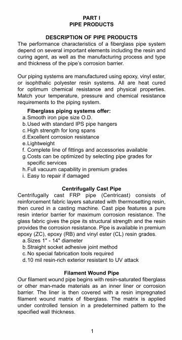
PART IPIPE PRODUCTS
DESCRIPTION OF PIPE PRODUCTSThe performance characteristics of a fiberglass pipe system depend on several important elements including the resin and curing agent, as well as the manufacturing process and type and thickness of the pipe’s corrosion barrier.
Our piping systems are manufactured using epoxy, vinyl ester, or isophthalic polyester resin systems. All are heat cured for optimum chemical resistance and physical properties. Match your temperature, pressure and chemical resistance requirements to the piping system.
Fiberglass piping systems offer:a. Smooth iron pipe size O.D.b. Used with standard IPS pipe hangersc. High strength for long spansd. Excellent corrosion resistancee. Lightweightf. Complete line of fittings and accessories availableg. Costs can be optimized by selecting pipe grades for
specific servicesh. Full vacuum capability in premium gradesi. Easy to repair if damaged
Centrifugally Cast PipeCentrifugally cast FRP pipe (Centricast) consists of reinforcement fabric layers saturated with thermosetting resin, then cured in a casting machine. Cast pipe features a pure resin interior barrier for maximum corrosion resistance. The glass fabric gives the pipe its structural strength and the resin provides the corrosion resistance. Pipe is available in premium epoxy (ZC), epoxy (RB) and vinyl ester (CL) resin grades.
a. Sizes 1" - 14" diameterb. Straight socket adhesive joint methodc. No special fabrication tools requiredd. 10 mil resin-rich exterior resistant to UV attack
Filament Wound PipeOur filament wound pipe begins with resin-saturated fiberglass or other man-made materials as an inner liner or corrosion barrier. The liner is then covered with a resin impregnated filament wound matrix of fiberglass. The matrix is applied under controlled tension in a predetermined pattern to the specified wall thickness.
1
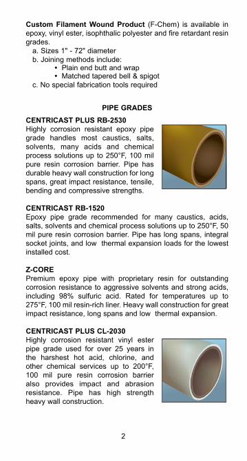
Custom Filament Wound Product (F-Chem) is available in epoxy, vinyl ester, isophthalic polyester and fire retardant resin grades.
a. Sizes 1" - 72" diameterb. Joining methods include: • Plain end butt and wrap • Matched tapered bell & spigot c. No special fabrication tools required
PIPE GRADESCENTRICAST PLUS RB-2530Highly corrosion resistant epoxy pipe grade handles most caustics, salts, solvents, many acids and chemical process solutions up to 250°F, 100 mil pure resin corrosion barrier. Pipe has durable heavy wall construction for long spans, great impact resistance, tensile, bending and compressive strengths.
CENTRICAST RB-1520Epoxy pipe grade recommended for many caustics, acids, salts, solvents and chemical process solutions up to 250°F, 50 mil pure resin corrosion barrier. Pipe has long spans, integral socket joints, and low thermal expansion loads for the lowest installed cost.
Z-COREPremium epoxy pipe with proprietary resin for outstanding corrosion resistance to aggressive solvents and strong acids, including 98% sulfuric acid. Rated for temperatures up to 275°F, 100 mil resin-rich liner. Heavy wall construction for great impact resistance, long spans and low thermal expansion.
CENTRICAST PLUS CL-2030Highly corrosion resistant vinyl ester pipe grade used for over 25 years in the harshest hot acid, chlorine, and other chemical services up to 200°F, 100 mil pure resin corrosion barrier also provides impact and abrasion resistance. Pipe has high strength heavy wall construction.
2

CENTRICAST CL-1520Vinyl ester pipe grade used for many hot acid, chlorine and corrosive chemical services up to 200°F, 50 mil pure resin corrosion barrier. Long spans, integral socket joints, and low thermal expansion loads provide for a low installed cost system.
F-CHEM and F-CHEM AR*Custom filament wound construction offers more flexibility in resin systems, corrosion barriers and wall thickness than our standard products. Let us assist you in selecting the right pipe for a specific application.
*AR grade is manufactured for added abrasion resistance.
3
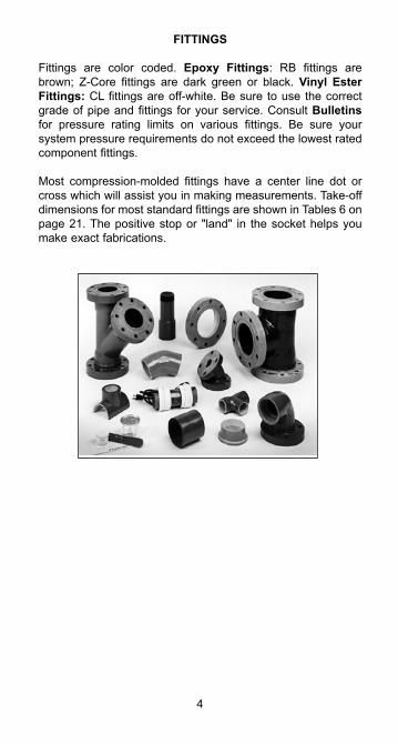
FITTINGS
Fittings are color coded. Epoxy Fittings: RB fittings are brown; Z-Core fittings are dark green or black. Vinyl Ester Fittings: CL fittings are off-white. Be sure to use the correct grade of pipe and fittings for your service. Consult Bulletins for pressure rating limits on various fittings. Be sure your system pressure requirements do not exceed the lowest rated component fittings.
Most compression-molded fittings have a center line dot or cross which will assist you in making measurements. Take-off dimensions for most standard fittings are shown in Tables 6 on page 21. The positive stop or "land" in the socket helps you make exact fabrications.
4
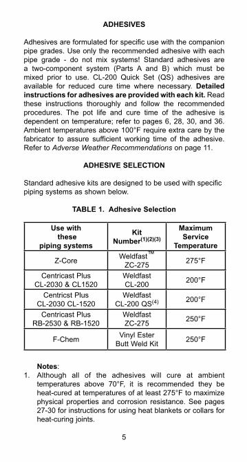
ADHESIVES
Adhesives are formulated for specific use with the companion pipe grades. Use only the recommended adhesive with each pipe grade - do not mix systems! Standard adhesives are a two-component system (Parts A and B) which must be mixed prior to use. CL-200 Quick Set (QS) adhesives are available for reduced cure time where necessary. Detailed instructions for adhesives are provided with each kit. Read these instructions thoroughly and follow the recommended procedures. The pot life and cure time of the adhesive is dependent on temperature; refer to pages 6, 28, 30, and 36. Ambient temperatures above 100°F require extra care by the fabricator to assure sufficient working time of the adhesive. Refer to Adverse Weather Recommendations on page 11.
ADHESIVE SELECTION
Standard adhesive kits are designed to be used with specific piping systems as shown below.
TABLE 1. Adhesive Selection
Use with these
piping systems
Kit Number(1)(2)(3)
Maximum Service
Temperature
Z-Core Weldfast™ ZC-275 275°F
Centricast PlusCL-2030 & CL1520
Weldfast CL-200 200°F
Centricst PlusCL-2030 CL-1520
Weldfast CL-200 QS(4) 200°F
Centricast PlusRB-2530 & RB-1520
Weldfast ZC-275 250°F
F-Chem Vinyl EsterButt Weld Kit 250°F
Notes:1. Although all of the adhesives will cure at ambient
temperatures above 70°F, it is recommended they be heat-cured at temperatures of at least 275°F to maximize physical properties and corrosion resistance. See pages 27-30 for instructions for using heat blankets or collars for heat-curing joints.
5
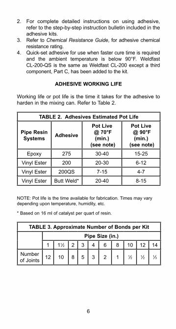
2. For complete detailed instructions on using adhesive, refer to the step-by-step instruction bulletin included in the adhesive kits.
3. Refer to Chemical Resistance Guide, for adhesive chemical resistance rating.
4. Quick-set adhesive for use when faster cure time is required and the ambient temperature is below 90°F. Weldfast CL-200-QS is the same as Weldfast CL-200 except a third component, Part C, has been added to the kit.
ADHESIVE WORKING LIFE
Working life or pot life is the time it takes for the adhesive to harden in the mixing can. Refer to Table 2.
TABLE 2. Adhesives Estimated Pot Life
Pipe Resin Systems Adhesive
Pot Live @ 70°F (min.)
(see note)
Pot Live @ 90°F (min.)
(see note)Epoxy 275 30-40 15-25
Vinyl Ester 200 20-30 6-12
Vinyl Ester 200QS 7-15 4-7
Vinyl Ester Butt Weld* 20-40 8-15
NOTE: Pot life is the time available for fabrication. Times may vary depending upon temperature, humidity, etc.
* Based on 16 ml of catalyst per quart of resin.
TABLE 3. Approximate Number of Bonds per KitPipe Size (in.)
1 11⁄2 2 3 4 6 8 10 12 14
Number of Joints 12 10 8 5 3 2 1 1⁄2 1⁄2 1⁄3
6
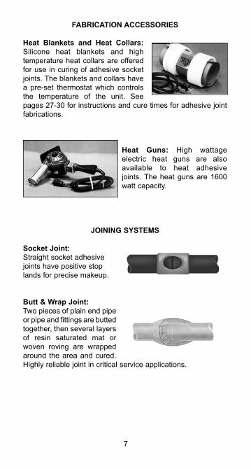
FABRICATION ACCESSORIES
Heat Blankets and Heat Collars: Silicone heat blankets and high temperature heat collars are offered for use in curing of adhesive socket joints. The blankets and collars have a pre-set thermostat which controls the temperature of the unit. See pages 27-30 for instructions and cure times for adhesive joint fabrications.
Heat Guns: High wattage electric heat guns are also available to heat adhesive joints. The heat guns are 1600 watt capacity.
JOINING SYSTEMS
Socket Joint:Straight socket adhesive joints have positive stop lands for precise makeup.
Butt & Wrap Joint:Two pieces of plain end pipe or pipe and fittings are butted together, then several layers of resin saturated mat or woven roving are wrapped around the area and cured. Highly reliable joint in critical service applications.
7
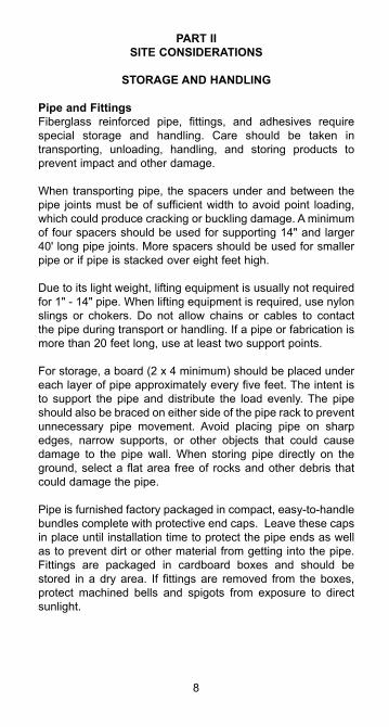
PART IISITE CONSIDERATIONS
STORAGE AND HANDLING
Pipe and FittingsFiberglass reinforced pipe, fittings, and adhesives require special storage and handling. Care should be taken in transporting, unloading, handling, and storing products to prevent impact and other damage.
When transporting pipe, the spacers under and between the pipe joints must be of sufficient width to avoid point loading, which could produce cracking or buckling damage. A minimum of four spacers should be used for supporting 14" and larger 40' long pipe joints. More spacers should be used for smaller pipe or if pipe is stacked over eight feet high.
Due to its light weight, lifting equipment is usually not required for 1" - 14" pipe. When lifting equipment is required, use nylon slings or chokers. Do not allow chains or cables to contact the pipe during transport or handling. If a pipe or fabrication is more than 20 feet long, use at least two support points.
For storage, a board (2 x 4 minimum) should be placed under each layer of pipe approximately every five feet. The intent is to support the pipe and distribute the load evenly. The pipe should also be braced on either side of the pipe rack to prevent unnecessary pipe movement. Avoid placing pipe on sharp edges, narrow supports, or other objects that could cause damage to the pipe wall. When storing pipe directly on the ground, select a flat area free of rocks and other debris that could damage the pipe.
Pipe is furnished factory packaged in compact, easy-to-handle bundles complete with protective end caps. Leave these caps in place until installation time to protect the pipe ends as well as to prevent dirt or other material from getting into the pipe. Fittings are packaged in cardboard boxes and should be stored in a dry area. If fittings are removed from the boxes, protect machined bells and spigots from exposure to direct sunlight.
8
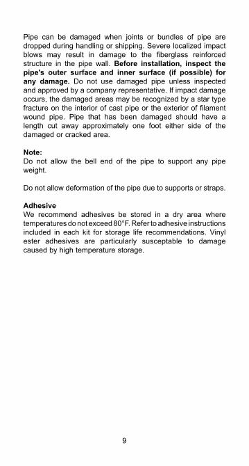
Pipe can be damaged when joints or bundles of pipe are dropped during handling or shipping. Severe localized impact blows may result in damage to the fiberglass reinforced structure in the pipe wall. Before installation, inspect the pipe's outer surface and inner surface (if possible) for any damage. Do not use damaged pipe unless inspected and approved by a company representative. If impact damage occurs, the damaged areas may be recognized by a star type fracture on the interior of cast pipe or the exterior of filament wound pipe. Pipe that has been damaged should have a length cut away approximately one foot either side of the damaged or cracked area.
Note: Do not allow the bell end of the pipe to support any pipe weight. Do not allow deformation of the pipe due to supports or straps.
AdhesiveWe recommend adhesives be stored in a dry area where temperatures do not exceed 80°F. Refer to adhesive instructions included in each kit for storage life recommendations. Vinyl ester adhesives are particularly susceptable to damage caused by high temperature storage.
9
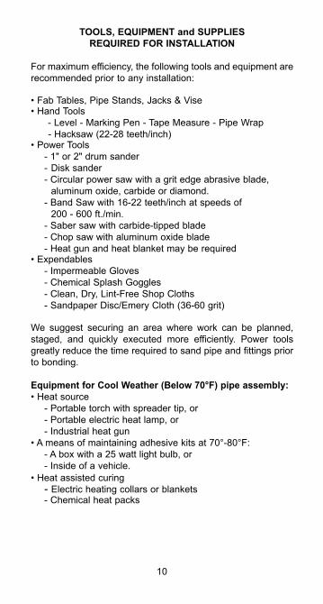
TOOLS, EQUIPMENT and SUPPLIESREQUIRED FOR INSTALLATION
For maximum efficiency, the following tools and equipment are recommended prior to any installation:
• Fab Tables, Pipe Stands, Jacks & Vise• Hand Tools - Level - Marking Pen - Tape Measure - Pipe Wrap - Hacksaw (22-28 teeth/inch)• Power Tools - 1" or 2" drum sander - Disk sander - Circular power saw with a grit edge abrasive blade, aluminum oxide, carbide or diamond. - Band Saw with 16-22 teeth/inch at speeds of 200 - 600 ft./min. - Saber saw with carbide-tipped blade - Chop saw with aluminum oxide blade - Heat gun and heat blanket may be required• Expendables - Impermeable Gloves - Chemical Splash Goggles - Clean, Dry, Lint-Free Shop Cloths - Sandpaper Disc/Emery Cloth (36-60 grit) We suggest securing an area where work can be planned, staged, and quickly executed more efficiently. Power tools greatly reduce the time required to sand pipe and fittings prior to bonding.
Equipment for Cool Weather (Below 70°F) pipe assembly:• Heat source - Portable torch with spreader tip, or - Portable electric heat lamp, or - Industrial heat gun• A means of maintaining adhesive kits at 70°-80°F: - A box with a 25 watt light bulb, or - Inside of a vehicle.• Heat assisted curing - Electric heating collars or blankets - Chemical heat packs
10
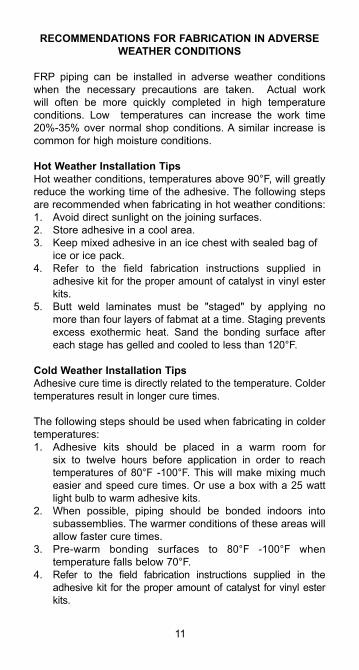
RECOMMENDATIONS FOR FABRICATION IN ADVERSEWEATHER CONDITIONS
FRP piping can be installed in adverse weather conditions when the necessary precautions are taken. Actual work will often be more quickly completed in high temperature conditions. Low temperatures can increase the work time 20%-35% over normal shop conditions. A similar increase is common for high moisture conditions.
Hot Weather Installation TipsHot weather conditions, temperatures above 90°F, will greatly reduce the working time of the adhesive. The following steps are recommended when fabricating in hot weather conditions:1. Avoid direct sunlight on the joining surfaces.2. Store adhesive in a cool area.3. Keep mixed adhesive in an ice chest with sealed bag of
ice or ice pack. 4. Refer to the field fabrication instructions supplied in
adhesive kit for the proper amount of catalyst in vinyl ester kits.
5. Butt weld laminates must be "staged" by applying no more than four layers of fabmat at a time. Staging prevents excess exothermic heat. Sand the bonding surface after each stage has gelled and cooled to less than 120°F.
Cold Weather Installation TipsAdhesive cure time is directly related to the temperature. Colder temperatures result in longer cure times.
The following steps should be used when fabricating in colder temperatures:1. Adhesive kits should be placed in a warm room for
six to twelve hours before application in order to reach temperatures of 80°F -100°F. This will make mixing much easier and speed cure times. Or use a box with a 25 watt light bulb to warm adhesive kits.
2. When possible, piping should be bonded indoors into subassemblies. The warmer conditions of these areas will allow faster cure times.
3. Pre-warm bonding surfaces to 80°F -100°F when temperature falls below 70°F.
4. Refer to the field fabrication instructions supplied in the adhesive kit for the proper amount of catalyst for vinyl ester kits.
11
5. A heat gun, collar or blanket may be used to obtain a faster cure time. Apply a layer of fiberglass insulation or a welding blanket around the heat collars or blankets when installation temperatures are below 50°F.
Extreme Moisture
Adhesive Joints• If fittings or pipe have moisture on the bonding surface,
wipe them dry prior to sanding.• Sand pipe or fittings immediately before applying the
adhesive to bond the joint. Sand surfaces until a fresh, dry surface is present, then remove dust with a clean dry cloth, and apply adhesive.
• Cure per the previous recommendations for normal, extreme heat or extreme cold temperatures.
Laminate Joints• Keep the glass fabric dry, as resins will not saturate wet
fabric. Discard glass fabric which has been wet or exposed to rain, as moisture can remove the bonding agent.
• In high humidity environments, keep the glass fabric in the plastic wrap until ready to use.
• If it is raining, move the work to a shelter, or construct a temporary shelter.• Bonding surfaces must be sanded immediately prior to application of the resin to the pipe or fitting. Sand or grind
until a fresh, dry surface is present, then wipe off the dust and apply resin.
• Saturate the fabric with the resin and apply a coat of resin to the sanded surface prior to applying the fabric.
• Refer to recommendations for conditions of extreme heat, cold, or normal conditions for curing.
• When a laminate requires staging, repeat the above pre-cautions for each step.
• Moisture will not affect the cured laminate joint.
12
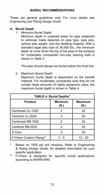
BURIAL RECOMMENDATIONS
These are general guidelines only. For more details see Engineering and Piping Design Guide.
A. Burial Depth1. Minimum Burial Depth Minimum depth in unpaved areas for pipe subjected
to vehicular loads depends on pipe type, pipe size, vehicle axle weight, and the bedding material. With a standard legal axle load of 34,000 lbs., the minimum depth of cover (from the top of the pipe to the surface) for moderately compacted non-clay bearing soils is shown in Table 4.
The pipe should always be buried below the frost line.
2. Maximum Burial Depth Maximum burial depth is dependent on the backfill
material. For moderately compacted soils that do not contain large amounts of highly expansive clays, the maximum burial depth is shown in Table 4.
TABLE 4. Burial Depths*Product Minimum
(ft.)Maximum
(ft.)Centricast CL-1520 2 20
Centricst CL-2030 2 20
Centricast RB-1520 2 20
Centricst RB-2530 2 20
Z-Core 2 20
F-Chem Custom Piping** 3 - 5 12 - 20
* Based on 1000 psi soil modulus. Refer to Engineering & Piping Design Guide, for detailed information for your specific application.
** F-Chem is designed for specific burial applications according to AWWA M45.
13
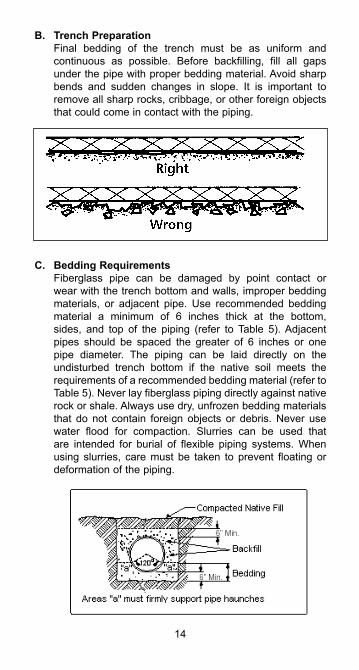
B. Trench Preparation Final bedding of the trench must be as uniform and
continuous as possible. Before backfilling, fill all gaps under the pipe with proper bedding material. Avoid sharp bends and sudden changes in slope. It is important to remove all sharp rocks, cribbage, or other foreign objects that could come in contact with the piping.
C. Bedding Requirements Fiberglass pipe can be damaged by point contact or
wear with the trench bottom and walls, improper bedding materials, or adjacent pipe. Use recommended bedding material a minimum of 6 inches thick at the bottom, sides, and top of the piping (refer to Table 5). Adjacent pipes should be spaced the greater of 6 inches or one pipe diameter. The piping can be laid directly on the undisturbed trench bottom if the native soil meets the requirements of a recommended bedding material (refer to Table 5). Never lay fiberglass piping directly against native rock or shale. Always use dry, unfrozen bedding materials that do not contain foreign objects or debris. Never use water flood for compaction. Slurries can be used that are intended for burial of flexible piping systems. When using slurries, care must be taken to prevent floating or deformation of the piping.
14
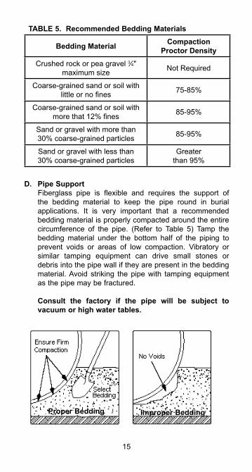
TABLE 5. Recommended Bedding Materials
Bedding Material CompactionProctor Density
Crushed rock or pea gravel 3⁄4" maximum size Not Required
Coarse-grained sand or soil with little or no fines 75-85%
Coarse-grained sand or soil with more that 12% fines 85-95%
Sand or gravel with more than 30% coarse-grained particles 85-95%
Sand or gravel with less than 30% coarse-grained particles
Greater than 95%
D. Pipe Support Fiberglass pipe is flexible and requires the support of
the bedding material to keep the pipe round in burial applications. It is very important that a recommended bedding material is properly compacted around the entire circumference of the pipe. (Refer to Table 5) Tamp the bedding material under the bottom half of the piping to prevent voids or areas of low compaction. Vibratory or similar tamping equipment can drive small stones or debris into the pipe wall if they are present in the bedding material. Avoid striking the pipe with tamping equipment as the pipe may be fractured.
Consult the factory if the pipe will be subject to vacuum or high water tables.
15
Proper Bedding Improper Bedding
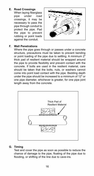
E. Road Crossings When laying fiberglass
pipe under road crossings, it may be necessary to pass the pipe through conduit to protect the pipe. Pad the pipe to prevent rubbing or point loads against the conduit.
F. Wall Penetrations Where the pipe goes through or passes under a concrete
structure, precautions must be taken to prevent bending or point loading of the pipe due to settling. A minimum 2" thick pad of resilient material should be wrapped around the pipe to provide flexibility and prevent contact with the concrete. If bolts are used in the resilient material, care should be taken that the bolts, nuts, or washers cannot come into point load contact with the pipe. Bedding depth under the pipe should be increased to a minimum of 12" or one pipe diameter, whichever is greater, for one pipe joint length away from the concrete.
G. Timing Test and cover the pipe as soon as possible to reduce the
chance of damage to the pipe, floating of the pipe due to flooding, or shifting of the line due to cave-ins.
16
Thick Pad of Resilient Material
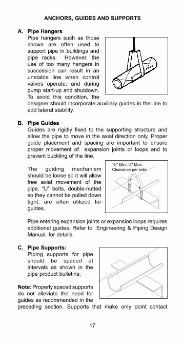
ANCHORS, GUIDES AND SUPPORTS
A. Pipe Hangers Pipe hangers such as those
shown are often used to support pipe in buildings and pipe racks. However, the use of too many hangers in succession can result in an unstable line when control valves operate, and during pump start-up and shutdown. To avoid this condition, the designer should incorporate auxiliary guides in the line to add lateral stability.
B. Pipe Guides Guides are rigidly fixed to the supporting structure and
allow the pipe to move in the axial direction only. Proper guide placement and spacing are important to ensure proper movement of expansion joints or loops and to prevent buckling of the line.
The guiding mechanism should be loose so it will allow free axial movement of the pipe. “U” bolts, double-nutted so they cannot be pulled down tight, are often utilized for guides.
Pipe entering expansion joints or expansion loops requires additional guides. Refer to Engineering & Piping Design Manual, for details.
C. Pipe Supports: Piping supports for pipe
should be spaced at intervals as shown in the pipe product bulletins.
Note: Properly spaced supports do not alleviate the need for guides as recommended in the preceding section. Supports that make only point contact
17
1⁄16" Min.-1⁄8" Max. Clearance per side
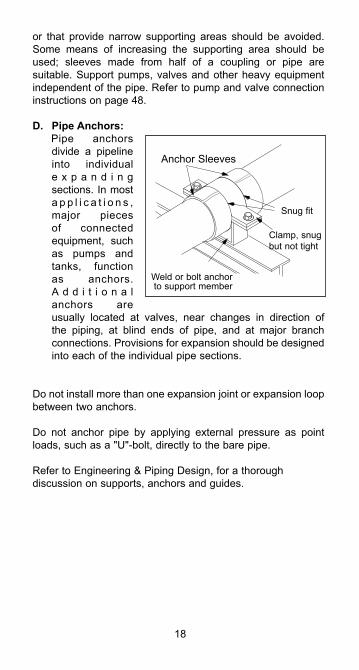
or that provide narrow supporting areas should be avoided. Some means of increasing the supporting area should be used; sleeves made from half of a coupling or pipe are suitable. Support pumps, valves and other heavy equipment independent of the pipe. Refer to pump and valve connection instructions on page 48.
D. Pipe Anchors: Pipe anchors
divide a pipeline into individual e x p a n d i n g sections. In most a p p l i c a t i o n s , major pieces of connected equipment, such as pumps and tanks, function as anchors. A d d i t i o n a l anchors are usually located at valves, near changes in direction of the piping, at blind ends of pipe, and at major branch connections. Provisions for expansion should be designed into each of the individual pipe sections.
Do not install more than one expansion joint or expansion loop between two anchors.
Do not anchor pipe by applying external pressure as point loads, such as a "U"-bolt, directly to the bare pipe.
Refer to Engineering & Piping Design, for a thorough discussion on supports, anchors and guides.
18
Anchor Sleeves
Clamp, snug but not tight
Weld or bolt anchor to support member
Snug fit
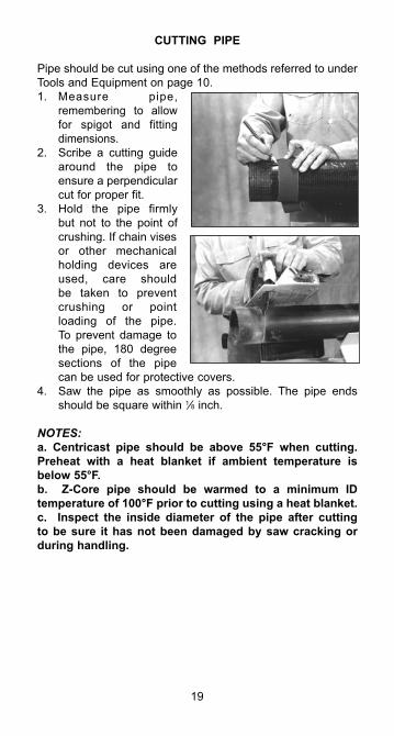
CUTTING PIPE
Pipe should be cut using one of the methods referred to under Tools and Equipment on page 10.1. Measure pipe,
remembering to allow for spigot and fitting dimensions.
2. Scribe a cutting guide around the pipe to ensure a perpendicular cut for proper fit.
3. Hold the pipe firmly but not to the point of crushing. If chain vises or other mechanical holding devices are used, care should be taken to prevent crushing or point loading of the pipe. To prevent damage to the pipe, 180 degree sections of the pipe can be used for protective covers.
4. Saw the pipe as smoothly as possible. The pipe ends should be square within 1⁄8 inch.
NOTES:a. Centricast pipe should be above 55°F when cutting. Preheat with a heat blanket if ambient temperature is below 55°F.b. Z-Core pipe should be warmed to a minimum ID temperature of 100°F prior to cutting using a heat blanket.c. Inspect the inside diameter of the pipe after cutting to be sure it has not been damaged by saw cracking or during handling.
19
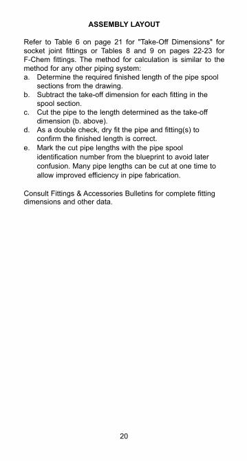
ASSEMBLY LAYOUT
Refer to Table 6 on page 21 for "Take-Off Dimensions" for socket joint fittings or Tables 8 and 9 on pages 22-23 for F-Chem fittings. The method for calculation is similar to the method for any other piping system:a. Determine the required finished length of the pipe spool sections from the drawing.b. Subtract the take-off dimension for each fitting in the
spool section.c. Cut the pipe to the length determined as the take-off
dimension (b. above).d. As a double check, dry fit the pipe and fitting(s) to
confirm the finished length is correct. e. Mark the cut pipe lengths with the pipe spool
identification number from the blueprint to avoid later confusion. Many pipe lengths can be cut at one time to allow improved efficiency in pipe fabrication.
Consult Fittings & Accessories Bulletins for complete fittingdimensions and other data.
20
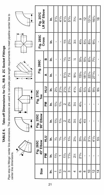
21
TAB
LE 6
. T
ake-
off D
imen
sion
s fo
r CL,
RB
& Z
C S
ocke
t Fitt
ings
Pip
e st
op to
fitti
ngs’
cen
ter l
ine
dim
ensi
ons.
The
dim
ensi
ons
are
used
to c
alcu
late
pip
e le
ngth
requ
irem
ents
to m
eet p
ipel
ine
cent
er li
ne to
ce
nter
line
dim
ensi
ons.
Size
Fig.
265
C45
° Elb
owFi
g. 2
55C
90° E
lbow
Fig.
275
CTe
eFi
g. 2
66C
Fig.
285
CC
ross
Fig.
257
CLR
90°
Elb
owPM
HLU
PMH
LUA
BIn
.In
.In
.In
.In
.In
.In
.In
.In
.In
.1
15 ⁄16
9 ⁄16
15 ⁄16
15 ⁄16
25 ⁄16
--
-313
⁄1611 ⁄2
115
⁄1617 ⁄1
617 ⁄1
6211
⁄16-
--
411⁄16
217 ⁄1
611
⁄162
2211
⁄16511
⁄1613
⁄1613 ⁄8
411⁄16
3115
⁄1613 ⁄1
625 ⁄8
25 ⁄8311
⁄1671 ⁄8
11 ⁄823 ⁄1
6515
⁄16
421 ⁄4
23 ⁄16
31 ⁄431 ⁄4
411⁄16
93 ⁄16
7 ⁄831 ⁄2
73 ⁄16
6215
⁄1633 ⁄1
643 ⁄1
643 ⁄1
663 ⁄1
615
9 ⁄16
55 ⁄16
43 ⁄16
98
-35 ⁄1
647 ⁄8
-51 ⁄1
618
11⁄16
55 ⁄16
53 ⁄16
1210
-311
⁄16-
-83 ⁄1
622
7 ⁄16
67 ⁄16
83 ⁄16
1311
⁄1612
-411
⁄16-
-93 ⁄1
627
15⁄16
75 ⁄16
93 ⁄16
163 ⁄1
6
14-
53 ⁄8-
-95 ⁄8
--
-18
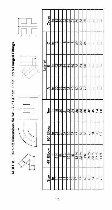
22
TAB
LE 8
. T
ake-
off D
imen
sion
s fo
r 14"
- 72
" F-
Che
m P
lain
End
& F
lang
ed F
ittin
gs
C
B
A
Siz
e45
° E
lbo
w90
° E
lbo
wTe
eLa
tera
lC
ross
AB
Cin
inin
inin
inin
in14
8 3 ⁄4
2118
3042
1218
1610
2420
3246
1420
1811
1⁄4
2721
3854
1622
2012
1⁄2
3022
3854
1622
2415
3624
4260
1824
3018
5 ⁄845
3052
7220
3036
22 1 ⁄2
5433
6284
2233
4226
6336
7296
2436
4829
7 ⁄872
42--
---
---
---
-54
33 1 ⁄2
8145
---
---
---
---
6037
1 ⁄490
54--
---
---
---
-72
44 3⁄4
108
60--
---
---
---
-
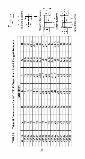
23
TAB
LE 9
. T
ake-
off D
imen
sion
s fo
r 14"
- 72
" F-
Che
m P
lain
End
& F
lang
ed R
educ
ers
Pla
in E
nd E
ccen
tric
Pla
in E
nd C
once
ntric
Flan
ged
Ecc
entri
c
Flan
ged
Con
cent
ric
Siz
e (i
nch
)A
B
CD
EF
GH
14X
1010
1014
1 ⁄416
18 3⁄4
2114
X12
510
1719
18 3 ⁄4
2116
X12
1010
1719
21 3 ⁄4
23 1 ⁄2
16X
145
1218
3 ⁄421
21 3 ⁄4
23 1⁄2
18X
1410
1218
3 ⁄421
22 3 ⁄4
2518
X16
512
21 1 ⁄4
23 1⁄2
22 3 ⁄4
2520
X16
1012
21 1⁄4
23 1 ⁄2
2527
1 ⁄220
X18
512
22 3 ⁄4
2525
27 1 ⁄2
24X
1815
1222
3 ⁄425
29 1 ⁄2
3224
X20
1012
2527
1 ⁄229
1 ⁄232
30X
2025
1225
27 1 ⁄2
3638
3 ⁄430
X24
1512
29 1 ⁄2
3236
38 3 ⁄4
36X
2430
1229
1 ⁄232
42 3 ⁄4
4636
X30
1515
38 3 ⁄4
3642
3 ⁄446
42X
3030
1538
3 ⁄436
49 1⁄2
5342
X36
1515
42 3 ⁄4
4649
1 ⁄253
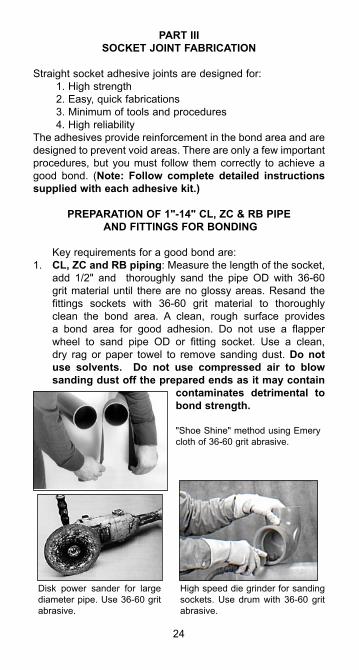
PART IIISOCKET JOINT FABRICATION
Straight socket adhesive joints are designed for: 1. High strength 2. Easy, quick fabrications 3. Minimum of tools and procedures 4. High reliabilityThe adhesives provide reinforcement in the bond area and are designed to prevent void areas. There are only a few important procedures, but you must follow them correctly to achieve a good bond. (Note: Follow complete detailed instructions supplied with each adhesive kit.)
PREPARATION OF 1"-14" CL, ZC & RB PIPE AND FITTINGS FOR BONDING
Key requirements for a good bond are:1. CL, ZC and RB piping: Measure the length of the socket,
add 1/2" and thoroughly sand the pipe OD with 36-60 grit material until there are no glossy areas. Resand the fittings sockets with 36-60 grit material to thoroughly clean the bond area. A clean, rough surface provides a bond area for good adhesion. Do not use a flapper wheel to sand pipe OD or fitting socket. Use a clean, dry rag or paper towel to remove sanding dust. Do not use solvents. Do not use compressed air to blow sanding dust off the prepared ends as it may contain
contaminates detrimental to bond strength.
24
"Shoe Shine" method using Emery cloth of 36-60 grit abrasive.
Disk power sander for large diameter pipe. Use 36-60 grit abrasive.
High speed die grinder for sanding sockets. Use drum with 36-60 grit abrasive.
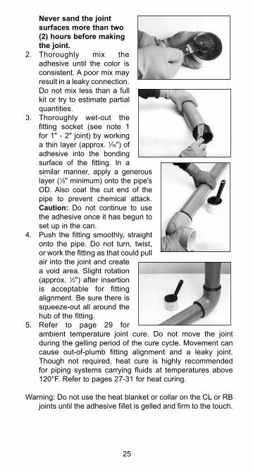
Never sand the joint surfaces more than two (2) hours before making the joint.
2. Thoroughly mix the adhesive until the color is consistent. A poor mix may result in a leaky connection. Do not mix less than a full kit or try to estimate partial quantities.
3. Thoroughly wet-out the fitting socket (see note 1 for 1" - 2" joint) by working a thin layer (approx. 1⁄16") of adhesive into the bonding surface of the fitting. In a similar manner, apply a generous layer (1⁄8" minimum) onto the pipe's OD. Also coat the cut end of the pipe to prevent chemical attack. Caution: Do not continue to use the adhesive once it has begun to set up in the can.
4. Push the fitting smoothly, straight onto the pipe. Do not turn, twist, or work the fitting as that could pull air into the joint and create a void area. Slight rotation (approx. 1⁄2") after insertion is acceptable for fitting alignment. Be sure there is squeeze-out all around the hub of the fitting.
5. Refer to page 29 for ambient temperature joint cure. Do not move the joint during the gelling period of the cure cycle. Movement can cause out-of-plumb fitting alignment and a leaky joint. Though not required, heat cure is highly recommended for piping systems carrying fluids at temperatures above 120°F. Refer to pages 27-31 for heat curing.
Warning: Do not use the heat blanket or collar on the CL or RB joints until the adhesive fillet is gelled and firm to the touch.
25
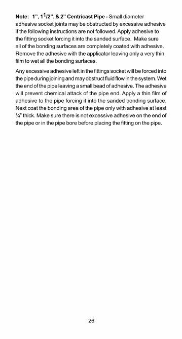
26
Note: 1”, 11/2”, & 2” Centricast Pipe - Small diameter adhesive socket joints may be obstructed by excessive adhesive if the following instructions are not followed. Apply adhesive to the fitting socket forcing it into the sanded surface. Make sure all of the bonding surfaces are completely coated with adhesive. Remove the adhesive with the applicator leaving only a very thin film to wet all the bonding surfaces.
Any excessive adhesive left in the fittings socket will be forced into the pipe during joining and may obstruct fluid flow in the system. Wet the end of the pipe leaving a small bead of adhesive. The adhesive will prevent chemical attack of the pipe end. Apply a thin film of adhesive to the pipe forcing it into the sanded bonding surface. Next coat the bonding area of the pipe only with adhesive at least ¼” thick. Make sure there is not excessive adhesive on the end of the pipe or in the pipe bore before placing the fitting on the pipe.
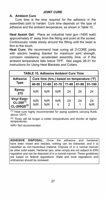
JOINT CUREA. Ambient Cure
Cure time is the time required for the adhesive in the assembled joint to harden. Cure time depends on the type of adhesive and the ambient temperature, as shown in Table 10.
Heat Assist Gel: Place an industrial heat gun (1600 watt) approximately 6" away from the fitting and point at the socket. Continuously rotate slowly around the fitting until the bead is firm to the touch.Heat Cure: We recommend heat curing all Z-CORE joints with electric heating blanket for maximum joint strength, corrosion resistance, accelerated assembly time, or if the ambient temperature falls below 70ºF. See pages 28-31 for Instructions for Using Heat Blankets and Collars.
27
(1) Heat cure highly recommended for piping systems carrying fluids above 120°F.(2) Times will be longer a colder temperatures and shorter at higher temperatures.N/R= Not recommended.
ADHESIVE DISPOSAL: Once the adhesive and hardener have been mixed and reacted, nothing can be extracted, and it is classified as non-hazardous material. Dispose of in a normal manner as other solid waste. Hardener jars, when empty are not subject to EPA regulation and can be disposed of in a normal manner. These guidelines are based on federal regulations. State and local regulations and ordinances should be reviewed.
TABLE 10. Adhesive Ambient Cure TimeAdhesive
TypeCure time (hrs.) based on temperature (°F)40-50 51-60 61-70 71-80 81-90 91-100
Epoxy: 275 N/R N/R N/R 24 24 24
Vinyl Ester:CL-200(1)
CL-200QS(2)N/RN/R
N/RN/R
N/R4
242
241
24N/R
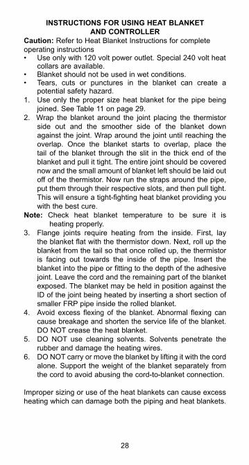
INSTRUCTIONS FOR USING HEAT BLANKETAND CONTROLLER
Caution: Refer to Heat Blanket Instructions for complete operating instructions• Use only with 120 volt power outlet. Special 240 volt heat
collars are available.• Blanket should not be used in wet conditions.• Tears, cuts or punctures in the blanket can create a
potential safety hazard.1. Use only the proper size heat blanket for the pipe being
joined. See Table 11 on page 29.2. Wrap the blanket around the joint placing the thermistor
side out and the smoother side of the blanket down against the joint. Wrap around the joint until reaching the overlap. Once the blanket starts to overlap, place the tail of the blanket through the slit in the thick end of the blanket and pull it tight. The entire joint should be covered now and the small amount of blanket left should be laid out off of the thermistor. Now run the straps around the pipe, put them through their respective slots, and then pull tight. This will ensure a tight-fighting heat blanket providing you with the best cure.
Note: Check heat blanket temperature to be sure it is heating properly.3. Flange joints require heating from the inside. First, lay
the blanket flat with the thermistor down. Next, roll up the blanket from the tail so that once rolled up, the thermistor is facing out towards the inside of the pipe. Insert the blanket into the pipe or fitting to the depth of the adhesive joint. Leave the cord and the remaining part of the blanket exposed. The blanket may be held in position against the ID of the joint being heated by inserting a short section of smaller FRP pipe inside the rolled blanket.
4. Avoid excess flexing of the blanket. Abnormal flexing can cause breakage and shorten the service life of the blanket. DO NOT crease the heat blanket.
5. DO NOT use cleaning solvents. Solvents penetrate the rubber and damage the heating wires.
6. DO NOT carry or move the blanket by lifting it with the cord alone. Support the weight of the blanket separately from the cord to avoid abusing the cord-to-blanket connection.
Improper sizing or use of the heat blankets can cause excess heating which can damage both the piping and heat blankets.
28
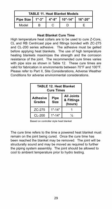
Heat Blanket Cure Time High temperature heat collars are to be used to cure Z-Core, CL and RB Centricast pipe and fittings bonded with ZC-275 and CL-200 series adhesive. The adhesive must be gelled before applying heat blankets. The use of high temperature heating blankets maximizes the strength and the corrosion resistance of the joint. The recommended cure times varies with pipe size as shown in Table 12. These cure times are valid for fabrication in environments between 70°F and 100°F. Please refer to Part II, Site Considerations, Adverse Weather Conditions for adverse environmental considerations.
The cure time refers to the time a powered heat blanket must remain on the joint being cured. Once the cure time has been reached the blanket may be removed. The joint will be structurally sound and may be moved as required to further the piping system assembly. The joint should be allowed to cool to ambient temperature prior to hydro testing.
29
Based on controller style heat blanket
TABLE 11. Heat Blanket ModelsPipe Size 1"-3" 4"-8" 10"-14" 16"-20"
Model B C D E
TABLE 12. Heat BlanketCure Times
AdhesiveGrades
Pipe Size
All Joints& Fittings
(hours)ZC-275 1"-14" 1
CL-200 1"-14" ½
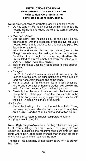
INSTRUCTIONS FOR USING HIGH TEMPERATURE HEAT COLLAR
(Refer to Heat Collar Bulletin forcomplete operating instructions.)
Note: Allow adhesive to gel before applying heating collar.• Do not bend or fold heating collar as this may break the
heating elements and cause the collar to work improperly or not al all.
For Pipe and Fittings:1. Use the same size heating collar as the pipe size you
are installing, with the exception of flanges. Do not use a heating collar that is designed for a larger size pipe. See Table 14 on page 31.
2. With the un-insulated flap on the bottom (next to the fitting), carefully wrap the heating collar around the joint. Feed the strap through the square ring. Caution: The un-insulated flap is extremely hot when the collar is on. DO NOT TOUCH with bare hands.
3. Tighten the straps until the heating collar is snug against the joint.
For Flanges:1. For 1", 11⁄2" and 2" flanges, an industrial heat gun may be
used to cure the joint. Be sure that the end of the gun is at least six inches from the opening of the flange.
2. For 3" through 16" flange joints, use a heating collar that is one pipe size smaller than the product you are working with. Remove the straps from the heating collar.
3. Carefully turn the collar inside out with the heated area facing the I.D. of the pipe. Place the heating collar in the I.D. of the flange. A split ring of pipe may be used to hold the collar in place while the joint is curing.
For Saddles:1. Place the heating collar over the saddle outlet. During
cool weather, a wind shield is recommended to keep heat on the joint. Saddles must be heat cured for two hours.
Allow the joint to return to ambient temperature before applying stress to the joint.
Note: High Temperature electric heating collars are designed to fit around fittings, and will overlap on pipe joints and couplings. Exceeding the recommended cure time on pipe joints where the heating collar overlaps may shorten the life of the heating collar and/or damage the pipe.The use of insulation may be necessary below 40°F to prevent heat loss.
30
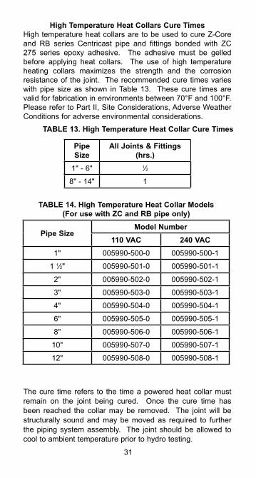
High Temperature Heat Collars Cure TimesHigh temperature heat collars are to be used to cure Z-Core and RB series Centricast pipe and fittings bonded with ZC 275 series epoxy adhesive. The adhesive must be gelled before applying heat collars. The use of high temperature heating collars maximizes the strength and the corrosion resistance of the joint. The recommended cure times varies with pipe size as shown in Table 13. These cure times are valid for fabrication in environments between 70°F and 100°F. Please refer to Part II, Site Considerations, Adverse Weather Conditions for adverse environmental considerations.
The cure time refers to the time a powered heat collar must remain on the joint being cured. Once the cure time has been reached the collar may be removed. The joint will be structurally sound and may be moved as required to further the piping system assembly. The joint should be allowed to cool to ambient temperature prior to hydro testing.
31
TABLE 14. High Temperature Heat Collar Models(For use with ZC and RB pipe only)
Pipe SizeModel Number
110 VAC 240 VAC1" 005990-500-0 005990-500-1
1 1⁄2" 005990-501-0 005990-501-1
2" 005990-502-0 005990-502-1
3" 005990-503-0 005990-503-1
4" 005990-504-0 005990-504-1
6" 005990-505-0 005990-505-1
8" 005990-506-0 005990-506-1
10" 005990-507-0 005990-507-1
12" 005990-508-0 005990-508-1
TABLE 13. High Temperature Heat Collar Cure Times
Pipe Size
All Joints & Fittings (hrs.)
1" - 6" 1⁄2
8" - 14" 1
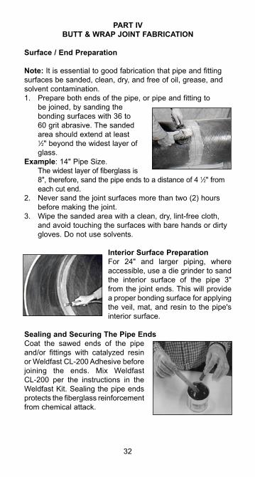
PART IVBUTT & WRAP JOINT FABRICATION
Surface / End Preparation
Note: It is essential to good fabrication that pipe and fitting surfaces be sanded, clean, dry, and free of oil, grease, and solvent contamination.1. Prepare both ends of the pipe, or pipe and fitting to
be joined, by sanding the bonding surfaces with 36 to 60 grit abrasive. The sanded area should extend at least 1⁄2" beyond the widest layer of glass.
Example: 14" Pipe Size. The widest layer of fiberglass is
8", therefore, sand the pipe ends to a distance of 4 1⁄2" from each cut end.
2. Never sand the joint surfaces more than two (2) hours before making the joint.
3. Wipe the sanded area with a clean, dry, lint-free cloth, and avoid touching the surfaces with bare hands or dirty gloves. Do not use solvents.
Interior Surface PreparationFor 24" and larger piping, where accessible, use a die grinder to sand the interior surface of the pipe 3" from the joint ends. This will provide a proper bonding surface for applying the veil, mat, and resin to the pipe's interior surface.
Sealing and Securing The Pipe EndsCoat the sawed ends of the pipe and/or fittings with catalyzed resin or Weldfast CL-200 Adhesive before joining the ends. Mix Weldfast CL-200 per the instructions in the Weldfast Kit. Sealing the pipe ends protects the fiberglass reinforcement from chemical attack.
32
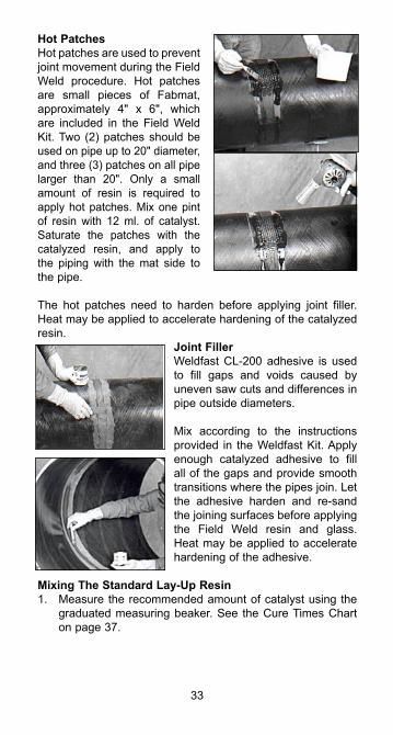
Hot PatchesHot patches are used to prevent joint movement during the Field Weld procedure. Hot patches are small pieces of Fabmat, approximately 4" x 6", which are included in the Field Weld Kit. Two (2) patches should be used on pipe up to 20" diameter, and three (3) patches on all pipe larger than 20". Only a small amount of resin is required to apply hot patches. Mix one pint of resin with 12 ml. of catalyst. Saturate the patches with the catalyzed resin, and apply to the piping with the mat side to the pipe.
The hot patches need to harden before applying joint filler. Heat may be applied to accelerate hardening of the catalyzed resin.
Joint FillerWeldfast CL-200 adhesive is used to fill gaps and voids caused by uneven saw cuts and differences in pipe outside diameters.
Mix according to the instructions provided in the Weldfast Kit. Apply enough catalyzed adhesive to fill all of the gaps and provide smooth transitions where the pipes join. Let the adhesive harden and re-sand the joining surfaces before applying the Field Weld resin and glass. Heat may be applied to accelerate hardening of the adhesive.
Mixing The Standard Lay-Up Resin1. Measure the recommended amount of catalyst using the
graduated measuring beaker. See the Cure Times Chart on page 37.
33
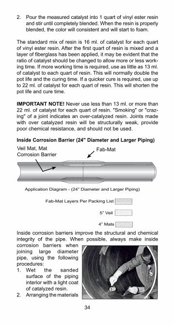
2. Pour the measured catalyst into 1 quart of vinyl ester resin and stir until completely blended. When the resin is properly blended, the color will consistent and will start to foam.
The standard mix of resin is 16 ml. of catalyst for each quart of vinyl ester resin. After the first quart of resin is mixed and a layer of fiberglass has been applied, it may be evident that the ratio of catalyst should be changed to allow more or less work-ing time. If more working time is required, use as little as 13 ml. of catalyst to each quart of resin. This will normally double the pot life and the curing time. If a quicker cure is required, use up to 22 ml. of catalyst for each quart of resin. This will shorten the pot life and cure time.
IMPORTANT NOTE! Never use less than 13 ml. or more than 22 ml. of catalyst for each quart of resin. "Smoking" or "craz-ing" of a joint indicates an over-catalyzed resin. Joints made with over catalyzed resin will be structurally weak, provide poor chemical resistance, and should not be used.
Inside Corrosion Barrier (24" Diameter and Larger Piping)
Inside corrosion barriers improve the structural and chemical integrity of the pipe. When possible, always make inside corrosion barriers when joining large diameter pipe, using the following procedures:1. Wet the sanded
surface of the piping interior with a light coat of catalyzed resin.
2. Arranging the materials
34
4” Mats
5” Veil
Fab-Mat Layers Per Packing List
Application Diagram - (24” Diameter and Larger Piping)
Veil Mat, MatCorrosion Barrier
Fab-Mat
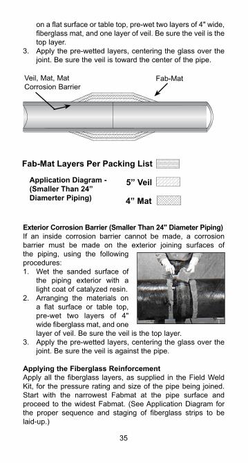
on a flat surface or table top, pre-wet two layers of 4" wide, fiberglass mat, and one layer of veil. Be sure the veil is the top layer.
3. Apply the pre-wetted layers, centering the glass over the joint. Be sure the veil is toward the center of the pipe.
Exterior Corrosion Barrier (Smaller Than 24" Diameter Piping)If an inside corrosion barrier cannot be made, a corrosion barrier must be made on the exterior joining surfaces of the piping, using the following procedures:1. Wet the sanded surface of
the piping exterior with a light coat of catalyzed resin.
2. Arranging the materials on a flat surface or table top, pre-wet two layers of 4" wide fiberglass mat, and one layer of veil. Be sure the veil is the top layer.
3. Apply the pre-wetted layers, centering the glass over the joint. Be sure the veil is against the pipe.
Applying the Fiberglass ReinforcementApply all the fiberglass layers, as supplied in the Field Weld Kit, for the pressure rating and size of the pipe being joined. Start with the narrowest Fabmat at the pipe surface and proceed to the widest Fabmat. (See Application Diagram for the proper sequence and staging of fiberglass strips to be laid-up.)
35
4” Mat
Fab-Mat Layers Per Packing List
5” VeilApplication Diagram -(Smaller Than 24”Diamerter Piping)
Veil, Mat, MatCorrosion Barrier
Fab-Mat
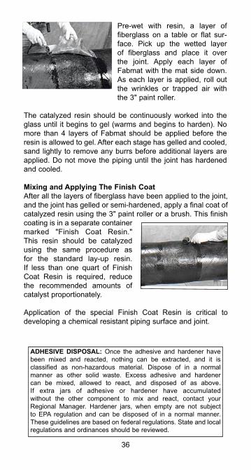
Pre-wet with resin, a layer of fiberglass on a table or flat sur-face. Pick up the wetted layer of fiberglass and place it over the joint. Apply each layer of Fabmat with the mat side down. As each layer is applied, roll out the wrinkles or trapped air with the 3" paint roller.
The catalyzed resin should be continuously worked into the glass until it begins to gel (warms and begins to harden). No more than 4 layers of Fabmat should be applied before the resin is allowed to gel. After each stage has gelled and cooled, sand lightly to remove any burrs before additional layers are applied. Do not move the piping until the joint has hardened and cooled.
Mixing and Applying The Finish CoatAfter all the layers of fiberglass have been applied to the joint, and the joint has gelled or semi-hardened, apply a final coat of catalyzed resin using the 3" paint roller or a brush. This finish coating is in a separate container marked "Finish Coat Resin." This resin should be catalyzed using the same procedure as for the standard lay-up resin. If less than one quart of Finish Coat Resin is required, reduce the recommended amounts of catalyst proportionately.
Application of the special Finish Coat Resin is critical to developing a chemical resistant piping surface and joint.
36
ADHESIVE DISPOSAL: Once the adhesive and hardener have been mixed and reacted, nothing can be extracted, and it is classified as non-hazardous material. Dispose of in a normal manner as other solid waste. Excess adhesive and hardener can be mixed, allowed to react, and disposed of as above. If extra jars of adhesive or hardener have accumulated without the other component to mix and react, contact your Regional Manager. Hardener jars, when empty are not subject to EPA regulation and can be disposed of in a normal manner. These guidelines are based on federal regulations. State and local regulations and ordinances should be reviewed.
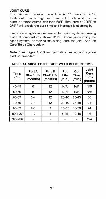
JOINT CUREThe minimum required cure time is 24 hours at 70°F. Inadequate joint strength will result if the catalyzed resin is cured at temperatures less than 60°F. Heat cure at 200°F to 275°F will accelerate cure time and increase joint strength.
Heat cure is highly recommended for piping systems carrying fluids at temperatures above 120°F. Before pressurizing the piping system, or moving the piping, cure the joint. See the Cure Times Chart below.
Note: See pages 48-50 for hydrostatic testing and system start-up procedure.
37
TABLE 14. VINYL ESTER BUTT WELD KIT CURE TIMES
Temp(°F)
Part A Shelf Life (months)
Part B Shelf Life (months)
Pot Life
(min.)
Gel Time(min.)
Joint Cure Time
(hours)40-49 6 12 N/R N/R N/R
50-59 5 12 N/R N/R N/R
60-69 3-4 12 20-40 25-45 36
70-79 3-4 12 20-40 25-45 24
80-89 2-3 9 15-35 18-38 24
90-100 1-2 4 8-15 10-18 16
200-250 - - - - 2-4
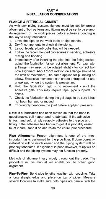
PART VINSTALLATION CONSIDERATIONS
FLANGE & FITTING ALIGNMENTAs with any piping system, flanges must be set for proper alignment of bolt patterns and fittings must be set to be plumb. Arrangement of the work pieces before adhesive bonding is the key to easy fabrication.1. Level the pipe on the work table or pipe stands.2. Dry-fit components to check dimensions.3. Layout levels, plumb bobs that will be needed.4. Follow the recommended procedures in sanding, adhesive
mixing and bonding.5. Immediately after inserting the pipe into the fitting socket,
adjust the fabrication for correct alignment. For example, a flange may need to be rotated slightly for correct bolt hole alignment. About ½" of rotation on a flange should be the limit of movement. The same applies for plumbing an elbow. Excessive movement can create entrapped air and a leak path when the system is pressurized.
6. Hold the fabrication rigid - no movement - until the adhesive gels. This may require tape, pipe supports, or shims.
7. Check the fabrication during the gel stage to be sure it has not been bumped or moved.
8. Thoroughly heat-cure the joint before applying pressure.
Note: If a fabrication has been moved so that the bond is questionable, pull it apart and re-fabricate. If the adhesive is fresh and soft, simply re-apply adhesive to the pipe and fitting. If the adhesive has begun to gel, it is probably easier to let it cure, sand it off and re-do the entire joint procedure.
Pipe Alignment: Proper alignment is one of the most important tasks performed by the pipe fitter. If done correctly, installation will be much easier and the piping system will be properly fabricated. If alignment is poor, however, fit-up will be difficult and the piping system may not function properly.
Methods of alignment vary widely throughout the trade. The procedure in this manual will enable you to obtain good alignment.
Pipe-To-Pipe: Bond pipe lengths together with coupling. Take a long straight edge and place on top of pipes. Measure several locations to make sure both pipes are parallel with the
38
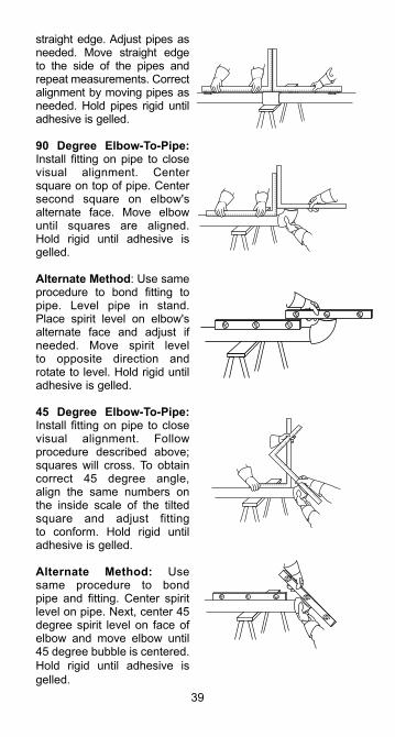
straight edge. Adjust pipes as needed. Move straight edge to the side of the pipes and repeat measurements. Correct alignment by moving pipes as needed. Hold pipes rigid until adhesive is gelled.
90 Degree Elbow-To-Pipe: Install fitting on pipe to close visual alignment. Center square on top of pipe. Center second square on elbow's alternate face. Move elbow until squares are aligned. Hold rigid until adhesive is gelled.
Alternate Method: Use same procedure to bond fitting to pipe. Level pipe in stand. Place spirit level on elbow's alternate face and adjust if needed. Move spirit level to opposite direction and rotate to level. Hold rigid until adhesive is gelled.
45 Degree Elbow-To-Pipe: Install fitting on pipe to close visual alignment. Follow procedure described above; squares will cross. To obtain correct 45 degree angle, align the same numbers on the inside scale of the tilted square and adjust fitting to conform. Hold rigid until adhesive is gelled.
Alternate Method: Use same procedure to bond pipe and fitting. Center spirit level on pipe. Next, center 45 degree spirit level on face of elbow and move elbow until 45 degree bubble is centered. Hold rigid until adhesive is gelled.
39
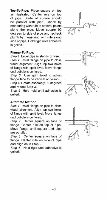
Tee-To-Pipe: Place square on tee as illustrated. Center rule on top of pipe. Blade of square should be parallel with pipe. Check by measuring with rule at several points along the pipe. Move square 90 degrees to side of pipe and recheck plumb by measuring with rule along side of pipe. Hold rigid until adhesive is gelled.
Flange-To-Pipe:Step 1 Level pipe in stands or vise.Step 2 Install flange on pipe to close visual alignment. Align top two holes of flange with spirit level. Move flange until bubble is centered.Step 3 Use spirit level to adjust flange face to be vertical or plumb.Step 4 Rotate assembly 90 degrees and repeat Step 3.Step 5 Hold rigid until adhesive is gelled.
Alternate Method:Step 1 Install flange on pipe to close visual alignment. Align top two holes of flange with spirit level. Move flange until bubble is centered.Step 2 Center square on face of flange. Center rule on top of pipe. Move flange until square and pipe are parallel.Step 3 Center square on face of flange. Center rule on side of pipe and align as in Step 2.Step 4 Hold rigid until adhesive is gelled.
40
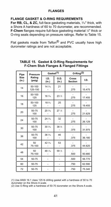
FLANGES
FLANGE GASKET & O-RING REQUIREMENTSFor RB, CL, & ZC, full-face gasketing materials, 3⁄16" thick, with a Shore A hardness of 60 to 70 durometer, are recommended. F-Chem flanges require full-face gasketing material 1⁄4" thick or O-ring seals depending on pressure ratings. Refer to Table 15.
Flat gaskets made from Teflon® and PVC usually have high durometer ratings and are not acceptable.
41
TABLE 15. Gasket & O-Ring Requirements for F-Chem Stub Flanges & Flanged Fittings
(1) Use ANSI 16.1 class 125 lb drilling gasket with a hardness of 50 to 70 durometer on the Shore A scale.(2) Use O-Ring with a hardness of 50-70 durometer on the Shore A scale.
Pipe Size(in.)
PressureRating(psig)
Gasket(1) O-Ring(2)
I.D.(in.)
O.D.(in.)
CrossSection I.D.
14 50-100125-150
14 3⁄16
-21-
-.275
-15.475
16 50-100125 16 3⁄16 23 1⁄2 -
.275-
17.455
18 50-100125
18 3⁄16
-25-
-.275
-19.455
20 50-75100
20 3⁄16
-27 1⁄2
--
.275-
21.629
24 50-75100
24 3⁄16
-32-
-.275
-26.129
30 50-75100
30 3⁄16
-38 3⁄4
--
.375-
31.975
36 50-75100
36 3⁄16
-46-
-.375
-36.180
42 5075-100
42 3⁄16
-53-
-.375
-44.620
48 5075-100
48 1⁄16
-59 1⁄2
--
.500-
50.680
54 50-75 - - .500 56.770
60 50-75 - - .750 62.590
72 50-75 - - .750 75.340
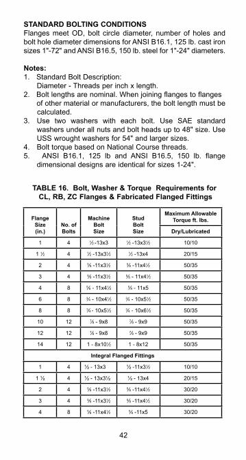
STANDARD BOLTING CONDITIONSFlanges meet OD, bolt circle diameter, number of holes and bolt hole diameter dimensions for ANSI B16.1, 125 lb. cast iron sizes 1"-72" and ANSI B16.5, 150 lb. steel for 1"-24" diameters.
Notes: 1. Standard Bolt Description: Diameter - Threads per inch x length. 2. Bolt lengths are nominal. When joining flanges to flanges of other material or manufacturers, the bolt length must be calculated.3. Use two washers with each bolt. Use SAE standard
washers under all nuts and bolt heads up to 48" size. Use USS wrought washers for 54" and larger sizes.
4. Bolt torque based on National Course threads.5. ANSI B16.1, 125 lb and ANSI B16.5, 150 lb. flange
dimensional designs are identical for sizes 1-24".
42
TABLE 16. Bolt, Washer & Torque Requirements for CL, RB, ZC Flanges & Fabricated Flanged Fittings
FlangeSize(in.)
No. of Bolts
MachineBolt Size
StudBolt Size
Maximum Allowable Torque ft. lbs.
Dry/Lubricated
1 4 1⁄2 -13x3 1⁄2 -13x31⁄2 10/10
1 1⁄2 4 1⁄2 -13x31⁄2 1⁄2 -13x4 20/15
2 4 5⁄8 -11x31⁄2 5⁄8 -11x41⁄2 50/35
3 4 5⁄8 -11x31⁄2 5⁄8 - 11x41⁄2 50/35
4 8 5⁄8 - 11x41⁄2 5⁄8 - 11x5 50/35
6 8 3⁄4 - 10x41⁄2 3⁄4 - 10x51⁄2 50/35
8 8 3⁄4 - 10x51⁄2 3⁄4 - 10x61⁄2 50/35
10 12 7⁄8 - 9x8 7⁄8 - 9x9 50/35
12 12 7⁄8 - 9x8 7⁄8 - 9x9 50/35
14 12 1 - 8x101⁄2 1 - 8x12 50/35
Integral Flanged Fittings
1 4 ½ - 13x3 ½ -11x31⁄2 10/10
1 ½ 4 ½ - 13x3½ ½ - 13x4 20/15
2 4 5⁄8 -11x31⁄2 5⁄8 -11x41⁄2 30/20
3 4 5⁄8 -11x31⁄2 5⁄8 -11x41⁄2 30/20
4 8 5⁄8 -11x41⁄2 5⁄8 -11x5 30/20
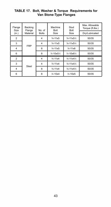
43
TABLE 17. Bolt, Washer & Torque Requirements for Van Stone-Type Flanges
FlangeSize(in.)
Backing FlangeMaterial
No. ofBolts
MachineBoltSize
StudBoltSize
Max. AllowableTorque (ft.lbs.)
Dry/Lubricated
2
FRP
4 5⁄8-11x5 5⁄8-11x51⁄2 50/35
3 4 5⁄8-11x5 5⁄8-11x51⁄2 50/35
4 8 5⁄8-11x5 5⁄8-11x6 50/35
6 8 3⁄4-10x51⁄2 3⁄4-10x61⁄2 50/35
2
Steel
4 5⁄8-11x4 5⁄8-11x41⁄2 50/35
3 4 5⁄8-11x4 5⁄8-11x41⁄2 50/35
4 8 5⁄8-11x4 5⁄8-11x41⁄2 50/35
6 8 3⁄4-10x4 3⁄4-10x5 50/35
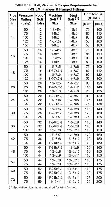
44
TABLE 18. Bolt, Washer & Torque Requirements for F-CHEM Flanges & Flanged Fittings
(1) Special bolt lengths are required for blind flanges.
Pipe Size (in)
Pressure Rating (psig)
No. of Bolt
Holes
Machine Bolt (1)
Size
Stud Bolt (1)
Size
Bolt Torque (ft. lbs.)
(Nom) (Max)
14
5075
100125150
1212121212
1-8x4½1-8x51-8x5
1-8x5½1-8x6
1-8x61-8x61-8x71-8x71-8x7
7585905050
100110120100100
16
5075
100125
16161616
1-8x4½1-8x5
1-8x5½1-8x6
1-8x61-8x61-8x71-8x7
75859050
100110120100
18
5075
100125
16161616
11⁄8-7x511⁄8-7x5½11⁄8-7x6
11⁄8-7x6½
11⁄8-7x611⁄8-7x711⁄8-7x711⁄8-7x8
75859050
100110120100
205075
100
202020
11⁄8-7x511⁄8-7x5½11⁄8-7x6
11⁄8-7x711⁄8-7x711⁄8-7x8
9010575
120140125
245075
100
202020
1¼-7x5½1¼-7x6
1¼-7x6½
11⁄4-7x711⁄4-7x811⁄4-7x8
9010575
120140125
305075
100
282828
1¼-7x61¼-7x6½1¼-7x7
11⁄4-7x811⁄4-7x811⁄4-7x9
10512075
140160125
365075
100
323232
1½-6x6½1½-6x7½1½-6x8
11⁄2-6x911⁄2-6x9
11⁄2-6x10
105120100
140160150
425075
100
363636
1½-6x71½-6x8
1½-6x8½
11⁄2-6x911⁄2-6x10¹¹⁄2-6x10
120100100
160150150
485075
100
444444
1½-6x7½1½-6x81½-6x9
11⁄2-6x911⁄2-6x10¹¹⁄2-6x11
120100100
160150150
54 5075
4444
1¾-5x81¾-5x9
13⁄4-5x10¹³⁄4-5x11
100100
175175
60 5075
5252
1¾-5x8½1¾-5x9½
13⁄4-5x1113⁄4-5x12
100100
175175
72 5075
6060
1¾-5x9½1¾-5x11
13⁄4-5x1113⁄4-5x13
125125
200200
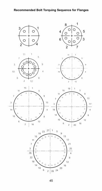
Recommended Bolt Torquing Sequence for Flanges
45
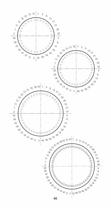
46
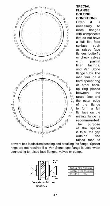
SPECIAL FLANGE BOLTING CONDITIONSOften it is necessary to mate flanges with components that do not have a full flat face surface such as raised face flanges, butterfly or check valves with partial liner facings, and Van Stone flange hubs. The addi t ion of a hard spacer ring or steel back-up ring placed between the raised face and the outer edge of the flange to form a full flat face on the mating flange is recommended. The purpose of the spacer is to fill the gap outside the raised face to
prevent bolt loads from bending and breaking the flange. Spacer rings are not required if a Van Stone-type flange is used when connecting to raised face flanges, valves or pumps.
47
14
57
53
49
45
4137
33
4
8
12
16
20
24
28
3236
2925
2117
13951595551
4743
3935
31
27
23
19
15
11
7
3
58
54
50
46
42
38
34302622
1810 6 2 6056
5248
4440
61
64
62
63
Back-up Ring ThicknessPipe Size Ring Thickness1" - 12" 9⁄16"
FIGURE 8.4
CONNECTING TO OTHER PIPING SYSTEMSIt is often necessary to connect our piping to another piping system or make a connection which will not be possible using flanges. Threaded connections are offered - primarily for instruments, thermo wells, etc. Select the appropriate fitting from the Fittings & Accessories Bulletins. Victaulic-type grooved adapters are also available for use with Series 77 coupling in certain sizes.
Threaded Joints1. Before making any threaded joints, be sure all bonded
joints are fully cured.2. Apply thread lubrication to both male and female threads.
A material which remains soft for the life of the joint is preferred. Be sure the thread lube is suitable for the fluid service.
3. Tighten the joint to seal. Do not over-torque. FRP threads should be handled carefully - as if they are brass.
Notes:1. The use of adhesive to bond a steel or metal pipe into a
flange is not recommended.2. If mating our piping system to steel or other FRP system,
the preferred method is with flanges. Terminate the old system with the other FRP flange and bolt our flange on the new system.
3. Be sure to check the anchors, guides, and supports of an existing system to avoid transfer of any stresses or thermal expansion loads into the system.
4. Do not try to thread pipe or fittings. This is very difficult and risky. Purchase the required factory part.
Tips: If no thread lube is available, the use of Weldfast Part "A" will usually be acceptable. Two wraps of Teflon® tape may also be used in lieu of thread lubricant.
48
Pump & Equipment ConnectionPipe connections to pumps or other equipment that involve vibration, shock loads or other mechanical movements should include flexible connectors. These flexible connectors allow for the absorption of vibration and eliminate the placing of undue strain on the pipe and fittings. A bellows-type expansion joint is recommended, although rubber hose has also been used with success.
HYDROSTATIC TESTING AND SYSTEM STARTUPHydrostatic Testing: When possible, piping systems should be hydrostatically tested prior to being put into service. Care should be taken when testing, as in actual installation, to avoid water hammer.
All anchors, guides and supports must be in place prior to testing the line. To hydrostatically test the line, observe the following:
Water is usually introduced into the system through a one-inch diameter or smaller pipe. Provision for bleeding air from the system should be made. Water should be introduced at the lowest point in the system and the air bled off through a partially open valve or loose flange at all high points in the system. Slowly close the valve, and bring the system gradually up to the desired pressure.
Test pressure should not be more than 1-1⁄2 times the working pressure of the piping system, and never exceed 1-1⁄2 times the rated operating pressure of the lowest rated component in the system. When testing is completed open all of the high point air bleeds before draining the piping. This will prevent vacuum collapse of the pipe.
For systems with severe chemical or temperature applications, a cyclic test may replace the static test. Contact us for recommendations.
Warnings:Air Testing: Hydrostatic test should be used instead of air or compressed gas if possible. When air or compressed gas is used for testing, tremendous amounts of energy can be stored in the system. If a failure occurs, the energy may be released catastrophically, which can result in property damage and personal injury. In cases where system contamination or fluid weight prevents the use of hydrostatic test, air test may be used with extreme caution. To reduce the risk of air testing,
49
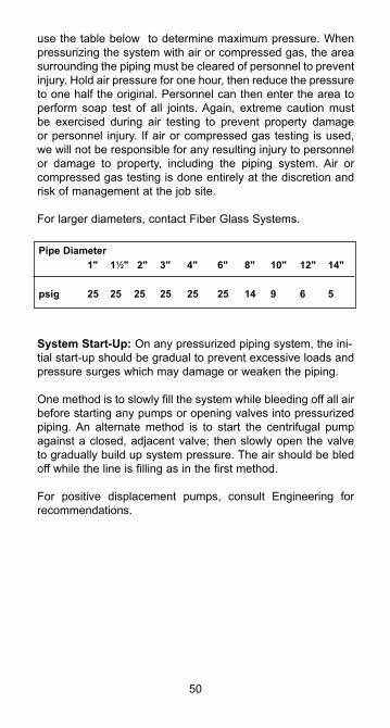
use the table below to determine maximum pressure. When pressurizing the system with air or compressed gas, the area surrounding the piping must be cleared of personnel to prevent injury. Hold air pressure for one hour, then reduce the pressure to one half the original. Personnel can then enter the area to perform soap test of all joints. Again, extreme caution must be exercised during air testing to prevent property damage or personnel injury. If air or compressed gas testing is used, we will not be responsible for any resulting injury to personnel or damage to property, including the piping system. Air or compressed gas testing is done entirely at the discretion and risk of management at the job site.
For larger diameters, contact Fiber Glass Systems.
System Start-Up: On any pressurized piping system, the ini-tial start-up should be gradual to prevent excessive loads and pressure surges which may damage or weaken the piping.
One method is to slowly fill the system while bleeding off all air before starting any pumps or opening valves into pressurized piping. An alternate method is to start the centrifugal pump against a closed, adjacent valve; then slowly open the valve to gradually build up system pressure. The air should be bled off while the line is filling as in the first method.
For positive displacement pumps, consult Engineering for recommendations.
50
Pipe Diameter 1" 11⁄2" 2" 3" 4" 6" 8" 10" 12" 14"
psig 25 25 25 25 25 25 14 9 6 5
WATER HAMMER - AVOIDING PROBLEMSWater hammer is a term generally used to describe situations where a pressure surge in the piping system causes violent movement of the system. Usually this pressure surge is caused by a sudden valve closing, electrical outage, pump failure, or some other out-of-the ordinary situation. The pressure surge is usually brief, but damage can be severe. In FRP piping, water hammer usually results in broken fittings due to pipe system movement caused by pressure. Insufficient system anchors, guides and supports allow excessive movement of the piping and creates fitting breaks.
If you suspect water hammer, consult with the project engineer as soon as possible to eliminate the problem. This may require installing slow operating valves, a pump bypass or surge protectors in the system.
More anchors, guides or supports may need to be added. If you can easily move the piping by pushing on it, changes in the pipe support arrangement to restrict movement probably need to be made.
Air in a system can also cause water hammer. Bleed air out of the piping prior to full pressure operation. Any pipe system which moves suddenly, creates a lot of noise, or generally seems unstable is a candidate for problems due to water hammer.
51
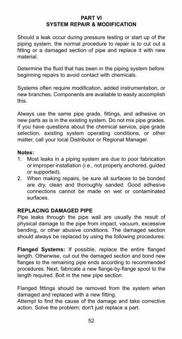
PART VISYSTEM REPAIR & MODIFICATION
Should a leak occur during pressure testing or start up of the piping system, the normal procedure to repair is to cut out a fitting or a damaged section of pipe and replace it with new material.
Determine the fluid that has been in the piping system before beginning repairs to avoid contact with chemicals.
Systems often require modification, added instrumentation, or new branches. Components are available to easily accomplish this.
Always use the same pipe grade, fittings, and adhesive on new parts as is in the existing system. Do not mix pipe grades. If you have questions about the chemical service, pipe grade selection, existing system operating conditions, or other matter, call your local Distributor or Regional Manager.
Notes:1. Most leaks in a piping system are due to poor fabrication
or improper installation (i.e., not properly anchored, guided or supported).
2. When making repairs, be sure all surfaces to be bonded are dry, clean and thoroughly sanded. Good adhesive connections cannot be made on wet or contaminated surfaces.
REPLACING DAMAGED PIPEPipe leaks through the pipe wall are usually the result of physical damage to the pipe from impact, vacuum, excessive bending, or other abusive conditions. The damaged section should always be replaced by using the following procedures:
Flanged Systems: If possible, replace the entire flanged length. Otherwise, cut out the damaged section and bond new flanges to the remaining pipe ends according to recommended procedures. Next, fabricate a new flange-by-flange spool to the length required. Bolt in the new pipe section.
Flanged fittings should be removed from the system when damaged and replaced with a new fitting.Attempt to find the cause of the damage and take corrective action. Solve the problem; don't just replace a part.
52
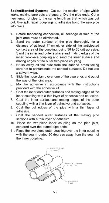
Socket/Bonded Systems: Cut out the section of pipe which leaks, making sure cuts are square. Dry the pipe ends. Cut a new length of pipe to the same length as that which was cut out. Use split repair couplings to adhesive bond the new pipe into place.
1. Before fabricating connection, all seepage or fluid at the joint area must be eliminated.
2. Sand the outer surface of the pipe thoroughly for a distance of at least 1" on either side of the anticipated contact area of the coupling, using 36 to 60 grit abrasive. Sand the inner and outer surface and mating edges of the inner two-piece coupling and sand the inner surface and mating edges of the outer two-piece coupling.
3. Brush away all the dust from the sanded areas taking care not to contaminate the sanded surfaces. Do not use a solvent wipe.
4. Slide the hose clamp over one of the pipe ends and out of the way of the joint area.
5. Mix the adhesive in accordance with the instructions provided with the adhesive kit.
6. Coat the inner and outer surfaces and mating edges of the inner coupling with a thin layer of adhesive and set aside.
7. Coat the inner surface and mating edges of the outer coupling with a thin layer of adhesive and set aside.
8. Coat the cut edges of the pipe with a thin layer of adhesive.
9. Coat the sanded outer surfaces of the mating pipe sections with a thin layer of adhesive.
10. Place the two-piece inner coupling on the pipe joint, centered over the butted pipe ends.
11. Place the two-piece outer coupling over the inner coupling with the seam rotated 90 degrees away from the seam of the inner coupling.
53
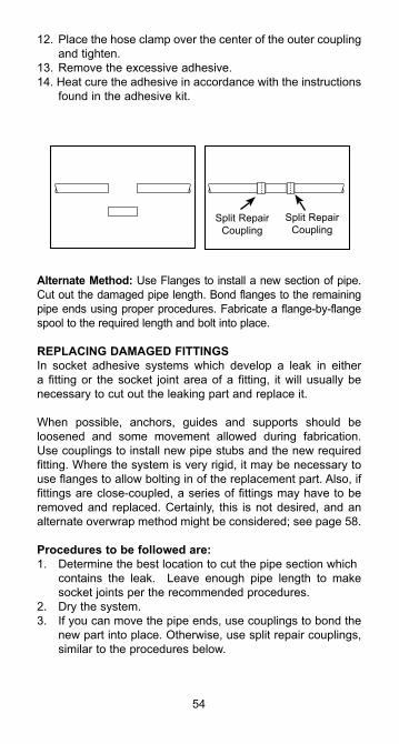
12. Place the hose clamp over the center of the outer coupling and tighten.
13. Remove the excessive adhesive.14. Heat cure the adhesive in accordance with the instructions
found in the adhesive kit.
Alternate Method: Use Flanges to install a new section of pipe. Cut out the damaged pipe length. Bond flanges to the remaining pipe ends using proper procedures. Fabricate a flange-by-flange spool to the required length and bolt into place.
REPLACING DAMAGED FITTINGSIn socket adhesive systems which develop a leak in either a fitting or the socket joint area of a fitting, it will usually be necessary to cut out the leaking part and replace it.
When possible, anchors, guides and supports should be loosened and some movement allowed during fabrication. Use couplings to install new pipe stubs and the new required fitting. Where the system is very rigid, it may be necessary to use flanges to allow bolting in of the replacement part. Also, if fittings are close-coupled, a series of fittings may have to be removed and replaced. Certainly, this is not desired, and an alternate overwrap method might be considered; see page 58.
Procedures to be followed are:1. Determine the best location to cut the pipe section which
contains the leak. Leave enough pipe length to make socket joints per the recommended procedures.
2. Dry the system.3. If you can move the pipe ends, use couplings to bond the
new part into place. Otherwise, use split repair couplings, similar to the procedures below.
54
Split Repair Coupling
Split Repair Coupling
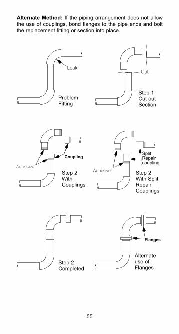
Alternate Method: If the piping arrangement does not allow the use of couplings, bond flanges to the pipe ends and bolt the replacement fitting or section into place.
55
Step 2 With Couplings
Step 2 With Split Repair Couplings
Step 2 Completed
Alternate use of Flanges
Problem Fitting
Step 1 Cut out Section
SplitRepaircoupling
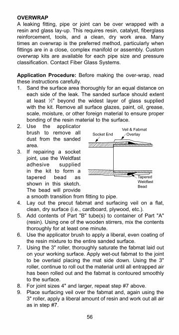
OVERWRAPA leaking fitting, pipe or joint can be over wrapped with a resin and glass lay-up. This requires resin, catalyst, fiberglass reinforcement, tools, and a clean, dry work area. Many times an overwrap is the preferred method, particularly when fittings are in a close, complex manifold or assembly. Custom overwrap kits are available for each pipe size and pressure classification. Contact Fiber Glass Systems.
Application Procedure: Before making the over-wrap, read these instructions carefully.1. Sand the surface area thoroughly for an equal distance on
each side of the leak. The sanded surface should extent at least 1⁄2" beyond the widest layer of glass supplied with the kit. Remove all surface glazes, paint, oil, grease, scale, moisture, or other foreign material to ensure proper bonding of the resin material to the surface.
2. Use the applicator brush to remove all dust from the sanded area.
3. If repairing a socket joint, use the Weldfast adhesive supplied in the kit to form a tapered bead as shown in this sketch. The bead will provide a smooth transition from fitting to pipe.
4. Lay out the precut fabmat and surfacing veil on a flat, clean, dry surface (i.e., cardboard, plywood, etc.).
5. Add contents of Part "B" tube(s) to container of Part "A" (resin). Using one of the wooden stirrers, mix the contents thoroughly for at least one minute.
6. Use the applicator brush to apply a liberal, even coating of the resin mixture to the entire sanded surface.
7. Using the 3" roller, thoroughly saturate the fabmat laid out on your working surface. Apply wet-out fabmat to the joint to be overlaid placing the mat side down. Using the 3" roller, continue to roll out the material until all entrapped air has been rolled out and the fabmat is contoured smoothly to the surface.
8. For joint sizes 4" and larger, repeat step #7 above.9. Place surfacing veil over the fabmat and, again using the
3" roller, apply a liberal amount of resin and work out all air as in step #7.
56
Socket End
Veil & Fabmat
Overlay
Tapered
Weldfast
Bead
Be sure that the pipe surface is thoroughly wet out with catalyzed resin.
Some guidelines on the overwrap are:1. The overwrap should be equally spaced on each side of
the point of the leak.2. The overwrap should be around the entire circumference
of the pipe or fitting.3. The pressure rating and pipe diameter will determine
the overwrap thickness. Consult Fiber Glass Systems' Technical Services to determine specific information about design of the overwrap.
4. The resin system of the overwrap should be compatible with the resin system of the existing pipe or fittings.
5. Cure the overwrap completely before pressure testing.
TEMPORARY FIXESPipe Leaks: The use of a conventional metal pipe clamp is a good method for containing a small leak.
Socket Leaks: Materials are available in the marketplace for making "ace bandage" types of over wraps.
Fitting Leaks: A pinhole type leak can sometimes be stopped by applying a thickness of adhesive over a dry, sanded area.
Caution: If hazardous materials or high pressures are present, replace the damaged pipe or fitting at once. Do not try a temporary repair. Make a permanent repair as soon as possible.
TAPPING INTO A LINEThe two most common methods for adding a branch or tapping into an existing line are the use of a tee or saddle. Saddles are often rated for lower pressure than the pipe; check the rating of the system versus the saddle. Consult Fittings & Accessories Bulletins.
Generally, the use of flanges to install a new tee is preferred.
57
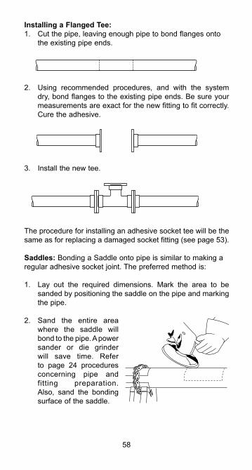
Installing a Flanged Tee:1. Cut the pipe, leaving enough pipe to bond flanges onto
the existing pipe ends.
2. Using recommended procedures, and with the system dry, bond flanges to the existing pipe ends. Be sure your measurements are exact for the new fitting to fit correctly. Cure the adhesive.
3. Install the new tee.
The procedure for installing an adhesive socket tee will be the same as for replacing a damaged socket fitting (see page 53).
Saddles: Bonding a Saddle onto pipe is similar to making aregular adhesive socket joint. The preferred method is:
1. Lay out the required dimensions. Mark the area to be sanded by positioning the saddle on the pipe and marking the pipe.
2. Sand the entire area where the saddle will bond to the pipe. A power sander or die grinder will save time. Refer to page 24 procedures concerning pipe and fitting preparation. Also, sand the bonding surface of the saddle.
58
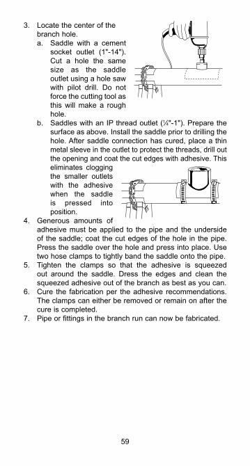
3. Locate the center of the branch hole.a. Saddle with a cement
socket outlet (1"-14"). Cut a hole the same size as the saddle outlet using a hole saw with pilot drill. Do not force the cutting tool as this will make a rough hole.
b. Saddles with an IP thread outlet (1⁄4"-1"). Prepare the surface as above. Install the saddle prior to drilling the hole. After saddle connection has cured, place a thin metal sleeve in the outlet to protect the threads, drill out the opening and coat the cut edges with adhesive. This eliminates clogging the smaller outlets with the adhesive when the saddle is pressed into position.
4. Generous amounts of adhesive must be applied to the pipe and the underside of the saddle; coat the cut edges of the hole in the pipe. Press the saddle over the hole and press into place. Use two hose clamps to tightly band the saddle onto the pipe.
5. Tighten the clamps so that the adhesive is squeezed out around the saddle. Dress the edges and clean the squeezed adhesive out of the branch as best as you can.
6. Cure the fabrication per the adhesive recommendations. The clamps can either be removed or remain on after the cure is completed.
7. Pipe or fittings in the branch run can now be fabricated.
59
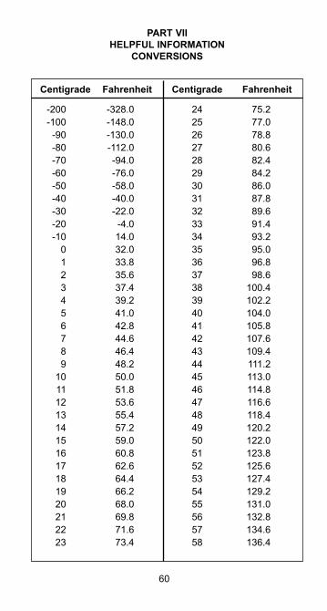
Centigrade Fahrenheit Centigrade Fahrenheit
PART VIIHELPFUL INFORMATION
CONVERSIONS
60
-200 -328.0 -100 -148.0 -90 -130.0 -80 -112.0 -70 -94.0 -60 -76.0 -50 -58.0 -40 -40.0 -30 -22.0 -20 -4.0 -10 14.0 0 32.0 1 33.8 2 35.6 3 37.4 4 39.2 5 41.0 6 42.8 7 44.6 8 46.4 9 48.2 10 50.0 11 51.8 12 53.6 13 55.4 14 57.2 15 59.0 16 60.8 17 62.6 18 64.4 19 66.2 20 68.0 21 69.8 22 71.6 23 73.4
24 75.2 25 77.0 26 78.8 27 80.6 28 82.4 29 84.2 30 86.0 31 87.8 32 89.6 33 91.4 34 93.2 35 95.0 36 96.8 37 98.6 38 100.4 39 102.2 40 104.0 41 105.8 42 107.6 43 109.4 44 111.2 45 113.0 46 114.8 47 116.6 48 118.4 49 120.2 50 122.0 51 123.8 52 125.6 53 127.4 54 129.2 55 131.0 56 132.8 57 134.6 58 136.4
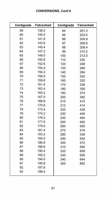
61
Centigrade Fahrenheit Centigrade Fahrenheit
CONVERSIONS, Cont’d
59 138.2 60 140.0 61 141.8 62 143.6 63 145.4 64 147.2 65 149.0 66 150.8 67 152.6 68 154.4 69 156.2 70 158.0 71 159.8 72 161.6 73 163.4 74 165.2 75 167.0 76 168.8 77 170.6 78 172.4 79 174.2 80 176.0 81 177.8 82 179.6 83 181.4 84 183.2 85 185.0 86 186.8 87 188.6 88 190.4 89 192.2 90 194.0 91 195.8 92 197.6 93 199.4
94 201.2 95 203.0 96 204.8 97 206.6 98 208.4 99 210.2 100 212.0 110 230 120 248 130 266 140 284 150 302 160 320 170 338 180 356 190 374 200 392 210 410 212 414 220 428 230 446 240 464 250 482 260 500 270 518 280 536 290 554 300 572 310 590 320 608 330 626 340 644 350 662
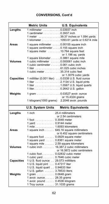
62
Metric Units U.S. EquivalentsLengths 1 millimeter . . . . . . . . . . .0.03937 inch 1 centimeter . . . . . . . . . . .0.3937 inch 1 meter . . . . . . . . . . . . . .39.37 inches or 1.094 yards 1 kilometer . . . . . . . . . . . .1093.61 yards or 0.6214 mileAreas 1 square millimeter . . . . .0.00155 square inch 1 square centimeter . . . . .0.155 square inch 1 square meter . . . . . . . .10.764 square feet or 1.196 sq. yards 1 square kilometer . . . . . .0.3861 square mileVolumes 1 cubic millimeter . . . . . .0.000061 cubic inch 1 cubic centimeter . . . . . .0.061 cubic inch 1 liter . . . . . . . . . . . . . . . .61.025 cubic inches 1 cubic meter . . . . . . . . . .35.314 cubic feet or 1.3079 cubic yardsCapacities 1 milliliter (0.001 liter) . . .0.0338 U.S. fluid ounce 1 liter . . . . . . . . . . . . . . . .2.1134 U.S. liquid pints 1 liter . . . . . . . . . . . . . . . .1.0567 U.S. liquid quarts 1 liter. . . . . . . . . . . . . . . . .0.2642 U.S. gallon
Weights 1 gram . . . . . . . . . . . . . . .0.03527 avoir. ounce or 15.4324 grains 1 kilogram(1000 grams) 2.2046 avoir. pounds
U.S. System Units Metric EquivalentsLengths 1 inch 25.4 millimeters or 2.54 centimeters 1 foot . . . . . . . . . . . . 0.3048 meter 1 yard . . . . . . . . . . . 0.9144 meter 1 mile . . . . . . . . . . . . 1.6093 kilometersAreas 1 square inch . . . . . . 645.16 square millimeters or 6.452 square centimeters 1 square foot . . . . . . 0.0929 square meter 1 square yard . . . . . 0.8361 square meter 1 square mile . . . . . . 2.59 square kilometersVolumes 1 cubic inch . . . . . . . 16,387.2 cubic millimeters or 16.3872 cubic centimeters 1 cubic foot . . . . . . . . 0.02832 cubic meter 1 cubic yard . . . . . . . 0.7646 cubic meter Capacities 1 U.S. fluid ounce . . 29.573 milliliters 1 U.S. liquid pint . . . 0.47317 liter 1 U.S. liquid quart . . 0.94633 liter 1 U.S. gallon . . . . . . 3.78533 litersWeights 1 grain . . . . . . . . . . . 0.0648 gram 1 avoir. ounce. . . . . . 28.35 grams 1 avoir. pound . . . . . 0.4536 kilogram 1 Troy ounce . . . . . . 31.1035 grams
CONVERSIONS, Cont’d
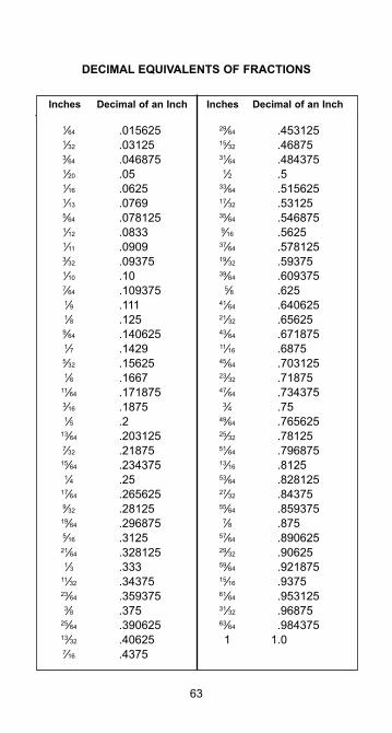
63
Inches Decimal of an Inch Inches Decimal of an Inch
DECIMAL EQUIVALENTS OF FRACTIONS
1⁄64 .015625 1⁄32 .03125 3⁄64 .046875 1⁄20 .05 1⁄16 .0625 1⁄13 .0769 5⁄64 .078125 1⁄12 .0833 1⁄11 .0909 3⁄32 .09375 1⁄10 .10 7⁄64 .109375 1⁄9 .111 1⁄8 .125 9⁄64 .140625 1⁄7 .1429 5⁄32 .15625 1⁄6 .1667 11⁄64 .171875 3⁄16 .1875 1⁄5 .2 13⁄64 .203125 7⁄32 .21875 15⁄64 .234375 1⁄4 .25 17⁄64 .265625 9⁄32 .28125 19⁄64 .296875 5⁄16 .3125 21⁄64 .328125 1⁄3 .333 11⁄32 .34375 23⁄64 .359375 3⁄8 .375 25⁄64 .390625 13⁄32 .40625 7⁄16 .4375
29⁄64 .453125 15⁄32 .46875 31⁄64 .484375 1⁄2 .5 33⁄64 .515625 17⁄32 .53125 35⁄64 .546875 9⁄16 .5625 37⁄64 .578125 19⁄32 .59375 39⁄64 .609375 5⁄8 .625 41⁄64 .640625 21⁄32 .65625 43⁄64 .671875 11⁄16 .6875 45⁄64 .703125 23⁄32 .71875 47⁄64 .734375 3⁄4 .75 49⁄64 .765625 25⁄32 .78125 51⁄64 .796875 13⁄16 .8125 53⁄64 .828125 27⁄32 .84375 55⁄64 .859375 7⁄8 .875 57⁄64 .890625 29⁄32 .90625 59⁄64 .921875 15⁄16 .9375 61⁄64 .953125 31⁄32 .96875 63⁄64 .984375 1 1.0
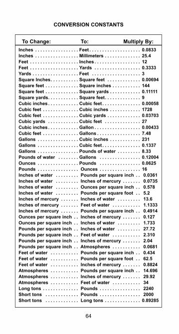
64
CONVERSION CONSTANTS
To Change: To: Multiply By:Inches . . . . . . . . . . . . . . . . . Feet . . . . . . . . . . . . . . . . . . . . 0.0833Inches . . . . . . . . . . . . . . . . . Millimeters . . . . . . . . . . . . . . 25.4Feet . . . . . . . . . . . . . . . . . . . Inches . . . . . . . . . . . . . . . . . . 12Feet . . . . . . . . . . . . . . . . . . . Yards . . . . . . . . . . . . . . . . . . 0.3333Yards . . . . . . . . . . . . . . . . . . Feet . . . . . . . . . . . . . . . . . . . 3Square Inches. . . . . . . . . . . Square feet . . . . . . . . . . . . . 0.00694Square feet . . . . . . . . . . . . . Square inches . . . . . . . . . . . 144Square feet . . . . . . . . . . . . . Square yards . . . . . . . . . . . . 0.11111Square yards. . . . . . . . . . . . Square feet. . . . . . . . . . . . . . 9Cubic inches . . . . . . . . . . . . Cubic feet . . . . . . . . . . . . . . . 0.00058Cubic feet . . . . . . . . . . . . . . Cubic inches . . . . . . . . . . . . 1728Cubic feet . . . . . . . . . . . . . . Cubic yards . . . . . . . . . . . . . 0.03703Cubic yards . . . . . . . . . . . . Cubic feet . . . . . . . . . . . . . . 27Cubic inches . . . . . . . . . . . . Gallon . . . . . . . . . . . . . . . . . . 0.00433Cubic feet . . . . . . . . . . . . . . Gallons . . . . . . . . . . . . . . . . . 7.48Gallons . . . . . . . . . . . . . . . . Cubic inches . . . . . . . . . . . . 231Gallons . . . . . . . . . . . . . . . . Cubic feet . . . . . . . . . . . . . . . 0.1337Gallons . . . . . . . . . . . . . . . . Pounds of water . . . . . . . . . 8.33Pounds of water . . . . . . . . Gallons . . . . . . . . . . . . . . . . 0.12004Ounces . . . . . . . . . . . . . . . . Pounds . . . . . . . . . . . . . . . . 0.0625Pounds . . . . . . . . . . . . . . . . Ounces . . . . . . . . . . . . . . . . 16Inches of water . . . . . . . . . Pounds per square inch . . 0.0361Inches of water . . . . . . . . . Inches of mercury . . . . . . . 0.0735Inches of water . . . . . . . . . Ounces per square inch . . 0.578Inches of water . . . . . . . . . Pounds per square foot . . 5.2Inches of mercury . . . . . . . Inches of water . . . . . . . . . 13.6Inches of mercury . . . . . . . Feet of water . . . . . . . . . . . 1.1333Inches of mercury . . . . . . . Pounds per square inch . . 0.4914Ounces per square inch . . Inches of mercury . . . . . . . 0.127Ounces per square inch . . Inches of water . . . . . . . . . 1.733Pounds per square inch . . Inches of water . . . . . . . . . 27.72Pounds per square inch . . Feet of water . . . . . . . . . . . 2.310Pounds per square inch . . Inches of mercury . . . . . . . 2.04Pounds per square inch . . Atmospheres . . . . . . . . . . . 0.0681Feet of water . . . . . . . . . . . Pounds per square inch . . 0.434Feet of water . . . . . . . . . . . Pounds per square foot . . 62.5Feet of water . . . . . . . . . . . Inches of mercury . . . . . . . 0.8824Atmospheres . . . . . . . . . . . Pounds per square inch . . 14.696Atmospheres . . . . . . . . . . . Inches of mercury . . . . . . . 29.92 Atmospheres . . . . . . . . . . . Feet of water . . . . . . . . . . . 34Long tons . . . . . . . . . . . . . . Pounds . . . . . . . . . . . . . . . . 2240Short tons . . . . . . . . . . . . . Pounds . . . . . . . . . . . . . . . . 2000Short tons . . . . . . . . . . . . . Long tons . . . . . . . . . . . . . . 0.89285
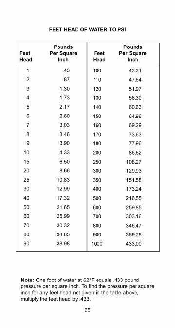
65
Pounds Pounds Feet Per Square Feet Per Square Head Inch Head Inch
FEET HEAD OF WATER TO PSI
1 .43
2 .87
3 1.30
4 1.73
5 2.17
6 2.60
7 3.03
8 3.46
9 3.90
10 4.33
15 6.50
20 8.66
25 10.83
30 12.99
40 17.32
50 21.65
60 25.99
70 30.32
80 34.65
90 38.98
100 43.31
110 47.64
120 51.97
130 56.30
140 60.63
150 64.96
160 69.29
170 73.63
180 77.96
200 86.62
250 108.27
300 129.93
350 151.58
400 173.24
500 216.55
600 259.85
700 303.16
800 346.47
900 389.78
1000 433.00
Note: One foot of water at 62°F equals .433 pound pressure per square inch. To find the pressure per square inch for any feet head not given in the table above, multiply the feet head by .433.
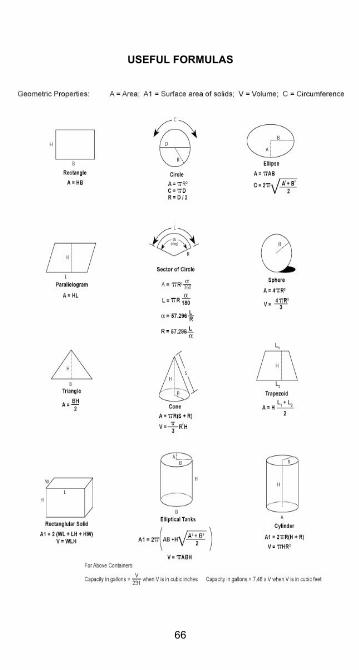
66
USEFUL FORMULAS
DEFINITION OF TERMS
ACCELERATOR - Any of a number of chemicals added to the resin, singly or in combination, which speed the hardening process or cause the hardening to occur (hardener, catalyst, curing agent, promoter).ADAPTER - A fitting used to join two pieces of pipe, or two fittings, which have different joining systems.ADHESIVE - A material formulated to bond together pipe and fittings resulting in high strength and corrosion resistant fabrications.BELL AND SPIGOT - A joining system in which two truncated conical surfaces come together and bond adhesively. The bell is the female end. The spigot is the male end.BUSHING - A fitting used to join two different sizes of pipe byreducing the size of the female end of the joint. Joints may come threaded or tapered.CATALYST - See hardener.CENTRIFUGAL CASTING - A process for making pipe in which the resin, fiberglass reinforcement and other ingredients are placed into the interior of a spinning steel rotary mold, forming the pipe through centrifugal force and the application of heat.COLLAR - See coupling.COMPRESSION MOLDING - A process for making fittings in which a molding compound is formed and cured into the finished part configuration through pressure and heat in a die.COMPRESSIVE FORCE - The force that occurs when opposing loads act on a material, crushing, or attempting to crush it. In pipe, circumferential compressive forces result from external collapse pressure, or heating of an end-restrained fiberglass pipe.CONCENTRIC REDUCER - A pipe fitting used to join two different sizes of pipe while maintaining the same center line in both.CONTACT MOLDING - A process for making fittings in which cut pieces of fiberglass reinforcement are laid on a mold, saturated with resin, and cured to the finished part shape.COUPLING (collar) - A short heavy wall cylindrical fitting used to join two pieces of the same size pipe in a straight line. The coupling always has female connection ends which can be bell, threaded or a mechanical joining method.CURE - The hardening of a thermoset resin system by the action of heat or chemical action.
67
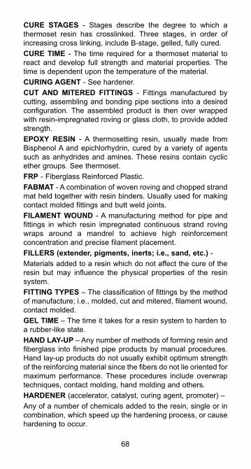
CURE STAGES - Stages describe the degree to which a thermoset resin has crosslinked. Three stages, in order of increasing cross linking, include B-stage, gelled, fully cured.CURE TIME - The time required for a thermoset material to react and develop full strength and material properties. The time is dependent upon the temperature of the material.CURING AGENT - See hardener.CUT AND MITERED FITTINGS - Fittings manufactured by cutting, assembling and bonding pipe sections into a desired configuration. The assembled product is then over wrapped with resin-impregnated roving or glass cloth, to provide added strength.EPOXY RESIN - A thermosetting resin, usually made from Bisphenol A and epichlorhydrin, cured by a variety of agents such as anhydrides and amines. These resins contain cyclic ether groups. See thermoset.FRP - Fiberglass Reinforced Plastic.FABMAT - A combination of woven roving and chopped strand mat held together with resin binders. Usually used for making contact molded fittings and butt weld joints.FILAMENT WOUND - A manufacturing method for pipe and fittings in which resin impregnated continuous strand roving wraps around a mandrel to achieve high reinforcement concentration and precise filament placement.FILLERS (extender, pigments, inerts; i.e., sand, etc.) -Materials added to a resin which do not affect the cure of the resin but may influence the physical properties of the resin system.FITTING TYPES – The classification of fittings by the method of manufacture; i.e., molded, cut and mitered, filament wound, contact molded.GEL TIME – The time it takes for a resin system to harden to a rubber-like state.HAND LAY-UP – Any number of methods of forming resin and fiberglass into finished pipe products by manual procedures. Hand lay-up products do not usually exhibit optimum strength of the reinforcing material since the fibers do not lie oriented for maximum performance. These procedures include overwrap techniques, contact molding, hand molding and others.HARDENER (accelerator, catalyst, curing agent, promoter) –Any of a number of chemicals added to the resin, single or in combination, which speed up the hardening process, or cause hardening to occur.
68
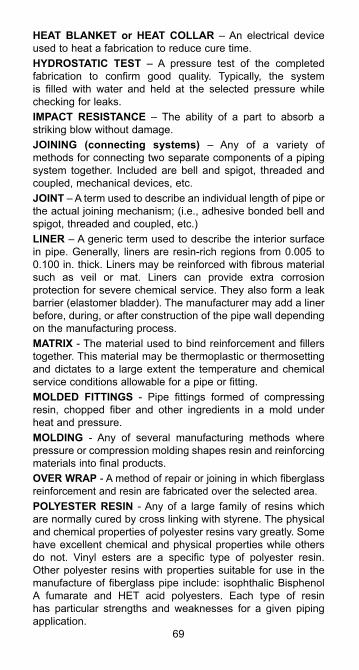
HEAT BLANKET or HEAT COLLAR – An electrical device used to heat a fabrication to reduce cure time.HYDROSTATIC TEST – A pressure test of the completed fabrication to confirm good quality. Typically, the system is filled with water and held at the selected pressure while checking for leaks.IMPACT RESISTANCE – The ability of a part to absorb a striking blow without damage.JOINING (connecting systems) – Any of a variety of methods for connecting two separate components of a piping system together. Included are bell and spigot, threaded and coupled, mechanical devices, etc.JOINT – A term used to describe an individual length of pipe or the actual joining mechanism; (i.e., adhesive bonded bell and spigot, threaded and coupled, etc.)LINER – A generic term used to describe the interior surface in pipe. Generally, liners are resin-rich regions from 0.005 to 0.100 in. thick. Liners may be reinforced with fibrous material such as veil or mat. Liners can provide extra corrosion protection for severe chemical service. They also form a leak barrier (elastomer bladder). The manufacturer may add a liner before, during, or after construction of the pipe wall depending on the manufacturing process.MATRIX - The material used to bind reinforcement and fillers together. This material may be thermoplastic or thermosetting and dictates to a large extent the temperature and chemical service conditions allowable for a pipe or fitting.MOLDED FITTINGS - Pipe fittings formed of compressing resin, chopped fiber and other ingredients in a mold under heat and pressure.MOLDING - Any of several manufacturing methods where pressure or compression molding shapes resin and reinforcing materials into final products.OVER WRAP - A method of repair or joining in which fiberglass reinforcement and resin are fabricated over the selected area.POLYESTER RESIN - Any of a large family of resins which are normally cured by cross linking with styrene. The physical and chemical properties of polyester resins vary greatly. Some have excellent chemical and physical properties while others do not. Vinyl esters are a specific type of polyester resin. Other polyester resins with properties suitable for use in the manufacture of fiberglass pipe include: isophthalic Bisphenol A fumarate and HET acid polyesters. Each type of resin has particular strengths and weaknesses for a given piping application.
69
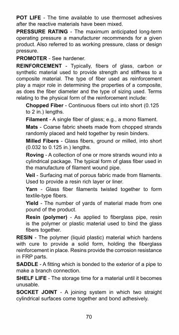
POT LIFE - The time available to use thermoset adhesives after the reactive materials have been mixed.PRESSURE RATING - The maximum anticipated long-term operating pressure a manufacturer recommends for a given product. Also referred to as working pressure, class or design pressure.PROMOTER - See hardener.REINFORCEMENT - Typically, fibers of glass, carbon or synthetic material used to provide strength and stiffness to a composite material. The type of fiber used as reinforcement play a major role in determining the properties of a composite, as does the fiber diameter and the type of sizing used. Terms relating to the physical form of the reinforcement include:
Chopped Fiber - Continuous fibers cut into short (0.125 to 2 in.) lengths.Filament - A single fiber of glass; e.g., a mono filament.Mats - Coarse fabric sheets made from chopped strands randomly placed and held together by resin binders.Milled Fibers - Glass fibers, ground or milled, into short (0.032 to 0.125 in.) lengths.Roving - A collection of one or more strands wound into a cylindrical package. The typical form of glass fiber used in the manufacture of filament wound pipe.Veil - Surfacing mat of porous fabric made from filaments. Used to provide a resin rich layer or liner.Yarn - Glass fiber filaments twisted together to form textile-type fibers.Yield - The number of yards of material made from one pound of the product.Resin (polymer) - As applied to fiberglass pipe, resin is the polymer or plastic material used to bind the glass fibers together.
RESIN - The polymer (liquid plastic) material which hardens with cure to provide a solid form, holding the fiberglass reinforcement in place. Resins provide the corrosion resistance in FRP parts.SADDLE - A fitting which is bonded to the exterior of a pipe to make a branch connection.SHELF LIFE - The storage time for a material until it becomes unusable.SOCKET JOINT - A joining system in which two straight cylindrical surfaces come together and bond adhesively.
70
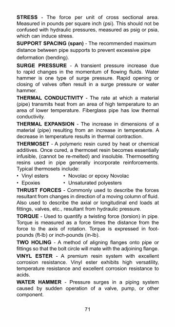
STRESS - The force per unit of cross sectional area. Measured in pounds per square inch (psi). This should not be confused with hydraulic pressures, measured as psig or psia, which can induce stress.SUPPORT SPACING (span) - The recommended maximumdistance between pipe supports to prevent excessive pipedeformation (bending).SURGE PRESSURE - A transient pressure increase due to rapid changes in the momentum of flowing fluids. Water hammer is one type of surge pressure. Rapid opening or closing of valves often result in a surge pressure or water hammer.THERMAL CONDUCTIVITY - The rate at which a material (pipe) transmits heat from an area of high temperature to an area of lower temperature. Fiberglass pipe has low thermal conductivity.THERMAL EXPANSION - The increase in dimensions of a material (pipe) resulting from an increase in temperature. A decrease in temperature results in thermal contraction.THERMOSET - A polymeric resin cured by heat or chemical additives. Once cured, a thermoset resin becomes essentially infusible, (cannot be re-melted) and insoluble. Thermosetting resins used in pipe generally incorporate reinforcements. Typical thermosets include:• Vinyl esters • Novolac or epoxy Novolac• Epoxies • Unsaturated polyestersTHRUST FORCES - Commonly used to describe the forces resultant from changes in direction of a moving column of fluid. Also used to describe the axial or longitudinal end loads at fittings, valves, etc., resultant from hydraulic pressure.TORQUE - Used to quantify a twisting force (torsion) in pipe. Torque is measured as a force times the distance from the force to the axis of rotation. Torque is expressed in foot-pounds (ft-lb) or inch-pounds (in-lb).TWO HOLING - A method of aligning flanges onto pipe or fittings so that the bolt circle will mate with the adjoining flange.VINYL ESTER - A premium resin system with excellent corrosion resistance. Vinyl ester exhibits high versatility, temperature resistance and excellent corrosion resistance to acids.WATER HAMMER - Pressure surges in a piping system caused by sudden operation of a valve, pump, or other component.
71
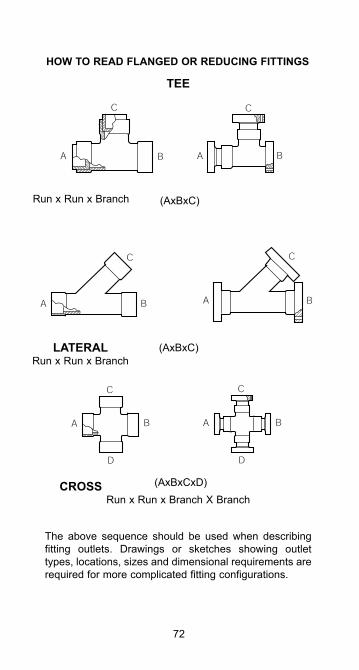
72
HOW TO READ FLANGED OR REDUCING FITTINGS
The above sequence should be used when describing fitting outlets. Drawings or sketches showing outlet types, locations, sizes and dimensional requirements are required for more complicated fitting configurations.
TEE
Run x Run x Branch
LATERALRun x Run x Branch
CROSSRun x Run x Branch X Branch
(AxBxC)
(AxBxC)
(AxBxCxD)
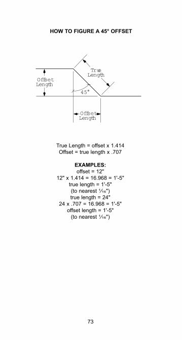
73
HOW TO FIGURE A 45° OFFSET
OffsetLength
OffsetLength
TrueLength
45°
True Length = offset x 1.414Offset = true length x .707
EXAMPLES:offset = 12"
12" x 1.414 = 16.968 = 1'-5"true length = 1'-5"(to nearest 1⁄16")true length = 24"
24 x .707 = 16.968 = 1'-5"offset length = 1'-5"
(to nearest 1⁄16")

74

75
www.nov.com/fgs
North America17115 San Pedro Ave. Suite 200San Antonio, TX 78232Phone: 1 (210) 477-7500
©2015 National Oilwell Varco. All rights reserved. INS1010ENG July 2015
National Oilwell Varco has produced this brochure for general information only, and it is not intended for design purposes. Although every effort has been made to maintain the accuracy and reliability of its contents, National Oilwell Varco in no way assumes responsibility for liability for any loss, damage or injury resulting from the use of information and data herein nor is any warranty expressed or implied. Always cross-reference the bulletin date with the most current version listed at the web site noted in this literature.
South America Europe Estrada de Acesso á Zona P.O. Box 6, 4190 CA Industrial Portuária de Suape, s/no. Geldermalsen, The Netherlands Recife, PE, Brazil 55.590-000 Phone: 31 345 587 587Phone: 55 31 3501 0023
Asia Pacific Middle EastNo. 7A, Tuas Avenue 3 P.O. Box 17324Jurong, Singapore 639407 Dubai, UAEPhone: 65 6861 6118 Phone: 971 4881 3566
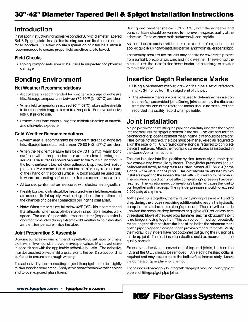
30”-42” Diameter Tapered Bell & Spigot Installation Instructions
IntroductionInstallation instructions for adhesive bonded 30”-42” diameter Tapered Bell & Spigot joints. Installation training and certification is required for all bonders. Qualified on-site supervision of initial installation is recommended to ensure proper field practices are followed.
Field Checks• Piping components should be visually inspected for physical
damage
Bonding EnvironmentHot Weather Recommendations• A cool area is recommended for long-term storage of adhesive
kits. Storage temperatures between 70-80°F (21-27° C) are ideal.
• When field temperatures exceed 90°F (32°C), store adhesive kits in ice chest with bagged ice or freezer pack. Remove adhesive kits just prior to use.
• Protect joints from direct sunlight to minimize heating of material and ultraviolet exposure.
Cold Weather Recommendations• A warm area is recommended for long-term storage of adhesive
kits. Storage temperatures between 70-80°F (21-27°C) are ideal.
• When the field temperature falls below 70°F (21°C), warm bond surfaces with a propane torch or another clean burning heat source. The surfaces should be warm to the touch but not hot. If the bond surface is too hot when adhesive is applied, it will set up prematurely. A bonder should be able to comfortably place the back of their hand on the bond surface. A torch should be used only to warm the bonding surface, not to force cure an adhesive joint.
• All bonded joints must be heat cured with electric heating collars.
• Freshly bonded joints should be heat cured when field temperatures are expected to fall rapidly. Heat curing reduces the cure time and the chances of pipeline contraction pulling the joint apart.
• Note: When temperatures fall below 32°F (0°C), it is recommended that all joints (when possible) be made in a portable, heated work space. The use of a portable kerosene heater (torpedo style) is also recommended during extreme cold weather to help maintain ambient temperature inside the pipe.
Joint Preparation & AssemblyBonding surfaces require light sanding with 40-80 grit paper or Emery cloth within two hours before adhesive application. Mix the adhesive in accordance with the applicable adhesive bulletin. The adhesive must be brushed on with mild pressure onto the bell & spigot bonding surfaces to ensure a thorough wetting.
The adhesive layer on the leading edge of the spigot should be slightly thicker than the other areas. Apply a thin coat of adhesive to the spigot end to coat exposed glass fibers.
During cool weather (below 70°F (21°C), both the adhesive and bond surfaces should be warmed to improve the spread ability of the adhesive. Once warmed both surfaces will cool rapidly.
As the adhesive cools it will become thicker; therefore, it should be applied quickly using two installers per bell and two installers per spigot.
The working area around the joint may need to be covered to protect from sunlight, precipitation, wind and frigid weather. The weight of the pipe requires the use of a side boom tractor, crane or large excavator to move the pipe.
Insertion Depth Reference Marks• Using a permanent marker, draw on the pipe a set of reference
marks 24 inches from the spigot end of the pipe.
• The reference marks are positions used to determine the insertion depth of an assembled joint. During joint assembly the distance from the bell end to the reference marks should be measured and recorded in a quality record when possible.
Joint InstallationA pipe joint is made by lifting the pipe and carefully inserting the spigot into the bell until the spigot is seated in the bell. The joint should then be checked for proper alignment meaning the joint should be straight. If the joint is not aligned, the pipe must be maneuvered as required to align the pipe joint. A hydraulic come-along is required to complete the joint make-up. Attach the hydraulic come-alongs as instructed in the Come-Along Instructions.
The joint is pulled into final position by simultaneously pumping the two come-along hydraulic cylinders. The cylinder pressures should be increased slowly to the pressures listed in manual TLS6619 (come alongs)while vibrating the joints. The joint should be vibrated by two installers impacting the sides of the bell with 5 lb. dead blow hammers. The vibrating should continue after come-along’s pressure has been reached. The vibrations and come-along’s loads will cause the joint to pull together until made up. The cylinder pressure should not exceed 5,000 psig at any time.
As the joint pulls together, the hydraulic cylinder pressure will tend to drop during the process requiring additional strokes on the hydraulic pump to maintain the come-along’s pressure. The joint will be made up when the pressure drop becomes negligible (300 psi or less with three sharp blows of the dead blow hammer) and it is obvious the joint is no longer moving together. This can be confirmed by repeatedly measuring the distance from the face of the bell to the reference mark on the pipe spigot and comparing to previous measurements. Verify the hydraulic cylinders have not bottomed out giving the illusion of a made-up joint. The final insertion depth should be recorded for the quality records.
Excessive adhesive squeezed out of tapered joints, both on the I.D. and the O.D., should be removed. An electric heating collar is required and may be applied to the bell surface immediately. Leave the come-alongs in place for one hour.
These instructions apply to integral bell/spigot pipe, coupling/spigot pipe and fitting/spigot pipe joints.
www.fgspipe.com • [email protected]
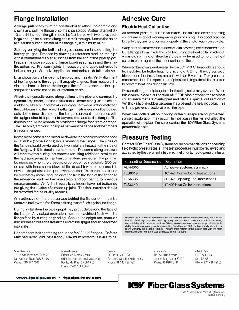
Flange InstallationA flange pull-beam must be constructed to attach the come-along chains and pull the flange onto the pipe spigot. A steel channel 6 x 13 and 54 inches in length should be fabricated with two holes each large enough for a come-along chain to fit through. Locate the holes to clear the outer diameter of the flange by a minimum of ½”.
Start by verifying the bell and spigot tapers are in spec using the factory gauges. Proceed by drawing a reference mark on the pipe with a permanent marker 18 inches from the end of the pipe spigot. Prepare the pipe spigot and flange bonding surfaces and then mix the adhesive. Pre-warm joints if necessary and apply adhesive to bell and spigot. Adhesive application methods are detailed above.
Lift and position the flange onto the spigot until it seats. Verify alignment of the flange onto the spigot. If properly aligned, then measure the distance from the face of the flange to the reference mark on the pipe spigot and record as the initial insertion depth.
Attach the hydraulic come-along collars to the pipe and connect the hydraulic cylinders, per the instruction for come-alongs to the collars and the pull-beam. Place two 4 x 4 or larger hardwood timbers between the pull-beam and the face of the flange. The timbers must be located outside the inner diameter of the flange to prevent interference with the spigot should it protrude beyond the face of the flange. The timbers should be smooth to protect the flange face from damage. The use of a 1/4” thick rubber pad between the flange and the timbers is recommended.
Increase the come-along pressure slowly to the pressures recomended in TLS6619 (come alongs) while vibrating the flange. The sides of the flange should be vibrated by two installers impacting the side of the flange with 5 lb. dead blow hammers. The come-along pressure will tend to drop during this process requiring additional strokes on the hydraulic pump to maintain come along pressure. The joint will be made up when the pressure drop becomes negligible (300 psi or less with three sharp blows of the dead blow hammer) and it is obvious the joint is no longer moving together. This can be confirmed by repeatedly measuring the distance from the face of the flange to the reference mark on the pipe spigot and comparing to previous measurements. Verify the hydraulic cylinders have not bottomed out giving the illusion of a made-up joint. The final insertion should be recorded for the quality records.
Any adhesive on the pipe surface behind the flange joint must be removed to allow the Van Stone bolt ring to seat flush against the flange.
During installation the pipe spigot may protrude beyond the face of the flange. Any spigot protrusion must be machined flush with the flange face by cutting or grinding. Should the spigot not protrude any squeezed out adhesive at the end of the spigot should be formed into a fillet.
Use standard bolt tightening sequence for 30”-42” flanges. (Refer to Matched Taper Joint Installation.) Maximum bolt torque is 400 ft-lbs.
Adhesive CureElectric Heat Collar UseAll bonded joints must be heat cured. Ensure the electric heating collars are in good working order prior to using. It is good practice to verify they are functioning properly at the end of each cure cycle.
Wrap heat collars over the surface of joint covering entire bonded area. Cure flanges from inside the pipe by turning the heat collar inside out. A narrow split ring of fiberglass pipe may be used to hold the heat collar in place against the inner surface of the pipe.
When ambient temperatures fall below 50°F (10°C) heat collars should be insulated for better heating efficiency. A 2-inch thick glass wool blanket or other insulating material with an R value of 7 or greater is recommended. The open ends of pipe and fittings should be blocked to prevent heat loss due to air flow.
On some fittings and pipe joints, the heating collar may overlap. When this occurs, place a cut section of 2” FRP pipe between the two heat collar layers that are overlapped and place a special cut section of 1/16” thick silicone rubber between the pipe and the heating collar. This will help prevent discoloration of the pipe.
When heat collars left on too long or the overlaps are not protected, some discoloration may occur. In most cases this will not affect the operation of the pipe. If unsure, contact the NOV Fiber Glass Systems personnel on site.
Pressure TestingContact NOV Fiber Glass Systems for recommendations concerning field hydro pressure tests. The test procedure must be reviewed and accepted by the pertinent site personnel prior to hydro pressure tests.
Supporting Documents Description
ADH4000 Adhesive Systems Summary
TLS6619 18”-42” Come-Along Instructions
TLS6636 30”-42” Tapering Tool Instructions
TLS6640 1”-42” Heat Collar Instructions
©2015 National Oilwell Varco. All rights reserved. INS1020 June 2015
National Oilwell Varco has produced this brochure for general information only, and it is not intended for design purposes. Although every effort has been made to maintain the accuracy and reliability of its contents, National Oilwell Varco in no way assumes responsibility for li-ability for any loss, damage or injury resulting from the use of information and data herein nor is any warranty expressed or implied. Always cross-reference the bulletin date with the most current version listed at the web site noted in this literature.
www.fgspipe.com • [email protected]
North America South America Europe Asia Pacific Middle East17115 San Pedro Ave. Suite 200 Estrada de Acesso á Zona P.O. Box 6, 4190 CA No. 7A, Tuas Avenue 3 P.O. Box 17324San Antonio, Texas 78232 USA Industrial Portuária de Suape, s/no. Geldermalsen, The Netherlands Jurong, Singapore 639407 Dubai, UAEPhone: 210 477 7500 Recife, PE, Brazil 55.590-000 Phone: 31 345 587 587 Phone: 65 6861 6118 Phone: 971 4881 3566 Phone: 55 81 3501 0023
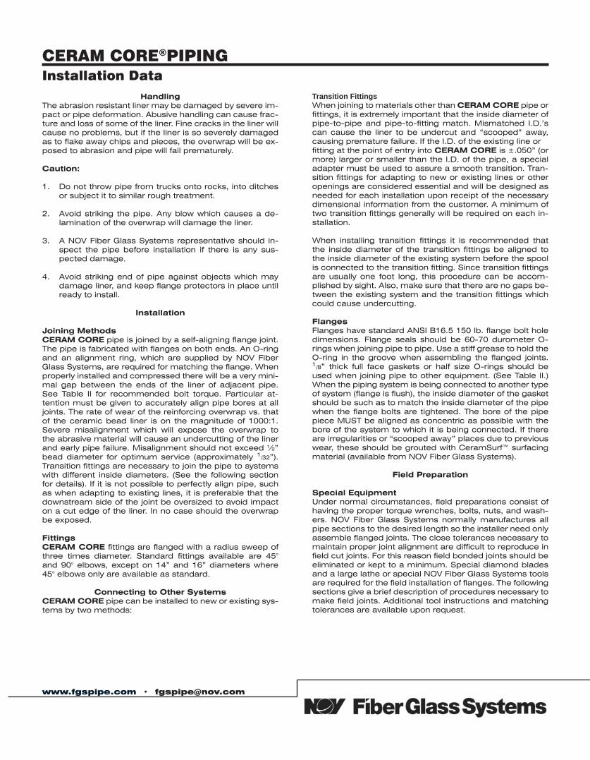
www.fgspipe.com • [email protected]
HandlingThe abrasion resistant liner may be damaged by severe im-pact or pipe deformation. Abusive handling can cause frac-ture and loss of some of the liner. Fine cracks in the liner will cause no problems, but if the liner is so severely damaged as to flake away chips and pieces, the overwrap will be ex-posed to abrasion and pipe will fail prematurely. Caution:
1. Do not throw pipe from trucks onto rocks, into ditches or subject it to similar rough treatment.
2. Avoid striking the pipe. Any blow which causes a de-lamination of the overwrap will damage the liner.
3. A NOV Fiber Glass Systems representative should in-spect the pipe before installation if there is any sus-pected damage.
4. Avoid striking end of pipe against objects which may damage liner, and keep flange protectors in place until ready to install.
Installation
Joining MethodsCERAM CORE pipe is joined by a self-aligning flange joint. The pipe is fabricated with flanges on both ends. An O-ring and an alignment ring, which are supplied by NOV Fiber Glass Systems, are required for matching the flange. When properly installed and compressed there will be a very mini-mal gap between the ends of the liner of adjacent pipe. See Table II for recommended bolt torque. Particular at-tention must be given to accurately align pipe bores at all joints. The rate of wear of the reinforcing overwrap vs. that of the ceramic bead liner is on the magnitude of 1000:1. Severe misalignment which will expose the overwrap to the abrasive material will cause an undercutting of the liner and early pipe failure. Misalignment should not exceed ½” bead diameter for optimum service (approximately 1/32”). Transition fittings are necessary to join the pipe to systems with different inside diameters. (See the following section for details). If it is not possible to perfectly align pipe, such as when adapting to existing lines, it is preferable that the downstream side of the joint be oversized to avoid impact on a cut edge of the liner. In no case should the overwrap be exposed.
FittingsCERAM CORE fittings are flanged with a radius sweep of three times diameter. Standard fittings available are 45° and 90° elbows, except on 14” and 16” diameters where 45° elbows only are available as standard.
Connecting to Other SystemsCERAM CORE pipe can be installed to new or existing sys-tems by two methods:
Transition FittingsWhen joining to materials other than CERAM CORE pipe or fittings, it is extremely important that the inside diameter of pipe-to-pipe and pipe-to-fitting match. Mismatched I.D.’s can cause the liner to be undercut and “scooped” away, causing premature failure. If the I.D. of the existing line or fitting at the point of entry into CERAM CORE is ±.050” (or more) larger or smaller than the I.D. of the pipe, a special adapter must be used to assure a smooth transition. Tran-sition fittings for adapting to new or existing lines or other openings are considered essential and will be designed as needed for each installation upon receipt of the necessary dimensional information from the customer. A minimum of two transition fittings generally will be required on each in-stallation.
When installing transition fittings it is recommended that the inside diameter of the transition fittings be aligned to the inside diameter of the existing system before the spool is connected to the transition fitting. Since transition fittings are usually one foot long, this procedure can be accom-plished by sight. Also, make sure that there are no gaps be-tween the existing system and the transition fittings which could cause undercutting.
FlangesFlanges have standard ANSI B16.5 150 lb. flange bolt hole dimensions. Flange seals should be 60-70 durometer O-rings when joining pipe to pipe. Use a stiff grease to hold the O-ring in the groove when assembling the flanged joints. 1/8” thick full face gaskets or half size O-rings should be used when joining pipe to other equipment. (See Table II.) When the piping system is being connected to another type of system (flange is flush), the inside diameter of the gasket should be such as to match the inside diameter of the pipe when the flange bolts are tightened. The bore of the pipe piece MUST be aligned as concentric as possible with the bore of the system to which it is being connected. If there are irregularities or “scooped away” places due to previous wear, these should be grouted with CeramSurf™ surfacing material (available from NOV Fiber Glass Systems).
Field Preparation
Special EquipmentUnder normal circumstances, field preparations consist of having the proper torque wrenches, bolts, nuts, and wash-ers. NOV Fiber Glass Systems normally manufactures all pipe sections to the desired length so the installer need only assemble flanged joints. The close tolerances necessary to maintain proper joint alignment are difficult to reproduce in field cut joints. For this reason field bonded joints should be eliminated or kept to a minimum. Special diamond blades and a large lathe or special NOV Fiber Glass Systems tools are required for the field installation of flanges. The following sections give a brief description of procedures necessary to make field joints. Additional tool instructions and matching tolerances are available upon request.
Installation DataCERAM CORE®PIPING
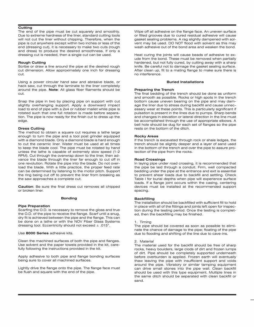
CuttingThe end of the pipe must be cut squarely and smoothly. Due to extreme hardness of the liner, standard cutting tools will not cut the liner without chipping. Therefore, when the pipe is cut anywhere except within two inches or less of the end (dressing cut), it is necessary to make two cuts (rough and dress) to produce the desired smoothness. If only a dressing cut is needed, then a single cut can be used.
Rough CuttingScribe or draw a line around the pipe at the desired rough cut dimension. Allow approximately one inch for dressing cut.
Using a power circular hand saw and abrasive blade, or hack saw, cut through the laminate to the liner completely around the pipe. Note: All glass fiber filaments should be cut.
Snap the pipe in two by placing pipe on support with cut slightly overhanging support. Apply a downward impact load to end of pipe with a 2x4 or rubber mallet while pipe is rotated such that one full rotation is made before separa-tion. The pipe is now ready for the finish cut to dress up the edge.
Dress CuttingThe method to obtain a square cut requires a lathe large enough to turn the pipe and a tool post grinder equipped with a diamond blade. Only a diamond blade is hard enough to cut the ceramic liner. Water must be used at all times to keep the blade cool. The pipe must be rotated by hand unless the lathe is capable of extremely slow speed (1-2 RPM). Cut through the overwrap down to the liner, then ad-vance the blade through the liner far enough to cut off in one revolution. Rotate the pipe into the blade. Do not over-load the blade. With a little practice, the proper feed rate can be determined by listening to the motor pitch. Support the ring being cut off to prevent the liner from breaking as the saw approaches a complete cut.
Caution: Be sure the final dress cut removes all chipped or broken liner.
Bonding
Pipe PreparationScarfing the O.D. is necessary to remove the gloss and true the O.D. of the pipe to receive the flange. Scarf until a snug, dry fit is achieved between the pipe and the flange. This can be done on a lathe or with the NOV Fiber Glass Systems dressing tool. Eccentricity should not exceed ± .015”.
Use 8000 Series adhesive kits.
Clean the machined surfaces of both the pipe and flanges. Use solvent and the paper towels provided in the kit, care-fully following the instructions provided in the kit.
Apply adhesive to both pipe and flange bonding surfaces being sure to cover all machined surfaces.
Lightly drive the flange onto the pipe. The flange face must be flush and square with the end of the pipe.
Wipe off all adhesive on the flange face. An uneven surface or filled grooves due to cured residual adhesive will cause gasket sealing problems. A rag slightly dampened with sol-vent may be used. DO NOT flood with solvent as this may wash adhesive out of the bond area and weaken the bond.
Heat curing the joints will cause beads of adhesive to ex-ude from the bond. These must be removed when partially hardened, but not fully cured, by cutting away with a sharp knife. Be careful not to damage the gasket sealing surface. After clean up, fit to a mating flange to make sure there is no interference.
Buried Installations
Preparing the TrenchThe final bedding of the trench should be done as uniform and smooth as possible. Rocks or high spots in the trench bottom cause uneven bearing on the pipe and may dam-age the liner due to stress during backfill and cause unnec-essary wear at these points. This is particularly significant if pulsation is present in the lines due to pumps. Sharp bends and changes in elevation or lateral direction in the line must be accomplished through the use of appropriate elbows. A bell hole should be dug for each set of flanges so the pipe rests on the bottom of the ditch.
Rocky AreasIf the trench is excavated through rock or shale ledges, the trench should be slightly deeper and a layer of sand used in the bottom of the trench and over the pipe to assure pro-tection of the pipe from the rocks.
Road CrossingsIn laying pipe under road crossing, it is recommended that the pipe be laid through a conduit. Firm, well compacted bedding under the pipe at the entrance and exit is essential to prevent shear loads due to backfill and settling. Check Table I for burial depths when pipe will experience surface loads. If a flange joint occurs within the casing, centering devices must be installed at the recommended support spacing.
BackfillingThe installation should be backfilled with sufficient fill to hold in place with all of the fittings and joints left open for inspec-tion during the testing period. Once the testing is complet-ed, then the backfilling may be finished.
1. TimingThe pipe should be covered as soon as possible to elimi-nate the chance of damage to the pipe; floating of the pipe due to flooding and shifting of the line due to cave-ins.
2. MaterialThe material used for the backfill should be free of sharp rocks, heavy boulders, large clods of dirt and frozen lumps of dirt. Pipe should be completely supported underneath before overburden is applied. Frozen earth will eventually thaw leaving the pipe with insufficient support and voids around the pipe. Vibratory or similar tamping equipment can drive small stones into the pipe wall. Clean backfill should be used with this type equipment. Multiple lines in the same ditch should be separated with clean backfill or sand.
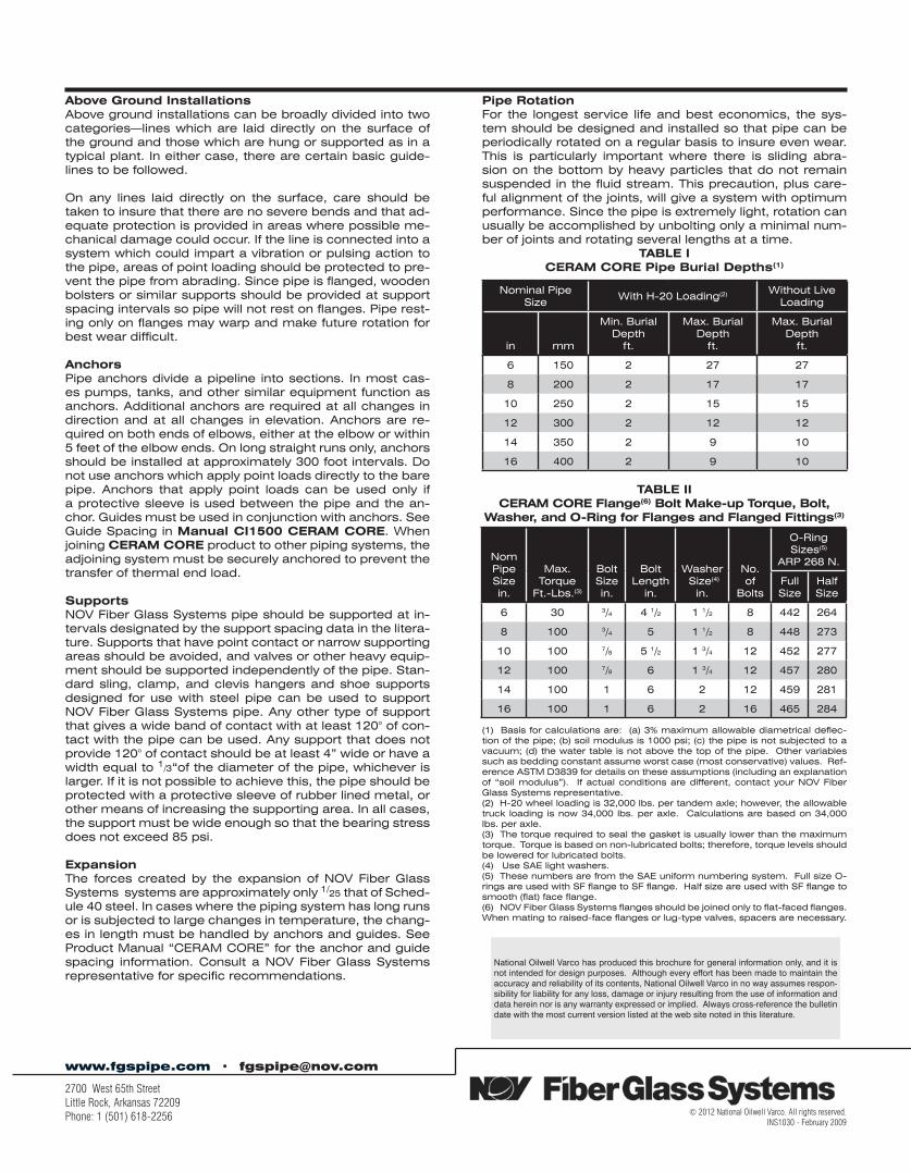
Above Ground InstallationsAbove ground installations can be broadly divided into two categories—lines which are laid directly on the surface of the ground and those which are hung or supported as in a typical plant. In either case, there are certain basic guide-lines to be followed.
On any lines laid directly on the surface, care should be taken to insure that there are no severe bends and that ad-equate protection is provided in areas where possible me-chanical damage could occur. If the line is connected into a system which could impart a vibration or pulsing action to the pipe, areas of point loading should be protected to pre-vent the pipe from abrading. Since pipe is flanged, wooden bolsters or similar supports should be provided at support spacing intervals so pipe will not rest on flanges. Pipe rest-ing only on flanges may warp and make future rotation for best wear difficult.
AnchorsPipe anchors divide a pipeline into sections. In most cas-es pumps, tanks, and other similar equipment function as anchors. Additional anchors are required at all changes in direction and at all changes in elevation. Anchors are re-quired on both ends of elbows, either at the elbow or within 5 feet of the elbow ends. On long straight runs only, anchors should be installed at approximately 300 foot intervals. Do not use anchors which apply point loads directly to the bare pipe. Anchors that apply point loads can be used only if a protective sleeve is used between the pipe and the an-chor. Guides must be used in conjunction with anchors. See Guide Spacing in Manual CI1500 CERAM CORE. When joining CERAM CORE product to other piping systems, the adjoining system must be securely anchored to prevent the transfer of thermal end load.
SupportsNOV Fiber Glass Systems pipe should be supported at in-tervals designated by the support spacing data in the litera-ture. Supports that have point contact or narrow supporting areas should be avoided, and valves or other heavy equip-ment should be supported independently of the pipe. Stan-dard sling, clamp, and clevis hangers and shoe supports designed for use with steel pipe can be used to support NOV Fiber Glass Systems pipe. Any other type of support that gives a wide band of contact with at least 120° of con-tact with the pipe can be used. Any support that does not provide 120° of contact should be at least 4” wide or have a width equal to 1/3“of the diameter of the pipe, whichever is larger. If it is not possible to achieve this, the pipe should be protected with a protective sleeve of rubber lined metal, or other means of increasing the supporting area. In all cases, the support must be wide enough so that the bearing stress does not exceed 85 psi.
ExpansionThe forces created by the expansion of NOV Fiber Glass Systems systems are approximately only 1/25 that of Sched-ule 40 steel. In cases where the piping system has long runs or is subjected to large changes in temperature, the chang-es in length must be handled by anchors and guides. See Product Manual “CERAM CORE” for the anchor and guide spacing information. Consult a NOV Fiber Glass Systems representative for specific recommendations.
Pipe RotationFor the longest service life and best economics, the sys-tem should be designed and installed so that pipe can be periodically rotated on a regular basis to insure even wear. This is particularly important where there is sliding abra-sion on the bottom by heavy particles that do not remain suspended in the fluid stream. This precaution, plus care-ful alignment of the joints, will give a system with optimum performance. Since the pipe is extremely light, rotation can usually be accomplished by unbolting only a minimal num-ber of joints and rotating several lengths at a time.
TABLE ICERAM CORE Pipe Burial Depths(1)
TABLE IICERAM CORE Flange(6) Bolt Make-up Torque, Bolt,
Washer, and O-Ring for Flanges and Flanged Fittings(3)
(1) Basis for calculations are: (a) 3% maximum allowable diametrical deflec-tion of the pipe; (b) soil modulus is 1000 psi; (c) the pipe is not subjected to a vacuum; (d) the water table is not above the top of the pipe. Other variables such as bedding constant assume worst case (most conservative) values. Ref-erence ASTM D3839 for details on these assumptions (including an explanation of “soil modulus”). If actual conditions are different, contact your NOV Fiber Glass Systems representative.(2) H-20 wheel loading is 32,000 lbs. per tandem axle; however, the allowable truck loading is now 34,000 lbs. per axle. Calculations are based on 34,000 lbs. per axle.(3) The torque required to seal the gasket is usually lower than the maximum torque. Torque is based on non-lubricated bolts; therefore, torque levels should be lowered for lubricated bolts.(4) Use SAE light washers.(5) These numbers are from the SAE uniform numbering system. Full size O-rings are used with SF flange to SF flange. Half size are used with SF flange to smooth (flat) face flange.(6) NOV Fiber Glass Systems flanges should be joined only to flat-faced flanges. When mating to raised-face flanges or lug-type valves, spacers are necessary.
www.fgspipe.com • [email protected]
2700 West 65th Street Little Rock, Arkansas 72209 Phone: 1 (501) 618-2256
National Oilwell Varco has produced this brochure for general information only, and it is not intended for design purposes. Although every effort has been made to maintain the accuracy and reliability of its contents, National Oilwell Varco in no way assumes respon-sibility for liability for any loss, damage or injury resulting from the use of information and data herein nor is any warranty expressed or implied. Always cross-reference the bulletin date with the most current version listed at the web site noted in this literature.
© 2012 National Oilwell Varco. All rights reserved. INS1030 - February 2009
Nominal Pipe Size
With H-20 Loading(2) Without LiveLoading
in mm
Min. BurialDepth
ft.
Max. BurialDepth
ft.
Max. BurialDepth
ft.
6 150 2 27 27
8 200 2 17 17
10 250 2 15 15
12 300 2 12 12
14 350 2 9 10
16 400 2 9 10
NomPipe Size in.
Max.Torque
Ft.-Lbs.(3)
BoltSizein.
BoltLength
in.
Washer Size(4)
in.
No. of
Bolts
O-Ring Sizes(5)
ARP 268 N.
Full Size
Half Size
6 30 3/4 4 1/2 1 1/2 8 442 264
8 100 3/4 5 1 1/2 8 448 273
10 100 7/8 5 1/2 1 3/4 12 452 277
12 100 7/8 6 1 3/4 12 457 280
14 100 1 6 2 12 459 281
16 100 1 6 2 16 465 284