Embed Size (px)
Citation preview
71
Chapter 3
Circuit/Wavelength Switching and Routing
Didier Colle, Tibor Cinkler, Sophie De Maesschalck (editors), Piet Demeester, Christoph Gauger, Robert Inkret, Martin Köhn, Marko Lackovic, Marije Ljolje, Xavi Masip-Bruin, Mario Mattiello, Christian Mauz, Branko Mikac, Mario Pickavet, Bart Puype, Sergio Sanchez-Lopez, Dominic A. Schupke, Josep Sole-Pareta , Slobodanka Tomić, Qiang Yan
3.1 Introduction
This chapter deals with circuit-switched optical networks. Circuit-switching means in this context that the optical network nodes switch complete wavelength channels, without interpreting the content carried in these wavelength channels. Note however that this does not necessarily exclude opaque switching operation. This chapter focuses on the network level aspects of circuit switched optical networks. The content of this chapter is divided in four main topics. The first topic concerns control plane architectures for IP over optical networks. Not only multi-layer but also multi-domain interworking schemes at the control plane are discussed. Also a modified version of the Private Network to Network Interface (PNNI) is studied as an alternative to the popular Generalized Multi-Protocol Label Switching (GMPLS) control plane solution. The second topic concerns the design of the optical layer. In this context mainly Routing and Wavelength Assignment (RWA) problems are

72 Circuit/Wavelength Switching and Routing
investigated. RWA is not only studied under static traffic, but also under dynamic and uncertain traffic demands. In addition, this chapter studies how network recovery schemes can be incorporated in the RWA. The third topic deals with the design of multi-layer IP over optical networks. More precisely, several techniques to build the logical network topology are investigated. Moreover, also the dynamic and asymmetric nature of the traffic in IP networks is considered. The fourth topic presents a classification of OVPNs (Optical Virtual Private Networks) and some general methods for setting them up optimally with various additional aspects including protection and grooming.
3.2 Control plane architectures for IP-over-WDM networks
Current research is driving the evolution of optical networks towards Intelligent Optical Networks (IONs) by investigating the prospect of introducing intelligence in the (optical) transport networks in the form of a distributed control plane. This evolution towards IONs has already been reflected in important standardization activities. The ITU has been developing an architectural framework for Automatic Switched Optical Networks (ASONs) 0, while the OIF has been standardizing the User-Network Interface (UNI) 0. The IETF has been working on the generalization of the Multi-Protocol Label Switching paradigm (GMPLS) 0 in order to control any kind of network technology making use of slightly modified, extended versions of current IP/MPLS routing and signaling protocols. Subsection 3.2.1 discusses control plane models for IP over Optical networks and the corresponding pros and cons of integrating/separating the control planes of both layers. Subsection 3.2.2 investigates issues regarding dynamic provisioning over multi-provider interconnected GMPLS-capable networks. Finally, subsection 3.2.3 discusses whether a PNNI-based optical control plane could act as an alternative to an MPLS-based one.
3.2.1. Control plane architectures for optical networks In the context of the current evolution towards a distributed control plane for (optical) transport networks, the possibility has been investigated of integrating this control plane with the control plane of client networks (i.e., typically IP/MPLS networks). The peer and the overlay control plane integration models are the two most prominent extremes based on respectively full and no integration of both control planes. As a compromise between both
73 Control plane architectures for IP-over-WDM networks
extremes the augmented model 0 0 has also been investigated. The goal of this section is to revise the pros and cons of these control plane models. A more in-depth study on control plane architectures for optical networks can be found in 0 and 0, from which this section is derived.
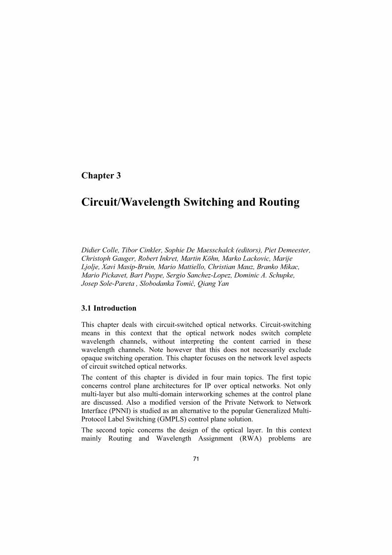
The overlay model The left side of figure 3.1 shows the overlay model concept. In the overlay model both the IP and OTN layer have separate and independent control planes. The (control channel of the) UNI – a first version has been standardized by the Optical Internetworking Forum (OIF) – is the interface between the two control planes. Both control planes are completely independent from each other. For coupling both layers, an IP over OTN translation protocol is provided in order to allow communication between the control planes of both layers. The IP over OTN translation protocol mainly provides address resolution between the layers and the signaling capabilities to initiate the connection setup/release, etc. One of the drawbacks of the overlay model is the duplication of control functionality (e.g., in both layers a routing protocol has to run). Another disadvantage is the scalability problem: for each established lightpath a corresponding IP routing peering session has to be started. This was experienced as a problem in classical IP-over-ATM, compared to MPLS. Another drawback of the overlay model is that there is a clear client/server relationship, e.g. address resolution is required due to separate address spaces. On the contrary, the advantage of separating both control plane instances in the overlay model is that any confidential information from the transport network is not disclosed/made accessible to any client network (operator) and that it is more straightforward to support multiple client layer networks and technologies.
OTN
NNI
NNIOXC
OXC
OXC OXC
OXC
IP
IP
IP
IP
IP
UNI interfacebetween IP
and OTN layer
Physical (= fiber)topology
OXC switch-fabric
Logical (= lightpath)topology
IP-routerForwarding Engine
OXC controllerOTN control channel
IP-routercontroller
IP control channel
IPUNI
Data-plane
Control-plane
IP/OXC controller
OXC
IPOXC
IP
OXC
IP
OXC
IP
OXC
IP
Physical (= fiber)topology
Control Channel
Customer Premise Equipment
Integrated IP/OTN box OXC switch fabric
IP-routerForwarding engine
Figure 3.1. - The overlay (left) and peer (right) model

74 Circuit/Wavelength Switching and Routing
The peer model The right side of figure 3.1 shows the peer model concept. In the peer model, a single control plane controls both the IP and OTN layers. The result is that IP router forwarding engines and OXC switch fabrics are treated as single logically integrated IP/OTN entities. So-called IP/OTN control channels are realized over the physical links between these logical IP/OTN entities. Lightpaths are treated as regular (optical) Label Switched Paths (LSPs) (in case GMPLS 0 is assumed) and thus do not result in a new peering session between the end-points (i.e., no control channel is established over the lightpath) 0. The peer model has some important advantages. First of all, duplication of functionality is avoided. Secondly, the disadvantages of the client/server relationship between IP and OTN (e.g., problems with address resolution) do not exist anymore. Although no additional peering session is required per established lightpath (which may solve some scalability problems: e.g., no processing of HELLO messages for each lightpath), the lightpath has to be advertised to the network as a so-called Traffic Engineering link in (G-)MPLS 0 and occupies a dedicated wavelength. Clear drawbacks of the peer model are the following. The peer model is not applicable to all imaginable business models. For example, an Internet Service Provider (ISP) and a Transport Network (TN)-operator may not allow that the control over their network is taken over by the other one. The peer model is also limited to a single domain or Autonomous System, and thus there is no way to reduce the route computation time by dividing the network into sub-domains.
The augmented model The augmented model is quite similar to the overlay model, in the sense that both layers may have their own control plane instance. However, some control information like reachability information may leak through the interface between both layers. Rephrased more practically, 0 states in what they call the “interdomain interconnection model” that the client layer reachability information is carried through the OTN, but OTN addresses are not propagated to the client network.
3.2.2. Dynamic Provisioning over Multi-Provider Interconnected Networks As Automatic Switched Optical Networks (ASONs) will need to provide services of a global reach, i.e. global connectivity, its control framework will

75 Control plane architectures for IP-over-WDM networks
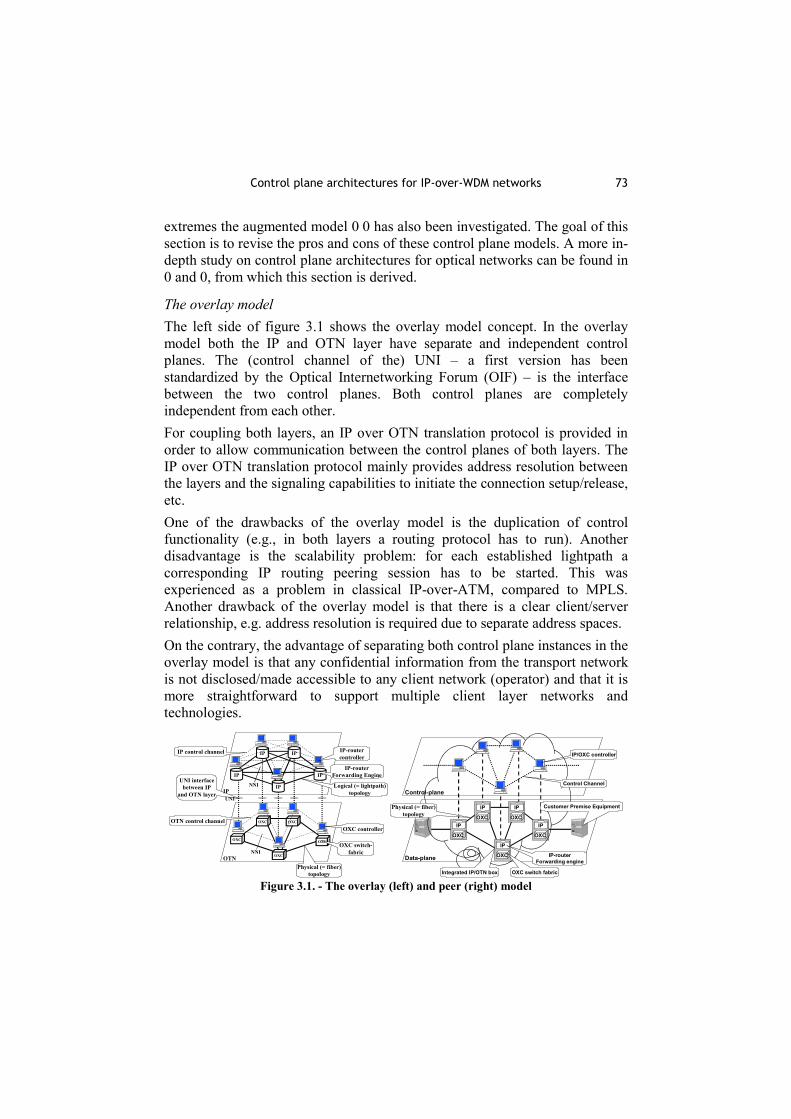
need to account not only for inter-layer (client IP-layer over server optical layer) but also for inter-domain and inter-provider inter-working issues. To support automatic provisioning over multiple domains, all the involved domains have to have some notion of the available resources. This information can then be used for the route calculation. Also the signalling procedure, which in GMPLS works seamlessly over different layers, has to account for the fact that the path will span different domains. Again the question can be raised concerning the amount of information that needs to be exchanged in order to most optimally support the performance objectives of all the involved parties. In this context the overlay, peer and augmented control plane inter-working models, previously described, can also be considered. For the near-term requirements and the current (old) operation models, the overlay model that provides reachability information, is considered to be a satisfactory choice. On the other hand, in the long term, novel operational scenarios, e.g. such involving dynamic bandwidth trading, will leverage the flexibility of the augmented model, with the peer model being its most extreme type. For such novel operation scenarios the flexibility of the interconnection architecture model is crucial. In the current interconnection architecture model the interconnections between domains are statically established. Applying the new paradigm of dynamic on-demand provisioning at the points of domains’ interconnections, a novel interconnection architecture model can evolve. This section is derived from 0, 0, and 0 in which this novel architecture for GMPLS network interconnections is proposed and studied. Figure 3.2 illustrates both static and extended dynamic interconnection architectures. In the static interconnection architecture the clients access the provider network at the provider edge (PE) nodes, and the domains inter-connect through domain border (B) nodes connected either directly by back-to-back links or through a cross-connect, in both cases over static configured interconnections. On the other hand, in a new Multi-Provider Edge (MPE) architecture, GMPLS-enabled cross-connects (MPE nodes) play the key role. Thereby, clients and domains connect to an MPE node, which can (as their peer and first-hop) take part in both the policy-based path calculation and the set-up of requested end-to-end connections. Two key functionalities of an MPE node are (i) provisioning of on-demand interconnections and (ii) routing or control mediation. Thereby MPE, as a multi-layer node, may be able to provide interconnections on the different layers.
76 Circuit/Wavelength Switching and Routing
PE P
PE
d4
d3 d1
d2 B
B
B B
PE
PE
c1
CE
CE
CE
c2
c3
MPES S
S
MPE
S S
S
MPES d4
d3 d1
d2 c1
CE
CE
c2
c3
CE
m2 m3
m1
Figure 3.2. - Static Interconnection Architecture (top) and MPE model (bottom)
With the MPE overlay acting as a middle tear between providers and customers, and the providers themselves, we attempt to address already cited problems of providers reluctant to share their internal link information. In this case MPE can act as a trusted mediator, collecting and customizing information. With MPE we also attempt to address the problem of inconsistent routing information, which arises, when provider domains are sharing already differently customized or aggregated information. Performance studies in 0, 0, and 0 illustrate how (i) the ability of MPE nodes to support dynamic interconnections between domains and (ii) the ability to invoke MPE services according to some policies, can improve network performance.
3.2.3. Comparing OPNNI versus GMPLS GMPLS is being considered by the IETF as an extension to the MPLS Traffic Engineering control plane model to include optical networking. However, the discussion about an optical control plane based on the ATM Private Network to Network Interface (PNNI) 0 paradigm has started in standardisation bodies. PNNI is expected to be suitable for ASON after some appropriate modifications. As a mature technology, the PNNI can be very practical for a seamless migration from current transport networks to ASON. Optical PNNI (O-PNNI) is an adaptation of the ATM PNNI to be an alternative control plane to the one provided by GMPLS. O-PNNI fits with the overlay model separating both the IP and OTN control planes. As mentioned above, no IP client can access the topology information from the transport network. Moreover, O-PNNI can be a control plane based on the augmented

77 Control plane architectures for IP-over-WDM networks
model, in which the client layer reachability information is carried through the OTN. In order to achieve this aim, the O-PNNI uses a modified PNNI Augmented Routing (PAR) 0. The main modifications consist basically of defining a set of PNNI Topology State Elements (PTSEs) to transport information of each client connected to the OTN. GMPLS uses IPv4 and/or IPv6 addresses. However, O-PNNI uses Network Service Access Point (NSAP) addresses, so no common address space may be built with IP based networks. O-PNNI supports Soft Permanent Virtual Connections (SPVCs), one of the ASON requirements. O-PNNI incorporates a Connection Admission Control (CAC) to indicate whether an optical node can admit a new connection. In GMPLS, the support of CAC does not seem to be well developed at this moment. A hierarchical structure allows the O-PNNI to support multiple levels (up to 104) and therefore is scalable for very large networks. In GMPLS, OSPF and IS-IS only support two hierarchical levels. ASON specifications recommend using separated control and data planes. GMPLS adds additional signalling information to the original MPLS signalling to support separated planes 0. A similar effort has to be done in O-PNNI in order to adapt the PNNI, in which the control plane is merged with the transport plane, to the ASON requirements. Service discovery is a concept introduced by the OIF. It consists in querying transport service characteristics before the optical UNI signalling establishes the connection. Neither O-PNNI nor GMPLS support service discovery. In GMPLS, OSPF and IS-IS use Traffic Engineering specific extensions to propagate QoS information. These parameters are stored at each node, and a modified Constrained Shortest Path First (CSPF) protocol computes a path through the network. The O-PNNI routing protocol includes support for QoS characteristics to determine the optimal path. Moreover, O-PNNI incorporates a “crankback” mechanism to support rerouting around a failed component at the connection setup. Finally, table 3.1 presents a general comparison of GMPLS and O-PNNI according to the optical control plane requirements.
Table 3.1. - Comparison of GMPLS and O-PNNI
CONTROL PLANE REQUIREMENTS GMPLS O-PNNI Addressing Yes Yes
Connection Admission Control No Yes

78 Circuit/Wavelength Switching and Routing
Hierarchical structure 2 levels Up to 104 levels Separated control and data plane Yes No
Service Discovery No No Path selection with QoS Yes Yes
3.3 Designing optimised reliable WDM networks
3.3.1. Static wavelength assignment in WDM networks with OXCs
Introduction Wavelength assignment is a major dimensioning step, especially in the case of large and highly loaded WDM networks as the ones studied in this COST action. That is the reason for the growing need for algorithms and tools able to perform this operation. This section will give an overview of the most efficient algorithms and the results they have provided when implemented in CANPC 0, described in chapter 6.3.
Algorithms Two wavelength assignment algorithms have been considered. The first one, TABUCOL, has been conceived at TCOM, and is presented in 0 and 0; the second one, Minimum Hop RWA has been proposed in 0. Both of them perform routing and wavelength assignment separately. In this way, the exact minimum number of fibres, for a given routing scheme, can be calculated (for each link, it is enough to divide the number of route channels by the capacity, in wavelengths per fibre, and to take the ceiling integer). Thus, after the wavelength assignment, one can check whether the solution is optimal or not (i.e., if it uses the minimum number of fibres). TABUCOL routing is based on an adaptive shortest path process, in which each link has an occupation weight that grows with the number of channels already routed on it. It performs wavelength assignment by means of a stochastic procedure based on the well-known graph colouring approach. M.H.RWA searches for all the shortest disjoint paths, in terms of the number of nodes, for each demand, and then, recursively, chooses among them the one that provides the lower congestion (occupation of the most charged link). Then, it simply browses the demands in decreasing order of path length, and assigns them to the first free wavelength found.

79 Designing optimised reliable WDM networks
Results The main aim of the simulations has been to route the studied network keeping the total number of fibres as low as possible, and then to achieve an optimal wavelength assignment without using wavelength converters. Computations have been done on all the five COST 266 topologies [see chapter 1.3], and results for the basic topology are reported in the following table.
Table 3.2. - Numerical results of the simulations on COST 266 basic topology TABUCOL M.H.RWA
Total fiber length (km) 174568 168858Fibers Max 8 7
16 per Avg 3.61* 3.48wl/ link Min 1 1fib Fiber occupation 83.1% 86.2%
Channels Max 108 101per Avg 47.99 47.98link Min 7 7
Total fiber length (km) 94188 95817Fibers Max 4 4
32 per Avg 1.96 1.96wl/ link Min 1 1fib Fiber occupation 77.2% 76.4%
Channels Max 105 100per Avg 48.52 47.98link Min 13 7
Total fiber length (km) 59282 61241Fibers Max 2 2
64 per Avg 1.20 1.22wl/ link Min 1 1fib Fiber occupation 63.7% 61.4%
Channels Max 104 100per Avg 48.71 47.98link Min 13 7
* Non-optimal solution (some fibers have been added to complete the assignment)
Both algorithms provide satisfying results, with a high fibre occupation. With one exception, they reach optimal solutions. Moreover, they seem to complement each other; in fact, TABUCOL performs better with a higher number of wavelengths per fibre (higher fibre occupation, lower number of fibres), while M.H.RWA performs better with a lower number of wavelengths per fibre.

80 Circuit/Wavelength Switching and Routing
Finally, it is very important to point out that, because of the optimal assignment, the use of wavelength converters would not have reduced the total number of used fibres.
3.3.2. Routing in Optical Networks under Inaccurate Network State Information In an ASON, the control plane includes a lightpath control mechanism to efficiently set up and tear down lightpaths, which may be either centralized or distributed. In spite of the fact that adaptive routing mechanisms based on global information perform better than the ones based on local information, they are only suitable for those networks where frequent network changes are not expected. Therefore, assuming distributed lightpath control in this scenario, maintaining precise global network state information on each node is almost impossible. Many factors, such as non-negligible propagation delay, frequent state updates and hierarchical topology aggregation, can affect the precision of the global network state information. Thus, when the lightpath selection process is performed based on outdated routing information, a connection blocking increment is produced. The BYPASS Based Optical Routing (BBOR) 0 is a new adaptive source routing mechanism that computes dynamically explicit lightpaths in an ASON without conversion capabilities. Its aim is to reduce the connection blocking probability due to performing routing and wavelength assignment decisions under inaccurate global network state information. The BBOR mechanism includes two main aspects, namely a triggering policy adapted to the RWA problem to reduce the routing signalling, and a bypass routing algorithm to counteract the effects of the routing inaccuracy produced by this routing signalling reduction. Existing triggering policies are based on updating by either a periodical refresh or sending an updating message whenever there is a change in the network state. The BBOR mechanism introduces a new triggering policy based on a threshold value, which aims to include the network congestion, namely the available network resources. A network node triggers an updating message whenever a fixed number of N wavelengths change their status. By changing the value of N, we can evaluate the impact of different degrees of inaccuracy in the connection-blocking ratio. The bypass routing algorithm dynamically reroutes the setup messages through an alternative pre-computed explicit route (bypass-path), when at any of the intermediate nodes the requested wavelength is found not available at the lightpath setup time. Two routing algorithms are derived from the BBOR mechanism, named ALG1 and ALG2.
81 Designing optimised reliable WDM networks
The BBOR mechanism consists of three basic processes: (1) decide which wavelength of which link (bundle of B fibres) might be bypassed, (2) include these wavelengths as a parameter to be considered when selecting the lightpath and (3) compute the bypass-paths.
3.3.3. Protection in the optical layer for mesh networks
Introduction There exist several possibilities to perform optical layer protection in mesh networks 0. A distinction can be made with respect to the entity that is protected, namely path protection or span protection. Normally, path protection is more difficult to realize because, in case of a failure, a reconfiguration of all OXCs of affected working paths has to be performed. When the span (or link) is protected, only neighbouring OXCs have to be reconfigured. In the latter case, it is also much easier to detect the occurrence of a fault. It is even possible to reroute the complete optical multiplex section signal containing several wavelengths by simple fibre switching. On the other hand, the length of the lightpath may significantly increase. This results in a degradation of the signals and may require their regeneration.
Mesh Protection
Path Span
m:n DSDP SSSP PC
Dedicated
Shared
DP Dedicated Pathm:n m:n Path ProtectionSP Shared Path
DS Dedicated SpanSS Shared SpanPC p-cycle Protection
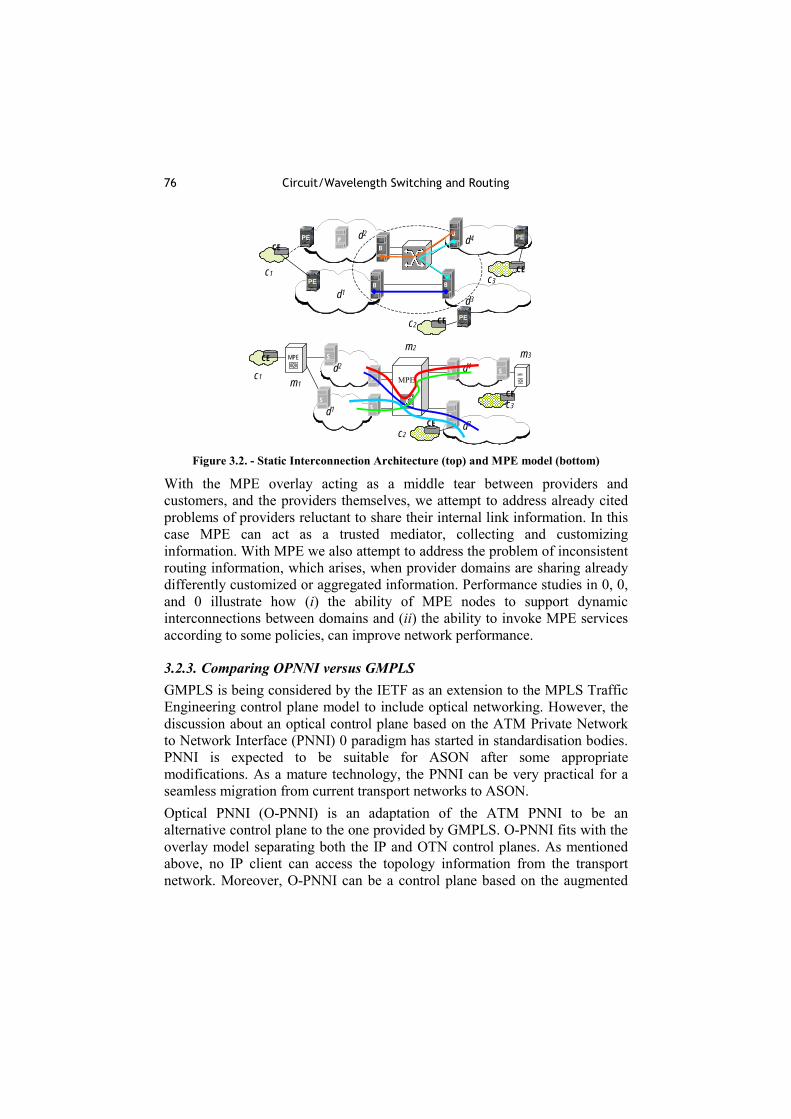
Figure 3.3. - Classification of different protection schemes in mesh networks.
In figure 3.3, a classification of common protection schemes in mesh networks is shown. A very simple approach is dedicated path protection (DP). In DP, for every working path, a protection path is reserved. This scheme is also denoted as 1+1 protection. When n working paths share one protection path, this is named 1:n protection or, more generally, when m protection paths are available, m:n protection. When all protection paths can use a common pool of protection resources, this is called shared path protection (SP). In general, this is the most capacity-efficient protection scheme.

82 Circuit/Wavelength Switching and Routing
Similar to the path protection schemes, dedicated span protection (DS) and shared span protection (SP) exist.
6
1
2
3
4
5 6
1
2
3
4
56
1
2
3
4
5 Figure 3.4. - p-cycle protection. From left to right: network with established p-cycle,
failure of an on-cycle and a straddling link.
A special case of span protection is the p-cycle protection scheme (see figure 3.4), introduced by Grover and Stamatelakis 0. The protection capacity is organized in cycles. Similar to a self-healing ring, when a failure of an on-cycle link occurs, the signal passes the cycle in the counter-propagating direction. The difference to an SDH shared protection ring (SPRing) is that also the straddling links may benefit from the protection by the cycle. Therefore, p-cycle protection is much more capacity-efficient than protection schemes based on rings. These schemes have in common that the protection resources are planned in advance and that for the occurrence of a failure a specific reaction is foreseen. In contrast to that, resilience procedures must start from the actual network state and the available resources in order to re-establish broken connections.
Unified ILP-Formulation It can be shown that for all these mesh protection schemes, a unified formulation as an ILP-problem can be adopted 0. Here the objective is to minimize the required capacity of the network. There must be sufficient spare capacity available to establish the intended protection scheme and to protect all entities. Often, the capacity requirements for a survivable network may be significantly reduced when the routing of the working paths is included in the optimization process of the protection resources. A pre-selection of the possible protection structures, e.g., a restriction to the k shortest possible protection paths for every working path or span, helps to reduce the complexity of the ILP-problem. For dedicated protection schemes and for m:n path protection, it is possible to divide the problem into less complex sub-problems for which simpler exact algorithms than the ILP-formulation exist.

83 Designing optimised reliable WDM networks
A case study for the different protection schemes has been performed using CPLEX 7.0 to solve the corresponding ILP-problems. The total traffic matrix for the year 2002 and a granularity of STM-16 per channel have been assumed. To compare the results, the required capacity of the different protection schemes has been normalized to the necessary working capacity of the networks when using shortest path routing. For path protection, two failure scenarios are investigated, namely a link failure, which requires an edge disjoint (ed) protection path, and the occurrence of link or node failures, which may be counteracted by a node disjoint (nd) protection path. Note that a node disjoint path implies an edge disjoint path.
0
50
100
150
200
250
300
350
400
450
500
DP ed DP nd m:n ed m:n nd SP ed SP nd DS SS PC
Norm
aliz
ed C
apac
ity [%
]
SpareWork
ed: edge disjointnd: node disjoint
Figure 3.5. - Capacity requirements for the BT network.
The results for BT network (see chapter 1.3) are shown in figure 3.5. For dedicated path protection, more than 160% additional capacity is required. To avoid trap-constellations, a slightly longer working-path than the shortest path has to be used. For node disjoint protection paths, 7% more capacity is needed compared to edge disjoint protection paths. These figures are only slightly improved by m:n protection. In contrast to that, for shared path protection only 165% capacity has to be installed for working and protection traffic. Dedicated span protection needs over 329% protection capacity. Here, sharing among the spans reduces this to 74%, resulting in slightly more capacity than for shared path protection. For a p-cycle scheme, the required protection capacity accounts to 71%, due to the better implicit pre-selection of possible protection candidates. Thus, a better solution in the restricted search space may be found.

84 Circuit/Wavelength Switching and Routing
Because the RT topology has a lower mean nodal degree, one needs significantly more protection capacity than for the BT network. Especially, dedicated span protection performs badly. Here, a resilient network requires at least 285% total capacity when using shared path protection. For the TT network, the requirements are just the other way around. Due to the high meshing degree of the topology, only 47% capacity is required to make the network survivable. In this case, shared path and shared span protection perform equally well.
Heuristics When the nodes have no wavelength conversion capabilities, every path and protection structure gets coloured (gets a specific wavelength). In this case, the ILP approach is unfeasible even for small networks, and one has to rely on heuristics with lower complexity. Here, as an example, two such algorithms are explained. In order to reduce the problem complexity, the planning of shared path protection for a given routing may be divided in two steps 0: • forming of a set of paths which may share protection resources, in the
following referred to as PSG (Protection Share Group), and • setting-up and allocating the needed spare resources for one PSG. The first sub-problem may be mapped on a graph colouring problem. This is similar to the wavelength allocation problem. In fact, when only link failures are investigated, both problems are equivalent. The second sub-problem may be solved by successively finding the shortest path in the network with special weights for the edges. These weights are adapted in each step. Another possibility is to use an ILP-formulation for each PSG. This is much simpler than to tackle the whole problem in one step. In general, the obtained solution is sub-optimal. Therefore, the required capacity is slightly higher than that obtained by solving the ILP-problem. On the other hand, the properties of the PSG allow the simplification of the node-switching functionality. When using p-cycle protection, the chosen wavelength assignment has a significant impact on the sharing of the protection resources 0. When the wavelengths are chosen in an unfavourable way and a link consists of only one pair of fibres, sharing is essentially only possible among straddling links of the cycles. Therefore, it is of crucial importance to perform the wavelength allocation and the p-cycle search jointly in order to benefit the most from the capacity savings of p-cycles.

85 Designing optimised reliable WDM networks
The developed algorithm is similar to the “First-Fit” assignment of wavelengths and works as follows. The working paths are ordered according to their hop-count and are assigned wavelengths one after the other. In each step, sufficient p-cycles for the chosen wavelength are added until all spans are protected. A scoring function is used to choose among different possible cycles. In general, due to the wavelength continuity constraints, between 40% and 60% additional resources are required for a network without wavelength conversion. The reason is that sharing of protection resources may only occur among paths with the same wavelength. The higher the mean nodal degree of the network, the lower will be this penalty. Another approach to avoid wavelength blocking with p-cycles is to use more fibres 0.
3.3.4. Multi-Ring networks Today’s transport networks are often organized in rings. Ring structures depend on simple optical add-drop multiplexers (OADM) and are easier to realize than mesh networks from a technological point of view. On the other hand, the planning of multi-ring-networks with several interweaved rings is very complex. In rings, the protection resources may be dedicated (dedicated protection rings, DPRing) or shared (shared protection rings, SPRing). In 0, 0 an optimized algorithm to deduce an optimal ring-coverage is developed. Here, the rings are constructed out of faces, a concept coming from graph-theory. This allows to gradually change them. From the ring-configuration, an effective graph of the network is constructed. It describes the effective logical topology, which results from the set of rings. With a fast routing and dimensioning algorithm, the rings are designed. The configuration is evaluated according to an objective function. Simulated annealing (SA) is used for the optimization. Beginning with a valid start configuration, in each step a neighbour configuration is derived from the actual configuration by choosing at random one of the operations: • adding one face to one of the rings, • creating a new ring with a random face, • deleting a face of a ring (when there are no faces left, the ring is
destroyed). It is possible to incorporate boundary conditions, e.g., the maximum number of nodes in a ring, into the objective function of the optimization process. This algorithm is especially suited for large and highly meshed networks, where
86 Circuit/Wavelength Switching and Routing
lots of possible cycles exist, and, therefore, the complexity of an approach that pre-computes these cycles is high.
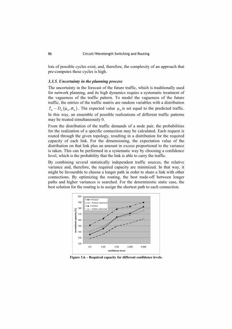
3.3.5. Uncertainty in the planning process The uncertainty in the forecast of the future traffic, which is traditionally used for network planning, and its high dynamics require a systematic treatment of the vagueness of the traffic pattern. To model the vagueness of the future traffic, the entries of the traffic matrix are random variables with a distribution
( ),T Dα α α αµ σ∼ . The expected value µα is set equal to the predicted traffic. In this way, an ensemble of possible realizations of different traffic patterns may be treated simultaneously 0. From the distribution of the traffic demands of a node pair, the probabilities for the realization of a specific connection may be calculated. Each request is routed through the given topology, resulting in a distribution for the required capacity of each link. For the dimensioning, the expectation value of the distribution on that link plus an amount in excess proportional to the variance is taken. This can be performed in a systematic way by choosing a confidence level, which is the probability that the link is able to carry the traffic. By combining several statistically independent traffic sources, the relative variance and, therefore, the required capacity are minimized. In that way, it might be favourable to choose a longer path in order to share a link with other connections. By optimizing the routing, the best trade-off between longer paths and higher variances is searched. For the deterministic static case, the best solution for the routing is to assign the shortest path to each connection.
120
130
140
150
160
170
180
190
200
0.9 0.95 0.99 0.995 0.999
confidence level
norm
aliz
ed c
apac
ity [%
]
PoissonPoisson optimizedUniformUniform optimized
Figure 3.6. - Required capacity for different confidence levels.

87 Designing IP over WDM networks
In figure 3.6, the results of a case study of a Pan-European network and different distributions are shown. The capacity is normalized to the deterministic case. Due to the uncertainty of the traffic pattern, a substantial excess of capacity in the network is necessary. With increasing confidence level, the required capacity rises. For example for a confidence level of 0.999, approximately twice the capacity of the deterministic case is needed. The higher relative variance of the uniform distribution results in a much higher required capacity for the same confidence level. With this very simple optimization procedure, capacity savings of 5% to 10% may be achieved. The reductions are greater for the uniform case. In general, the shortest path is assigned to the connections that occur with high probability, whereas the less likely ones take a longer path to share capacity with other connections. This design approach tends to bundle the traffic and leads to “unbalanced” networks. Some links will carry a lot of traffic whereas peripheral links are less utilized. This might cause problems with protection and restoration.
3.4 Designing IP over WDM networks
This section focuses on modelling, designing and dimensioning IP-over-WDM networks, including solutions assuming intermediate layers like SDH/SONET. Starting from a generic approach for IP-over-WDM network modelling, we present work on designing static WDM networks for transporting IP traffic and compare several data link layer topologies. Then, routing and grooming in IP transport networks are studied. Traffic engineering concepts for dynamic WDM networks and the influence of asymmetric IP traffic finalize this section.
3.4.1. An approach to an IP-over-WDM transmission network modelling
IP over WDM network structure The IP over WDM (figure 3.7) network has been modelled using two main node types: IPPoP (IP Point of Presence) node, and WDMPoP (WDM Point of Presence) node. An IPPoP node represents an aggregation point for the IP traffic, thus generating IP traffic for the WDM transmission network. It can be viewed as a backbone router, which aggregates IP traffic from many sources and lower levels of aggregation (e.g. edge routers in metropolitan areas). A WDM

88 Circuit/Wavelength Switching and Routing
network is composed of WDMPoP nodes serving as ingress and egress points for IP traffic entering and leaving a transmission network. They also provide switching functionality as intermediate nodes inside the WDM network. WDMPoP nodes are connected with optical fibres, carrying WDM signals.
IPPoP
WDMPoP
IP/WDMPoP
WDM transmission
baseband transmission Figure 3.7. - IP over WDM network structure
IP layer modelling An IPPoP node can directly contain two module types: IP node, and IP router, as shown in figure 3.8. An IPPoP node serves as a source and destination of the IP traffic. An IP router aggregates and splits IP traffic destined for different IPPoP nodes. IP nodes and IP routers are connected using line cards. Each line card has two interfaces. One is an electrical interface and serves as an interface towards the IP network equipment. The other interface is optical and handles the signal from/to transmission media.
IPRouterIPNode
IPPoP
generatedtraffic
traffic forthis node
internal IP traffic IP traffic to/from WDMnetwork
IPRouterIPNode
IPRouterIPNode
line cards
Figure 3.8. - IPPoP structure
DEMUX
OXC
MUX optical amplifiertransponder WDMPoP
WDM transmissionbaseband transmission
OXC
OXC
OXC
Figure 3.9. - WDMPoP structure – an
example
WDM layer modeling A WDM network consists of WDMPoP nodes connected with optical links carrying WDM signals. WDMPoP nodes contain several types of optical components. Optical components implement the functionality needed in the WDM network, including protection and restoration (P&R) mechanisms, and automatic channel switching. Figure 3.9 shows an example of a WDMPoP

89 Designing IP over WDM networks
node, which includes all optical elements in all possible interconnections. The WDMPoP structure is determined by the IP traffic demands, the WDMPoP connections and the P&R mechanism. The P&R mechanism determines the WDM equipment redundancy in the WDMPoP nodes, as well as the link redundancy between WDMPoP nodes. Some mechanisms (restoration) require dynamic switching (dynamic change from impaired path to alternative), which requires OXC usage.
3.4.2. Static Lightpath Routing in IP over WDM Networks The first IP-over-WDM networks that are emerging use OXCs to interconnect IP routers that communicate with each other over lightpaths 0. Intermediate multiplexing layers such as ATM or SDH are omitted, thus the whole available bandwidth of the lightpath is available 0. Given the bandwidth demands between IP router sources and destinations, a feasible and efficient (static) configuration of the lightpaths is needed. This is referred to as finding an optimal virtual topology seen by the IP layer and a routing and wavelength assignment (RWA) on the WDM layer. We split this problem into several sub-problems and solve these by heuristic algorithms. As laser sources currently constitute a large portion of the network element costs, we are interested in using as few sources (and thus lightpaths) as possible. In the considered architecture, the OXCs are interconnected by fibre pairs, one for each direction. For each fibre the wavelength constraint has to be fulfilled. An OXC is further connected to at most one IP router, which is source and sink for at least one lightpath. We assume that the originated and terminated lightpaths can be selected from a set of wavelengths. As we do not consider wavelength conversion at the WDM nodes, a lightpath retains its wavelength. Two routers become neighbours by a bidirectional virtual link (formed by two lightpaths, one for each direction) that offers the same amount of bandwidth capacity. The two contra-directional lightpaths do not necessarily need to have the same wavelength. Interconnected routers operate using a routing protocol. Today, routing protocols are shortest path based such as OSPF. As IP packets experience a delay at routers, the number of router hops should be restricted. We consider this by allowing only a maximum number of virtual links on the shortest path of a source-destination pair. Further constraints are discussed in 0. Of course, the offered total network load has to be carried. We assume here that we are given a demand matrix with bandwidth entries. Each entry is lower or equal than the maximum capacity of a lightpath. In non-synchronous

90 Circuit/Wavelength Switching and Routing
multiplexing environments which holds for IP we may add some margin to the demand entries. In the following subsection we present the general solution approach and apply it to a network example. More details can be found in 0.
Solution Approach Due to the RWA problem alone, the whole problem becomes too complex to be solved by means of integer linear programs 0, 0. Therefore we divide the problem into three sub-problems, and solve each by a heuristic algorithm. In the first step we find a virtual topology such that the number of (virtual) links is minimized and the given IP demand is carried in a greedy manner 0. Minimizing the virtual links corresponds to minimizing the lightpaths demanded from the WDM layer and thus the laser sources. In the next step, we route the lightpath demands in the optical network using a shortest path algorithm. In the last step we have to assign wavelengths to the paths taking into account the wavelength constraint in fibres and the wavelength continuity constraint in OXCs. In general, one is given a set of wavelengths which can be used network-wide, thus it is sufficient to obtain one feasible assignment. The wavelength assignment problem is related to the graph colouring problem 0. Efficient graph colouring algorithms exist, which do not only perform a colour assignment but also minimize the number of colours (wavelengths). We used this optimization approach for the wavelength assignment to provide efficient wavelength utilization throughout the network. It must be noted that there may be cases where the minimum number of colours obtained exceeds the cardinality of the wavelength set given through the system. The approach for the wavelength assignment is the heuristic algorithm “DSATUR” 0.
Case Study We used the described approach to configure the topology of the NSF network (14 nodes, 21 links) used in 0, where we associated each link with a fibre pair and each node with a router connected to an OXC. We also used the traffic matrix in 0 scaled such that the entry with the maximum value equals 10 Gbit/s, yielding a total network load of 120 Gbit/s. The bit rate capacity of a wavelength was set to 10 Gbit/s. In the case without constraints on the number of hops we obtain 19 virtual links (this is half of the number of laser sources) and 4 wavelengths. The number of 19 virtual links is close to 13, the minimum number of links needed to connect the network. The utilization of the wavelengths is half of the

91 Designing IP over WDM networks
capacity. This is still reasonable, since many demand-pairs in 0 carry much more traffic in one direction than in the other. Moreover, all nodes have to be connected, even those that do not source or sink much traffic. Figure 3.10 depicts the number of virtual links and the number of wavelengths when restricting the maximum number of allowed IP hops in the virtual topology algorithm. Both functions are decreasing monotonously and from 1 hop to 2 hops, the function graphs drop down very much, since IP multiplexing becomes possible. More results are included in 0.
0
25
50
75
100
1 2 3 4
Num
ber o
f Virt
ual L
inks
Number of IP Hops
89
3121 19
0
2
4
6
8
10
12
14
16
1 2 3 4
Num
ber o
f Wav
elen
gths
Number of IP Hops
14
6
5 4
Figure 3.10. - The number of virtual links and the number of wavelengths over the
number of IP hops
3.4.3. Design of Optimal Data Link Layer Topology for IP/WDM Networks Now, we will focus on the connectivity of IP backbone routers, i.e. the layer 2 topology. Thus, we do not take into account the cost of WDM equipment 0. In addition, the layer 2 topology does not necessarily follow the physical topology. We assume the physical topology to be given, i.e. the length and placement of the optical fibres are known. The traffic matrix between layer 2 nodes is also known and traffic demands in layer 2 are routed along the shortest paths in layer 1 (i.e., the optical network layer). We finally assume that the number of fibres on the links is unlimited. In 0, three scenarios to obtain a layer 2 topology are presented: 1. 1-to-1 mapping between layer 1 and layer 2 topology:
the layer 2 topology follows the physical topology; in 0 proposed for low traffic loads.
2. full mesh layer 2 topology: each router is connected directly to all other routers, and the minimum number of required interfaces equals the sum of the degree of all nodes; in 0 found to be the best solution for high traffic loads.

92 Circuit/Wavelength Switching and Routing
3. optimal topology: could give the best trade-off between the number of interfaces and their cost, here the focus is on finding the optimal topology.
For large networks, finding an optimal solution is an NP-hard problem. Hence, a genetic algorithm (GA) is used to obtain a near-optimal layer 2 topology. We consider only two scenarios for mapping IP on WDM: IP/POS/WDM and IP/GbE/WDM. From our point of view, the application of the chosen scenarios is most probable in the near future 0.
Generic Layer 2 P&R Capabilities In order to simplify the network design, only some generic P&R scenarios obtained from the first two layers are introduced: A Dual link:
router interfaces are doubled and placed onto two shortest independent physical paths in layer 1
B Dual link with dual router configuration: all router interfaces are distributed over two independent routers instead of on a single router
Additionally, traffic between interfaces can be shared, but in case of a failure, the load on the remaining interface increases. Here we assume that in case of the shared protection type, the traffic load is equally divided between the working and backup interface.
Results and Comments The described algorithm has been applied to a network sample taken from the case study developed within COST 239 and COST 266 (see chapter 1.3). We assume that the traffic matrix is given in terms of required 1 Gbit/s channels between layer 2 nodes. Topologies with dual link and dual link dual router type of protection are more expensive, but their performance is better in terms of potential packet loss. - shows the cost relationship between the scenarios described above (NP-No Protection, DL-Dual Link, DLS-Dual Link Shared, DLDR-Dual Link Dual Router, DLSDR-Dual Link Shared Dual Router). It can be seen that in the IP/GbE/WDM scenario the optimal topology gives a substantial reduction in price compared to the other two proposed scenarios, whereas in the IP/POS/WDM scenario the cost of the optimal topology is approximately equal to the cost of a fully meshed topology. The sum of the primary lightpath

93 Designing IP over WDM networks
lengths shows that topologies with shared protection (DLS and DLSDR) consist of less layer 2 links than other types of protection. Figure 3.12 shows the cost of an optimized topology for a given load. It can be seen that with growing traffic load, the cost of optimal topology increases almost linearly.
Figure 3.11. - Cost relationship between
proposed scenarios (load=1)
Figure 3.12. - Costs of optimal
topologies for different traffic loads
3.4.4. Dynamic routing and grooming in SDH/WDM multi-layer networks As mentioned before, one possibility for an IP transport network is a dynamic SDH network on top of a dynamic optical network (IP/SDH/WDM). This is from the viewpoint of network evolution one of the most probable architectures for future IP backbones. Assigning low-bandwidth electrical connections to high-speed optical lightpaths, also known as traffic grooming, is an important aspect in such networks 0. Routing on the electrical and optical layer is an essential component of every grooming strategy. Efficient transport of dynamic traffic demands requires optimised multi-layer routing and grooming algorithms. Non-integrated routing schemes treat both layers separately while integrated schemes try to improve the performance by combining both layers. Most approaches for integrated routing, e.g. 0 (SONET) or 0 (IP), take advantage of complete knowledge about topology and occupancy of both layers, which is not supported by the overlay network model 0. However, the overlay model is favoured from an operator point of view as information on transport networks is very sensitive and should be kept secret.

94 Circuit/Wavelength Switching and Routing
In the following we assume the mean IP traffic to be given for each node-by-node connection. We have to groom and route this traffic through a dynamic SDH/WDM multi-layer network.
Multi-layer Grooming and Routing Options The SDH/SONET-WDM-network approach leads to a multi-layer node model. This model comprises an optical cross-connect (OXC) on the optical layer, which is assumed to be non-blocking. The electrical layer mainly consists of a non-blocking electronic cross-connect (EXC), which is able to switch electrical connections at an arbitrary granularity. The EXC thus allows for an effective grooming of electrical connections. The EXC and OXC are connected by z transponders. In a centralized routing scheme, the routing control centre has to choose a path within the network for each connection request. Four basic grooming options can be identified: A single-hop grooming on existing lightpath:
Assign connection to one existing direct lightpath. B multi-hop grooming on existing lightpaths:
Route on the electrical layer by using more than one existing lightpath. C single-hop grooming on new lightpath:
Set up a new lightpath and route connection via this lightpath. D combined multi-hop grooming on new and existing lightpaths:
Combination of A and C. Route connection by using a series of existing and new lightpaths.
Non-integrated routing schemes are capable of grooming on either existing or new lightpaths. Only with integrated routing does the routing control centre have enough information to also perform the combined grooming described in D. As a reference we will consider two different non-integrated routing schemes, namely PreferOptical and PreferElectrical (TLRC in 0), which differ in the order they apply the different grooming policies until one succeeds (PreferOptical: A-C-B, PreferElectrical: A-B-C). In contrast to the non-integrated routing schemes, WIR applies the different grooming strategies in parallel, including combined grooming. For a connection request, each possible path that results from a grooming strategy is rated according to a set of criteria. Finally, the path with the best rating is chosen. Finding paths with combined grooming is harder than applying grooming purely on the electrical or optical layer. In 0, Zhu and Mukherjee use

95 Designing IP over WDM networks
a reachability graph capturing all possible links for a given connection request between any two nodes for their proposed SLRC scheme.
Simulation Studies The presented simulation study was performed using a fictitious 9-node German network, the topology of which is shown in figure 3.13. This network was introduced and dimensioned for static traffic demands 0 such that links contain a certain number of fibres each holding 8 wavelengths. For more details on the simulation scenario see 0. For a multi-layer node, the number z of transponders is a crucial parameter, from a performance as well as a cost point of view. Particularly, for a given network topology, transponders are the major variable cost factor. Hence, we introduce the fraction of transponders installed as the absolute number of transponders installed normalized by sum of all possible transponders in all nodes. For more details on this see 0. Figure 3.14 shows the blocking probability for different schemes over the fraction of transponders installed. The non-integrated routing scheme PreferOptical outperforms the scheme PreferElectrical by almost one order of magnitude. The integrated WIR achieves a request blocking probability that is about one order of magnitude below the best non-integrated scheme and slightly below SLRC. There is a noticeable bend in all curves at a fraction of about 0.55. For lower fractions, the request probability is dominated by blocking at the transponders. For larger fractions, there are sufficient transponders available so that wavelength blocking dominates.

96 Circuit/Wavelength Switching and Routing
Figure 3.13. - Fictitious 9-node network
of Germany
Figure 3.14. - Blocking probabilities in a
SDH/WDM network
Conclusions The impact of routing and grooming algorithms on the performance of multi-layer networks is not negligible. They reduce the blocking probability in the network as well as increase the usage of the wavelength channels.
3.4.5. Multi-layer traffic engineering in data-centric optical networks. The logical IP topology in multi-layer data-centric optical networks is supported by lightpaths, which can be set up or torn down dynamically in Intelligent Optical Networks (IONs). While regular traffic engineering (TE) typically only routes traffic in the IP layer, the ability to reconfigure the logical IP topology on demand leads to cross-layer traffic engineering capabilities.
What is Multi-layer Traffic Engineering and how does it work? Multi-layer Traffic Engineering allows reconfiguring the logical resources. To realize this however, a MTE process goes through three distinct phases 0. Firstly, the traffic over the logical topology needs to be monitored, either physically on the router interfaces, or by keeping track of bandwidth specification included in signalling messages. Problems may be detected, optionally signalled through the network, so as to trigger the next step, the decision taking phase. Here, the MTE strategy will find an appropriate reconfiguration of the logical topology, given the monitoring data. It will decide which logical IP links to set up and tear down, and also which traffic to attract to newly established links.

97 Designing IP over WDM networks
Lastly, once the reconfiguration has been decided on, corresponding MTE actions still need to be performed during the realization phase. The logical network layer will use signalling to request new lightpaths from the optical layer, or to remove existing lightpaths. It will also adjust IP routing to make sure the new logical topology is used efficiently.
Issues in designing Multi-layer Traffic Engineering Strategies Strategies can be classified according to a number of properties, some of them having analogies in classic TE. One aspect is the overall architecture of the network and strategy. Calculations may run either online or offline, and in the latter case, the strategy can be centralized, as opposed to being distributed. Also important is the distinction between peer (also called integrated) and overlay models in multi-layer networks. Furthermore, algorithms themselves can vary in complexity, because of the number of alternative actions considered, and the extent to which multi-layer actions interact with Single-layer Traffic Engineering (STE) actions (i.e. routing). A good TE strategy needs to integrate both MTE and STE aspects. The specific objective of the strategy is another property. Not just what this objective is, but also how it is reached; either by keeping the network optimal at all times (a proactive strategy), or by only reacting to certain problems that have been detected first (a reactive strategy). Further issues exist however, a certain amount of inertia may need to be introduced in the strategy to lower the number of lightpath operations, at the cost of a somewhat lower optimality of the logical topology. Care has to be taken then to avoid cumulative memory effects and other potential instabilities.
Benefits of Multi-layer Traffic Engineering Data from a case study highlights the benefits of MTE. A reactive strategy was chosen. It defines both lower and upper thresholds for bandwidth usage of an IP-link. Exceeding these bounds triggers the process which removes underloaded links or sets up new links to remove congestion. The choice of the new link and also the amount of traffic attracted over it, are optimized so that load on routers is reduced as much as possible, and bandwidth utilization of both previously congested and newly established link approaches an ideal mean between both thresholds. Figure 3.15 compares the performance of this strategy (i.e., the dynamic case) with the situation where the topology is statically dimensioned. Traffic volume is increased in steps, and from 60 sec. onwards, exceeds the nominal bandwidth volume for which the static case was dimensioned, leading to rising

98 Circuit/Wavelength Switching and Routing
packet loss ratio’s in this case. The reactive strategy however can keep PLR satisfactory small by provisioning additional lightpaths, at the cost of slightly higher optical bandwidth usage under nominal traffic (sec. 30 to 60). More details on this case study and further studies can be found in 0, 0 and 0.
0
50
100
150
200
250
0 30 60 90 120 150
Time (sec)
Tot
al #
wav
elen
gth
chan
nels
0%
5%
10%
15%
20%
25%
Average packet loss ratio
# wavelength channels: dynamic # wavelength channels: staticPLR: dynamic PLR: static
# channels: static
# channels: dynamic
PLR: static
PLR: dynamic
Figure 3.15. - Analysis of the benefits of MTE
Conclusions Multi-layer Traffic Engineering strategies deploy and profit from the additional flexibility provided by Intelligent Optical Networks. MTE algorithms can be approached from a number of different perspectives, and once some design issues have been taken care of, they yield significantly better performance than strategies which use statically dimensioned logical topologies.
3.4.6. Influence of traffic asymmetry on the network design IP traffic is, in contrast to telephone traffic, asymmetric. The degree of asymmetry depends of course on the exact location in the network (access versus backbone network, in the surrounding of a server farm or not, etc.). Today’s backbone network is designed to support bidirectional services like SONET/SDH. When this bidirectional and symmetric traffic is replaced by IP traffic, large portions of the network bandwidth may sit idle, while the bandwidth at the opposite direction can, at the same time, be completely
99 Designing IP over WDM networks
congested. Using unidirectional WDM line-systems instead of the currently in use bidirectional ones, could thus lead to a significant cost reduction. In this section, this cost advantage will be quantified for three of the COST266 optical backbone topologies discussed in the introductory chapter. More details can be found in 0, 0, 0 and 0, from which most of this section is extracted.
Assumptions and definitions First the traffic model explained in chapter 1.3 has to be extended to include an asymmetric IP traffic demand. This was based on the number of Internet hosts in each region (Ui) and the number of web sites stored in servers located in these regions (Wi):
jiijji
ijij
jiijji
jiji
trafficIPUWUW
UWtrafficIP
trafficIPUWUW
UWtrafficIP
−→
−→
+=
+=
***
**
***
**
αα
α
αα
α
2
2
where α allows to change the asymmetry of the traffic. We define the Asymmetry Factor (AF) of a traffic matrix M as
∑
∑
≠
≠
+
−
jijijiij
jijijiij
MM
MM
,,
,,
These equations allowed us to construct traffic matrices with different AFs for the time frame 2003-2008. The capacity installation problem in the optical layer was then solved for (a) the case that the line-systems in the optical layer are bidirectional and (b) the case that these line-systems are unidirectional, and this for the BT, RT and TT. The cost of a bidirectional line-system was assumed to be twice the cost of a unidirectional one. The logical layer on top of these optical networks was in all cases assumed to be a full mesh.
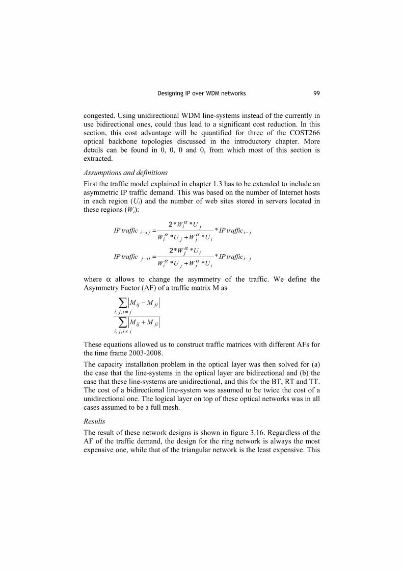
Results The result of these network designs is shown in figure 3.16. Regardless of the AF of the traffic demand, the design for the ring network is always the most expensive one, while that of the triangular network is the least expensive. This

100 Circuit/Wavelength Switching and Routing
is due to the used cost model that includes a proportional part of the digging cost in the link cost. The cost of a network design is then determined by the total length of used fibre, and not by the total duct length. Such a cost model would be used by a network operator that leases capacity from a carrier’s carrier. The total length of used fibre is largest for the RT, as the connections have to follow on average a longer path between source and destination than in the BT and TT (shortest path in km.).
Cost optical layer, AF IP traffic = 0%
0.0E+00
2.0E+05
4.0E+05
6.0E+05
8.0E+05
1.0E+06
1.2E+06
1.4E+06
2003 2004 2005 2006 2007 2008
Year
cost
ring-unidirring-bidirbasic-unidirbasic-bidirtriang-unidirtriang-bidir
Cost optical layer, AF IP traffic = 28.5%
0.0E+00
2.0E+05
4.0E+05
6.0E+05
8.0E+05
1.0E+06
1.2E+06
1.4E+06
2003 2004 2005 2006 2007 2008
Year
cost
ring-unidirring-bidirbasic-unidirbasic-bidirtriang-unidirtriang-bidir
Cost optical layer, AF IP traffic = 51.5%
0.0E+00
2.0E+05
4.0E+05
6.0E+05
8.0E+05
1.0E+06
1.2E+06
1.4E+06
2003 2004 2005 2006 2007 2008
Year
cost
ring-unidirring-bidirbasic-unidirbasic-bidirtriang-unidirtriang-bidir
Cost optical layer, AF IP traffic = 75.6%
0.0E+00
2.0E+05
4.0E+05
6.0E+05
8.0E+05
1.0E+06
1.2E+06
1.4E+06
2003 2004 2005 2006 2007 2008
Year
cost
ring-unidirring-bidirbasic-unidirbasic-bidirtriang-unidirtriang-bidir
Figure 3.16. - Cost of the unidirectional and bidirectional optical layer network design for
varying asymmetry factor of the traffic demand
When the AF of the IP traffic differs from 0, the designs with bidirectional line-systems are always more expensive than the design with unidirectional line-systems. The use of unidirectional line-systems instead of bidirectional ones would be 36% cheaper for the TT, 38% for the BT and 43% for the TT. This is of course due to the fact that the average filling of the bidirectional line-systems decreases as the AF of the traffic demand increases: only one direction of the bidirectional line-systems gets properly filled. With unidirectional line-systems, less line-systems can be installed on one direction of a link than on the other, and all line-systems are thus properly filled up.

101 Providing Optical VPN services
3.5 Providing Optical VPN services
Instead of providing leased line services, or providing wavelength channels or even dark fibres, it seems more useful in certain cases to provide a virtual private network. The term virtual network denotes that the network is not built physically and separately, but is only an allocated part of the resources of a public network of a provider. It is private since it serves a closed group of users. In general an OVPN (Optical Virtual Private Network) is a VPN built over optical channels, e.g., wavelength paths within a Multi-hop Wavelength Routing (WR) Dense Wavelength Division Multiplexing (DWDM) Network. The open objective is how to set these OVPNs in such a manner that all user needs are satisfied while using as few network resources as possible.
3.5.1. Overview Figure 3.17 shows an example optical VPN, where the core is optical, with MPLS routers attached to it. For connecting certain MPLS Routers (E), wavelength paths established using optical cross-connects are used. Since these routers are not connected in a full mesh by wavelength paths, the optical edge switches (O1-O4) will have to provide MPLS router functionality as well between certain domains and users. For example, when connecting E1 to E4 and E2 to E3 the OVPN will consist of three lightpaths crossing some cross-connects and four MPLS routers in nodes O1, O2, O3 and O4.
WR-DWDM
MPLS O2
E1
E2
O4
O3
E4
E3
O1
Figure 3.17. - Illustration of an OVPN

102 Circuit/Wavelength Switching and Routing
Here we have exploited the advantages of traffic grooming, i.e., numerous MPLS traffic streams (LSPs) of a VPN can share a single wavelength path. The objective of the optimisation is in all cases to reduce resource usage at higher (electrical) layers (i.e., to reduce the load of the virtual routers), subject to the constrained amount of capacity of each wavelength channel and limited number of wavelengths. The deployment of Virtual Private Networks (VPNs) increases steadily. Reference 0 reports three IP VPNs by GlobalOne, Infonet and Worldcom/UUnet. The last two are based on the MPLS technology. The deployment of VPNs grows in Enterprise networks according to 0. They report on the use of managed VPNs by Research, Insight-Research and NovaStor and add that the use of VPNs results in significant revenue. MPLS VPNs can be used jointly with BGP to avoid limitations of addressing plans and to ensure security 0. This paper also mentions provisioning end-to-end VPN services across multiple service providers and carriers. Reference 0 gives an excellent overview of technologies enabling VPNs and QoS support for VPNs (particularly DiffServ) and management alternatives. A detailed overview of MPLS based VPNs can be found in 0 and 0. VPNs share the link bandwidth and the node resources among each other. This idea has several advantages. We do not have to build separate private physical networks, but only to configure VPNs. This reduces costs and speeds up provisioning. Furthermore, the VPNs can be dynamically reconfigured or re-dimensioned in contrast to physical networks. This allows sharing resources between various VPNs. A VPN-DiffServ solution is proposed in 0. In 0 dynamic relations are in scope with capacity resizing and stochastic fair sharing, but without protection. The resource allocation in conjunction with the routing design has been analyzed in 0, 0 and 0 over multi-service networks with QoS constraints. Various tools are used, e.g., asymptotic approximations to reduce the complexity of the numerical calculations, multiplexing inside a VPN and introducing priorities between the traffic classes. Network dimensioning is addressed in 0 and the methodology is presented for determining the sizes of VPNs. An algorithm of very low complexity is presented in 0, however, the traffic streams are not handled separately (pipe model), but an aggregate traffic which has source or sink in one network node are handled jointly (hose model). The protection is not handled at all. All above papers configure VPNs over a network capable of performing multiplexing, e.g., Frame Relay, ATM, MPLS or any kind of multiservice

103 Providing Optical VPN services
networks. However, there are few methods for establishing VPNs over optical networks, and even less for two or more layers, which are of particular interest for GMPLS and ASTN networks. There are multiple papers discussing the architecture and configuration of VPNs 0 0. However, very few papers deal with the protection of these VPNs.
3.5.2. The Three Types of OVPNs Considered We differentiate 3 types of OVPNs denoted as T1, T2 and T3 based on the granularity of these VPNs: • T1: "VPNs over WR-DWDM": Here we assume that we build
conventional VPNs over an optical (Wavelength Routed-DWDM) network. Links of different VPNs can share a single wavelength path.
• T2: VPλN: This is the most widely accepted type of OVPNs. Here a VPN link is a wavelength path, and one wavelength path serves a single VPN only. This wastes the resources in some cases, however the control is simple. If the capacity of a wavelength path is not sufficient to accommodate a link of the VPN we allow use of multiple (even parallel) wavelength paths. The advantage is that the traffic of different VPNs is separated (and isolated), which simplifies management and enhances security. Compared to T1 it also decreases the load of the electrical layer.
• T3: VPmultifibreN: This is the enhanced version of T2 OVPNs for multifibre networks, where we assume that a point-to-point demand is a wavelength path, while a link consists of as many wavelength channels of a certain wavelength λ as there are fibres that support that wavelength.
If we have demands of low capacity, T1 is preferred, while for point-to-point connections approaching the capacity of a wavelength T3 is preferred. In all cases we assume traffic grooming 0, i.e., traffic streams of a VPN are groomed, i.e., multiplexed, e.g., in case of T2 into a single wavelength path, and they are handled together. In all Virtual Router nodes these traffic streams can be re-multiplexed. This can be done at the electrical layer only since re-multiplexing, i.e., time division multiplexing is required. For this reason, taking not only the optical, but both, optical and electrical layer into account when configuring the system is demanded.

104 Circuit/Wavelength Switching and Routing
3.5.3. Three Methods for Setting up OVPNs Optimally Many excellent papers deal with design, configuration and optimisation of WDM Networks. These methods can be generalised for the design of OVPNs, as well. Our goal is to configure the VPNs and the lightpath system optimally without separating the network layers. This improves the quality of the results; however, the complexity of the problem grows. Based on the level of decomposition we differentiate three methods denoted as M1, M2 and M3 for the OVPN configuration and they are described in detail in 0 and 0. • M1: Global: First we formulate the problem formally as an Integer Linear
Program (ILP) for the directed graph model in order to find the optimal configuration of all OVPNs simultaneously. Although this gives the globally optimal solution it is useless, due to its complexity. Therefore, less complex methods are needed that provide results close to the global optimum.
• M2: VPN-by-VPN: Here we decompose the problem to setting up VPNs one-by-one. The complexity is significantly lower; however, the quality of the results can be poor. For example setting up the first VPN can hinder setting up some other VPN by monopolising some of the common resources. Furthermore, this approach heavily depends on the order in which the VPNs are set up. This method is very useful if the demands for VPNs are not known in advance, appear one-by-one, and have to be satisfied without waiting for the other demands for VPNs that will arrive.
• M3: Demand-by-Demand: Here we decompose the whole problem to routing the demands one-by-one by a shortest path algorithm, e.g., that proposed by Dijkstra. This is the simplest method; however, the results might be poor. Here we need some heuristic tricks. A promising approach is to sort demands, and to start by those that need larger bandwidth, and are limited in length. Another possible heuristic approach is to decrease the cost of the links that are already used by the considered VPN when one new demand of that VPN has to be routed. The third heuristic decreases the costs of those wavelengths that are already used by the considered VPN. Using these three heuristics jointly improves the obtained results significantly, 0 presents these results.

105 Conclusions/Summary
3.5.4. Protection Alternatives for OVPNs We consider two protection alternatives for all the above OVPN types (T1-T3) and methods (M1-M3): protection at the higher (electrical) layer and at the lower (wavelength) layer. We refer to these methods as Internal and External OVPN Protection. In case of Internal protection, the OVPN users get enough resources not only to carry their traffic in a failure-free case, but also to switch to alternative paths in case of a failure. This will of course require adequate resource management and protection mechanisms. External protection is simpler for users, but more complex for the operators. In this case the operator must protect the failed spans of certain OVPNs, to "hide" the failures from the OVPN users. The protection paths can be made either link or node disjoint with the working path. Furthermore, dedicated and shared protection can be differentiated.
3.6 Conclusions/Summary
In this chapter four main topics in designing WDM-based networks have been discussed. The focus was limited to circuit-switched optical networks. The impact of the client network – in the future this will typically be an IP-MPLS network – and recovery capabilities were often taken into account due to their importance. The first topic studied concerns control plane architectures for such networks. There exist several control plane models for IP over Optical networks. In the overlay model, both layers have an independent control plane. The peer model integrates both control planes into a single integrated control plane controlling both layers (which is mainly favourable from a technical perspective). The augmented model is a compromise between both extremes. In order to enable more advanced and flexible provisioning scenarios of a global reach (e.g. bandwidth trading, dynamically provisioned re-configurable virtual networks of global reach), domains of different ASON providers will need to inter-work. For this purpose the novel MPE architectures, incorporating dynamically provisioned inter-domain interconnections, and leveraging flexibility of peer and augmented interconnection schemes, has been proposed and studied. As an alternative to a GMPLS-based optical control plane, an Optical PNNI (OPNNI) control plane has been studied. Both have technical pros and cons, and both need many extensions and adaptations because neither of them completely supports all the optical control plane requirements. Apart from

106 Circuit/Wavelength Switching and Routing
technical features and requirements, the final decision will depend on political and economical aspects. The second topic studied concerns the routing and wavelength assignment (RWA) in WDM networks. In a first case study, two novel RWA algorithms have been compared with each other. TABUCOL searches the shortest path based on a routing weight that increases with an increasing number of occupied wavelength channels on a link. M.H.RWA searches all disjoint shortest paths and selects the less congested one. It was shown that the former one performs best in case of a rather high number of wavelength channels per fibre, while the latter performs best in case of less wavelength channels per fibre. It was also found that the use of wavelength converters would often not reduce the number of required fibres. In order to deal with dynamic traffic in the optical network, the BYPASS Based Optical Routing (BBOR) technique is proposed. This technique reduces the signalling overhead by flooding new link states after a fixed number of wavelength channels changed their status and provides bypass routes to circumvent potential blocking on links defined as being congested. In a second part, the RWA-problem is extended to incorporate network recovery. It has been shown that the capacity efficiency of shared-span protection and p-cycles is comparable to that of shared path protection. p-cycles differ from shared protection rings in the sense that their backup resources are not only dedicated to protect on-cycle but also straddling links. The capacity efficiency of dedicated path protection and m:n protection are also comparable to each other but is significantly higher than that of the previously mentioned recovery schemes. Finally, dedicated span protection requires the highest amount of spare capacity. It was also found that the wavelength continuity constraint in network without wavelength converters severely impacts the capacity efficiency of p-cycles. Not only the impact of network recovery in meshed networks was investigated, but also a heuristic has been developed to design multi-ring networks. In the last case study, it was shown that the impact of the uncertainty – modelled as a probability distribution function – on the expected traffic volumes may become very large, when a tight confidence interval is considered. The third topic studied in this chapter differs from the second one in the sense that it studies the design of multi-layer IP-over-WDM networks. In such a network, the network can consist of an IP Point-of-Presence (IPPoP) node and/or of a WDMPoP node. Most of the work was dedicated to study

107 Conclusions/Summary
techniques to optimize the logical network topology. A distinction is made between static and dynamic techniques. For the static case, the first case study showed that limiting the number of hops along the shortest path in the logical IP network may significantly increase the number of logical links needed in the logical IP network and thus also the number of required wavelengths in the underlying optical network. In the second case study it was shown that optimizing the logical network topology might imply a significant reduction of the overall network cost in an IP/GbE/WDM scenario, while it does not improve the network cost – compared to a fully meshed topology – in an IP/PoS/WDM scenario. For the dynamic case, the first case study – dealing with SDH/WDM networks – showed that when a connection request cannot be supported by an existing lightpath, setting up a new lightpath for the connection leads to a smaller blocking probability than routing the connection over a chain of existing lightpaths. By having an integrated routing strategy, allowing the connection to be routed over a chain of existing and new lightpaths, the blocking probability is reduced even further. This case also showed the important impact of the fraction of installed transponders on the blocking probability. In the second case study, the benefit of dynamically reconfiguring the logical IP network was illustrated: it allows keeping the packet loss ratio reasonably low, while the physical resources are only used in case they are really needed. In addition to that, some other issues concerning dynamic reconfiguration of the logical IP network have been discussed (e.g., the need to introduce some inertia, in order to avoid instabilities). In the last case study, the impact of the typical asymmetric nature of the IP traffic has been investigated: the higher the traffic asymmetry, the more beneficial it becomes to deploy unidirectional line-systems, compared to bi-directional line-systems having the same amount of capacity in both directions. The fourth topic studied in this chapter classified optical VPNs, and proposed methods for their configuration including protection alternatives. Since this problem is very complex, it must be decomposed into smaller sub-problems, which can be solved for networks of practical interest. One of the most useful decomposition strategies is to route the demands one-by-one, sorted according to their bandwidth requirements and distance, as well as to apply a link-cost scheme, that prioritizes the use of wavelengths and links that are already used by demands of the considered VPN. The demand-by-demand decomposition allows using any method for routing and wavelength assignment or protection described in the preceding sections of this chapter. All these results are applicable to single layer static and dynamic networks such as the optical

108 Circuit/Wavelength Switching and Routing
transport network (ITU-T OTN) with the automatic switched optical network (ITU-T ASON) control plane as well as to general multi-layer transport networks, with the automatic switching capabilities such as those proposed for the automatic switched transport network (ITU-T ASTN) control plane or a generalized multiprotocol label switched (IETF GMPLS) control plane.
3.7 Issues open for further research
With respect to the first topic studied in this chapter, i.e. control plane architectures for IP-over-WDM networks, future research will need to address the development of novel algorithms (e.g., for traffic engineering), which use the protocols, currently under development and standardization, in an intelligent way. Also until now, the conducted studies with the MPE model focused on the effects improving the blocking probability of the services (single-domain and multi-domain VPNs) in the 2-layers (TDM/WDM) network for different 2-layers routing and resource sharing strategies. Future research will need to focus on the control plane architectural components, their functionalities and the way they organize in the distributed MPE overlay to support different interconnection models. In this context modelling of the multi-layer exchange point, which is the basic building block of this architecture, needs to be given special attention. The aim is also to generalize this 2-layers model to a multi-layer hierarchy. At last, the work on provisioning aspects of global VPNs over the MPE architecture needs to be continued. Future research should also focus on improving and concretizing the O-PNNI protocol to support all the optical control plane requirements. This improvement will consist of: • Specifying which parameters to advertise within the proposed PNNI
Topology State Element (PTSE) in order to disseminate optical network information throughout the hierarchical structure.
• Adding signalling information to support a separated control and data plane.
• Supporting service discovery to allow transport service characteristics to be queried before a connection establishment takes place.
With respect to the second topic studied in this chapter, i.e. the design of reliable WDM networks, future research should investigate how to extend the RWA algorithms TABUCOL and Minimum Hop RWA in order to incorporate

109 References
network recovery techniques. It will be crucial that this is done in such a way that the performance of these RWA algorithms does not deteriorate. Future research should also focus on extending the BBOR mechanism in order to make it applicable to networks with conversion capabilities: this may result in novel routing algorithms. Based on this, the impact of the conversion capabilities on the blocking probability will be examined: this may lead to the conclusion that the BBOR mechanism can act as potential alternative solution for improving the network performance to the solution that simply adds wavelength converters. Another research topic might concern analyzing the potential usage of the BBOR mechanism when proposing integrated routing strategies which take into account the collaboration of both the IP and optical layers. Taking into account the available signal and switching capabilities of optics, it would be interesting to develop new protection schemes specifically tailored to the WDM layer. Efficient heuristics are needed when an ILP formulation is not tractable. Another key issue for future research is the robustness of the network design when the dynamism of the traffic pattern in the transport networks increases and when traffic patterns become more unpredictable.
3.8 References
[1] ITU-T Rec. G.8080, “Architecture for the automatically switched optical network (ASON)”, November 2001.
[2] "User Network Interface (UNI) 1.0 Signaling Specification", OIF2000.125.3, June 2001.
[3] P. Ashwood-Smith, et al, "Generalized Multi-Protocol Label Switching (GMPLS) Architecture", internet-draft February 2001, http://search.ietf.org/internet-drafts/draft-many-gmpls-architecture-00.txt
[4] B. Rajagopalan, et al, “IP over Optical Networks: Architectural Aspects” IEEE Comm. Mag., Vol. 38, No. 9, pp. 94-102 (2000).
[5] L. Raptis, et al, “Design and Experiments of an Automatic Switched Optical Network (ASON)”, in proceedings of 27th European Conference on Optical Communications, Vol. 3 (Amsterdam, Netherlands, September 30th-October 4th, 2001), pp. 256-257.

110 Circuit/Wavelength Switching and Routing
[6] D. Colle, M. Jaeger, et al, "IP-based control plane architectures for optical networks", WAON 2001, 2nd International Workshop on All-Optical Networks of COST 266 - Advanced Infrastructure for Photonic Networks, 13-14 June, 2001, Zagreb, Croatia, pp. 7-15.
[7] D. Colle, M. Jaeger, et al, "Developing control plane models for optical networks", Technical Digest 2002 Optical Fiber Communication Conference (OFC2002), ISBN 1-55752-700-8, March 17-22, 2002, Anaheim, CA, USA, pp. 757-759.
[8] K. Kompella, and Y. Rekhter, “LSP Hierarchy with MPLS TE”, internet-draft March 2001, http://search.ietf.org/internet-drafts/draft-ietf-mpls-lsp-hierarchy-02.txt.
[9] S. Tomic, A. Jukan: "Dynamic Provisioning over Multi-provider Interconnected GMPLS-enabled Networks"; 7th IFIP Working-Conference on Optical Network Design and Modelling (ONDM 2003), February 03-05 2003 Budapest, Hungary.
[10] S. Tomic, A. Jukan: "MPFI: The Multi-provider Network Federation Interface for Interconnected Optical Networks"; IEEE Global Telecommunications Conference (GLOBECOM 2002), November 17-21 Taipei, Taiwan.
[11] S. Tomic, A. Jukan: "Policy-based Lightpath Provisioning Over Federated WDM Network Domains"; Optical Fiber Communication Conference 2002 (OFC 2002), March 17-22 Anaheim, California; pp 499 - 501.
[12] ATM Forum, af-pnni-0055.002, “Private Network to Network Interface Specification Version 1.1”, April 2002.
[13] ATM Forum, “PNNI Augmented routing (PAR)”, Version 1.0, af-ra-0104.000, January 1999.
[14] P. Ashwood-Smith, et al, "Generalized MPLS – Signaling Functional Description", internet-draft, May 2001.
[15] D. Tarongì, et al, “Computer Aided Network Planning Cockpit CANPC”, Proceedings of WAON 2001, 13-14 June 2001, Zagreb, Croatia.
[16] C. Bungarzeanu, J.Ehrensberger, D.Tarongì, “Planning Tool for Wavelength Assignment in Static WDM Transport Networks”, Proceedings of IEEE ICT 2001, 4-7 June 2001, Bucharest, Romania.

111 References
[17] P. Strahm, and C. Bungarzeanu, “Planning Tool for WDM Networks with All-Optical Packet Switching”, Proceedings of WAON 2001, 13-14 June 2001, Zagreb, Croatia.
[18] S. Baroni, and P. Bayvel, “Wavelength Requirements in Arbitrarily Connected Wavelength-Routed Optical Networks”, Journal of Lightwave Technology, vol. 15, no. 2, February 1997.
[19] X. Masip-Bruin, et al, “An Adaptive Routing Mechanism for Reducing the Routing Inaccuracy Effects in an ASON”, Proceedings of the Seventh Working Conference on Optical Network Design and Modelling (ONDM'03), pp.333-349, Budapest, Hungary, February 2003.
[20] G. Maier, et al, “Optical network survivability: Protection techniques in the WDM layer,” Photonic Networks Communication, vol. 4, no. 3-4, pp. 251–69, July-Dec. 2002.
[21] W. Grover, and D. Stamatelakis, “Cycle-oriented distributed preconfiguration: Ring-like speed with mesh-like capacity for self-planning network restoration”, in Proceedings of the IEEE International Conference on Communications (ICC), 1998, vol. 1, pp. 537–543.
[22] C. Mauz, “Unified ILP Formulation of Protection in Mesh Networks”, Proceedings of 7th International Conference on Telecommunications (ConTEL 2003).
[23] C. Mauz, "Allocation of Spare Capacity for Shared Protection of Optical Paths in Transport Networks", Proceedings of the Third International Workshop on Design of Reliable Communication Networks (DRCN'01), Oct. 2001.
[24] C. Mauz, "p-cycle Protection in Wavelength Routed Networks", Proceedings of the Seventh Working Conference on Optical Network Design and Modelling (ONDM'03), Feb. 2003.
[25] D. Schupke, C. Gruber, and A. Autenrieth,. “Optimal configuration of p-cycles in WDM networks”, Proceedings of the IEEE International Conference on Communications, 5:2761–2765, 2002.
[26] C. Mauz, "Optimized Ring Identification for an Arbitrary Network Topology and Traffic Matrix", Proceedings of Workshop on All Optical Networks (WAON) 2001, June 2001.

112 Circuit/Wavelength Switching and Routing
[27] C. Mauz, "Mapping of Arbitrary Traffic Demand and Network Topology on a Mesh of Rings Network", Proceedings of the Fifth Working Conference on Optical Network Design and Modelling (ONDM'01), Feb. 2001.
[28] C. Mauz, "Dimensioning of a Transport Network Being Robust to Changes of the Traffic Pattern", Proceedings of the Forth International Conference on Transparent Optical Networks (ICTON'02), Apr. 2002.
[29] N. Ghani, S. Dixit, and T.-S. Wang, “On IP-over-WDM integration,” IEEE Communications Magazine, vol. 38, no. 3, March 2000.
[30] D.A. Schupke, and D. Sellier, "Lightpath Configuration of transparent and static WDM Networks for IP Traffic," IEEE International Conference on Communications (ICC), Helsinki, Finland, June 11-15, 2001.
[31] R. Ramaswami, and K. N. Sivarajan, “Optical Networks: A Practical Perspective,” Morgan Kaufmann Publishers, San Francisco, California, 1998.
[32] R. Ramaswami, and K. N. Sivarajan, “Design of logical topologies for wavelength routed optical networks,” IEEE Journal on Selected Areas in Communication, vol. 14, no. 5, June 1996.
[33] M. Ljolje, R. Inkret, B. Mikac, “Design of Optimal Data Link Layer Topology for IP/WDM Networks”, 2nd International Workshop on All-Optical Networks (WAON 2001), Zagreb, Croatia, June 2001.
[34] R. Inkret, “Protection and Restoration Strategies for IP over WDM Networks”, Short Term Mission Report, COST 266 “Advanced Infrastructure for Photonic Networks”, France Telecom R&D, Lannion, France, 2000.
[35] M. Necker, C. Gauger, S. Bodamer: “A New Effcient Integrated Routing Scheme for SDH/SONET-WDM Multilayer Networks”, OFC2003.
[36] K. Zhu, B. Mukherjee: “On-Line Approaches for Provisioning Connections of Different Bandwidth Granularities in WDM Mesh Networks”, OFC 2002, Anaheim.

113 References
[37] M. Kodialam, T.V. Lakshman: “Integrated Dynamic IP and Wavelength Routing in IP over WDM Networks”, INFOCOM 2001, New York City, Vol. 1, pp. 358-366.
[38] E. Modiano, “Traffc Grooming in WDM Networks”, IEEE Communications Magazine, Vol. 39, No. 7, 2001, pp. 124-129.
[39] J. Späth, “Dynamic routing and resource allocation in WDM transport networks”, Computer Networks, Vol. 32, No. 5, 2000, pp. 519-538.
[40] J. Comellas, et al, “Traffic engineering beyond the IP-MPLS layer”, poster session at IST-LION/IST-OPTIMIST workshop on “Intelligent High-Capacity Optical Networks: opportunities and challenges”, October 2002, Turin, Italy.
[41] Q. Yan, et al, “Applying Intelligent Optical Networking Functionality in the deployment of the Next-Generation Internet“, LEOS Benelux 2002, Amsterdam, The Netherlands, December 2002.
[42] B. Puype, et al, “Multi-layer traffic engineering in data-centric optical networks”, COST266/IST Optimist workshop at ONDM 2003, Budapest, Hungary, February 2003.
[43] S. De Maesschalck, et al, “Influence of the IP Traffic Asymmetry on the Cost of the Optical Network Layer”, Photonic Network Communications, Vol. 4, No. 2, May 2002, pp. 133-150.
[44] S. De Maesschalck, et al, “How the Asymmetric Nature of IP Traffic influences the Cost of the underlying Optical Layer”, Fiber and Integrated Optics, Vol. 22, No. 2, February 2003.
[45] S. De Maesschalck, et al, “Asymmetric IP Traffic and its Consequences for the Optical Layer”, ECOC 2001, October 2001, Amsterdam, The Netherlands.
[46] S. De Maesschalck, et al, “Influence of the Asymmetric Nature of IP Traffic on the Cost of the Optical Layer”, Proc. IPoW, June 2002, Paris, France.
[47] "Global IP VPN Landscape Changing Rapidly'', IEEE Communications Magazine, Vol.39 No.3 p.64, March 2001
[48] "Necessity is the Mother of VPN Invention'', IEEE Communications Magazine, Vol.39 No.9 p.52, September 2001

114 Circuit/Wavelength Switching and Routing
[49] A. R. Moral, P. Bonenfant and M. Krishnaswamy, "The Optical Internet: Architectures and Protocols for the Global Infrastructure for Tomorrow'', IEEE Communications Magazine, Vol.39 No.7 pp.152-159, July 2001
[50] T. Braun, M. Guenter and I. Khalil, "Management of QoS Enabled VPNs'', IEEE Communications Magazine, Vol.39 No.5 pp.90-98, May 2001
[51] J. Guichard, I. Pepelnjak: "MPLS and VPN Architectures'', Cisco Press, 2001
[52] B. Davie, Y. Rekhter: "MPLS - Technology and Applications'', Academic Press, 2000
[53] I. Khalil, T. Braun: "Edge Provisioning and Fairness in VPN-Diffserv Networks'', The 9th International Conference on Computer Communication and Network (ICCCN 2000), October 2000, Las Vegas, USA
[54] R. Garg, H. Saran: "Fair Bandwidth Sharing Among Virtual Networks: A Capacity Resizing Approach'', IEEE INFOCOM March 2000, Tel-Aviv
[55] D. Mitra and K. G. Ramakrishnan: ``A Case Study of Multiservice, Multipriority Traffic Engineering Design for Data Networks'', IEEE GLOBECOM 99, pp.1077-1083, December 1999
[56] D. Mitra, J. A. Morrison and K. G. Ramakrishnan: "Optimization and Design of Network Routing using Refined Asymptotic Approximations'', Performance Evaluation, vol. 36-37, pp.267-288, 1999
[57] D. Mitra, J.A. Morrison and K. G. Ramakrishnan: "Virtual Private Networks: Joint Resource Allocation and Routing Design'', IEEE INFOCOM 99
[58] N. Anerousis: "Dynamic Virtual Private Network Dimensioning in Cost-Sensitive Environments'', IEEE Globecom, Rio de Janeiro, Brazil, December 1999.
[59] A. Kumar, R. Rastogi, A, Silberschatz, B.Yener: "Algorithms for Provisioning Virtual Private Networks in the Hose Model'', SIGCOM'01, August 2001, San Diego, California
[60] Y. Qing, Y. Sivalingam, B. Li: "Architecture and Analysis for Providing Virtual Private Networks (VPN) with QoS over Optical

115 References
WDM Networks'', SPIE Optical Networks Magazine, vol.2, no.2, Mar/Apr 2001, pp.57-65
[61] B. Ramamurthy, A. Ramakrishnan, "Design of Virtual Private Networks (VPNs) over Optical Wavelength Division Multiplexed (WDM) networks'', SPIE Optical Networks Magazine, vol.3, no.1, Jan/Feb 2002, pp.59-66
[62] E. Modiano, P.J. Lin, "Traffic Grooming in WDM Networks'', IEEE Communications Magazine, vol.39 no.7 pp.124-129, July 2001
[63] M. Maliosz, T. Cinkler: "Methods for Optical VPN Design over Multifiber Wavelength Routing Networks", IFIP ONDM 2003, Optical Network Design and Modelling, Budapest, Hungary, February 2003
[64] B. Megyer, T. Cinkler, Z. Szombat: "Setting up oVPNs with Traffic Grooming and Protection", IFIP ONDM 2003, Optical Network Design and Modelling, Budapest, Hungary, February 2003


