Embed Size (px)
Citation preview

C H A P T E R
1-1Cisco 3200 Series Router Hardware Reference
OL-5816-10
1Cisco 3200 Rugged Enclosures
This chapter provides an overview of the Cisco 3200 Rugged Enclosures so that simple troubleshooting,such as reconnecting a loose cable, can be performed in the field. The chapter is not intended as acomplete guide to the chassis, because the devices should be serviced or repaired by a qualifiedpersonnel.
The enclosure seals the Cisco 3200 Series router cards so that they can withstand the harsh environmentsthat are common in police cars, military vehicles, trains, airborne vehicles, and outdoor locations thatare exposed to the elements.
Cisco 3200 Rugged Enclosure features include:
• Symmetrical mounting holes for the mounting brackets, so that the unit can be mountedupside-down if required.
• A design that meets NEMA4 requirements (impervious to rain or hose-directed water). Theenclosure is slightly rounded on the top and bottom. This provides a non-pooling surface in case theenclosure is exposed to water.
• Maximum heat dissipation. Thermally conductive pads and thermal vias around the board perimeterof each card physically contact thermal plates that physically contact the aluminum chassis. Thisminimizes the overall board thermal rise by transferring heat into the surrounding environment.
The Cisco 3200 Rugged Enclosures are available as:
• A fully assembled Cisco 3270 Rugged Enclosure that supports the Cisco 3270 Rugged Router card,up to five mobile interface cards, and one Cisco Mobile Router Power Card (MRPC).
• A fully assembled Cisco 3230 Rugged Enclosure that supports the Mobile Access Router Card(MARC), up to five mobile interface cards (MICs), and one MRPC.

1-2Cisco 3200 Series Router Hardware Reference
OL-5816-10
Chapter 1 Cisco 3200 Rugged Enclosures
Figure 1-1 shows an exploded view of a Cisco 3230 Rugged Enclosure. (The design of the longerCisco 3270 Rugged Enclosure is similar.)
Figure 1-1 Exploded View of a Rugged Enclosure
The enclosures are sealed by using O-rings between the extrusion and the end caps.
1 I/O end cap1
1. This end cap shows four serial ports, but the typical configuration has two serial ports.
2 Wiring card
3 Card stack 4 Extrusion (body of the enclosure)
5 Antenna end cap
1 2
3
4
5
2704
39

1-3Cisco 3200 Series Router Hardware Reference
OL-5816-10
Chapter 1 Cisco 3200 Rugged Enclosures
Cisco 3270 Rugged EnclosureThe Cisco 3270 Rugged Enclosure operates in a temperature range from –40 to +165˚F (–40 to +74˚C)when all ports are copper. If the Cisco 3270 Router includes a fiber-optic port, it operates at atemperature range from –40 to +147˚F (–40 to +64˚C).
The Cisco 3270 Rugged Enclosure is designed to meet NEMA4 requirements.Figure 1-2 shows anexample of a fully assembled Cisco 3270 Rugged Enclosure. Note the greater length to accommodatethe Cisco 3270 Rugged Router card and future expansion.
Figure 1-2 Cisco 3270 Rugged Enclosure
2704
40

1-4Cisco 3200 Series Router Hardware Reference
OL-5816-10
Chapter 1 Cisco 3200 Rugged Enclosures
Cisco 3270 Router Card StackThe Cisco 3270 Rugged Enclosure supports the following configurations:
• One Cisco 3270 Rugged Router card
• Up to three Wireless Mobile Interface Cards (WMICs)
• One Serial Mobile Interface Card (SMIC)
• One Fast Ethernet Switch Mobile Interface Card (FESMIC)
• One Cisco Mobile Router Power Card (MRPC)
A base configuration includes one of each of the following: Cisco 3270 Rugged Router card, SMIC,FESMIC, and MRPC.
In the Cisco 3270 Rugged Enclosure, the cards should be stacked in the order shown inFigure 1-3. Thefigure includes three optional WMICs. If WMICs are added, the first WMIC should be installed on thebottom of the stack, and the next two WMICs should be installed at the top of the stack.
Figure 1-3 Example of a Cisco 3270 Router Card Stack with Three Optional WMICs
1 WMIC 1 2 MRPC
3 MARC 4 SMIC
5 FESMIC 6 WMIC 2
7 WMIC 3 8 Small-form-factor pluggable(SFP) module
9 Second PCI bus
2704
41
7
6
5
4
3
2
1
8
9

1-5Cisco 3200 Series Router Hardware Reference
OL-5816-10
Chapter 1 Cisco 3200 Rugged Enclosures
Cisco 3230 Rugged EnclosureThe Cisco 3230 Rugged Enclosure is designed to accommodate the Mobile Access Router Card(MARC). This enclosure operates in a temperature range from –40 to 165˚F (–40 to +74˚C), and iscertified to meet NEMA4 requirements.Figure 1-4 shows an example of a Cisco 3230 RuggedEnclosure.
Figure 1-4 Cisco 3230 Rugged Enclosure
1 Front of the enclosure (I/O end cap)1
1. This end cap shows four serial ports, but the typical configuration has two serial ports.
2 Back of the enclosure (antenna end cap)
2704
42
2
1
1-6Cisco 3200 Series Router Hardware Reference
OL-5816-10
Chapter 1 Cisco 3200 Rugged Enclosures
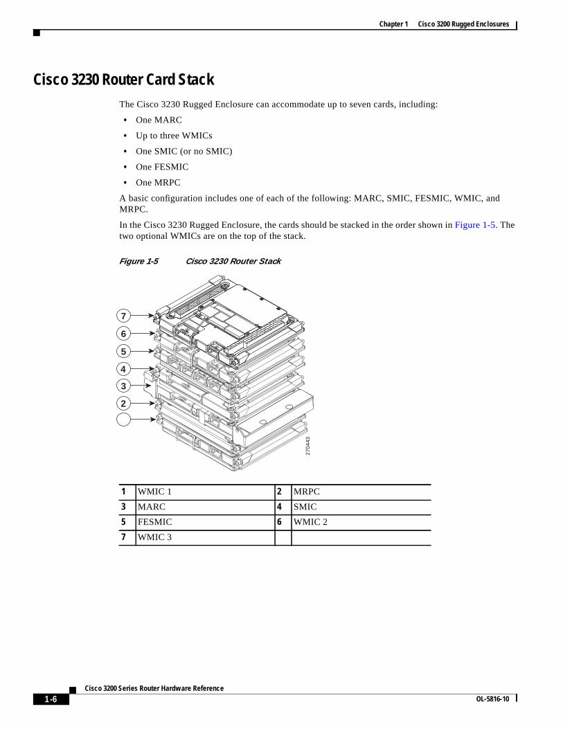
Cisco 3230 Router Card StackThe Cisco 3230 Rugged Enclosure can accommodate up to seven cards, including:
• One MARC
• Up to three WMICs
• One SMIC (or no SMIC)
• One FESMIC
• One MRPC
A basic configuration includes one of each of the following: MARC, SMIC, FESMIC, WMIC, andMRPC.
In the Cisco 3230 Rugged Enclosure, the cards should be stacked in the order shown inFigure 1-5. Thetwo optional WMICs are on the top of the stack.
Figure 1-5 Cisco 3230 Router Stack
1 WMIC 1 2 MRPC
3 MARC 4 SMIC
5 FESMIC 6 WMIC 2
7 WMIC 3
2704
43
7
6
5
4
3
2
1

1-7Cisco 3200 Series Router Hardware Reference
OL-5816-10
Chapter 1 Cisco 3200 Rugged Enclosures
Rugged Enclosure End CapsEach Cisco 3200 Rugged Enclosure has two end caps: an antenna end cap that connects to the back ofthe enclosure, and an I/O end cap that connects to the front of the enclosure. The port configurations ofthe I/O end caps vary, based on the contents of the enclosure. For example, the number and location ofantenna ports installed on the antenna end cap depend on how many WMICs are installed in theenclosure.
Note To prevent exposure to the elements, we recommend using the protective port covers (provided) on portsthat are not in use and using port covers (provided) on the mating cables.
Antenna End CapThe antenna end cap has four antenna ports on the flat side and two ports on the top surface. The end capis used with the Cisco 3270 Rugged Enclosure or the Cisco 3230 Rugged Enclosure. The antenna portsare connector type RP-TNC. Each RP-TNC is connected internally to a WMIC. Typically, two antennaports are used to support each WMIC. If fewer than three WMICs are installed, the unused antennaconnector ports are sealed with a cap to protect them from the environment.
Figure 1-6 Cisco 3200 Rugged Enclosure Antenna End Cap with a Mounting Bracket
Note By default, the Cisco 3205 WMIC uses the right antenna to receive and transmit data.
1355
33

1-8Cisco 3200 Series Router Hardware Reference
OL-5816-10
Chapter 1 Cisco 3200 Rugged Enclosures
Note For additional information on antennas and antenna cables, see the “Antenna Basics” technical note athttp://www.cisco.com/en/US/products/hw/wireless/ps458/products_installation_guide_chapter09186a008007f74a.htmland the “Antenna Cabling” technical note athttp://www.cisco.com/en/US/tech/tk722/tk809/technologies_tech_note09186a00801c12c2.shtml
I/O End Caps for the Cisco 3200 Rugged EnclosuresThe I/O end cap has multiple connectors for connecting power and data cables. The end capconfigurations shown in this section are fully populated; however, the number of ports and theirfunctions may differ, depending upon the number of WMICs in the system.
End Cap Fast Ethernet and WMIC Console Ports
Internally, five Fast Ethernet ports are available: one routed Fast Ethernet port on the router card and fourswitched Fast Ethernet ports on the Fast Ethernet Switch Mobile Interface Card (FESMIC). When aWMIC is installed in addition to the router, the WMIC Fast Ethernet port is connected internally to therouted Fast Ethernet port on the router card or is connected to one of the switched Fast Ethernet ports onthe FESMIC to provide a communications link with the router. In contrast, the Serial Mobile InterfaceCard (SMIC) and FESMIC communicate with the router through the bus. All the router Fast Ethernetports are addressed by using the slot/port format.
In typical configurations, the first WMIC Fast Ethernet port is connected to the routed Fast Ethernet porton the router card. The Fast Ethernet ports of the second and third WMICs are connected to FESMICswitched Fast Ethernet ports. The differences in the types of the router Fast Ethernet ports that theWMICs are connected to affect how they are configured, as, for example, when uploading a Cisco IOSimage to a WMIC.
The WMIC runs an independent Cisco IOS image and when you configure the WMIC, the link forms aninternal LAN. In standard configurations, the WMIC Fast Ethernet port is never brought out to the endcap.
The WMIC console port is brought out to the corresponding RJ-45 port on the I/O end cap, replacing aFast Ethernet port. If the router includes one WMIC, the EIA/TIA-232 WMIC console port replaces aFast Ethernet port on the end cap. If the router includes two WMICs, two WMIC EIA/TIA-232 consoleports replace two Fast Ethernet ports on the end cap.
Note At present, even if the router contains no WMICs, in standard configurations the maximum three FastEthernet ports are brought out to the end cap. Unused EIA/TIA-232 ports are sealed.
1-9Cisco 3200 Series Router Hardware Reference
OL-5816-10
Chapter 1 Cisco 3200 Rugged Enclosures
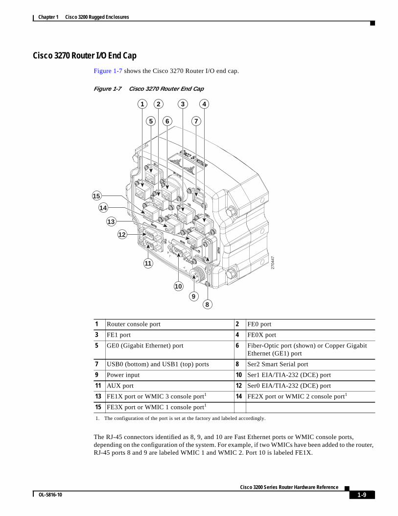
Cisco 3270 Router I/O End Cap
Figure 1-7 shows the Cisco 3270 Router I/O end cap.
Figure 1-7 Cisco 3270 Router End Cap
The RJ-45 connectors identified as 8, 9, and 10 are Fast Ethernet ports or WMIC console ports,depending on the configuration of the system. For example, if two WMICs have been added to the router,RJ-45 ports 8 and 9 are labeled WMIC 1 and WMIC 2. Port 10 is labeled FE1X.
1 Router console port 2 FE0 port
3 FE1 port 4 FE0X port
5 GE0 (Gigabit Ethernet) port 6 Fiber-Optic port (shown) or Copper GigabitEthernet (GE1) port
7 USB0 (bottom) and USB1 (top) ports 8 Ser2 Smart Serial port
9 Power input 10 Ser1 EIA/TIA-232 (DCE) port
11 AUX port 12 Ser0 EIA/TIA-232 (DCE) port
13 FE1X port or WMIC 3 console port1 14 FE2X port or WMIC 2 console port1
15 FE3X port or WMIC 1 console port1
1. The configuration of the port is set at the factory and labeled accordingly.
2704
47
12
15
14
13
11
9
10
8
1
5 6 7
2 3 4

1-10Cisco 3200 Series Router Hardware Reference
OL-5816-10
Chapter 1 Cisco 3200 Rugged Enclosures
Note The connectors are sealed at the factory with captive dust covers (not shown) that seal the ports andprotect the pins. The dust covers should be used to seal the ports when the ports are not covered by cableconnectors.
Fiber Optic Connector IP–67 Integrity
When the fiber-optic port is not connected or otherwise in use, the protective cover should be used toseal the port. To seal the fiber-optic port when it is connected to a cable, use connectors that maintainIP-67 integrity. The part numbers for the connectors are Tyco 1828618–1 and Tyco 1828618–2.
Caution When connecting fiber-optic cables, observe all standard procedures for safety, and maintain a cleanconnection.
Power Connector IP-67 Integrity
To seal the Tyco DC Power input power connector and maintain IP-67 integrity, use the following parts:
• 796094-2–CPC housing
• 66101-3–contact
• 207489-1–boot
• 207490-1–cable (grip size 11)
Smart Serial Port External Seal for System Integrity
When the Smart Serial port is not connected or otherwise in use, the protective cover should be used toseal the port. To seal the Smart Serial port when the port is connected to a cable, complete the steps inAppendix A, “Smart Serial Port External Seal.” in theCisco 3200 Series Router Hardware Reference.

1-11Cisco 3200 Series Router Hardware Reference
OL-5816-10
Chapter 1 Cisco 3200 Rugged Enclosures
USB Flash Storage Device Caveat
In some cases, using two USB flash storage devices causes unpredictable results (CSCsd11136).
If one USB flash storage device is plugged into a USB port and a second USB flash storage device isplugged into or unplugged from the other port, an error might occur (CSCsd44152). The error messageis, “USB_HOST_STACK-6-USB_FLASH_READY_TEST_TIME: USB flash 'Ready' test time over4 seconds.”
If an unsupported USB flash storage device is plugged into a USB port, an error might occur(CSCsd44152). The error message is, “Failed to enumerate a USB device as not able to read the device'sdescription.”
To correct the problems, remove any unsupported USB flash storage device and use only one supporteddevice in one of the two USB ports. The Cisco-supported flash storage devices listed below.
Item# Vendor Part Number
16-3153-01 SANDISK SDUJGU0-256-926
16-3153-01 M-SYSTEMS 8U-52E-0256-12A01C
16-3152-01 SANDISK SDUJGU0-128-926
16-3152-01 M-SYSTEMS 8U-52E-0128-12A01C
16-3151-01 SANDISK SDUJGU0-64-926
16-3151-01 M-SYSTEMS 8U-52E-0064-12A01C

1-12Cisco 3200 Series Router Hardware Reference
OL-5816-10
Chapter 1 Cisco 3200 Rugged Enclosures
Cisco 3230 Router I/O End Cap
Figure 1-8 shows the Cisco 3230 Router I/O end cap. It has multiple connectors that can be used toconnect power and data cables.
Figure 1-8 Cisco 3230 Router End Cap
Note The connectors are sealed at the factory with captive dust covers (not shown) that seal the ports andprotect the pins. The dust covers should be used to seal the ports when the ports are not otherwisecovered by cable connectors.
1 WMIC 1 console port 2 WMIC 2 console port
3 WMIC 3 console port 4 FE0 port
5 FE1X port 6 FE2X or MARC FE0X port (for moreinformation, see the“Fast Ethernet PortCabling for the Cisco 3250 and Cisco 3230Routers” section on page 1-16.)
7 AUX port 8 Router console port
9 Ser0 RS-232 (DCE) port 10 Ser1 RS-232 (DCE) port
11 Power input
2704
44
7
9 10 11
14 5 62 3
8

1-13Cisco 3200 Series Router Hardware Reference
OL-5816-10
Chapter 1 Cisco 3200 Rugged Enclosures
Protective End Cap CoverA protective end cap cover (Figure 1-9) provides weatherproof protection for the ports on the end capsof the Cisco 3200 Rugged Enclosure when the enclosure is installed outdoors. The protective end capcover also provides added protection for in-vehicle use, inhibiting corrosion on the ports and potentialdamage from objects that are stored near the enclosure inside a vehicle.
The protective end cap cover has a ruggedized design for high reliability and NEMA4 compliance.
Figure 1-9 Cisco 3200 Rugged Enclosure Protective End Cap Cover
1 Hinge point 2 NEC cable pass-through
3 Holes for 8–32 protective end cap coverscrews
4 Hinge/mounting bracket
5 Mounting bolt
1580
86
3
1
4
5
2

1-14Cisco 3200 Series Router Hardware Reference
OL-5816-10
Chapter 1 Cisco 3200 Rugged Enclosures
To attach the protective end cap cover to the enclosure, follow these steps (seeFigure 1-10).
Figure 1-10 Protective End Cap Cover Installation
Step 1 Loosen the end cap mounting hardware (four 1/4-20 bolts), but do not remove the bolts.
Step 2 Slide the hinge brackets onto the right side and the left side of the end cap cover. The mounting tabsshould slide under the loosened bolts.
Step 3 Re-torque the two loosened bolts on the right side of the end cap cover to between 58 and 68 in-lb.
Step 4 Ensure that the gasket is fully seated in the protective end cap cover.
Step 5 Close the cover on the protective end cap cover and ensure that it is fully seated.
Step 6 Re-torque the end cap cover bolts on left side of the end cap cover to between 58 and 68 in-lb.
Step 7 Tighten the 8-32 protective cover screws (18 in-lb) until they are seated.
For sealing, we recommend Liquid Tight Connector, which is described at the following URL:
http://www.newark.com/NewarkWebCommerce/newark/en_US/mfr/brands.jsp?mfg=HUBB
1 Hinge bracket 2 Hinge point
3 Cable/service loop cavity 4 NEC pass-through
5 Gasket 6 Cap mounting
1701
06
1
2
3
6
4 5

1-15Cisco 3200 Series Router Hardware Reference
OL-5816-10
Chapter 1 Cisco 3200 Rugged Enclosures
I/O End Cap Port SignalsThis section describes the ports and port signals on the Cisco 3200 Rugged Enclosure I/O end caps.
Gigabit Ethernet Signal LimitationsDue to CPU and memory bus limitations, a Gigabit Ethernet port transmits and receives packets belowthe line rate. The line rate is lower for small frames and higher for large frames.
Small packet streams on Gigabit Ethernet ports, such as 64-byte packet streams, support up to 24 percentof full duplex, bidirectional line rate traffic without experiencing packet drops.
The 512-byte packet streams support up to 78 percent of full duplex, bidirectional line rate traffic. The1518-byte packet streams support up to 88 percent of full duplex bidirectional line rate traffic.
At higher frame rates the RDRP receive drop counter (displayed by using theshow controller g0/0command) increases indicating dropped packets.
At higher frame rates for packet sizes greater than 512 bytes, the transmit underruns1 counter (displayedby using theshow int g0/0or show int g0/1command) increases. The transmit underruns might causeCRC errors on the peer router.
Fast Ethernet SignalsA Cisco router identifies a Ethernet port interfaces by slot number and port number in the format ofslot/port. For example, the slot/port address of a Fast Ethernet interface on the Cisco 3230 RuggedEnclosure is 0/0.
The Cisco 3270 Router Ethernet port signals are in compliance with IEEE 802.3. The interfaces supportthe following:
• Autonegotiationand parallel detection MII interface with extended register capability for10/100BASE-TX or 10/100/1000BASE-TX connections.
• Full-duplex and half-duplex modes.
• 3.3V operation low power consumption (300 mW typical).
• Low-power sleep mode.
• Robust baseline wander correction performance.
• MDIX support (Fast Ethernet and Gigabit Ethernet copper only).
• Jumbo Frame (4400 bytes) support on Gigabit Ethernet interfaces.
• 10BASE-T or 100BASE-TX using a single Ethernet connection.
• 10BASE-T, 100BASE-TX, or 1000BASE-TX using a Gigabit Ethernet copper connection.
• 100BAFX/100LX, 1000BASE-SX, 1000BASE-LX/LH for Gigabit Ethernet fiber-opticconnections. (The speed is not configurable.)
• Standard carrier signal multiple access collision detect (CSMA/CD) or full-duplex operation.
• Integrated programmable LED drivers.
1. Transmit underrun–an error on interfaces when the data is not ready on the memory bus when the systemattempts to transmit the data; a bad packet is transmitted.

1-16Cisco 3200 Series Router Hardware Reference
OL-5816-10
Chapter 1 Cisco 3200 Rugged Enclosures
The Cisco 3230 Router Ethernet port signals are in compliance with IEEE 802.3. The interfaces supportthe following:
• Autonegotiationand parallel detection MII interface with extended register capability for10/100BASE-TX connections
• Full-duplex and half-duplex modes
• 3.3V operation low power consumption (300 mW typical)
• Low-power sleep mode
• 10BASE-T or 100BASE-TX using a single Ethernet connection
• Robust baseline wander correction performance
• Standard carrier signal multiple access collision detect (CSMA/CD) or full-duplex operation
• Integrated programmable LED drivers
Fast Ethernet Port Cabling for the Cisco 3250 and Cisco 3230 Routers
Most Cisco 3200 Series router Ethernet ports support autodetection. If the device that the router isconnected to also supports autodetection, the choice of a straight-through or crossover Ethernet cabledoes not matter. However, the Cisco 3250 router MARC FE0X port does not support autodetection.
To connect a port marked MARC FE0X to a routing Ethernet port that does not support autodetection,use a straight-through Ethernet cable. To connect a MARC FE0X port to a hub, switch, a router hub, orswitch port, use a crossover Ethernet cable.Table 1-1 shows the connections.
For example, a port marked FE0X requires a crossover Ethernet cable to establish the Ethernet linkbetween a Cisco 3250 router and a hub. A port that does not support autodetection marked FE0 requiresa straight-through Ethernet cable to establish the Ethernet link between a Cisco 3250 router and a hub.
For additional information on cable pin assignments, see the “Cable Pinouts” chapter of theCiscoContent Services Switch Getting Started Guide at:
http://www.cisco.com/en/US/products/hw/contnetw/ps789/products_installation_guide_chapter09186a00805f718d.html
Table 1-1 General Guidelines for MAR Fast Ethernet Port Cabling
PortsServer, Workstation, or PersonalComputer Ethernet Link
Hub, Switch, Uplink RouterEthernet Hub, or Switch
Ports marked FE0X, FE1X,and so forth
Straight-through cable Crossover cable
Ports marked FE0, FE1, andso forth
Crossover cable Straight-through cable

1-17Cisco 3200 Series Router Hardware Reference
OL-5816-10
Chapter 1 Cisco 3200 Rugged Enclosures
Console Port SignalsYou can connect to the router or to a Wireless Mobile Interface Card (WMIC) by using a console cableto connect to the console interfaces.
The console port signals:
• Are asynchronous serial DCE
• Support 9.6-kbps, 19.2-kbps, 38.4-kbps, 57.6-kbps, and 115.2-kbps baud rates
• Support full modem control of DTR, DSR, RTS, and CTS signals
AUX Port SignalsThe AUX port is a serial asynchronous port that supports the following speeds:
• Cisco 3270 Rugged Router card in the Cisco 3270 Router: 1.2 kbps, 2.4 kbps, 4.8 kbps, 9.6 kbps,19.2 kbps, 38.4 kbps, 57.6 kbps, 115.2 kbps, and 460 kbps.
• Mobile Access Router Card (MARC) in the Cisco 3230 Router: 1.2 kbps, 2.4 kbps, 4.8 kbps,9.6 kbps, 19.2 kbps, 38.4 kbps, 57.6 kbps, and 115.2 kbps.
The AUX port supports the following:
• Asynchronous serial DTE
• 5 to 8 data bits
• 1, 1.5, or 2 stop bits
• Odd, even, or no parity
• Flow control by using RTS, CTS, DTR, and CDC signals

1-18Cisco 3200 Series Router Hardware Reference
OL-5816-10
Chapter 1 Cisco 3200 Rugged Enclosures
Cisco 3200 Rugged Enclosure LED IndicationsThis section describes the LED indications for the Cisco 3200 Rugged Enclosure I/O end caps.
Note The behavior of the WMIC LEDs is described in the“WMIC Console LEDs” section on page 1-19.
Cisco 3270 Rugged Enclosure I/O End Cap LED IndicationsTable 1-2 lists the LEDs for the Cisco 3270 Rugged Enclosure I/O end caps and their indications.
Table 1-2 LEDs for the Cisco 3270 Rugged Enclosure End Cap
LED Indication
Cisco 3270 Rugged Router card Solid green: OK.Blinking: Booting and self-testing.Black: Not OK or the power is off.
Serial Status/Link (1 status/linkLED per serial port)
Solid green: Link OK.Black: No link is detected.Amber blink: Activity.
Fast Ethernet(1 LED per port, except for thefiber-optic port, which has noLEDs)
Link LEDSolid green: Link OK.Black: No link is detected.
Activity LEDBlack: No activity and no connection.Green blink: Activity.
Gigabit Ethernet(2 LEDs per port)
Link LEDSolid green: Link OK.Black: no link is detected.
Activity LEDSolid green: Link OK.Black: No activity.Green blink: Activity.
Console Solid green: Link OK.Black: No activity.Green blink: Activity.
WMIC Console (Installation orOperation Mode)
For installation mode, seeTable 1-4 on page 1-19.
For operation mode, seeTable 1-5 on page 1-20.

1-19Cisco 3200 Series Router Hardware Reference
OL-5816-10
Chapter 1 Cisco 3200 Rugged Enclosures
Cisco 3230 Rugged Enclosure I/O End Cap LED IndicationsTable 1-3 lists the LEDs for the Cisco 3230 Rugged Enclosure I/O end caps and their indications.
WMIC Console LEDsWMIC console LEDs function in installation mode or operational mode. The WMIC is set to theinstallation mode by default. To change the function of the WMIC, use thestation role command.
Table 1-4 shows the status of the LEDs when the WMIC is in installation mode (signal strength).
Table 1-3 LEDs for Cisco 3230 Router I/O End Caps
LED Indication
MARC Solid green: OK.Blinking: Booting and self-testing.Black: Not OK or the power is off.
Serial Status/Link (1 status/link LED perserial port)
Solid green: Link OK.Black: No link is detected.Amber blink: Activity.
Fast Ethernet (2 LEDs per Fast Ethernetport)
Link LEDSolid green: Link OK.Black: No link is detected.
Activity LEDBlack: No activity.Green blink: Activity.
WMIC Console (Installation or OperationMode)
For installation mode, seeTable 1-4 on page 1-19.
For operation mode, seeTable 1-5 on page 1-20.
Table 1-4 WMIC Installation Mode
RSSI (dBm) Status LED Radio LED
> –51 Steady Steady
–58 to –54 Fast blinking (16 Hz) Steady
–60 to –57 Slow blinking (4 Hz Steady
–63 to –60 Very slow blinking (2 Hz) Steady
–66 to –63 Black Steady
–69 to –66 Black Fast blinking (16 Hz)
–72 to –69 Black Slow blinking (4 Hz
–75 to –72 Black Very slow blinking (2 Hz)
< –75 Black Black

1-20Cisco 3200 Series Router Hardware Reference
OL-5816-10
Chapter 1 Cisco 3200 Rugged Enclosures
Table 1-5 shows the status of the LEDs when the WMIC is in operational mode.
Thermal PlatesCisco 3200 Rugged Enclosures use thermal plates and Wedge Loks to transfer heat from the cards to theextrusion.Figure 1-11 shows a card with thermal plates. The conduction cooling removes the need forinternal fans.
Figure 1-11 Router Card with Thermal Plates
Table 1-5 WMIC Operational Mode
Indication Status LED Radio LED
Green steady At least one bridge is associated. —
Red steady Loading firmware. Firmware failure.
Green blink No bridges are associated. Transmitting or receiving packets onthe radio port.
Amber blink General warning. Maximum retries or buffer full.
Black (no light) — Default.
1 Power connector 2 Wedge Lok
3 ISA bus 4 PCI bus
2704
46
1
3
4
2

1-21Cisco 3200 Series Router Hardware Reference
OL-5816-10
Chapter 1 Cisco 3200 Rugged Enclosures
Mounting BracketsMounting brackets are available for the enclosures.
The notches in the mounting brackets allow you to temporarily install the bracket without the router inplace. The bolts for the notches in the mounting bracket can be installed on the enclosure before the otherbolts are installed. The partially installed bolts provide enough support to allow you to install the routerin the bracket, and then install and tighten the remaining bolts. The torque values for the mountingbracket screws are from 58 to 68 in-lb.
Figure 1-12 shows the Cisco 3270 Rugged Enclosure mounting bracket.
Figure 1-12 Cisco 3270 Rugged Enclosure Mounting Bracket
1700
50

1-22Cisco 3200 Series Router Hardware Reference
OL-5816-10
Chapter 1 Cisco 3200 Rugged Enclosures
Figure 1-13 shows the dimensions of the Cisco 3270 Rugged Enclosure mounting bracket.
Figure 1-13 Cisco 3270 Rugged Enclosure Mounting Bracket Dimensions
Figure 1-14 shows the Cisco 3230 Rugged Enclosure mounting bracket.
Figure 1-14 Cisco 3230 Rugged Enclosure Mounting Bracket
3.9
2326
00
1274
52

1-23Cisco 3200 Series Router Hardware Reference
OL-5816-10
Chapter 1 Cisco 3200 Rugged Enclosures
Figure 1-15 shows the dimensions of the Cisco 3230 Rugged Enclosure mounting bracket.
Figure 1-15 Cisco 3230 Rugged Enclosure Mounting Bracket Dimensions
2325
99

1-24Cisco 3200 Series Router Hardware Reference
OL-5816-10
Chapter 1 Cisco 3200 Rugged Enclosures


