Embed Size (px)
Citation preview
Closed Fuel Cycle
Waste Treatment
Strategy
Prepared for U.S. Department of Energy
Materials Recovery and Waste Forms Campaign
Compiled By: J.D. Vienna (PNNL)
Contributors: E.D. Collins (ORNL),
J.V. Crum (PNNL), W.L. Ebert (ANL),
S.M. Frank (INL), T.G. Garn (INL),
D. Gombert (Deceased), R. Jones (SRNL),
R.T. Jubin (ORNL), V.C. Maio (INL),
J.C. Marra (SRNL), J. Matyas (PNNL),
T.M. Nenoff (SNL), B.J. Riley (PNNL),
G.J. Sevigny (PNNL), N.R. Soelberg (INL),
D.M. Strachan (Retired), P.K. Thallapally (PNNL),
J.H. Westsik (PNNL)
February 27, 2015
FCRD-MRWFD-2015-000674, Rev. 0
PNNL-24114
DISCLAIMER
This information was prepared as an account of work sponsored by an
agency of the U.S. Government. Neither the U.S. Government nor any
agency thereof, nor any of their employees, makes any warranty,
expressed or implied, or assumes any legal liability or responsibility for
the accuracy, completeness, or usefulness, of any information, apparatus,
product, or process disclosed, or represents that its use would not infringe
privately owned rights. References herein to any specific commercial
product, process, or service by trade name, trade mark, manufacturer, or
otherwise, does not necessarily constitute or imply its endorsement,
recommendation, or favoring by the U.S. Government or any agency
thereof. The views and opinions of authors expressed herein do not
necessarily state or reflect those of the U.S. Government or any agency
thereof.
Closed Fuel Cycle Waste Treatment Strategy February 2015 iii
ABSTRACT
This study is aimed at evaluating the existing waste management approaches for nuclear fuel cycle
facilities in comparison to the objectives of implementing an advanced fuel cycle in the U.S. under
current legal, regulatory, and logistical constructs. The study begins with the Global Nuclear Energy
Partnership (GNEP) Integrated Waste Management Strategy (IWMS) (Gombert et al. 2008) as a general
strategy and associated Waste Treatment Baseline Study (WTBS) (Gombert et al. 2007). The tenets of the
IWMS are equally valid to the current waste management study. However, the flowsheet details have
changed significantly from those considered under GNEP. In addition, significant additional waste
management technology development has occurred since the GNEP waste management studies were
performed. This study updates the information found in the WTBS, summarizes the results of more
recent technology development efforts, and describes waste management approaches as they apply to a
representative full recycle reprocessing flowsheet. Many of the waste management technologies
discussed also apply to other potential flowsheets that involve reprocessing. These applications are
occasionally discussed where the data are more readily available.
The report summarizes the waste arising from aqueous reprocessing of a typical light-water reactor
(LWR) fuel to separate actinides for use in fabricating metal sodium fast reactor (SFR) fuel and from
electrochemical reprocessing of the metal SFR fuel to separate actinides for recycle back into the SFR in
the form of metal fuel. The primary streams considered and the recommended waste forms include:
Tritium separated from either a low volume gas stream or a high volume water stream. The
recommended waste form is low-water cement in high integrity containers (HICs).
Iodine-129 separated from off-gas streams in aqueous processing. There are a range of
potentially suitable waste forms. As a reference case, a glass composite material (GCM) formed
by the encapsulation of the silver Mordenite (AgZ) getter material in a low-temperature glass is
assumed. A number of alternatives with distinct advantages are also considered including a fused
silica waste form with encapsulated nano-sized AgI crystals.
Carbon-14 separated from LWR fuel treatment off-gases and immobilized as a CaCO3 in a
cement waste form.
Krypton-85 separated from LWR and SFR fuel treatment off-gases and stored as a compressed
gas.
An aqueous reprocessing high-level waste (HLW) raffinate waste which is immobilized by the
vitrification process in one of three forms: a single phase borosilicate glass, a borosilicate based
glass ceramic, or a multi-phased titanate ceramic [e.g., synthetic rock (Synroc)].
An undissolved solids (UDS) fraction from aqueous reprocessing of LWR fuel that is either
included in the borosilicate HLW glass or is immobilized in the form of a metal alloy in the case
of glass ceramics or titanate ceramics.
Zirconium-based LWR fuel cladding hulls and stainless steel (SS) fuel assembly hardware that
are washed and super-compacted for disposal or as an alternative with high promise for the
purification and reuse (or disposal as low-level waste, LLW) of Zr by reactive gas separations.
Electrochemical process salt HLW which is incorporated into a glass bonded Sodalite waste form
known as the ceramic waste form (CWF).
Electrochemical process UDS and SS cladding hulls which are melted into an iron based alloy
waste form.
Mass and volume estimates for each of the recommended waste forms based on the source terms from a
representative flowsheet are reported.

Closed Fuel Cycle Waste Treatment Strategy February 2015 iv
In addition to the above listed primary waste streams, a range of secondary process wastes are generated
by aqueous reprocessing of LWR fuel, metal SFR fuel fabrication, and electrochemical reprocessing of
SFR fuel. These secondary wastes have been summarized and volumes estimated by type and
classification.
The important waste management data gaps and research needs have been summarized for each primary
waste stream and selected waste process.
Closed Fuel Cycle Waste Treatment Strategy February 2015 v
CONTENTS
ABSTRACT ................................................................................................................................................ III
ABBREVIATIONS AND ACRONYMS ................................................................................................... XI
1. PROCESS FLOWSHEET AND WASTE STREAM DEFINITION ................................................. 1
1.1 AQUEOUS REPROCESSING ................................................................................................ 2
1.1.1 HEAD-END PROCESSING ....................................................................................... 3
1.1.2 CO-DECONTAMINATION ...................................................................................... 5
1.1.3 ACTINIDE-LANTHANIDE SEPARATION ............................................................. 5
1.1.4 OFF-GAS TREATMENT ........................................................................................... 7
1.2 ELECTROCHEMICAL PROCESSING ............................................................................... 13
1.2.1 ELECTROCHEMICAL SALT ................................................................................. 15
1.2.2 METAL WASTE STREAM ..................................................................................... 16
1.2.3 ELECTROCHEMICAL PROCESS OFF-GAS ........................................................ 18
2. OFF-GAS TREATMENT WASTE STREAMS .............................................................................. 19
2.1 TRITIUM ............................................................................................................................... 19
2.1.1 TRITIUM RECOVERY ........................................................................................... 20
2.1.2 TRITIUM IMMOBILIZATION ............................................................................... 21
2.2 IODINE .................................................................................................................................. 22
2.2.1 IODINE SEPARATIONS TECHNOLOGIES ......................................................... 22
2.2.2 IODINE WASTE FORMS ........................................................................................ 27
2.3 KRYPTON ............................................................................................................................. 37
2.3.1 KR RECOVERY PROCESSES ................................................................................ 37
2.3.2 KRYPTON STABILIZATION ................................................................................. 40
2.4 CARBON-14 .......................................................................................................................... 41
2.4.1 CARBON CAPTURE ............................................................................................... 42
2.4.2 CARBON STABILIZATION ................................................................................... 44
2.5 DATA GAPS AND RESEARCH NEEDS ............................................................................ 44
2.5.1 TRITIUM .................................................................................................................. 44
2.5.2 IODINE ..................................................................................................................... 45
2.5.3 CARBON .................................................................................................................. 45
2.5.4 KRYPTON ................................................................................................................ 45
2.5.5 INTERFACES AND INTEGRATION ..................................................................... 46
3. AQUEOUS HIGH LEVEL WASTE STREAMS ............................................................................ 47
3.1 HLW WASTE FORM REVIEWS ......................................................................................... 47
3.1.1 GNEP HLW WASTE FORM RECOMMENDATIONS.......................................... 49
3.2 BOROSILICATE GLASS ..................................................................................................... 52
3.3 TITANATE-BASED CERAMICS ........................................................................................ 53
3.4 PHOSPHATE GLASS ........................................................................................................... 55
3.5 METAL WASTE FORMS ..................................................................................................... 55
3.5.1 UDS COMPOSITION VARIATION ....................................................................... 55
3.5.2 SOLUBLE TC REDUCTION .................................................................................. 59
3.5.3 IRON-ZIRCONIUM BASED ALLOYS .................................................................. 60
3.5.4 EPSILON METAL ................................................................................................... 60
Closed Fuel Cycle Waste Treatment Strategy February 2015 vi
3.6 GLASS CERAMICS .............................................................................................................. 62
3.7 HIGH LEVEL WASTE FORM RECOMMENDATIONS ................................................... 65
3.8 HIGH-LEVEL WASTE VITRIFICATION PROCESS ........................................................ 65
3.8.1 WASTE FEED PREPARATION ............................................................................. 65
3.8.2 MELTING PROCESS .............................................................................................. 66
3.8.3 HLW GLASS CANISTER ....................................................................................... 69
3.8.4 GLASS CERAMICS................................................................................................. 70
3.9 DATA GAPS AND RESEARCH NEEDS ............................................................................ 71
3.9.1 BOROSILICATE GLASS ........................................................................................ 71
3.9.2 BOROSILICATE GLASS CERAMICS ................................................................... 71
3.9.3 TITANATE-BASED CERAMICS ........................................................................... 72
3.9.4 METAL WASTE FORMS FOR UDS AND TC ...................................................... 72
4. HULLS AND HARDWARE FROM LWR FUEL .......................................................................... 73
4.1 WASTE STREAM DEFINITION ......................................................................................... 73
4.2 MANAGEMENT APPROACHES FOR HULLS AND HARDWARE ................................ 74
4.2.1 CEMENTATION ...................................................................................................... 75
4.2.2 SUPER COMPACTION ........................................................................................... 78
4.3 METAL MELTING ............................................................................................................... 79
4.3.1 REACTIVE GAS PURIFICATION OF ZR ............................................................. 79
4.4 HULLS AND HARDWARE MANAGEMENT RECOMMENDATION ............................ 81
4.5 DATA GAPS AND RESEARCH NEEDS ............................................................................ 82
5. ELECTROCHEMICAL SALT HLW .............................................................................................. 83
5.1 GLASS-BONDED SODALITE............................................................................................. 83
5.1.1 ZEOLITE SALT OCCLUSION ............................................................................... 83
5.1.2 GLASS ENCAPSULATION .................................................................................... 84
5.1.3 EXCESS HALITE INCLUSIONS ............................................................................ 84
5.1.4 WASTE LOADING .................................................................................................. 84
5.1.5 THERMAL LOADING ............................................................................................ 85
5.1.6 CERAMIC WASTE FORM PROCESS ................................................................... 85
5.1.7 MASS AND VOLUME ESTIMATES ..................................................................... 87
5.2 ALTERNATIVE WASTE FORMS FOR IMMOBILIZATION OF SALT
PROCESSING WASTES ...................................................................................................... 88
5.2.1 TELLURITE GLASS ............................................................................................... 89
5.2.2 SOLUTION-BASED APPROACHES FOR MAKING SODALITE ....................... 89
5.3 DATA GAPS AND RESEARCH NEEDS ............................................................................ 90
6. ELECTROCHEMICAL UNDISSOLVED SOLIDS AND HULLS ................................................ 91
6.1 DATA GAPS AND RESEARCH NEEDS ............................................................................ 94
7. TRITIUM REMOVAL AND ENRICHMENT TECHNOLOGIES ................................................. 95
7.1 METHOD FOR ENRICHMENT OF TRITIUM IN WASTE WATER ................................ 96
7.1.1 COMBINED ELECTROLYSIS AND CATALYTIC EXCHANGE ....................... 96
7.1.2 BITHERMAL ........................................................................................................... 98
7.1.3 WATER DISTILLATION AND RECTIFICATION ............................................... 98
7.1.4 GIRDLER SULFIDE ................................................................................................ 99
7.1.5 CRYOGENIC DISTILLATION ............................................................................... 99
Closed Fuel Cycle Waste Treatment Strategy February 2015 vii
7.1.6 THERMAL CYCLE ABSORPTION PROCESS ..................................................... 99
7.1.7 INTEGRATED SYSTEMS ...................................................................................... 99
7.1.8 SUMMARY AND RECOMMENDATIONS ......................................................... 100
7.2 TRITIATED WATER IMMOBILIZATION ....................................................................... 100
7.3 DATA GAPS AND RESEARCH NEEDS .......................................................................... 103
8. SECONDARY WASTES ............................................................................................................... 105
8.1 TYPES OF SECONDARY WASTES ................................................................................. 105
8.2 SECONDARY WASTE VOLUMES .................................................................................. 105
8.3 DATA GAPS AND RESEARCH NEEDS .......................................................................... 110
9. CEMENTATION OF COMBINED WASTE STREAMS ............................................................. 111
9.1 DATA GAPS AND RESEARCH NEEDS .......................................................................... 112
10. SUMMARY AND CONCLUSIONS ............................................................................................. 113
11. REFERENCES ............................................................................................................................... 115
Closed Fuel Cycle Waste Treatment Strategy February 2015 viii
FIGURES FIGURE 1.1. OVERALL BLOCK FLOW DIAGRAM. ........................................................................................................... 1 FIGURE 1.2. GENERAL AQUEOUS SEPARATIONS FLOWSHEET ........................................................................................ 2 FIGURE 1.3. NOMINAL DOG FLOWSHEET SCHEMATIC .................................................................................................. 8 FIGURE 1.4. ADVANCED HOG FLOWSHEET SCHEMATIC ............................................................................................... 9 FIGURE 1.5. NOMINAL VESSEL VENTILATION OFF-GAS TREATMENT PROCESS SCHEMATIC........................................ 10 FIGURE 1.6. NOMINAL MELTER OFF-GAS TREATMENT SYSTEM. ................................................................................. 12 FIGURE 1.7. GENERAL ELECTROCHEMICAL SEPARATIONS FLOWSHEET ....................................................................... 13 FIGURE 2.1. CONCENTRATION OF
3H IN TYPICAL 50 GWD/TU PWR FUEL AS A FUNCTION OF TIME FROM DISCHARGE.
............................................................................................................................................................................ 20 FIGURE 2.2. SENSITIVITY OF PEAK ANNUAL DOSE FROM
129I TO WASTE FORM FRACTIONAL DEGRADATION RATE
(VAUGHN ET AL. 2012) ........................................................................................................................................ 29 FIGURE 2.3. AGIZ TREATMENT BOX FLOW DIAGRAM FOR THE REFERENCE FLOWSHEET ........................................... 35 FIGURE 2.4. AGAERO TREATMENT BOX FLOW DIAGRAM FOR THE ADVANCED FLOWSHEET ...................................... 36 FIGURE 3.1. COMPARISON OF WASTE FORM VOLUME (A) AND COST (B) FOR DIFFERENT COMBINED WASTE STREAMS
(GOMBERT ET AL. 2009). ..................................................................................................................................... 51 FIGURE 3.2. THE UDS COMPOSITIONS OF VARIOUS SEGMENTS OF IRRADIATED NUCLEAR FUELS, AS PERCENTAGE OF
TOTAL MASS (ADACHI ET AL. 1990). .................................................................................................................... 57 FIGURE 3.3. RESULTS OF ELECTROCHEMICAL TESTS WITH ALLOY EWF-1 IN ACIDIC BRINE. ..................................... 62 FIGURE 3.4. COMPARISON OF WASTE LOADINGS BETWEEN GLASS AND GLASS CERAMICS. ....................................... 63 FIGURE 3.5. PHASE FORMATION AS A FUNCTION OF COOLING RATE (IN TIMES OF EXPECTED NATURAL CANISTER
COOLING RATE, CRUM ET AL. 2012C) .................................................................................................................. 63 FIGURE 3.6. VISCOSITY OF GLASS CERAMICS MELT AS A FUNCTION OF INVERSE TEMPERATURE (CRUM ET AL. 2014).
............................................................................................................................................................................ 64 FIGURE 3.7. MODEL FOR PHASE CHANGE IN MODEL GLASS CERAMIC (CRUM ET AL. 2014) ....................................... 64 FIGURE 4.1. SCHEMATIC OF PROCESS OPTIONS FOR HULLS AND HARDWARE FROM (IAEA 1985). ............................. 75 FIGURE 4.2. SCHEMATIC OF IN-DRUM MIXING (OJOVAN AND LEE 2005) .................................................................... 76 FIGURE 4.3. EXAMPLES OF COMPOSITE CEMENT WASTE FORMS FABRICATED AT SELLAFIELD. WASTE IN (A) IS
COMPACTED ILW SOLIDS, IN (B) IS MAGNOX (MG ALLOY) FUEL CLADDING SWARF AND IN (C) IS ZIRCALOY
CLADDING HULLS FROM UOX FUEL ................................................................................................................... 77 FIGURE 4.4. EXAMPLE METAL WASTE FORM (A) COMPACTION UNIT, (B) PUCK, AND (C) CROSS-SECTION OF UC-C
CANISTER (COURTESY OF AREVA) .................................................................................................................... 78 FIGURE 4.5. PROCESS FLOW DIAGRAM FOR ZIRCONIUM RECOVERY CHLORINATION PROCESS. .................................. 80 FIGURE 4.6. POTENTIAL INSERTION OF PURIFIED RECYCLE ZIRCONIUM TETRACHLORIDE INTO THE PROCESS FOR
ZIRCONIUM ALLOY CLADDING MANUFACTURE. ................................................................................................. 81 FIGURE 5.1. RENDERED MODEL OF THE CWF CONTAINER, FROM MORRISON ET AL. (2010) ...................................... 87 FIGURE 5.2. EXAMPLE CWF RELATED PROCESS COST AS A FUNCTION OF IMPURITY CONTENT (FOR A 20 THM
REPROCESSING PLANT) ........................................................................................................................................ 88 FIGURE 6.1. ZR-FE PHASE DIAGRAM BASED ON (ARIAS 1988; MCDEAVITT ET AL. 1998) .......................................... 92 FIGURE 6.2. PHOTOGRAPH OF METAL WASTE FORM SAMPLE, FROM (EBERT 2005) .................................................... 92 FIGURE 6.3. MICROSTRUCTURES OF (A) 316SS-15ZR-10U ALLOY SHOWING STEEL AND ZRFE2 INTERMETALLIC
PHASES WITH BRIGHTER AREAS HAVING HIGH U CONCENTRATION AND (B) HT-9SS-2ZR-5U WITH THE SAME
FE-ZR-U INTERMETALLIC PHASES (OLSON 2012). .............................................................................................. 92 FIGURE 6.4. SEM PHOTOMICROGRAPHS OF SURFACES OF (A) 75SS-15ZR-0NM-10U ALLOY REACTED IN ACIDIC
SOLUTION SHOWING PREFERENTIAL DISSOLUTION OF FE-ZR-U INTERMETALLIC AND (B) 60SS-12ZR-26NM-2U
ALLOY REACTED UNDER THE SAME CONDITIONS WITH NO VISIBLE CORROSION. .............................................. 93 FIGURE 7.1. EXAMPLE CECE PROCESS SCHEMATIC (FROM WILLIS ET AL. 2013). ....................................................... 97 FIGURE 7.2. PHOTO OF THE MOSS UNIT WITH “LOST-STIRRER” TO BE UTILIZED AT ROSSENDORF (GESSER ET AL.
2000) ................................................................................................................................................................. 103
Closed Fuel Cycle Waste Treatment Strategy February 2015 ix
TABLES TABLE 1.1. NOMINAL LWR UNF COMPOSITION IN G/TU .............................................................................................. 3 TABLE 1.2. ISOTOPE PARTITIONING IN STANDARD AIR TPT (JUBIN ET AL. 2010). ........................................................ 3 TABLE 1.3. ESTIMATED COMPOSITION OF WASHED LWR HULLS FOR WASTE MANAGEMENT ..................................... 4 TABLE 1.4. SUMMARY OF THE ASSUMED UDS SPLIT FROM THE DISSOLVER SOLUTION AND THE RESULTING UDS
COMPOSITION ........................................................................................................................................................ 5 TABLE 1.5. NOMINAL HLW STREAM COMPOSITIONS, KG/TU ....................................................................................... 6 TABLE 1.6. ESTIMATED DFS FOR 5- AND 50-Y COOLED PWR UOX FUEL REPROCESSED IN A 1000 TU/Y PLANT ......... 7 TABLE 1.7. NOMINAL COMBINED GAS COMPOSITION ENTERING THE IODINE BED ........................................................ 8 TABLE 1.8. COMPOSITION OF HOG COMPONENTS AT VARIOUS STAGES, KG/TU REPROCESSED .................................. 10 TABLE 1.9. COMPARISON OF DOG AND VOG FLOWS IN KG/TU PROCESSED ............................................................... 11 TABLE 1.10. EXAMPLES MOG TREATMENT COMPONENTS AND PURPOSES ................................................................. 12 TABLE 1.11. EXAMPLE VITRIFICATION SYSTEM OFF-GAS FLOWS (KG/TU PROCESSED) .............................................. 13 TABLE 1.12. NOMINAL COMPOSITION FOR USED SFR METAL U/PU/ZR FUEL, 0.75 CONVERSION RATIO, 99.6
GWD/THM, 2Y COOLING) ................................................................................................................................... 14 TABLE 1.13. EXAMPLE SALT COMPOSITIONS (MASS% COMPONENT AND TOTAL KG/THM) ......................................... 16 TABLE 1.14. FREE ENERGIES OF FORMATION OF CHLORIDES (-ΔG0, KCAL/G-EQ AT 500 °C)(FROM NAS 1995) ......... 17 TABLE 1.15. NOMINAL METAL WASTE STREAM COMPOSITION, KG/THM................................................................... 17 TABLE 2.1. TRITIUM RECOVERY STEP: MOLECULAR SIEVES (MS3A) ......................................................................... 21 TABLE 2.2. RANGES OF ESTIMATED IODINE PARTITIONING BETWEEN VARIOUS OFF-GAS STREAMS .......................... 22 TABLE 2.3. IODINE RECOVERY PROCESS COMPARISON ............................................................................................... 26 TABLE 2.4. SUMMARY OF KRYPTON RECOVERY PROCESSES. ...................................................................................... 40 TABLE 2.5. SUMMARY OF KRYPTON STABILIZATION METHODS. ................................................................................. 41 TABLE 2.6. SUMMARY OF CARBON RECOVERY PROCESSES......................................................................................... 43 TABLE 3.1. CANDIDATE WASTE FORMS CONSIDERED FOR IMMOBILIZATION OF HLW FOR DISPOSAL
(BERNADZIKOWISKI ET AL. 1982). ....................................................................................................................... 48 TABLE 3.2. GLASS WASTE FORMS USED INTERNATIONALLY FOR IMMOBILIZATION OF HLW. .................................... 49 TABLE 3.3. SUMMARY OF WASTE FORMS FOR THREE PRIMARY CASES CONSIDERED BY GOMBERT ET AL. 2009) ...... 50 TABLE 3.4. EXAMPLE HLW COMPOSITIONS ................................................................................................................ 53 TABLE 3.5. SYNROC FAMILY OF COMPOSITIONS.......................................................................................................... 54 TABLE 3.6. RETENTION OF ELEMENTS OF INTEREST IN UDS, AS A PERCENT OF INVENTORY ...................................... 58 TABLE 3.7. SUMMARY OF WASTE, FRIT AND GLASS COMPOSITIONS (MASS% OF OXIDES) .......................................... 66 TABLE 3.8. SUMMARY OF MELT PROCESS METHODS .................................................................................................. 68 TABLE 3.9. MAXIMUM MELTER FEED CONCENTRATIONS, GRAMS OF GLASS PER LITER OF MELTER FEED. .................. 69 TABLE 3.10. SUMMARY OF EVALUATED HLW CANISTER OPTIONS FOR GLASS FOR 1000 TU/Y REPROCESSING PLANT
............................................................................................................................................................................ 70 TABLE 3.11. SUMMARY OF WASTE, FRIT, AND GLASS CERAMIC COMPOSITIONS (MASS%). ........................................ 70 TABLE 3.12. SUMMARY OF EVALUATED HLW CANISTER OPTIONS FOR GLASS CERAMIC VITRIFICATION ................. 71 TABLE 3.13. SUMMARY OF GLASS CERAMIC PRODUCTION RATE AND MELTER SCALES (ASSUMING A SINGLE LINE
WITH CONCENTRATED FEED)................................................................................................................................ 71 TABLE 4.1. EXAMPLE LIST OF NON-FUEL PARTS IN TYPICAL UNF ASSEMBLIES (OCRWM 2008) ............................. 73 TABLE 4.2. REPRESENTATIVE COMPOSITIONS OF STAINLESS STEELS AND ZIRCALOYS, MASS% .................................. 74 TABLE 5.1. CERAMIC WASTE FORM MASS AND VOLUME FOR 20 THM/Y REPROCESSING .......................................... 88 TABLE 7.1. TRITIUM SOURCE TERMS FOR 50 GWD/TU PWR FUEL. ............................................................................ 96 TABLE 7.2. TRITIUM REMOVAL TECHNOLOGIES IN COMMERCIAL USE - OPERATING AND PROPOSED FACILITIES ..... 100 TABLE 7.3. TRITIUM CEMENT MASSES AND VOLUME SUMMARIES ........................................................................... 102 TABLE 8.1. SUMMARY OF SECONDARY WASTE VOLUMES FOR FUEL RECYCLING, MOX FUEL FABRICATION AND FAST
REACTOR FUEL FABRICATION (FROM JONES AND CARTER 2013) ...................................................................... 107 TABLE 8.2. ESTIMATED SECONDARY WASTE VOLUMES (M
3) BY WASTE CLASSIFICATION FOR 800 TU/Y RECYCLING
FACILITY (FROM JONES AND CARTER 2013) ...................................................................................................... 108 TABLE 8.3. ESTIMATED SECONDARY WASTE VOLUMES (M
3) BY FUNCTIONAL AREA FOR 800 TU/Y RECYCLING
FACILITY (FROM JONES AND CARTER 2013) ...................................................................................................... 108 TABLE 8.4. ESTIMATED SECONDARY WASTE VOLUMES (M
3) FOR MOX FUEL FABRICATION (FROM JONES AND
CARTER 2013) ................................................................................................................................................... 109
Closed Fuel Cycle Waste Treatment Strategy February 2015 x
TABLE 8.5. ESTIMATED SECONDARY WASTE VOLUMES (M3) FOR FAST REACTOR FUEL FABRICATION (FROM JONES
AND CARTER 2013) ........................................................................................................................................... 109 TABLE 8.6. ESTIMATED USED FUEL REPROCESSING SECONDARY WASTE TOTAL PACKAGED VOLUME REDUCTIONS
THAT COULD BE COST-EFFECTIVE CONSIDERING TOTAL TREATMENT, STORAGE, TRANSPORTATION, AND
DISPOSAL COSTS. .............................................................................................................................................. 110 TABLE 9.1. HIGH-SODA CEMENT BLEND FORMULATIONS, DRY MASS% ................................................................... 111 TABLE 9.2. SUMMARY OF CEMENT WASTE FORM VOLUME AND MASS .................................................................... 112 TABLE 10.1. ESTIMATED REPROCESSING WASTE MASSES AND VOLUMES FOR A 1000 TU/Y AQUEOUS USED FUEL
REPROCESSING FACILITY (50 GW/TU BURNUP LWR FUEL). ............................................................................. 114 TABLE 10.2. ESTIMATED REPROCESSING WASTE MASSES AND VOLUMES FOR A 20 TU/Y ELECTROCHEMICAL USED
FUEL REPROCESSING FACILITY (100 GW/THM BURNUP SFR FUEL). ................................................................ 114
Closed Fuel Cycle Waste Treatment Strategy February 2015 xi
ABBREVIATIONS AND ACRONYMS
ACC Atelier de Compactage des Coques
AFCF Advanced Fuel Cycle Facility
AgAero silver functionalized silica aerogel
AgX silver-exchanged Faujasite
AgZ silver-exchanged Mordenite
AHA acetohydroxamic acid
ALS actinide-lanthanide separations
AMUSE Argonne model for universal solvent extraction
ANDRA Agence Nationale Pour la Gestion des Déchets Radioactifs
ANL Argonne National Laboratory
AVLIS atomic vapor laser isotope separation
BFS blast furnace slag
BNFP Barnwell Nuclear Fuel Plant
BWR boiling water reactor
CCIM cold crucible induction melter
CETE coupled end-to-end demonstration
CECE combined electrolysis catalytic exchange
CFR Code of Federal Regulations
CFTC Consolidated Fuel Treatment Center
CMPO octyl(phenyl)-N,N-diisobutylcarbamoylmethylphosphine oxide
CS/SR Cs, Sr, Ba, and Rb waste stream
DF decontamination factor
DOE-NE U.S. Department of Energy, Office of Nuclear Energy
DOG dissolver off-gas (treatment)
DTPA diethylenetriaminepentaacetic acid
DU depleted uranium
EAS Engineering Alternative Studies
EBR II Experimental Breeder Reactor II
Echem electrochemical processing
EPA Environmental Protection Agency
ER electrorefiner
EVS ejector venturi scrubber
FA fly ash
FCRD Fuel Cycle Research and Development (Program)
FOEAS Follow-On Engineering Alternative Studies
FR fast reactor
FP fission products
GCM glass composite materials
GNEP Global Nuclear Energy Partnership
GTCC greater-than-Class-C
GWd gigawatt days
HDEHP bis-(2-ethylhexyl) phosphoric acid
HEDTA N-(2-hydroxyethyl)ethylenediamine-N,N',N'-triacetic acid
HEH[EHP] 2-ethylhexylphosphonic acid mono-2-ethylhexyl ester
HEME high efficiency mist eliminator
HEPA high efficiency particulate air
HIC high-integrity container
HIP hot isostatic press
HLW high-level waste
Closed Fuel Cycle Waste Treatment Strategy February 2015 xii
HOG heat-end off-gas (treatment)
HTO tritiated-proton oxide (tritiated water, [3H,
2H,
1H]2O)
HUP hot uniaxial press
HWIM hot-walled induction melter
HWRM hot-walled resistance heated melter
HZ hydrogen Mordenite
IAEA International Atomic Energy Agency
ICM in-can melter
IFR Integral Fast Reactor
ILW intermediate-level waste
INEL Idaho National Engineering Laboratory
INL Idaho National Laboratory
JHCM joule-heated ceramic melter
LAW low-activity waste
LEU low-enriched uranium
LFCM liquid-fed Joule-heated ceramic melter
LLW low-level waste
LMFBR liquid-metal fast breeder reactor
LN lanthanide elements
LNFP lanthanide element fission product waste stream
LWR light water reactor
MA minor actinides (primarily Np, Am, Cm)
MC&A materials control and accountability
MDD modified direct denitration
MEI maximum exposed individual
MOF metal organic framework
MOG melter off-gas (treatment)
MOX mixed oxide [Pu,U]O2 (fuel)
MPC multi-purpose canister
MS3A molecular sieve 3A
NOX nitrogen oxides
OPC ordinary portland cement
ORIGEN Oak Ridge Isotope Generator
ORNL Oak Ridge National Laboratory
PNNL Pacific Northwest National Laboratory
PUREX plutonium uranium reduction extraction
PWR pressurized water reactor
SAS steam atomized scrubber
SCO selective catalytic oxidizer
SCR selective catalytic reducer
SMF sintered metal filter
SFR sodium fast reactor
SPS spark plasma sintering
SRNL Savannah River National Laboratory
SRS Savannah River Site
SWF separation and waste forms
TALSPEAK trivalent actinide-lanthanide separations by phosphorus-reagent extraction from aqueous
komplexes
TBP tributyl phosphate
tHM metric tons initial heavy metal (= tU for UOX fuel)
THORP Thermal Oxide Reprocessing Plant
Closed Fuel Cycle Waste Treatment Strategy February 2015 xiii
TL liquidus temperature
TMFP transition metal fission product waste stream
TOG tritium pretreatment off-gas (treatment)
TPT tritium pretreatment
tPu metric ton initial plutonium
TRC thermal reaction chamber
TRU transuranic (waste)
TRUEX transuranic extraction
tU metric ton initial uranium
UC-C universal container for compacted metal waste
UC-V universal container for vitrified waste
UDS undissolved solids
UFD Used Fuel Disposition
UNF used nuclear fuel
UOX uranium oxide (fuel)
UREX uranium extraction
VISION Verifiable Fuel Cycle Simulation
VOG vessel off-gas (treatment)
WAK Karlsruhe Reprocessing Plant (Wiederaufarbeitungsanlage Karlsruhe)
WESP wet electrostatic precipitator
WTP Hanford Tank Waste Treatment and Immobilization Plant
WVDP West Valley Demonstration Project
Closed Fuel Cycle Waste Treatment Strategy February 2015 1
1. PROCESS FLOWSHEET AND WASTE STREAM DEFINITION
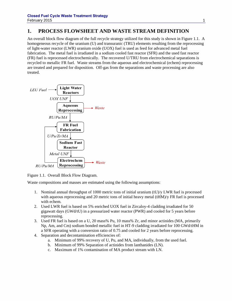
An overall block flow diagram of the full recycle strategy utilized for this study is shown in Figure 1.1. A
homogeneous recycle of the uranium (U) and transuranic (TRU) elements resulting from the reprocessing
of light-water reactor (LWR) uranium oxide (UOX) fuel is used as feed for advanced metal fuel
fabrication. The metal fuel is irradiated in a sodium cooled fast reactor (SFR) and the used fast reactor
(FR) fuel is reprocessed electrochemically. The recovered U/TRU from electrochemical separations is
recycled to metallic FR fuel. Waste streams from the aqueous and electrochemical (echem) reprocessing
are treated and prepared for disposition. Off-gas from the separations and waste processing are also
treated.
Figure 1.1. Overall Block Flow Diagram.
Waste compositions and masses are estimated using the following assumptions:
1. Nominal annual throughput of 1000 metric tons of initial uranium (tU)/y LWR fuel is processed
with aqueous reprocessing and 20 metric tons of initial heavy metal (tHM)/y FR fuel is processed
with echem.
2. Used LWR fuel is based on 5% enriched UOX fuel in Zircaloy-4 cladding irradiated for 50
gigawatt days (GWd/tU) in a pressurized water reactor (PWR) and cooled for 5 years before
reprocessing.
3. Used FR fuel is based on a U, 20 mass% Pu, 10 mass% Zr, and minor actinides (MA, primarily
Np, Am, and Cm) sodium bonded metallic fuel in HT-9 cladding irradiated for 100 GWd/tHM in
a SFR operating with a conversion ratio of 0.75 and cooled for 2 years before reprocessing.
4. Separation and decontamination efficiencies of:
a. Minimum of 99% recovery of U, Pu, and MA, individually, from the used fuel.
b. Minimum of 99% Separation of actinides from lanthanides (LN).
c. Maximum of 1% contamination of MA product stream with LN.
Closed Fuel Cycle Waste Treatment Strategy February 2015 2
1.1 Aqueous Reprocessing
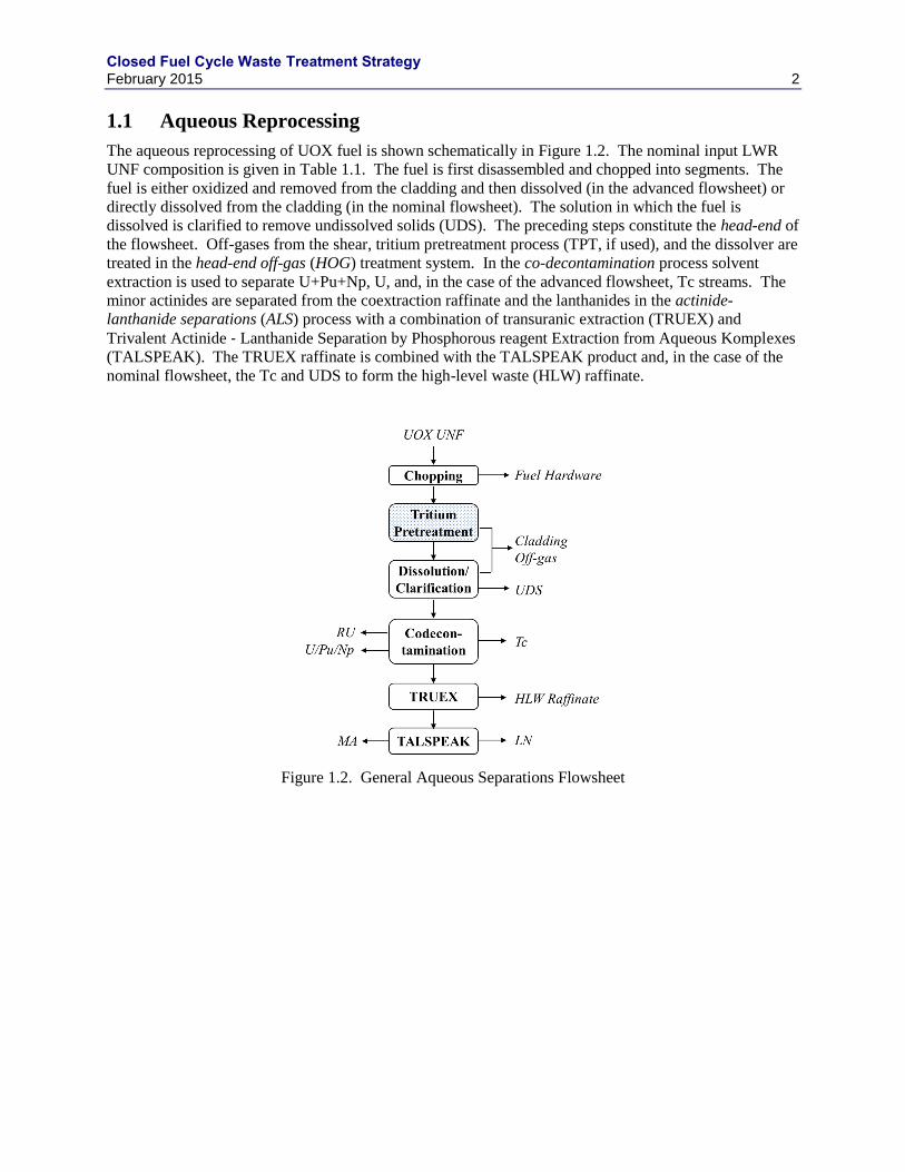
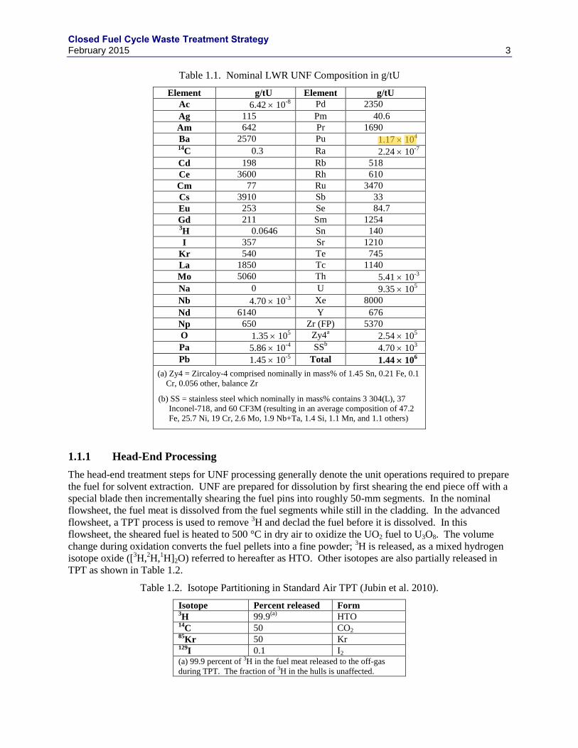
The aqueous reprocessing of UOX fuel is shown schematically in Figure 1.2. The nominal input LWR
UNF composition is given in Table 1.1. The fuel is first disassembled and chopped into segments. The
fuel is either oxidized and removed from the cladding and then dissolved (in the advanced flowsheet) or
directly dissolved from the cladding (in the nominal flowsheet). The solution in which the fuel is
dissolved is clarified to remove undissolved solids (UDS). The preceding steps constitute the head-end of
the flowsheet. Off-gases from the shear, tritium pretreatment process (TPT, if used), and the dissolver are
treated in the head-end off-gas (HOG) treatment system. In the co-decontamination process solvent
extraction is used to separate U+Pu+Np, U, and, in the case of the advanced flowsheet, Tc streams. The
minor actinides are separated from the coextraction raffinate and the lanthanides in the actinide-
lanthanide separations (ALS) process with a combination of transuranic extraction (TRUEX) and
Trivalent Actinide ‐ Lanthanide Separation by Phosphorous reagent Extraction from Aqueous Komplexes
(TALSPEAK). The TRUEX raffinate is combined with the TALSPEAK product and, in the case of the
nominal flowsheet, the Tc and UDS to form the high-level waste (HLW) raffinate.
Figure 1.2. General Aqueous Separations Flowsheet
Closed Fuel Cycle Waste Treatment Strategy February 2015 3
Table 1.1. Nominal LWR UNF Composition in g/tU
Element g/tU Element g/tU
Ac 6.42 10-8
Pd 2350
Ag 115 Pm 40.6
Am 642 Pr 1690
Ba 2570 Pu 1.17 104
14C 0.3 Ra 2.24 10
-7
Cd 198 Rb 518
Ce 3600 Rh 610
Cm 77 Ru 3470
Cs 3910 Sb 33
Eu 253 Se 84.7
Gd 211 Sm 1254 3H 0.0646 Sn 140
I 357 Sr 1210
Kr 540 Te 745
La 1850 Tc 1140
Mo 5060 Th 5.41 10-3
Na 0 U 9.35 105
Nb 4.70 10-3
Xe 8000
Nd 6140 Y 676
Np 650 Zr (FP) 5370
O 1.35 105 Zy4
a 2.54 10
5
Pa 5.86 10-4
SSb 4.70 10
3
Pb 1.45 10-5
Total 1.44 106
(a) Zy4 = Zircaloy-4 comprised nominally in mass% of 1.45 Sn, 0.21 Fe, 0.1
Cr, 0.056 other, balance Zr
(b) SS = stainless steel which nominally in mass% contains 3 304(L), 37
Inconel-718, and 60 CF3M (resulting in an average composition of 47.2
Fe, 25.7 Ni, 19 Cr, 2.6 Mo, 1.9 Nb+Ta, 1.4 Si, 1.1 Mn, and 1.1 others)
1.1.1 Head-End Processing
The head-end treatment steps for UNF processing generally denote the unit operations required to prepare
the fuel for solvent extraction. UNF are prepared for dissolution by first shearing the end piece off with a
special blade then incrementally shearing the fuel pins into roughly 50-mm segments. In the nominal
flowsheet, the fuel meat is dissolved from the fuel segments while still in the cladding. In the advanced
flowsheet, a TPT process is used to remove 3H and declad the fuel before it is dissolved. In this
flowsheet, the sheared fuel is heated to 500 °C in dry air to oxidize the UO2 fuel to U3O8. The volume
change during oxidation converts the fuel pellets into a fine powder; 3H is released, as a mixed hydrogen
isotope oxide ([3H,
2H,
1H]2O) referred to hereafter as HTO. Other isotopes are also partially released in
TPT as shown in Table 1.2.
Table 1.2. Isotope Partitioning in Standard Air TPT (Jubin et al. 2010).
Isotope Percent released Form 3H 99.9
(a) HTO
14C 50 CO2
85Kr 50 Kr
129I 0.1 I2
(a) 99.9 percent of 3H in the fuel meat released to the off-gas
during TPT. The fraction of 3H in the hulls is unaffected.
Closed Fuel Cycle Waste Treatment Strategy February 2015 4
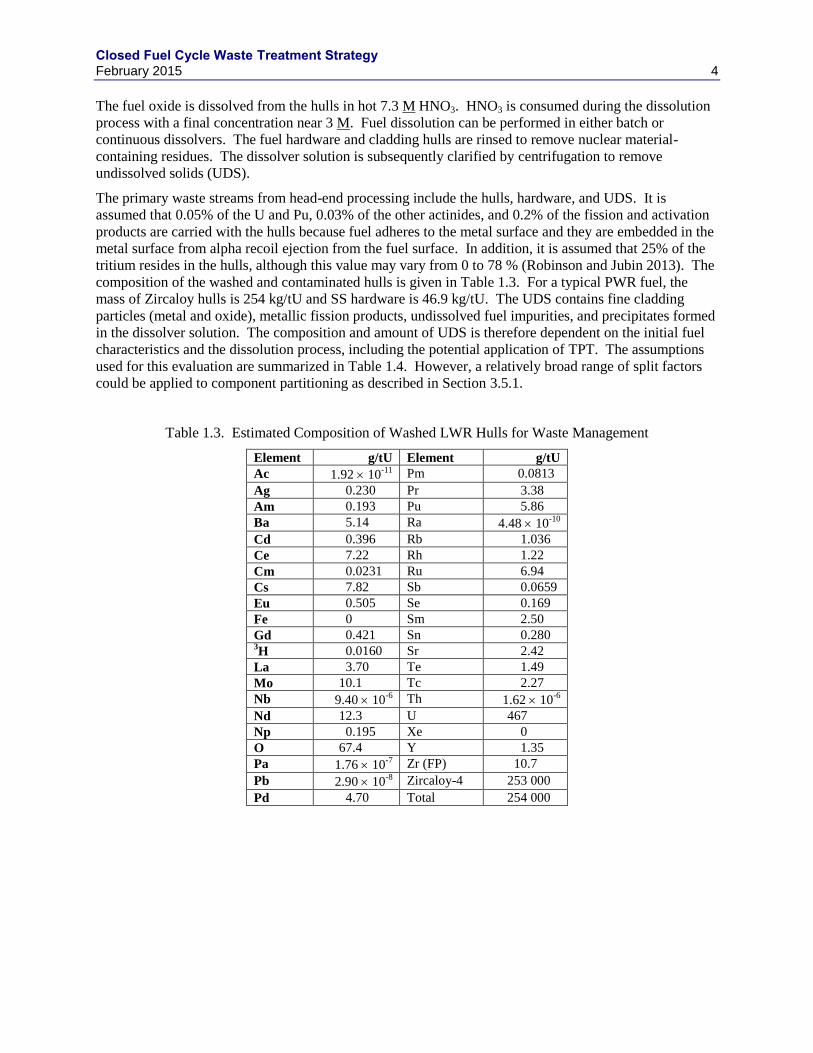
The fuel oxide is dissolved from the hulls in hot 7.3 M HNO3. HNO3 is consumed during the dissolution
process with a final concentration near 3 M. Fuel dissolution can be performed in either batch or
continuous dissolvers. The fuel hardware and cladding hulls are rinsed to remove nuclear material-
containing residues. The dissolver solution is subsequently clarified by centrifugation to remove
undissolved solids (UDS).
The primary waste streams from head-end processing include the hulls, hardware, and UDS. It is
assumed that 0.05% of the U and Pu, 0.03% of the other actinides, and 0.2% of the fission and activation
products are carried with the hulls because fuel adheres to the metal surface and they are embedded in the
metal surface from alpha recoil ejection from the fuel surface. In addition, it is assumed that 25% of the
tritium resides in the hulls, although this value may vary from 0 to 78 % (Robinson and Jubin 2013). The
composition of the washed and contaminated hulls is given in Table 1.3. For a typical PWR fuel, the
mass of Zircaloy hulls is 254 kg/tU and SS hardware is 46.9 kg/tU. The UDS contains fine cladding
particles (metal and oxide), metallic fission products, undissolved fuel impurities, and precipitates formed
in the dissolver solution. The composition and amount of UDS is therefore dependent on the initial fuel
characteristics and the dissolution process, including the potential application of TPT. The assumptions
used for this evaluation are summarized in Table 1.4. However, a relatively broad range of split factors
could be applied to component partitioning as described in Section 3.5.1.
Table 1.3. Estimated Composition of Washed LWR Hulls for Waste Management
Element g/tU Element g/tU
Ac 1.92 10-11
Pm 0.0813
Ag 0.230 Pr 3.38
Am 0.193 Pu 5.86
Ba 5.14 Ra 4.48 10-10
Cd 0.396 Rb 1.036
Ce 7.22 Rh 1.22
Cm 0.0231 Ru 6.94
Cs 7.82 Sb 0.0659
Eu 0.505 Se 0.169
Fe 0 Sm 2.50
Gd 0.421 Sn 0.280 3H 0.0160 Sr 2.42
La 3.70 Te 1.49
Mo 10.1 Tc 2.27
Nb 9.40 10-6
Th 1.62 10-6
Nd 12.3 U 467
Np 0.195 Xe 0
O 67.4 Y 1.35
Pa 1.76 10-7
Zr (FP) 10.7
Pb 2.90 10-8
Zircaloy-4 253 000
Pd 4.70 Total 254 000
Closed Fuel Cycle Waste Treatment Strategy February 2015 5
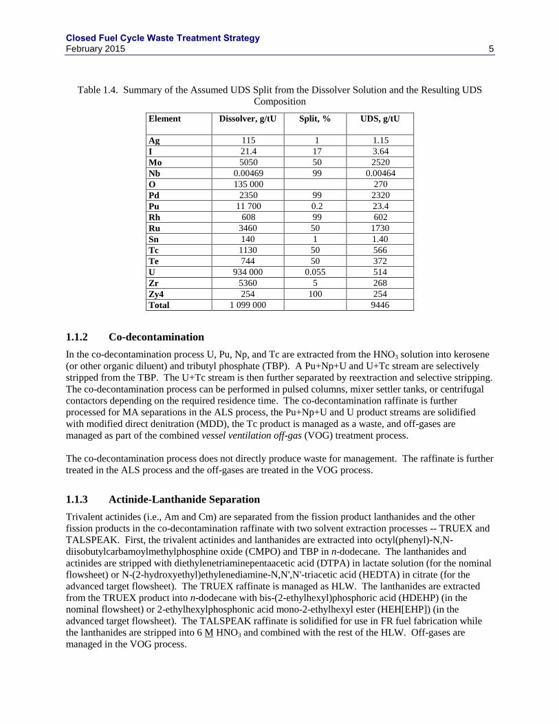
Table 1.4. Summary of the Assumed UDS Split from the Dissolver Solution and the Resulting UDS
Composition
Element Dissolver, g/tU Split, % UDS, g/tU
Ag 115 1 1.15
I 21.4 17 3.64
Mo 5050 50 2520
Nb 0.00469 99 0.00464
O 135 000 270
Pd 2350 99 2320
Pu 11 700 0.2 23.4
Rh 608 99 602
Ru 3460 50 1730
Sn 140 1 1.40
Tc 1130 50 566
Te 744 50 372
U 934 000 0.055 514
Zr 5360 5 268
Zy4 254 100 254
Total 1 099 000 9446
1.1.2 Co-decontamination
In the co-decontamination process U, Pu, Np, and Tc are extracted from the HNO3 solution into kerosene
(or other organic diluent) and tributyl phosphate (TBP). A Pu+Np+U and U+Tc stream are selectively
stripped from the TBP. The U+Tc stream is then further separated by reextraction and selective stripping.
The co-decontamination process can be performed in pulsed columns, mixer settler tanks, or centrifugal
contactors depending on the required residence time. The co-decontamination raffinate is further
processed for MA separations in the ALS process, the Pu+Np+U and U product streams are solidified
with modified direct denitration (MDD), the Tc product is managed as a waste, and off-gases are
managed as part of the combined vessel ventilation off-gas (VOG) treatment process.
The co-decontamination process does not directly produce waste for management. The raffinate is further
treated in the ALS process and the off-gases are treated in the VOG process.
1.1.3 Actinide-Lanthanide Separation
Trivalent actinides (i.e., Am and Cm) are separated from the fission product lanthanides and the other
fission products in the co-decontamination raffinate with two solvent extraction processes -- TRUEX and
TALSPEAK. First, the trivalent actinides and lanthanides are extracted into octyl(phenyl)-N,N-
diisobutylcarbamoylmethylphosphine oxide (CMPO) and TBP in n-dodecane. The lanthanides and
actinides are stripped with diethylenetriaminepentaacetic acid (DTPA) in lactate solution (for the nominal
flowsheet) or N-(2-hydroxyethyl)ethylenediamine-N,N',N'-triacetic acid (HEDTA) in citrate (for the
advanced target flowsheet). The TRUEX raffinate is managed as HLW. The lanthanides are extracted
from the TRUEX product into n-dodecane with bis-(2-ethylhexyl)phosphoric acid (HDEHP) (in the
nominal flowsheet) or 2-ethylhexylphosphonic acid mono-2-ethylhexyl ester (HEH[EHP]) (in the
advanced target flowsheet). The TALSPEAK raffinate is solidified for use in FR fuel fabrication while
the lanthanides are stripped into 6 M HNO3 and combined with the rest of the HLW. Off-gases are
managed in the VOG process.
Closed Fuel Cycle Waste Treatment Strategy February 2015 6
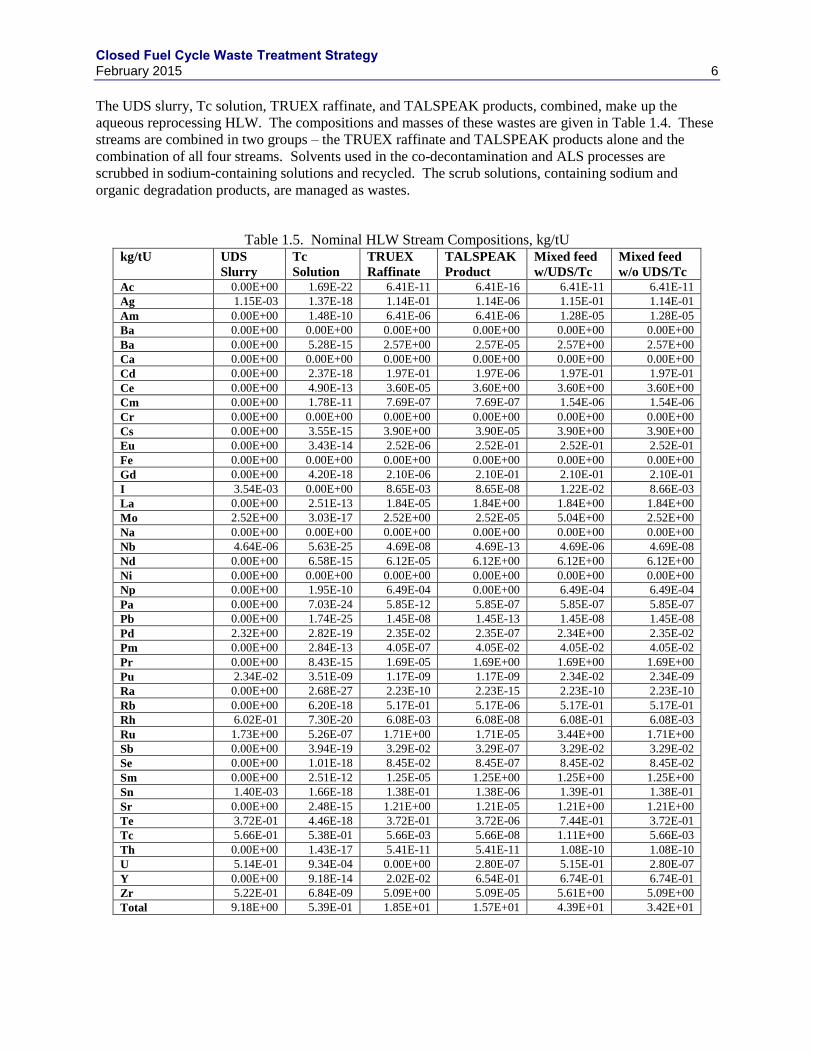
The UDS slurry, Tc solution, TRUEX raffinate, and TALSPEAK products, combined, make up the
aqueous reprocessing HLW. The compositions and masses of these wastes are given in Table 1.4. These
streams are combined in two groups – the TRUEX raffinate and TALSPEAK products alone and the
combination of all four streams. Solvents used in the co-decontamination and ALS processes are
scrubbed in sodium-containing solutions and recycled. The scrub solutions, containing sodium and
organic degradation products, are managed as wastes.
Table 1.5. Nominal HLW Stream Compositions, kg/tU kg/tU UDS
Slurry
Tc
Solution
TRUEX
Raffinate
TALSPEAK
Product
Mixed feed
w/UDS/Tc
Mixed feed
w/o UDS/Tc
Ac 0.00E+00 1.69E-22 6.41E-11 6.41E-16 6.41E-11 6.41E-11
Ag 1.15E-03 1.37E-18 1.14E-01 1.14E-06 1.15E-01 1.14E-01
Am 0.00E+00 1.48E-10 6.41E-06 6.41E-06 1.28E-05 1.28E-05
Ba 0.00E+00 0.00E+00 0.00E+00 0.00E+00 0.00E+00 0.00E+00
Ba 0.00E+00 5.28E-15 2.57E+00 2.57E-05 2.57E+00 2.57E+00
Ca 0.00E+00 0.00E+00 0.00E+00 0.00E+00 0.00E+00 0.00E+00
Cd 0.00E+00 2.37E-18 1.97E-01 1.97E-06 1.97E-01 1.97E-01
Ce 0.00E+00 4.90E-13 3.60E-05 3.60E+00 3.60E+00 3.60E+00
Cm 0.00E+00 1.78E-11 7.69E-07 7.69E-07 1.54E-06 1.54E-06
Cr 0.00E+00 0.00E+00 0.00E+00 0.00E+00 0.00E+00 0.00E+00
Cs 0.00E+00 3.55E-15 3.90E+00 3.90E-05 3.90E+00 3.90E+00
Eu 0.00E+00 3.43E-14 2.52E-06 2.52E-01 2.52E-01 2.52E-01
Fe 0.00E+00 0.00E+00 0.00E+00 0.00E+00 0.00E+00 0.00E+00
Gd 0.00E+00 4.20E-18 2.10E-06 2.10E-01 2.10E-01 2.10E-01
I 3.54E-03 0.00E+00 8.65E-03 8.65E-08 1.22E-02 8.66E-03
La 0.00E+00 2.51E-13 1.84E-05 1.84E+00 1.84E+00 1.84E+00
Mo 2.52E+00 3.03E-17 2.52E+00 2.52E-05 5.04E+00 2.52E+00
Na 0.00E+00 0.00E+00 0.00E+00 0.00E+00 0.00E+00 0.00E+00
Nb 4.64E-06 5.63E-25 4.69E-08 4.69E-13 4.69E-06 4.69E-08
Nd 0.00E+00 6.58E-15 6.12E-05 6.12E+00 6.12E+00 6.12E+00
Ni 0.00E+00 0.00E+00 0.00E+00 0.00E+00 0.00E+00 0.00E+00
Np 0.00E+00 1.95E-10 6.49E-04 0.00E+00 6.49E-04 6.49E-04
Pa 0.00E+00 7.03E-24 5.85E-12 5.85E-07 5.85E-07 5.85E-07
Pb 0.00E+00 1.74E-25 1.45E-08 1.45E-13 1.45E-08 1.45E-08
Pd 2.32E+00 2.82E-19 2.35E-02 2.35E-07 2.34E+00 2.35E-02
Pm 0.00E+00 2.84E-13 4.05E-07 4.05E-02 4.05E-02 4.05E-02
Pr 0.00E+00 8.43E-15 1.69E-05 1.69E+00 1.69E+00 1.69E+00
Pu 2.34E-02 3.51E-09 1.17E-09 1.17E-09 2.34E-02 2.34E-09
Ra 0.00E+00 2.68E-27 2.23E-10 2.23E-15 2.23E-10 2.23E-10
Rb 0.00E+00 6.20E-18 5.17E-01 5.17E-06 5.17E-01 5.17E-01
Rh 6.02E-01 7.30E-20 6.08E-03 6.08E-08 6.08E-01 6.08E-03
Ru 1.73E+00 5.26E-07 1.71E+00 1.71E-05 3.44E+00 1.71E+00
Sb 0.00E+00 3.94E-19 3.29E-02 3.29E-07 3.29E-02 3.29E-02
Se 0.00E+00 1.01E-18 8.45E-02 8.45E-07 8.45E-02 8.45E-02
Sm 0.00E+00 2.51E-12 1.25E-05 1.25E+00 1.25E+00 1.25E+00
Sn 1.40E-03 1.66E-18 1.38E-01 1.38E-06 1.39E-01 1.38E-01
Sr 0.00E+00 2.48E-15 1.21E+00 1.21E-05 1.21E+00 1.21E+00
Te 3.72E-01 4.46E-18 3.72E-01 3.72E-06 7.44E-01 3.72E-01
Tc 5.66E-01 5.38E-01 5.66E-03 5.66E-08 1.11E+00 5.66E-03
Th 0.00E+00 1.43E-17 5.41E-11 5.41E-11 1.08E-10 1.08E-10
U 5.14E-01 9.34E-04 0.00E+00 2.80E-07 5.15E-01 2.80E-07
Y 0.00E+00 9.18E-14 2.02E-02 6.54E-01 6.74E-01 6.74E-01
Zr 5.22E-01 6.84E-09 5.09E+00 5.09E-05 5.61E+00 5.09E+00
Total 9.18E+00 5.39E-01 1.85E+01 1.57E+01 4.39E+01 3.42E+01
Closed Fuel Cycle Waste Treatment Strategy February 2015 7
1.1.4 Off-Gas Treatment
Off-gas treatment systems are required to reduce the emissions from an aqueous reprocessing plant to safe
and regulatory compliant levels. Four primary off-gas treatment systems are considered: 1) dissolver off-
gas (DOG) for the nominal flowsheet or 2) combined head-end off-gas (HOG) for the advanced flowsheet
in which the dissolver and TPT off-gas (TOG) are managed; plus 3) vessel ventilation system off-gas
(VOG) and 4) HLW melter off-gas (MOG). Cell off-gas (COG) is assumed to be treated only by filtration
and isn’t specifically addressed in this section.
Off-gas decontamination factor (DF) requirements for an aqueous reprocessing facility are determined by
federal regulations 40 CFR 61 (EPA 2010a), 40 CFR 190 (EPA 2010b), and 10 CFR 20 (NRC 2012).
These regulations apply to the release of specific radionuclides and establish dose limits for the maximum
exposed individual (MEI) in the public, both in terms of whole body dose and dose to specific organs,
e.g., the thyroid (Soelberg et al. 2013). Jubin et al. (2012a) describe the application of these regulations to
a UNF reprocessing facility and derive a set of DF requirements summarized in Table 1.6 for four
volatile, radioactive off-gas components. Relatively high DFs are also required for aerosol and particulate
matter that require specific knowledge of radionuclide content to accurately determine a DF requirement
– a DF requirement of 1000 is assumed.
Table 1.6. Estimated DFs for 5- and 50-y Cooled PWR UOX Fuel Reprocessed in a 1000 tU/y Plant
Isotope HOG/DOG DFs VOG and MOG DFs
Cooling 5 y 50 y 5 y 50 y 3H 100 or 1 7 or 1 1 1
14C 10 10 1 1
85Kr 100 1 1 1 129
I 3000 3000 1000 1000
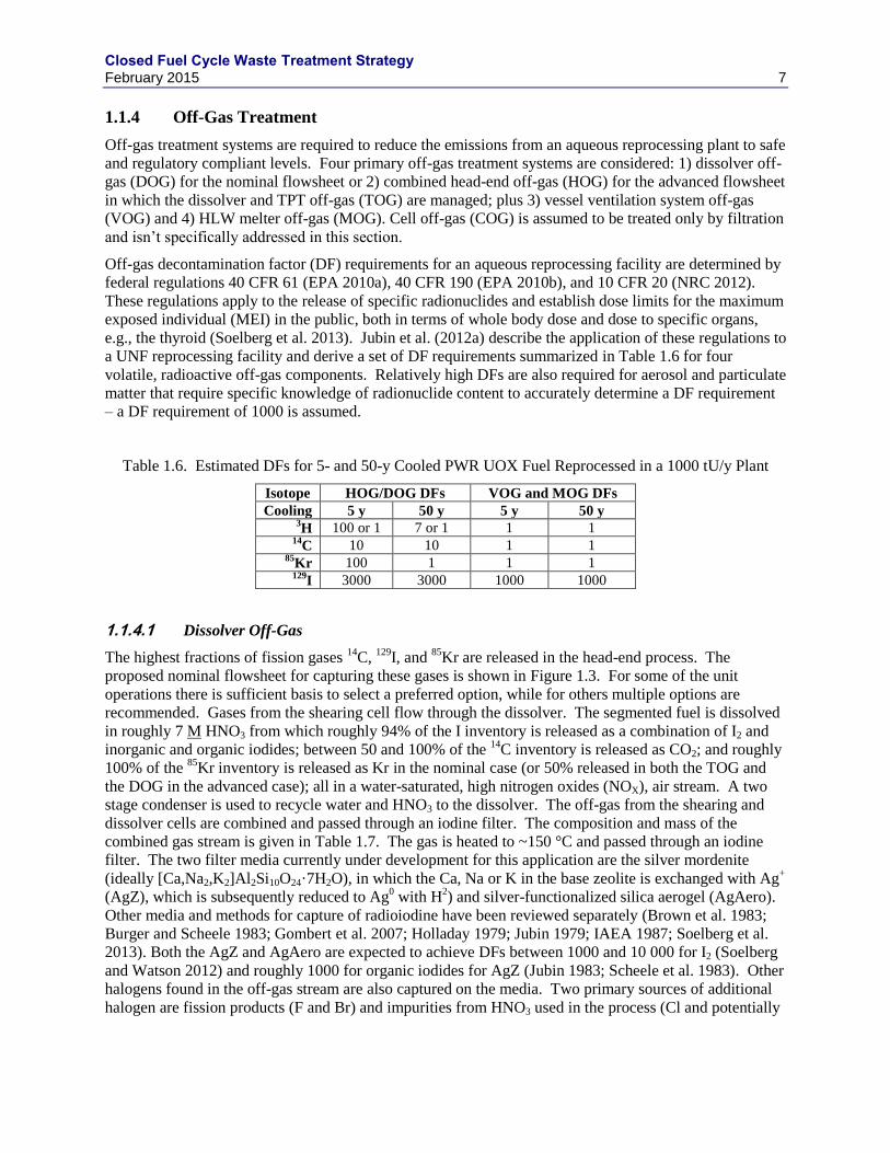
Dissolver Off-Gas 1.1.4.1
The highest fractions of fission gases 14
C, 129
I, and 85
Kr are released in the head-end process. The
proposed nominal flowsheet for capturing these gases is shown in Figure 1.3. For some of the unit
operations there is sufficient basis to select a preferred option, while for others multiple options are
recommended. Gases from the shearing cell flow through the dissolver. The segmented fuel is dissolved
in roughly 7 M HNO3 from which roughly 94% of the I inventory is released as a combination of I2 and
inorganic and organic iodides; between 50 and 100% of the 14
C inventory is released as CO2; and roughly
100% of the 85
Kr inventory is released as Kr in the nominal case (or 50% released in both the TOG and
the DOG in the advanced case); all in a water-saturated, high nitrogen oxides (NOX), air stream. A two
stage condenser is used to recycle water and HNO3 to the dissolver. The off-gas from the shearing and
dissolver cells are combined and passed through an iodine filter. The composition and mass of the
combined gas stream is given in Table 1.7. The gas is heated to ~150 °C and passed through an iodine
filter. The two filter media currently under development for this application are the silver mordenite
(ideally [Ca,Na2,K2]Al2Si10O24·7H2O), in which the Ca, Na or K in the base zeolite is exchanged with Ag+
(AgZ), which is subsequently reduced to Ag0 with H
2) and silver-functionalized silica aerogel (AgAero).
Other media and methods for capture of radioiodine have been reviewed separately (Brown et al. 1983;
Burger and Scheele 1983; Gombert et al. 2007; Holladay 1979; Jubin 1979; IAEA 1987; Soelberg et al.
2013). Both the AgZ and AgAero are expected to achieve DFs between 1000 and 10 000 for I2 (Soelberg
and Watson 2012) and roughly 1000 for organic iodides for AgZ (Jubin 1983; Scheele et al. 1983). Other
halogens found in the off-gas stream are also captured on the media. Two primary sources of additional
halogen are fission products (F and Br) and impurities from HNO3 used in the process (Cl and potentially
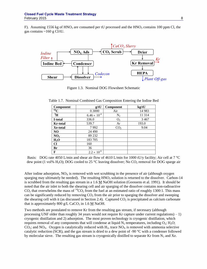
Closed Fuel Cycle Waste Treatment Strategy February 2015 8
F). Assuming 1556 kg of HNO3 are consumed per tU processed and the HNO3 contains 100 ppm Cl, the
gas contains ~160 g Cl/tU.
Figure 1.3. Nominal DOG Flowsheet Schematic
Table 1.7. Nominal Combined Gas Composition Entering the Iodine Bed
Component g/tU Component kg/tU 14
C 0.3000 Air 14 983
3H 6.46 10
-4 N2 11 314
I-total 336.0 O2 3 467
Kr-total 539.7 Ar 193.0
Xe-total 7 992 CO2 9.04
NO 24 490
NO2 89 232
H2O 183 705
Cl 160
Br 36
F 2.2 10-6
Basis: DOG rate 4050 L/min and shear air flow of 4610 L/min for 1000 tU/y facility; Air cell at 7 °C
dew point (1 vol% H2O); DOG cooled to 25 °C leaving dissolver; No CO2 removal for DOG sparge air
After iodine adsorption, NOX is removed with wet scrubbing in the presence of air (although oxygen
sparging may ultimately be needed). The resulting HNO3 solution is returned to the dissolver. Carbon-14
is scrubbed from the resulting gas stream in a 1.6 M NaOH solution (Goossens et al. 1991). It should be
noted that the air inlet to both the shearing cell and air sparging of the dissolver contains non-radioactive
CO2 that overwhelms the mass of 14
CO2 from the fuel at an estimated ratio of roughly 1300:1. This mass
can be significantly reduced by removing CO2 from the air prior to sparging the dissolver and sweeping
the shearing cell with it (as discussed in Section 2.4). Captured CO2 is precipitated as calcium carbonate
that is approximately 800 g/L CaCO3 in 1.6 M NaOH.
Two methods are postulated to remove Kr from the resulting gas stream, if necessary (although
processing UNF older than roughly 34 years would not require Kr capture under current regulations) – 1)
cryogenic distillation and 2) adsorption. The most proven technology is cryogenic distillation, which
requires removal of any components that will condense at liquid N2 temperatures, including O2; H2O;
CO2; and NOX. Oxygen is catalytically reduced with H2, trace NOX is removed with ammonia selective
catalytic reduction (SCR), and the gas stream is dried to a dew point of -90 °C with a condenser followed
by molecular sieve. The resulting gas stream is cryogenically distilled to separate Kr from N2 and Xe.
Closed Fuel Cycle Waste Treatment Strategy February 2015 9
The Kr gas stream contains 99.9% of the Kr from the fuel in a mixture of 80 vol% Kr, 10 vol% Xe, and
10 vol% H2 (from O2 removal).
In the adsorption process, Xe is first removed with a bed of AgZ or a metal organic framework (MOF).
The Kr is then captured with either a hydrogen mordenite (HZ) bed operated at -80 °C to -150 °C
(Gombert et al. 2007) or on a MOF at 0 °C to -40 °C (Thallapally et al. 2013; Thallapally and Strachan
2012). The lower temperature method still requires drying, but neither approach requires CO2, NOx, or
O2 removal. Generally, lower temperatures achieve higher loading and smaller beds. It is assumed that
95% of the Xe is removed in the first bed and 5% of the Xe and 99.9% of the Kr is removed in the second
bed.
The resulting gas is released to the plant off-gas management system where it is combined with other
process gases, filtered, and released through the facility exhaust stack.
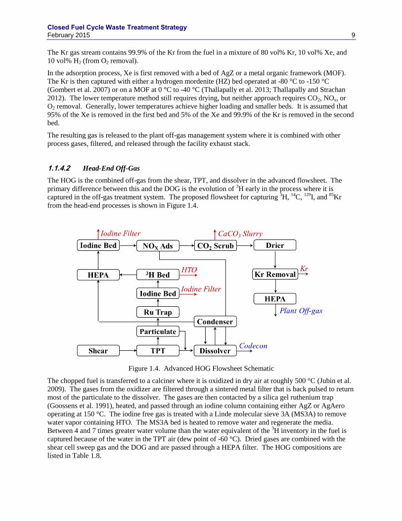
Head-End Off-Gas 1.1.4.2
The HOG is the combined off-gas from the shear, TPT, and dissolver in the advanced flowsheet. The
primary difference between this and the DOG is the evolution of 3H early in the process where it is
captured in the off-gas treatment system. The proposed flowsheet for capturing 3H,
14C,
129I, and
85Kr
from the head-end processes is shown in Figure 1.4.
Figure 1.4. Advanced HOG Flowsheet Schematic
The chopped fuel is transferred to a calciner where it is oxidized in dry air at roughly 500 °C (Jubin et al.
2009). The gases from the oxidizer are filtered through a sintered metal filter that is back pulsed to return
most of the particulate to the dissolver. The gases are then contacted by a silica gel ruthenium trap
(Goossens et al. 1991), heated, and passed through an iodine column containing either AgZ or AgAero
operating at 150 °C. The iodine free gas is treated with a Linde molecular sieve 3A (MS3A) to remove
water vapor containing HTO. The MS3A bed is heated to remove water and regenerate the media.
Between 4 and 7 times greater water volume than the water equivalent of the 3H inventory in the fuel is
captured because of the water in the TPT air (dew point of -60 °C). Dried gases are combined with the
shear cell sweep gas and the DOG and are passed through a HEPA filter. The HOG compositions are
listed in Table 1.8.
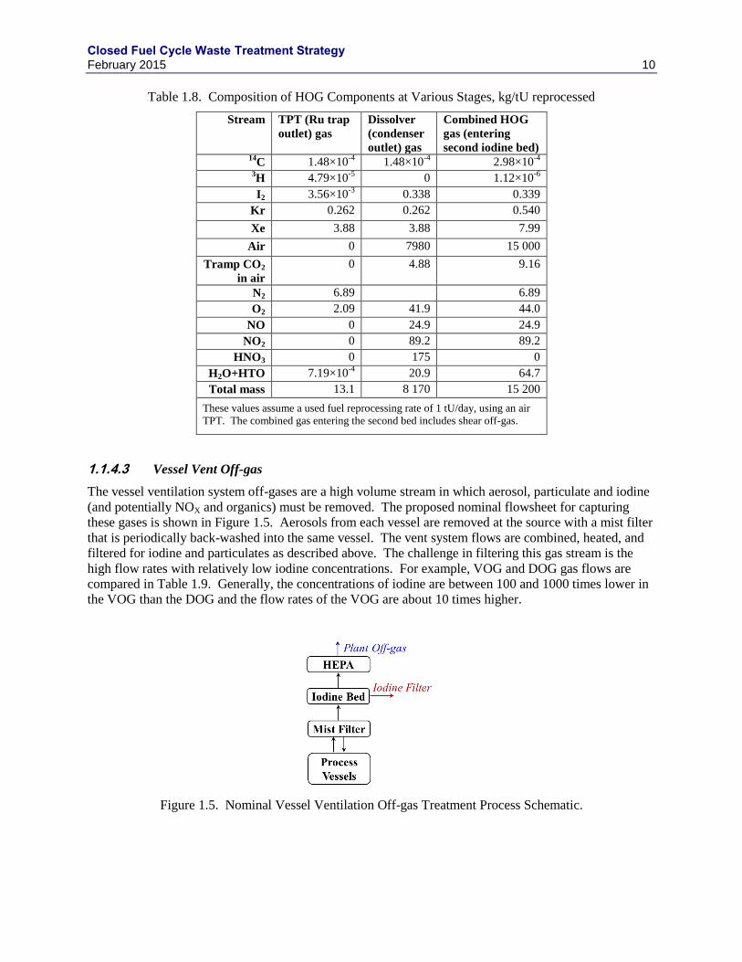
Closed Fuel Cycle Waste Treatment Strategy February 2015 10
Table 1.8. Composition of HOG Components at Various Stages, kg/tU reprocessed
Stream TPT (Ru trap
outlet) gas
Dissolver
(condenser
outlet) gas
Combined HOG
gas (entering
second iodine bed) 14
C 1.48×10⁻⁴
1.48×10⁻⁴
2.98×10⁻⁴
3H 4.79×10
-5 0 1.12×10
-6
I2 3.56×10⁻³
0.338 0.339
Kr 0.262 0.262 0.540
Xe 3.88 3.88 7.99
Air 0 7980 15 000
Tramp CO2
in air
0 4.88 9.16
N2 6.89 6.89
O2 2.09 41.9 44.0
NO 0 24.9 24.9
NO2 0 89.2 89.2
HNO3 0 175 0
H2O+HTO 7.19×10⁻⁴
20.9 64.7
Total mass 13.1 8 170 15 200
These values assume a used fuel reprocessing rate of 1 tU/day, using an air
TPT. The combined gas entering the second bed includes shear off-gas.
Vessel Vent Off-gas 1.1.4.3
The vessel ventilation system off-gases are a high volume stream in which aerosol, particulate and iodine
(and potentially NOX and organics) must be removed. The proposed nominal flowsheet for capturing
these gases is shown in Figure 1.5. Aerosols from each vessel are removed at the source with a mist filter
that is periodically back-washed into the same vessel. The vent system flows are combined, heated, and
filtered for iodine and particulates as described above. The challenge in filtering this gas stream is the
high flow rates with relatively low iodine concentrations. For example, VOG and DOG gas flows are
compared in Table 1.9. Generally, the concentrations of iodine are between 100 and 1000 times lower in
the VOG than the DOG and the flow rates of the VOG are about 10 times higher.
Figure 1.5. Nominal Vessel Ventilation Off-gas Treatment Process Schematic.
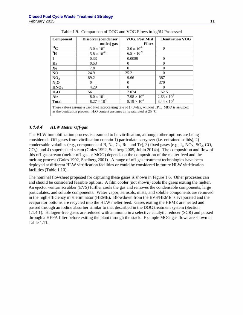
Closed Fuel Cycle Waste Treatment Strategy February 2015 11
Table 1.9. Comparison of DOG and VOG Flows in kg/tU Processed
Component Dissolver (condenser
outlet) gas
VOG, Post Mist
Filter
Denitration VOG
14C 3.0 10
-4 3.0 10
-8 0
3H 5.8 10
-11 6.5 × 10
-9
I 0.33 0.0089 0
Kr 0.53 0 0
Xe 7.8 0 0
NO 24.9 25.2 0
NO2 89.2 9.66 387
N2O 0 0 370
HNO3 4.29 0 0
H2O 156 2 074 52.5
Air 8.0 × 10³ 7.98 × 10
4 2.63 x 10
3
Total 8.27 × 10³ 8.19 × 10
4 3.44 x 10
3
These values assume a used fuel reprocessing rate of 1 tU/day, without TPT. MDD is assumed
as the denitration process. H2O content assumes air is saturated at 25 °C.
HLW Melter Off-gas 1.1.4.4
The HLW immobilization process is assumed to be vitrification, although other options are being
considered. Off-gases from vitrification contain 1) particulate carryover (i.e. entrained solids), 2)
condensable volatiles (e.g., compounds of B, Na, Cs, Ru, and Tc), 3) fixed gases (e.g., I2, NOX, SO2, CO,
CO2), and 4) superheated steam (Goles 1992, Soelberg 2009, Jubin 2014a). The composition and flow of
this off-gas stream (melter off-gas or MOG) depends on the composition of the melter feed and the
melting process (Goles 1992, Soelberg 2001). A range of off-gas treatment technologies have been
deployed at different HLW vitrification facilities or could be considered in future HLW vitrification
facilities (Table 1.10).
The nominal flowsheet proposed for capturing these gases is shown in Figure 1.6. Other processes can
and should be considered feasible options. A film cooler (not shown) cools the gases exiting the melter.
An ejector venturi scrubber (EVS) further cools the gas and removes the condensable components, large
particulates, and soluble components. Water vapor, aerosols, mists, and soluble components are removed
in the high efficiency mist eliminator (HEME). Blowdown from the EVS/HEME is evaporated and the
evaporator bottoms are recycled into the HLW melter feed. Gases exiting the HEME are heated and
passed through an iodine absorber similar to that described in the DOG treatment system (Section
1.1.4.1). Halogen-free gases are reduced with ammonia in a selective catalytic reducer (SCR) and passed
through a HEPA filter before exiting the plant through the stack. Example MOG gas flows are shown in
Table 1.11.
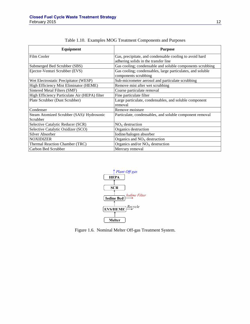
Closed Fuel Cycle Waste Treatment Strategy February 2015 12
Table 1.10. Examples MOG Treatment Components and Purposes
Equipment Purpose
Film Cooler Gas, precipitate, and condensable cooling to avoid hard
adhering solids in the transfer line
Submerged Bed Scrubber (SBS) Gas cooling; condensable and soluble components scrubbing
Ejector-Venturi Scrubber (EVS) Gas cooling; condensables, large particulates, and soluble
components scrubbing
Wet Electrostatic Precipitator (WESP) Sub-micrometer aerosol and particulate scrubbing
High Efficiency Mist Eliminator (HEME) Remove mist after wet scrubbing
Sintered Metal Filters (SMF) Coarse particulate removal
High Efficiency Particulate Air (HEPA) filter Fine particulate filter
Plate Scrubber (Dust Scrubber) Large particulate, condensables, and soluble component
removal
Condenser Remove moisture
Steam Atomized Scrubber (SAS)/ Hydrosonic
Scrubber
Particulate, condensables, and soluble component removal
Selective Catalytic Reducer (SCR) NOX destruction
Selective Catalytic Oxidizer (SCO) Organics destruction
Silver Absorber Iodine/halogen absorber
NOXIDIZER Organics and NOX destruction
Thermal Reaction Chamber (TRC) Organics and/or NOX destruction
Carbon Bed Scrubber Mercury removal
Figure 1.6. Nominal Melter Off-gas Treatment System.
Closed Fuel Cycle Waste Treatment Strategy February 2015 13
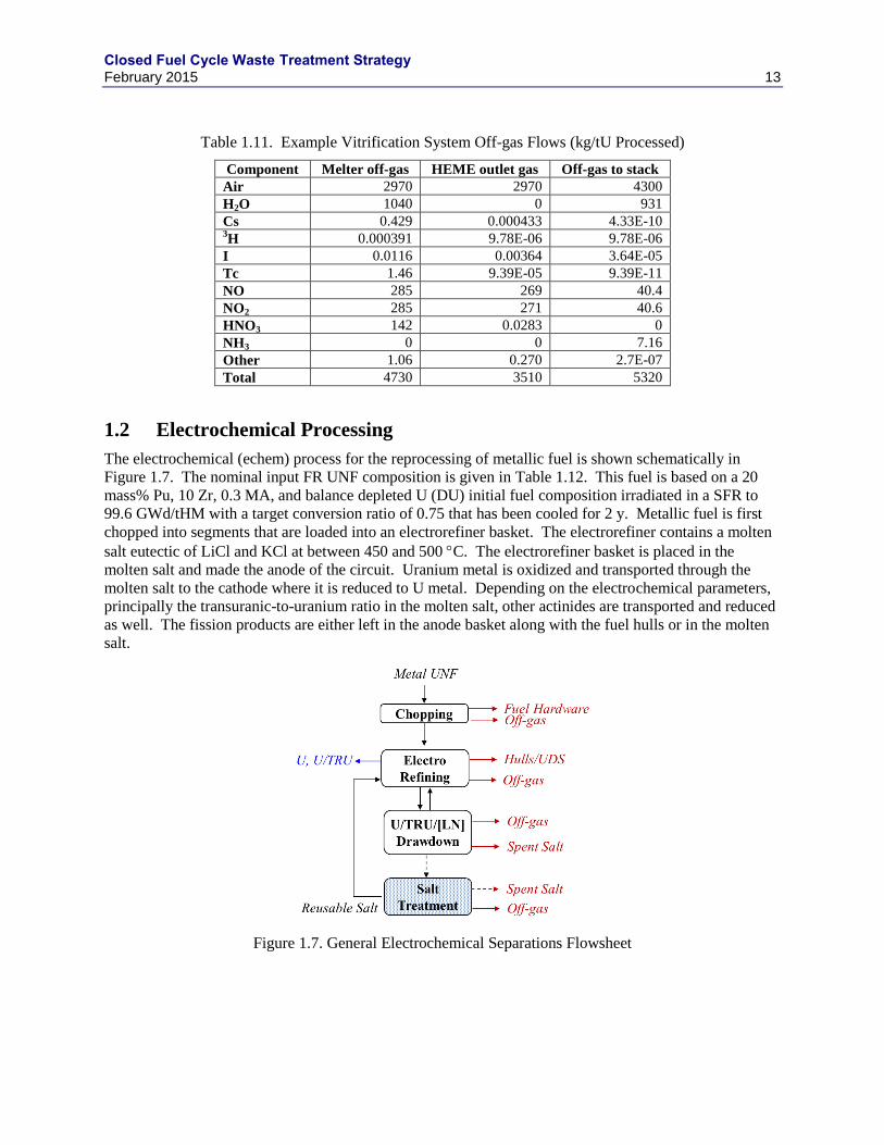
Table 1.11. Example Vitrification System Off-gas Flows (kg/tU Processed)
Component Melter off-gas HEME outlet gas Off-gas to stack
Air 2970 2970 4300
H2O 1040 0 931
Cs 0.429 0.000433 4.33E-10 3H 0.000391 9.78E-06 9.78E-06
I 0.0116 0.00364 3.64E-05
Tc 1.46 9.39E-05 9.39E-11
NO 285 269 40.4
NO2 285 271 40.6
HNO3 142 0.0283 0
NH3 0 0 7.16
Other 1.06 0.270 2.7E-07
Total 4730 3510 5320
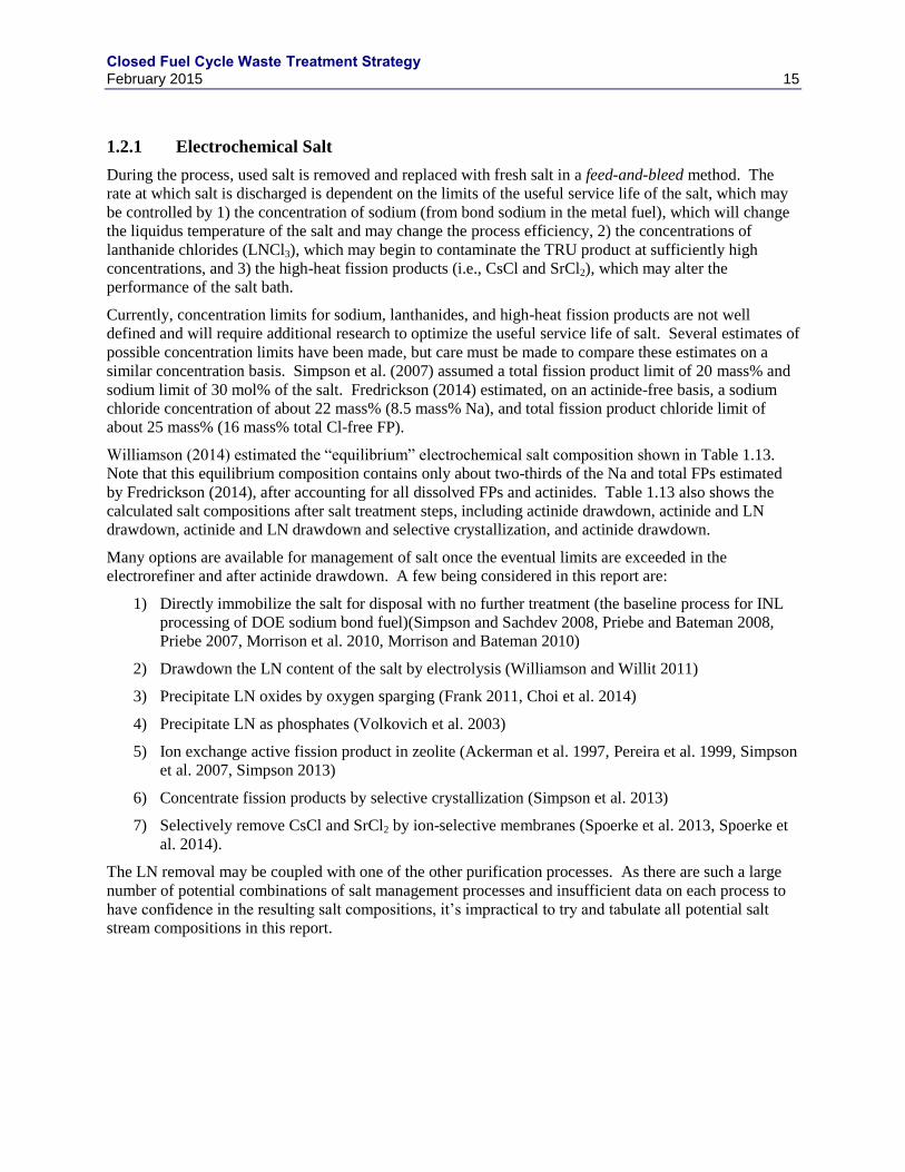
1.2 Electrochemical Processing
The electrochemical (echem) process for the reprocessing of metallic fuel is shown schematically in
Figure 1.7. The nominal input FR UNF composition is given in Table 1.12. This fuel is based on a 20
mass% Pu, 10 Zr, 0.3 MA, and balance depleted U (DU) initial fuel composition irradiated in a SFR to
99.6 GWd/tHM with a target conversion ratio of 0.75 that has been cooled for 2 y. Metallic fuel is first
chopped into segments that are loaded into an electrorefiner basket. The electrorefiner contains a molten
salt eutectic of LiCl and KCl at between 450 and 500 C. The electrorefiner basket is placed in the
molten salt and made the anode of the circuit. Uranium metal is oxidized and transported through the
molten salt to the cathode where it is reduced to U metal. Depending on the electrochemical parameters,
principally the transuranic-to-uranium ratio in the molten salt, other actinides are transported and reduced
as well. The fission products are either left in the anode basket along with the fuel hulls or in the molten
salt.
Figure 1.7. General Electrochemical Separations Flowsheet
Closed Fuel Cycle Waste Treatment Strategy February 2015 14
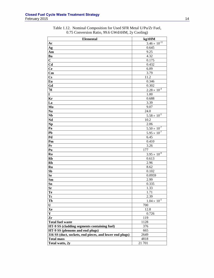
Table 1.12. Nominal Composition for Used SFR Metal U/Pu/Zr Fuel,
0.75 Conversion Ratio, 99.6 GWd/tHM, 2y Cooling)
Elemental kg/tHM
Ac 3.46 10-11
Ag 0.645
Am 9.25
Ba 4.32
C 0.175
Cd 0.432
Ce 6.09
Cm 3.79
Cs 11.2
Eu 0.346
Gd 0.302 3H 2.28 10
-4
I 1.00
Kr 0.688
La 3.39
Mo 9.07
Na 24.0
Nb 5.58 10-5
Nd 10.2
Np 2.06
Pa 5.50 10-7
Pb 5.95 10-7
Pd 6.45
Pm 0.410
Pr 3.26
Pu 177
Ra 3.95 10-9
Rb 0.613
Rh 2.96
Ru 8.62
Sb 0.102
Se 0.0959
Sm 2.99
Sn 0.335
Sr 1.33
Te 1.71
Tc 2.39
Th 1.04 10-5
U 700
Xe 12.8
Y 0.726
Zr 119
Total fuel waste 1128
HT-9 SS (cladding segments containing fuel) 376
HT-9 SS (plenums and end plugs) 665
316 SS (duct, sockets, end pieces, and lower end plugs) 2649
Total mass 4818
Total watts, 2y 21 701
Closed Fuel Cycle Waste Treatment Strategy February 2015 15
1.2.1 Electrochemical Salt
During the process, used salt is removed and replaced with fresh salt in a feed-and-bleed method. The
rate at which salt is discharged is dependent on the limits of the useful service life of the salt, which may
be controlled by 1) the concentration of sodium (from bond sodium in the metal fuel), which will change
the liquidus temperature of the salt and may change the process efficiency, 2) the concentrations of
lanthanide chlorides (LNCl3), which may begin to contaminate the TRU product at sufficiently high
concentrations, and 3) the high-heat fission products (i.e., CsCl and SrCl2), which may alter the
performance of the salt bath.
Currently, concentration limits for sodium, lanthanides, and high-heat fission products are not well
defined and will require additional research to optimize the useful service life of salt. Several estimates of
possible concentration limits have been made, but care must be made to compare these estimates on a
similar concentration basis. Simpson et al. (2007) assumed a total fission product limit of 20 mass% and
sodium limit of 30 mol% of the salt. Fredrickson (2014) estimated, on an actinide-free basis, a sodium
chloride concentration of about 22 mass% (8.5 mass% Na), and total fission product chloride limit of
about 25 mass% (16 mass% total Cl-free FP).
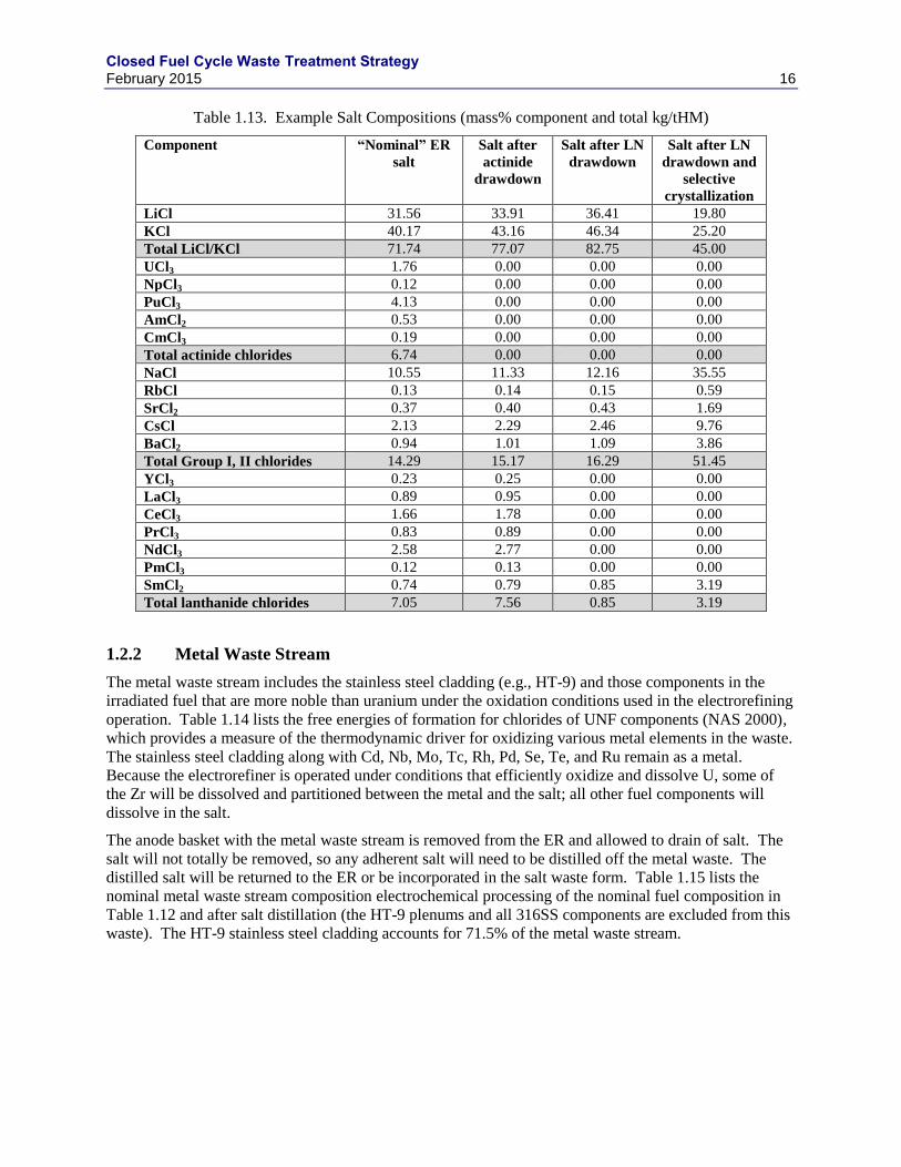
Williamson (2014) estimated the “equilibrium” electrochemical salt composition shown in Table 1.13.
Note that this equilibrium composition contains only about two-thirds of the Na and total FPs estimated
by Fredrickson (2014), after accounting for all dissolved FPs and actinides. Table 1.13 also shows the
calculated salt compositions after salt treatment steps, including actinide drawdown, actinide and LN
drawdown, actinide and LN drawdown and selective crystallization, and actinide drawdown.
Many options are available for management of salt once the eventual limits are exceeded in the
electrorefiner and after actinide drawdown. A few being considered in this report are:
1) Directly immobilize the salt for disposal with no further treatment (the baseline process for INL
processing of DOE sodium bond fuel)(Simpson and Sachdev 2008, Priebe and Bateman 2008,
Priebe 2007, Morrison et al. 2010, Morrison and Bateman 2010)
2) Drawdown the LN content of the salt by electrolysis (Williamson and Willit 2011)
3) Precipitate LN oxides by oxygen sparging (Frank 2011, Choi et al. 2014)
4) Precipitate LN as phosphates (Volkovich et al. 2003)
5) Ion exchange active fission product in zeolite (Ackerman et al. 1997, Pereira et al. 1999, Simpson
et al. 2007, Simpson 2013)
6) Concentrate fission products by selective crystallization (Simpson et al. 2013)
7) Selectively remove CsCl and SrCl2 by ion-selective membranes (Spoerke et al. 2013, Spoerke et
al. 2014).
The LN removal may be coupled with one of the other purification processes. As there are such a large
number of potential combinations of salt management processes and insufficient data on each process to
have confidence in the resulting salt compositions, it’s impractical to try and tabulate all potential salt
stream compositions in this report.
Closed Fuel Cycle Waste Treatment Strategy February 2015 16
Table 1.13. Example Salt Compositions (mass% component and total kg/tHM)
Component “Nominal” ER
salt
Salt after
actinide
drawdown
Salt after LN
drawdown
Salt after LN
drawdown and
selective
crystallization
LiCl 31.56 33.91 36.41 19.80
KCl 40.17 43.16 46.34 25.20
Total LiCl/KCl 71.74 77.07 82.75 45.00
UCl3 1.76 0.00 0.00 0.00
NpCl3 0.12 0.00 0.00 0.00
PuCl3 4.13 0.00 0.00 0.00
AmCl2 0.53 0.00 0.00 0.00
CmCl3 0.19 0.00 0.00 0.00
Total actinide chlorides 6.74 0.00 0.00 0.00
NaCl 10.55 11.33 12.16 35.55
RbCl 0.13 0.14 0.15 0.59
SrCl2 0.37 0.40 0.43 1.69
CsCl 2.13 2.29 2.46 9.76
BaCl2 0.94 1.01 1.09 3.86
Total Group I, II chlorides 14.29 15.17 16.29 51.45
YCl3 0.23 0.25 0.00 0.00
LaCl3 0.89 0.95 0.00 0.00
CeCl3 1.66 1.78 0.00 0.00
PrCl3 0.83 0.89 0.00 0.00
NdCl3 2.58 2.77 0.00 0.00
PmCl3 0.12 0.13 0.00 0.00
SmCl2 0.74 0.79 0.85 3.19
Total lanthanide chlorides 7.05 7.56 0.85 3.19
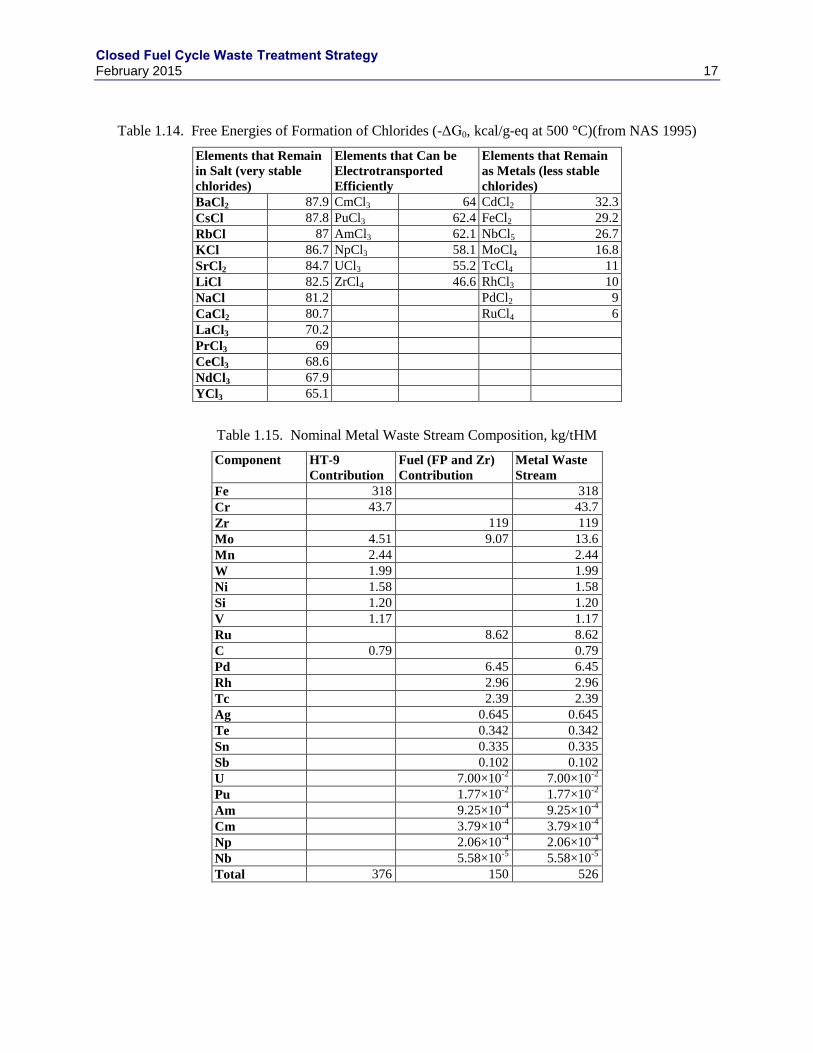
1.2.2 Metal Waste Stream
The metal waste stream includes the stainless steel cladding (e.g., HT-9) and those components in the
irradiated fuel that are more noble than uranium under the oxidation conditions used in the electrorefining
operation. Table 1.14 lists the free energies of formation for chlorides of UNF components (NAS 2000),
which provides a measure of the thermodynamic driver for oxidizing various metal elements in the waste.
The stainless steel cladding along with Cd, Nb, Mo, Tc, Rh, Pd, Se, Te, and Ru remain as a metal.
Because the electrorefiner is operated under conditions that efficiently oxidize and dissolve U, some of
the Zr will be dissolved and partitioned between the metal and the salt; all other fuel components will
dissolve in the salt.
The anode basket with the metal waste stream is removed from the ER and allowed to drain of salt. The
salt will not totally be removed, so any adherent salt will need to be distilled off the metal waste. The
distilled salt will be returned to the ER or be incorporated in the salt waste form. Table 1.15 lists the
nominal metal waste stream composition electrochemical processing of the nominal fuel composition in
Table 1.12 and after salt distillation (the HT-9 plenums and all 316SS components are excluded from this
waste). The HT-9 stainless steel cladding accounts for 71.5% of the metal waste stream.
Closed Fuel Cycle Waste Treatment Strategy February 2015 17
Table 1.14. Free Energies of Formation of Chlorides (-ΔG0, kcal/g-eq at 500 °C)(from NAS 1995)
Elements that Remain
in Salt (very stable
chlorides)
Elements that Can be
Electrotransported
Efficiently
Elements that Remain
as Metals (less stable
chlorides)
BaCl2 87.9 CmCl3 64 CdCl2 32.3
CsCl 87.8 PuCl3 62.4 FeCl2 29.2
RbCl 87 AmCl3 62.1 NbCl5 26.7
KCl 86.7 NpCl3 58.1 MoCl4 16.8
SrCl2 84.7 UCl3 55.2 TcCl4 11
LiCl 82.5 ZrCl4 46.6 RhCl3 10
NaCl 81.2 PdCl2 9
CaCl2 80.7 RuCl4 6
LaCl3 70.2
PrCl3 69
CeCl3 68.6
NdCl3 67.9
YCl3 65.1
Table 1.15. Nominal Metal Waste Stream Composition, kg/tHM
Component HT-9
Contribution
Fuel (FP and Zr)
Contribution
Metal Waste
Stream
Fe 318 318
Cr 43.7 43.7
Zr 119 119
Mo 4.51 9.07 13.6
Mn 2.44 2.44
W 1.99 1.99
Ni 1.58 1.58
Si 1.20 1.20
V 1.17 1.17
Ru 8.62 8.62
C 0.79 0.79
Pd 6.45 6.45
Rh 2.96 2.96
Tc 2.39 2.39
Ag 0.645 0.645
Te 0.342 0.342
Sn 0.335 0.335
Sb 0.102 0.102
U 7.00×10⁻²
7.00×10⁻²
Pu 1.77×10⁻²
1.77×10⁻²
Am 9.25×10⁻⁴
9.25×10⁻⁴
Cm 3.79×10⁻⁴
3.79×10⁻⁴
Np 2.06×10⁻⁴
2.06×10⁻⁴
Nb 5.58×10⁻⁵
5.58×10⁻⁵
Total 376 150 526
Closed Fuel Cycle Waste Treatment Strategy February 2015 18
1.2.3 Electrochemical Process Off-Gas
The requirements to manage the volatile radionuclides will be the same for the echem process as for the
aqueous-based processes. However, the bulk of the iodine is expected to remain in the salt and not
volatilize to the cell. The requirements for krypton capture imposed by 40 CFR 190 will require similar
decontamination factors as described in Section 1.1.4. The current design of the processing equipment
allows the release of volatile components to the cell atmosphere. This release then requires the treatment
of a slip stream from the cell gas to be processed. It is assumed that the cell atmosphere is argon. Similar
approaches to the recovery of krypton should be viable for this application. These include cryogenic
recovery of krypton and the use of solid sorbents. Detailed descriptions of these Kr recovery processes
are presented in Section 2.3 and are not repeated here. The concentration of Kr in the cell atmosphere
will be a function of the processing rate of the slipstream and the rate of fuel processed. Based on the
boiling points and melting points of the elements of interest, it would appear that cryogenic recovery
processes would be comparable to those for Kr recovery from a nitrogen stream. The cryogenic recovery
of krypton from the argon cell atmosphere would not require the catalytic removal of oxygen as is the
case with krypton recovery from an air stream. A Kr DF of 100 is assumed. The Kr recovery technology
may require some adaptation for argon cells to account for large amount of Ar compared to the Kr in the
slip stream.
The amount of 3H in the fuel is uncertain. Significant fractions of the
3H generated from ternary fission
are known to be released during reactor operation. It is assumed that recovery of 3H released to the cell
would be required and would be comparable to the recovery of 3H from the TPT. This would involve the
catalytic oxidation of 3H to
3H2O by the addition of oxygen to a small slipstream that is recycled back to
the cell. The system should be designed for a DF of 100. The tritiated water is captured on a MS3A and
managed as described in Section 7.2.
Unpublished studies of the mark-IV ER operation have shown that iodine is very stable in the ER salt.
However, the metal drawdown processes for actinides and potentially lanthanides will evolve Cl2 gas.
Chlorine gas evolved during these processes is captured in a getter and discharged as waste. It is possible
that I2 gas will also be liberated by these processes. Any I2 evolved during the process would also be
collected in the Cl2 scrubber system and discarded as waste. It is suspected that I2 would be released
proportionally to that of the Cl2. The overall I2 DF for the plant will need to be between 1000 and 3000.
The fraction retained in the salt will reduce the demand on the getter system.
Carbon-14 is not believed to be an issue as it will either partition to the salt phase or remain with the
noble metals.
Closed Fuel Cycle Waste Treatment Strategy February 2015 19
2. OFF-GAS TREATMENT WASTE STREAMS
During the processing of used fuel, volatile radionuclides need to be captured and managed so that facility
discharges do not exceed regulatory limits during normal operation and predictable off-normal events.
The volatile radionuclides of concern are 3H,
14C,
85Kr, and
129I. The chemical and physical form,
impurity concentrations, and specific handling requirements of the volatile waste streams are directly
determined by the capture methods deployed. Therefore, component capture and waste management are
considered in a holistic fashion for the four primary volatile radionuclides. Off-gas treatment systems and
volatile waste management approaches have been systematically evaluated in support of the GNEP
program (Gombert et al. 2007 and 2008; AFCF 2007; CFTC 2008). The evaluations include process
selection, equipment selection and scaling, waste form generation rate estimates, capital and operating
cost estimates, and descriptions of the state of technology development/demonstration and associated
technical gaps. Since those evaluations, significant additional research and analyses have been
conducted. This research includes the filling of technical gaps as well as the initial development of
innovative approaches that show some promise to perform better than the baseline approaches selected for
GNEP. In this section, the conclusions of the GNEP program studies are summarized with the results of
research performed since those studies; and reference waste management strategies are recommended and
current technology gaps for further research are summarized.
The off-gas treatment and waste management technologies discussed in the sections that follow are based
on the separations processes described in Sections 1.1 and 1.2, above.
2.1 Tritium
Tritium is generated in LWR fuel from ternary fission and activation of 2H and
10B in cooling water (a
fraction of which is contained in the hulls as zirconium hydride). The reference volatile gas source terms
are based on ORIGEN (Croff 1983) data for PWR fuel at a burn-up of 50 GWd/tHM. It should be noted
that BWR fuel may contain higher concentrations of 3H. The half-life of
3H is sufficiently small (12.26 y)
that the inventory is highly dependent on cooling time as shown in Figure 2.1, but for cooling times less
than roughly 70 years, controls are needed.
Tritium is not captured nor treated with current generation reprocessing plants (aqueous methods
practiced commercially and electro-chemical methods practiced at INL). Tritium is currently released to
the environment via atmospheric or waste water discharges. Direct discharge of 3H is not anticipated to
be an appropriate disposition path for a U.S. reprocessing plant (Jubin et al. 2013). The DF requirement
for tritium ranges from roughly 100 at 5 y cooling to roughly 7 at 50 y cooling to 1 at roughly 70 y
cooling (Jubin et al. 2012b). Likewise, the 3H waste form, assuming
3H is the only radionuclide of
concern in the waste form, needs to be protective of the environment for only 70 y. Tritium in zirconium-
clad LWR fuel is found split between the fuel meat and the cladding. The fraction contained in the
cladding may range from 0 to 78% (Robinson and Jubin 2013). In the case where the cladding is not
treated, only the fraction in the fuel meat must be managed.
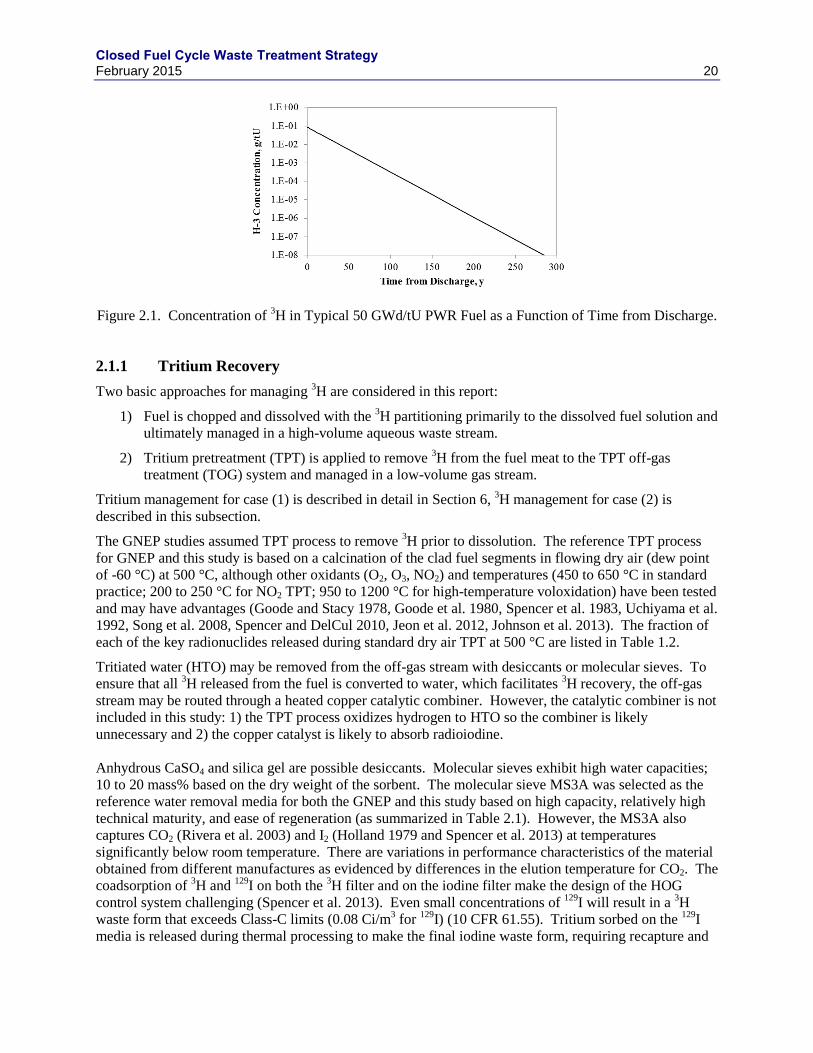
Closed Fuel Cycle Waste Treatment Strategy February 2015 20
Figure 2.1. Concentration of 3H in Typical 50 GWd/tU PWR Fuel as a Function of Time from Discharge.
2.1.1 Tritium Recovery
Two basic approaches for managing 3H are considered in this report:
1) Fuel is chopped and dissolved with the 3H partitioning primarily to the dissolved fuel solution and
ultimately managed in a high-volume aqueous waste stream.
2) Tritium pretreatment (TPT) is applied to remove 3H from the fuel meat to the TPT off-gas
treatment (TOG) system and managed in a low-volume gas stream.
Tritium management for case (1) is described in detail in Section 6, 3H management for case (2) is
described in this subsection.
The GNEP studies assumed TPT process to remove 3H prior to dissolution. The reference TPT process
for GNEP and this study is based on a calcination of the clad fuel segments in flowing dry air (dew point
of -60 °C) at 500 °C, although other oxidants (O2, O3, NO2) and temperatures (450 to 650 °C in standard
practice; 200 to 250 °C for NO2 TPT; 950 to 1200 °C for high-temperature voloxidation) have been tested
and may have advantages (Goode and Stacy 1978, Goode et al. 1980, Spencer et al. 1983, Uchiyama et al.
1992, Song et al. 2008, Spencer and DelCul 2010, Jeon et al. 2012, Johnson et al. 2013). The fraction of
each of the key radionuclides released during standard dry air TPT at 500 °C are listed in Table 1.2.
Tritiated water (HTO) may be removed from the off-gas stream with desiccants or molecular sieves. To
ensure that all 3H released from the fuel is converted to water, which facilitates
3H recovery, the off-gas
stream may be routed through a heated copper catalytic combiner. However, the catalytic combiner is not
included in this study: 1) the TPT process oxidizes hydrogen to HTO so the combiner is likely
unnecessary and 2) the copper catalyst is likely to absorb radioiodine.
Anhydrous CaSO4 and silica gel are possible desiccants. Molecular sieves exhibit high water capacities;
10 to 20 mass% based on the dry weight of the sorbent. The molecular sieve MS3A was selected as the
reference water removal media for both the GNEP and this study based on high capacity, relatively high
technical maturity, and ease of regeneration (as summarized in Table 2.1). However, the MS3A also
captures CO2 (Rivera et al. 2003) and I2 (Holland 1979 and Spencer et al. 2013) at temperatures
significantly below room temperature. There are variations in performance characteristics of the material
obtained from different manufactures as evidenced by differences in the elution temperature for CO2. The
coadsorption of 3H and
129I on both the
3H filter and on the iodine filter make the design of the HOG
control system challenging (Spencer et al. 2013). Even small concentrations of 129
I will result in a 3H
waste form that exceeds Class-C limits (0.08 Ci/m3 for
129I) (10 CFR 61.55). Tritium sorbed on the
129I
media is released during thermal processing to make the final iodine waste form, requiring recapture and
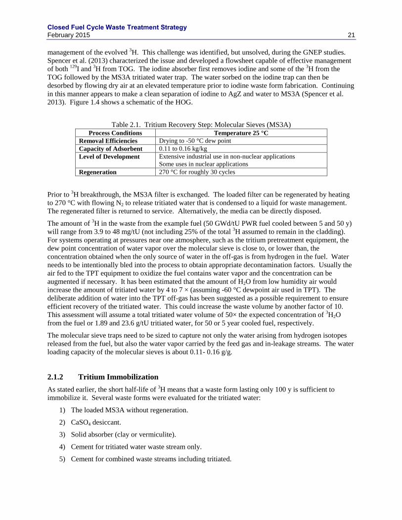
Closed Fuel Cycle Waste Treatment Strategy February 2015 21
management of the evolved 3H. This challenge was identified, but unsolved, during the GNEP studies.
Spencer et al. (2013) characterized the issue and developed a flowsheet capable of effective management
of both 129
I and 3H from TOG. The iodine absorber first removes iodine and some of the
3H from the
TOG followed by the MS3A tritiated water trap. The water sorbed on the iodine trap can then be
desorbed by flowing dry air at an elevated temperature prior to iodine waste form fabrication. Continuing
in this manner appears to make a clean separation of iodine to AgZ and water to MS3A (Spencer et al.
2013). Figure 1.4 shows a schematic of the HOG.
Table 2.1. Tritium Recovery Step: Molecular Sieves (MS3A) Process Conditions Temperature 25 °C
Removal Efficiencies Drying to -50 °C dew point
Capacity of Adsorbent 0.11 to 0.16 kg/kg
Level of Development Extensive industrial use in non-nuclear applications
Some uses in nuclear applications
Regeneration 270 °C for roughly 30 cycles
Prior to 3H breakthrough, the MS3A filter is exchanged. The loaded filter can be regenerated by heating
to 270 °C with flowing N2 to release tritiated water that is condensed to a liquid for waste management.
The regenerated filter is returned to service. Alternatively, the media can be directly disposed.
The amount of 3H in the waste from the example fuel (50 GWd/tU PWR fuel cooled between 5 and 50 y)
will range from 3.9 to 48 mg/tU (not including 25% of the total 3H assumed to remain in the cladding).
For systems operating at pressures near one atmosphere, such as the tritium pretreatment equipment, the
dew point concentration of water vapor over the molecular sieve is close to, or lower than, the
concentration obtained when the only source of water in the off-gas is from hydrogen in the fuel. Water
needs to be intentionally bled into the process to obtain appropriate decontamination factors. Usually the
air fed to the TPT equipment to oxidize the fuel contains water vapor and the concentration can be
augmented if necessary. It has been estimated that the amount of H2O from low humidity air would
increase the amount of tritiated water by 4 to 7 × (assuming -60 °C dewpoint air used in TPT). The
deliberate addition of water into the TPT off-gas has been suggested as a possible requirement to ensure
efficient recovery of the tritiated water. This could increase the waste volume by another factor of 10.
This assessment will assume a total tritiated water volume of 50× the expected concentration of 3H2O
from the fuel or 1.89 and 23.6 g/tU tritiated water, for 50 or 5 year cooled fuel, respectively.
The molecular sieve traps need to be sized to capture not only the water arising from hydrogen isotopes
released from the fuel, but also the water vapor carried by the feed gas and in-leakage streams. The water
loading capacity of the molecular sieves is about 0.11- 0.16 g/g.
2.1.2 Tritium Immobilization
As stated earlier, the short half-life of 3H means that a waste form lasting only 100 y is sufficient to
immobilize it. Several waste forms were evaluated for the tritiated water:
1) The loaded MS3A without regeneration.
2) CaSO4 desiccant.
3) Solid absorber (clay or vermiculite).
4) Cement for tritiated water waste stream only.
5) Cement for combined waste streams including tritiated.
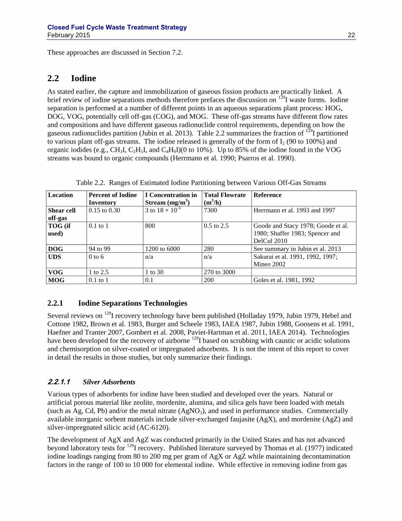
Closed Fuel Cycle Waste Treatment Strategy February 2015 22
These approaches are discussed in Section 7.2.
2.2 Iodine
As stated earlier, the capture and immobilization of gaseous fission products are practically linked. A
brief review of iodine separations methods therefore prefaces the discussion on 129
I waste forms. Iodine
separation is performed at a number of different points in an aqueous separations plant process: HOG,
DOG, VOG, potentially cell off-gas (COG), and MOG. These off-gas streams have different flow rates
and compositions and have different gaseous radionuclide control requirements, depending on how the
gaseous radionuclides partition (Jubin et al. 2013). Table 2.2 summarizes the fraction of 129
I partitioned
to various plant off-gas streams. The iodine released is generally of the form of I2 (90 to 100%) and
organic iodides (e.g., CH3I, C2H5I, and C4H9I)(0 to 10%). Up to 85% of the iodine found in the VOG
streams was bound to organic compounds (Herrmann et al. 1990; Psarros et al. 1990).
Table 2.2. Ranges of Estimated Iodine Partitioning between Various Off-Gas Streams
Location Percent of Iodine
Inventory
I Concentration in
Stream (mg/m3)
Total Flowrate
(m3/h)
Reference
Shear cell
off-gas
0.15 to 0.30 3 to 18 × 10-5
7300 Herrmann et al. 1993 and 1997
TOG (if
used)
0.1 to 1 800 0.5 to 2.5 Goode and Stacy 1978; Goode et al.
1980; Shaffer 1983; Spencer and
DelCul 2010
DOG 94 to 99 1200 to 6000 280 See summary in Jubin et al. 2013
UDS 0 to 6 n/a n/a Sakurai et al. 1991, 1992, 1997;
Mineo 2002
VOG 1 to 2.5 1 to 30 270 to 3000
MOG 0.1 to 1 0.1 200 Goles et al. 1981, 1992
2.2.1 Iodine Separations Technologies
Several reviews on 129
I recovery technology have been published (Holladay 1979, Jubin 1979, Hebel and
Cottone 1982, Brown et al. 1983, Burger and Scheele 1983, IAEA 1987, Jubin 1988, Goosens et al. 1991,
Haefner and Tranter 2007, Gombert et al. 2008, Paviet-Hartman et al. 2011, IAEA 2014). Technologies
have been developed for the recovery of airborne 129
I based on scrubbing with caustic or acidic solutions
and chemisorption on silver-coated or impregnated adsorbents. It is not the intent of this report to cover
in detail the results in those studies, but only summarize their findings.
Silver Adsorbents 2.2.1.1
Various types of adsorbents for iodine have been studied and developed over the years. Natural or
artificial porous material like zeolite, mordenite, alumina, and silica gels have been loaded with metals
(such as Ag, Cd, Pb) and/or the metal nitrate (AgNO3), and used in performance studies. Commercially
available inorganic sorbent materials include silver-exchanged faujasite (AgX), and mordenite (AgZ) and
silver-impregnated silicic acid (AC-6120).
The development of AgX and AgZ was conducted primarily in the United States and has not advanced
beyond laboratory tests for 129
I recovery. Published literature surveyed by Thomas et al. (1977) indicated
iodine loadings ranging from 80 to 200 mg per gram of AgX or AgZ while maintaining decontamination
factors in the range of 100 to 10 000 for elemental iodine. While effective in removing iodine from gas
Closed Fuel Cycle Waste Treatment Strategy February 2015 23
streams, the AgX substrate decomposes in the presence of NOx and water vapor. Therefore, a more acid
resistant substrate was desirable for use in the DOG application.
The AgZ sorbent has been developed specifically for application in DOG streams because of its high acid
resistance. Elemental iodine loadings of 170 mg per gram of Norton Zeolon 900 AgZ and typical methyl
iodide (CH3I) loadings of 140 to 180 mg per gram of substrate have been obtained for tests on simulated
DOG streams. An initial study of the mechanisms for CH3I adsorption into AgZ was recent completed. It
is shown that the zeolite catalytically cleaves the CH3- and -I and then captures the iodine by forming AgI
in the pores of the zeolite (Nenoff et al. 2014a). The resultant AgIZ is shown to be stable to this waste
stream; organic byproducts (e.g., methanol, dimethyl ether) are easily removed from the zeolite surface
with flowing gas and mild heat.
Studies were undertaken at Idaho National Engineering Laboratory (INEL) to find a method to regenerate
the filter bed thus reducing the quantity of silver lost to the waste stream. This work (Thomas et al. 1977;
Slansky et al. 1976) showed that regeneration in high temperature (400-500 °C) hydrogen was possible.
Burger and Scheele (1982) also indicated that recycle of the AgZ was possible, but they found variable
process performance and iodine removal that declined with repeated cycles. Because of the low trapping
efficiency of PbX, iodine circulates through the system, corroding the H2 pump. The final report on AgZ
development from INEL (Murphy et al. 1977) reported that an AgZ bed had been loaded with I2 and
recycled 13 times with a 20% loss in capacity compared to the initial loading.
The most extensive development and application of iodine adsorbents have been with AC-6120 (Furrer et
al. 1984; Herrmann et al. 1988; Maurel and Vigla 1987; Modolo and Odoj 1997; Sakurai and Takahashi
1994). For the WAK, AC-6120 was developed to the prototype stage for application with the DOG. The
DOG passes through an NO2 absorption column and high efficiency particulate air (HEPA) filter before
entering the iodide trap. Since 1975, adsorbent beds have been used to recover 129
I with DFs > 1000.
Some of the operating and design parameters include those used by Wilhelm et al. (1976); in the early
filters, 26 kg of low-impregnation AC-6120 (~7 mass% Ag) was used at a flow rate of 148 m3/h,
residence time of 0.6 – 1.4 s, an operating temperature of 130 °C, and up to 2 volume % of NOx in the gas
stream. Peak NOx concentrations of up to 20% were possible, DFs during the first 120 day service life
ranged from 1.0 × 10⁴ to 2.0 × 10
4. A high impregnation AC-6120H material, which contains ~12 mass%
Ag, was not used in the initial iodine sorption filter at WAK because of limited availability at the time.
The system was later modified to provide two filter drums in series. Up to 95 % utilization of the AC-
6120 based on the formation of AgI was achieved in the primary filter drum and DFs over the period
1975 to 1985 were > 104.
The AC6120H (~12 mass% Ag) sorbent was also tested on a side stream of the WAK VOG (Hermann et
al. 1989). In this test, the iodine filter was operated for nearly one year on a 10% side-stream (35 m3/h)
from the main VOG stream with a DF > 50. The filter was operated at 140 °C. This test showed a lower
DF because of low concentration of iodine and a high fraction of organic iodide.
More recently, silver-functionalized silica aeorgels have been under development for the capture and
immobilization of radioiodine (Matyas 2012a,b). This new silver absorber is attractive because of the
high I capacity and potentially simple conversion to a highly durable fused silica composite waste form.
Iodine capacities in the range of 45 mass% were measured with DF’s over 10 000 for laboratory tests with
simulated DOG gas streams (Matyas et al. 2011, Soelberg and Watson 2012). After aging in humid air at
150 °C the capacity reduction of roughly 20% was observed (Bruffey et al. 2013). This material is
promising, but is at an early stage of development.
Closed Fuel Cycle Waste Treatment Strategy February 2015 24
Charcoal / Activated Carbon 2.2.1.2
Although activated carbon has been used successfully in power plants, it has several serious drawbacks
for application in a nuclear reprocessing plant:
1. It has a relatively low ignition point; thus, without continuous air flow through the filter, the decay
heat of trapped radioiodine could ignite the bed.
2. The bed has poor iodine retention at high temperatures and permits total iodine releases upon ignition.
3. The presence of nitrogen oxides adversely affects performance; nitrogen oxides can also lead to the
production of explosive compounds within the filter bed
These factors led to the decision not to use this material in reprocessing plant off-gas systems in the past.
Caustic Scrubbing 2.2.1.3
Caustic scrubbing for 129
I recovery has been applied at the Windscale, THORP, UP1, UP2 and Tokai
reprocessing plants (Hebel and Cottone 1982; IAEA 1987). At the Windscale reprocessing plant, an
iodine DF of 50 has been reported, while the other DFs are not reported. The organic iodides pass
through the solution essentially unreacted, and CO2 and NOx deplete the scrubbing solution by forming
carbonate and nitrates. Methods for immobilizing the waste were not developed.
The operating experience at the Tokai reprocessing plant indicates that, while the caustic scrubber in the
DOG provides sufficient removal efficiency, that of the VOG scrubber is lower than expected. Organic
compounds in the VOG stream appear to be the cause of the low DF value (IAEA 1987). The THORP
plant utilizes a caustic scrubber to achieve an iodine DF of 100 (Hudson 1995). This same caustic
scrubber is used to scrub NOx, Ru(gas), and 14
C with DFs of 100, 100, and 70, respectively. Experimental
work has demonstrated that the NOx evolved during the dissolution process is effective in maintaining the 129
I in the volatile molecular form. Because 14
C is simultaneously removed with the iodine in the caustic
solution, an independent 14
C trapping technology could not be applied. This could complicate waste
management with the requirement that a single approach would be required.
Iodox 2.2.1.4
The Iodox technology was developed for application to liquid-metal fast breeder reactor (LMFBR) fuel
reprocessing where the spent fuel would have been processed within 180 days of leaving the reactor and
would have required high DFs to control 131
I releases (>104) (Birdwell 1990; Burch et al. 1976; Clark et
al. 1978; Collins and Benker 1979; Goumondy et al. 1981; Groenier and Hannaford 1975; Holladay 1979;
Jubin and Lewis 1987; Kaneko et al. 1978; Kaneko et al. 1980; Kaneko et al. 1979; Mailen 1975, 1976;
Yarbro et al. 1977). Decontamination factors up to 106 were obtained in cold engineering tests. The
method appeared to be equally efficient for both elemental and organic forms of iodine. A 20-22 M
HNO3 in a bubble cap column was used to recover the iodine as HI3O8. The process required secondary
steps to concentrate 13 M HNO3 to 22 M, recycle, concentrate acid diluted by moisture in the DOG, and
concentrate the waste stream to the solid anhydroiodic acid (ERDA, 1976). Due to the highly corrosive
nature of the hyperazeotropic nitric acid, the process equipment must be constructed of relatively
expensive materials such as zirconium or titanium (IAEA 1987). The iodine may also be recovered as
Ba(IO3) 2.
Major advantages of the process are that no unusual chemicals are added to the reprocessing plant, both
elemental and organic iodides are handled with high DFs, and the iodine products are suitable for
conversion to a waste form without significant added volume. Major disadvantages are the capital cost
Closed Fuel Cycle Waste Treatment Strategy February 2015 25
associated with the materials of construction that are required (zirconium or titanium) and the need to add
or produce the hyperazeotropic nitric acid (IAEA 1987).
Mercurex 2.2.1.5
This process was also developed for the treatment of the dissolver off-gas evolved during the processing
of very short cooled fuels where large iodine DFs are required (>105). The process used a mercuric
nitrate – nitric acid solution in a packed or bubble cap column to recover the iodine as HgI2 and iodine
complexes (Collard et al. 1981b; Palamalai et al. 1983; Wood and Richardson 1977). For elemental I2
and CH3I, DFs of 1000 to 5000 and 100 respectively have been obtained at temperatures of 50 °C.
Mercurex was applied at an industrial scale at the Dounreay and Nuclear Fuel Services reprocessing
plants with reported DFs of 150 and 32 for I2 and CH3I, respectively (Hebel and Cottone 1982). Two
scrubbers in series were installed in the Barnwell Nuclear Fuel Plant (BNFP). The DFs were claimed to
be 10 and 75 (IAEA 1987).
Major advantages of the process are that no unusual materials of construction are required (stainless steel
is suitable) and no special processes are required to produce the hyperazeotropic nitric acid. Major
disadvantages are the toxic nature of the mercury involved and the probable need to convert the mercury-
iodine compounds into a more suitable form for disposal (IAEA 1987) and relatively low DFs.
Silver Reactors 2.2.1.6
The Hanford PUREX Plant and the Savannah River Plant have for many years routinely used silver
reactors to remove 131
I from off-gas streams (Rodger and Reese 1969). The process involves passing the
DOG through a bed of heated ceramic saddles glazed with silver nitrate and chemisorbing the iodine as
silver iodide and iodate. Silver reactors have demonstrated DFs of 10 to 104 for
131I recovery. When the
silver reactor efficiency begins to fall, it can be regenerated up to 10 times by removing the accumulated
material with an alkaline sodium hyposulfite wash solution, washing, and spraying the bed with a solution
of 5 M AgNO3.
The development of the silver reactors appeared to have specifically included long term retention or
recovery of 129
I (they were solely to provide sufficient delay for the 131
I to decay before leaving the stack)
and no method for immobilizing liquid waste from the process or bed change-out was examined.
Strachan (1978) reported than an examination of some of the bed material in the silver reactor at Hartford
showed that no 129
I had been retained by the reactor following several years of operation. The analysis
indicated that virtually all the AgI that would have been formed had been converted to AgCl by a Cl-
bearing species in the off-gas stream. Chlorine contaminants in the process chemicals were the likely
sources of the chlorine.
Metal Organic Frameworks 2.2.1.7
Metal-organic frameworks (MOFs) are viewed by many as the next-generation of porous materials with
promising applications in gas separations. These materials are excellent candidates for selective gas
sorption for the following reasons: their ultrahigh capacity due to surface areas up to 6000m2/g, the
tunability of adsorption by judicious choices of metal centers or organic ligands, and the design of pore
sizes. Initial studies with ZIF-8 (2-methylimidazole zinc salt) framework for its size selective pore size
(approximating I2 size) showed very strong sorption for I2. Iodine loadings of up to 125 mass%, of which
110 mass% is inside the pores under static conditions, have been observed for ZIF-8 (Sava et al. 2011).
However, a sample of ZIF-8 was tested for iodine separation in flowing gas stream in a thin bed
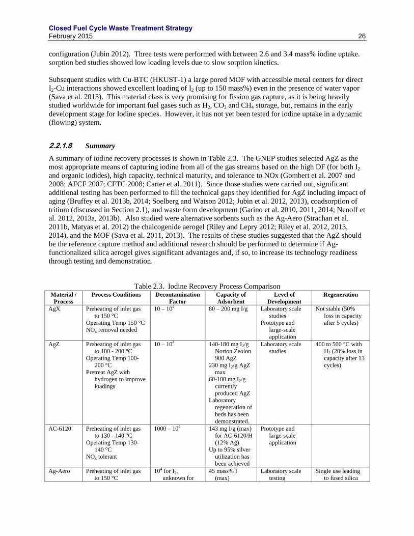
Closed Fuel Cycle Waste Treatment Strategy February 2015 26
configuration (Jubin 2012). Three tests were performed with between 2.6 and 3.4 mass% iodine uptake.
sorption bed studies showed low loading levels due to slow sorption kinetics.
Subsequent studies with Cu-BTC (HKUST-1) a large pored MOF with accessible metal centers for direct
I2-Cu interactions showed excellent loading of I2 (up to 150 mass%) even in the presence of water vapor
(Sava et al. 2013). This material class is very promising for fission gas capture, as it is being heavily
studied worldwide for important fuel gases such as H2, CO2 and CH4 storage, but, remains in the early
development stage for Iodine species. However, it has not yet been tested for iodine uptake in a dynamic
(flowing) system.
Summary 2.2.1.8
A summary of iodine recovery processes is shown in Table 2.3. The GNEP studies selected AgZ as the
most appropriate means of capturing iodine from all of the gas streams based on the high DF (for both I2
and organic iodides), high capacity, technical maturity, and tolerance to NOx (Gombert et al. 2007 and
2008; AFCF 2007; CFTC 2008; Carter et al. 2011). Since those studies were carried out, significant
additional testing has been performed to fill the technical gaps they identified for AgZ including impact of
aging (Bruffey et al. 2013b, 2014; Soelberg and Watson 2012; Jubin et al. 2012, 2013), coadsorption of
tritium (discussed in Section 2.1), and waste form development (Garino et al. 2010, 2011, 2014; Nenoff et
al. 2012, 2013a, 2013b). Also studied were alternative sorbents such as the Ag-Aero (Strachan et al.
2011b, Matyas et al. 2012) the chalcogenide aerogel (Riley and Lepry 2012; Riley et al. 2012, 2013,
2014), and the MOF (Sava et al. 2011, 2013). The results of these studies suggested that the AgZ should
be the reference capture method and additional research should be performed to determine if Ag-
functionalized silica aerogel gives significant advantages and, if so, to increase its technology readiness
through testing and demonstration.
Table 2.3. Iodine Recovery Process Comparison Material /
Process
Process Conditions Decontamination
Factor
Capacity of
Adsorbent
Level of
Development
Regeneration
AgX Preheating of inlet gas
to 150 °C
Operating Temp 150 °C
NOx removal needed
10 – 104 80 – 200 mg I/g Laboratory scale
studies
Prototype and
large-scale
application
Not stable (50%
loss in capacity
after 5 cycles)
AgZ Preheating of inlet gas
to 100 - 200 °C
Operating Temp 100-
200 °C
Pretreat AgZ with
hydrogen to improve
loadings
10 – 104 140-180 mg I2/g
Norton Zeolon
900 AgZ
230 mg I2/g AgZ
max
60-100 mg I2/g
currently
produced AgZ
Laboratory
regeneration of
beds has been
demonstrated.
Laboratory scale
studies
400 to 500 °C with
H2 (20% loss in
capacity after 13
cycles)
AC-6120 Preheating of inlet gas
to 130 - 140 °C
Operating Temp 130-
140 °C
NOx tolerant
1000 – 104 143 mg I/g (max)
for AC-6120/H
(12% Ag)
Up to 95% silver
utilization has
been achieved
Prototype and
large-scale
application
Ag-Aero Preheating of inlet gas
to 150 °C
104 for I2,
unknown for
45 mass% I
(max)
Laboratory scale
testing
Single use leading
to fused silica
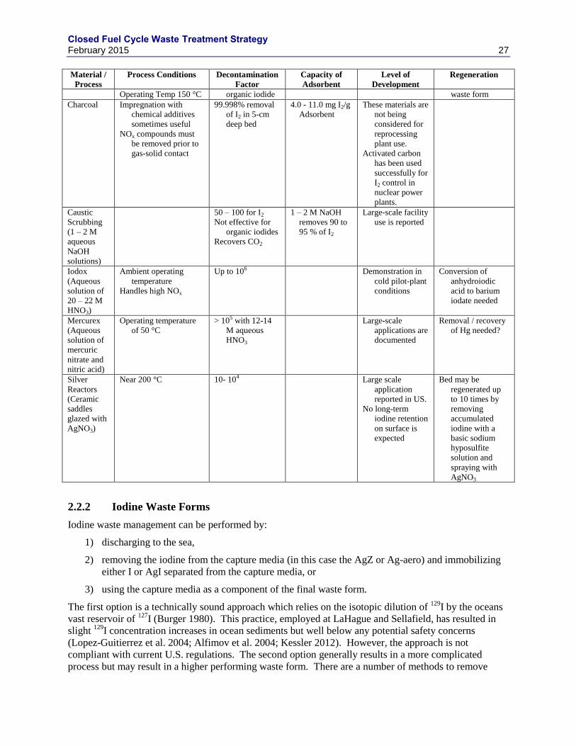
Closed Fuel Cycle Waste Treatment Strategy February 2015 27
Material /
Process
Process Conditions Decontamination
Factor
Capacity of
Adsorbent
Level of
Development
Regeneration
Operating Temp 150 °C organic iodide waste form
Charcoal Impregnation with
chemical additives
sometimes useful
NOx compounds must
be removed prior to
gas-solid contact
99.998% removal
of I2 in 5-cm
deep bed
4.0 - 11.0 mg I2/g
Adsorbent
These materials are
not being
considered for
reprocessing
plant use.
Activated carbon
has been used
successfully for
I2 control in
nuclear power
plants.
Caustic
Scrubbing
(1 – 2 M
aqueous
NaOH
solutions)
50 – 100 for I2
Not effective for
organic iodides
Recovers CO2
1 – 2 M NaOH
removes 90 to
95 % of I2
Large-scale facility
use is reported
Iodox
(Aqueous
solution of
20 – 22 M
HNO3)
Ambient operating
temperature
Handles high NOx
Up to 106 Demonstration in
cold pilot-plant
conditions
Conversion of
anhydroiodic
acid to barium
iodate needed
Mercurex
(Aqueous
solution of
mercuric
nitrate and
nitric acid)
Operating temperature
of 50 °C
> 105 with 12-14
M aqueous
HNO3
Large-scale
applications are
documented
Removal / recovery
of Hg needed?
Silver
Reactors
(Ceramic
saddles
glazed with
AgNO3)
Near 200 °C 10- 104
Large scale
application
reported in US.
No long-term
iodine retention
on surface is
expected
Bed may be
regenerated up
to 10 times by
removing
accumulated
iodine with a
basic sodium
hyposulfite
solution and
spraying with
AgNO3
2.2.2 Iodine Waste Forms
Iodine waste management can be performed by:
1) discharging to the sea,
2) removing the iodine from the capture media (in this case the AgZ or Ag-aero) and immobilizing
either I or AgI separated from the capture media, or
3) using the capture media as a component of the final waste form.
The first option is a technically sound approach which relies on the isotopic dilution of 129
I by the oceans
vast reservoir of 127
I (Burger 1980). This practice, employed at LaHague and Sellafield, has resulted in
slight 129
I concentration increases in ocean sediments but well below any potential safety concerns
(Lopez-Guitierrez et al. 2004; Alfimov et al. 2004; Kessler 2012). However, the approach is not
compliant with current U.S. regulations. The second option generally results in a more complicated
process but may result in a higher performing waste form. There are a number of methods to remove
Closed Fuel Cycle Waste Treatment Strategy February 2015 28
iodine from the AgIZ for use in waste form fabrication purposes. One example is reducing the silver-
iodide to silver metal using hydrogen gas at elevated temperature (this would allow for recycling of the
silver sorbent).
2AgI(s) + H2(g) → 2Ag(s) + 2HI(g)
The HI(g) can then be trapped in water or caustic solution (Berger et al. 1981) or trapped on another
sorbent more suitable for waste form synthesis. The third option may result in a simpler process and
adequate waste form(s). Both the second and third option will be considered here.
Several reviews on 129
I waste forms have been published (Altomare et al. 1979; Berger et al. 1981; Hebel
and Cottone 1982; IAEA 1987; Jubin 1988; Taylor 1990; Perera et al. 2004; Gombert et al. 2008;
Nishimura et al. 2009; and Tanabe et al. 2010). These reviews will are briefly summarized below.
Waste Form Performance Targets 2.2.2.1
Iodine-129 is consistently found to be one of the largest dose contributors in geologic repository
performance assessments due to its very long half-life (1.6107 y) and high mobility in most geological
environments (Swift and Nutt 2011; OECD 2009; Von Lensa et al. 2008). The long half-life has
prompted some to suggest iodine management similar to management of stable hazardous metals (e.g.,
Pb, Hg, etc.).
Burger (1980) recommended that dilution in both the absolute concentration of 129
I and the ratio of 129
I:
127I to be the most effective method for managing
129I in a safe and predictable manner. This dilution can
be accomplished by: 1) active isotopic dilution of 129
I with 127
I in the waste form, 2) dispersion of 129
I in
the sea, or 3) disposal of iodine loaded waste form in a salt repository containing a significant 127
I
reservoir. Although these are good practical solutions to 129
I management, the decision of disposal
environment will be driven by a number of factors and world experience has shown that safe and
predictable disposal options for 129
I is achievable by deep geologic disposal without isotopic dilution. It is
assumed for the purposes of this study that any generic deep geologic disposal environment may be
selected for disposal of the 129
I containing waste form(s).
A series of calculations were performed to estimate the impact of waste form durability on the
performance of generic repositories. These calculations included generic clay/shale, hard rock (e.g.,
granite), and bedded salt repositories and deep borehole disposal (Vaughn et al. 2012). The general
trends show:
For cases in which the dominant dose contributing radionuclides have half-lives that are much
shorter than the expected waste form lifetime, the waste form degradation rate does not have an
effect.
For cases in which the primary barrier to release, the slow diffusive pathway, dominates overall
repository performance, the waste form engineered barrier has a negligible effect on repository
performance.
For cases in which the waste form lifetime is on the same order of magnitude as the radionuclide
half-life and are not constrained by solubility and diffusion controls, the mean peak annual dose
rates are directly proportional to both the mass of the radionuclide disposed and the fractional
waste form degradation rate.
An example of this trend is shown for 129
I peak annual dose from a clay/shale repository as a function of
waste form fractional degradation rate in Figure 2.2. There is a linear relationship between degradation
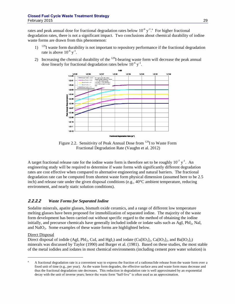
Closed Fuel Cycle Waste Treatment Strategy February 2015 29
rates and peak annual dose for fractional degradation rates below 10-6
y-1
.a For higher fractional
degradation rates, there is not a significant impact. Two conclusions about chemical durability of iodine
waste forms are drawn from this phenomenon:
1) 129I waste form durability is not important to repository performance if the fractional degradation
rate is above 10-6
y-1
.
2) Increasing the chemical durability of the 129
I-bearing waste form will decrease the peak annual
dose linearly for fractional degradation rates below 10-6
y-1
.
Figure 2.2. Sensitivity of Peak Annual Dose from 129
I to Waste Form
Fractional Degradation Rate (Vaughn et al. 2012)
A target fractional release rate for the iodine waste form is therefore set to be roughly 10-7
y-1
. An
engineering study will be required to determine if waste forms with significantly different degradation
rates are cost effective when compared to alternative engineering and natural barriers. The fractional
degradation rate can be computed from shortest waste form physical dimension (assumed here to be 2.5
inch) and release rate under the given disposal conditions (e.g., 40°C ambient temperature, reducing
environment, and nearly static solution conditions).
Waste Forms for Separated Iodine 2.2.2.2
Sodalite minerals, apatite glasses, bismuth oxide ceramics, and a range of different low temperature
melting glasses have been proposed for immobilization of separated iodine. The majority of the waste
form development has been carried out without specific regard to the method of obtaining the iodine
initially, and precursor chemicals have generally included iodide or iodate salts such as AgI, PbI2, NaI,
and NaIO3. Some examples of these waste forms are highlighted below.
Direct Disposal
Direct disposal of iodide (AgI, PbI2, CuI, and HgI2) and iodate (Cu[IO3]2, Ca[IO3]2, and Ba[IO3]2)
minerals was discussed by Taylor (1990) and Burger et al. (1981). Based on these studies, the most stable
of the metal iodides and iodates in most chemical environments (including cement pore water solution) is
a A fractional degradation rate is a convenient way to express the fraction of a radionuclide release from the waste form over a
fixed unit of time (e.g., per year). As the waste form degrades, the effective surface area and waste form mass decrease and
thus the fractional degradation rate decreases. This reduction in degradation rate is well approximated by an exponential
decay with the unit of inverse years; hence the waste form “half-live” is often used as an approximation.
Closed Fuel Cycle Waste Treatment Strategy February 2015 30
AgI. Inagaki et al. studied the dissolution rate of AgI in reducing environments with the presence of
FeCl2 (Inagaki et al. 2008) in dilute flowthrough conditions. Under these conditions, dissolution of AgI is
controlled by a redox reaction with Fe2+
which is kinetically retarded by the formation of a Ag0
passivation layer over the AgI particles. AgI is relatively soluble in acetate solution which is the solution
used for testing by the U.S. Environmental Protection Agency (EPA) Toxicity Characteristic Leaching
Procedure (TCLP) (EPA 1992). The solubility of silver acetate is 0.062 M or 6.7 g Ag/L (Dean 1973).
AgI therefore does not pass the EPA standards for land-disposal (as was confirmed for AgIZ with a
resulting Ag concentration of 125 mg/L per Scheele et al. (2002)) and would require further treatment for
disposal in a non-RCRA licensed facility. None of these minerals have demonstrated performance in the
right order of magnitude to significantly influence peak annual dose from deep geologic disposal
facilities.
Sodalite
Iodide sodalite is an aluminosilicate material (ideally, Na8Al6Si6O24I2) that requires high pressure and
temperature to be produced. Synthesis with up to 11.7 mass% equivalent I has been demonstrated, with a
theoretical waste loading of 22.0 mass% (Babad and Strachan 1980; IAEA 1987, Sheppard et al. 2006).
Hirabayash et al. (2012) developed a low-temperature method of forming sodalite from radioiodine
contianing AgX in an autoclave at 150°C. The solubility of the iodide sodalite was approximately 2 × 10-
4 mol/L with a normalized release rate of 10
-4 to 10
-5 g·m
-2·d
-1 at disposal temperature (Nakazawa et al.
2001). Maddrell et al. 2014 measured the durability of iodide sodalite using MCC-1 test with an S/V of 1
cm-1
, a temperature of 90°C, and a pH buffered at 11. The resulting normalized iodine release rates
ranged from 0.005–0.01 g·m-2
·d-1
. These rates are quite high, but, they have been measured under
relatively extreme conditions. Taylor (1990) recommended iodide sodalite as the most appropriate iodine
waste form for durability controlled release materials.
Glasses
Iodine incorporation into glass has been investigated in many different systems, for applications ranging
from optical materials to batteries to nuclear waste immobilization. These studies used either iodine or
iodine compounds. The primary oxide glass systems that have been studied for glass formation with
iodine or iodine-containing compounds are borates (Dalba et al. 1990; Mustarelli et al. 2005; Rocca et al.
1992; Rousselot et al. 1995; Souto et al. 1994), borosilicates (Maddrell and Abraitis 2004), and tellurites
(Chowdari et al. 2000). Many glass systems with oxyanions which alone form low melting point alkali
salts form glass well with AgI, including molybdates (Chowdari et al. 1998; Mustarelli et al. 2005;
Rousselot et al. 1995; Sanson et al. 2007a; Sanson et al. 2007b), tungstates (Mustarelli et al. 2005;
Senapati and Austen Angell 1991), arsenate (Rousselot et al. 1995), and phosphates (Mustarelli et al.
2005; Rousselot et al. 1995; Sakuragi et al. 2008; Yang et al. 2014). Finally, a large portion of literature
on iodine-containing glasses has focused on non-oxide, chalcogen (Ch; S, Se, and/or Te)-containing
compounds, including As-, Ge-, P-, and Zn-sulfides, selenides and/or tellurides, or other mixed-cation
halides, e.g., Ag, K, Pb. When put into glass, iodine is thought to enter the glass network in place of other
ions like oxygen, but in some cases, the iodine appears to occupy interstitial sites in the glass network
(Choi and Shin 1996).
In typical borosilicate waste glasses, solubility of iodine was initially thought to be very low but this can
be attributed to low retention of iodine during the melting process (Hrma 2010), posing processing
limitations for making glasses with high iodine content. Thus, low-temperature processing glasses are
more common in the literature. One of the more commonly studied glass systems in the literature for
incorporating AgI are of the family AgI-Ag2O-X, where X is often a mixture of P2O5, B2O3, Bi2O3, and/or
other additives. Mukunoki et al. (Mukunoki et al. 2007; Mukunoki et al. 2009) have developed a process
for capturing I- in BiPbO2I and mixing with a low-melting PbO-B2O3-ZnO glass for immobilizing iodine
Closed Fuel Cycle Waste Treatment Strategy February 2015 31
using a low-temperature process of ~520°C. A system of (AgI)1-x(Ag2MoO4)x glasses where 0.2 < x ≤ 0.4
has been studied as well with high AgI fractions (Rocca et al. 1999).
Phosphate glass systems have particularly been investigated for nuclear waste immobilization of iodine
(Sakuragi et al. 2008; Yang et al. 2014).
Due to their more covalent nature, non-oxide glasses such as chalcogenide glasses, can accommodate
more iodine in their network, and thus silver sulfides containing P or As have been studied as cation
conductors (Rousselot et al. 1995; Sanghera et al. 1988). Traditional chalcogenide glasses without silver
have also been studied containing large fractions of iodine (Koudelka and Pisárcik 1984), particularly
because iodine additions result in novel optical properties. Extremely high fractions of iodine, up to 33
mol%, have been reported in chalcogenide glasses, such as (As,Sb)-(S,Se,Te)-I and (Si,Ge)-(S,Se,Te)-I
(Sanghera et al. 1988). In general, chalcogenide glasses have lower glass transition temperatures of 200–
400°C versus >500°C for typical silicate-based HLW glasses. Chalcohalide glass systems containing
PbI2 (Lima et al. 2001; Troles et al. 2003) and CuI (Salmon and Xin 2002) have also been reported.
Infrared-transmitting glass ceramics in the Ge-Ga-(S,Se)-alkali iodide (Lin et al. 2013; Tang et al. 2008;
Yang et al. 2007) and lead iodide (Guo et al. 2007a; Guo et al. 2007b) systems are an area of current
research for optical applications. The affinity of chalcogenide systems for iodine is the principal reason
for considering them as sorbents using chalcogen-based aerogels called chalcogels.
Apatite
Apatite materials, primarily Pb5(VO4)3I, have been developed for the immobilization of radioiodine
(Audubert 1997; Guy et al. 2002; Perera et al. 2003; Zhang et al. 2007; Le Gallet et al. 2010; Stennett et
al. 2011). This material becomes unstable in air at temperatures above the typical sintering point of
700°C. Therefore, layered composites (Audubert et al. 1997 and Guy et al. 2002), hot isostatic press
(HIP) synthesis (Perera et al. 2003 and Zhang et al. 2007), fast microwave heating (Stennett et al. 2011),
or spark plasma sintering (SPS) at low temperature (Campayo et al. 2009; Le Gallet et al. 2010) were
used to contain the iodine during processing. The final waste form is suspected to release iodine via an
interdiffusion or ion exchange process (Guy et al. 2002; Zhang et al. 2007; Maddrell and Abraitis 2004).
Guy et al. 2002 found the initial dissolution rates vary with pH, time, and temperature. A typical V-
shaped dependence of log rate on pH is seen with a relatively steep slope in lower pH’s, a minimum near
pH 8, and a shallower slope at higher pH’s. The rate varies with time from an initial rate near 0.2 g·m-2
·d-
1 to roughly 5×10
-4 g·m
-2·d
-1 at 400 days. An activation energy for dissolution initial dissolution rate is 37
kJ·mol-1
.
More recently, attempts have been made to produce iodine containing oxyapatites (Campayo et al. 2011;
Coulon et al. 2014). The material is fabricated by a cement-like reaction of a mixture of one mole
tetracalcium phosphate, two moles tricalcium phosphate, and half a mole of sodium iodate in water. The
resulting material is a porous monolithic (cement-like) solid containing primarily
Ca10(PO4)6(OH)1.6(IO3)0.4 with roughly 6.5 mass% iodine. Normalized iodine losses during a 90°C MCC-
1 test (with 460 cm-1 S/V) were measured in DIW at 10-4
g·m-2
·d-1
(measured after two days).
Layered Bismuth Oxy-iodides
Krumhansl and colleagues have developed a hydrotalcite-like layered bismuth oxide waste form for
radioiodine (Krumhansl et al. 2009; Krumhansl and Nenoff 2011; Krumhansl and Nenoff 2013). A series
of materials with Bi:O:I ratios ranging from BiOI to Bi5O7I were fabricated by an aqueous precipitation
process. The chemical durabilities of the materials were characterized using a 7-day static test in DIW at
temperatures ranging from 20 to 90°C. The samples with Bi:I ratios in the range of 1.67 to 2.12
performed significantly better in static leach tests compared to samples with either higher or lower Bi:I
Closed Fuel Cycle Waste Treatment Strategy February 2015 32
ratios (<4 mg I/L), suggesting an ideal formulation of 2Bi for every I. The authors suggest that the iodine
release under these conditions may be solubility controlled.
Cement
Concrete has the advantages of low cost and known technology. It has been reported that the lowest leach
rate would result in complete leaching in about 2×10⁴ y (IAEA 1987). This is too short of time to meet
the stated performance criteria. However, it may be used to increase performance under certain
conditions such as interim storage, transportation, and repository intruder conditions. Concrete has been
used to provide additional protection and physical strength to Ba(IO3)2; a USSR fuel recycle plant of 1500
t/yr was shown to generate about 9 m3 of concrete containing barium iodate with a leach rate of 2-6 × 10
-6
g·cm-2
·d-1
(IAEA 1987). Recent Japanese studies have evaluated the use of cement to immobilize AgA
and AgS (Toyohara et al. 2002; JAEA and FEPC 2007; Haruguchi et al. 2012).
Simple iodine compounds, such as AgI, were studied in cements as an immobilization form. It was found
that AgI became unstable in slag cement due to the reduction of Ag+ to Ag
0 leading to release of I
-. It was
proposed that AgNO3 should be included in cement so as the iodine became soluble the Ag would also
become soluble and be available for scavenging radioiodine (Atkins et al 1990). However, in the short
term, AgNO3 showed very low solubilities (Atkins et al. 1990). High calcium silicate hydrogels and
calcium aluminate sulphate hydrates (such as Ca4Al2SO4(OH)6·6H2O) could maximize the immobilization
of I. This can be done with a 30 to 40% slag blend with aging (Atkins and Glasser 1990).
Clark and colleagues (Clark 1977; Clark and Thompson 1977) describes incorporation of barium iodate in
Portland cement for use in a liquid metal breeder reactor fuel reprocessing waste loaded to between 3 and
12 mass% I. Burger et al. (1981) report the relative corrosion rates of AgI and Ba(IO3)2 in cement.
Waste Forms for Iodine on Solid Capture Media 2.2.2.3
Cement Encapsulation
Encapsulation of AgIZ in cement was proposed by Burger et al. (1981). They found that the AgIZ-
containing cement was more than an order of magnitude more durable than an equivalently iodine loaded
cement containing Ba[IO3]2 in dynamic leach tests; while the rates were roughly equivalent for static
tests. Scheele et al. (2002) compared the TCLP responses of AgIZ (125 mg Ag/L) with grouted AgIZ
(<0.006 mg Ag/L). These were based on a type III cement mixture fabricated with 24 mass% H2O:51
cement:25 AgIZ. The addition of 127
I (in the form of CaI2) as a 3:1 isotopic diluent was also proposed. A
final cement formulation of 21 mass% H2O:42 cement:26 AgIZ:11 CaI2 was proposed as the final waste
form. Trevorrow et al. (1983) estimate the lifetime of cemented AgIZ to be on the order of 104 years
(assuming monolithic cement in standard 55-gallon drums).
Glass Encapsulation
Nenoff and colleagues have developed a glass composite material (GCM) for the immobilization of
radioiodine loaded AgZ (AgIZ) (Nenoff et al. 2008, 2011, 2012, 2014b,c,d; Garino et al. 2011). To
fabricate this waste form, the AgIZ media is ground and mixed with a powdered bismuth-zinc-silicate
glass frit and sintered at 550°C. The waste loading is generally 25 mass% AgIZ. When the commercially
available AgZ is used, then this translates to 1-2 mass% iodine. This loading may be increased if optimal
AgZ material (e.g., the synthetic AgZ with 18 mass% Ag previously available from Norton) is used. The
chemical durability of this product has been measured using single-pass flow-through methods under
dilute conditions (Nenoff et al. 2012). Iodine is released from GCM at less than 10-16
mol·cm-2
·s-1
at 25
°C and pH = 3 and pH = 8. In the measured conditions, Bi-Si-Glass dissolves at rates similar to, and
Closed Fuel Cycle Waste Treatment Strategy February 2015 33
possibly lower than, traditional nuclear waste glasses. Temperature has a relatively small effect on both
glass degradation and Ag and I release; maximum glass dissolution activation energies are 30 kJ/mol.
The rate model for iodine release from GCM waste form is estimated at: Rate (mol·cm-2
·s-1
) = 3.6 × 10-
12exp(-3608/T). Detailed information on this waste form and the process technology are given in Section
2.2.2.5.
This specific glass frit has also been tested as a potential waste form for other was streams (Nenoff et al.
2012). Similar sintering glasses for waste encapsulation using other frit compositions have been tested
and used in many applications (Gahlert and Ondracek 1988a,b; Vienna et al. 1999; Bernardo et al. 2006;
Michie et al. 2008; Malek et al. 2009; and Mayzan et al. 2014).
Heat Treated Silica Aerogels
In recent years, silica aerogels have been studied for confinement of radioactive wastes due to their low
cost, commercial availability, and high specific surface areas upwards of 1200 m2/g (Woignier et al. 1998,
2000; Reynes et al. 2001). As with AgZ, aerogels can act as precursors to the final glass matrix in which
the waste is actually immobilized (Woignier et al. 2000). The porous network of silica aerogel has been
used as a host matrix, or a sponge, for nuclear wastes (Reynes et al. 2001), where the silica aerogel was
soaked in a solution containing actinides in nitrate salt form and, after drying and nitrate decomposition,
the composite material is fully sintered, trapping the nuclear waste.
Matyas and colleagues are currently developing Ag-functionalized silica aerogels as iodine sorbents
(Matyas et al. 2011, 2012a,b, 2013; Strachan et al. 2011b). This particular sorbent is comparable to AgZ
in that both have a porous oxide scaffold with Ag0 binding sites for iodine, but with the significant
advantage that it can be directly consolidated to form a fused silica-based waste form with encapsulated
AgI nano-particles. The durability of the waste form is expected to be controlled by the dissolution of the
silica to exposing the AgI particles, and by the solubility of AgI. Fused silica durability has been studied
by many researchers and is significantly higher than that of typical borosilicate waste glasses. Fresh
AgAero has a capacity of roughly 45 mass% I2. However, aging in process may reduce the capacity to as
low as 22 mass%. Denisfication by HUP at temperatures as low as 1050°C was demonstrated with iodine
retention of >92% and densities as high as 2.2 × 10³ kg/m
3. Detailed information on this waste form and
the process technology are given in Section 2.2.2.6.
Hot Pressed Silver Sorbents
Direct conversion of solid iodine capture media into waste forms by hot-pressing, in particular by HIP,
has been proposed by a number of researchers. Miyakawa et al. (2013) have developed an alumina based
“Synroc” waste form by HIPing I-loaded AgA. The loaded AgA material heated under vacuum to
convert AgNO3 and AgIO3 to AgI and the material is HIPed at 1200°C under 175 MPa for 3 h (Tanabe et
al. 2010). AgI particles are encapsulated in the dense Al2O3 grain boundaries and triple points (JAEA
2007; Tanabe et al. 2010). The bulk density of the materials is 4,050 kg/m3 with roughly 8% porosity (1-
3% open porosity). The release of iodine is suggested to be controlled by bulk corrosion of the Al2O3
phase which, in-turn, is controlled by the solubility of amorphous Al(OH)3 (Miyakawa et al. 2013;
Tanabe et al. 2010).
Fujihara et al. (1999) HIPed AgI-containing porous silica sorbents at 1500°C for 3 h at 100 MPa to form a
synthetic rock waste form. The resulting waste form was primarily crystalline quartz with AgI found in
the grain boundaries and triple points (JAEA 2007). The low solubility of quartz in disposal environment
solutions suggested high iodine retention in the final waste form. Testing in dynamic solution showed
that for the first roughly 50 days (at 35°C) the iodine release was a function of the square root of time.
After 50 days, little to no release was measured out to 300 days (JAEA 2007).
Closed Fuel Cycle Waste Treatment Strategy February 2015 34
Direct conversion of silver zeolites into a final waste form by HIPing has been developed by a number of
researchers. HIPing of AgX to form sodalite was described above (Sheppard et al. 2006; Sheppard 2009;
Maddrell 2014). Direct hot-pressing of AgIZ has been attempted (Jubin et al. 2014b; Jubin and Bruffey
2014). Both crushed and uncrushed AgIZ were HIPed and no obvious advantage to crushing was found.
Densities in the range of 2500 to 2650 kg/m3 were achieved. Under the conditions used in these tests, the
majority of the resulting materials were fully amorphous. Although the results of these tests are
preliminary, the approach does seem promising.
Summary of Iodine Waste Forms and Recommendations 2.2.2.4
Based on the selection of AgZ as the reference capture media and AgAero as the primary alternative
option for iodine capture, the GCM and collapsed silica aerogel waste forms are the most appropriate
baseline waste forms for iodine in this study. Both of these waste forms have a high potential to have
waste form stability half-lives in the disposal facility on the same order of magnitude as the half-life of 129
I. Both of these have a process demonstrated to fabricate a dense and durable waste form. Direct hot
pressing of AgIZ should also be considered as a high potential value alternative to the GCM for AgIZ
immobilization.
The GNEP waste management baseline recommended grouted AgIZ as the preferred waste form for
iodine (Gombert et al. 2007). That was not selected in this study due to the relatively poor performance,
waste loadings, and impacts of cement leach solutions on the performance of other materials in the
disposal facility.
Glass Composite Material Fabrication 2.2.2.5
Section 2.2.1 describes the selection of AgZ as the reference iodine capture media in the DOG, VOG,
HOG, and MOG treatment systems. In addition, AgZ will be used in the off-gas treatment for the iodine
sorbent waste form fabrication process.
In the reference case, the iodine loaded AgZ is immobilized in a low-temperature glass composite
material (GCM) (Nenoff et al. 2008, 2011, 2014b,c,d; Garino et al. 2011). The AgZ columns are operated
with two banks in series and are alternatively used as the lead and lag bank. The lead bank is replaced
when breakthrough occurs, the ∆P meets the predetermined limit, or the scheduled life is achieved. The
lag bank then becomes the lead bank and the newly replaced media becomes the lag bank. Any
physisorbed halogens and tritium is removed from the AgZ by heating (to between 150 and 225°C) under
flowing nitrogen. The resulting gas is passed through the remaining bank. After degasing is complete,
the iodine-loaded AgZ (AgIZ) media is removed from the absorber cartridge, ground, mixed with glass
frit, cold-pressed, and sintered into a final GCM waste form.
The AgIZ is ground to a particle size of < 150 μm (equivalent screen aperture) and mixed in a 24.7
AgIZ:74.2 frit:1.1 mass% Ag metal flake ratio. The frit is assumed to be Ferro Corp. (Cleveland, OH)
number EG2922 glass powder. This is a commercially available Bi–Si-oxide glass (3 µm average particle
size, a density of 5.8 g/ cm3, coefficient of thermal expansion of 7.8 × 10
-6/°C, from). The glass has a
composition of: 7.8 mass% ZnO, 63.4 mass% Bi2O3, 5.4 mass% Al2O3, 23.4 mass% SiO2. An organic
binder of polyvinylalcohol and polyethyleneglycol is included in the mixture to add strength to the
pressed green material. The mixture is uniaxially pressed into 0.179-m diameter cylinders at roughly 70
MPa. Each green cylinder is sintered at between 500 and 550 °C and 30 MPa for 1 h. The sintered
cylinders have target dimensions of ~ 85% of the die (due to shrinkage) whose dimensions are 0.152-m (6
inch) diameter by 63-mm (2.5 inch) tall and have a density of ~ 4.0 – 4.15 × 10³ kg/m
3 (as determined by
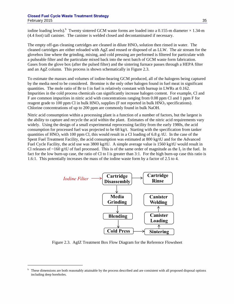
Closed Fuel Cycle Waste Treatment Strategy February 2015 35
iodine loading levels).b Twenty sintered GCM waste forms are loaded into a 0.155-m diameter × 1.34-m
(4.4 foot) tall canister. The canister is welded closed and decontaminated if necessary.
The empty off-gas cleaning cartridges are cleaned in dilute HNO3 solution then rinsed in water. The
cleaned cartridges are either reloaded with AgZ and reused or disposed of as LLW. The air stream for the
glovebox line where the grinding, mixing, and cold pressing are performed is filtered for particulate with
a pulseable filter and the particulate mixed back into the next batch of GCM waste form fabrication.
Gases from the glove box (after the pulsed filter) and the sintering furnace passes through a HEPA filter
and an AgZ column. This process is shown schematically in Figure 2.3.
To estimate the masses and volumes of iodine-bearing GCM produced, all of the halogens being captured
by the media need to be considered. Bromine is the only other halogen found in fuel meat in significant
quantities. The mole ratio of Br to I in fuel is relatively constant with burnup in LWRs at 0.162.
Impurities in the cold process chemicals can significantly increase halogen content. For example, Cl and
F are common impurities in nitric acid with concentrations ranging from 0.08 ppm Cl and 1 ppm F for
reagent grade to 100 ppm Cl in bulk HNO3 supplies (F not reported in bulk HNO3 specifications).
Chlorine concentrations of up to 200 ppm are commonly found in bulk NaOH.
Nitric acid consumption within a processing plant is a function of a number of factors, but the largest is
the ability to capture and recycle the acid within the plant. Estimates of the nitric acid requirements vary
widely. Using the design of a small experimental reprocessing facility from the early 1980s, the acid
consumption for processed fuel was projected to be 68 kg/t. Starting with the specification from tanker
quantities of HNO3 with 100 ppm Cl, this would result in a Cl loading of 6.8 g /tU. In the case of the
Spent Fuel Treatment Facility, the acid consumption was estimated at 800 kg/tU and for the Advanced
Fuel Cycle Facility, the acid use was 3800 kg/tU. A simple average value is 1560 kg/tU would result in
Cl releases of ~160 g/tU of fuel processed. This is of the same order of magnitude as the I2 in the fuel. In
fact for the low burn-up case, the ratio of Cl to I is greater than 3:1. For the high burn-up case this ratio is
1.6:1. This potentially increases the mass of the iodine waste form by a factor of 2.5 to 4.
Figure 2.3. AgIZ Treatment Box Flow Diagram for the Reference Flowsheet
b These dimensions are both reasonably attainable by the process described and are consistent with all proposed disposal options
including deep boreholes.
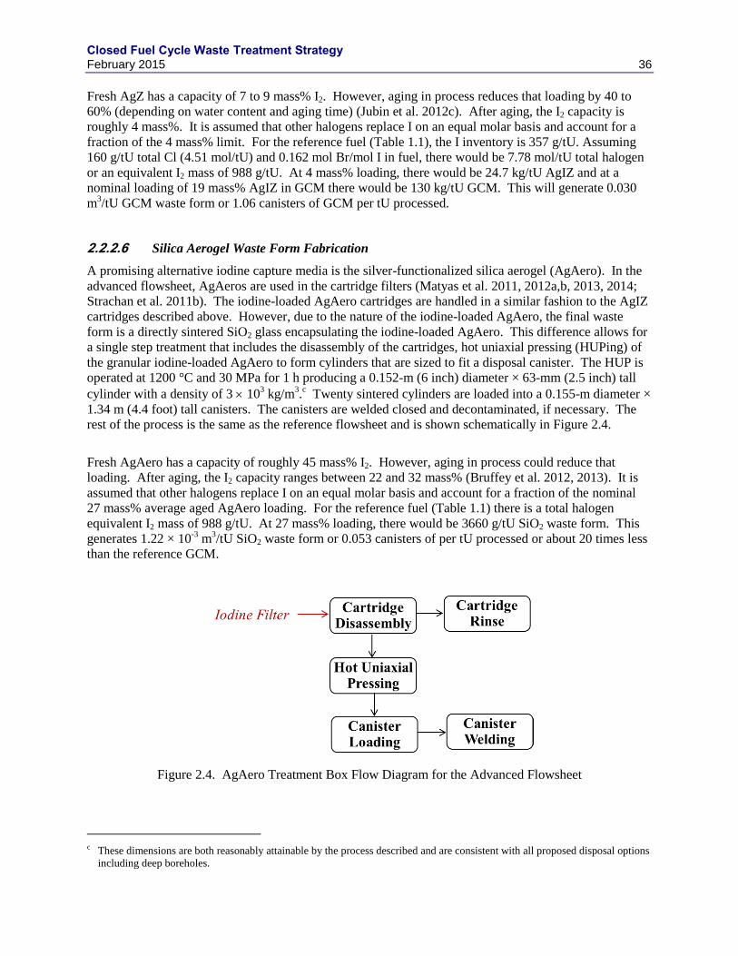
Closed Fuel Cycle Waste Treatment Strategy February 2015 36
Fresh AgZ has a capacity of 7 to 9 mass% I2. However, aging in process reduces that loading by 40 to
60% (depending on water content and aging time) (Jubin et al. 2012c). After aging, the I2 capacity is
roughly 4 mass%. It is assumed that other halogens replace I on an equal molar basis and account for a
fraction of the 4 mass% limit. For the reference fuel (Table 1.1), the I inventory is 357 g/tU. Assuming
160 g/tU total Cl (4.51 mol/tU) and 0.162 mol Br/mol I in fuel, there would be 7.78 mol/tU total halogen
or an equivalent I2 mass of 988 g/tU. At 4 mass% loading, there would be 24.7 kg/tU AgIZ and at a
nominal loading of 19 mass% AgIZ in GCM there would be 130 kg/tU GCM. This will generate 0.030
m3/tU GCM waste form or 1.06 canisters of GCM per tU processed.
Silica Aerogel Waste Form Fabrication 2.2.2.6
A promising alternative iodine capture media is the silver-functionalized silica aerogel (AgAero). In the
advanced flowsheet, AgAeros are used in the cartridge filters (Matyas et al. 2011, 2012a,b, 2013, 2014;
Strachan et al. 2011b). The iodine-loaded AgAero cartridges are handled in a similar fashion to the AgIZ
cartridges described above. However, due to the nature of the iodine-loaded AgAero, the final waste
form is a directly sintered SiO2 glass encapsulating the iodine-loaded AgAero. This difference allows for
a single step treatment that includes the disassembly of the cartridges, hot uniaxial pressing (HUPing) of
the granular iodine-loaded AgAero to form cylinders that are sized to fit a disposal canister. The HUP is
operated at 1200 °C and 30 MPa for 1 h producing a 0.152-m (6 inch) diameter × 63-mm (2.5 inch) tall
cylinder with a density of 3 103 kg/m
3.c Twenty sintered cylinders are loaded into a 0.155-m diameter ×
1.34 m (4.4 foot) tall canisters. The canisters are welded closed and decontaminated, if necessary. The
rest of the process is the same as the reference flowsheet and is shown schematically in Figure 2.4.
Fresh AgAero has a capacity of roughly 45 mass% I2. However, aging in process could reduce that
loading. After aging, the I2 capacity ranges between 22 and 32 mass% (Bruffey et al. 2012, 2013). It is
assumed that other halogens replace I on an equal molar basis and account for a fraction of the nominal
27 mass% average aged AgAero loading. For the reference fuel (Table 1.1) there is a total halogen
equivalent I2 mass of 988 g/tU. At 27 mass% loading, there would be 3660 g/tU SiO2 waste form. This
generates 1.22 × 10⁻³
m3/tU SiO2 waste form or 0.053 canisters of per tU processed or about 20 times less
than the reference GCM.
Figure 2.4. AgAero Treatment Box Flow Diagram for the Advanced Flowsheet
c These dimensions are both reasonably attainable by the process described and are consistent with all proposed disposal options
including deep boreholes.
Closed Fuel Cycle Waste Treatment Strategy February 2015 37
2.3 Krypton
Most of the 85
Kr (> 99%) remains in the spent fuel until it is sheared and dissolved. About 1 to 3% of the
fission gases are released during fuel pin sheering, depending on fuel characteristics. This means that
most of the 85
Kr would be primarily released in the DOG with a concentration in the range of hundreds of
parts per million. Recovery processes are based on physical separation from the off-gas since Kr is
chemically inert. The primary technologies for 85
Kr control are cryogenic distillation, fluorocarbon
adsorption, and sorption on molecular sieves or charcoal. Xenon is, by the time most fuel is processed, a
chemically stable fission product (the longest half-life is 36.4 d) and is also removed from the off-gas
streams in these processes. Xenon is present at about 10 times the Kr concentration.
2.3.1 Kr Recovery Processes
Cryogenic Distillation 2.3.1.1
Cryogenic distillation is a technology to recover rare gases that has been used commercially for many
years (Baetsle and Broothaerts 1977; Chesne et al. 1977; Henrich and von Ammon 1985b; Laser et al.
1973a; Yarbro et al. 1977). The cryogenic distillation process has been successfully used at the Idaho
Chemical Processing Plant (ICPP) to recover Kr (Soelberg et al. 2013). This commercial technology was
not optimized for removal of Kr at high DFs. Further development work has been done in Belgium,
France, Germany, India, and Japan on the cryogenic process (Barnert-Wiemer and Merz 1977; Bendixsen
and German 1971; Bendixsen et al. 1973; Bendixsen and Knecht 1976; Bendixsen et al. 1971;
Bohnenstingl et al. 1976; Casa 1977; Collard et al. 1981a; Davis and Martin 1973; Geens et al. 1981;
Geens et al. 1985; Geens et al. 1986; Henrich and Von Ammon 1985a; Hutter et al. 1987; Inada et al.
1979; Keilholtz 1971; Khan et al. 1975; Laser 1976; Laser et al. 1973b; Martin 1977; Monson 1982;
Offutt and Bendixsen 1969; Pence and Chou 1981; Ringel et al. 1981; Tamekiyo et al. 1983; Von
Ammon 1987; Weirich 1989; Whitmell et al. 1987; Yarbro et al. 1976; Yusa et al. 1977). Reported Kr
DFs were 100 to 1000 (Goossens et al. 1991).
When applied to dissolver off-gas, the gases must be pretreated to remove interfering constituents, thus
ensuring system safety and operability. All gases that condense at liquid nitrogen temperatures or above
have to be removed to prevent plugging of the equipment. These include NOx, water vapor, and CO2.
Oxygen must also be removed to avoid the formation and accumulation of ozone that is a radiolysis
product of the radiation from 85
Kr. Krypton and Xe are then removed from the off-gas stream in a
stripping column by dissolution in liquid nitrogen. They are subsequently separated in purification
columns, where the solvent is first removed along with most of the impurities and then the Kr is boiled
off from the Xe.
A hot pilot plant cryogenic unit for the recovery of 85
Kr became active in 1988 in the Tokai reprocessing
plant (Poncelet et al. 1991).
Fluorocarbon Absorption 2.3.1.2
Fluorocarbon absorption technology was developed at the Oak Ridge Gaseous Diffusion Plant and at the
Kernforschungszentrum Karlsruhe (KfK) (Hebel and Cottone 1982; Henrich 1985; IAEA 1980; Little
1983). This process uses an organic solvent (CCl2F2 also known as Freon R-12) to selectively absorb
noble gases from air or DOG streams; the noble gases are then stripped from the solvent by boiling.
The basis for this recovery process is the solubility difference that exists between the various gas
compounds in the solvent chosen for the process. Process performance data has been obtained using
tracer levels of 85
Kr in the column described above (Little 1983). Krypton recoveries greater than 99%
have been demonstrated with concentration factors ranging between 1000 and 10 000. Following the
Closed Fuel Cycle Waste Treatment Strategy February 2015 38
removal of the R-12 vapors, the typical product stream consists of CO2-78%, Xe-13%, N2-5.5%, Kr-2.0%,
O2-1.4% and Ar-0.1%.
Solid Sorbent Separation Processes 2.3.1.3
Both activated carbon and zeolites have been studied to recover krypton from the DOG stream. One
possible system uses a bed of synthetic silver mordenite (AgZ) at ambient temperatures to recover Xe.
The “Xe free” gas is then chilled and passed onto a second hydrogen mordenite (HZ) column operated at
~-80 °C where the Kr is absorbed. The Kr is recovered and concentrated on a third HZ column by
temperature swing on the second column to ~ 60 °C. The Kr is recovered from this third column again by
temperature swing to a cold trap (Trevorrow et al. 1983). The Xe bed is regenerated at 200 to 250 °C.
Laboratory tests have shown DFs of 400 for Kr and 4000 for Xe (Pence and Chou 1981).
Industrial scale demonstration of an adsorptive chromatographic separation of krypton on activated
charcoal at low temperatures (ACHAT) has been conducted at the research center Julich (KFA) in
Germany (Ringel 1990). Krypton DFs of 1600 have been obtained and Kr purities in the final product of
> 99%.
Monson (1981) reports that AgZ has the highest Kr adsorption capacity and examined other less
expensive zeolites for Kr recovery and non-cryogenic operating temperatures. His data show hydrogen
mordenite HZ has a capacity of on the order of 1 × 10⁻⁹
moles Kr per gm HZ at ambient temperatures.
Munakata et al. (2003) have also examined the use of AgZ and HZ to recover Xe and Kr from helium
carrier gas. They point out that this approach should have lower operating costs than cryogenic
distillation and will avoid the possible fire hazard resulting from the accumulation of ozone in the
cryogenic systems. It also has the advantage of avoiding the possible explosive reactions and fire risks
associated with NOx reactions and activated carbons that have also been studied for the recovery of
Kr/Xe. Loadings of 1 × 10⁻⁶
mol Kr/g AgZ and 2 × 10⁻⁷
mol Kr/g HZ were reported at a partial pressure
of ~ 5 Pa. Xe loadings are estimated to be 2 × 10⁻⁴
mol Xe/g AgZ and 1.5 × 10⁻⁵
mol Xe/g HZ were
reported at a partial pressure of ~55 Pa. Both of these loadings are at 273 K. Thus processing of 1 tU
would require a minimum bed size of ~500 L of AgZ at a packed density of 0.662 g/cm3. At these
conditions the bed would absorb ~0.3 mol of Kr in addition to the 67.4 mol of Xe. This is ~5% of the Kr.
Building from these data, and with the goal of operating the Kr recovery systems at or near room
temperature, two solid sorbents are currently under evaluation as part of the Off-gas Sigma Team effort.
These include several metal organic frameworks (MOF) materials (Strachan et al. 2011b, Thallapally et
al. 2012, 2013; Cabe et al. 2014) and an engineered form of a synthetic AgZ/HZ (Garn et al. 2012, Garn
and Greenhalgh 2013).
Recent sorbent development efforts resulted in a patented process for preparing engineered form sorbents
incorporating synthetic AgZ and HZ mordenite powders bound in a macroporous polymer (Garn et al.
2014). The AgZ-PAN and HZ-PAN engineered forms have been tested at bench-scale using thermal
swing and thermal/pressure swing combination operations. Xenon loadings for AgZ-PAN at room
temperature (22°C) of 3 × 10⁻⁵
mol Xe/g AgZ-PAN have been achieved using a Xe partial pressure of
~100 Pa. Slightly elevating the feed gas pressure to 20 psig increased Xe loading by a factor of nearly
three at room temperature. Loadings measured at 220 K for Xe at ~100 Pa and Kr at ~15 Pa were 6 × 10⁻⁴
mol Xe/g AgZ-PAN and 6 × 10⁻⁶
mol Kr/g AgZ-PAN. Loadings for HZ-PAN at 220 K using the same Xe
and Kr partial pressures were very similar to those with AgZ-PAN, suggesting the Xe/silver interaction is
more prevalent at room temperature and HZ-PAN being less expensive can be effectively used to capture
Kr at reduced temperatures. Recent thermal/pressure swing combination test results suggest Kr loadings
for HZ-PAN at 220 K can be increased by a factor of three by elevating feed gas pressures to 30 psig.
Apart from AgZ and HZ, MOF’s are being developed for the removal of Xe and Kr at near room
temperature. Among all the MOF materials tested, a nickel dioxobenzenedicarboxylic acid (NiDOBDC,
Closed Fuel Cycle Waste Treatment Strategy February 2015 39
Thallapally et. al., 2012) based MOF and a partially fluorinated MOF with copper (FMOF-Cu, Fernandez
et. al., 2012) have shown improved Xe and Kr capacities at room temperature relative to previous
materials (Debasis et. al., 2015). Adsorption experiments on the NiDOBDC showed that it has a Xe
adsorption capacity of 4.24 mmol Xe/g at 100 kPa and 298 K. However, it only adsorbs 3 mass% Kr
(3.57 × 10⁻⁴
mol Kr/g) under similar experimental conditions. However, the silver nanoparticle-loaded
NiDOBDC (Ag@NiDOBDC) had better Xe uptake capacity (5.3 × 10⁻³
mol Xe/g) and selectivity (Xe/Kr
≈ 7) over the parent framework (Liu et. al., 2014). Under the same conditions (room temperature and 100
kPa) the FMOFCu adsorbed 4.5 × 10⁻⁴
mol Xe/g and 3.4 × 10⁻⁵
mol Kr/g. However under low
temperatures (-40 °C) the FMOFCu adsorbed higher Kr (1.75 × 10⁻³
mol Kr/ g) than Xe (1.5 × 10⁻⁴
mol
Xe/g) at 100 kPa (Fernandez et. al., 2012).
The removal efficiency and capacity of NiDOBDC and FMOF-Cu for Kr recovery with two adsorption
beds in series at a non-cryogenic temperature (233 K) has been demonstrated (Liu et. al., 2014). The use
of 233 K was strictly an artifact of the experimental set-up used here. Independently, these MOFs have
been shown to have high capacities and specificities for Xe and Kr at temperatures >273 K. Passing a
mixture of 400 ppm Xe, 40 ppm Kr in dry air through bed 1 containing NiDOBDC shows the selective
capture of Xe, the outlet gas mixture from bed 1 now containing 40 ppm Kr in air is then passed through
bed 2 also containing NiDOBDC where Kr is removed (0.61 mmol/kg). Similar experiments performed
with FMOFCu instead of NiDOBDC in bed 2 result in adsorption capacities 3.7 times for Kr (1.03
mmol/kg) than from mixture containing Xe and Kr. Based on these results, a two bed system used for a
1000 tU/y plant would require a 1.9 m3 Xe bed and a 5.6 m
3 Kr bed (Cabe et al. 2014). These results
show that MOF materials continue to be promising for separation of Xe and Kr from air and from each
other at non-cryogenic temperatures.
Apart from MOFs, PNNL collaborated with University of Liverpool, UK to explore the applicability of
porous organic cage compound (CC3) for separation of Xe and Kr at room temperature (Chen et. al,
2014). In the solid state, CC3 molecules pack to give a robust 3-dimensional pore structure with pore-
limiting diameter of just 3.6 Å. This is slightly smaller than the diameter of Kr (3.69 Å) (Van Heest et al.
2012), and in principle too narrow to permit the diffusion of Xe. Therefore adsorption experiments at
room temperature using Xe and Kr were carried at 100 kPa. The Xe isotherm approaches saturation at
100 kPa (298 K) with an adsorption capacity of around 2.25 × 10⁻³
mol Xe/g, corresponding to three gas
molecules per CC3 cage. Similarly, the adsorption capacity of Kr at identical conditions was found to be
0.84 × 10⁻³
mol Kr/g. When air containing Xe (400 ppm) and Kr (40 ppm) was passed through this
column (start at 10 min), the Xe component was retained for more than 15 minutes, even at a flow rate of
0.67 L/s or twice as fast as that used in the studies of NiDOBDC (Liu et. al., 2012), whereas Kr and the
other components (N2, O2, and CO2) broke through the column almost immediately. Under these
conditions, CC3 adsorbs twice (11 mmol/kg) as much Xe as the leading MOF, Ni/DOBDC (4.8 mmol kg-
1). Likewise, the Xe/Kr selectivity for CC3 under these conditions is almost three times higher than for
Ni/DOBDC: 20.4 versus 7.3. This is ascribed to the near-perfect fit between the cavities in CC3 and the
Xe guests.
Summary and Recommendations 2.3.1.4
A summary of Kr recovery processes is shown in Table 2.4. Based on the technical maturity and
effectiveness, it is recommended that cryogenic distillation be the primary process for Kr recovery.
However, adsorption processes have shown promise to be cost effective alternatives and should be
developed further and demonstrated.
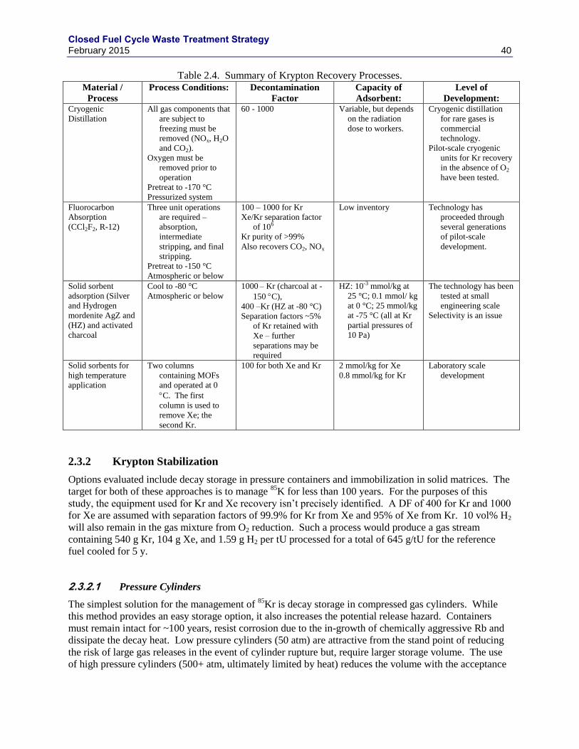
Closed Fuel Cycle Waste Treatment Strategy February 2015 40
Table 2.4. Summary of Krypton Recovery Processes. Material /
Process
Process Conditions: Decontamination
Factor
Capacity of
Adsorbent:
Level of
Development: Cryogenic
Distillation
All gas components that
are subject to
freezing must be
removed (NOx, H2O
and CO2).
Oxygen must be
removed prior to
operation
Pretreat to -170 °C
Pressurized system
60 - 1000 Variable, but depends
on the radiation
dose to workers.
Cryogenic distillation
for rare gases is
commercial
technology.
Pilot-scale cryogenic
units for Kr recovery
in the absence of O2
have been tested.
Fluorocarbon
Absorption
(CCl2F2, R-12)
Three unit operations
are required –
absorption,
intermediate
stripping, and final
stripping.
Pretreat to -150 °C
Atmospheric or below
100 – 1000 for Kr
Xe/Kr separation factor
of 106
Kr purity of >99%
Also recovers CO2, NOx
Low inventory Technology has
proceeded through
several generations
of pilot-scale
development.
Solid sorbent
adsorption (Silver
and Hydrogen
mordenite AgZ and
(HZ) and activated
charcoal
Cool to -80 °C
Atmospheric or below
1000 – Kr (charcoal at -
150 C),
400 –Kr (HZ at -80 °C)
Separation factors ~5%
of Kr retained with
Xe – further
separations may be
required
HZ: 10-3 mmol/kg at
25 °C; 0.1 mmol/ kg
at 0 °C; 25 mmol/kg
at -75 °C (all at Kr
partial pressures of
10 Pa)
The technology has been
tested at small
engineering scale
Selectivity is an issue
Solid sorbents for
high temperature
application
Two columns
containing MOFs
and operated at 0
C. The first
column is used to
remove Xe; the
second Kr.
100 for both Xe and Kr 2 mmol/kg for Xe
0.8 mmol/kg for Kr
Laboratory scale
development
2.3.2 Krypton Stabilization
Options evaluated include decay storage in pressure containers and immobilization in solid matrices. The
target for both of these approaches is to manage 85
K for less than 100 years. For the purposes of this
study, the equipment used for Kr and Xe recovery isn’t precisely identified. A DF of 400 for Kr and 1000
for Xe are assumed with separation factors of 99.9% for Kr from Xe and 95% of Xe from Kr. 10 vol% H2
will also remain in the gas mixture from O2 reduction. Such a process would produce a gas stream
containing 540 g Kr, 104 g Xe, and 1.59 g H2 per tU processed for a total of 645 g/tU for the reference
fuel cooled for 5 y.
Pressure Cylinders 2.3.2.1
The simplest solution for the management of 85
Kr is decay storage in compressed gas cylinders. While
this method provides an easy storage option, it also increases the potential release hazard. Containers
must remain intact for ~100 years, resist corrosion due to the in-growth of chemically aggressive Rb and
dissipate the decay heat. Low pressure cylinders (50 atm) are attractive from the stand point of reducing
the risk of large gas releases in the event of cylinder rupture but, require larger storage volume. The use
of high pressure cylinders (500+ atm, ultimately limited by heat) reduces the volume with the acceptance
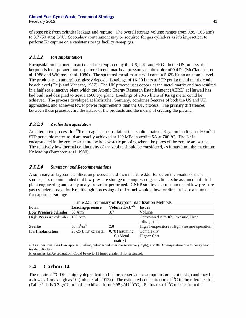
Closed Fuel Cycle Waste Treatment Strategy February 2015 41
of some risk from cylinder leakage and rupture. The overall storage volume ranges from 0.95 (163 atm)
to 3.7 (50 atm) L/tU. Secondary containment may be required for gas cylinders as it’s impractical to
perform Kr capture on a canister storage facility sweep gas.
Ion Implantation 2.3.2.2
Encapsulation in a metal matrix has been explored by the US, UK, and FRG. In the US process, the
krypton is incorporated into a sputtered metal matrix at pressures on the order of 0.4 Pa (McClanahan et
al. 1986 and Whitmell et al. 1980). The sputtered metal matrix will contain 5-6% Kr on an atomic level.
The product is an amorphous glassy deposit. Loadings of 16-20 liters at STP per kg metal matrix could
be achieved (Thijs and Vansant, 1987). The UK process uses copper as the metal matrix and has resulted
in a half scale inactive plant which the Atomic Energy Research Establishment (AERE) at Harwell has
had built and designed to treat a 1500 t/yr plant. Loadings of 20-25 liters of Kr/kg metal could be
achieved. The process developed at Karlsruhe, Germany, combines features of both the US and UK
approaches, and achieves lower power requirements than the UK process. The primary differences
between these processes are the nature of the products and the means of creating the plasma.
Zeolite Encapsulation 2.3.2.3
An alternative process for 85
Kr storage is encapsulation in a zeolite matrix. Krypton loadings of 50 m3 at
STP per cubic meter solid are readily achieved at 100 MPa in zeolite 5A at 700 °C. The Kr is
encapsulated in the zeolite structure by hot-isostatic pressing where the pores of the zeolite are sealed.
The relatively low thermal conductivity of the zeolite should be considered, as it may limit the maximum
Kr loading (Penzhorn et al. 1980).
Summary and Recommendations 2.3.2.4
A summary of krypton stabilization processes is shown in Table 2.5. Based on the results of these
studies, it is recommended that low-pressure storage in compressed gas cylinders be assumed until full
plant engineering and safety analyses can be performed. GNEP studies also recommended low-pressure
gas cylinder storage for Kr, although processing of older fuel would allow for direct release and no need
for capture or storage.
Table 2.5. Summary of Krypton Stabilization Methods. Form Loading/pressure Volume L/tU
a,b Issues
Low Pressure cylinder 50 Atm 3.7 Volume
High Pressure cylinder 163 Atm 1.1 Corrosion due to Rb, Pressure, Heat
dissipation
Zeolite 50 m3/m
3 2.8 High Temperature / High Pressure operation
Ion Implantation 20-25 L Kr/kg metal 0.78 (assuming
Cu Metal
matrix)
Complexity
Higher Cost
a. Assumes Ideal Gas Law applies (making cylinder volumes conservatively high), and 80 °C temperature due to decay heat
inside cylinders.
b. Assumes Kr/Xe separation. Could be up to 11 times greater if not separated.
2.4 Carbon-14
The required 14
C DF is highly dependent on fuel processed and assumptions on plant design and may be
as low as 1 or as high as 10 (Jubin et al. 2012a). The estimated concentration of 14
C in the reference fuel
(Table 1.1) is 0.3 g/tU, or in the oxidized form 0.95 g/tU 14
CO2. Estimates of 14
C release from the
Closed Fuel Cycle Waste Treatment Strategy February 2015 42
standard TPT process is roughly 50% (Table 1.2). The fraction of 14
C released from the dissolver may be
between 50 and 100%.d For the purposes of estimating waste form volumes, it is assumed that 100% of
the 14
C is released to the DOG in the reference case and 50% is released to the TOG and the other 50% is
released to the DOG in the case of the advanced flowsheet. The amounts of tramp 12
CO2 coming from
shear sweep gas and dissolver air inleakage and sparging were calculated assuming air flowrates of 5,830
m3/d through the shear cell and 6650 m
3/d though the dissolver (it is assumed that CO2-free air would be
used in the TPT). This would result in 9.16 kg/d of 12
CO2 or 1.83 kg/tU (for a nominal 5 tU/d plant). The
result is a dilution of 14
CO2 by 12
CO2 of roughly 1925:1.
2.4.1 Carbon Capture
There are a number of technologies that have been developed for CO2 removal. These include caustic
scrubbing, molecular sieve adsorption, adsorbent bed fixation, and co-absorption and concentration in
conjunction with Kr recovery and subsequent immobilization. There is sufficient cold-engineering results
that indicate these methods would work. However, their practicality in radioactive application remains
for the most part untested.
Caustic Scrubbing 2.4.1.1
Carbon dioxide adsorption in a caustic solution in a packed column to form carbonates is a common
industrial process that has been described in detail (Bray 1977). While the process has never been applied
specifically for 14
C recovery in the nuclear fuel cycle, the EPA indicated in 1977 that it would be the most
probable candidate for application at that time (Brown et al. 1983). The baseline process is scrubbing
with Ca(OH)2 because of the greater solubility and lower cost compared to the more efficient Ba(OH)2.
A double-alkali process involving Na2CO3 and CaCO3 is briefly described in the book edited by Goosens
(1991). Carbon dioxide is initially scrubbed from the off-gas stream with an aqueous NaOH stream to
form Na2CO3. The resulting solution is then reacted with lime (CaOH) to produce a solid CaCO3 product.
Caustic Slurry Scrubbing 2.4.1.2
Limited studies have been made into the use of alkaline earth hydroxide slurry in stirred tank reactors to
absorb CO2 (Notz 1980). The DF for Ba(OH) 2·8H2O is about 10 times greater than Ca(OH)2, which is
about 10 times greater than Mg(OH)2. The reaction rates were determined to be controlled by transport in
the aqueous phase and thus impacted by the hydrodynamic parameters of the reactor. Processing steps to
recover the spent material, dry, and package in a suitable waste form remains to be completed (Brown et
al. 1983).
d In the THORP facility, it is reported (Chris Phillips personal communication) that ~98% of the
14C in the
fuel is released during dissolution. However, information from AREVA indicates that only ~50% of the 14
C is released during dissolution. The THORP dissolver is a batch design with a long residence time.
The AREVA dissolver is a continuous ‘bucket wheel’ design which probably has a shorter residence time.
The implication is that 14
C release during dissolution is highly dependent on residence time.
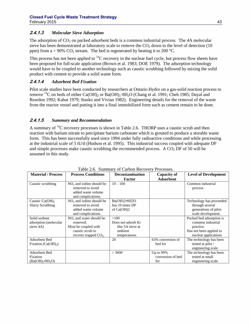
Closed Fuel Cycle Waste Treatment Strategy February 2015 43
Molecular Sieve Adsorption 2.4.1.3
The adsorption of CO2 on packed adsorbent beds is a common industrial process. The 4A molecular
sieve has been demonstrated at laboratory scale to remove the CO2 down to the level of detection (10
ppm) from a > 90% CO2 stream. The bed is regenerated by heating it to 200 °C.
This process has not been applied to 14
C recovery in the nuclear fuel cycle, but process flow sheets have
been proposed for full-scale application (Brown et al. 1983; DOE 1979). The adsorption technology
would have to be coupled to another technology such as caustic scrubbing followed by mixing the solid
product with cement to provide a solid waste form.
Adsorbent Bed Fixation 2.4.1.4
Pilot scale studies have been conducted by researchers at Ontario Hydro on a gas-solid reaction process to
remove 14
C on beds of either Ca(OH)2 or Ba(OH)2·8H2O (Chang et al. 1991; Cheh 1985; Dayal and
Reardon 1992; Kabat 1979; Stasko and Vivian 1982). Engineering details for the removal of the waste
from the reactor vessel and putting it into a final immobilized form such as cement remain to be done.
Summary and Recommendation 2.4.1.5
A summary of 14
C recovery processes is shown in Table 2.6. THORP uses a caustic scrub and then
reaction with barium nitrate to precipitate barium carbonate which is grouted to produce a storable waste
form. This has been successfully used since 1994 under fully radioactive conditions and while processing
at the industrial scale of 5 tU/d (Hudson et al. 1995). This industrial success coupled with adequate DF
and simple processes make caustic scrubbing the recommended process. A CO2 DF of 50 will be
assumed in this study.
Table 2.6. Summary of Carbon Recovery Processes. Material / Process Process Conditions Decontamination
Factor
Capacity of
Adsorbent
Level of Development
Caustic scrubbing NOx and iodine should be
removed to avoid
added waste volume
and complications.
10 – 100 Common industrial
process
Caustic Ca(OH)2
Slurry Scrubbing
NOx and iodine should be
removed to avoid
added waste volume
and complications.
Ba(OH)2•8H2O
has 10 times DF
of Ca(OH)2
Technology has proceeded
through several
generations of pilot-
scale development.
Solid sorbent
adsorption (molecular
sieve 4A)
NOx and water should be
removed.
Must be coupled with
caustic scrub to
recover trapped CO2.
>100
Does not adsorb Kr
like 5A sieve at
ambient
temperatures
Packed bed adsorption is
common industrial
practice.
Has not been applied to
nuclear applications
Adsorbent Bed
Fixation (Ca(OH)2)
20 63% conversion of
bed for
The technology has been
tested at pilot /
engineering scale
Adsorbent Bed
Fixation
(Ba(OH)2•8H2O)
> 3000 Up to 99%
conversion of bed
for
The technology has been
tested at small
engineering scale
Closed Fuel Cycle Waste Treatment Strategy February 2015 44
2.4.2 Carbon Stabilization
Most of the carbon immobilization studies conducted to date have considered calcium or barium
carbonate that is then mixed with cement and packaged in steel drums.e This is also the industrial process
applied at THORP. Precipitation of the carbonate by calcium is less expensive than barium and avoids
issues associated with the hazardous waste generated from barium handling and use. Cementation was
also recommended in the GNEP studies in the cases were 14
C capture was considered.
The process, as described by Holladay (1978) and Goosens (1991), is to capture CO2 in a 1.5 to 1.7 M
NaOH solution. CaOH is added to the solution to precipitate CaCO3 which is concentrated to 800 g/L
(CaCO3). The liquid phase of the CaCO3 slurry will contain a nominal 1.6 M NaOH. This scrubber
would also remove a portion of whatever NOX is in the gas stream. There may be some effect of
dissolved ions (Na+, NO2
-, NO3
-, OH
-, etc.) on the solubility of CaCO3. Lacking specific data 0%
dissolved CaCO3 is assumed; although it is recognized that there may be some dissolved CaCO3
circulating in the scrub system.
The annual waste product from the scrubber column would be 1.6 t of calcium carbonate containing ~2 kg
of Ca14
CO3. The mass of this aqueous slurry is expected to be 20 t which, if immobilized in cement at a
ratio of 30% slurry to 70% cement, would generate 65 t of cement or 190 drums (200 L capacity) of waste
product. To reduce the impact of non-radioactive CO2, the process could be designed to remove the CO2
from the air prior to sparging the dissolver, minimizing sparge gas flow, or using nitrogen in place of air.
Section 9 describes the cementation process and also discusses the possibility of combining the CaCO3
waste with other wastes for cementation.
2.5 Data Gaps and Research Needs
The development of an integrated reprocessing plant off-gas treatment system that efficiently meets all of
the regulatory requirements is a significant challenge, for both aqueous and other reprocessing
technologies. New materials and methods promise to improve the ability to effectively meet those
requirements. However, most of these methods are not fully technically mature and the unit operations
have not been integrated into a working system. The data gaps and research needs are given below first
for individual unit operations and then for integrated off-gas treatment systems.
2.5.1 Tritium
Demonstrate the process for obtaining a clean separation between 129
I and 3H during treatment of
prototypic simulated off-gas streams at laboratory scale. Follow-up with integrated cold- and hot-
off-gas system testing described below.
Processes under current investigation to support air/oxygen based tritium pretreatment of UNF
include sorption on MS3A to sequester the tritiated water. The high concentrations of NOx in the
off-gas could cause the tritium to be partially converted to tritiated nitric acid vapor. Information
needed to support the NO2 pretreatment process includes, but is not limited to, the speciation of
tritium in the off-gas stream (e.g, 3HHO,
3HNO3,
3HNO2, etc.) and the capacity of the MS3A
sorbent to sequester the tritium-bearing compounds. Alternatives to MS3A may need to be
identified that are more compatible with nitric or other acid gases.
e Leach tests conducted by Scheele and Burger (1982) have shown leach data indicating that ~1% of the 14C would be leached
in 1000 years. A carbonate loading of 2.5 mmol per gram of dry cement was tested.
Closed Fuel Cycle Waste Treatment Strategy February 2015 45
2.5.2 Iodine
Determine the iodine species (e.g., I2, HI, and CH3I) expected from each of the key off-gas
streams (DOG, HOG, TOG, VOG and MOG) and develop prototypic gas simulants for each of
these streams.
Demonstrate the efficiency of AgZ and alternate sorbents under increasing more prototypic off-
gas stream conditions to capture/control of the iodine species that will be present in DOG, HOG,
TOG, VOG and MOG streams. The focus of this effort will be on organic iodides and very dilute
streams. Data needed includes changes in capacity and capture efficiency as a function of stream
conditions. Evaluate performance of Ag-functionalized aerogels for adsorbing iodine under
prototypic off-gas conditions.
Successfully stabilize iodine and/or iodine loaded sorbents in a matrix suitable for disposal.
Determine “optimum” processing conditions and loading. This includes GCM for iodine loaded
AgZ, HIPing of iodine loaded AgZ, and consolidation of iodine loaded AgAero. Determine
composition of effluent from conversions process, i.e., iodine loss. Determine the effect of
residuals, such as organics, on waste form fabrication process.
Obtain data from the dissolution of actual UNF to evaluate the iodine evolution kinetics, the
fraction remaining in solution, and the species of iodine not evolved.
Determine long term performance of promising alternate iodine sorbents under operating
conditions. Determine extent of co-adsorption on these materials.
Determine the fate and behavior of iodine in used fuel during electrochemical reprocessing,
specifically during the drawdown processes.
2.5.3 Carbon
Determine the overall off-gas generation rate from a reprocessing plant using data from existing
facilities. Determine what physical and chemical form contaminants are generated and released
from these plants. Determine if 14
C capture will be required and to what efficiency.
Perform a trade study to determine if CO2-free air should be utilized in a reprocessing facility to
avoid generation of high volumes of 14
C related wastes.
Determine the fate and behavior of carbon in used fuel during echem reprocessing.
2.5.4 Krypton
Demonstrate a multi-bed system for the recovery of Kr from air at room temperature with MOF
and zeolite materials. Confirm capacity, adsorption rates, desorption rates, etc. as a function of
capture temperatures.
Understand long term effects of the build-up of Rb in Kr-85 storage systems. Continue the
analysis of the legacy Kr-85 capsules. Prepare new samples for extended storage.
Demonstrate the radiation stability of Kr capture and storage MOFs. Need to understand long
term stability when loaded with Kr-85.
Closed Fuel Cycle Waste Treatment Strategy February 2015 46
2.5.5 Interfaces and Integration
Demonstrate integration of individual off-gas capture systems at bench scale or larger. Evaluate
the combined system efficiency; determine sequencing, co-adsorption / interoperability issues.
As currently envisioned, the NO2 tritium pretreatment process utilizes a closed loop of
recirculating oxidant gas into which the volatile fission products would accumulate. The
recovery of the volatile radionuclides from a gas matrix of this nature has never been
demonstrated. The current choice for iodine recovery is silver exchanged mordenite which is
acid stable but it has not been tested for iodine capture from gas streams containing more than a
few % NOx. Testing and verification of capture performance is needed. There is a need to
identify and evaluate alternative media/processes to capture the iodine. This media needs to be
insensitive to NOx and nitric acid vapors that will be present in the off-gas stream and be
sufficiently selective to iodine. Current studies have shown significant degradation of AgZ under
advanced tritium pretreatment off-gas conditions. An alternate iodine capture method for this
application is needed. A molten NaOH scrubber has been proposed as a possible approach that
would not be impacted by the oxidant in the gas stream. Other systems using silver nitrate may
also be promising and will be examined for their efficacy.
In addition to the volatile species, the behavior of the semi-volatile elements needs to be
evaluated. The semivolatiles that arise in head-end pretreatment processes need to be identified,
and the amounts in the off-gas stream quantified and the effects (if any) that high concentrations
of the oxidant have on forming volatile compounds at relevant tritium pretreatment conditions
need to be characterized. Of initial interest is the behavior of ruthenium under advance tritium
pretreatment conditions.
Perform a volatile species material balance on an intact fuel pin as the pin is processed through
shearing, tritium pretreatment, and dissolution. Quantification of the release of semi-volatiles is
also needed.
Obtain data from plant operations through international collaboration on iodine emissions (origins
and speciation).
Demonstrate off-gas capture technologies on hot off-gas streams. This could be accomplished as
opportunities become available in the US or through international collaborations.
Closed Fuel Cycle Waste Treatment Strategy February 2015 47
3. AQUEOUS HIGH LEVEL WASTE STREAMS
The HLW is composed of the following process streams from the processing steps to recover U and Pu
from UNF:
a HLW raffinate from TRUEX, which contains the alkali, alkaline earth, and transition metal
fission products;
a separate Tc solution from the third segment of the U/Pu/Np co-decontamination process;
a lanthanide stream from TALSPEAK;
undissolved solids from dissolver sludge and solution clarification, containing primarily Mo, Tc,
Ru, Rh, Pd, Zr, Te, O, and Pu.
The compositions of these streams are given in Table 1.5.
This section begins with a discussion of the waste forms that have been considered for HLW
immobilization and the evaluations that have led to borosilicate glass as the preferred immobilization
method with Synroc crystalline ceramic as the next option for defense HLW. Then details of the HLW
vitrification process are provided. Finally, alternative candidate waste forms and processes with the
potential for significant advantages over the baseline borosilicate glass are presented.
3.1 HLW Waste Form Reviews
Borosilicate glass in a stainless steel canister is the baseline waste form for immobilization and disposal
of HLW in the U.S. and most of the rest of the world. Synroc (i.e. synthetic rock) (Ringwood et al. 1980;
Ringwood et al. 1981) is a synthetic crystalline ceramic that is considered as an option to the baseline
glass. Numerous other waste forms have been considered over the years for HLW immobilization.
In the U.S., the DOE and its predecessors have been conducting waste form and waste immobilization
process development and evaluation dating back to the 1950’s (Durham 1957; Ginell et al. 1954;
Goldman et al. 1957; Hatch 1953; Manowitz and Hatch 1954; Watson et al. 1958; White and Lahaie
1955). From 1966 to 1970, the Waste Solidification Engineering Prototypes program demonstrated pot
calcine, phosphate microcrystalline ceramic, phosphate glass, and borosilicate glass for immobilization of
commercial HLW (Schneider and Kelly 1969, Schneider 1969, McElroy et al. 1972, Mendel and McElroy
1972).
Between 1979 and 1981, DOE conducted its National High-Level Waste Technology Program to develop
and evaluate candidate waste forms for immobilization of HLW at DOE defense sites (Gray 1981). Table
3.1 lists the 17 waste forms initially considered for development and evaluation. By the end 1981, seven
candidate waste forms had been selected including (Hench et al. 1981):
Borosilicate glass
Synroc
Tailored ceramic
High-silica glass
FUETAP Concrete
Coated particles
Glass marbles in a lead matrix
Based on waste form evaluations conducted at the DOE national laboratories and independent
laboratories, peer review assessments, a product performance evaluation, and a processability assessment,
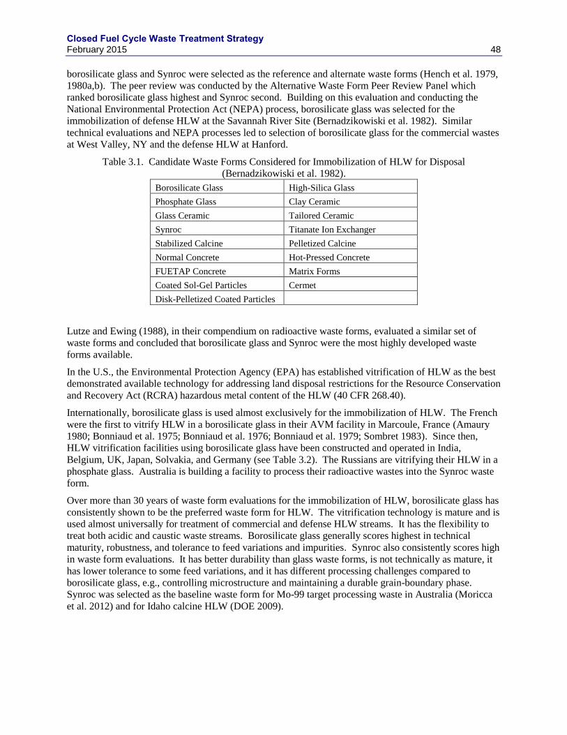
Closed Fuel Cycle Waste Treatment Strategy February 2015 48
borosilicate glass and Synroc were selected as the reference and alternate waste forms (Hench et al. 1979,
1980a,b). The peer review was conducted by the Alternative Waste Form Peer Review Panel which
ranked borosilicate glass highest and Synroc second. Building on this evaluation and conducting the
National Environmental Protection Act (NEPA) process, borosilicate glass was selected for the
immobilization of defense HLW at the Savannah River Site (Bernadzikowiski et al. 1982). Similar
technical evaluations and NEPA processes led to selection of borosilicate glass for the commercial wastes
at West Valley, NY and the defense HLW at Hanford.
Table 3.1. Candidate Waste Forms Considered for Immobilization of HLW for Disposal
(Bernadzikowiski et al. 1982).
Borosilicate Glass High-Silica Glass
Phosphate Glass Clay Ceramic
Glass Ceramic Tailored Ceramic
Synroc Titanate Ion Exchanger
Stabilized Calcine Pelletized Calcine
Normal Concrete Hot-Pressed Concrete
FUETAP Concrete Matrix Forms
Coated Sol-Gel Particles Cermet
Disk-Pelletized Coated Particles
Lutze and Ewing (1988), in their compendium on radioactive waste forms, evaluated a similar set of
waste forms and concluded that borosilicate glass and Synroc were the most highly developed waste
forms available.
In the U.S., the Environmental Protection Agency (EPA) has established vitrification of HLW as the best
demonstrated available technology for addressing land disposal restrictions for the Resource Conservation
and Recovery Act (RCRA) hazardous metal content of the HLW (40 CFR 268.40).
Internationally, borosilicate glass is used almost exclusively for the immobilization of HLW. The French
were the first to vitrify HLW in a borosilicate glass in their AVM facility in Marcoule, France (Amaury
1980; Bonniaud et al. 1975; Bonniaud et al. 1976; Bonniaud et al. 1979; Sombret 1983). Since then,
HLW vitrification facilities using borosilicate glass have been constructed and operated in India,
Belgium, UK, Japan, Solvakia, and Germany (see Table 3.2). The Russians are vitrifying their HLW in a
phosphate glass. Australia is building a facility to process their radioactive wastes into the Synroc waste
form.
Over more than 30 years of waste form evaluations for the immobilization of HLW, borosilicate glass has
consistently shown to be the preferred waste form for HLW. The vitrification technology is mature and is
used almost universally for treatment of commercial and defense HLW streams. It has the flexibility to
treat both acidic and caustic waste streams. Borosilicate glass generally scores highest in technical
maturity, robustness, and tolerance to feed variations and impurities. Synroc also consistently scores high
in waste form evaluations. It has better durability than glass waste forms, is not technically as mature, it
has lower tolerance to some feed variations, and it has different processing challenges compared to
borosilicate glass, e.g., controlling microstructure and maintaining a durable grain-boundary phase.
Synroc was selected as the baseline waste form for Mo-99 target processing waste in Australia (Moricca
et al. 2012) and for Idaho calcine HLW (DOE 2009).
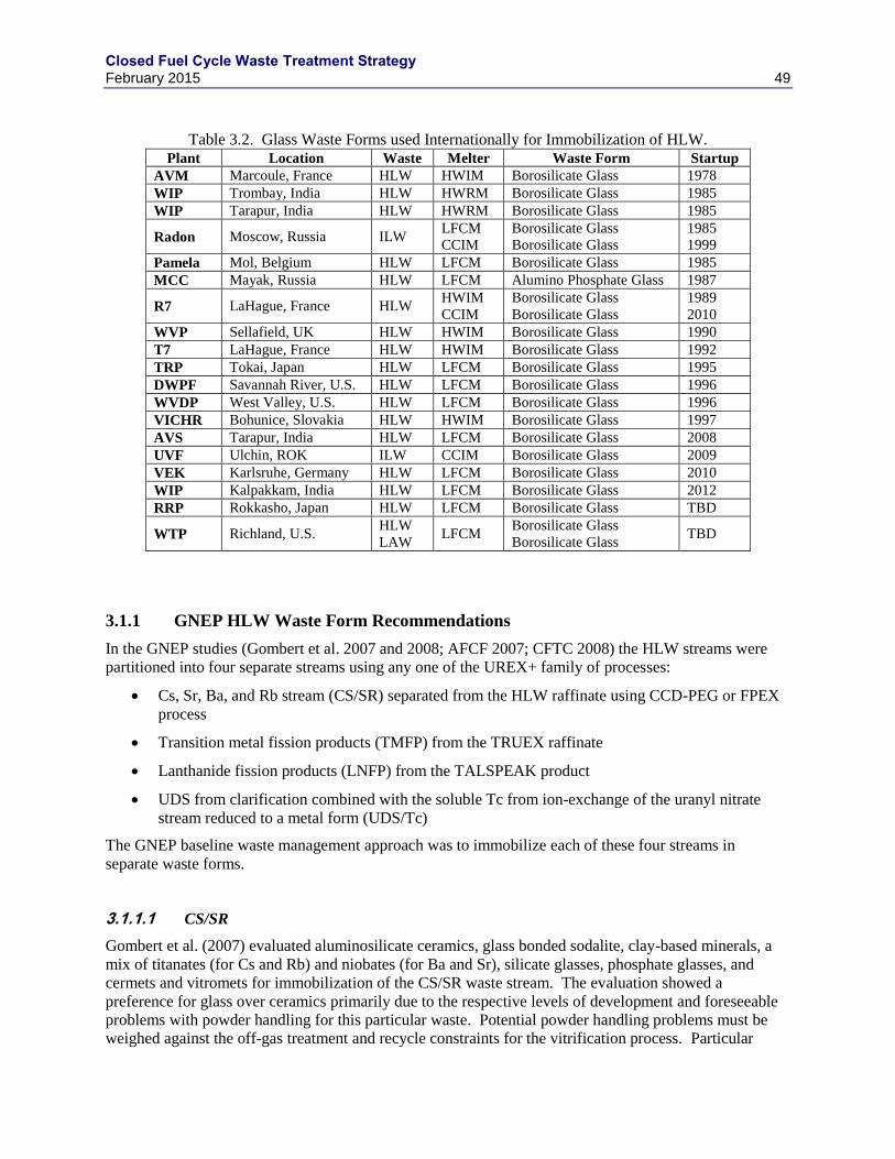
Closed Fuel Cycle Waste Treatment Strategy February 2015 49
Table 3.2. Glass Waste Forms used Internationally for Immobilization of HLW. Plant Location Waste Melter Waste Form Startup
AVM Marcoule, France HLW HWIM Borosilicate Glass 1978
WIP Trombay, India HLW HWRM Borosilicate Glass 1985
WIP Tarapur, India HLW HWRM Borosilicate Glass 1985
Radon Moscow, Russia ILW LFCM
CCIM
Borosilicate Glass
Borosilicate Glass
1985
1999
Pamela Mol, Belgium HLW LFCM Borosilicate Glass 1985
MCC Mayak, Russia HLW LFCM Alumino Phosphate Glass 1987
R7 LaHague, France HLW HWIM
CCIM
Borosilicate Glass
Borosilicate Glass
1989
2010
WVP Sellafield, UK HLW HWIM Borosilicate Glass 1990
T7 LaHague, France HLW HWIM Borosilicate Glass 1992
TRP Tokai, Japan HLW LFCM Borosilicate Glass 1995
DWPF Savannah River, U.S. HLW LFCM Borosilicate Glass 1996
WVDP West Valley, U.S. HLW LFCM Borosilicate Glass 1996
VICHR Bohunice, Slovakia HLW HWIM Borosilicate Glass 1997
AVS Tarapur, India HLW LFCM Borosilicate Glass 2008
UVF Ulchin, ROK ILW CCIM Borosilicate Glass 2009
VEK Karlsruhe, Germany HLW LFCM Borosilicate Glass 2010
WIP Kalpakkam, India HLW LFCM Borosilicate Glass 2012
RRP Rokkasho, Japan HLW LFCM Borosilicate Glass TBD
WTP Richland, U.S. HLW
LAW LFCM
Borosilicate Glass
Borosilicate Glass TBD
3.1.1 GNEP HLW Waste Form Recommendations
In the GNEP studies (Gombert et al. 2007 and 2008; AFCF 2007; CFTC 2008) the HLW streams were
partitioned into four separate streams using any one of the UREX+ family of processes:
Cs, Sr, Ba, and Rb stream (CS/SR) separated from the HLW raffinate using CCD-PEG or FPEX
process
Transition metal fission products (TMFP) from the TRUEX raffinate
Lanthanide fission products (LNFP) from the TALSPEAK product
UDS from clarification combined with the soluble Tc from ion-exchange of the uranyl nitrate
stream reduced to a metal form (UDS/Tc)
The GNEP baseline waste management approach was to immobilize each of these four streams in
separate waste forms.
CS/SR 3.1.1.1
Gombert et al. (2007) evaluated aluminosilicate ceramics, glass bonded sodalite, clay-based minerals, a
mix of titanates (for Cs and Rb) and niobates (for Ba and Sr), silicate glasses, phosphate glasses, and
cermets and vitromets for immobilization of the CS/SR waste stream. The evaluation showed a
preference for glass over ceramics primarily due to the respective levels of development and foreseeable
problems with powder handling for this particular waste. Potential powder handling problems must be
weighed against the off-gas treatment and recycle constraints for the vitrification process. Particular
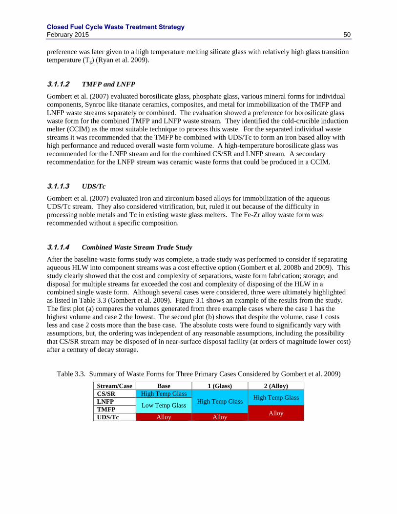
Closed Fuel Cycle Waste Treatment Strategy February 2015 50
preference was later given to a high temperature melting silicate glass with relatively high glass transition
temperature (Tg) (Ryan et al. 2009).
TMFP and LNFP 3.1.1.2
Gombert et al. (2007) evaluated borosilicate glass, phosphate glass, various mineral forms for individual
components, Synroc like titanate ceramics, composites, and metal for immobilization of the TMFP and
LNFP waste streams separately or combined. The evaluation showed a preference for borosilicate glass
waste form for the combined TMFP and LNFP waste stream. They identified the cold-crucible induction
melter (CCIM) as the most suitable technique to process this waste. For the separated individual waste
streams it was recommended that the TMFP be combined with UDS/Tc to form an iron based alloy with
high performance and reduced overall waste form volume. A high-temperature borosilicate glass was
recommended for the LNFP stream and for the combined CS/SR and LNFP stream. A secondary
recommendation for the LNFP stream was ceramic waste forms that could be produced in a CCIM.
UDS/Tc 3.1.1.3
Gombert et al. (2007) evaluated iron and zirconium based alloys for immobilization of the aqueous
UDS/Tc stream. They also considered vitrification, but, ruled it out because of the difficulty in
processing noble metals and Tc in existing waste glass melters. The Fe-Zr alloy waste form was
recommended without a specific composition.
Combined Waste Stream Trade Study 3.1.1.4
After the baseline waste forms study was complete, a trade study was performed to consider if separating
aqueous HLW into component streams was a cost effective option (Gombert et al. 2008b and 2009). This
study clearly showed that the cost and complexity of separations, waste form fabrication; storage; and
disposal for multiple streams far exceeded the cost and complexity of disposing of the HLW in a
combined single waste form. Although several cases were considered, three were ultimately highlighted
as listed in Table 3.3 (Gombert et al. 2009). Figure 3.1 shows an example of the results from the study.
The first plot (a) compares the volumes generated from three example cases where the case 1 has the
highest volume and case 2 the lowest. The second plot (b) shows that despite the volume, case 1 costs
less and case 2 costs more than the base case. The absolute costs were found to significantly vary with
assumptions, but, the ordering was independent of any reasonable assumptions, including the possibility
that CS/SR stream may be disposed of in near-surface disposal facility (at orders of magnitude lower cost)
after a century of decay storage.
Table 3.3. Summary of Waste Forms for Three Primary Cases Considered by Gombert et al. 2009)
Stream/Case Base 1 (Glass) 2 (Alloy)
CS/SR High Temp Glass
High Temp Glass High Temp Glass
LNFP Low Temp Glass
TMFP Alloy
UDS/Tc Alloy Alloy
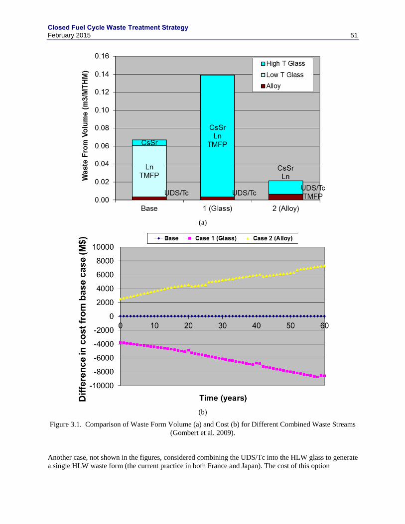
Closed Fuel Cycle Waste Treatment Strategy February 2015 51
(a)
(b)
Figure 3.1. Comparison of Waste Form Volume (a) and Cost (b) for Different Combined Waste Streams
(Gombert et al. 2009).
Another case, not shown in the figures, considered combining the UDS/Tc into the HLW glass to generate
a single HLW waste form (the current practice in both France and Japan). The cost of this option
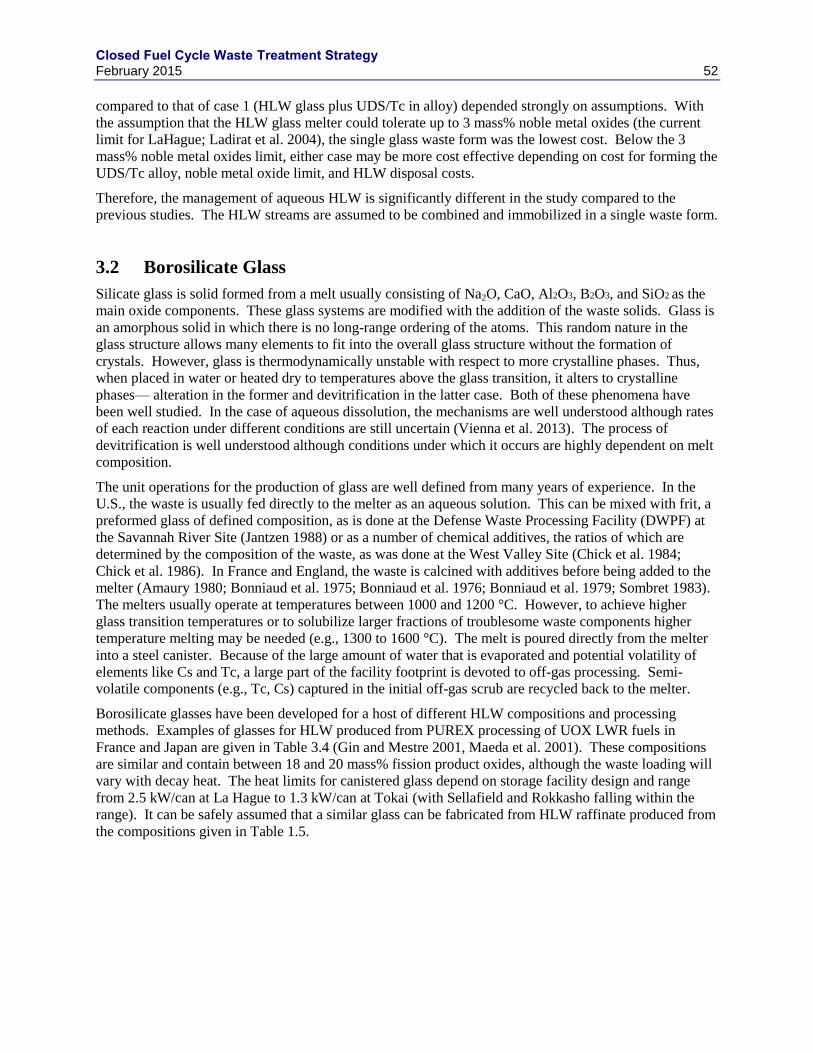
Closed Fuel Cycle Waste Treatment Strategy February 2015 52
compared to that of case 1 (HLW glass plus UDS/Tc in alloy) depended strongly on assumptions. With
the assumption that the HLW glass melter could tolerate up to 3 mass% noble metal oxides (the current
limit for LaHague; Ladirat et al. 2004), the single glass waste form was the lowest cost. Below the 3
mass% noble metal oxides limit, either case may be more cost effective depending on cost for forming the
UDS/Tc alloy, noble metal oxide limit, and HLW disposal costs.
Therefore, the management of aqueous HLW is significantly different in the study compared to the
previous studies. The HLW streams are assumed to be combined and immobilized in a single waste form.
3.2 Borosilicate Glass
Silicate glass is solid formed from a melt usually consisting of Na2O, CaO, Al2O3, B2O3, and SiO2 as the
main oxide components. These glass systems are modified with the addition of the waste solids. Glass is
an amorphous solid in which there is no long-range ordering of the atoms. This random nature in the
glass structure allows many elements to fit into the overall glass structure without the formation of
crystals. However, glass is thermodynamically unstable with respect to more crystalline phases. Thus,
when placed in water or heated dry to temperatures above the glass transition, it alters to crystalline
phases— alteration in the former and devitrification in the latter case. Both of these phenomena have
been well studied. In the case of aqueous dissolution, the mechanisms are well understood although rates
of each reaction under different conditions are still uncertain (Vienna et al. 2013). The process of
devitrification is well understood although conditions under which it occurs are highly dependent on melt
composition.
The unit operations for the production of glass are well defined from many years of experience. In the
U.S., the waste is usually fed directly to the melter as an aqueous solution. This can be mixed with frit, a
preformed glass of defined composition, as is done at the Defense Waste Processing Facility (DWPF) at
the Savannah River Site (Jantzen 1988) or as a number of chemical additives, the ratios of which are
determined by the composition of the waste, as was done at the West Valley Site (Chick et al. 1984;
Chick et al. 1986). In France and England, the waste is calcined with additives before being added to the
melter (Amaury 1980; Bonniaud et al. 1975; Bonniaud et al. 1976; Bonniaud et al. 1979; Sombret 1983).
The melters usually operate at temperatures between 1000 and 1200 °C. However, to achieve higher
glass transition temperatures or to solubilize larger fractions of troublesome waste components higher
temperature melting may be needed (e.g., 1300 to 1600 °C). The melt is poured directly from the melter
into a steel canister. Because of the large amount of water that is evaporated and potential volatility of
elements like Cs and Tc, a large part of the facility footprint is devoted to off-gas processing. Semi-
volatile components (e.g., Tc, Cs) captured in the initial off-gas scrub are recycled back to the melter.
Borosilicate glasses have been developed for a host of different HLW compositions and processing
methods. Examples of glasses for HLW produced from PUREX processing of UOX LWR fuels in
France and Japan are given in Table 3.4 (Gin and Mestre 2001, Maeda et al. 2001). These compositions
are similar and contain between 18 and 20 mass% fission product oxides, although the waste loading will
vary with decay heat. The heat limits for canistered glass depend on storage facility design and range
from 2.5 kW/can at La Hague to 1.3 kW/can at Tokai (with Sellafield and Rokkasho falling within the
range). It can be safely assumed that a similar glass can be fabricated from HLW raffinate produced from
the compositions given in Table 1.5.
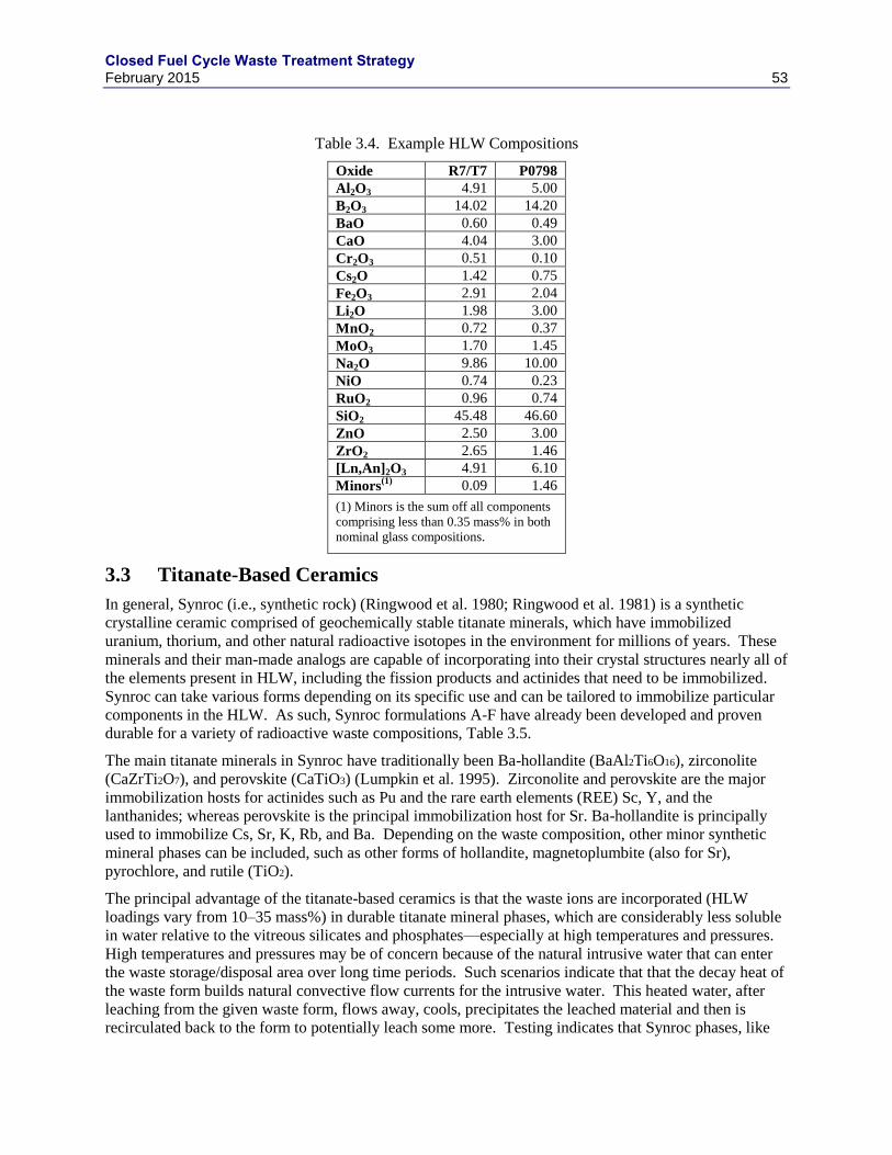
Closed Fuel Cycle Waste Treatment Strategy February 2015 53
Table 3.4. Example HLW Compositions
Oxide R7/T7 P0798
Al2O3 4.91 5.00
B2O3 14.02 14.20
BaO 0.60 0.49
CaO 4.04 3.00
Cr2O3 0.51 0.10
Cs2O 1.42 0.75
Fe2O3 2.91 2.04
Li2O 1.98 3.00
MnO2 0.72 0.37
MoO3 1.70 1.45
Na2O 9.86 10.00
NiO 0.74 0.23
RuO2 0.96 0.74
SiO2 45.48 46.60
ZnO 2.50 3.00
ZrO2 2.65 1.46
[Ln,An]2O3 4.91 6.10
Minors(1)
0.09 1.46
(1) Minors is the sum off all components
comprising less than 0.35 mass% in both
nominal glass compositions.
3.3 Titanate-Based Ceramics
In general, Synroc (i.e., synthetic rock) (Ringwood et al. 1980; Ringwood et al. 1981) is a synthetic
crystalline ceramic comprised of geochemically stable titanate minerals, which have immobilized
uranium, thorium, and other natural radioactive isotopes in the environment for millions of years. These
minerals and their man-made analogs are capable of incorporating into their crystal structures nearly all of
the elements present in HLW, including the fission products and actinides that need to be immobilized.
Synroc can take various forms depending on its specific use and can be tailored to immobilize particular
components in the HLW. As such, Synroc formulations A-F have already been developed and proven
durable for a variety of radioactive waste compositions, Table 3.5.
The main titanate minerals in Synroc have traditionally been Ba-hollandite (BaAl2Ti6O16), zirconolite
(CaZrTi2O7), and perovskite (CaTiO3) (Lumpkin et al. 1995). Zirconolite and perovskite are the major
immobilization hosts for actinides such as Pu and the rare earth elements (REE) Sc, Y, and the
lanthanides; whereas perovskite is the principal immobilization host for Sr. Ba-hollandite is principally
used to immobilize Cs, Sr, K, Rb, and Ba. Depending on the waste composition, other minor synthetic
mineral phases can be included, such as other forms of hollandite, magnetoplumbite (also for Sr),
pyrochlore, and rutile (TiO2).
The principal advantage of the titanate-based ceramics is that the waste ions are incorporated (HLW
loadings vary from 10–35 mass%) in durable titanate mineral phases, which are considerably less soluble
in water relative to the vitreous silicates and phosphates—especially at high temperatures and pressures.
High temperatures and pressures may be of concern because of the natural intrusive water that can enter
the waste storage/disposal area over long time periods. Such scenarios indicate that that the decay heat of
the waste form builds natural convective flow currents for the intrusive water. This heated water, after
leaching from the given waste form, flows away, cools, precipitates the leached material and then is
recirculated back to the form to potentially leach some more. Testing indicates that Synroc phases, like
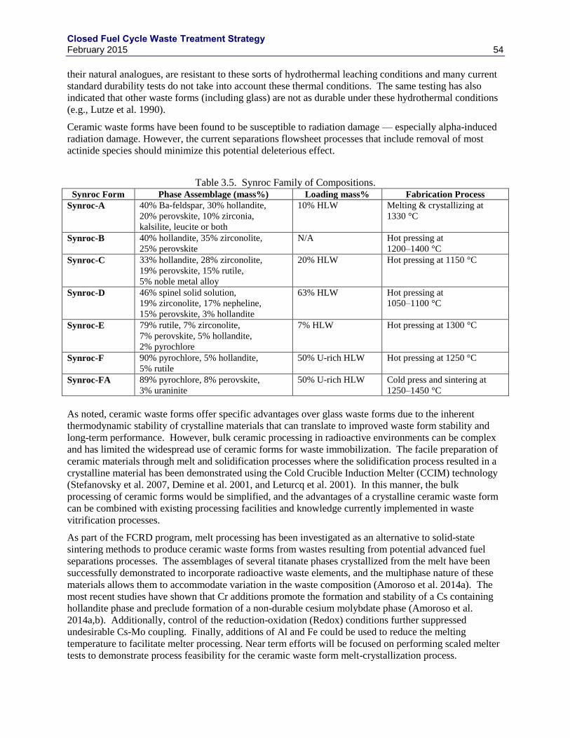
Closed Fuel Cycle Waste Treatment Strategy February 2015 54
their natural analogues, are resistant to these sorts of hydrothermal leaching conditions and many current
standard durability tests do not take into account these thermal conditions. The same testing has also
indicated that other waste forms (including glass) are not as durable under these hydrothermal conditions
(e.g., Lutze et al. 1990).
Ceramic waste forms have been found to be susceptible to radiation damage — especially alpha-induced
radiation damage. However, the current separations flowsheet processes that include removal of most
actinide species should minimize this potential deleterious effect.
Table 3.5. Synroc Family of Compositions. Synroc Form Phase Assemblage (mass%) Loading mass% Fabrication Process
Synroc-A 40% Ba-feldspar, 30% hollandite,
20% perovskite, 10% zirconia,
kalsilite, leucite or both
10% HLW Melting & crystallizing at
1330 °C
Synroc-B 40% hollandite, 35% zirconolite,
25% perovskite
N/A Hot pressing at
1200–1400 °C
Synroc-C 33% hollandite, 28% zirconolite,
19% perovskite, 15% rutile,
5% noble metal alloy
20% HLW Hot pressing at 1150 °C
Synroc-D 46% spinel solid solution,
19% zirconolite, 17% nepheline,
15% perovskite, 3% hollandite
63% HLW Hot pressing at
1050–1100 °C
Synroc-E 79% rutile, 7% zirconolite,
7% perovskite, 5% hollandite,
2% pyrochlore
7% HLW Hot pressing at 1300 °C
Synroc-F 90% pyrochlore, 5% hollandite,
5% rutile
50% U-rich HLW Hot pressing at 1250 °C
Synroc-FA 89% pyrochlore, 8% perovskite,
3% uraninite
50% U-rich HLW
Cold press and sintering at
1250–1450 °C
As noted, ceramic waste forms offer specific advantages over glass waste forms due to the inherent
thermodynamic stability of crystalline materials that can translate to improved waste form stability and
long-term performance. However, bulk ceramic processing in radioactive environments can be complex
and has limited the widespread use of ceramic forms for waste immobilization. The facile preparation of
ceramic materials through melt and solidification processes where the solidification process resulted in a
crystalline material has been demonstrated using the Cold Crucible Induction Melter (CCIM) technology
(Stefanovsky et al. 2007, Demine et al. 2001, and Leturcq et al. 2001). In this manner, the bulk
processing of ceramic forms would be simplified, and the advantages of a crystalline ceramic waste form
can be combined with existing processing facilities and knowledge currently implemented in waste
vitrification processes.
As part of the FCRD program, melt processing has been investigated as an alternative to solid-state
sintering methods to produce ceramic waste forms from wastes resulting from potential advanced fuel
separations processes. The assemblages of several titanate phases crystallized from the melt have been
successfully demonstrated to incorporate radioactive waste elements, and the multiphase nature of these
materials allows them to accommodate variation in the waste composition (Amoroso et al. 2014a). The
most recent studies have shown that Cr additions promote the formation and stability of a Cs containing
hollandite phase and preclude formation of a non-durable cesium molybdate phase (Amoroso et al.
2014a,b). Additionally, control of the reduction-oxidation (Redox) conditions further suppressed
undesirable Cs-Mo coupling. Finally, additions of Al and Fe could be used to reduce the melting
temperature to facilitate melter processing. Near term efforts will be focused on performing scaled melter
tests to demonstrate process feasibility for the ceramic waste form melt-crystallization process.
Closed Fuel Cycle Waste Treatment Strategy February 2015 55
The waste form developed for a variant of the HLW composition assumed in this study found waste
loadings of 24 mass% and bulk densities (Archimedes) ranging from 4500 to 4800 kg/m3 (Braase and
May 2014). Assuming a density of 4500 kg/m3, roughly 0.05 m
3/tU would be produced from the
reference waste stream; largely independent of cooling time.
3.4 Phosphate Glass
Phosphate glasses are amorphous solid materials with the waste chemically bound within the solid
structure much like borosilicate glasses. However, in the case of phosphate glasses the network is
primarily composed of PO4 tetrahedra instead of SiO4 tetrahedra. Two general families of phosphate
glasses have been investigated for vitrifying a wide range of different radioactive wastes. In research
supported by DOE, more than 500 iron phosphate glass waste form compositions have been studied over
a ~15 years, by Day and colleagues at the Missouri University of Science and Technology (see Day and
Ray 2013 for a summary of that work). Sodium alumino-phosphate glasses have been produced in Russia
since 1987 (Bradley and Payson 1997; Romanovski 2003, Borisov et al. 1999) to vitrify HLW, producing
more than 5,720 metric tons of glass over the time from 1987 to 2010.
These glasses are primarily composed of P2O5, Al2O3, Fe2O3/FeO, and Na2O. The properties of phosphate
glasses and melts tend to vary smoothly with concentrations of chemical additives. For some properties,
there is a transition in property-composition relationships at an oxygen-to phosphorous atomic ratio,
[O]:[P], of approximately 3.5. Phosphate glasses have a number of advantages over silicate-based glasses.
Primary among them are the relatively high solubility of chemical components that tend to be sparsely
soluble in silicate melts (e.g., Cr, P, S, Mo) and relatively low melting temperatures. However, they tend
to be less chemically durable, more susceptible to devitrification, and more corrosive to melter materials.
An evaluation of phosphate based glasses for GNEP found that they had significant advantages for
flowsheets resulting in high sulfate wastes or high molybdate wastes as phosphate glass can contain up to
roughly 4 mass% of either SO3 or MoO3 compared to roughly 1 and 2.5 mass%, respectively, for standard
borosilicate glasses (Ryan et al. 2009). However, wastes whose loadings in borosilicate glass are limited
by either heat or noble metals (Pd, Ru, Rh) would not be appropriate for phosphate glasses. For the
nominal waste composition supplied in Table 1.5, the loading would be limited by noble metals and heat
(for 5 y cooled waste), giving no advantage to the phosphate glass over borosilicate glasses.
3.5 Metal Waste Forms
Metal waste forms were developed as part of the GNEP project for immobilization of hulls, UDS, soluble
Tc, and/or transition metal fission product stream from aqueous processing operations. Initially, the metal
compositions were based on those developed for hulls and UDS from electrochemical processing of EBR-
II fuels: SS-15% Zr (see Section 6 for a detailed description of EBR-II metal waste form). Several
representative alloy waste form materials were made by melting simulated fuel wastes with Type 316L
stainless steel and tested to demonstrate fuel-waste loadings up to about 50% and the capacity to
encapsulate significant amounts of oxide with the alloys. Later, an epsilon metal waste form was
developed to represent direct processing of the fuel wastes without zirconium or added steel.
3.5.1 UDS Composition Variation
The undissolved solids (UDS) remaining after dissolution and clarification are primarily composed of
three phases: 1) epsilon metal particles formed during irradiation, 2) phases precipitated from solution in
Closed Fuel Cycle Waste Treatment Strategy February 2015 56
the dissolver or clarifier, and 3) chips of hulls generated during shearing process. The epsilon (ε) phase or
5-metal particles, form as primarily submicron alloy particles in UOX fuels during irradiation and remain
when fuel is dissolved in concentrated HNO3 (Kleykamp and Pejsa 1984). The main components of the
5-metal particles are Mo, Ru, Rh, Tc, and Pd. Tellurium has also been found in ε-metal phases when fuel
was dissolved under non-oxidizing conditions (Cui et al. 2004). Small amounts of Ag, Cd, Sn, and Sb
may also be present in the alloy, but these elements are in only trace concentrations in the fuel and are
difficult to detect. According to Kleykamp (1985), the composition of the 5-metal particle: “…varies
considerably and depends on the fission yield, the initial O/(U+Pu)-ratio of the fuel, i.e., the oxygen
potential, the temperature gradients in the pin, and the burn-up. As the oxygen potential of the Mo/MoO2
equilibrium is similar to slightly hypostoichiometric uranium-plutonium oxide fuel, the Mo concentration
in the alloys decreases continuously by oxidation of this element during irradiation due to an increase of
the oxygen potential of the FBR fuel with burn-up.” The relative amounts of Rh, Tc, and Pd are expected
to remain fairly consistent from fuel-to-fuel.
Depending on the chemistry of the dissolver and clarifier processes, varying amounts of hydrated
zirconium molybdates can precipitate and contain other elements such as U, Pu, Ba, rare earths, Sr, Cs,
and Te. Rao et al. (1990) identified the primary precipitates as a mixture of ZrMo2O7(OH)2·2H2O,
UO2Mo2O7·1.3H2O, Pu(MoO4)2·H2O and a range of non-crystalline molybdates. Various other oxides
have been observed in spent fuel, including Ba(U,Zr,Mo)O3, (Ba,Cs,Sr)MoO3, (Ba Sr)TeO3, and Pu2O2Te
have been identified in UDS. Lausch et al. (1994) found that 0.02 and 1.5% of the U and Pu from the
original fuel partitioned to the UDS from UOX fuel dissolved in 13 M HNO3. Silver iodide has also been
identified in the UDS (Sakurai et al. 1991, 1992, 1997; and Herrmann et al. 1997). Whether this is a
precipitation product or formed in the fuel is unknown.
Many researchers (e.g., Adachi et al. 1990, Lausch et al. 1994, Kleykamp 1990, Fortner 2007.) have
detected chips of zirconium cladding and stainless steel components in the UDS. The amount of steel and
cladding found in UDS will depend on shear operations.
Adachi et al. (1990) dissolved a PWR fuel (31.4 GWd/tU) in 4 M HNO3 at about 100 °C under a stream
of He. Their analysis of some of the undissolved solids showed that about 70 mass% of the UDS was
composed of Mo, Tc, Ru, Rh, and Pd, with the remainder being chips of cladding, etc. The solids were
analyzed with XRD and SEM with associated electron probe microanalysis. The mean particle size (as
measured with laser dispersion) increased from 68.4 nm at 2.5 h after dissolution to 117 nm at 3.5 h after
dissolution due to aggregation of the particles. Samples of the UDS from dissolutions of from fuel rod
segments that had experienced different burn-ups were dissolved for chemical analysis (Adachi et al.
1990). Those results are summarized to provide insight into the variance in the contents of Tc and other
components with fuel burn-up. The calculated burn-up increases from 8.4 GWd/tU for Sample 1 at or
near the end, to 17.6 GWd/tU for Samples 2, 3, and 4, to 31.4 GWd/t for Samples 5, 6, 7, and 8, to
36.1 GWd/tU for Samples 9 and 10. The amounts of UDS recovered from the dissolved segments
increased with the burn-up, from about 0.01 mass% at a burn-up of 8.4 GWd/tU to about 0.4 mass% at a
burn-up of 36.1 GWd/tU. The compositions of the dissolved UDS samples are compared in Table 3.2.
The concentrations of the components that comprise the insoluble 5-metal particles (Mo, Tc, Ru, Rh, and
Pd) are the most consistent between segments, with the average contents being 19% Mo, 50% Ru, 8.6%
Rh, 7.0% Pd, and 2.6% Tc. The vertical lines in Table 3.2 group the samples according to burn-up and
the numbers on the graph give the average burn-up, in GWd/tU, for each group of segments. Neglecting
the results for Sample 1, which was taken from the end of the rod, the relative amounts of each element
are only slightly affected by the burn-up: the relative amounts of Ru and Pd increase with burn-up
(consistent with the results from the ORIGEN2 code calculation (Croff 1983)), as does Mo to smaller
extent (contrary to the ORIGEN2 calculation results), whereas the relative amounts of Tc and Rh decrease
with burn-up (consistent with the ORIGEN2 calculation results). The fractions of the 5 noble metals
initially in the fuel (from ORIGEN2 calculations) that were found in the UDS from sample 8 (34.1
GWd/tU) were 15.5% Mo, 13.9% Pd, 39.9% Rh, 58.2% Ru, and 2.9% Tc (Adachi et al. 1990).
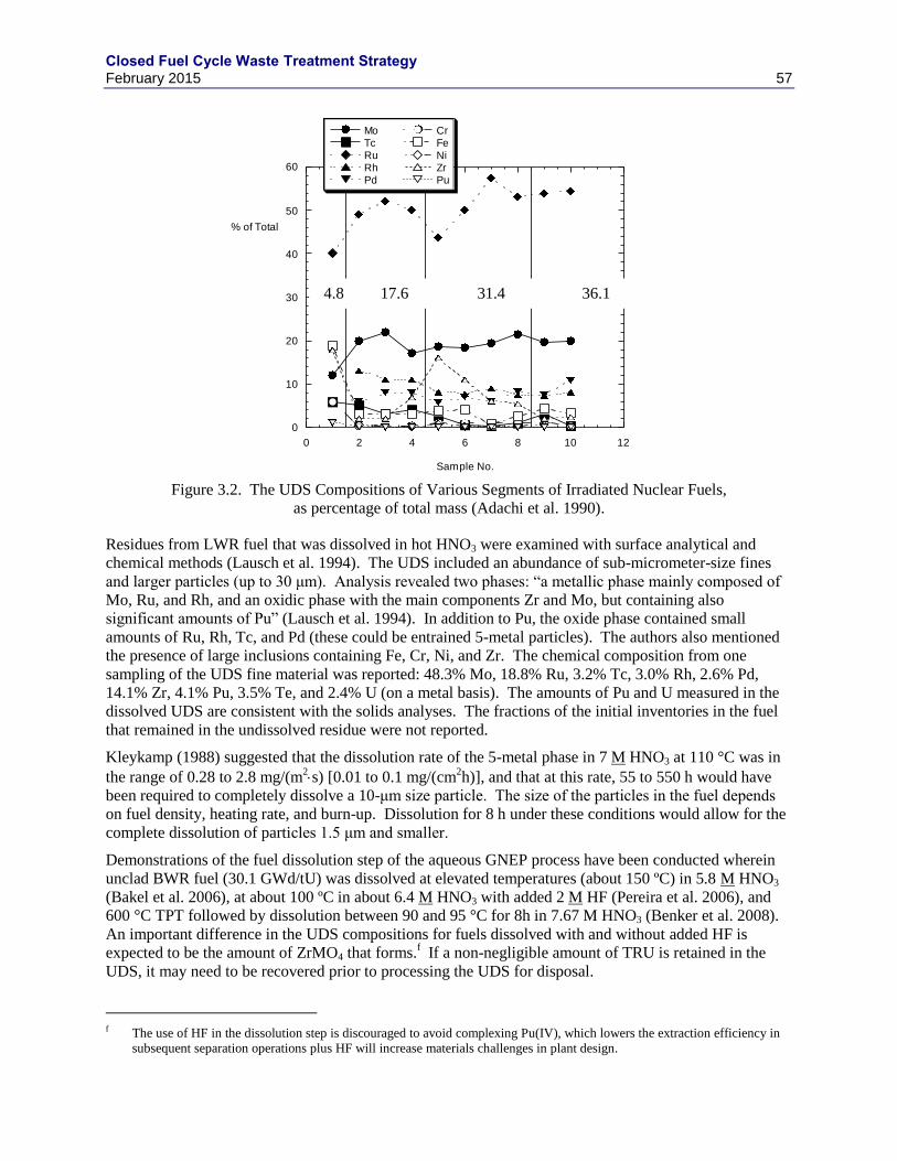
Closed Fuel Cycle Waste Treatment Strategy February 2015 57
Figure 3.2. The UDS Compositions of Various Segments of Irradiated Nuclear Fuels,
as percentage of total mass (Adachi et al. 1990).
Residues from LWR fuel that was dissolved in hot HNO3 were examined with surface analytical and
chemical methods (Lausch et al. 1994). The UDS included an abundance of sub-micrometer-size fines
and larger particles (up to 30 μm). Analysis revealed two phases: “a metallic phase mainly composed of
Mo, Ru, and Rh, and an oxidic phase with the main components Zr and Mo, but containing also
significant amounts of Pu” (Lausch et al. 1994). In addition to Pu, the oxide phase contained small
amounts of Ru, Rh, Tc, and Pd (these could be entrained 5-metal particles). The authors also mentioned
the presence of large inclusions containing Fe, Cr, Ni, and Zr. The chemical composition from one
sampling of the UDS fine material was reported: 48.3% Mo, 18.8% Ru, 3.2% Tc, 3.0% Rh, 2.6% Pd,
14.1% Zr, 4.1% Pu, 3.5% Te, and 2.4% U (on a metal basis). The amounts of Pu and U measured in the
dissolved UDS are consistent with the solids analyses. The fractions of the initial inventories in the fuel
that remained in the undissolved residue were not reported.
Kleykamp (1988) suggested that the dissolution rate of the 5-metal phase in 7 M HNO3 at 110 °C was in
the range of 0.28 to 2.8 mg/(m2s) [0.01 to 0.1 mg/(cm
2h)], and that at this rate, 55 to 550 h would have
been required to completely dissolve a 10-μm size particle. The size of the particles in the fuel depends
on fuel density, heating rate, and burn-up. Dissolution for 8 h under these conditions would allow for the
complete dissolution of particles 1.5 μm and smaller.
Demonstrations of the fuel dissolution step of the aqueous GNEP process have been conducted wherein
unclad BWR fuel (30.1 GWd/tU) was dissolved at elevated temperatures (about 150 ºC) in 5.8 M HNO3
(Bakel et al. 2006), at about 100 ºC in about 6.4 M HNO3 with added 2 M HF (Pereira et al. 2006), and
600 °C TPT followed by dissolution between 90 and 95 °C for 8h in 7.67 M HNO3 (Benker et al. 2008).
An important difference in the UDS compositions for fuels dissolved with and without added HF is
expected to be the amount of ZrMO4 that forms.f If a non-negligible amount of TRU is retained in the
UDS, it may need to be recovered prior to processing the UDS for disposal.
f The use of HF in the dissolution step is discouraged to avoid complexing Pu(IV), which lowers the extraction efficiency in
subsequent separation operations plus HF will increase materials challenges in plant design.
0
10
20
30
40
50
60
0 2 4 6 8 10 12
MoTcRuRhPd
CrFeNiZrPu
% of Total
Sample No.
4.8 17.6 31.4 36.1
GWd/MTU
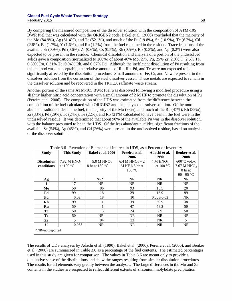
Closed Fuel Cycle Waste Treatment Strategy February 2015 58
By comparing the measured composition of the dissolver solution with the composition of ATM-105
BWR fuel that was calculated with the ORIGEN2 code, Bakel et al. (2006) concluded that the majority of
the Mo (84.9%), Ag (61.4%), and Te (52.1%), and much of the Pu (19.8%), Sn (10.9%), Tc (6.2%), Cd
(2.8%), Ba (1.7%), Y (1.6%), and Ru (1.2%) from the fuel remained in the residue. Trace fractions of the
available Sr (0.9%), Pd (0.6%), Zr (0.6%), Cs (0.5%), Rh (0.5%), Rb (0.3%), and Np (0.2%) were also
expected to be present in the residue. Chemical dissolution and analysis of a portion of the undissolved
solids gave a composition (normalized to 100%) of about 40% Mo, 27% Pu, 25% Zr, 2.8% U, 2.5% Te,
0.39% Ru, 0.31% Tc, 0.04% Rh, and 0.07% Pd. Although the inefficient dissolution of Pu resulting from
this method was unacceptable, the relative amounts of Ru, Rh, Pd, and Tc were not expected to be
significantly affected by the dissolution procedure. Small amounts of Fe, Cr, and Ni were present in the
dissolver solution from the corrosion of the steel dissolver vessel. These metals are expected to remain in
the dissolver solution and be recovered in the TRUEX raffinate waste stream.
Another portion of the same ATM-105 BWR fuel was dissolved following a modified procedure using a
slightly higher nitric acid concentration with a small amount of 2 M HF to promote the dissolution of Pu
(Pereira et al. 2006). The composition of the UDS was estimated from the difference between the
composition of the fuel calculated with ORIGIN2 and the analyzed dissolver solution. Of the more
abundant radionuclides in the fuel, the majority of the Mo (93%), and much of the Ru (47%), Rh (39%),
Zr (33%), Pd (29%), Tc (24%), Te (22%), and Rb (21%) calculated to have been in the fuel were in the
undissolved residue. It was determined that about 90% of the available Pu was in the dissolver solution,
with the balance presumed to be in the UDS. Of the less abundant nuclides, significant fractions of the
available Se (54%), Ag (45%), and Cd (26%) were present in the undissolved residue, based on analysis
of the dissolver solution.
Table 3.6. Retention of Elements of Interest in UDS, as a Percent of Inventory Study This Study Bakel et al. 2006 Pereira et al.
2006
Adachi et al.
1990
Benker et al.
2008
Dissolution
conditions
7.32 M HNO3
at 100 °C
5.8 M HNO3
8 hr at 150 °C
6.4 M HNO3 + 2
M HF 6.5 hr at
100 °C
4 M HNO3
at 100 °C
600°C volox
7.67 M HNO3
8 hr at
90 - 95 °C
Ag 1 NR* NR NR NR
I 17 NR NR NR NR
Mo 50 86 93 15.5 20
Pd 99 18 29 13.9 99
Pu 0.02 18 10 0.005-0.02 NR
Rh 99 1 39 39.9 38
Ru 50 1 47 58.2 50
Tc 50 3 24 2.9 50
Te 50 NR NR NR NR
Zr 5 84 33 NR 5
U 0.055 NR NR NR NR
*NR=not reported
The results of UDS analyses by Adachi et al. (1990), Bakel et al. (2006), Pereira et al. (2006), and Benker
et al. (2008) are summarized in Table 3.6 as a percentage of the fuel contents. The estimated percentages
used in this study are given for comparison. The values in Table 3.6 are meant only to provide a
qualitative sense of the distributions and show the ranges resulting from similar dissolution procedures.
The results for all elements vary greatly between the analyses. The large differences in the Mo and Zr
contents in the studies are suspected to reflect different extents of zirconium molybdate precipitation
Closed Fuel Cycle Waste Treatment Strategy February 2015 59
under the dissolution and filtration procedures and different amounts of cladding chips. The differences
in the results for Ru and Rh are not understood, but may be related to the extents to which the 5-metal
particles were dissolved. Their size distributions in the fuels and the dissolution times are both expected
to affect how efficiently the 5-metal particles are dissolved. Perhaps fortuitously, the dispositions of Tc
and Pd are very similar in the Adachi et al. (1990) and Bakel et al. (2006) studies.
3.5.2 Soluble Tc Reduction
In the aqueous process, roughly half of the Tc is expected to dissolve—the balance remains in the UDS as
a component of the 5-metal particles. The chemistry of the dissolver solution (a nitric acid solution) is
such that all dissolved Tc should be oxidized to Tc7+
as pertechnetate ions (TcO4−) or Tc2O7. The vapor
pressure of Tc2O7 is only about 0.01 Pa at 100 ºC, which is near the dissolver temperatures that have been
used in process demonstrations. At this temperature and chemistry, a small amount of Tc could volatilize
as Tc2O7 during fuel dissolution. Tc as the pertechnetate ion can be recovered in the raffinate with the
majority of fission products, with U, or as a separate product, but its behavior is directly dependent on the
presence or absence of the other species. Both Np and Tc are affected by the stripping reagent used for
Pu. If this is a pure reductant such as U(IV), the Np will follow the bulk U and the Tc will follow the Pu.
However, if a reduction/complexation reagent such as acetohydroxamic acid (AHA) is used, the reverse
behavior is observed, with Np following the Pu and the Tc following the bulk U. In the current aqueous
processing flowsheet, the Tc is partitioned to the U stream in the co-decontamination process (Section
1.1.2). After the initial U, Pu, and Np extraction, TcO4- co-extracts with uranium into the TBP. After
uranium is stripped with dilute nitric acid, TcO4- is stripped from the TBP with 10 M HNO3. The Tc strip
solution can be combined with the HLW raffinate stream or be treated to reduce Tc for incorporation into
a metal waste form. In the case of immobilizing the Tc with the UDS into a metal waste form the process
would require reduction of the TcO4- to Tc
0.
The nitric acid-technetic acid mixture (HTcO4 + HNO3) is evaporated at 100°C to remove nitric acid.
Only a small part of the technetium evaporates with the nitric acid, producing moderately pure
HTcO4·H2O. The HTcO4·H2O is diluted with water, then reacted with a formaldehyde reducing agent to
destroy the remaining nitric acid and reduce technetic acid to a suspension of TcO2·nH2O. The
suspension of TcO2·nH2O is then mixed with the UDS from the clarifier, evaporated to a dry solid, then
reduced to technetium metal at 900°C in H2/Ar. This process is expected to reduce all of the soluble Tc
and most of the UDS components to metal but may leave some oxides (the amount of oxide will not be
more than 30 mass% and is expected to be below 10 mass%). Zirconium and uranium are likely to
remain oxides and are expected to combined to produce (Zrx,Ux-1)O2 with a fluorite structure, which has
been previously studied as a candidate waste form for immobilization of actinides because of its high
radiation resistance (Gong et al. 2000).
An alternative Tc recovery process from the uranium dissolved in nitric acid solution is to ion exchange.
Dowex Marathon A (styrene-divinyl benzene gel with quaternary amine functional groups) and two
Reillex polyvinylpyridine anion exchange resins to remove the Tc from the UREX+ solution have been
evaluated in demonstrations: Reillex HPQ (poly-4-vinylpyridine, crosslinked, methyl chloride quaternary
salt) and Reillex HP (poly-4-vinylpyridine, crosslinked). The HPQ resin is more selective to TcO4- than
the HP resin; both are more efficient at removing TcO4- from solution than the Dowex Marathon
exchanger. The as-received resins are pretreated with a nitric acid solution to replace Cl- on the active
sites with NO3-, so TcO4
- replaces some of the NO3
– on the resin. The Tc can be recovered from the HP
resin by elution using NH4OH or NaOH. Alternatively, the Tc can be recovered and partially reduced by
pyrolysis of the resin followed by steam reforming in Ar/H2.
Ebert et al. (2009b) have reviewed options for recovering and immobilizing soluble Tc.
Closed Fuel Cycle Waste Treatment Strategy February 2015 60
3.5.3 Iron-Zirconium Based Alloys
Various Fe-Zr based alloys are expected to accommodate high levels of Zr, Mo, Ru, Rh, Pd, and Tc and
moderate amounts of oxide contaminants. Two alloys were developed to immobilize residual metallic
wastes from the electrochemical treatment of steel-clad and Zircaloy-clad spent sodium-bonded nuclear
fuels by processing the waste forms (Abraham et al. 1996, McDeavitt et al. 1998, Abraham et al. 1999).
An alloy of stainless steel (SS) with 15-mass% zirconium (SS-15Zr) was developed for waste streams that
were composed predominantly of SS cladding hulls and an alloy of Zr with 8 mass% SS (Zr-8SS) was
proposed for waste streams that were composed predominantly of Zircaloy cladding hulls. Both of these
alloys melted at 1600 °C using existing furnace technology. The performance of the steel-based alloys
was studied intensively to support EBR-II fuel processing waste immobilization (Ebert 2005) and more
recently as a potential waste form for UDS and soluble Tc under the GNEP project (Ebert 2008, 2010,
2012; Ebert et al. 2009, 2011; Frank et al. 2012; Olson and Frank 2012; Mausolf et al. 2012). Alloying
waste metals with stainless steels generates multi-phase materials comprised of Fe-Mo-Cr, Fe-Zr-Ni, and
Pd-Zr-Ni intermetallics and a steel-like solid solution phase that sequester particular waste elements.
Both Tc and Mo report to the Fe-Mo-Cr intermetallic and steel-like solid solution phases. Tc is not found
in the Zr-bearing intermetallics that host the U and other actinides. Alloy waste forms can be formulated
to generate sufficient amounts of the host phases required to accommodate all of the radionuclides in the
waste streams. For example, the lower U contents expected in processed metallic wastes (less than
0.003% based on Table 1.15) will require less Zr in the waste forms than do EBR-II wastes, which may
contain up to 11% U (this includes DU added to down-blend the waste form to LEU levels). The smaller
amounts of added Zr increase the waste loading but do not hinder processing or decrease waste form
durability. The measured corrosion behavior and approach to modeling radionuclide release from Fe-Zr-
based waste forms is discussed in Section 6.
3.5.4 Epsilon Metal
Use of an alloy waste form having a composition similar to the epsilon (ε)-metal particles formed during
UOX irradiation was investigated for immobilization of the UDS and soluble Tc (Crum and Strachan
2013). Evidence of ε-metal particles were found in the natural reactors located in Gabon, Africa
(Gauthier-Lafaye et al. 1996), and Utsunomiya and Ewing (2006) presented evidence that 99
Tc migrated
only a few centimeters over about 2 billion years although most had been converted to an arsenide. This
natural analog data provides evidence that ε-metal may be an attractive waste form to immobilize Tc and
Pd, which have long-lived isotopes important to repository performance 99
Tc (t1/2 = 2.13×10⁵ y) and
107Pd
(t1/2 = 6.5×10⁶ y).
The ε-metal waste form can be fabricated from 100% waste by consolidating the reduced UDS and
soluble Tc, as described in 3.5.2. Two technologies were found to efficiently densify this waste form:
HIP and spark-plasma sintering (SPS) (Rohatgi and Strachan 2011, Crum et al. 2012). In both processes
pressure and elevated temperatures are combined to densify the metal into a dense and durable waste
form. In the HIP process, the waste metal is placed in a metal canister that is evacuated and sealed. The
sealed canister is heated under pressure (200 MPa at 1500 °C) to make the final waste form. The final
diameter of the HIP cans are as close to inside diameter of the 0.61 m (OD) canister as possible while
leaving enough clearance so that they can be loaded reliably. The estimated design margins are roughly
1.5% (or 10 mm) in diameter and 2% (or 60 mm) in stacked height. The design compressed can height is
0.14 m and each HIP contains roughly 435 g of ε-metal with a waste form volume of 0.036 m3 and a HIP
can displacement in the canister of 0.040 m3. With this size can, twenty one cans fill a full height (3 m)
disposal canister. Based on an estimated partitioning of the components to the epsilon metal waste form
and an assumed density of 12 103 kg/m
3, the process would generate 35 HIP cans per year and 1.67
disposal canisters per year for a 1000 tU/y plant processing roughly 50 GWd/tU fuel. The HIP method is
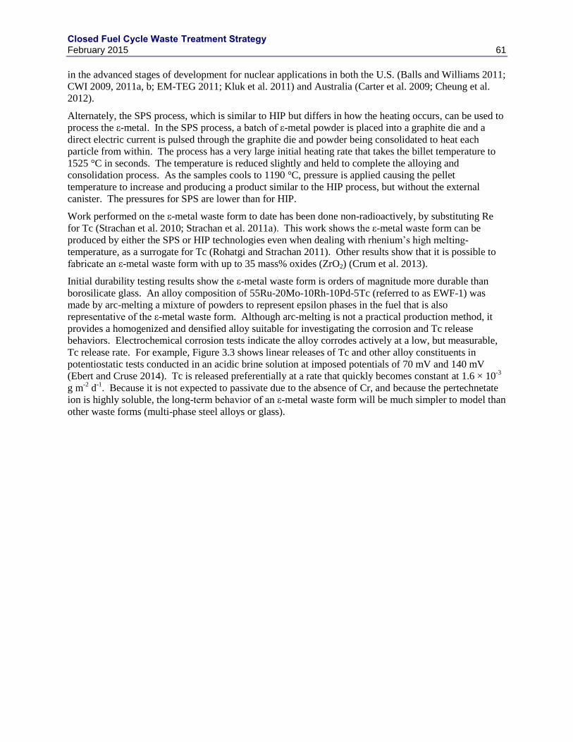
Closed Fuel Cycle Waste Treatment Strategy February 2015 61
in the advanced stages of development for nuclear applications in both the U.S. (Balls and Williams 2011;
CWI 2009, 2011a, b; EM-TEG 2011; Kluk et al. 2011) and Australia (Carter et al. 2009; Cheung et al.
2012).
Alternately, the SPS process, which is similar to HIP but differs in how the heating occurs, can be used to
process the ε-metal. In the SPS process, a batch of ε-metal powder is placed into a graphite die and a
direct electric current is pulsed through the graphite die and powder being consolidated to heat each
particle from within. The process has a very large initial heating rate that takes the billet temperature to
1525 °C in seconds. The temperature is reduced slightly and held to complete the alloying and
consolidation process. As the samples cools to 1190 °C, pressure is applied causing the pellet
temperature to increase and producing a product similar to the HIP process, but without the external
canister. The pressures for SPS are lower than for HIP.
Work performed on the ε-metal waste form to date has been done non-radioactively, by substituting Re
for Tc (Strachan et al. 2010; Strachan et al. 2011a). This work shows the ε-metal waste form can be
produced by either the SPS or HIP technologies even when dealing with rhenium’s high melting-
temperature, as a surrogate for Tc (Rohatgi and Strachan 2011). Other results show that it is possible to
fabricate an ε-metal waste form with up to 35 mass% oxides (ZrO2) (Crum et al. 2013).
Initial durability testing results show the ε-metal waste form is orders of magnitude more durable than
borosilicate glass. An alloy composition of 55Ru-20Mo-10Rh-10Pd-5Tc (referred to as EWF-1) was
made by arc-melting a mixture of powders to represent epsilon phases in the fuel that is also
representative of the ε-metal waste form. Although arc-melting is not a practical production method, it
provides a homogenized and densified alloy suitable for investigating the corrosion and Tc release
behaviors. Electrochemical corrosion tests indicate the alloy corrodes actively at a low, but measurable,
Tc release rate. For example, Figure 3.3 shows linear releases of Tc and other alloy constituents in
potentiostatic tests conducted in an acidic brine solution at imposed potentials of 70 mV and 140 mV
(Ebert and Cruse 2014). Tc is released preferentially at a rate that quickly becomes constant at 1.6 × 10⁻³
g m-2
d-1
. Because it is not expected to passivate due to the absence of Cr, and because the pertechnetate
ion is highly soluble, the long-term behavior of an ε-metal waste form will be much simpler to model than
other waste forms (multi-phase steel alloys or glass).
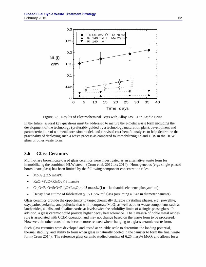
Closed Fuel Cycle Waste Treatment Strategy February 2015 62
Figure 3.3. Results of Electrochemical Tests with Alloy EWF-1 in Acidic Brine.
In the future, several key questions must be addressed to mature the ε-metal waste form including the
development of the technology (preferably guided by a technology maturation plan), development and
parameterization of a ε-metal corrosion model, and a revised cost-benefit analyses to help determine the
practicality of deploying such a waste process as compared to immobilizing Tc and UDS in the HLW
glass or other waste form.
3.6 Glass Ceramics
Multi-phase borosilicate-based glass ceramics were investigated as an alternative waste form for
immobilizing the combined HLW stream (Crum et al. 2012b,c; 2014). Homogeneous (e.g., single phased
borosilicate glass) has been limited by the following component concentration rules:
MoO3 ≤ 2.5 mass%
RuO2+PdO+Rh2O3 ≤ 3 mass%
Cs2O+BaO+SrO+Rb2O+Ln2O3 ≤ 45 mass% (Ln = lanthanide elements plus yttrium)
Decay heat at time of fabrication ≤ 15.1 KW/m3 glass (assuming a 0.43 m diameter canister)
Glass ceramics provide the opportunity to target chemically durable crystalline phases, e.g., powellite,
oxyapatite, cerianite, and pollucite that will incorporate MoO3 as well as other waste components such as
lanthanides, alkalis, and alkaline earths at levels twice the solubility limits of a single-phase glass. In
addition, a glass ceramic could provide higher decay heat tolerance. The 3 mass% of noble metal oxides
rule is associated with CCIM operation and may not change based on the waste form to be processed.
However, the other constraints become more relaxed when changing to a glass ceramic waste form.
Such glass ceramics were developed and tested at crucible scale to determine the loading potential,
thermal stability, and ability to form when glass is naturally cooled in the canister to form the final waste
form (Crum 2014). The reference glass ceramic studied consists of 6.25 mass% MoO3 and allows for a
0
0.05
0.1
0.15
0.2
0.25
0.3
0 5 10 15 20 25 30 35 40
Tc 140 mVRu 140 mVRh 140 mV
Tc 70 mVMo 70 mV
y = 0.15 + 0.0017x R2= 0.99
y = 0.010 + 0.00011x R2= 0.98
y = 0.023 + 0.00026x R2= 0.99
y = 0.036 + 0.0016x R2= 1.00
y = 0.031 + 0.00074x R2= 0.99
NL(i),
g/m2
Time, days
EWF2 AB 70mV 140mV cum soln
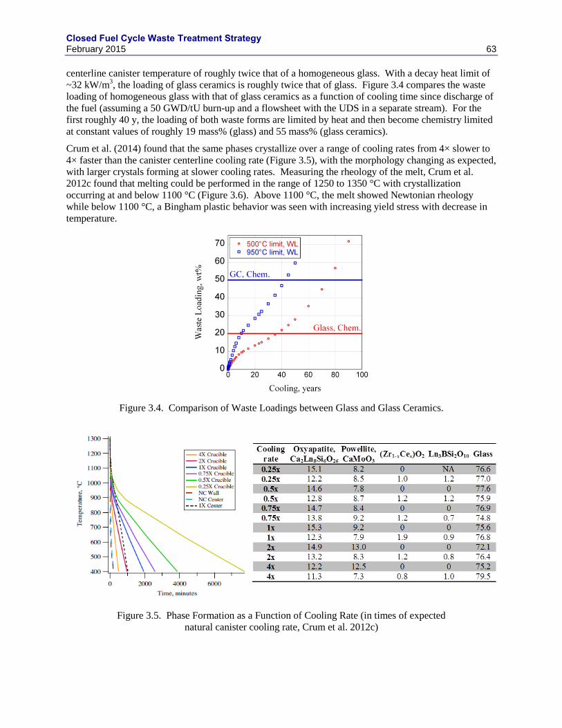
Closed Fuel Cycle Waste Treatment Strategy February 2015 63
centerline canister temperature of roughly twice that of a homogeneous glass. With a decay heat limit of
~32 kW/m3, the loading of glass ceramics is roughly twice that of glass. Figure 3.4 compares the waste
loading of homogeneous glass with that of glass ceramics as a function of cooling time since discharge of
the fuel (assuming a 50 GWD/tU burn-up and a flowsheet with the UDS in a separate stream). For the
first roughly 40 y, the loading of both waste forms are limited by heat and then become chemistry limited
at constant values of roughly 19 mass% (glass) and 55 mass% (glass ceramics).
Crum et al. (2014) found that the same phases crystallize over a range of cooling rates from 4× slower to
4× faster than the canister centerline cooling rate (Figure 3.5), with the morphology changing as expected,
with larger crystals forming at slower cooling rates. Measuring the rheology of the melt, Crum et al.
2012c found that melting could be performed in the range of 1250 to 1350 °C with crystallization
occurring at and below 1100 °C (Figure 3.6). Above 1100 °C, the melt showed Newtonian rheology
while below 1100 °C, a Bingham plastic behavior was seen with increasing yield stress with decrease in
temperature.
Figure 3.4. Comparison of Waste Loadings between Glass and Glass Ceramics.
Figure 3.5. Phase Formation as a Function of Cooling Rate (in times of expected
natural canister cooling rate, Crum et al. 2012c)
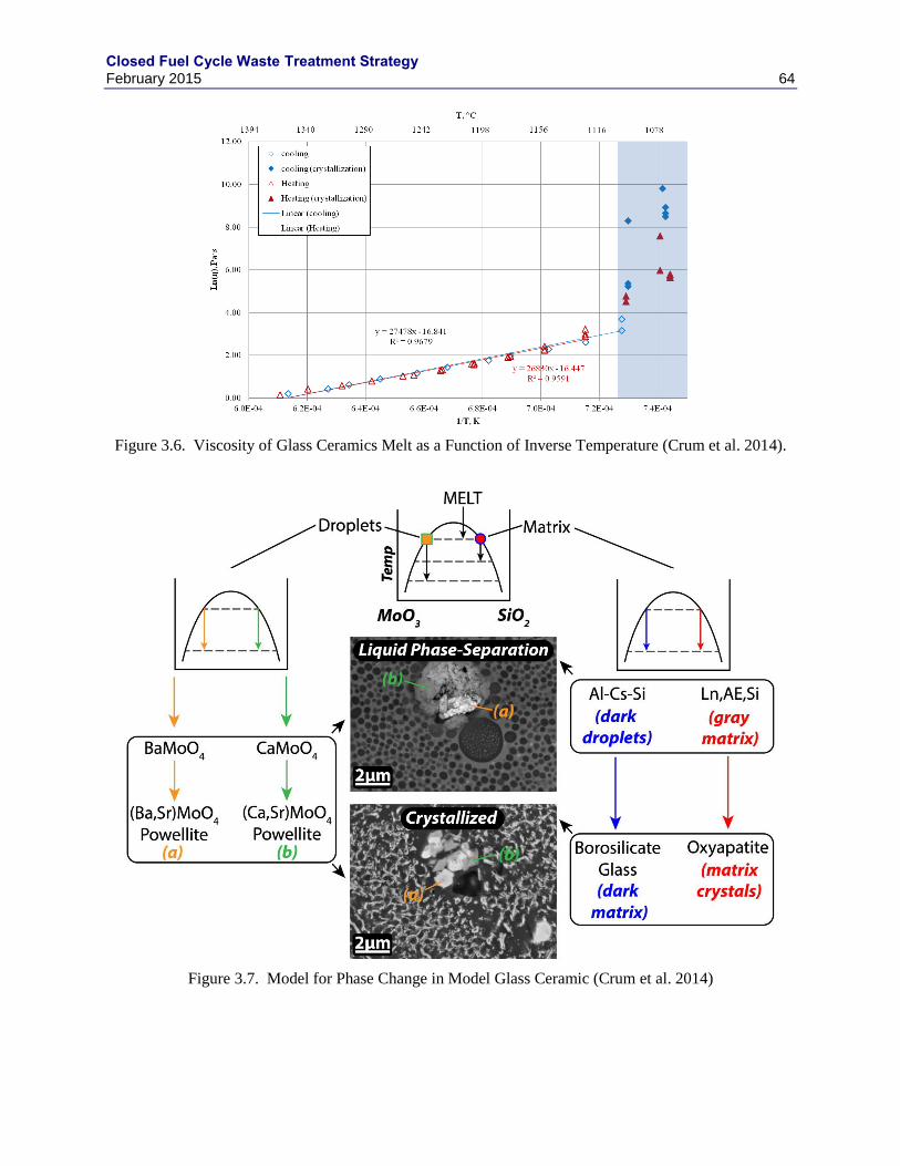
Closed Fuel Cycle Waste Treatment Strategy February 2015 64
Figure 3.6. Viscosity of Glass Ceramics Melt as a Function of Inverse Temperature (Crum et al. 2014).
Figure 3.7. Model for Phase Change in Model Glass Ceramic (Crum et al. 2014)
Closed Fuel Cycle Waste Treatment Strategy February 2015 65
The reference formulation was melted in an initial cold crucible induction melter (CCIM) test (Crum et al.
2014). The test was successful and produced several small scale (4 inch diameter) cans of waste form
that were cooled to mimic different cooling rates that might be experienced at full scale (a nominal full
scale canister center cooling (×), a 2× rate, and an ambient (fast) cooling). As with the laboratory tests,
the phases characterized in the samples showed relatively little variation in the amount of each phase
formed for the three cooling rates of 4× and slower, and three different can.
To better understand the phase formation process, Crum et al. (2014) analyzed phases quenched from heat
treatments at progressively lower temperatures. The results suggest two separate immiscible liquid phase
separation events followed by crystallization of oxyapatite and powellite from each separate immiscible
liquid as shown in Figure 3.7.
As a relatively immature technology, glass ceramics must be further developed and demonstrated before
adoption. A technology maturation plan has been developed to guide ongoing research and develop the
technology to a sufficient point to be ready for implementation (Vienna et al. 2012).
3.7 High Level Waste Form Recommendations
Several HLW forms have been developed and tested over the years. To date, only borosilicate glass and
sodium-alumino-phosphate glass have been produced at full scale, with most HLW (as judged by years of
production, number of sites, mass of glass, and total activity immobilized) being immobilized in
borosilicate glass. It is a good and well understood waste form and process with few drawbacks. It is
therefore recommended that glass be the reference waste form for HLW.
Several other waste forms show potential advantages over the reference borosilicate glass waste form.
Chief among them are titanate-based ceramics and glass ceramics. The titanate-based waste form will
have higher durability and performance that is less dependent on disposal environment (Lutze et al.
1990). However there are technological challenges in safely and reliably fabricating the waste form.
Development of a melt processed titanate-based ceramics form/process would allow for the advantages of
proven process technology with the benefits of a Synroc waste form. Glass ceramics can increase the
loading of glass and thereby reduce the cost of fabrication, storage, transportation, and disposal. Cost
analyses have found that higher loading glasses may require longer storage prior to disposal (up to 100 y).
However, there is still a cost benefit. Also, there is potential advantage to glass waste forms from long
cooled fuel (and glass ceramics) to separately immobilize UDS (to avoid noble metal limits in the melter).
To immobilize UDS, a metal alloy is the most developed and likely most suitable waste form. It is yet to
be determined if ε-metal or SS-based alloy would be more effective. Tests are in progress to inform that
decision.
3.8 High-Level Waste Vitrification Process
The main steps in the HLW vitrification process are receipt and preparation of the waste for feeding to the
melter including addition of the glass forming frit, feeding the waste/frit to the glass melter, melting the
materials to form the desired waste form (e.g., glass, glass ceramics, titanate ceramics), treating the
gaseous effluents from the melting process, pouring the waste form into a disposal canister, and cooling
and decontaminating the filled canisters for storage and disposal. The key process steps of feed
preparation, melting, and canister filling are described in more detail below.
3.8.1 Waste Feed Preparation
Three waste feed streams are combined into a waste feed adjustment vessel in targeted proportions:
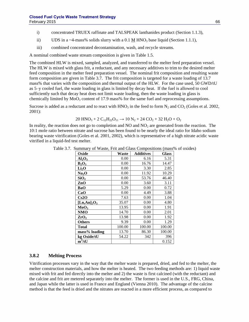
Closed Fuel Cycle Waste Treatment Strategy February 2015 66
i) concentrated TRUEX raffinate and TALSPEAK lanthanides product (Section 1.1.3),
ii) UDS in a ~4-mass% solids slurry with a 0.1 M HNO3 base liquid (Section 1.1.1),
iii) combined concentrated decontamination, wash, and recycle streams.
A nominal combined waste stream composition is given in Table 1.5.
The combined HLW is mixed, sampled, analyzed, and transferred to the melter feed preparation vessel.
The HLW is mixed with glass frit, a reductant, and any necessary additives to trim to the desired melter
feed composition in the melter feed preparation vessel. The nominal frit composition and resulting waste
form composition are given in Table 3.7. The frit composition is targeted for a waste loading of 13.7
mass% that varies with the composition and thermal output of the HLW. For the case used, 50 GWD/tU
as 5–y cooled fuel, the waste loading in glass is limited by decay heat. If the fuel is allowed to cool
sufficiently such that decay heat does not limit waste loading, then the waste loading in glass is
chemically limited by MoO3 content of 17.9 mass% for the same fuel and reprocessing assumptions.
Sucrose is added as a reductant and to react with HNO3 in the feed to form N2 and CO2 (Goles et al. 2002,
2001):
20 HNO3 + 2 C12H22O11 → 10 N2 + 24 CO2 + 32 H2O + O2
In reality, the reaction does not go to completion and NO and NO2 are generated from the reaction. The
10:1 mole ratio between nitrate and sucrose has been found to be nearly the ideal ratio for Idaho sodium
bearing waste vitrification (Goles et al. 2001, 2002), which is representative of a high nitrate acidic waste
vitrified in a liquid-fed test melter.
Table 3.7. Summary of Waste, Frit and Glass Compositions (mass% of oxides) Oxide Waste Additives Glass
Al2O3 0.00 6.16 5.31
B2O3 0.00 16.76 14.47
Li2O 0.00 3.30 2.85
Na2O 0.00 11.92 10.29
SiO2 0.00 53.76 46.40
ZnO 0.00 3.60 3.11
BaO 5.29 0.00 0.72
CaO 0.00 4.49 3.88
Cs2O 7.63 0.00 1.04
[Ln,An]2O3 35.07 0.00 4.80
MoO3 13.95 0.00 1.91
NMO 14.70 0.00 2.01
ZrO2 13.98 0.00 1.92
Others 9.39 0.00 1.29
Total 100.00 100.00 100.00
mass% loading 13.70 86.30 100.00
kg Oxide/tU 54.22 342 396
m3/tU 0.152
3.8.2 Melting Process
Vitrification processes vary in the way that the melter waste is prepared, dried, and fed to the melter, the
melter construction materials, and how the melter is heated. The two feeding methods are: 1) liquid waste
mixed with frit and fed directly into the melter and 2) the waste is first calcined (with the reductant) and
the calcine and frit are metered separately into the melter. The former is used in the U.S., FRG, China,
and Japan while the latter is used in France and England (Vienna 2010). The advantage of the calcine
method is that the feed is dried and the nitrates are reacted in a more efficient process, as compared to
Closed Fuel Cycle Waste Treatment Strategy February 2015 67
liquid or slurry feed in which the waste is dried and the nitrates destroyed in the melter. The primary
disadvantage of the calcination method is the high maintenance requirements with a high-temperature
rotating unit with a beater bar that must maintain gas tightness. The liquid feeding method has the
primary disadvantage of a lower processing rate due to the need for drying and nitrate reaction in the
melter. In contrast, the primary advantage is the simplicity of design and reduced maintenance
requirements.
The five melter options are (Vienna 2010):
1. The liquid-fed, Joule-heated, ceramic melter (LFCM) in which liquid waste is the feed and heat is
supplied by passing electrical current through the low electrical conductivity melt, thereby
generating Joule-heat (resistance heating). This melter has the advantages that the ceramic
refractories have low corrosion rates and, thus, have long service life (on the order of ten years or
more), they can be scaled to very large sizes and therefore very large throughputs. The
disadvantages are the temperature limits imposed by electrode stability (typically ≤ 1200 °C for
Inconel 690 electrodes) and the large melter size that must eventually be disposed of as highly
radioactive waste.
2. The hot-walled, induction melter (HWIM) is a metal can that is heated by low-frequency induction
(coupled directly to the metal melt container). The heat is transferred from the container to the
waste calcine plus glass frit or waste calcine plus glass additives to form the glass melt. The
advantages of this melter are the simplicity of design, no electrical conductivity constraints, and
small size. The primary disadvantages are the inability to scale up beyond roughly 0.5 m (for the
narrowest dimension) without significant reduction in heating efficiency, the low temperature limits
(≤ 1100 °C for high Ni alloys, but higher for platinum alloys), and the low melter life (typically < 1
y). These two disadvantages both significantly reduce the throughput rate and thereby are typically
only deployed with calciners to increase the waste processing rate.
3. The cold-crucible induction melter (CCIM) is fabricated from segmented, water cooled, metal tubes
(or sleeves). A radio frequency current passes through induction coils surrounding the melter. This
current inductively couples directly to the glass melt creating a current in the melt that generated
Joule-heating. The cooled wall maintains a solid glass shell as the “melt contact” material. The
advantages of this melter are high melting temperatures (1500 °C or higher if needed and
appropriately designed), high resistance to corrosive melts, tolerance to solid inclusions, small size,
high specific throughput, and the ability to completely cool and empty. The disadvantages are
small maximum size (≤ 1.4 m diameter), the need to manage radio frequency, and low energy
efficiency.
4. The hot-walled resistance heated melter (HWRM) is similar to the HWIM with the exception that
the heat is supplied to the canister by resistance heating. The advantages and disadvantages are
very similar to the HWIM.
5. The in-can melter (ICM) is a version of the HWIM or HWRM in which the melt is not cast out of
the melter but instead, the melt container is removed from the heat source and becomes the disposal
canister. The advantage of this melter, as compared to the HWIM and HWRM is that the melter
can be used for more corrosive melts as the lifetime is a single melt, and the ability to process
multi-phase materials with problematic melt rheologies as the melt is never cast (e.g., no noble
metal limts).
Table 3.8 summarizes the current HLW melting methods and Table 3.2 summarizes the application of
these melter technologies for nuclear waste glass production.
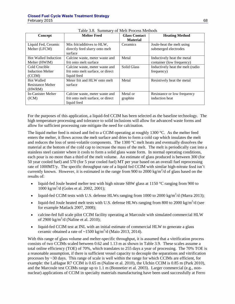
Closed Fuel Cycle Waste Treatment Strategy February 2015 68
Table 3.8. Summary of Melt Process Methods Concept Melter Feed Glass Contact
Material
Heating Method
Liquid Fed, Ceramic
Melter (LFCM)
Mix frit/additives to HLW,
directly feed slurry onto melt
surface
Ceramics Joule-heat the melt using
submerged electrodes
Hot Walled Induction
Melter (HWIM)
Calcine waste, meter waste and
frit onto melt surface
Metal Inductively heat the metal
container (low frequency)
Cold Crucible
Induction Melter
(CCIM)
Calcine waste, meter waste and
frit onto melt surface, or direct
liquid feed
Solid Glass Inductively heat the melt (radio
frequency)
Hot Walled
Resistance Melter
(HWRM)
Meter frit and HLW onto melt
surface
Metal Resistively heat the metal
In-Canister Melter
(ICM)
Calcine waste, meter waste and
frit onto melt surface, or direct
liquid feed
Metal or
graphite
Resistance or low frequency
induction heat
For the purposes of this application, a liquid-fed CCIM has been selected as the baseline technology. The
high temperature processing and tolerance to solid inclusions will allow for advanced waste forms and
allow for sufficient processing rate mitigate the need for calcination.
The liquid melter feed is mixed and fed to a CCIM operating at roughly 1300 °C. As the melter feed
enters the melter, it flows across the melt surface and dries to form a cold cap which insulates the melt
and reduces the loss of semi-volatile components. The 1300 °C melt heats and eventually dissolves the
material at the bottom of the cold cap to increase the mass of the melt. The melt is periodically cast into a
stainless steel canister where it cools to form a solid glass waste form. In normal operating conditions,
each pour is no more than a third of the melt volume. An estimate of glass produced is between 300 (for
50 year cooled fuel) and 570 (for 5 year cooled fuel) MT per year based on an overall fuel reprocessing
rate of 1000MT/y. The specific throughput rate of a liquid fed CCIM with similar high-nitrate feed isn’t
currently known. However, it is estimated in the range from 900 to 2000 kg/m2/d of glass based on the
results of:
liquid-fed Joule heated melter test with high nitrate SBW glass at 1150 °C ranging from 900 to
1000 kg/m2/d (Goles et al. 2002, 2001);
liquid-fed CCIM tests with U.S. defense HLWs ranging from 1000 to 2000 kg/m2/d (Marra 2013);
liquid-fed Joule heated melt tests with U.S. defense HLWs ranging from 800 to 2000 kg/m2/d (see
for example Matlack 2007, 2008);
calcine-fed full scale pilot CCIM facility operating at Marcoule with simulated commercial HLW
of 2900 kg/m2/d (Naline et al. 2010);
liquid-fed CCIM test at INL with an initial estimate of commercial HLW to generate a glass
ceramic obtained a rate of ~1500 kg/m2/d (Maio 2013, 2014).
With this range of glass volume and melter-specific throughput, it is assumed that a vitrification process
consists of two CCIMs scaled between 0.62 and 1.13 m as shown in Table 3.9. These scales assume a
total online efficiency (TOE) of 70%, which translates to 255 days a year of processing. The 70% TOE is
a reasonable assumption, if there is sufficient vessel capacity to decouple the separations and vitrification
processes by ~30 days. This range of scale is well within the range for which CCIMs are efficient, for
example: the LaHague R7 CCIM is 0.65 m (Naline et al. 2010), the Ulchin CCIM is 0.85 m (Park 2010),
and the Marcoule test CCIMs range up to 1.1 m (Bonnetier et al. 2003). Larger commercial (e.g., non-
nuclear) applications of CCIM in specialty materials manufacturing have been used successfully at Ferro
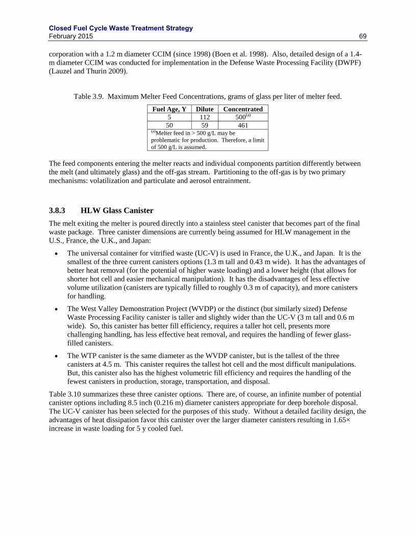
Closed Fuel Cycle Waste Treatment Strategy February 2015 69
corporation with a 1.2 m diameter CCIM (since 1998) (Boen et al. 1998). Also, detailed design of a 1.4-
m diameter CCIM was conducted for implementation in the Defense Waste Processing Facility (DWPF)
(Lauzel and Thurin 2009).
Table 3.9. Maximum Melter Feed Concentrations, grams of glass per liter of melter feed.
Fuel Age, Y Dilute Concentrated
5 112 500(a)
50 59 461 (a)Melter feed in > 500 g/L may be
problematic for production. Therefore, a limit
of 500 g/L is assumed.
The feed components entering the melter reacts and individual components partition differently between
the melt (and ultimately glass) and the off-gas stream. Partitioning to the off-gas is by two primary
mechanisms: volatilization and particulate and aerosol entrainment.
3.8.3 HLW Glass Canister
The melt exiting the melter is poured directly into a stainless steel canister that becomes part of the final
waste package. Three canister dimensions are currently being assumed for HLW management in the
U.S., France, the U.K., and Japan:
The universal container for vitrified waste (UC-V) is used in France, the U.K., and Japan. It is the
smallest of the three current canisters options (1.3 m tall and 0.43 m wide). It has the advantages of
better heat removal (for the potential of higher waste loading) and a lower height (that allows for
shorter hot cell and easier mechanical manipulation). It has the disadvantages of less effective
volume utilization (canisters are typically filled to roughly 0.3 m of capacity), and more canisters
for handling.
The West Valley Demonstration Project (WVDP) or the distinct (but similarly sized) Defense
Waste Processing Facility canister is taller and slightly wider than the UC-V (3 m tall and 0.6 m
wide). So, this canister has better fill efficiency, requires a taller hot cell, presents more
challenging handling, has less effective heat removal, and requires the handling of fewer glass-
filled canisters.
The WTP canister is the same diameter as the WVDP canister, but is the tallest of the three
canisters at 4.5 m. This canister requires the tallest hot cell and the most difficult manipulations.
But, this canister also has the highest volumetric fill efficiency and requires the handling of the
fewest canisters in production, storage, transportation, and disposal.
Table 3.10 summarizes these three canister options. There are, of course, an infinite number of potential
canister options including 8.5 inch (0.216 m) diameter canisters appropriate for deep borehole disposal.
The UC-V canister has been selected for the purposes of this study. Without a detailed facility design, the
advantages of heat dissipation favor this canister over the larger diameter canisters resulting in 1.65×
increase in waste loading for 5 y cooled fuel.
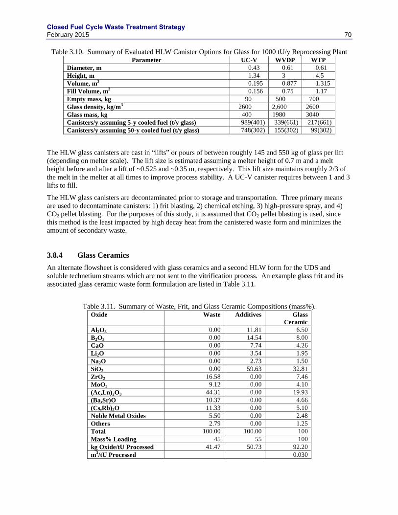
Closed Fuel Cycle Waste Treatment Strategy February 2015 70
Table 3.10. Summary of Evaluated HLW Canister Options for Glass for 1000 tU/y Reprocessing Plant Parameter UC-V WVDP WTP
Diameter, m 0.43 0.61 0.61
Height, m 1.34 3 4.5
Volume, m3 0.195 0.877 1.315
Fill Volume, m3 0.156 0.75 1.17
Empty mass, kg 90 500 700
Glass density, kg/m3 2600 2,600 2600
Glass mass, kg 400 1980 3040
Canisters/y assuming 5-y cooled fuel (t/y glass) 989(401) 339(661) 217(661)
Canisters/y assuming 50-y cooled fuel (t/y glass) 748(302) 155(302) 99(302)
The HLW glass canisters are cast in “lifts” or pours of between roughly 145 and 550 kg of glass per lift
(depending on melter scale). The lift size is estimated assuming a melter height of 0.7 m and a melt
height before and after a lift of ~0.525 and ~0.35 m, respectively. This lift size maintains roughly 2/3 of
the melt in the melter at all times to improve process stability. A UC-V canister requires between 1 and 3
lifts to fill.
The HLW glass canisters are decontaminated prior to storage and transportation. Three primary means
are used to decontaminate canisters: 1) frit blasting, 2) chemical etching, 3) high-pressure spray, and 4)
CO2 pellet blasting. For the purposes of this study, it is assumed that CO2 pellet blasting is used, since
this method is the least impacted by high decay heat from the canistered waste form and minimizes the
amount of secondary waste.
3.8.4 Glass Ceramics
An alternate flowsheet is considered with glass ceramics and a second HLW form for the UDS and
soluble technetium streams which are not sent to the vitrification process. An example glass frit and its
associated glass ceramic waste form formulation are listed in Table 3.11.
Table 3.11. Summary of Waste, Frit, and Glass Ceramic Compositions (mass%). Oxide Waste Additives Glass
Ceramic
Al2O3 0.00 11.81 6.50
B2O3 0.00 14.54 8.00
CaO 0.00 7.74 4.26
Li2O 0.00 3.54 1.95
Na2O 0.00 2.73 1.50
SiO2 0.00 59.63 32.81
ZrO2 16.58 0.00 7.46
MoO3 9.12 0.00 4.10
(Ac,Ln)2O3 44.31 0.00 19.93
(Ba,Sr)O 10.37 0.00 4.66
(Cs,Rb)2O 11.33 0.00 5.10
Noble Metal Oxides 5.50 0.00 2.48
Others 2.79 0.00 1.25
Total 100.00 100.00 100
Mass% Loading 45 55 100
kg Oxide/tU Processed 41.47 50.73 92.20
m3/tU Processed 0.030
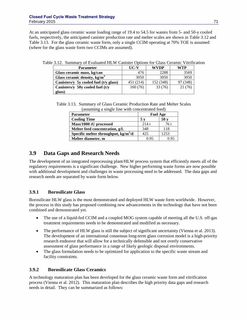
Closed Fuel Cycle Waste Treatment Strategy February 2015 71
At an anticipated glass ceramic waste loading range of 19.4 to 54.5 for wastes from 5- and 50-y cooled
fuels, respectively, the anticipated canister production rate and melter scales are shown in Table 3.12 and
Table 3.13. For the glass ceramic waste form, only a single CCIM operating at 70% TOE is assumed
(where for the glass waste form two CCIMs are assumed).
Table 3.12. Summary of Evaluated HLW Canister Options for Glass Ceramic Vitrification Parameter UC-V WVDP WTP
Glass ceramic mass, kg/can 476 2288 3569
Glass ceramic density, kg/m3 3050 3050 3050
Canisters/y 5y cooled fuel (t/y glass) 451 (214) 152 (348) 97 (348)
Canisters/y 50y cooled fuel (t/y
glass)
160 (76) 33 (76) 21 (76)
Table 3.13. Summary of Glass Ceramic Production Rate and Melter Scales
(assuming a single line with concentrated feed) Parameter Fuel Age
Cooling Time 5 y 50 y
Mass/1000 tU processed 214 t 76 t
Melter feed concentration, g/L 348 118
Specific melter throughput, kg/m2/d 425 1253
Melter diameter, m 0.95 0.95
3.9 Data Gaps and Research Needs
The development of an integrated reprocessing plant/HLW process system that efficiently meets all of the
regulatory requirements is a significant challenge. New higher performing waste forms are now possible
with additional development and challenges in waste processing need to be addressed. The data gaps and
research needs are separated by waste form below.
3.9.1 Borosilicate Glass
Borosilicate HLW glass is the most demonstrated and deployed HLW waste form worldwide. However,
the process in this study has proposed combining new advancements in the technology that have not been
combined and demonstrated yet.
The use of a liquid-fed CCIM and a coupled MOG system capable of meeting all the U.S. off-gas
treatment requirements needs to be demonstrated and modified as necessary.
The performance of HLW glass is still the subject of significant uncertainty (Vienna et al. 2013).
The development of an international consensus long-term glass corrosion model is a high-priority
research endeavor that will allow for a technically defensible and not overly conservative
assessment of glass performance in a range of likely geologic disposal environments.
The glass formulation needs to be optimized for application to the specific waste stream and
facility constraints.
3.9.2 Borosilicate Glass Ceramics
A technology maturation plan has been developed for the glass ceramic waste form and vitrification
process (Vienna et al. 2012). This maturation plan describes the high priority data gaps and research
needs in detail. They can be summarized as follows:
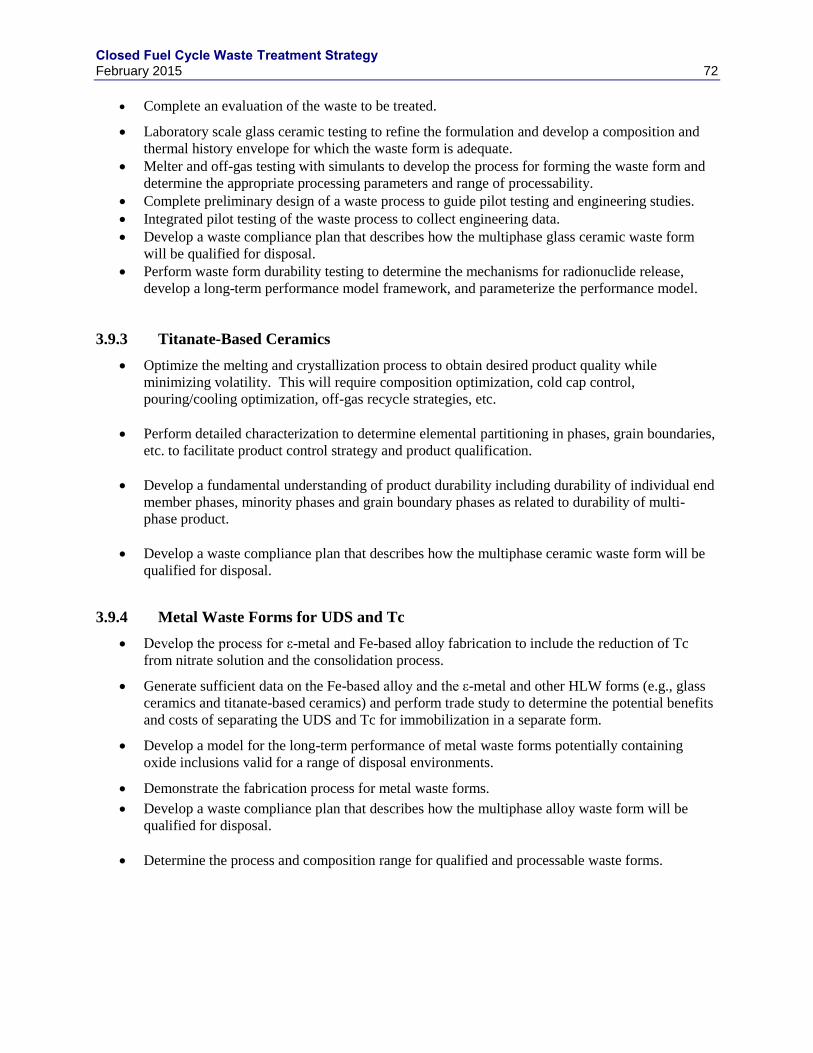
Closed Fuel Cycle Waste Treatment Strategy February 2015 72
Complete an evaluation of the waste to be treated.
Laboratory scale glass ceramic testing to refine the formulation and develop a composition and
thermal history envelope for which the waste form is adequate.
Melter and off-gas testing with simulants to develop the process for forming the waste form and
determine the appropriate processing parameters and range of processability.
Complete preliminary design of a waste process to guide pilot testing and engineering studies.
Integrated pilot testing of the waste process to collect engineering data.
Develop a waste compliance plan that describes how the multiphase glass ceramic waste form
will be qualified for disposal.
Perform waste form durability testing to determine the mechanisms for radionuclide release,
develop a long-term performance model framework, and parameterize the performance model.
3.9.3 Titanate-Based Ceramics
Optimize the melting and crystallization process to obtain desired product quality while
minimizing volatility. This will require composition optimization, cold cap control,
pouring/cooling optimization, off-gas recycle strategies, etc.
Perform detailed characterization to determine elemental partitioning in phases, grain boundaries,
etc. to facilitate product control strategy and product qualification.
Develop a fundamental understanding of product durability including durability of individual end
member phases, minority phases and grain boundary phases as related to durability of multi-
phase product.
Develop a waste compliance plan that describes how the multiphase ceramic waste form will be
qualified for disposal.
3.9.4 Metal Waste Forms for UDS and Tc
Develop the process for ε-metal and Fe-based alloy fabrication to include the reduction of Tc
from nitrate solution and the consolidation process.
Generate sufficient data on the Fe-based alloy and the ε-metal and other HLW forms (e.g., glass
ceramics and titanate-based ceramics) and perform trade study to determine the potential benefits
and costs of separating the UDS and Tc for immobilization in a separate form.
Develop a model for the long-term performance of metal waste forms potentially containing
oxide inclusions valid for a range of disposal environments.
Demonstrate the fabrication process for metal waste forms.
Develop a waste compliance plan that describes how the multiphase alloy waste form will be
qualified for disposal.
Determine the process and composition range for qualified and processable waste forms.
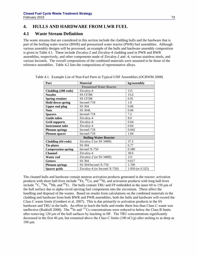
Closed Fuel Cycle Waste Treatment Strategy February 2015 73
4. HULLS AND HARDWARE FROM LWR FUEL
4.1 Waste Stream Definition
The waste streams that are considered in this section include the cladding hulls and the hardware that is
part of the boiling water reactor (BWR) and pressurized water reactor (PWR) fuel assemblies. Although
various assembly designs will be processed, an example of the hulls and hardware assembly composition
is given in Table 4.1. These include Zircaloy-2 and Zircaloy-4 cladding used in PWR and BWR
assemblies, respectively, and other components made of Zircaloy-2 and -4, various stainless steels, and
various Inconels. The overall compositions of the combined materials were assumed to be those of the
reference assemblies. Table 4.2 lists the compositions of representative alloys.
Table 4.1. Example List of Non-Fuel Parts in Typical UNF Assemblies (OCRWM 2008)
Part Material kg/assembly
Pressurized Water Reactor
Cladding (208 rods) Zircaloy-4 115
Nozzles SS CF3M 15.6
Spring retainer SS CF3M 0.91
Hold down spring Inconel-718 1.8
Upper end plug SS 304 0.06
Nuts SS 304L 0.66
Spacers Inconel-718 7.2
Guide tubes Zircaloy-4 8.0
Grid supports Zircaloy-4 0.64
Instrument tube Zircaloy-4 0.64
Plenum springs Inconel-718 0.042
Plenum spacer Inconel-718 1.04
Boiling Water Reactor
Cladding (64 rods) Zircaloy-2 (or SS 348H) 37.2
Tie plates SS 304 6.77
Compression spring Inconel X-750 0.580
Channel Zircaloy-4 38.6
Water rod Zircaloy-2 (or SS 348H) 121
Getters SS 304 0.617
Plenum springs SS 304/Inconel X-750 1.700
Spacer grids Zircaloy-4 (or Inconel X-750) 1.950 (or 0.325)
The cleaned hulls and hardware contain neutron activation products generated in the reactor: activation
products with short half-lives include 55
Fe, 60
Co, and 63
Ni, and activation products with long half-lives
include 14
C, 59
Ni, 93
Nb, and 99
Tc. The hulls contain TRU and FP embedded in the inner 60 to 150 μm of
the hull surface due to alpha recoil ejecting fuel components into the zirconium. These affect the
handling and disposal of the wastes. Based on results from calculations on the combined materials in the
cladding and hardware from both BWR and PWR assemblies, both the hulls and hardware will exceed the
Class C waste limits (Gombert et al. 2007). This is due primarily to activation products in the SS
hardware and TRU in the hulls. An effort to leach the hulls and render them less than Class C waste was
ineffective (Rudisill 2008). The 90
Sr and 137
Cs concentrations were reduced to below the Class B limits
after removing 120 μm of the hull surfaces by leaching in HF. The TRU concentrations significantly
decreased in the first 40 μm, but remained above the Class C limits (100 nCi/g) after etching to as deep as
180 μm.
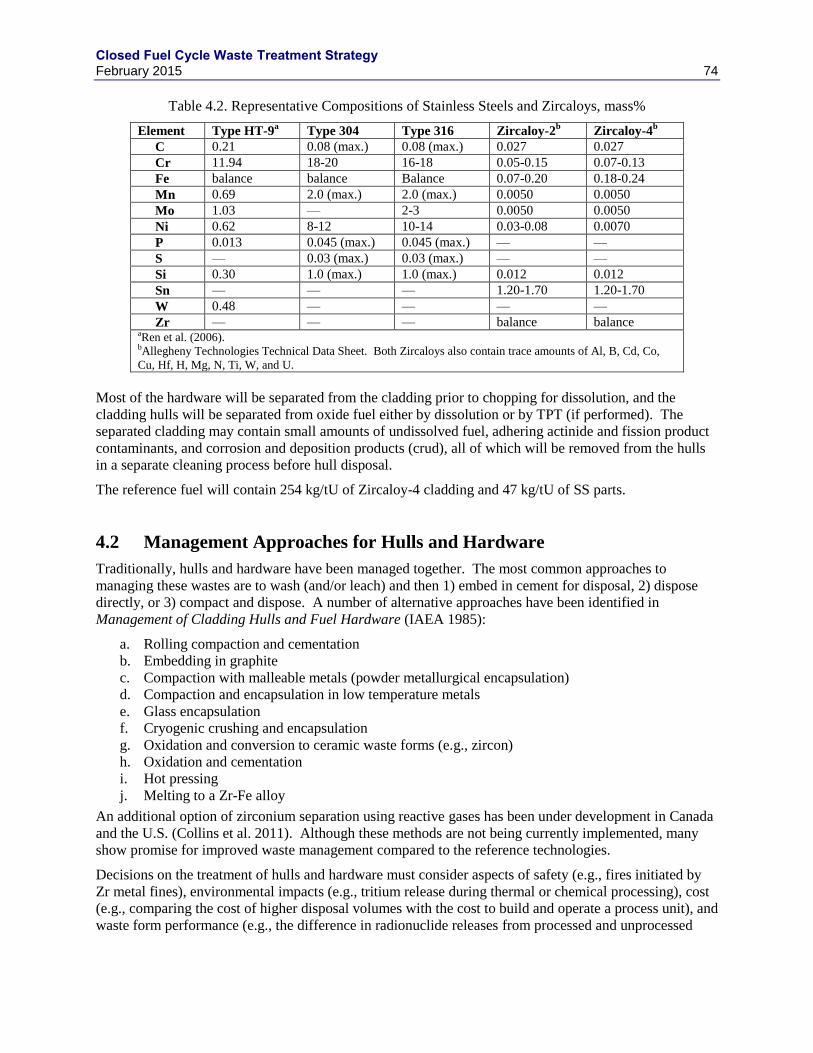
Closed Fuel Cycle Waste Treatment Strategy February 2015 74
Table 4.2. Representative Compositions of Stainless Steels and Zircaloys, mass%
Element Type HT-9a Type 304 Type 316 Zircaloy-2
b Zircaloy-4
b
C 0.21 0.08 (max.) 0.08 (max.) 0.027 0.027
Cr 11.94 18-20 16-18 0.05-0.15 0.07-0.13
Fe balance balance Balance 0.07-0.20 0.18-0.24
Mn 0.69 2.0 (max.) 2.0 (max.) 0.0050 0.0050
Mo 1.03 — 2-3 0.0050 0.0050
Ni 0.62 8-12 10-14 0.03-0.08 0.0070
P 0.013 0.045 (max.) 0.045 (max.) — —
S — 0.03 (max.) 0.03 (max.) — —
Si 0.30 1.0 (max.) 1.0 (max.) 0.012 0.012
Sn — — — 1.20-1.70 1.20-1.70
W 0.48 — — — —
Zr — — — balance balance aRen et al. (2006).
bAllegheny Technologies Technical Data Sheet. Both Zircaloys also contain trace amounts of Al, B, Cd, Co,
Cu, Hf, H, Mg, N, Ti, W, and U.
Most of the hardware will be separated from the cladding prior to chopping for dissolution, and the
cladding hulls will be separated from oxide fuel either by dissolution or by TPT (if performed). The
separated cladding may contain small amounts of undissolved fuel, adhering actinide and fission product
contaminants, and corrosion and deposition products (crud), all of which will be removed from the hulls
in a separate cleaning process before hull disposal.
The reference fuel will contain 254 kg/tU of Zircaloy-4 cladding and 47 kg/tU of SS parts.
4.2 Management Approaches for Hulls and Hardware
Traditionally, hulls and hardware have been managed together. The most common approaches to
managing these wastes are to wash (and/or leach) and then 1) embed in cement for disposal, 2) dispose
directly, or 3) compact and dispose. A number of alternative approaches have been identified in
Management of Cladding Hulls and Fuel Hardware (IAEA 1985):
a. Rolling compaction and cementation
b. Embedding in graphite
c. Compaction with malleable metals (powder metallurgical encapsulation)
d. Compaction and encapsulation in low temperature metals
e. Glass encapsulation
f. Cryogenic crushing and encapsulation
g. Oxidation and conversion to ceramic waste forms (e.g., zircon)
h. Oxidation and cementation
i. Hot pressing
j. Melting to a Zr-Fe alloy
An additional option of zirconium separation using reactive gases has been under development in Canada
and the U.S. (Collins et al. 2011). Although these methods are not being currently implemented, many
show promise for improved waste management compared to the reference technologies.
Decisions on the treatment of hulls and hardware must consider aspects of safety (e.g., fires initiated by
Zr metal fines), environmental impacts (e.g., tritium release during thermal or chemical processing), cost
(e.g., comparing the cost of higher disposal volumes with the cost to build and operate a process unit), and
waste form performance (e.g., the difference in radionuclide releases from processed and unprocessed
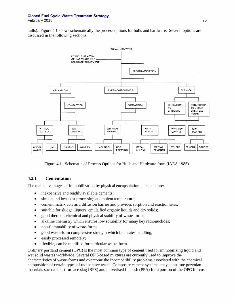
Closed Fuel Cycle Waste Treatment Strategy February 2015 75
hulls). Figure 4.1 shows schematically the process options for hulls and hardware. Several options are
discussed in the following sections.
Figure 4.1. Schematic of Process Options for Hulls and Hardware from (IAEA 1985).
4.2.1 Cementation
The main advantages of immobilization by physical encapsulation in cement are:
inexpensive and readily available cements;
simple and low-cost processing at ambient temperature;
cement matrix acts as a diffusion barrier and provides sorption and reaction sites;
suitable for sludge, liquors, emulsified organic liquids and dry solids;
good thermal, chemical and physical stability of waste-form;
alkaline chemistry which ensures low solubility for many key radionuclides;
non-flammability of waste-form;
good waste-form compressive strength which facilitates handling;
easily processed remotely;
flexible, can be modified for particular waste-form.
Ordinary portland cement (OPC) is the most common type of cement used for immobilizing liquid and
wet solid wastes worldwide. Several OPC-based mixtures are currently used to improve the
characteristics of waste-forms and overcome the incompatibility problems associated with the chemical
composition of certain types of radioactive waste. Composite cement systems may substitute pozzolan
materials such as blast furnace slag (BFS) and pulverised fuel ash (PFA) for a portion of the OPC for cost
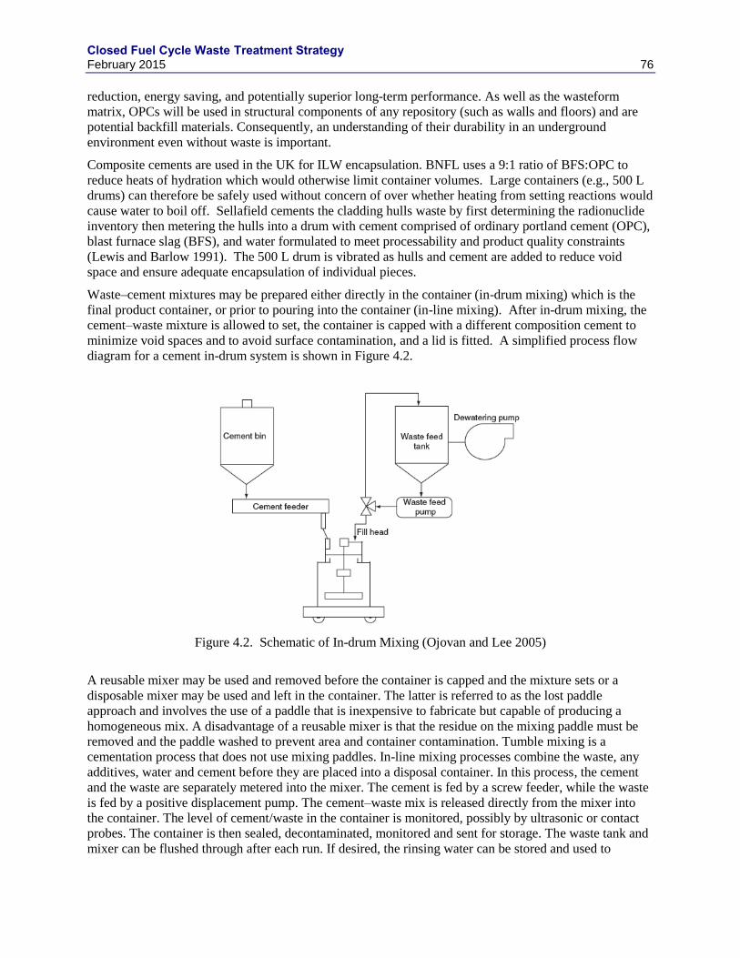
Closed Fuel Cycle Waste Treatment Strategy February 2015 76
reduction, energy saving, and potentially superior long-term performance. As well as the wasteform
matrix, OPCs will be used in structural components of any repository (such as walls and floors) and are
potential backfill materials. Consequently, an understanding of their durability in an underground
environment even without waste is important.
Composite cements are used in the UK for ILW encapsulation. BNFL uses a 9:1 ratio of BFS:OPC to
reduce heats of hydration which would otherwise limit container volumes. Large containers (e.g., 500 L
drums) can therefore be safely used without concern of over whether heating from setting reactions would
cause water to boil off. Sellafield cements the cladding hulls waste by first determining the radionuclide
inventory then metering the hulls into a drum with cement comprised of ordinary portland cement (OPC),
blast furnace slag (BFS), and water formulated to meet processability and product quality constraints
(Lewis and Barlow 1991). The 500 L drum is vibrated as hulls and cement are added to reduce void
space and ensure adequate encapsulation of individual pieces.
Waste–cement mixtures may be prepared either directly in the container (in-drum mixing) which is the
final product container, or prior to pouring into the container (in-line mixing). After in-drum mixing, the
cement–waste mixture is allowed to set, the container is capped with a different composition cement to
minimize void spaces and to avoid surface contamination, and a lid is fitted. A simplified process flow
diagram for a cement in-drum system is shown in Figure 4.2.
Figure 4.2. Schematic of In-drum Mixing (Ojovan and Lee 2005)
A reusable mixer may be used and removed before the container is capped and the mixture sets or a
disposable mixer may be used and left in the container. The latter is referred to as the lost paddle
approach and involves the use of a paddle that is inexpensive to fabricate but capable of producing a
homogeneous mix. A disadvantage of a reusable mixer is that the residue on the mixing paddle must be
removed and the paddle washed to prevent area and container contamination. Tumble mixing is a
cementation process that does not use mixing paddles. In-line mixing processes combine the waste, any
additives, water and cement before they are placed into a disposal container. In this process, the cement
and the waste are separately metered into the mixer. The cement is fed by a screw feeder, while the waste
is fed by a positive displacement pump. The cement–waste mix is released directly from the mixer into
the container. The level of cement/waste in the container is monitored, possibly by ultrasonic or contact
probes. The container is then sealed, decontaminated, monitored and sent for storage. The waste tank and
mixer can be flushed through after each run. If desired, the rinsing water can be stored and used to
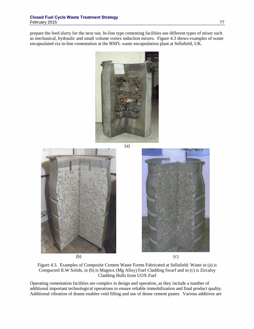
Closed Fuel Cycle Waste Treatment Strategy February 2015 77
prepare the feed slurry for the next run. In-line type cementing facilities use different types of mixer such
as mechanical, hydraulic and small volume vortex induction mixers. Figure 4.3 shows examples of waste
encapsulated via in-line cementation at the BNFL waste encapsulation plant at Sellafield, UK.
(a)
(b) (c)
Figure 4.3. Examples of Composite Cement Waste Forms Fabricated at Sellafield. Waste in (a) is
Compacted ILW Solids, in (b) is Magnox (Mg Alloy) Fuel Cladding Swarf and in (c) is Zircaloy
Cladding Hulls from UOX Fuel
Operating cementation facilities are complex in design and operation, as they include a number of
additional important technological operations to ensure reliable immobilization and final product quality.
Additional vibration of drums enables void filling and use of dense cement pastes. Various additives are
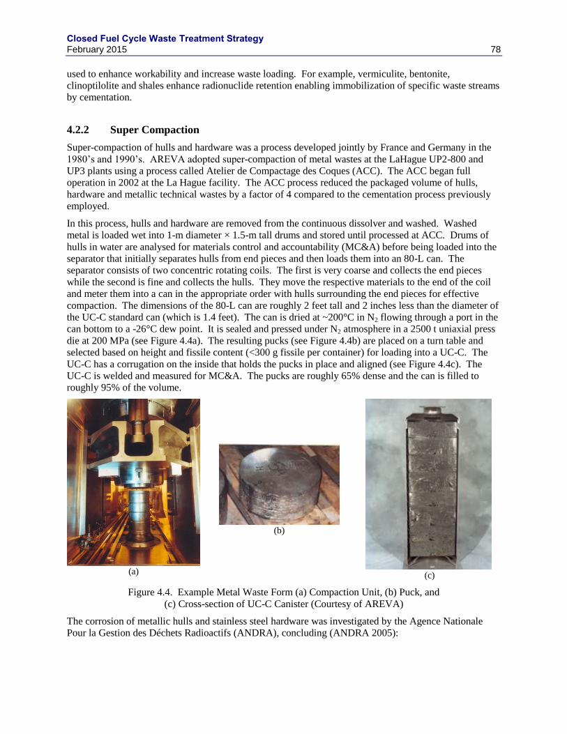
Closed Fuel Cycle Waste Treatment Strategy February 2015 78
used to enhance workability and increase waste loading. For example, vermiculite, bentonite,
clinoptilolite and shales enhance radionuclide retention enabling immobilization of specific waste streams
by cementation.
4.2.2 Super Compaction
Super-compaction of hulls and hardware was a process developed jointly by France and Germany in the
1980’s and 1990’s. AREVA adopted super-compaction of metal wastes at the LaHague UP2-800 and
UP3 plants using a process called Atelier de Compactage des Coques (ACC). The ACC began full
operation in 2002 at the La Hague facility. The ACC process reduced the packaged volume of hulls,
hardware and metallic technical wastes by a factor of 4 compared to the cementation process previously
employed.
In this process, hulls and hardware are removed from the continuous dissolver and washed. Washed
metal is loaded wet into 1-m diameter × 1.5-m tall drums and stored until processed at ACC. Drums of
hulls in water are analysed for materials control and accountability (MC&A) before being loaded into the
separator that initially separates hulls from end pieces and then loads them into an 80-L can. The
separator consists of two concentric rotating coils. The first is very coarse and collects the end pieces
while the second is fine and collects the hulls. They move the respective materials to the end of the coil
and meter them into a can in the appropriate order with hulls surrounding the end pieces for effective
compaction. The dimensions of the 80-L can are roughly 2 feet tall and 2 inches less than the diameter of
the UC-C standard can (which is 1.4 feet). The can is dried at ~200°C in N2 flowing through a port in the
can bottom to a -26°C dew point. It is sealed and pressed under N2 atmosphere in a 2500 t uniaxial press
die at 200 MPa (see Figure 4.4a). The resulting pucks (see Figure 4.4b) are placed on a turn table and
selected based on height and fissile content (<300 g fissile per container) for loading into a UC-C. The
UC-C has a corrugation on the inside that holds the pucks in place and aligned (see Figure 4.4c). The
UC-C is welded and measured for MC&A. The pucks are roughly 65% dense and the can is filled to
roughly 95% of the volume.
(a)
(b)
(c)
Figure 4.4. Example Metal Waste Form (a) Compaction Unit, (b) Puck, and
(c) Cross-section of UC-C Canister (Courtesy of AREVA)
The corrosion of metallic hulls and stainless steel hardware was investigated by the Agence Nationale
Pour la Gestion des Déchets Radioactifs (ANDRA), concluding (ANDRA 2005):
Closed Fuel Cycle Waste Treatment Strategy February 2015 79
“… the total release of radionuclides would take place over 15,000 years in the case of inconel,
70,000 years in the case of stainless steel and approximately 100,000 years in the case of Zircaloy
cladding…”
4.3 Metal Melting
As described in Section 6, melting has been proposed for both zirconium and SS hulls treated by
electrochemical processing. The same process is applicable to hulls from aqesous reprocessing and won’t
be repeated here.
Others have investigated melting of hulls, either directly (Perthier and Al. 1994) or with lower
temperature melting elements (Mazoyer and Vernaz 1986). Berthier et al. melted the hulls using a
(Ca,Ba)F2 flux in a cold crucible melter (Berthier et al. 1994). Mazoyer and Vernaz melted a eutectic
composition of 21.5 Cu mole% and 78.5 mole% Zr at 1150°C and embedded the resulting alloy in glass
(Mazoyer and Vernaz 1986).
4.3.1 Reactive Gas Purification of Zr
Recycle of the nuclear grade Zr has the potential to significantly reduce the UNF waste components that
require emplacement in a geologic repository. For example, the reference reprocessing facility would
produce more compacted hulls/hardware canisters than HLW glass canisters (Areva 2012). If Zr were
removed and the residue reintroduced into the dissolver or HLW glass, 50% fewer canisters would be
produced for the same amount of fuel processed (assuming hardware and metallic technological wastes
still produce ~15% of the canisters). For the process to be successful, the recovered zirconium product
must contain radionuclide concentrations that are inconsequential to the use of zirconium in future nuclear
applications, recognizing that the recovered zirconium will inherently contain one radioactive isotope, 93
Zr, which has a half-life of ~1.5 million years and a weak beta emission. At a minimum, the recovered
zirconium must meet specifications for disposal as LLW.
Reactive gas processes were tested for chemically decladding fuel including chlorination and
hydrochlorination (Zircex) (Bond et al. 1992). A “Hot-Wire” or “Crystal Bar” iodization process was
operated at Western Zirconium for natural Zr purification from 1982-1991 (Van Arkel and De Boer
1925). More recently, Collins further tested the reactive gas processes to purify Zr from irradiated fuel
hulls (Collins et al. 2010, 2012, 2014). They tested I2, Cl2, and HCl processes according to:
clad + 2 I2(g)350°C→ ZrI4(g) + ash ∷ ZrI4(g)
1500°C→ Zr(s) + 2I2 (g)
clad + 2 Cl2(g)350°C→ ZrCl4(g) + ash ∷ ZrCl4(g)
150°C→ ZrCl4(s)
clad + 4 HCl(g)350°C→ ZrCl4(g) + 2H2(g) + ash ∷ ZrCl4(g)
150°C→ ZrCl4(s)
The product of these reactions is either Zr metal or solid ZrCl4. The solid ZrCl4 is a direct input to the Zr
hulls manufacturing process. These three processes were evaluated both experimentally and through
process modelling and it was concluded that the direct chlorination process was the most promising
(Collins et al. 2012).
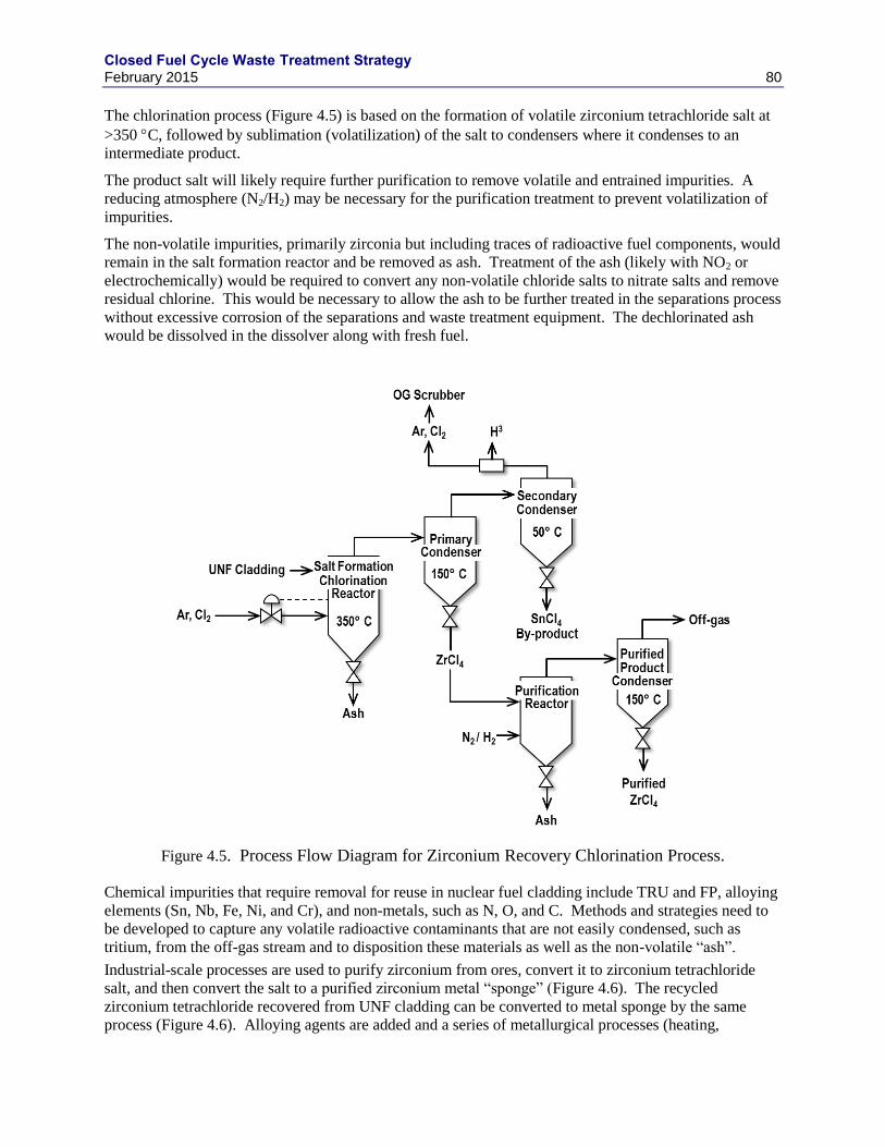
Closed Fuel Cycle Waste Treatment Strategy February 2015 80
The chlorination process (Figure 4.5) is based on the formation of volatile zirconium tetrachloride salt at
>350 C, followed by sublimation (volatilization) of the salt to condensers where it condenses to an
intermediate product.
The product salt will likely require further purification to remove volatile and entrained impurities. A
reducing atmosphere (N2/H2) may be necessary for the purification treatment to prevent volatilization of
impurities.
The non-volatile impurities, primarily zirconia but including traces of radioactive fuel components, would
remain in the salt formation reactor and be removed as ash. Treatment of the ash (likely with NO2 or
electrochemically) would be required to convert any non-volatile chloride salts to nitrate salts and remove
residual chlorine. This would be necessary to allow the ash to be further treated in the separations process
without excessive corrosion of the separations and waste treatment equipment. The dechlorinated ash
would be dissolved in the dissolver along with fresh fuel.
Figure 4.5. Process Flow Diagram for Zirconium Recovery Chlorination Process.
Chemical impurities that require removal for reuse in nuclear fuel cladding include TRU and FP, alloying
elements (Sn, Nb, Fe, Ni, and Cr), and non-metals, such as N, O, and C. Methods and strategies need to
be developed to capture any volatile radioactive contaminants that are not easily condensed, such as
tritium, from the off-gas stream and to disposition these materials as well as the non-volatile “ash”.
Industrial-scale processes are used to purify zirconium from ores, convert it to zirconium tetrachloride
salt, and then convert the salt to a purified zirconium metal “sponge” (Figure 4.6). The recycled
zirconium tetrachloride recovered from UNF cladding can be converted to metal sponge by the same
process (Figure 4.6). Alloying agents are added and a series of metallurgical processes (heating,
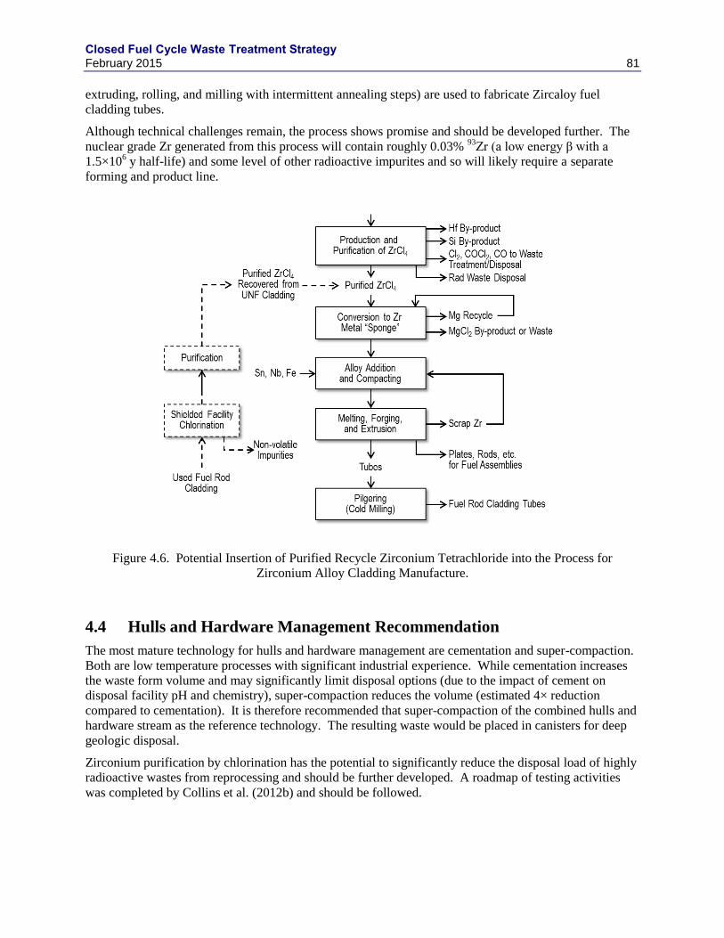
Closed Fuel Cycle Waste Treatment Strategy February 2015 81
extruding, rolling, and milling with intermittent annealing steps) are used to fabricate Zircaloy fuel
cladding tubes.
Although technical challenges remain, the process shows promise and should be developed further. The
nuclear grade Zr generated from this process will contain roughly 0.03% 93
Zr (a low energy β with a
1.5×10⁶ y half-life) and some level of other radioactive impurites and so will likely require a separate
forming and product line.
Figure 4.6. Potential Insertion of Purified Recycle Zirconium Tetrachloride into the Process for
Zirconium Alloy Cladding Manufacture.
4.4 Hulls and Hardware Management Recommendation
The most mature technology for hulls and hardware management are cementation and super-compaction.
Both are low temperature processes with significant industrial experience. While cementation increases
the waste form volume and may significantly limit disposal options (due to the impact of cement on
disposal facility pH and chemistry), super-compaction reduces the volume (estimated 4× reduction
compared to cementation). It is therefore recommended that super-compaction of the combined hulls and
hardware stream as the reference technology. The resulting waste would be placed in canisters for deep
geologic disposal.
Zirconium purification by chlorination has the potential to significantly reduce the disposal load of highly
radioactive wastes from reprocessing and should be further developed. A roadmap of testing activities
was completed by Collins et al. (2012b) and should be followed.
Closed Fuel Cycle Waste Treatment Strategy February 2015 82
4.5 Data Gaps and Research Needs
Develop and demonstrate a process for reactive gas separation of Zr for recycle or LLW
management.
Develop and demonstrate a method for managing the chlorinated ash from reactive gas Zr
purification. It’s been proposed that the ash would be treated to remove the chloride and returned
to the dissolved fuel stream.
Determine fate of residual 3H in cladding, determine the ability to remove tritium from the
cladding during the chlorination process, and evaluate the capture and disposal of 3HCl after Zr
purification. In industrial production of chlorine, HCl is removed from gas streams by water
washing. HCl is highly soluble in water but chlorine is not. The wet chlorine is then dried with
sulfuric acid. It may be possible to use a molecular sieve in place of sulfuric acid to dry the Cl
stream. This has not been demonstrated. Once the water becomes concentrated in HCl (3H), it
could be grouted (or neutralized and grouted).
Determine the performance characteristics of the compacted hulls, generate and parameterize a
long-term corrosion model, and develop a waste form compliance plan.
Closed Fuel Cycle Waste Treatment Strategy February 2015 83
5. ELECTROCHEMICAL SALT HLW
5.1 Glass-Bonded Sodalite
The glass-bonded sodalite waste form—usually referred to as the ceramic waste form (CWF)—that was
developed to immobilize high-level radioactive waste salts generated during the electrometallurgical
treatment of spent sodium-bonded nuclear fuel utilizes sodalite to contain NaCl from the waste salt and
borosilicate glass to encapsulate that sodalite in a physically durable monolithic waste form (Pereira et al.
1999, Simpson et al. 2001). Zeolite-4A is used to occlude the waste salt that is the working fluid in the
Echem process. The zeolite with the occluded salt is mixed with a low melting temperature glass and
heated to a temperature at which the salt-loaded zeolite first converts to sodalite then becomes
encapsulated in a glass matrix. This product is specific to the chloride salts generated during Echem
processing of fuel, but, could be used for a number of the wastes generated from salt processing described
in Section 1.2.1.
The glass phase serves three important purposes in the waste form: (1) it encapsulates the micron-sized
lanthanide and actinide oxides that are produced during the occlusion step (when the salt is contacted by
small amounts of residual water in the zeolite) and the halite inclusions that form during waste form
processing; (2) Na from the glass is exchanged with other alkali metal and alkaline earth cations in the
salt (most importantly fission products) allowing their incorporation in the glass phase; and (3) the glass
provides additional Na to sequester excess chloride as sodalite or halite. The glass phase provides the
chemical durability that controls the release of both radionuclides that are dissolved in the glass and
radionuclides in phases that are encapsulated by the glass. The primary role of the sodalite phase in the
waste form is to host the chloride so the radionuclide cations can dissolve in the glass; iodide is the only
radionuclide contained in the sodalite and halide phases.
5.1.1 Zeolite Salt Occlusion
The CWF is produced when waste salt from the electrorefiner that contains fission products is combined
with (occluded in the pores of) zeolite 4A [Na12(AlSiO4)12, on a dry basis]. The salt-occluded zeolite
(SLZ) is then mixed with borosilicate glass frit and consolidated in an electric furnace. The zeolite reacts
with the NaCl in the waste salt to form sodalite according to the reaction:
Na12(AlSiO4)12 + 4 NaCl → 2 Na8(AlSiO4)6Cl2. (1)
zeolite 4A halite sodalite
The production of sodalite is a stoichiometrically related to the amounts of zeolite 4A and halite in the
salt. The sodalite phase hosts the chloride (and iodide) in the waste form, whereas the radionuclide
cations in the salt waste replace Na+ in the glass to maintain charge balance. Iodide, as a halogen like
chlorine, can substitute for chloride and is the only radionuclide contained in the sodalite in significant
quantity.
One option being considered is the draw-down of lanthanides from the salt waste and inclusion of those
lanthanides in the CWF. The metal granules contained in the salt from LN-drawdown process. The
incorporation of lanthanide metals in the CWF has not been fully developed or tested, but conceptually
they can be added to the occlusion process. The misch metal particles would then be oxidized during the
salt occlusion process by residual water in the zeolite, as are actinide and rare earth chlorides in the waste
salt.
Closed Fuel Cycle Waste Treatment Strategy February 2015 84
5.1.2 Glass Encapsulation
The borosilicate glass (a) encapsulates sodalite and NaCl (halite) inclusions in a physically durable
monolithic waste form, (b) encapsulates the micron-sized lanthanide and actinide oxides that are produced
during the occlusion step (the lanthanide and actinide chlorides react with small amounts of residual water
in the zeolite), (c) provides Na from the glass for exchange with other alkali metal and alkaline earth
cations in the salt (most importantly the fission products), allowing their incorporation in the glass phase,
and (d) provides additional Na to supplement the amount of Na present in the salt waste to sequester
excess chloride as sodalite or halite. The glass phase provides the chemical durability that controls the
release of radionuclides that are either dissolved in the glass or in oxide phases that are encapsulated by
the glass.
5.1.3 Excess Halite Inclusions
The formation of nepheline during CWF production decreases the amounts of sodalite formed and waste
salt immobilized. A small amount of NaCl in excess of that needed to form sodalite during waste form
production is desirable to minimize sodalite decomposition to nepheline according to:
Na8(AlSiO4)6Cl2 ↔ 2 NaCl + 1.5 Na4(AlSiO4)4 (2)
Sodalite Halite Nepheline
Excess NaCl forms halite inclusions in the waste form that are distributed throughout the glass phase.
Small amounts of halite inclusions are not detrimental to the chemical durability of the glass phase
because they do not affect the glass composition or the performance of the waste form. Halite inclusions
do dissolve quickly when contacted by water, and increase the surface area that becomes exposed to
groundwater during glass degradation, but this is a minor effect. When the CWF is properly formulated,
the halite does not contain significant amounts of radionuclides except for iodine. In-order to gain access
to the inclusions, water must first dissolve the encapsulating glass phase. In terms of waste form
performance, the release of I– from halite inclusions is equivalent to the release of I
– from the glass that
dissolved to expose the inclusions. Tolerating a small amount of halite inclusions would accept a minor
decrease in waste form durability to gain a large benefit of waste loadings to be increased from roughly
8% to 12% for a minor (Ebert 2010).
5.1.4 Waste Loading
The loading of radionuclides in the waste form depends on the concentration of radionuclides in the salt,
the concentration of salt in the waste form, and any addition of elemental lanthanides that might be
separated from the salt to enable salt purification and recycle and then added back to the waste stream
prior to waste form processing.g The salt waste loading is limited primarily by (a) the chloride content of
the salt, and secondarily by (b) the Na content of the salt, (c) the Na content of the glass, needed for ion
exchange with other cations in the salt, and (d) the amount of glass needed to encapsulate the sodalite and
accommodate inclusion phases formed during processing (halite and mixed oxides of lanthanides and
actinides). For salts with high concentrations of heat-generating isotopes (e.g., 90
Sr, 134
Cs, and 137
Cs),
waste loading may be limited by the thermal stability of the CWF or heat limits imposed by the storage
and disposal systems. An initial evaluation of CWF for electrochemical salts showed that the maximum
centerline temperature for the baseline 20.5 inch diameter canister was 329 °C, well below the CWF
stability temperature. Less-than-maximum waste loadings may be desired to manage heat during waste
form storage and disposal activities.
g The concentration of radionuclides and the concentration of salt in the waste form provide alternative definitions of the waste
loading.
Closed Fuel Cycle Waste Treatment Strategy February 2015 85
The overall salt loading of 8 mass% in the CWF from Experimental Breeder Reactor-II (EBR-II) UNF
reprocessing was a conservatively low administrative limit based on the desire to minimize the amount of
halite formed. It is now known that additional halite is not detrimental to performance, and that
acceptable waste forms can likely be made with higher salt loadings (Ebert 2010). These higher salt
loadings require Na to be provided by the glass, and if that is still not sufficient, from additional sources
of Na.
The waste loading is usually limited by the amount of Na available in the salt and in the glass, or added to
the system to generate enough sodalite and halite to accommodate chloride in the salt. Other alkali metals
in the salt are not effective in generating sodalite and instead exchange with Na in the glass or react form
other phases (e.g., Cs-pollucite, Sr-celsian, Li-aluminosilicate). The Na released from the glass into the
salt is available for sodalite and halite formation. The Na content of the glass must be adequate to
accommodate the exchanges with other cations in the salt (unless another phase is formed or unless Na is
added from another source). The glass may become totally depleted of Na during waste form processing
(Frank 2004; O’Holleran 1999). This will halt sodalite production and the incorporation of waste salt into
the CWF.
Waste forms can be formulated utilizing other mineral phases to accommodate cations in the salt that
exceed solubilities in the glass and limit the salt waste loading. For example, pollucite and celsian can be
used to accommodate Cs and Sr and avoid unacceptably large amounts of radionuclide-bearing salt being
distributed throughout the waste form (Ebert 2010).
5.1.5 Thermal Loading
The impact of self-heating of the CWF is estimated using a previous study of the effects of heat treatment
on the phase composition and chemical durability to evaluate the impact of production upsets (Ebert et al.
2005). Two CWF products made with reference salt and glass contents were subjected to heat treatments
at 400 and 500 °C for durations up to 1 year, and at 600, 700, 800, and 850 °C for durations up to 100 h.
The CWF had been produced at 915 °C, so the higher temperatures certainly exceed the Tg of the binder
glass, although the value of Tg was not known.
Heating at the highest temperatures had only a small effect on the crystalline phase composition; the
amount of halite increased to as much as 3.7 mass%, and nepheline was detected in samples treated at 800
and 850 °C. This suggested that a small fraction of the sodalite decomposed to form nepheline at these
temperatures.
The effects of the heat treatments on the durability of the glass phases of CWF samples were determined
using product consistency tests (PCTs). The releases of Cl, B, Na, and Si in the PCTs were not affected
by the heat-treatment conditions. The long-term effects of self-heating on the physical and chemical
stability of the CWF are, therefore, considered to be negligible.
5.1.6 Ceramic Waste Form Process
The cost for the CWF fabrication process was estimated on the same basis of $5.4M per 15×15 ft hot cell
work area described above. The EBR-II salt management process flowsheet was used to estimate the
space and equipment needs for CWF fabrication (Bateman et al. 2007; Morrison and Bateman 2010;
Morrison et al. 2010; Priebe and Bateman 2008; Simpson et al. 2001).
Salt will be crushed to roughly 10-mm diameter particles in a jaw crusher. This operation was
demonstrated to effectively crush a 7-cm diameter rod of salt in seconds. The crushed salt is then ground
to < 250 μm diameter particles. Roughly 10 kg of ground salt is then loaded into a V-blender with an
appropriate amount of dried and ground (45-250 μm diameter) zeolite 4A at a ratio of ~70 kg zeolite/10
Closed Fuel Cycle Waste Treatment Strategy February 2015 86
kg salt. The mixture of materials is heated to ~500 °C and mixed for ~80 h to occlude the salt into the
zeolite pore-structure. The batch is then cooled and the appropriate amount of glass frit is added (~27 kg
glass frit/~80 kg SLZ) and the batch is mixed for another hour at room temperature.
The blended batch of SLZ and glass is transferred to a sintering can comprised of three roughly 1-m
segments that are roughly 0.52-m in diameter, as shown in Figure 5.1. The three segments are used to
accommodate the ~2.5× volume reduction that occurs when the reactants form the CWF. The canister
will have a segmented 6.35-cm diameter lifting rod in the center that will become embedded in the CWF
as it is made and consolidated in the bottom segment of the sintering can. Several batches of the
SLZ/glass mixture (~110 kg each) are loaded into the canister until a sufficient amount of material is
obtained to fill the bottom segment with CWF (~455 kg). A weighted cover plate is placed on the top of
the batch and the three-segment canister is loaded into a sintering furnace. The batch is heated at 1
°C/min to 500 °C and held for sufficient time (~60 h) to equilibrate the temperature throughout the
material before the frit begins to soften. In the next step, the batch is heated at 0.5 °C/min to 925 °C and
held at that temperature for sufficient time (~75 h) to react all the components to form a glass-bonded
sodalite waste form in the bottom segment having a density within 10% of the theoretical density, which
is 2340 kg/m3. The final step is the controlled cool down which is optimized to avoid cracking of the
CWF while maintaining the total furnace time of 250 h. The canister is removed from the furnace and the
top two segments of the sintering can are removed remotely. Only the bottom portion containing the
CWF will be disposed, while the top two portions are reused for the next batch (each segment advancing
down in the stack of three segments). The weight is removed from the bottom segment containing the
CWF, but the plate is left in the can as a spacer between successive CWF products that will be placed in a
disposal canister. Four 1.09-m-tall segments (containing 1.01 m of CWF) are placed in a 4.4-m-tall
disposal canister. Each sintering can segment with CWF is attached to the segment below it by a J-
groove fitting in the sintering can. The outer canister is welded closed and transferred to a canister
storage building until shipment to a geologic repository for disposal.
Although the 20.5-inch (0.52 m) diameter canister was used as a reference in this study, smaller canisters
appropriate for deep borehole disposal (e.g., 8.5 inch) are also possible. The heating cycle time is
expected to reduce with the square of canister diameter (Bateman and Solbrig 2006).
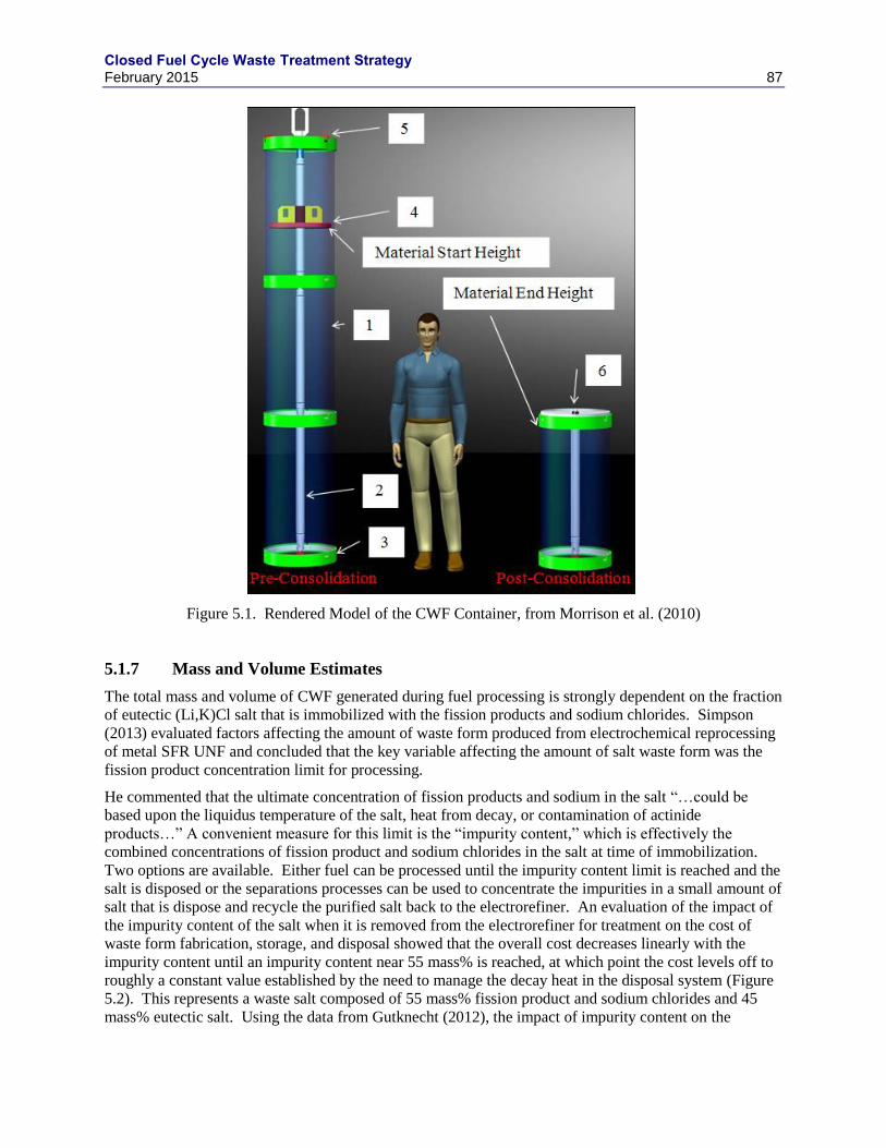
Closed Fuel Cycle Waste Treatment Strategy February 2015 87
Figure 5.1. Rendered Model of the CWF Container, from Morrison et al. (2010)
5.1.7 Mass and Volume Estimates
The total mass and volume of CWF generated during fuel processing is strongly dependent on the fraction
of eutectic (Li,K)Cl salt that is immobilized with the fission products and sodium chlorides. Simpson
(2013) evaluated factors affecting the amount of waste form produced from electrochemical reprocessing
of metal SFR UNF and concluded that the key variable affecting the amount of salt waste form was the
fission product concentration limit for processing.
He commented that the ultimate concentration of fission products and sodium in the salt “…could be
based upon the liquidus temperature of the salt, heat from decay, or contamination of actinide
products…” A convenient measure for this limit is the “impurity content,” which is effectively the
combined concentrations of fission product and sodium chlorides in the salt at time of immobilization.
Two options are available. Either fuel can be processed until the impurity content limit is reached and the
salt is disposed or the separations processes can be used to concentrate the impurities in a small amount of
salt that is dispose and recycle the purified salt back to the electrorefiner. An evaluation of the impact of
the impurity content of the salt when it is removed from the electrorefiner for treatment on the cost of
waste form fabrication, storage, and disposal showed that the overall cost decreases linearly with the
impurity content until an impurity content near 55 mass% is reached, at which point the cost levels off to
roughly a constant value established by the need to manage the decay heat in the disposal system (Figure
5.2). This represents a waste salt composed of 55 mass% fission product and sodium chlorides and 45
mass% eutectic salt. Using the data from Gutknecht (2012), the impact of impurity content on the
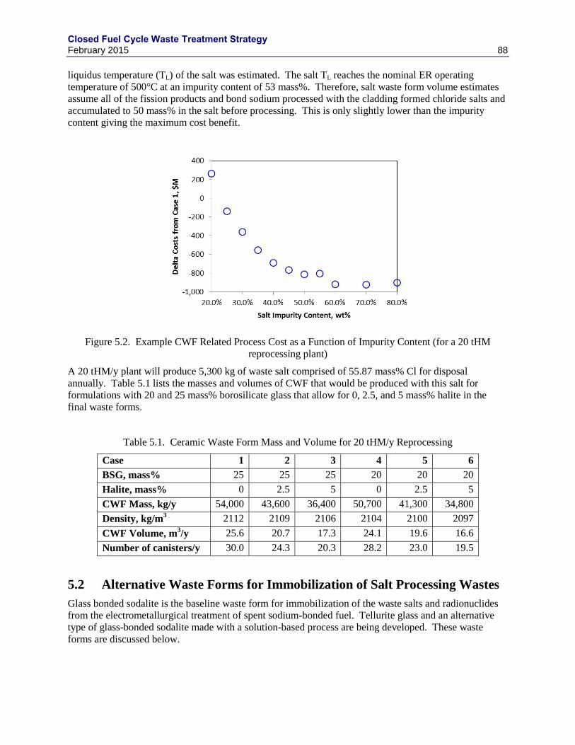
Closed Fuel Cycle Waste Treatment Strategy February 2015 88
liquidus temperature (TL) of the salt was estimated. The salt TL reaches the nominal ER operating
temperature of 500°C at an impurity content of 53 mass%. Therefore, salt waste form volume estimates
assume all of the fission products and bond sodium processed with the cladding formed chloride salts and
accumulated to 50 mass% in the salt before processing. This is only slightly lower than the impurity
content giving the maximum cost benefit.
Figure 5.2. Example CWF Related Process Cost as a Function of Impurity Content (for a 20 tHM
reprocessing plant)
A 20 tHM/y plant will produce 5,300 kg of waste salt comprised of 55.87 mass% Cl for disposal
annually. Table 5.1 lists the masses and volumes of CWF that would be produced with this salt for
formulations with 20 and 25 mass% borosilicate glass that allow for 0, 2.5, and 5 mass% halite in the
final waste forms.
Table 5.1. Ceramic Waste Form Mass and Volume for 20 tHM/y Reprocessing
Case 1 2 3 4 5 6
BSG, mass% 25 25 25 20 20 20
Halite, mass% 0 2.5 5 0 2.5 5
CWF Mass, kg/y 54,000 43,600 36,400 50,700 41,300 34,800
Density, kg/m3 2112 2109 2106 2104 2100 2097
CWF Volume, m3/y 25.6 20.7 17.3 24.1 19.6 16.6
Number of canisters/y 30.0 24.3 20.3 28.2 23.0 19.5
5.2 Alternative Waste Forms for Immobilization of Salt Processing Wastes
Glass bonded sodalite is the baseline waste form for immobilization of the waste salts and radionuclides
from the electrometallurgical treatment of spent sodium-bonded fuel. Tellurite glass and an alternative
type of glass-bonded sodalite made with a solution-based process are being developed. These waste
forms are discussed below.
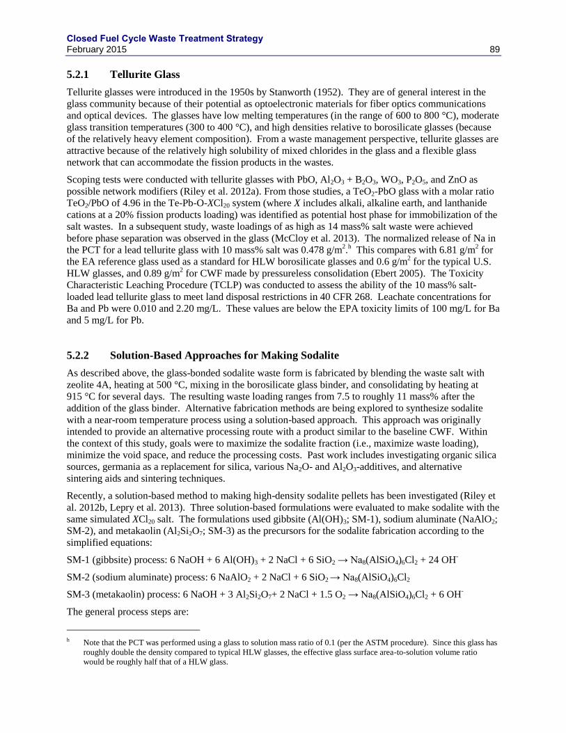
Closed Fuel Cycle Waste Treatment Strategy February 2015 89
5.2.1 Tellurite Glass
Tellurite glasses were introduced in the 1950s by Stanworth (1952). They are of general interest in the
glass community because of their potential as optoelectronic materials for fiber optics communications
and optical devices. The glasses have low melting temperatures (in the range of 600 to 800 °C), moderate
glass transition temperatures (300 to 400 °C), and high densities relative to borosilicate glasses (because
of the relatively heavy element composition). From a waste management perspective, tellurite glasses are
attractive because of the relatively high solubility of mixed chlorides in the glass and a flexible glass
network that can accommodate the fission products in the wastes.
Scoping tests were conducted with tellurite glasses with PbO, Al2O3 + B2O3, WO3, P2O5, and ZnO as
possible network modifiers (Riley et al. 2012a). From those studies, a TeO2-PbO glass with a molar ratio
TeO2/PbO of 4.96 in the Te-Pb-O-XCl20 system (where X includes alkali, alkaline earth, and lanthanide
cations at a 20% fission products loading) was identified as potential host phase for immobilization of the
salt wastes. In a subsequent study, waste loadings of as high as 14 mass% salt waste were achieved
before phase separation was observed in the glass (McCloy et al. 2013). The normalized release of Na in
the PCT for a lead tellurite glass with 10 mass% salt was 0.478 g/m2.h This compares with 6.81 g/m
2 for
the EA reference glass used as a standard for HLW borosilicate glasses and 0.6 g/m2 for the typical U.S.
HLW glasses, and 0.89 g/m2 for CWF made by pressureless consolidation (Ebert 2005). The Toxicity
Characteristic Leaching Procedure (TCLP) was conducted to assess the ability of the 10 mass% salt-
loaded lead tellurite glass to meet land disposal restrictions in 40 CFR 268. Leachate concentrations for
Ba and Pb were 0.010 and 2.20 mg/L. These values are below the EPA toxicity limits of 100 mg/L for Ba
and 5 mg/L for Pb.
5.2.2 Solution-Based Approaches for Making Sodalite
As described above, the glass-bonded sodalite waste form is fabricated by blending the waste salt with
zeolite 4A, heating at 500 °C, mixing in the borosilicate glass binder, and consolidating by heating at
915 °C for several days. The resulting waste loading ranges from 7.5 to roughly 11 mass% after the
addition of the glass binder. Alternative fabrication methods are being explored to synthesize sodalite
with a near-room temperature process using a solution-based approach. This approach was originally
intended to provide an alternative processing route with a product similar to the baseline CWF. Within
the context of this study, goals were to maximize the sodalite fraction (i.e., maximize waste loading),
minimize the void space, and reduce the processing costs. Past work includes investigating organic silica
sources, germania as a replacement for silica, various Na2O- and Al2O3-additives, and alternative
sintering aids and sintering techniques.
Recently, a solution-based method to making high-density sodalite pellets has been investigated (Riley et
al. 2012b, Lepry et al. 2013). Three solution-based formulations were evaluated to make sodalite with the
same simulated XCl20 salt. The formulations used gibbsite (Al(OH)3; SM-1), sodium aluminate (NaAlO2;
SM-2), and metakaolin (Al2Si2O7; SM-3) as the precursors for the sodalite fabrication according to the
simplified equations:
SM-1 (gibbsite) process: 6 NaOH + 6 Al(OH)3 + 2 NaCl + 6 SiO2 → Na8(AlSiO4)6Cl2 + 24 OH-
SM-2 (sodium aluminate) process: 6 NaAlO2 + 2 NaCl + 6 SiO2 → Na8(AlSiO4)6Cl2
SM-3 (metakaolin) process: 6 NaOH + 3 Al2Si2O7+ 2 NaCl + 1.5 O2 → Na8(AlSiO4)6Cl2 + 6 OH-
The general process steps are:
h Note that the PCT was performed using a glass to solution mass ratio of 0.1 (per the ASTM procedure). Since this glass has
roughly double the density compared to typical HLW glasses, the effective glass surface area-to-solution volume ratio
would be roughly half that of a HLW glass.
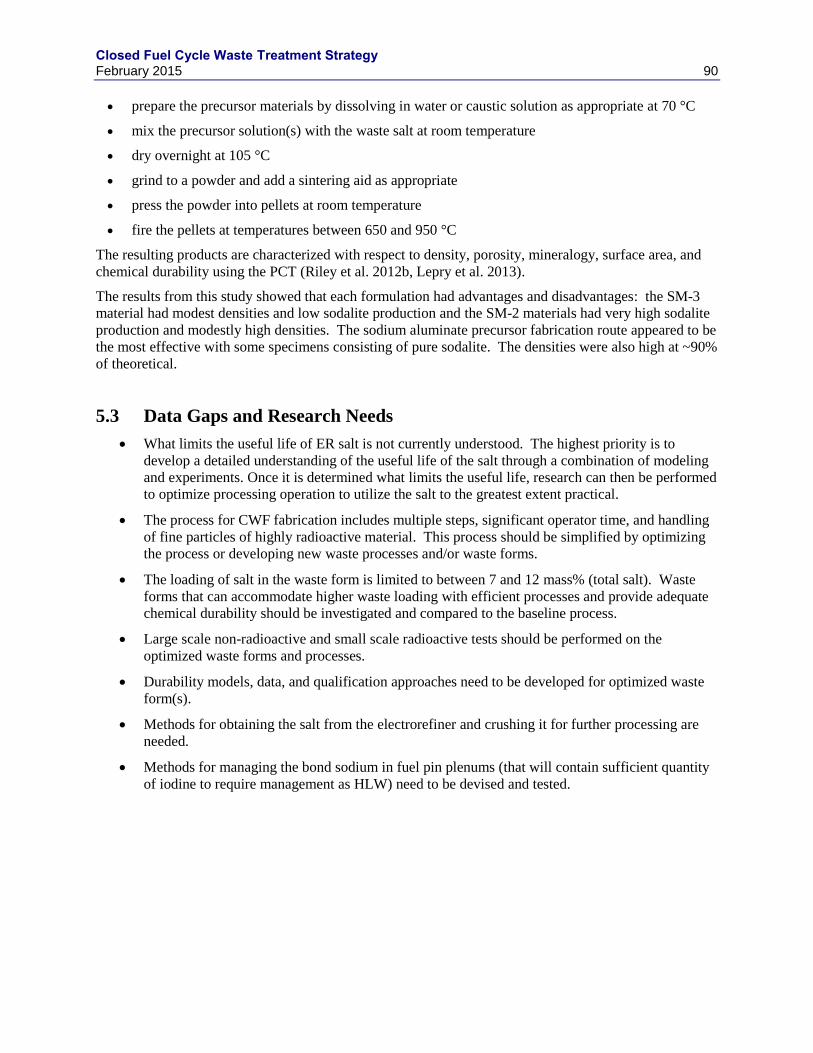
Closed Fuel Cycle Waste Treatment Strategy February 2015 90
prepare the precursor materials by dissolving in water or caustic solution as appropriate at 70 °C
mix the precursor solution(s) with the waste salt at room temperature
dry overnight at 105 °C
grind to a powder and add a sintering aid as appropriate
press the powder into pellets at room temperature
fire the pellets at temperatures between 650 and 950 °C
The resulting products are characterized with respect to density, porosity, mineralogy, surface area, and
chemical durability using the PCT (Riley et al. 2012b, Lepry et al. 2013).
The results from this study showed that each formulation had advantages and disadvantages: the SM-3
material had modest densities and low sodalite production and the SM-2 materials had very high sodalite
production and modestly high densities. The sodium aluminate precursor fabrication route appeared to be
the most effective with some specimens consisting of pure sodalite. The densities were also high at ~90%
of theoretical.
5.3 Data Gaps and Research Needs
What limits the useful life of ER salt is not currently understood. The highest priority is to
develop a detailed understanding of the useful life of the salt through a combination of modeling
and experiments. Once it is determined what limits the useful life, research can then be performed
to optimize processing operation to utilize the salt to the greatest extent practical.
The process for CWF fabrication includes multiple steps, significant operator time, and handling
of fine particles of highly radioactive material. This process should be simplified by optimizing
the process or developing new waste processes and/or waste forms.
The loading of salt in the waste form is limited to between 7 and 12 mass% (total salt). Waste
forms that can accommodate higher waste loading with efficient processes and provide adequate
chemical durability should be investigated and compared to the baseline process.
Large scale non-radioactive and small scale radioactive tests should be performed on the
optimized waste forms and processes.
Durability models, data, and qualification approaches need to be developed for optimized waste
form(s).
Methods for obtaining the salt from the electrorefiner and crushing it for further processing are
needed.
Methods for managing the bond sodium in fuel pin plenums (that will contain sufficient quantity
of iodine to require management as HLW) need to be devised and tested.
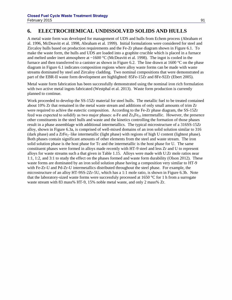
Closed Fuel Cycle Waste Treatment Strategy February 2015 91
6. ELECTROCHEMICAL UNDISSOLVED SOLIDS AND HULLS
A metal waste form was developed for management of UDS and hulls from Echem process (Abraham et
al. 1996, McDeavitt et al. 1998, Abraham et al. 1999). Initial formulations were considered for steel and
Zircaloy hulls based on production requirements and the Fe-Zr phase diagram shown in Figure 6.1. To
make the waste form, the hulls and UDS are loaded into a graphite crucible which is placed in a furnace
and melted under inert atmosphere at ~1600 °C (McDeavitt et al. 1998). The ingot is cooled in the
furnace and then transferred to a canister as shown in Figure 6.2. The line drawn at 1600 °C on the phase
diagram in Figure 6.1 indicates composition regions where alloy waste forms can be made with waste
streams dominated by steel and Zircaloy cladding. Two nominal compositions that were demonstrated as
part of the EBR-II waste form development are highlighted: 85Fe-15Zr and 8Fe-92Zr (Ebert 2005).
Metal waste form fabrication has been successfully demonstrated using the nominal iron rich formulation
with two active metal ingots fabricated (Westphal et al. 2013). Waste form production is currently
planned to continue.
Work proceeded to develop the SS-15Zr material for steel hulls. The metallic fuel to be treated contained
about 10% Zr that remained in the metal waste stream and additions of only small amounts of trim Zr
were required to achive the eutectic composition. According to the Fe-Zr phase diagram, the SS-15Zr
feed was expected to solidify as two major phases: α-Fe and Zr6Fe23 intermetallic. However, the presence
other constituents in the steel hulls and waste and the kinetics controlling the formation of those phases
result in a phase assemblage with additional intermetallics. The typical microstructure of a 316SS-15Zr
alloy, shown in Figure 6.3a, is comprised of well-mixed domains of an iron solid solution similar to 316
(dark phase) and a ZrFe2–like intermetallic (light phase) with regions of high U content (lightest phase).
Both phases contain significant amounts of other elements from the steel and waste stream. The iron
solid solution phase is the host phase for Tc and the intermetallic is the host phase for U. The same
constituent phases were formed in alloys made recently with HT-9 steel and less Zr and U to represent
alloys for waste streams such a that given in Table 1.15. Alloys were made with U:Zr mole ratios near
1:1, 1:2, and 3:1 to study the effect on the phases formed and waste form durability (Olson 2012). These
waste forms are dominated by an iron solid solution phase having a composition very similar to HT-9
with Fe-Zr-U and Pd-Zr-U intermetallics distributed throughout the steel phase. For example, the
microstructure of an alloy HT-9SS-2Zr-5U, which has a 1:1 mole ratio, is shown in Figure 6.3b. Note
that the laboratory-sized waste forms were successfuly processed at 1650 °C for 1 h from a surrogate
waste stream with 83 mass% HT-9, 15% noble metal waste, and only 2 mass% Zr.
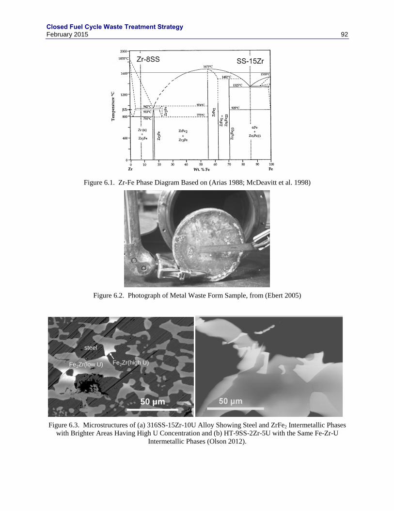
Closed Fuel Cycle Waste Treatment Strategy February 2015 92
Figure 6.1. Zr-Fe Phase Diagram Based on (Arias 1988; McDeavitt et al. 1998)
Figure 6.2. Photograph of Metal Waste Form Sample, from (Ebert 2005)
Figure 6.3. Microstructures of (a) 316SS-15Zr-10U Alloy Showing Steel and ZrFe2 Intermetallic Phases
with Brighter Areas Having High U Concentration and (b) HT-9SS-2Zr-5U with the Same Fe-Zr-U
Intermetallic Phases (Olson 2012).
Fe2Zr(low U)
steel
Fe2Zr(high U)
50 μm
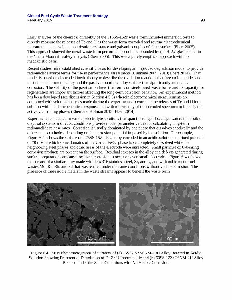
Closed Fuel Cycle Waste Treatment Strategy February 2015 93
Early analyses of the chemical durability of the 316SS-15Zr waste form included immersion tests to
directly measure the releases of Tc and U as the waste form corroded and routine electrochemical
measurements to evaluate polarization resistance and galvanic couples of clean surface (Ebert 2005).
This approach showed the metal waste form performance could be bounded by the HLW glass model in
the Yucca Mountain safety analysis (Ebert 2005). This was a purely empirical approach with no
mechanistic basis.
Recent studies have established scientific basis for developing an improved degradation model to provide
radionuclide source terms for use in performance assessments (Cunnane 2009, 2010; Ebert 2014). That
model is based on electrode kinetic theory to describe the oxidation reactions that free radionuclides and
host elements from the alloy and the passivation of the alloy surface that significantly attenuates
corrosion. The stability of the passivation layer that forms on steel-based waste forms and its capacity for
regeneration are important factors affecting the long-term corrosion behavior. An experimental method
has been developed (see discussion in Section 4.5.3) wherein electrochemical measurements are
combined with solution analyses made during the experiments to correlate the releases of Tc and U into
solution with the electrochemical response and with microscopy of the corroded specimen to identify the
actively corroding phases (Ebert and Kolman 2013; Ebert 2014).
Experiments conducted in various electrolyte solutions that span the range of seepage waters in possible
disposal systems and redox conditions provide model parameter values for calculating long-term
radionuclide release rates. Corrosion is usually dominated by one phase that dissolves anodically and the
others act as cathodes, depending on the corrosion potential imposed by the solution. For example,
Figure 6.4a shows the surface of a 75SS-15Zr-10U alloy corroded in an acidic solution at a fixed potential
of 70 mV in which some domains of the U-rich Fe-Zr phase have completely dissolved while the
neighboring steel phases and other areas of the electrode were unreacted. Small particles of U-bearing
corrosion products are present on the surface. Residual stresses in the alloy and defects generated during
surface preparation can cause localized corrosion to occur on even small electrodes. Figure 6.4b shows
the surface of a similar alloy made with less 316 stainless steel, Zr, and U, and with noble metal fuel
wastes Mo, Ru, Rh, and Pd that was reacted under the same conditions without visible corrosion. The
presence of these noble metals in the waste streams appears to benefit the waste form.
Figure 6.4. SEM Photomicrographs of Surfaces of (a) 75SS-15Zr-0NM-10U Alloy Reacted in Acidic
Solution Showing Preferential Dissolution of Fe-Zr-U Intermetallic and (b) 60SS-12Zr-26NM-2U Alloy
Reacted under the Same Conditions with No Visible Corrosion.
100 μm
100 μm
Closed Fuel Cycle Waste Treatment Strategy February 2015 94
The presence of multiple phases and the composition of those phases affect the corrosion behavior of
alloyed waste forms and the release of radionuclides from those phases, and localized corrosion further
complicates the modeling of the degradation behavior. An alloy waste form degradation model is being
developed to provide radionuclide source term values for use in performance assessment calculations for
potential engineered waste disposal systems (Ebert 2014). Radionuclide release occurs as the waste form
corrodes by an oxidative-dissolution process in which the radionuclide and surrounding host metal are
first oxidized and then the oxides dissolve. The oxidation occurs through electrochemical reactions with
the solution contacting the alloy surface; the oxidation rate depends on the amounts of redox-sensitive
species in the solution and the relative stabilities of the constituent alloy phases. The solution
composition affects the radionuclide release rates electrochemically through the effects of redox-active
components on the oxidation rate and chemically through the effects of pH and complexation on
radionuclide solubility. Dissolved chloride is key chemical component of the solution that destabilizes
passive layers formed on Cr-bearing phases.
Electrode kinetic theory provides the scientific basis for developing the degradation model, but is too
complicated to implement directly to model multi-phase alloy waste forms. Instead, a semi-empirical
modeling approach is being followed in which experimentally-measured values are used to determine
analytical dependencies of the corrosion and dissolution rates on environmental variables and represent
the effects of passivation and oxide dissolution on the release of radionuclides. Electrochemical test
methods have been designed specifically to provide data needed to determine environmental
dependencies and measure parameter values. Tests are being conducted with several representative alloys
in various solution compositions representing a wide range of disposal environmental conditions,
including acidic, neutral, and alkaline solutions with and without NaCl, a range of NaCl brine solutions,
various dissolved oxygen and hydrogen concentrations, and various temperatures (Ebert and Kolman
2013). Tests are conducted using electrodes fashioned from several representative alloys for extended
periods of several weeks to measure the effects of forming passive corrosion layers on the oxidation rate.
The release of radionuclides (primarily Tc and U) into solution is measured periodically during the tests
to correlate the radionuclide release rates with the active and passive oxidation rates and maturation of
passivating layer. After the experiments, the corroded electrodes are examined with SEM to identify
which phase was active during the experiment.
The alloy degradation model includes terms representing the electrochemical behavior of the bare surface,
the stabilizing effect of a passivation layer, and the resistance to dissolution on the radionuclide release
rate. All terms are sensitive to the corrosion environment and relate the rate of interest (the radionuclide
source term) to the release mechanism. The bare surface behavior depends on the redox potential
established by the groundwater and galvanic interactions between constituent phases of the waste form,
the passivation term depends on the Cr content of the waste form and the Cl content of the groundwater,
and dissolution term depends on the oxidation state of the radionuclide. Passivation can attenuate the
bare surface oxidation rate by two or three orders of magnitude and can be promoted by adding trim Cr to
the waste form. Electrode kinetics theory provides confidence that the behavior measured in experiments
represents long-term corrosion behavior.
6.1 Data Gaps and Research Needs
Significant development has been made on 300-series stainless steel based waste forms, but work has just
started with the newer HT-9 based formulations. The required testing includes formulation of the base
metal alloy, composition envelop definition, performance model development, durability parameter
testing, waste form compliance strategy development, process testing, and technology maturation. The
results of initial scoping tests indicate the testing and modeling approaches developed using tests with
316-based alloys will be directly applicable to alloys made with HT-9 stainless steel.
Closed Fuel Cycle Waste Treatment Strategy February 2015 95
7. TRITIUM REMOVAL AND ENRICHMENT TECHNOLOGIES
Future nuclear fuel reprocessing facilities will be required to reduce tritium released to the environment.
There are several alternatives for reducing the release of 3H from the wastewater of a reprocessing plant.
These alternatives include recycling of wastewater combined with treatment to reduce volume of tritiated
waste with subsequent long term containment (waste disposal) or storage. Recycling of wastewater alone
has a limited effect due to increased risk to the workers and limited need for relatively clean contaminated
water or nitric acid. Direct disposal of solidified tritiated waste water is feasible, but it creates large
volumes if the 3H is mixed with dissolver solutions, process condensates, and other waste streams and
therefore most of the reprocessing streams. Volume reduction alternatives include technologies for heavy
water reactor water clean-up, reactor coolant clean-up, and fusion reactor 3H removal systems, but these
removal processes are expensive to install and operate. Containment or disposal alternatives include
injection of tritiated waste-water into suitable deep geological formations or large water sources,
solidification and burial, intermediate length monitored storage (hundreds years) of concentrated tritium
to allow for use of tritium or decay products such as 3He to replace the dwindling supply from the
Darlington and Wolsung tritium reclamation facilities (Kouzes et al. 2010, 2011; Ni et al. 2013; Pickrell
et al. 2013).
The baseline capture method from reprocessing plants is by conversion of elemental tritium (3H2 and
3HH) to water (
3H2O and H
3HO) and collection of all tritiated water by condensation and absorption on a
molecular sieve. The molecular sieve collected water can solidified with cement, bitumen or other
materials. Water may also be treated to remove other radioactive contaminants, such as 14
C, that may
affect waste designation and disposal alternatives.
Other facilities purify the 3H to significantly reduce storage volume, at the expense of additional
processing, for long-term storage as a solid tritide and for future use of the tritium or the 3He decay
product. The significant volume reduction increases the safety of the subsequent steps such as transport,
interim storage and final disposal of tritiated waste. Furthermore, additional treatment decreases the
corresponding overall waste management cost, although the cost for enrichment is very high. Results
from groundwater treatment studies at the Hanford Site or LWR coolant treatment studies have not been
implemented because of cost. Based on the stage of large-scale development, combined electrolysis with
catalytic exchange systems should be the baseline process combined with large scale distillation columns
as an alternative first step. However, a cost-to-benefit analysis is needed to justify the processing cost
compared with direct disposal.
The analysis presented here assumes a reprocessing plant with a capacity of 1000 tU/y. The waste-water
stream with the largest 3H content includes the dissolver solution, collected condensate from the
dissolution process, and waste treatment process. The acid solutions are assumed to be recycled with a
periodic purge to minimize tritium buildup. The purge stream and the condensate from the acid recycle
process contain significant quantities of tritium. The waste water source is primarily collected from
aqueous dissolution and the solvent extraction process.
The estimated sources of the 3H are provided in Table 7.1 for PWR fuel with a burn-up of 50 GWd/tU as
an example. The tritium inventories that need to be treated depend on the dissolution processes and how
the zircaloy cladding and associated tritides, which form in the zircaloy during reactor operations and on
the fuel manufacturing processes (Jubin et al. 2012b). For the purposes of mass balances used in this
report it’s assumed that 25% of the 3H resides in the cladding and 75% in the fuel.
Closed Fuel Cycle Waste Treatment Strategy February 2015 96
Table 7.1. Tritium Source Terms for 50 GWd/tU PWR Fuel. Component Activity, Ci/tU Mass, g/tU
Cooling 5 y 50 y 5 y 50 y 3H (fission) 468 37 0.048 0.0039
3H (activation) 158 13 0.016 0.0013
Total 3H 626 50 0.065 0.0052
Three options for managing 3H are considered:
1) Tritium can be removed before dissolution by the tritium pretreatment process resulting in a low
volume (2-25 g/tU or 0.002 to 0.025 L/tU) of highly concentrated tritiated water. See Section 2.1
for a detailed discussion.
2) Manage the high-volume water streams discharged from the plant. If all of the water were to be
released from the facility, the releases from a baseline plant would be expected to be approximately
5000 kg/tU and exceed 3H release limits without some controls (Willis et al. 2013). The
concentration of 3H in the reprocessing facility waste water stream without enrichment is estimated
to be between 10 and 100 Ci/m3. The criteria for discharge to the environment are 1.0 × 10
-7 Ci/m
3
for air discharge and 1 × 10⁻³
Ci/m3 for water discharge at the site boundary (10CFR20), assuming
total dose limits don’t further restrict discharge. Most of the discharged water would have
sufficient tritium concentrations to require immobilization and disposal. There is the possibility of
limiting the volume of water with 3H concentrations that exceed the discharge limit by plant design
and operating strategy as described by Areva (2013). This approach may reduce the high-tritium
water volume to less than 300 kg/tU.
3) The 3H can be concentrated into a small volume stream by
3H enrichment processes described in the
following subsection.
7.1 Method for Enrichment of Tritium in Waste Water
Several methods have been used to enrich the 3H in a small volume water stream. This subsection
surveys some of the approaches.
7.1.1 Combined Electrolysis and Catalytic Exchange
Combined electrolysis catalytic exchange (CECE) is one of several processes based on the hydrogen
exchange in water that favors formation of liquid tritiated water when liquid H2O is contacted with
tritiated hydrogen (3HH or
3H2) gas (Sienkiewicz and Lentz 1988):
3HH(g) [
3H2] + H2O (1) → H
3HO (1) + H2 (g) [
3HH]
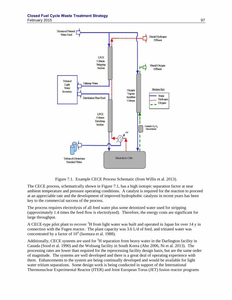
Closed Fuel Cycle Waste Treatment Strategy February 2015 97
Figure 7.1. Example CECE Process Schematic (from Willis et al. 2013).
The CECE process, schematically shown in Figure 7.1, has a high isotopic separation factor at near
ambient temperature and pressure operating conditions. A catalyst is required for the reaction to proceed
at an appreciable rate and the development of improved hydrophobic catalysts in recent years has been
key to the commercial success of the process.
The process requires electrolysis of all feed water plus some deionized water used for stripping
(approximately 1.4 times the feed flow is electrolyzed). Therefore, the energy costs are significant for
large throughput.
A CECE-type pilot plant to recover 3H from light water was built and operated in Japan for over 14 y in
connection with the Fugen reactor. The plant capacity was 3.6 L/d of feed, and tritiated water was
concentrated by a factor of 104 (Isomura et al. 1988).
Additionally, CECE systems are used for 3H separation from heavy water in the Darlington facility in
Canada (Sood et al. 1990) and the Wolsung facility in South Korea (Ahn 2006, Ni et al. 2013). The
processing rates are lower than required for the reprocessing facility design basis, but are the same order
of magnitude. The systems are well developed and there is a great deal of operating experience with
them. Enhancements to the system are being continually developed and would be available for light
water tritium separations. Some design work is being conducted in support of the International
Thermonuclear Experimental Reactor (ITER) and Joint European Torus (JET) fusion reactor programs
Closed Fuel Cycle Waste Treatment Strategy February 2015 98
(Sood et al. 1995). The Canadian and Korean facilities do not require ultra-clean heavy water and allow
higher concentrations in the water stream than would be required for discharge to the environment from a
reprocessing facility. Purified tritium for long term storage is also collected and used rather than dispose
of as waste. The total quantity of tritium produced at CANDU heavy water reactors is significantly
higher than at light water reactors. Cryogenic distillation is used for final purification of the 3H.
Considering the reduced total quantity, purification for reuse is considered financially unsound.
Electrolytic cells are an important part of the CECE process. Recent development and testing is focused
on use of a solid polymer electrolyte and membranes. This reduces the cell size to about 1/3 that of the
more conventional alkaline cells. Active development and testing of improved electrolytic cells is on-
going at several sites (Ogata 2003, 2005; Cristescu et al. 2006; and Michling 2008).
A successful demonstration of the CECE process was as part of the Atomic Energy Canada, Limited
(AECL) Prototype CIRCE Plant demonstration project at Hamilton, Ontario Canada (Klem 2004). A 7.5
kA electrolysis cell and a 2-inch diameter column with a total water flow of approximately 1.5 L/h is used
at the pilot plant. During testing, a detritiation factor exceeding 30 000 was achieved (Miller 2001).
A cost estimate by AECL (Miller 1999) prepared for the SRS provides a rough costs that may be
expected. With escalation to 2009, the costs approached $0.50/L ($2/gal).
7.1.2 Bithermal
The Bithermal process for 3H recovery consists of cold-stripping and cold-enriching columns and hot-
enriching and hot-stripping columns stacked in a vertical orientation with hydrogen gas flowing upward
countercurrent to the aqueous streams. Tritiated water to be treated is introduced between the cold-
stripping and cold-enriching columns. Three conditions are important to maximizing separation factors:
1) use of an active hydrophobic catalyst, 2) temperature control to enhance the stripping and enriching
conditions, and 3) high pressure. However, some catalysts developed for CECE are unsuitable because
the upper temperature limit is about 100 °C, which is lower than the optimum temperature for the
Bithermal process (Andreev et al. 2007). In the upper "cold stripper" section, non-tritiated water is used
to absorb tritium from the circulating hydrogen. The resulting hydrogen gas, essentially free of tritium is
recirculated to the hot-stripping column to remove 3H from the wastewater before discharge. The
3H-rich
product stream is withdrawn from between the cold and hot enrichment columns. The columns are
operated at near 5 MPa pressure to achieve maximum separation factors. The hot enrichment and
stripping column sections are operated at about 443 K (170 °C), and the cold-stripping and cold-
enrichment column sections are operated at about 323 K (50 °C). A prototype unit was installed and
operated successfully at the Prototype Combined Industrial Reforming and Catalytic Exchange (CIRCE)
demonstration project at Hamilton, Ontario Canada (Klem 2004).
Concerns with the Bithermal process include: 1) the containment of tritiated water and tritiated hydrogen
gas under high pressure, 2) safety with the use of high-pressure hydrogen gas in the process, and 3) the
fact that the process has not been used on a large industrial scale. In addition, the process flows are more
difficult to control than those in the CECE process.
7.1.3 Water Distillation and Rectification
Water distillation of tritiated water is the simplest separation method. It relies on the boiling point
difference (1.5 °C) between tritiated water and ordinary water. The method is used at heavy water plants
for the first crude separation of deuterium from protium. However, due to the low relative volatility
[p(H2O)/p(3HHO) = 1.056] and the high throughput (7 L/s), water distillation requires > 200 theoretical
plates), a high reflux ratio (> 25), and multiple large-diameter distillation columns (> 7.3 m). The high
reflux rate means the process consumes approximately thirty times more energy than single-pass
Closed Fuel Cycle Waste Treatment Strategy February 2015 99
evaporation. Some economy may be gained by mechanical vapor recompression of the overheated steam
from the column to heat the reboiler, but adds to the contaminated equipment inventory requiring
maintenance. Rough sizing for a plant to handle ~0.7 kg/s could include a primary column 30 meters
(100 feet) high and 7 m in diameter with secondary columns 24 m high and 2.4 m in diameter. Water
distillation is used as heavy water upgraders for the CANDU reactors to remove tritium and increase
deuterium concentrations (Sood et al. 1990).
Water distillation was proposed for tritium removal from reactor coolant in US at similar rates to systems
used for heavy water production. An integrated system in which water distillation, palladium metal
membrane separation, and thermal diffusion is used has been developed at GE-Hitachi Nuclear Energy
(GE) and installed at a commercial site in the UK where small volumes of radiochemicals are produced
(Geniesse and Stegen 2009).
7.1.4 Girdler Sulfide
Like the Bithermal hydrogen water process, the Girdler Sulfide (GS) process uses cold and hot columns
and a recirculating gas to drive the separation process (Miller and Van Alstyne 1994). However, in the
GS process hydrogen sulfide is the recirculating gas and no catalyst is required. The GS process is
described in more detail in Jeppson et al. (1997).
In the Miller (1999) evaluation, the GS process was judged to cost somewhat more than the CECE
process or a bithermal hydrogen-water process for the specific scenarios evaluated.
7.1.5 Cryogenic Distillation
This process is only used for small quantities of highly purified tritium already and is operated as a
distillation column at very low temperatures. The process requires elemental hydrogen and no water in
the system.
7.1.6 Thermal Cycle Absorption Process
The thermal cycle adsorption process (TCAP) separative capacity is comparable to a batch cryogenic
distillation system. The system has been used for many years at Savannah River for relatively high
concentration of tritium in a hydrogen stream. The system is a semi-continuous chromatographic process
for isotope separation that utilizes palladiums large isotopic effect (an effect that decreases with
temperature). The chromatographic separation utilized thermal absorption and desorption cycle to
separate the hydrogen isotopes. The system consists of a packed active column and a larger column of
diatomaceous earth called a plug flow reverser. Palladium coated on a high surface area diatomaceous
earth is used as the active packing material. Savannah River uses a LaNi4.25Al0.75 for hydrogen storage
during the processing to help maintain the compact size. The system operates under moderate conditions
with a high hydrogen density to maintain a small compact system. The operation of the system could be
modified to detritiate very low 3H concentration streams of hydrogen. The overall system size, cost, and
operating conditions would need be determined and tested. The system could be combined with other
technologies for 3H separation and for converting tritiated water to hydrogen gas (Horen and Lee 1991).
7.1.7 Integrated Systems
At GE-Hitachi Nuclear Energy (GE), several integrated system concepts for processing tritium
contaminated wastes have been developed. These systems are designed to reduce environmental
emissions and, in some cases, recover 3H for beneficial use. The initial integrated process was installed at
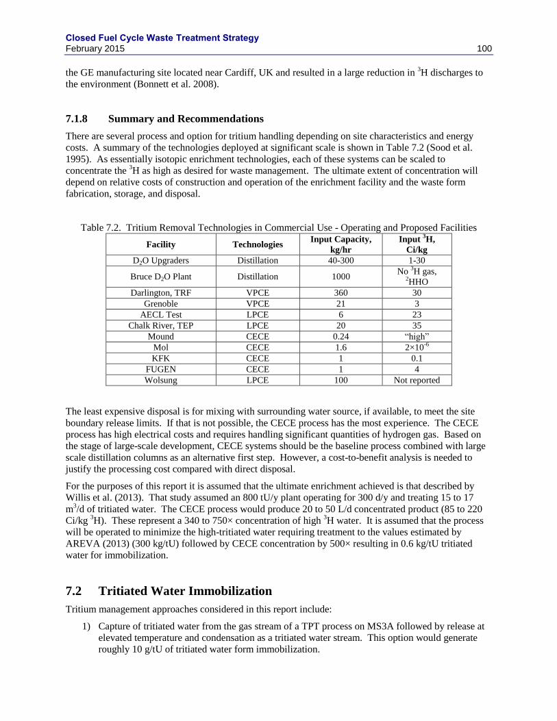
Closed Fuel Cycle Waste Treatment Strategy February 2015 100
the GE manufacturing site located near Cardiff, UK and resulted in a large reduction in 3H discharges to
the environment (Bonnett et al. 2008).
7.1.8 Summary and Recommendations
There are several process and option for tritium handling depending on site characteristics and energy
costs. A summary of the technologies deployed at significant scale is shown in Table 7.2 (Sood et al.
1995). As essentially isotopic enrichment technologies, each of these systems can be scaled to
concentrate the 3H as high as desired for waste management. The ultimate extent of concentration will
depend on relative costs of construction and operation of the enrichment facility and the waste form
fabrication, storage, and disposal.
Table 7.2. Tritium Removal Technologies in Commercial Use - Operating and Proposed Facilities
Facility Technologies Input Capacity,
kg/hr
Input 3H,
Ci/kg
D2O Upgraders Distillation 40-300 1-30
Bruce D2O Plant Distillation 1000 No
3H gas,
2HHO
Darlington, TRF VPCE 360 30
Grenoble VPCE 21 3
AECL Test LPCE 6 23
Chalk River, TEP LPCE 20 35
Mound CECE 0.24 “high”
Mol CECE 1.6 2×10⁻⁶
KFK CECE 1 0.1
FUGEN CECE 1 4
Wolsung LPCE 100 Not reported
The least expensive disposal is for mixing with surrounding water source, if available, to meet the site
boundary release limits. If that is not possible, the CECE process has the most experience. The CECE
process has high electrical costs and requires handling significant quantities of hydrogen gas. Based on
the stage of large-scale development, CECE systems should be the baseline process combined with large
scale distillation columns as an alternative first step. However, a cost-to-benefit analysis is needed to
justify the processing cost compared with direct disposal.
For the purposes of this report it is assumed that the ultimate enrichment achieved is that described by
Willis et al. (2013). That study assumed an 800 tU/y plant operating for 300 d/y and treating 15 to 17
m3/d of tritiated water. The CECE process would produce 20 to 50 L/d concentrated product (85 to 220
Ci/kg 3H). These represent a 340 to 750× concentration of high
3H water. It is assumed that the process
will be operated to minimize the high-tritiated water requiring treatment to the values estimated by
AREVA (2013) (300 kg/tU) followed by CECE concentration by 500× resulting in 0.6 kg/tU tritiated
water for immobilization.
7.2 Tritiated Water Immobilization
Tritium management approaches considered in this report include:
1) Capture of tritiated water from the gas stream of a TPT process on MS3A followed by release at
elevated temperature and condensation as a tritiated water stream. This option would generate
roughly 10 g/tU of tritiated water form immobilization.
Closed Fuel Cycle Waste Treatment Strategy February 2015 101
2) Immobilization of high volume aqueous stream from reprocessing which would generate between
300 and 5000 kg/tU of tritiated water for immobilization.
3) Concentrating tritiated water from the high volume aqueous stream to a low volume tritiated
water stream which would generate roughly 0.6 to 10 kg/tU of tritiated water for immobilization.
The relatively short half-life of 3H (12.26 y) shows that the performance of the waste form for tritiated
water in near surface (i.e., low-level waste, LLW) disposal need only be on the order of 100 y. Normal
cement waste forms are appropriate for the immobilization of LLW for on the order of 1000’s of years.
The GNEP studies recommended the tritiated water from the TPT process be immobilization in cement
(Gombert et al. 2007). Although the cement waste forms are known to last for 1000’s of years, the high
mobility of water in cement is likely too high for adequate protection (Eichholz 1988, NEA 1980, and
Tits et al. 2003) and additional barriers to 3H release will be required. Plastic or steel high integrity
containers (HIC) are likely to be required for disposal for cement waste forms. These containers are
regularly used and are certified for more than the 100 y required life. Later waste form volume studies
therefore assumed the cemented tritiated water was to be disposed of in 10-L poly-bottle HIC’s (Carter et
al. 2011). If HIC’s are used then cementation becomes optional, absorbents such as vermiculite or clay
may be sufficient to immobilize tritiated water contained in HICs. The NEA study on tritiated water
management concluded that the incorporation of tritiated water in cement with secondary containment is
preferred unless the tritium is highly enriched, in which case zirconium hydride is favored (NEA 1980).
There is also the potential to make commercial use of the separated 3H. Tritium is currently used as a
component in “self-powered” lights, as a tracer/label for medical research, and as a material in fusion
research. Tritium is also used in nuclear weapons. The global nonmilitary tritium market is estimated at
about 400 g per year. Ontario Power operates a tritium removal facility that produces about 2.5 kg of
tritium per year which overwhelms the current market. Unless there is an increase in demand for tritium,
it is unlikely to enter into the commercial market. Another potential indirect market exists for 3He, the
decay product of 3H. This isotope of He is used in neutron detectors and the supply of this critical isotope
is low (Kouzes et al. 2010; Kouzes et al. 2011; Ni et al. 2013; Pickrell et al. 2013). Currently there are
limited sources for this isotope. It is possible that the HIC system could be designed for eventual
recovery of 3He following sufficient decay time.
For the purposes of this report, it is assumed that tritiated water is cemented and stored in HIC’s.
Grouting is a well-developed technology for stabilizing a variety of waste forms. No problems are
anticipated for this method of disposing of a purified tritiated water stream (assuming other co-
contaminants do not change the waste classification, such as 129
I).
Because tritiated water is one of the streams being immobilized, care must be taken to avoid evaporative
losses to high-volume off-gas streams. A low-water cement is therefore fabricated in a sealed drum
system. The total water to solids ratio (mass water per mass combined ordinary portland cement [OPC],
fly ash [FA], and blast furnace slag [BFS]) of roughly 0.25 is required to fully complete the hydration
reactions in most cements. However, it is difficult to mix and move cements with such low ratios. A
ratio of typical cements range from 0.4 to 0.7 which give a good mix of properties. Low water cements
are formed to increase the strength and also reduce evaporation during processing. Low water cements
have ratios between 0.25 and 0.4 and often include additives to improve mixing and flow such as
plasticizers. A tritiated water to solids ratio of 0.3 will be assumed for the final cement.
A sealed in-drum cementation process, such as MOSS (Figure 7.2), is appropriate for use (Gesser et al.
2000). By this process, dry blends of OPC, BFS, and FA are blended and pre-staged in the drum with a
disposable mixer blade. The liquids and slurried solid encapsulates are added to the dry solid blend in the
drum and mixed by agitating the disposable mixer through a seal. The cement is allowed to set and
sampled as necessary. Assuming a loading of tritiated water of roughly 30 mass% in the final cement,
waste form that fills 90% of the drum volume, and a density of roughly 1.9 103 kg/m
3, the anticipated
masses and volume of cemented tritiated water are summarized in Table 7.3.
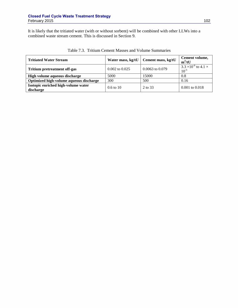
Closed Fuel Cycle Waste Treatment Strategy February 2015 102
It is likely that the tritiated water (with or without sorbent) will be combined with other LLWs into a
combined waste stream cement. This is discussed in Section 9.
Table 7.3. Tritium Cement Masses and Volume Summaries
Tritiated Water Stream Water mass, kg/tU Cement mass, kg/tU Cement volume,
m3/tU
Tritium pretreatment off-gas 0.002 to 0.025 0.0063 to 0.079 3.3 ×10
-6 to 4.1 ×
10-5
High volume aqueous discharge 5000 15000 0.8
Optimized high-volume aqueous discharge 300 500 0.16
Isotopic enriched high-volume water
discharge 0.6 to 10 2 to 33 0.001 to 0.018
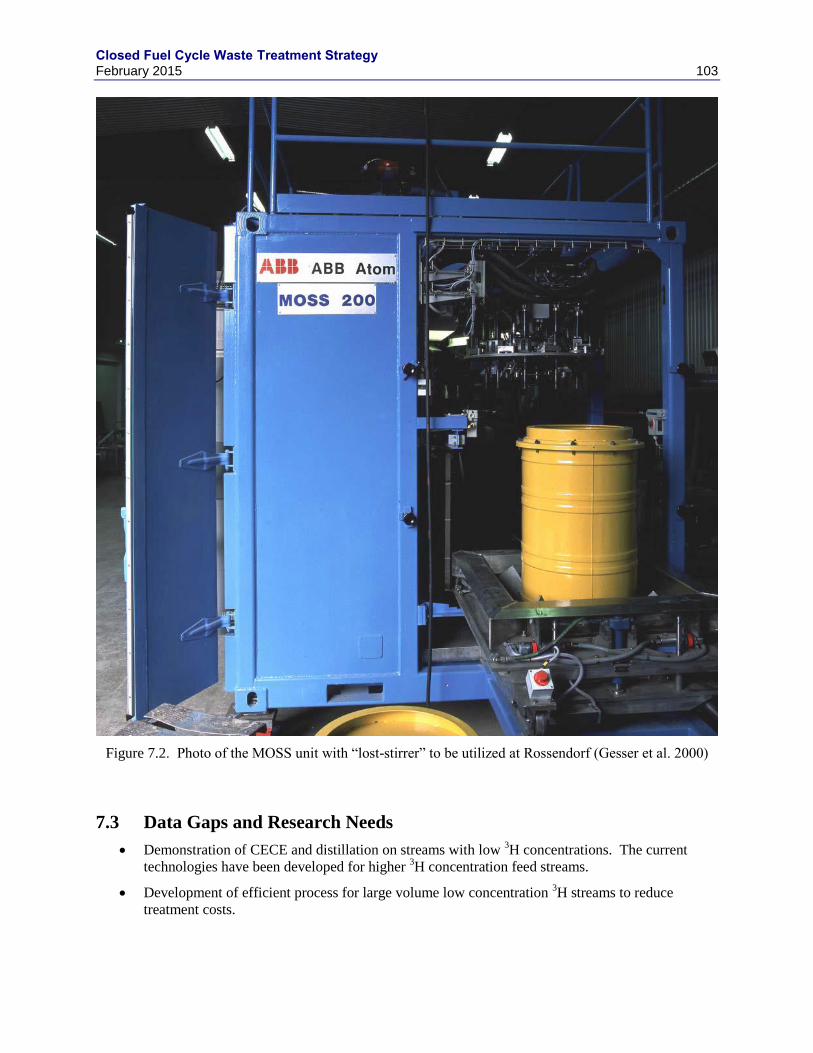
Closed Fuel Cycle Waste Treatment Strategy February 2015 103
Figure 7.2. Photo of the MOSS unit with “lost-stirrer” to be utilized at Rossendorf (Gesser et al. 2000)
7.3 Data Gaps and Research Needs
Demonstration of CECE and distillation on streams with low 3H concentrations. The current
technologies have been developed for higher 3H concentration feed streams.
Development of efficient process for large volume low concentration 3H streams to reduce
treatment costs.

Closed Fuel Cycle Waste Treatment Strategy February 2015 104
Process demonstration for direct disposal of inexpensive media used for water capture at high
efficiencies and high loadings.
Collect sufficient design data and perform a cost benefit analysis to determine the most cost
effective solution to 3H management in an appropriately scaled plant.
Closed Fuel Cycle Waste Treatment Strategy February 2015 105
8. SECONDARY WASTES
For the purposes of this report, secondary wastes are generated during the handling of radioactive
materials. These include wastes generated during operations and maintenance activities and wastes
generated during routine operations to control the spread of contamination (i.e. job control wastes).
8.1 Types of Secondary Wastes
Operations wastes can include:
Used multi-purpose canisters (MPCs)
Fuel cask and canister decontamination wipes and filters
Filtered solids
Pool sludge
Dewatered resins
Solvent residues
Containers from waste solidification processes
Miscellaneous chemical wastes
Solidified waste waters
Spent ion exchange resins
Packaging wastes
Maintenance wastes include:
Failed instruments and electronic equipment
Manipulator boots, arms, and counterweights
Failed piping and valves
Failed process vessels
Failed pumps and agitators
Various failed process-specific equipment
Job control wastes include:
Gloves
Shoe covers
Protective clothing
Step-off pads
Containment hut material
Secondary wastes are classified according to their activity level as described in 10 CFR 61. Class A
wastes have the lowest activity level, followed by Class B, Class C, and Greater Than Class C (GTCC).
If the wastes also contain hazardous organic and/or inorganic chemicals, then they are called “mixed”
Class A, Class B, Class C, or GTCC wastes.
8.2 Secondary Waste Volumes
Jones and Carter (2013) documented a comparison of estimated quantities of process and secondary
wastes from a future UNF recycling facility and from MOX and fast reactor fuel fabrication facilities.
This section summarizes the waste volume estimates from the Jones and Carter (2013) study. The reader
Closed Fuel Cycle Waste Treatment Strategy February 2015 106
is referred to that document and the references therein for detailed discussions of the assumptions and
factors considered in their analysis.
Estimates of secondary waste volumes were compiled from four sources. DOE had contracted with two
industrial partners, AREVA and Energy Solutions, to provide information based on their operating
experiences. AREVA and Energy Solutions provided secondary waste volume estimates for recycling,
MOX fabrication, and fast reactor fuel fabrication cases. Two estimates were available from the Used
Fuel Disposition (UFD) Campaign within DOE-NE. The first UFD estimate is based on work done at the
Savannah River Site (SRS) for the GNEP program to conduct Engineering Alternative Studies (EAS) and
Follow-On Engineering Alternative Studies (FOEAS) for fuel recycling processes (Jones 2011a). This is
designated as UFD/EAS in the waste volume tables that follow. The second UFD estimate is based on a
later study in which the as-generated waste volumes were the same but the final waste volumes were
reclassified according to radionuclide content of the waste streams (Jones 2012). This later estimate is
designated as UFD-2012 in the tables that follow. Secondary waste estimates for MOX fuel fabrication
were documented in a separate UFD study by Jones (2011b). There are no UFD-2012 waste volume
estimates for MOX or fast reactor fuel fabrication, and there are no UFD waste volume estimates for fast
reactor fuel fabrication.
Table 8.1 provides a summary of the ranges of secondary waste volumes for the cases of UNF recycling,
MOX fuel fabrication, and fast reactor fuel fabrication. The recycling waste volumes are based on a 50
GWd/tU, 5-year cooled LWR used fuel. The volumes are normalized to 1 tU from an 800 tU/y facility.
The waste volumes shown for the MOX and fast reactor fuel fabrication are estimated from processing
800 t of UNF per year (Jones and Carter 2013).
Table 8.2 and Table 8.3 provide the estimated secondary waste volumes for an 800 t/y UNF recycling
facility. Three cases are presented:
UNF-1: LWR uranium oxide fuel, 50 GWd/tU burnup, 5-year cooled
UNF-2: LWR uranium oxide fuel, 50 GWd/tU burnup, 50-year cooled
UNF-4: a blend of 90 tHM/y MOX (UNF-3) and 710 tU/y of UNF-1
where UNF-3 is a LWR MOX fuel, 50 GWd/t of initial heavy metal burnup, 5-year cooled.
Table 8.2 shows the estimated secondary waste volumes for a UNF recycling facility for the three fuel
cases from the four studies. Table 8.3 shows the estimated secondary waste volumes based on the
functional processing steps within the recycling facility.
Table 8.4 shows the estimated secondary waste volumes for a MOX fuel fabrication facility and Table 8.5
shows the estimated secondary waste volumes for a fast reactor fuel fabrication facility.
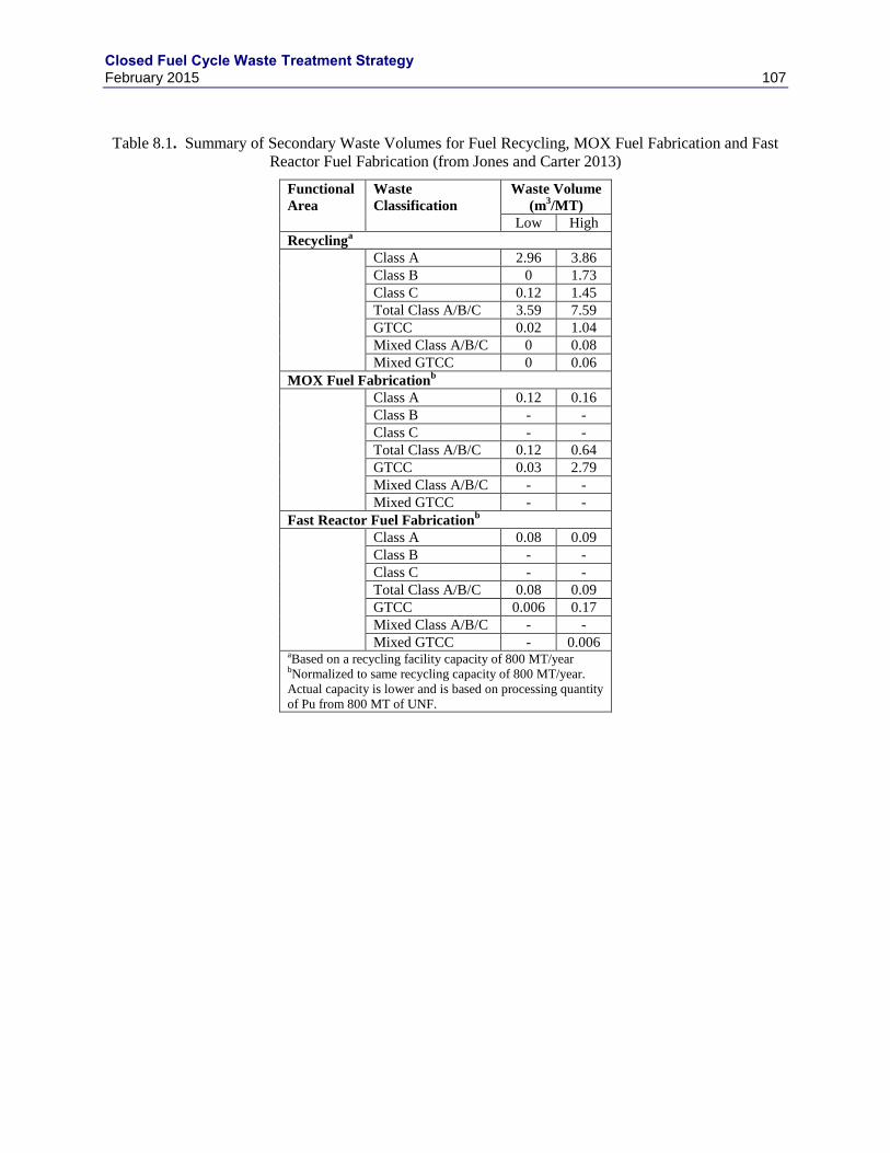
Closed Fuel Cycle Waste Treatment Strategy February 2015 107
Table 8.1. Summary of Secondary Waste Volumes for Fuel Recycling, MOX Fuel Fabrication and Fast
Reactor Fuel Fabrication (from Jones and Carter 2013)
Functional
Area
Waste
Classification
Waste Volume
(m3/MT)
Low High
Recyclinga
Class A 2.96 3.86
Class B 0 1.73
Class C 0.12 1.45
Total Class A/B/C 3.59 7.59
GTCC 0.02 1.04
Mixed Class A/B/C 0 0.08
Mixed GTCC 0 0.06
MOX Fuel Fabricationb
Class A 0.12 0.16
Class B - -
Class C - -
Total Class A/B/C 0.12 0.64
GTCC 0.03 2.79
Mixed Class A/B/C - -
Mixed GTCC - -
Fast Reactor Fuel Fabricationb
Class A 0.08 0.09
Class B - -
Class C - -
Total Class A/B/C 0.08 0.09
GTCC 0.006 0.17
Mixed Class A/B/C - -
Mixed GTCC - 0.006 aBased on a recycling facility capacity of 800 MT/year bNormalized to same recycling capacity of 800 MT/year.
Actual capacity is lower and is based on processing quantity
of Pu from 800 MT of UNF.
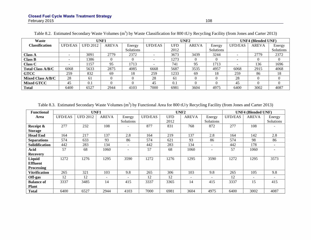
Closed Fuel Cycle Waste Treatment Strategy February 2015 108
Table 8.2. Estimated Secondary Waste Volumes (m3) by Waste Classification for 800 tU/y Recycling Facility (from Jones and Carter 2013)
Waste
Classification
UNF1 UNF2 UNF4 (Blended UNF)
UFD/EAS UFD 2012 AREVA Energy
Solutions
UFD/EAS UFD
2012
AREVA Energy
Solutions
UFD/EAS AREVA Energy
Solutions
Class A - 3091 2779 2372 - 3673 3439 3244 - 2779 2372
Class B - 1386 0 0 - 1273 0 0 - 0 0
Class C - 1157 95 1713 - 741 95 1713 - 136 1696
Total Class A/B/C 6068 5633 2875 4085 6668 5687 3535 4957 6068 2915 4068
GTCC 259 832 69 18 259 1233 69 18 259 86 18
Mixed Class A/B/C 28 61 0 0 28 61 0 0 28 0 0
Mixed GTCC 45 0.1 0 0 45 0.1 0 0 45 0 0
Total 6400 6527 2944 4103 7000 6981 3604 4975 6400 3002 4087
Table 8.3. Estimated Secondary Waste Volumes (m3) by Functional Area for 800 tU/y Recycling Facility (from Jones and Carter 2013)
Functional
Area
UNF1 UNF2 UNF4 (Blended UNF)
UFD/EAS UFD 2012 AREVA Energy
Solutions
UFD/EAS UFD
2012
AREVA Energy
Solutions
UFD/EAS AREVA Energy
Solutions
Receipt &
Storage
277 232 108 - 877 831 768 872 277 108 -
Head End 164 217 137 2.8 164 219 137 2.8 164 142 2.8
Separations 574 633 93 86 574 621 93 86 574 98 86
Solidification 442 283 134 - 442 283 134 - 442 178 -
Acid
Recovery
57 68 1060 - 57 68 1060 - 57 1060 -
Liquid
Effluent
Processing
1272 1276 1295 3590 1272 1276 1295 3590 1272 1295 3573
Vitrification 265 321 103 9.8 265 306 103 9.8 265 105 9.8
Off-gas 12 12 - - 12 12 - - 12 - -
Balance of
Plant
3337 3485 14 415 3337 3365 14 415 3337 15 415
Total 6400 6527 2944 4103 7000 6981 3604 4975 6400 3002 4087
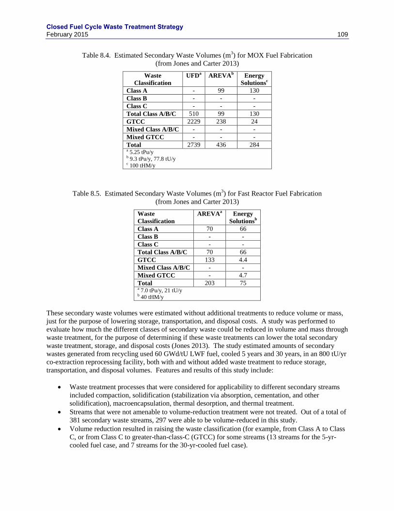
Closed Fuel Cycle Waste Treatment Strategy February 2015 109
Table 8.4. Estimated Secondary Waste Volumes (m3) for MOX Fuel Fabrication
(from Jones and Carter 2013)
Waste
Classification
UFDa
AREVAb
Energy
Solutionsc
Class A - 99 130
Class B - - -
Class C - - -
Total Class A/B/C 510 99 130
GTCC 2229 238 24
Mixed Class A/B/C - - -
Mixed GTCC - - -
Total 2739 436 284 a 5.25 tPu/y b 9.3 tPu/y, 77.8 tU/y c 100 tHM/y
Table 8.5. Estimated Secondary Waste Volumes (m3) for Fast Reactor Fuel Fabrication
(from Jones and Carter 2013)
Waste
Classification
AREVAa
Energy
Solutionsb
Class A 70 66
Class B - -
Class C - -
Total Class A/B/C 70 66
GTCC 133 4.4
Mixed Class A/B/C - -
Mixed GTCC - 4.7
Total 203 75 a 7.0 tPu/y, 21 tU/y b 40 tHM/y
These secondary waste volumes were estimated without additional treatments to reduce volume or mass,
just for the purpose of lowering storage, transportation, and disposal costs. A study was performed to
evaluate how much the different classes of secondary waste could be reduced in volume and mass through
waste treatment, for the purpose of determining if these waste treatments can lower the total secondary
waste treatment, storage, and disposal costs (Jones 2013). The study estimated amounts of secondary
wastes generated from recycling used 60 GWd/tU LWF fuel, cooled 5 years and 30 years, in an 800 tU/yr
co-extraction reprocessing facility, both with and without added waste treatment to reduce storage,
transportation, and disposal volumes. Features and results of this study include:
Waste treatment processes that were considered for applicability to different secondary streams
included compaction, solidification (stabilization via absorption, cementation, and other
solidification), macroencapsulation, thermal desorption, and thermal treatment.
Streams that were not amenable to volume-reduction treatment were not treated. Out of a total of
381 secondary waste streams, 297 were able to be volume-reduced in this study.
Volume reduction resulted in raising the waste classification (for example, from Class A to Class
C, or from Class C to greater-than-class-C (GTCC) for some streams (13 streams for the 5-yr-
cooled fuel case, and 7 streams for the 30-yr-cooled fuel case).
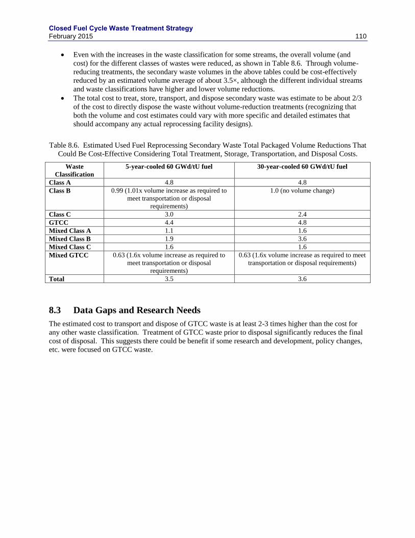
Closed Fuel Cycle Waste Treatment Strategy February 2015 110
Even with the increases in the waste classification for some streams, the overall volume (and
cost) for the different classes of wastes were reduced, as shown in Table 8.6. Through volume-
reducing treatments, the secondary waste volumes in the above tables could be cost-effectively
reduced by an estimated volume average of about 3.5×, although the different individual streams
and waste classifications have higher and lower volume reductions.
The total cost to treat, store, transport, and dispose secondary waste was estimate to be about 2/3
of the cost to directly dispose the waste without volume-reduction treatments (recognizing that
both the volume and cost estimates could vary with more specific and detailed estimates that
should accompany any actual reprocessing facility designs).
Table 8.6. Estimated Used Fuel Reprocessing Secondary Waste Total Packaged Volume Reductions That
Could Be Cost-Effective Considering Total Treatment, Storage, Transportation, and Disposal Costs.
Waste
Classification
5-year-cooled 60 GWd/tU fuel
30-year-cooled 60 GWd/tU fuel
Class A 4.8 4.8
Class B 0.99 (1.01x volume increase as required to
meet transportation or disposal
requirements)
1.0 (no volume change)
Class C 3.0 2.4
GTCC 4.4 4.8
Mixed Class A 1.1 1.6
Mixed Class B 1.9 3.6
Mixed Class C 1.6 1.6
Mixed GTCC 0.63 (1.6x volume increase as required to
meet transportation or disposal
requirements)
0.63 (1.6x volume increase as required to meet
transportation or disposal requirements)
Total 3.5 3.6
8.3 Data Gaps and Research Needs
The estimated cost to transport and dispose of GTCC waste is at least 2-3 times higher than the cost for
any other waste classification. Treatment of GTCC waste prior to disposal significantly reduces the final
cost of disposal. This suggests there could be benefit if some research and development, policy changes,
etc. were focused on GTCC waste.
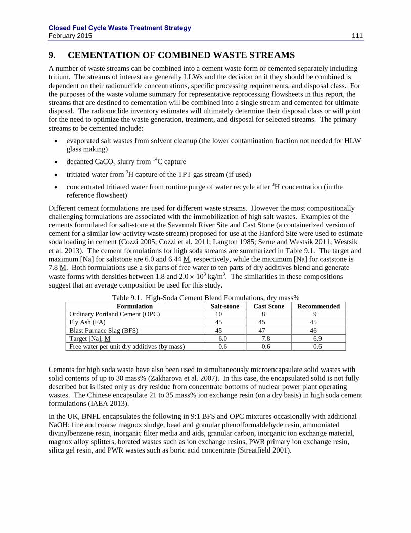
Closed Fuel Cycle Waste Treatment Strategy February 2015 111
9. CEMENTATION OF COMBINED WASTE STREAMS
A number of waste streams can be combined into a cement waste form or cemented separately including
tritium. The streams of interest are generally LLWs and the decision on if they should be combined is
dependent on their radionuclide concentrations, specific processing requirements, and disposal class. For
the purposes of the waste volume summary for representative reprocessing flowsheets in this report, the
streams that are destined to cementation will be combined into a single stream and cemented for ultimate
disposal. The radionuclide inventory estimates will ultimately determine their disposal class or will point
for the need to optimize the waste generation, treatment, and disposal for selected streams. The primary
streams to be cemented include:
evaporated salt wastes from solvent cleanup (the lower contamination fraction not needed for HLW
glass making)
decanted CaCO3 slurry from 14
C capture
tritiated water from 3H capture of the TPT gas stream (if used)
concentrated tritiated water from routine purge of water recycle after 3H concentration (in the
reference flowsheet)
Different cement formulations are used for different waste streams. However the most compositionally
challenging formulations are associated with the immobilization of high salt wastes. Examples of the
cements formulated for salt-stone at the Savannah River Site and Cast Stone (a containerized version of
cement for a similar low-activity waste stream) proposed for use at the Hanford Site were used to estimate
soda loading in cement (Cozzi 2005; Cozzi et al. 2011; Langton 1985; Serne and Westsik 2011; Westsik
et al. 2013). The cement formulations for high soda streams are summarized in Table 9.1. The target and
maximum [Na] for saltstone are 6.0 and 6.44 M, respectively, while the maximum [Na] for caststone is
7.8 M. Both formulations use a six parts of free water to ten parts of dry additives blend and generate
waste forms with densities between 1.8 and 2.0 103 kg/m
3. The similarities in these compositions
suggest that an average composition be used for this study.
Table 9.1. High-Soda Cement Blend Formulations, dry mass% Formulation Salt-stone Cast Stone Recommended
Ordinary Portland Cement (OPC) 10 8 9
Fly Ash (FA) 45 45 45
Blast Furnace Slag (BFS) 45 47 46
Target [Na], M 6.0 7.8 6.9
Free water per unit dry additives (by mass) 0.6 0.6 0.6
Cements for high soda waste have also been used to simultaneously microencapsulate solid wastes with
solid contents of up to 30 mass% (Zakharova et al. 2007). In this case, the encapsulated solid is not fully
described but is listed only as dry residue from concentrate bottoms of nuclear power plant operating
wastes. The Chinese encapsulate 21 to 35 mass% ion exchange resin (on a dry basis) in high soda cement
formulations (IAEA 2013).
In the UK, BNFL encapsulates the following in 9:1 BFS and OPC mixtures occasionally with additional
NaOH: fine and coarse magnox sludge, bead and granular phenolformaldehyde resin, ammoniated
divinylbenzene resin, inorganic filter media and aids, granular carbon, inorganic ion exchange material,
magnox alloy splitters, borated wastes such as ion exchange resins, PWR primary ion exchange resin,
silica gel resin, and PWR wastes such as boric acid concentrate (Streatfield 2001).
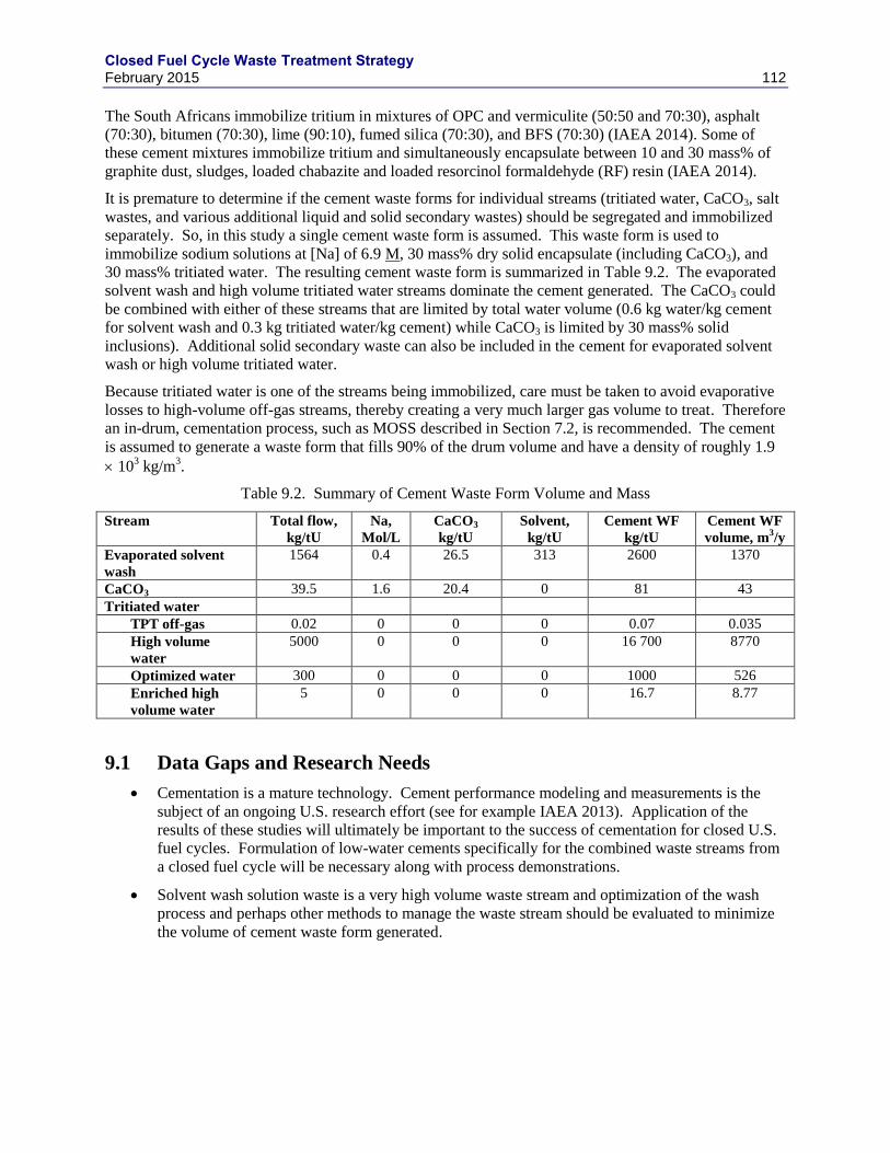
Closed Fuel Cycle Waste Treatment Strategy February 2015 112
The South Africans immobilize tritium in mixtures of OPC and vermiculite (50:50 and 70:30), asphalt
(70:30), bitumen (70:30), lime (90:10), fumed silica (70:30), and BFS (70:30) (IAEA 2014). Some of
these cement mixtures immobilize tritium and simultaneously encapsulate between 10 and 30 mass% of
graphite dust, sludges, loaded chabazite and loaded resorcinol formaldehyde (RF) resin (IAEA 2014).
It is premature to determine if the cement waste forms for individual streams (tritiated water, CaCO3, salt
wastes, and various additional liquid and solid secondary wastes) should be segregated and immobilized
separately. So, in this study a single cement waste form is assumed. This waste form is used to
immobilize sodium solutions at [Na] of 6.9 M, 30 mass% dry solid encapsulate (including CaCO3), and
30 mass% tritiated water. The resulting cement waste form is summarized in Table 9.2. The evaporated
solvent wash and high volume tritiated water streams dominate the cement generated. The CaCO3 could
be combined with either of these streams that are limited by total water volume (0.6 kg water/kg cement
for solvent wash and 0.3 kg tritiated water/kg cement) while CaCO3 is limited by 30 mass% solid
inclusions). Additional solid secondary waste can also be included in the cement for evaporated solvent
wash or high volume tritiated water.
Because tritiated water is one of the streams being immobilized, care must be taken to avoid evaporative
losses to high-volume off-gas streams, thereby creating a very much larger gas volume to treat. Therefore
an in-drum, cementation process, such as MOSS described in Section 7.2, is recommended. The cement
is assumed to generate a waste form that fills 90% of the drum volume and have a density of roughly 1.9
103 kg/m
3.
Table 9.2. Summary of Cement Waste Form Volume and Mass
Stream Total flow,
kg/tU
Na,
Mol/L
CaCO3
kg/tU
Solvent,
kg/tU
Cement WF
kg/tU
Cement WF
volume, m3/y
Evaporated solvent
wash
1564 0.4 26.5 313 2600 1370
CaCO3 39.5 1.6 20.4 0 81 43
Tritiated water
TPT off-gas 0.02 0 0 0 0.07 0.035
High volume
water
5000 0 0 0 16 700 8770
Optimized water 300 0 0 0 1000 526
Enriched high
volume water
5 0 0 0 16.7 8.77
9.1 Data Gaps and Research Needs
Cementation is a mature technology. Cement performance modeling and measurements is the
subject of an ongoing U.S. research effort (see for example IAEA 2013). Application of the
results of these studies will ultimately be important to the success of cementation for closed U.S.
fuel cycles. Formulation of low-water cements specifically for the combined waste streams from
a closed fuel cycle will be necessary along with process demonstrations.
Solvent wash solution waste is a very high volume waste stream and optimization of the wash
process and perhaps other methods to manage the waste stream should be evaluated to minimize
the volume of cement waste form generated.
Closed Fuel Cycle Waste Treatment Strategy February 2015 113
10. SUMMARY AND CONCLUSIONS
This study evaluates waste management approaches for nuclear fuel cycle facilities in comparison to the
objectives of implementing an advanced fuel cycle in the U.S. under current legal, regulatory, and
logistical constructs. The study rests heavily on the GNEP IWMS (Gombert et al. 2008) as a general
strategy and associated WTBS (Gombert et al. 2007). The approaches used in the IWMS are equally
valid to the current waste management study. However, the flowsheet details have changed significantly
from those considered under GNEP. In addition, significant additional waste management technology
development has occurred since the GNEP waste management studies were performed. This study
updates the information found in the WTBS, summarizes the results of more recent technology
development efforts, and describes waste management approaches as they apply to reasonable example
reprocessing flowsheets. Many of the waste management technologies discussed also apply to other
potential flowsheets that involve reprocessing. These applications have been discussed where the data are
more readily available.
The report summarizes the waste arising from aqueous reprocessing of a typical light-water reactor
(LWR) fuel to separate actinides for use in fabricating metal SFR fuel and from electrochemical
reprocessing of the metal SFR fuel to separate actinides for recycle back into the SFR in the form of metal
fuel. The primary streams considered and the recommended waste forms include:
Tritium separated from either a low volume gas stream or a high volume water stream. The
recommended waste form is low-water cement in HICs.
Iodine-129 separated from off-gas streams in aqueous processing. There are a range of
potentially suitable waste forms. The reference case is a GCM formed by the encapsulation of
the AgZ getter material in a low-temperature glass. A number of alternatives with distinct
advantages are also considered, including a fused silica waste form with encapsulated nano-sized
AgI crystals.
Carbon-14 separated from LWR fuel treatment off-gases and immobilized as CaCO3 in a cement
waste form.
Krypton-85 separated from LWR and SFR fuel treatment off-gases and stored as a compressed
gas.
An aqueous reprocessing HLW raffinate waste which is immobilized by the vitrification process
in one of three forms: a single phase borosilicate glass, a borosilicate based glass ceramic, or a
multi-phased crystalline ceramic (e.g. Synroc).
An UDS fraction from aqueous reprocessing of LWR fuel that is either included in the
borosilicate HLW glass or is immobilized in the form of a metal alloy if glass ceramics or
titanate-based ceramics are used as the HLW raffinate waste form.
Zirconium-based LWR fuel cladding hulls and SS fuel assembly hardware that are washed and
super-compacted for disposal or purified by reactive gas separations and either reused or disposed
as LLW.
Electrochemical process salt HLW which is incorporated into a glass bonded sodalite waste form
known as the CWF.
Electrochemical process UDS and SS cladding hulls which are melted into an iron-based alloy
waste form.
Mass and volume estimates for each of the recommended waste forms based on the source terms are
reported. The resulting waste form masses and volumes are summarized in Table 10.1 for LWR fuel and
Table 10.2 for FR fuel.
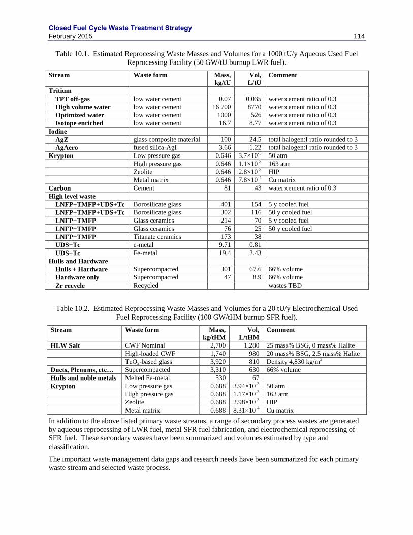
Closed Fuel Cycle Waste Treatment Strategy February 2015 114
Table 10.1. Estimated Reprocessing Waste Masses and Volumes for a 1000 tU/y Aqueous Used Fuel
Reprocessing Facility (50 GW/tU burnup LWR fuel).
Stream Waste form Mass,
kg/tU
Vol,
L/tU
Comment
Tritium
TPT off-gas low water cement 0.07 0.035 water:cement ratio of 0.3
High volume water low water cement 16 700 8770 water:cement ratio of 0.3
Optimized water low water cement 1000 526 water:cement ratio of 0.3
Isotope enriched low water cement 16.7 8.77 water:cement ratio of 0.3
Iodine
AgZ glass composite material 100 24.5 total halogen:I ratio rounded to 3
AgAero fused silica-AgI 3.66 1.22 total halogen:I ratio rounded to 3
Krypton Low pressure gas 0.646 3.7×10⁻³
50 atm
High pressure gas 0.646 1.1×10⁻³
163 atm
Zeolite 0.646 2.8×10⁻³
HIP
Metal matrix 0.646 7.8×10⁻⁴
Cu matrix
Carbon Cement 81 43 water:cement ratio of 0.3
High level waste
LNFP+TMFP+UDS+Tc Borosilicate glass 401 154 5 y cooled fuel
LNFP+TMFP+UDS+Tc Borosilicate glass 302 116 50 y cooled fuel
LNFP+TMFP Glass ceramics 214 70 5 y cooled fuel
LNFP+TMFP Glass ceramics 76 25 50 y cooled fuel
LNFP+TMFP Titanate ceramics 173 38
UDS+Tc e-metal 9.71 0.81
UDS+Tc Fe-metal 19.4 2.43
Hulls and Hardware
Hulls + Hardware Supercompacted 301 67.6 66% volume
Hardware only Supercompacted 47 8.9 66% volume
Zr recycle Recycled wastes TBD
Table 10.2. Estimated Reprocessing Waste Masses and Volumes for a 20 tU/y Electrochemical Used
Fuel Reprocessing Facility (100 GW/tHM burnup SFR fuel).
Stream Waste form Mass,
kg/tHM
Vol,
L/tHM
Comment
HLW Salt CWF Nominal 2,700 1,280 25 mass% BSG, 0 mass% Halite
High-loaded CWF 1,740 980 20 mass% BSG, 2.5 mass% Halite
TeO2-based glass 3,920 810 Density 4,830 kg/m3
Ducts, Plenums, etc… Supercompacted 3,310 630 66% volume
Hulls and noble metals Melted Fe-metal 530 67
Krypton Low pressure gas 0.688 3.94×10⁻³
50 atm
High pressure gas 0.688 1.17×10⁻³
163 atm
Zeolite 0.688 2.98×10⁻³
HIP
Metal matrix 0.688 8.31×10⁻⁴
Cu matrix
In addition to the above listed primary waste streams, a range of secondary process wastes are generated
by aqueous reprocessing of LWR fuel, metal SFR fuel fabrication, and electrochemical reprocessing of
SFR fuel. These secondary wastes have been summarized and volumes estimated by type and
classification.
The important waste management data gaps and research needs have been summarized for each primary
waste stream and selected waste process.
Closed Fuel Cycle Waste Treatment Strategy February 2015 115
11. REFERENCES
10 CFR 20. Standards for Protection against Radiation, U.S. Nuclear Regulatory Commission,
Washington, D.C.
10 CFR 61. Licensing Requirements for Land Disposal of Radioactive Waste, U.S. Nuclear Regulatory
Commission, Washington, D.C.
40 CFR 168. Land Disposal Restrictions, U.S. Environmental Protection Agency, Washington, D.C.
40 CFR 190. Environmental Radiation Protection Standards for Nuclear Power Operations, U.S.
Environmental Protection Agency, Washington, D.C.
Abraham, D.P., S.M. Mcdeavitt, and J. Park. 1996. "Microstructure and Phase Identification in Type 304
Stainless Steel-Zirconium Alloys," Metall. Mater. Trans. A, 27A(8):2151-2159. 10.1007/BF02651870.
Abraham, D.P., J.W. Richardson, Jr., and S.M. McDeavitt. 1997. "Laves Intermetallics in Stainless Steel-
Zirconium Alloys," Mater. Sci. Eng., A, A239-240:658-664. 10.1016/S0921-5093(97)00649-7.
Abraham, D.P., S.M. McDeavitt, D.D. Keiser, S.G. Johnson, M.L. Adamic, S.A. Barker, T.D. Disanto,
S.M. Frank, J.R. Krsul, M. Noy, J.W. Richardson, and B.R. Westphal. 1999. Metal Waste Form
Handbook, ANL-NT-121, Argonne National Laboratory, Argonne, IL.
Ackerman, J.P., T.R. Johnson, L.S.H. Chow, E.L. Carls, W.H. Hannum, and J.J. Laidler. 1997.
"Treatment of Wastes in the Ifr Fuel Cycle," Progress in Nuclear Energy, 31(1/2):141-154.
Adachi, T., M. Ohnuki, N. Yoshida, T. Sonobe, W. Kawamura, H. Takeishi, K. Gunji, T. Kimura, T.
Suzuki, and A. et. 1990. "Dissolution Study of Spent PWR Fuel: Dissolution Behavior and Chemical
Properties of Insoluble Residues," J. Nucl. Mater., 174(1):60-71. 10.1016/0022-3115(90)90421-I.
AFCF. 2007. Product Solidification, Waste Solidification, and Off-Gas Unit Operations Mass Balance
Basis, GNEP-AFCF-WAST-PC-RT-2007-000332, Advanced Fuel Cycle Facility Project, Idaho Falls, ID.
Ahn, D.-H., S. Paek, H.-J. Choi, K.-R. Kim, H. Chung, S.P. Yim, and M.S. Lee. 2006. "Development of
Water Detritiation Process Using the Hydrophobic Platinum Catalyst," Waste Management 2006, Tucson,
AZ.
Alfimov, V., A. Aldahan, G. Possnert, and P. Winsor. 2004. "Anthropogenic iodine-129 in seawater along
a transect from the Norwegian coastal current to the North Pole," Marine Pollution Bulletin, 49:1097-
1104.
Amaury, P. 1980. "Solidification and Storage of High Activity Nuclear Waste from Reprocessing: The
AVM Process," Uranium Nucl. Energy, 4:193-201.
Amoroso, J., J.C. Marra, M. Tang, Y. Lin, F. Chen, D. Su, and K.S. Brinkman. 2014a. "Melt Process
Multiphase Ceramic Waste Forms for Nuclear Waste Immobilization," Journal of Nuclear Materials,
454(1-3).
Amoroso, J., J. Marra, S.D. Conradson, M. Tang, and K. Brinkman. 2014b. "Melt Processed Single Phase
Hollandite Waste Forms for Nuclear Waste Immobilization: Ba(1.0)Cs(0.3)A(2.3)Ti(5.7)O(16); A = Cr,
Fe, Al," Journal of Alloys and Compounds, 584:590-599. DOI 10.1016/j.jallcom.2013.09.087.
Closed Fuel Cycle Waste Treatment Strategy February 2015 116
Andreev, B.M., E.P. Magomedbekov, A.A. Raitman, M.B. Pozenkevich, Y.A. Sakharovsky, and A.V.
Khoroshilov. 2007. Separation of Isotopes of Biogenic Elements in Two-Phase Systems. Elsevier,
Amsterdam, The Netherlands.
Areva. 2013. Task 9 Report – Improving the Estimates of Waste from Recycling, Sub-Task 5: Final
Technical Report, RPT-3007827-001, AREVA Federal Services, Charlotte, NC.
ASTM. 2008. Standard Test Method for Determining the Chemical Durability of Nuclear Waste Glasses:
The Product Consistency Test (PCT), ASTM C1285 - 02(2008), American Society for Testing and
Materials, West Conshohocken, Pennsylvania.
Atkins, M. and F.P. Glasser. 1990. "Encapsulation of Radioiodine in Cementitious Waste Forms,"
Scientific Basis for Nuclear Waste Management XIII, Vol. Materials Research Society Symposium
Proceedings, Vol. 176, 15-22 pp. Materials Research Society, Pittsburgh, PA.
Atkins, M., A. Kindness, F.P. Glasser, and I. Gibson. 1990. "The Use of Silver as a Selective Precipitant
for 129
I in Radioactive Waste Management," Waste Management, 10:303-308.
Baetsle, L.H. and J. Broothaerts. 1977. "Reprocessing Off-Gas Treatment Research in Belgium." In
Seminar on Radioactive Effluents from Nuclear Fuel Reprocessing Plants. Schule für Kerntechnik
Kernforschungszentrum, Karlsruhe, Germany.
Bakel, A.J., D.L. Bowers, K.J. Quigley, M.C. Regalbuto, J.A. Stillman, and G.F. Vandegrift. 2006.
"Dissolution of Irradiated Nuclear Fuel from the Big Rock Point Reactor." In Separations for the Nuclear
Fuel Cycle in the 21st Century, Vol 933, pp. 71-88. American Chemical Society, Washington, DC.
Balls, V.J. and R.C. Williams. 2011. Letter, "Use of Existing IWTU Hot Cells for Cdp HIP Treatment of
HLW Calcine White Paper," to Idaho Cleanup Project, Idaho Falls, ID.
Barnert-Wiemer, H. and E. Merz. 1977. “Off-Gas Treatment in HTR Fuel Reprocessing,” in Seminar on
Radioactive Effluents from Nuclear Fuel Reprocessing Plants, AED-CONF-77-473-027, Karlsruhe,
Germany.
Bateman, K.J. and C.W. Solbrig. "Using Center Hole Heat Transfer to Reduce Formation Times for
Ceramic Waste Forms from Pyroprocessing," 14th International Conference on Nuclear Engineering,
ICONE14, Paper number 89794, Miami, FL.
Bateman, K.J., C.J. Knight, and C.W. Solbrig. 2007. Current Status of Ceramic Waste Form
Development, INL/INT-06-11736, Rev. 1, Idaho National Laboratory, Idaho Falls, ID.
Bendixsen, C.L. and F.O. German. 1971. Operation of the ICPP Rare Gas Recovery Facility During
Fiscal Year 1970, Allied Chem. Corp., Idaho Chemical Processing Plant, Idaho Falls, ID.
Bendixsen, C.L., F.O. German, and R.R. Hammer. 1973. 1972 Operation of the ICPP (Idaho Chemical
Processing Plant) Rare Gas Recovery Facility, Allied Chem. Corp., Idaho Chemical Processing Plant,
Idaho Falls, ID.
Bendixsen, C.L. and D.A. Knecht. 1976. Separation and Storage of Krypton. In Proceedings NTIS,
Closed Fuel Cycle Waste Treatment Strategy February 2015 117
Bendixsen, C.L., G.F. Offutt, and B.R. Wheeler. 1971. "Cryogenic Rare Gas Recovery in Nuclear Fuel
Reprocessing," Chem. Eng. (New York), 78(22):55-57.
Bernadzikowski, TA, JS Allender, DE Gordon, TH Gould Jr, and JA Stone. 1982. The Development,
Evaluation, and Selection of Candidate High-Level Waste Forms, DP-MS-82-47, Savannah River
laboratory, Aiken, SC.
Bernardo, E., M. Varrasso, F. Cadamuro, and S. Hreglich. 2006. "Vitrification of wastes and preparation
of chemically stable sintered glass-ceramic products," Journal of Non-Crystalline Solids, 352:4017-4023.
Birdwell, J.F. 1990. "Iodine and NOx Behavior in the Dissolver Off-Gas and IODOX Systems in the Oak
Ridge National Laboratory Integrated Equipment Test Facility," the 21st DOE/NRC Nuclear Air Cleaning
Conference, US Department of Energy, Washington, DC.
Boen, R., C. Ladirat, M. Bonnal, and D. Delage. 1998. "Fusion De Verre Par Induction En Creuset Froid:
Perspectives D’applications Industrielles Exemples D’utilisation De La Technologie À L’élaboration Des
Émaux," International Conference on Electromagnetic Processing of Materials (EMP) 1997, Paris,
France.
Bohnenstingl, J., M. Heidendael, M. Laser, S. Mastera, and E. Merz. 1976. “Cryogenic Separation of
Krypton and Xenon from Dissolver Off-Gas,” in Proceedings of Symposium on The Management of
Radioactive Wastes from the Nuclear Fuel Cycle, IAEA, p. 129-137, ISBN 92-0-020276-4, Vienna,
Austria.
Bonnetier, A., J.F. Hollebecque, J. Lacombe, R. Do Quang, and P. Rivat. 2003. "Development of an
Advanced Cold Crucible for Direct Induction Melting of Glass," 4th International Conference on
Electromagnetic Processing of Materials, Lyon, France.
Bonnett, I., A. Busigin, and A. Shapiro. 2008. "Tritium Removal and Separation Technology
Developments," Fusion Sci. Technol., 54(1):209-214.
Bonniaud, R., C. Sombret, and A. Barbe. 1976. "Continuous Vitrification of Radioactive-Wastes,"
Chemical Engineering Progress, 72(3):47-48.
Bonniaud, R., C. Sombret, L. Rozand, A. Barbe, P. Auchapt, and J.A. Coste. 1976. "French Industrial
Plant AVM for Continuous Vitrification of High Level Radioactive Wastes," AIChE Symp. Ser., 72(154,
Radioact. Wastes Nucl. Fuel Cycle):145-150.
Bonniaud, R.A., A.F. Jouan, and C.G. Sombret. 1979. “Status of the French AVM Vitrification Facility,”
in Waste Management 1979, Tucson, AZ.
Borisov, G.B., A.S. Polyakov, and O.A. Mansourov. 1999. "Safety Issues of Russian Ep-500 Ceramic
Melter and the Feasibility of Its Usage to Vitrify Pu-Containing Materials," Nuclear Materials Safety
Management Vol II, 27:85-94.
Braase, L. and W.E. May. 2014. Material Recovery and Waste Form Development FY 2014
Accomplishments Report, FCRD-MRWFD-2015-00004, Idaho National Laboratory, Idaho Falls, ID.
Bray, G.R. 1977. Assessment of Carbon-14 Control Technology and Costs for the LWR Fuel Cycle,
Environmental Protection Agency, Washington, DC.
Closed Fuel Cycle Waste Treatment Strategy February 2015 118
Brown, R.A., J.D. Christian, and T.R. Thomas. 1983. Airborne Radionuclide Waste Management
Reference Document, ENICO-1133, Exxon Nuclear Idaho Company, Idaho Falls, ID.
Bruffey, S.H., K.K. Anderson, R.T. Jubin, and J.F. Walker. 2012. Aging and Iodine Loading of Silver-
Functionalized Aerogels, FCRD-SWF-2012-000256, Oak Ridge National Laboratory, Oak Ridge, TN.
Bruffey, S.H., K.K. Anderson, J.F. Walker, and R.T. Jubin. 2013. Humid Aging and Iodine Loading of
Silver Functionalized Aerogels, FCRD-SWF-2013-000258, Oak Ridge National Laboratory, Oak Ridge,
TN.
Bruffey, S.H., J.F. Walker, R.T. Jubin, and K.K. Anderson. 2013b. Dry Air Aging of Iodine-Loaded Silver
Mordenite, FCRD-SWF-2013-000259, Oak Ridge National Laboratory, Oak Ridge, TN.
Bruffey, S.H., R.T. Jubin, K.K. Anderson, and J.F. Walker. 2014. Aging of Iodine-Loaded Silver
Mordenite in NO2, FCRD-SWF-2014-000465, Oak Ridge National Laboratory, Oak Ridge, TN.
Buhl, J.-C. 1996. "The Properties of Salt-Filled Sodalites. Part 4. Synthesis and Heterogeneous Reactions
of Iodate-Enclathrated Sodalite Na8[AlSiO4]6(IO3)2-X(OH,H2O)X; 0.7 < X < 1.3," Thermochim. Acta,
286(2):251-262. 10.1016/0040-6031(96)02971-1.
Burch, W.D., O.O. Yarbro, W.S. Groenier, and M.J. Stephenson. 1976. Retention of Gaseous Fission
Products in Reprocessing LMFBR Fuels, IAEA-AG-63-2, International Atomic Energy Agency, Vienna,
Austria.
Burger, L.L. and R.D. Scheele. 1983. The Status of Radioiodine Control for Nuclear Fuel Reprocessing
Plants, PNL-4689, Pacific Northwest Laboratory, Richland, WA.
Burger, L.L., R.D. Scheele, and K.D. Weimers. 1981. Selection of a Form for Fixation of Iodine-129,
PNL-4045, Pacific Northwest Laboratory, Richland, WA.
Carter, M.L., H.J. Li, Y.J. Zhang, A.L. Gillen, and E.R. Vance. 2009. "Hiped Tailored Pyrochlore-Rich
Glass-Ceramic Waste Forms for the Immobilization of Nuclear Waste," Scientific Basis for Nuclear
Waste Management XXXII, Vol. 1124, 195-206 pp. Materials Research Society.
Casa, A.F. 1977. "Treatment of Gaseous Wastes from Reprocessing Plants," Not. Com. Naz. Energ. Nucl.
(Italy), 23(2):71-75.
CFTC. 2008. Follow-on Engineering Alternative Studies Summary Report, GNEP-CFTC-PMO-MI-DV-
2008-00087, Consolidated Fuel Treatment Center, Aiken, SC.
Chang, S.D., C.H. Cheh, and P.J. Leinonen. 1991. Demonstration of Carbon-14 Removal at CANDU
Nuclear Generating Stations, 0270-6482, Ontario Hydro, Ontario, Canada.
Cheh, C.H. 1985. "Removal of Carbon-14 from Nitrogen Annulus Gas," in Proceedings of the 18th DOE
Nuclear Air Cleaning Conference, Vol. 2:1283-1299.
Chen, L. Reiss, P. S. Chong, S. Y. Holden, D. Jelfs, K. E. Hasell, T.Little, M. A.Kewley, A. Briggs, M. E.
Stephenson, A. Thomas, K. M. Armstrong, J. A. Bell, J. Busto, J. Noel, R. Liu, J. Strachan, D. M.
Thallapally, P. K. Cooper, A. I. 2014. Separation of rare gases and chiral molecules by selective binding
in porous organic cages, Nature Materials, 13, 954-960.
Closed Fuel Cycle Waste Treatment Strategy February 2015 119
Chesne, A., P. Miquel, J.P. Goumondy, and A. Leseur. 1977. "Progress Report on French Research and
Development in the Treatment of Off-Gases from Reprocessing Plants." In Seminar on Radioactive
Effluents from Nuclear Fuel Reprocessing Plants. Schule für Kerntechnik Kernforschungszentrum,
Karlsruhe, Germany.
Cheung, C.K.W., E.R. Vance, M.W.A. Stewart, D.R.M. Brew, W. Bermudez, T. Eddowes, and S.
Moricca. 2012. "The Intermediate Level Liquid Molybdenum-99 Waste Treatment Process at the
Australian Nuclear Science and Technology Organisation," ATALANTE 2012, Procedia Chemistry.
Chick, L.A., W.M. Bowen, R.O. Lokken, J.W. Wald, L.R. Bunnell, and D.M. Strachan. 1984. West
Valley High-Level Nuclear Waste Glass Development: A Statistically Designed Mixture Study, PNL-
4992, Pacific Northwest National Laboratory, Richland, Washington.
Chick, L.A., R.O. Lokken, D.M. Strachan, and W.M. Bowen. 1986. "Development of a West Valley
Nuclear Waste Glass by Empirical Modeling," Bulletin of the American Ceramic Society, 65(2):114-118.
Cho, Y.Z., H.C. Yang, H.C. Eun, E.H. Kim, and I.T. Kim. 2006. "Characteristics of Oxidation Reaction
of Rare-Earth Chlorides for Precipitation in LiCl-KCl Molten Salt by Oxygen Sparging" Nuclear Science
and Technology, 43(10):1280-1286.
Choi, B.K. and K.H. Shin. 1996. "Ionic conductivity and Raman spectroscopic investigations of B2O3-
Na2O-Na2I2 glasses," Physics and Chemistry of Glasses, 37 (3):87-91.
Choi, J.H., I.H. Cho, H.C. Eun, H.S. Park, Y.Z. Cho, K.R. Lee, G.I. Park, S.H. Kim, C.H. Shin, and J.K.
Kim. 2014. "Fabrication and Physical Properties of Lanthanide Oxide Glass Wasteform for the
Immobilization of Lanthanide Oxide Wastes Generated from Pyrochemical Process" Journal of
Radioanalytical and Nuclear Chemistry, 299:1731-1738. DOI: 10.1007/s10967-013-2863-6.
Chowdari, B.V.R., K.L. Tan, and F. Ling. 1998. "Characterization of
xCuI·(50−x)AgI·yCu2MoO4·(50−y)CuPO3 glasses," Solid State Ionics, 107(1-2):89-103. DOI:
10.1016/s0167-2738(97)00521-3.
Chowdari, B.V.R., K.L. Tan, and F. Ling. 2000. "Synthesis and characterization of Cu2O·TeO2 and
CuI·Cu2O·TeO2 glasses," J. Mater. Sci., 35:2015-2027.
Clark, W.E. 1977. "The Isolation of Radioiodine with Portland Cement Part 1: Scoping Leach Studies,"
Nuclear Technology, 36:215-221.
Clark, W.E., W.B. Howerton, B.M. Benjamin, and W.H. Baldwin. 1978. "The Oxidation and Degradation
of Short-Chain Aliphatic Compounds by Hyperazeotropic Nitric Acid," Nucl. Sci. Eng., 66(1):110-117.
Clark, W.E. and C.T. Thompson. 1977. "Immobilization of Iodine in Concrete," U.S. Patent No.
4,017,417.
Collard, G.E.R., L.P.M. Geens, P.J. Vaesen, and W.R.A. Goossens. 1981a. "Experimental Development
and Design Aspects of a Krypton-85 Removal Distillation Unit," in Proceedings of the 16th DOE Nuclear
Air Cleaning Conference, Vol. 2, pp. 1072-1082.
Collard, G.E.R., D. Hennart, J. Van Dooren, and W.R.A. Goossens. 1981b. "Iodine Trapping and
Conditioning in the Mercurex System," in Proceedings of the 16th DOE Nuclear Air Cleaning
Conference, Vol. 1, pp. 552-565.
Closed Fuel Cycle Waste Treatment Strategy February 2015 120
Collins, E.D. and D.E. Benker. 1979. Iodox Process Tests in a Transuranium Element Production
Campaign, ORNL/TM-6182, Oak Ridge National Laboratory, Oak Ridge, TN.
Cozzi, A.D. 2005. Properties of Saltstone Prepared Containing H-Canyon Waste, WSRC-TR-2005-
00149, Savannah River National Laboratory, Aiken, SC.
Cozzi, A.D., E.K. Hansen, T.M. Jones, and Y.R. Safford. 2011. Bench Scale Saltstone Process
Development Mixing Study, SRNL-STI-2011-00346, Savannah River National Laboratory, Aiken, SC.
Cristescu, I., I.R. Cristescu, L. Dorr, M. Glugla, D. Murdoch, and S. Welte. 2006. "Long Term
Performances Assessment of a Water Detritiation System Components," Fusion Engineering and Design,
81(1-7):839-844. DOI 10.1016/j.fusengdes.2005.07.027.
Croff, A.G. 1983. "ORIGEN2 - A Versatile Computer Code for Calculating the Nuclide Compositions
and Characteristics of Nuclear-Materials," Nuclear Technology, 62(3):335-352.
Crum, J.V., D.M. Strachan, and M. Zumhoff. 2012a. Initial Evaluation of Processing Methods for an
Epsilon Metal Waste Form, FCR&D-SWF-2012-000108, Pacific Northwest National Laboratory,
Richland, WA.
Crum, J.V., L. Turo, B.J. Riley, M. Tang, and A. Kossoy. 2012b. "Multi-Phase Glass-Ceramics as a
Waste Form for Combined Fission Products: Alkalis, Alkaline Earths, Lanthanides, and Transition
Metals," Journal of the American Ceramic Society, 95(4):1297-1303.
Crum, J.V., C.P. Rodriguez, J.S. Mccloy, J.D. Vienna, and C.-W. Chung. 2012c. Glass Ceramic
Formulation Data Package, PNNL-21471, Pacific Northwest National Laboratory, Richland, WA.
Crum, J.V. and D.M. Strachan. 2013. Epsilon Metal Summary Report Fiscal Year 2013, FCRD-SWF-
2013-000292, Pacific Northwest National Laboratory, Richland, WA.
Crum, J.V., D.M. Strachan, A. Rohatgi, and M.R. Zumhoff. 2013. "Epsilon Metal Waste Form for
Immobilization of Noble Metals from Used Nuclear Fuel," Journal of Nuclear Materials, 441:103-112.
Crum, J.V., V. Maio, J.S. Mccloy, C. Scott, B.J. Riley, B. Benefiel, J.D. Vienna, K. Archibald, C.
Rodriguez, V. Rutledge, Z.H. Zhu, J.V. Ryan, and M.J. Olszta. 2014. "Cold Crucible Induction Melter
Studies for Making Glass Ceramic Waste Forms: A Feasibility Assessment," Journal of Nuclear
Materials, 444:481-492.
Cui, D., J. Low, C.J. Sjostedt, and K. Spahiu. 2004. "On Mo-Ru-Tc-Pd-Rh-Te Alloy Particles Extracted
from Spent Fuel and Their Leaching Behavior under Ar and H-2 Atmospheres," Radiochimica Acta,
92(9-11):551-555.
Cunnane, J.C. 2009. Initial Conceptual Model and Planned Testing Approach - Metal Waste Form,
FCRD-WAST-2010-000014, Argonne National Laboratory, Argonne, IL.
Cunnane, J.C. 2010. Conceptual Model and Results of Corrosion Experiments, FCRD-WAST-2010-
000162, Argonne National Laboratory, Argonne, IL.
CWI. 2009. Calcine Disposition Project Calcine Treatment Options Summary, RPT-650, Rev 0, Idaho
Cleanup Project, Idaho Falls, ID.
Closed Fuel Cycle Waste Treatment Strategy February 2015 121
CWI. 2011a. Calcine Disposition Project Technology Maturation Plan, PLN-1482, Rev 2, Idaho Cleanup
Project, Idaho Falls, ID.
CWI. 2011b. Contractor Project Execution Plan for the Calcine Disposition Project, PLN-2431, Rev 4,
Idaho Cleanup Project, Idaho Falls, ID.
Dalba, G., P. Fornasini, and F. Rocca. 1990. "Short Range Order in AgI:Ag2O:B2O3 Glasses: Results
from EXAFS and Related Techniques," Journal of Non-Crystalline Solids, 123(1-3):310-314.
Davis, J.S. and J.R. Martin. 1973. “A Cryogenic Approach to Fuel Reprocessing Gaseous Radioactive
Waste Treatment.” In Proceedings of the Symposium on Noble Gases, pp 302-313, Las Vegas, NV.
Day, D.E. and C.S. Ray. 2013. A Review of Iron Phosphate Glasses and Recommendations for Vitrifying
Hanford Waste, Missouri University of Science and Technology, Rolla, MO.
Dayal, R. and E.J. Reardon. 1992. "Cement-Based Engineered Barriers for Carbon-14 Isolation," Waste
Manage, 12(2-3):189-200. 10.1016/0956-053X(92)90048-N.
Debasi, B. et. al., Potential of Metal Organic Frameworks for Separation of Xenon and Krypton. Accounts
of Chemical Research, DOI: 10.1021/ar5003126
Demine, A.V., N.V. Krylova, P.P. Polyektov, I.N. Shestoperov, T.V. Smelova, V.F. Gorn, and G.M.
Medvedev. 2001. "High Level Liquid Waste Solidification Using a ‘Cold’ Crucible Induction Melter,"
Scientific Basis for Nuclear Waste Management XXIV, Vol. 663, 27-33 pp. Materials Research Society,
Warrendale, PA.
DOE. 1979. Technology for Commercial Radioactive Waste Management, US Department of Energy,
Washington, DC.
DOE. 2009. Amended Record of Decision: Idaho High-Level Waste and Facilities Disposition Final
Environmental Impact Statement Revised by State 12/21/09, Federal Register Doc. E9–31151, U.S.
Department of Energy, Washington, D.C.
Dubberly, A.E., K. Yoshida, C.E. Boardman, and T. Wu. 2000 "Superprism Oxide and Metal Fuel Core
Designs," in Proceedings of the 8th International Conference on Nuclear Engineering, ICONE 8,
American Society of Mechanical Engineers, Baltimore, MD.
Durham, R.W. 1957. “Fission Product Disposal in Glass.” in Proceedings of Fixation of Radioactivity in
Stable, Solid Media, AEC TID-7550, pp. 8-9, U.S. Atomic Energy Commission, Washington, D.C.
Ebert, W.L. 2005. Testing to Evaluate the Suitability of Waste Forms Developed for
Electrometallurgically-Treated Spent Sodium-Bonded Nuclear Fuel for Disposal in the Yucca Mountain
Repository, ANL-05/43, Argonne National Laboratory, Argonne, IL.
Ebert, W.L. 2008. Immobilizing Gnep Wastes in Pyrochemical Process Waste Forms, GNEP-WAST-
PMO-MI-DV-2008-000150, Argonne National Laboratory, Argonne, IL.
Ebert, W. 2010. Formulating a Glass-Bonded Mineral Waste Form for Waste Salts with High Cs and Sr
Contents, AFCI-WAST-2010-000173, Argonne National Laboratory, Argonne, IL.
Closed Fuel Cycle Waste Treatment Strategy February 2015 122
Ebert, W.L. 2014. Radionuclide Source Term Model for Metallic Waste Forms. FCRD-SWF-2014-
000224, Argonne National Laboratory, Argonne, IL.
Ebert, W.L. 2012. Development of a Corrosion Model for Metal Waste Forms: FY2012 Status Report,
FCRD-SWF-2012-000158, Argonne National Laboratory, Argonne, IL.
Ebert, W.L., D.W. Esh, S.M. Frank, K.M. Goff, M.C. Hash, S.G. Johnson, M.A. Lewis, L.R. Morss, T.L.
Moschetti, T.P. O’holleran, M.K. Richmann, J. Riley, W. P., L.J. Simpson, W. Sinkler, M.L. Stanley,
C.D. Tatko, D.J. Wronkiewicz, J.P. Ackerman, K.A. Arbesman, K.J. Bateman, T.J. Battisti, D.G.
Cummings, T. Disanto, M.L. Gougar, K.L. Hirsche, S.E. Kaps, L. Leibowitz, J.S. Luo, M. Noy, H.
Retzer, M.F. Simpson, D. Sun, A.R. Warren, and V.N. Zyryanov. 1999. Ceramic Waste Form Handbook,
ANL-NT-119, Argonne National Laboratory, Argonne, IL.
Ebert, W., N. Deitz, and D. Janney. 2005. Effects of Heat-Treatment and Formulation on the Phase
Composition and Chemical Durability of the EBR-II Ceramic Waste Form, ANL-05/32, Argonne
National Laboratory, Argonne, IL.
Ebert, W., M. Williamson, and S. Frank. 2009a. Immobilizing Tc-Bearing Waste Streams in an Iron-
Based Alloy Waste Form, AFCI-WAST-PMO-MI-DV-2009-000160, Argonne National Laboratory,
Argonne, IL.
Ebert, W., J. Fortner, I. Shkrob, and G. Jarvinen. 2009b. Options for Recovering and Immobiliziong the
Tc Dissolved During Oxide Fuel Dissolution, AFCI-WAST-PMO-MI-DV-2009-000161, Argonne
National Laboratory, Argonne, IL.
Ebert, W., S. Frank, L. Olson, E. Buck, and D. Zagidulin. 2011. Reference Alloy Waste Form RAW-1,
FCRD-WAST-2011-000185, Argonne National Laboratory, Argonne, IL.
Ebert, W.L., T.A. Cruse, and J.A. Fortner. 2012. Electrochemical Measurements with RAW-1(Tc), FCRD-
SWF-2012-000200, Argonne National Laboratory, Argonne, IL.
Ebert, W.L. and D. Kolman. 2013. Alloy Waste Form Testing Strategy Roadmap, FCRD-SWF-2013-
000226, Argonne National Laboratory, Argonne, IL.
Ebert, W.L. and Cruse, T.A. 2014. Unpublished data. Argonne National Laboratory.
Eichholz, G.G. 1988. Tritium Penetration through Concrete, Project E25-626, Georgia Institute of
Technology, Atlanta, GA.
EM-TEG. 2011. EM-TEG Report on the Idaho Calcine Disposition Project, Environmental Management
Technical Expert Group, U. S. Department of Energy, Office of Environmental Management,
Washington, D.C.
EPA. 2010a. Chapter 40. Environmental Protection Agency: Part 61--National Emission Standards for
Hazardous Air Pollutants. Subpart H—National Emission Standards for Emissions of Radionuclides
Other Than Radon from Department of Energy Facilities. 92 - Standard, 40CFR61.92. US
Environmental Protection Agency, Washington, DC.
EPA. 2010b. Protection of Environment: Chapter I--Environmental Protection Agency: Part 190--
Environmental Radiation Protection Standards for Nuclear Power Operations, 40CFR190.10. US
Environmental Protection Agency, Washington, DC.
Closed Fuel Cycle Waste Treatment Strategy February 2015 123
Fernandez, C. A., J. Liu, P.K. Thallapally, and D.M. Strachan. 2012. “Switching Kr/Xe Selectivity with
Temperature in a Metal Organic Framework,” J. Am. Chem. Soc., 134:9046-9049.
Fortner, J. 2007. Characterization of Undissolved Solids from Fuel Dissolution for UREX+
Demonstration. Argonne National Laboratory, Argonne, IL
Fortner, J.A. and W.L. Ebert. 2012. Status of Static Corrosion Tests with RAW-1(Tc), FCRD-UFD-2012-
000202, Argonne National Laboratory, Argonne, IL.
Frank, S.M. 2011. Development and Characterization of New High-Level Waste Forms for Achieving
Waste Minimization from Pyroprocessing, I-NERI-2007-004-K, INL/EXT-11-23352, Idaho National
Laboratory, Idaho Falls, ID.
Frank, S. to T.P. O’Holleran. 2004. “Product Consistency Test and Density Measurement Results from
Surrogate CWF Inter-Granular Glass Material” ANL-W Memo ENT-MS-(SMF)-04-005, August 26,
2004, Argonne National Laboratory, Idaho Falls, ID.
Frank, S.M., W.L. Ebert, and L. Olson. 2012. Final Report on Test Alloy Fabrication and Oxide Addition
Studies, FCRD-SWF-2012-000234, Idaho National Laboratory, Idaho Falls, ID.
Fredrickson, G. 2014. “Estimation of Composition of Salt Waste from Near-Term Pyroprocessing
Flowsheet,” Idaho National Laboratory Interoffice Memo to T.A. Todd, dtd. August 4, 2014, Idaho
National Laboratory, Idaho Falls, ID.
Fujihara, H., T. Murae, R. Wada, and T. Nishimura. 1999. "Fixation of radioactive iodine by hot isostatic
pressing," 7th International Conference on Radioactive Waste Management and Environmental
Remediation, ICEM ’99, 1-5 pp. Nagoya, Japan.
Furrer, J., K. Jannakos, A. Linek, J.G. Wilhelm, and H. Braun. 1984 Dissolver-Offgas Cleaning in A
Reprocessing Plant: Problems and Solutions. In Proceedings of Proceedings of International Topical
Meeting, Fuel Reprocessing and Waste Management., The American Nuclear Society, LaGrande Park,
IL.
Furrer, J., J.G. Wilhelm, and K. Jannukos. 1979 Aerosol and Iodine Removal System for the Dissolver
Off-Gas in a Large Fuel Reprocessing Plant. In Proceedings of the 15th DOE/NRC Nuclear Air Cleaning
Conference, Harvard Air Cleaning Laboratory, Boston, MA.
Gahlert, S. and G. Ondracek. 1988a. "Powder Technology Vitrification of Highly Radioactive-Waste
from Light-Water-Reactor (Lwr) and Fast-Breeder Reactor Reprocessing," Collection of Papers from the
7th Status Report of the Waste Treatment and Reprocessing Project: pp 453-463.
Gahlert, S. and G. Ondracek. 1988b. "Sintered Glass." In Radioactive Waste Forms for the Future, eds.
W. Lutze and R.C. Ewing, pp. 161-192. North-Holland, Amsterdam.
Garino, T.J., T.M. Nenoff, J.L. Krumhansl, and D.X. Rademacher. 2011. "Low-Temperature Sintering
Bi–Si–Zn-Oxide Glasses for Use in Either Glass Composite Materials or Core/Shell 129
I Waste Forms,"
Journal of the American Ceramic Society, 94(8):2412-2419.
Closed Fuel Cycle Waste Treatment Strategy February 2015 124
Garn, T. G., M. Mitchell, R. Greenhalgh, and J. D. Law. 2012. FY-12 INL Krypton Capture Activities
Supporting the Off-Gas Sigma Team, FCR&D-SWF-2012-000252, Idaho National Laboratory, Idaho
Falls, ID.
Garn, T.G. and M.R. Greenhalgh. 2013. Pressure Swing and Thermal Swing Adsorption Capacity
Comparisons for Kr and Xe Using AgZ-PAN and HZ-PAN Sorbents, FCRD-SWF-2013-000273, Idaho
National Laboratory, Idaho Falls, ID.
Garn, T.G., J.D. Law, M. Greenhalgh, and T.J. Tranter. 2014. "A Composite Media for Fluid Stream
Processing, a Method of Forming the Composite Media, and a Related Method of Processing a Fluid
Stream," United States Patent No. 8,686,083.
Gastellum, J.A., B.E. Ford, and J.T. Carter. 2012. Reprocessing Waste Spreadsheet Model
Documentation, FCRD-UFD-2012-000138, PNNL-21621, Pacific Northwest National Laboratory,
Richland, WA.
Gauthier-Lafaye, F., P. Holliger, and P.L. Blanc. 1996. "Natural Fission Reactors in the Franceville
Basin, Gabon: A Review of the Conditions and Results of a 'Critical Event' in a Geologic System,"
Geochimica et Cosmochimica Acta, 60(23):4831-4852.
Geens, L., G. Collard, W.R.A. Goossens, and P.J. Vaesen. 1981. Experience Gained in the
Cryodistillation Unit for Krypton Removal, BLG-547, Belgionucleaire, Mol, Belgium
Geens, L.P., G.E.R. Collard, W.R.A. Goossens, and L.H. Baetsle. 1985. "Krypton Recovery from
Reprocessing Off-Gases by Cryogenic Distillation," Radioact. Waste Manage. Nucl. Fuel Cycle, 6(3-
4):219-235.
Geens, L.P., W.R.A. Goossens, and J. Marien. 1986. Capture of Kyrpton by Cryogenic Distillation, EUR-
10515, S.C.K./C.E.N., Mol, Belgium
Geniesse, D. J., and G. E. Stegen. 2009. 2009 Evaluation of Tritium Removal and Mitigation
Technologies for Wastewater Treatment, DOE/RL-2009-18, Areva Federal Services, Richland, WA.
Gesser, C., G. Hedin, H. Johansson, B. Torstenfelt, and T. Waltersten. 2000. "Versatile Cement
Solidification of Low- and Intermediate Level Radwaste with the Moss System," Waste Management
2000, Tucson, AZ.
Gin, S. and J.P. Mestre. 2001. "Son 68 Nuclear Glass Alteration Kinetics between pH 7 and pH 11.5,"
Journal of Nuclear Materials, 295(1):83-96.
Ginell, W.S., J.J. Martin, and L.P. Hatch. 1954. "Ultimate Disposal of Radioactive Wastes," Nucleonics,
12(12):14-18.
Goldman, M.I., J.A. Servizi, R.A. Lauderdale, and R. Eliassen. 1957. “Fixation of Fission Products in
Ceramic Glazes.” In Proceedings of Fixation of Radioactivity in Stable, Solid Media, CONF-15, pp. 388,
US Atomic Energy Commission, Washington, D.C.
Goles, R.W. and A.J. Schmidt. 1992. “Evaluation of Liquid-Fed Ceramic Melter Off-Gas System
Technologies for the Hanford Waste Vitrification Plant,” PNL-8109, Pacific Northwest Laboratory,
Richland, WA.
Closed Fuel Cycle Waste Treatment Strategy February 2015 125
Goles, R.W., J.A. Del Debbio, R.J. Kirkham, B.D. Macisaac, J.A. McCray, D.D. Siemer, and N.R.
Soelberg. 2002. Test Summary Report INEEL Sodium-Bearing Waste Vitrification Demonstration RSM-
01-2, PNNL-13869, Pacific Northwest National Laboratory, Richland, WA.
Goles, R.W., J.M. Perez, B.D. Macisaac, D.D. Siemer, and J.A. Mccray. 2001. Test Summary Report
INEEL Sodium-Bearing Waste Vitrification Demonstration RSM-01-1, PNNL-13522, Pacific Northwest
National Laboratory, Richland, WA.
Gombert, D., R. Counce, A. Cozzi, J.V. Crum, W.L. Ebert, C.M. Jantzen, J. Jerden, R. Jubin, M.D.
Kaminski, V. Maio, J.C. Marra, T.M. Nenoff, R.D. Scheele, H.D. Smith, B. Spencer, D.M. Strachan, and
J.D. Vienna. 2007. Global Nuclear Energy Partnership Integrated Waste Management Strategy Waste
Treatment Baseline Study, GNEP-WAST-AI-RT-2007-000324, Idaho National Laboratory, Idaho Falls,
ID.
Gombert, D., J. Carter, A. Cozzi, R. Jones, G. Matthern, M. Nutt, S. Priebe, and K.B. Sorenson. 2008.
Global Nuclear Energy Partnership Integrated Waste Management Strategy, GNEP-WAST-WAST-AI-
RT-2008-000214, Idaho National Laboratory, Idaho Falls, ID.
Gong, W.L., W. Lutze, and R.C. Ewing. 2000. "Zirconia Ceramics for Excess Weapons Plutonium
Waste," Journal of Nuclear Materials, 277(2–3):239-249. http://dx.doi.org/10.1016/S0022-
3115(99)00195-6.
Goode, J.H. and R.G. Stacy. 1978. Head-End Reprocessing Studies with H. B. Robinson-2 Fuel,
ORNL/TM-6037, Oak Ridge National Laboratory, Oak Ridge, TN.
Goode, J.H., R.G. Stacy, and V.C.A. Vaughen. 1980. Comparison Studies of Head-End Processing Using
Three LWR Fuels, ORNL/TM-7103, Oak Ridge National Laboratory, Oak Ridge, TN.
Goossens, W.R.A., G.G. Eichholz, and D.W. Tedder. 1991. “Treatment of Gaseous Effluents at Nuclear
Facilities,” in Radioactive Waste Management Handbook 2, Harwood Academic Publishers, Chur.
Goumondy, J.P., P. Miquel, and E. Zellner. 1981. Removal Processes of Iodine in Reprocessing Plants,
Commissariat à l'énergie atomique et aux énergies alternatives, Bagnols-sur-Cèze, France.
Gray, P. L. 1981. The National Long-Term High-Level Waste Technology Program, presented at the
Winter Meeting of the American Nuclear Society, DP-MS-81-57, E. I. du Pont de Nemours & Co.
Savannah River Laboratory, Aiken, SC.
Groenier, W.S. and B.A. Hannaford. 1975. Engineering Evaluation of the Iodox Process. 2. Removal of
Iodine from Air Using a Nitric Acid Scrub in a Bubble-Cap Column. 3. Correlation of Mass-Transfer
Data. 4. Process Sensitivity to Impurities, ORNL-TM-4701, Oak Ridge National Laboratory, Oak Ridge,
TN.
Guo, H., H. Tao, Y. Zhai, S. Mao, and X. Zhao. 2007a. "Raman spectroscopic analysis of GeS2–Ga2S3–
PbI2 chalcohalide glasses," Spectrochimica Acta Part A: Molecular and Biomolecular Spectroscopy,
67(5):1351-1356. DOI: 10.1016/j.saa.2006.10.023.
Guo, H., Y. Zhai, H. Tao, Y. Gong, and X. Zhao. 2007b. "Synthesis and properties of GeS2–Ga2S3–PbI2
chalcohalide glasses," Materials Research Bulletin, 42(6):1111-1118. DOI:
10.1016/j.materresbull.2006.09.007.
Closed Fuel Cycle Waste Treatment Strategy February 2015 126
Gutknecht, T.Y. 2012. "Thermal Analysis of Surrogate Simulated Molten Salts with Metal Chloride
Impurities for Electrorefining Used Nuclear Fuel," Masters of Science, University of Idaho, Moscow, ID.
Han, Y.D. 2013. Operating Experience and Effect of the Wolsung Tritium Removal Facility: IAEA
Workshop in Buenos Aires, Argentina, November 2013, International Atomic Energy Agency, Vienna,
Austria.
Haruguchi, Y., S. Higuchi, M. Obata, T. Sakuragi, R. Takahashi, and H. Owada. 2013. "A study on Iodine
Release Behavior from Iodine-Immobilizing Cement Solid," Scientific Basis for Nuclear Waste
Management XXXVI, Vol. Materials Research Society Symposium Proceedings Vol. 1518, 85-90 pp.
Materials Research Society, Cambridge, England.
Hatch, L.P. 1953. "Ultimate Disposal of Radioactive Wastes," American Scientist, 41:410-421.
Hebel, W., and G. Cottone, eds. 1982. Management Modes for Iodine-129, Harwood Academic
Publishers. Switzerland.
Hebel, W., and G. Cottone, eds. 1983. Methods of Krypton-85 Managment, Harwood Academic
Publishers. Switzerland.
Hench, L.L., R.J.Charles, A.R.Cooper, R.C.Ewing, J.R.Hutchins, D.W.Readey, F.L. Versnyder, and
S.M.Widerhorn. 1979. The Evaluation and Selection of Candidate High Level Waste Forms. Alternative
Waste Form Peer Review Panel Report No. 1, US Department of Energy, Washington, DC.
Hench, L.L., R.J.Charles, A.R.Cooper, R.C.Ewing, J.R.Hutchins, D.W.Readey, F.L. Versnyder, and
S.M.Widerhorn. 1980a. The Evaluation and Selection of Candidate High Level Waste Forms. Alternative
Waste Form Peer Review Panel Report No. 2, US Department of Energy, Washington, DC.
Hench, L.L., R.J.Charles, A.R.Cooper, R.C.Ewing, J.R.Hutchins, D.W.Readey, F.L. Versnyder, and
S.M.Widerhorn. 1980b. The Evaluation and Selection of Candidate High Level Waste Forms. Alternative
Waste Form Peer Review Panel Report No. 3, US Department of Energy, Washington, DC.
Henrich, E. 1985. "Selective Absorption of Noble Gases in Freon-12 at Low Temperatures and
Atmospheric Pressure," the 18th DOE Nuclear Air Cleaning Conference (CONF-840806), US Department
of Energy, Washington, DC.
Henrich, E. and R. Von Ammon. 1985a. "Concept of Off-Gas Purification in Reprocessing Plants,"
Atomkernenerg./Kerntech., 46(2):81-88.
Henrich, E. and R. von Ammon. 1985b. "Das Konzept Der Abgasreingung in
Wiederaufarbeitungsanlgen," Atomkernenergie, Kerntechnik, 46(2):81-88.
Herrmann, B., V. Motoi, H. Fies, B. Stojanik, J. Furrer, and R. Kaempffer. 1988. "Testing an Iodine Filter
for the Vessel Offgas of the German Industrial-Scale Reprocessing Plant," the 20th DOE/NRC Nuclear Air
Cleaning Conference, Vol. 1, 234-245 pp. The Harvard Air Cleaning Laboratory, Cambridge, MA.
Herrmann, F.J., V. Motoi, B. Herrmann, A.V. Schoor, D.Fang, and B. Fies. 1990. “Retention and
Measurement of Iodine-129 and Organiciodine in the Offgas Streams of the Karlsruhe Reprocessing Plant
WAK.” In Proceedings of 21st DOE/NRC Nuclear Air Cleaning Conference, Harvard Air Cleaning
Laboratory, Boston, MA.
Closed Fuel Cycle Waste Treatment Strategy February 2015 127
Herrmann, F.J., V. Motoi, B. Herrmann, D. Fang, L. Finsterwalder, K.D. Kuhn, A. Van Shoor, C. Beyer,
J. Furrer, and W. Knoch. 1993. “Minimizing of Iodine-129 Release at the Karlsruhe Reprocessing Plant
WAK (CONF-902083).” In Proceedings of the 22nd
DOE/NRC Nuclear Air Cleaning and Treatment
Conference, The Harvard Air Cleaning Laboratory, Cambridge, MA.
Herrmann, F.J., B. Herrmann, K.D. Kuhn, A. Van Schoor, M. Weishaupt, J. Furrer, and W. Knoch. 1997.
"Control of Radio-Iodine at the German Reprocessing Plant WAK During Operation and after
Shutdown," the 24th DOE/NRC Nuclear Air Cleaning and Treatment Conference (NUREG/CP-0153,
CONF-960715), 618-627 pp. The Harvard Air Cleaning Laboratory, Cambridge, MA.
Holladay, D. W. 1978. Experiments with a Lime Slurry in a Stirred Tank for the Fixation of Carbon-14
Contaminated CO2 from Simulated HTGR Fuel Reprocessing Off-Gas, ORNL/TM-5757, Oak Ridge
National Laboratory, Oak Ridge, TN.
Holladay, D.W. 1979. A Literature Survey: Methods for the Removal of Iodine Species from Off-Gases
and Liquid Waste Streams of Nuclear Power and Nuclear Fuel Reprocessing Plants, with Emphasis on
Solid Sorbents, ORNL/TM-6350, Oak Ridge National Laboratory, Oak Ridge, TN.
Holtslander, W.J., T.E. Harrison, and D.A. Spagnolo. 1990. "The Chalk River Tritium Extraction Plant,"
Fusion Engineering and Design, 12(3):357-363. http://dx.doi.org/10.1016/0920-3796(90)90008-T.
Horen, A.S. and M.W. Lee. 1992. "Metal Hydride Based Isotope Separation - Large-Scale Operations,"
Fourth National Topical Meeting on Tritium Technology in Fission, Fusion, and Isotopic Applications,
Vol. 21, 282-286 pp. Albuquerque, NM.
Hrma, P.R. 2010. Retention of Halogens in Waste Glass, PNNL-19361, Pacific Northwest National
Laboratory, Richland, WA.
Hudson, P. I., C. P. Buckley, and W. W. Miller. 1995. “The Development and Design of the Off-Gas
Treatment System for the Thermal Oxide Reprocessing Plant (THORP) at Sellafield,” in Proceedings of
the 23rd DOE/NRC Nuclear Air Cleaning and Treatment Conference, p. 333-351.
Hutter, E., J. Amend, R. Von Ammon, W. Bumiller, and G. Neffe. 1987. Final Results and Consequences
of the Development of a Cryogenic Krypton Separation System, 0270-6482, Kernforschungszent.
Karlsruhe G.m.b.H.
IAEA. 1980. Separation, Storage and Disposal of Krypton-85, TRS-199, International Atomic Energy
Agency, Vienna, Austria.
IAEA. 1987. Treatment, Conditioning and Disposal of Iodine-129, TRS-276, International Atomic
Energy Agency, Vienna, Austria.
IAEA. 2013. The Behaviours of Cementitious Materials in Long Term Storage and Disposal of
Radioactive Waste - Results of a Coordinated Research Project, TECDOC-1701, International Atomic
Energy Agency, Vienna, Austria.
IAEA. 2014. Treatment of Radioactive Gaseous Waste, TECDOC-1744, International Atomic Energy
Agency, Vienna, Austria.
Closed Fuel Cycle Waste Treatment Strategy February 2015 128
Inada, E., N. Miura, O. Kuriyama, H. Tobita, S. Motoyama, and N. Tsunoda. 1979. Fundamental
Research on Pretreatment Process for Krypton-85 Recovery System. (IV). Adsorption Experiments of
Krypton, Xenon and Carbon Dioxide on Some Adsorbents at Low Temperatures.
Isomura, S., K. Suzuki, and M. Shibuya. 1988. "Separation and Recovery of Tritium by Hydrogen-Water
Isotopic Exchange Reaction," Fusion Technol., 14(2, Pt. 2A):518-523.
JAEA and FEPC. 2007. Second Progress Report on Research and Development for TRU Waste Disposal
in Japan, JAEA-Review 2007-010, FEPC TRU-TR2-2007-01, Japan Atomic Energy Agency and The
Federation of Electric Power Companies of Japan, Tokai-mura, Japan.
Jantzen, C.M. 1988. Glass Compositions and Frit Formulations Developed for DWPF, DPST-88-952,
Savannah River Laboratory, Aiken, SC.
Jeppson, D.W., R.K. Biyani, and J.B. Duncan. 1997. 1997 Evaluation of Technologies for Removal and
Mitigation of Tritium for Hanford Site Waste Waters, DOE/RL-97-54, Rev. 0, COGEMA Engineering
Corporation for U. S. Department of Energy, Richland Operations Office, Richland, WA.
Jeon, M.K., J.M. Shin, J.J. Park, and G. Il Park. 2012. "Simulation of Cs Behavior During the High
Temperature Voloxidation Process Using the HSC Chemistry Code," Journal of Nuclear Materials,
430(1-3):37-43. DOI 10.1016/j.jnucmat.2012.06.040.
Johnson, J.A., G.D. Delcul, B.B. Spencer, E.D. Collins, and R.D. Hunt. 2013. Kinetics of NO2 Reactions
with Uranium Oxides, FCRD-SWF-2013-000164, Oak Ridge National Laboratory, Oak Ridge, TN.
Jones, R.H. 2011a. Low Level Waste Disposition - Quantity and Inventory, FCRD-USED-2010-000033,
Rev. 2, Savannah River National Laboratory, Aiken, SC.
Jones, R.H. 2011b. Low Level Waste Inventory from MOX Fuel Fabrication, FCRD-USED-2011-000059,
Savannah River National Laboratory, Aiken, SC.
Jones, R.H. 2012. Low Level Waste Disposition - LLW Treatment/Management Data Input, FCRD-UFD-
2012-000185, Rev. 1, Savannah River National Laboratory, Aiken, SC.
Jones, R.H, 2013, Low Level Radioactive Waste Disposition – LLW Treatment/Management Data Input,
FCRD-UFD-2013-000195, Rev. 1, Savannah River National Laboratory, Aiken, SC.
Jones, R.H. and J.T. Carter. 2013. Comparison of Waste Estimates from Recycling and Fuel Fabrication,
FCRD-UFD-2013-000178, Savannah River National Laboratory, Aiken, SC.
Jubin, R.T. 1979. A Literature Survey of Methods to Remove Iodine from Off-Gas Streams Using Solid
Sorbents, ORNL/TM-6607, Oak Ridge National Laboratory, Oak Ridge, TN.
Jubin, R.T. 1983. "Organic Iodine Removal from Simulated Dissolver Off-Gas Streams Using Partially
Exchanged Silver Mordenite," 17th Annual Department of Energy Nuclear Air Cleaning Conference, Vol.
1, 183-198 pp. U.S. Department of Energy, Denver, CO.
Jubin, R.T. 2012. Summary of FY 2012 Off-Gas Sigma Team Activities, FCRD-SWF-2012-000331, Oak
Ridge National Laboratory, Oak Ridge, TN.
Closed Fuel Cycle Waste Treatment Strategy February 2015 129
Jubin, R.T., G.D. Delcul, J.M. Giaquinto, E.S. Meyers, D.W. Ramey, R.S. Owens, and B.B. Spencer.
2009. "AFCI Fuel Reprocessing R&D: Performance of Coupled End-to-End Integrated Voloxidation and
Dissolver Off-Gas Treatment " Global 2009, Paper 9264. American Nuclear Society.
Jubin, R.T. and B.E. Lewis. 1987. Demonstration of the Iodine and Nitrogen Oxide (NOx) Removal
Systems in the Oak Ridge National Laboratory (ORNL) Integrated Equipment Test (Iet) Facility, 0270-
6482, Oak Ridge National Laboratory, Oak Ridge, TN.
Jubin, R.T., D.W. Ramey, R.S. Owens, E.S. Meyers, B.B. Spencer, P.D. Bailey, and J.M. Giaquinto.
2010. "Control of Volatile Radionuclides from the Dissolution of Used Nuclear Fuel – 10224," Waste
Management 2010, Paper no. 10224 pp. Phoenix, AZ.
Jubin, R.T., N.R. Soelberg, D.M. Strachan, and G. Ilas. 2012a. Position Paper on Practicable
Performance Criteria for the Removal Efficiency of Volatile Radionuclides, FCRD-SWF-2012-000091,
Oak Ridge National Laboratory, Oak Ridge, TN.
Jubin, R.T., N.R. Soelberg, D.M. Strachan, and G. Ilas. 2012b. Fuel Age Impacts on Gasous Fission
Product Capture During Separations, FCRD-SWF-2012-000091, Oak Ridge National Laboratory, Oak
Ridge, TN.
Jubin, R. T., D. W. Ramey, B. B. Spencer, K. K. Anderson, and S. M. Robinson. 2012c. “Impact of
Pretreatment and Aging on the Iodine Capture Performance of Silver-Exchanged Mordenite,” In
Proceedings of Waste Management 2012, Paper # 12314, Phoenix, AZ.
Jubin, R.T., D.M. Strachan, and N.R. Soelberg. 2013. Iodine Pathways and Off-Gas Stream
Characteristics for Aqueous Reprocessing Plants – A Literature Survey and Assessment, FCRD-SWF-
2013-000308, Oak Ridge National Laboratory, Oak Ridge, TN.
Jubin, R.T. and S.H. Bruffey. 2014. "High-Temperature Pressing of Silver-Exchanged Mordenite into a
Potential Iodine Waste Form – 14096," Waste Management 2014, Paper number 14096, Phoenix, AZ
Jubin, R.T., D.M. Strachan, G. Ilas, B.B. Spencer, and N.R. Soelberg. 2014a. “Radioactive Semivolatiles
in Nuclear Fuel Reprocessing,” FCRD-SWF-2014-000601, Oak Ridge National Laboratory, Oak Ridge,
TN.
Jubin, R.T., S.H. Bruffey, and K.K. Patton. 2014b. Expanded Analysis of Hot Isostatic Pressed Iodine-
Loaded Silver-Exchanged Mordenite, FCRD-SWF-2014-000278, Oak Ridge National Laboratory, Oak
Ridge, TN.
Kabat, M.J. 1979. "Monitoring and Removal of Gaseous Carbon-14 Species," Proceedings of the 15th
DOE Nuclear Air Cleaning Conference, Vol. 1, pp. 208-230. Cambridge, MA.
Kaneko, H., K. Miura, N. Yoshiki, H. Takeda, and T. Hoshino. 1978. Removal of Iodine Species by
Concentrated Nitric Acid. (II). Fundamental Experiment by the Use of a Packed Column, PNCT-831-78-
02, pp. 84-90, Power Reactor and Nuclear Fuel Development Corp., Tokyo, Japan.
Kaneko, H., H. Muramoto, H. Takeda, T. Hoshino, and T. Segawa. 1980. “Iodine Removal in the PUREX
Reprocessing Process,” in Symposium on Fast Reactor Fuel Reprocessing, pp 185-194, Society of
Chemical Industry, Dounreay, UK.
Closed Fuel Cycle Waste Treatment Strategy February 2015 130
Kaneko, H., N. Yoshiki, H. Takeda, and T. Hoshino. 1979. “Removal of Iodine Species with
Concentrated Nitric Acid. (III). Fundamental Experiment of Iodine Concentration,” In International
Symposium on Fast Reactor Fuel Reprocessing, pp. 185. Dounreay, U.K.
Keilholtz, G.W. 1971. "Krypton-Xenon Removal Systems," Nucl. Safety, 12(6):591-599.
Keiser, D.D., D.P. Abraham, W. Sinkler, J.W. Richardson, and S.M. Mcdeavitt. 2000. "Actinide
Distribution in a Stainless Steel-15 Mass% Zirconium High-Level Nuclear Waste Form," J. Nucl. Mater.,
279(2,3):234-244. 10.1016/S0022-3115(00)00002-7.
Kessler, G. 2012. Sustainable and Safe Nuclear Fission Energy, Technology and Safety of Fast and
Thermal Nuclear Reactors. Springer, Heidelberg, Germany.
Khan, A.A., D.S. Deshingkar, and K. Ramarathinam. 1975. Krypton-85 Enrichment by Adsorption-
Desorption Process, BARC-859, Bhabha Atomic Research Centre, Bombay, India
Klem, M.J. and G.E. Stegen. 2004. 2004 Evaluation of Tritium Removal and Mitigation Technologies for
Wastewater Treatment, DOE/RL-2004-11, Rev. 0, COGEMA Engineering Corporation for U.S.
Department of Energy, Richland Operations Office, Richland, WA.
Kleykamp, H. 1985. "The Chemical-State for the Fission-Products in Oxide Fuels," Journal of Nuclear
Materials, 131(2-3):221-246.
Kleykamp, H. 1988. "The Chemical-State of the Fission-Products in Oxide Fuels at Different Stages of
the Nuclear-Fuel Cycle," Nuclear Technology, 80(3):412-422.
Kleykamp, H. 1987. "Composition after Dissolution in HNO3 of the Residue of KNK-II-I Fuel,"
Atomwirtschaft-Atomtechnik, 32(5):235-236.
Kleykamp, H. and R. Pejsa. 1984. "X-Ray Diffraction Studies on Irradiated Nuclear-Fuels," Journal of
Nuclear Materials, 124:56-63.
Kluk, A.F., H.C. Johnson, C.P. Mcginnis, M. Rinker, S.L. Ross, H.G. Sutter, and J. Vienna. 2011.
Preliminary Technology Readiness Assessment of the Calcine Disposition Project, U. S. Department of
Energy, Washington, D.C.
Koudelka, L. and M. Pisárcik. 1984. "Raman spectra and structure of As-S-I system glasses," Journal of
Non-Crystalline Solids, 64(1-2):87-94.
Kouzes, R.T., K.E. Conlin, J.H. Ely, L.E. Erikson, W.J. Kernan, A.T. Lintereur, E.R. Siciliano, D.L.
Stephens, D.C. Stromswold, R.M. Van Ginhoven, and M.L. Woodring. 2010. "Alternatives to 3He for
Neutron Detection for Homeland Security," Annu. Meet. Proc. Inst. Nucl. Mater. Manage.,
51st:kouze1/1-kouze1/9.
Kouzes, R.T., J.H. Ely, A.T. Lintereur, E.K. Mace, D.L. Stephens, and M.L. Woodring. 2011. "Neutron
Detection Gamma Ray Sensitivity Criteria," Nucl. Instrum. Methods Phys. Res., Sect. A, 654(1):412-416.
10.1016/j.nima.2011.07.030.
Krumhansl, J.L., T.M. Nenoff, D. Haefner, and R.T. Jubin. 2009. "Novel Bismuth–Based Inorganic
Oxide Waste Forms for Iodine Storage," Global 2009, Paper number 9282 pp. European Nuclear Society,
Paris, France.
Closed Fuel Cycle Waste Treatment Strategy February 2015 131
Krumhansl, J.L. and T.M. Nenoff. 2011. "Hydrotalcite-like layered bismuth-iodine-oxides as waste
forms," Applied Geochemistry, 26(1):57-64. DOI: 10.1016/j.apgeochem.2010.11.003.
Krumhansl, J.L. and T.M. Nenoff. 2013. "Mixed-Layered Bismuth-Oxygen-Iodine Materials for Capture
and Waste Disposal of Radioactive Iodine," United States Patent No. US 8,383,021 B1.
Ladirat, C., J. Lacombe, R. Do Quang, and A. Prod’homme. 2004. "Advanced Cold Crucible Melter Pilot
Plant Characteristics and First Results on Hllw Surrogates," Waste Management 2004, 4223 pp. Tucson,
AZ.
Lambregts, M.J. and S.M. Frank. 2003. "Characterization of Cesium Containing Glass-Bonded Ceramic
Waste Forms," Microporous and Mesoporous Materials, 64(1-3):1-9.
Langton, C.A. 1985. "Physical Properties of Saltstone: A Savannah River Plant Waste Form," Scientific
Basis for Nuclear Waste Management VIII, Vol. 44, 859-864 pp. Materials Research Society, Pittsburg,
PA.
Laser, M. 1976. Separation, Storage, and Disposal of Krypton-85: Status and Projects, KFA, Juelich.
Laser, M., H. Beaujean, J. Bohnenstingl, P. Filss, M. Heidendael, S. Mastera, E. Merz, and H. Vygen.
1973a. “Off-Gas Treatment and Krypton Disposal in HTGR-Fuel Element Reprocessing.” In Proceedings
of Symposium on the Management of Radioactive Wastes from Fuel Reprocessing, Organisation for
Economic Co-operation and Development, Paris, France.
Laser, M., H. Beaujean, J. Bohnenstingl, P. Filss, M. Heidendael, S. Mastera, E. Merz, and H. Vygen.
1973b. “Off-Gas Treatment and Krypton Disposal in HTGR [High-Temperature Gas-Cooled Reactor]
Fuel Element Reprocessing.” In Proceedings OECD Publ. Cent., Paris, France.
Lausch, J., R. Berg, L. Koch, M. Coquerelle, J.P. Glatz, C.T. Walker, and K. Mayer. 1994. "Dissolution
Residues of Highly Burnt Nuclear Fuels," J. Nucl. Mater., 208(1-2):73-80. 10.1016/0022-3115(94)90199-
6.
Lauzel, J. and F. Thurin. 2009. Summary of Art CCIM Phase II-A CCIM Sizing Studies, SGN-
9139000025, Societe Generale Pour Les Techniques Nouvelles (SGN), Paris, France.
Lepry, W.C., B.J. Riley, J.V. Crum, C.P. Rodriguez, and D.A. Pierce. 2013. "Solution-Based Approaches
for Making High-Density Sodalite Waste Forms to Immobilize Spent Electrochemical Salts," Journal of
Nuclear Materials, 442:350-359.
Leturcq, G., T. Advocat, K. Hart, G. Berger, J. Lacombe, and A. Bonnetier. 2001. "Solubility Study of Ti,
Zr-Based Ceramics Designed to Immobilize Long-Lived Radionuclides," American Mineralogist, 86(7-
8):871-880.
Lima, S.M., A.A. Andrade, T. Catunda, R. Lebullenger, F. Smektala, Y. Jestin, and M.L. Baesso. 2001.
"Thermal and optical properties of chalcohalide glass," Journal of Non-Crystalline Solids, 284(1–3):203-
209. DOI: 10.1016/S0022-3093(01)00403-3.
Lin, C., G. Qu, Z. Li, S. Dai, H. Ma, T. Xu, Q. Nie, and X. Zhang. 2013. "Correlation Between
Crystallization Behavior and Network Structure in GeS2–Ga2S3–CsI Chalcogenide Glasses," Journal of
the American Ceramic Society, 96(6):1779-1782. DOI: 10.1111/jace.12394.
Closed Fuel Cycle Waste Treatment Strategy February 2015 132
Little, D.K. 1983. "Noble Gas Removal and Concentration by Combining Fluorocarbon Absorption and
Adsorption Techniques," the 17th DOE Nuclear Air Cleaning Conference (CONF-820833), US
Department of Energy, Washington, DC.
Liu, J., Strachan, D. M., Thallapally, P. K., 2014. Enhanced noble gas adsorption in Ag@MOF-74Ni,
Chemical Communications, 50, 466-468.
Liu, J., Fernandez, C. A., Martin P. F., Strachan, D. M., Thallapally, P. K., 2014. A Two-Column Method
for the Separation of Kr and Xe from Process Off-Gases. Industrial & Engineering Chemistry Research,
53, 12893-12899.
Liu, J., Strachan, D. M., Thallapally, P. K., 2012. Metal Organci Frameworks for Removal of Xe and Kr
from Nuclear Reprocessing Plants. Langmuir, 28, 11584-11589.
Lopez-Gutierrez, J.M., M. Garcia-Leon, C. Schnabel, M. Suter, H.A. Synal, S. Szidat, and R. Garcia-
Tenorio. 2004. "Relative influence of 129I sources in a sediment core from the Kattegat area," Science of
the Total Environment, 323 195-210.
Lumpkin, G.R., K.L. Smith, and M.G. Blackford. 1995. "Development of Secondary Phases on Synroc
Leached at 150 °C.," Materials Research Society Symposium Proceedings, 353:855-862.
Lutze, W. and R.C. Ewing. 1988. Radioactive Waste Forms for the Future. North-Holland Press, New
York, New York.
Lutze, W., B. Grambow, and R.C. Ewing. 1990. "Performance of Borosilicate Glass, Synroc, and Spent
Fuel as Nuclear Waste Forms," In Waste Management 1990, pp. 847-851, Tucson, AZ.
Maddrell, E.R. and P.K. Abraitis. 2004. "A comparison of wasteforms and processes for the
immobilization of iodine-129," Mater. Res. Soc. Symp. Proc., 807(Scientific Basis for Nuclear Waste
Management XXVII):261-266.
Maddrell, E., A. Gandy, and M. Stennett. 2014. "The Durability of Iodide Sodalite," J. Nucl. Mater.,
449(1-3):168-172. 10.1016/j.jnucmat.2014.03.016.
Maeda, T., T. Banba, K. Sonoda, Y. Inagaki, and H. Furuya. 2001. "Release and Retention of Uranium
During Glass Corrosion," Journal of Nuclear Materials, 298(1-2):163-167. DOI 10.1016/S0022-
3115(01)00587-6.
Mailen, J.C. 1975. Use of Chemical Equilibrium Data to Calculate Iodox Column Operations,
ORNL/TM-5077, Oak Ridge National Laboratory, Oak Ridge, TN.
Mailen, J.C. 1976. "Use of Chemical Equilibrium Data to Calculate Iodox Column Operations," Nucl.
Technol., 30(3):325-332.
Maio, V. 2013. email, "Re: Melting Rate," to J.D. Vienna, INL, Idaho Falls, ID.
Maio, V. 2014. Glass-Ceramic High Level Waste Form Processability with Cold Crucible Induction
Melter Technology, FCRD-SWF-2014-000256, Idaho National Laboratory, Idaho Falls, ID.
Closed Fuel Cycle Waste Treatment Strategy February 2015 133
Malagani, J. P., et al. 1978. "Conductive Electrique et Spectres de Diffusion Raman des Verres Mixtes Ag
PO3 MI2 Avec M = Co, Hg, Pb. Correlation Entre Conductivite et Structure," Mat. Res. Bull. 13, 317.
Manowitz, B. and L.P. Hatch. 1954. "Processes for High-Level Waste Disposal," Nuclear Engineering,
50(12):144-152.
Malek, M., M.R. Khani, P. Alizadeh, and H. Kazemian. 2009. "Composite wasteform based on SiO2–
PbO–CaO–ZrO2–TiO2–(B2O3–K2O) parent glass with zircon as the second component," Ceramics
International, 35:1689-1692.
Marra, J.C. 2013. Review of DOE-EM Cold Crucible Induction Melter Testing Conducted from 2001-
2012, SRNL-STI-2013-00696, Savannah River National Laboratory, Aiken, SC.
Martin, J.R. 1977. "Radioactive Krypton Gas Separation," Patent No. US4045191A.
Matlack KS, H Gan, W Gong, IL Pegg, CC Chapman, and I Joseph. 2007. High Level Waste
Vitrification System Improvements. VSL-07R1010-1, Vitreous State Laboratory, The Catholic University
of America, Washington, D.C. Also published as ORP-56297
Matlack KS, H Gan, M Chaudhuri, WK Kot, W Gong, T Bardakci, IL Pegg, and I Joseph. 2008. Melt
Rate Enhancement for High Aluminum HLW Glass Formulations. VSL-08R1360-1, Vitreous State
Laboratory, The Catholic University of America, Washington, D.C., Also published as ORP-44236
Matyáš, J., G.E. Fryxell, B.J. Busche, K. Wallace, and L.S. Fifield. 2011. "Functionalized Silica
Aerogels: Advanced Materials to Capture and Immobilize Radioactive Iodine," Ceramic Materials for
Energy Applications, 21-32 pp. American Ceramic Society, Westervill, OH.
Matyas, J., G.E. Fryxell, B.J. Busche, K. Wallace, and L.S. Fifield. 2012a. "Functionalized Silica
Aerogels: Advanced Materials to Capture and Immobilize Radioactive Iodine," Ceramic Transactions,
Vol. 236, American Ceramic Society, Westerville, OH.
Matyas, J., M.J. Robinson, and G.E. Fryxell. 2012b. "The Effect of Temperature and Uniaxial Pressure on
the Densification Behavior of Silica Aerogel Granules," Ceramic Materials for Energy Applications II,
Vol. 33, 121-125 pp. American Ceramic Society, Westerville, OH.
Matyas, J. and R.K. Engler. 2013. Assessment of Methods to Consolidate Iodine-Loaded Silver-
Functionalized Silica Aerogel, PNNL-22874, Pacific Northwest National Laboratory, Richland, WA.
Maurel, J.M. and D. Vigla. 1987 “Behaviour of a Sorbent Material (AC 6120) for Iodine Removal in the
Presence of Nitrogen Oxide.” In Proceedings of the 19th DOE/NRC Nuclear Air Cleaning Conference
(NUREG/CP-0086-VI)(Conf-860820), U.S. Nuclear Regulatory Commission, Washington, D.C.
Mausolf, E., F. Poineau, and K. Czerwinski. 2012. Synthesis, Corrosion, and Morphological Results of
Cr-Doped Steel Alloys, FCRD-SWF-2012-000176, University of Nevada Las Vegas, Las Vegas, NV.
Mayzan, M.Z.H., M.C. Stennett, N.C. Hyatt, and R.J. Hand. 2014. "Graphite immobilisation in iron
phosphate glass composite materials produced by microwave and conventional sintering routes," Journal
of Nuclear Materials, 454:343-351.
McCloy, J.S., B.J. Riley, A.S. Lipton, C.F. Windisch, N.M. Washton, M.J. Olszta, and C.P. Rodriguez.
2013. "Structure and Chemistry in Halide Lead-Tellurite Glasses," Journal of Physical Chemistry C,
117(7):3456-3466.
Closed Fuel Cycle Waste Treatment Strategy February 2015 134
McDeavitt, S.M., D.P. Abraham, and J.Y. Park. 1998. "Evaluation of Stainless Steel-Zirconium Alloys as
High-Level Nuclear Waste Forms," Journal of Nuclear Materials, 257:21-34.
Mendel, J. E., and J. L.McElroy. 1972. Waste Solidification Program, Volume 10, Evaluation of Solidied
Waste Products, BNWL-1666, Battelle-Northwest, Richland, WA.
McElroy, J.L., K.J. Schneider, J. N. Hartley, J. E. Mendel, G. L. Richardson, R. W. McKee, and A. G.
Blasewitz. 1972. Waste Solidification Program Summary Report, Volume 11, Evaluation of WESP High
Level Waste Solidification Processes, BNWL-1667, Battelle Pacific Northwest Laboratories, Richland,
WA.
Michie, E.M., R.W. Grimes, and A.R. Boccaccini. 2008. "Hot-pressed phosphate glass–ceramic matrix
composites containing calcium phosphate particles for nuclear waste encapsulation," Journal of Material
Science, 43:4152-4156.
Michling, R., I. Cristescu, L. Dorr, T. Fanghanel, S. Welte, and W. Wurster. 2008. "Behavior of Solid
Polymer Membrane Electrolyzers in Use with Highly Tritiated Water," Fusion Science and Technology,
54(2):470-474.
Miller, A. I. and H. M. Van Alstyne. 1994. Heavy Water: A Distinctive and Essential Component of
CANDU, AECL-10962, Atomic Energy of Canada, Limited, Chalk River, Ontario.
Miller, A. I. 1999, Tritium Treatment Technologies for Groundwater Remediation at Savannah
River Site, WSRC-OS-98-00127, prepared by Chalk River Laboratories and Atomic Energy of Canada,
Limited, for Westinghouse Savannah River Company, Aiken, SC.
Miller, A. I., S. L. Celovsky, A. E. Everatt, W. R. C. Graham, and J. R. R. Tremblay. 2001. "Reply to
Questions Regarding Tritium Removal Technologies," Letter to D. L. Penwell, March 7, 2001, Atomic
Energy of Canada, Limited, Chalk River, Ontario.
Mineo H., M. Iizuka, S. Fujisaki. 2002. “Spent Fuel Dissolution Test Including Dissolver off-gas
Treatment in the NUCEF Alpha-Gamma Cell: Spent Fuel with Burnup up to 44 GW/t” in Proceedings of
NUCEF-2001, p. 511-518, JAERI, Tokai, Japan.
Miyakawa, H., T. Sakuragi, H. Owada, O. Kato, and K. Masuda. 2013. "Development of the Synthetic
Rock Technique for the Immobilization of Iodine: Kinetics of the Alumina Matrix Dissolution under
High Alkaline Conditions," Scientific Basis for Nuclear Waste Management XXXVI, Materials Research
Society Symposium Proceedings Vol. 1518, 79-84 pp. Materials Research Society, Cambridge, England.
Modolo, G. and R. Odoj. 1997. "Investigations on the Partitioning of 129
I from Silver-Impregnated Silica
in Preparation for Future Transmutation," Nuclear Technology, 117(1):80-86.
Monson, P. R. 1981. “Krypton Retention on Solid Adsorbents,” in Proceedings of the 16th DOE Nuclear
Air Cleaning Conference, pg 1387-1400, San Diego, CA.
Monson, P.R. 1982. Krypton Retention on Solid Adsorbents, DP-1615, E. I. Du Pont de Nemours and Co.,
Aiken, SC.
Closed Fuel Cycle Waste Treatment Strategy February 2015 135
Moricca, S., C. Orcutt, M. W. A. Stewart, W. Bermudez, E. R. Vance, T. Eddowes, R. Persaud and D.
Taylor. 2012. “Hot-isostatic Pressing of Synroc for nuclear waste disposal,” in Proc. Powder Met. 2012,
June 10–13, Nashville, TN.
Morrison, M.C. and K.J. Bateman. 2010. Perform 2nd Pre-Qualification Cwf Test Run, FCRD-SEPA-
2010-000057, Idaho National Laboratory, Idaho Falls, ID.
Morrison, M.C., K.J. Bateman, and M.F. Simpson. 2010. "Scale up of Ceramic Waste Forms for the
EBR-II Spent Fuel Treatment Process," 3rd International Pyroprocess Research Conference, Research
Institute of Atomic Reactors, Dimitrovgrad, Russia.
Morss, L.R. and W.L. Ebert. 2001. "Release of Uranium and Plutonium from the EBR-II Ceramic Waste
Form." In Environmental Issues and Waste Management Technologies in the Ceramic and Environmental
Issues and Waste Management Technologies in the Ceramic and Nuclear Industries VII, eds. G.L. Smith,
S.K. Sundaram and D.R. Spearing, Vol 132. American Ceramic Society, Westerville, OH.
Mukunoki, A., T. Chiba, Y. Suzuki, S. Uehara, H. Asano, and T. Nishimura. 2007 Development of an
iodine immobilization technique by low temperature vitrification with BiPbO2I. In Proceedings of 11th
Int. Conf. Environ. Remed. Radioact. Waste Manag.
Mukunoki, A., T. Chiba, Y. Suzuki, K. Yamaguchi, T. Sakuragi, and T. Nanba. 2009 Further
development of iodine immobilization technique by low temperature vitrification with BiPbO2I. In
Proceedings of 12th Int. Conf. Environ. Remed. Radioact. Waste Manag.
Munakata, K. et al. 2003. “Adsorption of Noble gases on Silver-Mordenite,” Journal of Nuclear Science
and Technology, 40 (9):695-697.
Murphy, L.P., B.A. Staples, and T.R. Thomas. 1977. Development of Ag0 for Bulk
129I Removal from
Nuclear Fuel Reprocessing Plants and PbX for 129
I Storage, ICP-1135, Allied Chemical Company, Idaho
Falls, ID.
Mustarelli, P., C. Tomasi, and A. Magistris. 2005. "Fractal Nanochannels as the Basis of the Ionic
Transport in AgI-Based Glasses," Journal of Physical Chemistry B, 109(37):17417-17421.
10.1021/jp052305b.
NAS. 1995. An Assessment of Continued R&D into an Electrometallurgical Approach for Treating DOE
Spent Nuclear Fuel, National Academy of Science, Washington, D.C.
NAS. 2000. Electrometallurgical Techniques for DOE Spent Fuel Treatment, National Academy of
Science, Washington, D.C.
Nakazawa, T., H. Kato, K. Okada, S. Ueta, and M. Mihara. 2001. "Iodine immobilization by sodalite
waste form," Scientific Basis for Nuclear Waste Management XXIV, Vol. 663, 51-57 pp. Materials
Research Society, Warrendale, PA.
Naline, S., F. Gouyaud, V. Robineau, C. Girold, and B. Carpentier. 2010. "Vitrification 2010 - A
Challenging French Vitrification Project to Retrofit a Cold Crucible Inductive Melter at the Lahague
Plant," Waste Management 2010, 10382 pp. Phoenix, AZ.
Closed Fuel Cycle Waste Treatment Strategy February 2015 136
NEA. 1980. Radiological Significance and Management of Tritium, Carbon-14, Krypton-85, and Iodine-
129 Arising from the Nuclear Fuel Cycle, Report by an Nea Group of Experts, Nuclear Energy Agency,
Paris, France.
Nenoff, T.M., T.J. Garino, J.L. Krumhansl, D. Rademacher, R.T. Jubin, and D. Haefner. 2008. Waste
Form Development and Testing for I2, AFCI-WAST-PMO-MI-DV-2009-000156, Sandia National
Laboratories, Albuquerque, NM.
Nenoff, T.M., T.J. Garino, J.L. Krumhansl, and D.F. Sava. 2011. Report on Iodine Containing Waste
Forms, FCRD-SWF-2011-000159, Sandia National Laboratories, Albuquerque, NM.
Nenoff, T.M., J.L. Krumhansl, T.J. Garino, N.W. Ockwig. 2012. “Low Sintering Temperature Glass
Waste Form for Sequestering Radioactive Iodine," U.S. Patent 8,262,950
Nenoff, T.M., M.A. Rodriguez, N. Soelberg, K.A. Chapman. 2014a “Silver-Mordenite for Radiological
Gas Capture from Complex Streams: Dual Catalytic CH3I Decomposition and I Confinement,” Micro.
Meso. Mater., , 200, 297-303.
Nenoff, T.M., P.V. Brady, C.D. Mowry, and T.J. Garino. 2014b. CH3I Loading and Sintering Effects on
AgI-MOR GCM Durability, FCRD-SWF-2014-000591, Sandia National Laboratories, Albuquerque, NM.
Nenoff, T.M., P.V. Brady, C.D. Mowry, and T.J. Garino. 2014c. AgI-MOR Loading Effect on the
Durability of the Sandia Low Temperature Sintering GCM Waste Form, FCRD-SWF-2014-000287,
Sandia National Laboratories, Albuquerque, NM.
Nenoff, T.M., P.V. Brady, C.D. Mowry, and T.J. Garino. 2014d. Effect of Particle Size on Iodine Laded
Ag-MOR on Final GCM Waste Form, FCRD-SWF-2014-000472, Sandia National Laboratories,
Albuquerque, NM.
Ni, M., Y. Wang, B. Yuan, J. Jiang, and Y. Wu. 2013. "Tritium Supply Assessment for ITER and
Demonstration Power Plant," Fusion Eng. Des., 88(9-10):2422-2426. 10.1016/j.fusengdes.2013.05.043.
Notz, K.J. 1980. "Processes for the Control 14
CO2 During Reprocessing," the International Symposium on
Management of Gaseous Wastes from Nuclear Facilities, International Atomic Energy Agency, Vienna,
Austria.
NRC. 2012. Chapter 10 Energy: Part 20 - Standards for Protection against Radiation, 10CFR20. U.S.
Nuclear Regulatory Commission, Washington, D.C.
OECD, NEA. 2009. Mobile Fission and Activation Products in Nuclear Waste Disposal, NEA-6310,
Organisation for Economic Co-Operation and Development, Nuclear Energy Agency, Paris, France.
Offutt, G.F. and C.L. Bendixsen. 1969. Rare Gas Recovery Facility at the Idaho Chemical Processing
Plant, IN-1221, TID-4500, Idaho Nuclear Corporation, Idaho Falls, ID.
O’Holleran, T. P. to S.G. Johnson. 1999. “Ceramic Waste Form Intergranular Glass Composition,” ANL-
W Memo ENT-NWM-(TPO)-99-010, Argonne National Laboratory, Idaho Falls, ID.
Ojovan, M.I. and W.E. Lee. 2005. An Introduction to Nuclear Waste Immobilization. Elsevier, Oxford,
U.K.
Closed Fuel Cycle Waste Treatment Strategy February 2015 137
Olson, L. 2012. Formulation of Reference Alloy Waste Form RAW-3, FCRD-SWF-2012-000348,
Savannah River National Laboratory, Aiken, SC.
Olson, L. and S. Frank. 2012. Effect of Cr Content in Metallic Waste Forms: Oxidation Layer Formation,
Electrochemistry, and Morphology, FCRD-SWF-2012-000161, Savannah River National Laboratory,
Aiken, SC.
Ogata, Y., Y. Sakuma, N. Ohtani, and M. Kotaka. 2003. "Tritium Separation from Heavy Water by
Electrolysis with Solid Polymer Electrolyte," Journal of Radioanalytical and Nuclear Chemistry,
255(3):539-541. DOI 10.1023/A:1022592601787.
Ogata, Y., Y. Sakuma, N. Ohtani, and M. Kotaka. 2005. "Tritium Separation by Electrolysis Using Solid
Polymer Electrolyte," Fusion Science and Technology, 48(1):136-139.
Paek, S., M. Lee, K.R. Kim, D.H. Ahn, K.M. Song, and S.H. Shon. 2008. "Development of Tritium
Storage and Transport Vessels," Waste Management 2008, Paper 8128 pp. Phoenix, AZ.
Palamalai, A., S.V. Mohan, and G.R. Balasubramanian. 1983. Simple Regeneration Method of Spent
Mercurex Scrub. In Proceedings Dep. At. Energy, India.
Park J-K. 2010. CCIM Installation and Commissioning – Lessons Learned, Final Report for
Subcontract AC69533N, Korea Hydro and Nuclear Power Co., Ltd. Daejeon, Republic of Korea.
Pence, D.T. and C.-C. Chou. 1981. "Treating a Nuclear Process Off-Gas Stream," Patent No.
WO8100413A1.
Penzhorn, R.D., P. Schuster, H.E. Noppel, and L.M. Hellwig. 1980. Long-Term Storage of Krypton-85 in
Zeolites. In Proceedings of the International Symposium on Management of Gaseous Wastes from
Nuclear Facilities, IAEA-SM-245/10, International Atomic Energy Agency,
Pereira, C., M.C. Hash, M.A. Lewis, M.K. Richmann, and J. Basco. 1999. "Incorporation of
Radionuclides from the Electrometallurgical Treatment of Spent Fuel into a Ceramic Waste Form,"
Scientific Basis for Nuclear Waste Management XXII, Vol. 556, 115-120 pp. American Ceramic Society,
Warrrendale, PA.
Pereira, C., M. C. Regalbuto, G. F. Vandegrift, A. Bakel, J. Basco, D. Bowers, J. P. Byrnes, M. A. Clark,
C. Cramer, J. R. Falkenberg, A. V. Guelis, L. Hafenrichter, M. Kalensky, J. F. Krebs, A. Leyva, L. Miller,
B. Shroy, V. Sullivan, Y. Tsai, K. J. Quigley, and A. Wright. 2006. Preliminary Results of the UREX+1a
Spent Fuel Process Demonstration. Argonne National Laboratory Letter Report, September 30, 2006.
Pickrell, M.M., A.D. Lavietes, V. Gavron, D. Henzlova, H.O. Menlove, M.J. Joyce, and R.T. Kouzes.
2013. "The IAEA Workshop on Requirements and Potential Technologies for Replacement of 3He
Detectors in IAEA Safeguards Applications," JNMM, 41(2):14-29.
Poncelet, F.J., D. Hugelmann, D. Saudray, S. Mukohara, and A. Cho. 1991 Head-End Process
Technology for the New Reprocessing Plants in France and Japan. In Proceedings of 3rd
International
Conference on Nuclear Fuel Reprocessing and Waste Management (RECOD' 91), Tokyo, Japan.
Priebe, S. 2007. "The Ceramic Waste Form Process at Idaho National Laboratory," 26th International
Conference on Incineration and Thermal Treatment Technologies, 763-775 pp. Air and Waste
Management Association, Phoenix, AZ.
Closed Fuel Cycle Waste Treatment Strategy February 2015 138
Priebe, S. and K. Bateman. 2008. "The Ceramic Waste Form Process at Idaho National Laboratory,"
Nuclear Technology, 162:199-207.
Psarros, N., H. Duschner, D. Molzahn, L. Schmidt, and S. Heise. 1990. Untersuchungen Zum
Jodaustausch aus Schwerfluechtigen Verbindungen. Schlussbericht. (Investigations Concerning the
Exchange of Iodine from Non-Volatile Organic Iodine Compounds. Final Report), Marburg University,
Marbure, Germany.
Rao, B.S.M., E. Gantner, J. Reinhardt, D. Steinert, and H.J. Ache. 1990. "Characterization of the Solids
Formed from Simulated Nuclear Fuel Reprocessing Solutions," Journal of Nuclear Materials, 170:39-49.
Ren, X., K. Sridharan, and T.R. Allen. 2006. "Corrosion of Ferritic-Martensitic Steel HT9 in Supercritical
Water," Journal of Nuclear Materials, 358:227-234.
Reynes, J., T. Woignier, and J. Phalippou. 2001. "Permeability measurement in composite aerogels:
application to nuclear waste storage," Journal of Non-Crystalline Solids, 285(1-3):323-327. DOI
10.1016/S0022-3093(01)00474-4.
Riley, B.J., B.T. Rieck, J.S. Mccloy, J.V. Crum, S.K. Sundaram, and J.D. Vienna. 2012a. "Tellurite Glass
as a Waste Form for Mixed Alkali-Chloride Waste Streams: Candidate Materials Selection and Initial
Testing," Journal of Nuclear Materials, 424(1-3):29-37. DOI 10.1016/j.jnucmat.2012.01.024.
Riley, B.J., J.V. Crum, J. Matyas, J.S. Mccloy, and W.C. Lepry. 2012b. "Solution-Derived, Chloride-
Containing Minerals as a Waste Form for Alkali Chlorides," Journal of the American Ceramic Society,
95(10):3115-3123. DOI 10.1111/j.1551-2916.2012.05363.x.
Riley, B.J., M.J. Schweiger, D.S. Kim, W.W. Lukens, B.D. Williams, C. Iovin, C.P. Rodriguez, N.R.
Overman, M.E. Bowden, D.R. Dixon, J.V. Crum, J.S. Mccloy, and A.A. Kruger. 2014. "Iodine Solubility
in a Low-Activity Waste Borosilicate Glass at 1000°C," Journal of Nuclear Materials, 452(1-3):178-188.
DOI 10.1016/j.jnucmat.2014.04.027.
Ringel, H.D. 1990. "Development of a Process for Adsorptive Separation of Kr-85 from Off-Gas of
Nuclear Facilities," the 21st DOE/NRC Nuclear Air Cleaning Conference (CONF-900813, Vol. 1), US
Department of Energy, Washington, DC.
Ringel, H.D., H. Barnert-Wiemer, H. Hackfort, and M. Heidendael. 1981. "Conditioning of Reprocessing
Dissolver Offgas Prior to Krypton Retention by Cryogenic Distillation," Proc. DOE Nucl. Air Clean.
Conf., 16(1):585-596.
Ringwood, A.E., S.E. Kesson, and N.G. Ware. 1980 Immobilization of U. S. Defense Nuclear Wastes
Using the Synroc Process. In Proceedings of Scientific Basis for Nuclear Waste Management, 2, Plenum
Press,
Ringwood, A.E., K.D. Reeve, and J.D. Tewhey. 1981 Recent Progress on Synroc Development. In
Proceedings of Scientific Basis of Nuclear Waste Management, Plenum Press,
Robinson, S. and R. Jubin. 2013. Review of Tritium in Zircaloy Cladding from Light Water Reactors,
FCRD-SWF-2013-000288, Oak Ridge National Laboratory, Oak Ridge, TN.
Closed Fuel Cycle Waste Treatment Strategy February 2015 139
Rocca, F., G. Dalba, P. Fornasini, and A. Tomasi. 1992. "Structural Study of AgI-Ag2O-B2O3 Glasses By
X-Ray Absorption-Spectroscopy," Solid State Ionics, 53:1253-1259.
Rodger, W.A. and S.L. Reese. 1969. "Removal of Iodine from Reprocessing-Plant Effluents," Reactor
and Fuel-Processing Technology, 12(2):173-180.
Rohatgi, A. and D.M. Strachan. 2011. Potential Production Technologies for Ε-Metal, Tc, and Noble
Metals – an Initial Assessment, Pacific Northwest National Laboratory, Richland, WA.
Rocca, F., G. Dalba, P. Fornasini, and A. Tomasi. 1992. "Structural Study of AgI-Ag2O-B2O3 Glasses By
X-Ray Absorption-Spectroscopy," Solid State Ionics, 53:1253-1259.
Rocca, F., A. Kuzmin, P. Mustarelli, C. Tomasi, and A. Magistris. 1999. "XANES and EXAFS at Mo K-
edge in (AgI)1-x(Ag2MoO4)x glasses and crystals," Solid State Ionics, 121(1-4):189-192.
Romanovsky, V.N. 2003. "Management of Accumulated High Level Waste at the Mayak Production
Association in the Russian Federation," Issues and Trends in Radioactive Waste Managment,
Proceedings:359-372, International Atomic Energy Agency, Vienna, Austria.
Rousselot, C., J.P. Malugani, R. Mercier, M. Tachez, P. Chieux, A.J. Pappin, and M.D. Ingram. 1995.
"The origins of neutron-scattering prepeaks and conductivity enhancement in AgI-containing glasses,"
Solid State Ionics, 78(3–4):211-221. 10.1016/0167-2738(95)00103-d.
Rudisill, T.S. 2008. Decontamination of Zircaloy Cladding Hulls from Spent Nuclear Fuel, WSRC-STI-
2008-00075, Savannah River National Laboratory, Aiken, SC.
Ryan, J.V., G.F. Piepel, A.L. Billings, J.C. Marra, C.S. Ray, J.V. Crum, J. Lang, and C. Rodriguez. 2009.
FY09 Combined Waste Streams Glass Testing-Summary Report; Advanced Fuel Cycle Initiative, AFCI-
WAST-WAST-MI-DV-2010-000022, Pacific Northwest National Laboratory, Richland, WA.
Sakuragi, T., T. Nishimura, Y. Nasu, H. Asano, K. Hoshino, and K. Iino. 2008. "Immobilization of
radioactive iodine using AgI vitrification technique for the TRU wastes disposal: Evaluation of leaching
and surface properties," Scientific Basis for Nuclear Waste Management XXXI, Vol. 1107, 279-285 pp.
Materials Research Society, Warrendale, PA.
Sakurai, T., A. Takahashi, N. Ishikawa, and Y. Komaki. 1991. "The Interaction of Iodine with Insoluble
Residue in the Dissolution of Simulated Spent-Fuel Pellets," Nuclear Technology, 94(1):99-107.
Sakurai, T., A. Takahashi, N. Ishikawa, Y. Komaki, M. Ohnuki, and T. Adachi. 1992. "The Iodine
Species and Their Behavior in the Dissolution of Spent-Fuel Specimens," Nuclear Technology, 99(1):70-
79.
Sakurai, T. and A. Takahashi. 1994. "Catalytic Effect of Silver-Impregnated Silica-Gel (AgS) on
Reaction of Methyl Iodide with Nitrogen Dioxide," Journal of Nuclear Science and Technology,
31(1):86-87.
Sakurai, T., K. Komatsu, and A. Takahashi. 1997. "Behavior of Iodine in the Dissolution of Spent
Nuclear Fuels," 24th DOE/NRC Nuclear Air Cleaning and Treatment Conference, 550-562 pp. Portland,
OR.
Closed Fuel Cycle Waste Treatment Strategy February 2015 140
Salmon, P.S. and S. Xin. 2002. "Chalcohalide glasses: The effect of covalent versus ionic bonding in
(CuI)0.6(Sb2Se3)0.4," Physical Review B, 65(6):064202.
Sanghera, J.S., J. Heo, and J.D. Mackenzie. 1988. "Chalcohalide glasses," Journal of Non-Crystalline
Solids, 103(2-3):155-178. DOI: 10.1016/0022-3093(88)90196-2.
Sanson, A., F. Rocca, G. Dalba, P. Fornasini, and R. Grisenti. 2007a. "Influence of temperature on the
local structure around iodine in fast-ion-conducting Agl : Ag2MoO4 glasses," New Journal of Physics,
9:13. 88. DOI: 10.1088/1367-2630/9/4/088.
Sanson, A., F. Rocca, P. Fornasini, G. Dalba, R. Grisenti, and A. Mandanici. 2007b. "Thermal behaviour
of the local environment around iodine in fast-ion-conducting AgI-doped glasses," Philosophical
Magazine, 87(3-5):769-777. DOI: 10.1080/14786430601032394.
Sava, D.F., K.W.Chapman, M.A. Rodriguez, J.A. Greathouse, P.S. Crozier, H. Zhao, P.J. Chupas, and
T.M. Nenoff. 2013. “Competitive I2 Sorption in Cu-BTC from Humid Gas Streams,” Chem. Mater., 25
(13), 2591–2596.
Scheele, R.D., L.L. Burger, and C.L. Matsuzaki. 1983. Methyl Iodide Sorption by Reduced Silver
Mordenite, PNL-4489, Pacific Northwest Laboratory, Richland, WA.
Scheele, R.D., C.F. Wend, W.C. Buchmiller, A.E. Kozelisky, and R.L. Sell. 2002. Preliminary
Evaluation of Spent Silver Mordenite Disposal Forms Resulting from Gaseous Radioiodine Control at
Hanford’s Waste Treatment Plant, Pacific Northwest National Laboratory, Richland, WA.
Schneider, K. J, Editor. 1969. Waste Solidification Program, Volume 1, Process Technology – Pot,
Spray and Phosphate Glass Solidification Processes, BNWL-1073, Battelle Northwest Laboratory,
Richland, WA.
Schneider, K. J. and V. P. Kelly. 1969. Waste Solidification Program, Volume 2, Design Features of the
Waste Solification Engineering Prototype, BNWL-968, Battelle Northwest Laboratory, Richland, WA.
Senapati, H. and C. Austen Angell. 1991. "Glass formation and anomalous annealing effects in the mixed
oxyanion system AgI·Ag2SO4·Ag2WO4," Journal of Non-Crystalline Solids, 130(1):58-66. DOI:
10.1016/0022-3093(91)90156-z.
Serne, R.J. and J.H. Westsik. 2011. Data Package for Secondary Waste Form Down-Selection—Cast
Stone, Pacific Northwest National Laboratory, Richland, WA.
Shaffer, J.H. 1983. Head-End Processing of Spent Breeder Reactor Fuels: Status of Laboratory Research
and Development Activities, ORNL/TM-8710, Union Carbide Corporation, Oak Ridge National
Laboratory, Oak Ridge, TN.
Sheppard, G.P., J.A. Hriljac, E.R. Maddrell, and N.C. Hyatt. 2006. "Silver Zeolites: Iodide Occlusion and
Conversion to Sodalite - a Potential 129
I Waste Form?," in Mater. Res. Soc. Symp. Proc., 932(Scientific
Basis for Nuclear Waste Management XXIX):775-782.
Sienkiewicz, C.J. and J.E. Lentz. 1988. "Recovery of Tritium from Water," Fusion Technology, 14:444-
449.
Closed Fuel Cycle Waste Treatment Strategy February 2015 141
Simpson, M.F. 2013. "Projected Salt Waste Production from a Commercial Pyroprocessing Facility,"
Science and Technology of Nuclear Installations, 2013:Article 945858.
http://dx.doi.org/10.1155/2013/945858.
Simpson, M.F. and P. Sachdev. 2008. "Development of Electrorefiner Waste Salt Disposal Process for the
EBR-II Spent Fuel Treatment Project " Nuclear Engineering and Technology, 40(3):175-182.
Simpson, M.F., K.M. Goff, and S.G. Johnson. 2001. "A Description of the Ceramic Waste Form
Production Process from the Demonstration Phase of the Electrometallurgical Treatment of EBR-II Spent
Fuel," Nuclear Technology, 134(3):263-277.
Simpson, M.F., T.S. Yoo, R.W. Benedict, S. Phongikaroon, S. Frank, P. Sachdev, and K. Hartman. 2007.
"Strategic Minimization of High Level Waste from Pyroprocessing of Spent Nuclear Fuel," Global 2007,
American Nuclear Society, LaGrange Park, IL.
Sinkler, W., T.P. O'holleran, S.M. Frank, M.K. Richmann, and S.G. Johnson. 2000. "Characterization of a
Glass-Bonded Ceramic Waste Form Loaded with U and Pu," Scientific Basis for Nuclear Waste
Management XXIII, Vol. 608, 423-429 pp. Materials Research Society, Warrendale, PA.
Soelberg, N.R. 2001. "Offgas Control for Mixed Waste Thermal Treatment Systems." In Hazardous and
Radioactive Waste Treatment Technologies Handbook, ed. C.H. Oh. CRC Press, Washington, D.C.
Soelberg, N.S., J. Roach, M. Ancho, and J. Richardson. 2009. “ART CCIM Phase II-A Off-Gas System
Evaluation Test Report,” INL/EXT-09-15711, Idaho National Laboratory, Idaho Falls, ID.
Soelberg, N.R., T.G. Garn, M.R. Greenhalgh, J.D. Law, R.T. Jubin, D.M. Strachan, and P.K. Thallapally.
2013. "Radioactive Iodine and Krypton Control for Nuclear Fuel Reprocessing Facilities," Science and
Technology of Nuclear Installations, 2013:Article ID 702496. doi:10.1155/2013/702496.
Soelberg, N.R. and T. Watson. 2012. Iodine Sorbent Performance in FY 2012 Deep Bed Tests, FCRD-
SWF-2012-000278, Idaho National Laboratory, Idaho Falls, ID.
Sombret, C. 1983. "The Status of French High-Level Radioactive Wastes Solidification." In The
Treatment and Handling of Radioactive Wastes, eds. A.G. Blasewitz, J.M. Davis and M.R. Smith.
Battelle Press, Columbus, OH.
Sood, S.K., J. Quelch, and R.B. Davidson. 1990. "Fusion Technology Experience at Ontario Hydro's
Darlington Tritium Removal Facility and Heavy Water Upgraders," Fusion Engineering and Design,
12(3):365-371. http://dx.doi.org/10.1016/0920-3796(90)90009-U.
Sood, S., O. Kveton, D. Spagnolo, and P. Gierszewski. 1995. Iter Task D55: Design of Water Detritiation
Plant, CFFTP G-9502, Ontario Hydro, Canada, Mississauga, Ontario Canada.
Song, K.C., G. Park, J.W. Lee, J.J. Park, and M.S. Yang. 2008. "Fractional Release Behavior of Volatile
and Semivolatile Fission Products During a Voloxidation and OREOX Treatment of Spent PWR Fuel,"
Nuclear Technology, 162(2):158-168.
Souto, S., M. Massot, and M. Balkanski. 1994. "Raman scattering and medium range order in ternary
borate glasses," Solid State Ionics, 70-71(Part 1):350-355.
Closed Fuel Cycle Waste Treatment Strategy February 2015 142
Spencer, B. B., Welch, T. D., and Whatley, M. E. 1983. Description of a Full-Scale Experimental
Voloxidizer Facility, ORNL-5924, Union Carbide Corp., Oak Ridge National Laboratory, Oak Ridge, TN.
Spencer, B.B. and G.D. Delcul. 2010. Engineering Analysis of Voloxidation Process, ORNL/TM-
2009/208, Oak Ridge National Laboratory, Oak Ridge, TN.
Spencer, B.B., S.H. Bruffey, J.F. Walker, K.K. Anderson, and R.T. Jubin. 2013. Iodine and Water Co-
Adsorption and Desorption on Deep Beds of 3A-Molecular Sieve and Silver Mordenite, FCRD-SWF-
2013-000329, Oak Ridge National Laboratory, Oak Ridge, TN.
Spoerke, E., J. Wheeler, J. Ihlefeld, M. Blea, K. Waldrip, and L. Johnson. 2013. Ion Selective Ceramics
for Waste Separations: End of Fiscal Year Project Assessment, FCRD-SWF-2013-000300, Sandia
National Laboratories, Albquerque, NM.
Spoerke, E., J. Wheeler, J. Ihlefeld, M. Blea, H. Brown-Shaklee, and M. Rodriguez. 2014. Ion Selective
Ceramics for Waste Separations: Performance and Design of Ion Selective Ceramic Membrane for
Molten Salt Recycle, FCRD-SWF-2014-000033, Sandia National Laboratories, Albquerque, NM.
Stanworth, J.E. 1952. "Tellurite Glass," Journal of the Society of Glass Technology, 36 (171):217-241.
Stasko, R.R. and G.A. Vivian. 1982. “An Overview of the Ontario Hydro Carbon-14 Control Program,”
In Proceedings of the Managemenr and Annual Information Meeting on NFWMP, Canadian Nuclear
Society: Winnipeg, Manitoba, Canada.
Stefanovsky, S.V., A.G. Ptashkin, O.A. Knyazev, S.A. Dmitriev, S.V. Yudintsev, and B.S. Nikonov.
2007. "Inductive Cold Crucible Melting of Actinide-Bearing Murataite-Based Ceramics," Journal of
Alloys and Compounds, 444:438-442. DOI: 10.1016/j.jallcom.2007.01.067.
Strachan, D.M. 1978. Analysis of the Dissolver Silver Reactors from Hanford's Purex Plant, RHO-ST-2,
Rockwell Hanford Operations, Richland, WA.
Strachan, D.M., J.V. Crum, E.C. Buck, B.J. Riley, and M.R. Zumhoff. 2010. Fiscal Year 2010 Summary
Report on the Epsilon-Metal Phase as a Waste Form for 99
Tc, Pacific Northwest National Laboratory,
Richland, WA.
Strachan, D.M., J.V. Crum, M.R. Zumhoff, C.C. Bovaird, J. C.F. Windisch, and B.J. Riley. 2011a.
Epsilon Metal Summary Report Fiscal Year 2011, Pacific Northwest National Laboratory, Richland, WA.
Strachan, D.M., J. Chun, J. Matyas, W.C. Lepry, B.J. Riley, J.V. Ryan, and P.K. Thallapally. 2011b.
Summary Report on the Volatile Radionuclide and Immobilization Research for FY2011 at PNNL,
FCRD-SWF-2011-000378, PNNL-20807, Pacific Northwest National Laboratory, Richland, WA.
Streatfield, R. 2001. "A Review and Update of the Bnfl Cement Formulation Development Programme
for the Immobilisation of Intermediate Level Wastes from Magnox Power Stations," Waste Management
2001, 52-02 pp. Tucson, AZ.
Swift, P.N. and W.M. Nutt. 2012. "Applying Insights from Repository Safety Assessments to Evaluating
Impacts of Partitioning and Transmutation," 11th Actinide and Fission Product Partitioning and
Transmutation, 145-154 pp. OECD, Nuclear Energy Agency.
Closed Fuel Cycle Waste Treatment Strategy February 2015 143
Tamekiyo, Y., T. Okada, T. Kishimoto, T. Kanazawa, T. Fujii, and K. Ishiyama. 1983. "Krypton
Recovery Pilot Plant," R&D, Res. Dev., 33(1):10-16.
Tanabe, H., T. Sakuragi, K. Yamaguchi, T. Sato, and H. Owada. 2010. "Development of new waste forms
to immobilize iodine-129 released from a spent fuel reprocessing plant," Adv. Sci. Technol. (Stafa-
Zuerich, Switz.), 73(5th Forum on New Materials, 2010, Part B):158-170. DOI:
10.4028/www.scientific.net/AST.73.158.
Tang, G., Z. Yang, L. Luo, and W. Chen. 2008. "Formation and Properties of GeSe2–Ga2Se3–PbI2 Novel
Chalcohalide Glasses," Journal of the American Ceramic Society, 91(5):1686-1689. DOI: 10.1111/j.1551-
2916.2008.02321.x.
Thallapally, P.K. and D.M. Strachan. 2012. Initial Proof-of-Principle for near Room Temperature Xe and
Kr Separation from Air with MOFs, PNNL-21452, Pacific Northwest National Laboratory, Richland,
WA.
Thallapally, P.K., J. Liu, and D.M. Strachan. 2013. Demonstrate the Removal Efficiency and Capacity of
MOF Materials for Krypton Recovery, PNNL-22693, Pacific Northwest National Laboratory, Richland,
WA.
Thomas, T.R., L.P. Murphy, B.A. Staples, and J.T. Nichol. 1977. Airborne Iodine Loading Capacities of
Metal Zeolites and a Method for Recycling Silver Zeolite, Allied Chemical Co., Idaho Falls, ID.
Tits, J., A. Jakob, E. Wieland, and P. Spieler. 2003. "Diffusion of Tritiated Water and 22
Na+ through Non-
Degraded Hardened Cement Pastes," Journal of Contaminant Hydrology, 61:45-62.
Todd, T.A. and J.D. Vienna. 2012. Separations and Waste Forms Campaign Implementation Plan,
FCRD-SWF-2012-00123, Rev. 1, U.S. Department of Energy, Office of Nuclear Energy, Idaho Falls, ID.
Toyohara, M., M. Kaneko, N. Mitsutsaka, H. Fujihara, N. Saito, and T. Murase. 2002. "Contribution to
Understanding Iodine Sorption Mechanism onto Mixed Solid Alumina Cement and Calcium
Compounds," Journal of Nuclear Science and Technology, 39 950-956.
Trevorrow, L.E., V.N. Kolba, G.F. Vandergrift, and M.J. Steindler. 1983. Compatibility of Technologies
with Regulations in the Waste Management of H-3, I-129, C-14, and Kr-85. Part II. Analysis, Argonne
National Laboratory, Argonne, IL.
Troles, J., F. Smektala, G. Boudebs, and A. Monteil. 2003. "Third order nonlinear optical characterization
of new chalcohalogenide glasses containing lead iodine," Optical Materials, 22(4):335-343. DOI:
10.1016/s0925-3467(02)00345-2.
Tunaboylu, K., M. Paulovic, and D. Ulrich. 1991. "Concept of a Tritium Extraction Facility for a
Reprocessing Plant," Nuclear Engineering and Design, 130(1):71-76. http://dx.doi.org/10.1016/0029-
5493(91)90194-M.
Uchiyama, G., M. Kitamura, K. Yamazaki, S. Torikai, S. Sugikawa, M. Maeda, and T. Tsujino. 1992.
"Study on Voloxidation Process for Tritium Control in Reprocessing," Radioactive Waste Management
and Environmental Restoration, 17(1):63-79.
Utsunomiya, S. and R.C. Ewing. 2006. "The Fate of the Epsilon Phase (Mo-Ru-Pd-Tc-Rh) in the UO2 of
the Oklo Natural Fission Reactors," Radiochimica Acta, 94:749-753.
Closed Fuel Cycle Waste Treatment Strategy February 2015 144
Vance, E.R. 1986. "Sol-gel production of titanosilicate glass-ceramics for nuclear waste immobilization,"
Journal of Material Science, 21(4):1413-1416.
Vienna, J.D., J. Luey, P. Hrma, H. Li, D.E. Smith, R.D. Scheele, H.L. Wigent, and J.V. Crum. 1999.
"Glass frit development for encapsulation of rocky flats ash," Ceramic Transactions, Vol. 93, 399-407 pp.
American Ceramic Society, Westerville, OH.
Vienna, J.D. 2010. "Nuclear Waste Vitrification in the United States: Recent Developments and Future
Options," International Journal of Applied Glass Science 1(3):309-321.
Vienna, J.D., J.V. Crum, G.J. Sevigny, and G.L. Smith. 2012. Preliminary Technology Maturation Plan
for Immobilization of High-Level Waste in Glass-Ceramics, FCRD-SWF-2012-000152, Pacific Northwest
National Laboratory, Richland, WA.
Vienna, J.D., J.V. Ryan, S. Gin, and Y. Inagaki. 2013. "Current Understanding and Remaining
Challenges in Modeling Long-Term Degradation of Borosilicate Nuclear Waste Glasses," International
Journal of Applied Glass Science, 4(4):283-294.
Volkovich, V.A., T.R. Griffiths, and R.C. Thied. 2003. "Treatment of Molten Saltwastes by Phosphate
Precipitation: Removal of Fission Product Elements after Pyrochemical Reprocessing of Spent Nuclear
Fuels in Chloride Melts," Journal of Nuclear Materials, 323(1):49-56.
Von Ammon, R. 1987. "Removal of Krypton from the Offgas of Nuclear Reprocessing Plants," GIT
Fachz. Lab., 31(10):906-908, 910-912, 912,914-915.
Von Lensa, W., R. Nabbi, M. Rossbach, D. Greneche, B. Quiniou, L. Boucher, M. Delpech, E. Gonzalez,
F. Alvarez, M.A. Cunado, G. Serrano, J.L. Cormenzana, W. Kuckshinrichs, R. Odoj, J. Wallenius, D.
Westlen, C. Zimmerman, and J. Marivoet. 2008. RED-IMPACT: Impact of Partitioning, Transmutation,
and Waste Reduction Technologies on the Final Nuclear Waste Disposal -- Synthesis Report. Reihe
Energie & Umwelt / Energy & Environment, Forschungszentrum Julich GmbH Zentralbibliothek, Verlag,
Julich, GmbH.
Watson, L.C., R.C. Duram, W.E. Erlebach, and H.K. Rae. 1958. “The Disposal of Fission Products in
Glass,” In Proceedings of The 2nd United Nations International Conference on Peaceful Uses of Atomic
Energy, 18, 27, United Nations, NY.
Weinlaender, W., K.L. Huppert, and M. Weishaupt. 1991. “Twenty Years of WAK Reprocessing Pilot
Plant Operation,” In Proceedings of 3rd
International Conference on Nuclear Fuel Reprocessing and
Waste Management (RECOD' 91), Tokyo, Japan.
Weirich, F. 1989. "Krypton Removal from the Dissolver Offgas with the Solvent R-12," Nukl.
Entsorgung, 4:189-199.
Westphal, B.R., S.M. Frank, W.M. Mccartin, D.G. Cummings, J.J. Giglio, T.P. O'holleran, P.A. Hahn,
T.S. Yoo, K.C. Marsden, K.J. Bateman, and M.N. Patterson. 2013. "Characterization of Irradiated Metal
Waste from the Pyrometallurgical Treatment of Used EBR-II Fuel," Metallurgical and Materials
Transactions A. DOI: 10.1007/s11661-013-2114-z.
Westsik JH, Jr, GF Piepel, MJ Lindberg, PG Heasler, TM Mercier, RL Russell, A Cozzi, WE Daniel, Jr,
RE Eibling, EK Hansen, MM Reigel, and DJ Swanberg. 2013. Supplemental Immobilization of Hanford
Closed Fuel Cycle Waste Treatment Strategy February 2015 145
Low-Activity Waste: Cast Stone Screening Tests. PNNL-22747, Pacific Northwest National Laboratory,
Richland, WA.
White, J.M. and G. Lahaie. 1955. Ultimate Fission Product Disposal, the Disposal of Curie Quantities of
Fission Products in Siliceous Materials, CRCE-591, Atomic Energy of Canada, Ltd., Pinawa, Canada.
Whitmell, D.S., L. Geens, R.D. Penzhorn, and M.J.S. Smith. 1987. “Capture and Immobilization of
Krypton-85,” In Radioactive Waste Management and Disposal, Commission of European Communities
Report, EUR-10163, pp. 169-184, European Commission. Luxembourg
Wilhelm, J.G. and J. Furrer. 1977. "Iodine Release in Reprocessing Plants." In Seminar on Radioactive
Effluents from Nuclear Fuel Reprocessing Plants. Schule für Kerntechnik Kernforschungszentrum,
Kerlsruhe, Germany.
Wilhelm, J.G., J. Furrer, and E. Schultes. 1976 Head-End Iodine Removal from a Reprocessing Plant with
a Solid Sorbent (CONF 760822). In Proceedings of the 14th ERDA Air Cleaning Conference, Harvard Air
Cleaning Laboratory, Boston, MA.
Willis, W., C. Phillips, R. Carter, S. Baker, W. Bowen, and M. Grygiel. 2013. LWR UOX and MOX Fuel
Recycle and LWR MOX and Fast Reactor Fuel Fabrication Waste Estimates, Energy Solutions, Richland,
WA.
Woignier, T., J. Reynes, J. Phalippou, J.L. Dussossoy, and N. Jacquet-Francillon. 1998. "Sintered silica
aerogel: a host matrix for long life nuclear wastes," Journal of Non-Crystalline Solids, 225(1):353-357.
DOI 10.1016/S0022-3093(98)00052-0.
Woignier, T., J. Reynes, J. Phalippou, and J.L. Dussossoy. 2000. "Nuclear waste storage in gel-derived
materials," Journal of Sol-Gel Science and Technology, 19(1-3):833-837. DOI
10.1023/A:1008784822052.
Wood, W. and A.C.B. Richardson. 1977. Considerations Bearing on the Disposal of Iodine-129. In
Proceedings NEA Specialist Meeting on Iodine-129, pp 90-100, Paris, France.
Yamanishi, T., Y. Iwai, Y. Kawamura, and M. Nishi. 2006. "A Design Study for Tritium Recovery
System from Cooling Water of a Fusion Power Plant," Fusion Engineering and Design, 81(1–7):797-802.
http://dx.doi.org/10.1016/j.fusengdes.2005.07.023.
Yang, J.H., J.M. Shin, J.J. Park, and G. Park. 2014. "Waste Form of Silver Iodide (AgI) with Low-
Temperature Sintering Glasses," Separation Science and Technology, 49:298-304. DOI:
10.1080/01496395.2013.817424.
Yang, Z., G. Tang, L. Luo, and W. Chen. 2007. "Visible Transparent GeSe2–Ga2Se3–KX (X=I, Br, or Cl)
Glasses for Infrared Optics," Journal of the American Ceramic Society, 90(2):667-669. DOI:
10.1111/j.1551-2916.2006.01458.x.
Yarbro, O.O., W.S. Groenier, and M.J. Stephenson. 1976. “Airborne Effluent Control for LMFBR Fuel
Reprocessing Plants,” In Proceedings Meeting on Controlling Airborne Effluents from Fuel Cycle Plants,
CONF-760806-6, pp. 22, Sun Valley, ID.
Yarbro, O.O., J.C. Mailen, and M.J. Stephenson. 1977. Retention of Gaseous Isotopes, IAEA-CN-36/408,
International Atomic Energy Agency, Salzburg, Austria.
Closed Fuel Cycle Waste Treatment Strategy February 2015 146
Ying, S., W. Heyi, S. Ge, L. Yangming, C. Wei, L. Yingnu, and X. Yifu. 2008. "Study on the Technology
of CECE–GC System for Water Detritiation," Fusion Engineering and Design, 83(10–12):1400-1404.
http://dx.doi.org/10.1016/j.fusengdes.2008.08.043.
Yusa, H., M. Kikuchi, H. Tsuchiya, O. Kawaguchi, and T. Segawa. 1977. "Application of Cryogenic
Distillation to Krypton-85 Recovery," Nucl. Eng. Des., 41(3):437-441. 10.1016/0029-5493(77)90084-X.
Zakharova, K.P., O.M. Khimchenko, L.P. Sukhanov, V.V. Aleksandrov, A.A. Sal’nikov, E.V.
Khromovskikh, and V.M. Pushkarev. 2007. "Development of the Process Regime for Cementing Salt
Concentrates from the Volgodonsk Nuclear Power Plant," Atomic Energy, 103(5):884-889.
Zhang, M., E.R. Maddrell, P.K. Abraitis, and E.K.H. Salje. 2007. "Impact of leach on lead vanado-
iodoapatite [Pb5(VO4)3I]: An infrared and Raman spectroscopic study," Materials Science and
Engineering B, 137 149-155.


