Embed Size (px)
Citation preview
Chapter Eleven
Fuel System
This chapter includes service procedures for theflame arrestor, carburetor, fuel pump andconnecting lines. Regular maintenance to the fuelsystem is limited to replacing the fuel filter,cleaning the flame arrestor and adjusting thecarburetor, as described in Chapter Four.
FLAME ARRESTOR
Removal/Installation
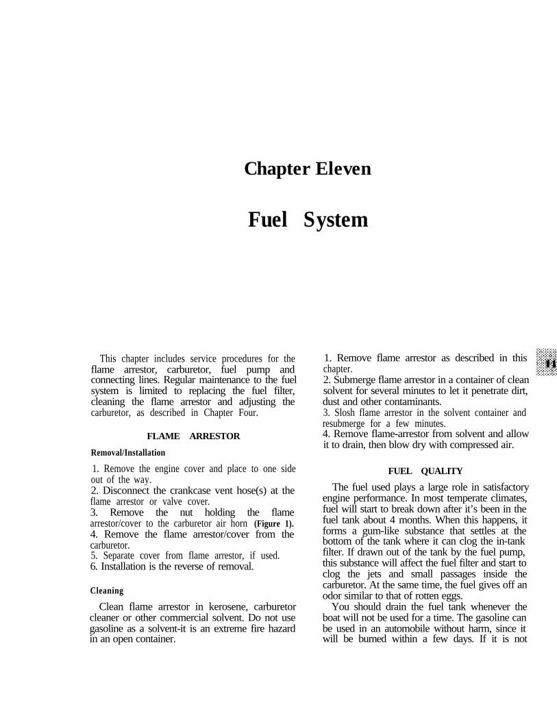
1. Remove the engine cover and place to one sideout of the way.2. Disconnect the crankcase vent hose(s) at theflame arrestor or valve cover.3. Remove the nut holding the flamearrestor/cover to the carburetor air horn (Figure 1).4. Remove the flame arrestor/cover from thecarburetor.5. Separate cover from flame arrestor, if used.6. Installation is the reverse of removal.
Cleaning
Clean flame arrestor in kerosene, carburetorcleaner or other commercial solvent. Do not usegasoline as a solvent-it is an extreme fire hazardin an open container.
1. Remove flame arrestor as described in thischapter.2. Submerge flame arrestor in a container of cleansolvent for several minutes to let it penetrate dirt,dust and other contaminants.3. Slosh flame arrestor in the solvent container andresubmerge for a few minutes.4. Remove flame-arrestor from solvent and allowit to drain, then blow dry with compressed air.
FUEL QUALITY
The fuel used plays a large role in satisfactoryengine performance. In most temperate climates,fuel will start to break down after it’s been in thefuel tank about 4 months. When this happens, itforms a gum-like substance that settles at thebottom of the tank where it can clog the in-tankfilter. If drawn out of the tank by the fuel pump,this substance will affect the fuel filter and start toclog the jets and small passages inside thecarburetor. At the same time, the fuel gives off anodor similar to that of rotten eggs.
You should drain the fuel tank whenever theboat will not be used for a time. The gasoline canbe used in an automobile without harm, since itwill be burned within a few days. If it is not
288 CHAPTER ELEVEN
possible to drain the tank, Mercury recommendsthe use of Quicksilver gasoline stabilizer andconditioner (or equivalent) to prevent the fuel fromspoiling.
Some gasolines sold for marine use may containalcohol, although this fact may not be advertised.Using such fuels is not recommended, unless youcan determine the nature of the blend. A mixture of10 percent ethyl alcohol and 90 percent unleadedgasoline is called gasohol. While it will providesatisfactory service in engines built after 1974,Mercury Marine does not recommend its use.
Fuels with an alcohol content tend to slowlyabsorb moisture from the air. When the moisturecontent of the fuel reaches approximately onepercent, it combines with the alcohol and separatesfrom the fuel. This separation does not normallyoccur when gasohol is used in an automobile, asthe tank is generally emptied within a few daysafter filling it.
The problem does occur in marine use, however,because boats often remain idle between start-upsfor days or even weeks. This length of time permitsseparation to take place. The water/alcoholmixture settles at the bottom of the tank where thefuel pickup carries it into the fuel line. Since anengine will not run on this mixture, it is necessaryto drain the fuel tank, flush out the fuel system withclean gasoline and then remove and clean the sparkplugs before the engine can be started. If it isnecessary to operate an engine on gasohol, do notstore such fuel in the tank(s) for more than a fewdays, especially in climates with high humidity.
Other problems which have been identified withthe use of misblended alcohol/gasoline fuelsinclude:
a .
b .
C.
Corrosion formation on the inside of fueltanks and steel fuel lines.Corrosion formation inside carburetors. Zincalloys (Holley carburetors) and aluminumalloys (Carter carburetors) are especiallysusceptible.Deterioration and failure of syntheticrubber/plastic materials such as O-ring seals,diaphragms, accelerator pump cups andgaskets.
d . Premature failure of fuel line hoses.
CARBURETOR FUNDAMENTALS
A gasoline engine must receive fuel and airmixed in a precise proportion in order to operate
efficiently at various speeds. At sea level, undernormal conditions, the ratio is 14.7: 1 at high speedand 12: 1 at low speeds. Carburetors are designed tomaintain these ratios while providing for suddenacceleration or increased loads.
A mixture with too much fuel is said to be“rich.” One with to little fuel is said to be “lean.”Incorrect mixture proportions can result from avariety of factors such as a dirty flame arrestor,defective choke, improperly adjusted idle mixtureor speed screws, a leaking needle valve or a floatthat has absorbed fuel.
The choke valve in a carburetor provides aricher than normal mixture of fuel and air until theengine warms up. If the choke valve sticks in anopen position, the engine will not start properly. Achoke that sticks in a closed position will cause aflooding condition.
The throat of a carburetor is often called a“barrel.” A single-barrel carburetor has only onethroat. Two-barrel carburetors have 2 throats and 2complete sets of metering devices, but only onefloat bowl and float. A 4-barrel carburetor has 4throats, 4 complete sets of metering devices and 2floats.
CARBURETORS
During the years covered by this manual, thefollowing carburetors have been used:
a. Rochester B and BC 1-bbl.b. Carter RBS 1-bbl.c. Mercury MD 1-bbl.d. Rochester 2GC and 2GV 2;bbl.e. MerCarb 2-bbl.f. Holley 2300 and 6317 2-bbl.
FUEL SYSTEM 289
g. Rochester 4GV 4-bbl.h. Rochester 4MV and 4MY 4-bbl.i. Holley 4160, 6407 and 6576 4-bbl.
Removal, overhaul and installation procedures areprovided for all models.
WARNINGCarburetors used on Mercruiser engines aredesigned for marine use. Do not substitute anautomotive carburetor. Fuel vapors escapingfrom such carburetors can create a fire orexplosion hazard.
Carburetor specifications vary with type andmodel year. The necessary specifications areprovided on instruction sheets accompanyingoverhaul kits, along with any specific proceduresrequired for adjustment.
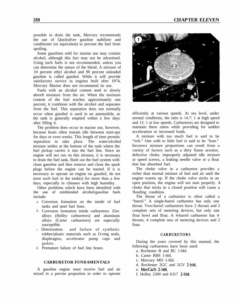
The carburetor model identification may bestamped on the carburetor main body/air horncasting, or on a tag attached to the carburetor byone of the air horn screws (Figure 2). Thisinformation is necessary to obtain the properoverhaul kit.
TroubleshootingMerCarb Acceleration “Bog”
Owners of MCM 120R/ 140R/ 170MR/ 470R/200MR/ 898R models may experience engine“bog” on acceleration. The cause of the problem isthe neoprene seal on the accelerator pump, whichexpands when gasoline blended with alcohol is
used. To alleviate the problem, install acceleratorpump kit part No. 3302-9046 and check the qualityof fuel used. See Fuel Quality in this chapter.
Carburetors with a date code 4501 stamped onthe body casting (built after May 1, 1984) have thekit installed in the carburetor and should notencounter this problem unless fuel with anexcessive quantity of alcohol is used.
MerCarb Right Turn Lean-out
Owners of MCM 120R and 140R engines mayexperience hesitation during a hard right turn. Theproblem affects carburetors with a build date priorto 4801 (built before August 1, 1984). Suchcarburetors use a spring-loaded inlet needle. Tosolve the problem, install a new inlet seat kit (partNo. 3302-9407). This contains a solid, 2-piece inletneedle. Reset the float level to 5116 in. using theprocedure which accompanies the kit.
No Idle Mixture Adjustment(MerCarb Carburetor)
Owners of MCM 120R/ 140R/ 170MR/ 470R/200MR/ 898R models may find that the carburetordoes not respond to idle mixture screw adjustment.This can be caused by overadjustment of the idlespeed screw to keep the engine running in forwardgear. When this is done, the throttle plates havestarted to open and adjusting the idle mixturescrew will have little or no effect on the engine. Todetermine whether the carburetor is misadjusted ordefective, refer to Idle Adjustments in ChapterFour. Perform Steps l- 10 of the adjustmentprocedure exactly as provided. If there is still littleor no response to adjustment of the idle mixturescrew, replace the carburetor.
Vapor LockMCM 120/140/170MR/190MR Models
A high flow fuel pump kit (part No. 42725A5) isoffered as a means of reducing the problem. Thishigh flow fuel pump is factory installed on modelsmanufactured after August 1986. However, thenew pump may not completely solve it. Problemswith vapor lock are increasing today due to thepoor quality of fuel available. Mercury Marineoffers the following pointers as steps in reducingthe vapor lock problem.
1. Let the engine idle for several minutes beforeshutting it down after a hard run.
290 CHAPTER ELEVEN
2. Let the engine idle 1-2 minutes after starting.3. Operate the bilge blower at idle and duringshutdown.4. Make sure there are sufficient vents to provide agood flow of air through the engine compartment.
Carburetor Removal/Installgtion
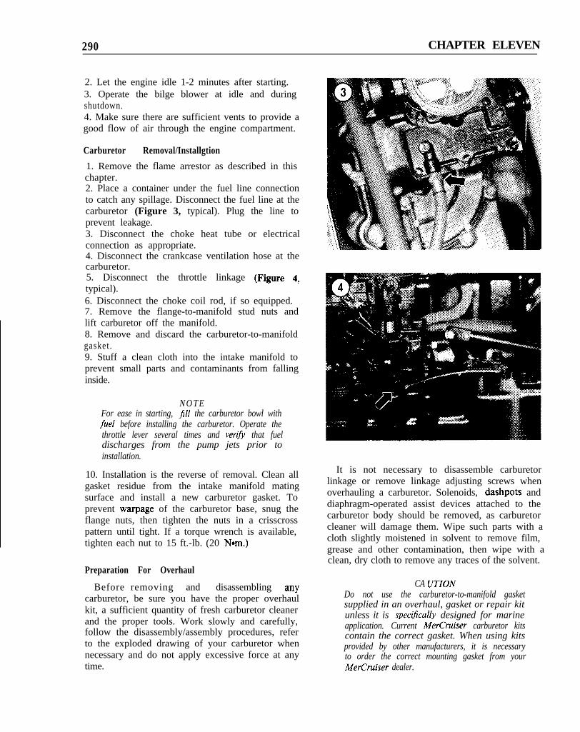
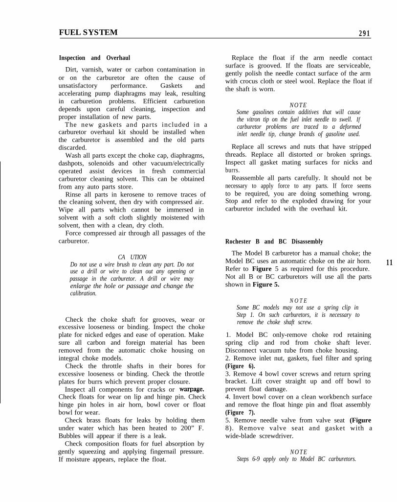
1. Remove the flame arrestor as described in thischapter.2. Place a container under the fuel line connectionto catch any spillage. Disconnect the fuel line at thecarburetor (Figure 3, typical). Plug the line toprevent leakage.3. Disconnect the choke heat tube or electricalconnection as appropriate.4. Disconnect the crankcase ventilation hose at thecarburetor.5. Disconnect the throttle linkage (Figure 4,typical).6. Disconnect the choke coil rod, if so equipped.7. Remove the flange-to-manifold stud nuts andlift carburetor off the manifold.8. Remove and discard the carburetor-to-manifoldgasket.9. Stuff a clean cloth into the intake manifold toprevent small parts and contaminants from fallinginside.
N O T EFor ease in starting, fill the carburetor bowl withfuel before installing the carburetor. Operate thethrottle lever several times and vertfy that fueldischarges from the pump jets prior toinstallation.
10. Installation is the reverse of removal. Clean allgasket residue from the intake manifold matingsurface and install a new carburetor gasket. Toprevent warpage of the carburetor base, snug theflange nuts, then tighten the nuts in a crisscrosspattern until tight. If a torque wrench is available,tighten each nut to 15 ft.-lb. (20 Nom.)
Preparation For Overhaul
Before removing and disassembling anycarburetor, be sure you have the proper overhaulkit, a sufficient quantity of fresh carburetor cleanerand the proper tools. Work slowly and carefully,follow the disassembly/assembly procedures, referto the exploded drawing of your carburetor whennecessary and do not apply excessive force at anytime.
It is not necessary to disassemble carburetorlinkage or remove linkage adjusting screws whenoverhauling a carburetor. Solenoids, dashpots anddiaphragm-operated assist devices attached to thecarburetor body should be removed, as carburetorcleaner will damage them. Wipe such parts with acloth slightly moistened in solvent to remove film,grease and other contamination, then wipe with aclean, dry cloth to remove any traces of the solvent.
CA UTIONDo not use the carburetor-to-manifold gasketsupplied in an overhaul, gasket or repair kitunless it is specijically designed for marineapplication. Current MerCruiser carburetor kitscontain the correct gasket. When using kitsprovided by other manufacturers, it is necessaryto order the correct mounting gasket from yourMerCruiser dealer.
FUEL SYSTEM 291
Inspection and Overhaul
Dirt, varnish, water or carbon contamination inor on the carburetor are often the cause ofunsatisfactory performance. Gaskets andaccelerating pump diaphragms may leak, resultingin carburetion problems. Efficient carburetiondepends upon careful cleaning, inspection andproper installation of new parts.
The new gaskets and parts included in acarburetor overhaul kit should be installed whenthe carburetor is assembled and the old partsdiscarded.
Wash all parts except the choke cap, diaphragms,dashpots, solenoids and other vacuum/electricallyoperated assist devices in fresh commercialcarburetor cleaning solvent. This can be obtainedfrom any auto parts store.
Rinse all parts in kerosene to remove traces ofthe cleaning solvent, then dry with compressed air.Wipe all parts which cannot be immersed insolvent with a soft cloth slightly moistened withsolvent, then with a clean, dry cloth.
Force compressed air through all passages of thecarburetor.
CA UTIONDo not use a wire brush to clean any part. Do notuse a drill or wire to clean out any opening orpassage in the carburetor. A drill or wire mayenlarge the hole or passage and change thecalibration.
Check the choke shaft for grooves, wear orexcessive looseness or binding. Inspect the chokeplate for nicked edges and ease of operation. Makesure all carbon and foreign material has beenremoved from the automatic choke housing onintegral choke models.
Check the throttle shafts in their bores forexcessive looseness or binding. Check the throttleplates for burrs which prevent proper closure.
Inspect all components for cracks or warpage.Check floats for wear on lip and hinge pin. Checkhinge pin holes in air horn, bowl cover or floatbowl for wear.
Check brass floats for leaks by holding themunder water which has been heated to 200” F.Bubbles will appear if there is a leak.
Check composition floats for fuel absorption bygently squeezing and applying fingernail pressure.If moisture appears, replace the float.
Replace the float if the arm needle contactsurface is grooved. If the floats are serviceable,gently polish the needle contact surface of the armwith crocus cloth or steel wool. Replace the float ifthe shaft is worn.
N O T ESome gasolines contain additives that will causethe vitron tip on the fuel inlet needle to swell. Ifcarburetor problems are traced to a deformedinlet needle tip, change brands of gasoline used.
Replace all screws and nuts that have strippedthreads. Replace all distorted or broken springs.Inspect all gasket mating surfaces for nicks andburrs.
Reassemble all parts carefully. It should not benecessary to apply force to any parts. If force seemsto be required, you are doing something wrong.Stop and refer to the exploded drawing for yourcarburetor included with the overhaul kit.
Rochester B and BC Disassembly
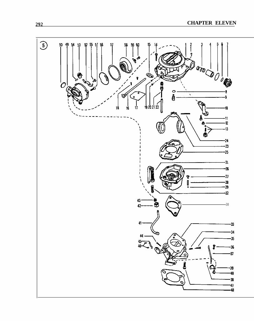
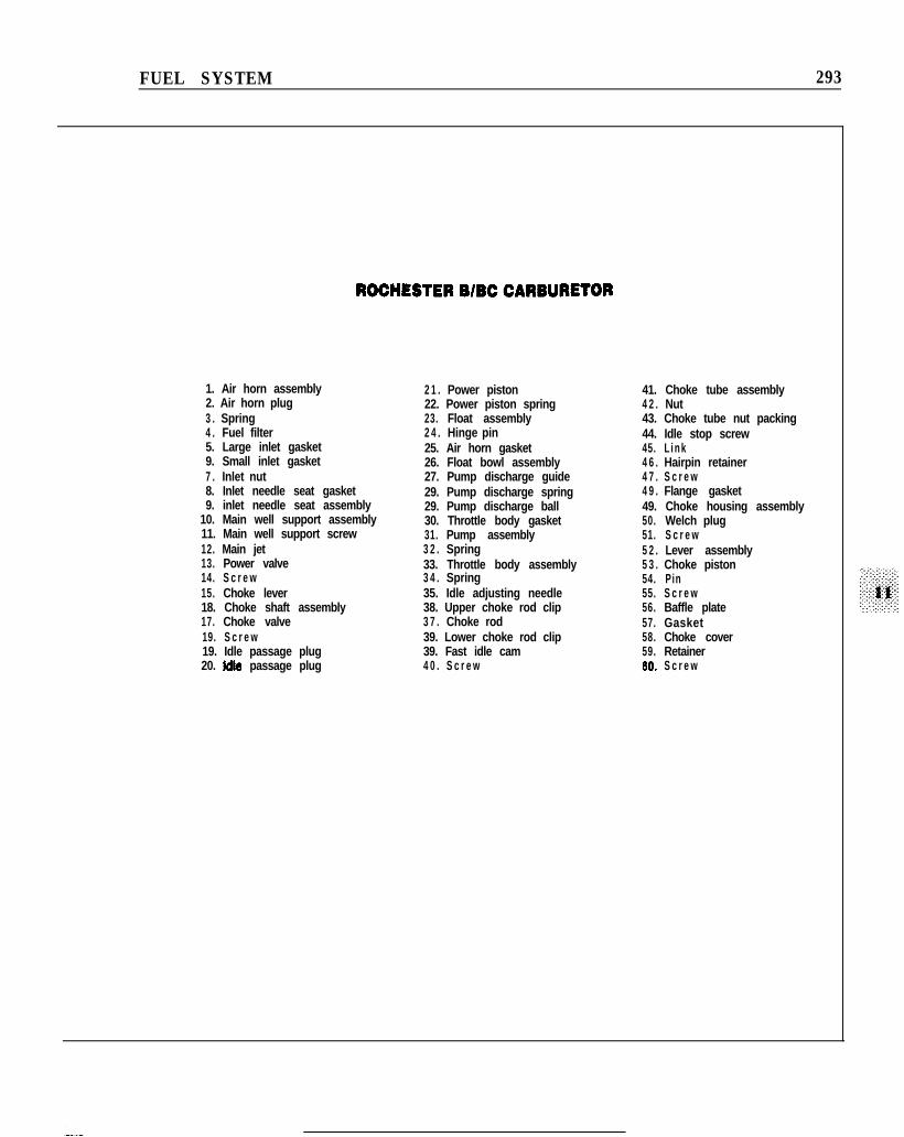
The Model B carburetor has a manual choke; theModel BC uses an automatic choke on the air horn.Refer to Figure 5 as required for this procedure.Not all B or BC carburetors will use all the partsshown in Figure 5.
N O T ESome BC models may not use a spring clip inStep 1. On such carburetors, it is necessary toremove the choke shaft screw.
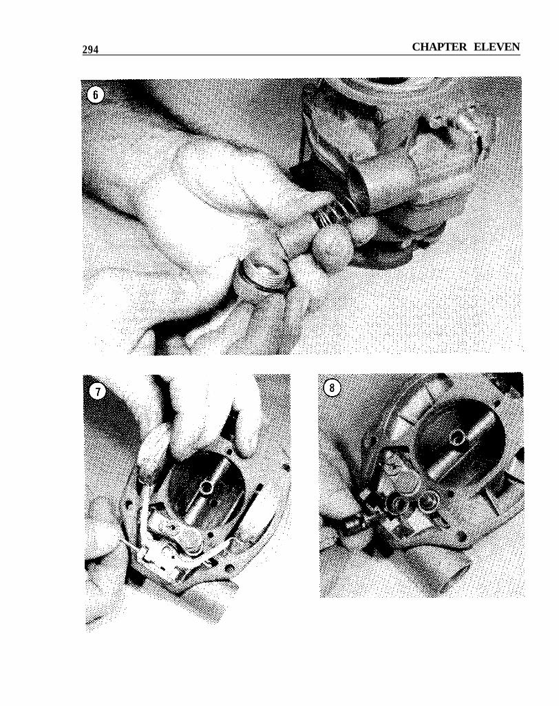
1. Model BC only-remove choke rod retainingspring clip and rod from choke shaft lever.Disconnect vacuum tube from choke housing.2. Remove inlet nut, gaskets, fuel filter and spring(Figure 6).3. Remove 4 bowl cover screws and return springbracket. Lift cover straight up and off bowl toprevent float damage.4. Invert bowl cover on a clean workbench surfaceand remove the float hinge pin and float assembly(Figure 7).5. Remove needle valve from valve seat (Figure8). Remove valve seat and gasket with awide-blade screwdriver.
N O T ESteps 6-9 apply only to Model BC carburetors.
11
292 CHAPTER ELEVEN
III
I\\
\\\
\‘b O43-
42- @ 0:
0
30
n e
FUEL SYSTEM 293
ROCHESTERBlBCCARBURETOR
1. Air horn assembly2. Air horn plug3 . Spring4 . Fuel filter5. Large inlet gasket9. Small inlet gasket7 . Inlet nut8. Inlet needle seat gasket9. inlet needle seat assembly
10. Main well support assembly11. Main well support screw12. Main jet13. Power valve14. S c r e w15. Choke lever18. Choke shaft assembly17. Choke valve19. S c r e w19. Idle passage plug20. idle passage plug
2 1 . Power piston22. Power piston spring23. Float assembly2 4 . Hinge pin25. Air horn gasket26. Float bowl assembly27. Pump discharge guide29. Pump discharge spring29. Pump discharge ball30. Throttle body gasket31. Pump assembly3 2 . Spring33. Throttle body assembly3 4 . Spring35. Idle adjusting needle38. Upper choke rod clip3 7 . Choke rod39. Lower choke rod clip39. Fast idle cam4 0 . S c r e w
41. Choke tube assembly4 2 . Nut43. Choke tube nut packing44. Idle stop screw45. L i n k4 6 . Hairpin retainer4 7 . S c r e w4 9 . Flange gasket49. Choke housing assembly50. Welch plug51. S c r e w5 2 . Lever assembly5 3 . Choke piston54. Pin55. S c r e w56. Baffle plate57. Gasket58. Choke cover59. Retainer60. S c r e w
294 CHAPTER ELEVEN
FUEL SYSTEM
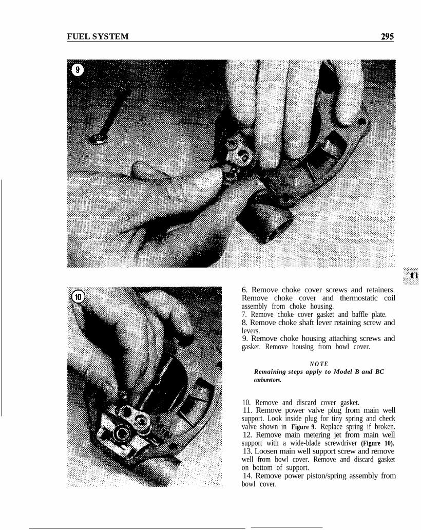
6. Remove choke cover screws and retainers.Remove choke cover and thermostatic coilassembly from choke housing.7. Remove choke cover gasket and baffle plate.8. Remove choke shaft lever retaining screw andlevers.9. Remove choke housing attaching screws andgasket. Remove housing from bowl cover.
NOTERemaining steps apply to Model B and BCcarburetors.
10. Remove and discard cover gasket.11. Remove power valve plug from main wellsupport. Look inside plug for tiny spring and checkvalve shown in Figure 9. Replace spring if broken.12. Remove main metering jet from main wellsupport with a wide-blade screwdriver (Figure 10).13. Loosen main well support screw and removewell from bowl cover. Remove and discard gasketon bottom of support.14. Remove power piston/spring assembly frombowl cover.
296 CHAPTER ELEVEN
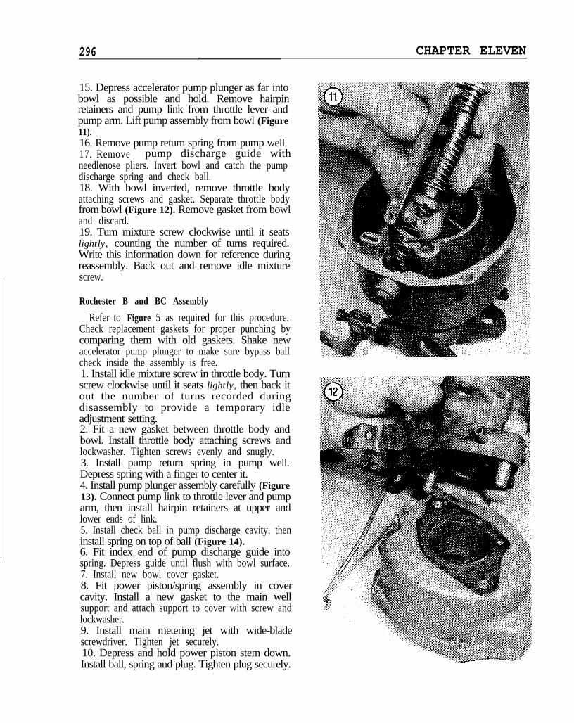
15. Depress accelerator pump plunger as far intobowl as possible and hold. Remove hairpinretainers and pump link from throttle lever andpump arm. Lift pump assembly from bowl (Figure11).16. Remove pump return spring from pump well.17. Remove pump discharge guide withneedlenose pliers. Invert bowl and catch the pumpdischarge spring and check ball.18. With bowl inverted, remove throttle bodyattaching screws and gasket. Separate throttle bodyfrom bowl (Figure 12). Remove gasket from bowland discard.19. Turn mixture screw clockwise until it seatslightly, counting the number of turns required.Write this information down for reference duringreassembly. Back out and remove idle mixturescrew.
Rochester B and BC Assembly
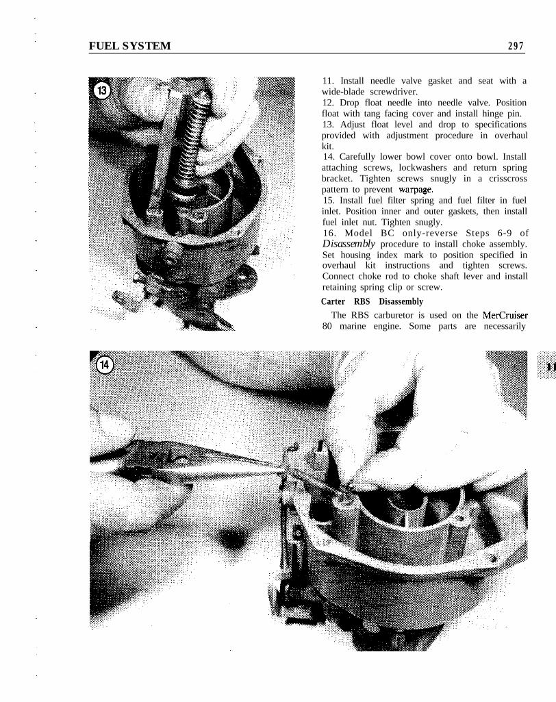
Refer to Figure 5 as required for this procedure.Check replacement gaskets for proper punching bycomparing them with old gaskets. Shake newaccelerator pump plunger to make sure bypass ballcheck inside the assembly is free.1. Install idle mixture screw in throttle body. Turnscrew clockwise until it seats lightly, then back itout the number of turns recorded duringdisassembly to provide a temporary idleadjustment setting.2. Fit a new gasket between throttle body andbowl. Install throttle body attaching screws andlockwasher. Tighten screws evenly and snugly.3. Install pump return spring in pump well.Depress spring with a finger to center it.4. Install pump plunger assembly carefully (Figure13). Connect pump link to throttle lever and pumparm, then install hairpin retainers at upper andlower ends of link.5. Install check ball in pump discharge cavity, theninstall spring on top of ball (Figure 14).6. Fit index end of pump discharge guide intospring. Depress guide until flush with bowl surface.7. Install new bowl cover gasket.8. Fit power piston/spring assembly in covercavity. Install a new gasket to the main wellsupport and attach support to cover with screw andlockwasher.9. Install main metering jet with wide-bladescrewdriver. Tighten jet securely.10. Depress and hold power piston stem down.Install ball, spring and plug. Tighten plug securely.
FUEL SYSTEM 297
11. Install needle valve gasket and seat with awide-blade screwdriver.12. Drop float needle into needle valve. Positionfloat with tang facing cover and install hinge pin.13. Adjust float level and drop to specificationsprovided with adjustment procedure in overhaulkit.14. Carefully lower bowl cover onto bowl. Installattaching screws, lockwashers and return springbracket. Tighten screws snugly in a crisscrosspattern to prevent warpage.15. Install fuel filter spring and fuel filter in fuelinlet. Position inner and outer gaskets, then installfuel inlet nut. Tighten snugly.16. Model BC only-reverse Steps 6-9 ofDisassembly procedure to install choke assembly.Set housing index mark to position specified inoverhaul kit instructions and tighten screws.Connect choke rod to choke shaft lever and installretaining spring clip or screw.
Carter RBS DisassemblyThe RBS carburetor is used on the MerCruiser
80 marine engine. Some parts are necessarily
298 CHAPTER ELEVEN
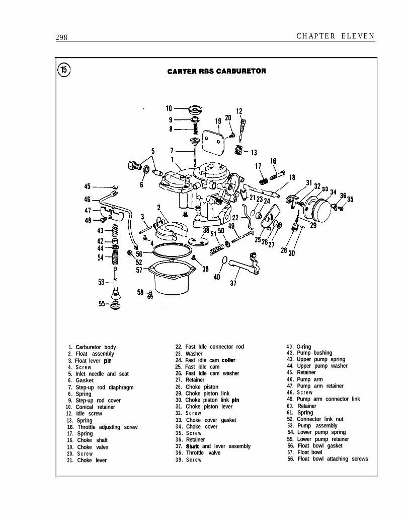
3 CARTERRBSCARBURETQR
46-/
42-@I44454 --II53 -Ii
1. Carburetor body2 . Float assembly3. Float lever pin4 . S c r e w5. Inlet needle and seat6 . Gasket7. Step-up rod diaphragm6 . Spring9. Step-up rod cover
10. Conical retainer12. Idle screw13. Spring16. Throttle adjustlng screw17. Spring16. Choke shaft19. Choke valve20. S c r e w21. Choke lever
22. Fast Idle connector rod23. Washer24. Fast idle cam Collar
25. Fast Idle cam26. Fast Idle cam washer27. Retainer26. Choke piston29. Choke piston link30. Choke piston link pin31. Choke piston lever32. S c r e w33. Choke cover gasket3 4 . Choke cover3 5 . S c r e w3 6 . Retainer37. Shalt and lever assembly3 6 . Throttle valve3 9 . S c r e w
4 0 . O-ring4 2 . Pump bushing43. Upper pump spring44. Upper pump washer45. Retainer4 6 . Pump arm47. Pump arm retainer4 6 . S c r e w49. Pump arm connector link60. Retainer61. Spring52. Connector link nut53. Pump assembly54. Lower pump spring55. Lower pump retainer56. Float bowl gasket57. Float bowl56. Float bowl attaching screws
FUEL SYSTEM 299
destroyed during disassembly. Make sure you havethe proper replacement parts before proceeding.
Refer to Figure 15 as required for this procedure.Not all RBS carburetors will use all the parts shownin Figure 15.
NOTEWhen the RBS is used in multiple carburetorinstallations, the thermostatic coil on the rearcarburetor is subjected to excessive wear andshould be routinely replaced during an overhaul.
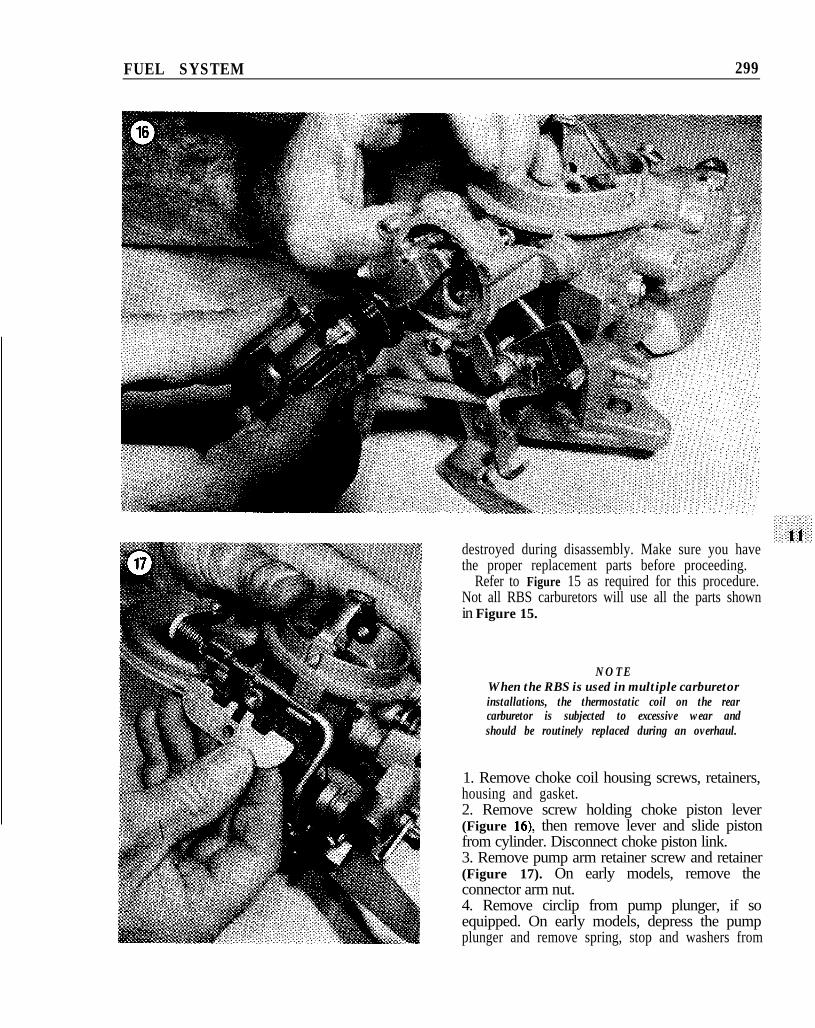
1. Remove choke coil housing screws, retainers,housing and gasket.2. Remove screw holding choke piston lever(Figure 16), then remove lever and slide pistonfrom cylinder. Disconnect choke piston link.3. Remove pump arm retainer screw and retainer(Figure 17). On early models, remove theconnector arm nut.4. Remove circlip from pump plunger, if soequipped. On early models, depress the pumpplunger and remove spring, stop and washers from
300 CHAPTER ELEVEN
FUEL SYSTEM 301
pump shaft. On late models, simply slide slotted11’
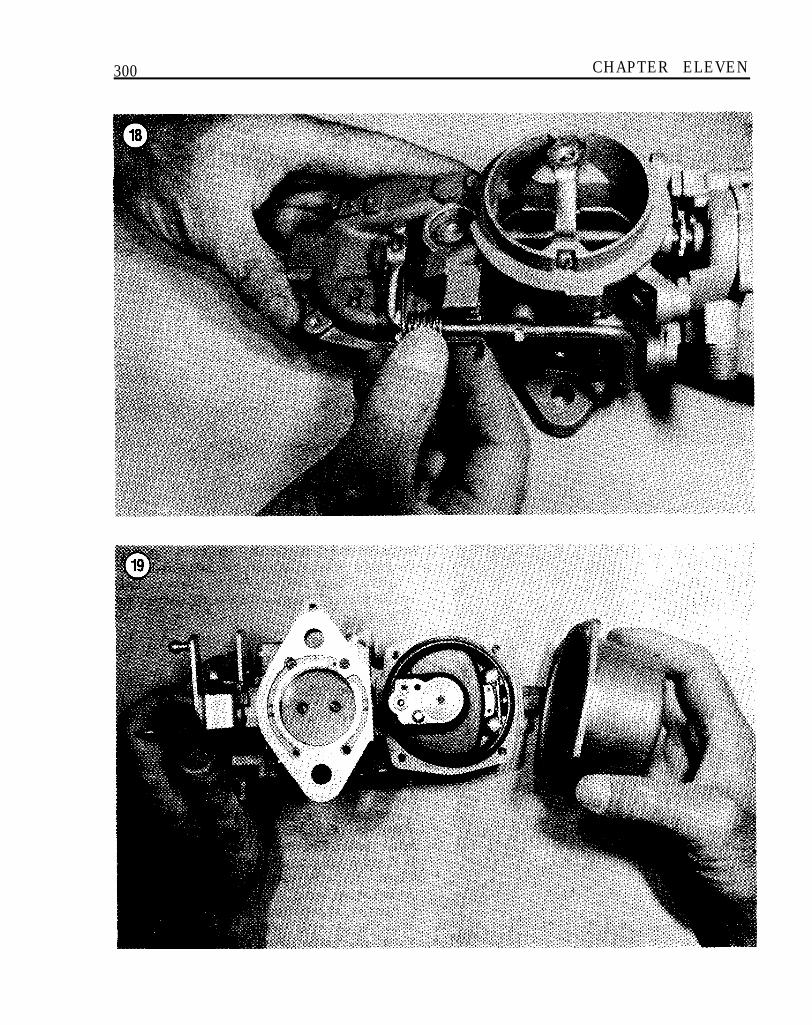
pump arm off shaft as shown in Figure 18.
NOTEDo not try to remove connector link attached topump arm in Step 5. Link removal requiresthrottle plate and lever assembly removal, whichis unnecessary for cleaning purposes.
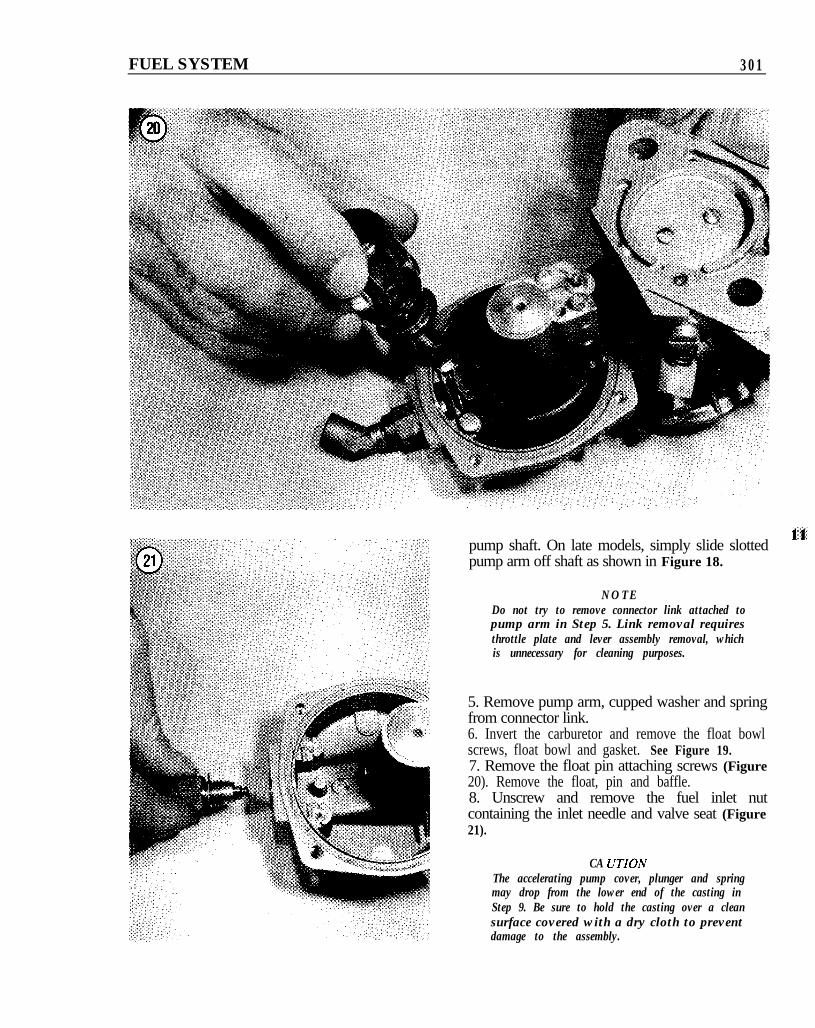
5. Remove pump arm, cupped washer and springfrom connector link.6. Invert the carburetor and remove the float bowlscrews, float bowl and gasket. See Figure 19.7. Remove the float pin attaching screws (Figure20). Remove the float, pin and baffle.8. Unscrew and remove the fuel inlet nutcontaining the inlet needle and valve seat (Figure21).
CA UTIONThe accelerating pump cover, plunger and springmay drop from the lower end of the casting inStep 9. Be sure to hold the casting over a cleansurface covered with a dry cloth to preventdamage to the assembly.
302 CHAPTER ELEVEN
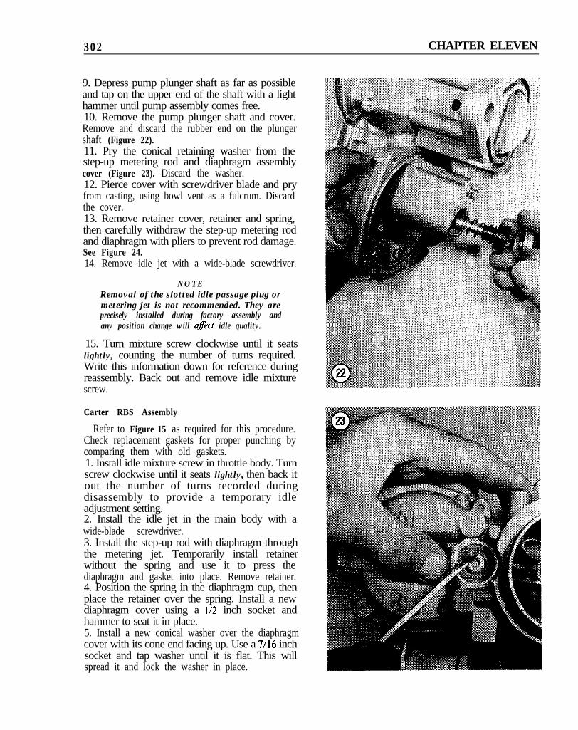
9. Depress pump plunger shaft as far as possibleand tap on the upper end of the shaft with a lighthammer until pump assembly comes free.10. Remove the pump plunger shaft and cover.Remove and discard the rubber end on the plungershaft (Figure 22).11. Pry the conical retaining washer from thestep-up metering rod and diaphragm assemblycover (Figure 23). Discard the washer.12. Pierce cover with screwdriver blade and pryfrom casting, using bowl vent as a fulcrum. Discardthe cover.13. Remove retainer cover, retainer and spring,then carefully withdraw the step-up metering rodand diaphragm with pliers to prevent rod damage.See Figure 24.14. Remove idle jet with a wide-blade screwdriver.
NOTERemoval of the slotted idle passage plug ormetering jet is not recommended. They areprecisely installed during factory assembly andany position change will aflect idle quality.
15. Turn mixture screw clockwise until it seatslightly, counting the number of turns required.Write this information down for reference duringreassembly. Back out and remove idle mixturescrew.
Carter RBS Assembly
Refer to Figure 15 as required for this procedure.Check replacement gaskets for proper punching bycomparing them with old gaskets.1. Install idle mixture screw in throttle body. Turnscrew clockwise until it seats lightly, then back itout the number of turns recorded duringdisassembly to provide a temporary idleadjustment setting.2. Install the idle jet in the main body with awide-blade screwdriver.3. Install the step-up rod with diaphragm throughthe metering jet. Temporarily install retainerwithout the spring and use it to press thediaphragm and gasket into place. Remove retainer.4. Position the spring in the diaphragm cup, thenplace the retainer over the spring. Install a newdiaphragm cover using a l/2 inch socket andhammer to seat it in place.5. Install a new conical washer over the diaphragmcover with its cone end facing up. Use a 7/16 inchsocket and tap washer until it is flat. This willspread it and lock the washer in place.
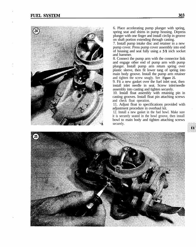
6. Place accelerating pump plunger with spring,spring seat and shims in pump housing. Depressplunger with one finger and install circlip in grooveon shaft portion extending through casting.7. Install pump intake disc and retainer in a newpump cover. Press pump cover assembly into endof housing and seat fully using a 5/8 inch socketand hammer.8. Connect the pump arm with the connector linkand engage other end of pump arm with pumpplunger. Install pump arm return spring overplastic sleeve, then fit lower tang of spring intomain body groove. Install the pump arm retainerand tighten the screw snugly. See Figure 25.9. Fit a new gasket over the fuel inlet seat, theninstall inlet needle in seat. Screw inlet/needleassembly into casting and tighten securely.10. Install float assembly with retaining pin incasting grooves. Install float pin attaching screwsand check float operation.11. Adjust float to specifications provided withadjustment procedure in overhaul kit.12. Install a new gasket in the fuel bowl. Make sureit is securely seated in the bowl groove, then installbowl to main body and tighten attaching screwssecurely.
304 CHAPTER ELEVEN
u26
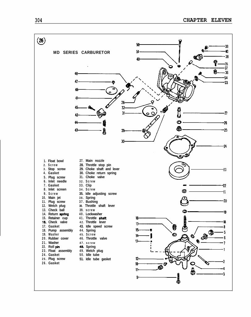
MD SERIES CARBURETOR
1. Float bowl2 . S c r e w3 . Stop screw4 . Gasket5 . Plug screw6 . Inlet needle7 . Gasket8 . Inlet screen9 . S c r e w
10. Main jet11. Plug screw12. Welch plug13. Check ball14. Return spring15. Retainer cup16. Check valve17. Gasket18. Pump assembly19. Washer2 0 . Rubber cover2 1 . Washer22. Roll pin2 3 . Float assembly2 4 . Gasket2 5 . Plug screw2 6 . Gasket
27. Main nozzle28. Throttle stop pin29. Choke shaft and lever30. Choke return spring31. Choke valve3 2 . S c r e w3 3 . Clip3 4 . S c r e w35. Idle adjusting screw3 6 . Spring3 7 . Bushing38. Throttle shaft lever39. s c r e w4 0 . Lockwasher4 1 . Throttle shag4 2 . Throttle lever43. Idle speed screw4 4 . Spring4 5 . S c r e w4 6 . Throttle valve4 7 . s c r e w40. Spring4 9 . Welch plug5 0 . Idle tube51. Idle tube gasket
23
@ 21
FUEL SYSTEM 305
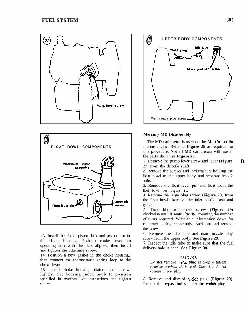
028FLOAT BOWL COMPONENTS
Accelerator pump
13. Install the choke piston, link and piston arm inthe choke housing. Position choke lever onoperating arm with the flats aligned, then installand tighten the attaching screw.14. Position a new gasket in the choke housing,then connect the thermostatic spring loop to thechoke lever.15. Install choke housing retainers and screwslightly. Set housing index mark to positionspecified in overhaul kit instructions and tightenscrews.
029 UPPER BODY COMPONENTS
Main nozzle plug screw
Mercury MD Disassembly
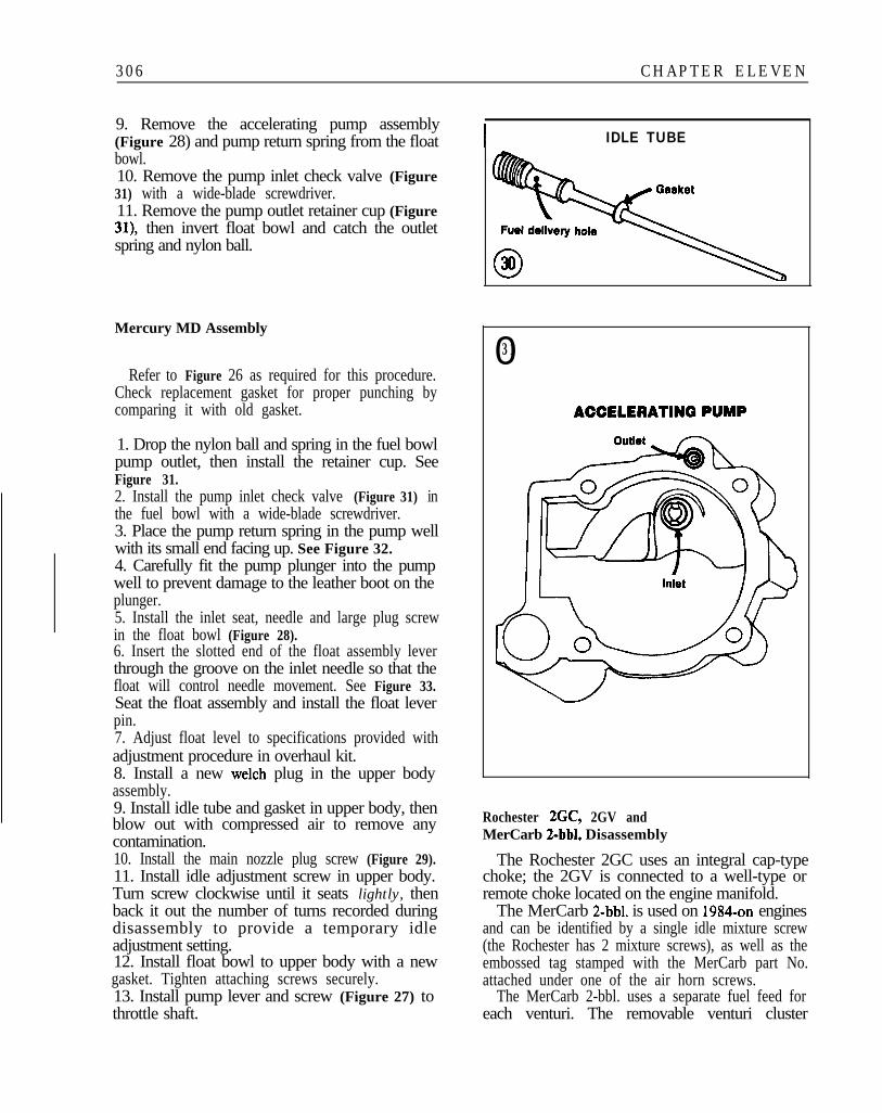
The MD carburetor is used on the MerCruiser 60marine engine. Refer to Figure 26 as required forthis procedure. Not all MD carburetors will use allthe parts shown in Figure 26.1. Remove the pump lever screw and lever (Figure 1127) from the throttle shaft.2. Remove the screws and lockwashers holding thefloat bowl to the upper body and separate into 2units.3. Remove the float lever pin and float from thefloat bowl. See Figure 28.4. Remove the large plug screw (Figure 28) fromthe float bowl. Remove the inlet needle, seat andgasket.5. Turn idle adjustment screw (Figure 29)clockwise until it seats lightly, counting the numberof turns required. Write this information down forreference during reassembly. Back out and removethe screw.6. Remove the idle tube and main nozzle plugscrew from the upper body. See Figure 29.7. Inspect the idle tube to make sure that the fueldelivery hole is open. See Figure 30.
CA UTIONDo not remove Welch plug in Step 8 unlesscomplete overhaul kit is used. Other kits do notcontain a new plug.
8. Remove and discard Welch plug (Figure 29).Inspect the bypass holes under the Welch plug.
306 CHAPTER ELEVEN
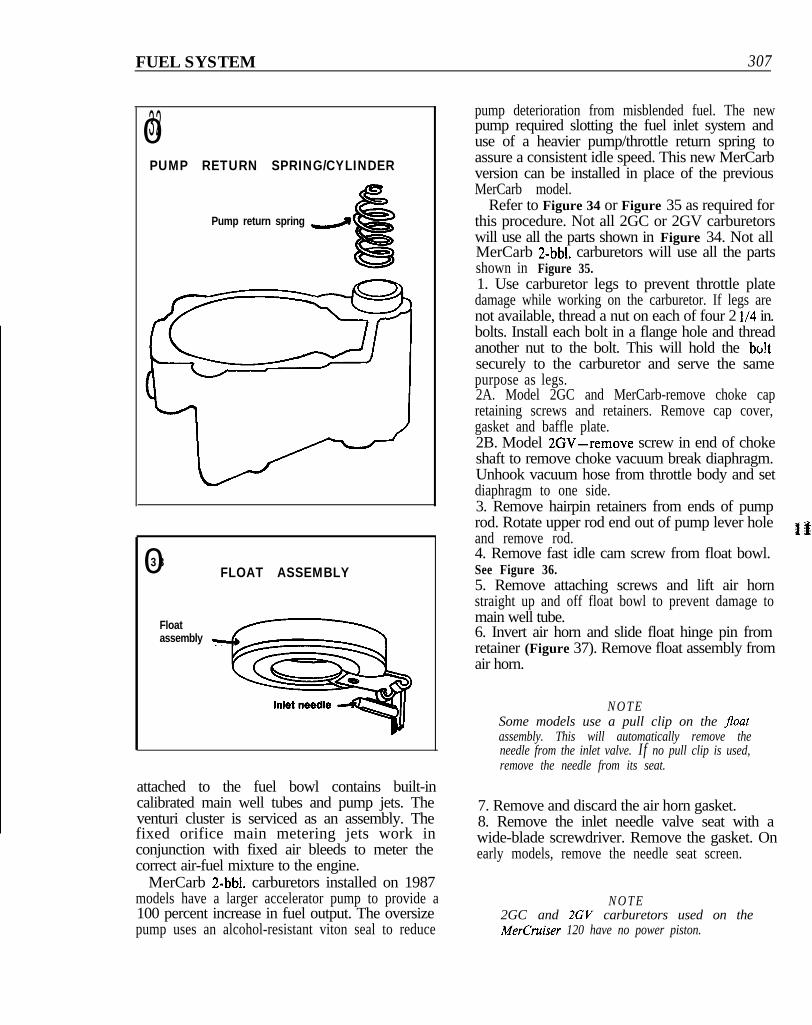
9. Remove the accelerating pump assembly(Figure 28) and pump return spring from the floatbowl.10. Remove the pump inlet check valve (Figure31) with a wide-blade screwdriver.11. Remove the pump outlet retainer cup (Figure31), then invert float bowl and catch the outletspring and nylon ball.
Mercury MD Assembly
Refer to Figure 26 as required for this procedure.Check replacement gasket for proper punching bycomparing it with old gasket.
1. Drop the nylon ball and spring in the fuel bowlpump outlet, then install the retainer cup. SeeFigure 31.2. Install the pump inlet check valve (Figure 31) inthe fuel bowl with a wide-blade screwdriver.3. Place the pump return spring in the pump wellwith its small end facing up. See Figure 32.4. Carefully fit the pump plunger into the pumpwell to prevent damage to the leather boot on theplunger.5. Install the inlet seat, needle and large plug screwin the float bowl (Figure 28).6. Insert the slotted end of the float assembly leverthrough the groove on the inlet needle so that thefloat will control needle movement. See Figure 33.Seat the float assembly and install the float leverpin.7. Adjust float level to specifications provided withadjustment procedure in overhaul kit.8. Install a new Welch plug in the upper bodyassembly.9. Install idle tube and gasket in upper body, thenblow out with compressed air to remove anycontamination.10. Install the main nozzle plug screw (Figure 29).11. Install idle adjustment screw in upper body.Turn screw clockwise until it seats lightly, thenback it out the number of turns recorded duringdisassembly to provide a temporary idleadjustment setting.12. Install float bowl to upper body with a newgasket. Tighten attaching screws securely.13. Install pump lever and screw (Figure 27) tothrottle shaft.
I IDLE TUBE
031
Rochester 2GC, 2GV andMerCarb 2-bbl. Disassembly
The Rochester 2GC uses an integral cap-typechoke; the 2GV is connected to a well-type orremote choke located on the engine manifold.
The MerCarb 2-bbl. is used on 1984-on enginesand can be identified by a single idle mixture screw(the Rochester has 2 mixture screws), as well as theembossed tag stamped with the MerCarb part No.attached under one of the air horn screws.
The MerCarb 2-bbl. uses a separate fuel feed foreach venturi. The removable venturi cluster
FUEL SYSTEM 307
032PUMP RETURN SPRING/CYLINDER
Pump return spring d
03 3FLOAT ASSEMBLY
Floatassembly
attached to the fuel bowl contains built-incalibrated main well tubes and pump jets. Theventuri cluster is serviced as an assembly. Thefixed orifice main metering jets work inconjunction with fixed air bleeds to meter thecorrect air-fuel mixture to the engine.
MerCarb 2-bbl. carburetors installed on 1987models have a larger accelerator pump to provide a100 percent increase in fuel output. The oversizepump uses an alcohol-resistant viton seal to reduce
pump deterioration from misblended fuel. The newpump required slotting the fuel inlet system anduse of a heavier pump/throttle return spring toassure a consistent idle speed. This new MerCarbversion can be installed in place of the previousMerCarb model.
Refer to Figure 34 or Figure 35 as required forthis procedure. Not all 2GC or 2GV carburetorswill use all the parts shown in Figure 34. Not allMerCarb 2-bbl. carburetors will use all the partsshown in Figure 35.1. Use carburetor legs to prevent throttle platedamage while working on the carburetor. If legs arenot available, thread a nut on each of four 2 l/4 in.bolts. Install each bolt in a flange hole and threadanother nut to the bolt. This will hold the bo!tsecurely to the carburetor and serve the samepurpose as legs.2A. Model 2GC and MerCarb-remove choke capretaining screws and retainers. Remove cap cover,gasket and baffle plate.2B. Model 2GV-remove screw in end of chokeshaft to remove choke vacuum break diaphragm.Unhook vacuum hose from throttle body and setdiaphragm to one side.3. Remove hairpin retainers from ends of pumprod. Rotate upper rod end out of pump lever holeand remove rod.
1 k
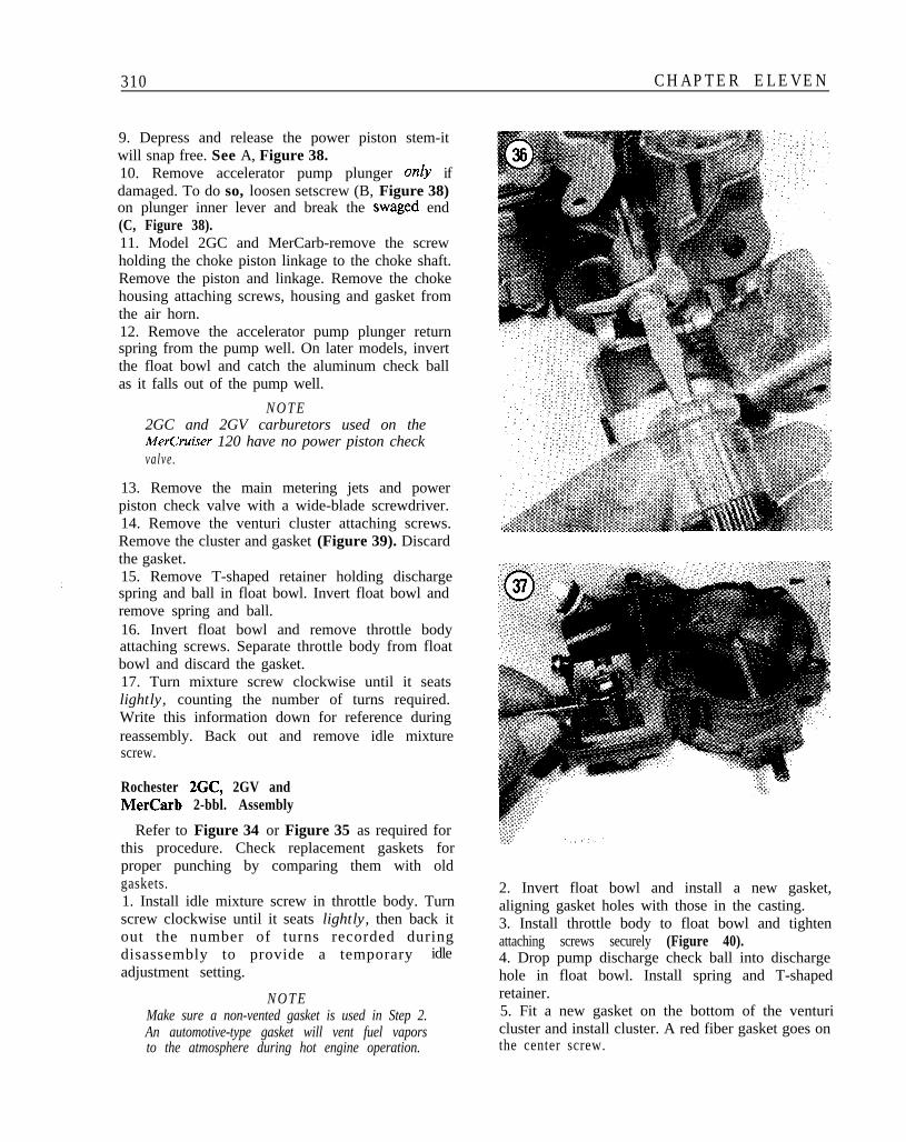
4. Remove fast idle cam screw from float bowl.See Figure 36.5. Remove attaching screws and lift air hornstraight up and off float bowl to prevent damage tomain well tube.6. Invert air horn and slide float hinge pin fromretainer (Figure 37). Remove float assembly fromair horn.
N O T ESome models use a pull clip on the floatassembly. This will automatically remove theneedle from the inlet valve. If no pull clip is used,remove the needle from its seat.
7. Remove and discard the air horn gasket.8. Remove the inlet needle valve seat with awide-blade screwdriver. Remove the gasket. Onearly models, remove the needle seat screen.
N O T E2GC and 2GV carburetors used on theMerCruiser 120 have no power piston.
308 CHAPTER ELEVEN
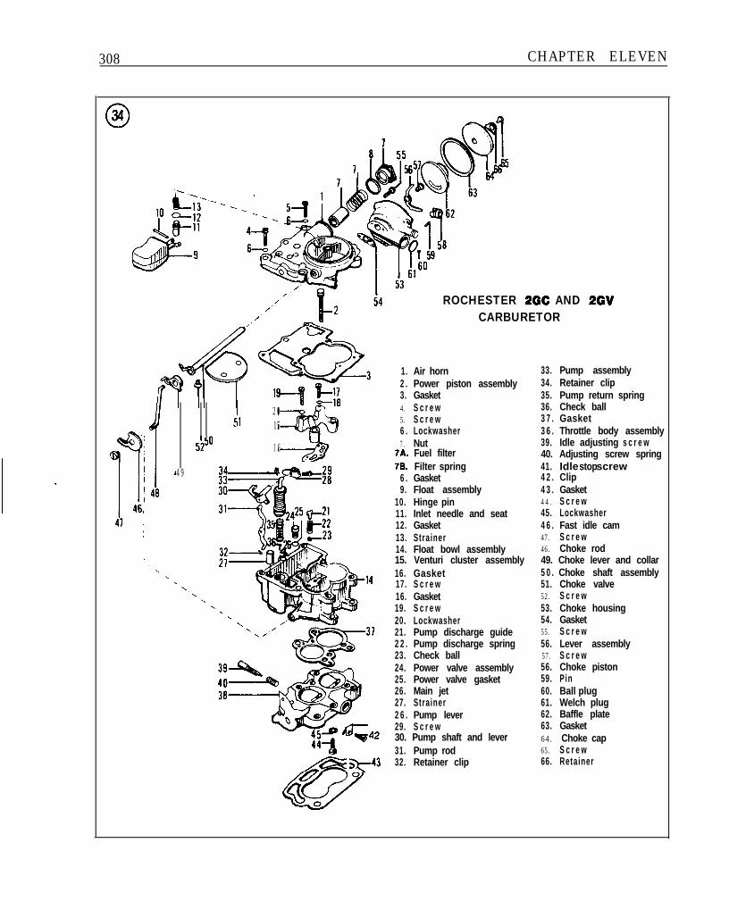
ROCHESTER 2GC AND 2GVCARBURETOR
I 2051 15
5250 1 6
49
1. Air horn 33. Pump assembly2 . Power piston assembly 34. Retainer clip3. Gasket 35. Pump return spring4. S c r e w 36. Check ball5. S c r e w 3 7 . Gasket6 . Lockwasher 3 6 . Throttle body assembly7 . Nut 39. Idle adjusting s c r e w
7A. Fuel filter 40. Adjusting screw spring78. Filter spring 41. Idle screwstop
6 . Gasket 4 2 . Clip9. Float assembly 4 3 . Gasket
10. Hinge pin 44. S c r e w11. Inlet needle and seat 45. Lockwasher12. Gasket 4 6 . Fast idle cam13. Strainer 47. S c r e w14. Float bowl assembly 46. Choke rod15. Venturi cluster assembly 49. Choke lever and collar16. Gasket 5 0 . Choke shaft assembly17. S c r e w 51. Choke valve16. Gasket 52. S c r e w19. S c r e w 53. Choke housing20. Lockwasher 54. Gasket21. Pump discharge guide 55. S c r e w2 2 . Pump discharge spring 56. Lever assembly23. Check ball 57. S c r e w24. Power valve assembly 56. Choke piston25. Power valve gasket 59. Pin26. Main jet 60. Ball plug27. Strainer 61. Welch plug2 6 . Pump lever 62. Baffle plate29. S c r e w 63. Gasket30. Pump shaft and lever 64. Choke cap31. Pump rod 65. S c r e w
5543 32. Retainer clip 66. Retainer
j_
FUEL SYSTEM 309
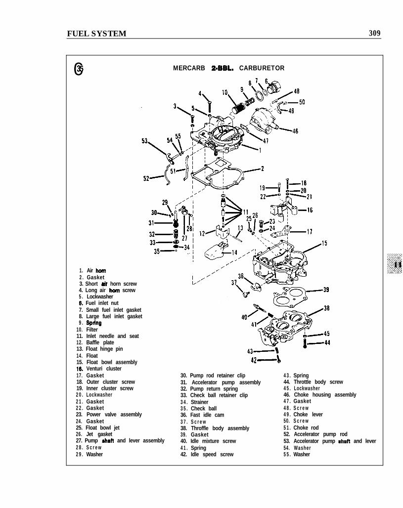
035 MERCARB 2=BBL. CARBURETOR
1. Air horn2 . Gasket3. Short air horn screw4. Long air horn screw5 . Lockwasher6. Fuel inlet nut7. Small fuel inlet gasket8. Large fuel inlet gasket9 . Sprtng
10. Filter11. Inlet needle and seat12. Baffle plate13. Float hinge pin14. Float15. Float bowl assembly
I//’
16. Venturi cluster17. Gasket18. Outer cluster screw19. Inner cluster screw2 0 . Lockwasher2 1 . Gasket2 2 . Gasket23. Power valve assembly24. Gasket25. Float bowl jet26. Jet gasket27. Pump shatt and lever assembly2 8 . S c r e w2 9 . Washer
42-b
30. Pump rod retainer clip31. Accelerator pump assembly32. Pump return spring33. Check ball retainer clip3 4 . Strainer3 5 . Check ball36. Fast idle cam3 7 . S c r e w38. Throffle body assembly39. Gasket40. Idle mixture screw4 1 . Spring42. Idle speed screw
4 3 . Spring44. Throttle body screw4 5 . Lockwasher46. Choke housing assembly4 7 . Gasket4 8 . S c r e w4 9 . Choke lever50. S c r e w5 1 . Choke rod52. Accelerator pump rod53. Accelerator pump shaft and lever54. Washer5 5 . Washer
310 CHAPTER ELEVEN
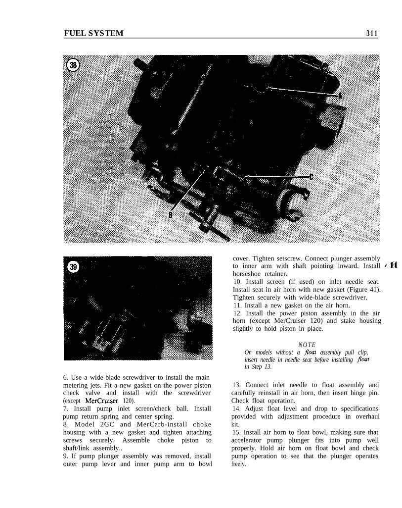
9. Depress and release the power piston stem-itwill snap free. See A, Figure 38.10. Remove accelerator pump plunger only ifdamaged. To do so, loosen setscrew (B, Figure 38)on plunger inner lever and break the swaged end(C, Figure 38).11. Model 2GC and MerCarb-remove the screwholding the choke piston linkage to the choke shaft.Remove the piston and linkage. Remove the chokehousing attaching screws, housing and gasket fromthe air horn.12. Remove the accelerator pump plunger returnspring from the pump well. On later models, invertthe float bowl and catch the aluminum check ballas it falls out of the pump well.
N O T E2GC and 2GV carburetors used on theMerCruiser 120 have no power piston checkvalve .
13. Remove the main metering jets and powerpiston check valve with a wide-blade screwdriver.14. Remove the venturi cluster attaching screws.Remove the cluster and gasket (Figure 39). Discardthe gasket.15. Remove T-shaped retainer holding dischargespring and ball in float bowl. Invert float bowl andremove spring and ball.16. Invert float bowl and remove throttle bodyattaching screws. Separate throttle body from floatbowl and discard the gasket.17. Turn mixture screw clockwise until it seatslightly, counting the number of turns required.Write this information down for reference duringreassembly. Back out and remove idle mixturescrew.
Rochester 2GC, 2GV andMerCarb 2-bbl. Assembly
Refer to Figure 34 or Figure 35 as required forthis procedure. Check replacement gaskets forproper punching by comparing them with oldgaskets.1. Install idle mixture screw in throttle body. Turnscrew clockwise until it seats lightly, then back itout the number of turns recorded duringdisassembly to provide a temporary idleadjustment setting.
N O T EMake sure a non-vented gasket is used in Step 2.An automotive-type gasket will vent fuel vaporsto the atmosphere during hot engine operation.
2. Invert float bowl and install a new gasket,aligning gasket holes with those in the casting.3. Install throttle body to float bowl and tightenattaching screws securely (Figure 40).4. Drop pump discharge check ball into dischargehole in float bowl. Install spring and T-shapedretainer.5. Fit a new gasket on the bottom of the venturicluster and install cluster. A red fiber gasket goes onthe center screw.
FUEL SYSTEM 311
6. Use a wide-blade screwdriver to install the mainmetering jets. Fit a new gasket on the power pistoncheck valve and install with the screwdriver(except MerCruiser 120).7. Install pump inlet screen/check ball. Installpump return spring and center spring.8. Model 2GC and MerCarb-install chokehousing with a new gasket and tighten attachingscrews securely. Assemble choke piston toshaft/link assembly..9. If pump plunger assembly was removed, installouter pump lever and inner pump arm to bowl
cover. Tighten setscrew. Connect plunger assemblyto inner arm with shaft pointing inward. Install I 11horseshoe retainer.10. Install screen (if used) on inlet needle seat.Install seat in air horn with new gasket (Figure 41).Tighten securely with wide-blade screwdriver.11. Install a new gasket on the air horn.12. Install the power piston assembly in the airhorn (except MerCruiser 120) and stake housingslightly to hold piston in place.
N O T EOn models without a float assembly pull clip,insert needle in needle seat before installing floatin Step 13.
13. Connect inlet needle to float assembly andcarefully reinstall in air horn, then insert hinge pin.Check float operation.14. Adjust float level and drop to specificationsprovided with adjustment procedure in overhaulkit.15. Install air horn to float bowl, making sure thataccelerator pump plunger fits into pump wellproperly. Hold air horn on float bowl and checkpump operation to see that the plunger operatesfreely.
312 CHAPTER ELEVEN
16. Install the air horn screws and lockwashers,tightening evenly and securely.17. Attach accelerator pump rod and installhairpin retainers.18. Model 2GC and MerCarb-position baffleplate and cover gasket on choke housing. Installcover and rotate until index marks are aligned asspecified in overhaul kit instructions. Installretainers/screws and tighten securely.19. Install choke rod in idle cam andcounterweight lever. Install idle cam to float bowl.Install choke lever to air horn.20. Model 2GV-connect vacuum breakdiaphragm linkage and install diaphragm bracketscrews.
Holley 2300-C and6317-1 Disassembly
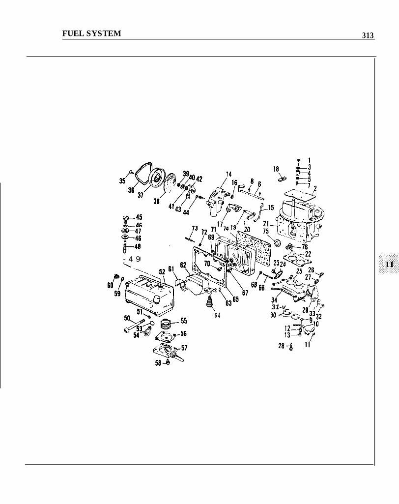
Refer to Figure 42 for this procedure. Not all2300-C or 63 17- 1 carburetors will use all the partsshown in Figure 42.
042
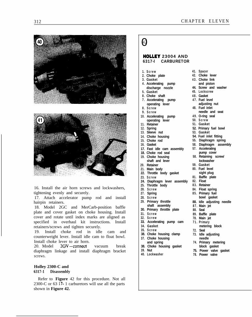
HOLLEY 23004 AND6317-l CARBURETOR
1. S c r e w 41. Spacer2. Choke plate 42. Choke lever3 . Gasket 4 3 . Choke link4 . Accelerating pump and piston
discharge nozzle 44. Screw and washer5 . Gasket 45. Lockscrew8 . Choke shaft 4 8 . Gasket7 . Accelerating pump 4 7 . Fuel level
operating lever adjusting nut8 . S c r e w 48. Fuel inlet9 . S c r e w needle and seat
10. Accelerating pump 4 9 . O-ring sealoperating lever 50. S c r e w
11. Retainer 51. Gasket12. Spring 52. Primary fuel bowl13. Sleeve nut 53. Gasket14. Choke housing 54. Fuel inlet fitting15. Choke rod 55. Diaphragm spring16. Gasket 58. Diaphragm assembly17. Fast idle cam assembly 57. Accelerating18. Choke rod seal pump cover19. Choke housing 58. Retaining screw/
shaft and lever lockwasher20. Retainer 59. Gasket21. Main body 80. Fuel level22. Throttle body gasket sight plug23. S c r e w 81. Baffle plate24. Diaphragm lever assembly 82. Float25. Throttle body 8 3 . Retainer28. S c r e w 84. Float spring27. Spring 8 5 . Primary fuel28. S c r e w bowl gasket29. Primary throttle 88. Idle adjusting needle
shaft assembly 8 7 . Main jet30. Primary throttle plate 88. Seal31. S c r e w 89. Baffle plate32. S c r e w 78. Main jet33. Accelerating pump cam 7 1 . Primary34. Gasket metering block35. S c r e w 72. Seal38. Choke housing clamp 73. Idle adjusting37. Choke housing needle
and spring 74. Primary metering38. Choke housing gasket block gasket39. Nut 75. Power valve gasket40. Lockwasher 78. Power valve
FUEL SYSTEM 313
@--4i
- 4 9\ .._
‘61-- ti6
6 4- CL31-v ’ Pr30 cd?& *‘.33;,
rgloI*=
314 CHAPTER ELEVEN
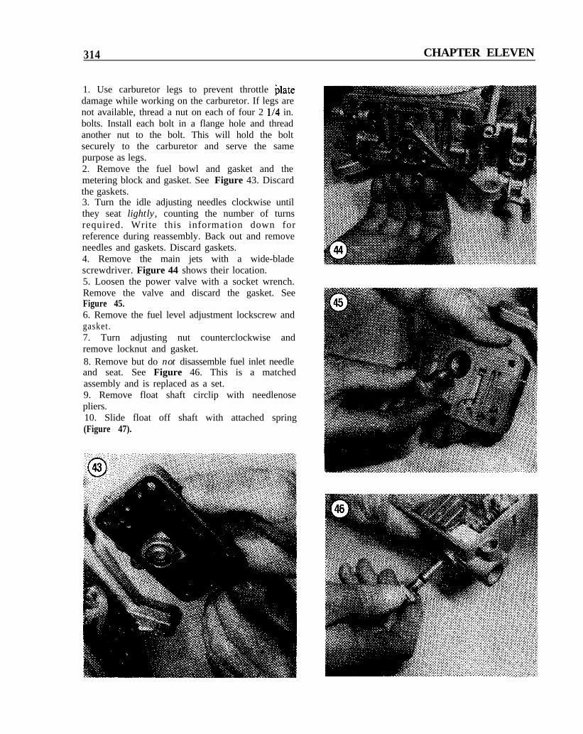
1. Use carburetor legs to prevent throttle platedamage while working on the carburetor. If legs arenot available, thread a nut on each of four 2 l/4 in.bolts. Install each bolt in a flange hole and threadanother nut to the bolt. This will hold the boltsecurely to the carburetor and serve the samepurpose as legs.2. Remove the fuel bowl and gasket and themetering block and gasket. See Figure 43. Discardthe gaskets.3. Turn the idle adjusting needles clockwise untilthey seat lightly, counting the number of turnsrequired. Write this information down forreference during reassembly. Back out and removeneedles and gaskets. Discard gaskets.4. Remove the main jets with a wide-bladescrewdriver. Figure 44 shows their location.5. Loosen the power valve with a socket wrench.Remove the valve and discard the gasket. SeeFigure 45.6. Remove the fuel level adjustment lockscrew andgasket.7. Turn adjusting nut counterclockwise andremove locknut and gasket.8. Remove but do not disassemble fuel inlet needleand seat. See Figure 46. This is a matchedassembly and is replaced as a set.9. Remove float shaft circlip with needlenosepliers.10. Slide float off shaft with attached spring(Figure 47).
FUEL SYSTEM 315
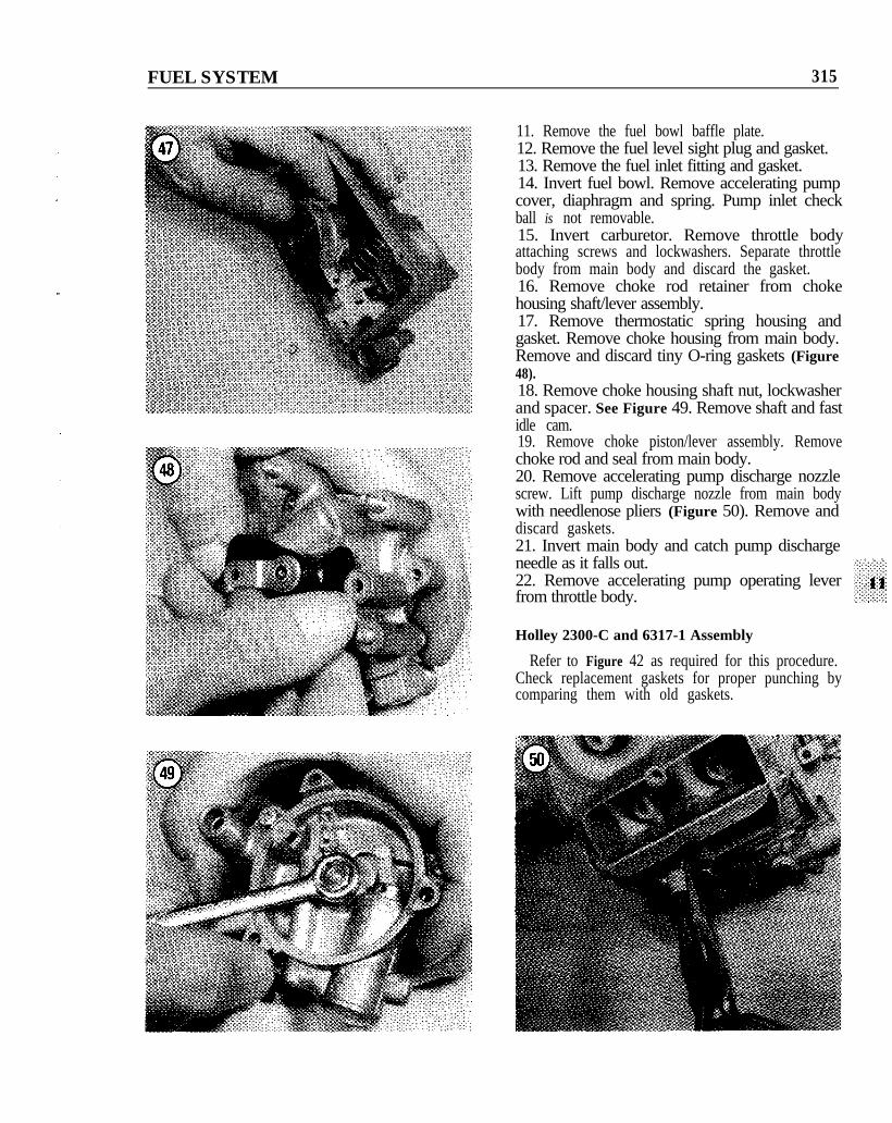
11. Remove the fuel bowl baffle plate.12. Remove the fuel level sight plug and gasket.13. Remove the fuel inlet fitting and gasket.14. Invert fuel bowl. Remove accelerating pumpcover, diaphragm and spring. Pump inlet checkball is not removable.15. Invert carburetor. Remove throttle bodyattaching screws and lockwashers. Separate throttlebody from main body and discard the gasket.16. Remove choke rod retainer from chokehousing shaft/lever assembly.17. Remove thermostatic spring housing andgasket. Remove choke housing from main body.Remove and discard tiny O-ring gaskets (Figure48).18. Remove choke housing shaft nut, lockwasherand spacer. See Figure 49. Remove shaft and fastidle cam.19. Remove choke piston/lever assembly. Removechoke rod and seal from main body.20. Remove accelerating pump discharge nozzlescrew. Lift pump discharge nozzle from main bodywith needlenose pliers (Figure 50). Remove anddiscard gaskets.21. Invert main body and catch pump dischargeneedle as it falls out.22. Remove accelerating pump operating leverfrom throttle body.
Holley 2300-C and 6317-1 Assembly
Refer to Figure 42 as required for this procedure.Check replacement gaskets for proper punching bycomparing them with old gaskets.
316 CHAPTER ELEVEN
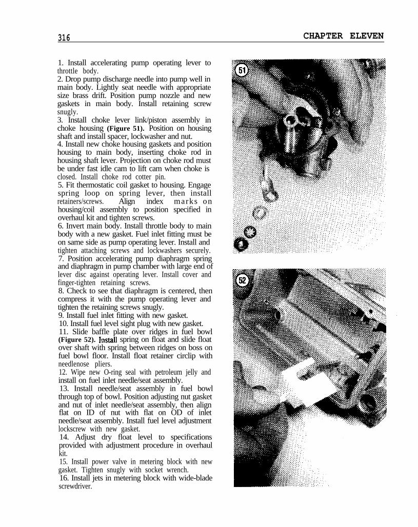
1. Install accelerating pump operating lever tothrottle body.2. Drop pump discharge needle into pump well inmain body. Lightly seat needle with appropriatesize brass drift. Position pump nozzle and newgaskets in main body. Install retaining screwsnugly.3. Install choke lever link/piston assembly inchoke housing (Figure 51). Position on housingshaft and install spacer, lockwasher and nut.4. Install new choke housing gaskets and positionhousing to main body, inserting choke rod inhousing shaft lever. Projection on choke rod mustbe under fast idle cam to lift cam when choke isclosed. Install choke rod cotter pin.5. Fit thermostatic coil gasket to housing. Engagespring loop on spring lever, then installretainers/screws. Align index marks onhousing/coil assembly to position specified inoverhaul kit and tighten screws.6. Invert main body. Install throttle body to mainbody with a new gasket. Fuel inlet fitting must beon same side as pump operating lever. Install andtighten attaching screws and lockwashers securely.7. Position accelerating pump diaphragm springand diaphragm in pump chamber with large end oflever disc against operating lever. Install cover andfinger-tighten retaining screws.8. Check to see that diaphragm is centered, thencompress it with the pump operating lever andtighten the retaining screws snugly.9. Install fuel inlet fitting with new gasket.10. Install fuel level sight plug with new gasket.11. Slide baffle plate over ridges in fuel bowl(Figure 52). Irrstall spring on float and slide floatover shaft with spring between ridges on boss onfuel bowl floor. Install float retainer circlip withneedlenose pliers.12. Wipe new O-ring seal with petroleum jelly andinstall on fuel inlet needle/seat assembly.13. Install needle/seat assembly in fuel bowlthrough top of bowl. Position adjusting nut gasketand nut of inlet needle/seat assembly, then alignflat on ID of nut with flat on OD of inletneedle/seat assembly. Install fuel level adjustmentlockscrew with new gasket.14. Adjust dry float level to specificationsprovided with adjustment procedure in overhaulkit.15. Install power valve in metering block with newgasket. Tighten snugly with socket wrench.16. Install jets in metering block with wide-bladescrewdriver.
FUEL SYSTEM 317
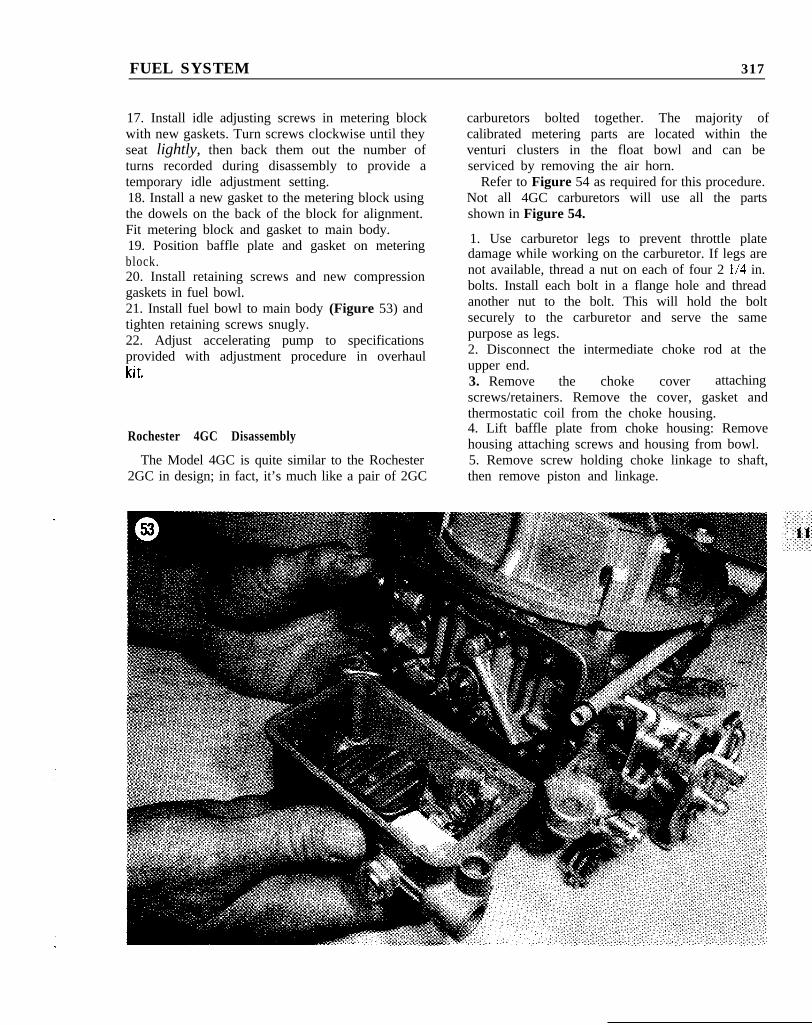
17. Install idle adjusting screws in metering block carburetors bolted together. The majority ofwith new gaskets. Turn screws clockwise until they calibrated metering parts are located within theseat lightly, then back them out the number of venturi clusters in the float bowl and can beturns recorded during disassembly to provide a serviced by removing the air horn.temporary idle adjustment setting. Refer to Figure 54 as required for this procedure.18. Install a new gasket to the metering block using Not all 4GC carburetors will use all the partsthe dowels on the back of the block for alignment. shown in Figure 54.Fit metering block and gasket to main body.19. Position baffle plate and gasket on meteringblock.20. Install retaining screws and new compressiongaskets in fuel bowl.21. Install fuel bowl to main body (Figure 53) andtighten retaining screws snugly.22. Adjust accelerating pump to specificationsprovided with adjustment procedure in overhaullA+
1. Use carburetor legs to prevent throttle platedamage while working on the carburetor. If legs are
3. Remove
not available, thread a nut on each of four 2 l/4 in.
the
bolts. Install each bolt in a flange hole and thread
choke
another nut to the bolt. This will hold the bolt
cover
securely to the carburetor and serve the same
attaching
purpose as legs.
screws/retainers. Remove the cover, gasket andthermostatic coil from the choke housing.
2. Disconnect the intermediate choke rod at theupper end.
hl L.
Rochester 4GC Disassembly 4. Lift baffle plate from choke housing: Removehousing attaching screws and housing from bowl.5. Remove screw holding choke linkage to shaft,then remove piston and linkage.
The Model 4GC is quite similar to the Rochester2GC in design; in fact, it’s much like a pair of 2GC
318 CHAPTER ELEVEN
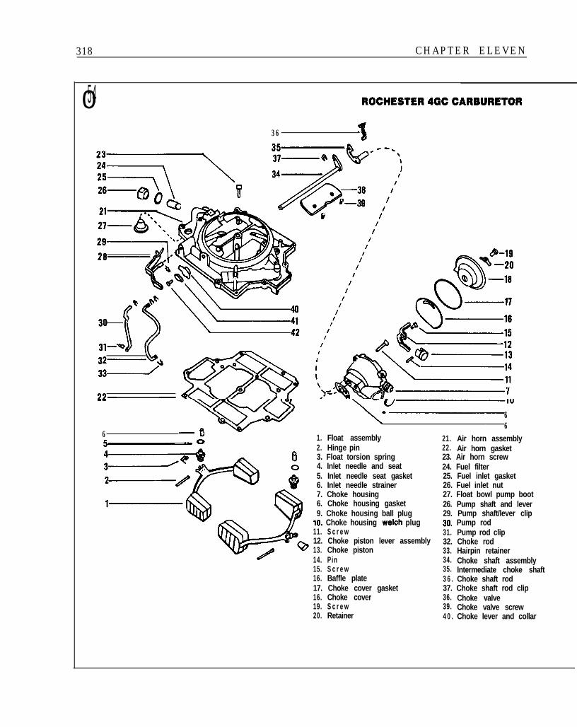
054 ROCHESTER4GCCARBURETOR
36
d
6
66
1. Float assembly 21. Air horn assembly2. Hinge pin 22. Air horn gasket3. Float torsion spring 23. Air horn screw4. Inlet needle and seat 24. Fuel filter5. Inlet needle seat gasket 25. Fuel inlet gasket6. Inlet needle strainer 26. Fuel inlet nut7. Choke housing 27. Float bowl pump boot6. Choke housing gasket 26. Pump shaft and lever9. Choke housing ball plug 29. Pump shaft/lever clip
IO. Choke housing Welch plug 30. Pump rod11. S c r e w 31. Pump rod clip12. Choke piston lever assembly 32. Choke rod13. Choke piston 33. Hairpin retainer14. Pin 34. Choke shaft assembly15. S c r e w 35. Intermediate choke shaft16. Baffle plate 3 6 . Choke shaft rod17. Choke cover gasket 37. Choke shaft rod clip16. Choke cover 36. Choke valve19. S c r e w 39. Choke valve screw20. Retainer 4 0 . Choke lever and collar
FUEL SYSTEM 319
78-0
84 l
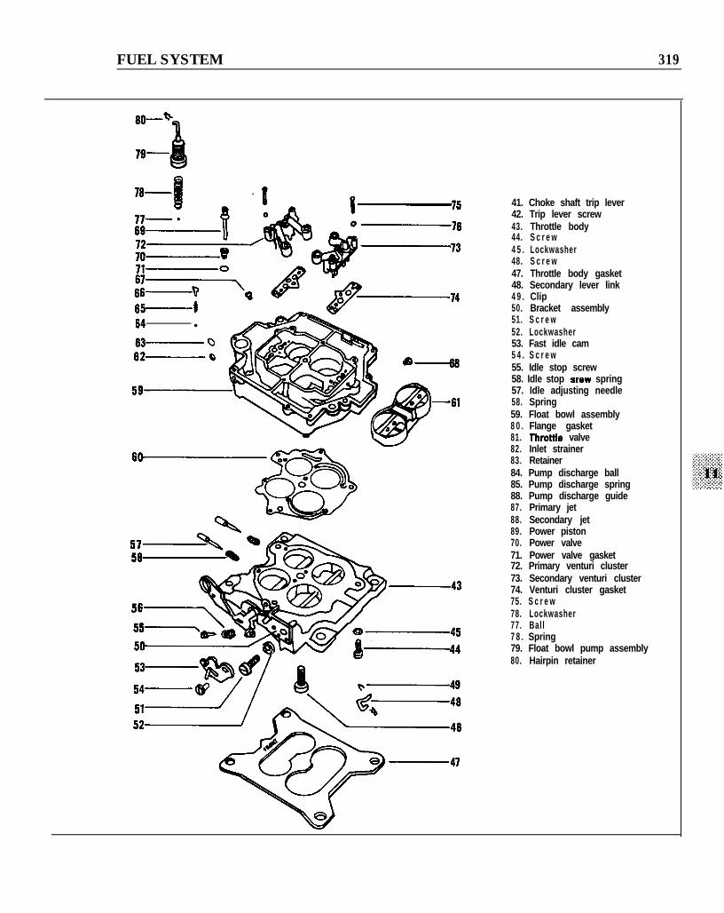
41. Choke shaft trip lever42. Trip lever screw43. Throttle body44. S c r e w4 5 . Lockwasher48. S c r e w47. Throttle body gasket48. Secondary lever link4 9 . Clip50. Bracket assembly51. S c r e w52. Lockwasher53. Fast idle cam5 4 . S c r e w55. Idle stop screw58. Idle stop srew spring57. Idle adjusting needle58. Spring59. Float bowl assembly8 0 . Flange gasket81. Throttle valve82. Inlet strainer83. Retainer84. Pump discharge ball85. Pump discharge spring88. Pump discharge guide87. Primary jet88. Secondary jet89. Power piston70. Power valve71. Power valve gasket72. Primary venturi cluster73. Secondary venturi cluster74. Venturi cluster gasket75. S c r e w78. Lockwasher77. Ball7 8 . Spring79. Float bowl pump assembly80. Hairpin retainer
320 CHAPTER ELEVEN
6. Unscrew and remove the fuel inlet fitting withscreen.7. Disconnect the spring clip at the upper end ofpump rod. Remove rod and clip from pump lever.8. Remove retainer screw holding trip lever tochoke shaft. Remove trip lever.9. Remove bowl cover attaching screws andcarefully lift bowl straight up and off main body toprevent damage to the float assemblies.10. Invert bowl cover on a clean workbenchsurface. Mark bowl cover casting and floatassemblies for identification during reassembly toassure that primary and secondary floats arereinstalled in their proper position.11. Remove the hinge pin and spring from onefloat. Remove the float and place to one side out ofthe way.12. Remove the float needle seat with a wide-bladescrewdriver. Remove seat gasket and strainer.Place to one side with the float removed in Step 11.13. Repeat Step 11 and Step 12 to remove theother float, needle seat, gasket and strainer.
NOTENeedle and seat are factory-matched and shouldnot be mixed during cleaning. If replacement isnecessary, replace needle and seat as a matchedpair.
14. Depress and release power piston, allowing itto snap free for removal. Remove power piston.15. Remove horseshoe clip from pump plungershaf t .16. Slide pump plunger through rubber seal andremove from bowl cover. Remove rubber seal.
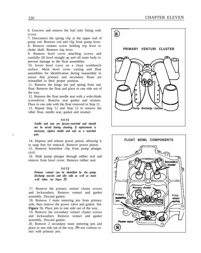
NOTEPrimary venturi can be identified by the pumpdischarge nozzles and idle tube as well as mainwell tubes. See Figure 55.
17. Remove the primary venturi cluster screwsand lockwashers. Remove venturi and gasketassembly. Discard gasket.18. Remove 2 main metering jets from primaryside, then remove the power valve and gasket. SeeFigure 56. Place jets to one side out of the way.19. Remove the secondary venturi cluster screwsand lockwashers. Remove venturi and gasketassembly. Discard gasket.20. Remove 2 secondary main metering jets andplace to one side out of the way. Do not confuse ormix with primary jets.
355
PRIMARY VENTURI CLUSTER
Pump discharge nozzle
FLOAT BOWL COMPONENTS
Primarymeterinjets \
Pump II
FUEL SYSTEM 321
PUMP SPRING GUIDE REMOVAL
Pump dischargespring guide
Pump bore. \ Auxiliary throttle
357
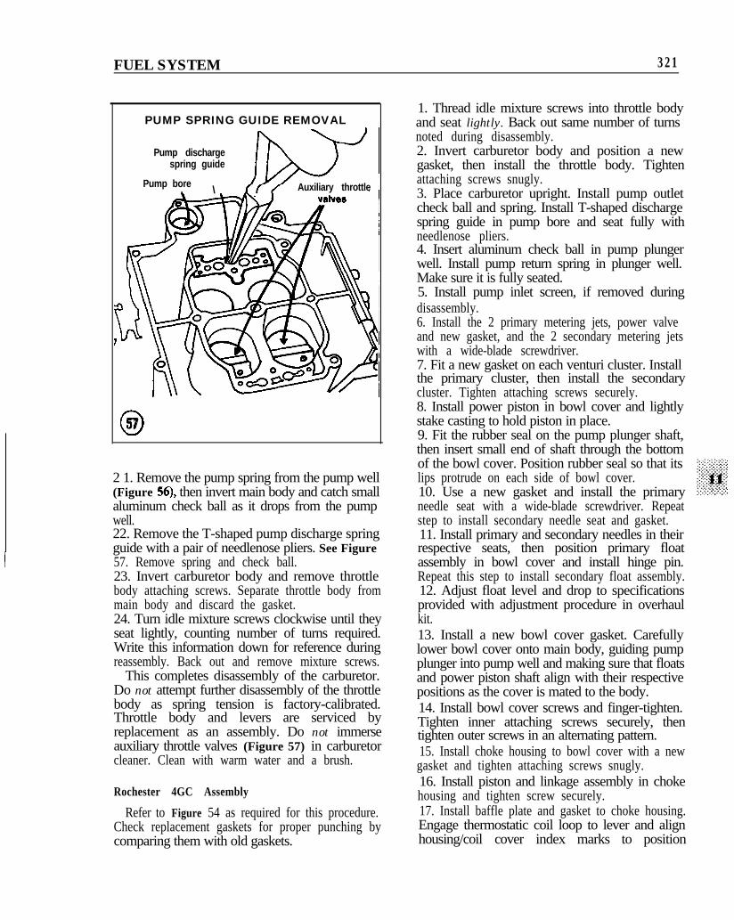
2 1. Remove the pump spring from the pump well(Figure 56), then invert main body and catch smallaluminum check ball as it drops from the pumpwell.22. Remove the T-shaped pump discharge springguide with a pair of needlenose pliers. See Figure57. Remove spring and check ball.23. Invert carburetor body and remove throttlebody attaching screws. Separate throttle body frommain body and discard the gasket.24. Turn idle mixture screws clockwise until theyseat lightly, counting number of turns required.Write this information down for reference duringreassembly. Back out and remove mixture screws.
This completes disassembly of the carburetor.Do not attempt further disassembly of the throttlebody as spring tension is factory-calibrated.Throttle body and levers are serviced byreplacement as an assembly. Do not immerseauxiliary throttle valves (Figure 57) in carburetorcleaner. Clean with warm water and a brush.
Rochester 4GC Assembly
Refer to Figure 54 as required for this procedure.Check replacement gaskets for proper punching bycomparing them with old gaskets.
1. Thread idle mixture screws into throttle bodyand seat lightly. Back out same number of turnsnoted during disassembly.2. Invert carburetor body and position a newgasket, then install the throttle body. Tightenattaching screws snugly.3. Place carburetor upright. Install pump outletcheck ball and spring. Install T-shaped dischargespring guide in pump bore and seat fully withneedlenose pliers.4. Insert aluminum check ball in pump plungerwell. Install pump return spring in plunger well.Make sure it is fully seated.5. Install pump inlet screen, if removed duringdisassembly.6. Install the 2 primary metering jets, power valveand new gasket, and the 2 secondary metering jetswith a wide-blade screwdriver.7. Fit a new gasket on each venturi cluster. Installthe primary cluster, then install the secondarycluster. Tighten attaching screws securely.8. Install power piston in bowl cover and lightlystake casting to hold piston in place.9. Fit the rubber seal on the pump plunger shaft,then insert small end of shaft through the bottomof the bowl cover. Position rubber seal so that itslips protrude on each side of bowl cover.10. Use a new gasket and install the primaryneedle seat with a wide-blade screwdriver. Repeatstep to install secondary needle seat and gasket.11. Install primary and secondary needles in theirrespective seats, then position primary floatassembly in bowl cover and install hinge pin.Repeat this step to install secondary float assembly.12. Adjust float level and drop to specificationsprovided with adjustment procedure in overhaulkit.13. Install a new bowl cover gasket. Carefullylower bowl cover onto main body, guiding pumpplunger into pump well and making sure that floatsand power piston shaft align with their respectivepositions as the cover is mated to the body.14. Install bowl cover screws and finger-tighten.Tighten inner attaching screws securely, thentighten outer screws in an alternating pattern.15. Install choke housing to bowl cover with a newgasket and tighten attaching screws snugly.16. Install piston and linkage assembly in chokehousing and tighten screw securely.17. Install baffle plate and gasket to choke housing.Engage thermostatic coil loop to lever and alignhousing/coil cover index marks to position
322 CHAPTERELEVEN
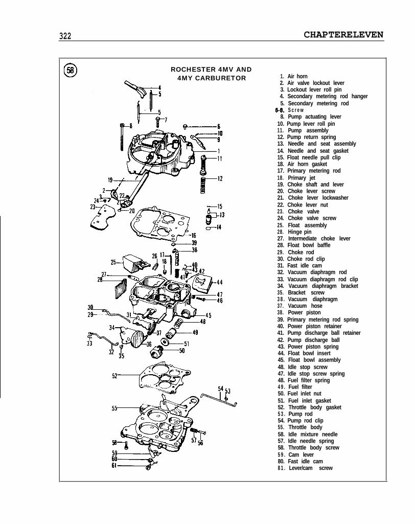
ROCHESTER 4MV AND4MY CARBURETOR 1. Air horn
2. Air valve lockout lever3. Lockout lever roll pin4. Secondary metering rod hanger5. Secondary metering rod
6-8. S c r e w8. Pump actuating lever
10. Pump lever roll pin11. Pump assembly12. Pump return spring13. Needle and seat assembly14. Needle and seat gasket15. Float needle pull clip18. Air horn gasket17. Primary metering rod18. Primary jet19. Choke shaft and lever20. Choke lever screw21. Choke lever lockwasher22. Choke lever nut23. Choke valve24. Choke valve screw25. Float assembly28. Hinge pin27. Intermediate choke lever28. Float bowl baffle29. Choke rod30. Choke rod clip31. Fast idle cam32. Vacuum diaphragm rod33. Vacuum diaphragm rod clip34. Vacuum diaphragm bracket35. Bracket screw3 8 . Vacuum diaphragm37. Vacuum hose38. Power piston39. Primary metering rod spring40. Power piston retainer41. Pump discharge ball retainer42. Pump discharge ball43. Power piston spring44. Float bowl insert45. Float bowl assembly48. Idle stop screw47. Idle stop screw spring48. Fuel filter spring4 9 . Fuel filter50. Fuel inlet nut51. Fuel inlet gasket52. Throttle body gasket5 3 . Pump rod54. Pump rod clip55. Throttle body58. Idle mixture needle57. Idle needle spring58. Throttle body screw5 9 . Cam lever80. Fast idle cam8 1 . Lever/cam screw
FUEL SYSTEM 323
specified in overhaul kit instructions. Install andtighten cover attaching retainers/screws.18. Install trip lever and connect intermediatechoke rod.19. Connect upper end of pump rod to pump leverwith spring clip.
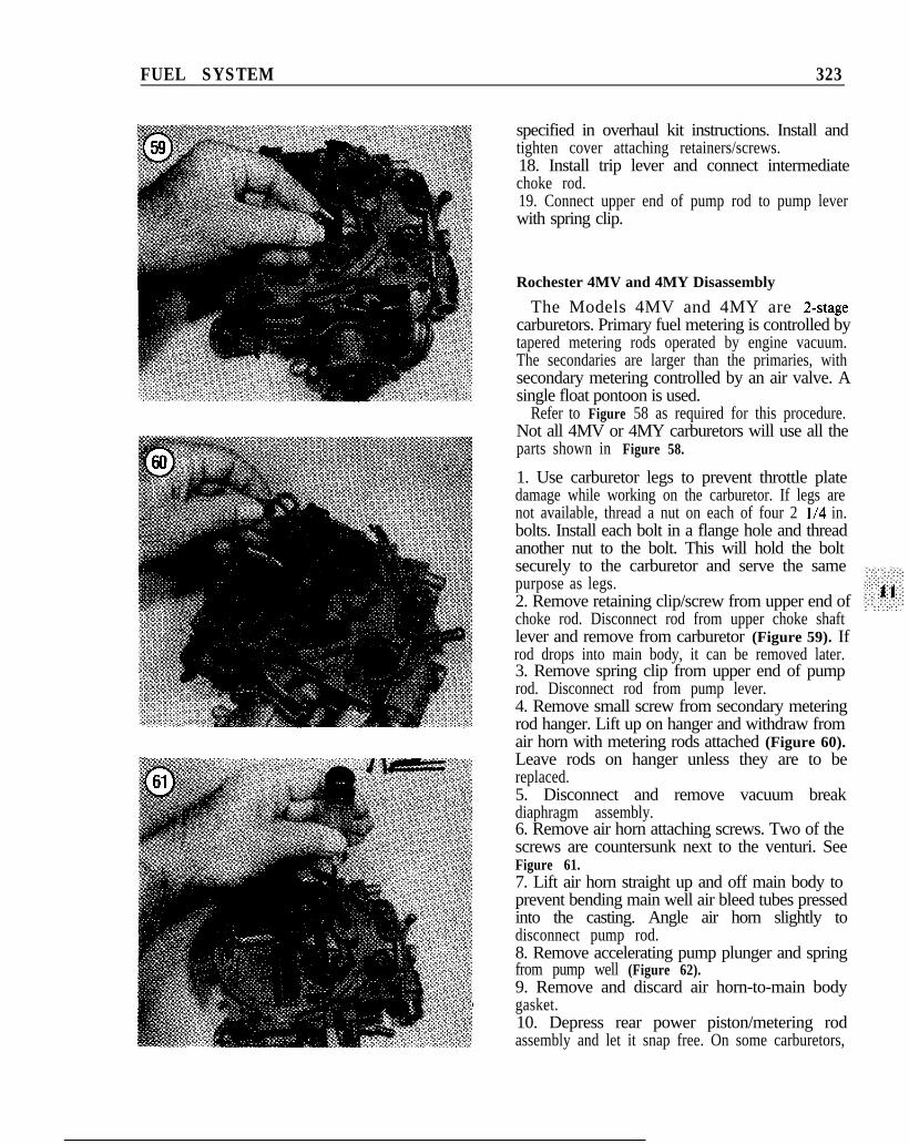
Rochester 4MV and 4MY Disassembly
The Models 4MV and 4MY are 2-stagecarburetors. Primary fuel metering is controlled bytapered metering rods operated by engine vacuum.The secondaries are larger than the primaries, withsecondary metering controlled by an air valve. Asingle float pontoon is used.
Refer to Figure 58 as required for this procedure.Not all 4MV or 4MY carburetors will use all theparts shown in Figure 58.
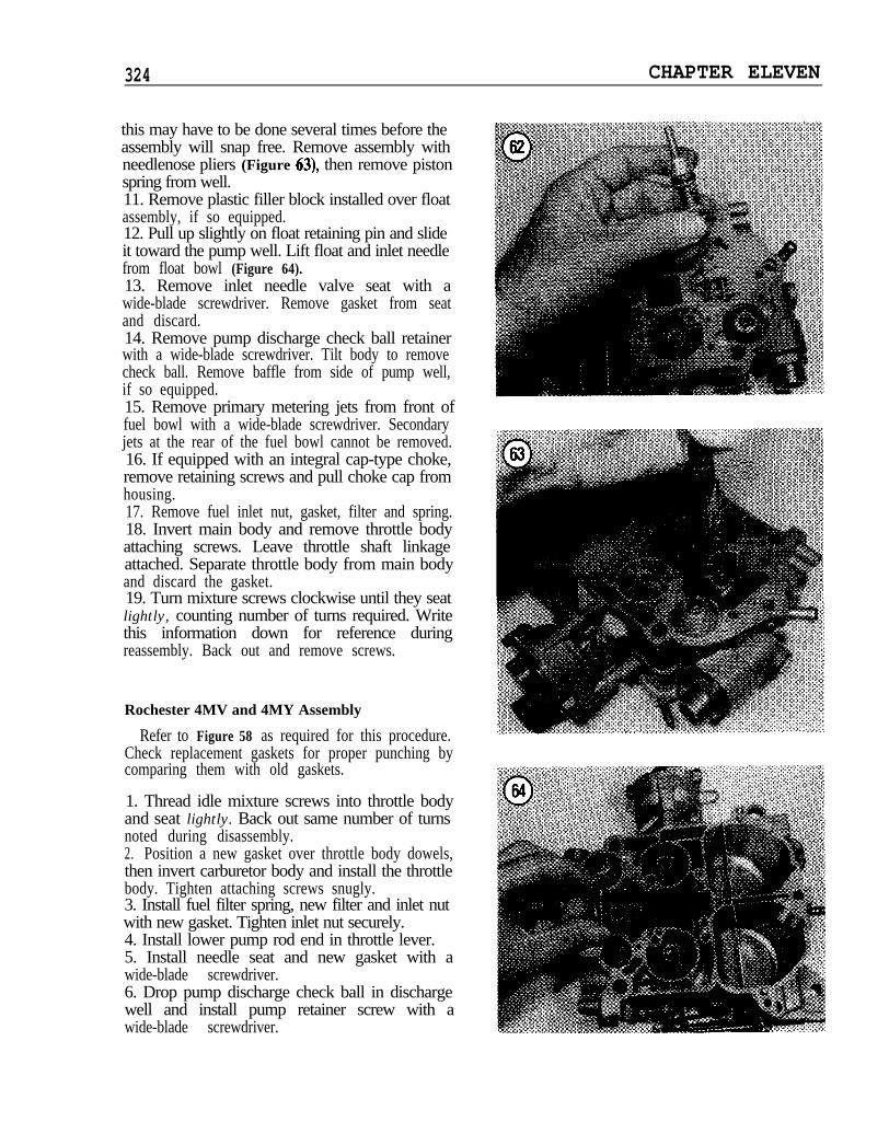
1. Use carburetor legs to prevent throttle platedamage while working on the carburetor. If legs arenot available, thread a nut on each of four 2 l/4 in.bolts. Install each bolt in a flange hole and threadanother nut to the bolt. This will hold the boltsecurely to the carburetor and serve the samepurpose as legs.2. Remove retaining clip/screw from upper end ofchoke rod. Disconnect rod from upper choke shaftlever and remove from carburetor (Figure 59). Ifrod drops into main body, it can be removed later.3. Remove spring clip from upper end of pumprod. Disconnect rod from pump lever.4. Remove small screw from secondary meteringrod hanger. Lift up on hanger and withdraw fromair horn with metering rods attached (Figure 60).Leave rods on hanger unless they are to bereplaced.5. Disconnect and remove vacuum breakdiaphragm assembly.6. Remove air horn attaching screws. Two of thescrews are countersunk next to the venturi. SeeFigure 61.7. Lift air horn straight up and off main body toprevent bending main well air bleed tubes pressedinto the casting. Angle air horn slightly todisconnect pump rod.8. Remove accelerating pump plunger and springfrom pump well (Figure 62).9. Remove and discard air horn-to-main bodygasket.10. Depress rear power piston/metering rodassembly and let it snap free. On some carburetors,
324 CHAPTER ELEVEN
this may have to be done several times before theassembly will snap free. Remove assembly withneedlenose pliers (Figure 63), then remove pistonspring from well.11. Remove plastic filler block installed over floatassembly, if so equipped.12. Pull up slightly on float retaining pin and slideit toward the pump well. Lift float and inlet needlefrom float bowl (Figure 64).13. Remove inlet needle valve seat with awide-blade screwdriver. Remove gasket from seatand discard.14. Remove pump discharge check ball retainerwith a wide-blade screwdriver. Tilt body to removecheck ball. Remove baffle from side of pump well,if so equipped.15. Remove primary metering jets from front offuel bowl with a wide-blade screwdriver. Secondaryjets at the rear of the fuel bowl cannot be removed.16. If equipped with an integral cap-type choke,remove retaining screws and pull choke cap fromhousing.17. Remove fuel inlet nut, gasket, filter and spring.18. Invert main body and remove throttle bodyattaching screws. Leave throttle shaft linkageattached. Separate throttle body from main bodyand discard the gasket.19. Turn mixture screws clockwise until they seatlightly, counting number of turns required. Writethis information down for reference duringreassembly. Back out and remove screws.
Rochester 4MV and 4MY Assembly
Refer to Figure 58 as required for this procedure.Check replacement gaskets for proper punching bycomparing them with old gaskets.
1. Thread idle mixture screws into throttle bodyand seat lightly. Back out same number of turnsnoted during disassembly.2. Position a new gasket over throttle body dowels,then invert carburetor body and install the throttlebody. Tighten attaching screws snugly.3. Install fuel filter spring, new filter and inlet nutwith new gasket. Tighten inlet nut securely.4. Install lower pump rod end in throttle lever.5. Install needle seat and new gasket with awide-blade screwdriver.6. Drop pump discharge check ball in dischargewell and install pump retainer screw with awide-blade screwdriver.
FUEL SYSTEM 325
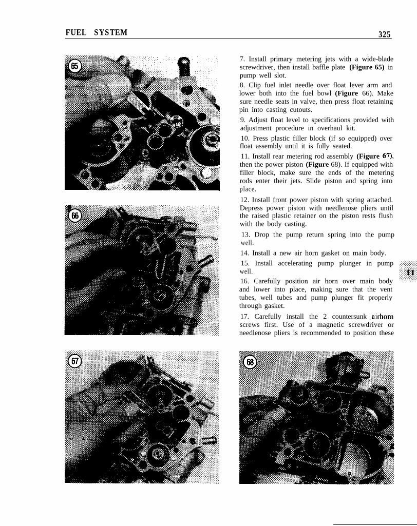
7. Install primary metering jets with a wide-bladescrewdriver, then install baffle plate (Figure 65) inpump well slot.
8. Clip fuel inlet needle over float lever arm andlower both into the fuel bowl (Figure 66). Makesure needle seats in valve, then press float retainingpin into casting cutouts.
9. Adjust float level to specifications provided withadjustment procedure in overhaul kit.
10. Press plastic filler block (if so equipped) overfloat assembly until it is fully seated.
11. Install rear metering rod assembly (Figure 67),then the power piston (Figure 68). If equipped withfiller block, make sure the ends of the meteringrods enter their jets. Slide piston and spring intoplace.
12. Install front power piston with spring attached.Depress power piston with needlenose pliers untilthe raised plastic retainer on the piston rests flushwith the body casting.
13. Drop the pump return spring into the pumpwell.
14. Install a new air horn gasket on main body.
15. Install accelerating pump plunger in pumpwell.
16. Carefully position air horn over main bodyand lower into place, making sure that the venttubes, well tubes and pump plunger fit properlythrough gasket.
17. Carefully install the 2 countersunk airhornscrews first. Use of a magnetic screwdriver orneedlenose pliers is recommended to position these
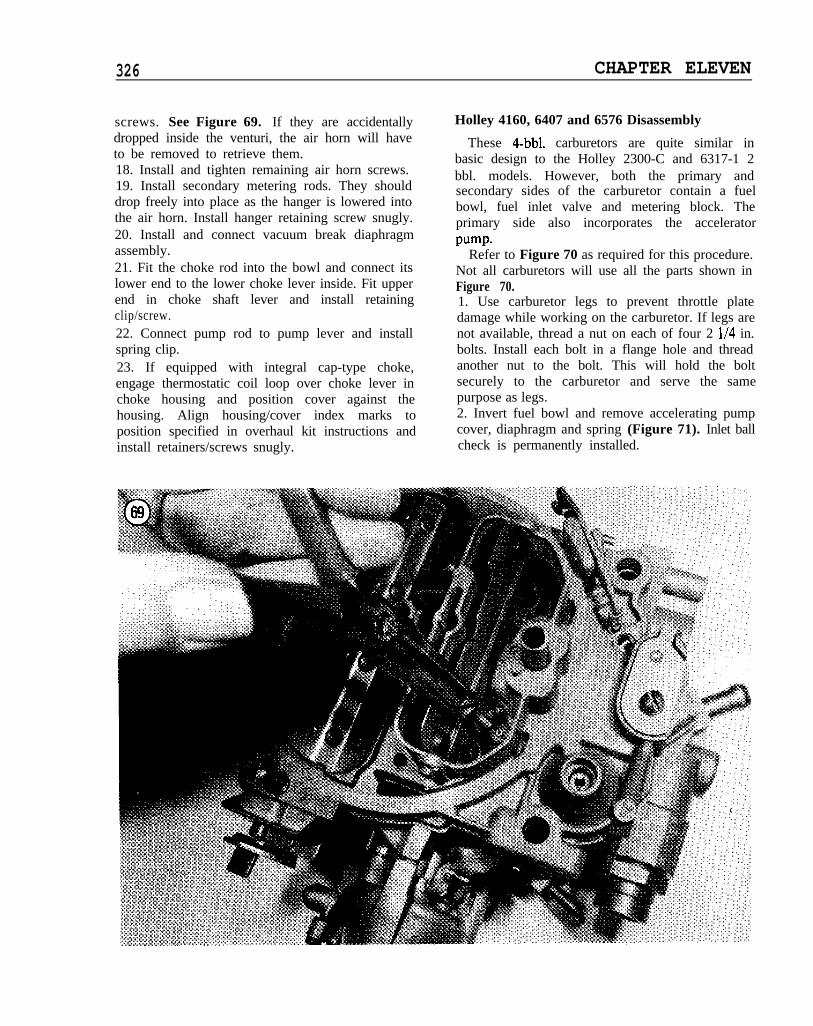
326 CHAPTER ELEVEN
screws. See Figure 69. If they are accidentallydropped inside the venturi, the air horn will haveto be removed to retrieve them.18. Install and tighten remaining air horn screws.19. Install secondary metering rods. They shoulddrop freely into place as the hanger is lowered intothe air horn. Install hanger retaining screw snugly.20. Install and connect vacuum break diaphragmassembly.21. Fit the choke rod into the bowl and connect itslower end to the lower choke lever inside. Fit upperend in choke shaft lever and install retainingclip/screw.22. Connect pump rod to pump lever and installspring clip.23. If equipped with integral cap-type choke,engage thermostatic coil loop over choke lever inchoke housing and position cover against thehousing. Align housing/cover index marks toposition specified in overhaul kit instructions andinstall retainers/screws snugly.
Holley 4160, 6407 and 6576 Disassembly
These 4-bbl. carburetors are quite similar inbasic design to the Holley 2300-C and 6317-1 2bbl. models. However, both the primary andsecondary sides of the carburetor contain a fuelbowl, fuel inlet valve and metering block. Theprimary side also incorporates the acceleratorpump.
Refer to Figure 70 as required for this procedure.Not all carburetors will use all the parts shown inFigure 70.1. Use carburetor legs to prevent throttle platedamage while working on the carburetor. If legs arenot available, thread a nut on each of four 2 l/4 in.bolts. Install each bolt in a flange hole and threadanother nut to the bolt. This will hold the boltsecurely to the carburetor and serve the samepurpose as legs.2. Invert fuel bowl and remove accelerating pumpcover, diaphragm and spring (Figure 71). Inlet ballcheck is permanently installed.
FUEL SYSTEM 327
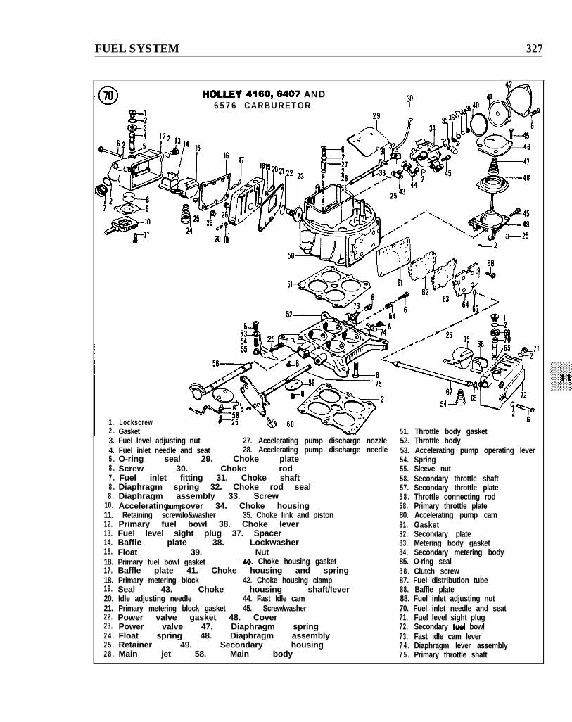
HOLLEY 4160,6407 AND6576 CARBURETOR
1. Lockscrew2 . Gasket 51. Throttle body gasket3. Fuel level adjusting nut 27. Accelerating pump discharge nozzle 52. Throttle body4. Fuel inlet needle and seat 28. Accelerating pump discharge needle 53. Accelerating pump operating lever5 . O-ring seal 29. Choke plate 54. Spring8 . Screw 30. Choke rod 55. Sleeve nut7 . Fuel inlet fitting 31. Choke shaft 58. Secondary throttle shaft8 . Diaphragm spring 32. Choke rod seal 57. Secondary throttle plate8 . Diaphragm assembly 33. Screw 5 8 . Throttle connecting rod
10. Accelerating cover 34. Choke housingpump 58. Primary throttle plate11. Retaining screw/lo&washer 35. Choke link and piston 80. Accelerating pump cam12. Primary fuel bowl 38. Choke lever 81. Gasket13. Fuel level sight plug 37. Spacer 82. Secondary plate14. Baffle plate 38. Lockwasher 83. Metering body gasket15. Float 39. Nut 84. Secondary metering body18. Primary fuel bowl gasket ,40. Choke housing gasket 85. O-ring seal17. Baffle plate 41. Choke housing and spring 8 8 . Clutch screw18. Primary metering block 42. Choke housing clamp 87. Fuel distribution tube19. Seal 43. Choke housing shaft/lever 88. Baffle plate20. Idle adjusting needle 44. Fast Idle cam 88. Fuel inlet adjusting nut21. Primary metering block gasket 45. Screw/washer 70. Fuel inlet needle and seat22. Power valve gasket 48. Cover 71. Fuel level sight plug23. Power valve 47. Diaphragm spring 72. Secondary fuel bowl2 4 . Float spring 48. Diaphragm assembly 73. Fast idle cam lever2 5 . Retainer 49. Secondary housing 7 4 . Diaphragm lever assembly2 8 . Main jet 58. Main body 7 5 . Primary throttle shaft
328 CHAPTER ELEVEN
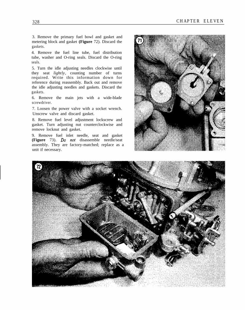
3. Remove the primary fuel bowl and gasket andmetering block and gasket (Figure 72). Discard thegaskets.
4. Remove the fuel line tube, fuel distributiontube, washer and O-ring seals. Discard the O-ringseals.
5. Turn the idle adjusting needles clockwise untilthey seat lightly, counting number of turnsrequired. Write this information down forreference during reassembly. Back out and removethe idle adjusting needles and gaskets. Discard thegaskets.
6. Remove the main jets with a wide-bladescrewdriver.
7. Loosen the power valve with a socket wrench.Unscrew valve and discard gasket.
8. Remove fuel level adjustment lockscrew andgasket. Turn adjusting nut counterclockwise andremove locknut and gasket.
9. Remove fuel inlet needle, seat and gasket(Figure 73). Do not disassemble needle/seatassembly. They are factory-matched; replace as aunit if necessary.
FUEL SYSTEM 329
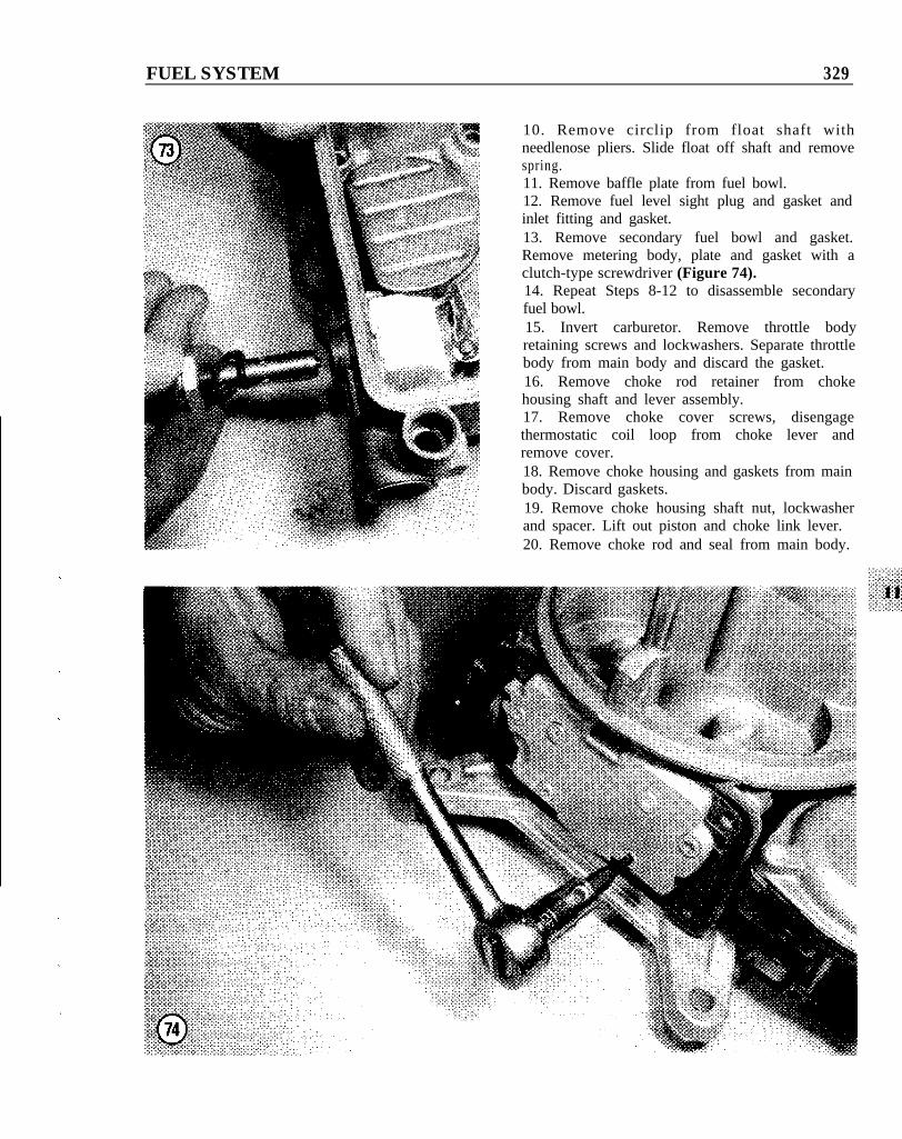
10. Remove circlip from float shaft withneedlenose pliers. Slide float off shaft and removespring.11. Remove baffle plate from fuel bowl.12. Remove fuel level sight plug and gasket andinlet fitting and gasket.13. Remove secondary fuel bowl and gasket.Remove metering body, plate and gasket with aclutch-type screwdriver (Figure 74).14. Repeat Steps 8-12 to disassemble secondaryfuel bowl.15. Invert carburetor. Remove throttle bodyretaining screws and lockwashers. Separate throttlebody from main body and discard the gasket.16. Remove choke rod retainer from chokehousing shaft and lever assembly.17. Remove choke cover screws, disengagethermostatic coil loop from choke lever andremove cover.18. Remove choke housing and gaskets from mainbody. Discard gaskets.19. Remove choke housing shaft nut, lockwasherand spacer. Lift out piston and choke link lever.20. Remove choke rod and seal from main body.
330 CHAPTER ELEVEN
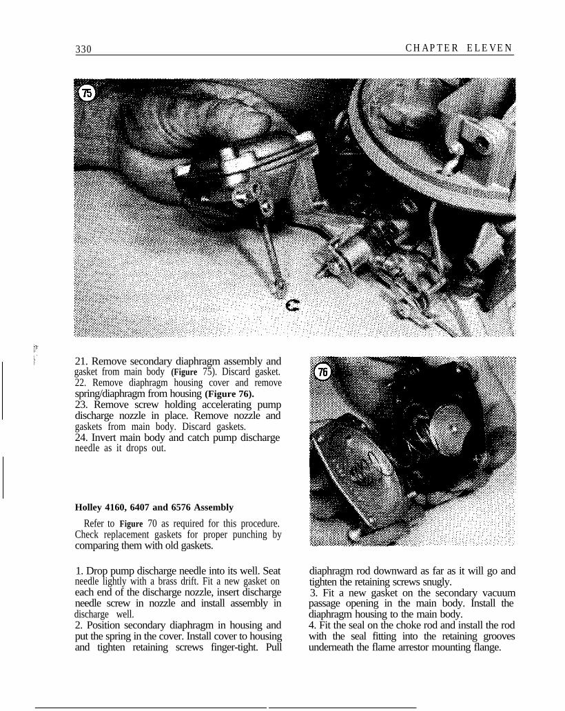
21. Remove secondary diaphragm assembly andgasket from main body (Figure 75). Discard gasket.22. Remove diaphragm housing cover and removespring/diaphragm from housing (Figure 76).23. Remove screw holding accelerating pumpdischarge nozzle in place. Remove nozzle andgaskets from main body. Discard gaskets.24. Invert main body and catch pump dischargeneedle as it drops out.
Holley 4160, 6407 and 6576 Assembly
Refer to Figure 70 as required for this procedure.Check replacement gaskets for proper punching bycomparing them with old gaskets.
1. Drop pump discharge needle into its well. Seatneedle lightly with a brass drift. Fit a new gasket oneach end of the discharge nozzle, insert dischargeneedle screw in nozzle and install assembly indischarge well.2. Position secondary diaphragm in housing andput the spring in the cover. Install cover to housingand tighten retaining screws finger-tight. Pull
diaphragm rod downward as far as it will go andtighten the retaining screws snugly.3. Fit a new gasket on the secondary vacuumpassage opening in the main body. Install thediaphragm housing to the main body.4. Fit the seal on the choke rod and install the rodwith the seal fitting into the retaining groovesunderneath the flame arrestor mounting flange.
FUEL SYSTEM 331
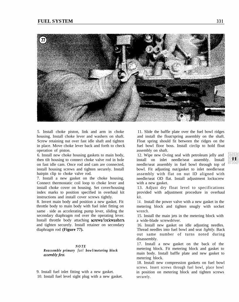
5. Install choke piston, link and arm in chokehousing. Install choke lever and washers on shaft.Screw retaining nut over fast idle shaft and tightenin place. Move choke lever back and forth to checkoperation of piston.6. Install new choke housing gaskets to main body,then tilt housing to connect choke valve rod in holeon fast idle cam. Once rod and cam are connected,install housing screws and tighten securely. Installhairpin clip to choke valve rod.7. Install a new gasket on the choke housing.Connect thermostatic coil loop to choke lever andinstall choke cover on housing. Set cover/housingindex marks to position specified in overhaul kitinstructions and install cover screws tightly.8. Invert main body and position a new gasket. Fitthrottle body to main body with fuel inlet fitting onsame I side as accelerating pump lever, sliding thesecondary diaphragm rod over the operating lever.Install throttle body attaching screws/lockwashersand tighten securely. Install retainer on secondarydiaphragm rod (Figure 77).
NOTEReassemble primary fuel bowl/metering blockassemblyjrst.
9. Install fuel inlet fitting with a new gasket.10. Install fuel level sight plug with a new gasket.
11. Slide the baffle plate over the fuel bowl ridgesand install the float/spring assembly on the shaft.Float spring should fit between the ridges on thefuel bowl floor boss. Install circlip to hold floatassembly on shaft.12. Wipe new O-ring seal with petroleum jelly andinstall on inlet needle/seat assembly. Installneedle/seat assembly in fuel bowl through top ofbowl. Fit adjusting nut/gasket to inlet needle/seatassembly with flat on nut ID aligned withneedle/seat OD flat. Install adjustment lockscrewwith a new gasket.13. Adjust dry float level to specificationsprovided with adjustment procedure in overhaulkit.1 4 . Install the power valve with a new gasket in themetering block and tighten snugly with socketwrench.15. Install the main jets in the metering block witha wide-blade screwdriver.16. Install new gasket on idle adjusting needles.Thread needles into fuel bowl and seat lightly. Backout same number of turns noted duringdisassembly.17. Install a new gasket on the back of themetering block. Fit metering block and gasket tomain body. Install baffle plate and new gasket tometering block.18. Install new compression gaskets on fuel bowlscrews. Insert screws through fuel bowl, place bowlin position on metering block and tighten screwssecurely.
332 CHAPTER ELEVEN
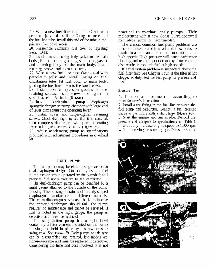
19. Wipe a new fuel distribution tube O-ring withpetroleum jelly and install the O-ring on one end ofthe fuel line tube. Install this end of the tube in theprimary fuel bowl recess.20. Reassemble secondary fuel bowl by repeatingSteps 10-13.21. Install a new metering body gasket to the mainbody., Fit the metering plate gasket, plate, gasketand metering body on the main body. Installretaining screws and tighten securely.22. Wipe a new fuel line tube O-ring seal withpetroleum jelly and install O-ring on fueldistribution tube. Fit fuel bowl to main body,guiding the fuel line tube into the bowl recess.23. Install new compression gaskets on theretaining screws. Install screws and tighten inseveral stages to 50 in.-lb. (6 Nam).24. Install accelerating pump diaphragmspring/diaphragm in pump chamber with large endof lever disc against the operating lever.25. Install cover and finger-tighten retainingscrews. Check diaphragm to see that it is centered,then compress diaphragm with pump operatinglever-and tighten screws securely (Figure 78).26. Adjust accelerating pump to specificationsprovided with adjustment procedures in overhaulkit.
FUEL PUMP
The fuel pump may be either a single-action ordual-diaphragm design. On both types, the fuelpump rocker arm is operated by the camshaft andprovides fuel under pressure to the carburetor.
The dual-diaphragm pump can be identified by asight gauge attached to the outside of the pumphousing. The housing contains 2 differently shapeddiaphragms manufactured of different materials.The extra diaphragm serves as a back-up in casethe primary diaphragm should fail. The pumprequires no maintenance and cannot be serviced. Iffuel is noted in the sight gauge, the pump isdefective and must be replaced.
The single-action pump has a sight bowlcontaining a filter element mounted on the pumphousing and held in place by a screw-pressureswing yoke. See Figure 79. Early pumps of this typecan be disassembled and repaired, late models arenon-serviceable and must be replaced if defective.Considering the time and cost involved, it is not
practical to overhaul early pumps. Theirreplacement with a new Coast Guard-approvedmarine-type pump is recommended.
The 2 most common fuel pump problems areincorrect pressure and low volume. Low pressureresults in a too-lean mixture and too little fuel athigh speeds. High pressure will cause carburetorflooding and result in poor economy. Low volumealso results in too little fuel at high speeds.
If a fuel system problem is suspected, check thefuel filter first. See Chapter Four. If the filter is notclogged or dirty, test the fuel pump for pressure andflow.
Pressure Test
1. Connect a tachometermanufacturer’s instructions.
according to
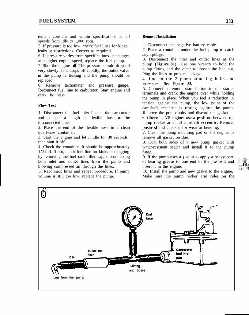
2. Install a tee fitting in the fuel line between thefuel pump and carburetor. Connect a fuel pressuregauge to the fitting with a short hose (Figure SO).3. Start the engine and run at idle. Record thepressure and compare to specifications in Table 1.4. Gradually increase engine speed to 1,000 rpmwhile observing pressure gauge. Pressure should
FUEL SYSTEM 333
remain constant and within specifications at allspeeds from idle to 1,000 rpm.5. If pressure is too low, check fuel lines for kinks,leaks or restrictions. Correct as required.6. If pressure varies from specifications or changesat a higher engine speed, replace the fuel pump.7. Shut the engine off The pressure should drop offvery slowly. If it drops off rapidly, the outlet valvein the pump is leaking and the pump should bereplaced.8. Remove tachometer and pressure gauge.Reconnect fuel line to carburetor. Start engine andcheck for leaks.
Flow Test
1. Disconnect the fuel inlet line at the carburetorand connect a length of flexible hose to thedisconnected line.2. Place the end of the flexible hose in a cleanquart-size container.3. Start the engine and let it idle for 30 seconds,then shut it off.4. Check the container. It should be approximatelyl/2 full. If not, check fuel line for kinks or cloggingby removing the fuel tank filler cap, disconnectingboth inlet and outlet lines from the pump andblowing compressed air through the lines.5. Reconnect lines and repeat procedure. If pumpvolume is still too low, replace the pump.
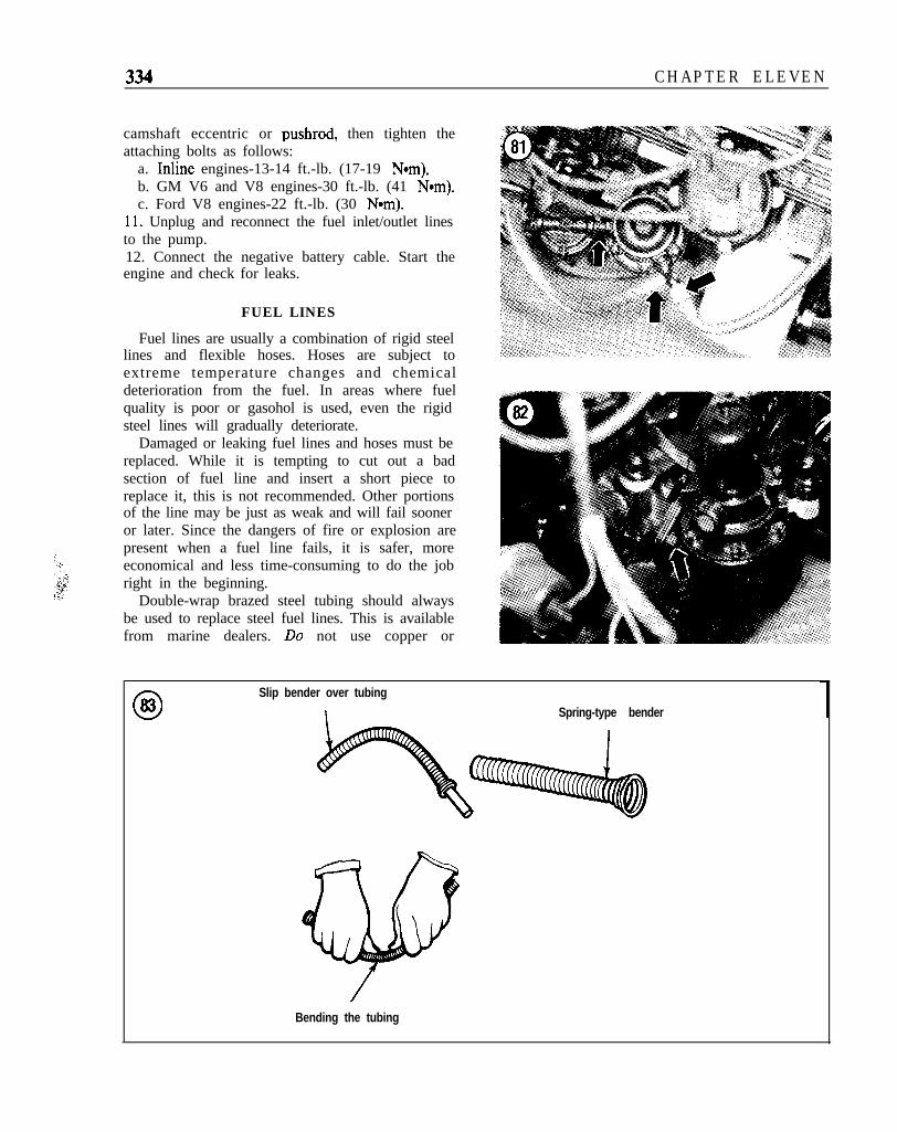
Removal/Installation
1. Disconnect the negative battery cable.2. Place a container under the fuel pump to catchany spillage.3. Disconnect the inlet and outlet lines at thepump (Figure 81). Use one wrench to hold thepump fitting and the other to loosen the line nut.Plug the lines to prevent leakage.4. Loosen the 2 pump attaching bolts andlockwashers. See Figure 82.5. Connect a remote start button to the starterterminals and crank the engine over while holdingthe pump in place. When you feel a reduction intension against the pump, the low point of thecamshaft eccentric is resting against the pump.Remove the pump bolts and discard the gasket.6. Chevrolet V8 engines use a pushrod between thepump rocker arm and camshaft eccentric. Removepushrod and check it for wear or bending.7. Clean the pump mounting pad on the engine toremove all gasket residue.8. Coat both sides of a new pump gasket withwater-resistant sealer and install it to the pumpflange.9. If the pump uses a pushrod, apply a heavy coatof bearing grease to one end of the pushrod andinsert it in the engine.10. Install the pump and new gasket to the engine.Make sure the pump rocker arm rides on the
080
In-line fuelfilter a
Hose - -’
c T-fittingand hoses
Line from fuel pump
CHAPTER ELEVEN
camshaft eccentric or pushrod, then tighten theattaching bolts as follows:
a. Inline engines-13-14 ft.-lb. (17-19 Nom).b. GM V6 and V8 engines-30 ft.-lb. (41 Nom).c. Ford V8 engines-22 ft.-lb. (30 N-m).
Il. Unplug and reconnect the fuel inlet/outlet linesto the pump.12. Connect the negative battery cable. Start theengine and check for leaks.
FUEL LINES
Fuel lines are usually a combination of rigid steellines and flexible hoses. Hoses are subject toextreme temperature changes and chemicaldeterioration from the fuel. In areas where fuelquality is poor or gasohol is used, even the rigidsteel lines will gradually deteriorate.
Damaged or leaking fuel lines and hoses must bereplaced. While it is tempting to cut out a badsection of fuel line and insert a short piece toreplace it, this is not recommended. Other portionsof the line may be just as weak and will fail sooneror later. Since the dangers of fire or explosion arepresent when a fuel line fails, it is safer, moreeconomical and less time-consuming to do the jobright in the beginning.
Double-wrap brazed steel tubing should alwaysbe used to replace steel fuel lines. This is availablefrom marine dealers. Do not use copper or
Slip bender over tubing
I Spring-type bender
Bending the tubing
FUEL SYSTEM 335
aluminum tubing as neither will withstand normal 2. Disconnect the negative battery cable.engine and boat vibration. Rubber hose made 3. Remove the damaged or deteriorated fuel line.specifically for fuel systems should be used. Other 4. Slip a spring-type tubing bender over the tubinghose materials are not formulated to withstand and carefully bend to match the old line. See Figurechemical deterioration from gasoline. 83.
To temporarily replace a fuel line, carry a lengthof fuel line hose, several worm-screw clamps and atubing cutter with you. If it is necessary to makeon-the-spot repairs, the damaged section of linecan be cut out and replaced by a piece of fuel hosesecured at each end with a clamp. This temporaryrepair should be replaced at the first availableopportunity.1. Obtain a suitable length of steel fuel line of the
5. Remove the fittings, if any, from the old lineand install on the new line.
engine and check for leaks.
6. Use a flaring tool to make a double lap flare oneach end of the line. See Figure 84. This willprovide a good seal and prevent the flare fromcracking.7. Install the new line and tighten the fittingssecurely.8. Reconnect the negative battery cable. Start the
correct diameter.
084
Flaring bar
/AI Flaring tool
The double lap flare
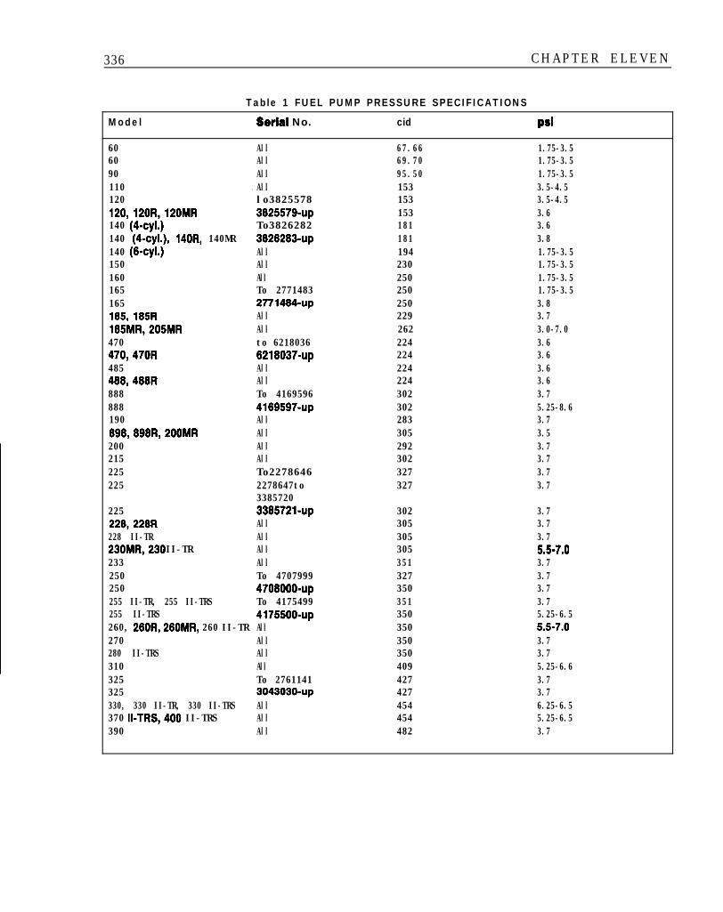
336 CHAPTER ELEVEN
Table 1 FUEL PUMP PRESSURE SPECIFICATIONS
Model Serial No.
60 All60 All90 All110 All.120 lo3825578120,120R,120MR 3826579-up140 (4-cyl.) To3826282140 (4-cyl.), 140R, 140MR 3826283~up140 (6~~1.) All150 All160 All165 To 2771483165 2771484~up185,185R All185MR,205MR All470 to 6218036470,470R 6218037-up485 All488,488R All888 To 4169596888 4169597~up190 All898,898R,200MR All200 All215 All225 To2278646225 2278647to
3385720225 338572%~~228,228R All228 II-TR All230MR,230 II-TR All233 All250 To 4707999250 4708000-up255 II-TR, 255 II-TRS To 4175499255 II-TRS 4175500~up260, 260R, 260MR, 260 II-TR All270 All280 II-TRS All310 All325 To 2761141325 3043030~up330, 330 II-TR, 330 II-TRS All370 II-TRS,400 II-TRS All390 All
cid Psi
67.66 1.75-3.569.70 1.75-3.595.50 1.75-3.5153 3.5-4.5153 3.5-4.5153 3.6181 3.6181 3.8194 1.75-3.5230 1.75-3.5250 1.75-3.5250 1.75-3.5250 3.8229 3.7262 3.0-7.0224 3.6224 3.6224 3.6224 3.6302 3.7302 5.25-8.6283 3.7305 3.5292 3.7302 3.7327 3.7327 3.7
302 3.7305 3.7305 3.7305 5.5-7.0351 3.7327 3.7350 3.7351 3.7350 5.25-6.5350 5.6-7.0350 3.7350 3.7409 5.25-6.6427 3.7427 3.7454 6.25-6.5454 5.25-6.5482 3.7