Embed Size (px)
Citation preview
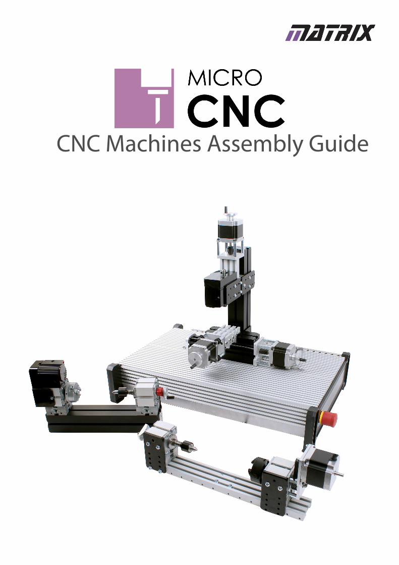
CNC Machines Assembly Guide
2 Copyright © 2017 Matrix TSL
Contents
Warnings 3
General Safety 3
Emergency Stop Restart Procedure 3
Before you start 4
Matrix Micro CNC Kits & Machines Modules 4
Assembly Notes 5
Small and Large Retaining Bars 5
Inserting Connection Pieces into Module T-Slots 5
2-axis Micro CNC Lathe (CN2668) Assembly 6
Parts required: 6
Step 1 – Attach Cross Slide Module to Base Plate 6
Step 2 – Attach Lathe Module to Base Plate 7
Step 3 – Attach Live Centre & Tool Post 7
Step 4 – Lathe Pre-use Adjustments 8
3 axis Micro CNC Milling Machine (CN4234) Assembly 10
Parts Required: 10
Step 1 – Attach Cross Slide Module to Base Plate 10
Step 2 – Assemble the Vertical Mill Module 11
Step 3 – Attach Vertical Mill Module to Base Plate 12
Step 4 – Attach the Vice 13
Step 5 – Attach Cutting Bit 13
Step 6 - 3 Axis Vertical Mill Pre-Use Adjustments 14
4 axis Micro CNC Milling Machine (CN8285) Assembly 16
Parts Required: 16
Step 1 – Attach Cross Slide Module to Base Plate 16
Step 2 – Assemble the Vertical Mill Module 17
Step 3 – Attach Vertical Mill Module to Base Plate 18
Step 4 – Reposition the Cutting Tool Head 19
Step 5 – Attach the 4-Axis Extended Bed Module 20
Step 6 – Attach Cutting Bit 21
Step 7 - 4 Axis Vertical Mill Pre-Use Adjustments 22
Adjusting the Cutting Tool Head Position 22
Adjusting the Length of the Extended Bed 24
Matrix MicroCNC - Getting Started 25
Introduction 25
Hardware Overview 25
Controller Base Plate 25
Platform Intel Face 25
Platform Emergency Stop 26
Machine Electrical Connections 27
2-Axis Lathe (CN2668) 27
3-Axis Milling Machine (CN4234) 28
4-Axis Milling Machine (CN8285) 29
Matrix MicroCNC Control Software 30
Connecting to a PC 30
Installing Drivers 30
Batch Files 32
Opening a Control Program 33
Control Software Overview 34
Basic Operations 35
Operate Motors 35
Lathe Setup Functions 36
Lathe Axis Movement Directions 36
Milling Machine Setup Functions 37
Milling Machines Axis Movement Directions 38
File Transfers 38
Navigate the ‘Windows’ and Linux Drives 39
Example Project 41
CAD Design to Dxf File - (Solidworks Example) 41
Generate G-Code using CAM Software (CAMBAM Example) 42
Import and Edit a Dxf File 42
Input Machining Parameters 43
Define Cutting Path 44
Generate Toolpaths 45
Produce G-Code 46
Transfer G-Code file to Linux 46
Lathe Control Program 47
Setup the Lathe 48
3 Copyright © 2017 Matrix TSL
Warnings
General safety
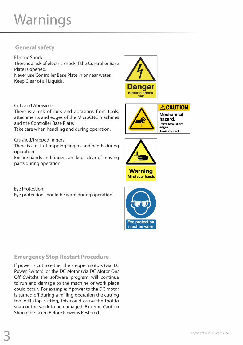
Electric Shock:There is a risk of electric shock if the Controller Base Plate is opened.Never use Controller Base Plate in or near water.Keep Clear of all Liquids.
Cuts and Abrasions:There is a risk of cuts and abrasions from tools, attachments and edges of the MicroCNC machines and the Controller Base Plate.Take care when handling and during operation.
Crushed/trapped fingers:There is a risk of trapping fingers and hands during operation.Ensure hands and fingers are kept clear of moving parts during operation.
Eye Protection:Eye protection should be worn during operation.
Emergency Stop Restart ProcedureIf power is cut to either the stepper motors (via IEC Power Switch), or the DC Motor (via DC Motor On/Off Switch) the software program will continue to run and damage to the machine or work piece could occur. For example: if power to the DC motor is turned off during a milling operation the cutting tool will stop cutting, this could cause the tool to snap or the work to be damaged. Extreme Caution Should be Taken Before Power is Restored.
4 Copyright © 2017 Matrix TSL
Before You Start
These instructions provide a step by step guide to assembling the Micro CNC Machines from prebuilt Modules, Micro CNC System Controller, and Accessory Packs.
Please Note: Matrix Supply four different Micro CNC Machine Kits, these are shown below. Each ‘Kit’ is made from a number of specific Modules & Accessories. Please refer to the Assembly Instructions for your ‘Kit’ as different kits do not include all the items listed below.
Matrix Micro CNC Kits & Machines Modules
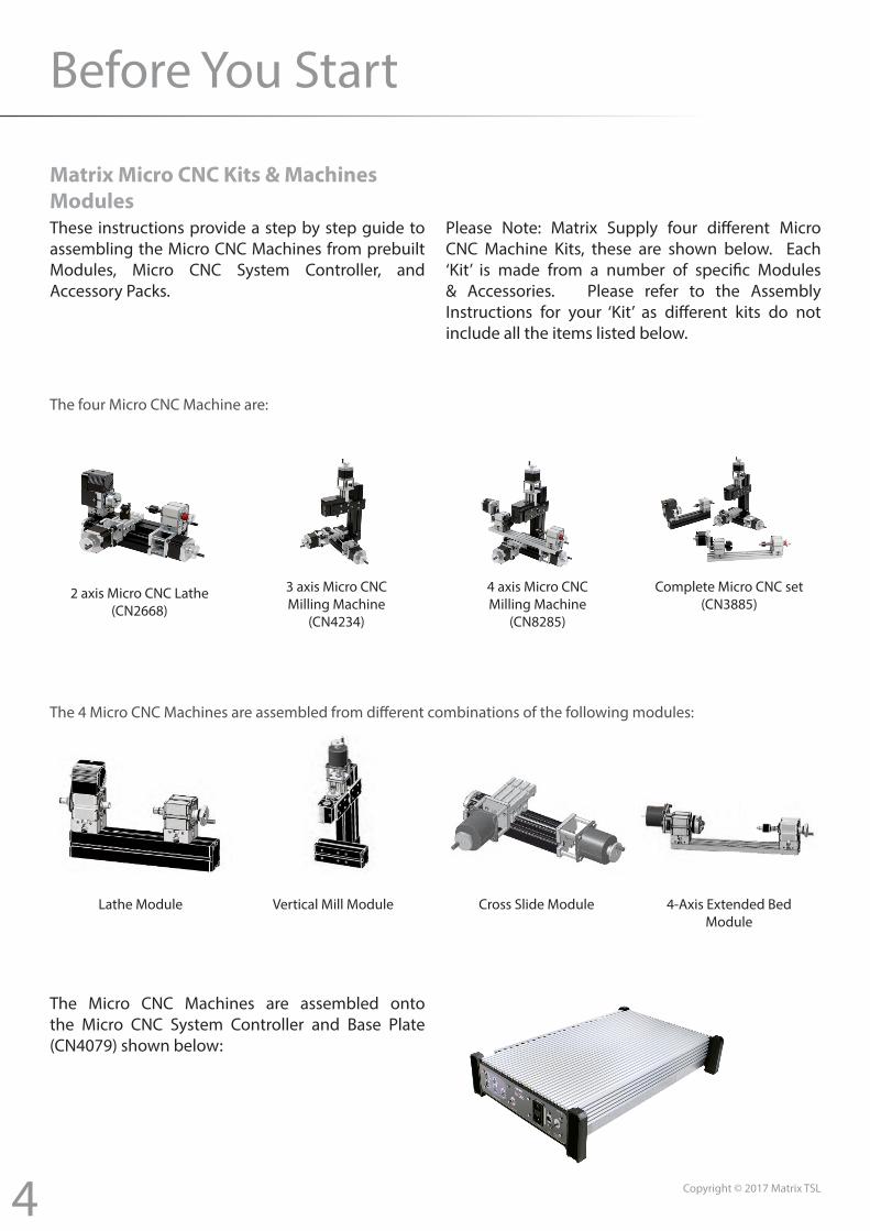
The four Micro CNC Machine are:
2 axis Micro CNC Lathe (CN2668)
3 axis Micro CNCMilling Machine
(CN4234)
4 axis Micro CNCMilling Machine
(CN8285)
Complete Micro CNC set(CN3885)
The 4 Micro CNC Machines are assembled from different combinations of the following modules:
Lathe Module Vertical Mill Module Cross Slide Module 4-Axis Extended BedModule
The Micro CNC Machines are assembled onto the Micro CNC System Controller and Base Plate (CN4079) shown below:
5
Assembly Notes:
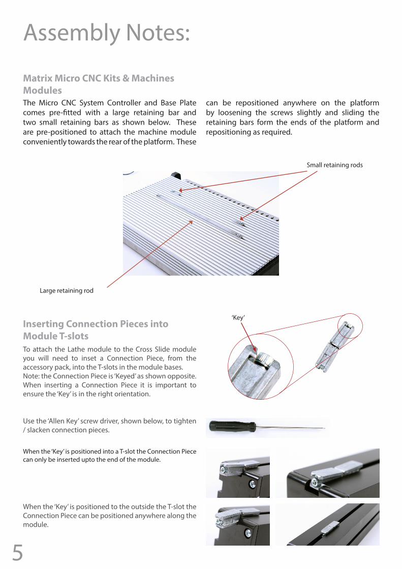
The Micro CNC System Controller and Base Plate comes pre-fitted with a large retaining bar and two small retaining bars as shown below. These are pre-positioned to attach the machine module conveniently towards the rear of the platform. These
can be repositioned anywhere on the platform by loosening the screws slightly and sliding the retaining bars form the ends of the platform and repositioning as required.
Matrix Micro CNC Kits & Machines Modules
Small retaining rods
Large retaining rod
Inserting Connection Pieces into Module T-slotsTo attach the Lathe module to the Cross Slide module you will need to inset a Connection Piece, from the accessory pack, into the T-slots in the module bases. Note: the Connection Piece is ‘Keyed’ as shown opposite. When inserting a Connection Piece it is important to ensure the ‘Key’ is in the right orientation.
When the ‘Key’ is positioned to the outside the T-slot the Connection Piece can be positioned anywhere along the module.
When the ‘Key’ is positioned into a T-slot the Connection Piece can only be inserted upto the end of the module.
‘Key’
Use the ‘Allen Key’ screw driver, shown below, to tighten / slacken connection pieces.
6 Copyright © 2017 Matrix TSL
2 axis Micro CNC Lathe (CN2668) Assembly
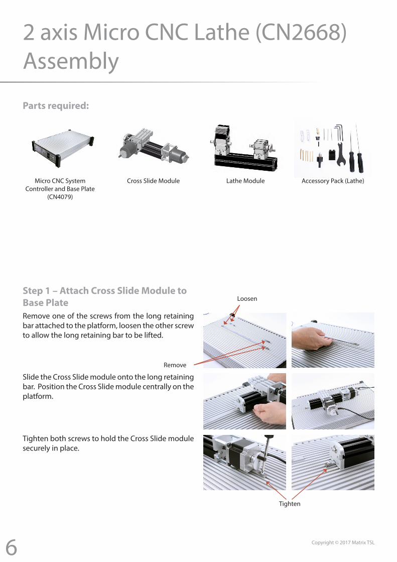
Parts required:
Micro CNC System Controller and Base Plate
(CN4079)
Cross Slide Module Lathe Module Accessory Pack (Lathe)
Step 1 – Attach Cross Slide Module to Base Plate
Tighten
Loosen
Remove
Remove one of the screws from the long retaining bar attached to the platform, loosen the other screw to allow the long retaining bar to be lifted.
Slide the Cross Slide module onto the long retaining bar. Position the Cross Slide module centrally on the platform.
Tighten both screws to hold the Cross Slide module securely in place.
7 Copyright © 2017 Matrix TSL
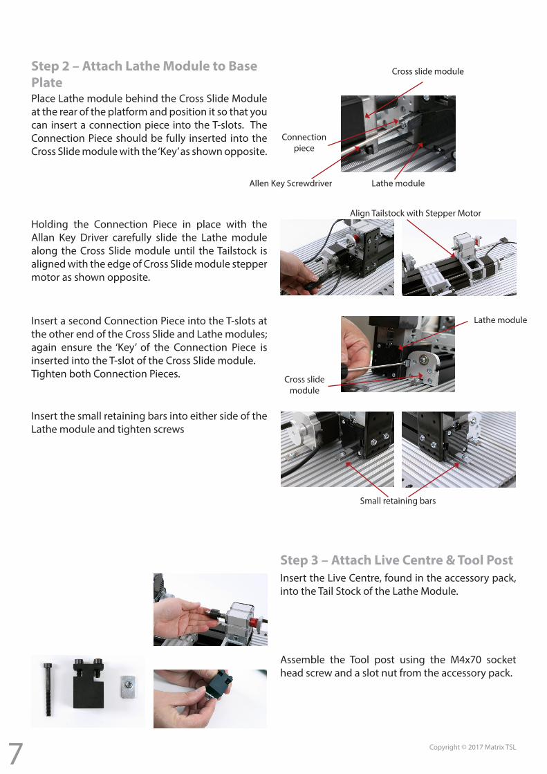
Step 2 – Attach Lathe Module to Base PlatePlace Lathe module behind the Cross Slide Module at the rear of the platform and position it so that you can insert a connection piece into the T-slots. The Connection Piece should be fully inserted into the Cross Slide module with the ‘Key’ as shown opposite.
Holding the Connection Piece in place with the Allan Key Driver carefully slide the Lathe module along the Cross Slide module until the Tailstock is aligned with the edge of Cross Slide module stepper motor as shown opposite.
Insert the small retaining bars into either side of the Lathe module and tighten screws
Step 3 – Attach Live Centre & Tool PostInsert the Live Centre, found in the accessory pack, into the Tail Stock of the Lathe Module.
Assemble the Tool post using the M4x70 socket head screw and a slot nut from the accessory pack.
Insert a second Connection Piece into the T-slots at the other end of the Cross Slide and Lathe modules; again ensure the ‘Key’ of the Connection Piece is inserted into the T-slot of the Cross Slide module.Tighten both Connection Pieces.
Cross slide module
Lathe module
Connection piece
Align Tailstock with Stepper Motor
Lathe module
Cross slide module
Small retaining bars
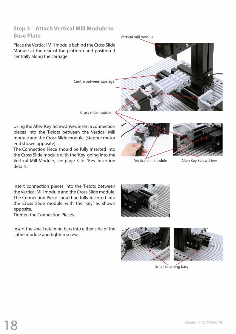
Allen Key Screwdriver
8 Copyright © 2017 Matrix TSL
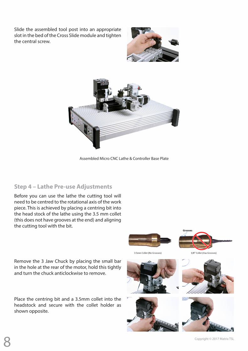
Slide the assembled tool post into an appropriate slot in the bed of the Cross Slide module and tighten the central screw.
Assembled Micro CNC Lathe & Controller Base Plate
Before you can use the lathe the cutting tool will need to be centred to the rotational axis of the work piece. This is achieved by placing a centring bit into the head stock of the lathe using the 3.5 mm collet (this does not have grooves at the end) and aligning the cutting tool with the bit.
Place the centring bit and a 3.5mm collet into the headstock and secure with the collet holder as shown opposite.
Step 4 – Lathe Pre-use Adjustments
Remove the 3 Jaw Chuck by placing the small bar in the hole at the rear of the motor, hold this tightly and turn the chuck anticlockwise to remove.
9 Copyright © 2017 Matrix TSL
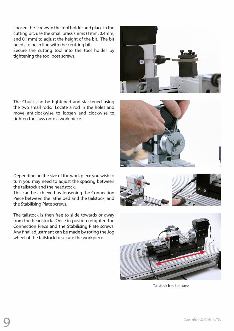
Loosen the screws in the tool holder and place in the cutting bit, use the small brass shims (1mm, 0.4mm, and 0.1mm) to adjust the height of the bit. The bit needs to be in line with the centring bit.Secure the cutting tool into the tool holder by tightening the tool post screws.
The Chuck can be tightened and slackened using the two small rods. Locate a rod in the holes and move anticlockwise to loosen and clockwise to tighten the jaws onto a work piece.
Depending on the size of the work piece you wish to turn you may need to adjust the spacing between the tailstock and the headstock.This can be achieved by loosening the Connection Piece between the lathe bed and the tailstock, and the Stabilising Plate screws.
The tailstock is then free to slide towards or away from the headstock. Once in postion retighten the Connection Piece and the Stabilising Plate screws. Any final adjustment can be made by roting the Jog wheel of the tailstock to secure the workpiece.
Tailstock free to move
10 Copyright © 2017 Matrix TSL
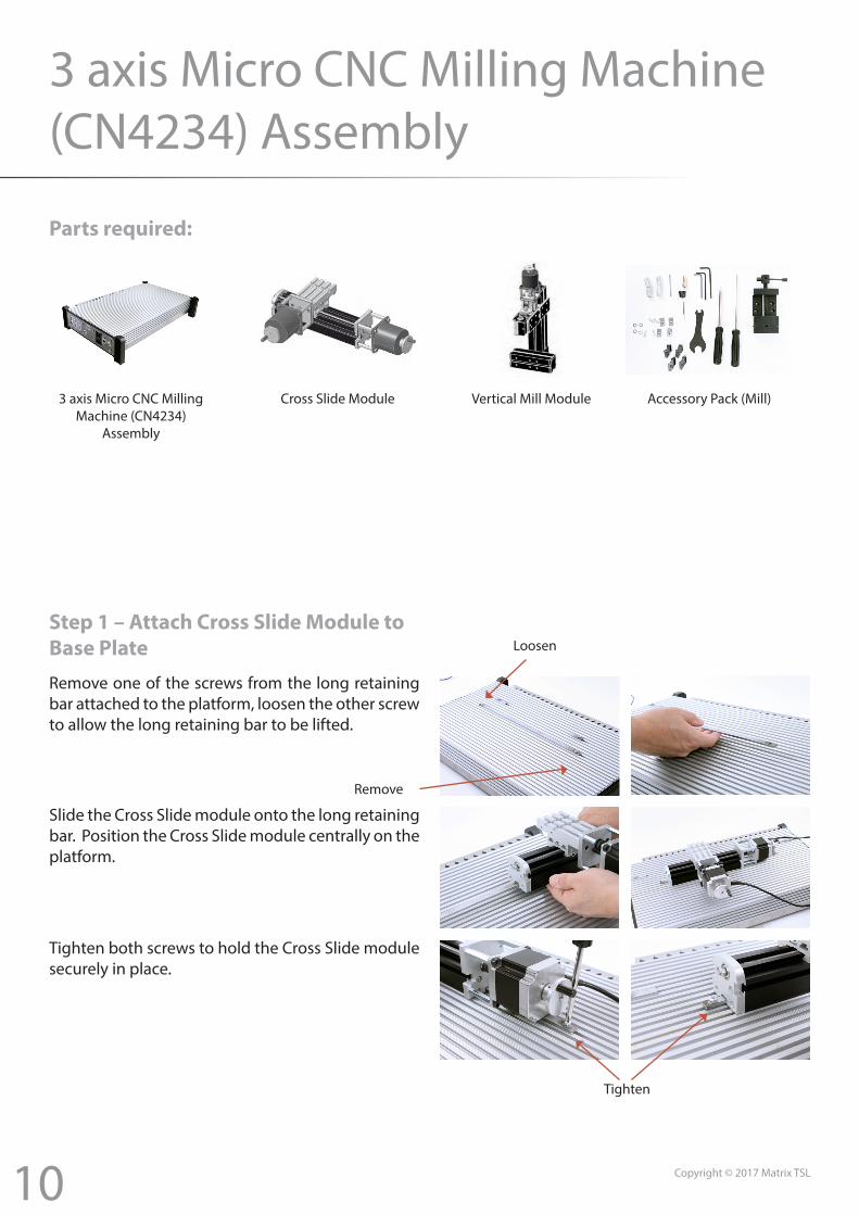
3 axis Micro CNC Milling Machine (CN4234) Assembly
Parts required:
3 axis Micro CNC Milling Machine (CN4234)
Assembly
Cross Slide Module Vertical Mill Module Accessory Pack (Mill)
Step 1 – Attach Cross Slide Module to Base Plate
Tighten
Loosen
Remove
Remove one of the screws from the long retaining bar attached to the platform, loosen the other screw to allow the long retaining bar to be lifted.
Slide the Cross Slide module onto the long retaining bar. Position the Cross Slide module centrally on the platform.
Tighten both screws to hold the Cross Slide module securely in place.
11 Copyright © 2017 Matrix TSL
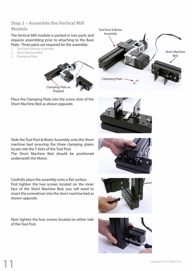
Step 2 – Assemble the Vertical Mill ModuleThe Vertical Mill module is packed in two parts and requires assembling prior to attaching to the Base Plate. Three parts are required for the assembly:1. Tool Post & Motor Assembly2. Short Machine Bed3. Clamping Plate
Place the Clamping Plate into the screw slots of the Short Machine Bed as shown opposite.
Slide the Tool Post & Motor Assembly onto the Short machine bed ensuring the three clamping plates locate into the T-slots of the Tool Post.The Short Machine Bed should be positioned underneath the Motor.
Carefully place the assembly onto a flat surface.First tighten the two screws located on the inner face of the Short Machine Bed, you will need to insert the screwdriver into the short machine bed as shown opposite.
Next tighten the four screws located on either side of the Tool Post.
Clamping Plate as Shipped
Clamping Plate
Tool Post & Motor Assembly
Short Machine Bed
12 Copyright © 2017 Matrix TSL
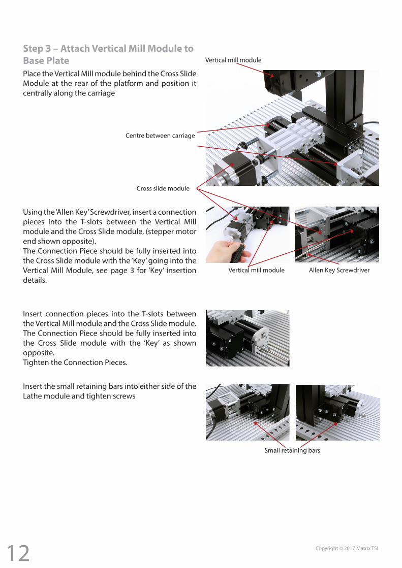
Small retaining bars
Step 3 – Attach Vertical Mill Module to Base PlatePlace the Vertical Mill module behind the Cross Slide Module at the rear of the platform and position it centrally along the carriage
Insert connection pieces into the T-slots between the Vertical Mill module and the Cross Slide module. The Connection Piece should be fully inserted into the Cross Slide module with the ‘Key’ as shown opposite.Tighten the Connection Pieces.
Allen Key Screwdriver
Cross slide module
Centre between carriage
Vertical mill module
Insert the small retaining bars into either side of the Lathe module and tighten screws
Vertical mill module
Using the ‘Allen Key’ Screwdriver, insert a connection pieces into the T-slots between the Vertical Mill module and the Cross Slide module, (stepper motor end shown opposite).The Connection Piece should be fully inserted into the Cross Slide module with the ‘Key’ going into the Vertical Mill Module, see page 3 for ‘Key’ insertion details.
13 Copyright © 2017 Matrix TSL
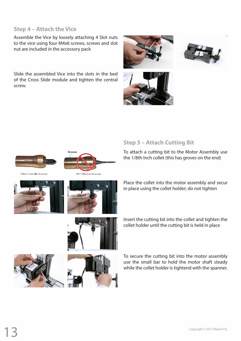
Step 4 – Attach the ViceAssemble the Vice by loosely attaching 4 Slot nuts to the vice using four M4x6 screws, screws and slot nut are included in the accessory pack
Slide the assembled Vice into the slots in the bed of the Cross Slide module and tighten the central screw.
Step 5 – Attach Cutting BitTo attach a cutting bit to the Motor Assembly use the 1/8th Inch collet (this has groves on the end)
Place the collet into the motor assembly and secur in place using the collet holder; do not tighten
Insert the cutting bit into the collet and tighten the collet holder until the cutting bit is held in place
To secure the cutting bit into the motor assembly use the small bar to hold the motor shaft steady while the collet holder is tightend with the spanner.
14 Copyright © 2017 Matrix TSL
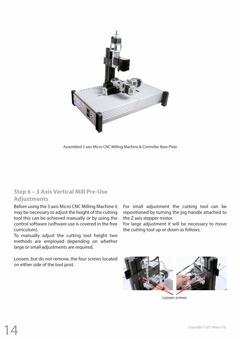
Assembled 3 axis Micro CNC Milling Machine & Controller Base Plate
Step 6 – 3 Axis Vertical Mill Pre-Use AdjustmentsBefore using the 3 axis Micro CNC Milling Machine it may be necessary to adjust the height of the cutting tool this can be achieved manually or by using the control software (software use is covered in the free curriculum).To manually adjust the cutting tool height two methods are employed depending on whether large or small adjustments are required.
For small adjustment the cutting tool can be repositioned by turning the jog handle attached to the Z axis stepper motor.For large adjustment it will be necessary to move the cutting tool up or down as follows.
Loosen, but do not remove, the four screws located on either side of the tool post.
Loosen screws
15 Copyright © 2017 Matrix TSL
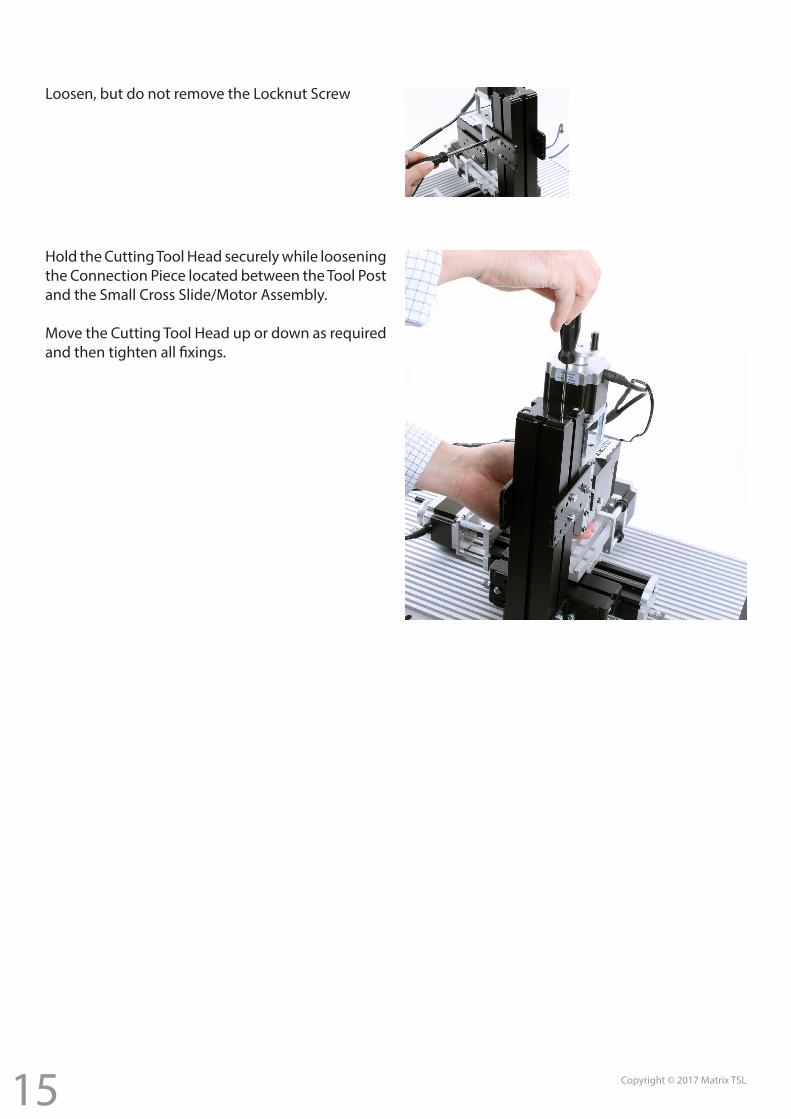
Loosen, but do not remove the Locknut Screw
Hold the Cutting Tool Head securely while loosening the Connection Piece located between the Tool Post and the Small Cross Slide/Motor Assembly.
Move the Cutting Tool Head up or down as required and then tighten all fixings.
16 Copyright © 2017 Matrix TSL
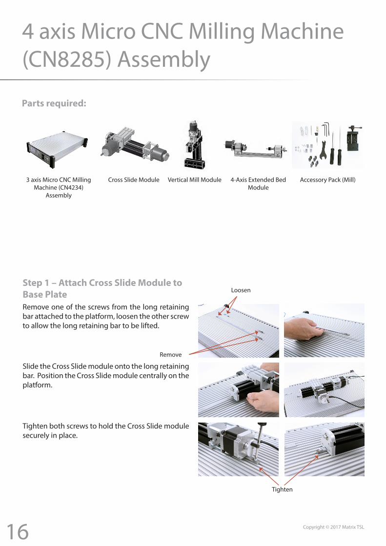
4 axis Micro CNC Milling Machine (CN8285) Assembly
Parts required:
3 axis Micro CNC Milling Machine (CN4234)
Assembly
Cross Slide Module Vertical Mill Module Accessory Pack (Mill)4-Axis Extended BedModule
Step 1 – Attach Cross Slide Module to Base Plate
Tighten
Loosen
Remove
Remove one of the screws from the long retaining bar attached to the platform, loosen the other screw to allow the long retaining bar to be lifted.
Slide the Cross Slide module onto the long retaining bar. Position the Cross Slide module centrally on the platform.
Tighten both screws to hold the Cross Slide module securely in place.

17 Copyright © 2017 Matrix TSL
Step 2 – Assemble the Vertical Mill ModuleThe Vertical Mill module is packed in two parts and requires assembling prior to attaching to the Base Plate. Three parts are required for the assembly:1. Tool Post & Motor Assembly2. Short Machine Bed3. Clamping Plate
Place the Clamping Plate into the screw slots of the Short Machine Bed as shown opposite.
Slide the Tool Post & Motor Assembly onto the Short machine bed ensuring the three clamping plates locate into the T-slots of the Tool Post.The Short Machine Bed Should be positioned underneath the Motor.
Carefully place the assembly onto a flat surface.First tighten the two screws located on the inner face of the Short Machine Bed, you will need to insert the screwdriver into the short machine bed as shown opposite.
Next tighten the four screws located on either side of the Tool Post.
Clamping Plate as Shipped
Clamping Plate
Tool Post & Motor Assembly
Short Machine Bed
18 Copyright © 2017 Matrix TSL
Step 3 – Attach Vertical Mill Module to Base Plate
Small retaining bars
Place the Vertical Mill module behind the Cross Slide Module at the rear of the platform and position it centrally along the carriage
Insert connection pieces into the T-slots between the Vertical Mill module and the Cross Slide module. The Connection Piece should be fully inserted into the Cross Slide module with the ‘Key’ as shown opposite.Tighten the Connection Pieces.
Allen Key Screwdriver
Cross slide module
Centre between carriage
Vertical mill module
Insert the small retaining bars into either side of the Lathe module and tighten screws
Vertical mill module
Using the ‘Allen Key’ Screwdriver, insert a connection pieces into the T-slots between the Vertical Mill module and the Cross Slide module, (stepper motor end shown opposite).The Connection Piece should be fully inserted into the Cross Slide module with the ‘Key’ going into the Vertical Mill Module, see page 3 for ‘Key’ insertion details.
19 Copyright © 2017 Matrix TSL
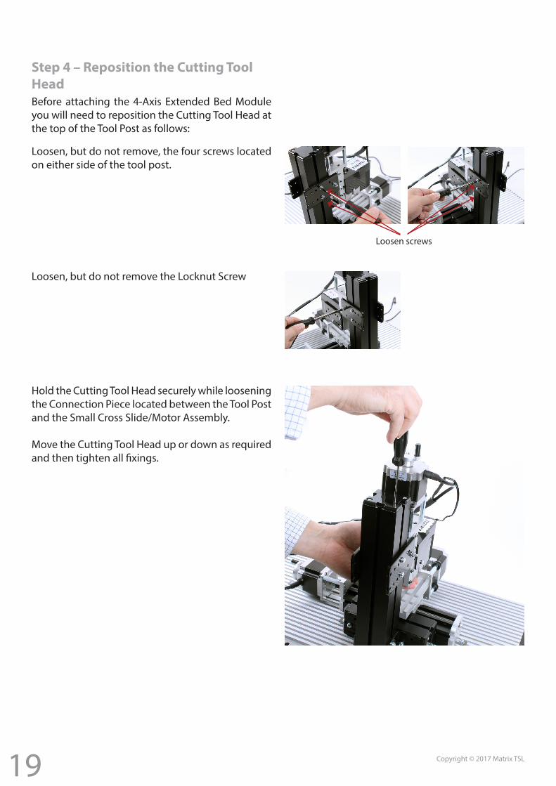
Step 4 – Reposition the Cutting Tool HeadBefore attaching the 4-Axis Extended Bed Module you will need to reposition the Cutting Tool Head at the top of the Tool Post as follows:
Loosen, but do not remove, the four screws located on either side of the tool post.
Loosen, but do not remove the Locknut Screw
Hold the Cutting Tool Head securely while loosening the Connection Piece located between the Tool Post and the Small Cross Slide/Motor Assembly.
Move the Cutting Tool Head up or down as required and then tighten all fixings.
Loosen screws
20 Copyright © 2017 Matrix TSL
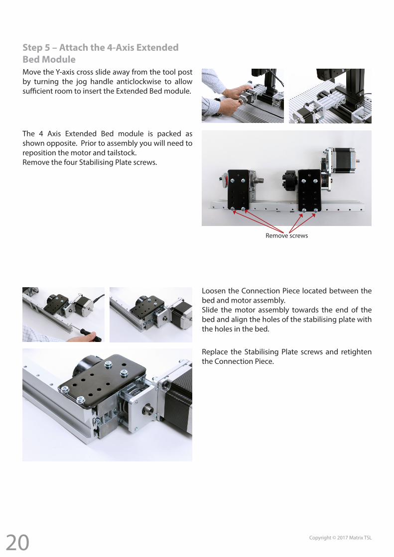
Step 5 – Attach the 4-Axis Extended Bed ModuleMove the Y-axis cross slide away from the tool post by turning the jog handle anticlockwise to allow sufficient room to insert the Extended Bed module.
The 4 Axis Extended Bed module is packed as shown opposite. Prior to assembly you will need to reposition the motor and tailstock.Remove the four Stabilising Plate screws.
Loosen the Connection Piece located between the bed and motor assembly. Slide the motor assembly towards the end of the bed and align the holes of the stabilising plate with the holes in the bed.
Replace the Stabilising Plate screws and retighten the Connection Piece.
Remove screws
21 Copyright © 2017 Matrix TSL
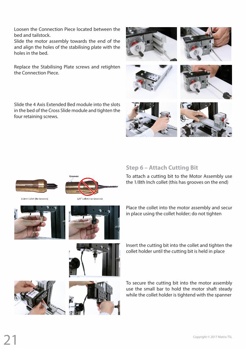
Loosen the Connection Piece located between the bed and tailstock. Slide the motor assembly towards the end of the and align the holes of the stabilising plate with the holes in the bed.
Replace the Stabilising Plate screws and retighten the Connection Piece.
Slide the 4 Axis Extended Bed module into the slots in the bed of the Cross Slide module and tighten the four retaining screws.
Step 6 – Attach Cutting BitTo attach a cutting bit to the Motor Assembly use the 1/8th Inch collet (this has grooves on the end)
Place the collet into the motor assembly and secur in place using the collet holder; do not tighten
Insert the cutting bit into the collet and tighten the collet holder until the cutting bit is held in place
To secure the cutting bit into the motor assembly use the small bar to hold the motor shaft steady while the collet holder is tightend with the spanner
22 Copyright © 2017 Matrix TSL
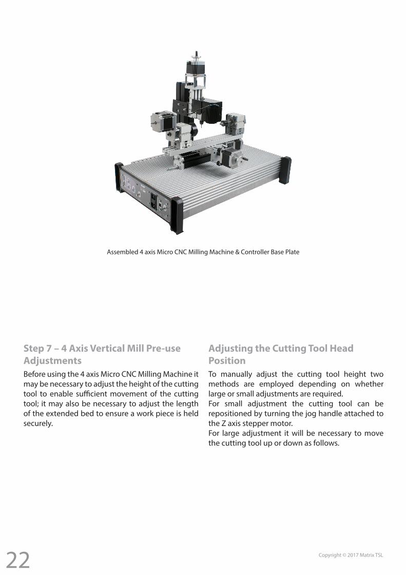
Assembled 4 axis Micro CNC Milling Machine & Controller Base Plate
Step 7 – 4 Axis Vertical Mill Pre-use AdjustmentsBefore using the 4 axis Micro CNC Milling Machine it may be necessary to adjust the height of the cutting tool to enable sufficient movement of the cutting tool; it may also be necessary to adjust the length of the extended bed to ensure a work piece is held securely.
Adjusting the Cutting Tool Head PositionTo manually adjust the cutting tool height two methods are employed depending on whether large or small adjustments are required.For small adjustment the cutting tool can be repositioned by turning the jog handle attached to the Z axis stepper motor.For large adjustment it will be necessary to move the cutting tool up or down as follows.
23 Copyright © 2017 Matrix TSL
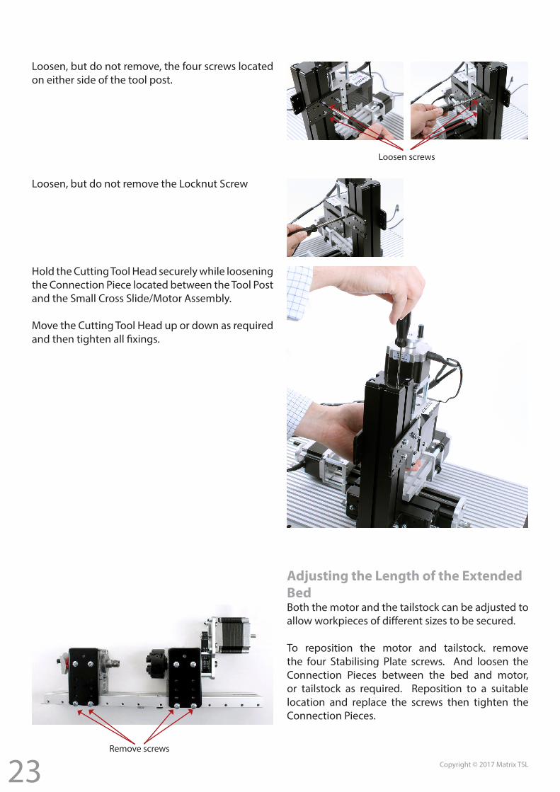
Loosen, but do not remove, the four screws located on either side of the tool post.
Loosen, but do not remove the Locknut Screw
Hold the Cutting Tool Head securely while loosening the Connection Piece located between the Tool Post and the Small Cross Slide/Motor Assembly.
Move the Cutting Tool Head up or down as required and then tighten all fixings.
Loosen screws
Adjusting the Length of the Extended BedBoth the motor and the tailstock can be adjusted to allow workpieces of different sizes to be secured.
To reposition the motor and tailstock. remove the four Stabilising Plate screws. And loosen the Connection Pieces between the bed and motor, or tailstock as required. Reposition to a suitable location and replace the screws then tighten the Connection Pieces.
Remove screws
24 Copyright © 2017 Matrix TSL
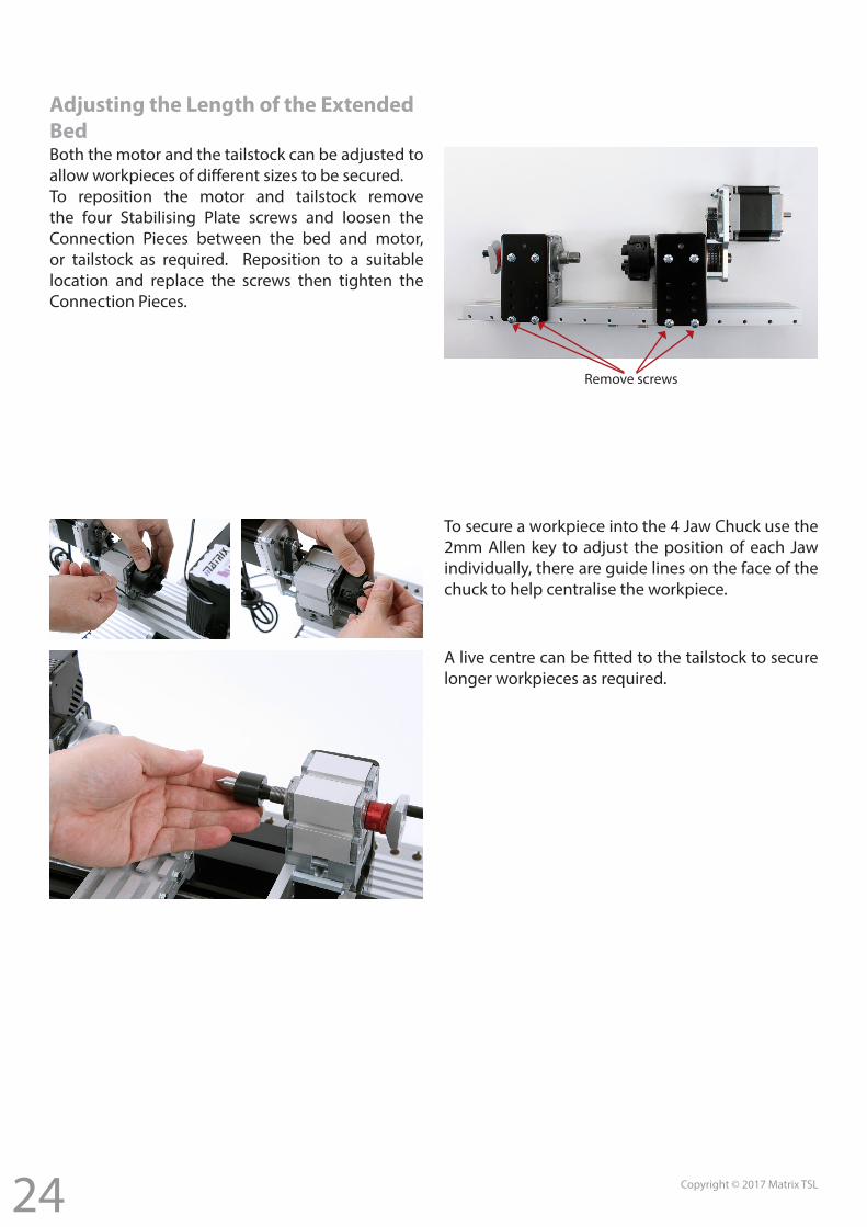
Remove screws
Adjusting the Length of the Extended BedBoth the motor and the tailstock can be adjusted to allow workpieces of different sizes to be secured.To reposition the motor and tailstock remove the four Stabilising Plate screws and loosen the Connection Pieces between the bed and motor, or tailstock as required. Reposition to a suitable location and replace the screws then tighten the Connection Pieces.
To secure a workpiece into the 4 Jaw Chuck use the 2mm Allen key to adjust the position of each Jaw individually, there are guide lines on the face of the chuck to help centralise the workpiece.
A live centre can be fitted to the tailstock to secure longer workpieces as required.
25 Copyright © 2017 Matrix TSL
Matrix MicroCNC – Getting Started
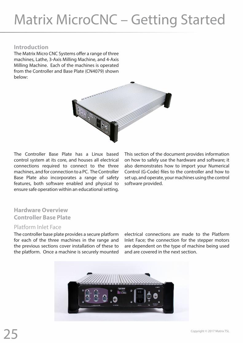
IntroductionThe Matrix Micro CNC Systems offer a range of three machines, Lathe, 3-Axis Milling Machine, and 4-Axis Milling Machine. Each of the machines is operated from the Controller and Base Plate (CN4079) shown below:
The Controller Base Plate has a Linux based control system at its core, and houses all electrical connections required to connect to the three machines, and for connection to a PC. The Controller Base Plate also incorporates a range of safety features, both software enabled and physical to ensure safe operation within an educational setting.
This section of the document provides information on how to safely use the hardware and software; it also demonstrates how to import your Numerical Control (G-Code) files to the controller and how to set up, and operate, your machines using the control software provided.
Hardware OverviewController Base Plate
Platform Inlet FaceThe controller base plate provides a secure platform for each of the three machines in the range and the previous sections cover installation of these to the platform. Once a machine is securely mounted
electrical connections are made to the Platform Inlet Face; the connection for the stepper motors are dependent on the type of machine being used and are covered in the next section.
26 Copyright © 2017 Matrix TSL
The DC motor connection is used to operate the Headstock (Chuck) of the lathe, or the Cutting bit for the milling machines. The motor is turned on using the DC motor On/Off switch at the right hand end of the inlet face; positioned to allow easy access while the machines are running. The DC motor CANNOT be operated unless the platform is connected to a PC and the control software is running. In addition, the DC motor is also connected to the Emergency Stop button located on the opposite end of the platform, right front during normal operation. In the event of the emergency stop button being pressed the restart procedure should be followed, see Page XX.The USB connection provides an interface to the PC. The USB is used to internally power the embedded Linux controller allowing program files to be imported, and machine setting to be entered
without the motors being energised.The IEC Power Inlet provides a switched, and fused, connection to a 110 - 240V (50-60Hz) mains supply. In addition, it is RECOMMENDED that the mains connection is provided through an RCD (Not Supplied). If manual adjustments to the stepper motors need to be made, i.e. during tooling, or origin, setup, the IEC switch can be turned Off, this will remove power from the motors to allow the adjustments to be made. Turning off the power with this switch has no effect on the software, or any programs running, see warning notes at the end of the document. Note the stepper motors should not be moved manually while energised.
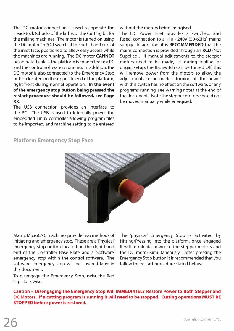
Platform Emergency Stop Face
Matrix MicroCNC machines provide two methods of initiating and emergency stop. These are a ‘Physical’ emergency stop button located on the right hand end of the Controller Base Plate and a ‘Software’ emergency stop within the control software. The software emergency stop will be covered later in this document.
The ‘physical’ Emergency Stop is activated by Hitting/Pressing into the platform, once engaged it will terminate power to the stepper motors and the DC motor simultaneously. After pressing the Emergency Stop button it is recommended that you follow the restart procedure stated below.
Caution – Disengaging the Emergency Stop Will IMMEDIATELY Restore Power to Both Stepper and DC Motors. If a cutting program is running it will need to be stopped. Cutting operations MUST BE STOPPED before power is restored.
To disengage the Emergency Stop, twist the Red cap clock wise.
27 Copyright © 2017 Matrix TSL
The restart procedure below assumes that the ‘Physical’ emergency stop button was activated to prevent injury to person(s) or to prevent damage to the machine/tool/part. Restart Procedure1. Isolate Controller Base Plate from mains electrical supply2. Switch off the DC Motor Toggle Switch.3. Switch off the IEC Power Switch.4. Stop the cutting program in software. (Note: the ‘Physical’
emergency stop has no effect on the cutting tool program, this will continue running until stopped in software.
5. Manually operate stepper motor jog wheels to move cutting tools clear of the work piece/machinery.
6. Remove and replace any damaged cutting tools / stock from the machine.
7. Disengage the ‘Physical’ emergency stop buttonAfter following the above procedure cutting operations can be resumed after ensuring the Hazardous condition that initiated the emergency stop has been removed.
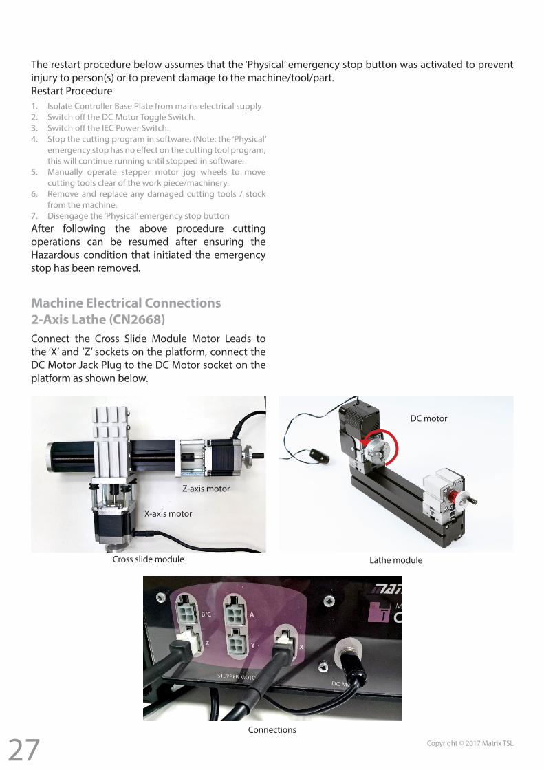
Machine Electrical Connections2-Axis Lathe (CN2668)Connect the Cross Slide Module Motor Leads to the ‘X’ and ’Z’ sockets on the platform, connect the DC Motor Jack Plug to the DC Motor socket on the platform as shown below.
Cross slide module Lathe module
Connections
DC motor
Z-axis motor
X-axis motor
28 Copyright © 2017 Matrix TSL
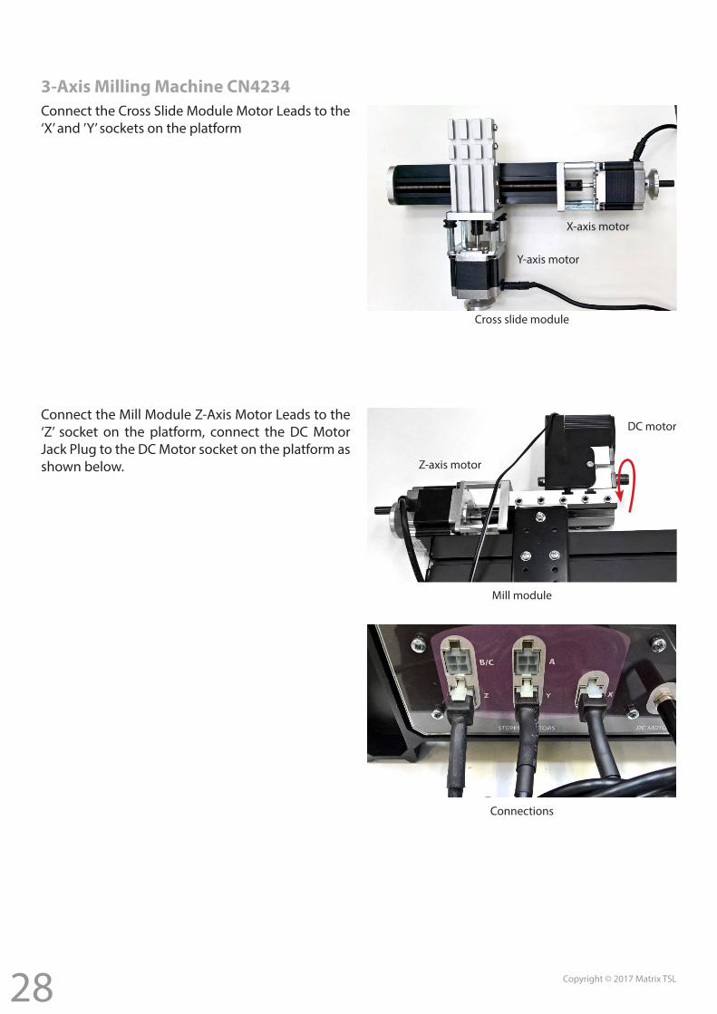
3-Axis Milling Machine CN4234Connect the Cross Slide Module Motor Leads to the ‘X’ and ’Y’ sockets on the platform
Cross slide module
X-axis motor
Y-axis motor
Connect the Mill Module Z-Axis Motor Leads to the ‘Z’ socket on the platform, connect the DC Motor Jack Plug to the DC Motor socket on the platform as shown below. Z-axis motor
DC motor
Connections
Mill module
29 Copyright © 2017 Matrix TSL
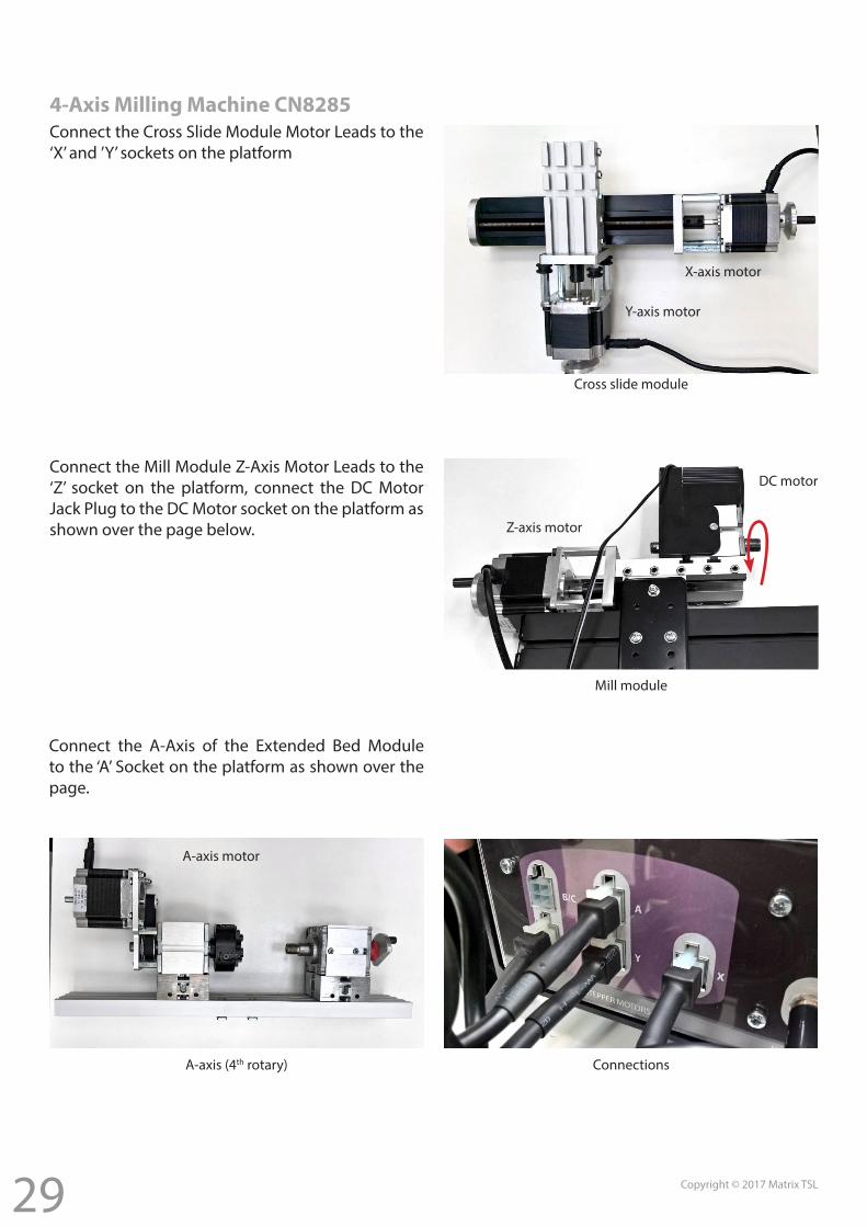
4-Axis Milling Machine CN8285Connect the Cross Slide Module Motor Leads to the ‘X’ and ’Y’ sockets on the platform
Cross slide module
X-axis motor
Y-axis motor
Connect the Mill Module Z-Axis Motor Leads to the ‘Z’ socket on the platform, connect the DC Motor Jack Plug to the DC Motor socket on the platform as shown over the page below. Z-axis motor
DC motor
Mill module
Connect the A-Axis of the Extended Bed Module to the ‘A’ Socket on the platform as shown over the page.
ConnectionsA-axis (4th rotary)
A-axis motor
30 Copyright © 2017 Matrix TSL
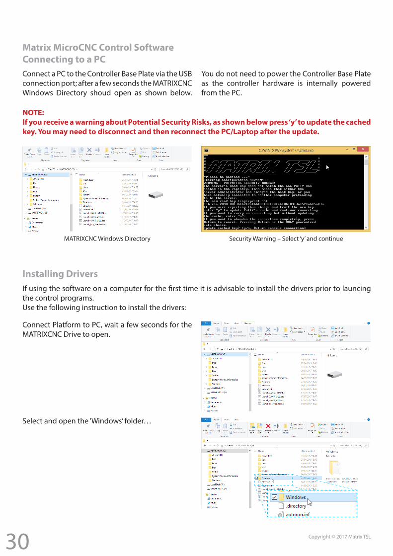
Matrix MicroCNC Control SoftwareConnecting to a PCConnect a PC to the Controller Base Plate via the USB connection port; after a few seconds the MATRIXCNC Windows Directory shoud open as shown below.
You do not need to power the Controller Base Plate as the controller hardware is internally powered from the PC.
NOTE:If you receive a warning about Potential Security Risks, as shown below press ‘y’ to update the cached key. You may need to disconnect and then reconnect the PC/Laptop after the update.
MATRIXCNC Windows Directory Security Warning – Select ‘y’ and continue
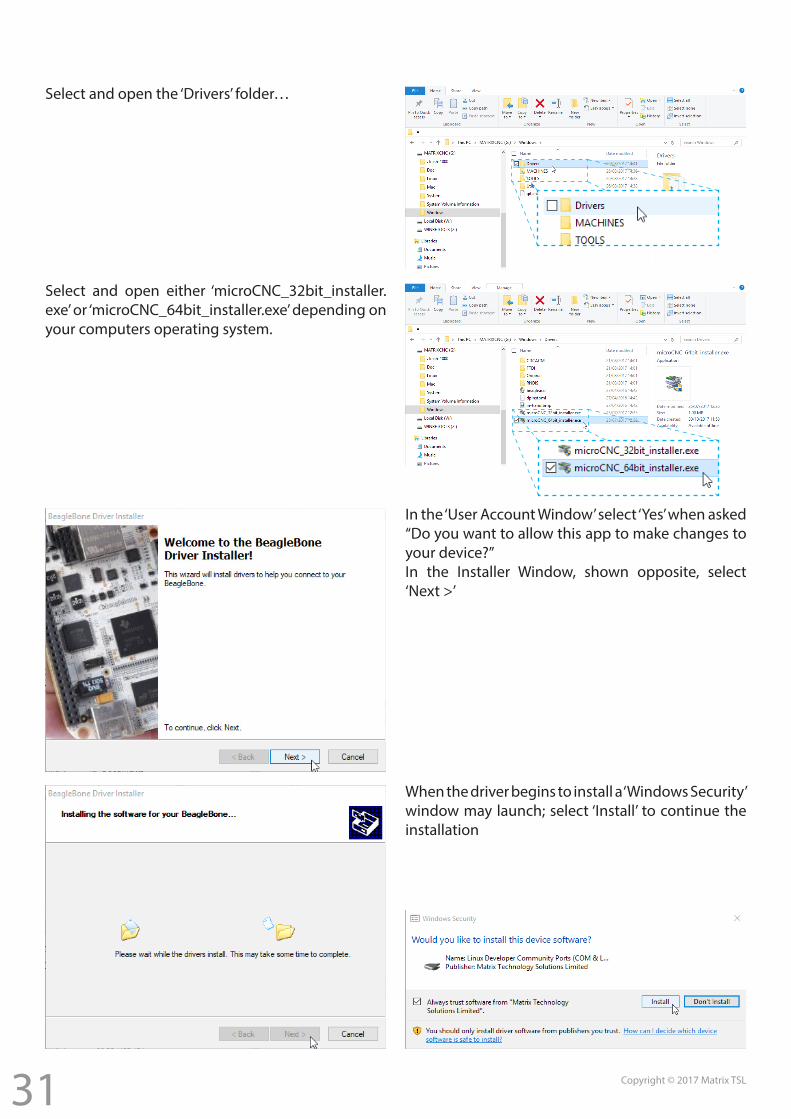
Installing DriversIf using the software on a computer for the first time it is advisable to install the drivers prior to launcing the control programs.Use the following instruction to install the drivers:
Connect Platform to PC, wait a few seconds for the MATRIXCNC Drive to open.
Select and open the ‘Windows’ folder…
31 Copyright © 2017 Matrix TSL
Select and open the ‘Drivers’ folder…
Select and open either ‘microCNC_32bit_installer.exe’ or ‘microCNC_64bit_installer.exe’ depending on your computers operating system.
In the ‘User Account Window’ select ‘Yes’ when asked “Do you want to allow this app to make changes to your device?”In the Installer Window, shown opposite, select ‘Next >’
When the driver begins to install a ‘Windows Security’ window may launch; select ‘Install’ to continue the installation
32 Copyright © 2017 Matrix TSL
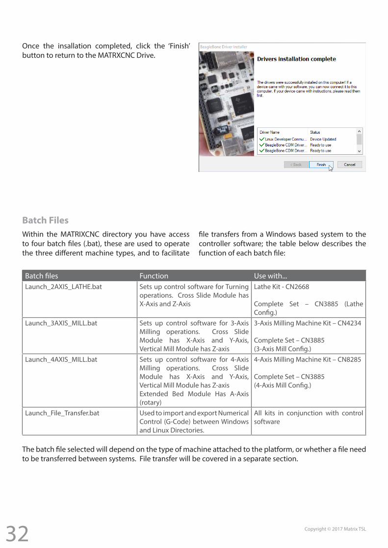
Once the insallation completed, click the ‘Finish’ button to return to the MATRXCNC Drive.
Batch FilesWithin the MATRIXCNC directory you have access to four batch files (.bat), these are used to operate the three different machine types, and to facilitate
file transfers from a Windows based system to the controller software; the table below describes the function of each batch file:
Batch files Function Use with...Launch_2AXIS_LATHE.bat Sets up control software for Turning
operations. Cross Slide Module has X-Axis and Z-Axis
Lathe Kit - CN2668
Complete Set – CN3885 (Lathe Config.)
Launch_3AXIS_MILL.bat Sets up control software for 3-Axis Milling operations. Cross Slide Module has X-Axis and Y-Axis, Vertical Mill Module has Z-axis
3-Axis Milling Machine Kit – CN4234
Complete Set – CN3885 (3-Axis Mill Config.)
Launch_4AXIS_MILL.bat Sets up control software for 4-Axis Milling operations. Cross Slide Module has X-Axis and Y-Axis, Vertical Mill Module has Z-axisExtended Bed Module Has A-Axis (rotary)
4-Axis Milling Machine Kit – CN8285
Complete Set – CN3885 (4-Axis Mill Config.)
Launch_File_Transfer.bat Used to import and export Numerical Control (G-Code) between Windows and Linux Directories.
All kits in conjunction with control software
The batch file selected will depend on the type of machine attached to the platform, or whether a file need to be transferred between systems. File transfer will be covered in a separate section.
33 Copyright © 2017 Matrix TSL
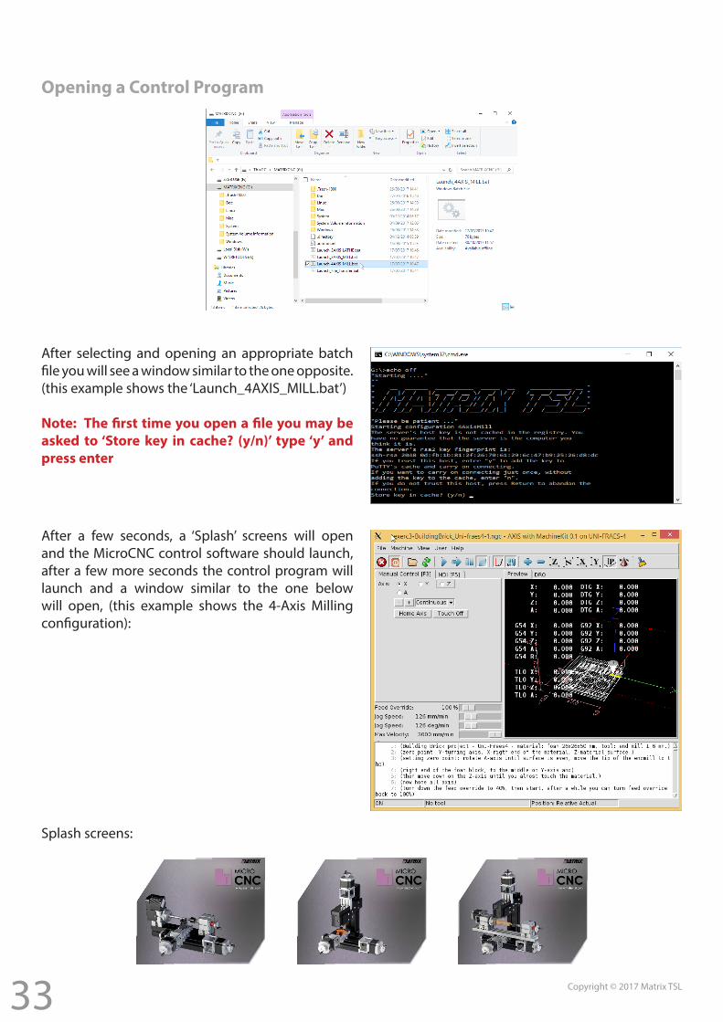
Opening a Control Program
After selecting and opening an appropriate batch file you will see a window similar to the one opposite.(this example shows the ‘Launch_4AXIS_MILL.bat’)
Note: The first time you open a file you may be asked to ‘Store key in cache? (y/n)’ type ‘y’ and press enter
After a few seconds, a ‘Splash’ screens will open and the MicroCNC control software should launch, after a few more seconds the control program will launch and a window similar to the one below will open, (this example shows the 4-Axis Milling configuration):
Splash screens:
34 Copyright © 2017 Matrix TSL
Control Software Overview
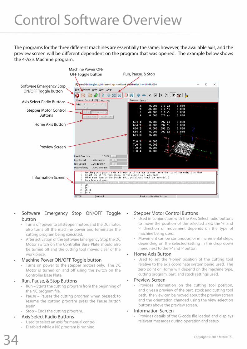
The programs for the three different machines are essentially the same; however, the available axis, and the preview screen will be different dependent on the program that was opened. The example below shows the 4-Axis Machine program.
• Software Emergency Stop ON/OFF Toggle button• Turns off power to all stepper motors and the DC motor,
also turns off the machine power and terminates the cutting program being executed.
• After activation of the Software Emergency Stop the DC Motor switch on the Controller Base Plate should also be turned off and the cutting tool moved clear of the work piece.
• Machine Power ON/OFF Toggle button• Turns on power to the stepper motors only. The DC
Motor is turned on and off using the switch on the Controller Base Plate.
• Run, Pause, & Stop Buttons• Run – Starts the cutting program from the beginning of
the NC program file.• Pause – Pauses the cutting program when pressed; to
resume the cutting program press the Pause button again.
• Stop – Ends the cutting program.• Axis Select Radio Buttons
• Used to select an axis for manual control• Disabled while a NC program is running
• Stepper Motor Control Buttons• Used in conjunction with the Axis Select radio buttons
to move the position of the selected axis; the ‘+’ and ‘-‘ direction of movement depends on the type of machine being used.
• Movement can be continuous, or in incremental steps, depending on the selected setting in the drop down menu next to the ‘+’ and ‘-‘ button.
• Home Axis Button• Used to set the ‘Home’ position of the cutting tool
relative to the axis coordinate system being used. The zero point or ‘Home’ will depend on the machine type, cutting program, part, and stock settings used.
• Preview Screen• Provides information on the cutting tool position,
and gives a preview of the part, stock and cutting tool path, the view can be moved about the preview screen and the orientation changed using the view selection buttons above the preview screen.
• Information Screen• Provides details of the G-code file loaded and displays
relevant messages during operation and setup.
Machine Power ON/OFF Toggle button
Software Emergency StopON/OFF Toggle button
Axis Select Radio Buttons
Stepper Motor ControlButtons
Home Axis Button
Preview Screen
Information Screen
Run, Pause, & Stop
35 Copyright © 2017 Matrix TSL
Basic Operations
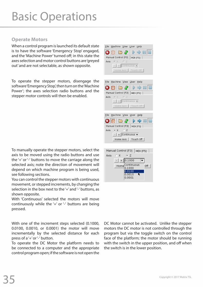
Operate MotorsWhen a control program is launched its default state is to have the software ‘Emergency Stop’ engaged, and the ‘Machine Power’ turned off; in this state the axes selection and motor control buttons are ‘greyed out’ and are not selectable, as shown opposite.
To operate the stepper motors, disengage the software ‘Emergency Stop’, then turn on the ‘Machine Power’; the axes selection radio buttons and the stepper motor controls will then be enabled.
To manually operate the stepper motors, select the axis to be moved using the radio buttons and use the ‘+’ or ‘-‘ buttons to move the carriage along the selected axis; note the direction of movement will depend on which machine program is being used, see following sections.You can control the stepper motors with continuous movement, or stepped increments, by changing the selection in the box next to the ‘+’ and ‘-‘ buttons, as shown opposite.With ‘Continuous’ selected the motors will move continuously while the ‘+’ or ‘-‘ buttons are being pressed.
With one of the increment steps selected (0.1000, 0.0100, 0.0010, or 0.0001) the motor will move incrementally by the selected distance for each press of a ‘+’ or ‘-‘ button.To operate the DC Motor the platform needs to be connected to a computer and the appropriate control program open; if the software is not open the
DC Motor cannot be activated. Unlike the stepper motors the DC motor is not controlled through the program but via the toggle switch on the control face of the platform; the motor should be running with the switch in the upper position, and off when the switch is in the lower position.
36 Copyright © 2017 Matrix TSL
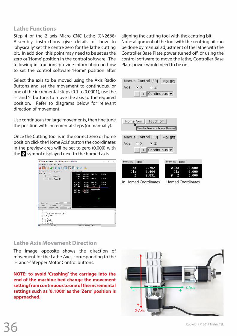
Lathe FunctionsStep 4 of the 2 axis Micro CNC Lathe (CN2668) Assembly instructions give details of how to ‘physically’ set the centre zero for the lathe cutting bit. In addition, this point may need to be set as the zero or ‘Home’ position in the control software. The following instructions provide information on how to set the control software ‘Home’ position after
aligning the cutting tool with the centring bit.Note: alignment of the tool with the centring bit can be done by manual adjustment of the lathe with the Controller Base Plate power turned off, or using the control software to move the lathe, Controller Base Plate power would need to be on.
Select the axis to be moved using the Axis Radio Buttons and set the movement to continuous, or one of the incremental steps (0.1 to 0.0001), use the ‘+’ and ‘-‘ buttons to move the axis to the required position. Refer to diagrams below for relevant direction of movement.
Use continuous for large movements, then fine tune the position with incremental steps (or manually).
Once the Cutting tool is in the correct zero or home position click the ‘Home Axis’ button the coordinates in the preview area will be set to zero (0.000) with the symbol displayed next to the homed axis.
Un-Homed Coordinates Homed Coordinates
Lathe Axis Movement DirectionThe image opposite shows the direction of movement for the Lathe Axes corresponding to the ‘+’ and ‘-‘ Stepper Motor Control buttons.
NOTE: to avoid ‘Crashing’ the carriage into the end of the machine bed change the movement setting from continuous to one of the incremental settings such as ‘0.1000’ as the ‘Zero’ position is approached.
37 Copyright © 2017 Matrix TSL
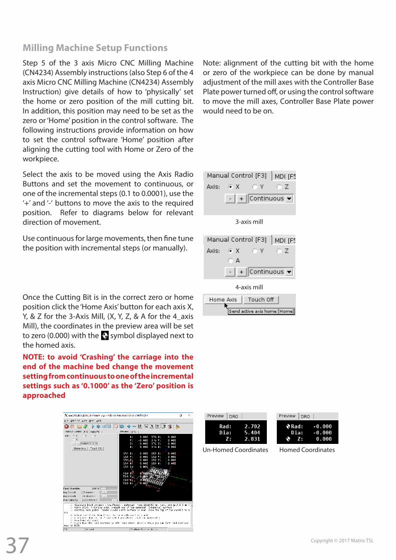
Milling Machine Setup FunctionsStep 5 of the 3 axis Micro CNC Milling Machine (CN4234) Assembly instructions (also Step 6 of the 4 axis Micro CNC Milling Machine (CN4234) Assembly Instruction) give details of how to ‘physically’ set the home or zero position of the mill cutting bit. In addition, this position may need to be set as the zero or ‘Home’ position in the control software. The following instructions provide information on how to set the control software ‘Home’ position after aligning the cutting tool with Home or Zero of the workpiece.
Note: alignment of the cutting bit with the home or zero of the workpiece can be done by manual adjustment of the mill axes with the Controller Base Plate power turned off, or using the control software to move the mill axes, Controller Base Plate power would need to be on.
Un-Homed Coordinates Homed Coordinates
Select the axis to be moved using the Axis Radio Buttons and set the movement to continuous, or one of the incremental steps (0.1 to 0.0001), use the ‘+’ and ‘-‘ buttons to move the axis to the required position. Refer to diagrams below for relevant direction of movement.
Use continuous for large movements, then fine tune the position with incremental steps (or manually).
Once the Cutting Bit is in the correct zero or home position click the ‘Home Axis’ button for each axis X, Y, & Z for the 3-Axis Mill, (X, Y, Z, & A for the 4_axis Mill), the coordinates in the preview area will be set to zero (0.000) with the symbol displayed next to the homed axis.
3-axis mill
4-axis mill
NOTE: to avoid ‘Crashing’ the carriage into the end of the machine bed change the movement setting from continuous to one of the incremental settings such as ‘0.1000’ as the ‘Zero’ position is approached
38 Copyright © 2017 Matrix TSL
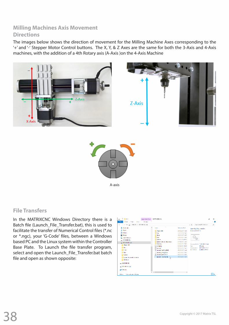
Milling Machines Axis Movement DirectionsThe images below shows the direction of movement for the Milling Machine Axes corresponding to the ‘+’ and ‘-‘ Stepper Motor Control buttons. The X, Y, & Z Axes are the same for both the 3-Axis and 4-Axis machines, with the addition of a 4th Rotary axis (A-Axis )on the 4-Axis Machine
A-axis
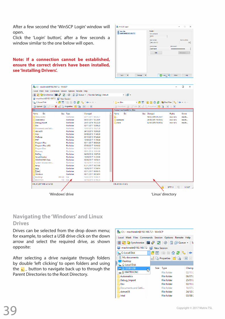
File TransfersIn the MATRIXCNC Windows Directory there is a Batch file (Launch_File_Transfer.bat), this is used to facilitate the transfer of Numerical Control files (*.nc or *.ngc), your ‘G-Code’ files, between a Windows based PC and the Linux system within the Controller Base Plate. To Launch the file transfer program, select and open the Launch_File_Transfer.bat batch file and open as shown opposite:
39 Copyright © 2017 Matrix TSL
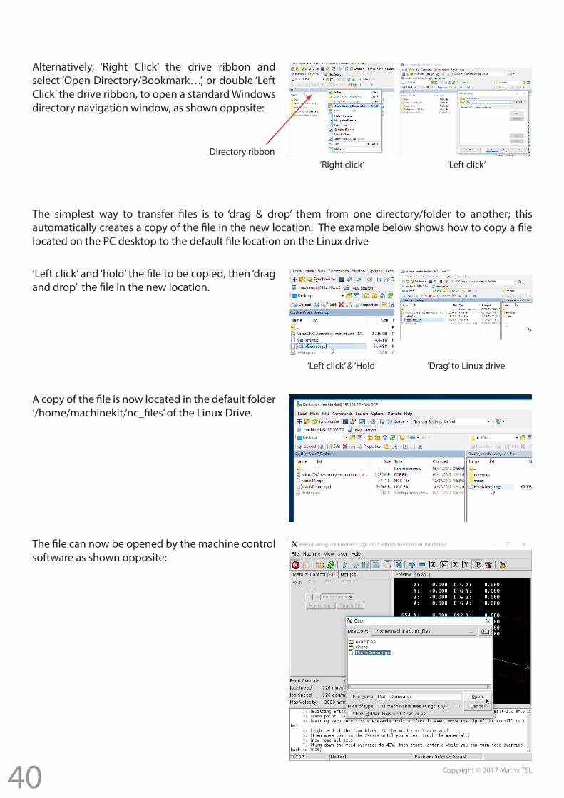
After a few second the ‘WinSCP Login’ window will open.Click the ‘Login’ button’, after a few seconds a window similar to the one below will open.
Note: If a connection cannot be established, ensure the correct drivers have been installed, see ‘Installing Drivers’.
Drives can be selected from the drop down menu; for example, to select a USB drive click on the down arrow and select the required drive, as shown opposite:
After selecting a drive navigate through folders by double ‘left clicking’ to open folders and using the button to navigate back up to through the Parent Directories to the Root Directory.
‘Windows’ drive ‘Linux’ directory
Navigating the ‘Windows’ and Linux Drives
40 Copyright © 2017 Matrix TSL
Alternatively, ‘Right Click’ the drive ribbon and select ‘Open Directory/Bookmark…’, or double ‘Left Click’ the drive ribbon, to open a standard Windows directory navigation window, as shown opposite:
Directory ribbon‘Right click’ ‘Left click’
The simplest way to transfer files is to ‘drag & drop’ them from one directory/folder to another; this automatically creates a copy of the file in the new location. The example below shows how to copy a file located on the PC desktop to the default file location on the Linux drive
‘Left click’ and ‘hold’ the file to be copied, then ‘drag and drop’ the file in the new location.
‘Left click’ & ‘Hold’ ‘Drag’ to Linux drive
A copy of the file is now located in the default folder ‘/home/machinekit/nc_files’ of the Linux Drive.
The file can now be opened by the machine control software as shown opposite:
41 Copyright © 2017 Matrix TSL
Example Project
This example project will show how to create a simple part on the Matrix MicroCNC Lathe. The part was first designed using a typical CAD package, Solidworks in this case, and then converted to a .dxf file. A typical CAM package, CAMBAM in this case, was then used to generate the G-Code used by the Matrix MicroCNC Lathe.
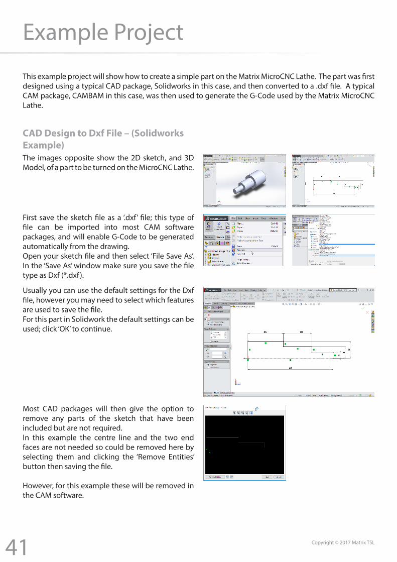
CAD Design to Dxf File – (Solidworks Example)The images opposite show the 2D sketch, and 3D Model, of a part to be turned on the MicroCNC Lathe.
First save the sketch file as a ‘.dxf’ file; this type of file can be imported into most CAM software packages, and will enable G-Code to be generated automatically from the drawing.Open your sketch file and then select ‘File Save As’. In the ‘Save As’ window make sure you save the file type as Dxf (*.dxf ).
Usually you can use the default settings for the Dxf file, however you may need to select which features are used to save the file.For this part in Solidwork the default settings can be used; click ‘OK’ to continue.
Most CAD packages will then give the option to remove any parts of the sketch that have been included but are not required.In this example the centre line and the two end faces are not needed so could be removed here by selecting them and clicking the ‘Remove Entities’ button then saving the file.
However, for this example these will be removed in the CAM software.
42 Copyright © 2017 Matrix TSL
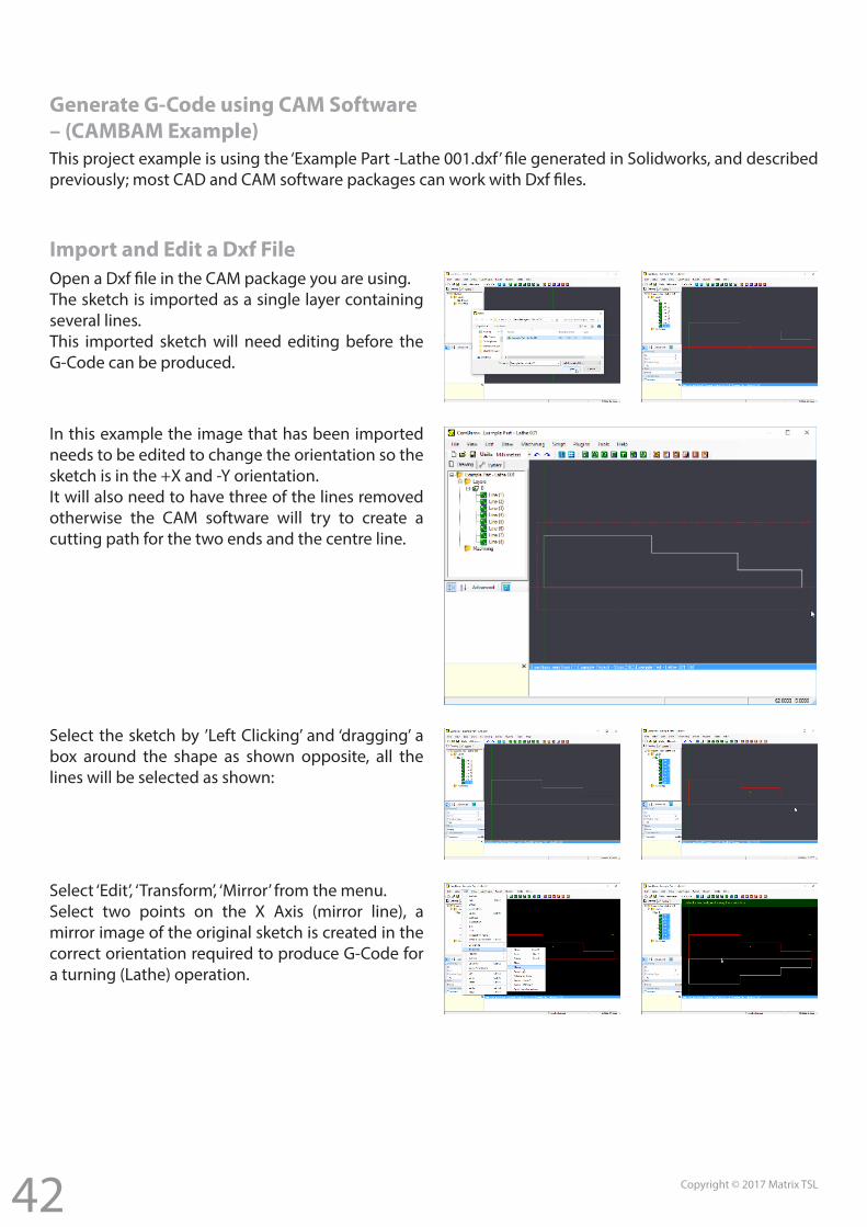
Generate G-Code using CAM Software – (CAMBAM Example)This project example is using the ‘Example Part -Lathe 001.dxf’ file generated in Solidworks, and described previously; most CAD and CAM software packages can work with Dxf files.
Import and Edit a Dxf FileOpen a Dxf file in the CAM package you are using.The sketch is imported as a single layer containing several lines.This imported sketch will need editing before the G-Code can be produced.
In this example the image that has been imported needs to be edited to change the orientation so the sketch is in the +X and -Y orientation.It will also need to have three of the lines removed otherwise the CAM software will try to create a cutting path for the two ends and the centre line.
Select the sketch by ’Left Clicking’ and ‘dragging’ a box around the shape as shown opposite, all the lines will be selected as shown:
Select ‘Edit’, ‘Transform’, ‘Mirror’ from the menu.Select two points on the X Axis (mirror line), a mirror image of the original sketch is created in the correct orientation required to produce G-Code for a turning (Lathe) operation.
43 Copyright © 2017 Matrix TSL
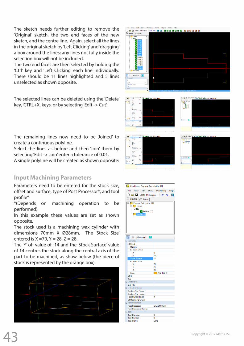
The sketch needs further editing to remove the ‘Original’ sketch, the two end faces of the new sketch, and the centre line. Again, select all the lines in the original sketch by ‘Left Clicking’ and ‘dragging’ a box around the lines; any lines not fully inside the selection box will not be included.The two end faces are then selected by holding the ‘Ctrl’ key and ‘Left Clicking’ each line individually. There should be 11 lines highlighted and 5 lines unselected as shown opposite.
The selected lines can be deleted using the ‘Delete’ key, ‘CTRL+X, keys, or by selecting ‘Edit -> Cut’.
The remaining lines now need to be ‘Joined’ to create a continuous polyline.Select the lines as before and then ‘Join’ them by selecting ‘Edit -> Join’ enter a tolerance of 0.01.A single polyline will be created as shown opposite:
Parameters need to be entered for the stock size, offset and surface, type of Post Processor*, and tool profile* *(Depends on machining operation to be performed).In this example these values are set as shown opposite.The stock used is a machining wax cylinder with dimensions 70mm X Ø28mm. The ‘Stock Size’ entered is X =70, Y = 28, Z = 28.The ‘Y’ off value of -14 and the ‘Stock Surface’ value of 14 centres the stock along the central axis of the part to be machined, as show below (the piece of stock is represented by the orange box).
Input Machining Parameters
44 Copyright © 2017 Matrix TSL
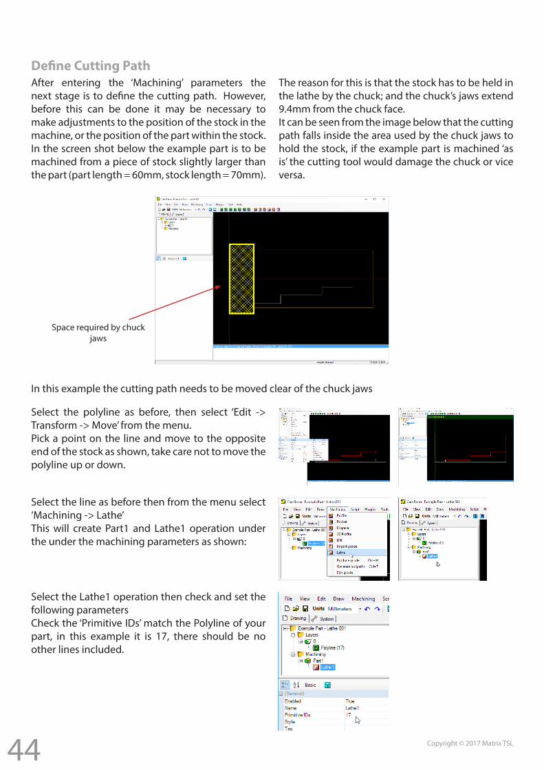
Define Cutting PathAfter entering the ‘Machining’ parameters the next stage is to define the cutting path. However, before this can be done it may be necessary to make adjustments to the position of the stock in the machine, or the position of the part within the stock.In the screen shot below the example part is to be machined from a piece of stock slightly larger than the part (part length = 60mm, stock length = 70mm).
The reason for this is that the stock has to be held in the lathe by the chuck; and the chuck’s jaws extend 9.4mm from the chuck face.It can be seen from the image below that the cutting path falls inside the area used by the chuck jaws to hold the stock, if the example part is machined ‘as is’ the cutting tool would damage the chuck or vice versa.
In this example the cutting path needs to be moved clear of the chuck jaws
Select the polyline as before, then select ‘Edit -> Transform -> Move’ from the menu.Pick a point on the line and move to the opposite end of the stock as shown, take care not to move the polyline up or down.
Select the line as before then from the menu select ‘Machining -> Lathe’This will create Part1 and Lathe1 operation under the under the machining parameters as shown:
Select the Lathe1 operation then check and set the following parametersCheck the ‘Primitive IDs’ match the Polyline of your part, in this example it is 17, there should be no other lines included.
Space required by chuck jaws
45 Copyright © 2017 Matrix TSL
Note: the following settings are for the Example Part – Lathe 001 Only.Clearance Plane – set to 15mm, this ensures the cutting tool is moved clear of the stock as it finishes one cut and moves to the next.Depth Increment – set to 0.4mm, this is how deep the cutting tool will cut into the stock material at each pass.Stock Surface – set to 14mm, this is the radius of our stock.Cut Feedrate – set to 500, this sets the speed of travel of the cutting tool along the workpiece, larger values move the tool quicker. Harder materials need to be cut at slower speeds.Plunge Feedrate – set to 150, this is the speed that the cutting tool is fed into the material, again harder materials require a slower speed.Work Plane – select ‘XZ’ from the drop down menu, this sets the axis for the lathe operation as shown previously the X-Axis cuts into the material towards the axis of rotation, the Z-Axis cuts along the length of the part.Lathe Cut Direction – select ‘Right Hand’ from the drop down menu, a right hand tool cuts from right to left, in this example we are cutting the stock from the end towards the chuck.Roughing / Finishing - select ‘Roughing’ from the drop down menu, a roughing operation will ‘roughly’ cut the stock to size, slightly larger than the finished dimensions. It is possible to include additional cutting operation one after the other; for example, a finishing operation could follow a
roughing operation, parameters would need to be set independently for each operation.Tool Profile - select ‘Lathe’ from the drop down menu.
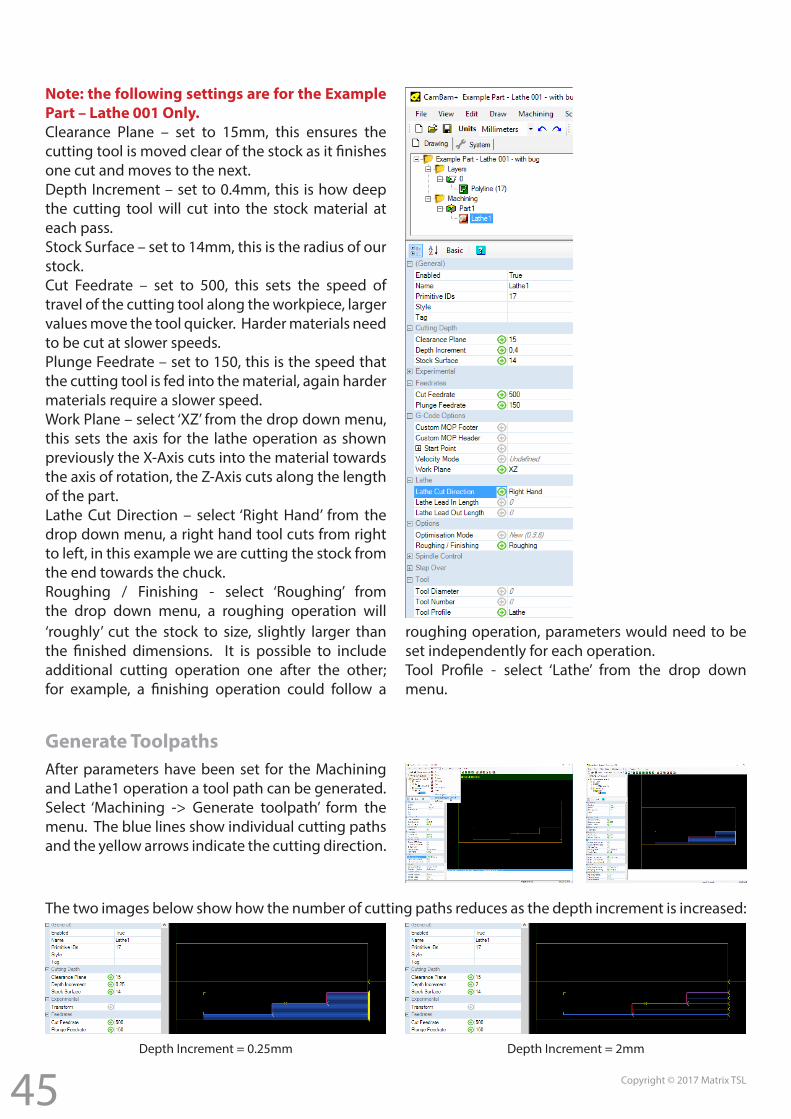
Generate ToolpathsAfter parameters have been set for the Machining and Lathe1 operation a tool path can be generated.Select ‘Machining -> Generate toolpath’ form the menu. The blue lines show individual cutting paths and the yellow arrows indicate the cutting direction.
The two images below show how the number of cutting paths reduces as the depth increment is increased:
Depth Increment = 0.25mm Depth Increment = 2mm
46 Copyright © 2017 Matrix TSL
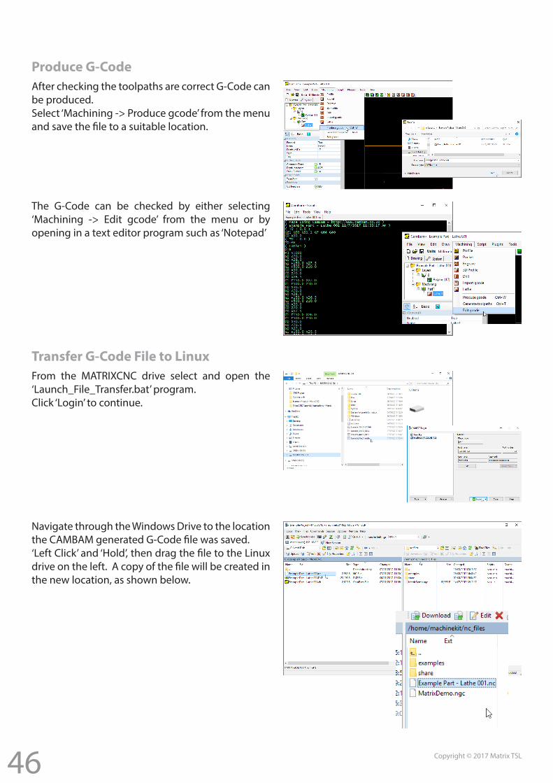
Produce G-CodeAfter checking the toolpaths are correct G-Code can be produced.Select ‘Machining -> Produce gcode’ from the menu and save the file to a suitable location.
The G-Code can be checked by either selecting ‘Machining -> Edit gcode’ from the menu or by opening in a text editor program such as ‘Notepad’
Transfer G-Code File to LinuxFrom the MATRIXCNC drive select and open the ‘Launch_File_Transfer.bat’ program. Click ‘Login’ to continue.
Navigate through the Windows Drive to the location the CAMBAM generated G-Code file was saved.‘Left Click’ and ‘Hold’, then drag the file to the Linux drive on the left. A copy of the file will be created in the new location, as shown below.
47 Copyright © 2017 Matrix TSL
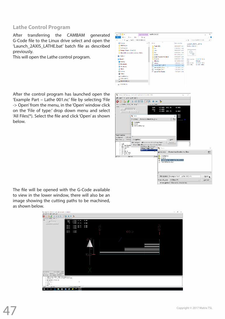
Lathe Control ProgramAfter transferring the CAMBAM generated G-Code file to the Linux drive select and open the ‘Launch_2AXIS_LATHE.bat’ batch file as described previously.This will open the Lathe control program.
After the control program has launched open the ‘Example Part – Lathe 001.nc’ file by selecting ‘File -> Open’ from the menu, in the ‘Open’ window click on the ‘File of type:’ drop down menu and select ‘All Files(*). Select the file and click ‘Open’ as shown below.
The file will be opened with the G-Code available to view in the lower window, there will also be an image showing the cutting paths to be machined, as shown below.
48 Copyright © 2017 Matrix TSL
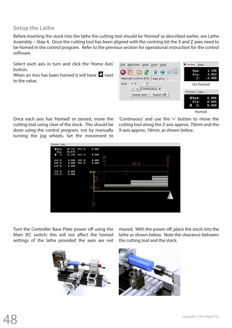
Setup the LatheBefore inserting the stock into the lathe the cutting tool should be ‘Homed’ as described earlier, see Lathe Assembly – Step 4. Once the cutting tool has been aligned with the centring bit the X and Z axes need to be homed in the control program. Refer to the previous section for operational instruction for the control software.
Select each axis in turn and click the ‘Home Axis’ button.When an Axis has been homed it will have next to the value.
Once each axis has ‘Homed’ or zeroed, move the cutting tool using clear of the stock. This should be done using the control program, not by manually turning the jog wheels. Set the movement to
‘Continuous’ and use the ‘+’ button to move the cutting tool along the Z-axis approx. 70mm and the X-axis approx. 18mm, as shown below.
Turn the Controller Base Plate power off using the Main IEC switch; this will not affect the homed settings of the lathe provided the axes are not
moved. With the power off, place the stock into the lathe as shown below. Note the clearance between the cutting tool and the stock.
Homed
Un-homed
49 Copyright © 2017 Matrix TSL
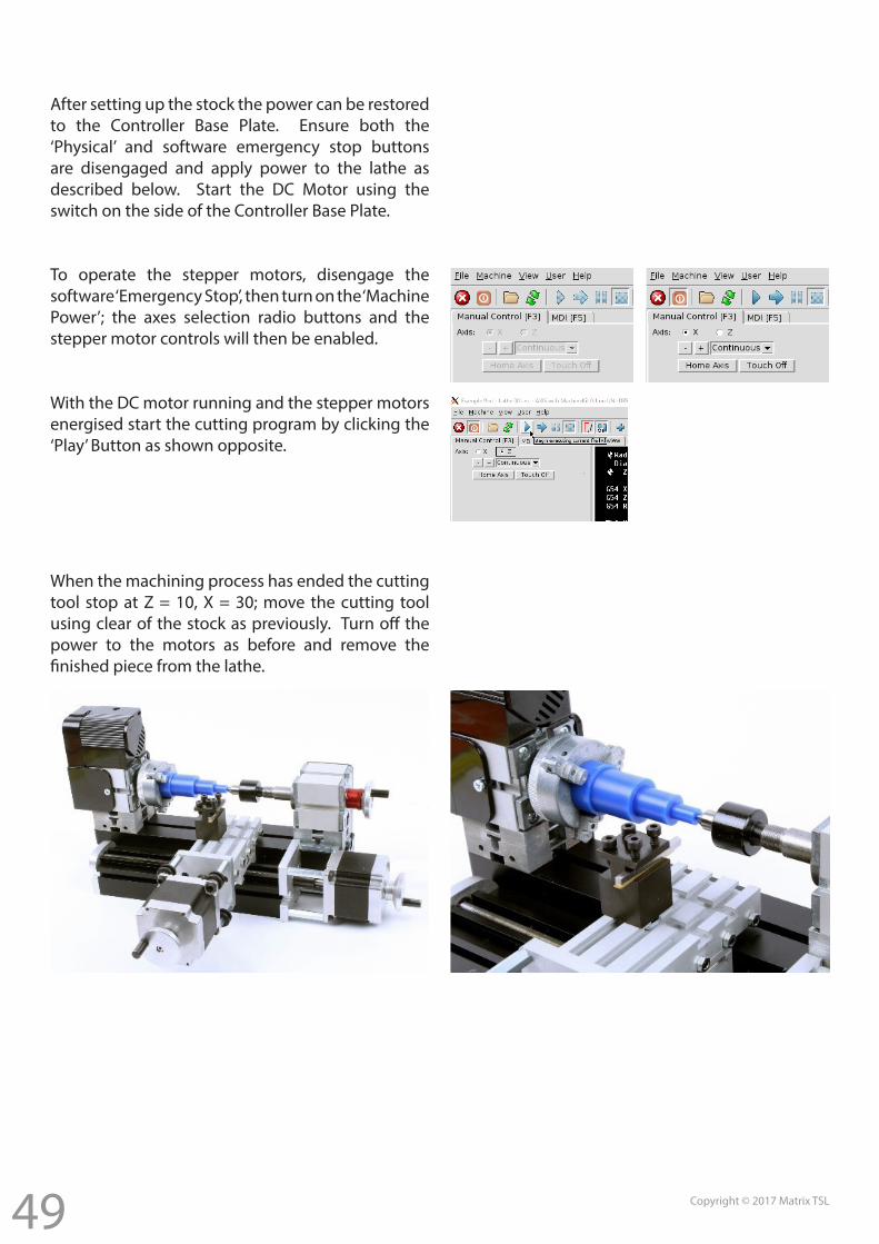
After setting up the stock the power can be restored to the Controller Base Plate. Ensure both the ‘Physical’ and software emergency stop buttons are disengaged and apply power to the lathe as described below. Start the DC Motor using the switch on the side of the Controller Base Plate.
To operate the stepper motors, disengage the software ‘Emergency Stop’, then turn on the ‘Machine Power’; the axes selection radio buttons and the stepper motor controls will then be enabled.
With the DC motor running and the stepper motors energised start the cutting program by clicking the ‘Play’ Button as shown opposite.
When the machining process has ended the cutting tool stop at Z = 10, X = 30; move the cutting tool using clear of the stock as previously. Turn off the power to the motors as before and remove the finished piece from the lathe.
Matrix Technology Solutions Ltd.The Factory
33 Gibbet StreetHalifax, HX1 5BA, UK
t: +44 (0)1422 252380e: [email protected]
www.matrixtsl.com


