Embed Size (px)
Citation preview
Colouring the sculpture through corresponding
area from 2D to 3D with augmented reality.
Submitted September 2020, in partial fulfilment of the conditions of the award of the
degree MSc in Human-Computer Interaction.
Yaozhong Zhang
Student ID: 20145930
School of Computer Science
University of Nottingham
I hereby declare that this dissertation is all my own work, except as indicated in the
text: Signature ______________________
Date 10/09/2020
I hereby declare that I have all necessary rights and consents to publicly distribute
this dissertation via the University of Nottingham's e-dissertation archive.
ii
Abstract
With the development of 3D modelling techniques and AR techniques, the traditional
methods of establishing 2D to 3D relation is no longer sufficient to meet the demand
for complex models and rapid relation building.
This dissertation presents a prototype development implemented that creating many-
to-many correspondences by marking image and 3D model regions that can be used
to colouring 3D model by colouring image for the end user. After comparing the three
methods in the conceptual design, I chose the creating render textures relation to
further development by changing to Zeus bust model and connecting the AR
environment. The results of testing each part of the prototype shows the viability of
the creating render textures relation method. The advantages of it are easy to build
many-to-many relations and adaptable for any model with properly UV mapping. But
there are still three main limitations and future work will focus on solving them,
building a database to store relation information data and printing 3D coloured
models in real world.
Keywords: augmented reality, AR colouring, render texture, Unity, 2D to 3D relation
iii
Acknowledgments
Thank you to the faculties and staffs at the University of Nottingham for their
continued enthusiasm for work during this difficult time.
Thank you for Associate Professor Paul Tennent, your guidance is really helpful on
my project. You give me more inspiration when we discuss the project during every
online meeting. Thank you for your work, I really enjoyed discussing with you.
Finally, I would like to thank my mother and father for their support for my studies.
Thank you, my families, friends for their care and concern during my studies.
iv
Table of Contents
Abstract ··································································································· ii
Acknowledgments ···················································································· iii
Table of Contents ····················································································· iv
List of Figures ························································································· vi
List of Tables ························································································· viii
1. Introduction ······················································································· 2
1.1 Research Background ········································································ 2
1.2 Research Gap and Motivation ······························································ 3
1.3 Project Aim and Question ··································································· 3
1.4 Dissertation Structure ········································································ 4
2. Related Work ····················································································· 6
2.1 Three-Dimensions Paint ····································································· 6
2.2 Augmented Reality Colouring ······························································ 8
3. Prototype Development ····································································· 12
3.1 Background ··················································································· 13
3.1.1 Unity and Vuforia ······································································ 13
3.1.2 Blender ·················································································· 14
3.1.3 Three-Dimensions Model ··························································· 15
3.1.3.1 Clossal Marble Bust of Zeus ················································· 16
3.1.3.2 Caligula Digital Sculpture ····················································· 17
3.2 Target User Group ·········································································· 18
3.3 Conceptual Design ·········································································· 18
3.3.1 Model Segmentation ································································· 19
3.3.2 Add Multiple Materials with Blender Software ································· 22
3.3.3 Creating Render Texture Relation ················································ 24
v
3.3.3.1 Pointing at the UV Map: ······················································ 26
3.3.3.2 Marking on Render Texture ·················································· 28
3.3.3.3 Saving the Relation Data ····················································· 30
3.3.4 Summary ················································································ 33
3.4 Detailed Design ·············································································· 34
3.4.1 The Front View Image ······························································· 34
3.4.2 Connected to Augmented Reality ················································· 35
3.4.2.1 Image Trager ···································································· 35
3.4.2.2 Augmented Reality Interface ················································ 36
4. Testing ···························································································· 38
4.1 Testing Devices ·············································································· 38
4.2 Conceptual Prototype Testing ···························································· 38
4.2.1 Brush Sprites ··········································································· 38
4.2.2 Distance Variable ····································································· 39
4.3 Augmented Reality Testing ······························································· 40
4.3.1 Target Registration ··································································· 40
4.3.2 Interface Interaction ·································································· 41
4.3.3 Running Performance ································································ 43
5. Discussion and Future Work ······························································ 45
5.1 Interpretations and Implications ·························································· 45
5.2 Limitations ····················································································· 46
5.3 Future Work ··················································································· 46
6. Conclusion ······················································································ 48
Bibliography ··························································································· 50
vi
List of Figures
Figure 1 Unity interface [34] ................................................................................... 13
Figure 2 Blender’s default Screen Layout [36] ..................................................... 14
Figure 3 Three-Dimensions modelling diagram ................................................... 15
Figure 4 Colossal marble bust of Zeus model [38] .............................................. 16
Figure 5 Caligula Digital Sculpture in white tunica and purple toga [40] ........... 17
Figure 6 Before filling (left) and after filling (right) ............................................... 19
Figure 7 Coloured Caligula low poly model in Unity ............................................ 21
Figure 8 Coloured Caligula high poly model in Unity .......................................... 22
Figure 9 Selecting the faces of model and assigning a material. ....................... 22
Figure 10 Original Zeus bust(left) and coloured skin of Zeus bust (right) ......... 23
Figure 11 Scene0 (left), Scene1 (middle), and Scene2(right) interface in Unity 24
Figure 12 Creator and user flow ............................................................................. 25
Figure 13 CanvasBase for 3D model in Unity ....................................................... 27
Figure 14 MeshMat Inspector ................................................................................. 27
Figure 15 Code for pointing UV .............................................................................. 28
Figure 16 DrawPanel Inspector .............................................................................. 28
Figure 17 Created brush sprites for marking sphere ........................................... 29
Figure 18 Code for revoke function ....................................................................... 29
Figure 19 Unsaved texture(left) and saved texture(right) .................................... 30
Figure 20 Code of save data ................................................................................... 30
Figure 21 Debug log for relation data in Console window .................................. 31
Figure 22 Code of distance detection with brush point ....................................... 31
Figure 23 Filling red in User mode ......................................................................... 32
Figure 24 Shape of front view image (left) and final view image (right) ............. 35
Figure 25 Image target ............................................................................................ 35
vii
Figure 26 Zeus bust on image target in Unity ....................................................... 36
Figure 27 Interface of Scene0 (left), Scene1 (middle), and Scene2 (right) ......... 36
Figure 28 Debug log for point number in Console window ................................. 39
Figure 29 Testing marking in AR system .............................................................. 43
Figure 30 Testing filling colour in AR system ...................................................... 44

viii
List of Tables
Table 1 Groups of Caligula model regions ·················································· 20
Table 2 Comparison between three methods ·············································· 33
Table 3 Testing f value ············································································· 40
Table 4 Testing image target registration ··················································· 40
Table 5 Testing interface interaction ·························································· 41
2
1. Introduction
1.1 Research Background
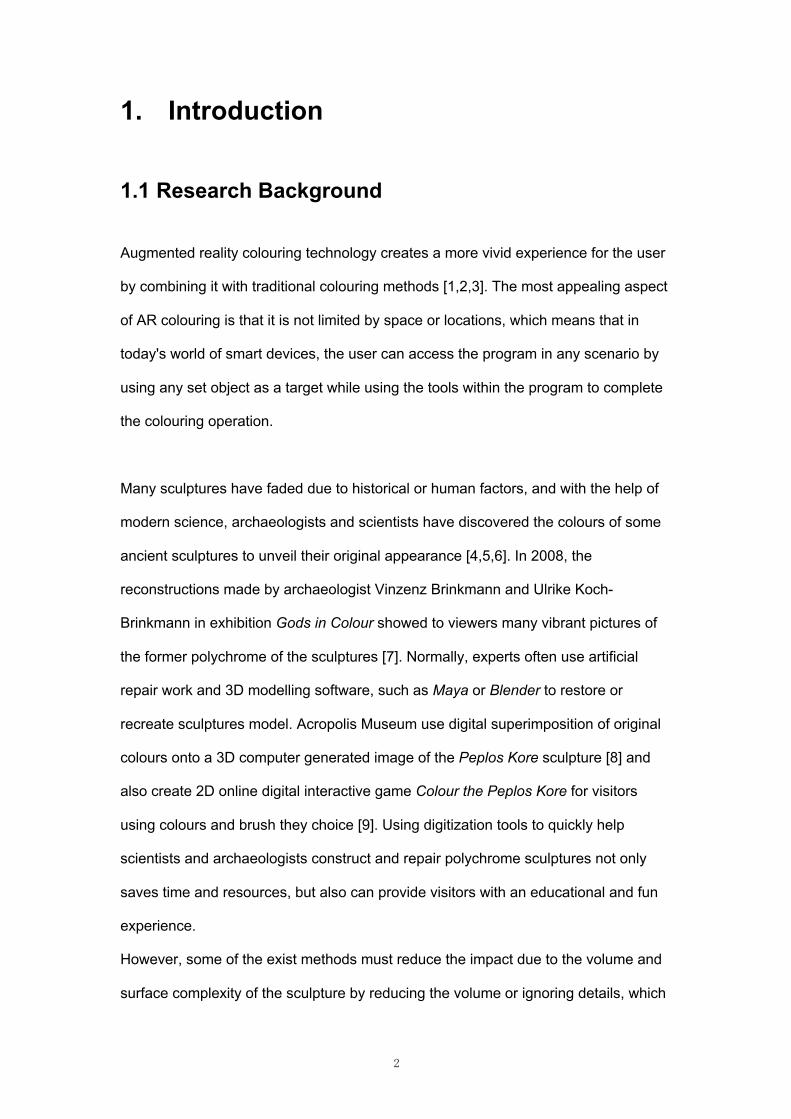
Augmented reality colouring technology creates a more vivid experience for the user
by combining it with traditional colouring methods [1,2,3]. The most appealing aspect
of AR colouring is that it is not limited by space or locations, which means that in
today's world of smart devices, the user can access the program in any scenario by
using any set object as a target while using the tools within the program to complete
the colouring operation.
Many sculptures have faded due to historical or human factors, and with the help of
modern science, archaeologists and scientists have discovered the colours of some
ancient sculptures to unveil their original appearance [4,5,6]. In 2008, the
reconstructions made by archaeologist Vinzenz Brinkmann and Ulrike Koch-
Brinkmann in exhibition Gods in Colour showed to viewers many vibrant pictures of
the former polychrome of the sculptures [7]. Normally, experts often use artificial
repair work and 3D modelling software, such as Maya or Blender to restore or
recreate sculptures model. Acropolis Museum use digital superimposition of original
colours onto a 3D computer generated image of the Peplos Kore sculpture [8] and
also create 2D online digital interactive game Colour the Peplos Kore for visitors
using colours and brush they choice [9]. Using digitization tools to quickly help
scientists and archaeologists construct and repair polychrome sculptures not only
saves time and resources, but also can provide visitors with an educational and fun
experience.
However, some of the exist methods must reduce the impact due to the volume and
surface complexity of the sculpture by reducing the volume or ignoring details, which
3
would compromise the physical characteristics of the original sculpture [10]. Majority
of the AR colouring work so far has been based on textbooks or pages, focusing on
hand-drawn textures for display on 3D models [1,2,11], and some of the work is
based on direct colouring to 3D models, interacting with models manipulating in
virtual space [12,13]. Therefore, the establishment of 2D to 3D correspondence
relation through AR technology still has broad application potential.
1.2 Research Gap and Motivation
After investigating and experimenting with currently viable methods of model
colouring and comparing them, first of all I found that they all have strengths and
weaknesses that are difficult to compensate for each other, they all directly satisfy
the users with colouring needs using the matching established by program's
producer [1,2,3,10,11]. In addition, the models are also relatively simple, which may
be related to the amount of workload and ease degree of modelling of the program,
as well as the final commercial presentation [28,30].
As the technical barriers to modelling become lower and lower, and a large number
of models are now available for free download online, the fastest way to improve
efficiency is to build a program that allows users to create their own correspondence
relations between models and images, the relations also could be used by others, so
that more models could be developed and used. It would directly impact the
museum's work to restore the polychrome sculpture.
1.3 Project Aim and Question
With the aim of allowing users to quickly obtain the 2D to 3D correspondence and
use it to colour the 3D model through image with AR, this dissertation describes a
4
prototype design that can colour 3D sculptures through images. In the prototype,
users can use a mobile device with a camera to scan the image target into the
program interface and use a haptic screen and capacitive pen to create a matching
area between the model and the image. By identifying the location of a finger or
capacitive pen on the image, the user can colour the area according to their
preference or reference colour. The prototype can be used to colour pages with
different image target in textbooks, electronic devices in the home or museum
environment for helping restoration, inspiring artists, and providing education for the
public and children.
Research question: How to implement colouring the sculpture through corresponding
area from 2D to 3D with augmented reality technology?
1.4 Dissertation Structure
The main content of the dissertation begins with the review of three-dimensions paint
and augmented reality colouring works currently applied in Chapter 2. A particular
attention is paid to the method of establishing corresponding regions between 2D
and 3D, which helps to properly conduct this study in the context of current research
with a broad perspective. In order to achieve the project aim, I have developed a
prototype in Chapter 3. In the conceptual design, I have used three methods to
determine the implementation flow and model applicability with using different models
for comparison. In the detail design, I have chosen an appropriate method to
connecting with AR interface. Chapter 4 documents the content and results of the
prototype test on the iOS platform. The following Chapter 5 then discuss the
interpretations and implications, the limitations with existing prototype and

5
recommendations for future work. Finally, Chapter 6 provides a brief conclusion of
the entire project and dissertation.
The main contributions are:
1 Implementation of conceptual design using different correspondence methods;
2 Comparison of the strengths and weaknesses of different methods and the types
of models to be applied;
3 A prototype for creator and end user is implemented;
4 Constructing a colouring system in the AR world.
6
2. Related Work
2.1 Three-Dimensions Paint
In three-dimensional computer graphics, applying texture mapping is a common way
to increase the apparent detail of an object without increasing the complexity and
details of the model [14]. In the last three decades, the development of 3D painting
has been pursuing a way to change the texture map of 3D models using brushes and
colours simulated by computer technology in virtual space. Developers realized that
textures have a very important influence on the appearance of the model, so much of
the basis for 3D painting is also based on textures.
In1990, Hanrahan and Haeberli introduced an interactive paint program,which
allows users to paint different types of paints and materials directly onto 3D shapes
[12]. Users can utilise the tablet to control the position of brushes containing shapes
and paints, and the created material properties are stored as a set of associated
texture maps in the end. The main contribution of this work is using rendering
techniques as the user paints to create the appearance of the surface of object and
the results of the interactive colouring is a reproduction of the 3D shape. The author
also gives a full description of the problems of creating and mapping texture maps,
firstly the problem of defining the coordinates and orientation of textures, and
secondly the problem of deformation of texture maps due to parameterization.
Subsequent works in 3D painting has also evolved in the direction of a more realistic
view.
Distinct from traditional 3D painting programs that use predefined UV maps, Takeo
Igarashi and Dennis Cosgrove present a technique for creating effective UV maps for
7
texture painting programs, this system of systems dynamically creates tailored UV
maps for newly drawn polygons during the painting process. The user can draw
undeformed strokes over the entire surface from any direction. Dynamic texture
distribution allows the user to draw smooth strokes at any zoom level. This technique
can be effectively implemented using standard 3D rendering capabilities without the
need to write code for pixel-level manipulation [15]. The result of the drawing is
stored as a standard texture polygon model and can be read by various graphics
applications. This work get inspiration for texture generation and preservation for 3D
painting. Lu et.al. allows the user to generate texture maps by drawing directly on the
surface of the 3D model using a defined UV map in relation [16]. During the painting
process, when the user paints strokes in the 3D view of the object, the system
subsequently re-projects the user's strokes to the corresponding positions in the 2D
texture bitmap based on predefined UV mappings (texture coordinates).
The proliferation of touch screens has made 3D painting no longer limited to
computer programs. Many previous works have demonstrated that using a haptic
device to draw textures directly from the surface of an object is an effective technique
for creating textured images intuitively and interactively [17,18,19,20,21]. In 2008,
Wakita et.al propose a system for designing haptic models based on textures for
haptic devices. In the system [22], differences in tactile impressions are rendered by
dynamically varying the magnitude and/or direction of the reaction force based on the
pixel values of the object surface, which maps the particular texture image and
converts roughness, stiffness, and friction into a 2D image.
With the advancement of technology, the development of software has made it more
realistic for 3D painting to be done. One of the most important developments is the
render texture. Render textures are special types of textures that are created and
updated by specifying a camera at run time in Unity software [23]. The Camera
8
component has a Target Texture variable, which can be set to a Render Texture
object to output the camera’s view to the texture rather than the screen [24].
Monitoring the display is a good metaphor for how it works: the camera is the
camera, the rendered textures are the video recording, and the material is the screen
your video is projected onto.
In 2015, the RealTime Painting project [25] published in Unity assess by Rodrigo
Fernández. The developer using render textures to simulate painting the texture of
material of the mesh in real time. In this project, the camera of the render texture
looks at a quad with the UV map of the model. And then anything that is placed in
front of the camera will be added the texture. Painting mesh in this way will allow us
to have a lot of freedom and will have very clean results for the end users, for now,
after merging texture it won’t allow users to roll back the changes made.
2.2 Augmented Reality Colouring
The definition of augmented reality (AR) used in this project refer the survey
proposed by Ronald Azuma in 1997 and a book written by Alain Craig in 2013. The
survey defines AR as any system that has the following three characteristics:
combines real and virtual; interactive in real time; registered in 3D [26]. In 2013, Alain
Craig further extends the augmented reality definition, not simply including the
essential components of AR, but also defining from users’ perspective. He defined
augmented reality is a medium that user’s experience that is interactive, at least by
changing perspective dependent on location and perspective of the viewer and the
digital information is overlaid on the physical world, that is in both spatial and
temporal registration with the physical world and that is interactive in real-time [27].
9
The target users of the majority of AR colouring works are children and based on the
context of colouring books or colouring page. In early AR colouring works, it common
to use image registration and image inpainting techniques to map or extract the
image texture to the visible and occluded regions of the 3D model. The users could
utilise the smart devices with camera scanning and recognizing the colours and
brush strokes to forming the model wrapped texture map on screen. Clark and
Dunser at The HIT Lab NZ in 2012 have created an interactive AR colouring book
that automatically performs registration and texture extraction from colouring book
pages. Allowing the user to innovate the colour of the book's content and
automatically mapping it to virtual pop-up 3D scenes and models based on the user
draws with a coloured pen. The key to the technique is image registration of pages
that has been colour removal by computing the RGB colour threshold within a pixel
through natural feature registration. The software identifies the black and white line
art as the baseline which by the light intensity and the saturation of colour on the
drawing [1]. Currently, Quiver [28], a company developed by The HIT Lab NZ, is
producing and releasing commercial products about AR colouring.
Lee and Choi use Vuforia SDK (Software Development Kit) with Unity 3D to bring
more possibilities to AR colouring book. They propose an algorithm to extract a
specific rectangular region from the live video and use it for colouring book's texture
map. The work involves the processing of image deformations by calculating the
transformation matrix from local coordinates to world coordinates, and from world
coordinates to screen coordinates. In addition, the perspective created in reality due
to the deviation of the camera from the page angle was corrected [29]. Basing on the
key technology, the AR colouring puzzle, Dinosaur Sketchbook [30], was built and
then was developed commercially, which provide its technical viability [3]. After that,
Cho et al. used colour image acquisition and processing algorithms, and matrix
computation and image processing algorithms to build a colouring game-Playing
10
House. The aim is to establish connections between the real world, the AR world,
and the VR (virtual reality) world, so that all worlds are seamlessly connected
together, enabling users to access the same content in different visual ways [31].
Norraji and Sunar built wARna (Wonderful Augmented Reality and Arts), a mobile-
based interactive augmented reality colouring book, by texture extraction and
mapping using benchmarking and image processing techniques, the colouring
system extracts textures within the frame and maps them to the corresponding 3D
model by detecting the marker frame [11]. After that, they developed colour
recognition and colouring programs for preschool learning based on wARna project
as educational purpose [32]. This work uses printed line arts provided by the
manufacturers, thus avoiding the problem of curved pages caused by bookbinding.
A major limitation in these works is that users cannot fully create 3D content. While
users can colour 3D content, they will always need to prepare publisher-supplied
print art lines. In order to increase interactivity and address the cause of user
boredom caused by the post-colouring model's view-only functionality, many
colouring works are also actively exploring the use of post-colouring models.
To the problem of camera's angle deviation from the page arising in the using of the
system, Magnenat et al. present a real-time variable surface tracking and texture
synthesis method for the AR colouring process. Deformable surface tracking allows
warped painted pages to be tracked in real time on mobile devices, increasing the
interactivity of the experience [2]. Real-time texture compositing uses textures drawn
by the user on the 2D image and applied in real time to solve mirroring and
parameterization seams artefacts, which proposed algorithm based on both diffusion-
based and patch-based methods, as it both extends the known parts of the image to
the unknown ones, and copies pixels know regions to unknown ones. According to
11
the testing results, texture composites aren't perfect, but acceptable to most users.
Unlike other AR colouring, which can just see the coloured model after colouring, live
colouring is more interactive for the user in real-time. MagicToon solves the problem
that AR content cannot be freely created by users, the system can automatically build
3D models according to user-drawn 2D images and interactively edit more complex
scenes in AR screen [10]. The system uses NaturaSketch [33] is a diffusion-based
and patch-based inflation method that encodes each pixel by calculating its distance
to the nearest black pixel and extends the drawing to the entire area using the
inflation method. This method can be used for symmetrical 3D models, with the
limitation that the original texture on the image is used as a texture for the front and
back surfaces of the 3D model.
From the above summary of works, most of the works are based on changing or
generating texture maps for implementing colour modified. For this project,
redesigning the user interface is important when developing mobile AR colouring
prototype. Moreover, establishing one-to-multipoint mapping relations requires
consideration of finding ways from the model generation steps.
12
3. Prototype Development
This project is going to use prototype development method to try a technical task of
colouring sculpture, the focus is on the feasibility of the idea to evaluate its
performance or the performance of some of its components. In the iterative process
of the project, it is easier to make rapid prototyping in the conceptual design and
compare the complexity and usability in each concept prototype and add interactive
components that are missing in the process of implementing functions. The designer
uses this prototype to consider risks and to determine which components are needed
in the final version. This can include testing the user interface or evaluating specific
technical components to find out what is suitable for the users.
The crux of this work is in building a correspondence relation between a front view
image of 3D model and a texture map wrapped on 3D model. Ideally, this relation
can be established by different users, then the end users could utilise it to transform
the colour of 3D model by colouring on the image.
As a result of current COVID-19 lockdowns, I am not going to attempt to user study
and the project will focus instead on the technical challenges. The project is
developed by Unity 3D and the AR part is designed using Vuforia, the detailed
information will be presented in the next section.
13
3.1 Background
3.1.1 Unity and Vuforia
Unity is a cross-platform game engine that provides interactive real-time 3D content
creation and supports C# language scripting developed by Unity Technologies from
2005. This project uses Unity 2019.2.8 f1 version as the development environment.
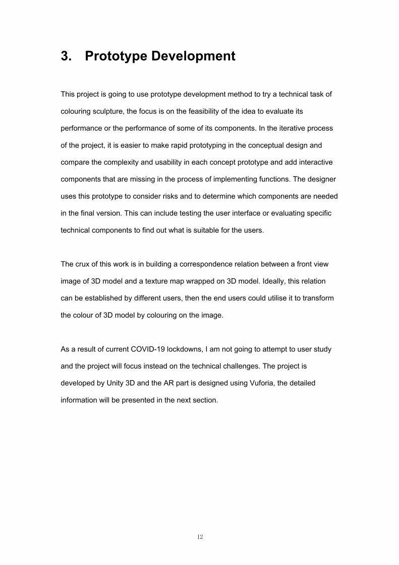
Figure 1 Unity interface [34]
The Toolbar provides the most basic functionality for working with objects, including
the basic tools for manipulating the scene view and the objects in it on the left and
the play, pause, and step controls in the middle. The Hierarchy Window shows the
texts names and hierarchical representation of each object in the Scene window. The
user can view and edit all the properties of the currently selected object in the
Inspector Window. The Project Window displays all the assets that are available to
use in the project (Figure 1). For the more detailed description, the renders can
check out the Unity manual [34].
14
This project utilises the Vuforlia version 8.5.9. As of 2017.2 version, Unity integrates
the Vuforia Engine, which makes it easier to create the most advanced augmented
reality experience for handheld and head-mounted display (HMD) devices. The
advantages of Vuforia are multi-platform release and 3D object target. The project
can be load on iOS, Windows and Android system, which provide convenience for
subsequent expansion of the system and full platform coverage. Moreover, 3D object
target might provide a realistic way for users triggering system and viewing
completed AR works in the real world. Reader can learn more about the Vuforia
Engine platform at Vuforia developer library [35].
3.1.2 Blender
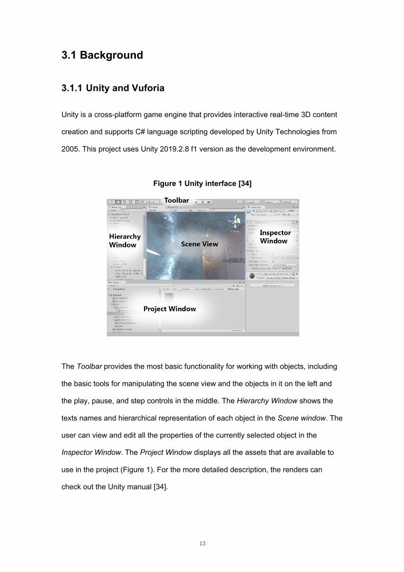
Blender is a cross-platform application and open source 3D creation suite, which can
be used to create 3D visualizations such as still images, 3D animations, VFX shots,
and video editing. Blender also has relatively small memory and drive requirements
compared to other 3D creation suites [36]. This project uses Blender version 2.83.4.
Blender’s interface is separated into three main parts: Topbar at the very top: Areas
in the middle, Status Bar at the bottom (Figure 2).
Figure 2 Blender’s default Screen Layout [36]
Topbar (blue), Areas (green) and Status Bar (red)
15
3.1.3 Three-Dimensions Model
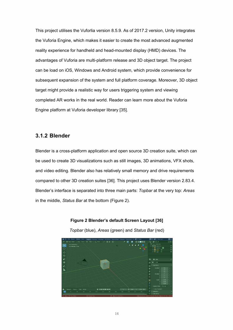
This section will introduce the 3D modelling process and the models used in the
prototype development (Figure 3).
The normal process for 3D modelling is firstly to build a low poly model in the
modelling software including the skeleton of the model and the large-scale region.
The second step is to enrich the details on the basis of the low poly model by
increasing more structures and the number of vertices, edges, and faces, then
establishing a high poly model. The third step is to topology the high poly model to
the low poly model for reducing the number of faces on the high poly model to ensure
the system with high speed and quality for model generation. The fourth step is to UV
unwrapping. The low poly model needs an unwrapped UV map to define how the
texture map wrap on the model. The fifth step is texture baking. The process is to
map the detail information including normal map with bump information, colour map,
metallic map, roughness map on the high poly model to the low poly model. The final
step is to adjust the parameters for getting ideal model.
Figure 3 Three-Dimensions modelling diagram
From the modelling process, it can be analysed that the following resources could be
used to transform the colours: model, UV map, and texture map.
In the next chapter Conceptual Design, these resources will be used to try to develop
a prototype with comparing different methods. The following introduces the models
used in the development process.
16
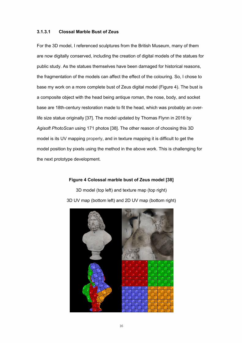
3.1.3.1 Clossal Marble Bust of Zeus
For the 3D model, I referenced sculptures from the British Museum, many of them
are now digitally conserved, including the creation of digital models of the statues for
public study. As the statues themselves have been damaged for historical reasons,
the fragmentation of the models can affect the effect of the colouring. So, I chose to
base my work on a more complete bust of Zeus digital model (Figure 4). The bust is
a composite object with the head being antique roman, the nose, body, and socket
base are 18th-century restoration made to fit the head, which was probably an over-
life size statue originally [37]. The model updated by Thomas Flynn in 2016 by
Agisoft PhotoScan using 171 photos [38]. The other reason of choosing this 3D
model is its UV mapping properly, and in texture mapping it is difficult to get the
model position by pixels using the method in the above work. This is challenging for
the next prototype development.
Figure 4 Colossal marble bust of Zeus model [38]
3D model (top left) and texture map (top right)
3D UV map (bottom left) and 2D UV map (bottom right)
17
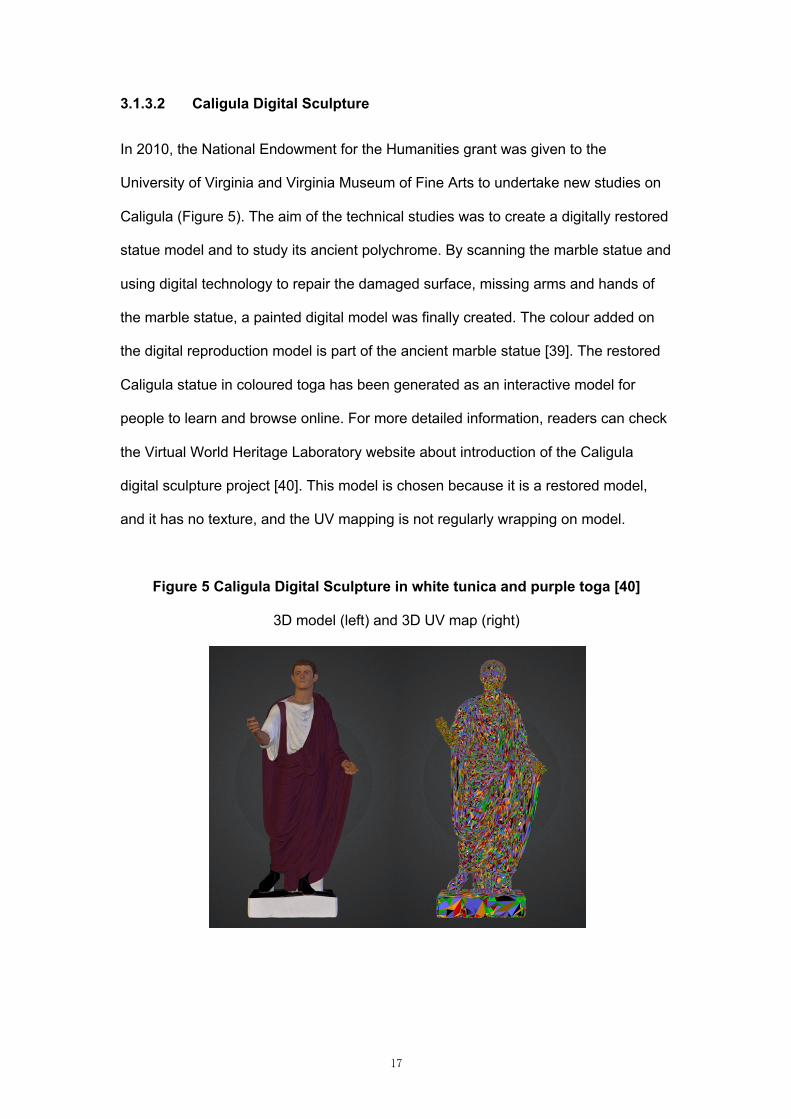
3.1.3.2 Caligula Digital Sculpture
In 2010, the National Endowment for the Humanities grant was given to the
University of Virginia and Virginia Museum of Fine Arts to undertake new studies on
Caligula (Figure 5). The aim of the technical studies was to create a digitally restored
statue model and to study its ancient polychrome. By scanning the marble statue and
using digital technology to repair the damaged surface, missing arms and hands of
the marble statue, a painted digital model was finally created. The colour added on
the digital reproduction model is part of the ancient marble statue [39]. The restored
Caligula statue in coloured toga has been generated as an interactive model for
people to learn and browse online. For more detailed information, readers can check
the Virtual World Heritage Laboratory website about introduction of the Caligula
digital sculpture project [40]. This model is chosen because it is a restored model,
and it has no texture, and the UV mapping is not regularly wrapping on model.
Figure 5 Caligula Digital Sculpture in white tunica and purple toga [40]
3D model (left) and 3D UV map (right)
18
3.2 Target User Group
The target group of users for this project includes museum colour restorers, as well
as members of the public with colouring needs. The end users can take advantage of
a relation that can be created in a relatively simple way by the creator.
Most of the works previously described in Chapter 2 were designed to face the user
directly for colouring, with the developer specifying the 2D to 3D correspondence,
and the user using this relation to colour the model, generating colours or
brushstrokes. But with the increasing simplicity of 3D modelling technology, such as
RealityCapture [44] software, that only needs to take multi-angle photos of a model,
there will be more and more resources could be used to develop in the future.
Therefore, the workload of developing program by traditional workflow is enormous
for companies or individuals.
In this prototype I consider two types of users: the creator, who can use the system
to quickly establish correspondence; and the end user, who uses the
correspondence to colour sculptures.
3.3 Conceptual Design
In the conceptual design, I consider the following three methods to implement 2D to
3D area building relations. This is to identify the steps of different methods to achieve
the functionality. After using the simple model to achieve the relations, I evaluated
the strengths and weaknesses of methods by using the more complex model
presented above as an example.
19
3.3.1 Model Segmentation
As explained modelling process in the 3.1.2, model segmentation can be done in two
ways. The one way is to model each component separately and then form a
complete model. The other way is to split the UV mapping of the model according to
the demand and then controlling colour of each component by changing material on
it. Both 2D images consist of the corresponding area of each 3D part.
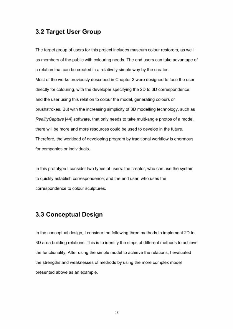
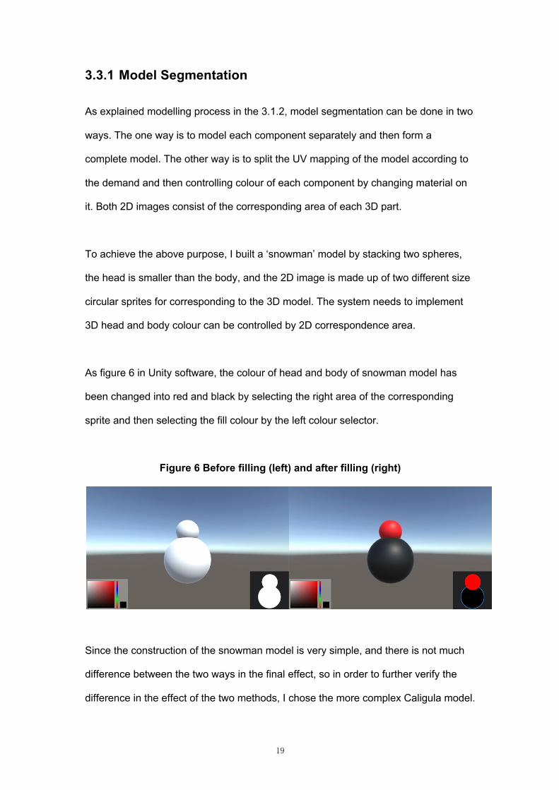
To achieve the above purpose, I built a ‘snowman’ model by stacking two spheres,
the head is smaller than the body, and the 2D image is made up of two different size
circular sprites for corresponding to the 3D model. The system needs to implement
3D head and body colour can be controlled by 2D correspondence area.
As figure 6 in Unity software, the colour of head and body of snowman model has
been changed into red and black by selecting the right area of the corresponding
sprite and then selecting the fill colour by the left colour selector.
Figure 6 Before filling (left) and after filling (right)
Since the construction of the snowman model is very simple, and there is not much
difference between the two ways in the final effect, so in order to further verify the
difference in the effect of the two methods, I chose the more complex Caligula model.
20
I topology the Caligula model, perform UV unwrapping, and then divide the part of
the model into 9 groups (Table 1)
Table 1 Groups of Caligula model regions
Group No. Region
1 Hair and eyebrows
2 Eyes
3 Pupil
4 Lips
5 All skins
6 Tunica
7 Toga
8 Shoes
9 Statue base
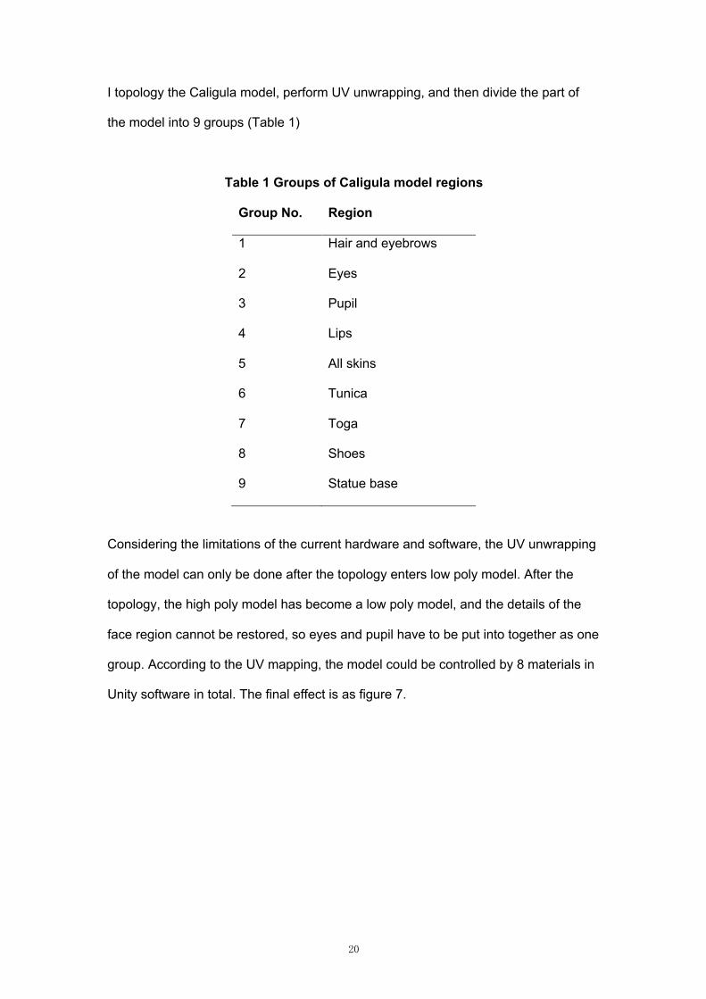
Considering the limitations of the current hardware and software, the UV unwrapping
of the model can only be done after the topology enters low poly model. After the
topology, the high poly model has become a low poly model, and the details of the
face region cannot be restored, so eyes and pupil have to be put into together as one
group. According to the UV mapping, the model could be controlled by 8 materials in
Unity software in total. The final effect is as figure 7.
21
Figure 7 Coloured Caligula low poly model in Unity
In splitting way, there is no need to consider about modelling, but topology and then
UV unwrapping is still required. Due to the low poly model, the facial features are
damaged very seriously, so that the appearance characteristics can no longer be
distinguished. It lacks the details of high poly model and also cannot use bake texture
of high poly model; the hair and clothes folds on the model have also lost their
original structure; the junction between each component is also severely jagged due
to the shape of faces on the model; the final effect can only restore the outer shape
of the original model but not details. The result shows this approach can only achieve
acceptable results with simple geometry model.
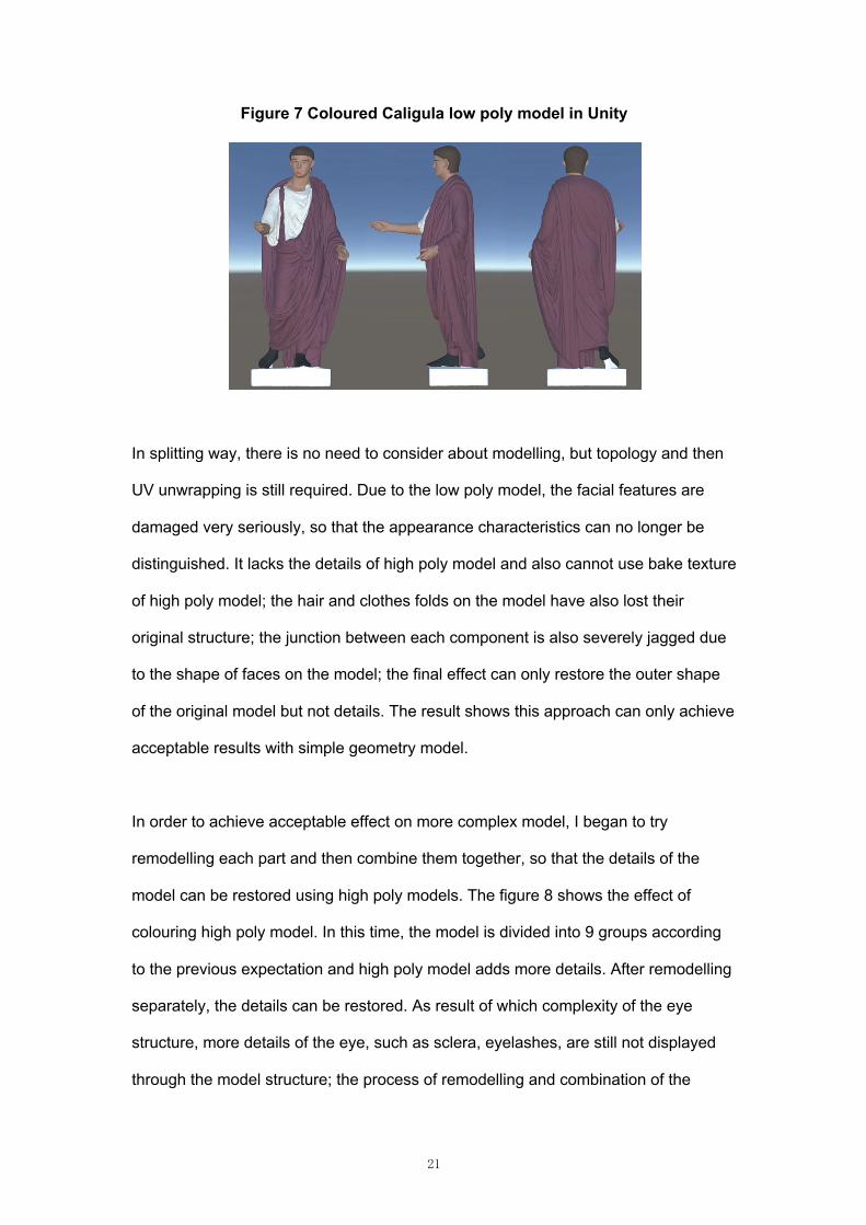
In order to achieve acceptable effect on more complex model, I began to try
remodelling each part and then combine them together, so that the details of the
model can be restored using high poly models. The figure 8 shows the effect of
colouring high poly model. In this time, the model is divided into 9 groups according
to the previous expectation and high poly model adds more details. After remodelling
separately, the details can be restored. As result of which complexity of the eye
structure, more details of the eye, such as sclera, eyelashes, are still not displayed
through the model structure; the process of remodelling and combination of the
22
model takes long than expected; inevitable seams generated in the modelling and
combination process; the designed 2D to 3D relations cannot be changed.
Figure 8 Coloured Caligula high poly model in Unity
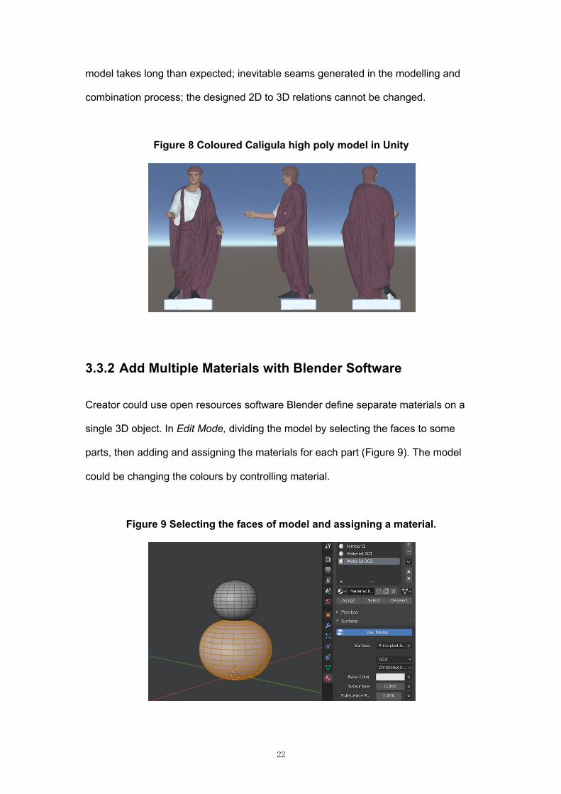
3.3.2 Add Multiple Materials with Blender Software
Creator could use open resources software Blender define separate materials on a
single 3D object. In Edit Mode, dividing the model by selecting the faces to some
parts, then adding and assigning the materials for each part (Figure 9). The model
could be changing the colours by controlling material.
Figure 9 Selecting the faces of model and assigning a material.
23
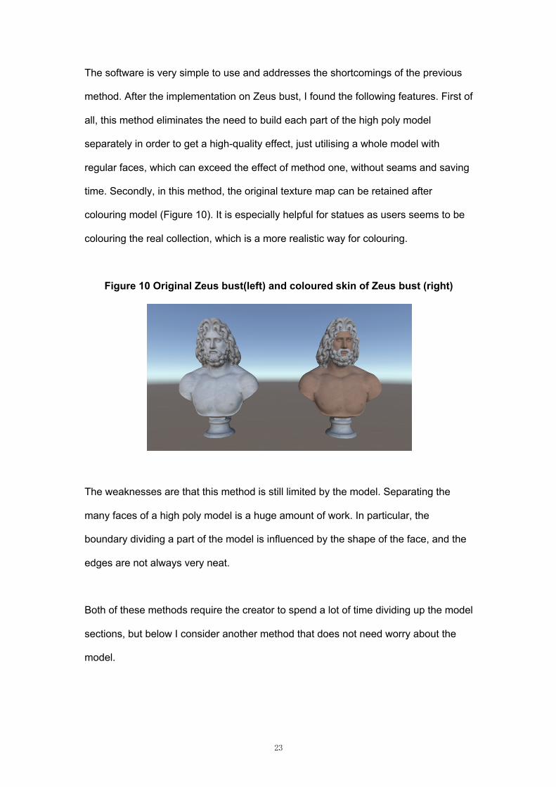
The software is very simple to use and addresses the shortcomings of the previous
method. After the implementation on Zeus bust, I found the following features. First of
all, this method eliminates the need to build each part of the high poly model
separately in order to get a high-quality effect, just utilising a whole model with
regular faces, which can exceed the effect of method one, without seams and saving
time. Secondly, in this method, the original texture map can be retained after
colouring model (Figure 10). It is especially helpful for statues as users seems to be
colouring the real collection, which is a more realistic way for colouring.
Figure 10 Original Zeus bust(left) and coloured skin of Zeus bust (right)
The weaknesses are that this method is still limited by the model. Separating the
many faces of a high poly model is a huge amount of work. In particular, the
boundary dividing a part of the model is influenced by the shape of the face, and the
edges are not always very neat.
Both of these methods require the creator to spend a lot of time dividing up the model
sections, but below I consider another method that does not need worry about the
model.
24
3.3.3 Creating Render Texture Relation
In this method, I tried to modify the texture map itself, and create a relation between
2D and 3D. Inspired by the aforementioned RealTime Painting project, the 3D model
can be coloured using render texture in an interactive way, the same can be utilised
in 2D image as well. So, my conception is that there are two modes in the system,
one for the creator mode and the other for the user mode. In the creator mode, the
creator can establish a matching relation between the render texture map and the
image by painting the colours and save it locally. In the user mode, the user can
change the colour of the 3D model by colouring the front view of the model, using the
matching relations that have been established by the creator.
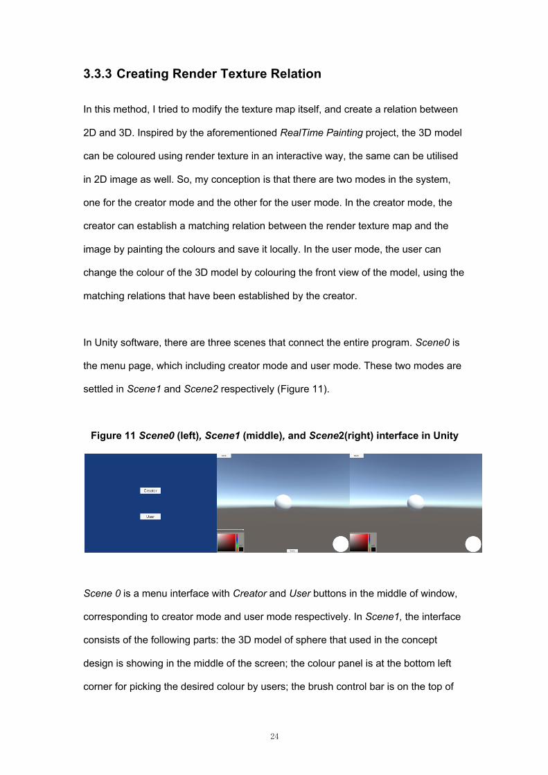
In Unity software, there are three scenes that connect the entire program. Scene0 is
the menu page, which including creator mode and user mode. These two modes are
settled in Scene1 and Scene2 respectively (Figure 11).
Figure 11 Scene0 (left), Scene1 (middle), and Scene2(right) interface in Unity
Scene 0 is a menu interface with Creator and User buttons in the middle of window,
corresponding to creator mode and user mode respectively. In Scene1, the interface
consists of the following parts: the 3D model of sphere that used in the concept
design is showing in the middle of the screen; the colour panel is at the bottom left
corner for picking the desired colour by users; the brush control bar is on the top of
25
the colour panel, which is for controlling size of the brush by dragging to the left or
right and the system is to use the maximum brush by default; the Revoke button that
will appear after painting and the Save button are both in the lower middle; the front
view area of the model, which is circular in the prototype in the lower left; the last one
is the Back button in the upper left corner, which is used to return to the menu. The
layout in Scene2 is the same as in Scene1, except that Scene2 doesn't need the
Revoke button, the Save button, and the brush size control bar.
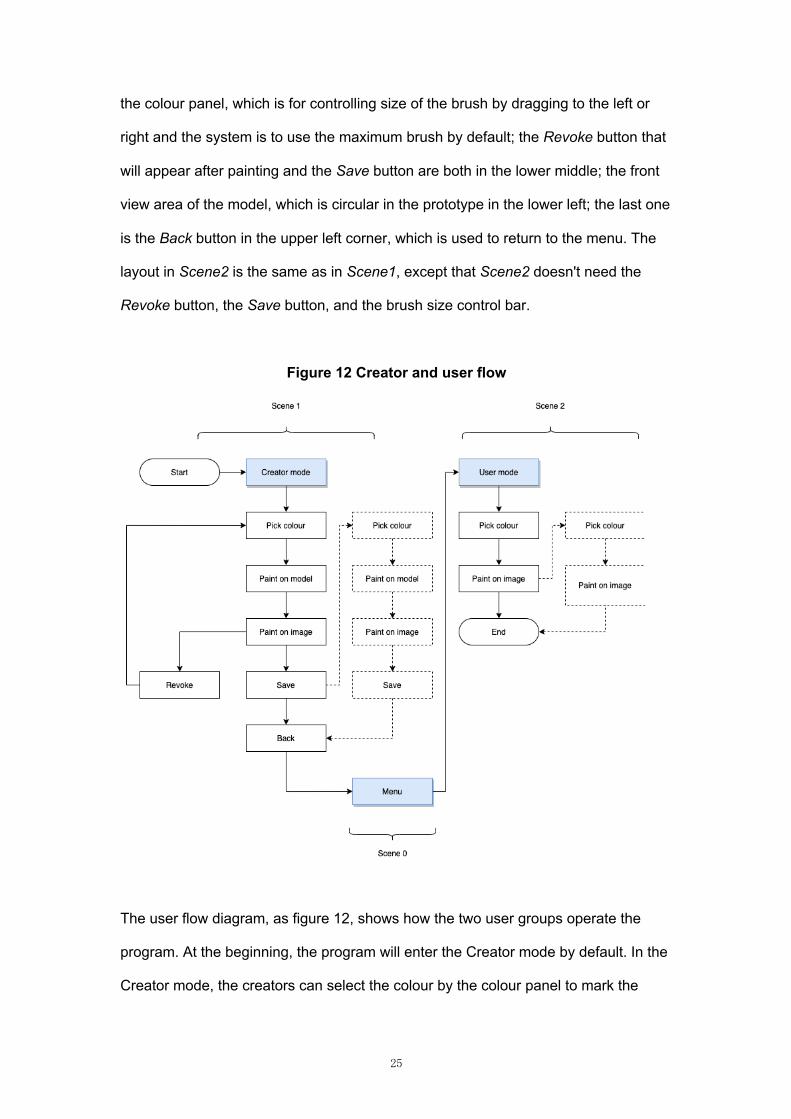
Figure 12 Creator and user flow
The user flow diagram, as figure 12, shows how the two user groups operate the
program. At the beginning, the program will enter the Creator mode by default. In the
Creator mode, the creators can select the colour by the colour panel to mark the
26
desired area in the 2D and 3D parts. First, use the brush to paint on the model to
mark the area, then performing the same operation on the front view image. In the
process of marking the areas. If the creator is not satisfied with one of them, the
creator can revoke it. Besides, if one of the parts no marking after clicking Save
button each time, the relation cannot be saved, and the system will prompt by
missing data. After saving, the creator can choose to continue to create the relation
using other colours or return to the menu interface. The user can enter the User
mode through the menu interface, they only need to fill in the image by any choosing
colour, at the same time the corresponding area of 3D model will be coloured as well.
Technically, in the process of implementing the prototype, the main situations
are as follows:
1. The relation between the UV Map and the point of interaction;
2. How to mark on render textures;
3. How to save the relation between render textures for user colouring.
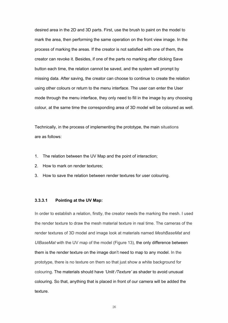
3.3.3.1 Pointing at the UV Map:
In order to establish a relation, firstly, the creator needs the marking the mesh. I used
the render texture to draw the mesh material texture in real time. The cameras of the
render textures of 3D model and image look at materials named MeshBaseMat and
UIBaseMat with the UV map of the model (Figure 13), the only difference between
them is the render texture on the image don’t need to map to any model. In the
prototype, there is no texture on them so that just show a white background for
colouring. The materials should have ‘Unlit /Texture’ as shader to avoid unusual
colouring. So that, anything that is placed in front of our camera will be added the
texture.
27
Figure 13 CanvasBase for 3D model in Unity
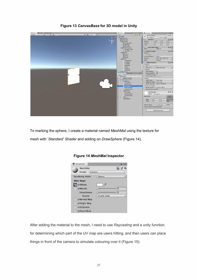
To marking the sphere, I create a material named MeshMat using the texture for
mesh with ‘Standard’ Shader and adding on DrawSphere (Figure 14).
Figure 14 MeshMat Inspector
After adding the material to the mesh, I need to use Raycasting and a unity function
for determining which part of the UV map are users hitting, and then users can place
things in front of the camera to simulate colouring over it (Figure 15).
28
Figure 15 Code for pointing UV
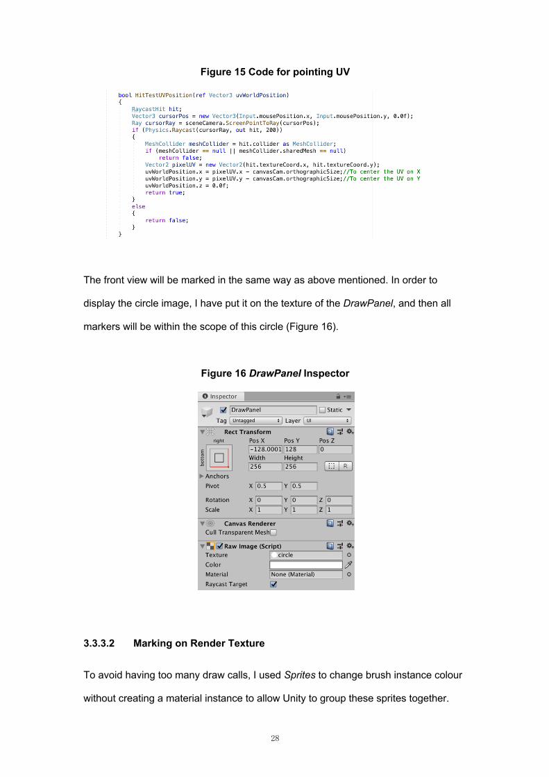
The front view will be marked in the same way as above mentioned. In order to
display the circle image, I have put it on the texture of the DrawPanel, and then all
markers will be within the scope of this circle (Figure 16).
Figure 16 DrawPanel Inspector
3.3.3.2 Marking on Render Texture
To avoid having too many draw calls, I used Sprites to change brush instance colour
without creating a material instance to allow Unity to group these sprites together.
29
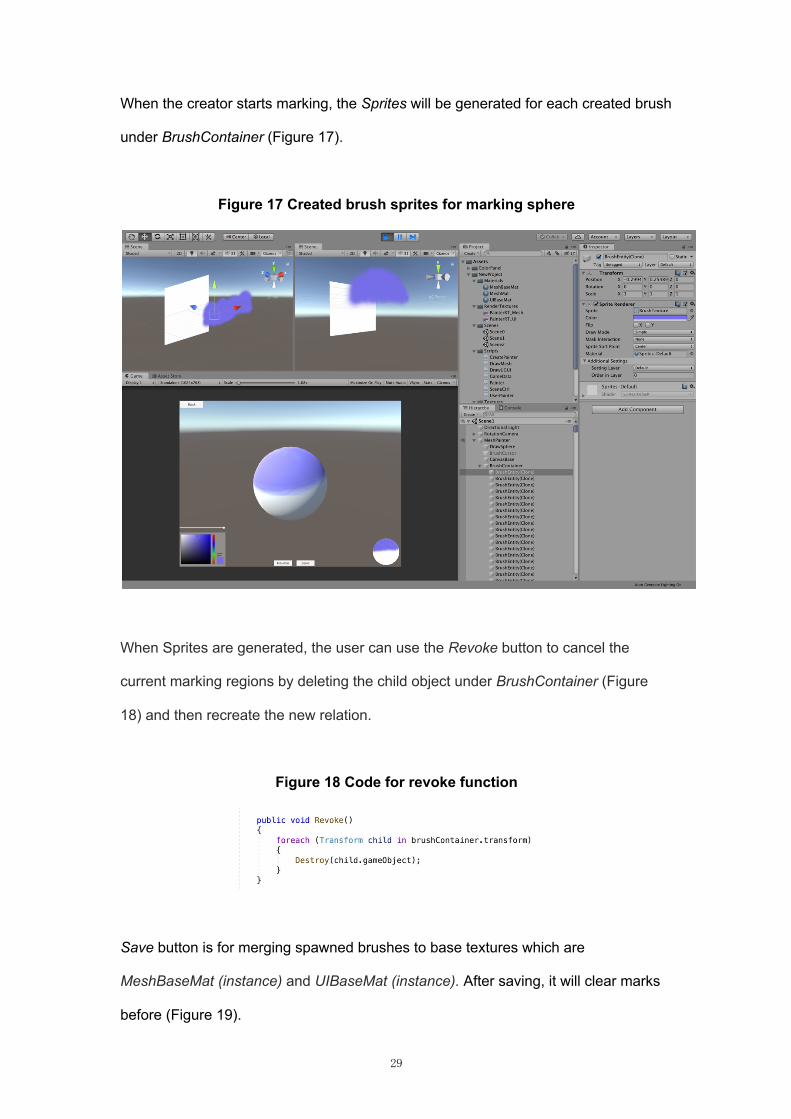
When the creator starts marking, the Sprites will be generated for each created brush
under BrushContainer (Figure 17).
Figure 17 Created brush sprites for marking sphere
When Sprites are generated, the user can use the Revoke button to cancel the
current marking regions by deleting the child object under BrushContainer (Figure
18) and then recreate the new relation.
Figure 18 Code for revoke function
Save button is for merging spawned brushes to base textures which are
MeshBaseMat (instance) and UIBaseMat (instance). After saving, it will clear marks
before (Figure 19).
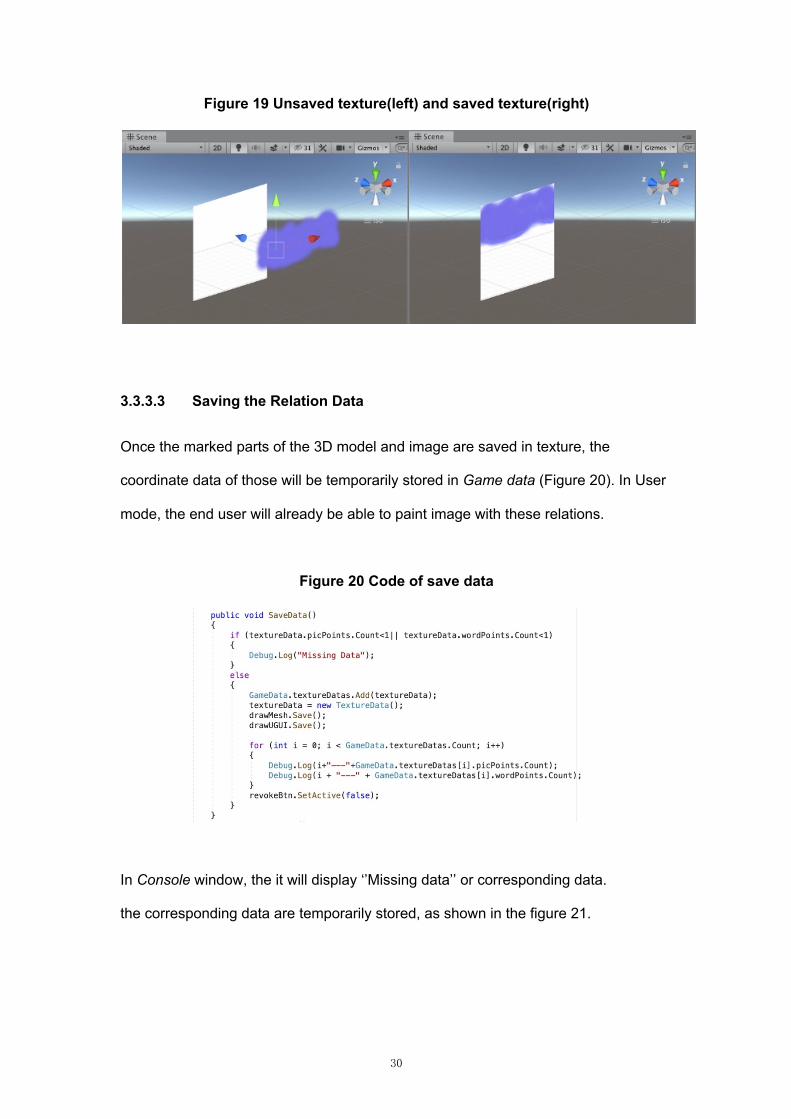
30
Figure 19 Unsaved texture(left) and saved texture(right)
3.3.3.3 Saving the Relation Data
Once the marked parts of the 3D model and image are saved in texture, the
coordinate data of those will be temporarily stored in Game data (Figure 20). In User
mode, the end user will already be able to paint image with these relations.
Figure 20 Code of save data
In Console window, the it will display ‘’Missing data’’ or corresponding data.
the corresponding data are temporarily stored, as shown in the figure 21.
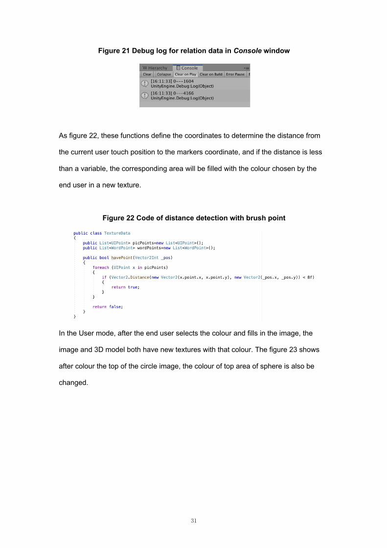
31
Figure 21 Debug log for relation data in Console window
As figure 22, these functions define the coordinates to determine the distance from
the current user touch position to the markers coordinate, and if the distance is less
than a variable, the corresponding area will be filled with the colour chosen by the
end user in a new texture.
Figure 22 Code of distance detection with brush point
In the User mode, after the end user selects the colour and fills in the image, the
image and 3D model both have new textures with that colour. The figure 23 shows
after colour the top of the circle image, the colour of top area of sphere is also be
changed.
32
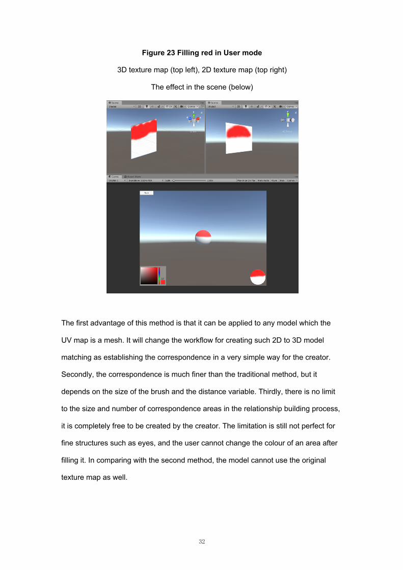
Figure 23 Filling red in User mode
3D texture map (top left), 2D texture map (top right)
The effect in the scene (below)
The first advantage of this method is that it can be applied to any model which the
UV map is a mesh. It will change the workflow for creating such 2D to 3D model
matching as establishing the correspondence in a very simple way for the creator.
Secondly, the correspondence is much finer than the traditional method, but it
depends on the size of the brush and the distance variable. Thirdly, there is no limit
to the size and number of correspondence areas in the relationship building process,
it is completely free to be created by the creator. The limitation is still not perfect for
fine structures such as eyes, and the user cannot change the colour of an area after
filling it. In comparing with the second method, the model cannot use the original
texture map as well.
33
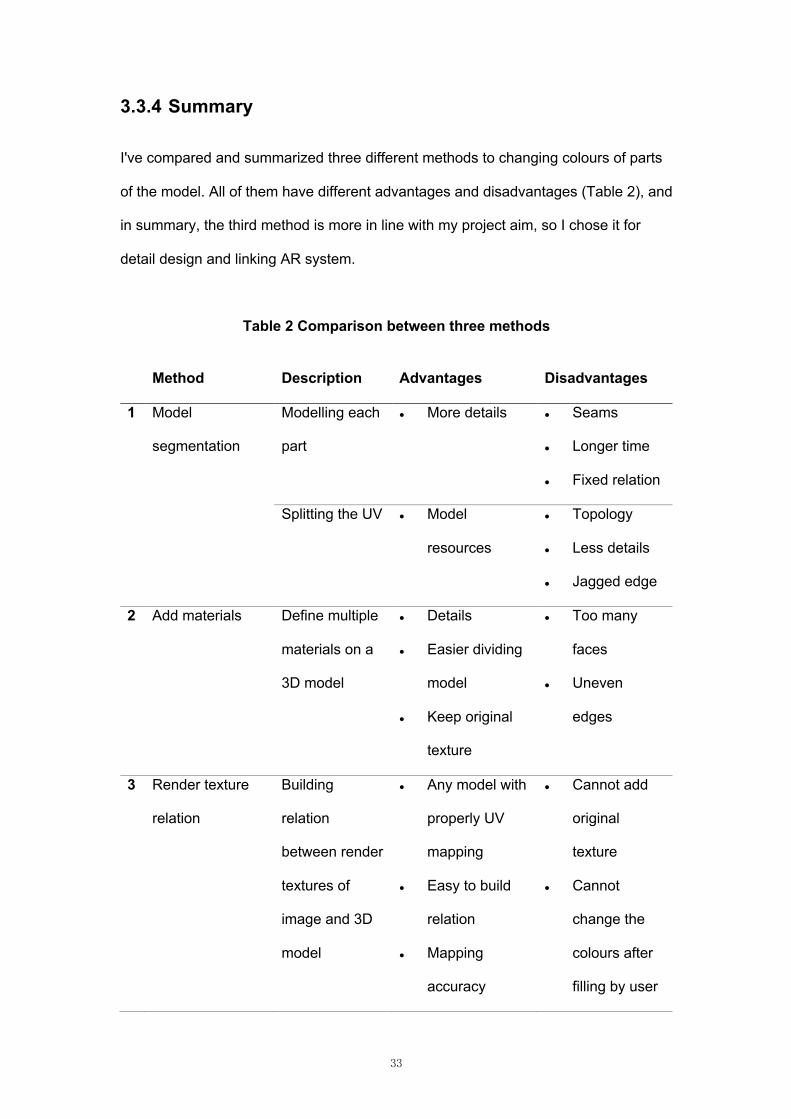
3.3.4 Summary
I've compared and summarized three different methods to changing colours of parts
of the model. All of them have different advantages and disadvantages (Table 2), and
in summary, the third method is more in line with my project aim, so I chose it for
detail design and linking AR system.
Table 2 Comparison between three methods
Method Description Advantages Disadvantages
1
Model
segmentation
Modelling each
part
l More details l Seams
l Longer time
l Fixed relation
Splitting the UV l Model
resources
l Topology
l Less details
l Jagged edge
2 Add materials Define multiple
materials on a
3D model
l Details
l Easier dividing
model
l Keep original
texture
l Too many
faces
l Uneven
edges
3 Render texture
relation
Building
relation
between render
textures of
image and 3D
model
l Any model with
properly UV
mapping
l Easy to build
relation
l Mapping
accuracy
l Cannot add
original
texture
l Cannot
change the
colours after
filling by user
34
l Many-to-many
mapping
3.4 Detailed Design
With the above summary, I chose the third method for further development. In this
part, I mainly introduce about the two parts, one is the setting of the front view and
the other AR development process.
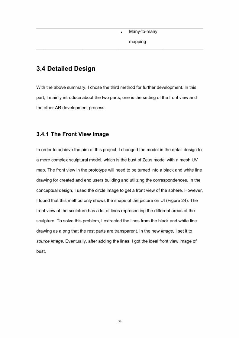
3.4.1 The Front View Image
In order to achieve the aim of this project, I changed the model in the detail design to
a more complex sculptural model, which is the bust of Zeus model with a mesh UV
map. The front view in the prototype will need to be turned into a black and white line
drawing for created and end users building and utilizing the correspondences. In the
conceptual design, I used the circle image to get a front view of the sphere. However,
I found that this method only shows the shape of the picture on UI (Figure 24). The
front view of the sculpture has a lot of lines representing the different areas of the
sculpture. To solve this problem, I extracted the lines from the black and white line
drawing as a png that the rest parts are transparent. In the new image, I set it to
source image. Eventually, after adding the lines, I got the ideal front view image of
bust.
35
Figure 24 Shape of front view image (left) and final view image (right)
3.4.2 Connected to Augmented Reality
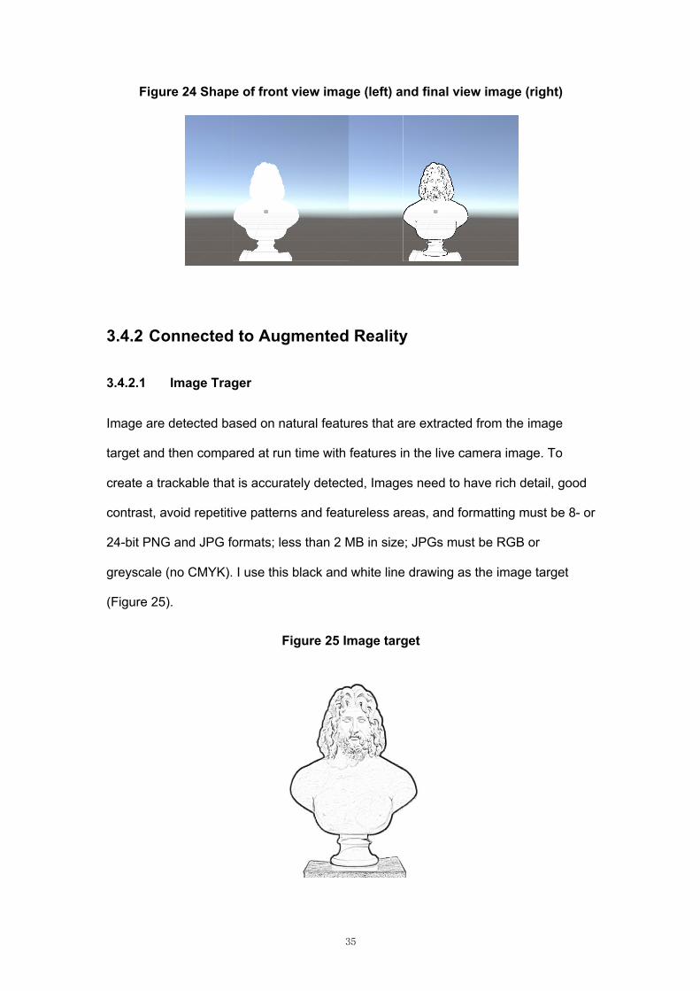
3.4.2.1 Image Trager
Image are detected based on natural features that are extracted from the image
target and then compared at run time with features in the live camera image. To
create a trackable that is accurately detected, Images need to have rich detail, good
contrast, avoid repetitive patterns and featureless areas, and formatting must be 8- or
24-bit PNG and JPG formats; less than 2 MB in size; JPGs must be RGB or
greyscale (no CMYK). I use this black and white line drawing as the image target
(Figure 25).
Figure 25 Image target
36
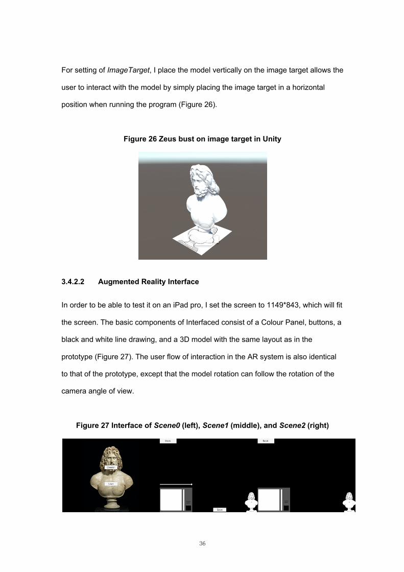
For setting of ImageTarget, I place the model vertically on the image target allows the
user to interact with the model by simply placing the image target in a horizontal
position when running the program (Figure 26).
Figure 26 Zeus bust on image target in Unity
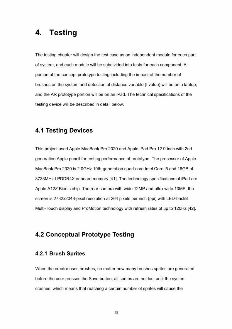
3.4.2.2 Augmented Reality Interface
In order to be able to test it on an iPad pro, I set the screen to 1149*843, which will fit
the screen. The basic components of Interfaced consist of a Colour Panel, buttons, a
black and white line drawing, and a 3D model with the same layout as in the
prototype (Figure 27). The user flow of interaction in the AR system is also identical
to that of the prototype, except that the model rotation can follow the rotation of the
camera angle of view.
Figure 27 Interface of Scene0 (left), Scene1 (middle), and Scene2 (right)

37
So far, all the setup and build of the prototype is complete. The next step is to install
it on the iPad pro for testing.
38
4. Testing
The testing chapter will design the test case as an independent module for each part
of system, and each module will be subdivided into tests for each component. A
portion of the concept prototype testing including the impact of the number of
brushes on the system and detection of distance variable (f value) will be on a laptop,
and the AR prototype portion will be on an iPad. The technical specifications of the
testing device will be described in detail below.
4.1 Testing Devices
This project used Apple MacBook Pro 2020 and Apple iPad Pro 12.9-inch with 2nd
generation Apple pencil for testing performance of prototype. The processor of Apple
MacBook Pro 2020 is 2.0GHz 10th-generation quad-core Intel Core i5 and 16GB of
3733MHz LPDDR4X onboard memory [41]. The technology specifications of iPad are
Apple A12Z Bionic chip. The rear camera with wide 12MP and ultra-wide 10MP, the
screen is 2732x2048-pixel resolution at 264 pixels per inch (ppi) with LED-backlit
Multi-Touch display and ProMotion technology with refresh rates of up to 120Hz [42].
4.2 Conceptual Prototype Testing
4.2.1 Brush Sprites
When the creator uses brushes, no matter how many brushes sprites are generated
before the user presses the Save button, all sprites are not lost until the system
crashes, which means that reaching a certain number of sprites will cause the
39
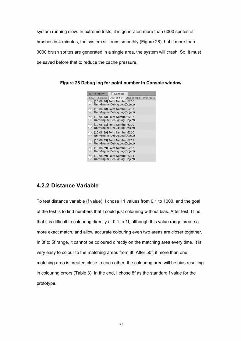
system running slow. In extreme tests, it is generated more than 6000 sprites of
brushes in 4 minutes, the system still runs smoothly (Figure 28), but if more than
3000 brush sprites are generated in a single area, the system will crash. So, it must
be saved before that to reduce the cache pressure.
Figure 28 Debug log for point number in Console window
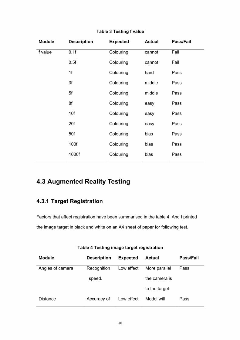
4.2.2 Distance Variable
To test distance variable (f value), I chose 11 values from 0.1 to 1000, and the goal
of the test is to find numbers that I could just colouring without bias. After test, I find
that it is difficult to colouring directly at 0.1 to 1f, although this value range create a
more exact match, and allow accurate colouring even two areas are closer together.
In 3f to 5f range, it cannot be coloured directly on the matching area every time. It is
very easy to colour to the matching areas from 8f. After 50f, if more than one
matching area is created close to each other, the colouring area will be bias resulting
in colouring errors (Table 3). In the end, I chose 8f as the standard f value for the
prototype.
40
Table 3 Testing f value
Module Description Expected Actual Pass/Fail
f value 0.1f Colouring cannot Fail
0.5f Colouring cannot Fail
1f Colouring hard Pass
3f Colouring middle Pass
5f Colouring middle Pass
8f Colouring easy Pass
10f Colouring easy Pass
20f Colouring easy Pass
50f Colouring bias Pass
100f Colouring bias Pass
1000f Colouring bias Pass
4.3 Augmented Reality Testing
4.3.1 Target Registration
Factors that affect registration have been summarised in the table 4. And I printed
the image target in black and white on an A4 sheet of paper for following test.
Table 4 Testing image target registration
Module Description Expected Actual Pass/Fail
Angles of camera Recognition
speed.
Low effect More parallel
the camera is
to the target
Pass
Distance Accuracy of Low effect Model will Pass
41
tracking disappear
when target
loses in screen
System latency System
latency
affects
registration
Low effect No significant
latency
Pass
Variable lighting Changes in
the intensity
of the light
Low effect No significant
difference in
recognition.
Pass
Shadows Shadows on
the image
target
Low effect Recognition
latency.
Pass
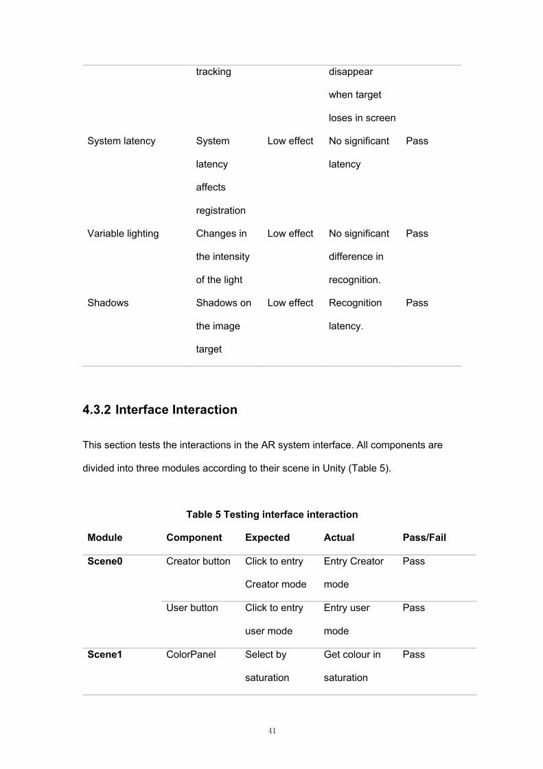
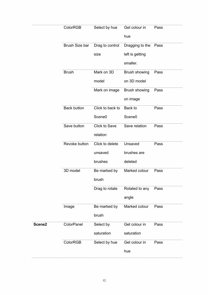
4.3.2 Interface Interaction
This section tests the interactions in the AR system interface. All components are
divided into three modules according to their scene in Unity (Table 5).
Table 5 Testing interface interaction
Module Component Expected Actual Pass/Fail
Scene0 Creator button Click to entry
Creator mode
Entry Creator
mode
Pass
User button Click to entry
user mode
Entry user
mode
Pass
Scene1 ColorPanel Select by
saturation
Get colour in
saturation
Pass
42
ColorRGB Select by hue Get colour in
hue
Pass
Brush Size bar Drag to control
size
Dragging to the
left is getting
smaller.
Pass
Brush Mark on 3D
model
Brush showing
on 3D model
Pass
Mark on image Brush showing
on image
Pass
Back button Click to back to
Scene0
Back to
Scene0
Pass
Save button Click to Save
relation
Save relation Pass
Revoke button Click to delete
unsaved
brushes
Unsaved
brushes are
deleted
Pass
3D model Be marked by
brush
Marked colour Pass
Drag to rotate Rotated to any
angle
Pass
Image Be marked by
brush
Marked colour Pass
Scene2 ColorPanel Select by
saturation
Get colour in
saturation
Pass
ColorRGB Select by hue Get colour in
hue
Pass
43
Brush Mark on image Brush showing
on image
Pass
Back button Back to
Scene0
Backed to
Scene0
Pass
Image Filling by brush Filled colour Pass
3D model Be marked by
relation
Filled colour
same as image
Pass
Drag to rotate Rotate to any
angle
Pass
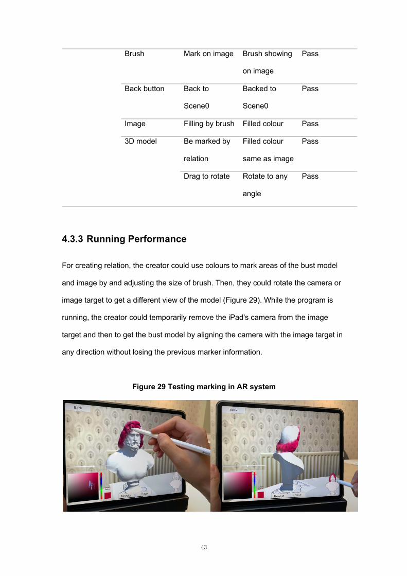
4.3.3 Running Performance
For creating relation, the creator could use colours to mark areas of the bust model
and image by and adjusting the size of brush. Then, they could rotate the camera or
image target to get a different view of the model (Figure 29). While the program is
running, the creator could temporarily remove the iPad's camera from the image
target and then to get the bust model by aligning the camera with the image target in
any direction without losing the previous marker information.
Figure 29 Testing marking in AR system
44
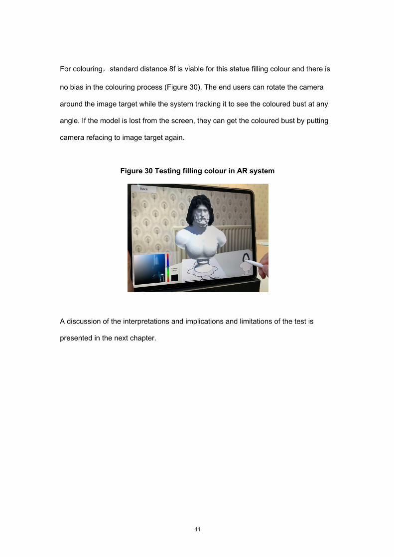
For colouring,standard distance 8f is viable for this statue filling colour and there is
no bias in the colouring process (Figure 30). The end users can rotate the camera
around the image target while the system tracking it to see the coloured bust at any
angle. If the model is lost from the screen, they can get the coloured bust by putting
camera refacing to image target again.
Figure 30 Testing filling colour in AR system
A discussion of the interpretations and implications and limitations of the test is
presented in the next chapter.
45
5. Discussion and Future Work
5.1 Interpretations and Implications
3D painting had already begun to develop programs to paint directly on the model
and to change different brushes and colours to simulate the effects of hand painting.
Hanrahan and Haeberli believe that 3D painting should be programmed to allow the
user should directly see the interactive results [12], which becomes the basis of
concept the development of this prototype. After that, the use of haptic screens in
development of 3D painting [22], and it also became the equipment support for AR
colouring project. Appreciate to the development of UV mapping, it has become very
easy to use texture maps to colour 3D models [15]. Now, this method is widely used
in AR colouring projects, whether it uses to diffuse texture [10, 33] or uses the both
copy and diffusion method [2], it is difficult to develop more complex models to get a
result due to the limitations of texture maps. In addition, these projects only consider
the end user experience, and ignore the process of establishing matching. So, the
initial idea of this project is a challenge to implement colouring the sculpture through
corresponding area from 2D to 3D with augmented reality. In the following
comparison and summary, it is found that the use of render texture in 3D model
proved the feasibility of colouring, and it is applied to the system for establishing
corresponding relations by colouring the model and the image with both render
textures.
Future projects should take into consideration the findings of this prototype because
the most important contribution of the prototype is to take creator into account the
user groups with a wilder perspective to build a system that is easier to establish 2D
to 3D relations, which means that the workflow for AR colouring might be reduced
46
and the system is more open to allow anyone to establish matching relations. More
and more complex models will be added to the AR colouring system, not only for
public entertainment and educational purposes, but also to assist restorers in
important areas such as museum restoration.
5.2 Limitations
As a result of the tests above, there are still some limitations in prototype. First, in the
interface design, the model's front view area is too small which makes it difficult to
create areas and fills using brushes, the size of the brushes needs to be adjusted
more appropriately to the interface design. Second, in the process of building
relations, although losing the model on the screen will not lose the relation
information, holding the iPad for a long time will be very tiring for the users, the
interactive flow and the presentation of the model need to be iteratively optimized.
Third, it is not friendly that the end user can't change the colour again after colouring,
which should be a function to be added in the future.
5.3 Future Work
In a wide perspective, there are two areas of work that could be undertaken in the
future, including building database and connecting 3D print. The database is a
system for organizing, storing and managing data according to data structures. One
of the ways in which future applications will work is to connect to the database, use
this connection to store the data generated by the application, and then colour the
model using the relations established by the creator within the database once the
user is connected to the network.
47
3D printing is a type of rapid prototyping technology in which a computer-designed
three-dimensional digital model is broken down into several layers of flat slices, and
then a 3D printer stacks the different bondable materials layer by layer in a slicing
pattern to eventually build up a complete object. The ultimate future presentation of
this project could be a 3D printed object as the final output, with the foreseeable
future being the use of coloured texture information to generate new model data that
can be exported as a solid coloured model via a pre-programmed 3D printing device.
In the function. if a more advanced method is used to improve the accuracy of the
matching relations, adding texture maps to compensate for model detail, and linking
to more advanced large-scale 3D printers working in conjunction, which could
provide a cheaper and more convenient option for the museum's restoration efforts
and reconnecting to the real world. There has been a case of painted models being
3D printed, but there are still some 3D printing material limitations that may cause the
colours to darken or become fragile [42].
48
6. Conclusion
This project implements three different methods to 2D to 3D region matching in the
conceptual design. The first method is discovered during the modelling process and
is used by most of the current programs for simple models, but the actual results
from the experimental Caligula model are not perfect and take a lot of time. The
second method has been optimized from the first, by adding multiple materials and
grouping the faces of the high poly model according to the model structure that
creator want to divide. This is the result of using advanced Blender software, but it is
still not friendly for establishing a large number of 2D-3D correspondences, and the
fine procedure depends on the model itself. The third method is to use marker
colours to establish correspondence between render textures of image and 3D
model. Although it temporarily cannot to add the original texture map and change the
filled colour, this method can handle any model with UV mapping properly, which
reducing the large amount of workload of modelling for creator to establish
correspondence. Such correspondences support many-to-many relations, and there
is no limit to the number of them.
In order to achieve the aim of simpler mapping creation, I chose to the render texture
mapping concept and eventually tested the Zeus bust model in the AR environment.
The test results showed that the idea of pointing to the UV map, marking on render
textures, and saving relations involved in concept of render texture mapping meet the
project aim, and the tests discover and then solve some of problems that appeared in
the prototype including the number of brushes sprites, distance detection, setting of
model front view image. Three major limitations and future work are: 1. image size
needs to be adjusted to fit the brush size and layout; 2. tiredness during utilizing
requires iterative optimization of the interaction process using additional user data

49
and device selection; 3. the end user cannot yet change the colour after filling in the
region. The broad future expectation is that the program can utilise the database to
provide end users with mapped data produced by creator, even each user can create
and use the correspondences data as both creator and end user, and finally, by
connecting to advanced 3D printers to produce physical models.
50
Bibliography
[1] Clark, A., & Dünser, A. (2012, March). An interactive augmented reality
coloring book. In 2012 IEEE Symposium on 3D User Interfaces (3DUI) (pp. 7-
10). IEEE.
[2] Magnenat, S., Ngo, D. T., Zünd, F., Ryffel, M., Noris, G., Rothlin, G., ... &
Sumner, R. W. (2015). Live texturing of augmented reality characters from
colored drawings. IEEE transactions on visualization and computer
graphics, 21(11), 1201-1210.
[3] Lee, Y. (2015, August). AR coloring jigsaw puzzles with texture extraction and
auto-UV mapping algorithm. In International Conference on Distributed,
Ambient, and Pervasive Interactions (pp. 182-187). Springer, Cham.
[4] Brinkmann, V., Ostergaard, J. S., Collareta, M., & Potts, A. (2008). The color of
life: polychromy in sculpture from antiquity to the present. (pp. 18–39) Getty
Publications.
[5] Bradley, M. (2009). The importance of colour on ancient marble sculpture. Art
history, 32(3), 427-457.
[6] Skovmøller, A., Brøns, C., & Sargent, M. L. (2018). The Polychromy of the
Sculpted Garments on the Statue of Gaius Fundilius Doctus in the Ny
Carlsberg Glyptotek. Polychromy in Ancient Sculpture and Architecture, 93-
100.
[7] Gods in Color – Golden Edition. (n.d.). Retrieved September 07, 2020, from
https://buntegoetter.liebieghaus.de/en/
[8] Archaic Colors: Acropolis Museum. Archaic Colors | Acropolis Museum. (1970,
August 4). https://www.theacropolismuseum.gr/en/content/archaic-colors-1.
[9] COLOUR THE PEPLOS KORE. (2020). Retrieved 7 September 2020, from
https://www.theacropolismuseum.gr/peploforos/.
51
[10] Feng, L., Yang, X., & Xiao, S. (2017, March). MagicToon: A 2D-to-3D creative
cartoon modeling system with mobile AR. In 2017 IEEE Virtual Reality
(VR) (pp. 195-204). IEEE.
[11] Norraji, M. F., & Sunar, M. S. (2015, December). wARna—Mobile-based
augmented reality colouring book. In 2015 4th International Conference on
Interactive Digital Media (ICIDM) (pp. 1-4). IEEE.
[12] Hanrahan, P., & Haeberli, P. (1990). Direct WYSIWYG painting and texturing
on 3D shapes. ACM SIGGRAPH Computer Graphics, 24(4), 215–223.
[13] Adams, B., Wicke, M., Dutré, P., Gross, M. H., Pauly, M., & Teschner, M.
(2004, June). Interactive 3D Painting on Point-Sampled Objects. In SPBG (pp.
57-66).
[14] Williams, L. (1990, February). 3D paint. In Proceedings of the 1990 symposium
on Interactive 3D graphics (pp. 225-233).
[15] Igarashi, T., & Cosgrove, D. (2001, March). Adaptive unwrapping for interactive
texture painting. In Proceedings of the 2001 symposium on Interactive 3D
graphics (pp. 209-216).
[16] Lu, S., Mok, P. Y., & Jin, X. (2017). A new design concept: 3D to 2D textile
pattern design for garments. Computer-Aided Design, 89, 35-49.
[17] Zilles, C. B., & Salisbury, J. K. (1995, August). A constraint-based god-object
method for haptic display. In Proceedings 1995 ieee/rsj international
conference on intelligent robots and systems. Human robot interaction and
cooperative robots (Vol. 3, pp. 146-151). IEEE.
[18] Basdogan, C., & Srinivasan, M. A. (2002). Haptic rendering in virtual
environments. Handbook of virtual environments, 1, 117-134.
[19] Theoktisto, V., Fairén, M., Navazo, I., & Monclús, E. (2005). Rendering detailed
haptic textures. In Second Workshop in Virtual Reality Interactions and
Physical Simulations (VRIPHYS 05) (pp. 16-23).
52
[20] Wakita, W., & Ido, S. (2008). A haptic rendering for high polygon model using
distance map and normal map. IPSJ Journal, 49(7), 2509-2517.
[21] Wakita, W., & Ido, S. (2008). A material system under haptic rendering for
pseudo-roughness. The Transactions of the Institute of Electronics, Information
and Communication Engineers J91-D, 2061-2070.
[22] Wakita, W., Murakami, K., & Ido, S. (2008, December). A texturebased haptic
model design with 3D brush. In Proc. 18th International Conference on Artificial
Reality and Telexistence (ICAT2008) (pp. 51-56).
[23] Technologies, U. (n.d.). Render Texture. Retrieved September 07, 2020, from
https://docs.unity3d.com/2019.4/Documentation/Manual/class-
RenderTexture.html
[24] Technologies, U. (n.d.). RenderTexture. Retrieved September 07, 2020, from
https://docs.unity3d.com/ScriptReference/RenderTexture.html
[25] RealTime Painting: Tutorials: Unity Asset Store. (n.d.). Retrieved September
07, 2020, from
https://assetstore.unity.com/packages/templates/tutorials/realtime-painting-
33506
[26] Azuma, R. T. (1997). A survey of augmented reality. Presence: Teleoperators
& Virtual Environments, 6(4), 355-385.
[27] Craig, A. B. (2013). Understanding augmented reality: Concepts and
applications. (pp. 1–36) Newnes.
[28] QuiverVision. (n.d.). Retrieved September 07, 2020, from
https://quivervision.com/
[29] Lee, Y., & Choi, J. (2015). Texture extraction from video and image warping for
AR coloring book. In Computer Science and its Applications (pp. 361-365).
Springer, Berlin, Heidelberg.
[30] Dinosaur Sketchbook. VUiDEA. (n.d.). Retrieved September 07, 2020, from
http://www.vuidea.com/

53
[31] Cho, K., Kim, H., & Lee, Y. (2016). Augmented reality coloring book with
transitional user interface. Indian Journal of Science and Technology, 9(20), 1-
5.
[32] Mokhtar, M. K., Mohamed, F., Sunar, M. S., Arshad, M. A. M., & Sidik, M. K. M.
(2018, November). Development of mobile-based augmented reality colouring
for preschool learning. In 2018 IEEE Conference on e-Learning, e-
Management and e-Services (IC3e) (pp. 11-16). IEEE.
[33] Olsen, L., Samavati, F., & Jorge, J. (2011). Naturasketch: Modeling from
images and natural sketches. IEEE Computer Graphics and
Applications, 31(6), 24-34.
[34] Technologies, U. (n.d.). Learning the interface. Retrieved September 07, 2020,
fromhttps://docs.unity3d.com/560/Documentation/Manual/LearningtheInterface.
html
[35] Getting Started with Vuforia Engine in Unity. Retrieved September 07, 2020,
from https://library.vuforia.com/articles/Training/getting-started-with-vuforia-in-
unity.html
[36] Window System Introduction. (n.d.). Retrieved September 07, 2020, from
https://docs.blender.org/manual/en/latest/interface/window_system/introduction
.html
[37] Colossal marble bust of Zeus: British Museum. (n.d.). Retrieved September 07,
2020, from https://www.britishmuseum.org/collection/object/G_1836-0709-1
[38] Colossal marble bust of Zeus 3D model. Retrieved September 07, 2020, from
https://sketchfab.com/3d-models/colossal-marble-bust-of-zeus-
9246efe1279543a784a08be62e6b96a8
[39] Frischer, B. (2020). Introduction with Remarks on the Methodological
Implications of the Digital Restoration of the Richmond Caligula. In New
Studies on the Portrait of Caligula in the Virginia Museum of Fine Arts (pp. 9-
16). Brill.
54
[40] The Digital Sculpture Project: Caligula. Retrieved September 07, 2020, from
http://www.digitalsculpture.org/caligula/index_sketchfab_purpurea.html
[41] MacBook Pro 13-inch - Technical Specifications. (n.d.). Retrieved September
07, 2020, from https://www.apple.com/uk/macbook-pro-13/specs/
[42] IPad Pro - Technical Specifications. (n.d.). Retrieved September 07, 2020, from
https://www.apple.com/uk/ipad-pro/specs/
[43] Mccarthy, J., Sebo, E., Wilkinson, B., & Sheehan, F. (2020). Open workflows
for polychromatic reconstruction of historical sculptural monuments in
3D. Journal on Computing and Cultural Heritage (JOCCH), 13(3), 1-16.
[44] Explore the possibilities of RealityCapture. (n.d.). Retrieved September 08,
2020, from http://www.capturingreality.com/
![\"Toward a Practicable Sculpture\" [Afterword to reprint of Edmund Gosse's 1895 \"The Place of Sculpture in Daily Life\"]](https://img.pdfslide.net/doc/110x75/635d8fd3a0f1eac29f0c412f/toward-a-practicable-sculpture-afterword-to-reprint-of-edmund-gosses-1895.jpg)


