Embed Size (px)
Citation preview
RELION® 670 SERIES— Transformer protection RET670 Version 2.2 IEC Commissioning manual

Document ID: 1MRK 504 165-UENIssued: October 2017
Revision: AProduct version: 2.2.1
© Copyright 2017 ABB. All rights reserved
Copyright
This document and parts thereof must not be reproduced or copied without writtenpermission from ABB, and the contents thereof must not be imparted to a thirdparty, nor used for any unauthorized purpose.
The software and hardware described in this document is furnished under a licenseand may be used or disclosed only in accordance with the terms of such license.
This product includes software developed by the OpenSSL Project for use in theOpenSSL Toolkit. (http://www.openssl.org/) This product includes cryptographicsoftware written/developed by: Eric Young ([email protected]) and Tim Hudson([email protected]).
TrademarksABB and Relion are registered trademarks of the ABB Group. All other brand orproduct names mentioned in this document may be trademarks or registeredtrademarks of their respective holders.
WarrantyPlease inquire about the terms of warranty from your nearest ABB representative.

Disclaimer
The data, examples and diagrams in this manual are included solely for the conceptor product description and are not to be deemed as a statement of guaranteedproperties. All persons responsible for applying the equipment addressed in thismanual must satisfy themselves that each intended application is suitable andacceptable, including that any applicable safety or other operational requirementsare complied with. In particular, any risks in applications where a system failureand/or product failure would create a risk for harm to property or persons(including but not limited to personal injuries or death) shall be the soleresponsibility of the person or entity applying the equipment, and those soresponsible are hereby requested to ensure that all measures are taken to exclude ormitigate such risks.
This document has been carefully checked by ABB but deviations cannot becompletely ruled out. In case any errors are detected, the reader is kindly requestedto notify the manufacturer. Other than under explicit contractual commitments, inno event shall ABB be responsible or liable for any loss or damage resulting fromthe use of this manual or the application of the equipment.

Conformity
This product complies with the directive of the Council of the EuropeanCommunities on the approximation of the laws of the Member States relating toelectromagnetic compatibility (EMC Directive 2004/108/EC) and concerningelectrical equipment for use within specified voltage limits (Low-voltage directive2006/95/EC). This conformity is the result of tests conducted by ABB inaccordance with the product standard EN 60255-26 for the EMC directive, andwith the product standards EN 60255-1 and EN 60255-27 for the low voltagedirective. The product is designed in accordance with the international standards ofthe IEC 60255 series.
Table of contents
Section 1 Introduction.....................................................................13This manual...................................................................................... 13Intended audience............................................................................ 13Product documentation.....................................................................14
Product documentation set..........................................................14Document revision history........................................................... 15Related documents......................................................................16
Document symbols and conventions................................................16Symbols.......................................................................................16Document conventions................................................................17
IEC 61850 edition 1 / edition 2 mapping...........................................18
Section 2 Safety information.......................................................... 27Symbols on the product....................................................................27Warnings.......................................................................................... 27Caution signs....................................................................................29Note signs.........................................................................................29
Section 3 Available functions......................................................... 31Main protection functions..................................................................31Back-up protection functions............................................................ 33Control and monitoring functions......................................................35Communication.................................................................................42Basic IED functions.......................................................................... 45
Section 4 Starting up......................................................................47Factory and site acceptance testing................................................. 47Commissioning checklist.................................................................. 47Checking the power supply.............................................................. 48Energizing the IED............................................................................48
Checking the IED operation.........................................................48IED start-up sequence.................................................................49
Setting up communication between PCM600 and the IED...............49Writing an application configuration to the IED.................................54Checking CT circuits.........................................................................55Checking VT circuits.........................................................................56Using the RTXP test switch.............................................................. 56Checking the binary input/output circuits..........................................57
Binary input circuits..................................................................... 57Binary output circuits................................................................... 57
Table of contents
Transformer protection RET670 2.2 IEC 1Commissioning manual
Checking optical connections........................................................... 58
Section 5 Configuring the IED and changing settings....................59Overview...........................................................................................59Configuring analog CT inputs........................................................... 60Supervision of input/output modules................................................ 60
Section 6 Establishing connection and verifying the SPA/IECcommunication............................................................... 63Entering settings...............................................................................63
Entering SPA settings..................................................................63Entering IEC settings...................................................................63
Verifying the communication............................................................ 64Verifying SPA communication..................................................... 64Verifying IEC communication...................................................... 64
Fibre optic loop................................................................................. 65Optical budget calculation for serial communication withSPA/IEC .......................................................................................... 65
Section 7 Establishing connection and verifying the LONcommunication............................................................... 67Communication via the rear ports ....................................................67
LON communication....................................................................67The LON Protocol........................................................................68Hardware and software modules.................................................68
Optical budget calculation for serial communication with LON ........70
Section 8 Establishing connection and verifying the IEC 61850communication............................................................... 71Overview...........................................................................................71Setting the station communication....................................................71Verifying the communication............................................................ 72
Section 9 Establishing connection and verifying the IEEEC37.118/1344 communication........................................73Overview...........................................................................................73Setting the PMU station communication (PMU Report)................... 73Setting the PMU station communication (PMU configuration)..........74Setting the TCP/UDP client communication..................................... 75Verifying the communication............................................................ 78
Verifying the IEEE C37.118/1344 TCP communication.............. 79Verifying the IEEE C37.118/1344 UDP communication..............85
Optical budget calculation for PMU - PDC communication.............. 86
Section 10 Testing IED operation.....................................................87Preparing for test.............................................................................. 87
Table of contents
2 Transformer protection RET670 2.2 IECCommissioning manual
Requirements.............................................................................. 87Preparing the IED to verify settings.............................................89
Activating the test mode................................................................... 90Preparing the connection to the test equipment............................... 90Connecting the test equipment to the IED........................................91Releasing the function to be tested.................................................. 92Verifying analog primary and secondary measurement................... 93Testing the protection functionality................................................... 94Forcing of binary input/output signals for testing.............................. 95
Forcing concept...........................................................................95How to enable forcing..................................................................95
Enable forcing by using LHMI................................................ 95Enable forcing using TESTMODE function block...................96
How to change binary input/output signals using forcing............ 96Forcing by using LHMI........................................................... 96Forcing by using PCM600...................................................... 98
How to undo forcing changes and return the IED to normaloperation......................................................................................99
Undo forcing by using TESTMODE component...................100Undo forcing by using LHMI................................................. 100Undo forcing by using PCM600............................................100
Section 11 Testing functionality by secondary injection.................103Testing disturbance report..............................................................103
Introduction................................................................................103Disturbance report settings........................................................103Disturbance recorder (DR)........................................................ 103Event recorder (ER) and Event list (EL).................................... 104
Identifying the function to test in the technical reference manual ..105Differential protection......................................................................105
Transformer differential protection T2WPDIF andT3WPDIF..... 105Verifying the settings............................................................ 105Completing the test.............................................................. 106
High impedance differential protection HZPDIF ....................... 106Verifying the settings............................................................ 106Completing the test.............................................................. 107
Restricted earth fault protection, low impedance REFPDIF ..... 107Verifying the settings............................................................ 107Completing the test.............................................................. 108
Additional security logic for differential protection LDRGFC .....108Verifying the settings............................................................ 108Completing the test.............................................................. 110
Impedance protection..................................................................... 110
Table of contents
Transformer protection RET670 2.2 IEC 3Commissioning manual
Distance protection zones, quadrilateral characteristicZMQPDIS.................................................................................. 110
Measuring the operating limit of set values.......................... 114Measuring the operating time of distance protection zones. 114Completing the test.............................................................. 115
Phase selection, quad, fixed angle, load encroachmentFDPSPDIS ................................................................................115
Measuring the operating limit of set values.......................... 118Completing the test.............................................................. 118
Full scheme distance protection, mho characteristic ZMHPDIS118Phase-to-phase faults.......................................................... 119Phase-to-earth faults............................................................ 119
Faulty phase identification with load encroachmentFMPSPDIS ............................................................................... 120Distance protection zones, quadrilateral characteristic,separate settings ZMRPDIS......................................................120
Measuring the operating limit of set values.......................... 124Measuring the operating time of distance protection zones. 125
Phase selection, quadrilateral characteristic with settableangle FRPSPDIS.......................................................................125
Measuring the operating limit of set values.......................... 127Completing the test.............................................................. 128
High speed distance protection zones, quadrilateral andmho characteristic ZMFPDIS.....................................................128
Measuring the operating limit of set values.......................... 132Measuring the operating time of distance protection zones. 132Completing the test.............................................................. 133
High Speed distance for series compensated line zones,quadrilateral and mho characteristic ZMFCPDIS ..................... 133
Measuring the operating limit of set values.......................... 136Measuring the operating time of distance protection zones. 137Completing the test.............................................................. 137
Power swing detection ZMRPSB ..............................................137Verifying the settings............................................................ 139Testing the power swing detection function ZMRPSB ........ 140Testing the tR1 timer............................................................ 140Testing the block input, interaction between FDPSPDISor FRPSPDIS and ZMRPSB ............................................... 141Completing the test.............................................................. 141
Power swing logic PSLPSCH....................................................141Testing the carrier send and trip signals.............................. 142Testing the influence of the residual overcurrent protection.142Checking the underreaching zone........................................143Completing the test.............................................................. 143
Table of contents
4 Transformer protection RET670 2.2 IECCommissioning manual
Pole slip protection PSPPPAM..................................................144Verifying the settings............................................................ 144Completing the test.............................................................. 146
Out-of-step protection OOSPPAM.............................................146Verifying the settings............................................................ 147Test of point RE (RFwdR, XFwdX)........................................... 151Test of the boundary between zone 1 and zone 2, whichis defined by the parameter ReachZ1.................................. 155Test of the point SE (RRvsR, XRvsX)...................................... 160
Automatic switch onto fault logic ZCVPSOF............................. 164Activating ZCVPSOF externally........................................... 165Initiating ZCVPSOF automatically and setting mode toimpedance............................................................................165Initiating ZCVPSOF automatically and setting mode toUILevel ................................................................................ 165Completing the test.............................................................. 165
Phase preference logic PPLPHIZ .............................................166Completing the test.............................................................. 167
Phase preference logic PPL2PHIZ............................................167Completing the test....................................................................168Under impedance protection for Generator ZGVPDIS.............. 168
Verifying the settings............................................................ 168Completing the test.............................................................. 171
Current protection...........................................................................172Instantaneous phase overcurrent protection 3-phase outputPHPIOC ....................................................................................172
Measuring the operate limit of set values.............................172Completing the test.............................................................. 172
Directional phase overcurrent protection, four stepsOC4PTOC................................................................................. 173
Verifying the settings............................................................ 173Completing the test.............................................................. 174
Instantaneous residual overcurrent protection EFPIOC ...........174Measuring the operate limit of set values.............................175Completing the test.............................................................. 175
Four step residual overcurrent protection, (Zero sequenceor negative sequence directionality) EF4PTOC ....................... 175
Four step directional earth fault protection........................... 175Four step non-directional earth fault protection....................176Completing the test.............................................................. 176
Four step negative sequence overcurrent protectionNS4PTOC .................................................................................176
Completing the test.............................................................. 177
Table of contents
Transformer protection RET670 2.2 IEC 5Commissioning manual
Sensitive directional residual overcurrent and powerprotection SDEPSDE ................................................................178
Measuring the operate and time limit for set values.............178Completing the test.............................................................. 184
Thermal overload protection, two time constants TRPTTR ......184Checking operate and reset values......................................184Completing the test.............................................................. 185
Breaker failure protection, phase segregated activation andoutput CCRBRF.........................................................................185
Checking the phase current operate value, IP>................... 185Checking the residual (earth fault) current operate valueIN> set below IP>................................................................. 186Checking the re-trip and back-up times................................186Verifying the re-trip mode..................................................... 186Verifying the back-up trip mode............................................187Verifying instantaneous back-up trip at CB faulty condition. 188Verifying the function mode Current/Contact....................... 188Completing the test.............................................................. 189
Stub protection STBPTOC........................................................ 189Measuring the operate limit of set values.............................189Completing the test.............................................................. 190
Pole discordance protection CCPDSC......................................190Verifying the settings............................................................ 190Completing the test.............................................................. 191
Directional underpower protection GUPPDUP .........................191Verifying the settings............................................................ 191Completing the test.............................................................. 193
Directional overpower protection GOPPDOP ...........................193Verifying the settings............................................................ 193Completing the test.............................................................. 194
Broken conductor check BRCPTOC ........................................ 194Measuring the operate and time limit of set values.............. 194Completing the test.............................................................. 194
Capacitor bank protection CBPGAPC.......................................195Verifying the settings and operation of the function............. 195Completing the test.............................................................. 199
Negative-sequence time overcurrent protection formachines NS2PTOC ................................................................ 199
Verifying settings by secondary injection............................. 199Completing the test.............................................................. 201
Voltage-restrained time overcurrent protection VRPVOC......... 201Verifying the settings............................................................ 201Completing the test.............................................................. 205
Voltage protection...........................................................................205
Table of contents
6 Transformer protection RET670 2.2 IECCommissioning manual
Two step undervoltage protection UV2PTUV ...........................205Verifying the settings............................................................ 205Completing the test.............................................................. 206
Two step overvoltage protection OV2PTOV .............................206Verifying the settings............................................................ 206Extended testing...................................................................207Completing the test.............................................................. 207
Two step residual overvoltage protection ROV2PTOV ............ 207Verifying the settings............................................................ 208Completing the test.............................................................. 208
Overexcitation protection OEXPVPH ....................................... 208Verifying the settings............................................................ 208Completing the test.............................................................. 209
Voltage differential protection VDCPTOV .................................209Check of undervoltage levels............................................... 209Check of voltage differential trip and alarm levels................211Check of trip and trip reset timers........................................ 212Final adjustment of compensation for VT ratio differences . 213Completing the test.............................................................. 213
Loss of voltage check LOVPTUV ............................................. 213Measuring the operate limit of set values.............................213Completing the test.............................................................. 214
Frequency protection......................................................................214Underfrequency protection SAPTUF ........................................214
Verifying the settings............................................................ 214Completing the test.............................................................. 216
Overfrequency protection SAPTOF ..........................................216Verifying the settings............................................................ 216Completing the test.............................................................. 217
Rate-of-change frequency protection SAPFRC ........................217Verifying the settings............................................................ 217Completing the test.............................................................. 218
Multipurpose protection.................................................................. 218General current and voltage protection CVGAPC.....................218
Built-in overcurrent feature (non-directional)........................ 218Overcurrent feature with current restraint.............................219Overcurrent feature with voltage restraint............................ 219Overcurrent feature with directionality..................................220Over/Undervoltage feature................................................... 220Completing the test.............................................................. 221
Secondary system supervision.......................................................221Current circuit supervision CCSSPVC.......................................221
Verifying the settings............................................................ 221
Table of contents
Transformer protection RET670 2.2 IEC 7Commissioning manual
Completing the test.............................................................. 221Fuse failure supervision FUFSPVC...........................................221
Checking that the binary inputs and outputs operate asexpected ..............................................................................222Measuring the operate value for the negative sequencefunction ................................................................................222Measuring the operate value for the zero-sequencefunction ................................................................................224Measuring the operate value for the dead line detectionfunction.................................................................................224Checking the operation of the du/dt and di/dt basedfunction ................................................................................225Completing the test.............................................................. 226
Fuse failure supervision VDSPVC.............................................226Completing the test.............................................................. 227
Control............................................................................................ 227Synchrocheck, energizing check, and synchronizingSESRSYN................................................................................. 227
Testing the synchronizing function....................................... 229Testing the synchrocheck functionality.................................229Testing the energizing check................................................232Testing the voltage selection................................................233Completing the test.............................................................. 235
Apparatus control APC..............................................................236Voltage control TR1ATCC, TR8ATCC, TCMYLTC, TCLYLTC. 236
Secondary test..................................................................... 238Check the activation of the voltage control operation...........238Check the normal voltage regulation function...................... 239Check the undervoltage block function................................ 240Check the upper and lower busbar voltage limit.................. 240Check the overcurrent block function................................... 241Single transformer................................................................ 241Parallel voltage regulation.................................................... 242Completing the test.............................................................. 247
Single command, 16 signals SINGLECMD............................... 247Interlocking................................................................................ 247
Scheme communication................................................................. 247Scheme communication logic for distance or overcurrentprotection ZCPSCH ..................................................................247
Testing permissive underreaching....................................... 248Testing permissive overreaching..........................................248Testing blocking scheme......................................................248Testing delta blocking scheme............................................. 249Checking of unblocking logic................................................249
Table of contents
8 Transformer protection RET670 2.2 IECCommissioning manual
Completing the test.............................................................. 250Phase segregated scheme communication logic fordistance or overcurrent protection ZC1PPSCH ........................250
Testing permissive underreaching....................................... 250Testing permissive overreaching..........................................251Testing blocking scheme......................................................251Completing the test.............................................................. 251
Current reversal and Weak-end infeed logic for distanceprotection 3-phase ZCRWPSCH ..............................................252
Current reversal logic........................................................... 252Weak end infeed logic.......................................................... 253Completing the test.............................................................. 253
Scheme communication logic for residual overcurrentprotection ECPSCH ..................................................................254
Testing the directional comparison logic function.................254Completing the test.............................................................. 255
Current reversal and weak-end infeed logic for residualovercurrent protection ECRWPSCH .........................................255
Testing the current reversal logic......................................... 256Testing the weak-end infeed logic........................................256Completing the test.............................................................. 258
Logic............................................................................................... 258Tripping logic, common 3-phase output SMPPTRC .................258
3 phase operating mode.......................................................2581ph/3ph operating mode...................................................... 2591ph/2ph/3ph operating mode............................................... 260Circuit breaker lockout..........................................................261Completing the test.............................................................. 261
Monitoring.......................................................................................262Gas medium supervision SSIMG.............................................. 262
Testing the gas medium supervision for pressure alarmand pressure lockout conditions...........................................262Testing the gas medium supervision for temperaturealarm and temperature lock out conditions.......................... 263Completing the test.............................................................. 263
Liquid medium supervision SSIML............................................ 263Testing the liquid medium supervision for level alarmand level lockout conditions................................................. 263Testing the liquid medium supervision for temperaturealarm and temperature lock out conditions.......................... 264Completing the test.............................................................. 264
Breaker monitoring SSCBR.......................................................264Verifying the settings............................................................ 265Completing the test.............................................................. 266
Table of contents
Transformer protection RET670 2.2 IEC 9Commissioning manual
Event function EVENT...............................................................267Fault locator LMBRFLO.............................................................267
Measuring the operate limit.................................................. 268Completing the test.............................................................. 268
Limit counter L4UFCNT.............................................................268Completing the test.............................................................. 269
Estimation of transformer insulation life LOLSPTR .................. 269Verifying the signals and settings.........................................269Completing the test.............................................................. 271
Metering..........................................................................................271Pulse-counter logic PCFCNT.................................................... 271Function for energy calculation and demand handlingETPMMTR.................................................................................271
Verifying the settings............................................................ 271Completing the test.............................................................. 272
Station communication................................................................... 273Multiple command and transmit MULTICMDRCV /MULTICMDSND........................................................................273
Remote communication..................................................................273Binary signal transfer.................................................................273
Basic IED functions........................................................................ 274Parameter setting group handling SETGRPS........................... 274
Verifying the settings............................................................ 274Completing the test.............................................................. 275
Exit test mode.................................................................................275
Section 12 Primary injection testing............................................... 277Transformer Voltage Control ATCC............................................... 277
Load drop compensation function, LDC.................................... 277Voltage control of Parallel Transformers................................... 279Minimum Circulating Current (MCC) method............................ 279Master Follower (MF) method................................................... 281Completing the test....................................................................282
Section 13 Checking the directionality........................................... 283Overview.........................................................................................283Testing the directionality of the distance protection........................283
Section 14 Commissioning and maintenance of the faultclearing system............................................................ 287Commissioning tests...................................................................... 287Periodic maintenance tests............................................................ 287
Visual inspection........................................................................288Maintenance tests..................................................................... 288
Preparation...........................................................................288
Table of contents
10 Transformer protection RET670 2.2 IECCommissioning manual
Recording............................................................................. 289Secondary injection.............................................................. 289Alarm test............................................................................. 289Self supervision check..........................................................289Trip circuit check.................................................................. 289Measurement of service currents......................................... 290Restoring.............................................................................. 291
Section 15 Troubleshooting............................................................293Checking the self supervision signals.............................................293
Checking the self supervision function...................................... 293Determine the cause of an internal failure............................293
Self supervision HMI data..........................................................293General IED status............................................................... 293
Fault tracing....................................................................................294Internal fault indications.............................................................294Using front-connected PC......................................................... 295Diagnosing the IED status via the LHMI hint menu...................297
Repair instruction............................................................................299Repair support................................................................................ 300Maintenance................................................................................... 300
Section 16 Glossary....................................................................... 301
Table of contents
Transformer protection RET670 2.2 IEC 11Commissioning manual

12
Section 1 Introduction
1.1 This manualGUID-AB423A30-13C2-46AF-B7FE-A73BB425EB5F v18
The commissioning manual contains instructions on how to commission the IED.The manual can also be used by system engineers and maintenance personnel forassistance during the testing phase. The manual provides procedures for thechecking of external circuitry and energizing the IED, parameter setting andconfiguration as well as verifying settings by secondary injection. The manualdescribes the process of testing an IED in a substation which is not in service. Thechapters are organized in the chronological order in which the IED should becommissioned. The relevant procedures may be followed also during the serviceand maintenance activities.
1.2 Intended audienceGUID-C9B8127F-5748-4BEA-9E4F-CC762FE28A3A v11
This manual addresses the personnel responsible for commissioning, maintenanceand taking the IED in and out of normal service.
The commissioning personnel must have a basic knowledge of handling electronicequipment. The commissioning and maintenance personnel must be wellexperienced in using protection equipment, test equipment, protection functionsand the configured functional logics in the IED.
1MRK 504 165-UEN A Section 1Introduction
Transformer protection RET670 2.2 IEC 13Commissioning manual
1.3 Product documentation
1.3.1 Product documentation setGUID-3AA69EA6-F1D8-47C6-A8E6-562F29C67172 v15
IEC07000220-4-en.vsd
Plan
ning
& p
urch
ase
Engi
neer
ing
Inst
allin
g
Com
mis
sion
ing
Ope
ratio
n
Mai
nten
ance
Dec
omm
issi
onin
gD
eins
tallin
g &
disp
osal
Application manual
Operation manual
Installation manual
Engineering manual
Communication protocol manual
Cyber security deployment guideline
Technical manual
Commissioning manual
IEC07000220 V4 EN-US
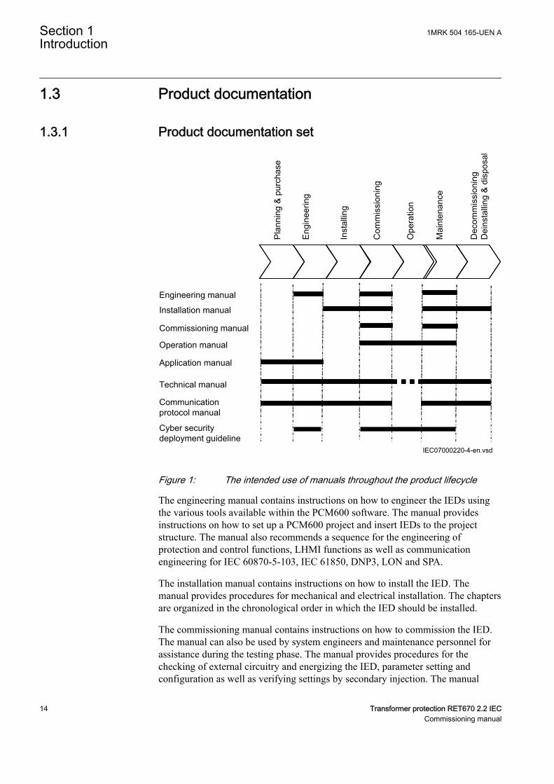
Figure 1: The intended use of manuals throughout the product lifecycle
The engineering manual contains instructions on how to engineer the IEDs usingthe various tools available within the PCM600 software. The manual providesinstructions on how to set up a PCM600 project and insert IEDs to the projectstructure. The manual also recommends a sequence for the engineering ofprotection and control functions, LHMI functions as well as communicationengineering for IEC 60870-5-103, IEC 61850, DNP3, LON and SPA.
The installation manual contains instructions on how to install the IED. Themanual provides procedures for mechanical and electrical installation. The chaptersare organized in the chronological order in which the IED should be installed.
The commissioning manual contains instructions on how to commission the IED.The manual can also be used by system engineers and maintenance personnel forassistance during the testing phase. The manual provides procedures for thechecking of external circuitry and energizing the IED, parameter setting andconfiguration as well as verifying settings by secondary injection. The manual
Section 1 1MRK 504 165-UEN AIntroduction
14 Transformer protection RET670 2.2 IECCommissioning manual
describes the process of testing an IED in a substation which is not in service. Thechapters are organized in the chronological order in which the IED should becommissioned. The relevant procedures may be followed also during the serviceand maintenance activities.
The operation manual contains instructions on how to operate the IED once it hasbeen commissioned. The manual provides instructions for the monitoring,controlling and setting of the IED. The manual also describes how to identifydisturbances and how to view calculated and measured power grid data todetermine the cause of a fault.
The application manual contains application descriptions and setting guidelinessorted per function. The manual can be used to find out when and for what purposea typical protection function can be used. The manual can also provide assistancefor calculating settings.
The technical manual contains operation principle descriptions, and lists functionblocks, logic diagrams, input and output signals, setting parameters and technicaldata, sorted per function. The manual can be used as a technical reference duringthe engineering phase, installation and commissioning phase, and during normalservice.
The communication protocol manual describes the communication protocolssupported by the IED. The manual concentrates on the vendor-specificimplementations.
The point list manual describes the outlook and properties of the data pointsspecific to the IED. The manual should be used in conjunction with thecorresponding communication protocol manual.
The cyber security deployment guideline describes the process for handling cybersecurity when communicating with the IED. Certification, Authorization with rolebased access control, and product engineering for cyber security related events aredescribed and sorted by function. The guideline can be used as a technicalreference during the engineering phase, installation and commissioning phase, andduring normal service.
1.3.2 Document revision historyGUID-C8027F8A-D3CB-41C1-B078-F9E59BB73A6C v4
Document revision/date History–/May 2017 First release
1MRK 504 165-UEN A Section 1Introduction
Transformer protection RET670 2.2 IEC 15Commissioning manual
1.3.3 Related documentsGUID-94E8A5CA-BE1B-45AF-81E7-5A41D34EE112 v5
Documents related to RET670 Document numbersApplication manual 1MRK 504 163-UEN
Commissioning manual 1MRK 504 165-UEN
Product guide 1MRK 504 166-BEN
Technical manual 1MRK 504 164-UEN
Type test certificate 1MRK 504 166-TEN
670 series manuals Document numbersOperation manual 1MRK 500 127-UEN
Engineering manual 1MRK 511 398-UEN
Installation manual 1MRK 514 026-UEN
Communication protocol manual, DNP3 1MRK 511 391-UUS
Communication protocol manual, IEC60870-5-103
1MRK 511 394-UEN
Communication protocol manual, IEC 61850Edition 1
1MRK 511 392-UEN
Communication protocol manual, IEC 61850Edition 2
1MRK 511 393-UEN
Communication protocol manual, LON 1MRK 511 395-UEN
Communication protocol manual, SPA 1MRK 511 396-UEN
Point list manual, DNP3 1MRK 511 397-UUS
Accessories guide 1MRK 514 012-BEN
Cyber security deployment guideline 1MRK 511 399-UEN
Connection and Installation components 1MRK 513 003-BEN
Test system, COMBITEST 1MRK 512 001-BEN
Application guide, Communication set-up 1MRK 505 382-UEN
1.4 Document symbols and conventions
1.4.1 SymbolsGUID-2945B229-DAB0-4F15-8A0E-B9CF0C2C7B15 v12
The electrical warning icon indicates the presence of a hazardwhich could result in electrical shock.
The warning icon indicates the presence of a hazard which couldresult in personal injury.
Section 1 1MRK 504 165-UEN AIntroduction
16 Transformer protection RET670 2.2 IECCommissioning manual
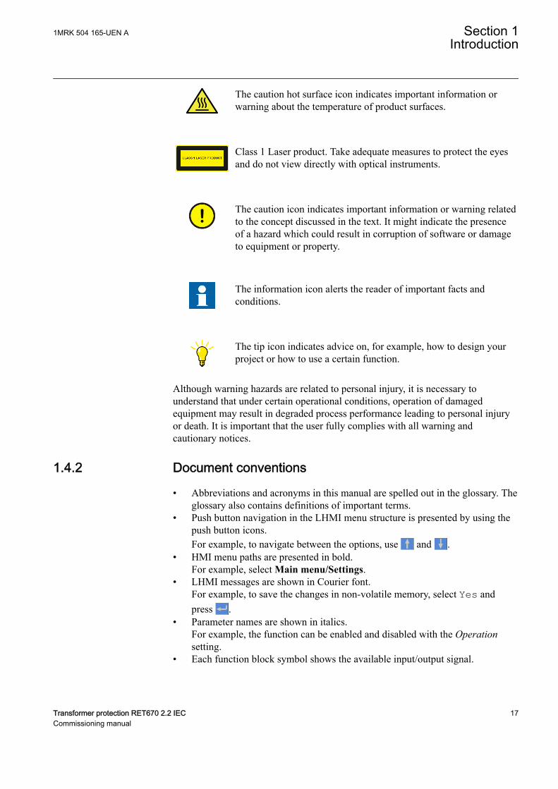
The caution hot surface icon indicates important information orwarning about the temperature of product surfaces.
Class 1 Laser product. Take adequate measures to protect the eyesand do not view directly with optical instruments.
The caution icon indicates important information or warning relatedto the concept discussed in the text. It might indicate the presenceof a hazard which could result in corruption of software or damageto equipment or property.
The information icon alerts the reader of important facts andconditions.
The tip icon indicates advice on, for example, how to design yourproject or how to use a certain function.
Although warning hazards are related to personal injury, it is necessary tounderstand that under certain operational conditions, operation of damagedequipment may result in degraded process performance leading to personal injuryor death. It is important that the user fully complies with all warning andcautionary notices.
1.4.2 Document conventionsGUID-96DFAB1A-98FE-4B26-8E90-F7CEB14B1AB6 v6
• Abbreviations and acronyms in this manual are spelled out in the glossary. Theglossary also contains definitions of important terms.
• Push button navigation in the LHMI menu structure is presented by using thepush button icons.For example, to navigate between the options, use and .
• HMI menu paths are presented in bold.For example, select Main menu/Settings.
• LHMI messages are shown in Courier font.For example, to save the changes in non-volatile memory, select Yes andpress .
• Parameter names are shown in italics.For example, the function can be enabled and disabled with the Operationsetting.
• Each function block symbol shows the available input/output signal.
1MRK 504 165-UEN A Section 1Introduction
Transformer protection RET670 2.2 IEC 17Commissioning manual
• the character ^ in front of an input/output signal name indicates that thesignal name may be customized using the PCM600 software.
• the character * after an input signal name indicates that the signal mustbe connected to another function block in the application configurationto achieve a valid application configuration.
• Logic diagrams describe the signal logic inside the function block and arebordered by dashed lines.• Signals in frames with a shaded area on their right hand side represent
setting parameter signals that are only settable via the PST, ECT orLHMI.
• If an internal signal path cannot be drawn with a continuous line, thesuffix -int is added to the signal name to indicate where the signal startsand continues.
• Signal paths that extend beyond the logic diagram and continue inanother diagram have the suffix ”-cont.”
Illustrations are used as an example and might show other productsthan the one the manual describes. The example that is illustrated isstill valid.
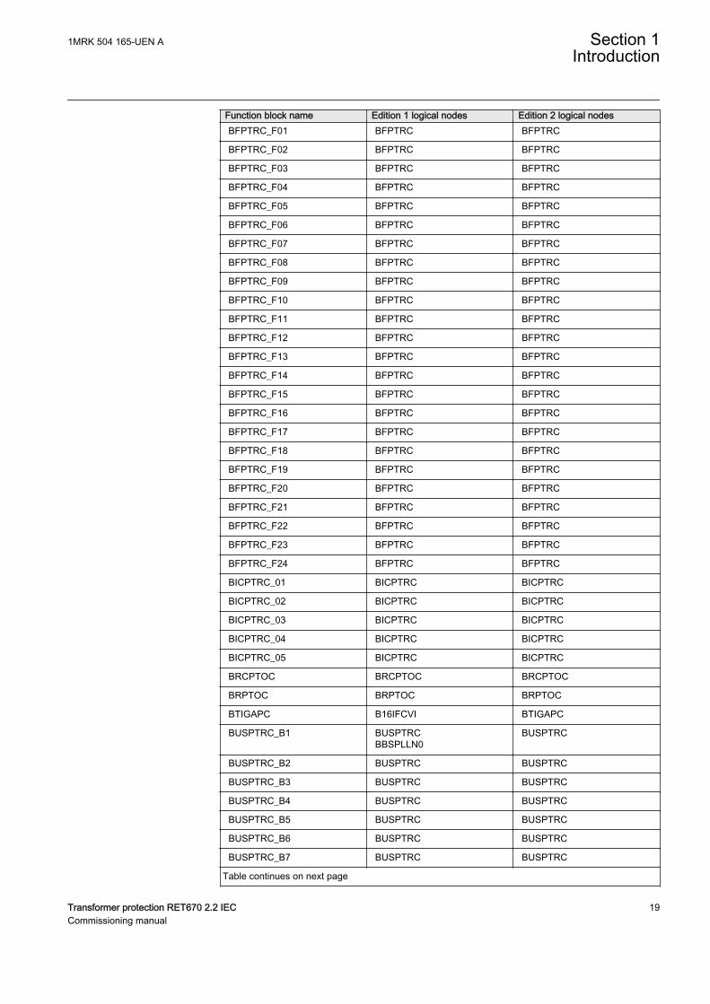
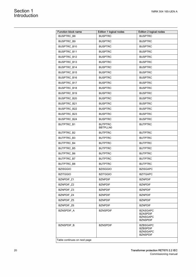
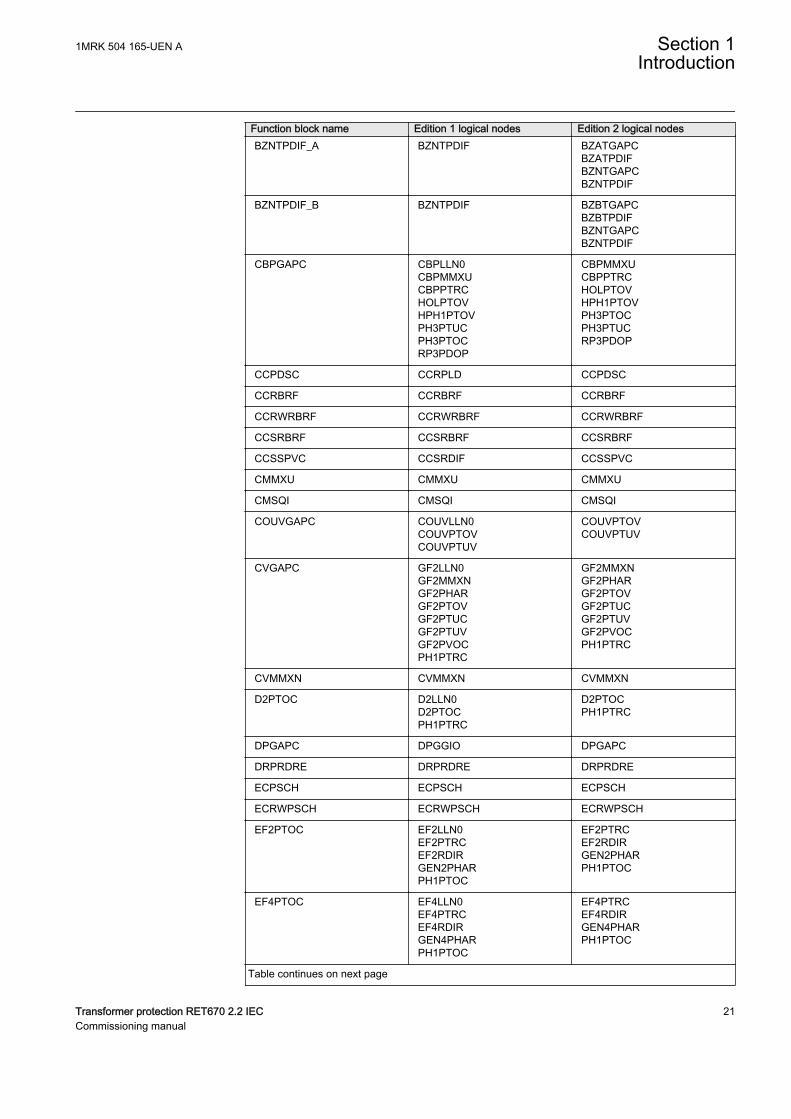
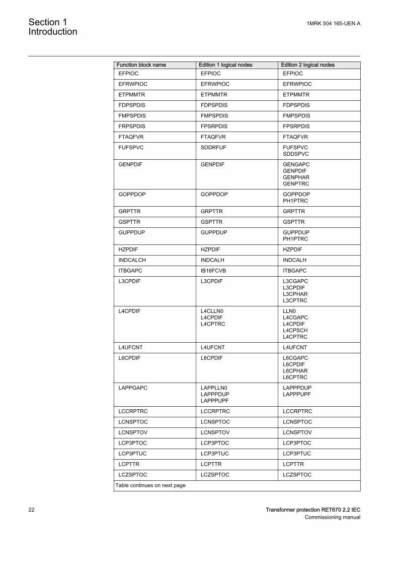
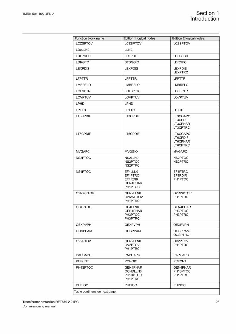
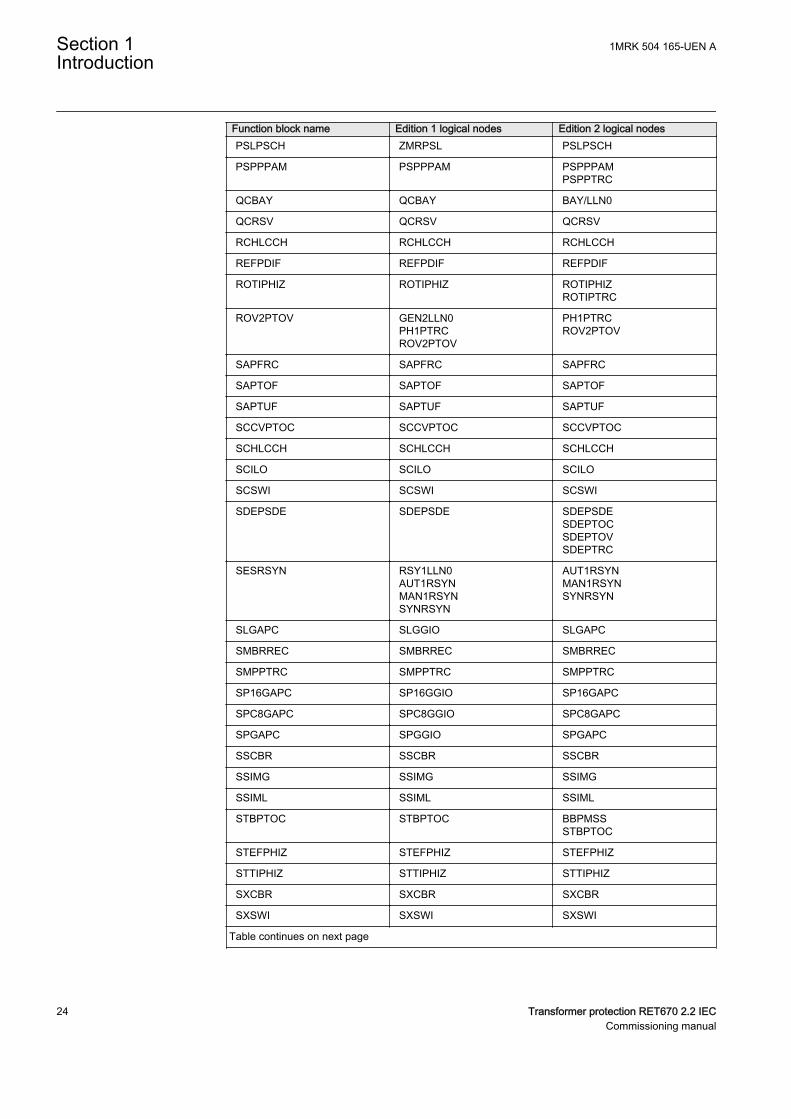
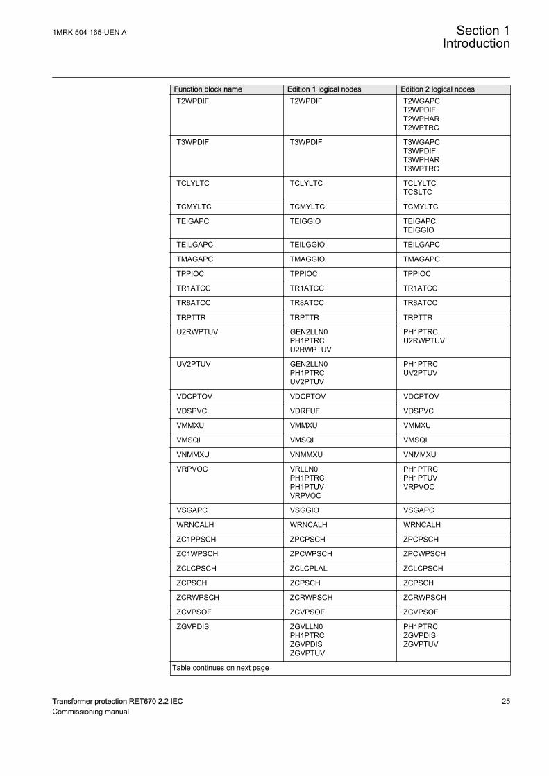
1.5 IEC 61850 edition 1 / edition 2 mappingGUID-C5133366-7260-4C47-A975-7DBAB3A33A96 v4
Function block names are used in ACT and PST to identify functions. Respectivefunction block names of Edition 1 logical nodes and Edition 2 logical nodes areshown in the table below.
Table 1: IEC 61850 edition 1 / edition 2 mapping
Function block name Edition 1 logical nodes Edition 2 logical nodesAEGPVOC AEGGAPC AEGPVOC
AGSAL AGSALSECLLN0
AGSAL
ALMCALH ALMCALH ALMCALH
ALTIM - ALTIM
ALTMS - ALTMS
ALTRK - ALTRK
BCZPDIF BCZPDIF BCZPDIF
BCZSPDIF BCZSPDIF BCZSPDIF
BCZTPDIF BCZTPDIF BCZTPDIF
BDCGAPC SWSGGIO BBCSWIBDCGAPC
BDZSGAPC BBS6LLN0BDZSGAPC
LLN0BDZSGAPC
Table continues on next page
Section 1 1MRK 504 165-UEN AIntroduction
18 Transformer protection RET670 2.2 IECCommissioning manual
Function block name Edition 1 logical nodes Edition 2 logical nodesBFPTRC_F01 BFPTRC BFPTRC
BFPTRC_F02 BFPTRC BFPTRC
BFPTRC_F03 BFPTRC BFPTRC
BFPTRC_F04 BFPTRC BFPTRC
BFPTRC_F05 BFPTRC BFPTRC
BFPTRC_F06 BFPTRC BFPTRC
BFPTRC_F07 BFPTRC BFPTRC
BFPTRC_F08 BFPTRC BFPTRC
BFPTRC_F09 BFPTRC BFPTRC
BFPTRC_F10 BFPTRC BFPTRC
BFPTRC_F11 BFPTRC BFPTRC
BFPTRC_F12 BFPTRC BFPTRC
BFPTRC_F13 BFPTRC BFPTRC
BFPTRC_F14 BFPTRC BFPTRC
BFPTRC_F15 BFPTRC BFPTRC
BFPTRC_F16 BFPTRC BFPTRC
BFPTRC_F17 BFPTRC BFPTRC
BFPTRC_F18 BFPTRC BFPTRC
BFPTRC_F19 BFPTRC BFPTRC
BFPTRC_F20 BFPTRC BFPTRC
BFPTRC_F21 BFPTRC BFPTRC
BFPTRC_F22 BFPTRC BFPTRC
BFPTRC_F23 BFPTRC BFPTRC
BFPTRC_F24 BFPTRC BFPTRC
BICPTRC_01 BICPTRC BICPTRC
BICPTRC_02 BICPTRC BICPTRC
BICPTRC_03 BICPTRC BICPTRC
BICPTRC_04 BICPTRC BICPTRC
BICPTRC_05 BICPTRC BICPTRC
BRCPTOC BRCPTOC BRCPTOC
BRPTOC BRPTOC BRPTOC
BTIGAPC B16IFCVI BTIGAPC
BUSPTRC_B1 BUSPTRCBBSPLLN0
BUSPTRC
BUSPTRC_B2 BUSPTRC BUSPTRC
BUSPTRC_B3 BUSPTRC BUSPTRC
BUSPTRC_B4 BUSPTRC BUSPTRC
BUSPTRC_B5 BUSPTRC BUSPTRC
BUSPTRC_B6 BUSPTRC BUSPTRC
BUSPTRC_B7 BUSPTRC BUSPTRC
Table continues on next page
1MRK 504 165-UEN A Section 1Introduction
Transformer protection RET670 2.2 IEC 19Commissioning manual
Function block name Edition 1 logical nodes Edition 2 logical nodesBUSPTRC_B8 BUSPTRC BUSPTRC
BUSPTRC_B9 BUSPTRC BUSPTRC
BUSPTRC_B10 BUSPTRC BUSPTRC
BUSPTRC_B11 BUSPTRC BUSPTRC
BUSPTRC_B12 BUSPTRC BUSPTRC
BUSPTRC_B13 BUSPTRC BUSPTRC
BUSPTRC_B14 BUSPTRC BUSPTRC
BUSPTRC_B15 BUSPTRC BUSPTRC
BUSPTRC_B16 BUSPTRC BUSPTRC
BUSPTRC_B17 BUSPTRC BUSPTRC
BUSPTRC_B18 BUSPTRC BUSPTRC
BUSPTRC_B19 BUSPTRC BUSPTRC
BUSPTRC_B20 BUSPTRC BUSPTRC
BUSPTRC_B21 BUSPTRC BUSPTRC
BUSPTRC_B22 BUSPTRC BUSPTRC
BUSPTRC_B23 BUSPTRC BUSPTRC
BUSPTRC_B24 BUSPTRC BUSPTRC
BUTPTRC_B1 BUTPTRCBBTPLLN0
BUTPTRC
BUTPTRC_B2 BUTPTRC BUTPTRC
BUTPTRC_B3 BUTPTRC BUTPTRC
BUTPTRC_B4 BUTPTRC BUTPTRC
BUTPTRC_B5 BUTPTRC BUTPTRC
BUTPTRC_B6 BUTPTRC BUTPTRC
BUTPTRC_B7 BUTPTRC BUTPTRC
BUTPTRC_B8 BUTPTRC BUTPTRC
BZISGGIO BZISGGIO BZISGAPC
BZITGGIO BZITGGIO BZITGAPC
BZNPDIF_Z1 BZNPDIF BZNPDIF
BZNPDIF_Z2 BZNPDIF BZNPDIF
BZNPDIF_Z3 BZNPDIF BZNPDIF
BZNPDIF_Z4 BZNPDIF BZNPDIF
BZNPDIF_Z5 BZNPDIF BZNPDIF
BZNPDIF_Z6 BZNPDIF BZNPDIF
BZNSPDIF_A BZNSPDIF BZASGAPCBZASPDIFBZNSGAPCBZNSPDIF
BZNSPDIF_B BZNSPDIF BZBSGAPCBZBSPDIFBZNSGAPCBZNSPDIF
Table continues on next page
Section 1 1MRK 504 165-UEN AIntroduction
20 Transformer protection RET670 2.2 IECCommissioning manual
Function block name Edition 1 logical nodes Edition 2 logical nodesBZNTPDIF_A BZNTPDIF BZATGAPC
BZATPDIFBZNTGAPCBZNTPDIF
BZNTPDIF_B BZNTPDIF BZBTGAPCBZBTPDIFBZNTGAPCBZNTPDIF
CBPGAPC CBPLLN0CBPMMXUCBPPTRCHOLPTOVHPH1PTOVPH3PTUCPH3PTOCRP3PDOP
CBPMMXUCBPPTRCHOLPTOVHPH1PTOVPH3PTOCPH3PTUCRP3PDOP
CCPDSC CCRPLD CCPDSC
CCRBRF CCRBRF CCRBRF
CCRWRBRF CCRWRBRF CCRWRBRF
CCSRBRF CCSRBRF CCSRBRF
CCSSPVC CCSRDIF CCSSPVC
CMMXU CMMXU CMMXU
CMSQI CMSQI CMSQI
COUVGAPC COUVLLN0COUVPTOVCOUVPTUV
COUVPTOVCOUVPTUV
CVGAPC GF2LLN0GF2MMXNGF2PHARGF2PTOVGF2PTUCGF2PTUVGF2PVOCPH1PTRC
GF2MMXNGF2PHARGF2PTOVGF2PTUCGF2PTUVGF2PVOCPH1PTRC
CVMMXN CVMMXN CVMMXN
D2PTOC D2LLN0D2PTOCPH1PTRC
D2PTOCPH1PTRC
DPGAPC DPGGIO DPGAPC
DRPRDRE DRPRDRE DRPRDRE
ECPSCH ECPSCH ECPSCH
ECRWPSCH ECRWPSCH ECRWPSCH
EF2PTOC EF2LLN0EF2PTRCEF2RDIRGEN2PHARPH1PTOC
EF2PTRCEF2RDIRGEN2PHARPH1PTOC
EF4PTOC EF4LLN0EF4PTRCEF4RDIRGEN4PHARPH1PTOC
EF4PTRCEF4RDIRGEN4PHARPH1PTOC
Table continues on next page
1MRK 504 165-UEN A Section 1Introduction
Transformer protection RET670 2.2 IEC 21Commissioning manual
Function block name Edition 1 logical nodes Edition 2 logical nodesEFPIOC EFPIOC EFPIOC
EFRWPIOC EFRWPIOC EFRWPIOC
ETPMMTR ETPMMTR ETPMMTR
FDPSPDIS FDPSPDIS FDPSPDIS
FMPSPDIS FMPSPDIS FMPSPDIS
FRPSPDIS FPSRPDIS FPSRPDIS
FTAQFVR FTAQFVR FTAQFVR
FUFSPVC SDDRFUF FUFSPVCSDDSPVC
GENPDIF GENPDIF GENGAPCGENPDIFGENPHARGENPTRC
GOPPDOP GOPPDOP GOPPDOPPH1PTRC
GRPTTR GRPTTR GRPTTR
GSPTTR GSPTTR GSPTTR
GUPPDUP GUPPDUP GUPPDUPPH1PTRC
HZPDIF HZPDIF HZPDIF
INDCALCH INDCALH INDCALH
ITBGAPC IB16FCVB ITBGAPC
L3CPDIF L3CPDIF L3CGAPCL3CPDIFL3CPHARL3CPTRC
L4CPDIF L4CLLN0L4CPDIFL4CPTRC
LLN0L4CGAPCL4CPDIFL4CPSCHL4CPTRC
L4UFCNT L4UFCNT L4UFCNT
L6CPDIF L6CPDIF L6CGAPCL6CPDIFL6CPHARL6CPTRC
LAPPGAPC LAPPLLN0LAPPPDUPLAPPPUPF
LAPPPDUPLAPPPUPF
LCCRPTRC LCCRPTRC LCCRPTRC
LCNSPTOC LCNSPTOC LCNSPTOC
LCNSPTOV LCNSPTOV LCNSPTOV
LCP3PTOC LCP3PTOC LCP3PTOC
LCP3PTUC LCP3PTUC LCP3PTUC
LCPTTR LCPTTR LCPTTR
LCZSPTOC LCZSPTOC LCZSPTOC
Table continues on next page
Section 1 1MRK 504 165-UEN AIntroduction
22 Transformer protection RET670 2.2 IECCommissioning manual
Function block name Edition 1 logical nodes Edition 2 logical nodesLCZSPTOV LCZSPTOV LCZSPTOV
LD0LLN0 LLN0 -
LDLPSCH LDLPDIF LDLPSCH
LDRGFC STSGGIO LDRGFC
LEXPDIS LEXPDIS LEXPDISLEXPTRC
LFPTTR LFPTTR LFPTTR
LMBRFLO LMBRFLO LMBRFLO
LOLSPTR LOLSPTR LOLSPTR
LOVPTUV LOVPTUV LOVPTUV
LPHD LPHD
LPTTR LPTTR LPTTR
LT3CPDIF LT3CPDIF LT3CGAPCLT3CPDIFLT3CPHARLT3CPTRC
LT6CPDIF LT6CPDIF LT6CGAPCLT6CPDIFLT6CPHARLT6CPTRC
MVGAPC MVGGIO MVGAPC
NS2PTOC NS2LLN0NS2PTOCNS2PTRC
NS2PTOCNS2PTRC
NS4PTOC EF4LLN0EF4PTRCEF4RDIRGEN4PHARPH1PTOC
EF4PTRCEF4RDIRPH1PTOC
O2RWPTOV GEN2LLN0O2RWPTOVPH1PTRC
O2RWPTOVPH1PTRC
OC4PTOC OC4LLN0GEN4PHARPH3PTOCPH3PTRC
GEN4PHARPH3PTOCPH3PTRC
OEXPVPH OEXPVPH OEXPVPH
OOSPPAM OOSPPAM OOSPPAMOOSPTRC
OV2PTOV GEN2LLN0OV2PTOVPH1PTRC
OV2PTOVPH1PTRC
PAPGAPC PAPGAPC PAPGAPC
PCFCNT PCGGIO PCFCNT
PH4SPTOC GEN4PHAROCNDLLN0PH1BPTOCPH1PTRC
GEN4PHARPH1BPTOCPH1PTRC
PHPIOC PHPIOC PHPIOC
Table continues on next page
1MRK 504 165-UEN A Section 1Introduction
Transformer protection RET670 2.2 IEC 23Commissioning manual
Function block name Edition 1 logical nodes Edition 2 logical nodesPSLPSCH ZMRPSL PSLPSCH
PSPPPAM PSPPPAM PSPPPAMPSPPTRC
QCBAY QCBAY BAY/LLN0
QCRSV QCRSV QCRSV
RCHLCCH RCHLCCH RCHLCCH
REFPDIF REFPDIF REFPDIF
ROTIPHIZ ROTIPHIZ ROTIPHIZROTIPTRC
ROV2PTOV GEN2LLN0PH1PTRCROV2PTOV
PH1PTRCROV2PTOV
SAPFRC SAPFRC SAPFRC
SAPTOF SAPTOF SAPTOF
SAPTUF SAPTUF SAPTUF
SCCVPTOC SCCVPTOC SCCVPTOC
SCHLCCH SCHLCCH SCHLCCH
SCILO SCILO SCILO
SCSWI SCSWI SCSWI
SDEPSDE SDEPSDE SDEPSDESDEPTOCSDEPTOVSDEPTRC
SESRSYN RSY1LLN0AUT1RSYNMAN1RSYNSYNRSYN
AUT1RSYNMAN1RSYNSYNRSYN
SLGAPC SLGGIO SLGAPC
SMBRREC SMBRREC SMBRREC
SMPPTRC SMPPTRC SMPPTRC
SP16GAPC SP16GGIO SP16GAPC
SPC8GAPC SPC8GGIO SPC8GAPC
SPGAPC SPGGIO SPGAPC
SSCBR SSCBR SSCBR
SSIMG SSIMG SSIMG
SSIML SSIML SSIML
STBPTOC STBPTOC BBPMSSSTBPTOC
STEFPHIZ STEFPHIZ STEFPHIZ
STTIPHIZ STTIPHIZ STTIPHIZ
SXCBR SXCBR SXCBR
SXSWI SXSWI SXSWI
Table continues on next page
Section 1 1MRK 504 165-UEN AIntroduction
24 Transformer protection RET670 2.2 IECCommissioning manual
Function block name Edition 1 logical nodes Edition 2 logical nodesT2WPDIF T2WPDIF T2WGAPC
T2WPDIFT2WPHART2WPTRC
T3WPDIF T3WPDIF T3WGAPCT3WPDIFT3WPHART3WPTRC
TCLYLTC TCLYLTC TCLYLTCTCSLTC
TCMYLTC TCMYLTC TCMYLTC
TEIGAPC TEIGGIO TEIGAPCTEIGGIO
TEILGAPC TEILGGIO TEILGAPC
TMAGAPC TMAGGIO TMAGAPC
TPPIOC TPPIOC TPPIOC
TR1ATCC TR1ATCC TR1ATCC
TR8ATCC TR8ATCC TR8ATCC
TRPTTR TRPTTR TRPTTR
U2RWPTUV GEN2LLN0PH1PTRCU2RWPTUV
PH1PTRCU2RWPTUV
UV2PTUV GEN2LLN0PH1PTRCUV2PTUV
PH1PTRCUV2PTUV
VDCPTOV VDCPTOV VDCPTOV
VDSPVC VDRFUF VDSPVC
VMMXU VMMXU VMMXU
VMSQI VMSQI VMSQI
VNMMXU VNMMXU VNMMXU
VRPVOC VRLLN0PH1PTRCPH1PTUVVRPVOC
PH1PTRCPH1PTUVVRPVOC
VSGAPC VSGGIO VSGAPC
WRNCALH WRNCALH WRNCALH
ZC1PPSCH ZPCPSCH ZPCPSCH
ZC1WPSCH ZPCWPSCH ZPCWPSCH
ZCLCPSCH ZCLCPLAL ZCLCPSCH
ZCPSCH ZCPSCH ZCPSCH
ZCRWPSCH ZCRWPSCH ZCRWPSCH
ZCVPSOF ZCVPSOF ZCVPSOF
ZGVPDIS ZGVLLN0PH1PTRCZGVPDISZGVPTUV
PH1PTRCZGVPDISZGVPTUV
Table continues on next page
1MRK 504 165-UEN A Section 1Introduction
Transformer protection RET670 2.2 IEC 25Commissioning manual

Function block name Edition 1 logical nodes Edition 2 logical nodesZMCAPDIS ZMCAPDIS ZMCAPDIS
ZMCPDIS ZMCPDIS ZMCPDIS
ZMFCPDIS ZMFCLLN0PSFPDISZMFPDISZMFPTRCZMMMXU
PSFPDISZMFPDISZMFPTRCZMMMXU
ZMFPDIS ZMFLLN0PSFPDISZMFPDISZMFPTRCZMMMXU
PSFPDISPSFPDISZMFPDISZMFPTRCZMMMXU
ZMHPDIS ZMHPDIS ZMHPDIS
ZMMAPDIS ZMMAPDIS ZMMAPDIS
ZMMPDIS ZMMPDIS ZMMPDIS
ZMQAPDIS ZMQAPDIS ZMQAPDIS
ZMQPDIS ZMQPDIS ZMQPDIS
ZMRAPDIS ZMRAPDIS ZMRAPDIS
ZMRPDIS ZMRPDIS ZMRPDIS
ZMRPSB ZMRPSB ZMRPSB
ZSMGAPC ZSMGAPC ZSMGAPC
Section 1 1MRK 504 165-UEN AIntroduction
26 Transformer protection RET670 2.2 IECCommissioning manual
Section 2 Safety information
2.1 Symbols on the productGUID-E48F2EC3-6AB8-4ECF-A77E-F16CE45CA5FD v2
All warnings must be observed.
Read the entire manual before doing installation or anymaintenance work on the product. All warnings must be observed.
Class 1 Laser product. Take adequate measures to protect your eyesand do not view directly with optical instruments.
Do not touch the unit in operation. The installation shall take intoaccount the worst case temperature.
2.2 WarningsIP1504-1 v2
Observe the warnings during all types of work related to the product.GUID-C9B6638A-57E7-4E05-9A33-A60E359C54AF v1
Only electrically skilled persons with the proper authorization andknowledge of any safety hazards are allowed to carry out theelectrical installation.
M2366-2 v2
National and local electrical safety regulations must always befollowed. Working in a high voltage environment requires seriousapproach to avoid human injuries and damage to equipment.
M2362-2 v1
Do not touch circuitry during operation. Potentially lethal voltagesand currents are present.
1MRK 504 165-UEN A Section 2Safety information
Transformer protection RET670 2.2 IEC 27Commissioning manual
M2364-2 v1
Always use suitable isolated test pins when measuring signals inopen circuitry. Potentially lethal voltages and currents are present.
M2370-2 v1
Never connect or disconnect a wire and/or a connector to or from aIED during normal operation. Hazardous voltages and currents arepresent that may be lethal. Operation may be disrupted and IED andmeasuring circuitry may be damaged.
GUID-BEDD698E-356C-4CF9-9DAE-64DB3CEADEAD v1
Dangerous voltages can occur on the connectors, even though theauxiliary voltage has been disconnected.
M2369-2 v3
Always connect the IED to protective earth, regardless of theoperating conditions. This also applies to special occasions such asbench testing, demonstrations and off-site configuration. This isclass 1 equipment that shall be earthed.
M2367-2 v1
Never disconnect the secondary connection of current transformercircuit without short-circuiting the transformer’s secondarywinding. Operating a current transformer with the secondarywinding open will cause a massive potential build-up that maydamage the transformer and may cause injuries to humans.
M2372-2 v1
Never remove any screw from a powered IED or from a IEDconnected to powered circuitry. Potentially lethal voltages andcurrents are present.
SEMOD168311-3 v1
Take adequate measures to protect the eyes. Never look into thelaser beam.
GUID-11CCF92B-E9E7-409C-84D0-DFDEA1DCBE85 v2
The IED with accessories should be mounted in a cubicle in arestricted access area within a power station, substation or industrialor retail environment.
Section 2 1MRK 504 165-UEN ASafety information
28 Transformer protection RET670 2.2 IECCommissioning manual
2.3 Caution signsIP1503-1 v1
GUID-5D1412B8-8F9D-4D39-B6D1-60FB35797FD0 v1
Whenever changes are made in the IED, measures should be takento avoid inadvertent tripping.
GUID-F2A7BD77-80FB-48F0-AAE5-BE73DE520CC2 v1
The IED contains components which are sensitive to electrostaticdischarge. ESD precautions shall always be observed prior totouching components.
M2695-2 v2
Always transport PCBs (modules) using certified conductive bags.
M2696-2 v1
Do not connect live wires to the IED. Internal circuitry may bedamaged
M2697-2 v2
Always use a conductive wrist strap connected to protective earthwhen replacing modules. Electrostatic discharge (ESD) maydamage the module and IED circuitry.
M2698-2 v2
Take care to avoid electrical shock during installation andcommissioning.
M2693-2 v1
Changing the active setting group will inevitably change the IEDsoperation. Be careful and check regulations before making thechange.
2.4 Note signsIP1497-1 v1
M19-2 v3
Observe the maximum allowed continuous current for the differentcurrent transformer inputs of the IED. See technical data.
1MRK 504 165-UEN A Section 2Safety information
Transformer protection RET670 2.2 IEC 29Commissioning manual

30
Section 3 Available functions
GUID-F5776DD1-BD04-4872-BB89-A0412B4B5CC3 v1
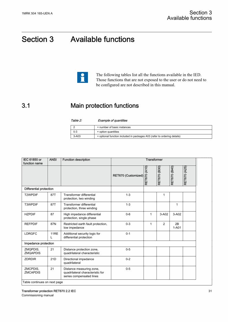
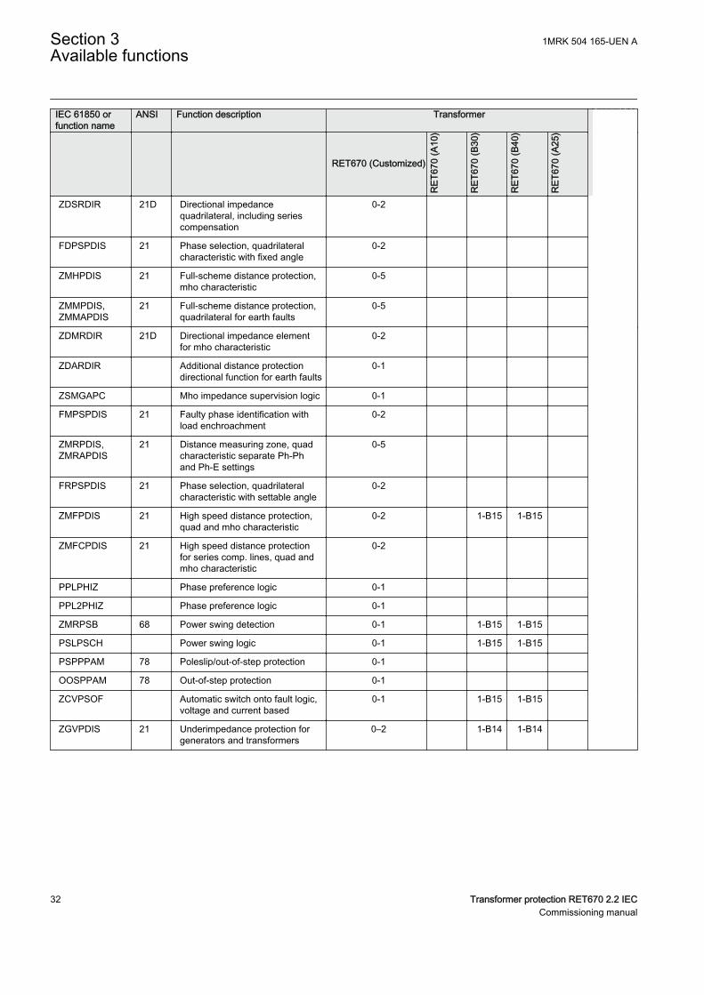
The following tables list all the functions available in the IED.Those functions that are not exposed to the user or do not need tobe configured are not described in this manual.
3.1 Main protection functionsGUID-66BAAD98-851D-4AAC-B386-B38B57718BD2 v13
Table 2: Example of quantities
2 = number of basic instances0-3 = option quantities3-A03 = optional function included in packages A03 (refer to ordering details)
IEC 61850 orfunction name
ANSI Function description Transformer
RET670 (Customized)
RET
670
(A10
)
RET
670
(B30
)
RET
670
(B40
)
RET
670
(A25
)
Differential protection
T2WPDIF 87T Transformer differentialprotection, two winding
1-3 1
T3WPDIF 87T Transformer differentialprotection, three winding
1-3 1
HZPDIF 87 High impedance differentialprotection, single phase
0-6 1 3-A02 3-A02
REFPDIF 87N Restricted earth fault protection,low impedance
0-3 1 2 2B1-A01
LDRGFC 11REL
Additional security logic fordifferential protection
0-1
Impedance protection
ZMQPDIS,ZMQAPDIS
21 Distance protection zone,quadrilateral characteristic
0-5
ZDRDIR 21D Directional impedancequadrilateral
0-2
ZMCPDIS,ZMCAPDIS
21 Distance measuring zone,quadrilateral characteristic forseries compensated lines
0-5
Table continues on next page
1MRK 504 165-UEN A Section 3Available functions
Transformer protection RET670 2.2 IEC 31Commissioning manual
IEC 61850 orfunction name
ANSI Function description Transformer
RET670 (Customized)
RET
670
(A10
)
RET
670
(B30
)
RET
670
(B40
)
RET
670
(A25
)
ZDSRDIR 21D Directional impedancequadrilateral, including seriescompensation
0-2
FDPSPDIS 21 Phase selection, quadrilateralcharacteristic with fixed angle
0-2
ZMHPDIS 21 Full-scheme distance protection,mho characteristic
0-5
ZMMPDIS,ZMMAPDIS
21 Full-scheme distance protection,quadrilateral for earth faults
0-5
ZDMRDIR 21D Directional impedance elementfor mho characteristic
0-2
ZDARDIR Additional distance protectiondirectional function for earth faults
0-1
ZSMGAPC Mho impedance supervision logic 0-1
FMPSPDIS 21 Faulty phase identification withload enchroachment
0-2
ZMRPDIS,ZMRAPDIS
21 Distance measuring zone, quadcharacteristic separate Ph-Phand Ph-E settings
0-5
FRPSPDIS 21 Phase selection, quadrilateralcharacteristic with settable angle
0-2
ZMFPDIS 21 High speed distance protection,quad and mho characteristic
0-2 1-B15 1-B15
ZMFCPDIS 21 High speed distance protectionfor series comp. lines, quad andmho characteristic
0-2
PPLPHIZ Phase preference logic 0-1
PPL2PHIZ Phase preference logic 0-1
ZMRPSB 68 Power swing detection 0-1 1-B15 1-B15
PSLPSCH Power swing logic 0-1 1-B15 1-B15
PSPPPAM 78 Poleslip/out-of-step protection 0-1
OOSPPAM 78 Out-of-step protection 0-1
ZCVPSOF Automatic switch onto fault logic,voltage and current based
0-1 1-B15 1-B15
ZGVPDIS 21 Underimpedance protection forgenerators and transformers
0–2 1-B14 1-B14
Section 3 1MRK 504 165-UEN AAvailable functions
32 Transformer protection RET670 2.2 IECCommissioning manual
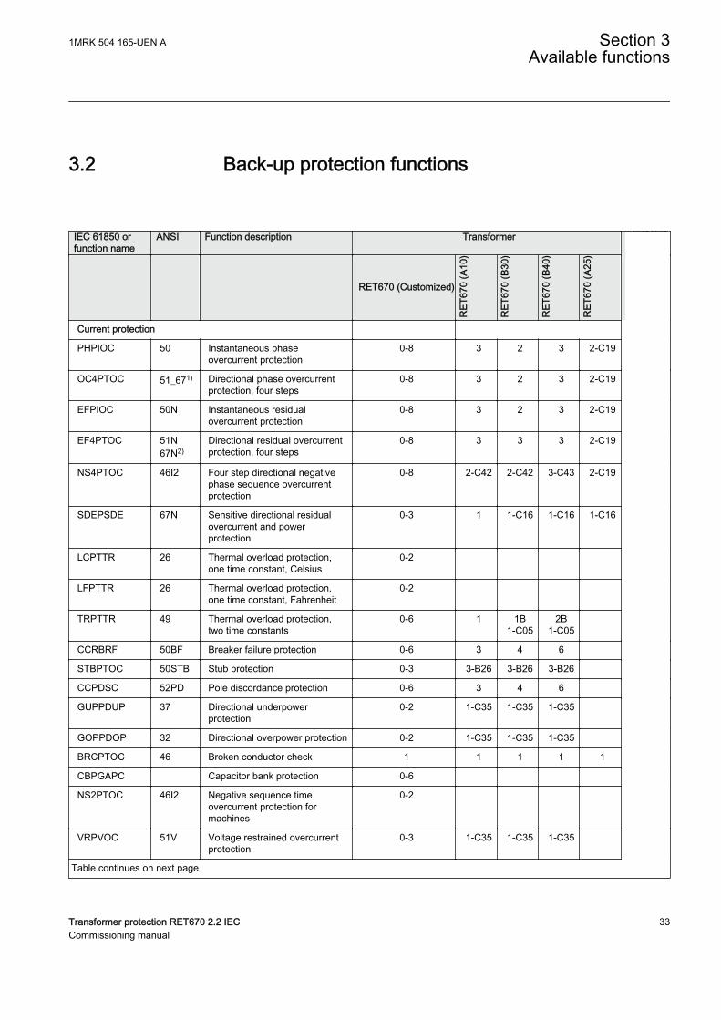
3.2 Back-up protection functionsGUID-A8D0852F-807F-4442-8730-E44808E194F0 v13
IEC 61850 orfunction name
ANSI Function description Transformer
RET670 (Customized)
RET
670
(A10
)
RET
670
(B30
)
RET
670
(B40
)
RET
670
(A25
)
Current protection
PHPIOC 50 Instantaneous phaseovercurrent protection
0-8 3 2 3 2-C19
OC4PTOC 51_671) Directional phase overcurrentprotection, four steps
0-8 3 2 3 2-C19
EFPIOC 50N Instantaneous residualovercurrent protection
0-8 3 2 3 2-C19
EF4PTOC 51N67N2)
Directional residual overcurrentprotection, four steps
0-8 3 3 3 2-C19
NS4PTOC 46I2 Four step directional negativephase sequence overcurrentprotection
0-8 2-C42 2-C42 3-C43 2-C19
SDEPSDE 67N Sensitive directional residualovercurrent and powerprotection
0-3 1 1-C16 1-C16 1-C16
LCPTTR 26 Thermal overload protection,one time constant, Celsius
0-2
LFPTTR 26 Thermal overload protection,one time constant, Fahrenheit
0-2
TRPTTR 49 Thermal overload protection,two time constants
0-6 1 1B1-C05
2B1-C05
CCRBRF 50BF Breaker failure protection 0-6 3 4 6
STBPTOC 50STB Stub protection 0-3 3-B26 3-B26 3-B26
CCPDSC 52PD Pole discordance protection 0-6 3 4 6
GUPPDUP 37 Directional underpowerprotection
0-2 1-C35 1-C35 1-C35
GOPPDOP 32 Directional overpower protection 0-2 1-C35 1-C35 1-C35
BRCPTOC 46 Broken conductor check 1 1 1 1 1
CBPGAPC Capacitor bank protection 0-6
NS2PTOC 46I2 Negative sequence timeovercurrent protection formachines
0-2
VRPVOC 51V Voltage restrained overcurrentprotection
0-3 1-C35 1-C35 1-C35
Table continues on next page
1MRK 504 165-UEN A Section 3Available functions
Transformer protection RET670 2.2 IEC 33Commissioning manual
IEC 61850 orfunction name
ANSI Function description Transformer
RET670 (Customized)
RET
670
(A10
)
RET
670
(B30
)
RET
670
(B40
)
RET
670
(A25
)
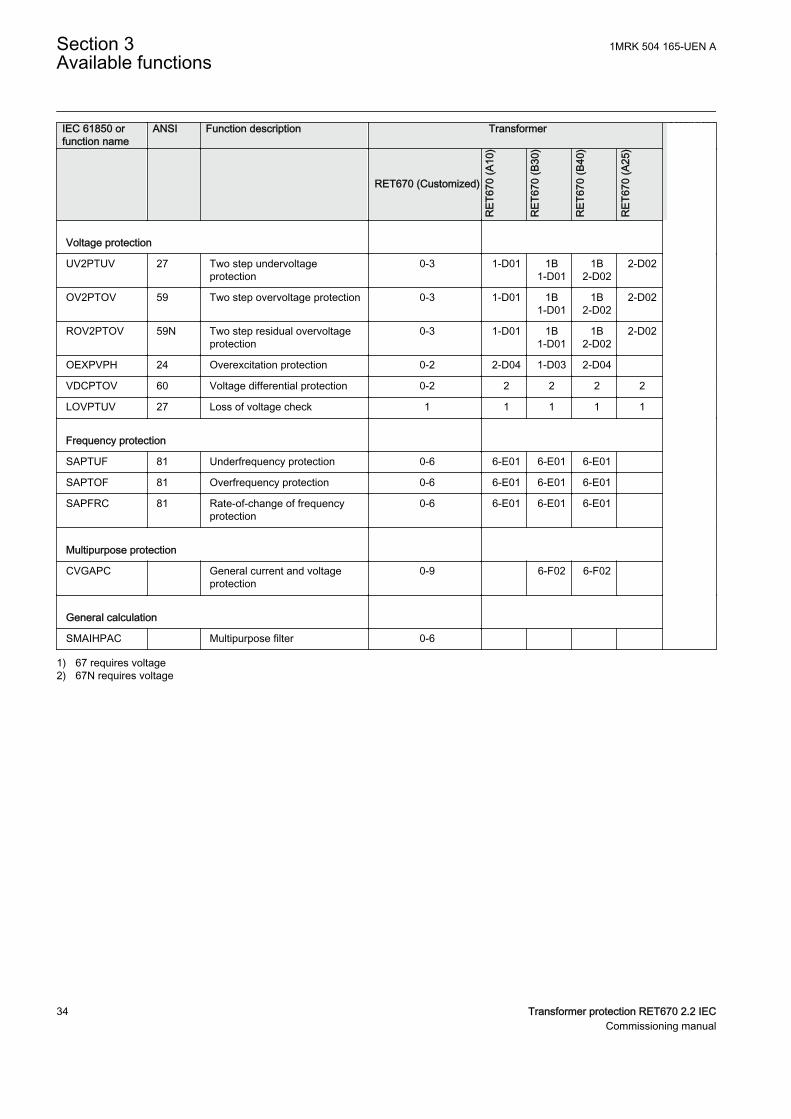
Voltage protection
UV2PTUV 27 Two step undervoltageprotection
0-3 1-D01 1B1-D01
1B2-D02
2-D02
OV2PTOV 59 Two step overvoltage protection 0-3 1-D01 1B1-D01
1B2-D02
2-D02
ROV2PTOV 59N Two step residual overvoltageprotection
0-3 1-D01 1B1-D01
1B2-D02
2-D02
OEXPVPH 24 Overexcitation protection 0-2 2-D04 1-D03 2-D04
VDCPTOV 60 Voltage differential protection 0-2 2 2 2 2
LOVPTUV 27 Loss of voltage check 1 1 1 1 1
Frequency protection
SAPTUF 81 Underfrequency protection 0-6 6-E01 6-E01 6-E01
SAPTOF 81 Overfrequency protection 0-6 6-E01 6-E01 6-E01
SAPFRC 81 Rate-of-change of frequencyprotection
0-6 6-E01 6-E01 6-E01
Multipurpose protection
CVGAPC General current and voltageprotection
0-9 6-F02 6-F02
General calculation
SMAIHPAC Multipurpose filter 0-6
1) 67 requires voltage2) 67N requires voltage
Section 3 1MRK 504 165-UEN AAvailable functions
34 Transformer protection RET670 2.2 IECCommissioning manual
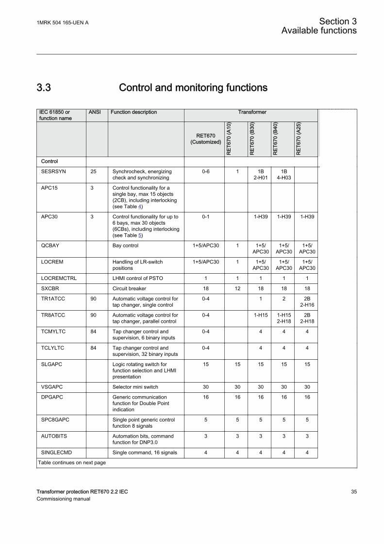
3.3 Control and monitoring functionsGUID-E3777F16-0B76-4157-A3BF-0B6B978863DE v15
IEC 61850 orfunction name
ANSI Function description Transformer
RET670(Customized)
RET
670
(A10
)
RET
670
(B30
)
RET
670
(B40
)
RET
670
(A25
)
Control
SESRSYN 25 Synchrocheck, energizingcheck and synchronizing
0-6 1 1B2-H01
1B4-H03
APC15 3 Control functionality for asingle bay, max 15 objects(2CB), including interlocking(see Table 4)
APC30 3 Control functionality for up to6 bays, max 30 objects(6CBs), including interlocking(see Table 5)
0-1 1-H39 1-H39 1-H39
QCBAY Bay control 1+5/APC30 1 1+5/APC30
1+5/APC30
1+5/APC30
LOCREM Handling of LR-switchpositions
1+5/APC30 1 1+5/APC30
1+5/APC30
1+5/APC30
LOCREMCTRL LHMI control of PSTO 1 1 1 1 1
SXCBR Circuit breaker 18 12 18 18 18
TR1ATCC 90 Automatic voltage control fortap changer, single control
0-4 1 2 2B2-H16
TR8ATCC 90 Automatic voltage control fortap changer, parallel control
0-4 1-H15 1-H152-H18
2B2-H18
TCMYLTC 84 Tap changer control andsupervision, 6 binary inputs
0-4 4 4 4
TCLYLTC 84 Tap changer control andsupervision, 32 binary inputs
0-4 4 4 4
SLGAPC Logic rotating switch forfunction selection and LHMIpresentation
15 15 15 15 15
VSGAPC Selector mini switch 30 30 30 30 30
DPGAPC Generic communicationfunction for Double Pointindication
16 16 16 16 16
SPC8GAPC Single point generic controlfunction 8 signals
5 5 5 5 5
AUTOBITS Automation bits, commandfunction for DNP3.0
3 3 3 3 3
SINGLECMD Single command, 16 signals 4 4 4 4 4
Table continues on next page
1MRK 504 165-UEN A Section 3Available functions
Transformer protection RET670 2.2 IEC 35Commissioning manual
IEC 61850 orfunction name
ANSI Function description Transformer
RET670(Customized)
RET
670
(A10
)
RET
670
(B30
)
RET
670
(B40
)
RET
670
(A25
)
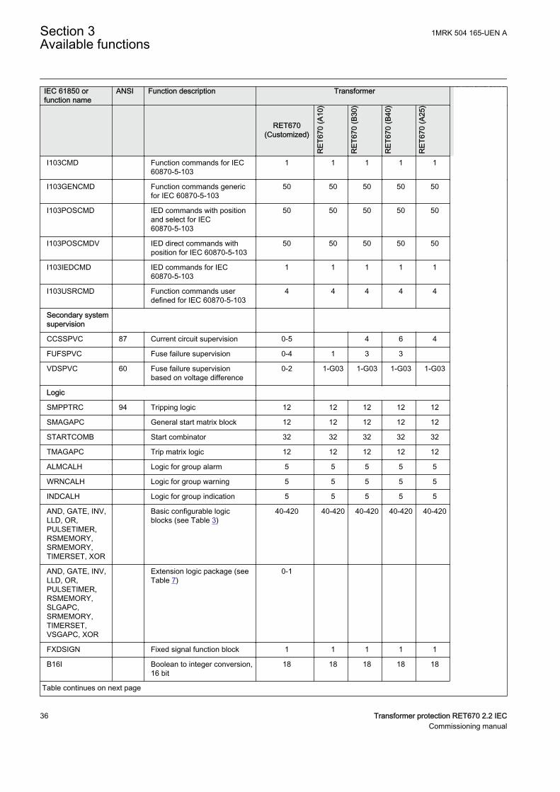
I103CMD Function commands for IEC60870-5-103
1 1 1 1 1
I103GENCMD Function commands genericfor IEC 60870-5-103
50 50 50 50 50
I103POSCMD IED commands with positionand select for IEC60870-5-103
50 50 50 50 50
I103POSCMDV IED direct commands withposition for IEC 60870-5-103
50 50 50 50 50
I103IEDCMD IED commands for IEC60870-5-103
1 1 1 1 1
I103USRCMD Function commands userdefined for IEC 60870-5-103
4 4 4 4 4
Secondary systemsupervision
CCSSPVC 87 Current circuit supervision 0-5 4 6 4
FUFSPVC Fuse failure supervision 0-4 1 3 3
VDSPVC 60 Fuse failure supervisionbased on voltage difference
0-2 1-G03 1-G03 1-G03 1-G03
Logic
SMPPTRC 94 Tripping logic 12 12 12 12 12
SMAGAPC General start matrix block 12 12 12 12 12
STARTCOMB Start combinator 32 32 32 32 32
TMAGAPC Trip matrix logic 12 12 12 12 12
ALMCALH Logic for group alarm 5 5 5 5 5
WRNCALH Logic for group warning 5 5 5 5 5
INDCALH Logic for group indication 5 5 5 5 5
AND, GATE, INV,LLD, OR,PULSETIMER,RSMEMORY,SRMEMORY,TIMERSET, XOR
Basic configurable logicblocks (see Table 3)
40-420 40-420 40-420 40-420 40-420
AND, GATE, INV,LLD, OR,PULSETIMER,RSMEMORY,SLGAPC,SRMEMORY,TIMERSET,VSGAPC, XOR
Extension logic package (seeTable 7)
0-1
FXDSIGN Fixed signal function block 1 1 1 1 1
B16I Boolean to integer conversion,16 bit
18 18 18 18 18
Table continues on next page
Section 3 1MRK 504 165-UEN AAvailable functions
36 Transformer protection RET670 2.2 IECCommissioning manual

IEC 61850 orfunction name
ANSI Function description Transformer
RET670(Customized)
RET
670
(A10
)
RET
670
(B30
)
RET
670
(B40
)
RET
670
(A25
)
BTIGAPC Boolean to integer conversionwith logical noderepresentation, 16 bit
16 16 16 16 16
IB16 Integer to Boolean 16conversion
18 18 18 18 18
ITBGAPC Integer to Boolean 16conversion with Logic Noderepresentation
16 16 16 16 16
TEIGAPC Elapsed time integrator withlimit transgression andoverflow supervision
12 12 12 12 12
INTCOMP Comparator for integer inputs 30 30 30 30 30
REALCOMP Comparator for real inputs 30 30 30 30 30
Table 3: Total number of instances for basic configurable logic blocks
Basic configurable logic block Total number of instancesAND 280
GATE 40
INV 420
LLD 40
OR 298
PULSETIMER 40
RSMEMORY 40
SRMEMORY 40
TIMERSET 60
XOR 40
1MRK 504 165-UEN A Section 3Available functions
Transformer protection RET670 2.2 IEC 37Commissioning manual
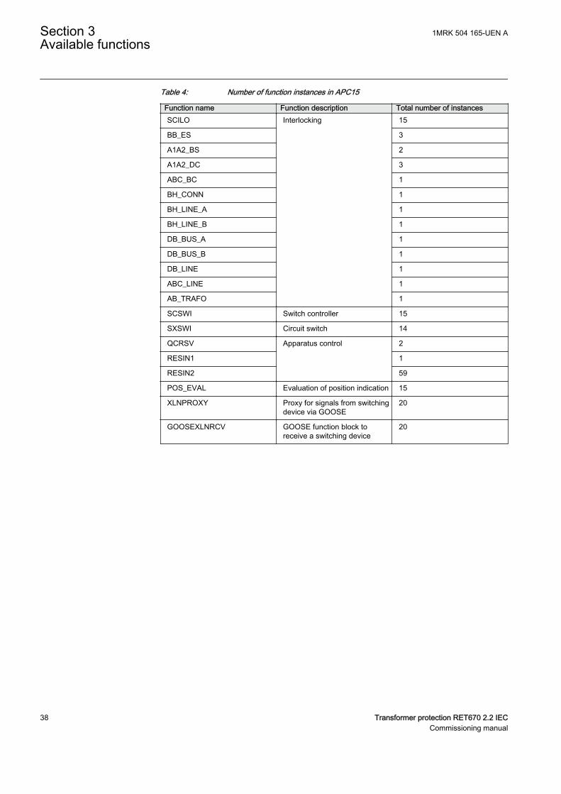
Table 4: Number of function instances in APC15
Function name Function description Total number of instancesSCILO Interlocking 15
BB_ES 3
A1A2_BS 2
A1A2_DC 3
ABC_BC 1
BH_CONN 1
BH_LINE_A 1
BH_LINE_B 1
DB_BUS_A 1
DB_BUS_B 1
DB_LINE 1
ABC_LINE 1
AB_TRAFO 1
SCSWI Switch controller 15
SXSWI Circuit switch 14
QCRSV Apparatus control 2
RESIN1 1
RESIN2 59
POS_EVAL Evaluation of position indication 15
XLNPROXY Proxy for signals from switchingdevice via GOOSE
20
GOOSEXLNRCV GOOSE function block toreceive a switching device
20
Section 3 1MRK 504 165-UEN AAvailable functions
38 Transformer protection RET670 2.2 IECCommissioning manual
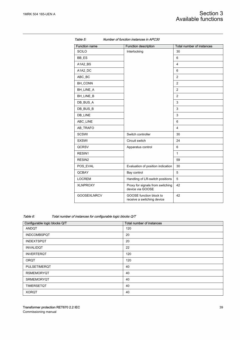
Table 5: Number of function instances in APC30
Function name Function description Total number of instancesSCILO Interlocking 30
BB_ES 6
A1A2_BS 4
A1A2_DC 6
ABC_BC 2
BH_CONN 2
BH_LINE_A 2
BH_LINE_B 2
DB_BUS_A 3
DB_BUS_B 3
DB_LINE 3
ABC_LINE 6
AB_TRAFO 4
SCSWI Switch controller 30
SXSWI Circuit switch 24
QCRSV Apparatus control 6
RESIN1 1
RESIN2 59
POS_EVAL Evaluation of position indication 30
QCBAY Bay control 5
LOCREM Handling of LR-switch positions 5
XLNPROXY Proxy for signals from switchingdevice via GOOSE
42
GOOSEXLNRCV GOOSE function block toreceive a switching device
42
Table 6: Total number of instances for configurable logic blocks Q/T
Configurable logic blocks Q/T Total number of instancesANDQT 120
INDCOMBSPQT 20
INDEXTSPQT 20
INVALIDQT 22
INVERTERQT 120
ORQT 120
PULSETIMERQT 40
RSMEMORYQT 40
SRMEMORYQT 40
TIMERSETQT 40
XORQT 40
1MRK 504 165-UEN A Section 3Available functions
Transformer protection RET670 2.2 IEC 39Commissioning manual
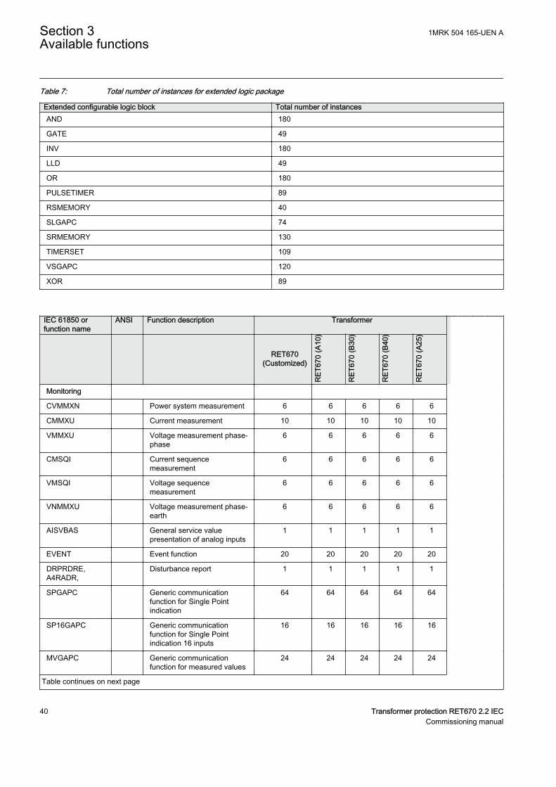
Table 7: Total number of instances for extended logic package
Extended configurable logic block Total number of instancesAND 180
GATE 49
INV 180
LLD 49
OR 180
PULSETIMER 89
RSMEMORY 40
SLGAPC 74
SRMEMORY 130
TIMERSET 109
VSGAPC 120
XOR 89
IEC 61850 orfunction name
ANSI Function description Transformer
RET670(Customized)
RET
670
(A10
)
RET
670
(B30
)
RET
670
(B40
)
RET
670
(A25
)
Monitoring
CVMMXN Power system measurement 6 6 6 6 6
CMMXU Current measurement 10 10 10 10 10
VMMXU Voltage measurement phase-phase
6 6 6 6 6
CMSQI Current sequencemeasurement
6 6 6 6 6
VMSQI Voltage sequencemeasurement
6 6 6 6 6
VNMMXU Voltage measurement phase-earth
6 6 6 6 6
AISVBAS General service valuepresentation of analog inputs
1 1 1 1 1
EVENT Event function 20 20 20 20 20
DRPRDRE,A4RADR,
Disturbance report 1 1 1 1 1
SPGAPC Generic communicationfunction for Single Pointindication
64 64 64 64 64
SP16GAPC Generic communicationfunction for Single Pointindication 16 inputs
16 16 16 16 16
MVGAPC Generic communicationfunction for measured values
24 24 24 24 24
Table continues on next page
Section 3 1MRK 504 165-UEN AAvailable functions
40 Transformer protection RET670 2.2 IECCommissioning manual
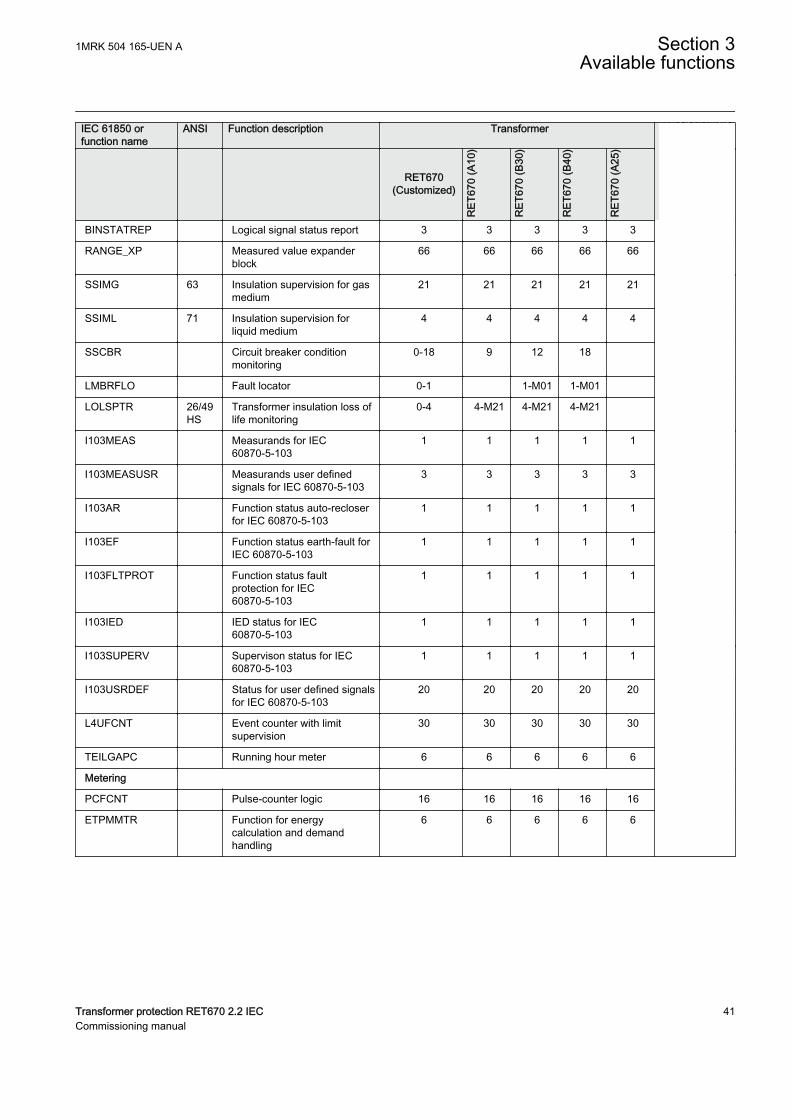
IEC 61850 orfunction name
ANSI Function description Transformer
RET670(Customized)
RET
670
(A10
)
RET
670
(B30
)
RET
670
(B40
)
RET
670
(A25
)
BINSTATREP Logical signal status report 3 3 3 3 3
RANGE_XP Measured value expanderblock
66 66 66 66 66
SSIMG 63 Insulation supervision for gasmedium
21 21 21 21 21
SSIML 71 Insulation supervision forliquid medium
4 4 4 4 4
SSCBR Circuit breaker conditionmonitoring
0-18 9 12 18
LMBRFLO Fault locator 0-1 1-M01 1-M01
LOLSPTR 26/49HS
Transformer insulation loss oflife monitoring
0-4 4-M21 4-M21 4-M21
I103MEAS Measurands for IEC60870-5-103
1 1 1 1 1
I103MEASUSR Measurands user definedsignals for IEC 60870-5-103
3 3 3 3 3
I103AR Function status auto-recloserfor IEC 60870-5-103
1 1 1 1 1
I103EF Function status earth-fault forIEC 60870-5-103
1 1 1 1 1
I103FLTPROT Function status faultprotection for IEC60870-5-103
1 1 1 1 1
I103IED IED status for IEC60870-5-103
1 1 1 1 1
I103SUPERV Supervison status for IEC60870-5-103
1 1 1 1 1
I103USRDEF Status for user defined signalsfor IEC 60870-5-103
20 20 20 20 20
L4UFCNT Event counter with limitsupervision
30 30 30 30 30
TEILGAPC Running hour meter 6 6 6 6 6
Metering
PCFCNT Pulse-counter logic 16 16 16 16 16
ETPMMTR Function for energycalculation and demandhandling
6 6 6 6 6
1MRK 504 165-UEN A Section 3Available functions
Transformer protection RET670 2.2 IEC 41Commissioning manual
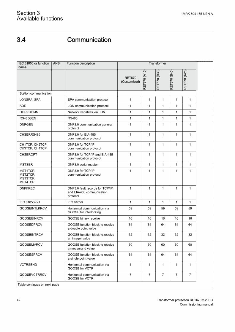
3.4 CommunicationGUID-5F144B53-B9A7-4173-80CF-CD4C84579CB5 v15
IEC 61850 or functionname
ANSI Function description Transformer
RET670(Customized)
RET
670
(A10
)
RET
670
(B30
)
RET
670
(B40
)
RET
670
(A25
)
Station communication
LONSPA, SPA SPA communication protocol 1 1 1 1 1
ADE LON communication protocol 1 1 1 1 1
HORZCOMM Network variables via LON 1 1 1 1 1
RS485GEN RS485 1 1 1 1 1
DNPGEN DNP3.0 communication generalprotocol
1 1 1 1 1
CHSERRS485 DNP3.0 for EIA-485communication protocol
1 1 1 1 1
CH1TCP, CH2TCP,CH3TCP, CH4TCP
DNP3.0 for TCP/IPcommunication protocol
1 1 1 1 1
CHSEROPT DNP3.0 for TCP/IP and EIA-485communication protocol
1 1 1 1 1
MSTSER DNP3.0 serial master 1 1 1 1 1
MST1TCP,MST2TCP,MST3TCP,MST4TCP
DNP3.0 for TCP/IPcommunication protocol
1 1 1 1 1
DNPFREC DNP3.0 fault records for TCP/IPand EIA-485 communicationprotocol
1 1 1 1 1
IEC 61850-8-1 IEC 61850 1 1 1 1 1
GOOSEINTLKRCV Horizontal communication viaGOOSE for interlocking
59 59 59 59 59
GOOSEBINRCV GOOSE binary receive 16 16 16 16 16
GOOSEDPRCV GOOSE function block to receivea double point value
64 64 64 64 64
GOOSEINTRCV GOOSE function block to receivean integer value
32 32 32 32 32
GOOSEMVRCV GOOSE function block to receivea measurand value
60 60 60 60 60
GOOSESPRCV GOOSE function block to receivea single point value
64 64 64 64 64
VCTRSEND Horizontal communication viaGOOSE for VCTR
1 1 1 1 1
GOOSEVCTRRCV Horizontal communication viaGOOSE for VCTR
7 7 7 7 7
Table continues on next page
Section 3 1MRK 504 165-UEN AAvailable functions
42 Transformer protection RET670 2.2 IECCommissioning manual
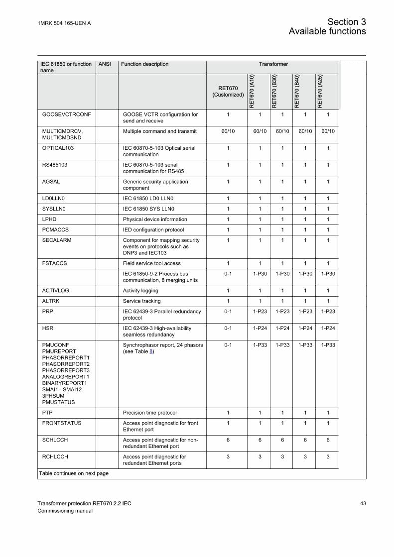
IEC 61850 or functionname
ANSI Function description Transformer
RET670(Customized)
RET
670
(A10
)
RET
670
(B30
)
RET
670
(B40
)
RET
670
(A25
)
GOOSEVCTRCONF GOOSE VCTR configuration forsend and receive
1 1 1 1 1
MULTICMDRCV,MULTICMDSND
Multiple command and transmit 60/10 60/10 60/10 60/10 60/10
OPTICAL103 IEC 60870-5-103 Optical serialcommunication
1 1 1 1 1
RS485103 IEC 60870-5-103 serialcommunication for RS485
1 1 1 1 1
AGSAL Generic security applicationcomponent
1 1 1 1 1
LD0LLN0 IEC 61850 LD0 LLN0 1 1 1 1 1
SYSLLN0 IEC 61850 SYS LLN0 1 1 1 1 1
LPHD Physical device information 1 1 1 1 1
PCMACCS IED configuration protocol 1 1 1 1 1
SECALARM Component for mapping securityevents on protocols such asDNP3 and IEC103
1 1 1 1 1
FSTACCS Field service tool access 1 1 1 1 1
IEC 61850-9-2 Process buscommunication, 8 merging units
0-1 1-P30 1-P30 1-P30 1-P30
ACTIVLOG Activity logging 1 1 1 1 1
ALTRK Service tracking 1 1 1 1 1
PRP IEC 62439-3 Parallel redundancyprotocol
0-1 1-P23 1-P23 1-P23 1-P23
HSR IEC 62439-3 High-availabilityseamless redundancy
0-1 1-P24 1-P24 1-P24 1-P24
PMUCONFPMUREPORTPHASORREPORT1PHASORREPORT2PHASORREPORT3ANALOGREPORT1BINARYREPORT1SMAI1 - SMAI123PHSUMPMUSTATUS
Synchrophasor report, 24 phasors(see Table 8)
0-1 1-P33 1-P33 1-P33 1-P33
PTP Precision time protocol 1 1 1 1 1
FRONTSTATUS Access point diagnostic for frontEthernet port
1 1 1 1 1
SCHLCCH Access point diagnostic for non-redundant Ethernet port
6 6 6 6 6
RCHLCCH Access point diagnostic forredundant Ethernet ports
3 3 3 3 3
Table continues on next page
1MRK 504 165-UEN A Section 3Available functions
Transformer protection RET670 2.2 IEC 43Commissioning manual
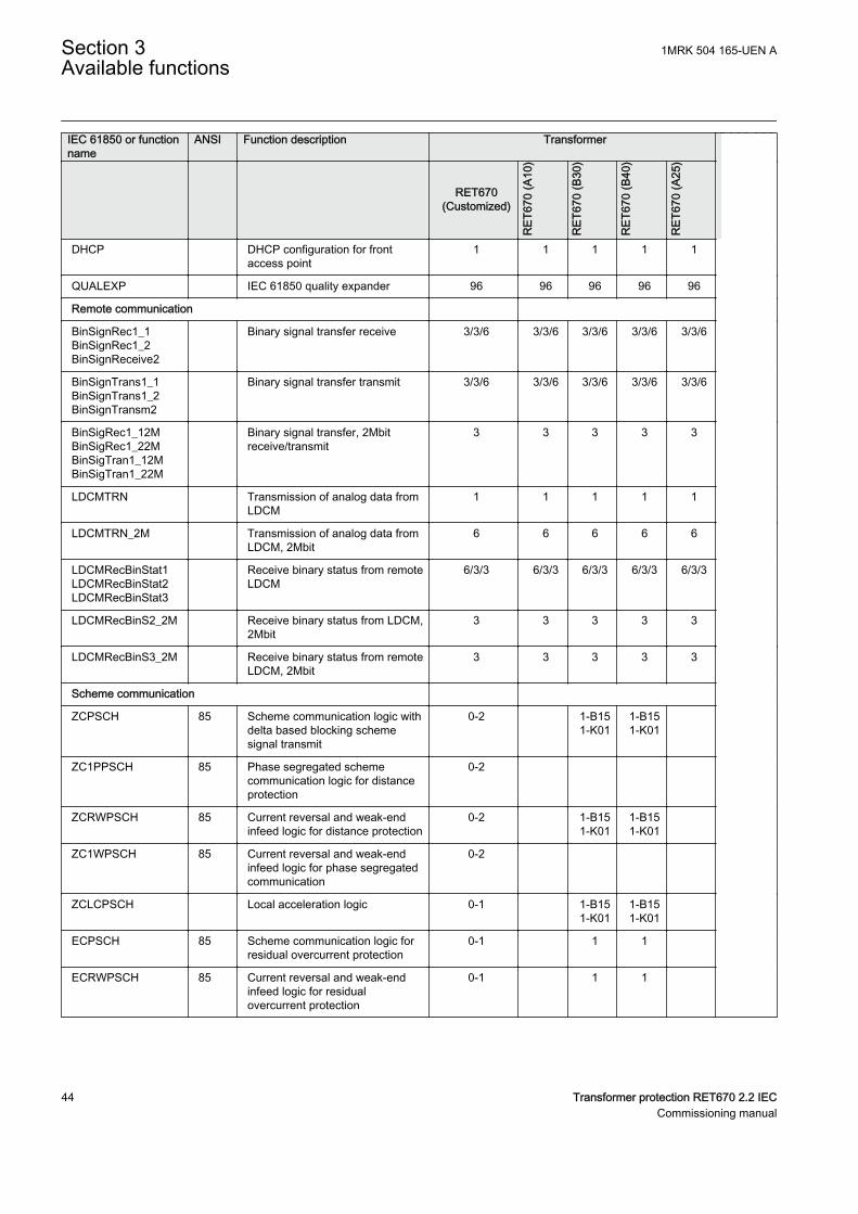
IEC 61850 or functionname
ANSI Function description Transformer
RET670(Customized)
RET
670
(A10
)
RET
670
(B30
)
RET
670
(B40
)
RET
670
(A25
)
DHCP DHCP configuration for frontaccess point
1 1 1 1 1
QUALEXP IEC 61850 quality expander 96 96 96 96 96
Remote communication
BinSignRec1_1BinSignRec1_2BinSignReceive2
Binary signal transfer receive 3/3/6 3/3/6 3/3/6 3/3/6 3/3/6
BinSignTrans1_1BinSignTrans1_2BinSignTransm2
Binary signal transfer transmit 3/3/6 3/3/6 3/3/6 3/3/6 3/3/6
BinSigRec1_12MBinSigRec1_22MBinSigTran1_12MBinSigTran1_22M
Binary signal transfer, 2Mbitreceive/transmit
3 3 3 3 3
LDCMTRN Transmission of analog data fromLDCM
1 1 1 1 1
LDCMTRN_2M Transmission of analog data fromLDCM, 2Mbit
6 6 6 6 6
LDCMRecBinStat1LDCMRecBinStat2LDCMRecBinStat3
Receive binary status from remoteLDCM
6/3/3 6/3/3 6/3/3 6/3/3 6/3/3
LDCMRecBinS2_2M Receive binary status from LDCM,2Mbit
3 3 3 3 3
LDCMRecBinS3_2M Receive binary status from remoteLDCM, 2Mbit
3 3 3 3 3
Scheme communication
ZCPSCH 85 Scheme communication logic withdelta based blocking schemesignal transmit
0-2 1-B151-K01
1-B151-K01
ZC1PPSCH 85 Phase segregated schemecommunication logic for distanceprotection
0-2
ZCRWPSCH 85 Current reversal and weak-endinfeed logic for distance protection
0-2 1-B151-K01
1-B151-K01
ZC1WPSCH 85 Current reversal and weak-endinfeed logic for phase segregatedcommunication
0-2
ZCLCPSCH Local acceleration logic 0-1 1-B151-K01
1-B151-K01
ECPSCH 85 Scheme communication logic forresidual overcurrent protection
0-1 1 1
ECRWPSCH 85 Current reversal and weak-endinfeed logic for residualovercurrent protection
0-1 1 1
Section 3 1MRK 504 165-UEN AAvailable functions
44 Transformer protection RET670 2.2 IECCommissioning manual
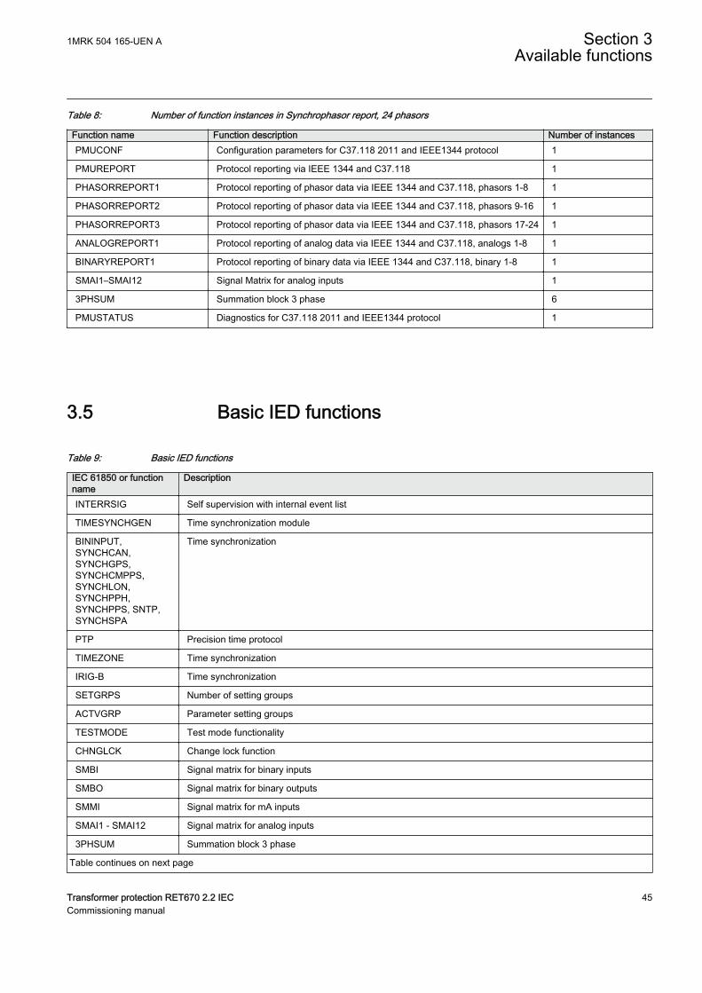
Table 8: Number of function instances in Synchrophasor report, 24 phasors
Function name Function description Number of instancesPMUCONF Configuration parameters for C37.118 2011 and IEEE1344 protocol 1
PMUREPORT Protocol reporting via IEEE 1344 and C37.118 1
PHASORREPORT1 Protocol reporting of phasor data via IEEE 1344 and C37.118, phasors 1-8 1
PHASORREPORT2 Protocol reporting of phasor data via IEEE 1344 and C37.118, phasors 9-16 1
PHASORREPORT3 Protocol reporting of phasor data via IEEE 1344 and C37.118, phasors 17-24 1
ANALOGREPORT1 Protocol reporting of analog data via IEEE 1344 and C37.118, analogs 1-8 1
BINARYREPORT1 Protocol reporting of binary data via IEEE 1344 and C37.118, binary 1-8 1
SMAI1–SMAI12 Signal Matrix for analog inputs 1
3PHSUM Summation block 3 phase 6
PMUSTATUS Diagnostics for C37.118 2011 and IEEE1344 protocol 1
3.5 Basic IED functionsGUID-C8F0E5D2-E305-4184-9627-F6B5864216CA v11
Table 9: Basic IED functions
IEC 61850 or functionname
Description
INTERRSIG Self supervision with internal event list
TIMESYNCHGEN Time synchronization module
BININPUT,SYNCHCAN,SYNCHGPS,SYNCHCMPPS,SYNCHLON,SYNCHPPH,SYNCHPPS, SNTP,SYNCHSPA
Time synchronization
PTP Precision time protocol
TIMEZONE Time synchronization
IRIG-B Time synchronization
SETGRPS Number of setting groups
ACTVGRP Parameter setting groups
TESTMODE Test mode functionality
CHNGLCK Change lock function
SMBI Signal matrix for binary inputs
SMBO Signal matrix for binary outputs
SMMI Signal matrix for mA inputs
SMAI1 - SMAI12 Signal matrix for analog inputs
3PHSUM Summation block 3 phase
Table continues on next page
1MRK 504 165-UEN A Section 3Available functions
Transformer protection RET670 2.2 IEC 45Commissioning manual
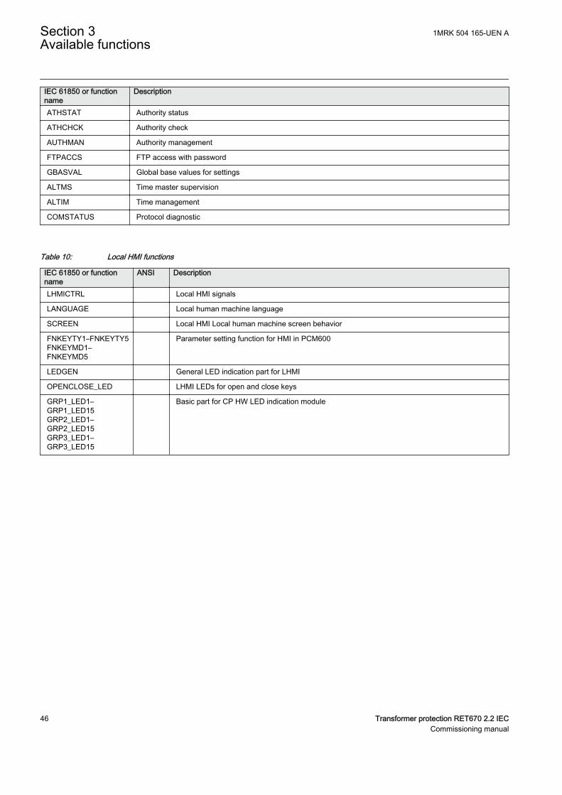
IEC 61850 or functionname
Description
ATHSTAT Authority status
ATHCHCK Authority check
AUTHMAN Authority management
FTPACCS FTP access with password
GBASVAL Global base values for settings
ALTMS Time master supervision
ALTIM Time management
COMSTATUS Protocol diagnostic
Table 10: Local HMI functions
IEC 61850 or functionname
ANSI Description
LHMICTRL Local HMI signals
LANGUAGE Local human machine language
SCREEN Local HMI Local human machine screen behavior
FNKEYTY1–FNKEYTY5FNKEYMD1–FNKEYMD5
Parameter setting function for HMI in PCM600
LEDGEN General LED indication part for LHMI
OPENCLOSE_LED LHMI LEDs for open and close keys
GRP1_LED1–GRP1_LED15GRP2_LED1–GRP2_LED15GRP3_LED1–GRP3_LED15
Basic part for CP HW LED indication module
Section 3 1MRK 504 165-UEN AAvailable functions
46 Transformer protection RET670 2.2 IECCommissioning manual
Section 4 Starting up
4.1 Factory and site acceptance testingGUID-38C2B5FA-9210-4D85-BA21-39CE98A1A84A v2
Testing the proper IED operation is carried out at different occasions, for example:
• Acceptance testing• Commissioning testing• Maintenance testing
This manual describes the workflow and the steps to carry out the commissioningtesting.
Factory acceptance testing (FAT) is typically done to verify that the IED and itscorresponding configuration meet the requirements of the utility or industry. Thistest is the most complex and in depth, as it is done to familiarize the user with anew product or to verify a new configuration. The complexity of this testingdepends on several factors, such as:
• New IED type• New configuration• Modified configuration
Site acceptance testing (SAT or commissioning testing) is typically done to verifythat the installed IED is correctly set and connected to the power system. SATrequires that the acceptance testing has been performed and that the applicationconfiguration is verified.
Maintenance testing is a periodic verification that the IED is healthy and hascorrect settings, depending on changes in the power system. There are also othertypes of maintenance testing.
4.2 Commissioning checklistGUID-93D14E4E-5DDE-4D37-84A6-2DF0656AB73D v3
Before starting up commissioning at site, check that the following items areavailable.
• Single line diagram• Protection block diagram• Circuit diagram• Setting list and configuration• RJ-45 Ethernet cable (CAT 5)
1MRK 504 165-UEN A Section 4Starting up
Transformer protection RET670 2.2 IEC 47Commissioning manual
• Three-phase test kit or other test equipment depending on the complexity ofthe configuration and functions to be tested.
• PC with PCM600 installed along with the connectivity packagescorresponding to the IEDs to be tested.
• Administration rights on the PC, to set up IP addresses• Product documentation (engineering manual, installation manual,
commissioning manual, operation manual, technical manual andcommunication protocol manual)
4.3 Checking the power supplyM11725-2 v6
Do not insert anything else to the female connector but thecorresponding male connector. Inserting anything else (such as ameasurement probe) may damage the female connector and preventa proper electrical contact between the printed circuit board and theexternal wiring connected to the screw terminal block.
Check that the auxiliary supply voltage remains within the permissible inputvoltage range under all operating conditions. Check that the polarity is correctbefore energizing the IED.
4.4 Energizing the IED
4.4.1 Checking the IED operationM11726-2 v7
Check all connections to external circuitry to ensure correct installation, beforeenergizing the IED and carrying out the commissioning procedures.
Energize the power supply of the IED to start it up. Keep the DC power supply onuntil the Root menu or the selected default screen is shown on the HMI beforeinterrupting the DC power supply again. The energization could be done in anumber of ways, from energizing a whole cubicle with many IEDs to energizingeach single IED one by one.
If HW (i.e. I/O and/or communication boards etc.) have been changed (i.e.removed, replaced, or added), the user should re-configure the IED by navigatingin the local HMI menu to: Main menu/Configuration/Reconfigure HW modulesto activate the changed hardware modules in order to enable the self-supervisionfunction to detect possible hardware errors.
Check also the self-supervision function in Main menu/Diagnostics/IED status/General menu in local HMI to verify that the IED operates properly.
Set the IED time if no time synchronization source is configured.
Section 4 1MRK 504 165-UEN AStarting up
48 Transformer protection RET670 2.2 IECCommissioning manual
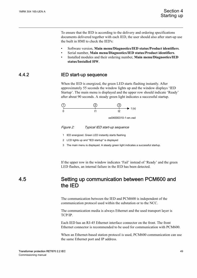
To ensure that the IED is according to the delivery and ordering specificationsdocuments delivered together with each IED, the user should also after start-up usethe built in HMI to check the IED's:
• Software version, Main menu/Diagnostics/IED status/Product identifiers.• Serial number, Main menu/Diagnostics/IED status/Product identifiers.• Installed modules and their ordering number, Main menu/Diagnostics/IED
status/Installed HW.
4.4.2 IED start-up sequenceM11727-3 v12
When the IED is energized, the green LED starts flashing instantly. Afterapproximately 55 seconds the window lights up and the window displays ‘IEDStartup’. The main menu is displayed and the upper row should indicate ‘Ready’after about 90 seconds. A steady green light indicates a successful startup.
xx04000310-1-en.vsd
t (s)0 t1 t2
1 32
IEC04000310 V2 EN-US
Figure 2: Typical IED start-up sequence
1 IED energized. Green LED instantly starts flashing
2 LCD lights up and "IED startup" is displayed
3 The main menu is displayed. A steady green light indicates a successful startup.
If the upper row in the window indicates ‘Fail’ instead of ‘Ready’ and the greenLED flashes, an internal failure in the IED has been detected.
4.5 Setting up communication between PCM600 andthe IED
SEMOD58570-5 v14
The communication between the IED and PCM600 is independent of thecommunication protocol used within the substation or to the NCC.
The communication media is always Ethernet and the used transport layer isTCP/IP.
Each IED has an RJ-45 Ethernet interface connector on the front. The frontEthernet connector is recommended to be used for communication with PCM600.
When an Ethernet-based station protocol is used, PCM600 communication can usethe same Ethernet port and IP address.
1MRK 504 165-UEN A Section 4Starting up
Transformer protection RET670 2.2 IEC 49Commissioning manual
To connect PCM600 to the IED, two basic variants must be considered.
• Direct point-to-point link between PCM600 and the IED front port. The frontport can be seen as a service port.
• A link via a station LAN or from remote via a network.
The physical connection and the IP address must be configured in both cases toenable communication.
The communication procedures are the same in both cases.
1. If needed, set the IP address for the IEDs.2. Set up the PC or workstation for a direct link (point-to-point), or3. Connect the PC or workstation to the LAN/WAN network.4. Configure the IED IP addresses in the PCM600 project for each IED to match
the IP addresses of the physical IEDs.
Setting up IP addressesCommunication between the IED and PCM600 is enabled from the LHMI. The IPaddress and the corresponding communication subnetwork mask must be set viathe Ethernet configuration tool (ECT) for each available Ethernet interface in theIED. Each Ethernet interface has a default factory IP address when the IED isdelivered. The IP adress and the subnetwork mask might have to be reset when anadditional Ethernet interface is installed or an interface is replaced.
• DHCP is available for the front port, and a device connected to it can therebyobtain an automatically assigned IP address via the local HMI path Mainmenu/Configuration/Communication/Ethernet configuration/Front port/DHCP or,
• Alternatively the default IP address for the IED front port is 10.1.150.3 and thecorresponding subnetwork mask is 255.255.255.0, which can be set via thelocal HMI path Main menu/Configuration/Communication/Ethernetconfiguration/AP_FRONT.
Setting up the PC or workstation for point-to-point access to IEDsfront portAn ethernet cable (max 2 m length) with RJ-45 connectors is needed to connecttwo physical Ethernet interfaces together without a hub, router, bridge or switch inbetween.
1. Select Search programs and files in the Start menu in Windows.
Section 4 1MRK 504 165-UEN AStarting up
50 Transformer protection RET670 2.2 IECCommissioning manual
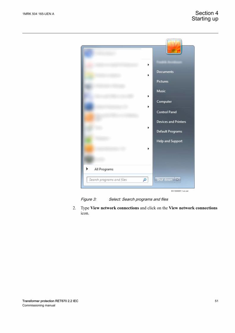
IEC13000057-1-en.vsdIEC13000057 V1 EN-US
Figure 3: Select: Search programs and files
2. Type View network connections and click on the View network connectionsicon.
1MRK 504 165-UEN A Section 4Starting up
Transformer protection RET670 2.2 IEC 51Commissioning manual
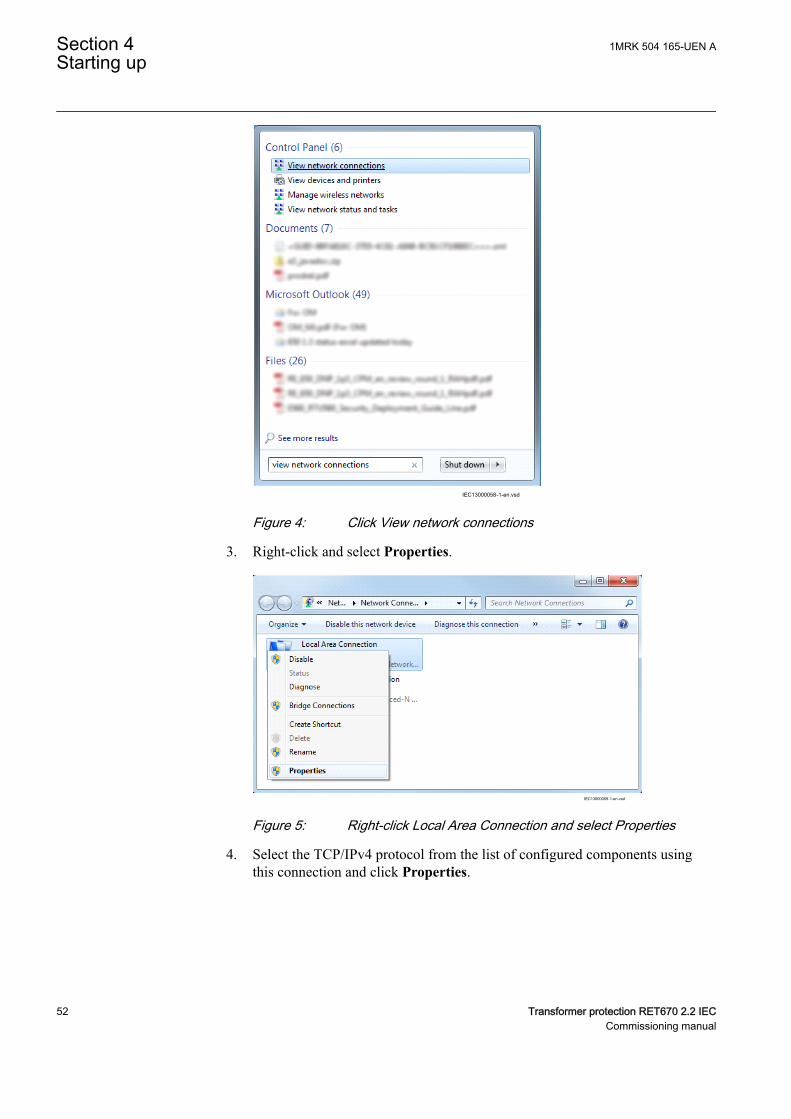
IEC13000058-1-en.vsdIEC13000058 V1 EN-US
Figure 4: Click View network connections
3. Right-click and select Properties.
IEC13000059-1-en.vsd
IEC13000059 V1 EN-US
Figure 5: Right-click Local Area Connection and select Properties
4. Select the TCP/IPv4 protocol from the list of configured components usingthis connection and click Properties.
Section 4 1MRK 504 165-UEN AStarting up
52 Transformer protection RET670 2.2 IECCommissioning manual
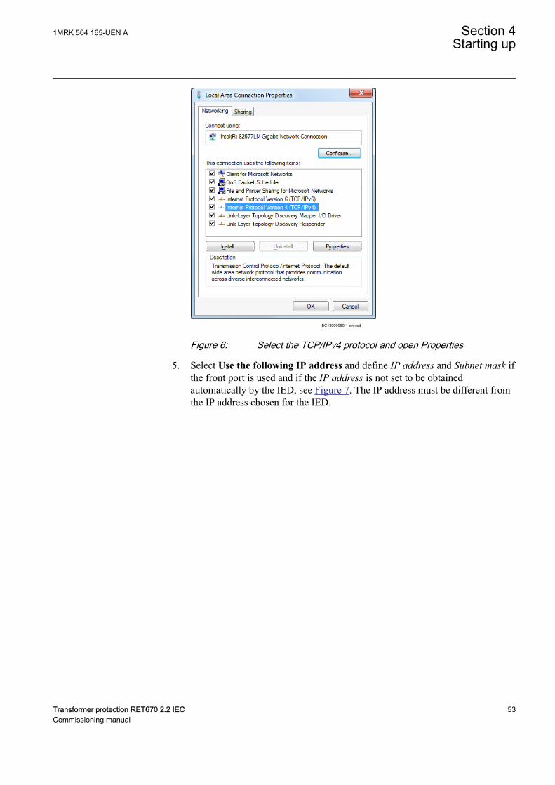
IEC13000060-1-en.vsdIEC13000060 V1 EN-US
Figure 6: Select the TCP/IPv4 protocol and open Properties
5. Select Use the following IP address and define IP address and Subnet mask ifthe front port is used and if the IP address is not set to be obtainedautomatically by the IED, see Figure 7. The IP address must be different fromthe IP address chosen for the IED.
1MRK 504 165-UEN A Section 4Starting up
Transformer protection RET670 2.2 IEC 53Commissioning manual
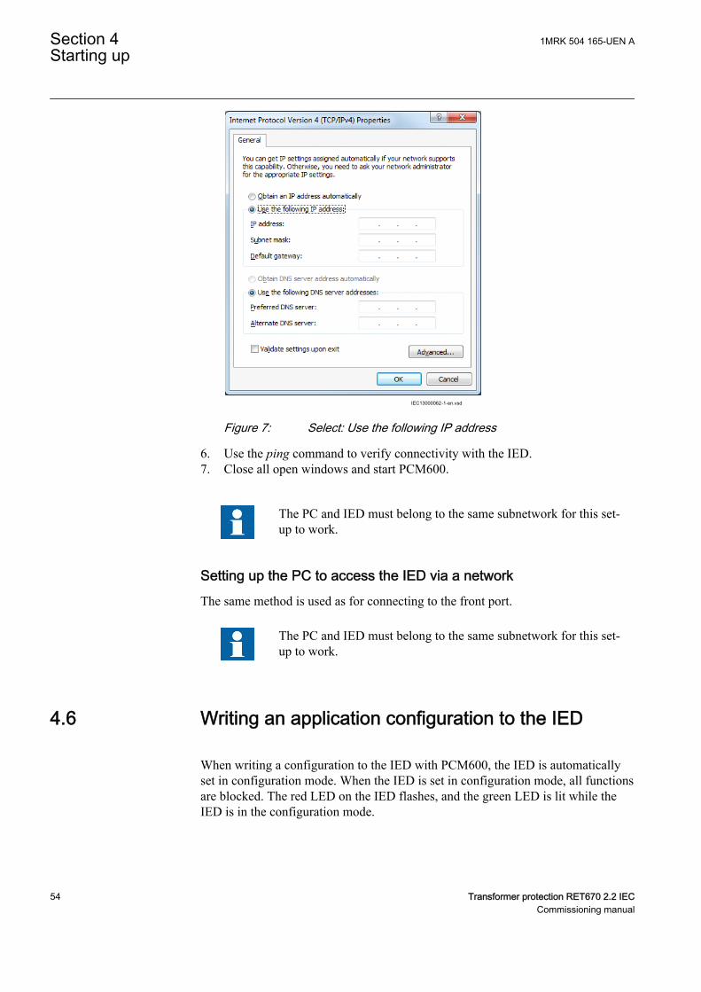
IEC13000062-1-en.vsdIEC13000062 V1 EN-US
Figure 7: Select: Use the following IP address
6. Use the ping command to verify connectivity with the IED.7. Close all open windows and start PCM600.
The PC and IED must belong to the same subnetwork for this set-up to work.
Setting up the PC to access the IED via a networkThe same method is used as for connecting to the front port.
The PC and IED must belong to the same subnetwork for this set-up to work.
4.6 Writing an application configuration to the IEDM11734-2 v6
When writing a configuration to the IED with PCM600, the IED is automaticallyset in configuration mode. When the IED is set in configuration mode, all functionsare blocked. The red LED on the IED flashes, and the green LED is lit while theIED is in the configuration mode.
Section 4 1MRK 504 165-UEN AStarting up
54 Transformer protection RET670 2.2 IECCommissioning manual
When the configuration is written and completed, the IED is automatically set intonormal mode. For further instructions please refer to the users manuals forPCM600.
4.7 Checking CT circuitsM12182-2 v15
Check that the wiring is in strict accordance with the suppliedconnection diagram.
The CTs must be connected in accordance with the circuit diagram provided withthe IED, both with regards to phases and polarity. The following tests shall beperformed on every primary CT connected to the IED:
• Primary injection test to verify the current ratio of the CT, the correct wiringup to the protection IED and correct phase sequence connection (that is L1,L2, L3.)
• Polarity check to prove that the predicted direction of secondary current flowis correct for a given direction of primary current flow. This is an essential testfor the proper operation of the differential function and directional protectionfunctions.
• CT secondary loop resistance measurement to confirm that the currenttransformer secondary loop DC resistance is within the specification for theconnected protection functions. When the measured loop resistance is near thecalculated value for maximum DC resistance, perform a complete burden test.
• CT excitation test in order to confirm that the current transformer is of thecorrect accuracy rating and that there are no shorted turns in the currenttransformer windings. Manufacturer's design curves must be available for thecurrent transformer to compare the actual results.
• Earthing check of the individual CT secondary circuits to verify that eachthree-phase set of main CTs is properly connected to the station earth and onlyat one electrical point.
• Insulation resistance check.
While the CT primary is energized, the secondary circuit shallnever be open circuited because extremely dangerous high voltagesmay arise.
Both the primary and the secondary sides must be disconnectedfrom the line and the IED when plotting the excitationcharacteristics.
1MRK 504 165-UEN A Section 4Starting up
Transformer protection RET670 2.2 IEC 55Commissioning manual
If the CT secondary circuit earth connection is removed without thecurrent transformer primary being de-energized, dangerous voltagesmay result in the secondary CT circuits.
4.8 Checking VT circuitsM11724-2 v10
Check that the wiring is in strict accordance with the supplied connection diagram.
Correct possible errors before continuing to test the circuitry.
Test the circuitry.
• Polarity check when applicable; this test is often omitted for CVTs• VT circuit voltage measurement (primary injection test)• Earthing check• Phase relationship• Insulation resistance check
The primary injection test verifies the VT ratio and the wiring all the way from theprimary system to the IED. Injection must be performed for each phase-to-neutralcircuit.
While testing VT secondary circuit and associated secondaryequipment, care shall be exercised to isolate the VT from the circuitbeing tested to avoid backcharging the VT from the secondary side.
4.9 Using the RTXP test switchGUID-F1E29C06-7FE8-44D8-AD5A-EE8990A2AA41 v5
The RTXP test switch is designed to provide the means of safe testing of the IED.This is achieved by the electromechanical design of the test switch and test plughandle. When the test plug handle is inserted, it first blocks the trip and alarmcircuits then it short circuits the CT secondary circuit and opens the VT secondarycircuits making the IED available for secondary injection.
When pulled out, the test handle is mechanically stopped in half withdrawnposition. In this position, the current and voltage enter the protection, but the alarmand trip circuits are still isolated and the IED is in test mode. Before removing thetest handle, check the measured values in the IED.
Section 4 1MRK 504 165-UEN AStarting up
56 Transformer protection RET670 2.2 IECCommissioning manual
Not until the test handle is completely removed, the trip and alarm circuits arerestored for operation.
Verify that the contact sockets have been crimped correctly and thatthey are fully inserted by tugging on the wires. Never do this withcurrent circuits in service.
Current circuit
1. Verify that the contacts are of current circuit type.2. Verify that the short circuit jumpers are located in the correct slots.
Voltage circuit
1. Verify that the contacts are of voltage circuit type.2. Check that no short circuit jumpers are located in the slots dedicated for
voltage.
Trip and alarm circuits
1. Check that the correct types of contacts are used.
4.10 Checking the binary input/output circuitsM11722-2 v4
Do not insert anything else to the female connector but thecorresponding male connector. Inserting anything else (such as ameasurement probe) may damage the female connector and preventa proper electrical contact between the printed circuit board and theexternal wiring connected to the screw terminal block.
4.10.1 Binary input circuitsM11722-4 v3
Preferably, disconnect the binary input connector from the binary input cards.Check all connected signals so that both input level and polarity are in accordancewith the IED specifications.
4.10.2 Binary output circuitsM11722-8 v3
Preferably, disconnect the binary output connector from the binary output cards.Check all connected signals so that both load and polarity are in accordance withIED specifications.
1MRK 504 165-UEN A Section 4Starting up
Transformer protection RET670 2.2 IEC 57Commissioning manual

4.11 Checking optical connectionsM16022-2 v7
Check that the Tx and Rx optical connections are correct.
An IED equipped with optical connections has an minimum spacerequirement of 180 mm for plastic fiber cables and 275 mm forglass fiber cables. Check the allowed minimum bending radiusfrom the optical cable manufacturer.
Section 4 1MRK 504 165-UEN AStarting up
58 Transformer protection RET670 2.2 IECCommissioning manual
Section 5 Configuring the IED and changingsettings
5.1 OverviewM11730-2 v6
The customer specific values for each setting parameter and a configuration filehave to be available before the IED can be set and configured, if the IED is notdelivered with a configuration.
Use the configuration tools in PCM600 to verify that the IED has the expectedconfiguration.
Each function included in the IED has several setting parameters, which have to beset in order to make the IED behave as intended. A factory default value isprovided for each parameter.The Parameter Setting Tool in PCM600 is used whenchanging setting parameters.
All settings can be
• Entered manually through the local HMI.• Written from a PC, either locally or remotely using PCM600. Front or rear
port communication has to be established before the settings can be written tothe IED.
Make sure that the DC supply is not turned off when the IED savesthe written configuration.
The IED uses a FLASH disk for storing configuration data and process data likecounters, object states, Local/Remote switch position etc. Since FLASH memory isused, measures have been taken in software to make sure that the FLASH disk isnot worn out by too intensive storing of data.
This means, that to be absolutely sure that all data have been saved to FLASH, it isnecessary to leave the IED with auxiliary power connected after all thecommissioning is done (including setting the Local/Remote switch to the desiredposition) for at least one hour after the last commissioning action performed on theIED.
After that time has elapsed, it will be safe to turn the IED off, no data will be lost.
1MRK 504 165-UEN A Section 5Configuring the IED and changing settings
Transformer protection RET670 2.2 IEC 59Commissioning manual
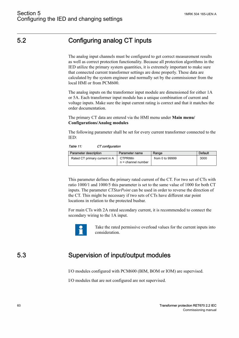
5.2 Configuring analog CT inputsM12312-6 v8
The analog input channels must be configured to get correct measurement resultsas well as correct protection functionality. Because all protection algorithms in theIED utilize the primary system quantities, it is extremely important to make surethat connected current transformer settings are done properly. These data arecalculated by the system engineer and normally set by the commissioner from thelocal HMI or from PCM600.
The analog inputs on the transformer input module are dimensioned for either 1Aor 5A. Each transformer input module has a unique combination of current andvoltage inputs. Make sure the input current rating is correct and that it matches theorder documentation.
The primary CT data are entered via the HMI menu under Main menu/Configurations/Analog modules
The following parameter shall be set for every current transformer connected to theIED:
Table 11: CT configuration
Parameter description Parameter name Range DefaultRated CT primary current in A CTPRIMn
n = channel numberfrom 0 to 99999 3000
This parameter defines the primary rated current of the CT. For two set of CTs withratio 1000/1 and 1000/5 this parameter is set to the same value of 1000 for both CTinputs. The parameter CTStarPoint can be used in order to reverse the direction ofthe CT. This might be necessary if two sets of CTs have different star pointlocations in relation to the protected busbar.
For main CTs with 2A rated secondary current, it is recommended to connect thesecondary wiring to the 1A input.
Take the rated permissive overload values for the current inputs intoconsideration.
5.3 Supervision of input/output modulesM11728-2 v3
I/O modules configured with PCM600 (BIM, BOM or IOM) are supervised.
I/O modules that are not configured are not supervised.
Section 5 1MRK 504 165-UEN AConfiguring the IED and changing settings
60 Transformer protection RET670 2.2 IECCommissioning manual

Each logical I/O module has an error flag that indicates signal or module failure.The error flag is also set when the physical I/O module of the correct type is notdetected in the connected slot.
1MRK 504 165-UEN A Section 5Configuring the IED and changing settings
Transformer protection RET670 2.2 IEC 61Commissioning manual

62
Section 6 Establishing connection and verifying theSPA/IEC communication
6.1 Entering settingsM11735-2 v2
If the IED is connected to a monitoring or control system via the rear SPA/IEC103port, the SPA/IEC103 port has to be set either for SPA or IEC103 use.
6.1.1 Entering SPA settingsM11735-7 v5
The SPA/IEC port is located on the rear side of the IED. Two types of interfacescan be used:
• plastic fibres with connector type HFBR• glass fibres with connector type ST
When using the SPA protocol, the rear SPA/IEC port must be set for SPA use.
Procedure:
1. Set the port for SPA use on the local HMI under Main menu /Configuration /Communication /Station communication/Portconfiguration/SLM optical serial port/PROTOCOL:1. When thecommunication protocol is selected, the IED is automatically restarted, andthe port then operates as a SPA port.
2. Set the SlaveAddress and BaudRate for the rear SPA port on the local HMIunder Main menu/Configuration/Communication/Stationcommunication/SPA/SPA:1. Use the same settings for these as is set in theSMS system for the IED.
6.1.2 Entering IEC settingsM11735-32 v5
The SPA/IEC port is located on the rear side of the IED. Two types of interfacescan be used:
• plastic fibres with connector type HFBR• glass fibres with connector type ST
When using the IEC protocol, the rear SPA/IEC port must be set for IEC use.
Procedure:
1MRK 504 165-UEN A Section 6Establishing connection and verifying the SPA/IEC communication
Transformer protection RET670 2.2 IEC 63Commissioning manual
1. Set the port for IEC use on the local HMI under Main menu /Configuration /Communication /Station communication/Portconfiguration/SLM optical serial port/PROTOCOL:1. When thecommunication protocol is selected, the IED is automatically restarted, andthe port then operates as an IEC port.
2. Set the SlaveAddress and BaudRate for the rear IEC port on the local HMIunder Main menu/Configuration/Communication/Stationcommunication/IEC60870-5-103/OPTICAL103:1. Use the same settingsfor these as is set in the SMS system for the IED.
6.2 Verifying the communicationM11735-77 v1
To verify that the rear communication with the SMS/SCS system is working, thereare some different methods. Choose one of the following.
6.2.1 Verifying SPA communicationM11735-81 v5
Procedure
1. Use a SPA-emulator and send “RF” to the IED. The answer from the IEDshould be the type and version of it, for example, “REL670 2.1...”.
2. Generate one binary event by activating a function, which is configured to anEVENT block where the used input is set to generate events on SPA. Theconfiguration must be made with the PCM600 software. Verify that the eventis presented in the SMS/SCS system.
During the following tests of the different functions in the IED, verify that theevents and indications in the SMS/SCS system are as expected.
6.2.2 Verifying IEC communicationM11735-91 v2
To verify that the IEC communication with the IEC master system is working,there are some different methods. Choose one of the following.
Procedure
1. Check that the master system time-out for response from the IED, forexample after a setting change, is > 40 seconds.
2. Use a protocol analyzer and record the communication between the IED andthe IEC master. Check in the protocol analyzer’s log that the IED answers themaster messages.
3. Generate one binary event by activating a function that is configured to anevent block where the used input is set to generate events on IEC. Theconfiguration must be made with the PCM600 software. Verify that the eventis presented in the IEC master system.
Section 6 1MRK 504 165-UEN AEstablishing connection and verifying the SPA/IEC communication
64 Transformer protection RET670 2.2 IECCommissioning manual
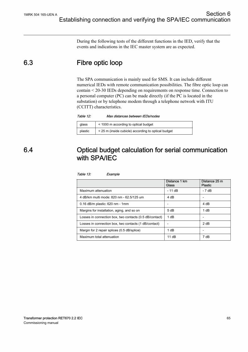
During the following tests of the different functions in the IED, verify that theevents and indications in the IEC master system are as expected.
6.3 Fibre optic loopM11905-3 v6
The SPA communication is mainly used for SMS. It can include differentnumerical IEDs with remote communication possibilities. The fibre optic loop cancontain < 20-30 IEDs depending on requirements on response time. Connection toa personal computer (PC) can be made directly (if the PC is located in thesubstation) or by telephone modem through a telephone network with ITU(CCITT) characteristics.
Table 12: Max distances between IEDs/nodes
glass < 1000 m according to optical budget
plastic < 25 m (inside cubicle) according to optical budget
6.4 Optical budget calculation for serial communicationwith SPA/IEC
M11736-4 v2
Table 13: Example
Distance 1 kmGlass
Distance 25 mPlastic
Maximum attenuation - 11 dB - 7 dB
4 dB/km multi mode: 820 nm - 62.5/125 um 4 dB -
0.16 dB/m plastic: 620 nm - 1mm - 4 dB
Margins for installation, aging, and so on 5 dB 1 dB
Losses in connection box, two contacts (0.5 dB/contact) 1 dB -
Losses in connection box, two contacts (1 dB/contact) - 2 dB
Margin for 2 repair splices (0.5 dB/splice) 1 dB -
Maximum total attenuation 11 dB 7 dB
1MRK 504 165-UEN A Section 6Establishing connection and verifying the SPA/IEC communication
Transformer protection RET670 2.2 IEC 65Commissioning manual

66
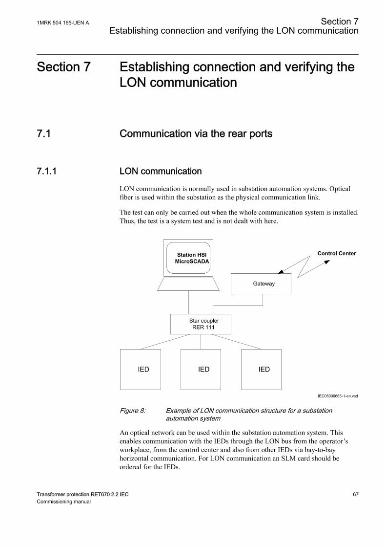
Section 7 Establishing connection and verifying theLON communication
7.1 Communication via the rear portsM12196-2 v1
7.1.1 LON communicationM12196-4 v5
LON communication is normally used in substation automation systems. Opticalfiber is used within the substation as the physical communication link.
The test can only be carried out when the whole communication system is installed.Thus, the test is a system test and is not dealt with here.
M14804-3 v5
Control Center
IED IEDIED
Gateway
Star couplerRER 111
Station HSIMicroSCADA
IEC05000663-1-en.vsdIEC05000663 V2 EN-US
Figure 8: Example of LON communication structure for a substationautomation system
An optical network can be used within the substation automation system. Thisenables communication with the IEDs through the LON bus from the operator’sworkplace, from the control center and also from other IEDs via bay-to-bayhorizontal communication. For LON communication an SLM card should beordered for the IEDs.
1MRK 504 165-UEN A Section 7Establishing connection and verifying the LON communication
Transformer protection RET670 2.2 IEC 67Commissioning manual
The fibre optic LON bus is implemented using either glass core or plastic core fibreoptic cables.
Table 14: Specification of the fibre optic connectors
Glass fibre Plastic fibreCable connector ST-connector snap-in connector
Cable diameter 62.5/125 m 1 mm
Max. cable length 1000 m 10 m
Wavelength 820-900 nm 660 nm
Transmitted power -13 dBm (HFBR-1414) -13 dBm (HFBR-1521)
Receiver sensitivity -24 dBm (HFBR-2412) -20 dBm (HFBR-2521)
7.1.2 The LON ProtocolM14804-32 v2
The LON protocol is specified in the LonTalkProtocol Specification Version 3from Echelon Corporation. This protocol is designed for communication in controlnetworks and is a peer-to-peer protocol where all the devices connected to thenetwork can communicate with each other directly. For more information of thebay-to-bay communication, refer to the section Multiple command function.
7.1.3 Hardware and software modulesM14804-35 v4
The hardware needed for applying LON communication depends on theapplication, but one very central unit needed is the LON Star Coupler and opticalfibres connecting the star coupler to the IEDs. To interface the IEDs from theMicroSCADA with Classic Monitor, application library LIB520 is required.
The HV Control 670 software module is included in the LIB520 high-voltageprocess package, which is a part of the Application Software Library inMicroSCADA applications.
The HV Control 670 software module is used for control functions in the IEDs.The module contains a process picture, dialogues and a tool to generate a processdatabase for the control application in MicroSCADA.
When using MicroSCADA Monitor Pro instead of the Classic Monitor, SA LIB isused together with 670 series Object Type files.
The HV Control 670 software module and 670 series Object Typefiles are used with both 650 and 670 series IEDs.
Use the LON Network Tool (LNT) to set the LON communication. This is asoftware tool applied as one node on the LON bus. To communicate via LON, theIEDs need to know
Section 7 1MRK 504 165-UEN AEstablishing connection and verifying the LON communication
68 Transformer protection RET670 2.2 IECCommissioning manual
• The node addresses of the other connected IEDs.• The network variable selectors to be used.
This is organized by LNT.
The node address is transferred to LNT via the local HMI by setting the parameterServicePinMsg = Yes. The node address is sent to LNT via the LON bus, or LNTcan scan the network for new nodes.
The communication speed of the LON bus is set to the default of 1.25 Mbit/s. Thiscan be changed by LNT.
M11888-3 v5
The LON communication setting parameters are set via the local HMI. Refer to theTechnical manual for more detailed specifications.
If LON communication from the IED stops because of illegal communicationparameter settings (outside the setting range) or due to other kind of disturbance, itis possible to reset the IED's LON port.
M11643-1 v4
LON communication setting parameters (Table 15) and LON node informationparameters (Table 16) can only be set via the LON Network Tool (LNT).
Some of these parameters can be viewed on the local HMI under Main menu/Configuration/Communication/Station communication/Portconfiguration/SLM optical LON port/LONGEN:1.
Table 15: LON communication setting parameters
Parameter Range Default Unit Parameter descriptionDomainID 0 0 - Domain identification number
SubnNetAddr* 0 - 255Step: 1
0 - Subnet address
NodeAddr* 0 - 127Step: 1
0 - Node address
*Can be viewed on the local HMI
Table 16: LON node information parameters
Parameter Range Default Unit Parameter descriptionNeuronID* 0 - 12 Not loaded - Neuron hardware identification
number in hexadecimal code
Location 0 - 6 No value - Location of the node
*Can be viewed on the local HMI
ADE settings are available on the local HMI under Main menu/Configuration/Communication/Station communicaton/LON/ADE:1
1MRK 504 165-UEN A Section 7Establishing connection and verifying the LON communication
Transformer protection RET670 2.2 IEC 69Commissioning manual
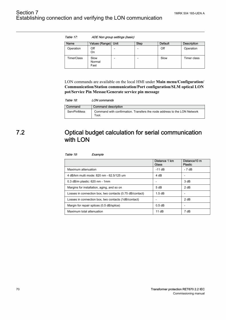
Table 17: ADE Non group settings (basic)
Name Values (Range) Unit Step Default DescriptionOperation Off
On- - Off Operation
TimerClass SlowNormalFast
- - Slow Timer class
LON commands are available on the local HMI under Main menu/Configuration/Communication/Station communication/Port configuration/SLM optical LONpot/Service Pin Messae/Generate service pin message
Table 18: LON commands
Command Command descriptionServPinMess Command with confirmation. Transfers the node address to the LON Network
Tool.
7.2 Optical budget calculation for serial communicationwith LON
M11737-4 v2
Table 19: Example
Distance 1 kmGlass
Distance10 mPlastic
Maximum attenuation -11 dB - 7 dB
4 dB/km multi mode: 820 nm - 62.5/125 um 4 dB -
0.3 dB/m plastic: 620 nm - 1mm - 3 dB
Margins for installation, aging, and so on 5 dB 2 dB
Losses in connection box, two contacts (0.75 dB/contact) 1.5 dB -
Losses in connection box, two contacts (1dB/contact) - 2 dB
Margin for repair splices (0.5 dB/splice) 0.5 dB -
Maximum total attenuation 11 dB 7 dB
Section 7 1MRK 504 165-UEN AEstablishing connection and verifying the LON communication
70 Transformer protection RET670 2.2 IECCommissioning manual
Section 8 Establishing connection and verifying theIEC 61850 communication
8.1 OverviewSEMOD172103-4 v8
The rear optical Ethernet ports are used for:
• process bus (IEC/UCA 61850-9-2LE) communication• IEEE C37.118/1344 communication• substation bus (IEC 61850-8-1) communication
8.2 Setting the station communicationSEMOD172108-3 v12
To enable IEC 61850 communication the corresponding ports must be activated.The rear access points can be used for IEC 61850-8-1 and IEC/UCA 61850-9-2LEcommunication. IEC 61850-8-1 redundant communication requires the use of twoEthernet ports, when it is activated for Ethernet port the next immediate port isselected as the second Ethernet port and will become hidden.
To enable IEC 61850 station communication:
In this example access points 1, 2 and 3 are used.
1. Activate IEC 61850-8-1 (substation bus) communication.Navigate to: Main menu/Configuration/Communication/Stationcommunication/IEC61850–8–1/IEC61850–8–1:1
2. Enable operation for Access Point 1 and 3 in the Ethernet configuration tool(ECT) in PCM600.
3. Enable redundant communication for Acess point 1 using ECT.4. Enable IEC/UCA 61850-9-2LE (process bus) communication for Access
point 3 by connecting it to a Merging unit in the Merging units tab in ECT.
There are no settings needed for the IEC/UCA 61850-9-2LE communication in thelocal HMI branch Station communication. Make sure that the optical fibres areconnected correctly. Communication is enabled whenever the merging unit startssending data.
1MRK 504 165-UEN A Section 8Establishing connection and verifying the IEC 61850 communication
Transformer protection RET670 2.2 IEC 71Commissioning manual

8.3 Verifying the communicationSEMOD172108-24 v10
To verify that the communication is working a test/analyzing tool, for exampleITT600, can be used.
Verifying redundant IEC 61850-8-1 communicationEnsure that the IED receives IEC 61850-8-1 data on the selected Ethernet ports.Browse in the local HMI to Main menu/Diagnostics/Communication/Ethernetstatus/Access point/APStatusRedundant/RCHLCCH:1 and check thatChARedStatus and ChBRedStatus are shown as Ok. Remove the opticalconnection to one of the Ethernet ports. Verify that either signal status (dependingon which connection that was removed) is shown as Error and the that other signalis shown as Ok. Be sure to re-connect the removed connection after completedverification.
Section 8 1MRK 504 165-UEN AEstablishing connection and verifying the IEC 61850 communication
72 Transformer protection RET670 2.2 IECCommissioning manual
Section 9 Establishing connection and verifying theIEEE C37.118/1344 communication
9.1 OverviewGUID-EFD77C28-6F7C-4277-8C7E-30E78CC8EFAD v3
The IED can support synchrophasor data communication via IEEE C37.118 and/orIEEE1344 with maximum 8 TCP clients and 6 UDP client groups, simultaneously.
The rear OEM ports are used for IEEE C37.118/1344 communication. The sameports can also be used for substation bus (IEC 61850-8-1) communication andprocess bus (IEC/UCA 61850-9-2LE) communication where applicable.
In order to establish a connection between PMU and a TCP/UDP client (PDCclient), an Ethernet communication link (e.g. optical fiber) shall be available andthe required parameters on both PMU and the TCP/UDP client shall be set. For thepurpose of this section, an Open PDC tool (PMU Connection Tester) installed on aPC is used as the TCP/UDP client.
9.2 Setting the PMU station communication (PMUReport)
GUID-B8DCD7BA-AEBA-4977-89D4-2F18ECE34A2F v1
1. Check the settings for the PMU Report parameters by navigating to: Mainmenu/Configuration/Communication/Station communication/phasormeasurement/PMU Report/PMUREPORT:11.1. Make sure that the operation of at least one PMU instance (e.g. PMU1)
is On.1.2. Enable sending the frequency data by setting the parameter
SendFreqInfo to On.2. Check the operation of the required phasor channels (PHASORREPORT) by
navigating to: Main menu/Configuration/Communication/Stationcommunication/phasor measurement/PMU Report/PHASORREPORT:x.
1MRK 504 165-UEN A Section 9Establishing connection and verifying the IEEE C37.118/1344 communication
Transformer protection RET670 2.2 IEC 73Commissioning manual

9.3 Setting the PMU station communication (PMUconfiguration)
GUID-B4BA9F74-5E28-42FC-8F33-0BC98D5AE6B0 v2
To enable IEEE C37.118/1344 communication, the corresponding OEM ports mustbe activated. The galvanic Ethernet front port and the rear optical ports can be usedfor IEEE C37.118/1344 communication.
To enable IEEE C37.118/1344 synchrophasor communication:
1. Enable communication for by navigating to: Main menu/Configuration/Communication/Ethernet configuration.1.1. Select the port.1.2. Set values for Mode, IPAddress and IPMask. Mode must be set to
Normal.1.3. Check that the correct IP address is assigned to the port.
2. Set the TCP communication parameters by navigating to: Main menu/Configuration/Communication/Station communication/phasormeasurement/PMU Configuration/PMUCONF. The first three parametersare related to TCP communication. The default TCP parameters setting canbe used. More information regarding TCP communication is available in theApplication manual under section Short guidance for use of TCP.
3. Set the UDP communication parameters by navigating to: Main menu/Configuration/Communication/Station communication/phasormeasurement/PMU Configuration/PMUCONF. The first three parametersare related to TCP communication and the rest of parameters are related tosetting of six independent UDP client groups. Each UDP group has eightparameters. More information regarding UDP communication is available inthe Application manual under section Short guidance for use of UDP. Thefollowing steps describes setting parameters for the first UDP group:3.1. Enable the first UDP group by setting the parameter SendDataUDP1 to
On.3.2. Set the UDP client IP address by setting the parameter
UDPDestAddres1 to 192.168.1.99. For the purpose of thecommunication set-up in this section the LAN IP address of the PC isused, where the PDC client tool is installed.
3.3. The default parameter settings can be used for the rest of parameters forthe first UDP group.
Section 9 1MRK 504 165-UEN AEstablishing connection and verifying the IEEE C37.118/1344 communication
74 Transformer protection RET670 2.2 IECCommissioning manual

9.4 Setting the TCP/UDP client communicationGUID-6CEE3261-D211-4051-8CA8-5840C27C560E v2
As an example of a TCP/UDP client, the openPDC tool (PMU Connection TesterVer. 4.2.12) from Grid Protection Alliance is used in this section. Install PMUConnection Tester tool on a PC with Ethernet network adaptor available. The samePC used for PCM600 can be used to install the PMU Connection Tester tool.
IEC140000133-1-en.vsd
IEC140000133 V1 EN-US
Figure 9: PMU Connection Tester tool
The following steps explain how to set the PMU Connection Tester parameters inorder to establish an IEEE C37.118 connection with the PMU:
1. Set the IP stack on PMU Connection Tester to IPv4. Note that the default IPstack on PMU Connection Tester tool is IPv6.
1MRK 504 165-UEN A Section 9Establishing connection and verifying the IEEE C37.118/1344 communication
Transformer protection RET670 2.2 IEC 75Commissioning manual
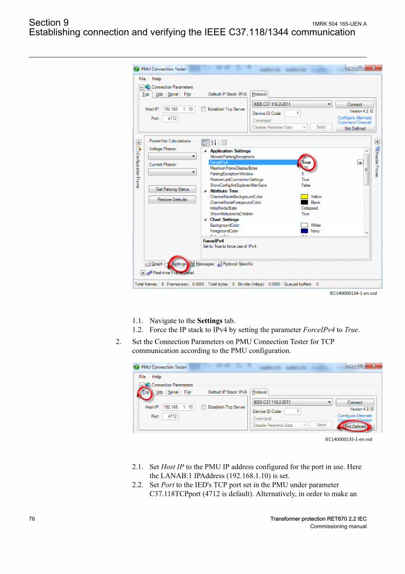
IEC140000134-1-en.vsd
IEC140000134 V1 EN-US
1.1. Navigate to the Settings tab.1.2. Force the IP stack to IPv4 by setting the parameter ForceIPv4 to True.
2. Set the Connection Parameters on PMU Connection Tester for TCPcommunication according to the PMU configuration.
IEC140000135-1-en.vsd
IEC140000135 V1 EN-US
2.1. Set Host IP to the PMU IP address configured for the port in use. Herethe LANAB:1 IPAddress (192.168.1.10) is set.
2.2. Set Port to the IED's TCP port set in the PMU under parameterC37.118TCPport (4712 is default). Alternatively, in order to make an
Section 9 1MRK 504 165-UEN AEstablishing connection and verifying the IEEE C37.118/1344 communication
76 Transformer protection RET670 2.2 IECCommissioning manual
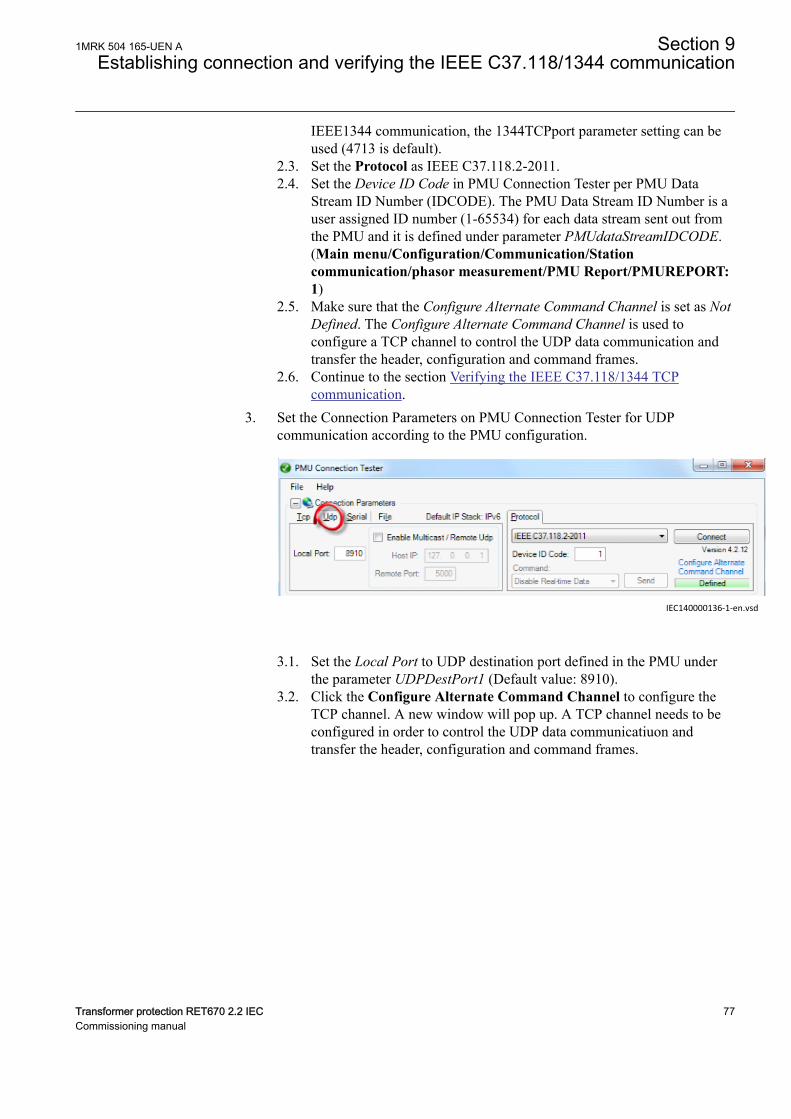
IEEE1344 communication, the 1344TCPport parameter setting can beused (4713 is default).
2.3. Set the Protocol as IEEE C37.118.2-2011.2.4. Set the Device ID Code in PMU Connection Tester per PMU Data
Stream ID Number (IDCODE). The PMU Data Stream ID Number is auser assigned ID number (1-65534) for each data stream sent out fromthe PMU and it is defined under parameter PMUdataStreamIDCODE.(Main menu/Configuration/Communication/Stationcommunication/phasor measurement/PMU Report/PMUREPORT:1)
2.5. Make sure that the Configure Alternate Command Channel is set as NotDefined. The Configure Alternate Command Channel is used toconfigure a TCP channel to control the UDP data communication andtransfer the header, configuration and command frames.
2.6. Continue to the section Verifying the IEEE C37.118/1344 TCPcommunication.
3. Set the Connection Parameters on PMU Connection Tester for UDPcommunication according to the PMU configuration.
IEC140000136-1-en.vsd
IEC140000136 V1 EN-US
3.1. Set the Local Port to UDP destination port defined in the PMU underthe parameter UDPDestPort1 (Default value: 8910).
3.2. Click the Configure Alternate Command Channel to configure theTCP channel. A new window will pop up. A TCP channel needs to beconfigured in order to control the UDP data communicatiuon andtransfer the header, configuration and command frames.
1MRK 504 165-UEN A Section 9Establishing connection and verifying the IEEE C37.118/1344 communication
Transformer protection RET670 2.2 IEC 77Commissioning manual
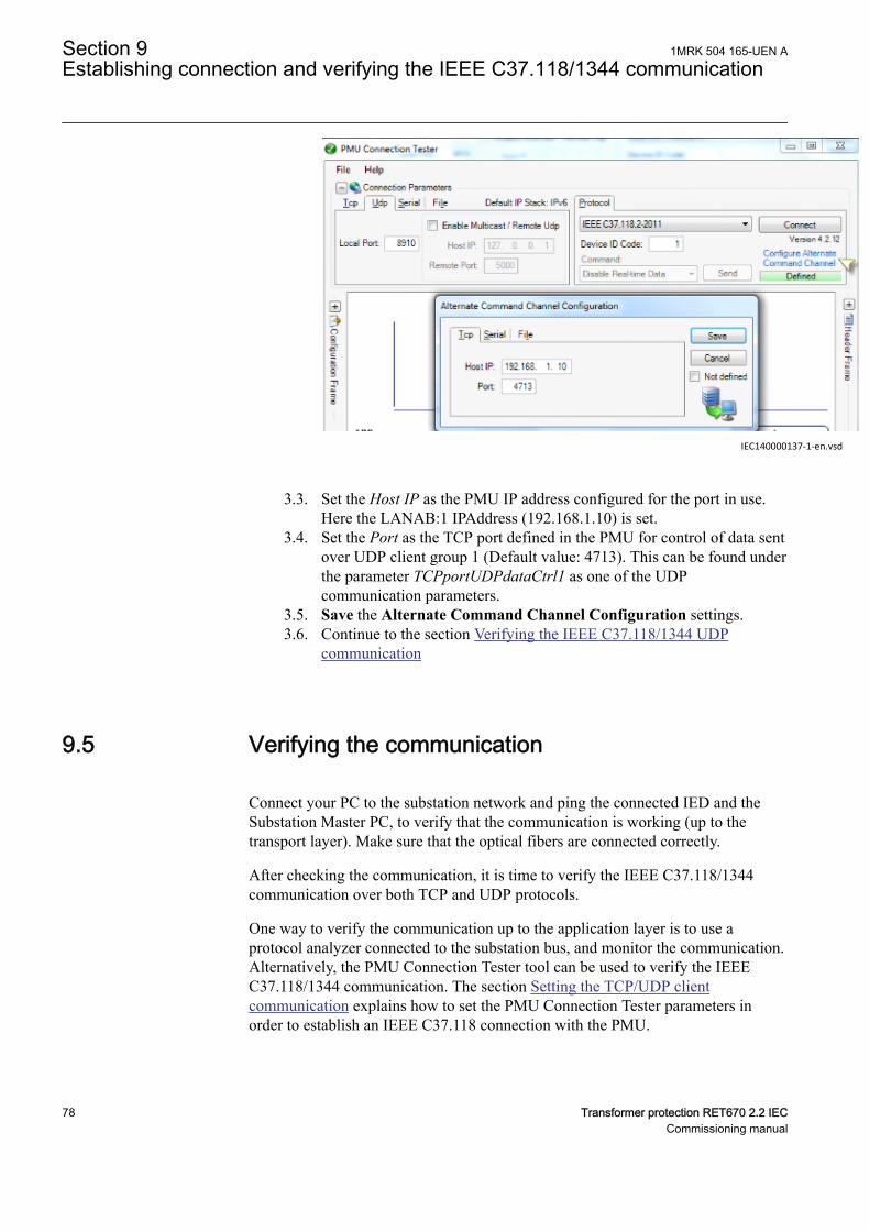
IEC140000137-1-en.vsd
IEC140000137 V1 EN-US
3.3. Set the Host IP as the PMU IP address configured for the port in use.Here the LANAB:1 IPAddress (192.168.1.10) is set.
3.4. Set the Port as the TCP port defined in the PMU for control of data sentover UDP client group 1 (Default value: 4713). This can be found underthe parameter TCPportUDPdataCtrl1 as one of the UDPcommunication parameters.
3.5. Save the Alternate Command Channel Configuration settings.3.6. Continue to the section Verifying the IEEE C37.118/1344 UDP
communication
9.5 Verifying the communicationGUID-D10769FC-6C70-48A3-A1D8-FAFCCA82A3BE v2
Connect your PC to the substation network and ping the connected IED and theSubstation Master PC, to verify that the communication is working (up to thetransport layer). Make sure that the optical fibers are connected correctly.
After checking the communication, it is time to verify the IEEE C37.118/1344communication over both TCP and UDP protocols.
One way to verify the communication up to the application layer is to use aprotocol analyzer connected to the substation bus, and monitor the communication.Alternatively, the PMU Connection Tester tool can be used to verify the IEEEC37.118/1344 communication. The section Setting the TCP/UDP clientcommunication explains how to set the PMU Connection Tester parameters inorder to establish an IEEE C37.118 connection with the PMU.
Section 9 1MRK 504 165-UEN AEstablishing connection and verifying the IEEE C37.118/1344 communication
78 Transformer protection RET670 2.2 IECCommissioning manual
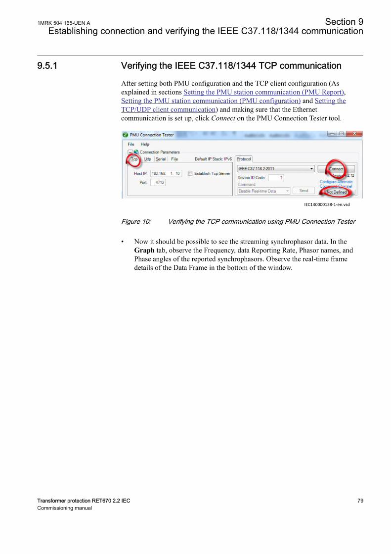
9.5.1 Verifying the IEEE C37.118/1344 TCP communicationGUID-289E2E92-431E-45FE-B586-A723588B98A1 v1
After setting both PMU configuration and the TCP client configuration (Asexplained in sections Setting the PMU station communication (PMU Report),Setting the PMU station communication (PMU configuration) and Setting theTCP/UDP client communication) and making sure that the Ethernetcommunication is set up, click Connect on the PMU Connection Tester tool.
IEC140000138-1-en.vsdIEC140000138 V1 EN-US
Figure 10: Verifying the TCP communication using PMU Connection Tester
• Now it should be possible to see the streaming synchrophasor data. In theGraph tab, observe the Frequency, data Reporting Rate, Phasor names, andPhase angles of the reported synchrophasors. Observe the real-time framedetails of the Data Frame in the bottom of the window.
1MRK 504 165-UEN A Section 9Establishing connection and verifying the IEEE C37.118/1344 communication
Transformer protection RET670 2.2 IEC 79Commissioning manual
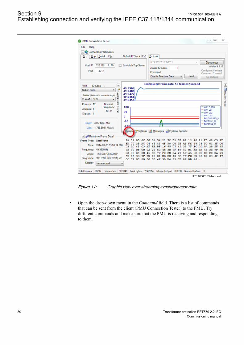
IEC140000139-1-en.vsdIEC140000139 V1 EN-US
Figure 11: Graphic view over streaming synchrophasor data
• Open the drop-down menu in the Command field. There is a list of commandsthat can be sent from the client (PMU Connection Tester) to the PMU. Trydifferent commands and make sure that the PMU is receiving and respondingto them.
Section 9 1MRK 504 165-UEN AEstablishing connection and verifying the IEEE C37.118/1344 communication
80 Transformer protection RET670 2.2 IECCommissioning manual
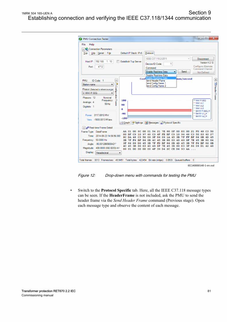
IEC140000140-1-en.vsdIEC140000140 V1 EN-US
Figure 12: Drop-down menu with commands for testing the PMU
• Switch to the Protocol Specific tab. Here, all the IEEE C37.118 message typescan be seen. If the HeaderFrame is not included, ask the PMU to send theheader frame via the Send Header Frame command (Previous stage). Openeach message type and observe the content of each message.
1MRK 504 165-UEN A Section 9Establishing connection and verifying the IEEE C37.118/1344 communication
Transformer protection RET670 2.2 IEC 81Commissioning manual
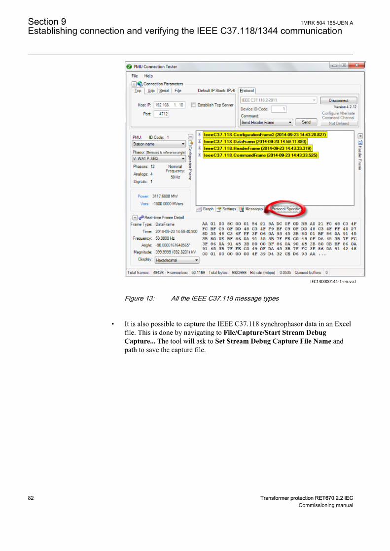
IEC140000141-1-en.vsdIEC140000141 V1 EN-US
Figure 13: All the IEEE C37.118 message types
• It is also possible to capture the IEEE C37.118 synchrophasor data in an Excelfile. This is done by navigating to File/Capture/Start Stream DebugCapture... The tool will ask to Set Stream Debug Capture File Name andpath to save the capture file.
Section 9 1MRK 504 165-UEN AEstablishing connection and verifying the IEEE C37.118/1344 communication
82 Transformer protection RET670 2.2 IECCommissioning manual
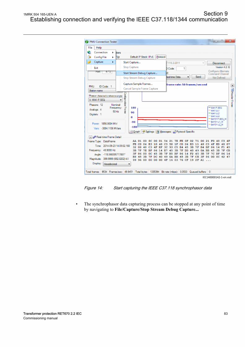
IEC140000142-1-en.vsdIEC140000142 V1 EN-US
Figure 14: Start capturing the IEEE C37.118 synchrophasor data
• The synchrophasor data capturing process can be stopped at any point of timeby navigating to File/Capture/Stop Stream Debug Capture...
1MRK 504 165-UEN A Section 9Establishing connection and verifying the IEEE C37.118/1344 communication
Transformer protection RET670 2.2 IEC 83Commissioning manual
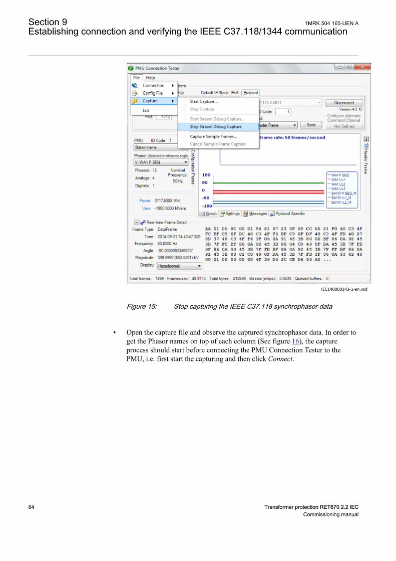
IEC140000143-1-en.vsdIEC140000143 V1 EN-US
Figure 15: Stop capturing the IEEE C37.118 synchrophasor data
• Open the capture file and observe the captured synchrophasor data. In order toget the Phasor names on top of each column (See figure 16), the captureprocess should start before connecting the PMU Connection Tester to thePMU, i.e. first start the capturing and then click Connect.
Section 9 1MRK 504 165-UEN AEstablishing connection and verifying the IEEE C37.118/1344 communication
84 Transformer protection RET670 2.2 IECCommissioning manual
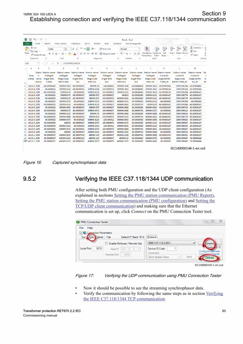
IEC140000144 V1 EN-US
Figure 16: Captured synchrophasor data
9.5.2 Verifying the IEEE C37.118/1344 UDP communicationGUID-F0D1117D-3D0F-498F-A00C-242763F8A4E6 v1
After setting both PMU configuration and the UDP client configuration (Asexplained in sections Setting the PMU station communication (PMU Report),Setting the PMU station communication (PMU configuration) and Setting theTCP/UDP client communication) and making sure that the Ethernetcommunication is set up, click Connect on the PMU Connection Tester tool.
IEC140000145-1-en.vsdIEC140000145 V1 EN-US
Figure 17: Verifying the UDP communication using PMU Connection Tester
• Now it should be possible to see the streaming synchrophasor data.• Verify the communication by following the same steps as in section Verifying
the IEEE C37.118/1344 TCP communication.
1MRK 504 165-UEN A Section 9Establishing connection and verifying the IEEE C37.118/1344 communication
Transformer protection RET670 2.2 IEC 85Commissioning manual
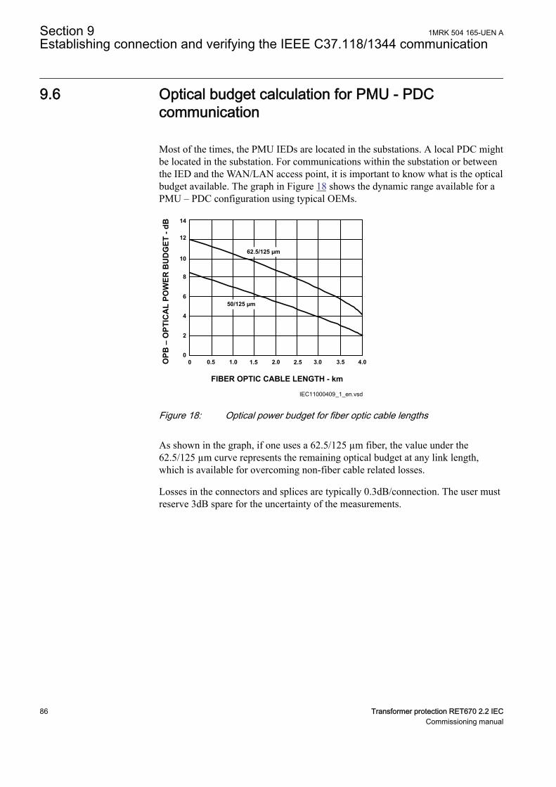
9.6 Optical budget calculation for PMU - PDCcommunication
GUID-F5DEACB1-4B83-4C68-B59A-694CAC78AF3D v3
Most of the times, the PMU IEDs are located in the substations. A local PDC mightbe located in the substation. For communications within the substation or betweenthe IED and the WAN/LAN access point, it is important to know what is the opticalbudget available. The graph in Figure 18 shows the dynamic range available for aPMU – PDC configuration using typical OEMs.
14
12
10
8
6
4
2
00 0.5 1.0 1.5 2.0 2.5 3.0 3.5 4.0
62.5/125 µm
50/125 µm
OPB
– O
PTIC
AL
POW
ER B
UD
GET
- dB
FIBER OPTIC CABLE LENGTH - km
IEC11000409_1_en.vsdIEC11000409 V1 EN-US
Figure 18: Optical power budget for fiber optic cable lengths
As shown in the graph, if one uses a 62.5/125 µm fiber, the value under the62.5/125 µm curve represents the remaining optical budget at any link length,which is available for overcoming non-fiber cable related losses.
Losses in the connectors and splices are typically 0.3dB/connection. The user mustreserve 3dB spare for the uncertainty of the measurements.
Section 9 1MRK 504 165-UEN AEstablishing connection and verifying the IEEE C37.118/1344 communication
86 Transformer protection RET670 2.2 IECCommissioning manual
Section 10 Testing IED operation
10.1 Preparing for testIP336-1 v1
10.1.1 RequirementsM11740-2 v9
IED test requirements:
• Calculated settings• Application configuration diagram• Signal matrix (SMT) configuration• Terminal connection diagram• Technical manual• Three-phase test equipment• Process bus, IEC/UCA 61850-9-2LE, MU test simulator, if IEC/UCA
61850-9-2LE process bus communication is used.• PCM600
The setting and configuration of the IED must be completed before the testing canstart.
The terminal diagram, available in the technical reference manual, is a generaldiagram of the IED.
Note that the same diagram is not always applicable to eachspecific delivery (especially for the configuration of all the binaryinputs and outputs).
Therefore, before testing, check that the available terminal diagram corresponds tothe IED.
The technical manual contains application and functionality summaries, functionblocks, logic diagrams, input and output signals, setting parameters and technicaldata sorted per function.
The test equipment should be able to provide a three-phase supply of voltages andcurrents. The magnitude of voltage and current as well as the phase angle betweenvoltage and current must be variable. The voltages and currents from the testequipment must be obtained from the same source and they must have minimalharmonic content. If the test equipment cannot indicate the phase angle, a separatephase-angle measuring instrument is necessary.
1MRK 504 165-UEN A Section 10Testing IED operation
Transformer protection RET670 2.2 IEC 87Commissioning manual
Prepare the IED for test before testing a particular function. Consider the logicdiagram of the tested protection function when performing the test. All includedfunctions in the IED are tested according to the corresponding test instructions inthis chapter. The functions can be tested in any order according to user preferences.Only the functions that are used (Operation is set to On) should be tested.
The response from a test can be viewed in different ways:
• Binary outputs signals• Service values on the local HMI (logical signals or phasors)• A PC with PCM600 application configuration software in work online mode
All setting groups that are used should be tested.
This IED is designed for a maximum continuous current of fourtimes the rated current.
All references to CT and VT must be interpreted as analog valuesreceived from merging units (MU) via IEC/UCA 61850-9-2LEcommunication protocol, analog values received from thetransformer input module, or analog values received from theLDCM.
When using a MU test simulator, make sure it is set to the correctSVID and that the system frequency is set to the same as in theIED.
Please observe the measuring accuracy of the IED, the testequipment and the angular accuracy for both of them.
Please consider the configured logic from the function block to theoutput contacts when measuring the operate time.
After intense testing, it is important that the IED is not immediatelyrestarted, which might cause a faulty trip due to flash memoryrestrictions. Some time must pass before the IED is restarted. Formore information about the flash memory, refer to section“Configuring the IED and changing settings”.
Section 10 1MRK 504 165-UEN ATesting IED operation
88 Transformer protection RET670 2.2 IECCommissioning manual
10.1.2 Preparing the IED to verify settingsM11741-2 v11
If a test switch is included, start preparation by making the necessary connectionsto the test switch. This means connecting the test equipment according to a specificand designated IED terminal diagram.
Put the IED into the test mode to facilitate the test of individual functions andprevent unwanted operation caused by other functions. The busbar differentialprotection is not included in the test mode and is not prevented to operate duringthe test operations. The test switch should then be connected to the IED.
Verify that analog input signals from the analog input module are measured andrecorded correctly by injecting currents and voltages required by the specific IED.
To make testing even more effective, use PCM600. PCM600 includes the Signalmonitoring tool, which is useful in reading the individual currents and voltages,their amplitudes and phase angles. In addition, PCM600 contains the Disturbancehandling tool. The content of reports generated by the Disturbance handling toolcan be configured which makes the work more efficient. For example, the tool maybe configured to only show time tagged events and to exclude analog informationand so on.
Check the disturbance report settings to ensure that the indications are correct.
For information about the functions to test, for example signal or parameter names,see the technical manual. The correct initiation of the disturbance recorder is madeon start and/or release or trip from a function. Also check that the wantedrecordings of analog (real and calculated) and binary signals are achieved.
Parameters can be entered into different setting groups. Make sureto test functions for the same parameter setting group. If needed,repeat the tests for all different setting groups used. The differencebetween testing the first parameter setting group and the remainingis that there is no need for testing the connections.
During testing, observe that the right testing method, that corresponds to the actualparameters set in the activated parameter setting group, is used.
Set and configure the function(s) before testing. Most functions are highly flexibleand permit a choice of functional and tripping modes. The various modes arechecked at the factory as part of the design verification. In certain cases, onlymodes with a high probability of coming into operation need to be checked whencommissioned to verify the configuration and settings.
1MRK 504 165-UEN A Section 10Testing IED operation
Transformer protection RET670 2.2 IEC 89Commissioning manual
10.2 Activating the test modeM11412-2 v14
Put the IED into the test mode before testing. The test mode blocks all protectionfunctions and some of the control functions in the IED, and the individual functionsto be tested can be unblocked to prevent unwanted operation caused by otherfunctions. In this way, it is possible to test slower back-up measuring functionswithout the interference from faster measuring functions. The test switch shouldthen be connected to the IED.Test mode is indicated when the yellow StartLEDflashes.
It is important that the IED function to be tested is put into test mode, even if theMU is sending data marked as "test". The IED will interpret these data as valid if itis not in test mode.
1. Browse to the TESTMODE menu and press E.The TESTMODE menu is found on the local HMI under Main menu/Test/IED test mode/TESTMODE
2. Use the up and down arrows to choose On and press E.3. Press the left arrow to exit the menu.
The dialog box Save changes appears.4. Choose Yes, press E and exit the menu.
The yellow startLED above the LCD will start flashing when the IED is intest mode.
10.3 Preparing the connection to the test equipmentM11743-2 v8
The IED can be equipped with a test switch of type RTXP8, RTXP18 or RTXP24.The test switch and its associated test plug handle (RTXH8, RTXH18 or RTXH24)are a part of the COMBITEST system, which provides secure and convenienttesting of the IED.
When using the COMBITEST, preparations for testing are automatically carriedout in the proper sequence, that is, for example, blocking of tripping circuits, shortcircuiting of CTs, opening of voltage circuits, making IED terminals available forsecondary injection. Terminals 1 and 8, 1 and 18 as well as 1 and 12 of the testswitches RTXP8, RTXP18 and RTXP24 respectively are not disconnected as theysupply DC power to the protection IED.
The RTXH test-plug handle leads may be connected to any type of test equipmentor instrument. When a number of protection IEDs of the same type are tested, thetest-plug handle only needs to be moved from the test switch of one protection IEDto the test switch of the other, without altering the previous connections.
Use COMBITEST test system to prevent unwanted tripping when the handle iswithdrawn, since latches on the handle secure it in the half withdrawn position. Inthis position, all voltages and currents are restored and any re-energizing transients
Section 10 1MRK 504 165-UEN ATesting IED operation
90 Transformer protection RET670 2.2 IECCommissioning manual
are given a chance to decay before the trip circuits are restored. When the latchesare released, the handle can be completely withdrawn from the test switch,restoring the trip circuits to the protection IED.
If a test switch is not used, perform measurement according to the provided circuitdiagrams.
Never disconnect the secondary connection of a current transformercircuit without first short-circuiting the transformer's secondarywinding. Operating a current transformer with the secondarywinding open will cause a massive potential build up that maydamage the transformer and cause personal injury.
10.4 Connecting the test equipment to the IEDM11744-2 v8
Connect the test equipment according to the IED specific connection diagram andthe needed input and output signals for the function under test. An example of aconnection is shown in figure 19.
Connect the current and voltage terminals. Pay attention to the current polarity.Make sure that the connection of input and output current terminals and theconnection of the residual current conductor is correct. Check that the input andoutput logical signals in the logic diagram for the function under test are connectedto the corresponding binary inputs and outputs of the IED under test.
To ensure correct results, make sure that the IED as well as the testequipment are properly earthed before testing.
1MRK 504 165-UEN A Section 10Testing IED operation
Transformer protection RET670 2.2 IEC 91Commissioning manual
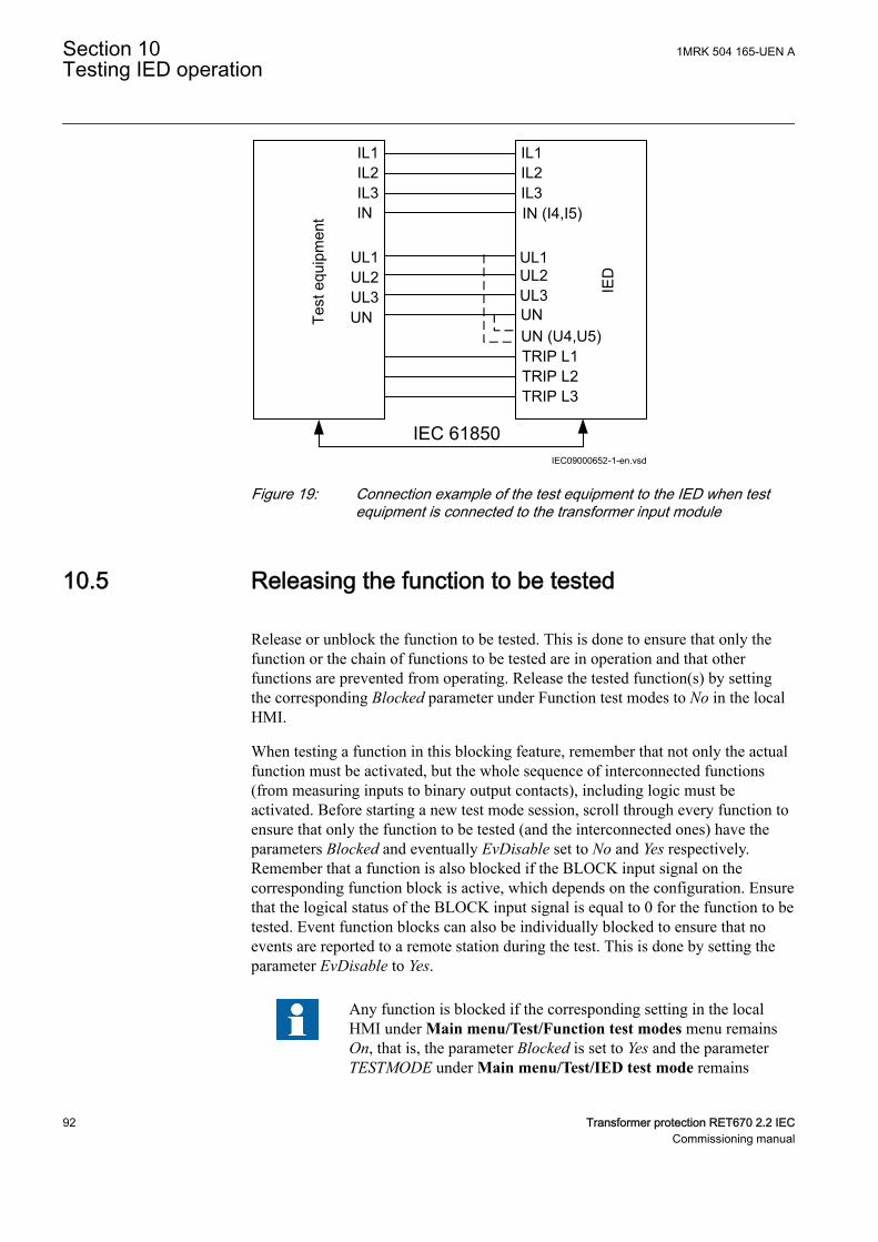
IL1IL2IL3IN
UL1UL2UL3UN
IL1IL2IL3
UL1
IN (I4,I5)
TRIP L1TRIP L2TRIP L3
Test
equ
ipm
ent
IED
IEC09000652-1-en.vsd
UL2UL3UNUN (U4,U5)
IEC 61850
IEC09000652 V1 EN-US
Figure 19: Connection example of the test equipment to the IED when testequipment is connected to the transformer input module
10.5 Releasing the function to be testedM11413-2 v7
Release or unblock the function to be tested. This is done to ensure that only thefunction or the chain of functions to be tested are in operation and that otherfunctions are prevented from operating. Release the tested function(s) by settingthe corresponding Blocked parameter under Function test modes to No in the localHMI.
When testing a function in this blocking feature, remember that not only the actualfunction must be activated, but the whole sequence of interconnected functions(from measuring inputs to binary output contacts), including logic must beactivated. Before starting a new test mode session, scroll through every function toensure that only the function to be tested (and the interconnected ones) have theparameters Blocked and eventually EvDisable set to No and Yes respectively.Remember that a function is also blocked if the BLOCK input signal on thecorresponding function block is active, which depends on the configuration. Ensurethat the logical status of the BLOCK input signal is equal to 0 for the function to betested. Event function blocks can also be individually blocked to ensure that noevents are reported to a remote station during the test. This is done by setting theparameter EvDisable to Yes.
Any function is blocked if the corresponding setting in the localHMI under Main menu/Test/Function test modes menu remainsOn, that is, the parameter Blocked is set to Yes and the parameterTESTMODE under Main menu/Test/IED test mode remains
Section 10 1MRK 504 165-UEN ATesting IED operation
92 Transformer protection RET670 2.2 IECCommissioning manual
active. All functions that were blocked or released in a previous testmode session, that is, the parameter Test mode is set to On, are resetwhen a new test mode session is started.
Procedure
1. Click the Function test modes menu.The Function test modes menu is located in the local HMI under Main menu/Test/Function test modes.
2. Browse to the function instance that needs to be released.3. Set parameter Blocked for the selected function to No.
10.6 Verifying analog primary and secondarymeasurement
M11745-2 v13
Verify that the connections are correct and that measuring and scaling is donecorrectly. This is done by injecting current and voltage to the IED.
Besides verifying analog input values from the merging unit via the IEC/UCA61850-9-2LE process bus, analog values from the transformer input module can beverified as follows.
Apply input signals as needed according to the actual hardware andthe application configuration.
1. Inject a symmetrical three-phase voltage and current at rated value.2. Compare the injected value with the measured values.
The voltage and current phasor menu in the local HMI is located under Mainmenu/Measurements/Analog primary values and Main menu/Measurements/Analog secondary values.
3. Compare the frequency reading with the set frequency and the direction of thepower.The frequency and active power are located under Main menu/Measurements/Monitoring/ServiceValues(MMXN)/CVMMXN:x. Thennavigate to the bottom of the list to find the frequency.
4. Inject an unsymmetrical three-phase voltage and current, to verify that phasesare correctly connected.
If some setting deviates, check the analog input settings under
Main menu/Configuration/Analog modules
1MRK 504 165-UEN A Section 10Testing IED operation
Transformer protection RET670 2.2 IEC 93Commissioning manual
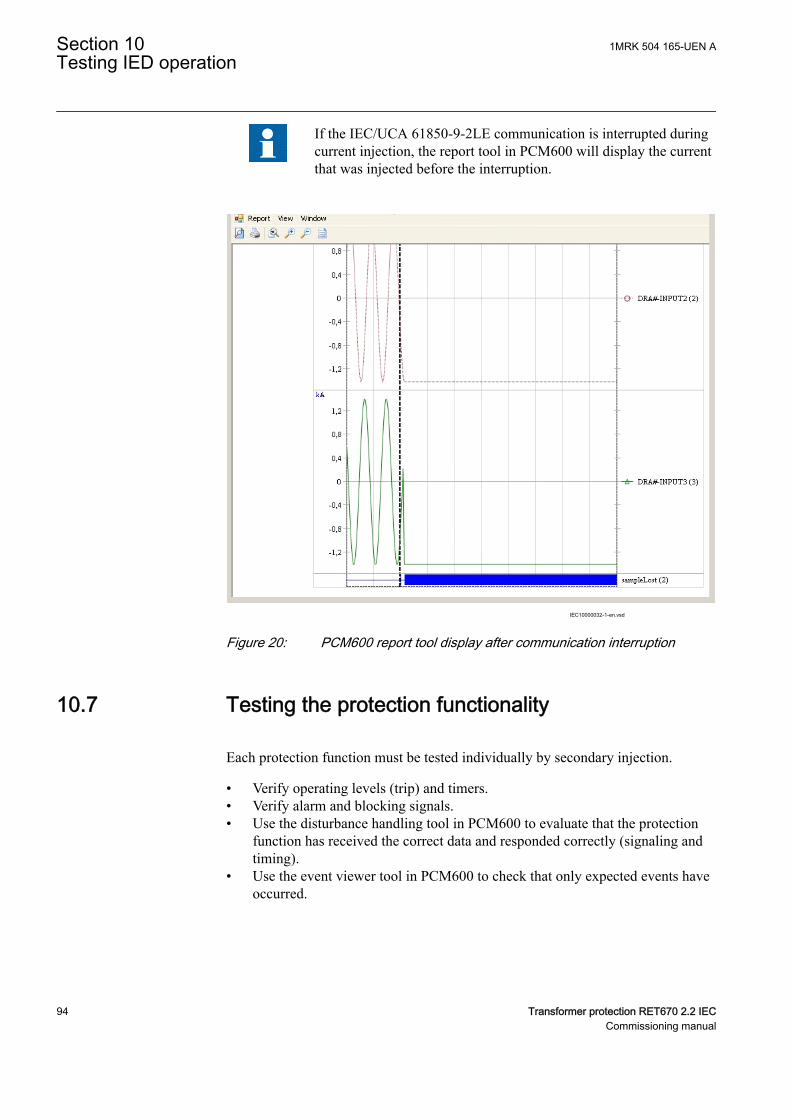
If the IEC/UCA 61850-9-2LE communication is interrupted duringcurrent injection, the report tool in PCM600 will display the currentthat was injected before the interruption.
IEC10000032-1-en.vsdIEC10000032 V1 EN-US
Figure 20: PCM600 report tool display after communication interruption
10.7 Testing the protection functionalityGUID-125B6F28-D3E5-4535-9CD6-6C056B79F496 v2
Each protection function must be tested individually by secondary injection.
• Verify operating levels (trip) and timers.• Verify alarm and blocking signals.• Use the disturbance handling tool in PCM600 to evaluate that the protection
function has received the correct data and responded correctly (signaling andtiming).
• Use the event viewer tool in PCM600 to check that only expected events haveoccurred.
Section 10 1MRK 504 165-UEN ATesting IED operation
94 Transformer protection RET670 2.2 IECCommissioning manual
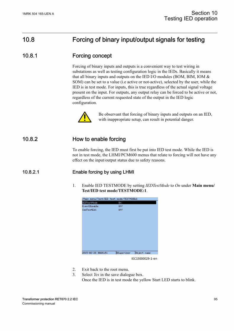
10.8 Forcing of binary input/output signals for testing
10.8.1 Forcing conceptGUID-3FD8C676-10E5-432A-8CD5-4643299AD794 v2
Forcing of binary inputs and outputs is a convenient way to test wiring insubstations as well as testing configuration logic in the IEDs. Basically it meansthat all binary inputs and outputs on the IED I/O modules (BOM, BIM, IOM &SOM) can be set to a value (i.e active or not-active), selected by the user, while theIED is in test mode. For inputs, this is true regardless of the actual signal voltagepresent on the input. For outputs, any output relay can be forced to be active or not,regardless of the current requested state of the output in the IED logicconfiguration.
Be observant that forcing of binary inputs and outputs on an IED,with inappropriate setup, can result in potential danger.
10.8.2 How to enable forcingGUID-50280F59-A98C-4E48-AB6D-2B4C138943DD v1
To enable forcing, the IED must first be put into IED test mode. While the IED isnot in test mode, the LHMI/PCM600 menus that relate to forcing will not have anyeffect on the input/output status due to safety reasons.
10.8.2.1 Enable forcing by using LHMIGUID-41F7C636-75BC-42EF-A955-4BD9E347619E v2
1. Enable IED TESTMODE by setting IEDTestMode to On under Main menu/Test/IED test mode/TESTMODE:1.
IEC15000029 V1 EN-US
2. Exit back to the root menu.3. Select Yes in the save dialogue box.
Once the IED is in test mode the yellow Start LED starts to blink.
1MRK 504 165-UEN A Section 10Testing IED operation
Transformer protection RET670 2.2 IEC 95Commissioning manual
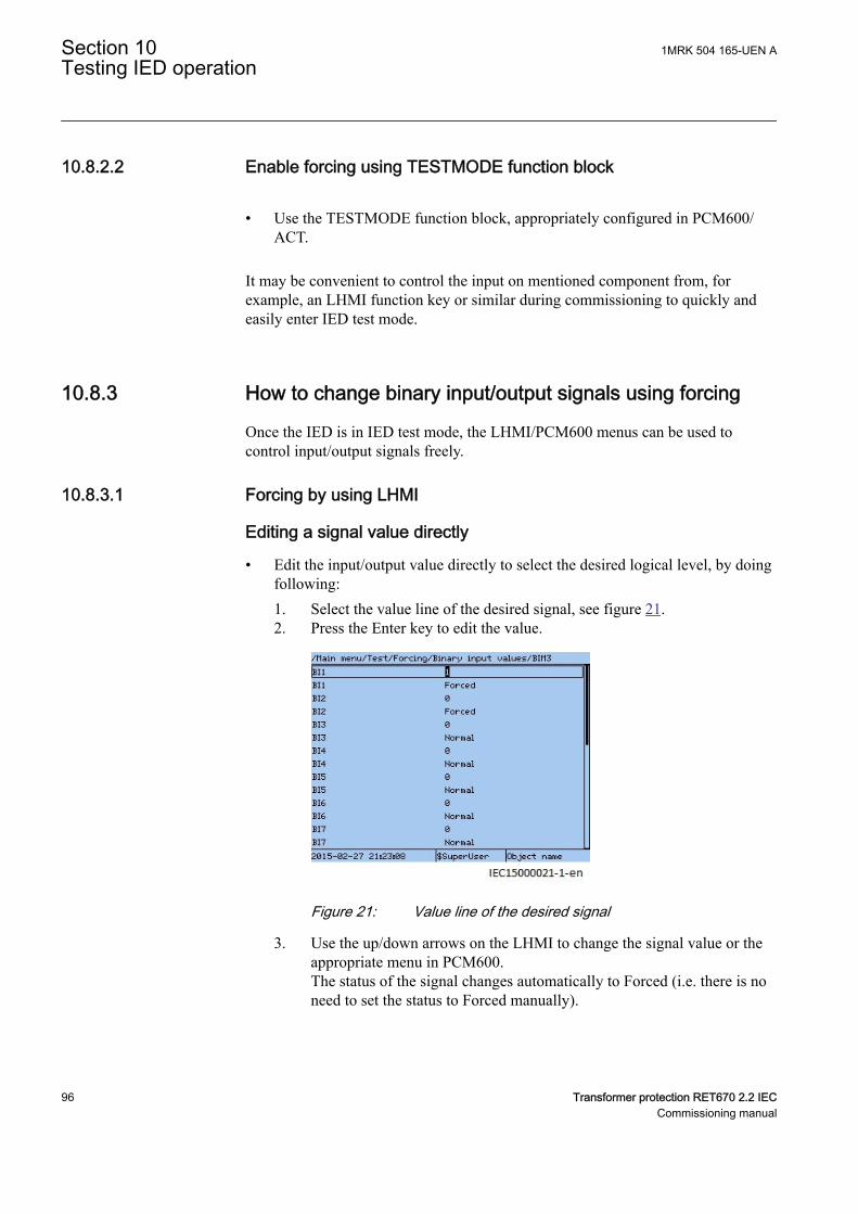
10.8.2.2 Enable forcing using TESTMODE function blockGUID-DD17B7D6-516F-4561-9D30-906B968EAFE0 v1
• Use the TESTMODE function block, appropriately configured in PCM600/ACT.
It may be convenient to control the input on mentioned component from, forexample, an LHMI function key or similar during commissioning to quickly andeasily enter IED test mode.
10.8.3 How to change binary input/output signals using forcingGUID-7DF9FAF1-68B1-49AF-9DE4-2A8D6F6FAEFE v1
Once the IED is in IED test mode, the LHMI/PCM600 menus can be used tocontrol input/output signals freely.
10.8.3.1 Forcing by using LHMIGUID-D885671F-79E5-4B75-8777-B59E44F6FCFC v1
Editing a signal value directlyGUID-E0C115BE-3AD1-48C7-BA2D-29857CD3D3ED v1
• Edit the input/output value directly to select the desired logical level, by doingfollowing:1. Select the value line of the desired signal, see figure 21.2. Press the Enter key to edit the value.
IEC15000021 V1 EN-US
Figure 21: Value line of the desired signal
3. Use the up/down arrows on the LHMI to change the signal value or theappropriate menu in PCM600.The status of the signal changes automatically to Forced (i.e. there is noneed to set the status to Forced manually).
Section 10 1MRK 504 165-UEN ATesting IED operation
96 Transformer protection RET670 2.2 IECCommissioning manual
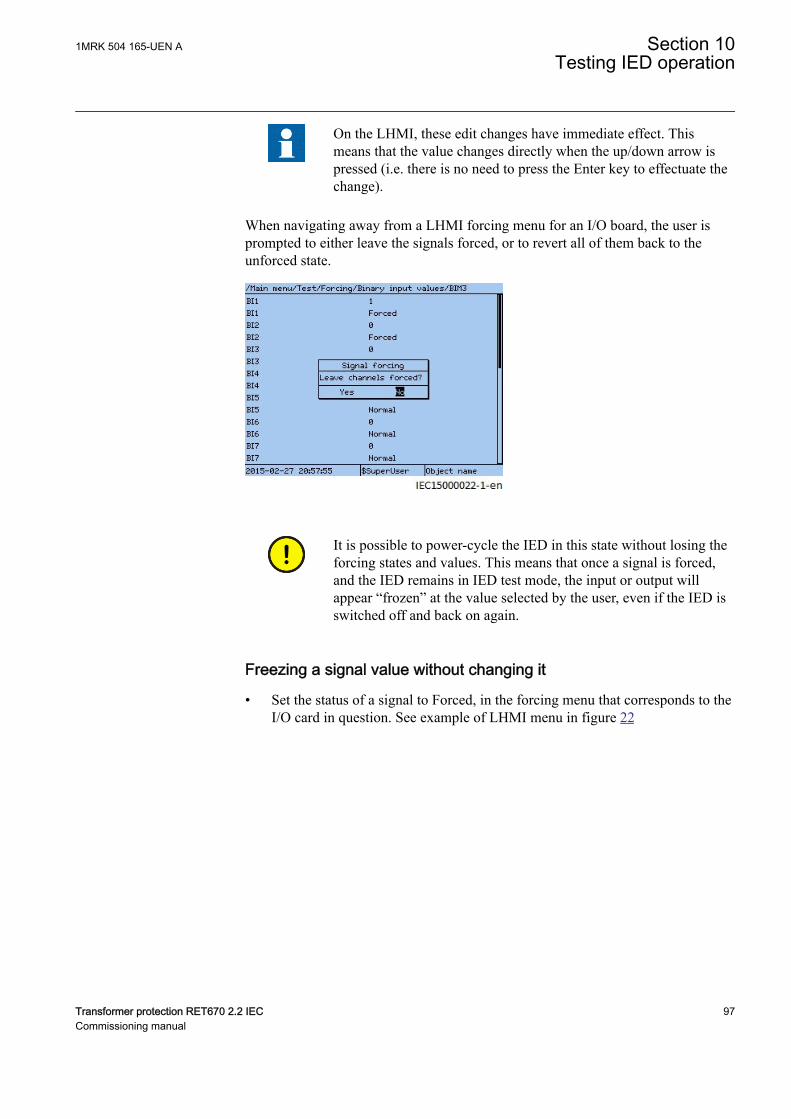
On the LHMI, these edit changes have immediate effect. Thismeans that the value changes directly when the up/down arrow ispressed (i.e. there is no need to press the Enter key to effectuate thechange).
When navigating away from a LHMI forcing menu for an I/O board, the user isprompted to either leave the signals forced, or to revert all of them back to theunforced state.
IEC15000022 V1 EN-US
It is possible to power-cycle the IED in this state without losing theforcing states and values. This means that once a signal is forced,and the IED remains in IED test mode, the input or output willappear “frozen” at the value selected by the user, even if the IED isswitched off and back on again.
Freezing a signal value without changing itGUID-FD76AAC1-7098-47D3-A3A1-6ACDF509ED91 v1
• Set the status of a signal to Forced, in the forcing menu that corresponds to theI/O card in question. See example of LHMI menu in figure 22
1MRK 504 165-UEN A Section 10Testing IED operation
Transformer protection RET670 2.2 IEC 97Commissioning manual
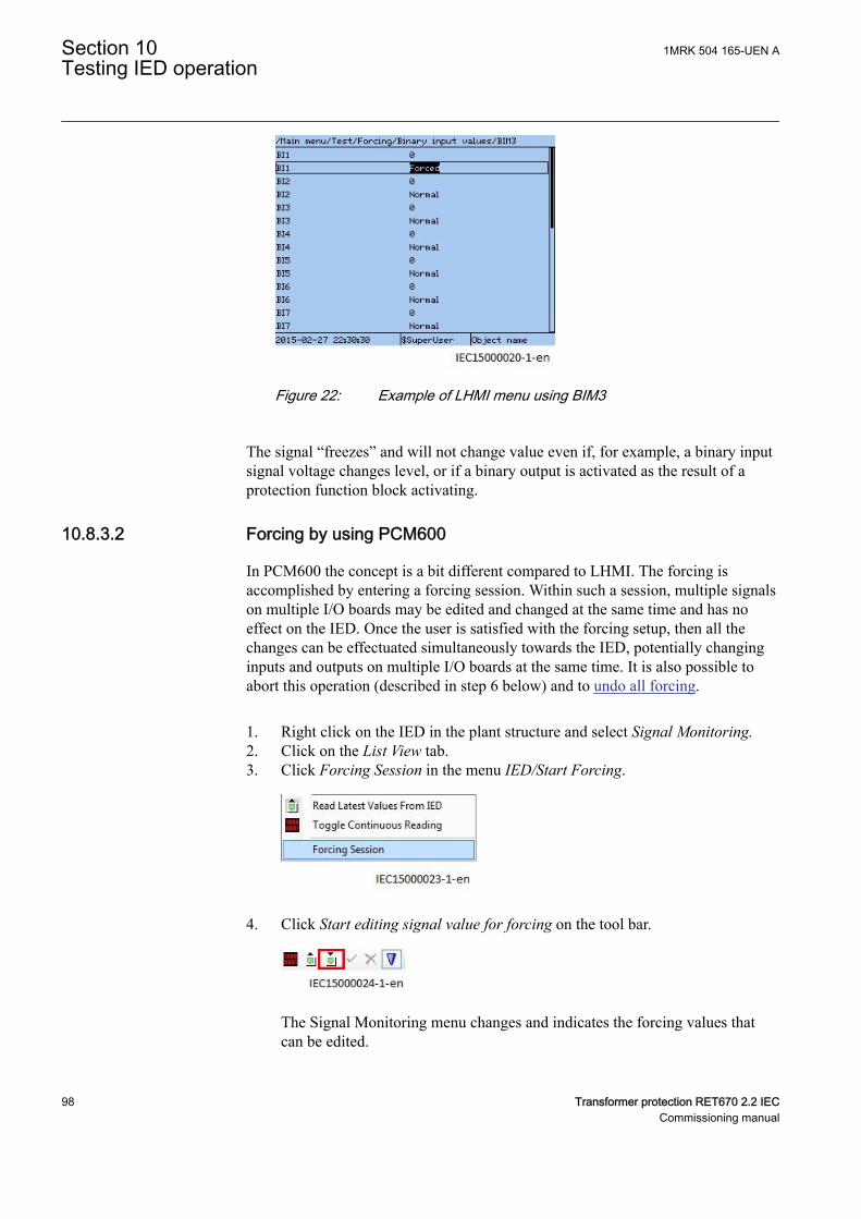
IEC15000020 V1 EN-US
Figure 22: Example of LHMI menu using BIM3
The signal “freezes” and will not change value even if, for example, a binary inputsignal voltage changes level, or if a binary output is activated as the result of aprotection function block activating.
10.8.3.2 Forcing by using PCM600GUID-E9D0DAE6-7A86-4FF9-943E-42039015D05B v1
In PCM600 the concept is a bit different compared to LHMI. The forcing isaccomplished by entering a forcing session. Within such a session, multiple signalson multiple I/O boards may be edited and changed at the same time and has noeffect on the IED. Once the user is satisfied with the forcing setup, then all thechanges can be effectuated simultaneously towards the IED, potentially changinginputs and outputs on multiple I/O boards at the same time. It is also possible toabort this operation (described in step 6 below) and to undo all forcing.
1. Right click on the IED in the plant structure and select Signal Monitoring.2. Click on the List View tab.3. Click Forcing Session in the menu IED/Start Forcing.
IEC15000023 V1 EN-US
4. Click Start editing signal value for forcing on the tool bar.
IEC15000024 V1 EN-US
The Signal Monitoring menu changes and indicates the forcing values thatcan be edited.
Section 10 1MRK 504 165-UEN ATesting IED operation
98 Transformer protection RET670 2.2 IECCommissioning manual
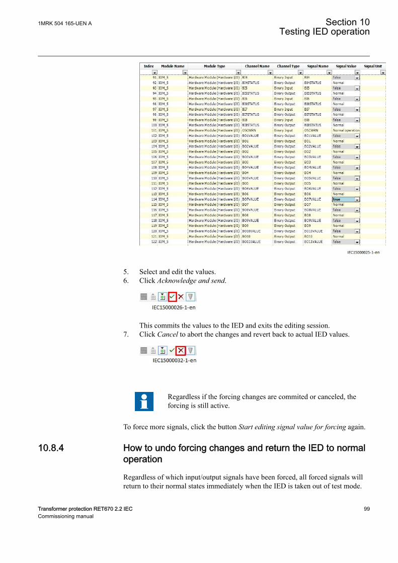
IEC15000025 V1 EN-US
5. Select and edit the values.6. Click Acknowledge and send.
IEC15000026 V1 EN-US
This commits the values to the IED and exits the editing session.7. Click Cancel to abort the changes and revert back to actual IED values.
IEC15000032 V1 EN-US
Regardless if the forcing changes are commited or canceled, theforcing is still active.
To force more signals, click the button Start editing signal value for forcing again.
10.8.4 How to undo forcing changes and return the IED to normaloperation
GUID-00E2BAD8-A29E-4B9D-80E6-E12F59E019BD v1
Regardless of which input/output signals have been forced, all forced signals willreturn to their normal states immediately when the IED is taken out of test mode.
1MRK 504 165-UEN A Section 10Testing IED operation
Transformer protection RET670 2.2 IEC 99Commissioning manual
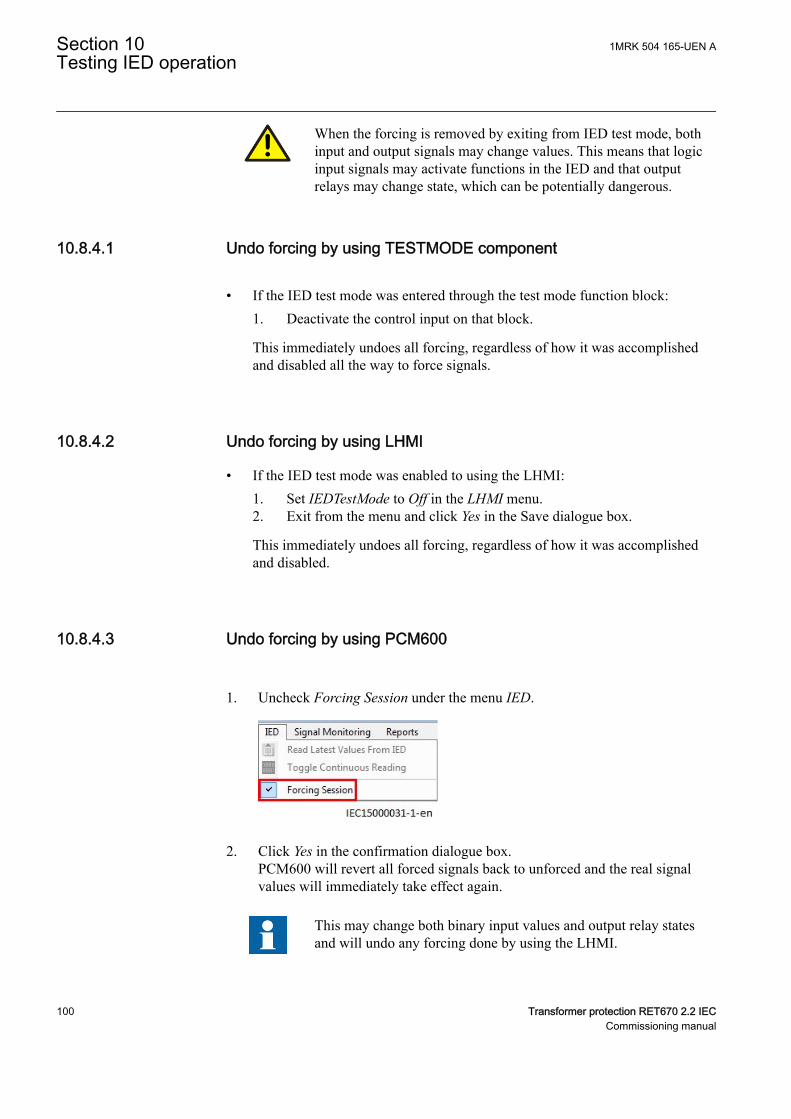
When the forcing is removed by exiting from IED test mode, bothinput and output signals may change values. This means that logicinput signals may activate functions in the IED and that outputrelays may change state, which can be potentially dangerous.
10.8.4.1 Undo forcing by using TESTMODE componentGUID-CA5CCA57-DFFF-4362-AC1D-08738D2BA45F v2
• If the IED test mode was entered through the test mode function block:1. Deactivate the control input on that block.
This immediately undoes all forcing, regardless of how it was accomplishedand disabled all the way to force signals.
10.8.4.2 Undo forcing by using LHMIGUID-55199606-E70D-49B1-885D-251700FB562B v1
• If the IED test mode was enabled to using the LHMI:1. Set IEDTestMode to Off in the LHMI menu.2. Exit from the menu and click Yes in the Save dialogue box.
This immediately undoes all forcing, regardless of how it was accomplishedand disabled.
10.8.4.3 Undo forcing by using PCM600GUID-CE7FD186-99FC-41C8-910F-894A57037777 v1
1. Uncheck Forcing Session under the menu IED.
IEC15000031 V1 EN-US
2. Click Yes in the confirmation dialogue box.PCM600 will revert all forced signals back to unforced and the real signalvalues will immediately take effect again.
This may change both binary input values and output relay statesand will undo any forcing done by using the LHMI.
Section 10 1MRK 504 165-UEN ATesting IED operation
100 Transformer protection RET670 2.2 IECCommissioning manual

If the IED is left in test mode, then it is still possible to performnew forcing operations, both from LHMI and from PCM600
1MRK 504 165-UEN A Section 10Testing IED operation
Transformer protection RET670 2.2 IEC 101Commissioning manual

102
Section 11 Testing functionality by secondaryinjection
11.1 Testing disturbance report
11.1.1 IntroductionM17101-2 v6
The following sub-functions are included in the disturbance report function:
• Disturbance recorder• Event list• Event recorder• Trip value recorder• Indications
If the disturbance report is set on, then its sub-functions are also set up and so it isnot possible to only switch these sub-functions off. The disturbance report functionis switched off (parameter Operation = Off) in PCM600 or the local HMI underMain menu/Settings/IED Settings/Monitoring/Disturbance report/DRPRDRE:1.
11.1.2 Disturbance report settingsM11746-2 v6
When the IED is in test mode, the disturbance report can be made active orinactive. If the disturbance recorder is turned on during test mode, recordings willbe made. When test mode is switched off all recordings made during the testsession are cleared.
Setting OpModeTest for the control of the disturbance recorder during test modeare located on the local HMI under Main menu/Settings/IED Settings/Monitoring/Disturbance report/DRPRDRE:1.
11.1.3 Disturbance recorder (DR)M11750-2 v6
A Manual Trig can be started at any time. This results in a recording of the actualvalues from all recorded channels.
The Manual Trig can be started in two ways:
1. From the local HMI under Main menu/Disturbance records.1.1. Enter on the row at the bottom of the HMI called Manual trig.
1MRK 504 165-UEN A Section 11Testing functionality by secondary injection
Transformer protection RET670 2.2 IEC 103Commissioning manual
A new recording begins. The view is updated if you leave the menu andreturn.
1.2. Navigate to General information or to Trip values to obtain moredetailed information.
2. Open the Disturbance handling tool for the IED in the plant structure inPCM600.2.1. Right-click and select Execute manual Trig in the window Available
recordings in IED.2.2. Read the required recordings from the IED.2.3. Refresh the window Recordings and select a recording.2.4. Right-click and select Create Report or Open With to export the
recordings to any disturbance analyzing tool that can handle Comtradeformatted files.
Evaluation of the results from the disturbance recording function requires access toa PC either permanently connected to the IED or temporarily connected to theEthernet port (RJ-45) on the front. The PCM600 software package must beinstalled in the PC.
Disturbance upload can be performed by the use of PCM600 or by any third partytool with IEC 61850 protocol. Reports can automatically be generated fromPCM600. Disturbance files can be analyzed by any tool reading Comtradeformatted disturbance files.
It could be useful to have a printer for hard copies. The correct start criteria andbehavior of the disturbance recording function can be checked when IEDprotective functions are tested.
When the IED is brought into normal service it is recommended to delete allrecordings, made during commissioning to avoid confusion in future fault analysis.
All recordings in the IED can be deleted in two ways:
1. in the local HMI under Main menu/Clear/Reset disturbances, or2. in the Disturbance handling tool in PCM600 by selecting Delete all recordings
in the IED... in the window Available Recordings in IED.
11.1.4 Event recorder (ER) and Event list (EL)M12645-2 v6
The result from the event recorder and event list can be viewed on the local HMIor, after upload, in PCM600 as follows:
1. on the local HMI under Main menu/Events, or in more details via2. the Event Viewer in PCM600.
The internal FIFO register of all events will appear when the event viewer islaunched.
Section 11 1MRK 504 165-UEN ATesting functionality by secondary injection
104 Transformer protection RET670 2.2 IECCommissioning manual
When the IED is brought into normal service it is recommended to delete all eventsresulting from commissioning tests to avoid confusion in future fault analysis. Allevents in the IED can be cleared in the local HMI under Main Menu//Clear/Clearinternal event list or Main menu/Clear/Clear process event list. It is notpossible to clear the event lists from PCM600.
When testing binary inputs, the event list (EL) might be used instead. No uploadingor analyzing of registrations is then needed since the event list keeps running,independent of start of disturbance registration.
11.2 Identifying the function to test in the technicalreference manual
M11748-2 v4
Use the technical manual to identify function blocks, logic diagrams, input andoutput signals, setting parameters and technical data.
11.3 Differential protectionIP10805-1 v1
11.3.1 Transformer differential protection T2WPDIF andT3WPDIFSEMOD54284-49 v7
Prepare the IED for verification of settings outlined in Section "Preparing the IEDto verify settings".
11.3.1.1 Verifying the settingsSEMOD54284-51 v11
1. Go to Main menu/Test/Function test modes/Differential protection andmake sure that the restricted earth fault protection, low impedance functionREFPDIF is set to Off and that the four step residual overcurrent functionEF4PTOC under Main menu/Test/Function test modes/Current protectionis set to Off, since they are configured to the same current transformer inputsas the transformer differential protection. Make sure that the transformerdifferential functions T2WPDIF or T3WPDIF are unblocked.
2. Connect the test set for injection of three-phase currents to the currentterminals of the IED, which are connected to the CTs on the HV side of thepower transformer.
3. Increase the current in phase L1 until the protection function operates andnote the operating current.
4. Check that the trip and alarm contacts operate according to the configurationlogic.
5. Decrease the current slowly from operate value and note the reset value.Depending on the power transformer vector group (Yd and so on), the single-phase injection current may appear as differential current in one or two phasesand the operating value of the injected single-phase current will be different.
1MRK 504 165-UEN A Section 11Testing functionality by secondary injection
Transformer protection RET670 2.2 IEC 105Commissioning manual
6. Check in the same way the function by injecting current in phases L2 and L3respectively.
7. Inject a symmetrical three-phase current and note the operate value.8. Connect the timer and set the current to twice the operate value.9. Switch on the current and note the operate time.10. Check in the same way the measuring circuits connected to the CTs on the LV
side and other current inputs to the transformer differential protection.11. Finally check that trip information is stored in the event menu.
Information on how to use the event menu is found in theoperator’s manual.
12. If available on the test set, a second harmonic current of about 20% (assumes15% setting on I1/I2 ratio parameter) can be added to the fundamentalfrequency in phase L1. Increase the current in phase L1 above the start valuemeasured in step 6. Repeat test with current injection in phases L2 and L3respectively.The balancing of currents flowing into and out of the differential zone ischecked by primary injection testing.Fifth harmonic blocking can be tested in a similar way.
For more detailed formulas, please refer to the Applicationmanual.
11.3.1.2 Completing the testSEMOD54284-86 v5
Continue to test another function or end the test by changing the TESTMODEsetting to Off. Restore connections and settings to their original values, if they werechanged for testing purposes.
11.3.2 High impedance differential protection HZPDIFSEMOD55257-42 v3
Prepare the IED for verification of settings outlined in Section "Preparing the IEDto verify settings".
11.3.2.1 Verifying the settingsSEMOD55257-46 v5
1. Connect single-phase or three-phase test set to inject the operating voltage.The injection is done across the measuring branch.
The required trip and alarm voltage, as well as the usedstabilizing resistance value must be set in the function. Noteas well that used CT input in the IED must have ratio set as1:1. This is essential for the measurement of the expected
Section 11 1MRK 504 165-UEN ATesting functionality by secondary injection
106 Transformer protection RET670 2.2 IECCommissioning manual
value. Normally a slightly higher operating value is noproblem as the sensitivity is not influenced much.
2. Increase the voltage and make note of the operate value U>Trip. This is doneby manual testing and without trip of the test set.
3. Connect the trip contact to the test set to stop the test set for measurement oftrip times below.
4. Reduce the voltage slowly and make note of the reset value. The reset valuemust be high for this function.
5. Check the operating time by injecting a voltage corresponding to 1.2 ˣU>Trip level. Make note of the measured trip time.
6. If required, verify the trip time at another voltage. Normally 2 ˣ U>Trip isselected.
7. If used, measure the alarm level operating value. Increase the voltage andmake note of the operate value U>Alarm. This is done with manual test andwithout trip of the test set.
8. Measure the operating time on the alarm output by connecting the stop of thetest set to an output from tAlarm. Inject a voltage 1.2 ˣ U>Alarm and measurethe alarm time.
9. Check that trip and alarm outputs operate according to the configurationlogic.
10. Finally check that start and alarm information is stored in the event menu andif a serial connection to the SA is available verify that the correct and only therequired signals are presented on the local HMI and on the SCADA system.
Information on how to use the event menu is found in the operator'smanual.
11.3.2.2 Completing the testSEMOD55257-73 v4
Continue to test another function or end the test by changing the TESTMODEsetting to Off. Restore connections and settings to their original values, if they werechanged for testing purposes.
11.3.3 Restricted earth fault protection, low impedance REFPDIFSEMOD55252-82 v8
Prepare the IED for verification of settings outlined in Section "Preparing the IEDto verify settings".
11.3.3.1 Verifying the settingsSEMOD55252-86 v11
1MRK 504 165-UEN A Section 11Testing functionality by secondary injection
Transformer protection RET670 2.2 IEC 107Commissioning manual
1. Connect the test set for single-phase current injection to the protectionterminals connected to the CT in the power transformer neutral-to-earthcircuit.
2. Increase the injection current and note the operating value of the protectionfunction.
3. Check that all trip and start signals appear according to the configurationlogic.
4. Decrease the current slowly from operate value and note the reset value.5. Connect the timer and set the current to ten times the value of the IdMin
setting.6. Switch on the current and note the operate time.7. Connect the test set to terminal L1 and neutral of the three-phase current input
configured to REFPDIF. Also inject a current higher than half the IdMinsetting in the neutral-to-earth circuit with the same phase angle and withpolarity corresponding to an internal fault.
8. Increase the current injected in L1, and note the operate value. Decrease thecurrent slowly and note the reset value.
9. Inject current into terminals L2 and L3 in the same way as in step 7 aboveand note the operate and reset values.
10. Inject a current equal to 10% of rated current into terminal L1.11. Inject a current in the neutral-to-earth circuit with the same phase angle and
with polarity corresponding to an external fault.12. Increase the current to five times the operating value and check that the
protection does not operate.13. Finally check that trip information is stored in the event and disturbance
recorder.
11.3.3.2 Completing the testSEMOD55252-118 v5
Continue to test another function or end the test by changing the TESTMODEsetting to Off. Restore connections and settings to their original values, if they werechanged for testing purposes.
11.3.4 Additional security logic for differential protection LDRGFCGUID-0E064528-0E70-4FA1-87C7-581DADC1EB55 v2
11.3.4.1 Verifying the settingsGUID-D9F626D4-4038-416F-888E-D3DB5047E79A v1
Prepare the IED for verification of settings outlined in section 1 “Overview” andsection 2 “Preparing for test” in this chapter.
Current variation local criteriaGUID-804E13B6-DC31-487B-A582-7886B1EF3EB7 v2
Procedure
Section 11 1MRK 504 165-UEN ATesting functionality by secondary injection
108 Transformer protection RET670 2.2 IECCommissioning manual
1. Set Operation to On.2. Connect the test set for three phase current injection to the appropriate IED
terminals.3. Inject symmetrical phase currents equal to half the rated current4. Increase the injected current in phase L1 slowly by more than the set ICV>.
No signal shall be activated.5. Decrease the injected current in phase L1 to half the rated current.6. Increase the injected current in phase L1 in a step by more than the set ICV>.
Start shall be activated.
Undervoltage criteriaGUID-57075848-249D-4F53-AB4D-A0DF2A04AC7C v2
Procedure
1. Connect the test set for three phase current injection and three phase voltageto the appropriate IED terminals.
2. Inject symmetrical phase voltages equal to the rated voltage.3. Decrease the injected voltage in phase L1 and note the operated value (start
value) of the function.4. Increase the voltage slowly and note the reset value.5. Connect a trip output contact to a timer.6. Reduce the injected voltage stepwise to 90 % of the operate level, and check
the time delay.7. Repeat points 3– 6 for phases L2 and L3.8. Inject symmetrical phase voltages equal to the rated voltage.9. Decrease the injected phase-phase voltage L1-L2 and note the operated value
(start value) of the function.10. Increase the voltage slowly and note the reset value.11. Connect a trip output contact to a timer.12. Reduce the injected voltage stepwise to 90 % of the operate level, and check
the time delay.13. Repeat points 9 – 12 for phases L2-L3 and L3-L1.
Zero sequence overcurrent criteriaGUID-27C0852A-008D-4107-8346-AB6A85043B7E v2
Procedure
1. Connect the test set for three phase voltage injection (L1, L2, L3) or residualvoltage injection (N) to the appropriate IED terminals. This is dependent onhow the IED is fed from the CT .
2. Increase the injected zero sequence current and note the operate value (startvalue) of the studied step of the function.
3. Decrease the current slowly and note the reset value.4. Connect a trip output contact to a timer.5. Set the injected current to 200 % of the operate level of the tested stage,
switch on the current and check the time delay.
1MRK 504 165-UEN A Section 11Testing functionality by secondary injection
Transformer protection RET670 2.2 IEC 109Commissioning manual
Low current criteriaGUID-64C0F94F-5DC8-476C-B8B5-2B80F2B42692 v2
Procedure
1. Connect the test set for three phase current injection to the appropriate IEDterminals.
2. Inject a symmetrical three phase current larger than the set value IUC<3. Decrease the injected current in phase L1 and note the operate value (start
value) of the studied step of the function.4. Increase the current slowly and note the reset value.5. Connect a trip output contact to a timer.6. Decrease the injected current stepwise to 50 % of the operate level and check
the time delay.7. Repeat steps 3 – 6 for phases L2 and L3.
11.3.4.2 Completing the testGUID-BE74F565-7465-4300-B2A6-D99CE8844147 v2
Continue to test another function or end the test by changing the test mode settingto off. Restore connections and settings to their original values, if they werechanged for testing purposes.
11.4 Impedance protectionSEMOD53525-1 v2
11.4.1 Distance protection zones, quadrilateral characteristicZMQPDIS
GUID-AF589812-9034-4DA4-B081-E3ACBA947058 v9
Prepare the IED for verification of settings outlined in Section "Preparing the IEDto verify settings".
Measure operating characteristics during constant current conditions. Keep themeasured current as close as possible to its rated value or lower. But make sure it ishigher than the set minimum operating current.
Ensure that the maximum continuous current to the IED does not exceed four timesits rated value, if the measurement of the operating characteristics runs underconstant voltage conditions.
The test procedure has to take into consideration that the shaped load encroachmentcharacteristic is active. It is therefore necessary to check the setting. To verify thesettings with the shaped load encroachment characteristic the test should be carriedout according to figures 23 and 24 and tables 20 and 21. In cases where the loadencroachment characteristic is activated tests according to the adjusted figuresshould be carried out.
Section 11 1MRK 504 165-UEN ATesting functionality by secondary injection
110 Transformer protection RET670 2.2 IECCommissioning manual
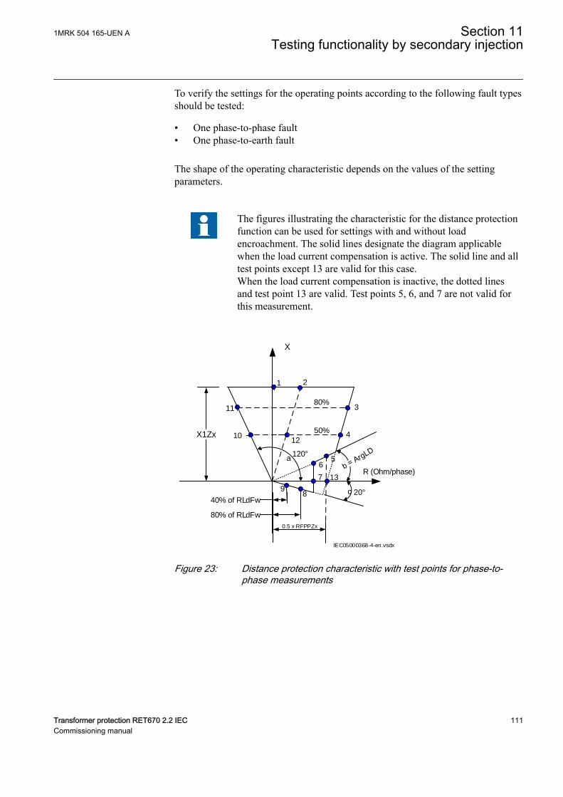
To verify the settings for the operating points according to the following fault typesshould be tested:
• One phase-to-phase fault• One phase-to-earth fault
The shape of the operating characteristic depends on the values of the settingparameters.
The figures illustrating the characteristic for the distance protectionfunction can be used for settings with and without loadencroachment. The solid lines designate the diagram applicablewhen the load current compensation is active. The solid line and alltest points except 13 are valid for this case.When the load current compensation is inactive, the dotted linesand test point 13 are valid. Test points 5, 6, and 7 are not valid forthis measurement.
X1Zx
X
R (Ohm/phase)
50%
80%
1 2
3
4
56
7
89
10
11
80% of RLdFw
40% of RLdFw
12
13
120°
20°
a
c
IEC05000368-4-en.vsdx
0.5 x RFPPZx
IEC05000368 V4 EN-US
Figure 23: Distance protection characteristic with test points for phase-to-phase measurements
1MRK 504 165-UEN A Section 11Testing functionality by secondary injection
Transformer protection RET670 2.2 IEC 111Commissioning manual
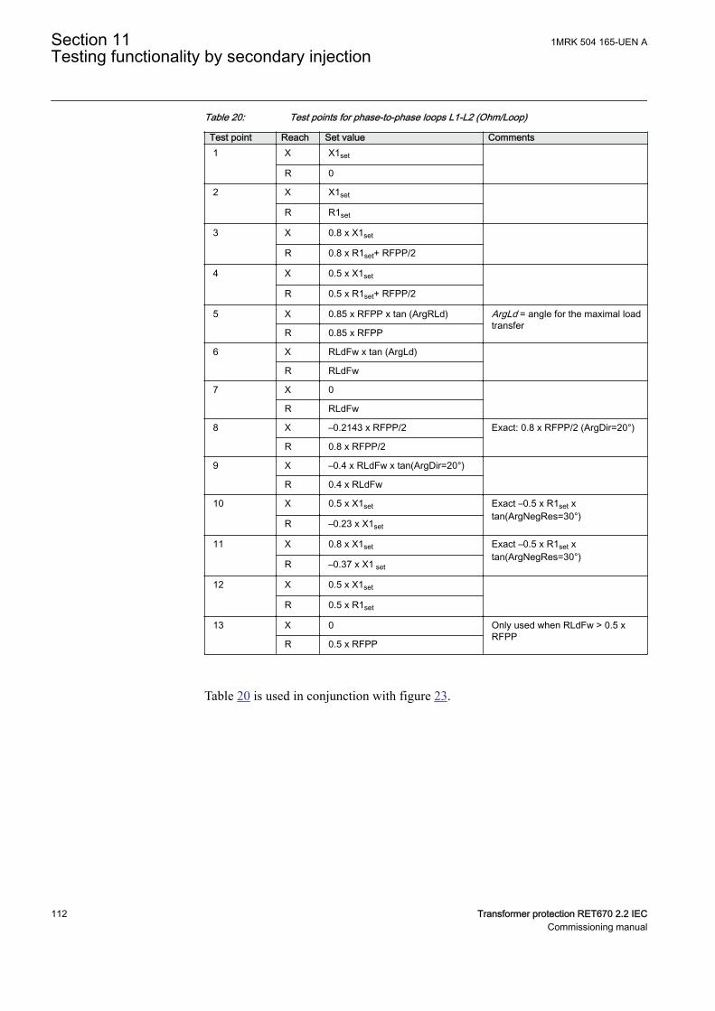
Table 20: Test points for phase-to-phase loops L1-L2 (Ohm/Loop)
Test point Reach Set value Comments1 X X1set
R 0
2 X X1set
R R1set
3 X 0.8 x X1set
R 0.8 x R1set+ RFPP/2
4 X 0.5 x X1set
R 0.5 x R1set+ RFPP/2
5 X 0.85 x RFPP x tan (ArgRLd) ArgLd = angle for the maximal loadtransfer
R 0.85 x RFPP
6 X RLdFw x tan (ArgLd)
R RLdFw
7 X 0
R RLdFw
8 X –0.2143 x RFPP/2 Exact: 0.8 x RFPP/2 (ArgDir=20°)
R 0.8 x RFPP/2
9 X –0.4 x RLdFw x tan(ArgDir=20°)
R 0.4 x RLdFw
10 X 0.5 x X1set Exact –0.5 x R1set xtan(ArgNegRes=30°)
R –0.23 x X1set
11 X 0.8 x X1set Exact –0.5 x R1set xtan(ArgNegRes=30°)
R –0.37 x X1 set
12 X 0.5 x X1set
R 0.5 x R1set
13 X 0 Only used when RLdFw > 0.5 xRFPP
R 0.5 x RFPP
Table 20 is used in conjunction with figure 23.
Section 11 1MRK 504 165-UEN ATesting functionality by secondary injection
112 Transformer protection RET670 2.2 IECCommissioning manual
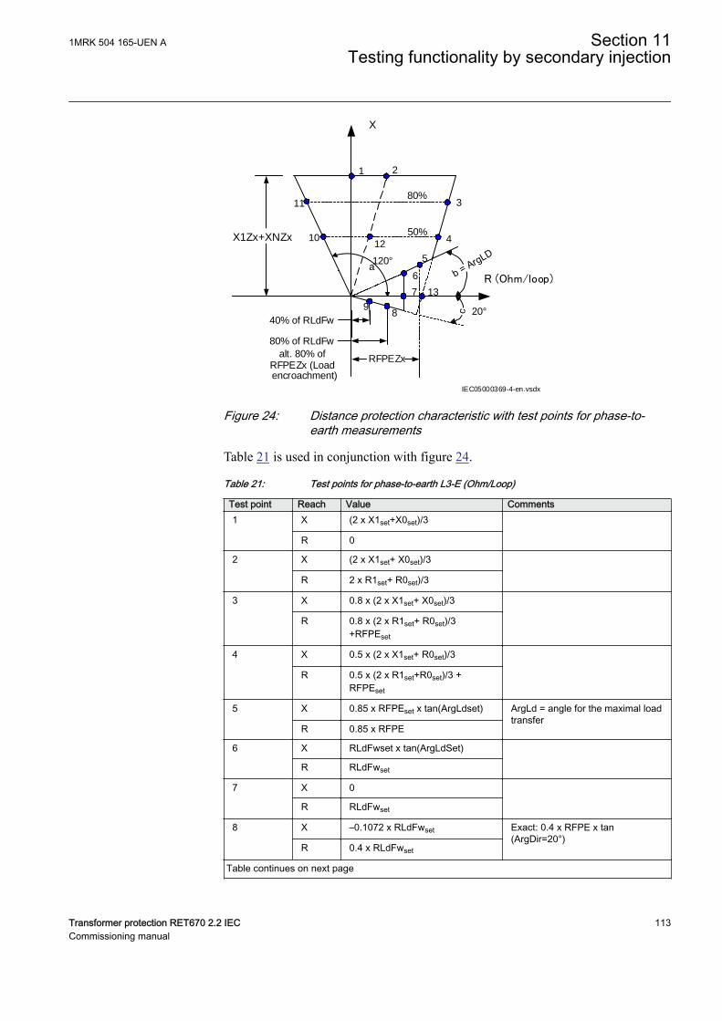
X1Zx+XNZx
X
R (Ohm/loop)
50%
80%
1 2
3
4
5
6
7
89
10
11
80% of RLdFw
40% of RLdFw
RFPEZx
12
13
alt. 80% ofRFPEZx (Loadencroachment)
120°
20°
a
IEC05000369-4-en.vsdx
IEC05000369 V4 EN-US
Figure 24: Distance protection characteristic with test points for phase-to-earth measurements
Table 21 is used in conjunction with figure 24.
Table 21: Test points for phase-to-earth L3-E (Ohm/Loop)
Test point Reach Value Comments1 X (2 x X1set+X0set)/3
R 0
2 X (2 x X1set+ X0set)/3
R 2 x R1set+ R0set)/3
3 X 0.8 x (2 x X1set+ X0set)/3
R 0.8 x (2 x R1set+ R0set)/3+RFPEset
4 X 0.5 x (2 x X1set+ R0set)/3
R 0.5 x (2 x R1set+R0set)/3 +RFPEset
5
X 0.85 x RFPEset x tan(ArgLdset) ArgLd = angle for the maximal loadtransfer
R 0.85 x RFPE
6 X RLdFwset x tan(ArgLdSet)
R RLdFwset
7 X 0
R RLdFwset
8 X –0.1072 x RLdFwset Exact: 0.4 x RFPE x tan(ArgDir=20°)
R 0.4 x RLdFwset
Table continues on next page
1MRK 504 165-UEN A Section 11Testing functionality by secondary injection
Transformer protection RET670 2.2 IEC 113Commissioning manual
Test point Reach Value Comments9 X –0.8 x RLdFwset x tan(ArgDir=20°)
R 0.8 x RLdFwset
10 X 0.17 x (2 x X1set + X0 set) Exact: 0.5 x (2 x X1set X0 set)/3
R -0.36 x (2 x X1set + X0set) Exact: 0.5 x (2X1set + X0set)/(3 xtan(AgNegDir=30°)
11 X 0.27 x (2 x X1set+X0set) Exact: 0.8 x (2 x X1set + X0set)/3
R –0.57 x (2 x X1set + X0set) Exact: 0.8 x (2X1set + X0set)/(3 xtan(AgNegDir=30°)
12 X 0.5 x (2 x X1set + X0set)/3
R 0.5 x (2 x R1set + R0set)/3
13 X 0 Only used when RLdFw > RFPE
R RFPE
11.4.1.1 Measuring the operating limit of set valuesM14944-126 v8
Procedure:
1. Subject the IED to healthy normal load conditions for at least two seconds.2. Apply the fault condition and slowly decrease the measured impedance to
find the operating value of the phase-to-phase fault for zone 1 according totest point 1 in figure 23 and table 20. Compare the result of the measurementwith the set value.
3. Repeat steps 1 to 2 to find the operating value for test points 2, 3 in table 20.Observe that the zones that are not tested have to be blocked and the zone thatis tested has to be released.
4. Repeat steps 1 to 3 to find the operating value for the phase-to-earth fault L3–E according to figure 24 and table 21.
Test points 8, 9. 10 and 11 are intended to test the directionallines of impedance protection. Since directionality is acommon function for all 5 measuring zones, it is onlynecessary to test points 8, 9. 10 and 11 once in the forwarddirection in order to test the accuracy of directionality(directional angles). Directional functionality testing (tripinside, no-trip outside) should always be made for allimpedance zones set with directionality (forward or reverse).
11.4.1.2 Measuring the operating time of distance protection zonesM14944-154 v6
Procedure:
Section 11 1MRK 504 165-UEN ATesting functionality by secondary injection
114 Transformer protection RET670 2.2 IECCommissioning manual
1. Subject the IED to healthy normal load conditions for at least two seconds.2. Apply the fault condition to find the operating time for the phase-to-phase
fault according to test point 12 in figure 23 and table 20 for zone 1. Comparethe result of the measurement with the setting t1PP.
3. Repeat steps 1 to 2 to find the operating time for the phase-to-earth faultaccording to test point 12 in figure 24 and table 21. Compare the result of themeasurement with the setting t1PE.
4. Repeat steps 1 to 3 to find the operating time for all other used measuringzones.Observe that the zones that are not tested have to be blocked and the zone thatis tested has to be released.
11.4.1.3 Completing the testM14944-167 v3
Continue to test another function or end the test by changing the TESTMODEsetting to Off. Restore connections and settings to their original values, if they werechanged for testing purposes.
11.4.2 Phase selection, quad, fixed angle, load encroachmentFDPSPDIS
M13906-3 v10
Prepare the IED for verification of settings outlined in Section "Preparing the IEDto verify settings".
The phase selectors operate on the same measuring principles as the impedancemeasuring zones. So it is necessary to follow the same principles as for distanceprotection, when performing the secondary injection tests.
Measure operating characteristics during constant current conditions. Keep themeasured current as close as possible to the rated value of its associated inputtransformer, or lower. But ensure that it is higher than the set minimum operatingcurrent.
Ensure that the maximum continuous current to the IED does not exceed four timesits rated value, if the measurement of the operating characteristics runs underconstant voltage conditions.
To verify the settings the operating points according to figures 25 and 26 should betested. See also tables 22 and 23 for information.
1MRK 504 165-UEN A Section 11Testing functionality by secondary injection
Transformer protection RET670 2.2 IEC 115Commissioning manual
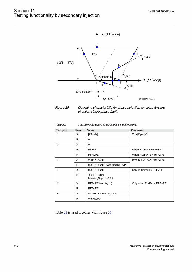
R
X
RFFwPE
1
3
5
2
4
ArgNegRes
85%
50% of RLdFw
6
IEC09000734-4-en.vsd
7
60°
)/( loopW
)/( loopW
)1( XNX +
IEC09000734 V4 EN-US
Figure 25: Operating characteristic for phase selection function, forwarddirection single-phase faults
Table 22: Test points for phase-to-earth loop L3-E (Ohm/loop)
Test point Reach Value Comments1 X [X1+XN] XN=(X0-X1)/3
R 0
2 X 0
R RLdFw When RLdFW < RFFwPE
R RFFwPE When RLdFwPE > RFFwPE
3 X 0.85·[X1+XN] R≈0.491·(X1+XN)+RFFwPE
R 0.85·[X1+XN]·1/tan(60°)+RFFwPE
4 X 0.85·[X1+XN] Can be limited by RFFwPE
R -0.85·[X1+XN]·tan (AngNegRes-90°)
5 X RFFwPE·tan (ArgLd) Only when RLdFw < RFFwPE
R RFFwPE
6 X -0.5·RLdFw·tan (ArgDir)
R 0.5·RLdFw
Table 22 is used together with figure 25.
Section 11 1MRK 504 165-UEN ATesting functionality by secondary injection
116 Transformer protection RET670 2.2 IECCommissioning manual
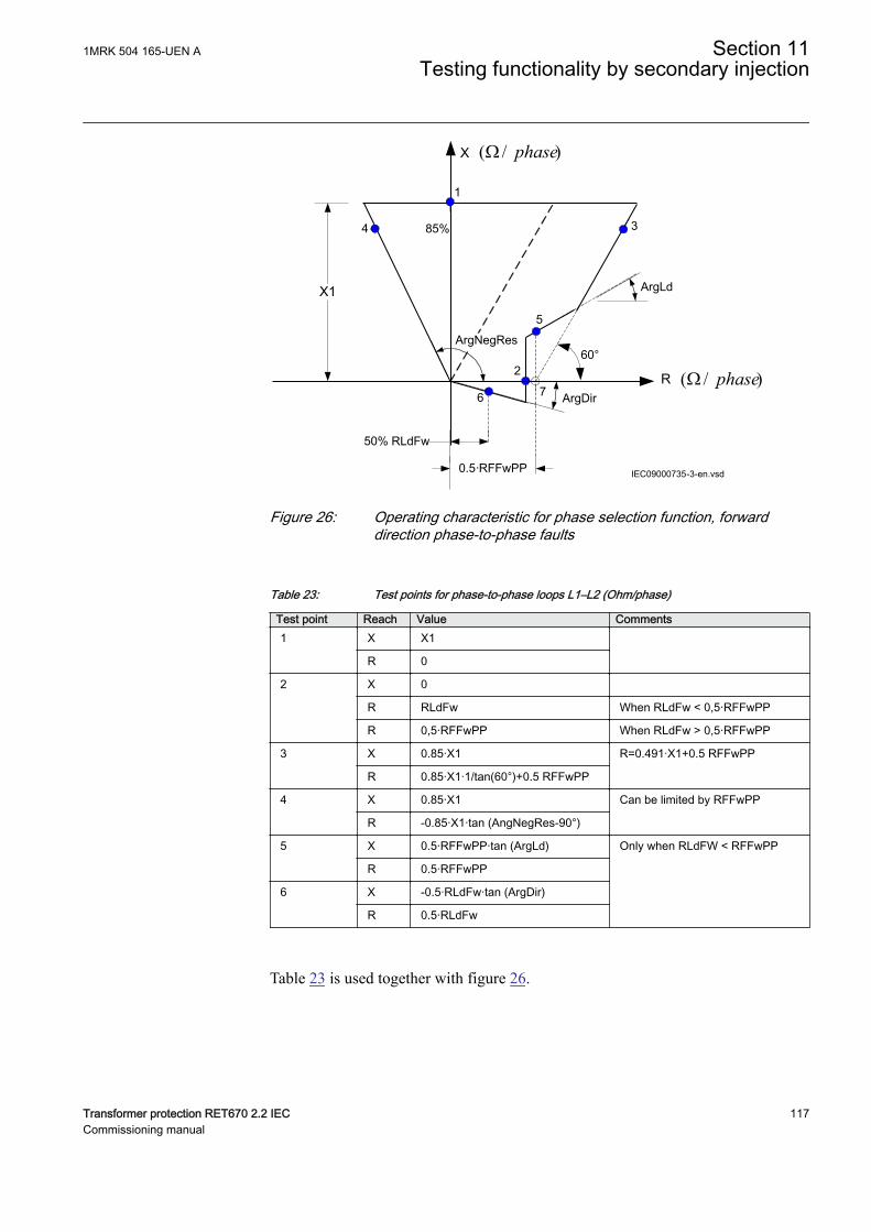
X1
R
X
85%
1
3
5
2
6
4
50% RLdFw
ArgNegRes
0.5·RFFwPP
ArgLd
IEC09000735-3-en.vsd
ArgDir
60°
)/( phaseW
)/( phaseW7
IEC09000735 V3 EN-US
Figure 26: Operating characteristic for phase selection function, forwarddirection phase-to-phase faults
Table 23: Test points for phase-to-phase loops L1–L2 (Ohm/phase)
Test point Reach Value Comments1 X X1
R 0
2 X 0
R RLdFw When RLdFw < 0,5·RFFwPP
R 0,5·RFFwPP When RLdFw > 0,5·RFFwPP
3 X 0.85·X1 R=0.491·X1+0.5 RFFwPP
R 0.85·X1·1/tan(60°)+0.5 RFFwPP
4 X 0.85·X1 Can be limited by RFFwPP
R -0.85·X1·tan (AngNegRes-90°)
5 X 0.5·RFFwPP·tan (ArgLd) Only when RLdFW < RFFwPP
R 0.5·RFFwPP
6 X -0.5·RLdFw·tan (ArgDir)
R 0.5·RLdFw
Table 23 is used together with figure 26.
1MRK 504 165-UEN A Section 11Testing functionality by secondary injection
Transformer protection RET670 2.2 IEC 117Commissioning manual
11.4.2.1 Measuring the operating limit of set valuesM13906-73 v6
Procedure:
1. Supply the IED with healthy conditions for at least two seconds.2. Apply the fault condition and slowly decrease the measured impedance to
find the operate value for of the phase-to-earth loop L3, test point 1,according to figure 25. Compare the result of the measurement with theexpected value according to table 22.The corresponding binary signals that inform about the operation of the phaseselection measuring elements are available in the local HMI underMain menu/Test/Function status/Impedance Protection/PhaseSelection(PDIS, 21)/FDPSPDIS:x.
3. Repeat steps 1 to 2 to find the operate values for the remaining test pointsaccording to figure 25 and table 22.
When the load encroachment characteristic is deliberately setvery high in order not to have an influence, then the test points2 and 5 can be replaced by test point 7.
4. Repeat steps 1 to 3 to find the operate value for the phase-to-phase fault in L1— L2 according to figure 26 and table 23.
11.4.2.2 Completing the testM13906-301 v5
Continue to test another function or end the test by changing the TESTMODEsetting to Off. Restore connections and settings to their original values, if they werechanged for testing purposes.
11.4.3 Full scheme distance protection, mho characteristicZMHPDIS
M14944-3 v10
Prepare the IED for verification of settings outlined in Section "Preparing the IEDto verify settings".
Consider releasing of the zone to be tested by setting the phase selector FMPSPDISto On.
Keep the current constant when measuring operating characteristics. Keep thecurrent as close as possible to its rated value or lower. But make sure it is higherthan the set minimum operating current.
Ensure that the maximum continuous current in an IED does not exceed four timesits rated value, if the measurement of the operating characteristics runs underconstant voltage conditions.
To verify the mho characteristic, at least two points should be tested.
Section 11 1MRK 504 165-UEN ATesting functionality by secondary injection
118 Transformer protection RET670 2.2 IECCommissioning manual
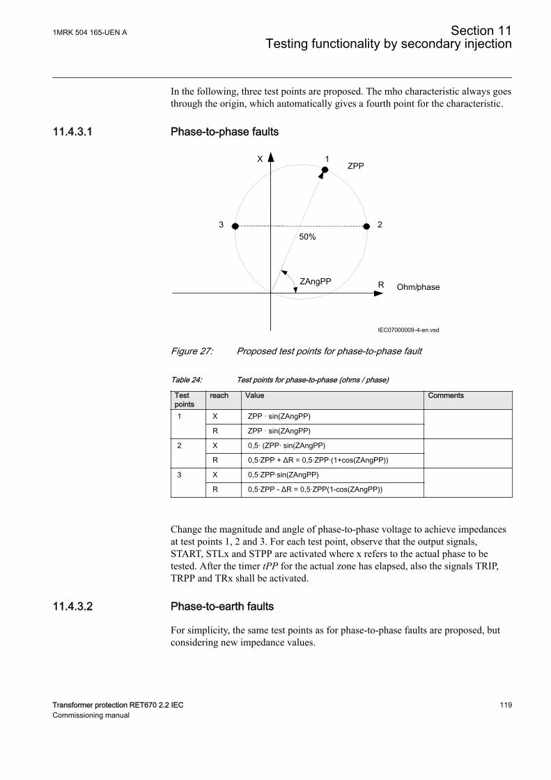
In the following, three test points are proposed. The mho characteristic always goesthrough the origin, which automatically gives a fourth point for the characteristic.
11.4.3.1 Phase-to-phase faultsM14944-292 v8
ZAngPP
ZPP1
23
Ohm/phaseR
X
IEC07000009-4-en.vsd
50%
IEC07000009 V4 EN-US
Figure 27: Proposed test points for phase-to-phase fault
Table 24: Test points for phase-to-phase (ohms / phase)
Testpoints
reach Value Comments
1 X ZPP · sin(ZAngPP)
R ZPP · sin(ZAngPP)
2 X 0,5· (ZPP· sin(ZAngPP)
R 0,5·ZPP + ΔR = 0,5·ZPP·(1+cos(ZAngPP))
3 X 0,5·ZPP·sin(ZAngPP)
R 0,5·ZPP - ΔR = 0,5·ZPP(1-cos(ZAngPP))
Change the magnitude and angle of phase-to-phase voltage to achieve impedancesat test points 1, 2 and 3. For each test point, observe that the output signals,START, STLx and STPP are activated where x refers to the actual phase to betested. After the timer tPP for the actual zone has elapsed, also the signals TRIP,TRPP and TRx shall be activated.
11.4.3.2 Phase-to-earth faultsM14944-393 v7
For simplicity, the same test points as for phase-to-phase faults are proposed, butconsidering new impedance values.
1MRK 504 165-UEN A Section 11Testing functionality by secondary injection
Transformer protection RET670 2.2 IEC 119Commissioning manual
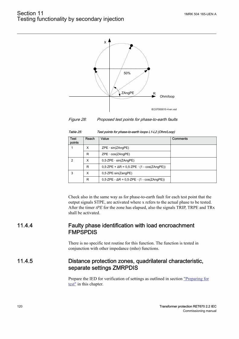
ZAngPE
50%
Ohm/loopR
X
IEC07000010-4-en.vsdIEC07000010 V4 EN-US
Figure 28: Proposed test points for phase-to-earth faults
Table 25: Test points for phase-to-earth loops L1-L2 (Ohm/Loop)
Testpoints
Reach Value Comments
1 X ZPE · sin(ZAngPE)
R ZPE · cos(ZAngPE)
2 X 0,5·ZPE · sin(ZAngPE)
R 0,5·ZPE + ΔR = 0,5·ZPE · (1 - cos(ZAngPE))
3 X 0,5·ZPE·sin(ZangPE)
R 0,5·ZPE - ΔR = 0,5·ZPE · (1 - cos(ZAngPE))
Check also in the same way as for phase-to-earth fault for each test point that theoutput signals STPE, are activated where x refers to the actual phase to be tested.After the timer tPE for the zone has elapsed, also the signals TRIP, TRPE and TRxshall be activated.
11.4.4 Faulty phase identification with load encroachmentFMPSPDIS
GUID-79761A97-A99A-4788-94A5-341308DF6E45 v3
There is no specific test routine for this function. The function is tested inconjunction with other impedance (mho) functions.
11.4.5 Distance protection zones, quadrilateral characteristic,separate settings ZMRPDIS
GUID-A35C2DED-70A6-4E96-864D-3A6C1147B350 v3
Prepare the IED for verification of settings as outlined in section "Preparing fortest" in this chapter.
Section 11 1MRK 504 165-UEN ATesting functionality by secondary injection
120 Transformer protection RET670 2.2 IECCommissioning manual
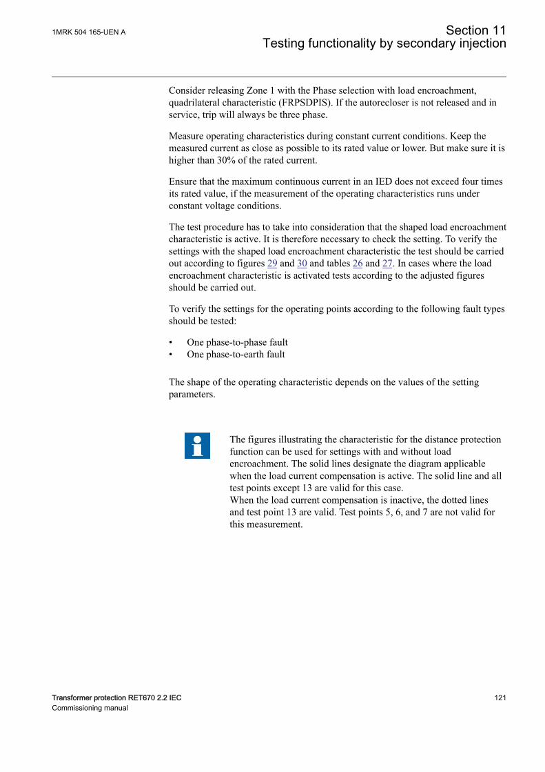
Consider releasing Zone 1 with the Phase selection with load encroachment,quadrilateral characteristic (FRPSDPIS). If the autorecloser is not released and inservice, trip will always be three phase.
Measure operating characteristics during constant current conditions. Keep themeasured current as close as possible to its rated value or lower. But make sure it ishigher than 30% of the rated current.
Ensure that the maximum continuous current in an IED does not exceed four timesits rated value, if the measurement of the operating characteristics runs underconstant voltage conditions.
The test procedure has to take into consideration that the shaped load encroachmentcharacteristic is active. It is therefore necessary to check the setting. To verify thesettings with the shaped load encroachment characteristic the test should be carriedout according to figures 29 and 30 and tables 26 and 27. In cases where the loadencroachment characteristic is activated tests according to the adjusted figuresshould be carried out.
To verify the settings for the operating points according to the following fault typesshould be tested:
• One phase-to-phase fault• One phase-to-earth fault
The shape of the operating characteristic depends on the values of the settingparameters.
The figures illustrating the characteristic for the distance protectionfunction can be used for settings with and without loadencroachment. The solid lines designate the diagram applicablewhen the load current compensation is active. The solid line and alltest points except 13 are valid for this case.When the load current compensation is inactive, the dotted linesand test point 13 are valid. Test points 5, 6, and 7 are not valid forthis measurement.
1MRK 504 165-UEN A Section 11Testing functionality by secondary injection
Transformer protection RET670 2.2 IEC 121Commissioning manual
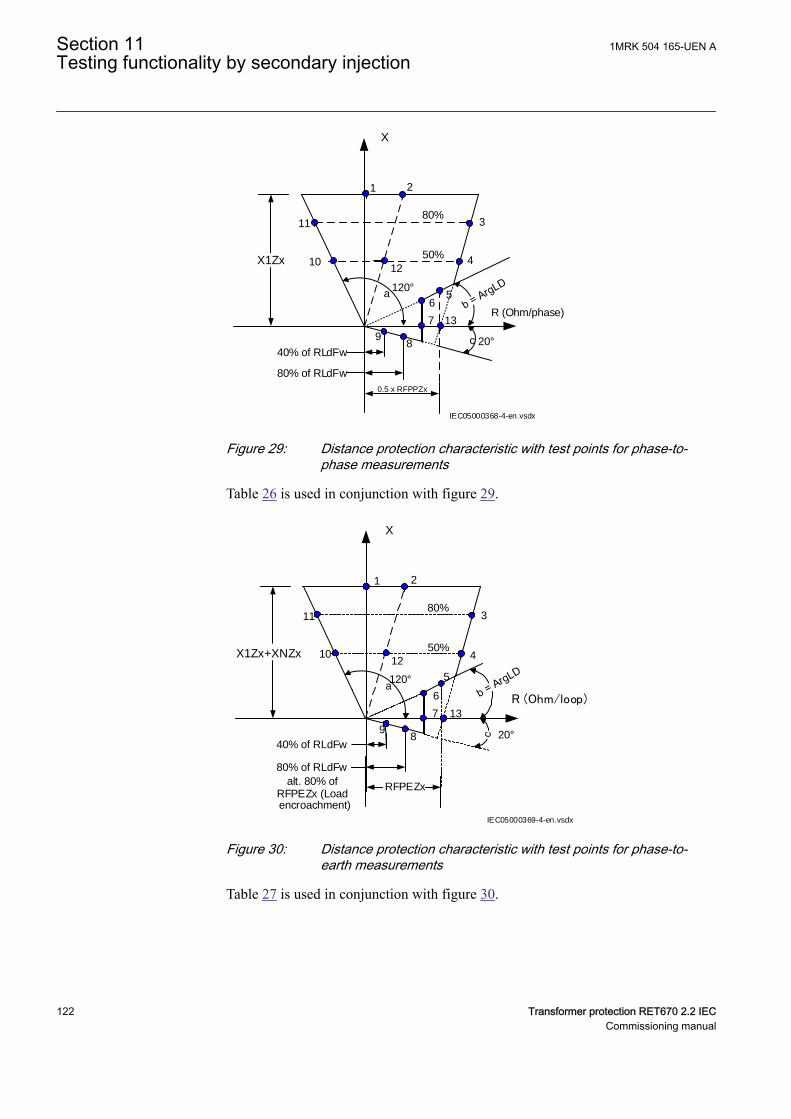
X1Zx
X
R (Ohm/phase)
50%
80%
1 2
3
4
56
7
89
10
11
80% of RLdFw
40% of RLdFw
12
13
120°
20°
a
c
IEC05000368-4-en.vsdx
0.5 x RFPPZx
IEC05000368 V4 EN-US
Figure 29: Distance protection characteristic with test points for phase-to-phase measurements
Table 26 is used in conjunction with figure 29.
X1Zx+XNZx
X
R (Ohm/loop)
50%
80%
1 2
3
4
5
6
7
89
10
11
80% of RLdFw
40% of RLdFw
RFPEZx
12
13
alt. 80% ofRFPEZx (Loadencroachment)
120°
20°
a
IEC05000369-4-en.vsdx
IEC05000369 V4 EN-US
Figure 30: Distance protection characteristic with test points for phase-to-earth measurements
Table 27 is used in conjunction with figure 30.
Section 11 1MRK 504 165-UEN ATesting functionality by secondary injection
122 Transformer protection RET670 2.2 IECCommissioning manual
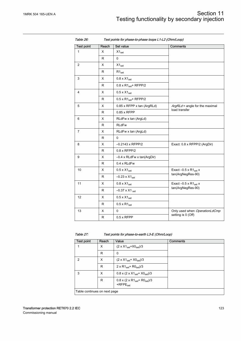
Table 26: Test points for phase-to-phase loops L1-L2 (Ohm/Loop)
Test point Reach Set value Comments1 X X1set
R 0
2 X X1set
R R1set
3 X 0.8 x X1set
R 0.8 x R1set+ RFPP/2
4 X 0.5 x X1set
R 0.5 x R1set+ RFPP/2
5 X 0.85 x RFPP x tan (ArgRLd) ArgRLd = angle for the maximalload transfer
R 0.85 x RFPP
6 X RLdFw x tan (ArgLd)
R RLdFw
7 X RLdFw x tan (ArgLd)
R 0
8 X –0.2143 x RFPP/2 Exact: 0.8 x RFPP/2 (ArgDir)
R 0.8 x RFPP/2
9 X –0.4 x RLdFw x tan(ArgDir)
R 0.4 x RLdFw
10 X 0.5 x X1set Exact –0.5 x R1set xtan(ArgNegRes-90)
R –0.23 x X1set
11 X 0.8 x X1set Exact –0.5 x R1set xtan(ArgNegRes-90)
R –0.37 x X1 set
12 X 0.5 x X1set
R 0.5 x R1set
13 X 0 Only used when OperationLdCmpsetting is 0 (Off)
R 0.5 x RFPP
Table 27: Test points for phase-to-earth L3-E (Ohm/Loop)
Test point Reach Value Comments1 X (2 x X1set+X0set)/3
R 0
2 X (2 x X1set+ X0set)/3
R 2 x R1set+ R0set)/3
3 X 0.8 x (2 x X1set+ X0set)/3
R 0.8 x (2 x R1set+ R0set)/3+RFPEset
Table continues on next page
1MRK 504 165-UEN A Section 11Testing functionality by secondary injection
Transformer protection RET670 2.2 IEC 123Commissioning manual
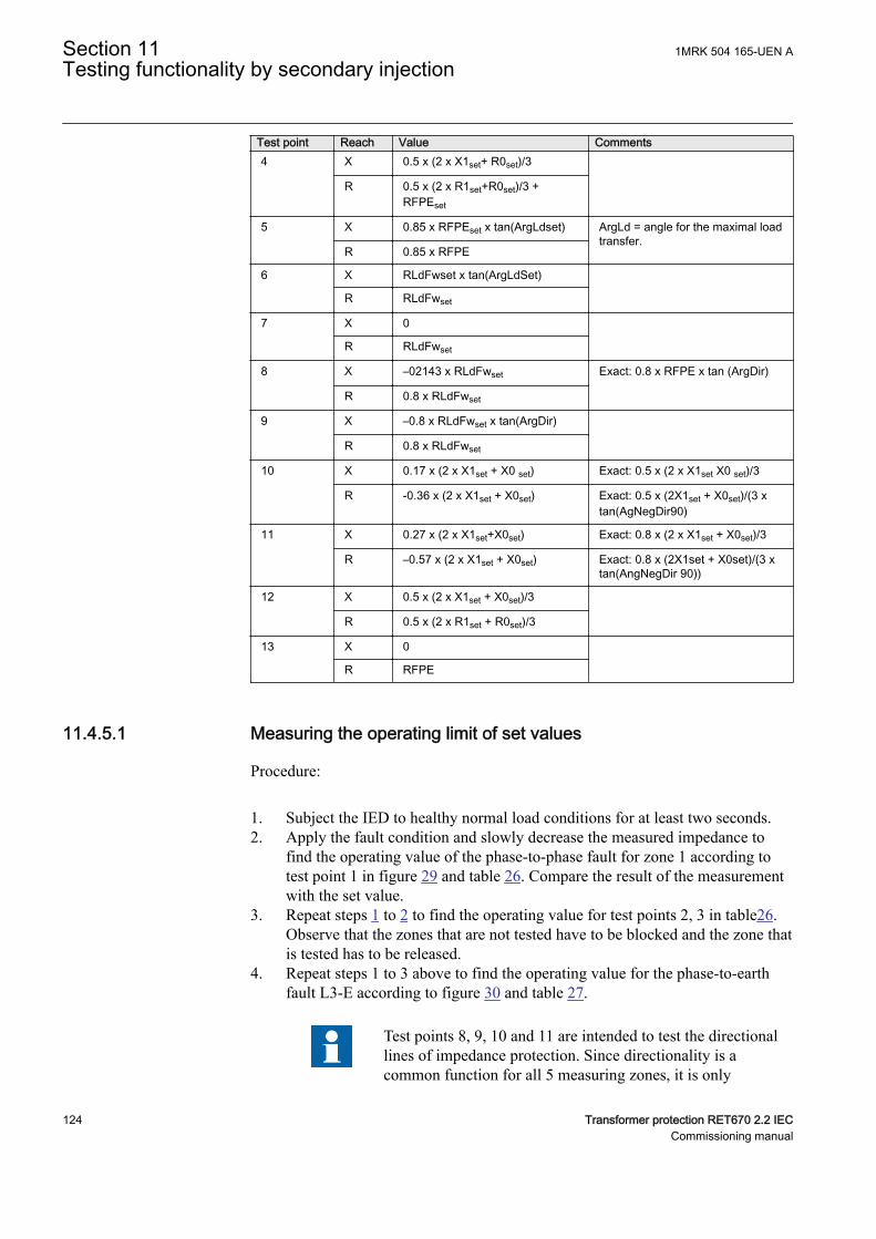
Test point Reach Value Comments4 X 0.5 x (2 x X1set+ R0set)/3
R 0.5 x (2 x R1set+R0set)/3 +RFPEset
5
X 0.85 x RFPEset x tan(ArgLdset) ArgLd = angle for the maximal loadtransfer.
R 0.85 x RFPE
6 X RLdFwset x tan(ArgLdSet)
R RLdFwset
7 X 0
R RLdFwset
8 X –02143 x RLdFwset Exact: 0.8 x RFPE x tan (ArgDir)
R 0.8 x RLdFwset
9 X –0.8 x RLdFwset x tan(ArgDir)
R 0.8 x RLdFwset
10 X 0.17 x (2 x X1set + X0 set) Exact: 0.5 x (2 x X1set X0 set)/3
R -0.36 x (2 x X1set + X0set) Exact: 0.5 x (2X1set + X0set)/(3 xtan(AgNegDir90)
11 X 0.27 x (2 x X1set+X0set) Exact: 0.8 x (2 x X1set + X0set)/3
R –0.57 x (2 x X1set + X0set) Exact: 0.8 x (2X1set + X0set)/(3 xtan(AngNegDir 90))
12 X 0.5 x (2 x X1set + X0set)/3
R 0.5 x (2 x R1set + R0set)/3
13 X 0
R RFPE
11.4.5.1 Measuring the operating limit of set valuesGUID-02EE80DB-CE52-49F0-99C4-14FD84766009 v3
Procedure:
1. Subject the IED to healthy normal load conditions for at least two seconds.2. Apply the fault condition and slowly decrease the measured impedance to
find the operating value of the phase-to-phase fault for zone 1 according totest point 1 in figure 29 and table 26. Compare the result of the measurementwith the set value.
3. Repeat steps 1 to 2 to find the operating value for test points 2, 3 in table26.Observe that the zones that are not tested have to be blocked and the zone thatis tested has to be released.
4. Repeat steps 1 to 3 above to find the operating value for the phase-to-earthfault L3-E according to figure 30 and table 27.
Test points 8, 9, 10 and 11 are intended to test the directionallines of impedance protection. Since directionality is acommon function for all 5 measuring zones, it is only
Section 11 1MRK 504 165-UEN ATesting functionality by secondary injection
124 Transformer protection RET670 2.2 IECCommissioning manual
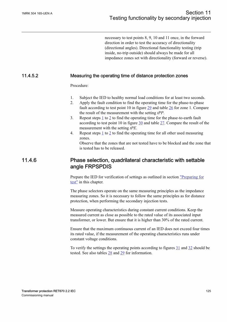
necessary to test points 8, 9, 10 and 11 once, in the forwarddirection in order to test the accuracy of directionality(directional angles). Directional functionality testing (tripinside, no-trip outside) should always be made for allimpedance zones set with directionality (forward or reverse).
11.4.5.2 Measuring the operating time of distance protection zonesGUID-9AEFB83B-A343-4965-BB41-59062CC0DB5F v3
Procedure:
1. Subject the IED to healthy normal load conditions for at least two seconds.2. Apply the fault condition to find the operating time for the phase-to-phase
fault according to test point 10 in figure 29 and table 26 for zone 1. Comparethe result of the measurement with the setting tPP.
3. Repeat steps 1 to 2 to find the operating time for the phase-to-earth faultaccording to test point 10 in figure 30 and table 27. Compare the result of themeasurement with the setting tPE.
4. Repeat steps 1 to 2 to find the operating time for all other used measuringzones.Observe that the zones that are not tested have to be blocked and the zone thatis tested has to be released.
11.4.6 Phase selection, quadrilateral characteristic with settableangle FRPSPDIS
GUID-701C863B-40C6-42D7-A0C8-ECEB084B1165 v4
Prepare the IED for verification of settings as outlined in section "Preparing fortest" in this chapter.
The phase selectors operate on the same measuring principles as the impedancemeasuring zones. So it is necessary to follow the same principles as for distanceprotection, when performing the secondary injection tests.
Measure operating characteristics during constant current conditions. Keep themeasured current as close as possible to the rated value of its associated inputtransformer, or lower. But ensure that it is higher than 30% of the rated current.
Ensure that the maximum continuous current of an IED does not exceed four timesits rated value, if the measurement of the operating characteristics runs underconstant voltage conditions.
To verify the settings the operating points according to figures 31 and 32 should betested. See also tables 28 and 29 for information.
1MRK 504 165-UEN A Section 11Testing functionality by secondary injection
Transformer protection RET670 2.2 IEC 125Commissioning manual
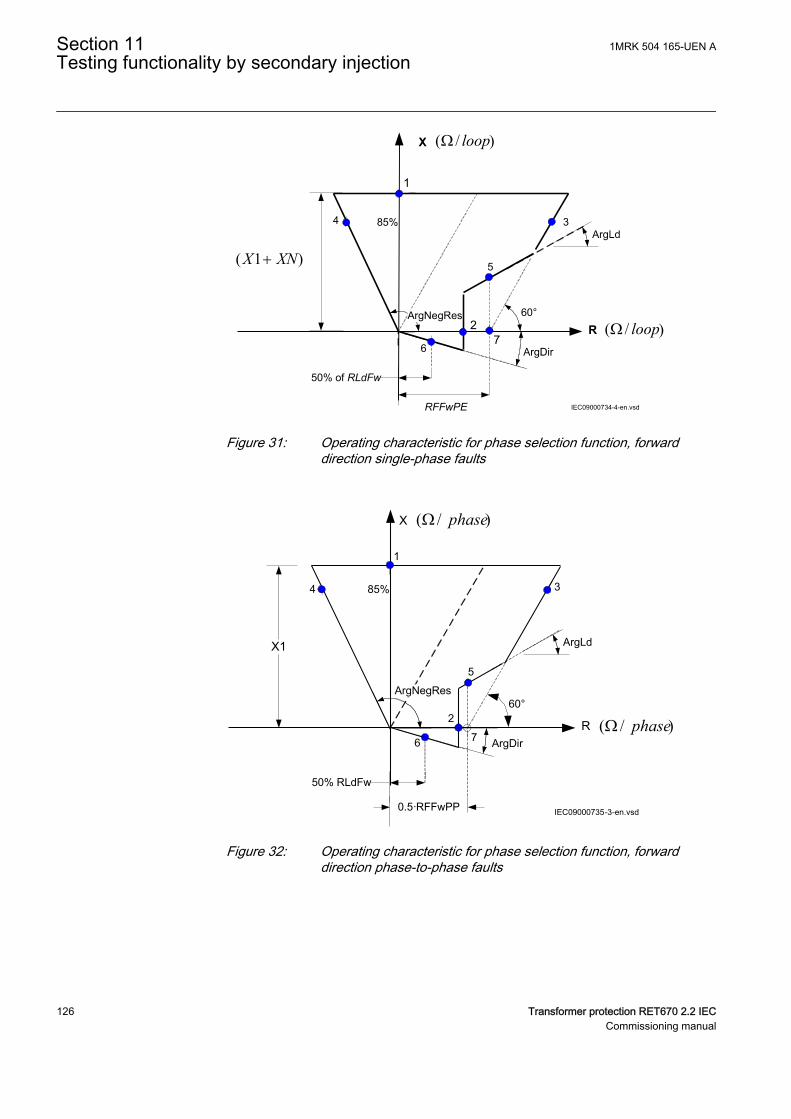
R
X
RFFwPE
1
3
5
2
4
ArgNegRes
85%
50% of RLdFw
6
IEC09000734-4-en.vsd
7
60°
)/( loopW
)/( loopW
)1( XNX +
IEC09000734 V4 EN-US
Figure 31: Operating characteristic for phase selection function, forwarddirection single-phase faults
X1
R
X
85%
1
3
5
2
6
4
50% RLdFw
ArgNegRes
0.5·RFFwPP
ArgLd
IEC09000735-3-en.vsd
ArgDir
60°
)/( phaseW
)/( phaseW7
IEC09000735 V3 EN-US
Figure 32: Operating characteristic for phase selection function, forwarddirection phase-to-phase faults
Section 11 1MRK 504 165-UEN ATesting functionality by secondary injection
126 Transformer protection RET670 2.2 IECCommissioning manual
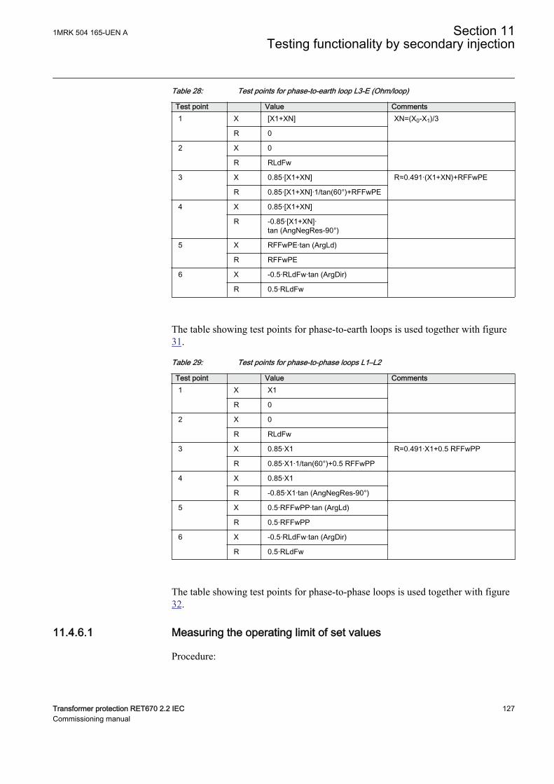
Table 28: Test points for phase-to-earth loop L3-E (Ohm/loop)
Test point Value Comments1 X [X1+XN] XN=(X0-X1)/3
R 0
2 X 0
R RLdFw
3 X 0.85·[X1+XN] R≈0.491·(X1+XN)+RFFwPE
R 0.85·[X1+XN]·1/tan(60°)+RFFwPE
4 X 0.85·[X1+XN]
R -0.85·[X1+XN]·tan (AngNegRes-90°)
5 X RFFwPE·tan (ArgLd)
R RFFwPE
6 X -0.5·RLdFw·tan (ArgDir)
R 0.5·RLdFw
The table showing test points for phase-to-earth loops is used together with figure31.
Table 29: Test points for phase-to-phase loops L1–L2
Test point Value Comments1 X X1
R 0
2 X 0
R RLdFw
3 X 0.85·X1 R=0.491·X1+0.5 RFFwPP
R 0.85·X1·1/tan(60°)+0.5 RFFwPP
4 X 0.85·X1
R -0.85·X1·tan (AngNegRes-90°)
5 X 0.5·RFFwPP·tan (ArgLd)
R 0.5·RFFwPP
6 X -0.5·RLdFw·tan (ArgDir)
R 0.5·RLdFw
The table showing test points for phase-to-phase loops is used together with figure32.
11.4.6.1 Measuring the operating limit of set valuesGUID-B1B7DEB6-7BC3-4A90-8D8F-E4E69B434AFA v3
Procedure:
1MRK 504 165-UEN A Section 11Testing functionality by secondary injection
Transformer protection RET670 2.2 IEC 127Commissioning manual
1. Supply the IED with healthy conditions for at least two seconds.2. Apply the fault condition and slowly decrease the measured impedance to
find the operate value for of the phase-to-earth loop L3, test point 1,according to figure 31. Compare the result of the measurement with theexpected value according to table 28.The corresponding binary signals that inform about the operation of the phaseselection measuring elements are available in the local HMI underMain menu/Test/Function status/Impedance Protection/PhaseSelection(PDIS, 21)/FRPSPDIS:x .
3. Repeat steps 1 to 2 to find the operate values for the remaining test pointsaccording to figure 31 and table 28.
When the load encroachment characteristic is deliberately setvery high in order not to have an influence, then the test points2 and 5 can be replaced by test point 7.
4. Repeat steps 1 to 3 to find the operate value for the phase-to-phase fault in L1— L2 according to figure 32 and table 29.
11.4.6.2 Completing the testM13906-301 v5
Continue to test another function or end the test by changing the TESTMODEsetting to Off. Restore connections and settings to their original values, if they werechanged for testing purposes.
11.4.7 High speed distance protection zones, quadrilateral andmho characteristic ZMFPDIS
GUID-DF1650F4-EC3E-402B-BE26-EF2EF1034237 v6
Prepare the IED for verification of settings outlined in section "Requirements" andsection "Preparing for test" in this chapter.
Measure operating characteristics during constant current conditions. Keep themeasured current as close as possible to its rated value or lower. But make sure it ishigher than the set minimum operating current.
Ensure that the maximum continuous current to the IED does not exceed four timesits rated value, if the measurement of the operating characteristics runs underconstant voltage conditions.
The test procedure has to take into consideration that the shaped load encroachmentcharacteristic is active. It is therefore necessary to check the setting. To verify thesettings with the shaped load encroachment characteristic the test should be carriedout according to figures 33 and 34 and tables 30 and 31. In cases where the loadencroachment characteristic is activated tests according to the adjusted figuresshould be carried out.
Section 11 1MRK 504 165-UEN ATesting functionality by secondary injection
128 Transformer protection RET670 2.2 IECCommissioning manual
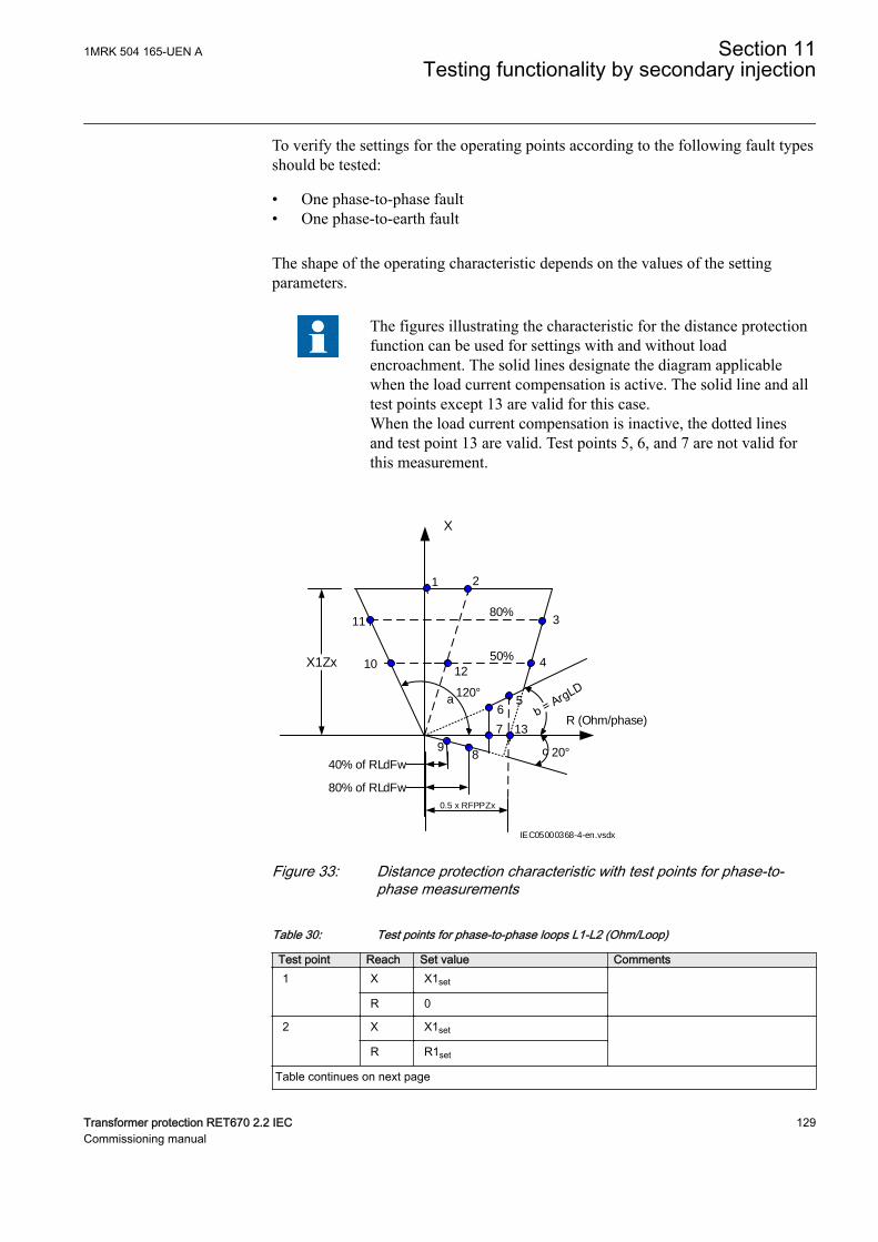
To verify the settings for the operating points according to the following fault typesshould be tested:
• One phase-to-phase fault• One phase-to-earth fault
The shape of the operating characteristic depends on the values of the settingparameters.
The figures illustrating the characteristic for the distance protectionfunction can be used for settings with and without loadencroachment. The solid lines designate the diagram applicablewhen the load current compensation is active. The solid line and alltest points except 13 are valid for this case.When the load current compensation is inactive, the dotted linesand test point 13 are valid. Test points 5, 6, and 7 are not valid forthis measurement.
X1Zx
X
R (Ohm/phase)
50%
80%
1 2
3
4
56
7
89
10
11
80% of RLdFw
40% of RLdFw
12
13
120°
20°
a
c
IEC05000368-4-en.vsdx
0.5 x RFPPZx
IEC05000368 V4 EN-US
Figure 33: Distance protection characteristic with test points for phase-to-phase measurements
Table 30: Test points for phase-to-phase loops L1-L2 (Ohm/Loop)
Test point Reach Set value Comments1 X X1set
R 0
2 X X1set
R R1set
Table continues on next page
1MRK 504 165-UEN A Section 11Testing functionality by secondary injection
Transformer protection RET670 2.2 IEC 129Commissioning manual
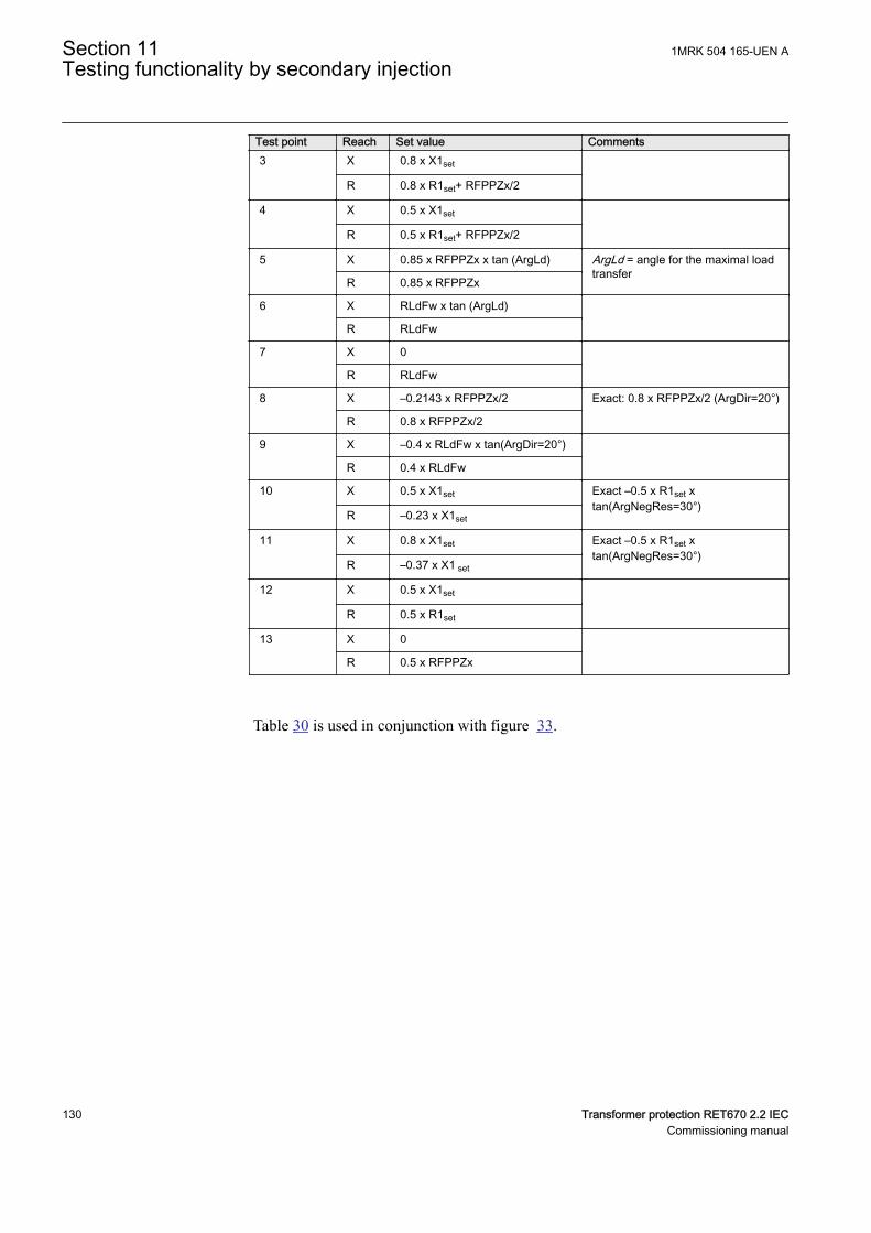
Test point Reach Set value Comments3 X 0.8 x X1set
R 0.8 x R1set+ RFPPZx/2
4 X 0.5 x X1set
R 0.5 x R1set+ RFPPZx/2
5 X 0.85 x RFPPZx x tan (ArgLd) ArgLd = angle for the maximal loadtransfer
R 0.85 x RFPPZx
6 X RLdFw x tan (ArgLd)
R RLdFw
7 X 0
R RLdFw
8 X –0.2143 x RFPPZx/2 Exact: 0.8 x RFPPZx/2 (ArgDir=20°)
R 0.8 x RFPPZx/2
9 X –0.4 x RLdFw x tan(ArgDir=20°)
R 0.4 x RLdFw
10 X 0.5 x X1set Exact –0.5 x R1set xtan(ArgNegRes=30°)
R –0.23 x X1set
11 X 0.8 x X1set Exact –0.5 x R1set xtan(ArgNegRes=30°)
R –0.37 x X1 set
12 X 0.5 x X1set
R 0.5 x R1set
13 X 0
R 0.5 x RFPPZx
Table 30 is used in conjunction with figure 33.
Section 11 1MRK 504 165-UEN ATesting functionality by secondary injection
130 Transformer protection RET670 2.2 IECCommissioning manual

X1Zx+XNZx
X
R (Ohm/loop)
50%
80%
1 2
3
4
5
6
7
89
10
11
80% of RLdFw
40% of RLdFw
RFPEZx
12
13
alt. 80% ofRFPEZx (Loadencroachment)
120°
20°
a
IEC05000369-4-en.vsdx
IEC05000369 V4 EN-US
Figure 34: Distance protection characteristic with test points for phase-to-earth measurements
Table 31 is used in conjunction with figure 34.
Table 31: Test points for phase-to-earth L3-E (Ohm/Loop)
Test point Reach Value Comments1 X (2 x X1set+X0set)/3
R 0
2 X (2 x X1set+ X0set)/3
R 2 x R1set+ R0set)/3
3 X 0.8 x (2 x X1set+ X0set)/3
R 0.8 x (2 x R1set+ R0set)/3+RFPEZxset
4 X 0.5 x (2 x X1set+ R0set)/3
R 0.5 x (2 x R1set+R0set)/3 +RFPEZxset
5
X 0.85 x RFPEZxset x tan(ArgLdset) ArgLd = angle for the maximal loadtransfer
R 0.85 x RFPEZx
6 X RLdFwset x tan(ArgLdSet)
R RLdFwset
7 X 0
R RLdFwset
8 X –02143 x RLdFwset Exact: 0.8 x RFPEZx x tan(ArgDir=20°)
R 0.8 x RLdFwset
Table continues on next page
1MRK 504 165-UEN A Section 11Testing functionality by secondary injection
Transformer protection RET670 2.2 IEC 131Commissioning manual
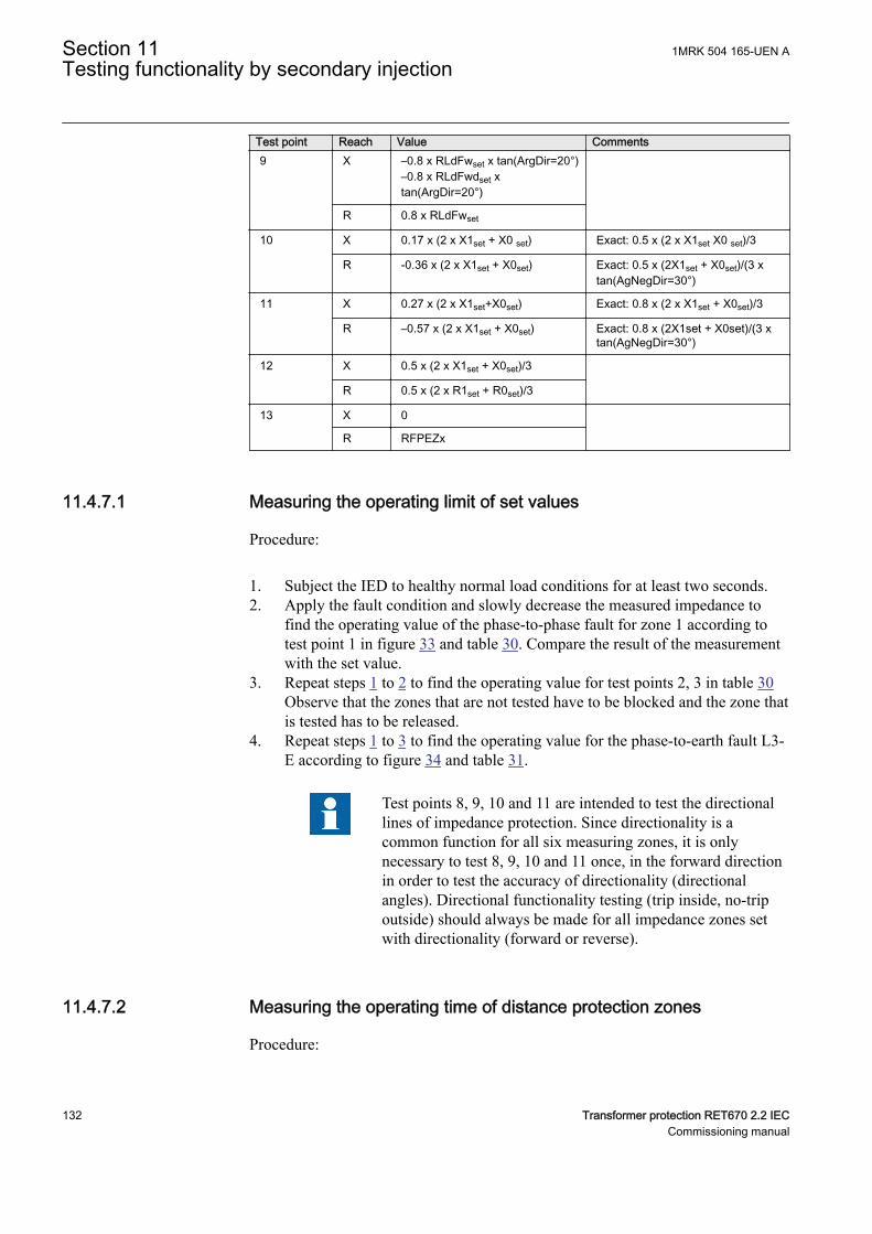
Test point Reach Value Comments9 X –0.8 x RLdFwset x tan(ArgDir=20°)
–0.8 x RLdFwdset xtan(ArgDir=20°)
R 0.8 x RLdFwset
10 X 0.17 x (2 x X1set + X0 set) Exact: 0.5 x (2 x X1set X0 set)/3
R -0.36 x (2 x X1set + X0set) Exact: 0.5 x (2X1set + X0set)/(3 xtan(AgNegDir=30°)
11 X 0.27 x (2 x X1set+X0set) Exact: 0.8 x (2 x X1set + X0set)/3
R –0.57 x (2 x X1set + X0set) Exact: 0.8 x (2X1set + X0set)/(3 xtan(AgNegDir=30°)
12 X 0.5 x (2 x X1set + X0set)/3
R 0.5 x (2 x R1set + R0set)/3
13 X 0
R RFPEZx
11.4.7.1 Measuring the operating limit of set valuesGUID-3FA4B640-38E7-406E-8FCC-8DEDABB024C4 v4
Procedure:
1. Subject the IED to healthy normal load conditions for at least two seconds.2. Apply the fault condition and slowly decrease the measured impedance to
find the operating value of the phase-to-phase fault for zone 1 according totest point 1 in figure 33 and table 30. Compare the result of the measurementwith the set value.
3. Repeat steps 1 to 2 to find the operating value for test points 2, 3 in table 30Observe that the zones that are not tested have to be blocked and the zone thatis tested has to be released.
4. Repeat steps 1 to 3 to find the operating value for the phase-to-earth fault L3-E according to figure 34 and table 31.
Test points 8, 9, 10 and 11 are intended to test the directionallines of impedance protection. Since directionality is acommon function for all six measuring zones, it is onlynecessary to test 8, 9, 10 and 11 once, in the forward directionin order to test the accuracy of directionality (directionalangles). Directional functionality testing (trip inside, no-tripoutside) should always be made for all impedance zones setwith directionality (forward or reverse).
11.4.7.2 Measuring the operating time of distance protection zonesGUID-BB93C603-F43E-40CB-8EFA-3B0F280C011D v5
Procedure:
Section 11 1MRK 504 165-UEN ATesting functionality by secondary injection
132 Transformer protection RET670 2.2 IECCommissioning manual
1. Subject the IED to healthy normal load conditions for at least two seconds.2. Apply the fault condition to find the operating time for the phase-to-phase
fault according to test point 12 in figure 33 and table 30 for zone 1. Comparethe result of the measurement to the setting tPPZ1.
3. Repeat steps 1 to 2 to find the operating time for the phase-to-earth faultaccording to test point 12 in figure 34 and table 31. Compare the result of themeasurement to the setting tPEZ1.
4. Repeat steps 1 to 2 to find the operating time for all other used measuringzones.The zones that are not tested have to be blocked and the zone that is testedhas to be released.
11.4.7.3 Completing the testGUID-60C5389E-B021-45BB-8CB3-E21348CF50EF v2
Continue to test another function or end the test by changing the TESTMODEsetting to Off. Restore connections and settings to their original values, if they werechanged for testing purposes.
11.4.8 High Speed distance for series compensated line zones,quadrilateral and mho characteristic ZMFCPDIS
GUID-EE954483-7157-4EA2-A5DD-537DF6864BC2 v4
Prepare the IED for verification of settings outlined in Section "Preparing the IEDto verify settings".
Measure operating characteristics during constant current conditions. Keep themeasured current as close as possible to its rated value or lower. But make sure it ishigher than the set minimum operating current.
Ensure that the maximum continuous current to the IED does not exceed four timesits rated value, if the measurement of the operating characteristics runs underconstant voltage conditions.
The test procedure has to take into consideration that the shaped load encroachmentcharacteristic is active. It is therefore necessary to check the setting. To verify thesettings with the shaped load encroachment characteristic the test should be carriedout according to figures 35 and 36 and tables 32 and 33. In cases where the loadencroachment characteristic is activated tests according to the adjusted figuresshould be carried out.
To verify the settings for the operating points according to the following fault typesshould be tested:
• One phase-to-phase fault• One phase-to-earth fault
The shape of the operating characteristic depends on the values of the settingparameters.
1MRK 504 165-UEN A Section 11Testing functionality by secondary injection
Transformer protection RET670 2.2 IEC 133Commissioning manual
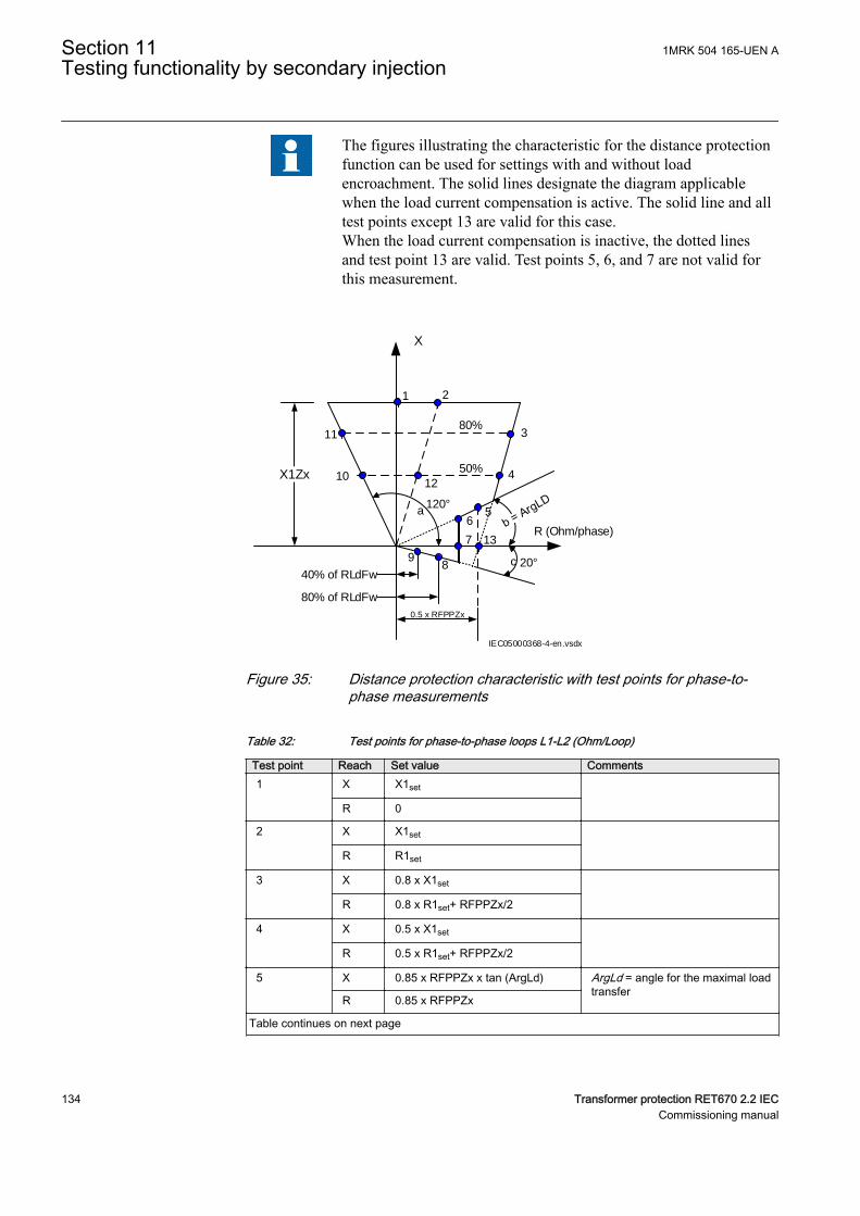
The figures illustrating the characteristic for the distance protectionfunction can be used for settings with and without loadencroachment. The solid lines designate the diagram applicablewhen the load current compensation is active. The solid line and alltest points except 13 are valid for this case.When the load current compensation is inactive, the dotted linesand test point 13 are valid. Test points 5, 6, and 7 are not valid forthis measurement.
X1Zx
X
R (Ohm/phase)
50%
80%
1 2
3
4
56
7
89
10
11
80% of RLdFw
40% of RLdFw
12
13
120°
20°
a
c
IEC05000368-4-en.vsdx
0.5 x RFPPZx
IEC05000368 V4 EN-US
Figure 35: Distance protection characteristic with test points for phase-to-phase measurements
Table 32: Test points for phase-to-phase loops L1-L2 (Ohm/Loop)
Test point Reach Set value Comments1 X X1set
R 0
2 X X1set
R R1set
3 X 0.8 x X1set
R 0.8 x R1set+ RFPPZx/2
4 X 0.5 x X1set
R 0.5 x R1set+ RFPPZx/2
5 X 0.85 x RFPPZx x tan (ArgLd) ArgLd = angle for the maximal loadtransfer
R 0.85 x RFPPZx
Table continues on next page
Section 11 1MRK 504 165-UEN ATesting functionality by secondary injection
134 Transformer protection RET670 2.2 IECCommissioning manual
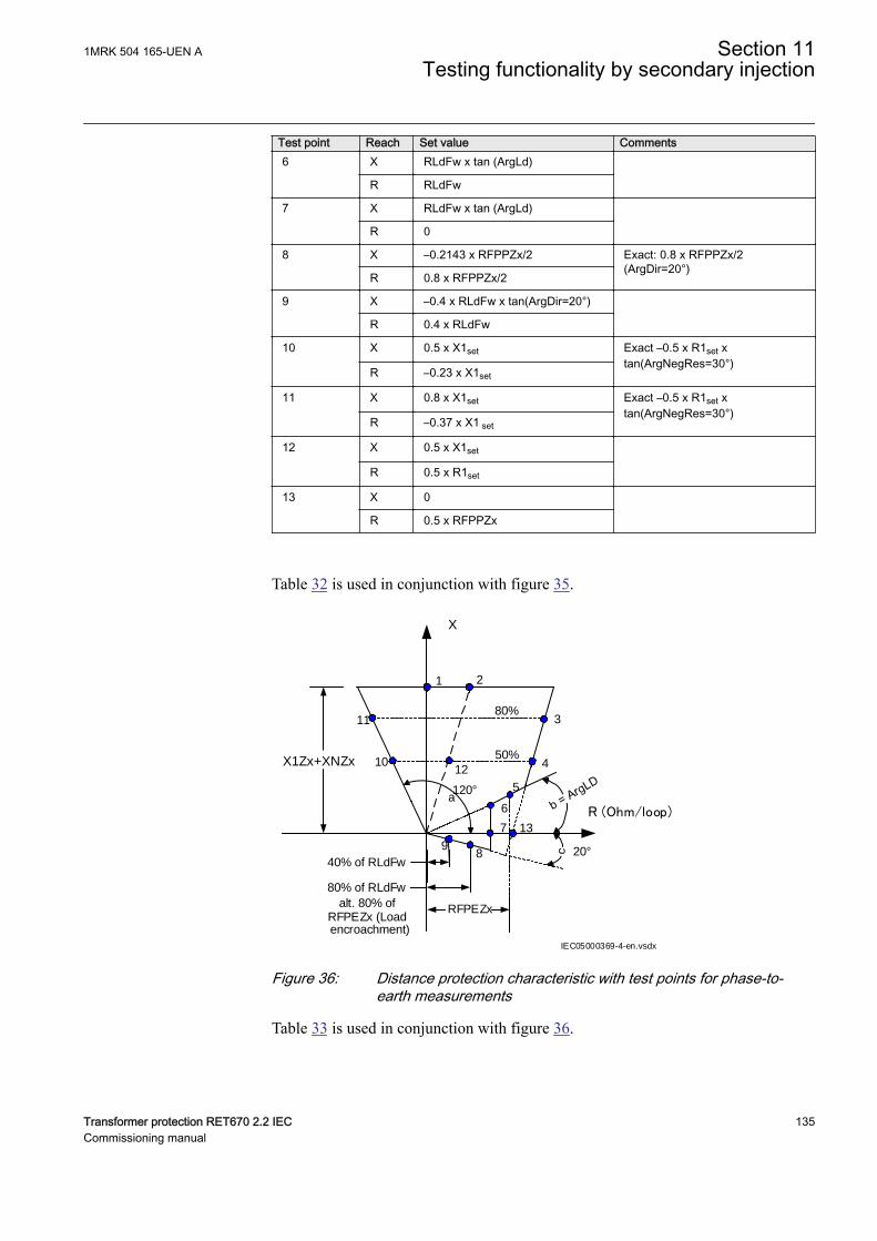
Test point Reach Set value Comments6 X RLdFw x tan (ArgLd)
R RLdFw
7 X RLdFw x tan (ArgLd)
R 0
8 X –0.2143 x RFPPZx/2 Exact: 0.8 x RFPPZx/2(ArgDir=20°)
R 0.8 x RFPPZx/2
9 X –0.4 x RLdFw x tan(ArgDir=20°)
R 0.4 x RLdFw
10 X 0.5 x X1set Exact –0.5 x R1set xtan(ArgNegRes=30°)
R –0.23 x X1set
11 X 0.8 x X1set Exact –0.5 x R1set xtan(ArgNegRes=30°)
R –0.37 x X1 set
12 X 0.5 x X1set
R 0.5 x R1set
13 X 0
R 0.5 x RFPPZx
Table 32 is used in conjunction with figure 35.
X1Zx+XNZx
X
R (Ohm/loop)
50%
80%
1 2
3
4
5
6
7
89
10
11
80% of RLdFw
40% of RLdFw
RFPEZx
12
13
alt. 80% ofRFPEZx (Loadencroachment)
120°
20°
a
IEC05000369-4-en.vsdx
IEC05000369 V4 EN-US
Figure 36: Distance protection characteristic with test points for phase-to-earth measurements
Table 33 is used in conjunction with figure 36.
1MRK 504 165-UEN A Section 11Testing functionality by secondary injection
Transformer protection RET670 2.2 IEC 135Commissioning manual
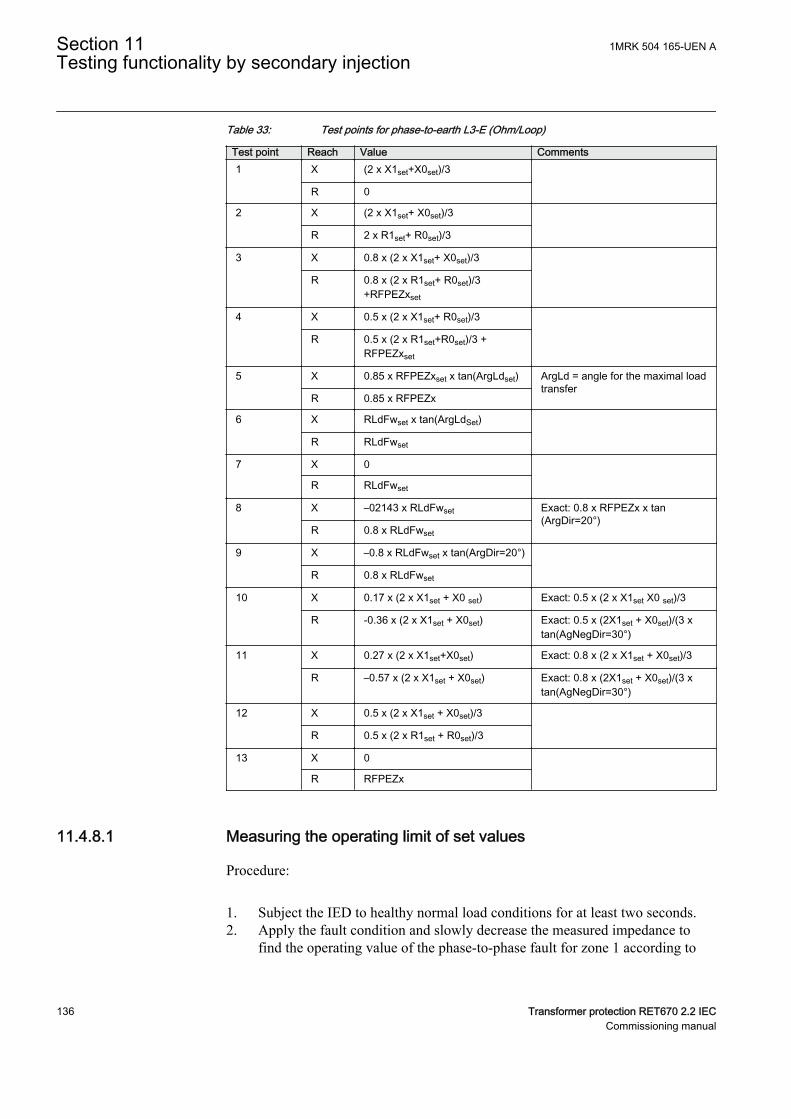
Table 33: Test points for phase-to-earth L3-E (Ohm/Loop)
Test point Reach Value Comments1 X (2 x X1set+X0set)/3
R 0
2 X (2 x X1set+ X0set)/3
R 2 x R1set+ R0set)/3
3 X 0.8 x (2 x X1set+ X0set)/3
R 0.8 x (2 x R1set+ R0set)/3+RFPEZxset
4 X 0.5 x (2 x X1set+ R0set)/3
R 0.5 x (2 x R1set+R0set)/3 +RFPEZxset
5
X 0.85 x RFPEZxset x tan(ArgLdset) ArgLd = angle for the maximal loadtransfer
R 0.85 x RFPEZx
6 X RLdFwset x tan(ArgLdSet)
R RLdFwset
7 X 0
R RLdFwset
8 X –02143 x RLdFwset Exact: 0.8 x RFPEZx x tan(ArgDir=20°)
R 0.8 x RLdFwset
9 X –0.8 x RLdFwset x tan(ArgDir=20°)
R 0.8 x RLdFwset
10 X 0.17 x (2 x X1set + X0 set) Exact: 0.5 x (2 x X1set X0 set)/3
R -0.36 x (2 x X1set + X0set) Exact: 0.5 x (2X1set + X0set)/(3 xtan(AgNegDir=30°)
11 X 0.27 x (2 x X1set+X0set) Exact: 0.8 x (2 x X1set + X0set)/3
R –0.57 x (2 x X1set + X0set) Exact: 0.8 x (2X1set + X0set)/(3 xtan(AgNegDir=30°)
12 X 0.5 x (2 x X1set + X0set)/3
R 0.5 x (2 x R1set + R0set)/3
13 X 0
R RFPEZx
11.4.8.1 Measuring the operating limit of set valuesGUID-24FEBCE7-3409-4204-AA15-A1E0A1605866 v3
Procedure:
1. Subject the IED to healthy normal load conditions for at least two seconds.2. Apply the fault condition and slowly decrease the measured impedance to
find the operating value of the phase-to-phase fault for zone 1 according to
Section 11 1MRK 504 165-UEN ATesting functionality by secondary injection
136 Transformer protection RET670 2.2 IECCommissioning manual
test point 1 in figure 35 and table 32. Compare the result of the measurementwith the set value.
3. Repeat steps 1 to 2 to find the operating value for test points 2, 3 in table 32.Observe that the zones that are not tested have to be blocked and the zone thatis tested has to be released.
4. Repeat steps 1 to 3 to find the operating value for the phase-to-earth fault L3-E according to figure 36 and table 33.
Test points 8, 9, 10 and 11 are intended to test the directionallines of impedance protection. Since directionality is acommon function for all six measuring zones, it is onlynecessary to test points 8, 9, 10 and 11 once, in the forwarddirection in order to test the accuracy of directionality(directional angles). Directional functionality testing (tripinside, no-trip outside) should always be made for allimpedance zones set with directionality (forward or reverse).
11.4.8.2 Measuring the operating time of distance protection zonesGUID-70AEC42A-9BC7-445A-AE21-2CEC0C3A79DC v3
Procedure:
1. Subject the IED to healthy normal load conditions for at least two seconds.2. Apply the fault condition to find the operating time for the phase-to-phase
fault according to test point 10 in figure 35 and table 32 for zone 1. Comparethe result of the measurement with the setting t1PP.
3. Repeat steps 1 to 2 to find the operating time for the phase-to-earth faultaccording to test point 10 in figure 36 and table 33. Compare the result of themeasurement with the setting t1PE.
4. Repeat steps 1 to 2 to find the operating time for all other used measuringzones.Observe that the zones that are not tested have to be blocked and the zone thatis tested has to be released.
11.4.8.3 Completing the testGUID-7FA2EA27-B6E2-48AB-8D53-22425E322FFA v1
Continue to test another function or end the test by changing the TESTMODEsetting to Off. Restore connections and settings to their original values, if they werechanged for testing purposes.
11.4.9 Power swing detection ZMRPSBM13888-2 v9
The aim is to verify that the settings of the Power swing detection functionZMRPSB is according to the setting table and to verify that ZMRPSB operates asexpected.
1MRK 504 165-UEN A Section 11Testing functionality by secondary injection
Transformer protection RET670 2.2 IEC 137Commissioning manual
Prepare the IED for verification of settings outlined in Section "Preparing the IEDto verify settings".
Before starting this process, all impedance measuring zones shall be set and inoperation. Test the outer resistive boarder in forward and reverse direction,RLdOutFw and RLdOutRv and the inner reactive boarder in forward and reversedirection X1InFw and X1InRv. See figure 37.
The corresponding resistive border for the inner resistive boundary and outerresistive boundary is calculated automatically from the setting of kLdRFw andkLdRRv.
The inner zone of ZMRPSB must cover all zones by at least 10% margin.
The test is mainly divided into two parts, one which aim is to verify that thesettings are in accordance to the selectivity plan and a second part to verify theoperation of ZMRPSB. The proposed test points for validation of the settings arenumbered according to figure 37
Test of the interactions or combinations that are not configured are not consideredin this instruction.
Section 11 1MRK 504 165-UEN ATesting functionality by secondary injection
138 Transformer protection RET670 2.2 IECCommissioning manual
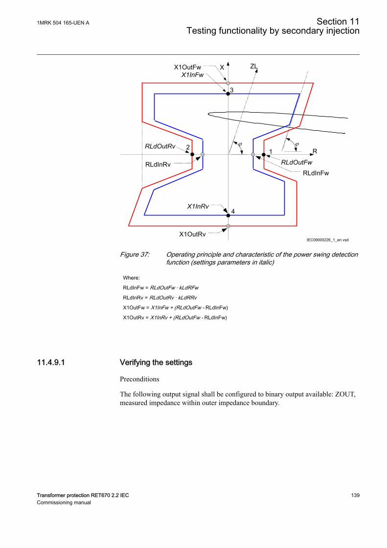
X1OutRv
ZL
j jR
XX1OutFwX1InFw
1RLdOutFw
RLdInFw
RLdOutRv
RLdInRv
2
3
4X1InRv
IEC09000226_1_en.vsdIEC09000226 V1 EN-US
Figure 37: Operating principle and characteristic of the power swing detectionfunction (settings parameters in italic)
Where:
RLdInFw = RLdOutFw · kLdRFw
RLdInRv = RLdOutRv · kLdRRv
X1OutFw = X1InFw + (RLdOutFw - RLdInFw)
X1OutRv = X1InRv + (RLdOutFw - RLdInFw)
11.4.9.1 Verifying the settingsM13888-11 v6
Preconditions
The following output signal shall be configured to binary output available: ZOUT,measured impedance within outer impedance boundary.
1MRK 504 165-UEN A Section 11Testing functionality by secondary injection
Transformer protection RET670 2.2 IEC 139Commissioning manual
1. Keep the measured current as close as possible to its rated value or lower.Keep it constant during the test, but ensure that it is higher than the setminimum operating current.
2. Ensure that the maximum continuous current to the IED does not exceed fourtimes its rated value, if the measurement of the operating characteristics runsunder constant voltage conditions.
3. Make the necessary connections and settings of the test equipment for test ofpoint 1 according to figure 37.
4. Decrease the measured three-phase impedance slowly and observe theoperation value for the signal ZOUT.
5. Compare the operation value with the set value.6. Do the necessary change of the setting of the test equipment and repeat step 4
and step 5 for point 2, 3 and 4 according to figure 37.
11.4.9.2 Testing the power swing detection function ZMRPSBM13888-27 v6
Preconditions
The following output signals shall be configured to binary outputs: ZOUT,measured impedance within outer impedance boundary, ZIN, measured impedancewithin inner impedance boundary and START, power swing detection.
1. Slowly decrease the measured impedance in all three phases until the STARTsignal gets activated.
2. Increase the measured voltages to their rated values.3. Decrease instantaneously voltages in all three phases to the values, which are
approximately 20% lower than the voltage that gives the set value R1LIn atthe predefined test current.
4. The START signal must not appear.5. Increase the measured voltages to their rated values.
11.4.9.3 Testing the tR1 timerM13888-47 v8
Preconditions
• The input I0CHECK, residual current (3I0) detection used to inhibit the startoutput must be configured to the output signal STPE on the FDPSPDIS orFRPSPDIS function.
• The input BLKI02, block inhibit of the start output for subsequent residualcurrent detection is connected to FALSE.
1. Program the test equipment for a single-phase to earth fault and energizeFDPSPDIS or FRPSDIS and check that the input BLOCK on the powerswing detection function ZMRPSB is activated.
2. Make a test sequence so that a single-phase to earth fault occurs after that thetrajectory of the impedance has passed the outer and inner boundary of
Section 11 1MRK 504 165-UEN ATesting functionality by secondary injection
140 Transformer protection RET670 2.2 IECCommissioning manual
ZMRPSB during power swing. Use the result from test of ZMRPSB above todetermine when the fault shall be applied. The earth-fault must be activatedbefore tR1 has elapsed.
3. Start the sequence and observe that the START signal will not be activated.
11.4.9.4 Testing the block input, interaction between FDPSPDIS orFRPSPDIS and ZMRPSB
M13888-73 v7
Precondition
The BLOCK input is configured and connected to STPE output on the FDPSPDISor FRPSPDIS function.
1. Make a test sequence so that a single phase-to-earth-fault occurs after that thetrajectory of the impedance has passed the outer boundary but not the innerboundary of the power swing detection function ZMRPSB. Use the resultfrom test of ZMRPSB above to instance when the fault shall be applied.
2. Start the test sequence by continuously reducing the voltage and observe thatthe output signal ZOUT may come, but not START.If the input I0CHECK is configured (connected to output signal STPE onFDPSPDIS or FRPSPDIS, the test of inhibit of ZMRPSB at earth-fault duringpower swing can be done in the same way as for test of tR1. The inhibit ofZMRPSB shall be instantaneous if the input TRSP is activated at the sametime as the input I0CHECK during power swing.
11.4.9.5 Completing the testM13888-99 v5
Continue to test another function or end the test by changing the TESTMODEsetting to Off. Restore connections and settings to their original values, if they werechanged for testing purposes.
11.4.10 Power swing logic PSLPSCHM14946-2 v4
Prepare the IED for verification of settings as outlined in section "Requirements"and section "Preparing for test" in this chapter.
Most readily available test equipment does not permit simulation of power-swingconditions and the simultaneous occurrence of different faults with controlled faultimpedance. For this reason it is necessary to enable the logic by connecting theSTPSD input signal to some other functional signal, which is used for testingpurposes.
Make sure that the existing configuration permits monitoring of the CS, TRIPsignals on the binary outputs of the IED. If not, configure connections to unusedbinary outputs, for test purposes.
1MRK 504 165-UEN A Section 11Testing functionality by secondary injection
Transformer protection RET670 2.2 IEC 141Commissioning manual
11.4.10.1 Testing the carrier send and trip signalsM14946-8 v3
Procedure
1. Set the operation of all distance zones, which are supposed to be blocked bythe operation of ZMRPSB, to Off.
2. Configure the STPSD functional inputs to the TRIP output of theunderreaching power-swing zone, if the underreaching communicationscheme is used.
3. Start instantaneously any kind of fault within the underreaching power-swingzone and check, that:• The CS signal appears after the time delay, which is equal to the sum of
set time delays for the underreaching zone tnPP or tnPE (dependent onthe type of fault) and for the carrier send security timer tCS. Also addthe usual operate time for the underreaching zone (approximately30ms).
• The TRIP signal appears after the time delay, which is equal to the sumof set time delays for the underreaching zone tnPP or tnPE (dependenton the type of fault) and for the trip security timer tTrip. Also add theusual operate time for the underreaching zone (approximately 30ms).
4. Simulate the receiving of the carrier signal so that the functional input signalCR becomes a logical one.
5. Configure the STPSD input to connect to the output START of the carrieraccelerating zone (Power-swing overreaching zone).
6. Initiate any kind of fault within the carrier accelerating zone and check thatthe TRIP signal appears after the time, which is equal to the time delay set onthe trip timer tTrip.Also consider the (average) operate time of the carrier acceleration zone(approximately 30ms).
11.4.10.2 Testing the influence of the residual overcurrent protectionM14946-28 v5
Additionally connect the IED according to the test instructions for the four stepresidual overcurrent protection function EF4PTOC, if the Power swing logic(PSLPSCH) is configured in a way that is controlled by this protection.
Procedure
1. Initiate a single phase-to-earth fault within both power-swing zones.Make sure that none of CS or TRIP output signals appear after the timedelays tCS and tTrip.BLKZMUR must appear together with the fault and must remain active untilthe fault has been switched off plus the time delay, as set on the tBlkTr timer.
2. Initiate a phase-to-phase fault within the operating area of both power-swingzones.
Section 11 1MRK 504 165-UEN ATesting functionality by secondary injection
142 Transformer protection RET670 2.2 IECCommissioning manual
Make sure that CS and TRIP output signals appear after the time delays tCS.3. Switch the operation of the zone 1 distance protection function on and fulfill
all the conditions for single-pole autoreclosing.4. Simulate a single phase-to-earth fault within the reach of zone 1 and both
power-swing zones.The fault should cause a single-pole tripping with the normal operating timeof zone 1.
5. Repeat the fault within the dead time of single-pole autoreclosing.Make sure, that PSLPSCH generates a BLKZMUR signal and no CS andTRIP.
11.4.10.3 Checking the underreaching zoneM14946-49 v3
Procedure
1. Set the operation of all normal distance protection zones to On.2. Simulate a fault without fault resistance in the middle of distance protection
zone 1.Make sure that the trip appears within the operate time for the distanceprotection zone 1 and no BLKZMOR output signal appears.
3. Switch off the fault and prepare a new fault without fault resistance within thenormal distance protection zone 2 operate area, but outside the zone 1 operatearea.
4. Switch on the fault and move it into the zone 1 operate area with a time delaylonger than the time set on the tDZ timer and faster than the time set on timertZL.
5. Observe the operate time, which must be equal to the operate time of zone 1,after the measured impedance enters its operate area.No delayed operation of zone 1 must be observed.
6. Configure the STPSD functional input to connect to the START functionaloutput and repeat the previous fault.Fast trip, caused by the operation of zone 1 must appear with a time delay,which is equal to the set time delay on the timer tZL plus zone 1 normaloperate time. Also, observe the BLKZMOR functional output signal, whichmust appear for a short time.
7. Be sure to establish the original configuration of the IED and the originalsettings of all setting parameters.
11.4.10.4 Completing the testM14946-70 v2
Continue to test another function or end the test by changing the TESTMODEsetting to Off. Restore connections and settings to their original values, if they werechanged for testing purposes.
1MRK 504 165-UEN A Section 11Testing functionality by secondary injection
Transformer protection RET670 2.2 IEC 143Commissioning manual
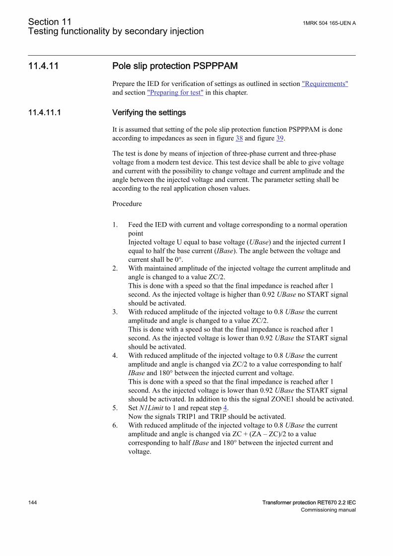
11.4.11 Pole slip protection PSPPPAMSEMOD175096-3 v2
Prepare the IED for verification of settings as outlined in section "Requirements"and section "Preparing for test" in this chapter.
11.4.11.1 Verifying the settingsSEMOD175096-7 v3
It is assumed that setting of the pole slip protection function PSPPPAM is doneaccording to impedances as seen in figure 38 and figure 39.
The test is done by means of injection of three-phase current and three-phasevoltage from a modern test device. This test device shall be able to give voltageand current with the possibility to change voltage and current amplitude and theangle between the injected voltage and current. The parameter setting shall beaccording to the real application chosen values.
Procedure
1. Feed the IED with current and voltage corresponding to a normal operationpointInjected voltage U equal to base voltage (UBase) and the injected current Iequal to half the base current (IBase). The angle between the voltage andcurrent shall be 0°.
2. With maintained amplitude of the injected voltage the current amplitude andangle is changed to a value ZC/2.This is done with a speed so that the final impedance is reached after 1second. As the injected voltage is higher than 0.92 UBase no START signalshould be activated.
3. With reduced amplitude of the injected voltage to 0.8 UBase the currentamplitude and angle is changed to a value ZC/2.This is done with a speed so that the final impedance is reached after 1second. As the injected voltage is lower than 0.92 UBase the START signalshould be activated.
4. With reduced amplitude of the injected voltage to 0.8 UBase the currentamplitude and angle is changed via ZC/2 to a value corresponding to halfIBase and 180° between the injected current and voltage.This is done with a speed so that the final impedance is reached after 1second. As the injected voltage is lower than 0.92 UBase the START signalshould be activated. In addition to this the signal ZONE1 should be activated.
5. Set N1Limit to 1 and repeat step 4.Now the signals TRIP1 and TRIP should be activated.
6. With reduced amplitude of the injected voltage to 0.8 UBase the currentamplitude and angle is changed via ZC + (ZA – ZC)/2 to a valuecorresponding to half IBase and 180° between the injected current andvoltage.
Section 11 1MRK 504 165-UEN ATesting functionality by secondary injection
144 Transformer protection RET670 2.2 IECCommissioning manual
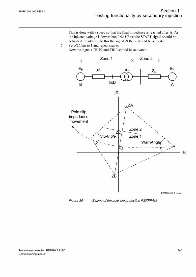
This is done with a speed so that the final impedance is reached after 1s. Asthe injected voltage is lower than 0.92 UBase the START signal should beactivated. In addition to this the signal ZONE2 should be activated.
7. Set N2Limit to 1 and repeat step 6.Now the signals TRIP2 and TRIP should be activated.
IEDB A
EB EAX’d XT ZS
Zone 1 Zone 2
jX
R
ZB
ZAPole slip
impedance movement
Zone 2
Zone 1WarnAngle
TripAngle
f
ZC
IEC07000099_2_en.vsdIEC07000099 V2 EN-US
Figure 38: Setting of the pole slip protection PSPPPAM
1MRK 504 165-UEN A Section 11Testing functionality by secondary injection
Transformer protection RET670 2.2 IEC 145Commissioning manual
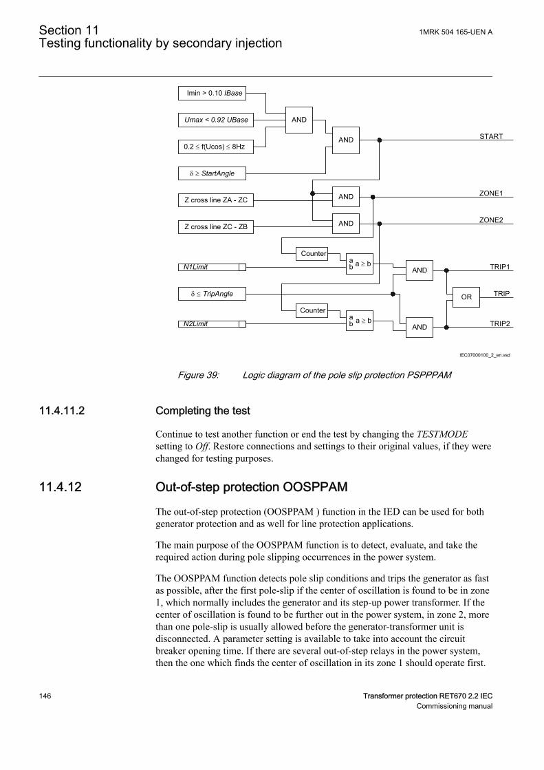
0.2 £ f(Ucos) £ 8Hz
AND
AND START
Z cross line ZA - ZC
Z cross line ZC - ZB
AND
AND
ZONE1
ZONE2
Counterab a ³ b
AND TRIP1
Counterab a ³ b
AND TRIP2
OR TRIP
IEC07000100_2_en.vsd
Imin > 0.10 IBase
Umax < 0.92 UBase
d ³ StartAngle
N1Limit
d £ TripAngle
N2Limit
IEC07000100 V2 EN-US
Figure 39: Logic diagram of the pole slip protection PSPPPAM
11.4.11.2 Completing the testSEMOD175096-39 v2
Continue to test another function or end the test by changing the TESTMODEsetting to Off. Restore connections and settings to their original values, if they werechanged for testing purposes.
11.4.12 Out-of-step protection OOSPPAMGUID-BF2F7D4C-F579-4EBD-9AFC-7C03296BD5D4 v8
The out-of-step protection (OOSPPAM ) function in the IED can be used for bothgenerator protection and as well for line protection applications.
The main purpose of the OOSPPAM function is to detect, evaluate, and take therequired action during pole slipping occurrences in the power system.
The OOSPPAM function detects pole slip conditions and trips the generator as fastas possible, after the first pole-slip if the center of oscillation is found to be in zone1, which normally includes the generator and its step-up power transformer. If thecenter of oscillation is found to be further out in the power system, in zone 2, morethan one pole-slip is usually allowed before the generator-transformer unit isdisconnected. A parameter setting is available to take into account the circuitbreaker opening time. If there are several out-of-step relays in the power system,then the one which finds the center of oscillation in its zone 1 should operate first.
Section 11 1MRK 504 165-UEN ATesting functionality by secondary injection
146 Transformer protection RET670 2.2 IECCommissioning manual
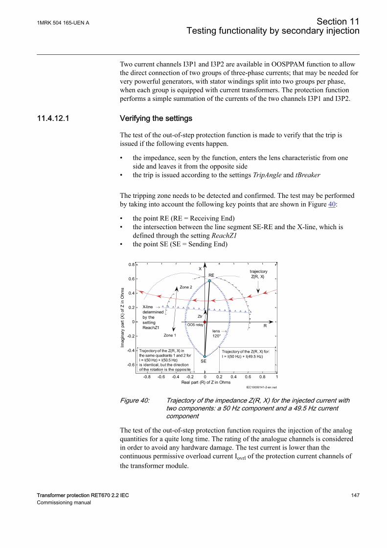
Two current channels I3P1 and I3P2 are available in OOSPPAM function to allowthe direct connection of two groups of three-phase currents; that may be needed forvery powerful generators, with stator windings split into two groups per phase,when each group is equipped with current transformers. The protection functionperforms a simple summation of the currents of the two channels I3P1 and I3P2.
11.4.12.1 Verifying the settingsGUID-708C4033-3111-481F-9868-FF207C18C9F9 v1
The test of the out-of-step protection function is made to verify that the trip isissued if the following events happen.
• the impedance, seen by the function, enters the lens characteristic from oneside and leaves it from the opposite side
• the trip is issued according to the settings TripAngle and tBreaker
The tripping zone needs to be detected and confirmed. The test may be performedby taking into account the following key points that are shown in Figure 40:
• the point RE (RE = Receiving End)• the intersection between the line segment SE-RE and the X-line, which is
defined through the setting ReachZ1• the point SE (SE = Sending End)
I = I(50 Hz) + I(49.5 Hz)
IEC10000141 V2 EN-US
Figure 40: Trajectory of the impedance Z(R, X) for the injected current withtwo components: a 50 Hz component and a 49.5 Hz currentcomponent
The test of the out-of-step protection function requires the injection of the analogquantities for a quite long time. The rating of the analogue channels is consideredin order to avoid any hardware damage. The test current is lower than thecontinuous permissive overload current Iovrl of the protection current channels ofthe transformer module.
1MRK 504 165-UEN A Section 11Testing functionality by secondary injection
Transformer protection RET670 2.2 IEC 147Commissioning manual
If the rated secondary current Irs of the analog channel is 1 A, then the maximumcurrent test Its is
I I I Ats ovrl rs
≤ = × =4 4
EQUATION14041 V1 EN-US (Equation 1)
If the CT of the generator has ratio 9000/1 A, then in primary values
I I II
IA
t ovrl p ovrl
rp
rs
≤ = × = × =,
49000
136000
EQUATION14042 V1 EN-US (Equation 2)
Reference is made to the numerical values of the example, explained in the“Setting guidelines” of the Application Manual. A test current equal to 2.5 time thebase current of the generator is chosen; this choice is related to the selected testvoltage that is applied while testing the point SE and RE.
I I At Base= × = × =2 5 2 5 8367 20918. .
EQUATION14043 V1 EN-US (Equation 3)
The parameter ReachZ1 defines the boundary between zone 1 and zone 2; it isexpressed in percent of the parameter ForwardX. If the setting of ReachZ1 = 12%,then corresponding primary value of the reactance is
XReachZ ForwardX
ZBaseRZ1
1
100 100
12
100
59 33
1000 9522 0= × × = × × =
.. .0068Ω
EQUATION14044 V1 EN-US (Equation 4)
The calculation of the test voltage, that is related to ReachZ1, is based on theimpedance ZRZ1 that has imaginary part XRZ1 and real part RRZ1 :
RRZachZ ForwardR
ZBase11
100 100
12
100
8 19
1000 9522 0 0= × × = × × =
Re .. . 009Ω
EQUATION14045 V1 EN-US (Equation 5)
The magnitude of the impedance ZRZ1 is:
2 2 2 21 1 1 0.009 0.068 0.069 RZ RZ RZZ R X= + = + = W
EQUATION14046 V1 EN-US (Equation 6)
Hence the reference voltage of the test of the boundary between zone 1 and zone 2is
V Z I Vt RZ RZ t,
.1 1
0 069 20918 1435= × = × =
EQUATION14047 V1 EN-US (Equation 7)
If the test voltage is lower than Vt,RZ1 (or in opposition), then the test is related tothe zone 1; if the test voltage is higher than Vt,RZ1, then the test is related to thezone 2.
Section 11 1MRK 504 165-UEN ATesting functionality by secondary injection
148 Transformer protection RET670 2.2 IECCommissioning manual
Considering the resistances and reactances which are related to the settings(ForwardR, ForwardX) and (ReverseR, ReverseX):
RForwardR
ZBaseFwdR
= × = × =
100
8 19
1000 9522 0 078
.. . Ω
EQUATION14048 V1 EN-US (Equation 8)
XForwardX
ZBaseFwdX
= × = × =
100
59 33
1000 9522 0 565
.. . Ω
EQUATION14049 V1 EN-US (Equation 9)
RReverseR
ZBaseRvsR
= × = × =
100
0 29
1000 9522 0 003
.. . Ω
EQUATION14050 V1 EN-US (Equation 10)
XReverseR
ZBaseRvsX
= × = × =
100
29 6
1000 9522 0 282
.. . Ω
EQUATION14051 V1 EN-US (Equation 11)
and the voltages that are related to them:
V Z I R X It FwdZ FwdZ t FwdR FwdX t,
. . .= × = + × = + × =2 2 2 2
0 078 0 565 20918 0 5700 20918 11931× = V
EQUATION14052 V1 EN-US (Equation 12)
V Z I R X It RvsZ RvsZ t RvsR RvsX t,
. . .= × = + × = + × =2 2 2 2
0 003 0 282 20918 0 2822 20918 5899× = V
EQUATION14053 V1 EN-US (Equation 13)
The previous calculations are in primary values. They are transferred to secondaryvalues to perform injections by a test set. Primary values are transferred tosecondary values by taking into account the CT ratio and the VT ratio (respectively9000/1 A and 13.8/0.1 kV in the example).
The magnitude of the secondary voltages, that are related to the points RE and SEof the R-X plane, needs to be checked.
RE (RFwdR, XFwdX):
V VV
VV
t FwdZs t FwdZ
VT s
VT p
, ,
,
,
.
..= × = × =11931
0 1
13 886 45
EQUATION14054 V1 EN-US (Equation 14)
SE (RRvsR, XRvsX):
V VV
VV
t RvsZs t RvsZ
VT s
VT p
, ,
,
,
.
..= × = × =5899
0 1
13 842 75
EQUATION14055 V1 EN-US (Equation 15)
The tests, which are described in this section, may require voltages that havemagnitude equal to 110% of the previous values. The continuous permissiveoverload voltage of the protection voltage channels of the TRM module is 420 V;so the previous voltages may be applied to the analog channels of the IEDcontinuously. Limitations may be related to the available test set; the current It was
1MRK 504 165-UEN A Section 11Testing functionality by secondary injection
Transformer protection RET670 2.2 IEC 149Commissioning manual
calculated by using a factor 2.5 (instead of the maximum value 4) in order toreduce the magnitude of the test voltage for the points RE and SE.
Test sets usually do not have a feature to simulate a real network during a powerswing and apply the related analog quantities at the terminal of the generator. Thescope of the present test is not a simulation of a real network. Voltages and currentsare supplied in order to measure an impedance that changes in the time andtraverses the plane R-X and, in particular, the area inside the lens characteristic.The test may be performed by applying:
• Symmetric three-phase voltage at 50 Hz. The magnitude depends on the pointof the characteristic that needs to be verified. The following three main pointsof the line segment SE-RE need to be checked:• the point RE (RFwdR, XFwdX)• a point which is related to the parameter ReachZ1 (boundary between
zone 1 and zone 2)• the point SE (RRvsR, XRvsX)
The phase angle of the test voltages is equal to:
• arctan (ForwardX/ForwardR) for tests in the quadrant 1 and 2 of the R-Xplane
• arctan (ReverseX/ReverseR) -180° for tests in the quadrant 3 and 4 of the R-Xplane
• Symmetric three-phase current, where the current is the summation of twocurrents that have the same magnitude, but different frequencies.
I I Atf
tI
502
20918
2
10459= = = =
GUID-F02E8D18-FF87-45BE-8142-E8FA19F6966B V1 EN-US (Equation 16)
The first current I50 has frequency 50 Hz, magnitude 10459 A (that is, 1.162 Asecondary) and phase angle 0º.The second current Itf has magnitude 10459 A (that is, 1.162 A secondary),phase angle 180º (at the starting time of the test) and frequency:• 49.5 Hz for the test as generator in the quadrant 1 and 2 of the R-X plane• 50.5 Hz for the test as generator in the quadrant 3 and 4 of the R-X plane
When the trajectory of the impedance, that is seen by the protectionfunction, traverses the lens characteristic then a pole slipping isdetected. The present procedure avoids tests of points of the lineSE-RE that are too close to the R-axis because in that case thevoltage is close to zero and, therefore, the impedance may approacha not defined quantity 0/0.
Section 11 1MRK 504 165-UEN ATesting functionality by secondary injection
150 Transformer protection RET670 2.2 IECCommissioning manual
The accuracy of the impedance reach is ±2% of the baseimpedance; that is considered while evaluating the test results.
For the test as motor the frequency current may have 50.5 Hz in thequadrant 1 and 2 of the R-X plane and 49.5 Hz in the quadrant 3and 4.
Verifying the settings by secondary injectionGUID-1752CE04-7C0F-4D37-9602-B22D8096DD2D v1
It is advised to connect the analog output channels of the function blockOOSPPAM to the internal disturbance recorder (and in particular to the functionblock A4RADR) in order to perform a better analysis of the tests.
If the device is in test mode, the recording of the disturbances are enabled by thesetting in Main menu/Settings/IED Settings/Monitoring/Disturbance report/DisturbanceReport/DRPRDRE:1: set the parameter OpModeTest to On.
1. Check the Application Configuration: verify that hardware voltage and currentchannels of the IED are properly connected to SMAI function blocks, and thatthe proper analog outputs of SMAI’s are connected to the analog inputs of thefunction block OOSPPAM.
2. Connect three-phase voltage channels of the test set to the appropriate IEDterminals.
3. Connect in parallel two groups of three-phase currents of the test set to theappropriate IED terminals.
4. Connect the appropriate trip output of the IED to the input channel of the testset that monitors the trip.
5. Go to Main menu/Settings/IED Settings/Impedance protection/OutOfStep(78,Ucos)/OOSPPAM(78,Ucos):1, and make sure that thefunction is enabled, that is, Operation is set to On.
11.4.12.2 Test of point RE (RFwdR, XFwdX)GUID-911D370F-8767-4D6C-9621-8663DD26006C v1
The trajectory of the impedance does not enter the lenscharacteristic.
GUID-5C5E9BEB-AA60-474E-ACEC-B972ACFE6FA2 v1
Preliminary steady state test at 50 HzGUID-8F95CCCC-3282-48E8-9F5E-3F3E77CCCAAE v1
• Go to Main menu/Test/Function status/Impedance protection/OutOfStep(78,Ucos)/OOSPPAM(78,Ucos):1/Outputs to check the availableservice values of the function block OOSPPAM.
• Apply the following three-phase symmetrical quantities (the phase angle isrelated to phase L1):
V VV
VV
ts t FwdZ
VT s
VT p
= × × = × × =1 1 1 1 119310 1
13 895 1. .
.
..
,
,
,
EQUATION14057 V1 EN-US (Equation 17)
1MRK 504 165-UEN A Section 11Testing functionality by secondary injection
Transformer protection RET670 2.2 IEC 151Commissioning manual
∠ =
=
=V
ForwardX
ForwardRts
arctan arctan.
.
59 33
8 1982..14°
EQUATION14058 V1 EN-US (Equation 18)
frequency of Vts = 50 Hz
I II
IA
s
CTs
CTp
50 5010459
1
90001 162= × = × = .
EQUATION14059 V1 EN-US (Equation 19)
∠I50s=0°frequency of I50s = 50 Hz
It II
IA
fs
CTs
CTp
tf= × = × =104591
90001 162.
EQUATION14062 V1 EN-US (Equation 20)
∠Itfs=0°frequency of Itfs = 50 Hz
• Check that the service values (VOLTAGE, CURRENT, R(%), X(%)) areaccording to the injected quantities and that ROTORANG is close to 0 rad.For this particular injection the service values are:• VOLTAGE = 13.12 kV• CURRENT = 20918 A• R = 9.01%• X = 65.27%• ROTORANG = 0.04 rad
Note that these values identify a point outside the lens characteristic, even if it isclose to the point RE. Neither START nor TRIP is issued.
Execution of the dynamic testGUID-0B73C849-107D-40DC-80BB-31CD441BF69A v1
The test may be performed by using two states of a sequence tool that is a basicfeature of test sets.
• State 1: pre-test condition.Steady voltage and current are applied in order to get a steady high impedance.This is a point in the plane R-X that is far away from the lens characteristic.Define the following three-phase symmetrical quantities (the phase angle isrelated to phase L1):
V VV
VV
ts t FwdZ
VT s
VT p
= × × = × × =1 1 1 1 119310 1
13 895 1. .
.
..
,
,
,
EQUATION14057 V1 EN-US (Equation 21)
∠ =
=
=V
ForwardX
ForwardRts
arctan arctan.
.
59 33
8 1982..14°
EQUATION14058 V1 EN-US (Equation 22)
Section 11 1MRK 504 165-UEN ATesting functionality by secondary injection
152 Transformer protection RET670 2.2 IECCommissioning manual
frequency of Vts = 50 HzI50s=0 AItfs=0 A
• State 2: main test step.Define the following three-phase symmetrical quantities (the phase angle isrelated to phase L1):
V VV
VV
ts t FwdZ
VT s
VT p
= × × = × × =1 1 1 1 119310 1
13 895 1. .
.
..
,
,
,
EQUATION14057 V1 EN-US (Equation 23)
∠ =
=
=V
ForwardX
ForwardRts
arctan arctan.
.
59 33
8 1982..14°
EQUATION14058 V1 EN-US (Equation 24)
frequency of Vts = 50 Hz
I II
IA
s
CTs
CTp
50 5010459
1
90001 162= × = × = .
EQUATION14059 V1 EN-US (Equation 25)
∠I50s = 0ºfrequency of I50s = 50 Hz
It II
IA
fs
CTs
CTp
tf= × = × =104591
90001 162.
EQUATION14062 V1 EN-US (Equation 26)
∠Itfs = 180ºfrequency of Itfs = 49.5 Hz Expected result: the protection function does not issue either start or trip.
The trajectory of the impedance traverses the lens characteristic inzone 2
GUID-9F0FE404-6D83-4308-9FE4-13259CE7D07A v1
Preliminary steady state test at 50 HzGUID-700F4EA1-B7D9-4B77-829A-433BB67C8A01 v1
• Go to Main menu/Test/Function status/Impedance protection/OutOfStep(78,Ucos)/OOSPPAM(78,Ucos):1/Outputs to check the availableservice values of the function block OOSPPAM.
• Apply the following three-phase symmetrical quantities (the phase angle isrelated to phase L1):
V VV
VV
ts t FwdZ
VT s
VT p
= × × = × × =0 9 0 9 119310 1
13 877 81. .
.
..
,
,
,
EQUATION14063 V1 EN-US (Equation 27)
1MRK 504 165-UEN A Section 11Testing functionality by secondary injection
Transformer protection RET670 2.2 IEC 153Commissioning manual
∠ =
=
=V
ForwardX
ForwardRts
arctan arctan.
.
59 33
8 1982..14°
EQUATION14058 V1 EN-US (Equation 28)
frequency of Vts = 50 Hz
I II
IA
s
CTs
CTp
50 5010459
1
90001 162= × = × = .
EQUATION14059 V1 EN-US (Equation 29)
∠I50s = 0ºfrequency of I50s = 50 Hz
It II
IA
fs
CTs
CTp
tf= × = × =104591
90001 162.
EQUATION14062 V1 EN-US (Equation 30)
∠Itfs = 0ºfrequency of Itf = 50 Hz
• Check that the service values (VOLTAGE, CURRENT, R(%), X(%) ) areaccording to the injected quantities and that ROTORANG is close to 3.14 rad.For this particular injection the service values are:• VOLTAGE = 10.74 kV• CURRENT = 20918 A• R = 7.37%• X = 53.40%• ROTORANG = -3.09 rad
Note that these values identify a point inside the lens characteristic, in the zone2, that is close to the point RE. The START is issued, but no TRIP isperformed.
Execution of the dynamic testGUID-028D7D67-B61A-4A7F-9978-4A0A41231B04 v1
The test may be performed by using two states of a sequence tool that is a basicfeature of test sets.
• State 1: pre-test condition.Steady voltage and current are applied in order to get a steady high impedance,that is, a point in the plane R-X which is far away from the lens characteristic.Define the following three-phase symmetrical quantities (the phase angle isrelated to phase L1):
V VV
VV
ts t FwdZ
VT s
VT p
= × × = × × =0 9 0 9 119310 1
13 877 81. .
.
..
,
,
,
EQUATION14063 V1 EN-US (Equation 31)
∠ =
=
=V
ForwardX
ForwardRts
arctan arctan.
.
59 33
8 1982..14°
EQUATION14058 V1 EN-US (Equation 32)
Section 11 1MRK 504 165-UEN ATesting functionality by secondary injection
154 Transformer protection RET670 2.2 IECCommissioning manual
frequency of Vts = 50 HzI50s = 0 AItfs = 0 A
• State 2: main test step.Define the following three-phase symmetrical quantities (the phase angle isrelated to phase L1):
V VV
VV
ts t FwdZ
VT s
VT p
= × × = × × =0 9 0 9 119310 1
13 877 81. .
.
..
,
,
,
EQUATION14063 V1 EN-US (Equation 33)
∠ =
=
=V
ForwardX
ForwardRts
arctan arctan.
.
59 33
8 1982..14°
EQUATION14058 V1 EN-US (Equation 34)
frequency of Vts = 50 Hz
I II
IA
s
CTs
CTp
50 5010459
1
90001 162= × = × = .
EQUATION14059 V1 EN-US (Equation 35)
∠I50s = 0ºfrequency of I50s = 50 Hz
It II
IA
fs
CTs
CTp
tf= × = × =104591
90001 162.
EQUATION14062 V1 EN-US (Equation 36)
∠Itfs = 180ºfrequency of Itfs = 49.5 Hz
Expected result: start of the protection function and trip in zone 2, when tripconditions are fulfilled.
11.4.12.3 Test of the boundary between zone 1 and zone 2, which is definedby the parameter ReachZ1
GUID-BE180E07-7D4B-4842-81FB-244DE8897430 v1
The trajectory of the impedance traverses the lens characteristic inzone 2
GUID-17F6AC8D-1F57-4245-A61D-776D469DD153 v1
Preliminary steady state test at 50 HzGUID-3D42E43D-873E-4271-9AAF-3B2789FF3B17 v1
• Go to Main menu/Test/Function status/Impedance protection/OutOfStep(78,Ucos)/OOSPPAM(78,Ucos):1/Outputs to check the availableservice values of the function block OOSPPAM.
• Apply the following three-phase symmetrical quantities (the phase angle isrelated to phase L1):
1MRK 504 165-UEN A Section 11Testing functionality by secondary injection
Transformer protection RET670 2.2 IEC 155Commissioning manual
V VV
VV
ts t RZ
VT s
VT p
= × × = × × =1 1 1 1 14350 1
13 811 44
1. .
.
..
,
,
,
EQUATION14065 V1 EN-US (Equation 37)
∠ =
=
=V
ForwardX
ForwardRts
arctan arctan.
.
59 33
8 1982..14°
EQUATION14058 V1 EN-US (Equation 38)
frequency of Vts = 50 Hz
I II
IA
s
CTs
CTp
50 5010459
1
90001 162= × = × = .
EQUATION14059 V1 EN-US (Equation 39)
∠I50s = 0ºfrequency of I50s = 50 Hz
It II
IA
fs
CTs
CTp
tf= × = × =104591
90001 162.
EQUATION14062 V1 EN-US (Equation 40)
∠Itfs = 0ºfrequency of Itfs = 50 Hz
• Check that the service values (VOLTAGE, CURRENT, R(%), X(%)) areaccording to the injected quantities and that ROTORANG is close to 3.14 rad.For this particular injection the service values are:• VOLTAGE = 1.58 kV• CURRENT = 20918 A• R = 1.08%• X = 7.85%• ROTORANG = -3.04 rad
Note that these values identify a point inside the lens characteristic, in the Zone 2,that is close to the boundary between zone 1 and zone 2. The START is issued, butno TRIP is performed.
Execution of the dynamic testGUID-53964189-42E4-4C4B-BFCD-64888BA938EF v1
The test may be performed by using two states of a sequence tool that is a basicfeature of test sets.
• State 1: pre-test condition.Steady voltage and current are applied in order to get a steady high impedance,that is a point in the plane R-X that is far away from the lens characteristic.Define the following three-phase symmetrical quantities (the phase angle isrelated to phase L1):
V VV
VV
ts t RZ
VT s
VT p
= × × = × × =1 1 1 1 14350 1
13 811 44
1. .
.
..
,
,
,
EQUATION14065 V1 EN-US (Equation 41)
Section 11 1MRK 504 165-UEN ATesting functionality by secondary injection
156 Transformer protection RET670 2.2 IECCommissioning manual
∠ =
=
=V
ForwardX
ForwardRts
arctan arctan.
.
59 33
8 1982..14°
EQUATION14058 V1 EN-US (Equation 42)
frequency of Vt= 50 Hz.I50s = 0 AItfs = 0 A
• State 2: main test step.Define the following three-phase symmetrical quantities (the phase angle isrelated to phase L1):
V VV
VV
ts t RZ
VT s
VT p
= × × = × × =1 1 1 1 14350 1
13 811 44
1. .
.
..
,
,
,
EQUATION14065 V1 EN-US (Equation 43)
∠ =
=
=V
ForwardX
ForwardRts
arctan arctan.
.
59 33
8 1982..14°
EQUATION14058 V1 EN-US (Equation 44)
frequency of Vt = 50 Hz
I II
IA
s
CTs
CTp
50 5010459
1
90001 162= × = × = .
EQUATION14059 V1 EN-US (Equation 45)
∠I50s = 0ºfrequency of I50s = 50 Hz
It II
IA
fs
CTs
CTp
tf= × = × =104591
90001 162.
EQUATION14062 V1 EN-US (Equation 46)
∠Itfs = 180ºfrequency of Itfs = 49.5 Hz Expected result: start of the protection function and trip in zone 2 when tripconditions are fulfilled.
The trajectory of the impedance traverses the lens characteristic inzone 1
GUID-12F82DD8-A4CE-48C9-944B-0CF3B3F6C9F9 v1
Preliminary steady state test at 50 HzGUID-AA953F5F-2389-4F05-8BBD-D8DC9AF3B0E4 v1
• Go to Main menu/Test/Function status/Impedance protection/OutOfStep(78,Ucos)/OOSPPAM(78,Ucos):1/Outputs to check the availableservice values of the function block OOSPPAM.
• Apply the following three-phase symmetrical quantities (the phase angle isrelated to phase L1):
1MRK 504 165-UEN A Section 11Testing functionality by secondary injection
Transformer protection RET670 2.2 IEC 157Commissioning manual

V VV
VV
ts t RZ
VT s
VT p
= × × = × × =0 9 0 9 14350 1
13 89 36
1. .
.
..
,
,
,
EQUATION14066 V1 EN-US (Equation 47)
∠ =
=
=V
ForwardX
ForwardRts
arctan arctan.
.
59 33
8 1982..14°
EQUATION14058 V1 EN-US (Equation 48)
frequency of Vts = 50 Hz
I II
IA
s
CTs
CTp
50 5010459
1
90001 162= × = × = .
EQUATION14059 V1 EN-US (Equation 49)
∠I50s = 0ºfrequency of I50s = 50 Hz
It II
IA
fs
CTs
CTp
tf= × = × =104591
90001 162.
EQUATION14062 V1 EN-US (Equation 50)
∠Itfs = 0ºfrequency of Itf = 50 Hz
• Check that the service values (VOLTAGE, CURRENT, R(%), X(%)) areaccording to the injected quantities and that ROTORANG is close to 3.14 rad.For this particular injection the service values are:• VOLTAGE = 1.29 kV• CURRENT = 20918 A• R = 0.89%• X=6.42%• ROTORANG = -3.04 rad
Note that these values identify a point inside the lens characteristic in zone 1,that is close to the boundary between zone 1 and zone 2. The START is issued,but no TRIP is performed.
Execution of the dynamic testGUID-98707DB3-9A1A-4458-9704-25F8FCB94B79 v1
The test may be performed by using two states of a sequence tool that is a basicfeature of test sets.
• State 1: pre-test condition.Steady voltage and current are applied in order to get a steady high impedance,that is a point in the plane R-X which is far away from the lens characteristic.Define the following three-phase symmetrical quantities (the phase angle isrelated to phase L1):
V VV
VV
ts t RZ
VT s
VT p
= × × = × × =0 9 0 9 14350 1
13 89 36
1. .
.
..
,
,
,
EQUATION14066 V1 EN-US (Equation 51)
Section 11 1MRK 504 165-UEN ATesting functionality by secondary injection
158 Transformer protection RET670 2.2 IECCommissioning manual
∠ =
=
=V
ForwardX
ForwardRts
arctan arctan.
.
59 33
8 1982..14°
EQUATION14058 V1 EN-US (Equation 52)
frequency of Vts = 50 HzI50s = 0 AItfs = 0 A
• State 2: main test step.Define the following three-phase symmetrical quantities (the phase angle isrelated to phase L1):
V VV
VV
ts t RZ
VT s
VT p
= × × = × × =0 9 0 9 14350 1
13 89 36
1. .
.
..
,
,
,
EQUATION14066 V1 EN-US (Equation 53)
∠ =
=
=V
ForwardX
ForwardRts
arctan arctan.
.
59 33
8 1982..14°
EQUATION14058 V1 EN-US (Equation 54)
frequency of Vts = 50 Hz
I II
IA
s
CTs
CTp
50 5010459
1
90001 162= × = × = .
EQUATION14059 V1 EN-US (Equation 55)
∠I50s = 0ºfrequency of I50s = 50 Hz
It II
IA
fs
CTs
CTp
tf= × = × =104591
90001 162.
EQUATION14062 V1 EN-US (Equation 56)
∠Itfs = 180ºfrequency of Itfs = 49.5 Hz Expected result: start of the protection function and trip in zone 1 when tripconditions are fulfilled.
1MRK 504 165-UEN A Section 11Testing functionality by secondary injection
Transformer protection RET670 2.2 IEC 159Commissioning manual
11.4.12.4 Test of the point SE (RRvsR, XRvsX)GUID-335F54E6-52DE-4BF1-A34B-0C2DB8059CC1 v1
The trajectory of the impedance traverses the lens characteristic inzone 1
GUID-2DD20D2E-6188-4631-A584-5E68B212E011 v1
Preliminary steady state test at 50 HzGUID-7BCF3D7B-1B84-46D4-B9E3-066894A878E8 v1
• Go to Main menu/Test/Function status/Impedance protection/OutOfStep(78,Ucos)/OOSPPAM(78,Ucos):1/Outputs to check the availableservice values of the function block OOSPPAM.
• Apply the following three-phase symmetrical quantities (the phase angle isrelated to phase L1):
V VV
VV
ts t RvsZ
VT s
VT p
= × × = × × =0 9 0 9 58990 1
13 838 47. .
.
..
,
,
,
EQUATION14067 V1 EN-US (Equation 57)
29.60arctan 180 arctan 180 90.56
0.29ts
ReverseXV
ReverseRÐ = - ° = - ° = - °æ ö æ ö
ç ÷ ç ÷è ø è ø
EQUATION14068 V1 EN-US (Equation 58)
frequency of Vts = 50 Hz
I II
IA
s
CTs
CTp
50 5010459
1
90001 162= × = × = .
EQUATION14059 V1 EN-US (Equation 59)
∠I50s = 0ºfrequency of I50s = 50 Hz
It II
IA
fs
CTs
CTp
tf= × = × =104591
90001 162.
EQUATION14062 V1 EN-US (Equation 60)
∠Itfs = 0ºfrequency of Itf = 50 Hz
• Check that the service values (VOLTAGE, CURRENT, R(%), X(%)) areaccording to the injected quantities and that ROTORANG is close to 3.14 rad.For this particular injection the service values are:• VOLTAGE = 5.31 kV• CURRENT = 20918 A• R = -0.26%• X = -26.65%• ROTORANG = -3.06 rad
Note that these values identify a point inside the lens characteristic in zone 1that is close to the point SE. The START is issued, but no TRIP is performed.
Section 11 1MRK 504 165-UEN ATesting functionality by secondary injection
160 Transformer protection RET670 2.2 IECCommissioning manual
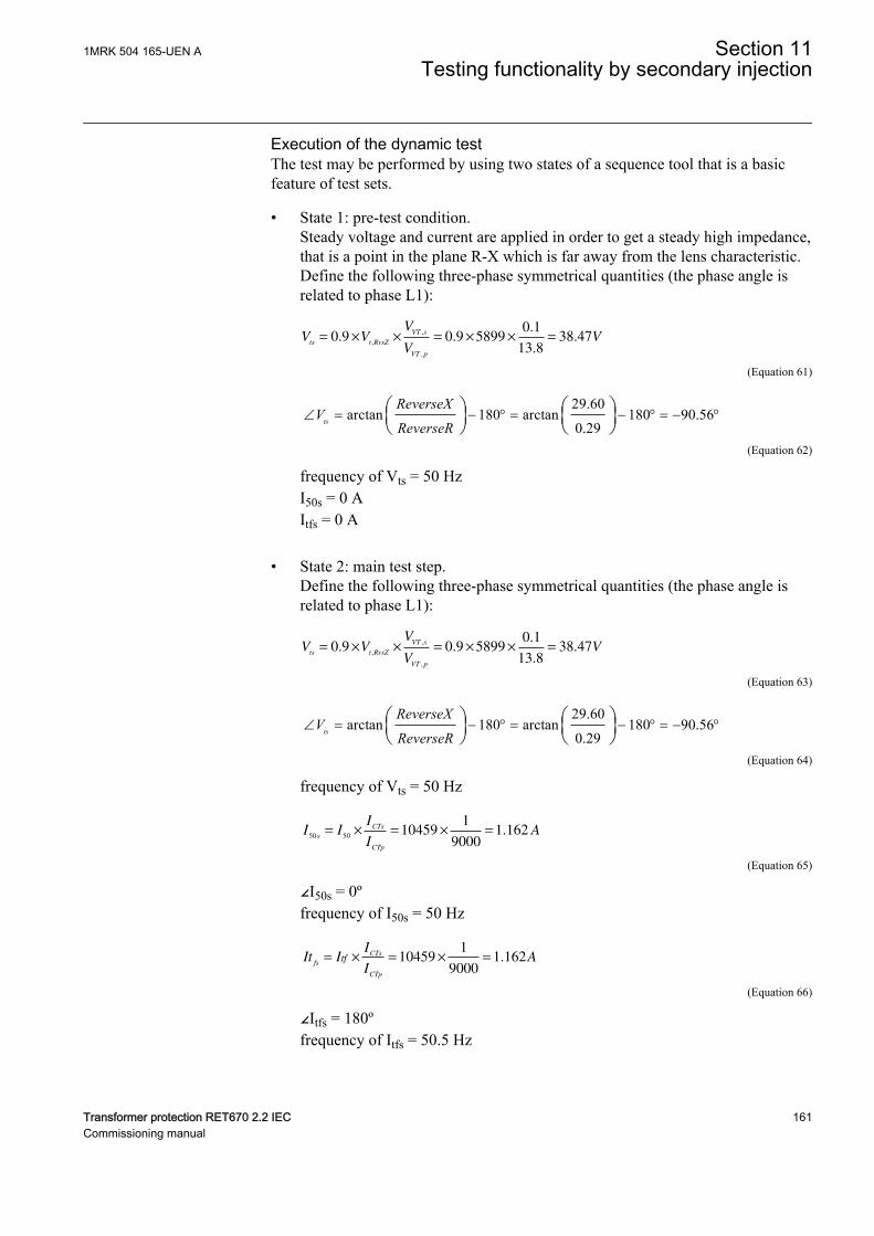
Execution of the dynamic testGUID-FF6DCD5B-96AA-4255-8740-B85C8C7148F5 v1
The test may be performed by using two states of a sequence tool that is a basicfeature of test sets.
• State 1: pre-test condition.Steady voltage and current are applied in order to get a steady high impedance,that is a point in the plane R-X which is far away from the lens characteristic.Define the following three-phase symmetrical quantities (the phase angle isrelated to phase L1):
V VV
VV
ts t RvsZ
VT s
VT p
= × × = × × =0 9 0 9 58990 1
13 838 47. .
.
..
,
,
,
EQUATION14067 V1 EN-US (Equation 61)
29.60arctan 180 arctan 180 90.56
0.29ts
ReverseXV
ReverseRÐ = - ° = - ° = - °æ ö æ ö
ç ÷ ç ÷è ø è ø
EQUATION14068 V1 EN-US (Equation 62)
frequency of Vts = 50 HzI50s = 0 AItfs = 0 A
• State 2: main test step.Define the following three-phase symmetrical quantities (the phase angle isrelated to phase L1):
V VV
VV
ts t RvsZ
VT s
VT p
= × × = × × =0 9 0 9 58990 1
13 838 47. .
.
..
,
,
,
EQUATION14067 V1 EN-US (Equation 63)
29.60arctan 180 arctan 180 90.56
0.29ts
ReverseXV
ReverseRÐ = - ° = - ° = - °æ ö æ ö
ç ÷ ç ÷è ø è ø
EQUATION14068 V1 EN-US (Equation 64)
frequency of Vts = 50 Hz
I II
IA
s
CTs
CTp
50 5010459
1
90001 162= × = × = .
EQUATION14059 V1 EN-US (Equation 65)
∠I50s = 0ºfrequency of I50s = 50 Hz
It II
IA
fs
CTs
CTp
tf= × = × =104591
90001 162.
EQUATION14062 V1 EN-US (Equation 66)
∠Itfs = 180ºfrequency of Itfs = 50.5 Hz
1MRK 504 165-UEN A Section 11Testing functionality by secondary injection
Transformer protection RET670 2.2 IEC 161Commissioning manual
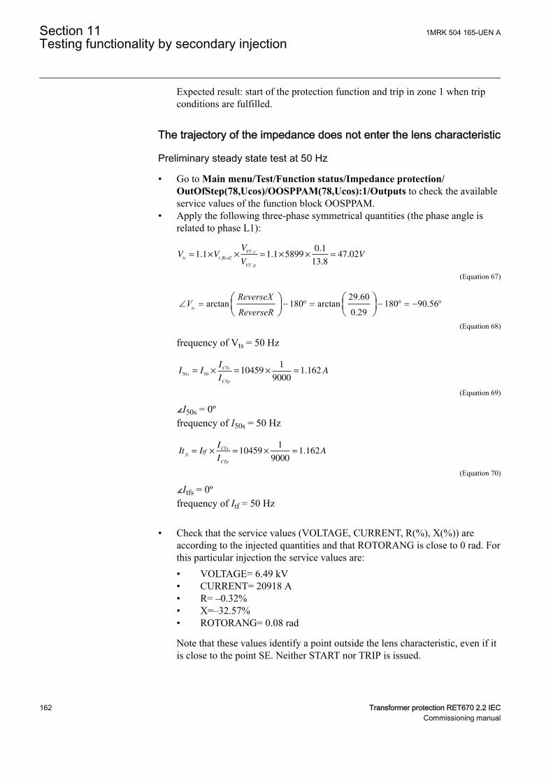
Expected result: start of the protection function and trip in zone 1 when tripconditions are fulfilled.
The trajectory of the impedance does not enter the lens characteristicGUID-189FECED-12A7-4A41-BCCF-D93C0FF9FA41 v1
Preliminary steady state test at 50 HzGUID-448D5357-6CC2-438E-83CA-25FD381B7DFF v1
• Go to Main menu/Test/Function status/Impedance protection/OutOfStep(78,Ucos)/OOSPPAM(78,Ucos):1/Outputs to check the availableservice values of the function block OOSPPAM.
• Apply the following three-phase symmetrical quantities (the phase angle isrelated to phase L1):
V VV
VV
ts t RvsZ
VT s
VT p
= × × = × × =1 1 1 1 58990 1
13 847 02. .
.
..
,
,
,
EQUATION14069 V1 EN-US (Equation 67)
29.60arctan 180 arctan 180 90.56
0.29ts
ReverseXV
ReverseRÐ = - ° = - ° = - °æ ö æ ö
ç ÷ ç ÷è ø è ø
EQUATION14068 V1 EN-US (Equation 68)
frequency of Vts = 50 Hz
I II
IA
s
CTs
CTp
50 5010459
1
90001 162= × = × = .
EQUATION14059 V1 EN-US (Equation 69)
∠I50s = 0ºfrequency of I50s = 50 Hz
It II
IA
fs
CTs
CTp
tf= × = × =104591
90001 162.
EQUATION14062 V1 EN-US (Equation 70)
∠Itfs = 0ºfrequency of Itf = 50 Hz
• Check that the service values (VOLTAGE, CURRENT, R(%), X(%)) areaccording to the injected quantities and that ROTORANG is close to 0 rad. Forthis particular injection the service values are:• VOLTAGE= 6.49 kV• CURRENT= 20918 A• R= –0.32%• X=–32.57%• ROTORANG= 0.08 rad
Note that these values identify a point outside the lens characteristic, even if itis close to the point SE. Neither START nor TRIP is issued.
Section 11 1MRK 504 165-UEN ATesting functionality by secondary injection
162 Transformer protection RET670 2.2 IECCommissioning manual
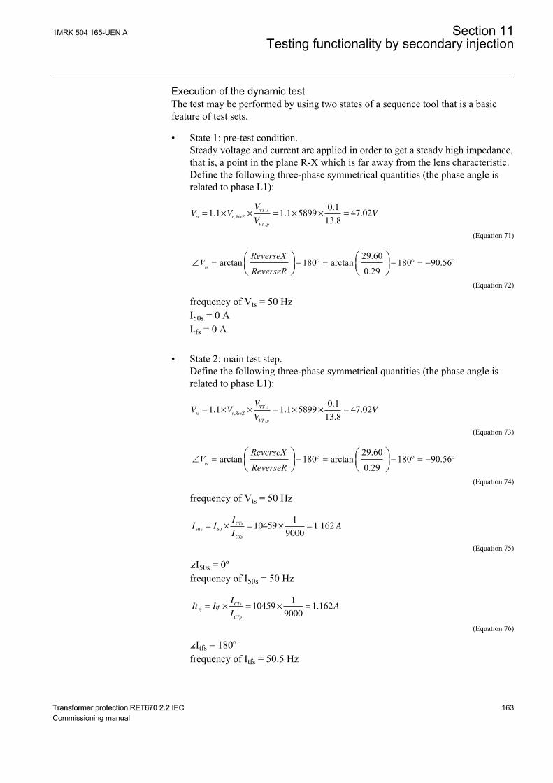
Execution of the dynamic testGUID-31EF4F76-8FC8-4952-896C-B3A8A5FD635A v1
The test may be performed by using two states of a sequence tool that is a basicfeature of test sets.
• State 1: pre-test condition.Steady voltage and current are applied in order to get a steady high impedance,that is, a point in the plane R-X which is far away from the lens characteristic.Define the following three-phase symmetrical quantities (the phase angle isrelated to phase L1):
V VV
VV
ts t RvsZ
VT s
VT p
= × × = × × =1 1 1 1 58990 1
13 847 02. .
.
..
,
,
,
EQUATION14069 V1 EN-US (Equation 71)
29.60arctan 180 arctan 180 90.56
0.29ts
ReverseXV
ReverseRÐ = - ° = - ° = - °æ ö æ ö
ç ÷ ç ÷è ø è ø
EQUATION14068 V1 EN-US (Equation 72)
frequency of Vts = 50 HzI50s = 0 AItfs = 0 A
• State 2: main test step.Define the following three-phase symmetrical quantities (the phase angle isrelated to phase L1):
V VV
VV
ts t RvsZ
VT s
VT p
= × × = × × =1 1 1 1 58990 1
13 847 02. .
.
..
,
,
,
EQUATION14069 V1 EN-US (Equation 73)
29.60arctan 180 arctan 180 90.56
0.29ts
ReverseXV
ReverseRÐ = - ° = - ° = - °æ ö æ ö
ç ÷ ç ÷è ø è ø
EQUATION14068 V1 EN-US (Equation 74)
frequency of Vts = 50 Hz
I II
IA
s
CTs
CTp
50 5010459
1
90001 162= × = × = .
EQUATION14059 V1 EN-US (Equation 75)
∠I50s = 0ºfrequency of I50s = 50 Hz
It II
IA
fs
CTs
CTp
tf= × = × =104591
90001 162.
EQUATION14062 V1 EN-US (Equation 76)
∠Itfs = 180ºfrequency of Itfs = 50.5 Hz
1MRK 504 165-UEN A Section 11Testing functionality by secondary injection
Transformer protection RET670 2.2 IEC 163Commissioning manual
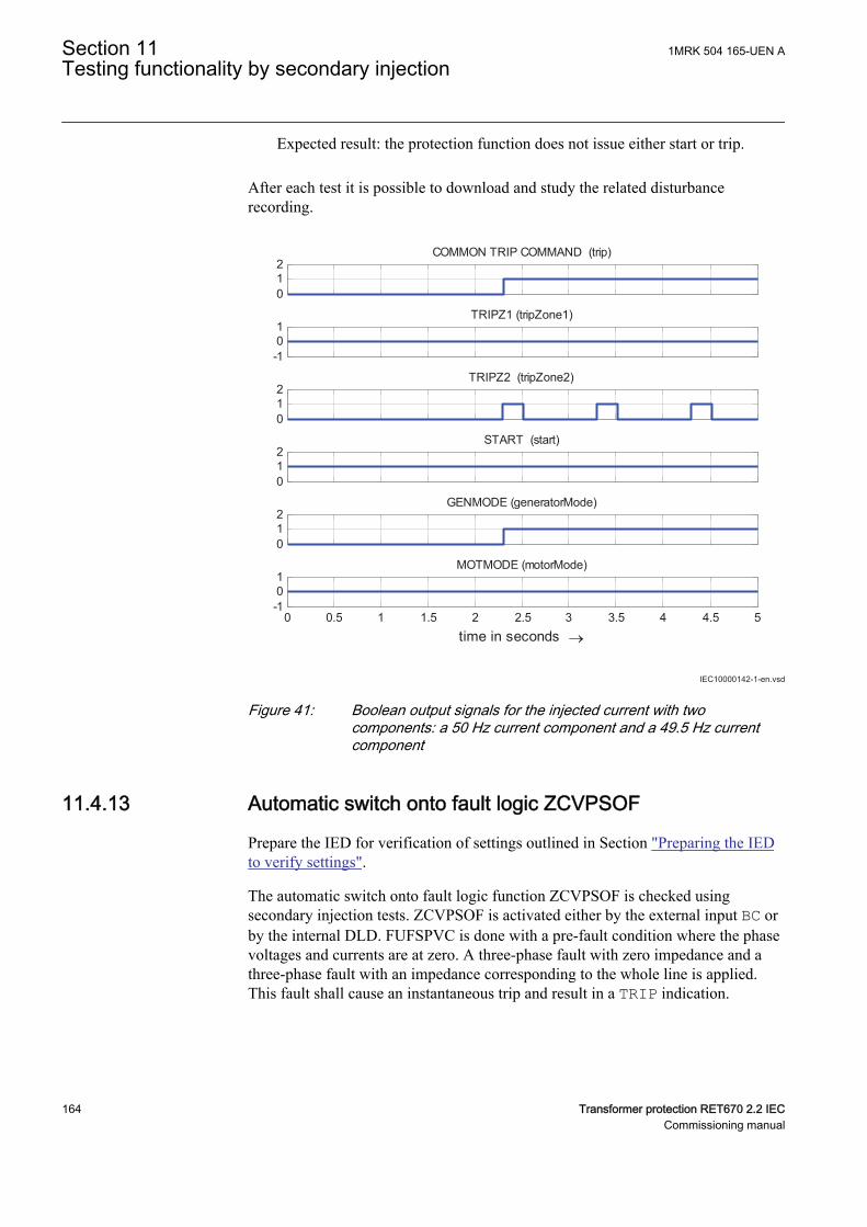
Expected result: the protection function does not issue either start or trip.
GUID-7C9F1163-0186-41DA-9D5F-DDA589323B9F v1
After each test it is possible to download and study the related disturbancerecording.
IEC10000142-1-en.vsd
012
COMMON TRIP COMMAND (trip)
-101
TRIPZ1 (tripZone1)
012
TRIPZ2 (tripZone2)
012
START (start)
012
GENMODE (generatorMode)
0 0.5 1 1.5 2 2.5 3 3.5 4 4.5 5-101
time in seconds →
MOTMODE (motorMode)
IEC10000142 V1 EN-US
Figure 41: Boolean output signals for the injected current with twocomponents: a 50 Hz current component and a 49.5 Hz currentcomponent
11.4.13 Automatic switch onto fault logic ZCVPSOFM13850-2 v9
Prepare the IED for verification of settings outlined in Section "Preparing the IEDto verify settings".
The automatic switch onto fault logic function ZCVPSOF is checked usingsecondary injection tests. ZCVPSOF is activated either by the external input BC orby the internal DLD. FUFSPVC is done with a pre-fault condition where the phasevoltages and currents are at zero. A three-phase fault with zero impedance and athree-phase fault with an impedance corresponding to the whole line is applied.This fault shall cause an instantaneous trip and result in a TRIP indication.
Section 11 1MRK 504 165-UEN ATesting functionality by secondary injection
164 Transformer protection RET670 2.2 IECCommissioning manual
11.4.13.1 Activating ZCVPSOF externallyM13850-14 v8
1. Set AutoInitMode to DLD disabled and Mode to Impedance.2. Activate the switch onto fault BC input.
During normal operating conditions, the BC input is de-energized.3. Apply a three-phase fault condition corresponding to a fault at approximately
45% of the line or with impedance at 50% of the used zone setting andcurrent greater than 30% of IBase.The ZACC input is activated.
4. Check that the TRIP output, external signals and indication are obtained.
11.4.13.2 Initiating ZCVPSOF automatically and setting mode to impedanceM13850-27 v8
1. Set AutoInitMode to Voltage and Mode to Impedance.2. Deactivate the switch onto fault BC input.3. Set the current and voltage inputs to lower than IPh< and UPh< for at least
one second.4. Apply a three-phase fault condition corresponding to a fault at approximately
45% of the line or with impedance at 50% of the used zone setting andcurrent greater than 30% of IBase.Apply a two-phase fault conditioncorresponding to a fault at approximately 45% of the line or with impedanceat 50% of the used zone setting and current greater than 30% of IBase.The ZACC input is activated.
5. Check that the correct TRIP output, external signals and indication areobtained.
11.4.13.3 Initiating ZCVPSOF automatically and setting mode to UILevelGUID-E83E1B3D-026C-48DB-BB9B-43C6597DE5DB v5
1. Set AutoInitMode to Voltage and Mode to UILevel.2. Deactivate the switch onto fault BC input.3. Set the current and voltage inputs to lower than IPh< and UPh< for at least
one second.4. Apply the three-phase currents in such a way that the magnitudes are greater
than IPh< and the three-phase voltages in such a way that the magnitudes andlower than UPh< at least for the duration of the tDuration setting.
5. Check that the correct TRIP output, external signals and indication areobtained.
11.4.13.4 Completing the testM13850-41 v5
Continue to test another function or end the test by changing the TESTMODEsetting to Off. Restore connections and settings to their original values, if they werechanged for testing purposes.
1MRK 504 165-UEN A Section 11Testing functionality by secondary injection
Transformer protection RET670 2.2 IEC 165Commissioning manual
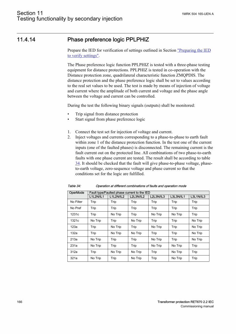
11.4.14 Phase preference logic PPLPHIZGUID-BD8EE7A0-710D-49C8-9B56-CB908BAF2C59 v7
Prepare the IED for verification of settings outlined in Section "Preparing the IEDto verify settings".
The Phase preference logic function PPLPHIZ is tested with a three-phase testingequipment for distance protections. PPLPHIZ is tested in co-operation with theDistance protection zone, quadrilateral characteristic function ZMQPDIS. Thedistance protection and the phase preference logic shall be set to values accordingto the real set values to be used. The test is made by means of injection of voltageand current where the amplitude of both current and voltage and the phase anglebetween the voltage and current can be controlled.
During the test the following binary signals (outputs) shall be monitored:
• Trip signal from distance protection• Start signal from phase preference logic
1. Connect the test set for injection of voltage and current.2. Inject voltages and currents corresponding to a phase-to-phase to earth fault
within zone 1 of the distance protection function. In the test one of the currentinputs (one of the faulted phases) is disconnected. The remaining current is thefault current out on the protected line. All combinations of two phase-to-earthfaults with one phase current are tested. The result shall be according to table34. It should be checked that the fault will give phase-to-phase voltage, phase-to-earth voltage, zero-sequence voltage and phase current so that theconditions set for the logic are fulfilled.
Table 34: Operation at different combinations of faults and operation mode
OperMode Fault type/Faulted phase current to the IEDL1L2N/IL1 L1L2N/IL2 L2L3N/IL2 L2L3N/IL3 L3L3N/IL1 L3L1N/IL3
No Filter Trip Trip Trip Trip Trip Trip
No Pref Trip Trip Trip Trip Trip Trip
1231c Trip No Trip Trip No Trip No Trip Trip
1321c No Trip Trip No Trip Trip Trip No Trip
123a Trip No Trip Trip No Trip Trip No Trip
132a Trip No Trip No Trip Trip Trip No Trip
213a No Trip Trip Trip No Trip Trip No Trip
231a No Trip Trip Trip No Trip No Trip Trip
312a Trip No Trip No Trip Trip No Trip Trip
321a No Trip Trip No Trip Trip No Trip Trip
Section 11 1MRK 504 165-UEN ATesting functionality by secondary injection
166 Transformer protection RET670 2.2 IECCommissioning manual
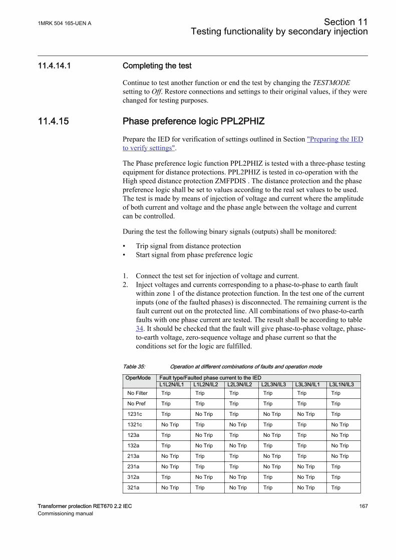
11.4.14.1 Completing the testGUID-8BD66BC8-AAC3-41C4-B819-B159361688D2 v4
Continue to test another function or end the test by changing the TESTMODEsetting to Off. Restore connections and settings to their original values, if they werechanged for testing purposes.
11.4.15 Phase preference logic PPL2PHIZGUID-E1547542-1407-4488-AD99-2A7D063885A4 v1
Prepare the IED for verification of settings outlined in Section "Preparing the IEDto verify settings".
The Phase preference logic function PPL2PHIZ is tested with a three-phase testingequipment for distance protections. PPL2PHIZ is tested in co-operation with theHigh speed distance protection ZMFPDIS . The distance protection and the phasepreference logic shall be set to values according to the real set values to be used.The test is made by means of injection of voltage and current where the amplitudeof both current and voltage and the phase angle between the voltage and currentcan be controlled.
During the test the following binary signals (outputs) shall be monitored:
• Trip signal from distance protection• Start signal from phase preference logic
1. Connect the test set for injection of voltage and current.2. Inject voltages and currents corresponding to a phase-to-phase to earth fault
within zone 1 of the distance protection function. In the test one of the currentinputs (one of the faulted phases) is disconnected. The remaining current is thefault current out on the protected line. All combinations of two phase-to-earthfaults with one phase current are tested. The result shall be according to table34. It should be checked that the fault will give phase-to-phase voltage, phase-to-earth voltage, zero-sequence voltage and phase current so that theconditions set for the logic are fulfilled.
Table 35: Operation at different combinations of faults and operation mode
OperMode Fault type/Faulted phase current to the IEDL1L2N/IL1 L1L2N/IL2 L2L3N/IL2 L2L3N/IL3 L3L3N/IL1 L3L1N/IL3
No Filter Trip Trip Trip Trip Trip Trip
No Pref Trip Trip Trip Trip Trip Trip
1231c Trip No Trip Trip No Trip No Trip Trip
1321c No Trip Trip No Trip Trip Trip No Trip
123a Trip No Trip Trip No Trip Trip No Trip
132a Trip No Trip No Trip Trip Trip No Trip
213a No Trip Trip Trip No Trip Trip No Trip
231a No Trip Trip Trip No Trip No Trip Trip
312a Trip No Trip No Trip Trip No Trip Trip
321a No Trip Trip No Trip Trip No Trip Trip
1MRK 504 165-UEN A Section 11Testing functionality by secondary injection
Transformer protection RET670 2.2 IEC 167Commissioning manual
11.4.16 Completing the testGUID-8BD66BC8-AAC3-41C4-B819-B159361688D2 v4
Continue to test another function or end the test by changing the TESTMODEsetting to Off. Restore connections and settings to their original values, if they werechanged for testing purposes.
11.4.17 Under impedance protection for Generator ZGVPDISGUID-F882501B-6A03-4409-BF70-DE1CF09E5541 v3
Prepare the IED for verification of settings.
Values of the logical signals for ZGVPDIS are available on the local HMI underMain menu/Tests/Function status/Impedance/ZGVPDIS (21G, Z<)/1:ZGVPDIS:ZGVPDIS. The Signal Monitoring in PCM600 shows the samesignals that are available on the local HMI.
11.4.17.1 Verifying the settingsGUID-202C5606-5F12-4C00-A12F-02A33EB571D9 v1
GUID-69610335-7C97-4134-8A47-05501AB5C620 v3
Distance protection zonesWhile measuring operating characteristics, keep the current constant. Keep thecurrent as close as possible to its rated value or lower, however make sure it ishigher than 30% of the rated current.
If the measurement of the operating characteristics runs under constant voltageconditions, ensure that the maximum continuous current in an IED does not exceedfour times its rated value.
To verify the zone 1 mho characteristic, at least two points must be tested.
Section 11 1MRK 504 165-UEN ATesting functionality by secondary injection
168 Transformer protection RET670 2.2 IECCommissioning manual
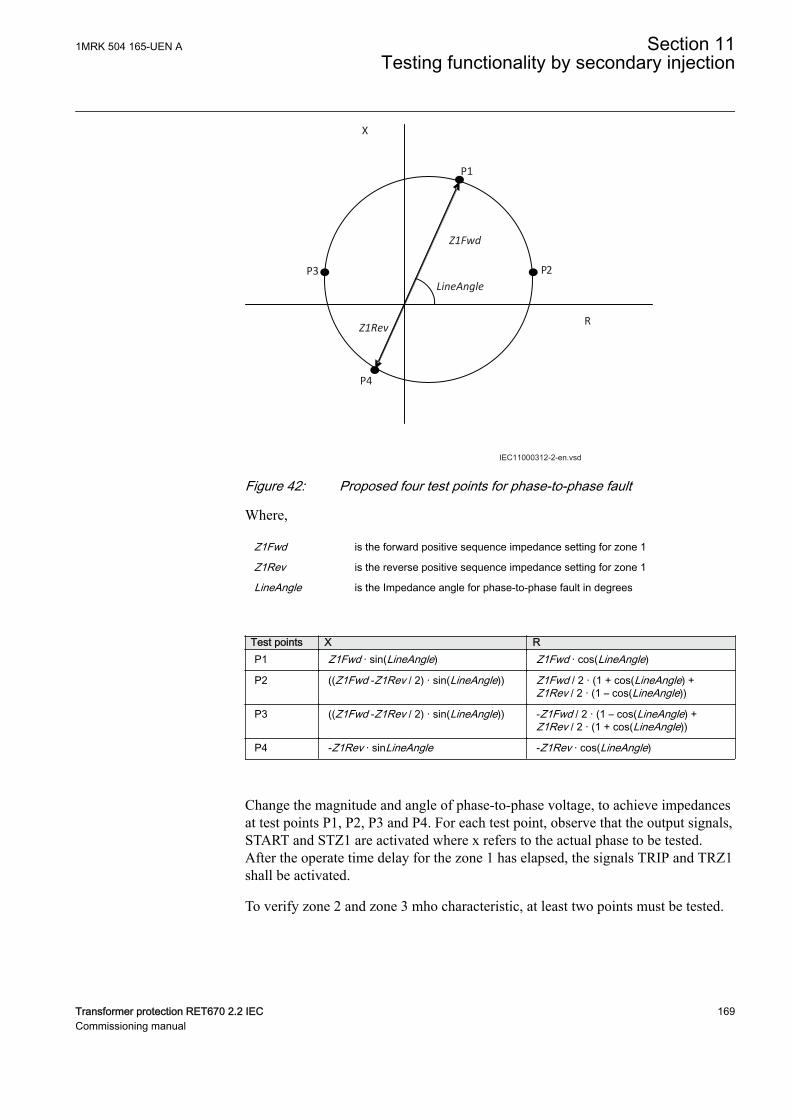
P1
P3
P4
X
R
LineAngle
Z1Fwd
Z1Rev
P2
IEC11000312-2-en.vsdIEC11000312 V2 EN-US
Figure 42: Proposed four test points for phase-to-phase fault
Where,
Z1Fwd is the forward positive sequence impedance setting for zone 1
Z1Rev is the reverse positive sequence impedance setting for zone 1
LineAngle is the Impedance angle for phase-to-phase fault in degrees
Test points X RP1 Z1Fwd · sin(LineAngle) Z1Fwd · cos(LineAngle)
P2 ((Z1Fwd -Z1Rev / 2) · sin(LineAngle)) Z1Fwd / 2 · (1 + cos(LineAngle) +Z1Rev / 2 · (1 – cos(LineAngle))
P3 ((Z1Fwd -Z1Rev / 2) · sin(LineAngle)) -Z1Fwd / 2 · (1 – cos(LineAngle) +Z1Rev / 2 · (1 + cos(LineAngle))
P4 -Z1Rev · sinLineAngle -Z1Rev · cos(LineAngle)
Change the magnitude and angle of phase-to-phase voltage, to achieve impedancesat test points P1, P2, P3 and P4. For each test point, observe that the output signals,START and STZ1 are activated where x refers to the actual phase to be tested.After the operate time delay for the zone 1 has elapsed, the signals TRIP and TRZ1shall be activated.
To verify zone 2 and zone 3 mho characteristic, at least two points must be tested.
1MRK 504 165-UEN A Section 11Testing functionality by secondary injection
Transformer protection RET670 2.2 IEC 169Commissioning manual
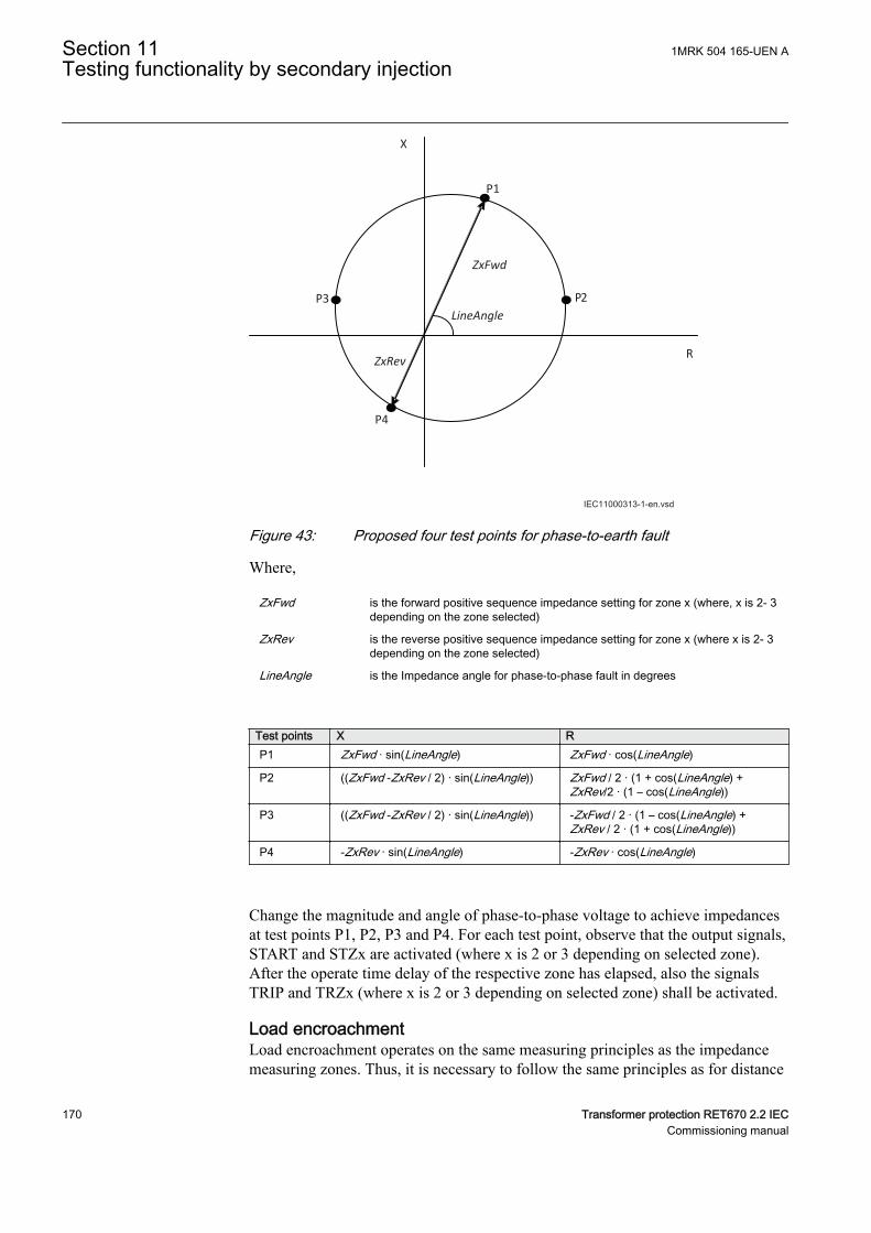
P1
P3
P4
X
R
LineAngle
ZxFwd
ZxRev
P2
IEC11000313-1-en.vsdIEC11000313 V2 EN-US
Figure 43: Proposed four test points for phase-to-earth fault
Where,
ZxFwd is the forward positive sequence impedance setting for zone x (where, x is 2- 3depending on the zone selected)
ZxRev is the reverse positive sequence impedance setting for zone x (where x is 2- 3depending on the zone selected)
LineAngle is the Impedance angle for phase-to-phase fault in degrees
Test points X RP1 ZxFwd · sin(LineAngle) ZxFwd · cos(LineAngle)
P2 ((ZxFwd -ZxRev / 2) · sin(LineAngle)) ZxFwd / 2 · (1 + cos(LineAngle) +ZxRev/2 · (1 – cos(LineAngle))
P3 ((ZxFwd -ZxRev / 2) · sin(LineAngle)) -ZxFwd / 2 · (1 – cos(LineAngle) +ZxRev / 2 · (1 + cos(LineAngle))
P4 -ZxRev · sin(LineAngle) -ZxRev · cos(LineAngle)
Change the magnitude and angle of phase-to-phase voltage to achieve impedancesat test points P1, P2, P3 and P4. For each test point, observe that the output signals,START and STZx are activated (where x is 2 or 3 depending on selected zone).After the operate time delay of the respective zone has elapsed, also the signalsTRIP and TRZx (where x is 2 or 3 depending on selected zone) shall be activated.
Load encroachmentGUID-4E0958A9-000E-440F-A880-89B54774AC63 v3
Load encroachment operates on the same measuring principles as the impedancemeasuring zones. Thus, it is necessary to follow the same principles as for distance
Section 11 1MRK 504 165-UEN ATesting functionality by secondary injection
170 Transformer protection RET670 2.2 IECCommissioning manual
protection when performing the secondary injection tests. Measure operatingcharacteristics during constant current conditions. Keep the injected current asclose as possible to the rated value of its associated input transformer or lower.Ensure, however, that it is higher than 30% of the rated current. Ensure that themaximum continuous current of an IED does not exceed four times Its rated value,if the measurement of the operating characteristics runs under constant voltageconditions.
Measuring the operate limit of set values of load encroachment function
The load encroachment does not have any special output to be verified. It can onlybe verified with the distance START and TRIP outputs.
Steps to test the load encroachment:
1. Supply the IED with healthy conditions for at least two seconds.2. Apply the fault condition and slowly decrease the injected impedance to find
the operate value for of the phase-to-earth and phase-to-phase loops.
Under voltage seal-inGUID-1219D2CC-D2EC-44B1-8F2E-A4C292590680 v2
The under voltage seal-in logic can be verified using the TRUV and STUV outputs.
Steps to verify the logic:
1. Keep all the current and voltage in normal balanced condition.2. Keeping the phase current at rated value, slowly reduce the voltage till it enters
into the respective zone mho characteristics and also below the set value of theunder voltage seal-in logic.
3. Before the operate time delay of the respective zone, reduce the currentmagnitude so that the operating impedance moves out of the mhocharacteristics.
4. The under voltage seal-in should give a START and TRIP after the operatetime delay is set for the under voltage logic.
11.4.17.2 Completing the testGUID-93110921-550A-441F-A36F-901488CC41BB v3
Continue to test another function or end the testing by setting the parameterTestMode to Off under Main menu/Tests/IED test mode/1: TESTMODE. Ifanother function is tested, then set the parameter Blocked to No under Main menu/Tests/Function test modes/Impedance/ZGVPDIS/1: ZGVPDIS for the function,or for each individual function in a chain, to be tested next. Remember to set theparameter Blocked to Yes, for each individual function that has been tested.
1MRK 504 165-UEN A Section 11Testing functionality by secondary injection
Transformer protection RET670 2.2 IEC 171Commissioning manual
11.5 Current protectionSEMOD53531-1 v1
11.5.1 Instantaneous phase overcurrent protection 3-phase outputPHPIOC
M11754-3 v8
Prepare the IED for verification of settings outlined in Section "Preparing the IEDto verify settings".
Values of the logical signals for PHPIOC are available on the local HMI underMain menu/Tests/Function status/Current protection/InstPhaseOverCurrent(50,3I>>)/PHPIOC(50;3I>>):x, where x = 1, 2, and 3.
The Signal Monitoring in PCM600 shows the same signals that are available on thelocal HMI.
To verify the settings the following fault type should be tested:
• Phase-to-earth fault
Ensure that the maximum continuous current, supplied from the current sourceused for the test of the IED, does not exceed four times the rated current value ofthe IED.
11.5.1.1 Measuring the operate limit of set valuesM11754-11 v7
1. Set the operation mode to 1 out of 3.2. Inject a phase current into the IED with an initial value below the set value of
IP>> and also make sure that the set value IP>> is in between IP>>Min andIP>>Max.
3. Increase the injected current in the Ln phase until the TRLn (n=1–3) signalappears.
4. Switch the fault current off.
Observe: Do not exceed the maximum permitted overloadingof the current circuits in the IED.
5. Compare the measured operating current with the set value.6. Set the operation mode to 2 out of 3 and inject current into one of the phases
and then check that no TRLn signal appears.
11.5.1.2 Completing the testM11754-24 v5
Continue to test another function or end the test by changing the TESTMODEsetting to Off. Restore connections and settings to their original values, if they werechanged for testing purposes.
Section 11 1MRK 504 165-UEN ATesting functionality by secondary injection
172 Transformer protection RET670 2.2 IECCommissioning manual
11.5.2 Directional phase overcurrent protection, four stepsOC4PTOC
SEMOD56287-67 v9
Prepare the IED for verification of settings outlined in Section "Preparing the IEDto verify settings".
Values of the logical signals for OC4PTOC are available on the local HMI underMain menu/Tests/Function status/Current protection/PhaseOverCurrent4Step(51_67,4(3I>))/OC4PTOC(51_67;4(3I>)):x, where x =instance number.
The Signal Monitoring in PCM600 shows the same signals that are available on thelocal HMI.
11.5.2.1 Verifying the settingsSEMOD56287-72 v10
The verification of the non-directional phase overcurrent function isdone as instructed below, but without applying any polarizingvoltage.
1. Connect the test set for current injection to the appropriate IED phases.If there is any configuration logic that is used to enable or block any of thefour available overcurrent steps, make sure that the step under test is enabled(for example, end fault protection).If 1 out of 3 currents are chosen for operation: Connect the injection currentto phases L1 and neutral.If 2 out of 3 currents are chosen for operation: Connect the injection currentinto phase L1 and out from phase L2.If 3 out of 3 currents are chosen for operation: Connect the symmetrical three-phase injection current into phases L1, L2 and L3.
2. Connect the test set for the appropriate three-phase voltage injection to theIED phases L1, L2 and L3. The protection shall be fed with a symmetricalthree-phase voltage.
3. Block higher set stages when testing lower set stages by following theprocedure described below:3.1. Set the injected polarizing voltage larger than the set minimum
polarizing voltage (default is 5% of UBase) and set the injection currentto lag the appropriate voltage by an angle of about 80° if forwarddirectional function is selected.If 1 out of 3 currents are chosen for operation: The voltage angle ofphase L1 is the reference.If 2 out of 3 currents are chosen for operation: The phase angle of thephase-to-phase voltage L1L2 is the reference for L1Phase.If 3 out of 3 currents are chosen for operation: The voltage angle ofphase L1 is the reference.
1MRK 504 165-UEN A Section 11Testing functionality by secondary injection
Transformer protection RET670 2.2 IEC 173Commissioning manual
If reverse directional function is selected, set the injection current to lagthe polarizing voltage by an angle equal to 260° (equal to 80° + 180°).
3.2. Increase the injected current, note the operate value of the tested step ofthe function and compare it to the set value.
3.3. Decrease the current slowly, note the reset value and compare it to thereset ratio 95%.
4. If the test has been performed by injection of current in phase L1, repeat thetest, injecting current into phases L2 and L3 with polarizing voltageconnected to phases L2, respectively L3 (1 out of 3 currents for operation).
5. If the test has been performed by injection of current in phases L1 – L2,repeat the test, injecting current into phases L2 – L3 and L3 – L1 with theappropriate phase angle of injected currents.
6. Connect a trip output contact to a timer.7. Set the injected current to 200% of the operate level of the tested stage,
switch on the current and check the time delay.For inverse time curves, check the operate time at a current equal to 110% ofthe operate current for txMin.
8. Check that all operate and start contacts operate according to theconfiguration (signal matrixes).
9. Reverse the direction of the injected current and check that the protectiondoes not operate.
10. If 2 out of 3 or 3 out of 3 currents are chosen for operation: Check that thefunction will not operate with current in one phase only.
11. Repeat the above described tests for the higher set stages.12. Check that start and trip information is stored in the event menu .
11.5.2.2 Completing the testSEMOD56287-118 v4
Continue to test another function or end the test by changing the TESTMODEsetting to Off. Restore connections and settings to their original values, if they werechanged for testing purposes.
11.5.3 Instantaneous residual overcurrent protection EFPIOCSEMOD52967-3 v7
Prepare the IED for verification of settings outlined in Section "Preparing the IEDto verify settings".
Values of the logical signals for EFPIOC are available on the local HMI underMain menu/Tests/Function status/Current protection/InstResidualOverCurrent(50N,IN>>)/EFPIOC(50N;IN>>):x, where x = 1, 2,and 3.
The Signal Monitoring in PCM600 shows the same signals that are available on thelocal HMI.
To verify the settings the following fault type should be tested:
• Phase-to-earth fault
Section 11 1MRK 504 165-UEN ATesting functionality by secondary injection
174 Transformer protection RET670 2.2 IECCommissioning manual
Ensure that the maximum continuous current, supplied from the current sourceused for the test of the IED, does not exceed four times the rated current value ofthe IED.
11.5.3.1 Measuring the operate limit of set valuesSEMOD52967-11 v9
1. Inject a phase current into the IED with an initial value below the set value ofIN>> and also make sure that the set value IN>> is in between IN>>Min andIN>>Max.
2. Increase the injected current in the Ln or in the neutral (summated currentinput) phase until the TRIP signal appears.
3. Switch the fault current off.
Do not exceed the maximum permitted overloading of thecurrent circuits in the IED.
4. Compare the measured operating current with the set value.
11.5.3.2 Completing the testSEMOD52967-24 v5
Continue to test another function or end the test by changing the TESTMODEsetting to Off. Restore connections and settings to their original values, if they werechanged for testing purposes.
11.5.4 Four step residual overcurrent protection, (Zero sequenceor negative sequence directionality) EF4PTOC
SEMOD53296-3 v9
Prepare the IED for verification of settings outlined in Section "Preparing the IEDto verify settings".
Values of the logical signals for D2PTOC are available on the local HMI underMain menu/Tests/Function status/Current protection/ResidualOverCurr4Step(51N_67N,4(IN>))/EF4PTOC(51N_67N;4(IN>)):x,where x = instance number.
The Signal Monitoring in PCM600 shows the same signals that are available on thelocal HMI.
11.5.4.1 Four step directional earth fault protectionSEMOD53296-208 v7
1. Connect the test set for single current injection to the appropriate IEDterminals.
1MRK 504 165-UEN A Section 11Testing functionality by secondary injection
Transformer protection RET670 2.2 IEC 175Commissioning manual
Connect the injection current to terminals L1 and neutral.2. Set the injected polarizing voltage slightly larger than the set minimum
polarizing voltage (5% of Ur) and set the injection current to lag the voltageby an angle equal to the set reference characteristic angle (AngleRCA), if theforward directional function is selected.If reverse directional function is selected, set the injection current to lag thepolarizing voltage by an angle equal to RCA+ 180°.
3. Increase the injected current and note the value at which the studied step ofthe function operates.
4. Decrease the current slowly and note the reset value.5. If the test has been performed by injection of current in phase L1, repeat the
test, injecting current into terminals L2 and L3 with a polarizing voltageconnected to terminals L2, respectively L3.
6. Block lower set steps when testing higher set steps according to theinstructions that follow.
7. Connect a trip output contact to a timer.8. Set the injected current to 200% of the operate level of the tested step, switch
on the current and check the time delay.For inverse time curves, check the operate time at a current equal to 110% ofthe operate current for txMin.
9. Check that all operate and start contacts operate according to theconfiguration (signal matrixes)
10. Reverse the direction of the injected current and check that the step does notoperate.
11. Check that the protection does not operate when the polarizing voltage iszero.
12. Repeat the above described tests for the higher set steps.13. Finally, check that start and trip information is stored in the event menu.
11.5.4.2 Four step non-directional earth fault protectionSEMOD53296-202 v4
1. Do as described in "Four step directional earth fault protection", but withoutapplying any polarizing voltage.
11.5.4.3 Completing the testSEMOD53296-122 v4
Continue to test another function or end the test by changing the TESTMODEsetting to Off. Restore connections and settings to their original values, if they werechanged for testing purposes.
11.5.5 Four step negative sequence overcurrent protectionNS4PTOC
GUID-EB1A8DFD-5BAC-4024-ADA2-D9BE7A2B50A0 v2
Prepare the IED for verification of settings as outlined in section "Preparing fortest" in this chapter.
Section 11 1MRK 504 165-UEN ATesting functionality by secondary injection
176 Transformer protection RET670 2.2 IECCommissioning manual
GUID-F7AA2194-4D1C-4475-8853-C7D064912614 v4
When inverse time overcurrent characteristic is selected, theoperate time of the stage will be the sum of the inverse time delayand the set definite time delay. Thus, if only the inverse time delayis required, it is important to set the definite time delay for thatstage to zero.
GUID-F973601F-BC67-4E4F-A4CA-BE6253E2FB92 v3
Procedure
1. Connect the test set for injection of three-phase currents and voltages to theappropriate CT and VT inputs of the IED.
2. Inject pure negative sequence current, that is, phase currents with exactlysame magnitude, reversed sequence and exactly 120° phase displaced into theIED with an initial value below negative sequence current pickup level. Nooutput signals should be activated. Check under NS4PTOC function ServiceValues that correct I2 magnitude is measured by the function.
3. Set the injected negative sequence polarizing voltage slightly larger than theset minimum polarizing voltage (default 5 % of Ub) and set the injectioncurrent to lag the voltage by an angle equal to the set reference characteristicangle (180° - AngleRCA) if the forward directional function is selected.If reverse directional function is selected, set the injection current to lag thepolarizing voltage by an angle equal to RCA.
4. Increase the injected current and note the value at which the studied step ofthe function operates.
5. Decrease the current slowly and note the reset value.6. Block lower set steps when testing higher set steps according to the
instructions that follow.7. Connect a trip output contact to a timer.8. Set the injected current to 200% of the operate level of the tested step, switch
on the current and check the time delay.For inverse time curves, check the operate time at a current equal to 110% ofthe operate current in order to test parameter txmin.
9. Check that all operate and start contacts operate according to theconfiguration (signal matrixes)
10. Reverse the direction of the injected current and check that the step does notoperate.
11. Check that the protection does not operate when the polarizing voltage iszero.
12. Repeat the above-described tests for the higher set steps.13. Finally, check that start and trip information is stored in the event menu.
11.5.5.1 Completing the testSEMOD53296-122 v4
Continue to test another function or end the test by changing the TESTMODEsetting to Off. Restore connections and settings to their original values, if they werechanged for testing purposes.
1MRK 504 165-UEN A Section 11Testing functionality by secondary injection
Transformer protection RET670 2.2 IEC 177Commissioning manual
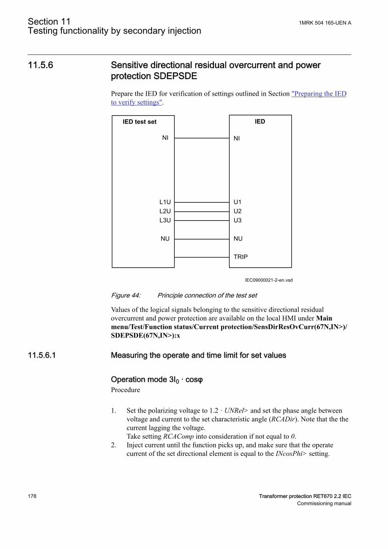
11.5.6 Sensitive directional residual overcurrent and powerprotection SDEPSDE
SEMOD175060-3 v7
Prepare the IED for verification of settings outlined in Section "Preparing the IEDto verify settings".
IEC09000021-2-en.vsd
IED test set
NI
IED
NI
L1UL2UL3U
NU
U1U2U3
NU
TRIP
IEC09000021 V2 EN-US
Figure 44: Principle connection of the test set
Values of the logical signals belonging to the sensitive directional residualovercurrent and power protection are available on the local HMI under Mainmenu/Test/Function status/Current protection/SensDirResOvCurr(67N,IN>)/SDEPSDE(67N,IN>):x
11.5.6.1 Measuring the operate and time limit for set valuesSEMOD175060-12 v2
Operation mode 3I0 · cosφSEMOD175060-34 v9
Procedure
1. Set the polarizing voltage to 1.2 · UNRel> and set the phase angle betweenvoltage and current to the set characteristic angle (RCADir). Note that the thecurrent lagging the voltage.Take setting RCAComp into consideration if not equal to 0.
2. Inject current until the function picks up, and make sure that the operatecurrent of the set directional element is equal to the INcosPhi> setting.
Section 11 1MRK 504 165-UEN ATesting functionality by secondary injection
178 Transformer protection RET670 2.2 IECCommissioning manual
The I Dir (3I0 · cosφ) function activates the START and STDIRIN output.3. Assume that φ´ is the phase angle between injected voltage (3U0) and current
(3I0) i.e. φ´ = RCADir-φ. Change φ´ to for example 45 degrees. Increase theinjected current until the function operates.
4. Compare the result with the set value and make sure that the new injected 3I0· cos φ is equal to the setting INcosPhi>..Take the set characteristic into consideration, see Figure 45 and Figure 46.
5. Measure the operate time of the timer by injecting a current two times the setINcosPhi> value and the polarizing voltage 1.2 · UNRel>.
( )0 0 cos3 3test test
kSN SrefTinv
I U j
×=
× ×IECEQUATION2402 V2 EN-US (Equation 77)
6. Compare the result with the expected value.The expected value depends on whether definite or inverse time was selected.
7. Set the polarizing voltage to zero and increase until the boolean output signalUNREL is activated, which is visible in the Application Configuration inPCM600 when the IED is in online mode. Compare the voltage with the setvalue UNRel> .
8. Continue to test another function or complete the test by setting the test modeto Off.
1MRK 504 165-UEN A Section 11Testing functionality by secondary injection
Transformer protection RET670 2.2 IEC 179Commissioning manual
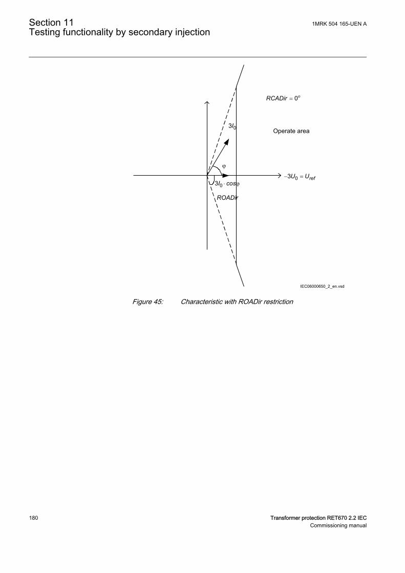
Operate area
ROADir
IEC06000650_2_en.vsd
= o0RCADir
03I
j
03 × jI cos- =03 refU U
IEC06000650 V2 EN-US
Figure 45: Characteristic with ROADir restriction
Section 11 1MRK 504 165-UEN ATesting functionality by secondary injection
180 Transformer protection RET670 2.2 IECCommissioning manual
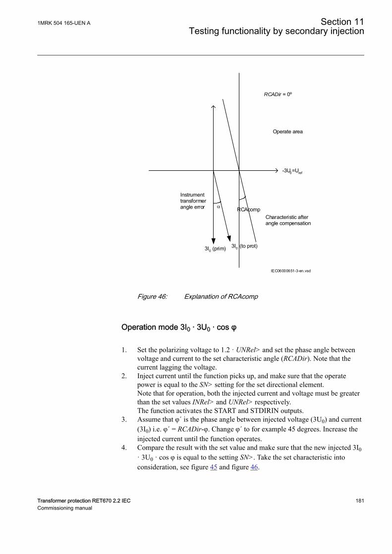
-3U0=Uref
Operate area
Instrumenttransformerangle error
3I0 (prim) 3I0 (to prot)
Characteristic afterangle compensation
RCAcomp
IEC06000651-3-en.vsd
RCADir = 0º
IEC06000651 V3 EN-US
Figure 46: Explanation of RCAcomp
Operation mode 3I0 · 3U0 · cos φSEMOD175060-76 v8
1. Set the polarizing voltage to 1.2 · UNRel> and set the phase angle betweenvoltage and current to the set characteristic angle (RCADir). Note that thecurrent lagging the voltage.
2. Inject current until the function picks up, and make sure that the operatepower is equal to the SN> setting for the set directional element.Note that for operation, both the injected current and voltage must be greaterthan the set values INRel> and UNRel> respectively.The function activates the START and STDIRIN outputs.
3. Assume that φ´ is the phase angle between injected voltage (3U0) and current(3I0) i.e. φ´ = RCADir-φ. Change φ´ to for example 45 degrees. Increase theinjected current until the function operates.
4. Compare the result with the set value and make sure that the new injected 3I0· 3U0 · cos φ is equal to the setting SN>. Take the set characteristic intoconsideration, see figure 45 and figure 46.
1MRK 504 165-UEN A Section 11Testing functionality by secondary injection
Transformer protection RET670 2.2 IEC 181Commissioning manual
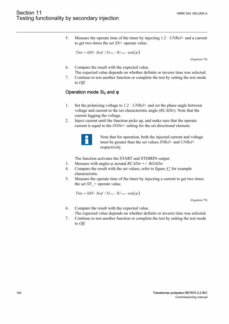
5. Measure the operate time of the timer by injecting 1.2 · UNRel> and a currentto get two times the set SN> operate value.
( )0 0/ 3 3 costest testTinv kSN Sref I U j= × × ×
IECEQUATION2403 V1 EN-US (Equation 78)
6. Compare the result with the expected value.The expected value depends on whether definite or inverse time was selected.
7. Continue to test another function or complete the test by setting the test modeto Off.
Operation mode 3I0 and φSEMOD175060-87 v8
1. Set the polarizing voltage to 1.2 · UNRel> and set the phase angle betweenvoltage and current to the set characteristic angle (RCADir). Note that thecurrent lagging the voltage.
2. Inject current until the function picks up, and make sure that the operatecurrent is equal to the INDir> setting for the set directional element.
Note that for operation, both the injected current and voltagemust be greater than the set values INRel> and UNRel>respectively.
The function activates the START and STDIRIN output.3. Measure with angles j around RCADir +/- ROADir.4. Compare the result with the set values, refer to figure 47 for example
characteristic.5. Measure the operate time of the timer by injecting a current to get two times
the set SN_> operate value.
( )0 0/ 3 3 costest testTinv kSN Sref I U j= × × ×
IECEQUATION2403 V1 EN-US (Equation 79)
6. Compare the result with the expected value.The expected value depends on whether definite or inverse time was selected.
7. Continue to test another function or complete the test by setting the test modeto Off.
Section 11 1MRK 504 165-UEN ATesting functionality by secondary injection
182 Transformer protection RET670 2.2 IECCommissioning manual
-3U0
Operate area
3I0
RCADir = 0º
ROADir = 80º
IEC06000652-3-en.vsdIEC06000652 V3 EN-US
Figure 47: Example characteristic
Non-directional earth fault current protectionSEMOD175060-117 v10
Procedure
1. Measure that the operate current is equal to the INNonDir> setting.The function activates the START and STDIRIN output.
2. Measure the operate time of the timer by injecting a current of 200% of theoperate value.
3. Compare the result with the expected value.The expected value depends on whether definite time tINNonDir or inversetime was selected.
4. Continue to test another function or complete the test by setting the test modeto Off.
Residual overvoltage release and protectionSEMOD175060-131 v6
Procedure
1. Measure that the operate voltage is equal to the UN> setting.The function activates the START and STUN signals.
2. Measure the operate time by injecting a voltage 1.2 times set UN> operatevalue.
3. Compare the result with the set tUN operate value.4. Inject a voltage 0.8 · UNRel> and a current high enough to operate the
directional function at the chosen angle.5. Increase the voltage until the directional function is released.6. Compare the measured value with the set UNRel> operate value.
1MRK 504 165-UEN A Section 11Testing functionality by secondary injection
Transformer protection RET670 2.2 IEC 183Commissioning manual
11.5.6.2 Completing the testSEMOD175060-148 v4
Continue to test another function or end the test by changing the TESTMODEsetting to Off. Restore connections and settings to their original values, if they werechanged for testing purposes.
11.5.7 Thermal overload protection, two time constants TRPTTRSEMOD53632-3 v5
Prepare the IED for verification of settings outlined in Section "Preparing the IEDto verify settings".
11.5.7.1 Checking operate and reset valuesSEMOD53632-11 v7
1. Connect symmetrical three-phase currents to the appropriate current terminalsof the IED.
2. Set the Time constant 1 (Tau1) and Time Constant 2 (Tau2) temporarily to 1minute.
3. Set the three-phase injection currents slightly lower than the set operate valueof stage IBase1, increase the current in phase L1 until stage IBase1operatesand note the operate value.
Observe the maximum permitted overloading of the currentcircuits in the IED.
4. Decrease the current slowly and note the reset value.
Check, in the same way, the operate and reset values of IBase1 for phases L2and L3.
5. Activate the cooling input signal, thus switching to base current IBase2.6. Check the operate and reset values (for all three phases) for IBase2 in the
same way as described above for stage IBase1.7. Deactivate the input signal for stage IBase2.8. Set the time constant for IBase1 in accordance with the setting plan.9. Set the injection current for phase L1 to 1.50 · IBase1.10. Connect a trip output contact to the timer and monitor the output of contacts
ALARM1 and ALARM2 to digital inputs in test equipment.Read the heat content in the thermal protection from the local HMI and waituntil the content is zero.
11. Switch on the injection current and check that ALARM1 and ALARM2contacts operate at the set percentage level and that the operate time fortripping is in accordance with the set Time Constant 1 (Tau1).With setting Itr = 101%IBase1 and injection current 1.50 · IBase1, the triptime from zero content in the memory shall be 0.60 · Time Constant 1 (Tau1).
12. Check that all trip and alarm contacts operate according to the configurationlogic.
Section 11 1MRK 504 165-UEN ATesting functionality by secondary injection
184 Transformer protection RET670 2.2 IECCommissioning manual
13. Switch off the injection current and check from the service menu readings ofthermal status and LOCKOUT that the lockout resets at the set percentage ofheat content.
14. Activate the cooling input signal to switch over to base current IBase2.Wait 5 minutes to empty the thermal memory and set Time Constant 2 (Tau2)in accordance with the setting plan.
15. Test with injection current 1.50 · IBase2 the thermal alarm level, the operatetime for tripping and the lockout reset in the same way as described for stageIBase1.
16. Finally check that start and trip information is stored in the event menu.
11.5.7.2 Completing the testSEMOD53632-51 v5
Continue to test another function or end the test by changing the TESTMODEsetting to Off. Restore connections and settings to their original values, if they werechanged for testing purposes.
11.5.8 Breaker failure protection, phase segregated activation andoutput CCRBRF
M12104-2 v12
Prepare the IED for verification of settings outlined in Section "Preparing the IEDto verify settings".
The Breaker failure protection, 3-phase activation and output function CCRBRFshould normally be tested in conjunction with some other function that provides astart signal. An external START signal can also be used.
To verify the settings in the most common back-up trip mode 1 out of 3, it issufficient to test phase-to-earth faults.
At mode 2 out of 4 the phase current setting, IP> can be checked by single-phaseinjection where the return current is connected to the summated current input. Thevalue of residual (earth fault) current IN set lower than IP> is easiest checked inback-up trip mode 1 out of 4.
11.5.8.1 Checking the phase current operate value, IP>M12104-23 v13
The check of the IP> current level is best made in FunctionMode = Current andBuTripMode = 1 out of 3 or 2 out of 4.
1. Apply the fault condition, including START of CCRBRF, with a currentbelow the set IP>.
2. Repeat the fault condition and increase the current in steps until a trip occurs.3. Compare the result with the set IP>.
1MRK 504 165-UEN A Section 11Testing functionality by secondary injection
Transformer protection RET670 2.2 IEC 185Commissioning manual

If No CBPos Check or Retrip off is set, only back-up trip can beused to check set IP>.
11.5.8.2 Checking the residual (earth fault) current operate value IN> setbelow IP>
M12104-80 v9
Check the low set IN> current where setting FunctionMode = Current and settingBuTripMode = 1 out of 4
1. Apply the fault condition, including START of CCRBRF, with a current justbelow set IN>.
2. Repeat the fault condition and increase the current in steps until trip appears.3. Compare the result with the set IN>.4. Disconnect AC and START input signals.
11.5.8.3 Checking the re-trip and back-up timesM12104-93 v11
The check of the set times can be made in connection with the check of operatevalues above.
Choose the applicable function and trip mode, such as FunctionMode = Currentand RetripMode = CB Pos Check .
1. Apply the fault condition, including start of CCRBRF, well above the setcurrent value. Measure the time from START of CCRBRF.
2. Check the re-trip t1 and back-up trip times t2 and t3.In applicable cases, the back-up trip for multi-phase start t2MPh and back-uptrip 2, t2 and t3 can also be checked. To check t2MPh, a two-phase or three-phase start shall be applied.
11.5.8.4 Verifying the re-trip modeM12104-36 v6
Choose the mode below, which corresponds to the actual case.
In the cases below it is assumed that FunctionMode = Current is selected.
Checking the case without re-trip, RetripMode = Retrip OffM12104-107 v7
1. Set RetripMode = Retrip Off.2. Apply the fault condition, including start of CCRBRF, well above the set
current value.3. Verify that no re-trip, but back-up trip is achieved after set time.
Checking the re-trip with current check, RetripMode = CB Pos CheckM12104-48 v7
Section 11 1MRK 504 165-UEN ATesting functionality by secondary injection
186 Transformer protection RET670 2.2 IECCommissioning manual
1. Set RetripMode = CB Pos Check.2. Apply the fault condition, including start of CCRBRF, well above the set
current value.3. Verify that re-trip is achieved after set time t1 and back-up trip after time t2.4. Apply the fault condition, including the start of CCRBRF, with the current
below the set current value.5. Verify that no re-trip and no back-up trip are obtained.
Checking re-trip without current checkM12104-58 v9
1. Set RetripMode = No CBPos Check.2. Apply the fault condition, including start of CCRBRF, well above the set
current value.3. Verify that re-trip is achieved after the set time t1, and the back-up trip after
time t2.4. Apply the fault condition, including start of CCRBRF, with current below set
current value.5. Verify that re-trip is achieved after set time t1, but no back-up trip is obtained.
11.5.8.5 Verifying the back-up trip modeM12104-146 v5
In the cases below it is assumed that FunctionMode = Current is selected.
Checking that back-up tripping is not achieved at normal CB trippingM12104-150 v8
Use the actual tripping modes. The case below applies to re-trip with current check.
1. Apply the fault condition, including start of CCRBRF, with phase currentwell above set value IP>.
2. Interrupt the current, with a margin before back-up trip time, t2. It may bemade at issue of re-trip command.
3. Check that re-trip is achieved, if selected, but no back-up trip is obtained.
The normal mode BuTripMode = 1 out of 3 should have been verified in the testsabove. In applicable cases the modes 1 out of 4 and 2 out of 4 can be checked.Choose the mode below, which corresponds to the actual case.
Checking the case BuTripMode = 1 out of 4M12104-165 v6
It is assumed that the earth-fault current setting IN> is below phase current settingIP>.
1. Set BuTripMode = 1 out of 4.2. Apply the fault condition, including start of CCRBRF, with one-phase current
below set IP> but above IN>. The residual earth-fault should then be aboveset IN>.
3. Verify that back-up trip is achieved after set time. If selected, re-trip shouldalso appear.
4. Disconnect AC and START input signals.
1MRK 504 165-UEN A Section 11Testing functionality by secondary injection
Transformer protection RET670 2.2 IEC 187Commissioning manual
Checking the case BuTripMode = 2 out of 4M12104-179 v7
The earth-fault current setting IN> may be equal to or below phase-current settingIP>.
1. Set BuTripMode = 2 out of 4.2. Apply the fault condition, including start of CCRBRF, with one-phase current
above set IP> and residual (earth fault) above set IN>.3. Verify that back-up trip is achieved after set time. If selected, re-trip should
also appear.4. Apply the fault condition, including start of CCRBRF, with at least one-phase
current below set IP> and residual (earth fault) above set IN>. The currentmay be arranged by feeding three- (or two-) phase currents with equal phaseangle (I0-component) below IP>, but of such value that the residual (earthfault) current (3I0) will be above set value IN>.
5. Verify that back-up trip is not achieved.6. Disconnect AC and START input signals.
11.5.8.6 Verifying instantaneous back-up trip at CB faulty conditionM12104-197 v7
Applies in a case where a signal from CB supervision function regarding CB beingfaulty and unable to trip is connected to input CBFLT.
1. Repeat the check of back-up trip time. Disconnect current and START inputsignals.
2. Activate the input CBFLT. The output CBALARM (CB faulty alarm) shouldappear after set time tCBAlarm. Keep the input activated.
3. Apply the fault condition, including start of CCRBRF, with current above setcurrent value.
4. Verify that back-up trip is obtained without intentional delay, for examplewithin 20ms from application of start.
11.5.8.7 Verifying the function mode Current/ContactM12104-237 v6
To be made only when FunctionMode = Current/Contact is selected. It is suggestedto make the tests in one phase only, or at three-phase trip applications for just three-phase tripping.
Checking the case with fault current above set value IP>M12104-241 v7
The operation shall be as in FunctionMode = Current.
1. Set FunctionMode = Current/Contact.2. Leave the inputs for CB close inactivated. These signals should not influence.3. Apply the fault condition, including the start of CCRBRF, with the current
above the set IP> value.4. Check that the re-trip, if selected, and back-up trip commands are achieved.
Section 11 1MRK 504 165-UEN ATesting functionality by secondary injection
188 Transformer protection RET670 2.2 IECCommissioning manual
Checking the case with fault current below set value I>BlkContM12104-281 v10
It simulates a case where the fault current is very low and operation will depend onCB position signal from CB auxiliary contact. It is suggested that re-trip withoutcurrent check is used, setting RetripMode = No CBPos Check.
1. Set FunctionMode = Current/Contact.2. Apply input signal for CB closed to the relevant input or inputs CBCLDL1 (2
or 3).3. Apply the fault condition with input signal(s) for start of CCRBRF. The value
of current should be below the set value I>BlkCont.4. Verify that phase selection re-trip (if selected) and back-up trip are achieved
after set times. Failure to trip is simulated by keeping the signal(s) CB closedactivated.
5. Disconnect the input signal and the START signal(s). Keep the CB closedsignal(s).
6. Apply the fault and the start again. The value of current should be below theset value I>BlkCont.
7. Arrange disconnection of BC closed signal(s) well before set back-up triptime t2. It simulates a correct CB tripping.
8. Verify that back-up trip is not achieved. Re-trip can appear for example, dueto selection “Re-trip without current check”.
11.5.8.8 Completing the testM12104-72 v5
Continue to test another function or end the test by changing the TESTMODEsetting to Off. Restore connections and settings to their original values, if they werechanged for testing purposes.
11.5.9 Stub protection STBPTOCM14922-2 v7
Prepare the IED for verification of settings outlined in Section "Preparing the IEDto verify settings".
Logical signals for STBPTOC protection are available on the local HMIunderMain menu/Settings/Setting group N/Current protection/Stub(PTOC,50STB)/STBPTOC:x
11.5.9.1 Measuring the operate limit of set valuesM14922-6 v8
1. Check that the input logical signals BLOCK and RELEASE and the outputlogical signal TRIP are all logical zero.
2. Activate the input RELEASE on the STBPTOC function block3. For a short while inject a current (fault current) in one phase to about 110% of
the set operating current, and switch the current off.Observe to not exceed the maximum permitted overloading of the currentcircuits in the IED.
1MRK 504 165-UEN A Section 11Testing functionality by secondary injection
Transformer protection RET670 2.2 IEC 189Commissioning manual
4. Switch the fault current on and measure the operating time of STBPTOC.Use the TRIP signal from the configured binary output to stop the timer. Theoperation should be instantaneously.
5. Activate the input BLOCK on the STBPTOC function block.6. Switch on the fault current (110% of the setting).
No TRIP signal should appear.7. Switch off the fault current.8. For a short while inject a current (fault current) in same phase to about 90%
of the set operating current, and switch the current off.9. Switch the fault current on.
No TRIP signal should appear.10. Switch off the fault current.11. Reset the RELEASE binary input.12. Switch the fault current on.
No TRIP signal should appear.13. Switch the fault current off.
11.5.9.2 Completing the testM14922-50 v4
Continue to test another function or end the test by changing the TESTMODEsetting to Off. Restore connections and settings to their original values, if they werechanged for testing purposes.
11.5.10 Pole discordance protection CCPDSCSEMOD55625-59 v6
Prepare the IED for verification of settings outlined in Section "Preparing the IEDto verify settings".
11.5.10.1 Verifying the settingsSEMOD55625-63 v8
1. External detection logic, Contact function selection = ContSel setting equalsCCPDSC signal from CB. Activate the EXTPDIND binary input, andmeasure the operating time of CCPDSC.Use the TRIP signal from the configured binary output to stop the timer.
2. Compare the measured time with the set value tTrip.3. Reset the EXTPDIND input.4. Activate the BLKDBYAR binary input.
This test should be performed together with Autorecloser SMBRREC.5. Activate the EXTPDIND binary input.
No TRIP signal should appear.6. Reset both BLKDBYAR and EXTPDIND binary inputs.7. Activate the BLOCK binary input.8. Activate EXTPDIND binary input.
NO TRIP signal should appear.9. Reset both BLOCK and EXTPDIND binary inputs.
Section 11 1MRK 504 165-UEN ATesting functionality by secondary injection
190 Transformer protection RET670 2.2 IECCommissioning manual
10. If Internal detection logic Contact function selection = ContSel setting equalsPole position from auxiliary contacts. Then set inputsPOLE1OPN...POLE3CL in a status that activates the pole discordance logicand repeats step 2 to step 6.
11. Unsymmetrical current detection with CB monitoring: Set measured currentin one phase to 110% of current release level. Activate CLOSECMD andmeasure the operating time of the CCPDSC protection.Use the TRIP signal from the configured binary output to stop the timer.
12. Deactivate the CLOSECMD: Set measured current in one phase to 90% ofCurrent Release level. Activate CLOSECMD.NO TRIP signal should appear.
13. Repeat the previous two steps using OPENCMD instead of CLOSECMD.Asymmetry current detection with CB monitoring: Set all three currents to110% of Current Release level. Activate CLOSECMD.NO TRIP signal should appear due to symmetrical condition.
14. Deactivate the CLOSECMD. Decrease one current with 120% of the currentunsymmetrical level compared to the other two phases. ActivateCLOSECMD and measure the operating time of the CCPDSC protection.Use the TRIP signal from the configured binary output to stop the timer.
15. Deactivate the CLOSECMD. Decrease one current with 80% of the currentunsymmetrical level compared to the other two phases. ActivateCLOSECMD.NO TRIP signal should appear.
11.5.10.2 Completing the testSEMOD55625-106 v4
Continue to test another function or end the test by changing the TESTMODEsetting to Off. Restore connections and settings to their original values, if they werechanged for testing purposes.
11.5.11 Directional underpower protection GUPPDUPSEMOD175027-3 v5
Prepare the IED for verification of settings outlined in Section "Preparing the IEDto verify settings".
11.5.11.1 Verifying the settingsSEMOD175027-7 v7
The underpower protection shall be set to values according to the real set values tobe used.
The test is made by means of injection of voltage and current where the amplitudeof both current and voltage and the phase angle between the voltage and currentcan be controlled. During the test, the analog outputs of active and reactive powershall be monitored.
1. Connect the test set for injection of voltage and current corresponding to themode to be used in the application. If a three-phase test set is available this
1MRK 504 165-UEN A Section 11Testing functionality by secondary injection
Transformer protection RET670 2.2 IEC 191Commissioning manual
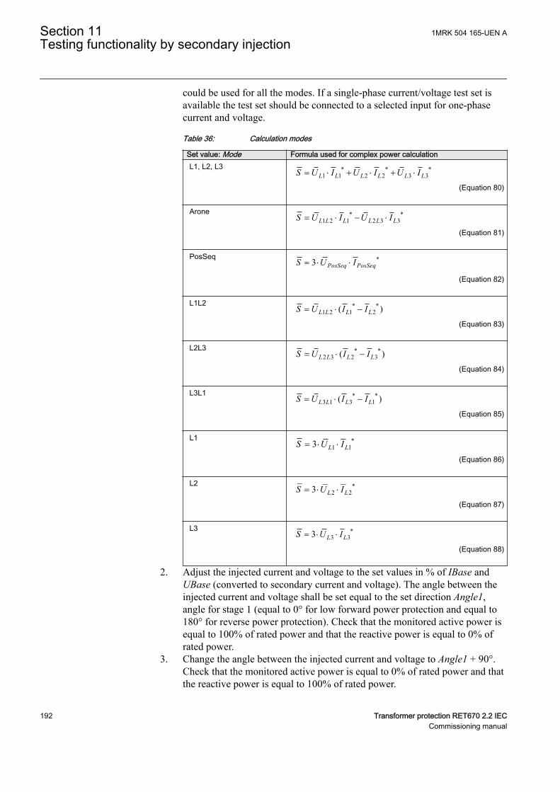
could be used for all the modes. If a single-phase current/voltage test set isavailable the test set should be connected to a selected input for one-phasecurrent and voltage.
Table 36: Calculation modes
Set value: Mode Formula used for complex power calculationL1, L2, L3 * * *
1 1 2 2 3 3L L L L L LS U I U I U I= × + × + ×
EQUATION1697 V1 EN-US (Equation 80)
Arone * *1 2 1 2 3 3L L L L L LS U I U I= × - ×
EQUATION1698 V1 EN-US (Equation 81)
PosSeq *3 PosSeq PosSeqS U I= × ×
EQUATION1699 V1 EN-US (Equation 82)
L1L2 * *1 2 1 2( )L L L LS U I I= × -
EQUATION1700 V1 EN-US (Equation 83)
L2L3 * *2 3 2 3( )L L L LS U I I= × -
EQUATION1701 V1 EN-US (Equation 84)
L3L1 * *3 1 3 1( )L L L LS U I I= × -
EQUATION1702 V1 EN-US (Equation 85)
L1 *1 13 L LS U I= × ×
EQUATION1703 V1 EN-US (Equation 86)
L2 *2 23 L LS U I= × ×
EQUATION1704 V1 EN-US (Equation 87)
L3 *3 33 L LS U I= × ×
EQUATION1705 V1 EN-US (Equation 88)
2. Adjust the injected current and voltage to the set values in % of IBase andUBase (converted to secondary current and voltage). The angle between theinjected current and voltage shall be set equal to the set direction Angle1,angle for stage 1 (equal to 0° for low forward power protection and equal to180° for reverse power protection). Check that the monitored active power isequal to 100% of rated power and that the reactive power is equal to 0% ofrated power.
3. Change the angle between the injected current and voltage to Angle1 + 90°.Check that the monitored active power is equal to 0% of rated power and thatthe reactive power is equal to 100% of rated power.
Section 11 1MRK 504 165-UEN ATesting functionality by secondary injection
192 Transformer protection RET670 2.2 IECCommissioning manual
4. Change the angle between the injected current and voltage back to 0°.Decrease the current slowly until the START1 signal, start of stage 1, isactivated.
5. Increase the current to 100% of IBase.6. Switch the current off and measure the time for activation of TRIP1, trip of
stage 1.7. If a second stage is used, repeat steps 2 to 6 for the second stage.
11.5.11.2 Completing the testSEMOD175027-15 v4
Continue to test another function or end the test by changing the TESTMODEsetting to Off. Restore connections and settings to their original values, if they werechanged for testing purposes.
11.5.12 Directional overpower protection GOPPDOPSEMOD175058-3 v5
Prepare the IED for verification of settings outlined in Section "Preparing the IEDto verify settings".
11.5.12.1 Verifying the settingsSEMOD175058-7 v6
The overpower protection shall be set to values according to the real set values tobe used. The test is made by means of injection of voltage and current where theamplitude of both current and voltage and the phase angle between the voltage andcurrent can be controlled. During the test the analog outputs of active and reactivepower shall be monitored.
1. Connect the test set for injection of voltage and current corresponding to themode to be used in the application. If a three phase test set is available thiscould be used for all the modes. If a single phase current/voltage test set isavailable the test set should be connected to a selected input for one phasecurrent and voltage.
2. Adjust the injected current and voltage to the set rated values in % of IBaseand UBase (converted to secondary current and voltage). The angle betweenthe injected current and voltage shall be set equal to the set direction Angle1,angle for stage 1 (equal to 0° for low forward power protection and equal to180° for reverse power protection). Check that the monitored active power isequal to 100% of rated power and that the reactive power is equal to 0% ofrated power.
3. Change the angle between the injected current and voltage to Angle1 + 90°.Check that the monitored active power is equal to 0% of rated power and thatthe reactive power is equal to 100% of rated power.
4. Change the angle between the injected current and voltage back to Angle1value. Increase the current slowly from 0 until the START1 signal, start ofstage 1, is activated. Check the injected power and compare it to the set valuePower1, power setting for stage 1 in % of Sbase.
1MRK 504 165-UEN A Section 11Testing functionality by secondary injection
Transformer protection RET670 2.2 IEC 193Commissioning manual
5. Increase the current to 100% of IBase and switch the current off.6. Switch the current on and measure the time for activation of TRIP1, trip of
stage 1.7. If a second stage is used, repeat steps 2 to 6 for the second stage.
11.5.12.2 Completing the testSEMOD175058-66 v4
Continue to test another function or end the test by changing the TESTMODEsetting to Off. Restore connections and settings to their original values, if they werechanged for testing purposes.
11.5.13 Broken conductor check BRCPTOCSEMOD175021-3 v5
Prepare the IED for verification of settings outlined in Section "Preparing the IEDto verify settings".
11.5.13.1 Measuring the operate and time limit of set valuesSEMOD175021-7 v6
1. Check that the input logical signal BLOCK to the BRCPTOC function blockis logical zero and note on the local HMI that the output signal TRIP from theBRCPTOC function block is equal to the logical 0.
2. Set the measured current (fault current) in one phase to about 110% of the setoperating current IP>.Observe to not exceed the maximum permitted overloading of the currentcircuits in the terminal.
3. Switch on the fault current and measure the operating time of BRCPTOC.TRIP is controlled by Gate 13 in the configuration.Use the TRIP signal from the configured binary output to stop the timer.
4. Compare the measured time with the set value tOper.5. Activate the BLOCK binary input.6. Switch on the fault current (110% of the setting) and wait longer than the set
value tOper.No TRIP signal should appear.
7. Switch off the fault current.8. Set the measured current (fault current) in same phase to about 90% of the set
operating current IP>. Switch off the current.9. Switch on the fault current and wait longer than the set value tOper.
No TRIP signal should appear.10. Switch off the fault current.
11.5.13.2 Completing the testSEMOD175021-42 v4
Continue to test another function or end the test by changing the TESTMODEsetting to Off. Restore connections and settings to their original values, if they werechanged for testing purposes.
Section 11 1MRK 504 165-UEN ATesting functionality by secondary injection
194 Transformer protection RET670 2.2 IECCommissioning manual
11.5.14 Capacitor bank protection CBPGAPCGUID-00163D04-EBA8-4CD2-9B7A-B3EC15D32069 v2
Prepare the IED for verification of settings as outlined in section "Preparing fortest" in this chapter.
In this section it is shown how to test the capacitor bank protection functionCBPGAPC for application on a 50Hz, 200MVAr, 400kV SCB with 500/1A ratioCT.
Note that such SCB is shown in the application manual for thisfunction. The same procedure can be used to test SCB with someother rating and different CT ratio.
As calculated in the application manual the base current for this particular SCBwill be 289A on the primary side and 0.578A on the CT secondary side. Before anytesting is commenced make sure that setting IBase for this function is set to 289A(that is, setting for the base current corresponds to the rated current of the protectedSCB). It will be also assumed that all other settings have values as shown in thesetting example in the application manual for this SCB.
Test equipment
Connect the secondary test set to the CT inputs on the IED dedicated for the SCBcurrents. Single- or three-phase test equipment can be used but it may be requiredto have facility to vary the frequency of the injected current signal(s).
11.5.14.1 Verifying the settings and operation of the functionGUID-81B167DE-7A86-4CBA-86E7-560A6B3EA665 v1
Reconnection inhibit featureGUID-C3E7B2EA-FF69-4D2B-BBDF-A135A97E4862 v2
1. Inject SCB rated current (that is, 0.587A at 50Hz for this SCB) in at least onephase (preferably perform this test with three phase injection).
2. After couple of seconds stop injection of all currents (that is, set all currentsback to 0A).
3. Check that function binary output signal RECNINH is set to logical 1 and thatonly resets after the set time under parameter tReconnInhibit (for example300s for this SCB) has expired.
4. If this binary signal is used to prevent CB closing make sure that it is properlyconnected/wired into the CB closing circuit.
Overcurrent featureGUID-7E1A7532-7A45-4DA2-A0F3-CE300F8A48BF v3
Note that during testing the overcurrent feature the harmonicvoltage overload feature or reactive power overload feature mayalso give start and operate signals depending on their actualsettings. Therefore it is best to switch them off during this test.
1MRK 504 165-UEN A Section 11Testing functionality by secondary injection
Transformer protection RET670 2.2 IEC 195Commissioning manual
1. Inject current 20% bigger than the set overcurrent pickup level under settingparameter IOC> (for example, 1.2 · 1.35 · 0.587A = 0951A at 50Hz for thisSCB) in phase L1 only.
2. Check that function binary output signals STOCL1 and STOC are set to one.3. Check that function binary output signals TROC and TRIP are set to one after
the set time under parameter tOC (that is, 30s for this SCB) has expired.4. If any of these signals are used for tripping, signaling and/or local/remote
indication check that all relevant contacts and LEDs have operated and thatall relevant GOOSE messages have been sent.
5. Check that service value from the function for current in phase L1, on thelocal HMI under Main menu/Test is approximately 476A (that is, 0.951A ·(500/1) = 476A).
6. Stop injection of all currents (that is, set all currents back to 0A).7. Check that all above mentioned function binary output signals now have
logical value zero.8. Repeat above steps 1-7 for phase L2 and phase L3.
Note that the operation of this feature is based on current peakvalue. That means that this overcurrent function is also able tooperate for the same current magnitude but for different injectedfrequencies. If required repeat this injection procedure for examplefor the 3rd harmonic by just simply injecting 3 · 50 = 150Hzcurrents with the same magnitude. Obtain results shall be the same.
Undercurrent featureGUID-5C2ED7D0-9BE3-40DC-82C0-C351878D4568 v2
1. Inject SCB rated current (that is, 0.587A at 50Hz for this SCB) in all threephases.
2. Lower phase L1 current 10% under the set value for setting parameter IUC<(that is, 0.9 · 0.7 · 0.587A = 0.370A at 50Hz for this SCB).
3. Check that function binary output signals STUCL1 and STUC are set to one.4. Check that function binary output signals TRUC and TRIP are set to one after
the set time under parameter tUC (for example, 5s for this SCB) has expired.5. If any of these signals are used for tripping, signaling and/or local/remote
indication check that all relevant contacts and LEDs have operated and thatall relevant GOOSE messages have been sent.
6. Check that service value from the function for current in phase L1, on thelocal HMI under Main menu/Test is approximately 185A (that is, 0.370A ·(500/1) = 185A).
7. Stop injection of all currents (that is, set all currents back to 0A).8. Check that all above mentioned function binary output signals now have
logical value zero because they will be automatically blocked by operation ofbuilt-in reconnection inhibit feature.
9. Repeat above steps 1-8 for phase L2 and phase L3.
Section 11 1MRK 504 165-UEN ATesting functionality by secondary injection
196 Transformer protection RET670 2.2 IECCommissioning manual
Reactive power overload featureGUID-6DA88E90-366A-494F-B3A4-F8B5A3FD6396 v3
Note that during testing the reactive power overload feature theharmonic voltage overload feature or overcurrent feature may alsogive start and operate signals depending on their actual settings.Therefore it is recommended to switch them off during this test.
1. Inject current equal to the set reactive power overload pickup level undersetting parameter QOL> (that is, 1.3 · 0.587A = 0.763A at 50Hz for thisSCB) in phase L1 only.
2. Check that function binary output signals STQOLL1 and STQOL are set toone.
3. Check that function binary output signals TRQOL and TRIP are set to oneafter the set time under parameter tQOL (for example, 60s for this SCB) hasexpired.
4. If any of these signals are used for tripping, signaling and/or local/remoteindication check that all relevant contacts and LEDs have operated and thatall relevant GOOSE messages have been sent.
5. Check that service value from the function for current in phase L1, on thelocal HMI under Main menu/Test is approximately 382A (that is, 0.763A ·(500/1) = 382A).
6. Check that service value from the function for reactive power in phase L1, onthe local HMI under Main menu/Test is approximately 169% (that is, 1.3 ·1.3 = 1,69pu = 169%).
7. Stop injection of all currents (that is, set all currents back to 0A).8. Check that all above mentioned function binary output signals now have
logical value zero.9. Repeat above steps 1 - 8 for phase L2 and phase L3.
Note that operation of this feature is based on injected current andinternally calculated true RMS values. That means that this featureis also able to operate for current signals with varying frequency.However due to relatively complex calculation procedure it isrecommended to do secondary tests only with fundamentalfrequency current signals.
The following formula can be used to calculate SCB reactive power in per-unitsystem when current with different frequency from the rated frequency is injected.
[ ] [ ]2rated
injected
fQ pu I pu
f= ×
EQUATION2273 V1 EN-US (Equation 89)
1MRK 504 165-UEN A Section 11Testing functionality by secondary injection
Transformer protection RET670 2.2 IEC 197Commissioning manual
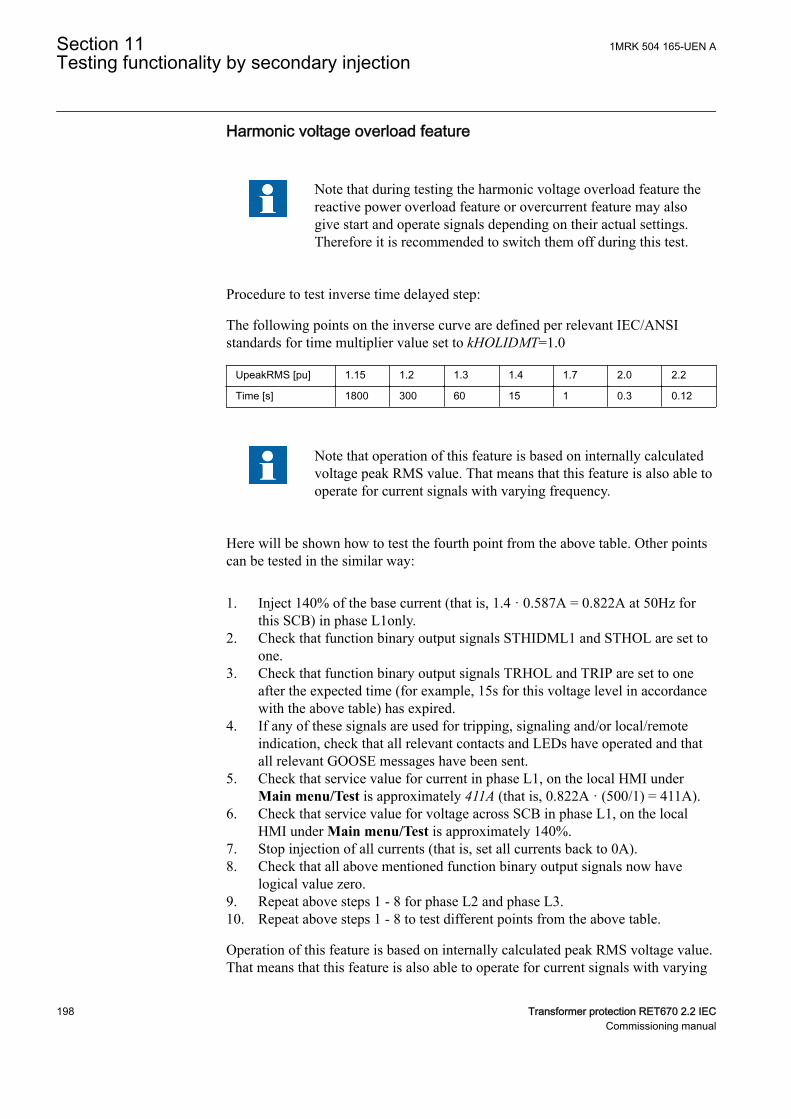
Harmonic voltage overload featureGUID-3C6B2C73-026D-4173-BD4D-1E7E9ADAE160 v3
Note that during testing the harmonic voltage overload feature thereactive power overload feature or overcurrent feature may alsogive start and operate signals depending on their actual settings.Therefore it is recommended to switch them off during this test.
Procedure to test inverse time delayed step:
The following points on the inverse curve are defined per relevant IEC/ANSIstandards for time multiplier value set to kHOLIDMT=1.0
UpeakRMS [pu] 1.15 1.2 1.3 1.4 1.7 2.0 2.2
Time [s] 1800 300 60 15 1 0.3 0.12
Note that operation of this feature is based on internally calculatedvoltage peak RMS value. That means that this feature is also able tooperate for current signals with varying frequency.
GUID-FECBCAD4-16CE-4EFC-9869-9F6D98E2F721 v2
Here will be shown how to test the fourth point from the above table. Other pointscan be tested in the similar way:
1. Inject 140% of the base current (that is, 1.4 · 0.587A = 0.822A at 50Hz forthis SCB) in phase L1only.
2. Check that function binary output signals STHIDML1 and STHOL are set toone.
3. Check that function binary output signals TRHOL and TRIP are set to oneafter the expected time (for example, 15s for this voltage level in accordancewith the above table) has expired.
4. If any of these signals are used for tripping, signaling and/or local/remoteindication, check that all relevant contacts and LEDs have operated and thatall relevant GOOSE messages have been sent.
5. Check that service value for current in phase L1, on the local HMI underMain menu/Test is approximately 411A (that is, 0.822A · (500/1) = 411A).
6. Check that service value for voltage across SCB in phase L1, on the localHMI under Main menu/Test is approximately 140%.
7. Stop injection of all currents (that is, set all currents back to 0A).8. Check that all above mentioned function binary output signals now have
logical value zero.9. Repeat above steps 1 - 8 for phase L2 and phase L3.10. Repeat above steps 1 - 8 to test different points from the above table.
Operation of this feature is based on internally calculated peak RMS voltage value.That means that this feature is also able to operate for current signals with varying
Section 11 1MRK 504 165-UEN ATesting functionality by secondary injection
198 Transformer protection RET670 2.2 IECCommissioning manual
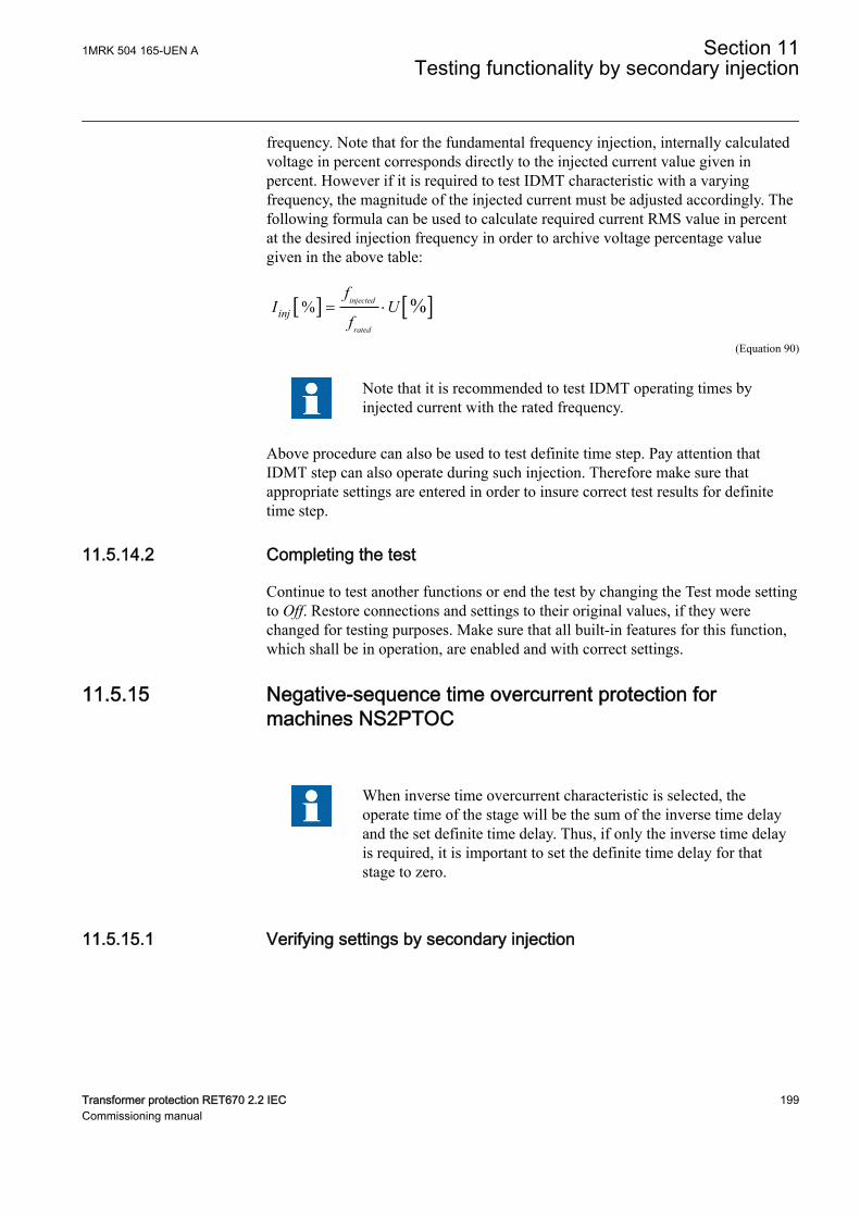
frequency. Note that for the fundamental frequency injection, internally calculatedvoltage in percent corresponds directly to the injected current value given inpercent. However if it is required to test IDMT characteristic with a varyingfrequency, the magnitude of the injected current must be adjusted accordingly. Thefollowing formula can be used to calculate required current RMS value in percentat the desired injection frequency in order to archive voltage percentage valuegiven in the above table:
[ ] [ ]% %injected
rated
inj
fI U
f= ×
EQUATION2274 V1 EN-US (Equation 90)
Note that it is recommended to test IDMT operating times byinjected current with the rated frequency.
Above procedure can also be used to test definite time step. Pay attention thatIDMT step can also operate during such injection. Therefore make sure thatappropriate settings are entered in order to insure correct test results for definitetime step.
11.5.14.2 Completing the testGUID-5AB7880E-629C-45E5-AF91-3EBDF19DEA79 v2
Continue to test another functions or end the test by changing the Test mode settingto Off. Restore connections and settings to their original values, if they werechanged for testing purposes. Make sure that all built-in features for this function,which shall be in operation, are enabled and with correct settings.
11.5.15 Negative-sequence time overcurrent protection formachines NS2PTOC
GUID-48A6DA1D-5CF5-4C1B-B1A4-3F2C73851FD4 v2
GUID-F7AA2194-4D1C-4475-8853-C7D064912614 v4
When inverse time overcurrent characteristic is selected, theoperate time of the stage will be the sum of the inverse time delayand the set definite time delay. Thus, if only the inverse time delayis required, it is important to set the definite time delay for thatstage to zero.
11.5.15.1 Verifying settings by secondary injectionGUID-EB788169-532A-4A3E-BBEC-DCB28169DF86 v6
1MRK 504 165-UEN A Section 11Testing functionality by secondary injection
Transformer protection RET670 2.2 IEC 199Commissioning manual
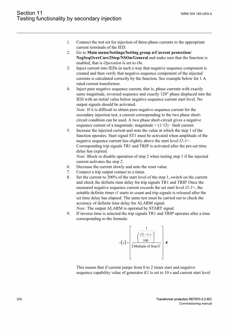
1. Connect the test set for injection of three-phase currents to the appropriatecurrent terminals of the IED.
2. Go to Main menu/Settings/Setting group n/Current protection/NegSeqOverCurr2Step/NSOn/General and make sure that the function isenabled, that is Operation is set to On.
3. Inject current into IEDs in such a way that negative sequence component iscreated and then verify that negative sequence component of the injectedcurrents is calculated correctly by the function. See example below for 1 Arated current transformer.
4. Inject pure negative sequence current, that is, phase currents with exactlysame magnitude, reversed sequence and exactly 120° phase displaced into theIED with an initial value below negative sequence current start level. Nooutput signals should be activated.Note: If it is difficult to obtain pure negative sequence current for thesecondary injection test, a current corresponding to the two phase short-circuit condition can be used. A two phase short-circuit gives a negativesequence current of a magnitude: magnitude = (1/√3) · fault current.
5. Increase the injected current and note the value at which the step 1 of thefunction operates. Start signal ST1 must be activated when amplitude of thenegative sequence current lies slightly above the start level I2-1>.Corresponding trip signals TR1 and TRIP is activated after the pre-set timedelay has expired.Note: Block or disable operation of step 2 when testing step 1 if the injectedcurrent activates the step 2.
6. Decrease the current slowly and note the reset value.7. Connect a trip output contact to a timer.8. Set the current to 200% of the start level of the step 1, switch on the current
and check the definite time delay for trip signals TR1 and TRIP. Once themeasured negative sequence current exceeds the set start level I2-1>, thesettable definite timer t1 starts to count and trip signals is released after theset time delay has elapsed. The same test must be carried out to check theaccuracy of definite time delay for ALARM signal.Note: The output ALARM is operated by START signal.
9. If inverse time is selected the trip signals TR1 and TRIP operates after a timecorresponding to the formula:
t s
I
[ ]
( )
=
− >
⋅
1
2 1
100
2
2
Multiple of StartKK
This means that if current jumps from 0 to 2 times start and negativesequence capability value of generator K1 is set to 10 s and current start level
Section 11 1MRK 504 165-UEN ATesting functionality by secondary injection
200 Transformer protection RET670 2.2 IECCommissioning manual
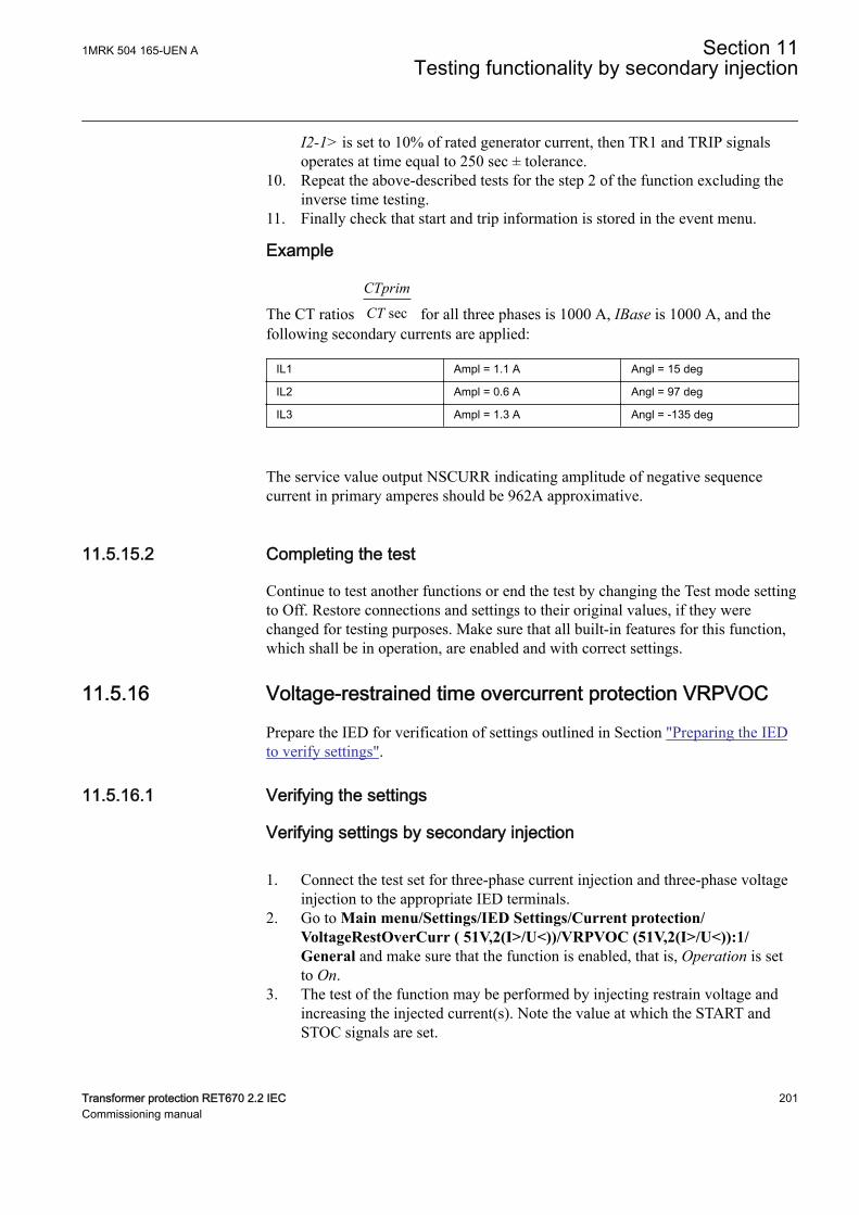
I2-1> is set to 10% of rated generator current, then TR1 and TRIP signalsoperates at time equal to 250 sec ± tolerance.
10. Repeat the above-described tests for the step 2 of the function excluding theinverse time testing.
11. Finally check that start and trip information is stored in the event menu.
Example
The CT ratios sec
CTprim
CT for all three phases is 1000 A, IBase is 1000 A, and thefollowing secondary currents are applied:
IL1 Ampl = 1.1 A Angl = 15 deg
IL2 Ampl = 0.6 A Angl = 97 deg
IL3 Ampl = 1.3 A Angl = -135 deg
The service value output NSCURR indicating amplitude of negative sequencecurrent in primary amperes should be 962A approximative.
11.5.15.2 Completing the testGUID-DA67F057-00AD-4391-B50E-047FD6C16EBB v1
Continue to test another functions or end the test by changing the Test mode settingto Off. Restore connections and settings to their original values, if they werechanged for testing purposes. Make sure that all built-in features for this function,which shall be in operation, are enabled and with correct settings.
11.5.16 Voltage-restrained time overcurrent protection VRPVOCGUID-764DA61A-D987-4358-867A-DA43ADDC6E57 v5
Prepare the IED for verification of settings outlined in Section "Preparing the IEDto verify settings".
11.5.16.1 Verifying the settingsGUID-3A2B7FF5-330E-4A0D-AB74-EBAE6258C176 v1
Verifying settings by secondary injectionGUID-39632D30-A8D8-417D-985C-8F886106783E v4
1. Connect the test set for three-phase current injection and three-phase voltageinjection to the appropriate IED terminals.
2. Go to Main menu/Settings/IED Settings/Current protection/VoltageRestOverCurr ( 51V,2(I>/U<))/VRPVOC (51V,2(I>/U<)):1/General and make sure that the function is enabled, that is, Operation is setto On.
3. The test of the function may be performed by injecting restrain voltage andincreasing the injected current(s). Note the value at which the START andSTOC signals are set.
1MRK 504 165-UEN A Section 11Testing functionality by secondary injection
Transformer protection RET670 2.2 IEC 201Commissioning manual
In the following equations, restrain voltage is the magnitudeof the minimum phase-to-phase voltage in secondary volts.
The set operate value in secondary amperes is calculated according to thefollowing equations:First part of the characteristic (Restrain voltage ≤ 25% of UBase):
StartCurrIBase
CT
CTprim
VDepFact
100 100× × ×
sec
IECEQUATION2432 V1 EN-US (Equation 91)
Second part of the characteristic (25% of UBase ≤ Restrain voltage ≤UHighLimit/100*UBase), valid when setting parameter VDepMode = Slope:
StartCurrIBase
CT
CTprim
VDepFact
UH
1001
100× ×
× −
sec
iighLimitUBase
VT
VTprim
strainVoltage−( )
× ×
× − ×
25
100
25
100secRe UUBase
VT
VTprim
StartCurrIBase×
+ × ×sec
100
CCT
CTprim
VDepFactsec×
100
IECEQUATION2433 V1 EN-US (Equation 92)
Third part of the characteristic (UHighLimit/100*UBase ≤ Restrain voltage):
StartCurrIBase
CT
CTprim100× ×
sec
IECEQUATION2434 V1 EN-US (Equation 93)
Example (rated secondary current = 1A):
CT ratio 10 000/1A
VT ratio 10 kV/100 V
StartCurr 100%
VDepFact 25%
UHighLimit 100%
IBase 10 000 A
10 kV
A test for each section of the characteristic of the function VRPVOC may beperformed; that may be achieved by applying the following voltages:First section of the characteristic:If VDepMode = Slope, the minimum measured phase-to-phase voltage islower than 0,25*UBase; if VDepMode = Step, the minimum measured phase-to-phase voltage is lower than UHighLimit/100*UBase:• UL1: Ampl = 10 / √3; Angle = 0°• UL2: Ampl = 10 / √3; Angle = 240°• UL3: Ampl = 100 / √3; Angle = 120°
Second section of the characteristic only:If VDepMode = Slope, the minimum measured phase-to-phase voltage isbetween 0,25*UBase and UHighLimit/100*UBase:
Section 11 1MRK 504 165-UEN ATesting functionality by secondary injection
202 Transformer protection RET670 2.2 IECCommissioning manual
• UL1: Ampl = 50 / √3; Angle = 0°• UL2: Ampl = 50 / √3; Angle = 240°• UL3: Ampl = 100 / √3; Angle = 120°
Last section of the characteristic:If VDepMode = either Slope or Step, the minimum measured phase-to-phasevoltage is higher than UHighLimit/100*UBase:• UL1: Ampl = 105/ √3; Angle = 0°• UL2: Ampl = 105/ √3; Angle = 240°• UL3: Ampl = 105 / √3; Angle = 120°
4. Inject the voltages that are related to the first part of the characteristic, andthen slowly increase the phase current IL1 from 0.0 A up to the value thefunction operates. The START and STOC signals must be activated when theamplitude of the phase current IL1 is slightly above 0.25 A on the secondaryside. The corresponding trip signals TROC and TRIP will be activated afterthe pre-set time delay has expired.
5. Decrease the current IL1 slowly and note the reset value.6. Repeat steps 4 and 5 applying voltages that are related to the second and the
last section of the characteristic; the function operates when IL1 is slightlyhigher than: 0.5 A in the second section; 1A in the last section.
7. Connect the trip output contact to the input channel of the test set in order tostop the injection and measure the trip time.
8. If definite time delay is used for the overcurrent step, set the settingCharacterist = IEC Def. Time. Apply the voltages related to the last part ofthe characteristic and inject a current IL1 200% higher than the set operationlevel, and check the definite time delay for trip (the signals TROC and TRIPof the protection function VRPVOC are active in trip condition).
9. If inverse time delay is used for the overcurrent step, the parameter settingCharacterist shall be properly set; we can refer, for example, to the settingIEC Very inv.; If the IEC Very inverse time characteristic is selected, the tripsignals TROC and TRIP will operate after a time defined by the equation:
t sk
I
StartCurr
[ ] =
−
13 5
1
. *
IECEQUATION2435 V1 EN-US (Equation 94)
where:
t Operate time in seconds
I Measured value (for example, phase current)
StartCurr Set operate value
This means that if the measured phase current jumps from 0 to 2 times the setoperate level and time multiplier k is set to 1.0 s (default value), then theTROC and TRIP signals will operate after a time delay equal to 13.5 s ±tolerance.
1MRK 504 165-UEN A Section 11Testing functionality by secondary injection
Transformer protection RET670 2.2 IEC 203Commissioning manual
Taking into account the above explanation, inject the voltages related to thelast part of the characteristic and inject a current IL1 200% higher than the setoperation level, and check the trip time delay.
If tDef_OC is set to a value different from 0 s, then this timedelay is added to the one that is defined by the IDMTcharacteristic.
10. Check the start and operate information that are stored in the event menu.11. The previous step 8 or 9 may be repeated also for the first and second section
of the characteristic.12. Supply the IED with symmetric three-phase voltages at their rated values. Go
to Main menu/Settings/IED Settings/Current protection/VoltageRestOverCurr(51V,2(I>/U<))/VRPVOC(51V,2(I>/U<)):1/Undervoltage and set the setting Operation_UV = On to activate theundervoltage stage.
13. Slowly decrease the voltage in two phases simultaneously, until the STUVand START signals appear.
14. Note the operate value. The set operate value in secondary volts is calculatedaccording to the following equation:
StartVolt UBase VT
VTprim100 3× ×
sec
IECEQUATION2436 V1 EN-US (Equation 95)
If the VRPVOC function is used as an overcurrent protectionwith undervoltage seal-in, it is necessary to first injectsufficient current to activate the STOC signal before theunder-voltage step is allowed to operate. In order to achievethat, apply symmetric three-phase voltages at their rated valueand then inject a current IL1 that is 200% higher than the setoperation level. Then slowly decrease the voltage in twophases simultaneously, until the STUV and START signalsappear.
15. Increase slowly the applied voltages of the previous two phases and note thereset value.
16. Check that the trip output of the relay is connected to the input channel of thetest in order to stop the injection and measure the trip time.
17. Inject symmetric three-phase voltages at their rated value and check that theSTUV and START signals reset as well as the trip signals of the functionblock (TRIP and TRUV).
18. Instantaneously decrease the voltage in two phases simultaneously to a value20% lower than the set operate value (take into account the previous note ifVRPVOC is configured in ACT with the undervoltage seal-in feature).
19. Measure the definite time delay for the TRUV and TRIP signals and compareit with the set value tDef_UV.
20. Check that start and operate information is stored in the event menu.
Section 11 1MRK 504 165-UEN ATesting functionality by secondary injection
204 Transformer protection RET670 2.2 IECCommissioning manual
11.5.16.2 Completing the testGUID-8A33AACE-7B89-4981-A872-78044BB1FD0D v2
Continue to test another function or end the test by changing the TESTMODEsetting to Off. Restore connections and settings to their original values, if they werechanged for testing purposes.
11.6 Voltage protectionSEMOD53540-1 v1
11.6.1 Two step undervoltage protection UV2PTUVM13796-2 v6
Prepare the IED for verification of settings outlined in Section "Preparing the IEDto verify settings".
11.6.1.1 Verifying the settingsM13796-9 v3
Verification of start value and time delay to operate for Step 1M13796-29 v10
1. Check that the IED settings are appropriate, especially the START value, thedefinite time delay and the 1 out of 3 operation mode.
2. Supply the IED with three-phase voltages at their rated values.3. Slowly decrease the voltage in one of the phases, until the START signal
appears.4. Note the operate value and compare it with the set value.
The operate value in secondary volts is calculated accordingto the following equations:
For phase-to-earth measurement:
U UBase VT
VTprim
1
100 3
<× ×
sec
IECEQUATION2430 V1 EN-US (Equation 96)
For phase-to-phase measurement:
UUBase
VT
VTprim
1
100
<× ×
sec
IECEQUATION2431 V1 EN-US (Equation 97)5. Increase the measured voltage to rated load conditions.6. Check that the START signal resets.7. Instantaneously decrease the voltage in one phase to a value about 20% lower
than the measured operate value.8. Measure the time delay for the TRIP signal, and compare it with the set value.
1MRK 504 165-UEN A Section 11Testing functionality by secondary injection
Transformer protection RET670 2.2 IEC 205Commissioning manual

9. Check the inverse time delay by injecting a voltage corresponding to 0.8 ×U1<.
For example, if the inverse time curve A is selected, the tripsignals TR1 and TRIP operate after a time corresponding tothe equation:
t sk
U
U
( ) =
−
<
1
11
IECEQUATION2428 V1 EN-US (Equation 98)
where:
t(s) Operate time in seconds
k1 Settable time multiplier of the function for step 1
U Measured voltage
U1< Set start voltage for step 1
For example, if the measured voltage jumps from the rated value to 0.8 timesthe set start voltage level and time multiplier k1 is set to 0.05 s (defaultvalue), then the TR1 and TRIP signals operate at a time equal to 0.250 s ±tolerance.
10. The test above can be repeated to check the inverse time characteristic atdifferent voltage levels.
11. Repeat the above described steps for Step 2 of the function.
Extended testingM13796-35 v8
The tests above can be repeated for 2 out of 3 and for 3 out of 3 operation mode.
11.6.1.2 Completing the testM13796-25 v5
Continue to test another function or end the test by changing the TESTMODEsetting to Off. Restore connections and settings to their original values, if they werechanged for testing purposes.
11.6.2 Two step overvoltage protection OV2PTOVM13806-2 v6
Prepare the IED for verification of settings outlined in Section "Preparing the IEDto verify settings".
11.6.2.1 Verifying the settingsM13806-9 v2
Verification of single-phase voltage and time delay to operate forStep 1
M13806-50 v9
Section 11 1MRK 504 165-UEN ATesting functionality by secondary injection
206 Transformer protection RET670 2.2 IECCommissioning manual
1. Apply single-phase voltage below the set value U1>.2. Slowly increase the voltage until the ST1 signal appears.3. Note the operate value and compare it with the set value U1>.
The operate value in secondary volts is calculated accordingto the following equations:
For phase-to-earth measurement:
U UBase VT
VTprim
1
100 3
>× ×
sec
IECEQUATION2426 V1 EN-US (Equation 99)
For phase-to-phase measurement:
UUBase
VT
VTprim
1
100
>× ×
sec
IECEQUATION2427 V1 EN-US (Equation 100)4. Decrease the voltage slowly and note the reset value.5. Set and apply about 20% higher voltage than the measured operate value for
one phase.6. Measure the time delay for the TR1 signal and compare it with the set value.7. Check the inverse time delay by injecting a voltage corresponding to 1.2 ×
U1>.8. Repeat the test to check the inverse time characteristic at different over-
voltage levels.9. Repeat the above described steps for Step 2 of the function.
11.6.2.2 Extended testingGUID-BE4B4A36-CCEE-4020-B7DC-6A83A43D11F5 v2
1. The tests above can be repeated for 2 out of 3 and for 3 out of 3 operationmode.
11.6.2.3 Completing the testM13806-43 v6
Continue to test another function or end the test by changing the TESTMODEsetting to Off. Restore connections and settings to their original values, if they werechanged for testing purposes.
11.6.3 Two step residual overvoltage protection ROV2PTOVSEMOD54358-3 v7
Prepare the IED for verification of settings outlined in Section "Preparing the IEDto verify settings".
1MRK 504 165-UEN A Section 11Testing functionality by secondary injection
Transformer protection RET670 2.2 IEC 207Commissioning manual
11.6.3.1 Verifying the settingsSEMOD54358-35 v11
1. Apply a single-phase voltage either to a single-phase voltage input or to aresidual voltage input with the start value below the set value U1>.
2. Slowly increase the value until ST1 appears.3. Note the operate value and compare it with the set value.4. Decrease the voltage slowly and note the reset value.5. Set and apply a 20% higher voltage than the measured operate value for one
phase.6. Measure the time delay for the TR1 signal and compare it with the set value.7. Check the inverse time delay by injecting a voltage corresponding to 1.2 ×
U1>.
For example, if the inverse time curve A is selected, the tripsignals TR1 and TRIP operate after a time corresponding tothe equation:
t sk
U
U
( ) =
>
−
1
11
IECEQUATION2429 V1 EN-US (Equation 101)
where:
t(s) Operate time in seconds
k1 Settable time multiplier of the function for step 1
U Measured voltage
U1> Set start voltage for step 1
8. Repeat the test for Step 2 of the function.
11.6.3.2 Completing the testSEMOD54358-38 v4
Continue to test another function or end the test by changing the TESTMODEsetting to Off. Restore connections and settings to their original values, if they werechanged for testing purposes.
11.6.4 Overexcitation protection OEXPVPHM6583-45 v5
Prepare the IED for verification of settings outlined in Section "Preparing the IEDto verify settings".
11.6.4.1 Verifying the settingsM6583-49 v4
Section 11 1MRK 504 165-UEN ATesting functionality by secondary injection
208 Transformer protection RET670 2.2 IECCommissioning manual
1. Enable function.2. Connect a symmetrical three-phase voltage input from the test set to the
appropriate connection terminals of the overexcitation protection OEXPVPHis configured for a three-phase voltage input.A single-phase injection voltage is applied if the function is configured for aphase-to-phase voltage input.OEXPVPH is conveniently tested using rated frequency for the injectionvoltage and increasing the injection voltage to get the desired overexcitationlevel.
3. Connect the alarm contact to the timer and set the time delay tAlarmtemporarily to zero.
4. Increase the voltage and note the operate value V/Hz>.5. Reduce the voltage slowly and note the reset value.6. Set the alarm time delay to the correct value according to the setting plan and
check the time delay, injecting a voltage corresponding to 1.2 · V/Hz>.7. Connect a trip output contact to the timer and temporarily set the time delay
tMin to 0.5s.8. Increase the voltage and note the V/Hz>> operate value9. Reduce the voltage slowly and note the reset value.10. Set the time delay to the correct value according to the setting plan and check
the time delay tMin, injecting a voltage corresponding to 1.2 · V/Hz>>.11. Check that trip and alarm contacts operate according to the configuration
logic.12. Set the cooling time constant temporarily to min value (1min.) to quickly
lower the thermal content.13. Wait for a period equal to 6 times Tcooling switch 20 minutes on a voltage
1.15 · V/Hz> and check the inverse operate time.Wait until the thermal memory is emptied, set the cooling time constantaccording to the setting plan and check another point on the inverse timecurve injecting a voltage 1.3 · V/Hz>.
14. Finally check that START and TRIP information is stored in the event menu.
11.6.4.2 Completing the testM6583-85 v4
Continue to test another function or end the test by changing the TESTMODEsetting to Off. Restore connections and settings to their original values, if they werechanged for testing purposes.
11.6.5 Voltage differential protection VDCPTOVSEMOD175258-3 v2
Prepare the IED for verification of settings as outlined in section "Requirements"and section "Preparing for test" in this chapter.
11.6.5.1 Check of undervoltage levelsSEMOD175258-71 v2
This test is relevant if the setting BlkDiffAtULow = Yes.
1MRK 504 165-UEN A Section 11Testing functionality by secondary injection
Transformer protection RET670 2.2 IEC 209Commissioning manual
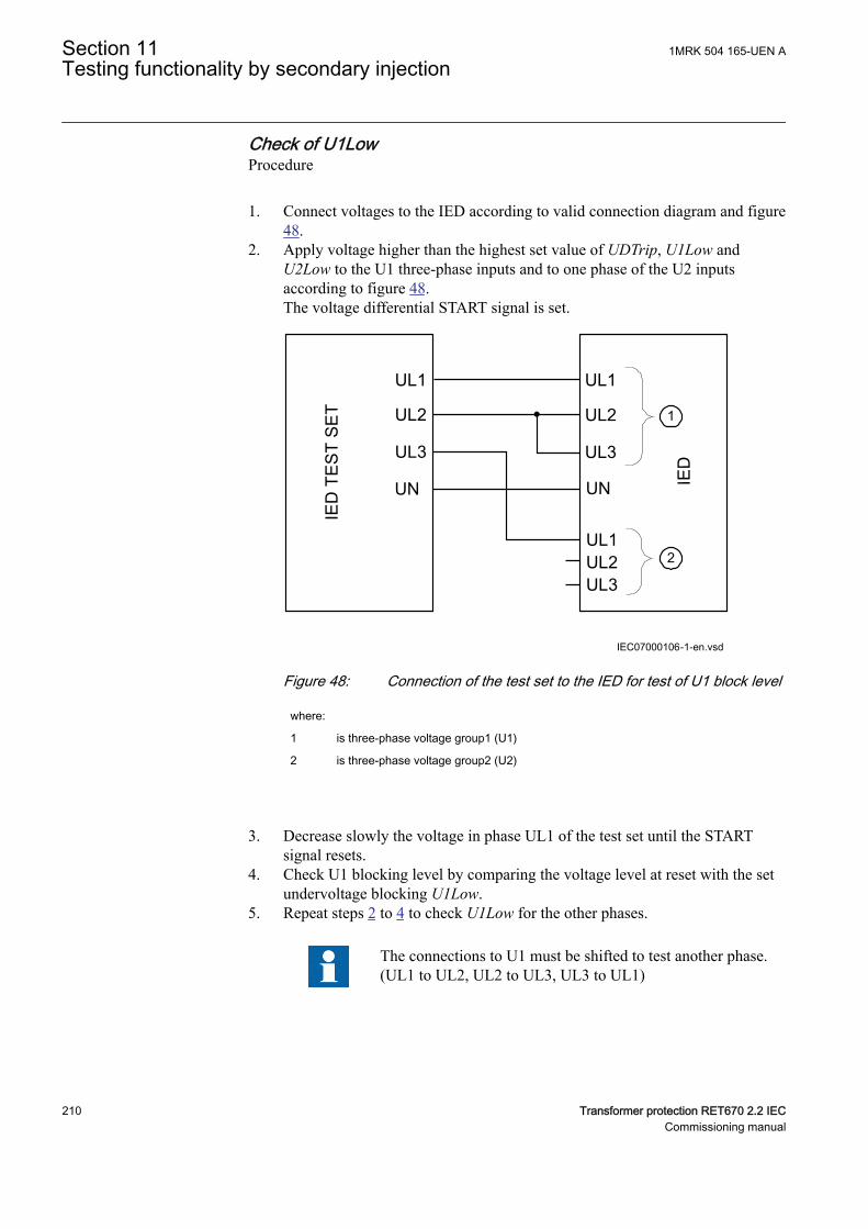
Check of U1LowSEMOD175258-75 v3
Procedure
1. Connect voltages to the IED according to valid connection diagram and figure48.
2. Apply voltage higher than the highest set value of UDTrip, U1Low andU2Low to the U1 three-phase inputs and to one phase of the U2 inputsaccording to figure 48.The voltage differential START signal is set.
UL1
UL2
UL3
UN
UL1
UL1UL2UL3
IED
TES
T SE
T
IED
IEC07000106-1-en.vsd
UL2
UL3
UN
1
2
IEC07000106 V2 EN-US
Figure 48: Connection of the test set to the IED for test of U1 block level
where:
1 is three-phase voltage group1 (U1)
2 is three-phase voltage group2 (U2)
3. Decrease slowly the voltage in phase UL1 of the test set until the STARTsignal resets.
4. Check U1 blocking level by comparing the voltage level at reset with the setundervoltage blocking U1Low.
5. Repeat steps 2 to 4 to check U1Low for the other phases.
The connections to U1 must be shifted to test another phase.(UL1 to UL2, UL2 to UL3, UL3 to UL1)
Section 11 1MRK 504 165-UEN ATesting functionality by secondary injection
210 Transformer protection RET670 2.2 IECCommissioning manual
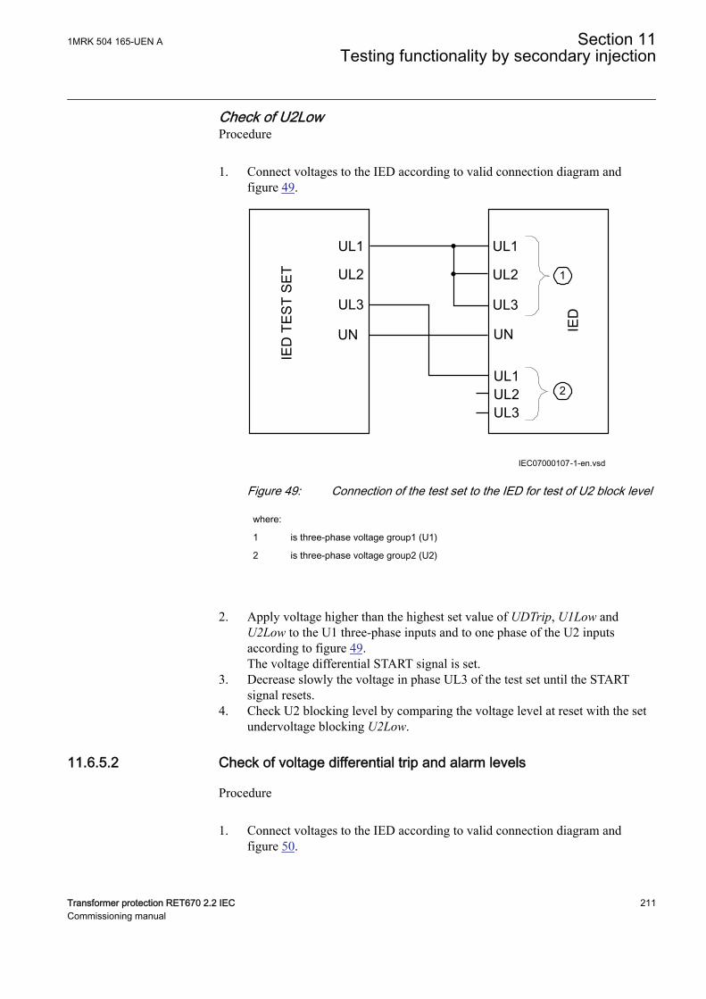
Check of U2LowSEMOD175258-91 v3
Procedure
1. Connect voltages to the IED according to valid connection diagram andfigure 49.
UL1
UL2
UL3
UN
UL1
UL1UL2UL3
IED
TES
T SE
T
IED
IEC07000107-1-en.vsd
UL2
UL3
UN
1
2
IEC07000107 V2 EN-US
Figure 49: Connection of the test set to the IED for test of U2 block level
where:
1 is three-phase voltage group1 (U1)
2 is three-phase voltage group2 (U2)
2. Apply voltage higher than the highest set value of UDTrip, U1Low andU2Low to the U1 three-phase inputs and to one phase of the U2 inputsaccording to figure 49.The voltage differential START signal is set.
3. Decrease slowly the voltage in phase UL3 of the test set until the STARTsignal resets.
4. Check U2 blocking level by comparing the voltage level at reset with the setundervoltage blocking U2Low.
11.6.5.2 Check of voltage differential trip and alarm levelsSEMOD175258-104 v3
Procedure
1. Connect voltages to the IED according to valid connection diagram andfigure 50.
1MRK 504 165-UEN A Section 11Testing functionality by secondary injection
Transformer protection RET670 2.2 IEC 211Commissioning manual
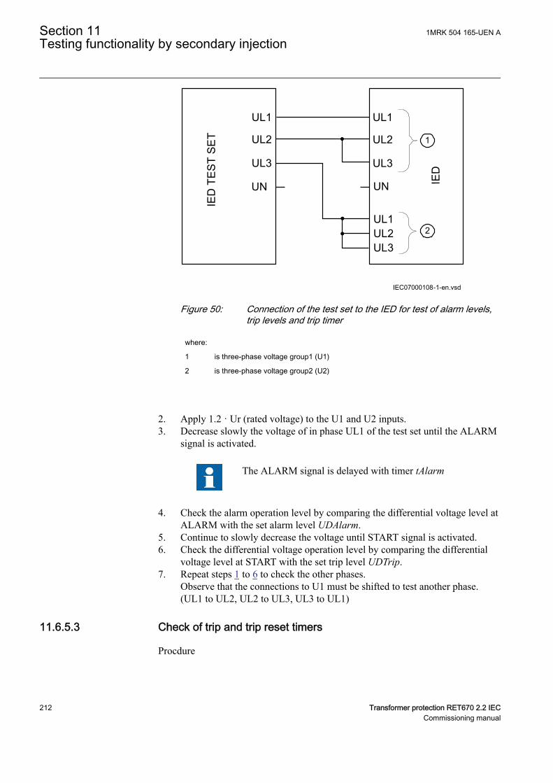
UL1
UL2
UL3
UN
UL1
UL1UL2UL3
IED
TES
T SE
T
IED
IEC07000108-1-en.vsd
UL2
UL3
UN
1
2
IEC07000108 V2 EN-US
Figure 50: Connection of the test set to the IED for test of alarm levels,trip levels and trip timer
where:
1 is three-phase voltage group1 (U1)
2 is three-phase voltage group2 (U2)
2. Apply 1.2 · Ur (rated voltage) to the U1 and U2 inputs.3. Decrease slowly the voltage of in phase UL1 of the test set until the ALARM
signal is activated.
The ALARM signal is delayed with timer tAlarm
4. Check the alarm operation level by comparing the differential voltage level atALARM with the set alarm level UDAlarm.
5. Continue to slowly decrease the voltage until START signal is activated.6. Check the differential voltage operation level by comparing the differential
voltage level at START with the set trip level UDTrip.7. Repeat steps 1 to 6 to check the other phases.
Observe that the connections to U1 must be shifted to test another phase.(UL1 to UL2, UL2 to UL3, UL3 to UL1)
11.6.5.3 Check of trip and trip reset timersSEMOD175258-124 v2
Procdure
Section 11 1MRK 504 165-UEN ATesting functionality by secondary injection
212 Transformer protection RET670 2.2 IECCommissioning manual
1. Connect voltages to the IED according to valid connection diagram and figure50.
2. Set Ur (rated voltage) to the U1 inputs and increase U2 voltage untildifferential voltage is 1.5 · operating level (UDTrip).
3. Switch on the test set. Measure the time from activation of the START signaluntil TRIP signal is activated.
4. Check the measured time by comparing it to the set trip time tTrip.5. Increase the voltage until START signal resets. Measure the time from reset
of START signal to reset of TRIP signal.6. Check the measured time by comparing it to the set trip reset time tReset.
11.6.5.4 Final adjustment of compensation for VT ratio differencesSEMOD175258-183 v2
Procedure
1. With the protection in test mode, view the differential voltage service valuesin each phase on the local HMI under Main menu/Test/Function status/Voltage protection/VoltageDiff(PTOV,60)/VDCPTOV:x.
The IED voltage inputs should be connected to the VTsaccording to valid connection diagram.
2. Record the differential voltages.3. Calculate the compensation factor RFLx for each phase.
For information about calculation of the compensation factor, see theapplication manual.
4. Set the compensation factors on the local HMI under Main menu/Settings/Settings group N/Voltage protection/VoltageDiff(PTOV,60)/VDCPTOV:x
5. Check that the differential voltages are close to zero.
11.6.5.5 Completing the testSEMOD175258-208 v2
Continue to test another function or end the test by changing the TESTMODEsetting to Off. Restore connections and settings to their original values, if they werechanged for testing purposes.
11.6.6 Loss of voltage check LOVPTUVSEMOD175023-3 v5
Prepare the IED for verification of settings outlined in Section "Preparing the IEDto verify settings".
11.6.6.1 Measuring the operate limit of set valuesSEMOD175023-7 v7
1MRK 504 165-UEN A Section 11Testing functionality by secondary injection
Transformer protection RET670 2.2 IEC 213Commissioning manual
1. Check that the input logical signals BLOCK, CBOPEN and VTSU are logicalzero.
2. Supply a three-phase rated voltage in all three phases and note on the localHMI that the TRIP logical signal is equal to the logical 0.
3. Switch off the voltage in all three phases.After set tTrip time a TRIP signal appears on the corresponding binary outputor on the local HMI.
Note that TRIP at this time is a pulse signal, duration shouldbe according to set tPulse.
4. Inject the measured voltages at rated values for at least set tRestore time.5. Activate the CBOPEN binary input.6. Simultaneously disconnect all the three-phase voltages from the IED.
No TRIP signal should appear.7. Inject the measured voltages at rated values for at least set tRestore time.8. Activate the VTSU binary input.9. Simultaneously disconnect all the three-phase voltages from the IED.
No TRIP signal should appear.10. Reset the VTSU binary input.11. Inject the measured voltages at rated values for at least set tRestore time.12. Activate the BLOCK binary input.13. Simultaneously disconnect all the three-phase voltages from the IED.
No TRIP signal should appear.14. Reset the BLOCK binary input.
11.6.6.2 Completing the testSEMOD175023-47 v4
Continue to test another function or end the test by changing the TESTMODEsetting to Off. Restore connections and settings to their original values, if they werechanged for testing purposes.
11.7 Frequency protectionSEMOD53547-1 v1
11.7.1 Underfrequency protection SAPTUFM16289-2 v7
Prepare the IED for verification of settings outlined in Section "Preparing the IEDto verify settings".
11.7.1.1 Verifying the settingsM16289-15 v3
Verification of START value and time delay to operateM16289-17 v7
Section 11 1MRK 504 165-UEN ATesting functionality by secondary injection
214 Transformer protection RET670 2.2 IECCommissioning manual
1. Check that the IED settings are appropriate, for example the start value andthe time delay.
2. Supply the IED with three-phase voltages at their rated values and initialfrequency.The initial frequency is calculated using Equation 102.
0.02 / 0.04 0.04rStartFrequency floor f StartFrequency
IECEQUATION16059 V1 EN-US (Equation 102)3. Slowly decrease the voltage frequency by steps of 40 mHz until the START
signal appears; during each step apply the voltage signal for a time that iseither at least 10% longer than (tDelay+100ms) or a suitable time to monitorthe function.
4. Note the frequency value at which the START signal appears and compare itwith the set value StartFrequency.
5. Increase the frequency until its rated value is reached.6. Check that the START signal resets.7. Supply the IED with three-phase voltages at their rated values and frequency
20 mHz over the set value StartFrequency.8. Decrease the frequency with a 40 mHz step, applying it for a time that is at
least 10% longer than (tDelay+100ms).9. Measure the time delay of the TRIP signal, and compare it with the set value
tDelay. Note that the measured time consists of the set value of the time delayplus the minimum operate time of the start function (80 - 90 ms).
Extended testingM16289-31 v6
1. The test above can be repeated to check the time to reset.2. The tests above can be repeated to test the frequency dependent inverse time
characteristic.
Verification of the low voltage magnitude blockingM16289-39 v7
1. Check that the IED settings are appropriate, for example the StartFrequency,UMin , and the tDelay.
2. Supply the IED with three-phase voltages at rated values.3. Slowly decrease the magnitude of the applied voltage, until the BLKDMAGN
signal appears.4. Note the voltage magnitude value and compare it with the set value UMin.5. Slowly decrease the frequency of the applied voltage, to a value below
StartFrequency.6. Check that the START signal does not appear.7. Wait for a time corresponding to tDelay, make sure that the TRIP signal does
not appear.
1MRK 504 165-UEN A Section 11Testing functionality by secondary injection
Transformer protection RET670 2.2 IEC 215Commissioning manual
11.7.1.2 Completing the testM16289-57 v5
Continue to test another function or end the test by changing the TESTMODEsetting to Off. Restore connections and settings to their original values, if they werechanged for testing purposes.
11.7.2 Overfrequency protection SAPTOFM16290-2 v7
Prepare the IED for verification of settings outlined in Section "Preparing the IEDto verify settings".
11.7.2.1 Verifying the settingsM16290-12 v2
Verification of START value and time delay to operateM16290-14 v6
1. Check that the IED settings are appropriate, for example the start value andthe time delay.
2. Supply the IED with three-phase voltages at their rated values and initialfrequency.
3. Slowly increase the frequency of the applied voltage with a 40 mHz step,applying it for a period that is 10% longer than tDelay.
4. Note the operate value and compare it with the set value.5. Decrease the frequency to rated operating conditions.6. Check that the START signal resets.7. Set the frequency to 20 mHz under the operate value.8. Increase the frequency with a 40 mHz step, applying it for a period that is
10% longer than tDelay.9. Measure the time delay for the TRIP signal, and compare it with the set value.
Note that the measured time consists of the set value for time delay plusminimum operate time of the start function (80 - 90 ms).
Extended testingM16290-28 v4
1. The test above can be repeated to check the time to reset.
Verification of the low voltage magnitude blockingM16290-34 v6
1. Check that the settings in the IED are appropriate, for example theStartFrequency and the tDelay.
2. Supply the IED with three-phase voltages at their rated values.3. Slowly decrease the magnitude of the applied voltage, until the BLKDMAGN
signal appears.4. Note the voltage magnitude value and compare it with the set value.
Section 11 1MRK 504 165-UEN ATesting functionality by secondary injection
216 Transformer protection RET670 2.2 IECCommissioning manual
5. Slowly increase the frequency of the applied voltage, to a value aboveStartFrequency.
6. Check that the START signal does not appear.7. Wait for a time corresponding to tDelay, make sure that the TRIP signal does
not appear.
11.7.2.2 Completing the testM16290-52 v5
Continue to test another function or end the test by changing the TESTMODEsetting to Off. Restore connections and settings to their original values, if they werechanged for testing purposes.
11.7.3 Rate-of-change frequency protection SAPFRCM16256-2 v6
Prepare the IED for verification of settings outlined in Section "Preparing the IEDto verify settings".
11.7.3.1 Verifying the settingsM16256-8 v1
Verification of START value and time delay to operateM16256-10 v5
1. Check that the settings in the IED are appropriate, especially the STARTvalue and the definite time delay. Set StartFreqGrad, to a rather smallnegative value.
2. Supply the IED with three-phase voltages at their rated values.3. Slowly decrease the frequency of the applied voltage, with an increasing rate-
of-change that finally exceeds the setting of StartFreqGrad, and check thatthe START signal appears.
4. Note the operate value and compare it with the set value.5. Increase the frequency to rated operating conditions, and zero rate-of-change.6. Check that the START signal resets.7. Instantaneously decrease the frequency of the applied voltage to a value about
20% lower than the nominal value.8. Measure the time delay for the TRIP signal, and compare it with the set value.
Extended testingM16256-29 v4
1. The test above can be repeated to check a positive setting of StartFreqGrad.2. The tests above can be repeated to check the time to reset.3. The tests above can be repeated to test the RESTORE signal, when the
frequency recovers from a low value.
1MRK 504 165-UEN A Section 11Testing functionality by secondary injection
Transformer protection RET670 2.2 IEC 217Commissioning manual
11.7.3.2 Completing the testM16256-39 v4
Continue to test another function or end the test by changing the TESTMODEsetting to Off. Restore connections and settings to their original values, if they werechanged for testing purposes.
11.8 Multipurpose protectionSEMOD53552-1 v1
11.8.1 General current and voltage protection CVGAPCSEMOD56488-3 v3
Prepare the IED for verification of settings as outlined in section "Requirements"and section "Preparing for test" in this chapter.
One of the new facilities within the general current and voltage protection functionCVGAPC is that the value, which is processed and used for evaluation in thefunction, can be chosen in many different ways by the setting parametersCurrentInput and VoltageInput.
These setting parameters decide what kind of preprocessing the connected three-phase CT and VT inputs shall be subjected to. That is, for example, single-phasequantities, phase-to-phase quantities, positive sequence quantities, negativesequence quantities, maximum quantity from the three-phase group, minimumquantity from the three-phase group, difference between maximum and minimumquantities (unbalance) can be derived and then used in the function.
Due to the versatile possibilities of CVGAPC itself, but also the possibilities oflogic combinations in the application configuration of outputs from more than oneCVGAPC function block, it is hardly possible to define a fully covering generalcommissioning test.
11.8.1.1 Built-in overcurrent feature (non-directional)SEMOD56488-9 v5
Procedure
1. Go to Main menu/Test/Function test modes/Multipurpose protection/GeneralCurrentVoltage(GAPC)/CVGAPC:x and make sure that CVGAPCto be tested is unblocked and other functions that might disturb the evaluationof the test are blocked.
2. Connect the test set for injection of three-phase currents to the appropriatecurrent terminals of the IED.
3. Inject current(s) in a way that relevant measured current (according to settingparameter CurrentInput) is created from the test set. Increase the current(s)until the low set stage operates and check against the set operate value.
4. Decrease the current slowly and check the reset value.5. Block high set stage if the injection current will activate the high set stage
when testing the low set stage according to below.
Section 11 1MRK 504 165-UEN ATesting functionality by secondary injection
218 Transformer protection RET670 2.2 IECCommissioning manual
6. Connect a TRIP output contact to the timer.7. Set the current to 200% of the operate value of low set stage, switch on the
current and check the time delay.For inverse time curves, check the operate time at a current equal to 110% ofthe operate current at tMin.
8. Check that TRIP and START contacts operate according to the configurationlogic.
9. Release the blocking of the high set stage and check the operate and resetvalue and the time delay for the high set stage in the same way as for the lowset stage.
10. Finally check that START and TRIP information is stored in the event menu.
Information on how to use the event menu is found in theoperator's manual.
11.8.1.2 Overcurrent feature with current restraintSEMOD56488-35 v3
The current restraining value has also to be measured or calculated and theinfluence on the operation has to be calculated when the testing of the operatevalue is done.
Procedure
1. Operate value measurementThe current restraining value has also to be measured or calculated and theinfluence on the operation has to be calculated when the testing of the operatevalue is done.
11.8.1.3 Overcurrent feature with voltage restraintSEMOD56488-44 v5
Procedure
1. Connect the test set for injection of three-phase currents and three-phasevoltages to the appropriate current and voltage terminals of the IED.
2. Inject current(s) and voltage(s) in a way that relevant measured (according tosetting parameter CurrentInput and VoltageInput) currents and voltages arecreated from the test set.Overall check in principal as above (non-directional overcurrent feature)
3. Operate value measurementThe relevant voltage restraining value (according to setting parameterVoltageInput) has also to be injected from the test set and the influence on theoperate value has to be calculated when testing of the operate value is done.
4. Operate time measurementDefinite times may be tested as above (non-directional overcurrent feature).For inverse time characteristics the START value (to which the overcurrent
1MRK 504 165-UEN A Section 11Testing functionality by secondary injection
Transformer protection RET670 2.2 IEC 219Commissioning manual
ratio has to be calculated) is the actual pickup value as got with actualrestraining from the voltage restraining quantity.
11.8.1.4 Overcurrent feature with directionalitySEMOD56488-60 v5
Please note that the directional characteristic can be set in two different ways eitherjust dependent on the angle between current and polarizing voltage (settingparameter DirPrinc_OC1 or DirPrinc_OC2 set to or in a way that the operatevalue also is dependent on the angle between current and polarizing voltageaccording to the I · cos(F) law (setting parameter DirPrinc_OC1 or DirPrinc_OC2set to I · cos(F). This has to be known if a more detailed measurement of thedirectional characteristic is made, than the one described below.
Procedure
1. Connect the test set for injection of three-phase currents and three-phasevoltages to the appropriate current and voltage terminals of the IED.
2. Inject current(s) and voltage(s) in a way that relevant measured (according tosetting parameter CurrentInput and VoltageInput) currents and voltages arecreated from the test set.
3. Set the relevant measuring quantity current to lag or lead (lag for negativeRCA angle and lead for positive RCA angle) the relevant polarizing quantityvoltage by an angle equal to the set IED characteristic angle (rca-dir) whenforward directional feature is selected and the CTstarpoint configurationparameter is set to ToObject.If reverse directional feature is selected or CTstarpoint configurationparameter is set to FromObject, the angle between current and polarizingvoltage shall be set equal to rca-dir+180°.
4. Overall check in principal as above (non-directional overcurrent feature)5. Reverse the direction of the injection current and check that the protection
does not operate.6. Check with low polarization voltage that the feature becomes non-directional,
blocked or with memory according to the setting.
11.8.1.5 Over/Undervoltage featureSEMOD56488-83 v2
Procedure
1. Connect the test set for injection three-phase voltages to the appropriatevoltage terminals of the IED.
2. Inject voltage(s) in a way that relevant measured (according to settingparameter VoltageInput) voltages are created from the test set.
3. Overall check in principal as above (non-directional overcurrent feature) andcorrespondingly for the undervoltage feature.
Section 11 1MRK 504 165-UEN ATesting functionality by secondary injection
220 Transformer protection RET670 2.2 IECCommissioning manual
11.8.1.6 Completing the testSEMOD56488-99 v2
Continue to test another function or end the test by changing the TESTMODEsetting to Off. Restore connections and settings to their original values, if they werechanged for testing purposes.
11.9 Secondary system supervisionSEMOD53556-1 v1
11.9.1 Current circuit supervision CCSSPVCM12917-25 v8
Prepare the IED for verification of settings outlined in Section "Preparing the IEDto verify settings".
The Current circuit supervision function CCSSPVC is conveniently tested with thesame three-phase test set as used when testing the measuring functions in the IED.
The condition for this procedure is that the setting of IMinOp is lower than thesetting of Ip>Block.
11.9.1.1 Verifying the settingsM12917-31 v8
1. Check the input circuits and the operate value of the IMinOp current leveldetector by injecting current, one phase at a time.
2. Check the phase current blocking function for all three phases by injectingcurrent, one phase at a time. The output signals shall reset with a delay of 1second when the current exceeds 1.5 · IBase.
3. Inject a current 0.1 · IBase to the reference current input I5.4. Increase slowly the current in one of the phases and check that FAIL output is
obtained when the current is above 0.9 · IBase.
11.9.1.2 Completing the testM12917-43 v4
Continue to test another function or end the test by changing the TESTMODEsetting to Off. Restore connections and settings to their original values, if they werechanged for testing purposes.
11.9.2 Fuse failure supervision FUFSPVCM1405-2 v8
Prepare the IED for verification of settings outlined in Section "Preparing the IEDto verify settings".
The verification is divided in two main parts. The first part is common to all fusefailure supervision options, and checks that binary inputs and outputs operate asexpected according to actual configuration. In the second part the relevant setoperate values are measured.
1MRK 504 165-UEN A Section 11Testing functionality by secondary injection
Transformer protection RET670 2.2 IEC 221Commissioning manual
11.9.2.1 Checking that the binary inputs and outputs operate as expectedM1405-9 v8
1. Simulate normal operating conditions with the three-phase currents in phasewith their corresponding phase voltages and with all of them equal to theirrated values.
2. Connect the nominal dc voltage to the DISCPOS binary input.• The signal BLKU should appear with almost no time delay.• The signals BLKZ and 3PH should not appear on the IED.• Only the distance protection function can operate.• Undervoltage-dependent functions must not operate.
3. Disconnect the dc voltage from the DISCPOS binary input terminal.4. Connect the nominal dc voltage to the MCBOP binary input.
• The BLKUand BLKZ signals should appear without any time delay.• All undervoltage-dependent functions must be blocked.
5. Disconnect the dc voltage from the MCBOP binary input terminal.6. Disconnect one of the phase voltages and observe the logical output signals
on the binary outputs of the IED.BLKU and BLKZ signals should appear simultaneously wether the BLKUand BLKZ reset depends on the setting SealIn “on” or “off”. If “on” no reset,if “off” reset.
7. After more than 5 seconds disconnect the remaining two-phase voltages andall three currents.• There should be no change in the high status of the output signals
BLKU and BLKZ.• The signal 3PH will appear.
8. Establish normal voltage and current operating conditions simultaneously andobserve the corresponding output signals.They should change to logical 0 as follows:• Signal 3PH after about 25ms• Signal BLKU after about 50ms• Signal BLKZ after about 200ms
11.9.2.2 Measuring the operate value for the negative sequence functionM1405-46 v12
Measure the operate value for the negative sequence function, if included in theIED.
Section 11 1MRK 504 165-UEN ATesting functionality by secondary injection
222 Transformer protection RET670 2.2 IECCommissioning manual

1. Simulate normal operating conditions with the three-phase currents in phasewith their corresponding phase voltages and with all of them equal to theirrated values.
2. Slowly decrease the measured voltage in one phase until the BLKU signalappears.
3. Record the measured voltage and calculate the corresponding negative-sequence voltage according to the equation (observe that the voltages in theequation are phasors):
3 2 12⋅ + ⋅ + ⋅U U U UL L2 L3= a a
EQUATION707 V2 EN-US (Equation 103)
Where:
UL1 , UL2 and UL3IEC00000275 V1 EN-US
are the measured phase voltages
2
33
1 0, 52
j
a e jp×
= × = - +.IECEQUATION00022 V2 EN-US
4. Compare the result with the set value of the negative-sequence operatingvoltage (consider that the set value 3U2> is in percentage of the base voltageUBase).
5. Repeat steps 1 and 2. Then slowly increase the measured current in one phaseuntil the BLKU signal disappears.
6. Record the measured current and calculate the corresponding negative-sequence current according to the equation (observe that the currents in theequation are phasors):
2
1 2 323 L L LI I a I a I× = + × + ×
IECEQUATION00021 V1 EN-US (Equation 104)
Where:
1 2 3L L LI I and I , IECEQUATION00020 V1 EN-US
are the measured phase currents
2
33
1 0, 52
j
a e jp×
= × = - +.IECEQUATION00022 V2 EN-US
7. Compare the result with the set value of the negative-sequence operatingcurrent. Consider that the set value 3I2< is in percentage of the base currentIBase.
1MRK 504 165-UEN A Section 11Testing functionality by secondary injection
Transformer protection RET670 2.2 IEC 223Commissioning manual
11.9.2.3 Measuring the operate value for the zero-sequence functionM1405-72 v11
Measure the operate value for the zero-sequence function, if included in the IED.
1. Simulate normal operating conditions with the three-phase currents in phasewith their corresponding phase voltages and with all of them equal to theirrated values.
2. Slowly decrease the measured voltage in one phase until the BLKU signalappears.
3. Record the measured voltage and calculate the corresponding zero-sequencevoltage according to the equation (observe that the voltages in the equationare phasors):
3 U0× UL1 UL2 UL3+ +=
IEC00000276 V1 EN-US (Equation 105)
Where:
UL1 , UL2 and UL3IEC00000275 V1 EN-US
are the measured phase voltages
4. Compare the result with the set value of the zero-sequence operating voltage(consider that the set value 3U0> is in percentage of the base voltage.)
5. Repeat steps 1 and 2. Then slowly increase the measured current in one phaseuntil the BLKU signal disappears.
6. Record the measured current and calculate the corresponding zero-sequencecurrent according to the equation (observe that the currents in the equation arephasors):
0 L1 L2 L33 =I I I I× + +IECEQUATION00019 V1 EN-US (Equation 106)
Where:
1 2 3L L LI I and I , IECEQUATION00020 V1 EN-US
are the measured phase currents
7. Compare the result with the set value of the zero-sequence operate current.Consider that the set value 3I0< is in percentage of the base current IBase.
11.9.2.4 Measuring the operate value for the dead line detection functionGUID-4ABF1FD4-F6D3-4109-AFE5-552875E558A0 v4
1. Apply three-phase voltages with their rated value and zero currents.2. Decrease the measured voltage in one phase until the DLD1PH signal
appears.3. This is the point at which the dead line condition is detected. Check the value
of the decreased voltage with the set value UDLD< (UDLD< is in percentageof the base voltage UBase).
Section 11 1MRK 504 165-UEN ATesting functionality by secondary injection
224 Transformer protection RET670 2.2 IECCommissioning manual
4. Apply three-phase currents with their rated value and zero voltages.5. Decrease the measured current in one phase until the DLD1PH signal
appears.6. This is the point at which the dead line condition is detected. Check the value
of the decreased current with the set value IDLD< (IDLD< is in percentage ofthe base current IBase).
11.9.2.5 Checking the operation of the du/dt and di/dt based functionM1405-96 v11
Check the operation of the du/dt and di/dt based function if included in the IED.
1. Simulate normal operating conditions with the three-phase currents in phasewith their corresponding phase voltages and with all of them equal to theirrated values.
2. Change the voltages and currents in all three phases simultaneously.The voltage change must be higher than the set value DU> and the currentchange must be lower than the set value DI<.• The BLKU and BLKZ signals appear without any time delay. The
BLKZ signal will be activated only if the internal deadline detection isnot activated at the same time.
• 3PH should appear after 5 seconds, if the remaining voltage levels arelower than the set UDLD< of the dead line detection function.
3. Apply normal conditions as in step 1.The BLKU, BLKZ and 3PH signals should reset, if activated, see step 1 and2.
4. Change the voltages and currents in all three phases simultaneously.The voltage change must be higher than the set value DU> and the currentchange must be higher than the set value DI<.The BLKU, BLKZ and 3PH signals should not appear.
5. Repeat step 2.6. Connect the nominal voltages in all three phases and feed a current below the
operate level in all three phases.7. Keep the current constant. Disconnect the voltage in all three phases
simultaneously.The BLKU, BLKZ and 3PH signals should not appear.
8. Change the magnitude of the voltage and current for phase 1 to a value higherthan the set value DU> and DI<.
9. Check that the start output signals STDUL1 and STDIL1 and the general startsignals STDU or STDI are activated.
10. Check that the start output signals for the current and voltage phases 2 and 3are activated by changing the magnitude of the voltage and current for phases2 and 3.
1MRK 504 165-UEN A Section 11Testing functionality by secondary injection
Transformer protection RET670 2.2 IEC 225Commissioning manual
11.9.2.6 Completing the testM1405-130 v5
Continue to test another function or end the test by changing the TESTMODEsetting to Off. Restore connections and settings to their original values, if they werechanged for testing purposes.
11.9.3 Fuse failure supervision VDSPVCGUID-DCCD4C4A-8335-43BA-A2B2-9994380985B0 v2
Prepare the IED for verification of settings outlined in Section "Preparing the IEDto verify settings".
GUID-004BFFE4-B1C1-4C0E-8D7A-ABE7B566AB28 v2
Checking the operation of binary input and output1. Simulate normal operation conditions with three-phase voltage on the main
fuse group and the pilot fuse group. Ensure the values are equal to their ratedvalues.
2. Disconnect one of the phase voltage from the main fuse group or the pilot fusegroup. Observe the binary outputs of the IED. The MAINFUF or thePILOTFUF signals are simultaneously activated. Only the output circuitrelated to the open phase will be active i.e either MAINFUF or PILOTFUF.
3. Establish a normal voltage operating condition and observe the correspondingoutput signals. MAINFUF or PILOTFUF should change to 0 in about 27 ms.
4. Set normal conditions as mentioned in step 1.5. Enable the BLOCK binary input and repeat step 2. MAINFUF or PILOTFUF
should not appear.
Checking the operation of MAINFUF and PILOTFUF1. Simulate normal operation conditions with three-phase voltage on the main
fuse group and the pilot fuse group. Ensure the values are equal to their ratedvalues.
2. Decrease one of the three-phase voltages on main fuse group or pilot fusegroup. The voltage change must be greater than the set value forUd>MainBlock or Ud>PilotAlarm. MAINFUF or PILOTFUF signals areactivated without any time delay.
3. Set normal conditions as mentioned in step 1. MAINFUF or PILOTFUFsignals should reset.
4. Set SealIn to On, UD>MainBlock to 20% of UBase and USealIn to 70% ofUBase.
5. Apply three-phase voltages with the value slightly below USealIn level.6. Decrease one of the three-phase voltages on main fuse group. The voltage
change must be greater than the set value for Ud>MainBlock. MAINFUFsignal is activated.
7. After more than 5 seconds increase the measured voltage back to the valueslightly below USealIn level. MAINFUF signal should not reset.
8. Slowly increase measured voltage to the value slightly above USealIn untilMAINFUF signal resets.
9. Record the measured voltage and compare with the set value USealIn.
Section 11 1MRK 504 165-UEN ATesting functionality by secondary injection
226 Transformer protection RET670 2.2 IECCommissioning manual
11.9.3.1 Completing the testGUID-38A57549-E6BF-46CB-ADFB-79305684EB67 v1
Continue to test another function or end the test by changing the TESTMODEsetting to Off. Restore connections and settings to their original values, if they werechanged for testing purposes.
11.10 ControlSEMOD53560-1 v1
11.10.1 Synchrocheck, energizing check, and synchronizingSESRSYN
M2377-3 v12
This section contains instructions on how to test the synchrocheck, energizingcheck, and synchronizing function SESRSYN for single, double and 1½ breakerarrangements.
Prepare the IED for verification of settings outlined in Section "Preparing the IEDto verify settings".
At commissioning and periodical checks, the functions shall be tested with the usedsettings. To test a specific function, it might be necessary to change some settingparameters, for example:
• AutoEnerg = Off/DLLB/DBLL/Both• ManEnerg = Off• Operation = Off/On• Activation of the voltage selection function if applicable
The tests explained in the test procedures below describe the settings, which can beused as references during testing before the final settings are specified. Aftertesting, restore the equipment to the normal or desired settings.
A secondary injection test set with the possibility to alter the phase angle andamplitude of the voltage is needed. The test set must also be able to generatedifferent frequencies on different outputs.
The description below applies for a system with a nominalfrequency of 50 Hz but can be directly applicable to 60 Hz.SESRSYN can be set to use different phases, phase to earth orphase to phase. Use the set voltages instead of what is indicatedbelow.
Figure 51 shows the general test connection principle, which can be used duringtesting. This description describes the test of the version intended for one bay.
Figure 52 shows the general test connection for a 1½ breaker diameter with one-phase voltage connected to the line side.
1MRK 504 165-UEN A Section 11Testing functionality by secondary injection
Transformer protection RET670 2.2 IEC 227Commissioning manual
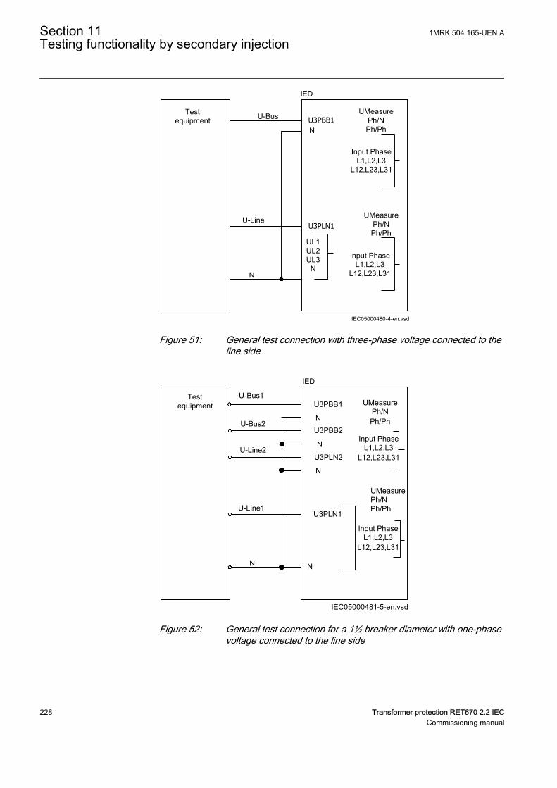
Testequipment
UMeasurePh/NPh/Ph
IEC05000480-4-en.vsd
U-Bus
U-Line
N
IED
U3PBB1N
UL1UL2UL3
N
Input PhaseL1,L2,L3
L12,L23,L31
UMeasurePh/NPh/Ph
Input PhaseL1,L2,L3
L12,L23,L31
U3PLN1
IEC05000480 V4 EN-US
Figure 51: General test connection with three-phase voltage connected to theline side
U-Bus1
U-Line1
N
Testequipment
IED
U3PBB1
N
IEC05000481-5-en.vsd
N
UMeasure Ph/NPh/Ph
U-Bus2
U-Line2
U3PBB2
U3PLN2
U3PLN1
N
N
Input PhaseL1,L2,L3
L12,L23,L31
UMeasurePh/NPh/Ph
Input PhaseL1,L2,L3
L12,L23,L31
IEC05000481 V5 EN-US
Figure 52: General test connection for a 1½ breaker diameter with one-phasevoltage connected to the line side
Section 11 1MRK 504 165-UEN ATesting functionality by secondary injection
228 Transformer protection RET670 2.2 IECCommissioning manual
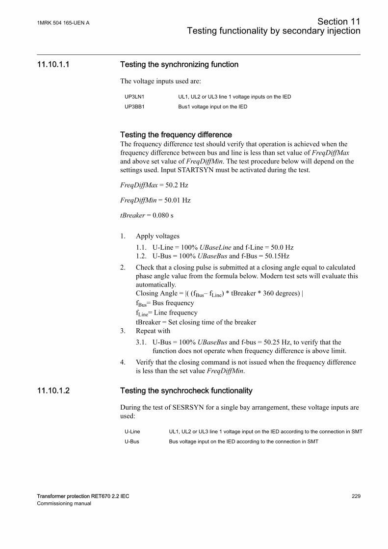
11.10.1.1 Testing the synchronizing functionM2377-21 v8
The voltage inputs used are:
UP3LN1 UL1, UL2 or UL3 line 1 voltage inputs on the IED
UP3BB1 Bus1 voltage input on the IED
Testing the frequency differenceM2377-116 v11
The frequency difference test should verify that operation is achieved when thefrequency difference between bus and line is less than set value of FreqDiffMaxand above set value of FreqDiffMin. The test procedure below will depend on thesettings used. Input STARTSYN must be activated during the test.
FreqDiffMax = 50.2 Hz
FreqDiffMin = 50.01 Hz
tBreaker = 0.080 s
1. Apply voltages1.1. U-Line = 100% UBaseLine and f-Line = 50.0 Hz1.2. U-Bus = 100% UBaseBus and f-Bus = 50.15Hz
2. Check that a closing pulse is submitted at a closing angle equal to calculatedphase angle value from the formula below. Modern test sets will evaluate thisautomatically.Closing Angle = |( (fBus– fLine) * tBreaker * 360 degrees) |fBus= Bus frequencyfLine= Line frequencytBreaker = Set closing time of the breaker
3. Repeat with3.1. U-Bus = 100% UBaseBus and f-bus = 50.25 Hz, to verify that the
function does not operate when frequency difference is above limit.4. Verify that the closing command is not issued when the frequency difference
is less than the set value FreqDiffMin.
11.10.1.2 Testing the synchrocheck functionalityM2377-132 v9
During the test of SESRSYN for a single bay arrangement, these voltage inputs areused:
U-Line UL1, UL2 or UL3 line 1 voltage input on the IED according to the connection in SMT
U-Bus Bus voltage input on the IED according to the connection in SMT
1MRK 504 165-UEN A Section 11Testing functionality by secondary injection
Transformer protection RET670 2.2 IEC 229Commissioning manual
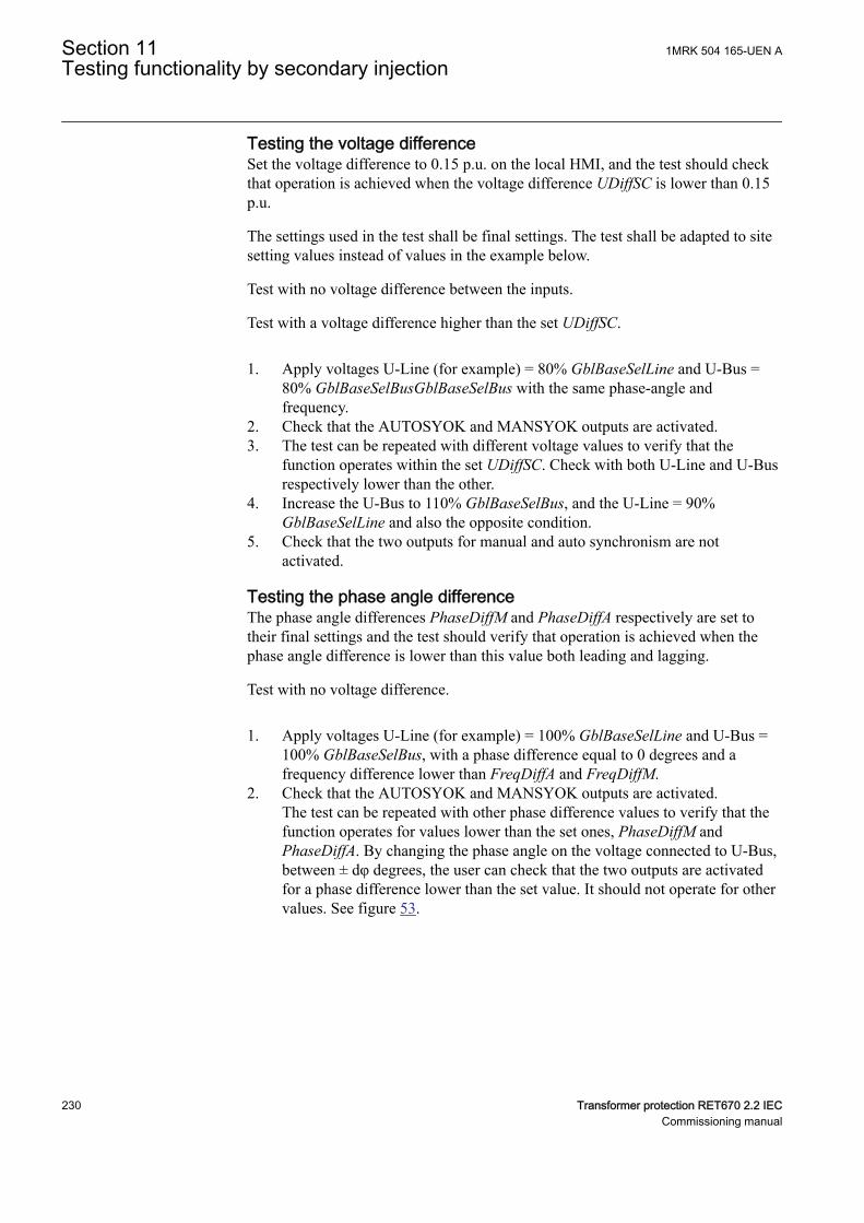
Testing the voltage differenceM2377-194 v8
Set the voltage difference to 0.15 p.u. on the local HMI, and the test should checkthat operation is achieved when the voltage difference UDiffSC is lower than 0.15p.u.
The settings used in the test shall be final settings. The test shall be adapted to sitesetting values instead of values in the example below.
Test with no voltage difference between the inputs.
Test with a voltage difference higher than the set UDiffSC.
1. Apply voltages U-Line (for example) = 80% GblBaseSelLine and U-Bus =80% GblBaseSelBusGblBaseSelBus with the same phase-angle andfrequency.
2. Check that the AUTOSYOK and MANSYOK outputs are activated.3. The test can be repeated with different voltage values to verify that the
function operates within the set UDiffSC. Check with both U-Line and U-Busrespectively lower than the other.
4. Increase the U-Bus to 110% GblBaseSelBus, and the U-Line = 90%GblBaseSelLine and also the opposite condition.
5. Check that the two outputs for manual and auto synchronism are notactivated.
Testing the phase angle differenceM2377-215 v8
The phase angle differences PhaseDiffM and PhaseDiffA respectively are set totheir final settings and the test should verify that operation is achieved when thephase angle difference is lower than this value both leading and lagging.
Test with no voltage difference.
1. Apply voltages U-Line (for example) = 100% GblBaseSelLine and U-Bus =100% GblBaseSelBus, with a phase difference equal to 0 degrees and afrequency difference lower than FreqDiffA and FreqDiffM.
2. Check that the AUTOSYOK and MANSYOK outputs are activated.The test can be repeated with other phase difference values to verify that thefunction operates for values lower than the set ones, PhaseDiffM andPhaseDiffA. By changing the phase angle on the voltage connected to U-Bus,between ± dφ degrees, the user can check that the two outputs are activatedfor a phase difference lower than the set value. It should not operate for othervalues. See figure 53.
Section 11 1MRK 504 165-UEN ATesting functionality by secondary injection
230 Transformer protection RET670 2.2 IECCommissioning manual
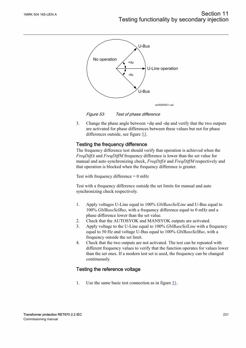
+dj
-dj
U-Bus
U-Line operation
U-Bus
No operation
en05000551.vsdIEC05000551 V1 EN-US
Figure 53: Test of phase difference
3. Change the phase angle between +dφ and -dφ and verify that the two outputsare activated for phase differences between these values but not for phasedifferences outside, see figure 53.
Testing the frequency differenceM2377-232 v9
The frequency difference test should verify that operation is achieved when theFreqDiffA and FreqDiffM frequency difference is lower than the set value formanual and auto synchronizing check, FreqDiffA and FreqDiffM respectively andthat operation is blocked when the frequency difference is greater.
Test with frequency difference = 0 mHz
Test with a frequency difference outside the set limits for manual and autosynchronizing check respectively.
1. Apply voltages U-Line equal to 100% GblBaseSelLine and U-Bus equal to100% GblBaseSelBus, with a frequency difference equal to 0 mHz and aphase difference lower than the set value.
2. Check that the AUTOSYOK and MANSYOK outputs are activated.3. Apply voltage to the U-Line equal to 100% GblBaseSelLine with a frequency
equal to 50 Hz and voltage U-Bus equal to 100% GblBaseSelBus, with afrequency outside the set limit.
4. Check that the two outputs are not activated. The test can be repeated withdifferent frequency values to verify that the function operates for values lowerthan the set ones. If a modern test set is used, the frequency can be changedcontinuously.
Testing the reference voltageM2377-249 v5
1. Use the same basic test connection as in figure 51.
1MRK 504 165-UEN A Section 11Testing functionality by secondary injection
Transformer protection RET670 2.2 IEC 231Commissioning manual
The voltage difference between the voltage connected to U-Bus and U-Lineshould be 0%, so that the AUTOSYOK and MANSYOK outputs are activatedfirst.
2. Change the U-Line voltage connection to U-Line2 without changing thesetting on the local HMI. Check that the two outputs are not activated.
11.10.1.3 Testing the energizing checkM2377-262 v6
During the test of the energizing check function for a single bay arrangement, thesevoltage inputs are used:
U-Line UL1, UL2 or UL3 line1 voltage inputs on the IED
U-Bus Bus voltage input on the IED
GeneralM2377-271 v6
When testing the energizing check function for the applicable bus, arrangementshall be done for the energizing check functions. The voltage is selected byactivation of different inputs in the voltage selection logic.
Live voltage level is fixed to 80% UBase and dead voltage level to fixed 40%UBase.
The test shall be performed according to the settings for the station. Test thealternatives below that are applicable.
Testing the dead line live bus (DLLB)M2377-276 v7
The test should verify that the energizing check function operates for a low voltageon the U-Line and for a high voltage on the U-Bus. This corresponds to theenergizing of a dead line to a live bus.
1. Apply a single-phase voltage 100% GblBaseSelBus to the U-Bus, and asingle-phase voltage 30% GblBaseSelLine to the U-Line.
2. Check that the AUTOENOK and MANENOK outputs are activated after settAutoEnerg respectively tManEnerg.
3. Increase the U-Line to 60% GblBaseSelLine and U-Bus to be equal to 100%GblBaseSelBus. The outputs should not be activated.
4. The test can be repeated with different values on the U-Bus and the U-Line.
Testing the dead bus live line (DBLL)M2377-289 v8
The test should verify that the energizing check function operates for a low voltageon the U-Bus and for a high voltage on the U-Line. This corresponds to anenergizing of a dead bus to a live line.
Section 11 1MRK 504 165-UEN ATesting functionality by secondary injection
232 Transformer protection RET670 2.2 IECCommissioning manual
1. Verify the settings AutoEnerg or ManEnerg to be DBLL.2. Apply a single-phase voltage of 30% GblBaseSelBus to the U-Bus and a
single-phase voltage of 100% GblBaseSelLine to the U-Line.3. Check that the AUTOENOK and MANENOK outputs are activated after set
tAutoEnerg respectively tManEnerg.4. Decrease the U-Line to 60% GblBaseSelLine and keep the U-Bus equal to
30% GblBaseSelBus. The outputs should not be activated.5. The test can be repeated with different values on the U-Bus and the U-Line.
Testing both directions (DLLB or DBLL)M2377-306 v7
1. Verify the local HMI settings AutoEnerg or ManEnerg to be Both.2. Apply a single-phase voltage of 30% GblBaseSelLine to the U-Line and a
single-phase voltage of 100% GblBaseSelBus to the U-Bus.3. Check that the AUTOENOK and MANENOK outputs are activated after set
tAutoEnerg respectively tManEnerg.4. Change the connection so that the U-Line is equal to100% GblBaseSelLine
and the U-Bus is equal to 30% GblBaseSelBus. The outputs should still beactivated.
5. The test can be repeated with different values on the U-Bus and the U-Line.
Testing the dead bus dead line (DBDL)M2377-323 v8
The test should verify that the energizing check function operates for a low voltageon both the U-Bus and the U-Line, that is, closing of the breaker in a non-energizedsystem. Test is valid only when this function is used.
1. Verify the local HMI setting AutoEnerg to be Off and ManEnerg to be DBLL.2. Set the parameter ManEnergDBDL to On.3. Apply a single-phase voltage of 30% GblBaseSelBus to the U-Bus and a
single-phase voltage of 30% GblBaseSelLine to the U-Line.4. Check that the MANENOK output is activated after set tManEnerg.5. Increase the U-Bus to 80% GblBaseSelBus and keep the U-Line equal to 30%
GblBaseSelLine. The outputs should not be activated.6. Repeat the test with ManEnerg set to DLLB with different values on the U-
Bus and the U-Line voltage.
11.10.1.4 Testing the voltage selectionM2377-342 v2
Testing the voltage selection for single CB arrangementsM2377-473 v7
This test should verify that the correct voltage is selected for the measurement inthe SESRSYN function used in a double-bus arrangement. Apply a single-phasevoltage of 100% GblBaseSelLine to the U-Line and a single-phase voltage of 100%GblBaseSelBus to the U-Bus.
1MRK 504 165-UEN A Section 11Testing functionality by secondary injection
Transformer protection RET670 2.2 IEC 233Commissioning manual
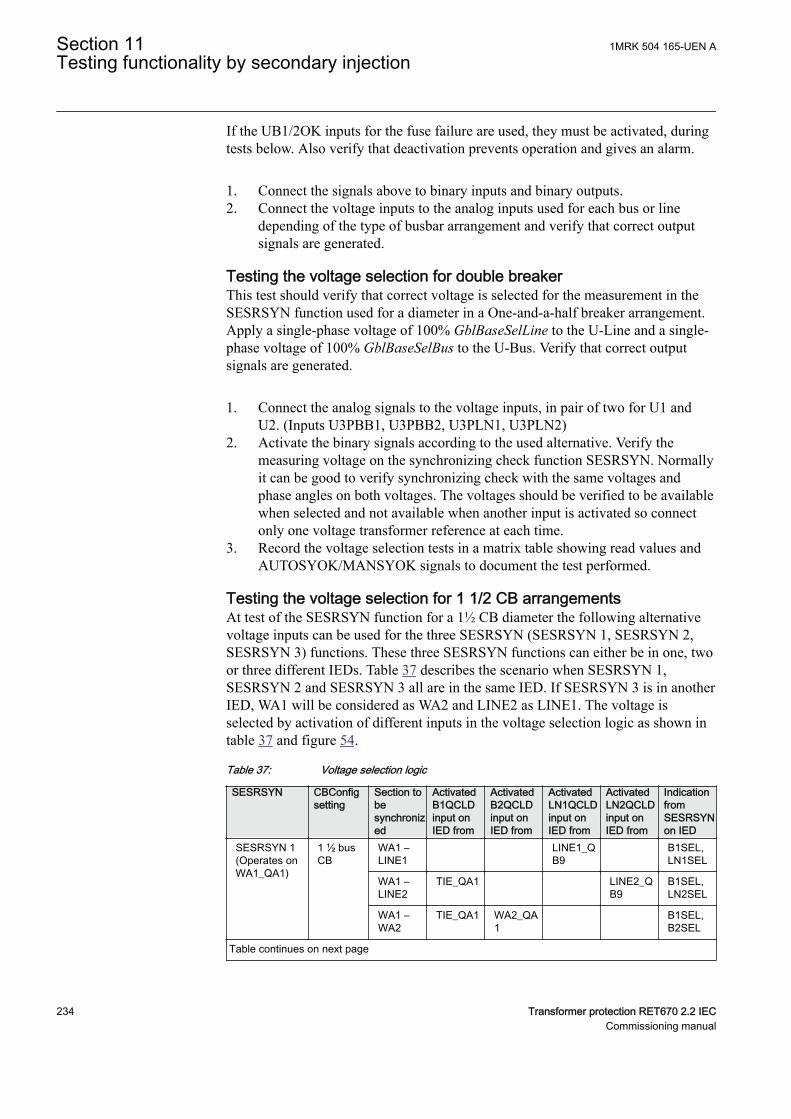
If the UB1/2OK inputs for the fuse failure are used, they must be activated, duringtests below. Also verify that deactivation prevents operation and gives an alarm.
1. Connect the signals above to binary inputs and binary outputs.2. Connect the voltage inputs to the analog inputs used for each bus or line
depending of the type of busbar arrangement and verify that correct outputsignals are generated.
Testing the voltage selection for double breakerM2377-691 v6
This test should verify that correct voltage is selected for the measurement in theSESRSYN function used for a diameter in a One-and-a-half breaker arrangement.Apply a single-phase voltage of 100% GblBaseSelLine to the U-Line and a single-phase voltage of 100% GblBaseSelBus to the U-Bus. Verify that correct outputsignals are generated.
1. Connect the analog signals to the voltage inputs, in pair of two for U1 andU2. (Inputs U3PBB1, U3PBB2, U3PLN1, U3PLN2)
2. Activate the binary signals according to the used alternative. Verify themeasuring voltage on the synchronizing check function SESRSYN. Normallyit can be good to verify synchronizing check with the same voltages andphase angles on both voltages. The voltages should be verified to be availablewhen selected and not available when another input is activated so connectonly one voltage transformer reference at each time.
3. Record the voltage selection tests in a matrix table showing read values andAUTOSYOK/MANSYOK signals to document the test performed.
Testing the voltage selection for 1 1/2 CB arrangementsGUID-12E7DA63-FE04-4C83-9BA6-34818C510DB8 v4
At test of the SESRSYN function for a 1½ CB diameter the following alternativevoltage inputs can be used for the three SESRSYN (SESRSYN 1, SESRSYN 2,SESRSYN 3) functions. These three SESRSYN functions can either be in one, twoor three different IEDs. Table 37 describes the scenario when SESRSYN 1,SESRSYN 2 and SESRSYN 3 all are in the same IED. If SESRSYN 3 is in anotherIED, WA1 will be considered as WA2 and LINE2 as LINE1. The voltage isselected by activation of different inputs in the voltage selection logic as shown intable 37 and figure 54.
Table 37: Voltage selection logic
SESRSYN CBConfigsetting
Section tobesynchronized
ActivatedB1QCLDinput onIED from
ActivatedB2QCLDinput onIED from
ActivatedLN1QCLDinput onIED from
ActivatedLN2QCLDinput onIED from
IndicationfromSESRSYNon IED
SESRSYN 1(Operates onWA1_QA1)
1 ½ busCB
WA1 –LINE1
LINE1_QB9
B1SEL,LN1SEL
WA1 –LINE2
TIE_QA1 LINE2_QB9
B1SEL,LN2SEL
WA1 –WA2
TIE_QA1 WA2_QA1
B1SEL,B2SEL
Table continues on next page
Section 11 1MRK 504 165-UEN ATesting functionality by secondary injection
234 Transformer protection RET670 2.2 IECCommissioning manual
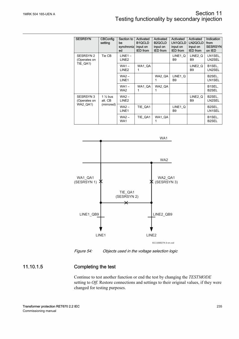
SESRSYN CBConfigsetting
Section tobesynchronized
ActivatedB1QCLDinput onIED from
ActivatedB2QCLDinput onIED from
ActivatedLN1QCLDinput onIED from
ActivatedLN2QCLDinput onIED from
IndicationfromSESRSYNon IED
SESRSYN 2(Operates onTIE_QA1)
Tie CB LINE1 –LINE2
LINE1_QB9
LINE2_QB9
LN1SEL,LN2SEL
WA1 –LINE2
WA1_QA1
LINE2_QB9
B1SEL,LN2SEL
WA2 –LINE1
WA2_QA1
LINE1_QB9
B2SEL,LN1SEL
WA1 –WA2
WA1_QA1
WA2_QA1
B1SEL,B2SEL
SESRSYN 3(Operates onWA2_QA1)
1 ½ busalt. CB(mirrored)
WA2 –LINE2
LINE2_QB9
B2SEL,LN2SEL
WA2 –LINE1
TIE_QA1 LINE1_QB9
B2SEL,LN1SEL
WA2 –WA1
TIE_QA1 WA1_QA1
B1SEL,B2SEL
WA1
WA2
WA1_QA1(SESRSYN 1)
WA2_QA1(SESRSYN 3)
TIE_QA1(SESRSYN 2)
LINE1 LINE2
LINE1_QB9 LINE2_QB9
IEC11000274-3-en.vsdIEC11000274 V3 EN-US
Figure 54: Objects used in the voltage selection logic
11.10.1.5 Completing the testM2377-1042 v5
Continue to test another function or end the test by changing the TESTMODEsetting to Off. Restore connections and settings to their original values, if they werechanged for testing purposes.
1MRK 504 165-UEN A Section 11Testing functionality by secondary injection
Transformer protection RET670 2.2 IEC 235Commissioning manual
11.10.2 Apparatus control APCM13385-2 v6
The apparatus control function consists of four types of function blocks, which areconnected in a delivery-specific way between bays and to the station level. For thatreason, test the total function in a system, that is, either in a complete deliverysystem as an acceptance test (FAT/SAT) or as parts of that system.
If a block/unblock command is sent from remote to function, whilethe IED is shut down, this command will not be recognized afterthe start up, thus the command that was sent prior to the shut downis used. In such cases, where there is a mismatch, the user isadvised to make a complete cycle of block/unblock operations toalign the statuses.
11.10.3 Voltage control TR1ATCC, TR8ATCC, TCMYLTC,TCLYLTC
SEMOD175185-3 v11
Prepare the IED for verification of settings outlined in Section "Preparing the IEDto verify settings".
The automatic voltage control for tap changer, single control TR1ATCC is basedon a transformer configuration that consists of one tap changer on a single two-winding power transformer.
The automatic voltage control for tap changer, parallel control TR8ATCC, ifinstalled, may be set to operate in Master Follower (MF) mode, or MinimiseCirculating Current (MCC) mode. The commissioning tests for each parallelcontrol mode are addressed separately in the following procedure.
Secondary injection of load current (IL) and secondary bus voltage (UB) equivalentquantities are required during installation and commissioning tests. The testconsists mainly of:
1. Increasing or decreasing the injected voltage or current at the analogue inputsof the IED.
2. Checking that the corresponding commands (Lower or Raise) are issued by thevoltage control function.
Setting confirmation is an important step for voltage control in the installation andcommissioning phase to ensure consistency of power systems base quantities,alarm/blocking conditions and parallel control settings for each transformer controlfunction.
Before starting any test, verify the following settings in PCM600 or the local HMIfor TR1ATCC, TR8ATCC and TCMYLTC and TCLYLTC.
• Confirm power system base quantities I1Base, I2Base, UBase.
Section 11 1MRK 504 165-UEN ATesting functionality by secondary injection
236 Transformer protection RET670 2.2 IECCommissioning manual
Main menu/Settings/Setting Group N/Control/TransformerVoltageControl(ATCC,90)/TR1ATCC:x/TR8ATCC:x/General
and
Main menu/Settings/Setting Group N/Control/TransformerVoltageControl(ATCC,90)/TR1ATCC:x
.
• Confirm that the setting for short circuit impedance Xr2 for TR1ATCC orTR8ATCC is in accordance with transformer data:• Short circuit impedance, available on the local HMI under Main menu/
Settings/General settings/Control/TransformerVoltageControl(ATCC,90)/TR1ATCC:x/TR8ATCC:x/Xr2.
• Confirm that the setting for TCMYLTC or TCLYLTC is in accordance withtransformer data:• Tap change timeout duration - effectively the maximum transformer tap
change time, tTCTimeout, available on the local HMI under Main menu/Settings/Setting Group N/Control/TransformerTapControl(YLTC,84)/TCMYLTC:x/TCLYLTC:x/tTCTimeout.
• Load tap changer pulse duration - required length of pulse from IED toload tap changer, tPulseDur, available on the local HMI under Mainmenu/Settings/Setting Group N/Control/TransformerTapControl(YLTC,84)/TCMYLTC:x/TCLYLTC:x/tPulseDur.
• Transformer tap range, LowVoltTap and HighVoltTap, available on thelocal HMI under Main menu/Settings/General Settings/Control/TransformerTapControl(YLTC,84)/TCMYLTC:x/TCLYLTC:x/HighVoltTap and .
• Load tap changer code type - method for digital feedback of tap position,CodeType, available on the local HMI under Main menu/Settings/General settings/Control/TransformerTapControl(YLTC,84)/TCMYLTC:x/TCLYLTC:x/CodeType.
During the installation and commissioning, the behavior of thevoltage control functions for different tests may be governed by aparameter group, available on the local HMI under Main menu/Settings/General settings/Control/TransformerVoltageControl(ATCC,90)/TR1ATCC:x/TR8ATCC:x. These parameter settings can cause a Total Block,Automatic Block or Alarm for a variety of system conditionsincluding over and under voltage, over current and tap changerfailure. It is important to review these settings and confirm theintended response of the voltage control function for differentsecondary injection tests.
1MRK 504 165-UEN A Section 11Testing functionality by secondary injection
Transformer protection RET670 2.2 IEC 237Commissioning manual
TerminologyThe busbar voltage UB is a shorter notation for the measured voltages UL1, UL2,UL3 or Uij, where Uij is the phase-phase voltage, Uij = Ui -Uj, or Ui, where Ui isone single-phase-to-earth voltage.
IL is a shorter notation for the measured load current; it is to be used instead of thethree-phase quantities IL1, IL2, IL3 or the two-phase quantities Ii and Ij, or single-phase current Ii.
Also note that for simplicity, the Parameter Setting menu structuresincluded in the following procedure are referred to universally asVCP1, for example, Main menu/Settings/Setting Group N/Control/TransformerVoltageControl(ATCC,90)/TR1ATCC:x/TR8ATCC:x/Time/t1 and t2l.
For cases where single-mode voltage control is implemented, the Parameter Settingmenu structure includes TR1ATCC:1 instead of the parallel designator TR8ATCC:1.
11.10.3.1 Secondary testSEMOD175185-145 v5
The voltage control function performs basic voltage regulation by comparing acalculated load voltage (UL) against a voltage range defined by setting UDeadband(with upper and lower limits U2 and U1 respectively). The calculated load voltageUL represents the secondary transformer bus voltage UB adjusted for Load dropcompensation (LDC) where enabled in settings.
Note that when LDC is disabled, UB equals UL.
When the load voltage UL stays within the interval between U1 and U2, no actionwill be taken.
If UL < U1 or UL > U2, a command timer will start, which is constant time orinverse time defined by setting t1 and t1Use. The command timer will operatewhile the measured voltage stays outside the inner deadband (defined by settingUDeadbandInner).
If UL remains outside of the voltage range defined by UDeadband and thecommand timer expires, the voltage control will execute a raise or lower commandto the transformer tap changer. This command sequence will be repeated until UL isbrought back within the inner deadband range.
11.10.3.2 Check the activation of the voltage control operationSEMOD175185-537 v8
Section 11 1MRK 504 165-UEN ATesting functionality by secondary injection
238 Transformer protection RET670 2.2 IECCommissioning manual
1. Confirm Transformer Tap Control = On and Transformer Voltage Control =On• Direct tap change control
Main menu/Settings/Setting Group N/Control/TransformerTapChanger(YLTC,84)/TCMYLTC:x/TCLYLTC:x/Operation• Automatic transformer voltage control
Main menu/Settings/Setting Group N/Control/TransformerVoltageControl(ATCC,90)/TR1ATCC:x/TR8ATCC:x/General/Operation• Enable Tap Command
Main menu/Settings/General settings/Control/TransformerTapChanger(YLTC,84)/TCMYLTC:x/TCLYLTC:x/EnabTapCmdWhile the test set is connected to the IED but no voltage is applied, thevoltage control functions will detect an undervoltage condition that mayresult in an alarm or blocking of the voltage-control operation. Theseconditions will be shown on the local HMI.
2. Apply the corresponding voltageConfirm the analog measuring mode prior to undertaking secondary injection(positive sequence, phase-to-phase, or phase-to-earth). This measuring modeis defined in the local HMI under Main menu/Settings/Setting Group N/Control/TransformerVoltageControl(ATCC,90)/TR1ATCC:x/TR8ATCC:x/General/MeasModeThe application of nominal voltage USet according to set MeasMode to theIEDs should cause the alarm or blocking condition for undervoltage to reset.
11.10.3.3 Check the normal voltage regulation functionSEMOD175185-562 v5
1. Review the settings for UDeadband (based on percentage of nominal busvoltage) and calculate the upper (U2) and lower (U1) voltage regulation limitsfor which a tap change command will be issued.
2. Review the expected time for first (t1) and subsequent (t2) tap changecommands from the voltage control function on the local HMI under Mainmenu/Settings/Setting Group N/Control/TransformerVoltageControl(ATCC,90)/TR1ATCC:x/TR8ATCC:x/Time/t1 and t2l
3. Lower the voltage 1% below U1 and wait for the issue of a Raise commandfrom the voltage control after the expiry of a constant or inverse time delayset by t1. Detection of this command will involve locating the allocatedbinary output for a raise pulse command in the Signal Matrix in PCM600 andmonitoring a positive from this output.
1MRK 504 165-UEN A Section 11Testing functionality by secondary injection
Transformer protection RET670 2.2 IEC 239Commissioning manual
4. After the issue of the raise command, return the applied voltage to USet(nominal value).
5. Raise the voltage 1% above the upper deadband limit U2 and wait for theissue of a lower command from the voltage control after the expiry of aconstant or inverse time delay set by t1. Detection of this command willinvolve locating the allocated binary output for a low pulse command in theSignal Matrix in PCM600 and monitoring a positive from this output.
6. Return the applied voltage to USet.
11.10.3.4 Check the undervoltage block functionSEMOD175185-578 v5
1. Confirm the setting for Ublock, nominally at 80% of rated voltage.2. Confirm the voltage control function response to an applied voltage below
Ublock, by reviewing the setting in the local HMI under Main menu/Settings/General settings/Control/TransformerVoltageControl(ATCC,90)/TR1ATCC:x/TR8ATCC:x/UVBk that may cause an alarm, total orautomatic block of the voltage control function to be displayed on the localHMI.
3. Apply a voltage slightly below Ublock and confirm the response of thevoltage control function.
11.10.3.5 Check the upper and lower busbar voltage limitSEMOD175185-588 v5
1. Confirm the settings for Umin and Umax in the local HMI under Main menu/Settings/Setting group N/Control/TransformerVoltageControl(ATCC,90)/TR1ATCC:x/TR8ATCC:x/Voltage/Umax or Umin and Main menu/Settings/IED Settings/Control/TR8ATCC (90)/TR8ATCC:n/Voltage/Umax
2. Confirm the voltage control function response to an applied voltage belowUmin and above Umax, by reviewing the settings in the local HMI underMain menu/Settings/General settings/Control/TransformerVoltageControl(ATCC,90)/TR1ATCC:x/TR8ATCC:x/UVPartBk and Main menu/General Settings/Control/TransformerVoltageControl/TR1ATCC:x/TR8ATCC:x/OVPartBk. Theseconditions may cause an alarm or total block of the voltage control functionto be displayed on the local HMI.
3. Decrease the injected voltage slightly below the Umin value and check for thecorresponding blocking or alarm condition on the local HMI. For an alarmcondition, the voltage regulation function is not blocked and a raise commandshould be issued from the IED.
4. Increase the applied voltage slightly above the Umax value and check for thecorresponding blocking or alarm condition on the local HMI. For an alarmcondition, the voltage regulation function is not blocked and a lowercommand should be issued from the IED.
Section 11 1MRK 504 165-UEN ATesting functionality by secondary injection
240 Transformer protection RET670 2.2 IECCommissioning manual
11.10.3.6 Check the overcurrent block functionSEMOD175185-605 v5
1. Confirm the setting for Iblock in the local HMI under Main menu/Settings/Setting group N/Control/TransformerVoltageControl(ATCC,91)/TR1ATCC:x/TR8ATCC:x/TCCtrl/Iblock
2. Confirm the voltage control function response to an applied current aboveIblock, by reviewing the settings in the local HMI under Main menu/Settings/General settings/Control/TransformerVoltageControl(ATCC,91)/TR1ATCC:x/TR8ATCC:x/OVPartBk. This condition may cause analarm or total block of the voltage control function to be displayed on thelocal HMI.
3. Inject a current higher than the Iblock setting and confirm the alarm orblocking condition is present on the local HMI. If an automatic or totalblocking condition occurs, change the applied secondary voltage and confirmthat no tap change commands are issued from the associated binary outputs.This situation can also be confirmed through reviewing the disturbance andservice reports on the local HMI.
11.10.3.7 Single transformerSEMOD175185-669 v2
Load drop compensationSEMOD175185-672 v5
1. Confirm that OperationLDC is set to On.2. Confirm settings for Rline and Xline.3. Calculate the expected load voltage UL (displayed as a measured value on the
local HMI) based on secondary injection of transformer secondary voltage(UB = USet) and rated load current (IL = I1Base), in accordance withequation 107.
EQUATION2080 V3 EN-US (Equation 107)
where:
UL, IL = Re(IL) + jlm(IL) are complex phase quantities
When all secondary phase-to-earth voltages are available, use the positive-sequence components of voltage and current. By separation of real andimaginary parts:
, , , ,ul re ub re rline il re xline il im= - × + ×
EQUATION2082 V1 EN-US (Equation 108)
1MRK 504 165-UEN A Section 11Testing functionality by secondary injection
Transformer protection RET670 2.2 IEC 241Commissioning manual
, , , ,ul im ub im xline il re rline il im= - × - ×
EQUATION2084 V1 EN-US (Equation 109)
where:
ub is the complex value of the busbar voltage
il is the complex value of the line current (secondary side)
rline is the value of the line resistance
xline is the value of the line reactance
For comparison with the set-point value, the modulus of UL are according toequation 110.
¦ UL¦ = (ul , re)2 + (ul , im)2
EQUATION2086 V2 EN-US (Equation 110)
4. Inject voltage for UB equal to setting USet.5. Inject current equal to rated current I2Base.6. Confirm on the local HMI that service values for bus voltage and load current
are equal to injected quantities.7. Confirm that the calculated value for load voltage, displayed on the local
HMI, is equal to that derived through hand calculations.8. When setting OperationLDC set to On, the voltage regulation algorithm uses
the calculated value for load voltage as the regulating quantity to compareagainst USet and the voltage deadband limits UDeadband andUDeadbandInner.
9. While injecting rated current I2Base into the IED, inject a quantity for UBthat is slightly higher then USet + |(Rline+jXLine) · IL|. This will ensure thatthe regulating voltage UL is higher than USet, and hence no tap changecommand should be issued from the IED.
10. Reduce the injected voltage for UB slightly below USet + |(Rline+jXLine) · IL|and confirm that the calculated value for load voltage is below USet and a tapchange command is issued from the IED.
11.10.3.8 Parallel voltage regulationSEMOD175185-714 v2
Master follower voltage regulationSEMOD175185-716 v6
1. For the transformers connected in the parallel group, confirm thatOperationPAR is set to MF.
2. For parallel operation, it is also recommended to confirm for parallel groupmembership, defined by setting TnRXOP in the local HMI under Mainmenu/Settings/Setting group N/Control/TransformerVoltageControl(ATCC,90)/TR8ATCC:x/ParCtrl
Section 11 1MRK 504 165-UEN ATesting functionality by secondary injection
242 Transformer protection RET670 2.2 IECCommissioning manual
The general parallel arrangement of transformers are defined by settingTnRXOP to On or Off. The following rules are applicable on the settingsT1RXOP – T4RXOP.If IED T1 and T2 are connected,• T1RXOP shall be set to On in instance 2 of TR8ATCC,• T2RXOP shall be set to On in instance 3 of TR8ATCC,• T2RXOP and T3RXOP shall be set to On in instance 1 of TR8ATCC,
and so on.
The parameter corresponding to the own IED must not be set.T1RXOP should thus not be set in IED T1, T2RXOP not inIED T2, and so on.
3. The lowest transformer number in the parallel group is by default set as theMaster – confirm that this is the case by reviewing the setting in the localHMI.
4. Review the settings for UDeadband (based on percentage of nominal busvoltage) and calculate the upper (U2) and lower (U1) voltage regulation limitsfor which a tap change command will be issued from the master transformerin the group.
5. Review the expected time for first (t1) and subsequent (t2) tap changecommands from the master transformer in the local HMI under Main menu/Settings/Setting group N/Control/TransformerVoltageControl(ATCC,90)/TR1ATCC:x/TR8ATCC:x/Time/t1 and t2
6. Apply a voltage 1% below U1 and wait for the issue of a raise command fromthe voltage control after the expiry of a constant or inverse time delay set byt1. Detection of this command will involve locating the allocated binaryoutput for a raise command in the Signal Matrix in PCM600 and monitoring apositive from this output. Confirm the timing of this command correlates withthe setting t1.
7. After the issue of the raise command, confirm that all follower transformersin the group change tap in accordance with the command issued from themaster transformer.
8. Inject a voltage UB for the master transformer that is 1% above the upperdeadband limit U2 and wait for the issue of a lower command from thevoltage control after the expiry of a constant or inverse time delay set by t2.
9. Confirm that all follower transformers in the group change tap in accordancewith this command.
Circulating current voltage regulationSEMOD175185-775 v6
This instruction for confirmation of circulating current voltage regulation assumestwo transformers in the parallel group. Setting confirmation through secondaryinjection requires calculation of circulating currents for each transformer based onimpedance values and respective compensating factors, and is therefore morecomplex for greater than two transformers.
1MRK 504 165-UEN A Section 11Testing functionality by secondary injection
Transformer protection RET670 2.2 IEC 243Commissioning manual
1. Confirm that OperationPAR is set to CC for the transformers in the parallelgroup.
2. For parallel operation, it is also recommended that settings be confirmed forparallel group membership, governed by setting TnRXOP in the local HMIunder Main menu/Settings/Setting group N/Control/TransformerVoltageControl(ATCC,90)/TR8ATCC:x/ParCtrlThe general parallel arrangement of transformers are defined by settingTnRXOP to On or Off. The following rules are applicable on the settingsT1RXOP - T4RXOP.If IED T1 and T2 are connected,• T1RXOP shall be set to On in instance 2 of TR8ATCC, and• T2RXOP shall be set to On in instance 1 of TR8ATCC.
If T1 - T3 are available,• T1RXOP and T2RXOP shall be set to On in instance 3 of TR8ATCC,• T2RXOP and T3RXOP shall be set to On in instance 1 of TR8ATCC
and so on.
The parameter corresponding to the own IED must not be set.T1RXOP should thus not be set in IED T1, T2RXOPnot inIED T2 and so on.
3. Review the settings for UDeadband (based on percentage of nominal busvoltage) and calculate the upper (U2) and lower (U1) voltage regulation limitsfor which a tap change command will be issued from the master transformerin the group.
4. Review the expected time for first (t1) and subsequent (t2) tap changecommands from the master transformer in the local HMI under Main menu/Settings/Setting group N/TransformerVoltageControl(ATCC,90)/TR1ATCC:x/TR8ATCC:x/Time/t1 and t2
5. Inject a voltage UB equal to USet for each transformer.6. Inject a load current for Transformer 1 that is equal to rated load current
I2Base and a load current for Transformer 2 that is equal to 95% of rated loadcurrent I2Base. This will have the effect of producing a calculated circulatingcurrent that flows from HV to LV side for Transformer 1 and LV to HV sidefor Transformer 2.
7. Confirm that a circulating current is measured on the local HMI that is equalin magnitude to 5% of I2Base, with polarity as discussed in step 6.
8. Confirm the settings for Ci (Compensation Factor) and Xi (Transformer ShortCircuit Impedance). Using these setting values and the measured quantity ofcirculating current from the local HMI (Icc_i), calculate the value forcirculating current voltage adjustment Uci.
_Udi Ci Icc i Xi= × ×EQUATION2088 V1 EN-US (Equation 111)
Section 11 1MRK 504 165-UEN ATesting functionality by secondary injection
244 Transformer protection RET670 2.2 IECCommissioning manual
The voltage regulation algorithm then increases (for transformer T2) ordecreases (for transformer T1) the measured voltage by Udi and compares Uiagainst the voltage deadband limits U1 and U2 for the purposes of voltageregulation.
EQUATION2090 V3 EN-US (Equation 112)
9. To cause a tap change, the calculated value for circulating current voltageadjustment must offset the injected quantity for bus voltage UB so that Ui isoutside the voltage deadband created by setting UDeadband. Expressed byequation 113 and equation 114.
EQUATION2092 V2 EN-US (Equation 113)
EQUATION2094 V2 EN-US (Equation 114)
(for the purposes of this test procedure)
Therfore:
_ 2Ci Icc i Xi U Uset× × > -EQUATION2096 V1 EN-US (Equation 115)
( )( )
2_ U UsetIcc i Ci Xi-
>×
EQUATION2098 V1 EN-US (Equation 116)
10. Using the settings for USet, UDeadband, C (Compensating factor) and Xr2(transformer short circuit impedance) calculate the magnitude of Icc_inecessary to cause a tap change command.
11. Inject current equal to I2Base for Transformer 1 and (I2Base - |Icc_i|) forTransformer 2 so that the magnitude of calculated circulating current willcause a raise command to be issued for Transformer 2 and a lower commandfor Transformer 1. Magnitude and direction of circulating currents measuredfor each transformer can be observed as service values on the local HMI andraise/lower commands detected from the binary output mapped in the SignalMatrix.
1MRK 504 165-UEN A Section 11Testing functionality by secondary injection
Transformer protection RET670 2.2 IEC 245Commissioning manual
The voltage injection equal to USet is required for bothtransformers during this test.
12. Confirm that a tap change command is issued from the voltage controlfunction to compensate for the circulating current.
13. Injected currents can be reversed such that the direction of calculatedcirculating currents change polarity, which will cause a lower command forTransformer 2 and a raise command for Transformer 1.
Circulating current limitSEMOD175185-841 v6
1. Confirm that OperationPAR is set to CC for each transformer in the parallelgroup.
2. Confirm that OperCCBlock is set to On for each transformer in the parallelgroup.
3. Review the setting for CircCurrLimit.4. Review the setting for CircCurrBk to confirm whether a circulating current
limit will result in an Alarm state, Auto Block or Auto&Man Block of theautomatic voltage control for tap changer, for parallel control functionTR8ATCC.
5. Inject a voltage UB equal to USet for each transformer.6. Inject a load current for Transformer 1 that is equal to rated load current
I2Base and a load current for Transformer 2 that is 1% less than (I2Base –(I2Base · CircCurrLimit))
7. Confirm that the automatic voltage control for tap changer, for parallelcontrol function TR8ATCC responds in accordance with the setting forCircCurrBk. Alarm and blocking conditions can be confirmed throughinterrogation of the event menu or the control menu on the local HMI.
VTmismatch during parallel operationSEMOD175185-859 v4
1. Confirm that OperationPAR is set to MF for each transformer in the parallelgroup.
2. Review the setting for VTmismatch and tVTmismatch.3. Inject a voltage UB equal to USet for Transformer 1 and a voltage less than
(USet – (VTmismatch · USet)) for Transformer 2.4. This condition should result in a VTmismatch which will mutually block the
operation of the automatic voltage control for tap changer, parallel controlfunction TR8ATCC for all transformers connected in the parallel group,which can be confirmed through interrogation of the local HMI.
5. Confirm that the automatic voltage control for tap changer, parallel controlfunction TR8ATCC responds in accordance with the setting for CircCurrBk.
Section 11 1MRK 504 165-UEN ATesting functionality by secondary injection
246 Transformer protection RET670 2.2 IECCommissioning manual
11.10.3.9 Completing the testSEMOD175185-374 v4
Continue to test another function or end the test by changing the TESTMODEsetting to Off. Restore connections and settings to their original values, if they werechanged for testing purposes.
11.10.4 Single command, 16 signals SINGLECMDSEMOD172444-5 v3
For the single command function block, it is necessary to configure the outputsignal to corresponding binary output of the IED. The operation of the singlecommand function (SINGLECMD) is then checked from the local HMI byapplying the commands with Mode = Off, Steady or Pulse, and by observing thelogic statuses of the corresponding binary output. Command control functionsincluded in the operation of different built-in functions must be tested at the sametime as their corresponding functions.
11.10.5 InterlockingM11755-2 v8
Prepare the IED for verification of settings outlined in Section "Preparing the IEDto verify settings".
Values of the logical signals are available on the local HMI under Main menu/Tests/Function status/Control/Apparatus control/Interlocking. The SignalMonitoring in PCM600 shows the same signals that are available on the local HMI.
The interlocking function consists of a bay-level part and a station-level part. Theinterlocking is delivery specific and is realized by bay-to-bay communication overthe station bus. For that reason, test the function in a system, that is, either in acomplete delivery system as an acceptance test (FAT/SAT) or as parts of thatsystem.
11.11 Scheme communicationSEMOD53569-1 v1
11.11.1 Scheme communication logic for distance or overcurrentprotection ZCPSCH
M13868-2 v7
Prepare the IED for verification of settings outlined in Section "Preparing the IEDto verify settings".
Check the scheme logic during the secondary injection test of the impedance orovercurrent protection functions.
Activation of the different zones verifies that the CS signal is issued from theintended zones. The CS signal from the independent tripping zone must have atSendMin minimum time.
1MRK 504 165-UEN A Section 11Testing functionality by secondary injection
Transformer protection RET670 2.2 IEC 247Commissioning manual
Check the tripping function by activating the CR and CRG inputs with theoverreaching zone used to achieve the CACC signal.
It is sufficient to activate the zones with only one type of fault with the secondaryinjection.
11.11.1.1 Testing permissive underreachingM13868-10 v4
1. Activate the receive (CR) signal in the IED.2. Apply healthy normal load conditions to the IED for at least two seconds.3. Apply a fault condition within the permissive zone.4. Check that correct trip outputs, external signals, and indications are obtained
for the actual type of fault generated.5. Check that other zones operate according to their zone timers and that the
send (CS) signal is obtained only for the zone configured to generate theactual signal.
6. Deactivate the receive (CR) signal in the IED.7. Check that the trip time complies with the zone timers and that correct trip
outputs, external signals, and indications are obtained for the actual type offault generated.
11.11.1.2 Testing permissive overreachingM13868-28 v4
1. Activate the receive (CR) signal in the IED.2. Apply healthy normal load conditions to the IED for at least two seconds.3. Apply a fault condition within the permissive zone.4. Check that correct trip outputs, external signals, and indication are obtained
for the actual type of fault generated.5. Check that the other zones operate according to their zone timer and that the
send (CS) signal is obtained only for the zones that are configured to give theactual signal. Also the zone connected to CS underreach is giving CS in thismode.
6. Deactivate the IED receive (CR) signal.7. Apply healthy normal load conditions to the IED for at least two seconds.8. Apply a fault condition within the permissive zone.9. Check that trip time complies with the zone timers and that correct trip
outputs, external signals, and indications are obtained for the actual type offault generated.
11.11.1.3 Testing blocking schemeM13868-50 v5
Section 11 1MRK 504 165-UEN ATesting functionality by secondary injection
248 Transformer protection RET670 2.2 IECCommissioning manual
1. Deactivate the receive (CR) signal of the IED.2. Apply healthy normal load conditions to the IED for at least two seconds.3. Apply a fault condition within the forward directed zone used for scheme
communication tripping.4. Check that correct trip outputs and external signals are obtained for the type
of fault generated and that the operate time complies with the tCoord timer(plus relay measuring time).
5. Check that the other zones operate according to their zone times and that asend (CS) signal is only obtained for the reverse zone.
6. Activate the IED receive (CR) signal.7. Apply a fault condition in the forward directed zone used for scheme
communication tripping.8. Check that the no trip from scheme communication occurs.9. Check that the trip time from the forward directed zone used for scheme
communication tripping complies with the zone timer and that correct tripoutputs, external signals, and indications are obtained for the actual type offault generated.
11.11.1.4 Testing delta blocking schemeGUID-D5FF46AF-0C5A-4AD4-8F2C-09EC17B681F1 v2
1. Deactivate the receive (CR) signal of the IED.2. Apply healthy normal load conditions to the IED for at least two seconds.3. Apply a fault condition within the forward directed zone used for scheme
communication tripping.4. Check that correct trip outputs and external signals are obtained for the type
of fault generated and that the operate time complies with the tCoord timer(plus relay measuring time).
5. Check that the other zones operate according to their zone times and that asend (CS) signal is only obtained for the reverse zone.
6. Check that for a forward fault, carrier send (CS) signal is first obtained fromthe delta based fault inception detection (as it is not directional) , andimmediately inhibited by the forward zone.
7. Activate the IED receive (CR) signal.8. Apply a fault condition in the forward directed zone used for scheme
communication tripping.9. Check that the no trip from scheme communication occurs.10. Check that the trip time from the forward directed zone used for scheme
communication tripping complies with the zone timer and that correct tripoutputs, external signals, and indications are obtained for the actual type offault generated.
11.11.1.5 Checking of unblocking logicM13868-72 v4
Check the unblocking function (if the function is required) when checking thecommunication scheme.
1MRK 504 165-UEN A Section 11Testing functionality by secondary injection
Transformer protection RET670 2.2 IEC 249Commissioning manual
Command function with continuous unblocking (Unblock = 1)M13868-76 v6
Procedure
1. Activate the guard input signal (CRG) of the IED.2. Using the scheme selected, check that a signal accelerated trip (TRIP) is
obtained when the guard signal is deactivated.
11.11.1.6 Completing the testM13868-84 v6
Continue to test another function or end the test by changing the TESTMODEsetting to Off. Restore connections and settings to their original values, if they werechanged for testing purposes.
11.11.2 Phase segregated scheme communication logic fordistance or overcurrent protection ZC1PPSCH
GUID-33B76F26-DEEF-46C3-A66F-A8713B50E413 v1
Prepare the IED for verification of settings outlined in Section "Preparing the IEDto verify settings".
Check the scheme logic during the secondary injection test of the impedanceprotection functions.
Activating of the different zones and phases verifies that the CSLx signal are issuedfrom the intended zones. The CSLx signal from the independent tripping zone musthave a tSendMin minimum time.
Check the tripping function by activating the CRLx inputs with the overreachingzone used to achieve the CACCLx signals.
It is sufficient to activate the zones with all types of fault with the secondaryinjection.
11.11.2.1 Testing permissive underreachingGUID-F8C6F099-5C88-466A-8C00-7211981B03B9 v1
1. Activate the receive (CRLx) signal in the IED.2. Apply healthy normal load conditions to the IED for at least two seconds.3. Apply a fault condition within the permissive zone.4. Check that correct trip outputs, external signals, and indications are obtained
for all the actual types of fault generated.5. Check that other zones operate according to their zone timers and that the
send (CSLx) signal is obtained only for the zone and phase configured togenerate the actual signal.
6. Deactivate the receive (CRLx) signal in the IED.7. Check that the trip time complies with the zone timers and that correct trip
outputs, external signals, and indications are obtained for the actual type offault generated.
Section 11 1MRK 504 165-UEN ATesting functionality by secondary injection
250 Transformer protection RET670 2.2 IECCommissioning manual
11.11.2.2 Testing permissive overreachingGUID-379F42E5-ABA9-4C43-9EE8-B0A5609371C8 v1
1. Activate the receive (CRLx) signal in the IED.2. Apply healthy normal load conditions to the IED for at least two seconds.3. Apply a fault condition within the permissive zone.4. Check that correct trip outputs, external signals, and indication are obtained
for the all actual types of fault generated.5. Check that the other zones operate according to their zone timer and that the
send (CSLx) signal is obtained only for the zones and phases that areconfigured to give the actual signal. Also the zone connected to CSLxunderreach is giving CSLx in this mode.
6. Deactivate the IED receive (CRLx) signal.7. Apply healthy normal load conditions to the IED for at least two seconds.8. Apply a fault condition within the permissive zone.9. Check that trip time complies with the zone timers and that correct trip
outputs, external signals, and indications are obtained for the actual type offault generated.
11.11.2.3 Testing blocking schemeGUID-4FAA2F15-BB34-456D-A7F2-E79245371CBD v1
1. Deactivate the receive (CRLx) signal of the IED.2. Apply healthy normal load conditions to the IED for at least two seconds.3. Apply a fault condition within the forward directed zone used for scheme
communication tripping.4. Check that correct trip outputs and external signals are obtained for the type
of fault generated and that the operate time complies with the tCoord timer(plus relay measuring time).
5. Check that the other zones operate according to their zone times and that asend (CSLx) signal is only obtained for the reverse zone.
6. Activate the IED receive (CRLx) signal.7. Apply a fault condition in the forward directed zone used for scheme
communication tripping.8. Check that the no trip from scheme communication occurs.9. Check that the trip time from the forward directed zone used for scheme
communication tripping complies with the zone timer and that correct tripoutputs, external signals, and indications are obtained for the actual type offault generated.
11.11.2.4 Completing the testM13868-84 v6
Continue to test another function or end the test by changing the TESTMODEsetting to Off. Restore connections and settings to their original values, if they werechanged for testing purposes.
1MRK 504 165-UEN A Section 11Testing functionality by secondary injection
Transformer protection RET670 2.2 IEC 251Commissioning manual
11.11.3 Current reversal and Weak-end infeed logic for distanceprotection 3-phase ZCRWPSCH
M14947-2 v7
Prepare the IED for verification of settings outlined in Section "Preparing the IEDto verify settings".
Values of the logical signals for ZCRWPSCH are available on the local HMI underMain menu/Tests/Function status / Scheme communication / ZCRWPSCH(85) /ZCRWPSCH:1.
The Signal Monitoring in PCM600 shows signals that are available on the LocalHMI.
The current reversal logic and the weak-end infeed functions are tested during thesecondary-injection test of the impedance or overcurrent protection zones togetherwith the scheme communication logic for the distance protection functionZCPSCH.
11.11.3.1 Current reversal logicM14947-8 v3
It is possible to check the delay of the CS send signal with tDelayRev by changingfrom a reverse to a forward fault.
By continuously activating the CR input and changing from a reverse to a forwardfault, the delay tDelayRev can be checked.
Checking of current reversalM14947-13 v9
The reverse zone timer must not operate before the forward zonefault is applied. The user might need to block the reverse zone timersetting during testing of current reversal.
The forward zone timer must be set longer than the tDelayRev setvalue.
1. Set the healthy condition to an impedance at 50% of the reach of the reversezone connected to IRV.
2. Activate the receive (CRL) signal.3. After the start condition is obtained for reverse zone, apply a fault at 50% of
the reach of the forward zone connected to WEIBLK2.4. Check that correct trip outputs and external signals are obtained for the type
of fault generated. The operation time should be about the tDelayRev setting
Section 11 1MRK 504 165-UEN ATesting functionality by secondary injection
252 Transformer protection RET670 2.2 IECCommissioning manual
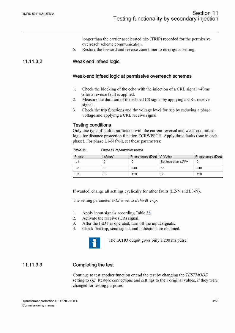
longer than the carrier accelerated trip (TRIP) recorded for the permissiveoverreach scheme communication.
5. Restore the forward and reverse zone timer to its original setting.
11.11.3.2 Weak end infeed logicM14947-37 v2
Weak-end infeed logic at permissive overreach schemesM14947-39 v5
1. Check the blocking of the echo with the injection of a CRL signal >40msafter a reverse fault is applied.
2. Measure the duration of the echoed CS signal by applying a CRL receivesignal.
3. Check the trip functions and the voltage level for trip by reducing a phasevoltage and applying a CRL receive signal.
Testing conditionsM14947-52 v7
Only one type of fault is sufficient, with the current reversal and weak-end infeedlogic for distance protection function ZCRWPSCH. Apply three faults (one in eachphase). For phase L1-N fault, set these parameters:
Table 38: Phase L1-N parameter values
Phase I (Amps) Phase-angle (Deg) V (Volts) Phase-angle (Deg)L1 0 0 Set less than UPN< 0
L2 0 240 63 240
L3 0 120 63 120
If wanted, change all settings cyclically for other faults (L2-N and L3-N).
The setting parameter WEI is set to Echo & Trip.
1. Apply input signals according Table 38.2. Activate the receive (CR) signal.3. After the IED has operated, turn off the input signals.4. Check that trip, send signal, and indication are obtained.
The ECHO output gives only a 200 ms pulse.
11.11.3.3 Completing the testM14947-105 v5
Continue to test another function or end the test by changing the TESTMODEsetting to Off. Restore connections and settings to their original values, if they werechanged for testing purposes.
1MRK 504 165-UEN A Section 11Testing functionality by secondary injection
Transformer protection RET670 2.2 IEC 253Commissioning manual
11.11.4 Scheme communication logic for residual overcurrentprotection ECPSCH
M13926-2 v6
Prepare the IED for verification of settings outlined in Section "Preparing the IEDto verify settings".
Before testing the communication logic for residual overcurrent protection functionECPSCH, the four step residual overcurrent protection function EF4PTOC has tobe tested according to the corresponding instruction. Once this is done, continuewith the instructions below.
If the current reversal and weak-end infeed logic for earth-fault protection isincluded, proceed with the testing according to the corresponding instruction aftertesting the communication logic for residual overcurrent protection. The currentreversal and weak-end-infeed functions shall be tested together with the permissivescheme.
11.11.4.1 Testing the directional comparison logic functionM13926-7 v2
Blocking schemeM13926-9 v6
1. Inject the polarizing voltage 3U0 at 5% of UBase (EF4PTOC) where thecurrent is lagging the voltage by 65°.
2. Inject current (65° lagging the voltage) in one phase at about 110% of the setoperating current, and switch the current off with the switch.
3. Switch the fault current on and measure the operating time of thecommunication logic.Use the TRIP signal from the configured binary output to stop the timer.
4. Compare the measured time with the set value tCoord.5. Activate the CR binary input.6. Check that the CRL output is activated when the CR input is activated.7. Switch the fault current on (110% of the set operating current) and wait
longer than the set value tCoord.
No TRIP signal should appear.
8. Switch the fault current off.9. Reset the CR binary input.10. Activate the BLOCK digital input.11. Switch the fault current on (110% of the set operating current) and wait for a
period longer than the set value tCoord.
Section 11 1MRK 504 165-UEN ATesting functionality by secondary injection
254 Transformer protection RET670 2.2 IECCommissioning manual
No TRIP signal should appear.
12. Switch the fault current and the polarizing voltage off.13. Reset the BLOCK digital input.
Permissive schemeM13926-42 v8
1. Inject the polarizing voltage 3U0, which is 5% of UBase (EF4PTOC) wherethe current is lagging the voltage by 65°.
2. Inject current (65° lagging the voltage) into one phase at about 110% of theset operating current, and switch the current off with the switch.
3. Switch the fault current on, (110% of the set operating current) and waitlonger than the set value tCoord.
No TRIP signal should appear, and the CS binary outputshould be activated.
4. Switch the fault current off.5. Activate the CR binary input.6. Switch the fault current on (110% of the set operating current) and measure
the operating time of the ECPSCH logic.Use the TRIP signal from the configured binary output to stop the timer.
7. Compare the measured time with the setting for tCoord.8. Activate the BLOCK digital input.9. Switch the fault current on (110% of the set operating current) and wait for a
period longer than the set value tCoord.
No TRIP signal should appear.
10. Switch the fault current and the polarizing voltage off.11. Reset the CR binary input and the BLOCK digital input.
11.11.4.2 Completing the testM13926-71 v5
Continue to test another function or end the test by changing the TESTMODEsetting to Off. Restore connections and settings to their original values, if they werechanged for testing purposes.
11.11.5 Current reversal and weak-end infeed logic for residualovercurrent protection ECRWPSCH
M13936-2 v8
Prepare the IED for verification of settings as outlined in section "Requirements"and section "Preparing for test" in this chapter.
1MRK 504 165-UEN A Section 11Testing functionality by secondary injection
Transformer protection RET670 2.2 IEC 255Commissioning manual
Values of the logical signals for ECRWPSCH are available on the Local HMIunder Main menu/Tests/Function status/Scheme communication/ECRWPSCH(85)/ECRWPSCH:1.
The Signal Monitoring in PCM600 shows service values that are available on theLocal HMI as well.
First, test the four step residual overcurrent protection function EF4PTOC and thenthe current reversal and weak-end infeed logic according to the correspondinginstructions. Then continue with the instructions below.
11.11.5.1 Testing the current reversal logicM13936-9 v7
1. Inject the polarizing voltage 3U0 to 5% of UBase and the phase anglebetween voltage and current to 155°, the current leads the voltage.
2. Inject current (180° — AngleRCA) in one phase to about 110% of the setoperating current of the four step residual overcurrent protection (IN>Dir).
3. Check that the IRVL output is activated in the disturbance recorder after theset time tPickUpRev.
4. Abruptly reverse the current to AngleRCA setting lagging the voltage, tooperate the forward directional element.
5. Check that the IRVL output still is activated after the reversal with a timedelay that complies with the setting tDelayRev.
6. Switch off the polarizing voltage and the current.
11.11.5.2 Testing the weak-end infeed logicM13936-25 v2
If setting WEI = EchoM13936-27 v8
1. Inject the polarizing voltage 3U0 to (180° — AngleRCA) of UBase and thephase angle between voltage and current to 155°, the current leads thevoltage.
2. Inject current (180° — AngleRCA) in one phase to about 110% of the settingoperating current (IN>Dir).
3. Activate the CRL binary input.
No ECHO and CS should appear.
4. Abruptly reverse the current to the setting of AngleRCA setup lagging thevoltage, to operate the forward directional element.
Section 11 1MRK 504 165-UEN ATesting functionality by secondary injection
256 Transformer protection RET670 2.2 IECCommissioning manual
No ECHO and CS should appear.
5. Switch off the current and check that the ECHO and CS appear on thecorresponding binary output during 200ms after resetting the directionalelement.
6. Switch off the CRL binary input.7. Activate the BLOCK binary input.8. Activate the CRL binary input.
No ECHO and CS should appear.
9. Switch off the polarizing voltage and reset the BLOCK and CRL binaryinput.
If setting WEI = Echo & TripM13936-52 v12
1. Inject the polarizing voltage 3U0 to about 90% of the setting (3U0>)operating voltage.
2. Activate the CRL binary input.
No ECHO, CS and TRWEI outputs should appear.
3. Increase the injected voltage to about 110% of the setting (3U0) operatingvoltage.
4. Activate the CRL binary input.5. Check that the ECHO, CS and TRWEI appear on the corresponding binary
output or on the local HMI.6. Reset the CRL binary input.7. Activate the BLOCK binary input.8. Activate the CRL binary input.
No ECHO, CS and TRWEI outputs should appear.
9. Reset the CRL and BLOCK binary input.10. Inject the polarizing voltage 3U0 to about 110% of the setting (3U0>) and
adjust the phase angle between the voltage and current to (180°- AnglRCA)setting, the current leads the voltage.
11. Inject current in one phase to about 110% of the set operate current(IN>Dir ).
12. Activate the CRL binary input.
1MRK 504 165-UEN A Section 11Testing functionality by secondary injection
Transformer protection RET670 2.2 IEC 257Commissioning manual
No ECHO and TRWEI should appear.
13. Abruptly reverse the current to 65° lagging the voltage to operate the forwarddirectional element.
No ECHO and TRWEI should appear.
14. Switch the current off and check that the ECHO, CS and TRWEI appear onthe corresponding binary output during 200ms after resetting the directionalelement. If EF4PTOC also operates in forward direction, CS should beobtained.
15. Switch the polarizing voltage off and reset the CRL binary input.
11.11.5.3 Completing the testM13936-90 v5
Continue to test another function or end the test by changing the TESTMODEsetting to Off. Restore connections and settings to their original values, if they werechanged for testing purposes.
11.12 LogicSEMOD53577-1 v1
11.12.1 Tripping logic, common 3-phase output SMPPTRCSEMOD54375-102 v10
Prepare the IED for verification of settings outlined in Section "Preparing the IEDto verify settings".
This function is functionality tested together with other protection functions (linedifferential protection, earth-fault overcurrent protection, and so on) within theIED. It is recommended that the function is tested together with the autorecloserfunction, when built into the IED or when a separate external unit is used forreclosing purposes.
11.12.1.1 3 phase operating modeSEMOD54375-106 v10
1. Check that AutoLock and TripLockout are both set to Off.2. Initiate a three-phase fault.
An adequate time interval between the faults should be considered, toovercome a reclaim time caused by the possible activation of the autorecloserfunction SMBRREC. The function must issue a three-phase trip in all caseswhen trip is initiated by any protection or some other built-in or external
Section 11 1MRK 504 165-UEN ATesting functionality by secondary injection
258 Transformer protection RET670 2.2 IECCommissioning manual
function. The following functional output signals must always appearsimultaneously: TRIP, TRL1, TRL2, TRL3 and TR3P.
11.12.1.2 1ph/3ph operating modeSEMOD54375-116 v5
In addition to various other tests, the following tests should be performed. Theydepend on the complete configuration of an IED:
Procedure
1. Make sure that TripLockout and AutoLock are both set to Off.2. Initiate different single-phase-to-earth faults one at a time.
Single-phase tripping will only be allowed when an autoreclose attempt willfollow. The autorecloser function SMBRREC has the functionality such asthe long trip time, CB ready and so on, which can prevent a proper single-phase tripping and autoreclose. To by-pass this problem the fault initiationshould be with a test set and with the autoreclose in full service with a test setconnected to the distance protection function. Consider using an adequatetime interval between faults, to overcome a reclaim time of which is activatedby SMBRREC. Only a single-phase trip should occur for each separate faultand only one of the trip outputs (TRLn) should be activated at a time.Functional outputs TRIP and TR1P should be active during each fault. Noother outputs should be active.
3. Initiate different phase-to-phase and three-phase faults.Consider using an adequate time interval between faults, to overcome areclaim time, which is activated by SMBRREC. A three-phase trip shouldoccur for each separate fault and all of the trips. Functional outputs TRIP, allTRLn and TR3P should be active at each fault.
No other outputs should be active.
4. Initiate a single phase-to-earth fault and switch it off immediately when thetrip signal is issued for the corresponding phase. Initiate the same fault onceagain within the reclaim time of the used SMBRREC.A single-phase fault shall be given at the first fault. A three-phase trip mustbe initiated for the second fault. Check that the corresponding trip signalsappear after both faults. Functional outputs TRIP, TRLn and TR1P should beactive during first fault. No other outputs should be active. Functional outputsTRIP, all TRLn and TR3P should be active during second fault.
5. Initiate a single phase-to-earth fault and switch it off immediately when thetrip signal is issued for the corresponding phase. Initiate the second singlephase-to-earth fault in one of the remaining phases within the time interval,shorter than tEvolvingFault (default setting 2.0s) and shorter than the dead-time of SMBRREC, when included in the protection scheme.Check that the second trip is a three-phase trip and that a three-phaseautoreclosing attempt is given after the three-phase dead time. Functional
1MRK 504 165-UEN A Section 11Testing functionality by secondary injection
Transformer protection RET670 2.2 IEC 259Commissioning manual
outputs TRIP, TRLn and TR1P should be active during the first fault. Noother outputs should be active. Functional outputs TRIP, all TRLn and TR3Pshould be active during second fault.
11.12.1.3 1ph/2ph/3ph operating modeSEMOD54375-143 v5
In addition to other tests, the following tests, which depend on the completeconfiguration of an IED, should be carried out.
Procedure
1. Make sure that AutoLock and TripLockout are both set to Off.2. Initiate different single-phase-to-earth faults one at a time.
Take an adequate time interval between faults into consideration, to overcomea reclaim time, which is activated by the autorecloser function SMBRREC.Only a single-phase trip should occur for each separate fault and only one ofthe trip outputs (TRLn) should be activated at a time. Functional outputsTRIP and TR1P should be active at each fault. No other outputs should beactive.
3. Initiate different phase-to-phase faults one at a time.Take an adequate time interval between faults into consideration, to overcomea reclaim time which is activated by SMBRREC. Only a two-phase tripshould occur for each separate fault and only corresponding two trip outputs(TRLn) should be activated at a time. Functional outputs TRIP and TR2Pshould be active at each fault. No other outputs should be active.
4. Initiate a three-phase fault.Take an adequate time interval between faults into consideration, to overcomea reclaim time, which may be activated by SMBRREC. Only a three-phasetrip should occur for the fault and all trip outputs (TRLn) should be activatedat the same time. Functional outputs TRIP and TR3P should be active at eachfault. No other outputs should be active.
5. Initiate a single phase-to-earth fault and switch it off immediately when thetrip signal is issued for the corresponding phase. Initiate the same fault onceagain within the reclaim time of the used SMBRREC.A single-phase fault shall be given at the first fault. A three-phase trip mustbe initiated for the second fault. Check that the corresponding trip signalsappear after both faults. Functional outputs TRIP, TRLn and TR1P should beactive during first fault. No other outputs should be active. Functional outputsTRIP, all TRLn and TR3P should be active during second fault.
6. Initiate a single phase-to-earth fault and switch it off immediately when thetrip signal is generated for the corresponding phase. Initiate the second single-phase-to-earth fault in one of the remaining phases within the time interval,shorter than tEvolvingFault (default setting 2.0s) and shorter than the dead-time of SMBRREC, when included in the protection scheme.Check that the second trip is a three-phase trip and that a three-phaseautoreclosing attempt is given after the three-phase dead time. Functionaloutputs TRIP, TRLn and TR1P should be active during first fault. No other
Section 11 1MRK 504 165-UEN ATesting functionality by secondary injection
260 Transformer protection RET670 2.2 IECCommissioning manual
outputs should be active. Functional outputs TRIP, all TRLn and TR3P shouldbe active during second fault.
7. Initiate a phase-to-phase fault and switch it off immediately when the tripsignal is issued for the corresponding two phases. Initiate a second phase-to-phase fault between two other phases within the time interval, shorterthantEvolvingFault (default setting 2.0s).Check, that the output signals, issued for the first fault, correspond to a two-trip for included phases. The output signals generated by the second faultmust correspond to the three-phase tripping action.
11.12.1.4 Circuit breaker lockoutSEMOD54375-170 v11
The following tests should be carried out when the built-in lockout function is usedin addition to possible other tests, which depends on the complete configuration ofan IED.
1. Check that AutoLock and TripLockout are both set to Off.2. Activate shortly the set lockout (SETLKOUT) signal in the IED.3. Check that the circuit breaker lockout (CLLKOUT) signal is set.4. Activate shortly thereafter, the reset lockout (RSTLKOUT) signal in the IED.5. Check that the circuit breaker lockout (CLLKOUT) signal is reset.6. Initiate a three-phase fault.
A three-phase trip should occur and all trip outputs TRL1, TRL2, TRL3should be activated. Functional outputs TRIP and TR3P should be active ateach fault. The output CLLKOUT should not be set.
7. Activate the automatic lockout function, set AutoLock = On and repeat.Besides the TRIP outputs, CLLKOUT should be set.
8. Reset the lockout signal by activating the reset lockout (RSTLKOUT) signal.9. Activate the trip signal lockout function, set TripLockout = On and repeat.
All trip outputs (TRL1, TRL2, TRL3) and functional outputs TRIP and TR3Pmust be active and stay active after each fault, CLLKOUT should be set.
10. Reset the lockout.All functional outputs should reset.
11. Deactivate the trip signal lockout function, set TripLockout = Off and theautomatic lockout function, set AutoLock = Off.
11.12.1.5 Completing the testSEMOD54375-203 v6
Continue to test another function or end the test by changing the TESTMODEsetting to Off. Restore connections and settings to their original values, if they werechanged for testing purposes.
1MRK 504 165-UEN A Section 11Testing functionality by secondary injection
Transformer protection RET670 2.2 IEC 261Commissioning manual
11.13 MonitoringSEMOD53581-1 v1
11.13.1 Gas medium supervision SSIMGGUID-0A83B4D5-51FF-43CB-8DC7-AFCEA2BC7B69 v2
Prepare the IED for verification of settings as outlined in Section "Preparing theIED to verify settings" in this chapter.
Values of logical signals for SSIMG protection are available on the local HMIunder Main menu/Tests/Function status/Monitoring/InsulationGas(63)/SSIMG(63):x, where x = 1, 2,....21.
The Signal Monitoring in PCM600 shows the same signals that are available on thelocal HMI.
Check that the input logical signal BLOCK is logical zero and that on the localHMI, the logical signals PRESALM, PRESLO, TEMPALM, TEMPLO, ALARM andLOCKOUT are logical zero.
11.13.1.1 Testing the gas medium supervision for pressure alarm and pressurelockout conditions
GUID-768DAAC8-F89D-4401-B86D-9B26FD7224F6 v3
1. Connect binary inputs to consider gas pressure and gas density to initiate thealarms.
2. Consider the analogue pressure input SENPRES and set SENPRES to a valuelower than PresAlmLimit or activate binary input signal SENPRESALM, checkthat outputs PRESALM and ALARM are activated after a set time delay oftPressureAlarm.
3. Gas pressure lockout input SETPLO can be used to set PRESLO.4. Also, reduce further the pressure level input below PresLOLimit or activate
the binary input signal SENPRESLO, check that PRESLO signal appears aftera set time delay of tPressureLO.
5. Activate BLOCK binary input and check that the outputs PRESALM, PRESLO,ALARM and LOCKOUT disappear.
6. Reset the BLOCK binary input.7. Make sure that pressure lockout condition exists and then activate the reset
lock out input RESETLO and check that the outputs PRESLO and LOCKOUTreset.
Section 11 1MRK 504 165-UEN ATesting functionality by secondary injection
262 Transformer protection RET670 2.2 IECCommissioning manual
11.13.1.2 Testing the gas medium supervision for temperature alarm andtemperature lock out conditions
GUID-EC145626-90B0-45A2-AD58-CB8BF203FE16 v1
1. Consider the analogue temperature input SENTEMP and set SENTEMP to avalue higher than TempAlarmLimit, check that outputs TEMPALM and ALARMare activated after a set time delay of tTempAlarm.
2. Temperature lockout input SETTLO can be used to set TEMPLO signal.3. Also, increase further the temperature input above TempLOLimit, check that
the outputs TEMPLO and LOCKOUT appears after a set time delay oftTempLockOut.
4. Activate BLOCK binary input and check that the outputs TEMPALM, TEMPLO,ALARM and LOCKOUT disappear.
5. Reset the BLOCK binary input.6. Make sure that temperature lockout condition exists and then activate the
reset lock out input RESETLO and check that the outputs TEMPLO andLOCKOUT reset.
11.13.1.3 Completing the testGUID-DD08C598-A35C-4300-9555-A0877F7DC511 v1
Continue to test another function or end the test by changing the TestMode settingto Off. Restore connections and settings to their original values, if they werechanged for testing purposes.
11.13.2 Liquid medium supervision SSIMLGUID-6426FDDA-B949-4FE7-BF42-B52014A9344B v3
Prepare the IED for verification of settings as outlined in section "Preparing theIED to verify settings" in this chapter.
Values of logical signals for SSIMG protection are available on the local HMIunder Main menu/Tests/Function status/Monitoring/InsulationLiquid(71)/SSIML(71):x, where x = 1, 2,....4.
Check that the input logical signal BLOCK is logical zero and that on the localHMI, the logical signals LVLALM, LVLLO, TEMPALM, TEMPLO, ALARM andLOCKOUT are logical zero.
11.13.2.1 Testing the liquid medium supervision for level alarm and levellockout conditions
GUID-C1F1E6CA-9512-4358-A4E7-84CC3698D156 v3
1. Connect the binary inputs to consider liquid level to initiate the alarms.2. Consider the analogue level input SENLEVEL and set SENLEVEL to a value
lower than LevelAlmLimit or activate binary input signal SENLVLALM, checkthat outputs LVLALM and ALARM are activated after a set time delay oftLevelAlarm.
3. Liquid level lockout input SENLVLLO can be used to set LVLLO.
1MRK 504 165-UEN A Section 11Testing functionality by secondary injection
Transformer protection RET670 2.2 IEC 263Commissioning manual
4. Also, reduce the liquid level input below LevelLOLimit or activate the binaryinput signal SENLVLLO, check that LVLLO signal after a set time delay oftLevelLockOut.
5. Activate BLOCK binary input and check that the outputs LVLALM, LVLLO,ALARM and LOCKOUT disappears.
6. Reset the BLOCK binary input.7. Make sure that level lockout condition exists and then activate the reset lock
out input RESETLO and check that the outputs PRESLO and LOCKOUT reset.
11.13.2.2 Testing the liquid medium supervision for temperature alarm andtemperature lock out conditions
GUID-189AF20B-D0E3-453D-A787-68F25D0903D3 v1
1. Consider the analogue temperature input SENTEMP and set SENTEMP to avalue higher than TempAlarmLimit, check that outputs TEMPALM and ALARMare activated after a set time delay of tTempAlarm.
2. Temperature lockout input SETTLO can be used to set TEMPLO signal.3. Also, increase further the temperature input above TempLOLimit, check that
the outputs TEMPLO and LOCKOUT appears after a set time delay oftTempLockOut.
4. Activate BLOCK binary input and check that the outputs TEMPALM, TEMPLO,ALARM and LOCKOUT disappear.
5. Reset the BLOCK binary input.6. Make sure that temperature lockout condition exists and then activate the
reset lock out input RESETLO and check that the outputs TEMPLO andLOCKOUT reset.
11.13.2.3 Completing the testGUID-1A0D8AF0-4C48-45E8-B31D-96734ED1A4D2 v1
Continue to test another function or end the test by changing the TestMode settingto Off. Restore connections and settings to their original values, if they werechanged for testing purposes.
11.13.3 Breaker monitoring SSCBRGUID-10D26C82-79FF-4EAD-AE4A-2F2DBE965087 v2
Prepare the IED for verification of settings outlined in section “Testing the IEDoperation”.
The Signal Monitoring tool in PCM600 shows the service values that are availableon the Local HMI as well.
Values of the logical signals belong to the breaker monitoring are available on thelocal HMI under: Main menu/Test/Function status/Monitoring/BreakerMonitoring/SSCBR:x
Section 11 1MRK 504 165-UEN ATesting functionality by secondary injection
264 Transformer protection RET670 2.2 IECCommissioning manual
11.13.3.1 Verifying the settingsGUID-962A344D-5F8D-49A6-B3AC-29C7FEED0A3D v4
1. Connect the test set for the injection of a three-phase current to the appropriatecurrent terminals of the IED.
2. If current need to be injected for a particular test, it should be done in thephase selected by the PhSel parameter.
3. Follow the sequence for positioning the auxiliary contacts before testing:
POSCLOSE 0 1 0
POSOPEN 0 0 1
4. Test of CB contact travel time4.1. Test the set timing defined by OpenTimeCorr, CloseTimeCorr,
tTrOpenAlm and tTrCloseAlm.4.2. Change the status of the auxiliary contacts such that travel time to open
TTRVOP and travel time to close TTRVCL exceed the respective setvalues (tTrOpenAlm and tTrCloseAlm). The measured travel time foropening and closing is shown on TTRVOP and TTRVCL respectively.
4.3. Check that TRVTOPAL and TRVTCLAL are activated.5. Test of CB status
5.1. Test the set current level defined by AccStopCurr.5.2. Check the CLOSEPOS output by changing the POSOPEN to 0 and
POSCLOSE to 1.5.3. Check the OPENPOS output by changing the POSOPEN to 1 and
POSCLOSE to 0 and also inject the current in the selected phase slightlylower and higher than AccStopCurr set value. Only for a current lowerthan set AccStopCurr should activate the output POSOPEN.
5.4. Check the circuit breaker is in INVDPOS if auxiliary contacts read samevalue or CB is open and inject the current in selected phase more thanAccStopCurr set value.
6. Test of remaining life of CB6.1. Test the set timing defined byRatedOperCurr, RatedFltCurr,
OperNoRated, OperNoFault, DirCoef, CBLifeAlmLevel.6.2. Vary the phase current in the selected phase from below rated operated
current, RatedOperCurr to above rated fault current, RatedFltCurr of abreaker.
6.3. The remaining life of CB output CBLIFEPH is estimated when the CB ischanged from closed to open position. Check that the output CBLIFEPHis decreased with a value that corresponds to the injected current.
6.4. CBLIFEAL is activated as soon as CBLIFEPH is below the setCBLifeAlmLevel value.
7. Test of accumulated energy
1MRK 504 165-UEN A Section 11Testing functionality by secondary injection
Transformer protection RET670 2.2 IEC 265Commissioning manual
7.1. Test the actual set values defined by AccSelCal to Aux Contact,ContTrCorr and AlmAccCurrPwr.
7.2. Inject phase current in the selected phase such that its value is greaterthan set AccStopCurr value.
7.3. When the breaker goes to open position, accumulated energy IPOWPH iscalculated. The calculated value can be seen on the output IPOWPH.
7.4. Alarm signal IPOWALPH appears when IPOWPH is greater than setAlmAccCurrPwr value.
7.5. Lockout signal IPOWLOPH appears if IPOWPH exceeds further to thethreshold value LOAccCurrPwr.
7.6. Calculation of accumulated energy IPOWPH is stopped when injectedcurrent is lower than set AccStopCurr value.
8. Test of CB operation cycles8.1. Test the actual set values defined by OperAlmLevel and OperLOLevel.8.2. The operation counter, NOOPER is updated for every close-open
sequence of the breaker by changing the position of auxiliary contactsPOSCLOSE and POSOPEN.
8.3. OPERALM is activated when NOOPER value exceeds the setOperAlmLevel value. The actual value can be read on the outputNOOPER.
8.4. OPERLO is activated when NOOPER value exceeds the setOperLOLevel value.
9. Test of CB spring charge monitoring9.1. Test the actual set value defined by SpChAlmTime.9.2. Enable SPRCHRST input. Also activate SPRCHRD after a time greater
than set time SpChAlmTime.9.3. At this condition, SPCHALM is activated.
10. Test of CB gas pressure indication10.1. Test the actual set value defined bytDGasPresAlm and tDGasPresLO.10.2. The output GPRESALM is activated after a time greater than set time of
tDGasPresAlm value if the input PRESALM is enabled.10.3. The output GPRESLO is activated after a set time of tDGasPresLO value
if the input PRESLO is enabled.
11.13.3.2 Completing the testGUID-0A16206F-690E-46EF-86F4-5A89E0BF640B v3
1. Continue to test another function or end the test by changing the Test modesetting to Off.
2. Restore connections and settings to their original values if they were changedfor testing purposes.
Section 11 1MRK 504 165-UEN ATesting functionality by secondary injection
266 Transformer protection RET670 2.2 IECCommissioning manual
11.13.4 Event function EVENTM11751-2 v5
Prepare the IED for verification of settings as outlined in section "Preparing fortest" in this chapter.
During testing, the IED can be set when in test mode from PST. The functionalityof the event reporting during test mode is set in the Parameter Setting tool inPCM600.
• Use event masks• Report no events• Report all events
In test mode, individual event blocks can be blocked from PCM600.
11.13.5 Fault locator LMBRFLOM14955-2 v7
Prepare the IED for verification of settings outlined in Section "Preparing the IEDto verify settings".
The Fault locator function LMBRFLO depends on other functions to workproperly, that is, phase selection information from distance protection function andanalog information supplied by the trip value recorder function. Check that properbinary start and phase selection signals are connected and voltage and currentsignals are configured (parameter settings).
The result is displayed on the local HMI or via PCM600. Distances to faults for thelast 100 recorded disturbances can be found on the local HMI under Main menu/Disturbance Records/Disturbance #n(n = 1–100)/General Information
If PCM600 is used, the result is displayed on the recording list after upload,including loop selection information.
Table 39: Test settings
Parameter ConditionI Higher than 30% Ir
Healthy conditions U = 63,5 V, I = 0 A & ZF = 0°
Impedance |Z| Test pointNote:
• Zx£ (X0 + 2 · X1)/3 For single-phase faults• Zx£ X1 For three and two phase faults• Zx£ (X0 + 2 · X1 XM)/3 For single-phase fault with mutual
zero-sequence current
Impedance angle ZF Test angle
• ZF arctan[(X0 + 2 · X1) / (R0 + 2R1)] For single-phasefaults
• ZF arctan(X1/R1) For two-phase faults
1MRK 504 165-UEN A Section 11Testing functionality by secondary injection
Transformer protection RET670 2.2 IEC 267Commissioning manual
11.13.5.1 Measuring the operate limitM14955-48 v5
1. Set the test point (|Z| fault impedance and ZF impedance phase angle ) for acondition that meets the requirements in table 39.
2. Subject the IED to healthy normal load conditions for at least two seconds.3. Apply a fault condition.
Check that the distance-to-fault value displayed on the HMI complies withequations 117, 118 and 119
pZxX1------- 100×=
EQUATION123 V1 EN-US (Equation 117)
in % for two- and three-phase faults
x3 Zp 100
X0 2 X1×
= ×+ ×
EQUATION124 V1 EN-US (Equation 118)
in % for single-phase-to-earth faults
p3 Z× x
X0 2 X1 XM±×+--------------------------------------------- 100×=
EQUATION125 V1 EN-US (Equation 119)
in % for single-phase-to-earth faults with mutual zero sequence current.
Where:
p = the expected value of a distance to fault in percent
Zx = set test point on the test set
X0 = set zero-sequence reactance of a line
X1 = set positive-sequence reactance of a line
XM = set mutual zero-sequence impedance of a line
11.13.5.2 Completing the testM14955-84 v6
Continue to test another function or end the test by changing the TESTMODEsetting to Off. Restore connections and settings to their original values, if they werechanged for testing purposes.
11.13.6 Limit counter L4UFCNTGUID-7EBDC372-3407-4577-8B9A-6AB1758A1F34 v2
The Limit counter function L4UFCNT can be tested by connecting a binary inputto the counter and applying pulses to the counter. The speed of the pulses must notexceed the cycle time of the function. Normally the counter will be tested whentesting the function that the counter is connected to, such as the trip function. Whenthe function is configured, test it together with the function that operates it. Trigger
Section 11 1MRK 504 165-UEN ATesting functionality by secondary injection
268 Transformer protection RET670 2.2 IECCommissioning manual
the function and check that the counter result corresponds to the number ofoperations.
11.13.6.1 Completing the testGUID-325F040B-BADC-4281-B965-9B7D6BFA3E15 v1
Continue to test another function or end the test by changing the Test mode settingto Off. Restore connections and settings to their original values, if they werechanged for testing purposes.
11.13.7 Estimation of transformer insulation life LOLSPTRGUID-C08B2360-2134-43DD-9F39-54CD9FA45B5B v1
Prepare the IED for verification of settings outlined in Section "Preparing the IEDto verify settings".
11.13.7.1 Verifying the signals and settingsGUID-1B9A0E70-A40C-4C83-A314-26B4B33C2F97 v1
Time measurement and the injection of current and voltage can be done usingcommon test equipment.
Verifying HPTMPMAX and TOTCALC outputsGUID-95D0A8EC-8901-4269-9FD3-7D7F386E6BB3 v1
1. Connect the test set for injection of three-phase currents to the appropriatecurrent terminals of the IED.
2. Activate the TOTVALID input and set some temperature value in TOTEMPinput.
3. Supply the IED with three-phase currents slightly more than the rated value.4. Make sure that the hot spot temperature (HPTMPMAX) is more than the set
value of TOTEMP.5. Activate the AMBVALID input and set some temperature value in
AMBTEMP input.6. Make sure that the top oil temperature calculated (TOTCALC) is more than
the set value of AMBTEMP.
Verifying WARNINGx and ALARMx outputsGUID-85CA2ABF-13A9-4A4B-8E3F-AEF71D091E32 v1
1. Connect the test set for injection of three-phase currents to the appropriatecurrent terminals of the IED.
2. Make sure that the settings in the IED are appropriate, especially the warningtemperature levels (WrnHPTmpLevX) and alarm time settings(tDelayToAlarmX).
3. Supply three-phase currents nearly zero to the IED and take note of hot spottemperature (HPTMPMAX).
4. Make sure that the WARNINGx and ALARMx signals remains low.5. Supply three-phase currents slightly more than the rated value to the IED and
take note of hot spot temperature (HPTMPMAX).Observe the maximum permitted overloading of the current circuits in theIED.
1MRK 504 165-UEN A Section 11Testing functionality by secondary injection
Transformer protection RET670 2.2 IEC 269Commissioning manual
6. Check the time until the warning limit has reached WrnHPTmpLev1 levelduring injection. Monitor the signal WARNING1 until it appears on thecorresponding binary output.
7. Compare the measured temperature (HPTMPMAX) with WrnHPTmpLev1setting.
8. check the time until the warning limit has reached WrnHPTmpLev2 levelduring injection. Monitor the signal WARNING2 until it appears on thecorresponding binary output.
9. Compare the measured temperature (HPTMPMAX) with WrnHPTmpLev2setting.
10. Wait for a time corresponding to tDelayToAlarm1 from the appearance ofWARNING1 signal. Make sure that the ALARM1 signal appears.
11. Note the time taken for the appearance of ALARM1 signal from theappearance of WARNING1 signal, and compare it with set value(tDelayToAlarm1).
12. Wait for a time corresponding to tDelayToAlarm2 from the appearance ofWARNING2 signal, and make sure that the ALARM2 signal appears.
13. Note the time taken for the appearance of ALARM2 signal from theappearance of WARNING2 signal, and compare it with set value(tDelayToAlarm2).
14. Activate the BLKWRN binary input. The WARNING1 and WARNING2signals should disappear.
15. Activate the BLKALM binary input. The ALARM1 and ALARM2 signalsshould disappear.
16. Reset the BLKWRN and BLKALM binary inputs. Once again warning andalarm signals should appear.
17. Reduce the three-phase currents suddenly to value lower than the ratedcurrent and take note of hot spot temperature.
18. Check the warnings reset limit (HystAbsHPT). Monitor the WARNING1 andWARNING2 signals until they disappears on the corresponding binaryoutputs. Take the HPTMPMAX readings and compare with the reset levelsettings.
Verifying LOLINDAY and LOLINYRS outputsGUID-C1B747CC-F961-4C6B-BB72-5F32B3FB3F06 v1
1. Connect the test set for injection of three-phase currents to the appropriatecurrent terminals of the IED.
2. Make sure that the settings in the IED are appropriate, especially set theEnaAgeCalc setting as Enable, TimeToUpdate setting as 1 hour andAgeingRateMeth setting as IEC.
3. Activate the TOTVALID input and set some temperature value in TOTEMPinput.
4. Supply the IED with three-phase currents slightly more than the rated value.5. Note the hot spot temperature (HPTMPMAX) and maintain it for another 1
hour.6. Check the LOLINDAY and LOLINYRS outputs after 1 hour and compare it
with the calculated loss of life value using IEC standard method.
Section 11 1MRK 504 165-UEN ATesting functionality by secondary injection
270 Transformer protection RET670 2.2 IECCommissioning manual
11.13.7.2 Completing the testGUID-46EC57EA-375B-4DBD-BE18-914156083384 v1
Continue to test another function or end the test by changing the Test mode settingto Off. Restore connections and settings to their original values, if they werechanged for testing purposes.
11.14 MeteringSEMOD53588-1 v1
11.14.1 Pulse-counter logic PCFCNTM13405-2 v7
The test of the Pulse-counter logic function PCFCNT requires the ParameterSetting tool in PCM600 or an appropriate connection to the local HMI with thenecessary functionality. A known number of pulses with different frequencies areconnected to the pulse counter input. The test should be performed with settingsOperation = On or Operation = Off and the function blocked or unblocked. Thepulse counter value is then checked in PCM600 or on the local HMI.
11.14.2 Function for energy calculation and demand handlingETPMMTR
GUID-4FC03017-93BD-4B30-A874-487BF89971D5 v1
Prepare the IED for verification of settings as outlined in section ”Overview “ andsection ”Preparing for test“ in this chapter.
11.14.2.1 Verifying the settingsGUID-F8F0D384-BC70-48CA-817E-EB9BFBD68A54 v3
Common test equipment can be used to determine the injection of current andvoltage and time measurement.
Verification of EAFACC & ERFACC output
1. Connect the test set for injection of three-phase currents and three-phasevoltage to the appropriate current and voltage terminals of the IED.
2. Ensure the instantaneous values of active and reactive power from CVMMXNfunction block are connected to ETPMMTR function block active and reactivepower inputs.
3. Enable the EnaAcc setting and set tEnergy as 1 minute.4. Activate the STARTACC input and supply the IED with three-phase currents
and voltages at their rated value.5. Check that the ACCINPRG signal appears continuously.6. Note the EAFACC and ERFACCvalue after 1 minute and compare it with
calculated energy value.7. Similarly check after each 1 minute whether the calculated integrated energy
value and EAFACC and ERFACC outputs are matching.8. After some time (multiple of minute) remove the current and voltage input
from CVMMXN function block.
1MRK 504 165-UEN A Section 11Testing functionality by secondary injection
Transformer protection RET670 2.2 IEC 271Commissioning manual
9. Check the EAFACC and ERFACC output in the next 1 minute cycle for theretaining the same value.
10. Activate STOPACC input after some time and supply the IED with samecurrent and voltage.
11. Check that the ACCINPRG signal disappears immediately and EAFACC andERFACC outputs also stop updating.
12. Similarly the testing can be done for EAFACC and ERFACC outputs bychanging the power inputs directions through direction settings.
Verification of MAXPAFD & MAXPRFD outputs
1. Repeat the above test steps 1 to 2.2. Set tEnergy setting as 1 minute and supply the IED with three-phase currents
and voltages at their rated value till 1 minute.3. Check the MAXPAFD and MAXPRFD outputs after 1 minute and compare it
with last 1 minute average power values.4. Increase either three-phase current or voltage above the last 1 minute value.5. After 1 minute check the MAXPAFD and MAXPRFD whether it is showing the
last 1 minute average power value as maximum.6. Next 1 minute cycle reduce the current or voltage below previous value.7. Check after 1 minute whether the MAXPAFD and MAXPRFD outputs are
retaining the old maximum value.8. Similarly the testing can be done for MAXPAFD and MAXPRFD outputs by
changing the power inputs directions through direction settings.
Verification of EAFALM & ERFALM outputs
1. Repeat the above test steps 1 to 2.2. Set tEnergy setting as 1 minute and supply the IED with three-phase currents
and voltages at their rated value till 1 minute.3. Ensure that the active and reactive energy values are less than the EALim and
ERLim setting default values respectively.4. Check that EAFALM and ERFALM are low.5. Increase the supply currents or voltage in next 1 minute cycle such that the
active or reactive energy values are greater than the EALim and ERLim settingdefault values respectively.
6. Check that EAFALM and ERFALM are high after 1 minute.7. Similarly the testing can be done for EARALM and ERRALM outputs by
changing the power inputs directions through direction settings.
11.14.2.2 Completing the testM13906-301 v5
Continue to test another function or end the test by changing the TESTMODEsetting to Off. Restore connections and settings to their original values, if they werechanged for testing purposes.
Section 11 1MRK 504 165-UEN ATesting functionality by secondary injection
272 Transformer protection RET670 2.2 IECCommissioning manual
11.15 Station communicationSEMOD53595-1 v1
11.15.1 Multiple command and transmit MULTICMDRCV /MULTICMDSND
SEMOD172432-5 v3
The multiple command and transmit function (MULTICMDRCV /MULTICMDSND) is only applicable for horizontal communication.
Test of the multiple command function block and multiple transmit isrecommended to be performed in a system, that is, either in a complete deliverysystem as an acceptance test (FAT/SAT) or as parts of that system, because thecommand function blocks are connected in a delivery-specific way between baysand the station level and transmit.
Command and transmit function blocks included in the operation of different built-in functions must be tested at the same time as their corresponding functions.
11.16 Remote communicationSEMOD53601-1 v1
11.16.1 Binary signal transferM14951-2 v6
Prepare the IED for verification of settings as outlined in section "Preparing theIED to verify settings".
To perform a test of the binary signal transfer functions, the hardware (LDCM) andbinary input and output signals to transfer must be configured as required by theapplication.
There are two types of internal self-supervision of the binary signal transfer:
• The I/O-circuit board is supervised as an I/O module. For example it generatesFAIL if the board is not inserted. I/O-modules not configured are notsupervised.
• The communication is supervised and the signal COMFAIL is generated if acommunication error is detected.
Status for inputs and outputs as well as self-supervision status are available fromthe local HMI under
• Self-supervision status: Main menu/Diagnostics/Internal events• Status for inputs and outputs: Main menu/Test/Function status, browse to the
function group of interest.• Remote communication related signals: Main menu/Test/Function status/
Communication/Remote communication
1MRK 504 165-UEN A Section 11Testing functionality by secondary injection
Transformer protection RET670 2.2 IEC 273Commissioning manual
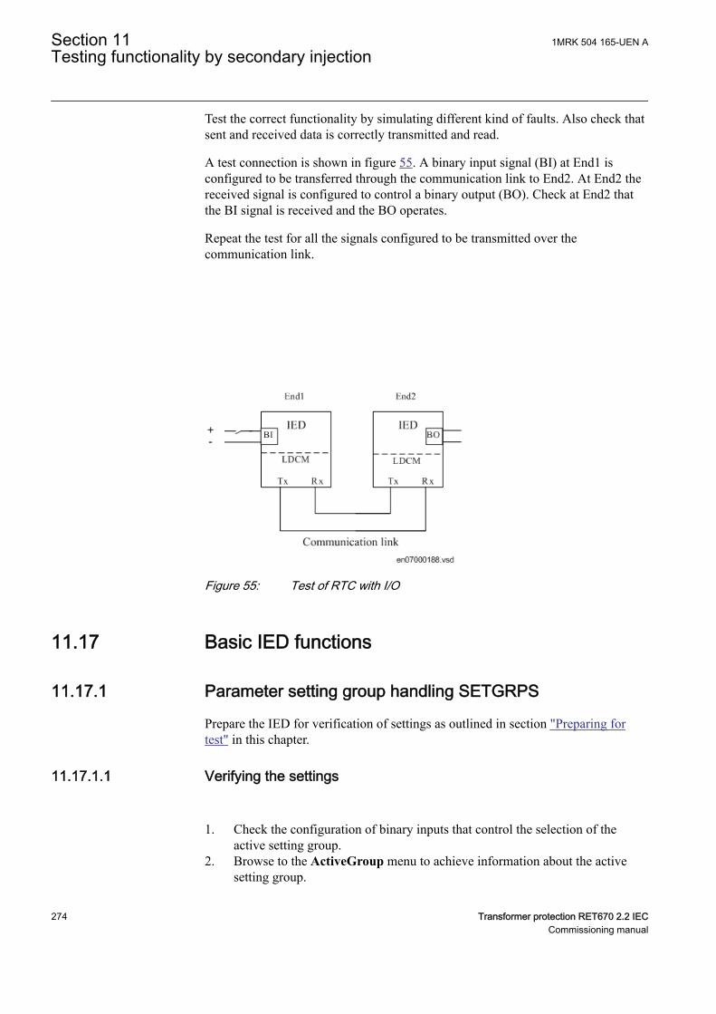
Test the correct functionality by simulating different kind of faults. Also check thatsent and received data is correctly transmitted and read.
A test connection is shown in figure 55. A binary input signal (BI) at End1 isconfigured to be transferred through the communication link to End2. At End2 thereceived signal is configured to control a binary output (BO). Check at End2 thatthe BI signal is received and the BO operates.
Repeat the test for all the signals configured to be transmitted over thecommunication link.
IEC07000188 V1 EN-US
Figure 55: Test of RTC with I/O
11.17 Basic IED functionsSEMOD52026-1 v1
11.17.1 Parameter setting group handling SETGRPSM11369-2 v4
Prepare the IED for verification of settings as outlined in section "Preparing fortest" in this chapter.
11.17.1.1 Verifying the settingsM11369-4 v4
1. Check the configuration of binary inputs that control the selection of theactive setting group.
2. Browse to the ActiveGroup menu to achieve information about the activesetting group.
Section 11 1MRK 504 165-UEN ATesting functionality by secondary injection
274 Transformer protection RET670 2.2 IECCommissioning manual
The ActiveGroup menu is located on the local HMI underMain menu/Test/Function status/Setting groups/ActiveGroup
3. Connect the appropriate dc voltage to the corresponding binary input of theIED and observe the information presented on the local HMI.The displayed information must always correspond to the activated input.
4. Check that the corresponding output indicates the active group.Operating procedures for the PC aided methods of changing the active settinggroups are described in the corresponding PCM600 documents andinstructions for the operators within the SCS are included in the SCSdocumentation.
11.17.1.2 Completing the testM11369-39 v4
Continue to test another function or end the test by changing the TESTMODEsetting to Off. Restore connections and settings to their original values, if they werechanged for testing purposes.
11.18 Exit test modeSEMOD53244-3 v5
The following procedure is used to return to normal operation.
After exiting the IED test mode, make sure that the MU is returnedto normal mode.
1. Navigate to the test mode folder.2. Change the On setting to Off. Press the 'E' key and the left arrow key.3. Answer YES, press the 'E' key and exit the menus.
1MRK 504 165-UEN A Section 11Testing functionality by secondary injection
Transformer protection RET670 2.2 IEC 275Commissioning manual

276
Section 12 Primary injection testingIP10812-1 v1
SEMOD65857-3 v3
Whenever it becomes necessary to work on primary equipment, it isessential that all the necessary switching, locking, earthing andsafety procedures are observed and obeyed in a rigid andformalized manner. Operating and testing procedures should bestrictly followed in order to avoid exposure to live equipment.
SEMOD65857-8 v2
A test with primary current through the protected zone is usually a final check thatthe current circuits are correctly connected to the IED protection scheme. It isimportant to have an appropriate source, which is able to inject sufficient current inthe primary circuit in order to distinguish between noise and real injected current.Therefore it is recommended that the injection current should be at least 10% ofrated CT primary current.
12.1 Transformer Voltage Control ATCCSEMOD176327-3 v3
12.1.1 Load drop compensation function, LDCSEMOD176327-117 v5
The load drop compensation function can be tested directly with operationalcurrents, in other words, with the power transformer in service and loaded.
When the system is carrying load there is a difference between the busbar voltage(UB) and the voltage at the load point (UL). This difference is load dependent andcan be compensated by the ATCC function.
The load current is fed into the ATCC function where parameters corresponding tothe line data for resistance and inductance are set. The voltage drop calculated bythe LDC is proportional to the voltage drop in the system up to the load point.
In the IED, this voltage is subtracted from the measured busbar voltage (UB) andthe result, corresponding to the voltage at the load point (UL) is presented to theATCC function for the purposes of voltage regulation. This voltage will be lower(if resistive or inductive load current is applied) than the Uset voltage and ATCCincreases the voltage in order to achieve the correct system voltage at the loadpoint.
1. Confirm the PST settings for Rline and Xline.
1MRK 504 165-UEN A Section 12Primary injection testing
Transformer protection RET670 2.2 IEC 277Commissioning manual
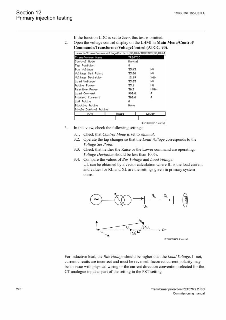
If the function LDC is set to Zero, this test is omitted.2. Open the voltage control display on the LHMI in Main Menu/Control/
Commands/TransformerVoltageControl (ATCC, 90).
IEC13000251-1-en.vsd
3. In this view, check the following settings:3.1. Check that Control Mode is set to Manual.3.2. Operate the tap changer so that the Load Voltage corresponds to the
Voltage Set Point.3.3. Check that neither the Raise or the Lower command are operating.
Voltage Deviation should be less than 100%.3.4. Compare the values of Bus Voltage and Load Voltage.
UL can be obtained by a vector calculation where IL is the load currentand values for RL and XL are the settings given in primary systemohms.
~ Load
RL XL
UB
UL
UB
RLIL
jXLILRe
IEC06000487-2-en.vsd
For inductive load, the Bus Voltage should be higher than the Load Voltage. If not,current circuits are incorrect and must be reversed. Incorrect current polarity maybe an issue with physical wiring or the current direction convention selected for theCT analogue input as part of the setting in the PST setting.
Section 12 1MRK 504 165-UEN APrimary injection testing
278 Transformer protection RET670 2.2 IECCommissioning manual
12.1.2 Voltage control of Parallel TransformersSEMOD176327-186 v3
In parallel operation, each transformer protection IED must be connected to thestation communication bus for data exchange. The following procedure assumesthat the necessary pre-configuration in the Parameter Setting tool and the SignalMatrix tool has been performed and tested to enable data exchange between IEDsor between instances of voltage control in the same IED.
For parallel operation, it is also recommended to confirm the setting for the generalparallel arrangement of transformers in Main menu/Settings/Setting group N/Control/TransformerVoltageControl(ATCC,90)/TR8ATCC:x/ParCtrl. Generalparallel arrangement of transformers are defined by setting TnRXOP to On or Off.The following rules are applicable for the settings of T1RXOP – T8RXOP.
• In each instance of TR8ATCC, set all TnRXOP parameters corresponding tothe connected IEDs to On except the parameter corresponding to the IEDitself. For example, do not set T1RXOP to On in IED T1 or T2RXOP to On inIED T2.
For example, if IEDs T1, T2 and T3 are connected,
• In instance 1 of TR8ATCC, set T2RXOP and T3RXOP to On.• In instance 2 of TR8ATCC, set T1RXOP and T3RXOP to On.• In instance 3 of TR8ATCC, set T1RXOP and T2RXOP to On.
12.1.3 Minimum Circulating Current (MCC) methodSEMOD176327-195 v3
Voltage control of parallel transformers with the circulating current method meansminimizing the circulating current at a given voltage target value. The busbarvoltage (UB) is measured individually for each transformer in the parallel group byits associated TR8ATCC function. These measured values are then exchangedbetween the transformers, and in each TR8ATCC block, the mean value of all UBvalues is calculated. The resulting value UBmean is then used in each IED insteadof UB for the voltage regulation.
1. Check the overcurrent blocking level (Iblock) in Main menu/Settings/General settings/Control/TransformerVoltageControl(ATCC,90)/TR8ATCC:x/TCCtrl/Iblock.
2. Check that the circulating current blocking (OperCCBlock) is set On, and thecheck the correct settings for circulating current limit (CircCurLimit) in Mainmenu/Settings/General settings/Control/TransformerVoltageControl(ATCC,90)/TR8ATCC:x/ParCtrl/CircCurrLimit.
1MRK 504 165-UEN A Section 12Primary injection testing
Transformer protection RET670 2.2 IEC 279Commissioning manual
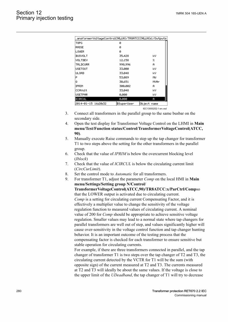
IEC13000252-1-en.vsd
3. Connect all transformers in the parallel group to the same busbar on thesecondary side.
4. Open the test display for Transformer Voltage Control on the LHMI in Mainmenu/Test/Function status/Control/TransformerVoltageControl(ATCC,90).
5. Manually execute Raise commands to step up the tap changer for transformerT1 to two steps above the setting for the other transformers in the parallelgroup.
6. Check that the value of IPRIM is below the overcurrent blocking level(Iblock)
7. Check that the value of ICIRCUL is below the circulating current limit(CircCurLimit).
8. Set the control mode to Automatic for all transformers.9. For transformer T1, adjust the parameter Comp on the local HMI in Main
menu/Settings/Setting group N/Control/TransformerVoltageControl(ATCC,90)/TR8ATCC:x/ParCtrl/Compsothat the LOWER output is activated due to circulating current.Comp is a setting for circulating current Compensating Factor, and it iseffectively a multiplier value to change the sensitivity of the voltageregulation function to measured values of circulating current. A nominalvalue of 200 for Comp should be appropriate to achieve sensitive voltageregulation. Smaller values may lead to a normal state where tap changers forparallel transformers are well out of step, and values significantly higher willcause over-sensitivity in the voltage control function and tap changer huntingbehavior. It is an important outcome of the testing process that thecompensating factor is checked for each transformer to ensure sensitive butstable operation for circulating currents.For example, if there are three transformers connected in parallel, and the tapchanger of transformer T1 is two steps over the tap changer of T2 and T3, thecirculating current detected by the VCTR for T1 will be the sum (withopposite sign) of the current measured at T2 and T3. The currents measuredat T2 and T3 will ideally be about the same values. If the voltage is close tothe upper limit of the UDeadband, the tap changer of T1 will try to decrease
Section 12 1MRK 504 165-UEN APrimary injection testing
280 Transformer protection RET670 2.2 IECCommissioning manual
the controlled voltage. In the opposite case, that is, the voltage is close to thelower limit of UDeadband, the tap changer at T1 will not try to decrease thecontrolled voltage. The tap changer for T2 and T3 will not operate due to thefact that the detected circulating current will be half of the current detected atT1. The setting of the parameter Comp then might need to be increased alittle. At least one tap changer step difference between the differenttransformers should be allowed in order to avoid the tap changers to operatetoo often. If the allowed difference is, for example, two steps, the tap changershall be stepped up three steps when setting the parameter Comp.
10. Set the Comp parameter for T2 and T3 in the same manner as for T1.According to the described procedure when the tap changer of onetransformer is two steps above the others, it shall automatically step down.When there are only two transformers in the group either shall one step downor the other step up depending on the voltage level at the ATCC.
12.1.4 Master Follower (MF) methodSEMOD176327-244 v3
The Master Follower method requires a Master to be nominated in a parallel group.It is responsible for measuring secondary bus voltage and executing commands toraise and lower tap changers, which are repeated by Follower transformers in thegroup.
1. Confirm the voltage blocking levels OVPartBK and UVPpartBK in Mainmenu/Settings/General settings/Control/TransformerVoltageControl(ATCC,90)/TR8ATCC:x/Voltage/Umax,Umin.
2. Check that MFMode is set to Follow Tap or Follow Cmd in Main menu/Settings/General settings/Control/TransformerVoltageControl(ATCC,90)/TR8ATCC:x/MFMode.If this setting is Follow Tap, all Follower transformers shall match the actualtap setting of the Master, while Follow Cmd requires that Followertransformers follow the RAISE and LOWER commands executed by theMaster.
3. Confirm the maximum difference in tap positions for parallel transformers.The number of taps is determined by the setting in the Parameter Setting toolunder Main menu/Settings/Setting group N/Control/TransformerVoltageControl(ATCC,90)/TR8ATCC:x/ParCtrl/MFPosDiffLim
4. Connect all transformers in the parallel group to the same busbar on both theprimary and secondary sides.
5. Set the control mode to Manual for each transformer in the parallel controlgroup
6. Open the test display for Transformer Voltage Control on the LHMI in Mainmenu/Test/Function status/Control/TransformerVoltageControl (ATCC,90).
1MRK 504 165-UEN A Section 12Primary injection testing
Transformer protection RET670 2.2 IEC 281Commissioning manual
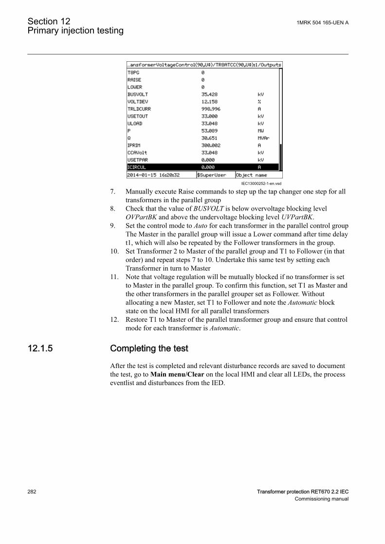
IEC13000252-1-en.vsd
7. Manually execute Raise commands to step up the tap changer one step for alltransformers in the parallel group
8. Check that the value of BUSVOLT is below overvoltage blocking levelOVPartBK and above the undervoltage blocking level UVPartBK.
9. Set the control mode to Auto for each transformer in the parallel control groupThe Master in the parallel group will issue a Lower command after time delayt1, which will also be repeated by the Follower transformers in the group.
10. Set Transformer 2 to Master of the parallel group and T1 to Follower (in thatorder) and repeat steps 7 to 10. Undertake this same test by setting eachTransformer in turn to Master
11. Note that voltage regulation will be mutually blocked if no transformer is setto Master in the parallel group. To confirm this function, set T1 as Master andthe other transformers in the parallel grouper set as Follower. Withoutallocating a new Master, set T1 to Follower and note the Automatic blockstate on the local HMI for all parallel transformers
12. Restore T1 to Master of the parallel transformer group and ensure that controlmode for each transformer is Automatic.
12.1.5 Completing the testSEMOD176327-287 v3
After the test is completed and relevant disturbance records are saved to documentthe test, go to Main menu/Clear on the local HMI and clear all LEDs, the processeventlist and disturbances from the IED.
Section 12 1MRK 504 165-UEN APrimary injection testing
282 Transformer protection RET670 2.2 IECCommissioning manual
Section 13 Checking the directionality
13.1 OverviewGUID-7E504488-F341-477A-953A-EB0B262911EB v2
Before starting this process, all individual devices that are involved in the faultclearance process of the protected object must have been individually tested andmust be set in operation. The circuit breaker must be ready for an open-close-opencycle.
The directional test is performed when the protected object is energized and acertain amount of load current is available. It is also necessary to know the flow ofthe load current (import or export, i.e. forward or reverse) by help of the indicationfrom an external instrument (energy-meter, or SCADA information).
The design of the test procedure depends on the type of protection function to betested. Some items that can be used as guidelines are the following.
13.2 Testing the directionality of the distance protectionGUID-EB5380B2-6086-4814-8890-102E55A79C82 v4
The test is performed by looking at the information given by the High speeddistance protection ZMFPDIS, ZMFCPDIS or the directional function ZDRDIR orZDMRDIR whichever is used.
Procedure:
1. Make sure that all control and protection functions that belong to the objectthat are going to be energized have been tested and are set to be in operation
2. Make sure that the primary load current fulfills the following conditions (byusing an external equipment):• The magnitude of the primary load current must be higher than the
minimum operating current set for the directional elements in the IED. Incase of default settings this means:• load current > 5% of base current• Otherwise the settings IMinOpPE and IMinOpPP for ZDRDIR or
ZDMRDIR are available under the HMI menu: Main menu/Settings/IED Settings/Impedance protection/DirectionalImpedance
The primary load impedance must have an angle (PHI) between the settingangles for the directional lines. In case of default settings this means:
1MRK 504 165-UEN A Section 13Checking the directionality
Transformer protection RET670 2.2 IEC 283Commissioning manual
• for forward (exported) load: -15 deg < PHI < 115 deg• for reverse (imported) load: 165 deg < PHI < 295 deg
The settings for forward load: - ArgDir < PHI < ArgNegRes and the settingsfor reverse load: 180 deg - ArgDir < PHI < 180 deg + ArgNegRes included inthe directional functions ZDRDIR or ZDMRDIR are available under the HMImenu:• Main menu/Settings/IED Settings/Impedance protection/
DirectionalImpedance3. The directionality of the load current is shown by the High speed distance
protection ZMFPDIS or ZMFCPDIS under the HMI menu: Main menu/Test/Function status/Impedance protection/HighSpeedDistance or by thedirectional function ZDRDIR or ZDMRDIR and it is available under the HMImenu: Main menu/Test/Function status/Impedance protection/DirectionalImpedanceThe following will be shown if the load current flows in forward (exporting)direction:• L1Dir = Forward• L2Dir = Forward• L3Dir = Forward
The following will be shown if the load current flows in the reverse direction(importing):• L1Dir = Reverse• L2Dir = Reverse• L3Dir = Reverse
Compare this result with the information given by the external equipment, itmust be the same. If the direction of the three phases is not the same, this is asign of incorrect connection of the voltage or current transformers serving thedistance protection function. It is also possible that there is a wrong setting forthe earthing point for one or more of the CTs serving distance protection (thesetting name is: CTStarPoint available under the HMI menu:Main menu/Configuration/Analog modules).If the directional function shows forward when it should show reverse (orvice-versa) for all the three phases, this probably means a wrong connection ofCTs and/or VTs serving the distance protection, or it can mean a wrong settingof earthing point (the setting name is : CTStarPoint) for all the three CTs, or itcould mean a wrong setting for the pre-processing blocks(3PhaseAnalogGroup under the HMI menu: Main menu/Configuration/Analog modules) connected to the CTs/VTs and serving the distanceprotection (verify that no wrong negation has been set; the setting name is:Negation).If the directional function shows “No direction” for all the three phases it canmean that the load current is below the minimum operating current or that theload impedance has an angle which is outside the above given valid angles fordetermining forward or reverse direction.
Section 13 1MRK 504 165-UEN AChecking the directionality
284 Transformer protection RET670 2.2 IECCommissioning manual
If the directional function shows “No direction” for only some of the threephases, this probably means a wrong CTs/VTs connection.
4. The measured impedance information is available under the same menu. Thesevalues are not affected by the minimum operating current setting of ZDRDIRor ZDMRDIR and the measured values are shown any time the load current ishigher than 3% of the base current:• L1R• L1X• L2R• L2X• L3R• L3X
The measured impedance information can still be used to determine thedirection of the load. A positive resistance measured in all phases indicates aforward (exporting) resistive load (active power), while a negative signindicates a reverse (importing) resistive load (active power). Usually it isenough to look at the resistive values to get information of the load direction,that must anyway be compared with the indication given by externalequipment measuring the same power flow.
1MRK 504 165-UEN A Section 13Checking the directionality
Transformer protection RET670 2.2 IEC 285Commissioning manual

286
Section 14 Commissioning and maintenance of thefault clearing system
14.1 Commissioning testsSEMOD56513-5 v4
During commissioning all protection functions shall be verified with the settingvalues used at each plant. The commissioning tests must include verification of allcircuits by green-lining the circuit diagrams and the configuration diagrams for theused functions.
Further, the settings for protection functions are tested and recorded carefully asoutlined for the future periodic maintenance tests.
The final testing includes primary verification of all directional functions whereload currents is checked on the local HMI and in PCM600. The amplitudes andangles of all currents and voltages should be checked and the symmetry verified.
Directional functions have information about the measured direction and, forexample, measured impedance. These values must be checked and verified ascorrect with the export or import of power available.
Finally, final trip tests must be performed. This involves activation of protectionfunctions or tripping outputs with the circuit breaker closed and the tripping of thebreaker verified. When several breakers are involved, each breaker must bechecked individually and it must be verified that the other involved breakers arenot tripped at the same time.
14.2 Periodic maintenance testsSEMOD56517-1 v1
SEMOD56520-5 v4
The periodicity of all tests depends on several factors, for example the importanceof the installation, environmental conditions, simple or complex equipment, staticor electromechanical IEDs, and so on.
The normal maintenance praxis of the user should be followed. However, ABB'srecommendation is as follows:
Every second to third year
• Visual inspection of all equipment.• Removal of dust on ventilation louvres and IEDs if necessary.• Periodic maintenance test for protection IEDs of object where no redundant
protections are provided.
1MRK 504 165-UEN A Section 14Commissioning and maintenance of the fault clearing system
Transformer protection RET670 2.2 IEC 287Commissioning manual
Every four to six years
• Periodic maintenance test for protection IEDs of objects with redundantprotection system.
First maintenance test should always be carried out after the firsthalf year of service.
When protection IEDs are combined with built-in control, the testinterval can be increased drastically, up to for instance 15 years,because the IED continuously reads service values, operates thebreakers, and so on.
14.2.1 Visual inspectionSEMOD56525-5 v3
Prior to testing, the protection IEDs should be inspected to detect any visibledamage that may have occurred (for example, dirt or moisture deposits,overheating).
Make sure that all IEDs are equipped with covers.
14.2.2 Maintenance testsSEMOD56534-1 v1
SEMOD56528-5 v5
To be made after the first half year of service, then with the cycle as proposedabove and after any suspected maloperation or change of the IED setting.
Testing of protection IEDs shall preferably be made with the primary circuit de-energized. The IED cannot protect the circuit during testing. Trained personnelmay test one IED at a time on live circuits where redundant protection is installedand de-energization of the primary circuit is not allowed.
ABB protection IEDs are preferably tested by aid of components from theCOMBITEST testing system described in information B03-9510 E. Maincomponents are RTXP 8/18/24 test switch usually located to the left in eachprotection IED and RTXH 8/18/24 test handle, which is inserted in test switch atsecondary testing. All necessary operations such as opening of trip circuits, short-circuiting of current circuits and opening of voltage circuits are automaticallyperformed in the right order to allow for simple and safe secondary testing evenwith the object in service.
14.2.2.1 PreparationSEMOD56528-10 v2
Before starting maintenance testing, the test engineers should scrutinize applicablecircuit diagrams and have the following documentation available:
Section 14 1MRK 504 165-UEN ACommissioning and maintenance of the fault clearing system
288 Transformer protection RET670 2.2 IECCommissioning manual
• Test instructions for protection IEDs to be tested• Test records from previous commissioning and maintenance tests• List of valid settings• Blank test records to fill in measured values
14.2.2.2 RecordingSEMOD56528-14 v2
It is of utmost importance to carefully record the test results. Special test sheetscovering the frequency of test, date of test and achieved test values should be used.IED setting list and protocols from previous tests should be available and all resultsshould be compared for differences. At component failures, spare equipment isused and set to the requested value. A note of the exchange is made and the newmeasured values are recorded. Test records for several years of testing should bestored in a common file for a station, or a part of a station, to give a simpleoverview of the period of testing and achieved test values. These test records arevaluable when analysis of service disturbances shall be done.
14.2.2.3 Secondary injectionSEMOD56528-17 v2
The periodic maintenance test is done by secondary injection from a portable testset. Each protection shall be tested according to the secondary injection testinformation for the specific protection IED. Only the setting values adopted shallbe checked for each protection function. If the discrepancy between obtained valueand requested set value is too big the setting should be adjusted, the new valuerecorded and a note should be made in the test record.
14.2.2.4 Alarm testSEMOD56528-20 v4
When inserting the test handle the alarm and event signalling is normally blocked.This is done in the IED by setting the event reporting to Off during the test. Thiscan be done when the test handle is inserted or the IED is set to test mode from thelocal HMI. At the end of the secondary injection test it should be checked that theevent and alarm signalling is correct by activating the events and performing someselected tests.
14.2.2.5 Self supervision checkSEMOD56528-23 v5
Once secondary testing has been completed, it should be checked that no self-supervision signals are activated continuously or sporadically. Especially check thetime synchronization system, GPS or other, and communication signals, bothstation communication and remote communication.
14.2.2.6 Trip circuit checkSEMOD56528-26 v5
When the protection IED undergoes an operational check, a tripping pulse isnormally obtained on one or more of the output contacts and preferably on the testswitch. The healthy circuit is of utmost importance for the protection operation. If
1MRK 504 165-UEN A Section 14Commissioning and maintenance of the fault clearing system
Transformer protection RET670 2.2 IEC 289Commissioning manual
the circuit is not provided with a continuous trip-circuit supervision, it is possibleto check that circuit is really closed when the test-plug handle has been removed byusing a high-ohmic voltmeter and measuring between the plus and the trip outputon the panel. The measurement is then done through the trip coil of the circuitbreaker and therefore the complete trip circuit is checked.
Note that the breaker must be closed.
Please observe that the test system does not provide built-insecurity during this test. If the instrument should be set on Ampinstead of Volts, the circuit breaker naturally is tripped, therefore,great care is necessary.
Trip circuit from trip IEDs to circuit breaker is often supervised by trip-circuitsupervision. It can then be checked that a circuit is healthy by opening trippingoutput terminals in the cubicle. When the terminal is opened, an alarm shall beachieved on the signal system after a delay of some seconds.
Remember to close the circuit directly after the test and tighten theterminal carefully.
14.2.2.7 Measurement of service currentsSEMOD56528-30 v4
After a maintenance test it is recommended to measure the service currents andservice voltages recorded by the protection IED. The service values are checked onthe local HMI or in PCM600. Ensure that the correct values and angles betweenvoltages and currents are recorded. Also check the direction of directionalfunctions such as Distance and directional overcurrent functions.
For transformer differential protection, the achieved differential current value isdependent on the tap changer position and can vary between less than 1% up toperhaps 10% of rated current. For line differential functions, the capacitivecharging currents can normally be recorded as a differential current.
The zero-sequence current to earth-fault protection IEDs should be measured. Thecurrent amounts normally very small but normally it is possible to see if the currentcircuit is "alive".
The neutral-point voltage to an earth-fault protection IED is checked. The voltageis normally 0.1 to 1V secondary. However, voltage can be considerably higher dueto harmonics. Normally a CVT secondary can have around 2.5 - 3% third-harmonicvoltage.
Section 14 1MRK 504 165-UEN ACommissioning and maintenance of the fault clearing system
290 Transformer protection RET670 2.2 IECCommissioning manual

14.2.2.8 RestoringSEMOD56528-36 v2
Maintenance is very important to improve the availability of the protection systemby detecting failures before the protection is required to operate. There is howeverlittle point in testing healthy equipment and then putting it back into service withan open terminal, with a removed fuse or open miniature circuit breaker with anopen connection, wrong setting, and so on.
Thus a list should be prepared of all items disturbed during test so that all can beput back into service quickly and without overlooking something. It should be putback into service item by item and signed by the responsible engineer.
1MRK 504 165-UEN A Section 14Commissioning and maintenance of the fault clearing system
Transformer protection RET670 2.2 IEC 291Commissioning manual

292
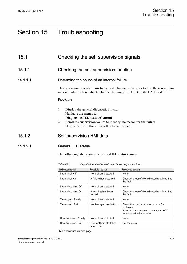
Section 15 Troubleshooting
15.1 Checking the self supervision signalsIP1474-1 v1
15.1.1 Checking the self supervision functionIP1473-1 v1
15.1.1.1 Determine the cause of an internal failureM11657-2 v1
This procedure describes how to navigate the menus in order to find the cause of aninternal failure when indicated by the flashing green LED on the HMI module.
Procedure
1. Display the general diagnostics menu.Navigate the menus to:Diagnostics/IED status/General
2. Scroll the supervision values to identify the reason for the failure.Use the arrow buttons to scroll between values.
15.1.2 Self supervision HMI dataIP1472-1 v1
15.1.2.1 General IED statusGUID-A84F3903-8A70-47D6-8613-AD7FF8BA3AEC v1
The following table shows the general IED status signals.M11656-1 v2
Table 40: Signals from the General menu in the diagnostics tree.
Indicated result Possible reason Proposed actionInternal fail Off No problem detected. None.
Internal fail On A failure has occurred. Check the rest of the indicated results to findthe fault.
Internal warning Off No problem detected. None.
Internal warning On A warning has beenissued.
Check the rest of the indicated results to findthe fault.
Time synch Ready No problem detected. None.
Time synch Fail No time synchronization. Check the synchronization source forproblems.If the problem persists, contact your ABBrepresentative for service.
Real time clock Ready No problem detected. None.
Real time clock Fail The real time clock hasbeen reset.
Set the clock.
Table continues on next page
1MRK 504 165-UEN A Section 15Troubleshooting
Transformer protection RET670 2.2 IEC 293Commissioning manual
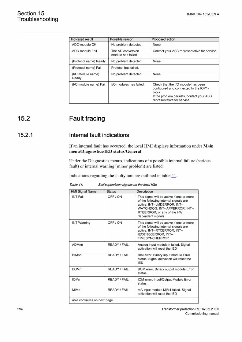
Indicated result Possible reason Proposed actionADC-module OK No problem detected. None.
ADC-module Fail The AD conversionmodule has failed.
Contact your ABB representative for service.
(Protocol name) Ready No problem detected. None.
(Protocol name) Fail Protocol has failed.
(I/O module name)Ready
No problem detected. None.
(I/O module name) Fail I/O modules has failed. Check that the I/O module has beenconfigured and connected to the IOP1-block.If the problem persists, contact your ABBrepresentative for service.
15.2 Fault tracingIP8765-1 v1
15.2.1 Internal fault indicationsM11763-2 v5
If an internal fault has occurred, the local HMI displays information under Mainmenu/Diagnostics/IED status/General
Under the Diagnostics menus, indications of a possible internal failure (seriousfault) or internal warning (minor problem) are listed.
Indications regarding the faulty unit are outlined in table 41.
Table 41: Self-supervision signals on the local HMI
HMI Signal Name: Status DescriptionINT Fail OFF / ON This signal will be active if one or more
of the following internal signals areactive; INT--LMDERROR, INT--WATCHDOG, INT--APPERROR, INT--RTEERROR, or any of the HWdependent signals
INT Warning OFF / ON This signal will be active if one or moreof the following internal signals areactive; INT--RTCERROR, INT--IEC61850ERROR, INT--TIMESYNCHERROR
ADMnn READY / FAIL Analog input module n failed. Signalactivation will reset the IED
BIMnn READY / FAIL BIM error. Binary input module Errorstatus. Signal activation will reset theIED
BOMn READY / FAIL BOM error. Binary output module Errorstatus.
IOMn READY / FAIL IOM-error. Input/Output Module Errorstatus.
MIMn READY / FAIL mA input module MIM1 failed. Signalactivation will reset the IED
Table continues on next page
Section 15 1MRK 504 165-UEN ATroubleshooting
294 Transformer protection RET670 2.2 IECCommissioning manual
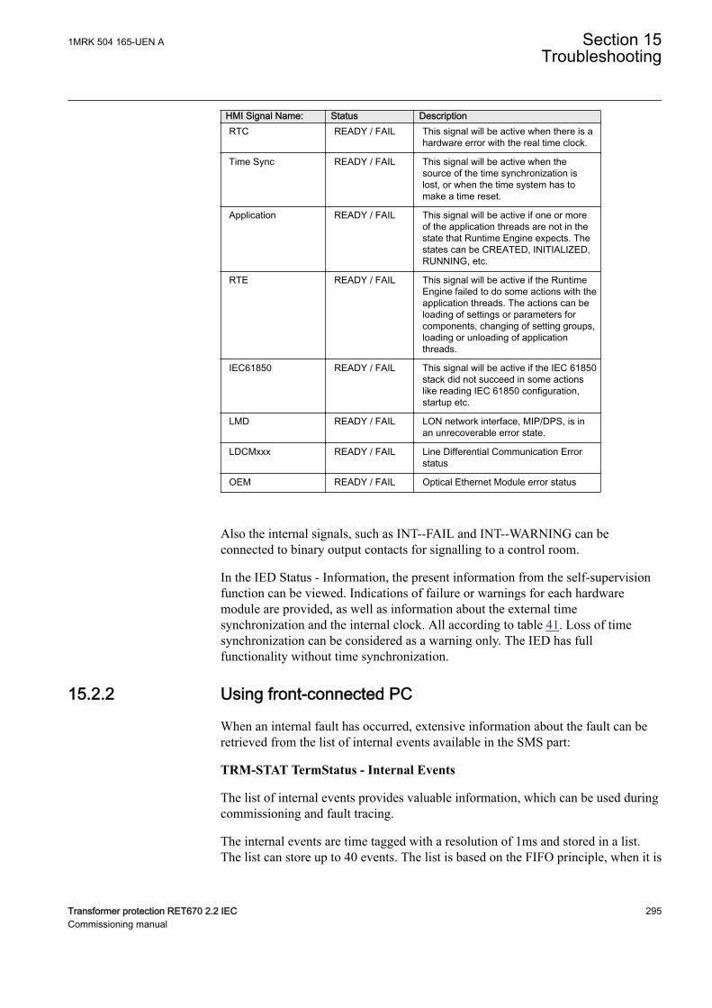
HMI Signal Name: Status DescriptionRTC READY / FAIL This signal will be active when there is a
hardware error with the real time clock.
Time Sync READY / FAIL This signal will be active when thesource of the time synchronization islost, or when the time system has tomake a time reset.
Application READY / FAIL This signal will be active if one or moreof the application threads are not in thestate that Runtime Engine expects. Thestates can be CREATED, INITIALIZED,RUNNING, etc.
RTE READY / FAIL This signal will be active if the RuntimeEngine failed to do some actions with theapplication threads. The actions can beloading of settings or parameters forcomponents, changing of setting groups,loading or unloading of applicationthreads.
IEC61850 READY / FAIL This signal will be active if the IEC 61850stack did not succeed in some actionslike reading IEC 61850 configuration,startup etc.
LMD READY / FAIL LON network interface, MIP/DPS, is inan unrecoverable error state.
LDCMxxx READY / FAIL Line Differential Communication Errorstatus
OEM READY / FAIL Optical Ethernet Module error status
Also the internal signals, such as INT--FAIL and INT--WARNING can beconnected to binary output contacts for signalling to a control room.
In the IED Status - Information, the present information from the self-supervisionfunction can be viewed. Indications of failure or warnings for each hardwaremodule are provided, as well as information about the external timesynchronization and the internal clock. All according to table 41. Loss of timesynchronization can be considered as a warning only. The IED has fullfunctionality without time synchronization.
15.2.2 Using front-connected PCM11763-203 v5
When an internal fault has occurred, extensive information about the fault can beretrieved from the list of internal events available in the SMS part:
TRM-STAT TermStatus - Internal Events
The list of internal events provides valuable information, which can be used duringcommissioning and fault tracing.
The internal events are time tagged with a resolution of 1ms and stored in a list.The list can store up to 40 events. The list is based on the FIFO principle, when it is
1MRK 504 165-UEN A Section 15Troubleshooting
Transformer protection RET670 2.2 IEC 295Commissioning manual
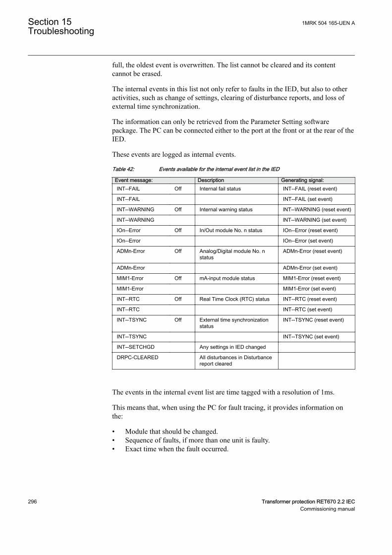
full, the oldest event is overwritten. The list cannot be cleared and its contentcannot be erased.
The internal events in this list not only refer to faults in the IED, but also to otheractivities, such as change of settings, clearing of disturbance reports, and loss ofexternal time synchronization.
The information can only be retrieved from the Parameter Setting softwarepackage. The PC can be connected either to the port at the front or at the rear of theIED.
These events are logged as internal events.
Table 42: Events available for the internal event list in the IED
Event message: Description Generating signal:INT--FAIL Off Internal fail status INT--FAIL (reset event)
INT--FAIL INT--FAIL (set event)
INT--WARNING Off Internal warning status lNT--WARNING (reset event)
INT--WARNING lNT--WARNING (set event)
IOn--Error Off In/Out module No. n status IOn--Error (reset event)
IOn--Error IOn--Error (set event)
ADMn-Error Off Analog/Digital module No. nstatus
ADMn-Error (reset event)
ADMn-Error ADMn-Error (set event)
MIM1-Error Off mA-input module status MIM1-Error (reset event)
MIM1-Error MIM1-Error (set event)
INT--RTC Off Real Time Clock (RTC) status INT--RTC (reset event)
INT--RTC INT--RTC (set event)
INT--TSYNC Off External time synchronizationstatus
INT--TSYNC (reset event)
INT--TSYNC INT--TSYNC (set event)
INT--SETCHGD Any settings in IED changed
DRPC-CLEARED All disturbances in Disturbancereport cleared
The events in the internal event list are time tagged with a resolution of 1ms.
This means that, when using the PC for fault tracing, it provides information onthe:
• Module that should be changed.• Sequence of faults, if more than one unit is faulty.• Exact time when the fault occurred.
Section 15 1MRK 504 165-UEN ATroubleshooting
296 Transformer protection RET670 2.2 IECCommissioning manual
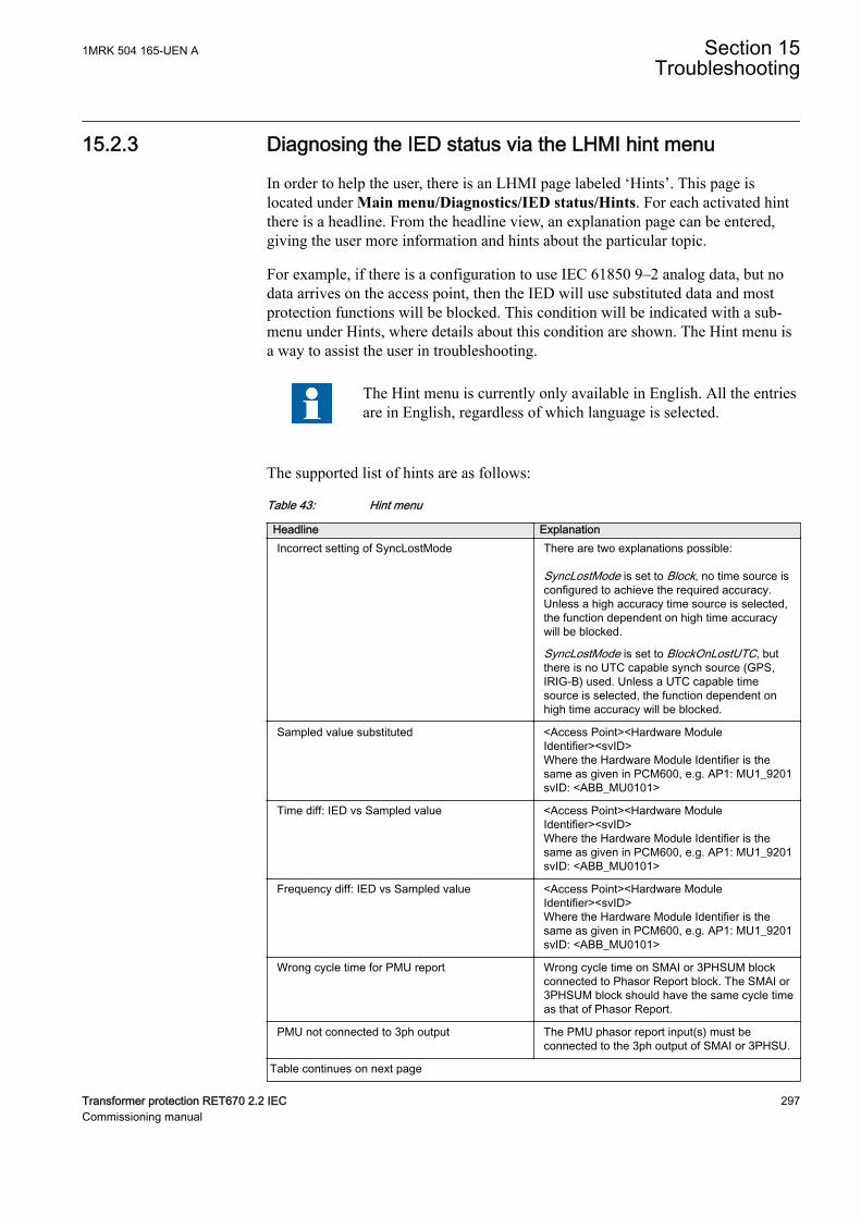
15.2.3 Diagnosing the IED status via the LHMI hint menuGUID-7E8503E9-441B-487A-9CD7-B43463D1CAE5 v2
In order to help the user, there is an LHMI page labeled ‘Hints’. This page islocated under Main menu/Diagnostics/IED status/Hints. For each activated hintthere is a headline. From the headline view, an explanation page can be entered,giving the user more information and hints about the particular topic.
For example, if there is a configuration to use IEC 61850 9–2 analog data, but nodata arrives on the access point, then the IED will use substituted data and mostprotection functions will be blocked. This condition will be indicated with a sub-menu under Hints, where details about this condition are shown. The Hint menu isa way to assist the user in troubleshooting.
The Hint menu is currently only available in English. All the entriesare in English, regardless of which language is selected.
The supported list of hints are as follows:
Table 43: Hint menu
Headline ExplanationIncorrect setting of SyncLostMode There are two explanations possible:
SyncLostMode is set to Block, no time source isconfigured to achieve the required accuracy.Unless a high accuracy time source is selected,the function dependent on high time accuracywill be blocked.
SyncLostMode is set to BlockOnLostUTC, butthere is no UTC capable synch source (GPS,IRIG-B) used. Unless a UTC capable timesource is selected, the function dependent onhigh time accuracy will be blocked.
Sampled value substituted <Access Point><Hardware ModuleIdentifier><svID>Where the Hardware Module Identifier is thesame as given in PCM600, e.g. AP1: MU1_9201svID: <ABB_MU0101>
Time diff: IED vs Sampled value <Access Point><Hardware ModuleIdentifier><svID>Where the Hardware Module Identifier is thesame as given in PCM600, e.g. AP1: MU1_9201svID: <ABB_MU0101>
Frequency diff: IED vs Sampled value <Access Point><Hardware ModuleIdentifier><svID>Where the Hardware Module Identifier is thesame as given in PCM600, e.g. AP1: MU1_9201svID: <ABB_MU0101>
Wrong cycle time for PMU report Wrong cycle time on SMAI or 3PHSUM blockconnected to Phasor Report block. The SMAI or3PHSUM block should have the same cycle timeas that of Phasor Report.
PMU not connected to 3ph output The PMU phasor report input(s) must beconnected to the 3ph output of SMAI or 3PHSU.
Table continues on next page
1MRK 504 165-UEN A Section 15Troubleshooting
Transformer protection RET670 2.2 IEC 297Commissioning manual
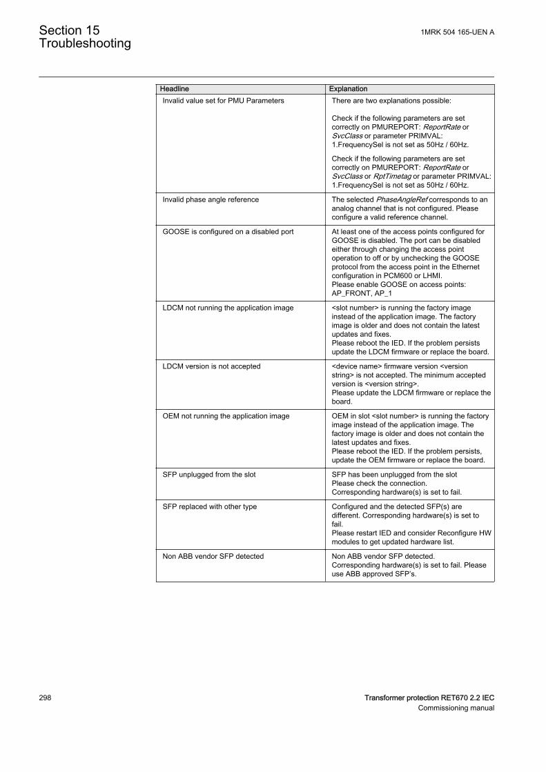
Headline ExplanationInvalid value set for PMU Parameters There are two explanations possible:
Check if the following parameters are setcorrectly on PMUREPORT: ReportRate orSvcClass or parameter PRIMVAL:1.FrequencySel is not set as 50Hz / 60Hz.
Check if the following parameters are setcorrectly on PMUREPORT: ReportRate orSvcClass or RptTimetag or parameter PRIMVAL:1.FrequencySel is not set as 50Hz / 60Hz.
Invalid phase angle reference The selected PhaseAngleRef corresponds to ananalog channel that is not configured. Pleaseconfigure a valid reference channel.
GOOSE is configured on a disabled port At least one of the access points configured forGOOSE is disabled. The port can be disabledeither through changing the access pointoperation to off or by unchecking the GOOSEprotocol from the access point in the Ethernetconfiguration in PCM600 or LHMI.Please enable GOOSE on access points:AP_FRONT, AP_1
LDCM not running the application image <slot number> is running the factory imageinstead of the application image. The factoryimage is older and does not contain the latestupdates and fixes.Please reboot the IED. If the problem persistsupdate the LDCM firmware or replace the board.
LDCM version is not accepted <device name> firmware version <versionstring> is not accepted. The minimum acceptedversion is <version string>.Please update the LDCM firmware or replace theboard.
OEM not running the application image OEM in slot <slot number> is running the factoryimage instead of the application image. Thefactory image is older and does not contain thelatest updates and fixes.Please reboot the IED. If the problem persists,update the OEM firmware or replace the board.
SFP unplugged from the slot SFP has been unplugged from the slotPlease check the connection.Corresponding hardware(s) is set to fail.
SFP replaced with other type Configured and the detected SFP(s) aredifferent. Corresponding hardware(s) is set tofail.Please restart IED and consider Reconfigure HWmodules to get updated hardware list.
Non ABB vendor SFP detected Non ABB vendor SFP detected.Corresponding hardware(s) is set to fail. Pleaseuse ABB approved SFP’s.
Section 15 1MRK 504 165-UEN ATroubleshooting
298 Transformer protection RET670 2.2 IECCommissioning manual
15.3 Repair instructionIP8767-1 v1
M11764-2 v2
Never disconnect the secondary connection of a current transformercircuit without short-circuiting the transformer’s secondarywinding. Operating a current transformer with the secondarywinding open will cause a massive potential build up that maydamage the transformer and may cause injuries to humans.
Never connect or disconnect a wire and/or a connector to or from aIED during normal service. Hazardous voltages and currents arepresent that may be lethal. Operation may be disrupted and IED andmeasuring circuitry may be damaged.
M11764-10 v1
An alternative is to open the IED and send only the faulty circuit board to ABB forrepair. When a printed circuit board is sent to ABB, it must always be placed in ametallic, ESD-proof, protection bag. The user can also purchase separatereplacement modules.
Strictly follow the company and country safety regulations.
M11766-4 v2
Most electronic components are sensitive to electrostatic discharge and latentdamage may occur. Please observe usual procedures for handling electronics andalso use an ESD wrist strap. A semi-conducting layer must be placed on theworkbench and connected to earth.
Disassemble and reassemble the IED accordingly:
1. Switch off the dc supply.2. Short-circuit the current transformers and disconnect all current and voltage
connections from the IED.3. Disconnect all signal wires by removing the female connectors.4. Disconnect the optical fibers.5. Unscrew the main back plate of the IED.6. If the transformer module is to be changed:
• Remove the IED from the panel if necessary.• Remove the rear plate of the IED.• Remove the front plate.• Remove the screws of the transformer input module, both front and rear.
7. Pull out the faulty module.8. Check that the new module has a correct identity number.9. Check that the springs on the card rail are connected to the corresponding
metallic area on the circuit board when the new module is inserted.10. Reassemble the IED.
1MRK 504 165-UEN A Section 15Troubleshooting
Transformer protection RET670 2.2 IEC 299Commissioning manual
If the IED has been calibrated with the system inputs, the calibration proceduremust be performed again to maintain the total system accuracy.
15.4 Repair supportM11768-3 v3
If an IED needs to be repaired, the whole IED must be removed and sent to anABB Logistic Center. Before returning the material, an inquiry must be sent to theABB Logistic Center.
e-mail: [email protected]
15.5 MaintenanceM11769-3 v2
The IED is self-supervised. No special maintenance is required.
Instructions from the power network company and other maintenance directivesvalid for maintenance of the power system must be followed.
Section 15 1MRK 504 165-UEN ATroubleshooting
300 Transformer protection RET670 2.2 IECCommissioning manual
Section 16 GlossaryM14893-1 v16
AC Alternating current
ACC Actual channel
ACT Application configuration tool within PCM600
A/D converter Analog-to-digital converter
ADBS Amplitude deadband supervision
ADM Analog digital conversion module, with timesynchronization
AI Analog input
ANSI American National Standards Institute
AR Autoreclosing
ASCT Auxiliary summation current transformer
ASD Adaptive signal detection
ASDU Application service data unit
AWG American Wire Gauge standard
BBP Busbar protection
BFOC/2,5 Bayonet fibre optic connector
BFP Breaker failure protection
BI Binary input
BIM Binary input module
BOM Binary output module
BOS Binary outputs status
BR External bistable relay
BS British Standards
BSR Binary signal transfer function, receiver blocks
BST Binary signal transfer function, transmit blocks
C37.94 IEEE/ANSI protocol used when sending binary signalsbetween IEDs
CAN Controller Area Network. ISO standard (ISO 11898) forserial communication
CB Circuit breaker
CBM Combined backplane module
1MRK 504 165-UEN A Section 16Glossary
Transformer protection RET670 2.2 IEC 301Commissioning manual
CCITT Consultative Committee for International Telegraph andTelephony. A United Nations-sponsored standards bodywithin the International Telecommunications Union.
CCM CAN carrier module
CCVT Capacitive Coupled Voltage Transformer
Class C Protection Current Transformer class as per IEEE/ ANSI
CMPPS Combined megapulses per second
CMT Communication Management tool in PCM600
CO cycle Close-open cycle
Codirectional Way of transmitting G.703 over a balanced line. Involvestwo twisted pairs making it possible to transmitinformation in both directions
COM Command
COMTRADE Standard Common Format for Transient Data Exchangeformat for Disturbance recorder according to IEEE/ANSIC37.111, 1999 / IEC 60255-24
Contra-directional Way of transmitting G.703 over a balanced line. Involvesfour twisted pairs, two of which are used for transmittingdata in both directions and two for transmitting clocksignals
COT Cause of transmission
CPU Central processing unit
CR Carrier receive
CRC Cyclic redundancy check
CROB Control relay output block
CS Carrier send
CT Current transformer
CU Communication unit
CVT or CCVT Capacitive voltage transformer
DAR Delayed autoreclosing
DARPA Defense Advanced Research Projects Agency (The USdeveloper of the TCP/IP protocol etc.)
DBDL Dead bus dead line
DBLL Dead bus live line
DC Direct current
DFC Data flow control
DFT Discrete Fourier transform
Section 16 1MRK 504 165-UEN AGlossary
302 Transformer protection RET670 2.2 IECCommissioning manual
DHCP Dynamic Host Configuration Protocol
DIP-switch Small switch mounted on a printed circuit board
DI Digital input
DLLB Dead line live bus
DNP Distributed Network Protocol as per IEEE Std 1815-2012
DR Disturbance recorder
DRAM Dynamic random access memory
DRH Disturbance report handler
DSP Digital signal processor
DTT Direct transfer trip scheme
ECT Ethernet configuration tool
EHV network Extra high voltage network
EIA Electronic Industries Association
EMC Electromagnetic compatibility
EMF Electromotive force
EMI Electromagnetic interference
EnFP End fault protection
EPA Enhanced performance architecture
ESD Electrostatic discharge
F-SMA Type of optical fibre connector
FAN Fault number
FCB Flow control bit; Frame count bit
FOX 20 Modular 20 channel telecommunication system forspeech, data and protection signals
FOX 512/515 Access multiplexer
FOX 6Plus Compact time-division multiplexer for the transmission ofup to seven duplex channels of digital data over opticalfibers
FPN Flexible product naming
FTP File Transfer Protocol
FUN Function type
G.703 Electrical and functional description for digital lines usedby local telephone companies. Can be transported overbalanced and unbalanced lines
GCM Communication interface module with carrier of GPSreceiver module
1MRK 504 165-UEN A Section 16Glossary
Transformer protection RET670 2.2 IEC 303Commissioning manual
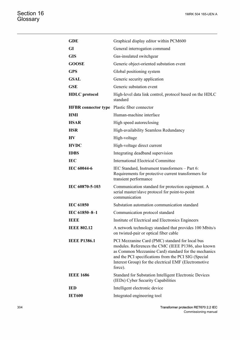
GDE Graphical display editor within PCM600
GI General interrogation command
GIS Gas-insulated switchgear
GOOSE Generic object-oriented substation event
GPS Global positioning system
GSAL Generic security application
GSE Generic substation event
HDLC protocol High-level data link control, protocol based on the HDLCstandard
HFBR connector type Plastic fiber connector
HMI Human-machine interface
HSAR High speed autoreclosing
HSR High-availability Seamless Redundancy
HV High-voltage
HVDC High-voltage direct current
IDBS Integrating deadband supervision
IEC International Electrical Committee
IEC 60044-6 IEC Standard, Instrument transformers – Part 6:Requirements for protective current transformers fortransient performance
IEC 60870-5-103 Communication standard for protection equipment. Aserial master/slave protocol for point-to-pointcommunication
IEC 61850 Substation automation communication standard
IEC 61850–8–1 Communication protocol standard
IEEE Institute of Electrical and Electronics Engineers
IEEE 802.12 A network technology standard that provides 100 Mbits/son twisted-pair or optical fiber cable
IEEE P1386.1 PCI Mezzanine Card (PMC) standard for local busmodules. References the CMC (IEEE P1386, also knownas Common Mezzanine Card) standard for the mechanicsand the PCI specifications from the PCI SIG (SpecialInterest Group) for the electrical EMF (Electromotiveforce).
IEEE 1686 Standard for Substation Intelligent Electronic Devices(IEDs) Cyber Security Capabilities
IED Intelligent electronic device
IET600 Integrated engineering tool
Section 16 1MRK 504 165-UEN AGlossary
304 Transformer protection RET670 2.2 IECCommissioning manual
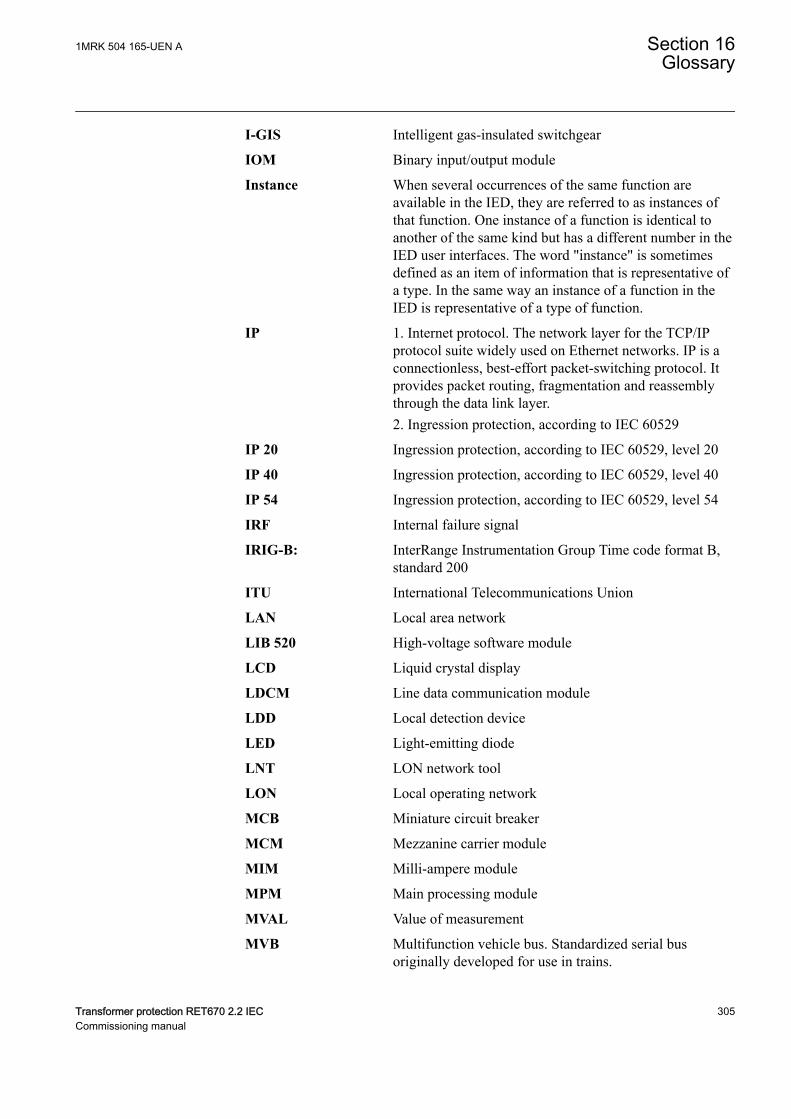
I-GIS Intelligent gas-insulated switchgear
IOM Binary input/output module
Instance When several occurrences of the same function areavailable in the IED, they are referred to as instances ofthat function. One instance of a function is identical toanother of the same kind but has a different number in theIED user interfaces. The word "instance" is sometimesdefined as an item of information that is representative ofa type. In the same way an instance of a function in theIED is representative of a type of function.
IP 1. Internet protocol. The network layer for the TCP/IPprotocol suite widely used on Ethernet networks. IP is aconnectionless, best-effort packet-switching protocol. Itprovides packet routing, fragmentation and reassemblythrough the data link layer.2. Ingression protection, according to IEC 60529
IP 20 Ingression protection, according to IEC 60529, level 20
IP 40 Ingression protection, according to IEC 60529, level 40
IP 54 Ingression protection, according to IEC 60529, level 54
IRF Internal failure signal
IRIG-B: InterRange Instrumentation Group Time code format B,standard 200
ITU International Telecommunications Union
LAN Local area network
LIB 520 High-voltage software module
LCD Liquid crystal display
LDCM Line data communication module
LDD Local detection device
LED Light-emitting diode
LNT LON network tool
LON Local operating network
MCB Miniature circuit breaker
MCM Mezzanine carrier module
MIM Milli-ampere module
MPM Main processing module
MVAL Value of measurement
MVB Multifunction vehicle bus. Standardized serial busoriginally developed for use in trains.
1MRK 504 165-UEN A Section 16Glossary
Transformer protection RET670 2.2 IEC 305Commissioning manual
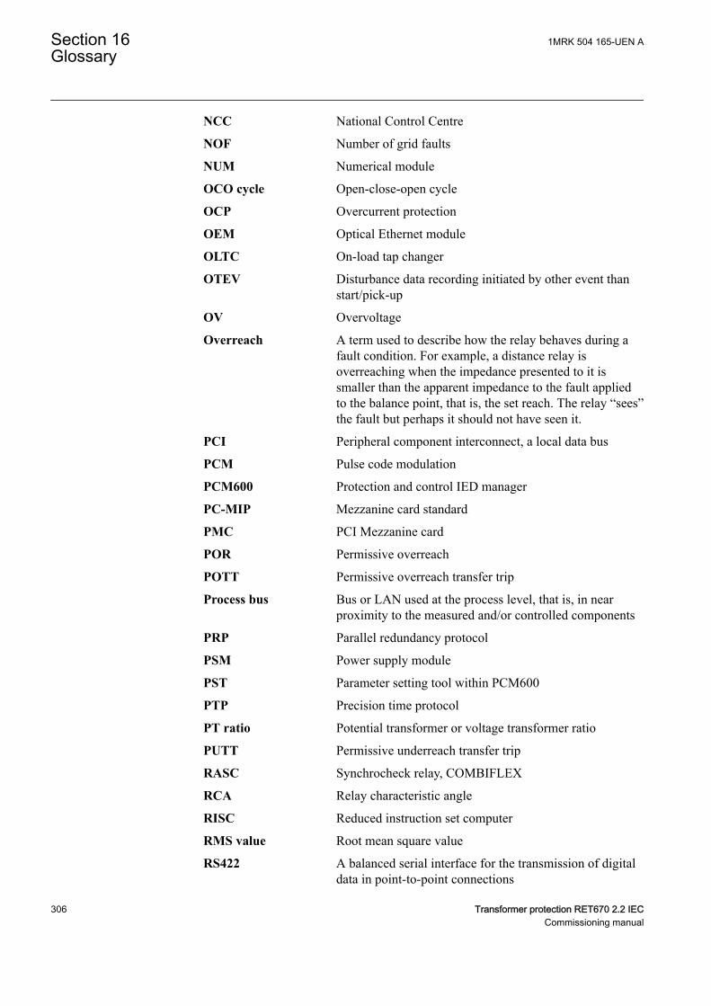
NCC National Control Centre
NOF Number of grid faults
NUM Numerical module
OCO cycle Open-close-open cycle
OCP Overcurrent protection
OEM Optical Ethernet module
OLTC On-load tap changer
OTEV Disturbance data recording initiated by other event thanstart/pick-up
OV Overvoltage
Overreach A term used to describe how the relay behaves during afault condition. For example, a distance relay isoverreaching when the impedance presented to it issmaller than the apparent impedance to the fault appliedto the balance point, that is, the set reach. The relay “sees”the fault but perhaps it should not have seen it.
PCI Peripheral component interconnect, a local data bus
PCM Pulse code modulation
PCM600 Protection and control IED manager
PC-MIP Mezzanine card standard
PMC PCI Mezzanine card
POR Permissive overreach
POTT Permissive overreach transfer trip
Process bus Bus or LAN used at the process level, that is, in nearproximity to the measured and/or controlled components
PRP Parallel redundancy protocol
PSM Power supply module
PST Parameter setting tool within PCM600
PTP Precision time protocol
PT ratio Potential transformer or voltage transformer ratio
PUTT Permissive underreach transfer trip
RASC Synchrocheck relay, COMBIFLEX
RCA Relay characteristic angle
RISC Reduced instruction set computer
RMS value Root mean square value
RS422 A balanced serial interface for the transmission of digitaldata in point-to-point connections
Section 16 1MRK 504 165-UEN AGlossary
306 Transformer protection RET670 2.2 IECCommissioning manual
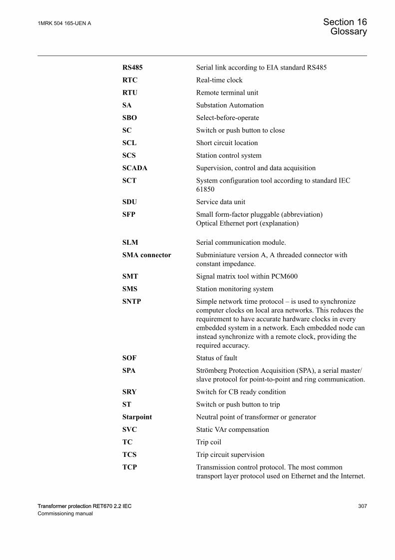
RS485 Serial link according to EIA standard RS485
RTC Real-time clock
RTU Remote terminal unit
SA Substation Automation
SBO Select-before-operate
SC Switch or push button to close
SCL Short circuit location
SCS Station control system
SCADA Supervision, control and data acquisition
SCT System configuration tool according to standard IEC61850
SDU Service data unit
SFP Small form-factor pluggable (abbreviation)Optical Ethernet port (explanation)
SLM Serial communication module.
SMA connector Subminiature version A, A threaded connector withconstant impedance.
SMT Signal matrix tool within PCM600
SMS Station monitoring system
SNTP Simple network time protocol – is used to synchronizecomputer clocks on local area networks. This reduces therequirement to have accurate hardware clocks in everyembedded system in a network. Each embedded node caninstead synchronize with a remote clock, providing therequired accuracy.
SOF Status of fault
SPA Strömberg Protection Acquisition (SPA), a serial master/slave protocol for point-to-point and ring communication.
SRY Switch for CB ready condition
ST Switch or push button to trip
Starpoint Neutral point of transformer or generator
SVC Static VAr compensation
TC Trip coil
TCS Trip circuit supervision
TCP Transmission control protocol. The most commontransport layer protocol used on Ethernet and the Internet.
1MRK 504 165-UEN A Section 16Glossary
Transformer protection RET670 2.2 IEC 307Commissioning manual
TCP/IP Transmission control protocol over Internet Protocol. Thede facto standard Ethernet protocols incorporated into4.2BSD Unix. TCP/IP was developed by DARPA forInternet working and encompasses both network layer andtransport layer protocols. While TCP and IP specify twoprotocols at specific protocol layers, TCP/IP is often usedto refer to the entire US Department of Defense protocolsuite based upon these, including Telnet, FTP, UDP andRDP.
TEF Time delayed earth-fault protection function
TLS Transport Layer Security
TM Transmit (disturbance data)
TNC connector Threaded Neill-Concelman, a threaded constantimpedance version of a BNC connector
TP Trip (recorded fault)
TPZ, TPY, TPX, TPS Current transformer class according to IEC
TRM Transformer Module. This module transforms currentsand voltages taken from the process into levels suitablefor further signal processing.
TYP Type identification
UMT User management tool
Underreach A term used to describe how the relay behaves during afault condition. For example, a distance relay isunderreaching when the impedance presented to it isgreater than the apparent impedance to the fault applied tothe balance point, that is, the set reach. The relay does not“see” the fault but perhaps it should have seen it. See alsoOverreach.
UTC Coordinated Universal Time. A coordinated time scale,maintained by the Bureau International des Poids etMesures (BIPM), which forms the basis of a coordinateddissemination of standard frequencies and time signals.UTC is derived from International Atomic Time (TAI) bythe addition of a whole number of "leap seconds" tosynchronize it with Universal Time 1 (UT1), thusallowing for the eccentricity of the Earth's orbit, therotational axis tilt (23.5 degrees), but still showing theEarth's irregular rotation, on which UT1 is based. TheCoordinated Universal Time is expressed using a 24-hourclock, and uses the Gregorian calendar. It is used foraeroplane and ship navigation, where it is also sometimesknown by the military name, "Zulu time." "Zulu" in thephonetic alphabet stands for "Z", which stands forlongitude zero.
Section 16 1MRK 504 165-UEN AGlossary
308 Transformer protection RET670 2.2 IECCommissioning manual

UV Undervoltage
WEI Weak end infeed logic
VT Voltage transformer
X.21 A digital signalling interface primarily used for telecomequipment
3IO Three times zero-sequence current.Often referred to as theresidual or the earth-fault current
3UO Three times the zero sequence voltage. Often referred toas the residual voltage or the neutral point voltage
1MRK 504 165-UEN A Section 16Glossary
Transformer protection RET670 2.2 IEC 309Commissioning manual

310

311

—ABB AB Grid Automation Products721 59 Västerås, SwedenPhone: +46 (0) 21 32 50 00
abb.com/protection-control
© Copyright 2017 ABB. All rights reserved. Specifications subject to change without notice. 1M
RK
50
4 1
65
-UE
N


