Embed Size (px)
Citation preview
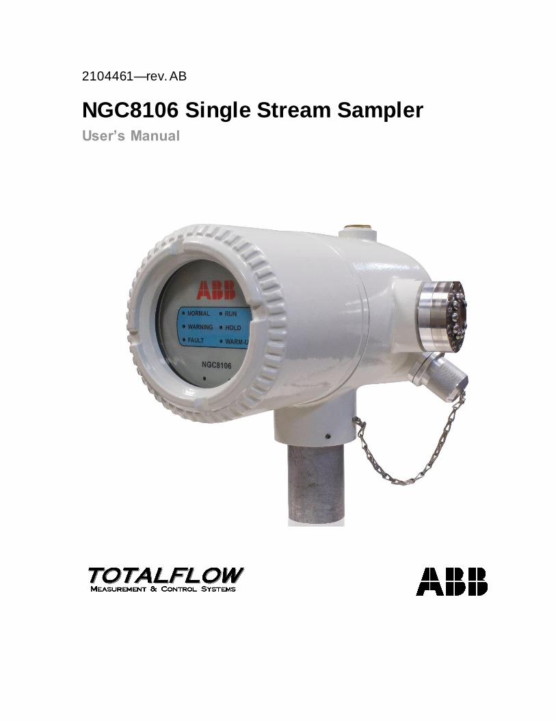
2104461—rev. AB
NGC8106 Single Stream Sampler User’s Manual

Intellectual Property & Copyright Notice
©2018 by ABB Inc., Totalflow (“Owner”), Bartlesville, Oklahoma 74006, U.S.A. All rights reserved.
Any and all derivatives of, including translations thereof, shall remain the sole property of the Owner,
regardless of any circumstances.
The original US English version of this manual shall be deemed the only valid version. Translated versions, in any other language, shall be maintained as accurately as possible. Should any
discrepancies exist, the US English version will be considered final.
Notice: This publication is for information only. The contents are subject to change without notice and should not be construed as a commitment, representation, warranty, or guarantee of any method,
product, or device by Owner.
Inquiries regarding this manual should be addressed to ABB Inc., Totalflow Products, Technical
Communications, 7051 Industrial Blvd., Bartlesville, Oklahoma 74006, U.S.A.
i
TABLE OF CONTENTS
INTRODUCTION ................................................................................................................. XIII
Chapter Descriptions ...................................................................................................xiii
Getting Help .................................................................................................................xiii
Before Calling..................................................................................................... xiv Key Symbols ............................................................................................................... xiv
Safety Practices and Precautions............................................................................... xiv
Safety Guidelines ................................................................................................xv Safety First ..........................................................................................................xv Equipment Markings ............................................................................................xv Grounding the Product ........................................................................................ xvi Operating Voltage............................................................................................... xvi Danger From Loss of Ground .............................................................................. xvi Safe Equipment .................................................................................................. xvi
Compliance ................................................................................................................. xvi
1.0 SYSTEM DESCRIPTION...................................................................................... 1–1
1.1 System Overview ...........................................................................................1–1
1.1.1 Framework ........................................................................................... 1–1 1.1.2 Calibration............................................................................................ 1–1 1.1.3 Typical Installation ................................................................................ 1–1
1.2 Processing a Sample .....................................................................................1–3
1.2.1 Hydrocarbons ....................................................................................... 1–3 1.3 Hardware System Specifications ...................................................................1–4
1.3.1 NGC8106 Standard Hardware Features ................................................. 1–5 1.3.2 Recommended Spare Parts .................................................................. 1–5 1.3.3 Cast Aluminum Enclosure ..................................................................... 1–6 1.3.4 Feed-Through Assembly ....................................................................... 1–8 1.3.5 Analytical Module ................................................................................. 1–9 1.3.6 Digital Controller Assembly and Display ................................................1–13 1.3.7 Termination Board ...............................................................................1–13
1.4 Grounding the NGC8106 .............................................................................1–14
1.4.1 Power Supply ......................................................................................1–15 1.4.2 Sample Probe .....................................................................................1–16 1.4.3 Other Considerations ...........................................................................1–16
1.5 Calibration/Validation Stream ......................................................................1–16
1.6 Operating Voltages and Cable Lengths ......................................................1–17
1.7 Sample Transport Tubing Design ................................................................1–19
1.7.1 Tube Quality ........................................................................................1–19 1.7.2 Calculation ..........................................................................................1–19 1.7.3 Analysis Time ......................................................................................1–19 1.7.4 Transit Volume ....................................................................................1–19 1.7.5 Gas Volume in Transit Tubing...............................................................1–20 1.7.6 Mole ...................................................................................................1–20 1.7.7 Maintaining Phase ...............................................................................1–20 1.7.8 Heat Tracing Sample Lines ..................................................................1–21 1.7.9 Tube Corrosion....................................................................................1–21 1.7.10 Tube Preparation .................................................................................1–21
ii
1.8 Calculating Lag Time ...................................................................................1–21
1.8.1 Calculations ........................................................................................1–22 1.8.2 Calculating Using Actual Pressure ........................................................1–22
1.9 NGC8106 Standard Software Features ......................................................1–23
1.9.1 Audit Quality Data................................................................................1–23 1.9.2 Security System...................................................................................1–23 1.9.3 Compressibility Options ........................................................................1–24 1.9.4 Calculation Options ..............................................................................1–24 1.9.5 Engineering Units ................................................................................1–24 1.9.6 Supported Protocols ............................................................................1–24
1.10 PCCU Local Communication Options .........................................................1–25
1.11 NGC8106 Startup Diagnostics ....................................................................1–25
1.11.1 Carrier Pressure Regulator Tests..........................................................1–26 1.11.2 Oven Temperature Test .......................................................................1–26 1.11.3 Processor Control Test.........................................................................1–26 1.11.4 Stream Test ........................................................................................1–26
1.12 Startup Wizard .............................................................................................1–26
1.12.1 Wizard ................................................................................................1–26
1.13 Historical Data ..............................................................................................1–26
1.13.1 Retaining Data.....................................................................................1–26 1.13.2 Analysis Cycles ...................................................................................1–27 1.13.3 Stream Averages .................................................................................1–27 1.13.4 Diagnostic Reports ..............................................................................1–27 1.13.5 Audit Logs ...........................................................................................1–27
1.14 TCR Sample Probe (Optional Equipment) ..................................................1–27
1.14.1 Location ..............................................................................................1–28 1.14.2 Other Considerations ...........................................................................1–29
1.15 ENC82 Environmental Enclosure (Optional Equipment) ............................1–29
1.15.1 Standard Features ...............................................................................1–29 1.15.2 Optional Features ................................................................................1–32
1.16 Sample Conditioning Modules (Optional Equipment) .................................1–32
1.16.1 Gas Types...........................................................................................1–32 1.16.2 Mounting Bracket .................................................................................1–33
1.17 Security Seal (Optional Equipment) ............................................................1–35
1.17.1 Customer Supplied Materials ................................................................1–35 1.17.2 Instructions..........................................................................................1–35
1.18 Optional Equipment Enclosure (Optional Equipment) ................................1–36
1.18.1 6200 Optional Equipment Enclosure .....................................................1–36 1.18.2 6700 Optional Equipment Enclosure .....................................................1–36 1.18.3 6800 Optional Equipment Enclosure .....................................................1–36
1.19 Power Supply Options (Optional Equipment)..............................................1–36
1.19.1 12/24 Vdc Solar Panel Power Pack .......................................................1–37 1.19.2 115/230 Vac UPS Power Option (24 Vdc Systems Only) ........................1–37 1.19.3 Explosion-Proof Power Supply (Optional Equipment) .............................1–38
2.0 INSTALLATION ..................................................................................................... 2–1
2.1 Overview ........................................................................................................2–1
2.1.1 What this Means ................................................................................... 2–1
iii
2.1.2 Organization......................................................................................... 2–1 2.1.3 Locating Area for Installation ................................................................. 2–3 2.1.4 Installation............................................................................................ 2–3
2.2 Unpacking and Inspection .............................................................................2–5
2.2.1 Shipping Carton.................................................................................... 2–5 2.2.2 Unpacking ............................................................................................ 2–5 2.2.3 Bill of Lading......................................................................................... 2–5 2.2.4 Inspection ............................................................................................ 2–5 2.2.5 Damaged Components ......................................................................... 2–5
2.3 Sample Probe Installation ..............................................................................2–5
2.3.1 Materials .............................................................................................. 2–6 2.3.2 Instructions........................................................................................... 2–6
2.4 Stand-Alone Installation .................................................................................2–7
2.4.1 Material Not Supplied............................................................................ 2–7 2.4.2 Instructions........................................................................................... 2–7
2.5 Large Free-Standing Environmental Enclosure Installation..........................2–8
2.5.1 Materials .............................................................................................. 2–8 2.5.2 Installation............................................................................................ 2–8
2.6 Small Free-Standing Environmental Enclosure Installation ..........................2–9
2.6.1 Materials .............................................................................................. 2–9 2.6.2 Installation............................................................................................ 2–9
2.7 Large Pipe-Mounted Environmental Enclosure Mounting Kit .....................2–11
2.7.1 Materials .............................................................................................2–11 2.7.2 Installation...........................................................................................2–11
2.8 Optional Support Leg Kit Installation ...........................................................2–13
2.8.1 Materials .............................................................................................2–14 2.8.2 Instructions..........................................................................................2–14
2.9 Small Pipe-Mounted Environmental Enclosure Mounting Kit .....................2–15
2.9.1 Materials .............................................................................................2–15 2.9.2 Installation...........................................................................................2–15
2.10 Pipe Saddle Installation ...............................................................................2–18
2.10.1 Material Not Supplied...........................................................................2–18 2.10.2 Instructions..........................................................................................2–18
2.11 Shelf Installation...........................................................................................2–19
2.11.1 Materials .............................................................................................2–19 2.11.2 Instructions..........................................................................................2–19
2.12 NGC8106 Installation ...................................................................................2–20
2.12.1 Materials .............................................................................................2–20 2.12.2 Instructions..........................................................................................2–20
2.13 Sample Conditioning Module Installation ....................................................2–22
2.13.1 Materials .............................................................................................2–22 2.13.2 Mounting Kits ......................................................................................2–22 2.13.3 Instructions..........................................................................................2–22
2.14 Sample Line Connections ............................................................................2–23
2.14.1 Materials .............................................................................................2–23 2.14.2 Instructions..........................................................................................2–24
2.15 Sample Line to NGC8106 Inside of ENC82 ................................................2–25
iv
2.15.1 Materials .............................................................................................2–25 2.15.2 Instructions..........................................................................................2–26
2.16 ENC82L Optional Pwr/Comm Outlet Box Assembly ...................................2–28
2.16.1 Materials .............................................................................................2–28 2.16.2 Customer Supplied Materials ................................................................2–28 2.16.3 Instructions..........................................................................................2–28
2.17 Carrier/Calibration Bottle Rack Installation on a Meter Run .......................2–35
2.17.1 Instructions..........................................................................................2–35 2.18 ENC82 Carrier Gas Bottle Rack Installation ...............................................2–35
2.18.1 Materials .............................................................................................2–36 2.18.2 Instructions..........................................................................................2–36
2.19 Carrier Gas Regulator Installation ...............................................................2–37
2.19.1 Materials .............................................................................................2–38 2.19.2 Instructions..........................................................................................2–38
2.20 ENC82L Calibration Gas Bottle Installation ................................................2–39
2.20.1 Materials .............................................................................................2–39 2.20.2 Instructions..........................................................................................2–39
2.21 ENC82S Calibration Gas Bottle Installation ................................................2–40
2.21.1 Materials .............................................................................................2–40 2.21.2 Instructions..........................................................................................2–40
2.22 Calibration Gas Regulator Installation .........................................................2–41
2.22.1 Materials .............................................................................................2–41 2.22.2 Instructions..........................................................................................2–41
2.23 Carrier Gas and Calibration Gas Connections ............................................2–43
2.23.1 Materials .............................................................................................2–43 2.23.2 Instructions..........................................................................................2–43
2.24 Vent Lines Connections ...............................................................................2–45
2.24.1 Materials .............................................................................................2–45 2.24.2 Instructions..........................................................................................2–45
2.25 ENC82L Optional Catalytic Heater Installation ...........................................2–46
2.25.1 Materials .............................................................................................2–46 2.25.2 Instructions..........................................................................................2–47
2.26 ENC82S Optional Catalytic Heater Installation ...........................................2–51
2.26.1 Materials .............................................................................................2–51 2.26.2 Instructions..........................................................................................2–51
2.27 ENC82 Optional Electric Heater Installation ...............................................2–53
2.27.1 Materials .............................................................................................2–53 2.27.2 Instructions..........................................................................................2–54
2.28 Sealing Environmental Enclosure................................................................2–56
2.28.1 Customer Supplied Materials ................................................................2–56 2.28.2 Instructions..........................................................................................2–56
2.29 Optional Equipment Enclosure Installation..................................................2–56
2.29.1 6200 Optional Equipment Enclosure .....................................................2–56 2.29.2 6700 Optional Equipment Enclosure .....................................................2–56 2.29.3 6800 Enclosure ...................................................................................2–57 2.29.4 Location ..............................................................................................2–57 2.29.5 Pipe-Mount Instructions ........................................................................2–57
v
2.29.6 Wall-Mount Instructions ........................................................................2–59
2.30 115/230 Vac UPS Power Pack (24 Vdc Systems) ......................................2–61
2.30.1 Instructions..........................................................................................2–61
2.31 115/230 Vac to 12 Vdc Explosion-Proof Power Supply Installation ...........2–62
2.31.1 Customer Supplied Materials ................................................................2–63 2.31.2 Instructions..........................................................................................2–64
2.32 110/240 Vac to 12/24 Vdc Power Supply Installation .................................2–65
2.32.1 Instructions..........................................................................................2–67
2.33 Battery Pack Installation ..............................................................................2–68
2.33.1 Instructions..........................................................................................2–68
2.34 Solar Power Pack ........................................................................................2–69
2.34.1 Instructions..........................................................................................2–70
2.35 DC Power Installation ..................................................................................2–73
2.35.1 Instructions..........................................................................................2–73
2.36 Remote Communication Installation............................................................2–73
3.0 NGC8106 START UP............................................................................................ 3–1
3.1 PCCU32 Installation and Setup .....................................................................3–1
3.1.1 Software Installation Instructions ............................................................ 3–1
3.2 Ethernet Installation and Setup .....................................................................3–2
3.2.1 TCP/IP Network Connection .................................................................. 3–3 3.2.2 TCP/IP Local Connection ...................................................................... 3–4
3.3 Connecting to NGC8106’s Local Port ...........................................................3–5
3.3.1 Instructions........................................................................................... 3–5
3.4 NGC8106 Diagnostics ...................................................................................3–6
3.5 NGC8106 Startup Wizard ..............................................................................3–7
3.5.1 Station Setup Instructions ...................................................................... 3–7 3.5.2 Stream Setup Instructions ..................................................................... 3–8 3.5.3 Calibration Setup Instructions ................................................................ 3–9 3.5.4 Diagnostics .......................................................................................... 3–9 3.5.5 Update Configuration ............................................................................ 3–9 3.5.6 Analyze Calibration Stream ..................................................................3–10 3.5.7 Startup Completion ..............................................................................3–10
3.6 Calibrating the NGC8106.............................................................................3–10
3.6.1 Instructions..........................................................................................3–11
3.7 Security System Setup.................................................................................3–13
3.7.1 Hardware Security ...............................................................................3–13 3.7.2 PCCU Security ....................................................................................3–13 3.7.3 Role Based Access Control (RBAC)......................................................3–13
3.8 Alarm Definitions ..........................................................................................3–14
4.0 MAINTENANCE ..................................................................................................... 4–1
4.1 Overview ........................................................................................................4–1
4.1.1 Help ..................................................................................................... 4–1 4.1.2 Maintaining Cleanliness ........................................................................ 4–1 4.1.3 How to Use This Chapter ...................................................................... 4–1 4.1.4 Returning Part(s ) for Repair................................................................... 4–2
vi
4.2 Spare Part Components ................................................................................4–2
4.2.1 Replacement Components .................................................................... 4–2 4.2.2 Replacement Parts ............................................................................... 4–2 4.2.3 Repair Time ......................................................................................... 4–5 4.2.4 Recommended Spares.......................................................................... 4–5 4.2.5 Customer Service ................................................................................. 4–5
4.3 Field Tool Kit ..................................................................................................4–6
4.4 Visual Inspection ............................................................................................4–7
4.4.1 Inspection ............................................................................................ 4–7
4.5 Backing Up Configuration Files (Save) .........................................................4–7
4.5.1 Instructions........................................................................................... 4–7
4.6 Restore Configuration Files ...........................................................................4–8
4.6.1 Instructions........................................................................................... 4–8
4.7 Reset Procedures ..........................................................................................4–8
4.7.1 Warm Start Instructions ......................................................................... 4–8 4.7.2 Cold Start Instructions ........................................................................... 4–9
4.8 Restore Factory Defaults .............................................................................4–10
4.8.1 Instructions..........................................................................................4–10
4.9 Lithium Battery Status..................................................................................4–11
4.9.1 Instructions..........................................................................................4–11
4.10 Changing NGC8106 Clock ..........................................................................4–11
4.10.1 Clock Change Not Crossing a Log Period Boundary ..............................4–12 4.10.2 Forward Clock Change Crossing a Log Period Boundary .......................4–12 4.10.3 Backward Clock Change Crossing a Log Period Boundary .....................4–12
4.11 Replacing Calibration or Carrier Gas Bottle(s) ............................................4–12
4.11.1 Instructions..........................................................................................4–12
4.12 Removing Digital Controller Assembly ........................................................4–13
4.12.1 Instructions..........................................................................................4–13
4.13 Replacing Digital Controller Complete Assembly........................................4–13
4.13.1 Instructions..........................................................................................4–14
4.14 Replacing Analytical Module........................................................................4–15
4.14.1 Instructions..........................................................................................4–15
4.15 Replacing GC Module..................................................................................4–18
4.15.1 Instructions..........................................................................................4–18 4.16 Replacing Termination Board ......................................................................4–21
4.16.1 Instructions..........................................................................................4–21 4.17 Replacing Feed-Through Assembly ............................................................4–22
4.17.1 Instructions..........................................................................................4–22
4.18 Replacing Lithium Battery ............................................................................4–25
4.18.1 Instructions..........................................................................................4–25
4.19 Replacing Frit Filters ....................................................................................4–26
4.19.1 Instructions..........................................................................................4–26
4.20 Replacing Feed-Through Interface Gasket .................................................4–28
4.20.1 Instructions..........................................................................................4–28
4.21 Replacing Feed-Through Manifold Gasket..................................................4–28
vii
4.21.1 Instructions..........................................................................................4–29
4.22 Replacing Termination Panel to Digital Controller Cable............................4–30
4.22.1 Instructions..........................................................................................4–30
4.23 Replacing Analytical Processor to Termination Panel Cable......................4–32
4.23.1 Instructions..........................................................................................4–32
5.0 TROUBLESHOOTING .......................................................................................... 5–1
5.1 Overview ........................................................................................................5–1
5.1.1 Troubleshooting Support ....................................................................... 5–1 5.1.2 Getting Started ..................................................................................... 5–1
5.2 Startup Diagnostic Troubleshooting ..............................................................5–3
5.2.1 Status .................................................................................................. 5–3 5.2.2 Carrier Pressure Regulator Test ............................................................ 5–3 5.2.3 Oven Temperature Test ........................................................................ 5–5 5.2.4 Processor Control Test.......................................................................... 5–5 5.2.5 Stream Test ......................................................................................... 5–6
5.3 Troubleshooting Alarms .................................................................................5–7
5.3.1 Operators ............................................................................................. 5–8 5.3.2 Alarm Severity ...................................................................................... 5–8 5.3.3 Pressure Regulator 1 or 2 Alarm ............................................................ 5–9 5.3.4 Sample Pressure Alarm .......................................................................5–10 5.3.5 Oven Temperature Error Alarm.............................................................5–11 5.3.6 No Stream Valve Selected....................................................................5–12 5.3.7 Digital-Analog Board Communication Error Alarm ..................................5–12 5.3.8 Calculation Error Alarm ........................................................................5–13 5.3.9 Calibration Un-Normalized Error Alarm..................................................5–14 5.3.10 Stream Sequence Error Alarm ..............................................................5–14 5.3.11 Calibration CV Percent Error Alarm.......................................................5–15 5.3.12 Calibration RF Percent Error Alarm .......................................................5–16 5.3.13 Enclosure Temperature Alarm ..............................................................5–16 5.3.14 Power Supply Alarm ............................................................................5–17 5.3.15 Low Carrier Gas Bottle (DI1) Alarm .......................................................5–17 5.3.16 Low Cal Gas Bottle (DI2) Alarm ............................................................5–18 5.3.17 GCM Processing Error Alarm ...............................................................5–18 5.3.18 Bad Bead Alarm ..................................................................................5–19 5.3.19 No Pilot Valve Change Detected Alarm .................................................5–19 5.3.20 Sample Flow Detection Alarm...............................................................5–20 5.3.21 CPU Loading Alarm .............................................................................5–20 5.3.22 System Memory Available Alarm ..........................................................5–20 5.3.23 RAM File Available Alarm .....................................................................5–21 5.3.24 FLASH File Available Alarm .................................................................5–21 5.3.25 Missing Peak-Calibration Not Used .......................................................5–22 5.3.26 Stream Un-Normalized Total ................................................................5–22
5.4 Alarm Troubleshooting Tests.......................................................................5–23
5.4.1 Sample Vent Pressure Test ..................................................................5–23 5.4.2 Column Vent Pressure Test ..................................................................5–23 5.4.3 Sample Pressure Test..........................................................................5–24 5.4.4 Feed-Through Assembly Blockage Test ................................................5–24 5.4.5 Temperature Sensor Test.....................................................................5–24 5.4.6 Abnormal Calibration Gas Depletion .....................................................5–25
viii
5.5 Power Troubleshooting ................................................................................5–25
5.5.1 Overview.............................................................................................5–25 5.5.2 Power Supply Voltage Test ..................................................................5–27 5.5.3 Equipment Isolation Test ......................................................................5–27 5.5.4 NGC8106 Module Isolation Test ...........................................................5–28 5.5.5 Charger Circuit Test .............................................................................5–29 5.5.6 Solar Panel Troubleshooting Test .........................................................5–30 5.5.7 AC Charger/Power Supply Troubleshooting Test ...................................5–31
5.6 Troubleshooting Communications ...............................................................5–32
5.6.1 Communication ...................................................................................5–32 5.6.2 Setting Up Communication ...................................................................5–33 5.6.3 Transceiver Supply Voltage Test ..........................................................5–35 5.6.4 12 Vdc Communication Supply Voltage Test .........................................5–35 5.6.5 Transceiver Check ...............................................................................5–36 5.6.6 RS-232 Communication Test ................................................................5–36 5.6.7 RS-485 Communications......................................................................5–37 5.6.8 RS-485 Communication Test ................................................................5–38
APPENDIX A XMODBUS REGISTERS ........................................................... A–1

ix
TABLE OF FIGURES
Figure 1-1 Typical Single Stream Installation .............................................................................. 1–2
Figure 1-2 Modular Design NGC8106 ........................................................................................ 1–5
Figure 1-3 NGC8106 Enclosure ................................................................................................. 1–6
Figure 1-4 NGC8106 Enclosure Left Side ................................................................................... 1–7
Figure 1-5 NGC8106 Enclosure Right Side................................................................................. 1–7
Figure 1-6 NGC Enclosure Bottom View..................................................................................... 1–8
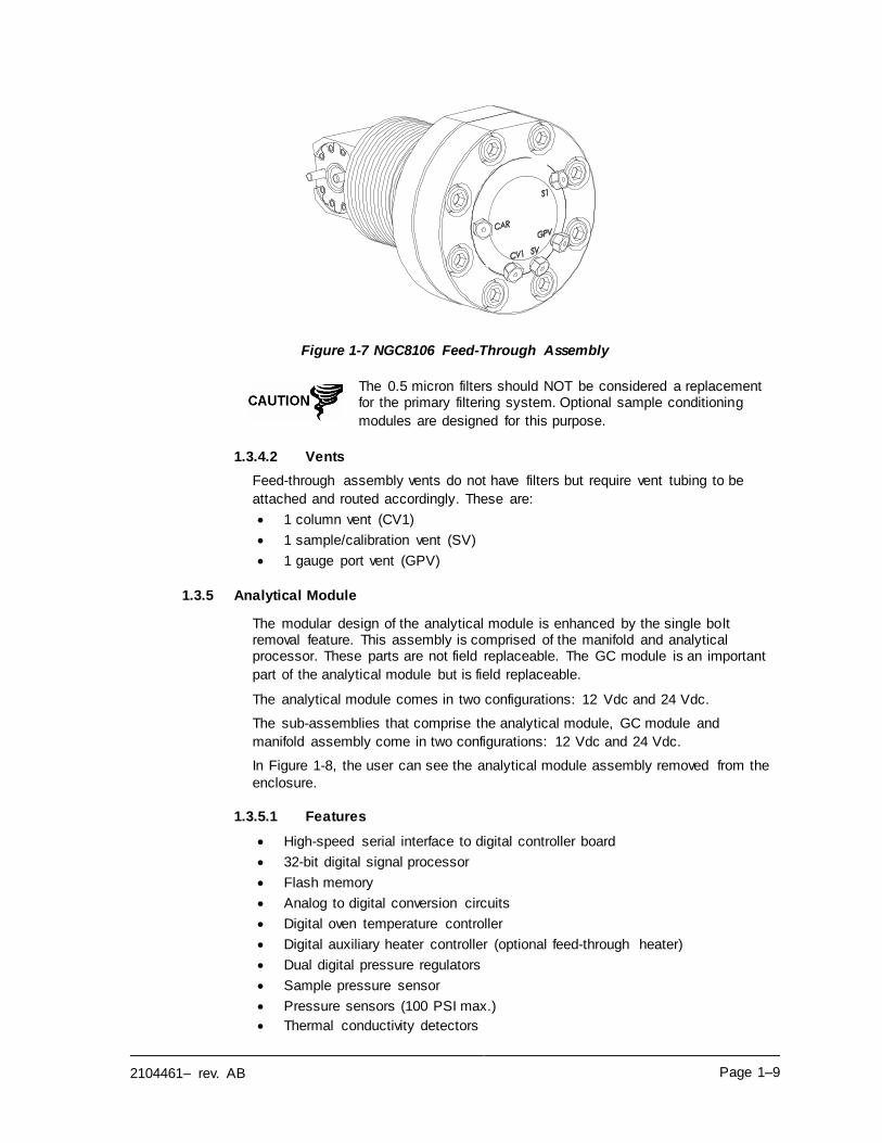
Figure 1-7 NGC8106 Feed-Through Assembly ........................................................................... 1–9
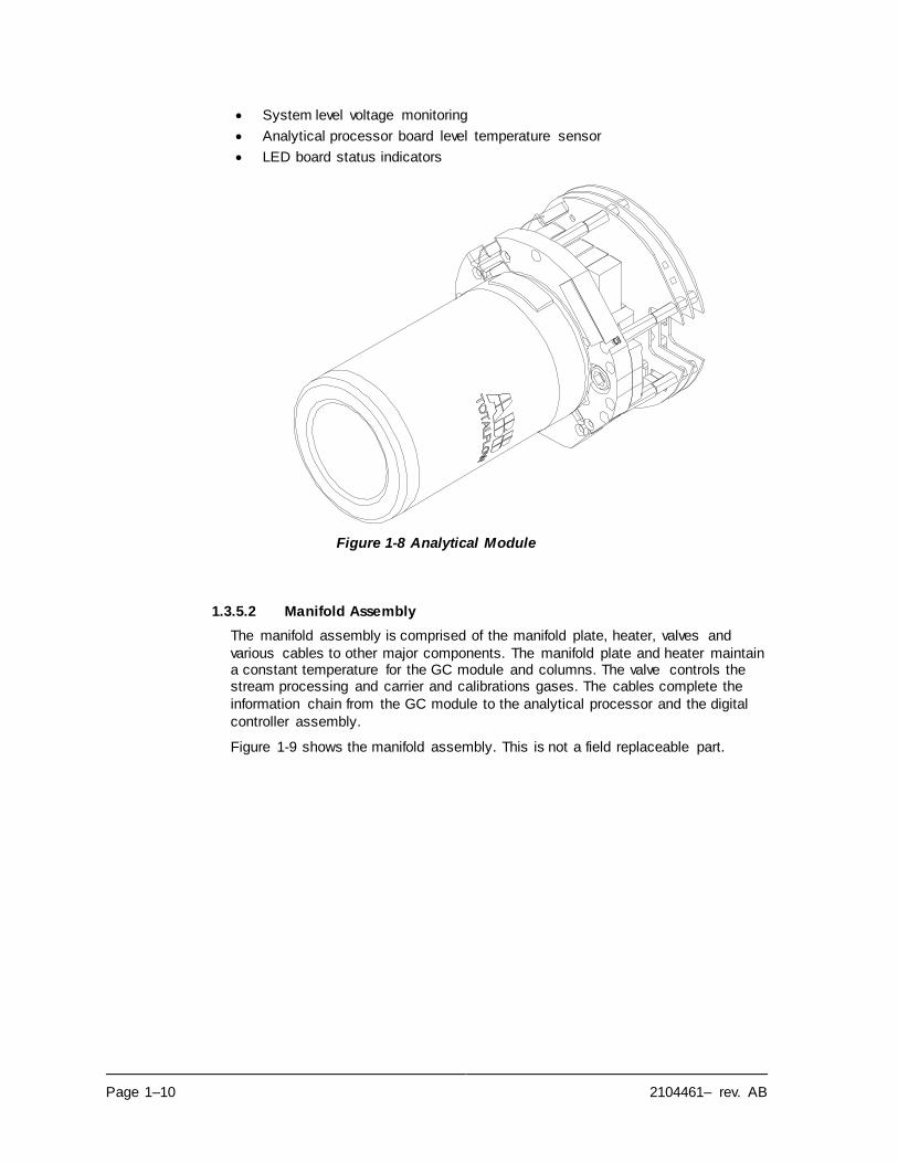
Figure 1-8 Analytical Module ....................................................................................................1–10
Figure 1-9 Manifold Assembly...................................................................................................1–11
Figure 1-10 Analytical Processor Assembly ...............................................................................1–12
Figure 1-11 GC Module Assembly ............................................................................................1–12
Figure 1-12 Digital Controller Assembly with Display ..................................................................1–13
Figure 1-13 Termination Board .................................................................................................1–14
Figure 1-14 NGC8106 Grounding Considerations ......................................................................1–15
Figure 1-15 Heat Tracing Sample Line ......................................................................................1–21
Figure 1-16 Typical Sample Installation Diagram .......................................................................1–22
Figure 1-17 Temperature Compensated Regulator with Sample Probe ........................................1–28
Figure 1-18 ENC82L Environmental Enclosure with Electric Heater ............................................1–30
Figure 1-19 ENC82L Environmental Enclosure with Catalytic Heater ...........................................1–30
Figure 1-20 ENC82S Environmental Enclosure with Electric Heater ............................................1–31
Figure 1-21 ENC82S Environmental Enclosure with Catalytic Heater ..........................................1–31
Figure 1-22 Available Sample Conditioning Modules ..................................................................1–33
Figure 1-23 Single Stream Sample Conditioning Assembly.........................................................1–34
Figure 1-24 Single Stream Conditioning Module Dimensions ......................................................1–34
Figure 1-25 NGC8106 End Cap Tabs for Security Seal ..............................................................1–35
Figure 1-26 Security Wire with Seal ..........................................................................................1–35
Figure 1-27 6800 Enclosure with 12/24 Vdc Solar Panel Power Pack Option ...............................1–37
Figure 1-28 6800 Enclosure with 115/230 Vac UPS Power Option ..............................................1–38
Figure 1-29 Explosion-Proof AC Power Supply ..........................................................................1–39
Figure 2-1 Basic Meter Run Installation ...................................................................................... 2–2
Figure 2-2 Typical Wall Shelf Mount Installation .......................................................................... 2–2
Figure 2-3 Sample Probe .......................................................................................................... 2–6
Figure 2-4 Sample Probe Insertion............................................................................................. 2–7
Figure 2-5 ENC82L–Enclosure Stand Installation........................................................................ 2–8
Figure 2-6 ENC82L–Enclosure Mounting Hardware .................................................................... 2–9
Figure 2-7 ENC82S–Enclosure Installation ................................................................................2–10
Figure 2-8 ENC82S–Enclosure Mounting Hardware ...................................................................2–10
Figure 2-9 ENC82L–Mounting Brackets ....................................................................................2–12
Figure 2-10 ENC82L–Mounting Hardware Installation ................................................................2–12
Figure 2-11 ENC82L–Adjustment Assembly ..............................................................................2–12
Figure 2-12 ENC82L–Pipe Mount installation.............................................................................2–13
Figure 2-13 ENC82L–Chain Retainer Lock ................................................................................2–13
Figure 2-14 ENC82L–Optional Support Leg Overview ................................................................2–14
x
Figure 2-15 ENC82S–Channel Tubing Installation .....................................................................2–16
Figure 2-16 ENC82S–Pipe-Mount Split Brackets .......................................................................2–16
Figure 2-17 ENC82S– Pipe-Mount Assembly ............................................................................2–17
Figure 2-18 ENC82S–Pipe-Mounted .........................................................................................2–17
Figure 2-19 Typical Pipe Saddle Installation ..............................................................................2–19
Figure 2-20 Shelf Installation ....................................................................................................2–20
Figure 2-21 NGC8106 Mounting ...............................................................................................2–21
Figure 2-22 NGC8106 Optional Mounting Flange Pipe ...............................................................2–21
Figure 2-23 Sample System Mounting Kits ................................................................................2–22
Figure 2-24 Sample Conditioning Assembly ..............................................................................2–23
Figure 2-25 Sample Conditioning Module Line Connections .......................................................2–24
Figure 2-26 ENC82L–Environmental Enclosure Sample Boot .....................................................2–26
Figure 2-27 ENC82S–Environmental Enclosure Sample Boot .....................................................2–27
Figure 2-28 Power Communication Outlet Box Assembly ...........................................................2–29
Figure 2-29 ENC82L Large Enclosure .......................................................................................2–30
Figure 2-30 Assembled Power/Communication Assembly ..........................................................2–31
Figure 2-31 Power Wiring Diagram ...........................................................................................2–32
Figure 2-32 Suggested RS-232 Wiring Instructions ....................................................................2–33
Figure 2-33 Suggested RS-485 Wiring Instructions ....................................................................2–34
Figure 2-34 Suggested RS-422 Wiring Instructions ....................................................................2–34
Figure 2-35 Carrier/Calibration Gas Bottle Rack Installation ........................................................2–35
Figure 2-36 Dual Bottle Rack Assembly ....................................................................................2–36
Figure 2-37 ENC82L–Dual Bottle Rack Installation ....................................................................2–37
Figure 2-38 ENC82S–Dual Bottle Rack Installation ....................................................................2–37
Figure 2-39 Carrier Gas Pressure Regulator with Relief Valve ....................................................2–38
Figure 2-40 Carrier Gas Low Pressure Switch Wiring Instruction .................................................2–39
Figure 2-41 Calibration Bottle Location......................................................................................2–40
Figure 2-42 Calibration Bottle Location......................................................................................2–41
Figure 2-43 Calibration Gas Pressure Regulator with Relief Valve ..............................................2–42
Figure 2-44 Calibration Blend Low Pressure Switch Wiring Instruction ........................................2–42
Figure 2-45 Carrier and Calibration Gas Connections .................................................................2–44
Figure 2-46 Vent Line Connections on Feed-Through Assembly .................................................2–46
Figure 2-47 Catalytic Heater Option in Environmental Enclosure .................................................2–47
Figure 2-48 Catalytic Heater Assemblies ...................................................................................2–48
Figure 2-49 Thermostat Assembly Installed ...............................................................................2–48
Figure 2-50 Regulator and Filter/Drain Assembly Installed ..........................................................2–49
Figure 2-51 Temperature Probe Installation ...............................................................................2–50
Figure 2-52 Electrical Pre-Heater Wiring Instructions..................................................................2–50
Figure 2-53 ENC82S Filter/Drain Assembly Installation ..............................................................2–52
Figure 2-54 ENC82S Catalytic Heater Pre-Heat Wiring ..............................................................2–52
Figure 2-55 ENC82L Electric Heater Installed in Enclosure.........................................................2–54
Figure 2-56 ENC82S Electric Heater Installed in Enclosure ........................................................2–54
Figure 2-57 ENC82L Electric Heater Option Wiring Instructions ..................................................2–55
Figure 2-58 ENC82S Electric Heater Option Wiring Instructions ..................................................2–55
xi
Figure 2-59 6200 Enclosure Pipe-Mounting Installation ..............................................................2–58
Figure 2-60 6700 Enclosure Pipe-Mounting Installation ..............................................................2–58
Figure 2-61 6800 Enclosure Pipe-Mounting Installation ..............................................................2–59
Figure 2-62 6200 Enclosure Wall-Mounted Installation ...............................................................2–60
Figure 2-63 6700 Enclosure Wall-Mounted Installation ...............................................................2–60
Figure 2-64 6800 Enclosure Wall-Mounted Installation ...............................................................2–61
Figure 2-65 115/230 Vac UPS Power Pack Option.....................................................................2–62
Figure 2-66 Explosion-Proof AC Power Supply Top/Front Dimensions ........................................2–63
Figure 2-67 Explosion-Proof AC Power Supply Side Dimensions ................................................2–64
Figure 2-68 Explosion-Proof AC Power Supply Wiring Instructions ..............................................2–65
Figure 2-69 6200 Optional Equipment Enclosure with Power Supply ...........................................2–66
Figure 2-70 6700 Optional Equipment Enclosure with Power Supply ...........................................2–66
Figure 2-71 AC/DC Converter Wiring Instructions ......................................................................2–67
Figure 2-72 Optional 6800 Enclosure with Battery Pack .............................................................2–68
Figure 2-73 12/24 Vdc Dual Battery Pack Cable ........................................................................2–68
Figure 2-74 Battery Pack with DC Power Supply Wiring Instructions ...........................................2–69
Figure 2-75 12 Vdc Battery Pack/Solar Panel Wiring Instructions ................................................2–71
Figure 2-76 24 Vdc Battery Pack/Solar Panel Wiring Instructions ................................................2–72
Figure 3-1 Ethernet Connections ............................................................................................... 3–2
Figure 3-2 Ethernet Cable-Typical .............................................................................................. 3–3
Figure 3-3 Ethernet Cross-Over Cable ....................................................................................... 3–4
Figure 3-4 MMI Communication Cables ...................................................................................... 3–6
Figure 3-5 Typical Chromatograph for Chrom-1 (Heavies) ..........................................................3–12
Figure 3-6 Typical Chromatograph for Chrom-2 (Lights) .............................................................3–12
Figure 4-1 NGC8106 Overall View ............................................................................................. 4–3
Figure 4-2 Analytical Module, Exploded...................................................................................... 4–4
Figure 4-3 Feed-Through Assembly, Exploded ........................................................................... 4–4
Figure 4-4 Digital Controller Complete Assembly .......................................................................4–10
Figure 4-5 Digital Controller Board ............................................................................................4–14
Figure 4-6 Analytical Module ....................................................................................................4–17
Figure 4-7 Analytical Processor Board ......................................................................................4–17
Figure 4-8 GC Module, Exploded View......................................................................................4–19
Figure 4-9 Termination Board ...................................................................................................4–22
Figure 4-10 Feed-Through Assembly ........................................................................................4–24
Figure 4-11 Primary Component Side Digital Controller Board ....................................................4–26
Figure 4-12 Feed-Through Assembly, Exploded View ................................................................4–27
Figure 5-1 Troubleshooting Flowchart ........................................................................................ 5–2
Figure 5-2 Power Troubleshooting Flowchart .............................................................................5–26
Figure 5-3 AC Charger/Power Supply Wiring .............................................................................5–32
Figure 5-4 Communication Troubleshooting Flowchart ...............................................................5–34
xii
LIST OF TABLES
Table 1–1 Hydrocarbons ........................................................................................................... 1–3
Table 1–2 System Specifications ............................................................................................... 1–4
Table 1–3 Calibration Gas Blend Recommended Components ...................................................1–16
Table 1–4 12 Vdc Battery Power Supply System Maximum Cable Lengths ..................................1–18
Table 1–5 AC Power Supply System Maximum Cable Lengths ...................................................1–18
Table 1–6 Internal Volume of Commonly Used Sample Transport Tubing ....................................1–20
Table 1–7 Calculation File Settings ...........................................................................................1–24
Table 1–8 Communication Option Comparison ..........................................................................1–25
Table 1–9 Optional Temperature Compensated Regulator (TCR) ...............................................1–28
Table 1–10 Sample Conditioning Module Descriptions ...............................................................1–33
Table 2–1 Installation Matrix ...................................................................................................... 2–3
Table 2–2 Port 1 and Port 2 Pin-Outs/Terminations....................................................................2–73
Table 3–1 Station Setup Screen Information............................................................................... 3–8
Table 3–2 Stream Setup Screens .............................................................................................. 3–8
Table 3–3 Defaulted Alarm Definitions ......................................................................................3–14
Table 4–1 Repair Time vs. Down Time....................................................................................... 4–5
Table 4–2 Recommended Spare Parts ....................................................................................... 4–6
Table 4–3 Tool Requirements .................................................................................................... 4–6
Table 5–1 NGC8106 Alarms...................................................................................................... 5–7
Table 5–2 Alarm Severity .......................................................................................................... 5–8
Table 5–3 Specifications for Solar Panels ..................................................................................5–30
Table 5–4 RS-232 Field Wiring on NGC8106 Termination Panel .................................................5–36
Table 5–5 RS-485 Terminations ...............................................................................................5–38
Table 5–6 RS-485 Field Wiring on NGC8106 Termination Panel .................................................5–38
xiii
Introduction This manual is written to provide an experienced chromatography technician with
the requirements necessary to install, set up and operate the Totalflow Model
NGC8106 Natural Gas Chromatograph.
Each of the chapters in this manual presents information in an organized and concise manner. Readers are able to look at the headings and get a broad picture of the content without reading every word. Also, there are overviews at the
beginning of each chapter that provides the user with an idea of what is in the
chapter and how it fits into the overall manual.
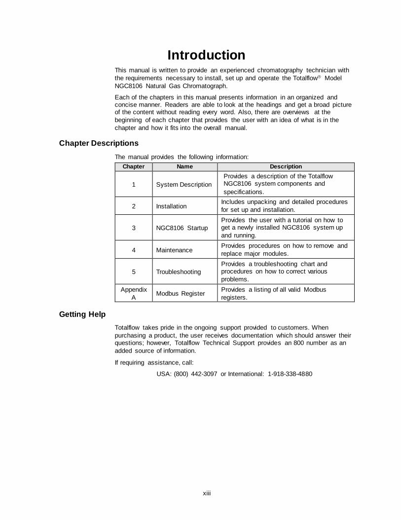
Chapter Descriptions
The manual provides the following information:
Chapter Name Description
1 System Description
Provides a description of the Totalflow NGC8106 system components and
specifications.
2 Installation Includes unpacking and detailed procedures
for set up and installation.
3 NGC8106 Startup
Provides the user with a tutorial on how to get a newly installed NGC8106 system up
and running.
4 Maintenance Provides procedures on how to remove and
replace major modules.
5 Troubleshooting
Provides a troubleshooting chart and procedures on how to correct various
problems.
Appendix
A Modbus Register
Provides a listing of all valid Modbus
registers.
Getting Help
Totalflow takes pride in the ongoing support provided to customers. When
purchasing a product, the user receives documentation which should answer their questions; however, Totalflow Technical Support provides an 800 number as an
added source of information.
If requiring assistance, call:
USA: (800) 442-3097 or International: 1-918-338-4880
xiv
Before Calling
• Know the Totalflow model and serial number. Serial numbers can be found
on a plate located on each unit.
• Be prepared to give the customer service representative a detailed
description of the problem.
• Note any alarms or messages as they appear.
• Prepare a written description of problem.
• Know the software version, board and optional part numbers.
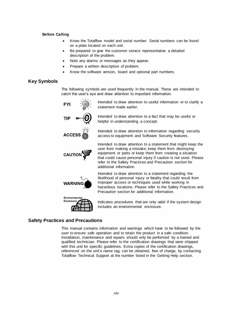
Key Symbols
The following symbols are used frequently in the manual. These are intended to
catch the user’s eye and draw attention to important information.
Intended to draw attention to useful information or to clarify a
statement made earlier.
Intended to draw attention to a fact that may be useful or
helpful in understanding a concept.
Intended to draw attention to information regarding security
access to equipment and Software Security features.
Intended to draw attention to a statement that might keep the user from making a mistake, keep them from destroying equipment or parts or keep them from creating a situation
that could cause personal injury if caution is not used. Please refer to the Safety Practices and Precaution section for
additional information.
Intended to draw attention to a statement regarding the likelihood of personal injury or fatality that could result from improper access or techniques used while working in
hazardous locations. Please refer to the Safety Practices and
Precaution section for additional information.
Indicates procedures that are only valid if the system design
includes an environmental enclosure.
Safety Practices and Precautions
This manual contains information and warnings which have to be followed by the
user to ensure safe operation and to retain the product in a safe condition. Installation, maintenance and repairs should only be performed by a trained and qualified technician. Please refer to the certification drawings that were shipped
with this unit for specific guidelines. Extra copies of the certification drawings, referenced on the unit’s name tag, can be obtained, free of charge, by contacting
Totalflow Technical Support at the number listed in the Getting Help section.
xv
Safety Guidelines
• DO NOT open the equipment to perform any adjustments, measurements, maintenance, parts replacement or repairs until all external power supplies
have been disconnected.
• Only a properly trained technician should work on any equipment with power
still applied.
• When opening covers or removing parts, exercise extreme care as live parts
or connections can be exposed.
• Installation and maintenance must be performed by person(s) qualified for
the type and area of installation according to national and local codes.
• Capacitors in the equipment can still be charged even after the unit has been
disconnected from all power supplies.
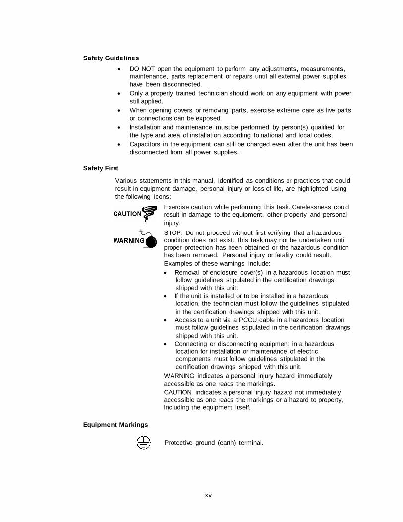
Safety First
Various statements in this manual, identified as conditions or practices that could
result in equipment damage, personal injury or loss of life, are highlighted using
the following icons:
Exercise caution while performing this task. Carelessness could result in damage to the equipment, other property and personal
injury.
STOP. Do not proceed without first verifying that a hazardous condition does not exist. This task may not be undertaken until proper protection has been obtained or the hazardous condition has been removed. Personal injury or fatality could result.
Examples of these warnings include:
• Removal of enclosure cover(s) in a hazardous location must follow guidelines stipulated in the certification drawings
shipped with this unit.
• If the unit is installed or to be installed in a hazardous location, the technician must follow the guidelines stipulated
in the certification drawings shipped with this unit.
• Access to a unit via a PCCU cable in a hazardous location must follow guidelines stipulated in the certification drawings
shipped with this unit.
• Connecting or disconnecting equipment in a hazardous
location for installation or maintenance of electric components must follow guidelines stipulated in the
certification drawings shipped with this unit.
WARNING indicates a personal injury hazard immediately
accessible as one reads the markings.
CAUTION indicates a personal injury hazard not immediately accessible as one reads the markings or a hazard to property,
including the equipment itself.
Equipment Markings
Protective ground (earth) terminal.
xvi
Grounding the Product
If a grounding conductor is required, it should be connected to the grounding
terminal before any other connections are made.
Operating Voltage
Before switching on the power, check that the operating voltage listed on the
equipment agrees with the power being connected to the equipment.
Danger From Loss of Ground
A grounding conductor may or may not be required depending on the hazardous
classification. If required, any interruption of the grounding conductor inside or outside the equipment or loose connection of the grounding conductor can result in a dangerous unit. Intentional interruption of the grounding conductor is not
permitted.
Safe Equipment
If it is determined that the equipment cannot be operated safely, it should be taken
out of operation and secured against unintentional usage.
Compliance
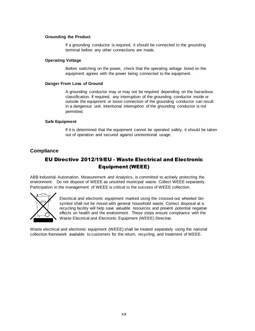
EU Directive 2012/19/EU - Waste Electrical and Electronic
Equipment (WEEE)
ABB Industrial Automation, Measurement and Analytics, is committed to actively protecting the environment. Do not dispose of WEEE as unsorted municipal waste. Collect WEEE separately.
Participation in the management of WEEE is critical to the success of WEEE collection.
Electrical and electronic equipment marked using the crossed-out wheeled bin
symbol shall not be mixed with general household waste. Correct disposal at a recycling facility will help save valuable resources and prevent potential negative effects on health and the environment. These steps ensure compliance with the
Waste Electrical and Electronic Equipment (WEEE) Directive.
Waste electrical and electronic equipment (WEEE) shall be treated separately using the national
collection framework available to customers for the return, recycling, and treatment of WEEE.
2104461– rev. AB Page 1–1
1.0 SYSTEM DESCRIPTION
1.1 System Overview
This chapter introduces the user to the Totalflow Model NGC8106 Single Stream Sampler (NGC8106). The NGC8106 is designed to continuously sample and
analyze a single natural gas stream. The NGC8106 determines composition, calorific value and then stores the analysis information. It is designed for natural
gas streams, 800 to 1500 Btu/scf (29.8 to 55.9 megajoules/meter3).
The unit is a fully functional gas chromatograph for pipeline-quality natural gas. It is designed to analyze natural gas streams that are dry of both hydrocarbon liquids and water. The unit can collect and retain analysis information for a single
stream. Applicable installations include: Sampling, Distribution, Custody Transfer with Metrology quality results, Production, Gas Gathering and End User Gas
Markets.
1.1.1 Framework
Based on ABB Totalflow’s XSeries technology, the NGC8106 features a common platform that combines the expandable framework of the XSeries equipment with the capabilities of a remote gas chromatograph. This expandability allows the
NGC8106 to run other applications such as AGA-3 and AGA-7 while simultaneously performing stream sampling and analysis. This new platform is
designed for operation on the Windows CE Real Time Operating System.
1.1.2 Calibration
Once installed on the meter run, the unit can immediately calculate the calorific value of natural gas. The user can either use their own calibration blend to adjust the unit to their company’s standards or use Totalflow’s recommended C6+
calibration gas.
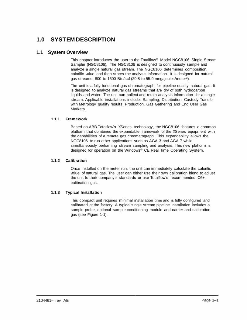
1.1.3 Typical Installation
This compact unit requires minimal installation time and is fully configured and calibrated at the factory. A typical single stream pipeline installation includes a
sample probe, optional sample conditioning module and carrier and calibration
gas (see Figure 1-1).
Page 1–2 2104461– rev. AB
Figure 1-1 Typical Single Stream Installation
CA
LIB
RA
TIO
N G
AS
CA
RR
IER
GA
S
SA
MP
LE
PR
OB
ES
AM
PL
E C
ON
DIT
ION
ING
MO
DU
LE
NG
C8
10
6
2104461– rev. AB Page 1–3
1.2 Processing a Sample
A natural gas sample is extracted from the pipeline, processed for particulate
removal and phase integrity by the sample conditioning module (optional, as required), transported to the NGC8106 and injected into the chromatographic
columns where component separation occurs.
The NGC8106 analyzes each sample and uses established chromatographic techniques. The resulting information consists of mole percent values for each component. These values are used to perform energy calculations. Calculated
values include: gas compressibility, real relative density, Btu/CV value, liquid GPM, Wobbe index, methane number and several other optional calculated values. Gas compressibility selections include NX-19, AGA-8 detail, single virial
summation factor, ISO summation factor and none (a factor of one is used).
The processed sample is then vented with the carrier gas, and the results are stored in memory and communicated to other devices, as needed. All of these
values, as well as composition, are available on various Modbus communication
protocols.
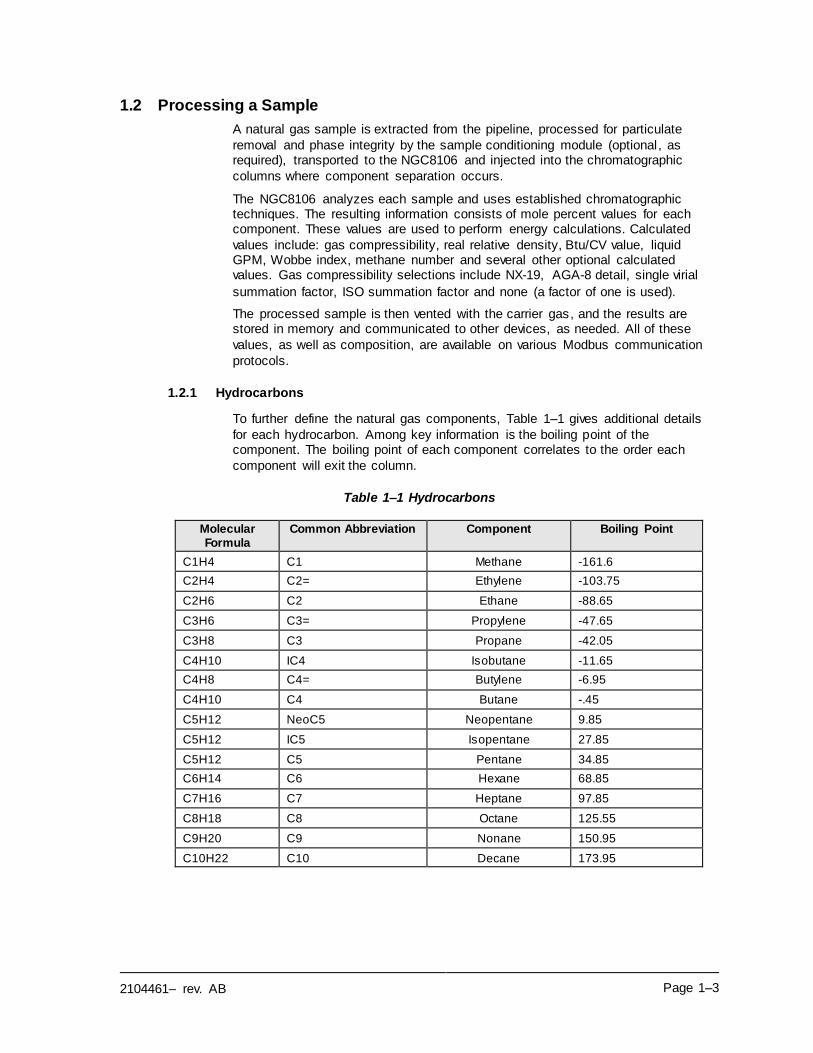
1.2.1 Hydrocarbons
To further define the natural gas components, Table 1–1 gives additional details
for each hydrocarbon. Among key information is the boiling point of the component. The boiling point of each component correlates to the order each
component will exit the column.
Table 1–1 Hydrocarbons
Molecular Formula
Common Abbreviation Component Boiling Point
C1H4 C1 Methane -161.6
C2H4 C2= Ethylene -103.75
C2H6 C2 Ethane -88.65
C3H6 C3= Propylene -47.65
C3H8 C3 Propane -42.05
C4H10 IC4 Isobutane -11.65
C4H8 C4= Butylene -6.95
C4H10 C4 Butane -.45
C5H12 NeoC5 Neopentane 9.85
C5H12 IC5 Isopentane 27.85
C5H12 C5 Pentane 34.85
C6H14 C6 Hexane 68.85
C7H16 C7 Heptane 97.85
C8H18 C8 Octane 125.55
C9H20 C9 Nonane 150.95
C10H22 C10 Decane 173.95
Page 1–4 2104461– rev. AB
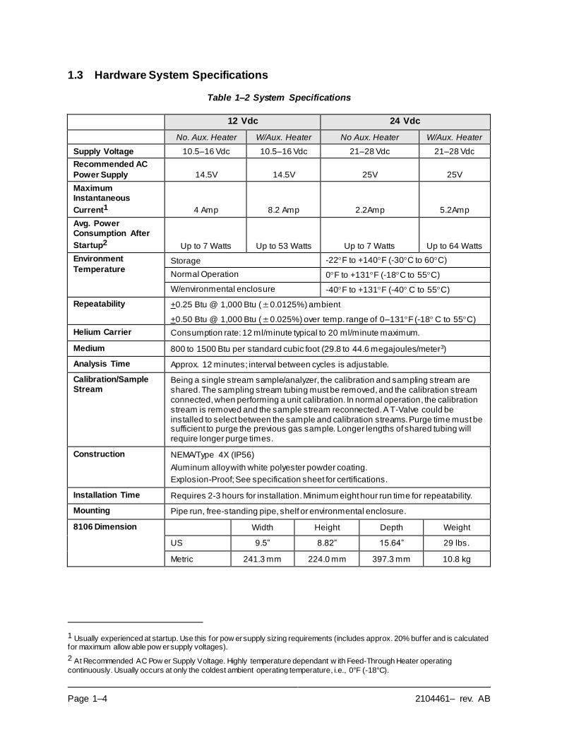
1.3 Hardware System Specifications
Table 1–2 System Specifications
12 Vdc 24 Vdc
No. Aux. Heater W/Aux. Heater No Aux. Heater W/Aux. Heater
Supply Voltage 10.5–16 Vdc 10.5–16 Vdc 21–28 Vdc 21–28 Vdc
Recommended AC
Power Supply 14.5V 14.5V 25V 25V
Maximum Instantaneous
Current1 4 Amp 8.2 Amp 2.2Amp 5.2Amp
Avg. Power Consumption After
Startup2 Up to 7 Watts Up to 53 Watts Up to 7 Watts Up to 64 Watts
Environment
Temperature Storage -22F to +140F (-30C to 60C)
Normal Operation 0F to +131F (-18C to 55C)
W/environmental enclosure -40F to +131F (-40 C to 55C)
Repeatability +0.25 Btu @ 1,000 Btu (0.0125%) ambient
+0.50 Btu @ 1,000 Btu (0.025%) over temp. range of 0–131F (-18 C to 55C)
Helium Carrier Consumption rate: 12 ml/minute typical to 20 ml/minute maximum.
Medium 800 to 1500 Btu per standard cubic foot (29.8 to 44.6 megajoules/meter3)
Analysis Time Approx. 12 minutes; interval between cycles is adjustable.
Calibration/Sample Stream
Being a single stream sample/analyzer, the calibration and sampling stream are shared. The sampling stream tubing must be removed, and the calibration stream connected, when performing a unit calibration. In normal operation, the calibration stream is removed and the sample stream reconnected. A T-Valve could be installed to select between the sample and calibration streams. Purge time must be sufficient to purge the previous gas sample. Longer lengths of shared tubing will require longer purge times.
Construction NEMA/Type 4X (IP56)
Aluminum alloy with white polyester powder coating.
Explosion-Proof; See specification sheet for certifications.
Installation Time Requires 2-3 hours for installation. Minimum eight hour run time for repeatability.
Mounting Pipe run, free-standing pipe, shelf or environmental enclosure.
8106 Dimension Width Height Depth Weight
US 9.5” 8.82” 15.64” 29 lbs.
Metric 241.3 mm 224.0 mm 397.3 mm 10.8 kg
1 Usually experienced at startup. Use this for pow er supply sizing requirements (includes approx. 20% buffer and is calculated for maximum allow able pow er supply voltages).
2 At Recommended AC Pow er Supply Voltage. Highly temperature dependant w ith Feed-Through Heater operating
continuously. Usually occurs at only the coldest ambient operating temperature, i.e., 0°F (-18°C).
2104461– rev. AB Page 1–5
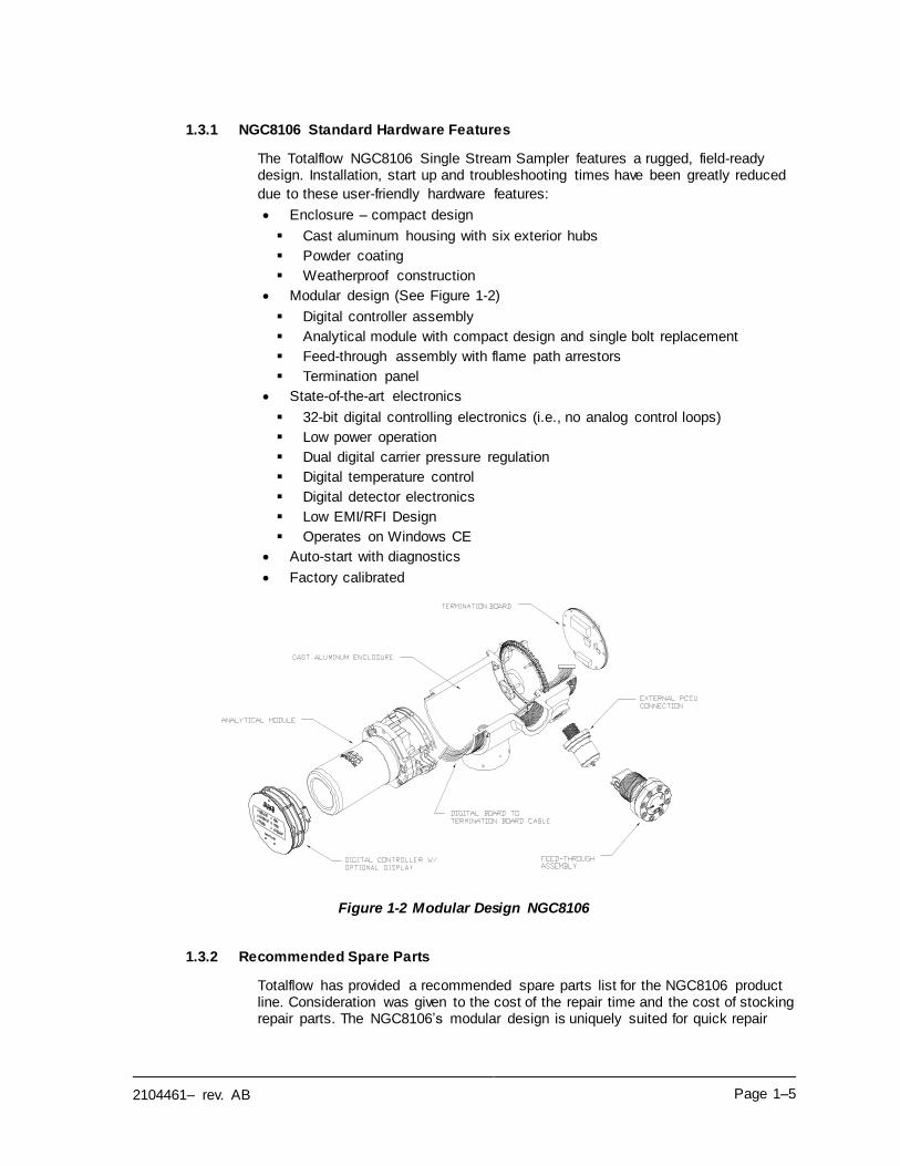
1.3.1 NGC8106 Standard Hardware Features
The Totalflow NGC8106 Single Stream Sampler features a rugged, field-ready design. Installation, start up and troubleshooting times have been greatly reduced
due to these user-friendly hardware features:
• Enclosure – compact design
▪ Cast aluminum housing with six exterior hubs
▪ Powder coating
▪ Weatherproof construction
• Modular design (See Figure 1-2)
▪ Digital controller assembly
▪ Analytical module with compact design and single bolt replacement
▪ Feed-through assembly with flame path arrestors
▪ Termination panel
• State-of-the-art electronics
▪ 32-bit digital controlling electronics (i.e., no analog control loops)
▪ Low power operation
▪ Dual digital carrier pressure regulation
▪ Digital temperature control
▪ Digital detector electronics
▪ Low EMI/RFI Design
▪ Operates on Windows CE
• Auto-start with diagnostics
• Factory calibrated
Figure 1-2 Modular Design NGC8106
1.3.2 Recommended Spare Parts
Totalflow has provided a recommended spare parts list for the NGC8106 product line. Consideration was given to the cost of the repair time and the cost of stocking repair parts. The NGC8106’s modular design is uniquely suited for quick repair
Page 1–6 2104461– rev. AB
times. A more comprehensive discussion of recommended spare parts can be
found in Chapter 4-Maintenance.
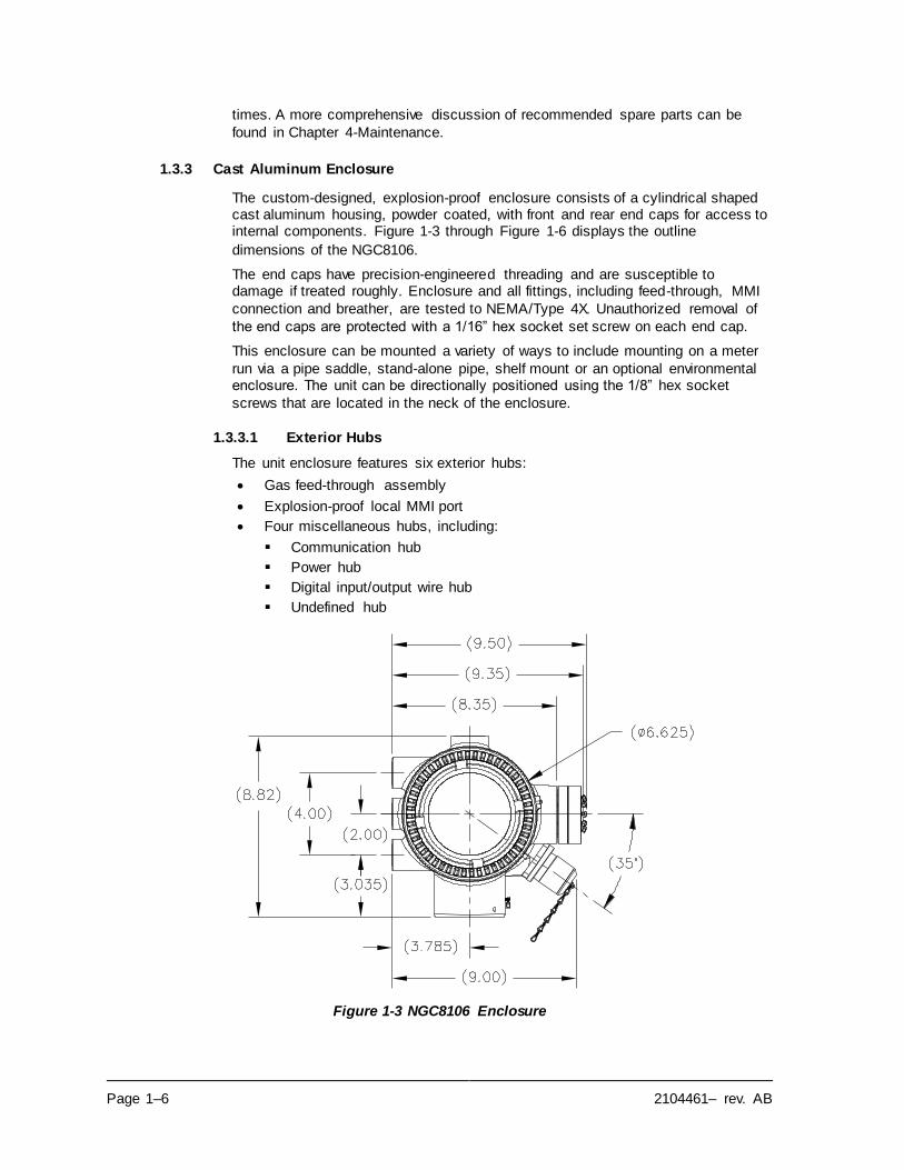
1.3.3 Cast Aluminum Enclosure
The custom-designed, explosion-proof enclosure consists of a cylindrical shaped cast aluminum housing, powder coated, with front and rear end caps for access to internal components. Figure 1-3 through Figure 1-6 displays the outline
dimensions of the NGC8106.
The end caps have precision-engineered threading and are susceptible to damage if treated roughly. Enclosure and all fittings, including feed-through, MMI
connection and breather, are tested to NEMA/Type 4X. Unauthorized removal of
the end caps are protected with a 1/16” hex socket set screw on each end cap.
This enclosure can be mounted a variety of ways to include mounting on a meter
run via a pipe saddle, stand-alone pipe, shelf mount or an optional environmental enclosure. The unit can be directionally positioned using the 1/8” hex socket
screws that are located in the neck of the enclosure.
1.3.3.1 Exterior Hubs
The unit enclosure features six exterior hubs:
• Gas feed-through assembly
• Explosion-proof local MMI port
• Four miscellaneous hubs, including:
▪ Communication hub
▪ Power hub
▪ Digital input/output wire hub
▪ Undefined hub
Figure 1-3 NGC8106 Enclosure
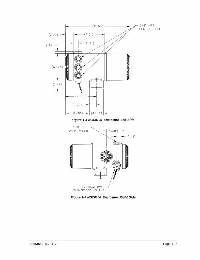
2104461– rev. AB Page 1–7
Figure 1-4 NGC8106 Enclosure Left Side
Figure 1-5 NGC8106 Enclosure Right Side
Page 1–8 2104461– rev. AB
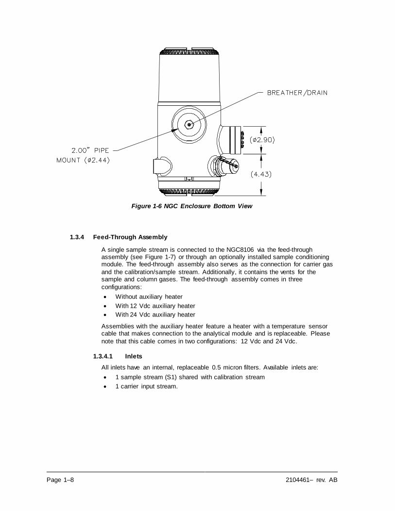
Figure 1-6 NGC Enclosure Bottom View
1.3.4 Feed-Through Assembly
A single sample stream is connected to the NGC8106 via the feed-through assembly (see Figure 1-7) or through an optionally installed sample conditioning module. The feed-through assembly also serves as the connection for carrier gas
and the calibration/sample stream. Additionally, it contains the vents for the sample and column gases. The feed-through assembly comes in three
configurations:
• Without auxiliary heater
• With 12 Vdc auxiliary heater
• With 24 Vdc auxiliary heater
Assemblies with the auxiliary heater feature a heater with a temperature sensor cable that makes connection to the analytical module and is replaceable. Please
note that this cable comes in two configurations: 12 Vdc and 24 Vdc.
1.3.4.1 Inlets
All inlets have an internal, replaceable 0.5 micron filters. Available inlets are:
• 1 sample stream (S1) shared with calibration stream
• 1 carrier input stream.
2104461– rev. AB Page 1–9
Figure 1-7 NGC8106 Feed-Through Assembly
The 0.5 micron filters should NOT be considered a replacement for the primary filtering system. Optional sample conditioning
modules are designed for this purpose.
1.3.4.2 Vents
Feed-through assembly vents do not have filters but require vent tubing to be
attached and routed accordingly. These are:
• 1 column vent (CV1)
• 1 sample/calibration vent (SV)
• 1 gauge port vent (GPV)
1.3.5 Analytical Module
The modular design of the analytical module is enhanced by the single bolt removal feature. This assembly is comprised of the manifold and analytical processor. These parts are not field replaceable. The GC module is an important
part of the analytical module but is field replaceable.
The analytical module comes in two configurations: 12 Vdc and 24 Vdc.
The sub-assemblies that comprise the analytical module, GC module and
manifold assembly come in two configurations: 12 Vdc and 24 Vdc.
In Figure 1-8, the user can see the analytical module assembly removed from the
enclosure.
1.3.5.1 Features
• High-speed serial interface to digital controller board
• 32-bit digital signal processor
• Flash memory
• Analog to digital conversion circuits
• Digital oven temperature controller
• Digital auxiliary heater controller (optional feed-through heater)
• Dual digital pressure regulators
• Sample pressure sensor
• Pressure sensors (100 PSI max.)
• Thermal conductivity detectors
Page 1–10 2104461– rev. AB
• System level voltage monitoring
• Analytical processor board level temperature sensor
• LED board status indicators
Figure 1-8 Analytical Module
1.3.5.2 Manifold Assembly
The manifold assembly is comprised of the manifold plate, heater, valves and
various cables to other major components. The manifold plate and heater maintain a constant temperature for the GC module and columns. The valve controls the stream processing and carrier and calibrations gases. The cables complete the
information chain from the GC module to the analytical processor and the digital
controller assembly.
Figure 1-9 shows the manifold assembly. This is not a field replaceable part.
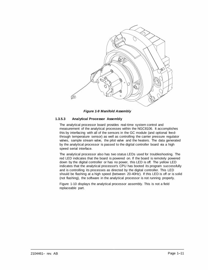
2104461– rev. AB Page 1–11
Figure 1-9 Manifold Assembly
1.3.5.3 Analytical Processor Assembly
The analytical processor board provides real-time system control and measurement of the analytical processes within the NGC8106. It accomplishes
this by interfacing with all of the sensors in the GC module (and optional feed-through temperature sensor) as well as controlling the carrier pressure regulator valves, sample stream valve, the pilot valve and the heaters. The data generated
by the analytical processor is passed to the digital controller board via a high
speed serial interface.
The analytical processor also has two status LEDs used for troubleshooting. The
red LED indicates that the board is powered on. If the board is remotely powered down by the digital controller or has no power, this LED is off. The yellow LED indicates that the analytical processor's CPU has booted its program successfully
and is controlling its processes as directed by the digital controller. This LED should be flashing at a high speed (between 20-40Hz). If this LED is off or is solid
(not flashing), the software in the analytical processor is not running properly.
Figure 1-10 displays the analytical processor assembly. This is not a field
replaceable part.
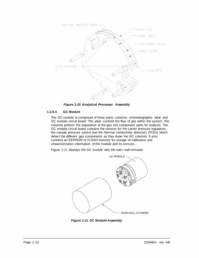
Page 1–12 2104461– rev. AB
Figure 1-10 Analytical Processor Assembly
1.3.5.4 GC Module
The GC module is comprised of three parts: columns, chromatographic valve and GC module circuit board. The valve controls the flow of gas within the system. The
columns perform the separation of the gas into component parts for analysis. The GC module circuit board contains the sensors for the carrier pressure regulators, the sample pressure sensor and the thermal conductivity detectors (TCDs) which
detect the different gas components as they leave the GC columns. It also contains an EEPROM or FLASH memory for storage of calibration and
characterization information of the module and its sensors.
Figure 1-11 displays the GC module with the oven wall removed.
Figure 1-11 GC Module Assembly
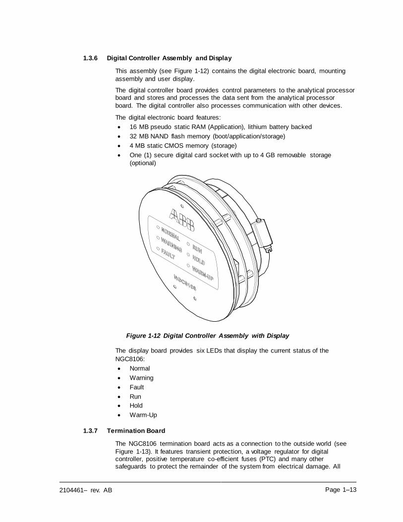
2104461– rev. AB Page 1–13
1.3.6 Digital Controller Assembly and Display
This assembly (see Figure 1-12) contains the digital electronic board, mounting
assembly and user display.
The digital controller board provides control parameters to the analytical processor board and stores and processes the data sent from the analytical processor
board. The digital controller also processes communication with other devices.
The digital electronic board features:
• 16 MB pseudo static RAM (Application), lithium battery backed
• 32 MB NAND flash memory (boot/application/storage)
• 4 MB static CMOS memory (storage)
• One (1) secure digital card socket with up to 4 GB removable storage
(optional)
Figure 1-12 Digital Controller Assembly with Display
The display board provides six LEDs that display the current status of the
NGC8106:
• Normal
• Warning
• Fault
• Run
• Hold
• Warm-Up
1.3.7 Termination Board
The NGC8106 termination board acts as a connection to the outside world (see
Figure 1-13). It features transient protection, a voltage regulator for digital controller, positive temperature co-efficient fuses (PTC) and many other safeguards to protect the remainder of the system from electrical damage. All
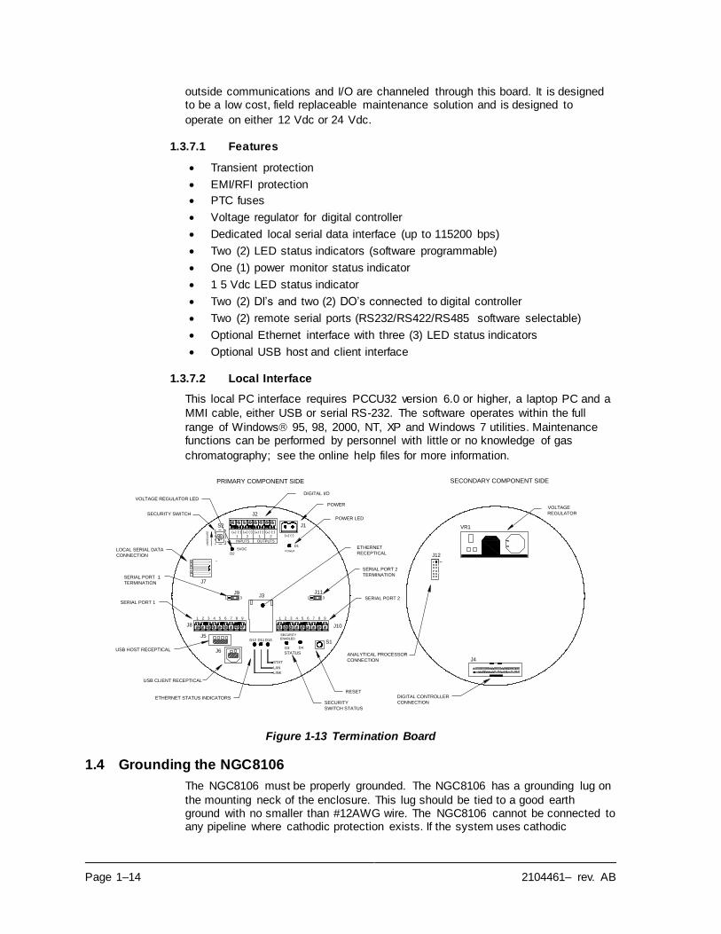
Page 1–14 2104461– rev. AB
outside communications and I/O are channeled through this board. It is designed to be a low cost, field replaceable maintenance solution and is designed to
operate on either 12 Vdc or 24 Vdc.
1.3.7.1 Features
• Transient protection
• EMI/RFI protection
• PTC fuses
• Voltage regulator for digital controller
• Dedicated local serial data interface (up to 115200 bps)
• Two (2) LED status indicators (software programmable)
• One (1) power monitor status indicator
• 1 5 Vdc LED status indicator
• Two (2) DI’s and two (2) DO’s connected to digital controller
• Two (2) remote serial ports (RS232/RS422/RS485 software selectable)
• Optional Ethernet interface with three (3) LED status indicators
• Optional USB host and client interface
1.3.7.2 Local Interface
This local PC interface requires PCCU32 version 6.0 or higher, a laptop PC and a
MMI cable, either USB or serial RS-232. The software operates within the full
range of Windows 95, 98, 2000, NT, XP and Windows 7 utilities. Maintenance functions can be performed by personnel with little or no knowledge of gas
chromatography; see the online help files for more information.
Figure 1-13 Termination Board
1.4 Grounding the NGC8106
The NGC8106 must be properly grounded. The NGC8106 has a grounding lug on
the mounting neck of the enclosure. This lug should be tied to a good earth ground with no smaller than #12AWG wire. The NGC8106 cannot be connected to any pipeline where cathodic protection exists. If the system uses cathodic
PRIMARY COMPONENT SIDE SECONDARY COMPONENT SIDE
J12
OUTPUTS
D4
(-)
2
(-)(+)
J7
POWER
D1
J9
D3
D2
5VDC
J2
J1
J6
1
J8
J5
32 54 76 98
D12 D11
J31 3
D13S1
LINK
LAN
STAT
41 32 5 6 87
J10
9
J111 3
INPUTS
(-)(-)
1
(+)
2
(+)
1
(+)
VR1S2
UN
SE
CU
RE
SECURITY
ENABLED
STATUS
(-)(+)
J4ANALYTICAL PROCESSOR
CONNECTION
DIGITAL CONTROLLER
CONNECTION
USB CLIENT RECEPTICAL
ETHERNET STATUS INDICATORS
RESET
USB HOST RECEPTICAL
SERIAL PORT 1
SERIAL PORT 1
TERMINATION
LOCAL SERIAL DATA
CONNECTION
SECURITY SWITCH
DIGITAL I/O
POWER
ETHERNET
RECEPTICAL
SERIAL PORT 2
TERMINATION
SERIAL PORT 2
VOLTAGE
REGULATOR
SECURITY
SWITCH STATUS
POWER LED
VOLTAGE REGULATOR LED
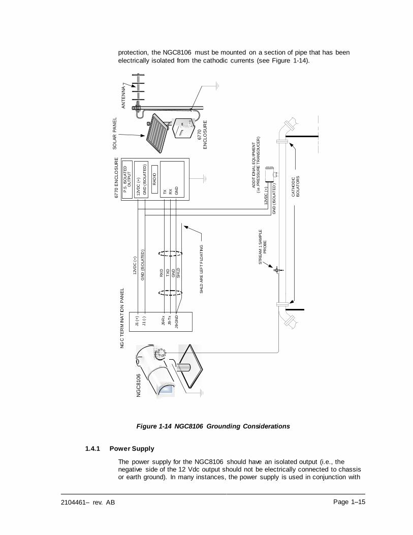
2104461– rev. AB Page 1–15
protection, the NGC8106 must be mounted on a section of pipe that has been
electrically isolated from the cathodic currents (see Figure 1-14).
Figure 1-14 NGC8106 Grounding Considerations
1.4.1 Power Supply
The power supply for the NGC8106 should have an isolated output (i.e., the negative side of the 12 Vdc output should not be electrically connected to chassis or earth ground). In many instances, the power supply is used in conjunction with
AN
TE
NN
AP
.S. IS
OLA
TE
D
OU
TP
UT
RA
DIO
12V
DC
(+)
GN
D (IS
OLA
TE
D)
J1 (+
)
J1
(-)
TX
RX
J9-R
x
J9-T
x
STR
EA
M 1
SA
MP
LE
PR
OB
E
J9-
GN
DS
HLD
GN
D
RX
D
TX
D
12V
DC
(+)
AD
DIT
ION
AL
EQ
UIP
ME
NT
(i.e
. PR
ES
SU
RE
TR
AN
SD
UC
ER
)
12V
DC
(+)
SH
LD A
RE
LE
FT
FLO
AT
ING
NG
C T
ER
MIN
AT
ION
PA
NE
L
GN
D (IS
OLA
TE
D)
GN
D (IS
OLA
TE
D)
CA
TH
OD
IC
ISO
LAT
OR
S
67
70
EN
CL
OS
UR
E
GN
D
67
70
EN
CL
OS
UR
ES
OLA
R P
AN
EL
NG
C8
10
6
Page 1–16 2104461– rev. AB
a radio. If the radio is connected to the NGC8106 via RS232/485/422, the communications should share the power ground. The communication shield
should only be connected at the NGC8106’s end. The other end should be left to
float (left unconnected).
1.4.2 Sample Probe
If the sample probe is mounted to a section of pipe where cathodic currents may
exist, the user needs to place isolators in the sample tubing between the sample probe and the NGC8106. Any time that the sample probe is on a section of pipe other than the one where the NGC8106 is directly mounted, tubing isolators
should be employed. It is very important that the probe ground and the NGC8106 ground be at the same potential. If this cannot be ensured, tubing isolators must
be used.
1.4.3 Other Considerations
If other devices are to be powered from the same isolated power supply that is powering the NGC8106, be careful to avoid any ground loops. The various devices should be connected in a star configuration. It is also important that any
additional powered devices be able to handle a fairly wide range of input voltages, as the NGC8106’s heater will draw about four (4) Amps (if the auxiliary heater is installed, it might be as much as eight (8) Amps). This load (4-8 Amps) being
drawn across any considerable length of cable can result in a substantial voltage drop Refer to the Cable Length Power Specifications table. The resulting lower input voltage to the additional device could affect its operation. Input voltage
excursions fluctuate with the toggling of the NGC8106’s heater(s). The heater(s) are turning on and off in an effort to maintain a constant internal temperature for
the NGC8106’s GC module.
In an office environment, ensure there is a good earth ground to the NGC8106. Often the third pin (ground) on the power cable is missing or has been removed. Improper grounding can lead to erratic behavior. If the unit is not properly
grounded, the user could have as much as 60 Vac (half-line voltage) on the case
of the equipment due to capacitive coupling within the power supply.
1.5 Calibration/Validation Stream
On the NGC8106 feed-through assembly, the sample stream must be removed and the calibration gas connected when performing a manual calibration. It is
recommend that a metal diaphragm regulator be set to 15 2 PSIG input. The
recommended calibration gas component concentrations for use with Peak Find
are found in Table 1–3.
It should be noted the components found in Table 1–3
represent a typical blend and is not suitable for all
applications.
Table 1–3 Calibration Gas Blend Recommended Components
Component Name
Abbreviation Mol % Component Name
Abbreviation Mol %
Nitrogen N2 2.500 Normal Butane NC4 0.300
Methane C1 89.570 Neo Pentane Neo C5 0.100
Carbon Dioxide CO2 1.000 Iso Pentane IC5 0.100
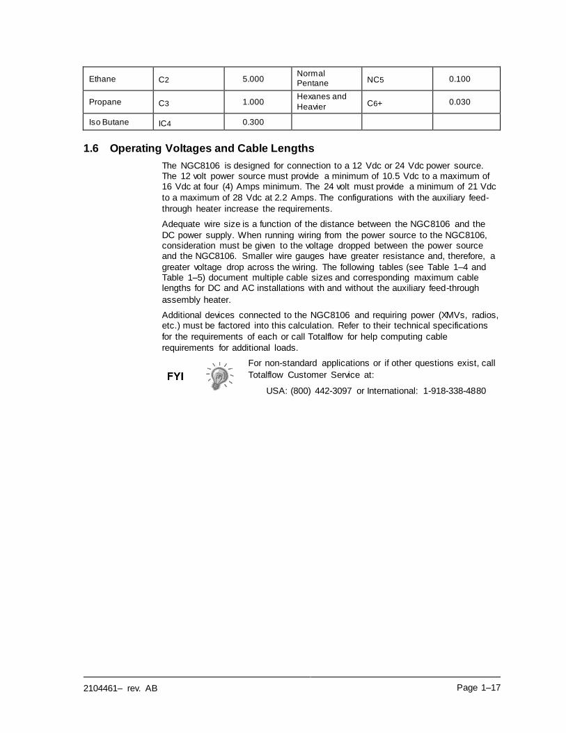
2104461– rev. AB Page 1–17
Ethane C2 5.000 Normal Pentane NC5 0.100
Propane C3 1.000 Hexanes and
Heavier C6+ 0.030
Iso Butane IC4 0.300
1.6 Operating Voltages and Cable Lengths
The NGC8106 is designed for connection to a 12 Vdc or 24 Vdc power source. The 12 volt power source must provide a minimum of 10.5 Vdc to a maximum of 16 Vdc at four (4) Amps minimum. The 24 volt must provide a minimum of 21 Vdc
to a maximum of 28 Vdc at 2.2 Amps. The configurations with the auxiliary feed-
through heater increase the requirements.
Adequate wire size is a function of the distance between the NGC8106 and the
DC power supply. When running wiring from the power source to the NGC8106, consideration must be given to the voltage dropped between the power source and the NGC8106. Smaller wire gauges have greater resistance and, therefore, a
greater voltage drop across the wiring. The following tables (see Table 1–4 and Table 1–5) document multiple cable sizes and corresponding maximum cable lengths for DC and AC installations with and without the auxiliary feed-through
assembly heater.
Additional devices connected to the NGC8106 and requiring power (XMVs, radios, etc.) must be factored into this calculation. Refer to their technical specifications
for the requirements of each or call Totalflow for help computing cable
requirements for additional loads.
For non-standard applications or if other questions exist, call
Totalflow Customer Service at:
USA: (800) 442-3097 or International: 1-918-338-4880
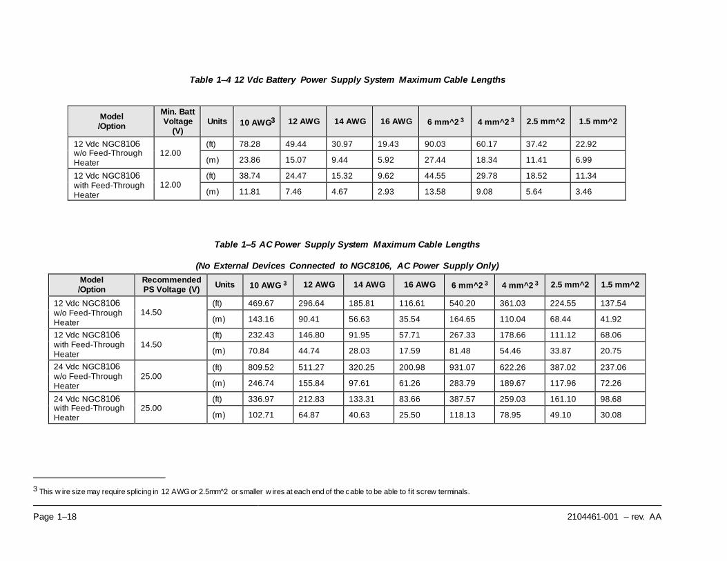
Page 1–18 2104461-001 – rev. AA
Table 1–4 12 Vdc Battery Power Supply System Maximum Cable Lengths
Model /Option
Min. Batt Voltage
(V) Units 10 AWG3 12 AWG 14 AWG 16 AWG 6 mm^2 3 4 mm^2 3 2.5 mm^2 1.5 mm^2
12 Vdc NGC8106 w/o Feed-Through Heater
12.00 (ft) 78.28 49.44 30.97 19.43 90.03 60.17 37.42 22.92
(m) 23.86 15.07 9.44 5.92 27.44 18.34 11.41 6.99
12 Vdc NGC8106 with Feed-Through Heater
12.00 (ft) 38.74 24.47 15.32 9.62 44.55 29.78 18.52 11.34
(m) 11.81 7.46 4.67 2.93 13.58 9.08 5.64 3.46
Table 1–5 AC Power Supply System Maximum Cable Lengths
(No External Devices Connected to NGC8106, AC Power Supply Only)
Model /Option
Recommended PS Voltage (V)
Units 10 AWG 3 12 AWG 14 AWG 16 AWG 6 mm^2 3 4 mm^2 3 2.5 mm^2 1.5 mm^2
12 Vdc NGC8106 w/o Feed-Through Heater
14.50 (ft) 469.67 296.64 185.81 116.61 540.20 361.03 224.55 137.54
(m) 143.16 90.41 56.63 35.54 164.65 110.04 68.44 41.92
12 Vdc NGC8106 with Feed-Through Heater
14.50 (ft) 232.43 146.80 91.95 57.71 267.33 178.66 111.12 68.06
(m) 70.84 44.74 28.03 17.59 81.48 54.46 33.87 20.75
24 Vdc NGC8106 w/o Feed-Through Heater
25.00 (ft) 809.52 511.27 320.25 200.98 931.07 622.26 387.02 237.06
(m) 246.74 155.84 97.61 61.26 283.79 189.67 117.96 72.26
24 Vdc NGC8106 with Feed-Through Heater
25.00 (ft) 336.97 212.83 133.31 83.66 387.57 259.03 161.10 98.68
(m) 102.71 64.87 40.63 25.50 118.13 78.95 49.10 30.08
3 This w ire size may require splicing in 12 AWG or 2.5mm^2 or smaller w ires at each end of the cable to be able to f it screw terminals.
2104461– rev. AB Page 1–19
1.7 Sample Transport Tubing Design
Information in this section enables the user to design the sample transport tubing
connected between the temperature compensated regulator (TCR) sample probe and the installed NGC8106. Minimizing transport lag time and maintaining a single vapor phase sample are important factors to consider when selecting transport
tubing.
Lag time is the time required to purge out one volume of transport tubing and the
volume of the sample conditioning system.
1.7.1 Tube Quality
Use only good quality, clean, stainless steel chromatographic-grade transport tubing for carrier, calibration gas and sample lines. Use of poor quality stainless
steel tubing delivers unsatisfactory results.
Do not use any type of plastic, Teflon or Teflon lined braided
steel tubing.
Transport tubing must be chromatographically clean. Tubing should be free of hydrocarbon contamination and particle free. During cutting, fitting and deburring,
the technician should ensure that no particles are allowed to remain in the tubing.
1.7.2 Calculation
Sample transport lag time estimated calculations do not consider the volume of the sample conditioning system. As such, the following equation can be used as a quick method to estimate lag time because normal transport tubing volume is
much greater than sample conditioning system tubing volume.
.)min/cc(RateFlowSampleActual
)TubingofFeet()TubingofFootperccVolume(TimeLag
=
For a detailed method of calculating lag time, see the Calculating Lag Time
section.
1.7.3 Analysis Time
If analysis results are used for process control or custody transfer, it is important to minimize the amount of time that the sample spends in transit from the TCR sample probe to the NGC8106. To arrive at the total cycle time between
representative samples, sample transit time must be added to the NGC8106 cycle
time.
1.7.4 Transit Volume
The total volume of sample gas in transit is calculated by multiplying the volume
per foot of sample transport tubing by the total length of tubing. To assist in making these calculations, refer to Table 1–6 for the internal volume of commonly
used sample transport tubing.
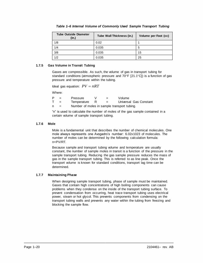
Page 1–20 2104461– rev. AB
Table 1–6 Internal Volume of Commonly Used Sample Transport Tubing
Tube Outside Diameter (in.)
Tube Wall Thickness (in.) Volume per Foot (cc)
1/8 0.02 1
1/4 0.035 5
3/8 0.035 15
1/2 0.035 25
1.7.5 Gas Volume in Transit Tubing
Gases are compressible. As such, the volume of gas in transport tubing for
standard conditions (atmospheric pressure and 70F [21.1C]) is a function of gas
pressure and temperature within the tubing.
Ideal gas equation: nRTPV =
Where:
P = Pressure V = Volume T = Temperature R = Universal Gas Constant
n = Number of moles in sample transport tubing.
“n” is used to calculate the number of moles of the gas sample contained in a
certain volume of sample transport tubing.
1.7.6 Mole
Mole is a fundamental unit that describes the number of chemical molecules. One mole always represents one Avogadro’s number: 6.02x10²³ of molecules. The number of moles can be determined by the following calculation formula:
n=PV/RT.
Because sample and transport tubing volume and temperature are usually constant, the number of sample moles in transit is a function of the pressure in the
sample transport tubing. Reducing the gas sample pressure reduces the mass of gas in the sample transport tubing. This is referred to as line peak. Once the transport volume is known for standard conditions, transport lag time can be
determined.
1.7.7 Maintaining Phase
When designing sample transport tubing, phase of sample must be maintained. Gases that contain high concentrations of high boiling components can cause
problems when they condense on the inside of the transport tubing surface. To prevent condensation from occurring, heat trace transport tubing uses electrical power, steam or hot glycol. This prevents components from condensing on the
transport tubing walls and prevents any water within the tubing from freezing and
blocking the sample flow.
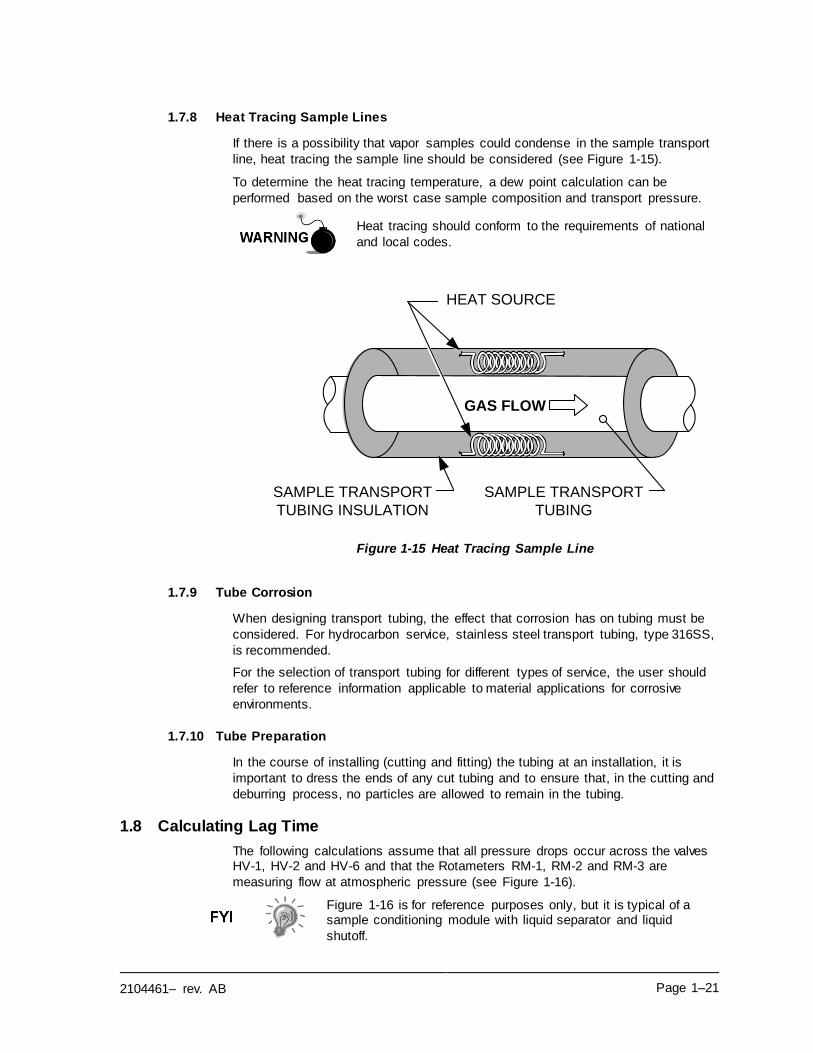
2104461– rev. AB Page 1–21
1.7.8 Heat Tracing Sample Lines
If there is a possibility that vapor samples could condense in the sample transport
line, heat tracing the sample line should be considered (see Figure 1-15).
To determine the heat tracing temperature, a dew point calculation can be
performed based on the worst case sample composition and transport pressure.
Heat tracing should conform to the requirements of national
and local codes.
Figure 1-15 Heat Tracing Sample Line
1.7.9 Tube Corrosion
When designing transport tubing, the effect that corrosion has on tubing must be
considered. For hydrocarbon service, stainless steel transport tubing, type 316SS,
is recommended.
For the selection of transport tubing for different types of service, the user should
refer to reference information applicable to material applications for corrosive
environments.
1.7.10 Tube Preparation
In the course of installing (cutting and fitting) the tubing at an installation, it is
important to dress the ends of any cut tubing and to ensure that, in the cutting and
deburring process, no particles are allowed to remain in the tubing.
1.8 Calculating Lag Time
The following calculations assume that all pressure drops occur across the valves HV-1, HV-2 and HV-6 and that the Rotameters RM-1, RM-2 and RM-3 are
measuring flow at atmospheric pressure (see Figure 1-16).
Figure 1-16 is for reference purposes only, but it is typical of a sample conditioning module with liquid separator and liquid
shutoff.
GAS FLOW
SAMPLE TRANSPORT
TUBING
HEAT SOURCE
SAMPLE TRANSPORT
TUBING INSULATION
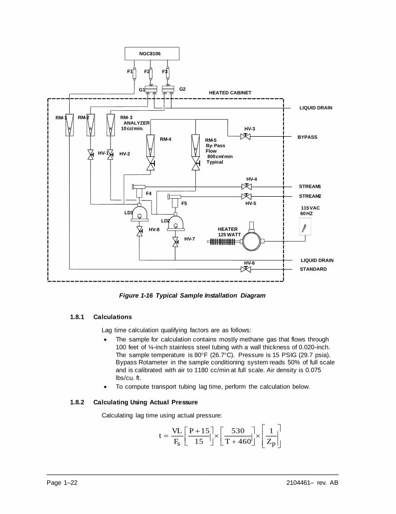
Page 1–22 2104461– rev. AB
Figure 1-16 Typical Sample Installation Diagram
1.8.1 Calculations
Lag time calculation qualifying factors are as follows:
• The sample for calculation contains mostly methane gas that flows through
100 feet of ¼-inch stainless steel tubing with a wall thickness of 0.020-inch.
The sample temperature is 80F (26.7C). Pressure is 15 PSIG (29.7 psia). Bypass Rotameter in the sample conditioning system reads 50% of full scale
and is calibrated with air to 1180 cc/min at full scale. Air density is 0.075
lbs/cu. ft.
• To compute transport tubing lag time, perform the calculation below.
1.8.2 Calculating Using Actual Pressure
Calculating lag time using actual pressure:
+
+=
ps Z
1
460T
530
15
15P
F
VLt
NGC8106
F1 F2 F3
G1 G2
RM-1 RM-2 RM- 3 ANALYZER
10 cc/min.
RM-4 RM-5By- PassFlow800 cm/minTypical
HV-1 HV-2
HV-3
HV-4
HV-5
HV-6
HV-7
HV-8
F4
F5
LD1
LD2
STANDARD
LIQUID DRAIN
STREAM 1
STREAM 2
BYPASS
LIQUID DRAIN
115 VAC60 HZ
HEATER125 WATT
HEATED CABINET
2104461– rev. AB Page 1–23
Where:
T = Purge Time L = Line Length, ft.
V = Tubing Volume, cc/ft. Fs = Standard Flow, cc/min. P = Actual Pressure, PSIG T = Actual Temperature, F
Zp = Compressibility at P Pressure
In this equation, the lowest possible pressure should be used.
This minimizes transport tubing lag time to reduce line or molecule peak. Care should be taken to ensure that enough pressure is available. This keeps the sample flowing throughout
the analysis system.
1.9 NGC8106 Standard Software Features
Totalflow’s onboard and host software work together to provide many key features
that enable the user to access, control and share data. The user-friendly interface allows multi-faceted report and communication capabilities without compromising
the integrity of the system or the data.
• Modular software design with application-based plug-in software modules
• Audit quality historical data
• Operational alarms
• Tri-level software security system
• Multiple calculation options
• Selectable engineering units
• Analysis reporting
• Communication protocol selection
• Web-enabled data collection
1.9.1 Audit Quality Data
Totalflow’s software design creates a historically accurate file system that uses
date and time stamped events to create an audit quality data structure.
The unit can collect, analyze and retain (default) stream data for the last 480 analysis cycles, retain the last 35 days of daily stream averages, retain the last 480 diagnostics reports, retain the last 480 alarms and retain the last 480 events.
These functions can be reconfigured by the user.
1.9.2 Security System
Users implementing PCCU version 7.6.0 or higher have access to three types of
security:
• Hardware security (bi-level)
• PCCU enforced security (bi-level)
• Role Based Access Control (multi-level)
Both the hardware and PCCU security functions are legacy systems. The hardware security consists of the security switch located on the termination board and is set to either On or Off. The PCCU security system forces the user to log on
as either an administrator or a user.
Role Based Access Control (RBAC) is a new feature within PCCU that is designed to allow an administrator to designate roles and control access levels to various
applications and processes in Totalflow G4 devices.
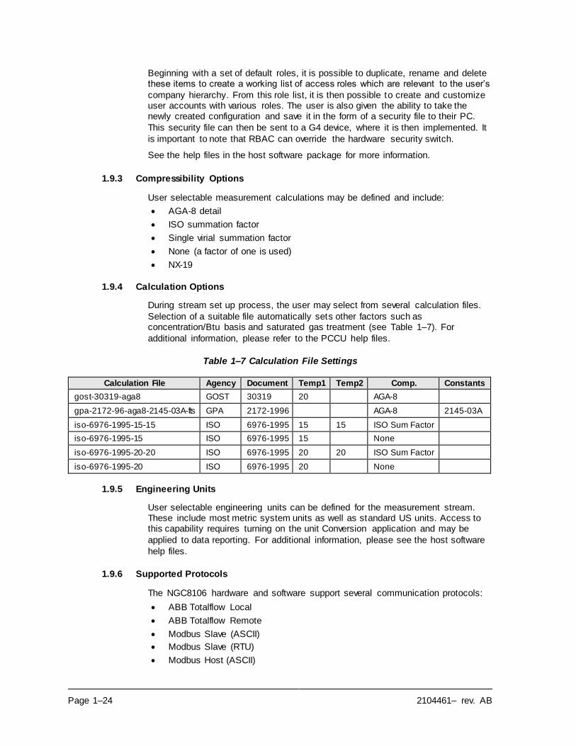
Page 1–24 2104461– rev. AB
Beginning with a set of default roles, it is possible to duplicate, rename and delete these items to create a working list of access roles which are relevant to the user’s
company hierarchy. From this role list, it is then possible to create and customize user accounts with various roles. The user is also given the ability to take the newly created configuration and save it in the form of a security file to their PC.
This security file can then be sent to a G4 device, where it is then implemented. It
is important to note that RBAC can override the hardware security switch.
See the help files in the host software package for more information.
1.9.3 Compressibility Options
User selectable measurement calculations may be defined and include:
• AGA-8 detail
• ISO summation factor
• Single virial summation factor
• None (a factor of one is used)
• NX-19
1.9.4 Calculation Options
During stream set up process, the user may select from several calculation files.
Selection of a suitable file automatically sets other factors such as concentration/Btu basis and saturated gas treatment (see Table 1–7). For
additional information, please refer to the PCCU help files.
Table 1–7 Calculation File Settings
Calculation File Agency Document Temp1 Temp2 Comp. Constants
gost-30319-aga8 GOST 30319 20 AGA-8
gpa-2172-96-aga8-2145-03A-fts GPA 2172-1996 AGA-8 2145-03A
iso-6976-1995-15-15 ISO 6976-1995 15 15 ISO Sum Factor
iso-6976-1995-15 ISO 6976-1995 15 None
iso-6976-1995-20-20 ISO 6976-1995 20 20 ISO Sum Factor
iso-6976-1995-20 ISO 6976-1995 20 None
1.9.5 Engineering Units
User selectable engineering units can be defined for the measurement stream. These include most metric system units as well as standard US units. Access to this capability requires turning on the unit Conversion application and may be
applied to data reporting. For additional information, please see the host software
help files.
1.9.6 Supported Protocols
The NGC8106 hardware and software support several communication protocols:
• ABB Totalflow Local
• ABB Totalflow Remote
• Modbus Slave (ASCII)
• Modbus Slave (RTU)
• Modbus Host (ASCII)
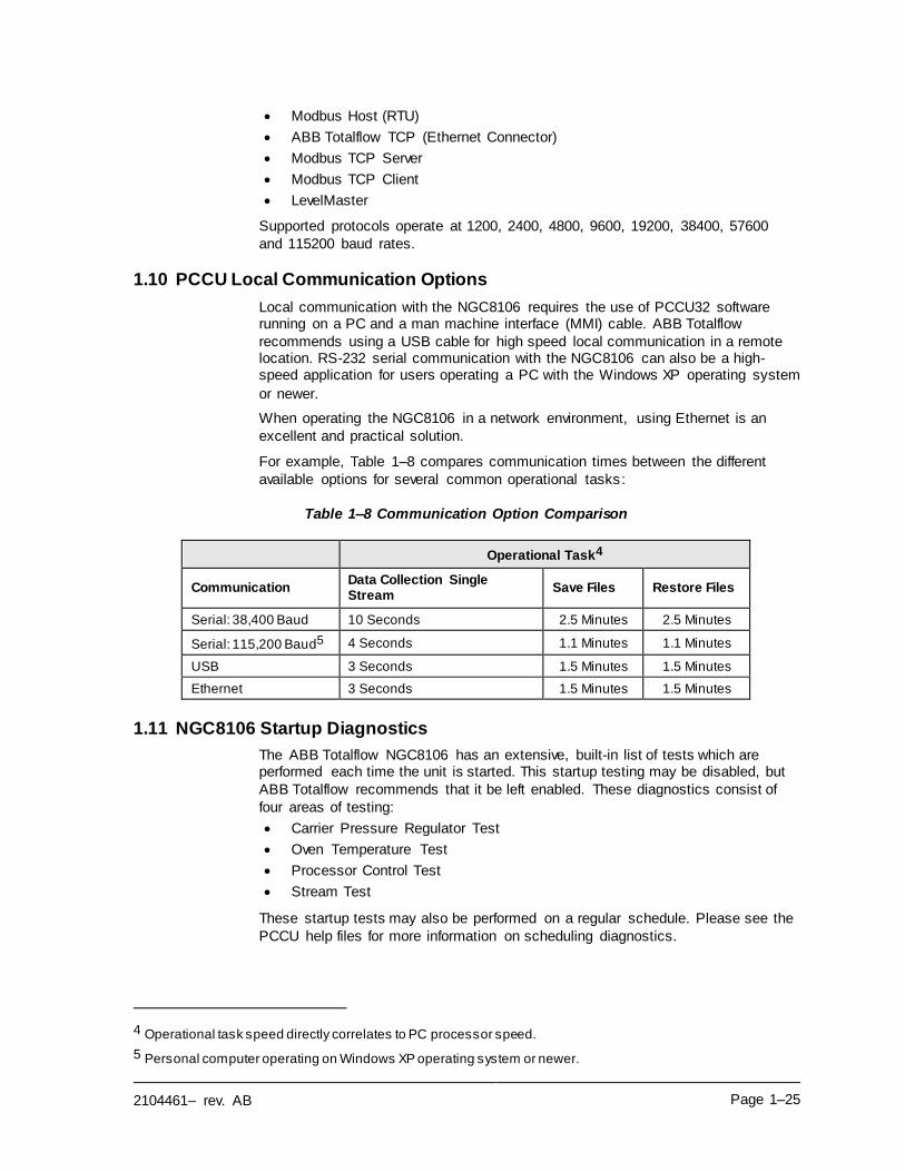
2104461– rev. AB Page 1–25
• Modbus Host (RTU)
• ABB Totalflow TCP (Ethernet Connector)
• Modbus TCP Server
• Modbus TCP Client
• LevelMaster
Supported protocols operate at 1200, 2400, 4800, 9600, 19200, 38400, 57600
and 115200 baud rates.
1.10 PCCU Local Communication Options
Local communication with the NGC8106 requires the use of PCCU32 software running on a PC and a man machine interface (MMI) cable. ABB Totalflow
recommends using a USB cable for high speed local communication in a remote location. RS-232 serial communication with the NGC8106 can also be a high-speed application for users operating a PC with the Windows XP operating system
or newer.
When operating the NGC8106 in a network environment, using Ethernet is an
excellent and practical solution.
For example, Table 1–8 compares communication times between the different
available options for several common operational tasks:
Table 1–8 Communication Option Comparison
Operational Task4
Communication Data Collection Single Stream
Save Files Restore Files
Serial: 38,400 Baud 10 Seconds 2.5 Minutes 2.5 Minutes
Serial: 115,200 Baud5 4 Seconds 1.1 Minutes 1.1 Minutes
USB 3 Seconds 1.5 Minutes 1.5 Minutes
Ethernet 3 Seconds 1.5 Minutes 1.5 Minutes
1.11 NGC8106 Startup Diagnostics
The ABB Totalflow NGC8106 has an extensive, built-in list of tests which are performed each time the unit is started. This startup testing may be disabled, but
ABB Totalflow recommends that it be left enabled. These diagnostics consist of
four areas of testing:
• Carrier Pressure Regulator Test
• Oven Temperature Test
• Processor Control Test
• Stream Test
These startup tests may also be performed on a regular schedule. Please see the
PCCU help files for more information on scheduling diagnostics.
4 Operational task speed directly correlates to PC processor speed.
5 Personal computer operating on Windows XP operating system or newer.
Page 1–26 2104461– rev. AB
1.11.1 Carrier Pressure Regulator Tests
This test compares the actual column pressure to the column pressure set point using carrier gas. A failure of this test indicates that the carrier pressure is not
meeting or over exceeding the expected level of pressure.
1.11.2 Oven Temperature Test
This test compares the actual oven temperature to the oven temperature set point. A failure of this test indicates that the oven is not maintaining the required
temperature.
1.11.3 Processor Control Test
This test contains three test areas: column 1 carrier pressure, column 2 carrier pressure and oven temperature. In each area, the test measures the effort
required to maintain the required value. From those measurements, the test develops a standard deviation and makes a series of comparisons. The failure of any of these comparisons indicates an erratic deviation exists . This means the
processor is not able to control the function.
1.11.4 Stream Test
This test measures various pressures for the input stream. Stream failure
indicates an inability to meet certain criteria.
During the initial startup, the input stream is disabled. If input pressure is detected,
the input stream is re-enabled, tested and either passed or failed.
1.12 Startup Wizard
The NGC8106 Startup Wizard is designed to walk the technician through procedures required for setting up the unit. Following the installation and connection to the NGC8106, the Startup Wizard begins automatically. This only
occurs the first time the user connects to the unit. This will also occur at start up
each time the user reconnects to the system until the unit setup is completed.
The wizard is designed to run concurrently with the NGC8106 Diagnostics.
1.12.1 Wizard
The wizard initiates the process of entering information to enable the NGC8106 to perform at its peak functionality. This includes device set up, stream set up, etc. Each screen has an associated help topic that automatically displays when the
user moves throughout the screens. These topics define the required information.
1.13 Historical Data
The NGC8106 compiles historical data that can be used for custody transfer
needs, verifies NGC8106 operation over time and provides a limited data backup for communication link reliability. Data retained by the NGC8106 can be collected
via a remote communication link or by a laptop PC operator interface.
1.13.1 Retaining Data
The user can configure how much data is retained by the NGC8106 via the
operator interface. The default configuration is as follows:
2104461– rev. AB Page 1–27
1.13.2 Analysis Cycles
The last 480 analysis cycles (default):
• Normalized components
• Un-normalized total
• Ideal Btu/CV
• Real Btu/CV (wet (inferior CV) and dry (superior CV))
• Relative density (specific gravity)
• Density
• GPM
• Wobbe index [dry Btu (superior CV)]
• Alarms
1.13.3 Stream Averages
• Last 840 hour averages
• Last 35 Daily averages
• Last monthly average
1.13.4 Diagnostic Reports
The last 480 analysis cycles:
• Selected peak times
• Selected peak areas
• Ideal Btu/CV
• Carrier regulator pressure
• Oven temperature
• Enclosure temperature
• Sample pressure
• Detector noise values
• Detector balance values
1.13.5 Audit Logs
• Last 100 alarms
• Last 100 events
1.14 TCR Sample Probe (Optional Equipment)
The temperature compensated regulator (TCR) sample probe is used to capture
natural gas from the pipeline for NGC8106 sampling and analysis. To capture the gas sample, it is recommended that the TCR sample probe be mounted on horizontal pipe runs; however, it can be mounted on vertical runs if this is more
suitable to the customer’s installation.
The TCR sample probe is specifically selected for operation with the NGC8106.
The design of the probe prevents icing without the need for electrical power.
It is the customer’s responsibility to install and weld a ¾-inch, female, NPT-standard pipeline coupling on the main meter run gas flow pipe. This coupling allows installation of the TCR
sample probe.
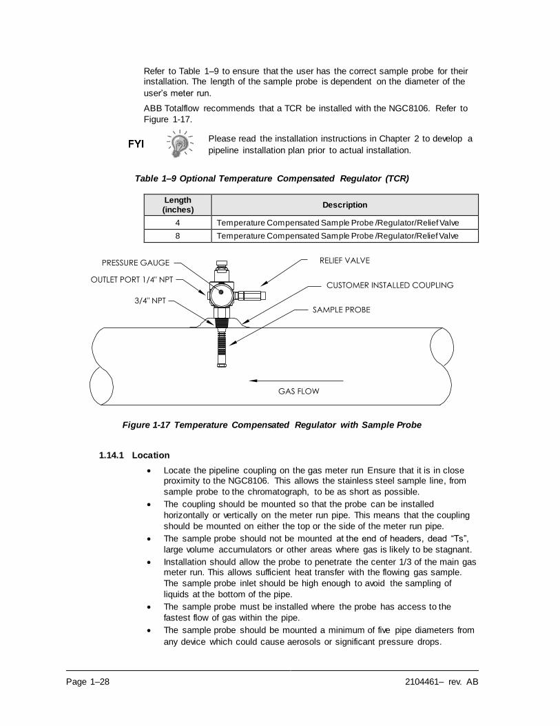
Page 1–28 2104461– rev. AB
Refer to Table 1–9 to ensure that the user has the correct sample probe for their installation. The length of the sample probe is dependent on the diameter of the
user’s meter run.
ABB Totalflow recommends that a TCR be installed with the NGC8106. Refer to
Figure 1-17.
Please read the installation instructions in Chapter 2 to develop a
pipeline installation plan prior to actual installation.
Table 1–9 Optional Temperature Compensated Regulator (TCR)
Length (inches)
Description
4 Temperature Compensated Sample Probe /Regulator/Relief Valve
8 Temperature Compensated Sample Probe /Regulator/Relief Valve
Figure 1-17 Temperature Compensated Regulator with Sample Probe
1.14.1 Location
• Locate the pipeline coupling on the gas meter run Ensure that it is in close proximity to the NGC8106. This allows the stainless steel sample line, from
sample probe to the chromatograph, to be as short as possible.
• The coupling should be mounted so that the probe can be installed
horizontally or vertically on the meter run pipe. This means that the coupling
should be mounted on either the top or the side of the meter run pipe.
• The sample probe should not be mounted at the end of headers, dead “Ts”,
large volume accumulators or other areas where gas is likely to be stagnant.
• Installation should allow the probe to penetrate the center 1/3 of the main gas meter run. This allows sufficient heat transfer with the flowing gas sample.
The sample probe inlet should be high enough to avoid the sampling of
liquids at the bottom of the pipe.
• The sample probe must be installed where the probe has access to the
fastest flow of gas within the pipe.
• The sample probe should be mounted a minimum of five pipe diameters from
any device which could cause aerosols or significant pressure drops.
3/4" NPT
GAS FLOW
SAMPLE PROBE
CUSTOMER INSTALLED COUPLING
PRESSURE GAUGE
OUTLET PORT 1/4" NPT
RELIEF VALVE
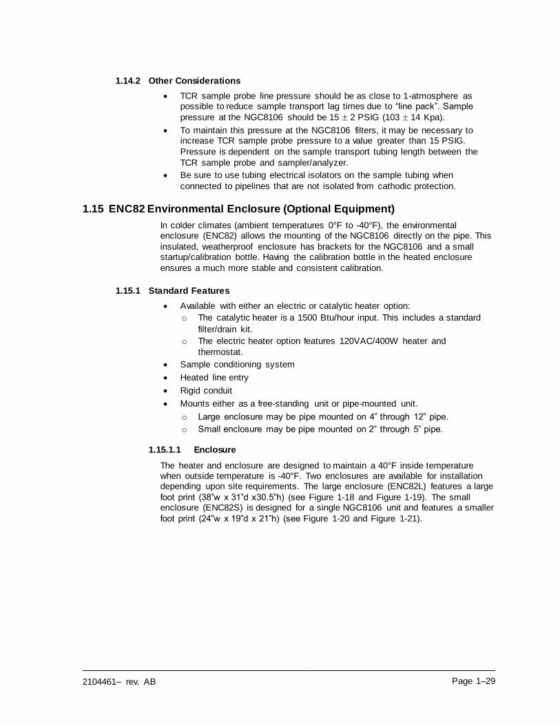
2104461– rev. AB Page 1–29
1.14.2 Other Considerations
• TCR sample probe line pressure should be as close to 1-atmosphere as possible to reduce sample transport lag times due to “line pack”. Sample
pressure at the NGC8106 should be 15 2 PSIG (103 14 Kpa).
• To maintain this pressure at the NGC8106 filters, it may be necessary to increase TCR sample probe pressure to a value greater than 15 PSIG.
Pressure is dependent on the sample transport tubing length between the
TCR sample probe and sampler/analyzer.
• Be sure to use tubing electrical isolators on the sample tubing when
connected to pipelines that are not isolated from cathodic protection.
1.15 ENC82 Environmental Enclosure (Optional Equipment)
In colder climates (ambient temperatures 0°F to -40°F), the environmental enclosure (ENC82) allows the mounting of the NGC8106 directly on the pipe. This
insulated, weatherproof enclosure has brackets for the NGC8106 and a small startup/calibration bottle. Having the calibration bottle in the heated enclosure
ensures a much more stable and consistent calibration.
1.15.1 Standard Features
• Available with either an electric or catalytic heater option:
o The catalytic heater is a 1500 Btu/hour input. This includes a standard
filter/drain kit.
o The electric heater option features 120VAC/400W heater and
thermostat.
• Sample conditioning system
• Heated line entry
• Rigid conduit
• Mounts either as a free-standing unit or pipe-mounted unit.
o Large enclosure may be pipe mounted on 4” through 12” pipe.
o Small enclosure may be pipe mounted on 2” through 5” pipe.
1.15.1.1 Enclosure
The heater and enclosure are designed to maintain a 40°F inside temperature when outside temperature is -40°F. Two enclosures are available for installation depending upon site requirements. The large enclosure (ENC82L) features a large
foot print (38”w x 31”d x30.5”h) (see Figure 1-18 and Figure 1-19). The small enclosure (ENC82S) is designed for a single NGC8106 unit and features a smaller
foot print (24”w x 19”d x 21”h) (see Figure 1-20 and Figure 1-21).
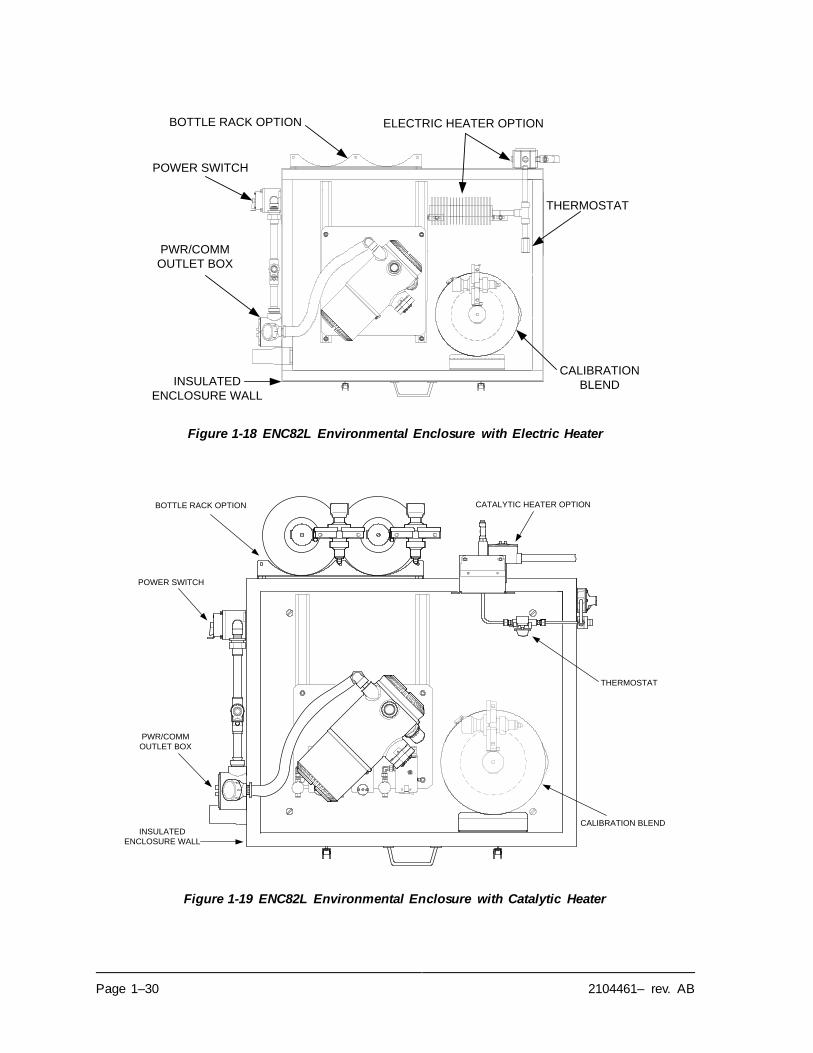
Page 1–30 2104461– rev. AB
Figure 1-18 ENC82L Environmental Enclosure with Electric Heater
Figure 1-19 ENC82L Environmental Enclosure with Catalytic Heater
BOTTLE RACK OPTION
POWER SWITCH
PWR/COMM
OUTLET BOX
THERMOSTAT
INSULATED
ENCLOSURE WALL
CALIBRATION
BLEND
ELECTRIC HEATER OPTION
CATALYTIC HEATER OPTIONBOTTLE RACK OPTION
POWER SWITCH
PWR/COMM
OUTLET BOX
THERMOSTAT
INSULATED
ENCLOSURE WALL
CALIBRATION BLEND
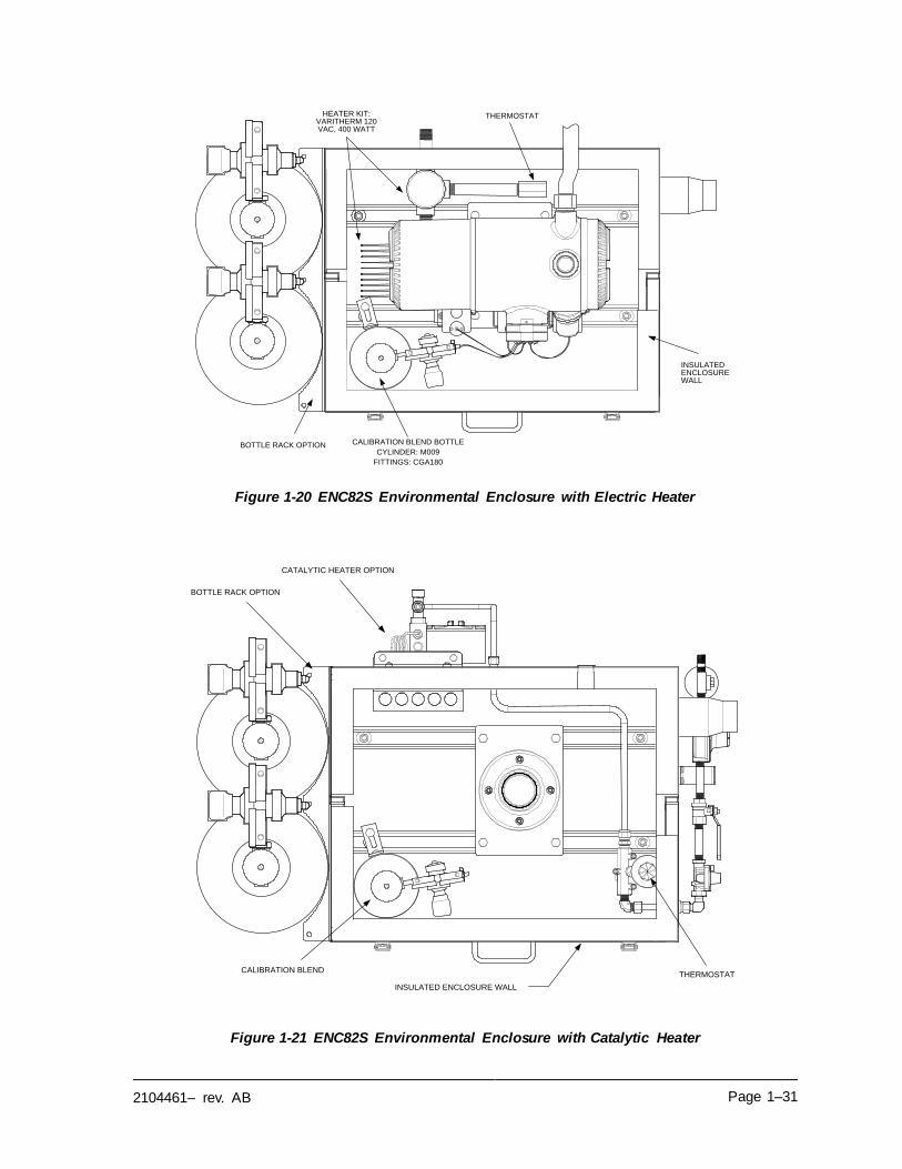
2104461– rev. AB Page 1–31
Figure 1-20 ENC82S Environmental Enclosure with Electric Heater
Figure 1-21 ENC82S Environmental Enclosure with Catalytic Heater
CALIBRATION BLEND BOTTLE
CYLINDER: M009
FITTINGS: CGA180
HEATER KIT: VARITHERM 120 VAC, 400 WATT
THERMOSTAT
INSULATED ENCLOSURE WALL
BOTTLE RACK OPTION
CATALYTIC HEATER OPTION
BOTTLE RACK OPTION
THERMOSTAT
INSULATED ENCLOSURE WALL
CALIBRATION BLEND
Page 1–32 2104461– rev. AB
1.15.1.2 Mounting Options
The ENC82 may be mounted directly on the pipe run, with or without the sample probe enclosed. Optional support leg(s) are available for added support when
mounted on the pipe run.
Optionally, a free-standing kit may be used to mount the enclosure next to the
meter run.
1.15.2 Optional Features
The following is a list of optional features:
• Calibration blend
• DC power switch (large enclosure only)
• Dual bottle rack
1.16 Sample Conditioning Modules (Optional Equipment)
For some NGC8106 installations, it may be necessary to install an optional sample system conditioning module to compensate for non-ideal natural gas
samples. These optional modules are pre-engineered to provide various levels of protection and bypass flows (see Figure 1-22). All of the sample conditioning modules include a level of particulate protection and come in two flow sizes: 50
CC and 450 CC per minute (see Table 1–10).
For installations where the gas is ideal, and the sample probe is located less than
10’ from the NGC8106, no sample conditioning module is required.
1.16.1 Gas Types
The user can select from one of four sample conditioning modules for installations where the gas samples do not meet the ideal clean and dry conditions. The following definitions define what is meant by the condition of natural gas to be
sampled:
• Clean gas is defined as having no particles larger than one micron and no
more than one milligram of solids per cubic meter of gas.
• Dry gas is defined as having no more than seven pounds of water per million
cubic feet of gas. Gas has less than 0.1 PPM of liquid at the coldest ambient condition expected at the coldest point in the system. The liquid can be water, oil, synthetic lubrication, glycol, condensed sample or any other non-
vapor contaminate.
• Stable gas is a vapor containing less than 0.1 PPM of liquid when vapor is
cooled to 18.3F (10C) below the coldest ambient temperature possible at
any point in the system.
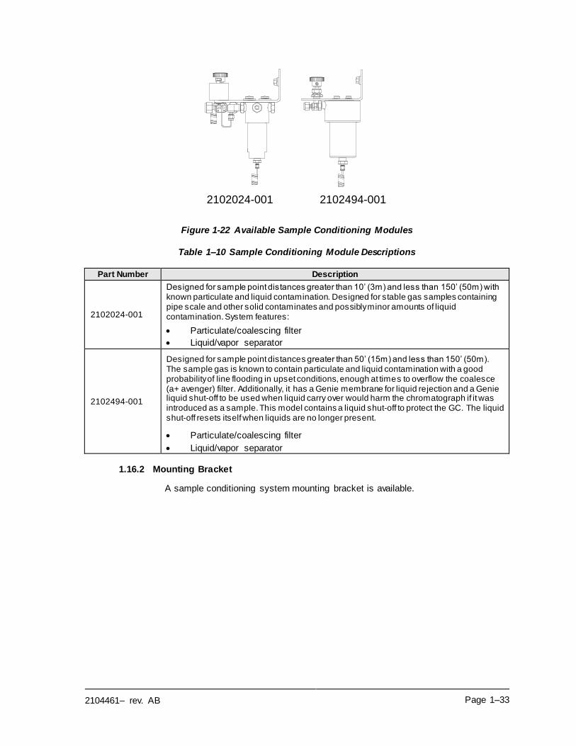
2104461– rev. AB Page 1–33
Figure 1-22 Available Sample Conditioning Modules
Table 1–10 Sample Conditioning Module Descriptions
Part Number Description
2102024-001
Designed for sample point distances greater than 10’ (3m) and less than 150’ (50m) with known particulate and liquid contamination. Designed for stable gas samples containing pipe scale and other solid contaminates and possibly minor amounts of liquid contamination. System features:
• Particulate/coalescing filter
• Liquid/vapor separator
2102494-001
Designed for sample point distances greater than 50’ (15m) and less than 150’ (50m). The sample gas is known to contain particulate and liquid contamination with a good probability of line flooding in upset conditions, enough at times to overflow the coalesce (a+ avenger) filter. Additionally, it has a Genie membrane for liquid rejection and a Genie liquid shut-off to be used when liquid carry over would harm the chromatograph if it was introduced as a sample. This model contains a liquid shut-off to protect the GC. The liquid shut-off resets itself when liquids are no longer present.
• Particulate/coalescing filter
• Liquid/vapor separator
1.16.2 Mounting Bracket
A sample conditioning system mounting bracket is available.
2102024-001 2102494-001
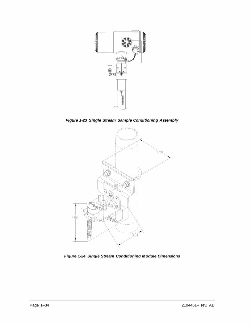
Page 1–34 2104461– rev. AB
Figure 1-23 Single Stream Sample Conditioning Assembly
Figure 1-24 Single Stream Conditioning Module Dimensions
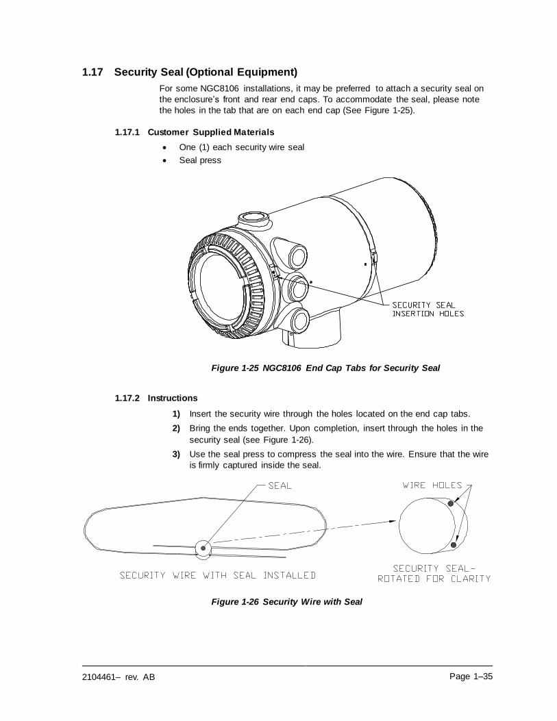
2104461– rev. AB Page 1–35
1.17 Security Seal (Optional Equipment)
For some NGC8106 installations, it may be preferred to attach a security seal on
the enclosure’s front and rear end caps. To accommodate the seal, please note
the holes in the tab that are on each end cap (See Figure 1-25).
1.17.1 Customer Supplied Materials
• One (1) each security wire seal
• Seal press
Figure 1-25 NGC8106 End Cap Tabs for Security Seal
1.17.2 Instructions
1) Insert the security wire through the holes located on the end cap tabs.
2) Bring the ends together. Upon completion, insert through the holes in the
security seal (see Figure 1-26).
3) Use the seal press to compress the seal into the wire. Ensure that the wire
is firmly captured inside the seal.
Figure 1-26 Security Wire with Seal
Page 1–36 2104461– rev. AB
1.18 Optional Equipment Enclosure (Optional Equipment)
If the optional enclosure is used, it may be configured to include other options .
These options include, but are not limited to, a battery pack to provide power to
the NGC8106, communication equipment, solar power charger and additional I/O.
Three enclosures are commonly used for NGC8106 installations: the 6200, 6700
and 6800 optional equipment enclosures.
The 6200 installation supports AC to DC. There is no battery pack option in this
installation.
The 6700 enclosure supports AC to DC. There is no battery pack option in this
installation.
The 6800 enclosure supports battery pack6 operation for the NGC8106 via solar
power, UPS system, AC to DC power or communication equipment.
Following the local codes for installation, these units would normally be located in a Division 2 or general-purpose area. The units may be mounted on a 2” pipe or
mounted on a flat surface.
1.18.1 6200 Optional Equipment Enclosure
The 6200 can accommodate the following equipment:
• 110/240 Volt to 12 Vdc
• 110/240 Volt to 24 Vdc
1.18.2 6700 Optional Equipment Enclosure
The 6700 enclosure can accommodate the following:
• Communication kit
• 120/240 Vac to 12 Vdc power supply
• 110/240 Volt to 12 Vdc
• 110/240 Volt to 24 Vdc
1.18.3 6800 Optional Equipment Enclosure
The 6800 enclosure can accommodate the following:
• Communication kit
• Solar panel power option
▪ Two (2) ea. 110 Ah Batteries
• 115/230 Vac UPS power option (24 Vdc systems only)
▪ Two (2) ea. 40–110 Ah Batteries
1.19 Power Supply Options (Optional Equipment)
Power supply options available for the NGC8106 are as follows:
• 110/240 Vac to 12/24 Vdc
• 115/230 Vac to 12/24 Vdc (explosion-proof)
• 24 Vdc to 12 Vdc converter (not applicable for systems with auxiliary heater)
• 12/24 Vdc solar panel power pack
6 Autonomy measured in hours.
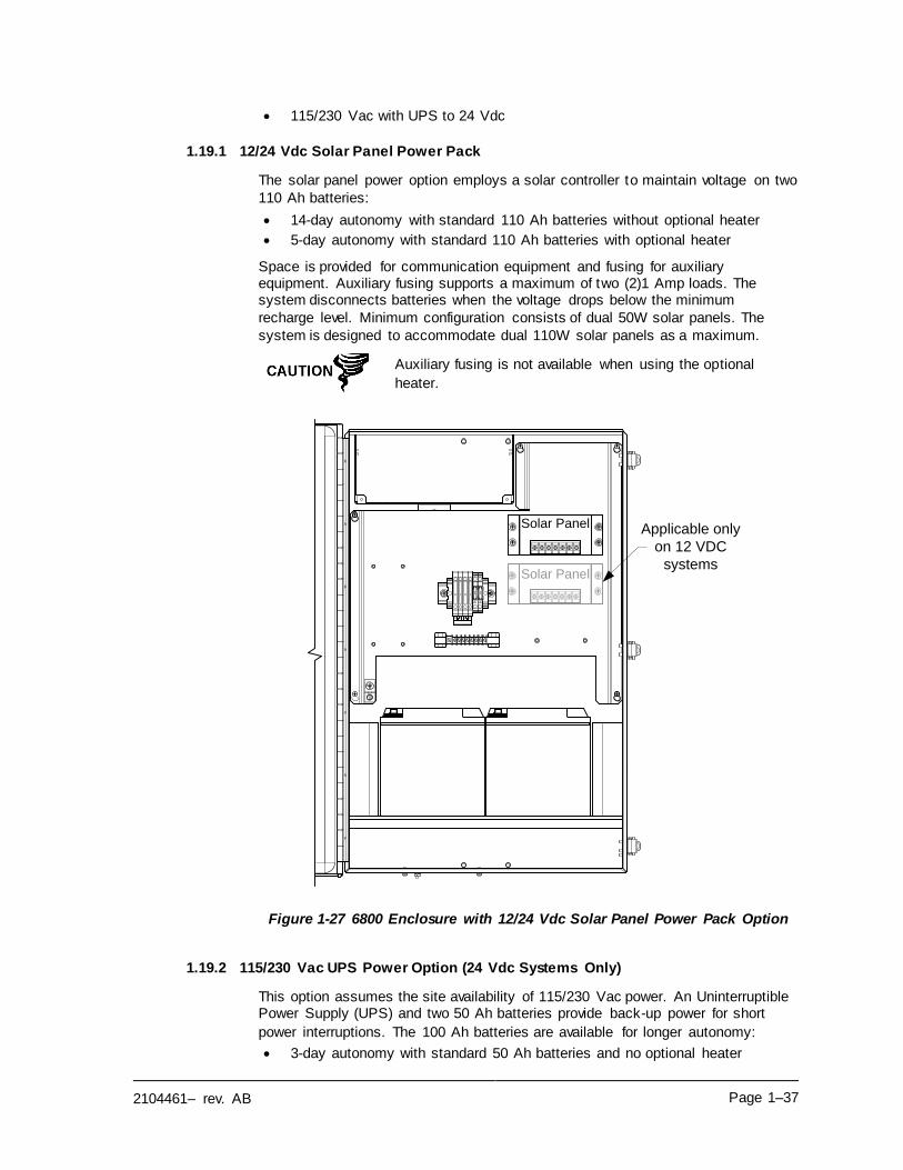
2104461– rev. AB Page 1–37
• 115/230 Vac with UPS to 24 Vdc
1.19.1 12/24 Vdc Solar Panel Power Pack
The solar panel power option employs a solar controller to maintain voltage on two
110 Ah batteries:
• 14-day autonomy with standard 110 Ah batteries without optional heater
• 5-day autonomy with standard 110 Ah batteries with optional heater
Space is provided for communication equipment and fusing for auxiliary equipment. Auxiliary fusing supports a maximum of two (2)1 Amp loads. The system disconnects batteries when the voltage drops below the minimum
recharge level. Minimum configuration consists of dual 50W solar panels. The
system is designed to accommodate dual 110W solar panels as a maximum.
Auxiliary fusing is not available when using the optional
heater.
Figure 1-27 6800 Enclosure with 12/24 Vdc Solar Panel Power Pack Option
1.19.2 115/230 Vac UPS Power Option (24 Vdc Systems Only)
This option assumes the site availability of 115/230 Vac power. An Uninterruptible Power Supply (UPS) and two 50 Ah batteries provide back-up power for short
power interruptions. The 100 Ah batteries are available for longer autonomy:
• 3-day autonomy with standard 50 Ah batteries and no optional heater
Solar Panel
Solar Panel
Applicable only
on 12 VDC
systems
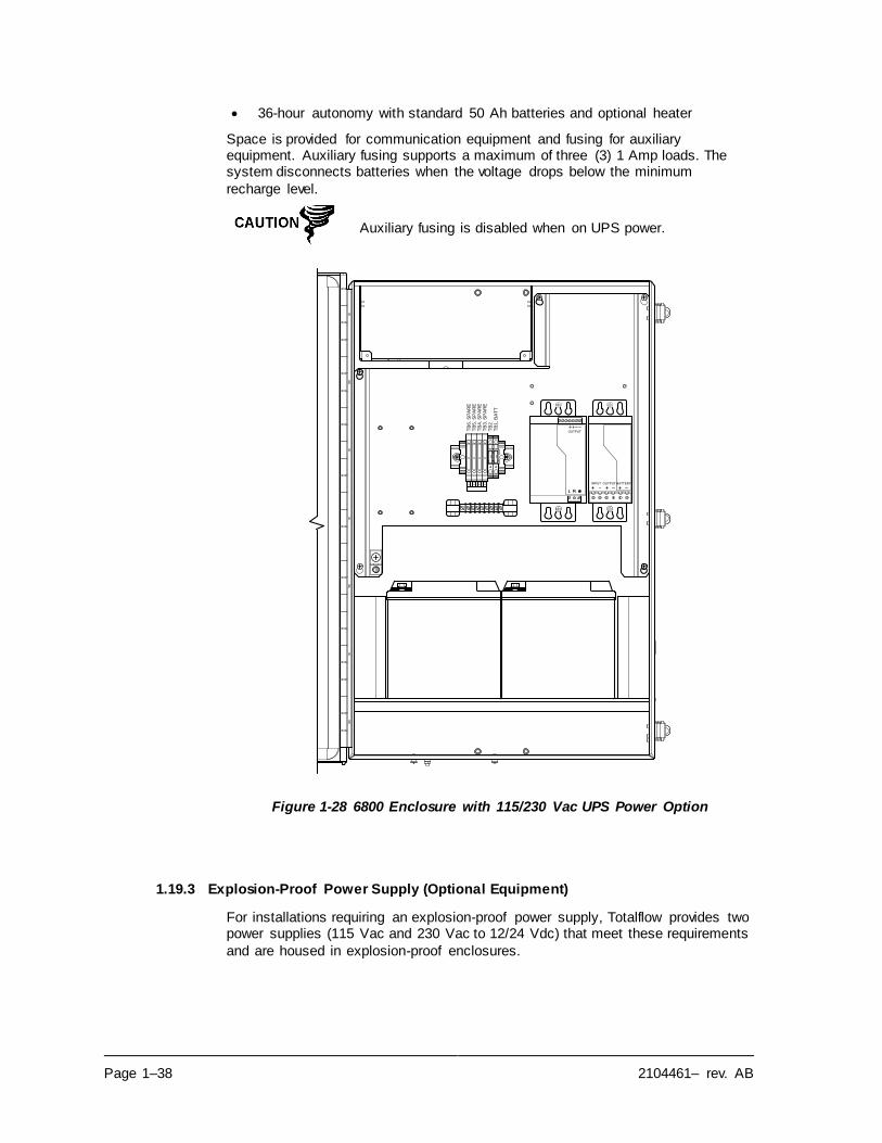
Page 1–38 2104461– rev. AB
• 36-hour autonomy with standard 50 Ah batteries and optional heater
Space is provided for communication equipment and fusing for auxiliary equipment. Auxiliary fusing supports a maximum of three (3) 1 Amp loads. The system disconnects batteries when the voltage drops below the minimum
recharge level.
Auxiliary fusing is disabled when on UPS power.
Figure 1-28 6800 Enclosure with 115/230 Vac UPS Power Option
1.19.3 Explosion-Proof Power Supply (Optional Equipment)
For installations requiring an explosion-proof power supply, Totalflow provides two power supplies (115 Vac and 230 Vac to 12/24 Vdc) that meet these requirements
and are housed in explosion-proof enclosures.
TB
1,
BA
TT
TB
4,
SP
AR
ET
B3
, S
PA
RE
TB
5,
SP
AR
ET
B6
, S
PA
RE
TB
2
BATTERYOUTPUTINPUT
OUTPUT
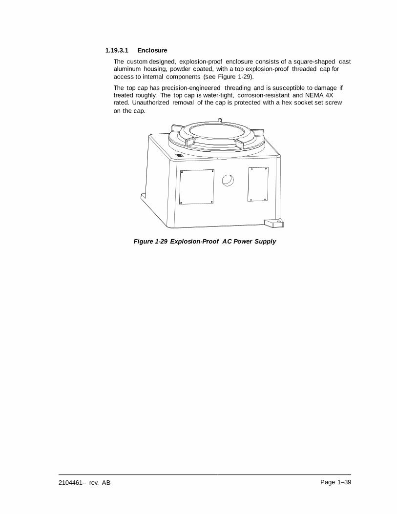
2104461– rev. AB Page 1–39
1.19.3.1 Enclosure
The custom designed, explosion-proof enclosure consists of a square-shaped cast aluminum housing, powder coated, with a top explosion-proof threaded cap for
access to internal components (see Figure 1-29).
The top cap has precision-engineered threading and is susceptible to damage if treated roughly. The top cap is water-tight, corrosion-resistant and NEMA 4X rated. Unauthorized removal of the cap is protected with a hex socket set screw
on the cap.
Figure 1-29 Explosion-Proof AC Power Supply

2104461– rev. AB Page 2–1
2.0 INSTALLATION
2.1 Overview
This chapter provides information for field installation of the NGC8106 and optional equipment. After completing the procedures within this chapter, the
NGC8106 is ready for startup.
The following procedures, unless otherwise stated, are applicable to all NGC8106 units. The NGC8106 is designed to be pipe-mounted (see Figure 2-1). Optionally,
a shelf-mounting kit (see Figure 2-2) may be purchased for use in mounting the unit on a wall, inside or outside of a building or a mounting plate for use in the
optional environmental enclosure.
The installation instructions in this chapter are to be performed
only when the area is known to be non-hazardous.
It is highly recommended that the user thoroughly read this chapter to establish an installation plan. Also, before beginning, refer to the wiring diagrams delivered with the new
NGC8106. Store these under the Drawings tab in the back of
this manual.
2.1.1 What this Means
Installation instructions that feature this icon are applicable
ONLY when the installation involves an environmental enclosure (ENC82). All other instructions may or may not be
applicable.
2.1.2 Organization
The following instruction sections are organized in the suggested installation order. Not all installation instructions will apply to the user’s situation. As this is the case, certain procedures may vary when the installation does not require certain
equipment.
Please note that, where applicable, typical instructions are first
and variations or specialized instructions follow.
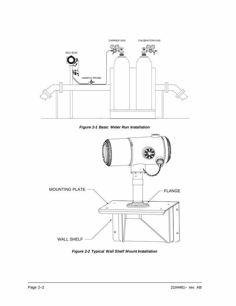
Page 2–2 2104461– rev. AB
Figure 2-1 Basic Meter Run Installation
Figure 2-2 Typical Wall Shelf Mount Installation
CALIBRATION GASCARRIER GAS
SAMPLE PROBE
NGC 8106
FLANGE
WALL SHELF
MOUNTING PLATE
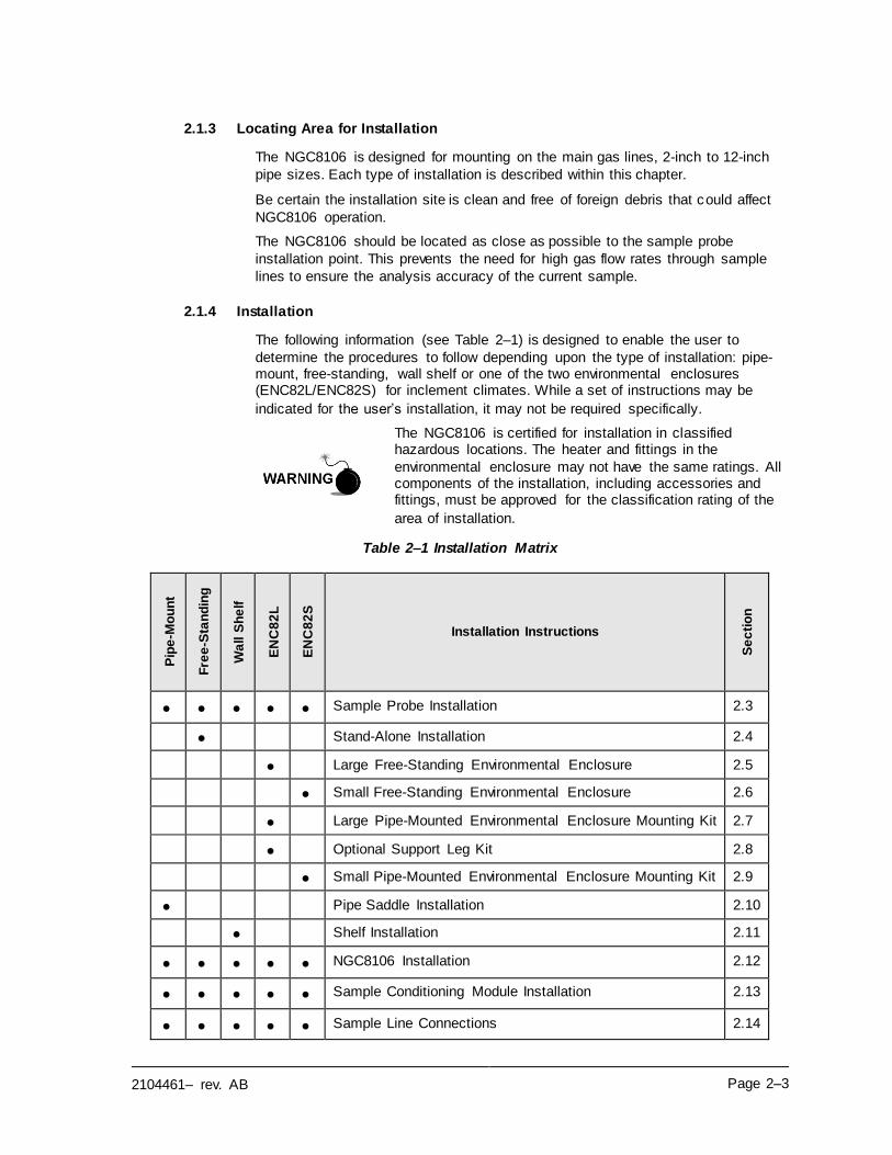
2104461– rev. AB Page 2–3
2.1.3 Locating Area for Installation
The NGC8106 is designed for mounting on the main gas lines, 2-inch to 12-inch
pipe sizes. Each type of installation is described within this chapter.
Be certain the installation site is clean and free of foreign debris that could affect
NGC8106 operation.
The NGC8106 should be located as close as possible to the sample probe
installation point. This prevents the need for high gas flow rates through sample
lines to ensure the analysis accuracy of the current sample.
2.1.4 Installation
The following information (see Table 2–1) is designed to enable the user to
determine the procedures to follow depending upon the type of installation: pipe-mount, free-standing, wall shelf or one of the two environmental enclosures (ENC82L/ENC82S) for inclement climates. While a set of instructions may be
indicated for the user’s installation, it may not be required specifically.
The NGC8106 is certified for installation in classified hazardous locations. The heater and fittings in the
environmental enclosure may not have the same ratings. All components of the installation, including accessories and fittings, must be approved for the classification rating of the
area of installation.
Table 2–1 Installation Matrix
Pip
e-M
ou
nt
Fre
e-S
tan
din
g
Wa
ll S
he
lf
EN
C8
2L
EN
C8
2S
Installation Instructions
Se
cti
on
• • • • • Sample Probe Installation 2.3
• Stand-Alone Installation 2.4
• Large Free-Standing Environmental Enclosure 2.5
• Small Free-Standing Environmental Enclosure 2.6
• Large Pipe-Mounted Environmental Enclosure Mounting Kit 2.7
• Optional Support Leg Kit 2.8
• Small Pipe-Mounted Environmental Enclosure Mounting Kit 2.9
• Pipe Saddle Installation 2.10
• Shelf Installation 2.11
• • • • • NGC8106 Installation 2.12
• • • • • Sample Conditioning Module Installation 2.13
• • • • • Sample Line Connections 2.14
Page 2–4 2104461– rev. AB
Pip
e-M
ou
nt
Fre
e-S
tan
din
g
Wa
ll S
he
lf
EN
C8
2L
EN
C8
2S
Installation Instructions
Se
cti
on
• • Sample Line to NGC8106 Inside of ENC82 2.15
• ENC82L Optional Pwr/Comm Outlet Box Assembly 2.16
• • • Carrier/Calibration Bottle Rack Installation on Meter Run 2.17
• • ENC82 Carrier Gas Bottle Rack Installation 2.18
• • • • • Carrier Gas Regulator Installation 2.19
• ENC82L Calibration Gas Bottle Installation 2.20
• ENC82S Calibration Gas Bottle Installation 2.21
• • • • • Calibration Gas Regulator Installation 2.22
• • • • • Carrier Gas and Calibration Gas Connections 2.23
• • • • • Vent Lines Connections 2.24
• ENC82L Optional Catalytic Heater Installation 2.25
• ENC82S Optional Catalytic Heater Installation 2.26
• • ENC82 Optional Electric Heater Installation 2.27
• • Sealing Environmental Enclosure 2.28
• • • • • Optional Equipment Enclosure Installation 2.29
• • • • • 115/230 Vac UPS Power Supply (24 Vdc Systems) 2.30
• • • • • 115/230 Vac to 12 Vdc Explosion-Proof Power Supply 2.31
• • • • • 110/240 Vac to 12/24 Vdc Power Supply 2.32
• • • • • 24 Vdc to 12 Vdc Power Converter 2.33
• • • • • Battery Pack Installation 2.34
• • • • • Solar Panel Installation 2.35
• • • • • Solar Power Pack 2.36
• • • • • DC Power Installation 2.37
• • • • • Remote Communication Installation 2.38
2104461– rev. AB Page 2–5
2.2 Unpacking and Inspection
2.2.1 Shipping Carton
Ensure that there is no external damage to the shipping container. If there is
significant, visible external damage, contact the receiving group, and report the
damage to the trucking company for a freight damage claim.
2.2.2 Unpacking
The NGC8106 is shipped in a specially designed shipping carton which contains
the unit, mounting brackets, parts list and wiring and interconnect diagrams.
Optional equipment is shipped in a separate carton.
Carefully remove all internal and external packing material. Upon completion,
remove all items from the box.
2.2.3 Bill of Lading
After removing the protective shipping cover from the NGC8106, compare the shipped contents with those listed on the bill of lading. All items should match
those on the bill of lading.
2.2.4 Inspection
Examine the internal NGC8106 components for evidence of damage.
Points of inspection are:
• Visually inspect exterior of the unit for dents, chipped paint, scratches,
damaged threads, broken glass plate, etc.
• Physically inspect rear interior-mounted circuit boards, cables and front-interior mounted circuit boards for loose cables, boards, display, mounting
screws, etc.
• If applicable, inspect the calibration/carrier gas bottles to ascertain they are
correct for the installation.
2.2.5 Damaged Components
If there is any damage or noticeable defects, notify a local ABB Totalflow representative. Keep all shipping materials as evidence of damage for the carrier’s
inspection. ABB Totalflow will arrange for immediate repair or replacement.
Telephone:
USA: (800) 442-3097 or International: 1-918-338-4880
2.3 Sample Probe Installation
If a sample probe has previously been installed, skip these instructions.
Sample probe pipe coupling should be located on the top of
the meter run but may be mounted vertical or horizontal.
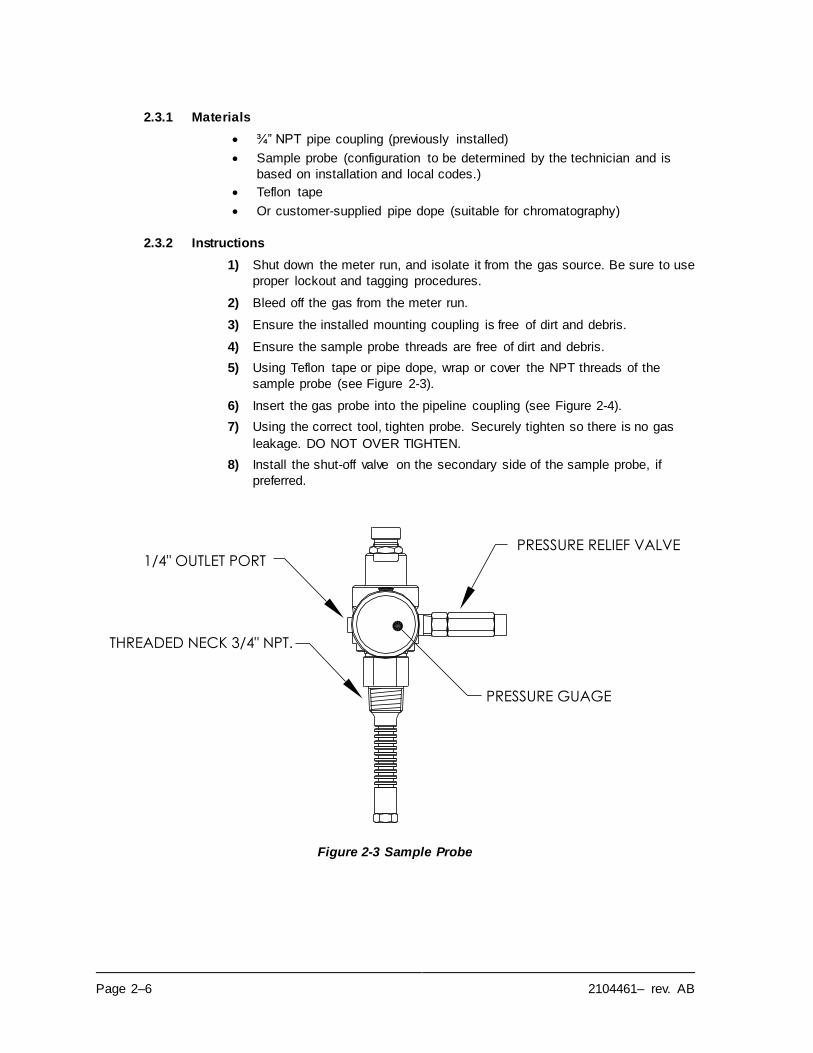
Page 2–6 2104461– rev. AB
2.3.1 Materials
• ¾” NPT pipe coupling (previously installed)
• Sample probe (configuration to be determined by the technician and is
based on installation and local codes.)
• Teflon tape
• Or customer-supplied pipe dope (suitable for chromatography)
2.3.2 Instructions
1) Shut down the meter run, and isolate it from the gas source. Be sure to use
proper lockout and tagging procedures.
2) Bleed off the gas from the meter run.
3) Ensure the installed mounting coupling is free of dirt and debris.
4) Ensure the sample probe threads are free of dirt and debris.
5) Using Teflon tape or pipe dope, wrap or cover the NPT threads of the
sample probe (see Figure 2-3).
6) Insert the gas probe into the pipeline coupling (see Figure 2-4).
7) Using the correct tool, tighten probe. Securely tighten so there is no gas
leakage. DO NOT OVER TIGHTEN.
8) Install the shut-off valve on the secondary side of the sample probe, if
preferred.
Figure 2-3 Sample Probe
THREADED NECK 3/4" NPT.
PRESSURE RELIEF VALVE
PRESSURE GUAGE
1/4" OUTLET PORT
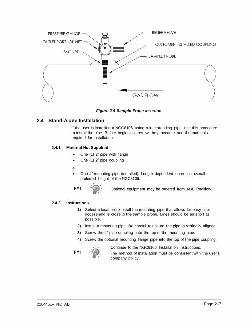
2104461– rev. AB Page 2–7
Figure 2-4 Sample Probe Insertion
2.4 Stand-Alone Installation
If the user is installing a NGC8106 using a free-standing pipe, use this procedure
to install the pipe. Before beginning, review the procedure and the materials
required for installation.
2.4.1 Material Not Supplied
• One (1) 2” pipe with flange
• One (1) 2” pipe coupling
or
• One 2” mounting pipe (installed). Length dependent upon final overall
preferred height of the NGC8106.
Optional equipment may be ordered from ABB Totalflow.
2.4.2 Instructions
1) Select a location to install the mounting pipe that allows for easy user access and is close to the sample probe. Lines should be as short as
possible.
2) Install a mounting pipe. Be careful to ensure the pipe is vertically aligned.
3) Screw the 2” pipe coupling onto the top of the mounting pipe.
4) Screw the optional mounting flange pipe into the top of the pipe coupling.
Continue to the NGC8106 Installation instructions.
The method of installation must be consistent with the user’s
company policy.
3/4" NPT
GAS FLOW
SAMPLE PROBE
CUSTOMER INSTALLED COUPLING
PRESSURE GAUGE
OUTLET PORT 1/4" NPT
RELIEF VALVE
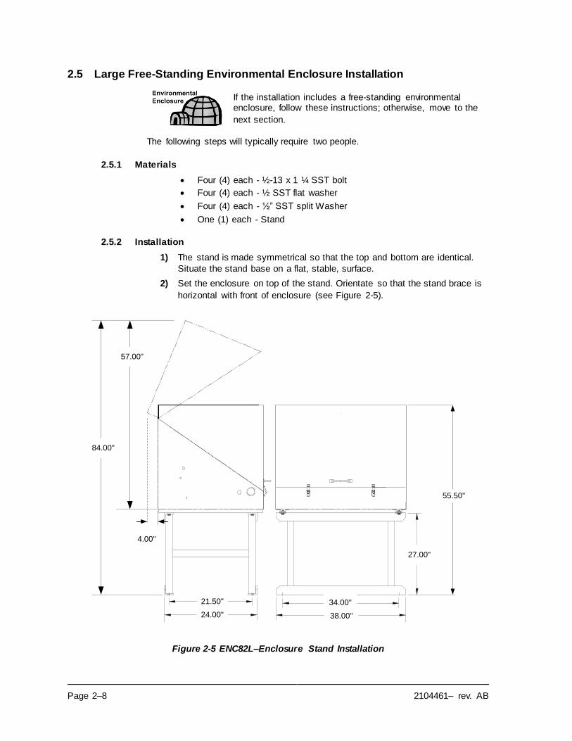
Page 2–8 2104461– rev. AB
2.5 Large Free-Standing Environmental Enclosure Installation
If the installation includes a free-standing environmental enclosure, follow these instructions; otherwise, move to the
next section.
The following steps will typically require two people.
2.5.1 Materials
• Four (4) each - ½-13 x 1 ¼ SST bolt
• Four (4) each - ½ SST flat washer
• Four (4) each - ½” SST split Washer
• One (1) each - Stand
2.5.2 Installation
1) The stand is made symmetrical so that the top and bottom are identical.
Situate the stand base on a flat, stable, surface.
2) Set the enclosure on top of the stand. Orientate so that the stand brace is
horizontal with front of enclosure (see Figure 2-5).
Figure 2-5 ENC82L–Enclosure Stand Installation
4.00"
55.50"
57.00"
84.00"
21.50"
24.00"
34.00"
38.00"
27.00"
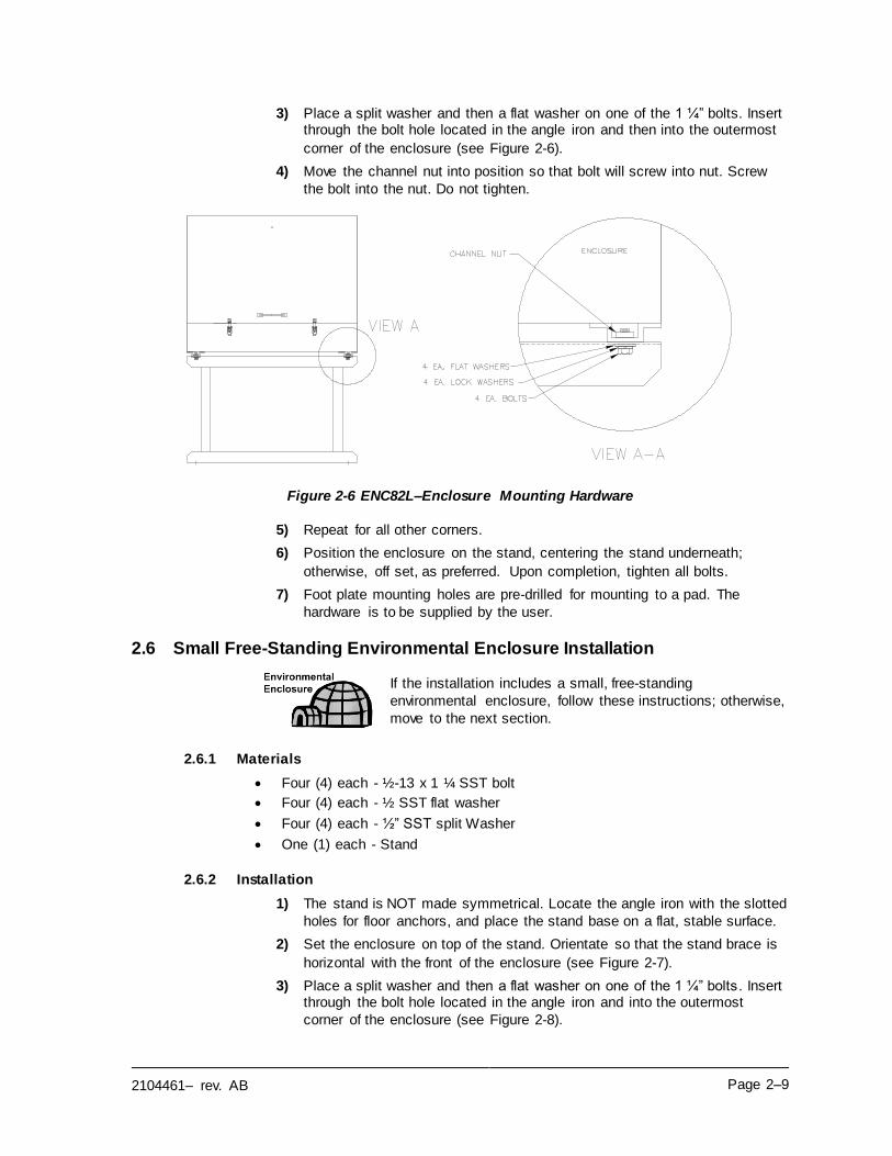
2104461– rev. AB Page 2–9
3) Place a split washer and then a flat washer on one of the 1 ¼” bolts. Insert through the bolt hole located in the angle iron and then into the outermost
corner of the enclosure (see Figure 2-6).
4) Move the channel nut into position so that bolt will screw into nut. Screw
the bolt into the nut. Do not tighten.
Figure 2-6 ENC82L–Enclosure Mounting Hardware
5) Repeat for all other corners.
6) Position the enclosure on the stand, centering the stand underneath;
otherwise, off set, as preferred. Upon completion, tighten all bolts.
7) Foot plate mounting holes are pre-drilled for mounting to a pad. The
hardware is to be supplied by the user.
2.6 Small Free-Standing Environmental Enclosure Installation
If the installation includes a small, free-standing
environmental enclosure, follow these instructions; otherwise,
move to the next section.
2.6.1 Materials
• Four (4) each - ½-13 x 1 ¼ SST bolt
• Four (4) each - ½ SST flat washer
• Four (4) each - ½” SST split Washer
• One (1) each - Stand
2.6.2 Installation
1) The stand is NOT made symmetrical. Locate the angle iron with the slotted
holes for floor anchors, and place the stand base on a flat, stable surface.
2) Set the enclosure on top of the stand. Orientate so that the stand brace is
horizontal with the front of the enclosure (see Figure 2-7).
3) Place a split washer and then a flat washer on one of the 1 ¼” bolts . Insert through the bolt hole located in the angle iron and into the outermost
corner of the enclosure (see Figure 2-8).
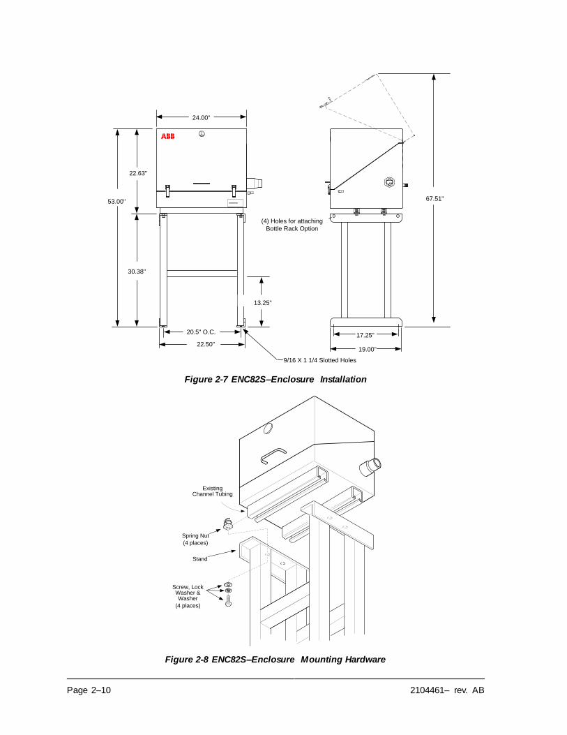
Page 2–10 2104461– rev. AB
Figure 2-7 ENC82S–Enclosure Installation
Figure 2-8 ENC82S–Enclosure Mounting Hardware
20.5" O.C.
19.00"
53.00"
9/16 X 1 1/4 Slotted Holes
30.38"
13.25"
22.50"
17.25"
22.63"
67.51"
24.00"
(4) Holes for attaching
Bottle Rack Option
Existing Channel Tubing
Spring Nut
(4 places)
Screw, Lock Washer & Washer
(4 places)
Stand
2104461– rev. AB Page 2–11
4) Move the channel spring nut into position so that bolt will screw into nut.
Screw the bolt into the nut. Do not tighten.
5) Repeat for all other corners.
6) Position the enclosure on the stand, centering stand underneath;
otherwise, offset, as preferred. Tighten all bolts.
7) Foot plate mounting holes are pre-drilled for mounting to a pad. The
hardware is to be supplied by the user.
2.7 Large Pipe-Mounted Environmental Enclosure Mounting Kit
If the installation includes a pipe-mounted environmental enclosure, follow these instructions as well as the optional support leg instructions; otherwise, continue to the next
applicable set of instructions.
2.7.1 Materials
• Four (4) each - ½” -13 x 1 ¼ SST bolt
• Four (4) each - ½” SST flat washer
• Four (4) each - ½” SST split washer
• Two (2) each - 2 ½” x ¼” 43” steel angle iron
May be used in conjunction with the optional support leg kit.
See Support Leg Installation procedures within this chapter.
2.7.2 Installation
1) Set two pieces of angle iron (see Figure 2-9) on the bottom of the upside-
down enclosure. Ensure that the side with the holes is facing the bottom of the enclosure and the solid sides of the angle iron are facing each other. Angle iron should be spaced so that the diameter of the pipe will fit in
between.
2) Place a split washer and then a flat washer on one of the 1 ¼” bolts (see
Figure 2-10).
3) Insert the bolt through one of the slotted holes located in the angle iron and into the outermost corner of the enclosure. Move the channel nut into
position so that bolt will screw into the nut.
4) Screw the bolt into the nut. Leave loose for later adjustment.
5) Install the other bolt, split washer and flat washer into the other slotted
hole.
6) Repeat for the other angle iron. Final tightening of the bolts is performed after the unit is mounted on the pipe to allow for left-to-right and front-to-
back positioning.
7) Remove the nut and washers from the adjustment assembly, if necessary
(see Figure 2-11).
8) Insert all-thread through the round hole on the adjustment side of the angle
iron.
9) Place the flat washer, split washer and nut on the all-thread.
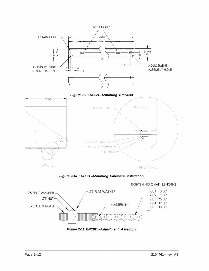
Page 2–12 2104461– rev. AB
Figure 2-9 ENC82L–Mounting Brackets
Figure 2-10 ENC82L–Mounting Hardware Installation
Figure 2-11 ENC82L–Adjustment Assembly
(2 1/2)
STK
.50
1.12
4.12 34.000
43.00
1.00
1.25
BOLT HOLES
.87
.87
CHAIN HOLE
CHAIN RETAINER
MOUNTING HOLE
ADJUSTMENT
ASSEMBLY HOLE
(31.00)
.75 ALL THREAD
.75 NUT
.75 SPLIT WASHER .75 FLAT WASHER
MASTERLINK
-001 13.00"
-002 19.00"-003 25.00"-004 32.00"-005 38.00"
TIGHTENING CHAIN LENGTHS
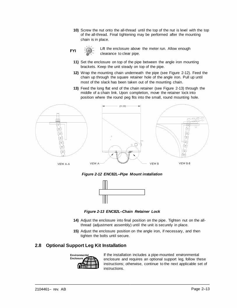
2104461– rev. AB Page 2–13
10) Screw the nut onto the all-thread until the top of the nut is level with the top of the all-thread. Final tightening may be performed after the mounting
chain is in place.
Lift the enclosure above the meter run. Allow enough
clearance to clear pipe.
11) Set the enclosure on top of the pipe between the angle iron mounting
brackets. Keep the unit steady on top of the pipe.
12) Wrap the mounting chain underneath the pipe (see Figure 2-12). Feed the chain up through the square retainer hole of the angle iron. Pull up until
most of the slack has been taken out of the mounting chain.
13) Feed the long flat end of the chain retainer (see Figure 2-13) through the middle of a chain link. Upon completion, move the retainer lock into
position where the round peg fits into the small, round mounting hole.
Figure 2-12 ENC82L–Pipe Mount installation
Figure 2-13 ENC82L–Chain Retainer Lock
14) Adjust the enclosure into final position on the pipe. Tighten nut on the all-
thread (adjustment assembly) until the unit is securely in place.
15) Adjust the enclosure position on the angle iron, if necessary, and then
tighten the bolts until secure.
2.8 Optional Support Leg Kit Installation
If the installation includes a pipe-mounted environmental enclosure and requires an optional support leg, follow these
instructions; otherwise, continue to the next applicable set of
instructions.
(31.00)
VIEW A-A VIEW B-BVIEW BVIEW A
Page 2–14 2104461– rev. AB
2.8.1 Materials
• Two (2) each - ½-13 x 1 ¼ SST bolt
• Two (2) each - ½ SST flat washer
• Two (2) each - ½” SST split washer
• One (1) each - Pre-assembled adjustable height support leg
Must use with the pipe-mounting kit.
2.8.2 Instructions
1) Set the support leg underneath the front or rear (or both if using two kits) of the pipe-mounted enclosure. Orientate so that the leg brace is horizontal
with the front of the enclosure (see Figure 2-14).
2) Place the split washer and then flat washer on one of the 1 ¼” bolts.
3) Insert the bolt through the hole located in the angle iron and into the
outermost corner of the enclosure. Move the channel nut into position so
that the bolt will screw into the nut.
Figure 2-14 ENC82L–Optional Support Leg Overview
4) Screw the bolt into the nut. Leave loose for later adjustment. Repeat for the
other corner.
5) If installing two support legs, repeat for the other angle iron. Final tightening of the bolts may be performed after the support leg(s) are in the
preferred positioned on a flat, stable surface.
6) Loosen the adjustment handle. Drop the leg foot down and retighten the
adjustment handle.
7) Foot plate mounting holes are pre-drilled for mounting to a pad. The
hardware is to be supplied by the user.
(31.00)
22.75TO
37.00
2104461– rev. AB Page 2–15
2.9 Small Pipe-Mounted Environmental Enclosure Mounting Kit
If the installation includes a pipe-mounted environmental
enclosure, follow these instructions; otherwise, continue to the next applicable set of instructions. The mounting kit is
available for 2”, 3”, 4”, and 6” pipe only.
2.9.1 Materials
• Two (2) each - Split U-brackets w/hardware
• Tow (2) each - 10 ½” channel tubes
• Four (4) each - ½” spring nut
• Four (4) each - ½” SST split washer
• Four (4) each - ½-13 x 1 ¼ SST bolt
• Four (4) each - ½” SST split washer
2.9.2 Installation
1) Place the enclosure upside down to gain access to the channel tubing on
the bottom of the enclosure.
2) Insert and move each spring nut into the approximate position inside of the
existing channel tubing (see Figure 2-15).
3) Set two pieces of channel tubing on the bottom of the upside-down
enclosure. Ensure that the side with the holes is facing the bottom of the
enclosure and that they are at a 90-degree angle to the existing tubing.
4) Insert and move the spring nut into the approximate position inside of the
existing channel tubing.
5) Place the split washer and then the flat washer on one of the 1 ¼” bolts.
6) Insert the bolt through the hole located in the channel tubing and into the
spring nut inside of the existing channel tubing. Move the channel nut into
position so that the bolt will screw into the nut. Do not tighten.
7) Repeat for the remaining screws and nuts.
8) Remove the screw and nut from both U-brackets (see Figure 2-16).
9) Slide both sides of the U-bracket into the newly mounted channel tubing (see Figure 2-17). Ensure that the pieces are correctly oriented to fit
around the pipe. Repeat for second bracket and tubing.
10) Separate the U-brackets to allow mounting on the pipe. Set the unit on the
pipe and move the brackets together so that they surround the pipe.
11) Reassemble U-bracket with the screw and nut. Leave loose until the enclosure has been centered over pipe and adjusted for position (see
Figure 2-18). Tighten.
Page 2–16 2104461– rev. AB
Figure 2-15 ENC82S–Channel Tubing Installation
Figure 2-16 ENC82S–Pipe-Mount Split Brackets
Spring Nut
Screw, Lock Washer & Washer
Existing Channel Tubing
Screw, Lock Washer & Washer
Spring Nut
2104461– rev. AB Page 2–17
Figure 2-17 ENC82S– Pipe-Mount Assembly
Figure 2-18 ENC82S–Pipe-Mounted
Screw & Nut Asm
Unassemble to fit on pipe
Pipe
Reassemble
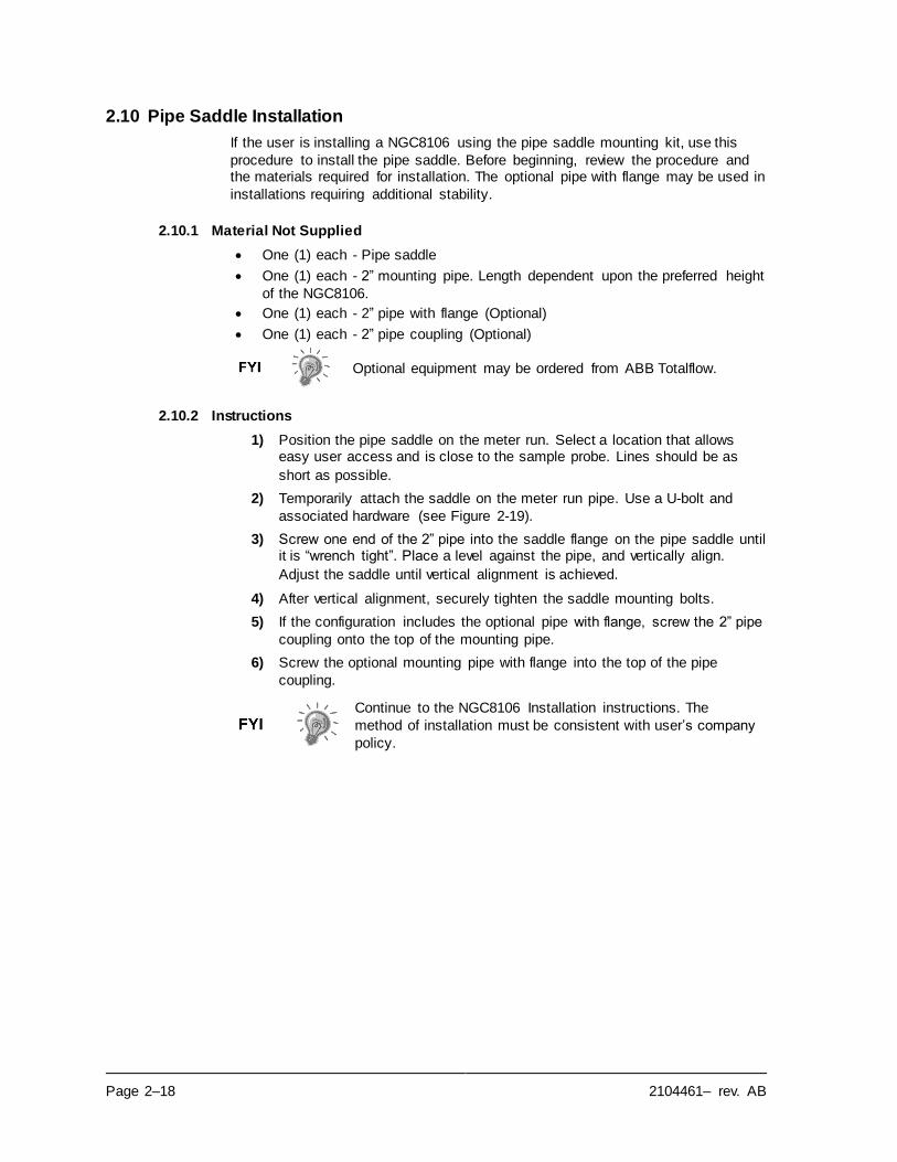
Page 2–18 2104461– rev. AB
2.10 Pipe Saddle Installation
If the user is installing a NGC8106 using the pipe saddle mounting kit, use this
procedure to install the pipe saddle. Before beginning, review the procedure and the materials required for installation. The optional pipe with flange may be used in
installations requiring additional stability.
2.10.1 Material Not Supplied
• One (1) each - Pipe saddle
• One (1) each - 2” mounting pipe. Length dependent upon the preferred height
of the NGC8106.
• One (1) each - 2” pipe with flange (Optional)
• One (1) each - 2” pipe coupling (Optional)
Optional equipment may be ordered from ABB Totalflow.
2.10.2 Instructions
1) Position the pipe saddle on the meter run. Select a location that allows easy user access and is close to the sample probe. Lines should be as
short as possible.
2) Temporarily attach the saddle on the meter run pipe. Use a U-bolt and
associated hardware (see Figure 2-19).
3) Screw one end of the 2” pipe into the saddle flange on the pipe saddle until it is “wrench tight”. Place a level against the pipe, and vertically align.
Adjust the saddle until vertical alignment is achieved.
4) After vertical alignment, securely tighten the saddle mounting bolts.
5) If the configuration includes the optional pipe with flange, screw the 2” pipe
coupling onto the top of the mounting pipe.
6) Screw the optional mounting pipe with flange into the top of the pipe
coupling.
Continue to the NGC8106 Installation instructions. The
method of installation must be consistent with user’s company
policy.
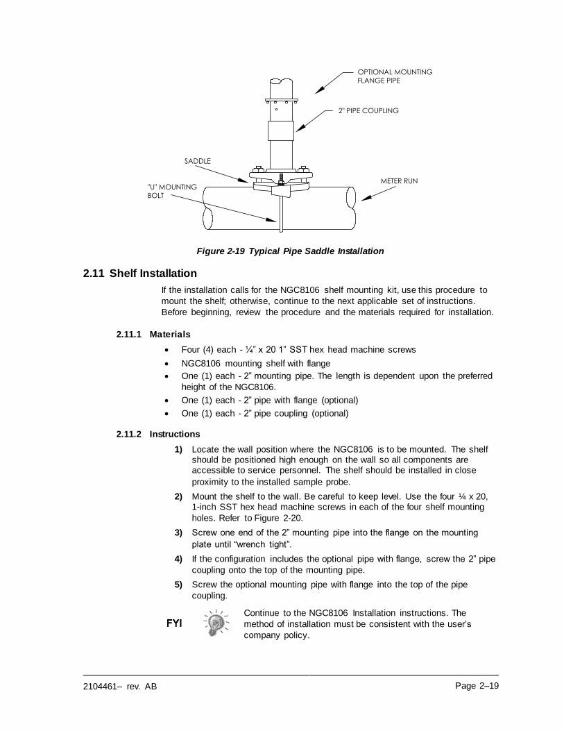
2104461– rev. AB Page 2–19
Figure 2-19 Typical Pipe Saddle Installation
2.11 Shelf Installation
If the installation calls for the NGC8106 shelf mounting kit, use this procedure to
mount the shelf; otherwise, continue to the next applicable set of instructions.
Before beginning, review the procedure and the materials required for installation.
2.11.1 Materials
• Four (4) each - ¼” x 20 1” SST hex head machine screws
• NGC8106 mounting shelf with flange
• One (1) each - 2” mounting pipe. The length is dependent upon the preferred
height of the NGC8106.
• One (1) each - 2” pipe with flange (optional)
• One (1) each - 2” pipe coupling (optional)
2.11.2 Instructions
1) Locate the wall position where the NGC8106 is to be mounted. The shelf should be positioned high enough on the wall so all components are accessible to service personnel. The shelf should be installed in close
proximity to the installed sample probe.
2) Mount the shelf to the wall. Be careful to keep level. Use the four ¼ x 20, 1-inch SST hex head machine screws in each of the four shelf mounting
holes. Refer to Figure 2-20.
3) Screw one end of the 2” mounting pipe into the flange on the mounting
plate until “wrench tight”.
4) If the configuration includes the optional pipe with flange, screw the 2” pipe
coupling onto the top of the mounting pipe.
5) Screw the optional mounting pipe with flange into the top of the pipe
coupling.
Continue to the NGC8106 Installation instructions. The
method of installation must be consistent with the user’s
company policy.
METER RUN"U" MOUNTING
BOLT
SADDLE
OPTIONAL MOUNTING
FLANGE PIPE
2" PIPE COUPLING
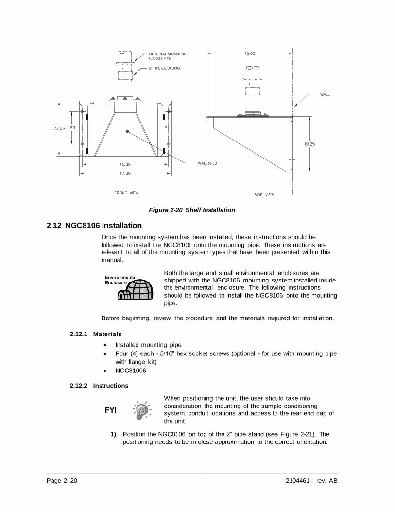
Page 2–20 2104461– rev. AB
Figure 2-20 Shelf Installation
2.12 NGC8106 Installation
Once the mounting system has been installed, these instructions should be
followed to install the NGC8106 onto the mounting pipe. These instructions are relevant to all of the mounting system types that have been presented within this
manual.
Both the large and small environmental enclosures are shipped with the NGC8106 mounting system installed inside the environmental enclosure. The following instructions
should be followed to install the NGC8106 onto the mounting
pipe.
Before beginning, review the procedure and the materials required for installation.
2.12.1 Materials
• Installed mounting pipe
• Four (4) each - 5/16” hex socket screws (optional - for use with mounting pipe
with flange kit)
• NGC81006
2.12.2 Instructions
When positioning the unit, the user should take into
consideration the mounting of the sample conditioning system, conduit locations and access to the rear end cap of
the unit.
1) Position the NGC8106 on top of the 2” pipe stand (see Figure 2-21). The
positioning needs to be in close approximation to the correct orientation.
OPTIONAL MOUNTING
FLANGE PIPE
2" PIPE COUPLING
WALL SHELF
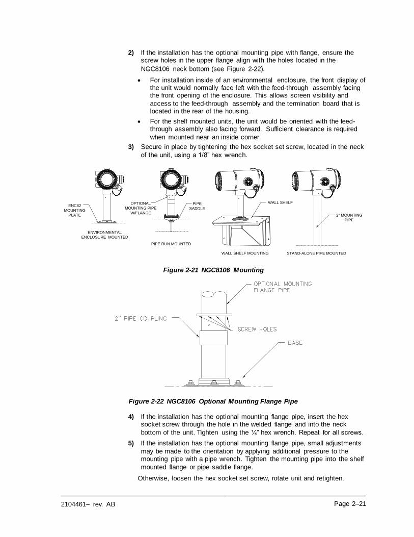
2104461– rev. AB Page 2–21
2) If the installation has the optional mounting pipe with flange, ensure the screw holes in the upper flange align with the holes located in the
NGC8106 neck bottom (see Figure 2-22).
• For installation inside of an environmental enclosure, the front display of the unit would normally face left with the feed-through assembly facing the front opening of the enclosure. This allows screen visibility and
access to the feed-through assembly and the termination board that is located in the rear of the housing.
• For the shelf mounted units, the unit would be oriented with the feed-through assembly also facing forward. Sufficient clearance is required
when mounted near an inside corner.
3) Secure in place by tightening the hex socket set screw, located in the neck
of the unit, using a 1/8” hex wrench.
Figure 2-21 NGC8106 Mounting
Figure 2-22 NGC8106 Optional Mounting Flange Pipe
4) If the installation has the optional mounting flange pipe, insert the hex socket screw through the hole in the welded flange and into the neck
bottom of the unit. Tighten using the ¼” hex wrench. Repeat for all screws.
5) If the installation has the optional mounting flange pipe, small adjustments
may be made to the orientation by applying additional pressure to the mounting pipe with a pipe wrench. Tighten the mounting pipe into the shelf
mounted flange or pipe saddle flange.
Otherwise, loosen the hex socket set screw, rotate unit and retighten.
PIPE RUN MOUNTED
PIPE
SADDLE
WALL SHELF MOUNTING
WALL SHELF
STAND-ALONE PIPE MOUNTED
ENVIRONMENTAL
ENCLOSURE MOUNTED
2" MOUNTING
PIPE
ENC82
MOUNTING
PLATE
OPTIONAL
MOUNTING PIPE
W/FLANGE
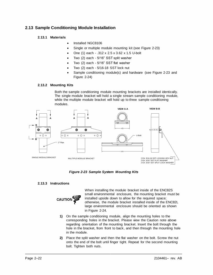
Page 2–22 2104461– rev. AB
2.13 Sample Conditioning Module Installation
2.13.1 Materials
• Installed NGC8106
• Single or multiple module mounting kit (see Figure 2-23)
• One (1) each - .312 x 2.5 x 3.62 x 1.5 U-bolt
• Two (2) each - 5/16” SST split washer
• Two (2) each - 5/16” SST flat washer
• Two (2) each - 5/16-18 SST lock nut
• Sample conditioning module(s) and hardware (see Figure 2-23 and
Figure 2-24)
2.13.2 Mounting Kits
Both the sample conditioning module mounting brackets are installed identically. The single module bracket will hold a single stream sample conditioning module, while the multiple module bracket will hold up to three sample conditioning
modules.
Figure 2-23 Sample System Mounting Kits
2.13.3 Instructions
When installing the module bracket inside of the ENC82S small environmental enclosure, the mounting bracket must be
installed upside down to allow for the required space; otherwise, the module bracket installed inside of the ENC82L large environmental enclosure should be oriented as shown
in Figure 2-24.
1) On the sample conditioning module, align the mounting holes to the corresponding holes in the bracket. Please view the Caution note above
regarding orientation of the mounting bracket. Insert the bolt through the hole in the bracket, from front to back, and then through the mounting hole
in the module.
2) Place the split washer and then the flat washer on the bolt. Screw the nut
onto the end of the bolt until finger tight. Repeat for the second mounting
bolt. Tighten both nuts.
2" Pipe
U-Bolt
VIEW A-A
A A A A
B
B
VIEW B-B
SINGLE MODULE BRACKETMULTIPLE MODULE BRACKET 2 EA. 5/16-18 SST LOCKING HEX NUT
2 EA. 5/16" SST FLAT WASHER
2 EA. 5/16" SST SPLIT LOCK WASHER
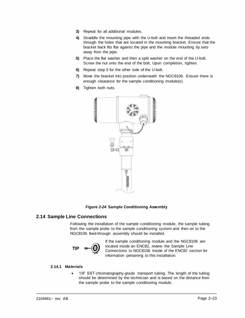
2104461– rev. AB Page 2–23
3) Repeat for all additional modules.
4) Straddle the mounting pipe with the U-bolt and insert the threaded ends through the holes that are located in the mounting bracket. Ensure that the
bracket back fits flat against the pipe and the module mounting lip sets
away from the pipe.
5) Place the flat washer and then a split washer on the end of the U-bolt.
Screw the nut onto the end of the bolt. Upon completion, tighten.
6) Repeat step 5 for the other side of the U-bolt.
7) Move the bracket into position underneath the NGC8106. Ensure there is
enough clearance for the sample conditioning module(s).
8) Tighten both nuts.
Figure 2-24 Sample Conditioning Assembly
2.14 Sample Line Connections
Following the installation of the sample conditioning module, the sample tubing
from the sample probe to the sample conditioning system and then on to the
NGC8106 feed-through assembly should be installed.
If the sample conditioning module and the NGC8106 are
located inside an ENC82, review the Sample Line Connections to NGC8106 Inside of the ENC82 section for
information pertaining to this installation.
2.14.1 Materials
• 1/8” SST chromatography-grade transport tubing. The length of the tubing should be determined by the technician and is based on the distance from
the sample probe to the sample conditioning module.
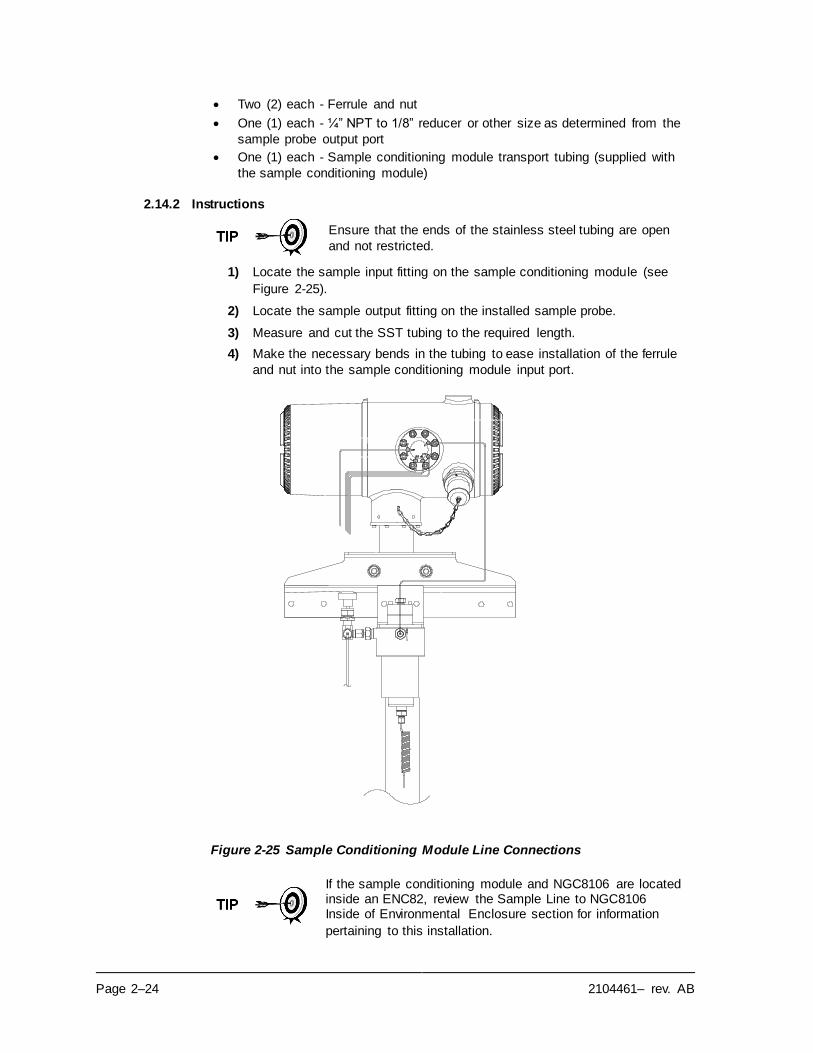
Page 2–24 2104461– rev. AB
• Two (2) each - Ferrule and nut
• One (1) each - ¼” NPT to 1/8” reducer or other size as determined from the
sample probe output port
• One (1) each - Sample conditioning module transport tubing (supplied with
the sample conditioning module)
2.14.2 Instructions
Ensure that the ends of the stainless steel tubing are open
and not restricted.
1) Locate the sample input fitting on the sample conditioning module (see
Figure 2-25).
2) Locate the sample output fitting on the installed sample probe.
3) Measure and cut the SST tubing to the required length.
4) Make the necessary bends in the tubing to ease installation of the ferrule
and nut into the sample conditioning module input port.
Figure 2-25 Sample Conditioning Module Line Connections
If the sample conditioning module and NGC8106 are located inside an ENC82, review the Sample Line to NGC8106 Inside of Environmental Enclosure section for information
pertaining to this installation.
2104461– rev. AB Page 2–25
Tube, ferrule and nut should always enter connection at a
right angle.
5) If necessary, install the reducer into the sample probe output fitting.
6) Install the ferrule and nut onto one end of the sample tubing.
7) Insert the tubing with the ferrule into the reducer/sample probe output
fitting. Move the nut down onto the ferrule, screw onto fitting and tighten.
8) Install the ferrule and nut onto the other end of the sample tubing.
9) Insert the ferrule into the sample conditioning module input fitting. Move
the nut down onto the ferrule, screw onto fitting and tighten.
10) Locate the sample output fitting on the sample conditioning module.
11) Locate the sample input on the NGC8106 feed-through assembly and
remove the sealing screw.
12) Make the necessary bends in the tubing to ease installation of the tubing
into the output fitting on the sample conditioning module and the ferrule
and Valco nut into the input on the NGC8106 feed-through assembly.
13) Insert the tubing with the ferrule into the output fitting on the sample conditioning module. Move the nut down onto the ferrule, screw onto fitting
and tighten.
14) Remove the plastic caps from the restrictor coils, the sealing screws from the feed-through column vents and the sealing screw from the sample vent
lines.
15) Purge the air from the transport tubing by opening the shut-off valve. The
valve is located on the sample probe.
The user needs to ensure they are following the requirements of national and local codes when performing
this purge.
16) Insert the tubing with the ferrule into the corresponding input port located on the NGC8106 feed-through assembly. Move the Valco nut down onto
the ferrule, screw into port and tighten.
DO NOT over tighten. After securing the tubing, check for
gas leaks.
2.15 Sample Line to NGC8106 Inside of ENC82
The sample line being installed to a unit, located inside the ENC82, requires making minute changes to the instructions listed for their installation. The following information and
steps should be noted during the installation.
2.15.1 Materials
• Installed sample conditioning module
• 1/8” SST chromatography-grade transport tubing (amount to be determined by technician and is based on the distance from the sample probe to the sample
conditioning module)
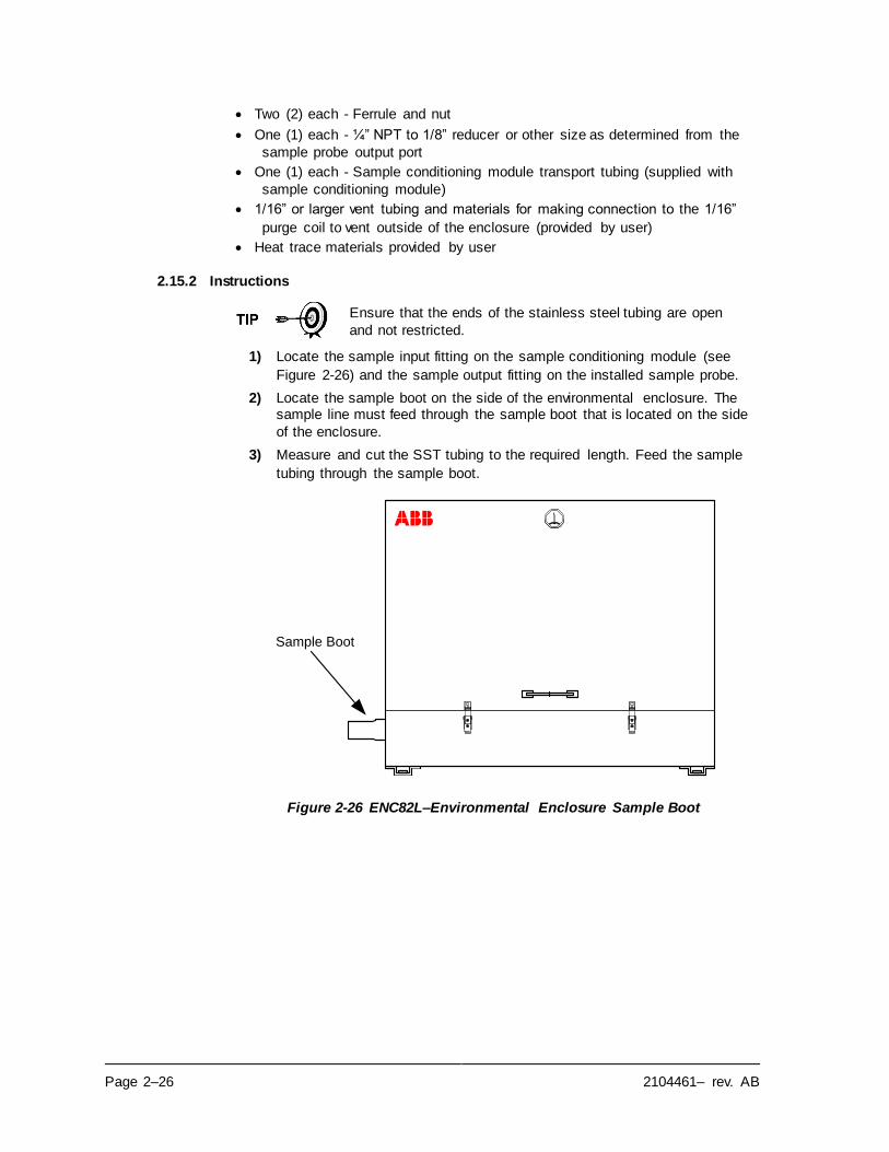
Page 2–26 2104461– rev. AB
• Two (2) each - Ferrule and nut
• One (1) each - ¼” NPT to 1/8” reducer or other size as determined from the
sample probe output port
• One (1) each - Sample conditioning module transport tubing (supplied with
sample conditioning module)
• 1/16” or larger vent tubing and materials for making connection to the 1/16”
purge coil to vent outside of the enclosure (provided by user)
• Heat trace materials provided by user
2.15.2 Instructions
Ensure that the ends of the stainless steel tubing are open
and not restricted.
1) Locate the sample input fitting on the sample conditioning module (see
Figure 2-26) and the sample output fitting on the installed sample probe.
2) Locate the sample boot on the side of the environmental enclosure. The sample line must feed through the sample boot that is located on the side
of the enclosure.
3) Measure and cut the SST tubing to the required length. Feed the sample
tubing through the sample boot.
Figure 2-26 ENC82L–Environmental Enclosure Sample Boot
Sample Boot
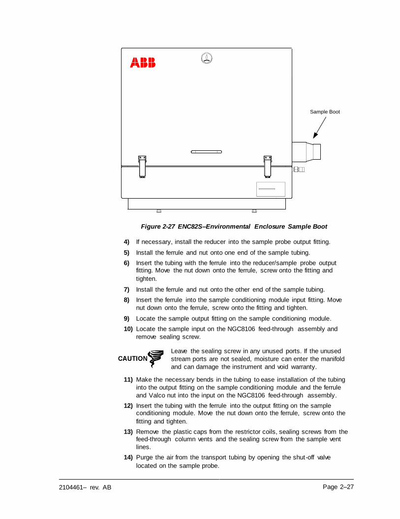
2104461– rev. AB Page 2–27
Figure 2-27 ENC82S–Environmental Enclosure Sample Boot
4) If necessary, install the reducer into the sample probe output fitting.
5) Install the ferrule and nut onto one end of the sample tubing.
6) Insert the tubing with the ferrule into the reducer/sample probe output fitting. Move the nut down onto the ferrule, screw onto the fitting and
tighten.
7) Install the ferrule and nut onto the other end of the sample tubing.
8) Insert the ferrule into the sample conditioning module input fitting. Move
nut down onto the ferrule, screw onto the fitting and tighten.
9) Locate the sample output fitting on the sample conditioning module.
10) Locate the sample input on the NGC8106 feed-through assembly and
remove sealing screw.
Leave the sealing screw in any unused ports. If the unused
stream ports are not sealed, moisture can enter the manifold
and can damage the instrument and void warranty.
11) Make the necessary bends in the tubing to ease installation of the tubing
into the output fitting on the sample conditioning module and the ferrule
and Valco nut into the input on the NGC8106 feed-through assembly.
12) Insert the tubing with the ferrule into the output fitting on the sample conditioning module. Move the nut down onto the ferrule, screw onto the
fitting and tighten.
13) Remove the plastic caps from the restrictor coils, sealing screws from the feed-through column vents and the sealing screw from the sample vent
lines.
14) Purge the air from the transport tubing by opening the shut-off valve
located on the sample probe.
Sample Boot
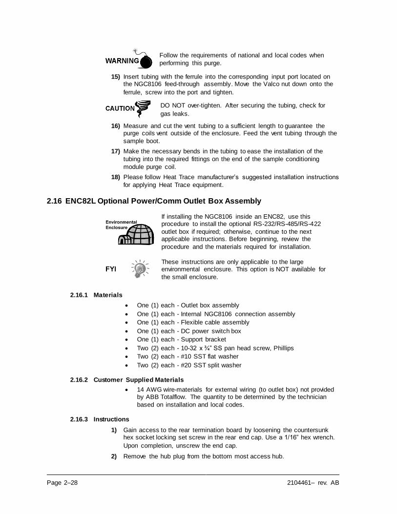
Page 2–28 2104461– rev. AB
Follow the requirements of national and local codes when
performing this purge.
15) Insert tubing with the ferrule into the corresponding input port located on the NGC8106 feed-through assembly. Move the Valco nut down onto the
ferrule, screw into the port and tighten.
DO NOT over-tighten. After securing the tubing, check for
gas leaks.
16) Measure and cut the vent tubing to a sufficient length to guarantee the purge coils vent outside of the enclosure. Feed the vent tubing through the
sample boot.
17) Make the necessary bends in the tubing to ease the installation of the
tubing into the required fittings on the end of the sample conditioning
module purge coil.
18) Please follow Heat Trace manufacturer’s suggested installation instructions
for applying Heat Trace equipment.
2.16 ENC82L Optional Power/Comm Outlet Box Assembly
If installing the NGC8106 inside an ENC82, use this procedure to install the optional RS-232/RS-485/RS-422
outlet box if required; otherwise, continue to the next applicable instructions. Before beginning, review the
procedure and the materials required for installation.
These instructions are only applicable to the large environmental enclosure. This option is NOT available for
the small enclosure.
2.16.1 Materials
• One (1) each - Outlet box assembly
• One (1) each - Internal NGC8106 connection assembly
• One (1) each - Flexible cable assembly
• One (1) each - DC power switch box
• One (1) each - Support bracket
• Two (2) each - 10-32 x ¾” SS pan head screw, Phillips
• Two (2) each - #10 SST flat washer
• Two (2) each - #20 SST split washer
2.16.2 Customer Supplied Materials
• 14 AWG wire-materials for external wiring (to outlet box) not provided by ABB Totalflow. The quantity to be determined by the technician
based on installation and local codes.
2.16.3 Instructions
1) Gain access to the rear termination board by loosening the countersunk hex socket locking set screw in the rear end cap. Use a 1/16” hex wrench.
Upon completion, unscrew the end cap.
2) Remove the hub plug from the bottom most access hub.
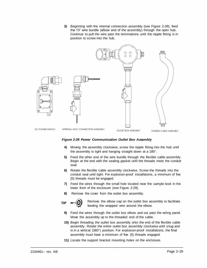
2104461– rev. AB Page 2–29
3) Beginning with the internal connection assembly (see Figure 2-28), feed the 13” wire bundle (elbow end of the assembly) through the open hub.
Continue to pull the wire past the terminations until the nipple fitting is in
position to screw into the hub.
Figure 2-28 Power Communication Outlet Box Assembly
4) Moving the assembly clockwise, screw the nipple fitting into the hub until
the assembly is tight and hanging straight down at a 180.
5) Feed the other end of the wire bundle through the flexible cable assembly. Begin at the end with the sealing gasket until the threads meet the conduit
seal.
6) Rotate the flexible cable assembly clockwise. Screw the threads into the
conduit seal until tight. For explosion-proof installations, a minimum of five
(5) threads must be engaged.
7) Feed the wires through the small hole located near the sample boot in the
lower front of the enclosure (see Figure 2-29).
8) Remove the cover from the outlet box assembly.
Remove the elbow cap on the outlet box assembly to facilitate
feeding the wrapped wire around the elbow.
9) Feed the wires through the outlet box elbow and out past the wiring panel.
Move the assembly up to the threaded end of the cable.
10) Begin threading the outlet box assembly onto the end of the flexible cable assembly. Rotate the entire outlet box assembly clockwise until snug and
is in a vertical (360) position. For explosion-proof installations, the final
assembly must have a minimum of five (5) threads engaged.
11) Locate the support bracket mounting holes on the enclosure.
DC POWER SWITCH INTERNAL NGC CONNECTION ASSEMBLYFLEXIBLE CABLE ASSEMBLYOUTLET BOX ASSEMBLY
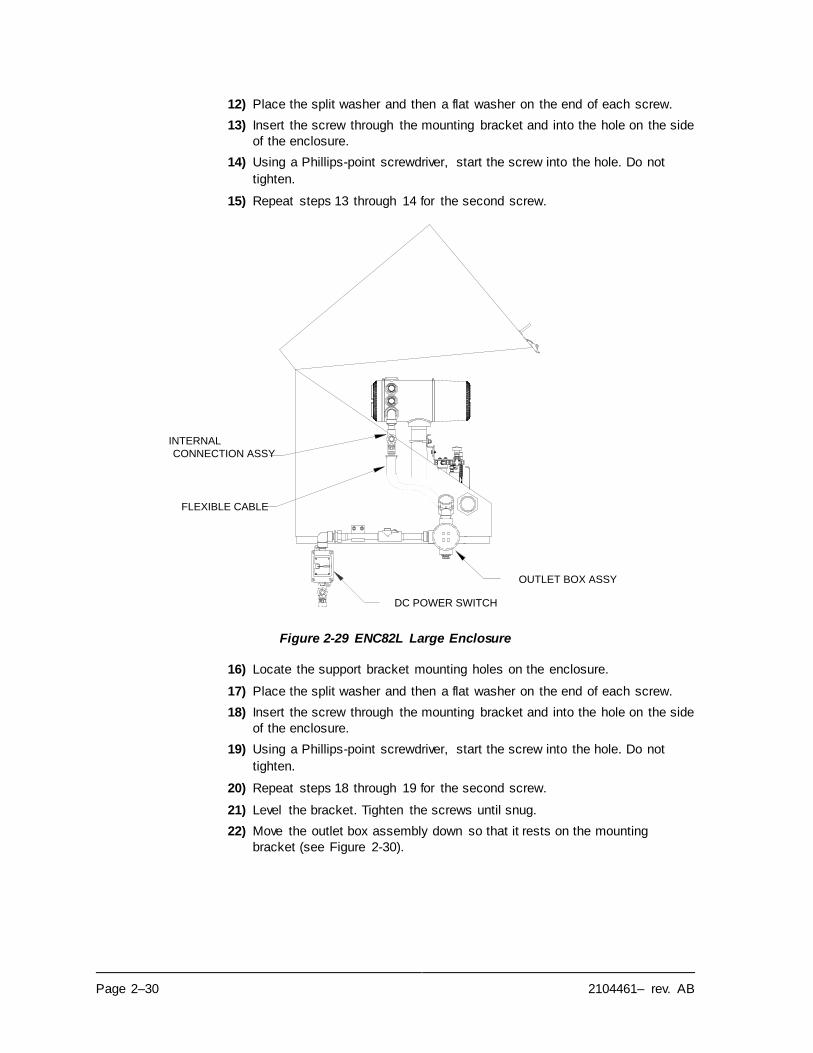
Page 2–30 2104461– rev. AB
12) Place the split washer and then a flat washer on the end of each screw.
13) Insert the screw through the mounting bracket and into the hole on the side
of the enclosure.
14) Using a Phillips-point screwdriver, start the screw into the hole. Do not
tighten.
15) Repeat steps 13 through 14 for the second screw.
Figure 2-29 ENC82L Large Enclosure
16) Locate the support bracket mounting holes on the enclosure.
17) Place the split washer and then a flat washer on the end of each screw.
18) Insert the screw through the mounting bracket and into the hole on the side
of the enclosure.
19) Using a Phillips-point screwdriver, start the screw into the hole. Do not
tighten.
20) Repeat steps 18 through 19 for the second screw.
21) Level the bracket. Tighten the screws until snug.
22) Move the outlet box assembly down so that it rests on the mounting
bracket (see Figure 2-30).
FLEXIBLE CABLE
DC POWER SWITCH
OUTLET BOX ASSY
INTERNAL
CONNECTION ASSY
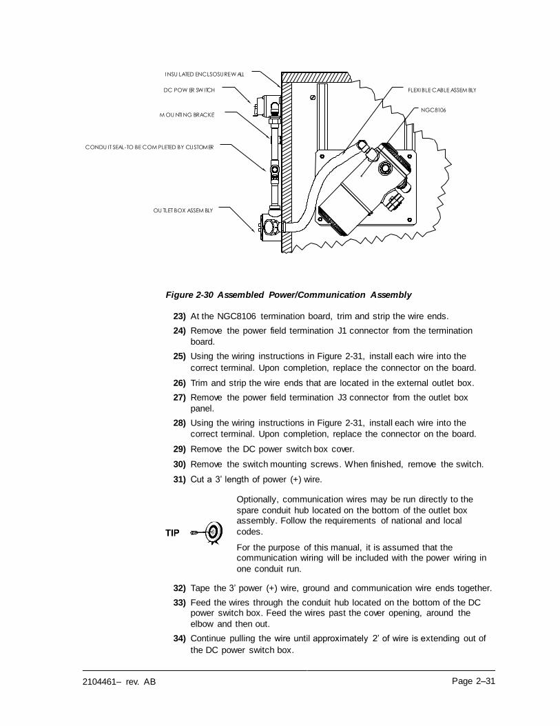
2104461– rev. AB Page 2–31
Figure 2-30 Assembled Power/Communication Assembly
23) At the NGC8106 termination board, trim and strip the wire ends.
24) Remove the power field termination J1 connector from the termination
board.
25) Using the wiring instructions in Figure 2-31, install each wire into the
correct terminal. Upon completion, replace the connector on the board.
26) Trim and strip the wire ends that are located in the external outlet box.
27) Remove the power field termination J3 connector from the outlet box
panel.
28) Using the wiring instructions in Figure 2-31, install each wire into the
correct terminal. Upon completion, replace the connector on the board.
29) Remove the DC power switch box cover.
30) Remove the switch mounting screws. When finished, remove the switch.
31) Cut a 3’ length of power (+) wire.
Optionally, communication wires may be run directly to the
spare conduit hub located on the bottom of the outlet box assembly. Follow the requirements of national and local
codes.
For the purpose of this manual, it is assumed that the communication wiring will be included with the power wiring in
one conduit run.
32) Tape the 3’ power (+) wire, ground and communication wire ends together.
33) Feed the wires through the conduit hub located on the bottom of the DC power switch box. Feed the wires past the cover opening, around the
elbow and then out.
34) Continue pulling the wire until approximately 2’ of wire is extending out of
the DC power switch box.
NGC8106
I NSU LATED ENCLSOSURE W ALL
M OU NTI NG BRACKET
FLEXI BLE CABLE ASSEM BLY DC POW ER SW ITCH
OU TLET BOX ASSEM BLY
CONDU IT SEAL-TO BE COM PLETED BY CUSTOMER
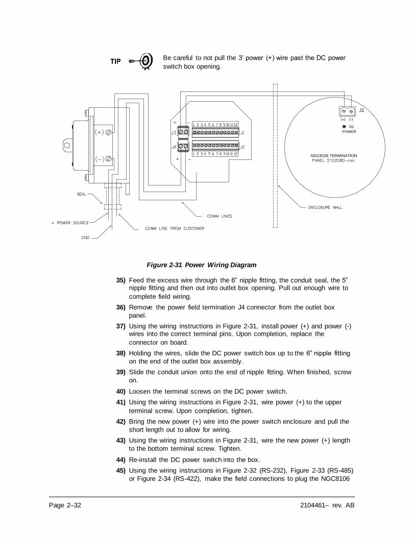
Page 2–32 2104461– rev. AB
Be careful to not pull the 3’ power (+) wire past the DC power
switch box opening.
Figure 2-31 Power Wiring Diagram
35) Feed the excess wire through the 6” nipple fitting, the conduit seal, the 5” nipple fitting and then out into outlet box opening. Pull out enough wire to
complete field wiring.
36) Remove the power field termination J4 connector from the outlet box
panel.
37) Using the wiring instructions in Figure 2-31, install power (+) and power (-) wires into the correct terminal pins. Upon completion, replace the
connector on board.
38) Holding the wires, slide the DC power switch box up to the 6” nipple fitting
on the end of the outlet box assembly.
39) Slide the conduit union onto the end of nipple fitting. When finished, screw
on.
40) Loosen the terminal screws on the DC power switch.
41) Using the wiring instructions in Figure 2-31, wire power (+) to the upper
terminal screw. Upon completion, tighten.
42) Bring the new power (+) wire into the power switch enclosure and pull the
short length out to allow for wiring.
43) Using the wiring instructions in Figure 2-31, wire the new power (+) length
to the bottom terminal screw. Tighten.
44) Re-install the DC power switch into the box.
45) Using the wiring instructions in Figure 2-32 (RS-232), Figure 2-33 (RS-485)
or Figure 2-34 (RS-422), make the field connections to plug the NGC8106
POWER
D1
J1
(-)(+)
NGC8106 TERMINATION
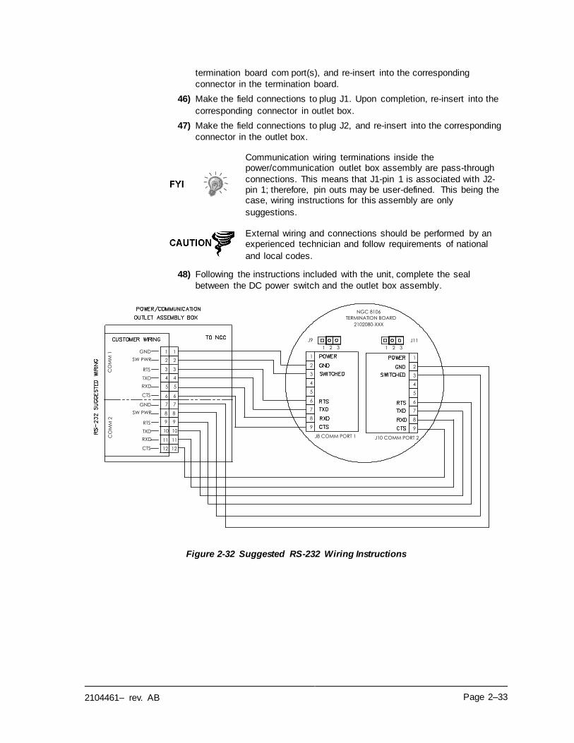
2104461– rev. AB Page 2–33
termination board com port(s), and re-insert into the corresponding
connector in the termination board.
46) Make the field connections to plug J1. Upon completion, re-insert into the
corresponding connector in outlet box.
47) Make the field connections to plug J2, and re-insert into the corresponding
connector in the outlet box.
Communication wiring terminations inside the power/communication outlet box assembly are pass-through
connections. This means that J1-pin 1 is associated with J2-pin 1; therefore, pin outs may be user-defined. This being the case, wiring instructions for this assembly are only
suggestions.
External wiring and connections should be performed by an experienced technician and follow requirements of national
and local codes.
48) Following the instructions included with the unit, complete the seal
between the DC power switch and the outlet box assembly.
Figure 2-32 Suggested RS-232 Wiring Instructions
5
3
4
2
J8 COMM PORT 1
1
NGC 8106
RXD
TXD
RTS
CTS
GND
8 8
10 10
9 9
11 11
12 12
6
7
8
9
1 2 3
J9
2102080-XXX
3 3
5 5
4 4
6 6
7 7
1 1
2 2SW PWR
CO
MM
1C
OM
M 2
TERMINATION BOARD
5
3
4
2
J10 COMM PORT 2
1
6
7
8
9
1 2 3
J11
RXD
TXD
RTS
CTS
GND
SW PWR

Page 2–34 2104461– rev. AB
Figure 2-33 Suggested RS-485 Wiring Instructions
Figure 2-34 Suggested RS-422 Wiring Instructions
5
3
4
2
J10 COMM PORT 2
1
6
7
8
9
BUS-
BUS+
RRTS
GND
SW PWR
TERMINATION BOARD
NGC 8106
2102080-XXX
1 2 3
J9
1 2 3
J11
5
3
4
2
J8 COMM PORT 1
1
BUS-
BUS+
RRTS
GND
8 8
10 10
9 9
11 11
12 12
6
7
8
9
3 3
5 5
4 4
6 6
7 7
1 1
2 2SW PWR
CO
MM
1C
OM
M 2
TERMINATION BOARD
5
3
4
2
J8 COMM PORT 1
1
NGC 8106
RXD+
TXD -
TXD+
RXD-
GND
8 8
10 10
9 9
11 11
12 12
6
7
8
9
2102080-XXX
3 3
5 5
4 4
6 6
7 7
1 1
2 2SW PWR
CO
MM
1C
OM
M 2
5
3
4
2
J10 COMM PORT 2
1
6
7
8
9
RXD+
TXD -
TXD+
RXD-
GND
SW PWR
1 2 3
J9
1 2 3
J11
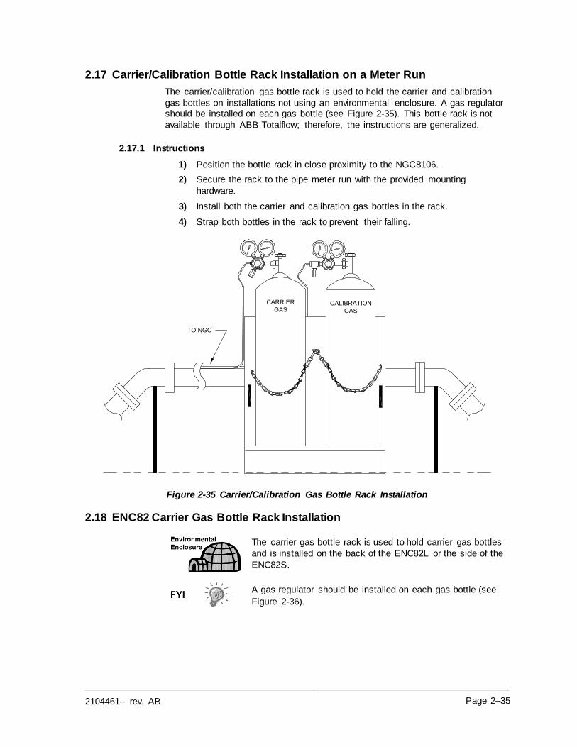
2104461– rev. AB Page 2–35
2.17 Carrier/Calibration Bottle Rack Installation on a Meter Run
The carrier/calibration gas bottle rack is used to hold the carrier and calibration
gas bottles on installations not using an environmental enclosure. A gas regulator should be installed on each gas bottle (see Figure 2-35). This bottle rack is not
available through ABB Totalflow; therefore, the instructions are generalized.
2.17.1 Instructions
1) Position the bottle rack in close proximity to the NGC8106.
2) Secure the rack to the pipe meter run with the provided mounting
hardware.
3) Install both the carrier and calibration gas bottles in the rack.
4) Strap both bottles in the rack to prevent their falling.
Figure 2-35 Carrier/Calibration Gas Bottle Rack Installation
2.18 ENC82 Carrier Gas Bottle Rack Installation
The carrier gas bottle rack is used to hold carrier gas bottles
and is installed on the back of the ENC82L or the side of the
ENC82S.
A gas regulator should be installed on each gas bottle (see
Figure 2-36).
CALIBRATION
GAS
CARRIER
GAS
TO NGC
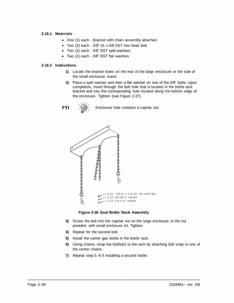
Page 2–36 2104461– rev. AB
2.18.1 Materials
• One (1) each - Bracket with chain assembly attached
• Two (2) each - 3/8”-16 x 5/8 SST hex head bolt
• Two (2) each - 3/8” SST split washers
• Two (2) each - 3/8” SST flat washers
2.18.2 Instructions
1) Locate the bracket holes on the rear of the large enclosure or the side of
the small enclosure stand.
2) Place a split washer and then a flat washer on one of the 5/8” bolts. Upon completion, insert through the bolt hole that is located in the bottle rack bracket and into the corresponding hole located along the bottom edge of
the enclosure. Tighten (see Figure 2-37).
Enclosure hole contains a captive nut.
Figure 2-36 Dual Bottle Rack Assembly
3) Screw the bolt into the captive nut on the large enclosure or the nut
provided with small enclosure kit. Tighten.
4) Repeat for the second bolt.
5) Install the carrier gas bottle in the bottle rack.
6) Using chains, strap the bottle(s) to the rack by attaching bolt snap to one of
the center chains.
7) Repeat step 5 -6 if installing a second bottle.
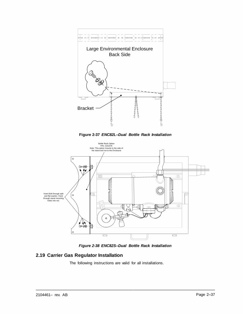
2104461– rev. AB Page 2–37
Figure 2-37 ENC82L–Dual Bottle Rack Installation
Figure 2-38 ENC82S–Dual Bottle Rack Installation
2.19 Carrier Gas Regulator Installation
The following instructions are valid for all installations.
Large Environmental Enclosure
Back Side
Bracket
Bottle Rack Option
P/N: 2101076
Note: This option mounts to the side of
the stand and not to the Enclosure
Insert Bolt through split
and flat washer. Feed
through stand mounting
holes into nut.
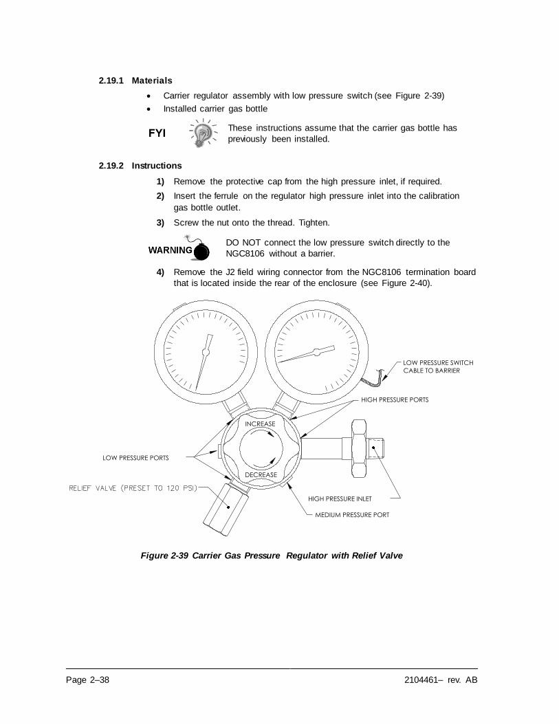
Page 2–38 2104461– rev. AB
2.19.1 Materials
• Carrier regulator assembly with low pressure switch (see Figure 2-39)
• Installed carrier gas bottle
These instructions assume that the carrier gas bottle has
previously been installed.
2.19.2 Instructions
1) Remove the protective cap from the high pressure inlet, if required.
2) Insert the ferrule on the regulator high pressure inlet into the calibration
gas bottle outlet.
3) Screw the nut onto the thread. Tighten.
DO NOT connect the low pressure switch directly to the
NGC8106 without a barrier.
4) Remove the J2 field wiring connector from the NGC8106 termination board
that is located inside the rear of the enclosure (see Figure 2-40).
Figure 2-39 Carrier Gas Pressure Regulator with Relief Valve
LOW PRESSURE PORTS
INCREASE
DECREASE
HIGH PRESSURE PORTS
HIGH PRESSURE INLET
MEDIUM PRESSURE PORT
LOW PRESSURE SWITCH
CABLE TO BARRIER
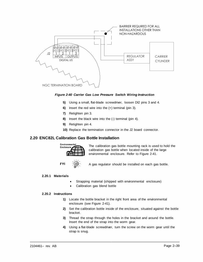
2104461– rev. AB Page 2–39
Figure 2-40 Carrier Gas Low Pressure Switch Wiring Instruction
5) Using a small, flat-blade screwdriver, loosen DI2 pins 3 and 4.
6) Insert the red wire into the (+) terminal (pin 3).
7) Retighten pin 3.
8) Insert the black wire into the (-) terminal (pin 4).
9) Retighten pin 4.
10) Replace the termination connector in the J2 board connector.
2.20 ENC82L Calibration Gas Bottle Installation
The calibration gas bottle mounting rack is used to hold the
calibration gas bottle when located inside of the large
environmental enclosure. Refer to Figure 2-41.
A gas regulator should be installed on each gas bottle.
2.20.1 Materials
• Strapping material (shipped with environmental enclosure)
• Calibration gas blend bottle
2.20.2 Instructions
1) Locate the bottle bracket in the right front area of the environmental
enclosure (see Figure 2-41).
2) Set the calibration bottle inside of the enclosure, situated against the bottle
bracket.
3) Thread the strap through the holes in the bracket and around the bottle.
Insert the end of the strap into the worm gear.
4) Using a flat-blade screwdriver, turn the screw on the worm gear until the
strap is snug.
ASSY
REGULATOR CARRIER
CYLINDER
J2(-)(+) (-)(+) (-)(+) (-)(+)
INPUTS OUTPUTS1 1 22
DIGITAL I/0
NGC TERMINATION BOARD
BARRIER REQUIRED FOR ALL
INSTALLATIONS OTHER THAN
NON-HAZARDOUS
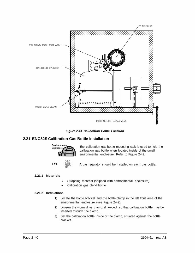
Page 2–40 2104461– rev. AB
Figure 2-41 Calibration Bottle Location
2.21 ENC82S Calibration Gas Bottle Installation
The calibration gas bottle mounting rack is used to hold the
calibration gas bottle when located inside of the small
environmental enclosure. Refer to Figure 2-42.
A gas regulator should be installed on each gas bottle.
2.21.1 Materials
• Strapping material (shipped with environmental enclosure)
• Calibration gas blend bottle
2.21.2 Instructions
1) Locate the bottle bracket and the bottle clamp in the left front area of the
environmental enclosure (see Figure 2-42).
2) Loosen the worm drive clamp, if needed, so that calibration bottle may be
inserted through the clamp.
3) Set the calibration bottle inside of the clamp, situated against the bottle
bracket.
CAL BLEND REGULATOR ASSY
CAL BLEND CYLINDER
W ORM GEAR CLAMP
NGC8106
RIGHT SIDE CUT-AW AY VIEW
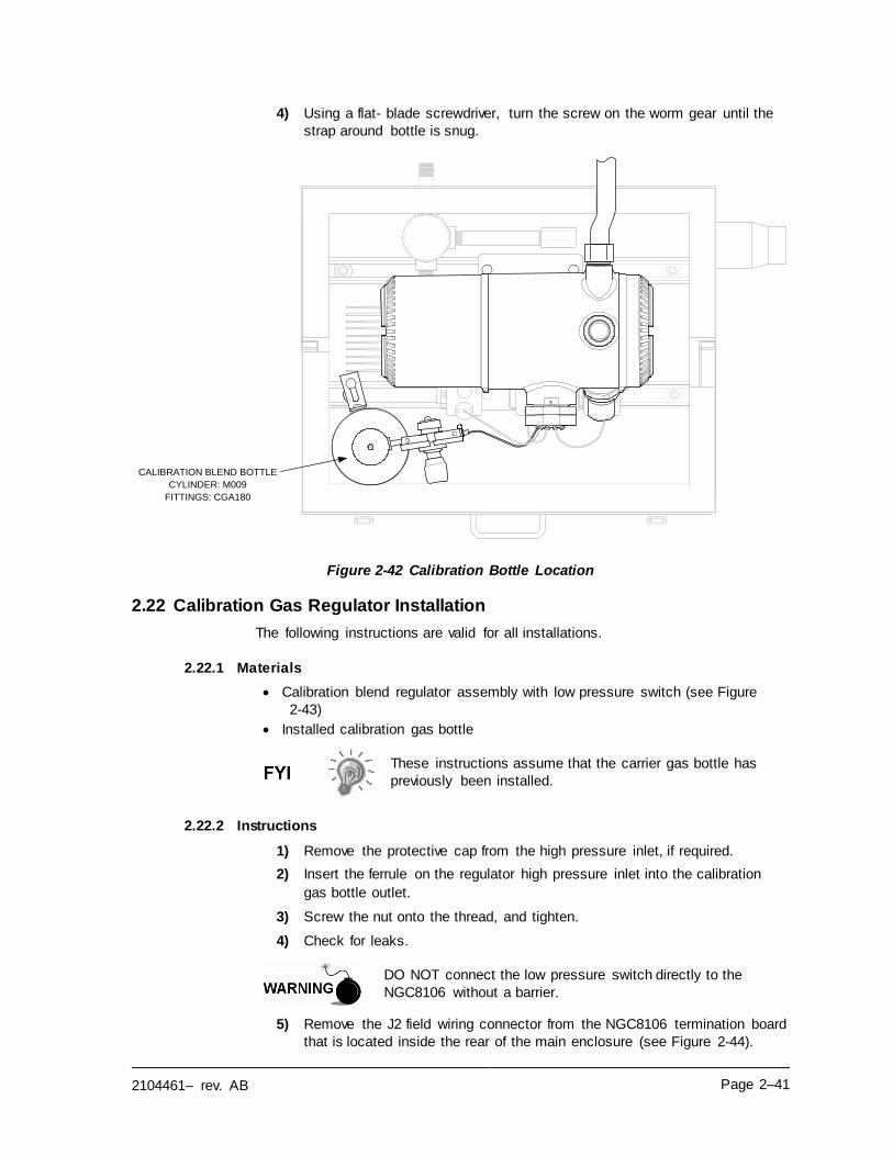
2104461– rev. AB Page 2–41
4) Using a flat- blade screwdriver, turn the screw on the worm gear until the
strap around bottle is snug.
Figure 2-42 Calibration Bottle Location
2.22 Calibration Gas Regulator Installation
The following instructions are valid for all installations.
2.22.1 Materials
• Calibration blend regulator assembly with low pressure switch (see Figure
2-43)
• Installed calibration gas bottle
These instructions assume that the carrier gas bottle has
previously been installed.
2.22.2 Instructions
1) Remove the protective cap from the high pressure inlet, if required.
2) Insert the ferrule on the regulator high pressure inlet into the calibration
gas bottle outlet.
3) Screw the nut onto the thread, and tighten.
4) Check for leaks.
DO NOT connect the low pressure switch directly to the
NGC8106 without a barrier.
5) Remove the J2 field wiring connector from the NGC8106 termination board
that is located inside the rear of the main enclosure (see Figure 2-44).
CALIBRATION BLEND BOTTLE
CYLINDER: M009
FITTINGS: CGA180
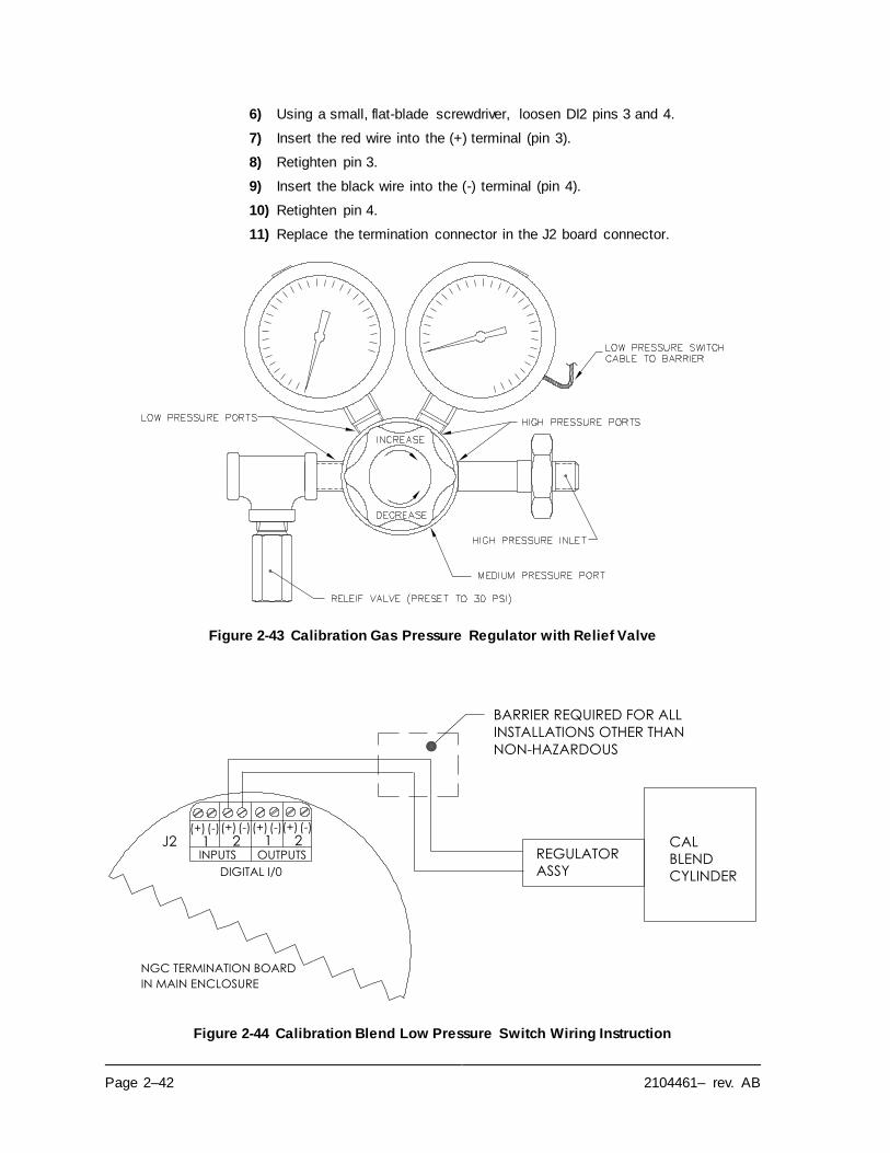
Page 2–42 2104461– rev. AB
6) Using a small, flat-blade screwdriver, loosen DI2 pins 3 and 4.
7) Insert the red wire into the (+) terminal (pin 3).
8) Retighten pin 3.
9) Insert the black wire into the (-) terminal (pin 4).
10) Retighten pin 4.
11) Replace the termination connector in the J2 board connector.
Figure 2-43 Calibration Gas Pressure Regulator with Relief Valve
Figure 2-44 Calibration Blend Low Pressure Switch Wiring Instruction
ASSY
REGULATORCAL
BLEND
CYLINDER
J2(-)(+) (-)(+) (-)(+) (-)(+)
INPUTS OUTPUTS1 1 22
DIGITAL I/0
NGC TERMINATION BOARD
BARRIER REQUIRED FOR ALL
INSTALLATIONS OTHER THAN
NON-HAZARDOUS
IN MAIN ENCLOSURE
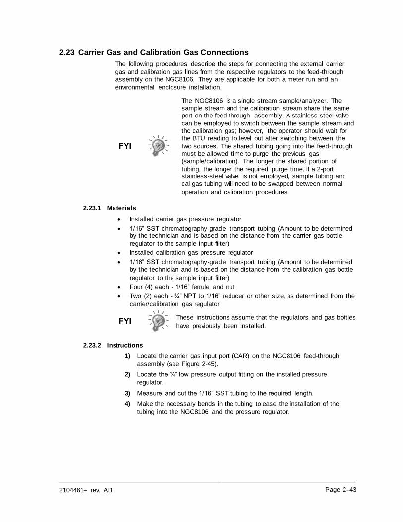
2104461– rev. AB Page 2–43
2.23 Carrier Gas and Calibration Gas Connections
The following procedures describe the steps for connecting the external carrier
gas and calibration gas lines from the respective regulators to the feed-through assembly on the NGC8106. They are applicable for both a meter run and an
environmental enclosure installation.
The NGC8106 is a single stream sample/analyzer. The sample stream and the calibration stream share the same port on the feed-through assembly. A stainless-steel valve
can be employed to switch between the sample stream and the calibration gas; however, the operator should wait for the BTU reading to level out after switching between the
two sources. The shared tubing going into the feed-through must be allowed time to purge the previous gas (sample/calibration). The longer the shared portion of
tubing, the longer the required purge time. If a 2-port stainless-steel valve is not employed, sample tubing and cal gas tubing will need to be swapped between normal
operation and calibration procedures.
2.23.1 Materials
• Installed carrier gas pressure regulator
• 1/16” SST chromatography-grade transport tubing (Amount to be determined by the technician and is based on the distance from the carrier gas bottle
regulator to the sample input filter)
• Installed calibration gas pressure regulator
• 1/16” SST chromatography-grade transport tubing (Amount to be determined by the technician and is based on the distance from the calibration gas bottle
regulator to the sample input filter)
• Four (4) each - 1/16” ferrule and nut
• Two (2) each - ¼” NPT to 1/16” reducer or other size, as determined from the
carrier/calibration gas regulator
These instructions assume that the regulators and gas bottles
have previously been installed.
2.23.2 Instructions
1) Locate the carrier gas input port (CAR) on the NGC8106 feed-through
assembly (see Figure 2-45).
2) Locate the ¼” low pressure output fitting on the installed pressure
regulator.
3) Measure and cut the 1/16” SST tubing to the required length.
4) Make the necessary bends in the tubing to ease the installation of the
tubing into the NGC8106 and the pressure regulator.
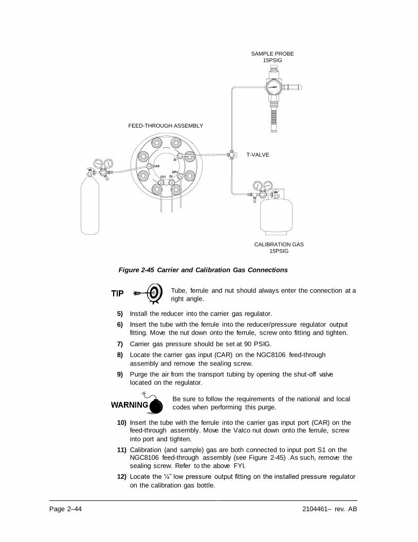
Page 2–44 2104461– rev. AB
Figure 2-45 Carrier and Calibration Gas Connections
Tube, ferrule and nut should always enter the connection at a
right angle.
5) Install the reducer into the carrier gas regulator.
6) Insert the tube with the ferrule into the reducer/pressure regulator output
fitting. Move the nut down onto the ferrule, screw onto fitting and tighten.
7) Carrier gas pressure should be set at 90 PSIG.
8) Locate the carrier gas input (CAR) on the NGC8106 feed-through
assembly and remove the sealing screw.
9) Purge the air from the transport tubing by opening the shut-off valve
located on the regulator.
Be sure to follow the requirements of the national and local
codes when performing this purge.
10) Insert the tube with the ferrule into the carrier gas input port (CAR) on the feed-through assembly. Move the Valco nut down onto the ferrule, screw
into port and tighten.
11) Calibration (and sample) gas are both connected to input port S1 on the NGC8106 feed-through assembly (see Figure 2-45) .As such, remove the
sealing screw. Refer to the above FYI.
12) Locate the ¼” low pressure output fitting on the installed pressure regulator
on the calibration gas bottle.
FEED-THROUGH ASSEMBLY
CALIBRATION GAS
15PSIG
SAMPLE PROBE
15PSIG
T-VALVE
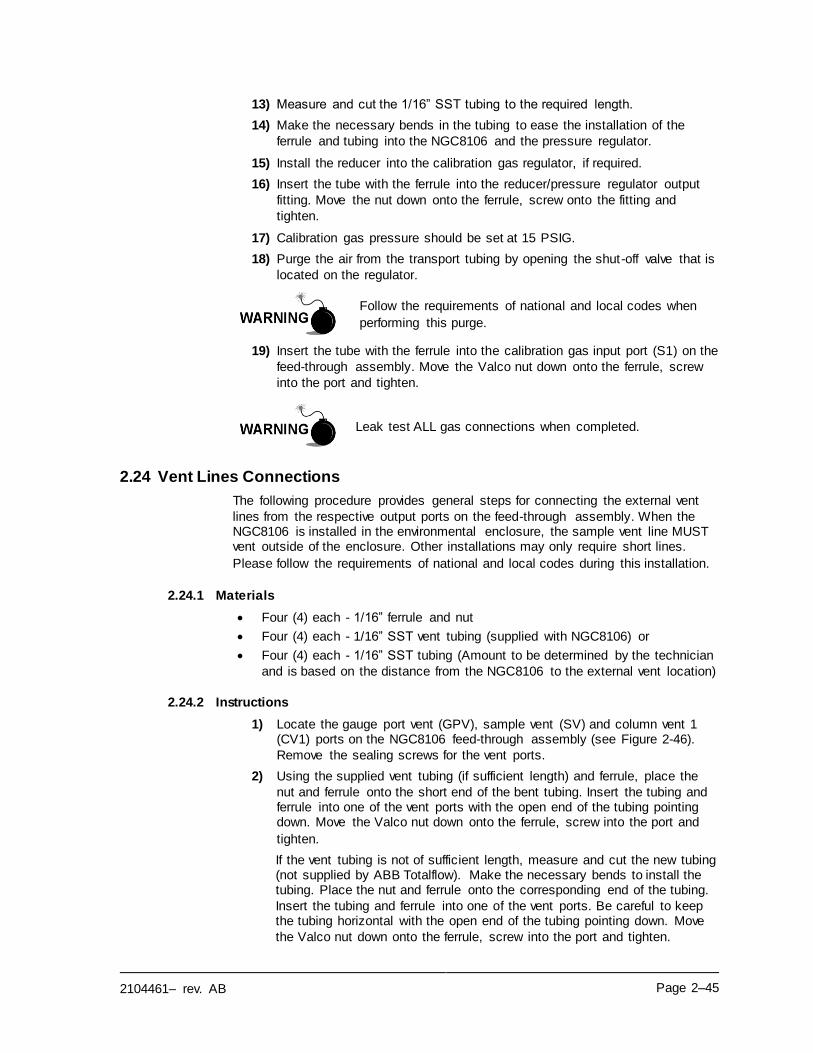
2104461– rev. AB Page 2–45
13) Measure and cut the 1/16” SST tubing to the required length.
14) Make the necessary bends in the tubing to ease the installation of the
ferrule and tubing into the NGC8106 and the pressure regulator.
15) Install the reducer into the calibration gas regulator, if required.
16) Insert the tube with the ferrule into the reducer/pressure regulator output
fitting. Move the nut down onto the ferrule, screw onto the fitting and
tighten.
17) Calibration gas pressure should be set at 15 PSIG.
18) Purge the air from the transport tubing by opening the shut-off valve that is
located on the regulator.
Follow the requirements of national and local codes when
performing this purge.
19) Insert the tube with the ferrule into the calibration gas input port (S1) on the
feed-through assembly. Move the Valco nut down onto the ferrule, screw
into the port and tighten.
Leak test ALL gas connections when completed.
2.24 Vent Lines Connections
The following procedure provides general steps for connecting the external vent
lines from the respective output ports on the feed-through assembly. When the NGC8106 is installed in the environmental enclosure, the sample vent line MUST vent outside of the enclosure. Other installations may only require short lines.
Please follow the requirements of national and local codes during this installation.
2.24.1 Materials
• Four (4) each - 1/16” ferrule and nut
• Four (4) each - 1/16” SST vent tubing (supplied with NGC8106) or
• Four (4) each - 1/16” SST tubing (Amount to be determined by the technician
and is based on the distance from the NGC8106 to the external vent location)
2.24.2 Instructions
1) Locate the gauge port vent (GPV), sample vent (SV) and column vent 1 (CV1) ports on the NGC8106 feed-through assembly (see Figure 2-46).
Remove the sealing screws for the vent ports.
2) Using the supplied vent tubing (if sufficient length) and ferrule, place the
nut and ferrule onto the short end of the bent tubing. Insert the tubing and ferrule into one of the vent ports with the open end of the tubing pointing down. Move the Valco nut down onto the ferrule, screw into the port and
tighten.
If the vent tubing is not of sufficient length, measure and cut the new tubing (not supplied by ABB Totalflow). Make the necessary bends to install the tubing. Place the nut and ferrule onto the corresponding end of the tubing.
Insert the tubing and ferrule into one of the vent ports. Be careful to keep the tubing horizontal with the open end of the tubing pointing down. Move
the Valco nut down onto the ferrule, screw into the port and tighten.
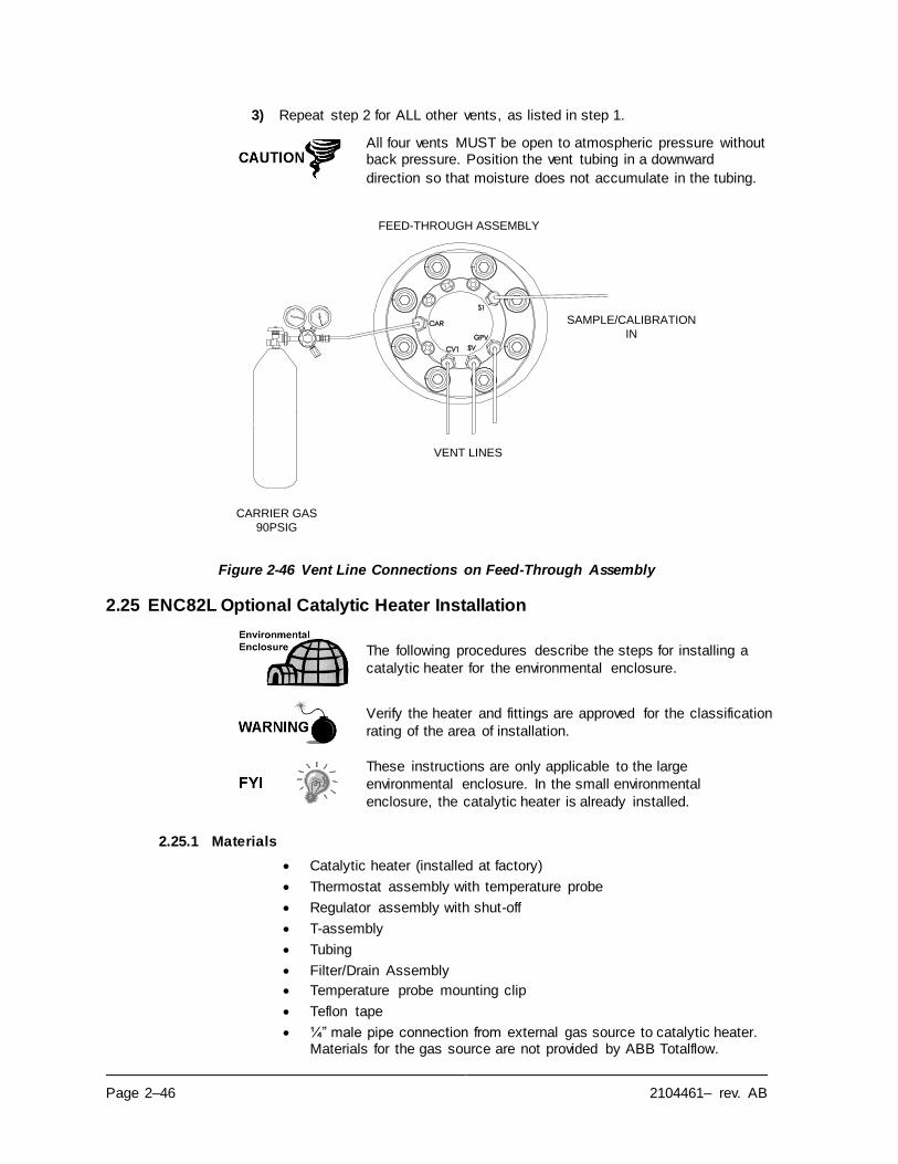
Page 2–46 2104461– rev. AB
3) Repeat step 2 for ALL other vents, as listed in step 1.
All four vents MUST be open to atmospheric pressure without back pressure. Position the vent tubing in a downward
direction so that moisture does not accumulate in the tubing.
Figure 2-46 Vent Line Connections on Feed-Through Assembly
2.25 ENC82L Optional Catalytic Heater Installation
The following procedures describe the steps for installing a
catalytic heater for the environmental enclosure.
Verify the heater and fittings are approved for the classification
rating of the area of installation.
These instructions are only applicable to the large
environmental enclosure. In the small environmental
enclosure, the catalytic heater is already installed.
2.25.1 Materials
• Catalytic heater (installed at factory)
• Thermostat assembly with temperature probe
• Regulator assembly with shut-off
• T-assembly
• Tubing
• Filter/Drain Assembly
• Temperature probe mounting clip
• Teflon tape
• ¼” male pipe connection from external gas source to catalytic heater. Materials for the gas source are not provided by ABB Totalflow.
FEED-THROUGH ASSEMBLY
CARRIER GAS
90PSIG
VENT LINES
SAMPLE/CALIBRATION
IN
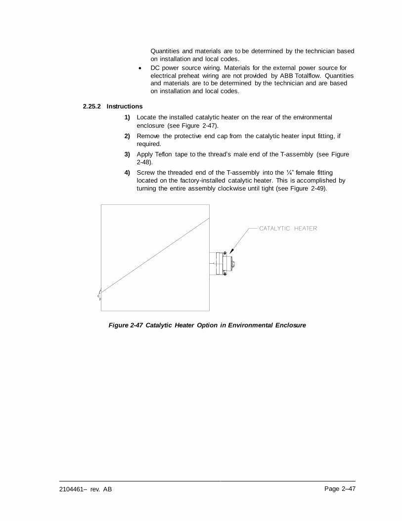
2104461– rev. AB Page 2–47
Quantities and materials are to be determined by the technician based
on installation and local codes.
• DC power source wiring. Materials for the external power source for
electrical preheat wiring are not provided by ABB Totalflow. Quantities and materials are to be determined by the technician and are based
on installation and local codes.
2.25.2 Instructions
1) Locate the installed catalytic heater on the rear of the environmental
enclosure (see Figure 2-47).
2) Remove the protective end cap from the catalytic heater input fitting, if
required.
3) Apply Teflon tape to the thread’s male end of the T-assembly (see Figure
2-48).
4) Screw the threaded end of the T-assembly into the ¼” female fitting
located on the factory-installed catalytic heater. This is accomplished by
turning the entire assembly clockwise until tight (see Figure 2-49).
Figure 2-47 Catalytic Heater Option in Environmental Enclosure
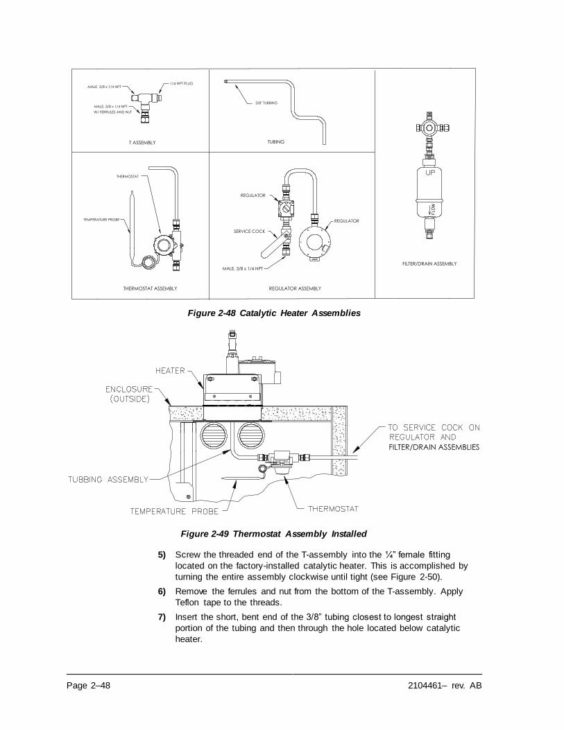
Page 2–48 2104461– rev. AB
Figure 2-48 Catalytic Heater Assemblies
Figure 2-49 Thermostat Assembly Installed
5) Screw the threaded end of the T-assembly into the ¼” female fitting
located on the factory-installed catalytic heater. This is accomplished by
turning the entire assembly clockwise until tight (see Figure 2-50).
6) Remove the ferrules and nut from the bottom of the T-assembly. Apply
Teflon tape to the threads.
7) Insert the short, bent end of the 3/8” tubing closest to longest straight
portion of the tubing and then through the hole located below catalytic
heater.
FILTER/DRAIN ASSEMBLY
T ASSEMBLY TUBING
THERMOSTAT ASSEMBLY REGULATOR ASSEMBLY
REGULATOR
MALE, 3/8 x 1/4 NPT
MALE, 3/8 x 1/4 NPT1/4 NPT PLUG
3/8" TUBBING
REGULATOR
MALE, 3/8 x 1/4 NPT
SERVICE COCK
THERMOSTAT
TEMPERATURE PROBE
W/ FERRULES AND NUT
FILTER/DRAIN ASSEMBLIES
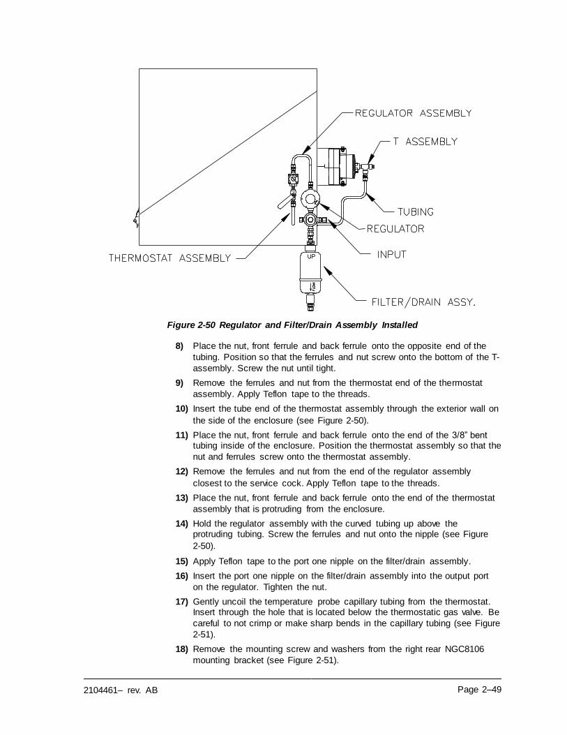
2104461– rev. AB Page 2–49
Figure 2-50 Regulator and Filter/Drain Assembly Installed
8) Place the nut, front ferrule and back ferrule onto the opposite end of the
tubing. Position so that the ferrules and nut screw onto the bottom of the T-
assembly. Screw the nut until tight.
9) Remove the ferrules and nut from the thermostat end of the thermostat
assembly. Apply Teflon tape to the threads.
10) Insert the tube end of the thermostat assembly through the exterior wall on
the side of the enclosure (see Figure 2-50).
11) Place the nut, front ferrule and back ferrule onto the end of the 3/8” bent tubing inside of the enclosure. Position the thermostat assembly so that the
nut and ferrules screw onto the thermostat assembly.
12) Remove the ferrules and nut from the end of the regulator assembly
closest to the service cock. Apply Teflon tape to the threads.
13) Place the nut, front ferrule and back ferrule onto the end of the thermostat
assembly that is protruding from the enclosure.
14) Hold the regulator assembly with the curved tubing up above the protruding tubing. Screw the ferrules and nut onto the nipple (see Figure
2-50).
15) Apply Teflon tape to the port one nipple on the filter/drain assembly.
16) Insert the port one nipple on the filter/drain assembly into the output port
on the regulator. Tighten the nut.
17) Gently uncoil the temperature probe capillary tubing from the thermostat. Insert through the hole that is located below the thermostatic gas valve. Be
careful to not crimp or make sharp bends in the capillary tubing (see Figure
2-51).
18) Remove the mounting screw and washers from the right rear NGC8106
mounting bracket (see Figure 2-51).
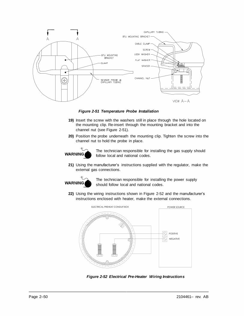
Page 2–50 2104461– rev. AB
Figure 2-51 Temperature Probe Installation
19) Insert the screw with the washers still in place through the hole located on the mounting clip. Re-insert through the mounting bracket and into the
channel nut (see Figure 2-51).
20) Position the probe underneath the mounting clip. Tighten the screw into the
channel nut to hold the probe in place.
The technician responsible for installing the gas supply should
follow local and national codes.
21) Using the manufacturer’s instructions supplied with the regulator, make the
external gas connections.
The technician responsible for installing the power supply
should follow local and national codes.
22) Using the wiring instructions shown in Figure 2-52 and the manufacturer’s
instructions enclosed with heater, make the external connections.
Figure 2-52 Electrical Pre-Heater Wiring Instructions
ELECTRICAL PREHEAT CONDUIT BOX POWER SOURCE
POSITIVE
NEGATIVE
2104461– rev. AB Page 2–51
2.26 ENC82S Optional Catalytic Heater Installation
These instructions are only applicable to the small
environmental enclosure (ENC82S).
Verify the heater and fittings are approved for the classification
rating of the area of installation.
If the optional catalytic heater is configured for the small environmental enclosure,
the external gas connections, electrical pre-heater wiring and installation of the
filter drain kit are the only things required.
2.26.1 Materials
• Teflon tape
• ¼” male pipe connection from the external gas source to the catalytic heater. Materials for the gas source are not provided by ABB
Totalflow. Quantities and materials are to be determined by the
technician and are based on installation and local codes.
• DC power source wiring. Materials for the external power source for electrical preheat wiring are not provided by ABB Totalflow. Quantities and materials are to be determined by the technician and are based
on installation and local codes.
2.26.2 Instructions
The technician responsible for installing the gas supply should
follow local and national codes.
1) Using the manufacturer’s instructions supplied with the regulator, make the
external gas connections.
2) Apply Teflon tape to the port one nipple on the filter/drain assembly.
3) Insert the port one nipple on the filter/drain assembly into the output port
on the regulator. Tighten the nut (see Figure 2-53).
The technician responsible for installing the power supply
should follow local and national codes.
4) Using the wiring instructions shown in Figure 2-52 and the manufacturer’s
instructions enclosed with the heater, make the external connections.
Page 2–52 2104461– rev. AB
Figure 2-53 ENC82S Filter/Drain Assembly Installation
Figure 2-54 ENC82S Catalytic Heater Pre-Heat Wiring
Customer Gas Inlet
(¼” NPT)
Vent Drain
Catalytic Heater Inlet
Add Filter/Drain Asm here
Drain
(¼” NPT)
Regulator
Bracket/Tie Strap
Stopcock
Filter/Drain Kit
P/N: 2103855
Regulator
Catalytic Heater Option
From Customer-Supplied
12Vdc Power Source
(+)
(-)
2104461– rev. AB Page 2–53
2.27 ENC82 Optional Electric Heater Installation
The following procedures describe the steps for wiring an
electric heater for the environmental enclosure.
Verify the heater and fittings are approved for the
classification rating of the area of installation.
2.27.1 Materials
• Electric heater option (Factory Installed. See Figure 2-55 and Figure
2-56).
• AC power source wiring. Materials for the external power source for
electric heater wiring are not provided by ABB Totalflow. Quantities and materials are to be determined by the technician and are based
on installation and local codes.
The technician responsible for installing the power supply
should follow local codes.
Page 2–54 2104461– rev. AB
Figure 2-55 ENC82L Electric Heater Installed in Enclosure
Figure 2-56 ENC82S Electric Heater Installed in Enclosure
2.27.2 Instructions
1) Using the wiring instructions shown in Figure 2-57 or the manufacturer’s
instructions enclosed with the heater, make the external connections.
BOTTLE RACK OPTION
POWER SWITCH
PWR/COMM
OUTLET BOX
THERMOSTAT
INSULATED
ENCLOSURE WALL
CALIBRATION
BLEND
ELECTRIC HEATER OPTION
CALIBRATION BLEND BOTTLE
CYLINDER : M 009 FITTINGS : CGA 180
HEATER KIT : VARITHERM 120 Vac , 400 WATT
THERMOSTAT
INSULATED ENCLOSURE WALL
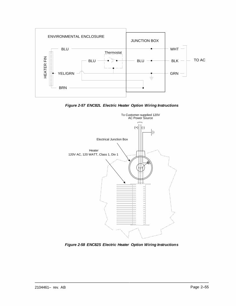
2104461– rev. AB Page 2–55
Figure 2-57 ENC82L Electric Heater Option Wiring Instructions
Figure 2-58 ENC82S Electric Heater Option Wiring Instructions
ENVIRONMENTAL ENCLOSUREJUNCTION BOX
HE
AT
ER
FIN
BLU
YEL/GRN
BRN
BLU BLU
WHT
BLK
GRN
TO AC
Thermostat
(+) (-)
To Customer-supplied 120V AC Power Source
Heater
120V AC, 120 WATT, Class 1, Div 1
Electrical Junction Box
Page 2–56 2104461– rev. AB
2.28 Sealing Environmental Enclosure
When all sample and vent tubing has been installed and leak
tested, the sample boot must be sealed. The following procedures describe the steps for sealing the environmental
enclosure.
2.28.1 Customer Supplied Materials
• Aerosol-insulating foam
2.28.2 Instructions
1) When all sample and vent connections are complete, apply aerosol-
insulating foam from inside the enclosure. The user needs to ensure that they are pointing toward the outside of boot. Make sure that the overspray
falls outside the enclosure.
2.29 Optional Equipment Enclosure Installation
If the optional enclosure is used, it may be configured to include other options including, but not limited to, a battery pack to provide reserve power to the
NGC8106, communication equipment, solar power charger and additional I/O.
Three enclosures are commonly used for the NGC8106 installation: the 6200, 6700 or 6800 enclosures. The unit may be mounted on a 2” pipe or mounted on a
flat surface such as a wall.
If configured, the battery and solar panel are packed and shipped separately from
the enclosure.
Before beginning, review the procedures and the materials required for the installation. Inspect all power cables where they terminate and the connector for
breakage.
The optional equipment enclosure may be approved for classified hazardous locations or potentially explosive atmospheres. Verify the rating listed on the unit tag and install
per the referenced control drawing. Be sure to follow the requirements of national and local codes when installing the
optional equipment enclosure.
2.29.1 6200 Optional Equipment Enclosure
The 6200 can accommodate the following equipment:
• Power supply kit for 6200
▪ 110/240 Volt to 12 Vdc
▪ 110/240 Volt to 24 Vdc
The 6200 installation will be for AC and 24 Vdc sites. There is no battery-backed
option in this installation.
2.29.2 6700 Optional Equipment Enclosure
The 6700 enclosure can accommodate the following:
• Power supply kit
▪ 120/240 Vac / 12 Vdc power supply
▪ 110/240 Volt to 12 Vdc
2104461– rev. AB Page 2–57
▪ 110/240 Volt to 24 Vdc
2.29.3 6800 Enclosure
The 6800 enclosure can accommodate the following:
• Solar panel power option (12 or 24 Vdc option)
• 115/230 Vac UPS power option (24 Vdc systems only)
2.29.4 Location
Mount the enclosure on a nearby wall, panel or pole. Make sure that the approved conduit can be installed between the power supply’s enclosure and the NGC8106.
Avoid obstructions.
2.29.5 Pipe-Mount Instructions
The enclosure mounting brackets and fastening hardware are supplied with the
unit. The user must provide a 2” pipe of suitable length (see Figure 2-59).
If a charging source such as a solar panel is preferred, this procedure may be
adapted to mount the solar panel on the upper portion of the pipe.
The instructions assume the mounting pipe has been previously installed. If not,
refer to the previous installation sections within this chapter for either free-standing
pipe installation or pipe saddle installation.
1) When the unit is received, unpack and inspect all components for evidence
of damage. Report damage to the shipping carrier and to ABB Totalflow’s
service department.
2) Using instructions supplied with the mounting kit, attach the bracket to the
back of the enclosure unit.
3) Position the unit on the 2” mounting pipe, and secure in place with two U-
bolts, split washers, flat washers and two bolts (see Figure 2-59, Figure
2-60 and Figure 2-61).
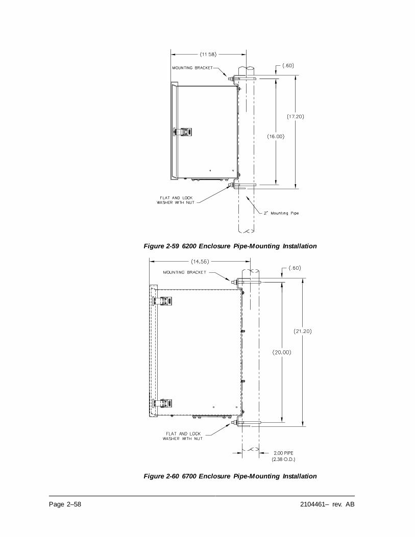
Page 2–58 2104461– rev. AB
Figure 2-59 6200 Enclosure Pipe-Mounting Installation
Figure 2-60 6700 Enclosure Pipe-Mounting Installation
(2.38 O.D.)
2.00 PIPE
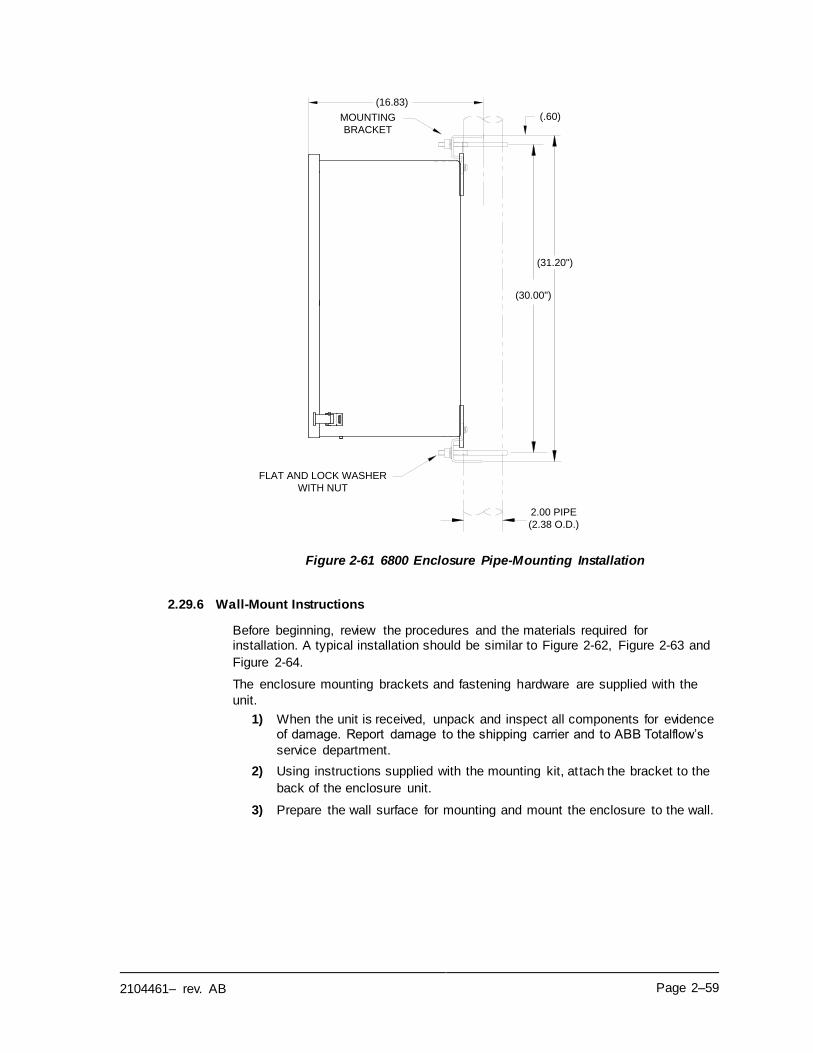
2104461– rev. AB Page 2–59
Figure 2-61 6800 Enclosure Pipe-Mounting Installation
2.29.6 Wall-Mount Instructions
Before beginning, review the procedures and the materials required for installation. A typical installation should be similar to Figure 2-62, Figure 2-63 and
Figure 2-64.
The enclosure mounting brackets and fastening hardware are supplied with the
unit.
1) When the unit is received, unpack and inspect all components for evidence of damage. Report damage to the shipping carrier and to ABB Totalflow’s
service department.
2) Using instructions supplied with the mounting kit, attach the bracket to the
back of the enclosure unit.
3) Prepare the wall surface for mounting and mount the enclosure to the wall.
(16.83)
MOUNTING
BRACKET
(.60)
(31.20")
(30.00")
2.00 PIPE
(2.38 O.D.)
FLAT AND LOCK WASHER
WITH NUT
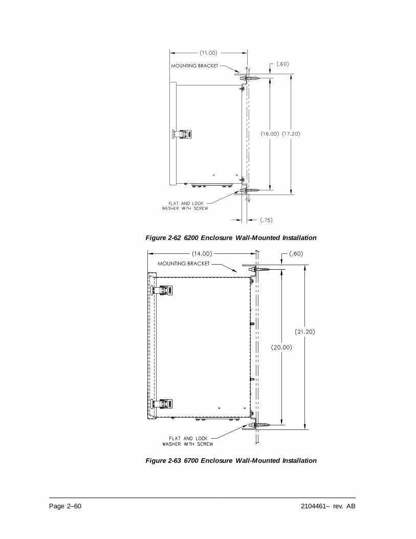
Page 2–60 2104461– rev. AB
Figure 2-62 6200 Enclosure Wall-Mounted Installation
Figure 2-63 6700 Enclosure Wall-Mounted Installation
MOUNTING BRACKET
MOUNTING BRACKET
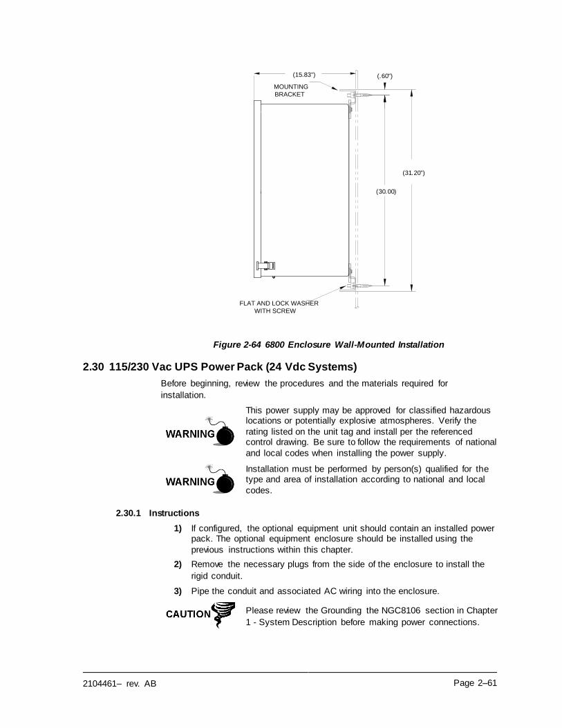
2104461– rev. AB Page 2–61
Figure 2-64 6800 Enclosure Wall-Mounted Installation
2.30 115/230 Vac UPS Power Pack (24 Vdc Systems)
Before beginning, review the procedures and the materials required for
installation.
This power supply may be approved for classified hazardous locations or potentially explosive atmospheres. Verify the
rating listed on the unit tag and install per the referenced control drawing. Be sure to follow the requirements of national
and local codes when installing the power supply.
Installation must be performed by person(s) qualified for the type and area of installation according to national and local
codes.
2.30.1 Instructions
1) If configured, the optional equipment unit should contain an installed power pack. The optional equipment enclosure should be installed using the
previous instructions within this chapter.
2) Remove the necessary plugs from the side of the enclosure to install the
rigid conduit.
3) Pipe the conduit and associated AC wiring into the enclosure.
Please review the Grounding the NGC8106 section in Chapter
1 - System Description before making power connections.
(31.20")
(30.00)
(.60")(15.83")
MOUNTING
BRACKET
FLAT AND LOCK WASHER
WITH SCREW
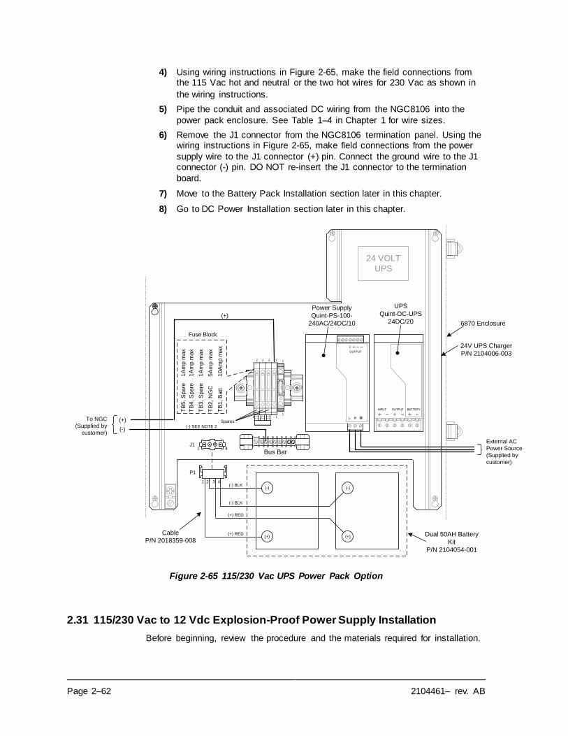
Page 2–62 2104461– rev. AB
4) Using wiring instructions in Figure 2-65, make the field connections from the 115 Vac hot and neutral or the two hot wires for 230 Vac as shown in
the wiring instructions.
5) Pipe the conduit and associated DC wiring from the NGC8106 into the
power pack enclosure. See Table 1–4 in Chapter 1 for wire sizes.
6) Remove the J1 connector from the NGC8106 termination panel. Using the wiring instructions in Figure 2-65, make field connections from the power
supply wire to the J1 connector (+) pin. Connect the ground wire to the J1 connector (-) pin. DO NOT re-insert the J1 connector to the termination
board.
7) Move to the Battery Pack Installation section later in this chapter.
8) Go to DC Power Installation section later in this chapter.
Figure 2-65 115/230 Vac UPS Power Pack Option
2.31 115/230 Vac to 12 Vdc Explosion-Proof Power Supply Installation
Before beginning, review the procedure and the materials required for installation.
BATTERYOUTPUTINPUT
OUTPUT
Power Supply
Quint-PS-100-
240AC/24DC/10
UPS
Quint-DC-UPS
24DC/20
External AC
Power Source
(Supplied by
customer)
Fuse Block
Spares
TB
5, S
pa
re1
Am
p m
ax
TB
4,
Sp
are
1A
mp
ma
x
TB
3,
Sp
are
1A
mp
ma
x
TB
2, N
GC
5A
mp
ma
x
TB
1,
Ba
tt1
0A
mp
ma
x
1
2 2 12
21
2
To NGC
(Supplied by
customer)
Bus Bar
(-)
(+)
J11 4
24 VOLT
UPS
(-) SEE NOTE 2
Dual 50AH Battery
Kit
P/N 2104054-001
24V UPS Charger
P/N 2104006-003
6870 Enclosure
P1
(+)
(-)
(+)
(-)
(+) RED
(+) RED
(-) BLK
(-) BLK
(+)
1 2 3 4
Cable
P/N 2018359-008
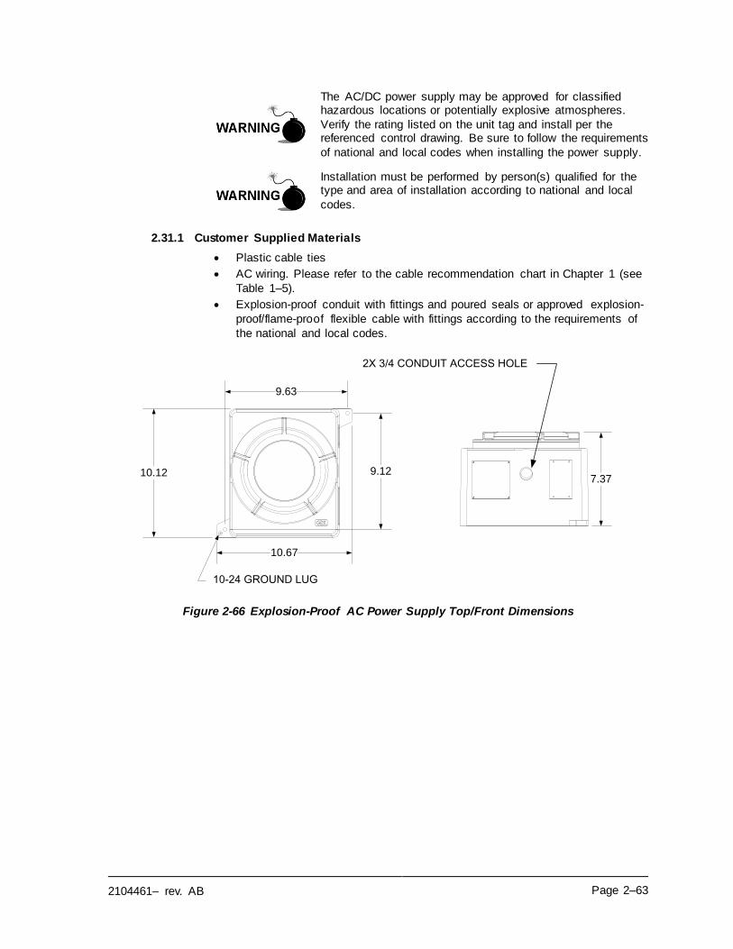
2104461– rev. AB Page 2–63
The AC/DC power supply may be approved for classified hazardous locations or potentially explosive atmospheres.
Verify the rating listed on the unit tag and install per the referenced control drawing. Be sure to follow the requirements
of national and local codes when installing the power supply.
Installation must be performed by person(s) qualified for the type and area of installation according to national and local
codes.
2.31.1 Customer Supplied Materials
• Plastic cable ties
• AC wiring. Please refer to the cable recommendation chart in Chapter 1 (see
Table 1–5).
• Explosion-proof conduit with fittings and poured seals or approved explosion-
proof/flame-proof flexible cable with fittings according to the requirements of
the national and local codes.
Figure 2-66 Explosion-Proof AC Power Supply Top/Front Dimensions
9.63
9.12
10.67
10.12
10-24 GROUND LUG
7.37
2X 3/4 CONDUIT ACCESS HOLE
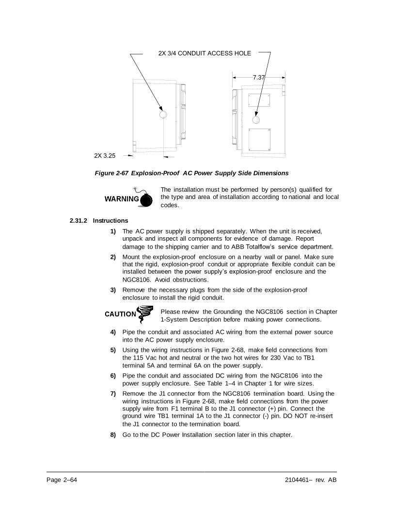
Page 2–64 2104461– rev. AB
Figure 2-67 Explosion-Proof AC Power Supply Side Dimensions
The installation must be performed by person(s) qualified for the type and area of installation according to national and local
codes.
2.31.2 Instructions
1) The AC power supply is shipped separately. When the unit is received, unpack and inspect all components for evidence of damage. Report
damage to the shipping carrier and to ABB Totalflow’s service department.
2) Mount the explosion-proof enclosure on a nearby wall or panel. Make sure that the rigid, explosion-proof conduit or appropriate flexible conduit can be installed between the power supply’s explosion-proof enclosure and the
NGC8106. Avoid obstructions.
3) Remove the necessary plugs from the side of the explosion-proof
enclosure to install the rigid conduit.
Please review the Grounding the NGC8106 section in Chapter
1-System Description before making power connections.
4) Pipe the conduit and associated AC wiring from the external power source
into the AC power supply enclosure.
5) Using the wiring instructions in Figure 2-68, make field connections from
the 115 Vac hot and neutral or the two hot wires for 230 Vac to TB1
terminal 5A and terminal 6A on the power supply.
6) Pipe the conduit and associated DC wiring from the NGC8106 into the
power supply enclosure. See Table 1–4 in Chapter 1 for wire sizes.
7) Remove the J1 connector from the NGC8106 termination board. Using the
wiring instructions in Figure 2-68, make field connections from the power supply wire from F1 terminal B to the J1 connector (+) pin. Connect the ground wire TB1 terminal 1A to the J1 connector (-) pin. DO NOT re-insert
the J1 connector to the termination board.
8) Go to the DC Power Installation section later in this chapter.
7.37
2X 3/4 CONDUIT ACCESS HOLE
2X 3.25
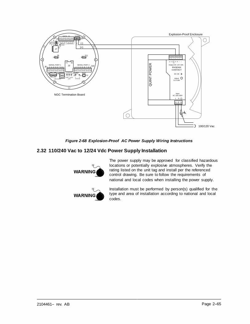
2104461– rev. AB Page 2–65
Figure 2-68 Explosion-Proof AC Power Supply Wiring Instructions
2.32 110/240 Vac to 12/24 Vdc Power Supply Installation
The power supply may be approved for classified hazardous
locations or potentially explosive atmospheres. Verify the rating listed on the unit tag and install per the referenced control drawing. Be sure to follow the requirements of
national and local codes when installing the power supply.
Installation must be performed by person(s) qualified for the type and area of installation according to national and local
codes.
QU
INT
PO
WE
R
PHOENIX
CONTACT
Input
AC 100-240V
L N
--++DC
OK
DC OK
Adjust
11.5-18V
SERIAL PORT 1
1 2 3 4 5 6 7 8 9
SERIAL PORT 2
1 2 3 4 5 6 7 8 9
1 2 1 2(+) (-) (+) (-) (+) (-) (+) (-)
INPUTS OUTPUTS
(+) (-)PWR IN
PWR5VDC
J10J8
SE
CU
RIT
Y
DIGITAL I/O POWER
S2
RESETSECURITYENABLED
LINK STATLAN
1 2STATUS
S1D4D3
D13D11D12ETHERNET
J7
J3
D2
USB HOST
USB CLIENT
J2 J1
J5 J6
UN
SE
CU
RE
NGC Termination Board
(-)
(+)
TERM
NO TERM
TERM
NO TERM
J1131
J931
Explosion-Proof Enclosure
100/120 Vac
13 14
Output DC 12V 10A
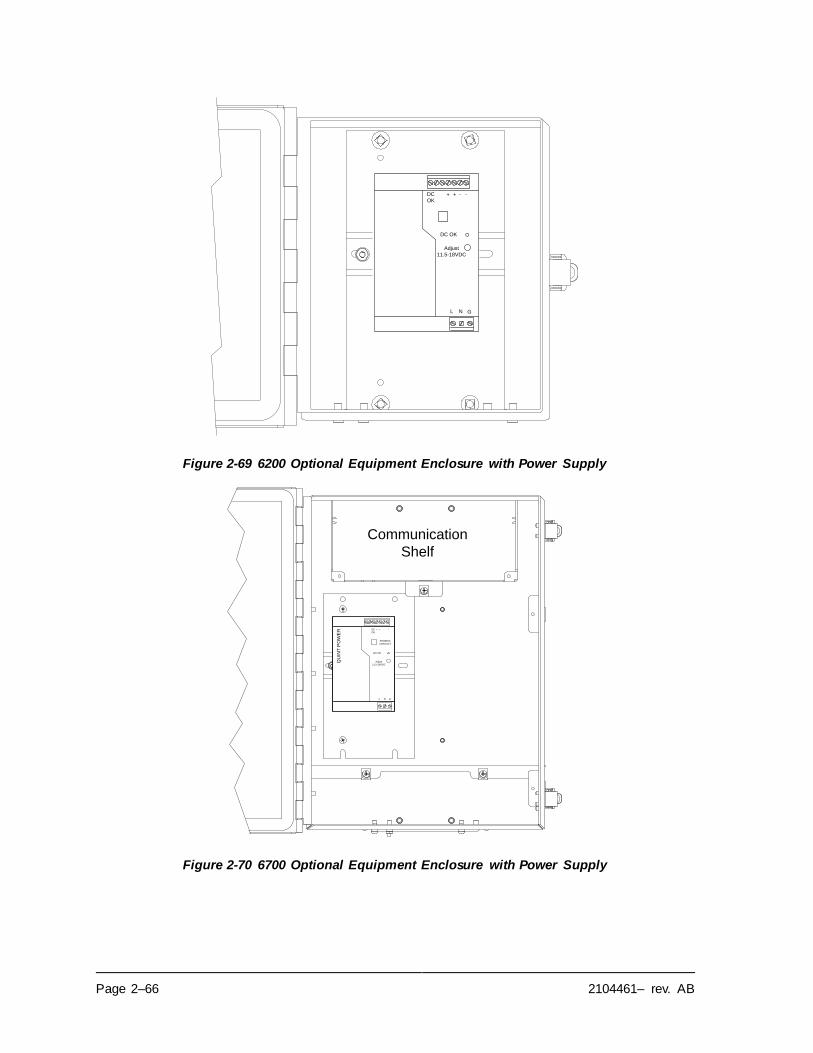
Page 2–66 2104461– rev. AB
Figure 2-69 6200 Optional Equipment Enclosure with Power Supply
Figure 2-70 6700 Optional Equipment Enclosure with Power Supply
L N G
-+DC
OK
DC OK
Adjust
11.5-18VDC
+ -
QU
INT
PO
WE
R
PHOENIX
CONTACT
L N G
--+ +DC
OK
DC OK
Adjust
11.5-18VDC
Communication
Shelf
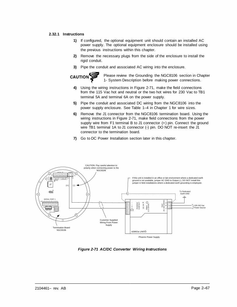
2104461– rev. AB Page 2–67
2.32.1 Instructions
1) If configured, the optional equipment unit should contain an installed AC power supply. The optional equipment enclosure should be installed using
the previous instructions within this chapter.
2) Remove the necessary plugs from the side of the enclosure to install the
rigid conduit.
3) Pipe the conduit and associated AC wiring into the enclosure.
Please review the Grounding the NGC8106 section in Chapter
1- System Description before making power connections.
4) Using the wiring instructions in Figure 2-71, make the field connections from the 115 Vac hot and neutral or the two hot wires for 230 Vac to TB1
terminal 5A and terminal 6A on the power supply.
5) Pipe the conduit and associated DC wiring from the NGC8106 into the
power supply enclosure. See Table 1–4 in Chapter 1 for wire sizes.
6) Remove the J1 connector from the NGC8106 termination board. Using the wiring instructions in Figure 2-71, make field connections from the power
supply wire from F1 terminal B to J1 connector (+) pin. Connect the ground wire TB1 terminal 1A to J1 connector (-) pin. DO NOT re-insert the J1
connector to the termination board.
7) Go to DC Power Installation section later in this chapter.
Figure 2-71 AC/DC Converter Wiring Instructions
Termination Board
NGC8106
SERIAL PORT 11 2 3 4 5 6 7 8 9
1 2 1 2(+) (-) (+) (-) (+) (-) (+) (-)
INPUTS OUTPUTS
5VDC
TERM
NO TERM
J931
J8
SE
CU
RIT
Y
UN
SE
CU
RE
DIGITAL I/O POWER
S2
J7
D2
USB HOST
USB CLIENT
J2 J1
J5 J6
(+) (-)
100-240 Vac
Power Source
To Dedicated
Earth GND
(+) (-)
QUINT POWER
PH
OE
NIX
CO
NT
AC
T
Inp
ut
AC
10
0-2
40
VA
C
LN
G--
++
DC
OK
DC
OK
Ad
just
11.5
-18V
DC
If this unit is installed in an office or lab environment where a dedicated earth
ground is not available, jumper AC GND to Output (-). DO NOT install this
jumper in field installations where a dedicated earth grounding is employed.
Customer Supplied
Wiring From Power
Supply
CAUTION: Pay careful attention to
polarity when connecting power to the
NGC8106
Phoenix Power Supply
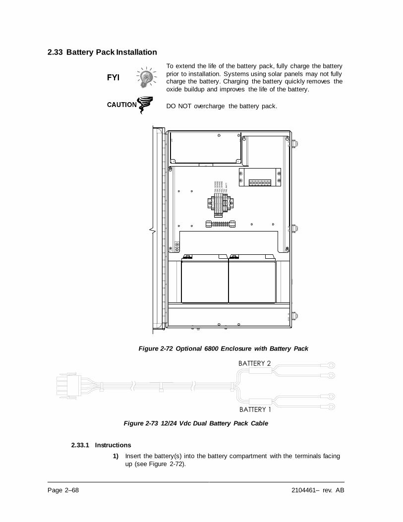
Page 2–68 2104461– rev. AB
2.33 Battery Pack Installation
To extend the life of the battery pack, fully charge the battery
prior to installation. Systems using solar panels may not fully charge the battery. Charging the battery quickly removes the
oxide buildup and improves the life of the battery.
DO NOT overcharge the battery pack.
Figure 2-72 Optional 6800 Enclosure with Battery Pack
Figure 2-73 12/24 Vdc Dual Battery Pack Cable
2.33.1 Instructions
1) Insert the battery(s) into the battery compartment with the terminals facing
up (see Figure 2-72).
TB
1,
BA
TT
TB
4,
SP
AR
ET
B3
, S
PA
RE
TB
5,
SP
AR
ET
B6
, S
PA
RE
TB
2
BATTERY 2
BATTERY 1
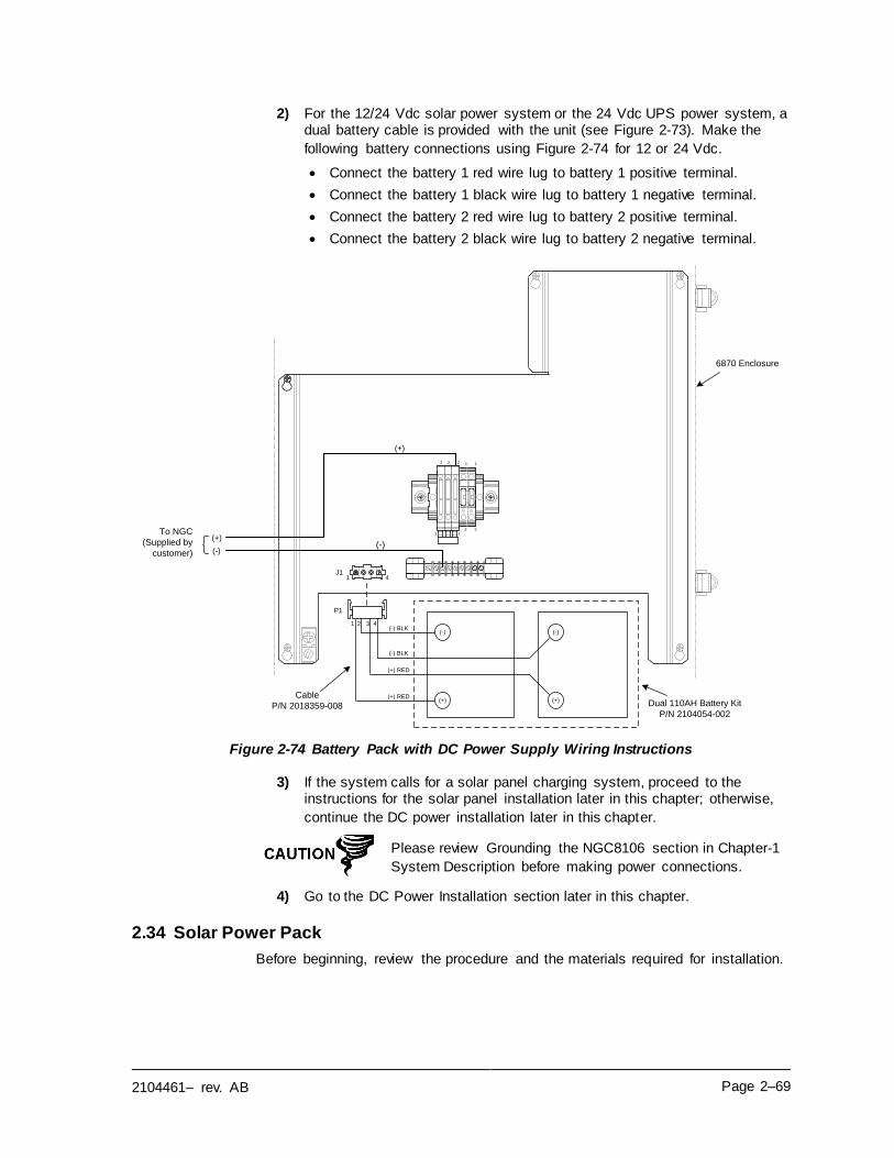
2104461– rev. AB Page 2–69
2) For the 12/24 Vdc solar power system or the 24 Vdc UPS power system, a dual battery cable is provided with the unit (see Figure 2-73). Make the
following battery connections using Figure 2-74 for 12 or 24 Vdc.
• Connect the battery 1 red wire lug to battery 1 positive terminal.
• Connect the battery 1 black wire lug to battery 1 negative terminal.
• Connect the battery 2 red wire lug to battery 2 positive terminal.
• Connect the battery 2 black wire lug to battery 2 negative terminal.
Figure 2-74 Battery Pack with DC Power Supply Wiring Instructions
3) If the system calls for a solar panel charging system, proceed to the instructions for the solar panel installation later in this chapter; otherwise,
continue the DC power installation later in this chapter.
Please review Grounding the NGC8106 section in Chapter-1
System Description before making power connections.
4) Go to the DC Power Installation section later in this chapter.
2.34 Solar Power Pack
Before beginning, review the procedure and the materials required for installation.
(-)
(+)
J11 4
1
2 1
2
2 12
21
(+)
(-)
Dual 110AH Battery Kit
P/N 2104054-002
6870 Enclosure
P1
(+)
(-)
(+)
(-)
(+) RED
(+) RED
(-) BLK
(-) BLK
1 2 3 4
Cable
P/N 2018359-008
To NGC
(Supplied by
customer)
Page 2–70 2104461– rev. AB
The power supply may be approved for classified hazardous locations or potentially explosive atmospheres. Verify the
rating listed on the unit tag and install per the referenced control drawing. Be sure to follow the requirements of
national and local codes when installing the power supply.
Installation must be performed by person(s) qualified for the type and area of installation according to national and local
codes.
2.34.1 Instructions
1) If configured, the optional equipment enclosure should contain an installed power supply. The enclosure and solar panel(s) should be installed using
instructions detailed previously in this chapter.
2) Remove the plug from the access hole in the equipment enclosure. Insert
the solar panel power cable through an access hole on the side of the case. Allow enough power cable for the field wiring to the solar charger
connector pins, 3 and 4.
Please review the Grounding the NGC8106 section in
Chapter 1-System Description before making power
connections.
3) Pipe the conduit and associated DC wiring from the NGC8106 into the
power supply enclosure. See Table 1–4 in Chapter 1 for wire sizes.
4) Field wire the solar panel cables to the solar charger inside the enclosure. Using the wiring instructions in Figure 2-75 for 12 Vdc or Figure 2-76 for 24
Vdc, make the field connections.
• Loosen the terminal block securing screws, insert wire and then
retighten. Connect the solar panel (+) lead to pin 4 and the (-) wire to pin 3 terminal. Verify the main battery pack is connected.
5) Following the connection of the solar panel power cable, secure the cable
to the 2’ extension pipe and the mounting pipe cable with the provided
plastic tie-wraps.
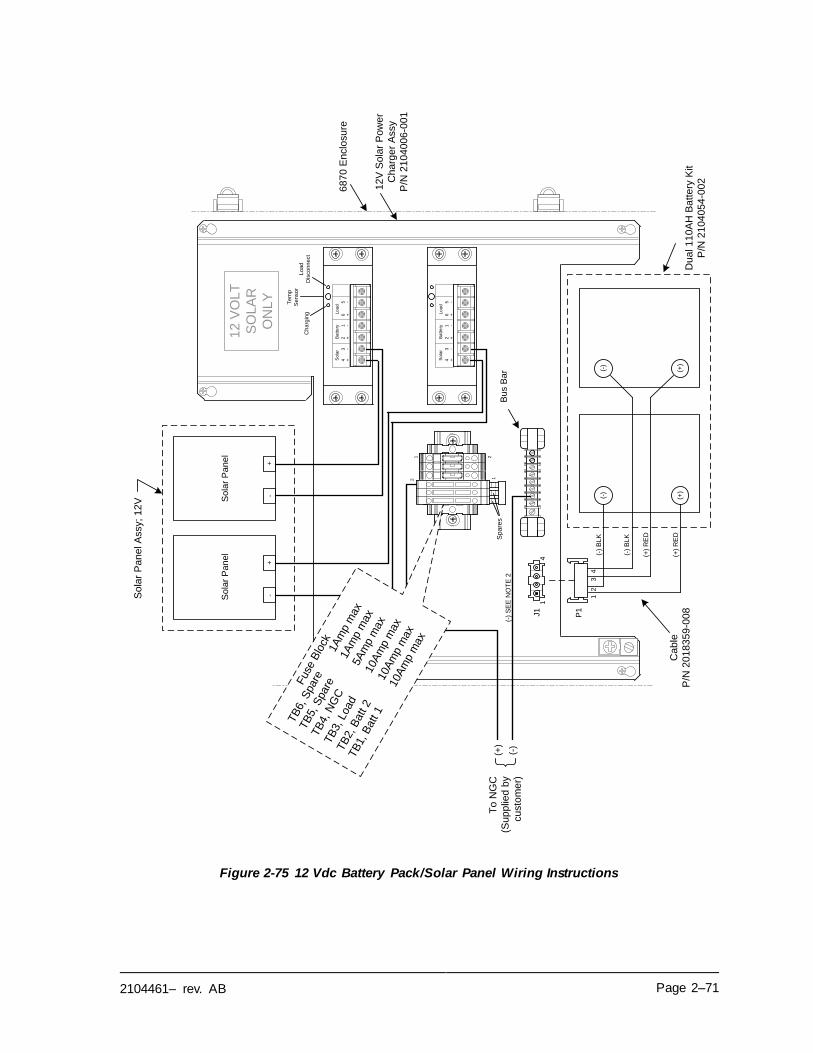
2104461– rev. AB Page 2–71
Figure 2-75 12 Vdc Battery Pack/Solar Panel Wiring Instructions
12
34
65
-+
-+
+-
So
lar
Ba
tte
ryL
oa
d
12
34
65
-+
-+
+-
So
lar
Ba
tte
ryL
oa
d
Ch
arg
ing
Te
mp
Se
nso
r
Bu
s B
ar
(-)
(+)
Sp
are
s
So
lar
Pa
ne
lS
ola
r P
an
el
+-
+-So
lar
Pa
ne
l A
ssy;
12
V
J1
14
12
VO
LT
SO
LA
R
ON
LY
(-)
SE
E N
OT
E 2
Du
al 1
10A
H B
atte
ry K
it
P/N
21
04
05
4-0
02
12
V S
ola
r P
ow
er
Ch
arg
er
Assy
P/N
21
04
00
6-0
01
68
70
En
clo
su
re
2 1
1 2
(+)
Lo
ad
Dis
co
nn
ect
P1
(+)
(-)
(+)
(-)
(+)
RE
D
(+)
RE
D
(-)
BL
K
(-)
BL
K
12
34
Ca
ble
P/N
20
18
35
9-0
08
To
NG
C
(Su
pp
lied
by
cu
sto
me
r)
TB
6, S
pare
1A
mp m
ax
TB
5, S
pare
1A
mp m
ax
TB
4, N
GC
5A
mp m
ax
TB
3, Load
10A
mp m
ax
TB
2, B
att 2
10A
mp m
ax
TB
1, B
att 1
10A
mp m
ax
Fuse
Blo
ck
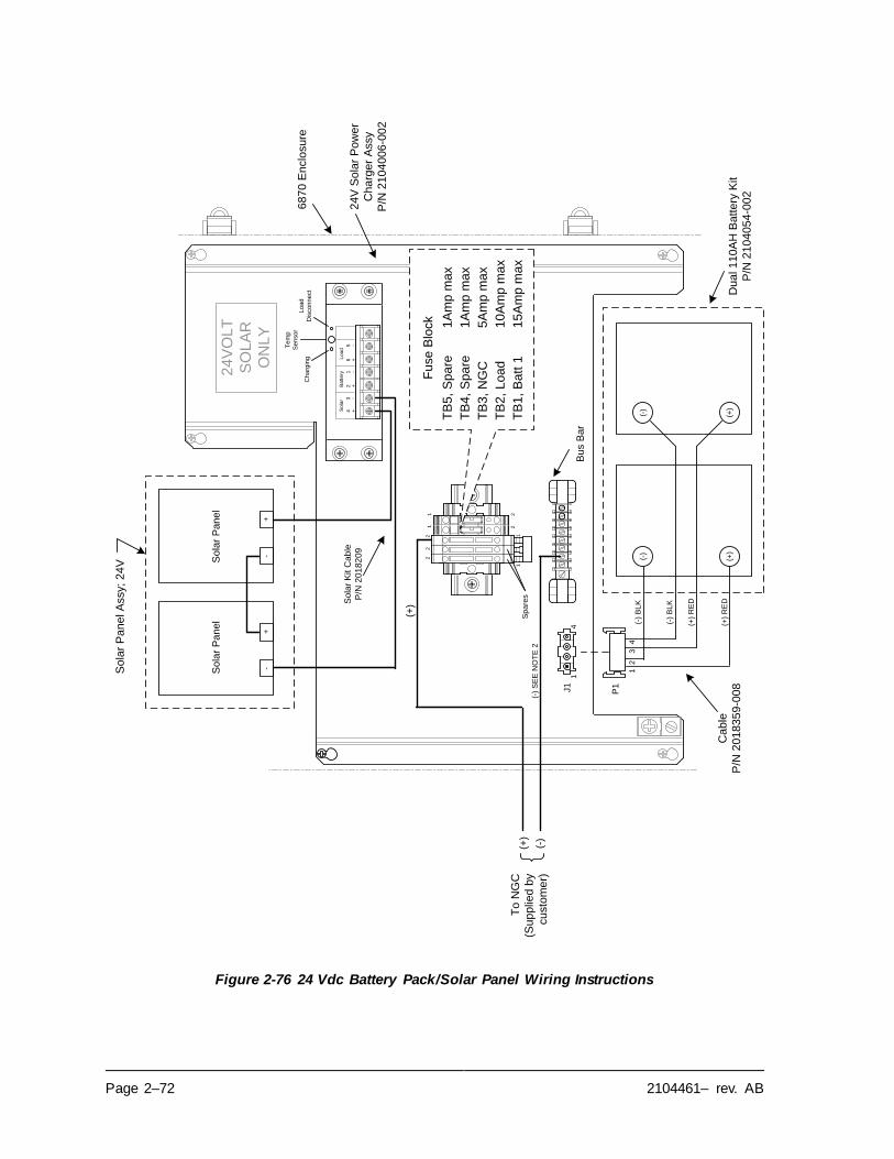
Page 2–72 2104461– rev. AB
Figure 2-76 24 Vdc Battery Pack/Solar Panel Wiring Instructions
Bu
s B
ar
(-)
(+)
Sp
are
s
So
lar
Pa
ne
lS
ola
r P
an
el
12
34
65
-+
-+
+-
So
lar
Ba
tte
ryL
oa
d
Ch
arg
ing
Lo
ad
Dis
co
nn
ect
Te
mp
Se
nso
r
+-
+-So
lar
Pa
ne
l A
ssy;
24
V
J1
14
1
21 2
21
2
21
(+)
24
VO
LT
SO
LA
R
ON
LY
(-)
SE
E N
OT
E 2
Du
al 1
10A
H B
atte
ry K
it
P/N
21
04
05
4-0
02
24
V S
ola
r P
ow
er
Ch
arg
er
Assy
P/N
21
04
00
6-0
02
68
70
En
clo
su
re
P1
(+)
(-)
(+)
(-)
(+)
RE
D
(+)
RE
D
(-)
BL
K
(-)
BL
K
12
34
Ca
ble
P/N
20
18
35
9-0
08
To
NG
C
(Su
pp
lied
by
cu
sto
me
r)
So
lar
Kit C
ab
le
P/N
20
18
20
9
Fu
se
Blo
ck
TB
5,
Sp
are
1A
mp
ma
x
TB
4,
Sp
are
1A
mp
ma
x
TB
3,
NG
C5
Am
p m
ax
TB
2,
Lo
ad
10
Am
p m
ax
TB
1,
Ba
tt 1
15
Am
p m
ax
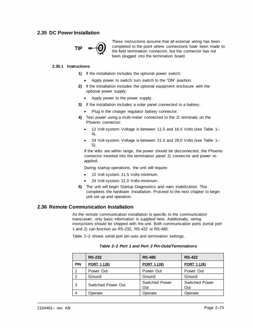
2104461– rev. AB Page 2–73
2.35 DC Power Installation
These instructions assume that all external wiring has been
completed to the point where connections have been made to the field termination connector, but the connector has not
been plugged into the termination board.
2.35.1 Instructions
1) If the installation includes the optional power switch:
• Apply power to switch; turn switch to the “ON” position.
2) If the installation includes the optional equipment enclosure with the
optional power supply:
• Apply power to the power supply.
3) If the installation includes a solar panel connected to a battery:
• Plug in the charger regulator battery connector.
4) Test power using a multi-meter connected to the J1 terminals on the
Phoenix connector:
• 12 Volt system: Voltage is between 11.5 and 16.0 Volts (see Table 1–4).
• 24 Volt system: Voltage is between 21.0 and 28.0 Volts (see Table 1–5).
If the volts are within range, the power should be disconnected, the Phoenix
connector inserted into the termination panel J1 connector and power re-
applied.
During startup operations, the unit will require:
• 12 Volt system: 11.5 Volts minimum.
• 24 Volt system: 21.0 Volts minimum.
5) The unit will begin Startup Diagnostics and oven stabilization. This
completes the hardware installation. Proceed to the next chapter to begin
unit set up and operation.
2.36 Remote Communication Installation
As the remote communication installation is specific to the communication transceiver, only basic information is supplied here. Additionally, wiring instructions should be shipped with the unit. Both communication ports (serial port
1 and 2) can function as RS-232, RS-422 or RS-485.
Table 2–2 shows serial port pin outs and termination settings.
Table 2–2 Port 1 and Port 2 Pin-Outs/Terminations
RS-232 RS-485 RS-422
PIN PORT 1 (J8) PORT 1 (J8) PORT 1 (J8)
1 Power Out Power Out Power Out
2 Ground Ground Ground
3 Switched Power Out Switched Power
Out
Switched Power
Out
4 Operate Operate Operate
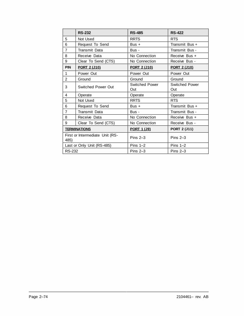
Page 2–74 2104461– rev. AB
RS-232 RS-485 RS-422
5 Not Used RRTS RTS
6 Request To Send Bus + Transmit Bus +
7 Transmit Data Bus - Transmit Bus -
8 Receive Data No Connection Receive Bus +
9 Clear To Send (CTS) No Connection Receive Bus -
PIN PORT 2 (J10) PORT 2 (J10) PORT 2 (J10)
1 Power Out Power Out Power Out
2 Ground Ground Ground
3 Switched Power Out Switched Power
Out
Switched Power
Out
4 Operate Operate Operate
5 Not Used RRTS RTS
6 Request To Send Bus + Transmit Bus +
7 Transmit Data Bus - Transmit Bus -
8 Receive Data No Connection Receive Bus +
9 Clear To Send (CTS) No Connection Receive Bus -
TERMINATIONS PORT 1 (J9) PORT 2 (J11)
First or Intermediate Unit (RS-
485) Pins 2–3 Pins 2–3
Last or Only Unit (RS-485) Pins 1–2 Pins 1–2
RS-232 Pins 2–3 Pins 2–3
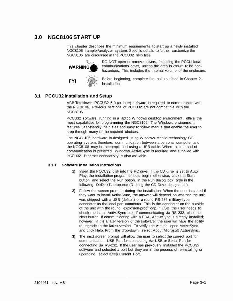
2104461– rev. AB Page 3–1
3.0 NGC8106 START UP
This chapter describes the minimum requirements to start up a newly installed NGC8106 sampler/analyzer system. Specific details to further customize the
NGC8106 are discussed in the PCCU32 help files.
DO NOT open or remove covers, including the PCCU local communications cover, unless the area is known to be non-
hazardous. This includes the internal volume of the enclosure.
Before beginning, complete the tasks outlined in Chapter 2 -
Installation.
3.1 PCCU32 Installation and Setup
ABB Totalflow’s PCCU32 6.0 (or later) software is required to communicate with the NGC8106. Previous versions of PCCU32 are not compatible with the
NGC8106.
PCCU32 software, running in a laptop Windows desktop environment, offers the most capabilities for programming the NGC8106. The Windows-environment
features user-friendly help files and easy to follow menus that enable the user to
step through many of the required choices.
The NGC8106 hardware is designed using Windows Mobile technology CE
operating system; therefore, communication between a personal computer and the NGC8106 may be accomplished using a USB cable. When this method of communication is preferred, Windows ActiveSync is required and supplied with
PCCU32. Ethernet connectivity is also available.
3.1.1 Software Installation Instructions
1) Insert the PCCU32 disk into the PC drive. If the CD drive is set to Auto Play, the installation program should begin; otherwise, click the Start
button, and select the Run option. In the Run dialog box, type in the
following: D:\Disk1\setup.exe (D being the CD Drive designation).
2) Follow the screen prompts during the installation. When the user is asked if they want to install ActiveSync, the answer will depend on whether the unit
was shipped with a USB (default) or a round RS-232 military-type connector as the local port connector. This is the connector on the outside of the unit with the round, explosion-proof cap. If USB, the user needs to
check the Install ActiveSync box. If communicating via RS-232, click the Next button. If communicating with a PDA, ActiveSync is already installed; however, if it is a later version of the software, the user will have the ability
to upgrade to the latest version. To verify the version, open ActiveSync,
and click Help. From the drop-down, select About Microsoft ActiveSync.
3) The next screen prompt will allow the user to select the correct port for communication: USB Port for connecting via USB or Serial Port for
connecting via RS-232. If the user has previously installed the PCCU32 software and selected a port but they are in the process of re-installing or
upgrading, select Keep Current Port.
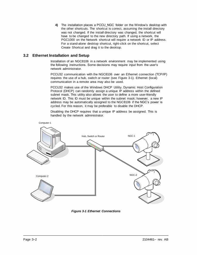
Page 3–2 2104461– rev. AB
4) The installation places a PCCU_NGC folder on the Window’s desktop with the other shortcuts. The shortcut is correct, assuming the install directory
was not changed. If the install directory was changed, the shortcut will have to be changed to the new directory path. If using a network, the PGC1000 on the Network shortcut will require a network ID or IP address.
For a stand-alone desktop shortcut, right-click on the shortcut, select
Create Shortcut and drag it to the desktop.
3.2 Ethernet Installation and Setup
Installation of an NGC8106 in a network environment may be implemented using the following instructions. Some decisions may require input from the user’s
network administrator.
PCCU32 communication with the NGC8106 over an Ethernet connection (TCP/IP) requires the use of a hub, switch or router (see Figure 3-1). Ethernet (local)
communication in a remote area may also be used.
PCCU32 makes use of the Windows DHCP Utility. Dynamic Host Configuration Protocol (DHCP) can randomly assign a unique IP address within the defined subnet mask. This utility also allows the user to define a more user-friendly
network ID. This ID must be unique within the subnet mask; however, a new IP address may be automatically assigned to the NGC8106 if the NGC’s power is
cycled. For this reason, it may be preferable to disable the DHCP.
Disabling the DHCP requires that a unique IP address be assigned. This is
handled by the network administrator.
Figure 3-1 Ethernet Connections
`
Computer-2
Hub, Switch or Router NGC-1
NGC-2
Computer-1
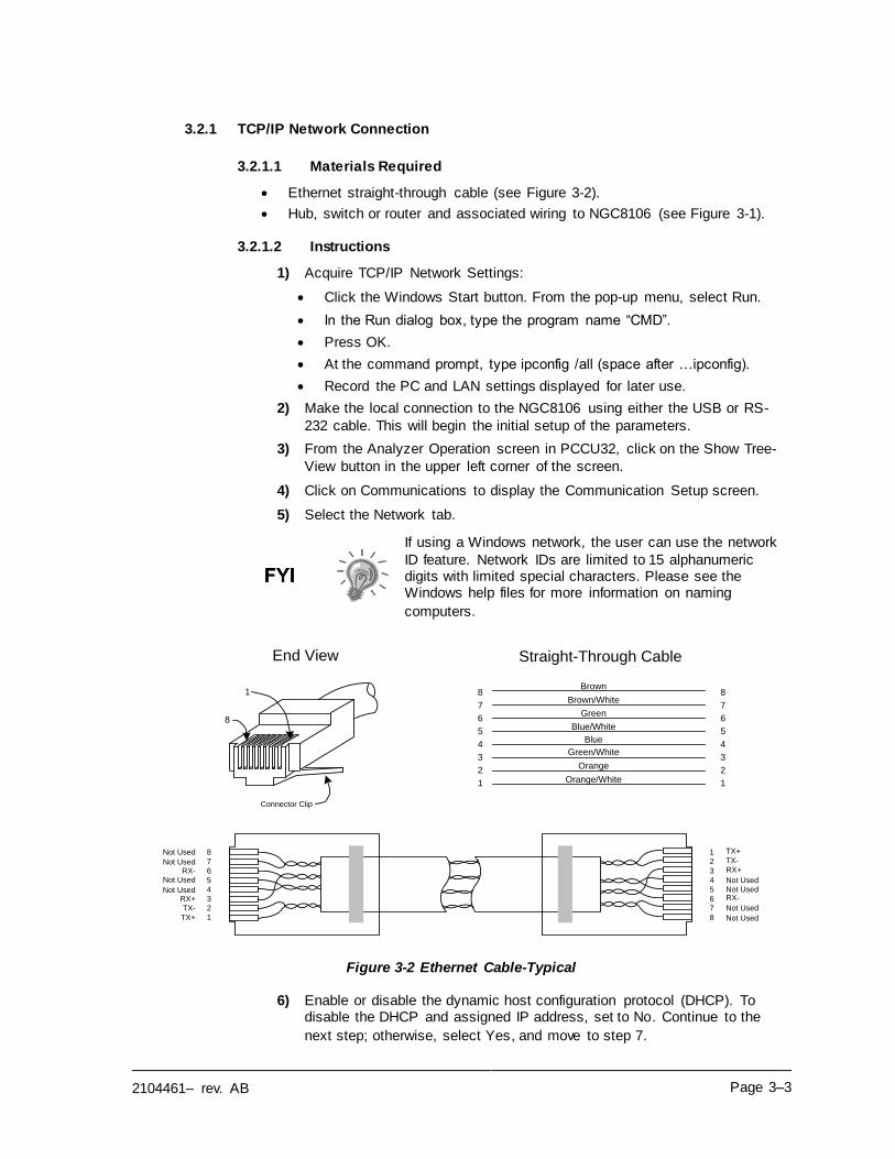
2104461– rev. AB Page 3–3
3.2.1 TCP/IP Network Connection
3.2.1.1 Materials Required
• Ethernet straight-through cable (see Figure 3-2).
• Hub, switch or router and associated wiring to NGC8106 (see Figure 3-1).
3.2.1.2 Instructions
1) Acquire TCP/IP Network Settings:
• Click the Windows Start button. From the pop-up menu, select Run.
• In the Run dialog box, type the program name “CMD”.
• Press OK.
• At the command prompt, type ipconfig /all (space after …ipconfig).
• Record the PC and LAN settings displayed for later use.
2) Make the local connection to the NGC8106 using either the USB or RS-
232 cable. This will begin the initial setup of the parameters.
3) From the Analyzer Operation screen in PCCU32, click on the Show Tree-
View button in the upper left corner of the screen.
4) Click on Communications to display the Communication Setup screen.
5) Select the Network tab.
If using a Windows network, the user can use the network
ID feature. Network IDs are limited to 15 alphanumeric digits with limited special characters. Please see the Windows help files for more information on naming
computers.
Figure 3-2 Ethernet Cable-Typical
6) Enable or disable the dynamic host configuration protocol (DHCP). To disable the DHCP and assigned IP address, set to No. Continue to the
next step; otherwise, select Yes, and move to step 7.
8
7
6
5
4
3
2
1 8
7
6
5
4
3
2
1Not Used
RX-
RX+
TX-
TX+
Not Used
Not Used
Not Used
Not Used
Not Used
Not Used
Not Used
8
7
6
5
4
3
2
1 Orange/White
8
7
6
5
4
3
2
1
Orange
Green/White
Blue
Blue/White
Green
Brown/White
Brown
Straight-Through Cable
Connector Clip
End View
RX-
RX+
TX-
TX+
8
1
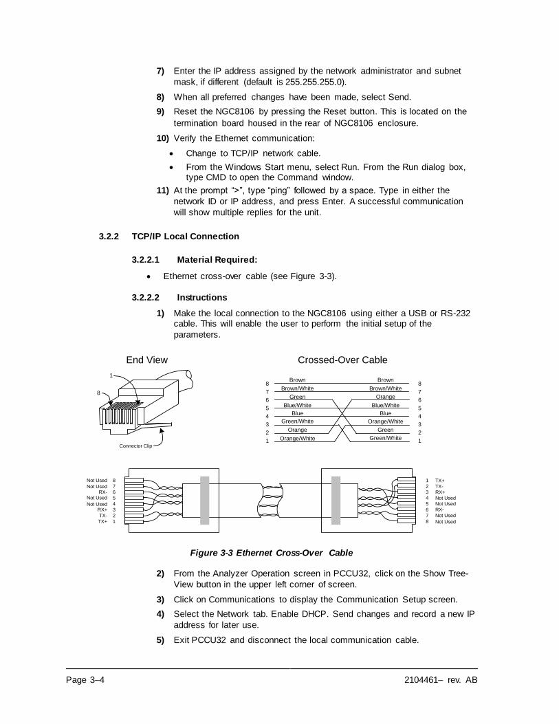
Page 3–4 2104461– rev. AB
7) Enter the IP address assigned by the network administrator and subnet
mask, if different (default is 255.255.255.0).
8) When all preferred changes have been made, select Send.
9) Reset the NGC8106 by pressing the Reset button. This is located on the
termination board housed in the rear of NGC8106 enclosure.
10) Verify the Ethernet communication:
• Change to TCP/IP network cable.
• From the Windows Start menu, select Run. From the Run dialog box, type CMD to open the Command window.
11) At the prompt “>”, type “ping” followed by a space. Type in either the
network ID or IP address, and press Enter. A successful communication
will show multiple replies for the unit.
3.2.2 TCP/IP Local Connection
3.2.2.1 Material Required:
• Ethernet cross-over cable (see Figure 3-3).
3.2.2.2 Instructions
1) Make the local connection to the NGC8106 using either a USB or RS-232 cable. This will enable the user to perform the initial setup of the
parameters.
Figure 3-3 Ethernet Cross-Over Cable
2) From the Analyzer Operation screen in PCCU32, click on the Show Tree-
View button in the upper left corner of screen.
3) Click on Communications to display the Communication Setup screen.
4) Select the Network tab. Enable DHCP. Send changes and record a new IP
address for later use.
5) Exit PCCU32 and disconnect the local communication cable.
8
7
6
5
4
3
2
1 8
7
6
5
4
3
2
1Not Used
RX-
RX+
TX-
TX+
Not Used
Not Used
Not Used
Not Used
Not Used
Not Used
Not Used
TX+
TX-
RX+
RX-
8
7
6
5
4
3
2
1 Orange/White
8
7
6
5
4
3
2
1
Orange
Green/White
Blue
Blue/White
Green
Brown/White
Brown
Orange
Green
Orange/White
Green/White
Blue/White
Blue
Brown/White
Brown
Crossed-Over Cable
Connector Clip
End View
8
1
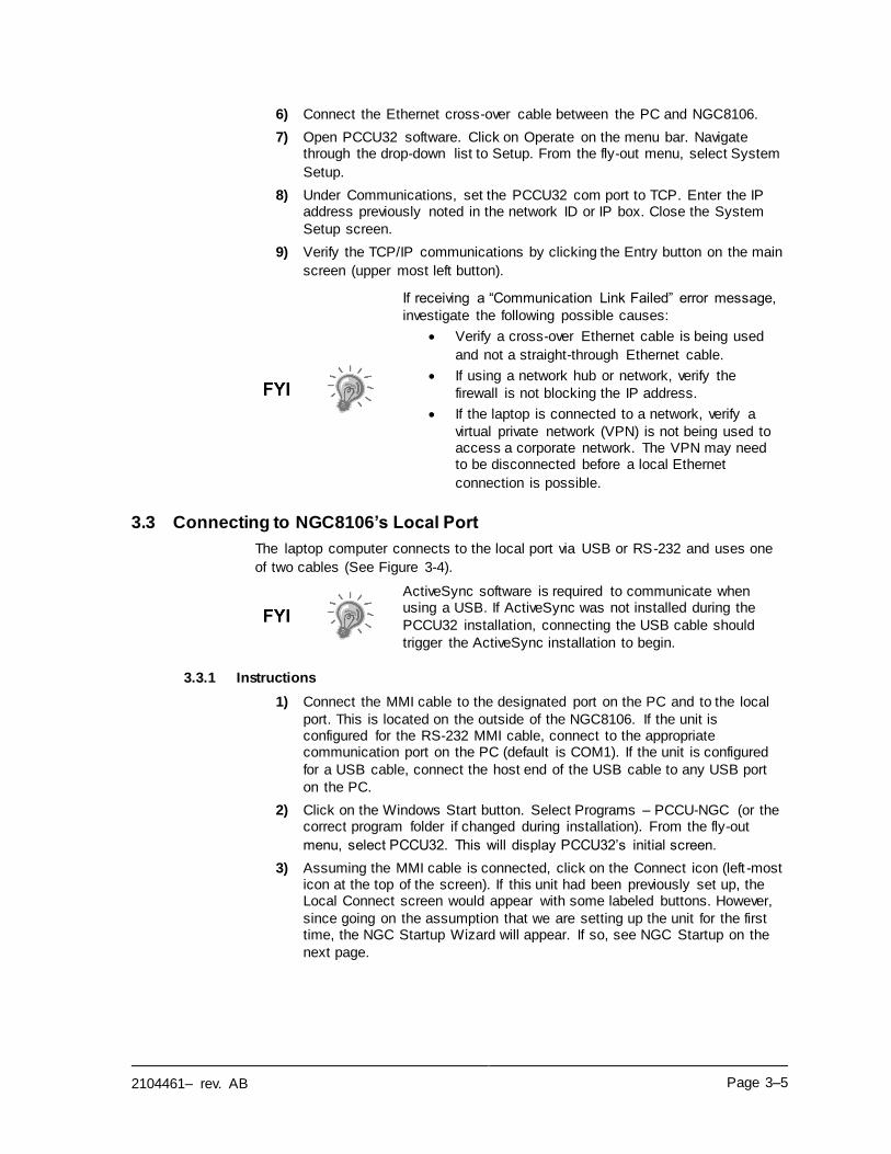
2104461– rev. AB Page 3–5
6) Connect the Ethernet cross-over cable between the PC and NGC8106.
7) Open PCCU32 software. Click on Operate on the menu bar. Navigate through the drop-down list to Setup. From the fly-out menu, select System
Setup.
8) Under Communications, set the PCCU32 com port to TCP. Enter the IP address previously noted in the network ID or IP box. Close the System
Setup screen.
9) Verify the TCP/IP communications by clicking the Entry button on the main
screen (upper most left button).
If receiving a “Communication Link Failed” error message,
investigate the following possible causes:
• Verify a cross-over Ethernet cable is being used
and not a straight-through Ethernet cable.
• If using a network hub or network, verify the
firewall is not blocking the IP address.
• If the laptop is connected to a network, verify a
virtual private network (VPN) is not being used to access a corporate network. The VPN may need to be disconnected before a local Ethernet
connection is possible.
3.3 Connecting to NGC8106’s Local Port
The laptop computer connects to the local port via USB or RS-232 and uses one
of two cables (See Figure 3-4).
ActiveSync software is required to communicate when using a USB. If ActiveSync was not installed during the
PCCU32 installation, connecting the USB cable should
trigger the ActiveSync installation to begin.
3.3.1 Instructions
1) Connect the MMI cable to the designated port on the PC and to the local
port. This is located on the outside of the NGC8106. If the unit is configured for the RS-232 MMI cable, connect to the appropriate communication port on the PC (default is COM1). If the unit is configured
for a USB cable, connect the host end of the USB cable to any USB port
on the PC.
2) Click on the Windows Start button. Select Programs – PCCU-NGC (or the correct program folder if changed during installation). From the fly-out
menu, select PCCU32. This will display PCCU32’s initial screen.
3) Assuming the MMI cable is connected, click on the Connect icon (left -most icon at the top of the screen). If this unit had been previously set up, the Local Connect screen would appear with some labeled buttons. However,
since going on the assumption that we are setting up the unit for the first time, the NGC Startup Wizard will appear. If so, see NGC Startup on the
next page.
Page 3–6 2104461– rev. AB
USB Cable
RS-232 Cable
Figure 3-4 MMI Communication Cables
If the Invalid Security Code screen should appear, enter four zeros (0000) for the new code, and click OK. The
NGC8106 should have defaulted to 0000 on startup.
4) Again, if the unit has already been set up, the Local Connect screen displays two buttons: Entry Setup and Collect Historical Data. Clicking on
Entry Setup will take the user to the Analyzer Operation screen. This screen has links to other operations. Daily operations should be performed from this screen. Historical data collection can also be performed from here
by clicking on the Collect icon at the top of the screen.
If a communication error is received, click on the Setup icon along the top of the screen, and verify the PCCU com port. If using USB, this should indicate USB; if not, click on
the down arrow. The user will need to scroll through the available selections and select USB. If the user is using serial communications with the round connector on the
NGC8106 end, select the communications port being used (COM1, etc.). When finished, close the Setup screen, and
click the Connect icon again.
3.4 NGC8106 Diagnostics
In Chapter 2-Installation, the DC power circuit to the NGC8106 was completed.
Once power was applied to the unit, the NG8106 began the startup procedure:
• Unit cold started and loaded startup information into RAM memory.
• Startup Diagnostics to run. If diagnostics are not successful, the unit will
return a system fault and cease startup.
Startup Diagnostics consists of four areas of testing:
• Carrier Pressure Regulator Test
• Oven Temperature Test
• Processor Control Test
2104461– rev. AB Page 3–7
• Stream Test
As noted above, the oven temperature test is one of the diagnostic tests run. To
pass this test, the oven temperature must reach 60 C and stabilize. Additionally, part of the processor control test is testing the amount of effort the oven controller
takes to keep the oven at its set point of 60 C. Based on the ambient
temperature, this could take up to an hour. During this time, the user can enter
information via the Startup Wizard.
During the initial start-up, the input stream is disabled. If input pressure is detected
during the stream test, the input stream will be re-enabled, tested and either passed or failed. If the device fails the input stream test, the input stream will
remain disabled.
During the diagnostics or upon completion, the user may view the status of the diagnostic tests by clicking on the Diagnostics button on the Analyzer Operation screen. Part of the startup diagnostic takes the user to the Diagnostic screen.
When the unit completes the startup diagnostics and has passed the appropriate tests, with the exception of no input stream pressure, the unit will go into hold mode. Totalflow recommends that the unit be allowed to run at least eight hours to
completely stabilize and then a calibration is performed. This is also spelled out in
the Startup Wizard.
3.5 NGC8106 Startup Wizard
After starting PCCU32 and clicking the Connect icon, the NGC8106 Startup Wizard begins automatically. This will only happen the first time the user connects to the unit or each time they reconnect to the unit and have not completed the
Startup Wizard.
The wizard walks the user through the process of entering all the necessary information to enable the operation of the NGC8106. Each screen has an
associated Help screen that automatically displays when moving from screen to
screen.
Step through all the screens in the Startup Wizard, and fill in the required
information. The unit may be concurrently running the startup diagnostics as the user is entering data into the Startup Wizard. One of the steps in the Startup Wizard is displaying the Diagnostics screen to view the results. If the diagnostics
are still in progress, the Startup Wizard will not allow the user to continue until the
diagnostics have finished.
The following procedure is only an outline. Specific steps are discussed in the
Wizard help file.
3.5.1 Station Setup Instructions
1) Enter the Station ID (ten alphanumeric digits) and Location (24 alphanumeric digits) (see Table 3–1). The Station ID should be a unique
identifier from other devices that the user communicates with.
2) Verify the date and time. If they are incorrect, set the PCCU Date/Time
parameter field to Yes.
Additional items in the Station Setup screen are not required for startup. For more information regarding the
setup of these items, see the help topic displayed with each
screen.
3) When all the preferred changes have been made, click the Send button
and then the Next button to move to the next screen.
Page 3–8 2104461– rev. AB
Table 3–1 Station Setup Screen Information
Description Value
Station ID Assign a unique identifier (ten alphanumeric digits).
Location Enter information regarding the meter location (24 alphanumeric digits).
Date/Time Display the current unit’s date/time.
Set Device with PCCU Date/Time Resets the device’s date and time to match the PC.
3.5.2 Stream Setup Instructions
1) Enter the Stream ID, Location, Contract Settings and Calculation Settings
(see Table 3–2).
2) When all the preferred changes have been made, select the Send button
and then the Next button to move to the next screen.
During the stream setup, please note that each time Next is selected, the user should see the Stream ID, located on the
first line of each screen, change value. The user must move through all four streams even if the unit is a single-
stream unit.
Table 3–2 Stream Setup Screens
Setup Tab Available Values
Stream ID Assign unique Identifier (ten alphanumeric digits).
Location Enter information regarding the meter location (24
alphanumeric digits).
Calibration Stream Stream 1 is used for calibration AND as the input
sampling stream.
Contract Settings Value Available Units
Contract Pressure 14.73 PSIA (default) KPa, InH20, Mbar, InHg, PSIA, Bar, mmHg, PSFa, MPa,
Pa or kgcm2
Contract Temperature 60.00 F(default) C, F, R or K
Relative Humidity 100.00 %(default) Percent
Contract Hour 0 (default) Hour (0-23)
Calculation Settings Value
Current Calculation File GPA-2172-1996(AGA-8), ISO-6976-1995, etc.1
Sum IC5 & NeoC5 No (default), Yes
C6+ Index Split Mode2
Default-User Defined with C6+ Reported, 47.466% C6 35.340% C7 17.194% C8, 50% C6 50% C7 0% C8, 50% C6 25% C7 25% C8, 57.143% C6 28.572% C7 14.285% C8, User Defined C6+ Not Reported.
C6, C7, C8, C9, C10` Used to enter split percentages , if desired.
1 File selection automatically sets the remainder of items on this screen. See PCCU Help f iles for more information.
2 Note that making a selection in this f ield (other than user-defined) will override any values in the C6+ Split Percent area of the
Stream Setup screen.
2104461– rev. AB Page 3–9
3.5.3 Calibration Setup Instructions
1) In a single stream sampler/analyzer, stream 1 (S1) is used for calibration and stream sampling. Unless a T-valve is being used, the operator will
have to remove the stream tubing and connect the tubing from the calibration gas. When calibration has completed, the sample stream should be re-connected to the stream 1 (S1) port. When switching between
sample gases and calibration gases, time should be allowed for the tubing
to purge the previous gas. Wait for the BTU value to settle.
2) Change the Calibration Cycles Average and Purge Cycles, if required.
Default Calibration Cycles Average is 3 and Purge Cycles is 2.
3) Make changes to the concentrations in the % BLEND column. Ensure that
the Total Mole % equals 100%.
Caution should be used when entering the component blend percentages to match the components labeled on the
calibration bottle. Mistakes will cause incorrect values.
If the Total Mole % does not equal 100% exactly, add or subtract the remainder to or from the methane (C1) to force
the total to 100%.
4) When finished and Total Mole% equals 100%, select the Next button to
move to the next screen.
5) When all preferred changes have been made, select the Send button and
then the Next button to move to the next screen.
3.5.4 Diagnostics
1) As discussed earlier, diagnostics began when power was applied to the
unit. The user cannot proceed beyond the Diagnostics screen until diagnostics have passed. When completed, select the Next button to move
to the next screen.
During the initial startup, the input stream is disabled. The
input stream is enabled when stream pressure is detected. If
no stream pressure is detected, a failure is logged.
Totalflow recommends that the diagnostic stream test be
performed after initial diagnostics. Select the Help button for
additional information.
2) When all the preferred changes have been made, select the Send button
and then the Next button to move to the next screen.
3.5.5 Update Configuration
1) Totalflow recommends that the user save the unit configuration file following setup. Change the parameter value beside Save Configuration
Data to Now to save the configuration.
2) Select the Send button and then the Next button to move to the next
screen.
Page 3–10 2104461– rev. AB
3.5.6 Analyze Calibration Stream
1) Prior to running the sample stream, the NGC8106 should run a calibration. Connect the calibration gas to the input port (S1). The cycle clock will
begin, and the user should see animated gas running on the input stream.
2) Allow the stream to process for two or three cycles (approximately 30-minutes). During the final cycle, change the Next Mode to Hold. When the
unit completes the current cycle, it will enter Hold mode.
3) Select the Next button to verify the analysis results.
4) Compare the normalized % for each component-to-component and
percentages listed on the calibration blend bottle. Component percentages
should be relatively similar.
There will not be any comparisons for C6+ individual components. There may be values in the Normalized column
for Hexane thru Decane, but this is based on the C6+ configuration entered in Stream Setup. For comparison
purposes, use the components called Heavies.
5) Select the Next button to verify the heavy components on Chrom-1.
6) Verify that the appropriate components are visible and labeled. For the standard C6+ application, the user should see C6+, C3, IC4, nC4, neoC5, iC5 and nC5. The second peak from the left that looks like two peaks is a
composite peak of C2- and is not used in calculations.
7) Select the Next button to verify the light components on Chrom-2.
8) Verify that the appropriate components are visible and labeled. The user should see N2, C1, CO2 and C2. The first peak on the left is a composite
peak of C3+ and is not used in calculations.
9) Disconnect the calibration blend and reconnect the sample tubing. Select
the Next button to begin the process stream analysis. Select Run on the left side of the screen to begin the sample analysis. The buttons beside Run should turn blue, the cycle clock will begin, and the user should see
animated gas running on the process stream.
3.5.7 Startup Completion
1) The unit should continue to cycle through the input process stream
performing analysis and producing data.
2) ABB Totalflow recommends that the unit be allowed to run at least eight
hours before calibration to allow the unit to stabilize.
3) Select the Close button to complete the Startup Wizard and to return to
PCCU32’s Local Analyzer Operation screen. If completed satisfactorily, the Startup Wizard should not reappear when connecting to the unit. However, should the user like to review or make changes, they may re-enter the
Startup Wizard by selecting NGC8106 Startup Wizard from the Help drop-
down menu.
3.6 Calibrating the NGC8106
The NGC8106 is factory-calibrated and should not require an immediate calibration. It is recommended that the unit operate for a period of eight continuous hours before a field calibration. After the eight hours have elapsed, a
2104461– rev. AB Page 3–11
field calibration should be performed. This will allow for adjustments due to the
location’s barometric pressure and other factors .
A calibration cycle includes purge cycles and multiple calibration cycles for averaging. The system defaults to two purge cycles and three calibration cycles. When the calibration is complete, a thorough examination of the results should
follow.
Allow the NGC8106 to run for a minimum of eight hours
before a field calibration is performed.
3.6.1 Instructions
1) After connecting the calibration blend to the input port (S1), select Cal from
the Analyzer Operation screen.
2) When the current cycle completes, the unit should begin a calibration
cycle.
3) When the calibration is complete, the unit should move to the designated Next mode. The user can view the results on the Analyzer Operation
screen.
4) The calibration stream’s UnNormalized total should be 0.5% (between
99.5% and 100.5%).
If values exceed these parameters, proceed to the
Troubleshooting chapter within this manual.
5) Carefully examine the calibration stream’s Chrom-1 and Chrom-2 by
clicking on the button. Look for unlabeled peaks and base line
anomalies. Figure 3-5 and Figure 3-6 should be used as a guide.
If errors exist, proceed to the Troubleshooting chapter within
this manual.
6) Once the unit is running smoothly and is producing good chroms and all the peaks are labeled and eluting correctly, perform a save and restore
procedure to update TfCold.
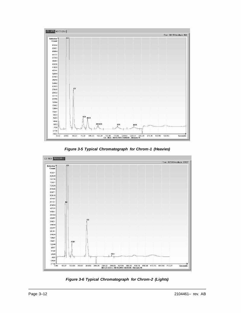
Page 3–12 2104461– rev. AB
Figure 3-5 Typical Chromatograph for Chrom-1 (Heavies)
Figure 3-6 Typical Chromatograph for Chrom-2 (Lights)

2104461– rev. AB Page 3–13
3.7 Security System Setup
3.7.1 Hardware Security
The NGC8106 board has a bi-level security system built in. For the purpose of this
manual, this is referred to as hardware security. The security switch, located on the termination board of the NGC8106, must be switched down for the hardware security system to be functional. The switch must be switched up to change the
device’s security code. Security codes are checked via remote communication,
whether the switch is on or off.
3.7.2 PCCU Security
When the NGC8106 is accessed through the PCCU32 or WINCCU host software
packages, either remotely or locally, there is a second level of security included.
This is referred to as the software security.
The security switch, located on the termination board of the NGC8106, must be
switched on for the hardware security system to be functional. The switch must be switched off to change the device’s security code. Security codes are checked via
remote communication, whether the switch is on or off.
When the system is set up, each user logs onto the system with a unique user name (up to 25 alphanumeric digits) and a 4-digit alphanumeric password. This
takes place before the user connects to the unit.
The software security system is designed to have two levels of user access:
• Reading data files – read-only access (User)
• Sending application and configurations - read/write access (Admin)
By default, user access is restricted from modifying the application table or from downloading files to the device’s TfData and TfCold drives but has all other user-type privileges. These default privileges can be edited by the administrator and
consists of 4-digit alphanumeric pass codes (level 1 and level 2).
The NGC8106 does not send an error message when trying
to write an operation where the proper hardware security
code does not exist; it simply will not accept value changes.
3.7.3 Role Based Access Control (RBAC)
The RBAC system is effective in PCCU versions 7.16.0 or higher. RBAC adds a
third level of security to the NGC8106 and supersedes the hardware security
system.
While available for setup, RBAC is not operational when the new system is
delivered. This allows the customer to define any specific roles beyond the basic
four (4) defined roles:
• Basic
• Advanced
• Expert
• Administrator
Administrators can develop additional roles, set up and assign specific users a role and define application access independently for each user. Levels of access
for each application are:
• Yes or No
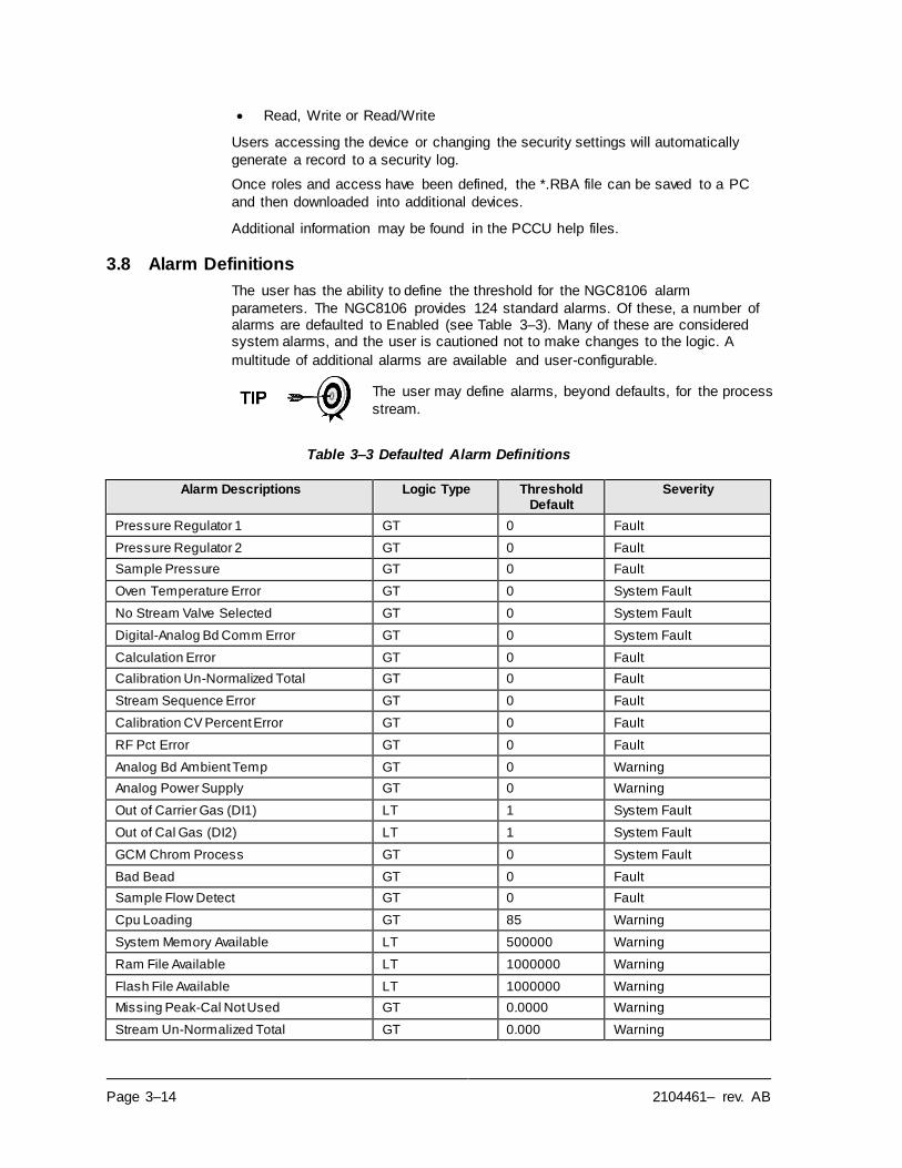
Page 3–14 2104461– rev. AB
• Read, Write or Read/Write
Users accessing the device or changing the security settings will automatically
generate a record to a security log.
Once roles and access have been defined, the *.RBA file can be saved to a PC
and then downloaded into additional devices.
Additional information may be found in the PCCU help files.
3.8 Alarm Definitions
The user has the ability to define the threshold for the NGC8106 alarm
parameters. The NGC8106 provides 124 standard alarms. Of these, a number of alarms are defaulted to Enabled (see Table 3–3). Many of these are considered system alarms, and the user is cautioned not to make changes to the logic. A
multitude of additional alarms are available and user-configurable.
The user may define alarms, beyond defaults, for the process
stream.
Table 3–3 Defaulted Alarm Definitions
Alarm Descriptions Logic Type Threshold Default
Severity
Pressure Regulator 1 GT 0 Fault
Pressure Regulator 2 GT 0 Fault
Sample Pressure GT 0 Fault
Oven Temperature Error GT 0 System Fault
No Stream Valve Selected GT 0 System Fault
Digital-Analog Bd Comm Error GT 0 System Fault
Calculation Error GT 0 Fault
Calibration Un-Normalized Total GT 0 Fault
Stream Sequence Error GT 0 Fault
Calibration CV Percent Error GT 0 Fault
RF Pct Error GT 0 Fault
Analog Bd Ambient Temp GT 0 Warning
Analog Power Supply GT 0 Warning
Out of Carrier Gas (DI1) LT 1 System Fault
Out of Cal Gas (DI2) LT 1 System Fault
GCM Chrom Process GT 0 System Fault
Bad Bead GT 0 Fault
Sample Flow Detect GT 0 Fault
Cpu Loading GT 85 Warning
System Memory Available LT 500000 Warning
Ram File Available LT 1000000 Warning
Flash File Available LT 1000000 Warning
Missing Peak-Cal Not Used GT 0.0000 Warning
Stream Un-Normalized Total GT 0.000 Warning
2104461– rev. AB Page 4–1
4.0 MAINTENANCE
4.1 Overview
This chapter provides the user with maintenance information and instructions on how to remove and install NGC8106 components. Performance of the
recommended procedures maintains the unit in optimal operating condition,
reduces system downtime and ensures accuracy of natural gas sample analysis.
It is recommended that the user develop regularly scheduled daily, weekly or
monthly maintenance programs. By establishing such programs, NGC8106 downtime will be reduced, and the system will operate at optimum analytical efficiency. Perform all the recommended procedures as presented within this
chapter. If additional procedures are developed, they should be included with
those already in existence.
Practical experience permits updating the maintenance procedures and
associated schedules over time. This results in many procedures being performed on a routine basis before potential problem(s) result in a failure.
For all maintenance steps: remove power from the device, or ensure the area is known to be non-hazardous, including the internal volume of the enclosure, before removing any
enclosure cover or performing any of the maintenance steps
in this section.
4.1.1 Help
If technical assistance is required during the performance of maintenance
functions or if returning parts, the user should contact the ABB Totalflow customer
service department at the following phone number:
USA: (800) 442-3097 or International: 1-918-338-4880
4.1.2 Maintaining Cleanliness
It is important that an inspection time period be established to examine the unit for
internal and external cleanliness and damage.
Because an NGC8106 installation is primarily exposed to external environmental
conditions, it is important that it be regularly inspected for cleanliness, both externally and internally. Even though the NGC8106 is tightly sealed against moisture and foreign contamination, it is recommended that the internal
components be examined for moisture and/or contamination. If contamination is found, the system should be shut down and cleaned. If such contamination is not
removed, it could render the NGC8106 inoperable.
4.1.3 How to Use This Chapter
Record all items within this chapter in the maintenance practice procedures. Practical experience permits updating this schedule over a period of time. This results in many maintenance items being handled on a routine basis before
potential problem(s) result in a failure.
Page 4–2 2104461– rev. AB
4.1.4 Returning Part(s) for Repair
If an ABB Totalflow component is to be returned for repair, securely wrap it in protective anti-static packaging. Before returning a component, call ABB Totalflow
for a Return for Authorization number (RA). Affix this number to the outside of the
return package.
Parts shipments must be prepaid by the customer. Any part not covered by the
original system warranty will be shipped to the customer, F.O.B.
When the user removes the front or rear end caps, their hands can become coated with a black-thread lubricant. If
this happens, wash hands before performing maintenance functions. Use Go-Jo or an equivalent type hand cleanser. The lubricant MUST NOT come in contact with components.
DO NOT wipe lubricant on clothing, as it cannot be removed
easily.
If enclosure needs more thread lubricant, use Vaseline.
4.2 Spare Part Components
The information in this section presents the user with the components (see Figure 4-1) and parts that are accessible for removal and installation. Replacement
components will be covered first. Subsequent sections will have instructions for
replacing spare parts.
4.2.1 Replacement Components
The following is a list of components that may be replaced:
• Analytical module (12 or 24 Vdc) with or without GC module (see Figure 4-2)
• GC module
• Digital controller assembly with display
• Termination panel
• Feed-through assembly without preheat (see Figure 4-3)
• Feed-through assembly with preheat (12 or 24 Vdc)
4.2.2 Replacement Parts
The following is a list of parts that may be replaced:
• Lithium battery
• Frit filters
• Analytical processor to termination panel cable
• Termination panel to digital controller cable
• Feed-through O-ring
• Feed-through interface gasket
• Feed-through manifold gasket
• Feed-through heater with temperature sensor (12 or 24 Vdc)
• GC module temperature sensor
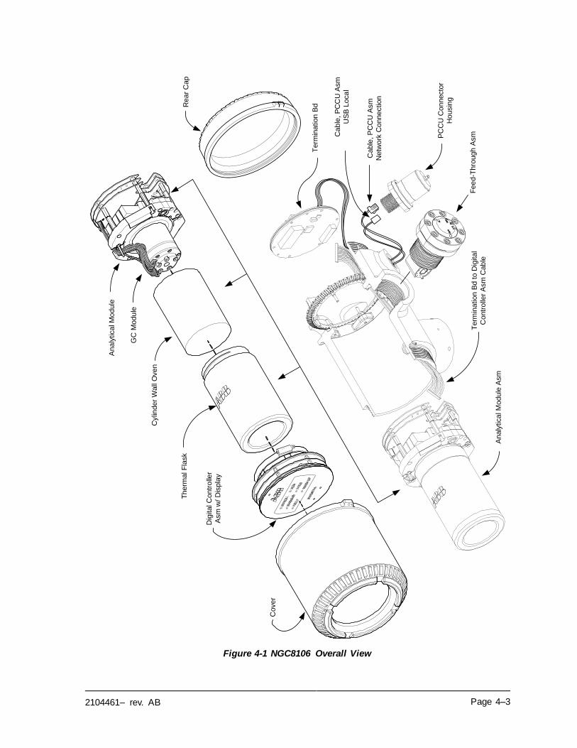
2104461– rev. AB Page 4–3
Figure 4-1 NGC8106 Overall View
Cylin
der W
all
Oven
Cover
Dig
ital C
ontr
olle
r
Asm
w/ D
isp
lay
Th
erm
al F
lask
Fee
d-T
hro
ugh
Asm
Rea
r C
ap
PC
CU
Con
necto
r
Ho
usin
g
Term
ination
Bd
Analy
tica
l M
odule
Asm
An
aly
tica
l M
odule
Term
ina
tion
Bd
to D
igita
l
Contr
olle
r A
sm
Cab
le
Ca
ble
, P
CC
U A
sm
US
B L
oca
l
Cable
, P
CC
U A
sm
Netw
ork
Co
nnection
GC
Modu
le
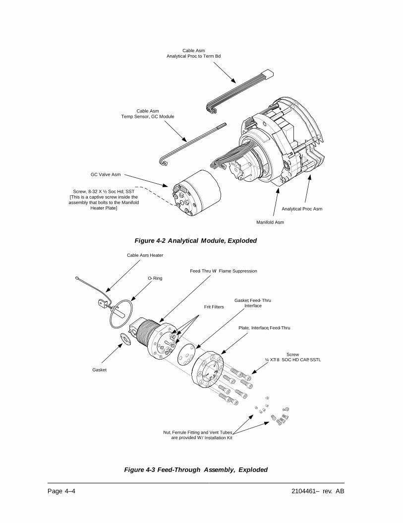
Page 4–4 2104461– rev. AB
Figure 4-2 Analytical Module, Exploded
Figure 4-3 Feed-Through Assembly, Exploded
Cable Asm
Temp Sensor, GC Module
GC Valve Asm
Cable Asm
Analytical Proc to Term Bd
Screw, 8-32 X ½ Soc Hd; SST
[This is a captive screw inside the
assembly that bolts to the Manifold
Heater Plate]
Analytical Proc Asm
Manifold Asm
Frit Filters
Screw
¼ X 7/ 8 SOC HD CAP, SSTL
Feed- Thru W/ Flame Suppression
Gasket, Feed- Thru
Interface
Plate, Interface, Feed-Thru
O- Ring
Gasket
Nut, Ferrule Fitting and Vent Tubes are provided W/ Installation Kit
Cable Asm, Heater
2104461– rev. AB Page 4–5
4.2.3 Repair Time
ABB Totalflow has provided a recommended spares list for the NGC8106. Consideration was given to the cost of the repair time and the cost of stocking the
repair parts. The NGC8106’s modular design is uniquely suited for quick repair times. The following table lists four categories that concern repair times and the spares required to achieve those various repair times. Repair days are
represented as work days not calendar days.
Table 4–1 Repair Time vs. Down Time
Repair Time Requirements
No down time
If the application cannot allow for any down time, the
user will need to consider having two units up and running. When one fails, the user can simply switch to
the backup unit and send the failed unit in for repair.
In less than 8 hours
If the user is required to have a down time of less than
eight hours, the user will have to stock replacement parts on-site. The repair parts required would depend on the variety of applications at the site. If the user has
multiple units or applications at a single site, this would
be a typical scenario.
In less than 48 hours
This category is for applications where the parts would be stocked at the factory. Overnight delivery of the part
would allow for repair the next day. This might be typical for a fixed application that could tolerate a 48-
hour repair time.
In less than 120 hours
This category is suited for any application or mix of
applications. Within five working days, the site can
receive shipment of stocked or built-to-order parts.
4.2.4 Recommended Spares
Recommended spares are provided for each of these categories, depending upon whether there is a single or multiple units at the site(s) and whether the
applications are fixed applications (stocked at the factory) or built-to-order (not stocked at the factory). The user will need to balance the cost of the spares with the cost of the repair time. With the variety of options available, the user can
manage the repair time for the units, as needed.
4.2.5 Customer Service
Customer service can be called out and may have the stocked applications available for replacement (depending upon usage by the individual on service
calls). The scheduling for a call-out is typically a week. If service personnel are needed in a more timely fashion, maintenance contracts may need to be considered. Phone support from the factory is available to help with the diagnosis
of a problem. Alarms from the unit are also a key to quick diagnosis and repair of
any failure.
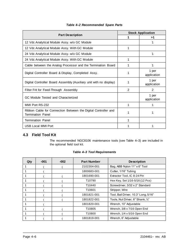
Page 4–6 2104461– rev. AB
Table 4–2 Recommended Spare Parts
Part Description Stock Application
1 >1
12 Vdc Analytical Module Assy. w/o GC Module 1
12 Vdc Analytical Module Assy. With GC Module 1
24 Vdc Analytical Module Assy. w/o GC Module 1
24 Vdc Analytical Module Assy. With GC Module 1
Cable between the Analog Processor and the Termination Board 1 1
Digital Controller Board & Display, Completed Assy. 1 1 per
application
Digital Controller Board Assembly (Auxiliary unit with no display) 1 1 per
application
Filter Frit for Feed-Through Assembly 2 2
GC Module Tested and Characterized 1 per
application
MMI Port RS-232 1 1
Ribbon Cable for Connection Between the Digital Controller and
Termination Panel 1 1
Termination Panel 1
USB Local MMI Port 1 1
4.3 Field Tool Kit
The recommended NGC8106 maintenance tools (see Table 4–3) are included in
the optional field tool kit.
Table 4–3 Tool Requirements
Qty -001 -002 Part Number Description
1 ( ( 2102304-001 Bag, ABB Nylon 11” x 6” Tool
1 ( 1800683-001 Cutter, 1/16” Tubing
1 ( ( 1801690-001 Extractor Tool, IC 8-24 Pin
1 ( ( T10790 Hex Key, Set 1/16-5/16 (12 Pcs)
1 ( ( T10440 Screwdriver, 3/32 x 2” Standard
1 ( ( T10601 Stripper, Wire
1 ( ( 1801821-001 Tool, Ball Driver, 10.3” Long, 5/16”
1 ( ( 1801822-001 Tools, Nut Driver, 6” Shank, ¼”
1 ( 1801820-001 Wrench, 10” Adjustable
1 ( ( T10805 Wrench, 3/8 x 7/16 Open End
1 ( ( T10800 Wrench, 1/4 x 5/16 Open End
1 ( ( 1801819-001 Wrench, 6” Adjustable
2104461– rev. AB Page 4–7
4.4 Visual Inspection
Periodically, the NGC8106 should be given an external, visual examination. Visual
checks maintain optimum system operation and accuracy of natural gas sample
analysis.
4.4.1 Inspection
During the visual inspection, components should be examined for the following
conditions:
• Pipe or wall mounting: The unit must be in a vertical position and the mounting brackets tightened on the pipe. The wall mounting bracket must be
securely affixed to the mounting wall.
• Carrier gas bottle mounting rack: The mounting rack should be tilted
backward slightly to keep the bottles from falling forward.
• Bottles within mounting rack: The bottles must be securely strapped in the
mounting rack.
• Bottle regulators: These must be tightened securely and checked for leaks.
• Pipe mounted sample probe: These must be securely mounted in the pipe
meter run using an approved probe adapter.
• Stainless steel tubing connected between sample probe and NGC8106: These must not be bent or closed off. The connections must be tight. Such
conditions impede the sample flow to the NGC8106.
• Tightness of front and rear end caps: Hand tightening gently is adequate.
• Input/output terminations, external power or signal cable runs: All input/output cable and power and signal conduit runs to Div 2 or non-hazardous areas
must be sealed per NEC codes.
4.5 Backing Up Configuration Files (Save)
Before beginning any maintenance on the NGC8106, the user should collect the data and back up all configuration files to their laptop’s hard drive or a floppy disk.
This safeguards the data and allows the user to re-start the unit without the trouble
associated with re-configuring the NGC8106 should any problems arise.
Although there are Save buttons in the Entry mode screens that allows the user to
back up Entry mode data items, a complete system backup is only accomplished by using the Save and Restore Utility. When using this utility to back up files, the user should also download the files to the TfCold drive. This safeguards the
system in the event of a “cold” start.
4.5.1 Instructions
1) Collect data from the unit.
2) While in PCCU, use the Save and Restore Utility found under File Utilities in the Operate drop-down menu on the main PCCU32 toolbar. The user
can also click the Save and Restore Utility icon on the toolbar.
3) In the Save and Restore window, click the Save Station Files button.
4) When the Save Station Files window appears, verify the default name and
path for the files. Click OK. This will save the TfData files to the PC.
5) When finished saving the station files, a new window will offer the option to restore the station files to the TfCold drive. If Yes is selected, the station
files will be downloaded to that drive.
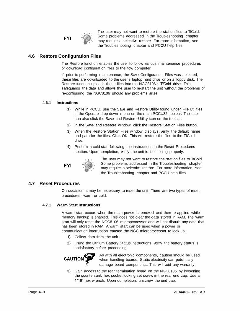
Page 4–8 2104461– rev. AB
The user may not want to restore the station files to TfCold. Some problems addressed in the Troubleshooting chapter
may require a selective restore. For more information, see
the Troubleshooting chapter and PCCU help files.
4.6 Restore Configuration Files
The Restore function enables the user to follow various maintenance procedures
or download configuration files to the flow computer.
If, prior to performing maintenance, the Save Configuration Files was selected,
these files are downloaded to the user’s laptop hard drive or on a floppy disk. The Restore function uploads these files into the NGC8106’s TfCold drive. This safeguards the data and allows the user to re-start the unit without the problems of
re-configuring the NGC8106 should any problems arise.
4.6.1 Instructions
1) While in PCCU, use the Save and Restore Utility found under File Utilities in the Operate drop-down menu on the main PCCU32 toolbar. The user
can also click the Save and Restore Utility icon on the toolbar.
2) In the Save and Restore window, click the Restore Station Files button.
3) When the Restore Station Files window displays, verify the default name and path for the files. Click OK. This will restore the files to the TfCold
drive.
4) Perform a cold start following the instructions in the Reset Procedures
section. Upon completion, verify the unit is functioning properly.
The user may not want to restore the station files to TfCold. Some problems addressed in the Troubleshooting chapter may require a selective restore. For more information, see
the Troubleshooting chapter and PCCU help files.
4.7 Reset Procedures
On occasion, it may be necessary to reset the unit. There are two types of reset
procedures: warm or cold.
4.7.1 Warm Start Instructions
A warm start occurs when the main power is removed and then re-applied while memory backup is enabled. This does not clear the data stored in RAM. The warm
start will only reset the NGC8106 microprocessor and will not disturb any data that has been stored in RAM. A warm start can be used when a power or
communication interruption caused the NGC microprocessor to lock up.
1) Collect data from the unit.
2) Using the Lithium Battery Status instructions, verify the battery status is
satisfactory before proceeding.
As with all electronic components, caution should be used when handling boards. Static electricity can potentially
damage board components. This will void any warranty.
3) Gain access to the rear termination board on the NGC8106 by loosening the countersunk hex socket locking set screw in the rear end cap. Use a
1/16” hex wrench. Upon completion, unscrew the end cap.
2104461– rev. AB Page 4–9
4) To warm start the unit, depress the S1 reset switch on the termination
board.
Or, to remove the NGC8106 from service, disconnect the power connector
J1 from the board.
5) To place NGC8106 back into service, return the power connection J1 to
the termination board.
4.7.2 Cold Start Instructions
A cold start clears all the data that is stored in RAM as well as resetting all entered variables to their factory default values. Discretionary use of this procedure is
advised.
1) On the Analyzer Operation screen, click Hold under Next Mode. When the unit completes the current cycle and enters hold, the user may continue to
the next step.
As with all electronic components, caution should be used when handling boards. Static electricity can potentially
damage board components. This voids any warranty.
2) Gain access to the digital controller assembly by loosening the countersunk hex socket locking set screw in the front end cap. Use a 1/16”
hex wrench. Upon completion, unscrew the end cap.
3) Gain access to rear termination panel on the NGC8106 by loosening the
countersunk hex socket locking set screw in the rear end cap. Use a 1/16”
hex wrench. Upon completion, unscrew the end cap.
4) Unplug the lithium battery connector from the J5 receptacle on the digital
controller board (see Figure 4-4).
5) Push the Reset button located on the termination board. This is located in
the rear of the enclosure.
6) Initially, the Boot Loader screen will appear on front display.
7) When the Navigation screen displays, restore the lithium battery
connection on the digital controller board.
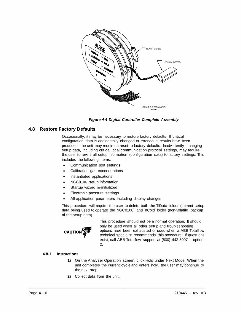
Page 4–10 2104461– rev. AB
Figure 4-4 Digital Controller Complete Assembly
4.8 Restore Factory Defaults
Occasionally, it may be necessary to restore factory defaults. If critical configuration data is accidentally changed or erroneous results have been
produced, the unit may require a reset to factory defaults. Inadvertently changing setup data, including critical local communication protocol settings, may require the user to revert all setup information (configuration data) to factory settings. This
includes the following items:
• Communication port settings
• Calibration gas concentrations
• Instantiated applications
• NGC8106 setup information
• Startup wizard re-initialized
• Electronic pressure settings
• All application parameters including display changes
This procedure will require the user to delete both the TfData folder (current setup data being used to operate the NGC8106) and TfCold folder (non-volatile backup
of the setup data).
This procedure should not be a normal operation. It should
only be used when all other setup and troubleshooting options have been exhausted or used when a ABB Totalflow technical specialist recommends this procedure. If questions
exist, call ABB Totalflow support at (800) 442-3097 – option
2.
4.8.1 Instructions
1) On the Analyzer Operation screen, click Hold under Next Mode. When the
unit completes the current cycle and enters hold, the user may continue to
the next step.
2) Collect data from the unit.
CLAMP SCREW
CABLE TO TERMINATION BOARD
LITHIUM BATTERY
2104461– rev. AB Page 4–11
3) Shut down PCCU32.
The system may not allow the deletion of active files when the NGC8106 is in normal operation (running from FLASH);
therefore, the user should force the unit into Boot Loader
mode.
4) Force the NGC8106’s operating system into Boot Loader mode.
5) Press the Reset button on the NGC8106’s termination board. Wait about
eight seconds until the Initializing System screen displays.
6) Press the Reset button a second time. The unit should now be in Boot
Loader mode.
7) Right-click on the Activesync icon located in the System Tray on the PC.
From the pop-up screen, select Explore.
8) In the new window, highlight the TfData folder under Mobile Devices.
9) Right click on the folder, and select Delete. The folder will disappear.
10) Open the Flash folder by double-clicking on it.
11) Highlight the TfCold folder. Right-click on it, and select Delete. The folder
will disappear.
12) Press the Reset button on the termination board. This action should cause the \Flash\Factory\TfCold information, saved at the factory, to be copied into a new TfData folder. This will restore all factory settings. The unit has
successfully been reset if the user sees the Startup Wizard when they
reconnect with PCCU32.
4.9 Lithium Battery Status
Prior to various maintenance procedures, especially when a cold start is not desirable or feasible, the user should verify that the lithium battery status is
satisfactory.
If the user is directed to these instructions from another set of instructions, please
return to them when the status has been verified.
4.9.1 Instructions
1) While in the PCCU Analyzer Operation screen, select Station Setup from
the icons across the top of the screen.
2) Select the value beside Lithium Battery Status.
3) If the Lithium Battery Status value reads OK, then power may be removed
from the unit without causing a cold start.
4) If Lithium Battery Status reads Low Voltage or Not Connected, the lithium battery should be connected or replaced prior to removing power from the
unit. See the Replacing the Lithium Battery instructions later in the chapter.
4.10 Changing NGC8106 Clock
When measurement streams are turned on within NGC8106, changing the clock could affect the time when log period entries are made. To protect the integrity of accounting audit trails, the NGC8106 handles these types of clock changes as
follows:
Page 4–12 2104461– rev. AB
Examples are based on a 60-minute log period.
4.10.1 Clock Change Not Crossing a Log Period Boundary
When the next log period entry is made, the clock is not altered.
Example: If the present time is 4:15 p.m. and the clock is changed to 4:05 p.m. of the same day, the daily flow record is the same. The entry reflects the
accumulation over a 70-minute time period (15-minutes plus 55-minutes).
4.10.2 Forward Clock Change Crossing a Log Period Boundary
This forces a log period entry for part of the log period that has accumulated since the last log period entry. NGC8106 then advances to a new data flow record and
begins maintaining the balance of the day’s data in a newly defined boundary.
Example: If the present time is 4:55 p.m. and the clock is changed to 5:05 p.m. of the same day, the entry reflects only a 55-minute average accumulation. A new
flow record is then written. This period is also based on a 55-minute accumulation.
4.10.3 Backward Clock Change Crossing a Log Period Boundary
This forces a log period entry for part of the log period that has accumulated since the last log period entry. This is the same as for a forward clock change crossing
an hourly boundary. NGC8106 advances to a new day’s data flow record and
maintains the balance of the day’s data in a new record.
Example: If the present time is 5:05 p.m. and the clock is changed to 4:55 p.m. of
the same day, the log period record entry reflects only a 5-minute average accumulation (5:00 to 5:05). A new flow record is then written. This log period is
based on a 5-minute accumulation (4:55 to 5:00).
A backward clock change uses two (2) daily records to maintain data integrity. This assures that previously recorded
data is not overwritten.
If it is necessary to make small backward time changes less than one (1) hour, the user should wait until the current hour has progressed far enough to make a change that does not
cross an hour boundary.
4.11 Replacing Calibration or Carrier Gas Bottle(s)
When calibration or carrier gas bottle(s) require replacement, please use the
following instructions.
4.11.1 Instructions
1) On the Analyzer Operation screen, click Hold under Next Mode. When the unit completes the current cycle and enters hold, the user may continue to
the next step.
2) Turn off the calibration and/or carrier gas at the bottle.
3) Remove the regulator from the bottle.
4) Exchange the bottle with the full bottle.
5) Re-Install the regulator into the bottle. Verify that the pressure regulator is
set correctly to either 15 PSIG for calibration gas or 90 PSIG for carrier
gas. Open the shut-off valve on the regulator.
2104461– rev. AB Page 4–13
6) At the NGC8106 feed-through assembly, loosen the nut and ferrule from
the corresponding inlet. Allow the air to purge from the line.
Be sure to follow the requirements of the national and local
codes when performing this purge.
7) Re-insert the ferrule and nut into the correct inlet and tighten.
8) Leak test the connections at the bottle regulator and the feed-through
assembly.
9) In PCCU32, with the unit still in hold, run two single cycles. Inspect the chromatograms to determine if the unit is processing correctly. If chroms
are satisfactory, return the unit to normal operation.
4.12 Removing Digital Controller Assembly
This section presents the procedures for removal and installation of the digital controller assembly and mounting bracket. If the user has been directed here from
another procedure, return back to the corresponding procedure when disassembly
is complete.
As with all electronic components, caution should be used
when handling boards. Static electricity can potentially damage
board components. This voids any warranty.
4.12.1 Instructions
1) On the Analyzer Operation screen, click Hold under Next Mode. When the
unit completes the current cycle and enters hold, the user may continue to
the next step.
2) Gain access to the digital controller assembly by loosening the countersunk hex socket locking set screw in the front end cap using a
1/16” hex wrench then unscrewing the end cap.
3) Using a flat blade screwdriver, loosen the screw in the mounting clamp.
4) Unplug the ground cable from the digital controller assembly.
5) Slide the assembly off of the thermal flask. Be careful to not unplug the flat ribbon cable connecting the digital controller assembly to the termination
board or the lithium battery.
DO NOT remove the NGC8106 board-mounted lithium battery
or the termination board cable at this time. Removing the lithium battery will cause a cold start, and that may not be preferred. When replacing the lithium battery, the termination
board cable must remain connected to power the digital controller assembly; otherwise, the unit will cold start. The user will receive specific instructions during each procedure if
either cable should be unplugged.
6) To reassemble, perform steps 3–5 in reverse order. Be careful to align the
display horizontally before tightening the screw.
4.13 Replacing Digital Controller Complete Assembly
Access to the digital controller assembly is gained by removing the front-mounted
digital controller assembly from the analytical module.
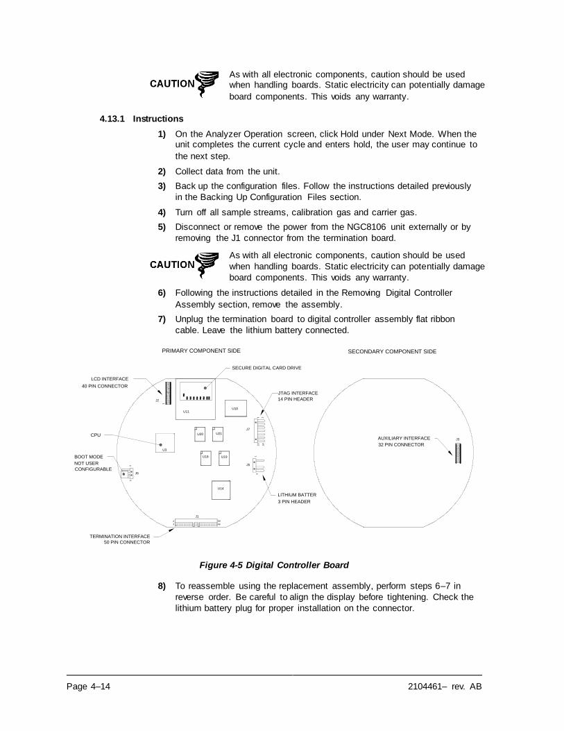
Page 4–14 2104461– rev. AB
As with all electronic components, caution should be used when handling boards. Static electricity can potentially damage
board components. This voids any warranty.
4.13.1 Instructions
1) On the Analyzer Operation screen, click Hold under Next Mode. When the unit completes the current cycle and enters hold, the user may continue to
the next step.
2) Collect data from the unit.
3) Back up the configuration files. Follow the instructions detailed previously
in the Backing Up Configuration Files section.
4) Turn off all sample streams, calibration gas and carrier gas.
5) Disconnect or remove the power from the NGC8106 unit externally or by
removing the J1 connector from the termination board.
As with all electronic components, caution should be used
when handling boards. Static electricity can potentially damage
board components. This voids any warranty.
6) Following the instructions detailed in the Removing Digital Controller
Assembly section, remove the assembly.
7) Unplug the termination board to digital controller assembly flat ribbon
cable. Leave the lithium battery connected.
Figure 4-5 Digital Controller Board
8) To reassemble using the replacement assembly, perform steps 6–7 in
reverse order. Be careful to align the display before tightening. Check the
lithium battery plug for proper installation on the connector.
PRIMARY COMPONENT SIDE SECONDARY COMPONENT SIDE
3
J6
1
21
4
2
1
J1
50
49
U14
U3
J2
U11
U19U18
U20 U21
13
U10
1
J5
14
J7
J3
SECURE DIGITAL CARD DRIVE
JTAG INTERFACE
14 PIN HEADER
AUXILIARY INTERFACE
32 PIN CONNECTOR
3 PIN HEADER
LITHIUM BATTER
TERMINATION INTERFACE
50 PIN CONNECTOR
BOOT MODE
NOT USER
CONFIGURABLE
LCD INTERFACE
40 PIN CONNECTOR
CPU

2104461– rev. AB Page 4–15
Please note that the termination board to digital controller ribbon cable pin 1 wire is NOT red. On the digital controller
board, the red edge (pin 1) of the cable should plug into pin 50, the right side of plug. The plug is keyed. As such, do not
force the plug into the connector.
9) Re-plug the ground cable onto the new assembly.
10) Once assembled, apply power to the NGC8106 (step 5).
11) Restore the configuration files. Follow the instructions detailed previously
in the Restore Configuration Files section.
12) Re-install front and rear end caps.
For the purposes of returning this assembly to Totalflow service for warranty or repair, please contact ABB Totalflow
customer service for an RA number. Please keep the lithium
battery connected to the digital controller board for return.
Please note that since power was removed from this unit, the
NGC8106 will perform Startup Diagnostics and stabilize. If the user has disabled the Startup Diagnostics, they should be enabled and power cycled to the unit. If the power has been
withheld from the unit for an unknown or lengthy period of
time, a complete startup should be performed.
For more information on enabling the diagnostics in PCCU,
click the Diagnostics button and then the Help button.
4.14 Replacing Analytical Module
This section presents the procedures for removal and installation of the analytical
module. The module is a completely self-contained unit and is part of the
NGC8106. Read through all procedural steps before beginning disassembly.
Before beginning the procedure, verify that the module is appropriately rated for
the system voltage. Compare the module voltage to the ID tag. The ID tag is
located on the side of the enclosure.
When the analytical module is removed, the module should
be placed on a clean, dirt-free work surface. Care should be taken that gas ports be free from lint or dust particles. ABB Totalflow strongly suggests that the GC replacement module
be kept in a sealed, static free envelope until the last
possible moment before installation.
It is important that the bottom surface of the module be
placed on a clean, lint-free cloth to prevent components from
being scratched, damaged or contaminated.
For the purposes of returning this assembly to ABB Totalflow
service for warranty or repair, please contact ABB Totalflow
customer service for an RA number.
4.14.1 Instructions
1) On the Analyzer Operation screen, click Hold under Next Mode. When the
unit completes the current cycle and enters hold, the user may continue to
the next step.
2) Collect data from the unit.
Page 4–16 2104461– rev. AB
3) Back up the configuration files. Follow the instructions detailed previously
in the Backing Up Configuration Files section.
4) Using the Lithium Battery Status instructions, verify the battery status is
satisfactory before proceeding.
5) Turn off all sample streams, calibration gas and carrier gas.
6) Disconnect or remove the power from the NGC8106 unit externally or by
removing the J1 connector from the termination board.
As with all electronic components, caution should be used when handling boards. Static electricity can potentially
damage board components. This voids the warranty
7) Gain access to the digital controller assembly by loosening the countersunk hex socket locking set screw in the front end cap. Use a 1/16”
hex wrench. Upon completion, unscrew the end cap.
8) Following the instructions detailed previously in the Digital Controller Assembly Mounting Bracket section, remove the assembly. If weather/circumstances permit, the digital controller assembly may be
suspended by the cables to eliminate stress on the cable connections.
Move to step 10.
9) Carefully unplug the cable to the termination board. Leave the lithium battery plugged in. Set the digital controller assembly aside on a clean, lint -
free surface.
10) Using a 5/16” hex wrench, loosen the mounting screw (see Figure 4-6) holding the analytical module in place until the module can be s lowly lifted from the enclosure. Take care to not pull or stress wires attached to the
rear of the assembly.
11) Detach the analytical module rear face jack, J1 and J4, if the auxiliary
heater is installed (see Figure 4-7).
12) Set module on a clean, lint-free surface.
13) Verify that the gasket on the feed-through assembly manifold interface is in place, in good condition and free from metal filings or other contamination.
If the gasket has fallen off inside the enclosure or stuck to the GC module, replace onto the feed-through manifold interface. Ensure that the gasket
does NOT cover the gas portholes.
14) Verify the S1 auxiliary heater switch is set to the correct position. If using
the auxiliary feed-through heater, set the position to Normal.
15) Insert the mounting screw into the analytical module.
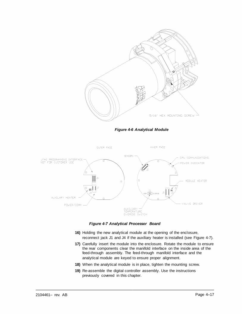
2104461– rev. AB Page 4–17
Figure 4-6 Analytical Module
Figure 4-7 Analytical Processor Board
16) Holding the new analytical module at the opening of the enclosure,
reconnect jack J1 and J4 if the auxiliary heater is installed (see Figure 4-7).
17) Carefully insert the module into the enclosure. Rotate the module to ensure the rear components clear the manifold interface on the inside area of the feed-through assembly. The feed-through manifold interface and the
analytical module are keyed to ensure proper alignment.
18) When the analytical module is in place, tighten the mounting screw.
19) Re-assemble the digital controller assembly. Use the instructions
previously covered in this chapter.
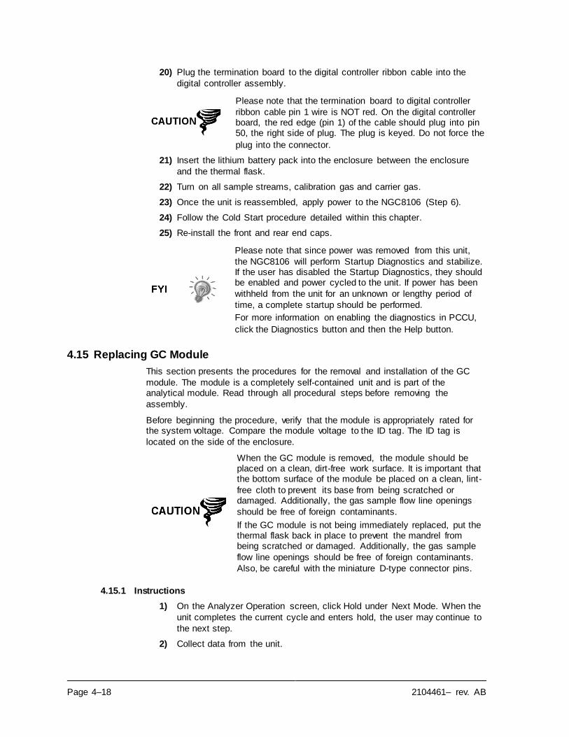
Page 4–18 2104461– rev. AB
20) Plug the termination board to the digital controller ribbon cable into the
digital controller assembly.
Please note that the termination board to digital controller
ribbon cable pin 1 wire is NOT red. On the digital controller board, the red edge (pin 1) of the cable should plug into pin 50, the right side of plug. The plug is keyed. Do not force the
plug into the connector.
21) Insert the lithium battery pack into the enclosure between the enclosure
and the thermal flask.
22) Turn on all sample streams, calibration gas and carrier gas.
23) Once the unit is reassembled, apply power to the NGC8106 (Step 6).
24) Follow the Cold Start procedure detailed within this chapter.
25) Re-install the front and rear end caps.
Please note that since power was removed from this unit,
the NGC8106 will perform Startup Diagnostics and stabilize. If the user has disabled the Startup Diagnostics, they should be enabled and power cycled to the unit. If power has been
withheld from the unit for an unknown or lengthy period of
time, a complete startup should be performed.
For more information on enabling the diagnostics in PCCU,
click the Diagnostics button and then the Help button.
4.15 Replacing GC Module
This section presents the procedures for the removal and installation of the GC
module. The module is a completely self-contained unit and is part of the analytical module. Read through all procedural steps before removing the
assembly.
Before beginning the procedure, verify that the module is appropriately rated for the system voltage. Compare the module voltage to the ID tag. The ID tag is
located on the side of the enclosure.
When the GC module is removed, the module should be placed on a clean, dirt-free work surface. It is important that the bottom surface of the module be placed on a clean, lint-
free cloth to prevent its base from being scratched or damaged. Additionally, the gas sample flow line openings
should be free of foreign contaminants.
If the GC module is not being immediately replaced, put the thermal flask back in place to prevent the mandrel from being scratched or damaged. Additionally, the gas sample
flow line openings should be free of foreign contaminants.
Also, be careful with the miniature D-type connector pins.
4.15.1 Instructions
1) On the Analyzer Operation screen, click Hold under Next Mode. When the
unit completes the current cycle and enters hold, the user may continue to
the next step.
2) Collect data from the unit.
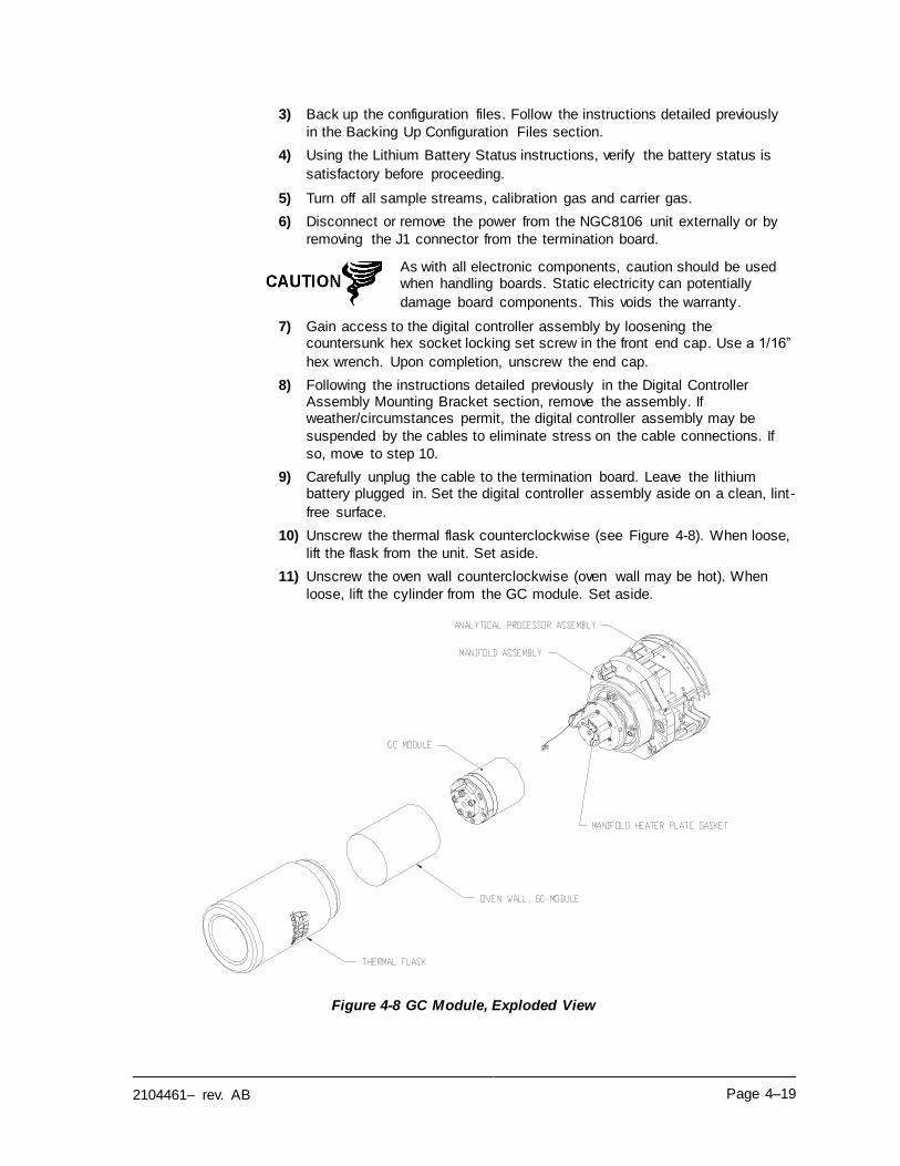
2104461– rev. AB Page 4–19
3) Back up the configuration files. Follow the instructions detailed previously
in the Backing Up Configuration Files section.
4) Using the Lithium Battery Status instructions, verify the battery status is
satisfactory before proceeding.
5) Turn off all sample streams, calibration gas and carrier gas.
6) Disconnect or remove the power from the NGC8106 unit externally or by
removing the J1 connector from the termination board.
As with all electronic components, caution should be used when handling boards. Static electricity can potentially
damage board components. This voids the warranty.
7) Gain access to the digital controller assembly by loosening the countersunk hex socket locking set screw in the front end cap. Use a 1/16”
hex wrench. Upon completion, unscrew the end cap.
8) Following the instructions detailed previously in the Digital Controller Assembly Mounting Bracket section, remove the assembly. If weather/circumstances permit, the digital controller assembly may be
suspended by the cables to eliminate stress on the cable connections. If
so, move to step 10.
9) Carefully unplug the cable to the termination board. Leave the lithium battery plugged in. Set the digital controller assembly aside on a clean, lint-
free surface.
10) Unscrew the thermal flask counterclockwise (see Figure 4-8). When loose,
lift the flask from the unit. Set aside.
11) Unscrew the oven wall counterclockwise (oven wall may be hot). When
loose, lift the cylinder from the GC module. Set aside.
Figure 4-8 GC Module, Exploded View
Page 4–20 2104461– rev. AB
12) Using the extraction tool, remove the cable connectors from J1, J2 and J3
jacks. DO NOT pull the connectors from the board by wires.
13) Using a 9/64” hex wrench, loosen the mounting screw inside the center of
the assembly. When loose, lift the assembly from the manifold assembly.
Set aside on a clean, lint-free surface.
14) Verify that the manifold heater plate gasket is in place and in good
condition.
15) Carefully insert the replacement module onto the manifold assembly.
Rotate the module to ensure that the key holes line up and the module
rests on the base. The unit should not turn once it is seated correctly.
16) When the GC module is in place, tighten the mounting screw.
17) Carefully restore the cable connectors to J1, J2 and J3 jacks. Be careful to
not press against the wires attached to the connector head.
18) Replace the oven wall onto the GC module. Be careful to not pinch or bind
any of the cables. When fully on, turn the oven wall clockwise to tighten.
19) Replace the thermal flask over the GC module. When the flask reaches the
mounting bracket, turn clockwise to tighten.
20) Using instructions previously covered in this chapter, re-assemble the
digital controller assembly
21) Plug the termination board to the digital controller ribbon cable and then
into the digital controller assembly, if disconnected.
Please note that the termination board to the digital controller ribbon cable pin 1 wire is NOT red. On the digital controller board, the red edge (pin 1) of the cable should plug into pin
50, the right side of the plug. The plug is keyed. Do not force
plug into the connector.
22) Insert the lithium battery pack into the enclosure between the enclosure
and the thermal flask.
23) Turn on all sample streams, calibration gas and carrier gas.
24) Once the unit is reassembled, apply power to the NGC8106 (Step 6).
For the purposes of returning this assembly to ABB Totalflow service for warranty or repair, please contact ABB Totalflow
customer service for an RA number.
25) Follow the Cold Start procedure within this chapter.
26) Re-install the front and rear end caps.
Please note that since power was removed from this unit, the NGC8106 will perform Startup Diagnostics and stabilize. If the user has disabled the Startup Diagnostics, they should be
enabled and power cycled to the unit. If power has been withheld from the unit for an unknown or lengthy period of
time, a complete startup should be performed.
For more information on enabling the diagnostics in PCCU,
click the Diagnostics button and then the Help button.
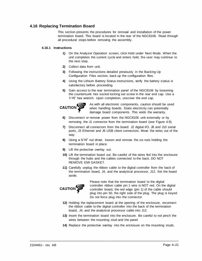
2104461– rev. AB Page 4–21
4.16 Replacing Termination Board
This section presents the procedures for removal and installation of the power
termination board. This board is located in the rear of the NGC8106. Read through
all procedural steps before removing the assembly.
4.16.1 Instructions
1) On the Analyzer Operation screen, click Hold under Next Mode. When the
unit completes the current cycle and enters hold, the user may continue to
the next step.
2) Collect data from unit.
3) Following the instructions detailed previously in the Backing Up
Configuration Files section, back up the configuration files.
4) Using the Lithium Battery Status instructions, verify the battery s tatus is
satisfactory before proceeding.
5) Gain access to the rear termination panel of the NGC8106 by loosening the countersunk hex socket locking set screw in the rear end cap. Use a
1/16” hex wrench. Upon completion, unscrew the end cap.
As with all electronic components, caution should be used
when handling boards. Static electricity can potentially
damage board components. This voids the warranty.
6) Disconnect or remove power from the NGC8106 unit externally or by
removing the J1 connector from the termination board (see Figure 4-9).
7) Disconnect all connectors from the board: J2 digital I/O, J8 and J10 serial ports, J3 Ethernet and J6 USB client connectors. Move the wires out of the
way.
8) Using a 5/16” nut driver, loosen and remove the six nuts holding the
termination board in place.
9) Lift the protective overlay out.
10) Lift the termination board out. Be careful of the wires fed into the enclosure through the hubs and the cables connected to the back. DO NOT
REMOVE EMI GASKET.
11) Carefully unplug the ribbon cable to the digital controller from the back of
the termination board, J4, and the analytical processor, J12. Set the board
aside.
Please note that the termination board to the digital controller ribbon cable pin 1 wire is NOT red. On the digital
controller board, the red edge (pin 1) of the cable should plug into pin 50, the right side of the plug. The plug is keyed.
Do not force plug into the connector.
12) Holding the replacement board at the opening of the enclosure, reconnect the ribbon cable to the digital controller into the back of the termination
board, J4, and the analytical processor cable into J12.
13) Insert the termination board into the enclosure. Be careful to not pinch the
wires between the mounting stud and the panel.
14) Replace the protective overlay into the enclosure on the mounting studs.
Page 4–22 2104461– rev. AB
Figure 4-9 Termination Board
15) Replace the nuts to hold the termination board in place.
16) Restore J2, J8, J10, J3 and J6 connections, if applicable.
17) Once the unit is reassembled, apply power to the NGC8106 (Step 6).
18) Reinstall the front and rear end caps.
For the purposes of returning this assembly to ABB Totalflow service for warranty or repair, please contact ABB
Totalflow customer service for an RA number.
Please note that since power was removed from this unit, the NGC8106 will perform Startup Diagnostics and stabilize.
If the user has disabled the Startup Diagnostics, they should be enabled and power cycled to the unit. If the power has been withheld from the unit for an unknown or lengthy
period of time, a complete startup should be performed.
For more information on enabling the diagnostics in PCCU,
click the Diagnostics button and then the Help button.
4.17 Replacing Feed-Through Assembly
This section presents the procedures for the removal and installation of the feed-through assembly. This assembly is located on the side of the NGC8106. Read
through all the procedural steps before removing the assembly.
Before beginning the procedure, verify that the module is appropriately rated for the system voltage. Compare the module voltage to the ID tag. The ID tag is
located on the side of the enclosure.
4.17.1 Instructions
1) On the Analyzer Operation screen, click Hold under Next Mode. When the unit completes the current cycle and enters hold, the user may continue to
the next step.
PRIMARY COMPONENT SIDE SECONDARY COMPONENT SIDE
VR1S2
UN
SE
CU
RE
SECURITY
ENABLED
STATUS
(-)(+)
J4ANALYTICAL PROCESSOR
CONNECTION
DIGITAL CONTROLLER
CONNECTION
USB CLIENT RECEPTICAL
ETHERNET STATUS INDICATORS
RESET
USB HOST RECEPTICAL
SERIAL PORT 1
SERIAL PORT 1
TERMINATION
LOCAL SERIAL DATA
CONNECTION
SECURITY SWITCH
DIGITAL I/O
POWER
ETHERNET
RECEPTICAL
SERIAL PORT 2
TERMINATION
SERIAL PORT 2
VOLTAGE
REGULATOR
SECURITY
SWITCH STATUS
OUTPUTS
D4
(-)
2
(-)(+)
J7
POWER
D1
J9
D3
D2
5VDC
J2
J1
J6
1
J8
J5
32 54 76 98
D12 D11
J31 3
D13 S1
LINK
LAN
STAT
41 32 5 6 87
J10
9
J111 3
INPUTS
(-)(-)
1
(+)
2
(+)
1
(+)
J12
2104461– rev. AB Page 4–23
2) Collect data from the unit.
3) Following the instructions detailed in the Backing Up Configuration Files
section, back up the configuration files.
4) Using the Lithium Battery Status instructions, verify the battery status is
satisfactory before proceeding.
5) Turn off all sample streams, calibration gas and carrier gas.
6) Disconnect or remove the power from the NGC8106 unit externally or by
removing the J1 connector from the termination board.
As with all electronic components, caution should be used when handling boards. Static electricity can potentially
damage board components, voiding any warranty.
7) Gain access to the digital controller assembly by loosening the countersunk hex socket locking set screw in the front end cap using a
1/16” hex wrench, then unscrewing the end cap.
8) Following the instructions detailed previously in this chapter entitled, Digital Controller Assembly Mounting Bracket, remove the assembly. If weather/circumstances permit, the digital controller assembly may be
suspended by the cables to eliminate stress on the cable connections. If
this is the case, move to step 10.
9) Carefully unplug the cable to the termination panel, leaving the lithium battery plugged in. Set the digital controller assembly aside on a clean, lint -
free surface.
10) Using a 5/16” hex wrench, loosen the mounting screw holding the analytical module in place until the module can be slowly lifted from the enclosure, taking care to not pull the wires attached to the rear of the
assembly.
11) Detach the analytical module rear face jack J1 and J4, if the auxiliary
heater is installed.
12) Set the module on a clean, lint-free surface.
13) Using a ¼” open end wrench, loosen the Valco nut and remove the input
line. Repeat for all the sample, carrier and calibration gas lines.
14) Using a 5/64” hex wrench, loosen the feed-through set screw.
15) Unscrew the feed-through assembly, turning by hand counterclockwise
until free.
16) On the replacement assembly, install o-ring and manifold gasket supplied
with new feed-through assembly (see Figure 4-10).
17) Carefully apply the sealing thread lubricant to the threads on the feed-through assembly, being extremely careful to not contaminate the feed-
through manifold and gasket.
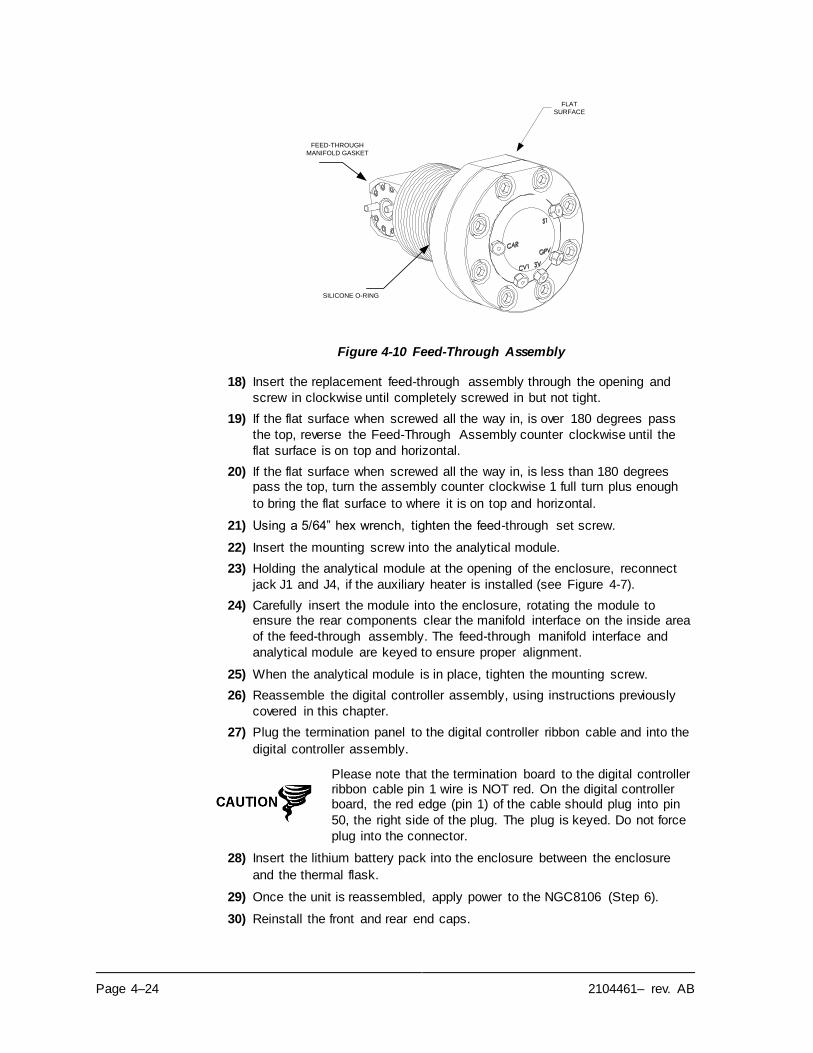
Page 4–24 2104461– rev. AB
Figure 4-10 Feed-Through Assembly
18) Insert the replacement feed-through assembly through the opening and
screw in clockwise until completely screwed in but not tight.
19) If the flat surface when screwed all the way in, is over 180 degrees pass
the top, reverse the Feed-Through Assembly counter clockwise until the
flat surface is on top and horizontal.
20) If the flat surface when screwed all the way in, is less than 180 degrees pass the top, turn the assembly counter clockwise 1 full turn plus enough
to bring the flat surface to where it is on top and horizontal.
21) Using a 5/64” hex wrench, tighten the feed-through set screw.
22) Insert the mounting screw into the analytical module.
23) Holding the analytical module at the opening of the enclosure, reconnect
jack J1 and J4, if the auxiliary heater is installed (see Figure 4-7).
24) Carefully insert the module into the enclosure, rotating the module to ensure the rear components clear the manifold interface on the inside area
of the feed-through assembly. The feed-through manifold interface and
analytical module are keyed to ensure proper alignment.
25) When the analytical module is in place, tighten the mounting screw.
26) Reassemble the digital controller assembly, using instructions previously
covered in this chapter.
27) Plug the termination panel to the digital controller ribbon cable and into the
digital controller assembly.
Please note that the termination board to the digital controller ribbon cable pin 1 wire is NOT red. On the digital controller board, the red edge (pin 1) of the cable should plug into pin
50, the right side of the plug. The plug is keyed. Do not force
plug into the connector.
28) Insert the lithium battery pack into the enclosure between the enclosure
and the thermal flask.
29) Once the unit is reassembled, apply power to the NGC8106 (Step 6).
30) Reinstall the front and rear end caps.
FEED-THROUGH
MANIFOLD GASKET
FLAT
SURFACE
SILICONE O-RING
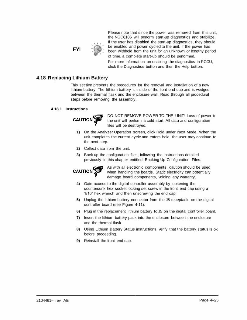
2104461– rev. AB Page 4–25
Please note that since the power was removed from this unit, the NGC8106 will perform start-up diagnostics and stabilize.
If the user has disabled the start-up diagnostics, they should be enabled and power cycled to the unit. If the power has been withheld from the unit for an unknown or lengthy period
of time, a complete start-up should be performed.
For more information on enabling the diagnostics in PCCU,
click the Diagnostics button and then the Help button.
4.18 Replacing Lithium Battery
This section presents the procedures for the removal and installation of a new lithium battery. The lithium battery is inside of the front end cap and is wedged
between the thermal flask and the enclosure wall. Read through all procedural
steps before removing the assembly.
4.18.1 Instructions
DO NOT REMOVE POWER TO THE UNIT! Loss of power to
the unit will perform a cold start. All data and configuration
files will be destroyed.
1) On the Analyzer Operation screen, click Hold under Next Mode. When the
unit completes the current cycle and enters hold, the user may continue to
the next step.
2) Collect data from the unit.
3) Back up the configuration files, following the instructions detailed
previously in this chapter entitled, Backing Up Configuration Files.
As with all electronic components, caution should be used
when handling the boards. Static electricity can potentially
damage board components, voiding any warranty.
4) Gain access to the digital controller assembly by loosening the
countersunk hex socket locking set screw in the front end cap using a
1/16” hex wrench and then unscrewing the end cap.
5) Unplug the lithium battery connector from the J5 receptacle on the digital
controller board (see Figure 4-11).
6) Plug in the replacement lithium battery to J5 on the digital controller board.
7) Insert the lithium battery pack into the enclosure between the enclosure
and the thermal flask.
8) Using Lithium Battery Status instructions, verify that the battery status is ok
before proceeding.
9) Reinstall the front end cap.
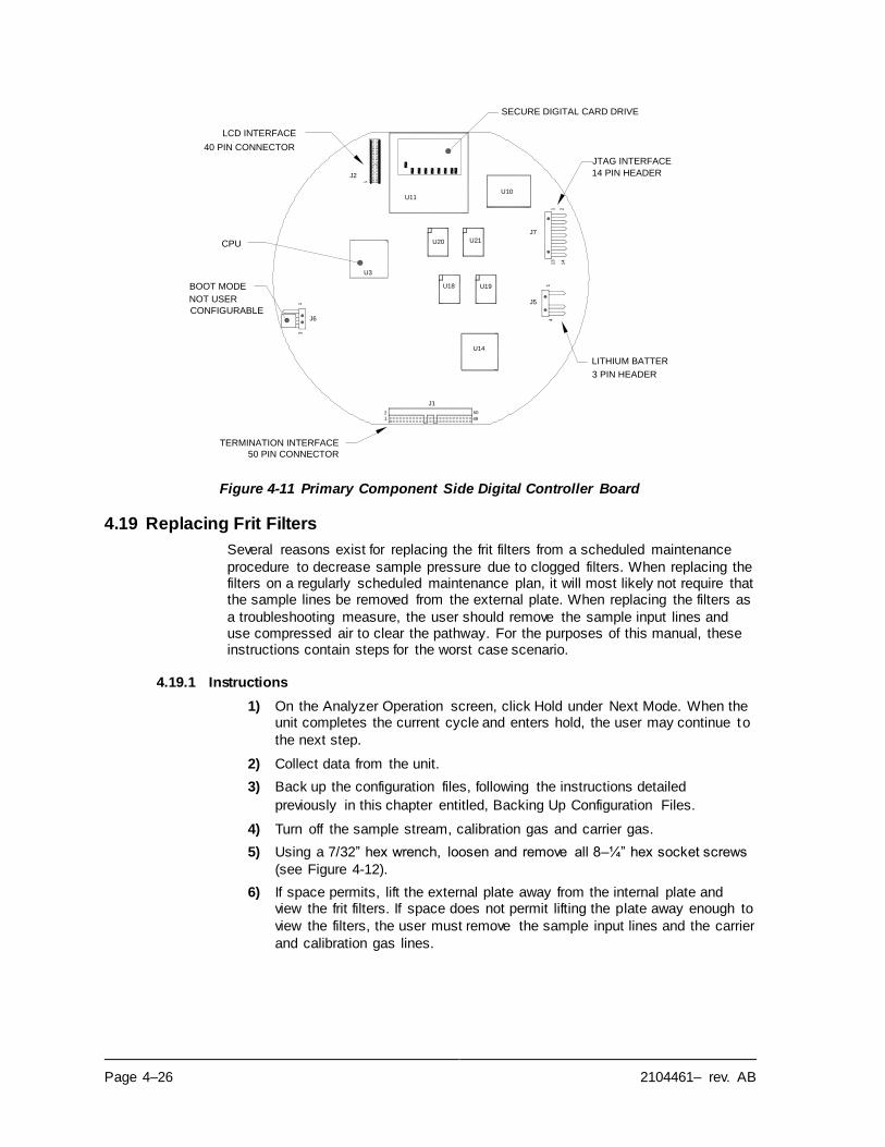
Page 4–26 2104461– rev. AB
Figure 4-11 Primary Component Side Digital Controller Board
4.19 Replacing Frit Filters
Several reasons exist for replacing the frit filters from a scheduled maintenance
procedure to decrease sample pressure due to clogged filters. When replacing the filters on a regularly scheduled maintenance plan, it will most likely not require that the sample lines be removed from the external plate. When replacing the filters as
a troubleshooting measure, the user should remove the sample input lines and use compressed air to clear the pathway. For the purposes of this manual, these instructions contain steps for the worst case scenario.
4.19.1 Instructions
1) On the Analyzer Operation screen, click Hold under Next Mode. When the unit completes the current cycle and enters hold, the user may continue to
the next step.
2) Collect data from the unit.
3) Back up the configuration files, following the instructions detailed
previously in this chapter entitled, Backing Up Configuration Files.
4) Turn off the sample stream, calibration gas and carrier gas.
5) Using a 7/32” hex wrench, loosen and remove all 8–¼” hex socket screws
(see Figure 4-12).
6) If space permits, lift the external plate away from the internal plate and view the frit filters. If space does not permit lifting the plate away enough to
view the filters, the user must remove the sample input lines and the carrier
and calibration gas lines.
3
J6
1
21
4
2
1
J1
50
49
U14
U3
J2
U11
U19U18
U20 U21
13
U10
1
J5
14
J7
SECURE DIGITAL CARD DRIVE
JTAG INTERFACE
14 PIN HEADER
3 PIN HEADER
LITHIUM BATTER
TERMINATION INTERFACE
50 PIN CONNECTOR
BOOT MODE
NOT USER
CONFIGURABLE
LCD INTERFACE
40 PIN CONNECTOR
CPU
2104461– rev. AB Page 4–27
Figure 4-12 Feed-Through Assembly, Exploded View
7) If the filters appear soiled, it will be necessary to remount the external plate, and remove the input lines. To remove the input lines, continue to
the next step; otherwise, move to step 8.
8) Using a ¼” open end wrench, loosen the Valco nut, and remove the input
line. Repeat for all sample, carrier and calibration gas lines.
9) Remove the 8–¼” hex socket mounting screws.
10) Remove the used filters from the filter sockets. Using an edged instrument or fingernail, put pressure on the outermost edge of each filter to pop them
out.
11) If replacing filters due to clogging, the user should also use compressed air to blow out the input holes in the external plate. It may also be necessary to wipe clean the gasket located on the internal plate; otherwise, move to
the next step.
12) Using the replacement filter, carefully lay the filter into the filter socket, applying uniform pressure to the filter. DO NOT use any pointed instrument
to push the filter into place. Vents do not require filters.
13) Reseat the external plate, aligning the mounting pins on the internal plate
to the corresponding holes on the external plate.
14) Replace the 8–¼” mounting screws, using a star pattern when tightening
the screws.
15) If the sample, carrier and calibration gas lines were removed, purge the air
from the transport tubing, and reconnect to the corresponding ports.
DO NOT over-tighten. After securing the tubing, check for gas
leaks.
OPTIONAL FEED-THROUGH
HEATER CABLE
.5 MICRON INPUT
FRIT FILTERS
FEED-THROUGH
INTERFACE GASKET
SILICONE O-RING
EXTERNAL PLATE
MOUNTING HOLES FOR
1/4" SST HEX SOCKET
SCREWS
INTERNAL PLATE
FEED-THROUGH
MANIFOLD GASKET
Page 4–28 2104461– rev. AB
4.20 Replacing Feed-Through Interface Gasket
Should the feed-through interface gasket require replacement (see Figure 4-12),
follow these instructions. Typically, the user would change the gasket while performing another procedure, but for the purposes of this manual, the instructions
will start and finish as a complete procedure.
4.20.1 Instructions
1) On the Analyzer Operation screen, click Hold under Next Mode. When the unit completes the current cycle and enters hold, the user may continue to
the next step.
2) Collect data from the unit.
3) Back up the configuration files, following the instructions detailed
previously in this chapter entitled, Backing Up Configuration Files.
4) Turn off sample stream, calibration gas and carrier gas.
5) Using a 7/32” hex wrench, loosen and remove all 8–¼” hex socket screws.
6) If space permits, lift the external plate away from the internal plate and remove the damaged gasket from the internal plate. If space does not permit lifting the plate away enough to replace the gasket, the user must
remove the sample input lines and the carrier and calibration gas lines.
7) Remount the external plate and remove the input lines. To remove the
input lines, continue to the next step; otherwise, skip to step 8.
8) Using a ¼” open end wrench, loosen the Valco nut and remove the input
line. Repeat for all sample, carrier and calibration gas lines.
9) Remove the 8–¼” hex socket mounting screws.
10) Remove the damaged gasket from the internal plate.
11) Clean the gasket area on the internal plate using a clean, dry lint -free cloth
before placing the new gasket on the internal plate. The gasket is keyed to ensure that it is placed correctly. The gasket should not cover any holes in
the internal plate.
12) Reseat the external plate, aligning the mounting pins on the internal plate
to the corresponding holes on the external plate.
13) Replace the 8–¼” mounting screws, using a star pattern when tightening
the screws.
14) If the sample, carrier and calibration gas lines were removed, purge air
from the transport tubing, and reconnect to the corresponding ports.
DO NOT over-tighten. After securing the tubing, check for gas
leaks.
4.21 Replacing Feed-Through Manifold Gasket
Should the feed-through manifold gasket require replacement (see Figure 4-12), follow these instructions. Typically, the user would change the gasket while performing another procedure, but for the purposes of this manual, the instructions
will start and finish as a complete procedure.
2104461– rev. AB Page 4–29
4.21.1 Instructions
1) On the Analyzer Operation screen, click Hold under Next Mode. When the unit completes the current cycle and enters hold, the user may continue to
the next step.
2) Collect data from the unit.
3) Back up the configuration files, following the instructions detailed
previously in this chapter entitled, Backing Up Configuration Files.
4) Using the Lithium Battery Status instructions, verify the battery status is ok
before proceeding.
5) Turn off the sample stream, calibration gas and carrier gas.
6) Disconnect or remove power from the NGC8106 unit externally, or remove
the J1 connector from termination panel.
As with all electronic components, caution should be used when handling boards. Static electricity can potentially
damage board components, voiding any warranty.
7) Gain access to the digital controller assembly by loosening the countersunk hex socket locking set screw in the front end cap using a
1/16” hex wrench then unscrewing the end cap.
8) Following the instructions detailed previously in this chapter entitled, Digital
Controller Assembly Mounting Bracket, remove assembly. If weather/circumstances permit, the digital controller assembly may be suspended by the cables to eliminate stress on cable connections. If this is
the case, move to step 10.
9) Carefully unplug the cable to the termination panel, leaving the lithium battery plugged in, and set the digital controller assembly aside on a clean,
lint-free surface.
10) Using a 5/16” hex wrench, loosen the mounting screw holding the
analytical module in place until the module can be slowly lifted from the enclosure, taking care to not pull the wires attached to the rear of the
assembly.
11) Detach analytical module rear face jack J1 and J4 if auxiliary heater is
installed.
12) Set the module on a clean, lint-free surface.
13) Replace the gasket on the feed-through assembly manifold interface,
ensuring that the gasket does NOT cover the gas port holes.
14) Insert the mounting screw into the analytical module.
15) Holding the analytical module at the opening of the enclosure, reconnect
jumper J1 and J4, if the auxiliary heater is installed (see Figure 4-7).
16) Carefully insert the module into the enclosure, rotating the module to
ensure the rear components clear the manifold interface on the inside area of the feed-through assembly. The feed-through manifold interface and the
analytical module are keyed to ensure proper alignment.
17) When the analytical module is in place, tighten the mounting screw.
18) Reassemble the digital controller assembly, using instructions previously
covered in this chapter.
Page 4–30 2104461– rev. AB
19) Plug the termination panel to the digital controller ribbon cable into the
digital controller assembly.
Please note that the termination board to the digital controller
ribbon cable pin 1 wire is NOT red. On the digital controller board, the red edge (pin 1) of the cable should plug into pin 50, the right side of the plug. The plug is keyed. Do not force
plug into the connector.
20) Insert the lithium battery pack into the enclosure, between the enclosure
and the thermal flask.
21) Once the unit is reassembled, apply power to the NGC8201 (Step 6).
22) Reinstall the front and rear end caps.
Please note that since power was removed from this unit, the
NGC8106 will perform startup diagnostics and stabilize. If the user has disabled the startup diagnostics, it should be enabled and power cycled to the unit. If the power has been withheld
from the unit for an unknown or lengthy period of time, a
complete startup should be performed.
For more information on enabling the diagnostics in PCCU,
click the Diagnostics button and then the Help button.
4.22 Replacing Termination Panel to Digital Controller Cable
Should the termination panel to digital controller cable become damaged and
require replacement, follow these instructions. Typically, the user would change the cable while performing another procedure, but for the purposes of this manual,
the instructions will start and finish as a complete procedure.
4.22.1 Instructions
1) On the Analyzer Operation screen, click Hold under Next Mode. When the unit completes the current cycle and enters hold, the user may continue to
the next step.
2) Collect data from the unit.
3) Back up the configuration files following the instructions detailed previously
in this chapter entitled, Backing Up Configuration Files.
4) Using the Lithium Battery Status instructions, verify the battery status is ok
before proceeding.
5) Turn off the sample stream, calibration gas and carrier gas.
6) Disconnect or remove the power from the NGC unit externally, or remove
the J1 connector from the termination panel.
As with all electronic components, caution should be used
when handling the boards. Static electricity can potentially
damage board components, voiding any warranty.
7) Gain access to the digital controller assembly by loosening the
countersunk hex socket locking set screw in the front end cap using a
1/16” hex wrench and then unscrewing the end cap.
8) Following the instructions detailed previously in this chapter entitled, Removing Digital Controller Assembly, remove the assembly (see Figure
2104461– rev. AB Page 4–31
4-4). If weather/circumstances permit, the digital controller assembly may be suspended by the cables to eliminate stress on the cable connections;
the user may skip to step 10.
9) Carefully unplug the cable to the termination panel, leaving the lithium battery plugged in, and set the digital controller assembly aside on a clean,
lint-free surface.
10) Using a 5/16” hex wrench, loosen the mounting screw holding the
analytical module in place until the module can be slowly lifted from the enclosure, taking care to not pull the wires attached to the rear of the
assembly (see Figure 4-7).
11) Detach the analytical module rear face jack J1 and J4, if the auxiliary
heater is installed.
12) Set the module on a clean, lint-free surface.
13) Reach into the enclosure through the front opening, and unplug the ribbon
cable from the rear of the termination panel J4.
14) On the replacement cable, verify the orientation by viewing the keyed receptacle on the termination panel and cable. Insert the plug into the J4
connector.
15) Verify that the gasket on the feed-through assembly manifold interface is in place and in good condition. If the gasket has fallen off inside the enclosure or is stuck to the GC module, replace onto the feed-through
manifold interface, ensuring that the gasket does NOT cover the gas
portholes.
16) Insert the mounting screw into the analytical module.
17) Holding the analytical module at the opening of the enclosure, reconnect
jack J1 and J4, if the auxiliary heater is installed (see Figure 4-6).
18) Carefully insert the module into the enclosure, rotating the module to
ensure that the rear components clear the manifold interface on the inside area of the feed-through assembly. The feed-through manifold interface
and analytical module are keyed to ensure the proper alignment.
19) When the analytical module is in place, tighten the mounting screw.
20) Reassemble the digital controller assembly using the instructions
previously covered in this chapter.
21) Plug the termination panel into the digital controller ribbon cable and then
into the digital controller assembly.
Please note that the termination board to the digital controller ribbon cable pin 1 wire is NOT red. On the digital controller
board, the red edge (pin 1) of the cable should plug into pin 50, the right side of the plug. The plug is keyed. Do not force
plug into the connector.
22) Insert the lithium battery pack is into the enclosure between the enclosure
and the thermal flask.
23) Once the unit is reassembled, apply power to the NGC8106 (Step 6).
24) Reinstall the front and rear end caps.
Page 4–32 2104461– rev. AB
Please note that since the power was removed from this unit, the NGC8106 will perform start-up diagnostics and stabilize. If
the user has disabled the start-up diagnostics, they should be enabled and power cycled to the unit. If the power has been withheld from the unit for an unknown or lengthy period of
time, a complete start-up should be performed.
For more information on enabling the diagnostics in PCCU,
click the Diagnostics button and then the Help button.
4.23 Replacing Analytical Processor to Termination Panel Cable
Should the cable connecting the analytical processor to the termination panel require replacement, use the following instructions.
4.23.1 Instructions
1) On the Analyzer Operation screen, click Hold under Next Mode. When the unit completes the current cycle and enters hold, the user may continue to
the next step.
2) Collect data from the unit.
3) Back up the configuration files following the instructions detailed previously
in this chapter entitled, Backing Up Configuration Files.
4) Using the Lithium Battery Status instructions, verify the battery status is ok
before proceeding.
5) Disconnect or remove the power from the NGC8106 unit externally, or
remove the J1 connector from the termination panel.
As with all the electronic components, caution should be
used when handling boards. Static electricity can potentially
damage the board components, voiding any warranty.
6) Following the instructions detailed previously in this chapter entitled,
Replacing Termination Panel, remove the panel and unplug the cable. Reaching into the enclosure, unplug the analytical processor to the termination panel cable from the analytical processor assembly (see Figure
4-7).
7) Using the replacement cable, insert it into the enclosure, and plug into the power/communication connector, J1. Connect the cable to the back of the
termination panel J12 connector (see Figure 4-9).
8) Reinstall the termination panel.
Please note that the termination board to the digital
controller ribbon cable pin 1 wire is NOT red. On the digital controller board, the red edge (pin 1) of the cable should plug into pin 50, the right side of the plug. The plug is keyed.
Do not force plug into the connector.
9) Once the unit is reassembled, apply power to the NGC8106 (Step 6).
For the purposes of returning this assembly to Totalflow service for warranty or repair, please contact Totalflow
customer service for an RA number.
10) Reinstall the rear end cap.
2104461– rev. AB Page 4–33
Please note that since power was removed from this unit, the NGC8106 will perform start-up diagnostics and stabilize.
If the user has disabled the start-up diagnostics, they should be enabled and power cycled to the unit. If the power has been withheld from the unit for an unknown or lengthy period
of time, a complete start-up should be performed.
For more information on enabling the diagnostics in PCCU,
click the Diagnostics button and then the Help button.

2104461– rev. AB Page 5–1
5.0 TROUBLESHOOTING
5.1 Overview
As an aid to troubleshooting the NGC8106, this chapter will provide troubleshooting guidelines for the various subsystems of the NGC8106. Some of
these procedures will differ slightly from other Totalflow products because the communications, power charger/source and other I/O are contained in a separate
enclosure rather than within the NGC8106 enclosure.
Some of the procedures are based on tests performed on the NGC8106 termination panel and others are based on tests performed on components located in a separate enclosure. The user will determine which of these
procedures correspond to their particular unit. If using equipment other than the Totalflow enclosure, the user will need to refer to the manufacturer’s procedures
for troubleshooting their equipment.
DO NOT open or remove covers, including the PCCU local communications cover, unless the area is known to be non-
hazardous, including the internal volume of the enclosure.
5.1.1 Troubleshooting Support
If troubleshooting instructions do not lead to a resolution and assistance is
required, the user can contact the Totalflow service department.
USA: (800) 442–3097 or International: 001–918-338-4880
5.1.2 Getting Started
Using Figure 5-1, the user can determine which section pertains to them and skip
to that section.
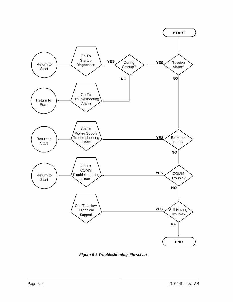
Page 5–2 2104461– rev. AB
Figure 5-1 Troubleshooting Flowchart
Return to
Start
Return to
Start
Return to
Start
Still Having
Trouble?
YES
NO
START
Batteries
Dead?
Go To
COMM
Troublelshooting
Chart
Call Totalflow
Technical
Support
YES
NO
Return to
Start
END
Receive
Alarm?
YES
NO
During
Startup?
YES
NO
Go To
Startup
Diagnostics
Go To
Troubleshooting
Alarm
COMM
Trouble?
YES
NO
Go To
Power Supply
Troubleshooting
Chart
2104461– rev. AB Page 5–3
5.2 Startup Diagnostic Troubleshooting
This section focuses on determining what has caused an alarm during start-up
diagnostics. The Totalflow® NGC8106 has an extensive built-in list of tests which are performed each time the unit is started. This start-up testing may be disabled,
but Totalflow recommends that it be left enabled.
These diagnostics consist of 4 areas of testing:
• Carrier Pressure Regulator Test
• Oven Temperature Test
• Processor Control Test
• Stream Test
These start-up tests may also be performed on a regular schedule. Please see the
PCCU help files for more information on scheduling diagnostics.
Totalflow has endeavored to perform extensive testing on each NGC8106 prior to shipment, and each unit is factory
calibrated using our standard calibration blend.
During the stream test, the input stream will be disabled if no pressure is detected. Failure to detect pressure on the input
stream will result in an input stream failure.
5.2.1 Status
The following description status and definitions are standard for all start -up diagnostics. Additionally, each test group will have status results that will narrow
down the possibilities for troubleshooting.
Status Description
Idle No tests are running.
In Progress Test(s) are in progress.
Passed Basic and/or additional tests, if required, passed.
Failed The basic test failed plus additional more in-depth
tests were run and also failed.
Aborted Tests were aborted by the user using the Abort
command.
5.2.2 Carrier Pressure Regulator Test
If the carrier pressure test failed, the following procedure will step the user through the troubleshooting process. On occasion, these instructions may detour to other
procedures, and, when complete, the user should return to these procedures to
continue.
5.2.2.1 Description
These alarms are indicative of low carrier pressure. The causes range from a
closed carrier bottle regulator to a blockage inside the GC module.
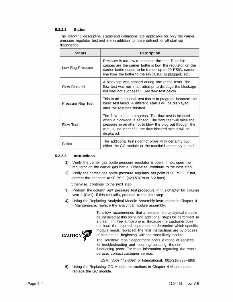
Page 5–4 2104461– rev. AB
5.2.2.2 Status
The following descriptive status and definitions are applicable for only the carrier pressure regulator test and are in addition to those defined for all start -up
diagnostics.
Status Description
Low Reg Pressure
Pressure is too low to continue the test. Possible
causes are the carrier bottle is low, the regulator on the carrier bottle needs to be turned up to 90 PSIG, carrier
line from the bottle to the NGC8106 is plugged, etc.
Flow Blocked
A blockage was sensed during one of the tests. The
flow test was run in an attempt to dislodge the blockage
but was not successful. See flow test below.
Pressure Reg Test
This is an additional test that is in progress because the basic test failed. A different status will be displayed
after the test has finished.
Flow Test
The flow test is in progress. The flow test is initiated when a blockage is sensed. The flow test will raise the pressure in an attempt to blow the plug out through the
vent. If unsuccessful, the flow blocked status will be
displayed.
Failed The additional tests cannot prove with certainty but
either the GC module or the manifold assembly is bad.
5.2.2.3 Instructions
1) Verify the carrier gas bottle pressure regulator is open. If not, open the
regulator on the carrier gas bottle. Otherwise, continue to the next step.
2) Verify the carrier gas bottle pressure regulator set point is 90 PSIG. If not,
correct the set point to 90 PSIG (620.5 kPa or 6.2 bars).
Otherwise, continue to the next step.
3) Perform the column vent pressure test procedure in this chapter for column
vent 1 (CV1). If this test fails, proceed to the next step.
4) Using the Replacing Analytical Module Assembly instructions in Chapter 4
- Maintenance, replace the analytical module assembly.
Totalflow recommends that a replacement analytical module
be installed at this point and additional steps be performed in a clean, lint free atmosphere. Because the customer does not have the required equipment to determine which specific
module needs replaced, the final instructions are by process
of elimination, beginning with the most likely module.
The Totalflow repair department offers a range of services
for troubleshooting and repairing/replacing the non-functioning parts. For more information regarding the repair
service, contact customer service:
USA: (800) 442-3097 or International: 001-918-338-4888
5) Using the Replacing GC Module instructions in Chapter 4-Maintenance,
replace the GC module.
2104461– rev. AB Page 5–5
5.2.3 Oven Temperature Test
If the oven temperature test failed, the following procedure will step the user through the troubleshooting process. On occasion, these instructions may detour
the user to other procedures, and, when complete, they should return to these
procedures to continue.
5.2.3.1 Description
This alarm is indicative of a temperature condition. The causes range from an
unplugged cable to a bad module heater.
5.2.3.2 Instructions
1) Verify that the cable is plugged in and in good repair. If the cable is
unplugged, plug-in the cable.
Otherwise, continue to the next step.
2) Verify that the analytical processor to GC module cable is plugged in and in good repair. If the cable is unplugged, reinstall plug. If cable appears to
be damaged, continue to the next step.
3) Using the Replacing Analytical Module Assembly instructions in Chapter 4-
Maintenance, replace the analytical module assembly.
Totalflow recommends that a replacement analytical module be installed at this point, and additional steps be performed
in a clean, lint free atmosphere.
The Totalflow repair department offers a range of services for troubleshooting and repairing/replacing the non-functioning parts. For more information regarding the repair
service, contact customer service:
USA: (800) 442-3097 or International: 1-918-338-4880
5.2.4 Processor Control Test
If Col 1 carrier pressure test fails, or the oven temperature test failed, the following
procedure will step the user through the troubleshooting process. On occasion, these instructions may detour to other procedures, and when complete, the user
should return to these procedures to continue.
5.2.4.1 Description
These alarms are indicative of a lack of ability to control a function. If the failure is
either one or both of the column carrier pressure tests, it could be a missing or failed gasket. If the failure is in the oven control temperature test, it could be something as easy as a missing GC module cover or analytical module thermal
flask.
5.2.4.2 Instructions
1) If the start-up diagnostics are being performed following the disassembly/replacement of a module or spare part, insure that the unit is completely reassembled, including the thermal flask and both the front and
rear end caps, and re-start the diagnostics. If diagnostics again fail, repeat disassembly steps and verify that all gaskets and connections are tight and
correctly installed.
Page 5–6 2104461– rev. AB
Otherwise, continue to the next step.
2) If the start-up diagnostics are being performed from an initial startup, verify
that the analytical module is not loose inside the enclosure.
3) Verify that the GC module is tight and that the cables are correctly installed
and not damaged.
4) Reassemble the unit and restart diagnostics. If the unit continues to fail, replace the entire analytical module and return to Totalflow for warranty
repair/replacement.
5.2.5 Stream Test
The stream flow diagnostics go through a series of tests, testing the input stream
pressure at different conditions as listed below. Each column will display the pressure results after that part of the test has completed. The status column will
reflect the current and final status of the tests.
The following procedure will step the user through the troubleshooting process. On occasion, these instructions may detour the user to other procedures, and,
when complete, they should return to these procedures to continue.
During the stream test, if no pressure is detected on the
input stream it will be disabled and a failure will be logged.
The following descriptive status and definitions are applicable for only the stream
test and are in addition to those defined for all start-up diagnostics.
Status Description
Failed Initial Pressure Failed the Initial Pressure test.
Failed Resting Pressure Failed the Resting Pressure test.
Failed No Pressure Failed the Maximum Pressure test.
Failed Holding Pressure Failed the Holding Pressure test.
Failed Flowing Pressure Failed the Flowing Pressure test.
Failed Ending Pressure Failed the Ending Pressure test.
Waiting This will be displayed by stream waiting to be tested. The tests are run sequentially.
5.2.5.1 Description
These alarms are indicative of a sample pressure problem. The causes range
from a plugged frit filter to a bad GC module.
5.2.5.2 Instructions
1) Perform the sample vent pressure test procedure, found in this chapter, for
the sample vent. If the test failed, proceed to the next step.
2) Perform the feed-through assembly blockage test on the sample vent (SV). If the test fails, replace the feed-through assembly with new or refurbished
assembly.
Otherwise, continue to the next step.
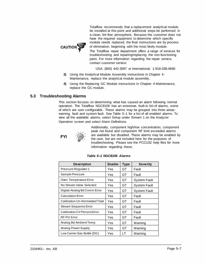
2104461– rev. AB Page 5–7
Totalflow recommends that a replacement analytical module be installed at this point and additional steps be performed in
a clean, lint free atmosphere. Because the customer does not have the required equipment to determine which specific module needs replaced, the final instructions are by process
of elimination, beginning with the most likely module.
The Totalflow repair department offers a range of services for troubleshooting and repairing/replacing the non-functioning
parts. For more information regarding the repair service,
contact customer service:
USA: (800) 442-3097 or International: 1-918-338-4880
3) Using the Analytical Module Assembly instructions in Chapter 4-
Maintenance, replace the analytical module assembly.
4) Using the Replacing GC Module instructions in Chapter 4-Maintenance,
replace the GC module.
5.3 Troubleshooting Alarms
This section focuses on determining what has caused an alarm following normal operation. The Totalflow NGC8106 has an extensive, built-in list of alarms, some
of which are user configurable. These alarms may be grouped into three areas: warning, fault and system fault. See Table 5–1 for a list of all enabled alarms. To view all the available alarms, select Setup under Stream 1 on the Analyzer
Operation screen and select Alarm Definitions.
Additionally, component high/low concentration, component peak not found and component RF limit exceeded alarms
are available but disabled. These alarms may be enabled by the user, but are not included here for the purposes of troubleshooting. Please see the PCCU32 help files for more
information regarding these.
Table 5–1 NGC8106 Alarms
Description Enable Type Severity
Pressure Regulator 1 Yes GT Fault
Sample Pressure Yes GT Fault
Oven Temperature Error Yes GT System Fault
No Stream Valve Selected Yes GT System Fault
Digital-Analog Bd Comm Error Yes GT System Fault
Calculation Error Yes GT Fault
Calibration Un-Normalized Total Yes GT Fault
Stream Sequence Error Yes GT Fault
Calibration CV Percent Error Yes GT Fault
RF Pct Error Yes GT Fault
Analog Bd Ambient Temp Yes GT Warning
Analog Power Supply Yes GT Warning
Low Carrier Gas Bottle (DI1) Yes LT Warning
Page 5–8 2104461– rev. AB
Description Enable Type Severity
Low Cal Gas Bottle (DI2) Yes LT Warning
GCM Chrom Process Yes GT System Fault
Bad Bead Yes GT Fault
No Pilot Valve Change Detected Yes GT Fault
Sample Flow Detect Yes GT Fault
CPU Loading Yes GT Warning
System Memory Available Yes LT Warning
Ram File Available Yes LT Warning
Flash File Available Yes LT Warning
Missing Peak-Cal Not Used Yes GT Warning
Stream Un-Normalized Total Yes GT Warning
5.3.1 Operators
• GT = Greater Than
• LT = Less Than
• And = Including
• Or = Instead of
• GE = Greater Than or Equal To
• LE = Less Than or Equal To
• NAND = And Not
• Nor = Not Or
• Plus = In addition to
• Minus = Not Included or subtract from
5.3.2 Alarm Severity
Table 5–2 Alarm Severity
Type Definition
General Indicates that an alarm exists, but that it is not critical to the operation of the unit. Use general when testing for some condition that may occur from time to time and want to know when it happens.
Warning Indicates that an alarm exists, but typically is not critical but may indicate or provide unexpected results.
Fault
Indicates that a malfunction exists that may affect the operation of the unit and most likely will provide unexpected results. The fault will keep the input stream from having its data updated. However, a fault would not stop a scheduled or manually initiated calibration from occurring, and, if the calibration corrects the alarm condition, the alarm will be cleared.
System Fault
This typically indicates that a maintenance problem exists. Analysis processing will still occur depending on the problem; however, results will not be updated for the input stream while this condition exists. Default system faults are already defined, and, unless the user has a situation in which he/she wants to stop stream data from being updated, should not use this category of alarm.
2104461– rev. AB Page 5–9
5.3.3 Pressure Regulator 1 or 2 Alarm
If the pressure regulator 1 or pressure regulator 2 alarm is in fault status, the following procedure will step the user through the troubleshooting process. On
occasion, these instructions may detour to other procedures, and, when complete,
the user should return to these procedures to continue.
5.3.3.1 Description
These alarms are indicative of low or restricted carrier pressure. The causes range from an empty or low carrier bottle, restricted pressure or to a blockage
inside the GC module.
5.3.3.2 Instructions
1) If the carrier bottle regulator includes an installed low pressure switch, investigate if the low carrier gas bottle warning is also present; otherwise,
continue to next step.
If the low carrier gas bottle warning is present, replace the carrier gas
bottle; otherwise, continue to the next step.
2) Verify the carrier gas bottle pressure is above 90 PSIG. If the pressure is
below 90 PSIG, replace the carrier gas bottle.
Otherwise, continue to the next step.
3) Verify the carrier gas bottle pressure regulator set point is 90 PSIG. If not,
correct the set point to 90 PSIG.
Otherwise, continue to the next step.
4) Verify the column vent 1 (CV1), sample vent (SV) and gauge port vent
(GPV) are open and unobstructed.
5) Check the sampling system for leaks and tubing restrictions. Repair the
leak or restriction, if found. Otherwise, continue to the next step.
6) Perform start-up diagnostics.
7) If the carrier pressure regulator 1 and 2 tests both pass, continue to the
next step.
8) Perform Column Vent Pressure Test procedure, found in this chapter, for
both column vent 1 and column vent 2. If either test failed, proceed to the
next step.
9) Perform Feed-Through Assembly Blockage Test procedure, found in this chapter, on column vent 1 (CV1). If the test fails, replace the feed-through
assembly with a new or refurbished assembly.
Otherwise, continue to the next step.
Page 5–10 2104461– rev. AB
Totalflow recommends that a replacement analytical module be installed at this point and additional steps be performed in
a clean, lint free atmosphere.
Because the customer does not have the required equipment to determine which specific module needs replaced, the final
instructions are by process of elimination, beginning with the
most likely module.
The Totalflow repair department offers a range of services for
troubleshooting and repairing/replacing the non-functioning parts. For more information regarding the repair service,
contact customer service:
USA: (800) 442-3097 or International: 1-918-338-4880
10) Using the Replacing Analytical Module instructions in Chapter-4
Maintenance, replace the analytical module assembly.
11) Using the Replacing GC Module instructions in Chapter 4-Maintenance,
replace the GC module.
5.3.4 Sample Pressure Alarm
If the sample pressure alarm is in fault status, the following procedure will step the user through the troubleshooting process. On occasion, these instructions may detour to other procedures, and, when complete, should return the user to these
procedures to continue.
5.3.4.1 Description
These alarms are indicative of low sample or calibration gas pressure. The causes range from an empty or low calibration gas bottle to a blockage inside the GC
module.
5.3.4.2 Instructions
1) If the calibration gas bottle regulator includes an installed low pressure
switch, investigate if the lo bottle calibration gas warning is also present;
otherwise, continue to next step.
If the lo bottle calibration gas warning is present, replace the calibration gas
bottle; otherwise, continue to the next step.
2) Verify the calibration gas bottle pressure is above 15 PSIG. If the pressure
is below 15 PSIG, replace the calibration gas bottle. Otherwise, continue to
next step.
3) Verify the calibration gas bottle pressure regulator set point is 15 PSIG. If
not, correct the set point to 15 PSIG. Otherwise, continue to next step.
4) Verify the sample vent is open and unobstructed.
5) Perform Sample Vent Pressure Test, found in this chapter. If the test failed,
continue to the next step; otherwise, skip to step 7.
6) Perform the Feed-Through Assembly Blockage Test found in this chapter, on the sample vent (SV). If the test fails, replace the feed-through
assembly.
Otherwise, continue to next step.
7) Check the sampling system for leaks and tubing restrictions. Repair the
leak or restriction, if found. Otherwise, continue to next step.
2104461– rev. AB Page 5–11
8) Perform start-up diagnostics. If the stream test fails, continue to the next
step.
9) Follow Replacing Frit Filters instructions in Chapter 4-Maintenance, verify
filters are clean and free of obstructions. If needed, replace filters.
Totalflow recommends that a replacement analytical module be installed at this point and additional steps be performed in
a clean, lint free atmosphere.
Because the customer does not have the required equipment to determine which specific module needs replaced, the final instructions are by process of elimination, beginning with the
most likely module.
The Totalflow repair department offers a range of services for troubleshooting and repairing/replacing the non-functioning
parts. For more information regarding the repair service,
contact customer service:
USA: (800) 442-3097 or International: 1-918-338-4880
10) Using the Analytical Module Assembly instructions in Chapter 4-
Maintenance, replace the analytical module assembly.
11) Using the Replacing GC Module instructions in Chapter 4-Maintenance,
replace the GC module.
5.3.5 Oven Temperature Error Alarm
If the oven temperature error alarm is in system fault status, the following
procedure will step the user through the troubleshooting process. On occasion, these instructions may detour the user to other procedures, and, when complete,
they should return to these procedures to continue.
5.3.5.1 Description
This alarm is indicative of an issue surrounding the ability to control the oven
temperature. The causes range from an unplugged cable, to an inability to
communicate with a sensor.
5.3.5.2 Instructions
1) Verify that the auxiliary heater switch on the analytical processor board coincides with the feed-through assembly configuration. If the feed-through
assembly has an installed auxiliary heater, verify that the switch on board is set to normal. If no auxiliary heater is installed, the switch should be set
to override.
2) Verify that the temperature sensor is plugged into the GC module.
3) Follow the Temperature Sensor Test procedure found in this chapter. If the
test fails, follow the Temperature Sensor to GC Module Assembly
Replacement instructions in Chapter 4-Maintenance.
Otherwise, continue to the next step.
4) Remaining options are not field repairable. Using the Analytical Module Assembly instructions in Chapter 4-Maintenance, replace the analytical
module assembly.
Page 5–12 2104461– rev. AB
The information provided for troubleshooting this alarm is only intended to cover basic steps that can be performed in the
field. On occasion, additional troubleshooting steps may be provided by Totalflow technical support in an effort to reduce down time. Additionally, it may be desirable to return a
module to Totalflow for comprehensive testing and/or repair.
5.3.6 No Stream Valve Selected
If no stream valve selected alarm is in system fault status, the following procedure will step the user through the troubleshooting process. On occasion, these
instructions may detour the user to other procedures, and, when complete, they
should return to these procedures to continue.
5.3.6.1 Description
These alarms are indicative of an attempt to run a cycle with insufficient sample pressure. If the sample pressure is too low when diagnostics are run, it will disable
the input stream, but continue to try and run chroms. This can also be caused if
the digital and analytical board moves out of synchronization.
5.3.6.2 Instructions
1) Check the sampling system for leaks, tubing restrictions and incorrec t pressure settings. Repair the leak or restriction, or adjust the pressure
setting, if found; otherwise, continue to next step.
2) Place the NGC8106 in hold, allow 25 minutes (approximately two cycles) to lapse and then run a single cycle. If the alarm reappears, continue to the
next step.
3) The unit should still be in hold. Manually enable the input stream.
4) Perform start-up diagnostics.
If the stream test fails, continue to the next step.
5) Perform a warm start.
The information provided for troubleshooting this alarm is only
intended to cover basic steps that can be performed in the field. On occasion, additional troubleshooting steps may be provided by Totalflow technical support in an effort to reduce
down time. Additionally, it may be desirable to return a
module to Totalflow for comprehensive testing and/or repair.
5.3.7 Digital-Analog Board Communication Error Alarm
If the digital-analog board communication error alarm is in system fault status, the
following procedure will step the user through the troubleshoot ing process. On occasion, these instructions may detour the user to other procedures, and, when
complete, they should return to these procedures to continue.
5.3.7.1 Description
These alarms are indicative of a communication error between the digital board
and the analytical processor board. Verify the cable connectors are firmly and
correctly connected to both the digital and analytical processor boards.
2104461– rev. AB Page 5–13
5.3.7.2 Instructions
1) In the alarm log, check the frequency of the error. If multiple errors exist,
place the unit in hold and then launch a cycle.
2) If the alarms continue to register, perform a warm start.
3) When the unit completes the start-up diagnostics without error, place the
unit in run.
4) Following 2-3 cycles, verify that no new alarms are registering.
If the alarms continue to register, call Totalflow technical support.
The information provided for troubleshooting this alarm is only
intended to cover basic steps that can be performed in the field. On occasion, additional troubleshooting steps may be provided by Totalflow technical support in an effort to reduce
down time. Additionally, it may be desirable to return a
module to Totalflow for comprehensive testing and/or repair.
5.3.8 Calculation Error Alarm
If the calculation error alarm is in fault status, the following procedure will step the
user through the troubleshooting process. On occasion, these instructions may detour the user to other procedures, and, when complete, they should return to
these procedures to continue.
5.3.8.1 Description
These alarms are indicative of the AGA-8 compressibility calculation not
functioning properly. Typically, this error would be caused by a gas sample being out of specification for AGA-8 but could indicate that the component’s peak has
shifted.
5.3.8.2 Instructions
1) Following Calibrating the NGC8106 instructions in Chapter 3-Startup,
perform a calibration ensuring that the next mode is set to hold.
2) When the unit enters hold, select Peak Find.
3) Verify that the peaks are correctly labeled and integrated. If the peaks are
not correctly labeled and integrated, continue to the next step.
Otherwise, skip to step 5.
4) In the Peak Find screen, Run Auto PF. This process will typically require
45 minutes to complete. When the cycle is complete, repeat step 3.
5) Under Next Mode, select Run.
6) Allow the unit to run a minimum of an hour and then perform a calibration.
The information provided for troubleshooting this alarm is only
intended to cover basic steps that can be performed in the field. On occasion, additional troubleshooting steps may be provided by Totalflow technical support in an effort to reduce
down time. Additionally, it may be desirable to return a
module to Totalflow for comprehensive testing and/or repair.
Page 5–14 2104461– rev. AB
5.3.9 Calibration Un-Normalized Error Alarm
If the calibration un-normalized error alarm is in fault status, the following procedure will step the user through the troubleshooting process. On occasion,
these instructions may detour the user to other procedures, and, when complete,
they should return to these procedures to continue.
5.3.9.1 Description
These alarms are indicative of a change to the un-normalized total of sufficient percentage to activate the alarm. This alarm will discontinue a scheduled
calibration and will need to be disabled prior to calibrating the unit.
5.3.9.2 Instructions
1) On the Analyzer Operation screen, click Hold under Next Mode. When the unit completes the current cycle and enters hold, the user may continue to
the next step.
2) Verify the calibration blend concentrations to calibration blend
concentrations listed on the Calibration Setup screen. If an error exists,
make corrections and send the setup when complete.
3) Under Stream Setup, Alarm Definitions, locate the calibration un-
normalized error alarm and set alarm enable to No. Send change.
4) Following the Calibrating the NGC8106 instructions in Chapter 3-Startup,
perform a calibration ensuring that the Next Mode is set to Hold.
5) When unit enters hold, select Peak Find.
6) Verify that the peaks are correctly labeled and integrated. If the peaks are correctly labeled and integrated, return the unit to operation; otherwise,
continue to the next step.
7) Select Peak Find from the Analyzer Operation screen. Ensure that
Automatic is check marked and then select Run Auto PF. This procedure
will require approximately 45 minutes.
8) When the unit enters hold, verify that the peaks are correctly labeled and integrated. If the peaks are correctly labeled and integrated, return the unit
to operation; otherwise, contact Totalflow technical support.
9) Reset the Alarm Enable to Yes. Verify that the alarm threshold is a valid configuration. Typically, the un-normalized total should be within .50%
(between 99.5 and 100.5).
10) Return the unit to regular operation.
The information provided for troubleshooting this alarm is only intended to cover basic steps that can be performed in the
field. On occasion, additional troubleshooting steps may be provided by Totalflow technical support in an effort to reduce down time. Additionally, it may be desirable to return a
module to Totalflow for comprehensive testing and/or repair.
5.3.10 Stream Sequence Error Alarm
If the stream sequence error alarm is in fault status, the following procedure will step the user through the troubleshooting process. On occasion, these instructions
may detour the user to other procedures, and, when complete, they should return
to these procedures to continue.
2104461– rev. AB Page 5–15
5.3.10.1 Description
These alarms are indicative of a synchronization problem following a manual data
post process in factory mode.
5.3.10.2 Instructions
1) On the Analyzer Operation screen, click Hold under Next Mode. When the unit completes the current cycle and enters hold, the user may continue to
the next step.
2) Following Reset Procedure instructions in Chapter 4-Maintenance, perform
a warm start.
5.3.11 Calibration CV Percent Error Alarm
If the calibration CV percent error alarm is in fault status, the following procedure will step the user through the troubleshooting process. On occasion, these
instructions may detour the user to other procedures, and, when complete, they
should return to these procedures to continue.
5.3.11.1 Description
These alarms are indicative of a change to the CV Percent of sufficient percentage to activate the alarm. This alarm will discontinue a scheduled
calibration and will need to be disabled prior to calibrating the unit.
5.3.11.2 Instructions
1) On the Analyzer Operation screen, click Hold under Next Mode. When the unit completes the current cycle and enters hold, the user may continue to
the next step.
2) Verify the calibration blend concentrations to calibration blend
concentrations listed on the Calibration Setup screen. If the errors exist,
make corrections and send the setup when complete.
3) Under Stream Setup, Alarm Definitions, locate the Calibration CV Percent
Error Alarm and set Alarm Enable to No. Send the change.
4) Following the Calibrating the NGC8106 instructions in Chapter 3-Startup,
perform a calibration ensuring that the Next Mode is set to Hold.
5) When the unit enters hold, select Peak Find.
6) Verify that the peaks are correctly labeled and integrated. If the peaks are
correctly labeled and integrated, return the unit to operation.
7) Reset the Alarm Enable to Yes. Verify that the alarm threshold is a valid
configuration.
8) Return the unit to regular operation.
The information provided for troubleshooting this alarm is only
intended to cover basic steps that can be performed in the field. On occasion, additional troubleshooting steps may be provided by Totalflow technical support in an effort to reduce
down time. Additionally, it may be desirable to return a
module to Totalflow for comprehensive testing and/or repair.
Page 5–16 2104461– rev. AB
5.3.12 Calibration RF Percent Error Alarm
If the response factor (RF) percent error alarm is in fault status, the following procedure will step the user through the troubleshooting process. On occasion,
these instructions may detour the user to other procedures, and, when complete,
the user should return to these procedures to continue.
5.3.12.1 Description
These alarms are indicative of a change to the response factor of sufficient percentage to activate the alarm. This alarm will discontinue a scheduled
calibration and will need to be disabled prior to calibrating the unit.
5.3.12.2 Instructions
1) Verify the calibration blend concentrations to calibration blend concentrations listed on the Calibration Setup screen. If the errors exist,
make corrections and send the setup when complete.
2) On the Analyzer Operation screen, click Hold under Next Mode. When the
unit completes the current cycle and enters hold, the user may continue to
the next step.
3) Under Stream Setup, Alarm Definitions, locate the RF Percent Error Alarm
and set Alarm Enable to No. Send the change.
4) When the unit enters hold, select Peak Find. Select Run Auto PF.
5) Verify that the peaks are correctly labeled and integrated. If the peaks are
correctly labeled and integrated, return the unit to operation.
6) Allow unit to cycle 3-4 times.
7) Following the Calibrating the NGC8106 instructions in Chapter 3-Startup,
perform a calibration ensuring that the Next Mode is set to Hold.
8) Reset the Alarm Enable to Yes. Verify that the alarm threshold is a valid
configuration.
9) Return the unit to regular operation.
The information provided for troubleshooting this alarm is only
intended to cover basic steps that can be performed in the field. On occasion, additional troubleshooting steps may be provided by Totalflow technical support in an effort to reduce
down time. Additionally, it may be desirable to return a
module to Totalflow for comprehensive testing and/or repair.
5.3.13 Enclosure Temperature Alarm
If the enclosure temperature alarm is in warning status, the following procedure
will step the user through the troubleshooting process. On occasion, these instructions may detour the user to other procedures, and, when complete, they
should return to these procedures to continue.
5.3.13.1 Description
These alarms are indicative of either extremely high or low temperatures ins ide
the enclosure. Causes could range from external temperatures being extremely
high or low, to a bad temperature sensor on the analytical board.
2104461– rev. AB Page 5–17
5.3.13.2 Instructions
1) Compare the outside temperature with the temperature reading on the Analyzer Operation screen, Enclosure Temperature. Atmospheric temperature could be less than the enclosure temperature by as much as
20 degrees.
If the temperature differential seems reasonable, the unit may be operating
out of range. This unit is designed to operate between 0F and 120F.
Otherwise, continue to the next step.
2) If the temperature differential does not seem reasonable, the analytical processor assembly may have a bad temperature sensor. As this alarm is
only a warning, it will not affect the operation of the unit. The user may
replace the analytical module, as needed.
The Totalflow repair department offers a range of services for troubleshooting and repairing/replacing the non-functioning
parts. For more information regarding the repair service,
contact customer service:
USA: (800) 442-3097 or International: 1-918-338-4880
5.3.14 Power Supply Alarm
If the power supply alarm is in warning status, the following procedure will step the user through the troubleshooting process. On occasion, these instructions may detour the user to other procedures, and, when complete, they should return to
these procedures to continue.
5.3.14.1 Description
These alarms are indicative of input voltage either below 11 volts or above 16
volts. Causes may range from a power supply issue to a bad cable.
5.3.14.2 Instruction
1) Check the power supply to termination panel, following instructions later in this chapter, Termination Panel Supply Voltage Test. If the test fails,
restore the power supply to proper working specifications; otherwise,
continue to the next step.
2) Following the Cable Replacement instructions in Chapter 4-Maintenance, check the analytical processor to termination panel cable for damage. If the
cable is damaged, replace; otherwise, continue to the next step.
3) Following the Cable Replacement instructions in Chapter 4-Maintenance, check the termination panel to digital controller cable for damage. If the cable is damaged, replace; otherwise, contact Totalflow technical support
for additional instructions.
5.3.15 Low Carrier Gas Bottle (DI1) Alarm
If the low carrier gas bottle (DI1) alarm is in warning status, the following procedure will step the user through the troubleshooting process. On occasion, these instructions may detour the user to other procedures, and, when complete,
they should return to these procedures to continue.
Page 5–18 2104461– rev. AB
5.3.15.1 Description
These alarms are indicative of the carrier gas bottle pressure below the threshold.
5.3.15.2 Instructions
1) Verify that the carrier gas bottle regulator low pressure switch threshold is set around 90 PSIG. The alarm is switched when pressure drops below the
threshold.
2) If the threshold is above the current bottle PSIG, replace the carrier gas
bottle.
3) If the threshold is below the current bottle PSIG, verify the regulator is
functioning properly.
4) Perform the Abnormal Calibration Gas Depletion procedure, found in this chapter. If the procedure fails to locate the problem, contact Totalflow
technical support following the procedure in the Introduction section of this
manual.
5.3.16 Low Cal Gas Bottle (DI2) Alarm
If the lo bottle calibration gas (DI2) alarm is in warning status, the following procedure will step the user through the troubleshooting process. On occasion,
these instructions may detour the user to other procedures, and, when complete,
they should return to these procedures to continue.
5.3.16.1 Description
These alarms are indicative of the calibration gas bottle pressure below the
threshold.
5.3.16.2 Instructions
1) Verify that the calibration gas bottle regulator low pressure switch threshold
is set around 15 PSIG. The alarm is switched when the pressure drops
below the threshold.
2) If the threshold is above the current bottle PSIG, replace the calibration
gas bottle.
3) If the threshold is below the current bottle PSIG, verify the regulator is
functioning properly.
4) Perform the Abnormal Calibration Gas Depletion procedure, found in this chapter. If the procedure fails to locate the problem, contact Totalflow technical support following the procedure in the Introduction section of this
manual.
5.3.17 GCM Processing Error Alarm
If the GCM chrom process alarm is in warning status, the following procedure will step the user through the troubleshooting process. On occasion, these instructions may detour the user to other procedures, and, when complete, they should return
to these procedures to continue.
5.3.17.1 Description
This alarm is indicative of an error that stops the GCM application from signaling the chrom application to process a chrom. The following internal errors could
2104461– rev. AB Page 5–19
instigate this alarm: communication response error, polling error, sequence error
and data error.
5.3.17.2 Instructions
1) In the alarm log, check the frequency of the error. If multiple errors exist,
place the unit in hold and then launch a cycle.
2) If the alarms continue to register, perform a warm start.
3) When the unit completes the start-up diagnostics without error, place the
unit in run.
4) Following 2-3 cycles, verify that no new alarms are registering.
If alarms continue to register, call Totalflow technical support.
5.3.18 Bad Bead Alarm
If the bad bead alarm is in fault status, the following procedure will step the user through the troubleshooting process. On occasion, these instructions may detour
the user to other procedures, and when complete, they should return to these
procedures to continue.
5.3.18.1 Description
These alarms are indicative of problem with the GC module.
5.3.18.2 Instructions
1) Following the GC Module Replacement instructions in Chapter 4-
Maintenance, replace the GC module.
5.3.19 No Pilot Valve Change Detected Alarm
If no pilot valve change detected alarm is in warning status, the following
procedure will step the user through the troubleshooting process. On occasion, these instructions may detour the user to other procedures, and, when complete,
they should return to these procedures to continue.
5.3.19.1 Description
These alarms are indicative of the pressure regulator problem on the manifold.
During backflush, a valve is changed, but no disturbance is registered.
5.3.19.2 Instructions
1) Verify the carrier gas bottle pressure is above 90 PSIG. If the pressure is
below 90 PSIG, replace the carrier gas bottle.
Otherwise, continue to the next step.
2) Verify the carrier gas bottle pressure regulator set point is 90 PSIG. If not,
correct the set point to 90 PSIG.
Otherwise, continue to the next step.
3) Following the Manifold Replacement instructions in Chapter 4-
Maintenance, replace the manifold.
Page 5–20 2104461– rev. AB
5.3.20 Sample Flow Detection Alarm
If the sample flow detection alarm is in fault status, the following procedure will step the user through the troubleshooting process. On occasion, these instructions
may detour the user to other procedures, and, when complete, they should return
to these procedures to continue.
5.3.20.1 Description
These alarms are indicative of a pressure issue such as a blocked vent tube, too
short bleed cycle or stream test is in auto, etc.
5.3.20.2 Instructions
1) Inspect the vent tubes for blockage, including crimps in tubing, dirt or
debris.
2) Following the instructions later in this chapter, perform the sample
pressure test.
3) Verify the sample bleed time is set greater than one second.
4) Following the GC Module Replacement instructions in Chapter 4-
Maintenance, replace the GC module.
5.3.21 CPU Loading Alarm
If the CPU loading alarm is in warning status, the following procedure will step the
user through the troubleshooting process. On occasion, these instructions may detour the user to other procedures, and, when complete, they should return to
these procedures to continue.
5.3.21.1 Description
These alarms are indicative of the processor being overloaded. An occasional
spike in processor loading is to be expected. Multiple occurrences are not field
repairable.
5.3.21.2 Instructions
1) View the alarm history for multiple occurrences. If an occasional warning is
registered, this is not a problem.
2) If multiple alarm occurrences exist, contact Totalflow technical support for
additional help.
5.3.22 System Memory Available Alarm
If the system memory available alarm is in warning status, the following procedure will step the user through the troubleshooting process. On occasion, these instructions may detour the user to other procedures, and, when complete, they
should return to these procedures to continue.
5.3.22.1 Description
These alarms are indicative of the task memory resource getting full. The recommended files size for the task memory is 1 to 2 MB. This alarm may be
received after adding additional applications.
2104461– rev. AB Page 5–21
5.3.22.2 Instructions
1) View the alarm history for multiple occurrences. If an occasional warning is
registered, this is not a problem.
2) View the resources from the PCCU Entry screen to check the available memory. If applicable, the available memory could be increased
incrementally.
Please note that when increasing the available memory, the
available RAM file space is reduced. Caution should be used!
3) Following the Reset Procedure instructions in Chapter 4-Maintenance,
warm start the unit to defrag the system memory.
4) Reducing the number of instantiated applications may be required. Contact
Totalflow technical support for assistance.
5.3.23 RAM File Available Alarm
If the RAM file available alarm is in warning status, the following procedure will
step the user through the troubleshooting process. On occasion, these instructions may detour the user to other procedures, and, when complete, they should return
to these procedures to continue.
5.3.23.1 Description
These alarms are indicative of the TfData file resource becoming full. The
recommended files size for TfData is 2 to 3 MB. This alarm may be received after changing the log period frequency, adding applications or setting up additional
trend files.
5.3.23.2 Instructions
1) View the alarm history for multiple occurrences. If an occasional warning is
registered, this is not a problem.
2) View the resources from the PCCU Entry screen to check the available RAM file space. If applicable, the RAM file space could be increased
incrementally.
Please note that when increasing the RAM file space, the
available memory file space is reduced. Caution should be
used!
3) Following the Reset Procedure instructions in Chapter 4-Maintenance,
warm start the unit to defrag the system memory.
4) Reducing the number of instantiated applications, trend files or lengthening the log periods may be required. Contact Totalflow technical support for
assistance.
5.3.24 FLASH File Available Alarm
If the FLASH file available alarm is in warning status, the following procedure will
step the user through the troubleshooting process. On occasion, these instructions may detour the user to other procedures, and, when complete, they should return
to these procedures to continue.
Page 5–22 2104461– rev. AB
5.3.24.1 Description
These alarms are indicative of a shortage of file space in the 32 MB FLASH. Typically, this space is not user accessible; however, instantiating too many
applications may cause an alarm.
5.3.24.2 Instructions
1) View the alarm history for multiple occurrences. If an occasional warning is
registered, this is not a problem.
2) Please contact Totalflow technical support for assistance.
5.3.25 Missing Peak-Calibration Not Used
If the missing peak-calibration not used is in warning status, the following procedure will step the user through the troubleshooting process. On occasion, these instructions may detour the user to other procedures, and, when complete,
they should return to these procedures to continue.
5.3.25.1 Description
These alarms are indicative of a missing peak during a calibration cycle and
calibration will not be used.
5.3.25.2 Instructions
1) Verify the calibration blend concentrations to the calibration blend concentrations listed on the Calibration Setup screen. If errors exist, make
corrections and send the setup when complete.
2) On the Analyzer Operation screen, click Hold under Next Mode. When the unit completes the current cycle and enters hold, the user may continue to
the next step.
3) When the unit enters hold, select Peak Find from the Analyzer Operation
screen. Ensure that Automatic is check marked and then select Run Auto
PF. This procedure will require approximately 45 minutes.
4) Verify that peaks are correctly labeled and integrated. Refer to Figure 3-5 and Figure 3-6 for comparison. On chrom 1, NC5 peak should elute around
160 seconds. On chrom 2, C2 peak should elute at approximately 220 seconds. If peaks are correctly labeled and integrated, return the unit to operation, and continue to the next step; otherwise, contact Totalflow
technical support.
5) Allow the unit to cycle 3-4 times.
6) Following the Calibrating the NGC8106 instructions in Chapter 3-Startup,
perform a calibration ensuring that the Next Mode is set to Hold.
7) When the unit enters hold, verify that peaks are correctly labeled and integrated. If peaks are correctly labeled and integrated, return the unit to
operation.
8) If peaks are not correctly labeled and integrated, contact Totalflow
technical support for assistance.
5.3.26 Stream Un-Normalized Total
If the stream un-normalized total is in warning status (default), the following procedure will step the user through the troubleshooting process. If the severity of
2104461– rev. AB Page 5–23
the alarm is set to fault, the new stream data is not allowed to update. On occasion, these instructions may detour the user to other procedures, and, when
complete, they should return to these procedures to continue.
5.3.26.1 Description
These alarms are indicative of a change to the process stream un-normalized total
of the sufficient percentage to activate the alarm.
5.3.26.2 Instructions
1) Verify that the alarm threshold is a valid configuration. Typically, the
unnormalized total should be within 6.50% (between 99.5 and 100.5).
2) Verify the calibration blend concentrations to the calibration blend concentrations listed on the Calibration Setup screen. If errors exist, make
corrections and send the setup when complete.
3) On the Analyzer Operation screen, click Hold under Next Mode. When the unit completes the current cycle and enters hold, the user may continue to
the next step.
4) When the unit enters hold, select Peak Find. Select Run Auto PF. Ensure that Automatic is check marked and then select Run Auto PF. This
procedure will require approximately 45 minutes.
5) Verify that peaks are correctly labeled and integrated. If peaks are correctly labeled and integrated, return the unit to operation; otherwise, continue to
the next step.
6) Allow unit to cycle 3-4 times.
7) Follow the Calibrating the NGC8106 instructions in Chapter 3-Startup,
perform a calibration.
5.4 Alarm Troubleshooting Tests
5.4.1 Sample Vent Pressure Test
5.4.1.1 Instructions
1) Attach flowmeter to the sample valve.
2) From the Analyzer Operation screen, click on Diagnostics.
3) Select the Manual Operation tab.
4) Under Manual Control, open the sample shutoff valve.
5) When opened, the SV should measure a spike to 15 sccm. Close the valve
when done reading.
6) If the SV does not spike to 15 sccm, the test has failed.
7) Return to troubleshooting instructions.
5.4.2 Column Vent Pressure Test
5.4.2.1 Instructions
1) Attach flowmeter to CV1.
2) From the Analyzer Operation screen, click on Diagnostics.
3) Select the Manual Operation tab.
4) Under Manual Control, open the stream 1 valve.
Page 5–24 2104461– rev. AB
5) When opened, the CV1 should measure between 3–12 sccm. Close the
valve when done reading.
6) If the CV1 measures within this range, continue to the next step. If CV1 does not measure within the range, the test has failed. Return to
troubleshooting alarm instructions.
5.4.3 Sample Pressure Test
5.4.3.1 Instructions
1) Place unit in Hold.
2) From the Analyzer Operation screen, click on Diagnostics.
3) Select the Manual Operation tab and select Monitor.
4) Read the sample pressure from the current reading.
5) Under Manual Control, open stream 1 valve.
6) Under Manual Control, close the sample shutoff valve.
7) The sample pressure reading under Current should increase.
8) Under Manual Control, open the sample shutoff valve.
9) The sample pressure reading under Current should decrease rapidly.
10) If the pressure decreases slowly, close the sample shutoff valve and return
to the troubleshooting alarm instructions. The test has failed.
5.4.4 Feed-Through Assembly Blockage Test
1) Remove the feed-through assembly from the NGC8106 following Feed-
Through Assembly instructions in Chapter 4-Maintenance.
2) If testing from the pressure regulator 1 or 2 alarms, continue to steps 3 and
4.
If testing from the stream test in the start-up diagnostics or from the sample
pressure alarm, skip to step 5.
3) Attach the pressure source to CV1 and activate. If the flow through
assembly is impeded, the test has failed. Return to troubleshooting alarm
instructions; otherwise, continue to next step.
4) Attach the pressure source to SV and activate. If the flow through assembly is impeded, the test has failed. Return to the troubleshooting
alarm instructions.
5.4.5 Temperature Sensor Test
5.4.5.1 Instructions
1) Unplug the sensor from the GC module.
2) Connect the digital multimeter (DMM), set to read resistance, positive lead
to pin 1 and negative lead to pin 2.
3) The meter should indicate a resistance reading between approximately 10 K ohms and 1 M ohms. The resistance value is dependent on the temperature of the gas chromatograph oven and ambient temperature;
therefore, any reading in this range should indicate a functioning
temperature sensor.
2104461– rev. AB Page 5–25
5.4.6 Abnormal Calibration Gas Depletion
5.4.6.1 Description
If the calibration (and/or carrier) gas has depleted significantly sooner than
expected, there may one or more issues.
5.4.6.2 Instructions
1) If the NGC8106 has been running normally but consuming too much calibration (and/or carrier) gas, carefully leak test the gas bottle regulator,
tubing and connections to the NGC8106.
2) If the unit is new start-up installation, check and tighten the analytical module mounting bolt. The module may have been loosened due to
vibration during shipping.
3) If the unit has been disassembled recently, re-check and tighten all
assemblies including the analytical module mounting bolt.
4) If the NGC8106 has been powered down for any significant length of time, the calibration (also carrier and sample) gas should be shut off. Some valves may be left in an open or partially open state allowing gas to
continue flowing.
5.5 Power Troubleshooting
5.5.1 Overview
This section focuses on determining what has caused the NGC8106 to lose
power. Generally, the loss of power can be attributed to only the power supply system. However, if the power supply system is used for powering a transceiver, or other peripheral equipment, a problem with that equipment may drain the
battery and cause the NGC8106 to lose power. Notice that the power troubleshooting flowchart (see Figure 5-2) takes the user through several tests, but also directs them to the communication troubleshooting flowchart located
further in this chapter.
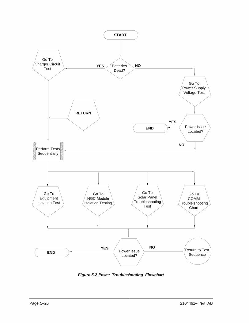
Page 5–26 2104461– rev. AB
Figure 5-2 Power Troubleshooting Flowchart
Go To
Charger Circuit
Test
START
Batteries
Dead?
RETURN
Go To
Equipment
Isolation Test
Go To
COMM
Troublelshooting
Chart
Go To
NGC Module
Isolation Testing
YES NO
Power Issue
Located?
YES NOReturn to Test
Sequence
Perform Tests
Sequentially
END
Go To
Power Supply
Voltage Test
Power Issue
Located?
YES
NO
END
Go To
Solar Panel
Troubleshooting
Test
2104461– rev. AB Page 5–27
5.5.2 Power Supply Voltage Test
This test assumes a power supply is in good working order and has previously been tested and qualified to power an
NGC8106. If the power supply is under suspicion, it is recommended that it be replaced with a known good power
supply before conducting these tests.
5.5.2.1 Instructions
1) Check that the power supply voltage setting, the power supply current
rating and the cables used for the installation meet the recommended
requirements (see System Specifications in Chapter 1).
If this is a new installation and the external equipment is being powered from the NGC8106 termination panel, call Totalflow technical support for
help in evaluating the cable and power supply installation requirements.
Correct and retest as necessary.
2) Check for a poor cable connection in the cable between the NGC8106 and
the power source. Verify all field wiring screw terminals are tight.
Correct and retest as necessary.
3) Verify that there are no other devices that may drop an excessive voltage across them in the power supply circuit (to the NGC8106) like a fuse, diode
or a barrier device, etc.
Correct and retest as necessary.
4) Disconnect the power supply cable at the NGC8106 termination panel J1.
5) Measure the power supply cable voltage at the connector and compare
with the table recommendations (see Table 1–4 and Table 1–5).
If the power supply voltage does not meet recommendations, check the cabling and other loads on the power supply. Also check the power supply
output voltage setting.
Correct and retest as necessary.
6) Reconnect the power supply cable to the NGC8106 termination panel J1.
5.5.3 Equipment Isolation Test
This test isolates the peripheral equipment from the equation to verify that excessive current is not being drawn from the power source, thus reducing the
amount of power supplied to the NGC8106.
This procedure assumes that the previous power supply voltage test was
performed and that no errors were found.
5.5.3.1 Instructions
1) While the NGC8106 is operating, verify that the voltage at the NGC8106 termination panel is between 11.5 Vdc-16 Vdc (for 12 Vdc systems) or 22
Vdc to 28 Vdc (for 24 Vdc systems).
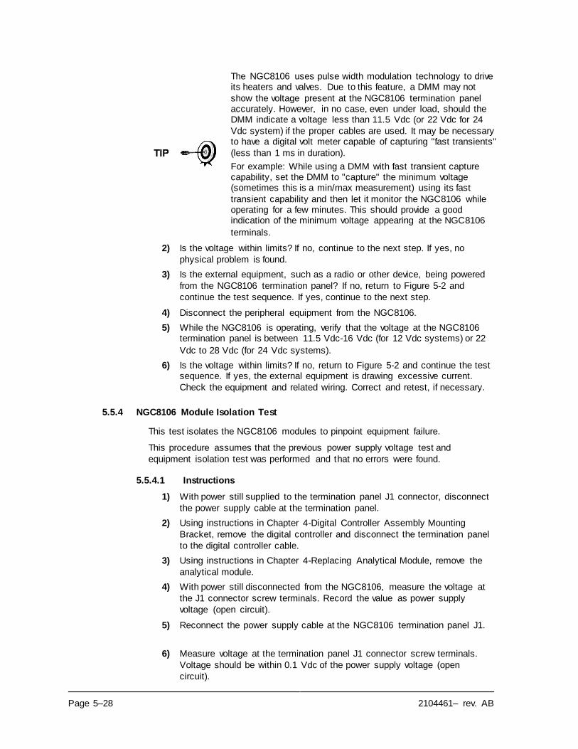
Page 5–28 2104461– rev. AB
The NGC8106 uses pulse width modulation technology to drive its heaters and valves. Due to this feature, a DMM may not
show the voltage present at the NGC8106 termination panel accurately. However, in no case, even under load, should the DMM indicate a voltage less than 11.5 Vdc (or 22 Vdc for 24
Vdc system) if the proper cables are used. It may be necessary to have a digital volt meter capable of capturing "fast transients"
(less than 1 ms in duration).
For example: While using a DMM with fast transient capture capability, set the DMM to "capture" the minimum voltage (sometimes this is a min/max measurement) using its fast
transient capability and then let it monitor the NGC8106 while operating for a few minutes. This should provide a good indication of the minimum voltage appearing at the NGC8106
terminals.
2) Is the voltage within limits? If no, continue to the next step. If yes, no
physical problem is found.
3) Is the external equipment, such as a radio or other device, being powered
from the NGC8106 termination panel? If no, return to Figure 5-2 and
continue the test sequence. If yes, continue to the next step.
4) Disconnect the peripheral equipment from the NGC8106.
5) While the NGC8106 is operating, verify that the voltage at the NGC8106 termination panel is between 11.5 Vdc-16 Vdc (for 12 Vdc systems) or 22
Vdc to 28 Vdc (for 24 Vdc systems).
6) Is the voltage within limits? If no, return to Figure 5-2 and continue the test sequence. If yes, the external equipment is drawing excessive current.
Check the equipment and related wiring. Correct and retest, if necessary.
5.5.4 NGC8106 Module Isolation Test
This test isolates the NGC8106 modules to pinpoint equipment failure.
This procedure assumes that the previous power supply voltage test and
equipment isolation test was performed and that no errors were found.
5.5.4.1 Instructions
1) With power still supplied to the termination panel J1 connector, disconnect
the power supply cable at the termination panel.
2) Using instructions in Chapter 4-Digital Controller Assembly Mounting
Bracket, remove the digital controller and disconnect the termination panel
to the digital controller cable.
3) Using instructions in Chapter 4-Replacing Analytical Module, remove the
analytical module.
4) With power still disconnected from the NGC8106, measure the voltage at
the J1 connector screw terminals. Record the value as power supply
voltage (open circuit).
5) Reconnect the power supply cable at the NGC8106 termination panel J1.
6) Measure voltage at the termination panel J1 connector screw terminals.
Voltage should be within 0.1 Vdc of the power supply voltage (open
circuit).
2104461– rev. AB Page 5–29
i.e., only 0.1 Vdc drop max. between the PS and the NGC8106.
7) If the voltage drop is greater than 0.1V, replace the termination panel using instructions in Chapter 4-Replacing Termination Panel and return to step 6.
If the voltage drop is again greater than 0.1V, call Totalflow technical support, following the instructions in the Introduction to this manual,
Getting Help.
If the drop is less than 0.1V, check the termination panel to the analytical
processor cable for pinched or exposed insulation. Also, check the feed-
through auxiliary heater cable for similar damage.
8) Was the damaged cable found? If yes, replace the appropriate cable using
instructions in chapter 4.
If no, use instructions in Chapter 4- Replacing Analytical Module, and
replace the module. Skip to step 10.
9) Reinstall the analytical module.
10) Reinstall the digital controller assembly.
11) If disconnected during a procedure, reconnect the J1 power supply connector to the termination panel. It may require 10-60 seconds for the processors in the NGC8106 to fully boot and for the NGC8106 to start
drawing normal to full power. However, under normal operation, the
NGC8106 should never draw current beyond its rated values.
12) Return to the equipment isolation test.
5.5.5 Charger Circuit Test
If the system setup includes a battery pack, solar panel or AC charger/power supply connected to the optional equipment enclosure, and the unit’s battery is not
staying charged, the user will need to test the battery pack, AC charger/power
supply or the solar panel.
The following instructions contain the steps required to perform the circuit testing.
5.5.5.1 Things to Consider
The following list points to other troubleshooting procedures that the user may
want to consider as well:
• Solar Panel Troubleshooting Test
• AC Charger/Power Supply Troubleshooting Test
5.5.5.2 Instructions
1) Begin by disconnecting power from the AC charger/power supply, located
in the optional enclosure.
2) Replace the battery with a known good battery using the Battery Pack
Replacement procedure located in Chapter 4-Maintenance.
3) Reconnect the power to the charger/supply. If the battery pack is charged
through an AC charger, skip to step 5; otherwise, continue to step 4.
4) Measure the solar panel charging voltage at the charger regulator using a DMM connecting the (+) and (-) leads to the (+) and (-) solar panel wires. Loaded voltage should be greater than or equal to the specification listed
in Table 5–3. If the voltage is within range, the battery was bad.
Page 5–30 2104461– rev. AB
If the loaded voltage is not above the minimum, perform the solar panel
troubleshooting test found later in this chapter.
5) If the unit uses an AC charger, perform the AC charger/power supply
troubleshooting test found later in this chapter.
6) If all other testing to this point has not located the error, return to Figure 5-2
power troubleshooting flowchart and continue.
Table 5–3 Specifications for Solar Panels
Panel Max Volts at PMax Open Circuit Load Resistance Loaded Voltage
50 54W 17.4V 21.7V 5 Ω 100W 16–18 Vdc
85 87W 17.4V 21.7V 5 Ω 100W 16–18 Vdc
5.5.6 Solar Panel Troubleshooting Test
If the system setup includes a solar panel connected to the optional equipment enclosure, and it is not supplying the required voltage and current to the NGC unit,
the user may need to test the solar panel.
The following instructions contain the steps required to do so.
5.5.6.1 Things to Consider
The following list points to other troubleshooting procedures that the user may
want to consider as well:
• Power Consumption Test (Remote Equipment)
• AC Charger/Power Supply Troubleshooting Test
5.5.6.2 Required Equipment
• Digital Multimeter with 0-20 Vdc range.
• Required resistors for testing specific panels listed in Table 5–3.
In continuous low sun light conditions, the unit may not supply
the required voltage. The solar panel should be positioned so
it receives the most sunlight. Do not place it in a shaded area.
5.5.6.3 Instructions
1) Measure the solar panel voltage at the controller assembly using a DMM connecting the (+) and (-) leads to the (+) and (-) solar panel wires. The
loaded voltage should be greater than or equal to the specifications listed in Table 5–3. If the solar panel is not above the minimum, replace the solar
panel, and continue to step 2.
2) Check the solar panel angle and direction. In the northern hemisphere, the
panel should face due south and in the southern hemisphere, due north.
3) Check the solar panel for any physical damage or obstructions to sunlight. Sunlight obstruction prevents the solar panel from receiving enough sunlight to charge the installed battery pack. Clear any debris from the cell
face of the panel.
4) Check the solar panel wiring to be certain it is correctly connected to the associated termination pins located in the enclosure (see Figure 2-75 and
Figure 2-76).
5) Disconnect the solar panel from the field device.
2104461– rev. AB Page 5–31
6) Set the DMM range to read over 20 Vdc.
7) Determine if the open circuit voltage is greater than or equal to the specifications listed in Table 5–3 by clipping the positive lead of the DMM
to the positive wire and clipping the negative lead of the DMM to the negative wire. If the solar panel is not above the minimum, continue to the
next step.
8) Using the selected resistor from Table 5–3 for the solar panel wattage,
attach the selected resistor between the two solar panel wires.
9) Clip the positive lead of the DMM to the one side of the test resistor.
10) Clip the negative lead of the DMM to the other side of the test resistor.
11) Determine if the loaded voltage is greater than or equal to the specifications listed in Table 5–3. If the solar panel is not above the
minimum, replace the solar panel and return to step 3.
5.5.7 AC Charger/Power Supply Troubleshooting Test
If the system setup includes an AC charger/power supply connected to the
optional equipment enclosure, and is not supplying the required voltage to the NGC8106 unit, the user may need to test the AC charger/power supply. The
following instructions contain the steps required to do so.
5.5.7.1 Instructions
1) Check the input AC voltage to the enclosure power supply. Be certain the
primary AC voltage is correct.
2) If the primary input AC voltage level is correct, and there is no DC output
from the power supply, replace the F1 charger fuse (see Figure 5-3).
3) If the fuse is not faulty or there is no charger DC output voltage after
replacing the fuse, replace the AC charger/power supply.
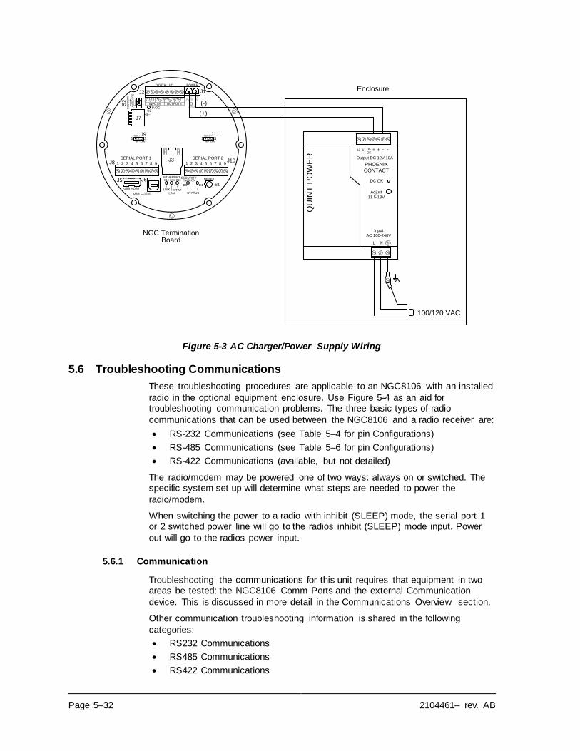
Page 5–32 2104461– rev. AB
Figure 5-3 AC Charger/Power Supply Wiring
5.6 Troubleshooting Communications
These troubleshooting procedures are applicable to an NGC8106 with an installed
radio in the optional equipment enclosure. Use Figure 5-4 as an aid for troubleshooting communication problems. The three basic types of radio
communications that can be used between the NGC8106 and a radio receiver are:
• RS-232 Communications (see Table 5–4 for pin Configurations)
• RS-485 Communications (see Table 5–6 for pin Configurations)
• RS-422 Communications (available, but not detailed)
The radio/modem may be powered one of two ways: always on or switched. The specific system set up will determine what steps are needed to power the
radio/modem.
When switching the power to a radio with inhibit (SLEEP) mode, the serial port 1 or 2 switched power line will go to the radios inhibit (SLEEP) mode input. Power
out will go to the radios power input.
5.6.1 Communication
Troubleshooting the communications for this unit requires that equipment in two areas be tested: the NGC8106 Comm Ports and the external Communication
device. This is discussed in more detail in the Communications Overview section.
Other communication troubleshooting information is shared in the following
categories:
• RS232 Communications
• RS485 Communications
• RS422 Communications
QU
INT
PO
WE
R
PHOENIX
CONTACT
Input
AC 100-240V
L N
--++DC
OK
DC OK
Adjust
11.5-18V
SERIAL PORT 1
1 2 3 4 5 6 7 8 9
SERIAL PORT 2
1 2 3 4 5 6 7 8 9
1 2 1 2(+) (-) (+) (-) (+) (-) (+) (-)
INPUTS OUTPUTS
(+) (-)PWR IN
PWR5VDC
J10J8
SE
CU
RIT
Y
DIGITAL I/O POWER
S2
RESETSECURITYENABLED
LINK STATLAN
1 2STATUS
S1D4D3
D13D11D12ETHERNET
J7
J3
D2
USB HOST
USB CLIENT
J2 J1
J5 J6
UN
SE
CU
RE
NGC Termination Board
(-)
(+)
TERM
NO TERM
TERM
NO TERM
J1131
J931
Enclosure
100/120 VAC
13 14
Output DC 12V 10A
2104461– rev. AB Page 5–33
5.6.2 Setting Up Communication
After the installation of the communication equipment and before placing the
communication system into operation, the user should note the following:
• Verify field wiring terminations on the NGC8106 termination panel.
• Verify field wiring from the NGC8106 unit to the termination strip inside the
enclosure.
• Verify the field wiring from the termination strip to the radio.
• Check the NGC8106 identifier (ID). Log the ID for future reference.
• Log the NGC8106 access security code, baud rate, listen cycle, protocol and
interface for future reference.
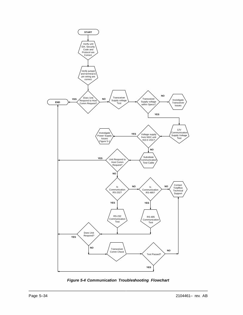
Page 5–34 2104461– rev. AB
Figure 5-4 Communication Troubleshooting Flowchart
12V
Communication
Supply Voltage
Test
START
Does Unit
Respond to Host
Comm Request?
RS-232
Communication
Test
YES NO
Verify unit
ID#, Security
Code and
Protocol are
Correct.
NO
YES
Verify jumper
and terminal &
pin wiring are
correct.
END
Transceiver
Supply voltage
within Specs?
YES
Voltage supply
from NGC unit
=10.5 VDC?
NO
Investigate
Power Supply
Issues
Figure 5-1
Transceiver
Comm Check
Substitute
Communication
Test Cable
Transceiver
Supply voltage
Test
Investigate
Transceiver
Issues
Unit Respond to
Host Comm
Request?
YES
NO
RS-485
Communication
Test
Is
Communication
RS-232?
YES
NOIs
Communication
RS-485?
YES
NOContact
Totalflow
Technical
Support
Does Unit
Respond?
NO
YES
Test Passed?
NO
YES
2104461– rev. AB Page 5–35
The following helpful hints aid the user after the
communication equipment has been installed and setup:
When the communication equipment is powered/switched on, the NGC8106 displays the communication icon after it
recognizes the NGC8106 ID and is responding.
Check the baud rate of the NGC8106 transmission and the listen time settings. The baud rate and time settings can be changed by entering the Station Setup screen from the
Analyzer Operation screen. Default settings are 1200 baud and the listening time is four seconds with the
communications interface turned off.
The minimum power required for operating the remote communications is 11.9 Vdc (default) or as set by user. Should the power fall below this level, remote
communications will be terminated.
Test the remote communications using RS-232 troubleshooting cable. Use the RS-232 to RS-485
communication converter in conjunction with the RS-232 troubleshooting cable to test the RS-485 remote
communications.
5.6.3 Transceiver Supply Voltage Test
Using the wiring information and guidelines supplied by the transceiver manufacturer, verify that the transceiver is receiving the manufacturer’s suggested voltage. If the unit is receiving sufficient voltage, continue to the optional
equipment enclosure wiring voltage test.
If the transceiver is not receiving sufficient voltage, investigate the power supply issues. These may involve
wiring irregularities at the AC charger/power supply, XFC/XRC board or at the power relay if using the relay for
switching power to the radio.
5.6.4 12 Vdc Communication Supply Voltage Test
5.6.4.1 Instructions
If the transceiver does not feature a sleep mode and power is supplied through an
optional relay, begin with Step 1 -Relay Supply Voltage Test.
If the transceiver features a sleep mode, or is continuously powered, begin with
step 2.
1) If the transceiver does not feature a sleep mode and receives power through an optional relay, activate serial port 1 or 2 switched power out (pin 3) and, using a digital multimeter (DMM) set to volts DC, measure the
voltage at the relay between relay coil terminals.
If the voltage reads the same as the supplied voltage (12 Vdc) and the transceiver is still not receiving power, the relay may be incorrectly wired
(use normally open contacts), or the relay may be bad.
If the relay is not receiving power, continue to step 2.
2) If the transceiver features a sleep mode or is continuously powered, using
a digital multimeter (DMM) set to volts DC, measure the voltage at each
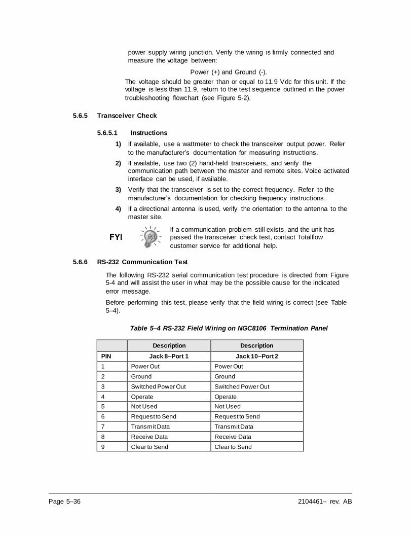
Page 5–36 2104461– rev. AB
power supply wiring junction. Verify the wiring is firmly connected and
measure the voltage between:
Power (+) and Ground (-).
The voltage should be greater than or equal to 11.9 Vdc for this unit. If the voltage is less than 11.9, return to the test sequence outlined in the power
troubleshooting flowchart (see Figure 5-2).
5.6.5 Transceiver Check
5.6.5.1 Instructions
1) If available, use a wattmeter to check the transceiver output power. Refer
to the manufacturer’s documentation for measuring instructions.
2) If available, use two (2) hand-held transceivers, and verify the communication path between the master and remote sites. Voice activated
interface can be used, if available.
3) Verify that the transceiver is set to the correct frequency. Refer to the
manufacturer’s documentation for checking frequency instructions.
4) If a directional antenna is used, verify the orientation to the antenna to the
master site.
If a communication problem still exists, and the unit has passed the transceiver check test, contact Totalflow
customer service for additional help.
5.6.6 RS-232 Communication Test
The following RS-232 serial communication test procedure is directed from Figure 5-4 and will assist the user in what may be the possible cause for the indicated
error message.
Before performing this test, please verify that the field wiring is correct (see Table
5–4).
Table 5–4 RS-232 Field Wiring on NGC8106 Termination Panel
Description Description
PIN Jack 8–Port 1 Jack 10–Port 2
1 Power Out Power Out
2 Ground Ground
3 Switched Power Out Switched Power Out
4 Operate Operate
5 Not Used Not Used
6 Request to Send Request to Send
7 Transmit Data Transmit Data
8 Receive Data Receive Data
9 Clear to Send Clear to Send
2104461– rev. AB Page 5–37
When troubleshooting RS-232 mode, verify the termination settings of the serial port 1 J9 and serial port 2 J11 on the
termination panel have pins 2 and 3 jumpered.
5.6.6.1 Instructions
Voltage on the following steps may be hard to see using a digital multimeter. If available, an oscilloscope will provide a more accurate reading. To verify, the host software must be
continuously polling the NGC8106.
Generally speaking, these tests performed on the terminal board will only verify incorrect or damaged wiring. If all
previous testing passed and all wiring, jack and terminations have been verified as correct, the board will need to be replaced. Contact Totalflow customer service. See Getting
Help in the introduction of this manual for instructions.
1) Using an oscilloscope, measure the receiving data voltage on the
termination panel J8 or J10 between:
Port 1, J8–pin 2 (Ground) and pin 8 (Receive Data) or
Port 2, J10–pin 2 (Ground) and pin 8 (Receive Data).
When the unit is receiving data from the host, the voltage should vary
between -5 Vdc and +5 Vdc. This would indicate that the unit is receiving data; continue to step 2. If the unit is not receiving data, investigate the
wiring issues (see Table 5–4).
2) Using an oscilloscope, measure the request to send voltage on the
termination panel J8 or J10 between:
Port 1, J8–pin 2 (Ground) and pin 6 (Request to Send) or
Port 2, J10–pin 2 (Ground) and pin 6 (Request to Send).
When the unit is communicating with the host, the voltage should be +5 Vdc and remain +5 Vdc until the XFC transmit stops. This would indicate that the unit is transmitting data; continue to step 3. If the unit is not receiving data,
investigate the wiring issues (see Table 5–4).
3) Using an oscilloscope, measure the transmit data voltage on the
termination panel J8 or J10 between:
Port 1, J8–pin 2 (Ground) and pin 7 (Transmit Data) or
Port 2, J10–pin 2 (Ground) and pin 7 (Transmit Data).
When the unit is transmitting to the host, the voltage should vary between -5 and +5 Vdc. This would indicate that the unit is transmitting data. If the unit
is still not responding, continue to the next test as directed in Figure 5-4.
5.6.7 RS-485 Communications
The following RS-485 serial communication test procedure is directed from Figure 5-4 and will assist the user in what may be the possible cause for the indicated
error message.
When troubleshooting RS-485 mode, verify the termination settings of port 1 J9 and port 2 J11 on the termination panel
are correctly jumpered (see Table 5–5).
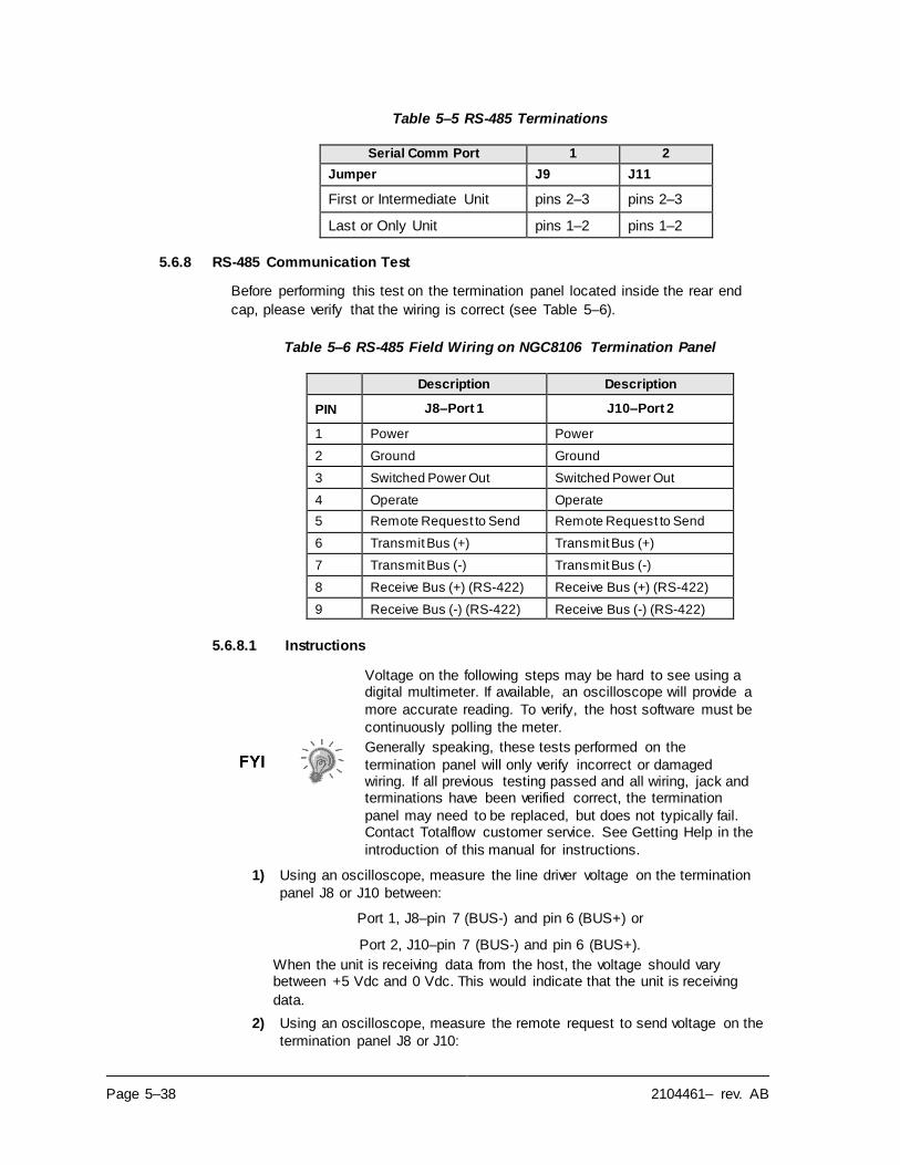
Page 5–38 2104461– rev. AB
Table 5–5 RS-485 Terminations
Serial Comm Port 1 2
Jumper J9 J11
First or Intermediate Unit pins 2–3 pins 2–3
Last or Only Unit pins 1–2 pins 1–2
5.6.8 RS-485 Communication Test
Before performing this test on the termination panel located inside the rear end
cap, please verify that the wiring is correct (see Table 5–6).
Table 5–6 RS-485 Field Wiring on NGC8106 Termination Panel
Description Description
PIN J8–Port 1 J10–Port 2
1 Power Power
2 Ground Ground
3 Switched Power Out Switched Power Out
4 Operate Operate
5 Remote Request to Send Remote Request to Send
6 Transmit Bus (+) Transmit Bus (+)
7 Transmit Bus (-) Transmit Bus (-)
8 Receive Bus (+) (RS-422) Receive Bus (+) (RS-422)
9 Receive Bus (-) (RS-422) Receive Bus (-) (RS-422)
5.6.8.1 Instructions
Voltage on the following steps may be hard to see using a digital multimeter. If available, an oscilloscope will provide a
more accurate reading. To verify, the host software must be
continuously polling the meter.
Generally speaking, these tests performed on the
termination panel will only verify incorrect or damaged wiring. If all previous testing passed and all wiring, jack and terminations have been verified correct, the termination
panel may need to be replaced, but does not typically fail. Contact Totalflow customer service. See Getting Help in the
introduction of this manual for instructions.
1) Using an oscilloscope, measure the line driver voltage on the termination
panel J8 or J10 between:
Port 1, J8–pin 7 (BUS-) and pin 6 (BUS+) or
Port 2, J10–pin 7 (BUS-) and pin 6 (BUS+).
When the unit is receiving data from the host, the voltage should vary between +5 Vdc and 0 Vdc. This would indicate that the unit is receiving
data.
2) Using an oscilloscope, measure the remote request to send voltage on the
termination panel J8 or J10:
2104461– rev. AB Page 5–39
Port 1, J8–pin 2 (Ground) and pin 5 (RRTS)
Port 2, J10–pin 2 (Ground) and pin 5 (RRTS)
When the unit is transmitting data, the voltage should vary between +5 Vdc
and 0 Vdc. This would indicate that the RRTS is working correctly.
3) If any inaccuracy exists, investigate the wiring errors or damaged wires.
If a communication problem still exists and the unit has
passed the tests in steps 1 and 2, additional testing will be
required.

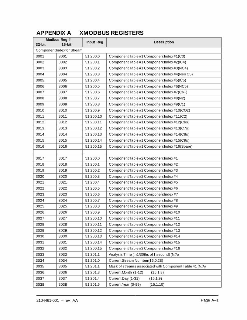
2104461-001 – rev. AA Page A–1
APPENDIX A XMODBUS REGISTERS Modbus Reg #
32-bit 16-bit Input Reg Description
Component Index for Stream
3001 3001 51.200.0 Component Table #1 Component Index #1(C3)
3002 3002 51.200.1 Component Table #1 Component Index #2(IC4)
3003 3003 51.200.2 Component Table #1 Component Index #3(NC4)
3004 3004 51.200.3 Component Table #1 Component Index #4(Neo C5)
3005 3005 51.200.4 Component Table #1 Component Index #5(IC5)
3006 3006 51.200.5 Component Table #1 Component Index #6(NC5)
3007 3007 51.200.6 Component Table #1 Component Index #7(C6+)
3008 3008 51.200.7 Component Table #1 Component Index #8(N2)
3009 3009 51.200.8 Component Table #1 Component Index #9(C1)
3010 3010 51.200.9 Component Table #1 Component Index #10(CO2)
3011 3011 51.200.10 Component Table #1 Component Index #11(C2)
3012 3012 51.200.11 Component Table #1 Component Index #12(C6s)
3013 3013 51.200.12 Component Table #1 Component Index #13(C7s)
3014 3014 51.200.13 Component Table #1 Component Index #14(C8s)
3015 3015 51.200.14 Component Table #1 Component Index #15(C9s)
3016 3016 51.200.15 Component Table #1 Component Index #16(Spare)
3017 3017 51.200.0 Component Table #2 Component Index #1
3018 3018 51.200.1 Component Table #2 Component Index #2
3019 3019 51.200.2 Component Table #2 Component Index #3
3020 3020 51.200.3 Component Table #2 Component Index #4
3021 3021 51.200.4 Component Table #2 Component Index #5
3022 3022 51.200.5 Component Table #2 Component Index #6
3023 3023 51.200.6 Component Table #2 Component Index #7
3024 3024 51.200.7 Component Table #2 Component Index #8
3025 3025 51.200.8 Component Table #2 Component Index #9
3026 3026 51.200.9 Component Table #2 Component Index #10
3027 3027 51.200.10 Component Table #2 Component Index #11
3028 3028 51.200.11 Component Table #2 Component Index #12
3029 3029 51.200.12 Component Table #2 Component Index #13
3030 3030 51.200.13 Component Table #2 Component Index #14
3031 3031 51.200.14 Component Table #2 Component Index #15
3032 3032 51.200.15 Component Table #2 Component Index #16
3033 3033 51.201.1 Analysis Time (in1/30ths of 1 second) (N/A)
3034 3034 51.201.0 Current Stream Number(15.0.28)
3035 3035 51.201.1 Mask of streams associated with Component Table 41 (N/A)
3036 3036 51.201.3 Current Month (1-12) (15.1.8)
3037 3037 51.201.4 Current Day (1-31) (15.1.9)
3038 3038 51.201.5 Current Year (0-99) (15.1.10)
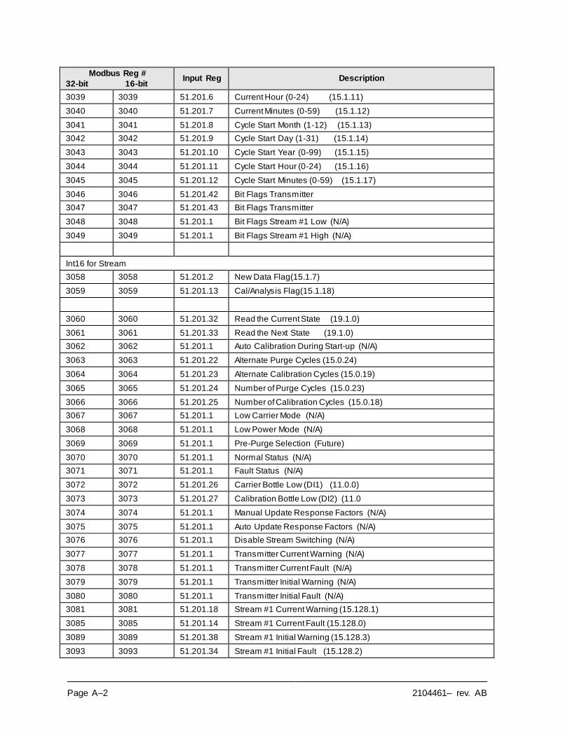
Page A–2 2104461– rev. AB
Modbus Reg #
32-bit 16-bit Input Reg Description
3039 3039 51.201.6 Current Hour (0-24) (15.1.11)
3040 3040 51.201.7 Current Minutes (0-59) (15.1.12)
3041 3041 51.201.8 Cycle Start Month (1-12) (15.1.13)
3042 3042 51.201.9 Cycle Start Day (1-31) (15.1.14)
3043 3043 51.201.10 Cycle Start Year (0-99) (15.1.15)
3044 3044 51.201.11 Cycle Start Hour (0-24) (15.1.16)
3045 3045 51.201.12 Cycle Start Minutes (0-59) (15.1.17)
3046 3046 51.201.42 Bit Flags Transmitter
3047 3047 51.201.43 Bit Flags Transmitter
3048 3048 51.201.1 Bit Flags Stream #1 Low (N/A)
3049 3049 51.201.1 Bit Flags Stream #1 High (N/A)
Int16 for Stream
3058 3058 51.201.2 New Data Flag(15.1.7)
3059 3059 51.201.13 Cal/Analysis Flag(15.1.18)
3060 3060 51.201.32 Read the Current State (19.1.0)
3061 3061 51.201.33 Read the Next State (19.1.0)
3062 3062 51.201.1 Auto Calibration During Start-up (N/A)
3063 3063 51.201.22 Alternate Purge Cycles (15.0.24)
3064 3064 51.201.23 Alternate Calibration Cycles (15.0.19)
3065 3065 51.201.24 Number of Purge Cycles (15.0.23)
3066 3066 51.201.25 Number of Calibration Cycles (15.0.18)
3067 3067 51.201.1 Low Carrier Mode (N/A)
3068 3068 51.201.1 Low Power Mode (N/A)
3069 3069 51.201.1 Pre-Purge Selection (Future)
3070 3070 51.201.1 Normal Status (N/A)
3071 3071 51.201.1 Fault Status (N/A)
3072 3072 51.201.26 Carrier Bottle Low (DI1) (11.0.0)
3073 3073 51.201.27 Calibration Bottle Low (DI2) (11.0
3074 3074 51.201.1 Manual Update Response Factors (N/A)
3075 3075 51.201.1 Auto Update Response Factors (N/A)
3076 3076 51.201.1 Disable Stream Switching (N/A)
3077 3077 51.201.1 Transmitter Current Warning (N/A)
3078 3078 51.201.1 Transmitter Current Fault (N/A)
3079 3079 51.201.1 Transmitter Initial Warning (N/A)
3080 3080 51.201.1 Transmitter Initial Fault (N/A)
3081 3081 51.201.18 Stream #1 Current Warning (15.128.1)
3085 3085 51.201.14 Stream #1 Current Fault (15.128.0)
3089 3089 51.201.38 Stream #1 Initial Warning (15.128.3)
3093 3093 51.201.34 Stream #1 Initial Fault (15.128.2)
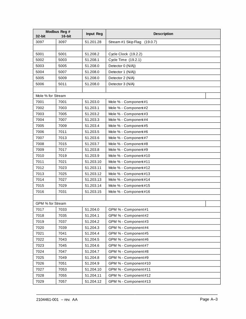
2104461-001 – rev. AA Page A–3
Modbus Reg #
32-bit 16-bit Input Reg Description
3097 3097 51.201.28 Stream #1 Skip Flag (19.0.7)
5001 5001 51.208.2 Cycle Clock (19.2.2)
5002 5003 51.208.1 Cycle Time (19.2.1)
5003 5005 51.208.0 Detector 0 (N/A))
5004 5007 51.208.0 Detector 1 (N/A))
5005 5009 51.208.0 Detector 2 (N/A)
5006 5011 51.208.0 Detector 3 (N/A)
Mole % for Stream
7001 7001 51.203.0 Mole % - Component #1
7002 7003 51.203.1 Mole % - Component #2
7003 7005 51.203.2 Mole % - Component #3
7004 7007 51.203.3 Mole % - Component #4
7005 7009 51.203.4 Mole % - Component #5
7006 7011 51.203.5 Mole % - Component #6
7007 7013 51.203.6 Mole % - Component #7
7008 7015 51.203.7 Mole % - Component #8
7009 7017 51.203.8 Mole % - Component #9
7010 7019 51.203.9 Mole % - Component #10
7011 7021 51.203.10 Mole % - Component #11
7012 7023 51.203.11 Mole % - Component #12
7013 7025 51.203.12 Mole % - Component #13
7014 7027 51.203.13 Mole % - Component #14
7015 7029 51.203.14 Mole % - Component #15
7016 7031 51.203.15 Mole % - Component #16
GPM % for Stream
7017 7033 51.204.0 GPM % - Component #1
7018 7035 51.204.1 GPM % - Component #2
7019 7037 51.204.2 GPM % - Component #3
7020 7039 51.204.3 GPM % - Component #4
7021 7041 51.204.4 GPM % - Component #5
7022 7043 51.204.5 GPM % - Component #6
7023 7045 51.204.6 GPM % - Component #7
7024 7047 51.204.7 GPM % - Component #8
7025 7049 51.204.8 GPM % - Component #9
7026 7051 51.204.9 GPM % - Component #10
7027 7053 51.204.10 GPM % - Component #11
7028 7055 51.204.11 GPM % - Component #12
7029 7057 51.204.12 GPM % - Component #13
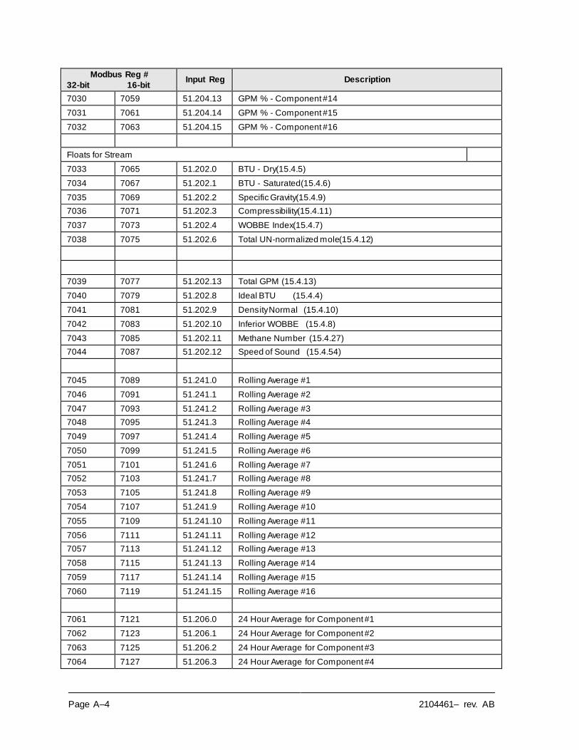
Page A–4 2104461– rev. AB
Modbus Reg #
32-bit 16-bit Input Reg Description
7030 7059 51.204.13 GPM % - Component #14
7031 7061 51.204.14 GPM % - Component #15
7032 7063 51.204.15 GPM % - Component #16
Floats for Stream
7033 7065 51.202.0 BTU - Dry(15.4.5)
7034 7067 51.202.1 BTU - Saturated(15.4.6)
7035 7069 51.202.2 Specific Gravity(15.4.9)
7036 7071 51.202.3 Compressibility(15.4.11)
7037 7073 51.202.4 WOBBE Index(15.4.7)
7038 7075 51.202.6 Total UN-normalized mole(15.4.12)
7039 7077 51.202.13 Total GPM (15.4.13)
7040 7079 51.202.8 Ideal BTU (15.4.4)
7041 7081 51.202.9 Density Normal (15.4.10)
7042 7083 51.202.10 Inferior WOBBE (15.4.8)
7043 7085 51.202.11 Methane Number (15.4.27)
7044 7087 51.202.12 Speed of Sound (15.4.54)
7045 7089 51.241.0 Rolling Average #1
7046 7091 51.241.1 Rolling Average #2
7047 7093 51.241.2 Rolling Average #3
7048 7095 51.241.3 Rolling Average #4
7049 7097 51.241.4 Rolling Average #5
7050 7099 51.241.5 Rolling Average #6
7051 7101 51.241.6 Rolling Average #7
7052 7103 51.241.7 Rolling Average #8
7053 7105 51.241.8 Rolling Average #9
7054 7107 51.241.9 Rolling Average #10
7055 7109 51.241.10 Rolling Average #11
7056 7111 51.241.11 Rolling Average #12
7057 7113 51.241.12 Rolling Average #13
7058 7115 51.241.13 Rolling Average #14
7059 7117 51.241.14 Rolling Average #15
7060 7119 51.241.15 Rolling Average #16
7061 7121 51.206.0 24 Hour Average for Component #1
7062 7123 51.206.1 24 Hour Average for Component #2
7063 7125 51.206.2 24 Hour Average for Component #3
7064 7127 51.206.3 24 Hour Average for Component #4
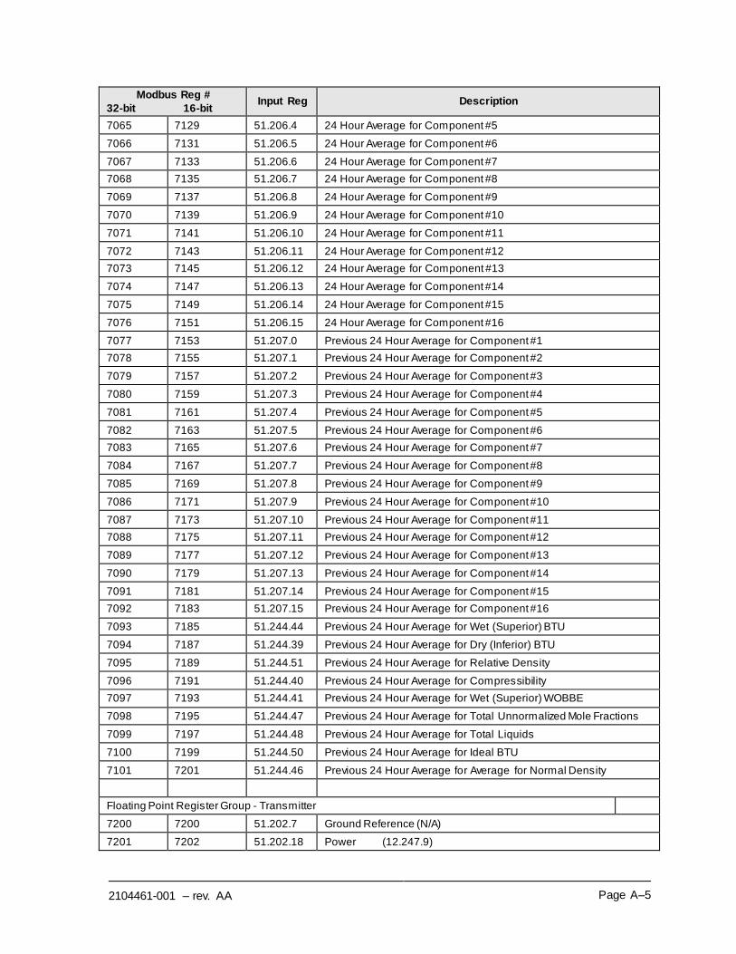
2104461-001 – rev. AA Page A–5
Modbus Reg #
32-bit 16-bit Input Reg Description
7065 7129 51.206.4 24 Hour Average for Component #5
7066 7131 51.206.5 24 Hour Average for Component #6
7067 7133 51.206.6 24 Hour Average for Component #7
7068 7135 51.206.7 24 Hour Average for Component #8
7069 7137 51.206.8 24 Hour Average for Component #9
7070 7139 51.206.9 24 Hour Average for Component #10
7071 7141 51.206.10 24 Hour Average for Component #11
7072 7143 51.206.11 24 Hour Average for Component #12
7073 7145 51.206.12 24 Hour Average for Component #13
7074 7147 51.206.13 24 Hour Average for Component #14
7075 7149 51.206.14 24 Hour Average for Component #15
7076 7151 51.206.15 24 Hour Average for Component #16
7077 7153 51.207.0 Previous 24 Hour Average for Component #1
7078 7155 51.207.1 Previous 24 Hour Average for Component #2
7079 7157 51.207.2 Previous 24 Hour Average for Component #3
7080 7159 51.207.3 Previous 24 Hour Average for Component #4
7081 7161 51.207.4 Previous 24 Hour Average for Component #5
7082 7163 51.207.5 Previous 24 Hour Average for Component #6
7083 7165 51.207.6 Previous 24 Hour Average for Component #7
7084 7167 51.207.7 Previous 24 Hour Average for Component #8
7085 7169 51.207.8 Previous 24 Hour Average for Component #9
7086 7171 51.207.9 Previous 24 Hour Average for Component #10
7087 7173 51.207.10 Previous 24 Hour Average for Component #11
7088 7175 51.207.11 Previous 24 Hour Average for Component #12
7089 7177 51.207.12 Previous 24 Hour Average for Component #13
7090 7179 51.207.13 Previous 24 Hour Average for Component #14
7091 7181 51.207.14 Previous 24 Hour Average for Component #15
7092 7183 51.207.15 Previous 24 Hour Average for Component #16
7093 7185 51.244.44 Previous 24 Hour Average for Wet (Superior) BTU
7094 7187 51.244.39 Previous 24 Hour Average for Dry (Inferior) BTU
7095 7189 51.244.51 Previous 24 Hour Average for Relative Density
7096 7191 51.244.40 Previous 24 Hour Average for Compressibility
7097 7193 51.244.41 Previous 24 Hour Average for Wet (Superior) WOBBE
7098 7195 51.244.47 Previous 24 Hour Average for Total Unnormalized Mole Fractions
7099 7197 51.244.48 Previous 24 Hour Average for Total Liquids
7100 7199 51.244.50 Previous 24 Hour Average for Ideal BTU
7101 7201 51.244.46 Previous 24 Hour Average for Average for Normal Density
Floating Point Register Group - Transmitter
7200 7200 51.202.7 Ground Reference (N/A)
7201 7202 51.202.18 Power (12.247.9)
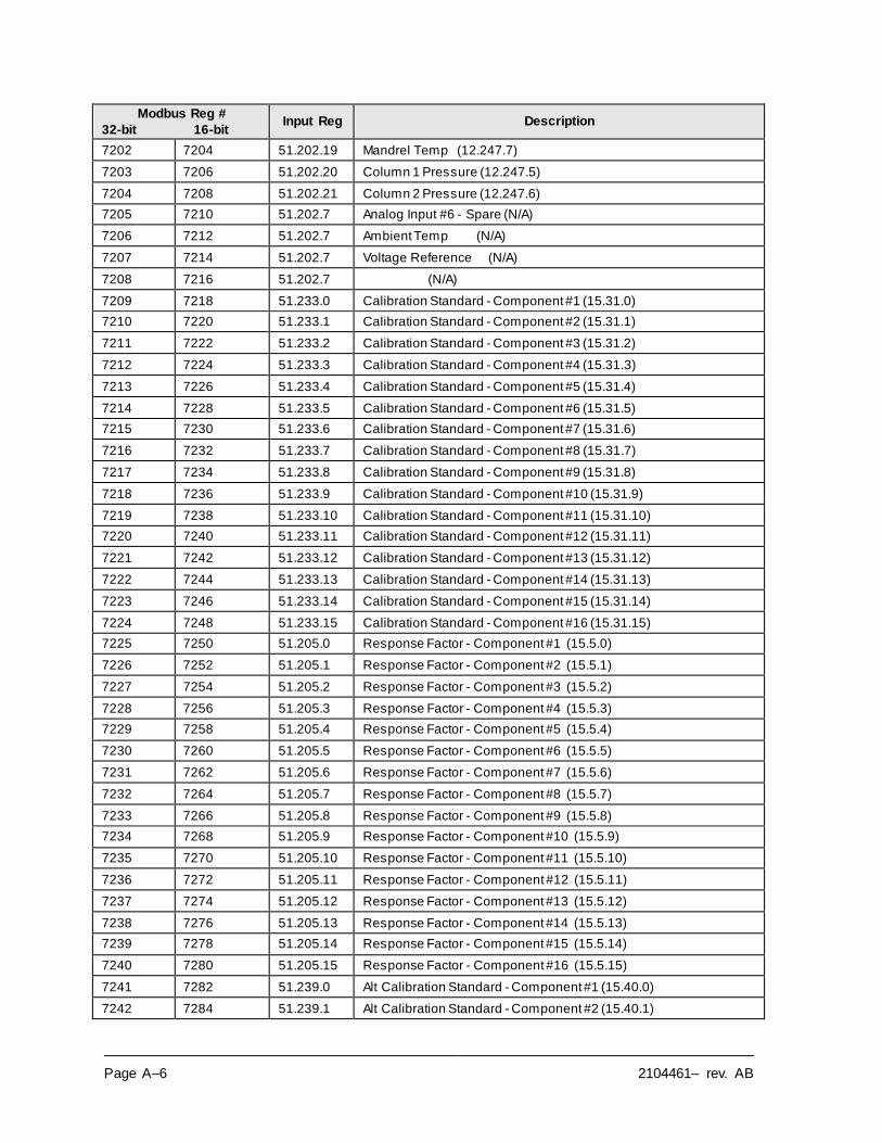
Page A–6 2104461– rev. AB
Modbus Reg #
32-bit 16-bit Input Reg Description
7202 7204 51.202.19 Mandrel Temp (12.247.7)
7203 7206 51.202.20 Column 1 Pressure (12.247.5)
7204 7208 51.202.21 Column 2 Pressure (12.247.6)
7205 7210 51.202.7 Analog Input #6 - Spare (N/A)
7206 7212 51.202.7 Ambient Temp (N/A)
7207 7214 51.202.7 Voltage Reference (N/A)
7208 7216 51.202.7 (N/A)
7209 7218 51.233.0 Calibration Standard - Component #1 (15.31.0)
7210 7220 51.233.1 Calibration Standard - Component #2 (15.31.1)
7211 7222 51.233.2 Calibration Standard - Component #3 (15.31.2)
7212 7224 51.233.3 Calibration Standard - Component #4 (15.31.3)
7213 7226 51.233.4 Calibration Standard - Component #5 (15.31.4)
7214 7228 51.233.5 Calibration Standard - Component #6 (15.31.5)
7215 7230 51.233.6 Calibration Standard - Component #7 (15.31.6)
7216 7232 51.233.7 Calibration Standard - Component #8 (15.31.7)
7217 7234 51.233.8 Calibration Standard - Component #9 (15.31.8)
7218 7236 51.233.9 Calibration Standard - Component #10 (15.31.9)
7219 7238 51.233.10 Calibration Standard - Component #11 (15.31.10)
7220 7240 51.233.11 Calibration Standard - Component #12 (15.31.11)
7221 7242 51.233.12 Calibration Standard - Component #13 (15.31.12)
7222 7244 51.233.13 Calibration Standard - Component #14 (15.31.13)
7223 7246 51.233.14 Calibration Standard - Component #15 (15.31.14)
7224 7248 51.233.15 Calibration Standard - Component #16 (15.31.15)
7225 7250 51.205.0 Response Factor - Component #1 (15.5.0)
7226 7252 51.205.1 Response Factor - Component #2 (15.5.1)
7227 7254 51.205.2 Response Factor - Component #3 (15.5.2)
7228 7256 51.205.3 Response Factor - Component #4 (15.5.3)
7229 7258 51.205.4 Response Factor - Component #5 (15.5.4)
7230 7260 51.205.5 Response Factor - Component #6 (15.5.5)
7231 7262 51.205.6 Response Factor - Component #7 (15.5.6)
7232 7264 51.205.7 Response Factor - Component #8 (15.5.7)
7233 7266 51.205.8 Response Factor - Component #9 (15.5.8)
7234 7268 51.205.9 Response Factor - Component #10 (15.5.9)
7235 7270 51.205.10 Response Factor - Component #11 (15.5.10)
7236 7272 51.205.11 Response Factor - Component #12 (15.5.11)
7237 7274 51.205.12 Response Factor - Component #13 (15.5.12)
7238 7276 51.205.13 Response Factor - Component #14 (15.5.13)
7239 7278 51.205.14 Response Factor - Component #15 (15.5.14)
7240 7280 51.205.15 Response Factor - Component #16 (15.5.15)
7241 7282 51.239.0 Alt Calibration Standard - Component #1 (15.40.0)
7242 7284 51.239.1 Alt Calibration Standard - Component #2 (15.40.1)
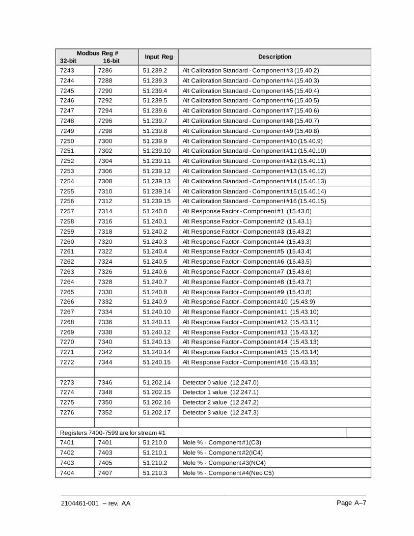
2104461-001 – rev. AA Page A–7
Modbus Reg #
32-bit 16-bit Input Reg Description
7243 7286 51.239.2 Alt Calibration Standard - Component #3 (15.40.2)
7244 7288 51.239.3 Alt Calibration Standard - Component #4 (15.40.3)
7245 7290 51.239.4 Alt Calibration Standard - Component #5 (15.40.4)
7246 7292 51.239.5 Alt Calibration Standard - Component #6 (15.40.5)
7247 7294 51.239.6 Alt Calibration Standard - Component #7 (15.40.6)
7248 7296 51.239.7 Alt Calibration Standard - Component #8 (15.40.7)
7249 7298 51.239.8 Alt Calibration Standard - Component #9 (15.40.8)
7250 7300 51.239.9 Alt Calibration Standard - Component #10 (15.40.9)
7251 7302 51.239.10 Alt Calibration Standard - Component #11 (15.40.10)
7252 7304 51.239.11 Alt Calibration Standard - Component #12 (15.40.11)
7253 7306 51.239.12 Alt Calibration Standard - Component #13 (15.40.12)
7254 7308 51.239.13 Alt Calibration Standard - Component #14 (15.40.13)
7255 7310 51.239.14 Alt Calibration Standard - Component #15 (15.40.14)
7256 7312 51.239.15 Alt Calibration Standard - Component #16 (15.40.15)
7257 7314 51.240.0 Alt Response Factor - Component #1 (15.43.0)
7258 7316 51.240.1 Alt Response Factor - Component #2 (15.43.1)
7259 7318 51.240.2 Alt Response Factor - Component #3 (15.43.2)
7260 7320 51.240.3 Alt Response Factor - Component #4 (15.43.3)
7261 7322 51.240.4 Alt Response Factor - Component #5 (15.43.4)
7262 7324 51.240.5 Alt Response Factor - Component #6 (15.43.5)
7263 7326 51.240.6 Alt Response Factor - Component #7 (15.43.6)
7264 7328 51.240.7 Alt Response Factor - Component #8 (15.43.7)
7265 7330 51.240.8 Alt Response Factor - Component #9 (15.43.8)
7266 7332 51.240.9 Alt Response Factor - Component #10 (15.43.9)
7267 7334 51.240.10 Alt Response Factor - Component #11 (15.43.10)
7268 7336 51.240.11 Alt Response Factor - Component #12 (15.43.11)
7269 7338 51.240.12 Alt Response Factor - Component #13 (15.43.12)
7270 7340 51.240.13 Alt Response Factor - Component #14 (15.43.13)
7271 7342 51.240.14 Alt Response Factor - Component #15 (15.43.14)
7272 7344 51.240.15 Alt Response Factor - Component #16 (15.43.15)
7273 7346 51.202.14 Detector 0 value (12.247.0)
7274 7348 51.202.15 Detector 1 value (12.247.1)
7275 7350 51.202.16 Detector 2 value (12.247.2)
7276 7352 51.202.17 Detector 3 value (12.247.3)
Registers 7400-7599 are for stream #1
7401 7401 51.210.0 Mole % - Component #1(C3)
7402 7403 51.210.1 Mole % - Component #2(IC4)
7403 7405 51.210.2 Mole % - Component #3(NC4)
7404 7407 51.210.3 Mole % - Component #4(Neo C5)
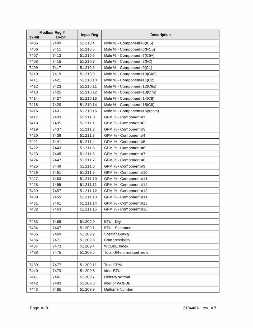
Page A–8 2104461– rev. AB
Modbus Reg #
32-bit 16-bit Input Reg Description
7405 7409 51.210.4 Mole % - Component #5(IC5)
7406 7411 51.210.5 Mole % - Component #6(NC5)
7407 7413 51.210.6 Mole % - Component #7(C6+)
7408 7415 51.210.7 Mole % - Component #8(N2)
7409 7417 51.210.8 Mole % - Component #9(C1)
7410 7419 51.210.9 Mole % - Component #10(C02)
7411 7421 51.210.10 Mole % - Component #11(C2)
7412 7423 51.210.11 Mole % - Component #12(C6s)
7413 7425 51.210.12 Mole % - Component #13(C7s)
7414 7427 51.210.13 Mole % - Component #14(C8)
7415 7429 51.210.14 Mole % - Component #15(C9)
7416 7431 51.210.15 Mole % - Component #16(spare)
7417 7433 51.211.0 GPM % - Component #1
7418 7435 51.211.1 GPM % - Component #2
7419 7437 51.211.2 GPM % - Component #3
7420 7439 51.211.3 GPM % - Component #4
7421 7441 51.211.4 GPM % - Component #5
7422 7443 51.211.5 GPM % - Component #6
7423 7445 51.211.6 GPM % - Component #7
7424 7447 51.211.7 GPM % - Component #8
7425 7449 51.211.8 GPM % - Component #9
7426 7451 51.211.9 GPM % - Component #10
7427 7453 51.211.10 GPM % - Component #11
7428 7455 51.211.11 GPM % - Component #12
7429 7457 51.211.12 GPM % - Component #13
7430 7459 51.211.13 GPM % - Component #14
7431 7461 51.211.14 GPM % - Component #15
7432 7463 51.211.15 GPM % - Component #16
7433 7465 51.209.0 BTU - Dry
7434 7467 51.209.1 BTU - Saturated
7435 7469 51.209.2 Specific Gravity
7436 7471 51.209.3 Compressibility
7437 7473 51.209.4 WOBBE Index
7438 7475 51.209.5 Total UN-normalized mole
7439 7477 51.209.11 Total GPM
7440 7479 51.209.6 Ideal BTU
7441 7481 51.209.7 Density Normal
7442 7483 51.209.8 Inferior WOBBE
7443 7485 51.209.9 Methane Number
2104461-001 – rev. AA Page A–9
Modbus Reg #
32-bit 16-bit Input Reg Description
7444 7487 51.209.10 Speed of Sound
7445 7489 51.235.0 Rolling Average #1
7446 7491 51.235.1 Rolling Average #2
7447 7493 51.235.2 Rolling Average #3
7448 7495 51.235.3 Rolling Average #4
7449 7497 51.235.4 Rolling Average #5
7450 7499 51.235.5 Rolling Average #6
7451 7501 51.235.6 Rolling Average #7
7452 7503 51.235.7 Rolling Average #8
7453 7505 51.235.8 Rolling Average #9
7454 7507 51.235.9 Rolling Average #10
7455 7509 51.235.10 Rolling Average #11
7456 7511 51.235.11 Rolling Average #12
7457 7513 51.235.12 Rolling Average #13
7458 7515 51.235.13 Rolling Average #14
7459 7517 51.235.14 Rolling Average #15
7460 7519 51.235.15 Rolling Average #16
7461 7521 51.212.0 24 Hour Average for Component #1
7462 7523 51.212.1 24 Hour Average for Component #2
7463 7525 51.212.2 24 Hour Average for Component #3
7464 7527 51.212.3 24 Hour Average for Component #4
7465 7529 51.212.4 24 Hour Average for Component #5
7466 7531 51.212.5 24 Hour Average for Component #6
7467 7533 51.212.6 24 Hour Average for Component #7
7468 7535 51.212.7 24 Hour Average for Component #8
7469 7537 51.212.8 24 Hour Average for Component #9
7470 7539 51.212.9 24 Hour Average for Component #10
7471 7541 51.212.10 24 Hour Average for Component #11
7472 7543 51.212.11 24 Hour Average for Component #12
7473 7545 51.212.12 24 Hour Average for Component #13
7474 7547 51.212.13 24 Hour Average for Component #14
7475 7549 51.212.14 24 Hour Average for Component #15
7476 7551 51.212.15 24 Hour Average for Component #16
7477 7553 51.213.0 Previous 24 Hour Average for Component #1
7478 7555 51.213.1 Previous 24 Hour Average for Component #2
7479 7557 51.213.2 Previous 24 Hour Average for Component #3
7480 7559 51.213.3 Previous 24 Hour Average for Component #4
7481 7561 51.213.4 Previous 24 Hour Average for Component #5
7482 7563 51.213.5 Previous 24 Hour Average for Component #6
Page A–10 2104461– rev. AB
Modbus Reg #
32-bit 16-bit Input Reg Description
7483 7565 51.213.6 Previous 24 Hour Average for Component #7
7484 7567 51.213.7 Previous 24 Hour Average for Component #8
7485 7569 51.213.8 Previous 24 Hour Average for Component #9
7486 7571 51.213.9 Previous 24 Hour Average for Component #10
7487 7573 51.213.10 Previous 24 Hour Average for Component #11
7488 7575 51.213.11 Previous 24 Hour Average for Component #12
7489 7577 51.213.12 Previous 24 Hour Average for Component #13
7490 7579 51.213.13 Previous 24 Hour Average for Component #14
7491 7581 51.213.14 Previous 24 Hour Average for Component #15
7492 7583 51.213.15 Previous 24 Hour Average for Component #16


