Embed Size (px)
Citation preview

Computed tomography model-based treatment of atrialfibrillation and atrial macro-re-entrant tachycardia
Christopher Piorkowski*, Simon Kircher, Arash Arya, Thomas Gaspar, Masahiro Esato, Sam Riahi,Andreas Bollmann, Daniela Husser, Charlotte Staab, Philipp Sommer, and Gerhard Hindricks
Department of Electrophysiology, University of Leipzig, Heart Center, Strumpellstrasse 39, 04289 Leipzig, Germany
Received 2 February 2008; accepted after revision 12 May 2008; online publish-ahead-of-print 23 June 2008
Aims Accurate orientation within true three-dimensional (3D) anatomies is essential for the successfulradiofrequency (RF) catheter ablation of atrial fibrillation (AF) and atrial macro-re-entrant tachycardia(MRT). In this prospective study, ablation of AF and MRTwas performed exclusively using a pre-acquiredand integrated computed tomography (CT) image for anatomical 3D orientation without electro-ana-tomic reconstruction of the left atrium (LA).Methods and results Fifty-four consecutive patients suffering from AF (n ¼ 36) and/or MRT (n ¼ 18)underwent RF catheter ablation. A 3D CT image was registered into the NavX-Ensite system withoutreconstruction of the atrial chamber anatomy. The quality of CT alignment was assessed and validatedaccording to fluoroscopy information, electrogram characteristics, and tactile feedback at 31 pre-defined LA control points. The ablation of AF as well as mapping and ablation of MRT was performedwithin the 3D CT anatomy. In all patients, mapping and ablation could be performed without the recon-struction of the respective atrial chamber anatomy. The overall CT alignment was highly accurate withtrue surface contact in 90% (84%; 100%) of the control points. Complete isolation of all pulmonary vein(PV) funnels was achieved in 35 of 36 patients (97%) with AF. In patients with persistent AF (n ¼ 11),additional isolation of the posterior LA (box lesion) and the placement of a mitral isthmus line were per-formed. The MRT mechanisms were as follows: around a PV ostium (n ¼ 6), perimitral (n ¼ 4), throughLA roof (n ¼ 5), septal (n ¼ 2), and around left atrial appendage (n ¼ 1). After a follow-up of 122+33days, 22/25 (88%) patients with paroxysmal AF, 8/11 (73%) with persistent AF, and 16/18 (89%) with MRTremained free from arrhythmia recurrences.Conclusion For patients with AF and MRT, our study shows the feasibility of successful placement ofcomplex linear ablation line concepts guided by an integrated 3D image anatomy alone rather than cath-eter-based virtual chamber surface reconstructions.
KEYWORDSAtrial fibrillation;
Ablation;
Three dimensional image;
Model-guided therapy
Introduction
Radiofrequency (RF) catheter ablation of atrial fibrillation(AF) and atrial macro-re-entrant tachycardia (MRT) hasbecome an accepted potentially curative treatmentapproach. Because of the complex three-dimensional (3D)distributions of initiating triggers and perpetuating sub-strate, catheter ablation of the mentioned arrhythmiasrequires an accurate 3D visualization of the atrial anatomy.
To provide 3D orientation, currently, electro-anatomicmapping systems (EAM) are commonly being used to recon-struct a virtual 3D chamber anatomy through the acquisitionof a limited number of anatomical surface location pointsderived from the position of the catheter tip and an extrapol-ation of the chamber surface in between these acquired ana-tomical points.1,2 However, the resolution and accuracy ofsuch a virtual 3D chamber anatomy, solely based on EAM,are limited by the number of acquired anatomical surfacelocation points and the reliability of a true surface locationof the catheter tip in areas with difficult catheter access.* Corresponding author. Tel: þ49 341 8651413; fax: þ49 341 8651460.
E-mail address: [email protected]
Published on behalf of the European Society of Cardiology. All rights reserved. & The Author 2008.For permissions please email: [email protected] online version of this article has been published under an open access model. Users are entitled to use, reproduce, disseminate, or displaythe open access version of this article for non-commercial purposes provided that the original authorship is properly and fully attributed; theJournal, Learned Society and Oxford University Press are attributed as the original place of publication with correct citation details given; ifan article is subsequently reproduced or disseminated not in its entirety but only in part or as a derivative work this must be clearly indicated.For commercial re-use, please contact journals.permissions&oxfordjournals.org.
Europace (2008) 10, 939–948doi:10.1093/europace/eun147

A more detailed appreciation of the complex left atrium(LA) anatomy can be obtained with 3D-anatomical chamberreconstructions derived from computed tomography (CT)or magnetic resonance imaging (MRI) studies.3,4 Super-imposition of pre-acquired CT/MRI images onto the electro-anatomic 3D-reconstruction is associated with an improvedclinical outcome in AF ablation procedures.5 So far thisimage integration is based on registration involving land-mark points and surface alignment. Currently, it is notclear which registration protocol provides the most accurateand reliable image integration. Therefore, until now, CT/MRI imaging has been merely used in adjunction to theelectro-anatomic reconstruction.
In the present prospective clinical study, ablation of AFand atrial MRT was performed in a larger patient populationexclusively using a pre-acquired and integrated CT image foranatomical 3D orientation without electro-anatomic recon-struction of the LA.
Methods
Patient characteristics
In this prospective study, between May 2007 and September 2007, atotal of 54 consecutive patients suffering from highly symptomaticdrug-refractory AF (n ¼ 36) and/or atrial MRT (n ¼ 18) underwentRF catheter ablation at our institution (21 females, 33 males,mean age 61+10 years). Out of the 36 patients with AF, 25 (69%)suffered from paroxysmal and 11 (31%) from persistent AF. Persist-ent AF was defined as documented AF lasting for more than 7 days.
Among 54 patients, structural heart disease was present in 23(43%) patients [coronary artery disease (n ¼ 7), dilated cardiomyo-pathy (n ¼ 8), and valvular heart disease (n ¼ 9)]. Arterial hyper-tension was present in 31 (57%) patients. Lone AF was seen in 13(24%) patients. Left ventricular ejection fraction averaged56 + 9%. Left atrium diameter measured 44+9 mm. The durationof the arrhythmia history had a median of 60 months (range: 8–252).Twenty-one of the 54 patients (39%) had undergone prior AF ablationprocedures.
Table 1 displays baseline characteristics for the three groups ofpatients with paroxysmal AF, persistent AF, and atrial MRTseparately.
Computed tomography imaging and segmentation
Forty of 54 (74%) patients received a cardiac CT imaging ona 64-slice helical system (Philips Brilliance 64 CT, Best, TheNetherlands) as a standard imaging procedure within 24 h beforeelectrophysiological study. For the remaining 14 (26%) patients,thoracic CT studies were used, which had been acquired previously,either for prior AF ablation procedures (n ¼ 13) or for clinical indi-cations other than electrophysiological therapy planning (n ¼ 1).
Data acquisition was performed during expiratory breath hold inlate diastole with the following scan parameters: effective thick-ness 0.8 mm, increment 20.8 mm, voltage 120 kV, tube current500 mAs, rotation time 0.33 s, and scan time 16–20 s. Imaging wasinitiated at the transaxial level of the aortic arch and carried caud-ally to cover the cardiac chambers. Non-ionic-iodinated contrastmaterial (Ultravist 370, Schering AG, Berlin, Germany) was adminis-tered intravenously (60 mL, 4 mL/s).
All CT data were uploaded onto the NavX-Ensite system (Endocar-dial Solutions, Inc., St Paul, MN, USA, version 7.0), by which seg-mentation and 3D reconstruction of the LA were performed usingthe incorporated segmentation software. The segmented anatom-ical 3D image was exported into the real-time mapping system forregistration.
Electrophysiological study and registration process
Prior to the procedure, transoesophageal echocardiography was per-formed to exclude thrombus formation within the LA. Patients werestudied under deep propofol sedation with continuous invasivemonitoring of arterial blood pressure and oxygen saturation. Stan-dard catheters were placed in the right ventricular apex and thecoronary sinus.
Patients presenting with AF at the beginning of the procedurereceived an electrical cardioversion into sinus rhythm (SR). Inpatients presenting with an atrial MRT entrainment mappingwithin the high right atrium (RA), the RA isthmus and the coronarysinus confirmed the LA origin of the macro-re-entrant circuit.6
A single trans-septal puncture was performed under fluoroscopicguidance to gain access to the LA. After trans-septal puncture, aninitial intravenous bolus and repeated doses of heparin were admi-nistered to maintain an activated clotting time of 250–300 s. TheNavX-Ensite system (Endocardial Solutions, Inc., St Paul, MN, USA,version 7.0) was used for non-fluoroscopic 3D catheter orientation,CT image integration, activation mapping, and tagging of the abla-tion sites with the coronary sinus lead 5/6 serving as system refer-ence. Throughout the procedure, respiratory motion compensationof the NavX-EnSite system was used to stabilize the catheterimage in the case of instability due to deep or changing breathingpattern. Trans-septal access and catheter navigation were per-formed with steerable sheath technology (Agilis, St Jude Medical,Inc., St Paul, MN, USA).
Computed tomography registrationFor image integration, the ‘Digital Image Fusion’ (DIF) algorithmprovided by NavX-EnSite (Endocardial Solutions, Inc., St Paul, MN,USA, version 7.0) was used. Among other features, DIF containsfield scaling and morphing algorithms. Field scaling is designed tocompensate for distortions in NavX anatomies caused by electricalfield inhomogenities. Morphing artificially changes the NavXanatomy in order to improve the fit into a given 3D image. Duringour registration process, both these algorithms were intentionallynot used.
A 7 Fr catheter containing a deflectable decapolar 4 Fr Lasso loopof variable diameter size (15–25 mm) (Optima, St Jude Medical,Inc., St Paul, MN, USA) was introduced into each pulmonary vein(PV) subsequently. Initial PV conduction was assessed. Whilebacking out of each PV, anatomical points were acquired throughall the 10 catheter poles simultaneously, using the automaticmode of anatomic point acquisition with the multipolar mappingcatheter as ‘Active EnGuide’ (Figure 1A). The vein–atrium transitionwas determined combining information from the fluoroscopiccardiac silhouette, impedance changes, and PV–atrium electrogramcharacteristics. In this way, a separate anatomy for each of the fourPVs was created (Figure 1B). These four PV anatomies served as themain anatomical structures for the integration of the CT image(Figure 1C). In order to align the Lasso-reconstructed PV anatomieswith the CT-PVs, for each PV two to four anatomical landmarks wereplaced at corresponding locations between the NavX anatomy andthe CT-PV surface. Care was taken to define the landmark on theNavX anatomy first and on the CT-PV second (and not vice versa),in order to bring the CT towards the NavX anatomy and to leavethe morphology of the NavX anatomy itself unchanged (otherwisethe morphing algorithm would have changed the NavX anatomy,which was not intended).
After the alignment of the Lasso-reconstructed PV anatomies withthe CT-PVs, the multipolar mapping catheter was replaced by a4 mm M-curve irrigated tip ablation catheter (IBI Therapy CooledPath, St Jude Medical, Inc., St Paul, MN, USA). Further, fine adjust-ment of image integration was achieved through three additionallandmarks (at the LA roof, at the basal posterior LA, and in the LAisthmus). These landmarks were visited with the ablation cathetertip according to fluoroscopy and electrogram information. Oncethe individual landmark was reached, the assumed corresponding
C. Piorkowski et al.940

position on the CT surface was marked and this way the CT surfacewas pulled towards the tip of the ablation catheter, without furtheranatomical point acquisition or anatomy reconstruction.
Assessment of alignment qualityAfter completion of the registration process, the quality of CT align-ment was assessed through several LA control positions, which hadto be visited with the ablation catheter by two electrophysiologistsindependently. Control point location and surface contact werereached and verified according to fluoroscopy information, electro-gram characteristics, and tactile feedback. For each of the controlpoints, the position of the catheter tip in relation to the integratedCT surface was evaluated in a nominal fashion.
The following control positions were visited: septal, inferior, pos-terior, and superior mitral annulus; LA isthmus; tissue bridgebetween left atrial appendage (LAA) and left upper pulmonaryvein (LUPV); anterior, inferior, posterior, and superior wall of eachPV; left-sided, middle, and right-sided LA roof; left-sided, middle,and right-sided basal LA; and annular, middle, and posterior partof the LA septum (Figure 2).
To further verify the quality of the image integration process,ablation points were not marked as projection onto the CT surfaceor as ‘Lesion at Mouse’, but they were taken as ‘3D Lesion onEnGuide’ representing the true 3D anatomical position of the tipof the ablation catheter, demonstrating the presence or theabsence of surface contact to the CT image.
Ablation procedure and follow-up
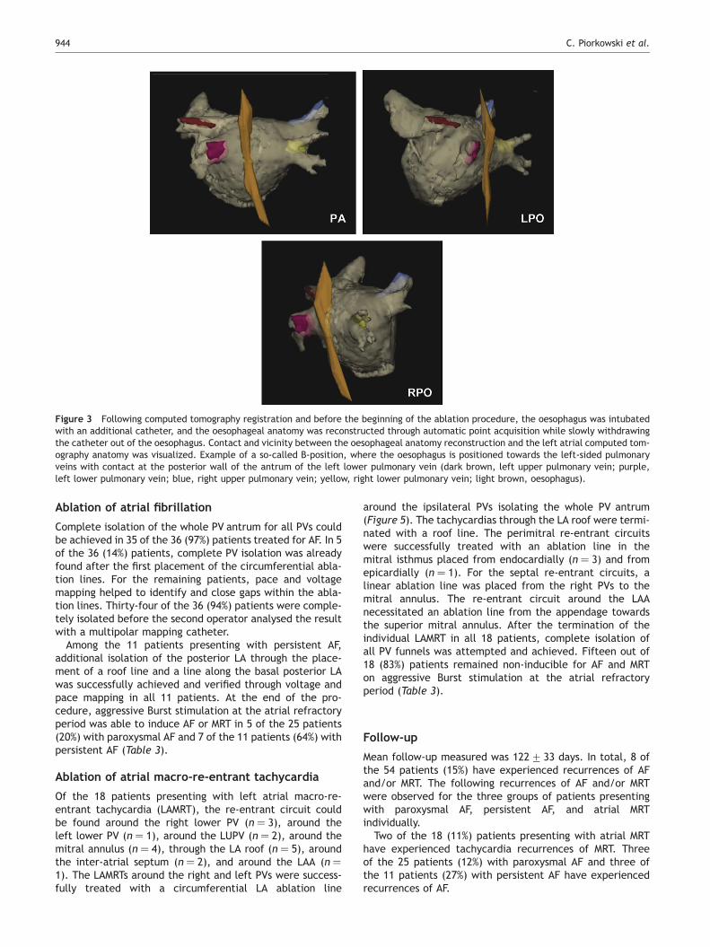
In all patients, an additional catheter was used for the reconstruc-tion of the oesophageal anatomy (Figure 3). The oesophagealanatomy and location were stored in the map.7
For the treatment of paroxysmal AF, circumferential LA ablationlines were placed around the antrum of the ipsilateral PVs (irrigatedtip catheter, pre-selected tip temperature of 488C, and maximumpower of 30–50 W) (Figure 4A). On the basis of reduction in theelectrogram amplitude, the ablation catheter was moved to thenext ablation position. Ablation in contact areas between the LAand the oesophagus was avoided. In regions near to the oesophagus,maximum power was reduced to 30 W, special attention was paid tolocal electrogram amplitude reduction, and the burning time waslimited to 30 s. After circumferential line placement, voltage andpace mapping along the ablation line were used to identify andclose gaps. The isolation of all PVs with bidirectional block wasthe procedural endpoint. This was additionally verified by the
placement of a multipolar circular mapping catheter within theencircled areas, which was performed by a second electrophysiolo-gist not involved in the ablation part of the procedure.
In patients with persistent AF, isolation of the PVs was performedafter electrical cardioversion into SR, as described earlier. Addition-ally, linear lesions were added at the LA roof and the basal posteriorLA, the latter always being placed with only 30 W due to oesopha-geal vicinity. Completeness of the additional linear lesions wasachieved and verified through voltage and pace mapping withinthe isolated posterior LA box (Figure 4B). Eventually, an LAisthmus line was placed as continuous and transmural as possible,however, without line continuity enforcement through epicardialablation. The ablation of fragmented potentials, ablation withinthe coronary sinus, and RA ablations were not performed. The RAisthmus was only ablated in the case of clinically documentedtypical RA flutter.
In patients with atrial MRT, after CT registration, activation andentrainment mapping were performed in order to identify there-entrant circuit. The electrical information was displayed on theintegrated CT surface through colour-coded isochronal lines(Figure 5). After the detection of the macro-re-entrant circuit andablation of the MRT, the PVs were assessed during SR. Complete iso-lation of all PV funnels was performed as described earlier.
At the end of the procedure, AF/MRT inducibility was tested in allpatients using 20 s Burst stimulation at the effective atrial refrac-tory period, but did not initiate any further ablation treatment.After ablation, anti-arrhythmic drugs were discontinued andpatients were put on b-blocker only. Anticoagulation was initiatedfor 6 months. Proton pump inhibitors were added for 4 weeks.
Following inclusion into the study and prior to ablation, a continu-ous 7-day electrocardiogram (ECG) (Lifecard CF, DelmarReynoldsMedical Inc., Irvine, CA, USA) was recorded in all patients. TheECG was repeated immediately after the ablation and after3 months. In the case of symptoms outside the recording periods,the patients were advised to contact our institution or the referringphysician to obtain an ECG documentation. Atrial fibrillation/macro-re-entrant tachycardia longer than 30 s was considered asan episode of sustained arrhythmia recurrence. More than 27 000 hof continuous ECG recording have been analysed to assess rhythmoutcome.
Statistics
Continuous variables are presented as mean+ standard deviation(SD), if appropriate. In the case of a non-Gaussian distribution,
Table 1 Patient characteristics
Paroxysmal AF (n ¼ 25) Persistent AF (n ¼ 11) MRT (n ¼ 18)
Age (years)a 60+8 62+10 57+15Male, n(%) 15 (60) 7 (64) 11 (61)AF/MRT history (months)b 60 (27; 108) 72 (18; 132) 72 (36; 111)Arterial hypertension, n(%) 17 (68) 7 (64) 7 (39)Coronary artery disease, n(%) 4 (16) 1 (9) 2 (11)Dilated cardiomyopathy 0 (0) 1 (9) 7 (39)Valvular heart disease, n(%) 1 (4) 2 (18) 6 (33)Mitral valve replacement (n) Mech. valve (1) – Mech. valve (4)Mitral valve reconstruction (n) – Reconstruction (1) Reconstruction (2)Aortic valve replacement (n) – Mech. valve (1) –Lone AF, n(%) 9 (36) 2 (18) 2 (11)Left atrial diameter (mm)a 37+9 53+6 47+5Left ventricular ejection fraction (%)a 64+6 63+7 50+15Prior AF ablation, n(%) 2 (8) 3 (27) 16 (89)
AF, atrial fibrillation and MRT, macro-re-entrant tachycardia.aData given as mean and standard deviation.bData given as median and quartiles.
AF/MRT mapping and ablation without LA reconstruction 941

Figure 1 Main step for registering the three-dimensional computed tomography image of the leftatrium into the real-time mapping system. Regis-tration is based on reconstruction of the four pulmonary vein anatomies. (A) Pulmonary vein reconstruction was achieved through automatic ana-tomic point acquisition through all 10 poles of a multipolar circular mapping catheter while slowly withdrawing the catheter out of each pulmonaryvein (in the picture, the left upper pulmonary vein). (B) Sync view of the four reconstructed pulmonary vein anatomies (blue, left upper pulmonaryvein; yellow, left lower pulmonary vein; purple, right upper pulmonary vein; brown, right lower pulmonary vein) and the imported three-dimensional computed tomography image, before registration. (C) Alignment between the NavX reconstructed pulmonary vein anatomies andthe pulmonaryveinsof the three-dimensional computed tomography image.After thatmain registration step, furtherfine adjustment wasachievedthrough three pre-defined landmark points (left atrium roof, basal left atrium, and left atrium isthmus) visited with the ablation catheter.
C. Piorkowski et al.942

median and quartiles are given. Categorical variables are expressedas the number and percentage of patients.
Results
Procedural data
Mean procedure time as measured from the first femoralpuncture to the removal of all sheaths was 187+35 min.Registering the 3D CT into the real-time mapping systemrequired 9+3 min. Fluoroscopy time and RF burning timemeasured were 35+12 and 47+10 min, respectively.The irradiation dose was 13 800 (7200; 29 350) cGy/cm2.In average, 45+13 RF pulses were applied during theablation.
One patient showed pericardial effusion on thepost-interventional echocardiographic evaluation, whichresolved after conservative treatment. Two patients devel-oped a significant haematoma at the femoral access sitewithout documentation of pseudoaneurysm, fistula, ordeep venous thrombosis.
Table 2 displays the procedural data for the three groupsof patients: paroxysmal AF, persistent AF, and atrial MRTseparately.
Assessment of computed tomography alignmentquality
The assessment of the 31 LA control points revealed concor-dance of the registered CTsurface with the true catheter tipposition in 90% (84%; 100%) of the control points. Thirteenpatients had shown complete concordance of all control
points between catheter tip and CT surface. The patientwith the least accurate registration showed concordancein only 22 of 31 (71%) control points.
The quality of CT alignment was not different betweenpatients with a newly acquired and those with a previouslyacquired CT scan [90% (81%; 100%) vs. 91% (84%; 100%);P ¼ 1.0]. The CT alignment quality also did not differbetween patients with CT imaging during SR (n ¼ 28) andthose with CT imaging during AF (n ¼ 26) [97% (90%; 100%)vs. 94% (84%; 100%); P ¼ 0.827].
The control points with the highest accuracy of the regis-tration process and concordance between catheter tip andCT surface in all 54 patients were found within the LAisthmus; at the tissue bridge between LAA and LUPV; atthe posterior wall of the LUPV; at the superior and posteriorwall of the LLPV; at the superior, posterior, and inferior wallof the RUPV; at the superior wall of the RLPV; along thewhole LA roof; and at the left-sided and middle parts ofthe basal LA. The control points with the lowest accuracyof the registration process were found at the septal mitralannulus; at the anterior wall of the RUPV; and at theannular as well as the middle aspect of the LA septum;with concordance between catheter tip and CT surface in38 (70%), 40 (74%), 34 (63%), and 35 (65%) of the 54 patients,respectively.
During ablation, the quality of the image integrationprocess was further verified by tagging the ablation pointsas ‘3D Lesion on EnGuide’, representing the true 3D anatom-ical position of the catheter tip and, therefore, subjectivelydemonstrating the presence or the absence of contact to theintegrated CT surface (Figure 4).
Figure 2 Control points that had to be visited with the catheter tip to assess the alignment accuracy by two independent electrophysiol-ogists. Control point location and tissue contact were reached and assessed according to fluoroscopy information, electrogram character-istics, and tactile feedback. For each of the control points, the position of the catheter tip in relation to the registered computedtomography surface was evaluated in a nominal fashion (1–4, septal/inferior/posterior/superior mitral annulus; 5, left atrium isthmus; 6,tissue bridge between left atrium appendage and left upper pulmonary vein; 7–22, anterior/inferior/posterior/superior wall of each pulmon-ary vein; 23–25, left-sided, middle, and right-sided left atrium roof; 26–28, left-sided, middle, and right-sided basal left atrium; 29–31,annular, middle, and posterior part of the left atrium septum).
AF/MRT mapping and ablation without LA reconstruction 943
Ablation of atrial fibrillation
Complete isolation of the whole PV antrum for all PVs couldbe achieved in 35 of the 36 (97%) patients treated for AF. In 5of the 36 (14%) patients, complete PV isolation was alreadyfound after the first placement of the circumferential abla-tion lines. For the remaining patients, pace and voltagemapping helped to identify and close gaps within the abla-tion lines. Thirty-four of the 36 (94%) patients were comple-tely isolated before the second operator analysed the resultwith a multipolar mapping catheter.
Among the 11 patients presenting with persistent AF,additional isolation of the posterior LA through the place-ment of a roof line and a line along the basal posterior LAwas successfully achieved and verified through voltage andpace mapping in all 11 patients. At the end of the pro-cedure, aggressive Burst stimulation at the atrial refractoryperiod was able to induce AF or MRT in 5 of the 25 patients(20%) with paroxysmal AF and 7 of the 11 patients (64%) withpersistent AF (Table 3).
Ablation of atrial macro-re-entrant tachycardia
Of the 18 patients presenting with left atrial macro-re-entrant tachycardia (LAMRT), the re-entrant circuit couldbe found around the right lower PV (n ¼ 3), around theleft lower PV (n ¼ 1), around the LUPV (n ¼ 2), around themitral annulus (n ¼ 4), through the LA roof (n ¼ 5), aroundthe inter-atrial septum (n ¼ 2), and around the LAA (n ¼1). The LAMRTs around the right and left PVs were success-fully treated with a circumferential LA ablation line
around the ipsilateral PVs isolating the whole PV antrum(Figure 5). The tachycardias through the LA roof were termi-nated with a roof line. The perimitral re-entrant circuitswere successfully treated with an ablation line in themitral isthmus placed from endocardially (n ¼ 3) and fromepicardially (n ¼ 1). For the septal re-entrant circuits, alinear ablation line was placed from the right PVs to themitral annulus. The re-entrant circuit around the LAAnecessitated an ablation line from the appendage towardsthe superior mitral annulus. After the termination of theindividual LAMRT in all 18 patients, complete isolation ofall PV funnels was attempted and achieved. Fifteen out of18 (83%) patients remained non-inducible for AF and MRTon aggressive Burst stimulation at the atrial refractoryperiod (Table 3).
Follow-up
Mean follow-up measured was 122+33 days. In total, 8 ofthe 54 patients (15%) have experienced recurrences of AFand/or MRT. The following recurrences of AF and/or MRTwere observed for the three groups of patients presentingwith paroxysmal AF, persistent AF, and atrial MRTindividually.
Two of the 18 (11%) patients presenting with atrial MRThave experienced tachycardia recurrences of MRT. Threeof the 25 patients (12%) with paroxysmal AF and three ofthe 11 patients (27%) with persistent AF have experiencedrecurrences of AF.
Figure 3 Following computed tomography registration and before the beginning of the ablation procedure, the oesophagus was intubatedwith an additional catheter, and the oesophageal anatomy was reconstructed through automatic point acquisition while slowly withdrawingthe catheter out of the oesophagus. Contact and vicinity between the oesophageal anatomy reconstruction and the left atrial computed tom-ography anatomy was visualized. Example of a so-called B-position, where the oesophagus is positioned towards the left-sided pulmonaryveins with contact at the posterior wall of the antrum of the left lower pulmonary vein (dark brown, left upper pulmonary vein; purple,left lower pulmonary vein; blue, right upper pulmonary vein; yellow, right lower pulmonary vein; light brown, oesophagus).
C. Piorkowski et al.944

Figure 4 Left atrial ablation procedures in patients presenting with paroxysmal and persistent atrial fibrillation. Ablation points weremarked as ‘three-dimensional Lesion on EnGuide’ (red-coloured lesion points), which documents the true three-dimensional localizationof the catheter tip (no projection on computed tomography surface and no ‘Lesion at Mouse’). The true position of the catheter tip onthe computed tomography surface can be appreciated for all ablation target areas, underlining the registration accuracy. Pink-colouredlesion points represent ablation in areas with oesophageal vicinity (energy reduction to 30 W and shorter ablation duration). (A) Exampleof a patient with paroxysmal atrial fibrillation. Circumferential left atrial lesions were deployed around the funnels of the left- and right-sidedpulmonary veins. As an anatomical variation, this patient presented with a common funnel of the left-sided pulmonary veins. (B) Example of apatient with persistent atrial fibrillation. After circumferential left atrial ablation, additional linear ablation lines were placed in the leftatrium for further substrate modification (left atrium roof, left atrium isthmus, and posterior basal left atrium). The resulting ‘box-lesion’at the posterior left atrium was completely isolated using voltage and pace mapping criteria.
AF/MRT mapping and ablation without LA reconstruction 945

Discussion
Main findings of the study
In a population of patients presenting with paroxysmal AF,persistent AF, and atrial MRT, our study shows the feasibility
of successful placement of different complex linear ablationline concepts guided by an integrated 3D image anatomyalone, rather than catheter-based virtual atrial chamberreconstructions.
Benefits and limitations of image integration
The catheter ablation of complex atrial arrhythmias requiresaccurate knowledge of the true cardiac anatomy of therespective patient for the placement of either purely anato-mically defined sets of ablation lines such as in those with AFor the understanding of the true 3D spread of electrical acti-vation throughout the cardiac anatomy with subsequentdesign and placement of respective ablation lesions suchas in patients with atrial MRT. Following that principleidea, the concept of image integration has been developed,superimposing pre-acquired 3D CT/MRI images onto the EAMchamber surface reconstruction in order to add moredetailed anatomical orientation. Despite having shown clini-cal benefit with a higher rate of ablation success, currenttechniques of image integration do have limitations.7–9
So far, registration of the pre-acquired 3D image into thereal-time mapping system can be achieved with two differ-ent registration modalities—landmark and surface regis-tration. Landmark registration is based on the alignmentof distinct stable and easily accessible 3D points betweenthe EAM surface reconstruction and their assumed positionon the 3D image. For surface registration, all 3D points ofthe EAM surface reconstruction are attached to the closestpossible CT surface. Previous studies have shown limitationsfor each of the two registration modalities.10,11 Landmarkregistration ultimately depends on the quality of the individ-ual landmark. Several landmarks such as aortic arch, coron-ary sinus, caval veins, or different LA locations have beensuggested; however, registration points at the posteriorPV–LA junction have resulted in the least registrationerror.11 After all, although landmark registration could ade-quately delineate specific anatomical regions, it could notguarantee a good global fit, measured as the average dis-tance between all 3D EAM points and the closest 3D imagesurface location. Surface registration, in contrast, couldachieve a better global registration result; however, apply-ing that algorithm shifted map and image significantly, dislo-cated well-aligned landmarks at the posterior PV–LAjunction, and resulted in significant registration inaccura-cies especially in target areas for circumferential PV abla-tion.11 One reason for these limitations can be seen in thequality of the 3D EAM surface reconstruction, which in
Figure 5 Example of a patient with a left atrial macro-re-entranttachycardia. The left panel shows the pure three-dimensional com-puted tomography anatomy after registration. The NavX recon-structed pulmonary veins are hidden. The distal part of eachpulmonary vein is cut off for image clarity. Locations within thecomputed tomography anatomy were visited with the ablation cath-eter. In stable catheter positions (small yellow points), entrainmentmapping was performed. The right panel illustrates the colour-coded entrainment information in a three-dimensional fashion.Red colours representing areas with a short return cycle (close tothe re-entrant circuit) and purple colours representing areas witha long return cycle (far away from the re-entrant circuit). ‘Isochro-nal lines’ connect locations with a similar length of the return cycle.The map clearly shows a macro-re-entrant circuit around the rightlower pulmonary vein. Circumferential ablation around theantrum of the right-sided pulmonary veins terminated thetachycardia.
Table 2 Ablation characteristics
Paroxysmal AF (n ¼ 25) Persistent AF (n ¼ 11) MRT (n ¼ 18)
Mean procedure time (min)a 188+40 195+45 205+21Mean fluoroscopy time (min)a 34+9 45+17 43+12Irradiation dose (cGy/cm2)b 13 800 (11 100; 23 900) 16 200 (7100; 33 300) 15 300 (11 900; 34 000)RF burning time (min)b 53 (35; 59) 61 (47; 84) 44 (31; 52)Number of RF pulsesb 46 (30; 60) 43 (38; 69) 37 (26; 44)RF energy (J)b 97 498 (71 649; 115 680) 111 864 (98 065; 131 700) 92 416 (53 780; 980 493)
AF, atrial fibrillation; MRT, macro-re-entrant tachycardia; RF, radiofrequency.aData given as mean and standard deviation.bData given as median and quartiles.
C. Piorkowski et al.946

itself can be anatomically misleading due to indentation ofthe LA wall and inadequate point collection in areas withdifficult catheter access. Variations in LA size and LAanatomy due to differences in LA filling and cardiacrhythm carry further uncertainties. Owing to these limit-ations so far, image integration has only been used as anadjunct to conventional 3D EAM, and in questionable situ-ations has simply been disregarded.
Image integration in the present study
Our study is the first one to report the placement of complex3D ablation lines directly within an atrial 3D image withoutEAM surface reconstruction for the treatment of a largergroup of patients presenting with AF and atrial MRT. Giventheir stable position fixated in the posterior mediastinum,the PVs served as the main registration structure (Figure 1).
Thirty-one pre-defined control points in the LA and at theLA–PV junction served for the assessment of the alignmentquality and revealed a high accuracy of the registrationprocess (Figure 2). Among all 54 patients in 90% (84%;100%) of the control points, concordance between fluoro-scopy/electrogram/tactile-guided catheter tip position andsurface contact on the integrated CT image could befound. In 13 patients, all control points were imaged accu-rately. The highest percentage of concordance was foundat the control points covering the posterior aspect of LAand PVs. The lowest percentage of concordance was foundat the control points of the LA septum and anterior to theright upper PV. The fixation of the heart through the pos-terior LA and the PVs at the posterior mediastinum can beseen as a reason for the observed distribution of controlpoints with higher and lower registration accuracy. The posi-tion of the posterior LA and the PVs is very stable and repro-ducible, which incidentally suits the purpose of AF ablationline placement. In contrast, the mitral annulus and the LAseptum are much more mobile and sensitive towardschanges in LA filling and cardiac rhythm, which, however,is less relevant from the point of AF catheter ablation.Optimal catheter access to all pre-defined control pointsand the quality of CT segmentation and 3D CT reconstructionmay constitute further reasons for observed alignmentinaccuracies in the mentioned areas. Clinically, in all54 patients, the ablation procedure could be finished suc-cessfully within the CT image, and no additional atrialchamber reconstruction was required. The registrationaccuracy was further underlined by tagging of the ablationpoints as ‘3D Lesion on EnGuide’, which technically does
not represent a catheter tip projection onto the CTsurface, but a true 3D position of the catheter tip revealingthe presence or the absence of surface contact to the CTimage (Figure 4).
In our approach, we did not use the Ensite Field scalingalgorithm to compensate for inhomogenities in the trans-thoracic electrical fields. Indeed, in order to apply thefield scaling algorithm, one has to first reconstruct the 3Dgeometry of the chamber being mapped so that the electri-cal field inhomogenities can be detected by non-linearitiesin the detected inter-electrode distances of the rovingcatheter. Our approach, in which the chamber is notreconstructed, therefore, does not allow the field scalingalgorithm to be applied. Although the application of fieldscaling could lead to more accurate image integration,12
we found our approach to be of sufficient accuracy forclinical use. Further, prospective clinical research workconcerning not only the PV isolation but also the ablationof intra-atrial targets should further determine the clinicalusefulness of this approach.
Patient population, procedural, and clinicaloutcome
Our study population included a consecutive group ofpatients presenting for catheter interventional treatmentof AF and atrial MRT. Among them, the patients with per-sistent AF showed a significantly enlarged LA (53+6 mm).Furthermore, 11 patients had experienced previous cardiacsurgery and six patients presented with a common antrumof the left-sided PVs (Figure 4A).
This cohort of patients with variable and partially alteredatrial anatomies presenting with different types of complexatrial arrhythmias rather constitutes a challenge for theinterventional electrophysiologist. However, in all patients,it was possible to plan and perform the required lesion lineconcept within the anatomy of the registered 3D imagewithout atrial chamber reconstruction.
In all 54 patients complete isolation of all PVs wasattempted. In patients with AF that was the primarytherapeutical target. In patients with MRT, the primarytherapeutical target was to map, and ablate the MRT, butafterwards as a secondary therapeutical target the PVswere also isolated in those patients. In 53 of the 54 (98%)patients, complete isolation was achieved and verifiedthrough bidirectional block on a circular multipolarmapping catheter placed by a second electrophysiologistwho was not involved in the ablation part of the procedure.
Table 3 Procedural and clinical outcome
Paroxysmal AF (n ¼ 25) Persistent AF (n ¼ 11) MRT (n ¼ 18)
Re-entrant pathway – – Perimitral (4)LA roof (5)Around PV (6)Septal (2)Around LAA (1)
Complete PV isolation, n(%) 24 (96) 11 (100) 18 (100)AF/MRT inducibility, n(%) 5 (20) 7 (64) 3 (17)AF/MRT recurrences, n(%) 3 (12) 3 (27) 2 (11)
AF, atrial fibrillation; MRT, macro-re-entrant tachycardia; LA, left atrium; PV, pulmonary vein; LAA, left atrial appendage.
AF/MRT mapping and ablation without LA reconstruction 947

On a follow-up based on a serial 7-day-Holter ECG includ-ing the analysis of more than 27 000 h of ECG recording, theclinical outcome showed 88% freedom from AF and/or MRTin patients presenting with paroxysmal AF. In patients withpersistent AF, the success rate (freedom from AF and/orMRT) after a single LA intervention measured 73%. Sixteenof 18 (89%) patients presenting with atrial MRT remainedfree of AF and/or MRT during follow-up.
Limitation of the study
Our study, although being prospective in nature, representsa non-randomized single-centre experience. The currentfollow-up period does not allow a final judgement on long-term clinical benefit; however, the main purpose of thestudy was to analyse procedural aspects with a clear elec-trophysiologically defined procedural endpoint.
The assessment of the accuracy of 3D image integrationin vivo is difficult, given a moving organ, a breathingpatient, and a static image. Imaging modalities such asMRI or intra-cardiac echo lack spatial resolution or 3D orien-tation to provide an accurate in vivo assessment of 3D imageintegration accuracy. We therefore took a very clinicalapproach and validated the position of the tip of the cath-eter within the integrated CT image against our judgementon catheter tip position derived from fluoroscopy, localelectrogram, and tactile information. This is a rough andnon-quantitative assessment. However, performed for 31different points throughout the LA and the PV individually,it does give a good impression as to whether the registrationis accurate and the catheter appears in the CT where wewould expect it to or whether this is not the case.
Furthermore, potential inaccuracies in the control pointanalysis result from changes in LA filling, cardiac cyclelength, and respiratory motion.
Clinical implications
Our study describes practical image integration in one of themost widely used electro-anatomical mapping systems,NavX-Ensite. Utilizing this tool, feasibility of successfulplacement of different complex linear ablation line conceptsguided by an integrated 3D image anatomy alone, rather thancatheter-based virtual chamber reconstructions, has beenshown in a heterogeneous group of patients presenting witha variety of atrial anatomies and clinical arrhythmias.
Following the principle idea, that a 3D reconstructedimaging technology provides higher anatomical accuracywhen compared with any virtual point-by-point EAMsurface reconstruction, our data are part of the first stepsto develop approaches, in which electrophysiological analy-sis, therapy planning, and ablation can be performed within
realistic 3D cardiac chamber anatomies. Currently, CT scanradiation exposures and off-line CT segmentation representlimitations for that concept. However, 3D images acquiredon-line during the EP procedure (through either rotationangiography or even echocardiography), and immediatelyexported into the real-time mapping system, may developinto simple tools to overcome these limitations.
Conflict of interest: none declared.
Funding
Funding to pay the Open Access publication charges for this articlewas provided by Hospital resources.
References1. Ben-Haim SA, Osadchy D, Schuster I, Hayam G, Josephson ME. Nonfluoro-
scopic, in vivo navigation and mapping technology. Nat Med 1996;2:1393–5.
2. Krum D, Goel A, Hauck J, Schweitzer J, Hare J, Attari M et al. Catheterlocation, tracking, cardiac chamber geometry creation, and ablationusing cutaneous patches. J Interv Card Electrophysiol 2005;12:17–22.
3. Piorkowski C, Hindricks G, Schreiber D, Tanner H, Weise W, Koch A et al.Electroanatomic reconstruction of the left atrium, pulmonary veins, andesophagus compared with the ‘true anatomy’ on multislice computedtomography in patients undergoing catheter ablation of atrial fibrillation.Heart Rhythm 2006;3:317–27.
4. Dong J, Dickfeld T, Dalal D, Cheema A, Vasamreddy CR, Henrikson CAet al. Initial experience in the use of integrated electroanatomicmapping with three-dimensional MR/CT images to guide catheter abla-tion of atrial fibrillation. J Cardiovasc Electrophysiol 2006;17:459–66.
5. Kistler PM, Rajappan K, Jahngir M, Earley MJ, Harris S, Abrams D et al.The impact of CT image integration into an electroanatomic mappingsystem on clinical outcomes of catheter ablation of atrial fibrillation.J Cardiovasc Electrophysiol 2006;17:1093–101.
6. Shalganov TN, Vatasescu R, Paprika D, Kornyei L, Vanyi J, Geller L et al. Asimple algorithm for defining the mechanism and the chamber of origin inatrial tachycardias. J Electrocardiol 2006;39:369–76.
7. Kottkamp H, Piorkowski C, Tanner H, Kobza R, Dorszewski A,Schirdewahn P et al. Topographic variability of the esophageal leftatrial relation influencing ablation lines in patients with atrial fibrillation.J Cardiovasc Electrophysiol 2005;16:146–50.
8. Heist EK, Chevalier J, Holmvang G, Singh JP, Ellinor PT, Milan DJ et al.Factors affecting error in integration of electroanatomic mapping withCT and MR imaging during catheter ablation of atrial fibrillation.J Interv Card Electrophysiol 2006;17:21–7.
9. Ferguson J. Optimizing catheter navigation for AF ablation: do not justfollow the map!. J Cardiovasc Electrophysiol 2007;18:283–5.
10. Zhong H, Lacomis JM, Schwartzman D. On the accuracy of CartoMergefor guiding posterior left atrial ablation in man. Heart Rhythm 2007;4:595–602.
11. Fahmy TS, Mlcochova H, Wazni OM, Patel D, Cihak R, Kanj M et al.Intracardiac echo-guided image integration: optimizing strategies forregistration. J Cardiovasc Electrophysiol 2007;18:276–82.
12. Brooks AG, Wilson L, Kuklik P, Stiles MK, John B, Hany Dimitri S et al.Image integration using NavX Fusion: initial experience and validation.Heart Rhythm 2008;5:526–35.
C. Piorkowski et al.948


![[Guideline of atrial fibrillation]](https://img.pdfslide.net/doc/110x75/634997ca8e60111deb0a49ae/guideline-of-atrial-fibrillation.jpg)


