Embed Size (px)
Citation preview

Internal Report
SPARC-FEL-08/001 14 January 2008
Conclusive EUROFEL REPORTS FOR SEEDING AT SPARC collaboration
L.Giannessia, D. Alesinig, M. Biaginig, M. Boscolog, M. Bougearde, A. Lo Buea, B.
Carrée, M. Castellanog, A. Cianchig, F. Cioccia, E. Chiadronig, A. Clozzag, M. E. Couprief, L. Cultrerag, G. Dattolia, S. De Silvestric, A. Di Pacem, G. Di Pirrog, A.
Doriaa, A. Dragog, M. Ferrariog, D. Filippettog, F. Frassettob, V. Fuscog, G. P. Galleranoa, A. Gallog, D. Garzellae, A. Ghigog, E. Giovenalea, M. Labate, G. Lamberte, M. Mattiolid, H. Merdjie, M. Miglioratig, P.
Musumecii, M. Nisolic, G.L. Orlandia, P.L. Ottavianil, E. Paceg, L. Palumbog, A. Petraliaa, M. Petrarcad, L. Polettob, M. Quattrominia, C. Ronsivallea, P. Rossia, P.
Salièrese, E. Sabiam, G. Sansonec, L. Serafinih, I. Spassovskya, B. Spatarog, S. Stagirac, V. Surrentia, O. Tchebakoffe, S. Tomassinig, G. Tondellob, C. Vaccarezzag, C. Vicariog
a
ENEA C. R. Frascati, Via E. Fermi 45, 00044 Frascati (Rome) ITALY
bCNR-INFM, Laboratorio LUXOR & Dip. di Ing. dell'Informazione, Padova, Italy
c National Laboratory for Ultrafast and Ultraintense Optical Science, CNR-INFM, Department of Physics, Politecnico di Milano, Piazza L.da Vinci
32, 20133 Milano, Italy d
INFN Sez. Roma I, Rome, Italy
eService des Photons Atomes et Molécules, CEA Saclay, DSM/DRECAM, France
fSOLEIL, Sant-Aubin, Gif-sur-Yvette CEDEX, France
gINFN Laboratori Nazionali Frascati, Via E. Fermi 44, 00044 Frascati(Rome), Italy
hINFN Milano, Italy
iUCLA Dep. of Physics and Astronomy, Los Angeles, USA
lENEA C.R. Bologna, Italy
lENEA C.R. Portici, Napoli, Italy

Collection of conclusive reports for the Seeding @ SPARC collaboration. All the reports are
also published on line in the EUROFEL web repository www.eurofel.org

Commissioning of the laser system for the seeding experiment at SPARC
1
Commissioning of the laser system for the seeding
experiment at SPARC
Eurofel D.4.10
C. Vicario(a), A. Drago(a), D. Filippetto(a), L. Giannessi(b), A. Petralia(b), M. Petrarca(a), I. Spassosky(b)
aINFN Laboratori Nazionali Frascati, Via E. Fermi 44, 00044 Frascati(Rome), Italy
bENEA C. R. Frascati, Via E. Fermi 45, 00044 Frascati (Rome) ITALY

Commissioning of the laser system for the seeding experiment at SPARC
2
1. Introduction
The installation of the laser system devoted to the generation of a high frequency seed for the SPARC FEL amplifier seeding experiment [1] has been completed. The laser system consists of a Coherent Legend [2] HFE regenerative amplifier pumped by an Evolution 30 and seeded by the same Mira [3] originating the laser chain which drives the SPARC photoinjector. The laser was commissioned in 2006 using an independent Mira oscillator which is available at the ENEA IR laboratory. In the meanwhile a clean room a stabilized optical table and an infrared optical transfer line have been installed in the SPARC hall. In the fall 2007 the regenerative amplifier and all the ancillary equipment necessary for its operation have been moved to the clean room at SPARC. The laser has gone through the alignment procedure and the amplifier has been seeded with the Mira oscillator of the photoinjector. In this report we provide an overview of the installation layout of the laser system and the trigger signals used and we summarize the laser performances resulting from the tests.
2. The Laser system components
The whole laser apparatus has been produced by Coherent Inc. It is composed by the following subsystem:
1 - The “MIRA” oscillator. This is the Ti:Sa (Ti:Al2O3) oscillator which supply IR (800nm) pulses with 1,2 W of average power (specifications) at a repetition rate of 79,3 MHz; this frequencies was chosen to correspond to the 36th sub-harmonic of the S-band accelerating system. The oscillator is capable to produce 100 fs pulse width with 10 nm FWHM spectra. The “MIRA” is pumped from a frequency doubled CW 5W diode pumped Nd:YVO4. Being a Ti:Sa Kerr lenses mode-locked laser it supplies pulses with a large bandwidth which is indispensable to achieve the best work efficiency from the device which will allow us to modify the pulses from their Gaussian shape to the flat-top profile, that is the acousto-optic dispersive filter: “DAZZLER”. The outgoing pulses are Transform Limited pulses, so they have the shortest possible temporal length regarding to their bandwidth so they satisfied the transform limited condition: DnDt~1.
2 - The “LEGEND F-HE” is the amplifying apparatus which is composed by all the components required for the chirp amplification process (stretcher/compressor) and a regenerative amplifier, which is an oscillator with two intracavity pockel cells, quarter wave plates and polarizers, to realize optical switches for injection and extraction of the seed in the cavity. The outgoing pulses have an energy of 2.5mJ at a repetition rate up to 1KHz. In operating conditions the repetition rate will be set to 10 Hz. The amplifier is pumped by the “EVOLUTION 30” a high energy per pulse 1 kHz diode pumped Q-switched Nd:Ylf laser. The laser radiation frequency is doubled intracavity for an output wavelength of 527 nm.
The oscillator and the amplifier are installed in two separated clean room. A description of the installation layout is provided in the next section.

Commissioning of the laser system for the seeding experiment at SPARC
3
3. The laser system layout
In Fig. 1 a schematic layout of the laser system is shown. The Mira oscillator is located in the clean room at the injector level, while the amplifier clean room is positioned at the level of the transfer line between the linac and the undulators. The transport of the radiation is done by means of two periscopes translating the optical axis at about 15 cm from the ground. The optical path between the two laser is ≈ 15m.
Fig. 1. Layout of the laser system for the seeding experiment.
In the original optical design, a symmetrical layout consisting of two telescopes installed respectively at the exit of the Mira oscillator in clean room #1, and at the entrance of the regenerative amplifier in clean room#2, was foreseen. We have modified this layout because of the small but not negligible energy loss in the second telescope. The Mira oscillator is indeed used to seed the photocathode laser chain as well, where a dazzler for pulse shaping is installed before the regenerative amplifier. The minimum continuous wave (CW) seed power for the stable operation of the regenerative amplifier is about 200 mW and assuming a transmission efficiency of 50% of the Dazzler, the CW power required on the photoinjector laser path is about 400 mW. The total CW power available from the Mira oscillator is 600-800 mW, depending on the alignment / optimization conditions. For this reason the energy required on the photoinjector laser line is about 2/3 of the total available power in the worse conditions. Even a small loss on the IR transfer line connecting the two lasers in clean room #1 and #2 may have a substantial impact on the stability of the seeding source. For this reason we opted for an asymmetric solution, with a single telescope installed in clean room #1. The optical mode size is controlled with a beam expander with variable focal length installed on the column of the first periscope. The telescope is set in order to produce a waist in the stretcher just before the regenerative amplifier. The seed energy before the stretcher ranges between 160-200 mW. The interlock on the input bandwidth consisting in two photodiodes located at the stretcher has been modified in order to enable the system operation with an input pulse energy lower than expected. A picture of the laser system is shown in Fig.2 and in Fig. 3.
Mira oscillator to the
harmonic generation chamber to the
photoinjector
amplifier periscopes delay line
regenerative amplifier telescope
clean room #1
clean room #2

Commissioning of the laser system for the seeding experiment at SPARC
4
Fig. 2. The regenerative amplifier installed in the SPARC clean room. On the left the delay line for the synchronization with the e-beam is visible
Fig. 3. The optical path at the laser exit. The periscope is required in order to switch the polarisation from horizontal to vertical.

Commissioning of the laser system for the seeding experiment at SPARC
5
4. The trigger
A description of the trigger layout for the photoinjector laser system is given in ref.[1]. The trigger requirement for the seed laser amplifier system consist in the 10 Hz trigger signal controlling the pockels cells for injection and extraction of the light from the oscillator cavity and the 1 kHz trigger driving the pump laser. The amplifier laser is also self triggered at 79.3 MHz which is the pulse repetition rate of the Mira seed oscillator. To guarantee, the gain stability in the Ti:Sa laser rods the regenerative amplifier are pumped by the Evolution-30 laser at 1 KHz repetition frequency.
Fig. 4. Trigger layout
This signal is sent to the home-built circuit, which receives also a 1 KHz signal coming from the laser oscillator A home-built circuit, based on a Set-Reset flip-flop (SR-FF), selects one pulse, in the 1 KHz pulse train, that follows the 10 Hz. In this way, a rough lock to the power supply 50 Hz is accomplished.
The gating applied by the pulse pickers to open and close the regenerative amplifier and defines the beam-time has to be locked with the pulse train coming from the mode-locked laser oscillator in order to avoid an intra-pulse switching. This is accomplished using the laser company supplied Synchronization and Delay Generator (SDGII). The SDGII enables synchronization of a user-supplied trigger source with an external RF source (typically from the laser mode-locker). Each input trigger is precisely synchronized to the RF signal by high-speed electronics. The SDGII produces four delayed trigger signals, one fixed and three users adjustable in 250 ps steps. Two of the adjustable trigger signals are typically used to trigger the drivers of the Pockels cells in the regenerative amplifier. The other outputs are used to trigger a digital delay generator DG-535. An integrated countdown circuit conveniently allows the researcher to adjust the output repetition rate to values below the master input rate. The SDGII is microprocessor-controlled, and all delays are digitally displayed and accessible via front panel knobs, RS-232 and/or GPIB connections.
Mira
79 M
Hz
Stanford delay generator A
Evolution 15 (photoinjector)
Legend regen. amplifier
Evolution 30 (photoinjector)
1 kHz
Stanford delay generator B
1 kHz
10 Hz
1/100
photoinjector laser
seeding laser amplifier
~
to the rf and the harmonic generation chamber gas inlet
10 Hz
50 Hz

Commissioning of the laser system for the seeding experiment at SPARC
6
5. Laser commissioning and characterization
After the installation in the clean room, the first operation consisted in restoring the alignment between the pump laser and the regenerative amplifier oscillator. The high pulse energy Legend Ti:Sa rod is pumped on two sides by the Evolution beam. The Evolution beam is splitted in two arms and the two beams are focalized in the rod on the two opposite faces. The pump laser alignment consisted in superimposing this two beams before and after the Ti:Sa rod. After completing the pump laser alignment we have re-aligned the optical cavity of the regenerative amplifier. This operation has been realized by seeding the laser with the seed pulse from the Mira oscillator and by following the optical path with IR sensitive paper through all the elements of the cavity for a whole round trip. Switching off the pockels cells responsible of extracting the beam from the amplifier we operated the laser as an oscillator. The power of the pump laser was controlled by modifying the diodes driving current. The current ranges from 10.3 A (threshold of the pump laser) up to 21.7 A (maximum operating current). After the first alignment the threshold current for oscillation of the laser was about 20 A. With a successive optimization this threshold was reduced to about 14 A.
After this procedure the trigger to the pockels cells was restored and the seed from the Mira was injected in the cavity. We have then optimized the rise time of the pulse oscillating in the cavity and we have tuned the pockels cells in order to extract the highest energy pulse at saturation. The pulse evolution was observed with a monitoring photodiode installed in the Legend behind one of the cavity mirrors. After optimization the pulse energy vs. the pump laser current is shown in Fig. 4.
16 17 18 19 20 21 221
2
3
4
Current (A)
Ener
gy (m
J)
Fig. 5. Pulse energy after the regenerative amplifier resonator as a function of the current in the
photodiodes of the pump laser.
We observed a light dependence of the optical axis of the cavity on the pump laser power which may depend on thermal effects on the laser rod and on a residual misalignment of the pump laser axis with the optical cavity axis. We have then optimized the cavity and the pockels cells for a photodiode current of 21.5 A. In these conditions the extracted energy per pulse after the regenerative amplifier resonator was about 3.5 mJ. After the compressor the pulse energy was reduced to 2.3-2.4 mJ.
A qualitative optimization of the pulse length has been realized by focalizing the laser with a lens with f=56 mm and by maximizing non-linear effects in air changing the dispersion in the compressor. An image of the radiation pattern in optimized conditions projected on the wall of the clean room is shown in Fig. 6. The blue spot in the centre of the image was visible only through a UV sensitive CCD camera and not by naked eye.

Commissioning of the laser system for the seeding experiment at SPARC
7
Fig. 6. Pattern of the radiation after focalization in air.
6. Conclusions
The optical transfer line connecting the photoinjector laser system to the FEL seeding laser system has been installed. The laser has been installed and aligned. The energy per pulse observed is about 2.3 μJ which is still lower than the specifications but sufficient to initiate the tests of harmonics generation in gas, as foreseen by the experimental programme.
7. Acknowledgments
This work has been partially funded by the EU under the 6th Framework programme, contract no. 011935 EUROFEL.
8. References
[1] L. Poletto et al., EUROFEL-Report-2005-DS4-008 1st Technical Design Report for the Seeding @SPARC experiment, available at http://www.eurofel.org/spanstylefontfamilyarialtimesseriffontsize130documentsfont/eurofelscientificreports/index_eng.html
[2] Informations on the Mira oscillator are available at http://www.coherent.com/downloads/MIRA900.pdf
[3] Informations on the Legend amplifiers are available at http://www.coherent.com/lasers/index.cfm?fuseaction=show.page&id=1511&loc=1513
[4] J. M. Dudley, G. Genty, S. Coen, Reviews of Modern Physics 78 1135-1184 (2006).

Commissioning of the HHG source at SPARC
1
Commissioning of the HHG source at SPARC
Eurofel D.4.11
M. Labat(b), M. Bougeard(a), M. E. Couprie(b), L. Cultrera(c), A. Drago(c), D. Filippetto(c), D. Garzella(a), L. Giannessi(d), A. Petralia(d), M. Petrarca(c), I. Spassosky(d), C. Vicario(c)
aService des Photons Atomes et Molécules, CEA Saclay, DSM/DRECAM, France bSOLEIL, Sant-Aubin, Gif-sur-Yvette CEDEX, France
cINFN Laboratori Nazionali Frascati, Via E. Fermi 44, 00044 Frascati(Rome), Italy
dENEA C. R. Frascati, Via E. Fermi 45, 00044 Frascati (Rome) ITALY

Commissioning of the HHG source at SPARC
2
1. Introduction
The phase of installation of the required components for the seed source at SPARC has been successfully concluded. The last step consisted in the final assembly, alignment and test of the harmonic generation chamber with the laser system and the e-beam transfer line. The harmonic generation chamber was previously tested at CEA [1-2]. The femtosecond laser system (LUCA) of the Saclay Laser-matter Interaction Center (SLIC) was used as fundamental source for the tests. The main characteristics of this laser (2 TW, 20 Hz CPA Titanium:Sapphire System [3]) substantially outperform, in terms of energy per pulse and peak power, the one of the laser system which is available at SPARC. For this reason these preliminary tests were done downgrading the LUCA performances in order to determine the optimized geometry of the gas cell and the laser optical beamline in conditions similar to the one foreseen at SPARC. The chamber was then delivered to Frascati in the beginning of 2007 and the laser system for the seeding experiment has been completed in November of the same year. The latter step required the installation of a clean room to host the laser system and the realization of an optical beam line for transporting the light from the cathode drive laser to the amplifier. The laser system has been recently commissioned [4] and performances close to the specifications have been demonstrated. Now the laser has been employed in the commissioning of the harmonic generation source as it was foreseen in the seeding at SPARC experimental plan [5]. In this paper we provide a description of the harmonic generation chamber experimental layout, and we report on the measurement of harmonics generated in gas.
2. Layout of the harmonic generation source
The setup for the production of the harmonics in gas is composed by three chambers. The laser is focussed by a plano-convex lens (f=2 m) and delivered through an antireflecting coated 790 nm window in the first chamber where harmonic generation occurs. In this chamber a cell is filled by Argon gas and is illuminated by the laser source. The gas inlet valve is triggered at 10 Hz by the same low frequency trigger signal that enables the pockel cells extracting the pulse from the regenerative amplifier. A second chamber is used to increase the vacuum gradient between the first chamber and the SPARC transfer line. Then the third chamber, 1.5 meters downwards, is used to match the harmonic beam with a waist located in the middle of the first undulator for a correct overlap with the e-beam. The optical mode shaping is performed using two spherical mirrors reflecting nearly at normal incidence, both equipped with motorized mounts, and an additional translation stage under the second mirror, for the adaptation of the focusing point in the undulator. The distance between the gas jet and the middle of the first undulator is about 8 m. A view of the array of the three chambers is shown in Figure 1. A picture of the chambers in the SPARC HALL is shown in Figure 2.

Commissioning of the HHG source at SPARC
3
Fig. 1. Layout of the harmonic generation chambers
Fig. 2. Harmonic generation chamber in the SPARC Hall
Gas cell
IR laser UV light
Mode matching chamber
differential vacuum

Commissioning of the HHG source at SPARC
4
3. Observation of harmonics
After optimization the laser was delivering 2.3 mJ per pulse after the compression stage. At the exit of the third chamber an optical table with the necessary diagnostics has been installed. An interferential filter centred at 266 nm is used to eliminate the infrared light. A focussing lens with focal length of 200 mm is used to set up an optimized detection position in the focus of the lens. Initially a yellow paper sheet has been positioned in the focal position in order to facilitate the eye detection of the third harmonic light. This set-up has been used in order to find the fine alignment which allowed the first observation of the harmonic light.
After the first observation an UV sensitive photodiode (DET710) has been mounted on the output optical table, at the focussing point of the UV lens. The photodiode has been used in the optimization of the signal by varying the position of the waist in the gas cell, the dispersion of the compressor after the regenerative amplifier, the pressure of the gas and the trigger delay between the laser and the aperture of the inlet valve.
In Fig. 3 the traces of two photodiodes are shown simultaneously. The upper trace is the infrared photodiode signal from the Ti:Sa laser detected before the harmonic generation chamber, the lower trace is the UV photodiode signal collected after the chamber. The lower signal could not be detected when the trigger enabling the gas inlet valve is inhibited.
Fig. 3. Photodiode signals in the infrared (cyan) and UV (yellow)
A spectrometer with a resolution of 0.3nm has been installed on the output table, after the interferential filter and the focussing lens. The exposure time has been set to 200 ms in order to collect at least one harmonic pulse. The spectrometer output window is shown in Fig. 4.

Commissioning of the HHG source at SPARC
5
Fig. 4. Spectrometer output window
The observed spectrum corresponding to the third harmonic of the Ti:Sa laser is centred at 268 nm and the measured bandwidth is 1.8 nm-fwhm. A calibrated power meter (Molectron, Model 33-05, 3V/mJ) has been used instead of the photodiode to measure the energy of the third harmonic. The third harmonic intensity on the oscilloscope is 1.5±0.5 mV corresponding to an energy of 0.5±0.15µJ. No signal is observed without gas, for this reason we may neglect any contamination from the drive laser. Since the transmission of the interferential filter is around 20%, we assume an energy per pulse at the output of the gas jet of 2.5±0.8µJ. This value, assuming an energy per pulse of the drive laser of 2.2 mJ, corresponds to a conversion efficiency of about 10-3.
The spatial profile of the radiation has been collected by projecting the beam on a reflecting screen. The image has been detected with an high sensitivity CCD camera (Canon IXUS 800 IS). The image is shown in Fig. 5.
.
Fig. 5. Spot of the UV radiation at the detection screen

Commissioning of the HHG source at SPARC
6
4. Conclusions
The third harmonics has been generated in a gas cell, with the 2.2 mJ IR laser. First optimisations have been performed in terms of gas pressure, IR spot size, interacting geometry and position of the focussing lens.
According to the first estimation (photodiode and power meter), the energy per pulse on the third harmonic is around 2.5 µJ. The spectral width is 1.8 nm (fwhm). The wave front could not be directly recorded with an UV sensitive camera but appeared quite homogeneous on the fluorescent screen.
5. Acknowledgments
This work has been partially funded by the EU under the 6th Framework programme, contract no. 011935 EUROFEL.
6. References [1] O. Tcherbakoff, M. Labat, G. Lambert et al., Seeding the SPARC facility with harmonic generation in gases: preliminary tests of the harmonic
generation gas chambers, in proc. of FEL 2006 conference, BESSY, Berlin, Germany, MOPPH047M. Labat et al., Seeding SPARC Facility with Harmonic Generation in Gases, http://www.JACoW.org, 124 (2006)
[2] O. Tcherbakoff et al., Test of HHG in gas at CEA, EUROFEL-Report-2006-DS4-018 [3] See http://www-femtodrecam.cea.fr/slic/luca/luca1.htm [4] D. Filippetto, L. Giannessi, I. Spassovsky, A. Petralia, M. Petrarca, C. Vicario Commissioning o the seeding at Sparc Laser system, EUROFEL-
Report-2007-DS4, submitted to EUROFEL web site http://www.eurofel.org http://www.eurofel.org/spanstylefontfamilyarialtimesseriffontsize130documentsfont/eurofelscientificreports/index_eng.html
[5] L. Poletto et al., EUROFEL-Report-2005-DS4-008 1st Technical Design Report for the Seeding @SPARC experiment, available at http://www.eurofel.org/spanstylefontfamilyarialtimesseriffontsize130documentsfont/eurofelscientificreports/index_eng.html
From left to right L. Giannessi, M. Labat, D. Garzella, M.E. Couprie

Implementing a HHG Laser as Seed in a HGHG-FEL
1
Implementing a HHG Laser as seed
in a HGHG-FEL
Eurofel D.4.12 - 15.01.2008
L.Giannessia, D. Alesinig, M. Biaginig, M. Boscolog, M. Bougearde, A. Lo Buea, B. Carrée, M. Castellanog, A. Cianchig, F. Cioccia, E. Chiadronig, A. Clozzag, M. E. Couprief, L. Cultrerag, G. Dattolia, S. De Silvestric, A. Di Pacem, G. Di Pirrog, A.
Doriaa, A. Dragog, M. Ferrariog, D. Filippettog, F. Frassettob, V. Fuscog, G. P. Galleranoa, A. Gallog, D. Garzellae, A. Ghigog, E. Giovenalea, M. Labate, G. Lamberte, M. Mattiolid, H. Merdjie, M. Miglioratig, P.
Musumecii, M. Nisolic, G.L. Orlandia, P.L. Ottavianil, E. Paceg, L. Palumbog, A. Petraliaa, M. Petrarcad, L. Polettob, M. Quattrominia, C. Ronsivallea, P. Rossia, P.
Salièrese, E. Sabiam, G. Sansonec, L. Serafinih, I. Spassovskya, B. Spatarog, S. Stagirac, V. Surrentia, O. Tchebakoffe, S. Tomassinig, G. Tondellob, C. Vaccarezzag, C. Vicariog
a
ENEA C. R. Frascati, Via E. Fermi 45, 00044 Frascati (Rome) ITALY
bCNR-INFM, Laboratorio LUXOR & Dip. di Ing. dell'Informazione, Padova, Italy
c National Laboratory for Ultrafast and Ultraintense Optical Science, CNR-INFM, Department of Physics, Politecnico di Milano, Piazza L.da Vinci
32, 20133 Milano, Italy d
INFN Sez. Roma I, Rome, Italy
eService des Photons Atomes et Molécules, CEA Saclay, DSM/DRECAM, France
fSOLEIL, Sant-Aubin, Gif-sur-Yvette CEDEX, France
gINFN Laboratori Nazionali Frascati, Via E. Fermi 44, 00044 Frascati(Rome), Italy
hINFN Milano, Italy
iUCLA Dep. of Physics and Astronomy, Los Angeles, USA
lENEA C.R. Bologna, Italy
lENEA C.R. Portici, Napoli, Italy

Implementing a HHG Laser as Seed in a HGHG-FEL
2
1. INTRODUCTION................................................................................................................................................... 3 2. OVERVIEW OF SPARC ....................................................................................................................................... 4
2.1. INTRODUCTION................................................................................................................................................. 4 2.2. THE SPARC UNDULATOR................................................................................................................................ 5
2.2.1. Undulator magnetic field characterization................................................................................................. 7 2.3. THE PHASE SHIFTERS ........................................................................................................................................ 8
2.3.1. Effect of a phase mismatch ......................................................................................................................... 8 2.3.2. The phase shifter....................................................................................................................................... 11
3. THE SEED SOURCE ........................................................................................................................................... 13 3.1. INTRODUCTION............................................................................................................................................... 13 3.2. THE DRIVE LASER ........................................................................................................................................... 13 3.3. THE HARMONIC GENERATION CHAMBER ........................................................................................................ 14
3.3.1. Observation of harmonics......................................................................................................................... 16 3.4. THE INJECTION CHICANE ................................................................................................................................ 17
4. SCHEDULED EXPERIMENTS.......................................................................................................................... 19 4.1. SPARC AS A HHG SEEDED AMPLIFIER........................................................................................................... 19 4.2. THE SUPERRADIANT CASCADE ....................................................................................................................... 21 4.3. THE HARMONIC CASCADED FEL .................................................................................................................... 22 4.4. THE FRESH BUNCH INJECTION TECHNIQUE...................................................................................................... 23
5. CONCLUSIONS ................................................................................................................................................... 25 6. ACKNOWLEDGMENTS .................................................................................................................................... 25 7. REFERENCES...................................................................................................................................................... 25

Implementing a HHG Laser as Seed in a HGHG-FEL
3
1. Introduction
In the framework of the FP6 programme the European Community has stimulated a coordinated international joint effort between several research institutions to implement a research work plan at the SPARC FEL test facility aiming at the investigation of seeded and cascaded FELs[1]. With this contribution the SPARC experiment has gained a new and exciting opportunity to study FEL dynamics in seeded configurations. Several schemes aiming at the generation of radiation at short wavelength are tried for the first time and the commissioning of SPARC comes at an opportune time since it will allow European research laboratories to test and develop these new techniques in preparation of the next foreseen short wavelength light sources.
Intense seed sources are available in the visible and near-UV region of the spectrum based on reliable solid state laser technology and it is widely recognized that the FEL operating range may be extended to shorter wavelengths with cascaded schemes, i.e. taking advantage of the harmonic generation process in the FEL dynamics [2]-[7]. On the other hand, high harmonic multiplication factors in a multi-stage cascade FEL are limited by the energy spread induced in each stage by the FEL process and these configurations are affected by stability issues associated to the fluctuation of one or more of the large number of parameters defining the configuration [8],[9]. An alternative to a multi-stage cascade with a high harmonic multiplication factor is that of seeding the FEL amplifier directly at short wavelengths with the high order harmonics of an intense Ti:Sa laser pulse generated in a Gas Jet [10]. Such a possibility is considered in the scheme of several proposed facilities [11]-[13] and first experiments have been exploited at SCSS [14].
The main goal of the experiment at SPARC, which has been partially funded by the EUROFEL collaboration, is to study and test the amplification and the FEL harmonic generation process of an input seed signal obtained as higher order harmonics generated in gases. This technique is also combined with harmonic generation and cascaded FEL configuration with the aim of pushing to the ultimate wavelength, the range of operation of the FEL. Schemes such as the superradiant cascade [15] and the harmonic cascade [16] are particularly promising in the generation of ultrashort radiation pulses at short wavelength and are within the SPARC possibilities.
In this report we provide an overview of the SPARC FEL and of the various components realized for implementing the seeding experiments. In the next section the features of the SPARC accelerator and undulator are reviewed. In section 3 a description of the hardware for the seeding experiment installed at SPARC is given. In the last chapter we analyze some of the experiments that are planned for the next future and that can be realized in the unique framework of the SPARC laboratory.
Implementing a HHG Laser as Seed in a HGHG-FEL
4
2. Overview of SPARC
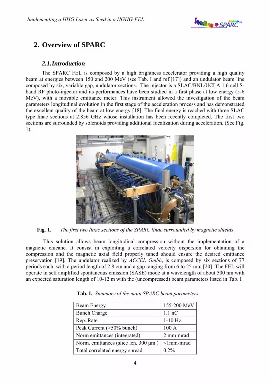
2.1. Introduction The SPARC FEL is composed by a high brightness accelerator providing a high quality
beam at energies between 150 and 200 MeV (see Tab. I and ref.[17]) and an undulator beam line composed by six, variable gap, undulator sections. The injector is a SLAC/BNL/UCLA 1.6 cell S-band RF photo-injector and its performances have been studied in a first phase at low energy (5-6 MeV), with a movable emittance meter. This instrument allowed the investigation of the beam parameters longitudinal evolution in the first stage of the acceleration process and has demonstrated the excellent quality of the beam at low energy [18]. The final energy is reached with three SLAC type linac sections at 2.856 GHz whose installation has been recently completed. The first two sections are surrounded by solenoids providing additional focalization during acceleration. (See Fig. 1).
Fig. 1. The first two linac sections of the SPARC linac surrounded by magnetic shields
This solution allows beam longitudinal compression without the implementation of a magnetic chicane. It consist in exploiting a correlated velocity dispersion for obtaining the compression and the magnetic axial field properly tuned should ensure the desired emittance preservation [19]. The undulator realized by ACCEL Gmbh, is composed by six sections of 77 periods each, with a period length of 2.8 cm and a gap ranging from 6 to 25 mm [20]. The FEL will operate in self amplified spontaneous emission (SASE) mode at a wavelength of about 500 nm with an expected saturation length of 10-12 m with the (uncompressed) beam parameters listed in Tab. I
Tab. I. Summary of the main SPARC beam parameters
Beam Energy 155-200 MeV Bunch Charge 1.1 nC Rep. Rate 1-10 Hz Peak Current (>50% bunch) 100 A Norm emittances (integrated) 2 mm-mrad Norm. emittances (slice len. 300 μm ) <1mm-mrad Total correlated energy spread 0.2%

Implementing a HHG Laser as Seed in a HGHG-FEL
5
Total uncorrelated energy spread 0.06% e-bunch duration (RMS) ~4 ps
2.2. The SPARC Undulator The SPARC undulator consists of six identical sections whose characteristics are reported in
Tab. II. The permanent magnets, constituting each section, are arranged according to the standard Halbach configuration.
Tab. II. Undulator parameters
Period 2.8 cm Undulator length 2.156.m No of Periods 77 Gap (nom./min/max) 0.958 / 0.6 / 2.5 cm K (nom./max/min) 2.145 / 3.2 / 0.38 Remanent field 1.31 T Blocks per period 4 Block size (h x l x w) 2 x 0.7 x 5 cm
These undulator sections are separated by empty gaps dedicated to the installation of
quadrupoles for the beam transport, phase correctors for the compensation of the phase advance between electrons and fields in the longitudinal phase and for the installation of diagnostics for both the e-beam and the FEL radiation. A picture of one of the diagnostic stations before the final installation is shown in Fig. 2
Fig. 2. SPARC diagnostic station. The assembly includes a quadrupole, vertical and horizontal correctors and diagnostics with different apertures for extracting radiation in the horizontal and vertical plane
The quadrupole responsible of the horizontal focusing is clearly visible in the picture. The electron beam transport in the undulator is indeed realized with a FODO lattice, where the focusing

Implementing a HHG Laser as Seed in a HGHG-FEL
6
is provided in the vertical direction by the undulator field, and in the horizontal direction by quadrupoles between the sections. We have sketched a layout of one period of the undulator lattice in Fig. 3.
Fig. 3. Layout of the undulator FODO lattice
The undulator has been realized by ACCEL and installed in the SPARC hall during the last months. In Fig. 4, Fig. 5 and Fig. 6Fig. 4, pictures of the SPARC undulator installed in the SPARC hall are shown.
Fig. 4. SPARC Undulator (ACCEL) during installation
Fig. 5. SPARC Undulator, positioning section #6
LP
LU
D Dq
Quadrupoles
Undulators
LQ

Implementing a HHG Laser as Seed in a HGHG-FEL
7
Fig. 6. SPARC undulator, another view of the undulator beam line with “four men” at work
2.2.1. Undulator magnetic field characterization Very strict tolerances are required on the magnetic field quality of the SPARC undulators in
order to meet the condition of saturation in about 12 meters of magnetic length and to ensure the design performances, which foresee the simultaneous operation at the fundamental and at higher harmonics [21]. From this point of view the undulator is the core element of SPARC, providing, along with the e-beam, the active medium of the FEL. The undulator is also responsible of the beam transport optics, which has to be correctly integrated in the transport system of the whole device. Two issues are of major concern:
1. Accurate identification of the mechanical and magnetic axes and control of the gap tuning.
2. Quality of the magnetic field, namely homogeneity of the transverse magnetic field components along the beam axis and minimization of the errors of the field integrals calculated along the beam axis.
A highly accurate magnetic field measurement system was therefore required for the undulator characterization and optimization. A Hall probe bench has been used. The bench consists of a 3m long heavy granite block with the top surface polished to a flatness of ± 5µm in order to gain the smallest possible jitter on the Hall probe movement (Fig. 7). All magnetic measurements have been carried out in a dedicated room with temperature control with a stability of ±0.5°C. By means of an optical level (NAK2 by Leica) and a laser tracker (LTD 500 by Leica) an absolute horizontal plane has been defined in the hall and the granite block has been aligned to this plane with an error of 10 µm/m.
A coordinate system has been defined with the axes aligned to the edges of the granite block and a point on the carriage has been continuously monitored with a time separation of 0,1 seconds along with the longitudinal displacement of the probe.
A flexible transverse probe Lakeshore HMFT-3E03-VR (Hall probe accuracy of 0.05%, resolution of 0.1G, temperature compensated) is mounted on a diamagnetic arm which is mounted on a x-y translation stage Physik Instrumente mod. M 521 equipped with non contact linear encoder. The PI M 521 linear tables provide low friction, backlash-free positioning and guarantee 1µ /100mm straightness and flatness by using high precision linear guiding rails with recirculating ball bearings. The longitudinal movement is controlled via a DC-servo motor drive with encoder

Implementing a HHG Laser as Seed in a HGHG-FEL
8
PI mod. C136-10 which guarantees 1µm resolution. A view of the SPARC undulator magnetic measurement system is shown in Fig. 7.
Fig. 7. The SPARC undulator magnetic measurement system during a magnetic field longitudinal scan
2.3. The phase shifters In a single-pass FEL designed with segmented undulator, the gaps between each undulator
segment introduce a phase shift between the electron transverse velocity and the phase of the electromagnetic field. Such a phase mismatch may cause the electrons to momentarily gain energy from the radiation field, interrupting the amplification process. The phase shift f induced by a drift Ld between two segments is a function of the undulator K parameter
( )2/12 20
2 KLL
u
dd
+==λλγ
φ (1)
The SPARC undulator is a variable gap device where the K parameter may be varied in the range indicated in Tab. II. The main effect of a phase mismatch on the FEL dynamics is an increase of the saturation length [22]. In order to compensate the phase error between two undulator segments in a variable gap device, a variable phase shifter is required. The effects of phase mismatch at SPARC were analyzed in [23]. In the next section we recall the main results of this analysis and in section 2.3.2 we give a brief overview of the compact phase shifters realized by ACCEL Gmbh and that are one of the distinguishing components of the undulator itself.
2.3.1. Effect of a phase mismatch The effect of a phase mismatch at the five breaks between the six undulators of the SPARC
FEL operating in SASE mode are shown in Fig. 1. The time dependent simulation has been obtained with PERSEO[24] with the electron beam parameters listed in Tab. III. The breaks between the undulators have been simulated by multiplying the laser field by a phase factor
( )φiexp at each break location.
Implementing a HHG Laser as Seed in a HGHG-FEL
9
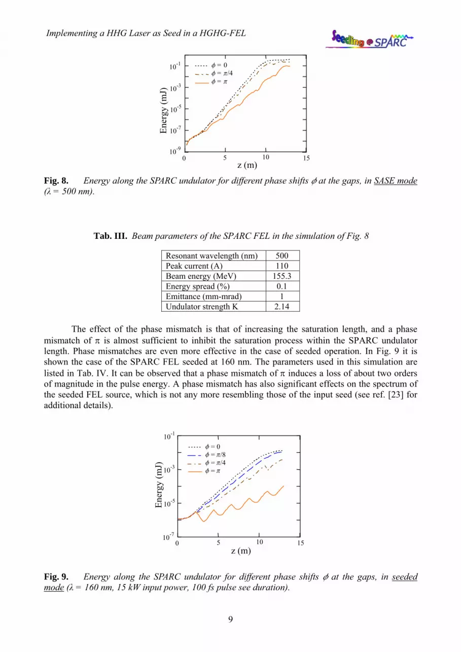
Fig. 8. Energy along the SPARC undulator for different phase shifts f at the gaps, in SASE mode (λ = 500 nm).
Tab. III. Beam parameters of the SPARC FEL in the simulation of Fig. 8
Resonant wavelength (nm) 500 Peak current (A) 110 Beam energy (MeV) 155.3 Energy spread (%) 0.1 Emittance (mm-mrad) 1 Undulator strength K 2.14
The effect of the phase mismatch is that of increasing the saturation length, and a phase mismatch of π is almost sufficient to inhibit the saturation process within the SPARC undulator length. Phase mismatches are even more effective in the case of seeded operation. In Fig. 9 it is shown the case of the SPARC FEL seeded at 160 nm. The parameters used in this simulation are listed in Tab. IV. It can be observed that a phase mismatch of π induces a loss of about two orders of magnitude in the pulse energy. A phase mismatch has also significant effects on the spectrum of the seeded FEL source, which is not any more resembling those of the input seed (see ref. [23] for additional details).
Fig. 9. Energy along the SPARC undulator for different phase shifts f at the gaps, in seeded mode (λ = 160 nm, 15 kW input power, 100 fs pulse see duration).
z (m)0 5 10 15
Ener
gy (m
J)
10-7
10-9
10-5
10-3
10-1 f = 0 f = p/4 f = p
10 -5
z (m) 10 - 7
10 - 3
10 -1
5 10 15
Ener
gy (m
J)
f = 0 f = p/8 f = p/4 f = p
0

Implementing a HHG Laser as Seed in a HGHG-FEL
10
Tab. IV. Parameters of the seeded mode simulation
Resonant wavelength (nm) 160 Energy spread (%) 0.1 Undulator strength K 1.226 Seed wavelength (nm) 160 Seed pulse energy (nJ) 1.7 Seed pulse duration (fs) 100
In addition to the correction of phase jumps at the undulator segmentations, phase shifter can be exploited to balance the growth of different harmonics of the FEL resonant wavelength. According to steady state FEL simulations this method is very effective in suppressing the fundamental harmonic growth [25]. We analysed this effect in simulations in time dependent mode in the SPARC case [23]. While in SASE regime the phase discontinuities introduced at the undulator gaps are in general not sufficient to provide the required depression of the fundamental harmonic gain, according to simulations, the method apparently works in seeded mode. An example is provided in the plot of Fig. 10, obtained assuming a seed at 88 nm (9th harmonic of the Ti:Sa laser) corresponding to the third harmonic of the undulator tuned with the fundamental resonance at 264 nm. The parameters used in the simulation of this example are listed in Tab. V.
Tab. V. Parameters of the seeded mode simulation
Resonant wavelength (nm) 264 Peak current (A) 110 Beam energy (MeV) 200 Energy spread (%) 0.04 Undulator strength K 1.945 Seed wavelength (nm) 88 Seed pulse energy (nJ) 0.5 Seed pulse duration (fs) 100
Fig. 10. Pulse energy along the SPARC undulator in seeded mode at the third harmonic (λ = 88 nm, corresponding to a FEL resonance at 264 nm). In (a) phase does not change at each gap. In (b) phase shifts f = ±2π/3, with alternated sign, are introduced at each gap.
z (m)
Ener
gy (m
J)
10-9
0 5 10 15
10-7
10-5
10-3
10-1
0 5 10 15z (m)
(a) (b)
1st harm. 3rd harm.
1st harm. 3rd harm.

Implementing a HHG Laser as Seed in a HGHG-FEL
11
2.3.2. The phase shifters design and construction A phase shift is obtained by a magnetic chicane that delays the beam due to a longer path.
This shift may be in principle realized as in the main undulator, with the same kind of permanent magnets, in a similar arrangement. The undulator is indeed capable of inducing a phase advance of 2π for each period. The possibility to vary the gap of this device, i.e. the electron beam path length, independently from that of the undulator allows to compensate for a given phase difference. The main requirement for such a phase corrector is that the field integrals must vanish independently of the specific undulator gap considered. The phase shifters design consists of two groups of permanent magnets, arranged as in the main undulator, in a variable gap magnet assembly which can be tuned independently of the main undulator gap. The simplest way to obtain this is to use a whole undulator period (four magnets). The SPARC undulator period is 28 mm and consists of four magnets with different magnetization axes; each magnet is 6.95 mm long and the magnets are assumed to be separated by a 50 μm gap. Two magnetic configurations were analysed in ref.[23], both capable of adjusting the phase and to fulfil the requirements in terms of field integrals. In the first one, the ending magnets have the same width but a reduced thickness. In the second one, they were vertically cut. In the final realization the first option was selected. A RADIA model of the magnetic assembly is shown in Fig. 11.
Fig. 11. Phase shifter RADIA model (five horizontally cut magnets)
In Fig. 12 the vertical component of the magnetic field is shown.
Fig. 12. Vertical component of the magnetic field.

Implementing a HHG Laser as Seed in a HGHG-FEL
12
In Fig. 13 one of the two “jaws” constituting the phase shifter which has been realized by ACCEL is shown. The main plate visible on the right is fixed to the ending of one of the undulator bars (upper or lower). Two elements are symmetrically installed on the ending faces of the undulator and the five magnets constituting the magnetic array, which are visible in the figure, realize the desired magnetic field profile.
Fig. 13. One of the “jaws” of the phase shifter realized by ACCEL.

Implementing a HHG Laser as Seed in a HGHG-FEL
13
3. The seed source
3.1. Introduction The main components of the seed source consist in the implementation of a second laser
amplification chain operating in parallel to the photo-injector laser system, in the installation of a chamber devoted to the generation of high harmonics in gas, which has been realized at CEA, and finally in the implementation of the hardware required for injecting, in the electron transfer line connecting the SPARC linac with the SPARC undulator, the radiation generated in the chamber. A chicane deflecting the e-beam from the linac axis and a periscope allowing the injection of the harmonic beam have been realized at this purpose. The realization of all these components has followed the guidelines given in the technical design report prepared during the project design phase of the project and published in ref.[1].
The three components:
1. laser system
2. harmonic generation chamber,
3. injection periscope,
will be briefly discussed in the following sections.
3.2. The drive laser The laser system consists of a Coherent Legend [27] HFE regenerative amplifier pumped by
an Evolution 30 and seeded by the same Mira [26] originating the laser chain which drives the SPARC photoinjector. The laser was commissioned in November 2007 in a clean room installed in the SPARC hall. The details of the installation of the laser system can be found in ref.[28].
The whole laser apparatus has been produced by Coherent Inc. and is composed by the following subsystem:
1 - The “MIRA” oscillator. This is the Ti:Sa (Ti:Al2O3) oscillator which supply IR (800nm) pluses with 1,2 W of average power at a repetition rate of 79,3 MHz; this frequency was chosen to correspond to the 36th sub-harmonic of the S-band accelerating system. The oscillator is capable of producing 100 fs pulses with 10 nm FWHM spectra. The “MIRA” is pumped from a frequency doubled CW 5W diode pumped Nd:YVO4.
2 - The “LEGEND F-HE” is the amplifying apparatus which is composed by all the components required for the chirp amplification process (stretcher/compressor) and a regenerative amplifier, which is an oscillator with two intracavity pockel cells, quarter wave plates and polarizers, to realize optical switches for injection and extraction of the seed in the cavity. The outgoing pulses have an energy of 2.5mJ at a repetition rate up to 1KHz. The operation rep rate is set to 10 Hz. The amplifier is pumped by the “EVOLUTION 30” a high energy per pulse 1 kHz diode pumped Q-switched Nd:Ylf laser. The laser radiation frequency is doubled intracavity for an output wavelength of 527 nm.
The oscillator and the amplifier are installed in two separated clean room. In Fig. 14 a schematic layout of the laser system is shown. The Mira oscillator is located in the clean room at the injector level, while the amplifier clean room is positioned at the level of the transfer line between the linac and the undulators. The transport of the radiation is done by means of two

Implementing a HHG Laser as Seed in a HGHG-FEL
14
periscopes translating the optical axis at about 15 cm from the ground. The optical path between the two laser is ≈ 15m.
Fig. 14. Layout of the laser system for the seeding experiment.
A picture of the laser system is shown in Fig. 15
Fig. 15. The regenerative amplifier installed in the SPARC clean room. On the left the delay line for the synchronization with the e-beam is visible
The optical transfer line connecting the photo-injector laser to the FEL seeding laser system has been installed. On the left the delay line for the fine synchronization with the electron beam is visible. No particular difficulty has arisen from the substantial distance between the oscillator and the amplifier. The laser has been installed and aligned and the energy per pulse detected is about 2.3 μJ. More details on the installation of the laser system can be found in ref.[28].
3.3. The harmonic generation chamber The high harmonic generation (HHG) chamber was previously tested at CEA [29], [30] with
the femtosecond laser system (LUCA) of the Saclay Laser-matter Interaction Center (SLIC). The main characteristics of this laser (2 TW, 20 Hz CPA Titanium:Sapphire System [31]) substantially outperform, in terms of energy per pulse and peak power, the one of the laser system which is available at SPARC. For this reason these preliminary tests were done downgrading the LUCA
Mira oscillator to the
harmonic generation chamber to the
photoinjector
amplifier periscopes delay line
regenerative amplifier telescope
clean room #1
clean room #2

Implementing a HHG Laser as Seed in a HGHG-FEL
15
performances in order to determine the optimized geometry of the gas cell and the laser optical beamline in conditions similar to the one foreseen at SPARC. The chamber was then delivered to Frascati in the beginning of 2007 and the laser system for the seeding experiment has been completed in November of the same year. In December the chambers have been aligned with the laser and the injection periscope, and have been commissioned. A preliminary test was concluded with the observation of the third harmonic of the Ti:Sa beam.
The setup for the production of the harmonics in gas is composed by three chambers. The laser is focussed by a plano-convex lens (f=2 m) and delivered through an antireflecting coated 790nm window, in the first chamber where harmonic generation occurs. In this chamber a cell is filled by Argon gas and is illuminated by the laser source. The gas inlet valve is triggered at 10 Hz by the same low frequency trigger signal that enables the extraction of the laser pulse from the regenerative amplifier. A second chamber is used to increase the vacuum gradient between the first chamber and the SPARC transfer line. Then the third chamber, 1.5 meters downwards, is used to match the harmonic beam with a waist located in the middle of the first undulator for a correct overlap with the e-beam. The optical mode shaping is performed using two spherical mirrors reflecting nearly at normal incidence, both equipped with motorized mounts, and an additional translation stage under the second mirror, for the adaptation of the focusing point in the undulator. The distance between the gas jet and the middle of the first undulator is about 8 m. A view of the array of the three chambers is shown in Fig. 16. A picture of the chambers in the SPARC HALL is shown in Fig. 17.
Fig. 16. Layout of the harmonic generation chambers
Gas cell
IR laser UV light
Mode matching chamber
differential vacuum

Implementing a HHG Laser as Seed in a HGHG-FEL
16
Fig. 17. Harmonic generation chamber in the SPARC Hall
3.3.1. Observation of harmonics In Fig. 18 two photodiodes traces are shown simultaneously. The upper trace is an infrared
photodiode from the Ti:Sa laser detected before the harmonic generation chamber, the lower trace is the UV photodiode signal collected after the chamber. The lower signal could not be detected when the trigger enabling the gas inlet valve is inhibited.
Fig. 18. Photodiode signals in the infrared (cyan) and UV (yellow)
The above image was obtained after a first optimization of the signal by varying the position of the waist in the gas cell, the dispersion of the compressor after the regenerative amplifier, the pressure of the gas and the trigger delay between the laser and the aperture of the inlet valve. The laser was delivering approximately 2.3 mJ per pulse after the compression stage. An interferential filter centred at 266 nm was used to eliminate the infrared light and a focussing lens with focal length of 200 mm was used to set up an optimized detection position in the focus of the lens.
A spectrometer with a resolution of 0.3nm has been installed on the output table, after the interferential filter and the focussing lens. The observed spectrum (Fig. 19) corresponding to the third harmonic of the Ti:Sa laser is centred at 268 nm and the measured bandwidth is 1.8 nm-fwhm.

Implementing a HHG Laser as Seed in a HGHG-FEL
17
Fig. 19. Spectrometer output window
A calibrated power meter (Molectron, Model 33-05, 3V/mJ) has been used measure the energy of the third harmonic. The third harmonic energy per pulse at the output of the gas jet is estimated to be 2.5±0.8µJ.
The spatial profile of the radiation (Fig. 20) has been collected by projecting the beam on a reflecting screen. The image has been detected with an high sensitivity CCD camera (Canon IXUS 800 IS).
.
Fig. 20. Spot of the UV radiation at the detection screen
More details on the HHG chamber commissioning at SPARC may be found in ref.[32].
3.4. The injection chicane One of the elements designed and built for injecting a seed in the SPARC FEL is a chicane
deflecting the e-beam from the linac axis and a periscope allowing the control of the optical beam position in the undulator, as shown in Fig. 21 . The layout of the transfer line has been modified in order allow the electron beam to perform the small “orbit chicane” and avoid interaction with the photon beam injected at the periscope, while they need to be superimposed at the undulator entrance. The required orbit bump is from 5 to 10 mm at the periscope location. This element is installed in the middle of the SPARC transfer line, as described in ref.[1]. The vertical periscope is constituted by two chambers containing piezo-controlled mirror holders allowing the alignment of

Implementing a HHG Laser as Seed in a HGHG-FEL
18
electrons and radiation. An analysis of the impact of the magnets and the wake fields generated by the upper periscope chamber on the electron beam was given in ref.[1].
Fig. 21. CAD representation of the injection chicane and periscope
The chicane magnets have been realized by Busato & Satta under ENEA design and tested in the magnetic measurement laboratory at ENEA. The whole assembly has been installed at SPARC and has been used in the alignment of the harmonic generation source with the transfer line. In Fig. 22 a view of the “real” system during the installation phase is shown.
.
Fig. 22. SPARC transfer line
e – beam
uv – beam
To the undulator

Implementing a HHG Laser as Seed in a HGHG-FEL
19
4. Scheduled experiments
During the construction and installation phase of the various components of the seeding experiment the preliminary simulation work developed in ref. [1] has been extended with more detailed calculations, new ideas and scientific proposals. In this section we will review part of this work that has been the subject of several publications and participation to international conferences.
High-order odd harmonics of the Ti:Sa laser are generated at the wavelengths 266nm, 160nm, and 114nm in the HHG chamber. The second harmonic of the Ti:Sa may be generated with a non-linear crystal. The undulator resonance condition is tuned at these wavelengths by varying the beam energy and undulator strength K according to the plot shown in Fig. 1.
The flexibility offered by the variable gap configuration of the SPARC undulator and the
natural synchronization of the electron beam with the laser driving the photo-injector, makes the SPARC layout particularly suited for a number of experiments where the FEL amplifier is seeded by an external laser source.
4.1. SPARC as a HHG seeded amplifier The high order harmonics result from the strong non-linear polarisation induced on the rare
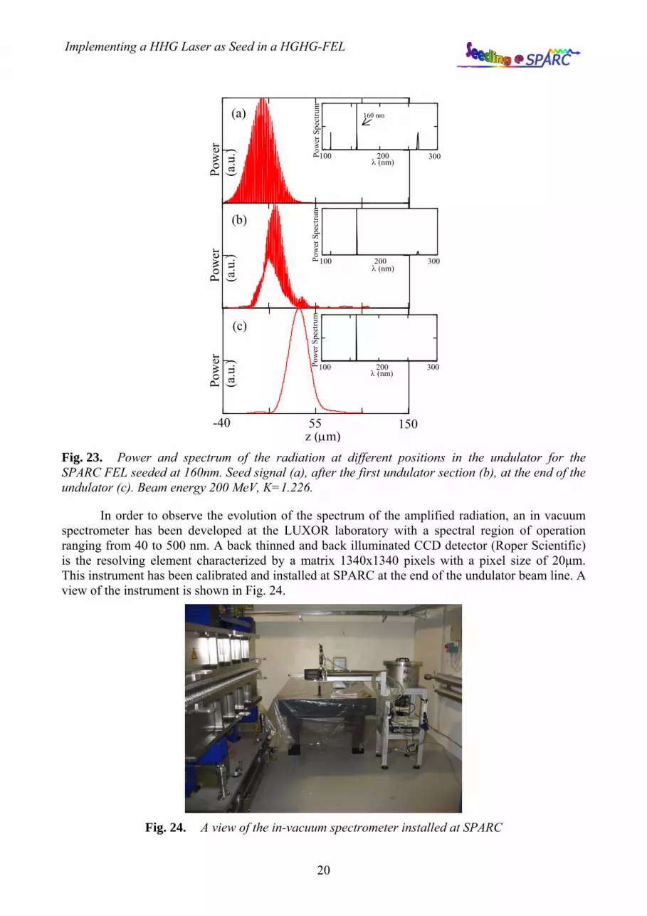
gases atoms, such as Ar, Xe, Ne and He, by the focused intense electromagnetic field of the "pump" laser. The emitted pulse is composed by a sequence of short bursts separated by one half of the fundamental laser period (400nm) and the spectrum contains the odd harmonics of the original laser. A simulation of the amplification of a pulse at 160nm with the typical time structure of harmonics generated in gas has been done with Perseo[24]. The laser pulse shape vs. the longitudinal coordinate is shown in Fig. 23 at different positions along the undulator. The radiation spectrum is also shown in the figure and the effect of the spectral “cleaning” associated with the limited FEL bandwidth (FEL parameter ρ ≈ 4⋅10-3) is evident. An analogous behaviour is observed at the third harmonic generated by the non-linear FEL dynamics.
0.5 1 1.5 2100
200
300
400 170 MeV200 MeV160 - 266 - 400 nm114 - 160 - 266 nm
K
Wav
elen
gth
(nm
)
Implementing a HHG Laser as Seed in a HGHG-FEL
20
Fig. 23. Power and spectrum of the radiation at different positions in the undulator for the SPARC FEL seeded at 160nm. Seed signal (a), after the first undulator section (b), at the end of the undulator (c). Beam energy 200 MeV, K=1.226.
In order to observe the evolution of the spectrum of the amplified radiation, an in vacuum spectrometer has been developed at the LUXOR laboratory with a spectral region of operation ranging from 40 to 500 nm. A back thinned and back illuminated CCD detector (Roper Scientific) is the resolving element characterized by a matrix 1340x1340 pixels with a pixel size of 20μm. This instrument has been calibrated and installed at SPARC at the end of the undulator beam line. A view of the instrument is shown in Fig. 24.
Fig. 24. A view of the in-vacuum spectrometer installed at SPARC
Pow
er
(a.u
.)
Pow
er
(a.u
.)
-40 55 150z (μm)
Pow
er
(a.u
.)
(a)
(b)
(c)
100 200 300λ (nm)
Pow
er S
pect
rum
160 nm
100 200 300λ (nm)
Pow
er S
pect
rum
100 200 300λ (nm)
Pow
er S
pect
rum

Implementing a HHG Laser as Seed in a HGHG-FEL
21
More simulations of the SPARC amplifier seeded by harmonics generated in gas may be found in ref.[33].
4.2. The superradiant cascade The six SPARC undulators may be configured in order to set up a single stage cascaded FEL
based on a modulator-radiator configuration, similar to the one tested at BNL [34]. The layout of this configuration is shown in Fig. 25.
Fig. 25. Single stage cascaded FEL configuration
The number of sections of modulator and radiator may be adapted on the intensity of the available seed. Intense short pulses allow to test the superradiant cascade concept [15]. The seed laser power may be indeed sufficient to reach saturation in a modulator made by a single segment tuned at the seed wavelength (as in Fig. 25). The pulse generated in these conditions propagates with the typical signature of superradiance [35] in the following radiator composed by the remaining five sections tuned at an harmonic of the seed. The feasibility of this experiment at SPARC was studied in [36]. In ref. [37] we have shown that similar results may be obtained by seeding the FEL with a pulse with the time structure of high harmonics generated in gas as in Fig. 23,a. The result of the simulation is summarized in Fig. 26 where the pulse energy along the undulator is plotted (lower left). For z<2.1 m the energy at the fundamental (266 nm) in the modulator is shown (dashed) while for z>2.1m the 2nd harmonic (≈133nm) is plotted (continuous). In Fig. 26,a the pulse shape at z=2.1m where the fast structure from HHG is still visible, is shown. In Fig. 26,b.1 and Fig. 26,b.2 the pulse spectrum and shape at the end of the undulator are respectively shown. The pulse energy from the Perseo simulation exceeds 10μJ
Fig. 26. Bottom left: Pulse energy along the undulator. For z<2.1 m the energy at the fundamental in the modulator is shown (266nm). For z>2.1m the pulse energy at the 2nd harmonic (≈133nm) is plotted. In (a) the pulse shape at z=2.1m is shown. In (b.2) and (b.1) the pulse spectrum and shape at the end of the undulator are respectively shown.
λ = λ 0
λ = λ0/2
modul ator radiator

Implementing a HHG Laser as Seed in a HGHG-FEL
22
4.3. The harmonic cascaded FEL As in the last stage of the previous configuration, the two undulators are tuned at different,
fundamental frequencies, but have instead one of their higher order harmonics in common. According to the SPARC FEL undulator properties, this scheme may be tested in configurations where the fourth of the sixth harmonic of the 266nm signal used as seed of the first section, are amplified as the third or fifth harmonics in the second section. This configuration has been analysed with numerical simulations in time dependent mode. Both the codes Perseo and a modified version of the code Genesis 1.3 [16], [38] and [39] which includes the self consistent dynamics of the higher order harmonics have been used. In the example considered in Fig. 27, we show the result obtained with Perseo. The cascade is driven by a seed of 2 MW peak power at a wavelength corresponding to the third harmonic of the Ti:Sa drive laser. The first undulator has the fundamental resonance at 266nm and the second section is tuned at 222nm. The two undulators have a common resonance at 44nm, corresponding to the 6th harmonic of the first section and the 5th of the second.
Fig. 27. FEL Harmonic cascade FEL configuration.
The energy of the radiation pulse at the wavelength of 44nm vs the longitudinal coordinate in the radiator is shown in Fig. 28.
Fig. 28. Pulse energy vs. the longitudinal coordinate in the radiator.
The pulse shape is shown in Fig. 29 and the relevant spectrum is shown in Fig. 30
266 nm 222 nm
44 nm
0 5 10 15
0.1
0.2
0.3
0.4
z (m)
Ener
gy (μ
J)

Implementing a HHG Laser as Seed in a HGHG-FEL
23
Fig. 29. Longitudinal profile of the radiation power at the end of the second undulator.
Fig. 30. Power spectrum of the radiation pulse as shown in Fig. 29.
4.4. The fresh bunch injection technique The fresh bunch injection technique was proposed in ref.[40] as a way to overcome the
limitation due to the induced energy spread in multi stage FEL cascades. The underlying idea is that a multiple stage cascade is seeded with a radiation pulse shorter than the e-beam bunch. After the first stage consisting in a modulator and a radiator where the radiation is multiplied in frequency, a dispersive section is used to shift longitudinally the radiation pulse over the electron current, in order to provide “fresh” electrons for the next stage of the cascade where a further harmonic multiplication takes place. The dispersive section at SPARC can be realized with two undulators, as shown in Fig. 31. In this case the first two undulators (A and B) represent the modulator and radiator sections of single stage cascade, the following two undulators (C and D) are tuned off resonance with the seed wavelength and its higher order harmonics. These undulators play the role of the dispersive section where the radiation exiting the first radiator at 200 nm (B) is longitudinally separated from the part of the electron beam where it has been heated in the previous sections, by the FEL interaction with the seed.
Fig. 31. Fresh bunch injection technique layout.
400nm 200 nm
modulator radiator
modulator radiator
200 nm 300 nm ≈ 380 nm
dispersion 100 nm
(A) (B) (C) (D) (E) (F)
44.2 44.3 44.4wavelength (nm)
Pow
ersp
ectru
m
38.2 9.8 57.9 106 1540
0.
1
ζ (μm)
Pow
er (a
.u.)

Implementing a HHG Laser as Seed in a HGHG-FEL
24
Section (E) is the modulator of the second stage cascade and section (F) is the radiator that is tuned in order to match the resonance of its third harmonic with the second harmonic of the radiator (E). This is necessary since the K parameter excursion of the undulator is not sufficient to span the 1st to 3rd harmonic range and coupling on the higher order odd harmonics in a linear undulator based FEL has been considered [11]. Complete simulations of the double stage cascade at SPARC have been done.

Implementing a HHG Laser as Seed in a HGHG-FEL
25
5. Conclusions
The SPARC FEL facility collects several new concepts in accelerator and FEL physics, ranging from the velocity beam compression to the possibility of exploiting the effects of phase shifts between the undulators, the seeding experiences with harmonics generated in gases or in other more conventional nonlinear materials, the cascaded configurations and the fresh bunch injection technique.
We have presented an overview of the SPARC facility status, the hardware implementation specifically devoted to the seeding source and some of the planned experiments, with the aim of transmitting at least part of our excitement for the possibilities opened by the contribution of the European community via the sixth framework programme.
We have the convincement that the field of FEL light sources will greatly benefit in experimenting those ideas and in the next future a substantial leap in knowledge will be possible.
6. Acknowledgments
This work has been partially funded by the EU under the 6th Framework programme, contract no. 011935 EUROFEL.
7. References
[1] L. Poletto et al., EUROFEL-Report-2005-DS4-008 1st Technical Design Report for the Seeding @SPARC experiment, available at http://www.eurofel.org/spanstylefontfamilyarialtimesseriffontsize130documentsfont/eurofelscientificreports/index_eng.html
[2] I. Boscolo, V. Stagno, Il Nuovo Cimento 58, 267 (1980) [3] L. H. Yu, Phys. Rev. A 44, 5178 (1991) [4] R. Bonifacio, L. De Salvo, and P. Pierini, Nucl. Instrum. Methods Phys. Res. A 293, 627 (1990) [5] H. P. Freund, S. G. Biedron, and S. V. Milton, IEEE J. Quantum Electron. 36, 275 (2000) [6] S. G. Biedron et al., Phys. Rev. ST Accel. Beams 5, 030701 (2002) [7] G. Dattoli et al. Journal of Appl. Phys. 97, 113102 (2005) [8] B. Kuske et al. Development of Figures of Merit to Evaluate the Output of FEL HGHG Cascades,
www.jacow.org, Proceedings of the 2006 FEL conference, BESSY, Berlin, MOPPH051 (2006) [9] G. De Ninno et al. Start-to-end Time-Dependent Study of FEL Output Sensitivity to Electron-
beam Jitters for the First Stage of the FERMI@Elettra Project, www.jacow.org, Proceedings of the 2006 FEL conference, BESSY, Berlin, MOPPH058 (2006)
[10] D. Garzella et al., Nucl. Instrum. Methods Phys. Res. Sect. A 528, 502 (2004). [11] C. Bruni, The Arc En Ciel FEL proposal, www.jacow.org, Proceedings of the 2006 FEL
conference, BESSY, Berlin, MOPPH048 (2006) [12] B. McNeil et al, The Conceptual Design of the 4GLS XUV-FEL, www.jacow.org, Proceedings of
the 2006 FEL conference, BESSY, Berlin, MOPPH012 (2006) [13] C. Vaccarezza et al., Status of the SPARX FEL project , www.jacow.org, Procs. of the 2006 EPAC
conference MOPCH028 (2006). [14] G. Lambert et al., submitted to Nature Physics. [15] L. Giannessi, P. Musumeci, S. Spampinati, J. Appl. Phys. 98, 043110 (2005) [16] L. Giannessi and P. Musumeci, New Journal of Physics 8, (2006) 294

Implementing a HHG Laser as Seed in a HGHG-FEL
26
[17] D. Alesini et al. Technical Design Report for the advanced photoinjector , Ed by L. Palumbo, J. Rosenzweig, available at www.lnf.infn.it/acceleratori/sparc/SPARC_TDR.pdf ,
[18] M. Ferrario et al., Phys. Rev. Lett. 99, 234801 (2007) [19] L. Serafini and M. Ferrario, in Physics and Science with the X-Ray Free-Electron Laser, edited by
S.Chattopadhyay, M. Cornacchia, I. Lindau, and C.Pellegrini, AIP Conf. Proc.No. 581 (AIP, New York, 2001).
[20] F. Ciocci et al. SPARC undulator parameter set SPARC-FEL-03/003 available at http://www.frascati.enea.it/SPARC/notes.htm
[21] L. Giannessi, C. Ronsivalle SPARC Undulator Layout, Undulator Parameters, Start to End Simulation and Tolerances, SPARC-FEL-06/006 available at http://www.frascati.enea.it/SPARC/notes.htm
[22] H.P. Freund, Physical Review E 70, 015501 (2004). [23] G. Parisi et al. Phase shifters for the SPARC Undulator System, http://www.jacow.org,
proceedings of the 2005 FEL Conference, p.187 (2005) [24] L. Giannessi, Overview of Perseo, a system for simulating FEL dynamics in Mathcad,
http://www.jacow.org, in Proc. of the 2006 FEL conference, p. 91 (2006), see also http://www.perseo.enea.it
[25] B.W.J. McNeil et al. Phys. Rev. Lett. 96 084801 (2006) [26] Information on the Mira oscillator are available at
http://www.coherent.com/downloads/MIRA900.pdf [27] Information on the Legend amplifiers are available at
http://www.coherent.com/lasers/index.cfm?fuseaction=show.page&id=1511&loc=1513 [28] C. Vicario et al. Commissioning of the laser system for the seeding experiment at SPARC,
EUROFEL Report - 2007-DS4-XXX (submitted) http://www.eurofel.org/spanstylefontfamilyarialtimesseriffontsize130documentsfont/eurofelscientificreports/index_eng.html
[29] O. Tcherbakoff, M. Labat, G. Lambert et al., Seeding the SPARC facility with harmonic generation in gases: preliminary tests of the harmonic generation gas chambers, http://www.jacow.org, Proc. of FEL 2006 conference, BESSY, Berlin, Germany, MOPPH047M.
[30] O. Tcherbakoff et al., Test of HHG in gas at CEA, EUROFEL-Report-2006-DS4-018 http://www.eurofel.org/spanstylefontfamilyarialtimesseriffontsize130documentsfont/eurofelscientificreports/index_eng.html
[31] See http://www-femtodrecam.cea.fr/slic/luca/luca1.htm [32] M. Labat, Commissioning of the HHG source at SPARC, EUROFEL-Report-2007-DS4-xxx
(submitted) http://www.eurofel.org/spanstylefontfamilyarialtimesseriffontsize130documentsfont/eurofelscientificreports/index_eng.html
[33] M. Labat et al. Seeding SPARC Facility with Harmonic Generation in gases in Procs. of the workshop “Frontiers in FEL Physics and Related Topics, Elba Island-La Biodola, Tuscany (Italy) September 8 - 14, 2007” to be published in Nucl. Instrum. & Meth.
[34] L. H. Yu et al. Phys. Rev. Lett. 91, 074801 (2003) [35] R. Bonifacio, L.De Salvo Souza, P.Pierini, and N. Piovella, Nucl.Instrum. & Meth. A 296, 358
(1990) [36] L. Giannessi, P. Musumeci, in Proc. of the 27th FEL conference, JACoW (Joint Accelerator
Conference Website) at http://www.JACoW.org, p. 210 (2005) [37] L. Giannessi et al. Seeding experiments at SPARC in Procs. of the workshop “Frontiers in FEL
Physics and Related Topics, Elba Island-La Biodola, Tuscany (Italy) September 8 - 14, 2007” submitted to Nuclear Instrum. & Meth.
[38] S. Reiche, Nuclear Instrum. & Meth. A429, 243 (1999) [39] S. Reiche et al. Recent Upgrade to the free electron laser code Genesis 1.3 http://www.jacow.org,
Proceedings of the EPAC 2007 Conference, 1270 (2007)

Implementing a HHG Laser as Seed in a HGHG-FEL
27
[40] I. Ben-Zvi, K.M. Yang, L. H. Yu, Nucl. Instrum. & Meth. A 318, 726 (1992)


