Embed Size (px)
Citation preview
SEEDING ROBOT
Sunitha .M
Assistant Professor, Dept. of ECE, CJITS, Jangaon, Warangal, JNTUH, India
Abstract: The main aim of the paper is to design a robot to remove the human factor from labor intensive and/or dangerous work. In modern farming applications, so many different types of automation techniques are used for easy and staff less operations that includes the important functions like seeding and spraying fertilizers. Here in this project we implement a robot which automatically sows seeds in the farm ready to be seeded. The project intends to develop a prototype of an autonomous agricultural robot that includes an automated guidance system which helps sow seeds in an efficient manner checking depth in which it is being sowed and inter seed distance. Micro controller user’s kinematics algorithms to maintain position control on the motors. PWM channels of micro controller and MOSFET based power amplifiers and power transistors are used to control motors. This robot is developed with two motors which make it more generic about hardware. All the logic is implemented in the software. Microcontroller 8051 is used to intelligently monitor the robot. Keil uVision4 software provides an integrated development environment to develop a program to do the same.
Keywords: Seeding, Fertilization, Hardware, Software
1. Introduction
Many of the tasks associated with horticulture, such as picking, pruning, pest and weed control, are repetitive and arduous and there is a problem in getting and retaining labor to do them. Such tasks seem ideally suited to robots and, in countries where labor costs are high, there is an economic incentive to use automation as a solution to the problem. However, while robots are commonly used for repetitive tasks in industry they have not been successful in horticulture. The industrial environment is clean, well-lit, dry and uniform while the horticultural environment is extremely variable in terms of weather, terrain and light[1]. The components, which are manipulated in industrial settings, are Uniform, un-obscured, stationary and robust whilst those in horticulture are generally very variable in terms of shape, color and size, hidden amongst foliage, moving (for example, in the wind) and are soft and easily damaged during handling.
The key problem areas associated with horticultural robotics are:
Path finding- navigation both within the rows of an orchard and in order to get to the orchard. Mapping- keeping track of where the robotic task has already been completed and where it remains to be done. The design of the mechanical agent or arm of the robot, which will perform the task of spraying, and could later be developed for tasks like pruning, pollinating, picking etc. Building a chassis, which is cost effective, can handle rough terrain, sloping ground, muddy soil and rain. Obstacle avoidance: technique for recognition of obstacles such as people, poles, wires, stumps and rocks so that the robot can navigate safely around these[1][2]. Swarm behavior management- to allow multiple robots to function together in one area under remote control without interfering with each other. Overall cost- most of the horticultural tasks, such as seeding and fertilizing, only last for a few months of the year and it is not cost effective to use a robot for such a short period. Ideally, robots should be capable of performing many different operations, such as fertilizing followed by picking of the fruits, bud count followed by pollination followed by fruit count, in order to extend the useful work period of the robot and ensure a reasonable payback time on the robot
This machine consists of a simple electro-mechanical system supported on a chassis, driven by dc motors. User interface portals will help the user to input the type of operation to be performed (fertilizing/seeding operations), and to input other information, like the dimensions of the field. Apparatus to plough the field, seeding tray, and mechanical arms for closing the dug pits are also provided. Special spraying mechanism
Proceedings of The Intl. Conf. on Information, Engineering, Management and Security 2014 [ICIEMS 2014] 273
ICIEMS 2014 ISBN : 978-81-925233-3-0 www.edlib.asdf.res.in / www.iciems.in
Dow
nloa
ded
from
www.e
dlib.a
sdf.r
es.in
for spraying water and fertilizers is also mounted on the chassis. The microcontroller 8051 forms the brain of this machine and controls all the operations mentioned above. Both small and large landholders can implement this prototype machine.
2. Mechanical System Description
The machine set up contains six important parts:
A. Power supply
A variable regulated power supply, also called a variable bench power supply, is one where we can continuously adjust the output voltage to our requirements. This type of regulation is ideal for having a simple variable bench power supply. While a dedicated supply is quite handy, it’s much handier to have a variable supply on hand, especially for testing. Most digital logic circuits and processors need a 5 volt power supply. To use these parts we need to build a regulated 5 volt source. Usually we start with an unregulated power supply ranging from 9 volts to 24 volts DC. To make a 5 volt power supply, we use a LM7805 voltage regulator IC (Integrated Circuit).
B. Seeding Motor
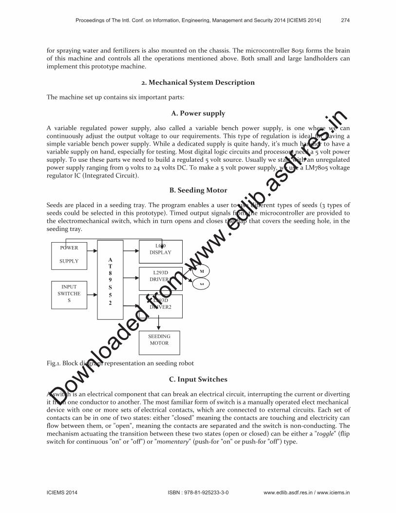
Seeds are placed in a seeding tray. The program enables a user to use different types of seeds (3 types of seeds could be selected in this prototype). Timed output signals from the microcontroller are provided to the electromechanical switch, which in turn opens and closes the flap that covers the seeding hole, in the seeding tray.
Fig.1. Block diagram representation an seeding robot
C. Input Switches
A switch is an electrical component that can break an electrical circuit, interrupting the current or diverting it from one conductor to another. The most familiar form of switch is a manually operated elect mechanical device with one or more sets of electrical contacts, which are connected to external circuits. Each set of contacts can be in one of two states: either "closed" meaning the contacts are touching and electricity can flow between them, or "open", meaning the contacts are separated and the switch is non-conducting. The mechanism actuating the transition between these two states (open or closed) can be either a "toggle" (flip switch for continuous "on" or "off") or "momentary" (push-for "on" or push-for "off") type.
A
T
8
9
S
5
2
POWER
SUPPLY
INPUT
SWITCHE
S
LCD
DISPLAY
L293D
DRIVER1
M
M
L293D
DRIVER2
SEEDING
MOTOR
Proceedings of The Intl. Conf. on Information, Engineering, Management and Security 2014 [ICIEMS 2014] 274
ICIEMS 2014 ISBN : 978-81-925233-3-0 www.edlib.asdf.res.in / www.iciems.in
Dow
nloa
ded
from
www.e
dlib.a
sdf.r
es.in
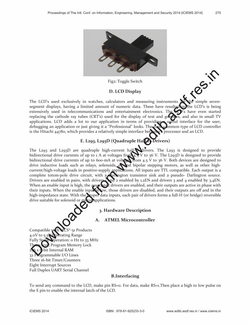
Fig2: Toggle Switch
D. LCD Display
The LCD’s used exclusively in watches, calculators and measuring instruments are the simple seven-segment displays, having a limited amount of numeric data. These have resulted in the LCD’s is being extensively used in telecommunications and entertainment electronics. The LCD’s have even started replacing the cathode ray tubes (CRT’s) used for the display of text and graphics, and also in small TV applications. LCD adds a lot to our application in terms of providing a useful interface for the user, debugging an application or just giving it a "Professional" looks. The most common type of LCD controller is the Hitachi 44780, which provides a relatively simple interface between a processor and an LCD.
E. L293, L293D (Quadruple Half H-Drivers)
The L293 and L293D are quadruple high-current half-H drivers. The L293 is designed to provide bidirectional drive currents of up to 1 A at voltages from 4.5 V to 36 V. The L293D is designed to provide bidirectional drive currents of up to 600-mA at voltages from 4.5 V to 36 V. Both devices are designed to drive inductive loads such as relays, solenoids, dc and bipolar stepping motors, as well as other high-current/high-voltage loads in positive-supply applications. All inputs are TTL compatible. Each output is a complete totem-pole drive circuit, with a Darlington transistor sink and a pseudo- Darlington source. Drivers are enabled in pairs, with drivers 1 and 2 enabled by 1,2EN and drivers 3 and 4 enabled by 3,4EN. When an enable input is high, the associated drivers are enabled, and their outputs are active in phase with their inputs. When the enable input is low, those drivers are disabled, and their outputs are off and in the high-impedance state. With the proper data inputs, each pair of drivers forms a full-H (or bridge) reversible drive suitable for solenoid or motor applications.
3. Hardware Description
A. ATMEL Microcontroller
Compatible with MCS®-51 Products 4.0V to 5.5V Operating Range Fully Static Operation: 0 Hz to 33 MHz Three-level Program Memory Lock 256 x 8-bit Internal RAM 32 Programmable I/O Lines Three 16-bit Timer/Counters Eight Interrupt Sources Full Duplex UART Serial Channel
B.Interfacing
To send any command to the LCD, make pin RS=0. For data, make RS=1.Then place a high to low pulse on the E pin to enable the internal latch of the LCD.
Proceedings of The Intl. Conf. on Information, Engineering, Management and Security 2014 [ICIEMS 2014] 275
ICIEMS 2014 ISBN : 978-81-925233-3-0 www.edlib.asdf.res.in / www.iciems.in
Dow
nloa
ded
from
www.e
dlib.a
sdf.r
es.in
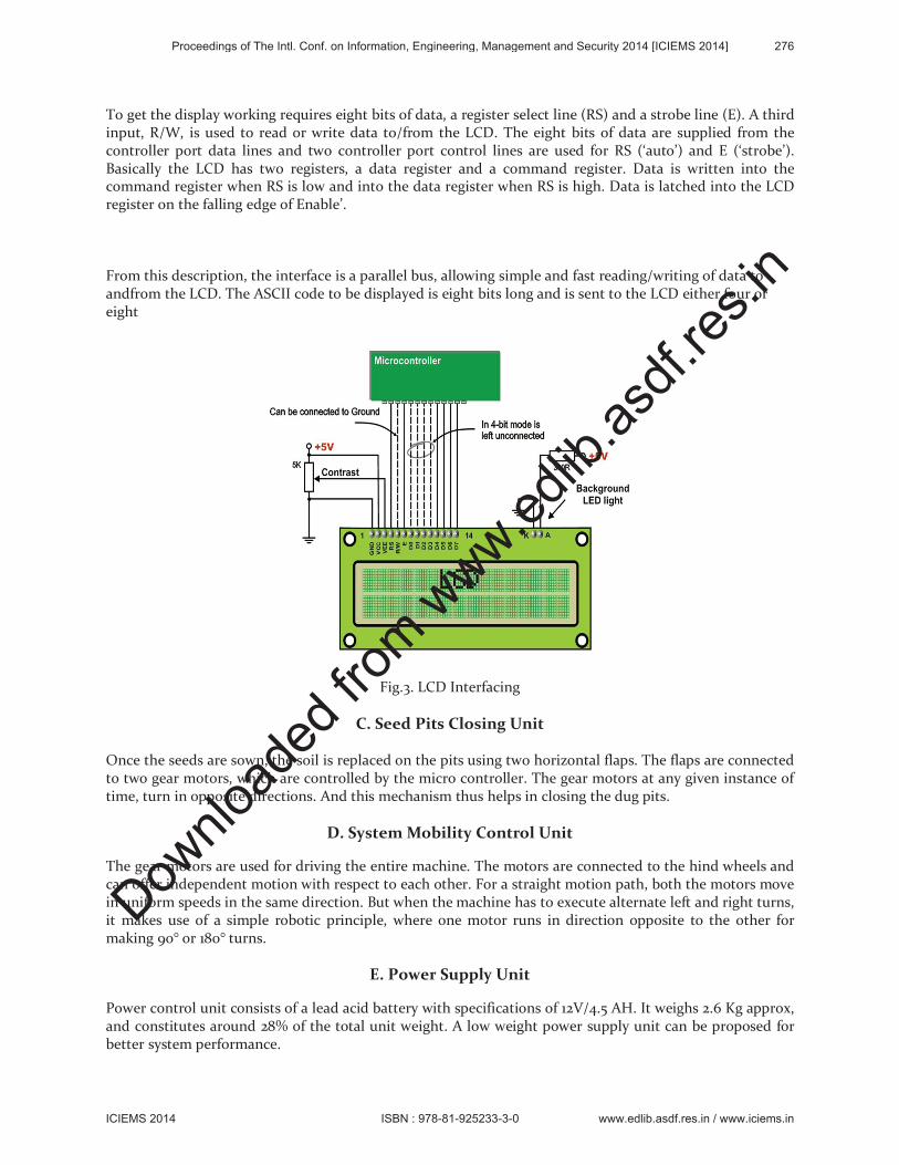
To get the display working requires eight bits of data, a register select line (RS) and a strobe line (E). A third input, R/W, is used to read or write data to/from the LCD. The eight bits of data are supplied from the controller port data lines and two controller port control lines are used for RS (‘auto’) and E (‘strobe’). Basically the LCD has two registers, a data register and a command register. Data is written into the command register when RS is low and into the data register when RS is high. Data is latched into the LCD register on the falling edge of Enable’.
From this description, the interface is a parallel bus, allowing simple and fast reading/writing of data to andfrom the LCD. The ASCII code to be displayed is eight bits long and is sent to the LCD either four or eight
Fig.3. LCD Interfacing
C. Seed Pits Closing Unit
Once the seeds are sown, the soil is replaced on the pits using two horizontal flaps. The flaps are connected to two gear motors, which are controlled by the micro controller. The gear motors at any given instance of time, turn in opposite directions. And this mechanism thus helps in closing the dug pits.
D. System Mobility Control Unit
The gear motors are used for driving the entire machine. The motors are connected to the hind wheels and can offer independent motion with respect to each other. For a straight motion path, both the motors move in uniform speeds in the same direction. But when the machine has to execute alternate left and right turns, it makes use of a simple robotic principle, where one motor runs in direction opposite to the other for making 90° or 180° turns.
E. Power Supply Unit
Power control unit consists of a lead acid battery with specifications of 12V/4.5 AH. It weighs 2.6 Kg approx, and constitutes around 28% of the total unit weight. A low weight power supply unit can be proposed for better system performance.
Proceedings of The Intl. Conf. on Information, Engineering, Management and Security 2014 [ICIEMS 2014] 276
ICIEMS 2014 ISBN : 978-81-925233-3-0 www.edlib.asdf.res.in / www.iciems.in
Dow
nloa
ded
from
www.e
dlib.a
sdf.r
es.in
F. Driver Circuits
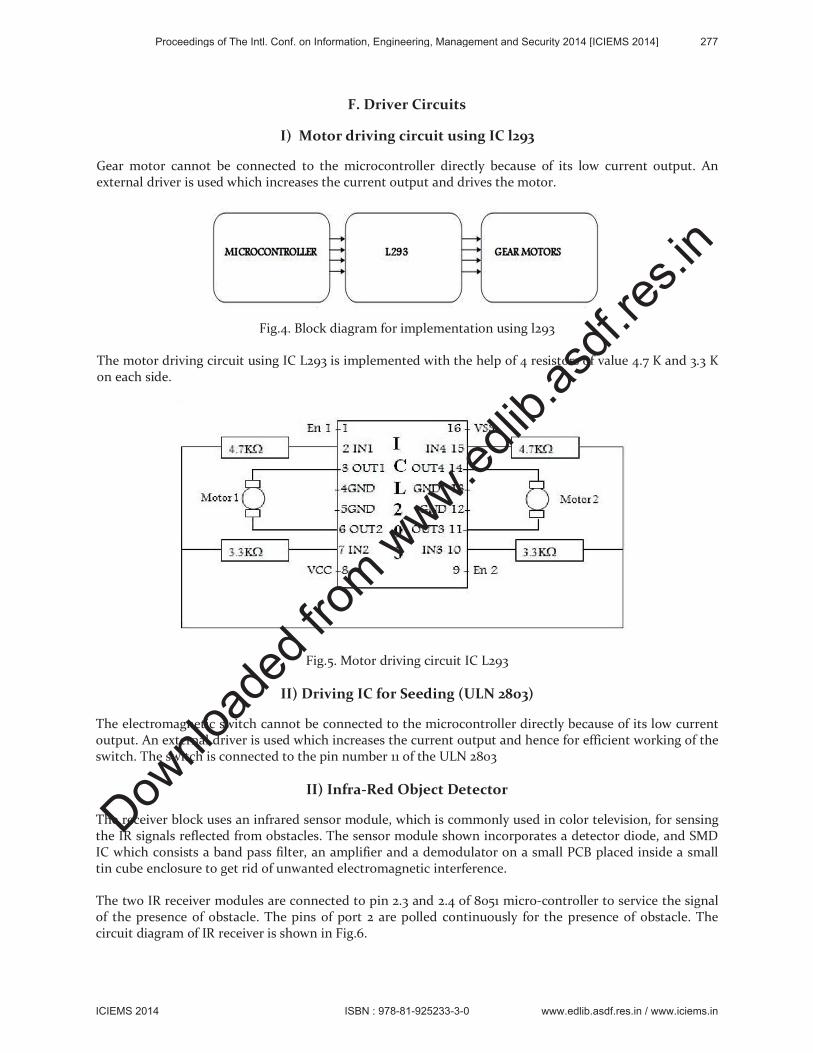
I) Motor driving circuit using IC l293
Gear motor cannot be connected to the microcontroller directly because of its low current output. An external driver is used which increases the current output and drives the motor.
Fig.4. Block diagram for implementation using l293
The motor driving circuit using IC L293 is implemented with the help of 4 resistors of value 4.7 K and 3.3 K on each side.
Fig.5. Motor driving circuit IC L293
II) Driving IC for Seeding (ULN 2803)
The electromagnetic switch cannot be connected to the microcontroller directly because of its low current output. An external driver is used which increases the current output and hence for efficient working of the switch. The switch is connected to the pin number 11 of the ULN 2803
II) Infra-Red Object Detector
The receiver block uses an infrared sensor module, which is commonly used in color television, for sensing the IR signals reflected from obstacles. The sensor module shown incorporates a detector diode, and SMD IC which consists a band pass filter, an amplifier and a demodulator on a small PCB placed inside a small tin cube enclosure to get rid of unwanted electromagnetic interference.
The two IR receiver modules are connected to pin 2.3 and 2.4 of 8051 micro-controller to service the signal of the presence of obstacle. The pins of port 2 are polled continuously for the presence of obstacle. The circuit diagram of IR receiver is shown in Fig.6.
Proceedings of The Intl. Conf. on Information, Engineering, Management and Security 2014 [ICIEMS 2014] 277
ICIEMS 2014 ISBN : 978-81-925233-3-0 www.edlib.asdf.res.in / www.iciems.in
Dow
nloa
ded
from
www.e
dlib.a
sdf.r
es.in
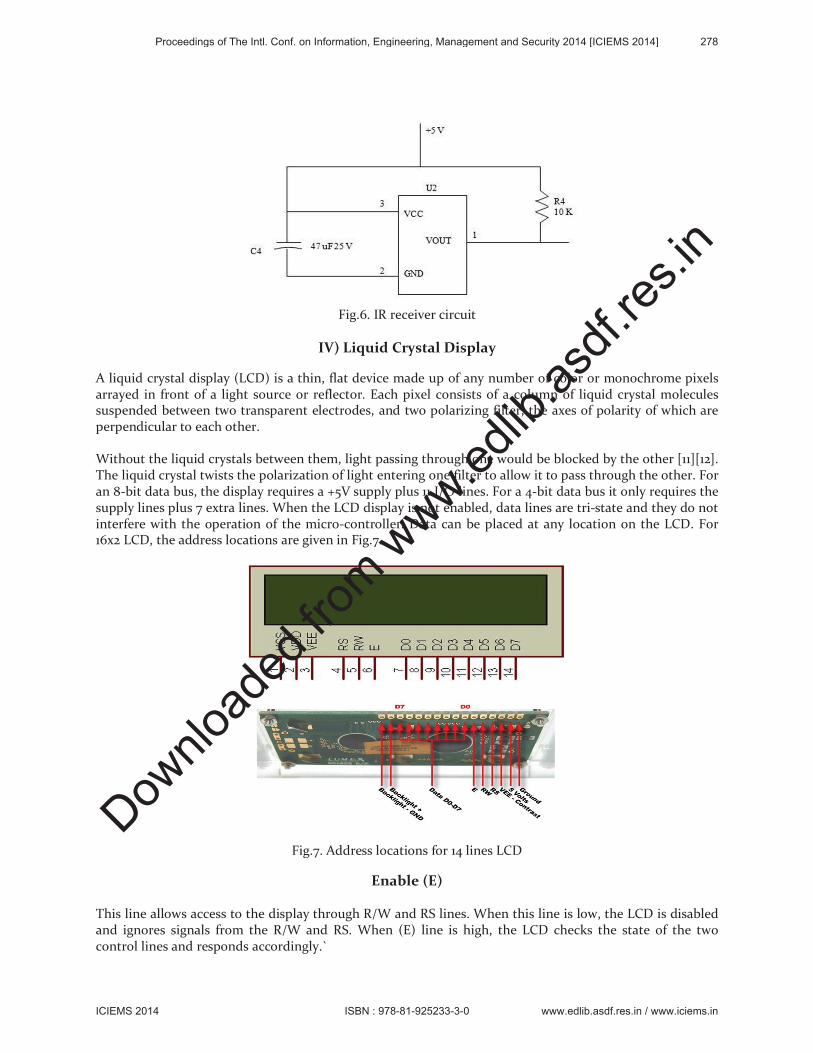
Fig.6. IR receiver circuit
IV) Liquid Crystal Display
A liquid crystal display (LCD) is a thin, flat device made up of any number of color or monochrome pixels arrayed in front of a light source or reflector. Each pixel consists of a column of liquid crystal molecules suspended between two transparent electrodes, and two polarizing filter, the axes of polarity of which are perpendicular to each other.
Without the liquid crystals between them, light passing through one would be blocked by the other [11][12]. The liquid crystal twists the polarization of light entering one filter to allow it to pass through the other. For an 8-bit data bus, the display requires a +5V supply plus 11 I/O lines. For a 4-bit data bus it only requires the supply lines plus 7 extra lines. When the LCD display is not enabled, data lines are tri-state and they do not interfere with the operation of the micro-controller. Data can be placed at any location on the LCD. For 16x2 LCD, the address locations are given in Fig.7.
Fig.7. Address locations for 14 lines LCD
Enable (E)
This line allows access to the display through R/W and RS lines. When this line is low, the LCD is disabled and ignores signals from the R/W and RS. When (E) line is high, the LCD checks the state of the two control lines and responds accordingly.`
Proceedings of The Intl. Conf. on Information, Engineering, Management and Security 2014 [ICIEMS 2014] 278
ICIEMS 2014 ISBN : 978-81-925233-3-0 www.edlib.asdf.res.in / www.iciems.in
Dow
nloa
ded
from
www.e
dlib.a
sdf.r
es.in
Read/Write (R/W)
This line determines the direction of data between the LCD and micro-controller. When it is low, data is written to the LCD. When it is high, data is read from the LCD.
Register Select (RS)
With the help of this line, the LCD interprets the type of data on data lines. When it is low, an instruction is being written to the LCD. When it is high, a character is being written to the LCD.
D. Logic status on control lines
E - 0 Access to LCD disabled- 1 Access to LCD enabled
R/W – 0 Writing data to LCD
- 1 Reading data from LCD
RS – 0 Instruction - 1 Character
E. Writing data to the LCD
Writing data to the LCD is done in several steps Set R/W bit to low Set RS bit to logic 0 or 1 (Instruction or character) Set data to data lines (If it is writing) Set E line to high Set E line to low Software Description Keil uVision4 software provides an integrated development environment to develop a program for the embedded system.
4. Advantages
The model Eliminates human intervention in some of the most labor-intensive parts of an agriculture procedure. The simplicity of the model enables even an illiterate user to use it with ease. It enables clean seeding pattern. The usage of DC battery enables the user to be free of constrains of ever rising electricity bills and the dependency on normal electricity. Simple and lightweight design makes the transportation of the apparatus easy. Minimal hardware usage helps in the easy maintenance of the system.
5. Limitations
The machine takes considerably long duration of time while executing the right and left turns. Current model does not have provision for using an AC power source. The program makes use of time delay technique for determining the effective seeding distance between two consecutive seeds. This technique compromises the system accuracy for different type of terrains and soil types. From the tests conducted, it is evidently noted that the apparatus works best for dry clayish (fine) soil. The seeding accuracy obtained is 94.827% as compared to seeding on a perfect flat surface. The machine moves at a speed of 55RPM compared to 58-60 RPMs` perfect flat surface. The seeding accuracy obtained for sandy (medium course) soil is 82.75% as compared to seeding on a perfect flat surface. The machine moves at a speed of 48-50RPM compared to 58-60 RPMs` perfect flat surface. The seeding accuracy obtained for very coarse soil is 72.41% as compared to seeding on a perfect flat surface. The machine moves at a speed of 40-45RPM compared to 58-60 RPMs` perfect flat surface.
6. Application
The prototype can be modified for any type of crop seed. It can also be modified in ways so that it could be used in different soil types and terrains.
Proceedings of The Intl. Conf. on Information, Engineering, Management and Security 2014 [ICIEMS 2014] 279
ICIEMS 2014 ISBN : 978-81-925233-3-0 www.edlib.asdf.res.in / www.iciems.in
Dow
nloa
ded
from
www.e
dlib.a
sdf.r
es.in
7. Scope for Future Improvement
The model can be modified to fit in extra features, namely a mechanism for weeding, and planting the saplings. Hydraulics could be used so that the level of the digger could be adjusted automatically. Solar cells can replace the DC battery to reduce the recharging cost and improve the overall efficiency. Ultrasonic detectors could replace IR sensors for better performance. An optocoupler coupled with the wheel motors can help in improving the overall system accuracy when it comes to effective seeding distance between two consecutive seeds to effective seeding distance between two consecutive seeds
8. Conclusion
In this paper we have integrated the features of all the hardware components used and have been developed in it. Presence of every module has been reasoned out and placed carefully thus contributing to the best working of the unit. Secondly using highly advanced IC’s and with the help of growing technology the project has been successfully designed and tested.
9. References
1. Belforte, G, Deboli, R, Gay, P, Piccarolo, P & Ricauda Aimonino, D 2006,”Robot design and testing for greenhouse applications‟, Biosystems Engineering, vol. 95, no. 3, pp. 309-321.
2. Naoshi Kondo and K.C. ting, “ROBOTICS FOR PLANT PRODUCTION” 3. Arima, S., Kondo, N., Fujiura, T., Nakamura, H. & Yamashita, J. (1995). Basic studies on cucumber
harvesting robot. Proceedings of ARBIP95 vol. 1, 195–202. Japan Society of Agricultural Machinery. 4. Bar, A., Edan, Y. & Alper, Y. (1996). Robotic transplanting: simulation and adaptation. Paper no.
963008. St. Joseph, MI: ASAE. 5. Bourely, A., Rabatel, G., & Sevila, F. (1991). A mobile robot with two actuators to pick apples. The
Second Workshop on Robotics in Agriculture & the Food Industry, 229–237. Italy: DIST University of Genova.
6. Coppock, G. E. (1983). Robotic principles in the selective harvesting of Valencia oranges. Robotics and Intelligent Machine in Agriculture, 138–145. St. Joseph, MI: ASAE.
7. Kondo, N. & Endo, S. (1987). Visual sensor for recognizing fruit (Part 1). Journal of the Japanese Society of Agricultural Machinery 49(6): 563–570.
8. Kondo, N., Monta, M., Shibano, Y. & Mohri, K. (1993). Basic mechanism of robot adapt ed to physical properties of tomato plant. Proceedings of International Conference for Agricultural Machinery and Process Engineering 3: 840–849.
9. Kondo, N., Monta, M., Shibano, Y., Mohri, K. & Arima, S. (1994). Robotic harvesting hands for fruit vegetables. Paper no. 943071. St. Joseph, MI: ASAE.
10. Kondo, N., Nakamura, H., Monta, M., Shibano, Y. & Mohri, K. (1994). Visual Sensor for Cucumber Harvesting Robot. Proceedings of Processing Automation Conference III, 461–470.
11. Kondo, N., Fujiura, T., Monta, M., Shibano, Y, Mohri, K. & Yamada, H. (1995). End-effectors for petty-tomato harvesting robot. Acta Horticulturae 399: 239–245.
12. Kozai, T., Ting, K. C. & Aitken-Christie, J. (1991). Considerations for automation of micro-propagation systems. Automated Agriculture for the 21
st Century, 503–517. St. Joseph, MI: ASAE. 13. Kutz, L. J., Miles, G. E., Hammer, P. A. & Krutz, G. W. (1987). Robotic transplanting of bedding
plants. Transactions of the ASAE 30(3): 586–590. 14. Lee, M. F., Gunkel, W. W. & Throop, J. A. (1994). A digital regulator and tracking controller design
for a electro-hydraulic robotic grape pruner. Computers in Agriculture-Proceedings of the 5th
International Conference, 23–28. St. Joseph, MI: ASAE. 15. Miles, G. E. (1994). Automation basics: perception, reasoning, communication, planning, and
implementation. Greenhouse Systems-Automation, Culture, and Environment, 8–15. Ithaca, NY: NRAES-72, Northeast Regional Agricultural Engineering Service.
Proceedings of The Intl. Conf. on Information, Engineering, Management and Security 2014 [ICIEMS 2014] 280
ICIEMS 2014 ISBN : 978-81-925233-3-0 www.edlib.asdf.res.in / www.iciems.in
Dow
nloa
ded
from
www.e
dlib.a
sdf.r
es.in
16. Miyazawa, F. (1987). Gantry system. Proceedings of International Symposium on Agricultural Mechanization and International Cooperation in High Technology Era, 109–114. Japanese Society of Agricultural machinery.
17. Monta, M., Kondo, N., Shibano, Y. & Mohri, K. (1994). Study on a robot to work in vineyard. Paper no. 943072. St. Joseph, MI: ASAE.
18. Monta, M., Kondo, N., Ting, K. C., Giacomelli, G. A., Mears, D. R. & Kim, Y (1996). End-effector for tomato harvesting robot. Paper no. 963007. St. Joseph, MI: ASAE.
19. Murakami, N., Inoue, K. & Ootsuka, K. (1995). Selective harvesting robot of cabbage. Pro ceedings of ARBIP95 vol. 2,25–32. Japan Society of Agricultural Machinery.
20. Ochs, E. S. & Gunkel, W. W. (1993). Robotic grape pruner field performance simulation. Paper no. 933528. St. Joseph, MI: ASAE.
Proceedings of The Intl. Conf. on Information, Engineering, Management and Security 2014 [ICIEMS 2014] 281
ICIEMS 2014 ISBN : 978-81-925233-3-0 www.edlib.asdf.res.in / www.iciems.in
Dow
nloa
ded
from
www.e
dlib.a
sdf.r
es.in