Embed Size (px)
Citation preview

IEEE TRANSACTIONS ON AUTOMATIC CONTROL, VOL. 43, NO. 4, APRIL 1998 509
Conflict Resolution for Air Traffic Management:A Study in Multiagent Hybrid Systems
Claire Tomlin,Student Member, IEEE, George J. Pappas,Student Member, IEEE, and Shankar Sastry,Fellow, IEEE
Abstract—Air Traffic Management (ATM) of the future allowsfor the possibility of free flight, in which aircraft choose theirown optimal routes, altitudes, and velocities. The safe resolutionof trajectory conflicts between aircraft is necessary to the successof such a distributed control system. In this paper, we present amethod to synthesize provably safe conflict resolution maneuvers.The method models the aircraft and the maneuver as ahybridcontrol systemand calculates the maximal set of safe initialconditions for each aircraft so that separation is assured in thepresence of uncertainties in the actions of the other aircraft.Examples of maneuvers using both speed and heading changesare worked out in detail.
Index Terms—Air traffic management, conflict resolution, hy-brid systems, verification.
I. INTRODUCTION
A IR transportation systems are faced with soaring demandsfor air travel. The annual air traffic rate in the United
States is expected to grow by 3–5% annually for at leastthe next 15 years [1]. The current National Airspace System(NAS) architecture and management will not be able toefficiently handle this increase because of several limitingfactors including the following.
• Inefficient airspace utilization:Currently, the airspace isvery rigidly structured and aircraft are forced to travelalong predetermined jetways. This is generally not opti-mal and disallows aircraft to fly directly to the destinationand take advantage of favorable winds. This problemis particularly evident in transoceanic routes which areexperiencing the greatest demand growth (for example,nearly 15% [1] annually across the Pacific Ocean).
• Increased Air Traffic Control (ATC) workload:Separationamong aircraft as well as vectoring aircraft in order toavoid weather hazards is performed centrally by ATC.In congested areas, such as the regions close to urbanairports referred to as Terminal Radar Approach CONtrols(TRACON’s), controllers frequently simplify their heavyworkload by keeping aircraft in holding patterns outsidethe TRACON.
• Obsolete technology:The computer technology used inmost ATC centers is nearly 30 years old [2]. Commu-nication is restricted to congested voice communication
Manuscript received August 2, 1996. Recommended by Associate Editor,P. J. Antsaklis. This work was supported by NASA under Grant NAG 2-1039,by the Army Research Office under Grants DAAH 04-95-1-0588 and DAAH04-96-1-0341, and by NSERC and ZONTA postgraduate fellowships.
The authors are with the Department of Electrical Engineering and Com-puter Sciences, University of California, Berkeley, CA 94720 USA.
Publisher Item Identifier S 0018-9286(98)02660-9.
between the aircraft and ATC. Navigation is performed byflying over fixed VHF Omni-Directional Range (VOR)points.
In view of the above problems, the aviation communityis working toward an innovative concept calledFree Flight[3]. Free Flight allows pilots to choose their own routes,altitude, and speed. User preference would be restricted onlyin congested airspace or to prevent unauthorized entry ofspecial use airspace (such as military airspace). Free Flight ispotentially feasible because of enabling technologies such asGlobal Positioning Systems (GPS), datalink communicationslike Automatic Dependence Surveillance-Broadcast (ADS-B) [4], [5], Traffic Alert and Collision Avoidance Systems(TCAS) [6], and powerful on-board computation. In addition,tools such as NASA’s Center-TRACON Automation System(CTAS) [7] and MITRE’s URET [8] will serve as decisionsupport tools for ground controllers in an effort to reduce ATCworkload and optimize capacity.
The above technological advances will also enable thecurrent ATC system to accommodate future air traffic growth:sophisticated on-board equipment will allow aircraft to sharesome of the workload, such as navigation, weather prediction,and aircraft separation, with ground controllers. In order toimprove the current standards of safety in an unstructuredFree Flight environment, conflict detection and resolutionalgorithms are vital. Such algorithms would be used either onthe ground by Air Traffic Control or in the air by the FlightManagement System (FMS) of each aircraft.
In the proposed Free Flight airspace, each aircraft is sur-rounded by two virtualcylinders [4], the protected zoneandthealert zone, shown in Fig. 1. A conflict or loss of separationbetween two aircraft occurs whenever the protected zonesof the aircraft overlap. If the alert zones overlap, eitherATC is notified about the potential conflict, or the aircraftexchange sensor and intent information in order to predictand resolve the conflict. The radius and the height of theen-route protected zone over U.S. airspace is currently 2.5nautical mi and 2000 ft (1000 ft below 29 000 ft, 4000 ftover oceanic airspace), respectively. The size of the alertzone, currently under debate, depends on various factorsincluding airspeed, altitude, accuracy of sensing equipment,traffic situation, aircraft performance, and average human andsystem response times.
Current research endeavors in conflict prediction and res-olution include [9]–[13]. Conflict prediction could be spatial,temporal, or probabilistic. Spatial and temporal approaches,such as [11] and [13], calculate the four-dimensional coordi-
0018–9286/98$10.00 1998 IEEE

510 IEEE TRANSACTIONS ON AUTOMATIC CONTROL, VOL. 43, NO. 4, APRIL 1998
Fig. 1. Protected and alert zone for one aircraft.
nates of a possible conflict. Probabilistic approaches, such as[9] and [10], assume stochastic uncertainty in the measuredinformation and determine the probability of collision. Thework of [11] and [12] formulates conflict resolution as anoptimal control problem, whereas [13] treats the problem asa convex optimization problem. The user interface of CTASallows controllers to manually alter aircraft trajectories toresolve conflicts in en route airspace [14]. TCAS [6] providesresolution advisories (flight level changes) to pilots involvedin two-aircraft conflicts, however these advisories are notformally verified. (Conflict prediction and resolution are themost important modules that are in need of augmentationand verification in the current implementations of CTAS andTCAS.)
In [15] a possible future architecture for Air Traffic Manage-ment (ATM) is presented. In our paradigm, aircraft are allowedto self-optimize in the spirit of Free Flight, communicate stateand intent data to each other using an ADS-B datalink forconflict prediction, and coordinate with each other to resolvepotential conflicts. State and intent data could be uncertain.Coordination among the aircraft is in the form ofmaneuverswhich are finite sequences offlight modessuch as heading,altitude, and speed changes for each aircraft. These types ofmaneuvers are routinely used in current Air Traffic Controlpractice since they are easily understandable by pilots as wellas easily implementable by on-board autopilots which regulatethe aircraft to heading and speed setpoints. The main thrust ofour conflict resolution algorithms is toverify that a maneuversuccessfully resolves the conflict by computing the set of initialconditions for which the maneuver is safe, where safety meansthat separation is maintained. In the presence of boundeduncertainty in the state or intent data, we take a worst caseapproach and verify that the worst case system trajectory issafe.
The flight mode switching occurring in each maneuver ismodeled by a finite-state automaton with the relative aircraftconfiguration dynamics residing within each flight mode. Aconflict resolution maneuver is therefore modeled by a finitestate automaton interacting with a set of continuous controlsystems, resulting in ahybrid control system. The interactionand information exchange of all of the aircraft involved in themaneuver results in amultiagent hybrid control system.
There are several approaches to hybrid system model-ing, verification, and controller design (see, for example,[16]–[19]). The computer science approach is to extend models
of finite-state automata to timed automata [20], linear hybridautomata [21], and hybrid input/output automata [22]. Linearhybrid automata model or abstract the continuous dynamicsby differential inclusions of the form and verifyproperties of the resulting abstracted system [23]–[25]. Spec-ifications are verified for these models using either modelchecking, which exhaustively check all system trajectories, ordeductive theorem-proving techniques [26], which prove thespecification by induction on all system trajectories. In thisframework, controller design has also been developed [27],[28]. Automated computational tools have been developedfor both model checking [29], [30] and theorem proving[31]. Control theoretic approaches to modeling, analysis, andcontroller design for hybrid systems have extended the theoryof dynamical systems to include discrete modes of operation.Modeling approaches include those of [32]–[37]. Analysis anddesign techniques extend existing control techniques, suchas stability theory [33], optimal control [33], [36], [37], andcontrol of discrete-event systems [38], [39], to hybrid systems.
Our conflict resolution algorithms are in the spirit of modelchecking, but we use control theoretic (deductive) techniquesto calculate the reachable region for hybrid systems withgeneral nonlinear dynamics. Our method calculates the largestcontrolled invariant subset of the complement of each aircraft’sprotected zone, taking into account the uncertainty of theactions of the other aircraft. In order to compute this safeset of states, we first develop a method to compute thecontrolled invariant subsets for continuous systems in thepresence of disturbances. A natural framework for this typeof problem is zero-sum noncooperative dynamic game theory[40], [41]. In this framework, uncertain information aboutneighboring aircraft is treated as a disturbance. For a two-aircraft example, assuming a saddle solution to the gameexists, each aircraft chooses an optimal policy assuming theworst possible disturbance. This is motivated by the work of[42], in which game theoretic methods are used to prove safetyof a set of maneuvers in Intelligent Vehicle Highway Systems.
Along with the safe set of initial states, we calculate thecorresponding safe set of control inputs as a function of thestate. Within its safe region of operation, the aircraft maydesign its trajectory to optimize over other criteria, such as fuelefficiency or minimal deviation from route. At the boundaryof its safe region, the aircraft must apply the particular controlwhich keeps it out of its unsafe region. Thus, we are naturallyled to a switching control-based protocol which isleastrestrictive. A more detailed description of this multiobjectivemethodology may be found in [43]. The resultant hybridsystem is safe by design, as we illustrate with two versionsof an interesting example of two-aircraft conflict resolution inthe horizontal plane.
The organization of this paper is as follows: In Section IIour modeling formalism and design methodology for hybridsystems is described. Section III presents the game theoreticapproach to computing the safe set of initial conditions andcontrol inputs for continuous systems. Section IV describessafety verification of coordinated maneuvers using the resultsof Section III. Section V presents a brief summary and someissues for further research.

TOMLIN et al.: CONFLICT RESOLUTION FOR AIR TRAFFIC MANAGEMENT 511
(a) (b)
Fig. 2. Two different conflict resolution maneuvers, with associated modes.
II. HYBRID MODEL AND DESIGN METHODOLOGY
In this section, we present a hybrid system model for conflictresolution maneuvers and a method to verify the safety of, andsynthesize control schemes for, these maneuvers. The discretestates of the hybrid system model the different flight modesthat each aircraft steps through while executing the maneuver.For example, consider the two-aircraft examples of Fig. 2. Inthe first, the aircraft avoid each other by transitioning througha sequence of heading changes: “left,” “straight,” “right,” andthen back to the original “cruise” mode; in the second theconflict is avoided by both aircraft transitioning to a “circle”mode from a “cruise” mode.
Each mode has associated with it the relative aircraft con-figuration dynamics. The verification of the safety of eachmaneuver, with possible variations in the control inputs ofeach aircraft and changes in the switching times betweenmodes, is complicated and in general not possible to computemanually. The hybrid model presented in this section providesan organized, formal way to model and prove the safety ofthe maneuver.
The hybrid model described below is inspired by that of[23] for linear hybrid automata, with the difference that weallow for a nonlinear continuous dynamic model within eachdiscrete state and a general discrete transition relation.
Hybrid System Model
A hybrid system is defined to be the tuplein which
• is the state space, with afinite set of discrete states and an -manifold; a stateof the system is a pair
• is the product of the input setand disturbance set; the space of acceptable control anddisturbance trajectories are denoted by
• is a finite set of transition labels;• is the set of initial conditions;
• is the invariant associated with eachdiscrete state, meaning that the state may flowwithin only if
• is the set of discrete jumpswith meaning that if the current stateis the system may instantaneously take a discretetransition to state
• is a map which associates witheach discrete state a control systemFor notational convenience we use to denote
Hybrid systems evolve in so-called “dense time” by eithercontinuous flows or discrete transitions. Trajectories of thehybrid system starting at a state evolve according to
as long as the continuous state remains within Ifthe invariance condition is not satisfied, then a discrete transi-tion is forced and the continuous state may be reinitialized. If
, then the discrete state may jump fromto and the continuous stateis reinitialized to and thenflows according to
Relative Aircraft Configuration Models
We now describe the continuous dynamics within eachdiscrete state Because conflicts between aircraft depend onthe relative position and velocity of the agents, the continuousmodels we use arerelative models, describing the motion ofeach aircraft in the system with respect to the other aircraft. Forexample, to study pairwise conflict between the trajectories oftwo aircraft, aircraft 1 and aircraft 2, a relative model with itsorigin centered on aircraft 1 is used. The configuration of anindividual aircraft is described by an element of the Lie group
of rigid motions in or called orrespectively. In planar situations, in which aircraft are flyingat the same altitude, will be used.
Following the example described above, let denotethe configuration of aircraft 1, and let denote theconfiguration of aircraft 2. The trajectories of both aircraft arekinematically modeled as left invariant vector fields on
512 IEEE TRANSACTIONS ON AUTOMATIC CONTROL, VOL. 43, NO. 4, APRIL 1998
Therefore
(1)
(2)
where the Lie algebra associated with the Liegroup A coordinate change is performed to place theidentity element of the Lie group on aircraft 1. Thus, let
denote the relative configuration of aircraft 2 withrespect to aircraft 1. Then
(3)
Differentiation yields the dynamics of the relative config-uration
(4)
Note that the vector field which describes the evolution ofis neither left nor right invariant.
Consider the Lie group and its associated Lie algebraA coordinate chart for is given by
representing the planar position and orientation of a rigid body.In this coordinate chart, the relative configurationis givenin homogeneous coordinates by
(5)
where represent the relative position of aircraft 2 withrespect to aircraft 1 and is the relative orientation. In localcoordinates, the coordinate transformation (3) is expressed as
(6)
(7)
with parameterizing the absolute position and orien-tation of aircraft The Lie algebra elementsare represented as matrices in of the form
(8)
where represent the linear and angular velocities. Insert-ing (5) and (8) in (4) results in the relative configurationdynamics in local coordinates
(9)
Similar results for may be found in [44]. Thus foreach discrete state the dynamics is describedby (9), with The linear (or angular) velocityof aircraft 1 is the control input and the uncertain linear(or angular) velocity of aircraft 2 is considered to be thedisturbance
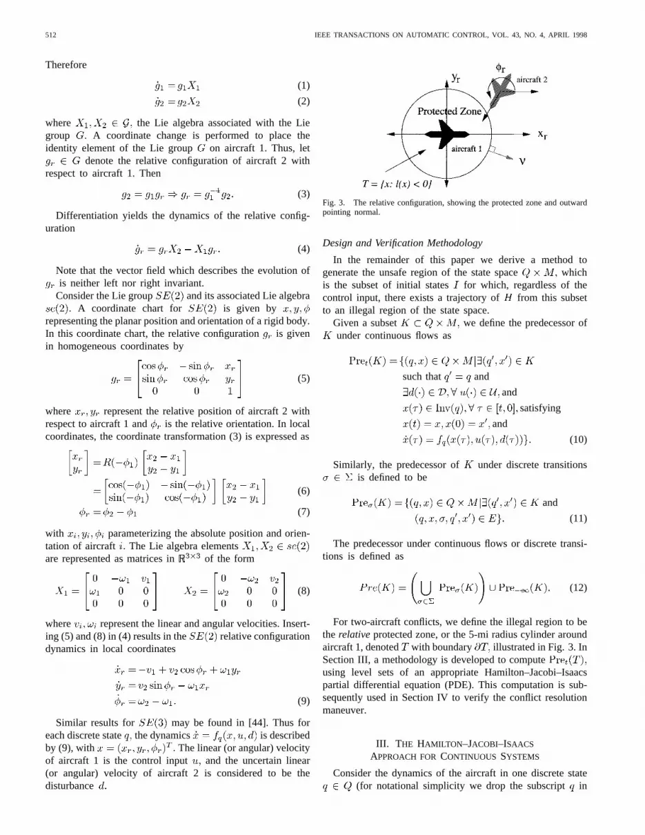
Fig. 3. The relative configuration, showing the protected zone and outwardpointing normal.
Design and Verification Methodology
In the remainder of this paper we derive a method togenerate the unsafe region of the state space whichis the subset of initial states for which, regardless of thecontrol input, there exists a trajectory of from this subsetto an illegal region of the state space.
Given a subset we define the predecessor ofunder continuous flows as
such that and
and
satisfying
and
(10)
Similarly, the predecessor of under discrete transitionsis defined to be
and
(11)
The predecessor under continuous flows or discrete transi-tions is defined as
(12)
For two-aircraft conflicts, we define the illegal region to bethe relativeprotected zone, or the 5-mi radius cylinder aroundaircraft 1, denoted with boundary illustrated in Fig. 3. InSection III, a methodology is developed to computeusing level sets of an appropriate Hamilton–Jacobi–Isaacspartial differential equation (PDE). This computation is sub-sequently used in Section IV to verify the conflict resolutionmaneuver.
III. T HE HAMILTON –JACOBI–ISAACS
APPROACH FORCONTINUOUS SYSTEMS
Consider the dynamics of the aircraft in one discrete state(for notational simplicity we drop the subscript in

TOMLIN et al.: CONFLICT RESOLUTION FOR AIR TRAFFIC MANAGEMENT 513
this section)
(13)
where describes the relative configuration of aircraft 2with respect to aircraft 1, is the control inputwhich models the actions of aircraft 1, and is thedisturbance input which models the actions of aircraft 2. Weassume that the system starts at stateat initial time Both
and are known sets, but whereas the control inputmaybe chosen by the designer, the disturbanceis unknown, andmodels the uncertainty of the actions of aircraft 2.
The goal is to maintain safe operation of (13), meaning thatthe system trajectories do not enter the “Target set.” Weassume that there exists a differentiable function so that
and
A. The Value Function and theHamilton–Jacobi–Isaacs Equation
This section describes the computation of the unsafe subsetof the state space, denoted which is thesubset from which there exists a disturbance action suchthat the resulting trajectory of (13) enters in at most s.Due to the uncertainty in the actions of aircraft 2, the safestpossible strategy of aircraft 1 is to fly a trajectory whichguarantees that the minimum allowable separation with aircraft2 is maintained,regardlessof the actions of aircraft 2. Weformulate this problem as a two-person, zero-sum dynamicalgame and calculate the “losing” states for aircraft 1.
Consider (13) over the time interval where Thevalue function of the game is defined by
(14)
such that This value function maybe interpreted as the cost of a trajectory which starts atat time evolves according to (13) with inputand ends at the final state Note that the value functiondepends only on the final state: there is no running cost, orLagrangian. This encodes the fact that we are only interestedin whether or not the system trajectory ends inand arenot concerned with intermediate states. The game is lost byaircraft 1 if the terminal state is inside .
Given we first characterize theunsafeportion of defined as those states for which thereexists some disturbance such that for all inputsthe vector field points into the safeportion of consistsof the states for which there is some inputsuch that for all disturbances the vector field pointsoutward from Define the outward pointing normal to as
then
Safe portion of
Unsafe portion of
(15)
The optimal control and the worst disturbance aregiven by
(16)
(17)
The game is said to have a saddle solution if theresulting optimal cost does not depend on the order in whichthe maximization and minimization is performed
(18)
The concept of a saddle solution is key to our computationof the safe regions of operation of the aircraft, since a solutionof (13) with , and represents an optimaltrajectory foreachplayer under the assumption that the otherplayer plays its optimal strategy.
Aircraft 1 maintains safety at time by operating outsideof
(19)
(20)
Let denote the boundary of To calculatethe unsafe set of states for all we constructthe Hamilton–Jacobi–Isaacs PDE for this system and attemptto calculate its steady-state solution. Define the Hamiltonian
where is the costate.The optimal Hamiltonian is given by
(21)
and satisfies Hamilton’s equations (provided issmooth in and )
(22)
with the boundary conditions andIf is a smooth function of and thensatisfies the Hamilton–Jacobi–Isaacs equation
(23)
with boundary condition It is difficult toguarantee that the PDE (23) has smooth solutions for alldue to the occurrence of “shocks,” i.e., discontinuities inasa function of If there are no shocks in the solution of (23),

514 IEEE TRANSACTIONS ON AUTOMATIC CONTROL, VOL. 43, NO. 4, APRIL 1998
we characterize the set
(24)by solving the modified Hamilton–Jacobi–Isaacs equation
(25)
with boundary condition The “min” is addedto the right-hand side of (25) to ensure that states which areonce unsafe cannot become safe. In practical applications,since one is concerned only with aircraft in the alert zone,the calculation of (24) may be approximated by computing
for sufficiently large such as min.The set defines the least restrictive control
schemefor safety. If aircraft 2 is outside anycontrol input may be safely applied by aircraft 1, whereas onthe boundary, the only input which may be safely applied toensure safety is The safe set of control inputs associatedwith each state at time is
(26)
Additional system requirements, such as optimal fuel trajec-tories and passenger comfort, can now be incorporated by op-timizing secondary and tertiary criteria within the constraintsof set (26), following the multiobjective design methodologyof [43].
We now apply this general framework to the planarrelative model (9) in local coordinates with thecontrol actions either the angular or linear velocities.
B. Angular Velocities as Control Actions
Consider the case in which the linear velocities of bothaircraft are fixed, and the control inputs of theaircraft are the angular velocities, and
(27)
with state variables and controland disturbance inputs
Without loss of generality (we scale thecoefficients of and if this is not met), assume thatand for
The target set is the protected zone in the relative frame
(28)
which is a 5-mi-radius cylindrical block in thespace. Thus the function may be defined as
(29)
The optimal Hamiltonian is
(30)
Defining theswitching functions and as
(31)
where the saddle solution exists when andand is calculated as
(32)
The equations for are obtained through (22) and are
(33)
with the outward pointing normal toat any point on
The safe and unsafe portions of are calculated using(15) with Thus, those onfor which
(34)
constitute the unsafe portion, and those on forwhich
(35)
are the final state conditions for the boundary of the unsafeset To solve for and along this boundaryfor we must first determine and Equations(32) are not defined at since ongiving rise to “abnormal extremals” (meaning that the optimalHamiltonian loses dependence onand at these points).Analogously to [41, pp. 442–443], we use an indirect methodto calculate and at any point onthe derivatives of the switching functions and are
(36)
(37)
Consider, for example for thecase . This point satisfies (35) and thus belongs to
for all At this point, and , meaningthat for values of slightly less than zero, andThus for this point, and
These values for and remain valid for as long asand When and the
saddle solution switches and the computation of the boundarycontinues with the new values of and thus introducing“kinks” into the boundary. These points correspond to loss ofsmoothness in the Hamilton–Jacobi–Isaacs equation discussedabove. Fig. 4 displays the resulting boundary of the unsafe set
for until the first time that either orswitches.
The automaton illustrating theleast restrictive controlschemefor safety is shown in Fig. 5. The computation ofthe boundary of is in general difficult. For certainranges of and the surfaces shown in Fig. 4 intersect,

TOMLIN et al.: CONFLICT RESOLUTION FOR AIR TRAFFIC MANAGEMENT 515
(a)
(b)
Fig. 4. The Target setT = f(xr; yr); �r 2 (0; �)jx2r+ y2
r� 52g (cylinder) and the boundary of the setPret(T ) (enclosed by the boundary) fort < 0
until the first switch in eithers1(t) or s2(t): The second picture is a top view of the first.
and at the intersection, it is not clear that is the uniquesafe input.
C. Linear Velocities as Control Actions
Now consider the case in which the angular velocities ofthe two aircraft are zero and the control inputs are the linearvelocities of the aircraft: and model (9)
reduces to
(38)
The input and disturbance lie in closed subsets of thepositive real line
2 2

516 IEEE TRANSACTIONS ON AUTOMATIC CONTROL, VOL. 43, NO. 4, APRIL 1998
Fig. 5. Switching law governing the two-aircraft system with angular ve-locity control inputs. The law is least restrictive in that the controlu isnot restricted when the state is outsidePret(T ): The diagonal transitionsin the automaton for the boundary ofPret(T) are not shown for legibility.In practice,t should be chosen large enough to take into account aircraft inthe alert zone.
The Target set and function are defined as in theprevious example. In this example, it is straightforward tocalculate the saddle solution directly, by integrating(38) for piecewise constant and and substituting thesolutions into the cost function (14). We define the switchingfunctions and as
(39)
Proposition 1 (Saddle Solution for Linear Velocity Controls):The global saddle solution to the game described bysystem (38) for the cost given by (14) is
ifif
(40)
ifif
(41)
Proof: See the Appendix.As can be seen from (40), depends on the position of
aircraft 2 relative to aircraft 1. If aircraft 2 is ahead of aircraft 1in the relative axis frame, then is at its lower limit; if aircraft2 is behind aircraft 1 in the relative axis frame, thenis atits upper limit. If aircraft 2 is heading toward aircraft 1, then
is at its upper limit; if aircraft 2 is heading away fromaircraft 1, is at its lower limit. The bang–bang nature ofthe saddle solution allows us to abstract the system behaviorby the hybrid automaton shown in Fig. 6, which describes theleast restrictive control scheme for safety. The unsafe sets of
Fig. 6. Switching law governing the two-aircraft system with linear velocitycontrol inputs.
states are illustrated in Fig. 7 for various values of andspeed ranges as illustrated.
IV. V ERIFICATION OF CONFLICT RESOLUTION MANEUVERS
In this section we apply the calculation ofSection III to calculate the unsafe set of initial conditions fora conflict resolution maneuver. We illustrate the methodologyon a maneuver whose form is chosen to be a finite sequenceof heading changes resulting in a trapezoidal deviationfrom the desired path. Consider the conflict scenario andresolution maneuver shown in Fig. 2(a). The protocol may belinguistically expressed as follows.
1) Cruise until aircraft are mi apart.2) Make a heading change of and fly until a lateral
displacement of at leastmi is achieved for both aircraft.3) Make a heading change to original heading and fly until
the aircraft are mi apart.4) Make a heading change of and fly until a lateral
displacement of mi is achieved for both aircraft.5) Make a heading change to original heading and cruise.
The maneuver is modeled as the hybrid automatonshown in Fig. 8. [The state space of iswhereand models the different flight modes in the maneuver, and
are the continuous variableswhich evolve within each discrete location according to therelative configuration dynamics (9).] The initial condition ofthe automaton is
(42)

TOMLIN et al.: CONFLICT RESOLUTION FOR AIR TRAFFIC MANAGEMENT 517
Fig. 7. Pret(T ) shown in the(xr; yr)-plane for [v1; v1] = [2; 4]; [v
2; v2] = [1; 5]; and�r = �=2;0;��=4;��=2:
Fig. 8. Modeling conflict resolution maneuver as a hybrid automaton.

518 IEEE TRANSACTIONS ON AUTOMATIC CONTROL, VOL. 43, NO. 4, APRIL 1998
Fig. 9. Computation ofPre�1(T ) for each discrete state infCRUISE;LEFT;STRAIGHT;RIGHTg:
where is the radius of the alert zone. Thus the aircraft areassumed to be initially cruising and their protected zones donot intersect. The safety specification for is that the statedoes not enter defined as
(43)
Due to uncertainties in the velocity of the other aircraft,the worst case scenario is assumed for, and therefore thedynamics evolve according to the saddle solution (41). Thisintroduces additional switching surfaces within each discretestate.
The automaton of Fig. 8 starts in the mode andflows in that state until the interaircraft distance is less thanmiles, at which point both aircraft make a heading change of
Discrete heading changes have the effect of resetting thestate by a rotation matrix since the coordinate frame dependson the orientation of the aircraft [6], [7]. In modeboth aircraft make a nominal lateral displacement of at least
This is achieved using a timer variableas shown. Bothaircraft then return to their original heading and cruise untiltheir relative distance is greater than miles. Once this isachieved, the reverse maneuver is performed in order returnto the original cruise path and heading. The heading changesof both aircraft are assumed to occur simultaneously.
For this example, the velocities of the aircraft are chosento be the same as in the second example of Section III:
and The radius of therelative protected zone is 5 mi while the alert zone has a radiusof 25 mi.1 Instead of fixing values for the parametersand we initially leave the first three unrestricted and let
Their values will be determined in orderto minimize the unsafe set of initial states of the maneuver.
Fig. 9 displays the union of eachcalculated within the alert zone for each discrete state
in the absenceof invariants for each discrete state since the parameters
and are unconstrained. The set labeled(respectively, displays theset of states which could flow into under themode (respectively, modes).
in the and modes are rotationsof this set in the mode by corresponding toaircraft 1 at the origin of the relative frame rotating byThe intersection of the sets in this figure representsthose states which are unsafe underall modes, since outsideof this intersection the aircraft may always switch modes toenter a safe region, by choosing appropriate values for theparameters Fig. 10 displays the minimal unsafe setas a subset of the in the maneuver(shown as the shaded set). The values of and arechosen so that the switches between modes occur on theboundary of this minimal set.
1The velocities and size of the alert zone are scaled in order to producevisualizable figures.

TOMLIN et al.: CONFLICT RESOLUTION FOR AIR TRAFFIC MANAGEMENT 519
Fig. 10. Partitioning the Alert Zone into safe and unsafe regions.
Fig. 11. Conflict Resolution for three aircraft: the Roundabout maneuver.
The type of maneuver that may be verified with thistechnique can be much more general than that described here:in [45] we construct various parameter-dependent maneuversfor two, three, and four aircraft by using artificial potential fieldmethods from robotic path planning to produce the maneuvers.For three aircraft coming into conflict this approach producesthe Roundaboutmaneuver, shown in Fig. 11.
V. CONCLUSIONS
In this paper, we have presented a methodology for gen-erating provably safe conflict resolution maneuvers for twoaircraft. The method is based on calculating reachable sets forhybrid systems with nonlinear dynamics within each discretestate. The approach allows for uncertainty in the intent ofone of the aircraft and calculates the least restrictive con-trol scheme for the other aircraft, based on the worst caseuncertainty. This calculation is then used to determine, for agiven maneuver with possible variation in its parameters, theminimal unsafe operating region for each aircraft.
Important research issues that we are currently addressingare the computation of numerical solutions to the Hamil-ton–Jacobi–Isaacs PDE and the efficient representation andmanipulation of the reachable sets. The computation of thesolution to the Hamilton–Jacobi–Isaacs PDE when is
not a smooth function of and is possible, a survey paper[46] presents efficient computation schemes. In addition, weare extending the verification methodology to include lift anddrag aerodynamic forces in the dynamics of the aircraft. Somepreliminary results in this context have been presented in [43].Finally, we are investigatingprobabilistic verification, whichcalculates the probability of a system trajectory entering anunsafe region.
APPENDIX
Proof of Proposition 1: Starting at time (free) and in-tegrating to the final time zero, the solution to (38) has
and
(44)
Substituting (44) into the cost index (14), (29), and ignoringthe constant results in
Define theswitching functions as in (39). Con-sider the case in which,
We will show that in this case the saddle solution isand Note that we assume that in the intervalboth and do not change sign. If is such thatthe switching functions do change sign on this interval, thenthe interval must be broken into two intervals and the saddlesolution calculated separately for each interval.
Let and vary , i.e., let whereThen
(45)

520 IEEE TRANSACTIONS ON AUTOMATIC CONTROL, VOL. 43, NO. 4, APRIL 1998
Similarly, let and vary , i.e., letwhere Then
(46)
Summarizing, we have shown above that in this case
(47)
Therefore, is a saddle solution in this case.The three other cases can be shown in a similar manner.
REFERENCES
[1] Honeywell Inc., “Markets report,” Tech. Rep. NASA Contract NAS2-114279, Final Rep. for AATT Contract, 1996.
[2] T. S. Perry, “In search of the future of air traffic control,”IEEESpectrum, vol. 34, pp. 18–35, 1997.
[3] Radio Technical Commission for Aeronautics. Final report of RTCA TaskForce 3: Free flight implementation, RTCA, Washington DC, Tech. Rep.,Oct. 1995.
[4] Honeywell Inc., “Technology and procedures report,” Tech. Rep. NASANAS2-114279, Final Rep. for AATT Contract, 1996.
[5] S. Kahne and I. Frolow, “Air traffic management: Evolution withtechnology,”IEEE Contr. Syst. Mag., vol. 16, pp. 12–21, Aug. 1996.
[6] W. H. Harman, “TCAS: A system for preventing midair collisions,”Lincoln Lab. J., vol. 2, no. 3, pp. 437–457, 1989.
[7] H. Erzberger, T. J. Davis, and S. Green, “Design of center-TRACONautomation system,” inProc. AGARD Guidance and Control Symp.Machine Intelligence in Air Traffic Management, Berlin, Germany, 1993,pp. 11.1–11.12.
[8] D. J. Brudnicki and A. L. McFarland, “User request evaluation tool(URET) conflict probe performance and benefits assessment,” inProc.U.S.A./Europe ATM Seminar, Eurocontrol, Paris, 1997.
[9] L. Yang and J. Kuchar, “Prototype conflict alerting logic for free flight,”in Proc. 35th AIAA Aerospace Sciences Meeting & Exhibit, AIAA 97-0220, Reno, NV, Jan. 1997.
[10] R. A. Paielli and H. Erzberger, “Conflict probability and estimation forfree flight,” in Proc. 35th AIAA Aerospace Sciences Meeting & Exhibit,AIAA 97-0001, Reno, NV, Jan. 1997.
[11] J. Krozel, T. Mueller, and G. Hunter, “Free flight conflict detection andresolution analysis,” inProc. AIAA Guidance, Navigation and ControlConf., AIAA-96-3763, San Diego, CA, Aug. 1996.
[12] Y. Zhao and R. Schultz, “Deterministic resolution of two aircraftconflict in free flight,” inProc. AIAA Guidance, Navigation and ControlConference, AIAA-97-3547, New Orleans, LA, Aug. 1997.
[13] J.-H. Oh and E. Feron, “Fast detection and resolution of multipleconflicts for 3-Dimensional free flight,” inProc. IEEE Conf. Decisionand Control, San Diego, CA, 1997.
[14] R. Slattery and S. Green, “Conflict free trajectory planning for air trafficcontrol automation,” NASA Ames Research Center, Moffett Field, CA,Technical Rep. NASA TM-108790, Jan. 1994.
[15] C. Tomlin, G. Pappas, J. Lygeros, D. Godbole, and S. Sastry, “Hybridcontrol models of next generation air traffic management,” inHybridSystems IV, Lecture Notes in Computer Science 1273, P. Antsaklis,W. Kohn, A. Nerode, and S. Sastry, Eds. New York: Springer-Verlag,1997, pp. 378–404; longer version available as UCB/ERL Memo M97/7.
[16] R. L. Grossman, A. Nerode, A. P. Ravn, and H. Rischel, Eds.,HybridSystems, Lecture Notes in Computer Science 736. New York: Springer-Verlag, 1993.
[17] P. Antsaklis, W. Kohn, A. Nerode, and S. Sastry, Eds.,Hybrid SystemsII , Lecture Notes in Computer Science 999. New York: Springer-Verlag, 1995.
[18] R. Alur, T. A. Henzinger, and E. D. Sontag, Eds.,Hybrid Systems III,Lecture Notes in Computer Science 1066. New York: Springer-Verlag,1996.
[19] P. Antsaklis, W. Kohn, A. Nerode, and S. Sastry, Eds.,Hybrid SystemsIV, Lecture Notes in Computer Science 1273. New York: Springer-Verlag, 1997.
[20] R. Alur and D. Dill, “A theory of timed automata,”Theoretical Com-puter Science, vol. 126, pp. 183–235, 1994.
[21] R. Alur, C. Courcoubetis, T. A. Henzinger, P.-H. Ho, X. Nicollin,A. Olivero, J. Sifakis, and S. Yovine, “The algorithmic analysis ofhybrid systems,” inProc. 11th Int. Conf. Analysis and Optimizationof Systems: Discrete-Event Systems, Lecture Notes in Control andInformation Sciences 199, G. Cohen and J.-P. Quadrat, Eds. NewYork: Springer-Verlag, 1994, pp. 331–351.
[22] N. Lynch, R. Segala, F. Vaandrager, and H. B. Weinberg, “Hybrid I/Oautomata,” inHybrid Systems III, Lecture Notes in Computer Science1066. New York: Springer-Verlag, 1996, pp. 496–510.
[23] T. A. Henzinger, “The theory of hybrid automata,” inProc. 11th Ann.Symp. Logic in Computer Science. New York: IEEE Computer Soc.Press, 1996, pp. 278–292.
[24] A. Puri and P. Varaiya, “Decidability of hybrid systems with rectangulardifferential inclusions,” inProc. 6th Int. Computer Aided VerificationConf., Stanford, CA, 1994, pp. 95–104.
[25] G. Pappas and S. Sastry, “Toward continuous abstractions of dynamicaland control systems,” inHybrid Systems IV, Lecture Notes in ComputerScience 1273, P. Antsaklis, W. Kohn, A. Nerode, and S. Sastry, Eds.New York: Springer-Verlag, 1997, pp. 329–341.
[26] Z. Manna and A. Pnueli,Temporal Verification of Reactive Systems:Safety. New York: Springer-Verlag, 1995.
[27] O. Maler, A. Pnueli, and J. Sifakis, “On the synthesis of discretecontrollers for timed systems,” inSTACS 95: Theoretical Aspects ofComputer Science, Lecture Notes in Computer Science 900, E. W.Mayr and C. Puech, Eds. Munich, Germany: Springer Verlag, 1995,pp. 229–242.
[28] H. Wong-Toi, “The synthesis of controllers for linear hybrid automata,”in Proc. IEEE Conf. Decision and Control, San Diego, CA, 1997.
[29] T. A. Henzinger, P. H. Ho, and H. Wong-Toi, “A user guide toHYTECH,” in TACAS 95: Tools and Algorithms for the Constructionand Analysis of Systems, Lecture Notes in Computer Science 1019, E.Brinksma, W. Cleaveland, K. Larsen, T. Margaria, and B. Steffen, Eds.New York: Springer Verlag, 1995, pp. 41–71.
[30] C. Daws, A. Olivero, S. Tripakis, and S. Yovine, “The tool KRO-NOS,” in Hybrid Systems III, Verification and Control, Lecture Notesin Computer Science 1066. New York: Springer-Verlag, 1996, pp.208–219.
[31] N. Bjorner, A. Browne, E. Chang, M. Colon, A. Kapur, Z. Manna, H.Sipma, and T. Uribe, “STeP: The Stanford Temporal Prover (educationalrelease), user’s manual,” Dept. Computer Science, Stanford Univ., Tech.Rep., STAN-CS-TR-95-1562, 1995.
[32] R. W. Brockett, “Hybrid models for motion control systems,” inPerspectives in Control, H. Trentelman and J. C. Willems, Eds. Boston,MA: Birkhauser, 1993, pp. 29–54.
[33] M. S. Branicky, “Control of hybrid systems,” Ph.D. dissertation, Dept.Electrical Engineering and Computer Sciences, MIT, 1994.
[34] L. Tavernini, “Differential automata and their discrete simulators,”Nonlinear Analysis, Theory, Methods and Applications, vol. 11, no. 6,pp. 665–683, 1987.
[35] A. Deshpande, “Control of hybrid systems,” Ph.D. dissertation, Dept.Electrical Engineering and Computer Sciences, Univ. California, Berke-ley, 1994.
[36] J. Lygeros, “Hierarchical, hybrid control of large scale systems,” Ph.D.dissertation, Dept. Electrical Engineering and Computer Sciences, Univ.California, Berkeley, 1996.
[37] A. Nerode and W. Kohn, “Models for hybrid systems: Automata,topologies, controllability, observability,” inHybrid Systems, LectureNotes in Computer Science 736, R. L. Grossman, A. Nerode, A. P.Ravn, and H. Rischel, Eds. New York: Springer Verlag, 1993, pp.317–356.
[38] M. Lemmon, J. A. Stiver, and P. J. Antsaklis, “Event identificationand intelligent hybrid control,” inHybrid Systems, Lecture Notes inComputer Science 736, R. L. Grossman, A. Nerode, A. P. Ravn, and H.Rischel, Eds. New York: Springer Verlag, 1993, pp. 268–296.

TOMLIN et al.: CONFLICT RESOLUTION FOR AIR TRAFFIC MANAGEMENT 521
[39] M. Heymann, F. Lin, and G. Meyer, “Control synthesis for a classof hybrid systems subject to configuration-based safety constraints,”in Hybrid and Real Time Systems, Lecture Notes in Computer Science1201, O. Maler, Ed. New York: Springer Verlag, 1997, pp. 376–391.
[40] R. Isaacs,Differential Games. New York: Wiley, 1967.[41] T. Basar and G. J. Olsder,Dynamic Non-Cooperative Game Theory, 2nd
ed. New York: Academic, 1995.[42] J. Lygeros, D. N. Godbole, and S. Sastry, “A verified hybrid controller
for automated vehicles,” Inst. Transportation Studies, Univ. California,Berkeley, Tech. Rep. {UCB-ITS-PRR-97-9}, 1997.
[43] J. Lygeros, C. Tomlin, and S. Sastry, “Multiobjective hybrid controllersynthesis,” inHybrid and Real-Time Systems, Lecture Notes in ComputerScience 1201, O. Maler, Ed. Grenoble, France: Springer-Verlag, 1997,pp. 109–123.
[44] C. Tomlin, G. Pappas, and S. Sastry, “Conflict resolution for air trafficmanagement: A case study in multi-agent hybrid systems,” ElectronicsResearch Laboratory, Univ. California, Berkeley, Tech. Rep., UCB/ERLM96/38, 1996.
[45] J. Kosecka, C. Tomlin, G. Pappas, and S. Sastry, “Generation of conflictresolution maneuvers for air traffic management,” inProc, Int. Conf.Intelligent Robots and Systems (IROS), Grenoble, 1997, pp. 1598–1603.
[46] J. A. Sethian, “Theory, algorithms, and applications of level set methodsfor propagating interfaces,” Center for Pure and Applied Mathematics(PAM-651), Univ. California, Berkeley, Tech. Rep., 1995.
Claire Tomlin (S’94) was born in 1969. She re-ceived the B.A.Sc. degree in electrical engineeringfrom the University of Waterloo, Canada, in 1992,the M.Sc. degree in electrical engineering fromImperial College, University of London, U.K., in1993, and is currently a candidate for the Ph.D.degree in electrical engineering from the Universityof California, Berkeley.
She was a graduate fellow at Harvard Universityin 1994, and she has been a Visiting Researcherat NASA Ames Reasearch Center since 1994. Her
research interests include hybrid systems, nonlinear control systems, air trafficmanagement, and flight vehicle dynamics and control
Ms. Tomlin is a recipient of the Zonta Amelia Earhart Award for Aero-nautics Research (1996–1998) and of the Natural Sciences and EngineeringResearch Council of Canada 1967 Scholarship (1992).
George J. Pappas(S’90) received the B.S. degreein computer and systems engineering in 1991 andthe M.S. degree in computer and systems engi-neering in 1992, both from Rensselaer PolytechnicInstitute, Troy, NY. He is currently a Ph.D. candi-date in electrical engineering at the University ofCalifornia, Berkeley.
His research interests include nonlinear controlsystems, geometric control theory, and hierarchicaland hybrid systems, with applications to air trafficmanagement systems.
Shankar Sastry (S’79–M’80–SM’90–F’95) re-ceived the Ph.D. degree in 1981 from the Universityof California, Berkeley.
He was a member of faculty at the MassachusettsInstitute of Technology (MIT), Cambridge, from1980 to 1982 and the Gordon McKay Professorat Harvard University, Cambridge, in 1994. Heis currently a Professor of Electrical Engineeringand Computer Sciences and the Director of theElectronics Research Laboratory at the Universityof California, Berkeley. He has held visiting
appointments at the Australian National University, Canberra, the Universityof Rome, Scuola Normale and the University of Pisa, the CNRS LaboratoryLAAS in Toulouse, and as a Vinton Hayes Visiting Fellow at the Center forIntelligent Control Systems at MIT. His research interests include nonlinearand adaptive control, robotic telesurgery, control of hybrid systems, andbiological motor control. He is a coauthor ofAdaptive Control: Stability,Convergence and Robustness(Englewood Cliffs, NJ: Prentice Hall, 1989)andA Mathematical Introduction to Robotic Manipulation(New York: CRC,1994). He has coeditedHybrid Control II and Hybrid Control IV, LectureNotes in Computer Science (New York: Springer, 1995, 1997, respectively).
Dr. Sastry was an Associate Editor of the IEEE TRANSACTIONS ON
AUTOMATIC CONTROL, IEEE CONTROL MAGAZINE, IEEE TRANSACTIONS ON
CIRCUITS AND SYSTEMS, and theJournal of Mathematical Systems, Estimationand Control and is an Associate Editor of theIMA Journal of Control andInformation, International Journal of Adaptive Control and Signal Processing,andJournal of Biomimetic Systems and Materials.He received the Presidentof India Gold Medal in 1977, the IBM Faculty Development Award for1983–1985, the NSF Presidential Young Investigator Award in 1985, and theEckman Award of the American Automatic Control Council in 1990.


