Embed Size (px)
Citation preview

Control of natural circulation loops by electrohydrodynamic
pumping
W Grassi, D Testi and D Della Vista
University of Pisa, DESTEC (Department of Energy, Systems, Territory and
Construction Engineering), Largo Lucio Lazzarino, 56122, Pisa, Italy
E-mail: [email protected]
Abstract. The paper analyses the effect of electrohydrodynamic (EHD) pumping on the
control of natural circulation loops (NCLs). The two major objectives of the investigation are:
finding the optimal configuration of an EHD pump and demonstrating that the NCL flow
direction can be inverted by exploiting the EHD phenomena. In the initial experimental set-up,
we measured the static pressure rise given by an EHD pump made of three consecutive
modules of point-ring electrodes for different dielectric fluids and electrode materials. When
reversing the polarity of the applied DC voltage, we observed opposite pumping directions,
suggesting the presence of two distinct EHD phenomena, inducing motion on opposite
directions: ion-drag pumping and conduction pumping. The former was identified as a more
efficient process compared to the latter. Based on these preliminary experiments, we built a
NCL, operating with the fluid HFE-7100. Two oppositely mounted optimised pumping
sections could be alternately activated, to promote clockwise or anticlockwise motion. In the
first series of tests, alternately, the pumping sections were triggered prior to the heat input. In
any case, the circulation followed the EHD pumping direction. In other tests, the electric field
was applied when natural circulation was already present and the flow was reversed by means
of opposite EHD pumping, at both polarities. Simply inverting the polarity of the applied
voltage, we could alternate ion-drag and conduction pumping; in this way, we easily controlled
the direction of motion by means of a single EHD pumping device.
1. Introduction on natural circulation loops
The main objectives of the present experimental investigation are: finding the optimal configuration
for an electrohydrodynamic (EHD) pump and demonstrating that the flow direction in natural
circulation loops (NCLs) can be inverted and managed by exploiting the EHD phenomena.
The problem of heat transfer and stability prediction and control in thermo-gravitational systems and
particularly in NCLs has been extensively investigated in theoretical/numerical and experimental
works. Research has been stimulated by important applications of the phenomenon in oceanography,
geophysics and engineering systems such as nuclear reactor emergency cooling, solar thermosyphon
collectors and other industrial equipment. The pioneering works of Keller [1] and Welander [2] proved
that even a simplified one-dimensional model can predict that a steady-state condition can be broken
by small perturbations, inducing oscillatory non-periodic motion of the fluid in the loop. Welander
proposed a physical explanation of such instability, based on the creation of thermal anomalies (hot or
cold “pockets”) in correspondence of the heat source or sink that materially accelerate and decelerate
around the loop. It was also pointed out that the flow is supposed to be stable when buoyancy and
31st UIT (Italian Union of Thermo-fluid-dynamics) Heat Transfer Conference 2013 IOP Publishing
Journal of Physics: Conference Series 501 (2014) 012006 doi:10.1088/1742-6596/501/1/012006
Content from this work may be used under the terms of the Creative Commons Attribution 3.0 licence. Any further distribution
of this work must maintain attribution to the author(s) and the title of the work, journal citation and DOI.
Published under licence by IOP Publishing Ltd 1

frictional forces are small or large enough. Modelling a rectangular loop, Chen [3] showed that its
aspect ratio (height-to-width) is an important stability parameter and that the flow is least stable in a
square loop. Vijayan et al. [4] predicted that the flow is more stable at larger length-to-diameter ratios
of the loop.
The first experimental confirmation of the Welander instability in ordinary single-phase fluids was
obtained by Creveling et al. [5] in a toroidal loop. Many subsequent experimental works were
reviewed by Vijayan et al. [6]. Stability maps based on the one-dimensional theory were found to be
highly conservative, predicting much larger unstable zones with respect to the experimental results.
This discrepancy was attributed to the multidimensional nature of the phenomenon, with additional
damping effects especially occurring during the low-velocity flow phase of the oscillation cycle. More
recently, Marcelli et al. [7] performed a three-dimensional simulation reproducing experimental data,
providing further insight on the complex instability mechanisms.
Fichera and Pagano [8] tackled the problem of stabilising the dynamics of NCLs by means of a
feedback control strategy based on the physical model. An alternative approach that we propose as a
mean for managing the thermosyphon flow is the superposition of a body force of electrical nature. As
mentioned, we experimentally analysed the effect of optimised EHD pumps on the flow in a NCL.
Two different mechanisms were employed: ion-drag pumping [9,10] and conduction pumping [11,12],
both based on the Coulomb force. Ion-drag pumping is associated with the ion injection phenomenon,
occurring at the metal-liquid interface, while conduction pumping is based on the process of
dissociation of neutral species in the fluid bulk, enhanced by the electric field. Both mechanisms are
illustrated in detail in the next section.
A previous application of EHD pumping on a NCL is reported by Shelestynsky et al. [13], though
this case deals with a two-phase loop, in which vapour bubbles are pumped by polarisation forces
(dielectrophoresis and electrostriction) acting at the liquid-vapour interface.
2. EHD pumping mechanisms
EHD pumping has shown extensive potential for low velocity and micro-pumping applications, such
as cooling of microprocessors [14], microhydraulic actuators [15] and devices for thermal control in
microgravity and space [16]. In spite of their low pumping efficiency and the necessity to operate only
with dielectric fluids (as most refrigerants, solvents, esters and oils are), EHD pumps have a simple,
lightweight, low-cost, easy-to-fabricate and reliable design, with no moving parts. Other advantages
are: minimal maintenance, no vibrations, no acoustical noise and ease with which pumping can be
controlled by modulation of the applied voltage. All these characteristics make EHD pumping suitable
for the scope of flow management and control of NCLs. We now review the two main methods of
pressure head generation by electric body force.
2.1. Conduction pumping
In weak electrolytes, neutral species partially dissociate in a reversible process by which positive and
negative ions are formed and a thermodynamic dissociation/recombination equilibrium is reached.
Liquid dielectrics have a very low concentration of ionic components and the recombination process
generally involves only ion pairs. At the application of the electric field, the dissociation rate
proportionally increases, while the recombination rate is independent of it [17]. An upper bound for
the recombination rate constant was found by Langevin [18]. At electric fields above a threshold value
(indicatively, around 105 V/m, depending on the liquid characteristics), the dissociation rate is so
enhanced that ions are no longer in equilibrium with their parent electrolytes and their creation cannot
keep pace with their removal by the field. The ions that are moving in any volume element of the
liquid were created at some distance by irreversible dissociation. As a consequence, the flux of anions
(or cations) cannot be uniform, increasing towards the anode (or cathode) [19]. The formation of
heterocharge layers (i.e., layers constituted by charge of the opposite polarity from the one of the
adjacent electrode) is an obvious consequence. The thickness of these layers is not only controlled by
the kinetics of ionic dissociation, but is also proportional to the relaxation time of the working fluid
31st UIT (Italian Union of Thermo-fluid-dynamics) Heat Transfer Conference 2013 IOP Publishing
Journal of Physics: Conference Series 501 (2014) 012006 doi:10.1088/1742-6596/501/1/012006
2

and the strength of the local electric field [20]. While the charges are redistributed by the electric field,
they induce a fluid motion from the liquid to the electrode side attracting them, which can be useful
for pumping purposes. For instance, considering an electrode configuration as shown in figure 1, a net
axial flow is induced, thanks to the contribution of the high-voltage (HV) electrode, where the electric
field is particularly strong and the corresponding heterocharge layer is thick as well.
Figure 1. Axial motion generated by field-enhanced dissociation in a configuration with point and
ring electrodes [20].
We refer to this pumping mechanism as conduction pumping, because the electrical current and the
induced flow are due to charge carriers produced by dissociation of molecules within the fluid, as
opposed to injection from electrodes. This latter, competing phenomenon of charge creation – which is
described in the next subsection – generally develops at higher electric fields (in the order of 106-107
V/m, depending on the fluid properties and on the material of the sharper electrode) and rapidly
becomes dominant.
2.2. Ion-drag pumping
Work has to be done in order to extract an electron from the surface of a metal. The potential energy
barrier is called work function and depends on the material. The application of an electric field lowers
the barrier of a significant quantity (s1), as illustrated in figure 2 for the case of vacuum.
Figure 2. Potential barrier at the application of an electric field in vacuum [21].
31st UIT (Italian Union of Thermo-fluid-dynamics) Heat Transfer Conference 2013 IOP Publishing
Journal of Physics: Conference Series 501 (2014) 012006 doi:10.1088/1742-6596/501/1/012006
3

When the electrode is wetted by an electrolytic solution, the barrier through which electrons must
tunnel is thinner and lower than in vacuum [22] for two main reasons:
• condensed matter usually presents a free-electron band or at least numerous acceptor levels,
whose energy is well below the one of an electron in vacuum;
• under an electric field, with the metal being the cathode, positive ions dissociated in the liquid
congregate on the interface and form the so-called electric (or charged) double layer (see
figure 3).
Within the double layer, the electric field is intensified by a factor � and a further lowering (s2) of
the potential energy barrier is obtained. At this point, the barrier is around 3 eV, but electrons do not
have to cross through the whole of it, since they can reach acceptor levels which are 1 to 2 eV below,
with the length of the tunnel accordingly shortened.
Figure 3. Potential barrier at the formation of the electric double layer [21].
In dielectric liquids, the concentration and composition of ionic impurities in the bulk determine
the net charge in the double layer [23]. Moreover, neutral admixture molecules with high electro-
acceptor qualities have a considerable probability of taking part in electrochemical reactions at the
interface, by virtue of the lowering of the potential barrier promoted by the electric double layer. In
this way, negative ions are created in the proximity of the cathode, as shown in figure 4. The same
scheme can be applied to a positive electrode, with electrons following the opposite path (i.e.,
departing from molecules of high electro-donor qualities and reaching the metal), resulting in the
creation of positive ions near the anode.
We are now dealing with homocharges (i.e., charges of the same polarity of the electrode, which
we generally refer to as the emitter). For a sufficiently high electric field, the ions escape from the
charged double layer and are pushed away from the emitter by electrical repulsion. The injected space
charge gives rise to a plume-like motion towards the facing electrode, called collector [24]. This flow
is stronger and in opposite direction with respect to the previously-described motion based on field-
enhanced dissociation, so, when active, it prevails.
31st UIT (Italian Union of Thermo-fluid-dynamics) Heat Transfer Conference 2013 IOP Publishing
Journal of Physics: Conference Series 501 (2014) 012006 doi:10.1088/1742-6596/501/1/012006
4

Figure 4. Electrochemical ionisation of neutral molecules at the metal/liquid interface [21].
The ion injection phenomenon occurs at the sharper electrode and, as already mentioned, is mainly
controlled by the electrochemistry of the interface, which critically depends on the shape (i.e., radius
of curvature) and composition of the emitter, as well as on the chemical properties of the dielectric
fluid; in particular, the concentration and nature of the adsorbed species play a fundamental role for
two different reasons:
• the ionic species created by the dissociation of electrolytes are responsible for the formation of
the electric double layer (see again figure 3);
• the extrinsic neutral molecules of high electro-acceptor (or electro-donor) qualities may
directly take part in the reduction (or oxidation) reactions of ionisation.
Obviously, the polarity set on the emitter plays a major role, since the rates of reduction reactions
in the solution are totally unrelated to the rates of oxidation reactions that could occur at the
application of the opposite polarity.
Granted that ionic layers are necessary for electron exchange to take place at liquid/metal contacts,
the very nature of the injected carriers remains unknown. Identifying them is a very difficult task,
since the amount of matter involved is extremely small by chemical standards. In a non-polar or
weakly polar insulating liquid, these impurities have a strong influence on the rate of ion formation.
Also, the rate easily changes over a wide range, by changing the concentration of an impurity [25].
Therefore, the creation of charge carriers at interfaces does not depend on the electric field alone, but
more on the delicate balance between the competing effects of ion concentration and velocity, on one
hand, and of kinetics of ion neutralisation, on the other. This explains why ion injection has always
been found an unpredictable process [19] and related research heavily relies on experimentation.
As for the electrode, a participation at the ionisation reactions can be excluded for inert metals or
for cathodic reductions, since metals are very poor electro-acceptors. In any case, the electrode has a
role in the erratic behaviour of ion injection. In fact, the real structure of its surface is microscopically
very rough. Even highly polished surfaces have a high density of micro-asperities; their characteristic
dimensions are less than 2 �m, giving local electric-field amplification factors of about 102-103 [26].
31st UIT (Italian Union of Thermo-fluid-dynamics) Heat Transfer Conference 2013 IOP Publishing
Journal of Physics: Conference Series 501 (2014) 012006 doi:10.1088/1742-6596/501/1/012006
5

From the fluid-dynamical viewpoint, as previously mentioned, the injected space charge is driven
by the Coulomb force towards the opposite electrode. Along the path, the ions drag the fluid neutral
molecules and set them into motion. This mechanism can be conveniently used for creating a
submerged jet impinging on a surface and intensifying heat removal rates [27-32] or for pumping a
fluid in a chosen direction; in this latter case, the method is known as ion-drag pumping [15,33-35]. As
in conduction pumping, the pressure rise is easily controllable by adjusting the applied voltage.
The more evident difference between the two pumping mechanisms is the direction of flow for a
given pair of electrodes. In a typical module of an ion-drag pump, the fluid moves from the sharper
electrode, e.g. a point, to the collector, e.g. a ring. The opposite applies to conduction pumping, where
the flow direction, with this particular design, would be from the ring to the point. Both methods were
applied in the experimental campaign reported herein, in which EHD pumping was employed to
control the flow of a NCL.
3. Experimental activity
3.1. EHD pump testing apparatus
Prior to application to a NCL, we intended to optimise the configuration of the EHD pump. For this
sake, we built the pressure head generation testing apparatus illustrated in figure 5.
This basic testing equipment is made of a pumping section on the lower side and a static pressure
head measuring section on the upper side, connected by flexible pipework. The EHD pump is a series
of three consecutive electrical modules, each module containing a pair of electrodes in point-ring
configuration (see figure 6). A microammeter measures the total current transiting through the
modules, electrically connected in parallel. The measuring section is made of a digital camera and two
vertical glass tubes with a graduated ruler positioned behind them. Pressure head is simply measured
by recording the difference in height that is established between the free surfaces of the two columns
of the tested fluid (whose density is known), when voltage is applied to the electrodes.
Figure 5. EHD pump testing apparatus.
31st UIT (Italian Union of Thermo-fluid-dynamics) Heat Transfer Conference 2013 IOP Publishing
Journal of Physics: Conference Series 501 (2014) 012006 doi:10.1088/1742-6596/501/1/012006
6
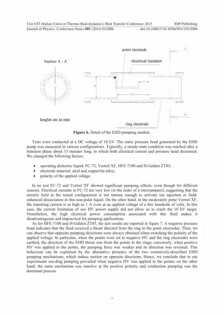
Figure 6. Detail of the EHD pumping module.
Tests were conducted at a DC voltage of 10 kV. The static pressure head generated by the EHD
pump was measured in various configurations. Typically, a steady-state condition was reached after a
transient phase about 15 minutes long, in which both electrical current and pressure head decreased.
We changed the following factors:
• operating dielectric liquid: FC-72, Vertrel XF, HFE-7100 and H-Galden ZT85;
• electrode material: steel and copper/tin alloy;
• polarity of the applied voltage.
In no test FC-72 and Vertrel XF showed significant pumping effects, even though for different
reasons. Electrical currents in FC-72 are very low (in the order of a microampere), suggesting that the
electric field in the tested configuration is not intense enough to activate ion injection or field-
enhanced dissociation in this non-polar liquid. On the other hand, in the moderately polar Vertrel XF,
the transiting current is as high as 1 A even at an applied voltage of a few hundreds of volts. In this
case, the current limitation of our HV power supply did not allow us to reach the 10 kV target.
Nonetheless, the high electrical power consumption associated with this fluid makes it
disadvantageous and impractical for pumping applications.
As for HFE-7100 and H-Galden ZT85, the test results are reported in figure 7. A negative pressure
head indicates that the fluid received a thrust directed from the ring to the point electrodes. Then, we
can observe that opposite pumping directions were always obtained when switching the polarity of the
applied voltage. In particular, when the points were set to negative HV and the ring electrodes were
earthed, the direction of the EHD thrust was from the points to the rings; conversely, when positive
HV was applied to the points, the pumping force was weaker and its direction was reversed. This
behaviour can be explained by the alternative presence of the two extensively-described EHD
pumping mechanisms, which induce motion on opposite directions. Hence, we conclude that in our
experiments ion-drag pumping prevailed when negative HV was applied to the points; on the other
hand, the same mechanism was inactive at the positive polarity and conduction pumping was the
dominant process.
31st UIT (Italian Union of Thermo-fluid-dynamics) Heat Transfer Conference 2013 IOP Publishing
Journal of Physics: Conference Series 501 (2014) 012006 doi:10.1088/1742-6596/501/1/012006
7

Figure 7. Measured electrical current and generated pressure head (steady-state values) for various
configurations operated with H-Galden ZT85 and HFE-7100 (applied voltage: 10 kV).
Among the tested configurations, the one giving the highest static pressure head was: negative
polarity on the points, HFE-7100 as working fluid and copper-tin alloy as electrode material.
According to the above model, we assume that ion-drag pumping was occurring. Homocharges in the
proximity of a HV electrode, typical of ion injection, reduce the intensity of the electric field on that
region and, consequently, are expected to lower the transiting electrical current. When positive
polarity was imposed on the points, not only the generated pressure head was lower, but we also
measured higher electrical currents, coherently with the presence of heterocharges and conduction
pumping. Thus, ion-drag pumping is a more efficient process than conduction pumping, generating a
higher pressure head with a lower energy input; the main drawback is its less predictable behaviour
and the possible deterioration of the working fluid (owing to the irreversible electrochemical reactions
that may occur at the metal/liquid interface) that can only be ruled out by means of long-term tests.
The same order of magnitude of generated pressure head was obtained by Jeong and Seyed-
Yagoobi [36] on R-123 with a similar experimental setup and an EHD pump design optimised for
conduction pumping.
3.2. Experiments on an EHD-controlled NCL
Based on the results of the above-described tests, we built a natural circulation loop operating with
HFE-7100. The physical properties of the liquid are reported in table 1.
The loop is a square of side 30 cm; the inner diameter of the pipe is 14 mm. A thermal power of 60
W was applied to the lower horizontal side and removed from the upper one; the vertical legs were
adiabatic. We selected the size of the loop and the applied heat input according to the instrumentation
already available in our laboratory and to the problems of heat removal associated with the use of
dielectric fluids such as HFE-7100 (low thermal conductivity, low specific heat, low boiling point).
Temperature was measured at each of the four vertexes by Negative Temperature Coefficient
(NTC) sensors (±0.2 K accuracy), previously calibrated in a thermostatic bath by a reference
resistance thermometer. We also measured the volumetric flow rate of the circulating liquid by means
of a transit time ultrasonic flow meter (±0.5% accuracy). A schematic of the experimental NCL is
shown in figure 8.
Two pumping sections are present, each made by three consecutive electrical modules, as
illustrated in figure 9. Every module is formed by a pair of electrodes obtained by a metallic grid; the
high voltage electrode is properly cut and bent, in order to create four points, directed perpendicularly
31st UIT (Italian Union of Thermo-fluid-dynamics) Heat Transfer Conference 2013 IOP Publishing
Journal of Physics: Conference Series 501 (2014) 012006 doi:10.1088/1742-6596/501/1/012006
8

towards the opposite grid. The two pumping sections are oppositely mounted and can be alternately
activated, to promote clockwise or anticlockwise motion. When the points are set at a negative HV and
the grid is earthed, the expected pumping direction goes from the points to the grid (due to ion-drag
pumping). The flow direction is determined by measuring the temperature difference between NTCs 1
and 2. The adiabaticity of the vertical legs of the loop is verified by sensors 3 and 4.
Table 1. Physical properties of HFE-7100 at 25°C and 1 bar (courtesy of 3M).
Chemical name methoxy-nonafluorobutane
Chemical formula C4F9OCH3
Dielectric strength 11 MV/m
Electrical conductivity 3.04·10-8 S/m
Relative dielectric permittivity 7.39
Density 1.48 kg/dm3
Specific heat 1.18 kJ/(kg·K)
Thermal conductivity 0.069 W/(m·K)
Thermal expansion coefficient 1.53·10-3 1/K
Kinetic viscosity 0.369 cSt
Sonic velocity 580 m/s
Boiling point 61°C
Freezing point -135°C
Figure 8. Schematic of the experimental EHD-controlled NCL.
31st UIT (Italian Union of Thermo-fluid-dynamics) Heat Transfer Conference 2013 IOP Publishing
Journal of Physics: Conference Series 501 (2014) 012006 doi:10.1088/1742-6596/501/1/012006
9

Figure 9. Detail of the EHD pump mounted on the NCL.
In the first series of tests, alternately, one of the pumping sections was activated prior to the heat
input, applying negative polarity to the points. The circulation repeatedly followed the ion-drag
pumping direction: 5 clockwise (activation of EHD pump B) and 5 anticlockwise tests (activation of
EHD pump A).
In subsequent tests, the electric field was applied when natural circulation was already ongoing. In
any case, the direction of motion was reversed by means of the ion-drag pumping mechanism. A
typical ∆T-versus-time graph is showed in figure 10, ∆T being the temperature difference either
between NTCs 1 and 4 for anticlockwise motion (negative values), or between NTCs 3 and 2 for
clockwise flow. At the activation of EHD pump B (minute 6), the flow is reversed from anticlockwise
to clockwise motion. Next (minute 10), the flow is forced to return to anticlockwise motion, switching
off the electric field and, at the same time, giving a proper anticlockwise inclination (about 15 degrees)
to the whole loop. At minute 16, pump B is reactivated, producing again the inversion of the flow. The
measured flow rate goes from 15 cm/s in pure natural circulation to about 7 cm/s when pump B is
active, owing to additional EHD-induced pressure drop.
In a final series of tests, we analysed the effect of switching the polarity of the 10 kV applied
voltage on a single pumping section. According to the tests of pressure head generation, it means that
we alternately activated the two EHD pumping mechanisms. In any case, the flow in the loop was
reversed, following the local upward or downward EHD thrust. Therefore, it was experimentally
verified that the direction of motion can be conveniently controlled by means of a single pumping
section, simply inverting the polarity of the applied electric tension.
31st UIT (Italian Union of Thermo-fluid-dynamics) Heat Transfer Conference 2013 IOP Publishing
Journal of Physics: Conference Series 501 (2014) 012006 doi:10.1088/1742-6596/501/1/012006
10

Figure 10. Typical ∆T-versus-time graph with and without ion-drag pumping.
4. Concluding remarks
The manuscript reports on experiments carried out on a natural circulation loop, controlled by
electrohydrodynamic pumping devices. Optimization of EHD pumps and control of NCLs is a multi-
disciplinary physical problem involving electrochemistry, fluid dynamics and heat transfer. The
following major goals are achieved: first, the optimal configuration of an EHD pump is found by
changing the working fluid, the high voltage electrode material and by reversing the applied DC
voltage, allowing to identify ion-drag pumping as a more efficient process compared to conductive
pumping; then, experiments are conducted on an EHD-controlled NCL, demonstrating that the NCL
flow direction can be inverted and managed by exploiting the physical phenomena of ion-drag and
conduction pumping.
Future progress of the research work includes a focus on stabilization of NCLs. We will attempt to
develop a stability model of the NCL with and without the action of the electric field. The stability
issues inherent in the considered thermal and geometrical configuration will be identified and
characterized as, for instance, in Vijayan [37] or Mousavian et al. [38]. The stability analysis with
EHD is expected to show suppression of instabilities typical of NCLs, as hinted by the present
experimental investigation, in which instability phenomena seemed to be ruled out by the
superimposed EHD-driven forced convection, establishing in any case the direction of flow in the
loop.
Acknowledgements
The experimental work outlined in the present paper was carried out in the frame of the National
Research Project PRIN 2008 entitled “Complex flow structures in thermogravitational systems, their
prediction, promotion and heat transfer optimisation”, research package “Application of
electrohydrodynamic techniques to heat transfer enhancement and optimization in single-phase
thermogravitational systems”, co-funded by the University of Pisa and the Italian Ministry of
Education, Universities and Research, which are gratefully acknowledged.
31st UIT (Italian Union of Thermo-fluid-dynamics) Heat Transfer Conference 2013 IOP Publishing
Journal of Physics: Conference Series 501 (2014) 012006 doi:10.1088/1742-6596/501/1/012006
11

References
[1] Keller J B 1966 J. Fluid Mech. 26 599
[2] Welander P 1967 J. Fluid Mech. 29 17
[3] Chen K 1985 ASME J. Heat Transfer 107 826
[4] Vijayan P K, Nayak A. K., Pilkhwal D S, Saha D and Venkat Raj V 1992 Proc. 5th Int. Topical
Meeting on Reactor Thermalhydraulics (Salt Lake City, UT) vol 1 p 261
[5] Creveling H F, De Paz J F, Baladi J Y and Schoenhals R J 1975 J. Fluid Mech. 67 65
[6] Vijayan P K, Sharma M and Saha D 2007 Exp. Thermal Fluid Science 31 925
[7] Marcelli A, Galassi M C, Misale M, Devia F, Garibaldi P and D’Auria F 2009 Proc. 64th ATI
National Conf. (L’Aquila, Italy) paper 08.06
[8] Fichera A and Pagano A 2003 Int. J. Heat Mass Transfer 46 2425
[9] Stuetzer O M 1960 J. Appl. Phys. 31 136
[10] Bryan J E and Seyed-Yagoobi J 1991 IEEE Trans. Electr. Insul. 26 647
[11] Atten P and Seyed-Yagoobi J 2003 IEEE Trans. Dielectr. Electr. Insul. 10 27
[12] Pearson M R and Seyed-Yagoobi J 2009 IEEE Trans. Dielectr. Electr. Insul. 16 424
[13] Shelestynsky S J, Ching C Y and Chang J-S 2003 Annual Report Conf. on Electrical Insulation
and Dielectric Phenomena (Albuquerque, NM) paper 7C-9
[14] Lin C-W and Jang J-Y 2005 Sens. Actuators A 122 167
[15] Richter A, Plettner A, Hoffmann K A and Sandmaier H 1991 Sens. Actuators A 29 159
[16] Babin B R, Peterson G P and Seyed-Yagoobi J 1993 AIAA J. Thermophys. Heat Transfer 7 340
[17] Zhakin A I 1998 Classic Theories of Ion Recombination and Dissociation in Liquids
Electrohydrodynamics ed A Castellanos (New York: Springer-Verlag Wien) pp 84-102
[18] Langevin P 1903 Ann. Chim. Phys. 28 433 (in French)
[19] Felici N J 1971 Direct Current 2 90
[20] Jeong S I, Seyed-Yagoobi J and Atten P 2003 IEEE Trans. Ind. Appl. 39 355
[21] Grassi W, Testi D and Della Vista D 2007 J. Enhanced Heat Transfer 14 161
[22] Felici N J 1985 IEEE Trans. Electr. Insul. 20 233
[23] Jayaram S 1993 Proc. IEEE Conf. on Electrical Insulation and Dielectric Phenomena (Pocono
Manor, PA) p 86
[24] Atten P, Malraison B and Zahn M 1997 IEEE Trans. Dielectr. Electr. Insul. 4 710
[25] Stishkov Yu K and Buyanov A V 2002 Proc. 14th Int. Conf. on Dielectric Liquids (Graz,
Austria) p 63
[26] Little R P and Whitney W T 1963 J. Appl. Phys. 34 2430
[27] Grassi W, Testi D and Saputelli M 2005 Int. J. Thermal Sciences 44 1072
[28] Grassi W, Testi D and Della Vista D 2006 J. Electrostatics 64 574
[29] Grassi W and Testi D 2006 Annals New York Academy Sciences 1077 527
[30] Testi D 2007 J. Thermophys. Heat Transfer 21 431
[31] Grassi W and Testi D 2009 Annals New York Academy Sciences 1161 452
[32] Testi D and Grassi W 2013 J. Heat Transfer 135 082202-1
[33] Pickard W F 1963 J. Appl. Phys. 34 246
[34] Pickard W F 1963 J. Appl. Phys. 34, 251
[35] Babin B R, Peterson G P and Seyed-Yagoobi J 1993 J. Thermophys. Heat Transfer 7 340
[36] Jeong S I and Seyed-Yagoobi J 2002 J. Electrostatics 56 123
[37] Vijayan P K 2002 Nuclear Eng. Design 215 139
[38] Mousavian S K, Misale M, D’Auria F and Salehi M A 2004 Annals Nuclear Energy 31 1177
31st UIT (Italian Union of Thermo-fluid-dynamics) Heat Transfer Conference 2013 IOP Publishing
Journal of Physics: Conference Series 501 (2014) 012006 doi:10.1088/1742-6596/501/1/012006
12


