Embed Size (px)
Citation preview

Copyright Warning & Restrictions
The copyright law of the United States (Title 17, United States Code) governs the making of photocopies or other
reproductions of copyrighted material.
Under certain conditions specified in the law, libraries and archives are authorized to furnish a photocopy or other
reproduction. One of these specified conditions is that the photocopy or reproduction is not to be “used for any
purpose other than private study, scholarship, or research.” If a, user makes a request for, or later uses, a photocopy or reproduction for purposes in excess of “fair use” that user
may be liable for copyright infringement,
This institution reserves the right to refuse to accept a copying order if, in its judgment, fulfillment of the order
would involve violation of copyright law.
Please Note: The author retains the copyright while the New Jersey Institute of Technology reserves the right to
distribute this thesis or dissertation
Printing note: If you do not wish to print this page, then select “Pages from: first page # to: last page #” on the print dialog screen

The Van Houten library has removed some of the personal information and all signatures from the approval page and biographical sketches of theses and dissertations in order to protect the identity of NJIT graduates and faculty.
THE DESIGN AND IMPLEMENTATION OF A TIMESHARED COMPUTER BASED CONSTRUCTION COST ESTIMATING SYSTEM FOR AN ELECTRIC UTILITY
BY
THOMAS ARNOLD WES TPHAL
A THESIS
PRESENTED IN PARTIAL FULFILLMENT OF
THE REQUIREMENTS FOR THE DEGREE
OF
MASTER OF SCIENCE IN MANAGEMENT ENGINEERING
AT
NEWARK COLLEGE OF ENGINEERING
This thesis is to be used only with due regard to the rights of the author. Bibliographical references may be noted, but passages must met ~e eepied without permission of the College and without credit being given in subsequent written or published work.
NEWARK, NEWJERSEY 1974

ABSTRACT
The Hork of the distribution department of' an electric utility involves a great deal of medium to heavy construction. This work is vital to serve the energy needs of' the public. An electric utility constantly builds, reinf'orces, and repairs electric distribution facilities. The material and labor used to accomplish this construction is expensive.. Money in sufficient am.ounts is seldom, if ever, available to finance all proposed construction projects. Therefore, the cost of proposed projects must be estimated in advance, so that management may decide on an economic basis which projects will be authorized.
The need for accurate construction cost estimates is imperative to the economic operation of an electric utility. This thesis delves into the problem of the design and implementation of' a computer based cost estimating system to insure the accuracy and timeliness of estimates.
In order to accomplish the design, a series of eight main program modules was written in the BASIC language for use on the General Electric Mark III foreground system. These programs access individually tailored sequential and random disk files using third generation real time computer techniques. The system was made available to eight field locations via remote terminal facilities. The immediacy and flexibility of the time sharing environment proved to be valuable selling pOints in the implementation of the new system.
At this writing, the new estimating system has met with the approval of the field project engineers, and is well on the way to replacing the manual system. Input simplification has enabled the company to use less technically skilled personnel for the estimating function, with resulting cost savings. Results thus far far have shown the system to be flexible, timely, and accurate.
APPROVAL OF THESIS
THE DESIGN AND IMPLEMENTATION OF A TIMESHARED COMPUTER BASED CONSTRUCTION COST ESTIMATING SYSTEM FOR AN ELECTRIC UTILITY
BY
THOMAS ARNOLD WESTPHAL
FOR
DEPARTMENT OF INDUSTRIAL ENGINEERING
NE\rlARK COLLEGE OF ENGINEERING
BY
FACULTY COMllITTEE
APPROVED: __ ~ ______ w_,~ __ ~ ______ ____
NEWARK, NEl..J JERSEY
MAY, JJ.974
PREF'ACE
The problem of obtaining consistent, accurate, and
timely cost estimates must be solved in order to insure
the smooth economic operation of any construction oriented
industry. Difficulty in meeting the above criteria marked
the operation of the manual estimating system employed by
the Electric Distribution Department of the Public Service
Electric and Gas Company of New Jersey. The author, a
computer applications engineer employed by that company,
was assigned to investigate the estimating procedure$
with the goal of implementing a computer based system to
replace the manual one.
A review of the literature showed that other utilities
had implemented computer based estimating techniques, and
had found them to be quite satisfactory. The author was
not completely satisfied with any single system found in
the literature. He set out instead, to develop a hybrid
design incorporating some of the ideas of the reviewed
systems. The author felt that cost estimating was a natural
application for a time shared computer system. The system
he developed was adapted from the best features of the man
ual system incorporating the author¥s ideas and those from
the literature.
The idea of reducing the complexity of input in order
to allow less technically sophisticated users to access and
execute the system appears to be a unique solution to the
the estimating probl:em.. The author feels that this in no
small way contributed to the success the system has ex
perienced during implementation ..
Sincere appreciation is extended to Prof. loR. Goldsteiq
thesis advisor" who offered guidance and advice whenever
called upon; to Mr. K. F. Mullaney who supplied considerable
expertise in explaining the methods of the manual system;
to Mrs .. M. 1l1urray who typed the final copy from a note
ridden draft; and finally to my 'tvif e Terri and S'on Tommy
Jr. who offered patience and understanding during the
lengthy preparation of this volumee
THOMAS A. WESTPHAL
TABLE OF CONTENTS
CHAPTER I - ELECTRIC UTILITY INDUSTRY
Introduction •....•....... II ....................... \11 • iii .. • ' ... 1
Electric Utility Origins • • • • • • • • • • • • • • • • • • G • • • • • • •
Public Service Electric Department ....................... .. How Electricity is Distributed ...................... . Geographic Division of Department . . . . . . .' . . . . . . . . . . The Role of Cost Estimating ................................. .
CHAPTER II - DISTRIBUTION CONSTRUCTION AND COST ESTIMATING SYSTEMS
Introduction • • • • • • • • • • • • • • .. • e • • • • • • • • • • • • • • • • • • • • •
Types of line Crews
Types of Line Crews Overhead .. " .............................. .. Underground •••••••••••.•••••
Distribution Construction ......................... .
Overhead Construction ................................. . Guying and Anchoring .............................. ..
Conductor Configurations - Overhead ................ .. Open Wire Armless .. l1li ••••••• lit III •• 81 ••••••••• Ii .... .
Spacer C a.ble .• ., III .... 6 e .... " • \\ •• ,. .............. e .. ..
Open v.lire .... o, ................... 00 ........ e ................. ..
Lashed Ca.ble It. e ........... flI .......................... '8 .. ., ., •
Aerial Cable . e ..... ., .......... til ....... e ................ .
Underground Construction ••••••••.••••••••••••••••• Conduit Construction ••••••••••••••••••••••••• Cable Installation ••••••••••••••••••••••••••• Cable Splicing ............................... .
The Est~ating Task ••......•....•.••••••..••••••••
Review of Three Estimating Systems •••••••••••••••• Louisiana Power and Light System ••••••••••••• Comments on the L.P. &L. System •••••••••••••• The Detroit Edison System •••••••••••••••••••• Comments on the De:lrr0i t Edison System .. " ...... 0
C • E. S • L.. Sys tam ..... 0 .. (I. • fill ... til • 0 ...... ., ••• G ,. • G •• e
Comments on the C.E.S.L. System ••••••••••••••
S1.ll11ll1a.ry • & ...... 0 ..... til ........ ff ... 1Ft •• ,. ......... e .......... .
2
4 5
11
13
15
15 17 18 19 21
22 22 25 25 28 28 31 31 33 36 38
39 39
ttt 49
.~51 53 57
TABLE OF CONTENTS (Cont1d)
CHAPTER III - MANUAL METHOD FOR COST ESTIl1ATING
Intoduction .......................................... 59 General Steps f0r Estimate Preparation ..... "........... 59 Evaluation of Circuit Routes ........................ 59 Determination of Required Material ................... " GO .. ,. .. 60 Gathering of Cost Information "..................... 61
Preparation of the Estimate Form •••••••••••••••••• 63
Preparation of the Estimate Summary................. 68 Preparation of a Stores Listing ••••••••••••••••••• 70 Paper Flow - Manual System •••••••••••••••••••••••• 71
Surtttnary .......... Go ................ it .. Ii " .. • .. .. • • • • • • .. .. .. • .. • .. .. ... 72
CHAPTER IV - DESIGNING AN ESTIl~TING SYSTEM
Introduction • • • • • • • • • e • • • • • • • • • • .. • • • • • • • • .. • • • • • • • ..
General Design Criteria ••••••••••••••••••••••••••• Design of the Required Input ••••••••••••••••••••••
Desired Output •••••.•••••••••••••••••••••••••••••• Selecting the Computer System ••••••••••••••••••••• Selection of a Computer Language ••••••••••••••••••
File Layout and Structure ••••••••••••••••••••••••• Basic Layout of the Programs ••••••••••••••••••••••
Program Names and Functions ••••••••••••••••••••••• Analysis o·f Additional Load on Terminals ........... ..
CHAPTER V - DETAILED DESCRIPTION OF THE OPERATION OF THE OVERHEAD MODULE
74 74 75 78 84 87 88 90 91 95
IntDoduction . G ......... 0 ..... iii ...... e 6 ... e ........... ,. •• ., • 106
Functions of the Overhead Module •••••••••••••••••• 107
Creation of the File Input •••••••••••••••••••••••• 108
Reading the Cost Estimating Data Files •••••••••••• 118
Estimate for Guys, Anchors, and Switches •••••••••• 131
Estimate for Overhead Cables •••••••••••••••••••••• 133
TABLE OF CONTENTS (Conttd)
CHAPTER -V- (CONTtD)
Estimate for Overhead Cables e •••••••• •••••••••••• 133 Matching the Cable Code ............................ 133 Naming the Construction Type ••••••••••••••••• 134 Computing the Installation Factor .............. 13.5 Calculating the Labor and Material Costs •••• 135
Calculation of Pole Top Material and Labor Costs.. 138 Setting to the Proper Record •••••••••••••••• 139 Initiating the Proper Pole Top Sequence ••••• 139 Cost Calculation Equations ................... 140 Summary of the Pole Top Section ••••••••••••• 141
Appending of the Work Files DJllISC and MATFILE ........ 142 Chaining out of the Overhead Module •••••••••••••• 143 Printing of the Estimate Reports ••••••••••••••••• 143 Summ.ary ., Cit .... e 0 ..... ., ................ .at 0 • e .............. II 148
CHAPTER VI - IMPLEMENTATION OF THE COMPUTERIZED CONSTRUCTION COST ESTIMATING SYSTEM
Introduction ........ " ...... eO ... e ......... 01 .......... e ..
Steps Used to Implement the New System •••••••••••
Introducing the New Sys tem .......................... .. Preparation of User Documentation •••..•••••••••••
Discussing the System in Each Field Location •••••
Use of Classes • • • • • • • • • • • • • • • • • • e • • • • • • • • ~ • • • • • • •
Organizing for Computerized Cost Estimating ••••••
Clearing System with Union ••••••••••••.•••••••••• Running Test Cases in Each Division •••••••••••••• Parallel Run of the New and Old System •••••••••••
Replacing the Old System ••••••••••••••••••••••••• Feedback From the Field Divisions ••••••••••••••••
Adjus ting the Sys tem •••••.• Go •••••••••••••••••••••
Audi ting the Sys tem ................................ .
Stmnnary eo .......................................... .
154 154 156 156 156 157 157 158 158 159 159 160 160 161 161
TABLE OF CONTENTS (Cont'd)
CHAPTER VII - ECONOMIC JUSTIFICATION OF THE COMPUTERIZED ESTIMATING SYSTm~
Introduction ., ............ ........ " .. til .... ., ,. ,. .............. ' .. • .. 162
Irl$ntirication of Cost Items ••••••••••••••••••••• 162 Manual System Cost Factors ......................... 163
Computer System Cost Factors •••••••••••••••• 164 Break Even Analysis ........ "................................ 166 Total Cost Savings ................................ 167 Conclusion • • • • .. • • • 6 ,. • .. e 8 • • til • • • • • • • e • • • .. • eo. • • " • e 0 167
CHAPTER VIII - CONCLUSIONS AND RECo.MMENDATIONS
Conclusions III ........ e ... G .. ... ., • 01 (; .... 1& 8< Ii .. " .. ., ......... ., • • • • 169 A Vital Need for a Cost Estimating System ••• 170 Cost Estimating an Excallent application e ....
for Digital computers ••••••••••••••••• 171 Use of Time Shared Computers •••••••••••••••• 171 The G.E. MK II System ........................ 172 BASIC is the Preferred Computer Language •••• 172 Existing Terminal Facilities Are Adequate.... 173 The Use of Disk Stored Files Is preferred ••• 173 Multi-structured File Organization Simplfies Input Carefully Organized Input is Essential •••••• 174 Economic Justification •••••••••••.•••••••••• 174
Recon:o:nendations ................................................. 175 Department Wide Implementation •••••••••••••• Company Wide Implementation ••••••••••••••••• Implementation in Other Utilities ••••••••••• Other Indus trie s ............ " ........................... .. Future System Development •••••••••••••••••••
C .. P.M. Scheduling .......................... " .. co .. .
Interface \<lith Material System .......... to ...
Cost Feedback ..... eo ........ e ....... 11 ... Ii II " ., •
175 175 176 176 177 178 178 179
A Final 't~ord .. e • 6 •• it ... Ii .. 0 •• e •• it G- ...... ,. ..... :0 e., •••• CD • • 179
GIiAPTER IX - CRITICAL EVALUATIONS Letter of Evaluation ••••••••••••••••••••••••••••• 182 Letter of Evaluation ••••••••••••••••••••••••••••• 183
APPENDICES A - Introduction to the BASIC Language ••••••••••• 186 B - Program listings " ......................... e .... ".... • .. .. .. • • • .. • 201
LIST OF FIGURES
1.1 Public Service Bulk Power System
1.2 Basic Transmission and Distribution System
2.1 Common Wood Poles
2.2 Open Wire Armless Construction
2 .. 3 Spacer Cable Construction
2.4 Open Wire Construction
2.5 Lashed Cable Construction
2.6 Aerial Cable Construction
2.7 Typical U.G. Duct and Conduit Arrangements 2.8 Partial Listing of U.g. Cables
2.9 U.g. Cable Pulling Gear
2.10 L.P.&L. System Data Sheet
2.11 L.P.& L. System Output
2&12 Detroit Edisonts Material Packages
2.13 C.E.S.L. System Summary Sheet
2.14 C.E.S.L. System History Report
2.15 C.S.E.L. System Detailed Report
3.1 P.S.E & G. Material Accounting Guide
3.2 Sample Manual Estimate
3.3 Sample Manual Estimate - Page 2
3.4 Manual Estimate Cost Sheet
3.5 Manual Estimate Summary
4.1 Proposed EstLmate System Input Data Sheet
4.2 Input Data Sheet Cont1d
4 .. 3 Compute Vs. ItO Comparison
4.4 Graph of Cost Comparison of Vendor Services
4.5 Complete Estimate System Flowchart
4.6 Table of Queueing Values
4.7 Queu~ng Values for Exixting Terminals 4 .. 8 Graph of Mean Persons in QUeueing/No. Term.
6 8
20
23 26
27 29 30
34 35 37 41 45 50 54 55 56 62
64 65 66
69
79 80 85 86
95 96
98 100
LIST OF FIGURES (CONTtD)
4 .. 10
Graph of Mean Time in Queue/Mean Service Time Graph of Probe All Terminals are Busy
4 .. 11 Table of Vendor Stastics
5 .. 1 A Listing of User Input for Test Case
User Data Re-Sorted into D365 File
Listing of O.H. Program Module 5 .. 2
5.3 5,,4 1\
II 11 tI II
5.5 II II II II II t!
5.6 II II II It II n
5 e 7 II II II II II If
5 .. 8 II II II II II It
5 .. 9 "f'able'of Common Estimating Values
5.10 Table of Overhead Cable Costs
5.11 Table of Guy, anchor, and switch File 5.12 Pole top construction File 5.13 " II II II It II
5 .. 14 It II It 11 11 II
5 .. 15 II 11 If II II It
5 .. 16 \I II II 11 11 II
5.17 Contents of Matfile for sample run
5,,18 The Estimate Report Using Sample Data 5.19 The Estimate Summary Using Sample Data
5.20 The Estimate Material Material list 5.21 Flowchart of Overhead Module
102
103
104-109 III
112
113 114-115 116 117 119 120
121 122
123
124-125 126
144-145 146 147 149

The purpose of this thesis is the design and imple
mentation of a real-time computer based cOBstruction cost
estimating system for the Electric Distribution Depart
ment of the Public Service Electric and Gas Company of
New Jersey. itlhile the system will be specifically de
signed for electric utility construction cost estimating,
the fechniques employed are applicable to other industries.
Chapter I will describe the work of an electric utility.
The founding and development of the Public Service Company
is covered. The Scope of the work of the Electric Distrib
ution Department will be introduced with emphasis on the
role of cost estimating within that department.
Chapter II will acquaint the reader with the funda
mentals of electric distribution construction. The various
types of work crews will be introduced, and the methods of
installing overhead and underground cable will be discussed.
This material will be included to give the reader a better
understanding of the remainder of the chapter; a discussion
of three existing computer based cost estimating systems.
The first two systems to be discussed are the Louisiana
Power and Light system, and the Detroit Edison system.. Both

systems are batch oriented and represent solutions found
for resolving the estimating problem by other utilities.
The former sets forth concepts of data organization, while
the latter introduces the concept of unitized kits of mat
erials. Both will prove useful in aiding the author in the
design of his system. The third system to be reviewed is
one written by the University of Illwnois Civil Engineering
Laboratory for building and highway construction cost esti
mating. This system employs real time computer techniques
beneficial for rapid estimating turn-around and local file
maint€llhnance.
Chapter III will acquaint the reader with the manual
method of construction cost estimating currently used by
Public Service. The preparation of the necessary data will
be discussed first. The chapter will stress the complexity
of estimating construction costs accurately, and the necess
ity of using highly qualified personnel to do estimates.
The three estimate reports; the estimate general, the esti
mate summary, and the material list will be presented and
illustrated in this chapter. Finally, the author will set
forth his contention that a properly designed computer based
estimating system could take much of the complexity out of
the function. Such a system would make it possible to use

lesser skilled personnel for cost estimating. Accuracy
could be improved, costs lowered, and turn-around time
shortened ..
Chapter IV will set up the basic criteria for de
signing a real-time computer based cost estimating system ..
The design of the required input will be introduced and
proposed data sheets will be illustrated. The output from
the computer will serve as a direct replacement for the man
ually produced reports i-Jhich will be illustrated in Chapter
III. A cost effectiveness study will be conducted among
various vendor time-sharing services in order to select
the most economic system.
Having selected a computer service, the problem of
selecting an appropriate computer language will be tackled
next.. The FORTRAN IV and BASIC language will be compared
for use in writing the system. Af'ter selecting a computer
language, the layout and structure of the necessay data
files will be discussed.
The latter part of Chapter IV will set up the general
design criteria for th main program modules to be used in
the proposed system. The system will contain eight modules
divided functionally as to purpose. The first two will be
designed to check and sort user input input data. The sec
ond two will handle cost calculations for overhead construc-

ion. The fifth module will handle cost calculations for
underground construction. The last three modules will pro
duce the required estimate reports.
The final section of Chapter Iv will deal with the
problem of increased terminal usage required by the new
cost estimating system. The load will be analyzed using
queueing techniques. The results will show if more term
inals are required.
In order to give the reader an understanding of how
a cost estimating system could be written on a time-shared
computer, Chapter V will disect the operation of the main
overhead module. This chapter will cover the operation of
the module from the reading of the user input, through the
cost calculation, ending with the output to a work file.
Special emphasis will be placed on the use of a mnlti
structured random binary file for simplifying input.
Chapter VI will discuss the implementation of the new
computerized construction cost estimating system in the
eight field divisions of the Electic Distribution Department ..
Subsequent to the introductory phase, test cases will be
run in each division to compare manual and computer esti
mate results. After the test runs are satisfactorily ac
complished, a parallel run of the new and old system will
be done ..

Chapter VII will show whether the use of a computer
based cost estimating system is economically justified.
An analysis will be done which will determine the total
fixed and variable costs associated with a manual and a
computer estimate. Based on the estimated annual number
of estimates prepared, a net benefit or loss will be shown"
The techniques used in the estimating system for file
access and data handling will be shown to be applicable to
other industries. The techniques used illustrate how a
relatively small amount of available computer core space
can be used to handle large programs and data files. The
author hopes that the reader will gain some insight into
the design and implementation of a computer based cost
estimate system from the reading of this thesis.

Introduction
CHAPTER I
ELECTRIC UTILITY INDUSTRY
The need for accurate cost estimates is imperative in
the Electric Distribution Department of Public Service.
It will be the purpose of this paper to describe how a
computer-based estimating system may be researched, de
signed and implemented by the author for this department.
In order to understand the role of cost estimating
in the Electric Distribution Department of a large
electric utility, it is necessary to have a basic under
standing of the industry itself. The author will attempt
to discuss the origins of the industry and of the specific
utility that will serve as a framework for this paper;
Public Service Electric and Gas Company of New Jersey. He
will describe how electricity is distributed by this
company. He will then focus on the organization of the
Electric Distribution Department within the wider organi
zation of the Electric Department. Having accomplished
this the author will further focus on the project cost
estimating cycle within the Electric Distribution
Department.
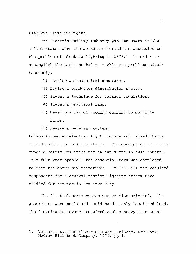
Electric utility Origins
The Electric utility Industry got its start in the
united States when Thomas Edison turned his attention to
the problem of electric lighting in 1877.1
In order to
2.
accomplish the task, he had to tackle six problems simul-
taneously.
(1) Develop an economical generator.
(2) Devise a conductor distribution system.
(3) Invent a technique for voltage regulation.
(4) Invent a practical lamp.
(5) Develop a way of feeding current to multiple
bulbs.
(6) Devise a metering system.
Edison formed an electric light company and raised the re-
quired capital by selling shares. The concept of privately
owned electric utilities was an early one in this country.
In a four year span all the essential work was completed
to meet the above six objectives. In 1881 all the required
components for a central station lighting system were
readied for service in New York City.
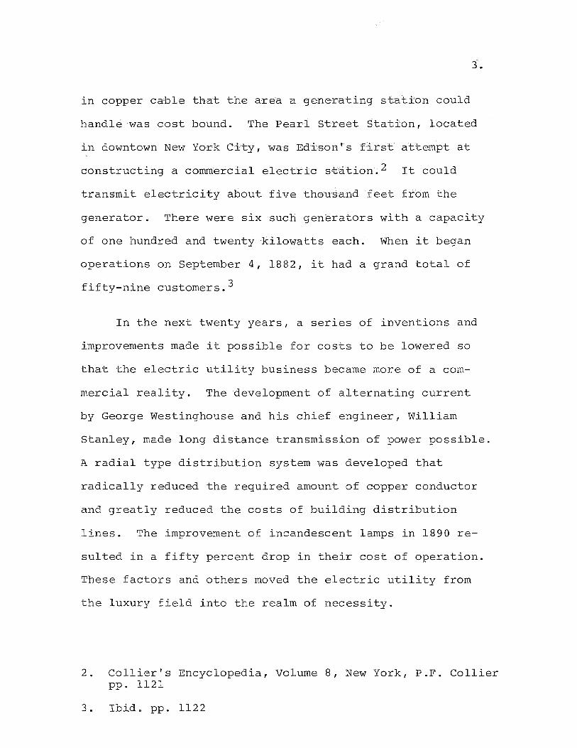
The first electric system was station oriented. The
generators were small and could handle only localized load.
The distribution system required such a heavy investment
1. Vennard, E., The Electric Power Business, New York, McGraw Hill Book Company, 1970, pp.4.
3.
in copper cable that the area a generating station could
handle was cost bound. The Pearl street station, located
in downtown New York City, was Edison's first attempt at
constructing a corrunercial electric station. 2 It could
transmit electricity about five thousand feet from the
generator. There were six such generators with a capacity
of one hundred and twenty kilowatts each. When it began
operations on September 4, 1882, it had a grand total of
fifty-nine customers. 3
In the next twenty years, a series of inventions and
improvements made it possible for costs to be lowered so
that the electric utility business became more of a com-
mercial reality. The development of alternating current
by George Westinghouse and his chief engineer, William
Stanley, made long distance transmission of power possible.
A radial type distribution system was developed that
radically reduced the required amount of copper conductor
and greatly reduced the costs of building distribution
lines. The improvement of incandescent lamps in 1890 re-
suited in a fifty percent drop in their cost of operation.
These factors and others moved the electric utility from
the luxury field into the realm of necessity.
2. Collier's Encyclopedia, Volume 8, New York, P.F. Collier pp. 1121
3. Ibid. pp. 1122
4 .
After 1900 one of the most notable trends in the
industry was the consolidation of small, individually owned
stations into larger systems. This trend was noted by
Thomas Nesbitt McCarter, then Attorney-General of the
State of New Jersey. New Jersey, like many other states,
was a patch-work of tiny electric utilities. It was
McCarter's vision to combine these utilities under one
company. 4 The idea was to lease these companies for 999
years at rentals sufficient to cover their fixed charges
and, if possible, dividend requirements. 5 The new company
was incorporated on May 6, 1903 under the name, Public
Service Corporation of New Jersey
Public Service Electric Department
The Electric Department of Public Service provides
electric·service to an area of the state of New Jersey known
as the lIindustrial corridor". This corridor is a forty
mile wide strip of land between New York and Philadelphia.
It contains nearly 80% of the state's population and in-
dustry. For the past twenty years electrical load has
doubled in magnitude every ten years. The Company has
grown in size from its modest start under McCarter to serve
approximately 1,655,989 metered customers using 27 / 311,104,206
kilowatt hours of electrical energy.
4. Editors, liTo Develop the State of New Jersey", Fortune Magazine, Nov. 1937, pp.lOO.
5. Ibid. pp.lOl.
5.
This vast load is serviced by the company1s Electric
Department. It is the job of the Electric Department to
plan, and supervise the construction of all major plant
additions, such as generating stations, switching stations,
and sUbstations. It also plans, designs, and builds the
system for transmitting the electricity from the generating
stations to the user. The latter facet of the operation of
the department falls under the jurisdiction of the Electric
Distribution Department, a subdivision of the Electric
Department. Before proceeding, it would be of benefit to
the reader to become acquainted with the techniques of dis
tributing electric energy.
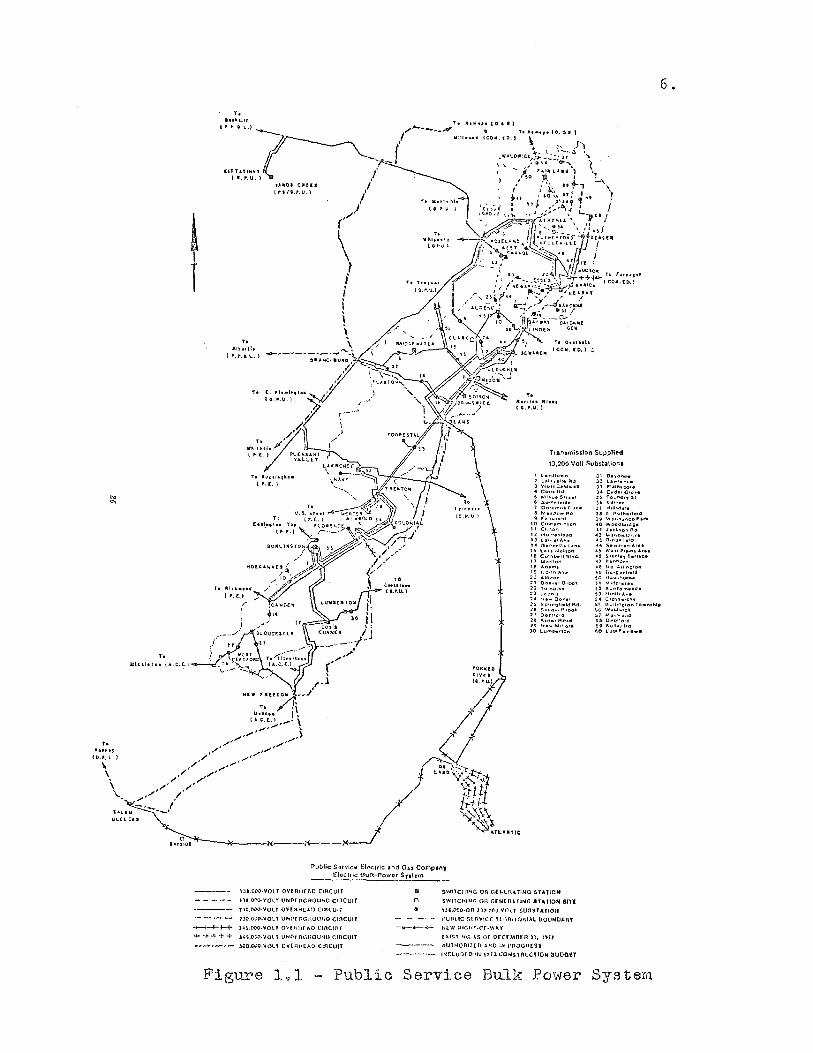
How Electricity is Di~tributed
The illustration marked Figure 1.1 shows how electricity
is transmitted from a generating station through various
stages and equipment to customers.
The majority of power leaving the generating system is
conducted over more than 893 miles of 138,000 volt and
230,000 volt transmission lines to 32 switching stations
located in major load areas of the territory. Unlike the
days of Edison, today's generating stations are located
many miles from the ultimate user. The transmission system
is suppored on the familiar steel tower for the most part,
however, some 90 miles are underground in high pressure oil
.. 11:11".,
(tlo.".l.l
\, \
\ \..
T.
l.!l,U.lu (".C.~)
T.
T.
Alhllh I ,..,., a L. }
t. 'h .. h,I .. 1I
(cu".\I.}
ToD ai,le:lt.~"fI,.
".1..]
V. 5, ~t"d T,
Elldl •• ,hft TI:,
(',(.1
T. 1II1' •• olUi
I p. f.~ /' /-
TO e ... hl .... (0..',0.'
6 •
T, a"HI,,1t I COir!o (D.» ;,
Ttansmission Supplied
13,200 Volt Sub$tatlon..
1 Law,Hc ..... :2' tal .. ,11111';' Rd! 1 WoUCl:tld .. .,1l ~ Coo- ltd :50 f,.'I,,,,,,,, 51r .... 1 (, S<.>""",rw,ll& T OO'<:'f"'U~ rlu:.
11 1>\' .. ...,0 ... FlcS ~ r ""~O .. >d
10 C." .... ~n" .... tO" II CI,lton Il '~o"",,"I .... d 13 La<.l'e' A~. ,.0 .. ,.. .. t<l!ll ...... 1~ t.,& Nbiion 16 CuI1<llN>t. (H.d. 11 '~"'ll0n tl! A(Uml
19 r.oO\'" A." 20 AM..,n..-21 O" .. ~ .. , O'l'ct. 22 tV'''t>,~. :23 L-l'c"'1 1'( tIb .. Oow ... .l!. So·,r<;lhald Ad ;>1\ 55<1" ... £]'0-011 '11 D.,£jlfo'd ;>1& IO.uu,.Il;;'HI 2<,1 1'11" ....... 0-0,"(1 30 lUlnt..rlo ..
JI. thro"ne Jl t ... l.l">C.
J) Plal"ul-I;uo J" C.d"C'e~. 3!. (ound.-,. 51 J(' Il<l ..... "", Jt toI.lhd,l. 3& " AVII'I.rlo.d J'i WI""'~n(;o,P." .0 wo .. ab"dg. ,t J IC~ 10," Rd -4:1' "" •• ,{> .. O.\ •• 43 R.o .... I,!!ltI ~" !.e- ....... l<rb. ,> ..... 11"1 ..... 1 ......
..& :!>lIn'oy I.H.'_ '7 Pfl-nl'>o"" 4e I'a A.I,,,,Olo,n "9 0"'0 • .,1,.14 50 II a"" '''0'''''' ~ 1 V .;jdl.~ .. ...
~.2 S, .. "", ...... d. ~ J N,Nt> A~. 5--'1 C'Qu .... >e_' !.~ (I "tl."O'Cl-" Te .. ",."'I" ~G , ... ld.,cll !.o1 M.,p.oo(I !'.!< O"I>"e,d ~'9 ';' .... 11., Ad to t:.11 F •• /i •• ",
Public SorvtcIJ EI~trl-c .and Ou Comp-ll't, 'flo-chloe Oul'k,POW(lf SJ',h-m
lll.ON)·yot T OV[nllf AO ClIlcutr
IlI.ON-·VOt I UNN RcnOU)-;Q CU1CUIf'
no.th"oO·VOlY O""'"H( ... n CIRCUli
JJD<.OOO-VOl T VP1l'[ tlGROtHW CIRCUit
-r--I-+-H- )"~.O(lO·VOl' ovr 11Hf AD CIRCUl'r
..... + 4- + -:- JH.OOO-\lOl T UNOf n{~twU~n CIIlCUIT
~OO.c-.1O·I/Ol.l Ot'lftl1(AO CIRCUIT
m o
SwllCltlNG OF! GEN(ru,'ttNO SUllON
swnCHINt~ on (aN( RUiNG STATtOH Slll
U'.OOO·OR nao()O:\!OlT SUDSTAYI(rH
I'unuc !1fr;IIIC( HfH1HOniAl tJQuutJAAr
-ii-r--..;;- NEW mCIlT·(\F.W"'"
p.IS'fI~r: 45, or orrn.mrR H. \'UI
AU1HOlUUD .UfO lHi l'ftOOil!Sl
I~ClUD[D IN nlJ.CONsntUCTlQW luoan
Figure 1.1 Public Service Bulk Power System
pipe type cable. The design, construction and maintenance
of the transmission system is part of the work of the
Electric Distribution Department
When it reaches the switching stations, the power is
stepped down by means of large transformers to 26,400 volts
for transmission in smaller blocks to local areas. While
stepping down the voltage to lower or subtransmission volt
age is sometimes considered the primary function of
switching stations, the control or switching of the large
quantities of power which pass through these stations is
also an important function. Therefore, the typical
switching station is equipped with a number of high capacity
circuit breakers for connecting and disconnecting the in
coming and outgoing circuits. The switching stations are
maintained and in part operated by the Electric Distribution
Department.
The transmission system is linked with other companies
in the Pennsylvania-New Jersey-Maryland (PJM) interconnection
through 500,000, 230,000, and 138,000 volt lines connecting
Public Service with other electric utilities in their re
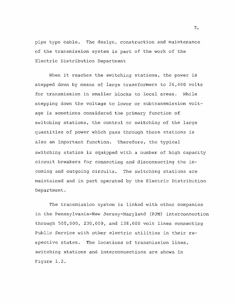
spective states. The locations of transmission lines,
switching stations and interconnections are shown in
Figure 1.2.
LARGE INDUSTRY StJOSTAilON
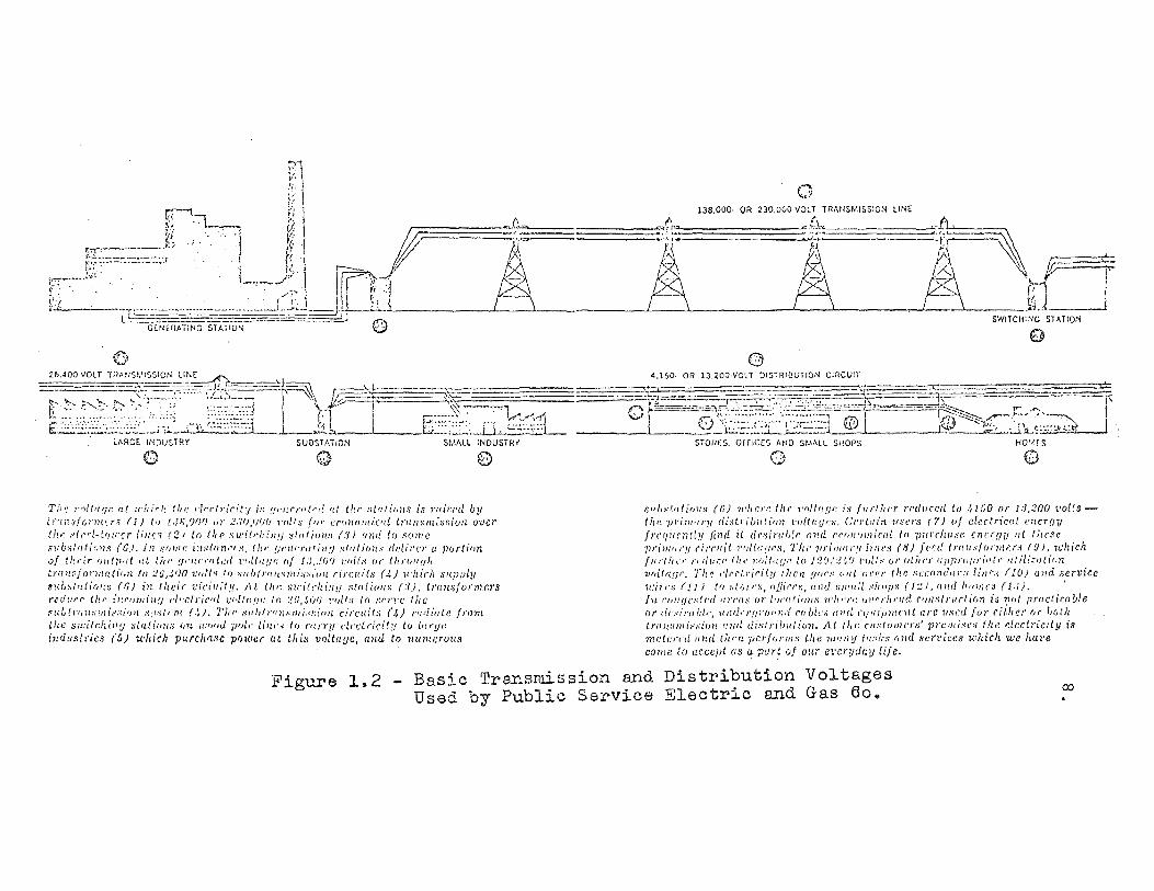
Th,: l"011'lar at :I'''irh the r-!"f'll';,ily is [ll'nr,./I/"Il rd thr' ,~tr:lirll!S is ?'Ilisl'd by it'!n!l/r .. l'Hu.r.:l (J) (f) !,JR/)f)f) ur 2.N)/P)() l'fI[/::; (flJ' cnl1/(utl/cfll tl'fln:·\JHi.')~i(Ja over (hi- slrl'/·[rlll'cr lili~s (21 If) 111(' su;ill'ir:'I1!1 ~ll/li/J1I8 (81 (1Iltllr, 81J1IIC SlibsllJlillH,~ (ei, 111 ,,'rill/1' hls/lln,-I's, 11/1' fjl'/II'r,dill!! s/lIlillil-' rldil'C/' (l ]lortion of thrir (lillji/(l ttt UII' !!f'ru'J'ttl,:d 1",[(I[!/f: oj l:/,.!O{J 1'lIitS lIr UlI'Olff,h
trrlH,r:fonllflU'Vlt to :.!a,.;I)O 'L'ults It) Nuh(nntS1Hls",'uH (i(cuds (.{) H'/Il'rh snpply s!(bs/'Itiol;~ (6) in lileir vicillily, At ti'l' Slrilt'hill!! :ill/liollS (:1), t1'll1l.>fOI'I1l!':)'S
r('dllrl' thr i/!rIJlIliWJ f'i"r:lrir'll v/,IIII!II' In :'!U,,~(lr) !'IIIt.'l 10 :;(,/'l'(' tite .~H/;!rfnL""fHi~:il·l)1l .'1:ISt,'nt (.~). T1J{' SItl,/rn lP'nu' . .:..':io1L circuits (4) r((l[inle !fOnt lhe su:ilr.h.iJlV ~l(di"n:; {JU U:fJ(JU /)1)[,' liHf'd to C"UTlI dn;lrh·ily lu [urge indus/ties (5) u:hicil purclllzsc p(J1ocr at t"i~ VOlill!}C, lInd to numcrulill
o
STOrieS, OffiCES MID SMALL SHOPS HOt/,(S
o o
8111,,,I .. lIio)1,, (e) l"',CI'C Ihe ,'oil!!!!" i~ /11(/11('1' (('!II/rei! 10 ,\11;0 or 1;1,'200 t'ollstI(I~ 7)l'il/uu'y dis/rib,,:,it'/t t'U/((1UI:,', Cn'Uu'n 1IS/,I'S (7) (1/ electric"l /'))CTUY
/l'c'lllC'nily find it d(',~i/'llI)Ir, 1I1l1l rrlllllllllirlr/ III 111ll'cIiIlSI\ ClI(,l'!J!J lit Ihr.~e 111'imlll'1I circuit 1'111I11!1(''', The IJfill/iI/'l/lillc,i (8) /('('Ii t/'(III.'/OJ'l/IU,i ([0, lJ.'hich /Ul'tllO' l'n/ltr.r Uli' l~(J!tft!Jf~ to l;?O!;!'~() l'OUs VI' uthr'r lIjJPI'U!II'i,/t(, ut ii!:':11 {if,)1
1",/1 ((II r, TIt~ ,'II'fll'icity Ihell ,'lues (,II( Ol."'/' tht; s(.'Clln(,'l/l'ylil/rs (10) Mid service
11:il'l'o (II) to sliJ/"", ({filer';, IIl/d ~}I/(C:I "lellfls (I:.!),II//(/ h""I(,s (1,1), ' I'll rllJlIIcsll'rlll/'l'l(S or III('I/Ii"/I,' ll'len'" 11l",,.IeI'(((/ Cl!lIslr,((,/il,n is 111,( pmclirn/;/e or c/,.,,·,il'uIJi,', 'II Iirl''J'!I}'O II Il',. CIf/;ic,q ,,/fell'IIIIi,ni/Cnt are lIsflljor either (,r 'Joth translllissiull l!IId disl,.i!l/Ilif;7!, A( tic,. ('/lslom,,/'s' 11l'cmi"e8 lite electricily is mc/,,""r/,tI/(1 tJ(/,)) pnr/o),lIls tll<~ ""IIIY (I/s!.-" MId si.'rt'iccs which we hure COllle to accept as a purt 0/ O!(r Cl'CrllclG'!J life,
Figure 1..2 Basic Transmission and Distribution Voltages Used by Public Service Electric and Gas Go.
9 •
Power is transmitted from the switching stations, or
in some cases more directly from the generating station,
to more than 244 sUbstations and 193 customer owned sub
stations by means of subtransmission lines operating at
26,400 volts. Subtransmission circuits of these voltages
are often routed on wood pole lines, however, in congested
areas, underground conduits are used. The subtransmission
system is designed, constructed, and maintained by the
Electric Distribution Department.
The past ten years have seen the increasing use of
substations tapped directly to high voltage transmission
sources. In 1972 approximately 44% of all Public Service
electric load was fed in this manner. The use of sub
transmission is by-passed with this method.
Substations, which transform the electric energy to
a lower voltage for distribution over a local area, vary
in size from 2000kVA (Kilo Volt Amphere) self-contained
unit type sUbstations serving a single distribution circuit
to large mUltiple circuit substations of over 60,OOOkVA
capacity. Substations are equipped with large circuit
breakers, voltage regulation equipment, and complex relaying
devices. While they are not designed and built by the
Electric Distribution Department, they are operated and
maintained by it.
10.
Each substation feeds a specific geographic area,
which may range in extent from one to many square miles,
by means of primary distribution circuits operating at
4150 or 13,200 volts. There are over 1400 of these pri
mary circuits. Some circuits are overhead operating on
more than 600,000 wood poles, other are underground in
conduit, and still others are direct buried in trenches.
Ordinarily, primary circuits are from one to five miles
in length, however, in rural areas they may extend to ten
miles or more. The design, construction, operating and
maintenance of primary circuits form the bulk of the work
of the Electric Distribution Department.
Approximately 150,000 distribution transformers are
connected to the primary distribution lines. These
transformers serve the purpose of stepping down the pri
mary voltage to the proper utilization voltage. Typically,
this voltage is the 120/240 volt service which is a
country-wide standard. The wires which carry power from
distribution transformers to the customer are called the
secondary system. The secondary system may be overhead on
pole lines or underground. A majority of the customers in
the Public Service system are served at 120/240 volts.
Installation and maintenance of the secondary transformer
and conductor system is another major function of the
Electric Distribution Department.
11.
Geographic Division of the Electric Distribution Department
The author has briefly introduced the principle com
ponents of the transmission and distribution systems.
Each of these is composed of many devices, apparatus, and
equipment. In order to install, operate, and maintain
this equipment a great deal of manpower is required.
About 4,300 employees are on the job to do this work.
Obviously, it would be poor planning to operate so wide
spread a system from one central location, therefore, the
following eight locations are used:
(1) Bergen Division, Hackensack
(2) Camden Division, Moorestown
(3) Elizabeth Division, Elizabeth
(4) Essex Division, Irvington
(5) Hudson Division, Secaucus
(6) New Brunswick Division, New Brunswick
(7) Passaic Division, Clifton
(8) Trenton Division, Trenton
At the division level, a functional breakdown takes
place with each organized as follows.
(1) Substation Department - concerned with operation
and maintenance of substation equipment.
(2) Transmission Department - concerned with the in
stallation and maintenance of high voltage tower
lines.
12.
(3) Meter Department - concerned with the installa
tion, testing and maintenance of watt-hour meters.
(4) Service Engineering Department - concerned with
providing electric service to new customers.
(5) Line Department - concerned with the physical work
entailed in constructing and maintaining overhead
and underground, primary and secondary distribution
systems.
(6) Distribution Engineering Department - concerned
with the planning, designing, estimating, and con
struction layout of the primary and secondary
distribution systems.
It can easily be seen that department (5) and (6) above
are closely allied. The Distribution Engineering Department
is really the staff service group of the Line Department. It
is in the Distribution Engineering Department that the project
job cycle starts. Load forecasts from the Electric System
Department in the Company's General Office in Newark supple
mented with local division forecasts will indicate problem
areas on subtransmission and distribution circuits. The
Division Planning Engineer must find ways to alleviate these
problem areas. It is his job to suggest alternative circuit
rearrangements and reinforcements. He will also work with
the major projects group of his local division to determine

13.
a best feasible circuit route.
The Role of Cost Estimating
Formal requests for cost estimates are most often
originated in the Project Sponsors Group in the Distribution
Department's General Office staff. The estimates are pre
pared locally, in the appropriate field division. The
estimates are based on the request and the plan devised by
the local Planning Engineer. The estimate serves as a
basis for requesting money in the annual capital construction
budget.
The cost estimate plays a very important role in deter
mining the feasibility of a project. On a local basis it
is often the determining factor in deciding among several
proposed alternative plans to accomplish the necessary load
relief. On a departmental basis it serves as a basis for
allocating capital construction funds among the eight field
divisions.
Cost estimates serve as a basis for local division
manpqwer planning. Since estimates are made well in advance
of actual work, they are a valuable tool in determining re
quired capital manhours for the coming year. Required
operating and maintenance can also be forecasted based on
the capital manhours described in the cost estimates.
14.
Cost estimates also provide an invaluable aid in the
area of construction cost control. As a project leaves
the planning stage and is being worked on in the field, it
would be impossible to determine the level of efficiency
of job performance without the standard provided by the
cost estimate. The estimate provides many details of a
project including; material requirements, manhours, de
tailed costs, etc.; to act as standards by which to control
the actual job.
The need for accurate cost estimates is imperative
in the Electric Distribution Department of Public Service.
It will be the purpose of this paper to describe how a
computer-based estimating system will be researched,
designed and implemented by the author for this department.
Introduction
CHAPTER II
DISTRIBUTION CONSTRUCTION AND
COST ESTIMA~NG SYSTEMS
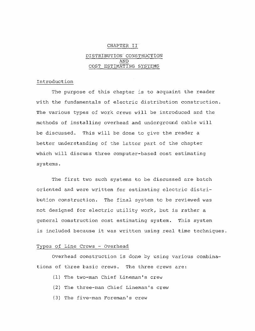
The purpose of this chapter is to acquaint the reader
with the fundamentals of electric distribution construction.
The various types of work crews will be introduced and the
methods of installing overhead and underground cable will
be discussed. This will be done to give the reader a
better understanding of the latter part of the chapter
which will discuss three computer-based cost estimating
systems.
The first two such systems to be discussed are batch
oriented and were written for estimating electric distri-
bution construction. The final system to be reviewed was
not designed for electric utility work, but is rather a
general construction cost estimating system. This system
is included because it was written using real time techniques.
Types of Line Crews - Overhead
Overhead construction is done by using various combina-
tions of three basic crews. The three crews are:
(1) The two-man Chief Lineman's crew
(2) The three-man Chief Lineman's crew
(3) The five-man Foreman's crew

Each crew can be used for many purposes and can best be
defined by limitations agreed to in the union contract.
16.
The two-man Chief Lineman's crew consists of a Chief
Lineman and a Grade 1 or Grade 2 lineman operating a
single bucket aerial lift truck. The crew is used to per
form primarily street light and secondary cable installation
and maintenance. This crew cannot work on energized pri
mary wire operating at 13,200 volts.
The three-man Chief Lineman's crew consists of a
Chief Lineman and two Grade 1 linemen. This type of crew
operates a double bucket aerial lift truck. This type
of crew can install transformers on energized construction.
They can set poles up to forty-five feet in length. The
limiting factor on the three-man crew is that it cannot
install more than two phases of new primary construction.
The Foreman operated crew consists of five men. The
make up of the crew can vary, but it normally has two
Grade 1 linemen, one Grade 2 lineman and a line helper.
This crew can do any type of overhead work including the
installation of three phase primary wire.
Current practice has seen a decline in the number of
Foreman operated crews and an increase in the Chief Lineman
operated crews. A Chief Lineman is the highest step in the

17.
unionized work force. He assumes some supervisory responsi
bilities, but not all. In practice, several Chief's crews
are supervised by one roving Foreman. Operating efficiency
has been increased in this way. Often, when three phase
wire is to be installed, a roving Foreman can be used in
combination with a three-man and a two-man Chief's crew.
Types of Line Crews - Underground
Underground crews are a bit more specialized then over
head crews. There are five basic crew types, including:
(1 ) Splicing Crew Grade 2
(2) Splicing Crew Grade 1
( 3 ) Chief Splicer Crew
(4 ) Cable Pulling Crew
(5) Trenching Crew
Each type of crew is used for specific applications in the
underground operation.
The Splicing Crew Grade 2 is the most widely used crew.
It consists of a grade 2 splicer and helper. The grade 2
crew can perform most types of straight splices used in
underground construction. These splices can be made on
cables under the 26,000 volt class.
The Splicing Crew Grade 1 consists of a grade 1 splicer
and his helper. They can perform all the work of a grade 2
18.
crew and also can make splices on 26,000 volt cables. They
cannot make branch splices, however.
The Chief Cable Splicer functions much like the Chief
Lineman in the overhead. He can perform some supervisory
duties. Working in combination with grade 1 and grade 2
splicers, cable pieceouts and 26,000 volt branch splices
can be performed.
The Cable pulling Crew consists of a Foreman or Chief
Mechanic, a mechanic grade 1, a winch truck driver and two
helpers. This type of crew specializes in installing cable
in underground conduit.
The Trenching Crew can be formed with any number of
men from two to five. It is usually made up of a Chief
Mechanic in addition to the required amount of underground
helpers. The function of this crew is to trench and in
stall conduit.
Distribution Construction
As stated earlier, the work of the Distribution
Engineering Department is primarily concerned with the
installation and maintenance of overhead construction.
Primary overhead "and underground cables can be of sev
eral voltage classes including 69-kV, 26-kV, 13-kV and

19.
4-kV. In addition to differing voltage classes, cable can
be purchased in many different current carrying capacities.
Cable can be installed in several different configurations
giving rise to a multiplicity of materials and varying labor
requirements. The next two sections will give the reader
an idea of what is involved in overhead and underground
worki and to provide him with some background on the task
involved in accurately estimating the cost of such work.
Overhead Construction
Overhead construction accounts for the majority of
existing circuit miles on the Public Service system. Over
head construction is much less expensive to install than
equivalent underground construction. This type of con
struction is most often used in suburban and rural areas
of relatively low load density. Overhead circuits are
radial in design, with tie points provided for load restor
ation during circuit failure.
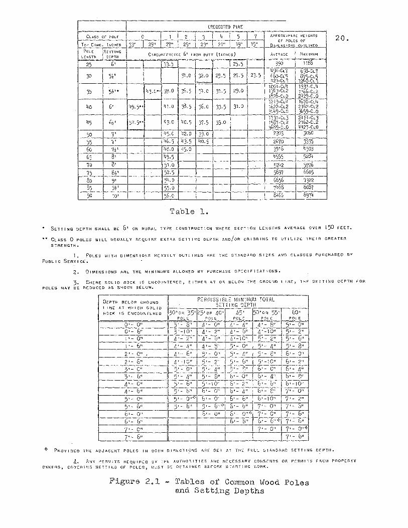
Overhead construction uses wood poles for support.
Wood poles come in a large variety of sizes and thick
nesses. The Table in Figure 2.1 illustrates wood poles
commonly used by Public Service. The estimator must be
familiar with the application of each type and he must also
know the cost of each type. The typical installation will
CR[OSOTEl) P lifE f--
~-rm--rqIsT7"-T APPROXI>'H[ WEIGHTS CLASS C.r POLe 0
Top C IRC- l~cH:(s 33" ,; n- --~ -- ..... to Ii " :::" or POLES Or
29 27 2), 2) 21 19 l~ DI"I;'.s'O"$ OUTLINED
Pel€: SC:Ti I JJG
C,"M,""'~": ~' i'"~"0h""''' LEt.:CTH CEPTH I gAX 114UH
" -25 6'
, 33.) 125.5 990 1180 i
-il::;U--:::CLI b30-CL'/ 30 %' 3".0 32·0 29·5 27.5 23-5 bbo-C~~ 87'i-CL~
_ .-..521-CL 124O-CL
20.
~6.5 KG'1-CLl} 1331-CL4
35 5~" 43·(.>' 39·0 :7LO 31·5 29·0 1-:.!:6-CL2 1'166-CL2 i-
162 -CLO 242Q-CLO
14.1.0 ;3.5 36.0 12 i3-C~lt lo~O-CLl+
40 6' 49·5' 33· 5 31.0 1622-CL2 21D2-CL2 3':~9_-~ 3b59-CLO
45 6~1 52·5'· 1+3·0 ljO·5 n~1-cL3 2414-CL3 .
31·5 35·0 t~7-CL2 21b2-CL2
ST.O -- 0,:l:~ 4lt21-CLO
50 I 7' , 45·0 ~2.0 2303 -jObo--
55 '/' 46·5 ))3·5 40·5 I 2070 3335 60 7~' ~o.O 45·0 3916 !}503
65 8' 49·5 - 4555 .---C SW+-
70 0' 51.0 521~2 5976 75 8l ' 52.5 5897 0605
80 9' )4.0 G656 1322 55 <;" -' 55·0 1~68 8c87
50 10' 56.0 C4.66 097lt
Table 1.
SETTING DEPTH SHALL BE 6· ON RURAL TYPE CONSTRUCTION II'KERE SECTION LENGTHS AVERAGE OVER ISO FEET.
CLASS 0 POLES WILL USUALLY REQUIRE EXTRA SETTING DEPTH AND/OR CRIBBING TO UTILIZE THEIR GREATER
STRENGTH.
1. POLES WITH DIMENSIO~S HEAVILY OUTLINED APE THE STANDARD SIZES AND CLASSES PURCHASED BY
PUBLIC SERVIO£.
2. DIMENSIONS ARE THE MINIMUMS ALLOWED BY PURCHASE SPECIFICATIONS.
3. ~KERE SOLID ROCK IS ENCOUNTEqED, EITHER AT OR BELOW THE GROUNO LINE, TH~ SETTING OEPTH FOR POLES M~Y 8E REDUCEO AS SHOWN BELOW.
DEPTH BElOW GROU'~D ~ PERhIISStBl.E k':tNlhl,Ut,\ TOTAL liNE AT WK I CH SOL I D lLif-____ -r __ -=.~:::.::.:.,T..:..T:...1 :.:,NG:::.,_D:.;:::.;P:,..T;.:H"--___ .,-_.,..-_-l ROCK IS ENCOUNTERED 1!30 1 0R 35'Q5'OR 40' ,15' sO'OR 55' Eo'
Ii POLE I POLE POLE POLE POLE ii :5 '- 0" ~~O=,,=f=A~_;'~;;'_ ;;"Ll;;":' ~" ..1_-4"';";, -;;';-~8;:7=, --rr 5' - 0" 0' - 0" !i ),-10" 4'- 2" 4'- G" 4'-10" 5'- 2"
1 ,- 0" II 4'- 2" 4'- b" .1'-10" 5'- 2" 5'- G"
5'- 0"
P~OVIDED THE ADJACENT POLES IN 80TH DIRECTI~NS ARE SET AT THE FULL STANDARD SETTING DEPTH.
4. ANY C'ERIlITS REQUIRED BY THE AUTHORITIES AI;!) NECESSARY CONS£!ITS OR PERMITS FROM PHOPERTY O~~ERS, COVERING SElllhG Of POLES, M~5T 8E OUTAINED BEFORE ST~RT!tJC V:ORK.
Figure 2 .. 1 - Tables of Common Hood Poles and Setting Depths

21.
usually call for a 35 foot class four thickness pole. This,
of course, pre-supposes an uncluttered location in a straight
run of wire where average height and mechanical strength
will suffice. In installations where additional height is
required to clear an obstruction or to provide necessary
clearance for Bell Telephone Company cables, poles up to
90 feet in height may be used. The class number denotes
thickness. A class 5 pole is thin while a class 0 pole
is thick. Thicker poles are used for mechanical strength.
Poles are set by a three or five man crew. In general,
the smaller crew can handle smaller poles in easy access
areas. In order to install a pole, the crew must haul it
from a stockyard to the installation site. Secondly, a
hole is dug to a specified depth defined by the pole to
be set. The hole can often be dug mechanically with a truck
mounted borer. In special cases, the hole may be dug with
a shovel, a jack-hammer, or may even be blasted with
dynamite. The estimator must know the conditions under
which the pole will be set in order to accurately estimate
the labor requirement.
Guying and anchoring - After the poles are set, the use
of proper guying and anchoring must be employed to give the
pole line needed strength. A pole line under stress from
22.
the installation of conductors requires guy and anchors to
avoid mechanical failure. The estimator must choose from
a host of guy and anchor materials, including:
(1) 3/8 in. galvanized guy wire
(2) 5/16 in. galvanized guy wire
(3) Light duty anchors
(4) Heavy duty anchors
(5) Swamp anchors
(6) Power installed anchors
Each arrangement has a unique material cost requirement and
associated labor cost.
Conductor Configurations - Overhead
Unlike underground construction, overhead conductors
can be installed on poles in many different configurations.
Conductors operating at the same voltage with similar cur
rent carrying characteristics can be installed on poles in
different ways. The estimator must be familiar with the
various configurations because each will use substantially
different insulating and support material.
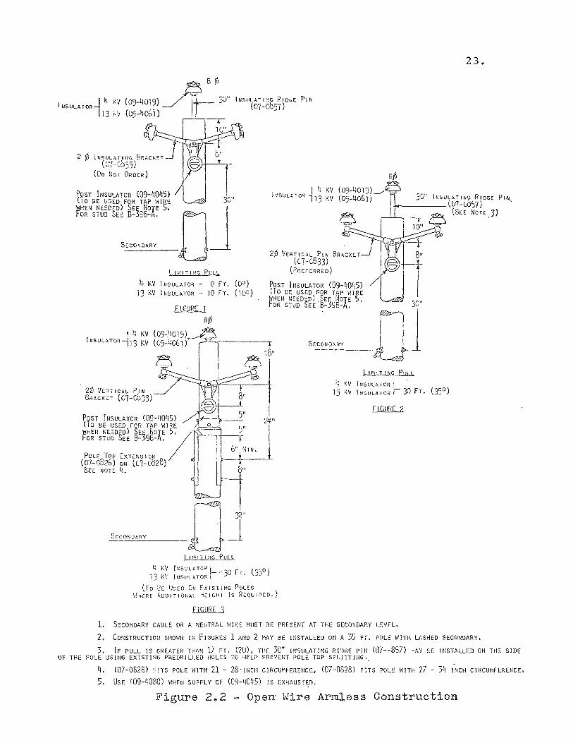
Open wire armless configuration - Three phase open wire
armless construction uses three current carrying conductors
and a non-supporting neutral. It is supported on the wood
poles with an epoxy insulated V-bracket and an epoxy ridge
pin. This type of construction is illustrated in Figure 2.2.
14 KV I NSULA TOR
13 ,,~
B ¢
(0)-4019) A 3()"
(05-406 i)
iNSULATING ERAChET (O'!-0035)
(Do NCT ORDER)
23.
POST INSULATOR (09-4045) (To llE U~ED FOR TAP \'liRE WFHEN NEEDED) SEE NOTE ~.
3C" I 4 KV
I h'SUUl TC~ 113 KV 301' 1r-,lSULATI N~ -RIDGE PtJ~ -t-----(07-C057) -
OR STUD SEE B-596-A.
OJ L It, IT I Nr, PIilJ.
4 KV INSULATOR - 0 FT. (00) i3 KV INSULATOR - 10 FT. (100)
2'/1 VERTICAL PJN BRACKET (C7-Cb33)
FIGURE 1
B¢
26 VERTICAL PIN BRACKET «(7-(,833)
(PREF [RREO)
POST INSULATOR (09-4045) (To BE USED FOR TAP WIRE ~HEN NEED~D) SEE NOTE 5, 'jO" fOR STUD ~EE B-595-A.
S"O'O'o, ~ I -UJ bJ1.1J.l..U;G PUI l
4 KV INSULATOR I -13 KV INSULATOR r 30 FT. (35°)
FIGURE 2 POST INSULATOR (09-4045) ~ \
eTa BE USED FOR TAP \,IRE Sd' 2-+" WHEll NEEDRD) SEE NOTE /.. ''''---,-j-----,_ FOR STUD ~EE B-596-A, ..
-Ib",MIN.
POLE Top EXTENSION
(07-0326) OR «(7-(628) SEC llOT[ 4. b"
SeCONDARY
L I" \ T I ~'G PUt L
11 K\, INSULt,TOR ,'. ___ ~O FT. (-)50) 13 K\' I NSUl HOR )
(To EE UseD ON EXISTING POLES WHeRE AODITIONAl HEIGHT Is REQUIRED.)
FiGURE 3
1. SECONDARY CABLE OR A NEUTRAL WIRE MUST BE PRESENT AT THE SECONDARY LEVEL.
(SEE NOTt))
2. Cor:STRUCTIOrl SHOWN III FIGURES 1 AND 2 MAY BE WSTAlLED 011 A 35 FT. POLE I'IITH U,SHED 'SECONDARY.
3. IF PULL IS GREATER THr,M 17 FT, (20), THE 30" iNSULATiNG RInGE PiN <O7--857} -AY BE INSTALLED ON THE SIDE OF THE POLE USING EXISTING PilEDRILLED HOLES TO HELP PREVEfjT POLE TOP SPLITTING.
4. (07-0826) FiTS POLE WITH 21 - 28'!NCH CIRCUMFERENCE. (07-0823) FITS POLE WITH 27 - 3q iNCH CiRCUMFERENCE,
5. USE (09-~080l WHEN SUPPLY OF <09- llOQS) ! S EXHAUSTED.
Figure 242 - Operr Wire Armless Construction
24.
rhis type of construction is preferred by Public Service
Jecause of its appearance, lightning protection ability,
~nd good current carrying capacity.
The estimator must be familiar with the insulating
brackets used for normal pole tops as well as construction
used for special purpose pole tops including:
(1) Dead end pole top - used to stop a run of wire
or as part of other special purpose pole tops.
(2) Small angle pole top - used when conductors
form a small angle at the pole causing stress.
(3 ) Large angle pole top - used when conductors form
a large angle at the pole.
(4 ) Riser pole top - used at the termination of
underground cable at a point where it taps into
the overhead.
(5) Lightning arrester pole top - used for lightning
protection installations.
(6) Extension pole tops - used for extra height
when an existing pole is too short.
(7) Side extension pole tops - used when it is neces
sary to clear an obstruction.
(8) Switch or recloser pole top - used when a break
or tie point is to be installed.
The estimator must be familiar with the various types of
crossarms, brackets and insulators necessary to build these
25.
pole tops in each configuration type.
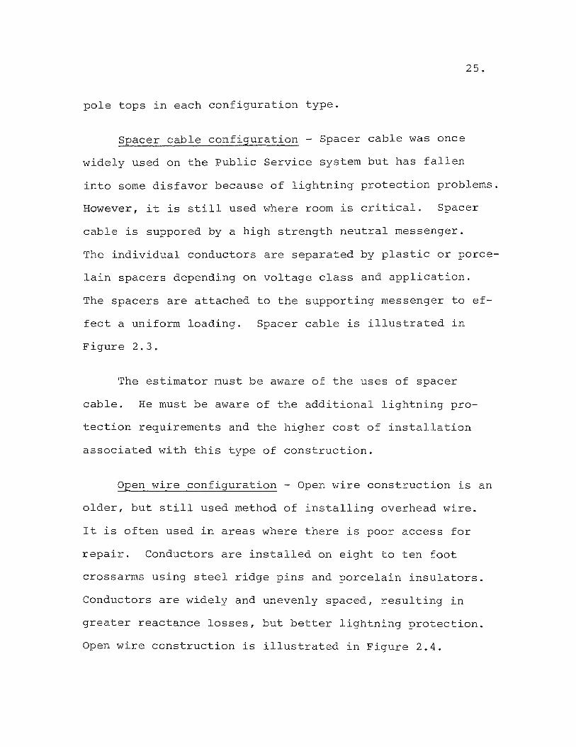
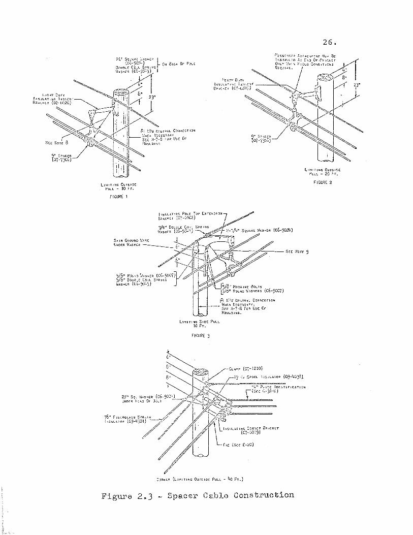
Spacer cable configuration - Spacer cable was once
widely used on the Public Service system but has fallen
into some disfavor because of lightning protection problems.
However, it is still used where room is critical. Spacer
cable is suppored by a high strength neutral messenger.
The individual conductors are separated by plastic or porce
lain spacers depending on voltage class and application.
The spacers are attached to the supporting messenger to ef-
fect a uniform loading.
Figure 2.3.
Spacer cable is illustrated in
The estimator must be aware of the uses of spacer
cable. He must be aware of the additional lightning pro
tection requirements and the higher cost of installation
associated with this type of construction.
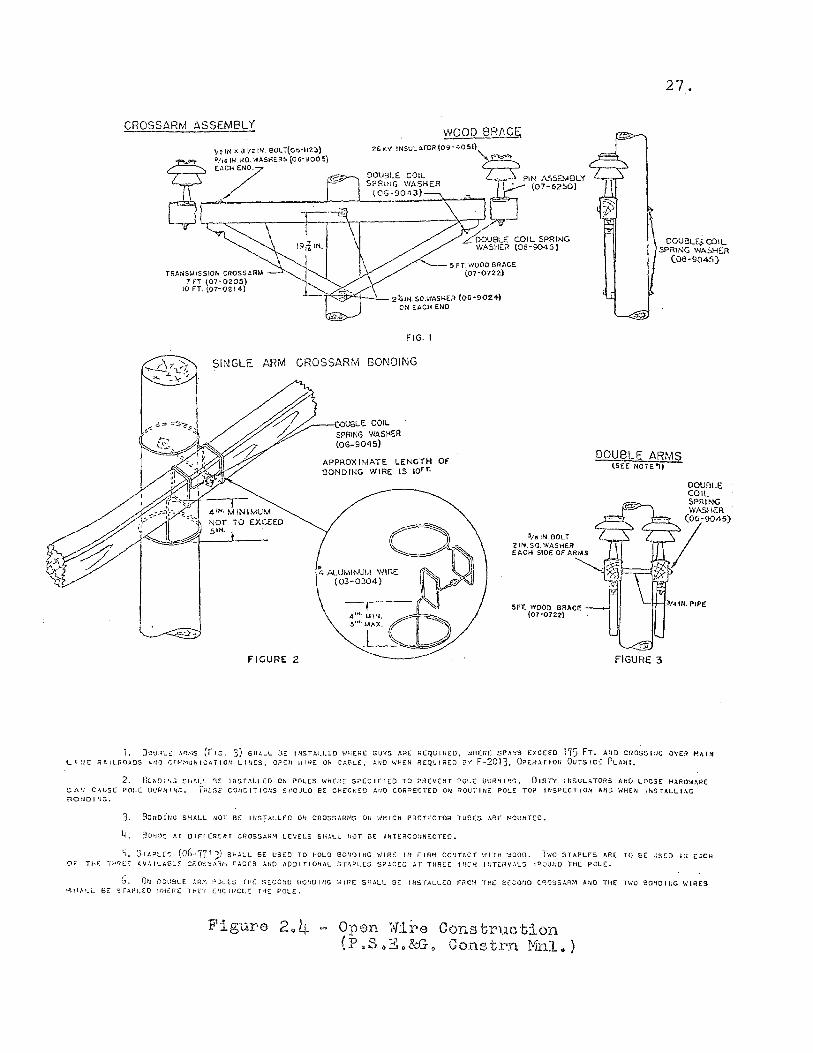
Open wire configuration - Open wire construction is an
older, but still used method of installing overhead wire.
It is often used in areas where there is poor access for
repair. Conductors are installed on eight to ten foot
crossarms using steel ridge pins and porcelain insulators.
Conductors are widely and unevenly spaced, resulting in
greater reactance losses, but better lightning protection.
Open wire construction is illustrated in Figure 2.4.
LIMITING OU-TSI!)!
PULL - 10 Fr.
f IGIJ?E 1
Figure 2 .. 3
hI5ULATII~(; POlt: Top EXTENSION
8;""'0 (C'{-CO02)
~t r;r,1 1;r:UT~"'L CO,ojIil£CTlOlrt
I--!--- \-!lfE:1t ~:[C[s::;:..~Y. SEE H-7-8 Fa. t;S( .0' :'tO~LOUC.
LH-tITINC SlOE PULL 10 FT.
F IGIJ?E 3
Spacer CRbJ.8 Constructicn
26.
ll:-4ITlhiC Oursl~£ PULL - 20 FT.
flGl.HE 2
CROSSARM ASSEMBLY WOOD 8RAC~
~z IN X 8'/2 IN. BOLT(06'1I2~1 20 f(V INSULAfOR (O;'-40~11\-~
6~ i~7~~:NODWASH£RS (06.9005
1
L6 t.:::::s:PIN ASSEMBLY
. (07-52~O)
.~~
TRANSMISSION CROSSARM 7 FT (07-0205)
10 FT. (07-0214)
LoOUBU:: COIL SPRING. WASHER (06-9045)
5 FT. WOOD BRACE (07-07U)
T"<~b-"+--.l_ 2l:."J. SOWI\SKER (OG-9024) ON EACH END
FIG. I
SINGLE ARM CROSSARM BONDING
FIGURE 2
/"--~~V8LE COIL SPRING WASH-Sil (06-9045)
APPROXIMATE LENGTH Of BONDING WIRE IS IOfr.
'/5 IN. BOLT "lIN. SO. WASHER EACH SIDE OF ARMS
27.
DOUBLE!. COIL SPRING WASHER
(013-9045)
DOUBLE ARMS (SEE NorE "I)
DOUOLE COIL SPRING WASHER
t§!"'"
FIGURE 3
1. DQURL~ An~s (fiG. 3) SHALL BE INSTA1.LEO WHERE GUYS ARE REQUIRED, WHERE SPA~S EXCEED 175 FT. AIIO CROSSI~C OVER HAI~ L r HE RAILROA~S ... tJ,) C(1!-!:-1'J'HCATION LHJ£S, OPEl: '.;Jl~( Oft CAOL!:, ";flO \.tHEN R£QJJIRCO 8v F-2C13. OPEHArlOH OUTSIOr PLMH.
2. GC.ND1'H~ ~hf,L',- 0;;[ If4STALLCD ON POLES I . ..JHERE S?ECIF1£D TO ?REVENT ?OLt OUIlNP;I}. DIRT'/' INSUL.\TOR5 MIO LOOSE HARD'W,\RE
CAN CAUSE POLE 8!)RNPJG. i"HESf C0I10IT1C,'l$ SPOULO BE CHECV.£O AtlO CORRECTED ON ROUTINE POLE TOP trlSPECTIOU AND \'''H(~j I."l:STA.LLI!,C 80UOlfJG.
J. 80UO!'NG SHALL UOT BE IHS!ALU:O O~I CROSSAHMS 011 WHICH PAOTt:CTOr:l TunES ARE ~OU!'iT(O.
4. 8o~o~ AT OlrrERCNT CROSSARM LeVELS SHALL NOT BE INTERCOUNECTEO.
t:,. 3rA?L[~ (Oh-'17'3) SH"\LL BE USED TO HOLD 80."JDING \,.!IR( III FIRM Corrrt,CT ',11TH "::tOoo. TiJO STAPLES AR£ TO 8E t;$.[O tt, E&'CH
OF Th'l-: Tl-<I1[r: I\.\I:~ILAGL::' t:';O$3,'\{~,"1 FACES ANO ADDITIO,'IJ\L S'CA?LCS SP..\CEO AT THR[[ t~ICH I~JTEi~V';LS A~OUNO THE POLE~
S. Otl DOt:SLE .e.n~"l POLES THE ~ECO~IO BOI:OII:G ',,/lnE SHALL nc: INS1"ALt.£O FRO,'" TH( SE:;OfJQ (.qOSSMf~.' ANO "(HE n-lO eOtlOHlG WI:R(S ';'H.'·i.L et: s rA-PLEO \'nliRE "fHC:\ (fte IHCLE HiE POLE.
Figure 2 .. 4 Open Wi~e Construction (p .,S"E.&..--G. Gonstrn lfilll.)
28.
The estimator must be aware of the proper insulators
used for different voltage classes used in this type of
construction. Since this type of configuration is most
often installed in areas of difficult access, the esti
mator must calculate the additional labor requirement to
install the construction project.
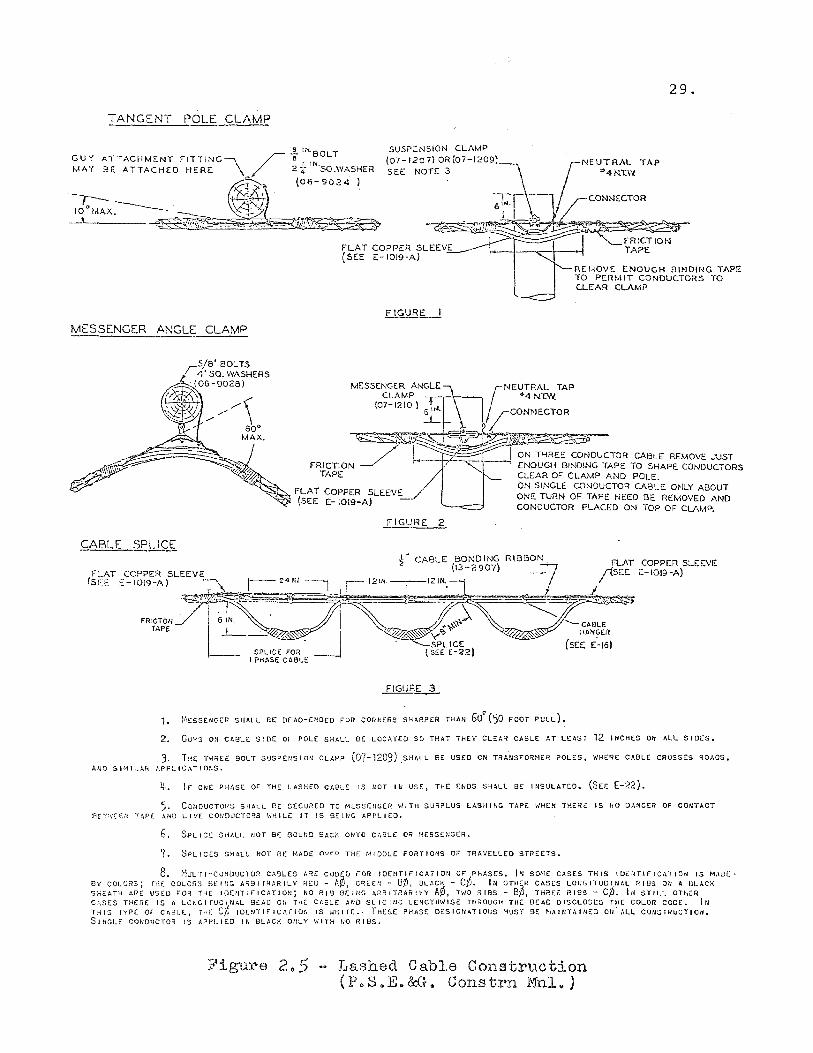
Lashed cable configuration. This type of construc-
tion was once popular because of ease of installation.
It has limited use now, because of the frequency of
failures experienced with it. Lashed cable is made up
of a bundle of conductors surrounded by a metal strip
wound around them. It is supported by a neutral messenger.
This type of construction requires no insulating brackets
or crossarms. See Figure 2.5.
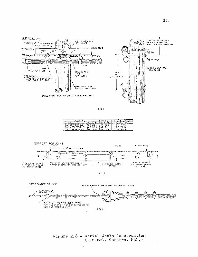
Aerial Cable. Aerial cable is really underground
type cable run along a pole line. The cable is run through
rings and is supported by a messenger. It is used where
extreme reliability is required in an overhead application.
This type of construction is illustrated in Figure 2.6.
The estimator must be familiar with the types of
underground cable suitable for this application. He must
know the proper support rings to use. He must also be
aware of the installation and splicing methods required.
TANGENT POLE CLAMP
GUY ATTACHMENT FITTING / i IN'BOLT : 'N.
MAY BE ATTACHED HERE \A 2:r SO.WASHER
~. (06-9024 I 1~ , ~ ',' , o ___ . \'A~
lOMAX. __ ''<'t-lflr~'r:;:!;"~~-;;--~ ~~ .. It>_ ..... tl",'''' .
SUS?;:NSION CLAMP (07-1207) OR(07-1209) SEE NOTE 3
FLAT COPPER SLEEVE (SEE E - 1019 -A)
F ICURE
MESSENGER ANGLE CLAMP
29.
REf-lOVE ENOUGH BINDING TAPE 'fa PERM IT CONDUCTORS TO CLEAR CLAMP
MESSENGER ANGLE CLAMP
(07-12101 r NEUTRAL TAP +4N.T.W;
, I-CONNECTOR
CABLE SPI ICE
~~~~~~~~.~~~~~~~~~~~~~~~-,.~_-",:_,_,_,~~,r
FLAT COPPER SLEEVE (SEE E-1019-A)
FIGURE 2
~ ~ ON THREE CONDUCTOR CABLE REMOVE JUST ENOUGH BINDING TAPE TO SHAPE CONDUCTORS CLEAR OF CLAMP AND POLE. ON SINGLE CONDUCTOR CABLE ONLY ABOUT ONE TURN OF TAPE NEED BE REMOVED AND CONDUCTOR PLACED ON TOP OF CLAMP.
~. CABLE BONDING
FLAT COPPER SLEEVE (13-2907) (S".E £-1019-A) .• ~, ~-24Irl ~ 111211'< ~12IN':1
FRICTON~~~~-====::7r';;;;;;S~ i~~-:~ TAPE I 6t ~ y" ~v: ---- J y-. 5~ICE
SPLICE FOR __ (SEE E-22) I PHASE CABt:£
FIGURE 3
'-CABLE HANGER
(SEE £:"16)
1.
2.
i4£SSENGER SHALL BE: DEAD-ENDED FOR CORNERS SHARPER THAN 600
(50 FOOT PULL).
GUYS ON CABLE SIDE OF POLE SHALL BE LOCATED SO THAT THEY CLEAR CABLE AT LEAST 12 INCHES OH ALL sIDes.
3, THE THREE BOLT 5USPEllSION CLAr<P (07-1209) ,SHALL BE USED CN TilAIISFORt·tER POLES, WHERE CABLE CROSSES RO;'OS,
ANa StMtLAR APPLiCAT10~S.
~. IF ONE PHASE OF THE LASHED CAeLE 'S ROT IU USE, THE ENDS SHALL BE INSULATEO. (SEC [-22).
5. CONDUCTORS SHALL BE 5(CUREO TO MESSEIJGER WITH SU~?LUS LASHING TAPE WHEN THERE IS NO DANGER OF CONTACT B(~-~ .... E€.,'1 TAPE ANI) LIVE COt,'OvCTCP.3 \'JHILt: IT IS BEI~lG APPLIED.
G, SPLICE SHALL NOT BE BOUND 8AC~ ONTO CABLE OR MESSENGER.
7. SPLICES SHALL HOT 8E MADE n\I~O THE MIDDLE PORTIONS.OF TRAVELLED STREETS.
8. ~'lUL'rl-COIIOUC10R CABLES ,,1E COD5D ,OR IDENTIFICATION OF PHASES. IN SQ.'·IE CASES THIS IDOHIFICATlOli IS MADe, By COL(JK~;; rH[ COLeR3 HEHlG AC?8IrRARILY REO - AyJ, GR-E(N - B~, BLACK - c¢. IN OTHlJ? CASES LOtJGITUQINAL RIBS 011 A BLACK SHEATH ARE USED rOR THE IOENTIFICATION; NO Rig BEING ARBITRARIlY A¢, TWO RIBS - 8¢, TH~E~ RIBS - C¢. IN STtLL OTHER CASES TH£:RE IS ALONGI fVOINAL e£AD Ol1 THE CAGLE Al\'D SL ICltle LENGTH~"'ISE THROUGH THE OEAD DISCLOSES THE COLOR CODE. IN THIS TYPE or CABLE, THE C¢ IOENTIFICArlon IS WHITe.- TH£SE PHASE OESIGNATIO~S MUST 9[ MAINTAINED OU"ALL COUSTRUCTlON. SlflGLE CONOtJCTOR IS APPLIED IN BLACK O~LY WITH NO RIBS.
Figure 2 .. 5 Lashed Cable Construction (PeS.E.&G~ Constrn Mnl.)
§QSPENSION _ ~.,'\.... 2'1 4 FT. GUt>RD ARM AeRIAL CA5LE SUSP~NS10N h I ;~R:: !:07'0203}
ClAf/,P(07-120S) ': \ I ' I l~' L_
"""""", - -= .~ '~7 -; =h"" j J? ~ .)i;R:\ ~ .-f"
~s s §3'n~,%10~-;;")?d't="*=~="-~(;)-~ -.~ ~ -- i),~ - . --- . - - -.~o;;;;.
~--.-.-J.l ~~-=~~-~.==-- t". ~<~ I 1\: I i I I l' '\ RING ,-- 12 IN. ---, • \ . i ) I'
THROUGl-IOUT RUN j .; : I ! ! i GROUl'ID WIRE \. !' /.; '41HW
RING Sf-DDLE . 1.':1 SEE. NOTE I ItlSTALL or~LYON THREE RINGS ;: I I I !l NE.AAES T POLE ON EACti SIDE : I j
'I~,- \ ~~.
H-7-A FOR OF MOULDING)
SEE
CABLE ATTACHMENT ON STREET SIDE IS PREFERRED
FIG. I
r SPLICE CONNECTOR7
[---3FT. TO 6FT.~
----~&:-.2~'"APPR;X.->1 ·?f: .. ',i,-- s~ =1JI~,;.;r5==~·==· =~1r=1b=;t._,~ 6. r~f",._,- ~.\ - - , -+-w_ '}---------i1hl;' m \\~
/ l~j}1 \ INSTALL RtNG SkODLES WIRE: SERVING TO SUPPORT SLE(YE./ BONDING RIBBON...1 ON FiRST IHHf.F Rlt-;{jS COPPE RON COPPE,R-COVER:ED MES5£NGfR COMPOS!TlON SLEEVE SOLDERED TO SHEATH t:.c.CH SmE OF SPLICE (07-7301) (13-2907)
ME~?ENGER SPLICE
Figure 2,,6
F1G.2
FIG.3
Cable Construction Constrn .. Mnl.)
Aerial (P"S .. E&G.
30.
31.
Underground Construction
Overhead construction is used in light to medium load
density areas. In urban areas of heavy load density the
distribution system is installed underground. Choice be-
tween overhead and underground depends on a number of
widely differing factors. Comparative economics is the
most powerful factor influencing the choice. The capital
cost of an underground system may be five to ten times
6 greater than that for an overhead system.
Underground distribution systems as constructed by
Public Service Electric and Gas Company use conduit sec-
tions carrying insulated cable. The conduit sections are
run between manholes below street or sidewalk grades.
Conduit, cable, and manhole locations are almost infinite
in variety.
Conduit Construction. Conduits are the hollow tubes
in which cables are installed. Conduits are seldom In-
stalled singularly, but rather In groups called duct banks.
The size of the duct bank depends on the diameter of the
largest cable to be installed, the length of cable to be
run between manholes, and the number of bends. Conduit
comes in a large number of sizes. However, little is gained
by using smaller sizes. The four inch and five inch conduit
are the commonly used sizes.
6. Skrotzki, G. A., Electric Transmission and Distr~bution, New York: McGraw Hill Book Company Inc., 1954, Page 184
32.
The number of ducts depends upon local load require
ments. Provision should be made for required circuits and
for future expansion. Eight to sixteen ducts in a bank
is the usual requirement for a main run, while four to
six ducts on side branches will suffice. Ducts are also
made of various materials including:
(1) Concrete
(2) Concrete-Asbestos
(3) Poly Vinyl Chloride
Selection of proper duct material depends on installation
requirements.
Installation of a conduit system begins with trenching.
Trenching is normally contracted out to various independent
contractors. However, a certain amount will be done by a
trenching crew. A trench approximately three feet wide
averaging five feet in depth is dug between manhole loca-
tions. Factors which effect required manhours for
trenching include:
(1) Location of trench - street, sidewalk, open field.
(2) Condition of soil for digging - sand, mud, rock.
(3) Use of mechanical equipment.
The estimator must properly decide on required trenching
labor to accurately arrive at costs.
Coincident with trenching would be the larger excava
tions required for manhole locations. The three factors
mentioned above also influence the required labor for
manhole installations.
33.
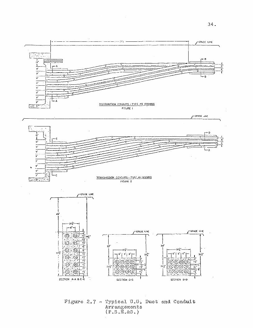
After trenching and manhole installation is completed,
comes the installation of the conduit in banks which con-
nect manholes. The selected type and number of ducts are
arranged into standard banks. This is illustrated in
Figure 2.7. The ducts are held in place by temporary forms.
Cement is poured into the forms to make a permanent arrange
ment. The trenches and excavations are back-filled and
streets and sidewalks are repaved to complete the job.
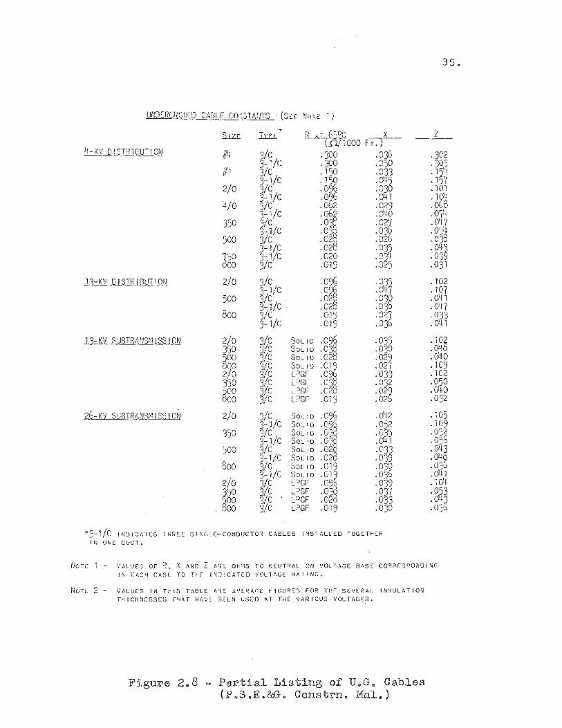
Cable Installation. Interdependent with duct selec-
tion and sizing is the choice of cable. Most underground
cable is lead sheathed, and also, oil-impregnated, paper
insulated. Cable comes in various sizes according to the
load it is expected to carry and voltage at which it is
to operate. A table of commonly used cable is shown in
Figure 2.8.
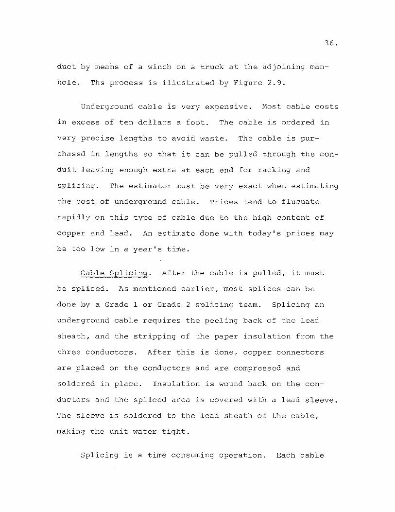
After the installation of conduit and manholes comes
the installation of underground cable. The new conduit is
tested for continuity by passing a rod through it. A rope
is attached to the rod and pulled through the conduit.
The rope in turn is used to pull a steel cable attached to
the underground cable. The cable is pulled through the
34.
if-------------~,.' I r~~"~ ~_ II .• ': __ .1.
f----...--.,,--____ ~~~~~;B %--f t:=====~~ ~'\ -
I
DISTRIBUTION CONDUITS - TYPE "2 FANNING
FIGURE I
rGRAD:' LINE
/r------------------------------------------------------------------~--~----~--~
"
~~£i~ .... , .... '~~. '= 1-9" ~.
--1- r, \. 9"
SECTION A-A 8 C-C
YRANSMISSICN CONDL!lTS - TYPE "'I ~
FIGURE 2
Figu:t'e 237 - Typical U"G;, Duct and Conduit Arrangements (P .. S"E.&G. )
35.
UNDERGROU:!D CABLE cor~3TA:JTS ' (SEE NOTE 1)
" ~;r:,OC X __ Z_ 1Uz.E TYPf mOOD FT.)
4-KV QISTRIBUTION /Il' 3/G ·300 .03b J 't
1/1 3-1/C ·300 .050 3/G .150 .033
2/0 3-1/C .150 .O'f5 1/C .096 .030 3-1/C .Oi6 .0+ 1
4/0 3/G .002 .029 3-1/C o~
.0;0 350 3/C .0':) .027
3-1/C .03' .039 500 3/G .02 .020
3-1/C .028 .035 'ISO 3-1/c .020 .ojt 860 3/C .019 .025
13-KV 0 I STR I [lUT I ON 2/0 3/C .096 .035 3-1/C .09~ 04C' . (
500 3/G .02 .030 3-1/C .020 .030
800 3/C .019 .02J 3-1/C .019 .030
l1-KV SUBTRIV!S~11 SS ION 2/0 3/C SOLID .09~ .035 350 3!C SOLID .03R .030 ~oo 3!C SOLID .020 .029 000 3!c SOLID .Oli .027 2/0 3/c LPGr .0911, .033 350 3/c LPGr · 03'~ .032 ~OO 3/c LPGr .028 .02;
00 3/c LPGr .019 .020
26-KV SUBTRANSMISSIO~ 2/0 3/c SOLID .096 .012 3-1/C SOLID .09~ .052
350 3/C SOLID .03, .035 3-1/C SOLID O':l .0+1
500 3/c SOLID · '<Q .033 .0:::: 3-1/C SOLID .020 .039
800 3/C SOLID .019 .030 3-1/C SOLID .011 .036
2/0 3/C LPGr .09* .039
350 3/c LPGr 0"" .037 · )
@OD 3/c LPGr .026 .033 , 00 3/c LPGr .019 .03D
*3-1/C IrlDlCATES THREE SlrJGLE-CONOUCTOR CABLES INSTALLED TOGETHER IN ONE DVCT.
·302 ·305 Fh
• Jt
· 157 · 101 · 101 .oG8
0'711 · I t
.0-17
.0'jJ.
.038
.045
.039
.031
.102
.107
.0'11 · a.n .033 · O't 1
. lOS
.O't
.040
.109
.102
.050
.0'10
.032
.105
.109
.052
.056 ·O't5 .O't .036 .041 · 1 O~ .D53 .eil? .D3o
NOTE 1 - VALUES OF R, X AND Z ARE OHMS TO NEUTRAL ON VOLTAGE BASE CORRESPONOING IN EACH CASl TO THE INDICATED VOLTAGE RATING.
NOTl 2 - VALUES IN 1MIS TAGLE ARE AVERAGE FIGURES FOR THE SEVERAL INSULATION THICKNESSES T~AT HAvE BEEN USED AT THE VARIOUS VOLTAGES.
Figure 2 0 8 - Partial Listing of U.G 4 Cables (P.SQE.&G. Constrne Mnl.)
36.
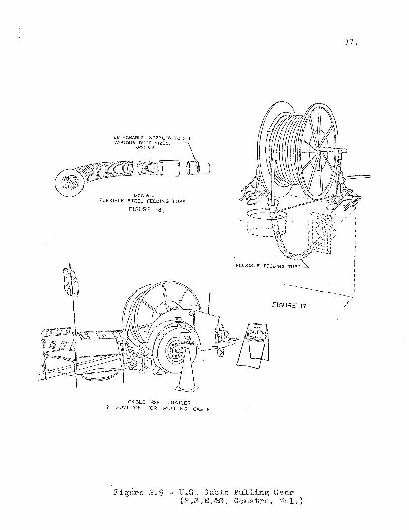
duct by means of a winch on a truck at the adjoining man
hole. Ths process is illustrated by Figure 2.9.
Underground cable is very expensive. Most cable costs
in excess of ten dollars a foot. The cable is ordered in
very precise lengths to avoid waste. The cable is pur
chased in lengths so that it can be pulled through the con
duit leaving enough extra at each end for racking and
splicing. The estimator must be very exact when estimating
the cost of underground cable. Prices tend to flucuate
rapidly on this type of cable due to the high content of
copper and lead. An estimate done with today's prices may
be too low in a year's time.
Cable Splicing. After the cable is pulled, it must
be spliced. As mentioned earlier, most splices can be
done by a Grade 1 or Grade 2 splicing team. Splicing an
underground cable requires the peeling back of the lead
sheath, and the stripping of the paper insulation from the
three conductors. After this is done, copper connectors
are placed on the conductors and are compressed and
soldered in place. Insulation is wound back on the con-
ductors and the spliced area is covered with a lead sleeve.
The sleeve is soldered to the lead sheath of the cable,
making the unit water tight.
Splicing is a time consuming operation. Each cable
DETACHA8L- NO VARIOU' Co ZZLES TO FIT , ::> DUCT S IZ-S
~~"""'~"""'''''''''''''' MOC 515 c., \
~'[JO
FLEXIBLE MOC 514 STEEL FEEDING TUBE
FIGURE 16
CABLE R"""" IN POSITION FOR-L
TRAILER PULLING CABLE
FIGURE' 17
r,1 • '
.rl 19ure 2" 9 - U G .. " Gable Pullj (p Q ~ _ .ng Gear ".Jo,!:;.&\}. Co t ns -rn .. r1nl .. )
37.

type, of which there are approximately forty, requires a
different splicing time. The straight splice described
requires about eight manho~rs to execute. Splices on
gas-filled cable may take as long as thirty hours.
The Estimating Task
38.
The task of estimating overhead and underground
construction is not an easy one. The estimator must have
full knowledge of the construction with which he is working.
He must work with large varieties of material and know
current costs. He must know the component parts that
make up a construction unit. The previous sections give
an idea of the scope of this problem.
Perhaps more difficult than the material portion of
the estimate is the calculation of the required labor.
Distribution work is done in the field, not in the confines
of a factory. Field conditions vary greatly. Base labor
hours may be applied to major units of construction. How-
ever, sufficient room must be left for engineering judgment
of field conditions. Labor is not constant on similar
jobs done in different locations. It is not constant for
similar jobs done during different seasons. Varying
traffic conditions may change the required labor for a
job. All these factors must be borne in mind by the esti
mator.
39.
Using manual estimating systems, field construction
estimators are burdened with considerable record keeping.
In addition to the record keeping, there is a considerable
amount of calculation required in cost estimating. Esti-
mating appears to be an excellent task to assign to
electronic computers. Before designing such a system,
it will be helpful to review what others have done in this
area. The following section will review three such com-
puter systems.
Review of Three Construction Cost Estimating Systems
Researching the literature available on cost estimating
turned up many systems programmed for computer use. Quite
a few of the systems are similar in concept. Included for
discussion here are three which the author feels are repre-
sentative. Each has some features which are worthwhile for
inclusion in a cost estimating system designed for Public
Service Electric Distribution Department.
Louisiana Power and Light Cost Estimating System
This system was investigated because it is one of the
earliest attempts by the utility industry to computerize
the cost estimating function. Louisiana Power and Light
has used an electronic computer to some extent in the cost
estimating area since 1958. 7 The current form of the sys-
tern was designed in 1962 and implemented in 1965.
7. Kittrel, Lee L" "Job Estimating by Computer", 1969 PICA Conference Proceedings, IEEE Publishing Co. N.Y. pp. 318.
40.
The basic concept of this system is the construction
plan. See Figure 2.10. The construction plan form was
designed to be used by the field engineer. It was designed
to help set up engineering specifications for line con
struction in an orderly way. The specifications required
in the L.P.& L. system are written in the form of codes and
quantities. The specifications written in such a way are
used by the programs to provide the required costs for each
job.
The construction plan is divided into three major parts:
(1) Title Block
(2) Drawing Area
(3) Notes Area
The notes area is subdivided into sections down the page and
across the page as either the pole or span columns. The
form is designed to handle installs, removals, transfers t
and salvage. On the drawing, each pole location where work
is to be done is identified with a pole number which, in
turn, correlates with an entry on the bottom half of the
sheet. The tabular bottom section of the form is used for
describing the work to be done and the materials to be used
to accomplish the job.
The L.P.& L. system uses a logical system of names,
each of which described a type of structure or unit. In
order to completely specify a type of structure or unit for
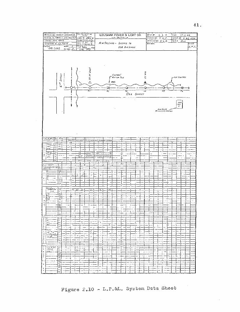
41.
l ! ( ~JI
",'
" It'llrfl,,;!s(.
fJLIN~ c.,"',;Tlr«rI.D
= --
I- E=E- -t- '----l: j- --~ --
----- --
• -- i-
Figure 2 .. 10
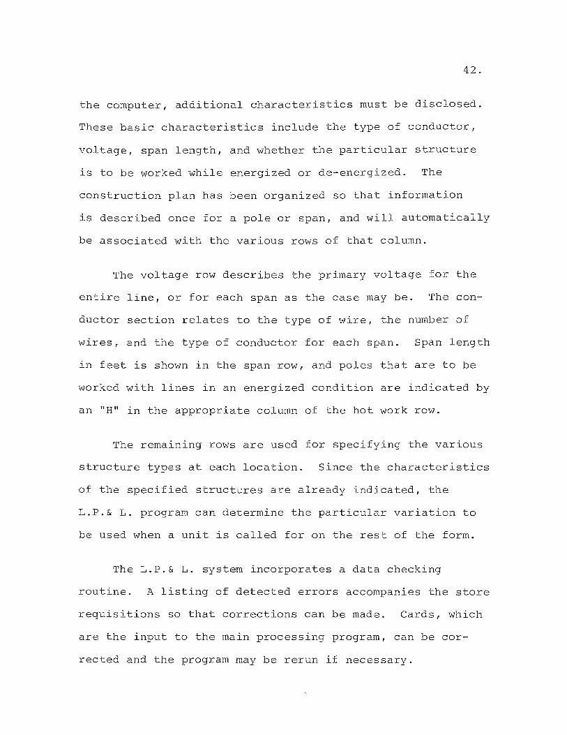
42.
the computer, additional characteristics must be disclosed.
These basic characteristics include the type of conductor,
voltage, span length, and whether the particular structure
is to be worked while energized or de-energized. The
construction plan has been organized so that information
is described once for a pole or span, and will automatically
be associated with the various rows of that column.
The voltage row describes the primary voltage for the
entire line, or for each span as the case may be. The con
ductor section relates to the type of wire, the number of
wires, and the type of conductor for each span. Span length
in feet is shown in the span row, and poles that are to be
worked with lines in an energized condition are indicated by
an "H" in the appropriate column of the hot work row.
The remaining rows are used for specifying the various
structure types at each location. Since the characteristics
of the specified structures are already indicated, the
L.P.& L. program can determine the particular variation to
be used when a unit is called for on the rest of the form.
The L.P.& L. system incorporates a data checking
routine. A listing of detected errors accompanies the store
requisitions so that corrections can be made. Cards, which
are the input to the main processing program, can be cor
rected and the program may be rerun if necessary.
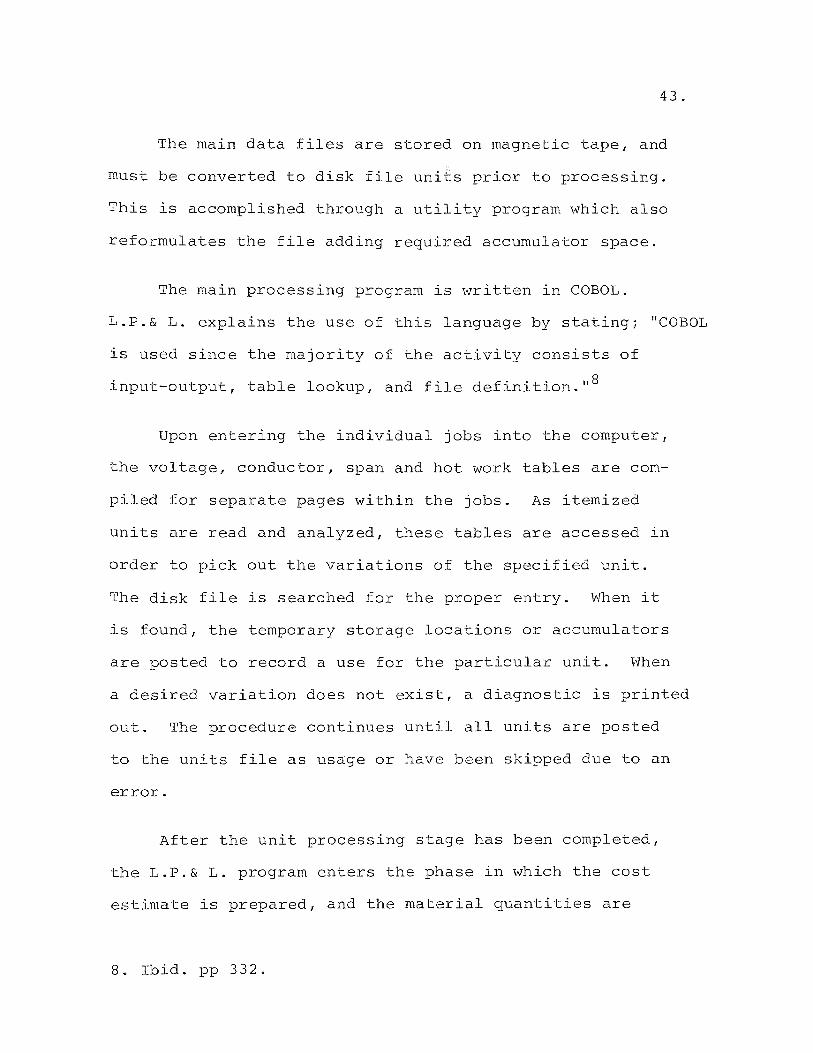
43.
The main data files are stored on magnetic tape, and
must be converted to disk file units prior to processing.
This is accomplished through a utility program which also
reformulates the file adding required accumulator space.
The main processing program is written in COBOL.
L.P.& L. explains the use of this language by stating; "COBOL
is used since the majority of the activity consists of
input-output, table lookup, and file definition,II8
Upon entering the individual jobs into the computer,
the voltage, conductor, span and hot work tables are com
piled for separate pages within the jobs. As itemized
units are read and analyzed, these tables are accessed in
order to pick out the variations of the specified unit.
The disk file is searched for the proper entry. When it
is found, the temporary storage locations or accumulators
are posted to record a use for the particular unit. When
a desired variation does not exist, a diagnostic is printed
out. The procedure continues until all units are posted
to the units file as usage or have been skipped due to an
error.
After the unit processing stage has been completed,
the L.P.& L. program enters the phase in which the cost
estimate is prepared, and the material quantities are
8. Ibid. pp 332.

44.
posted to the material item file. The disk file is searched
for units which were used to do the job. As the units are
read back in, the appropriate accumulators in core are
posted and totaled, indicating the new construction, main
tenance, or removal figures. Each item that makes up the
unit must be posted and updated so as to yield the correct
amount of new construction materials desired. The above
process is continued until all units that showed a usage
have been processed.
The used units also have been read back into the com
puter and processed in order according to certain classifi
cations and categories. This is done so that the construction
cost estimate, Figure 2.11, can be printed out once a given
category has been processed and completed. When the program
completes the cost estimate, it enters the bill of material
phase. The material item disk file is now searched for
items that have indicated a usage on new construction work.
This file will be printed out indicating the quantity used,
class item or stock number and the item description. The
material report is shown as Figure 2.12. When the estimate
is completed, the accumulators in core and the disk file
are initialized to zero and the next estimate is started.
Comments on the L.P.& L. System. The L.P.& L. system
presents some good ideas on organizing input data. The use
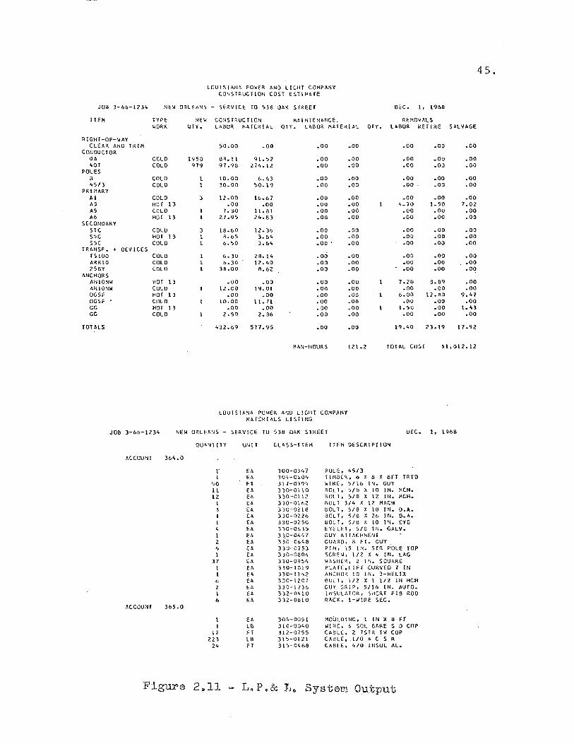
45.
LOUISIMlh PO\lf~ AND LIGHT COMPANY CQ'JSTRUCTlOt; COST £SHHHE
JOB l-6&-1?34 NEil ORLEANS - SERVICE TO S}8 OAI( SHEET OEC. I, 1966
ITE!I TYPE NEil CO'IS [RUC r ION HAl NTENANCE. REHO'IALS WORK (JTY. LABOR MATERIAL OTY • LABOR MATERIAL Qry. LABUR HEr I RE SALVAGE
RIGHT -OF-WAY CLEAR AND TRIH 50.00 .00 .00 .00 .00 .00 .00
CONDuerOR OA COLO 1958 SB. II 91.;2 .00 .00 .00 .OU .00 '>OT COLO ''179 91.98 274.12 .00 .00 .00 .00 .00
POLES 8 COLO 10.00 6.43 .00 .00 .00 .00 .00 4Sf} COLO 30.00 ;0.19 .00 .00 .00 .00 .00
PR!HhRV Al COLO :I lZ .00 1&.67 .00 .00 .00 .00 .00 AS HOT 13 .00 .00 .00 .00 4.10 I. SO 7.02 AS COLO 7.00 l!.81 .00 .00 .00 .OU .00 A6 HOT 13 27.95 24.83 .00 .00 .00 .00 .00
SECONDARY SIC COLO 3 18.1>0 12.3& .00 .00 .00 .00 .00 SSC HOI 13 I R.b5 3.&4 .00 .00 .00 .00 .00 SSC COLO 1 0.'>0 3.&4 .00 . .00 .00 .00 .00
TRAt/SF. + DEVICES TSIOO COLO &.30 28.14 .00 .00 .00 .00 .00 ARRIO COLU &.30 12.40 .00 .00 .00 .00 .00 25BY COlU 38.00 8.&2 .00 .00 .00 .00 .00
ANCHORS ANIONI< HOT L3 .00 .00 .O(J .00 1.]0 8.89 .00 IINIONI< COLO 12.00 19.01 .00 .00 .00 .00 .00 OG5F HOI 13 .00 .00 .00 .co 6.00 17.RO 9.47 OGSF CULO 10.00 11.11 .00 .00 .00 .00 .CO GG HOT 13 .00 .00 .00 .00 I. ;U .00 1.4} GG COLD 2.50 2.86 .00 .00 .00 .00 .00
TOTALS ~32.69 517.95 .00 .00 19.40 21.19 17.9l
IIMI-HOURS 121.2 TOTAL CO~T H,012.12
LUUISIANA POWER IINU LIGHT COMPANY HllfEHIALS LISTING
JOB 3-0&-1234 NEw ORLEMIS - SERVICE TO 538 OAK S TREE T DEC. 1. 1968
()UhN1ITY UNI T CLASS-ITEM IfE!; DE SCR I PH ON
ACCOUNT 3M.0
r fA 300-0347 PDLE, 45/3 I H 304-0&04 l! 110ER, 6 X 8 X 8fT TRTO
~o FT 311-0994 WI~E, ~Ilb ! N. GUY It fA 330-0110 ROL T. 'j/8 X 10 IN. ~CH.
12 EA 330-0112 ROlT, S/8 X 12 IN. ~CH. I U. 330-0162 RULT 3/4 X 12 !lACIl 3 Ell 330-0218 OOL T, 5/8 X I~ IN. O.A. I EA 330- 02 26 BOLT, S/8 X 26 IN. O. h.
EA 330-0250 BOL T, S/8 X 10 Ill. EYE 4 EA 310-0&35 EYELET, 5/8 IN. GALV. I EA :n.O-06,.7 GUY ATT~CHHHH 2 ~A 330-0648 GUARD. S Fl. GUY
" fA 330-0753 PIN, 15 IN. STR POLE rop 1 EA 3 )0-0304 SCREW, 112 X 4 IN. LAG
31 fA )30-0q~,. WASHER, 2 IN. SQUhRE 1 EA 330-1019 PLATF.,LIFf CURVED 7 IN I EA 330- II '.2 ANCHOR 10 IN. 3-IiHIX 6 fA 3JO-1201 !lUlT, III X I 112 11"1 HCH 2 \:A 330-I73b GUY GRIP, 5116 11"1. AUIO. I flo 332-0410 INSULATOR, SHORT fl8 ROD 6 ~A >32-0810 RACK, I-WIRE SEC.
ACCOUNT 365.0
1 EA 304-0051 HOULDING, 1 IN )( II H I Ul 310-0040 WJHE, 6 SOL 8AHE S 0 COP
12 FT 312-0755 CABLE, 2 lSIR IW COP 223 LB 31'>-0121 CIIBLE • . 1/0 A C S R
24 FI 315-0468 CABLE, 4/0 IIlSUL AL.
Figure 2,,11 L.P.& 1,,, System Ou,tpnt
46.
of certain key factors, such as voltage class, construction
type, and span length to uniquely identify input data is a
valuable one. Much time can be saved in processing the
data when the inputs can be grouped. The use of random
access disk files is also a plus factor for this system.
Tape file must be read sequentially and construction units
are seldom sequential in nature. Random access to unit
files is imperative to run a cost estimating system in
reasonable time.
The L.P.& L. system, however, leaves something to be
desired in a few respects. It is a batch system requiring
card input. The author feels that an estimating system
should be available on-line to the user in real time for
rapid turn around. The L.P. & L. system produces reports
formatted in a very general way. The author intends to
design a system which will produce a letter sized report
which will direclty replace the typewritten report which
currently accompanies a reply to a request for an estimate.
Another deficiency is the lack of an underground portion
on the estimate.
The Detroit Edison Cost Estimating System. Detroit
Edison has produced an estimating system which in operation
is similar to the Louisiana Power and Light system. The
D.E. system, however, incorporates the use of precoded
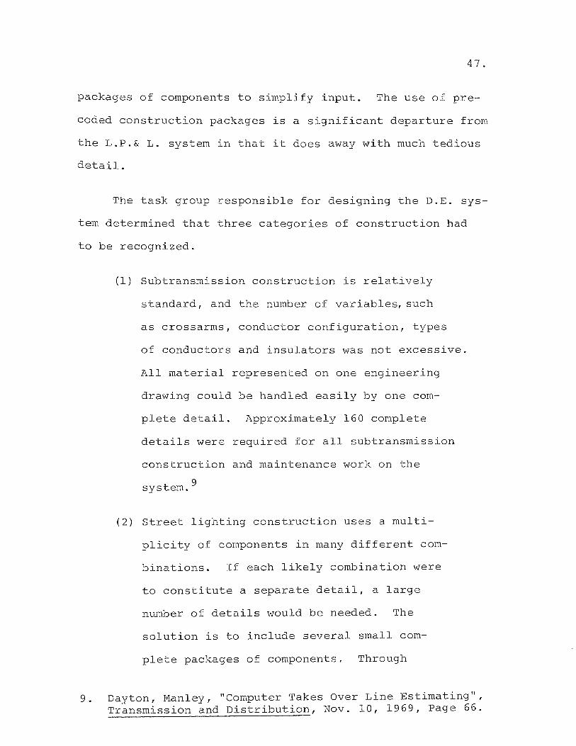
47.
packages of components to simplify input. The use of pre-
coded construction packages is a significant departure from
the L.P.& L. system in that it does away with much tedious
detail.
The task group responsible for designing the D.E. sys-
tern determined that three categories of construction had
to be recognized.
(1) Subtransmission construction is relatively
standard, and the number of variables, such
as crossarms, conductor configuration, types
of conductors and insulators was not excessive.
All material represented on one engineering
drawing could be handled easily by one com-
plete detail. Approximately 160 complete
details were required for all subtransmission
construction and maintenance work on the
system. 9
(2) Street lighting construction uses a multi-
plicity of components in many different com-
binations. If each likely combination were
to constitute a separate detail, a large
number of details \vould be needed. The
solution is to include several small com-
plete packages of components. Through
9. Dayton, Manley, "Computer Takes Over Line Estimating", Transmission and Distribution, Nov. 10, 1969, Page 66.
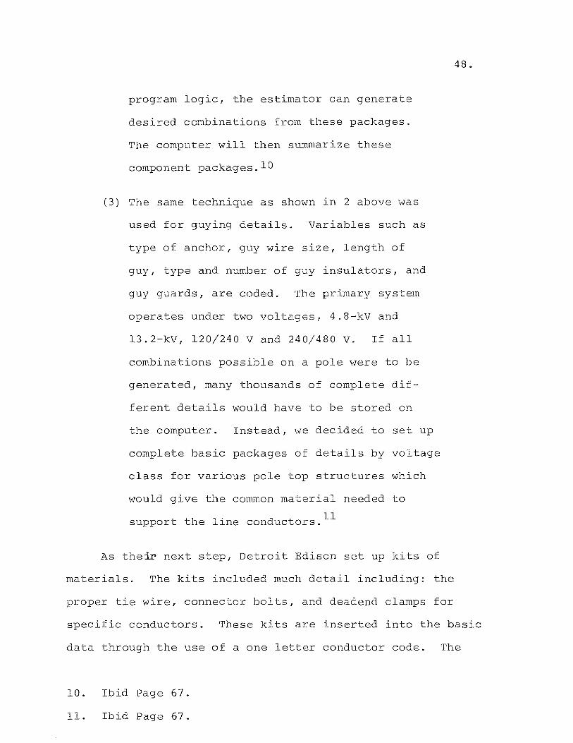
program logic, the estimator can generate
desired combinations from these packages.
The computer will then summarize these
component packages. 10
(3) The same technique as shown in 2 above was
used fer guying details. Variables such as
type of anchor, guy wire size, length of
guy, type and number of guy insulators, and
guy guards, are coded. The primary system
operates under two voltages, 4.8-kV and
13.2-kV, 120/240 V and 240/480 V. If all
combinations possible on a pole were to be
generated, many thousands of complete dif
ferent details would have to be stored on
the computer. Instead, we decided to set up
complete basic packages of details by voltage
class for various pole top structures which
would give the common material needed to
support the line conductors. ll
As their next step, Detroit Edison set up kits of
materials. The kits included much detail including: the
48.
proper tie wire, connector bolts, and deadend clamps for
specific conductors. These kits are inserted into the basic
data through the use of a one letter conductor code. The
10. Ibid Page 67.
11. Ibid Page 67.
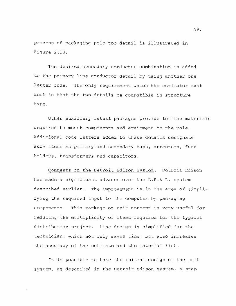
process of packaging pole top detail is illustrated in
Figure 2.13.
49.
The desired secondary conductor combination is added
to the primary line conductor detail by using another one
letter code. The only requirement which the estimator must
meet is that the two details be compatible in structure
type.
Other auxiliary detail packages provide for the materials
required to mount components and equipment on the pole.
Additional code letters added to these details designate
such items as primary and secondary taps, arresters, fuse
holders, transformers and capacitors.
Comments on the Detroit Edison System. Detroit Edison
has made a significant advance over the L.P.& L. system
described earlier. The improvement is in the area of simpli
fying the required input to the computer by packaging
components. This package or unit concept is very useful for
reducing the multiplicity of items required for the typical
distribution project. Line design is simplified for the
technician, which not only saves time, but also increases
the accuracy of the estimate and the material list.
It is possible to take the initial design of the unit
system, as described in the Detroit Edison system, a step
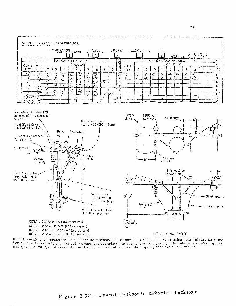
50.
DEL\JL - ESTIMATIHG O~DERIHG FORM DE:. FO~"'\ 0:[.. 112 1·6~
CLAS5!f"ICA.iION STPE:ET SY ST EM sua T RA~;$MISSION meN L1GHTtl"-JG COM"'~UNICATION a.p.L.,
[JJ OJ m PACKAGED DETAILS r' '-I
QUA."l- tOLUMNS O!
1 , ,
I 110 D~ QUAI+
TITY 1 2 3 ,I 5 6 7 8 9 Ei TITY 1
L/- 0 -S-- "Y -1 [0 IB 5 i /7 D!l "2 I
? 0 5 IX -==3 1::3 :72 I 5" L.t'1 ID! z / / 0 .5' X 3 o I 0" .LL.l:.P ..or Dn 2. 0 6 P 12. -4- C /=5 1/7 D:'
I / P 5" X 3 a L 2. 8 D~ L Z SiX 12 0 .J 'Z D3 .,S/ .Lj.. DU lliO/O D I Dl
I/)/ D }"\ -I I r\ , f
~enole 2 B deiail179 for grounding disconnect brocxel
Durabute cutout No 5 Be. IJf 13 !w - ed. no. "(06-0101, showil No. 6WP.ot 4.8 xv
Fuse See note 7
fer de!ail ~\ t: ~?l~@ ~:1
fl 2 "{?'{ . 3 J "~ ,- ,
,0. , ~ ]lose ~e .-E;..2;,~"~,"[--I':';Fi:-~~-.:'"". T !1:~ '8 'i. ... <>' 1 Phase
35 mal ~[o. 0- ~ tags to grade J'~j . ::
~ II '3' 0" £ttlstili1Qid OJo;(; / ~ij\ r; ;; -termitHltion lJt1d 'b»lf troi(fuoy UGL 1- lr::----·
.' f
~!-, ,I -t" N?utrol zone ~r7,L~~ for 4.8 kv if Il{)
;!2;~';;~£[~'" line secondary
t~~'i:uIJ r ~ H,,!IJtrcl zone for 13 lev
if 0';5 !iM 5 econdary
DETAIL 2023-P7A30 (13 KV armiess)
DET AIL 20Z3a-P7X30 (13 k" c(assam) DETAIL 2023b-P5A30 (4.8 kvcrossarm) OfT A IL 2023c- P5X30 (4.8 kv crosso(m)
t 4'-8" to second ary racr
W DEPT. (;703 OR DEH NO.
GENERATED DET AILS COLUi.I~JS
~ 2 3 4 5 6 7 8 9 .. '
~ r-f-~ '-/- £. 4- -4-.LL E .L). -'1
,
Secondary ~.
I
DET AIL 17260 - T5X20
C 0 0 _f G G G
2-r-\Y
G G r.
Djsc-,:~t::! construction d~tai!s are tbe basis for the mechanization of line detz:iI estimating. By breaking down primary construction 0f1 Z! ~Jiven pole into a prescnbed package, and secondary into another pack2ge, these can be selected by coded symbols and modified for specizll ciicumst2nces by the addition of suffixes which specify th2t particular v2~iat[on.
Figure 2,,12 = Dotroit Edison's Material Packages
51.
further. If it is possible for an estimator to select a
package of components out of a finite list, then it is
also possible for the computer to select these packages
given enough basic information about the design of the line.
This will reduce the work of the estimator by a considerable
degree, and lessen the expertise required to properly esti
mate a project.
The C.E.S.L. Estimating System. The concept of using
computers in real time in a time sharing environment is a
relatively current one. The third generation of computer
hardware provided the resources necessary to accomplish
the feat. The emergence of time sharing can be traced
back to Dartmouth University and the work done on the de
velopment of the BASIC computer language in 1967. The
ability for field estimators to have hands-on access to
an estimating system would provide power and flexibility
not available with batch oriented systems. Such a system
has been written by the University of Illinois Civil
Engineering Department.
The University of Illinois Civil Engineering Systems
Laboratory estimating program is a time-shared, remote
terminal system used by contractors, engineering firms,
and civil engineering students. Each user has direct
access to the system through a terminal similar to an
electric typewriter.

52.
According to C.E.S.L. documentation, no knowledge of
computer procedures or programming is necessary on the part
of the user to run the system. The C.E.S.L. programs are
designed so that all input is error checked. Although the
user has the initial responsibility of entering his data
correctly, cross checks are made between input and stored
data. The use of direct conversation techniques allows a
user to update and print out stored data while he sits at
his terminal.
The steps in using the C.E.S.L. system are as follows:
(1) Define the estimating accounts. These are six
character identifiers.
FOUNDN, ROOFG, etc.
For example, EXCAVN,
(2) Perform the calculations necessary to provide
quantities of material from the construction
drawings.
(3) Enter the estimating accounts with the quanti
ties of work units.
(4) Assign history file descriptors and access the
historical data files via terminal.
(5) Enter for each account defined:
(a) a lump sum cost
(b) a unit cost
53.
(c) a productivity factor for each craft
and equipment used.
(6) Create a resource cost file.
(7) Request preparation of the estimate by the
computer.
(8) Review the results and modify the estimate as
desired.
The procedure used in the computer for calculating the
cost estimate is similar to the method used in the L.P.& L.
system. Three reports are generated by the computer. A
detailed report which shows the estimated items and associ-
ated quantity and cost for each account. A summary sheet
is produced which shows the estimated costs that were cal-
culated using resource enumeration and costing for each
estimating account. Finally, a second summary sheet is
produced which shows a combination of calculated costs
and entered costs. The three reports are shown in Figures
2.14, 2.15, and 2.16. After studying the results the user
can modify his input data and rerun the estimate as desired. 12
Comments on the C.E.S.L. system. Although this system
is not specifically designed for electric utility estimating,
it presents some useful concepts. The idea of an on-line
system available for use when needed is very desirable for
12. Boyer L.T., "Remote Terminal Cost Estimating", Journal of the American Society ofj Civil Engineers, Vol 98 COl mar 1972 pp 14
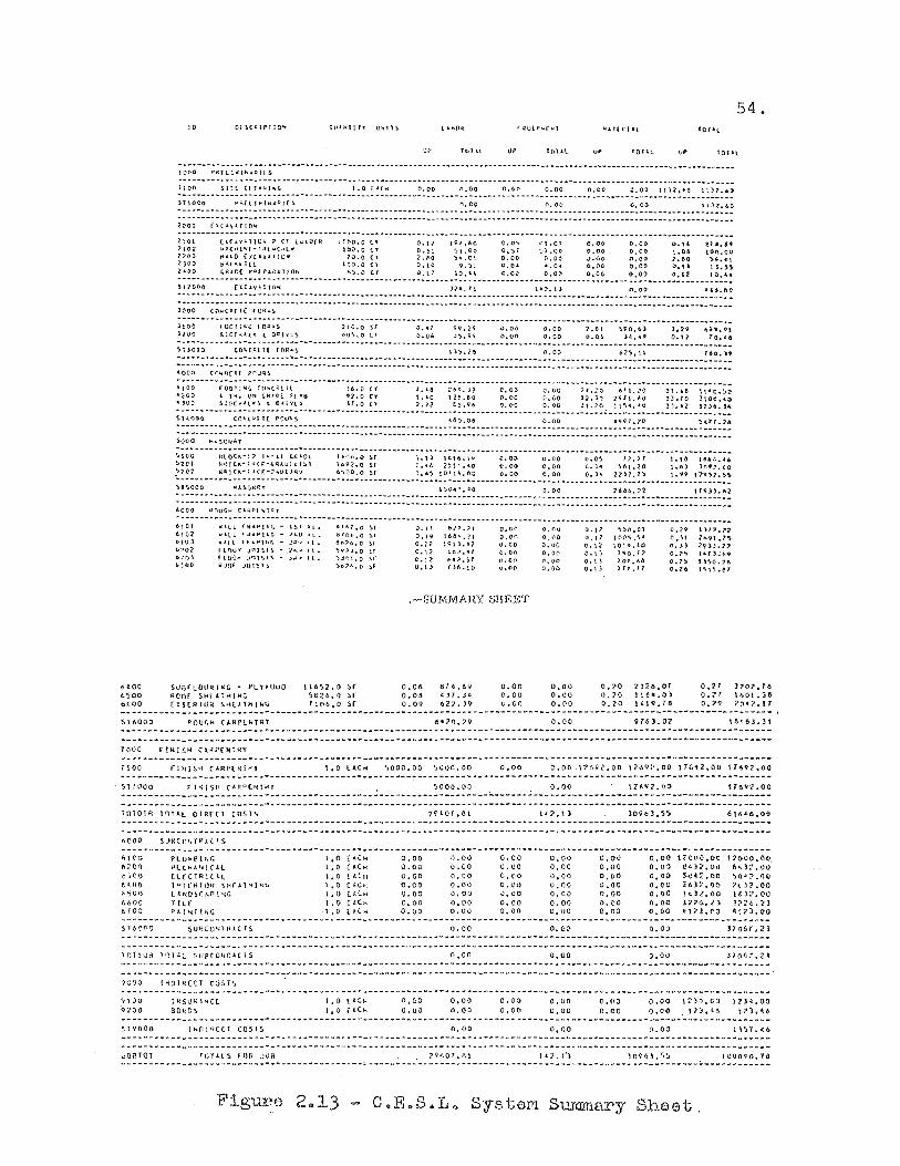
1><00 t;-SOO 6600
'ST6000
TIOC
10
UP roll! UP lOT J.l UP UP
~ ~;~-- -;;~ ~ ;:~:: ;~Z ~ ---- ..... -...... --- --- -- .. -.. -.. -_ .... -......... -............ -- .......... -........ -...... -............... ,,-,_ .............. ---- .... --- .... -- .. -- .. -_ ... --...... .. ;; ~~- ..... -- ~;~ ~ .. ;;;;:;: ~ .. --.. -_ .... --- .. -- .. ; ~~-~:~: -_ ........ ~ ~ ~~ .......... ~ ~ ~~ .. -_ .... ; ~;; .. -- .... ~ ~ ~~ .... -_ .. ~ ~~~ .... __ .. ; ~~; --~ ~~;:;; --~;;;~; ~ ---- -.. --- -------_ .. --- ----- -.. -.. ---- ---- .. --- -- .. -- --- -- -- ------ .. ---- .. -- -.. ---_ .... --- -------- .. --- ..... -........ ----- -----_ ... --------SHGOo pqlllo, .. ,::t!£5. (\,0(1 {'I.0v 0.-00. \1)1.&0 .. -_ .............. -_ ...... - .... -_ ............ - .. -.......... _ ...... -- ...... -_ .... ---_ .......... -.......... -................ -_ .. --- ...... _ .... -_ .... '" -_ ...... - ... -.......... _ .. -.. _ .............. --- .. .. ;;~; .. --;: ~~:; ;~~: ---- .... --_ .... -_ .... -.. --_ .. -- -_ .......... -.. -_ .. -. ---- --- --_. -- ~ ...... -~ .. ------_ .... -.. -- .. -- .. -.... -- .. -_ .. -- -. -- .. ---- .. -------------_ .... ----- -- --------_ ... -.. ----- .... ----_ .... -~ .. ---_ .. ------ -- .... -.. --- ........ ----_ .... --- .. --_ .... --_ .. ---.. -- ...... ----- -- -.. ---------
(l.(h'.I.1!l)1.i 7 (1 LU1U{R tltlO.O ('f Ool:;' l~'.!O 0,0';' fL09 0,00 0.000 0.16. ii!1.a.69 ,,"l(kp·r-l>l:t .. C"'l~ 10;',0 (l OT~l ~t.OO 0,.,1 ~1".QO 0.00 0,00 t.06 tOO.OO 1-1.1."0 {J:(iI.'t'.l!lOtf ?O,O CY ~.-'!O ';l .... Ql 0.00 O~OO 0.-00 0,00 1.00 ".IIt..,ll 6.1.("", ttl.. lC:J,O () 0.10 9.SI 0,0' •• Ot 0.00. 0.00 0.1' 1 J.YS ,Ri.[:{ PI:I[f'.I.R;l11l1J. 1.-".0 (r 0.t1 IO.-t~ C.G;) 0,000 0.00. 0.0t'! 4.12 10.'"
- - -_ .. - -~ - - .... -- ~ -_ .... - .. ~ .. - -- ---- - -_ ... _ .. - -- --- --- & ... ~- - ...... - ~ .. -_.- - .. " • - - - -- - -_ ... - - -. -- .. --- - .... -_ .... - ... - --- - ----- .... _-- ---- ........ --
511(.00 [1.(l..,1110,,: J;:>"1(, t.ll;].t) 00.00 ~'6~60 -- .. -....... --- -.. -_ .. ----_ ....... -- -- -. ---.. ---_ .... -- .. ---_ .. --_ .... _ ..... --- ---. ----- -... -... -- _ ...... -.. -------_ .... -- ----_ .. --- _ ..... ---.. -_ .... - ... -- .. --... -- .... --_ .. --- ---_ ....... -_ ........ _ .... -...... --.. --_ ...... ------- .. -.... -- ......... --- -_ ........... _ ...... _ .. _ .. -- ---- ..... --_ .... -- -.. --.... --_ .. --- ---_ .. _------
------ - -_ .... -_ .. -~ .... -..... ~ .. '"" -.. -.. -- .. -... -- ~ --- .... -_ .. _ .. -.... _- ------- ... -.. ~ -_ .. -- _ .. -.... ---_ ....... --- -.. --- ---_ .. _ .. ----- -_ .. --- -_ ... -... --.... -.. ~l)OOO C.O'-(t:(l( rt);::? .. S 1l~.?6 <l.Ot} to?';.l\ r6o.lt -.... --......... _ ... _ .... -...... -- .. ---"- --'" _ .. --_ .. -_ ....... -.... -... -------- .... -- .... --- -.. -- --------- --- ... -....... -.... ---............ -- --- ----...... _- -------- ... :~~;--- ~ ~~;~; ~ -;~~;~- .. --- --_ ..... ------.. --. ------ .. ----_ .............. -_ .. -_ .. _ ..... - .... --_ .. ---- --- .... -- ....... ---...... -_ .... ----... -- _ .. --_ .. ----;~~; --_ .... ; ~;~~: ~ -~~I:~; ~~~ ----_ .. --.... -~;: ~ .. ;; -_ .... -- .. ~ ;~:; -.. -; ~:: :;_ .... -.. ~: ~;- .. ---~~~; -.. --; :~;; .. --;; ~ :;; -_ .... ~ ~~:~ .. -; ~; ~ ~;; "<00 L pt. (Hl GIH{)t SL.lH 91.0 (1 !,'O 12a.e-o 0.('0 O,VO 12.HI 2-<;11.1.0 lLTO 3100.'-0 "')00 SdoC"'l""j t O"iyt!> H.O (l '1.12 r:.~.'il> O.DO o,~o 31.:-0 IIS~,~O lJ~.2 nle.ld. ...... - - .... - .. _ .. - -- - .... _ .. -_ .. - - p .. -_ ...... -- _ .. ---- .. -- _ .. _ .... - - .... _ .... - .. _ ...... - - -- - ~ _ ....... -- .... -- _ .. --_ ........ - .. _ ...... -_ ... -- - -- ....... - -- - .. - - .. --- ..........
Suoo,) CO"'C ... rH f'oul<!> ",So,oe 0.00 uQ1.70 ~tll.24 :::::: :::: ::::: :::: ::::: ::: .. -_ .. -- .. -.... -- .... -----_ .. -.. _ .... -- --_ .. ----.... -_. --.. -- .. -- .. ---_ .. --- --.... -.. -.... ---- _ .. _ .. -------- --.. -_ .. _-.. -- -- .. --- _ .. --~ -_ .. ---_ ....... -----_ .. -_ .. -.. ----_ ...... ---- .. -_ .. -_ ...... --... ---... -.. -- .. - .... ---.. --- ------- .. ---'looo
suarLDU~l~G .. PL'>UuO ROOf S-H[ATH(HG [Xl(QIU~ ~~(~lHI~~
IIbS2.0 ~r Sb2t>~0: .!:Ir Ttflb~O Sci
1.0 (AC ..
.-SUMMARY SHEET
0.0' 0.0. 0.09
fj!C.6~
.cd 7. jl:l
6'<.J9
~ooo.oo ~OUO.OO
0.00 0.00 o.OC
0.00
0,00 0.00 O.~O
0.00
23213..01 H 64.0) 1419. fa
54.
J?01.76 1.1\01.1& 70·?lT
___ ~ _______________ ~ ___ ._.- _______ .. _______________ ~ __ ~ ___ "M~ ___ ~ ______ ~ ____ • _______ ~ ____________________________ ~ ____ _
~"(100
IQI01R to,ll OIRfcr COSI~
6~OO SU6CO~r~jC1S
Plu;.;B Il-;f. )J.l(H.t.I'ICI.L (l(CTRICAl lUl(~il)~ ~KrA1Hlk~
L.t.NI}!)CAP\4G YlL[ P.l\ .. T!~-G
SUt3C Ol.tl R 1.( rs.
1000 I~DI~(Cl COSTS
9100 9100
S-l'i'OOO
BO~OS
1.0 ( .. CH l.O (,.C~
t.O (ACIt 1.0 (",CO-{ LO (I.CJ..
1.0 (ACH .1,0 [H ...
I. n t :'::1{
1.0 (.1;(.1-{
0,00 0,00 0.00 0.00 0.00 C.oD 0.00
1.1.(;[)
0.00
SOOG.OO
0.01.) 0.00 0.00 0.00 0,00 0.00 0.00
0.00
n,OO
0,00' 0.00
fl.OO
o.co U.OO O.CO 0.00 J.OO O.CO 0.00
0.00 0.00
0.00
O,c·o 0.00 o~oa o~oo
a.co 0.00 G.OQ
O.cO
0.00
0,00 0.00
0,00
0,00 0,00 0,00 v.ao iLOO 0.00 (\.00
O. (q)
O.OQ
309.3,55
0.00 0.00 (j.OO 0.00 0.00 0.00 0.00
n.oo
0.00
170tJO.OC e~l:?OI.1
5D1!t2.00 ZGJ2.00 !t.l:l.OO 10'2'6 • .? ). .e17! .. <"O
12000.00, 6il.37.00 ~O':'~rjO
1'( j;? 00 1~)7.00
:32-:-!o. ~ 1 I;t7J.OO
0.00 12~D.oa 11)4.00 0.00 17).t~ ll).~6
JOP-10t 'OlA.lS InR ,JUB ]9 .... 01.(Q 1l2.1·) )O·H:l.S~ tOQ{)90.11J _~~ ___ ~ __________ ~ ______ ~_-_~"~~ ____ ~ _______ ~ ____ N~ __ ~_~ ___________ ~ __ ~ ___ " __ ~~_N ______ U~" _________ ~_~ ___ ~_~ ___ ~ ___ ~ __
Figure 2,,13 C.E .. S .. L~ System Summary Sheet,
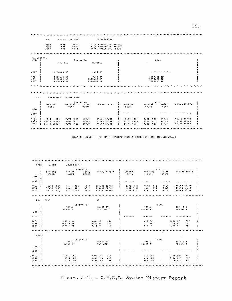
.109
JM9 .J!Jij6 ' Joar
P'l."tRUlL AoCCOUlif
~102 6102 COll
OESC~IPTlO~
KAlL r~L»t~G ~ 2~D FL. ~AlL f~t~I~G - Z~D fL • fA'WE ~ALlt J~O rLOG~
55.
@VU<lIHn JOO I (ST l~kT(O ,lOll
I 1"lllAL ~(yIHO
I I I
JI)£9 I 6l'O6.00 Sf 0,00 sr ...... _ .. _ ..................... I
AV(! I re,o~,.o Sf O.~O Sf ttcy.ZO U .. Hh';tt 1 tHO,OG Sf" 8~'O.OO sr 'rotl.I)" ~r .1007 I THO,CO H n1ZO-,.,I)O sr "HI~J.OO ~v
2010 ClP.P(kT(R JOU!I(JC(YJ.(lU
lSTJ"HO f!KAL H·rI~( ()rTI~( \Ol'Al ~ROOUC n V [TY ST-TI<[ O'-ll~( TotAL r_ooutT J VI Ty HOU~S HUUfC:S I<OUH HOURS ~OUR' HOURS
JO"Cl
Jt)ij9 ---------.. -kV£. O,O( 00 O.'IJ( 00 198 •• 19 • .3' Sf/HR O.O( 00 O.OT O~l IC~ .S Lt.?O H/K~ ,JO!?b !'G..~(loOt) o.U( H) t6G.9 H.oO sr/KR-_ 1)2.0( 9,,:> s.O( .t) 1(0.0 ~o.()~ ~f/Hrt
J(dil l'9.ZttOO~) o.V( 00 U,9.2' 40.-00 SF ItHf 12'.5( -i1'" ~2.;Z( H) 1);\". T -.1.'16 SF/Hi<
EXAMPLE OF HISTORY REPOHT FOR ACCOUNT 61.02 ON ,JOB J0139
iii .................................................................................. " ........ t ........................... , ................................................. ..
1010 LJ..HOR: JUURHfYt4J..ti
[SllI-lAT(n ST-l1"£ U", ... T 11-<[ tOTAL HOUR~ ,",uUH5 HO{H~S
.)08
JOB~
,.V( .. O.O( Ot) o~UC 0.) -67 •• JOB6 ')r~,)(100!) o.u{ 0') ~T.5 .)oel !>-9. T ( lOOt.) O~Vt 0, ) ~Q.7
PRnplJ(TIVlfl
1<';,09 ~r/HR t lI.ij. 00 Sf" IHR 13t1.00 Sf IHf.1
o.O( O'L) t ~. ')( !\~t)
6~;"~( 9-11)
fI"'.l.l nV-Tl~[ 1nTll l-(UUf~S ttnUAS
O. oc Ot) o..O( t 61:)
" •• ( 9 f)
P~OOUCTI\lIT'f'
!olO.t17 sr/~Jt
IJ6.65 !,r/HR 116 t 69Sf"/HA
11' ........... "" , ................................. ,:, • .:; ................ "" .. ' .................... "" ..................... 1) ........................................ .
Joe
JOB?
JOg
JOS?
• LyE. .JC1)6
.JQ!H
PIN£
lOIA.l
6'1 j6 '" 0- lif n69j~ \ tlf 6";/~{ Hf
T(ll!L
IlUI.h'tI I r
(~l pU.TfO
t\o.v LUS-8~. I lHSo tlL ~ L!HS
QU.o411TY PER \IN! T
o.~o HF 0.' I Sf O.ld l:lF
/Sf IH (Sf
OIJJdd lTl' PtR wn r
O,<':l Lt.lS O. n I Lf{~
o t 0 i LflS
( Sf I Sf f Sf
lOlLl QUlo.lo4'ffTy
0.0 nf 0,0 Of 0.0 kr
0,0 l"~ 0.0 ll1'> ll.O t ~s
f T ~b.L
OU"~l11Y P-(R UNIT
o.on fjr 0,00 Sf 0.00 ~f
!Sf /sr /5r
QUA ":1 tl t p(n V'i.' 1 T
o~oo las 0.00 Lf\S 0 .. 00 Lt.:S
.. ~<I. • ./> ........... oS~ .......... f •••• " ....... , .............. ,i ... '~., •• <I. •• t ....... o .......... 't .. * ............. _~ ............................. -.Io,,"' ................. ,.. •• -:. .. ...
Figure 2'014 CoE.SoL. System History Report
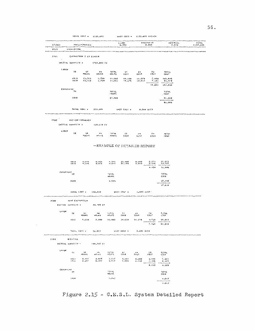
U-f';.OIl' ('I>tJr .. I'(~' Jt4HRtAl t"flL Sflt:iOO f'iIt£t.I .. I ... .tA,J(S 0.000 0.000 0.001;) tlJ::- •• OC .------ --~ ... --- '"''' -- -.. _ .. --_ .. --- ... ---- ... -----------.. -_ ....... __ ... -_ .. -....... -.... -_ ... ---_ ... ----- -- ------... -.. ---_ .. -.. -_ .............. _ .. -.... -.. --- -- ..
210t ( l.C'-'vl.IIUN l ty 1..0~Oflt
(1(Ill.Ll 'lUklllJ . I 'OO~()OO <>
t..ltOA 10 " ,w rOllt "
., .. lOUL iI1(1,LJ~s. ,.;flU"! rcQUA!» (OH (Un (OH (05.1
HHQ l~ .. JOO 1. ToO 11 .. coo &ol.l '50 lC .. 07~ T .''SO I 'OS.',,!. 10tO 15-.100 t. Tou tT.OOO T7.6T~ 1:<'.11" T.UI '1t .. 'n.
14:.ill ~ 1 \-U .10.
(oUlp'k(uf to 10 r tL tOY.1l
"'OURS COSO'
1;)10 iT .000 Al .. 0~O -_ .. _---- ..... 81.090
- TOtAL (0:>1 . 7' .... 69. U'fll COS,T 0.164; $,CY
-- .--_ ........ _-- _ ... -.. ------- .. -..... -"'-----_ .. ---_ .. -_ ......... -- -_ ... ---.. ------------- _ ... --.. ---_ .. --_ .. --- ---- _ ..... -_ ... -... --_ ... -... ------------- ...
Iw1Tt.t.l ~Ul.w'll' c IOO.OOQ Cl
I. S1 (ust "' (U~l '" «(t!>1
-EXAMPLE OF DETAILED REPORT
&011,/ 1010
,.~."" .. ~,~
fDILl lO~ f •
0.000 0.000
"'00 H"IIO ();C.l.y.li.ttooc
;neo
1),'ITI'l c..-vl"cllr,. •
'0 1010 1.000
RJ.c..:r ll\.
hlfll.t QU.lI'(\ tl '( . 1 Oo.ovO· (.
ll.HlIA
'0 " " '"'«!.JotS ~~Oll .. ~
.tOIO 0.6'1 0.0-00 1<::1 u (1,0" o.oeoc
F ' ? I'''' ~gure <....,,_:>
(JIIIJl CO!.f •
te.ooo
" COSt
)4.000
IJ-.ll (0\1 ..
'tIlt. >lC:;Ps
o. t ~ 1 o. ti .. r
10 f ~t HDUIi.'J,
" (OH
O.L"'Io. C. (100
14.2\0
o~oo.o
0.000
'" tOST
f. C'O::'1
TOllL (OSI
~1' .coO
\T,OOO
lOUl C.O!.l
rOUl c O~ f
J.. 01..,
C.E.S~L. System Detailed Report
56.

57.
cost estimating. Rapid turn-around, and the ability to
modify the input data for result comparison, adds a needed
dimension to computer-based cost estimating.
The ability to manipulate data files and create files
for special purposes would work well in a de-centralized
operation such as the Electric Distribution Department of
Public Service. Each of the Company's field locations
would be able to set up and maintain data files which would
more accurately describe local productivity than a general
file stored Company-wide.
Summary
This chapter has attempted to acquaint the reader with
the scope of electric distribution construction. The various
crew types used to do this work were introduced. The basic
types of construction were explained. The reason for doing
this was to give some appreciation of the complexity of
estimating this type of work.
The latter part of the chapter introduced the concept
of using the computer for cost estimates. Three existing
systems were reviewed. Two systems were designed specific
ally for electric distribution construction estimation:
the Louisiana Power and Light system and the Detroit Edison
system. The L.P.& L. system presents some good ideas on

58.
organizing input data, and on the use of random access
methods for handling data files. The Detroit Edison system
introduced the concept of construction packages or units in
order to simplify the required input. The third system
investigated was the University of Illinois Civil Engineering
Laboratory estimating system. While it was not designed
for electric distribution estimating, it uses real time
concepts which the author feels would be beneficial.
CHl\PTER III
MANUAL METHOD FOR COST ESTIMATING
Introduction
The purpose of this chapter is to acquaint the reader
with the currently used manual methods of construction cost
estimating in the Electric Distribution Department of
Public Service Electric and Gas Company. The preparation
of the necessary data will be discussed first. The
gathering of cost and productivity information is then
covered. Finally, the preparation of the estimating forms
is reviewed.
General Steps for Estimate Preparation
The preparation of a cost estimate is a relatively
complex function. The job consists of the following basic
steps.
(I) The evaluation of proposed circuit routes.
(2) The determination of required material and labor.
(3 ) The gathering of cost information.
(4 ) The preparation of the estimate form.
(5 ) The preparation of the estimate summary.
( 6 ) The preparation of a stores requirement
listing.
Evaluation of Proposed Circuit Routes
When a plan is received by the major projects group
60.
from the planning group, the first step is to check primary
and secondary circuit prints in the office. This is done
as an initial step to check the feasibility of the proposed
route. Having done this, the engineer will survey the pro
posed route in the field. The field check is performed
because circuit prints do not indicate obstacles and route
problems that may actually exist.
In the course of the field check, the engineer looks
for such things as; tree problems, existing pole conditions,
guying problems, telephone construction, to name a few.
Primary circuit routes are measured with a wheel device.
Underground cable routes are measured with a tape, since
very accurate cutting lengths are required for the expen
sive conductors.
Determination of the Required Material
During the field check, the engineer will take notes
on a secondary print which shows the street plan in a one
inch to one hundred feet (1" = 100') scale. The notes
indicate the major items of material required to do the
job. After returning to the office, he will review the
prints to determine the total amounts of each material
item needed. The reSUlting material summary includes wire
and cable lengths by stock type, number of poles of each
size and class, pole brackets, insulators, c~ossarms,

61.
transformers, etc. The development of such a summary from
print and field surveys requires a thorough knowledge of
construction.
Gathering of Cost Information
Current costs of various material items are gathered
by the engineer from the monthly stock ledger. However,
in order to use the ledger, the engineer must be familiar
with the class and code number assigned to the material
for which he seeks a cost. Labor costs are not so uni
formly arrived at. Current practice is for each engineer
to develop his own figures for work units based on his ex
perience in his division. Labor costs are calculated from
productivity figures using base labor rates unique to the
local field division. The rate is unique because it is
partially loaded to reflect the non-productive time for
each division.
After the base costs are assembled for each unique
job unit, they must be sorted into proper electric utility
accounts as required by the State Public utility Commission.
The engineer is supplied with a material accounting guide
by the clerical group to help him with this procedure. A
page from such a manual is shown as Figure 3.1. Even with
the aid of the manual, the sorting procedure is time con
suming.
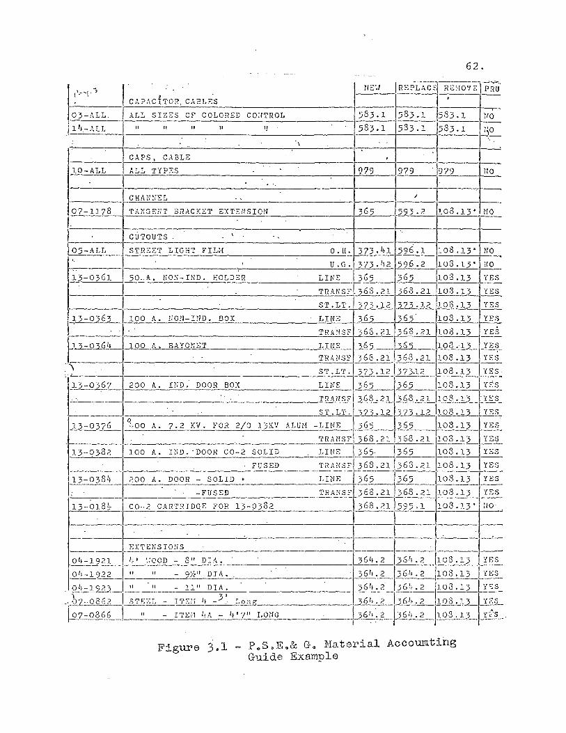
62.
I CAPAd:o'R, CABLES
I REl'i'ACf ---'"-~-
t"'~-"""'"~ . -; 11 E';! R~['iO'! E PRU
•
03-ALL ALL SIZES or COLORED CO;lTROL 583.1 583.1 583.1 llO
1 1,-ALL " II " II '! 583.1 533.1 583.1 'iO
.\
CAPS, CABLE , 10-ALL ALL TYPES 9'19 979 979 tlO
. '. CHA,·mEL ' , /
07-1178 TA~:GEHT 3IL\CKET EXTENSIon ~ 593.2 108.13· 1'ro
CUTOUTS \
05-ALL S1'RSST LIGHT FIL}! O.H. 373. 4 1 596.1 108.13" ~fO
, U.G. 373. 1,2 596.2 103.13~ HO ,.
13-0361 50,A. NON-HID . HOLDER LINE 365 ~108.13 YES
I TRANSF~21 63.21 ,108.13 YES
ST.LTl3]5.12 )~.12 103.12 YES
~J...l=.Q3~_1 100 A. NO~I- IND. BOX LINE 365 ~. 103.13 YES
·l TRA:-ISF 368.21 363.21 103.13 YES
~\2-03Glf 100 A, BAYOJ-n:T LINE :262 36 2 103.13_ YES
I TRANS:: 368.21 )68.21 1108.13 YES ..
".~~;- 200 A. INO" DOOR BOX LINE 365 1365 /108.13 I YES ~ , .• ~. ST'LT'~"73'121373.12 /108.13 IYES
___________ '_-"-T.:.!.R~A~.lSF ~368 .• 21 1108.12 TSS
i--'---__________________ "'-S,T-o....O-. =L.=....o.T. ,XZ.3· 12 3B· 12 .h08 • 13 c-I2§.,.. ..u.-03'(L1~.,00 A. 7.2 KV. FOR 2/0 13K'! ,!\.LUI-! -LINE _ 365 )65 108.13 YES
+______ TRANS? 368.21 368.21 103 .13 _~
13-0382 \100 A. IND. 'DOOR CO-2 SOLID LINE 365· . 365 103.13 YES
FUSED TRANSF 368.21 368.21 108.13 YES
13-038 1, [_?~~-;~DOOR - SOLID_" _______ L_I_N_E---\ 36-5-u--1365 1108.13 YES
r~ '. -FUSED TRANS? 3~368.21 108.13 YES
13-018~ I. CO-.2 CARTRIDQE FOR 13-9382 368.21 ~95 ,1_1_1_0_3_,_1_3_' ~
1 EXTErl~IO:[S ·1 L ~-1-9-2-1-!' If I ',IOOD - 8" DIA. 36 1,.2 364.2 108 .13 ~ .Q.1!-1'Z]2 -' II " - 91l" DIll.. 36 1,.2 364.2 103.13 I YES
. Olf-19?}_I" It - 11" DIA. 36 1 •• 2' ,36 1.,2 103.13 b~ )a-0362 I STE":L - I'i'Sil If _3' L..2...!l.e _______ .'---_~!J11 :L~I ~ 6 1,.2 108 .1~_ y~S I 07-0866 1~-tl----I'rEi.1 llA - 1,' 7 11 LOriG 1.2_~~_ )6 1,. 2_ho3 .13 _'£.53_.
~ . . I
Figure 3.1 - P oS0Eo& G. Material Accoumting Guide Exsmple

63.
Preparation of the Estimate Form
After the costs are spread into the proper accounts,
the estimate form can be prepared. The layout of this form
is shown in Figures 3.2 and 3.3. A brief set of instruc
tions for filling out the form is as follows:
(1) The required loading for labor and material
is different in each division but are approxi
mately the following:
(a) labor loading is 130% of direct labor.
(b) material loading (OR) is 50% of material.
(c) material loading (UG) is 25% of material.
(2) E364.1, shown in Column 1 of Figure 3.2, is the
pole account. Some thirty different poles are
used with 100 possible labor productivities.
See Figure 3.3 for a partial listing from a
table used by a field division in their manual
estimating system.
(3) E364.2, shown In Column 1 of Figure 3.2, is
the crossarm, bracket, and guying account.
A partial table from the same source as
above is shown in Figure 3.3.
(4) E365, shown in Column 1 of Figure 3.2, is
the account which contains the major costs
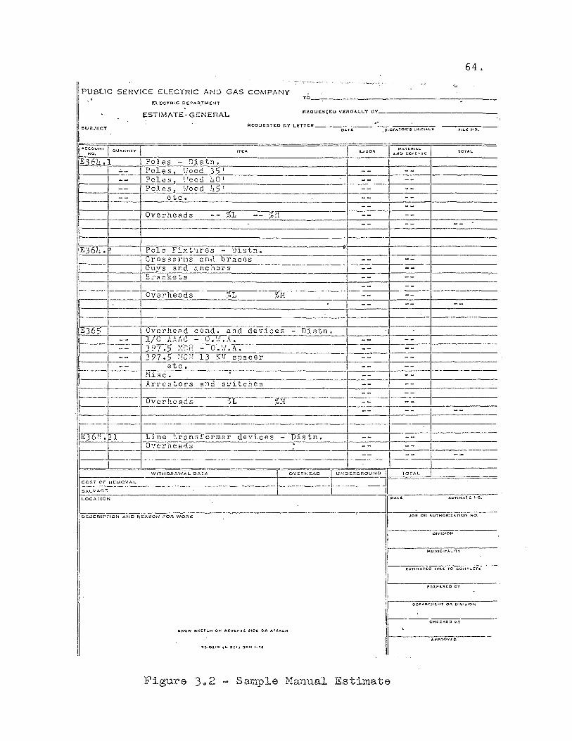
64. ~'~---' .'-','
" PUBLIC SERVICE ELECTRIC AND GAS COMPANY . TO, J(L£CYRIC OEf'AR.TMfNT .
. ESTIMATE· GENERAL
iRI!:QUES,[Ea VERBAl..t.Y BY
REQU~STEO BY LETTER .' SUBJeCT 0..t.1'(' OIC'tATOA'., tHITI"'L$ 'TL.i( N::>.
. ""CCOl!Nf
QU"'NTI't't fUM L..,U'IOi=!; ~"'TCRI.A.IL
'tOY"A~ "0, "'NO IO(r.tN1ii!:
E36h.1 I Poles - :1istn. -- Poles Hood 35' -- ---- Poles-,_ ';rcod hOI -- ---- Poles vlood U~I -- ---- etc. -- --
-- --Overheads -- %L -- ;elf -- --
-- -- --
~6u_. Pole Fixt 11res - Distn. CrossarPlS an,i braces -- --Guys and anchors -- --SrC1ckets -- --
-- --Overheads :r;L %1·1 -- --
-- -- --
E36~ OvcrheC1d condo and devices - Distn. -- I/O HAC - O.H.A. -- ---
397 .~ :>: r. !'f O.~J.A. -- - -- ---- 397 .)!fC:l 13 KV spacer -- I ---- etc. -- --
!Hsc. I -- --Arrestors and sl·,i tches -- --
-- --Overhea.ds ~t %~,! -- I -------
I I I l=
-- -- --
E~ 1 L:ine t.r~n3£'orr.ter de'fices - Distn. -- --6'rerheads -- --
I --I
--
I --
I WITHDRAWAL O ....... TA I OVEra:EAD JUNDERGROUND II TOT.f.L
cost Or R!::MCVAt.. I I If ::;:ALVAG£ L
II PAT<
LOCATtON i:!li'-IMATC NO.
D£SCRIPTlON AND REASON FOR WORK I .IOU Ort AUTHORIz. .... norJ N.:."'.
I OIYI!llON
I J.(UN1Ct,.;'I...ITY
I £~Tlt-lA1'II:O TlI.(( TO COHPL;&:Tt. , ./"J:\I.PAflCQ til'
DI:"AftT!-U:I-U 0 ... OIVI:510N
C~H:CKICO a'l'
&HO ..... S..:tfCH ON ;J\il:..,Cf\:U:. :tIOC OR AUACH ,
Ir--· AI"p..nO'w'£o .-
I D~.O;tI" ,t: ,2.1) JjOH ~,"!I
Figure 3 .. 2 Sample Manual Es timate
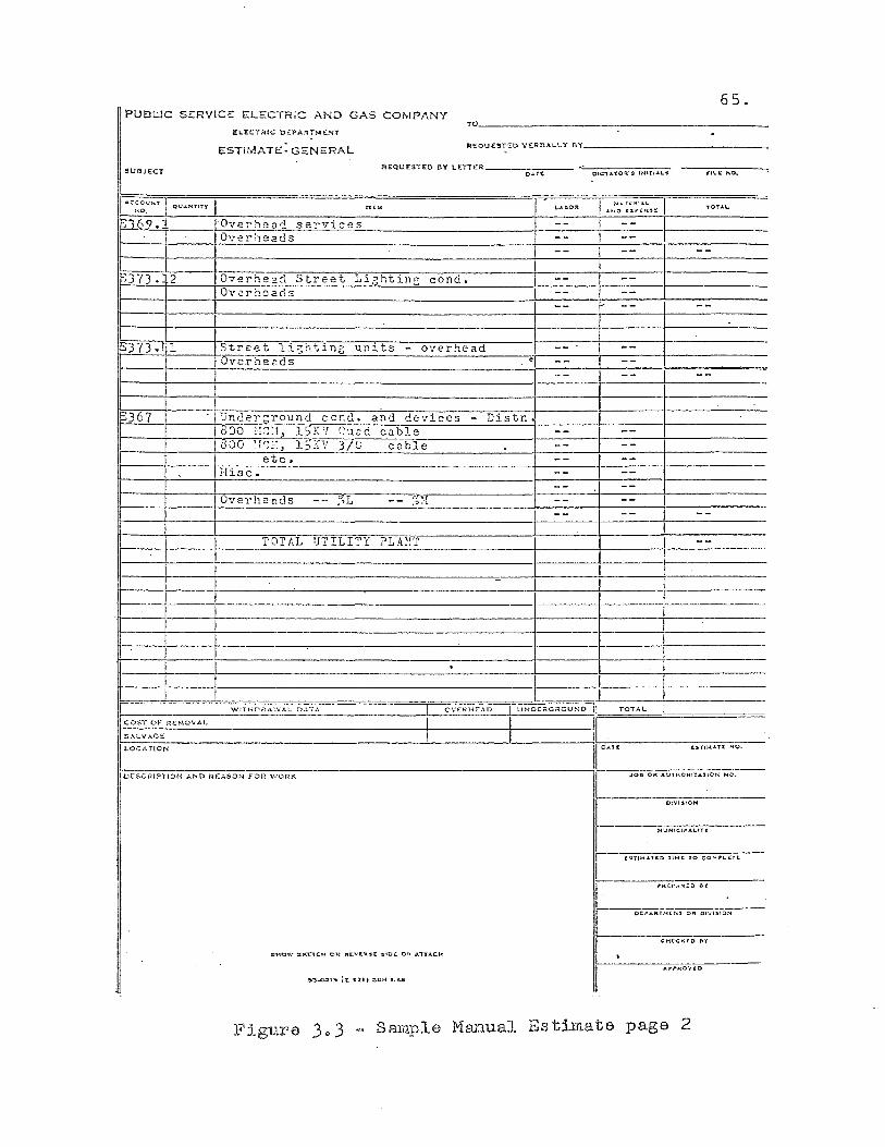
65. I PUBl.:.!C SERVICE ELECTRIC AND GAS COMPANY
EL'ECTRfC OEP-ART!otENT
ESTIMATE: GENERAL
SU9J'ECT
TO' ____________________________________________ __
REQU£STED VERBALLY 8"(' _______________ _
A£QU!:SiED flY LEiTER ____ o=-.-=,:-::.,...-__
J-O ... n:I'lU,L "'-"'OI;XP'(N,(
E~69.iT ______ ro~v~e~~~~~.~e~a~~7-~s~e~r~v~i~c~e~s~------------------------+---------}---------r---------------Overheads
'373. 2 Overhe~d Street Lightin3 condo OVi:!rhsarls
Street lishtlng unlts - overhead Overhe;:ds
etc. Hisc.
Overhends
TOTAL UTILITY PLA~T
r-.---+-----+----------------------------------------~-------+-------+-------------
r---t~----------~~--~--W!THDRA'.vAL 0..:..,:.. OVER};~AD UNOC;iGRCUND TOTAL
~':.T.-O-F--R-E-"-O-V-A-L----.------------------+-------+------__ ....JIll SALV:~CE .
I~L~O~C~A-'_'O~N---~--------------------------------------~1l:!ATl OESCRIPilON AND RE ..... SO:-.l FOR ""ORK
I:STI::.tA T (. NQ.
.Jot! OR AuIHOR1-:AnON. NC'.
CI'-'ISION
~Uf.jlClf"ALI1'f
r- l:OT!,.."TI:D 'H~C to CO:--;;-Lcrt
I
D[:-PAIiTH(lir OR OI'.,'lS!O~
CHtC"eo bY
~. ,
Figure 3 .. 3 Sample rvIanual Estimate page 2
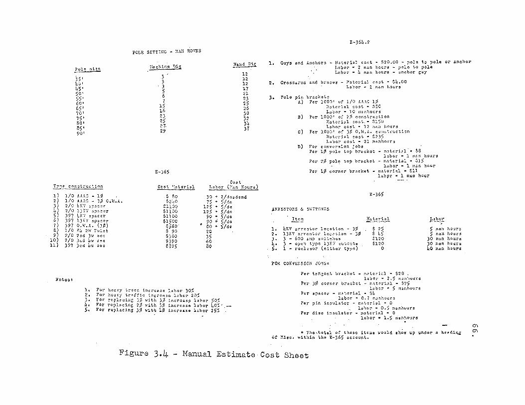
!.n: e
1) 2 ) 3) h) 5) 6) 1) 8) 9)
10) 11)
J$' hot hS' SO' SS' 60' 65' 70' 75' SO' 8S' 90'
con3truct1on
1/0 ABC - 1:3 1/0 HAC: - J¢ O;H.;'. 2/0 4K'/ ~p"cer 2/0 1):{'J' s?.1ccr 397 hK7 spacer )97 l):<V sp.cor 397 O.H.A. ()l) 1/0 ?!J ?rF T"ist 2/0 2ed )." see 2/0 Jed 4" ,,.e 397 Jcd 411 soc
POLE SETTIUG - !{Ali HO'fRS
!lachine Dill.
3 :> :3 5 6 7
15 16 23 25 27· 29
1':-)65
Cost
.$
':n terial
80 $240
$1100 S1100 S1100 $1500
$S60 $ 90 $)00 $390 $825
1. For hocvy trees incroRoe labor 30~ 2. For heavy tr.rfic incronse labor 20~
l{IInd Dig
12 12 12 17 21 23 25 26 )0 32 )1. 37
CO" t Labor ()t~n Hours)
)0 + 2/do;;dend 75 + Side
125· + Side 12S • 51de
90 + Side 90 .; Side eo • Side 20 35 60 So
3. For rcp1.cin<; 315 with ).0 incro".p ln1>or 50J 4. For ropl~cinc 215 with 315 increaso lo~or LO~'.-S. For ropllcinS 3. with 1. increa.o labor 2Sl
E-364.2
Ouys ~nd Anchors - Material cost· $20.00 - polo to polo or gnchor Lnbor • 2 man hours - pole to pole
1.
2.
.. Labor· 1. man hours - anchor cuy
CroS5~ras and hraces - Material co.t • Cb.OO Labor - 2 man hours
Polo pin ;...)
B)
c)
D)
brackets Per 1000' of 1(0 AIAC 1_
~atcrial cost" sao Labor· 10 g.nhours
Per 1000' of 2~ construction Material co.t." 8150 Lohor cost • 12 nAn hour5
Fcr 1000' of 3. D.W.A. construction !toted.l cost· :';235 l.nbo~ coat - 21 PAnhours
Fer convc~sion jobs POI' 10 pole top bracket - materiel·· $8
labor " 1 ~nn hours Por 2¢ pOl! top.brackct - ~aterial " $lS
lnbor • 1 nan hour Por 1¢ corner brecKat - matcri"-l • $11
1ab9r • 1 nan hour
ARRESTORS & SWITCHES
~
1. 4KV arrestor loc.tion - )~ 2. 13KV ~rrcstor locotion - 3¢ ]. 3 - 600 .rna ,witch •• b. ) - open typo l)~'l cutout" 5. 1 ~ roc1osor (eithor type)
FCR CONVERSIOn J01S~
E-)65
Hn to r'i a1
$ 25 $ 4S $120 $120
o
Fer tpn30nt brackot - notarial • $20 . labor' 2.5 ~Jn~our.
Per 3~ oornar bracket - n~teri~l • $25 lobor • 5 manhours
POI' .pacer - m,teriA1 " $4 labor· 0.7 nanhour.
Fer pin insulator - mote rial • 0 l&bor • 0.5 •• nhour.
Per diso inoul.t;~ - mntorial • 0 l~bor • 1.5 ~anhour •
Labor
5 man S man
)0 man )0 !'liln
40 >IAn
hours hours hours hours hour.
.. Th. ·,totel of those ite",. would .how up under" h .. din.;: or Mi.c. within th~ E-365 account.
Figure 3.4 - 11anual Estimate Cost Sheet
of overhead construction. Costs for installing
all overhead wire and cable are shown here. A
partial listing of cable material and labor
costs are shown in Figure 3.3.
(5) E366 is the underground trenching and conduit
account. Costs are based on difficulty of
digging and the type and amount of conduit
used.
(6) E367, Column 7, Figure 3.2, page 65, is the
underground cable account. It will normally
contain the major costs of the underground
portion of the cost estimate.
67.
(7) Escalation costs must be applied to all accounts
so that an estimate prepared today will take
into account the ingraces of inflation. Cost
data on all estimates should be accurate as
of January 1 of the year following their
preparation. The estimate of escalation will
begin at that point and be calculated at a
given percentage of labor, material, and
overhead burden costs per month until the
estimated start of the job. From the start
of construction to the end of construction
this cost is estimated at one half the above
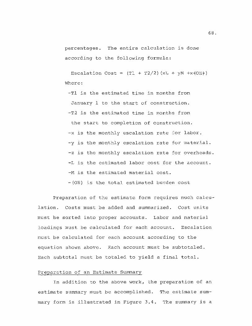
percentages. The entire calculation is done
according to the following formula:
Escalation Cost
Where:
(Tl + T2/2) (xL + yM +x~ORt)
-Tl is the estimated time in months from
January 1 to the start of construction.
-T2 is the estimated time in months from
the start to completion of construction.
-x is the monthly escalation rate for labor.
68.
-y is the monthly escalation rate for material.
-z is the monthly escalation rate for overheads.
-L is the estimated labor cost for the account.
-M is the estimated material cost.
-(OR) is the total estimated burden cost
Preparation of the estimate form requires much calcu
lation. Costs must be added and summarized. Cost units
must be sorted into proper accounts. Labor and material
loadings must be calculated for each account. Escalation
must be calculated for each account according to the
equation shown above. Each account must be subtotaled.
Each subtotal must be totaled to yield a final total.
Preparation of an Estimate Summary
In addition to the above work, the preparation of an
estimate summary must be accomplished. The estimate sum
mary form is illustrated in Figure 3.4. The summary is a
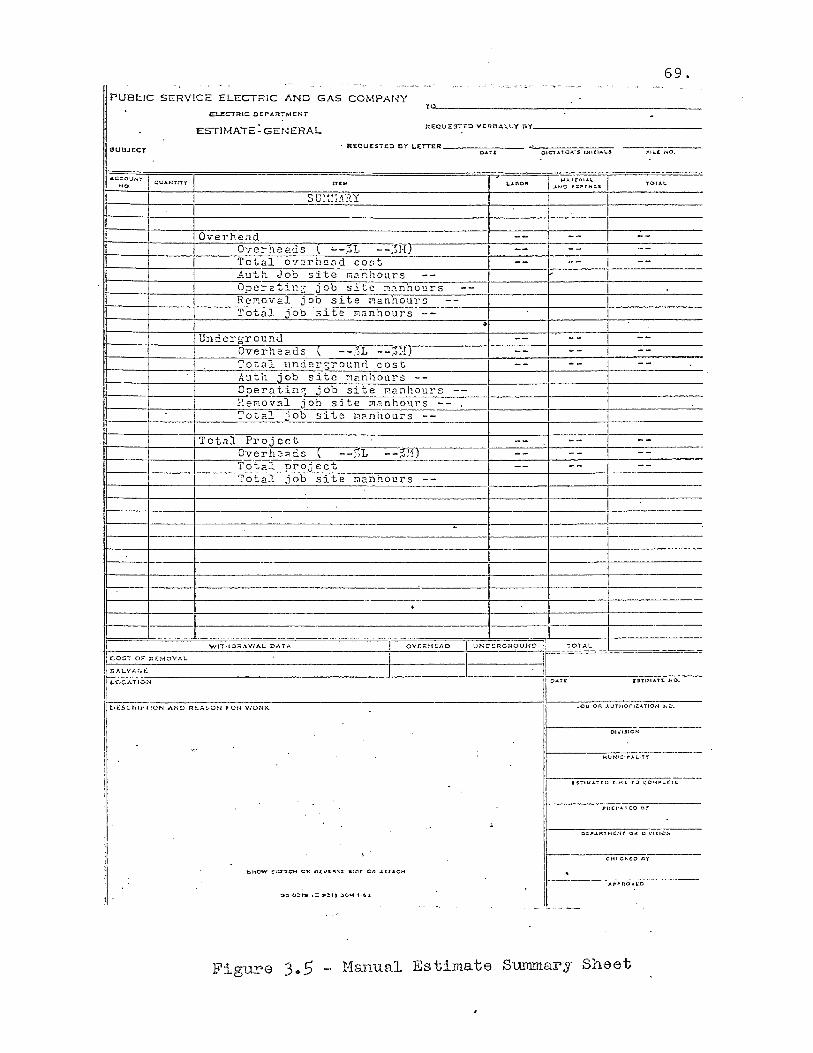
69.
PUBLIC SERVICE ELECTRIC AND GAS COMPANY TO
lD....!!CT:A:IC OEPARiMENT
ESTIMATE: GENERAL R£QUESTt:D \{E-Ri!At..LY BY _______________ _
UU8JECT .. REQUESTED Dr L.ETTER ___ -::-= ___ --'----,.,.-.,--.,..--:-0-
OAT! OIC'lATOI\'!5 2NITIA,\"S
ACCOU'NY NO.
rr ....
SU!~:;:\RY
Overhead Overheads ( "--%1 --;:,H) Total overhead cost Auth Job site rnanhours OperatinG job site ~~nhours Re~Qval job site ~anhours Total job site rnanhours --
Underground Overhe2.ds --:~L --,o:'f) Total undergrounn cost
It-___ +-___ + ____ n,,'..::u:.-t::..:.:h:.-.-j 0 b 5 it e :12 n h 0 u r s --1I ____ +-___ + ___ -=O~o::.:::e..:T-..:a=t"l.::.· :.:..:n U 0 b s1 t e l'la n h ou r s
WbOA )..!I ... T e""I ......
....ND iL!Xf'I!.N:;'C lOU.1,.
1I ____ +-___ + ___ -..:P"' . ..:8::..n:,..: . ..:o~';..I[.::a:.:l::__;j 0 b s 1 tern a n h 0 \\1' S --Tot 21 job s i te!:l2. n Il..:o"-u..:..:r..:s:.:..:.::-----..:....--+------::-----+--------...:..-
Total Proj cct 1t-___ +-___ + ___ ~O;,.v.:.erhe"'G.s \ --;,1 --~:'l)
To"tal proj ect l' 0 tal job '-=s-::;C-tL:e-:cm-a-:n::-;:h-o=--u-,y".s-------+------l-----+--------
1~----+--------------------~----~------------------_4--------·~------+_------------
WtTHD~l!..WAL D.'lt.T ..... OV(F;HEAD U;>...;D£Rcn<?UNO TOTAL
I ~~O_$T 0_" "_£MO'--VAL _______ I-__ ----'Ir . SALVt..GE II """:'ATI"" II DAU
-Z:Sll,U,Tt: NO.
OI"1510N
151'I~ATtQ TIM( TO CC'41>:..tTC
Figure 3 .. 5 - :r-·1anua.l Estimate Su.nnnar·y Sheet

re-sorting and reduction of the information shown on the
estimate form. The summary shows all direct overhead
70.
labor and material as one figure which is the sum of all
overhead accounts shown on the estimate form. The sum of
all burdens is shown next as a separate entry for labor
and material. Total escalation costs are shown in sum
mation for all overhead accounts as the next entry. The
next section in the overhead summary is a listing of manhour
requirements needed to do the overhead portion of the job.
The hours are summarized for direct overhead labor,
operating and maintenance manhours, construction removal
manhours, and a final total for all required manhours.
Following the overhead summary a similar summary is
prepared for the underground portion of the work. Finally,
a total project summary is developed showing; total
direct labor and material, total burden costs, total es
calation costs, and a grand total of the above.
Preparation of a Stores Requirement Listing
The material for the project must be ordered well in
advance of the proposed starting date of the required con
struction. A form must be submitted to the stores group
requesting the material. The form shows each major item
of material needed as well as the required delivery date.
All delivery dates will not be the same. It is desirable
to spread delivery dates over the length of the project.
The estimator must be aware of the sequence of events
involved in the project in order to spread deliveries
properly.
Paper Flow - Manual System
71.
The manual system requires that an Assistant Engineer
or a Senior Engineering Plant Assistant prepare the esti
mate, estimate summary, and the stores requirement
listing. The estimate is checked by the group leader
involved. The overhead portion is checked by the Overhead
Engineer; the underground pOTItion by the Underground
Engineer. The completed estimate is reviewed by the
Planning Engineer and submitted to the department head, the
Distribution Engineer for department approval. Having
passed departmental approval,the estimate is submitted to
the Division Superintendent for final division approval
before it is submitted to the General Office for inclusion
in the Distribution Department Budget.
It should be noted that if the estimate is found to
be in error on the various levels of checking, it is re
submitted to the original estimator for recalculation and
retyping. The manual system is very tedious for error cor
rection. A computerized system could contain the input
data in an on-line file during the approval stage. If
72.
errors were found, the necessary corrections could be made
to the data file and the estimate rerun. A considerable
time savings would result.
After an estimate has been approved and included in
the Budget, the original estimator is designated as the
project sponsor. If the original estimator is not avail-
able, the work will be done by an equivalent member of
the original work group.
Summary
This chapter has attempted to acquaint the reader
with the manual estimating system currently used in the
Electric Distribution Department of Public Service
Electric and Gas Company. It has followed the current
method from the gathering of data to the preparation of
the final estimate forms. It should be apparent to the
reader that the estimating function is a complex and time
consuming operation. The preparation of estimates is
confined at present to the more technically skilled union
people of higher classifications or to management personnel.
The author feels that a properly designed real time
computer program or series of programs can take much of
the complexity out of the function. Also, such a system
could reduce the time required to do an estimate con
siderably. In fact, the author envisions a relatively

large economic benefit can be derived from computerizing
the cost estimating function.
73.
74.
CHAPTER IV
DESIGNING AN ESTIMATING SYSTEM
Introduction
The purpose of this chapter is to set forth the basic
criteria for designing a real time computer cost esti
mating system. Topics to be covered will start with
the required input and proceed to the required output.
The intention is to introduce the design in general
termsi more specific discussions will be included in
chapters to follow.
General Design Criteria
The design of any computer system written to replace
a manual operation follows a pattern. The following is a
list of topics to be covered in designing the cost esti
mating system to replace the manual methods currently
used by Public Service.
(1) Design of the required input.
(2 ) Design of the required output.
(3 ) Selection of a time sharing computer system.
(4 ) Selection of a computer language.
( 5 ) File layout and structure.
(6) Basic layout of the programs.
(7) Analysis of additional load on existing terminals.

Design of the Required Input
The design of the required input will be done so as
to minimize the work of the estimator. This, of course,
will place an added burden on the design and programming
of the system, but it is felt that extra hours spent in
this area will more then be repaid in subsequent time
saved by the users of the system. It is the author's
75.
experience that many computer systems fail to gain user
acceptance because of overly demanding input requirements.
Where possible, input will be dependent only upon
general job knowledge and currently used code descriptions.
For example, yes or no answers to questions set forth on
the data sheets often simplifies input for a user. The
use of commonly used codes to describe wire and cable
will be employed, thereby defeating the need for new codes
in the data.
To cite a specific example, a typical line of data
input for describing the installation of an overhead run
of cable would include the following:
(1) Cable Code - commonly used stock ledger code.
(a) Example; 031854 is 13kv h.d.p. 397 kcmil al.
(2) Number of poles in run of wire - this is easily
arrived at from a map or field survey.
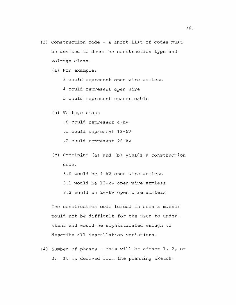
(3) Construction code - a short list of codes must
be devised to describe construction type and
voltage class.
(a) For example:
3 could represent open wire armless
4 could represent open wire
5 could represent spacer cable
(b) Voltage class
(c)
.0 could represent 4-kV
.1 could represent 13-kV
.2 could represent 26-kV
Combining (a) and (b) yields
code.
3.0 would be 4-kV open wire
3.1 would be 13-kV open wire
3.2 would be 26-kV open wire
a construction
armless
armless
armless
The construction code formed in such a manner
would not be difficult for the user to under
stand and would be sophisticated enough to
describe all installation variations.
(4) Number of phases - this will be either 1, 2, or
3. It is derived from the planning sketch.
76.

(5) Special purpose pole top construction. This
will not require the input of special codes
on the user's part. The user will indicate
in the appropriate column the amount of such
special pole tops required. This will greatly
simplify the amount of knowledge required by
an estimator to do an estimate. The computer
will develop the proper material based on
the construction code and the number of phases.
(6) Labor factors - Data files will contain normal
labor productivity for all material units.
However, it is often necessary to increase or
decrease labor content to fit the specific
nature of the job. For example, a run of wire
installed on a busy street will take longer
then similar construction on a quiet street.
Factors which effect productivity include:
(a) Existing construction
(b) Traffic conditions
(c) Tree conditions
77.
Each line of cable data will provide for factors
to vary labor through direct multiplication.
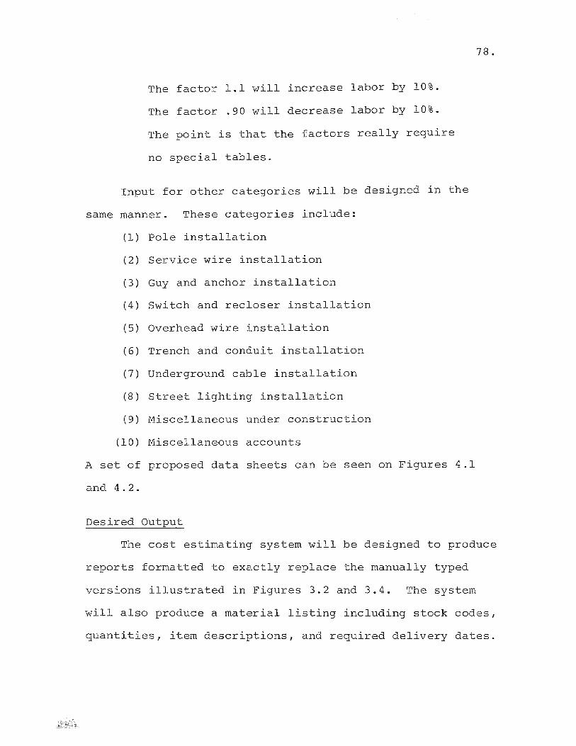
The factor 1.1 will increase labor by 10%.
The factor .90 will decrease labor by 10%.
The point is that the factors really require
no special tables.
Input for other categories will be designed in the
same manner. These categories include:
(1) Pole installation
(2) Service wire installation
(3) Guy and anchor installation
(4) Switch and recloser installation
(5) Overhead wire installation
(6) Trench and conduit installation
(7) Underground cable installation
(8) Street lighting installation
(9) Miscellaneous under construction
(10) Miscellaneous accounts
A set of proposed data sheets can be seen on Figures 4.1
and 4.2.
Desired Output
78.
The cost estimating system will be designed to produce
reports formatted to exactly replace the manually typed
versions illustrated in Figures 3.2 and 3.4. The system
will also produce a material listing including stock codes,
quantities, item descriptions, and required delivery dates.
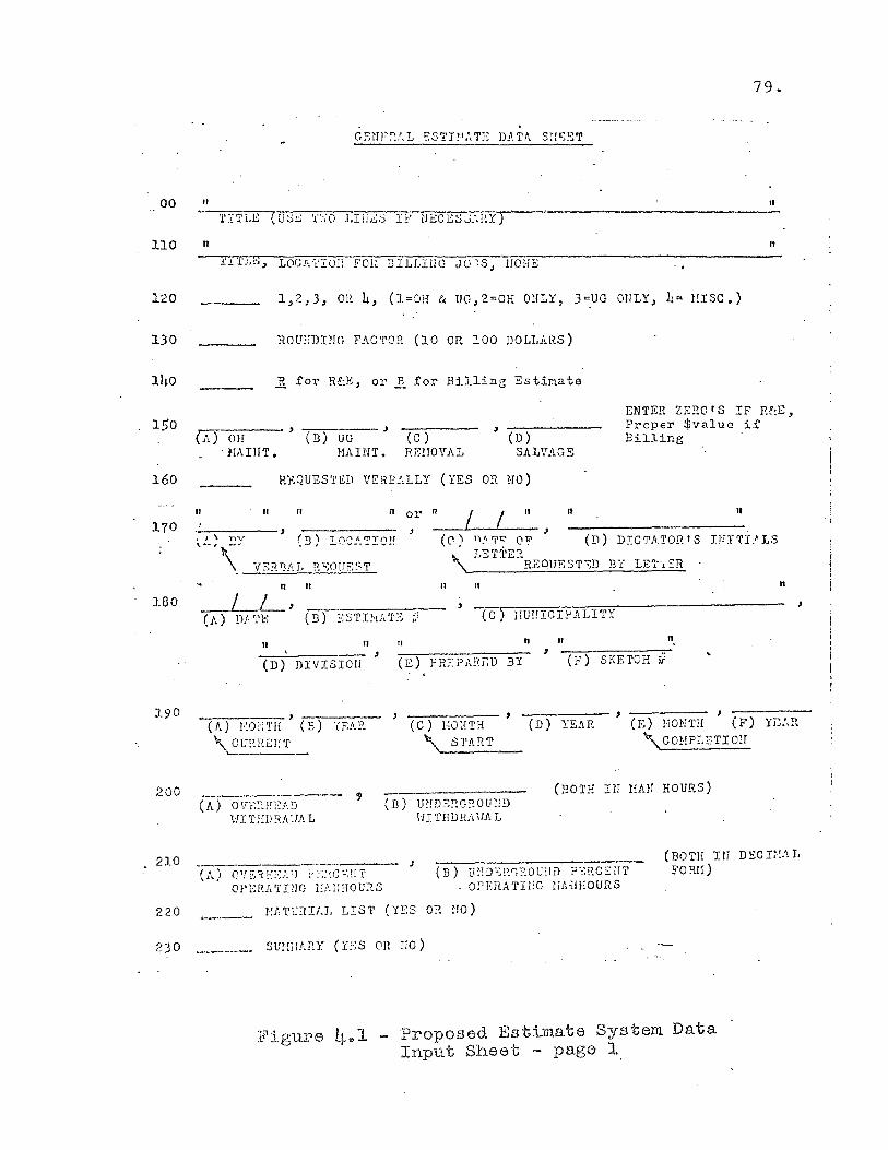
79.
00 II II
110 II II
130 ROU~nING FACTOR (10 OR 100 DOLLARS)
11;0
150
160
170
180
200
210
220
2)0
~ for R~Ej or ~ for Billing Esti~ate
1.-:----- , , \/1.) Oll Cn) UG (C)
R;::?fOVAL
, ------(D)
ENTER ZE~OIS IF R~E, Proper $value if Bi.lline '
, NAIliT. HADlT. SALVAGS
REQUESTED VERB~LLY (YES OR HO)
II It II II II II or 11 I I , ----~~-----,
(c) n~7~ OV (D) DICTATOR'S I~I~I'LS ~ LETTE::!. '\. -=~EOUF:ST-:::D BY LB'l"l SR
II
T (\0 I, l71T('\U .....J •• "" _~ .... _ ........
II' n 11 II n
L L , , (l.) D.t: rl'B 0.3) ~~ s 1'I~·lA 'I' ~~ :, (C ) llU!HCI!-'ALITY J'
II II fl II II' , (F) SKETCH if (D) DIVISIOI!
,
(A) EO~TH (B) YEAR \. CU:1.RElfT
, -------(C) 1;OHT:1
--,---- , -----CD) YE.'l.R (E) HONTH (F) YL:.P.
'\ START '\ CO!,!PL?TIO!T '------
, (BOTH 1M HAN HOURS) (A) OV'~::f:E.t'.D
I,II T:lIJ:-\A'} A L
(l' .. ) CPfS1.E:':':P_J ~:~:~.c"":nT OPErE TPlG l:!~tl:-lOU3.S
(D) Ur!D:>::G::OU:!!) HI THDHA iIA L
(B) ll;:!)~;:'.(','?OU:1D ,)':~!1CSlT':i'
. OPERA TIl:G liA~IHOURS
~]T~alt1 LIST (YES OR ~O)
Slf!:HATIY (Y:~S on liO)
(BOTH rtf D'SCr::.U E'O S.H)
:F'5 .. gure LI."l -Proposed Estimate System Data Input Sheet - page 1
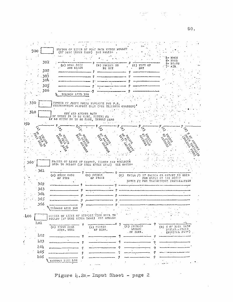
:300 0 )0):
302 . . 303 30L.
30$ '.
306
150
/lUl:i}'-;fl c·~· !.!.:~!:s o!" PC)',:.' 11"- "/, lr'!ICH VOLLO~-I (1::' ,;0;;:: ,;l:n;il Z:-;l~C) :;;:;;: ;oOLIS!> •
(.q !-,C;.:: 5'::-::,-; --, -(ll-)-!,-·U-!:-U-':-~~---.O---' (C') TYl'B OF J.I:n CU,SS Bl:: SST SET
'I
S'
'1'
-------··9 t:- TEROud~! J.T=~S· 320
. , .. " -.;:. ,;.
"L" HAC!! 5- lw;n 6,:, DI,l.ST
;'7'" AIR.
. ...
" .~ -
80.
.....
~ 360'0
361
!i!J~:Z:::?~ OF" r~!~I::S CE' Ct.!'I'0!17, S~·.'!7C:r A}iD ~!:CLOS::R DAn. TO fOLLO',} (IF :iO;:'::: (;;!r;:" ZF,~,;) St;3 GU::LS<>
'J
' .. ' ~- ... ' '-.
-.-
36~ . 363 )64 365 366
L02
h03 ho4 h05 L06
(x) S'i'OC!: CODE ·Or IT£:!
'J
9
.9 """'".--.-------. ')
.• . 9 ~\:s"ou(.:! Le:!:: )50 '
SEP.V. 'JIRt;
(B) ;;U:::a~" OF ITE.:·:S
----------"'''' ?
"I
-----~,. 9
------- Ii' '1 ')
IF S\''I'i'CH 0" CUi'0U7 _IS USED FOR InS:::.l (1~ TE POJ:!', FOR 1':U.liSf0?!-!:::t Ii!S7A.LI..ATI0l1
(0) ,\V::,ll-G::; LF.~!Gl·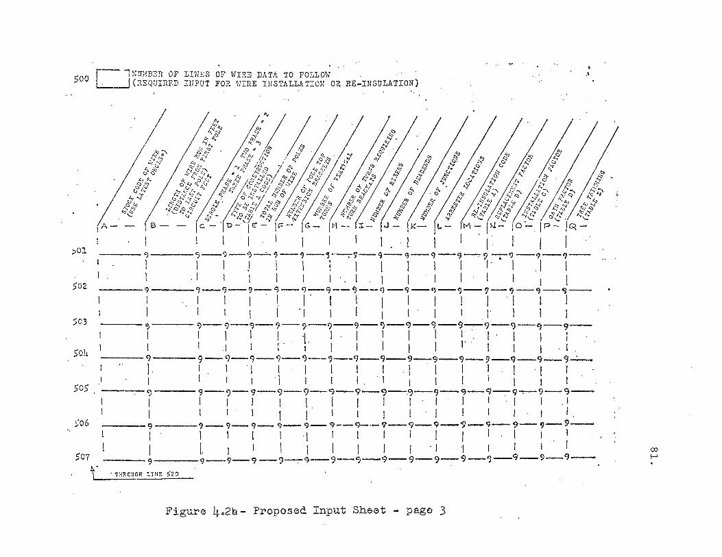
[ ] NmmER OF LDlES OF HIRE DATA TO FOLLOi'; 500 . (REQUInF.D INPUT FOR \'lIRE IllSTALLA TION OR RE~INSULATION)
;:,01
502
503
501.
505
~o6
507
r
/ [//1 ,-:J ".' "J
/ 1 6 -
I
.? ~ /..6'" r::; . I;; <}> /c';' .'.0..(1
'Y .,'j' //s> 1.' '" ~ ".' t;'/? 0",
f<J '" 'Y:"\,/ ~ I> a ..... 4) '9 ~, .... ~\ II-I 4,J "-./ .q, I}j
. .;j It r. ~~:;:r~6j .So':! ",'::'" b .,"i 0'-<. . S- (;? 0
.0.. 0'/:;':;. ~ c r...;: ": .4: Q! '9 'v 1'.] ~.S: ,~" .. ~:: ~v c, ~,) rv tf
!...~~ r.q::! i:; ~ I~' lv' .Q.~;;:,;' it' r,,~ & A ... ... '" -Y <::> ,-l ...... "'.Il:::J,... :;..".l.:J..... So.... ¢;)-'
1;- "-/:;$ "'f; .... -t/f . .::-'" "" ~ .:;-Ie - '1 t:> - I to - I t= -- 1 G - I H -. l:t - I,J-I I I I ! I I 1 I I I I
----".)--9--<)--·· 9--9--'3--. 9--q--g--q -9--=-9 -r9 --?--?--
\ I ! 1 I I·! I I I I ,. I .1 I '" I I . I I I I I I'. I I I.'! !.! I I 1 ----9-9-· 9-9-q-9--~---q-I!J--<)-'1--fJ-'1-9-'9--
I I I' I. I' I I I I I ! I ! I I 1 1 I ! 'I 1 I I I' I 1 . , I I I
9 I I ---9-9-~-9-?---9--9-C)-9-9-9-9-')-9-9-
1 I I I ., I· I I 1 I I. I' I I I . I .1 I I' I' I I ! I I \. I I I . I
t}
I I ---9-9-9-9-9--'--9-9-9-~---Cj-9-q-9-9-=--
I II I I I I I . I I I I I . I I \ I I . i 1 \ I . 1 I I I I I 1 I
9
1· I ---9-')-9-9-9-...... 9-9-9-.~-9-9-9-9-, -9-9-
1 I I I I I I I I' I I I '. I I . I I I' I 1 i . 1 I I !. I I I I· I I .
----9 - 9-9-9- '9- 9--'9-·-9-'9---:9-'9-9--9-9-~-I I I I I I I I I I I I I I. I I. I I I I I I J I . I .,/ I I I I
----9--9-9-9-.9--9--9-9-9-9-9 --:-9-9 - 9- 9 -
<=)
I I 9 I I <)
. TH?OOCH LIm: >20
Figure 4.2b- Proposed Input Sheet - page 3
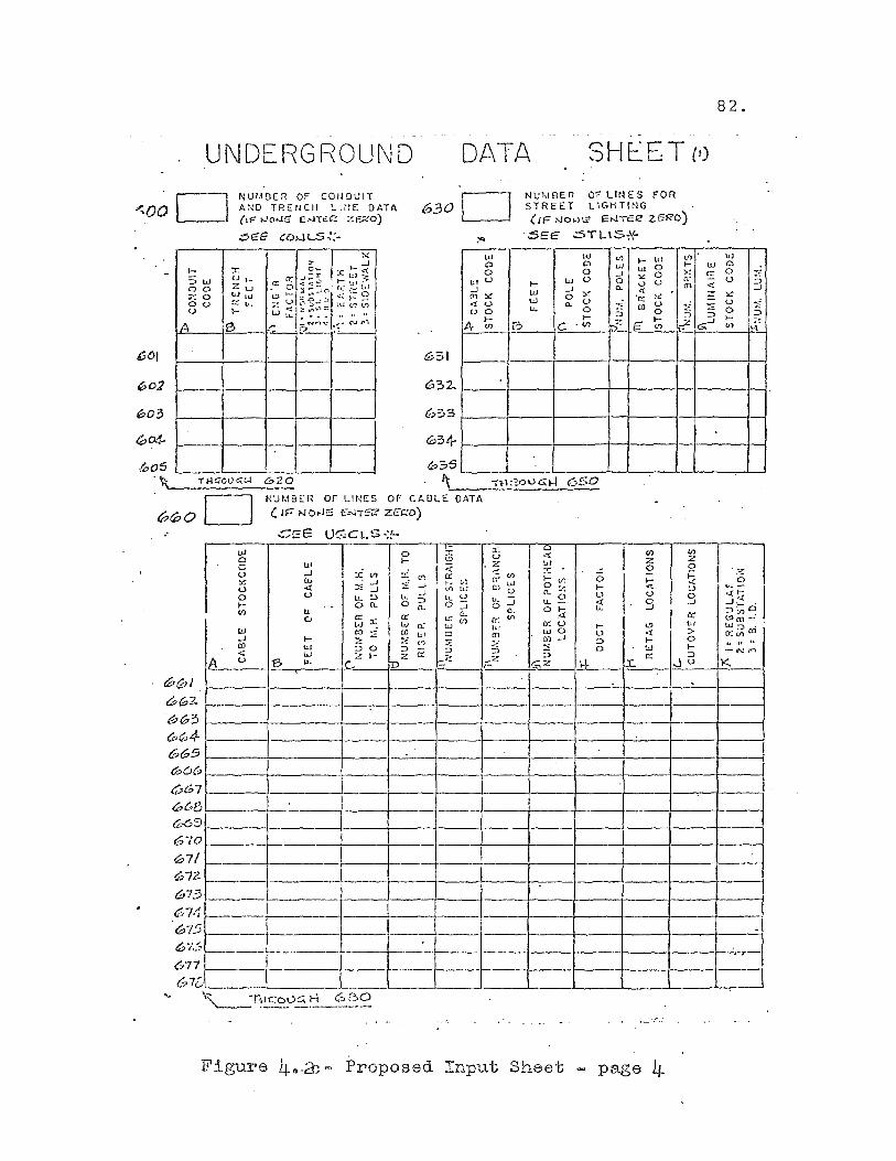
UNDERGROUND DATA SHEE T (t)
'-.000 NU/ADER OF COIlDUIT AND Tp.ErJCH LItlE DATA (IF' oJot-l!: ENT':£'! Ze;.:'O)
630 0 NUMIJER OF LlrH:S FOR STREET LlGKTlNG (/1= O'Jb>-ll?" EO'J"'f't:12' ZEk'O)
.:56E COw L-S ~:- ::SEE .::5TL..IS,\<'
,I ~ :z -.J l- X J~~ :c t;; ~ :::>w u 1_ ",CI: ..: ... \,.:J .- ul ;-. 0 0 2w . 0 -':30 u:c_ hJ % 0 W lu lJ>- ~ 6.:l1 <.: r= ~ Ou c:::..,. ., v
~~'""" u ~ ... <:.(
w"- .. _ .... .... A B ~
':'N~~.,....Nf"1 !? .~
1-
w w (f)
0 0 w ~
0 0 ..J W
v w v 0 '" IJI ~ U .J .J 0-en ::<: w :.~ <!
0 'c::: <! u w a. U u 0 LL.. 0 ::': ro
::> }- }-
"'z A til ~ C ' til £ \
051
632.
u,,3S ~,-___ 1'1-_\ :~o IJ'::;; H 650
D "UMBER OF LINES OF Ct.OLE DATA
&7&1 60'2. b63 (P64 66S <»O~
667 068 05 670 G71 G72
073 67·1 &>/5 6'/':'
677
67C
Ul 0 c u ~ V 0 I-C/)
W .J OJ <:
A u
-,
-.
~---
'---.
<: rF N()tJS eNT6i? Z£C?D)
CSE O(;Cl.S·:!-
1 0 ~
lo' -.J :i :i ''l C" W .J :i -<! :': .J -' U ..J u.. :.l t~ ::>
' - on. 0 n. I.L c.. [;j:x:
cc W 0:
c:J ~ CD ul I- ;:;: ..: .< ,~
"J ::> 0 ::> -w ("z l- cc D
Z 13 u..
~.
."
- t t-"----. 'T~~vE..~_c" B~
I~ . ,. c, V> W \~ u 0 .J
u: CL U)
W CD :;;; ::>
-;:::.;:.
---
:r: I "~" ! (I) u z ,z 1.11 0 -::: ..,.. ..::: U) -
(r' l.J
I-U) 0 I-(1J o ., >- I
~ U n. " • u u .... - u..:::
0 .J <! 0 a, o .~ u.. -.J (f) IT
lol cr.u >- '" CD wO U <! CD .J ::> I-~ :! 0 W ::> ::> _2 I-\..
0: <.::z .:r.. ,-
------
lot 0 0 V
:.! u 0 }-
'"
Figure 4".& - Proposed Input Sheet - page 4
'" >-
'" cr ID
i ::-> ~
(I)
z 0
S 0 0 -.J
cr w > 0 I-::>
,Ju
0
w c:::
"" :::: --" ::>
GO .J
82.
W 0 0 ~ V ::>
.J ::<: u :i 0 ::> >-~ '"
I~~ I '" ~ I .J I- ' ::>0'>0 "'m-' w::> ' ocin aJ .. .. .. -f',.! r<1
K.
. ,-
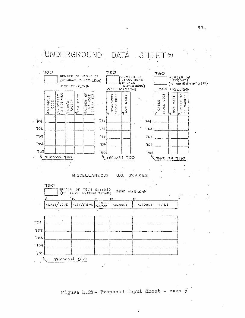
83.
Uf'JDERGROUND DATp,
700 1'30 7(00
D I·W!.:OER OF 1.\,\rmOLCS
(I P !-.loNE" eAl-TC::1'2 z.Ec=C)
$(;6' Co....t L'S.,'?-D 'tlUl,IBEA OF
STANCHIONS ( I r= lJo>.l1i"
C',.,)T'::C. zeeo) SEE MI5lS.;t
D NUMOER OF PIECE OUTS (\\'= lhlONCE...rree..ZEIZO)
::5SG" UGCL S-I?-
I- ~ >- lL w'') -' 0 W W < Z ~J =~ -' ul ;; rc ·t 0-0 w :E rc
~~ 0: '"
c:: 0 r 0 ,n Z 0 .- r. t:) I- eJ q <:{
Vl- u 3: :::w <1: u Vl .- '. :>: ,. .. w <{ 0 =, c-:
N W-
7. w >-0 0 z -0 ru <{ u. :;: z ~ <{ u ~ I- 0 0
w 0 0 0 >- I-w 0 Z
~ W U <.( 0::..., .J ~ w<{ en ~ ~O:: <{ u 3: .: u 0 0 :Jw e- CJ A ;? .C_ L .~ 1)\ U)
I-'?:£: (f) ,--
I- F:,:C or;:': en A Vl
10!
102.. I----I--+--+--t---l
105 I--- ---il--I--I---I
1041-_~ __ t-__ r-_c __ ---;
lo5~ __ ~_~_~~_~ ~ \ 1t4>'.:00G,I-! ,'20.
13\
ihZ --763
134
135 \. IH:-:o'-'~I-l -,50
MISCELLANE OUS U.G. DEVICES
'190 r-!tlU:,WCH OF L--.l (11= NONE?
GL~SS/ CODE e.
IT£:.\S EIHERED e-~TS(2.. zct::o)
p'
ACCOUNT ACCOUNT TITLE
191 r.---------+---------+------r---------r----------------~ 1!')'2.
15~~-----------r--------_1-------~---------~------------------~
lS4r _________ -r ____ ~------j_--------~ __ --------------~
Figu.l?e 4,,31 ~ 'Proposed Input Sheet - page 5

The intent is to do away with all manual reports,
summaries, and material listings. This will result in
approximately a four hour time saving per estimate over
the manual system.
Selecting the Computer System
84.
It may seem add at first glance to select a computer
system before the programs are designed. However, it is
difficult, if not impossible, to do any design work
without knowing what tools will be available. Computer
salesmen would have you believe that all high level
languages and file structures are directly transferable
from one machine to another. In reality, such is almost
never the case. Therefore, it is necessary to know what
machine you are designing for before you start.
As mentioned earlier, the estimating system will
reside in a time-sharing computer. The following com
parison will therefore, only consider time-sharing service
vendors. The very size of the system will automatically
eliminate many small capacity computer service vendors.
The programs will occupy approximately 100 K of core in
smaller program segments of 5 to 15 K of 36 bit words at
a time. For the comparison, the author has selected the
following services:
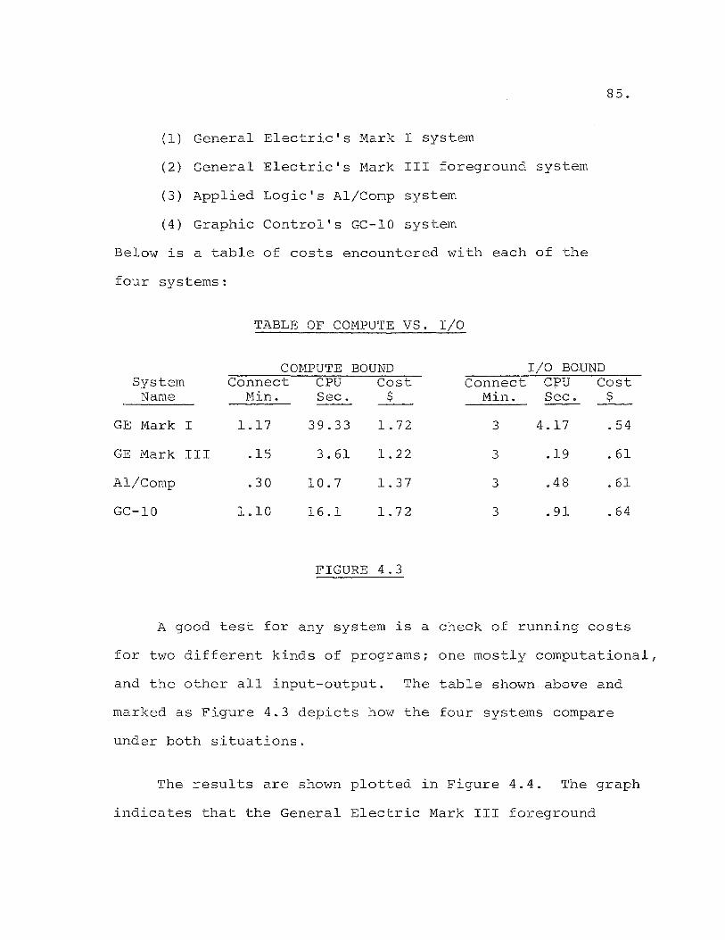
85.
(1) General Electric's Mark I system
( 2) General Electric's Mark III foreground system
(3) Applied Logic's Al/Comp system
(4) Graphic Control's GC-IO system
Below is a table of costs encountered with each of the
four systems:
TABLE OF COMPUTE VS. I/O
COMPUTE BOUND I/O BOUND System Connect CPU Cost Connect CPU Cost
Name Min. Sec. $ Min. Sec. $
GE Mark I 1.17 39.33 1.72 3 4.17 .54
GE Mark III .15 3.61 1.22 3 .19 .61
Al/Comp .30 10.7 1.37 3 .48 .61
GC-IO 1.10 16.1 1.72 3 .91 .64
FIGURE 4.3
A good test for any system is a check of running costs
for two different kinds of programs; one mostly computational,
and the other all input-output. The table shown above and
marked as Figure 4.3 depicts how the four systems compare
under both situations.
The results are shown plotted in Figure 4.4. The graph
indicates that the General Electric Mark III foreground
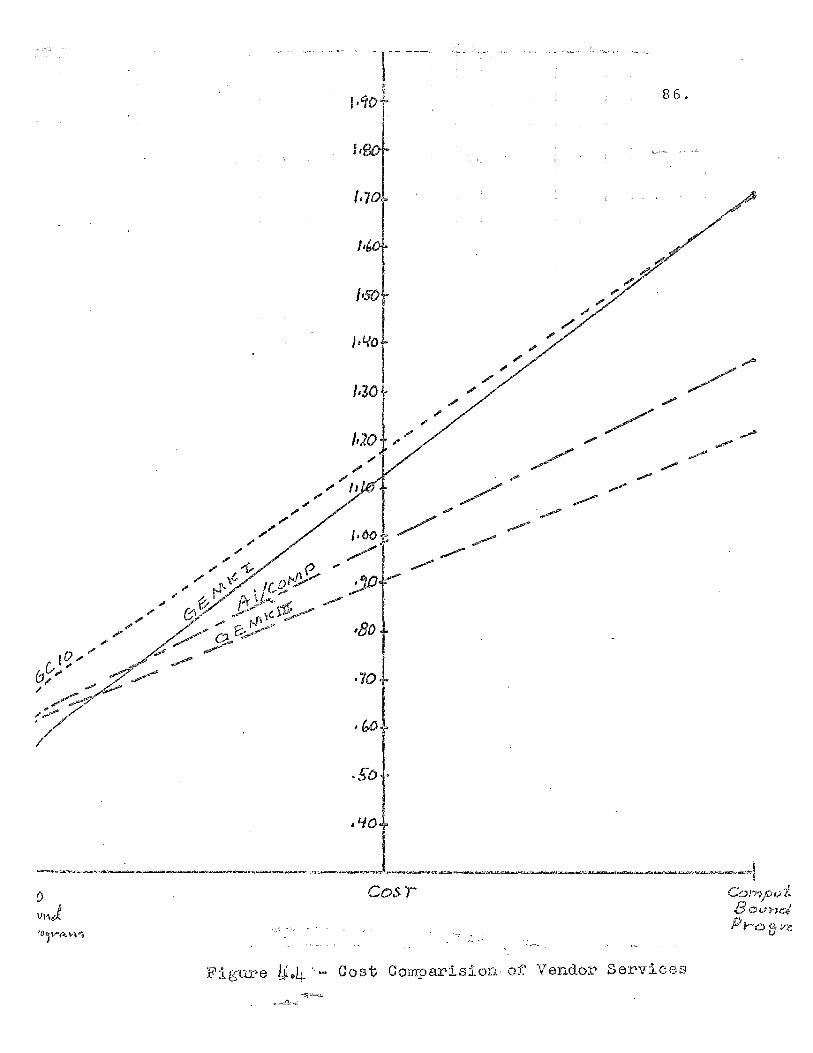
j,
/ ".
/ ..... /'
~
,'10
Cos!
" , .'- ~ .
86.
..... /
/
~ ,.,.. .."",. .,...,..
Co!'1":'j>vt: BOLn')e4 Pr(.) fJ i/e
Fig-w:e U.4 "- Cost Comparision of Vendor Ser'vic8s -5!~
._:\<~
system is the most economical for all but the most I/O
bound programs. The estimating system will be a mix
ture of heavy computation and lengthy I/O. Therefore,
the Mark III system is the economic choice. Another
cost advantage of this system is the availability of
local phone lines throughout the state, thereby reducing
what could be large phone bills to access the system.
Selection of a Computer Language
The General Electric Mark III foreground system has
two powerful time sharing languages available.
(1) FORTRAN IV
(2) BASIC
FORTRAN IV is a powerful scientific language incorpor
ating the original FORTR~N language el€ments, augmented
with sophisticated file handling abilities. It was
developed for General Electric by an independent soft
ware house especially for the Honeywell 635 computer
on which it resides. It compiles to form an extremely
efficient object code with resulting savings in C.P.U.
costs.
A drawback of the language is the limitation im
posed on alpha-numeric variables. FORTRAN IV limits
alpha-numeric strings to four characters. The esti
mating system will need to handle strings of up to
87.
88.
forty characters. FORTRAN IV will pose a problem in this
area.
Fortunately, the General Electric Mark III fore
ground system also has a very sophisticated version of
the BASIC compiler available. BASIC was originally
developed by Dartmouth College for use on a prototype
Mark I system using a General Electric 265 computer.
The language was designed as a simplified subset of
FORTRAN with special features for the time-sharing
environment. In the eight years since its inception,
the language has undergone many changes. Today, it
rivals FORTRAN in many areas,4and offers some real
advantages over tha~ language, including:
(1) Sequential file reading
(2) Powerful matrix manipulating functions
(3) String variables up to 119 characters in
length
(4) ASCII and Binary file handling capabilities
BASIC is, therefore, the obvious choise for a file
oriented system using long string descriptors such as the
cost estimating system that the author envisions.
File Layout and Structure
The cost estimating system will rely heavily on "data
files. A set of files will be stored separately for each

89.
of the eight field divisions. This will be done because
productivity information varies depending on the division
doing the work. The breakdown shown earlier in the
chapter for the data input serves well to define the
files needed for the estimating system.
separate files will be set up to service program
modules for poles, guys, anchors, switches, overhead
cable, pole top hardware, conduit, manholes, underground
cable, etc. Most of the above files will be of small
size; however, eight versions of each file will be
stored to service each division. Total file storage
space will be large because of the above reason.
In general, the files will be stored on disk devices
for rapid access. Most of the files will be stored in
the sequential ASCII mode. These files will be directly
listable on a user terminal for easy updating and review.
The files will be similar in concept and structure.
Each will contain a code (usually the commonly used company
stock ledger code) 1 a material cost, and productivity
figures for one or multiple circumstances. The differing
labor units will result in different record sizes for
each file.
The large file needed to store pole top hardware

90.
information will be stored in random binary format.
Such files are not directly listable on a terminal device,
therefore, listing and editing programs must be provided
for the user. Binary files must be precisely defined
prior to initial storage. Record lengths must be defined,
as well as the total number of records to be stored.
Such files are not dynamically expandable as are the
ASCII files described. Binary files offer some real
advantages over other file structures in the areas of
direct access to a particular record, and lower storage
costs.
Basic Layout of the Programs
The cost estimating system will be modular in con
cept. Each program will be called into core when
needed. The program will call the proper files to do
the estimate as defined by the user input. Calculations
will be performed by the program to arrive at material
and labor costs. The cost figures, along with the proper
string descriptors, will be written to an intermediate
work file. After execution of the program module currently
in core, the next program needed will be called into core
to do the subsequent part of the estimate. This will con
tinue until all parts of the estimate as defined by the
input data are complete. At that point, the terminal

sequence programs will be called in as required to pro
duce the types estimate on the user terminal. This
program module will call on the work file which was
91.
being appended during the execution of the primary stages
of the system. The file will be read and sorted into
ascending account order and finally a report will be
produced on the user terminal.
Program names and functions. The following is a
list of the main program modules and the functions per
formed by them.
(1) ESTCK$ - The function of this program is to
check user input data. Data will be checked
for syntax errors, and for rationality. A
report will be generated on the user terminal
listing the input data line by line. Correct
data will not be altered. However, incorrect
data will be appended with diagnostic messages.
Compiler aborts will be disabled, and the
file will be processed in one pass. If all
data is correct, the user will be chained to
the main processing module. If the data con
tains errors, the user will be advised to make
the necessary corrections and run the ESTCK$
program again.

92.
(2) ESTRE$ - This is the main processing module.
After the data has been checked by the ESTCK$
program, this program will be called. The
function of this program is to read in user
input data and sort it into the proper work
files for the execution of the rest of the
system. For example, data for the pole install
ation module will be written into the file
D3641. This program also records the user
number, the date, the time, and the name of
the estimate into the usage file USAGE. The
program will finally decide which program will
be called next, based on user input. If the
estimate contains overhead data for pole in
stallation, the program E3641 will be called.
If the estimate contains no overhead data,
the program E366 will be called.
(3) E3641$ - This program will call in the files
POLES, D3641, and COMINFO. These files are
necessary to do cost estimating for pole in
stallations. User input is stored in D364l,
cost information is stored in POLES, and labor
rates are stored in COMINFO. The costs are
calculated and written to DMTSG. The material
required is written to the file MATFILE.

(4) E365W* - This program will be called into core
after the completion of E3641$. The operation
of this program is the most complex of the
system and will be discussed in detail in the
next chapter. For the purpose of this section,
the function of this program is to read in the
user input from file D365 and the files
93.
associated with overhead costs including: OHCABLE,
BRPTOP, GYANSW, and COMINFO. Costs are calculated
and written to DMISC. Material requirements are
written to ~~TFILE. If an underground estimate
is needed, the next program called is E367W*.
(5) E367W* - This program is the one which produces
the costs and material necessary for the under
ground portion of the estimate. It calls in
the user input data from the file D367. It
also called in the underground data files
STLIGHT, UGCABLE, CONMAN, and UGMISC. The pro
gram produces the cost and material information
and wirtes it to the files DMISC and MATFILE.
The program then called in the next program in
sequence, MISCP*.
(6) MISCP* - This is the first program of the closing
sequence of the system. Its purpose is to call

94.
in the files produced by the calculating section
of the system, DMISC and MATFILE. This program
sorts the cost data stored in file DMISC into
ascending account order. It loads the estimate
for indirect labor and material based on per-
centages stored In the file COMINFO. It produces
the estimate in the same format as the former,
manually typed report as illustrated in Figure
3.2. Based on user needs, as denoted on the
input data sheet, the system will stop at this
point or call in the next program in sequence,
SUMRY* .
(7) SUMRY* - The function of this program is to
produce an estimate summary report. The report
is produced using information dumped to the
data file SCRPAD by the program MISCP*. The
summary will be of the form shown in Figure 3.4,
Afain, depending on user needs, the system will
stop here or chain into the final program
module, 1-1ATLS*.
(8) MATLS* - The function of this program is to read
the data produced by prior program modules,
stored in the file MATFILE, and to print out a

material list. The raw data contained in MAT
FILE is sorted into ascending material stock
code order. The codes are then matched with
the proper material description by using cross
matching procedures with the data file MATNM.
95.
A complete flow chart of the system is shown in Figure 4.5.
The flowchart shows the inter-relationships of files and
programs discussed above.
Analysis of Additional Load on Existing Terminals
The implementation of computer-based cost estimating
via remote terminals in each of the eight field divisions
will result in additions to the existing queues waiting
to access various other computer programs and systems.
With this in mind, it would seem appropriate to determine
whether the developing queues would be of an intolerably
large size, and consequently result ln excessively long
waits. It will be the purpose of this section to deter
mine whether additional terminal equipment will be
required as a result of the additional work load imposed
by a cost estimating system.
A study of terminal traffic was conducted ln Essex,
Hudson, and Trenton Divisions by the author in September,
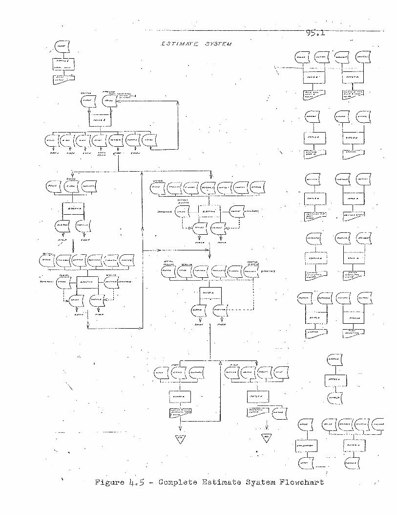
- '._.-'----'-- -
.ESTIMATC SYSTEM
. 7' I "u~
't'
8QE;JQ.~ , , : J r::::::J..: :-l~O y-_,J .
. I"'~" ~'~'
L. ___ >'
, ,
, '. Figure 4,,5 - Complete Estimate Sys.tem Flo1tlchart
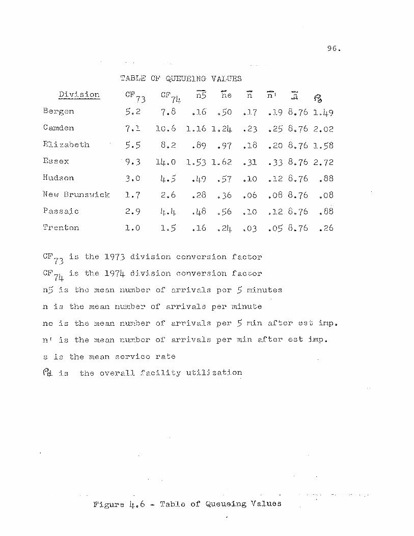
96.
TABLE OF QUEUEING VALUES
Division CF73 CB1
74 ~ - nl ne n ~ fA Bergen 5.2 7.8 .16 950 .17 u19 8,.~(6 1.49
Camden 7.1 10.6 1.16 1.24 .23 .25 8.76 2.02
Elizabeth 5.5 8 .. 2 .89 .97 .18 .20 8.76 1.58
Essex ·9.3 14.0 1.53 1.62 .31 .33 8.76 2 .. 72
Hudson 3.0 4.5 .49 .57 .10 .12 8.76 .88
NeH BrunsHick 1.7 2.6 .. 28 .36 .06 .08 8.76 .08
Passa;ic 2.9 L~. 4 .4.8 .56 .10 .12 8.76 .88
Trenton 1.0 1.5 .16 .24 .03 .05 8.76 .26
CF73 is the 1973 division conversion factor
CF74
is the 1974 division conversion factor
n5 is the mean number of arrivals per 5 minutes
n is the mean number of arrivals per minute
ne is the mean number of arrivals per 5 min after est imp.
nt is the mean number of arrivals per min after est imp.
s is the mean service rate
r~ is the overall facility utilization
Fligure 4.6 - Table of Queueing Values
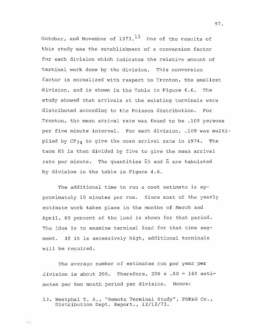
97.
October, and November of 1973. 13 One of the results of
this study was the establishment of a conversion factor
for each division which indicates the relative amount of
terminal work done by the division. This conversion
factor is normalized with respect to Trenton, the smallest
division, and is shown in the Table in Figure 4.6. The
study showed that arrivals at the existing terminals were
distributed according to the Poisson distribution. For
Trenton, the mean arrival rate was found to be .109 persons
per five minute interval. For each division, .109 was multi-
plied by CF74 to give the mean arrival rate in 1974. The
term nS is then divided by five to give the mean arrival
rate per minute. The quantities nS and n are tabulated
by division in the table in Figure 4.6.
The additional time to run a cost estimate is ap-
proximately 10 minutes per run. Since most of the yearly
estimate work takes place in the months of March and
April, 80 percent of the load is shown for that period.
The idea is to examine terminal load for that time seg-
ment. If it is excessively high, additional terminals
will be required.
The average number of estimates run per year per
division is about 200. Therefore, 200 x .80 = 160 esti-
mates per two month period per division. Hence:
13. Westphal T. A., "Remote Terminal Study" 1 PSE&G Co. , Distribution Dept. Report., 12/12/73.
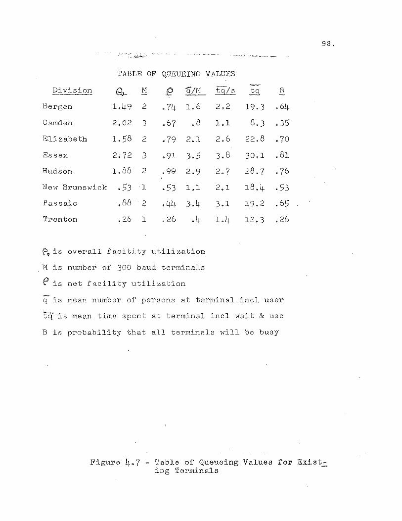
, ~ -- ---~-~ ,-- - _-oc. __ ~ '._
,",--..j:~ .•
'TABLE OF QUEUEING
Division f1- H e q/M
Bergen 1.49 2 .74 106
Camden 2.02 3 067 .8
Elizabeth 1.58 2 .79 2.1
Essex 2~72 3 .91 3.5
Hudson 1.88 2 .99 2.9
NeH Brunswick .53 "I .53 1.1
Passaic .88 -"2 .44 3.4
Trenton .26 1 .26 • L~
~ is overall facitity utilization
M is number of 300 baud terminals
e is net facility utilization
VALUES
tq/s
2.2
1.1
2.6
3.8
2.7
2.1
3.1
1.4
!.s. B
19,.3 .64
8.3 .35
22.8 .70
30.1 .81
28.7 .76
18.4 .53
19.2 ,65
12.3 .26
q is mean number of persons at terminal incl user
tq is mean time spent at terminal incl wait & use
B is probability that all terminals will be busy
98.
Figure 407 - Table of Queueing Values for Existing ~rerminals
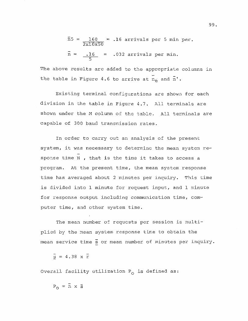
99.
n5 = 160 = .16 arrivals per 5 min per. 2xlOx50
n = .16 = .032 arrivals per min. 5
The above results are added to the appropriate columns In
the table in Figure 4.6 to arrive at ne and ;'.
Existing terminal configurations are shown for each
division in the table in Figure 4.7. All terminals are
shown under the M collli~n of the table. All terminals are
capable of 300 baud transmission rates.
In order to carry out an analysis of the present
system, it was necessary to determine the mean system re-
sponse time N , that is the time it takes to access a
program. At the present time, the mean system response
time has averaged about 2 minutes per inquiry. This time
is divided into 1 minute for request input, and 1 minute
for response output including communication timer com-
puter time, and other system time.
The mean number of requests per session is multi-
plied by the mean system response time to obtain the
mean service time s or mean number of minutes per inquiry.
s 4.38 x r
Overall facility utilization Po is defined as:
Po = n x s
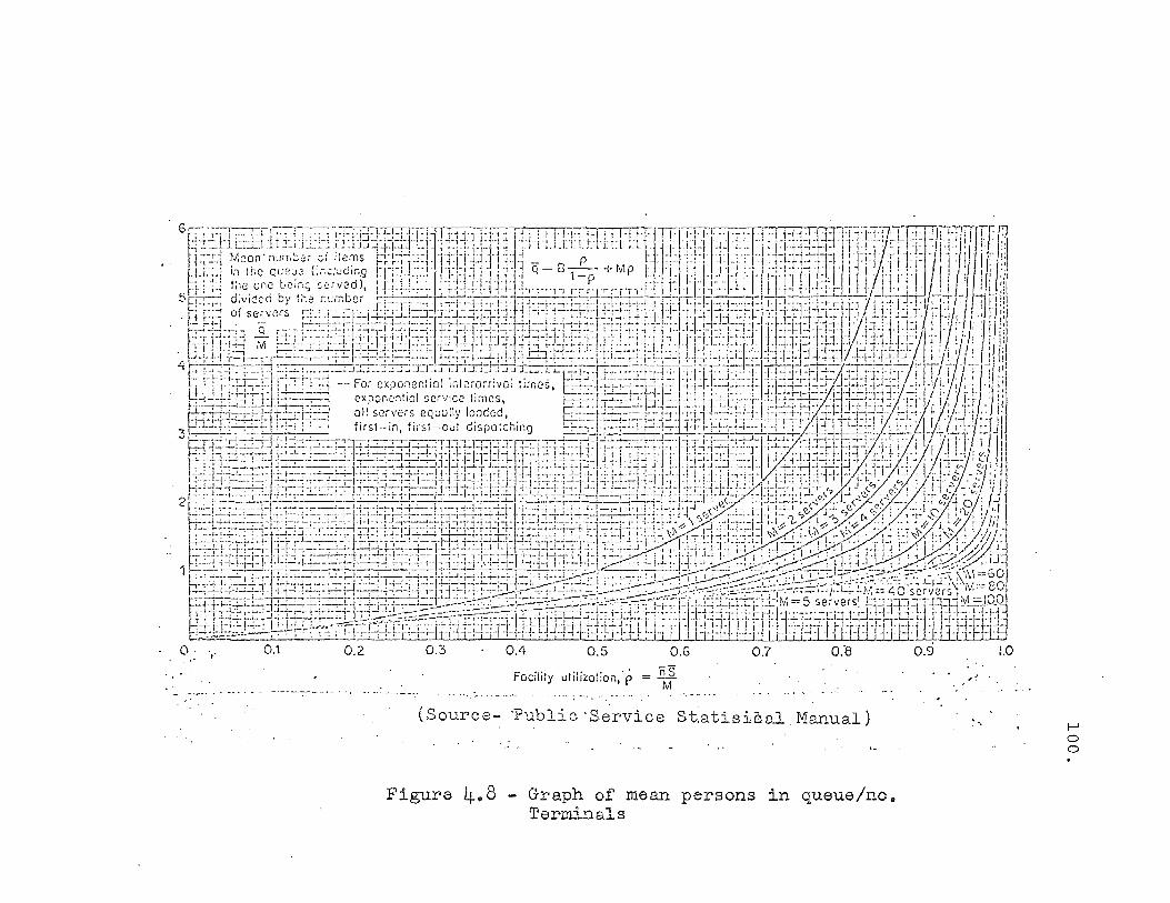
Facility utilizQtion,p
(Source- -Public -Service St.atisic.al Manual) . ,
Figure 4.8 - Graph of mean persons in queue/no. Terminals
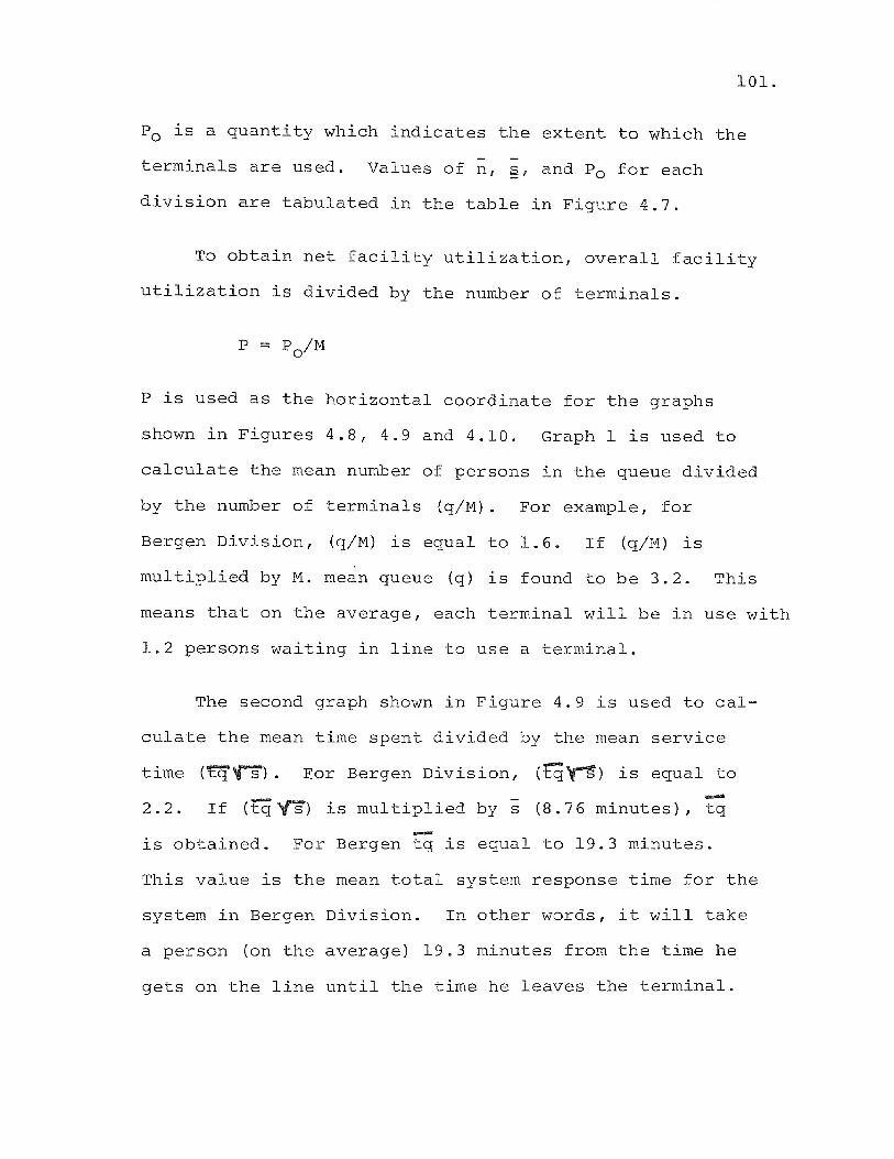
101.
Po is a quantity which indicates the extent to which the
terminals are used. Values of n , §f and Po for each
division are tabulated in the table in Figure 4.7.
To obtain net facility utilization, overall facility
utilization is divided by the number of terminals.
P is used as the horizontal coordinate for the graphs
shown in Figures 4.8, 4.9 and 4.10. Graph 1 is used to
calculate the mean number of persons in the queue divided
by the number of terminals (q/M). For example, for
Bergen Division, (q/M) is equal to 1.6. If (q/M) is
multiplied by M. mean queue (q) is found to be 3.2. This
means that on the average, each terminal will be In use with
1.2 persons waiting in line to use a terminal.
The second graph shown in Figure 4.9 is used to cal-
culate the mean time spent divided by the mean service
time (~~). For Bergen Division, (tg~) is equal to .... 2.2. If (rq~) is multiplied by s (8.76 minutes), tq
is obtained. For Bergen tq is equal to 19.3 minutes.
This value is the mean total system response time for the
system in Bergen Division. In other words, it will take
a person (on the average) 19.3 minutes from the time he
gets on the line until the time he leaves the terminal.
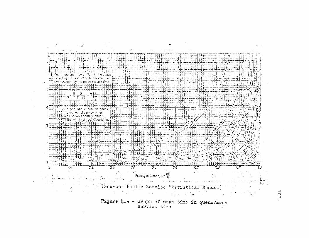
... ~,
I [--,-r .,., T'"'' ,,~-:.,,-p-ri'''··'''' ':1-'-'-1'1'-'-"--''' r,'r;-'j-l-r-1-' ~Tl-:;;'''T.-r,· '~-~-r-'-.-~:--, ~'-:-~~~-lD----' . ''C''1 11l':'II:!"!lrl:!'I~j' "I~""'rl': ':'1';1' .~ I" , .. L '-:'j·;-I·I':·r",,--;,,···'--r"·;·'-I·:·,···1.··",'·'·I+""" ,., ....... !.; :. ":'1 {]'I \ ":-_f _' .~ .; J..! ! ~ l-! .;:: _ L.,";' i. ... 1.,'_ t· : ,'; -- !~: ~:. J _!_:.-L I . ~.~;~ • ~[ .-~.'+ L r. J. ~ !:: _ !~-:_. ; '=;:i. " L:.j :i_;:r ,l::'-L ~ ~!. i'~;'-~--: ~~;::: \. L!::' -: =-~~7"J_T .:-.:-.L.:~ :.:~:~~; ~.;. -~':. ~ '. ';: , r ' r" "1-1.:.1 .j. II. I., t j'l"'j'~' ;.1.1 .. I .. ;. [i-I.I. I. r--!-1. L!'j.l .. i. t,;. I· \.;.1., '-'-}.', :"1::ijL .... \ ... f "";'f :.! ... J .~_,.Lc.,.I.;..:.J..: .. "..:-,-~.1· .. · ~·:,·I i""; : . J-J ~·.EH::i~ ·rtF!:JtH+ LtU:!tU. =t~H1:jlttU~ =i:!~i~i:!~+:l:tltlJ~::tl~t:_t~~~i=~~2:}:j~~~ ~j=~=:=t=i?J~t-t-r~~ _~~~t~1j~!:\:J:1 J:~:; ",.,.~ ,~. L I • .;-!.~ : i l·j·I-i-I·I!.' h· I 1+I·n I·! 1-' ~"+I'II'i L [ L /.: "-;'T- '_ .. f. ;--, .!-!-:. ;jj .. L!+:-~i· r'''' _:_'-I"'j';_; ·i·l.!-;--;- ,-;.".;.;-:+,: ., .. 1: (.1:.! i
6~~~\:~~{:;~:~ -;~'+~',;:!+f!-!~~j-!'!~;:!~i-i':f~:=i:EEfi=I'~~;~~~=1~;+1~1:;~~~:l:f:qf~i~:~i:;:f~{~;=!f~~jL~~:~~~:~;:2'-t!~=0/:-~;;S~E:{~~:!::;-[;~~"':,
~ ,:,e~n 1.lfT'C sru11 by Oili'c:r:11fT ,1:(; qceue Llh:!::i:ll : r: j:h:::r..j~c;:I}L::i Tn:i=~:;:-:r:C::f.1}::-J~F;::::::~:h-=:·i::t:t1.jLd:i::k:':::-:-J:::;::i:!:l.:::::q:'I.I'::;·!" I
t (,:1c:t:d;ng lhc lome 'of.en 10 ~·crv:ce .1~c '::j:~:tiT J:L:.LL::i::~::i:1-:I~:L:-I; i:,;.:l:J::ii:::i:i.::i:!=!.:dT2:.;:l:.b::'::':-L':::'::r.i::b:i:l-=:-;..t.:=i:::±..i::tf',::i::l/.::!:r:':!!' I . I::\:~\:I ~~f~-~~·~'Y!\~j~:~~!~;~; ~{H~:l~;~~. ~ j.:SJ=iI1Jfi:~!=bJl~1::tj3~::GE~ltlJi:l:=U~i:t!:T~J~I: ::te~jjlJ±Fl:Yi~=~1~C!:~}:L~=jE/tJ i:::1
5. ;±~~JI-r?l+j~:t~~~·j~*l~i:$ft~l~t~~~~I~ftlrf}~l~i~l=t*l~lj~~:1$i~~3,~tfij1r~~~lfjjm~~~ ~j~~~;~~j~;~:~~!~~~$L~~~~=j~6~:ffl;:':1 f:'---'!+d - J2. --~.- + S q'-+-;---+'-'+--"·'''!·I",-I.L. i-iO-I-'.,-;+ I" I I·LI-Lt-t·'~-t'·1-~"-T·t,· L,_:_Ll·C·[·i !I-,-,~.l- .. ~·J-';:f-+ I"~ .-/ .',-{ 'i 'I t=t::l~~IF q - III. (,I- p) ~!: !1+-:j~j.:.l:'~I~~:·I:;*!-:l= ~~i:lt:if~fi:b::F~';: "!:!-=lj::"lj:.i:i!~:I·~:':l:c+;'i::!·j-:i~~::-,.;:.r'(I:·IU·~~::i:t-: './J:I:-( L.' ·;f~·I·J:;; :j ~~tF-i::;:-~:rrr.j:-;:F;:.cq: :qT :,:.;:,:: ::b::::n::::Vl.=/:,:i- t;: .-:1:'1':1':/-:1:-,::= H~·::;. :!:Lcl:tLn::r:t.:r: CP:i: :t:b:~-J.=-Jlt '::::~:;~::L:"::''' _::j::=' :: .::-:::: .~r, ;, R-,-,·! +h:1.!L1-H·! ..1-1'1-['- ~'l' i'\ -++'j'H'I.I";-l+i-!·l·j·! il-H- r-'-H-I.:J i .1+,-'+11. j'TH';"--;-"~"'! +'1-;·~-'·1"-1'·!· :.';'I.".'-;'!-'·/ 'f--·:f;-/~ f -!..!: J" t-:-~--'I- -1- i-I :-\-r-1- -ti- -1-1- - - -r-: -r-I-11-;-1 I-crr-l-'-,-r-[i" - -, -I -,- .. - ,--!-:.';- tr!-r---l- "'I-j-i-, ! --;-j-(- ·--r-;-~-,-!· -ll-·:J~··f_.··I- =o_L;_ ... !-:-~-/·~-f -./ i - ... -, -;-r "-I~ ,
.q f-:;:==tC:'~ - For c>:ooncnl iol i,,:erorriva: limes. gCr:::'I':':+I-:Ce=I'l:'P: 1lJ.1'·T.L!-C!'~:-:-:-i::!~:~'::P~Cl:==n:b;-~~::i=ll~::.r:;7f:-J _T:t::L i f~- r-'::-/;::C.-';:P.:-;:/::'/:· ~F:!J .. -- ., , " ., f"'- ... \-1-1 . .1--1, ... '.I .. ·· .. l·!~ .. ·l .. -'---' .. --·-·l-.. --'..L. .. LJ·· .... I~· .•. ,- -.LI·J·"1-1~·-·/·~ '·'·V·- I' '''1'' i, I ;.+ ·-:'-·~-i~1-lcy.pon8:11:clservlcc hmes, t _1-;_;._ -;··-I-l--1-1-+r~-;-j-·'- 'I'-~- _11 t-~--{-~-~-f-·7-LI.-.;_L.~-I·,-:~!-;-:- -;-t-: L..r-l··~·,-~I-L:-;-~~'--!-·i·~-' ;-/":- ·i---f'~·; .\ rr-'-h'rl , d d I' .1.·--,-'---r--- .L .. ,., "1' r - .c ... ---1-,-' --~ _L L .. . r .• -'-I '1""'- -, .. /-.---f·r .. 1.1. 1 ...... I· .. ·l· ,- .,t ....... ,_. '" I 'j
-,-~j::;::!J 7,:1 Sen'i;(S equally '?C e .' . j::J=i:i:H:L:d::Ll'.:t~I:'=~~!::~;=i:T,,!::j=i::-;:tj~)'::l:ijj-:::r:'J:=1:J:i':'(>;A.:;-~: ~i:'=I-;=i:tj- t~/;:!.::'::;:).j:j·ct":'i=i ;:i;':1 ji~";''±:;- j.'1~';'~'·0;.;· oul. d~~p'o ~r:!,'~'2g.r-1 :;:!_:l::l~:.l-I::. .:: ': =j=l:.,::.tb::i-::I:+r :;:';::~'rJ: 1-::1 :~ti:;:,:-..!=·:J:::-'Q0:::-i=i=+-l::rj::;.:~:' (,,"' _Ll:':~ ,,?'.)" ,,:,'':':/ j i:: r' i·:1
3 8::!::j-~-H1 t:'!':!:.r::L'·! ·,.:+·::;1JE::.:f:I·i::'L~:l'::~H::j::l=bJj:U:..=r:,~'::!::ji.:i:J . .!.,.; H.:ti.:J::td::..-ti-,·!j~I:~;/; .:}.:, ::;.::.:~.:cH .::-?,;fi~=:· //l}(c.:J.;: 5' f ~! j .. ) ~±::;=U:l::Llj::J'l:i:~-; '~~:l:':!:.b~j:+.: j G=E'J'~U:I=I=!J ·1~:H:il·:J:±:lj:I:Lti.:i:U::[··!:~i:~:-:j *-;:.:·~·.,~r·;-;·i:'~~~::'~_J(1v'? .. i::: J '?; . ...;' f1:' ej f~}: ~ i i:}
~-"':-;-L1-i"l-rl "!-i''-!'j -p.:::. ··rl-i,·,j·: i·I.::}.. lLf·[ T L .• "['i' Lq.l.I ... ;·' ..... 1 .. ·'·1. I_I. ... 1.: ~ '-'':'''!'.''[',,'''i-IX;,', ij ,.: .... ' ":J .. c' II .... . Vi /'\'j
:~~_J~~:j?2~EI;±JTj~:=Sl~::E/Ei~:::j~JI3:iJI~I:{~!i~t'l':;:j::1:. fIJ]jJ:i:lt~t~;·:j±fl=p:: 0<:ft~:j:~r:tL:~l:l~H::'\::~':~'I:Jt/ . .:,.::{(i ::ii: P r'2; ji >1' '-":.,.tJ±}J:lr::l:!.;:I:-tJ':4i--!::~1:.t!·-;:U::tj:'l:i:!:.i~I:'!:':t;::f~ :::::i:;:!:I::1I=Lt;:I.:i:;:.St~;::~.:1::tU:I.::j:1.::L·:i:1:J=U· ~zq::.b:t·~/·:;;,:-;/:·:-~·!~'~l·~,:":;
21 ,";-:--=~;::i::.:, J:.!:.;::L:(:!::J:l:i:i::i:'j':-r':S=eLU· d.: 'J:.' H~:L:.~ J:h.ix: jjJ);"~::i :,. ct.:c1"_i. 1.:.1 J::l.:'t.=::C: :.:.J:f-;':~: -;·!j:::!.:t-1:::!:.J,.:::) ... i/({' _ci:b .h'.1i; i;;
~'-;-:-;'l'd r'·1. ~ \-1+ i·i·i-I.l-I'·!·:·I·' +i+I·1::l-I·1.J·II'·!-j, .. I+ij+l, :.-!-; ,.J.~ i I fj'i-I'i--Il-i ~ I'f' i'l ;1/1:=t=~I·! ~:J -'/,--;.1.;.: y, .!/, : >.I[;(I.'/-!-(O·': .; .. "11 ~-t..,-.. -L,l";'-"rt1+ .. -1 •. -1-I., .. ( ..... ! ·h-1. . - 1-1"1-:·/'" ~. , .... ,_LI .... , "'-1,), . -,,'" - . -,;..:'1' · .... 1· .. /1- .... .1..',-', 'r," l·-t· l . ~~}1) '/' J
t±.dtI3tlp.::p:§-jTl::l::.i~rj~~+Ft.\:r.i:Fl:-f.I::~:!~:.::.:.:;rr.-;:::f~lTt-):~d:l:i:i::fj:l:l:j:lj:.L~j:T.I=::,:t:s.:0,J:t'.:.):(:;-:::::j.7":':t,::J.::'f-:a ffI-i
1~~fattlf~~$~~tt{~~I~nt_i!f~W;(fi%f~f1~~~ o 0.1 0.2 0,3 0.4 0.5 0.6 0.7 0.8 0.9 1.0
RS FOCilily utii;zction, p = Wi
C~'6urce- Public 'Service Statistical 'Manual)
Figure 4.9 Graph of mean time in queue/mean service time
1,. ••• ' ..
f-J o tv
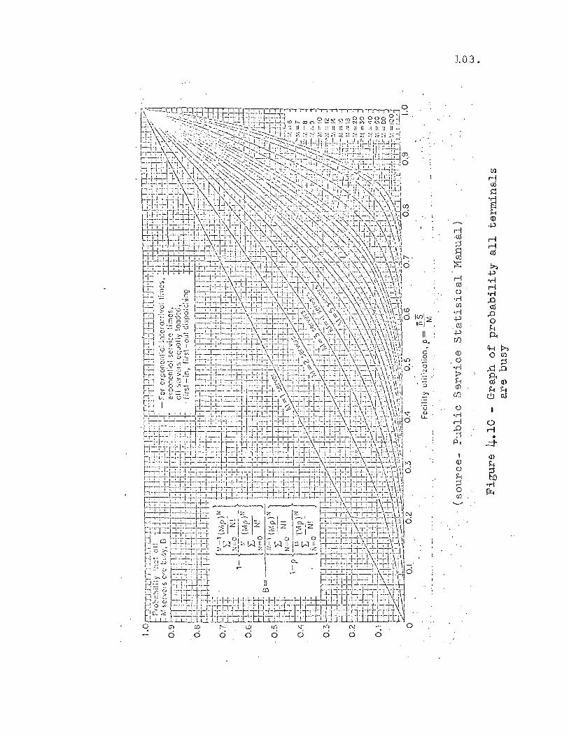
103.
til rl oj
~
'~ H (j)
rl .p
·cd rl ;::) rl
~ oj
~ f;>:. .p
rl 'M oj rl 0 'M 'M ..0 ({J oj
1(j)1~ 'M ..0 .p 0 lei . cU H
1\ .p p., a.. c/)
c <D <i--Jf;>:.
0 o til 0 .c:E 0 'M N ? p., H oj (!)
::> <D ~~ >- UJ
'u 0 & 'M
.-l 0
..0 .-l ;::) • P-l ...::t 1 (!)
<D ~ 0
H bO ;::) ..-I 0 Ii. ({J
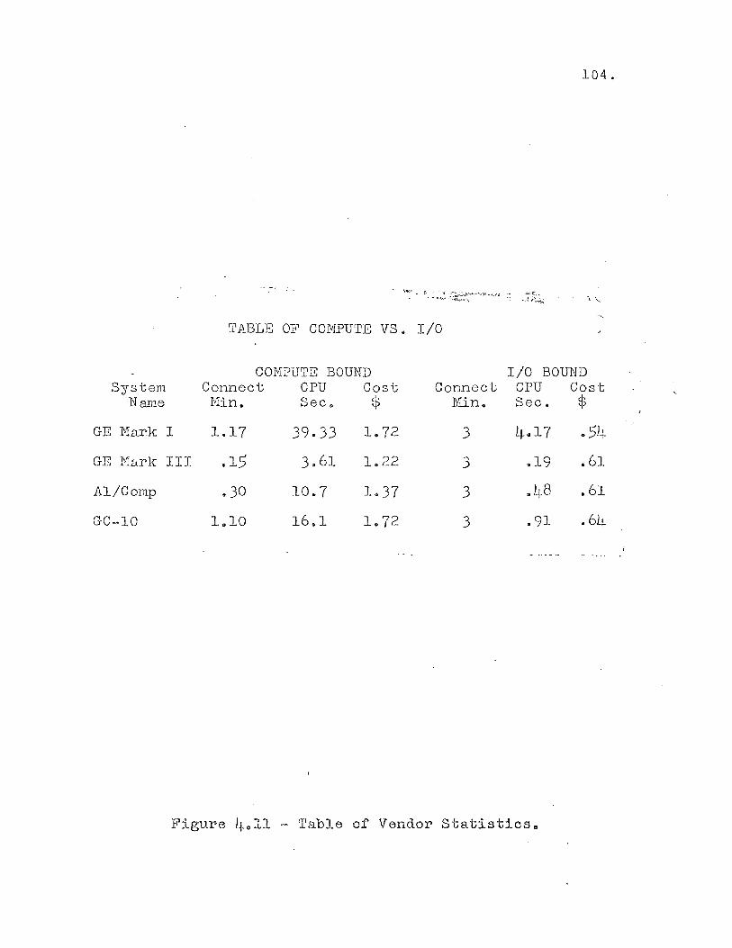
104.
<--.: •• _t~_... \',
TABLE OF COMPUTE VS. I/O
cm1PUTE BOUND I/O BOU1iD System Connect CPU Cost Connect CPU Cost
N arne rUn. Sec. $ Min. Sec. $
GE 1-1ark I 1.17 39.33 1.72 3 4.17 .54
GE l'llnrk III .15 3.61 1.22 3 .19 .61
Al/Comp .. 30 10.7 1.37 3 .. L~8 .61
GC-10 1.10 16.1 L.72 3 .91 • 6L~
Figure 4.11 - Table of Vendor Statistics o

105.
The last graph shown in Figure 4.10 is used to cal
cUlate B, the probability that all terminals will be
busy. For example, at Bergen Division, a person arriving
at the terminals will find both of them occupied 64
percent of the time.
The present terminal placement scheme had as its
sole criterion that waiting time be less than 20 minutes
for each division. This criterion is satisfied in all
divisions at present even with the additional load of the
estimating system. No additional terminals are neces
sary.
Summary
It was the purpose of this chapter to layout the
basic framework of the proposed cost estimating system.
The use of simplified input was discussed. The selection
of a time sharing computer system was made using economic
criteria. A computer language, BASIC, was selected and
based on the design needs of the system. Finally, the
file design, and the general system layout, was flow
charted and discussed.
In total, this chapter has laid the framework to
delve into the detailed program design,to be examined
in the next chapter.

Introduction
CHAPTER V
DETAILED DESCRIPTION OF THE
OPERATION OF THE OVERHEAD MODULE
The purpose of this chapter is to explain to the
reader, in detail, the operation of the overhead module
of the construction cost estimating system. The overhead
module is representative of the other calculation modules
of the system, and an understanding of it will give the
reader an understanding of the entire system.
Before the discussion of the program module, the
reader should refer to a brief introduction to some BASIC
language elements given in Appendix I to aid him in the
work to follow. The explanation of the overhead module
will commence with the reading of a test run of user in
formation from the file D365. The reader will be shown
the structure and contents of all pertinent data files
used by the module. The methods used to calculate the
estimated costs will be explained in detail. The work
files created by the module using the test data will be
illustrated using actual dumps of file contents during
the execution of the test run. Finally the reports de
rived from the test run will be shown.

107.
Functions of the Overhead Program Module
The functions of the overhead program module (E365W$)
are enumerated below. The enumeration serves as a topic
summary for the remainder of the chapter.
(1) Read information from the user data file D365.
(2) Read in the data stored in the overhead data
files:
(a) COMINFO - Contains general estimate costs
and percentages.
(b) OHCABLE - Contains overhead cable costs and
labor hours.
(c) BRPTOP - Contains pole top construction
costs and labor hours
(d) GYANSW - Contains material and labor costs
for guys, anchors, and switch
installations.
(e) NAMES3 - Contains the string descriptors
for overhead cables.
(3) Produce a cost estimate and material requirement
for guys, anchors, and switches.
(4) Produce a cost estimate and material requirement
for overhead primary and secondary cable.
(5) The interaction of the program with simplified
user input and the random binary file BRPTOP
to produce pole top hardware material costs
and material requirements.
(6) The appending of the work files for material
and costs.
(7) The selection of a chaining point for the
rest of the system.
(8) The production of the cost estimate printout,
the estimate summary, and the material list.
108.
The report will follow a set of test data through the
system from its entry in the data file INPUT to the produc
tion of the final reports. Actual listings of all pertinent
data files will be used to illustrate the functions of
the system in progress.
Creation of the File INPUT
The user of the cost estimating system must complete
his map and field surveys as in the manual system. At this
point, he must fill out a set of data sheets as shown in
Figures 4.1 to 4.5. The computer system is accessed and the
data is entered from the terminal or through a pre-punched
paper tape. The input for the test case is shown on Figure
5.1.
The user runs a check of the data by executing the
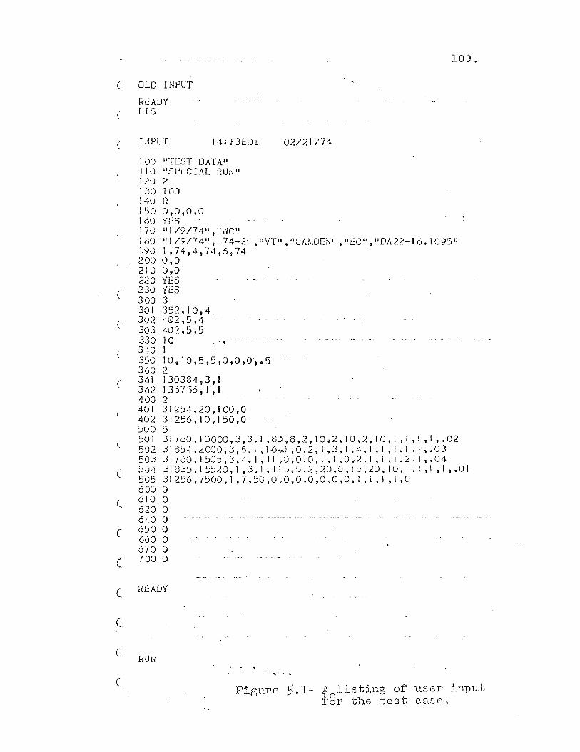
(
(
(
(
(
c
(
(
(
C
(
109.
OLD INPUT
READY LIS
INPUT 14:~3fDT 02/21/74
100 110 12U 130 14U 1::>0 160 170 I dU 1.90 200 210 220 230 300 301 302 303 330 340 350 360 361 362 400 401 402 5UO 501 502 50j j04 505 600 610 620 640 650 660 670 700
wrEST DATAII "Sl-'eCIAL !fUNII 2 100 R 0,0,0,0 YES 111/9/74 11 ,II,-ICII II I 19/74 11 , II 74-.-211 , II VT" , "CAMDEi~1I , II EC 1/ , II DA22-J 6. I 095 11
1,74,4,74,6,74 0,0 Uto YES YeS 3 352, 10,4_ 402,5,4 402,5,5 10 1
. "
10,10,5,5,0,0,0,.5 2 130384 9 3,1 13::> 755, I t I 2 31254,20,100,0 31256,10,150,0 5 31 760, 10000,3,3. I ,80, G , 2, 1 ° i 2, 10,2, 10, I ,I , 1 ,I ,.02 31 Sj4, 2000,3 t 5. I , 1-61'> I ,0,2, I 13, 1 ,4. I I I , 1 • I ,I ,.03 J 1 760 t I :i0'j , 3 , 4. 1 , I I .0, ° , 0 , 1 1 1 ,0, 2 1 I , 1 , 1 • 2 , I ,.04 31(335, I :';:)20, 1,3.1,115,5,2,20,0,15,20,10, I, 1,1, 1,.01 31 256 , 7':.i 00, 1 , 7 , 50 , ° to, ° ,0 ,0 ,0 ,0, 1-, I , I , I , ° ° ° o ° -- --.-.- --° o
° o
READY
nUn
Figure 5.1- t-l. listing of user input r8r the test case.

110.
the program ESTeK$. If the data is correct, the program
ESTRE$ will be executed next. This program will write
the user input to several work files. The data for the
program module E365W$ is written to the file D365. The
contents of D365 after the execution of ESTRE$ is shown
in Figure 5.2.
The coded program module is illustrated in Figures
5.3 through 5.8. Flow charts can be seen in Figures 5.21
through 5.25. Line 1000 on Figure 5.3 sets up the file
D365 as file number one. On line 1100 the first access
to the file is made. The value of X2 is read. X2 is the
amount of user guy and anchor data stored in subsequent
entries in the file. Line 1120 tests the value of X2,
if it is zero, the program branches to line 1190. If it
has a value, the program reads in the data up to the
limit of reads as denoted by the value of X2.
Line 1190 will be read to find a value for Xl, the
number of lines of user switch data to follow in the data
file D365. If the value of Xl is zero value, the program
reads in the values of Z(l), Z(2), Z$(l) 1 and Z(3). These
are respectively, the number of months for which excala
tion is to take place, the estimate type, the estimate
format code, and the cost rounding factor. After reading
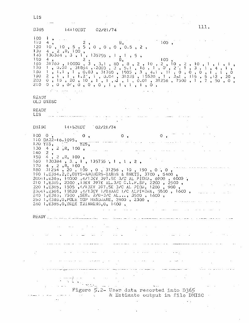
LIS
0365 14:10EOT 02/12.1/74 111.
100 1 , 1 1 U 4 , 2 , Ii , I 00 , 1 20 10, lOt 5 , 5 , 0 , 0 , 0 , 0.5 , 2 , I 3 U 4. 2 ,H t 1 00 , 140 130304,3, I t 135755, ,1,5, 150 4 , 2 , R, 100 , 160 31760 t 10000 • 3 , 3.1 I 80 I 3 , 2 , 10 , 2 , 10 , 2 , 10 , 1 , I ,It I 70 1 , 0 • 02 I 3 I 854 " 2 000 I 3 , 5. I , 1 6 , ItO- , 2', 1 t 3 , I , 4 , I , lGU 1 , I. I ti, 0.03 , 31760 , 1505 , 3 , 4.1 , 11 , 0 , 0 , 0 , I , I ,0 1902,1,1,1.2',1,0.04,31835,15520; I, 3ot.l, 115 I 5,;2,20, 200 0 , 15 , 20 , 10 .f 1 t 1 ,...J , I , 0.0 I t 31256 , 7500 , I t 7 1 50 , 0 , 210 0 , 0 , 0/, 0 , 0 , 0 , 1 , I , I , 1 , 0 ,
READY OLD DHISC
READY LIS
DMISC . 02/21174
100 0 , 0 0 , 0 110 DA22-16.1095, 120 YES, .'( YES, 1 30 4, 2 ~ R, 1 00 , 140 2, 150 4 , 2 ,FI, 100 , 160 130384, 3., I , 135755 " I , 1 , 2 , 170 4, 2 ,R, 100 , 180 31254, 20 , 100 , 0 , 31256 , 10 , 150 , 0 " 0 , 190 1 ,E364.2,0,GUYS-Ai~CHORS-XARi.\S & BRKTS, 3700 , 5400 , 20lJ41,t:365, 10000 .,4/13f.V 397.5K 31C AL PIO\;A, 6900 , 6000 t
210 I,E365, 2000 ,13KV 397K AL.3/C C.L.P.SP, 2200 , 2500 , 220 I,E365, 1505,4/13KV 397.5K 3/C AL PIO~, 1200 , 900 t
2304I,c365, 15520 ,4/13KV 1/0AAAC I/C ALPP'OiiA, 5500 y 1600 , 240 1,1::36:>, 7-3>00 ,SEfL 2/0-3/C AL. •• I 3500 , 1600 , 2:)0 1, t:36S, 0, PULE TOP HARD,,'ARE, 2800 , 2300 , 260 I,E36S,O,fnEE TRIMI.IlNG,O, 1400 ,
READY. _ .... ___ ._. ____ . ..-:._. ______ .
'"0 _ ••• _. __ ~._, ________ • _ ____ ••• " _ .. __ _
".0. __ ;
, '.
Figure 5~2- User data resorted into D365 & Estimate output in file DMISC
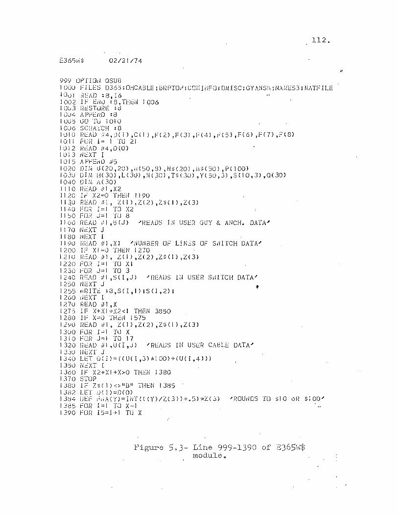
112.
E3651'i$ 02/21174
99<J OPTIOI~ OSUB 1000 FILES 036:); OHCABLE ; BRPTOP; COI.\ WFU; OM!SC; GY ANSl'i; NAMl:S3; MATF ILE lOu I RL:AD 18, 16 1002 IF E~O :8,TH~N 1006 1 Ou3 l?ESTuRt: : d I uu4 APi-'i::HD :8 IOU:> GU 'ru I OJ 0 IOu6 SC!iATCH : 8 1010 READ 7F4,D( I) ,C(I) ,F(2) ,F(3) ,F(4) ,F(5) ,F(6) ,Fen ,F(s) I 0 I I F 0 Ii 1 = I TU 21 1012 R~AD #4,0(0) 1 iJ I 3 !~ L:XT I I 0 I 5 A PfJEiW #5 1020 OI!.-j U(20,20) ,id50,8) ,N$(20) ,/.\$(5U) ,PC 100) 103u 0 1/.\ H ( 30) I L (30) "\\ ( 30) ,TS ( 30) , Y ( 50,3) ,S ( I 0 ,3) ,0 (30) 1040 DIM ;\(30) . 1110 nEAO if! ,X2 1120 IF X2=O THEN 1190 I i ~o READ eJ\, Z( I) ,Z(2) ,Z$( I) ,Z(3) 1140 FOR 1=1 TO X2 11~0 FOR J=I TO 8 1160 READ #1 ,BCJ) /REAOS IN USER GUY & ANCH. DATA' 1170 NfXT J 1180 NEXT I 1190 READ if 1 ,X I /NU/.\BER OF LI NiS OF S,./lTCH DATA" 1200 IF XI=O THEN 1270 1210 HcAD !iI, £(I),Z(2),Z$(I),Z(3) 1220 FO]? 1=1 TO XI 1230 FUR J=I TO 3 1240 READ :II,SO,J) /REAIJS IN USER SliITCH DATA" 1200 NEXT J I 2 55 !'d~ ITf : 8 9 S <I , I ) ; SCI, 2) ; 1260 rlEXT I 1270 READ ifl,X 1275 IF X+XI+X2<1 THEN 3850 1280 IF x=o THi~ 1575 12YO l?EAD f/19 Z(I),Z(2),ZS(I),Z(3) 1300 FOR 1=1 TO X 1310 FOR J=I TO 17 1320 Rt:AD ifl ,un ?J) 1RfADS IN USER CABLE DATA/ 1330 lJi;XT J 1J40 Lt:T O(l)=«UU,JHIOO)+(U(I,4})} 1350 lkXT I 1360 IF X2+XI+X>0 THEN J380 1370 STOP 1380 Ii::: ZSC I) Ollt)" 1llEN 1385 1382 LET UCJ)=D(O) 1384 UI:::I= hUdY)=INT(((Y)/Z(3»+.5)*Z('::n "ROUlWS TU slO oF? S100" 1385 FOR 1=1 TO X-I 1390 FOR 15=1+1 TO X
Figure 5.3- Line 999-1390 or E365w$ module~
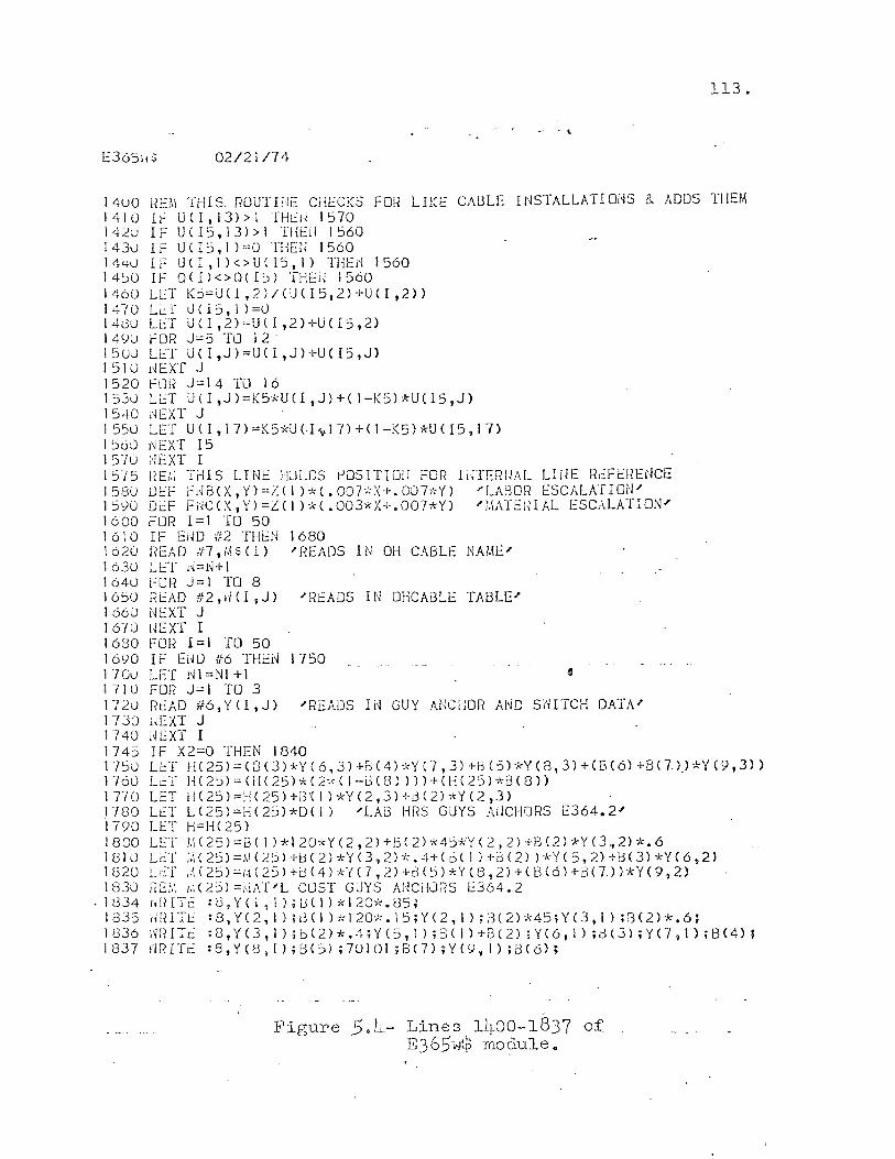
113.
, . E365i1$ 02/21174
14110 REM Till S, RUUT lilE CHECKS FOR LIKE CABLE I NSTALLATI OdS 8. ADDS THEM I 4 I 0 Il-: U CIt 13) > I THc'H I 570 14~u IF UCI5,13»1 THEii 1560 1 430 IF U C 15,1 ) =0 THEU 1560 1440 1 F U ( I , I ) < > U ( 15, I) HIEd 1560 14~0 If 0(1)<>0(15) THEU 1560 1460 LET Kj=U(I,2)/(UCI5,2)+U(I,2» 1470 L~T 0(15,1 )=ll 14dU LET UC1,2)=U(I,2)+UCI5,2) 149U fOR J=5 TO 12' 1 5 U0 Li::T U ( I ,J ) = U ( I ,J ) +U ( 15 , J) I 5 III l~ E XT J 1520 FOR J=14 TO 16 1530 LET UCI,J)=K5*UCI,J)+(I-K5)*UC15,J) 1 540 r~EXT J 1550 LET U(I,17)=K5*U(I~17)+(I-K5)*U(I5,17) 1500 j"lEXT 15 1570 NEXT I 1575 REI.; TrlIS LINE HOLDS r'oSITIOI! FOR IilTErWAL LWE ReFERENCE 1580 DEF Frli3(X,Y>=LCI)*(.007'):X+.007,':Y) "LAl3oH ESCALATION" IS')() OEF FHCCX,Y)=Z(IHC.003*X+.007*Y) "I.\ATEHIAL ESCALATION' 1600 FOR 1=1 TO 50 1610 IF END #2 THEN 1680 1620 READ #7,~5(I) "READS IN 6H CABLE NAME' 1630 LET 1~=N+l 1640 fOR J=1 TO 8 1650 FlL:AD #2,iiCl,J) "RcADS IN OHCAI3LE TABLE' 1660 NEXT J 1670 HEXT I 1680 FOl{ 1=1 TO 50 1690 IF Ei~D If6 THEN 1750 17Gu LET NI=NI+I e 1710 FOR J=i TO 3 1720 R~AO #6,Y(I,J) "READS IN GUY ANCHOR AND sarTCH DATA' 1730 lJEXT J 1740 i~EXT I 1745 IF X2=0 THEN 1840 175U L~T H(25)=CD(J)*Y(6,3)+BC41*Y(7,3)+BCS)*Y(8,3)+(B(6)+BCl).)*Y(9,3» 1760 LC:T IH2::;)=(H(25)*(2*(I-i3(S»»)+(ll(25)*B(8)) 1 TlO LET H(25)==llC25)+G'( I )*Y(2,3)+!3C2)*Y(2,J) 1780 Lt.:T L(25)=H(25,*O( I) "LAG HRS GUYS AIlCHiJRS E364.2" 1790 LET H=H(25) 1800 LET tl(251=BCI1*120*YC2,2)+BC2)*45*Y(2,2)+B(2)*Y(3,2)*.6 ISIU L~T ~(25'=M(2~)+B(2)*Y(3,2)*.4+(6(1)+3(2) )*Y(5,2)+B(3)*Y(6,2) 1 (320 L c'f ,.\ ( 25) == I;d 25) + i.H 4 ) * Y (7 , 2) -I-!3 ( :i ) * Y C 8 t 2) + ( 13 ( 6 ) + i3 C n ) * Y ( 9 ,2) U33U fiEf:, 1:, (2:j) ==;,IAT"L COST GUYS AIlCi-luRS E364.2
.1(334 riHITl: :8,YCI,1).[3(!)*120*.85; i835 tmITt: :S,Y(2, I) it3C! )*120*. IS;YC2, 1) ;13(2)'k45;Y(3,l) ;13(2)*.6; I 836 I'm IT c: : 8 t Y (3 , I ) ; b (2) *.";'; Y ( 5 1 I 1 ; 3 ( I ) + f3 C 2) ; Y (6, I ) • <:l (3) ; Y (7 , I ) ; !:H 4) ; I 837 >'i R IT c: : 8, Y ( 8 I I ) ; B ( 5) ; 7 () I 01 ; B C 7) ; Y (9, 1 ) ; B C 6) ;
Figure 5.4- Lines 1400-1837 of E3651oJ$ module G
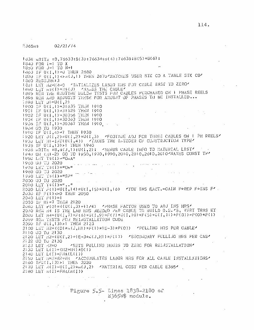
E365tiS 02/21/74
1038 ,;RITc :8,76633;8(3);76634;[.)(4) ;76636;[3(5)+8(6); 1340 fOR 1=1 TO X 18~O fOR J=l TO N+I
114.
I cl60 1 f U ( I , 1 ) =0 THEN 2680 13-/U IF U(I,I)<>dCJ,I) THEI~ 267u",'.lAICHES USER STI( CD &. TABLE STK CD" I 8UO I~ESTLlJ--lt: 3 18dl U:::T iiL=H4=O "IiirIALIZES LA8i.JR Hi6 FlJR CABLE [NSf TO ZERD-' 11::)<)0 LET Ij$(l)=I.~SCJ) "i'iA:,,::S THe CAGLE'" 189S RC:M Toii.: RJUTIilE l::>ELOIl TESTS FOil CAi3LES f-lU;::CHASED OU 1 PHASE REELS 1396 RL:i.i Arm ADJUS-[S THESE FuR Ai.\iJUdT uF PHASES III DE INSTALLED ••• Id98 LET ul=U(I,2) 1900 If U(1 ,1)=31835 THtN 1910 1901 IF U<I ,1)=31025 THEH 1910 1902 IF U(1 ,1)=30356 THi.:N 1910 1')04 IF U ( I , 1 ) =30363 TlkU 1910 1906 IF U(l,I)=30367 THEN 1910 1908 GO TU 1930 1910 IF 'un ,4)=7 THErr 1930 1920 LET U<I,2)=UCI,2),lcU<I,3) --'FOOTAGE ADJ FOri THOSt: CABLES ON PH REELS'" 1930 Lr..::T HI=Ii.JT(UCl,4» "TAKES THE IuTEGEFI OF CO,ISTRJCTIOi,j TYPE ..... 1,)]5 IF U<I,IJ»l THEN 1:940 I '/.J6 fI~?ITL: :8"HJ, 1) ;U(l, 2); "SEiiDS CAiJLE IHFO TO ;.\ATERIAL LIST" 1,/40 O;~ Cdl-2) GO TO IY50,1970,1990,2010,2010,2010,.2010"NA!,IES CONST TI-''' ly~O LeT TS{!)=1I0IiAII 1960 GLl TLJ 2020 1'/70 LeT T$CI)=1I0~i" 1980 GO TLJ 2020 1990 LET T$ (1) =tlSP" 2000 GLJ TLJ 2020 2010 LET 1'$(1)=11 •• 11
2020 LET 1:(1)=U<ItI4b'~UCI,15)-!<U(I,16) "TOT INS F-J\CT.=GAIN F*REP F*INS F"-2030 IF FCI)<>O THEN 2050 2040 LET F( 1 )=1 2050 I~ HI=7 THEIl 2120 2u6U LET P(0)=«U(I,3)+1)/4) "PHASE FACTOR USED TO ADJ INS HRS' 2070 Ht:i,\ d4 IS THE LAD HFiS i~E[:Dt:D PeR CABLE TO oUI LD D. E. "S t VERT TRNS ET 208u LET i-i4= (U Cl ,7) *i-= (6) +Li C I ,9 ):<'F (7) +U ( I 9 10) *f (5) +U ( I t II) *F (8) ) *p CO) *F ( I ) 2089 r?t::,',l TeSTS FOH RU.iJSTALL,\TION CUDE 2090 IF U(l,13»1 THEd 2123 2100 L~T d2={C01*hCJ,ii])*Hl)-klE-3)*P(0» "'PULLING H!?S PER CABLE" 2110 GO 'I'll 2130 .2120 LET i--l2=<UCI',.2)*lE-3*i;CJ,Hl)*FC1)} "'SeCOliDARY PULLIUG f-fl{S PER CAB" 21 22 GO TLJ 2130 2123 U:T H2=0 "SETS PULLING HOURS TO ZERO FOR RELiSTALLATION'" 2130 LET Ul)=(112+i-l4PO(I) 2140 LET LCI)=FNACLCI» 21 ~)U LET h=H+H2+i14 "ACCUi,\ULATES LABOR HRS FO::? ALL CAc)LE I NST ALLATI ONS'" 2100 Ii'::UCI,13»l Ti1Ei~ 2220 2170 LL:T ;HI)=UCI,2H-n(J i 2) "i.IATEfHAL COST PER CABLE 1:365' 2180 LET M(I)=FNACM{I»
Figure SaS- Lines 1838-2180 of E365H$ module ..
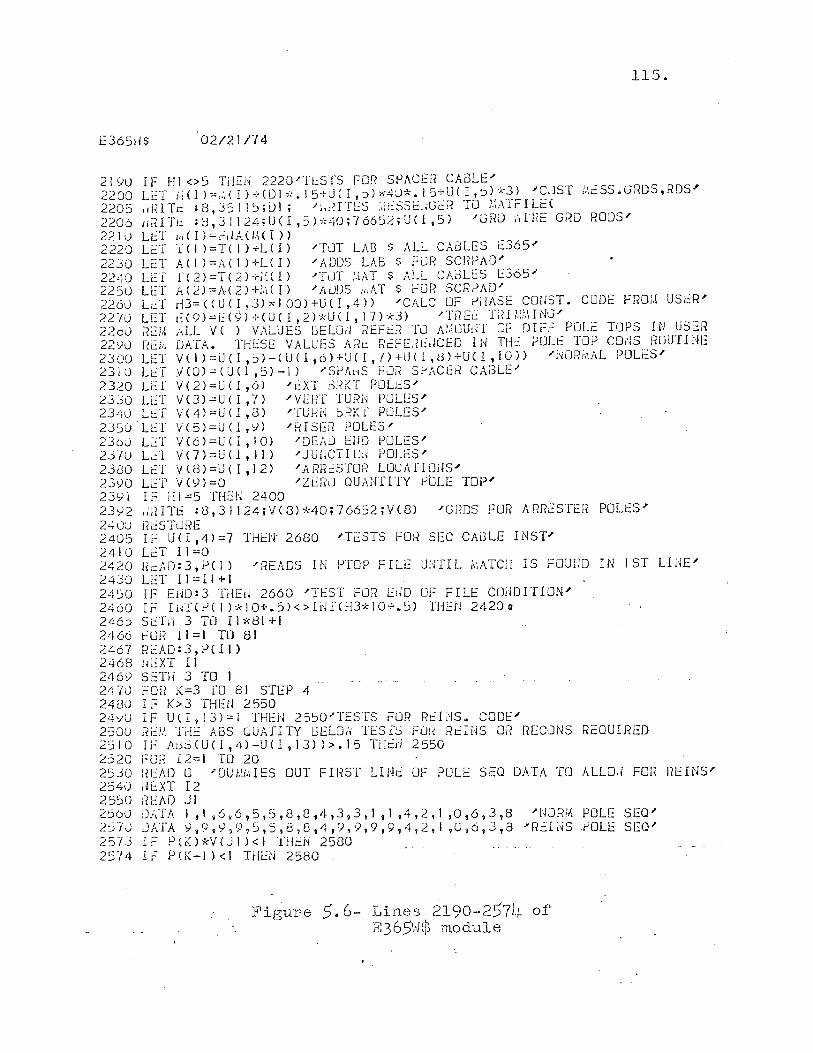
115.
EJ65dS 02/21174
21YU IF Hl<>5 THEU 2220"TlSTS FOI( SPACER CABLE" 2200 Lt:T i.\(l)==.:.(IH-Wlx.15+UeI,j)x40*.15+UCI,S)·kJ ) -"CJST i.iCSS.GRDS,rmS" 2205 ,dHTr: :8,35115;ul; "1"IITES :.:CSScliGcf? TO i.~r\TrILE( 2206 IiRIT!.: :3,31124;U(f,5b·~40;·/66:52;UCl,5) "GRD ,'dHE GRD RODS" 2210 Lt:T /.l(I)=i:dA(/.\(I» 2220 LcT 1(1 l=T( I)+LCI) "TJT LAB $ ALL CAJLES E365 J
2230 L::T ACI)=A{I)+LCI) "ADDS LAB $ FJH SCEPAD" 2240 LC:T f(2)=T(2)+;.~Cl) -"TJT ;.\:\T $ ALL CADU~S 1::365'" 2250 LeT A(2)=A(2)+:.1(!) -"ADDS ii,AT $ hJR SCRPAD" 2260 L:"::T d3=(CU{I,3)xI00)+U<I,4» "CALC OF rJiJASE COUST. CODE FRO].\ USt.:R" 22"1U LET t(9)==Uy)+(U( I t2)*U(I, 17>*.3) "TREe Ti?II.~;.\ING" 22d0 ;?:::M i\LL VC ) VALUES bELLJ;J j~EFL~;:{ TJ A~.HJU!~T m: 01[=,:: POLe TDPS IN USER 22<)0 REi" DATA. ThESE VALUES Ai~c r~cFE;?t:dCEO ll~ TIE iJOLE TOil CO,'iS I~OUTINE 2300 LET V(I)==U(I,5l-CU(I,6)+U(I,7)+U(I,U)+U(I,IO» "~OH~AL POLES' 2310 LET V{O)==(UCl ,5)-1) "SfJAIIS FJR Sr'ACEli CABLE" 2320 LeT V(2)=U( I ,6) "eXT Dl~i(T POLt:S" 23jO LeT V(3)=U(I,7) 'VEHI l'UR~ PJLES' 2340 Li::T V (4) =U (l ,d) "TUl{i'J bRKT PULES" 2350 L~T V(5)=U(I,Y) "HISER POLES' 230v LeT V(6)=lj<I, 10) 'DEAL) EliD POLES" 237u L~T V(7)=U<I,II) "JUUCTIOi~ POLES" 23(30 LfT V«3)=U(I,J2) "Aii'ReSTOR LOCATIOHS" 23')0 LET V(l)==O ''It::RlJ QUANTITY rJOLE TOP" 23YI IF HI==5 THEN 2400 23')2 ,mITt:: :8,31124;V(3l*40;76652;V(3) "CROS FOf'? ARRi:STER POLES" 24lX.J j'?cSTtJRE 2405 IF UU,4)=7 THEN' 2630 "TESTS FOR SEC CAGLE INSTJ 2410 LET II =0 2420 IkAD:J,J.>C I) 'READS IN fJTOP FILE UUTIL /.',ATCli IS FOUrw IN 1 ST LINE" 2430 LET 11=11+1 2450 IF EliD:3 TdEU 2660 "TEST FOR [dO OF FILE COilDITION" 2460 IF IdT(!-'( I P:l0+.5)<>IiH(!-13*iO+.5l THEN 24204 2465 St:Ti' 3 TtJ 11,,81+1 2466 FUR 11=1 TO 81 2467 READ:J,P(IJ) 2468 liEXT 11 2469 SETji J TO I 2470 FOR K=J TO 81 STEP 4 24i30 IF K>J THEJl 2550 24yU IF U CI 1 13) = I THEH 2550"TESTS FOR Rd NS. CODE J
2300 Rei.\ TdE ASS (JUATI TY l:3ELOl'; TES r::; FUJi ReHJS OR RECONS RcQUI RED 2510 IF A0S(U<I,4)-U<I,13»>.15 Tl-!:::d 2550 2:520 FOI-l 12=1 TO 20 2530 j?I::AD lJ 'OUl.\i.-,IES OUT FIFIST LINe OF POLE SEQ DATA TO ALLO,/ FOR REINS' 2540 ,-IEXT 12 2550 !'?EAD Jl 2Sou DATA 1,1.6,,6,5,5,8,8,4,3,3,1,1,4,2,1 ,O,6,J,8 "UJRM POLE SEQ' 207J DATA Y,9.Y~9,5,5,8,8!4,<),9,9,9,4,2,I,U,6.3,8 .J'Rdi~S tJOLl.: SEQ' 25n IF PCiO*V(J1J<1 TIki'! 2580 25-/4 IF iJ CK-I ) <I THEN 2580
Figure 5.6- Lines 2190-2574 of E365':J~l> module
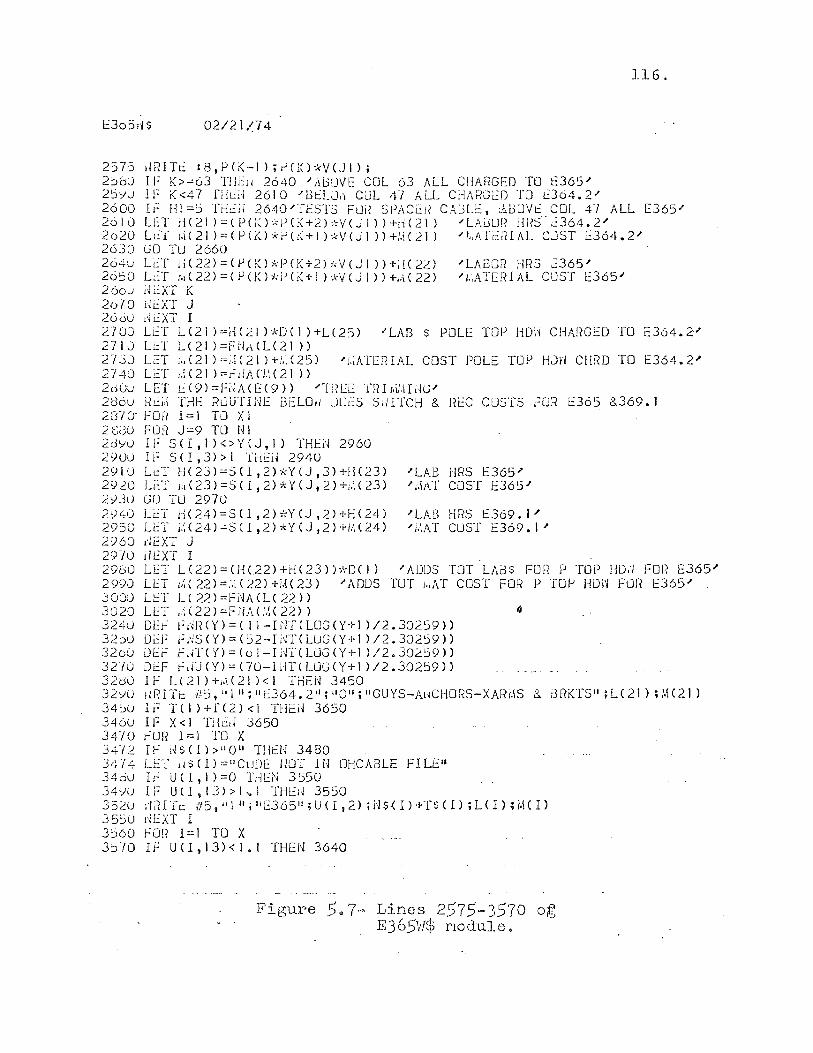
1::305;1$ 02/21/74
2575 .IRITt.:: :8,PCK-I);vCKPV(JI); 2~bJ If K>=63 THEil 2640 "AliUVE COL 63 ALL CHARGED TO l:365.1' 2:)')0 If K<47 fHt:d 2610 "BtLLk, CUL Irt hLL CHARG[D TO d64.2.1'
116.
2600 IF HI =5 TrlC:ij 2640"'11::S'1'5 FUii SPACc~ CAUL:':, }d3[JVf COL 47 ALL E365.1' 2610 LET rH21)=(P(K)'~P(i(+2)-.~V(JI»+iH21) "LAJUi? i{i?S"C:364.2.1' 2020 L:"::T {.\(21 )=(p(;o*i-'el~+1 PV(JI »+1.\(21) .I'/"ATcliIAL CJST t:36'i.2" 2630 GO Tu 2660 204u LC:T ri(22)=(!lCK)*P(K+2hWeJI »+i!U2) .I'LABO!? HRS ":365.1' 2650 LC:T r.1 (22) = (P CK) *i1 ei( -1-] ) ,\"v (J 1 ) ) +'/l e 22) "i.,ATEIH AL COST 1:365.1' 260J l~r..:XT K 2670 iJEXT J 2600 l~tXT I 2700 LET L<21 )=HC21 )*De 1 )+LC25) "LAS $ POLE TOP HOd CHA[WED TO c364.2" 2710 U:T LC21 )=FiJ JdLC21» 2730 L~T i.,(21 )=;,;(21 )+i,;(25) 2740 LeT ).;e21 )=r~dA(J.;(21»
"'f,;ATERIAL COST POLE TOP HJrI CHiW TO E364.2"
2dUU LET t(9)=Fi;ACE(9» .I'-mEE TRL'D'HiKV 2tl6u HC:d THE rtuUTINE fJELOIl JOi:S S,iITCH & REC COSTS FO:i E365 &369.1 231~ FOR I=J TO XI 2SJO FOR J=9 TO NI 2dYU IF SCI,I)<>YeJ,I) THEN 2960 2900 IF SCI,3»1 THC:N 2940 2SflU LC:T H(23)=SCl,2)*YeJ,3H-ll<23) .I'LAB HRS 1::365.1' 2920 Lt::T i.,(23)=S<I,2)*YeJ,2)+,.'.C23) "').\1\1' COST E365.1' 2";]0 GO TU 2970 2940 L~T H(24)=SCI,2)*YeJ,2)+H(24) .I'LAB HRS E369.1" 2950 LET ~(24)=S(1,2)*Y(J,2)+M(24) "'MAT CUST E369.\.I' 2960 dEXT J 29-/0 d I::XT I 2980 LET L(22)=(He22)+H(23»;\-DCI) "ADDS TOT LAC3s FOR P TOP HDi; FOR E365" 2990 LET j.;{22)=:,i(22)+iH23) .I'ADDS TOT /.;AT COST FOR P TOl-> HD1'/ FDR E365" 3000 LfT L(22)=fNACLC22» 3020 LET ~(22)=FNA(U(22» 3240 OE~ f~R(Y)=( Il-INTCLOGCY+] )/2.30259» 32~U DEf fdS(Y)=(~2-I~T(LUG(Y+l )/2.30259» 320CJ j)f:j':- fJf(Y)=(ol-IlrrcUjGCY+l )/2.30259» 3270 OEF hW(Y)=(70-IdTCLLJGCY+I )/2.302:>9» 32bO IF L(21)+,.i(21)<1 THEN 3450 32y() ,IRITi:: #:s,"III;IIU64.2i1i'1011;IIGUYS-Al~CHORS-XARI.\S & i3RKTS"iL(21);M(21) 34~u IF T( I }+f(2) <1 THEil 3650 346U IF X<l Tried 3650 3410 ~UR 1=1 TO X 34-/2 IF i"lsel»1l01l Tllr:N 3480 3'~-[4 LET dS(l)=tlCuDE !lOT 1/-1 OHCABLE FILEII 34du I~ U(I,l)=O THEN 3550 34YU IF U ( I , 1.3) > ] -.! THL:j~ 3550 3 5 ~U ,'I i1 IT 1: if 5 , "I II; I, E3 6 5 II ; U ( I I 2) ; 1'1 $.( I ) +T SCI) ; L< I ) ; M ( I> 3550 r-iEXT I 3560 FOR 1=1 TO X 3570 If UCI,13)<I.1 THEN 3640
Figure 5.7- Lines 2575-3570 o~ E365H$ module.
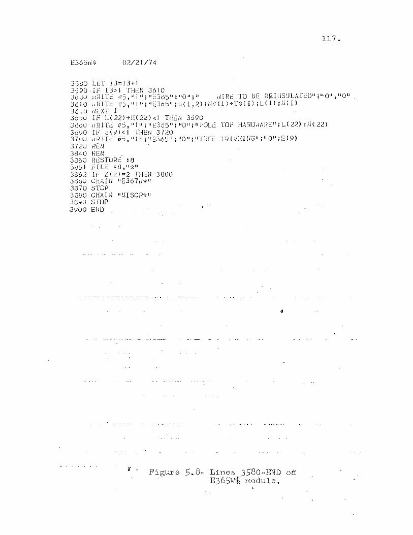
E36Sri$ 02/21/74
3580 LEI I3=13+1 3090·If 13>1 THeN 3610
117.
3600 rUUIc ~5,'I[II;IIl::36511;1l0"iil dIRi TO llE R&:.IiiSULATi::DH;1I01l,"011 36 1 0 I d II T l: ;f 5 , tI 1 II ; IJ d 6 j II ; U ( I , 2) n 1 $ ( 1 ) + T S ( I) i L( I ) ; 1,(( I ) 36.:tO fH':XT 1 30:)0 IF LC 22)+!.!C 2;,:) <l THL:I'i 3690 3600 iiRITi i!5,'QII jllt365 1l jll0lljlltJOLi TOP HARlJiiAI{c ll jU22)jicl(22) 36vO IF dy)< 1 Tr-li:l'I 3720 37LJO .fiETi #5, "I IIi II £:365"; UO"; wrilf:E TR r;.\:.a liC11 ; II 0"; E (9) 3720 Hi::l.! 3840 HE/.! . 33:'>0 f.<t:STiJRE :8 3dj I FILe : <3, II *11
3a52 If Z(2)=2 THEN 3880 3060 CHAIJi IlE367d*1J 3870 STOP 3880 CHAld u/HSCP*" 33'7U STOP 3Y(J0 EiiD
f I Figure 5e 8- Lines 358o-END o~ E365VJ$ module.

118.
in these values, the program will read in the amount of
user input for switches as denoted by the value stored in
Xl.
Line 1270 will be read by the program to find the value
for X, the number of lines of cable data to follow in the
data file 0365. If X equals zero, line 1280 will branch
the program execution to line 1575. Note the last item
in line 140 in file 0365 holds the value of five to be
stored in X. Cable data is read into the program by the
iterative routine contained in lines 1300 through 1350.
This data is read from lines 160 through 200 in file 0365
as shown in Figure 5.2.
Reading the Cost Estimating Oata Files
Each division has stored in its catalogue, files of
material costs and labor productivity. These files are
accessed by the cost estimating system in order to produce
an estimate adjusted for operating conditions in each
division. The files accessed by the program module E365W$
are: (1) COMINFO, (2) OHCABLE, (3) BRPTOP, (4) GYANSW, and
(5) NAMES3. These files are illustrated in formatted form
in Figures 5.9 through 5.17.
The file COMINFO shown ln Figure 5.9 is sequential
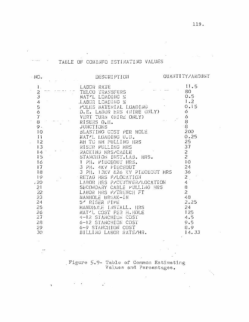
NO ..
1 . 2 .....
3 4 5 6 7 8 9· 10 1 1 12 13 14 15 16 17 18 19
j 20 21 22 23 24 25 26 27 28 29 30
119.
TABLE OF COMINFO ESTIMATING VALUES
DESCRIPTION QUAHTITY/AMOUNT
LABOR RATE TELCO TRANSFERS MAT"L LOADING ;~
.LABon LOAD I nG % .POLES ihATEf~IAL LOADldG D.E. LABOR HRS (~IRE ONLY) VERT TUR1'1 on Rt: ONLY) RISERS O.H. JUNCTIONS BLASTING COST ~ER HOLE MAT'L LOADING U.G. MH TO MH PULLING HRS RISER PULLING HRS RACKING HnS/CABLE ST.AJ4CHION Il~ST.LAD. HRS. I PH. PIECEOUT HRS. 3 PH. 4KV ~IECEOUT 3 PH. 13KV &26 KV PIiCEOUT HRS RETAG HRS P/LOCATION LABOR HRS P/CU·fOVER/LOCATIOU SEC01~DARY CABLE PULLI dG HRS LAf30R HRS P/Tf?ENCH FT MANHOLE BREAK-IN 5' nISiR PIPE HANDH~LE INSTALL. HRS MAT'L COST PER H.HOLE 4-1 2 STAi~CHI Ui~ COST 6-12 S1·AHCHION COST 6-9 STANCHION COST BILLING LABOR RATE/HR.
11.5 SO 0.5 1 .2 0.15 6 6 S 8 200 0.25 25 37 2 2 10 24 36 2 4 S 2 48 .2.25 24 125 4.5 9.5 S.9 14.33
. Figure 5.9- Table of Con~on Estimating Values and Percentages.
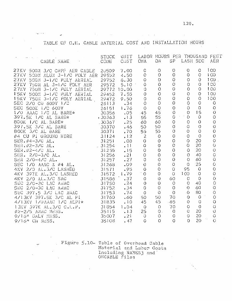
120.
TABLE OF O.H. CABLE ,\\ATERIAL COST AND INSTALLATIOU HOURS
CABLE NAME STOCK UNIT LABOR HOURS PER THOUSAND FEEf CODE CUST OHA O~ SP LASH SEC AER
27KV 500~ 3/C CMPF AER CABLE 27KV 500M ALU~ 3-J/C POLY AER 27KV SOOM 3-\/C POLY A~RIAL 27KV 750~ AL 3-1/C POLY AER 27KV 750),\ 3-I/C POLY AERIAL 15KV 5001.\ 3-\/C POLY AERIAL 15KV 750M 3-\/CPOLY AERIAL SEC 2/0 CU 600V J/C
20509 29552 29752 29572 29772 29452 29472 26113 26151 30356
SEC 500K I/C 600V 1 /0 AAAC l/C AL BARE* 397.5K lie AL BARE* 800K I/C AL.BARE* 397.5K 3/C AL BARE aOOK 3/C AL BARE #4 CU PI GROUND WIRE SfFL ff4-31C AL. SEt?' ii2-3/C AL. SEI~. #2-4/C AL. SER. 2/0-3/C AL. SER 2/0-4/C AL. SEC 110 AAAC 3. #4 AL. 4KV 2/0 AL.3/C LASHED 4KV 397K AL.3/C LASHED 4KV 2/0 AL.3/C SAC SL::C 2/0-2C LAC AtiAC SL::C 2/0-3C LAC AdAC SL::C 397.5 3/C LAC AhAC 4/13KV 397.5K 3/C AL PI 4/13KV 1/0AAAC I/C ALPI* 13KV 397K AL.3/C C.L.P. #2-2/5 ANAC M~SS. 9/16" GAL V 11\ESSa 9/\6 11 eli ;.\t::SS.
} 30363 .30367 30370 30371 31124 31251
.. 31254 31255 31256 31257 31268 31571 31572 31586 31750 31752 31753 31760 31835 31854 351 I 5 35007 35108
7.00 4.50 8.30 5.10
10.00 7 • 55 9.50
.34 1 .. 76
.05
.13
.25
.46
.70 • 12 .08 .. 1 1 • 15 .21 .27 .09 .95
1.79 .37 .24 .34 .74 .60 • 10
1.04 • 13 .. 2l 047
o o o o o o o o o
45 55 60 50 55
2 o o o o o o o
'0 o o o o
50 45 o
25 o o
o o o o o o o o o
45 55 60 50 55 o o o o o o o o o o o o o
50 45 o O. o o
Fig~re 5.10- Table of Overhead Cable Haterial and Labor Costs Including NM1ES3 and· OHCABLE .files
o o o o o o o o o o o o o o o o o o o o o o o
60 o o o
70 65 70 o o o
o o o o o o o o o o o o o o o o o o o o o
95 100
o o o o o o o o o o
o o o o o o o o o
15 o o o o o
20 20 20 40 60 25 o o o
40 60 80 o o o
20 20 20
100 100 \00 . 100 100 100 100
o o o o o o o o o o o o o o o o o o o o o o o ()
o o
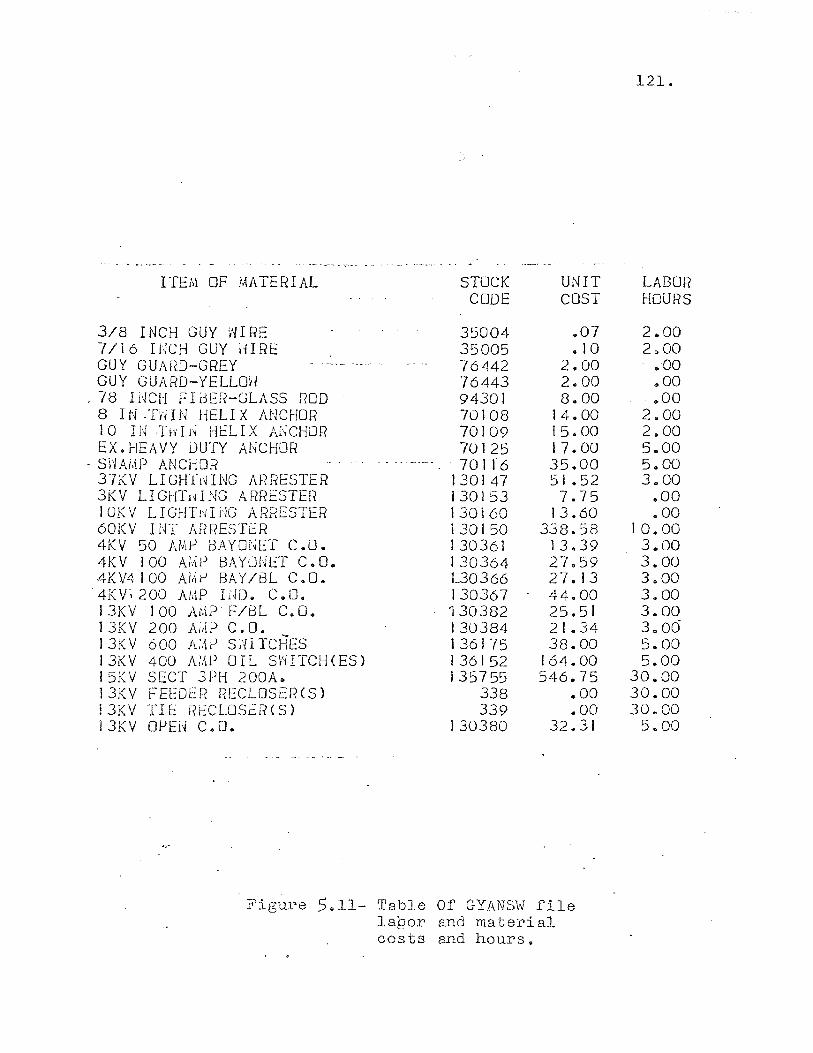
ITEM OF MATERIAL
3/8 INCH GUY WIRE 7/16 INCH GUY iiIRE GUY GUAfW-GREY GUY GUARD-YEllOH
.78 INCH FIdER-GlASS ROO 8 I N --nil N HELl X ANCHOR 10 IN :ndj~ Hr:LIX ANCHOR EX. HEAVY DUTY ANCHOR
- S-j--IAi,iP ANCHOR 37KV lIGl-frrHNG ARr~ESTER 3KV lIGHTldNG ARl-?ESTEF{ 10KV LIGHTrHi'lG ARRESTER 60KV INT ARRESTER 4KV 50 AMP BAYONET C.O. 4KV 100 A;,{e BAYONET C .. O .. 4KV4100 Af,\P BAY/Bl C.O. 4KV~200 AMP IND. c.o. J3KV 100 AMPF/BL C.O. 13KV 200 AiM) C. O. 13KV 600 A:,1P SI'll TCHES 13KV 400 AMP OIL SWITCH(ES) 15KV SECT 3PH 200A. 13KV FEEDER REClOSERCS) !3KV TIE RECLOSfR(S) !3KV OPEN c.o.
STOCK CODE
3S004 35005 76442 76443 94301 70108 70109 70125 70116
130147 130153 130160 130150 130361 130364 L30366 130367 '130382 130384 J 36175 136152 135755
338 339
130380
UNIT COST
.07 • 10
2.00 2.00 8.00
14.00 15.00 17.00 35.00 51 .52 7.75
13.60 338.58
13.39 27.59 27.13 44.00 25.51 21.34 38.00
164.00 546.75
.. 00
.00 32.31
Figure 5.11- Table Of GYANSVl file laQor and material cos ts and hours ..
121.
LABOR HOURS
2.00 2.00
..00
.. 00 ,,00
2.00 2.00 5.00 5.00 3 .. 00
.00
.00 10.00
3 .. 00 3.00 3.00 3.00 3.00 3.06 5.00 5.00
30 .. 00 30.00 30.00
5.00
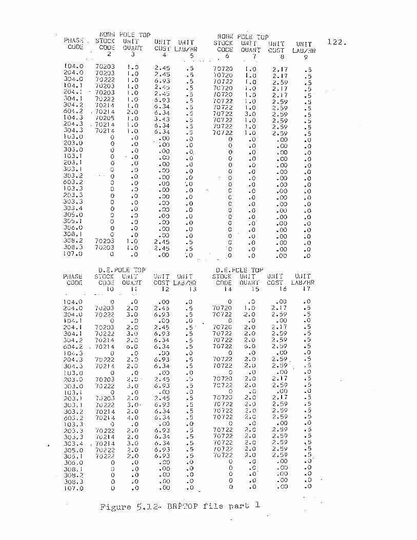
Nornl POLE TOP Norm POLE TOP PHASE STOCK Ui'liT UfIIT UiHT STuCK UNIT UNIT UNIT 122. CUOE coot: QUAcH CUS!' LAB/HR CODE QUANT COST LA [j/I-m
2 3 4 5 6 7 8 9 104.0 70203 1.0 2.45 .5 70720 1.0 2.17 .5 204.0 70203 1.0 2.45 .5 -/0720 1.0 2.17 .5 304.0 70222 1.0 6.93 .5 70722 1.0 2.59 .5 104.1 70203 t .0 2.45 .5 7U720 I .0 2.17 .5 204. I 70203 1.0 2.45 .5 70720 1.0 2.17 .5 304. I 70222 1.0 6.93 .5 70722 1.0 2.59 .5 304.2 70214 1.0 6.34 .5 70722 1.0 2.59 .5 604.2 - 70214 2.0 6.34 .5 70722 3.0 2.59 .5 104.3 70205 1.0 3.43 .5 70722 I .0 2.59 .5 204.3 ,70214 I .0 6.34 .5 "/0722 1.0 2.:>9 .5 304.3 70214 1 .0 6.34 .5 70722 I .0 2.59 .5 IU3.0 0 .0 .00 .0 0 .0 .00 .0 203.0 0 .0 ~OO .0 0 .0 .00 .0 303.0 0 .0 .00 .0, 0 .0 .00 .0 103.1 0 .0 .00 .0 0 .0 .00 .0 203.1 0 .0 .00 .0 0 .0 .00 .0 303.1 0 .0 .00 .0 0 .0 .00 .0 303.2 0 .0 .00 .0 0 .0 .00 .0 603.2 0 .0 .00 '.0 0 .0 .00 .0 103.3 0 .0 .00 '.0 0 .0 .00 .0 203.3 0 .0 .00 .0 0 .0 .00 .0 303.3 0 .0 .00 .0 0 .0 .00 .0 303.4 0 .0 .00 .0 0 .0 .00 .0 30~.0 0 .0 .00 .0 0 .0 .,00 .0 305.1 0 .0 .00 .0 0 .0 .00 .0 306.0 0 .0 .00 .0 0 .0 .00 .0 308. I 0 .0 .00 .0 0 .0 .00 .0 308.2 70203 1.0 2.45 .5 0 .0 .00 .0 308.3 70203 1.0 2.45 .5 0 .0 .00 .0 107.0 0 .0 .00 '.0 0 .0 .00 .0
D.E.POLE TOP D.E.POLE TOP PHASE STOC!~ UH IT Ui'JIT Uli IT STOCK UdIT UUlT UiJIT
CODE ClJOE QUAl!T COST LA3/HfI CODE QUANT COST LAtl/HR 10 II 12 13 14 15 16 17
104.0 0 .0 .00 .0 0 .0 .00 .0 204.0 70203 2.0 2.4:> .5 '/0720 1.0 2.17 .5 304.0 70222 3.0 6.93 .5 70722 .2.0 2.59 .5 104. I 0 .0 .00 .0 0 .0 .00 .0 204. I 70203 2.0 2.45 .5 70720 2.0 2. I 7 .5 304. I 70222 3.0 6.93 .5 70722 2.0 2.59 .5 304.2 70214 2.0 6.34 .5 70722 2.0 2.59 .5 604.2 70214 6.0 6.34 .5 70722 6.0 2.59 .5 104.3 0 .0 .00 .0 0 .0 .00 .0 204.3 -{0222 2.0 6.93 .5 70722 2.0 2.59. .5 304.3 70214 2.0 6.34 .5 70722 2.0 2.59 .5 103.0 0 .0 .00 .0 0 .0 .00 .0 203.0 70203 2.0 2.45 .5 70720 2.0 2.17 .5 303.0 70222 J.O 6.93 .5 70722 2.0 2.59 .5 103. I 0 .0 .00 .0 0 .0 .00 .0 203. I 70203 2.0 2.45 .5 70720 2.0 2. I 7 .5 311J. I 70222 3.0- 6.93 .5 -'0722 2.0 2.59 .5 303.2 70214 2.0 6.34 .5 70722 2.0 2.59 .5 603.2 70214 4.0 6.34 .5 70722 2.0 2.59 .5 103.3 0 .0 .00 .0 0 .0 .00 .0 203.3 70222 2.0 6.93 .5 70722 2.0 2.59 .5 303.3 70214 2.0 6.34 .5 70722 2.0 2.59 .5 303.4 70214 3.0 6.34 .5 70722 2.0 2.59 ~5
305.0 -/0222 2.0 6.93 .5 70722 2.0 2.59 .5 305.1 70222 2.0 6.93 .5 -'0722 2.0 2.59 .5 306.0 0 .0 .00 .0 0 .0 .00 .0 308.1 0 .0 .00 ,0 0 .0 .00 .0 308.2 0 .0 .00 .0 0 .0 .00 .0 308.3 0 .0 .00 .0 0 ,0 .00 .0 107.0 0 .0 .00 .0 0 .0 .00 .0
Figure 5 .. 12- BRP'fOP file part 1
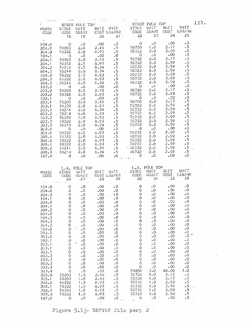
RISER POLE TOP RISER POLE TOp 123. PHASE STOCK U,dT Ui1IT U~IIT STOCK U,HT UNIT UNIT com: CODE OUAin- COST LAd/rJR CODE OUAl'lT COST LAB/HR
18 19 20 21 ' 22 23 24 25
104.0 0 .0 .00 .0 0 .0 .00 .0 204.0 70203 2.0 2.45 .5 70720 1.0 2.17 .5 304.0 70222 2.0 6.93 .5 70722 2.0 2.59 .5 104.1 0 .0 .00 .0 0 .0 .00 .0 204. I 70203 2.0 2.45 .5 70720 2.0 2. 17 .5 304.1 70222 2.0 6.93 .5 70722 2.0 2.59 .5 304.2 70214 2.0 6.34 .:i 70722 2.0 2.59 .5 604.2 70214 6.0 6.34 .5 70722 6.0 2.59 .5 104.3 70222 2.0 6.93 .5 70722 2.0 2.59 .5 204.3 70222 2.0 6.93 .5 70722 2.0 2.59 .5 304.3 " 70214 2.0 6.34 .5 70722 2.0 2.59 .5 103.0 0 .0 .00 .0 0 .0 .00 .0 203.0 70203 2.0 2.45 .5 70720 2.0 2. 17 .5 " 303.0 70222 2.0 6.93 .5 70722 2.0 2.59 .5 103.1 0 .0 .00 .0 0 .0 .00 .0 203. I 70203 2.0 2.45 .5 70720 2.0 2.17 .5 303. I 70222 2.0 6.93 .5 70722 2.0 2.59 .5 303.2 70214 2.0 6.34 .5 70722 2.0 2.59 .5 603.2 " 70214 6.0 6.34 .5 70722 6.0 2.59 .5 103.3 70222 2.0 6.93 .5 70722 2.0 2.59 .5 203.3 70222 2.0 6.93 .5 '/0722 2.0 2.59 .5 303.3 70214 2.0 6.34 .5 70722 2.0 2.59 .5 303.4 0 ,0 .00 .0 0 .0 .00 .0 30::5.0 70222 2.0 6.93 .5 70722 2.0 2.59 .5 305. I '/0222 2.0 6.93 .5 70722 2.0 2.59 .5 306.0 70222 2.0 6.93 .5 70722 2.0 2.59 .5 308. I 70222 2.0 6.93 ,5 70722 2.0 2.59 .5 308.2 70214 2.0 6.34 .5 " 70722 2.0 2.59 .5 308.3 70214 2.0 6.34 .5 70722 2.0 2.59 .5 107.0 0 .0 .00 .0 0 .0 .00 .0
LA. POLE TOr> L.A. POLE TOP PHASE STOCK Ul'iIT UUI T UdIT STOCK UiET UNIT UUlT
CODE CODE QUA.;IT CuST LAd/HR CODE OUl\ilT COST LAS/HR 26 ,27 28 29 30 31 32 33
104.0 0 .0 .00 .0 0 .0 .00 .0 204.0 0 .0 .00 .0 0 .0 .00 .0 304.0 0 .0 .00 '.0 0 .0 .00 .0 104. I 0 .0 .00 .0 0 .0 .00 .0 204.1 0 .0 .00 .0 0 .0 .00 .0 304. I 0 .0 .00 .0 0 .0 .00 .0 304.2 0 .0 .00 .0 0 .0 .00 .0 604.2 0 .0 .00 .0 0 .0 .00 .0 104.3 0 ,.0 .00 .0 0 .0 .00 .0 204.3 0 .0 .00 .0 0 .0 ~ 00 .0 304.J 0 .0 .00 .0 0 .0 .00 .0 103.0 0 .0 .00 .0 0 .0 .00 .0 203.0 0 .0 .00 .0 0 .0 .00 .0 303.0 0 .0 .00 .0 0 .0 .00 .0 • 103.1 0 .0 .00 .0 0 .0 .00 .0 203. I 0 .. .0 .00 .0 0 .0 .00 .0 303.1 0 .0 .00 .0 0 .0 .00 .0 303.2 0 .0 .00 ,0 0 .0 .00 .0 603.2 0 .0 .00 .0 0 .0 .00 .0 103.3 0 .0 .00 .0 0 .0 .00 .0 203.3 0 .0 .00 .0 0 .0 .00 .0 303.3 0 .0 .00 .0 0 .0 .00 .0 303.4 0 .0 .00 .0 70850 3.0 40.00 3.0 305.0 70203 1.0 2. Jj:> ".5 '/0720 1.0 2.1'/ .5 J05. I 70203 1.0 2.45 .5 70720 1.0 2.17 .5 306.0 70222 1.0 6.93 ",5 70722 1.0 2.59 .5 30B.l 70222 1.0 6.93 .5 70722 l.0 2.59 .5 308.2 70222 1,0 6.93 ,-
• :::J 70722 1.0 2.59 .5 308.3 70222 1.0 6.93 .5 70722 1.0 2.59 " .:::>
107.0 0 ,0 .00 .0 0 .0 .00 .0
Figure 5 .. 1]- BRPTOP file par-i~ 2
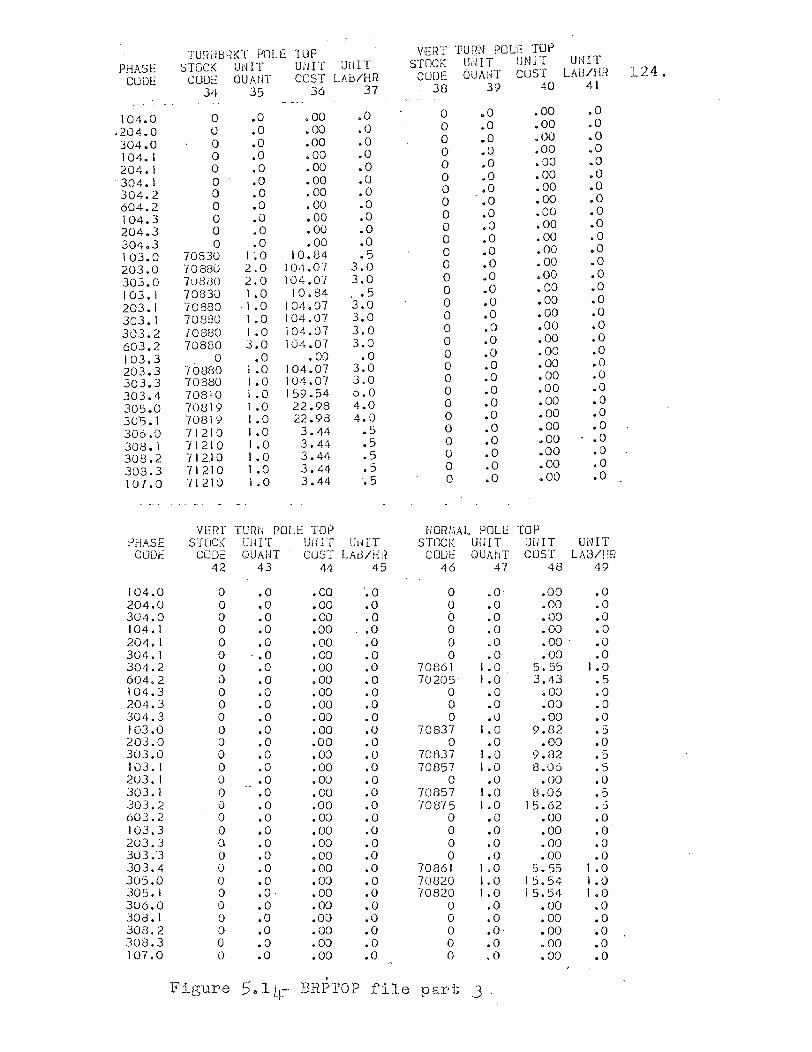
TUR?HHln f;OLE TOP VERT TURN POLE TOP
PHASE ::)TOCK Ul'ilT U;'lI '[ UnIT STOCK U,HT UNIT UcHT
CUDl: COllE QUAff[ COST LAtJ/HH CUl)[: QUANT CUST LAn/HR 124. 34 35 36 37 38 39 40 41
104.0 0 .0 .00 .0 0 .0 .00 .0
.204.0 0 .0 .00 .0 0 .0 .00 .0
304.0 0 .0 .00 .0 0 .0 .00 .0
104. I 0 .0 .00 .0 0 .0 .00 .0
204. I 0 .0 .00 .0 0 ,0 .00 .0
304. I a .0 .00 .0 0 .0 .00 .0
304.2 0 .0 .00 .0 a .0 .00 .0
604.2 0 .0 .00 .0 0 .0 .00 .0
104.3 0 .0 .00 .0 0 .0 .00 .0
204.3 0 .0 .00 .0 0 .0 .00 .0
304.3 0 .0 .00 .0 0 .0 .00 .0
103.0 70830 I ~o 10.84 .5 0 .0 • 00 .0
203.0 "J0880 2.0 104.07 3.0 0 .0 .00 .0
303.0 7:)8(30 2.0 104.07 3.0 0 .0 .00 .0
103.1 70830 1.0 10.84 .• 5 0 .0 .00 .0
203.1 70880 ·1.0 104.07 3.0 0 .0 .00 .0
303.1 70880 I .0 104.07 3.0 0 .0 .00 .0
303.2 70880 I .0 104.07 3.0 0 .0 .00 .0
603.2 70880 3.0 104.07 3.0 0 .0 .00 .0
103.3 0 .0 .00 .0 0 .0 .00 .0
203.3 70880 1.0 104.07 3.0 a .0 .00 .0
303.3 70880 I .0 104.07 3.0 0 .0 .00 .0
303.4 70810 1.0 159.54 6.0 0 .0 .00 .0
305.0 70819 1.0 22.98 4.0 0 .0 .00 .0
305.1 70819 1.0 22.98 4.0 0 .0 .00 .0
306.0 71210 I .0 3.44 .5 0 .0 .00 .0
308.1 -11210 1.0 3.44 .5 0 .0 .00 .0
308.2 712.10 1.0 3.44 .5 0 .0 .00 .0
308.3 71210 1.0 3.44 .5 0 .0 .00 .0
107.0 71210 1.0 3.44 .5 0 ,0 .00 .0
VERI' TURN POLE TOP NORI,iAL POLE TOP PHASE STOCK U1HT UjilT UHIT STOCK UmT Ul-nT UNIT
CODE CODE QUAiJT CuST LAd/HI? COUl:: QUAtIT COST LAS/HR 42 43 44 45 46 47 48 49
104.0 0 .0 .00 '.0 0 • o· .00 .0 204.0 0 .0 .00 .0 0 .0 .00 .0 304.0 0 .0 .00 ',0 b .0 .00 .0 104.1 0 .0 .00 .0 0 .0 .00 .0 204. J 0 .0 .00 .0 0 .0 .00 . .0 304. I 0 .• 0 .00 .0 0 .0 .00 .0 304.2 0 .0 ,00 .0 70861 1.0 5.55 1.0 604.2 0 .0 .00 .0 70205 1.0 3.43 .5 104.3 0 .0 .00 .0 0 .0 .00 .0 204.3 0 .0 .00 .0 0 .0 .00 .0 304.3 0 .0 .00 .0 0 .0 .00 .0 103.0 0 .0 .00 .0 70837 1.0 9.82 .5 203.0 0 .0 .00 .0 0 .0 .00 .0 303.0 0 .0 .00 .0 70837 1.0 9.82 .5 103. I 0 .0 .00 .0 70857 1.0 8.06 .5 203. I 0 .0 .00 .0 0 .0 .00 .0 303. I 0 .0 .00 .0 70857 1.0 8.06 .5 303.2 0 .0 .00 .0 70875 1.0 15.62 • '5 603.2 0 .0 .00 .0 0 .0 .00 .0 103.3 0 .0 .00 .0 0 .0 .00 .0 203.3 0 .0 .00 ·.0 0 .0 .00 .0 303.'3 0 .0 .00 .0 0 .0 • 00 .0 303.4 0 .0 .00 .0 70861 1.0 5.55 1.0 305.0 0 .0 .00 .0 70820 I. a 15.54 1.0 305. I 0 .0· .00 .0 70820 1.0 15.54 1.0 306.0 0 .0 .00 .0 0 .0 .00 .0 308.1 0 .0 .00 .0 0 .0 .00 .0 308.2 0 .0 .00 .0 0 .0- 000 .0 308.3 0 .0 .00 .0 0 .0 .00 .0 107.0 0 .0 .00 .0 0 .0 .00 .0
. 1i" _ l.gure 5a1 Lr:- BRP'rOp file part .3
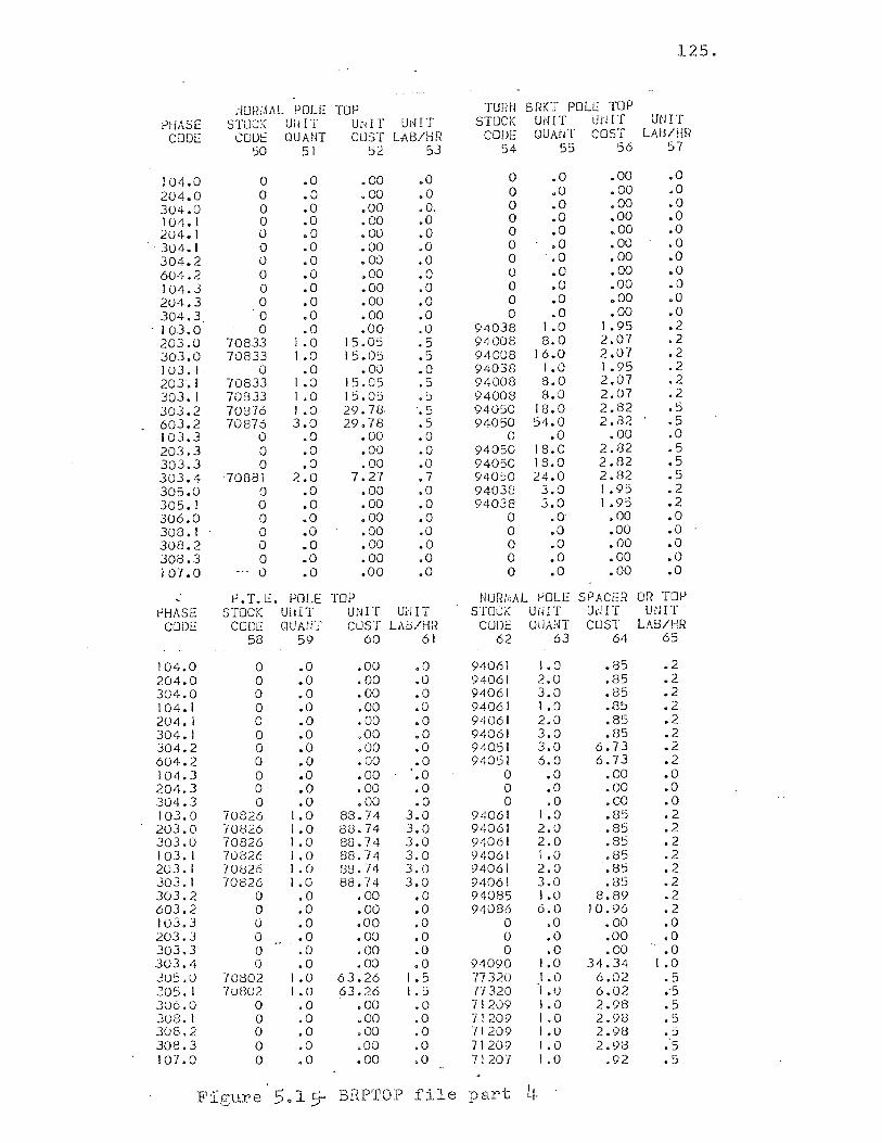
125.
rlURi.\i\l POLE TOP TURri BRKT POL:": TUP PHASE S1'OC:< Ul! IT U,'dT Uj~IT STOCK UNIT UNIT UNIT
CUDE com: QUANT CUST lAB/HH CODE OUMiT COST LAU/HR SO 51 5<! 53 54 55 56 57
104.0 0 .0 .00 .0 0 .0 .00 .0
204.0 0 .0 .00 .0 0 .0 .00 .0
304.0 a • 0 .00 .0 . 0 .0 .00 .0
104.1 0 .0 .00 ,0 0 .0 .00 .0 204. J 0 .0 .00 .0 0 ,0 .00 .0 304. I a .0 .00 ,0 0 .0 .00 .0 304.2 0 .0 .00 .0 0 .0 • 00 .0 604.2 0 .0 .00 .0 0 .0 .00 .0 104.3 0 .0 .00 .0 0 .0 .00 .0 204.3 0 .0 • 00 .0 0 .0 .00 .0 304.3 0 .0 • 00 .0 0 .0 .00 .0 103.0 0 .0 .00 .0 94038 I .0 1.95 .2 203.0 70833 1.0 15.0S .5 94008 8.0 2.07 .2 303.0 70833 1.0 15.05 ,- 94008 16.0 2.07 .2 .::J
1u3. I 0 .0 .00 .0 94038 1.0 1.95 .2 203.1 70833 1.0 15.05 .5 94008 8.0 2.07 .2 303.1 70833 1.0 15.05 .5 94008 8.0 2.07 .2 303.2 70876 I .0 29.78 .5 94050 18.0 2.82 .5 603.2 70876 3.0 29.78 .5 94050 54.0 2.82 .5 IOJ.3 0 .0 .00 .0 a .0 .00 ;0 203.3 0 .0 .00 .0 94050 18.0 2.82 .5 303.3 0 .0 .00 .0 94050 18.0 2.82 .5 303.4 70881 2.0 7.27 .7 94050 24.0 2.82 .5 305.0 0 .0 .00 .0 94038 3.0 1.95 .2 305. I a .0 .00 .0 94038 3.0 1.95 .2 306.0 0 .0 .00 .0 a .0 .00 .0 308. I 0 .0 .00 .0 0 .0 .00 .0 308.2 0 .0 .00 .0 0 .0 .00 .0 308.3 0 .0 .00 .0 a .0 .00 .0 10-1.0 0 .0 .00 .0 0 .0 • 00 .0
~.T.E. POLE TOP NOli/riAL I-'OLE SPACER OR TOP tJHASE STOCK UiliT UNIT mJlT STOCK UiHT UJ'JIT maT
CODE CODE QUMiT CUST LAb/HR CODE QUANT CUST LA!)/HH 58 59 60 61 62 63 64 65
104.0 a .0 .00 .0 94061 1.0 .85 .2 204.0 0 .0 .00 .0 94061 2.0 .85 .2 304.0 0 .0 .00 .0 94061 3.0 .85 .2 104.1 a .0 .00 .0 9406J 1.0 .85 .2 204. J 0 .0 .00 .0 94061 2.0 .85 .2 304.1 a .0 .00 .0 94061 3.0 .85 .2 304.2 a .0 .00 .0 94051 3.0 6.73 .2 604.2 0 .0 .00 .0 94051 6.0 6.73 .2 J04.3 a .0 .00 '.0 a .0 • 00 .0 204.3 0 .0 .00 .0 0 .0 .00 .0 304.3 a .0 .00 .0 0 .0 • 00 .0 103.0 70826 1.0 88.74 3.0 94061 1.0 .85 .2 203.0 70826 1.0 88.74 3,0 94061 2.0 .85 .2 303.0 70826 1.0 88.74 3.0 94061 2.0 .85 .2 103. I 70826 1.0 88.74 3.0 94061 1.0 .85 .2 203.1 /0826 1.0 88.74 3.0 94061 2.0 .85 .2 303.1 70826 1.0 88.74 3.0 9;W61 3.0 .85 .2 303.2 0 .0 • 00 .0 94085 1.0 8.89 .2 603.2 0 .0 .00 .0 94086 6.0 10.96 .2 103.3 0 .0 .00 .0 0 .0 • 00 .0 203.J 0 .0 .00 .0 0 .0 .00 .0 303.3 0 .0 .00 .0 0 .0 .00 .0 303.4 0 .0 • 00 .0 94090 1.0 34.34 I .0 JOS.O -/0002 1.0 63.26 I .5 7732u 1.0 6.02 .5 305.1 70802 1.0 63.26 1 ,-.J 77320 1.0 6.02 .'5 306.0 0 .0 .00 .0 71209 1.0 2,98 .5 308.1 0 .0 .00 .0 71209 I .0 2.98 .5 308.2 0 .0 .00 .0 71209 1.0 2.9B .5 30e.3 a .0 .00 .0 71209 1.0 2.93 :5 107.0 0 .0 .00 .0 71207 1.0 .92 .5
Figure 5.15- BRP'rop file part L~
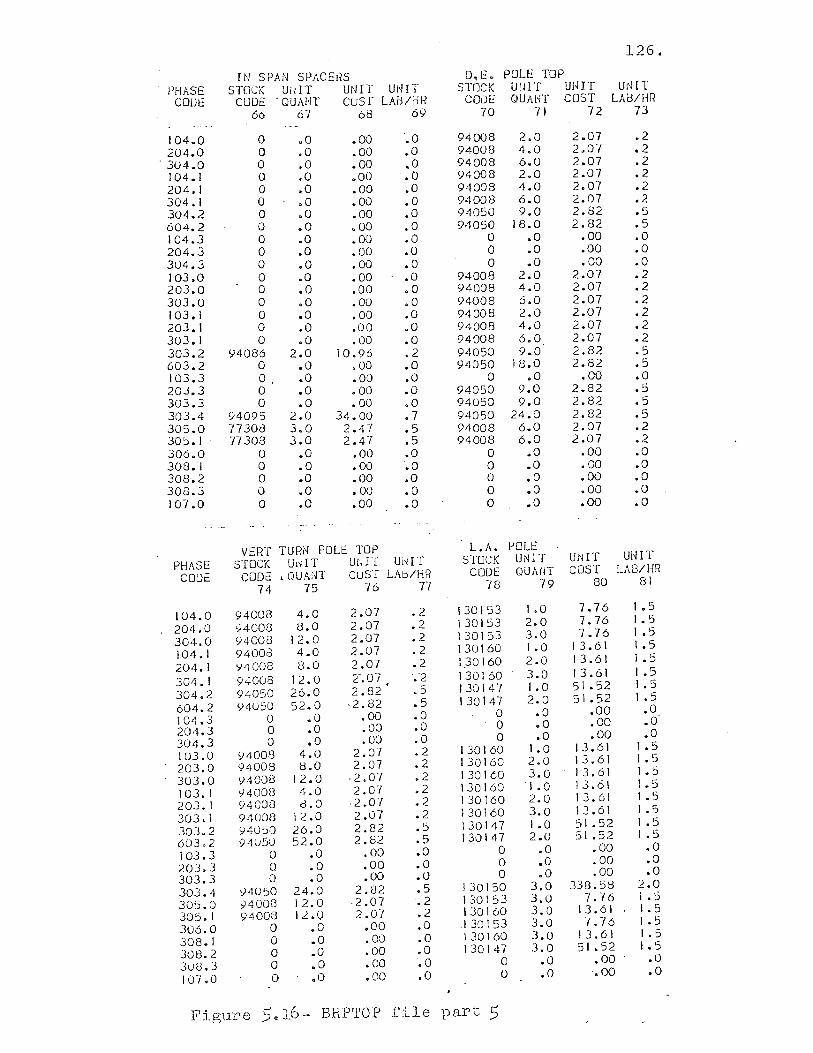
126.
IN SPAN SPACEi"lS 0.1::. POLl:: TOP PHASE STOCK UuIT UNIT UNIT STOCK ulln U!HT UtI IT
COOt: CUDE " QUAiH cusr LAB/rlR CODE QUAIH COST LA!3/HR 66 67 68 69 70 71 72 73
104.0 0 .0 .00 ".0 94008 2.0 2.07 .2
204.0 0 .0 .00 .0 94008 4.0 2.01 .2 " 304.0 a .0 .00 ,0 94008 6.0 2.07 .2
104.1 0 .0 .00 ".0 94008 2.0 2.07 .2 204.] 0 .0 .00 .0 94008 4.0 2.07 .2 304.1 0 .0 .00 ,0 94008 6.0 2.07 .2 304.2 0 .0 .00 .0 94050 9.0 2.82 .5
604.2 0 .0 .00 .0 94050 18.0 2.82 .5 104.3 0 .0 .00 .0 0 .0 .00 .0 204.3 0 .0 .00 .0 0 .0 .00 .0
304.3 0 .0 .00 .0 0 .0 .00 .0 103.0 0 ".0 .00 .0 94008 2.0 2.07 .2 203.0 0 .0 .00 .0 94008 4.0 2.07 .2 303.0 0 .0 .00 .0 94008 6.0 2.07 .2 103.1 0 .0 .00 .0 94008 2.0 2.07 .2 203.] 0 .0 .00 .0 94008 4.0 2.07 .2 303. I 0 .0 .00 .0 94008 6.0 2.07 .2 303.2 94086 2.0 10.96 .2 94050 9.0 2.82 .5 603.2 0 .0 .00 .0 94050 18.0 2.82 .5 103.3 O. .0 .00 .0 a .0 .00 .0 20.3.3 a .0 .00 .0 94050 9.0 2.82 .5 303.3 a .0 .00 .0 94050 9.0 2.82 .5 303.4 94095 2.0 34.00 .7 94050 24.0 2.82 .5 305.0 77308 3.0 2.47 .5 94008 6.0 2.07 .2 305.1 77308 3.0 2.47 .5 94008 6.0 2.07 .2 306.0 a .0 .00 .0 a .0 .00 .0 308.1 a .0 .00 '.0 a .0 .00 .0 308.2 a .0 .00 .0 0 .0 .00 .0 308.3 0 .0 .00 .0 0 .0 .00 .0 107.0 a .0 .00 .0 0 .0 .00 .0
VERT TURN POLl: TOP L.A. POLE
PHASE STOCK UdIT UrHT UrHT STOCK UNIT unIT UNIT
CODe CODe • QUANT cuST LAd/HR CODE QUANT COST LAB/HR
74 75 76 Tl "/8 79 80 81
104.0 94008 4.0 2.07 .2 130153 I .0 7.76 1 .5
204.0 94008 8.0 2.07 .2 130153 2.0 7.76 1.5
304.0 Y400e 12.0 2.07 .2 130153 3.0 7.76 I .:.
104. I 94003 4.0 2.07 .2 130160 1. a 13.61 1 .5
204.1 y4008 8.0 2.07 .2 1)0160 2.0 13.61 1 .5
304. I 94008 12.0 Z.07 "'-2 130160 3.0 13.61 1 .5
304.2 94050 26.0 2.82 .5 130147 1.0 51.52 1.5
604.2 <)4U50 52.0 ,2.82 .5 130147 2.0 51.52 I .5
104.3 0 .0 .00 .0 0 .0 .00 .0
204.3 a .0 .00 .0 0 .0 • 00 .0
304.3 0 .0 .00 .0 0 .0 .00 .0
103.0 94008 4.0 2.07 .2 130160 1.0 13.61 I .5
203.0 94008 8.0 2.07 .2 130160 2.0 13.61 I ,-.::>
303.0 Y400t3 12.0 ·2.07 .2 130160 3.0 13.61 1.5
103.1 Y4008 4.0 2.07 .2 130160 I .0 13.61 1.5
203.1 94008 8.0 ·2.07 .2 130160 2.0 13.61 1 .5
303.1 94008 12.0 2.07 .2 130160 3.0 13.61 1.5
303.2 94050 26.0 2.82 .5 130147 1.0 51.52 1 .5
60302 94u50 52.0 2.82 .5 130147 2.0 51.52 1 .:.
103.3 a .0 .00 .0 0 .0 .00 .0
20:3.3 0 .0 .00 .0 a .0 .00 .0
303.3 0 .0 .00 .0 0 .0 • 00 .0
303.4 <)4U:;0 24.0 2.82 .5 130150 3.0 338.58 2.0
305.0 94008 12.0 ·2.07 .2 130153 3.0 7. -/6 I .5
305. I 94008 IL.O 2.07 .2 130160 3.0 13.61 I. :;
306.0 0 .0 .00 .0 "I 3a 1 53 3.0 7.76 1.5
308.1 0 .0 .00 .0 130160 3.0 13.61 1.5
308.2 0 ,0 .00 .0 130147 3.0 51.52 I • :.
3U8.3 0 .0 .00 .0 0 .0 .00 .0
107.0 0 .0 .00 .0 0 .0 .00 .0
I"igure 5~ 16- BRPTOP file part .5

127.
ASCII in structure. The file contains labor rates and
loadings as well as miscellaneous items not feasible for
storage in other files. COMINFO data is read into the
E365W$ program module as illustrated in Figure 5.3, line
1010.
The files OHCABLE and NAMES3 are shown in report
form in Figure 5.10. Both files are sequential ASCII in
structure. The OHCABLE file contains material costs and
productivity hours for each cable indicated. The cost
shown is per linear foot for the number of conductors
normally wound on a reel. The labor hours shown are
based on six different types of construction.
(1) OWA is open wire armless construction and is
in column 3 of the OHCABLE file.
(2) OW is open wire construction. This value is
stored in the fourth column of the OHCABLE
file.
(3) SP is spacer cable construction. This value
is stored ln the fifth column of the OHCABLE
file.
(4) LASH is lashed cable construction. This value
is stored in the sixth column of the OHCABLE
file.

(5) SEC is secondary construction. This value is
stored in the seventh column of the OHCABLE
file.
(6) AER is aerial cable construction. This value
is stored in the eighth column of the OHCABLE
file.
128.
The column position used in this table is also the number
used to describe construction type on the data sheet. This
enables the program to select the proper labor value from
the file when needed for the estimate. If it is possible
for a cable to be installed in more than one construction
type, labor values are provided in all appropriate
columns. For example, cable code 31760 on Figure 5.10
shows values in three columns, indicating that this cable
can be installed in three different ways.
The cable name shown in the table in Figure 5.10
is stored in the NAMES3 file. This file stores the
string information necessary to label the cables in the
same sequence as the OHCABLE file. Consequently, when
cables are added or deleted from the OHCABLE file the
corresponding name must be added or deleted from the
NAMES3 file.

The OHCABLE file and the Nm~ES3 file are read into
the E365W$ program module shown in Figure 5.4 in lines
1600 through 1670.
The file GYANSW is shown in report form in Figure
5.11. The file is sequential ASCII in structure. The
file contains material cost and labor hours for guy,
anchor, and switch installations. This file is read
into the program module in lines 1680 through 1740 as
shown in Figure 5.4.
129.
The large file BRPTOP is shown in report form in
Figures 5.12 through 5.16. This file is stored in ran
dom binary structure. The file contains information
structured in such a way as to relieve the estimator of
the burden of entering, in the input data, detailed
information on required pole top material items. The
file is organized in an N by 81 word structure. N can
be any number of 81 word records needed by a particular
division. The first record in the file is a directory
of the rest of the file. This is done by sequencing the
phase code key in the same order as they are found in
the rest of the file. The phase code key is formed by
multiplying the number of phases to be installed by 100
and adding the construction code to it. For example,
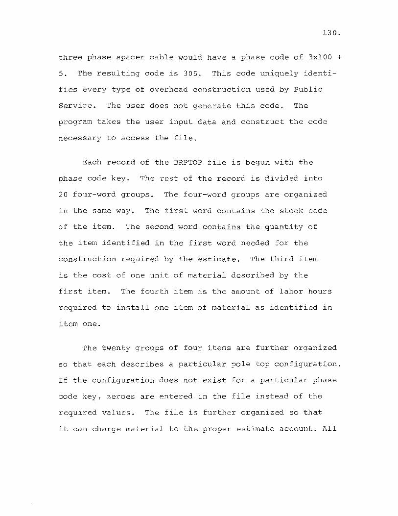
130.
three phase spacer cable would have a phase code of 3xlOO +
5. The resulting code is 305. This code uniquely identi
fies every type of overhead construction used by Public
Service. The user does not generate this code. The
program takes the user input data and construct the code
necessary to access the file.
Each record of the BRPTOP file is begun with the
phase code key. The rest of the record is divided into
20 four-word groups. The four-word groups are organized
in the same way. The first word contains the stock code
of the item. The second word contains the quantity of
the item identified in the first word needed for the
construction required by the estimate. The third item
is the cost of one unit of material described by the
first item. The fourth item is the amount of labor hours
required to install one item of material as identified in
item one.
The twenty groups of four items are further organized
so that each describes a particular pole top configuration.
If the configuration does not exist for a particular phase
code key, zeroes are entered in the file instead of the
required values. The file is further organized so that
it can charge material to the proper estimate account. All

131.
entries below column 47 are automatically charged to
account E364.2. All entries above column 63 are auto
matically charged to account E365. The program module
E365W$ tests for spacer cable installations to determine
to which account material from columns 44 through 62 is
charged.
The BRPTOP file is read into the program module a
line at a time so as not to use too much core space.
Lines 2405 through 2468 in Figure 5.6 are used to read
this file.
The organization of this file by phase code key,
by pole top construction unit, and by account to be
charged, was developed by the author in order to simplify
user input. He believes that it is a unique approach to
the estimating problem. Research into the literature
available on computer cost estimating techniques have
not changed this belief.
Producing the Cost Estimate for Guys, Anchors, and Switches
The routine used to calculate the costs of guys and
anchors is located in Figures 5.4 and 5.5 in lines 1745
to 1838. Line 1745 tests to see if there is guy and
anchor data in the user input, if so the program execution
branches to line 1750. Lines 1750 to 1770 calculate the
132.
required labor hours to install guys and anchors I and
stores the result in a variable named H(25). It can be
seem that user data stored in the B array is being multi
plied by values stored in the Y array which is the data
read in from the file GYANSW. The third column of the Y
array contains the labor hours to install guys and
anchors. The B array tells the computer how many of each
type are to be installed. No search is necessary, since
the type of installation is pre-specified on the data
sheet. After the labor hours are accumulated in H(25),
they are multiplied by the labor rate D(l) 1 in line 1780.
Material costs are similarly calculated in lines 1800-
1820 of Figure 5.4.
After the costs are calculated, the material require
ment is written to MATFILE in lines 1834-1838 in Figures
5.4 and 5.5.
The cost calculation for switches and reclosers is
done in the routine of Figure 5.7 in lines 2860-2970.
The user data is stored in the S array_ The switch data
from the GYANSW file is stored in the Y array. A search
is performed by the program to find a match between user
input code numbers and those stored in the Y array. When
a match is found in line 2890, the calculation is per
formed in line 2910 for labor and material. This will be

133.
done if these costs will be charged to account E365. If
the costs are to be charged to account E369.1, the pro
gram branches to line 2940.
Producing the Cost Estimate for Overhead Cables
The largest cost portion of an overhead construction
cost estimate is that due to the installation of overhead
primary and secondary cables. This cost is made up of the
material cost of the cable, the cost of pulling the cable
into position on the pole, and the cost of building the
pole top construction. This part of the estimate is done
by the E365W$ module in lines 1840 through 2800 of
Figures 5.5 through 5.7.
Matching the cable code. The desired cable needed
for the estimate is input by the user and stored in the U
array in the first position of every line. This value is
checked against the OHCABLE data stored in the W array.
The checking procedure is accomplished using a doubly
nested iteration loop for I and J contained in lines 1840
and 1850. The user cable is indexed on the outer I loop
while the OHCABLE data is indexed on the inner J loop.
The IF statement of line 1870 serves as a gate, and will
step through the J loop until a match is found in the W
array. If a match is not found an error code is generated
134.
in line 3474. When a match is found, the execution of the
program falls through the IF statement of line 1870, and
proceeds to initialization the H2 and H4 variables. The
cable is named in line 1890 using information stored in
the M$ string array from the NA~lliS3 file.
The cable stock code is then checked against several
codes of cables known to be supplied on single conductor
reels. If a match is found In line 1900-1906, the footage
is adjusted to three times the quantity input by the user
in line 1920 of the E365W$ module. This is done because
all cables are considered to be supplied on three con
ductor reels by the user, the program must recalculate
the special cases. This was done to further simplify the
input requirements for the user.
Naming the construction type. Line 1930 takes the
integer of the construction code input by the user. It
will be remembered that this code is a single digit num
ber followed by a single digit decimal (ex. 3.1). In
order to use this code to access the proper column of the
W array, the decimal must be chopped off and the number
stored in integer form in the variable Hl. Line 1935
tests for reinsulation code, if it is greater than 1, the
program branches to line 1940 in order to avoid appending
135.
the material file MATFILE as would be done if the program
had executed line 1936.
The large computed GO TO statement found In line 1940
of Figure 5.5 selects the proper string to be concatenated
with the cable name to further describe the installation
on the final report.
Computing the total installation factor. Line 2020
computes the final installation factor to be used in
determining the amount of extra labor needed for the line
of cable being processed. If this factor equates to zero,
a mistake has been made on the user's part. The program
tests this value in line 2030. If the factor as stored
in the variable f(l) is equal to zero, the program sets
the value to one in line 2040. The reader should note
that the final installation factor is made up of the
mUltiplication of the user input replacement factor, In
stallation factor, and the gain factor.
Calculating the Labor and Material Costs. The cal
cUlation of the costs of pulling the cable, and the wire
work associated with the building of special pole tops is
done in the program section bounded by lines 2080 and 2200
of Figures5.5 and 5.6. The variable H4 is used to store
136.
the result of the equation on line 2080. User input data
for the amount of special pole tops including: vertical
turns (U(I,7», risers (U(I,9», deadends (U(I/IO» rand
junctions (U(I,ll» 1 is multiplied by the corresponding
normal labor hours to do each from the COMINFO file stored
in the variables F(5) through F(8). The total is multi
plied by the total installation factor calculated in line
2020 and explained above. The total is further multiplied
by the phase factor P(O) calculated in line 2060 and used
to adjust three phase labor figures stored in the OHCABLE
file for single or double phase installations. The vari
able H2 is calculated in one of two places depending on
whether the cable being installed is a primary or secondary
cable. If it is a primary installation, the calculation
will be done in line 2100 of Figure 5.5. The OHCABLE
data stored in the W array is referenced at the Jth line
position determined by the IF statement of line 1870, and
the Hlth column number determined by the integer of the
construction code as calculated in line 1930. This item
as stored in the W array will be the proper pulling labor
hours required for the cable in question. For example,
the first line of the user cable data found in Figure 5.1,
line 501, would reference the W array in the following way.
The stock code 31760 would have found a match in the 28th

137.
line of the OHCABLE file, the construction code of 3.1
would result in an integer value of 3 stored in Hl. The
resultant reference would be made at the 28th line, third
column of the W array_ This position is held by the
value of 50 hours, the normal labor requirement to install
1000 feet of the cable. This value is multiplied by the
total installation factor F(l) to arrive at the adjusted
labor hours for the job in question. This value is then
multiplied by P(O) to adjust for the number of phases.
In our test case, the value of F(l) is 1, and the value
of P(O) is also 1.
The last thing to be done in finding the labor cost
is to mUltiply the labor hours H2 + H4 times the labor
rate D(l). This is done in line 3130 of Figure 5.5.
Finally, the figure is rounded to the nearest 10 or 100
dollars using the rounding function FNA in line 2140.
The function is defined in line 1384 of Figure 5.3.
The material cost for the cable is arrived at in
line 2170 of Figure 5.5. It is simply the number of
feet of cable as shown in the user data times the cost
per foot as stored in the W array_ This cost is then
rounded using the FNA function in line 2180.
A test is made for spacer cable installation in line

138.
2190 of Figure 5.6. If the test shows that the installa
tion is spacer cable, lines 220-2206 are executed to provide
for supporting messenger cable and ground rods. If the
installation is not spacer cable, the program will branch
to the equations contained in lines 2210-2250. These
equations are used to subtotal the material and labor for
all cable installations.
Calculation of Pole Top Material and Labor Costs
The calculation of pole top labor and material costs
is accomplished by the routine bounded by lines 2260 and
2680 of Figures 5.6 and 5.7 of the E365W$ program module.
In general terms, the purpose of the routine is to sub
stitute user data into the V array for easier handling,
to search the BRPTOP file for the proper data, and to
calculate labor and material costs for pole top construc
tion.
Lines 2300 through 2390 of Figure 5.6 load each line
of user overhead cable data stored in the U array into the
singly dimensioned V array. This is done to simplify the
iteration needed to step through this data in a subsequent
calculation. The phase code key is calculated in line
2260 of Figure 5.6 and is stored In the variable H3. It
is derived as described above, by multiplying the number
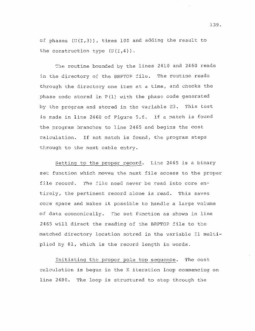
of phases (U(I,3», times 100 and adding the result to
the construction type (U(I,4».
139.
The routine bounded by the lines 2410 and 2460 reads
in the directory of the BRPTOP file. The routine reads
through the directory one item at a time, and checks the
phase code stored in P(l) with the phase code generated
by the program and stored in the variable H3. This test
is made in line 2460 of Figure 5.6. If a match is found
the program branches to line 2465 and begins the cost
calculation. If not match is found, the program steps
through to the next cable entry.
Setting to the proper record. Line 2465 is a binary
set function which moves the next file access to the proper
file record. The file need never be read into core en
tirely, the pertinent record alone is read. This saves
core space and makes it possible to handle a large volume
of data economically. The set function as shown in line
2465 will direct the reading of the BRPTOP file to the
matched directory location sotred in the variable II multi
plied by 81, which is the record length in words.
Initiating the proper pole top sequence. The cost
calculation is begun in the K iteration loop commencing on
line 2480. The loop is structured to step through the
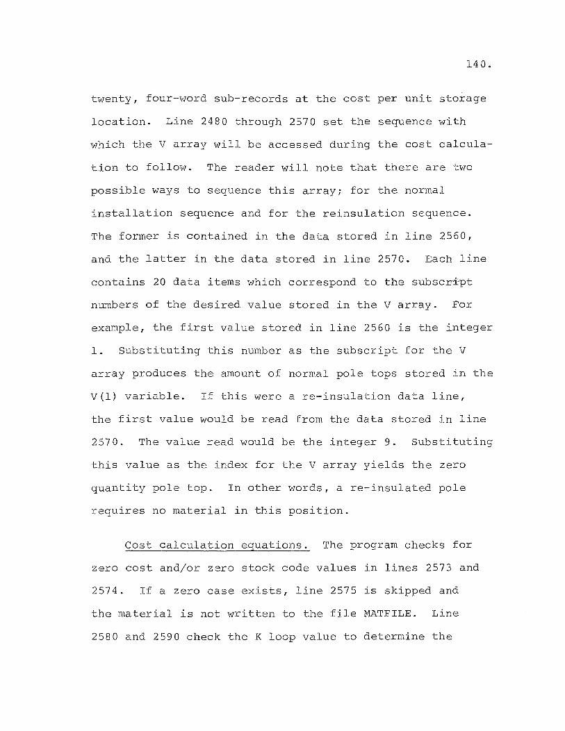
140.
twenty, four-word sub-records at the cost per unit storage
location. Line 2480 through 2570 set the sequence with
which the V array will be accessed during the cost calcula
tion to follow. The reader will note that there are two
possible ways to sequence this array; for the normal
installation sequence and for the reinsulation sequence.
The former is contained in the data stored in line 2560,
and the latter in the data stored in line 2570. Each line
contains 20 data items which correspond to the subscript
numbers of the desired value stored in the V array. For
example, the first value stored in line 2560 is the integer
1. Substituting this number as the subscript for the V
array produces the amount of normal pole tops stored in the
V(l) variable. If this were a re-insulation data line,
the first value would be read from the data stored in line
2570. The value read would be the integer 9. Substituting
this value as the index for the V array yields the zero
quantity pole top. In other words, a re-insulated pole
requires no material in this position.
Cost calculation eguations. The program checks for
zero cost and/or zero stock code values in lines 2573 and
2574. If a zero case exists, line 2575 is skipped and
the material is not written to the file ~ffiTFILE. Line
2580 and 2590 check the K loop value to determine the

141.
account to which the material cost and labor cost should
be charged. As explained earlier, all charges under a K
value of 47 will be charged to account E364.2. All K
values above 63 will be charged to account E365. Labor
hours for labor charged to account E364.2 will be stored
in the variable H(21). Material costs will be stored in
the variable M(21). The variable H(22) and M(22) will
store the costs for account E365. In either case the
calculation will be done in the following manner. The
P(k) variable holds the quantity of the item of pole
top material. The P(K+2) variable holds the labor hours
required to install a unit of material. The V(Jl) vari
able holds the amount of the particular pole top in
question. The multiplication of the above three variables
yields the total cost for the pole top material required
in the user data. The costs developed in the above cal
cUlations are rounded and totaled using the equations
contained in lines 2700 through 2740.
Summary of the pole top calculation section. The
use of the simplification techniques incorporated in the
structure and handling of the random binary pole top con
struction file BRPTOP make the assembly of input data an
easy matter. Other systems the author has reviewed
require a catalog of construction packages in order for
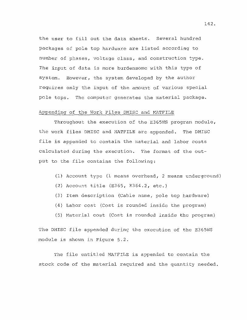
142.
the user to fill out the data sheets. Several hundred
packages of pole top hardware are listed according to
nUmber of phases, voltage class, and construction type.
The input of data is more burdensome with this type of
system. However, the system developed by the author
requires only the input of the amount of various special
pole tops. The computer generates the material package.
Appending of the Work Files DMISC and MATFILE
Throughout the execution of the E365WS program module,
the work files DMISC and IVlATFILE are appended. The DMISC
file is appended to contain the material and labor costs
calculated during the execution. The format of the out
put to the file contains the following:
(1) Account type (1 means overhead, 2 means underground)
(2) Account title (E365, E364.2, etc.)
(3) Item description (Cable name, pole top hardware)
(4) Labor cost (Cost is rounded inside the program)
(5) Material cost (Cost is rounded inside the program)
The DMISC file appended during the execution of the E365W$
module is shown in Figure 5.2.
The file entitled MATFILE is appended to contain the
stock code of the material required and the quantity needed.

The contents of this file created during the run of the
sample data is shown in Figure 5.17.
Chaining Out of the E365W$ Module
143.
Upon completion of the E365W$ module, the selection
of a chaining point must be made in the program. The pro
gram section bounded by lines 3852 and 3880 provides this
function. If the estimate is an overhead only type, the
program will chain to the MISCP program to produce the
cost estimate printout. If the estimate contains underground
data, the program will chain to the underground module
E367W$.
Printing of The Estimate, The Estimate Summary, and The
Material List
After the completion of the calculating modules of
the estimate system, the MISCP*, SUMRY*, and ~~TLS* pro
gram modules are called in, sequentially, to produce the
necessary reports. The functions of these programs were
discussed in Chapter IV. The cost estimate for the sample
data is shown in Figure 5.18.
illustrated in Figure 5.19.
The estimate summary is
Finally, the material list is
shown in Figure 5.20. The reader will note that these com
puter reports are similar to the manually produced reports.
They are a direct replacement for these reports, conse
quently, no retyping is necessary. After the necessary
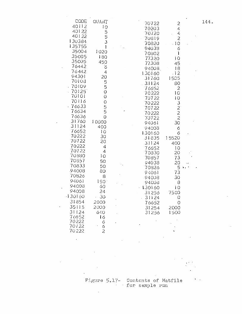
CODE QUA1~T 70722 2 401 J 2 10. 70.20.3 4 40.122 5 7o.i2o. 4 40122 5 70819 2
130384 3 70820 .10 135755 1 940.38 6 350.0.4 10.20 70.802 I 3500.5 180 77320 10 35005 450. TI308 45 76442 '6 94008. 18 76442 4 130160 ·12 94301 20 31760 1505 701GB 5 .31124 80
. 70.109 5 76652 2
. 70.125 0 70.222 10. 70101 0 70722 10. 70116 0 70222 3
.. 76633 5 70722 2 76634 5 70.222 2 76636 0 70.722 2 31760 10.0.0.0. 94061 30. 31124 40.0 940.0.8 6 76652 10 130.160 6 70.222 30 31835 15520 70.722 20 31124 40.0. 70222 4 76652 10. 70722 4 70.830 20. 70880. 10 70.857 73 70857 50 94038 20. 70.833 50 70.826 5 h'
.940.0.8 80 94061 73 70.826 8 940.08 30 9L~o.61 i50' 940.08 8 940.0.3 60. L3G16G 10. 940.0.8 24 31256 750.0.
·130)60. -30 31124 0 31854 20.0.0. 76652 0. 35115 200.0 31254 20.00 31124 640 31256 150.0. 76652 16 70.222 6 70.722 6 70222 2
Figure 5.17- Contents of Matfile .. -for sample run
144.
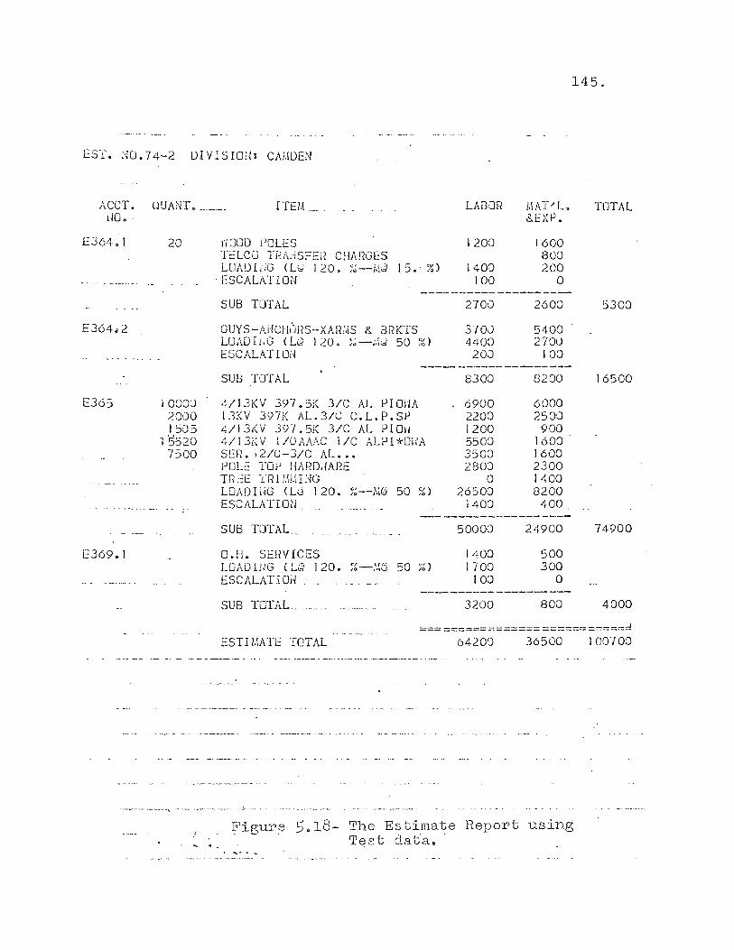
145.
ES'f. NO.74-2 UIVISIOU: CA)'!DEl'f
ACCT. UUANT. "_' __ ITEM __ llO. '
E364.1 20
E364.2
E365 10000
E369.1
2000 1505
1 '5520 7500
1"1000 tJOLES TELCO Tf~AdSFER CHARGES LOAD L~G (Ltd 120. ~~--i.\J 15. %)
"ESCALATION
SUS TOTAL
GUYS-MICH~JRS-XAR;,IS &. BRKTS LOAD! lJG (LQ 120. )~-.'.ld 50 ~b) ESCALATION
SUB TOTAL
4/13KV 397.5;( 3/C AL PI GilA 13KV 397K J\L.3/C C.L.P.SP 4/13f.V 39'/ • 5i~ 3/C AL PIO\I 41 I 3I(V 1/0AAAC IIC ALPI*Oi{A SEH. > 2/0 -3/C AL ••• POLL:: TOp HAfW,lARE TRtE '(Rl l.\i.\IHG LOADli~G (Lid 120. /~--J\~@ 50 ;~ )
ESCALATION
SUB TOTAL
O.H. SEHVICES LOAD I NG (L~ 1 20. ~~ -:.10 50 ~~) ESCALATIOi-/ ,_ ', ... _, . ,
SUB TOTAL.,
LABOR
1200
1400 100
2700
370J 4400 20J
8300
6900 2200 1200 5500 3500 280:)
0 2650:)
1400
50000
1400 1700
100
3200
1.IAT"L. 8..EXP.
1600 800 200
a 2600
5400 2700
100
8200
6000 2500
900 1600 1600 2300 1400 8200
400
24900
500 300
a
800
TOTAL
5300
16500
74900
4000
, ============================
ESTI J.IATE TOTAL 6420') 36500
--- ~----'\ .... - ~-.. -~--.-.
, ." Figure 5.18- The Estimate Report using
T<:.:st dat"a.
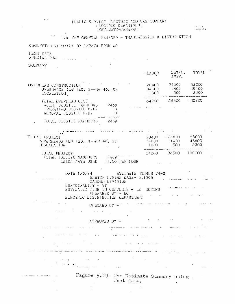
PUBLIC SH?VICE ELECTIHC AND GAS COI.IPANY r.:LECT1HC Dl::I.lAf(TI,lEtJl ESTIMAT~-G~~ERAL
TJ: THE GE;JE!?AL /,IAliAGER - TRAUSI.\I S5 ION 8. DISTf~I BUTION
REOUESTED VER8ALLY BY 1/9/74 FRO~ ~C
TeST DATA SPL::CIAL RUd
SiJl,\i.IARY
DVt:l?Hi::AD CJnSTRUCTI ON UVEiidEADS (L<;;, 120. ~~-i'\;;:) 46'. ?,O ESCALATIOi~
LABOR
28400 34000
1800
;.\AP'L. 8.EXP.
24600 11400
500
TOTAL
53000 45400
2300 --------~-----------------
rOTAL OVERHEAD COST ,\UTH. JJ:3S ITt 1.~Ai~iiOUiiS OPElV,Trim JU[;;SITE M.H. RE:.\uVAL JOBSITE !.i.H.
2469 o o
TUTAL JOB5ITE ;.\J\llHOURS 2469
•• <
TUTAL Pf?OJECT :OV~RtiEADS (L~ 120. %--~G 46~ %) ESCALATION
64200
28400 34000
1800
36500
24600 11400
500
100700
53000 45400
2300
TOTAL PROJECT 64200 36500 100700 TOTAL JOGSITE ),\M~HOURS
LA30H RATE USED 2469
II .50 PER HOUR
DATE 1/9/74 ESTI ~,iATE lJU;;'BER 74':;"2 SKeTCH UUl,(i3EI? DA22-1 6. 1095 CA;.\DEil DIVISION
MU~ICIPALITY - VT ESTI~ATED TIJE TO CO~PLt:TE - _2 MONTHS
PREPARED BY - EC ELECTRIC DISTJ~IDUnLJil Dj~PARn\ENT
, , 1
CHECKED BY -
APPROVED BY -
. ...........
Figure 5 .. 19- 'rhe Estimate Surmnary using Test data e
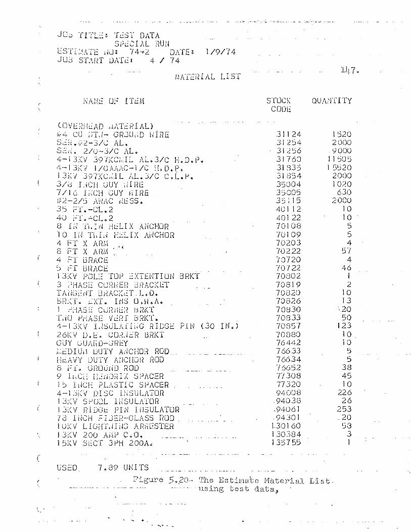
c
(
JCJb TIlL':: TeSI DATA Sh:CIAL l1UH
ESTI:.IATc IU; 74 .... 2 DATE t 1/9/74 JOn STAnT DATe: 4 / 74
1.\ATciHAL LIST
(OVE~?lH.:AD /.IAT:::RIAL) ·,i£r CU iiT~i- GRJUl'!D hiRE Sc;~ • ,12 -3/~ AL ~ S0:rt. 2/0-J/C AL. 4- J 3.<V J9T(C;,;r L AL & 3/C H. D. e .. 4-13i("I 1 IOAAAC-l IC H. D. P. 13K\1 397KCi:,lL J,L.J/C c.L.p" 3/J I i~CI1 GUY ill HE 7/1 6 I !'iCH GUY Ii I HE . #2-2/j AHAC ~~SS. 35 FL-CL.2 40 FT.~CL.2 8 I i-J 1'1 il J~ HL:LI X ANCHOR . 10 IU TI;Ij~ Hi.:LIX AUCHOR 4 fT X ARi,\ 8 FT X AFm ~.' 4
4 FT i3RACI:: 5 FT GRACE 13KV POLE TO~ ~XTENTION BRKT 3 PHASE CURNER i3RACKET TANGE~T BRACK~T-L.D. l::ml~T. fXT. IrIS O.H .. A. 1 PHASE Cu;1di::i t31~KT TiiO rJrlASE VL:nr BRKT .. 4-1 3:(V L~SuLAfL~G ii lOGE 26KV 0.1:: .. COr~>jiR J3RKT GLJY GUAhD-JREY ;.,cDIUi.\ DUTY Al~CHOR ROD .. HeAVY DUTY AnCHOR ROD 8 ff. GR00~D ROD 9 IHCii H:::r~DrdX SPACER 15 IdCH PL\.STIC SJjACER 4-1 Ji~V D1 SC L~SULi\TOR 1 J:~V SfJOOL IUSULATOR I JiCV rH DGr: PI N I ilSULATOR "13 IUel-! rIJEa-GLASS ROD 10;(V LIGiTLHd'J Ar?tiESTER 13KV 200 A~P C~O. J5KV SECT 3PH 200AQ
USED. 7 <> 89 UNITS.
P I l~ (30 IN 0 )
STOCK CODE
31124 31254 31256 31760 31D35 31854 35004 35005 35115 40112 40122 70108 70109 70203 70222 70720 70122 70802 70819 70820 70826 70830 70833 70857 70880 76442 76633 76634 76652 77308 77320 94008
.94038
.94061 .94301 1.30160 130384 135755
QUA'HITY
1520 2000
·9000 ) 1 505 1 5::i20
2000 1020 630
2000 10 )0 5 5 4
57 4
46 I 2
10 13
;20 50
123 10 10
5 5
38 45 10
226 26
253 .20
3 J
Figure 5 0 20- The Estimabe M~terial List . . - ...... -. ... using test data,
148.
signatures are entered on the reports, they are sent out
to the general office sponsor.
Summary
This chapter has attempted to explain in detail the
operation of the E365W$ module of the construction cost
estimating system designed by the author. The explanation
of the program was augmented with a discussion of all data
files used by the program. Listings of all files were
provided to aid the explanation. The cost calculation
section was divided into three parts, including; guys,
cables, and pole top hardware. The use of a test run was
included to help implement the discussion.
The intent of the chapter was to give the reader an
insight into the operation of a program module of the cost
estimating system in order to aid him in understanding the
entire system. Listings of all program modules are avail
able in the appendix to this paper.
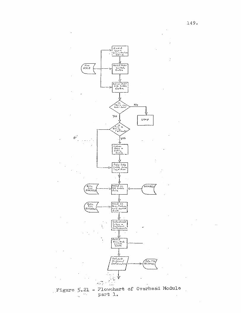
Figure 5.,21 .'",,1.'
Flowchart of Overhead Module part 1"
149 .
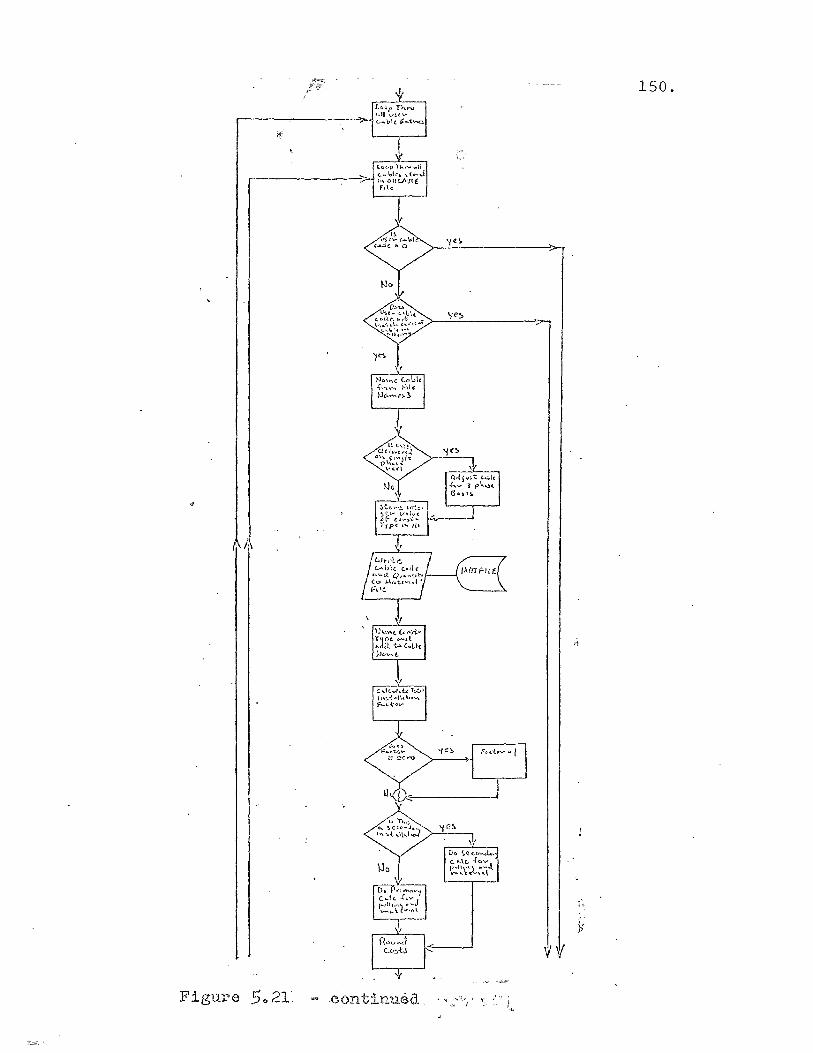
150.
Figu.re 5 .. 21· .continuea ...
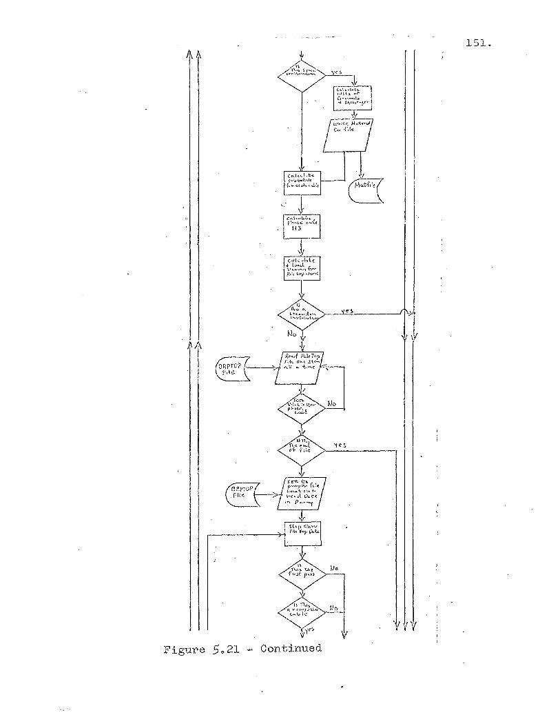
151.
,!
C10tid~(
I
Figure 5021 Continued
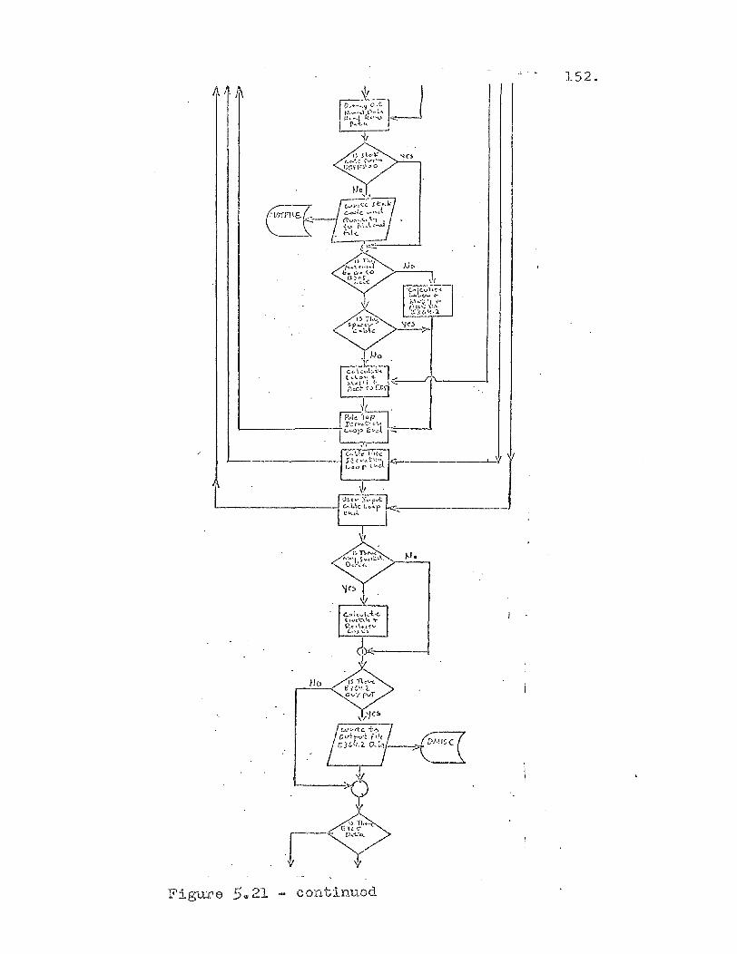
152.
\!! . P,k .,;p-l
!.-_________ --1-r·:.th·::-~"\.1 t I L=P /.;'·-J.l-~--.I. ,I,
<:\c--.------
IJ.
Figure 5 .. 21 contlnued
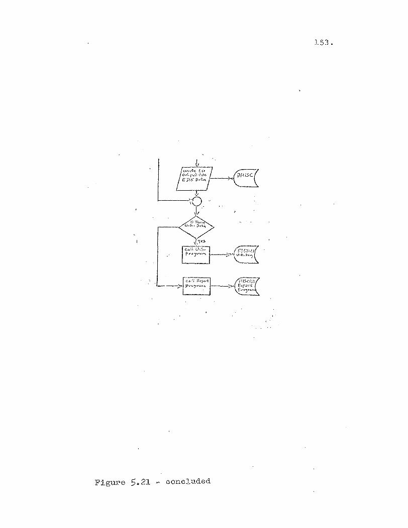
153.
Figure 5c21 - concluded
CHAPTER VI
IMPLEMENTATION OF THE COMPUTERIZED
CONSTRUCTION COST ESTI~~TING SYSTEM
Introduction
The implementation of any new computer system
requires careful preparation to ins'ure success. Consider
able skepticism existed among field engineers that so
complicated a function as cost estimating could be done
on a computer. The problem had to be overcome using
discussions and classes concerning the use of the system
in each field location. Complete user documentation had
to be prepared and distributed. Test cases had to be run
in each division comparing manual versus computer solu
tions to estimates.
Organizational changes had to be made to incorporate
the new estimating system. The office unions had to be
convinced that the use of lower classification personnel
to do cost estimates using the new system did not violate
the contract. The following discussion shows how this
was accomplished in order to implement the new system.
Steps Used To Implement the New System
The implementation of any new computer system requires
careful planning. The finest system can meet with disaster
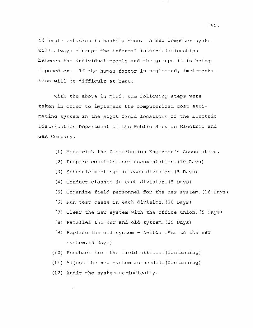
155.
if implementation is hastily done. A new computer system
will always disrupt the informal inter-relationships
between the individual people and the groups it is being
imposed on. If the human factor is neglected r implementa
tion will be difficult at best.
with the above in mind, the following steps were
taken in order to implement the computerized cost esti
mating system in the eight field locations of the Electric
Distribution Department of the Public Service Electric and
Gas Company.
(1) Meet with the Distribution Engineer's Association.
(2) Prepare complete user documentation. (10 Days)
(3) Schedule meetings in each division. (5 Days)
(4) Conduct classes in each division. (5 Days)
(5) Organize field personnel for the new system. (16 Days)
(6) Run test cases in each division. (20 Days)
(7) Clear the new system with the office union. (5 Days)
(8) Parallel the new and old system. (30 Days)
(9) Replace the old system - switch over to the new
system. (5 Days)
(10) Feedback from the field offices. (Continuing)
(11) Adjust the new system as needed. (Continuing)
(12) Audit the system periodically.
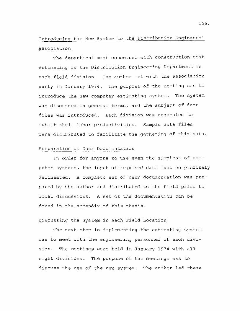
156.
Introducing the New System to the Distribution Engineers'
Association
The department most concerned with construction cost
estimating is the Distribution Engineering Department in
each field division. The author met with the association
early in January 1974. The purpose of the meeting was to
introduce the new computer estimating system. The system
was discussed in general terms, and the subject of data
files was introduced. Each division was requested to
submit their labor productivities. Sample data files
were distributed to facilitate the gathering of this data.
Preparation of User Documentation
In order for anyone to use even the simplest of com
puter systems, the input of required data must be precisely
delineated. A complete set of user documentation was pre
pared by the author and distributed to the field prior to
local discussions. A set of the documentation can be
found in the appendix of this thesis.
Discussing the System in Each Field Location
The next step in implementing the estimating system
was to meet with the engineering personnel of each divi
sion. The meetings were held ln January 1974 with all
eight divisions. The purpose of the meetings was to
discuss the use of the new system. The author led these
157.
meetings, which revolved around the discussion of the user
documentation. The engineering personnel were informed of
the structure of the data files, and how the programs used
these files in order to produce an estimate. Some engineers
expressed skepticism that a computer system would be flex
ible enough to properly handle all of the situations that
arise in the preparation of a cost estimate. The author
assured them that the system was capable of handling 95%
of the possible cases. Arrangements were made to perform
tests of the system in each division before the scheduled
implementation.
Use of Classes
Before implementation of the system, the author and
his assistants conducted classes for those personnel
directly involved with the implementation in each division.
Again, the user documentation was discussed. Special
emphasis was placed on accessing the General Electric
Mark III foreground system. Interpretation of system and
program error diagnostics was stressed.
Organizing for Computerized Cost Estimating
Since the new system greatly simplified the cost esti
mating function, the exclusive use of management and higher
level union personnel was no longer needed. It was recom
mended that Engineering Plant personnel be used to fill
158.
out the data sheets. It was further recommended that data
be input to the system by a clerk. The clerk would run
the system and produce the reports. The reports would
then be rough checked by the Engineering Plant Assistant
and re-submitted to the clerk if errors were found. If
the reports appeared to be correct, the completed esti
mate would be given to an Assistant Engineer for further
checking. If approved, the reports would be submitted to
the appropriate Group Head for signature. Following that,
the reports would be submitted to the Distribution Engineer
for approval and signature. The reports would then be
sent to the Division Superintendent for final approval and
for forwarding to the General Office.
Clearing the New System and Use of Personnel with the Union
In order to preclude any union problems, the subject
of computerized cost estimating was discussed with union
officers in each field division. The union was shown that
the simplicity of the new system fit within the job speci
fications of Clerk and Engineering Plant Assistant. The
union was given a demonstration of the system to reinforce
this contention. In all cases the union agreed that the
estimating system did not appear to violate the contract.
Running Test Cases in Each Division
In order to convince engineers in each division that
the new system could accurately calculate construction
cost estimates, test cases were devised and run. The
159.
test cases consisted of estimating one thousand foot
lengths of various types of cables and installations by
manual methods and by computer. In most cases these tests
were very satisfactory. They showed that the computer
estimate system could duplicate answers arrived at by care
ful hand calculation. Where they were not satisfactory,
the cause of the problem was often found to be data file
errors. In a few cases the program was found to be in
error, and changes were made to correct it. At the con
clusion of the test runs, all divisions agreed to proceed
with a parallel run of the new and old system.
Parallel Run of the New and Old System
The next step in the implementation of the computerized
cost estimating system was to run a parallel operation with
the old manual system. This is the stage the implementa
tion has reached at the writing of this thesis. Results
have shown that the new system is performing very well.
Few problems have cropped up, and the author feels that
the remainder of the trial should go smoothly.
Replacing the Old System
After the successful completion of the parallel run

160.
of the two systems, the old system will be phased out if
the computer estimate can produce accurate estimates and
handle at least 95% of all estimates desired. The new
system will be spot-checked during this stager but all
new estimates will be produced by the computer system.
Feedback From the Field Divisions
After the old system is phased out and the computer
system is in operation in all divisions, provision must
be made for feedback of user problems. The feedback
mechanism will be provided through the Time Sharing
computer Coordination Committee. The committee was
originally set up with the author as chairman and a repre
sentative from each division. The purpose of the
committee was to disseminate information about time sharing
systems and programming techniques. Feedback concerning
the cost estimating system will be introduced during the
regular meetings of this committee.
Adjusting the System
Based on the feedback from the field divisions re
viewed during the regular committee meetings discussed
above, changes will be made to the estimating system.
When the program is changed, the committee will axso
serve as a method to inform the field users of the change.
161.
Auditing the System
The estimating system will be audited for accuracy
and timeliness once every six months by the time sharing
coordinator in each division. Test cases will be pre
pared using unit lengths of cable and unit packages of
construction hardware. Current costs from the division
stock ledger will be used in a manual check of a computer
run estimate. Division data files will be checked and
updated by the local division coordinator.
Results of estimates will be checked against actual
field construction costs in order to audit the results of
the estimating system. The check will be performed by
each local division coordinator. The estimate system will
then be adjusted by the coordinator by revising the loading
and estimating percentages in the COMINFO file.
Summary
It was the purpose of this chapter to inform the
reader of the implementation of the computerized construc
tion cost estimating system in the Electric Distribution
Department of the Public Service Electric and Gas Company.
A plan for the implementation was presented and followed
through its several stages. The implementation is pro
gressing smoothly at the writing of this thesis.
Introduction
CHAPTER VII
ECONOMIC JUSTIFICATION OF THE
COMPUTERIZED ESTI~~TING SYSTEM
The replacement of the manual method of cost esti
mating used in the Electric Distribution Department of
the Public Service Electric and Gas Company was done to
simplify the function and to achieve standardization.
Thus far, the system has proven successful in accom
plishing these goals. It is also apparent that signi
gicant cost savings will accrue due to the implementation
of the computerized system.
It is the purpose of this chapter to analyze and
compare the costs associated with the manual system and
the new system. The costs will be compared on the basis
of expected usage in all divisions. First, a break-even
analysis will be made to find the minimQm amount of
estimates required to justify the new system. Secondly,
the total cost savings derived from doing all estimates
on the new system will be calculated.
Identification of Cost Items
The calculations to follow will be made on the as
sumption that the costs are equal for preparing the
163.
preliminary data for either the manual or the computerized
systems. This is a valid assumption because both systems
require that surveys of map and field conditions be made.
Neither will require a change in the normal pre-estimate
work. Hence, the cost of the preliminary work will be
dropped from the calculation.
Manual system cost factors. The manual system re
quired that the estimate be prepared by management
personnel or by a Senior Engineering Plant Assistant.
The average cost per hour for this work is $15.50. The
amount of time required to do an estimate manually is
six hours. This figure is an average based on a con
census of the Time Share Committee members. After an
estimate is calculated by hand, it must be typed. The
cost os a typist is $9.50 per hour. The above constants
will be identified by the following list.
(1) E$ is the cost per engineering labor hours.
($15.50)
(2) T$ is the cost per typing hours. ($9.50)
(3) Em is the engineering time necessary to cal
culate an estimate manually. (6 hours)
(4) Tm is the required time to type an estimate.
(1 hour)

164.
(5) X is amount of estimates to break even.
The cost of one estimate calculated manually is therefore:
X* (E$(Em) + T$(Tm» 1* (15.50(6) + 9.50(1)) = 102.50
The result of the above equation shows that it costs $102.50
to calculate and type a construction cost estimate manually.
computer system cost factors. The computer system has
simplified the estimate function so that an Engineering
Plant Assistant is able to prepare the estimate data sheet.
The average hourly wage for this job category is $12.00
per hour. The amount of time required to fill out a data
sheet is .5 hours. The data is entered via terminal by a
clerk. The wage for a clerk is $9.50 per hour. The amount
of time required to enter data and receive the reports is
.5 hours. The figures used above were arrived at by the
members of the Time Sharing Computer Coordination Committee.
In addition to the costs described above, there are
cost factors associated with the computer. The charges
are as follows:
(1) Terminal connect hours @ $14 per hour.
(2) Computer Resource units charges @ $.40 per
unit of processing time. (Includes C.P.U.
and Disk access charges.)
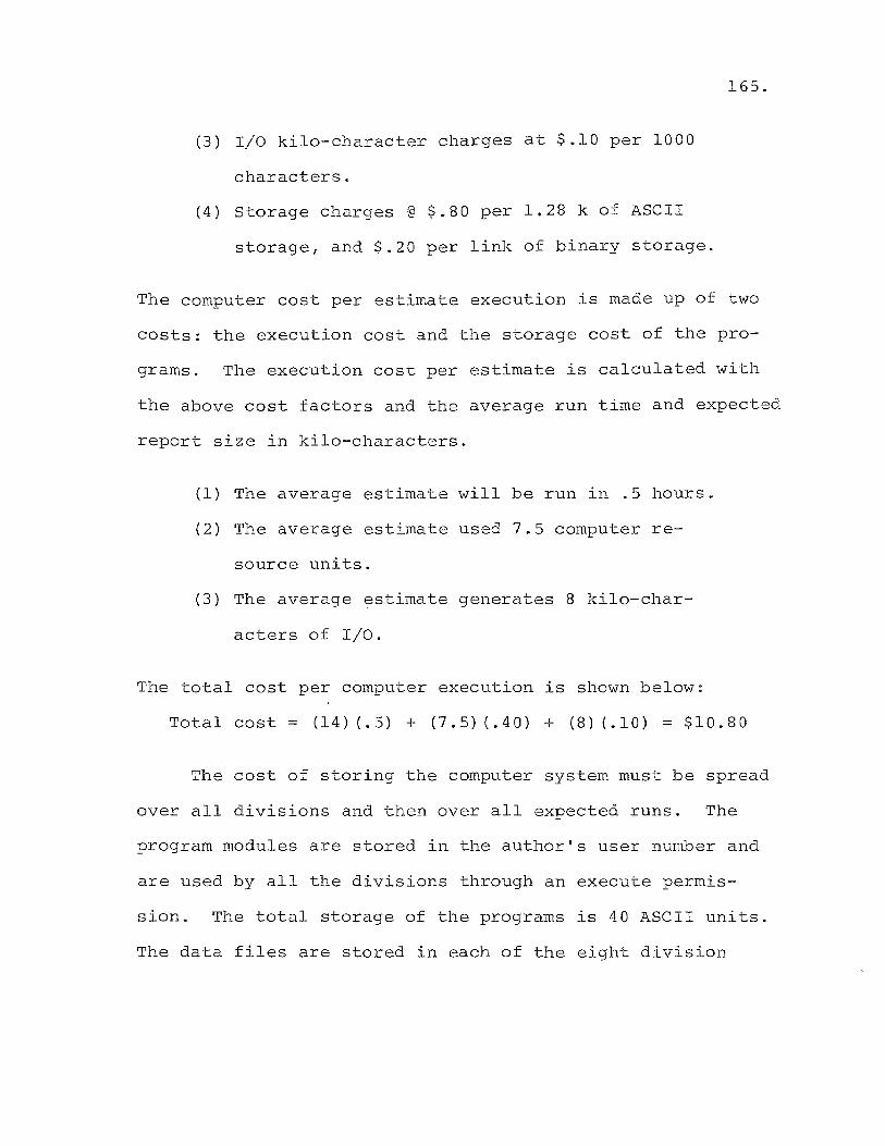
(3) I/O kilo-character charges at $.10 per 1000
characters.
(4) Storage charges @ $.80 per 1.28 k of ASCII
storage, and $.20 per link of binary storage.
165.
The computer cost per estimate execution is made up of two
costs: the execution cost and the storage cost of the pro
grams. The execution cost per estimate is calculated with
the above cost factors and the average run time and expected
report size in kilo-characters.
(1) The average estimate will be run in .5 hours.
(2) The average estimate used 7.5 computer re
source units.
(3) The average estimate generates 8 kilo-char
acters of I/O.
The total cost per computer execution is shown below:
Total cost = (14) (.5) + (7.5) (.40) + (8) (.10) = $10.80
The cost of storing the computer system must be spread
over all divisions and then over all expected runs. The
program modules are stored in the author's user number and
are used by all the divisions through an execute permis
sion. The total storage of the programs is 40 ASCII units.
The data files are stored in each of the eight division
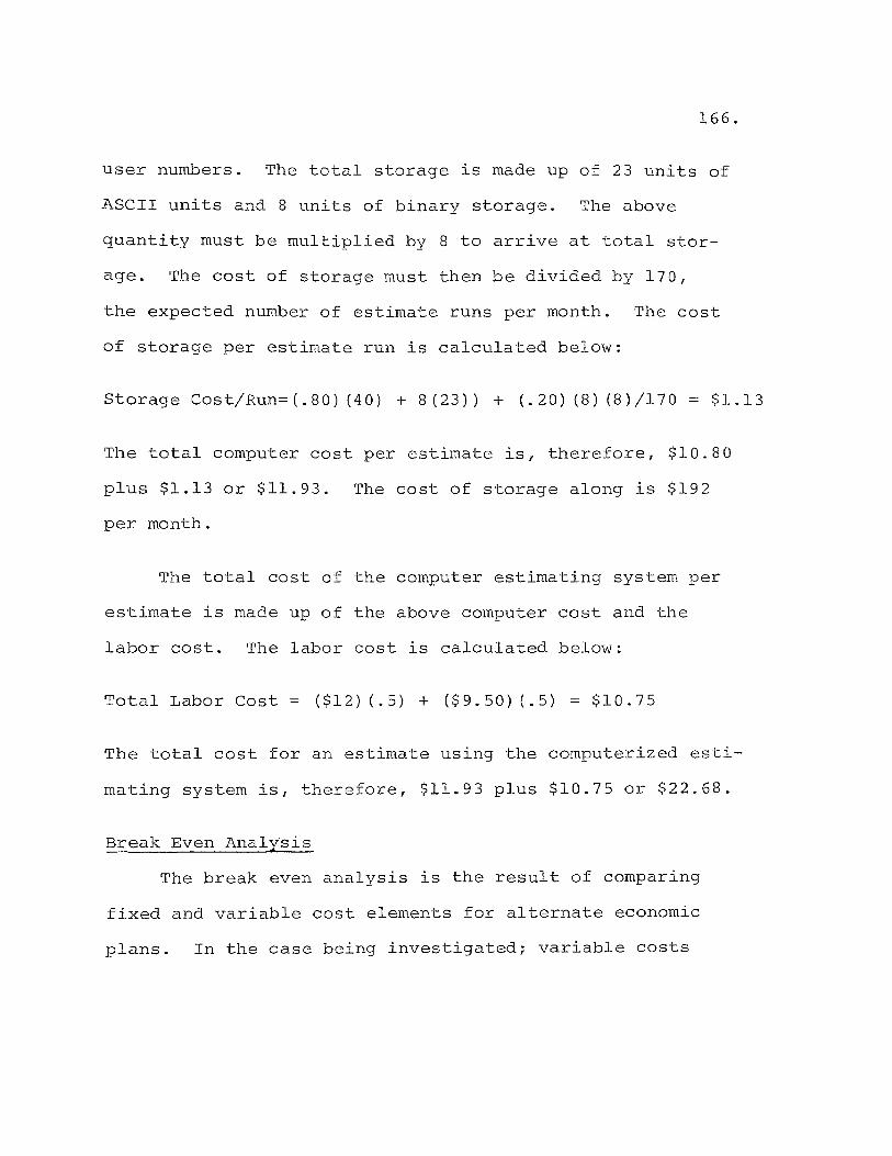
166.
user numbers. The total storage is made up of 23 units of
ASCII units and 8 units of binary storage. The above
quantity must be multiplied by 8 to arrive at total stor
age. The cost of storage must then be divided by 170,
the expected number of estimate runs per month. The cost
of storage per estimate run is calculated below:
Storage Cost/Run=(.80) (40) + 8(23» + (.20) (8) (8)/170 $1.13
The total computer cost per estimate is, therefore, $10.80
plus $1.13 or $11.93. The cost of storage along is $192
per month.
The total cost of the computer estimating system per
estimate is made up of the above computer cost and the
labor cost. The labor cost is calculated below:
Total Labor Cost = ($12) (.5) + ($9.50) (.5) = $10.75
The total cost for an estimate using the computerized esti
mating system iS I therefore, $11.93 plus $10.75 or $22.68.
Break Even Analysis
The break even analysis is the result of comparing
fixed and variable cost elements for alternate economic
plans. In the case being investigated; variable costs
167.
include labor plus execution costs; fixed costs are file
storage costs.
X(Manual Cost) = X(Computer System Cost) + Storage
where X is the number of estimates required to break
even.
Break Even = (22.68 + 192.)/102.50 = 2 estimates/mo.
The computer system will pay for itself if only 2.0 esti
mates are done per month.
Total Cost Savings
The total cost savings amount to $79.82 per estimate.
The average amount of estimates done per year by the
Electric Distribution Department of Public Service Electric
and Gas Company is approximately 2,000. The total savings
to be expected from the implementation of the computerized
cost estimating system is, therefore, ($79.82) x (2000) =
$159,640.00 per year.
Conclusion
The implementation of the computerized construction
cost estimating system apart from standardizing and simpli
fying the estimating function, provides a considerable cost
benefit to the company. The cost for an estimate done
manually, averaged $102.50; the cost for the same estimate
168.
using the computer is $22.68. The cost saving per estimate
is, therefore, $79.82. Based on the average use of 2000
estimates annually, the computerized system will save
$159,640.00 per year.
General
CHAPTER VIII
CONCLUSIONS AND RECOMMENDATIONS
The purpose of this Thesis is the design and imple
mentation of a real time computer based construction cost
estimating system for the Electric Distribution Department
of the Public Service Electric and Gas Company of New
Jersey. While the system was specifically designed for
electric utility construction cost estimating, the techni
ques employed are applicable to other industries.
Conclusions
The preparation of this Thesis has led the author to
the following conclusions:
1. There is a vital need for a cost estimating
system in the Distribution Department of
Public Service Electric and Gas Company of
New Jersey.
2. Cost estimating is an excellent application
for digital computers.
3. The use of time-shared computers is a real
advantage for a decentralized distribution
department.
4. The General Electric Mark III foreground
system is the most cost effective for the
cost estimating application of those systems
available and tested.
5. The use of the BASIC computer language is
preferable to FORTRAN IV for the estimating
application.
6. The existing terminal facilities available
in the field divisions are adequate to handle
the new system without excessive waiting.
7. The use of disk stored random binary and
sequential file structures are preferable
for the cost estimating system.
8. Multi structured file organization has sim
plified input and make it possible to use
less technically skilled personnel.
9. Carefully organized implementation is in
suring the acceptance and success of the
system.
10. A considerable economic benefit should
accrue when the system is fully implemented.
170.
171.
A vital need for a cost estimating system - Prior
to the system design work, it was apparent to management
that the manual cost estimating system was not consistent
among the eight field divisions. Estimates were often
inaccurate and were often submitted late. The need
for accuracy, consistency and timeliness was necessary
to the smooth economic functioning of the department,
therefore, a new system capable of meeting the above
criteria was of vital importance.
Cost estimating is an excellent application for
digital computers - The large volume of labor and
material data can be conveniently stored on magnetic
storage devices. The multitudinous calculations and
file look ups can be rapidly handled under program con
trol. Decision criteria and circuit design variation
can be successfully transferred to program logic. A
great deal of manual effort can be saved using digital
computers. In fact, other electric utilities have
developed systems in past years to handle the function.
Use of time-shared computers - The use of time
shared computers is an excellent medium for the esti
mating application. Flexibility was built into the
system allowing each of the eight field divisions to
have their own data files. The immediacy of the data
input and return of the final estimate is important
172.
for the calculation of variations on a proposed construc
tion project. In practice, many more variations are
being tried with the new system, resulting in better
cost/benefit optimization. Also, the feeling of control
over the computer has helped sell the system to field
personnel.
The General Electric Mark III system - The selection
of a time-shared computer service was conducted among
four vendors. The General Electric Mark III system was
found to be most cost effective for a system which is
a blend of input-output and computation. The system
also offered the advantage of local dial-up for our
geographically spread field divisions. A considerable
savings in telephone costs has been gained by using
the General Electric telephone network. Finally, the
General Electric Mark III system offered a user oriented
executive system and diagnostic package. The ease of use
proved to be important in gaining Union acceptance in
field locations.
BASIC is the preferred computer language - The se
lection of the BASIC language was based on its ability
to handle the necessary system logic, its ability to

173.
handle data files, and its ability to handle alphanumeric
string input. FORTRAN was able to handle four character
alphas while BASIC could handle the 30 character strings
necessary in the estimating system. The BASIC compiler
was able to generate efficient code resulting in fast
program execution.
Existing terminal facilities are adequate - An
investigation of existing load on field terminal facil
ities using queueing techniques showed that current
facilities are adequate. The criteria of waiting times
of no longer than 20 minutes was not violated in any
field location.
The use of disk stored files is preferred - The use
of disk stored files for rapid access is a great benefit
in reducing execution times. Sequential ANSCII structure
was used for shorter files. These files are directly
listable on local field terminals and are open to modi
fication by responsible field personnel. The random-binary
structural files cut processing times on the large files
access by the system. These files are listable and
modifiable under program control.
Multi-structured file organization simplifies input -
The goal of input simplification was met by using multi-
structured random binary file organization. The file
which generates pole top material was organized such
that the program can select packages of required
materials. The user is not burdened with knowing the
exact items required for pole top construction. The
use of personnel of lesser technical skills was facil
itated by this method. Management personnel were freed
of the exclusive duty of estimate preparation.
174.
Carefully organized implementation is essential - The
success of any system, no matter how fantastic that
system is, can be jeopardized by poor implementation.
Care was taken to document the system, to meet with field
personnel, and to ease the new system into effect. This
program has paid off and the new cost estimating system
has met with excellent response from the field.
Economic Justification - The implementation of the
computerized construction cost estimating system in add
ition to standardizing and simplifying the estimating
function, provides a considerable cost benefit to the
company. The cost of an estimate done manually averaged
$102.50; the cost for the same estimate using the computer
system was $22.68. The cost saving per estimate is,
therefore, $79.82. Based on the average use of 2000 esti
mates annually, the computerized system should save

175.
$159,640 per year.
Recommendations
The following is series of recommendations based on
the conclusions reached by the author during his work on
the construction cost estimating system.
Department wide implementation - If the parallel
run in all field divisions proves as successful as the
early results indicate, then the computer based esti
mating system should be adopted as the only acceptable
means for producing a cost estimate in the Electric
Distribution Department. This recommendation is based
on the improved estimate technique and the cost savings
provided by the computer based system.
Company wide implementation - If the estimating
system proves successful and anticipated savings are
realized in the Electric Distribution Department of
Public Service, then it is recommended that a similar
system be designed for each of the other operating de
partments of the company. Construction work done by
the Electric Engineering Department includes: installa
tion of conduit, construction of substationa dns
switching stations, and the construction of generating
stations. Projects must be estimated by the Electric
176.
Engineering Department in a similar manner as that used
by the Electric Distribution Department. Therefore, a
similar computer based estimating system can be designed
for this department. In the same way, the Gas Department,
and the Generation Department could benefit from a com
puterized cost estimating system.
Implementation in other electric utilities - Electric
distribution construction is fairly similar throughout
the country. utility accounting methods are virtually
identical in all American electric utilities. With the
above facts in mind, it is not difficult to see that the
system designed by the author could be put to use by
other utilities. Data files and report structures could
be easily modified to fit local requirements. Smaller
utilities without the necessary capital to invest in a
computer system would find such a system particularly
beneficial because they would pay only for operating
expense on a time-shared computer.
Other industries - Many of the concepts used in the
design of the computer based estimating system discussed
in the course of this thesis are applicable to the general
solution of the estimating problem. The use and struc
ture of data files would be similar in other industries.

177.
The design of the program modules for the time sharing
environment could serve as examples for other industries
desiring such an estimating system. The concept of
input simplification would well be used by other estimate
system designers.
Further system development - The following is a list
of suggested expansion of the computer based estimating
system.
1. Creation of a random binary file containing
authorized estimate money to serve as a
directory of active jobs.
2. Generating C.P.M. reports from the labor
output data from the estimating system.
3. Interfacing the estimate system and the
material ordering system.
4. Feedback of actual dollars spent versus
estimated dollars to serve as control
mechanism.
The creation of a random binary file to contain the
account and cost information output from the estimate
program could serve as a rapid directory for management
for all authorized jobs. Such a file could be created
as a function of the report producing program (MISCP$).
Video terminals could be provided for management to
access cost information as needed. The file could also
serve as a data base to produce cost reports on work in
progress.
178.
C.P.M. Scheduling - It is current practice to schedule
line work crews manually in each division through the
means of a modified Gantt Chart. Enough data is available
in the estimate files to provide the necessary input data
for a critical path method (C.P.M.) scheduling program.
The author envisions that a direct interface could be
designed between the estimate system and the General
Electric Mark III package C.P.M. program, entitled CPMXl$***.
The output of the program could be a C.P.M. report or a
graphical representation of the C.P.M. solution. The
author believes that a significantly improved schedule
of line crews could be made if this recommendation is
implemented.
Interface with material system - The output of the
estimating system includes a material list as illustrated
in Figure 5.20. The material list must be submitted for
keypunching in order to serve as input to the current

material ordering system resident on a company owned
Univac 1106 computer system. The Univac system is
capable of accepting eight level ASCII code on paper
tape. Each field division has a General Electric
Terminet 300 terminal capable of punching eight level
ASCII code on paper tape directly from computer output.
With the addition of some extra programming in both
systems, it would be possible to enter input from one
system to the other through the means of paper tape.
This would save the cost of repunching data and elimi
nate resulting error.
Cost Feedback - A final recommendation concerns
179.
the control of expended money. The author recommends
that a study be made to determine the feasibility of
interfacing the current Univac 1106 based work order
system and the output of the estimating program. As
costs accrue to the various accounts of an authorization
through work done in the field as reported on work
order forms, a check could be made against estimated
dollars for that account. A monthly report could be
generated which would review the charges to authori
zations and flag those in danger of being overspent.
A Final Word
The author would like to state that this thesis
offers a real solution to a real problem as it existed
in the Electric Distribution Department of the Public
Service Electric and Gas Company of New Jersey. It is
not intended to be a text book solution, but rather an
honest effort to attain a workable estimating system in
a reasonable time frame.
180.
CHAPTER IX
CRITICAL EVALUATIONS
The lett:lers presented on the following pages reflect
the opil!l~i()ns of two men highly qualified to write on the
subject of construction cost estimating. The first letter
was written by my supervisor) Mr. H. S. Bl~~elt, Manager
of Methods of the Electric Distr-:hbution Department of the
Public Service Electric and Gas Company of New Jersey.
Mr. Blauvelt has had over thirty years of experience in
the Distribution Department" Most of his cars;er was spent
in field supervisory positions, including the top manage
ment position of superintendent in several divisions.
The second letter of critical eValuation was sub
mitted by Mr. R. F .. Dauer, Assist~t Manager of Electric
Distribution of the Orange and Rockland Utilities Company.
Mr. Dauer is also highly qualified to write on the subject
of construction cost estimating. He has had extensive
experience as project engineer for field construction
jobs, and has had a good deal of experience \"ii th computer
applications.
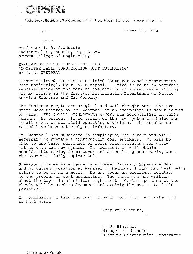
Public Service Electric and Gas Company 80 Park Place Newark. N.J. 07101 Phone 201/622-7000
Professor I. R. Goldstein Industrial Engineering Department Newark College of Engineering
EVALUATION OF THE THESIS ENTITLED
March 19, 1974
IICOMPUTER BASED CONSTRUCTION COST ESTIM1\TING" BY T. A. WESTPHAL
I have reviewed the thesis entitled "Computer Based Construction cost Estimating", by T. A. Westphal. I find it to be an accurate representation of the work he has done in this area while working for my office in the Electric Distribution Department of Public Service Electric and Gas Company.
The design concepts are original and well thought out. The programs were written by Mr. Westphal in an exceptionally short period of time. The entire programming effort was accomplished in three months. A"t present, field trials of the new system are being run in all eight of our field operating divisions. The results obtained have been extremely satisfactory.
Mr. Westphal has succeeded in simplifying the effort and skill necessary to prepare a construction cost estimate. We will be able to use Union personnel of lower classification for estimating with the new system. In addition, we will obtain a considerable saving in manpower and a resulting cost saving when the system is fully implemented.
Speaking from my experience as a former Division Superintendent and my current position as Manager of Methods, I find Mr. Westphal's effort to be of high merit. He has found an excellent solution to the problem of cost estimating. The thesis he has written about the topic is of similar high merit. Certain portion of the thesis will be used to document and explain the system to field personnel.
In conclusion, I find the work to be in good form, accurate, and of high merit.
The erq Peo Ie
Very truly yours,
H. S. Blauvelt Manager of Methods Electric Distribution Department
c .. 75 WEST ROUTE 59, SPRING VALLEY, NEW YORK 10977
April 10, 1974
Mr. Thomas Westphal Public Service Electric & Gas Company 80 Park Place - Room 7360 Newark, New Jersey
914-352-6000
I received a copy of your Thesis IIComputer Based Construction Cost Estimating'! and have read it with interest. As you may know, Orange and Rockland Utilities is a combination Electric and Gas utility serving Orange and Rockland Counties and a portion of Sul1ivan County in New York State. Our wholly owned subsidary Rockland Electric Company provides electric to communities in northern Bergen, Passaic and Sussex Counties in New Jersey, while our other subsidary Pike County Power and Light provides electric to portions of Pike County, Pa .. At present we do not have a computerized estimating system, though we are interested in developing one for Electric Distribution Construction Projects.
It would appear that you have a sound basic knowledge of electric distribution construction. Chapter II serves as a demonstration of this fact. The estimating system as a whole, was written with input simplicity as a guideline and yet with sufficient flexibility to allow the user coverage of a wide range of construction conditions.
The manual systems like the one you described in Chapter III do present problems. It was interesting to see your technique for simplifying the estimating function. We, too, are interested in using nonmanagement union personnel for estimating and I have found your work in this area to be well thought out.
I have some background in the computer systems area and found Chapter IV and V to be well constructed and executed. Chapter IV explained in what I thought was a very straight forward manner how a relatively large system can be written for the small core space generally available on a time shared computer. Chapter V was unique in that it takes the reader inside a program and explains in detail how it works. The flow charts and documented program listing were a great assistance in understanding the text.
Mr. Thomas Westphal Page 2 April 10, 1974
Your Chapter on implementation (this is always a difficult area) impressed me with how rapidly a well constructed computer system could be brought into effect and in s~-l-ing a system this is an important factor.
I was also interested in the cost savings PSE&G will experience with the computerized system.
In conclusion, I found your Thesis to be an accurate representation of construction cost estimating as it pertains to the Electric Utility Industry. It offers an excellent computer design.
RFD/alb
Sincerely,
ORANGE AND ROCKLAND UTILITIES, INC.
R. f. Dauer Ass·t. Manager Electric Distribution
APPENDIX A
An Introduction to the
BASIC Computer Language
Source
General Electric
Information Services
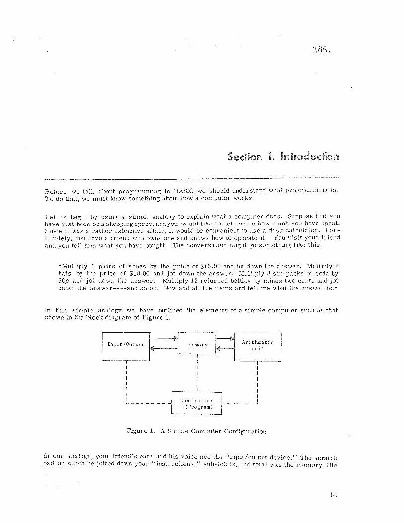
Section 1.
Before we talk about programming in BASIC we should understand what programming is. To do that, we must know something about how a computel' works.
Let us begin by using a simple analogy to explain what a computer does. Suppose that YOll
have just been Oil a shopping spree, and you would like to determine how much you have spellt. Since it was a rather extensive affair, it would be convenient to use a desk calculator. FortunaJcly, you have a friend who owns one and knows how to operate it. You visit your friend and you tell him what you have bought. The conversation might go something like this:
"Multiply 6 pairs of shoes by the price of $15.00 and jot down the answer. Multiply 2 hats by the price of $10.00 and jot down the answer. Multiply 3 si..x-packs of soda by 50,6 and jot down the answer. Multiply 12 returned bottles by minus two cents and jot down the answer----and so OIl. Now add all the items and tell me what the answer is."
In this Simple analogy we have outlined the elements of a simple computer such as that shm'll1 in the block diagram of Figure 1 .
Input fOul put
I
I r
~
---------
. '" Hemory
I I
Controller (Program)
~ Arithmetic
Unit
I
I I
____ I
Figure 1. A Simple Computer Configuration
In our analogy, your friend's ears and his voice are the "input/output deviee." The scratch pad on which he jotted down your "instructions," sub-totals, and total was the memory. His
I-I
desk calculator was the "arithmetic unit." His ability to underst.and and interpret your instructions, and to operate the desk calculator and jot down items on the scratch pad represent the "program" built into the "controller"----which is, of course, your friend.
In an actual computer these functions are all performed by electronic components. In the BASIC 1 Time-Sharing Service, the processor is a GE computer, and the input/output device for our purpose is a terminal. In fact, there are many terminals, all connected to the same computer. The computer operates so much more quickly than you can type in or print out information that it can "time share" many input/output devices. Tbis is clone in much the Sd.me way that a good waitress in a restaurant can wait on several tables without causing any inconvenience to her other patrons. While one is drinking his Cocktail, she can be serving the main course to another. While he is eating the main cOUl'se, she can serve dessert to a third patron. Then she can deliver the check to a fourth in time to return to the first just as he is finishing his cocktail and is ready to order another. If the patrons were not able to see one another, each might think that the waitress was serving only him.
In the same way, GE Time-Sharing Service can accept an "order" from one terminal, then service many others, and still return to the first one in time to accept the next "order" without delay. Thus, it appears to each user, sitting at his terminal, that he has exclusive use of the computer.
The fact that a terminal is used as an input/ output device means that it can be located some distance from the computer. To go back to our analogy, it is as if you decided to call your friend 011 the telephone rather than drive over to his house. This is, of course, much more convenient. Since computers have not yet been designed to respond to the spoken word, we don't eall up the computer by telephone, but by a terminal. The cornputel' can readily interpret th' deetricCiI sign::d3 pl1t out by the terminal, and the human operator has little difficulty operat.ills a tC!'millal keybo:u:d. It is almost identical to that of a standard typewriter. By the same t.oi'.f:n, thE: computer can readily generate electrical signals which cause a terminal to print out a mC'5sage which the operator can read.
Thus, V}8 nOw have all the elements of a "time-shared" computer system serving many re!llot-:; l"e;l!blls. There remains one problem howevel'--Gomputers have a "l::tnguage" all tbeir OW[;, S,) Lu' as pt'ogram instructions are concerned. They don't do arithmetic the way humans do, eit:,,:~L'. It is as if, in our analogy, <the friend were Japanese, spoke no English, and used ii!1 ;,)),'.':.13 :·;ttlJer thaI! a desk c::-llcubtor. What we need is a translator. Maybe your friend's wife SpPl)~S EnF~Ii.sh. We talk tol!eron the phone, so that she can translate into Japanese for her flU'S b:..nd awi tl'anslatc his ,~nswers back into English for us. Meanwhile, he can use the .lh,,(~us to do wh.lt we would have done Oll a c:1.leulatol'.
If cime-sh:1.ring br~ngs eV2ry man his own computer, the BASIC language makes every man his own progr'l.mrr;·::r.
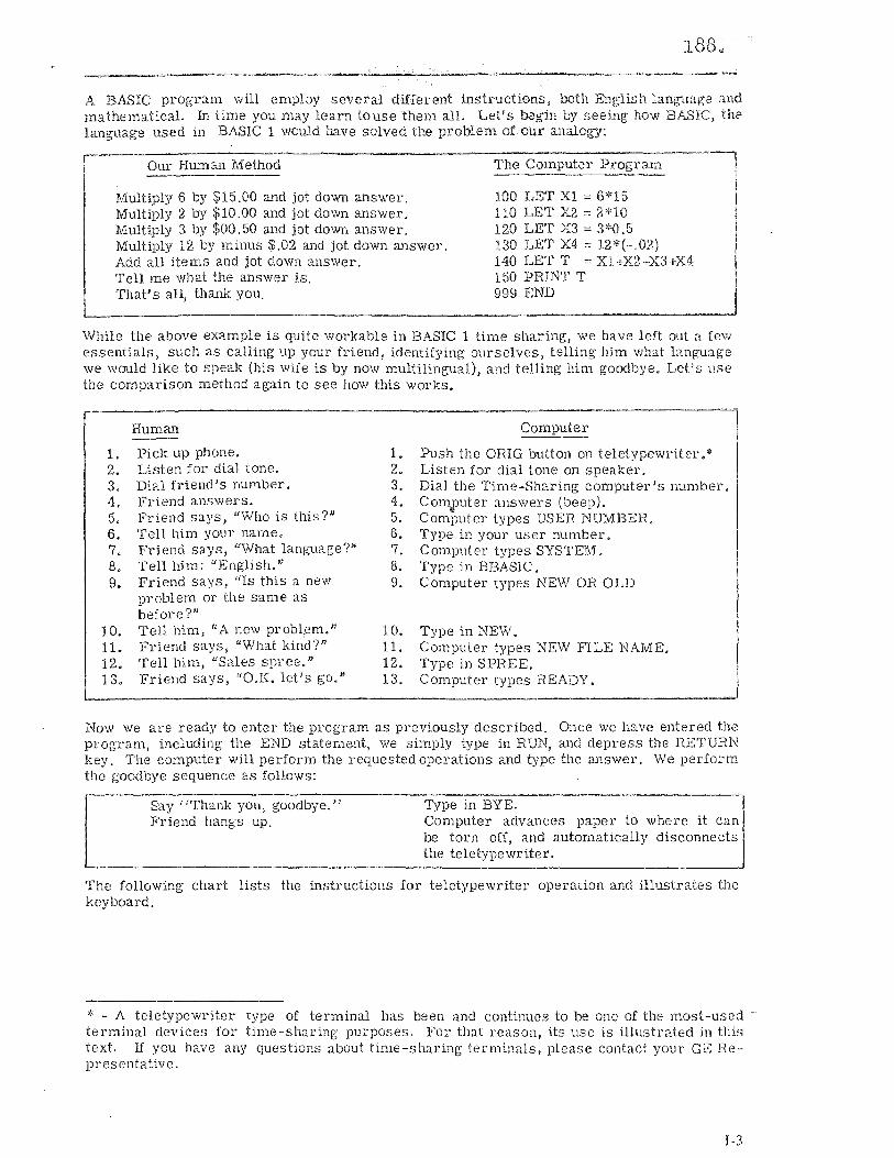
188,.
A BABIC prograrn will emplDY several different instructions, both English language ;i.nct mathematical. In time you may learn touse them all. Let's begin by seeing how BABIC, the la)1guage used in BASIC 1 would have solved the problem of our analo!D':
Our Human Method The Computer Program
Multiply 6 by $15.00 and jot down answer. Multiply 2. by $10.00 and jot down answer. Multiply 3 by $00.50 and jot down answer. Multiply 12 by minus $.02 and jot down answer. Add all items and jot down answer.
100 LET Xl := 6*15 110 LET X2 = 2*10 120 LET X3 = 3*0.5 130 LET X4 = 12*(-.02) 140 LET T == X1+X..2-tX3+X4 150 PRINT T Tell me what the fu'1SWer is.
That's all, thank you. 999 END
While the above example is quite workable in BASIC 1 time sharing, we have left out a few essentials, such as calling up your friend, identifying ourselves, telling him what lang-uage we would like to speak (his Wife is by now multilingual), and telling him goodbye. Let's use the comparison method again to see how this 'Narks.
Human
1. Pick up phone. 2. Listen for dial tone. 3. Dial friend's number. 4. Friend answers. 5. Friend says, "Who is this?" 6, Tell hirn your name. 7. Friend says, "What language?'" 8. Tell him: "English." 9. Friend says, "Is this a new
problem or the same as
1. 2. 3. 4. 5, 6, 7. 8. 9.
Computer
Push the ORIG button on teletypewriter.* Listen for dial tone on speaker. Dial the Time-Sharing computer's number. Computer answers (beep). .. Computer types USER NUMBER, Type in your user number. Computer types SYSTEM, Type in BBASIC. Computer types NEW OR OLD
before?" I
10. Tell him, "A new problpm." 10. Type in NEW. J 11. Friend says, "What kind?" 11. Computer types NEW FILE NAME. 12. Tell 11im, uSales spree." 12. Type in SPREE.
~_1_3_. __ F __ r_ie_l_ld __ S_a_y_s_'_'_(0 __ .K __ ,_1_et_'_s_g_0_._" _____ 1_3_, ___ C_o_m __ p_t_lt_e_r_t_'y_p_e_S __ R_E_A __ D_Y_, ______ ~ ____ ~ ___ ~
Now we are ready to enter the program as previously described. Once we have entered the program, including the END statement, we simply type in HUN, and depress the HETURN key. The computer will perform the requested operations and type the answer. We perform the goodbye sequence as follows:
Friend hangs up. Type in BYE. Computer advances paper to where it can be torn off, and automatically disconnects the teletypewriter. [
Say "Thank you, goodbye."
__________ __~ ________________________________________________________ -J
The following chart lists the instructions for teletypewriter operation and illustrates the keyboard.
>I< - A teletypewriter type of terminal has been and continues to be One of the most-used " terminal devices for time-sharing purposes. For that reason, its use is illustrated in this text. If you have any questions about time-sharing terminals, please contact your GE Hepresentative.
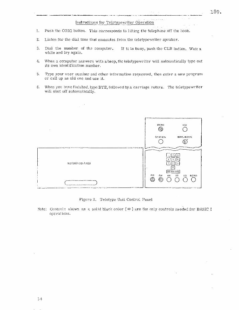
Instructions for Teletypewriter Operation
1. Push the ORIG button. This corresponds to lifting the telephone off the hook.
2. Listen for the dial tone that emanates from the teletypewriter speaker.
3. Dial the number of the computer. while and try again.
If it is busy, push the CLR button. Wait a
4. When a computer answers with a beep, the teletypewriter will automatically type out its own identification number.
5. Type your user number and other information requested, then enter a new program or call up an old one and use it.
6. When you have finished, type BYE, followed by a carriage return. The teletypewriter will shut off automatically.
1l!l)(·RLI REST
0 OUI Of SERVo NORMAL RESTORE
0 ®
KE'lBOAHDAHEA
------------------------------------
I I
Ixxxxxnxx< I ORIG CLR AMI TIT LCL BUZ·RLI
0000 . __ :J ( '--------
--------_._----------------' '----------------'
Figul'l.: 2. Teletype Unit Control Panel
Note: Controls shown as ;-I. solid black color (€!J ) are the only controls needed for BASIC I ope r-a t ions.
1-4
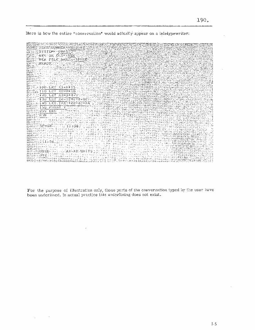
190 ..
Here is how the entire "conversation" would actually appear on a teletypewriter:
For the purpose of illustration only, those parts of the conversation typed by the user have been wlderlinecl. In actual practice this underlining does not exist.
1-5
s ,~---------------------------------------------------------------------------------------
~ow we've carried our analogy far enough. It's time we entered the world of BASIC and time-sharing. Let's discuss the BASIC program.
~acll program instruction must be entered on a separate line and must be followed by a I:arriage return. Notice that each BABIC program instruction to the computer is assigned a I\umber---in the example we used 100, llO, 120 and so Oil. The computer executes the i£1-iltructions in numerical order, thus the program must be written so that the instructions, \Vhen taken in numerical order, follow a logical sequence. For example, it would do no good to ask for PRINT T before the other instructions had been executed, because the computer \<muldn't know the value of T and could not print it. Notice that we said "taken in numerical IJrder,JJ The instructions can be typed in any order because the computer will automatically ('esequence them into numerical order. This is a great convenience and is one of the reasons ~Ol' numbering- th.e instructions in the first place.
if we l'ealized after the program was all written that we bad forgotten one line, we would Just type it in: 141 LET X5 == 3*17, All instructions would automa.tically be put into se'{upnticll order by the computer. We don't have to retype the whole program. For this reason, l)lOst programmers leave a few spare numbers between instructions. This makes it easier to ~[)ITr:ct ,)1' modify the program later.
t'lery prOr;i';Ur. must have an END statement so that the computer will know when it has \!rGcessec1 all the prO[;l'all1 instructions. The END statement must be the highest numbered instruction ill the pl'ogr::Cll1. Most users d(;sil~rl(l.te a sufficiently lar'ge number (for example: 999 m tht' t:x3mpk). t·J e~lSGi.·i'~ that :,11 other instru.ctions will have lower line numbers. Be~;WSI.: linr-~ nUU,ijf;rS :H'e limited to five dip;its, the largest jWr',11issible line number is 99999.
\'dicc til'1.t O.Ldl h • .srrucrioll is in si:lljlle a1s01)l'aic [orm, ra"her than i.n English or arithmetic. 'l",at is \""~ (!.\\1:ts,lY, l1l'lHiply 6 x 15 Instead we say, LET X=: 6"15. ,'\JiY arbitrary alpha:Xeti.c l(>rt.~,l.' DI,ly be used instead of X :1':; 1m;?; as it is a letter or a letter fc;]jo\\','d by a single (;1gif. m!ll:bt~l- (i.e., 0,1,2,3,4,5,6.7,8, 01' 9).
191 ..
Be sur", to distill[.';ui.sh between "zero" and the l.etter "oh", and between the! digit "one" and the lower c:l.se "ell". Tilere are no lower case letters on a teletypewriter, but if you are accllsiumed tIl l1sill;; ]i:;v:cr C:lse "ell" ona typewriter for the digit "one"--he c3.reful~ Also, since tlld'l:' is no 10'.'/(']:' cJ.se X, or a multiplication sign 011 a teletypewriter, we use the asterisk !(J1' tllis purpose.
, ' ,-0
192 ..
s
Most programs can be reduced to three simple steps:
1. Providing data 2. Performing desired calculations 3. Printing out answers
Because Steps 1 and 3 are the easiest to understand, let's start with them. Assume some kind of calculation is needed, for example:
Thel'e '-\.l'e three ways in wbichstep 1 can be performed. First, we can simply say: READ Y. Then we can include a statement: DATA 3, 7, 23, 71. lin illustration of a BASIC program using these statements is:
READY LET X ::; -3.14159 *y PRINT X G¢ TqJ 10 DATA 3,'7,23,'71 END
Whenever the computer encounters a RE.AJ) statement in the program, it will read the next value of Y. The first time it will read 3, the next time 7, the next time 23, and soon until no more data is left to be read. Then it will stop. Ii our program bad said: LET X = A*B, we would have bad to say: READ A, B. The computer would then take the numbers two at a time from our DATA statement regarding: the first numb€r as A and the second as B, the third as A and the fourth as B and so on.
The second way of providing data is the F,OR. .. NEXT method. For example, we could say: F0H Y 1 T0 10. Notice the use of /{0" for the letter ({O" to distint:;uish it from the numeric zero. At the appropriate point, where the next variable is required in the prog-ram we would give a NEXT Y instruction. The computer would then perform the desired calculation for all integTal values of Y from 1 to 10. If we want larger or smaller steps. we simply specify the size of step required. For example: Fc,OR Y = 1 TO 10 STEP 0.1 would cause the machine to use: 1,1.1,1.2,1.3, ... This method o[ input is very useful for computing tables of sqnares, cubes, square roots, cub€ roots, etc.
The third wa.y of providing data is to have the computer ask [or it. For example, assume we have a progr:lm which needs the values of A, B, and C, which we would like to provide each time we run the program. To do this, we use two instructions: PRINT "ENTEH fI, B, C1i
;
followed on the next line by INPUT A, B, C. The computer will now ask for tile values of A, Band C by typing: ENTP:n A,B,C? Then you enter any values, for example 2,8, -10, by typing tbem in and clepressinp; the RETURN key. The computer will perfor111 the ealcuL,tions with the values you provided ~"ldprintoutthe answer. If you have programmed a loop (whicb we will discuss later) it will ': you to ENTER A,B,C again.
1-7
193"
s In p In In
So much for providing data. Now let's see how we get information out of the computer. Ag:lin, there are three ways in which we can get the computer to print out information, using program instructions. The first two use the PRINT command. Anything included in tluotes following a PRINT command will be printed as is. For example, the command PRrNT "T", would cause T to be printed, perhaps as a column heading. The command PRINT T, however, without the quotes around T, would cause the computer to print the value of T. In our very first example (SPREE), for instance, ,'Ie could have written 149 PRrNT "T=" before the 150 PRINT T instruction. The teletypewriter would then have printed out T= On one line, and the value of T (111.26) immediately below it on the neAt line. To save paper, we could have written: 150 PRINT "T="; T in which case we would receive the printout: T= 111.26.
Thus by using quotation marks, we can get the computer to print out what we specify, for column headings, line titles, and so on. By omitting the quotation marks we can get it to print (;,10 actual value of the quantity called for.
N(H: 10t'S discuss where the computer is going to print. Each PRINT instruction causes the compn:er to begin a new line. A PRINT instruction with nothing after it won't print anything', but it will ad'.r;lllce the paper one line. This is a useful technique for improving the appearance of jour printout.
l\ page is divided into five zones of fifteen spaces each across each line. Anything' in quotes is printr:d j1lst ,1S it appears. For anything not in quotes, however, a comma is the signal for the C()l'1)mtL::' to move to the next zone. For example, if we used the instruction PRINT A, B, C, (",)tl: that we used no quotation marks around the letters) the computer would start at the 12ft ,~c!ge of the page and print the value of A. Then it would skip over to column 15 and print rhe value of B. It would skip the necessary spaces to br ing it to column 30, and print the v:l1ue of C. We could thus get as many as five printouts across the page, beginning at columns 0, 15, 30, 45, and 60. This operation is just lil(e tabulating on a typewriter.
If we want to get more than five eolumns, 'we can compress the printouts by using a semicolon instead of a comma between the letters. Then the spacing between printouts will depend all how many characters are printed. When each value is printed, one space appears in front of the number [ai' thesi(?;n,andasmany as four spaces after the number. The sign is printed only II it is minus. The following ta.ble shows the field widths for the different numbers of ci1ar:1cters.
1-8
Numb,r of Characters
2, :~} or £.1.
:), 6) 01" '7 8, 9, or 10 1l.1~)or13
Field Width
3 6 9
12 1.5
194"
How are numbers printed out? Here are the rules which the BASIC language uses:
L No more than si.x significant digits are printed (except for integers---see rule <1 beloW).
2. Any trailing zeros after the decimal point are not printed.
3. For numbers less than 0.1, the form X.XXXXX E-Y is used, unless the entire significant part of the number can be printed as a si.x digit number. For example, 0.0000376 is the same as 3.76 x 10⁻⁵, and will be printed as 3.76E-5.
4. If the number is an integer (in other words a whole number), a decimal point will not be printed and as many as nine digits will be printed in full.
The third method of printing out information involves the use of the LIST system command Wh1ch instructs the comr-uter to type out your entire program just as it is stored in the computer. This is very useful for obtaining the current version of a program which has undergone many corrections, additions and deletions as it was being typed in.
There is another BASIC command that is useful when listing programs. This is the REM (Hemarks) command. It is useful for documenting comments in a program and can be used by the programme r to make rernarks throughout the program logic. Following a REM statement the computer will type out exactly what is stated. For example:
IS A LIST 01" CONSTANTS,
The difference between PRINT and REM i.s that, in the first case, the words to be printed out should be in quotation marks; and they are printed when the program is RUN. In the second case, the words to be printed out are not in quotation marks; and they are printed when the program is listed, btlt not when it is RUN.
1-9
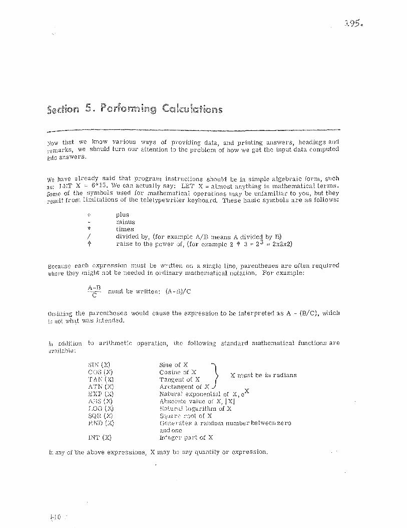
5. Pe . U1
Now that we lmow various ways of providing elata, and printing answers, headings and remarks, we should turn our attention to the problem of how we g'et the input data computed into answers.
We have already said that program instructions should be in simple algebraic form, such as: LET X =: 6*15. We can actually say: LET X =: almost anything in mathematical terms. Some of the symbols used for mathematical operations may be unfamiliar to you, but they result from limitations of the teletypewriter keyboard These basic symbols are as follows:
+ plus minus
* times I divided by, (for example AlB means A divided by B) l' raise to the power of, (for example 2 ~ 3 :co 2 3 == 2x2x2)
Because each expression must be written on a single line, parentheses are often required wllere they might not be needed in ordinary mathematical notation. For example:
A~B must be written: (A-E)/C
On,itting the parentheses would cause the expression to be interpreted as A - (B/C), which is not Wh:lt was idended.
III addition to arit,hmetic operation, the following standard mathematical fW1ctions are aV;lilable:
;")IN (X) COS (X) TAN (X) ATN (X) EXP (X) AJJS (X) LOG (X) SQH (X) E/,;D (X)
INT (Xl
Sine of X } Cosine of X X must be ill radians Tangent of X Arctangent of X Nat1!l'al exponential of X, eX A\:soil.l,tE: value of X, I Xj ~;atur-; .. .1. ;.ogarithm of X Sq UJl' <" 1'8ot of X Genel'ates a ranc\om number between zero and one Integer part of X
In any of 'the above expressions, X may be any quantity or expression.
1·10
195 ..
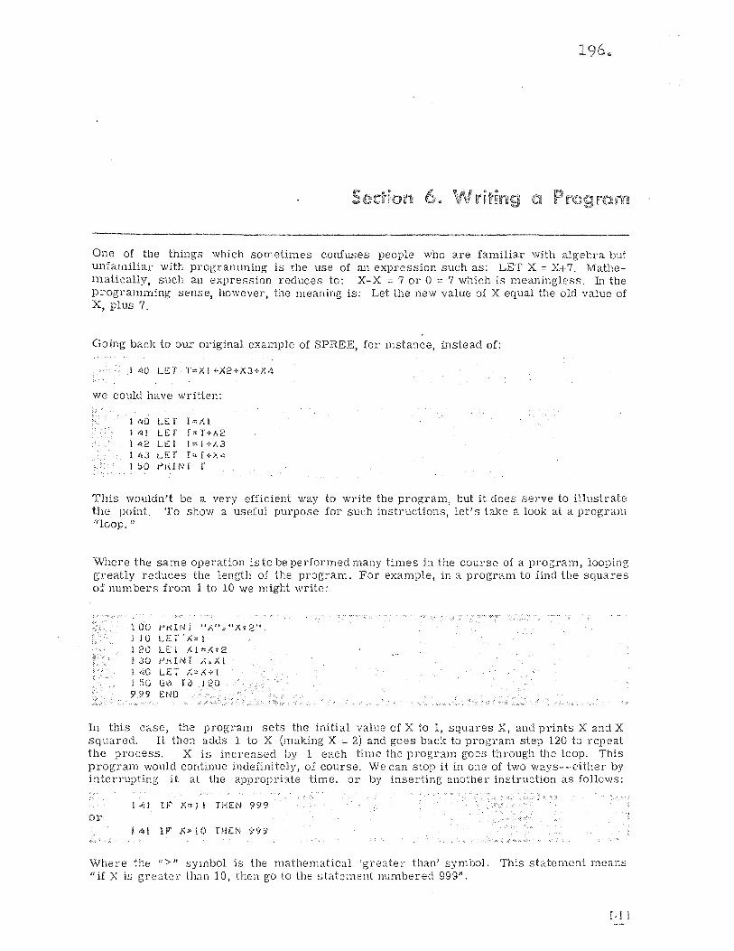
196"
pi ra
One of the things which sometimes confuses people who are familiar with algebra but unfamiliar with programming is the use of an expression such as: LET X:= X+7. Mathe-111atically, such an expression reduces to: X-X:= 7 or 0 := 7 which is meaningless. In the programming sense, however, the meaning is: Let the new value of X equal the old value of X, plus 7.
Going back to our original example of SPREE, for instance, instead of:
I 40 u:r r=Xl +X2+X3+X4
We could have written:
140 LET 1"'/\1 14l u:r r", 1"+{,2 142 LEi T:=1+l\3 I i;J LEf r"'f+X4 1 :'0 r'rdNf T
This wouldn't be a very efficient way to write the program, but it does serve to illustrate the point. To show a useful purpose for such instructions, let's take a look at a program "loop. "
\\l11ere the same operation is to be performed many times in the course of a program, looping greatly reduces the length of the program. For example, in a program to find the squares of numbers from 1 to 10 we might write:
100 YKHJT ".1\", "At 2" jjOLEr')(=l I 20 U: I 1.1" f.. t 2 130 })KIN! X.Al I 40 LET X=X+l I 50 G0 [0 .120 999 END
In this case, the program sets the initial value of X to 1, squares X, and prints X and X squared. It then adds 1 to X (making X = 2) and goes back to program step 120 to repeat the process. X is increased by 1 each time the program goes through the loop. This program would continue indefinitely, of course. We can stop it in one of two ways--either by interrupting it at the appropriate time. or by inserting another instruction as follows:
.. , , .. ..
1 "'H IF' X,,~! THEN 999 ,.
01'
! 4! U'~ X"!Q THEN 999
Where the ">,, symbol is the matbematical 'greater than' symbol. This statement means "if X is greater than 10, then go to the statement numbered 999".
I-I I
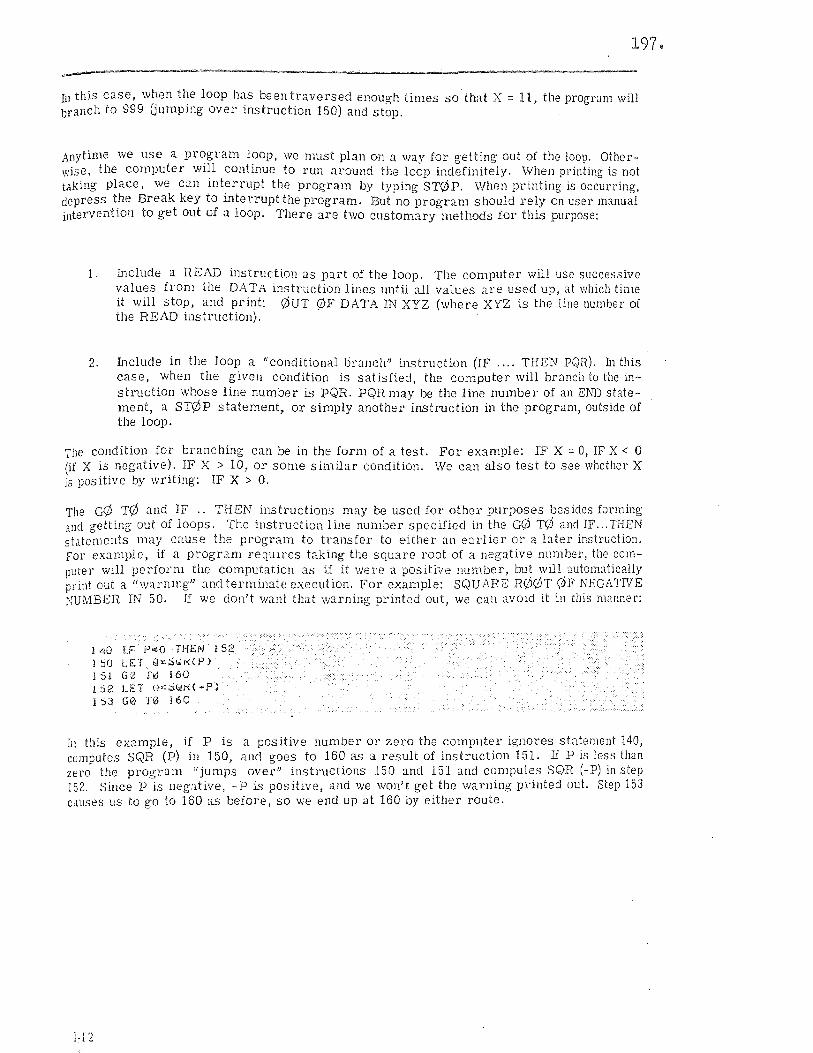
197.
In this case, when the loop has been traversed enough times so that X == 11, the program will branch to 999 Gumping over instruction 150) and stop.
Anytime we use a program loop, we must plan on a way for getting out of the loop. Otherwise. the computer will continue to run around the loop indefinitely. When printing is not taking place, we can interrupt the program by typing ST0P. When printing is occurring, depress the Break key to interrupt the program. But no program should rely On user manual intervention to get out of a loop. There are two customary methods for this purpose:
1. Include a READ instruction as part of the loop. The computer will use successive values from the DATA instruction lines until all values are used up,. at which tirne it will stop, and print: QUT 0F DATA IN XYZ (where XYZ is the line number of the READ instruction).
2. Include in the loop a "conditional bl'anch" instruction (IF .... THEN PQR). In this case, when the given condition is satisfied, the computer will branch to the instruction whose line number is PQR. PQR may be the line number of an END statement, a ST¢P statement, or simply another instruction in the program, outside of the loop.
The condition for branching can be in the form of a test. For example: IF X = 0, IF X < 0 (if X is negative). IF X > 10, or SOme similar condition. We can also test to see whether X is positive by writing: IF X > O.
The G¢ T¢ and IF " THEN instructions may be used for other purposes besides forming and getting out of loops. The instruction line number specified in the G¢ TQ and IF ... THEN statements may cause the program to transfer to either an earlier 01' a later instruction. For example, if a program requires taking the square root of a negative number, the computer will perform the computation as if it were a positive number, bu~ '.vill automatically print out a "warning" and terminate execution. For example: SQUARE R00T <OF NEGATIVE NUMBER IN 50. If we don't want that warning printed out, we call avoid it in this manner:
140 IF peO THEN 152 I 50 LET Ql!;;)WI'<O") 1 51 GB 1'0 160 152 LET ~~;;;~K(~P)
153 G0 T0 160
III this example, if P is a positive number or zero the computer ignores statement 140, comoutcs SQR (P) in 150, and goes to 160 as a result of instruction 151. If P is less than zero" the program "jumps over" instructions 150 and 151 and computes SQR (-P) in step 152. Since P IS negative, -P is positive, and we won't get the warning printed out. step 153 causes us to go to 160 as before, so we end up at 160 by either route.
1·]2
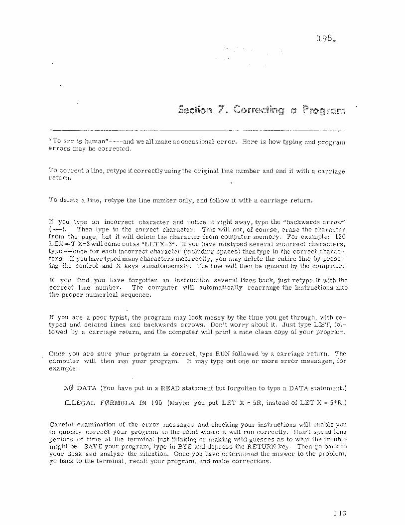
198
UTo err is human" ----and we all make an occasional error. Here is how typing and program errors may be conected.
To correct a line, retype it correctly using the original line number and end it with a caniage return.
To delete a line, retype the line number only, and follow it with a carriage return.
If you type an incorrect character and notice it right away, type the "backwards arrow" (-). Then type in the correct character. This will not, of course, el'ase the character from the page, but it will delete the character from computer memory. For example: 120 LEX--T X=3 will come out as "LETX=3". If you have mistyped several incorrect characters, type -once for each incorrect character (including spaces) then t:'vpe in the correct characters. If you have typed many characters incorrectly, you may delete the entire line by pressing the control and X keys simultaneously. The line will then be ignored by the computer.
If you find you have forgotten an insh'uction several lines back, just retype it with the correct line number. The computer will automatically rearrange the instructions into the proper numerical sequence.
If you are a poor typist, the program rnay look messy by the time you get through, with retyped and deleted lines and backwards arrows. Don't worry about it. Just type LIBT, followed by a carriage return, and the computer \ViII print a nice clean copy of your program.
Once you are sure your program is correct, type RUN followed by a carriage return. The computer will then run your program. It l'nay Lype out one or more error roessages, for example:
N\b DATA (You have put in a READ statement but forgotten to type a DATA statement.)
ILLEGAL F¢RMULA IN 190 (Maybe you put LET X = 5R, instead of LET X = 5*R.)
Careful examination of the error messages and checking your instructions will enable you to quickly correct your program to the point where it will run correctly. Don't spend 10nD; periods of time at the terminal just thinking or making wild guesses as to what the trouble might be. SAVE your program, type in BYE and depress the RETURN key. Then go back to your desk and analyze the situation. Once you have determined the answer to the problem, go back to the terminal, recall your program, and make corrections.
1·13
Unless you SAVE your program, the computer will l!forg-et" it as soon as you "sign off. n If yOU want to have the computer II remember" your program, yot! must type SA VE, depress RETURN, and wait for the computer to answer READY before you say BYE.
199.
To recall a sewed program, ask for an 0LD program and type in the file name in response to the computer instruction 0LD FILE N.t.\JvlE. When the computer has found your program it will type RE.t.\..Dy. If you subsequently wish to UNSAVE the program, type UNSAVE and depress the RETURN key.
If you forget which program you have saved, type CAT ALq)G, followed by a carriage return. The computpr will list the names of all the programs saved under your user number.
If you want to start a llew program, simply type NEW, followed by a carri3g-e return. This may be done at any time. The computer will then ask: NEW FILE NAME--type in your new program name and the new program.
HEN A..ME is another command that may be useful when you wish to slightly modify an existing program, but still retain the old program. First SAVE the existing program; then type RE!'iAME. and depl'ess the RETURN key. The computer '.!fill ask for NEW FILE NAME. You may then type in the llew name and mOdify your program, since the original program has been saved under the old name. Your modified program may be saved under the new name.
By nOw you sl10uld be able todoh'lo things: write simple programs in B .. '\SIC and understand most of the material in the more advanced B/lSIC Language Chapter. To increase your understanding, try to understand the program logic of the sample problems in the next section.
j·14

APPENDIX B
Construction Cost Estimating
Program Listings
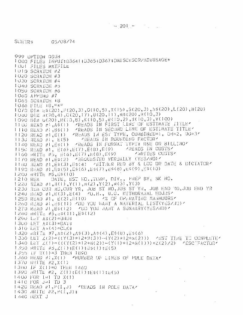
- 201 -
SLJhTR $ 05/08/74
999 UPTION OSUB 1000 FILE::) INPUf;OJ64J ;DJ65;DJ67;OMISC;SCRfJAD;USAGt* I ULJ I FILES M-ATFI Li:.: I (j 1 0 SC~?ATCH fU I 020 SCf?ATCH #3 I 030 SU1ATCH #4 I 040 SC I~A1CH #I:J 10:::i0 SCHAfCH If6 I 060 A PfJEHu #7 1065 SCfiAfCH : 8 1066 FILE :8,"-k ll
I 0 10 D I Nt t: $ ( 20 ) 9 P ( 20, J) , G ( 1 0 ,5) ,X ( I ~) ,S ( 20 I J) ,N $ ( 20) ,L ( 20) ,M ( 20) I UdO 0 1M yy ( 20,4) 1 C (20, 1 -;) ,U (20, 1 1 ) ,M $ ( 20) ,l~ ( 10, J) 1090 DIM u(20) ,H( 10,8) ,[« 10,5) ,lie 10,2) ,BC 10,J) ,V( 100) 1 J 00 r~EAD #1 ,A$ (1) -"fftADS IN FIRST Lldt::" UF l::STIMATE iT11.1:::" I I JO [<lAD ifl ,13$( 1) J'F?l::i\DS IN SECOND LINE UF EST1/.1ATE TITU::" I 120 l~lAD #1 ,l::( I) "'F?lAUS L~ tsr TYfJE, CUiABINfLJ=I, UH=2, UG=3-' 113u HEAD if!, 1:':(5) "'HEADS IN RUUNDl/'jG FACTOf?J' I J 40 IH::AD if I ,12$( i) /1?t:J\OS IN FORMAT TYPE; R&E OR BILLING" J !:::i0 R [AD if I, E ( 6) ,[ CI ) ? E (8) IE (9) J'!? [A OS IN CUSTS'" 1160 HHITi.:r/:lj" leo) ,ECI) ,J::(8) ,E(9) /~HdTr.:S CU~)lS'" 11-/0 l~EAO ifl ,0:S(2) "1-?EOUJ:::SfED VEFIBALLY (YI::S/t\lU)" II dO liL:AD #1
912$(3) ,[S(4) "tITIILl? m:o BY & Loe OR DATE & DICTATOR"
I! 90 j{b\O If! ,[$(5) ,[$(6) ,l:~s(n ~E$«3) ~t:$(9) ,ES( 10) I ;2 00 'i.JfH Ti:.: If 5 , i~ $ ( I 0 ) 1210 ~H:;'i, DAT!::, EST fm.,TO\'iN, DIV., j.J[{EP BY, SK NO. I 220 UEAD if 1 ,'\1 ( I ) , Y ( 1 ) , ill (2.) , Y (2) 'I M (3) , Y ( 3) 1230 RtM CUR MO,CUR YR, JUG ST MO,JUB ST YH, JOB END ~U9JOU END YR 1240 1?L:AD -ill 91::(3) ,1:::(4) "'U.H., U.G. VIITfl[)!"~i\i~AL HOUI-IS-' 1 2::S () f? I:: A D # J, I:: ( 2) ,L ( I 0) J' ~~ [J F U P dl AT I N G MAl ~ H U U R S .... 1260 !IEAD itl ,eS( 11) J'DU YOU hAirr A MATEFlIAL LIST(Yt:S/.~rJ);' 1270 Hr..:AD tf.! ,ESC 12) "U[J YUU dArlT A SU:AiAAI~Y(YcS/1\lO)"" 12(;)0 rH?ITi.: 1I5,cS(II),[$(I;n 1200 Lt:T AS(2)=UNUS 13uo LI::T A$(3)=OA1-$ 13]0 LET AS(4)=CLJ<$ 1320 ",IUTi:.: in ,AS(2) ,A$(J) ,AS(4) ,[$«3) ,l.::$(6) 13jO LLI L(2)=«Y(3)*12+M(3»-(Y(2)*12+~(2») J'~ST TIME TO CUMPLETE" 1 340 LL:l L ( I )::: ( ( ( Y (2) * 12+/1. ( 2) ) - ( Y ( I ) )'~ I 2+!id I ) ) ) -+-L: (2 ) 12) .1 ESC' F ACTUf(;' 13:::i0 ,mITt: ib,Z(l);ECI);[S(I);E(S) j .3::h I F d 1 ) = 3 T H L: i~ I 890 1360 HEAD 11 ,XCI) 'NUM8ER UF LINES Of POLE DATA-' 1 3"10 Ii f( I T E It 2 , X ( I ) I 3 bU .£ F X ( I ) =0 THl:N 1 460 I J <)0 H IH TI:.: # 2, Z ( I ) ; E ( I ) ; E S ( 1 ) H: ( :) ) 14 U0 FUH I::: 1 TO X ( 1 ) I 4 10F 0 R J:::: I TO 3 1420 UEAD ifl.,P(l ,J) ,f!~EADS IN POLE DArAJ' 1430 ~RITE #2,PCI,J); 1440 UEXT J
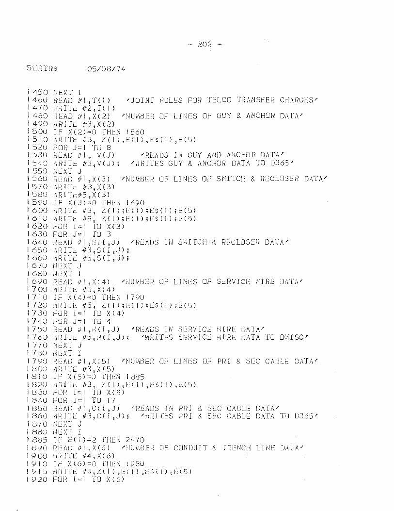
- 202 -
SLJrrrRS OS/08/74
1 450 UC:::XT I I 460 ~EAD 111 ,TC I) "JUINT ~OLt:S For? TELCO TUANS~ER CdARGES" J 4 -101m I Te 11 2, T ( I ) 1480 RC:::AD #1 ,X(2) 'NUMbER OF LINES OF GUY & ANCHOR DATA' 1490 id~ITt: #3,X(2) 1 :s OU I F XC 2) =0 THl:N 1 560 I 5 I 0 t'1 R I 'It: /I 3 , L ( I ) , Eel ) ,E $ ( I ) ,E ( 5 ) I 5:20 FOF? J= I TO 8 I ~3U F{J:':AD ifl, V(J) "READS IN GUY Al\jO ANCHOR DATA" 1540 vmITt: 113,V(J); "(mITES GUY & ANCHOR DATA TO 0365)' 1 5S0 Nt:XT J I ~60 F?EAD iii ,X(3) "NUMBER OF LH4ES ot-: SWITCH & RECLOSL:R DATA' I 5 7 0 iv I?I T t:: II 3 , X ( 3 ) ! 5BO f'iRITt..:ifS t X(3) 1590 IF X(3)::::0 THtN 1690 1600 vdHTr:: #3, Z(]HE(]);E$(I);E(5) 161U (mITe liS, Z(I);E(I);E$(I);L:(5) I 6:2 0 FOR I:::: 1 fO X ( 3 ) 1630 FOl=? J::::l ru 3 1640 liEAD -f1l,SCI,J) J'READS IN SWITCH &. RECLOSEf( DATA' I 65 0 H 1(1 T t: /I 3 , S ( I ,J) ; 1 660 f~ R I Tt: #S 1 S ( I , J) ; 16-10 NCXT J 16dO NEXT I 16YO fn:=:AD ifl ,X(4) -"NUMbER UF LINL~SOF Si.::RVICE i'.JIliE DATA' 1700 v~l(ITJ::: #5,X(4) 1710 IF X(4)=[) THJ:::N 1790 I 7 20 i'~ f? I TI:: # S? !.. ( 1 ) ; l::: ( I ) ; i:.:: $ ( ] ) ; t: ( 5 ) 1730 fOf-{ 1::::1 ru X(4) 1740 t-:OR J::::l TLJ 4 17':)u f{tAD 111 "HI ,J) 'Rt:ADS IN SERVICi:.:: IliFf!:: OAT/v" 1760 HfHTt: iI:),fHI,J); 'f~fdTES SEi~VICt: iHfiE DATA TO D,'.1ISC" 1 TIO NeXT J 17dU Nl:::XT I 17YU READ #1 ,X(5) 'NUMBER OF LINES Of PRr & SEC CAULE DATA" I 0 00 i~ f~ ITt: if 3 ? X ( 5 ) I B l 0 I F X ( 5) =0 THt:N I 885 1820 idilTL: #3, Z( I) ,E( I) ,1::$( 1) ,E(I) 11:330 FOR 1::::1 TO Xes) lB,tO FOR J=I TO 17 1850 iil:::AD itl ,C( I ,J) 't{EADS IN PRI & SlC CABLE DATA" 1860 I'WI1'L: ftJ,C(I,J); J'Hr~IfLS P["?I 6., SEC CAI:3LE DATA 1'(J 0365' 18/0 NEXT J I adO dlXT I 1 8(3S IF E ( 1 )::::2 THlN 24 -/0 I uYO r~EAD ;If I ,X(6) '!\!UIABEf? fJF CONDUIT (~ Tf,ENCI-1 LINE O/\'1A" J 9 00 vm 1 T E if 4 , X ( 6 ) 1910 IF X(6)=O fllt:N 1980 10i::> ,iHITt: #4,1.(1 ),E(I),[$(I),[(5) i Y20 Fun 1=1 TO X(6)
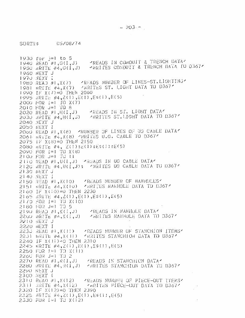
- 203 -
SOR1T{ S 05/08/74
1930 1940 1950 1960 197u 1980 1981 1990 1995 2000 2010 2020 2030 2040 20~0 2000 2061 2075 2080 20YO 210u 2110 2120 2130 2 j 40 2150 2151 2160 210 lJ
21 /0 2180 219U 22uu 2210 2220 2230 22jl 2240 224~
2250 2260 227U 2280 22YO 2300 231U 23 II 2320 2325 2330
for j=! to 5 READ #1,GCl,J) r'lRITt: 114,O(1,J) l'-lEXT J
'READS IN CO~DUIT & TRENCH DATA~ JvvRI rES CONDUIT & TRENCH DATA ru D367"
NEXT I READ #1 ,X(7) 'READS NUMBER Of l1NES-ST.L1GHTINC' ~RITt: #4,X(7) 'rlRITt:S ST. LIGHT DATA TO D367' If X(])=OfHEN 2060 v'IR ITt: 114, Z ( 1 ) ,EC 1 ) ,E $ ( 1 ) ,E ( 5) FOr? I = I fO X C 7 ) fOR J=l TO 8 n E A 0 ;1 I t H ( I ? J ) ,m I TE #4, H ( I , J) [~EXT J NEXT I
· ... f~tADS li~ Sf. lIGHT DATA" "HRITES ST. LIGHT DATA TO 0367.1'
READ #1 ,Xed) 'NUMBER OF LINES OF UG CAblE DATA' H~nTt: #4~X(8) I'H~HTES U.G. CABLE TLJ 0367' IF X(8)=0 THLN 2150 t'l t( ITt: If 4 7 2. ( I ) ; E ( I ) ; E $ ( 1 ) ; E ( 5) FLJR 1=1 TLJ X(8) For? J=l TU II f([AD til ,UCI 9 J) 'J-~LAlJS IN UG CABLE DATA" df?1TL #4,0<1,J); "W[~ITES UG CABLe: DATA TU 0367" NEXT J NEXT I READ til ,xc 10) "1-(EAOS NUMBE!~ OF 1.1ANHULES" 1dHTt: #4,X(IO) "d~HTES MAN HOLt:: DATA TO D367' IF X(10)=0 THEN 2230 HFUTt: #4,2.( I) ,E( I) ,ESC I) ,1:(5) ~OR 1=1 TO X( 10) FDR J==I TO 5 Rl~AD ill ,K (I ,J) i'~[~lTt: 1f4,K<I,J) dtXT J HEXT I
'READS IN MANHULt DATA" "\W ITl.:S MANHUU: DATA TU 0367"
,~t.:AD itl ,XC II} "READS NUMt3Efi LJF STANCHION ITEMS'" hRITl:: #4,X( 11) "fvrnTEs STAi'1CHIOd DATA TO D367 .... IF X( II )=0 THEN 2310 ~RITE #4,Z(I) ,Eel) ,ESCI) ,E(5) FUR 1:--'1 TO X( II) FUR J:c=j TJ 2 ritA!) !Il ,lie 1 1 J) ?[?fADS IN STANCHION DATA" )\mrTi~ l/4,F?CI ,J) "'i'mln~s SlANCIHUN DATA TO D367.P Nl::XT' J N!~XT I r~L:AD if I 9 X ( 12) f ~7L::ADS NUMbER OF PI LCE-OUT r TEMS)' lmITt:: .fl4?XC1:'::) J'Hi(ITiS PIEce-OUT DATA TO D367J' IF X(12)=0 THEN 2390 ,W ITt::: if41!. ( J ) ,12 ( I ) , E $ ( I ) ~ E ( 5) FOR 1=1 TO X( 12)
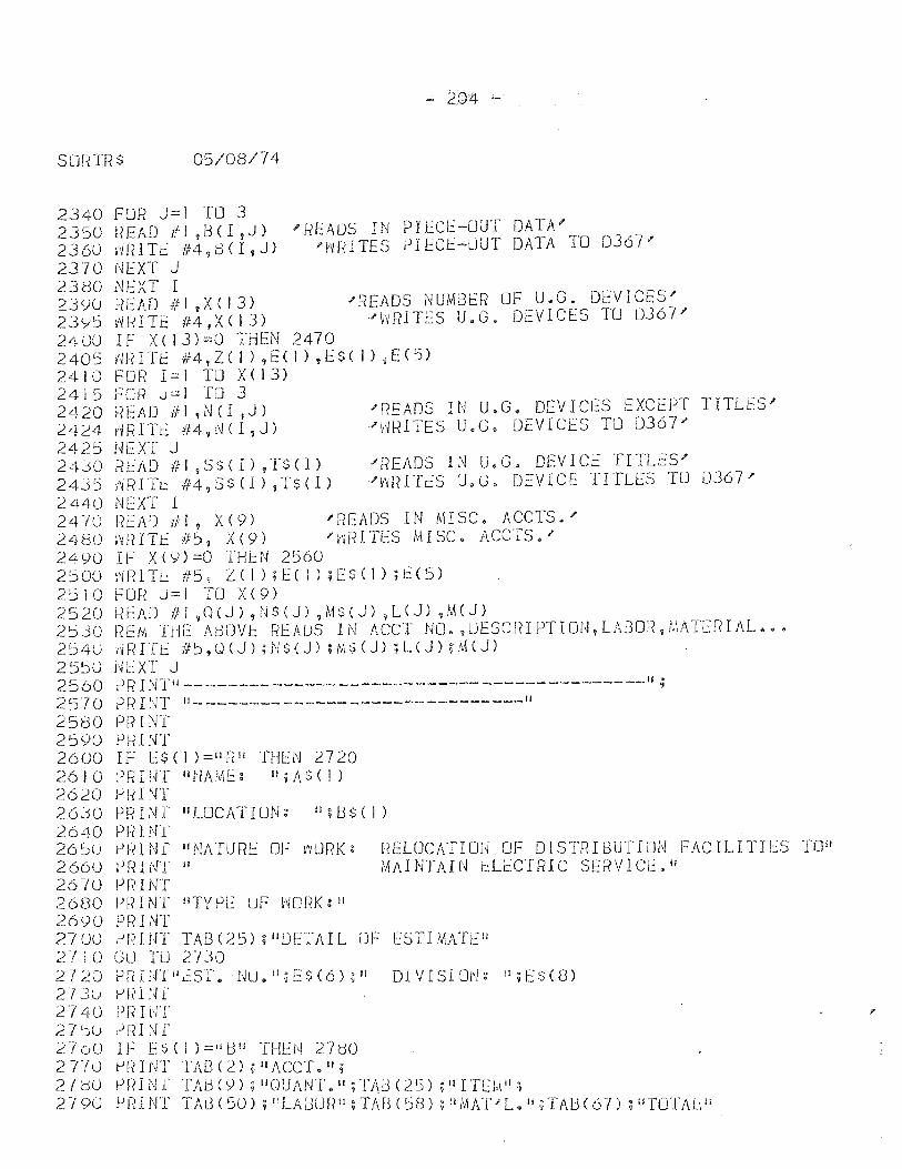
- 204 -
sonTRS 05/08/74
2340 FOR J=l TO 3 2350 HEAD #1 ,B(I,J) 'READS IN PIECE-OUT DATA' 2360 ~RIT~ #4,B(I,J) 'HRITES PIECE-UUT DATA TO 0367' 2370 NEXT J 23BO NEXT I 239U READ #1 ,X(13) 'READS NUMBER OF U.G. DEVICES' 2 J y:5 MH T f If 4 , X ( I 3) ... Id f?l T E S U. G. DE V ICE S TO D 367 ;' 240U IF X(13)=0 THEN 2470 2405 vmITt #4,Z(!) ,EC I) ,E$( I) ,E(5) 2410 FOR 1=1 TO X(13) 2415 FOR J=I TO 3 2420 READ #1 ,NCI,J) 'READS IN U.G. DEVICES EXCEPT TITLES' 2424 dRITE ff4,N( I ,J) J'~mITES U.G. DEVICES TO 0367)' 2421:) NEXT J 24JO READ #1 ,S$(I),TS(I) )'READS IN U.G. DEVICE TITLES)' 2435 riRIT~ #4,S$(I) ,TS(I) '~RITES U.G. DEVICE TITLES TO 0367)' 2440 NEXT i 2410 READ #1, X(9) )'READS IN MISC. ACCTS.' 2480 ~RITE #5, X(9) '~RITES MISC. ACC'rS.' 2490 IF X(9)=0 IH~N 2560 2500 I'm I T L: # 5 ~ L ( I ) ; E ( I ) ; E $ ( 1 ) ; t ( 5 ) 2510 FOR J=I TO X(9) 2520 READ III ,OCJ) ,N$(J) ?M$(J) ,LeJ) ,M(J) 2530 nEt'll THE AtlDVl:.: REAUS IN ACCT NO., LJESC in PT I ON? L\BOf?, 1,[ATEfH J\L ••. 2 ~) 4 0 ~m IT E -# 5 ? Q ( J ) ; N $ ( J) ; lvl $ (J) ; L ( J ) ; M ( J ) 2550 dl:XT J 2560 lJR I N'1'II-------- _________________________ ---------11 ; 2570 PFHNT "-----------.------------------- 11
2580 PRINT 2590 lJRINT 2600 IF [S( 1 )=11[(11 THEN 2720 2610 PRII~T litlAM[~: II;I\$(])
2620 PiiI NT 2630 lJ!{INf "LOCATION: ";I:3$(l) 2640 PF? I NT 26~U PRINT "NATURE OF ,yURK: RELOCATIOU OF DISllHBUTliJN FACILITIES TO" 2660 PF?HfT II MAINTAIN i::.LECTRIC SE~?VICi2.1i 26·10 PI? I NT 2680 PF?INT wfYlJE UF vWRKgll 2690 Pf<INT 270U PRINT TAB(25);"DETAIL OF ESTIMATE" 2110 GO TU 2730 2120 lJRIlffilt:Sr. Nu.";ES(6);1l DIVISl0i'4g 1I;E.:$(8) 213u P ~~ 1. N l' 27 40 PI~ I NT 27 ~U PRI 1'4 r 2100 IF ES( I )=lilJil THEN 27<30 2 T/U pf;> I NT TAG ( 2.) ; 1I ACCT. II ;
270U p~<INr TAB(Y);liQUANT.II;TJ\B(25) ;IIITElJ.II; 2-/90 lJr?INT TAB(50) ;!lLA8Un ll ;TAf3(':)R) ;IlMAT-"L.ii;TAl:H67) ; HnJTALII
I'
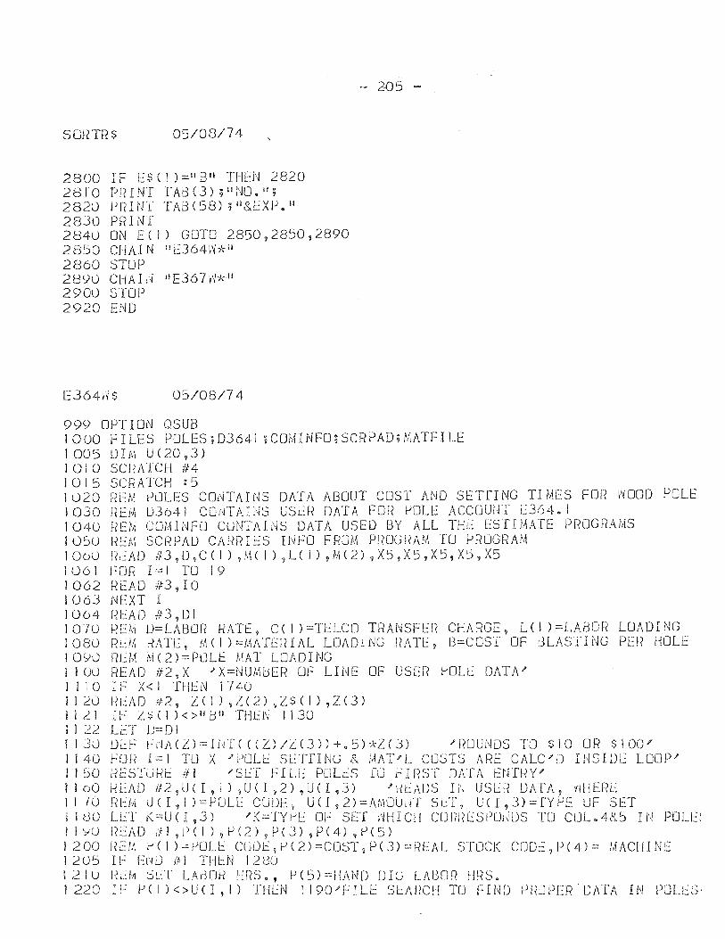
SQF,TR$ 05/08/74
2800 I F E $ ( I ) = II a Ii THEN 2820 281"0 Pl-HNT TA[3(3) ;IINO.II; 2820 j-lRINT TAB(58) ;1I&EXP o ll
2830 PRINT 284U ON E(I) GOTO 2850,2850,2890 2850 CHAl N II E364}~*lI
2860 STUP 2890 CHAIU lIE367,'j1," 2900 STOP 2920 END
E364d$ 05/013/74
999 OPTION OSUB
- 205 -
1000 F I LES POLES; 03641 ; Cm.1l NFO; seRPAO; MATF I LE 1005 DIM U(20,3) 10 J 0 SU~AICH i/4 I 0 I 5 SCF-? ATCH : 5 1 u20 REM PuLES CO,'iTAI NS DATA ABOUT COST AND SETrI NG TI MES FOR \"I00[) POLE 1 030 r~EM JJ3(,A I COrG AI NS USt:f~ DATA FOR pOLE ACCOUNT L:364 $ I 1040 REM COM1NFO CUNTAINS DATA USED BY ALL TH~ ES'[IMAIE PROGRAMS IU~O REM SCRPAO CARRIES IN~O FROM PROGRAM TO PROGRAM 1000 r?t::AD 113,D,C( I) ,M( I) jL( 1) ,M(2) 9X5,X5,X5,X5,X5 1061 ~OR 1=1 TO 19 I 062 ~(EAD #3, 10 1063 N!:.:XT I I 064 r~ E A D If 3 , 0 I 1070 R~M U=LABOR HATE, C(I )=TELCO TRANSFER CHARGE, L(I )=LABOR LOADING i080 RUA KATE, M(I )=IAAT!:.:RIAL LOADING !-IATE, B=COST OF dLASTING PE!i HOLE 1090 R~M M(2)=PULE MAl LOADING 1100 READ #2,X 'X=NUMbER UF LINE OF USER ~OL[ DATA' I I 10 IF X< 1 THI:::N 1740
.1120 I~EAD #2, 1.(1),1.(2),Z$(I),Z(3) .1121 IF Z::i(I)<>lIb" THEN /130 I I 22 LET 0= D I 1130 Dl::~ ri~A(L)=Ikf«(Z)IL(3»+.:i»)\-Z(J) "RUUNDS TO $10 OR $100' /140 r:Ul( 1=1 TU X 'j-)OL~ S!:.:TfING 8- MAT'L COSTS ARE CALC/D IHSIDE LOOP" 1150 I~ESTLJHI::: ifl "SET FILL POLt:S fU FIRST DATA UHI-{Y" IloO HLAD i/2,U<I, 1) ,U( r ,2) ,U(I ,3) "f?iADS Ii'j USLF? DATA, Yi/JERE 11-/0 Iit::.M uCI,I)=PUL[ CUDE~, UCI,2)=AMOU1H SLT, U(I,3)=fYf-JE UF SET j I dO LET K=U(I ,3) "K=TYl-'E OF SET i'iHICH CUrmLSI)UiWS TO CLJL.48.5 IN POLE: 1 1 YU F?cAD til ,e ( 1 ) , j-l (2) 9 P (J) I P (4) ,j-l (5) 1200 ~(E/:1 r'( I )::::j-lUU': CLJl)I::,j-l(2)=CDST,P(3)=f~EAL STCJCK COLE,P(4)= MACHINE 1205 IF ErH) HI THL-:N 12BO 1210 I~L:M :-)l~T LAt3Di-{ HRS., P(S)=HAND DIe) LAl30R fmS. 1220 IF 1->(I)<>UU,I) THEN 119CFFILE SLAriCH TO FIND PRJPER'DAIA IN PUU:'::S·
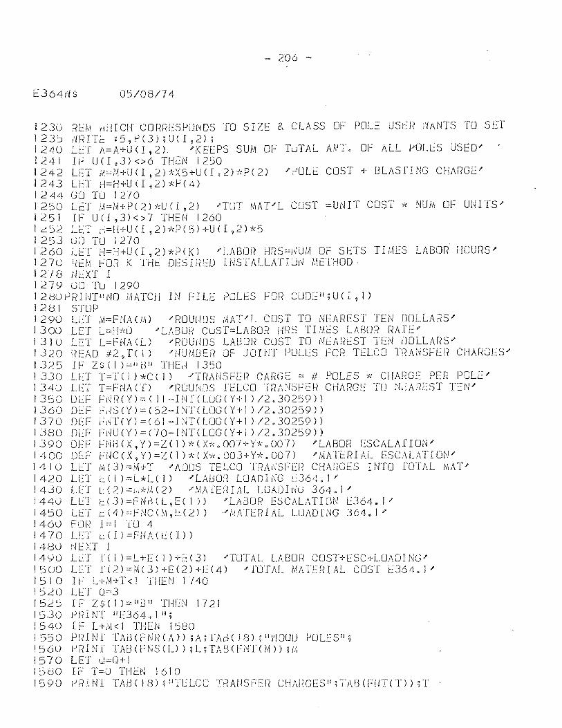
- 206 -
OS/08/74
1230 REM nHICH COR1~ESPOt'lDS TO SIZE & CLASS OF POLE USt::F~ ;'IANTS TO SET 123~ /{RITI:: :5,rJ(3);UU,2); 1240 LET A=A+U(I,2) "KEEPS SUM OF TLlTAL AMI. Of ALL POLtS USED .... 1241 IF U( 1,3) <>6 THEN 1250 1242 LET M=M+U(I,2)*X5+U(I,2)*P(2) '~OLi COST + BLASfING CHARGE' 1243 LET H=H+U(I,2)*P(4) 1244 (JO TU 1270 1250 LET M=M+P(2)*U(I,2) 'TOT MAT'L COST =UNIT COST * NUM OF UNITS .... I 25 1 IF U ( 1 ,3) < > 7 THE N 1 260 1 ~52 LET d=ti+U(I ,2)~":P(5)+U(I ,2)*5 1 253 GO TU 1270 1260 LET H=H+U(l ,2)*P(K) "LABOr? HRS=lWIII Of SETS THIES LABOR HOURS' 1270 REM FOR K TH~ DESIRED INSTALLATIUN METHOD 1278 i'kXT I 1279 GO TLJ 1290 12d0rJRIlrr"NO t,IATCH IN FILE yOLES FOR CUDEil;U(I, I) 1281 STOP J 290 Ll~T ,\1=Ft-lAClA) 'ROUUDS iAAT"L COST TO NEAREST TEN DOLLARS' J 300 LET L=H*D "LABOH Cus T=LABOR HRS TL'.H::S LABOR RA fE' 131 U LET L=Fl~A (L) "ROUiJDS LA[301~ COST TO NEAl~t:ST TEN l)OLLAI?S' 1320 ~<EAD iI2~T( 1) "NUI.1SE!? m-: JOINT PULES FOR TELCO T;?ANSFER CHM<GES .... 1325 IF ZSCI)="d l' THE;,) 1350 I 330 LET '1'=1 ( 1 ) *C ( 1) "TRANSFE R CAr~G E = if POLES :k CHARGE PER POLE" 134~ LET T=FNAC[) 'RUUNDS fELCO TRANSfER CHARGE TO ~~AREST TEN' 1350 LJEf FNf~(y)=( II ~HIT(LUG(Y+1 )/2.30259» I J 60 DE F F i 4 S ( Y ) = ( 52- I NT ( UJG ( Y + 1 ) 12 • 30259 » 1370 DEF Fl'iT(Y)=(61-INT(LUGCY+l )/2.30259» 1380 DlF FNU(Y)=(JO-INTCLOGCY+I)/2.30259» 1390 DEF FNB(X,Y)=Z()*(X*.007+Y*.007) 'LABOR ESCALAfION" 1400 OfF FNC(X,y)=zel)*(X*.003+Y*.007) 'MAT0RIAL ESCALATION' 1410 LET M(3)=M+T 'ADDS TELCO TRANSFER CHARGES INTO [OTAL MAT' 1420 LET L( I )=L*L( 1 )'LAGOn LOADING L364.1' 1430 L.[:T L: (2) =j,,*i,\ (2) -"MATErn AL LOADIt~G 364. 1 J'
1440 LLT t(3)=FNr::(L t E( 1» "LA8UR ESCALATION 12364.1' 1450 LET t:(4)::.:FNCO\,ELn) "r,IATERIAL LUADING 364.1" 1460 FOR I~I TO 4 1470 LET L(I)=FNA(lCI» 1480 l\IEXT I 14<)0 LL:T T ( I ) =L +E ( ) ) +E (3) "TOTAL LAl30r< COST+ESC+LOADI NG.;> 1500 LET I(2)=~(3)+E(2)+E(4) 'TOTAL MATERIAL COS1' l364.1' 1510 IF L+M+T<l THEN 1740 1 ::)20 LET (,)=3 I 52::) 1 F Z $ ( I ) =- II i3 11 THEN 1 72 i 1530 eRINT IIEJ64.11I; 154U IF L+M<I THEN 1580 ; 5 SOP R I NITA i3 ( F N ~{ ( A » ; A ;' l' Ad ( 1 8) ; II vi ODD !-' 0 L E S Il ;
1560 ~RINi TABCFNS(L»;L;TABCFNl'(M»;M 1570 LET u=O+1 1~80 IF T=O THEN 1610 1590 !->R.1 NT TAB ( 18) 1 wH':LCCJ TRAnSFER CHAnGES It ;-rAG (FiJTCf) ) ; T
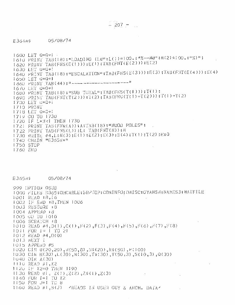
- 207 -
£364r'/$ 05/08/74
1600 LET 0=0+1· lolt) t-lnUff TABC IS) ;11LOADING (U:R";L( 1)*1 00. ;'I%--M~Il;M(2)-;A.·1 00. ;II~~) II; 162t) t-lnINT TA8(FNSC[(1 »);E(J);TABCFNTCEC2»));EC2) 1630 LET 0=0+ 1 1640 t-lRINT TA!:3(IS) ;"ESCALATIONII;TAI:3CFNSCE(3») ;[(3) ;TAl:HFUT(E(4») ;1:.:(4)
1 6:'0 LET 0=0+ I I 66U r> F? I NT T AS ( 44) ; iI ____ ------ ------- ___ II
167u LET 0=0+1 1680 t-lRINT TABC IS); IISU/3 TUTALII,TAI3(FNS(T( I») ;T( 1); 1690 PRHJT TAU (FNTCTC2») ;TC 2) ;TAB (FNU erc I) +T( 2») ;T( I) +T( 2) 1700 LET u=O+1 1710 PRINT 1718 L[T 0=0+1 17ly GO TO 17JO 1720 IF L+~<l THEN 1730 1721 P~HNT TAi3CF1HdA»;A;TA3(18);II\~OOO POLES"; 1722 PRINT TAf3(FNSCL) ;L; IAElCFNTCM»;M I 730 mn Tt:: -# 4 , L ;r.f( 3) ; [ ( 1 ) ; E ( 2 ) ; E C 3) ? E ( 4) ; T ( 1 ) ; T ( 2) a{; 0 1740 CHAIN "EJ65v~*1I 1750 STOP 1760 END
E365d$ 05/08/74
999 OPTION OSLJB I GOO FILES D365;OHCABLE;B!{t-l[OP;COM1NFU; OMISC;GYANS\Y;NAMES3; MATFILE 1001 nEAO :(3,16 . 1002 If E~D :8,THLN 1006 I 003 11J'::SIURE ~ 8 I 004 /\. PPEL'lO ; 8 I 005 GO ILJ 1010 I 006 SCj~ ATCH : 8 1010 F?EAD ft4 9 D( 1) ~C(l) ,f(2) ,Fe]) ,F(4) ,F(5) ,f(6) ,F(n ,F(S) I 0 I I j": Of? 1::: I TO 2 I 1012 READ #4,OCO) I U I J f~EXT I IOI:J APPEIIO #5 I 0 2 \J D u,\ U ( 20 ? 20) , d ( 50 , 8) ,11 $ ( 20) ~ M $ ( 50) ,t-l ( J 00) 1030 DIM H(30) ,L(30),M(30) ,1$(30) 9Y(50,3) 95(103) ,O(30) 1 t) 40 D I tv; A ( 30) , I! lO r{EAD III ,X2 I 12U IF X2=O Tflt:N 1190 1130 f?EAO Ttl, Z(I)?Z(.:?),Z$(1),Z(3) I 140 FOR 1=1 TO X2 1150 FOR j~1 TU H I I () 0 REA 0 II I ,3 (j ) " f~ L: A 0 S I [~ U 5 U~ GUY & A N C H • DAr A .?'
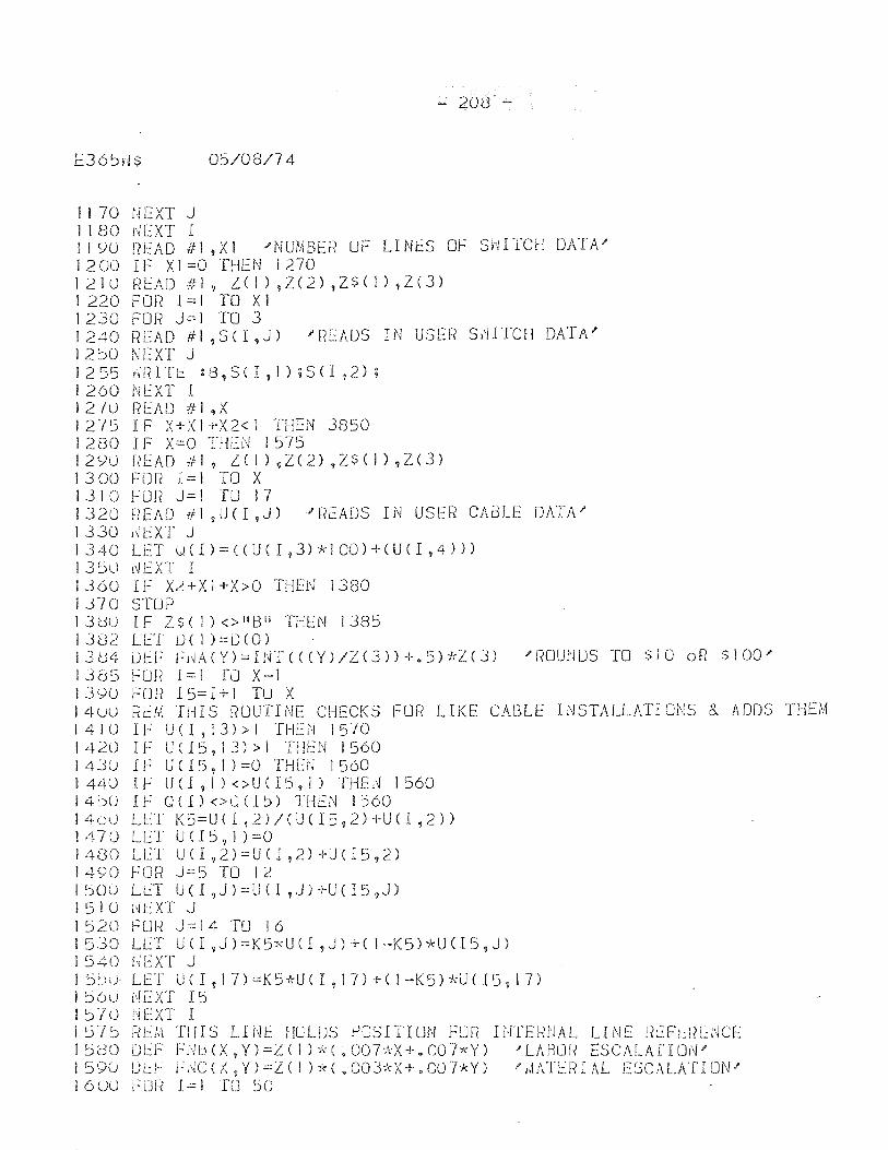
E36:>i4$
1170 nEXT J 1 I 80 1'~EXT I
- 208 -
05/08/74
II YU !(EAD ifl ,XI .?NUMBER UF LINt:S OF Sl1ITCH DATA; 1200 IF Xl=O THEN 1270 1210 ~(EAD Ill, Z(I),Z(2),Z$(I),Z(3) I 220 Fon I = I TO XI 1230 FOR J=:I TO 3 1240 READ #1 ,S( I ,J) ;REAOS IN USl:F? SI'HTCH DATA" 12::S0 NEXT J I 2 55 {m 1 T 1:: : 8 , S <I , I ) ; S <I , 2 ); 1260 NEXT I I 2 70 J? E A D t11, X 1275 IF X+XI +X2< I THEN 3850 I 280 IF X=O THi::N 1575 1290 l?EAD if], l( I) ,Z(2) ,Z$( I) ,Z(3) 1 300 FO [{ I == I TO X 1310 Fon J==J TO 17 1320 READ ill ,lJ( I ,J) 'F?EADS IN USER CAr:3LE DATA" 1330 rH::XT J I 3 4 0 LET u ( I ) == ( ( U ( I 9 3) * 1 00 ) + ( U ( I , 4 ) ) ) 1 3~u t~EXT I 1360 IF X~+XI+X>O THEN 1380 1310 STUP 13UO IF Z$(I)<>I'B~l THEN 13(3:5 I 3 D 2 L l::T lJ ( I ) == [) ( 0 ) 131:34 iJEF Fj~A(Y)==INT«(Y)/Z(3»+.5)irZ(3) ;J10UNUS TO $10 of? $100; 1385 FOr? 1=1 TO X-I 139U FOR 15=1+1 TU X 1400 [(eM THIS RUUTINE CHECKS FOR LIKE CAt~LE I NSTALLATI oNS 8. ADDS THEM I 4 I U IF U ( I , 1 3) > 1 THE ;'~ I 5 -/ 0 142U IF U( 15 1 13) > I THEN 1560 1430 IF U(I5,1):O THEN 1560 I 440 IF U CI 9 I ) < > U ( 15, I) THE i~ I 560 14~0 IF 0(1)<>0(1:» THEN 1560 I 40d LlT K 5=U (l ? 2) / (U (I5 9 2 H-U CI ,2) ) 1 470 LET U ( I 5 , 1 ) =0 1400 U::T UCI,2)=U(I,2)+U(l5,2) J490 FOR J=:5 TO 12 150U LL::T U(l ,J):::UCl ,J)+U<I5,J) 151 0 r~EXT J 1520 FUR J==14 TO 16 1530 LET un ,J)=K5"i,U(I ,J)+( 1-K5)*U<I5,J) 1540 HEXT J I :':hu· LET U( I, 17)=K5,'rU( 1,17) +( 1--K5)')\-U( 15,17) I ~(jU NeXT 15 15iU tJEXT I I fj75 RlM TillS LINE HOLlJS f-iOSIT1UN FOR INTEfHJAL LINE tLFL:!?U~CE r 5dO DL:F F1JtH X, Y) =L ( 1 ) * ( . 007~":X + 000 (xY) ... LM3Ll[< [SCALAr r ON; 159U UL:i-' h,IC(X,Y):::L(1 )*(.003*X+.007*Y) "I,IATEfHAL ESCALATION'" I 6uu ~'UR I::.: 1 TO 50
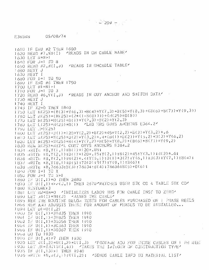
- 209 -
05/08/74
1610 IF END #2 THeN 1680 1620 READ #7,~$(I) ~READS IN OH CABL~ NAME' 1630 Lf:T N=N+ I 1640 ~OR J=i TO 8 1650 READ #2,~(I,J) 'READS IN OHCABLE TABLE' I 660 NL~XT J J610 NEXT I 1680 FOR 1=1 TU 50 1690 IF END #6 TH~N 1750 I 7 00 L L: T N I == N I + I 1710 FUR J=i TO 3 1120 READ #6,YCI,J) ~READS IN GUY ANCHOR AND S~I'rCH DATA' 1130 NEXT J 1 740 [~EXT I_ 174~ IF X2=O THfN 1840 17~O LET H(25)=(B(3)*Y(6,3)+B(4)*Y(7,J)+B(S)*YCS,3)+(JC6)+B(7»*Y(9,3» 1760 LL:T r-J(25)==(H(2S)*(2*(1-BU3) »)+(H(25)*B(8» I Flu LET H(2S)=H(25)+u( I )::;-Y(2,3)+u(2)*Y(2,3) 170u Lt:T L(25)=I-IU5)*D(I) 'LAB HRS GUYS AHCHORS EJ64.2J' 1-1")0 LET d=!1(25) J U Uu L l:. T t;\ ( 2 S ) =!:) ( I ) 7: 1 20 * Y ( 2 , 2) + 13 ( 2 ) -/( 4 S -k Y ( .2 ? 2) +- [) ( 2 ) * Y U ? 2 ) * . 6 I 0 I 0 LL'f iii ( 25) ::: M ( .2 S )-1- L3 ( 2) * Y ( J ,2) * . 4 + ( D ( I ) + lH 2 ) ) * Y ( 5 ? 2) + U ( 3) * Y ( 6 , 2 ) I tl20 U':f fA ( 2 S ) = II\( .2 5 H- 8 ( 4) * Y (7 , 2) + fj ( 5) * Y ( 8 ,2) + ( B ( 6 ) + 8 U ) ) k Y ( 9 , 2 ) 1830 I~U.t iH25)==!I\AT'L COST GUYS A~!CHURS E364.2 1 dJ4 ,1t-HTe g[3, Y( 1,1) ;[:)( 1 )-),120-1<.85; I 83 ~ ii IE Tt. : [3, Y ( 2 , 1 ) ;1:3 ( 1 ) :1<- 1 20*. I 5; Y< 2 , I ) ; 8 ( 2) * 45; Y ( J, I ) ; 13 ( 2) * . 6 ; 1 BJ 6 Ii Ii I TL:. : 8
9 Y ( 3 t I ) i 13 ( 2 ) * . 4; Y ( ~, I ) ; [3 ( 1 ) + B ( 2) ; Y ( 6 , I ) ; J ( 3) ; Y ( 7 9 1 ) ; 8 ( 4) ;
1 83 7 i~ R ITt: : 8, Y ( 8 , I ) ; B ( 5) ; 701 01 ; R ( 7) ; Y ( 9, I ) ; 13 ( 6) ; I d 3 d , l' f n T t: : [3 1 7 66 33 ; B ( 3) ? 7 6634 j 8 ( 4) ; 7 6636 H3C 5 ) + B ( 6) ; 184u FOR 1=1 oro X 185U FOR j=l TU N+I 186U IF U(I,I)=O [HEN 2680 I U'iO IF U (I , 1 ) <> II (J, I) THEN 26-;U / 1,~ArCIlES USEJ? STK CD 8.. TABLE STK CD;> 1 800 Rj~STu RE g 3 1 [3d 1 LL::T d2:::H4=O "IUTIALIZES LABOR HRS FOr? CABU: INS[ TO Zt:f~lJ" I tNU LET j~ $ ( I ) =:,1 $ ( J) , l~A/.\t:S THE CADLE:::' 1 [l")5 Rb'A -nit: ROUTHIE BlLOi'/ TESTS FOFI CABLES PURCHASED UN 1 i--'1!ASE [(EELS I b06 l~t:A1 A!W ADJ USTS THLSE For'? AMOUNT UF PHASES TO BE IfISTALLED. ~ • Id98 LET ul=U{I,2) 1 ~)U,) 1 F U (I 1 1).:::3 I <335 THEN 1910 J 901 Ii: U ( I ? I ) =31025 THEN 1 9! 0 1Y02 If: U(I,I)=.30J56 TH1:N 1910 I YU4 IF U ( I , I ) =30363 THEN 1910 I YU6 IF U ( I ~ 1 ) =30367 T!lEN i ') I 0 1 ':Jud GO TiJ 1930 ! 91 (j IF U( I ~4)=::7 fllEN 1930 1920 LET tJCI f 2)=UCI,2)*UCl,3) "FDOIA0E ADJ FUR ffl OS 1:: CABU:S ON I fJH REb I <).JU LL:T HI = If~ 1'( U CI ? 4) ) "TAKES THt: hITt:GUi OF CCLJSTUJCTI Del TY PE' 1 93') IF U ( I ~ 13) > 1 THEl\! 1940 I <).j 6 \ dd T 1.: ~ U 9 ,/ ( J ? I ) ; U Cl ? 2); -" S E I JDS CAB LEI J.I F 0 TOM A Tl:: rnA L Ll S T ...
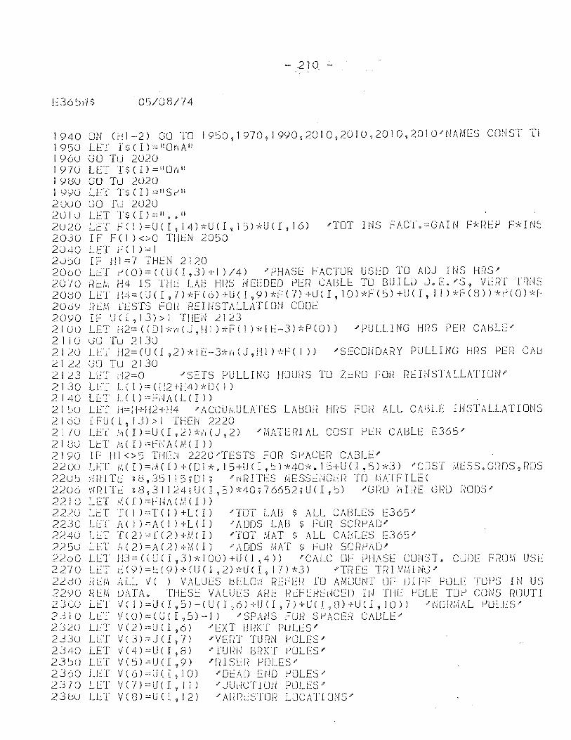
- 210 -
E36~d$ 05/08/74
1940 ON (HI-2) GO TO 19~0,1970,1990t2010,2010,2010,2010'NAM[S CONST Tl 1950 LET TS(l)=IIO¥',AlI I 960 GO TU 2020 1970 LET T$(I)=1I0Vi li
I 90U GO TU 2020 19':JO LET Ts(I)=IISI--I1 20uO GO Tu 2U20 2010 LET '1'$(1)=II •• il 2U20 LET fel )=U(I,14)*U(I,15)*U(I,16) 'TOT INS FACT.=GAIN F*REP F*IN~ 20jO IFF ( 1 ) <>0 THd,>] 2050 2040 LET f(I)=1 20 1jO IF 111=7 THlN 2120 2000 LlT ~(O)=«U(I,3)+1)/4) 'PHASE ~ACTUR USED TO ADJ INS HRS' 20-10 f?cll\ 1-14 IS THE LAB HRS j\!EEDED PL:ft CAUL!:: TU BUILD l).E./S , Vt:fiT lfm~ 2000 L l T 114 = ( U ( I , I ) * F ( 6 ) + U ( I ? <) ) k F ( 7) + LJ ( I , I 0 ) * F ( :» + U C I , I I ) * F C 8 ) ) ~'d) ( 0 ) -],J" 20b>' F?clit n::STS r-:OU REH~STALLATl m.r CDDE 2090 IF Uel,13»1 THEN 212] 2100 LET IQ=«Dl,l;r'ICJ,HI )*F(I )*11:.:-3)*P(0)) "'PULLING Hl{S PE!~ CAbLEI' 2 I lOGO Tu 2130 2120 LLT fI2=(U(I,2)*IE-3-lndJ,Hl)-kF(I» "SECOUOARY PULLING HRS PER CMj 2. I 22 :30 Tu 21 30 2123 LtT d2=0 "SETS PULLING HOURS TO Zr.:RD FOI( 1?1::I!1STALLATI01'.j" 2130 LtT L(1)=(H2+H4)*DC1) 2140 LET LC l)o-::Fl'IACLCI» 21 :..)U LET H==i-l+H2+H4 -"ACCUJ;,ULATES LAGOf~ flf?S FOU ALL CA;3LE IHSTALLATIONS 2 I 6CJ I F:U C I , 13) > I THEN 2220 21~U LET M(I)=UCI,2)*~(J,2) 'MATERIAL COST PER CAGLE E365' 2180 LET MCI)=fNACMCI» 2190 IF HI<>5 THEN 2220'1'I::STS FOR S~ACER CABL0' 22 ou L I:: l' 1/, C I ) = 1.1( I ) -+ ( 0 I *. I 5 -+ U ( I , ~ ) ); /+0 7~. 1 5 + U ( I , 5 Hd ) " C] S T ME S S • G ["( D S , rm S 22u~ dRITl.: :(3,35115;01; 'H~<I1't:S MESSt::dG!.:r~ TO I.\ATF I LI:: ( 2206 WRITE z8,JI124;U(1,5)*40;76652;U(I,S) 'GRD ~IRE GRD RODS' 2210 LE:T i'tiC I )=t':{4A(!v\( I» 22}O LlT T ( 1 ) =1' ( i ) +l C I) ;TOT LAU $ ALL CAbLES [365/ 2230 LET A(1)=AC1)+LCI) "ADDS LAB $ FUR scnf-lAD/ 2240 LET T(2)=r(2)+~(I) 'TOT MAT $ ALL CAblES [365/ 22SU LET" A(2)=A(2)+;V;(1) "ADDS MAT $ FLm SCf~f-IAD/
2200 LET H.3==«UCI,:-3)*100)+UU,4» "CALC DF PHASE cmlSTo CuDE FRlJ.l.l USE 2270 LET i(9):'::t:C9)+(U(I?2)~HJ(I,17)*3) "'1'nEE TRIWHNG" 22dO i?EM ALL V( ) VALUES ~ELO~ REFER TO AMUUNT UF DIFF POLE TOPS IN US 22()O /1 LM UJ\TA. TlllSE VALU t.:s Af-?!:: I? t:FL~l-.(trK;ED I U THE FOLE 1'OrJ CDi\!S R[JUT I 2 J 0U L tT \I ( ! ) = U (l , ::, ) - ( U CI ~ 6 ) + U ( 1 , "{ )-1- U ( I ,[3) + U (1 , I 0 ) ) f NO f? MAL r) U L l S f ?-~10 Lt~T VCO)=(UCI,S)-I) "SPAi'lS FOli SiJACE~~ CAULE" 2J:2U U:T V(2)=U( 1,6) 'EXT URi(T POLt:S'" 2JJu Lt::T V(])=UCI t 7) 'VErn TURN {-JOLES" 2340 LET V(4)=U( I ,S) .... TUIII-I f3RKT rJOLE:S" 23:)U Ll:T V(5):::U(1 ,9) 'f-HSU? POLES" 2360 LET V(6)=U(I,10) "DEAD END POLES" 2310 LET VC-/)=U( I,ll) 'JUHCTIOd PULESI' 230u LET V(S) ::::U(l, 12) 'A!ii(cSTOJ? LOCATIUNS"
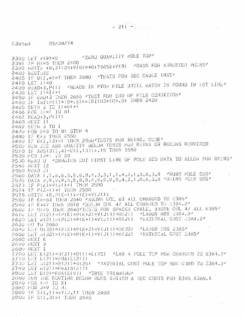
..; 21 I -
E365d$ 05/08/74
2390 lET V (9) =0 "ZiRU QUANTI1Y IJOLE TOP" 239 I I F HI::: 5 TH E N 2400 23';)2 HI?ITt: :o,31124;VU:3)*40;76652;V(8) ;GHDS Fmi Afil~L:STlR POLES""
2400 [~t:STLJRE 2405 IF U(I,4)=7 THEN 2680 'TESTS FOR SEC CAdlE INST" 2410 lET 11=0
IYI"Ofl F"ILE" U" r\'"I~Il J~A1~CfJ IS FOUN]) I!~ Is'r- I.,Ijh'~' ;':420f?l:AD:3,P(I) 'F?EA[)SIN r ,. 1 _;L
2430 lET 11:::11+1 2450 IF E~O:3 THEN 2660 'TEST FOR END UF FILE CONDITION" 2460 n:- Il'ir(~( I )*10+eS)<>INf(113""'"10+.5) THEN 2420 2465 SET~ 3 TO 11*81+1 2466 FOR 11=1 TO 81 2467 [?EAD;3,P(I I) 2463 I~EXT I I 2469 S ETVi 3 TO 1 24-/u FOR K=3 TO 81 STEp 4 2480 IF K>3 TH~N 2550 249U IF U(I,13)=1 THEN 25~O"TESTS FUR REINS. CODE' 250U !<LM THE ADS QUATITY BE LOI"1 TESTS FdF? Ri:~INS OR RECJfJS RL:OUIrIED 2510 IF AUS(UCI,4)-U(I,13»>.15 THEN 2550 2520 ~:Of? 1.2=1 fD 20 2530 ReAD 0 "[)U!kdL~S OUT r-"rr~ST LINE or: POLE SEQ [)ATA TO ALLO,~ FOr~ nEHIS'" 2540 NEXT 12 2 5'.50 f-?EAO J 1 2560 DATA I, I ,6,6,5,5,d,t3,4,3,3, I 91 ,4,2~ 1,0,6,3,8 "NlJfm PULE SLQ'" .257u DATA:J,9'~99,5?5?e,8?4,9,9i9,9,4,2,1 ,0,6,3,8 "1(l:':INS PULE SEQ" 2573 IF pC!()*VeJI)<1 TlIl::N 25BO 25-/4 IF P C< -I ) < I THEN 2580 2!j75 ),lfHTt: :8,PC(-I);f-'(]()*V(Jl); 258U IF K>=63 Tl!t:N 2640 "Al3JVE COL 63 AL.L CHAf?GEO TO [::365" 2=.J'JU IF K<47 THeN 2610 "BEL:JvJ CUL 47 ALL CHARGED TO t364~2' 26UU ll~' HI =~) flkN 2640-'TESTS For? SPACb? CAblE, ABOVE COL 47 ALL L:365; .2 6 I LJ Li...: T r I ( 2 1 ) :.:: ( P C K ) * P ( K -1-.2 ) :I; v ( J 1 » + H (;2 i ) .f LA i3 (J R f-!l? S ::: 3 6 4 • 2 " 2620 U::T 11.(21 ):::(P(KH-:P(j(+1 )*veJI »+i'H21) "'I!,ATEF?IAL ClJST t.:364.2 .... 26J0 l;U Tu 2660 264U L:I tl(22)=(PCK)*PCK+2H,V(JI »+]-1(22) "LAlHJR fms 12365'" c:6~O Lr":T l/l(22):::(f)(K)*PCK+l H:V(JI »+Nl(22) '1,\ATE:JHAL C;JST f:::J65" 2 660 riEXT K 26/U tiEXT J 26Uu rlEXT I 2lGu LET L(21 ):::[!C21 );'<"OC I) +L(25) "'LAB $ POLE TOP HOri CHM«;ED 'TO [364 .. 2" 21: U LLT L(21 )=FNA(L(21» 27JU Li::T ,,1(21 )=.',(2J )+M(25) .... l,1ATE!HAL COST PULE TOP HDYi CHPf) TO [36t1.2 .... 2740 Ll.:T /.,(21 )=Fi~A(M(21» 280U LLT t:(9)=FiHdt.:(9)) "THEE TRIMMIr~G/ 2<:3oU i?U!: idE r?UUTINE BElOiv ODES Stil rCH & RlC COSTS FLJf? E365 &369. I 28/0 ~OR 1=l TO XI 28dO fUR J=9 fU NI 2890 IF SCI,l )<>Y(J,I) 1"Ht:N 2960 290U IF SCI,3»1 THEN 2940
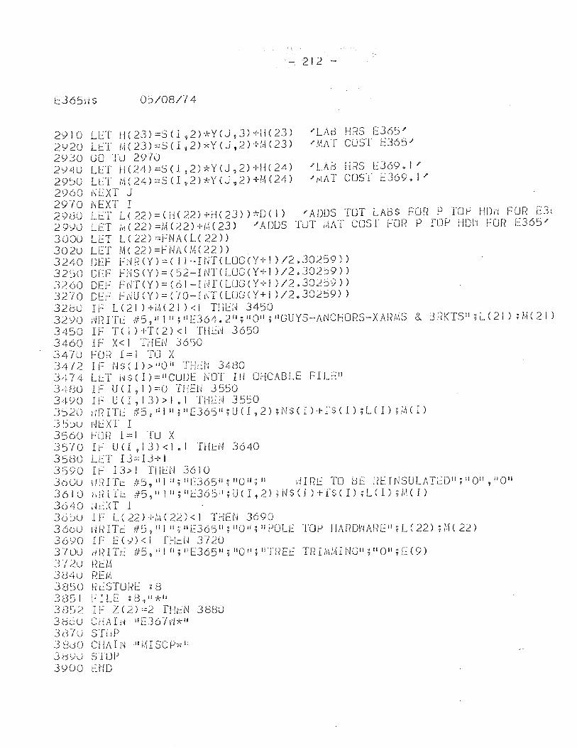
- 212 -
E365ri $ 05/08/74
2910 LET d(23)=SCl,2)*YeJ,3)+!l(23) "LAd HRS 1::365" 2920 LET M(23)=SCI,2)*YeJ,2)+M(23) 'MAT CUST E365" 29]0 GO Tu 297U 294U LET H(24)=SCl!2)*Y(J,2)+H(24) J'LAd HRS i::369.!" 29~O L~T M(24)=SCI,2)*Y(J,2)+M(24) "MAT COST i::369.1' 2960 dEXT J 2970 NEXT I 298U LC:T L( 22)=(H( 22) +[J(23) )'irD( I) 'ADDS TOT LADS FOR P rOJ-! HDH FUR E3( 29')0 LET l,j(22)=!AC22H-i.;(23) "ADDS TuT ),IAT COST FOf{ P rop HDI~ FOr? 1:365' 300U LET L(22)=FNACL(22» 302U LET M(22)=FNA(M(22» 3240 OEF FH[{(Y)=( II-nn(LUG(Y+l )/2.30259» 3250 OfF fNS(Y)=(52-INTCLUG(Y+l )/2.30259» 3260 OEi-: Flfr(Y):::(61-li~r(LUG(Y+1 )/2.30259» 3270 OEF F~U(Y)=(JO-I~T(LUG(Y+I )/2.30259» 3200 IF LC21 )+1:\(21 )<1 TlIU~ 3450 32<)0 ;i!(ITE #5,ilJlli!lE364.211;liOIl;IIGUYS-J\NCHO~{S-XARt,\S & 3t(KTSII;L(21);M(2Il 3450 If T(l)+T(2)<1 THLi~ 3650 3460 IF X<I THEN 3650 3470 FOR l=l TO X 34-/2 IF t,IS(I» oI OII THdi 3480 3474 U::.T l~$(I)=IICUDE NOT IN OHCABLE FILEII 34<30 IF U CI , I ) =0 T!lEi,! 3550 34 C) 0 I I ~ U ( I ? 1 3) > I • I T H b'i 3 5') 0 3') 201m ITt: fJ.::5 9 II ! II ; II E3 6 5 II ; U ( I , 2 ) ; N S ( I ) ;- r $ ( I ) ; L ( I ) ; ;,H I ) 35~u j\jI:.':XT I 3560 ~OR l=lfU X 3510 I~ U(1 ,13)<1.1 THtN 3640 3500 LLT 13=13+1 3590 IF 13>/ THtN 3610 36UO H~nTt: f/5,illti; li 0J65 11 ;IIOii;1I ,'iIRl TO Uf f?f'-:INSULATED!I; IJ OII, II O" 3 6 1 0 Ii ; n Ii.: it 5 ? iI I i I ; II E 3 6 5 II ; U ( I t 2) ; N $ ( I ) '1- T $ ( I ) ; L ( I ) ; /II ( I ) 3640 Ik,;<T 1 36~u IF l(22)+M(22)<1 THEN 3690 360u iWITc #5'111j lI;llE365 11 ;IIOIl;lIPUU: TOf-i HAROY\Af~Ei!;L(22) ;i.\(22) 3690 IF 1::(1)<] fHt:U T/20 3700 ,mITt:: i/:5,Ii!O;IlE365 IJ ;nOJl;nn{Et: TRI!,i::lING",!lO";[(9) J-; 20 3(340 3850 3(351 JE3:J2 380u 38"/U .3 doO 3d\)0 3900
REM f?cSTUKi:: g 8 1"'"ILE :8,11*" IF Z ( 2) =2 fHt':N CHArd IIE36-/,'i*1I STUP ellA It'l II M I SC P'K li STOP t:ND
3880
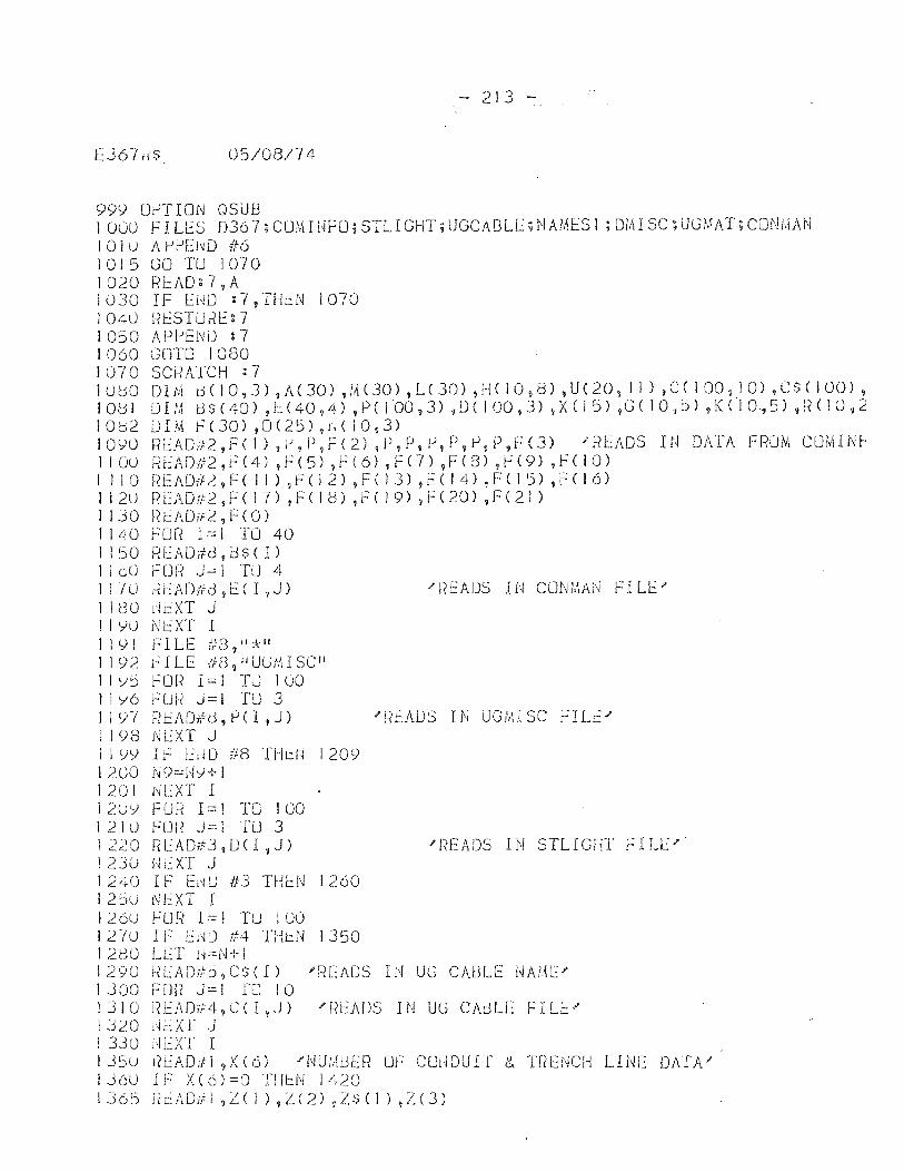
- 213 -
E367,j$ 05/08/74
999 Uf--lTION OSUlJ I 000 FILES 0367; CUM I UFU; STlI GHT; UGCABlE; N AMES I ; DMI SC; UGf.1AT; CONi,IAN 10lu APj-JEl~D #6 1015 GU TU 1070 1020 READ:7,A J030 IF EHO :7,THl.:N 1070 1040 liESTURE: 7 1050 APi-'END :7 1060 GOTO 1080 1070 SCRATCH :7 lObO 0 IN! t.)( 10,3) ,A (30) ,M (30) ,L ( 30) ,H ( i 0,8) 1 U ( 20, J 1 ) ,C ( J 00, I 0) ,C $ ( 1(0) , JOe 1 0 Hi tJ $ ( 40) , f::. ( 40 ,4) , P ( 1 00 , 3) ,D ( I 00 , 3) ,X ( 1 5) ,G ( 1 0 , ::i) ,K ( I 0,5) , t~ ( lOt 2 1082 OIl\-I F(30) ,0(25) ,H( 10,3) 1090 REAO#2,F(J) ,~,P,F(2) 9P!P,P!P,~,P,F(3) 'READS IN DATA FRUM COMIN~ I I (jU REA Oil 2 , r-: ( 4) , F ( 5) , F ( 6) , F ( 7 ) ? F (3) ,F ( 9) ,F ( I 0 ) 1 J I 0 ~{E AO# 2 I F ( I 1 ) ,f ( 1 2) ,F ( 1 3) ,F ( I 4) ! F ( 1 5) ,F ( I 6) I 12u fH::AOfl2 9 F ( 17) 1 F ( 10) ,F ( 19) ,F ( 20) ,F (21 ) 1 ] 3 0 ~{ I:: A 0 if 2 , F ( 0 ) 1140 FOR 1=1 TO 40 1150 REAOJd,l:3S(I) J IoU FUR J~l TU 4 JllO HeADtid,E( I,J) /fiEADS IN CuNMAN r::ru::' J I eo rit:XT J I I YU Nl::XT I I I 9 I F"~ I LE /,'3,01 '* II I 192 J"': I lE ;','(3 ~ Ii UG:.1I SC" I IY~ FOR 1=1 TU 100 lly6 FUi~ J=I TO 3 1191 READdd,PCI,J) 'R~ADS IN UGM1SC FILE' I I <;8 tj l:XT J I J 9Y r F l~dD #8 THt:U 1209 J 200 N9==t-iY+ I 120 I NEXT I 12uy FOR 1==1 TO 100 J 21 u 1220 123U 1240 I 2~u 126U 121u 12(30 1290 1300 1310 1:320 1330 135u 136U IJ65
Fem J::; 1 TO 3 RLAOTtJ,D<I,J) Ui~XT J I F El~U 1f3 THI..::N 1260 NEXT I F LJ R 1:=! TtJ I 00 IF EMu #4 "[HeN 1350 LeI' H=N+I
'liEADS IN STlIGHT FIll""
~EADdj,C$(I) 'READS IN UG CA~lE NAME' FOIf J==i 1'0 10 REAOJ4,C(I,J) 'READS IN UG CAdlE FILE' j~cxr J ikXT I ricAOffl,.X(6) J'NUM13Ef? OF C(JdDUI r c, Tr?ENCH LINE DATA' IF X(6)::::C)n!r.:.N 1420 ! I L~ A 0 if I ~ L ( 1 ) 9 L ( 2) 1 Z s ( I ) ,Z ( 3 )
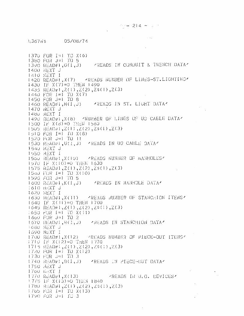
1::367i'i$ 05/08/74
1370 FOR 1=1 T8 X(6) 1380 FOR J=l TO 5
- 214 -
13';)0 !iEAD#J ,GC I ,J) .!'t~EADS IN CUNDUIT & TnENCH DATA ..... 1400 l'llXT J I 4 J 0 "i t:: XT I 1420 nEAD;tI,X(7) ..... READS l~U{'\BER OF LINeS-ST.LIGHTING.!' 143u IF X(7)=0 THEN 1490 1435 f~EADffl1Z( 1) ,L(2) ,Z$( I) ,Z(3) 1440 FOR 1=1 TO X(7) 1450 FOR J=I TO 8 1460 i~EADitl ,H( I ,J) "fiEADS IN ST. LIGHT DATA" 1470 r-JEXT J 14tsu i,j l:XT I 1490 i?EADTfI,XeS) "NUHBEfi OF LHJES OF UG CABLE DATA" 1500 I~ X(d)=O THiiJ 1560 I 5 U 5 f~ E Alj it I ? L ( 1 ) 1 L ( 2) ,L S ( 1 ) ,L ( 3 ) 1510 Fon 1=1 TU xes) 1520 FUR J=I TO II 1530 RlADul ,U(I,J) J'READS IN UG CAUL~ DATA' I 54U lii~XT J 1 ~50 i~EXT I 156U F?EADitl,X(IU) J'READS j'WMUER OF tftArH-IOU':S" J :) -( u I i~ X ( I 0 ) = 0 T l-l E t-! I 630 J 575 lkAD/t I 1 Z ( I ) ,Z ( 2) ,Z $ ( I ) ,Z ( 3) j :JoJ FUf~ 1:::: I TLl X ( 10) 1590 fOR J=I TO 5 1600 READyl ,K(I,J) "READS IN MANHOLE DATAJ' I 6 I 0 lJ tXT J 1620 [H:XT I 16JO i"?EAD#1 ,X( II) 'READS HU,\WEf~ OF STANCHION ITEMSI' I 640 r F x ( I I ) =0 THEN l"{ 00 I 6 4 :i R l:: A Dif I ,L ( 1 ) 1 L ( 2) ,L $ ( I ) t Z ( 3 ) 1650 ~UP 1=1 [0 X( 11) 160U FOR J=! TO 2 1670 UEAUill ,R(I ,J) 'RE:ADS IN STANCHIOU DATA" 16f3u iH:XT J 1690 Nl::XT I 1700 Rl::AD#1,X(!2) "READS NUMBER OF PIECE-OUT ITEMS' 171u I~ X(12)=O TH~N 1770 1 -; 1 i-) t< [ADd 1 ,Z ( 1 ) ? L ( 2) ? L $ ( I ) ? L ( .3) 112U fOR 1=1 TU X(12) I 730 ~UR J=I TO .3 1/40 RL::ADi'f1 ,l3( I ,J) "READS IN PIr~CE-LJUl DATA." 1 750 ,~cXT J 110u Nr..:XT I 1 nu ikAD-ifl ,XC 13) "READS IU U.C. DEVICES'" I TiS If X(13)=() THl2N 11340 17'0U !icADiil ,L( 1) ,i.:.(2) ,LS( J) ,L(3) lib:) ,L.'LJR 1=1 TU X(13) 1 -; yO t":Uf? J::.: I ru 3
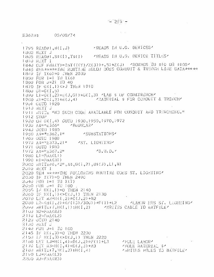
- 21::5 -
E367d$ 05/08/74
17<)':) READffl ,NO ,J) 'Rf::ADS Id U.G. DI.-::VICES" 1 800 NEXT J ld0'J HEAD#l,SS(U;r$(I) )'READS If'J U.G. DEVICE TITLeS" 181Ul~e:XTI 1840 DI.-::f ff'JA(Y)=I~T((Y)/Z(3»+.5)*L(J) "ROUNDS TO $10 UR $100" ld45 PEI.l*",cA+kfrJt:: ;~UUTIliE dELO,i DOt:S CUdDUIT &. Tf~tlJCH Lli~t DATA***** 1849 IF X(6)=O fHI.-::N 2030 185u FUR 1=1 TU X(6) 1 860 FOh' J =21 1'0 40 I '8 -; 0 If G (l , I ) < > J THl.:: N L 9 I 0 I 8(j1j G I =G ( I , 5) IJ9u Ll=GCI,2H,c(J,Gl)*G<I,3) "LAD $ ur: COU&TF?G~CH/ 1900 ,vtl =GCl ,2)*t:(,J ,4) /l,\ATERIAL $ FUR CUi,mUIT &. D{EliCH" 19u1 G01'O 1920 i 910 ;H:XT J I Y II ,mITe 11010 SUCH CODe: AVAILABLE fOli CONDUIT ANO TfLl~CHING.I' 1912 STUP 1920 UN GCI,4) GOrD 1930 , 1950,1970,1972 1930 A$:::!lc.:366 i1 /[{LGULAlil' I 940 0010 1980 19jO A$::: 1I t:362. III /SUBSTATIOt~SJ'
I Y6u (JOTO 1980 I (Ylu 1\$==111::.:373.21 jj J'ST. LIGHTINGJ' 19)1 GO'1'O 1980 1912 J\$=ill::36-1.2 11 1'[3. U. D • .I'
19(:)0 Ll =FHA(L1) 1 990 tell =Fr,A U\ I ) 2 U 00 j'd< ITt: if 6 , II 2 iI 7 A $ , G ( I ,2) ? t3 $ ( J) ,L1 ,M I 2010 NEXT I 2020 REM *x***THE fOLLO~ING ROUTIN~ DUlS ST. LIGHTING~ 2030 IF X(7):::0 TH~N 2490 2u4t.] FlJn 1= I TO X (7) 2U~0 ~UR ~=I [0 100 . 205~ If HCI,I)=O THEN 2140 2060 a: H ( I , I ) < > C (J , I) T H L r ~ 2 I 30 '2.CY/O U_:T AQ==H( I ,2)*C(J ,2) +M2 20;:)0 L2c-(d(l,.2)*(~(13)/300»*F(I)+L2 .ILABUfi HR5 51'0 LIGI!TI1~G/
2u;)u dHITc: (,110,1) ;H( I ,2) J'mUTES CABLE 10 iI'IATFILJ::/ 2 I uiJ M 2 ::: f'; i ~ A ( /.Q ) ? I 10 L2==h~A( L2) 2 1 2U 0 DIll 21 40 2 1 .j 0 lJL:: X f J 2.140 fCJr? J=l ro 100 2145 IF HCI,3)=0 THEN 2230 ",21L:>U If H(J,3)<>O(J,1) THU~ 2220 ?loO LE1' LJ=HCI,4)*n(J,2)*F(I)+L3 2170 LLT /.\J:::!ICI,4Hd)(J,J)+!O 2 1 (30 iliH TL: g 7 9 H ( I , J) ; H ( I ,4) 21':)0 L.3=FHi\(LJ) 2200 ;!tJ::: F [·l A ( 1,13)
J' fJllLE LAUm?.I' .I' POLL /,(A1I:JU AL $" 1'~lf(ITLS HJLlS TJ Ml\TFIU::i'
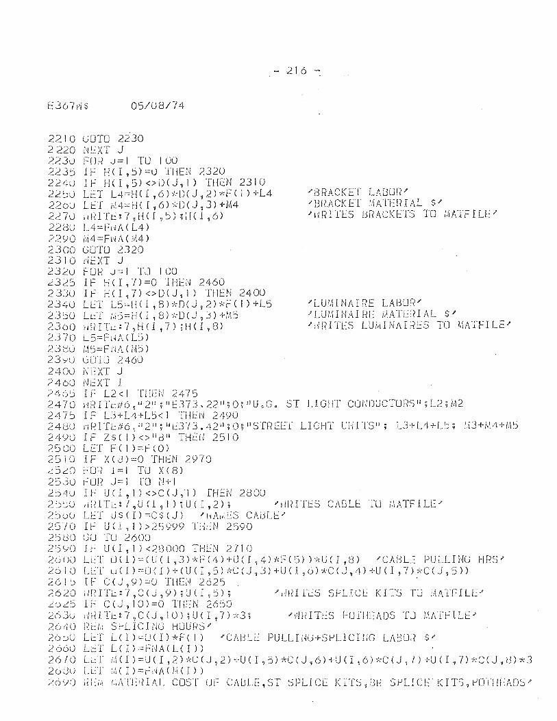
E367d$ 05/08/74
2210 lJOTO 2230 2220 NEXT J 2230 FOR J=l TU 100 2235 IF HCI,5)=O THEN 2320 224U IF HCI,5)<>DeJ,J) THEN 2310 22~0 LET L4=HCI,6)*D(J,2)*F(1)+L4 220u LET M4=HCI,6)*O(J,3)+M4 2270 ! I R 1 Tt::: 7 ,H C I ,5) ; H C I ,6) 22(30 L4=Fl'IACL4) 2290 1;14 = FHA ( ifl4 ) 2300 GOTO 2320 2310 dEXT J 2320 FOR J=I TO 100 ~325 IF HCI,7)=0 "[HEN 2460 2330 l~ HCI,7)<>DCJ,I) THEN 2400 23L~0 LL::T L5=He I ,Sh<-DeJ, 2)*F( I) +L5 2350 L~T M5=Hel,8)*OCJ,3)+M5 2300 ;"mITL::7,H(I,7);HCI,S) 2370 L5=FdACL~» 238u !,15=Fl-IA(W» 23yU GUIU 2460 2400 Ni::XT J 2460 Ni':XT I 246 1j I r: L2< I TIH=:U 2475
- 216 -
"'BRACKET LABm~/ "URACKEf ~ATERIAL $/ "IlRITES BRACKETS TO :,IATFILEI'
... L U 1,\1 N A IRE LA L3 0 f{ .I' J'LUMINAI~E MATE~IAL $/ "1i1~ITES LUi,dNAI~{tS TO /,\ATFILE.I
2470 '"IRITr:d6 ,d2 i1 ? IIE373. 22 11 ;0; IlU.G. ST LIGHT CONDUCTOF?SI' ;L2;M2 247~ IF L3+L4+L5<1 THEN 2490 2480 Yir~ITt:/f6,1I211;11t::373.42il;O;IlST!~EEI LIGHT UHITS'I; LJ+L4+L5; 1,lJ""l-/,{4+M5 2490 IF Z$(I)<>"BII THt:il 2510 2500 LET F(l)=feO) 2510 IF xeJ)=o THl::N 2')70 ~520 ~OR 1=1 TO xes) 2530 0UR J=l [0 N+l 2 :5 4 U I F U U , I ) < > C ( J ,. 1) THE N 28 00 2!.)~() ,iF?ITt::l,UCI,I);UCI,2); "lmrn:s CAlJLi:: ILl j,\ATFILC/ 2',)00 U:T LJ $ ( I) =C $ (J) "HA1'IES C!\iJLi:::'-25/0 I~ U(I,I»25Y99 TH~N 2590 25(30 (3D 'IU 2600 251)0 It" U (I, 1) <2£3000 THEN 2710 2o()O LLT U(I)=(U(I,3)-kF-C4H-UCI,4)i(F(5)b,,"U(I,B) "CAUL":: PULLINU Hf?S? 26 I () LLT u ( 1 ) ;:'U ( I ) + (U ( I ,5) *c (J , J) +U ( I ,0 H:C ( J ,4) +U ( I , 7) -;I,C ( j , ::5 » 261) IF C(J,9)=O THEN 2625 " 2620 ilfnr~:1,CCj?9)iU(I,~); /,i!dfLS 5i.JLICL KITS TLl i,\ATFILLJ' Lo~5 IF C(J,10)=0 1"HEN 2650 26 3U,llH T L:. ~ 7 , C (J , 1 0) ; U ( I , 7) -:d ; J' "ill( I T I.: S HJ r)j LAD S . r J J.~ AT ~ I L E " 2(j40 ik!.: Si-'LICI tJG HOURS" ~:6~0 LeT L(I)=OCI)*FC 1) "CAUU':: PULLIHlJ+S~LICrrIG LAl:30~ $" 2660 Lr:T L(I)=Fi-lACLCI» 2 6 i 0 L l.:.1- lit ( I ) == U ( I I 2 ) -/,C ( J j 2 ) + U C I , 5) k C ( J , 6 ) + U ( I j 6 ) 7, C ( J 1 1 ) + U ( I , 7 ) "f.: C ( J , (3 ) A J 20JU LLT !A(I)=~0A(I~CI»
26')0 ;?Lfii ("ATEiHAL COST UF CAUU:,ST SPLICL KITS,tlH S~LICE" KITS, 1..J[JflILA[)S"
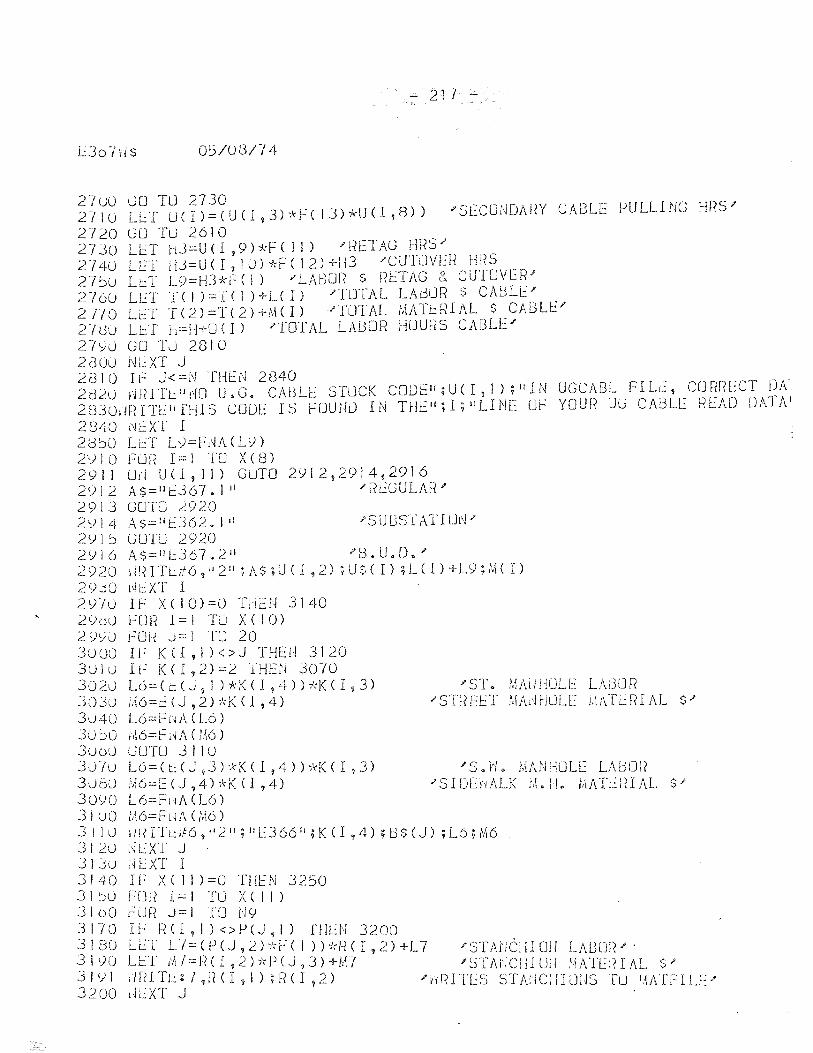
- 217 -
EJohiS 05/0SF/4
27uO GO TO 2730 271U Ll:T U(I)=<U(l,3)-)rf(lJ)*U(I,B» "'StCONDAj~Y CABLE PULLING l-ms'" 2720 GO Tu 2610 2730 LI::T ti3=U ( I ,9) *F ( 1 I ) ,. F?ETAG HRS" 2140 LL:T JU=U ( I , 1 u) -):F ( 12) +113 "'CUTJVER Hf"{S 27':Ju LeT L9=H3*f ( i) "LABUl{ S !fETAG &. CUHJVER/ 276CJ LET '1"( I )=TC 1 )+L( I) "TUTAL lA13UR $ CAfJLE-' 2TI0 LeT 1(2)=T(2)+[-.\(1) "JuTAl t.;ATL:RIAL $ CAfJU~/ 2/dO LE'f h=H+O(I) 'TOTAL LABOR HOURS CABLE' 279U GO 'IU 2810 2euu NL:XT J 2(310 IF J<=N THEN 2840 2820 i'/RITt:: lI dO U.G. CA13Ll:: STUCK CODEII;U(I,I);IIJN UGCABL FILe, CORRECT D1\'. 2830dFCIT[ilfl-llS COUl:: IS HJUN0 IN THtH;I;IILINE O~: YOUf~ JG CABLE READ DATAl
2840 ,\!t::XT I 28~U Li~T L9=hH\ (LI) 2910 FLJR 1=1 TO Xes) 2911 Of! U( 1, II) GuTO 2<)12,2914,2916 2912 A$=1I1::367.1 11 'F~EGULAH'" 291J GOTO 2920 2014 AS=liE362.1 il J'SUBSTATIUd" 2<)15 GUTO 2920 2Y16 A$::::1I1.::36702 11 "S.U.D." 2 <) 20 \ i [n T L:!! 6 , d 2 11 ~ A $ ; U ( I ,2) ; U $ ( 1) ; L ( I ) + L 9 ; !'.{( I ) 2Y.jO i~l:XT I 2')'/u II--' X( 10)=0 1'dE:N 3140 290U I--'UR 1=1 TJ X(10) 2y,:/u FLJf"l: J==l TLJ 20 3UDO IF K(I, 1 )<>J 1'HEi,1 3120 3UJu IF )«1,2)=2 THEt'J 3070 302u L6=Ce(J'jI)*K(I,4»*KCI,3) /ST~ r.ji\uHULE LABOR 30JU ;,16=t::(J,2)*K<1,4) "'STf?E:L::T !·.I/U'IHULE 1.1ATlrHAL $/ 3040 L6=-Fw\(L6) 30')0 3uou 30"/u 30GU 3Q')0 3!uo 311 U 312U 313u 3140 31 ~)u 3100 3170 3180 3190 311)] 3200
1I\6=FHA (M6) l.i01'U 3 J 1 U L6=(~(J,3)*K(I,4»*K(I,3) :'.{6:..::E (J ,4H-K (1,4) L6=Fw\ (L6) t"l6=FHA (i,j6)
"'S.ltl. MANHOLl": L\UOr? "S I Dlru\LK ;il. H. ::\/\1'1.:: lH AL $'"
,i!( I TLA6 , d 2 II ; II E 366 II ; K C I ,4) ; t:l $ (.J) ; L6 ; M6 l'iLXT J "Ji:.:XT I IF XC 1 J )=0 THEN 3250 FUl? 1 =- I TU X ( I 1 ) FUH J=l 1'0 1'19 I F F~ ( 1 , 1 ) < > P (J , 1) TrIU·) J 2 00 LET L/=(peJ,2)*FCI »*RCI 2)+L7 L 1.:: T dl I:::: [-( ( I , 2 ) j, P ( J ? 3 ) + M 7 ' ill( ITt:: 1 ,Ii ( I ? I ) ; F? ( I . 2 )
'" 51' M·letl I Ull LA13[J[~ '" .
','v-r J ' !-lCl\l
"'~)TMiCHI (]i·j !,~ATl:? I AL $" "HI~ITlS STAr·jCifIU:·IS Tu !,~/dTILEJ'
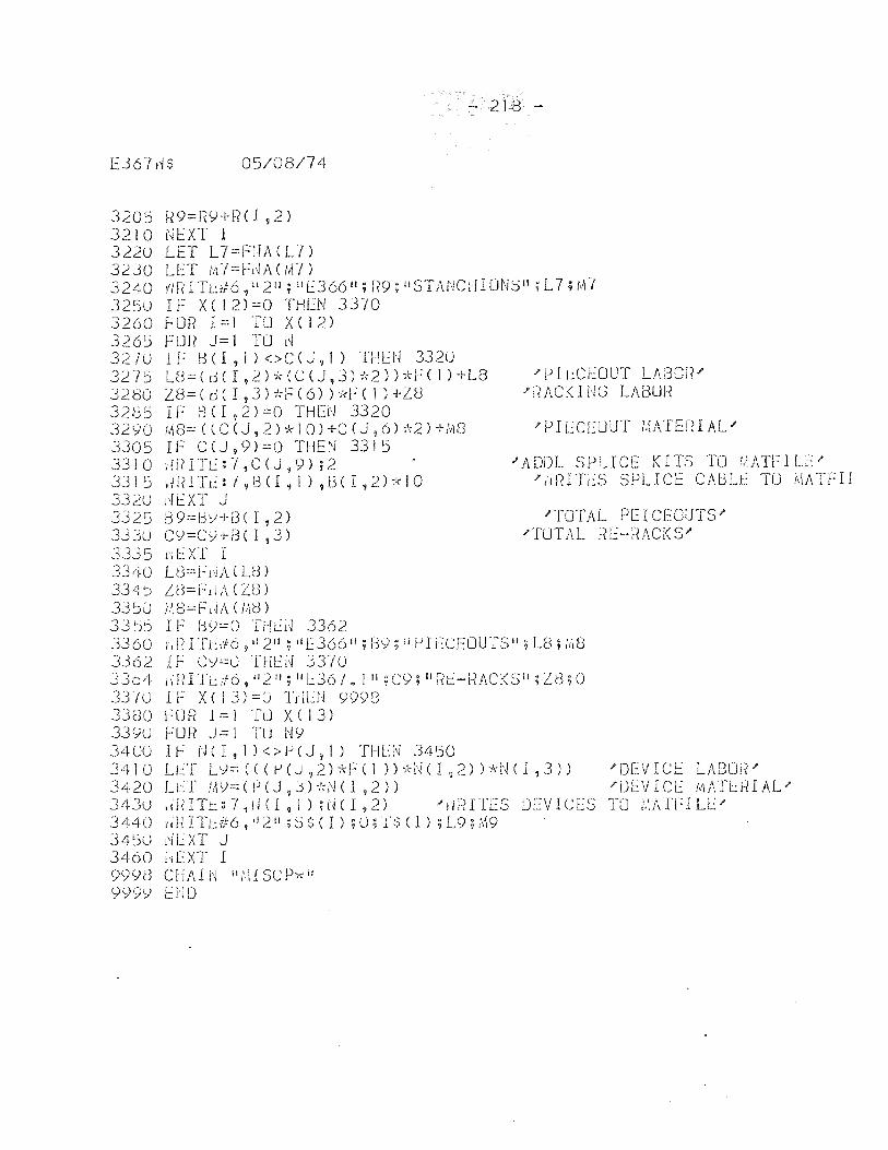
E367dS 05/08/74
3205 R9=RY+RCI,2) 3210 NEXT I 3220 LET L7=fr·IACL7) 3230 LET MJ=f~A(M7)
- 21B -
3240 riRITt::f6,li211;iIE366";R9;ilSTANCHIONSIl;L7;1'17 3250 If X(12)=0 THEN 33JO 3260 fOR 1=1 TO X(12) 3265 FOR J=1 TO N 3210 IF l3 (I 1 I ) <>C (J, I) THl::N 3320 327ij LC3=(dCI,2)x(C(J,3)*2»*FCI)+L8 "PIL:CEOUT LAr30[(1' 3280 Z8=(dCI,3)*F(6»*F(1)+Z8 "RACKING LABUR 3285 IF 8(1,2)=0 THEN 3320 3290 M8=«CeJ,2)*10)+C(J,6)*2)+M8 'PIECEUUT MATERIAL' 3305 IF CeJ,9)=0 TIlEN 3315 3310 ;lRITE:-I,CeJ,9);2 "ADDL SPLICE KITS TO J,\ATFIL[" 3315 IlidTL::7,8(I~1)?t3(I,2)7(10 ",d{ITL::S SPLICe CAGLE TO MATFIJ 3320 I~ EXT J 3325 89=BY+BCI,2) "T01~L PEICEOJTS" 333U CY=CY+BCI,3) "TUTAL HE-RACKS' J3j5 dlXT I 3J4U U3=Fj\jJ\.(U3) 334') LU=flU\C D3) 33~(j j',{8=F'd;\(t/J:3) 33 ~h If HiJ:::O Tl-!L:i'~ 3362 3360 id~ I Tt::d6 7 II 211; 11[366 11 ; By; i11JI lCEOUTSll; La; ;':i8
3362 IF Cy=0 Tl!U·[ 3370 J 3 0 4 i W I Tc if 6 ? iI 2 II ; II L 3 6 7 • I II ; C Y ; II r~ t:: - R A C K S II ; D3 ; 0 3370 1 r X ( 13) ==() TdlN 9998 33UO HJR 1 = I TLJ X e I 3) 3390 fUR J=l TU N9 3400 lb N(I,l)<>peJ,I) THLN 3450 Jl1-10 U:T L)=«(l-'(J?2)~~F(1 »:ki\i(I?2»*1'~(1,3» "DEVIC!::: LAf301~' 3420 Li:T J:lC):.::(f)(J ~.::n-!:NCI ,2» "DL:.VICL iliAfL:!-HAL-' 343u ,iidTt:::7,iHI 9 1);rHI,2) 'rlrnTES UEVICES TO ,\'iAITlLL' 3 440 ,;!H T t: if: 6 1 II ~ II ; ~ $ ( I ) ; () ; r $ (l ) ; L 9 P\ 9 3450 dLXT J 3'[60 NEXT I 9998 CHAl N II i.U SC px II 9<)9Y Elm
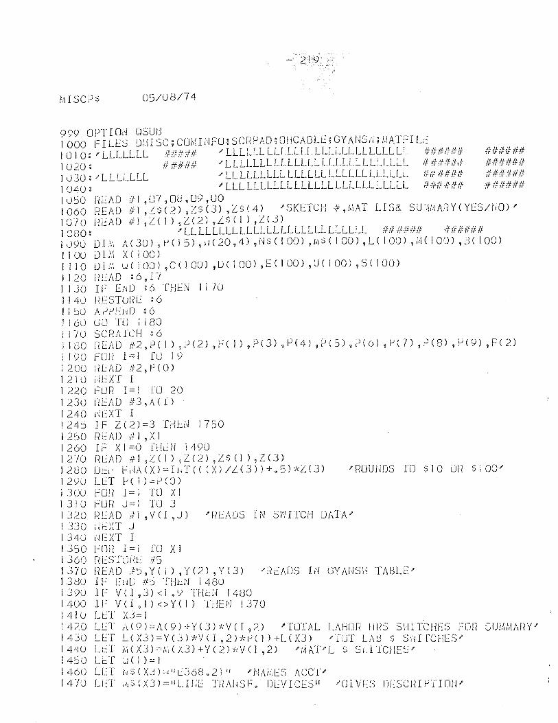
- 219 ~
MISCPS 05/08/74
999 OPT I o!~ OSUJ3 1000 FILES DIHSC;CUMhIFU;SCr"(PAD;mlCAt3U':;GYAr~S,i;MATFILE 1010~'LLLLLLL ##### 'LLLLLLLLLLLLLLLLLLLLLLLLLLL if##### #U#U## I U 20: If #4## "" L LLLLLL LLLLLLL LLLLLL LLLLLLL if #/f/h'f,f: ###:/NNf lu30='LLLLLLL ""LLLLLLLLLLLLLLLLLLLLLLLLLLL ###### H##i## IU40: 'LLLLLLLLLLLLLLLLLLLLLLLLLLL ###### ######
IU~O READ #1 ,07,OU,09,UO 1060 r~EAD ill ,L$(2) ,ZS(3) ,ZS(4) . "SKETCH 7't,i,IAT LIS& SU',j,'J,AnY(YEs/tJO);' 1070 i?EAD ill ,Z(!) ,Z(2) ,i$ (I) ,Z(3) 1080: 'LLLLLLLLLLLLLLLLLLLLLLLLLLL ###### #OCO#O 1 090 D I i:1 A ( 30) ? 1-) ( I 5) 9 i J ( 20 , 4) ,i,j $ ( 1 00) ,i1\ $ ( I 00) ,L ( I 00) ,i"i ( IOU) , n ( I 00) I 1 00 i) 1,\\ X ( 100) J 1 IOU 1;.'1 U ( I 0:) ,C ( I 00) ,D ( 1 00) , E ( I 00) ,U ( 1 00) ,S ( I 00) I 1 20 f~ t::AD : 6 , I -/ I 130 I F tHO : 6 THiN I I 70 1 I 40 i~ESTUl-~E : 6 Il~OAf-lr)EHD:6
1 I 60 GO TU 1 1 80 I J 70 scr~Al'CH : 6 J 180 j:n:AD tf2,P( 1) ,P(2) ,FC I) ,P(3) ,P(4) ,P(5) ,P(6) ,1.)(7) ,~(8) ,/.J(9) ,F(2) 1190 r=-:UE 1:::1 [LJ 19 1200 j(L:AD fi2, P (0) 1210 NEXT I 1220 fOR 1=1 [0 20 I 230 F?EAlJ if3? A <I ) 1240 I'Jt::XT I 124~ IF Z(2)=3 THL~ 1750 1250 fiEAD if! ? XI 1260 IF Xl=O fHcN 1490 12-/0 r~L:AD #:1 ,i.e 1) ,Z(2) ,Z$ (1) ,Z(3) 1280 DU' t-'l,iA(X)=Ild"« (X)IL(3»+@5)*Z(3) "'POUUDS TO S10 UI( S100/ 129U LL:T ~Cl)=P(O) I 3 UU F CJ l? I == I T [) X I 1310 FUR J=1 TO 3 1320 ~{[AD ttl tV<I ,J) "'F?EADS IN SI'HTCH Df,TA" 1330 ikXT J 134U (~EXT I 1 3') 0 F m? I == I ffJ X I 1 360 r{lSTUf~t: #5 1310 nEAD }':),Y( 1) ,Y(2) ,Y(3) -"READS IN GYANSI'i TABLE-" 131:30 IF [HL) if'j THt:N 1480 1390 IF V( 1,3) <I.Y THeN 1480 1400 IF VCI?l)<>Y(I) HJEN 1370 l4lu LlT X3=1 1420 LET Jd9)=J\C9H-Y(3)*VCI ,2) "TLJTAL LASUf{ lms SHITCHE:S FrJR SUMMM?Y-" 1430 U~T L(X3)=YeJ)j;V(l,2)-;!;i.JelH-L(X3) "'TUT LAU $ SHIfCHES" 14'+U LLT A\(X3)=;,1(X3)+Y(2)*VCI,2) '[i!i\T'L $ SldTCJIES" 14~0 U::T u( l)=.::) 1460 LET 1~$(XJ):c::IIL:J68~21 II PNAIi.1~S ACCl" lLUO LL:T ,11$(X3)=IILHlt TPA1~SF. DL:VICESII "GIVf:S DLSCJHt)'rIfJ!P
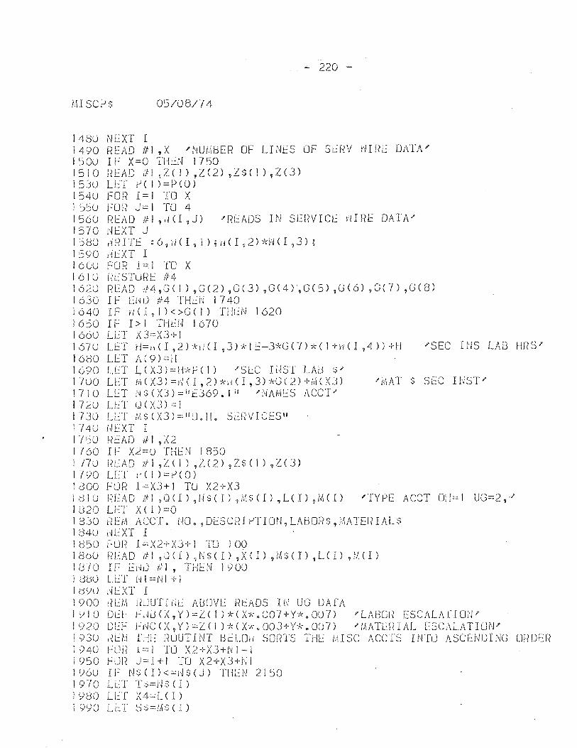
- 220 -
!H SCP$ 05/08/74
148U NEXT I J490 READ #1 ,X 'NU~BER OF LINES OF SERV NIRE DAfA' 150U IF X=O TI-kN 1750 1510 HEAD If1~Z(I),Z(2),Z$(I),Z(3) 1530 LET P(I)=P(O) 1540 FOR 1=1 TO X I 5~u FOR J=I TO 4 1560 r~EAD ill ,li<I ,J) .J'F{l.:::ADS IN SE~?VICE ~nRE DATA" 1570 dEXT J I Lj80 ln~ 1 Tf : 6 ~ ii ( I , 1 ) ; 11 ( I ,2) *:-1 ( I ,3) ; 1590 lifXT I 160U FOR 1=1 TO X 1610 Rt-:STUl?E 114 1620 READ rf4,G( I) ,G(2) ,G(3) ,G(4),G(5) ,C(6) ,G(7) ,G(8) 1630 1 f EHU 114 'fHEN 1740 1640 I F II ( I , I ) < >G ( I) THt.::N 1620 £650 IF 1>1 THEU 1670 1660 LLT X3=X3+1 167u L[T rl==,dl,2)*IICl,3)*IE-37<G(7)*(1+/dI,4»+H 'SEC I:'IS LAB }-If(S' 1680 LET A(9)=}! 1690 LET L(X3)==H*P(!) "SeC rUST LAD ~/ I 7 u 0 LET M ( X 3 ) == i'~ ( I , 2 ) 'k ii ( 1 , 3 ) ,'<-0 ( 2 ) -I- i,\ ( X J ) .... [1\ AT $ SEC INS T ;" 1710 LLT Hs(X3)=llfJ69.liI 'NAMES 1\CeT" 172u LET U(X3)=1 1730 LLT t!t$(X3)="U.H. S[RVICES" 174U ULXT 1 1'/50 j,?t.:AD #1,X2 1760 If X~==O THEN 1850 1 T7'J [{E;\D 1tl ,Z( 1) ,Z(2) ,Z$(!) ,Z(3) 1 790 LET i' ( 1 ):::: P ( 0 ) laoo FUR 1=XJ+1 Tu X2+X3 I (3 J U r~ E /" D /f. I ,Q CI ) ,U $ ( I ) i /,\ $ ( I ) ,L ( r ) ,(vi ( I ) J' TY PEA CC T 0;-1 == 1 U C = 2 ,-/ 1U20 Lf::T X(I)=O 1830 REM ACCT. NO.,DESCRI~TION.LABOR$,~ATERIALS 184U HEXT I 1050 FUR I ::.:X2+ X3+ I TO 100 I 80u fi EA D ill , ,) ( I ) ,N $ ( 1 ) ,X ( I ) ,M $ ( 1 ) ,L ( I ) ,i;\( I ) 1[,310 IF [i'll) til, THEN 1900 1 di.ju U'::T N 1 ==N I + 1 I d<JO j,jl.:::XT I 1900 [{EM l?UUTI UE ABCJVE ntADS r!~ UG [)AfA 1')10 [)1':1' r-:dd(X,Y)=L::( I )*(X*.007+Y:k.OO'l) "'LA130It [SCALArIDt'.I? 1920 DL:F h\JCC<,Y)=Z(1 )-k(X'*.003+Y'*.OO7) J'lfIATL:!<IAL ESC;\LATIUN' 1 93u t~U,1 fdi':: FWUT I NT BELOil sorrrs TIlL bd SC Accrs I NTLl ASCEND INC mWLR 1940 FUii 1=! TO X2+X3+N 1-1 1950 j--'un J==I+l TO X2+X3+J'-,il 196U IF N$(I)<=j~$(J) TilEN 2,1:>0 1910 LET T~=NS(I) 1980 LeI X4=LCI) 1990 LlT ~~=MS(I)
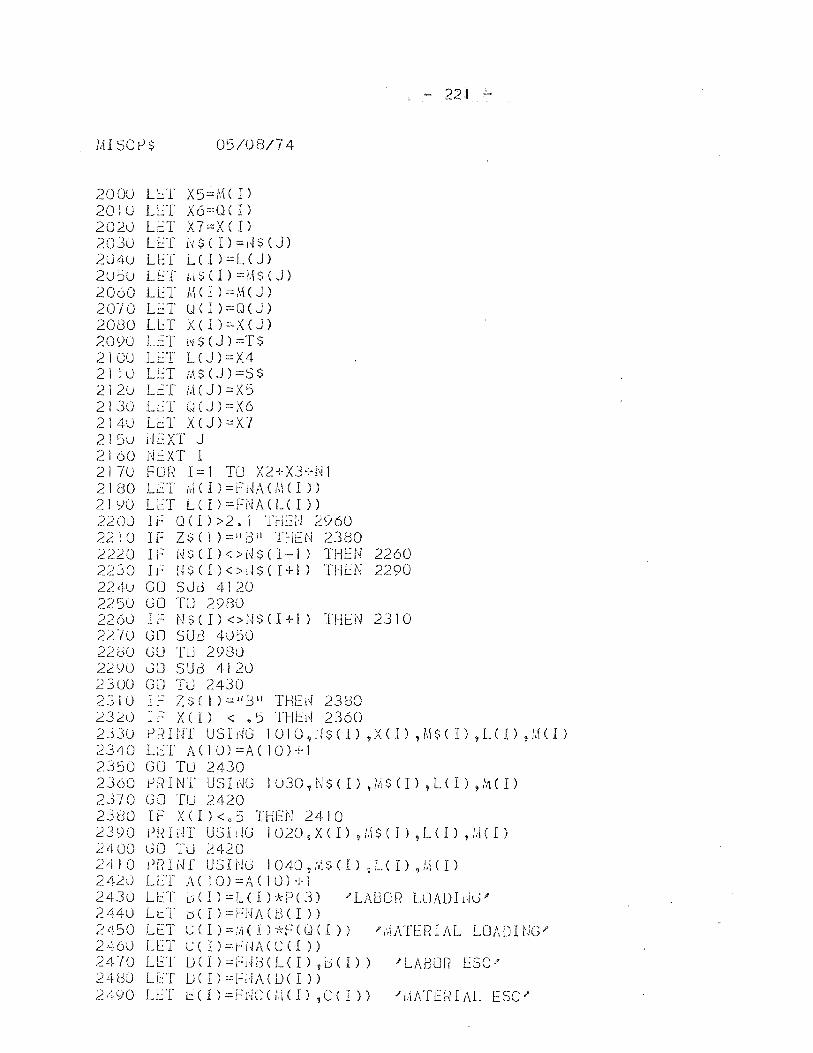
!:II SCt-l$ 05/08/74
2000 U.:T X 5;';'.1 ( I) 201 U LET )(6=0 ( 1) 202U LET X 7=X ( 1) 2030 LET 1~$(I)=l~$(J) 204U LET LCI)=L(J) 2U:)u LET hl~(l)=H$(J) 2060 LET MCI)=M(J) 2010 LET u(I)=OeJ) 2080 LlT X(I)=X(J) 2090 LET ~S(J)=T$ 2100 Lt:T L(J):.::X4 21 lU LET MS(J)=S$ 212u LET i:\CJ)=X5 2130 LET UeJ)=X6 2140 LET X(J)=X7 215u rlL::XT J 2160 NEXT I 2170 FOR 1=1 TO X2+X3+Nl 2180 LET h(CI)=FI4A(I\\CI» 21YU LET LCI)=FNACLCI» 2200 Ii·: OCl»2.1 'ffiGJ 2960 2210 IF ZSCI ):.::ll}:3 t1 THEN 2380 2220 IF NSCI)<>NS(I-I) THEN 2260 2230 U: H $ CI ) < > 11 $ CI -}- I) THLN 2290 224u GO SUd 4120 2250 GO TU 2980 2260 IF NSCI)<>i~$(I+l) THEN 2310 2270 GO SUd 4J50 22dO GO TU 2980 22YO CO SUd 4120 2300 GO TLJ 2430 2310 IF ZSCI)::,::"3!1 THEd 2380 L320 IF XCI) < 45 THb~ 2360
- 221 -
;~J3u f)rHUr USldG 1010,11$( 1) ,X( 1) ,M$( 1) ,L( I) ,M( 1)
2340 LEI ACIO)=ACIO)+1 2350 GO TLJ 2430 2360 l.J~?INT USIl'JG lU30 1 i'JS(l) ,IllS (I) ,lCl) ,,\1(I)
2370 GO TU 2420 2380 IF X(I)<.5 THEN 2410 2390 PlnllT USI!JG 1020 9 X(I),I.\$(I),LCI),!HI) 2400 liD T0 2420 24 I 0 rJ f? Ii ~ r US U I G I 040 , [,1:;; ( r ) ,1-( I ) ,,1,\ ( I ) 2420 LLf AC 10)=A(IO)+1 2430 LET lJ(J) :::LU Hd.J( 3) "LAbon LUADlijG)' 2440 LtT bCI)=FNACbCI» 2450 LET c(I)=~(I)*F(Q(I» )'~ATERIAL LOADING' 2460 L[1 c( I)=r;;,Ji\CCCI» 2470 U::T 1)(I)==r-:[~i3(L(I) ,0(1» )'LABOl~ ESC' 2 4 00 LET lJ ( I ) :.:: F il A ( 1) ( I ) ) 2490 LET l:(I)=Fr·IC(l.\(I),C(I» "J.\ATEf~IAL ESC"
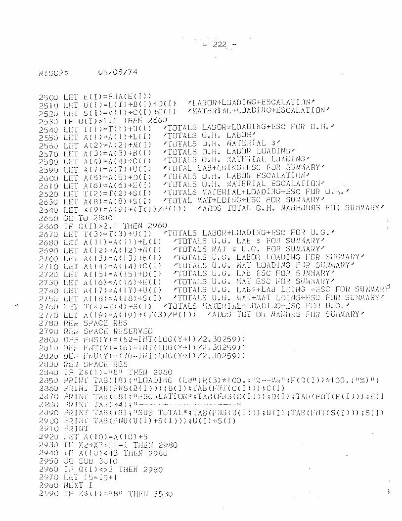
- 222, -
I·HSCP$ 05/08/74
2500 LET ~(I)=FNA(ECI» 2510 LET U(I)=L(I)+BCI)+D(I) 'LAUOR+LUADIrjG+lSCALATI~N' 2520 LET SCI)=JACI)+C(I)+E(I) )'i,(ATElnJ\L'r-LLJADHjG+LSCAL;\TIOI'~' 2030 IF (1(1»1.1 THEN 2660 2540 LET f(1):=TC1)+LJeI) 'TOTALS LABOR+LOADING+LSC FOi? O.H.' 2550 LET A C 1 ) =A ( 1 ) +L( I) ?TOTALS U. Ii. LM3CJf?' 2560 LET A(2)=AC2)+MCI) ?TUIALS J.H. MATERIAL $' 2570 LET A(3)=AC3H-SCl) rnJTALS O.H. LA13Ur? LOADING)' 2580 LC:T A(4)=A(4)+C(I) 'TOTALS D.H. i',IATElHAL LUADING.!' 2590 LET A(7)=Ae7)+U(I) )'TOTAL LAG+lul~G+ESC FOR SUM~ARY' 2600 LET A(5)=A(5)+DCI) ?[OTAlS O.ri. LABOR ESCALATIUJ)' 2610 LET A(6)=1')'(6)+[0) ""{JTALS O.H. r,lATERIAL f::SCALAfIOiF , 2620 LET T(2)=1'C2)+S(I) ?TUTALS 1,[ArEl~lAL+LOADI1~G+ESC rOR U.H.' 2630 LET A(3)=A(8)+S(l) 'TOTAL MAT+LDIUG+ESC FOr? SU:,\,IMN" 2640 LET A(9)=}\(9)+eT( I )/r!( 1» )'ADDS rUTAL U.H. !:IAUHJURS FUr? SUfLI.\AF?Y'"
2650 GO TLJ 2800 2660 IF 0(I»2.i THEN 2960 2670 LET T(3)=T(3)+U(I) "TOTALS LA!)Oi~+LOADIlm+ESC FOi'{ U.G." 2680 LC:T A(JI):::.ACll)+L(l) )'TOTALS U"G. LAb $ FOt( SUr,I,IJ\i?Y' 2690 LET A( 12)=A( 12) HI( I) "TOTALS MAT $ U.G. FOR SUIJi\ARY.I 2100 Li:..:'l' A( 13)=A( 13)+tH1) "TUfALS U.G. LABor? LOADING For? SU;',\II.\A!W" 2110 LET A ( 14) =A ( 14) +C ( I ) "'TOTALS U a G. MAT LOADI i~G F J[1 SU ;,{I,\Ai"(Y" 2'1'2.0 U:'f /\(15)=A(15)+))(I) )'TOTALS U.G. LAU ESC f:OR SIHIMM<Y)' 2730 LET A(16)=)"(16)+1:::(1) -'TOTALS U.G. /;\AT ESC FOR SdHi'.I!\!~Y/ . 2740 LET A(17)=A(I])+U(I) 'TOTALS U.G. LA8$+LA13 LDING +ESC FOR SUMMAR~ 2700 LET Ae 18)=A(18)+S(I) )'TOTALS U.G. MAT+~AT LD1NG+ESC FOR SUMMARY' 2760 LeT ]"(4)=T(4)+S(1) -'TOTALS !.1ATEHIAL+LOADliIG+ESC j:"'lJf( U.G.)' 2TI0 LET A(19)=A(19H-CT(3)/P(J» 'ADuS TOT 0[1 iAAUlms HJI? SU1.liAi\[(Y)' 27<:30 I?Ei'J\ SPACE RES 2790 ~?Eld SIJACc riESERVED 280U Dt2F t;iIS(Y):::(~2-HIT(LOG(Y+l )/2.30259)) 2dl0 ULF hH('()=(c)i-INTCLUG(Y+l )/2.30259» 282U uu: FliU(Y)=UO~-IHT(LUG(Y+l )/2.30259» 2830 R~;~ S~ACE RES 21340 IF 2s( 1 )=11/311 THEU 2900 2d50 PRHIl TAE:3CIg);IIUJADING (Udll;P.(3)*100.;II~~_-,~/\(~iI;F(t)(I»*100.;II%)iI;
2360 PfHNl TA.BCFNS(E3CI»);i:H 1) ;TA!JeFUf(C( I») ;e(l) 2010 P!1If'JT TAd (18); IIESCALATIm·)11 ;TA1.:3(FHS(D( I») ;D( I) ;TA/JeFfJT(E( I») ;L:( I ;.: BdG pn 1 NT TAd ( 44) ; Ii ~-~--- ------- ________ 11
2<.NO P!UNT TAI3(18);IISU1.:3 TuTAl'I;TABCFd::5(U(I));U(I) ;TM3(FUTCS(I») ;S(I) 2 SJ 00 p ru i H T M3 ( i f W ( U ( I) + S ( I ) ) ) ; U (I ) + S ( 1) 2')\ 0 PRI!n 2920 LET A(10)=A(10)+5 2930 IF X~+X3+NI=1 THL::N 29(30 2~40 IF AeI0)<45 THEN 2980 2950 GfJ SUB 3UI0 2960 IF 0(1)<>3 THEN 2980 2970 Lt~T 15;;:;:I5+1 2900 NlXT I 2 eN 0 I F Z $ ( ! ) := II B II T I ! L:: l~ 3 5:3 0
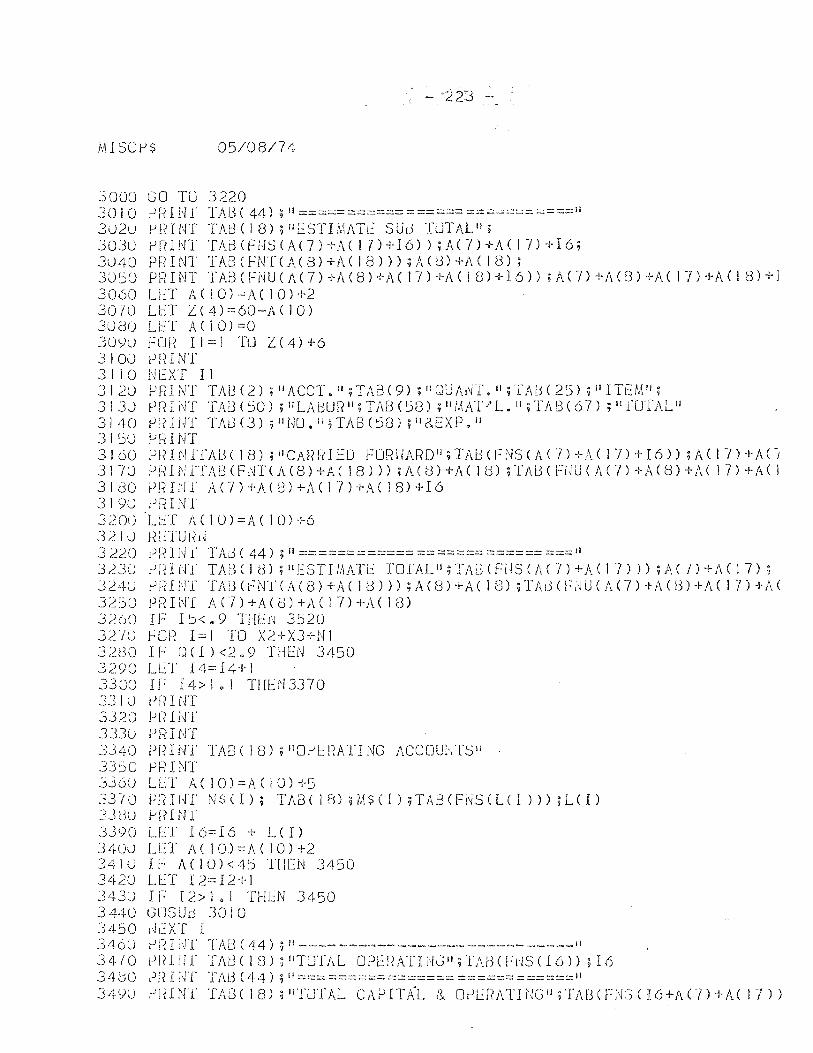
- 223 -
r.ll SC tiS 05/0S/74
3000 GO TU 3220 30 10 j·)R I H r TAB C 44) ; i! :::::::::::::::::: ::::=:::::::::::::::: :::===:::::::: ::::0-=::::=::::::::= ::::===11 3020 l.Jt?UH TAt3(18);IIi.::STHIATr.:: SUd TlJTALiI; 30Ju P[?lNT TAi:3CFHSCA(7)+A(17)+I6»;AC/)+ACI7)+I6; 3040 PRIN1' TABCFNTCA(S)+AC1B»);AeJ)+ACIS); 3050 PFHNT 'i'Ai:3(FNUCAC7)+ACS)+A( 17)+A( 1 8)+16» ;A(7)+ACO)+A( 17H·A( 18)+] 3060 LET )\(10)=)\CIO)+2 3070 L~T Z(4)::::60-AC10) 3080 LET /l.CIO)=O 30<)0 FOI? 11::::1 TO Z(4)+6 310U prHNT 3110 NEXT I I 3120 PRINT TABU) ;HACCT.";TAB(9) ;tlQUA1~T.II;TAB(25) ;i'ITl::M"; 3130 j.JfHNT TAi3(SO) ;IlLADUF?II;TAU(:::;(3) ;lIl,~AT/L.jl;TAI3(67) ;llfUTALII 31/~0 P~?INT TAl3(j);1l1,ll).II,TABC58);1I8..EXP.1I J 1 50 jJ~1 NT 3160 PR1NTfAl:3(IS);"CMHIIELJ FOF?I'IARD il ;TA!:HFNSCA(7)+ACI7)+I6»;A(17)+j\C-j 3170 PRINTTAI3(F,'H(A(S)+A( 18») ;A(8)+A( IS) ;TAl3(FUUCAC7)+A(S)+AC 17)+AC I 3180 PRINT A(7)+A(S)+ACI7)+ACIS)+I6 3190 rJfHNT 3200 L~T A(10)=ACIO)+6 3210 HL:TUI~d 3220 Pi;: I i~f TAG ( 44) ; II ============ =::::::::::::::::=::: ====::::= :::::::::11 3~3() tlrnUT TAJ3(1(3) ;1I1:::STIMATt: TOTAL'!;TAL3CFiiSC!d7)+ACI7») ;A(7)+A(17); 324U I')l~li.j'f TAl3(l-=N'f(A(S)+A( 18») ;A(S)+A( 1m ;TAr3(HJUCA(7)+/\U3)+A( 17)+/\.( 3250 PRIN'[ A(7)+A(8)+A(17)+ACI8) 3260 I F I ~< • 9 THt::J'~ 3520 32'/0 FOR 1=1 TO X2+X3+NI J~80 IF 0 (1) <2.9 Tl-JL:N 3450 3290 LeT 14=14+1 3300 IF r 4> I 0 1 TlIH! 3370 33 l:j IJI{ I i'H 3320 jJr{l NT 333u Pf-?INT 3340 Pl~INi' TA8(IS),flO~E!~ATING ACCOU1-rrS II
33::)0 Hi INT 3360 LLf A(10)=AC1O)+5 3T/O PiHHT N~;(I); TAB(18);M$(1);TAB(Fi~S(L(1»));L(I) 33uo )-1[(11<11' 3390 lLT 16:::16 + L(I) 3 -40u LET j\ ( 1 0) = A ( 1 0 ) + 2 3410 IF ;\(10)<4:::; THEN 3450 3420 LET I2::::12+1 3430 IF 12>1.1 THLN 3450 3440 GUSUd 30 10 3450 Ih:XT I 3400 tI I? I lfl' TAG C 44) :; II ---- --.---- ~ __ ~~ __ ~ ---,--- -_----11 34/0 j-)I?IiJr T/\B(IS);"TOTAL OP1':RATI>!JII;lMHFrJSCI6»;I6 3400 Pf( I l~'r TAd (44) ; II ==:::: ::::::::::::c::=:::: ::~::::::;::=:::::::::: ::::::::::::::::::::::::: ::::=:::::::::::: II ]itSll) !-'IHNl' TAS(IS);Jl'fUTAL CAPITAL l~ OIJL:r?ATIi~C;Jj;T/d3(FN3(I6+l\Cn+A(I-i»
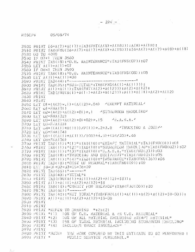
.,
- 224 -
lHSCPS 05/08/74
3500 3510 3520 3530 3540 3550 3560 3570 3580 35YO 3600 3610 3620 3630 3640 3650 3600 3670 36(30 3690 3700 Till) 3720 3730 314U 3750 3760 37/0 3780 3i90 3~300 31:310 3020 3(3JO 3 t~~}\) 385U 3860 3870 313(30 3d90 390U 3910 3920 3930 3940 39~U 396U 3970 3980 399U
P f( I NT I 6+ A ( 7 ) + A ( I 7) ; T A:3 ( F NT ( ;\ ( 8) + A ( I 8 ) ) ) ; A C tl ) + A ( 1 8) ; PFH NT TAd ( H1U ( 16+ A ( 7) +A ( I 7) + A (3) + A C 1 8) ) ) ; 16+ A <7 ) + A ( 17) + Id 8) + A ( I 8) GO TU 4000 IF 07<1 THEN 3560 PRINT TASC1S);l!0.H. J'.1AINTENANCE!I;TAl3(FNS(07»;07 LET A( 1 )=A( I) +07 IF Od< 1 TlkN 3590 PRINI TAo( IS) ;lIU.G. f.1AINTENANCE";TABCFNS(OG) ;08 LET A ( I I ) = A ( I 1 ) +08 P R I Nl TAa ( 44) ; 11- ______ ------- ------ - ----- __ II
Pt~ I NT flu3 ( 35) ; II S U i)-TOT AL II ; TAB (FNS (A ( 1 ) + A ( 1 1 ) ) ) ; j.1RI1H A(1)+AC11);TABCFNTCA(2)+ACI2»);A(2)+A(12); j.1 R I NT TAB (F N U ( A ( I ) + A C 1 I ) + A ( 2) + A ( 1 2 ) ) ) ; A ( I ) + A C 1 I ) + A ( 2 ) + A ( I 2) JJr? I1,IT PI( I j'rf LET Ul=(A(2)*.1 )+(A(12)*.04) 'EXEMPT MATERIAL' L:::T UI=Ff'iA(01) LET U2=(A(2)+ACI2)+OI)*.1 "STOR~ROOM HANDLING' LL:T U2=FNACD2) LET u3=(A(2)+ACI2)+01+02)k.15 '~.A.S.A.' LLT U3=F,JA(LJ3) LeT U4=CC/\(I)+AC11»/PCI»*'.2*J.8 'TfiUCKING & t..:QUIP' LET uj=Fi\!A ( 04) LET U6::::( (CA( 1 )+A( II »/IOO)';',4.5)-H04/30)*. 66 U::T LJo=FI1A(06) ~nIiJT TAl3 (II); IIC 1) II ;TAf3( 18) ~!lt:XENIPT ::\ATERIAL" ;TAI3 CFl'!U( UI» ;01 PRINT TAB( II); 11(2) II ;TA8( 18); iISIOrtl:I(OlJ!,\ HAt,iDLldGll;TA[3(FiWC02» ;02 !.JF?INT TAd( II) ;11(3)II;TA3(1(3) ;"E.A.S.A.l!;TAf3(FHU(03» ;03 J-iFHNT TAd(18);IITF?UCKH1G AND EOUIPril121ffi l ;TAlH(:UUCiJS»;D5 pr~Ii'~T TABe II );IIC4)il;TAJ(18);IIIHSU~iAf~Cl~II;TAB(Fj~U(J6» ;06 PRItH TAoe 18) ;!!COST OF RL\\O\fALiI;lABCFNUCU9» i09 LET 18=OI+02+03+U~+06+09 PP HIT TAd (66) ; "_- ____ iI j.J1{ Hff TAl3 (40) ; 11'[0 '1 ALII ; }J fH NT "fA13 ( F ;'JU ( A ( 1 )-l- A ( 1 I ) + A ( 2 ) -}-A C 1 2 H· I 8 ) ) ; c.J r?I NT A ( 1 ) + A ( I 1 ) + A ( 2) + A ( 1 2) + H3 PfHNT TAB(lc3);"Cf(lUIJ for? S!ILVAGEI!;TA8(FlWC[JO);lJO PR IN f TAd ( 66) ; iI ______ 11
PRINT TM3(40);"UET TOTALI1;TAB(FNU(AC1)+A( 11)+A(2)+A(12)+I8-00»; PIH NT A( I ) + A ( 1 I ) +A (2) +A ( 12) + I 0-00 }) n I NT PPINT PI-HHT I'FIt::FEF? TO Df<J\HING II;Z$(2) PRINf II( I) lm~ OF 0.1!. i'\ATE~~IAL & 4?6 U.G. i:IATUnALi' PI~lNT 11(2) IO~6 DF ALL !-.IATUHAL HJCLUDING 1:Xi::MPT J:iATE~(lAL!I P n I NT II (J) I 5% OF TUTAL ;.1AIEFH AL I i\fCLUD Il~G STUh\~ f? LlU ,'.\ HAimr... I NGII P}~INT II (4) INCLUUr::S Tj~UC!< INSURAl~CLIi . PFII in Pf<ItH iI;·lOTLg THe: HDRI< CDVlREO l:lY TillS ESTIMATE: fLJ DE PEr?FmWfD PHINT II PUjjLIC SEf(VI\.~t. l)L:f?Su!J1JEL."
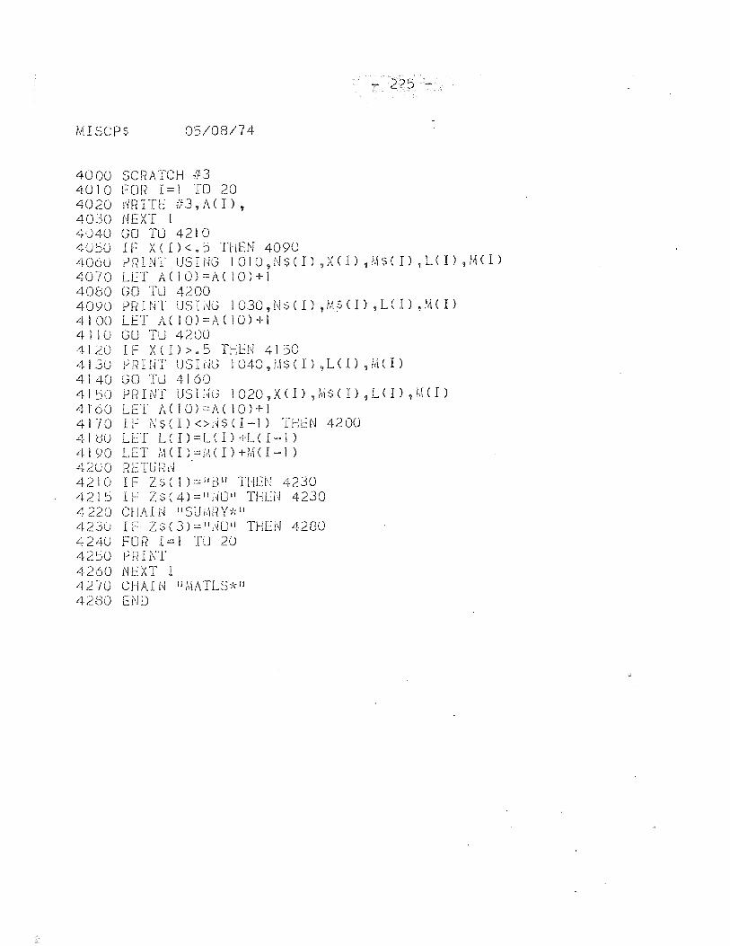
MISCPS 05/08/74
4000 SCf~ATCH 11=3 4010 FOR 1=1 TO 20 4020 rlRITE #3,A(I), 4030 NEXT I 4040 GO TLJ 4210 40:)0 If X(I)<.5 THEN 4090
- 225 -
4060 ?fHNT UShJG 1010,NS(I),X(I),MS(I),LCI),MCI) 4070 LET ACIO)=AC10)+] 4080 GO TLJ 4200 4090 PRINT USLKJ 1030,Ns(I),filS(I),LCI)t MC1 ) 4100 LET A( 10)=A(10)+1 4 I lOG 0 TU 4200 41dO IF X(I».5 THEN 4150 4130 PRIIH USF1G 1040?[.!$(l),LCI),MU) 4140 GO TLJ 4160 4150 PRINT USIi~G 1020,X(l) 9!v1$( 1) ,LeI) ,MCI) 4t60 LET A(10)=A( 10)+1 4170 IF 01$( I) <>l~S (I-I) THEN 4200 410U LET L(l)=L(1)+LU-l) 41 YO LET M (I) =f:\( I) +MC I -I) 4200 l~ETU fill 4210 IF ZS C 1 ) =;id l1 THEN 4230 421:) IF ZS(4)=11 1'm ll THLH 4230 ,0,220 Cl!AIN IISUMf-?Y-;,:1I 4230 IF ZS(3)=II,~CJIi THLI'I 4280 4240 FOR 1=1 TU 20 42ljO PRINT 4260 NEXT I 4270 CHAI N II MATLS;,,:II 42BO END
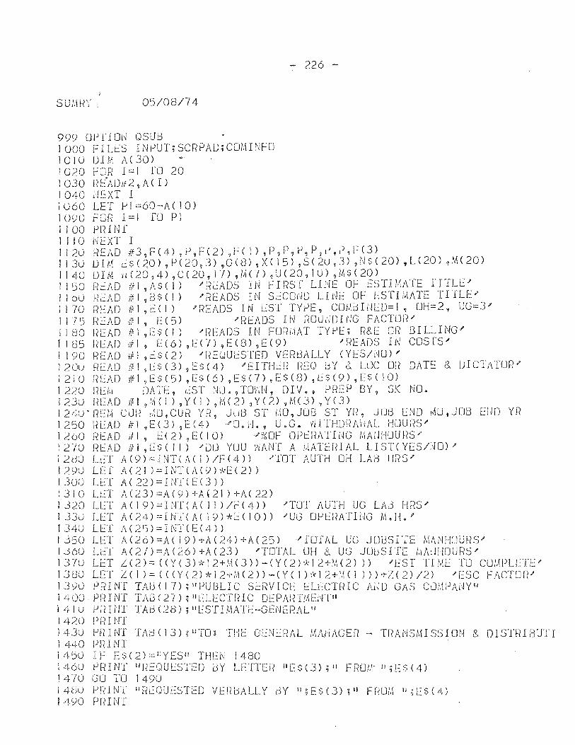
05/08/74
999 Or>fl 01'1 QSUB 1000 FILES INPUT;SCRPAD;COMINFO 1010 DIM /\(30) 1020 Fm? 1=1 TO 20 1030 !? !::"ADif 2 9A( I) 1040 NEXT I 1060 lET Pi=60-A(10) 1090 [::01{ 1=1 I'D PI I 100 PRJ N r 1110 NEXT I
- 226 -
1120 f{EAD #3?F(4) ,IJ,F(2) ,FC I) ,P"P,P,P,r),P,FC3) 1130 DIM 1..::$(20) ,P(20,3) ,G(3) ,XC 15) ,5(20,3) ,NS( 20) ,L(20) ,M(20) I I 40 0 I M H (20,4) ,C ( 20, 1 7) ? J,{ (7) 1 U ( 20, 10) ?!It $ ( 20) J 150 READ IFI ,li$( I) "f-?L:ADS IN FIF?ST lINE OF ESTIMATE fITll>' J 100 m~AD #1,13$(1) "f-?t:ADS IN SECOt'W tIdE OF ESTIt'AATE TITLE;> ) I 70 READ #: I ,t~ ( I) .. READS IN LST TYJ-lE, COt,li3 ItH'::O= I, OH=2, UG=3;> 1175 nEAD -If I , E(5) ;>READS IN POlj.'H)UJG FACTLJf?" II eo ~<EAD III ,e$( I) "READS IN FORI.\AT TYPE; R&E Of? BILLING" I 1 C3 5 t{ E A [) iJl, E ( 6) ,E (n ,E ( 8) ,E ( 9 ) / REA D S I f~ COS r S " 1190 READ i'll ,i$(2) "'REUUESTED VERI:3ALlY (YE:S/NU) I'
120u FIEAf) fll ,!~~3 (3) ,ES( 4) 'EITHU< r~EO i3Y & LLJC m? DATE.: & DICTATOR" 1210 qEAD #1,1:::$(5) ,E$(6) ,E$(7) ,E$(3) ,L$(9) ,[$( 10) 1220 REI,: DATE, EST l'hJ.?TOHI~, OIV., PREP BY, SK l'mo 1 2Ju R LAD if I ,',1 ( 1 ) 9 Y ( 1 ) ,i\H 2) 1 Y ( 2) 1 M ( 3) 'I Y ( 3 ) 124U' RE/,\ CUr? ,MJ,CUR Yr~, JUt3 ST LfO,JOB ST YI~? JOl3 END !AU,JOB ElJD Yr? 1250 l?L:AD #1 ~E(3) ,E(4)J'0.H., U.G. ~'JlnlOf{AHAl Hour~s;> 1200 F?EAD if I ,t:(2),ECI0) "';;:;OF OPl-=RATING MAIJHLJUnS" 1 2 -/0 [{EAD If I ,1:: $ ( 1 i) J'lJLJ YUU I~Ar{r A "IATEIH AL l I STC YES/;~O) " 12HO lET A(9):::INTCA( 1 )/F(4» /TOT AUTH DJ-! LAB [ms" 129Ll lLf A(21 )=INTCA(9H:f2(2» 1 300 L1:::T A ( 22) = I NT C E (3) )
1310 l~T A(23)=A(9)+A'21)+A(22) 1320 ll::T A(19)=HIT(ACI1)/F(4» "'TOT AUTH UG LAB !--[f(S" 1330 LET A(24)=I.NTCAC 19)*1:.:(10» 'UG OJ-lU{ATING M.H." IJ4U ll::T A(25)=INTCE(4» 1350 Ll::T A(26)=ACI9)+A(24)+A(25) "'[OfAL UG JUUSI'fE MANHOURS' lJ(50 L:::T A(X{)=A(26)+A(23) 'TOTAL OH 8. UG JLJUSIT[ !,\AdJIOURS;> 137u LET L(2):::(Y(3)*12+!'1(3)-(YC2)~\-12+~'l(2») "EST TIML TU COMPLL:TE" 13dLl lET L(J)=«(Y(2)*12+M(2»-(Y(1):{-12+~.j(1 »)+'Z(2)/2) ;[SC FACTLJI1/ jJyLl PRINT TAl:3(I7);flPUBLIC SL:RVICl: f::Lt::CTf.HC Al'lU GAS CJMPANYll 1400 PRINT TA3(27) ;IIElECTfHC DEPldnM[[~TII 141 U PfllJ'n TAo (28); "ESTHIATE-GENERALII 1420 Pf.? I NT 1430 PF/INT TA£-3(13);IITO: THE GU1ERAL MANAGER - TRAHSl,uS5ION 8, OIST!?IElUTI i 440 PrilNT 14':)0 IF L$(2)::::liYESH THI::N 1480 1460 PFHNT IIREC,lULSTED BY LETTEI< 11[$(3); II Fr~m,\· !I ;ES (4) 1470 GO TO 1490 14~:)() f-Jnnrr IInEOUESTED VERbALLY BY Il;ES(3);1I Ff.WI.\ ";1::$(4) 14S10 PRINT
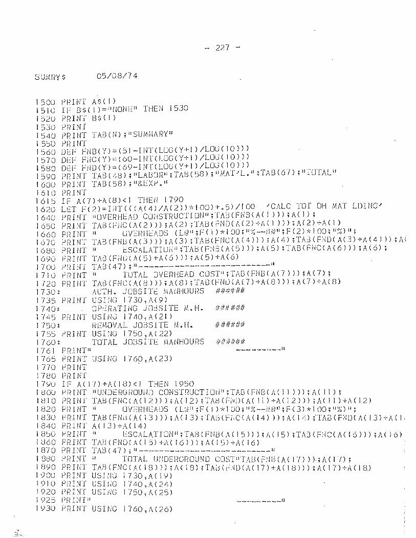
- 2XI -
SUMRY$ 05/08/74
1500 PRINT A$C I) J 510 IF B$( 1 )=iltmNEIi THEN 1530 1 520 PRINT B $ ( I ) 15JU PRINT 1540 PRINT TABCN); IISUMMARYII I 5~D PR INT 1560 DEF FNB(Y>=(51-INTCLUGCY+I)/LOG(10») 1570 DEF fllC(Y)=C60-I!4TCLUGCY+l )/LOG( 10»)) 1 5 BOD E F ~ i'l D ( Y ) := ( 69- I NT ( LOG ( Y + 1 ) I L OJ ( 1 0 ) ) ) 1590 PR INT TAB (48) ; IILAl:30R'I; TAB (58) ; "MAT .... L.1l ;TAB C6 7) ; II fOTALlf 1600 PRINT TAB(58); II&EXl-J." 1610 PRINT 1615 IF A(7)+A(8)<1 THEN 1790 1620 LET F(2)=I~T(C(A(4)/A(2»*IOO)+.5)/100 .... CALC TOT OH MAT LOING' 1640 PRINT 1I0VERHEAO COHSTRUCTIDt'-J Il ;TAi:HFUBCAC1 »);A(I); 1650 PRli~T TABCF1JCCA(2»);A(2);TABCFNOCA(2)+ACI »);A(2)+ACI) 1660 PRINT II UVERHl::AOS CL@II;FCI)*100;iI~6--t.J©Il;F(2)*100;11~6)1I; 1670 PRINT TABCFNbCA(3»);AC3);TAB(FNCCA(4»);A(4);TAl3(F;~D(A(3)+A(4»);A( 1680 PfHNT II ESCALATIUi~1l;'TAb(FNi3(A(5») ;A(5) ;TABCFNCCA(6») ;A(6); 1690 PRINT TA3CFND(A(S)+A(6»);A(5)+A(6) I 700 P R I HI' TAB (47) ; 11- ______ ------- ------ ------11
1 710 rlf~rNT II TOTAL OVERI-iEAO CLJSTII;TABCFNB(A(7») ;A(7); 1720 PRINT TA8CFNCCA(8») ;A(8) ;TAi3(FUtJ(AC7)+A(8») ;A(7)+A(8) 1730: AUTH. JOBSITl:: tiiMJ!-!OURS ###### 1735 PRINf USING 1730,A(9) 1740: OP~RATING J08SITE M.H. ###### 1745 PRINT USINJ 1740,A(21) 175U: REMOVAL JOBSITE M.H. 11##### 1755 PRINT USING 1750,A(22) 1760: TOTAL JOBSITE MANHOURS ###### 1761 PRINT"
_________ 11
1765 PRINT USING 1769,A(23) 1 TIO PRINT 1780 PFn NT 17yu IF A(17)+A(IU)<1 THEN 1950 J dOl! P!~INT IlUNOEF?GROUHO CONSTRUCTIOl~l/;TAB(FN8(A( II») ;A( 11); 1810 PRINl' TABCFNC(ACI2»);A(12);TAl:)CHWCA( 11)+ACI2»);A(11 )+/\(12) I 820 Pin NT II fJ V E Ii H E A OS (Ug II ; F ( I ) * I 00 ; ! 1 ~~ -- j,W 11 ; F C 3 ) * I 00; 11 ~~) II ;
1 83 U P R I NT TAB (F N L5( A ( I 3 ) ) ) ; A ( I 3) ; 'fA J3 ( F ;.j C ( A ( I 4) ) ) ; A ( 1 4) fT A B ( F [\lO ( A ( I 3 ) + A C I ' 1840 PRINT A(13)+A(14) 1 8~0 [oj f-? I NT II ESCALAT I Ol'Jif ; TAB ( F N 13 ( A ( I 5) ) ) Ud I 5) ; 1'A8 ( FdC ( A ( 1 6 ) ) ) ; A ( 1 6) ! 13 6 ° P R I NT TAB ( F N 0 ( A ( I 5) + A ( 1 6 ) ) ) ; A ( I 5) + A C 1 6 ) 1 87 ° PR I NT TAB ( 47) ; II ----,- ------- ------ --------11
1 880 PR I NT II TOTAL UNDD~GROUND COSTIITAI:l< FW3 C A ( 17) ) ) ; A ( I 7) ; 1 890 P R I NT TAB ( F N C ( A ( I 8 ) ) ) ; i\ ( 1 8) ; T A 13 ( F j~ DCA ( 1 7 ) + A ( I 8 ) ) ) ; A ( 1 n + A ( I 8) 1900 PRINT USING 1730,A(19) 19JO PFHNT USIUG 1740,A(24) 1920 PRINT USING 1750,A(25) 1925 Pf( HIT II 1930 lJRIN1' USING 1760,A(26)
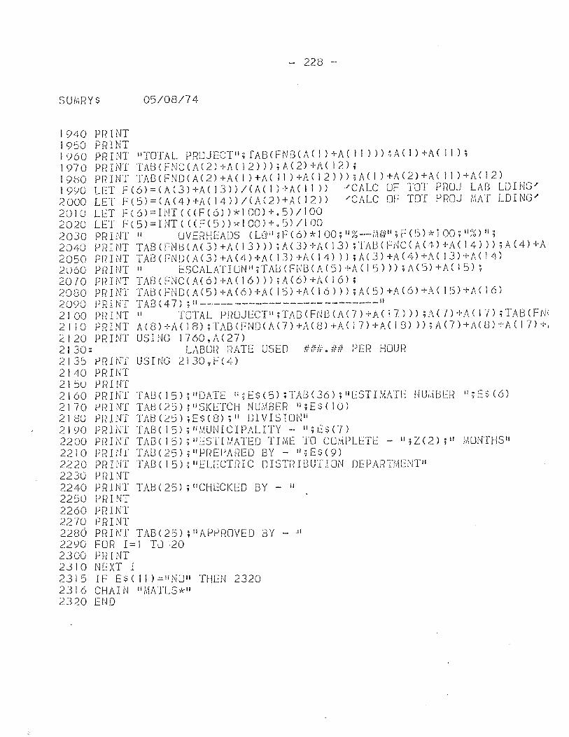
- 228 -
05/08/74
1940 PRINT 1950 PRINT 1960 PRINT wfOTAL PROJECTII;TABCFNBCA( I )+A( II») ~AC I )+A( II); 1970 PRINT TAt3CFNCCA(2)+A(12»);A(2)+J\(12); 19(30 PRINT TAB(FNOCAC2)+A(1 )+A( 11 )+ACI2»);Jdl )+1\(2)+;\( 11 )+1\(12) 1990 LET F(6)=(A(3)+ACI3»/(AC1)+A(II» ./CALC OF TOT PROJ LAB LDING/ 2000 LET F(S)=(A(4)+ACI4»/CA(2)+ACI2» 'CALC OF TOT PROJ MAT LOING' 2010 LET F(6)=INT«CF(6»*100)+.5)/100 2020 LEI F(5)=INTCCCF(S»*100)+.S)/IOO 2030 PRINT II UVEF?HEAOS CU]Il;F(6)*100;1I%--M@ll;F(5)*100;11~~)1l; 2040 PRINT TABCFNtHA(3)+!dI3»);A(3)+AC13);TAUCFNCCA(4)+A(14»);A(4)+A' 2050 P R I NT T A8 ( F NO C A C 3 ) + A (4 )-1- A C 1 .3) + A ( I 4) ) ) ; A ( 3 ) + A ( 4) + A ( I 3) + A C J 4 ) 2060 PI~INT II f.::SCALATIUNl!;TABCFNBCACS) +I\C 15») ;1\(5) +AC 15); 2070 PRINT TAB(FNCCA(6)+A(16»);A(6)+AC16); 2080 PRINT TAUCFNOCA(5)+A(6)+A(IS)+A(16»);A(S)+AC6)+ACIS)+A(16) 2090 PRINT TAB(47) ;11 __________________________ 11
2100 PRINT II TOTAL P!(UJECTi';TABCFNI:3(AC7)+A(17»);A(7)+J\(I7);TABCFN( 2 1 lOP R I NT A ( (3 ) + A ( 1 8) ; T A8 ( F N 0 ( A ( 7 ) + Ii. ( 8) + A ( I 7) + A ( I 8) » ; A ( 7 ) + A ( (3 ) + A C 1 7) + J
2120 PRINT USING 1760,A(27) 2130: LABUR RATE USED ###.## PER HOUR 2135 PRIN'[ USING 2130,F(4) 2140 PF?INT 2150 pnINT 2160 PRINT TA8(15);110AT£ ";E$(5);TAl3(36);I'ESTIIAATE HUI,HJE!{ ";1::$(6) 2170 PF?INT TAtH25);IlSKETCH NUi\1BER ";E$(10) 2180 PRINT TA8(25);E$(8);1I lJIVISIOHIi 2 I <)0 PR I NT TAB ( I 5) ; II MUN I C I PAL ITY - II;L: $ ('7) 2200 PRINT TAB( 15); IIESTIMATED TIME TO COMPU.:TE - 1l,;Z(2); II MONTHSti 2210 PRINl' TAB(25);IlIJREPJ\f?EO BY - II;E$(9) 2220 PtHNT TAB(15);IIELECTnIC OISTRI8UTION OEPAI~TMENTIl 2230 PRINT 2240 PFII NT TAB (25) ; "CHECKEO BY - II
2250 PRINT 2260 PRINT 2270 PfHNT 2280 PRINT TAB(25);"APPROVED BY _II
2290 FUR 1=1 TU~20 2300 PRINT 2310 NEXT I 2315 IF ES( 11 )=IINUiI THEN 2320 2316 CHAIN "MATLS,'r 1i
2320 END
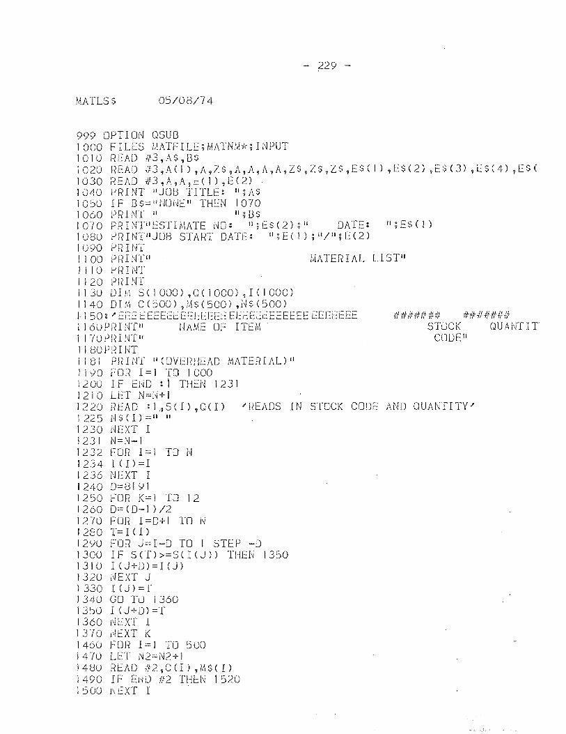
MATLSS 0!j/08/74
999 OPTI Oi~ QSU3 1000 FILES MATFILE;MATNM*;INPUT 1010 READ #3,A$,8S
- 229 -
1020 READ 1f3,A(I) ,A,Z$,A,A,A,A,Z$,ZS,ZS,ES( I) ,[$(2) ,ES(3) ,1.::$(4) ,E$( 1030 READ #3,A,A,ECI),E(2) . 1040 t-JRINT lIJOU TITLE: II;AS 1050 I F 8S=lIt·lOi~E" THEN 1070 1060 PRINT II II;B$ 1070 PRHl'fiIESTIMATE NO: 1I;f:$(2);1l DATE: [I;E$(I) 1080 tJf?INP'J013 START DATE: II;E(I) ;11/";E(2) 1090 PF?I NT 1100 PRINTu MATERIAL LISTII I I 10 PF?I NT 1120 I)FHNT I 1 30 0 I f.,1 S e 1 000) ,Q ( J 000) ~ I ( I 000 ) 1140 DIM C(!jOO) ,[,\$(500) ,H$(500) 1150 g I' EE:E I:.:EEEEEEEEEEEt: EEEEEt:EEEEEE EEEfEEE ###fffUNf #####I!# J J 60PF<Hff'1 I·IAME OF ITEM STuCK QUANTIT I 1 70 P R I Wf II C (J 0 Eli 11 80Pl{I NT 1181 PRINT if (DVEFmEAO MATERIAL) II 1190 FOR 1=1 TO 1000 1 200 I F E1W : i THEN 1 23 I 1210 LET N=N+I 1220 READ ;1~S(I),Q(I) 'READS IN STOCK CODE AND OUANfITY' 1 225 N $ <I ) :::" II
1230 dEXT I 1231 N=N-I 1232 FOR 1=1 TO N 1234I(!)=I 1236 NEXT I 12400=81IJI 1250 FOR K=1 TO 12 1260 0=(0-1 )/2 1270 FOR 1=0+1 TO N 1280 T= I (I)
1290 FOR J=I-O TO 1 STEP -0 1300 IF S (n >=S e I (J» THEN 1350 1310 IeJ+D)=ICJ) I 32U i~EXT J 1 330 I (J) = f 1340 GO TO 1360 13~U I (J+D)=T 1360 l'i EXT I 1370 dEXT K 1460 fOR 1=1 TO 5UO 147U LET J'>J2=N2+1 14UO READ ft2,CCI) ,M$(I) 1490 IF ENO #2 TH~N 1520 I 500 I~ t:XT I
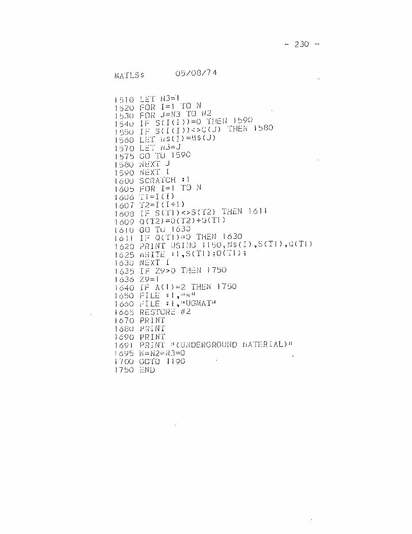
{,\ATLS $ 05/08/74
1510 LET U3==1 1520 FOR 1=1 TO N 1530 FOH J=N3 TO I~2 I 540 IF S ( 1 ( I ) ) =0 THEi~ 1590 I 550 IF S ( I ( I ) ) < > C (J) THEU 1 580 I 560 LET f~ $ ( I) =1,\ $ (J)
1 570 LET i'l3 = J 1575 GO TU 1590 1580 l'H::XT J 1590 NEXT I 1600 SCRATCH : 1 1605 FOR 1=1 TO N 1606 '1'l=I(I) 1607 '1'2=IC1+1) 1608 IF 5([1 )<>S(T2) THEN 1611 1609 0(T2)=Q(T2)+0(TI) 1610 GO TU 1630
- 230 -
1611 IF OCTI )=0 THEN 1630 1620 PF?INT USInG 1150,1'1$( I) ,S(Tl) ,CHTI) I 625 r'i fH TE : 1 , S cn ) ; 0 (T I ) ; 1630 NEXT I 1635 IF Z9>0 THEN 1750 1636 Z9=1 1640 IF ACI )=2 THEN 1750 1650 FILE gl,li*11
1 660 FILE z 1 ,11 UGMA'1'iI 1665 liESTuHE #2 1670 PRINT 1680 PfiI NT 1690 Pl1INT 1691 PRINT "(Ui\lDERGROUND I~IATERIAL)JI 1695 N=N2=H3=0 1700 GOTO 1190 1750 END
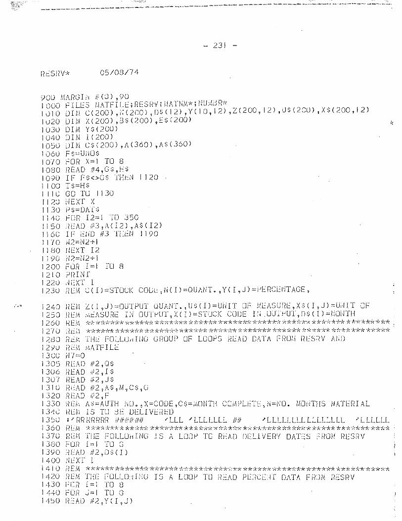
{ ,.'1
----------------------------------------------------------------------~
- 231 -
Rcsnv* 05/08/74
900 MARGI~#(O) ,90 I 000 F I LF S /,IATF I L E; RES fN; I.\ATNM~~; nU:M:l R~\-1 0 1 0 0 I ),1- C ( 200) ,i{ ( 200) , D $ ( 1 2) , Y ( 1 0, 1 2) ,Z ( 200, I 2) ,U $ ( 2(0) ,X $ ( 200 , I 2) I \.J 20 1) IrA X ( 200) ,B $ ( 200) ,E S ( 200) 1030 DIM Y$(200) ]040 DIM 1(200) 10:'0 DIM C$(200) ,A(360) ,A$(360) 1060 F$=UiJO$ 1070 FOR X=I TO 8 1080 READ #4,G$,H$ 1090 IF Fs<>G$ THi::N 1 120 1 100 T$=H$ 1 I lOGO TO 1130 1120 HEXT X 1130 P$=DATs 1140 FOR 12=1 TO 350 1150 READ 1~f:3,;\(I2),A$eI2)
I 160 IF EUD #3 THl::N I 190 I I 7 0 i~ 2 = l'<l 2 + I 11 (30 UEXT 12 1 1 90 N2=(~2+ I 1200 FOR 1=1 [0 8 1210 PFHNf 1220 dEXT I 1230 REM C(1)=STOCK C01)~,N(I)=QUANT.,Y(I,J)=~ERCENTAGE,
1240 1250 1260 1270 1280 1290 1300 1305 1306 130-1 1310 1320 1330 1340 1350 1360 1370 1380 1390 1400 1410 1420 1430 1440 1450
REM ZeI,J)=OUTPUT OUANT.,U$(Il=UNIT OF MEASURE,X$eI,J)=UNIT OF REM JlleASURE Hi OUT~UT,X(I)=STOCK CODE I!J.UUT~UT,D$CI)=!.\OUTH !
*-;t:*"k**'k;'<r; "k****~k *-};"k··k·k"k* "k***"-:*****-k--J0( *-:1:**-k.!,; ·k"k·*~k·k";r.~ **';'(--}:*--kk ***-****"1\");: . ~tEM f?i i,\ kk**~" *****'k ******* *~b"*:"* **'k*:'r* -A'***'k** -;'d"k*** *-I,**')"k ***'j( "k)\:* ***~l(~" . Rd'. THE FOLLu,dNG GROUP OF LOOrJS ReAD DATA FROM RfS~~V AND I~EM rl\/\ TF I LE iO=O READ If:2,Q$ UEAD iF2, IS I~EAD #2,J$ R~AD #2,AS,M,C$,G READ f12,F REi;1 A$=AUTH NO.? X=CODE ~C $= .. 'iONTH COMPLETe, i'~=NO. IMJ£~THS MATE!~I AL REh IS TO BE DELIVERED
J'LLL / LLL LLLL lill 'LLLLLLLLLLLLLLLL 'LLLLLL
RL::M TilE FOLLOHING IS A LOOP TO F?eAD DELI VERY DATES F~?LJH F?ESFtV FCJr? 1= I TO G liEAD ;12,0$ (I) dEXT I n E1.'\ ***-;>;'1<* ****-Je-!<;-k ***'k** *)"****-k *-k,I;-,,** 'k*-J,,'hl,;-k 'k**-;"**k *"k**** ;<;***** ***",,:)1. [{EM THE FOLLOH INC r S A LOO~ TCJ READ PEf?CEiH DATA F RU;'t~ F?ESF?V FOR 1=1 TO 8 r:un J=I TO G HEAD#2,YCI,J)
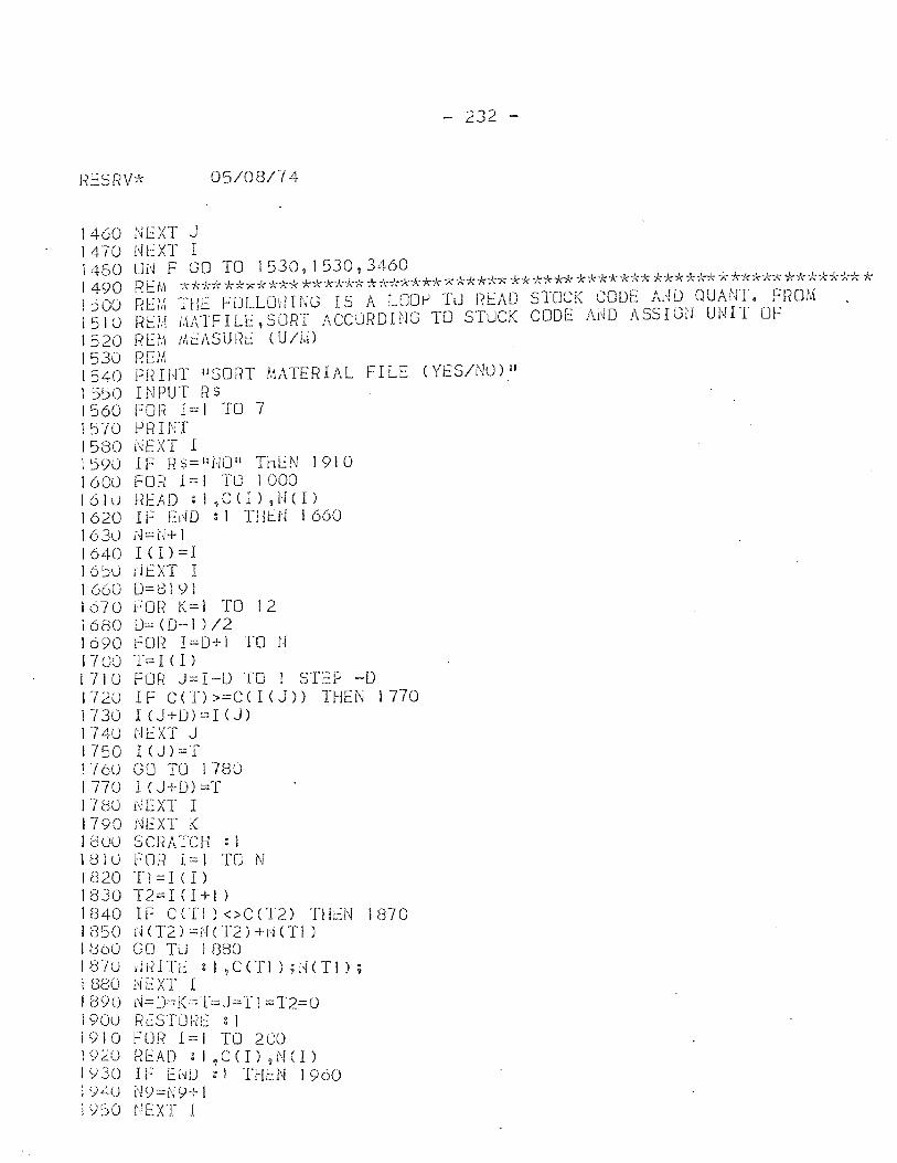
RESRV~\"
1460 NEXT J 1 470 l~l:XT I
- 232 -
05/08/74
1480 ON F GO TO 1530,1530,3460 1 490 REM ~"*-k.!, -k**'k*** *i"*"k*"'';~'c''-J,*,,,*******-r; *7,**'r.'-7-.- *-)"-*'k*~'<* ******~<*·k*~J.:**)'r;*~l;*-J.·* ,";
REi,~ THE FLJLLLJ./ I NG I S A LOOI) TLJ READ REM MATFILE,SLJRT ACCURDING TO STUCK REK MEASURE CUlM)
STOCK CODE /lAD UUANT. FROM CODE A~O ASSIGN UNIT OF 1 ~OO
1510 1520 1530 1540 1 5~0 1560 1570 1580 1590 1600 161u 1620 1630 16"'1-0 165u I 660 1670 1680 1690 1700 1710 172U 1730 1740 1750 1760 1770 1180 1790 180U i81() 1820 1830 11340 lr350 1(300 IfnU 1880 1890 190U 1910 192U 1930 1;)40 1950
RE}.1 PfHNT IISORT MATERIAL FILE (YES/NO) II
INPUT R$ FOli 1= 1 TO 7 PRINT UEXT I IF R$=IIULJII THEN 1910 FOR 1=1 TO 1000 f?EAD : 1 ,C CI) ,i'l( I) IF ElW : I THtN 1660
1-,1 == U+ I 1 <I) =1 dfXT I 0=81YI fOI~ K=i TO 12 1)= (D-l ) /2 fOF? 1:::0+1 TO N T::: I C I ) FOR J:::I-D TO I STEP -0 IF CeT»=CCIeJ» THE~ 1770 I (J+D)=I (J)
NEXT J I(J):::T GO TO 1780 I(J+O)=T r~ EXT I NEXT K scnATCH : 1 FOR 1=1 TO N 'I1:::1(1) T2=1 (H-I ) IF ceTI )<>CCT2) Tl-It:N 1870 ~(T2)=N(T2)+N(TI ) GO T0 1880 d ii I Tt g 1 ,C en ) ; lH T 1 ) ; NEXT I ~=D=K=T=J=Tl=T2=O RC:STLJRt: : 1 FDR 1=1 TO 2()0 R f2AD : I ,C ( 1) 'I N ( 1)
If E~D :1 TH~N 1960 N9=Ns/+1 NEXT I
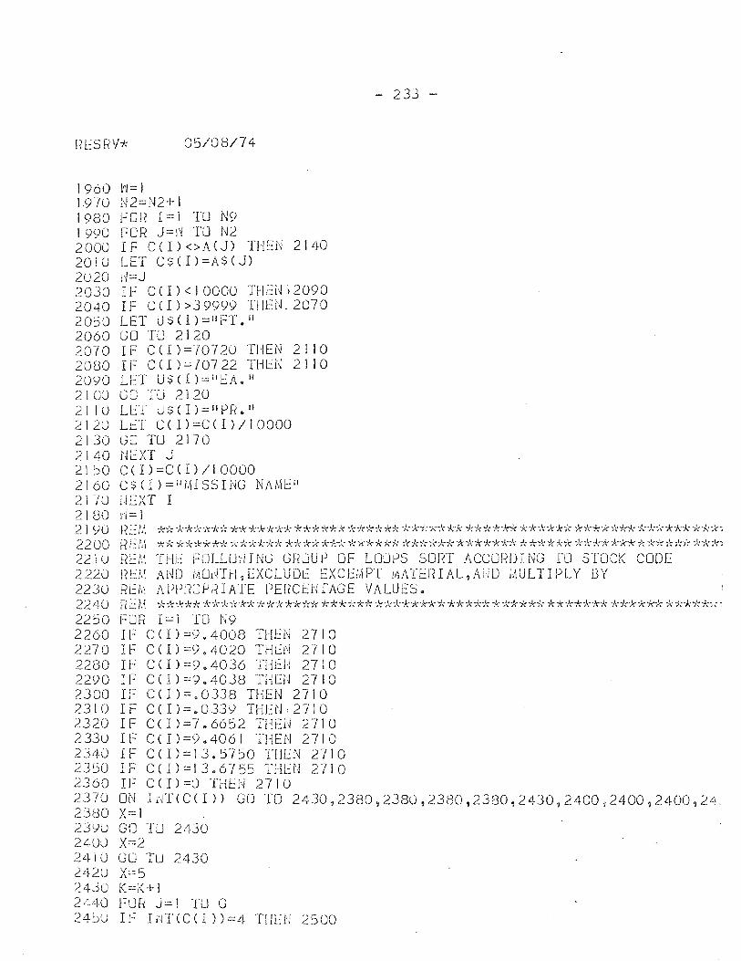
1960 vi= I 1970 N2=N2+1
05/08/74
1980 FOR {=1 TO N9 1990 FOR J=~ TO N2 2000 IF CCI)<>A(J) THEN 2140 2010 LET CS(I)=A$(J) 2020 d=J 2030 IF C(I)<IOOOO THENi2090 2040 IF C(I»39999 THEN. 2070 20::50 LET U$(I)='IFToll 2060 GO TU 2120 2070 IF CCI)=}0720 THEN 2110 2080 IF CCI)=10722 THEN 2110 2090 LET U$(I)::::liEA. 1l
2100 CO TU 2120 211U Lf::T US(l)=IIPF{.1I ~120 Lt:T CCI)=C(I)/l0000 2130 GO TU 2170 2140 t.JC:XT J 21~0 C(I)=C(I)/10000 2160 CS(I)=iliHSSING NAMEI' 21 -/0 jH~XT I 2180 /1=1
- 233 -
21 90 HE/I\ *)\; -k**-idn', -k*,":*"k"k* ~l:;~4;*,!cJ.:* *-k*,!C;--k* **--k*-Id-f.; ,J:-ht**:'( **-***iC *-k*-k-J~*~l: *-,i,;..,',;-ld;* -k--k*: 22 00 ~~t:l,\ 7(* **'k*** F~***'k* *"k~'<-*~~~< i-,.""x·;k**··k **i~*it;-J, "k**';,'**"k * *-;!:**"/r; *,1:****,-)< *~~i~}t'A~"l( *· ... k:~'; 221 U F?l::M THE FlJLLU~'i I NG GROU p OF LOLlPS SORT ACCUFW I NG TO STOCK CODE 2220 F{t-.:/:( Ai~D iMHTi-I,EXCLUDt EXCEi,\PT MATi:JHAL,AiW ,':\ULTIPLY 13Y 2230 Rthl APPRJPRIATE PERCENfAGE VALUES. 2240 F?t:f.\ ,I:~"**--k ,\;;l:;-k-;'>:*-}..-*-k**)\:** -k**--**,\: ,,,******-j,**--k-J.;***-};*;\:-), ****-:d;* *-Jo"**~l-; * ,':*-f:*,", ~ 2250 FOR 1=1 TO N9 2260 IF C(I)=9.4008 THEN 2710 2270 IF C(I)=V.4020 TH~N 2710 2280 If C(I)=9.4036 THEN 2710 2290 IF CCI)=9.4038 THEN 2710 2300 IF C(I)=.0338 THEN 2710 2310 IF C(I)=.0339 THEN,2710 2320 IF CCI)=7.6652 THEN 2710 2330 IF C(l)=9.4061 THEN 2710 2340 IF C(1)=J3.5750 THEN 2710 2350 IF C(1)=13.6755 THEN 2710 2360 IF CCI)=(j THEN 2710 2370 ON IuTCC(I» GO TO 2430,2380,2380,2380,2380,2430,2400,2400,2400,24 2380 X=l 23YO GO TU 2430 240:) X==2 2410 GO TU 2430 242u X=5 2430 K=K+I 2i~40 FUR J= 1 TU G 24~U If IuT(C(I»=4 THEN 2500
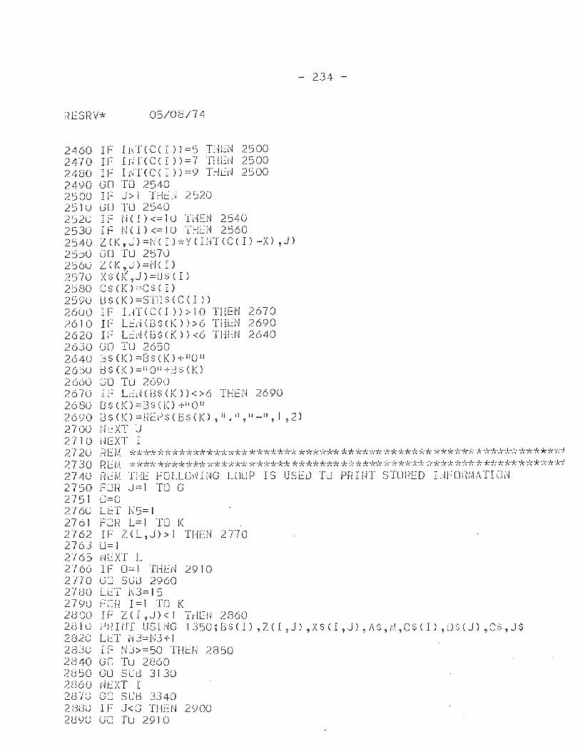
05/08/74
2460 IF IwICC(I»=5 THEN 2500 2470 IF IrUCC( r »=7 THEli 2500 2480 IF Lff( C ( I » =9 THb~ 2500 2490 GO TO 2540 2500 IF J>l TH~~ 2520 2:Slu GO TU 2:S40 2520 IF NCI)<=IO THEN 2540 2530 IF N(I)<=IO THEN 2560 2540 Z(K,J)=NCI»)\:YONT(C(1)-X) ,J) 25~0 GO TU 2570 2560 Z(K,J)=N( 1) 2570 X$(~,J)=U$(I) 2580 C $ (K) =C $ ( 1) 2590 S$(K)=STRS(C(I» 26()0 IF Ilfr(C(l »>10 THEN 2670 2610 IF Lb~(8$(K»>6 THlN 2690 2620 IF Lt.:l\j 03$ (K» <6 THEN 2640 2630 GO TU 2650 2640 G S ( K ) = B $ ( K )-I- i I 0 i I
265U i:)$(K)=IIOil+B$(K) 2 (i60 GO Tu 2690 2670 IF Lb.JC 8$ (K » < >6 THfN 2690 2680 i]$C!()=BS(K)+IIOIl
- 234 -
2690 B$(K)=!~b)$(B$(K) ,iI.iI,II_", 1,2) 2700 Ul::XT J 2710 J.lEXT I 272U Rf':M -k*,'c: .. *****,b"**,h",*:\;****:h'ck *-k****:!d,*:l.:!:i:; **-)o',-,b\;* ****** -k-,'ck'fc'c',***-Jdol:-J 2730 REM ************************************************************M 2740 REM THE FOLLmHNG LOUP I S USED TU PR I NT STUF?ED L~FOrn\ATI ON 2750 FOR J=l TO C 2751 0=0 276U LET 1\i5= 1 27 61 f"OI~ L= 1 TO 1< 2762 IF Z(L,J»! THEN 2770 2763 U=l 27 65 i~EXT L 2766 IF 0=1 THEN 2910 2110 GO SUo 2960 27(30 LlT N3=15 2790 fOt? 1=1 TO K 2 e 00 I F Z (l ,J) < I THE II 2860 28 I U l~ fH NT US I i'J G 1 J 50 ; B $ ( I ) ,Z ( I , J) ,X $ ( I ,J) , t\ ~i 9 t,\ ,C $ ( I ) , L) $ ( J) ? C $ , J $ 2820 LET N3=lB+l 28Ju IF NJ>=50 THLU 2850 . 2(340 GO Tu 2860 2850 GO SUd 3130 2860 11lXT I 2S-iU CCJ SUB 3340 28tlO IF J<G THEN 2SiOO 21390 GO TU 2910
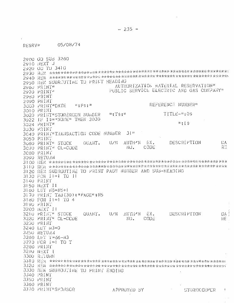
- 235 -
Rt5RV* 05/08/74
2900 2910 2',)20 2930 2<)40 2950 2Y60 2970 2900 2990 3000 3010 3020 3022 3024 3u30 3040 3050 3060 3070 3080 3090 3100 3110 3120 3130 3140 3150 3160 3170 31(30 3190 3200 3210 3220 J2JO 3240 32~O 3260 32'(0 3280 3290 3300 3310 3J20 3330 3340 33~O 3360 3370
GO SUl3 3260 litXT J GO Tu 3410 F?t:t.\ **"!..-k *"):'k"'k-;k--;; 'it:'l,,:***"k* ·k"k"k*"k* ,:l:~'<:**'1-:* **:!:i-:';--('7':* ****** **:'<**"k******'k*"f,**"J\"k*: RENt **"k*",'<7: "k:X'*~1:..,~**:'r:·k**); i~***'):** ·k:t:-1":*~~*~l:*'")t:*",;'<i~ ~~·k·;J .. :***~d( ****".*:* *****-:k"k *-;.;*-)(-:;t::
f~a\ SUBROUTINE TO jJRIUT HEAOr;~G f)RINTil AUTHm?IZATIOrJ h:ATCRIAL f~[SERVATION" PRaHn PUBLIC SERVICL ELECTRIC AND GAS C01,\i)A;~yll
t->RINT Pf? I NT ?RH.JTiIOATE II; P$; II F?EFL:!~[NCE NUl,m[F~11
eRINT eRI[nlisTor~cROo!;1 NU1>lBEI~ II;T$;II TITLt.::-il;O$ I F I $= IIlmi'.!!:: II THEN 3030 PRINTII II; I $
PRINT PRINTilTRAi,lSACTIOiJ CODE NUMBEr? 31 II
PRINT PRINTi' STUCK QUANT 0 U/r,! AUTH"'N EX. OESCF?I VTION IJA PF( I NTll CL-COIJE NU. CODE RE PRINT RETUHl~ r~ Ei\1 * **--1<*-;':*..,": *** ... t:** --J:*~~* ... !-:* .,t;·k·k"k"}(** ")<-k"!< )!';~'r7<; "k--/:"k"k,l.:;·k*"k**'-.rf:::l:* "k*:!-:i<"'k:~ '"k****)\:";!: * ").:)\; REM ************************************************************** nEM SUB i?[JUTI Nt:: TO PR I NT PAGE NUt,IBER AHO S Uti-HEADI NG FUR I I = I TO I I PfHNT NEXT II LET r~5=N5+ I Pf{Il\)'f TAd (30) ; II PAGEl!; N5 F 0 Ii I I = 1 TO 4 PRINT r~EXT I I lJliUrl,"1 STOCK OUAHT. U/lA AUTH"'N EX. DESCRIPTION Of, Pfn l-rr ll CL-CODE NU. CODE J~E PF?l NT LL:T 1-13=0 fiETU f~,~ LL::T T==66-i'd r:OR 1==1 TO T PfH ~rr r~ EXT I tit::TUHH
REM ********************************************~****************i R Efi1 *>~*,:l:"kFt; **'kit** "k*"l:"!("k)~ "k"k*"k*-k"k '~*7-:***"k*"k**"k *:-~:lr.;***.), -k"k"k"k-x1< ,,;\;"k"A"*'k*"k **i'<-'A~i I{EM ::-';Ui3 RuUT I l'JE TO PR 1 NT END HIG PFlINT PI? I NT PI=? I NT t->R I NTJI SPOdSO!{ A PPROV t:iJ l3 Y
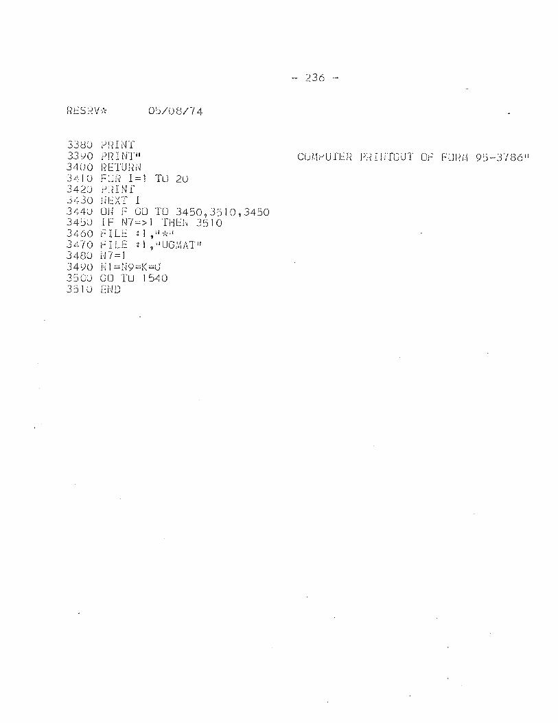
33C3U PRINT 33 yO PJ~ I NTH 34()O J?ETU~{d
0:)/08/74
3410 FOR 1=1 TO 20 342U rJl-{ I NT 3430 nC:XT I 3440 OU F GO TO 3450,3510,3450 34:)0 IF N7=>1 THeN 3510 3460 flU': : 1,11,',11
3470 fILE :\ ,ilUGMATII 3480 N7=1 34YO N 1 =tN=K=LJ 3500 GO TU 1540 3510 END
- 236 -
CU1.!I:-'U fER PfH llTOUT Or; Fm~i,\ 95-3786"
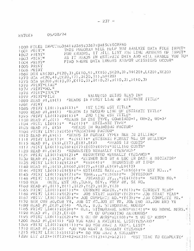
f::STCKS 05/08/74
1000 1001 IO()2 100J 1004 1005 1006 1060 10-10 10-/S 1076 1077 1078 1079 1080 10S1 1085 1090 1095 1100 11 U4 1105 1106 1110 I 1 1 I 1115 1117 1120 1121 1130 1135 1140 1144 1145 1146 1150 1160 1165 1 J 66 1 1 6-; 1170 1180 J I t3 5 i I 90 II \)5 1200 12u5 1210 121 :) 1220
FILES INPUT;uJ641 ;OJ65;[)J67;9il\IS~;S~r?PAD. _ ._, __. PRINTIt THIS pf(UGr~A].\ i'11LL !1t:Ll) ~U.U.,,~l~AL:~l: DA!f\J'IL~ II~~UT" J-JRINT" FOR ERf~ur?S. IT .-IILL LI.~l lI.~~ LTl-It: .'lU:,ld~!:S Dr: II,If-lUT." PRINTIl AS IT READS IN C:STIJrlA1L:: DA1A Aim fdLL t:['·I}\BLE YDU lUll PfHNTIl FIi'~D v'tHERE DATA ERf{uRS AiiD/OR LJI,\ISSIOiIS OCCUF?fI
P!il NT prnNT DIM ts(20) ,P(20,J) ,G( 10,5) ,XC 15) ,S(20,J) ,i'J$(20) ,L(20) ,\H20) D I J\1 ,j( 20 , 4) ,C ( 20 , 1 7) ? U ( 20, J 1 ) ,t.'i $ ( 20 ) . . f) I;1t u ( 20) ,H ( I 0 ,8) 9 K ( I 0, 5) ,R ( J 0,2) ,tiC I 0 ,3) ,U ( I 0 ,3) ? Ii I NT 1/ LIN E II P R IiT[1I NO. II 1) r~ ll'ffU HI PUTII P fH Iff! I F I LEV A L U E ( 5 ) B LIN G F? i:: A 0 I N II H[AD #1 ,AS( I) "READS IN flPST LLll::: OF ESTIMATE fIILI:" rJRINT j)rnr!T LIl-Ie J) ;A$( 1);" 1ST LINE t..::ST TITLEIJ READ #1,[3$( 1) "RJ::ADS 111 SEco;m LINE OF i:::STB;ATE T11Lt:" jJFUNT Llr~(l) ;U$C 1):;1i 2i'iD LHk t:ST rITLl~li READ #1 ,~(l) "READS IN EST TYPE, COM8IN~O=1, OH=2, UG=3-' fJf.?INI LIN(l);'1 il;~(l);11 [STL.;ATf TYyEIl f~EAD #1, E(S) .ff<EADS III RUUI~DlljG FACTUR" ernNf LINe 1) ;1:.:(5)? iIRUU;~DIfiG FACTUR" READ #1,1::$( 1) /F~EADS IN FORi/tAT JYi-'[; R&E ur~ GILLING" tJfHiH LINe 1) ,it ;i;t::S( 1);11 t:STI;.\l\n:: FURj,\AT R[~L': or? lJILLINGJI i~EAO #1, [(6) ,[(7) ,E(8) ,E(9) "nEAOS hi COSTS" Pl·(lNI LI1'1( 1) n:(6) ;EO) ;E(8) ;E(<)) ;1l!:3ILLING CUSTS!! F?EAD itl ,Es(2) "nc:out:SfEO VEHL);\LLY (YES/NO)--PRINT LI1HI);l:$(2);" HEOUfSTEO VUWALLY (Yt:S/NO)II f~[AD 1/1 ,E$(J) ,E$(4) --EITHER RLQ BY & LOC Uf~ DATE:: & DICTATOl?" Pf?INT LHI( 1) 9t:S(3);" ";E$(4);1I REQUESTED t3Y LJFO" l-?EAD ,:;1 ,L:$(5) ,[$(6)',1::$(7) ,i.::$(S) ,E$(9),lS(JO) !->~?INT LIi~(J) ,E$(5) ;11:::: ESTIMATE DATt: ••• " ;E$(6) ;11:::: EST NO ••• 11
eRINI LIr.JC\);l::$(7);II:::: TU;·jN •••• ll:;J::$(3);II:::: DIVISILJf1 il
iJfniff LIN(1);E$(9)~I1= PREdARE:O t3Y ••• ";ES(IOHiI::: SKETCH UO." [t[iit DXH'::, EST Im.,TLHd·~, DIV., !-IF?EP BY, 5K 1\10. REA 0 i;~ 1 ,1.1 ( 1 ) , Y ( I ) , 1. \ ( 2) , Y ( 2 ) , M ( 3) , Y ( 3 ) prnNT LIH(1),j,1(I):;"= CUr~[it:NT M01~Til •• II;Y(I);II:::: CUJiFlEi·iT YEAn" yliINT LEUI) ;(.1(2) ;11::: JOG START !.iUNTH";Y(2) ;11= JJfj STAtH YEAn l1
!->F?Ii'n LItI( I HIvI(]) ;t!::: JOG COW-'LlTt': j~O.II;Y(J):;II:::: JJiJ COI,\PLL::TE YR.I' REM cur~ !,\O,CUR YR, JUB ST i:\O,JOB 5T YrI, JOb um !,lO,J013 Ei~D YI~ f?r':AD It! ,E(J) ,E(4) .fUoH., U.G. i'JlHIDnAhAL HUURS'" PFdNT LIN(1);E(]);I'=: O.H. liITHiJ!?}\HAL IdlmS II ;!::(!J.);II= UG l'iDn\'IL MHF?S." RLAD 7fJ, [(2),[(10) /~~ OF Oh:RATING ;,Ii\I.j[-IUUf?S'" PRINT LIN( 1) ;L(2) ;11= ;6 Od OP iMlr?Sil;L:( 10) ;11= ;~ UG OP MI!l?SIr i~t.AO 111 ,ES( 11) .fOO YLJU h1\NI A 1,IATl::IHAL LISf(YL:s/,m),1 yrH>lf LL~(I) n:$( II) ;11:::: DO YOU IjAln A j,lXfl'L LIS1'n . nEI\D;~1 ,0:$( 12) "UU YOU HP.l~T A SU/'.':!'.\ARY (YES/NO)" PRHfT LLH 1) ;ES(12) ;11= DO YOU iI}\j1il' A 5U;:,,'-,'d,.\?Yll LLT L(2)=«Y(3)-kI2+!,'\(3))-(Y(2)-kJ2+h\(2))) .fEST '1'11\\[ TO CU,\\PLl::TE.I'
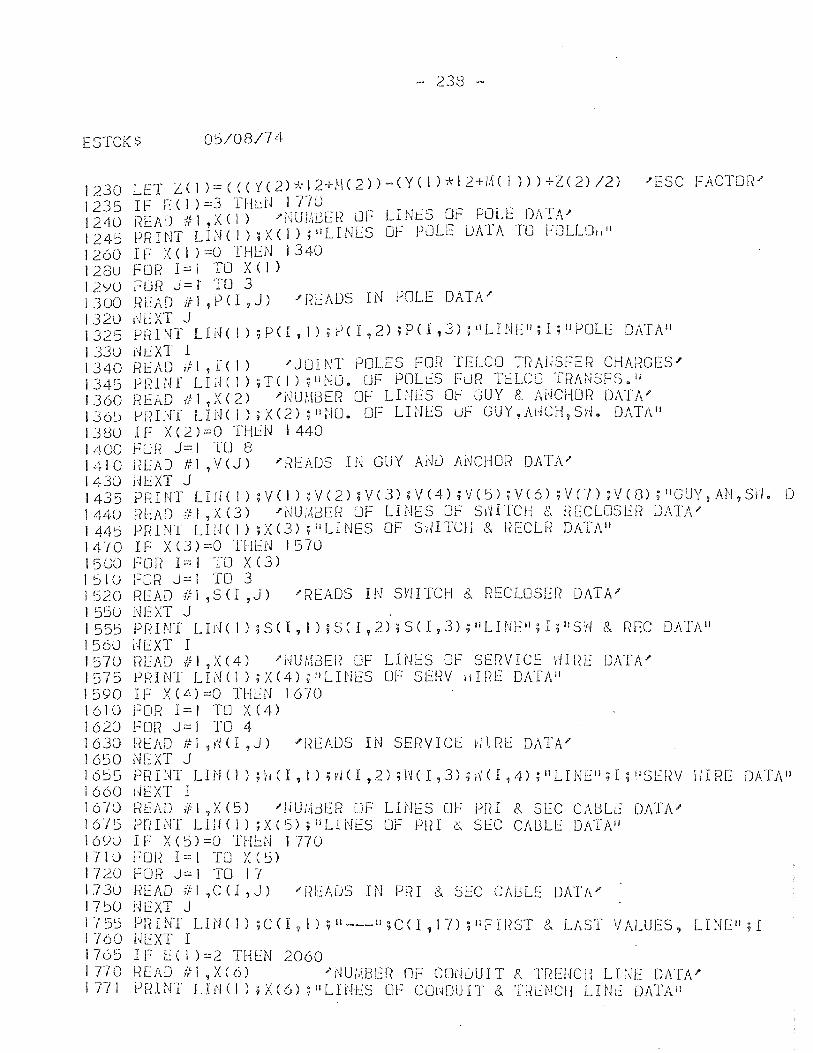
- 238 -
ESTCK$ 05/08/74
1230 1235 1240 1245 1260 128U 12YU 1300 1320 1325 133U 1340 1345 1360 136~
130U 1400 1410 1430 1435 1440 1445 1470 1500 1 51 (j 1520 1550 1555 1560 1570 1575 1590 1610 1620 1630 1650 1655 1660 16-10 1675 16yU 1710 1720 1.730 17~O 1-155 1760 1765 J T10 1771
LET L ( I ):::: ( ( ( Y C 2) ;1; 1 2 + M ( 2 ) ) - ( Y ( I ) :!;- I 2 + /.{( I » ) + Z ( 2) /2) )' ESC FACT 0 1< )' IF E(I )=3 TH~N 1710 !?EAD (.{: 1 X ( I) "HUli,l3U~ LlF LI Nt:S OF POLE DATil," PRINT LINe I) ;X( I) ;'iLINES Of PJLE DATA TO FOLLOil li
IF X(I )=0 '[HEN 1340 FOR 1:= I TO X ( I ) FOI~ J= f TO 3 READ #1 ,PCI,J) IREADS IN POLE DATA' !'~EXT J P f< I NT LIN ( I ) ; P ( I , 1 ) ; jJ( I , 2) ; P ( I , 3) ; Ii LIN E 1/ ; I ; II POL E D AT A II NiXT I .~EAD ,/ I 7 r ( I ) )' J01 NT POLES FOR TELCO TR AliSFE R CHARGES' Pl<INI LItH I) ;T(I) ;lJ0l.O. OF PClLt.::S FUR TELCO Tr{Al',iSF~).il ncAD 1f:1
1X(2) 'NUI.mE[~ OF LINES Of GUY 8.. AUCHO!? DATA"
t-!fHNT LIN(I);X(2);ntW. OF LINES LJF GUY,Al,[CH,Sd. DATAII IF X(2)=0 THtN 1440 FOH J=1 TO 8 }~EAD #1 ,V(J) "READS Hl GUY Ai~1J ANCHOR DATA" HEXT J PR I NT L III< I ) ; v ( I ) :; v ( 2) ; v ( 3) ; v (4) ; v ( 5) ; v ( 6) ; v (7 ) ; v ( G) ; II GUY, AN, Sil. D READ:'!I,X(3) "NU,.1l:3Er? LJF LINES OF SilITCH (., j?ECLOSEr? DATA' PRHn LIU( 1) :;X(3) ; IlLINES OF S,HTCH 8.. i~ECLf~ DATAI1 I~ X(3)=0 THl::N 1570 FDR 1=1 TO X(3) fClR J:::1 TO 3 READ ifl ,so ,J) "READS IN Sl'lITCH &. RECLOSER DATA" NEXT J . PRINT LId( I) ;50, I HSCI,2);S(l,3);IILINEiI;.I;IISW 8 .. REe DATA" dEXT I READ #1 ,X(4) '~UMBER OF LINES OF SERVICE 0IRE DATA' P~{1 NT LPJ (1 ) ; X (4) ; II LHiES m:: SEl~V II I RE DAT}\II IF X(4)=0 THLN 1670 FOR 1=1 TO X(4) FOR J=I TO 4 i~EAD til ?~'~(l ,J) /Rl::ADS IN SERVICE HIRE DATA" NEXT J PFH NT LIn ( I ) ; II ( I , I ) ;vI( I ,2) ; W ( I ,3) n"1 ( I ,4) ; II LIN Ell; I ; II SEr{V II I RE DATA II I~EXT I READ ill?X (5) J'NU!t\13ER OF LItIES CJF priI 8.. SEC CAI3Lr.: DATl\" PriINT LIU(I) ;X(5) ;IILINES OF P~H 0, SEC CABLE DAT1\'I IF X(5)=O TH~N 1770 F or~ I:.:: 1 TO X ( :) l-:UR J= 1 TO 1-( READ {f-l ,CO,J) 'r~EAUS IN PRI &. SEC CAULE DATA' !,/EXT J Pl?INT LIN(l),C(!,I);II---'I;C<I,I1);IIi=Il{ST &. LAST VALUES. LINElI:I UEXT I ' , IF ECI )=2 THEN 2060 i~EAD #1 ,X(O) "'cWiABI:.:F? OF CONDUIT 8.. Tr?El-ICI1 LINE DATA'" PRINT LHH1) ;X(6) ;IILINES Dt-: COliDUIT &. TW~NCH LINl~ DATA"
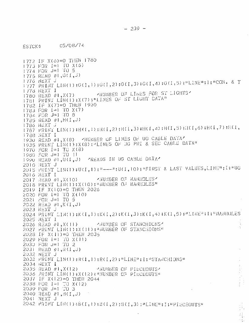
- 239 -
ESICKS 05/08/74
1772 1773 1774-11'75 11'/6 1777 1 Tid 1780 1 7 Bl 1782 1783 1784 1785 1786 1787 1780 193U 1935 1970 1980 19yu 2010 2015 2016 2017 2018 2019 2020 2021 2022 2023 2024 2025 2026 2027 2028 2029 2U3U 2031 2U32 2033 2034 2035 2<J 3 6 2037 2038 2039 2040 2041 2042
IF X(6)==0 THf:N 1780 FOR 1:.::1 TO X(6) FOR J:.::J TU 5 R !~AD if I ,G ( I ,J) ~~XT J . P FH NT L III< 1 ) ; G ( I , 1 ) ; G ( I ? 2) ; G ( I ,3) ; G ( I 'I 4) ; G ( I , 5) ; II LIN E"; I ; II C ON. & T
j\IEXT I READ if 1 ,X (7) )' lW/.\BE!< OF L I l\lES FOr< ST LI GHTS'" PFHNT LINe 1) ;X (7) ; HLINES OF ST LIGHT DATAl! IF X(7)==0 THLN 1930 FOt? 1 = 1 TO X (7) Fon J==ITO 8 f~EAD it!? H ( I ? J ) i~EXT J ~ R I N',( LIN ( 1 ) ; H (l , 1 ); 1 HI, 2) nf( I , 3) HI ( I ,4) ; H (I , 5) ;;! ( I , 6) ; H ( I 1 7 ) ; H ( I ,
i~EXT I READ if! ,X(S) "'NUMBER OF LINES Or: UG CABLE DATA" PRINT LIN(I);X(S);"LINES OF UG PHI 8, SEC CABLE DATN' FOR I:.:: I TU X (8) FOR J:.:: I TO 11 READ #1 ,U(I,J) )'R~AUS IN UG CABLE DATA' ;·!EXT J rJRINT LItH I) ? U (1,1); 11 ___ "; U( I, 10):; IJFI liST &. LAST VALUES, LINEIl; I; IIUG ; .. IEXT I F~EAD i/:I,X(10) J'dU;,.\BER OF i\Hd~HOLES/ PR I !~T LI N C I ) ; X ( I 0) ; II i\lUftiSER OF MA1\JHOLES II IF X(IO)=O THEN 2026 f'OR 1 = I TO X ( 10) rOR J=I TO 5 READ ill ,K <I ,J) N C:XT J PI<I NT L I!~ ( I ) ; K <I , I ) ; l~ ( I ,2) ; K ( I ,3) ; K ( I ,4) ; K ( I ,5) ; II L Hil [J ; I ; ill.1ANf IULES NEXT I f{EAD itl ,X( 11) "'f'-iUi';j8ER OF STAr,jCHIUNS'" fJF?INT LHH I) ;X( 11) ;i11'JUiltBE!? OF STANC:HONS" IF X( 11):.::0 THEN 2035 f 01< 1 = 1 TU X ( 1 I ) r:OR ..)= r TO 2 R t.::: A D it 1 ,f( <I ,J) NEXT J rJ Fn N r LIN ( 1 ) ; F? ( I 9 I ) ; R ( I ,2) ; II LIN E 1/ :j I ; n S T Al~ CHI UN S II l~EXT I Ri:.:AD ~,;I,X(12) J'l'W!,1BER OF PIL:CEOUTS" PrHNT LINCI):;X(12),1I1'JU:,IBEI? OF Plt:ClUUTSIi IF X( 12)=0 TilE!·! 2044 FOR 1:.::1 TO X(12) FUR J:.::J TO 3 F?EAD /11 ,D( I ,J) NEXT J prH NT L I H ( I ) ; B ( I ? i ) ;lH I 92) ; B ( I 'J 3) ; II LIN E"; I ; II PI L:CECJUTS II
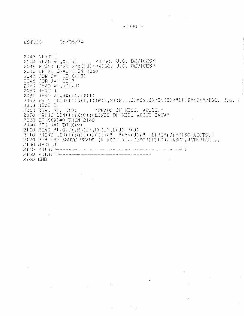
- 240 -
lSTCK$ 0:5/08/74
2()43 NEXT I 2044 W~AD ill ,XC 13) "i\\ISC. U.G. DI::VICES" 2 0 4 5 rJ ).{ H-j T L EH 1 ); X ( I 3 ) ; II I,ll S C • U • G • 0 I:: V ICE S II 2046 IF X(!3)=0 THEN 2060 2047 fOR 1=1 TO X(13) 2048 FOR J=l TO 3 204~ HEAD #1,NCI,J) 20~O l\!EXT J 2051 lH::AD J'FI ,S$(1) ,T$(I) 20 5 2 PIn NT L I H C I ) ; l,j C I , 1 ) ; H ( I , 2) ; N ( I , 3) ; S $ ( I ) ; T $ ( I ) ; II L Ii ~ E"; I ; II ;:11 S C • U • G. 20~3 NEXT I 2060 R~AD #1, X(9) "READS IN MISC. ACCTS.' 207() PRI;H LIlHl);X(9);"LINES OF MISC ACCTS DATAII 2080 IF X(9)=O THiN 2140 2090 FOR J=1 TO X(9) 21 00 R tAD iF 1 ,(J (J) ,N $ ( J ) ,M $ ( J) ,L ( J) ? r,\( J) 2110 P1HNT LIN(I);OeJ);U$(J);i1 11;/.1$(J);II--LIl~L::II;J;lli'.usc ACCTS.II 2120 !(EM -rr-li: ABOVE READS IN ACCT NO. ,DEscnrpTIOH,LABO~{,MATERIAL ••• 2130 Ui:.:XT J 214() Pl{INTII------------------------------------------II; 21 50 P f< I NT 11- ------ __ . _____ ------ _______ ----11
2100 END
REFERENCES
"A Computerized Cost Estimating Systein,1I Architectural Record, Vol. 152, November 1972, pp. 78-80~
Adkins, D. G. and F .. S. Radhfanski, !lCost Procedures and Control,1f Cost Engineering, Vol. 4, July, 1959 pp~ 11-20.
Balcomb, "Cost Estimating, II Engineering Contractor, July 14, 1959, No .. 6333.
Basse, W. A., "Computer Talws Over Line Estimating," Electrical v.Jorld, Vol. 172, November 10, 1969, pp. 7)6:::r;rr::- --
Bauman, Ho C., "Accuracy Considerations for Capital Cost Estimation,'1 Industrial and Chemistry, Vol.50 Apr .. 1958.
Beutel, M. L .. , IIComputer Estimates Costsll, Engineering pews-Record, Vol. 170, Feb. 28, 1963. pp.26-30.
Buetel, H. L., 11;-,J8':; Code Simplfies, Expanding Estimating by Computer',11 Enp;ineering NeHs-Record, Vol.172, May
-ll~', ~1964, -pp~ -J~0-35.
Broderick, it!. C., II Estimating and Labor Uni ts for Elec tric Designers, II Consulting Engineering, Vol 68. June 1969 pp. 105-107.
Boyer" L.T.)} "Hemote Terminal Cost Estimating, II Journal of ..,i~~~ gonstruction Division; l\merican §~cie~::L of Civil K'Qgineer~., Vol 9~Jlarch 1972. pp. 1-15.
Capek, H. C, fI l'Estimating PT'oject Costs- Not an Easy Task,11 Pl~t }~~ngineerin..8., Nov 12, 1969, pp" 89·~90o
IrCornputer for Cost Estimating,lI Chemical Engineerinr;, Vol~ 67, October 3, 1960, pp~119.
Corbe t t., \IT. R., II HC;H 'tie Prepare Preliminary Cos t Es tima tes" , Cops~lti_~ ~];J'lL~eer, Vol 42, October, 1954·, PP078-80o
Dallavia, L. A., Estirnating General Construction Costs, 2nd ed., New York: F.W. Dodge, 1957
DeutSCh, 11* E., Est;i.E18.ti_C2~ Th~or:X' Englewood Cliffs: Prentice Hall Inc o :: 19'b5~
Edm1.illds, J$ "CIvICI Automates Cost Analyses," consult:Lre Engineering, Vol" 35, November, 1970, pp,,102-10~
Enyedy, Go, IIComputerized Project Validation and Estimation System, rI Tr8n~actions of the Arnerican Association of Cost Engineers, July 19b9, pp 198-206" - --
Engineer, May 13,
Fate, H. E., IIMultiproject Estimating Plf"ogram, II Electric ~igh t and Power, t!Iay 1968:1 pp. 96-100@
Fleischmann, E., IICost Studies and Computers- A Critique,lI Public Utilities Fortnightly, Volume 86, Nov, 1970., pp" 41-[~[~"
Frangipane, L. A., IIHow to Estimate R&D Labor Cost," Industrial Engineerins., Vol.2, January 1970, pp.38-~_o •.
Gallagher, P. F., £;ro:ject Estimating ~ the Engineering :rIethod, New Y rk: Hayden Book Co., 1965 .. - r.
Galopin,F. E., flEstimate Construction Cost," H'Tdrocarbon Processing" Vol L~7, JulYJ 1968, pp 107-108.
Geddes, S., Estima.tine; for B~ilding and Civil Engineering l1ork~; London: Goorge Nevmes Ltd., 1%0.
Geddes, S., Buildi~nd Public Horks Acimi nis tration, Es tit"" matifill. and Cos ting, Fifth Edition, London: George--NehTnes Ltd., 1957.
flGood Estimate, Half the Battle," Roads and Streets, Vol. 115, March, 1972, pp. 128-130a
Grsnt, E~L., and ''''.G .. Ireson, Principles of Enr;ineering Economy, Fourth Edition, NeH York~ The Honald Press, 19611._ .
Hackney, J. H., "An Outline of Capital Cost Estimating, II Cost Engineerinji, Volume 1, October,1956, pp" 27-33"
Hackney, J-. ~I'l., "1'1nat Effects Estimate Accuracy~l\ Povrer Engineering, Vol. 59, November, 1955, pp .. 69-tb:--
Hartridge, H. L., trKeeping Costs on Construction 1tJork!l" Contract Hecord, Volume 39, April 15, 1925, ppo362 ----- .

Kearsey, H" E., liThe Relationship Bet'(,-Jeen Costs and £3 ~:;. tiY'lating,il Industrial Hanap;ement, Vol. 15, July, 1928, pp. 234=236.
Kittrell, L. L., "Job Estimating by Computer, II Sixth PICA Conference Proceed~np;s, 1969, pp. 317-323.
Kittrell, L. L., IICut Job Estimating Time for Distribution,lI Electrical World, Vol. 167, pp 76-78"
Naconi)) G. V., "Fundamentals of Es timating, II General Building Contractor, Vol 2, November, 1928, pp. 30.
HattheHs, P. F., liThe Electrical Contractor's Estimate,ti Proceedings of the American Association of Cost Engineers ;-19"65.-
]\'1aynard, H. B., Editor, Industrial Engineering Handbook, Second Edition, New York: McGraw Hill Inc., 1953.
t1r'I_K Expands its Computerized Estimating, II Roads and Streets, Vol. 113, march, 1970, pp56-62.
I!National Construction Estimato~,11 Fourteenth Edition, Los Angeles: Craftman Book Company, 1966.
Ponder, '11. C., "Keep Them ~I;i thin Budget, II Hydrocarbon .!)'ocessinfl, Vol ~-7, July, 1968$1 pp. 107-108.
v Pulver, I-L E., Const1.~.ction Estimates and Costs, NeH Y rk:
NcGraH Hi11Book Company" Inc., 19I~0-:--- ('
Heps, I. J", "Steps in Estimating for Data Processing, II Roads and StreetE, Vol. 112, april, 1969, pp 108-110
Richar'dson, L. H. "Controlling Construction Costs,1l Con tractor~r and Engineers, Vol. 21, July, 1930.
Samaras, rl'~ T., I{Estimating Project Costs- ltmat the Text books DonI t Tell, II Electronics, Vol. 1.15, Feb., 1972, pp. 90-92.
Shaffe:c, L. R., II C013ESTCO, E3 tima ting Tool for the Nechanieal Contractor" II Heating, Pipi~J and Air Condi tion-ir}.f:;', Vol. 38 J Oct 1966, pp-92-98. -- "--
. Somers, J e C., I'Reducing the Expence of Cost Estimating,rt .1\1aJ':2:"-i'acturing Industries, Vol. 16, August, 1929 .. pp l Y-T?O ~.:::::o "-_J (II

Vennard, E .. 9 The Electric POIier Business, Ne\,.,f York: I-1cGraw • 1 ~ -- ON • - ~ ~ ~. ~
Hl.l..l Book Company I c., 1970~
Vernon, I. R., Realistit:! ,Cost Estimating., Dearborn Michigan: ASTHE Eubli shing Co"' 1961L
Hilson, F" 't/", Editor, l1anufacturing Planning and Estimating Handbook, New York: McGraw Hill Book Company Inc",196 3


