Embed Size (px)
Citation preview
Page 1
INSTALLATION INSTRUCTIONS
POWER-VENT HIGH-EFFICIENCY
FIREPLACE
BAY WINDOW MANTIS MODELSBF28(B,C,G)MK(N,P)-5BP28(B,C,G)MK(N,P)-5
FIREPLACE MANTIS MODELSFF28BMK(N,P)-3FW28BMK(N,P)-3
WARNING: If not installed, operated and maintained in accordance with the manufacturer’s instructions, this product could expose you to substances in fuel or from fuel combustion which can cause death or serious ill-ness.
This appliance may be installed in an aftermarket, permanently located, manufactured home (USA only) or mobile home, where not prohibited by state or local codes.This appliance is only for use with the type of gas indicated on the rating plate. This appliance is not convertible for use with other gases, unless a certified kit is used.
™
Attention: Check local codes for venting requirements.
WARNINGFIRE OR EXPLOSION HAZARDFailure to follow safety warnings exactly could result in serious injury, death or property damage.
— Do not store or use gasoline or other flam-mable vapors and liquids in the vicinity of this or any other appliance.
— WHAT TO DO IF YOU SMELL GAS• Do not try to light any appliance.• Do not touch any electrical switch; do
not use any phone in your building.• Leave the building immediately.• Immediately call your gas supplier
from a neighbor’s phone. Follow the gas supplier’s instructions.
• If you cannot reach your gas supplier, call the fire department.
— Installation and service must be per-formed by a qualified installer, service agency or the gas supplier.
INSTALLER: Leave this manual with the appliance.CONSUMER: Retain this manual for future reference.
HOT GLASS
DO NOT TOUCH
NEVER
WILLCAUSE BURNS.
GLASSUNTIL COOLED.
ALLOW CHILDRENTO TOUCH GLASS.
WARNING
A barrier designed to reduce the risk of burns from thehot viewing glass is provided with this appliance and shallbe installed for the protection of children and other at-riskindividuals.
30260-7-0315Page 2
TABLE OF CONTENTS
Important Safety Information ................................................................................................ 3Safety Information for Users of LP-Gas................................................................................ 4Introduction ...........................................................................................................................5Specifications & Accessories ................................................................................................ 6Installation and General Safety Information ......................................................................... 7Gas Supply ...........................................................................................................................8Vent Clearances ................................................................................................................... 9Venting Requirements ................................................................................................... 10-11PVVK-SH636 Vent Kit ........................................................................................................ 12Vent Examples for Single Flue ......................................................................................13-14PVCA Horizontal Colinear Direct Vent Adaptor .................................................................. 15Direct Vent and Colinear Direct Vent Adaptor................................................................16-17Rough Framing Dimensions ............................................................................................... 18Bay Window Mantis Clearance to Combustibles ................................................................ 19Fireplace Mantis Clearance to Combustibles ..................................................................... 20Bay Window Mantis Specifications ................................................................................21-22Fireplace Mantis Specifications .....................................................................................23-24Bay Window Mantis Log Set Installation ............................................................................ 25Fireplace Mantis Log Set Installation Instructions .............................................................. 26Gas Connection Installation................................................................................................ 27Wiring .................................................................................................................................28Start Up Check List............................................................................................................. 29Lighting Instructions............................................................................................................ 30Start Up and Adjustments ..............................................................................................31-32FRBTC Remote Instructions..........................................................................................33-38Automatic Humidifier Operation.......................................................................................... 39Optional Controls ................................................................................................................ 39Maintenance & Service..................................................................................................40-42Master Parts Distributor List ............................................................................................... 43How To Order Repair Parts ................................................................................................ 43Bay Window Mantis Parts List .......................................................................................44-45Bay Window Mantis Parts View .....................................................................................46-47Fireplace Mantis Parts List ............................................................................................48-49Fireplace Mantis Parts View ............................................................................................... 50Warranty Terms .................................................................................................................. 51
SECTION PAGE
30260-7-0315 Page 3
IMPORTANT SAFETY INFORMATIONTHIS IS A HEATING APPLIANCE
WARNINGThis appliance must be installed and repaired by a quali-fied service person who is familiar with the proper instal-lation and operation of the Mantis Power-Vent High Effi-ciency Fireplace. Installers who are not familiar with the installation of the Mantis and have questions, should con-tact Empire Comfort Systems, Inc. prior to installing the appliance to avoid creating a hazardous operating condi-tion.
• Due to high temperatures the appliance should be located out of traffic and away from furniture and draperies.
• Children and adults should be alerted to the hazards of high surface temperatures and should stay away to avoid burns or clothing ignition.
• Young children should be carefully supervised when they are in the same room as the appli-ance. Toddlers, young children and others may be susceptible to accidental contact burns. A physi-cal barrier is recommended if there are at risk individuals in the house. To restrict access to a fireplace or stove, install an adjustable safety gate to keep away toddlers, young children and other at risk individuals out of the room and away from hot surfaces.
• Clothing or other flammable material should not be placed on or near the appliance.
• Any safety screen or guard removed for servicing an appliance, must be replaced prior to operating the appliance.
• Keep burner and control compartment clean.• For manufactured home (USA only) or mobile home
or residential installation convertible for use with natural gas and liquefied petroleum gases when provision is made for the simple conversion from one gas to the other.
• Young children should be carefully supervised when they are in the same room as the appliance. Toddlers, young children, and others may be susceptible to ac-cidental contact burns. A physical barrier is recom-mended if there are at-risk individuals in the house. To restrict access to a fireplace or stove, install an adjust-able safety gate to keep toddlers young children, and other at-risk indivicuals out of the room and away from hot surfaces.
• A barrier designed to reduce the risk of burns from the hot viewing glass is provided with this appliance and shall be installed for the protection of children and other at-risk individuals.
• If the barrier becomes damaged, the barrier shall be replaced with the manufacturer’s barrier for this appli-ance.
• Any safety screen, guard, or barrier removed for servic-ing an appliance must be replaced prior to operating the appliance.
WARNINGInstallation and repair should be done by a QUALIFIED SERVICE PERSON. The appliance should be inspected before use and at least annually by a qualified service person. More frequent cleaning may be required due to excessive lint from carpeting, bedding materials, etc. It is imperative that control compartments, burners and circulating air passageways of the appliance be kept clean.
• DO NOT put anything around the heater that will obstruct the flow of combustion and ventilation air.
• DO keep the appliance area clear and free from combustible material, gasoline and other flammable vapors and liquids.
• DO examine venting system periodically and replace damaged parts.
• DO make a periodic visual check of burner. Clean and replace damaged parts.
• DO NOT use this heater if any part has been under water. Immediately call a qualified service technician to inspect the heater and to replace any part of the control system and any gas control which has been under water.
• DO NOT operate this appliance without the front panel installed.
Note to the Installer1. The installer must leave instruction manual with owner after
installation.2. The installer must have the owner fill out and mail
registration card supplied with the heater. 3. The installer should show the owner how to start and
operate heater and thermostat.4. The installer must locate unit near a grounded wall
receptacle for 115VAC power and must provide gas supply and vent the unit properly for safe operation.
Safety markings are frequently used in this manual to designate a degree or level of serious-ness and should not be ignored.
WARNING indicates a potentially hazardous situation that if not avoided, could result in personal injury or death.
CAUTION indicates a potentially hazardous situation that if not avoided, may result in mi-nor or moderate injury or property damage.
30260-7-0315Page 4
SAFETY INFORMATION FOR USERS OF LP-GASLP-Gas (Propane) is a flammable gas which can cause fires and explosions. In its natural state, propane is odorless and colorless. You may not know all the following safety precautions which can protect both you and your family from an accident. Read them carefully now, then review them point by point with the
members of your household. Someday, there may not be a minute to lose, everyone’s safety will depend on knowing ex-actly what to do. If, after reading the following information, you feel you still need more information, please contact your gas supplier.
LP-GAS WARNING ODORIf a gas leak happens, you should be able to smell the gas because of the odorant put in the LP-Gas.
That’s your signal to go into immediate action!• Do not operate electric switches, light matches, use your
phone. Do not do anything that could ignite the gas.• Get everyone out of the building, vehicle, trailer, or area.
Do that IMMEDIATELY.• Close all gas tank or cylinder supply valves.• LP-Gas is heavier than air and may settle in low areas
such as basements. When you have reason to suspect a gas leak, keep out of basements and other low areas. Stay out until firefighters declare them to be safe.
• Use your neighbor’s phone and call a trained LP-Gas service person and the fire department. Even though you may not continue to smell gas, do not turn on the gas again. Do not re-enter the building, vehicle, trailer, or area.
• Finally, let the service man and firefighters check for es-caped gas. Have them air out the area before you return. Properly trained LP-Gas service people should repair the leak, then check and relight the gas appliance for you.
NO ODOR DETECTED - ODOR FADESome people cannot smell well. Some people cannot smell the odor of the chemical put into the gas. You must find out if you can smell the odorant in propane. Smoking can decrease your ability to smell. Being around an odor for a time can affect your sensitivity or ability to detect that odor. Sometimes other odors in the area mask the gas odor. People may not smell the gas odor or their minds are on something else. Thinking about smelling a gas odor can make it easier to smell.
The odorant in LP-gas is colorless, and it can fade under some circumstances. For example, if there is an underground leak, the movement of the gas through soil can filter the odor-ant. Odorants in LP-Gas also are subject to oxidation. This
fading can occur if there is rust inside the storage tank or in iron gas pipes.
The odorant in escaped gas can adsorb or absorb onto or into walls, masonry and other materials and fabrics in a room. That will take some of the odorant out of the gas, reducing its odor intensity.
LP-Gas may stratify in a closed area, and the odor intensity could vary at different levels. Since it is heavier than air, there may be more odor at lower levels. Always be sensitive to the slightest gas odor. If you detect any odor, treat it as a serious leak. Immediately go into action as instructed earlier.
SOME POINTS TO REMEMBER• Learn to recognize the odor of LP-gas. Your local LP-Gas
Dealer can give you a “Scratch and Sniff” pamphlet. Use it to find out what the propane odor smells like. If you sus-pect that your LP-Gas has a weak or abnormal odor, call your LP-Gas Dealer.
• If you are not qualified, do not light pilot lights, perform service, or make adjustments to appliances on the LP-Gas system. If you are qualified, consciously think about the odor of LP-Gas prior to and while lighting pilot lights or performing service or making adjustments.
• Sometimes a basement or a closed-up house has a musty smell that can cover up the LP-Gas odor. Do not try to light pilot lights, perform service, or make adjustments in an area where the conditions are such that you may not detect the odor if there has been a leak of LP-Gas.
• Odor fade, due to oxidation by rust or adsorption on walls of new cylinders and tanks, is possible. Therefore, people should be particularly alert and careful when new tanks or cylinders are placed in service. Odor fade can occur in new tanks, or reinstalled old tanks, if they are filled and allowed to set too long before refilling. Cylinders and tanks which have been out of service for a time may develop internal
rust which will cause odor fade. If such conditions are suspected to exist, a periodic sniff test of the gas is advisable. If you have any question about the gas odor, call your LP-gas dealer. A periodic sniff test of the LP-gas is a good safety measure under any condition.
• If, at any time, you do not smell the LP-Gas odorant and you think you should, assume you have a leak. Then take the same immediate action recommended above for the occasion when you do detect the odorized LP-Gas.
• If you experience a complete “gas out,” (the container is under no vapor pressure), turn the tank valve off immediately. If the container valve is left on, the container may draw in some air through openings such as pilot light orifices. If this occurs, some new internal rusting could occur. If the valve is left open, then treat the container as a new tank. Always be sure your container is under vapor pressure by turning it off at the container before it goes completely empty or having it refilled before it is completely empty.
30260-7-0315 Page 5
INTRODUCTIONWARNING
The safety information listed below must be followed during the installation, service, and operation of this product. Failure to following the safety recommenda-tions could result in possible damage to the equip-ment, serious personal injury, or death.
Additional code information listed below is for refer-ence purposes only and does not necessarily have ju-risdiction over local or state codes. Always consult with local authorities before installing any gas appliance.
Combustion and Ventilation AirCANADA: National Standard of Canada for Natural Gas and Propane Installation Codes (NSCNGPIC) CAN/CGA-B149.1 and .2, Part 7, Venting Systems and Air Supply for AppliancesU.S.: National Fuel Gas Code NFPA 54/ANSI Z223.1(NFGC), Air for Combustion and Ventilation.
Electrical Connections CANADA: Canadian Electrical Code CSA C22.1U.S.: National Electrical Code (NEC) ANSI/NFPA 70
Gas Piping and Gas Pipe Pressure TestingCANADA: NSCNGPIC Part 5U.S.: NFGC and National Plumbing Codes
General InstallationsCANADA: NSCNGPIC. For a copy, contact Standard Sales, CSA International, 178 Rexdale Blvd., Etobicoke (Toronto), Ontario, M9W 1R3 CanadaU.S.: Current edition of the NFGC and NFPA 90B. For copies contact the National Fire Protection Association Inc., Batterymarch Park, Quincy, MA 02269 or American Gas Association, 400 N. Capitol, N.W., Washington DC 20001 or www.NFPA.org.
SafetyCANADA: (NSCNGPIC) CAN/GCA-B149.1 and .2 National Standard of CanadaU.S.: NFGC NFPA 5/ANSI Z223.1
Attention: This appliance may be installed in the U.S. or in Canada.
30260-7-0315Page 6
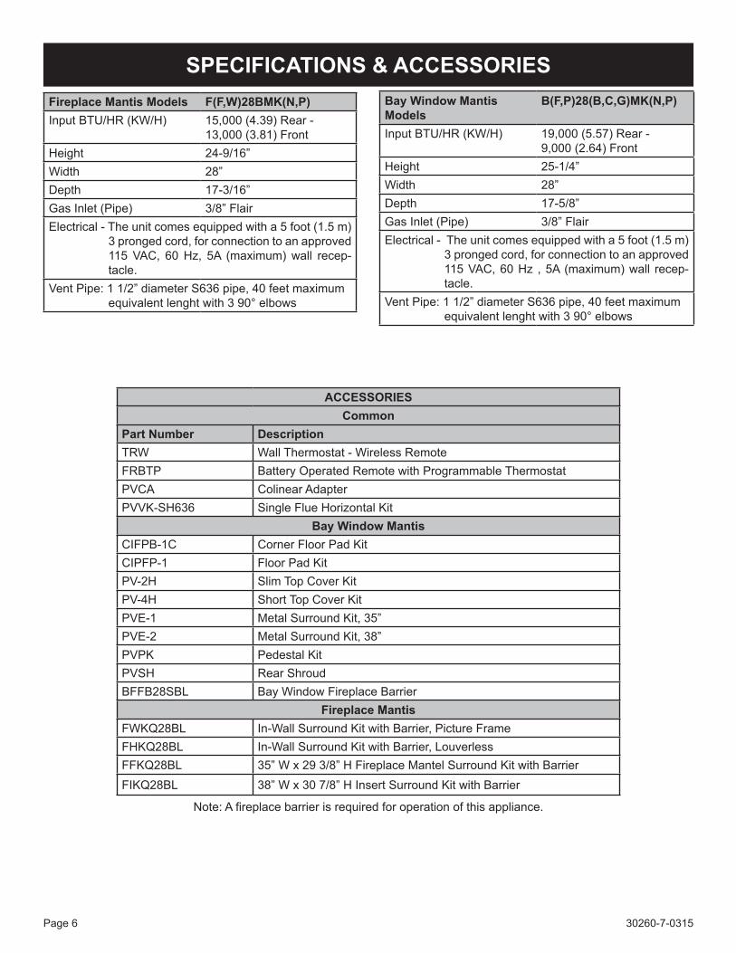
Bay Window Mantis Models
B(F,P)28(B,C,G)MK(N,P)
Input BTU/HR (KW/H) 19,000 (5.57) Rear - 9,000 (2.64) Front
Height 25-1/4”Width 28”Depth 17-5/8”Gas Inlet (Pipe) 3/8” FlairElectrical - The unit comes equipped with a 5 foot (1.5 m)
3 pronged cord, for connection to an approved 115 VAC, 60 Hz , 5A (maximum) wall recep-tacle.
Vent Pipe: 1 1/2” diameter S636 pipe, 40 feet maximum equivalent lenght with 3 90° elbows
SPECIFICATIONS & ACCESSORIESFireplace Mantis Models F(F,W)28BMK(N,P)Input BTU/HR (KW/H) 15,000 (4.39) Rear -
13,000 (3.81) FrontHeight 24-9/16”Width 28”Depth 17-3/16”Gas Inlet (Pipe) 3/8” FlairElectrical - The unit comes equipped with a 5 foot (1.5 m)
3 pronged cord, for connection to an approved 115 VAC, 60 Hz, 5A (maximum) wall recep-tacle.
Vent Pipe: 1 1/2” diameter S636 pipe, 40 feet maximum equivalent lenght with 3 90° elbows
ACCESSORIESCommon
Part Number DescriptionTRW Wall Thermostat - Wireless RemoteFRBTP Battery Operated Remote with Programmable ThermostatPVCA Colinear AdapterPVVK-SH636 Single Flue Horizontal Kit
Bay Window MantisCIFPB-1C Corner Floor Pad KitCIPFP-1 Floor Pad KitPV-2H Slim Top Cover KitPV-4H Short Top Cover KitPVE-1 Metal Surround Kit, 35”PVE-2 Metal Surround Kit, 38”PVPK Pedestal KitPVSH Rear ShroudBFFB28SBL Bay Window Fireplace Barrier
Fireplace MantisFWKQ28BL In-Wall Surround Kit with Barrier, Picture FrameFHKQ28BL In-Wall Surround Kit with Barrier, LouverlessFFKQ28BL 35” W x 29 3/8” H Fireplace Mantel Surround Kit with BarrierFIKQ28BL 38” W x 30 7/8” H Insert Surround Kit with Barrier
Note: A fireplace barrier is required for operation of this appliance.
30260-7-0315 Page 7
INSTALLATION AND GENERAL SAFETY INFORMATIONGeneral InformationThis series is designed certified in accordance with American National Standard/CSA Standard Z21.88 and CSA America In-terim Requirement 109-2009 as a Gas Fireplace Heater to be installed according to these instructions.
Any alteration of the original design, installed other than as shown in these instructions will be the responsibility of the person and company making the changes, and will void the warranty. This product may not be used with any type of gas other than what is shown on the rating plate.
ImportantAll Correspondence should refer to complete Model Number, Serial Number and type of gas.
InstallationInstallation, replacement, gas piping, gas utilization equipment or accessories, and the repair and service of this equipment must be performed by a qualified agency. The term “qualified agency” means any individual, firm, corporation or company which either in person or through a representative is engaged in and is responsible for (a) the installation or replacement of gas piping or (b) the connection, installation, repair or servicing of equipment, who is experienced in such work, familiar with all precautions required and has complied with all the requirements of the authority having jurisdiction.
• This installation must conform with local codes, or in the absence of local codes, in Canada use Canadian Elec-trical Code CSA C22.1 and in the United States use the National Fuel Gas Code NFPA 54/ANSI Z223.1.
• This appliance, when installed, must be electrically ground-ed in accordance with local codes or. In the absence of lo-cal codes, in Canada with the Canadian Electrical Code CSA C22.1 and in the United States with the National Elec-trical Code ANSI/NFPA 70.
• Provide adequate clearances around the heater for servic-ing and ensure there are no obstructions to the combus-tion air intake situated at the back of the heater. Refer to Pages 18 to 20.
• The Mantis Power-Vent High-Efficiency Fireplace must be installed on a flat, solid continuous surface (i.e. wood, metal, concrete). Rough or uneven surfaces can cause vibration or humming in the heater.
• This fireplace must be installed in such a way where the fireplace can be removed for servicing the heat ex-changer and the flue that are located in the rear sec-tion of the fireplace.
• This appliance is equipped with a three-prong [ground-ing] plug for your protection against shock hazard and should be plugged directly into a properly grounded three-prong receptacle. Do not cut or remove the grounding prong from this plug. For an ungrounded re-ceptacle, purchase an adapter with two prongs and a wire for grounding.
Note: Under no circumstances should the appliance be in-stalled under conditions that would not allow for easy removal of the appliance to carry out routine inspec-tion and service to the appliance.
Note: Where a mantel surround is being used on insert in-stallations and zero clearance fireplace installations, the combustion air intake slot located in the top mantel surround must not be obstructed. This will allow com-bustion air to enter through the slot to the combustion air inlet located at the back of the heater.
Note: During initial firing of this unit, residual oil from the heat exchanger may bake off and smoke may oc-cur. Provide adequate ventilation to the area where the heater is installed to prevent triggering of smoke alarms. Refer to page 32 for more detail.
A manufactured home (USA only) or mobile home OEM instal-lation must conform with the Manufactured Home Construc-tion and Safety Standard, Title 24 CFR, Part 3280, or when such a standard is not applicable, the Standard for Manufac-tured Home Installations, ANSI/NCSBCS Z225.1, or Standard for Gas Equipped Recreational Vehicles and Mobile Housing, CSA Z240.0.
Installation on Combustible FlooringIf this appliance is to be installed directly on carpeting, tile, or other combustible material, other than wood flooring, the appli-ance shall be installed on a metal or wood panel extending the full width and depth of the appliance.
The base referred to above does not mean the fire-proof base as used on wood stoves. The protection is primarily for rugs that may be extremely thick and light-color tile that can dis-color.
Installation in Residential GaragesGas utilization equipment in residential garages shall be in-stalled so that all burners and burner ignition devices are lo-cated not less than 18 inches (457 mm) above the floor. The equipment shall be located, or protected, so it is not subject to physical damage by vehicles.
Operation of Fireplace During ConstructionThe fireplace shall not be used during construction.
WARNINGDo not operate fireplace with the glass front removed, or if it is cracked or broken. Replacement of the glass shall be performed by a licensed or qualified service person
30260-7-0315Page 8
GAS SUPPLYAll gas piping must be installed in compliance with local codes and utility regulations. In the absence of local codes the installation must comply with NFCG NFPA 54/ANSI Z223.1. CAN/CGA - B149(.1 or .2) installation code. Note: Never use plastic pipe. Check to confirm whether your local codes allow copper tubing or galvanized.
Where permitted flexible gas connectors must be certified to the following standards: — ANS Z21.24 Appliance Connectors of Corrugated Metal
Tubing and Fittings— ANS Z21.45 Assembled Flexible Appliance Connectors
of Other Than All-Metal ConstructionThe above connectors may be used if acceptable by the authority having jurisdiction. The state of Massachusetts requires that a flexible appliance connector cannot exceed three feet in length.
A drip leg should be installed in the vertical gas supply pipe run to the unit.
Manual Shut-off ValveSome local regulations require the installation of a manual shut-off valve and ground joint union external to the appliance. The shutoff should be accessible for service and/or emergency use. Consult the local utility or gas supplier for additional requirements regarding the placement of the manual shut off valve. Compounds used on threaded joints of gas piping shall be resistant to the action of liquefied pe-troleum gases.
Leak Testing
WARNING - FIRE OR EXPLOSION HAZARDNever test for leaks with an open flame. Check all connections using a commercially available soap solution. A fire or explosion may result causing property damage, personal injury or loss of life. Failure to follow the safety warnings exactly could re-sult in serious injury, death or property damage.
After gas piping to the heater is complete, all connections must be tested for gas leaks. This includes pipe connec-tions at the main gas valve, emergency shutoff valve and flexible gas connectors (if applicable). The soap and water solution can be applied on each joint or union using a small paintbrush. If any bubbling is observed, the connection is not sealed adequately and must be retightened. Repeat the tightening and soap check process until the bubbling ceases. Important Note:
When pressure testing the gas supply lines at pressures greater than ½ psig (14 in. w.c.), the gas supply pip-ing system must be disconnected from the appliance to prevent damage to the gas control valve. If the test pressure is less than or equal to ½ psig (14 in. w.c.), close the manual shut-off valve.
Pressure Testing of the Gas Supply System1. To check the inlet pressure to the gas valve, a
1/8 inch N.P.T. plugged tapping, accessible for test gauge connection, must be placed immediately up-stream of the gas supply connection to the appliance.
2. The appliance and its individual shutoff valve must be disconnected from the gas supply piping system during any pressure testing of that system at test pressures in excess of 1/2 psig.
3. The appliance must be isolated from the gas supply piping system by closing its individual manual shutoff valve during any pressure testing of the gas supply pip-ing system at test pressures equal to or less than 1/2 psig.
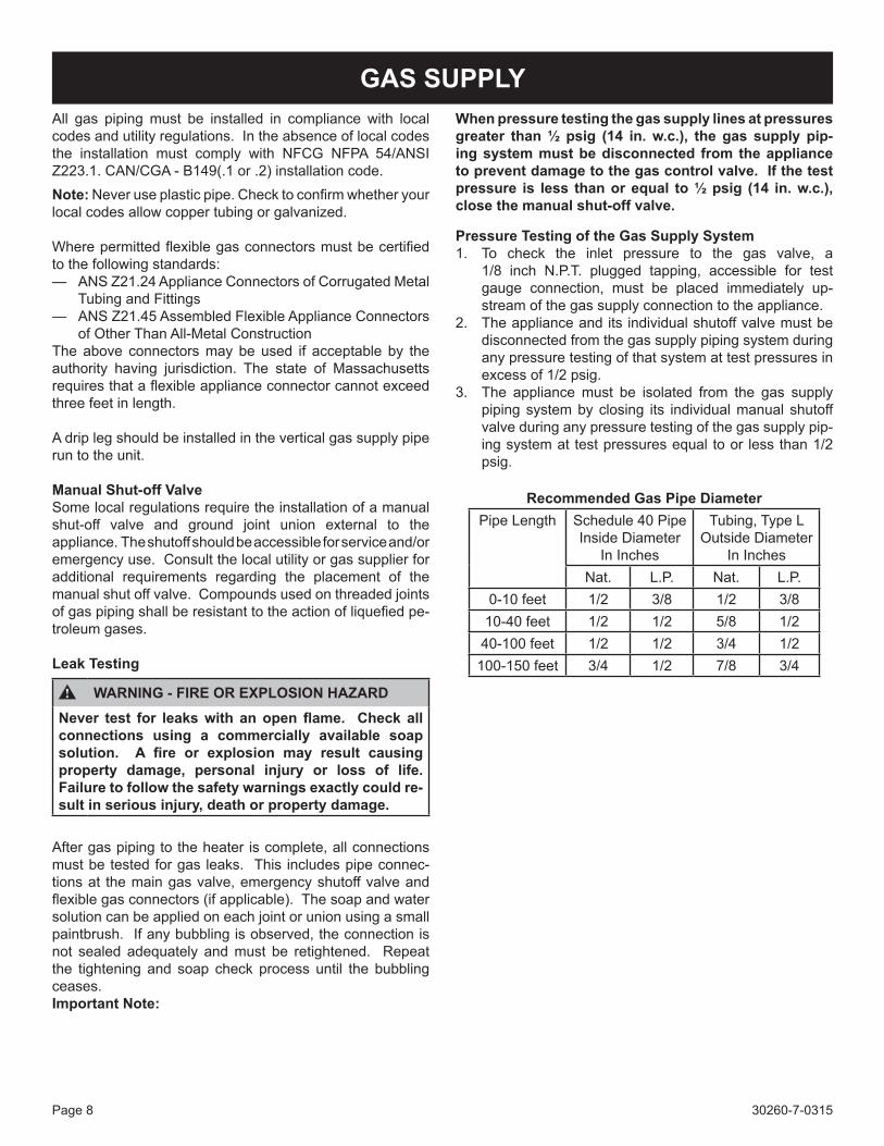
Recommended Gas Pipe DiameterPipe Length Schedule 40 Pipe
Inside Diameter In Inches
Tubing, Type L Outside Diameter
In InchesNat. L.P. Nat. L.P.
0-10 feet 1/2 3/8 1/2 3/810-40 feet 1/2 1/2 5/8 1/240-100 feet 1/2 1/2 3/4 1/2100-150 feet 3/4 1/2 7/8 3/4
30260-7-0315 Page 9
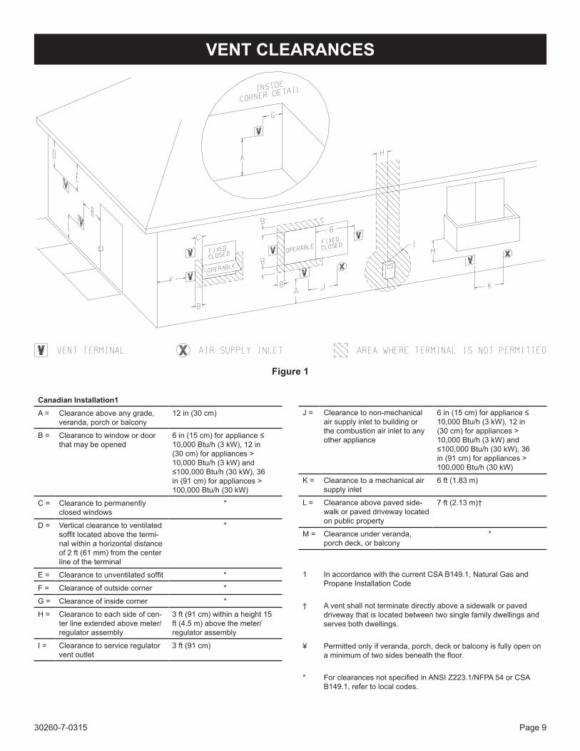
Figure 1
VENT CLEARANCES
Canadian Installation1A = Clearance above any grade,
veranda, porch or balcony12 in (30 cm)
B = Clearance to window or door that may be opened
6 in (15 cm) for appliance ≤ 10,000 Btu/h (3 kW), 12 in (30 cm) for appliances > 10,000 Btu/h (3 kW) and ≤100,000 Btu/h (30 kW), 36 in (91 cm) for appliances > 100,000 Btu/h (30 kW)
C = Clearance to permanently closed windows
*
D = Vertical clearance to ventilated soffit located above the termi-nal within a horizontal distance of 2 ft (61 mm) from the center line of the terminal
*
E = Clearance to unventilated soffit *
F = Clearance of outside corner *
G = Clearance of inside corner *
H = Clearance to each side of cen-ter line extended above meter/regulator assembly
3 ft (91 cm) within a height 15 ft (4.5 m) above the meter/regulator assembly
I = Clearance to service regulator vent outlet
3 ft (91 cm)
J = Clearance to non-mechanical air supply inlet to building or the combustion air inlet to any other appliance
6 in (15 cm) for appliance ≤ 10,000 Btu/h (3 kW), 12 in (30 cm) for appliances > 10,000 Btu/h (3 kW) and ≤100,000 Btu/h (30 kW), 36 in (91 cm) for appliances > 100,000 Btu/h (30 kW)
K = Clearance to a mechanical air supply inlet
6 ft (1.83 m)
L = Clearance above paved side-walk or paved driveway located on public property
7 ft (2.13 m)†
M = Clearance under veranda, porch deck, or balcony
*
1 In accordance with the current CSA B149.1, Natural Gas and Propane Installation Code
† A vent shall not terminate directly above a sidewalk or paved driveway that is located between two single family dwellings and serves both dwellings.
¥ Permitted only if veranda, porch, deck or balcony is fully open on a minimum of two sides beneath the floor.
* For clearances not specified in ANSI Z223.1/NFPA 54 or CSA B149.1, refer to local codes.
30260-7-0315Page 10
VENTING REQUIREMENTSWARNING
This appliance must not be vented with any other appliances, even if that appliance is of the condensing type. Common venting can result in severe corrosion of other appliances or their venting and can allow combustion gases to escape through such appliances or vents. Do not vent the heater into a fireplace chimney or building chase.
WARNINGUpon completion of the installation, carefully inspect the entire flue system to assure it is properly sealed. DO NOT use any vent material other than what is specified in this manual. Leaks in the flue system can result in serious personal injury or death due to exposure of flue prod-ucts, including carbon monoxide.
The Mantis is classified as a “Category IV” appliance, which requires special venting materials and installation procedures. Installations can be Conventional (1-pipe) and Direct Vent (2-pipe). In selecting a location for installation, it is necessary to provide adequate clearances for servicing and proper instal-lation.
All vent and combustion air pipes and fittings must be Sched-ule 40 PVC and meet the ANSI/ASTM Standard D1785. Ce-ment must conform to ASTM Standard D2564.
Installation in Canada must conform to the requirements of CSA B149 code. Vent systems must be composed of pipe, fit-tings, cements, and primers listed to ULC S636. In Canada, the primer and cement must be of the same manufacturer as the vent system; do not mix primers and cements from one manufacturer with a vent system from a different manufacturer. Follow the manufacturer’s instructions the use of primer and cement and never use primer or cement beyond its expiration date.
The safe operation, as defined by ULC S636, of the vent system is based on following these installation instructions, the vent system manufacturer’s installation instructions, and proper use of primer and cement. Acceptability under Canadian standard CSA B149 is dependent upon full compliance with all installa-tion instructions. Under this standard, it is recommended that the vent system be checked once a year by qualified service personnel. The authority having jurisdiction (gas inspection authority, municipal building department, fire department, etc) should be consulted before installation to determine the need to obtain a permit.
The maximum vent length is 40 feet equivalent with (3) 90° elbows. The minimum vent length is 12 inch-es. Each 90° elbow used in the vent system will be the equivalent to 3 feet, and each 45° elbow is equivalent to 1.5 feet, which should be added to the overall vent length.
1. The installation must conform with, as applicable:A. A non-metallic venting system for use in Canada shall
be listed to the Standard for Type BH Gas Venting Systems, ULC S636.
B. A maintenance schedule, when a means is provided to neutralize condensate, if required.
C. Periodic cleaning of the condensate collection and disposal system(s), if required.
D. For Category IV appliances:(1) When the manufacturer supplies the venting sys-
tem, the instructions shall include a parts list and instructions covering the installation of properly identified parts to provide for the venting of the vent gases to the outdoors.
(2) When the parts for venting the vent gases are not provided by the manufacturer and they are spe-cific types listed by a nationally recognized test-ing agency, these instructions shall clearly identify and specify the use of the specific parts.
2. For Category IV appliances, the venting system shall be installed in accordance with the appliance manufacturer’s instructions.
3. Instructions for proper venting installation:A. Horizontal portions of the venting system shall:
(1) Be supported to prevent sagging. The methods of and intervals for supports shall be specified in the installation manuals.
(2) Slope upwards not less than 1/4 in/ft (21 mm/m) from the appliance to the vent terminal.
(3) Category IV appliances shall be installed so as to prevent accumulation of condensate in the vent-ing system.
4. Category IV appliance installations shall provide a means for removal of condensate.
5. For appliance installation instructions accompanying a di-rect vent appliance or other appliance that can utilize a side wall vent system shall include information on where the vent terminal can and cannot terminate, including:For Category IV appliances, the following statement:
The vent for this appliance shall not terminate:(a) Over public walkways; or(b) Near soffit vents or crawl space vents or other
areas where condensate or vapor could create a nuisance or hazard or cause property damage; or
(c) Where condensate vapor could cause damage or could be detrimental to the operation of regula-tors, relief valves, or other equipment.
6. Non-metallic venting systems shall not interchange com-ponents with another listed or unlisted metallic or nonme-tallic vent systems.
Attention: Check local codes for venting requirements.
Note: IPEX System 636 Flue Gas Venting Adaptor is pro-vided. Installer to check for adhesive material require-ments.
30260-7-0315 Page 11
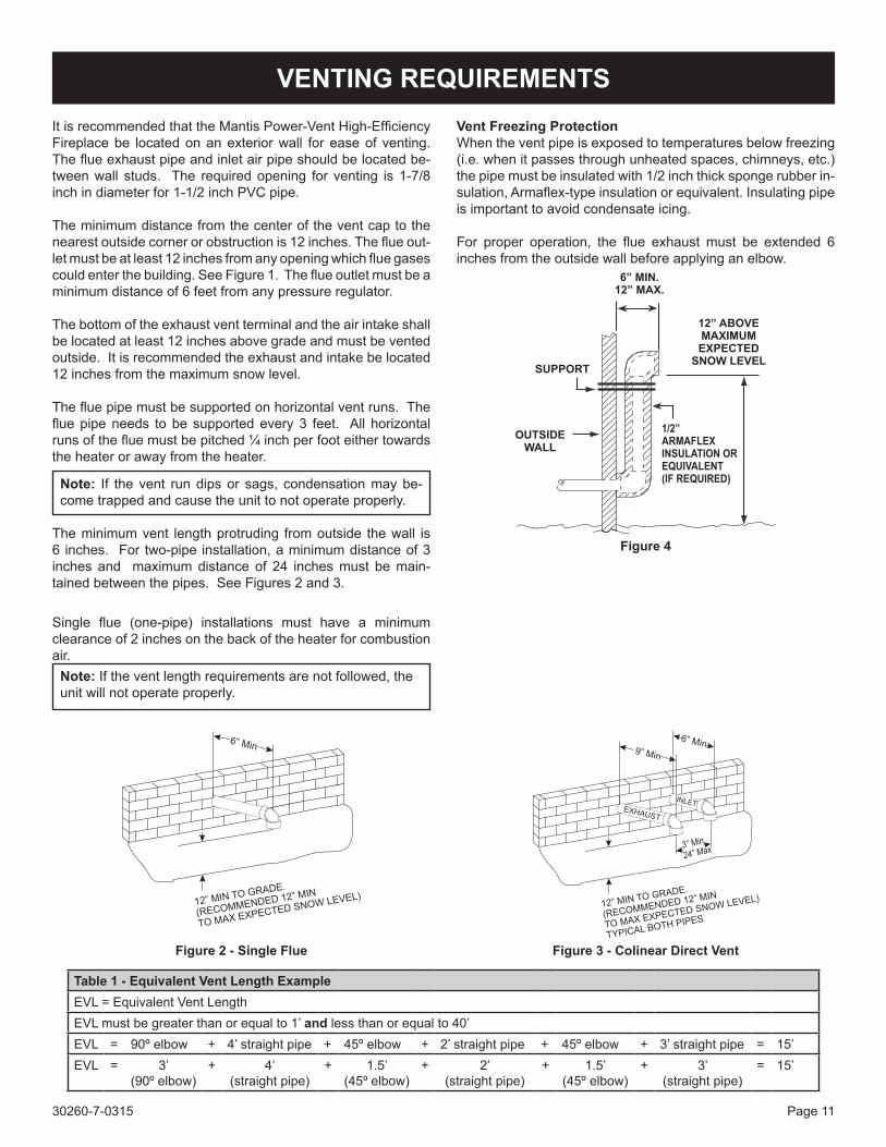
VENTING REQUIREMENTSIt is recommended that the Mantis Power-Vent High-Efficiency Fireplace be located on an exterior wall for ease of venting. The flue exhaust pipe and inlet air pipe should be located be-tween wall studs. The required opening for venting is 1-7/8 inch in diameter for 1-1/2 inch PVC pipe.
The minimum distance from the center of the vent cap to the nearest outside corner or obstruction is 12 inches. The flue out-let must be at least 12 inches from any opening which flue gases could enter the building. See Figure 1. The flue outlet must be a minimum distance of 6 feet from any pressure regulator.
The bottom of the exhaust vent terminal and the air intake shall be located at least 12 inches above grade and must be vented outside. It is recommended the exhaust and intake be located 12 inches from the maximum snow level.
The flue pipe must be supported on horizontal vent runs. The flue pipe needs to be supported every 3 feet. All horizontal runs of the flue must be pitched ¼ inch per foot either towards the heater or away from the heater.
Note: If the vent run dips or sags, condensation may be-come trapped and cause the unit to not operate properly.
The minimum vent length protruding from outside the wall is 6 inches. For two-pipe installation, a minimum distance of 3 inches and maximum distance of 24 inches must be main-tained between the pipes. See Figures 2 and 3.
Single flue (one-pipe) installations must have a minimum clearance of 2 inches on the back of the heater for combustion air.
Note: If the vent length requirements are not followed, the unit will not operate properly.
Figure 3 - Colinear Direct Vent
Table 1 - Equivalent Vent Length ExampleEVL = Equivalent Vent LengthEVL must be greater than or equal to 1’ and less than or equal to 40’EVL = 90º elbow + 4’ straight pipe + 45º elbow + 2’ straight pipe + 45º elbow + 3’ straight pipe = 15’EVL = 3’
(90º elbow)+ 4’
(straight pipe)+ 1.5’
(45º elbow)+ 2’
(straight pipe)+ 1.5’
(45º elbow)+ 3’
(straight pipe)= 15’
Figure 2 - Single Flue
Vent Freezing ProtectionWhen the vent pipe is exposed to temperatures below freezing (i.e. when it passes through unheated spaces, chimneys, etc.) the pipe must be insulated with 1/2 inch thick sponge rubber in-sulation, Armaflex-type insulation or equivalent. Insulating pipe is important to avoid condensate icing.
For proper operation, the flue exhaust must be extended 6 inches from the outside wall before applying an elbow.
Figure 4
30260-7-0315Page 12
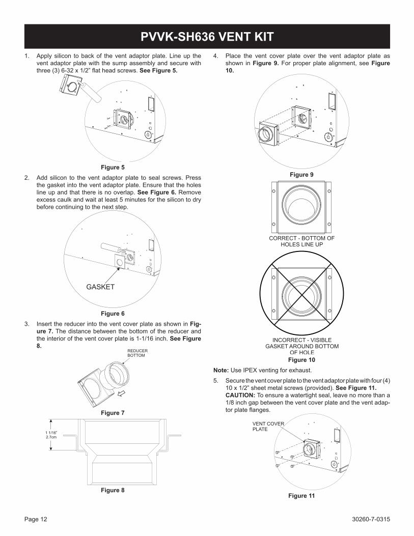
4. Place the vent cover plate over the vent adaptor plate as shown in Figure 9. For proper plate alignment, see Figure 10.
Figure 9
Figure 10Note: Use IPEX venting for exhaust.
5. Secure the vent cover plate to the vent adaptor plate with four (4) 10 x 1/2” sheet metal screws (provided). See Figure 11. CAUTION: To ensure a watertight seal, leave no more than a 1/8 inch gap between the vent cover plate and the vent adap-tor plate flanges.
Figure 11
1. Apply silicon to back of the vent adaptor plate. Line up the vent adaptor plate with the sump assembly and secure with three (3) 6-32 x 1/2” flat head screws. See Figure 5.
Anti-
Seize
Figure 52. Add silicon to the vent adaptor plate to seal screws. Press
the gasket into the vent adaptor plate. Ensure that the holes line up and that there is no overlap. See Figure 6. Remove excess caulk and wait at least 5 minutes for the silicon to dry before continuing to the next step.
Figure 63. Insert the reducer into the vent cover plate as shown in Fig-
ure 7. The distance between the bottom of the reducer and the interior of the vent cover plate is 1-1/16 inch. See Figure 8.
Figure 7
Figure 8
PVVK-SH636 VENT KIT
30260-7-0315 Page 13
VENT EXAMPLES FOR SINGLE FLUE
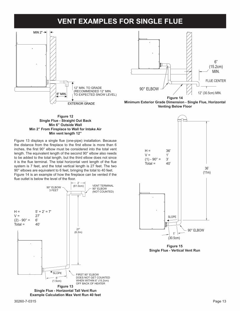
Figure 13 displays a single flue (one-pipe) installation. Because the distance from the fireplace to the first elbow is more than 6 inches, the first 90° elbow must be considered into the total vent length. The equivalent length of the second 90° elbow also needs to be added to the total length, but the third elbow does not since it is the flue terminal. The total horizontal vent length of the flue system is 7 feet, and the total vertical length is 27 feet. The two 90° elbows are equivalent to 6 feet, bringing the total to 40 feet. Figure 14 is an example of how the fireplace can be vented if the flue outlet is below the level of the floor.
Figure 13Single Flue - Horizontal Tall Vent Run
Example Calculation Max Vent Run 40 feet
H = 5’ + 2’ = 7’V = 27’(2) - 90° = 6’Total = 40’
Figure 14Minimum Exterior Grade Dimension - Single Flue, Horizontal
Venting Below Floor
Figure 12Single Flue - Straight Out Back
Min 6” Outside WallMin 2” From Fireplace to Wall for Intake Air
Min vent length 12”
Figure 15Single Flue - Vertical Vent Run
H = 36’V = 1’(1) - 90° = 3’Total = 40’
30260-7-0315Page 14
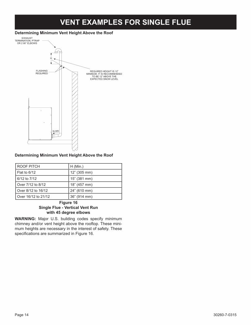
VENT EXAMPLES FOR SINGLE FLUEDetermining Minimum Vent Height Above the Roof
Figure 16Single Flue - Vertical Vent Run
with 45 degree elbowsWARNING: Major U.S. building codes specify minimum chimney and/or vent height above the rooftop. These mini-mum heights are necessary in the interest of safety. These specifications are summarized in Figure 16.
ROOF PITCH H (Min.)Flat to 6/12 12” (305 mm)
6/12 to 7/12 15” (381 mm)Over 7/12 to 8/12 18” (457 mm)Over 8/12 to 16/12 24” (610 mm)Over 16/12 to 21/12 36” (914 mm)
Determining Minimum Vent Height Above the Roof
30260-7-0315 Page 15
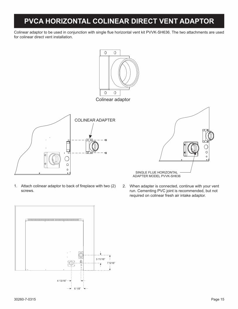
PVCA HORIZONTAL COLINEAR DIRECT VENT ADAPTOR
1. Attach colinear adaptor to back of fireplace with two (2) screws.
2. When adapter is connected, continue with your vent run. Cementing PVC joint is recommended, but not required on colinear fresh air intake adaptor.
Colinear adaptor
Colinear adaptor to be used in conjunction with single flue horizontal vent kit PVVK-SH636. The two attachments are used for colinear direct vent installation.
30260-7-0315Page 16
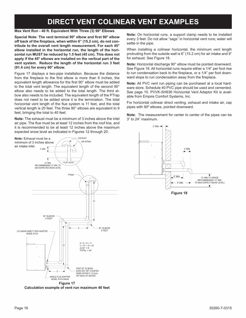
DIRECT VENT COLINEAR VENT EXAMPLESMax Vent Run - 40 ft. Equivalent With Three (3) 90° ElbowsSpecial Note: The vent terminal 90° elbow and first 90° elbow off back of the fireplace, when within 6” (15.2 cm), do not con-tribute to the overall vent length measurement. For each 45° elbow installed in the horizontal run, the length of the hori-zontal run MUST be reduced by 1.5 feet (45 cm). This does not apply if the 45° elbows are installed on the vertical part of the vent system. Reduce the length of the horizontal run 3 feet (91.4 cm) for every 90° elbow.Figure 17 displays a two-pipe installation. Because the distance from the fireplace to the first elbow is more than 6 inches, the equivalent length allowance for the first 90° elbow must be added to the total vent length. The equivalent length of the second 90° elbow also needs to be added to the total length. The third el-bow also needs to be included. The equivalent length of the PTrap does not need to be added since it is the termination. The total horizontal vent length of the flue system is 11 feet, and the total vertical length is 20 feet. The three 90° elbows are equivalent to 9 feet, bringing the total to 40 feet.
Note: The exhaust must be a minimum of 3 inches above the inlet air pipe. The flue must be at least 12 inches from the roof line, and it is recommended to be at least 12 inches above the maximum expected snow level as indicated in Figures 12 through 20.
Note: Exhaust must be a minimum of 3 inches above air intake inlet.
Figure 17Calculation example of vent run maximum 40 feet
Note: On horizontal runs, a support clamp needs to be installed every 3 feet. Do not allow “sags” in horizontal vent runs; water will settle in the pipe.
When installing a colinear horizontal, the minimum vent length protruding from the outside wall is 6” (15.2 cm) for air intake and 9” for exhaust. See Figure 18.
Note: Horizontal discharge 90° elbow must be pointed downward. See Figure 18. All horizontal runs require either a 1/4” per foot rise to run condensation back to the fireplace, or a 1/4” per foot down-ward slope to run condensation away from the fireplace.
Note: All PVC vent run piping can be purchased at a local hard-ware store. Schedule 40 PVC pipe should be used and cemented. See page 10. PVVK-SH636 Horizontal Vent Adaptor Kit is avail-able from Empire Comfort Systems, Inc.
For horizontal colinear direct venting, exhaust and intake air, cap pipes with 90º elbows, pointed downward.
Note: The measurement for center to center of the pipes can be 3” to 24” maximum.
Figure 18
30260-7-0315 Page 17
DIRECT VENT COLINEAR VENT EXAMPLES
Figure 19
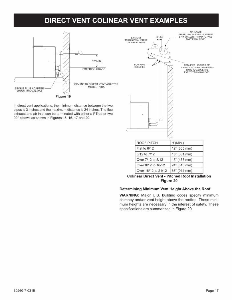
In direct vent applications, the minimum distance between the two pipes is 3 inches and the maximum distance is 24 inches. The flue exhaust and air inlet can be terminated with either a PTrap or two 90° elbows as shown in Figures 15, 16, 17 and 20.
Colinear Direct Vent - Pitched Roof InstallationFigure 20
Determining Minimum Vent Height Above the RoofWARNING: Major U.S. building codes specify minimum chimney and/or vent height above the rooftop. These mini-mum heights are necessary in the interest of safety. These specifications are summarized in Figure 20.
ROOF PITCH H (Min.)Flat to 6/12 12” (305 mm)
6/12 to 7/12 15” (381 mm)Over 7/12 to 8/12 18” (457 mm)Over 8/12 to 16/12 24” (610 mm)Over 16/12 to 21/12 36” (914 mm)
30260-7-0315Page 18
ROUGH FRAMING DIMENSIONS
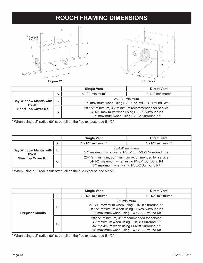
Figure 21 Figure 22
Single Vent Direct Vent
Bay Window Mantis with PV-4H
Short Top Cover Kit
A 8-1/2” minimum* 8-1/2” minimum*
B 25-1/4” minimum27” maximum when using PVE-1 or PVE-2 Surround Kits
C28-1/2” minimum, 33” minimum recommended for service
34-1/2” maximum when using PVE-1 Surround Kit37” maximum when using PVE-2 Surround Kit
* When using a 2” radius 90° street ell on the flue exhaust, add 5-1/2”.
Single Vent Direct Vent
Bay Window Mantis with PV-2H
Slim Top Cover Kit
A 13-1/2” minimum* 13-1/2” minimum*
B 25-1/4” minimum27” maximum when using PVE-1 or PVE-2 Surround Kits
C28-1/2” minimum, 33” minimum recommended for service
34-1/2” maximum when using PVE-1 Surround Kit37” maximum when using PVE-2 Surround Kit
* When using a 2” radius 90° street ell on the flue exhaust, add 5-1/2”.
Single Vent Direct Vent
Fireplace Mantis
A 19-1/2” minimum* 19-1/2” minimum*
B
25” minimum27-3/4” maximum when using FHK28 Surround Kit28-1/2” maximum when using FFK28 Surround Kit
32” maximum when using FWK28 Surround Kit
C
28-1/2” minimum, 31” recommended for service33” maximum when using FHK28 Surround Kit34” maximum when using FFK28 Surround Kit34” maximum when using FWK28 Surround Kit
* When using a 2” radius 90° street ell on the flue exhaust, add 5-1/2”.
30260-7-0315 Page 19
BAY WINDOW MANTIS CLEARANCE TO COMBUSTIBLES
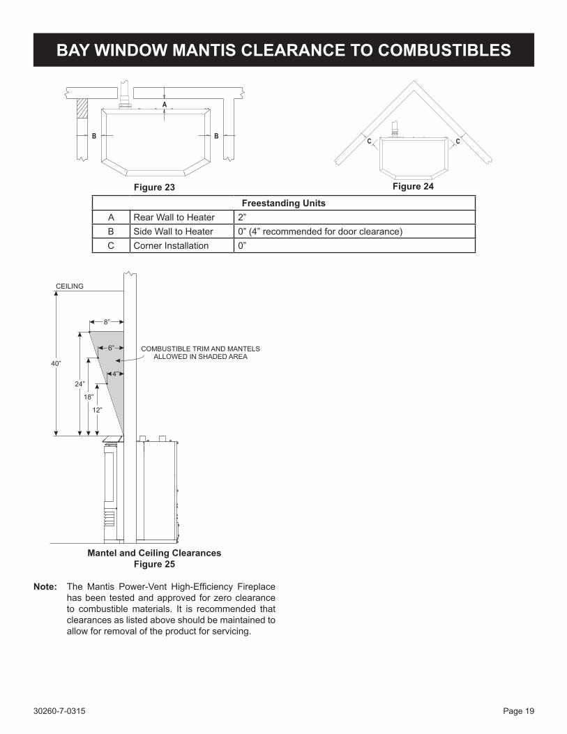
Freestanding UnitsA Rear Wall to Heater 2”B Side Wall to Heater 0” (4” recommended for door clearance)C Corner Installation 0”
Note: The Mantis Power-Vent High-Efficiency Fireplace has been tested and approved for zero clearance to combustible materials. It is recommended that clearances as listed above should be maintained to allow for removal of the product for servicing.
Figure 23 Figure 24
Mantel and Ceiling ClearancesFigure 25
30260-7-0315Page 20
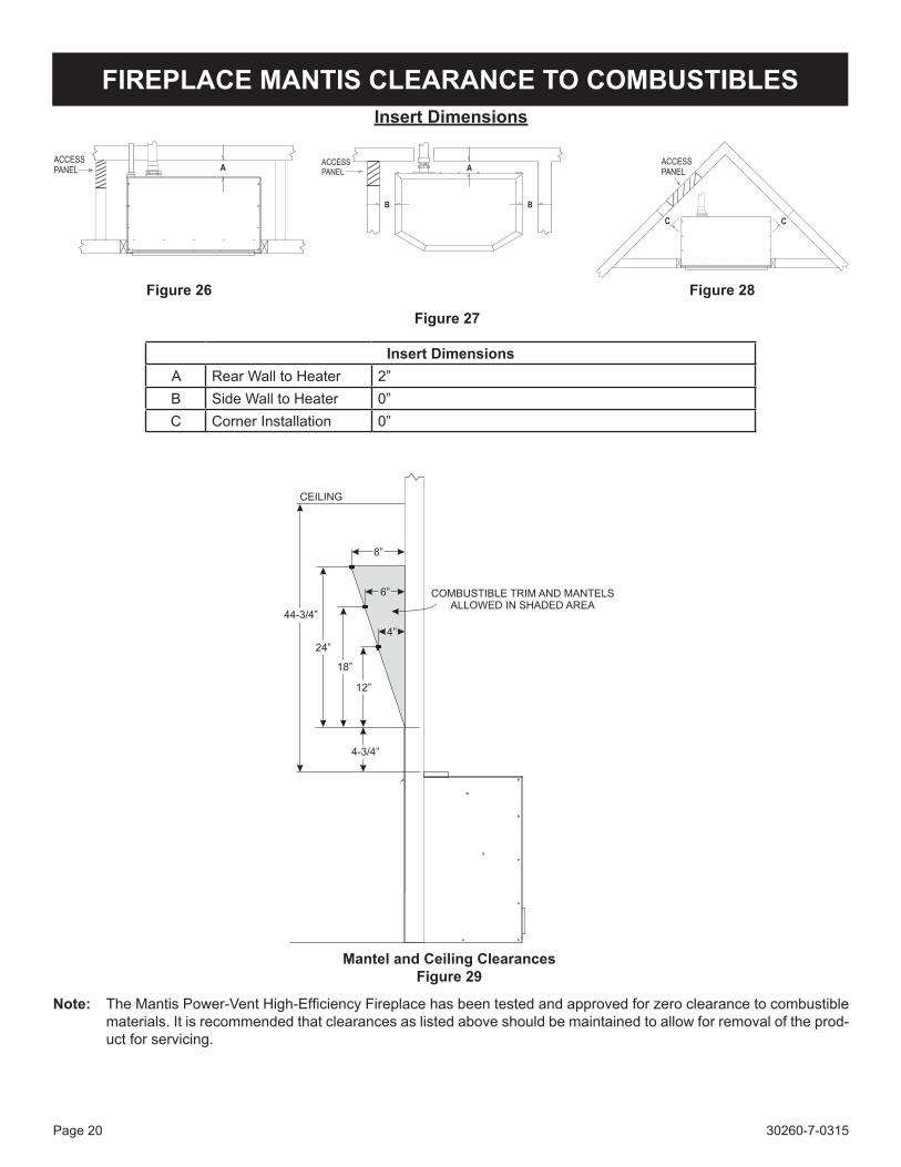
FIREPLACE MANTIS CLEARANCE TO COMBUSTIBLESInsert Dimensions
Insert DimensionsA Rear Wall to Heater 2”B Side Wall to Heater 0”C Corner Installation 0”
Note: The Mantis Power-Vent High-Efficiency Fireplace has been tested and approved for zero clearance to combustible materials. It is recommended that clearances as listed above should be maintained to allow for removal of the prod-uct for servicing.
Figure 26 Figure 28
Mantel and Ceiling ClearancesFigure 29
Figure 27
30260-7-0315 Page 21
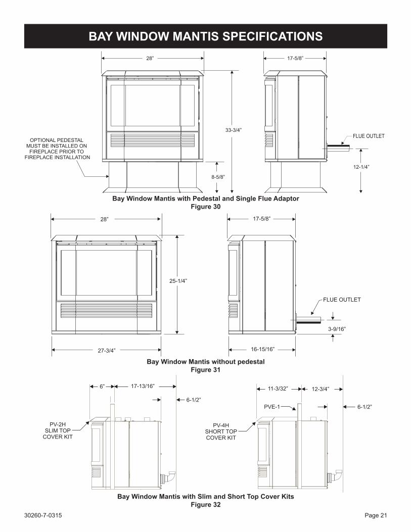
BAY WINDOW MANTIS SPECIFICATIONS
Bay Window Mantis with Pedestal and Single Flue AdaptorFigure 30
Bay Window Mantis without pedestalFigure 31
Bay Window Mantis with Slim and Short Top Cover KitsFigure 32
30260-7-0315Page 22
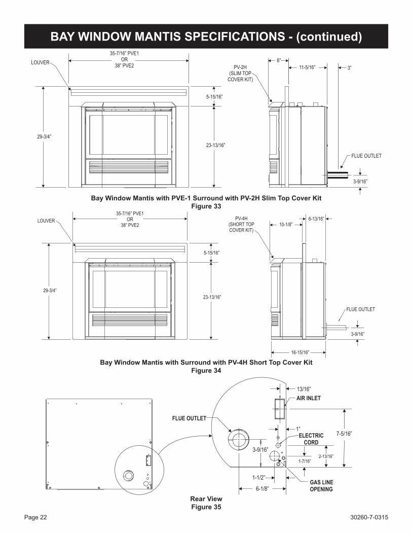
BAY WINDOW MANTIS SPECIFICATIONS - (continued)
Bay Window Mantis with PVE-1 Surround with PV-2H Slim Top Cover KitFigure 33
Bay Window Mantis with Surround with PV-4H Short Top Cover KitFigure 34
Rear ViewFigure 35
30260-7-0315 Page 23
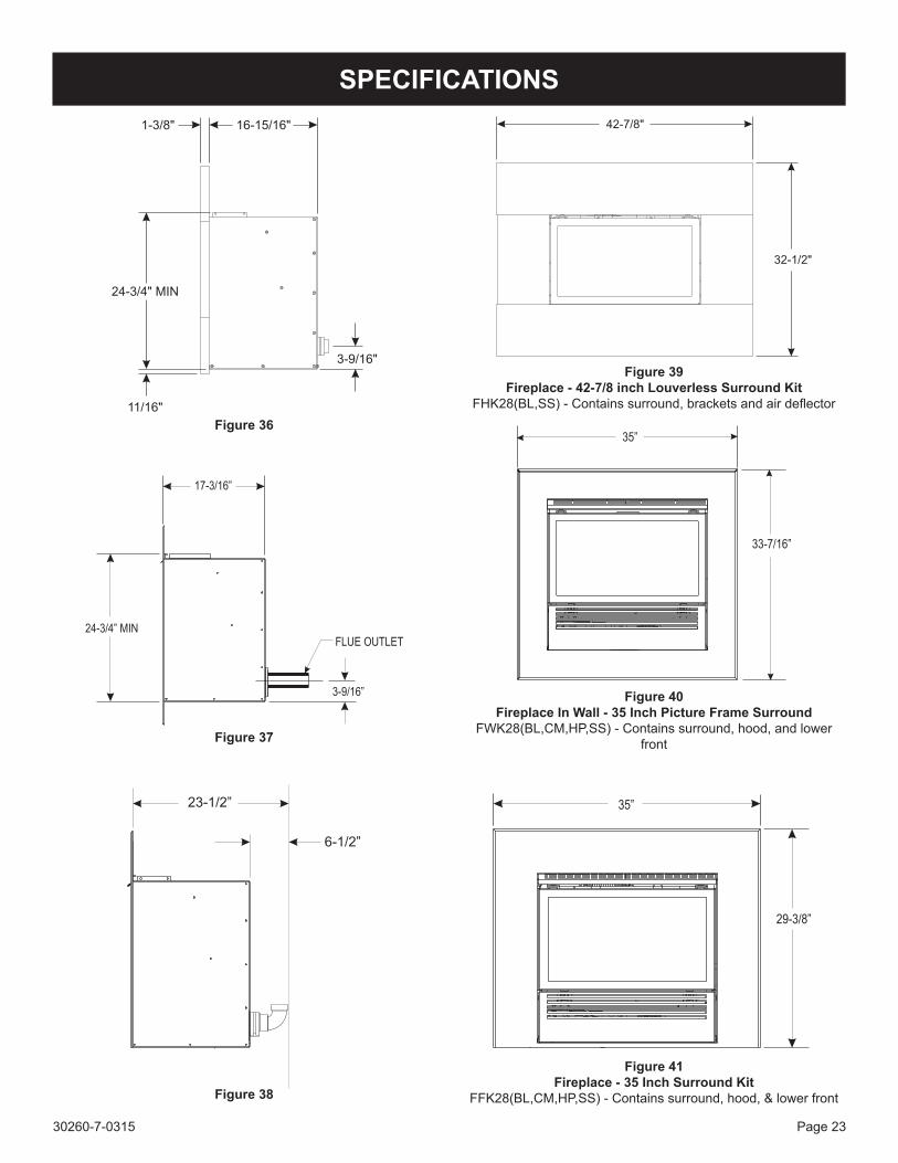
Figure 40Fireplace In Wall - 35 Inch Picture Frame Surround
FWK28(BL,CM,HP,SS) - Contains surround, hood, and lower front
Figure 41Fireplace - 35 Inch Surround Kit
FFK28(BL,CM,HP,SS) - Contains surround, hood, & lower front
SPECIFICATIONS
Figure 38
Figure 37
Figure 39Fireplace - 42-7/8 inch Louverless Surround Kit
FHK28(BL,SS) - Contains surround, brackets and air deflectorFigure 36
30260-7-0315Page 24
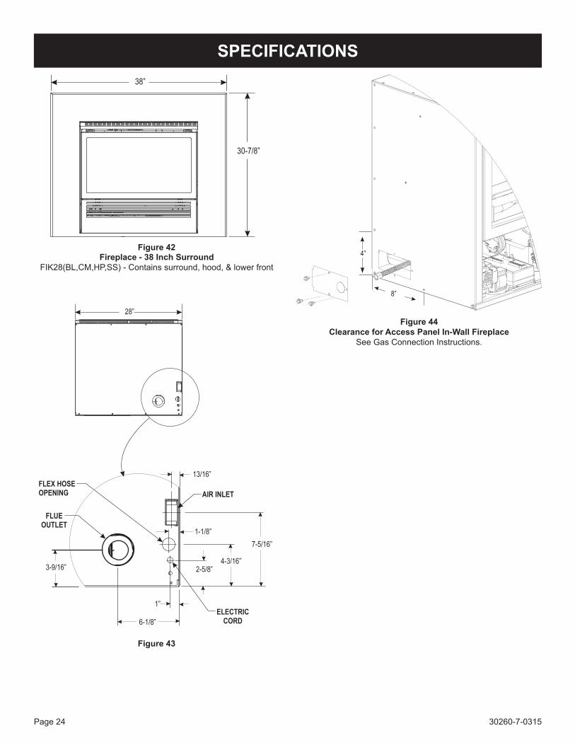
SPECIFICATIONS
Fireplace - 38 Inch Surround FIK28(BL,CM,HP,SS) - Contains surround, hood, & lower front
Figure 42
Figure 43
Figure 44Clearance for Access Panel In-Wall Fireplace
See Gas Connection Instructions.
30260-7-0315 Page 25
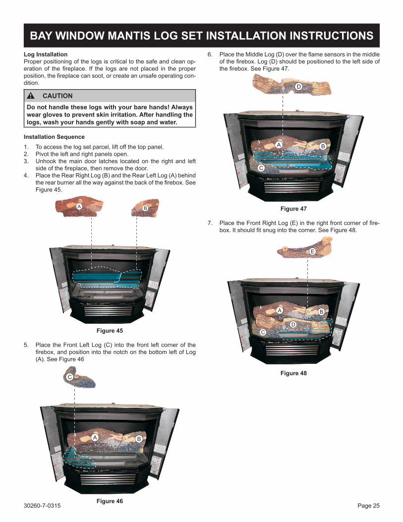
BAY WINDOW MANTIS LOG SET INSTALLATION INSTRUCTIONSLog InstallationProper positioning of the logs is critical to the safe and clean op-eration of the fireplace. If the logs are not placed in the proper position, the fireplace can soot, or create an unsafe operating con-dition.
CAUTIONDo not handle these logs with your bare hands! Always wear gloves to prevent skin irritation. After handling the logs, wash your hands gently with soap and water.
Installation Sequence1. To access the log set parcel, lift off the top panel.2. Pivot the left and right panels open.3. Unhook the main door latches located on the right and left
side of the fireplace, then remove the door. 4. Place the Rear Right Log (B) and the Rear Left Log (A) behind
the rear burner all the way against the back of the firebox. See Figure 45.
A B
Figure 45
5. Place the Front Left Log (C) into the front left corner of the firebox, and position into the notch on the bottom left of Log (A). See Figure 46
C
A B
Figure 46
6. Place the Middle Log (D) over the flame sensors in the middle of the firebox. Log (D) should be positioned to the left side of the firebox. See Figure 47.
D
A B
C
Figure 47
7. Place the Front Right Log (E) in the right front corner of fire-box. It should fit snug into the corner. See Figure 48.
E
A B
D
C
Figure 48
30260-7-0315Page 26
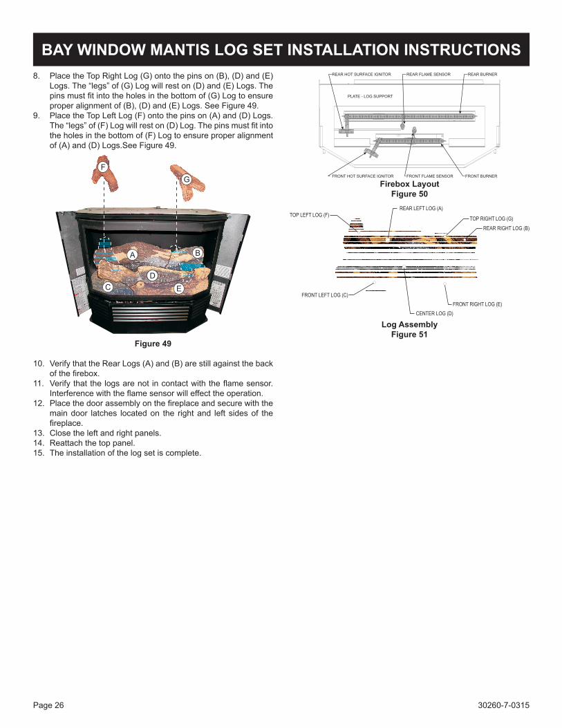
8. Place the Top Right Log (G) onto the pins on (B), (D) and (E) Logs. The “legs” of (G) Log will rest on (D) and (E) Logs. The pins must fit into the holes in the bottom of (G) Log to ensure proper alignment of (B), (D) and (E) Logs. See Figure 49.
9. Place the Top Left Log (F) onto the pins on (A) and (D) Logs. The “legs” of (F) Log will rest on (D) Log. The pins must fit into the holes in the bottom of (F) Log to ensure proper alignment of (A) and (D) Logs.See Figure 49.
F
G
A B
D
C E
Figure 49
10. Verify that the Rear Logs (A) and (B) are still against the back of the firebox.
11. Verify that the logs are not in contact with the flame sensor. Interference with the flame sensor will effect the operation.
12. Place the door assembly on the fireplace and secure with the main door latches located on the right and left sides of the fireplace.
13. Close the left and right panels.14. Reattach the top panel.15. The installation of the log set is complete.
BAY WINDOW MANTIS LOG SET INSTALLATION INSTRUCTIONS
Firebox LayoutFigure 50
Log AssemblyFigure 51
30260-7-0315 Page 27
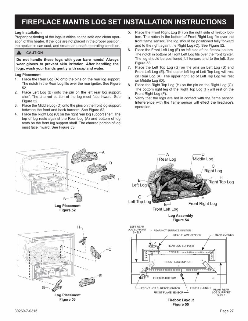
FIREPLACE MANTIS LOG SET INSTALLATION INSTRUCTIONSLog InstallationProper positioning of the logs is critical to the safe and clean oper-ation of this heater. If the logs are not placed in the proper position, the appliance can soot, and create an unsafe operating condition.
CAUTION
Do not handle these logs with your bare hands! Always wear gloves to prevent skin irritation. After handling the logs, wash your hands gently with soap and water.
Log Placement1. Place the Rear Log (A) onto the pins on the rear log support.
The notch in the Rear Log fits over the rear igniter. See Figure 52.
2. Place Left Log (B) onto the pin on the left rear log support shelf. The charred portion of the log must face inward. See Figure 52.
3. Place the Middle Log (D) onto the pins on the front log support between the front and back burners. See Figure 52.
4. Place the Right Log (C) on the right rear log support shelf. The top of log rests against the Rear Log (A) and bottom of log rests on the front log support shelf. The charred portion of log must face inward. See Figure 53.
Log PlacementFigure 53
B
F
D
A
H
C
G
E
Log PlacementFigure 52
5. Place the Front Right Log (F) on the right side of firebox bot-tom. The notch in the bottom of Front Right Log fits over the front flame sensor. The log should be positioned fully forward and to the right againt the Right Log (C). See Figure 52.
6. Place the Front Left Log (E) on left side of the firebox bottom. The notch in bottom of Front Left Log fits over the front Igniter. The log should be positioned full forward and to the left. See Figure 53.
7. Place the Left Top Log (G) on the pins on Left Log (B) and Front Left Log (E). The upper left leg of Left Top Log will rest on Rear Log (A). The upper right leg of Left Top Log will rest on Middle Log (D).
8. Place the Right Top Log (H) on the pin on the Right Log (C). The bottom right leg of the Right Top Log (H) will rest on the Front Right Log (F).
9. Verify that the logs are not in contact with the flame sensor. Interference with the flame sensor will effect the fireplace’s operation.
Firebox LayoutFigure 55
Log AssemblyFigure 54
30260-7-0315Page 28
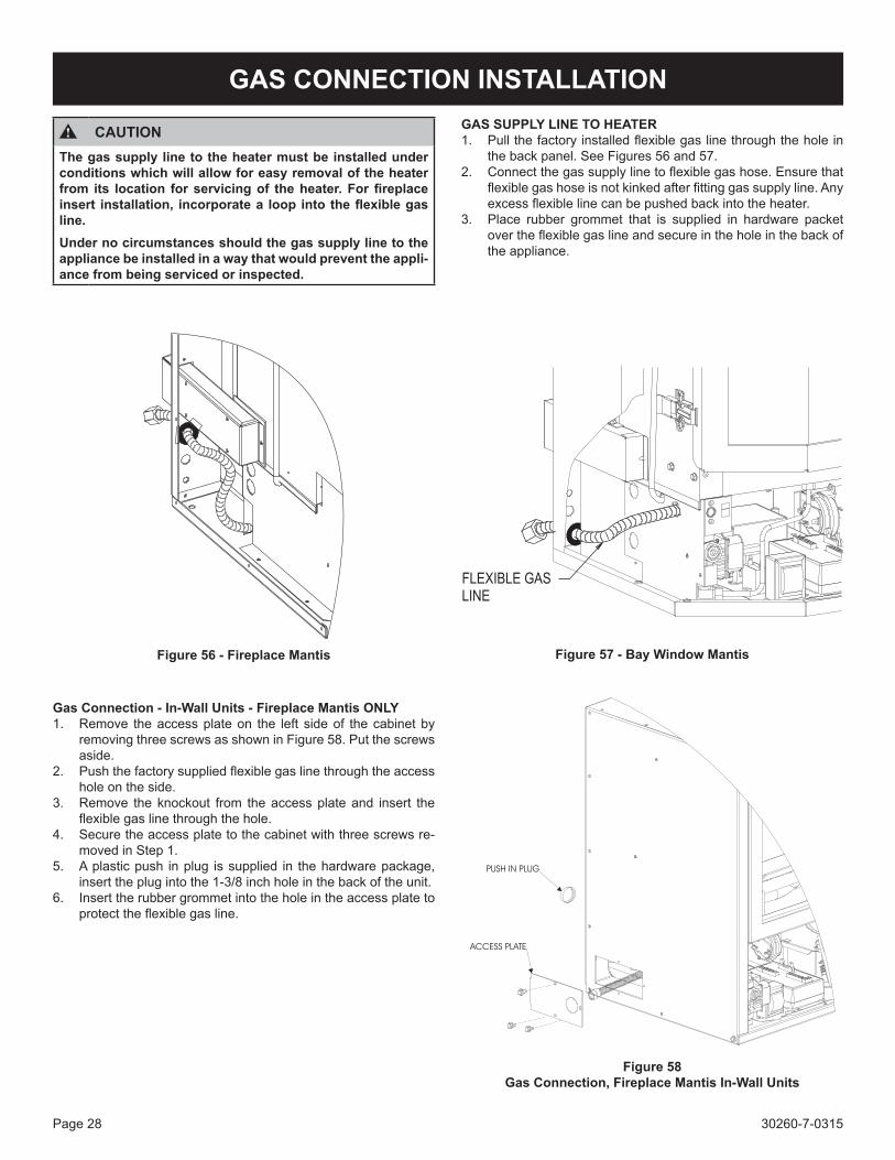
GAS CONNECTION INSTALLATION
CAUTIONThe gas supply line to the heater must be installed under conditions which will allow for easy removal of the heater from its location for servicing of the heater. For fireplace insert installation, incorporate a loop into the flexible gas line.Under no circumstances should the gas supply line to the appliance be installed in a way that would prevent the appli-ance from being serviced or inspected.
GAS SUPPLY LINE TO HEATER1. Pull the factory installed flexible gas line through the hole in
the back panel. See Figures 56 and 57.2. Connect the gas supply line to flexible gas hose. Ensure that
flexible gas hose is not kinked after fitting gas supply line. Any excess flexible line can be pushed back into the heater.
3. Place rubber grommet that is supplied in hardware packet over the flexible gas line and secure in the hole in the back of the appliance.
Gas Connection - In-Wall Units - Fireplace Mantis ONLY1. Remove the access plate on the left side of the cabinet by
removing three screws as shown in Figure 58. Put the screws aside.
2. Push the factory supplied flexible gas line through the access hole on the side.
3. Remove the knockout from the access plate and insert the flexible gas line through the hole.
4. Secure the access plate to the cabinet with three screws re-moved in Step 1.
5. A plastic push in plug is supplied in the hardware package, insert the plug into the 1-3/8 inch hole in the back of the unit.
6. Insert the rubber grommet into the hole in the access plate to protect the flexible gas line.
Figure 56 - Fireplace Mantis Figure 57 - Bay Window Mantis
Figure 58Gas Connection, Fireplace Mantis In-Wall Units
30260-7-0315 Page 29
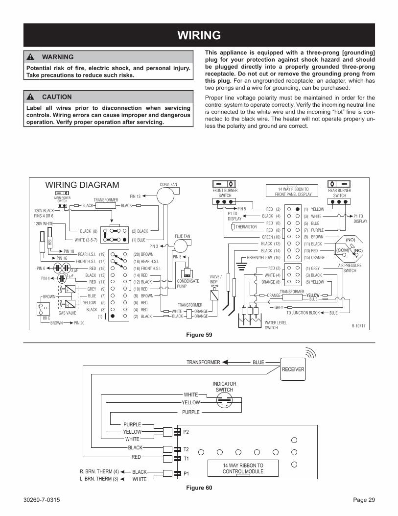
WIRINGThis appliance is equipped with a three-prong [grounding] plug for your protection against shock hazard and should be plugged directly into a properly grounded three-prong receptacle. Do not cut or remove the grounding prong from this plug. For an ungrounded receptacle, an adapter, which has two prongs and a wire for grounding, can be purchased.
Proper line voltage polarity must be maintained in order for the control system to operate correctly. Verify the incoming neutral line is connected to the white wire and the incoming “hot” line is con-nected to the black wire. The heater will not operate properly un-less the polarity and ground are correct.
Figure 59
Figure 60
WARNINGPotential risk of fire, electric shock, and personal injury. Take precautions to reduce such risks.
CAUTIONLabel all wires prior to disconnection when servicing controls. Wiring errors can cause improper and dangerous operation. Verify proper operation after servicing.
30260-7-0315Page 30
START UP CHECK LIST
1. Verify the gas line service does not exceed 10.5 in. w.c. and is not below 4.0 in. w.c. for natural gas, nor exceeds 13.0 in. w.c. or is below 11.0 in. w.c. for LP gas.
2. Check and inspect the appliance for gas leaks. In the event of gas leaks, cut off the gas supply to the heater immediate-ly and call your gas supplier. Verify the gas line has been purged.
3. Verify that all exhaust and inlet air pipes are unobstructed and properly joined.
4. Visually verify the burners are free of dust and debris. See Figures 45 and 50.
5. Check and verify that logs are place correctly. See pages 25 to 26. The logs must be in the correct position or the heater will not operate correctly.
DO NOT light heater without the logs installed, the heater will not operate properly.
6. Verify that all panels are secured in place and that the glass assembly door has been locked in position.
7. Verify the two burner switches are in the OFF position before applying power and the main power switch.
8. After verifying and checking all the above points, proceed to lighting instructions. Refer to Page 30.
9. Verify that the polarity of the connections are correct and the line voltage power .
Note: If using a surround, verify it is installed per the instruc-tions included with the kit.
WARNING
BEFORE OPERATING THIS APPLIANCE, CAREFULLY READ THE FOLLOWING.
30260-7-0315 Page 31
LIGHTING INSTRUCTIONS
FOR YOUR SAFETY READ BEFORE LIGHTING
WARNING: IF YOU DO NOT FOLLOW THESE INSTRUCTIONS EXACTLY, A FIRE OR EXPLOSION MAY RESULT CAUSING PROPERTY DAMAGE, PERSONAL INJURY, OR LOSS OF LIFE.
A. BEFORE LIGHTING smell all around the appliance area for gas. Be sure to smell next to the floor be-cause some gas is heavier than air and will settle on the floor.
WHAT TO DO IF YOU SMELL GAS • Do not try to light any appliance. • Do not touch any electrical switch. • Do not use any phone in your building. • Immediately call your gas supplier from a neigh-
bor’s phone. Follow the gas supplier’s instruc-tions.
• If you can not reach your gas supplier, call the fire department.
B. Use the on-the-wall switch or remote con-trol switch to turn the gas control on/off. Any at-tempted repairs or adjustments should be performed by a qualified service technician. Applying force or attempted repair may result in a fire or explosion.
C. Do not use this appliance if any part has been under water. Immediately call a qualified service technician to inspect the appliance and to replace any part of the control system and any gas control which has been under water.
LIGHTING INSTRUCTIONS1. STOP! Read the safety information above on this la-
bel.2. Set the thermostat, if used, to the lowest setting.3. Turn off all electric power to the appliance. Turn off
electrical control switches to “O.”4. This appliance is equipped with an ignition device that
automatically lights the burner. Do not try to light the burner by hand.
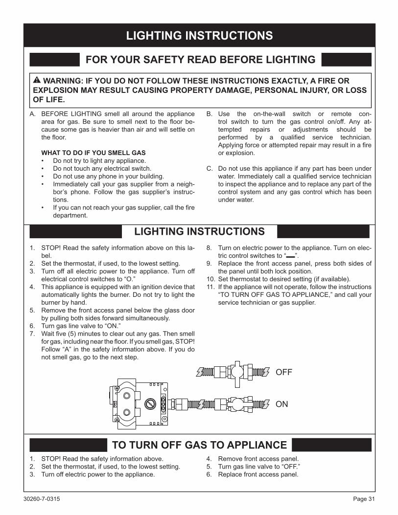
5. Remove the front access panel below the glass door by pulling both sides forward simultaneously.
6. Turn gas line valve to “ON.”7. Wait five (5) minutes to clear out any gas. Then smell
for gas, including near the floor. If you smell gas, STOP! Follow “A” in the safety information above. If you do not smell gas, go to the next step.
8. Turn on electric power to the appliance. Turn on elec-tric control switches to “ ”.
9. Replace the front access panel, press both sides of the panel until both lock position.
10. Set thermostat to desired setting (if available).11. If the appliance will not operate, follow the instructions
“TO TURN OFF GAS TO APPLIANCE,” and call your service technician or gas supplier.
TO TURN OFF GAS TO APPLIANCE1. STOP! Read the safety information above.2. Set the thermostat, if used, to the lowest setting.3. Turn off electric power to the appliance.
4. Remove front access panel.5. Turn gas line valve to “OFF.”6. Replace front access panel.
30260-7-0315Page 32
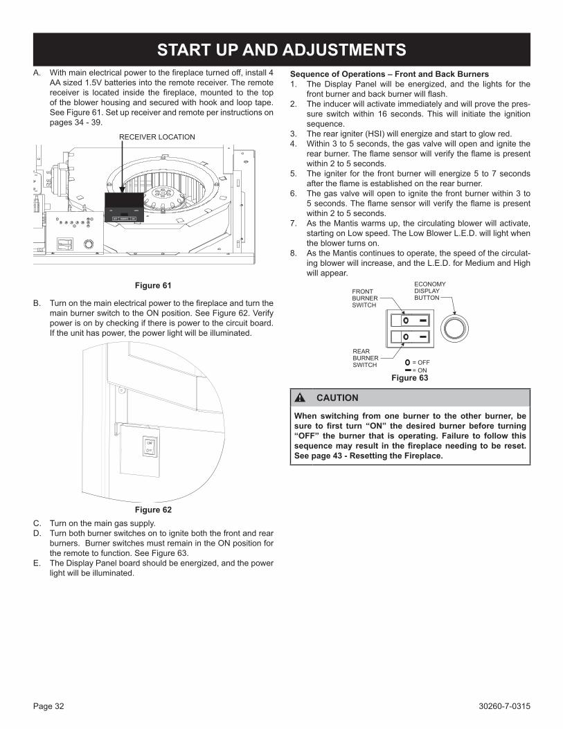
START UP AND ADJUSTMENTSA. With main electrical power to the fireplace turned off, install 4
AA sized 1.5V batteries into the remote receiver. The remote receiver is located inside the fireplace, mounted to the top of the blower housing and secured with hook and loop tape. See Figure 61. Set up receiver and remote per instructions on pages 34 - 39.
Figure 61
B. Turn on the main electrical power to the fireplace and turn the main burner switch to the ON position. See Figure 62. Verify power is on by checking if there is power to the circuit board. If the unit has power, the power light will be illuminated.
Figure 62C. Turn on the main gas supply.D. Turn both burner switches on to ignite both the front and rear
burners. Burner switches must remain in the ON position for the remote to function. See Figure 63.
E. The Display Panel board should be energized, and the power light will be illuminated.
Sequence of Operations – Front and Back Burners1. The Display Panel will be energized, and the lights for the
front burner and back burner will flash. 2. The inducer will activate immediately and will prove the pres-
sure switch within 16 seconds. This will initiate the ignition sequence.
3. The rear igniter (HSI) will energize and start to glow red. 4. Within 3 to 5 seconds, the gas valve will open and ignite the
rear burner. The flame sensor will verify the flame is present within 2 to 5 seconds.
5. The igniter for the front burner will energize 5 to 7 seconds after the flame is established on the rear burner.
6. The gas valve will open to ignite the front burner within 3 to 5 seconds. The flame sensor will verify the flame is present within 2 to 5 seconds.
7. As the Mantis warms up, the circulating blower will activate, starting on Low speed. The Low Blower L.E.D. will light when the blower turns on.
8. As the Mantis continues to operate, the speed of the circulat-ing blower will increase, and the L.E.D. for Medium and High will appear.
Figure 63
CAUTION
When switching from one burner to the other burner, be sure to first turn “ON” the desired burner before turning “OFF” the burner that is operating. Failure to follow this sequence may result in the fireplace needing to be reset. See page 43 - Resetting the Fireplace.
30260-7-0315 Page 33
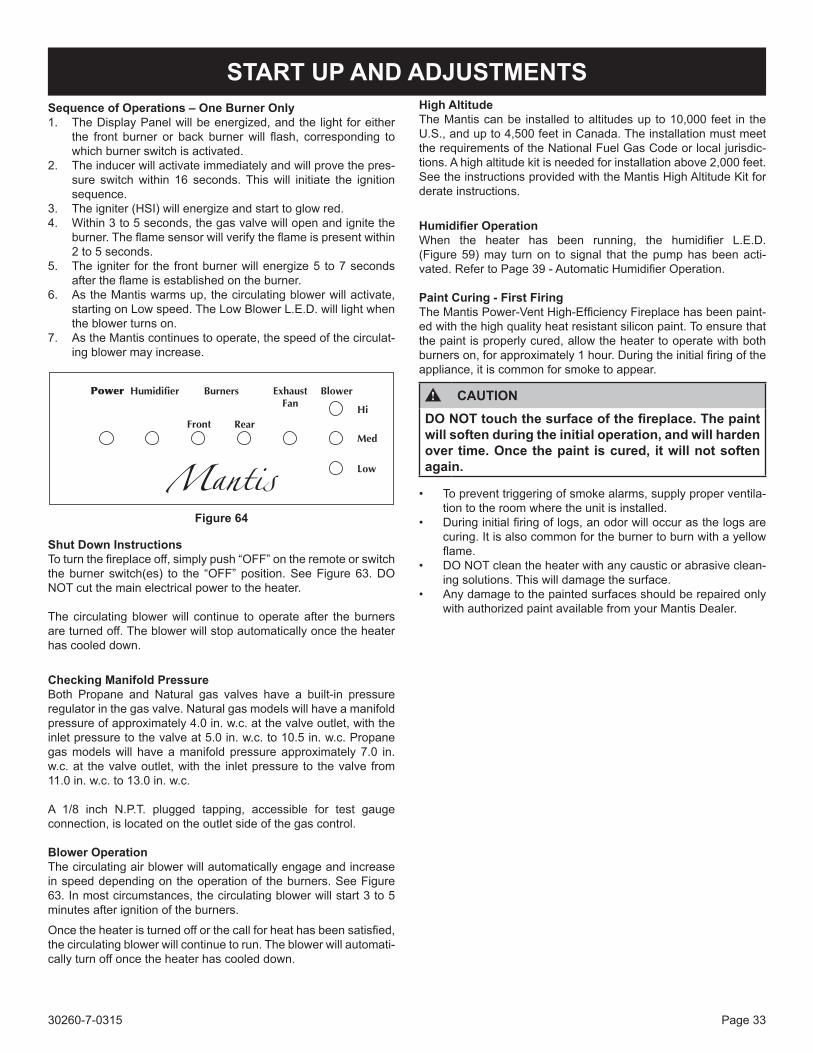
START UP AND ADJUSTMENTSSequence of Operations – One Burner Only1. The Display Panel will be energized, and the light for either
the front burner or back burner will flash, corresponding to which burner switch is activated.
2. The inducer will activate immediately and will prove the pres-sure switch within 16 seconds. This will initiate the ignition sequence.
3. The igniter (HSI) will energize and start to glow red. 4. Within 3 to 5 seconds, the gas valve will open and ignite the
burner. The flame sensor will verify the flame is present within 2 to 5 seconds.
5. The igniter for the front burner will energize 5 to 7 seconds after the flame is established on the burner.
6. As the Mantis warms up, the circulating blower will activate, starting on Low speed. The Low Blower L.E.D. will light when the blower turns on.
7. As the Mantis continues to operate, the speed of the circulat-ing blower may increase.
Figure 64
Shut Down InstructionsTo turn the fireplace off, simply push “OFF” on the remote or switch the burner switch(es) to the “OFF” position. See Figure 63. DO NOT cut the main electrical power to the heater.
The circulating blower will continue to operate after the burners are turned off. The blower will stop automatically once the heater has cooled down.
Checking Manifold PressureBoth Propane and Natural gas valves have a built-in pressure regulator in the gas valve. Natural gas models will have a manifold pressure of approximately 4.0 in. w.c. at the valve outlet, with the inlet pressure to the valve at 5.0 in. w.c. to 10.5 in. w.c. Propane gas models will have a manifold pressure approximately 7.0 in. w.c. at the valve outlet, with the inlet pressure to the valve from 11.0 in. w.c. to 13.0 in. w.c.
A 1/8 inch N.P.T. plugged tapping, accessible for test gauge connection, is located on the outlet side of the gas control.
Blower OperationThe circulating air blower will automatically engage and increase in speed depending on the operation of the burners. See Figure 63. In most circumstances, the circulating blower will start 3 to 5 minutes after ignition of the burners.
Once the heater is turned off or the call for heat has been satisfied, the circulating blower will continue to run. The blower will automati-cally turn off once the heater has cooled down.
High AltitudeThe Mantis can be installed to altitudes up to 10,000 feet in the U.S., and up to 4,500 feet in Canada. The installation must meet the requirements of the National Fuel Gas Code or local jurisdic-tions. A high altitude kit is needed for installation above 2,000 feet. See the instructions provided with the Mantis High Altitude Kit for derate instructions.
Humidifier OperationWhen the heater has been running, the humidifier L.E.D. (Figure 59) may turn on to signal that the pump has been acti-vated. Refer to Page 39 - Automatic Humidifier Operation.
Paint Curing - First FiringThe Mantis Power-Vent High-Efficiency Fireplace has been paint-ed with the high quality heat resistant silicon paint. To ensure that the paint is properly cured, allow the heater to operate with both burners on, for approximately 1 hour. During the initial firing of the appliance, it is common for smoke to appear.
CAUTIONDO NOT touch the surface of the fireplace. The paint will soften during the initial operation, and will harden over time. Once the paint is cured, it will not soften again.
• To prevent triggering of smoke alarms, supply proper ventila-tion to the room where the unit is installed.
• During initial firing of logs, an odor will occur as the logs are curing. It is also common for the burner to burn with a yellow flame.
• DO NOT clean the heater with any caustic or abrasive clean-ing solutions. This will damage the surface.
• Any damage to the painted surfaces should be repaired only with authorized paint available from your Mantis Dealer.
30260-7-0315Page 34
FRBTC REMOTE INSTRUCTIONSINTRODUCTIONThis remote control system was developed to provide a safe, reliable and user-friendly remote control system for gas heating appliances. This all battery system operates independently of household current. The system operates on radio frequencies with a non-directional signals. The SYSTEM’s operating range is approximately 20 feet range. The system operates on one of 1,048,576 security codes that are programmed into the transmitter at the factory; the remote receiver’s code must be matched to that of the transmitter prior to initial use.
Review COMMUNICATION SAFETY SECTION under TRANSMITTER section and THERMO SAFETY SECTION under REMOTE RECEIVER section. These signal/temperature safety features shut down the fireplace system when a potentially unsafe condition exists.
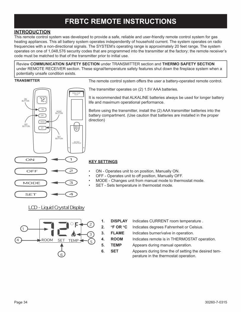
The remote control system offers the user a battery-operated remote control.
The transmitter operates on (2) 1.5V AAA batteries.
It is recommended that ALKALINE batteries always be used for longer battery life and maximum operational performance.
Before using the transmitter, install the (2) AAA transmitter batteries into the battery compartment. (Use caution that batteries are installed in the proper direction)
KEY SETTINGS
• ON - Operates unit to on position, Manually ON.• OFF - Operates unit to off position, Manually OFF.• MODE - Changes unit from manual mode to thermostat mode.• SET - Sets temperature in thermostat mode.
1. DISPLAY Indicates CURRENT room temperature .2. °F OR °C Indicates degrees Fahrenheit or Celsius.3. FLAME Indicates burner/valve in operation.4. ROOM Indicates remote is in THERMOSTAT operation.5. TEMP Appears during manual operation.6. SET Appears during time the of setting the desired tem-
perature in the thermostat operation.
30260-7-0315 Page 35
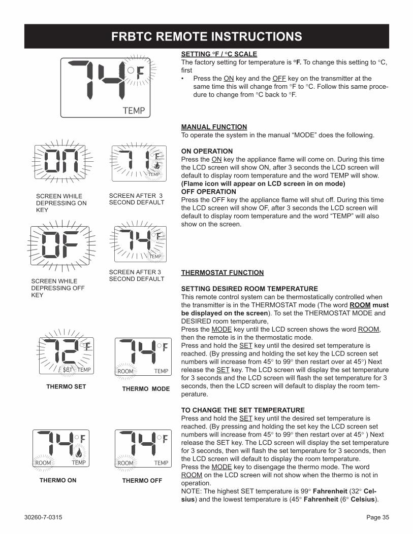
SETTING °F / °C SCALEThe factory setting for temperature is °F. To change this setting to °C, first• Press the ON key and the OFF key on the transmitter at the
same time this will change from °F to °C. Follow this same proce-dure to change from °C back to °F.
MANUAL FUNCTIONTo operate the system in the manual “MODE” does the following.
ON OPERATIONPress the ON key the appliance flame will come on. During this time the LCD screen will show ON, after 3 seconds the LCD screen will default to display room temperature and the word TEMP will show. (Flame icon will appear on LCD screen in on mode)OFF OPERATIONPress the OFF key the appliance flame will shut off. During this time the LCD screen will show OF, after 3 seconds the LCD screen will default to display room temperature and the word “TEMP” will also show on the screen.
THERMOSTAT FUNCTION
SETTING DESIRED ROOM TEMPERATUREThis remote control system can be thermostatically controlled when the transmitter is in the THERMOSTAT mode (The word ROOM must be displayed on the screen). To set the THERMOSTAT MODE and DESIRED room temperature,Press the MODE key until the LCD screen shows the word ROOM, then the remote is in the thermostatic mode.Press and hold the SET key until the desired set temperature is reached. (By pressing and holding the set key the LCD screen set numbers will increase from 45° to 99° then restart over at 45°) Next release the SET key. The LCD screen will display the set temperature for 3 seconds and the LCD screen will flash the set temperature for 3 seconds, then the LCD screen will default to display the room tem-perature.
TO CHANGE THE SET TEMPERATUREPress and hold the SET key until the desired set temperature is reached. (By pressing and holding the set key the LCD screen set numbers will increase from 45° to 99° then restart over at 45° ) Next release the SET key. The LCD screen will display the set temperature for 3 seconds, then will flash the set temperature for 3 seconds, then the LCD screen will default to display the room temperature.Press the MODE key to disengage the thermo mode. The word ROOM on the LCD screen will not show when the thermo is not in operation.NOTE: The highest SET temperature is 99° Fahrenheit (32° Cel-sius) and the lowest temperature is (45° Fahrenheit (6° Celsius).
FRBTC REMOTE INSTRUCTIONS
30260-7-0315Page 36
OPERATIONAL NOTES:The Thermostat Feature on the transmitter operates the appliance whenever the ROOM TEMPERATURE varies a certain number of degrees from the SET TEMPERATURE. This variation is called the “SWING” or TEMPERATURE DIFFERENTIAL. The normal operating cycle of an appliance may be 2-4 times per hour depending on how well the room or home is insulated from the cold or drafts. The fac-tory setting for the “swing number” is 2. This represents a temperature variation of +/- 2°F (1°C) between SET temperature and ROOM temperature, which determines when the fireplace will be activated. This function is pre-set at the factory.
The transmitter has ON and OFF manual functions that are activated by pressing either button on the face of the transmitter. When a button on the transmitter is pressed the word ON or OF will appear on the LCD screen to show while the signal is being sent. Upon initial use, there may be a delay of three seconds before the remote receiver will respond to the transmitter. This is part of the system’s design.
REMOTE RECEIVER
CAUTION: THE REMOTE RECEIVER SHOULD BE POSITIONED WHERE AMBIENT TEMPERATURES DO NOT EXCEED 130° F.
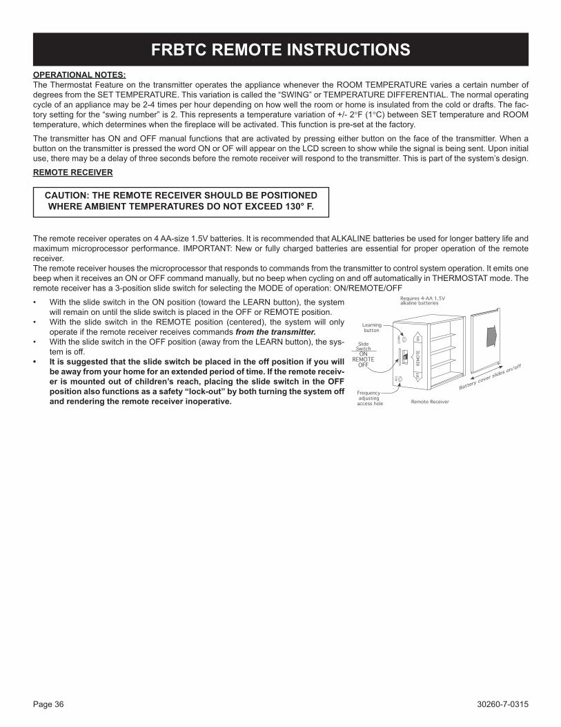
The remote receiver operates on 4 AA-size 1.5V batteries. It is recommended that ALKALINE batteries be used for longer battery life and maximum microprocessor performance. IMPORTANT: New or fully charged batteries are essential for proper operation of the remote receiver.The remote receiver houses the microprocessor that responds to commands from the transmitter to control system operation. It emits one beep when it receives an ON or OFF command manually, but no beep when cycling on and off automatically in THERMOSTAT mode. The remote receiver has a 3-position slide switch for selecting the MODE of operation: ON/REMOTE/OFF
• With the slide switch in the ON position (toward the LEARN button), the system will remain on until the slide switch is placed in the OFF or REMOTE position.
• With the slide switch in the REMOTE position (centered), the system will only operate if the remote receiver receives commands from the transmitter.
• With the slide switch in the OFF position (away from the LEARN button), the sys-tem is off.
• It is suggested that the slide switch be placed in the off position if you will be away from your home for an extended period of time. If the remote receiv-er is mounted out of children’s reach, placing the slide switch in the OFF position also functions as a safety “lock-out” by both turning the system off and rendering the remote receiver inoperative.
FRBTC REMOTE INSTRUCTIONS
30260-7-0315 Page 37
CP (CHILDPROOF) FEATURE
This ECS remote control includes a CHILDPROOF “LOCK-OUT” feature that allows the user to “LOCK-OUT” operation of the appliance, from the TRANSMITTER.
SETTING “LOCK-OUT” –(CP)
• To activate the “LOCK-OUT” feature, press and hold the ON button and the MODE button at the same time for 5 seconds. The letters CP will appear in the TEMP frame on the LCD screen.
• To disengage the “LOCK-OUT”, press and hold the ON button and the MODE button at the same time for 5 seconds and the letters CP will disappear from the LCD screen and the transmitter will return to its normal operating condition.
• To verify that transmitter is in the CP lock-out mode press any key and the LCD screen will show “CP”
NOTE: If the appliance is already operating in the ON or THERMOSTAT MODES, engaging the “LOCK-OUT” will not cancel the operating MODE. Engaging the “LOCK-OUT” prevents only the manual operation of the TRANSMITTER. If in the auto modes, the THERMOSTAT operation will continue to operate normally. To totally “LOCK-OUT” the operation of the TRANSMITTER’S operating signals; the transmit-ter’s MODE must be set to OFF.
THERMOSTAT UPDATING FEATURE –TRANSMITTER – (T/S –TX)
This ECS remote control has a THERMOSTAT UPDATING Feature built into its software. The THERMO UPDATING Feature operates in the following manner, but only in the THERMOSTAT MODES:
The transmitter normally reads the ROOM temperature every 2 minutes checking the ROOM temperature against the SET tem-perature and then sends a signal to the receiver.
COMMUNICATION – SAFETY – TRANSMITTER – (C/S – TX)
This ECS remote control has a COMMUNICATION –SAFETY function built into its software. It provides an extra margin of safety when the TRANSMITTER is out of the normal 20 foot operating range of the receiver.
The COMMUNICATION – SAFETY feature operates in the following manner, in all OPERATING MODES – ON/ OFF THERMOSTAT.
At all times and in all OPERATING MODES, the transmitter sends an RF signal every fifteen (15) minutes, to the receiver, indicating that the transmitter is within the normal operating range of 20 feet. Should the receiver NOT receive a transmitter signal every 15 minutes, the IC software, in the RECEIVER, will begin a 2-HOUR (120-minute) countdown timing function. If during this 2-hour period, the receiver does not receive a signal from the transmitter, the receiver will shut down the appliance being controlled by the receiver. The RECEIVER will then emit a series of rapid “beeps” for a period of 10 seconds. Then after 10 seconds of rapid beeping, the RECEIVER will continue to emit a single “beep” every 4 seconds until a transmitter ON or MODE Button is pressed to reset the receiver. The intermittent 4-second beeping will go on for as long as the receiver’s batteries last which could be in excess of one year.
To “reset” the RECEIVER and operate the appliance, you must press the ON or MODE button on the transmitter. By turning the system to ON, the COMMUNICATION -SAFETY operation is overridden and the system will return to normal operation depending on the MODE selected at the transmitter. The COMMUNICATION – SAFETY feature will reactivate should the transmitter be taken out of the normal operating range or should the transmitter’s batteries fail or be removed.
FRBTC REMOTE INSTRUCTIONS
30260-7-0315Page 38
THERMO- SAFETY FEATURE – RECEIVER (T/S –RX)This ECS remote control has a THERMO- SAFETY feature that is built into the system’s RECEIVER. This feature is tem-perature- activated and provides an extra margin of safety when the RECEIVER is operating where ambient temperatures exceed 130°F degrees inside the receiver case.
The THERMO-SAFETY feature, in the RECEIVER, operates in the following manner, when the appliance is in operation.
The receiver is thermally protected from extreme heat conditions. Heat can have negative effect on the operation of the receiver’s microprocessors.
For REMOTE RECEIVERS that operate on BATTERY POWER, these heat conditions can cause batteries to discharge when temperatures exceed 115°F. Studies show that alkaline batteries, when exposed to a constant temperature of 115°F, can lose up to 50% of their operating power. When the battery cools down, it will partially recharge itself, but constant heat-ing and cooling will reduce the battery’s normal life expectancy.
When the ambient temperature at the THERMISTOR, inside the receiver case, reaches 130°F, the THERMISTOR will auto-matically shut the appliance down and the RECEIVER will begin emitting a series of 2 “beeps”, every 4 seconds. When the ambient temperature, at the RECEIVER, drops between 120°F and 130°F, the user can reactivate the appliance by pushing the MODE button on the transmitter. The word ON must display on the LCD screen. When the MODE button is pressed to ON, the THERMISTOR “resets” itself and the fireplace will begin operating again. However, the “beeping” will continue, if the ambient temperature remains between 120°F and 130°F. This “beeping” alerts the user that the RECEIVER should be repositioned so the ambient temperature drops below 120°F.
When the temperature drops below 120°F, the “beeping” will cease, providing the user has “reset” the THERMISTOR by pushing the MODE button to ON to operate the appliance, either manually or thermally. Allow sufficient time for the receiver to cool below 120°F, and then press MODE button to stop beeping.
MATCHING SECURITY CODES
Each transmitter can use one of 1,048,576 unique security codes. It may be necessary to program the remote receiver to LEARN the security code of the transmitter upon initial use, if batteries are replaced, or if a replacement transmitter is purchased from your dealer or the factory. When matching security codes, be sure slide button on the receiver is in the RE-MOTE position; the code will NOT “LEARN” if the slide switch is in the OFF position. Program the remote receiver to LEARN a new security code by pushing in the LEARN button on the top of the remote receiver and then pressing any button on the transmitter. A change in the beeping pattern, at the receiver, indicates the transmitter’s code has been programmed into the receiver. When an existing receiver is matched to a new transmitter, the new security code will overwrite the old one.
The microprocessor that controls the security code matching procedure is controlled by a timing function. If you are unsuc-cessful in matching the security code on the first attempt, wait 1 - 2 minutes before trying again--this delay allows the micro-processor to reset its timer circuitry--and try up to two or three more times.
TRANSMITTER WALL CLIP
The transmitter can be hung on a wall using the clip provided. If the clip is installed on a solid wood wall, drill 1/8” pilot holes and install with the screws provided. If it is installed on a plaster/wallboard wall, first drill two 1/4” holes into the wall. Then use a hammer to tap in the two plastic wall anchors flush with the wall; then install the screws provided.
FRBTC REMOTE INSTRUCTIONS
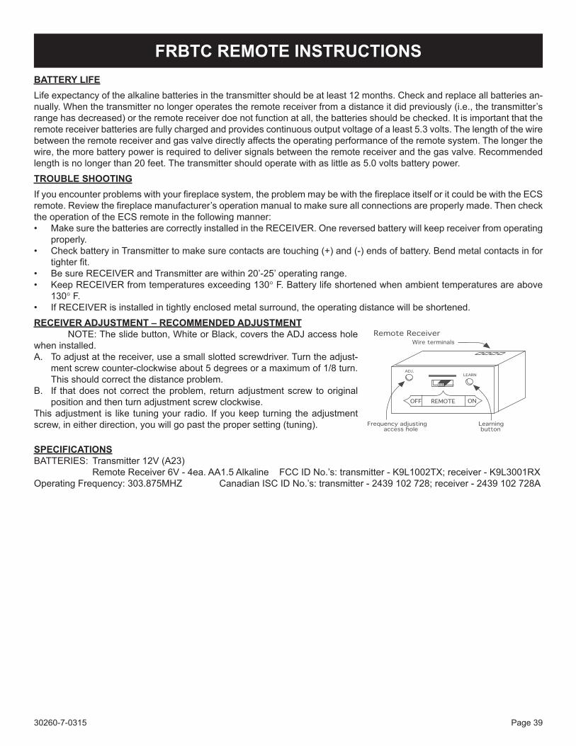
30260-7-0315 Page 39
BATTERY LIFELife expectancy of the alkaline batteries in the transmitter should be at least 12 months. Check and replace all batteries an-nually. When the transmitter no longer operates the remote receiver from a distance it did previously (i.e., the transmitter’s range has decreased) or the remote receiver doe not function at all, the batteries should be checked. It is important that the remote receiver batteries are fully charged and provides continuous output voltage of a least 5.3 volts. The length of the wire between the remote receiver and gas valve directly affects the operating performance of the remote system. The longer the wire, the more battery power is required to deliver signals between the remote receiver and the gas valve. Recommended length is no longer than 20 feet. The transmitter should operate with as little as 5.0 volts battery power.TROUBLE SHOOTINGIf you encounter problems with your fireplace system, the problem may be with the fireplace itself or it could be with the ECS remote. Review the fireplace manufacturer’s operation manual to make sure all connections are properly made. Then check the operation of the ECS remote in the following manner:• Make sure the batteries are correctly installed in the RECEIVER. One reversed battery will keep receiver from operating
properly.• Check battery in Transmitter to make sure contacts are touching (+) and (-) ends of battery. Bend metal contacts in for
tighter fit.• Be sure RECEIVER and Transmitter are within 20’-25’ operating range.• Keep RECEIVER from temperatures exceeding 130° F. Battery life shortened when ambient temperatures are above
130° F.• If RECEIVER is installed in tightly enclosed metal surround, the operating distance will be shortened.RECEIVER ADJUSTMENT – RECOMMENDED ADJUSTMENT NOTE: The slide button, White or Black, covers the ADJ access hole when installed.A. To adjust at the receiver, use a small slotted screwdriver. Turn the adjust-
ment screw counter-clockwise about 5 degrees or a maximum of 1/8 turn. This should correct the distance problem.
B. If that does not correct the problem, return adjustment screw to original position and then turn adjustment screw clockwise.
This adjustment is like tuning your radio. If you keep turning the adjustment screw, in either direction, you will go past the proper setting (tuning).
SPECIFICATIONSBATTERIES: Transmitter 12V (A23) Remote Receiver 6V - 4ea. AA1.5 Alkaline FCC ID No.’s: transmitter - K9L1002TX; receiver - K9L3001RXOperating Frequency: 303.875MHZ Canadian ISC ID No.’s: transmitter - 2439 102 728; receiver - 2439 102 728A
FRBTC REMOTE INSTRUCTIONS
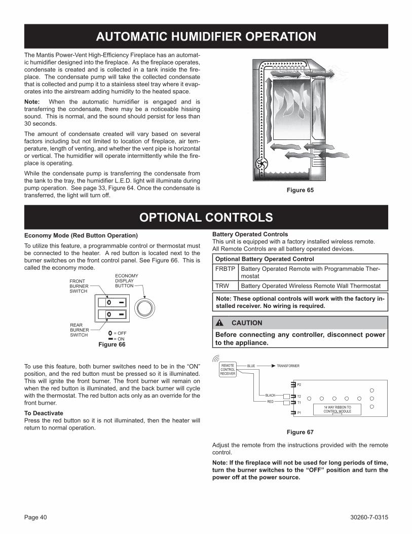
30260-7-0315Page 40
AUTOMATIC HUMIDIFIER OPERATIONThe Mantis Power-Vent High-Efficiency Fireplace has an automat-ic humidifier designed into the fireplace. As the fireplace operates, condensate is created and is collected in a tank inside the fire-place. The condensate pump will take the collected condensate that is collected and pump it to a stainless steel tray where it evap-orates into the airstream adding humidity to the heated space.
Note: When the automatic humidifier is engaged and is transferring the condensate, there may be a noticeable hissing sound. This is normal, and the sound should persist for less than 30 seconds.
The amount of condensate created will vary based on several factors including but not limited to location of fireplace, air tem-perature, length of venting, and whether the vent pipe is horizontal or vertical. The humidifier will operate intermittently while the fire-place is operating.
While the condensate pump is transferring the condensate from the tank to the tray, the humidifier L.E.D. light will illuminate during pump operation. See page 33, Figure 64. Once the condensate is transferred, the light will turn off.
Figure 65
OPTIONAL CONTROLSEconomy Mode (Red Button Operation)To utilize this feature, a programmable control or thermostat must be connected to the heater. A red button is located next to the burner switches on the front control panel. See Figure 66. This is called the economy mode.
Figure 66
To use this feature, both burner switches need to be in the “ON” position, and the red button must be pressed so it is illuminated. This will ignite the front burner. The front burner will remain on when the red button is illuminated, and the back burner will cycle with the thermostat. The red button acts only as an override for the front burner.
To DeactivatePress the red button so it is not illuminated, then the heater will return to normal operation.
Battery Operated ControlsThis unit is equipped with a factory installed wireless remote.All Remote Controls are all battery operated devices.
Optional Battery Operated ControlFRBTP Battery Operated Remote with Programmable Ther-
mostatTRW Battery Operated Wireless Remote Wall Thermostat
Note: These optional controls will work with the factory in-stalled receiver. No wiring is required.
CAUTIONBefore connecting any controller, disconnect power to the appliance.
Figure 67
Adjust the remote from the instructions provided with the remote control.
Note: If the fireplace will not be used for long periods of time, turn the burner switches to the “OFF” position and turn the power off at the power source.
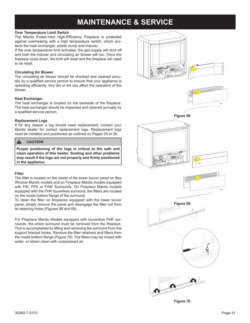
30260-7-0315 Page 41
MAINTENANCE & SERVICEOver Temperature Limit SwitchThe Mantis Power-Vent High-Efficiency Fireplace is protected against overheating with a high temperature switch, which pro-tects the heat exchanger, plastic sump and inducer. If the over temperature limit activates, the gas supply will shut off and both the inducer and circulating air blower will run. Once the fireplace cools down, the limit will reset and the fireplace will need to be reset.
Circulating Air BlowerThe circulating air blower should be checked and cleaned annu-ally by a qualified service person to ensure that your appliance is operating efficiently. Any dirt or lint can affect the operation of the blower.
Heat ExchangerThe heat exchanger is located on the backside of the fireplace. The heat exchanger should be inspected and cleaned annually by a qualified service person.
Replacement LogsIf for any reason a log should need replacement, contact your Mantis dealer for correct replacement logs. Replacement logs must be installed and positioned as outlined on Pages 25 to 26.
CAUTION
Proper positioning of the logs is critical to the safe and clean operation of this heater. Sooting and other problems may result if the logs are not properly and firmly positioned in the appliance.
FilterThe filter is located on the inside of the lower louver panel on Bay Window Mantis models and on Fireplace Mantis models equipped with FIK, FFK or FWK Surrounds. On Fireplace Mantis models equipped with the FHK louverless surround, the filters are located on the inside bottom flange of the surround.To clean the filter on fireplaces equipped with the lower louver panel, simply remove the panel and disengage the filter rod from its retaining holes (Figures 68 and 69).
For Fireplace Mantis Models equipped with louverless FHK sur-rounds, the entire surround must be removed from the fireplace. This is accomplished by lifting and removing the surround from the support bracket hooks. Remove the filter retainers and filters from the inside bottom flange (Figure 70). The filters may be rinsed with water or blown clean with compressed air.
Figure 68
Figure 69
Figure 70
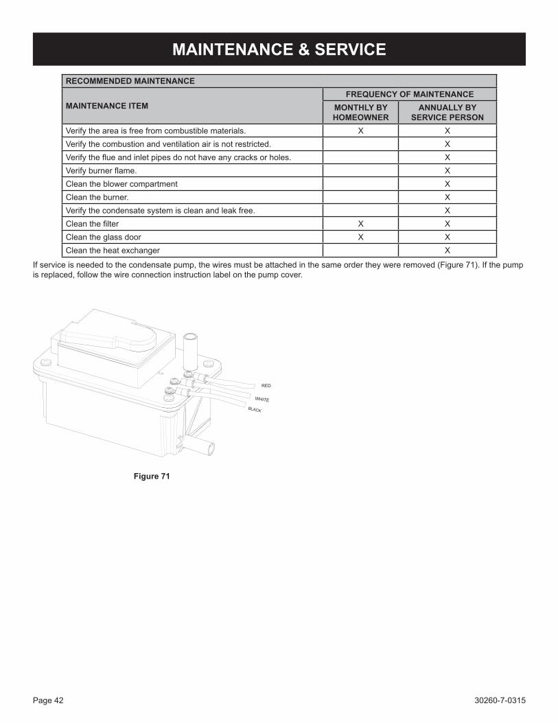
30260-7-0315Page 42
MAINTENANCE & SERVICE
RECOMMENDED MAINTENANCE
MAINTENANCE ITEMFREQUENCY OF MAINTENANCE
MONTHLY BY HOMEOWNER
ANNUALLY BY SERVICE PERSON
Verify the area is free from combustible materials. X XVerify the combustion and ventilation air is not restricted. XVerify the flue and inlet pipes do not have any cracks or holes. XVerify burner flame. XClean the blower compartment XClean the burner. XVerify the condensate system is clean and leak free. XClean the filter X XClean the glass door X XClean the heat exchanger X
If service is needed to the condensate pump, the wires must be attached in the same order they were removed (Figure 71). If the pump is replaced, follow the wire connection instruction label on the pump cover.
Figure 71
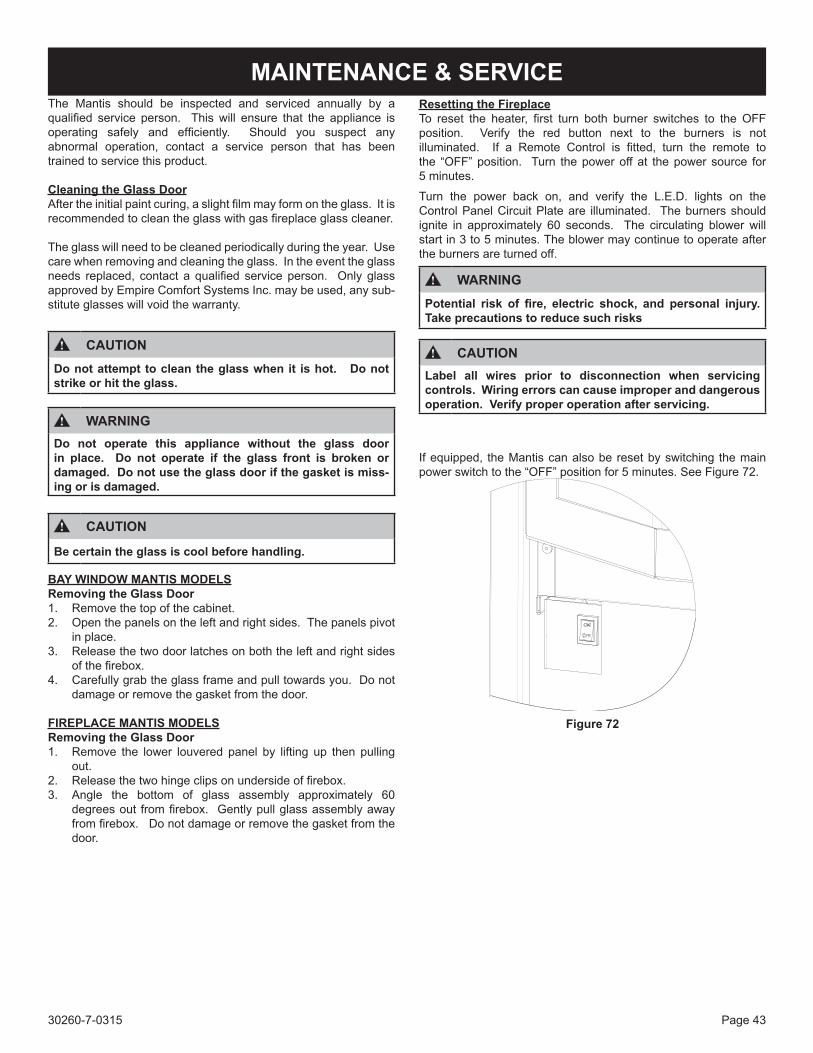
30260-7-0315 Page 43
MAINTENANCE & SERVICEThe Mantis should be inspected and serviced annually by a qualified service person. This will ensure that the appliance is operating safely and efficiently. Should you suspect any abnormal operation, contact a service person that has been trained to service this product.
Cleaning the Glass DoorAfter the initial paint curing, a slight film may form on the glass. It is recommended to clean the glass with gas fireplace glass cleaner.
The glass will need to be cleaned periodically during the year. Use care when removing and cleaning the glass. In the event the glass needs replaced, contact a qualified service person. Only glass approved by Empire Comfort Systems Inc. may be used, any sub-stitute glasses will void the warranty.
CAUTIONDo not attempt to clean the glass when it is hot. Do not strike or hit the glass.
WARNINGDo not operate this appliance without the glass door in place. Do not operate if the glass front is broken or damaged. Do not use the glass door if the gasket is miss-ing or is damaged.
CAUTION
Be certain the glass is cool before handling.
BAY WINDOW MANTIS MODELSRemoving the Glass Door1. Remove the top of the cabinet.2. Open the panels on the left and right sides. The panels pivot
in place. 3. Release the two door latches on both the left and right sides
of the firebox.4. Carefully grab the glass frame and pull towards you. Do not
damage or remove the gasket from the door.
FIREPLACE MANTIS MODELSRemoving the Glass Door1. Remove the lower louvered panel by lifting up then pulling
out.2. Release the two hinge clips on underside of firebox.3. Angle the bottom of glass assembly approximately 60
degrees out from firebox. Gently pull glass assembly away from firebox. Do not damage or remove the gasket from the door.
Resetting the FireplaceTo reset the heater, first turn both burner switches to the OFF position. Verify the red button next to the burners is not illuminated. If a Remote Control is fitted, turn the remote to the “OFF” position. Turn the power off at the power source for 5 minutes.
Turn the power back on, and verify the L.E.D. lights on the Control Panel Circuit Plate are illuminated. The burners should ignite in approximately 60 seconds. The circulating blower will start in 3 to 5 minutes. The blower may continue to operate after the burners are turned off.
WARNINGPotential risk of fire, electric shock, and personal injury. Take precautions to reduce such risks
CAUTIONLabel all wires prior to disconnection when servicing controls. Wiring errors can cause improper and dangerous operation. Verify proper operation after servicing.
If equipped, the Mantis can also be reset by switching the main power switch to the “OFF” position for 5 minutes. See Figure 72.
Figure 72
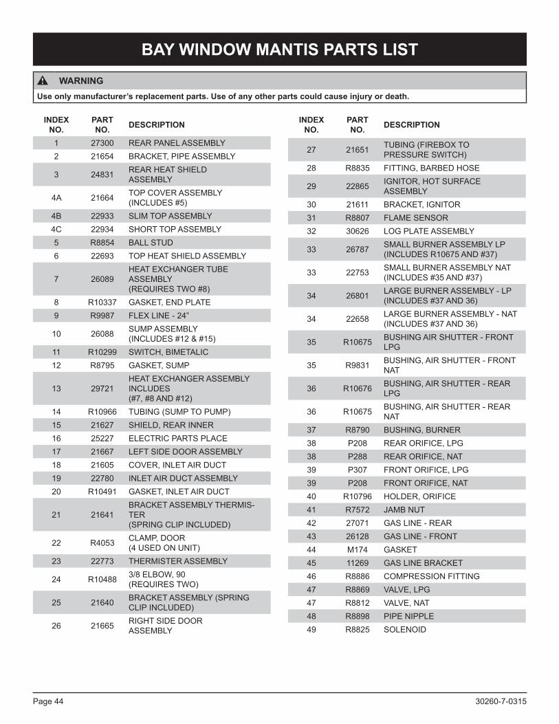
30260-7-0315Page 44
BAY WINDOW MANTIS PARTS LIST
WARNINGUse only manufacturer’s replacement parts. Use of any other parts could cause injury or death.
INDEX NO.
PART NO. DESCRIPTION
1 27300 REAR PANEL ASSEMBLY2 21654 BRACKET, PIPE ASSEMBLY
3 24831 REAR HEAT SHIELD ASSEMBLY
4A 21664 TOP COVER ASSEMBLY (INCLUDES #5)
4B 22933 SLIM TOP ASSEMBLY4C 22934 SHORT TOP ASSEMBLY5 R8854 BALL STUD6 22693 TOP HEAT SHIELD ASSEMBLY
7 26089HEAT EXCHANGER TUBE ASSEMBLY (REQUIRES TWO #8)
8 R10337 GASKET, END PLATE9 R9987 FLEX LINE - 24”
10 26088 SUMP ASSEMBLY (INCLUDES #12 & #15)
11 R10299 SWITCH, BIMETALIC12 R8795 GASKET, SUMP
13 29721HEAT EXCHANGER ASSEMBLY INCLUDES (#7, #8 AND #12)
14 R10966 TUBING (SUMP TO PUMP)15 21627 SHIELD, REAR INNER16 25227 ELECTRIC PARTS PLACE17 21667 LEFT SIDE DOOR ASSEMBLY18 21605 COVER, INLET AIR DUCT19 22780 INLET AIR DUCT ASSEMBLY20 R10491 GASKET, INLET AIR DUCT
21 21641BRACKET ASSEMBLY THERMIS-TER (SPRING CLIP INCLUDED)
22 R4053 CLAMP, DOOR (4 USED ON UNIT)
23 22773 THERMISTER ASSEMBLY
24 R10488 3/8 ELBOW, 90 (REQUIRES TWO)
25 21640 BRACKET ASSEMBLY (SPRING CLIP INCLUDED)
26 21665 RIGHT SIDE DOOR ASSEMBLY
27 21651 TUBING (FIREBOX TO PRESSURE SWITCH)
28 R8835 FITTING, BARBED HOSE
29 22865 IGNITOR, HOT SURFACE ASSEMBLY
30 21611 BRACKET, IGNITOR31 R8807 FLAME SENSOR32 30626 LOG PLATE ASSEMBLY
33 26787 SMALL BURNER ASSEMBLY LP (INCLUDES R10675 AND #37)
33 22753 SMALL BURNER ASSEMBLY NAT (INCLUDES #35 AND #37)
34 26801 LARGE BURNER ASSEMBLY - LP (INCLUDES #37 AND 36)
34 22658 LARGE BURNER ASSEMBLY - NAT (INCLUDES #37 AND 36)
35 R10675 BUSHING AIR SHUTTER - FRONT LPG
35 R9831 BUSHING, AIR SHUTTER - FRONT NAT
36 R10676 BUSHING, AIR SHUTTER - REAR LPG
36 R10675 BUSHING, AIR SHUTTER - REAR NAT
37 R8790 BUSHING, BURNER38 P208 REAR ORIFICE, LPG38 P288 REAR ORIFICE, NAT39 P307 FRONT ORIFICE, LPG39 P208 FRONT ORIFICE, NAT40 R10796 HOLDER, ORIFICE41 R7572 JAMB NUT42 27071 GAS LINE - REAR43 26128 GAS LINE - FRONT44 M174 GASKET45 11269 GAS LINE BRACKET46 R8886 COMPRESSION FITTING47 R8869 VALVE, LPG47 R8812 VALVE, NAT48 R8898 PIPE NIPPLE49 R8825 SOLENOID
INDEX NO.
PART NO. DESCRIPTION
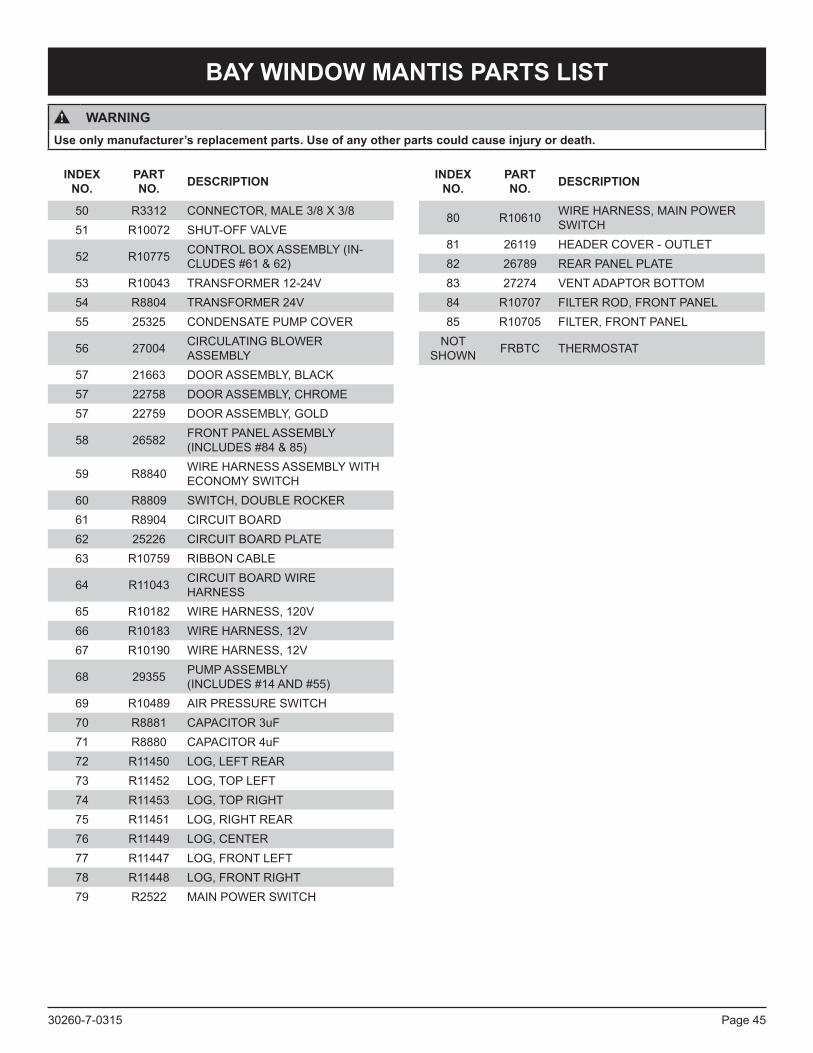
30260-7-0315 Page 45
BAY WINDOW MANTIS PARTS LIST
WARNINGUse only manufacturer’s replacement parts. Use of any other parts could cause injury or death.
50 R3312 CONNECTOR, MALE 3/8 X 3/851 R10072 SHUT-OFF VALVE
52 R10775 CONTROL BOX ASSEMBLY (IN-CLUDES #61 & 62)
53 R10043 TRANSFORMER 12-24V54 R8804 TRANSFORMER 24V55 25325 CONDENSATE PUMP COVER
56 27004 CIRCULATING BLOWER ASSEMBLY
57 21663 DOOR ASSEMBLY, BLACK57 22758 DOOR ASSEMBLY, CHROME57 22759 DOOR ASSEMBLY, GOLD
58 26582 FRONT PANEL ASSEMBLY (INCLUDES #84 & 85)
59 R8840 WIRE HARNESS ASSEMBLY WITH ECONOMY SWITCH
60 R8809 SWITCH, DOUBLE ROCKER61 R8904 CIRCUIT BOARD62 25226 CIRCUIT BOARD PLATE63 R10759 RIBBON CABLE
64 R11043 CIRCUIT BOARD WIRE HARNESS
65 R10182 WIRE HARNESS, 120V66 R10183 WIRE HARNESS, 12V67 R10190 WIRE HARNESS, 12V
68 29355 PUMP ASSEMBLY (INCLUDES #14 AND #55)
69 R10489 AIR PRESSURE SWITCH70 R8881 CAPACITOR 3uF71 R8880 CAPACITOR 4uF72 R11450 LOG, LEFT REAR73 R11452 LOG, TOP LEFT74 R11453 LOG, TOP RIGHT75 R11451 LOG, RIGHT REAR76 R11449 LOG, CENTER77 R11447 LOG, FRONT LEFT78 R11448 LOG, FRONT RIGHT79 R2522 MAIN POWER SWITCH
80 R10610 WIRE HARNESS, MAIN POWER SWITCH
81 26119 HEADER COVER - OUTLET82 26789 REAR PANEL PLATE83 27274 VENT ADAPTOR BOTTOM84 R10707 FILTER ROD, FRONT PANEL85 R10705 FILTER, FRONT PANEL
NOT SHOWN FRBTC THERMOSTAT
INDEX NO.
PART NO. DESCRIPTION INDEX
NO.PART NO. DESCRIPTION
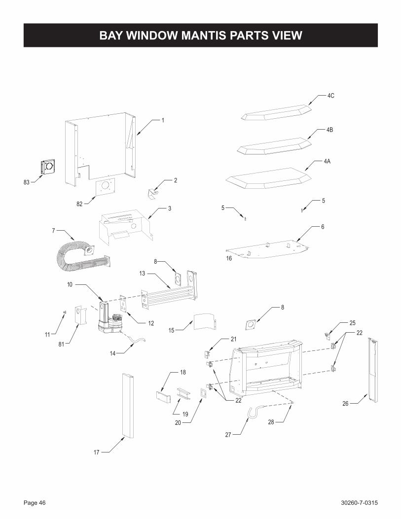
30260-7-0315Page 46
BAY WINDOW MANTIS PARTS VIEW
1
4A
3
2
4B
4C
5
6
8
25
22
5
17
21
18
22
15
10
8
26
16
12
20
19
14
11
28
27
13
81
82
7
83
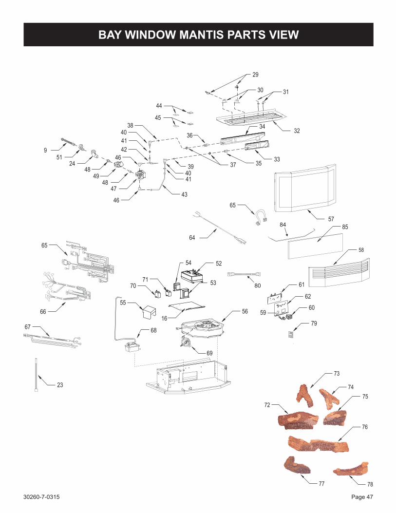
30260-7-0315 Page 47
BAY WINDOW MANTIS PARTS VIEW
77
73
74
75
76
72
78
85
43
40
41
46
47
46
44
49
4841
40
45
31
32
33
34
30
38
39 37 35
42
29
48
51
24
9
65
64
5784
56
52
16
69
70
67
71
5960
55
68
54
53
23
61
62
79
80
58
66
65
36
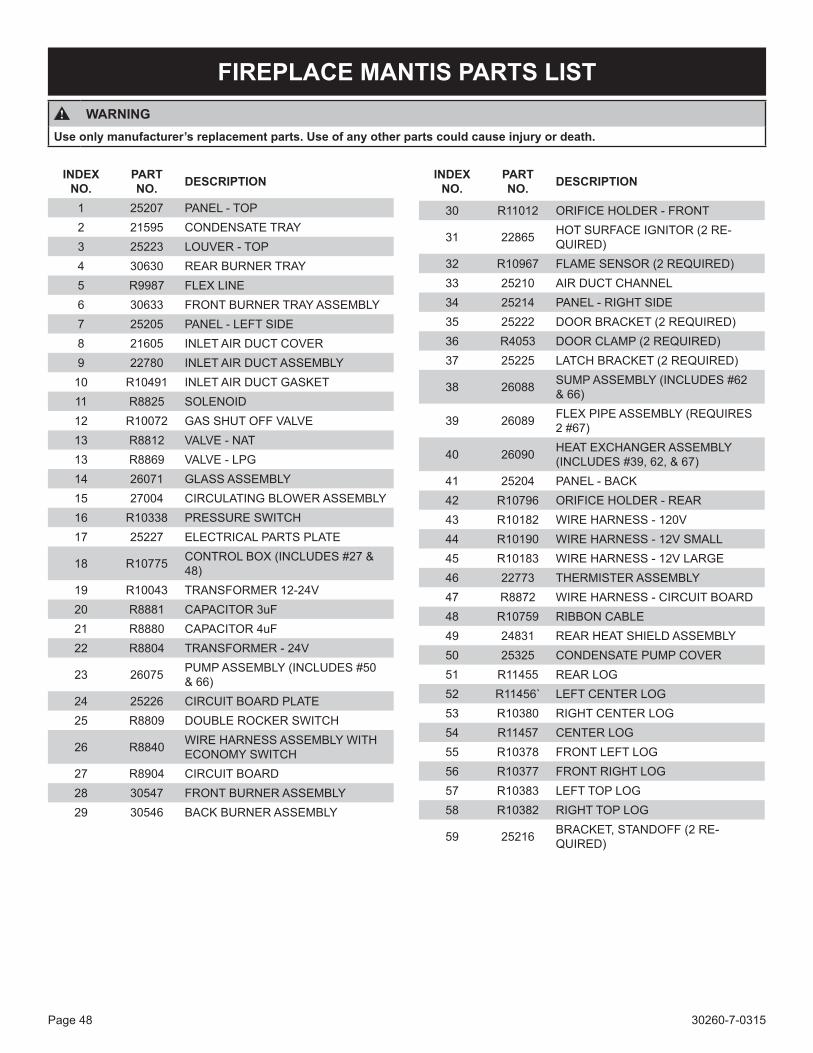
30260-7-0315Page 48
FIREPLACE MANTIS PARTS LISTWARNING
Use only manufacturer’s replacement parts. Use of any other parts could cause injury or death.
INDEX NO.
PART NO. DESCRIPTION
1 25207 PANEL - TOP2 21595 CONDENSATE TRAY3 25223 LOUVER - TOP4 30630 REAR BURNER TRAY5 R9987 FLEX LINE6 30633 FRONT BURNER TRAY ASSEMBLY7 25205 PANEL - LEFT SIDE8 21605 INLET AIR DUCT COVER9 22780 INLET AIR DUCT ASSEMBLY10 R10491 INLET AIR DUCT GASKET11 R8825 SOLENOID12 R10072 GAS SHUT OFF VALVE13 R8812 VALVE - NAT13 R8869 VALVE - LPG14 26071 GLASS ASSEMBLY15 27004 CIRCULATING BLOWER ASSEMBLY16 R10338 PRESSURE SWITCH17 25227 ELECTRICAL PARTS PLATE
18 R10775 CONTROL BOX (INCLUDES #27 & 48)
19 R10043 TRANSFORMER 12-24V20 R8881 CAPACITOR 3uF21 R8880 CAPACITOR 4uF22 R8804 TRANSFORMER - 24V
23 26075 PUMP ASSEMBLY (INCLUDES #50 & 66)
24 25226 CIRCUIT BOARD PLATE25 R8809 DOUBLE ROCKER SWITCH
26 R8840 WIRE HARNESS ASSEMBLY WITH ECONOMY SWITCH
27 R8904 CIRCUIT BOARD28 30547 FRONT BURNER ASSEMBLY29 30546 BACK BURNER ASSEMBLY
30 R11012 ORIFICE HOLDER - FRONT
31 22865 HOT SURFACE IGNITOR (2 RE-QUIRED)
32 R10967 FLAME SENSOR (2 REQUIRED)33 25210 AIR DUCT CHANNEL34 25214 PANEL - RIGHT SIDE35 25222 DOOR BRACKET (2 REQUIRED)36 R4053 DOOR CLAMP (2 REQUIRED)37 25225 LATCH BRACKET (2 REQUIRED)
38 26088 SUMP ASSEMBLY (INCLUDES #62 & 66)
39 26089 FLEX PIPE ASSEMBLY (REQUIRES 2 #67)
40 26090 HEAT EXCHANGER ASSEMBLY (INCLUDES #39, 62, & 67)
41 25204 PANEL - BACK42 R10796 ORIFICE HOLDER - REAR43 R10182 WIRE HARNESS - 120V44 R10190 WIRE HARNESS - 12V SMALL45 R10183 WIRE HARNESS - 12V LARGE46 22773 THERMISTER ASSEMBLY47 R8872 WIRE HARNESS - CIRCUIT BOARD48 R10759 RIBBON CABLE49 24831 REAR HEAT SHIELD ASSEMBLY50 25325 CONDENSATE PUMP COVER51 R11455 REAR LOG52 R11456` LEFT CENTER LOG53 R10380 RIGHT CENTER LOG54 R11457 CENTER LOG55 R10378 FRONT LEFT LOG56 R10377 FRONT RIGHT LOG57 R10383 LEFT TOP LOG58 R10382 RIGHT TOP LOG
59 25216 BRACKET, STANDOFF (2 RE-QUIRED)
INDEX NO.
PART NO. DESCRIPTION
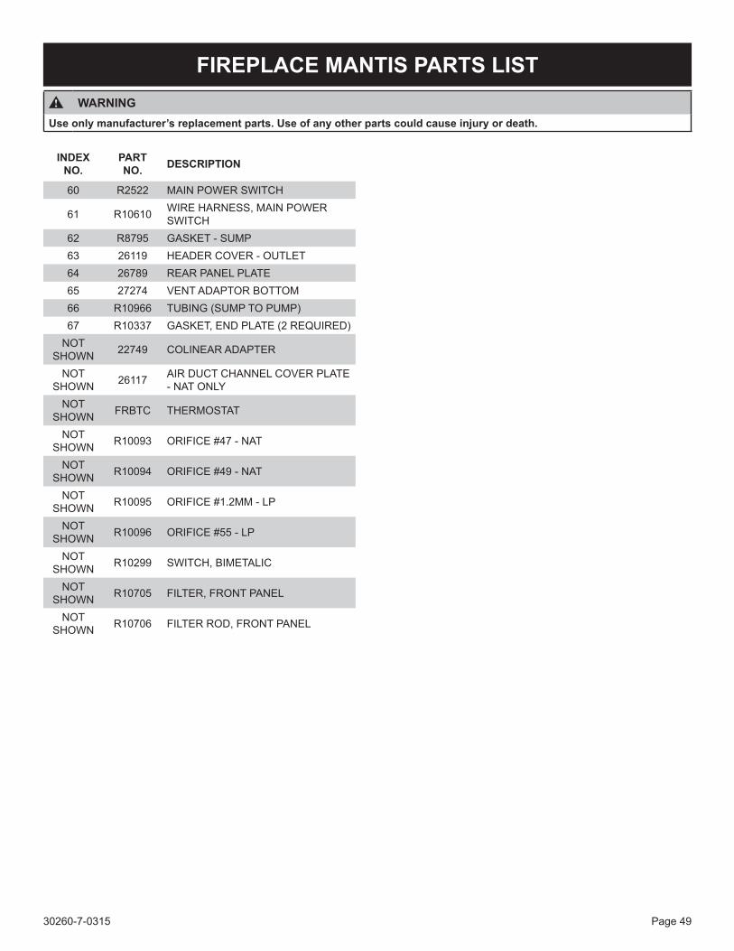
30260-7-0315 Page 49
FIREPLACE MANTIS PARTS LISTWARNING
Use only manufacturer’s replacement parts. Use of any other parts could cause injury or death.
60 R2522 MAIN POWER SWITCH
61 R10610 WIRE HARNESS, MAIN POWER SWITCH
62 R8795 GASKET - SUMP63 26119 HEADER COVER - OUTLET64 26789 REAR PANEL PLATE65 27274 VENT ADAPTOR BOTTOM66 R10966 TUBING (SUMP TO PUMP)67 R10337 GASKET, END PLATE (2 REQUIRED)
NOT SHOWN 22749 COLINEAR ADAPTER
NOT SHOWN 26117 AIR DUCT CHANNEL COVER PLATE
- NAT ONLYNOT
SHOWN FRBTC THERMOSTAT
NOT SHOWN R10093 ORIFICE #47 - NAT
NOT SHOWN R10094 ORIFICE #49 - NAT
NOT SHOWN R10095 ORIFICE #1.2MM - LP
NOT SHOWN R10096 ORIFICE #55 - LP
NOT SHOWN R10299 SWITCH, BIMETALIC
NOT SHOWN R10705 FILTER, FRONT PANEL
NOT SHOWN R10706 FILTER ROD, FRONT PANEL
INDEX NO.
PART NO. DESCRIPTION
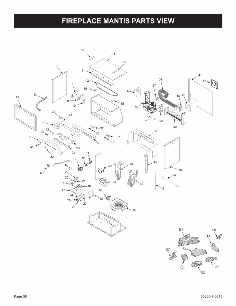
30260-7-0315Page 50
FIREPLACE MANTIS PARTS VIEW
51 58
53
54
52
57
55
56
1
2
3
4
5
6
7
8
9
11
1213
14
15
1617
1819
2021
22
23
44
43
46
48
45
24
25
2627
28
50
33
49
35
40
38
63
39
41
37
36
35
32
10
31
31
30
59
60
6134
32
37
36
42
29
47
62
64
65
67
67
59
66
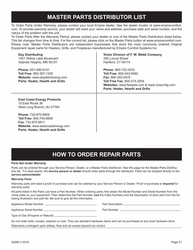
30260-7-0315 Page 51
To Order Parts Under Warranty, please contact your local Empire dealer. See the dealer locator at www.empirecomfort.com. To provide warranty service, your dealer will need your name and address, purchase date and serial number, and the nature of the problem with the unit. To Order Parts After the Warranty Period, please contact your dealer or one of the Master Parts Distributors listed below. This list changes from time to time. For the current list, please click on the Master Parts button at www.empirecomfort.com.Please note: Master Parts Distributors are independent businesses that stock the most commonly ordered Original Equipment repair parts for Heaters, Grills, and Fireplaces manufactured by Empire Comfort Systems Inc.
MASTER PARTS DISTRIBUTOR LIST
Parts Not Under WarrantyParts can be ordered through your Service Person, Dealer, or a Master Parts Distributor. See this page for the Master Parts Distribu-tors list. For best results, the service person or dealer should order parts through the distributor. Parts can be shipped directly to the service person/dealer.Warranty PartsWarranty parts will need a proof of purchase and can be ordered by your Service Person or Dealer. Proof of purchase is required for warranty parts.All parts listed in the Parts List have a Part Number. When ordering parts, first obtain the Model Number and Serial Number from the name plate on your equipment. Then determine the Part Number (not the Index Number) and the Description of each part from the fol-lowing illustration and part list. Be sure to give all this information . . .
Appliance Model Number Part Description
Appliance Serial Number Part Number
Type of Gas (Propane or Natural)
Do not order bolts, screws, washers or nuts. They are standard hardware items and can be purchased at any local hardware store. Shipments contingent upon strikes, fires and all causes beyond our control.
HOW TO ORDER REPAIR PARTS
Dey Distributing1401 Willow Lake BoulevardVadnais Heights, MN 55101
Phone: 651-490-9191Toll Free: 800-397-1339Website: www.deydistributing.comParts: Heater, Hearth and Grills
Victor Division of F. W. Webb Company200 Locust StreetHartford, CT 06114
Phone: 860-722-2433Toll Free: 800-243-9360Fax: 860-293-0479Toll Free Fax: 800-274-2004Websites: www.fwwebb.com & www.victormfg.comParts: Heater, Hearth and Grills
East Coast Energy Products10 East Route 36West Long Branch, NJ 07764
Phone: 732-870-8809Toll Free: 800-755-8809Fax: 732-870-8811Website: www.eastcoastenergy.comParts: Heater, Hearth and Grills
30260-7-0315Page 52
EMPIREEMPIREComfort Systems
Empire Comfort Systems Inc.918 Freeburg Ave. Belleville, IL 62220
If you have a general question about our products, please e-mail us at [email protected]. If you have a service or repair question, please contact your dealer.
www.empirecomfort.com
WARRANTYEmpire Comfort Systems Inc. warranties this Mantis fireplace to be free from defects at the time of purchase and for the periods speci-fied below. Mantis fireplaces must be installed by a qualified technician and must be maintained and operated safely, in accordance with the instructions in the owner’s manual. This warranty applies to the original purchaser only and is not transferable. All warranty repairs must be accomplished by a qualified gas appliance technician.
Limited Lifetime Parts Warranty – Factory-Installed Glass If the factory-installed glass fails because of defective workmanship or material, Empire will repair or replace at Empire’s op-tion.
Limited Ten-Year Parts Warranty – Combustion Chamber Empire promises to the owner that if the combustion chamber (see parts list) fails because of defective workmanship or mate-rial within ten years from the date of purchase, Empire will repair or replace at Empire’s option.
Limited Five-Year Parts Warranty – All Other Components (Except Thermostats) Should any part fail because of defective workmanship or material within five years from the date of purchase, Empire will repair or replace at Empire’s option.
Limited Two-Year Labor Warranty – All Components (Except Remote Controls, Thermostats)Within two years from the date of purchase, Empire will pay reasonable labor to have defects repaired at Empire’s option.
Limited One-Year Parts Warranty – Remote Controls, Thermostats Should any remote control or thermostat fail because of defective workmanship within one year from the date of purchase, Empire will repair or replace at Empire’s option.
Duties of the Owner The appliance must be installed by the selling dealer or his designated installer and operated in accordance with the instruc-tions furnished with the appliance. A bill of sale, cancelled check, or payment record should be kept to verify purchase date and establish warranty period. Ready access to the appliance for service.
What Is Not Covered Damages that might result from the use, misuse, or improper installation of this appliance. Travel, diagnostic costs and freight charges on warranted parts to and from the factory. Claims that do not involve defective workmanship or materials. Unauthorized service or parts replacements. Removal and reinstallation cost. Inoperable due to improper or lack of maintenance.
How To Get Service To make a claim under this warranty, please have your receipt available and contact your installing dealer. Provide the dealer with the model number, serial number, type of gas, and purchase verification. The installing dealer is responsible for providing service and will contact the factory to initiate any warranted parts replacements. Empire will make replacement parts available at the factory. Shipping expenses are not covered. If, after contacting your Empire dealer, service received has not been satisfactory, contact: Consumer Relations Department, Empire Comfort Systems Inc., PO Box 529, Belleville, Illinois 62222, or send an e-mail to [email protected] with “Consumer Relations” in the subject line.
Your Rights Under State Law This warranty gives your specific legal rights, and you may also have other rights, which vary from state to state.


