Embed Size (px)
Citation preview
COSMO Fall 2020 Mission OverviewChadd Miller1, Majid Alhajeri2, Siva Shankar3, Conner Neilsen4, Lea
Chandler5, Alexei Smith6, Jett Moore7, Matt Weber8, ShabthakiriRajasekaran9, Sam Holt10, Jash Bhalavat11
1.Project Manager, 2.Systems Engineer, 3.Test Lead, 4.ADCS Lead,5.FSW Lead, 6.COMMs Lead, 7.EPS Lead, 8.Interfacing Electronics Lead,
9.TCS/STR Volunteer, 10.STR Volunteer, 11.Solar Panel Volunteer
December 14, 2020
COSMO will take scalar and vector measurements of the Earth’s magnetic field inLow Earth Orbit (LEO) in a CubeSat sized platform to provide a space-based
solution for updates to the World Magnetic Field Model (WMM).
1
Table of Contents
Table of Contents 2
Executive Summary 5
Project Background 7
Mission Design 7Overview 7Requirements and Constraints 9CONOPS Discussion 11Radiation Analysis 12Current Status, Major Decisions, and Next Steps 13
Payload (PLD) 14Overview 14Payload Interfacing 14Spacecraft PLD Interfacing Next Steps 15
Spacecraft Overview 16Description of Spacecraft Subsystems 16COSMO Layout 16
Structures (STR) 19Structure Overview 19Structure Key Driving Requirements 19Structures Status 20Structure Steps to PIR 24
Command and Data Handling (CDH) 25CDH Overview 25CDH Requirements 25CDH Status & Major Decisions 26CDH Next Steps/Path to PIR 28
Electrical & Power System (EPS) 30EPS Overview 30EPS Key Driving Requirements 32EPS Status 32
2
Power Management Board 32Power Budget 33
EPS MOVING FORWARD 34EPS Board 34Power Budget 34
EPS - Solar Panels 34SP Overview 34SP Status 35SP Next Steps 35
Interfacing Electronics (Backplane, S-Band DB, GSE) 37Backplane Overview 37Backplane Status 37
Schematic Design 38Layout 38Wire Routing 39Deployment Circuitry 39RBF and Separation circuitry 40
Backplane Next Steps 40S-Band DB Overview 40S-Band DB Status 41S-Band DB Next Steps 41GSE Overview 41GSE Status 42GSE Next Steps 42
Communications (COMMs) 44COMMs Overview 44COMMS Requirements 44COMMS Status 45COMMS Major Changes 49COMMs Next Steps/Path to PIR 49
Attitude Determination and Control Subsystem (ADCS) 53ADCS Overview 53ADCS Requirements 53ADCS Status 54ADCS Major Changes 57ADCS Next Steps/Path to PIR 57
Thermal Control System (TCS) 58Overview 58
3
Requirements 59Current Status 59Major Decisions This Semester 62Next Steps 62
Flight Software (FSW) 64FSW Overview 64FSW Requirements 64FSW Status 64FSW Semester Major Decisions 65FSW Next Steps 68
Integration and Testing (I&T) 68I&T Overview 68I&T Testing Timeline 69I&T Status & Decisions 69I&T Next Steps and Path to PIR 71
Project Management 71Schedule Overview 71Subsystem Schedule Highlights 72
Structures 72Electronics 73COMMs 74FSW 74
Budget Overview 74PM Next Steps 75
4
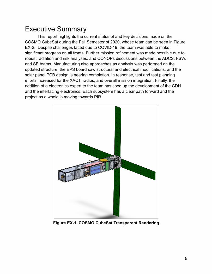
Executive SummaryThis report highlights the current status of and key decisions made on the
COSMO CubeSat during the Fall Semester of 2020, whose team can be seen in FigureEX-2. Despite challenges faced due to COVID-19, the team was able to makesignificant progress on all fronts. Further mission refinement was made possible due torobust radiation and risk analyses, and CONOPs discussions between the ADCS, FSW,and SE teams. Manufacturing also approaches as analysis was performed on theupdated structure, the EPS board saw structural and electrical modifications, and thesolar panel PCB design is nearing completion. In response, test and test planningefforts increased for the XACT, radios, and overall mission integration. Finally, theaddition of a electronics expert to the team has sped up the development of the CDHand the interfacing electronics. Each subsystem has a clear path forward and theproject as a whole is moving towards PIR.
Figure EX-1. COSMO CubeSat Transparent Rendering
5
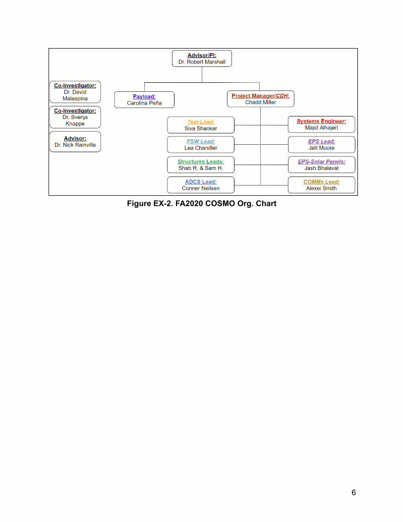
Figure EX-2. FA2020 COSMO Org. Chart
6
Project BackgroundThe Earth produces a geomagnetic field that runs from its center to the space
around it due to the dynamic currents within the core. Although it is often represented asa perfect dipole, perturbations from crustal fields and other anomalies distort this field.Furthermore, the geographic and magnetic poles are misaligned, and the magneticpoles continue to drift at an increasing rate.
Because navigation and control systems globally reply on knowledge of theEarth's magnetic field, a standard called the World Magnetic Model (WMM) was createdand adopted by NATO, the DoD, and many civilian referencing systems. It is updated bythe National Geospatial-Intelligence Agency (NGA) every 5 years, with the most recentin 2019.
The data for these updates is currently provided by a 3 spacecraft constellationoperated by the European Space Agency (ESA). This mission, called SWARM, is set fordecommissioning by 2024. COSMO’s goal is to replace SWARM as the primary sourceof WMM geomagnetic data.
NGA also sponsored a competition, called MagQuest, to seek novel approachesfor this data collection. COSMO was a competitor and the only university-led team, andtook second place with a prize of $225,000 at the conclusion this year. Due to thisparticipation, COSMO has been designed to meet the MagQuest requirements, whichensures that the mission meets the needs of the WMM, even if it is not selected asNGA’s ultimate solution.
Mission DesignOverview
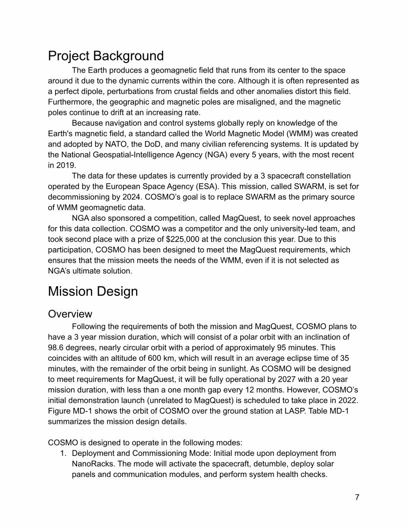
Following the requirements of both the mission and MagQuest, COSMO plans tohave a 3 year mission duration, which will consist of a polar orbit with an inclination of98.6 degrees, nearly circular orbit with a period of approximately 95 minutes. Thiscoincides with an altitude of 600 km, which will result in an average eclipse time of 35minutes, with the remainder of the orbit being in sunlight. As COSMO will be designedto meet requirements for MagQuest, it will be fully operational by 2027 with a 20 yearmission duration, with less than a one month gap every 12 months. However, COSMO’sinitial demonstration launch (unrelated to MagQuest) is scheduled to take place in 2022.Figure MD-1 shows the orbit of COSMO over the ground station at LASP. Table MD-1summarizes the mission design details.
COSMO is designed to operate in the following modes:1. Deployment and Commissioning Mode: Initial mode upon deployment from
NanoRacks. The mode will activate the spacecraft, detumble, deploy solarpanels and communication modules, and perform system health checks.
7
2. Safe Mode: Activated during time of low battery power or system failure, andprioritizes system survival. Only high priority components ensuring systemsurvival and communications active.
3. Science Operations Mode: Nominal mode of operation of spacecraft. Defined byactivation of data collection during eclipse portion of orbit, and battery rechargingduring sunlit portions of orbit.
4. Communications Operations Mode: Primary mode in which the spacecraftcommunicates with the ground. When in range of the LASP ground station, thespacecraft will downlink on-board memory via S-Band transmission.
5. Attitude Switching Mode: Mode when activating on-board reaction wheels tomaneuver between different pointing states (magnetic field lines, Sun, groundstation).
Figure MD-1. COSMO orbit as modeled on STK.
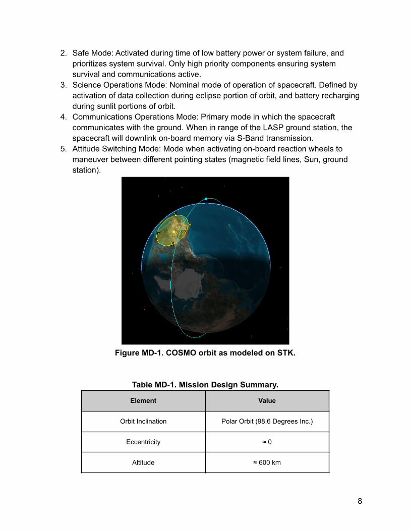
Table MD-1. Mission Design Summary.
Element Value
Orbit Inclination Polar Orbit (98.6 Degrees Inc.)
Eccentricity ≈ 0
Altitude ≈ 600 km
8
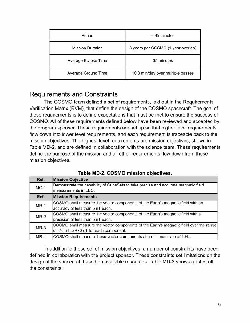
Period ≈ 95 minutes
Mission Duration 3 years per COSMO (1 year overlap)
Average Eclipse Time 35 minutes
Average Ground Time 10.3 min/day over multiple passes
Requirements and ConstraintsThe COSMO team defined a set of requirements, laid out in the Requirements
Verification Matrix (RVM), that define the design of the COSMO spacecraft. The goal ofthese requirements is to define expectations that must be met to ensure the success ofCOSMO. All of these requirements defined below have been reviewed and accepted bythe program sponsor. These requirements are set up so that higher level requirementsflow down into lower level requirements, and each requirement is traceable back to themission objectives. The highest level requirements are mission objectives, shown inTable MD-2, and are defined in collaboration with the science team. These requirementsdefine the purpose of the mission and all other requirements flow down from thesemission objectives.
Table MD-2. COSMO mission objectives.Ref. Mission Objective
MO-1 Demonstrate the capability of CubeSats to take precise and accurate magnetic fieldmeasurements in LEO.
Ref. Mission Requirements
MR-1 COSMO shall measure the vector components of the Earth's magnetic field with anaccuracy of less than 5 nT each.
MR-2 COSMO shall measure the vector components of the Earth's magnetic field with aprecision of less than 5 nT each.
MR-3 COSMO shall measure the vector components of the Earth's magnetic field over the rangeof -70 uT to +70 uT for each component.
MR-4 COSMO shall measure these vector components at a minimum rate of 1 Hz.
In addition to these set of mission objectives, a number of constraints have beendefined in collaboration with the project sponsor. These constraints set limitations on thedesign of the spacecraft based on available resources. Table MD-3 shows a list of allthe constraints.
9
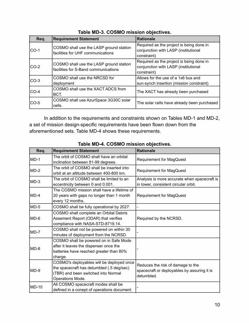
Table MD-3. COSMO mission objectives.Req. Requirement Statement Rationale
CO-1 COSMO shall use the LASP ground stationfacilities for UHF communications
Required as the project is being done inconjunction with LASP (institutionalconstraint)
CO-2 COSMO shall use the LASP ground stationfacilities for S-Band communications
Required as the project is being done inconjunction with LASP (institutionalconstraint)
CO-3 COSMO shall use the NRCSD fordeployment
Allows for the use of a 1x6 bus andsun-synch insertion (mission constraint)
CO-4 COSMO shall use the XACT ADCS fromBCT. The XACT has already been purchased
CO-5 COSMO shall use AzurSpace 3G30C solarcells. The solar cells have already been purchased
In addition to the requirements and constraints shown on Tables MD-1 and MD-2,a set of mission design-specific requirements have been flown down from theaforementioned sets. Table MD-4 shows these requirements.
Table MD-4. COSMO mission objectives.Req. Requirement Statement Rationale
MD-1 The orbit of COSMO shall have an orbitalinclination between 81-99 degrees. Requirement for MagQuest
MD-2 The orbit of COSMO shall be inserted intoorbit at an altitude between 400-800 km. Requirement for MagQuest
MD-3 The orbit of COSMO shall be limited to aneccentricity between 0 and 0.001.
Analysis is more accurate when spacecraft isin lower, consistent circular orbit.
MD-4The COSMO mission shall have a lifetime of20 years with gaps no longer than 1 monthevery 12 months.
Requirement for MagQuest
MD-5 COSMO shall be fully operational by 2027. -
MD-6COSMO shall complete an Orbital DebrisAssement Report (ODAR) that verifiescompliance with NASA-STD-8719.14.
Required by the NCRSD.
MD-7 COSMO shall not be powered on within 30minutes of deployment from the NCRSD. -
MD-8
COSMO shall be powered on in Safe Modeafter it leaves the dispenser once thebatteries have reached greater than 80%charge.
-
MD-9
COSMO's deployables will be deployed oncethe spacecraft has detumbled (.5 deg/sec)(TBR) and been switched into NormalOperations Mode.
Reduces the risk of damage to thespacecraft or deployables by assuring it isdetumbled.
MD-10 All COSMO spacecraft modes shall bedefined in a conept of operations document -
10
(DOC ____)
MD-11 The mission shall provide a ground segmentto monitor and control COSMO.
The mission will need this in order to sendcommands and receive telemetry.
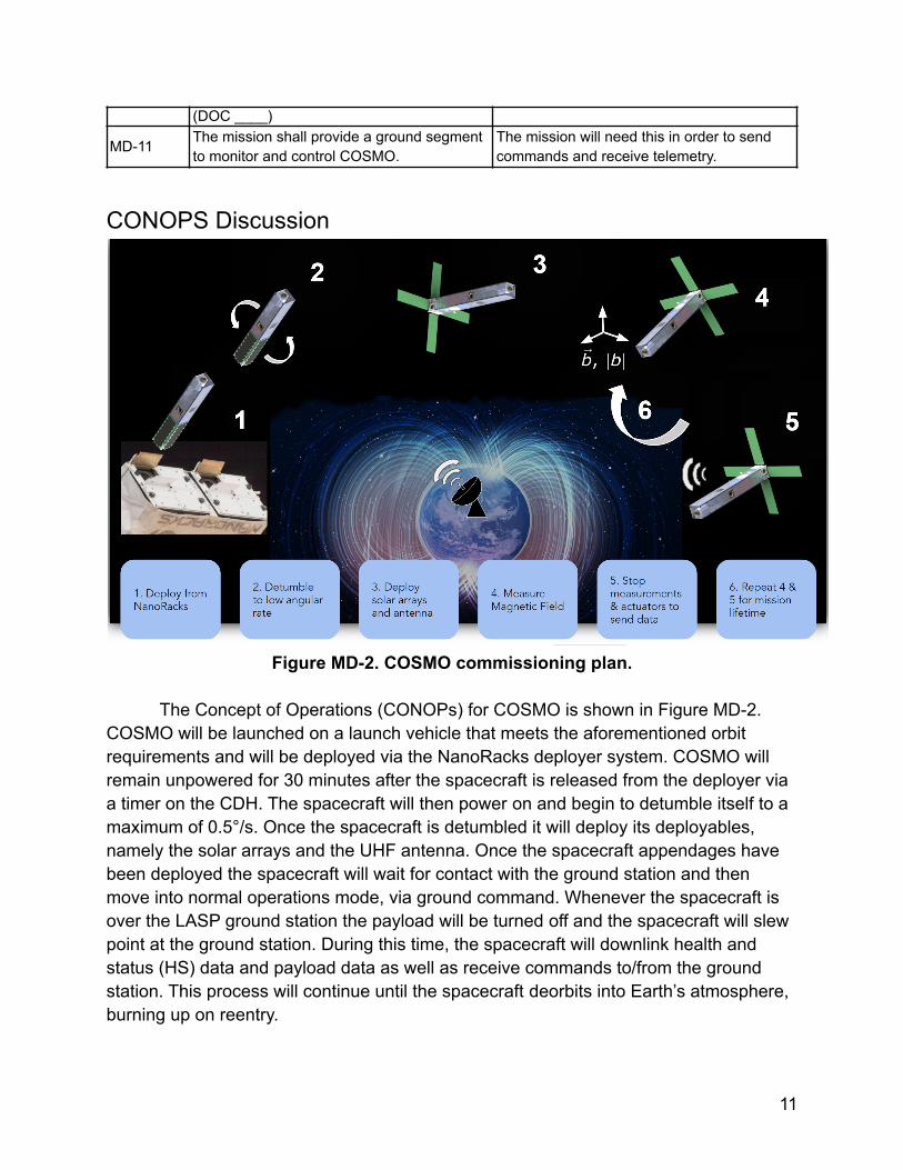
CONOPS Discussion
Figure MD-2. COSMO commissioning plan.
The Concept of Operations (CONOPs) for COSMO is shown in Figure MD-2.COSMO will be launched on a launch vehicle that meets the aforementioned orbitrequirements and will be deployed via the NanoRacks deployer system. COSMO willremain unpowered for 30 minutes after the spacecraft is released from the deployer viaa timer on the CDH. The spacecraft will then power on and begin to detumble itself to amaximum of 0.5°/s. Once the spacecraft is detumbled it will deploy its deployables,namely the solar arrays and the UHF antenna. Once the spacecraft appendages havebeen deployed the spacecraft will wait for contact with the ground station and thenmove into normal operations mode, via ground command. Whenever the spacecraft isover the LASP ground station the payload will be turned off and the spacecraft will slewpoint at the ground station. During this time, the spacecraft will downlink health andstatus (HS) data and payload data as well as receive commands to/from the groundstation. This process will continue until the spacecraft deorbits into Earth’s atmosphere,burning up on reentry.
11
Normal operations for COSMO will mean that the spacecraft will be takingscience data throughout its orbit. In this mode the spacecraft will be sun-pointed on theday-side for power generation and will track Earth’s magnetic field on the night-side.Where this transition between attitude states is still to be determined. This magneticfield tracking, to within 45 degrees, is required to take magnetic field data as the qualityof data reduces as the magnetometer becomes perpendicular with the field. Initialanalysis was done to determine if the spacecraft would be able to generate enoughpower if the magnetic field was tracked throughout the orbit. This was found to not bepossible based on the current power budget. The team therefore moved to the abovediscussed operation plan, attaining data at around 2/3 of the orbit. COSMO also has astringent magnetic noise requirement. The solar arrays have a large amount of currentflowing through them, in turn causing magnetic noise. Further testing needs to be doneto determine how much noise this will create and whether the day-side data is viable.On the night-side of the orbit the spacecraft will be able to take very clean data withoutthe magnetic noise of the solar arrays and the potential to turn off the torque rods (TRs)for this portion of the orbit.
Radiation AnalysisA radiation analysis study was initiated in the Fall 2020 semester, in order to
model the expected radiation environment that COSMO will endure over the course of 3years in orbit. The radiation analysis is critical in determining the necessary shieldingrequired to protect COSMO’s radiation-sensitive components, such as the electronics,from all forms of radiation. The study was conducted on STK SEET and SPENVIS, twodifferent software of different modeling approaches, for verification of results.
The primary objective of the radiation analysis was to determine the requiredshielding necessary to protect components prone to degradation due to exposure. Thesecondary objective was to model the SEU rates of COSMO at the intended orbit, inorder to characterize the need for additional protective measures. Detailed analysis andresults can be found in the Radiation Analysis folder in the Systems Engineering folderon Google Drive. The following tables provide a summary of the key outcomes of theanalysis:
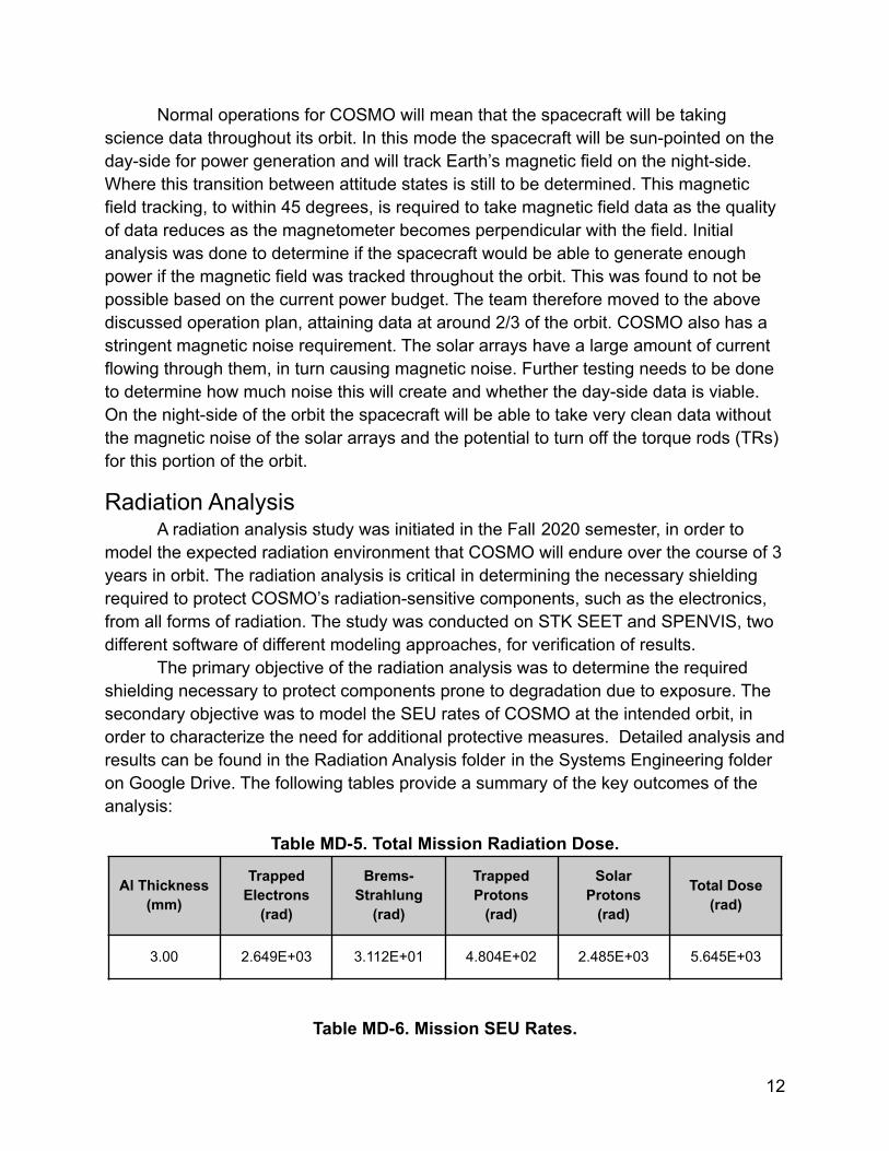
Table MD-5. Total Mission Radiation Dose.
Al Thickness(mm)
TrappedElectrons
(rad)
Brems-Strahlung
(rad)
TrappedProtons
(rad)
SolarProtons
(rad)
Total Dose(rad)
3.00 2.649E+03 3.112E+01 4.804E+02 2.485E+03 5.645E+03
Table MD-6. Mission SEU Rates.
12
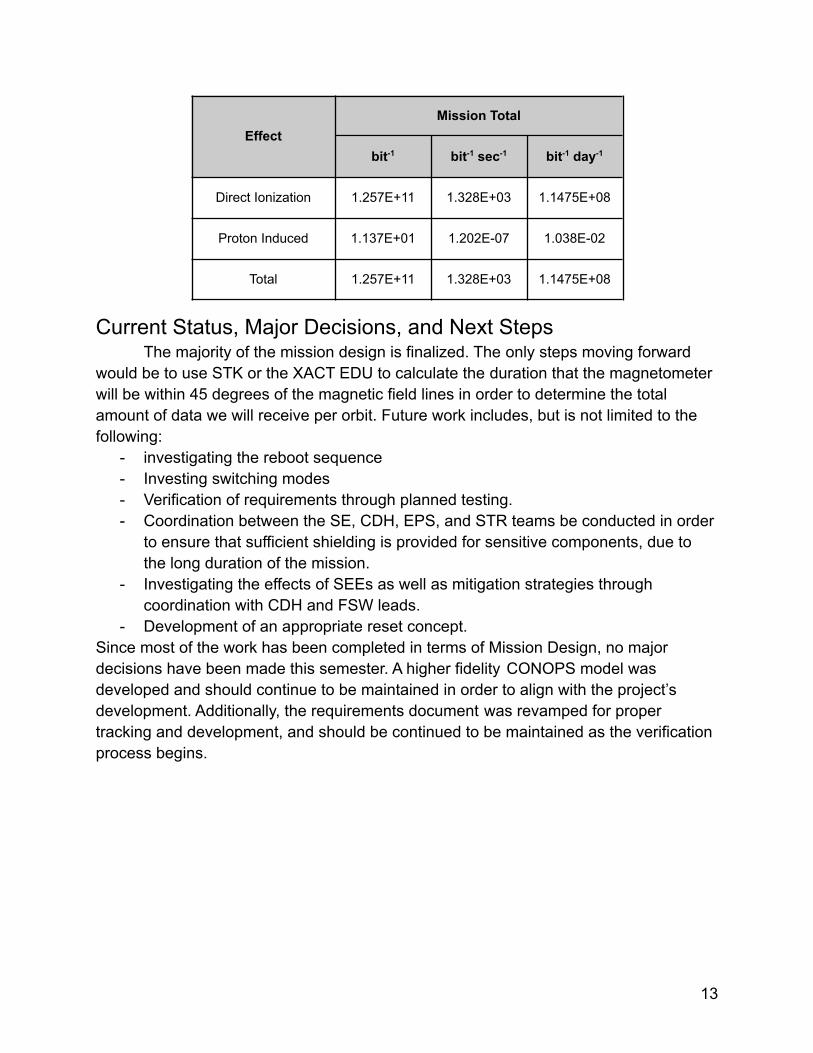
EffectMission Total
bit-1 bit-1 sec-1 bit-1 day-1
Direct Ionization 1.257E+11 1.328E+03 1.1475E+08
Proton Induced 1.137E+01 1.202E-07 1.038E-02
Total 1.257E+11 1.328E+03 1.1475E+08
Current Status, Major Decisions, and Next StepsThe majority of the mission design is finalized. The only steps moving forward
would be to use STK or the XACT EDU to calculate the duration that the magnetometerwill be within 45 degrees of the magnetic field lines in order to determine the totalamount of data we will receive per orbit. Future work includes, but is not limited to thefollowing:
- investigating the reboot sequence- Investing switching modes- Verification of requirements through planned testing.- Coordination between the SE, CDH, EPS, and STR teams be conducted in order
to ensure that sufficient shielding is provided for sensitive components, due tothe long duration of the mission.
- Investigating the effects of SEEs as well as mitigation strategies throughcoordination with CDH and FSW leads.
- Development of an appropriate reset concept.Since most of the work has been completed in terms of Mission Design, no majordecisions have been made this semester. A higher fidelity CONOPS model wasdeveloped and should continue to be maintained in order to align with the project’sdevelopment. Additionally, the requirements document was revamped for propertracking and development, and should be continued to be maintained as the verificationprocess begins.
13
Payload (PLD)Overview
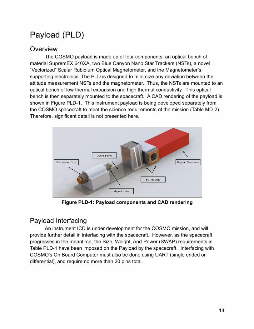
The COSMO payload is made up of four components: an optical bench ofmaterial SupremEX 640XA, two Blue Canyon Nano Star Trackers (NSTs), a novel“Vectorized” Scalar Rubidium Optical Magnetometer, and the Magnetometer’ssupporting electronics. The PLD is designed to minimize any deviation between theattitude measurement NSTs and the magnetometer. Thus, the NSTs are mounted to anoptical bench of low thermal expansion and high thermal conductivity. This opticalbench is then separately mounted to the spacecraft. A CAD rendering of the payload isshown in Figure PLD-1. This instrument payload is being developed separately fromthe COSMO spacecraft to meet the science requirements of the mission (Table MD-2).Therefore, significant detail is not presented here.
Figure PLD-1: Payload components and CAD rendering
Payload InterfacingAn instrument ICD is under development for the COSMO mission, and will
provide further detail in interfacing with the spacecraft. However, as the spacecraftprogresses in the meantime, the Size, Weight, And Power (SWAP) requirements inTable PLD-1 have been imposed on the Payload by the spacecraft. Interfacing withCOSMO’s On Board Computer must also be done using UART (single ended ordifferential), and require no more than 20 pins total.
14
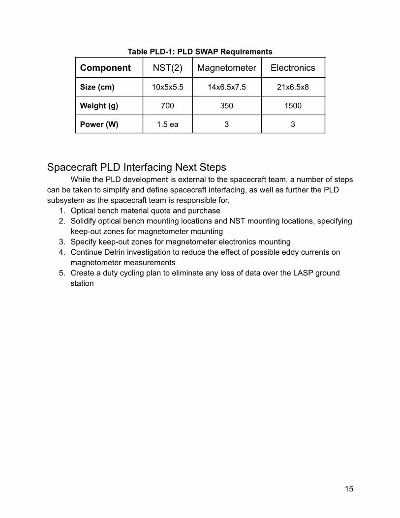
Table PLD-1: PLD SWAP Requirements
Component NST(2) Magnetometer Electronics
Size (cm) 10x5x5.5 14x6.5x7.5 21x6.5x8
Weight (g) 700 350 1500
Power (W) 1.5 ea 3 3
Spacecraft PLD Interfacing Next StepsWhile the PLD development is external to the spacecraft team, a number of steps
can be taken to simplify and define spacecraft interfacing, as well as further the PLDsubsystem as the spacecraft team is responsible for.
1. Optical bench material quote and purchase2. Solidify optical bench mounting locations and NST mounting locations, specifying
keep-out zones for magnetometer mounting3. Specify keep-out zones for magnetometer electronics mounting4. Continue Delrin investigation to reduce the effect of possible eddy currents on
magnetometer measurements5. Create a duty cycling plan to eliminate any loss of data over the LASP ground
station
15
Spacecraft OverviewDescription of Spacecraft SubsystemsThis section will discuss the design of the COSMO spacecraft as well as each of thesubsystems that make up the COSMO spacecraft.
- PLD - Payload: Consists of the magnetometer, star trackers, optical bench andpayload electronics. The purpose of the payload subsystem is to conduct thescience mission.
- EPS - Electrical & Power System: Consists of the solar arrays, batteries, andEPS PCB. The purpose of the EPS is to provide power to the rest of thesubsystems.
- CDH - Command & Data Handling: Consists of the CDH PCB, which includes theon board computer (microcontroller) and memory.
- FSW - Flight Software: Exists in the CDH subsystem. Software used to operatesubsystems and translate transmissions into commands.
- ADCS - Attitude Determination and Control System. Consists of the BCTXACT-15 unit to perform necessary pointing maneuvers, as well as a Coarse SunSensor and GPS slice.
- TCS - Thermal Control System. Contains TMP100 temperature sensors, batterytemperature sensors (RTDs), battery heater(s), and thermal coatings. Used toregulate the temperature of COSMO components to within operational limits.
- COMMs - Communications Subsystem: Consists of two radios and antennas, anAstrodev Lithium-II UHF radio and tape measure antenna and a CyldeSpaceHSTX S-Band radio and patch antenna. Used for transmitting and receiving data.
- STR - Structures Subsystem. Consists of the structural components of COSMO,such as the chassis, hinges, rails, and subsystem mounts.
COSMO LayoutFigures SO-1, SO-2, and SO-3 show the COSMO coordinate plane used to
describe COSMO’s axes, the key components that make up the COSMO spacecraft.And COSMO’s system block diagram, respectively.
16
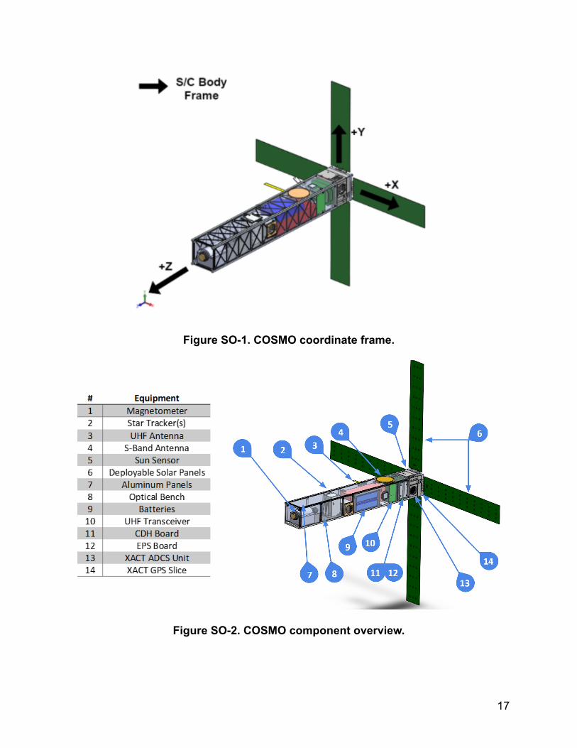
Figure SO-1. COSMO coordinate frame.
Figure SO-2. COSMO component overview.
17
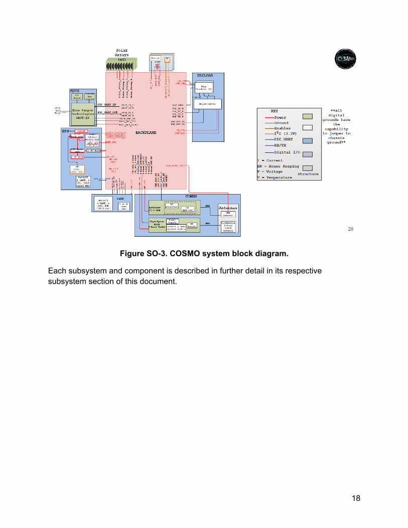
Figure SO-3. COSMO system block diagram.
Each subsystem and component is described in further detail in its respectivesubsystem section of this document.
18
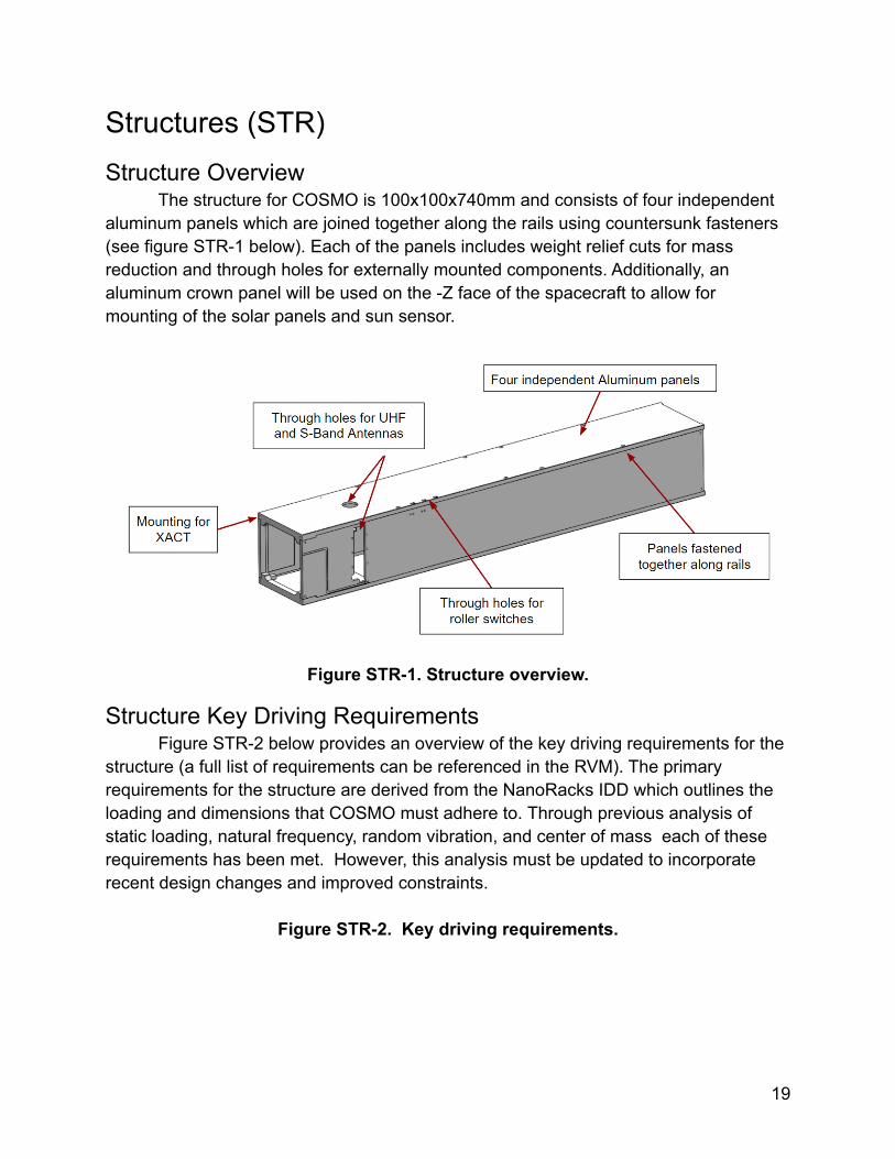
Structures (STR)Structure Overview
The structure for COSMO is 100x100x740mm and consists of four independentaluminum panels which are joined together along the rails using countersunk fasteners(see figure STR-1 below). Each of the panels includes weight relief cuts for massreduction and through holes for externally mounted components. Additionally, analuminum crown panel will be used on the -Z face of the spacecraft to allow formounting of the solar panels and sun sensor.
Figure STR-1. Structure overview.
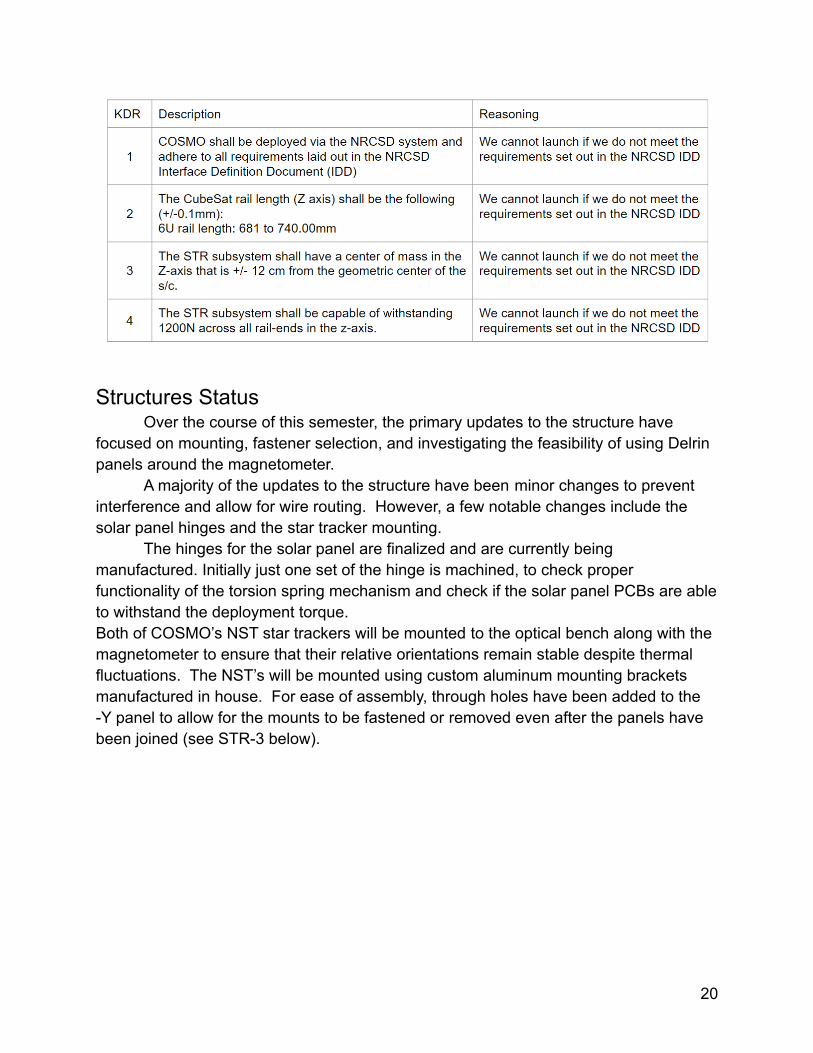
Structure Key Driving RequirementsFigure STR-2 below provides an overview of the key driving requirements for the
structure (a full list of requirements can be referenced in the RVM). The primaryrequirements for the structure are derived from the NanoRacks IDD which outlines theloading and dimensions that COSMO must adhere to. Through previous analysis ofstatic loading, natural frequency, random vibration, and center of mass each of theserequirements has been met. However, this analysis must be updated to incorporaterecent design changes and improved constraints.
Figure STR-2. Key driving requirements.
19
Structures StatusOver the course of this semester, the primary updates to the structure have
focused on mounting, fastener selection, and investigating the feasibility of using Delrinpanels around the magnetometer.
A majority of the updates to the structure have been minor changes to preventinterference and allow for wire routing. However, a few notable changes include thesolar panel hinges and the star tracker mounting.
The hinges for the solar panel are finalized and are currently beingmanufactured. Initially just one set of the hinge is machined, to check properfunctionality of the torsion spring mechanism and check if the solar panel PCBs are ableto withstand the deployment torque.Both of COSMO’s NST star trackers will be mounted to the optical bench along with themagnetometer to ensure that their relative orientations remain stable despite thermalfluctuations. The NST’s will be mounted using custom aluminum mounting bracketsmanufactured in house. For ease of assembly, through holes have been added to the-Y panel to allow for the mounts to be fastened or removed even after the panels havebeen joined (see STR-3 below).
20
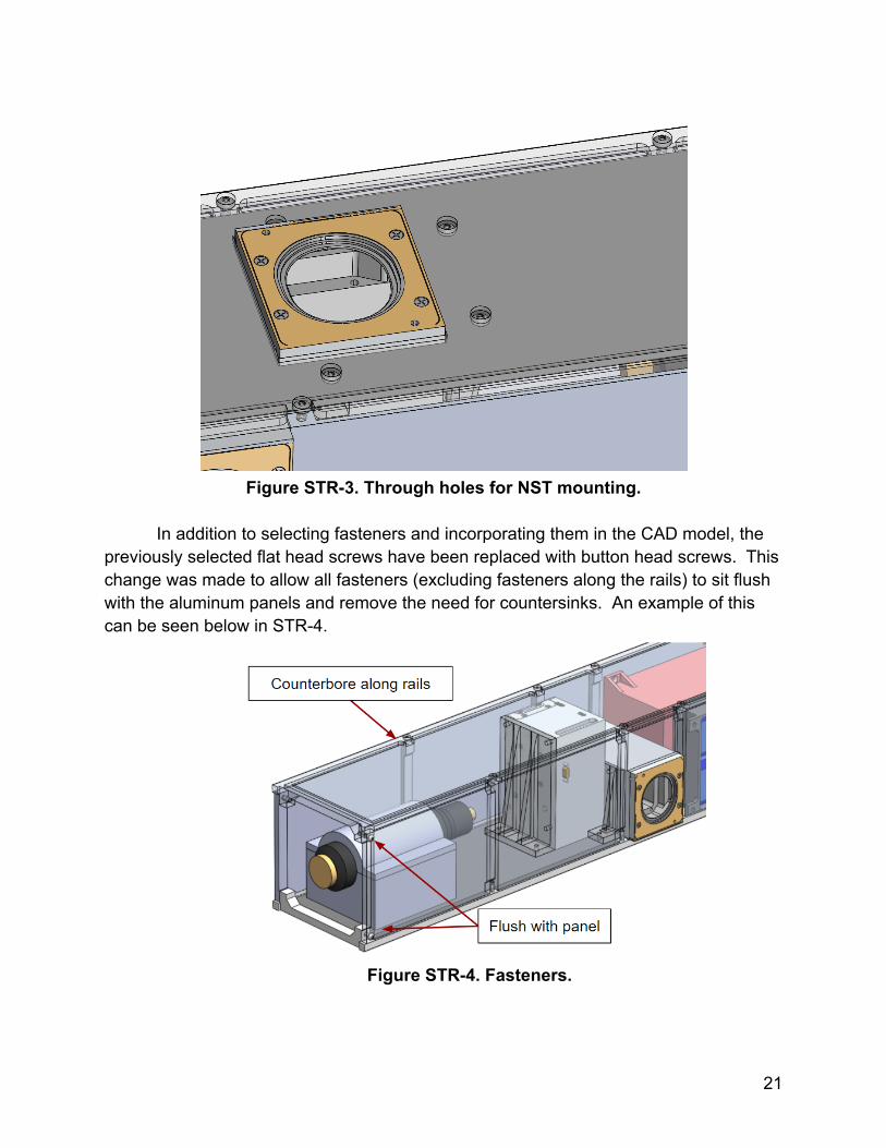
Figure STR-3. Through holes for NST mounting.
In addition to selecting fasteners and incorporating them in the CAD model, thepreviously selected flat head screws have been replaced with button head screws. Thischange was made to allow all fasteners (excluding fasteners along the rails) to sit flushwith the aluminum panels and remove the need for countersinks. An example of thiscan be seen below in STR-4.
Figure STR-4. Fasteners.
21
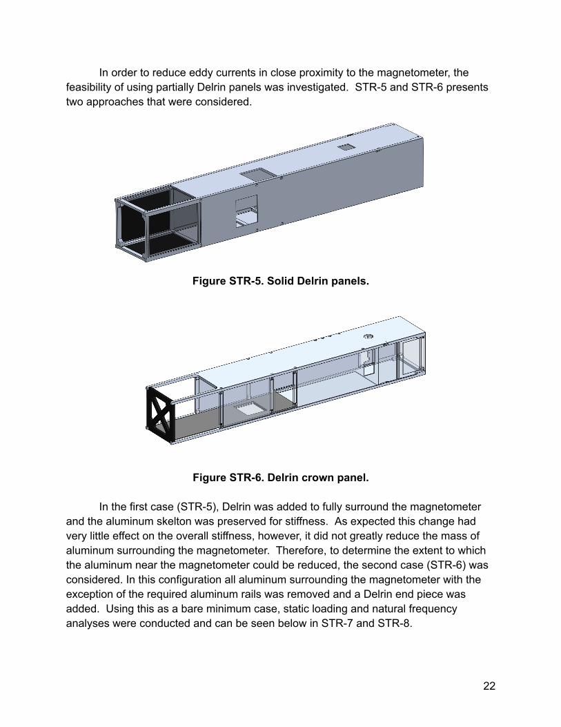
In order to reduce eddy currents in close proximity to the magnetometer, thefeasibility of using partially Delrin panels was investigated. STR-5 and STR-6 presentstwo approaches that were considered.
Figure STR-5. Solid Delrin panels.
Figure STR-6. Delrin crown panel.
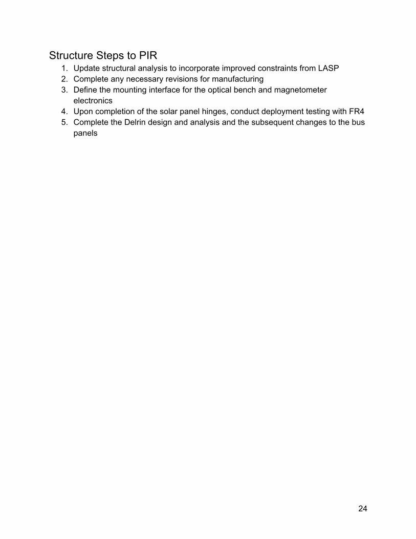
In the first case (STR-5), Delrin was added to fully surround the magnetometerand the aluminum skelton was preserved for stiffness. As expected this change hadvery little effect on the overall stiffness, however, it did not greatly reduce the mass ofaluminum surrounding the magnetometer. Therefore, to determine the extent to whichthe aluminum near the magnetometer could be reduced, the second case (STR-6) wasconsidered. In this configuration all aluminum surrounding the magnetometer with theexception of the required aluminum rails was removed and a Delrin end piece wasadded. Using this as a bare minimum case, static loading and natural frequencyanalyses were conducted and can be seen below in STR-7 and STR-8.
22
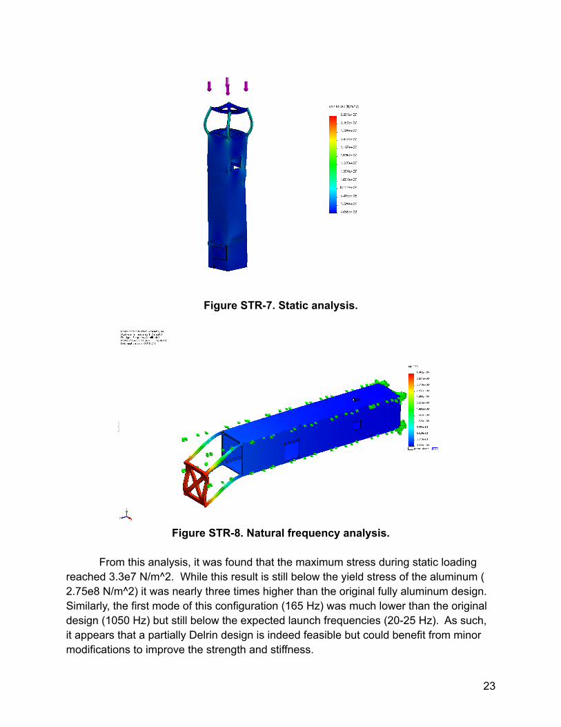
Figure STR-7. Static analysis.
Figure STR-8. Natural frequency analysis.
From this analysis, it was found that the maximum stress during static loadingreached 3.3e7 N/m^2. While this result is still below the yield stress of the aluminum (2.75e8 N/m^2) it was nearly three times higher than the original fully aluminum design.Similarly, the first mode of this configuration (165 Hz) was much lower than the originaldesign (1050 Hz) but still below the expected launch frequencies (20-25 Hz). As such,it appears that a partially Delrin design is indeed feasible but could benefit from minormodifications to improve the strength and stiffness.
23
Structure Steps to PIR1. Update structural analysis to incorporate improved constraints from LASP2. Complete any necessary revisions for manufacturing3. Define the mounting interface for the optical bench and magnetometer
electronics4. Upon completion of the solar panel hinges, conduct deployment testing with FR45. Complete the Delrin design and analysis and the subsequent changes to the bus
panels
24
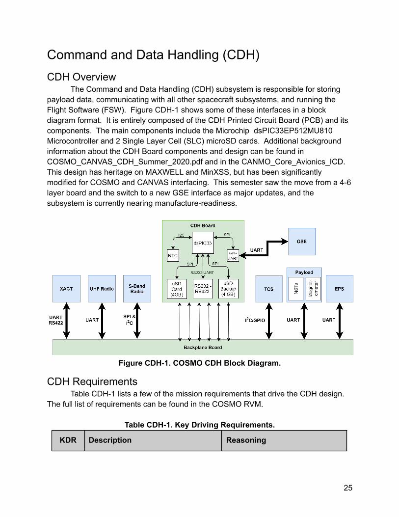
Command and Data Handling (CDH)CDH Overview
The Command and Data Handling (CDH) subsystem is responsible for storingpayload data, communicating with all other spacecraft subsystems, and running theFlight Software (FSW). Figure CDH-1 shows some of these interfaces in a blockdiagram format. It is entirely composed of the CDH Printed Circuit Board (PCB) and itscomponents. The main components include the Microchip dsPIC33EP512MU810Microcontroller and 2 Single Layer Cell (SLC) microSD cards. Additional backgroundinformation about the CDH Board components and design can be found inCOSMO_CANVAS_CDH_Summer_2020.pdf and in the CANMO_Core_Avionics_ICD.This design has heritage on MAXWELL and MinXSS, but has been significantlymodified for COSMO and CANVAS interfacing. This semester saw the move from a 4-6layer board and the switch to a new GSE interface as major updates, and thesubsystem is currently nearing manufacture-readiness.
Figure CDH-1. COSMO CDH Block Diagram.
CDH RequirementsTable CDH-1 lists a few of the mission requirements that drive the CDH design.
The full list of requirements can be found in the COSMO RVM.
Table CDH-1. Key Driving Requirements.
KDR Description Reasoning
25
1
The COSMO CDH shall be capableof interfacing with all spacecraftsubsystems and components(including STR)
The CDH must be able tointerface to communicatecommands and data.
2The CDH shall be capable ofoperating in the radiationenvironment of Earth.
3 year mission duration over thepoles presents a more significantradiation challenge, which mustbe addressed for missionsuccess.
3
The CDH shall include a minimum oftwo weeks worth of on board datastorage.
Should communications have arecoverable failure, thespacecraft will still be able torecord data for a period while therecovery is executed.
CDH Status & Major DecisionsThe CDH board has been redesigned to meet COSMO and CANVAS interfacing
requirements and has undergone two layout revisions based on the changing projectneeds. The current revision is in a pre-reviewed state. The main schematic design hasremained unchanged as of CDR, but several small changes have been made. Thelayout has changed significantly, however.
Many general electronics updates have been carried out since CDR with theassistance of CANVAS’ Electrical Engineer. These include the implementation of Altiumproject version control, unified board design principles, common board shape andtemplates, and library control. Additional information on these principles can be foundin the Electrical Engineering Principles document in the LAIR-Altium Shared Drive.
Schematic changes include mainly the addition of internal signal debugconnectors and removal of the large Debug connector that can be found on previousCDH revisions and that of MAXWELL and MinXSS in favor of a new GSE design.Another schematic change was the significant re-assignment of pins on the PIC andbackplane connector to promote routing ease. These pin assignment updates can beseen in this document: CDH_PIC_Redesign_Notes.
26
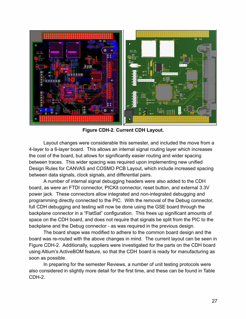
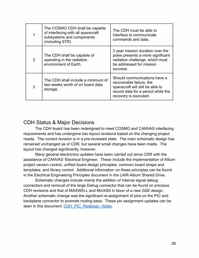
Figure CDH-2. Current CDH Layout.
Layout changes were considerable this semester, and included the move from a4-layer to a 6-layer board. This allows an internal signal routing layer which increasesthe cost of the board, but allows for significantly easier routing and wider spacingbetween traces. This wider spacing was required upon implementing new unifiedDesign Rules for CANVAS and COSMO PCB Layout, which include increased spacingbetween data signals, clock signals, and differential pairs.
A number of internal signal debugging headers were also added to the CDHboard, as were an FTDI connector, PICKit connector, reset button, and external 3.3Vpower jack. These connectors allow integrated and non-integrated debugging andprogramming directly connected to the PIC. With the removal of the Debug connector,full CDH debugging and testing will now be done using the GSE board through thebackplane connector in a “FlatSat” configuration. This frees up significant amounts ofspace on the CDH board, and does not require that signals be split from the PIC to thebackplane and the Debug connector - as was required in the previous design.
The board shape was modified to adhere to the common board design and theboard was re-routed with the above changes in mind. The current layout can be seen inFigure CDH-2. Additionally, suppliers were investigated for the parts on the CDH boardusing Altium’s ActiveBOM feature, so that the CDH board is ready for manufacturing assoon as possible.
In preparing for the semester Reviews, a number of unit testing protocols werealso considered in slightly more detail for the first time, and these can be found in TableCDH-2.
27
Table CDH-2. Unit Testing Overview.
Test Name Description Resources Needed
Acceptance -Continuity
Check continuity between pinsand their locations on thebackplane, power, GND, etc.
Multimeter (GSE preferred),power supply
Acceptance -Basic
Functionality
Ensure connection to requiredcomponents, check output ofOSC2, I/Os should be high-Z
Multimeter, oscilloscope,power supply (GSEpreferred)
Acceptance -Programmable
(LED)
Plug in PIC programmer toGSE connector, attempt toprogram device and makeLED blink
PICKit4 Programmer, powersupply, LED blink program
Functional-Digital
Interfaces
Load tested program to toggleat least all digital interfaces(possible all pins), checkhigh/low
PICKit4 Programmer, powersupply, toggle I/Os program,multimeter (GSE preferred)
Functional -PeripheralInterfaces
Test UART, SPI, I2C lines forbasic functionality, heavily testRS422 converters
PICKit4 Programmer, powersupply, simple interfacedriver program, oscilloscope(GSE strongly preferred)
Functional - SDCard Memory
Test
Read/write SD Card withdummy data, ensure access tospecific areas of memory
PICKit4 Programmer, powersupply, simple SD cardread/write program, (GSEstrongly preferred)
Functional - RTCWatchdog Reset
Test the watchdog’s ability toreset the CDH in the event ofa latchup
PICKit4 Programmer, powersupply, program to causereset, (GSE stronglypreferred)
CDH Next Steps/Path to PIRPre-Integration Review readiness is defined here as having a fully manufactured
and unit-tested CDH board that is functional and ready to begin integration andintegrated testing. The steps to reach this point, in chronological order, are:
1. CDH Board Layout Review with CANVAS EE and make final revisionsa. Planned to be done over Winter 2020-2021
2. Altium Heritage/Radiation Tolerance analysisa. Examine to ensure every component had flight heritage or has
been cleared for space use - planned Winter 2020-2021, not criticalpath for Revision 1
3. CDH Board Revision 1 manufacturing preparation4. Procure CDH board and components5. Board manufacture by assembly of components onto PCB (internally or
externally)
28
6. CDH Unit Testing (see table CDH-2)a. Requires additional resources like simple FSW scripts and
preferred access to functioning GSE boardb. Test procedures should also be written if possible
7. CDH EMI Testinga. After unit testing is complete, the CDH board should be testing in its
peak current mode to examine its EMI
At this point, the first revision of the CDH board should be ready for PIR. AfterPIR, the CDH component ratings should also be checked to ensure their maximumlimits meet at least twice the expected operating conditions (Parts Ratings Template).Additionally a hard reset concept should be considered and implemented on Revision 2of the CDH board. This reset method would help the CDH recover itself and the rest ofthe spacecraft from failures caused by Single Event Effect (SEE) radiation events. It iscrucial, however, that this reset concept perform a full power removal from the CDH (asopposed to the current watchdog and reset button performing a “soft” reset by togglingthe PIC’s MCLR pin). It is tentatively recommended to use the CDH RTC Watchdog asthe master device and to edit its circuitry to be able to activate an enable line on thebackplane or CDH board which completely severs the connection from the backplanepower to the CDH power plane. The CDH, effectively reset, may then operate and workto individually reset additional subsystems (including the EPS PIC) as needed toattempt to recover from a SEE failure.
29
Electrical & Power System (EPS)EPS Overview
The Electrical and Power Subsystem (EPS) is responsible for generation,storage, and distribution of power to all subsystems. The subsystem consists ofthree primary components: two 14.8 V 2600 mAh Tenergy Li Ion batteries, foursolar panels and a power management printed circuit board (EPS board). TheEPS board takes in a 17-24V solar panel voltage and converts it to a 16 V busvoltage to charge the batteries. Further, the EPS board bucks the bus voltage intothree regulated voltage rails. One of the voltage rails is 3.3V and powers mostspacecraft electronics and ICs. The other two rails output 12V with one of the 12Vrails dedicated to the XACT due to its 3A inrush current. In addition to distributingpower, the EPS monitors the battery state of charge and is tasked with efficientlyoptimizing solar panel power using the dsPIC 33 microchip. The chip alsopackages data for UART communication with the CDH. For ground testing andpowering the EPS contains pin headers for programming and a DC jack for groundcharging. The EPS also contains part of the inhibit circuitry required by NanoRacks. The physical deployment switches for this circuitry can be found on thebackplane, or GSE board. Figure EPS-1 depicts the block diagram for EPS.
30
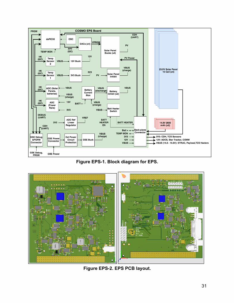
Figure EPS-1. Block diagram for EPS.
Figure EPS-2. EPS PCB layout.
31
EPS Key Driving RequirementsTable EPS-1 displays the key driving requirements behind the Electrical and
Power Subsystem. The requirements listed are not an exhaustive list of therequirements behind EPS, but they do capture what led to the design described inthe EPS overview. Requirement EPS-2.1 is motivated by advice from LASP.
Table EPS-1. EPS Key Driving Requirements.
Req. Description
EPS-1 COSMO shall be power positive on average over the course of anorbit.
EPS-2.1 The EPS battery shall not fall below a state of charge of 60%.
EPS-6 The EPS shall provide power to every subsystem at the appropriatevoltage.
EPS-11 The EPS subsystem shall follow all electrical system requirementsof the dispenser.
EPS Status
Power Management BoardRevision 0A of the EPS board has been procured from Advanced Circuits and is
awaiting population. To get to this point, the EPS board has been significantly modifiedfrom the MAXWELL design. In order to meet structural requirements the board wasconstricted to a 90x94 mm footprint. To accommodate the limited surface area 2 morelayers were added to the PCB, for 6 total, including an additional signal layer and anadditional ground layer. With the extra signal layer the board was rerouted. The boardalso contains the necessary components for mounting in the cardstack including copperpours for the rails, a notch and removal holes. The copper pours are the primaryinterface with the rails. The rails provide thermal relief and prevent abrasions to thesurface of the PCB. The notch enables external wire routing through boards on thecardstack. The removal holes allow the EPS board to evenly be pulled out of thebackplane using allen wrenches.
In addition to structural changes, several electrical changes were made fromMAXWELL’s design. Instead of 12V regulated rails, MAXWELL’s EPS board containedtwo 5V rails. To accommodate 12V, the peripheral components for the 5V buck
32
converters were modified to alter the output voltage. Similarly the peripheralcomponents for the Solar Panel buck converters were exchanged to account forCANVAS input and output voltage requirements. Additionally, voltage dividerssurrounding the dsPIC 33 were adjusted for 12V rail monitoring. In order to ease groundtesting a physical program reset switch was added to the board in order to reset thedsPIC. Further, pin headers were added to the board for signal testing and microchipprogramming.
The current design follows the MAXWELL pseudo peak power trackingmethodology for power conversion. The current peak power tracking is not functionaland is instead replaced by a less efficient current limiting resistor. There are concernsabout the lag time and compatibility of peak power tracking with the current EPS buckconvertors. The current limiting resistors could end up being sufficient for the design,but this will need to be verified through testing on Revision 0A.
Before ordering the board it was important to design rules specific tomanufacturing and board requirements. Specifically manufacturing clearance toleranceswere taken from Advanced Circuits and trace width rules were implemented forexpected board current. In order to confirm the board’s compatibility with theserequirements a design rule check(DRC) was used to eliminate discrepancies. After theboard was validated through the DRC, four boards were ordered from AdvancedCircuits. Additionally, components for the board were found using Altium’s Active BOMfeature and they were ordered from Digikey and Samtec. A stencil is still needed forboard production.
For more details on the EPS board functionality and interfaces please refer to theCANMO Core Avionics ICD for Fall 202
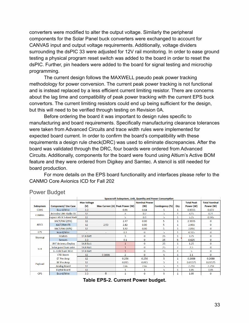
Power Budget
Table EPS-2. Current Power budget.
33
The current power budget meets design requirement EPS-2.1 that the batteryshall not fall below a state of charge of 60%. This semester there was investigation intothe buck converter loss and its effects on the power budget. Further investigation shallbe done through EPS testing in the spring.
EPS MOVING FORWARDAction items before PIR:EPS Board
1. Procure stencil for solder paste placement.2. Populate board using manual pick-n-place in electronics lab.
a. Initial continuity test to confirm board functionality.3. Test signal noise and values.4. Test solar panel brownout voltage by slowly lowering input voltage with a DC
power supply.5. Test battery charging capability using DC power jack.6. Test board EMI.7. Test peak power tracking capabilities using board pin headers.
a. Investigate other methods if needed through a trade study.i. Direct Energy Transferii. Current Limiting Resistorsiii. Dedicated/True Peak Power Tracking
8. Integrate EPS with other boards by utilizing the GSE board.a. Test communication with CDH.b. Test inhibit circuitry capabilities.
9. Modify board according to shortcomings discovered in testing.10.Procure and populate Rev 1.
a. Automatic pick-n-place may be available through the EE department.Power Budget
1. Review power budget code2. Modify if needed3. Implement discoveries from power conversion investigation
EPS - Solar PanelsSP Overview
The solar panel printed circuit board has the solar cells attached to it along withthe burn wire resistors and is mounted on the outside of the satellite. The solar cellsprovide power to the spacecraft such that it can sustain flight operations. When thespacecraft is not in an eclipse, the board collects the power and charges the battery that
34
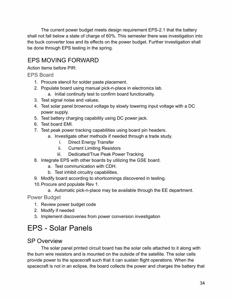
will be used during the eclipses. The burn wire resistors are hooked up to nylon wiresand they will be powered in order to create heat and melt the wire to deploy the solarpanels. For COSMO, the solar panels have 10 cells on each board totalling 40 cells forthe satellite. The panel is rectangular in shape with a length of 482 mm and width 88mm.
Figure EPS-3. Solar Panel 3D Preview with Dimensions.
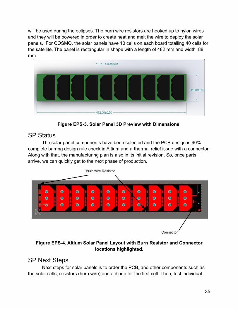
SP StatusThe solar panel components have been selected and the PCB design is 90%
complete barring design rule check in Altium and a thermal relief issue with a connector.Along with that, the manufacturing plan is also in its initial revision. So, once partsarrive, we can quickly get to the next phase of production.
Figure EPS-4. Altium Solar Panel Layout with Burn Resistor and Connectorlocations highlighted.
SP Next StepsNext steps for solar panels is to order the PCB, and other components such as
the solar cells, resistors (burn wire) and a diode for the first cell. Then, test individual
35
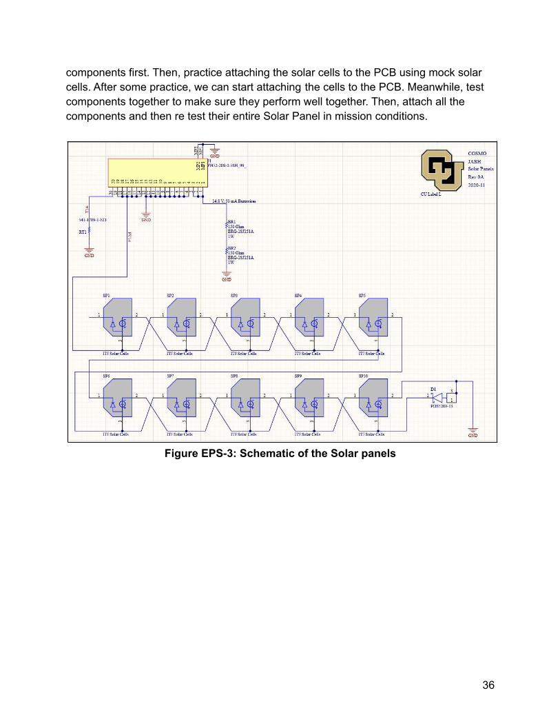
components first. Then, practice attaching the solar cells to the PCB using mock solarcells. After some practice, we can start attaching the cells to the PCB. Meanwhile, testcomponents together to make sure they perform well together. Then, attach all thecomponents and then re test their entire Solar Panel in mission conditions.
Figure EPS-3: Schematic of the Solar panels
36
Interfacing Electronics (Backplane, S-Band DB,GSE)Backplane Overview
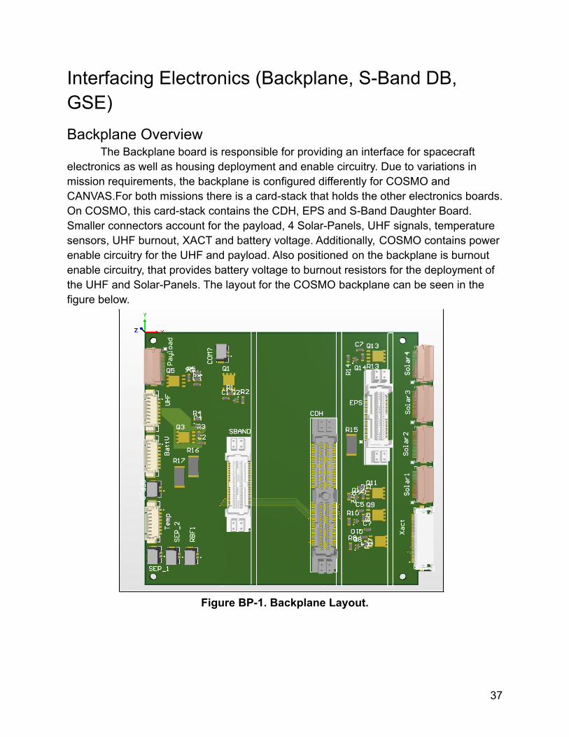
The Backplane board is responsible for providing an interface for spacecraftelectronics as well as housing deployment and enable circuitry. Due to variations inmission requirements, the backplane is configured differently for COSMO andCANVAS.For both missions there is a card-stack that holds the other electronics boards.On COSMO, this card-stack contains the CDH, EPS and S-Band Daughter Board.Smaller connectors account for the payload, 4 Solar-Panels, UHF signals, temperaturesensors, UHF burnout, XACT and battery voltage. Additionally, COSMO contains powerenable circuitry for the UHF and payload. Also positioned on the backplane is burnoutenable circuitry, that provides battery voltage to burnout resistors for the deployment ofthe UHF and Solar-Panels. The layout for the COSMO backplane can be seen in thefigure below.
Figure BP-1. Backplane Layout.
37
Backplane StatusMost changes to the backplane occurred in Summer 2020. In the last semester
there has been investigation into the specifications of wire routing and compatibility ofconnectors.
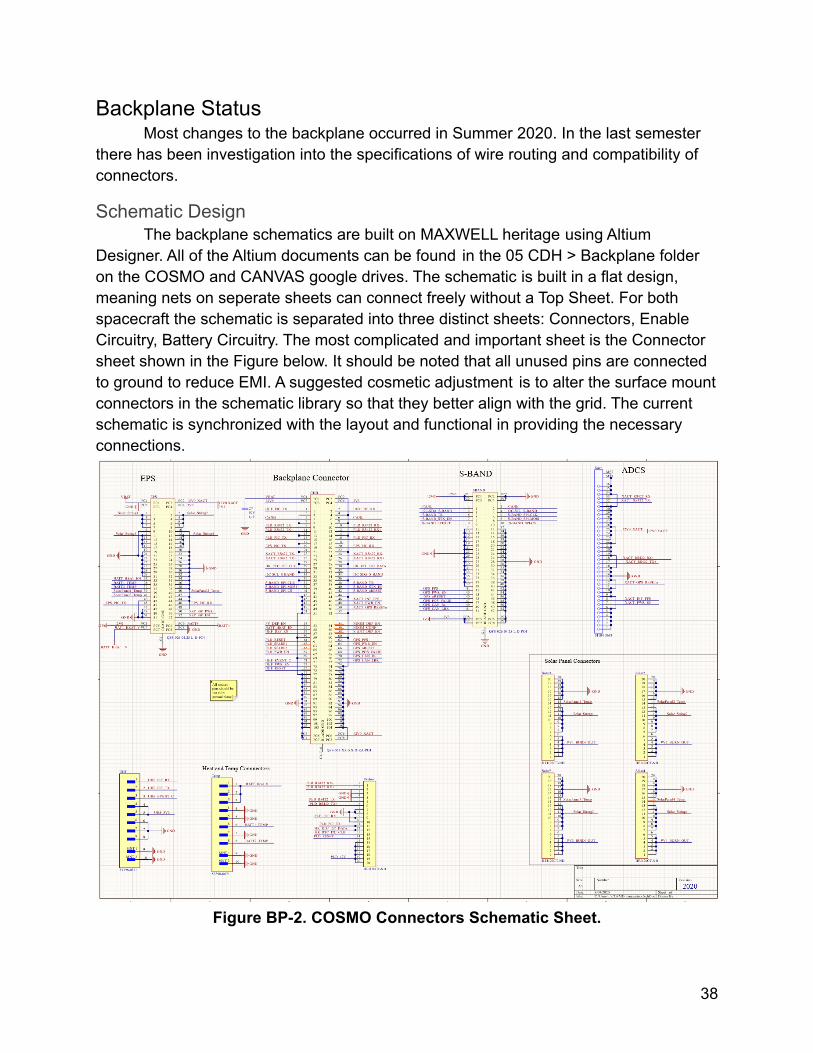
Schematic DesignThe backplane schematics are built on MAXWELL heritage using Altium
Designer. All of the Altium documents can be found in the 05 CDH > Backplane folderon the COSMO and CANVAS google drives. The schematic is built in a flat design,meaning nets on seperate sheets can connect freely without a Top Sheet. For bothspacecraft the schematic is separated into three distinct sheets: Connectors, EnableCircuitry, Battery Circuitry. The most complicated and important sheet is the Connectorsheet shown in the Figure below. It should be noted that all unused pins are connectedto ground to reduce EMI. A suggested cosmetic adjustment is to alter the surface mountconnectors in the schematic library so that they better align with the grid. The currentschematic is synchronized with the layout and functional in providing the necessaryconnections.
Figure BP-2. COSMO Connectors Schematic Sheet.
38
LayoutTwo factors were taken into consideration when determining the backplane
layout, ease of routing and EMI (Electromagnetic Interference). The board anticipated tocreate the most EMI is the EPS. To account for this, the EPS is placed away from theanalog board on CANVAS and the magnetometer on COSMO. For ease of routing, thesurface mount connectors are placed along the edges of the backplane on the sideclosest to the instrument being connected. Rules for Advanced Circuit’s 4-Layer Specialare currently implemented in Altium in addition to Net specific width constraints. Routingis still needed on both backplanes as well as a design rule check. In order to adjust forthe rules, the biggest anticipated obstacle is Silk Screen clearance constraints. Thermalconsiderations may also be needed for the backplane.
Wire RoutingThe wire routing for COSMO is not as developed as the routing for CANVAS
because there are not as many obstacles for cables in COSMO to run into. In CANVAS,the cables from the payloads need to be routed through the card stack to the analogboard, but this is not the case for COSMO because the payload will be routed directly tothe payload connector on the backplane. As for other cables throughout the COSMOstructure, such as cables from the solar panels, batteries, UHF, and XACT to thebackplane, these will be bundled and staked to the structure as needed. The wirebundling and staking methods will follow those used in the MinXSS mission, namely theuse of ESD safe and low outgassing zip ties for bundling and Arathane 5753 + cabosilglue for wire staking. These methods of bundling and staking inside the structure haveproven successful in past missions to prevent stray cables and wires from interferingwith other components.
Deployment CircuitryPower enable circuitry allows a controlled distribution of inrush current between
spacecraft components. Inrush current is the current needed to startup a component.The XACT has a dedicated 3A line so it doesn’t need a power enable switch. The UHFand payload enable circuitry, allows a multi stage power startup for the spacecraft,controlled by the CDH board.
Similar to the power enable circuitry, the burnout circuitry allows a controlleddeployment of inertia altering spacecraft components. In the current state of the CDHand backplane all solar panels must be deployed at once. If a unified deployment is notstructurally feasible, separate pins could be dedicated in order to deploy eachSolar-Panel string individually. In addition to the Solar-Panels, burnout circuitry isincluded for the UHF antenna on both spacecraft.
39
RBF and Separation circuitryTwo of the key design requirements for the backplane are, “The subsystem shall
adhere to all Electrical System Design and Inhibits outlined by NRCSD” (EPS-11) and”The RBF / ABF feature shall preclude any power from any source operating anysatellite functions except for pre- integration battery charging”(EPS-11.6). Thebackplane contributes to these requirements by housing connections for physicaldeployment switches in addition to a RBF(Remove Before Flight) switch.
The backplane works in combination with the EPS board to ensure the NRCSDrequirement is met. Deployment switches D1 and D2 are connected in series with theRBF switch to disable power between battery positive and load on the EPS board. D3 isonly a physical switch on the backplane separating battery negative and ground.
Backplane Next Steps1. Investigate thermal relief with TCS subsystem.2. Confirm mounting with structures.
○ May need to alter mounting hole location.3. Verify connector schematics with other electronics members.4. Finish routing boards.5. Make sure the board passes DRC(Design Rule
Check).○ Silkscreen will need to be altered.
6. Procure and populate first revision of COSMOBackplane PCB.
7. Perform continuity tests to confirm signals areconnected.
8. Integrate with structure and other boards
S-Band DB OverviewThe S-Band Daughter Board(DB) is intended to provide an interface between the
Clyde Space HSTX-01-0073 S-Band Transmitter and the backplane of the spacecraft.On the CANVAS mission the S-Band DB will also provide an interface for the NovAtelOEM 719A GPS receiver, but on COSMO the GPS connector will be unpopulated. Forthe Clyde Space Transmitter interface there is a 104 pin through hole connector on theDB. The necessary signals from the transmitter are connected to testing headers andthe backplane connector. The S-Band transmitter uses SPI and I2C lines tocommunicate with the CDH. Therefore, SCL, SDA, MISO, MOSI and CLK lines areaccounted for on the backplane connector.
40
S-Band DB StatusThe S-Band DB layout is complete on a 2 layer board. A brief reroute is still
required before ordering. The board is built to be configurable in the cardstack.However, the width of the S-Band transmitter is slightly larger than the inner walls soslots will be utilized rather than the rails used on other boards. The headers allow easyaccess to board signals for continuity testing after board population.
S-Band DB Next Steps● Add GPS power enable circuitry● Order PCB
○ Output Gerber files○ Advanced Circuits 2 layer special○ Order components
● Populate boards○ Manually apply solder paste
■ No stencil necessary○ Manual pick-n-place
● Test signals using pin headers● Integrate with flat sat using GSE.
GSE OverviewThe Ground Support Equipment (GSE) board will be used for testing electronics
and debugging COSMO’s flight computer. This board will be similar to the backplane butit will not be integrated into the final COSMO structure. It will feature edge-mountedconnectors for tabletop (FlatSat) integration with the EPS, CDH, and S-Band DB.
The GSE development has been favored over the backplane developmenttoward the end of the Fall 2020 semester due to the need of a method of testing the firstrevisions of the PCB boards. The current state of the GSE board is under developmentin Altium. The schematics for connectors and pin assignments is being worked on.
Figure GSE-1 below shows the CANVAS FBD of the signal lines that will be usedin the integrated GSE testing setup. This figure will be updated to create a separateversion for COSMO’s test setup that will exclude CANVAS’ digital and analog board andwill include the EPS board.
41
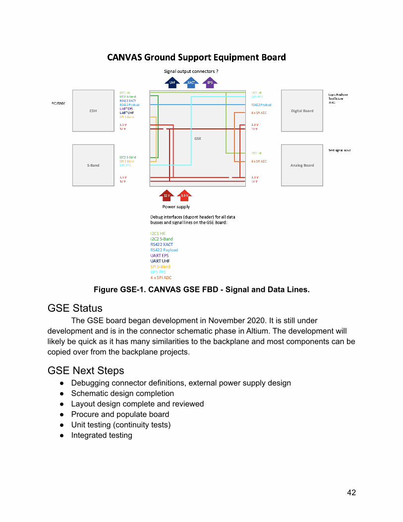
Figure GSE-1. CANVAS GSE FBD - Signal and Data Lines.
GSE StatusThe GSE board began development in November 2020. It is still under
development and is in the connector schematic phase in Altium. The development willlikely be quick as it has many similarities to the backplane and most components can becopied over from the backplane projects.
GSE Next Steps● Debugging connector definitions, external power supply design● Schematic design completion● Layout design complete and reviewed● Procure and populate board● Unit testing (continuity tests)● Integrated testing
42
Communications (COMMs)COMMs Overview
The COMMs subsystem will transmit payload data via amateur S-band (2402.5MHz), transmit beacon and housekeeping data via amateur UHF (437.25 MHz), andreceive uplinked commands via amateur UHF. This mission will use LASP’s groundstation for all communications. All link budget calculations are based on a 20° elevationmask due to LASP’s current capabilities. This mission could use a 10° elevation mask inthe future. LASP proprietary HYDRA commanding software will be used for test andoperational commanding. Specs for radios can be seen below in the Status section.
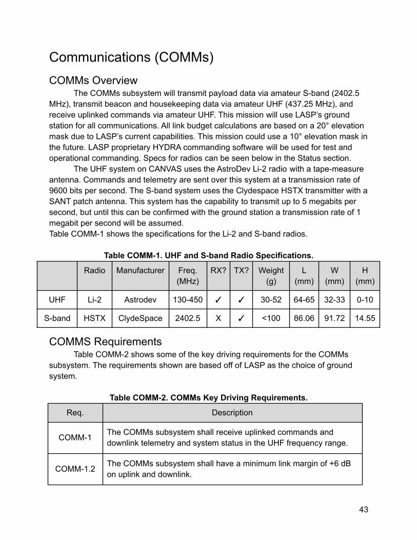
The UHF system on CANVAS uses the AstroDev Li-2 radio with a tape-measureantenna. Commands and telemetry are sent over this system at a transmission rate of9600 bits per second. The S-band system uses the Clydespace HSTX transmitter with aSANT patch antenna. This system has the capability to transmit up to 5 megabits persecond, but until this can be confirmed with the ground station a transmission rate of 1megabit per second will be assumed.Table COMM-1 shows the specifications for the Li-2 and S-band radios.
Table COMM-1. UHF and S-band Radio Specifications.
Radio Manufacturer Freq.(MHz)
RX? TX? Weight(g)
L(mm)
W(mm)
H(mm)
UHF Li-2 Astrodev 130-450 ✓ ✓ 30-52 64-65 32-33 0-10
S-band HSTX ClydeSpace 2402.5 X ✓ <100 86.06 91.72 14.55
COMMS RequirementsTable COMM-2 shows some of the key driving requirements for the COMMs
subsystem. The requirements shown are based off of LASP as the choice of groundsystem.
Table COMM-2. COMMs Key Driving Requirements.
Req. Description
COMM-1 The COMMs subsystem shall receive uplinked commands anddownlink telemetry and system status in the UHF frequency range.
COMM-1.2 The COMMs subsystem shall have a minimum link margin of +6 dBon uplink and downlink.
43
COMM-2 The COMMs subsystem shall send science data in the S-bandfrequency range.
COMMS StatusMuch of the work done for the COMMs subsystem this semester was done in
preparation for subsystem testing, which is scheduled to begin next semester.Two prototypes of the PCB that interfaces with the Li-2 radio were populated, to
be used in testing. These boards cannot be used in flight because they contain tin,which has whiskering properties in space. The layout is unlikely to change, so theprototype is fine to use in testing. The PCB will be temporarily wired to the Li-2 radio(this process must be done in the STIg lab, as the radio is flight hardware) for testingand removed once a tin-free flight board is obtained and populated.
The CAD model for the UHF antenna housing was updated for ease ofmanufacturing, and now more closely resembles the housing used in MinXSS. Thehousing now uses 3 U-brackets (Figure COMM-1) as opposed to two, and has fewersharp edges. Before this change, the largest U-bracket was integrated into the mainhousing unit and would have required special drill bits to manufacture. It was alsodecided that the housing will be manufactured from Delrin (which was used for CSSWEand MinXSS) instead of windform (which MAXWELL is using). The CAD was updated toinclude these changes. In addition to this, the assembly plan and bill of materials werecreated so that the housing can be manufactured and assembled in the spring. Theupdated assembly is shown in figure COMM-2. This image shows the antenna stowedinside the housing. A prototype of the housing has been 3D printed, and fit-tested with atape measure.
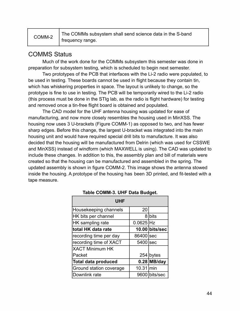
Table COMM-3. UHF Data Budget.
UHF
Housekeeping channels 20HK bits per channel 8 bitsHK sampling rate 0.0625 Hztotal HK data rate 10.00 bits/secrecording time per day 86400 secrecording time of XACT 5400 secXACT Minimum HKPacket 254 bytesTotal data produced 0.28 MB/dayGround station coverage 10.31 minDownlink rate 9600 bits/sec
44
Data downlink capability 0.71 MB/day
Margin153.33
%
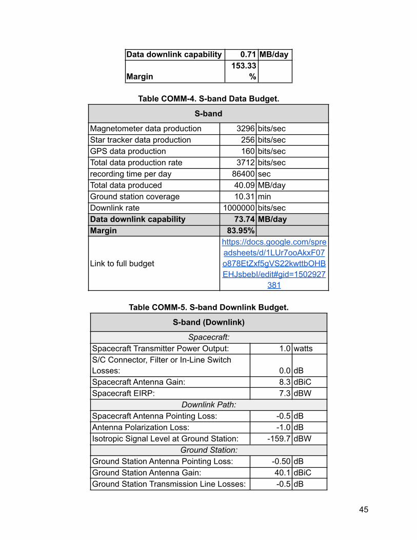
Table COMM-4. S-band Data Budget.
S-band
Magnetometer data production 3296 bits/secStar tracker data production 256 bits/secGPS data production 160 bits/secTotal data production rate 3712 bits/secrecording time per day 86400 secTotal data produced 40.09 MB/dayGround station coverage 10.31 minDownlink rate 1000000 bits/secData downlink capability 73.74 MB/dayMargin 83.95%
Link to full budget
https://docs.google.com/spreadsheets/d/1LUr7ooAkxF07o878EtZxf5gVS22kwttbOHBEHJsbebI/edit#gid=1502927
381
Table COMM-5. S-band Downlink Budget.
S-band (Downlink)
Spacecraft:Spacecraft Transmitter Power Output: 1.0 wattsS/C Connector, Filter or In-Line SwitchLosses: 0.0 dBSpacecraft Antenna Gain: 8.3 dBiCSpacecraft EIRP: 7.3 dBW
Downlink Path:Spacecraft Antenna Pointing Loss: -0.5 dBAntenna Polarization Loss: -1.0 dBIsotropic Signal Level at Ground Station: -159.7 dBW
Ground Station:Ground Station Antenna Pointing Loss: -0.50 dBGround Station Antenna Gain: 40.1 dBiCGround Station Transmission Line Losses: -0.5 dB
45
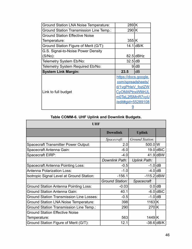
Ground Station LNA Noise Temperature: 289 KGround Station Transmission Line Temp.: 290 KGround Station Effective NoiseTemperature: 355 KGround Station Figure of Merit (G/T): 14.1 dB/KG.S. Signal-to-Noise Power Density(S/No): 82.5 dBHzTelemetry System Eb/No: 32.5 dBTelemetry System Required Eb/No: 9 dBSystem Link Margin: 23.5 dB
Link to full budget
https://docs.google.com/spreadsheets/d/1vgPhleV_fozlZWCyOMAPtnxWMrULm0TeL2fSMnR7vyU/edit#gid=55289108
9
Table COMM-6. UHF Uplink and Downlink Budgets.
UHF
Downlink Uplink
Spacecraft: Ground Station:Spacecraft Transmitter Power Output: 2.0 500.0 WSpacecraft Antenna Gain: -6.0 19.0 dBiCSpacecraft EIRP: -4.0 41.9 dBW
Downlink Path: Uplink Path:Spacecraft Antenna Pointing Loss: -0.5 -1.0 dBAntenna Polarization Loss: -1.0 -4.0 dBIsotropic Signal Level at Ground Station: -156.1 -115.2 dBW
Ground Station: SpacecraftGround Station Antenna Pointing Loss: -0.03 0.0 dBGround Station Antenna Gain: 40.1 -6.0 dBiCGround Station Transmission Line Losses: -0.5 -1.0 dBGround Station LNA Noise Temperature: 398 1163 KGround Station Transmission Line Temp.: 290 270 KGround Station Effective NoiseTemperature: 563 1449 KGround Station Figure of Merit (G/T): 12.1 -38.6 dB/K
46
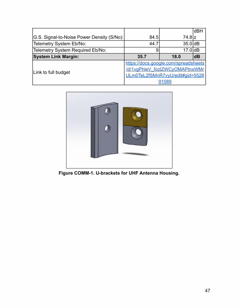
G.S. Signal-to-Noise Power Density (S/No): 84.5 74.8dBHz
Telemetry System Eb/No: 44.7 35.0 dBTelemetry System Required Eb/No: 9 17.0 dBSystem Link Margin: 35.7 18.0 dB
Link to full budget
https://docs.google.com/spreadsheets/d/1vgPhleV_fozlZWCyOMAPtnxWMrULm0TeL2fSMnR7vyU/edit#gid=5528
91089
Figure COMM-1. U-brackets for UHF Antenna Housing.
47
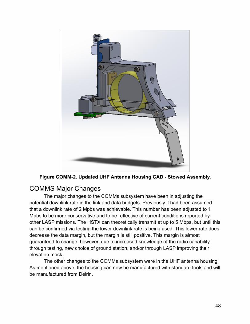
Figure COMM-2. Updated UHF Antenna Housing CAD - Stowed Assembly.
COMMS Major ChangesThe major changes to the COMMs subsystem have been in adjusting the
potential downlink rate in the link and data budgets. Previously it had been assumedthat a downlink rate of 2 Mpbs was achievable. This number has been adjusted to 1Mpbs to be more conservative and to be reflective of current conditions reported byother LASP missions. The HSTX can theoretically transmit at up to 5 Mbps, but until thiscan be confirmed via testing the lower downlink rate is being used. This lower rate doesdecrease the data margin, but the margin is still positive. This margin is almostguaranteed to change, however, due to increased knowledge of the radio capabilitythrough testing, new choice of ground station, and/or through LASP improving theirelevation mask.
The other changes to the COMMs subsystem were in the UHF antenna housing.As mentioned above, the housing can now be manufactured with standard tools and willbe manufactured from Delrin.
48
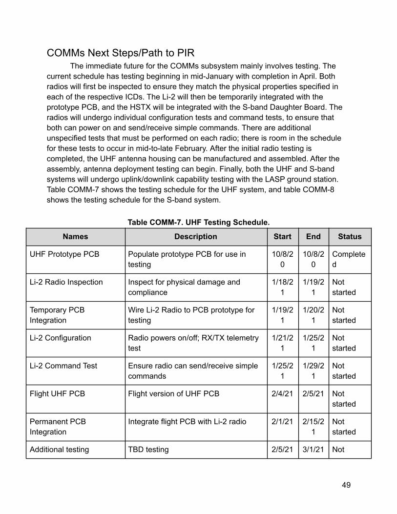
COMMs Next Steps/Path to PIRThe immediate future for the COMMs subsystem mainly involves testing. The
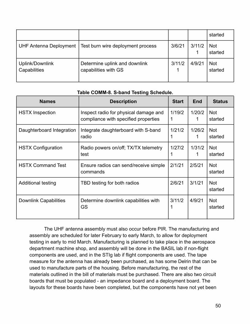
current schedule has testing beginning in mid-January with completion in April. Bothradios will first be inspected to ensure they match the physical properties specified ineach of the respective ICDs. The Li-2 will then be temporarily integrated with theprototype PCB, and the HSTX will be integrated with the S-band Daughter Board. Theradios will undergo individual configuration tests and command tests, to ensure thatboth can power on and send/receive simple commands. There are additionalunspecified tests that must be performed on each radio; there is room in the schedulefor these tests to occur in mid-to-late February. After the initial radio testing iscompleted, the UHF antenna housing can be manufactured and assembled. After theassembly, antenna deployment testing can begin. Finally, both the UHF and S-bandsystems will undergo uplink/downlink capability testing with the LASP ground station.Table COMM-7 shows the testing schedule for the UHF system, and table COMM-8shows the testing schedule for the S-band system.
Table COMM-7. UHF Testing Schedule.
Names Description Start End Status
UHF Prototype PCB Populate prototype PCB for use intesting
10/8/20
10/8/20
Completed
Li-2 Radio Inspection Inspect for physical damage andcompliance
1/18/21
1/19/21
Notstarted
Temporary PCBIntegration
Wire Li-2 Radio to PCB prototype fortesting
1/19/21
1/20/21
Notstarted
Li-2 Configuration Radio powers on/off; RX/TX telemetrytest
1/21/21
1/25/21
Notstarted
Li-2 Command Test Ensure radio can send/receive simplecommands
1/25/21
1/29/21
Notstarted
Flight UHF PCB Flight version of UHF PCB 2/4/21 2/5/21 Notstarted
Permanent PCBIntegration
Integrate flight PCB with Li-2 radio 2/1/21 2/15/21
Notstarted
Additional testing TBD testing 2/5/21 3/1/21 Not
49
started
UHF Antenna Deployment Test burn wire deployment process 3/6/21 3/11/21
Notstarted
Uplink/DownlinkCapabilities
Determine uplink and downlinkcapabilities with GS
3/11/21
4/9/21 Notstarted
Table COMM-8. S-band Testing Schedule.
Names Description Start End Status
HSTX Inspection Inspect radio for physical damage andcompliance with specified properties
1/19/21
1/20/21
Notstarted
Daughterboard Integration Integrate daughterboard with S-bandradio
1/21/21
1/26/21
Notstarted
HSTX Configuration Radio powers on/off; TX/TX telemetrytest
1/27/21
1/31/21
Notstarted
HSTX Command Test Ensure radios can send/receive simplecommands
2/1/21 2/5/21 Notstarted
Additional testing TBD testing for both radios 2/6/21 3/1/21 Notstarted
Downlink Capabilities Determine downlink capabilities withGS
3/11/21
4/9/21 Notstarted
The UHF antenna assembly must also occur before PIR. The manufacturing andassembly are scheduled for later February to early March, to allow for deploymenttesting in early to mid March. Manufacturing is planned to take place in the aerospacedepartment machine shop, and assembly will be done in the BASIL lab if non-flightcomponents are used, and in the STIg lab if flight components are used. The tapemeasure for the antenna has already been purchased, as has some Delrin that can beused to manufacture parts of the housing. Before manufacturing, the rest of thematerials outlined in the bill of materials must be purchased. There are also two circuitboards that must be populated - an impedance board and a deployment board. Thelayouts for these boards have been completed, but the components have not yet been
50
ordered. The boards should not need to be professionally populated.
51
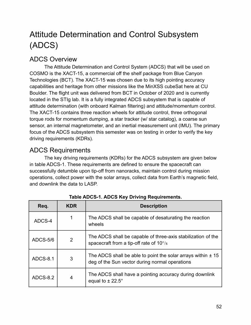
Attitude Determination and Control Subsystem(ADCS)ADCS Overview
The Attitude Determination and Control System (ADCS) that will be used onCOSMO is the XACT-15, a commercial off the shelf package from Blue CanyonTechnologies (BCT). The XACT-15 was chosen due to its high pointing accuracycapabilities and heritage from other missions like the MinXSS cubeSat here at CUBoulder. The flight unit was delivered from BCT in October of 2020 and is currentlylocated in the STIg lab. It is a fully integrated ADCS subsystem that is capable ofattitude determination (with onboard Kalman filtering) and attitude/momentum control.The XACT-15 contains three reaction wheels for attitude control, three orthogonaltorque rods for momentum dumping, a star tracker (w/ star catalog), a coarse sunsensor, an internal magnetometer, and an inertial measurement unit (IMU). The primaryfocus of the ADCS subsystem this semester was on testing in order to verify the keydriving requirements (KDRs).
ADCS RequirementsThe key driving requirements (KDRs) for the ADCS subsystem are given below
in table ADCS-1. These requirements are defined to ensure the spacecraft cansuccessfully detumble upon tip-off from nanoracks, maintain control during missionoperations, collect power with the solar arrays, collect data from Earth’s magnetic field,and downlink the data to LASP.
Table ADCS-1. ADCS Key Driving Requirements.
Req. KDR Description
ADCS-4 1 The ADCS shall be capable of desaturating the reactionwheels
ADCS-5/6 2 The ADCS shall be capable of three-axis stabilization of thespacecraft from a tip-off rate of 10°/s
ADCS-8.1 3 The ADCS shall be able to point the solar arrays within ± 15deg of the Sun vector during normal operations
ADCS-8.2 4 The ADCS shall have a pointing accuracy during downlinkequal to ± 22.5°
52
ADCS-8.4 5 The ADCS shall be capable of slewing the spacecraft at aminimum rate of 0.36 °/sec.
ADCS-8.5 6 The ADCS shall have a pointing accuracy during magneticfield tracking equal to ± 22.5°
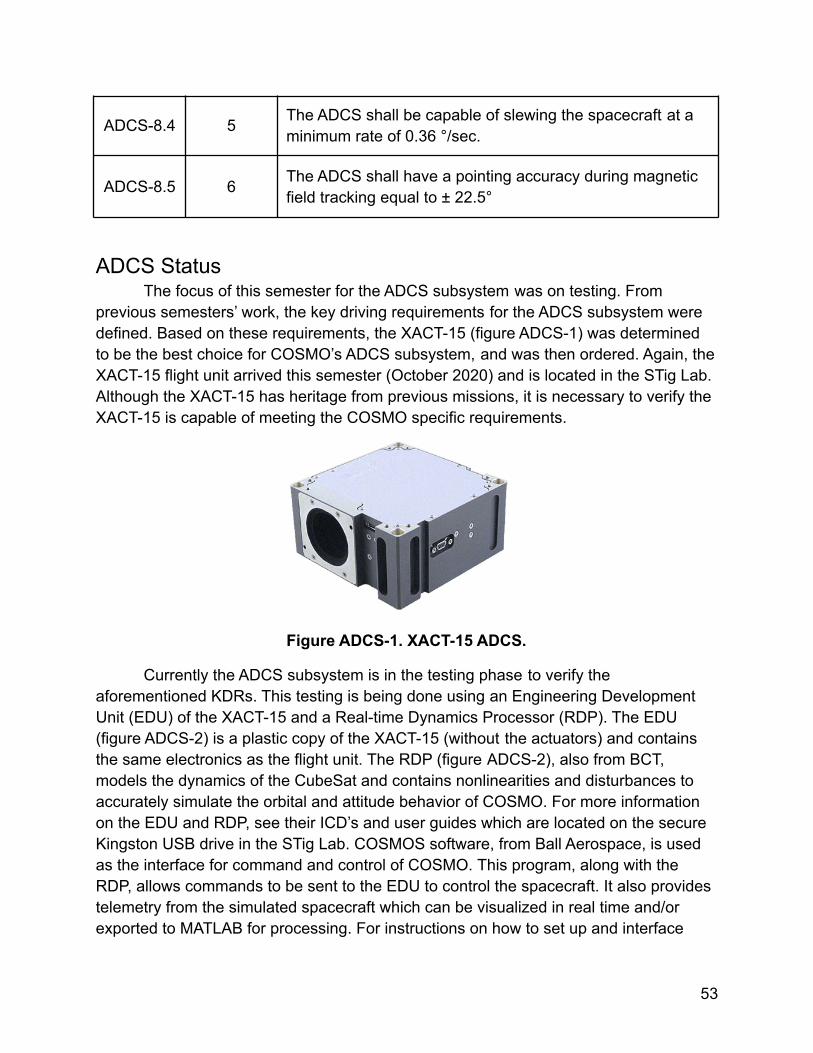
ADCS StatusThe focus of this semester for the ADCS subsystem was on testing. From
previous semesters’ work, the key driving requirements for the ADCS subsystem weredefined. Based on these requirements, the XACT-15 (figure ADCS-1) was determinedto be the best choice for COSMO’s ADCS subsystem, and was then ordered. Again, theXACT-15 flight unit arrived this semester (October 2020) and is located in the STig Lab.Although the XACT-15 has heritage from previous missions, it is necessary to verify theXACT-15 is capable of meeting the COSMO specific requirements.
Figure ADCS-1. XACT-15 ADCS.
Currently the ADCS subsystem is in the testing phase to verify theaforementioned KDRs. This testing is being done using an Engineering DevelopmentUnit (EDU) of the XACT-15 and a Real-time Dynamics Processor (RDP). The EDU(figure ADCS-2) is a plastic copy of the XACT-15 (without the actuators) and containsthe same electronics as the flight unit. The RDP (figure ADCS-2), also from BCT,models the dynamics of the CubeSat and contains nonlinearities and disturbances toaccurately simulate the orbital and attitude behavior of COSMO. For more informationon the EDU and RDP, see their ICD’s and user guides which are located on the secureKingston USB drive in the STig Lab. COSMOS software, from Ball Aerospace, is usedas the interface for command and control of COSMO. This program, along with theRDP, allows commands to be sent to the EDU to control the spacecraft. It also providestelemetry from the simulated spacecraft which can be visualized in real time and/orexported to MATLAB for processing. For instructions on how to set up and interface
53
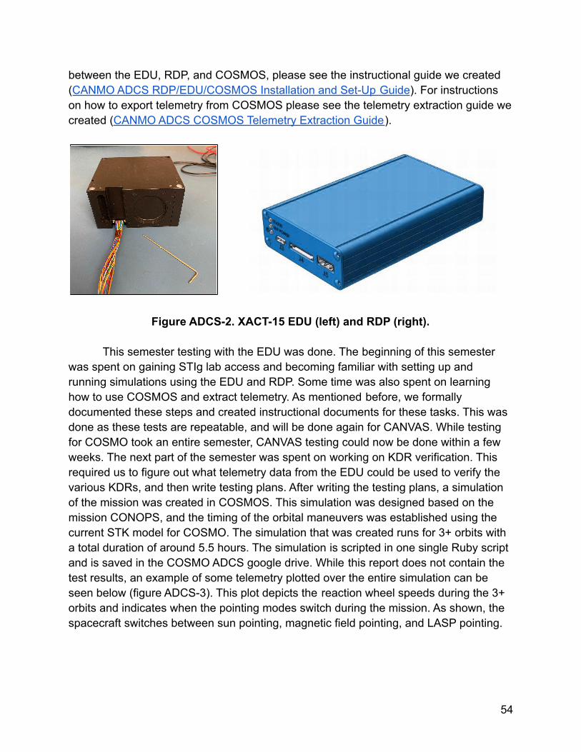
between the EDU, RDP, and COSMOS, please see the instructional guide we created(CANMO ADCS RDP/EDU/COSMOS Installation and Set-Up Guide). For instructionson how to export telemetry from COSMOS please see the telemetry extraction guide wecreated (CANMO ADCS COSMOS Telemetry Extraction Guide).
Figure ADCS-2. XACT-15 EDU (left) and RDP (right).
This semester testing with the EDU was done. The beginning of this semesterwas spent on gaining STIg lab access and becoming familiar with setting up andrunning simulations using the EDU and RDP. Some time was also spent on learninghow to use COSMOS and extract telemetry. As mentioned before, we formallydocumented these steps and created instructional documents for these tasks. This wasdone as these tests are repeatable, and will be done again for CANVAS. While testingfor COSMO took an entire semester, CANVAS testing could now be done within a fewweeks. The next part of the semester was spent on working on KDR verification. Thisrequired us to figure out what telemetry data from the EDU could be used to verify thevarious KDRs, and then write testing plans. After writing the testing plans, a simulationof the mission was created in COSMOS. This simulation was designed based on themission CONOPS, and the timing of the orbital maneuvers was established using thecurrent STK model for COSMO. The simulation that was created runs for 3+ orbits witha total duration of around 5.5 hours. The simulation is scripted in one single Ruby scriptand is saved in the COSMO ADCS google drive. While this report does not contain thetest results, an example of some telemetry plotted over the entire simulation can beseen below (figure ADCS-3). This plot depicts the reaction wheel speeds during the 3+orbits and indicates when the pointing modes switch during the mission. As shown, thespacecraft switches between sun pointing, magnetic field pointing, and LASP pointing.
54
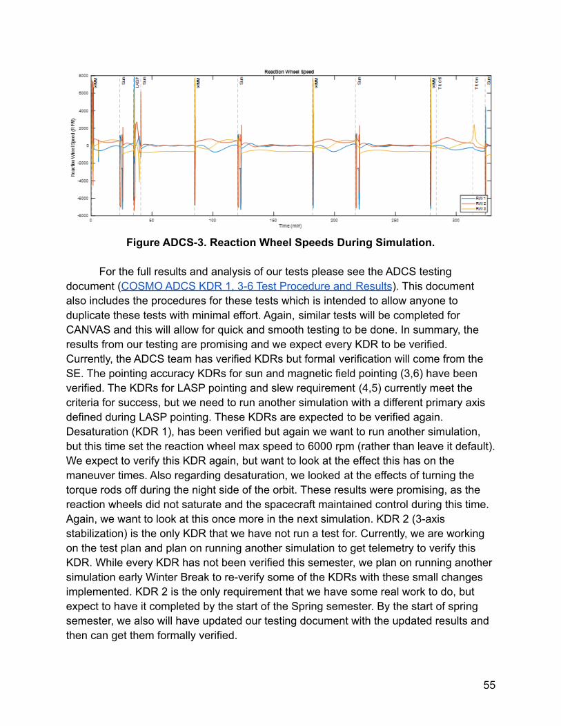
Figure ADCS-3. Reaction Wheel Speeds During Simulation.
For the full results and analysis of our tests please see the ADCS testingdocument (COSMO ADCS KDR 1, 3-6 Test Procedure and Results). This documentalso includes the procedures for these tests which is intended to allow anyone toduplicate these tests with minimal effort. Again, similar tests will be completed forCANVAS and this will allow for quick and smooth testing to be done. In summary, theresults from our testing are promising and we expect every KDR to be verified.Currently, the ADCS team has verified KDRs but formal verification will come from theSE. The pointing accuracy KDRs for sun and magnetic field pointing (3,6) have beenverified. The KDRs for LASP pointing and slew requirement (4,5) currently meet thecriteria for success, but we need to run another simulation with a different primary axisdefined during LASP pointing. These KDRs are expected to be verified again.Desaturation (KDR 1), has been verified but again we want to run another simulation,but this time set the reaction wheel max speed to 6000 rpm (rather than leave it default).We expect to verify this KDR again, but want to look at the effect this has on themaneuver times. Also regarding desaturation, we looked at the effects of turning thetorque rods off during the night side of the orbit. These results were promising, as thereaction wheels did not saturate and the spacecraft maintained control during this time.Again, we want to look at this once more in the next simulation. KDR 2 (3-axisstabilization) is the only KDR that we have not run a test for. Currently, we are workingon the test plan and plan on running another simulation to get telemetry to verify thisKDR. While every KDR has not been verified this semester, we plan on running anothersimulation early Winter Break to re-verify some of the KDRs with these small changesimplemented. KDR 2 is the only requirement that we have some real work to do, butexpect to have it completed by the start of the Spring semester. By the start of springsemester, we also will have updated our testing document with the updated results andthen can get them formally verified.
55
Flight software ADCS commands were also worked on this semester. CompletingEDU testing informed us what FSW commands are needed to be sent to the XACT-15during the mission. Lea, the FSW lead, created a document in the Spring 2020semester with a list of ADCS flight software commands. The ADCS FSW commandscan be found in the google drive (ADCS Software Commands). This semester, the FSWcommand structures in RUBY were translated to the FSW language. Some of this wasalready done in the Spring semester, but we updated some of those commands andadded some new ones that will be used. Regarding FSW, we still have a lot of work todo with the FSW lead next semester. A process needs to be developed on howFSW/CDH will communicate with the ADCS subsystem and what required telemetrypackets/definitions will be used.
ADCS Major ChangesNo major changes were made to the ADCS subsystem this semester. Although,
some changes in documentation were made. The previous ADCS lead has someexperience with the test set-up and wrote some instructions on how to get it up andrunning. These instructions were helpful to newcomers (like ourselves), but wereminimal and were missing some key information and steps. We had some difficultygetting the test set-up running this semester. There were about 3 different instances wegot stuck and how to reach out to BCT for guidance. These hurdles pertained toinstalling COSMOS correctly, configuring the RDP testing software, and configuring thecomputer to work with the EDU and RDP. This took up almost a month of our time.There was also no information on how to extract the telemetry from COSMOS forprocessing in MATLAB. To address these challenges and help prevent this fromhappening again with others, we created two instructional documents forEDU/RDP/COSMOS set-up, interface, and telemetry extraction (documents mentionedand linked in the previous section). We also applied this idea of documentation to ourtesting procedures. The goal of all this documentation is of course to provide thenecessary information for others to repeat these same tests but with ease and minimaleffort.
ADCS Next Steps/Path to PIRThere are some immediate smaller action items that need to be done for the
ADCS subsystem. These are tasks that we plan on completing in December andJanuary:
1. Re-run testing simulation with updated axis defined to re-verify KDRs 4and 5 (December 18, 2020).
2. Re-run testing simulation with reaction wheel speeds defined (December18, 2020)
3. Update testing document with new results (January 5th, 2020)4. Complete testing plan and run simulation for KDR 2 (January 15th, 2020)
56
5. Get KDR testing results formally verified - i.e. signed off on (January 10th,2020)
6. Work with SE to update CONOPS and STK with maneuver times fromEDU testing (January 20th, 2020)
A lot of important tasks need to be done for the ADCS subsystem before PIR.These are larger broad-level tasks that will ready the ADCS subsystem for PIR and willbe our focus for the Spring 2021 semester:
1. Work with FSW/CDH to develop processes and plans for communicationbetween CDH and ADCS subsystems (Early-Mid Spring 2021)
2. Develop flight hardware testing plan for the XACT-15 (i.e. what needs tobe done in order to ready the flight unit for tests? What subsystems will beinvolved? What testing will take place?) (Early-Mid Spring 2021)
3. Perform flight hardware testing of the XACT-15 (Mid-Late Spring 2021)4. Develop plans for flight hardware integration and EMI testing that will take
place post-integration (Late Spring 2021)
57
Thermal Control System (TCS)Overview
The purpose of thermal analysis for a spacecraft is to ensure that all subsystemcomponents will stay within their defined operational and survival temperature limitsduring any point of the mission. Apart from the subsystem components the mainpayload science instruments may also require to stay within a strict temperature rangeand in thermal stability throughout the mission.
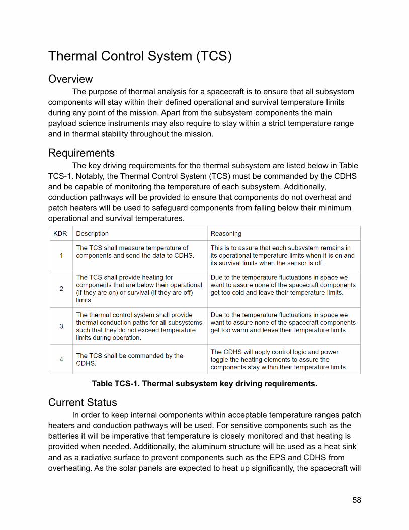
RequirementsThe key driving requirements for the thermal subsystem are listed below in Table
TCS-1. Notably, the Thermal Control System (TCS) must be commanded by the CDHSand be capable of monitoring the temperature of each subsystem. Additionally,conduction pathways will be provided to ensure that components do not overheat andpatch heaters will be used to safeguard components from falling below their minimumoperational and survival temperatures.
Table TCS-1. Thermal subsystem key driving requirements.
Current StatusIn order to keep internal components within acceptable temperature ranges patch
heaters and conduction pathways will be used. For sensitive components such as thebatteries it will be imperative that temperature is closely monitored and that heating isprovided when needed. Additionally, the aluminum structure will be used as a heat sinkand as a radiative surface to prevent components such as the EPS and CDHS fromoverheating. As the solar panels are expected to heat up significantly, the spacecraft will
58
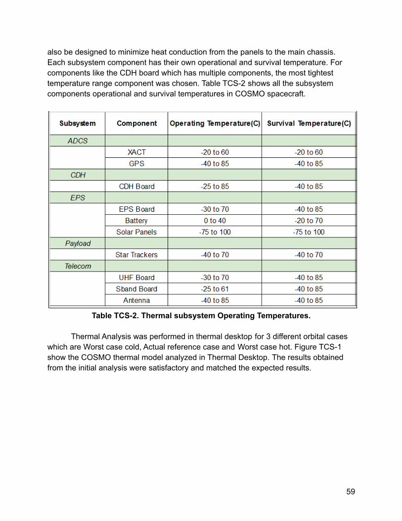
also be designed to minimize heat conduction from the panels to the main chassis.Each subsystem component has their own operational and survival temperature. Forcomponents like the CDH board which has multiple components, the most tightesttemperature range component was chosen. Table TCS-2 shows all the subsystemcomponents operational and survival temperatures in COSMO spacecraft.
Table TCS-2. Thermal subsystem Operating Temperatures.
Thermal Analysis was performed in thermal desktop for 3 different orbital caseswhich are Worst case cold, Actual reference case and Worst case hot. Figure TCS-1show the COSMO thermal model analyzed in Thermal Desktop. The results obtainedfrom the initial analysis were satisfactory and matched the expected results.
59
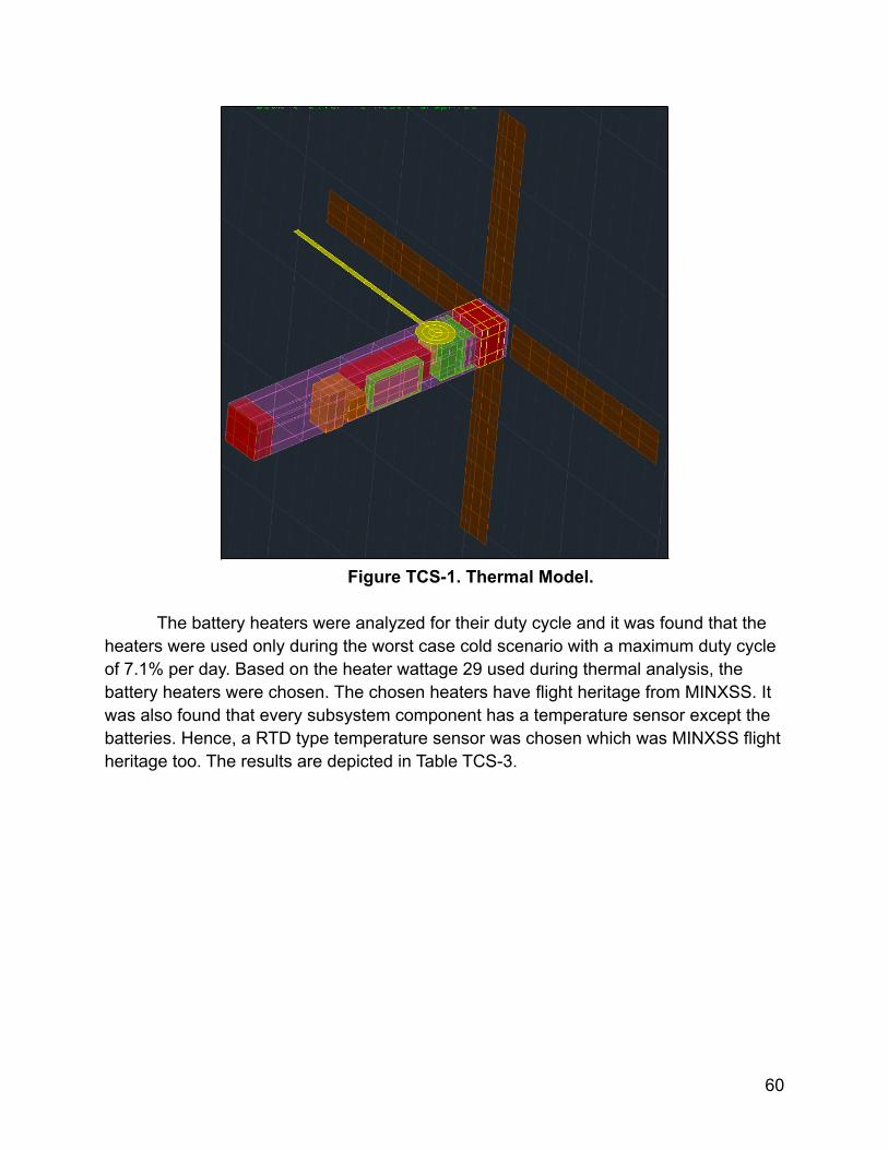
Figure TCS-1. Thermal Model.
The battery heaters were analyzed for their duty cycle and it was found that theheaters were used only during the worst case cold scenario with a maximum duty cycleof 7.1% per day. Based on the heater wattage 29 used during thermal analysis, thebattery heaters were chosen. The chosen heaters have flight heritage from MINXSS. Itwas also found that every subsystem component has a temperature sensor except thebatteries. Hence, a RTD type temperature sensor was chosen which was MINXSS flightheritage too. The results are depicted in Table TCS-3.
60
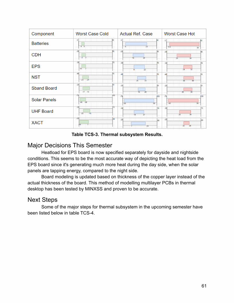
Table TCS-3. Thermal subsystem Results.
Major Decisions This SemesterHeatload for EPS board is now specified separately for dayside and nightside
conditions. This seems to be the most accurate way of depicting the heat load from theEPS board since it's generating much more heat during the day side, when the solarpanels are tapping energy, compared to the night side.
Board modeling is updated based on thickness of the copper layer instead of theactual thickness of the board. This method of modelling multilayer PCBs in thermaldesktop has been tested by MINXSS and proven to be accurate.
Next StepsSome of the major steps for thermal subsystem in the upcoming semester have
been listed below in table TCS-4.
61
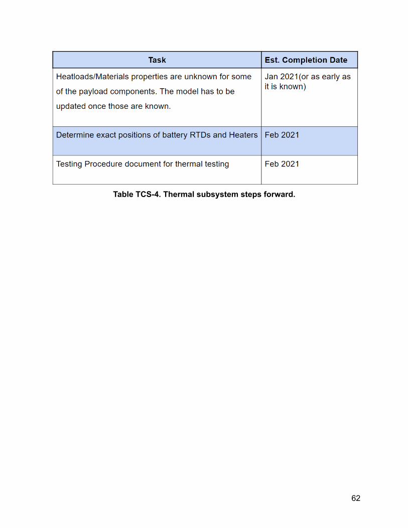
Table TCS-4. Thermal subsystem steps forward.
62
Flight Software (FSW)FSW Overview
The flight software subsystem is composed of the embedded code running onthe CDH and EPS computers. Due to the choice to use MAXWELL heritage designedfor the CDH and EPS boards, the team has decided to modify the flight softwaredeveloped for MAXWELL for use on both subsystems. The MAXWELL code is still indevelopment and has heritage on the QB-50 mission. In addition, the CDH softwarereferences MinXSS heritage code to interface with the BCT XACT, as the ADCScomponent selected for COSMO differs from that on MAXWELL.
Because there will be no onboard operating systems, the software must define itsown tasks and scheduler. The CDH code is responsible for managing the spacecraftmodes and subsystems, executing commands from ground, and handling anddownlinking data. The EPS code is responsible for peak power tracking, calculating thestate-of-charge of the batteries, and collecting EPS telemetry.
FSW RequirementsThe driving requirements for the COSMO FSW are shown below in Table FSW-1.
These requirements were selected as they dictate the core autonomous functionality ofthe software required for mission success.
Table FSW-1. FSW Key Driving Requirements.KDR Description
1 The software shall autonomously manage a set of spacecraft modes andcommand each of the spacecraft subsystems
2 The software shall authenticate, process, and route ground commands tothe appropriate subsystem.
3 The software shall support error handling.
4 The software shall control the deployment of all satellite extensions.
FSW StatusThe CDH FSW responsibilities are separated into "tasks" and a scheduler is
defined to execute these tasks at a certain frequency depending on their urgency. Thetasks and scheduler are shown in Figure FSW-1. The high rate task consists only of thewatchdog timer reset, the mid-rate tasks include interfaces and spacecraft operations,and the low-rate tasks consist of deployments and spacecraft monitoring. Again,because there’s no onboard OS, there’s no enforcement of the timing so the task
63
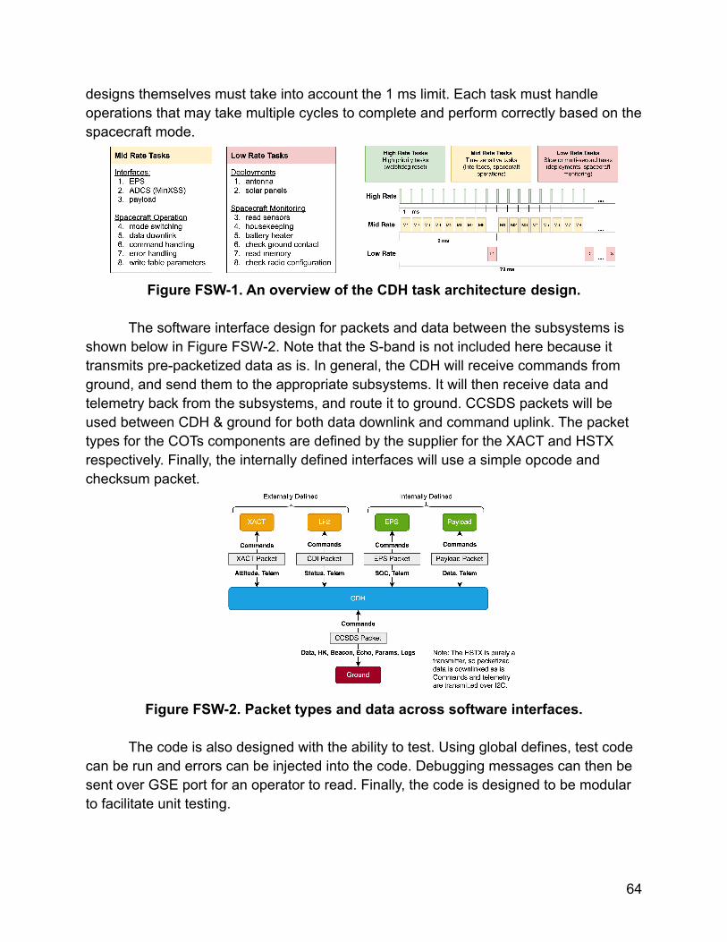
designs themselves must take into account the 1 ms limit. Each task must handleoperations that may take multiple cycles to complete and perform correctly based on thespacecraft mode.
Figure FSW-1. An overview of the CDH task architecture design.
The software interface design for packets and data between the subsystems isshown below in Figure FSW-2. Note that the S-band is not included here because ittransmits pre-packetized data as is. In general, the CDH will receive commands fromground, and send them to the appropriate subsystems. It will then receive data andtelemetry back from the subsystems, and route it to ground. CCSDS packets will beused between CDH & ground for both data downlink and command uplink. The packettypes for the COTs components are defined by the supplier for the XACT and HSTXrespectively. Finally, the internally defined interfaces will use a simple opcode andchecksum packet.
Figure FSW-2. Packet types and data across software interfaces.
The code is also designed with the ability to test. Using global defines, test codecan be run and errors can be injected into the code. Debugging messages can then besent over GSE port for an operator to read. Finally, the code is designed to be modularto facilitate unit testing.
64
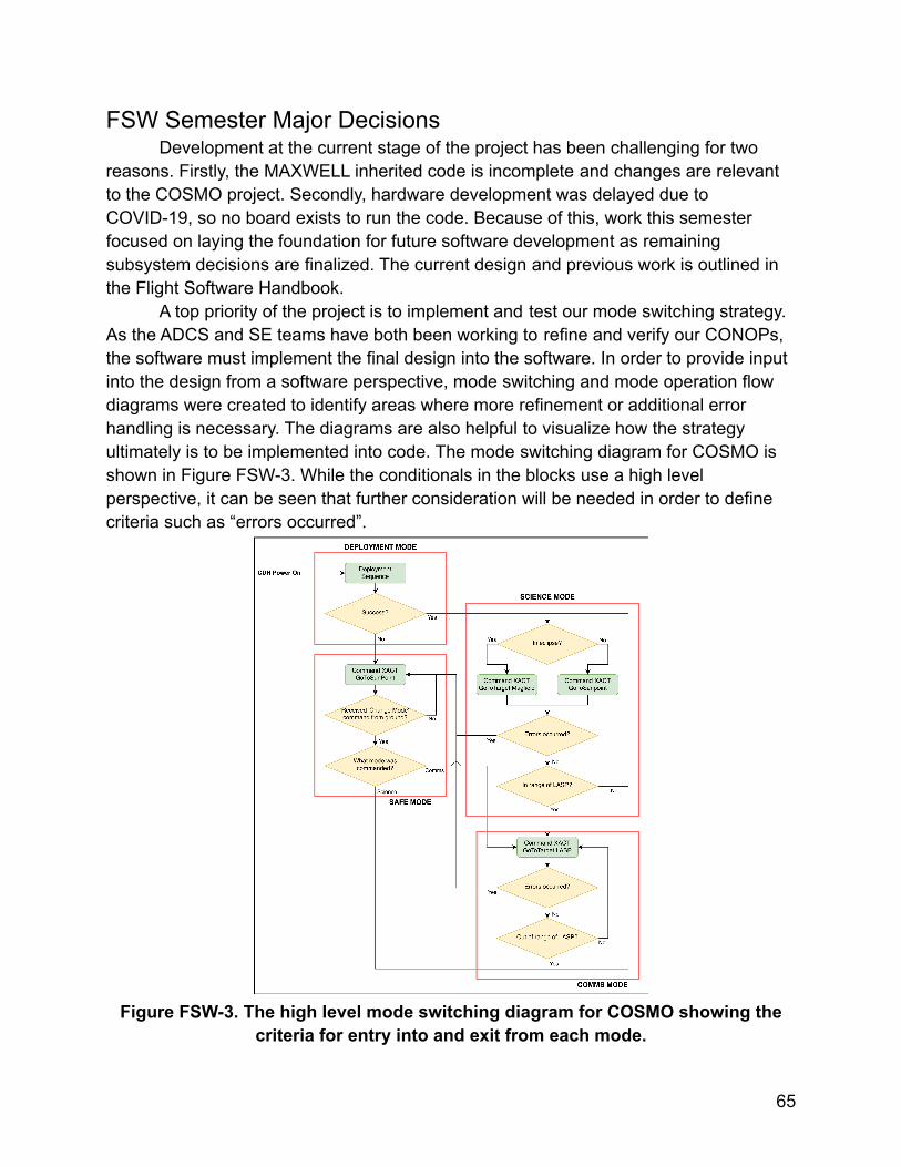
FSW Semester Major DecisionsDevelopment at the current stage of the project has been challenging for two
reasons. Firstly, the MAXWELL inherited code is incomplete and changes are relevantto the COSMO project. Secondly, hardware development was delayed due toCOVID-19, so no board exists to run the code. Because of this, work this semesterfocused on laying the foundation for future software development as remainingsubsystem decisions are finalized. The current design and previous work is outlined inthe Flight Software Handbook.
A top priority of the project is to implement and test our mode switching strategy.As the ADCS and SE teams have both been working to refine and verify our CONOPs,the software must implement the final design into the software. In order to provide inputinto the design from a software perspective, mode switching and mode operation flowdiagrams were created to identify areas where more refinement or additional errorhandling is necessary. The diagrams are also helpful to visualize how the strategyultimately is to be implemented into code. The mode switching diagram for COSMO isshown in Figure FSW-3. While the conditionals in the blocks use a high levelperspective, it can be seen that further consideration will be needed in order to definecriteria such as “errors occurred”.
Figure FSW-3. The high level mode switching diagram for COSMO showing thecriteria for entry into and exit from each mode.
65
There was much discussion on the CANVAS team this semester regarding theCDH and payload software, and concerns regarding the SD card operation for bothmissions were brought up. The team had hoped to use the MAXWELL test setup toverify the current understanding of the current SD card code and the test modifications;however, the team was unable to negotiate time on the setup. Considerations such asdownlink priority, retransmit address lookup, and virtual channel ID (VCID) selectionmust still be addressed, and some recommendations have been provided by MagnusKarlsson of LASP. Ultimately, as memory is plentiful on the mission, decisions regardingmemory allocation and priority will primarily be based on the number of packet types tobe stored and their frequency of generation.
Additionally, new information arose from Dr. Nicholas Rainville this semesterregarding the robustness of the current MAXWELL EPS peak power tracking (PPT)strategy and battery state-of-charge (SOC) calculations. PPT aims to find the “sweetspot” on the solar panel IV curve that maximizes power draw by controlling the currentdrawn from the panel. The existing MAXWELL design uses a hybrid of software andhardware strategies to control the current that results in a delayed reaction. A purelysoftware based strategy would reduce this reaction time and increase efficiency, butrequire additional development and thorough testing, as there would be no recovery inthe case of a software fault. A purely hardware design in the form of current limitingresistors is robust but inefficient. Further investigation by Jett Moore of the EPSsubsystem will be conducted next semester and the results will influence the finalsoftware implementation. For the SOC calculation, a coarse method is beingimplemented on MAXWELL that results in errors of up to 5% and large swings incalculation outputs. However, this method can likely be used for COSMO with minimalmodifications, as the error is tolerable for our mission and the output swing can beaccounted for with a hysteresis band for decisions based on SOC.
Finally, the software documentation and knowledge has been condensedprimarily into two living documents to be shared with the CANVAS project. Firstly, theSoftware Development Guide provides instructions for the development environmentsetup and standard coding strategies. Future additions to the document will includerobust integration procedures as the software team grows, and instructions to programand run code on the dsPIC. Secondly, the Flight Software Handbook details previousdesign decisions, the current status, and all future work of the COSMO and CANVASCubesat flight software. The document must be updated as additional decisions aremade. Both documents are listed and linked in Table FSW-2.
Table FSW-2: Reference Documents.Document No. Title Author(s)
66
1 Software Development Guide Lea Chandler
2 Flight Software Handbook Lea Chandler
FSW Next StepsSoftware design often follows a design, implement, and test development flow,
and this flight software is no different. However, it is unclear what the future of thesoftware team will be in the upcoming semester. Design work for the CDH software isstill necessary to specify the data downlink and command uplink packet contents, selectthe housekeeping data for the real-time and full housekeeping packets, and to definethe SD card store and fetch operations for all packet types. Necessary design work forthe EPS software is the telemetry packets to and commanding packets from the CDH,and the aforementioned PPT and SOC implementations. Because much of thesedecisions primarily involve mission operation, they can be made with little input from asoftware perspective and can be completed within the next semester.
Implementation of the finalized CONOPs, packet structures and parsing, andadditional hardware drivers for new components will require software manpower. Thesetasks can likely be completed within a semester, even accounting for time to come up tospeed with the project.
However, testing and modifying the design and implementation will take muchlonger and should be started as soon as possible. Unit testing of modules should occuras those modules are being implemented, followed by end-to-end functionality testing.Verification of the software KDRs should be completed within a year of the initialimplementation of a majority of the code. Finally, day-in-the-life testing can occur oncethe hardware has been finalized and components have been connected in-the-loop.Following this timeline, the bulk of the software should be in the testing stages with fewmodifications necessary by the end of 2021 or early 2022.
Integration and Testing (I&T)I&T Overview
Integration and Testing is a major part of any engineering project. In this sectionwe will discuss what goes into the testing phases of COSMO, what is required from atesting plan, as well as delve into the integration plan and what went into the thoughtprocess for making it.
To begin, testing of COSMO is essential, as it enables us to understand theproblems we may face, risks we may encounter, and how the spacecraft will performwhen faced with the problems we anticipate. As such, individual subsystem testing isessential before we integrate the spacecraft. Each subsystem has met with the testing
67
team to confirm what tests will be performed and when to create the testing timeline, aslisted in the next section of this report. In addition, testing plans were created for anytests the subsystems would need to perform, as well as for any testable KDR.
In addition to testing plans, an integral part of the I&T process is integration;combining all subsystems of the spacecraft efficiently to create a well organized,functioning satellite. An integration plan consists of an order in which to integrate eachof the subsystems, as well as steps to be taken in each part of integration to ensure awell functioning spacecraft.
I&T Testing TimelineWith the beginning of testing this semester, the team wanted to create a
centralized document to show a timeline of testing, so as to understand how muchtesting we should be doing, as well as the consequences of delaying certain tests.Unfortunately, the initial testing timeline we created was too optimistic, as such, thetimeline was updated post end of semester presentation to represent these changes. Asnapshot of the timeline can be view below, while the entire timeline can be found at thefollowing link: COSMO Testing Timeline
68
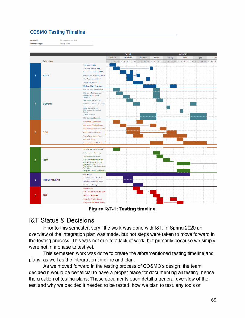
Figure I&T-1: Testing timeline.
I&T Status & DecisionsPrior to this semester, very little work was done with I&T. In Spring 2020 an
overview of the integration plan was made, but not steps were taken to move forward inthe testing process. This was not due to a lack of work, but primarily because we simplywere not in a phase to test yet.
This semester, work was done to create the aforementioned testing timeline andplans, as well as the integration timeline and plan.
As we moved forward in the testing process of COSMO’s design, the teamdecided it would be beneficial to have a proper place for documenting all testing, hencethe creation of testing plans. These documents each detail a general overview of thetest and why we decided it needed to be tested, how we plan to test, any tools or
69
equipment used, and who will be performing the test. In addition, each plan has a tablewhere each step of the testing process should be written out with it’s description anddate completed to be able to recreate the test if/when needed. Testing plans arecurrently located in the google drive at the following link: COSMO Testing Plans
Also as aforementioned, we wanted to create an integration plan as we moveforward with the integration of COSMO. This plan goes into detail of the initialIntegration overview we created last semester (Integration Overview), while also givingsteps to the tester as to what the process of integration should accomplish. Though it isnot filled out yet, the plan also gives space for the actual integration procedure, whichwill be filled out when integration actually takes place. The goal for this document is thatall aspects of integration will be documented properly, and stored in one location. Thedocument is currently housed in COSMO’s google drive, at the following hyperlink:COSMO Integration Plan.
I&T Next Steps and Path to PIRTasks for Next Spring 2020 Testing Team
i. Moving into next semester, the new testing lead will first have to familiarizethemselves with the documents we’ve created. Go over the testing andintegration plans, and most importantly, the testing timeline
ii. Next, the testing lead will have to reach out to the other subsystem leads, andunderstand what stages they’re at in the testing process. Once they have hadsubsystem meetings, the testing lead will have to update the COSMO TestingTimeline.
iii. The lead should then look over and update the COSMO Integration Plan. This isgoing to be vital going into Spring 2020, as there is a good chance COSMObegins the integration process by March.
iv. Once those steps are completed, the lead should just keep updated on whattests are being run, and make sure the testing plans and other documentationare being updated as the tests are completed.
Path to PIRi. Major step in getting to PIR is going to be completing the integration plan.
Though testing plans will need to be updated as testing progresses, those maytake a backseat as we move into integration. Integrating the spacecraft is goingto be a massive task the new testing lead will have to take up and essentiallylead.
ii. The new lead should also consistently be updating the plans for both integrationand test in the google drive as changes are made on both those fronts.
70
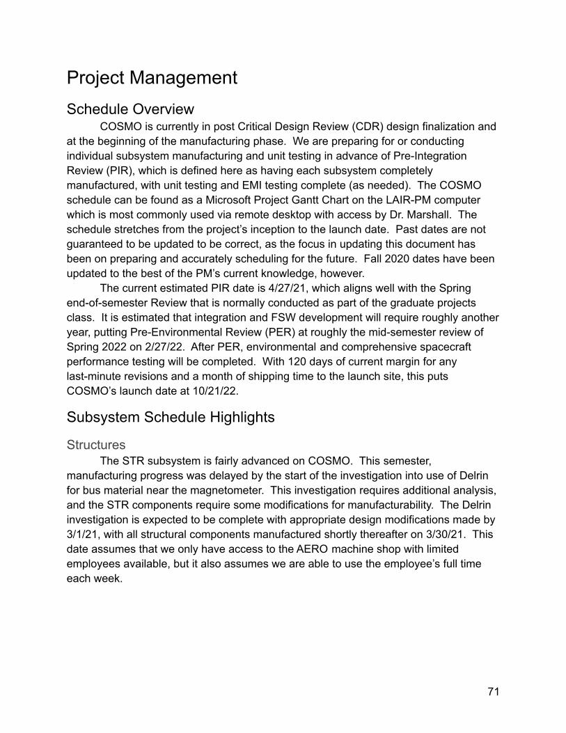
Project ManagementSchedule Overview
COSMO is currently in post Critical Design Review (CDR) design finalization andat the beginning of the manufacturing phase. We are preparing for or conductingindividual subsystem manufacturing and unit testing in advance of Pre-IntegrationReview (PIR), which is defined here as having each subsystem completelymanufactured, with unit testing and EMI testing complete (as needed). The COSMOschedule can be found as a Microsoft Project Gantt Chart on the LAIR-PM computerwhich is most commonly used via remote desktop with access by Dr. Marshall. Theschedule stretches from the project’s inception to the launch date. Past dates are notguaranteed to be updated to be correct, as the focus in updating this document hasbeen on preparing and accurately scheduling for the future. Fall 2020 dates have beenupdated to the best of the PM’s current knowledge, however.
The current estimated PIR date is 4/27/21, which aligns well with the Springend-of-semester Review that is normally conducted as part of the graduate projectsclass. It is estimated that integration and FSW development will require roughly anotheryear, putting Pre-Environmental Review (PER) at roughly the mid-semester review ofSpring 2022 on 2/27/22. After PER, environmental and comprehensive spacecraftperformance testing will be completed. With 120 days of current margin for anylast-minute revisions and a month of shipping time to the launch site, this putsCOSMO’s launch date at 10/21/22.
Subsystem Schedule Highlights
StructuresThe STR subsystem is fairly advanced on COSMO. This semester,
manufacturing progress was delayed by the start of the investigation into use of Delrinfor bus material near the magnetometer. This investigation requires additional analysis,and the STR components require some modifications for manufacturability. The Delrininvestigation is expected to be complete with appropriate design modifications made by3/1/21, with all structural components manufactured shortly thereafter on 3/30/21. Thisdate assumes that we only have access to the AERO machine shop with limitedemployees available, but it also assumes we are able to use the employee’s full timeeach week.
71
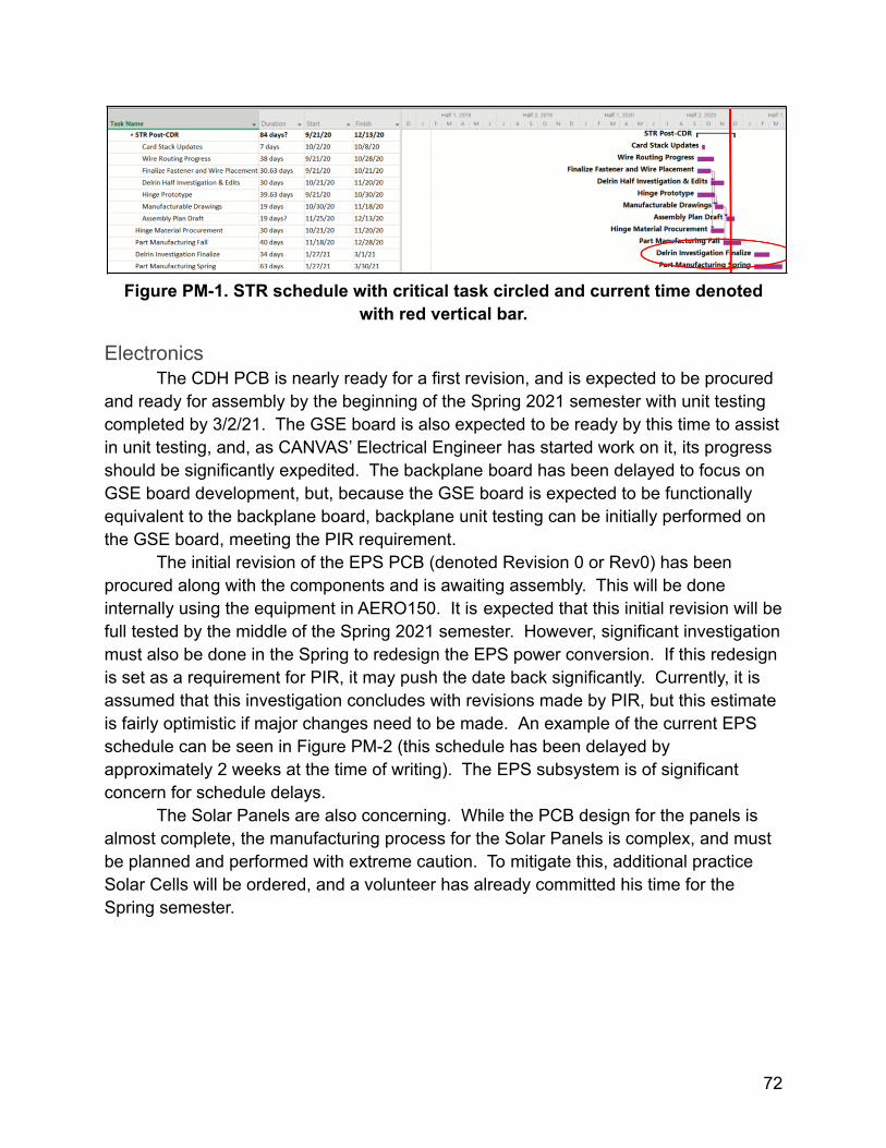
Figure PM-1. STR schedule with critical task circled and current time denotedwith red vertical bar.
ElectronicsThe CDH PCB is nearly ready for a first revision, and is expected to be procured
and ready for assembly by the beginning of the Spring 2021 semester with unit testingcompleted by 3/2/21. The GSE board is also expected to be ready by this time to assistin unit testing, and, as CANVAS’ Electrical Engineer has started work on it, its progressshould be significantly expedited. The backplane board has been delayed to focus onGSE board development, but, because the GSE board is expected to be functionallyequivalent to the backplane board, backplane unit testing can be initially performed onthe GSE board, meeting the PIR requirement.
The initial revision of the EPS PCB (denoted Revision 0 or Rev0) has beenprocured along with the components and is awaiting assembly. This will be doneinternally using the equipment in AERO150. It is expected that this initial revision will befull tested by the middle of the Spring 2021 semester. However, significant investigationmust also be done in the Spring to redesign the EPS power conversion. If this redesignis set as a requirement for PIR, it may push the date back significantly. Currently, it isassumed that this investigation concludes with revisions made by PIR, but this estimateis fairly optimistic if major changes need to be made. An example of the current EPSschedule can be seen in Figure PM-2 (this schedule has been delayed byapproximately 2 weeks at the time of writing). The EPS subsystem is of significantconcern for schedule delays.
The Solar Panels are also concerning. While the PCB design for the panels isalmost complete, the manufacturing process for the Solar Panels is complex, and mustbe planned and performed with extreme caution. To mitigate this, additional practiceSolar Cells will be ordered, and a volunteer has already committed his time for theSpring semester.
72
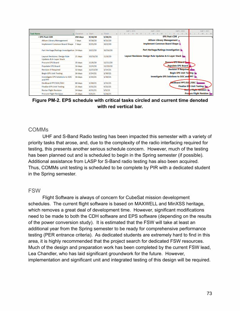
Figure PM-2. EPS schedule with critical tasks circled and current time denotedwith red vertical bar.
COMMsUHF and S-Band Radio testing has been impacted this semester with a variety of
priority tasks that arose, and, due to the complexity of the radio interfacing required fortesting, this presents another serious schedule concern. However, much of the testinghas been planned out and is scheduled to begin in the Spring semester (if possible).Additional assistance from LASP for S-Band radio testing has also been acquired.Thus, COMMs unit testing is scheduled to be complete by PIR with a dedicated studentin the Spring semester.
FSWFlight Software is always of concern for CubeSat mission development
schedules. The current flight software is based on MAXWELL and MinXSS heritage,which removes a great deal of development time. However, significant modificationsneed to be made to both the CDH software and EPS software (depending on the resultsof the power conversion study). It is estimated that the FSW will take at least anadditional year from the Spring semester to be ready for comprehensive performancetesting (PER entrance criteria). As dedicated students are extremely hard to find in thisarea, it is highly recommended that the project search for dedicated FSW resources.Much of the design and preparation work has been completed by the current FSW lead,Lea Chandler, who has laid significant groundwork for the future. However,implementation and significant unit and integrated testing of this design will be required.
73
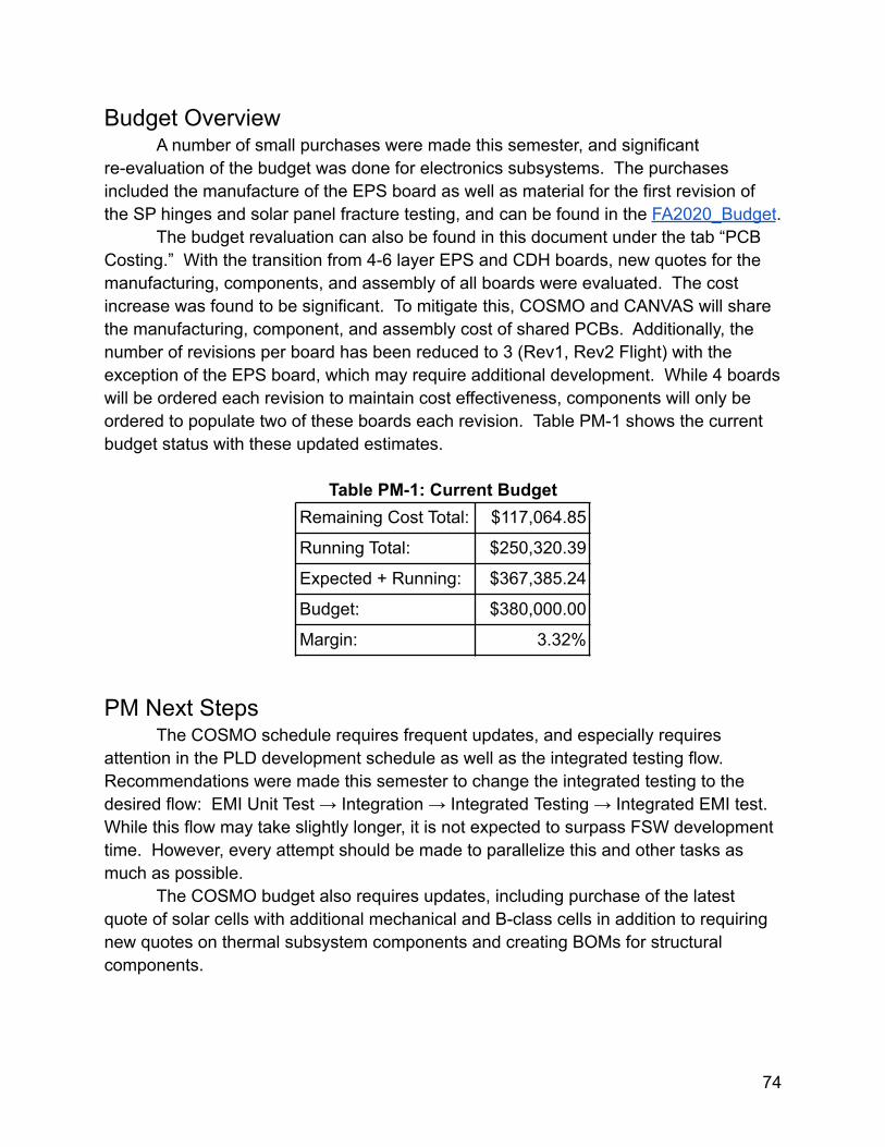
Budget OverviewA number of small purchases were made this semester, and significant
re-evaluation of the budget was done for electronics subsystems. The purchasesincluded the manufacture of the EPS board as well as material for the first revision ofthe SP hinges and solar panel fracture testing, and can be found in the FA2020_Budget.
The budget revaluation can also be found in this document under the tab “PCBCosting.” With the transition from 4-6 layer EPS and CDH boards, new quotes for themanufacturing, components, and assembly of all boards were evaluated. The costincrease was found to be significant. To mitigate this, COSMO and CANVAS will sharethe manufacturing, component, and assembly cost of shared PCBs. Additionally, thenumber of revisions per board has been reduced to 3 (Rev1, Rev2 Flight) with theexception of the EPS board, which may require additional development. While 4 boardswill be ordered each revision to maintain cost effectiveness, components will only beordered to populate two of these boards each revision. Table PM-1 shows the currentbudget status with these updated estimates.
Table PM-1: Current BudgetRemaining Cost Total: $117,064.85
Running Total: $250,320.39
Expected + Running: $367,385.24
Budget: $380,000.00
Margin: 3.32%
PM Next StepsThe COSMO schedule requires frequent updates, and especially requires
attention in the PLD development schedule as well as the integrated testing flow.Recommendations were made this semester to change the integrated testing to thedesired flow: EMI Unit Test → Integration → Integrated Testing → Integrated EMI test.While this flow may take slightly longer, it is not expected to surpass FSW developmenttime. However, every attempt should be made to parallelize this and other tasks asmuch as possible.
The COSMO budget also requires updates, including purchase of the latestquote of solar cells with additional mechanical and B-class cells in addition to requiringnew quotes on thermal subsystem components and creating BOMs for structuralcomponents.
74


