Embed Size (px)
Citation preview
arX
iv:0
804.
4140
v1 [
phys
ics.
optic
s] 2
5 A
pr 2
008
Coupled-resonator-induced reflection inphotonic-crystal waveguide structures
Sergei F. Mingaleev1, Andrey E. Miroshnichenko2,and Yuri S. Kivshar 2
1 VPI Development Center, Belarus High Technologies Park, Minsk 220034, Belarus2Nonlinear Physics Center and Center for Ultra-high bandwidth Devices for Optical Systems
(CUDOS), Australian National University, Canberra ACT 0200, Australia
Abstract: We study the resonant transmission of light in a coupled-resonator optical waveguide interacting with two nearly identical sidecavities. We reveal and describe a novel effect of the coupled-resonator-induced reflection (CRIR) characterized by a very high and easily tunablequality factor of the reflection line, for the case of the inter-site couplingbetween the cavities and the waveguide. This effect differssharply from thecoupled-resonator-induced transparency (CRIT) – an all-optical analogueof the electromagnetically-induced transparency – which has recentlybeen studied theoretically and observed experimentally for the structuresbased on micro-ring resonators and photonic crystal cavities. Both CRIRand CRIT effects have the same physical origin which can be attributedto the Fano-Feshbach resonances in the systems exhibiting more thanone resonance. We discuss the applicability of the novel CRIR effect tothe control of the slow-light propagation and low-threshold all-opticalswitching.
© 2008 Optical Society of America
OCIS codes:230.7390; 260.2030; 250.5300; 230.5750
References and links1. B.E. Little, S.T. Chu, H.A. Haus, J. Foresi, and J.-P. Laine, “Microring resonator channel dropping filters”, J.
Lightwave Techn.15, 998–1005 (1997).2. S. Fan, P.R. Villeneuve, J.D. Joannopoulos, M.J. Khan, C.Manolatou, and H.A. Haus, “Theoretical analysis of
channel drop tunneling processes”, Phys. Rev. B59, 15882–15892 (1999).3. Y. Xu, Y. Li, R.K. Lee, and A. Yariv, “Scattering-theory analysis of waveguide-resonator coupling”, Phys. Rev.
E 62, 7389–7404 (2000).4. D.D. Smith, H. Chang, K.A. Fuller, A.T. Rosenberger, and R.W. Boyd, “Coupled-resonator-induced trans-
parency”, Phys. Rev. A69, 063804 (2004).5. D.D. Smith and H. Chang, “Coherence phenomena in coupled optical resonators”, J. Mod. Opt.51, 2503–2513
(2004).6. L. Maleki, A.B. Matsko, A.A. Savchenkov, and V.S. Ilchenko, “Tunable delay line with interacting whispering-
gallery-mode resonators”, Opt. Lett.29, 626–628 (2004).7. A.B. Matsko, A.A. Savchenkov, D. Strekalov, V.S. Ilchenko and L. Maleki, “Interference effects in lossy res-
onator chains”, J. Mod. Opt.51, 2515–2522 (2004).8. W. Suh, Z. Wang, and S. Fan, “Temporal coupled-mode theoryand the presence of non-orthogonal modes in
lossless multimode cavities”, IEEE J. Quant. Electron.40, 1511–1518 (2004).9. T. Opatrny and D.G. Welsch, “Coupled cavities for enhancing the cross-phase-modulation in electromagnetically
induced transparency”, Phys. Rev. A64, 23805 (2001).10. A. Naweed, G. Farca, S.I. Shopova, and A.T. Rosenberger,“Induced transparency and absorption in coupled
whispering-gallery microresonators”, Phys. Rev. A71, 043804 (2005).11. Q. Xu, S. Sandhu, M.L. Povinelli, J. Shakya, S. Fan, and M.Lipson, “Experimental realization of an on-chip
all-optical analogue to electromagnetically induced transparency”, Phys. Rev. Lett.96, 123901 (2006).
12. Q. Xu, J. Shakya, and M. Lipson, “Direct measurement of tunable optical delays on chip analogue to electro-magnetically induced transparency”, Opt. Express14, 6463–6468 (2006).
13. J. Pan, S. Sandhu, Y. Huo, M. L. Povinelli, M. M. Fejer, S. Fan, and J. S. Harris, ” Optical Ana-logue to Electromagnetically Induced Transparency in Photonic Crystals, Simulation and Experiments,”in Slow and Fast Light, OSA Technical Digest (CD) (Optical Society of America, 2007), paper SWB2.http://www.opticsinfobase.org/abstract.cfm?URI=SL-2007-SWB2
14. R.W. Boyd and D.J. Gauthier, “Transparency on an opticalchip”, Nature441, 701–702 (2006).15. B. Maes, P. Bienstman, and R. Baets, “Switching in coupled nonlinear photonic-crystal resonators”, J. Opt. Soc.
Am. B 22, 1778–1784 (2005).16. S.F. Mingaleev, A.E. Miroshnichenko, Y.S. Kivshar, andK. Busch, “All-optical switching, bistability, and slow-
light transmission in photonic crystal waveguide-resonator structures”, Phys. Rev. E74, 046603 (2006).17. S.F. Mingaleev, A.E. Miroshnichenko, and Y.S. Kivshar,“Low-threshold bistability of slow light in photonic-
crystal waveguides”, Opt. Express15, 12380–12385 (2007).18. S. Fan, “Manipulating light with photonic crystals”, Physica B394, 221–228 (2007).19. S. Fan, “Sharp asymmetric line shapes in side-coupled waveguide-cavity systems”, Appl. Phys. Lett.80, 908–910
(2002).20. A.E. Miroshnichenko, S.F. Mingaleev, S. Flach, and Y.S.Kivshar, “Nonlinear Fano resonance and bistable wave
transmission”, Phys. Rev. E71, 036626 (2005).21. M.F. Yanik and S. Fan, “Stopping light all optically”, Phys. Rev. Lett.92, 083901 (2004).22. A. Yariv, Y. Xu, R.K. Lee, and A. Scherer, “Coupled-resonator optical waveguide: a proposal and analysis”, Opt.
Lett. 24, 711 (1999).23. K. Busch, S.F. Mingaleev, A. Garcia-Martin, M. Schillinger, and D. Hermann, “Wannier function approach to
photonic crystal circuits”, J. Phys.: Condens. Matter.15, R1233–R1256 (2003).24. H. Feshbach, “Unified theory of nuclear reactions, I”, Ann. Phys. (N.Y.)5, 357 (1958); “A unified theory of
nuclear reactions, II”, Ann. Phys. (N.Y.)19, 287 (1962).25. F.H. Mies, “Configuration interaction theory: effects of overlapping resonances”, Phys. Rev.175, 164–175
(1968); F.H. Mies, “Resonant scattering theory of association reactions and unimolecular decomposition: I. Aunited theory of radiative and collisional recombination”, J. Chem. Phys.51, 787–797 (1969).
26. A.I. Magunov, I.Rotter, and S.I. Strakhova, “Fano resonances in the overlapping regime”, Phys. Rev. B68,245305 (2003).
27. M.Raoult and F.H. Mies, “Feshbach resonance in atomic binary collisions in the wigner threshold law regime”,Phys. Rev. A70, 012710 (2004).
28. Y.A. Vlasov, M. O’Boyle, H.F. Hamann, and S.J. McNab, “Active control of slow light on a chip with photoniccrystal waveguides”, Nature438, 65–69 (2005).
29. H. Gersen, T.J. Karle, R.J.P. Engelen, W. Bogaerts, J.P.Korterik, N.F. van Hulst, T.F. Krauss, and L. Kuipers,“Direct observation of Bloch harmonics and negative phase velocity in photonic crystal waveguides”, Phys. Rev.Lett. 94, 123901 (2005).
30. M. Notomi, K. Yamada, A. Shinya, J. Takahashi, C. Takahashi, and I. Yokohama, “Extremely large group velocitydispersion of line-defect waveguides in photonic crystal slabs”, Phys. Rev. Lett.87, 253902 (2001).
31. R. Jacobsen, A. Lavrinenko, L. Frandsen, C. Peucheret, B. Zsigri, G. Moulin, J. Fage-Pedersen, and P. Borel, “Di-rect experimental and numerical determination of extremely high group indices in photonic crystal waveguides”,Opt. Express13, 7861–7871 (2005).
32. S. Assefa, S.J. McNab, and Y.A. Vlasov, “Transmission ofslow light through photonic crystal waveguide bends,”Opt. Lett.31, 745–747 (2006).
33. Y.A. Vlasov and S.J. McNab, “Coupling into the slow lightmode in slab-type photonic crystal waveguides,” Opt.Lett. 31, 50–52 (2006) .
1. Introduction
Many concepts of photonic devices employ high-Q optical resonators, such as micro-rings orphotonic crystal cavities, side coupled to the transmission waveguide. Among them, the de-vices which employseveral resonatorshave attracted a special attention because the couplingbetween optical resonators may lead to a variety of novel effects such as the high-order reso-nances with flattened passband region [1, 2, 3], the appearance of additional resonances withextremely high-Q factors [3], etc. One of the most interesting and promising effects that was dis-covered for the double-resonator photonic structure shownschematically in Fig. 1(a) is an all-optical analogue of theelectromagnetically-induced transparency(EIT). We describe the reso-nant transmission observed for such structure as the effectof coupled-resonator-induced trans-parency(CRIT) [4]. It has been predicted theoretically by several research groups [4, 5, 6, 7, 8],
although one can also mention the early work [9] which suggested an idea ofmacroscopicdouble-resonator optical system exhibiting the same EIT-like effect. Recently, the CRIT ef-fect has been observed experimentally in the system of two interacting micro-resonators for thewhispering-gallery modes [10] and in the integrated photonic chips employed either two micro-ring resonators [11, 12] or two photonic-crystal cavities [13]. Such CRIT devices provide anefficiently tunable ‘transparency on an optical chip’, and they are considered as a crucial steptowards the development of integrated all-optical chips [14]. In particular, they can be employedfor significant (103 times) reduction of the threshold power for optical bistability [15].
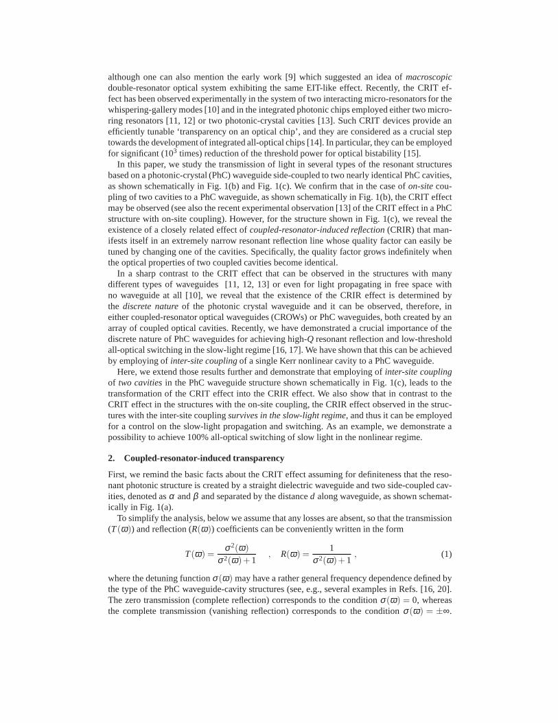
In this paper, we study the transmission of light in several types of the resonant structuresbased on a photonic-crystal (PhC) waveguide side-coupled to two nearly identical PhC cavities,as shown schematically in Fig. 1(b) and Fig. 1(c). We confirm that in the case ofon-sitecou-pling of two cavities to a PhC waveguide, as shown schematically in Fig. 1(b), the CRIT effectmay be observed (see also the recent experimental observation [13] of the CRIT effect in a PhCstructure with on-site coupling). However, for the structure shown in Fig. 1(c), we reveal theexistence of a closely related effect ofcoupled-resonator-induced reflection(CRIR) that man-ifests itself in an extremely narrow resonant reflection line whose quality factor can easily betuned by changing one of the cavities. Specifically, the quality factor grows indefinitely whenthe optical properties of two coupled cavities become identical.
In a sharp contrast to the CRIT effect that can be observed in the structures with manydifferent types of waveguides [11, 12, 13] or even for light propagating in free space withno waveguide at all [10], we reveal that the existence of the CRIR effect is determined bythe discrete natureof the photonic crystal waveguide and it can be observed, therefore, ineither coupled-resonator optical waveguides (CROWs) or PhC waveguides, both created by anarray of coupled optical cavities. Recently, we have demonstrated a crucial importance of thediscrete nature of PhC waveguides for achieving high-Q resonant reflection and low-thresholdall-optical switching in the slow-light regime [16, 17]. Wehave shown that this can be achievedby employing ofinter-site couplingof a single Kerr nonlinear cavity to a PhC waveguide.
Here, we extend those results further and demonstrate that employing of inter-site couplingof two cavitiesin the PhC waveguide structure shown schematically in Fig. 1(c), leads to thetransformation of the CRIT effect into the CRIR effect. We also show that in contrast to theCRIT effect in the structures with the on-site coupling, theCRIR effect observed in the struc-tures with the inter-site couplingsurvives in the slow-light regime, and thus it can be employedfor a control on the slow-light propagation and switching. As an example, we demonstrate apossibility to achieve 100% all-optical switching of slow light in the nonlinear regime.
2. Coupled-resonator-induced transparency
First, we remind the basic facts about the CRIT effect assuming for definiteness that the reso-nant photonic structure is created by a straight dielectricwaveguide and two side-coupled cav-ities, denoted asα andβ and separated by the distanced along waveguide, as shown schemat-ically in Fig. 1(a).
To simplify the analysis, below we assume that any losses areabsent, so that the transmission(T(ω)) and reflection (R(ω)) coefficients can be conveniently written in the form
T(ω) =σ2(ω)
σ2(ω)+1, R(ω) =
1σ2(ω)+1
, (1)
where the detuning functionσ(ω) may have a rather general frequency dependence defined bythe type of the PhC waveguide-cavity structures (see, e.g.,several examples in Refs. [16, 20].The zero transmission (complete reflection) corresponds tothe conditionσ(ω) = 0, whereasthe complete transmission (vanishing reflection) corresponds to the conditionσ(ω) = ±∞.
Fig. 1. Three types of the geometries of a straight photonic-crystal waveguide side coupledto two nonlinear optical resonators,α andβ . Standard coupled-mode theory is based onthe geometry (a) which does not account for discreteness-induced effects in the photonic-crystal waveguides. For instance, light transmission and bistability are qualitatively differ-ent for (b) on-site and (c) inter-site locations of the resonator along waveguide and thiscannot be distinguished within the conceptual framework ofstructure of type (a).
Therefore, the resonant frequencies can be conveniently found as zeros of the nominator anddenominator of the auxiliary functionσ(ω).
For the simplest resonant structure created by a straight waveguide coupled to a single cavity(e.g., the cavityα), we can obtain [16]
σ(ω) ≃(ωα −ω)
γα, (2)
with a resonant reflection at the frequency that almost coincides with the frequencyωα of thelocalized cavity mode of an isolated cavity. The spectral width γα of the resonance is deter-mined by the overlap integral between the cavity mode and thewaveguide mode at the resonantfrequency, rapidly decaying as the distance between the cavity and the waveguide grows.
To find the characteristic functionσ(ω) for the waveguide structure with two cavities, wecan employ a variety of methods [5, 6, 7, 8, 15], including thesimplest approach based on thetransfer-matrix technique [19]. A detailed analysis of thelight scattering in such structures canbe found in Refs. [6, 11, 18], and here we present the results for the special case when twocavities are separated by the distanced = 2πm/k(ωt), wherek(ω) is the waveguide dispersionrelation,m is integer, and the frequencyωt is defined below. In this case, assuming that thereis no direct coupling between the cavities, i.e. either the distanced is sufficiently large or the
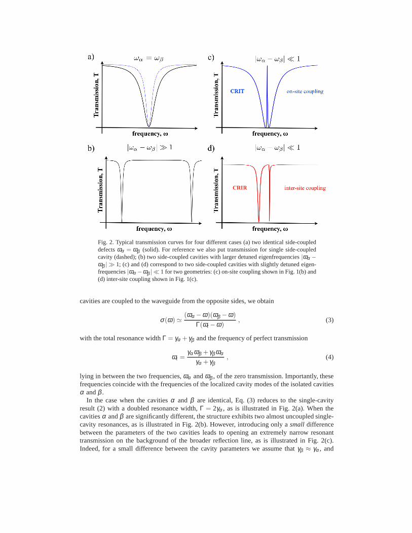
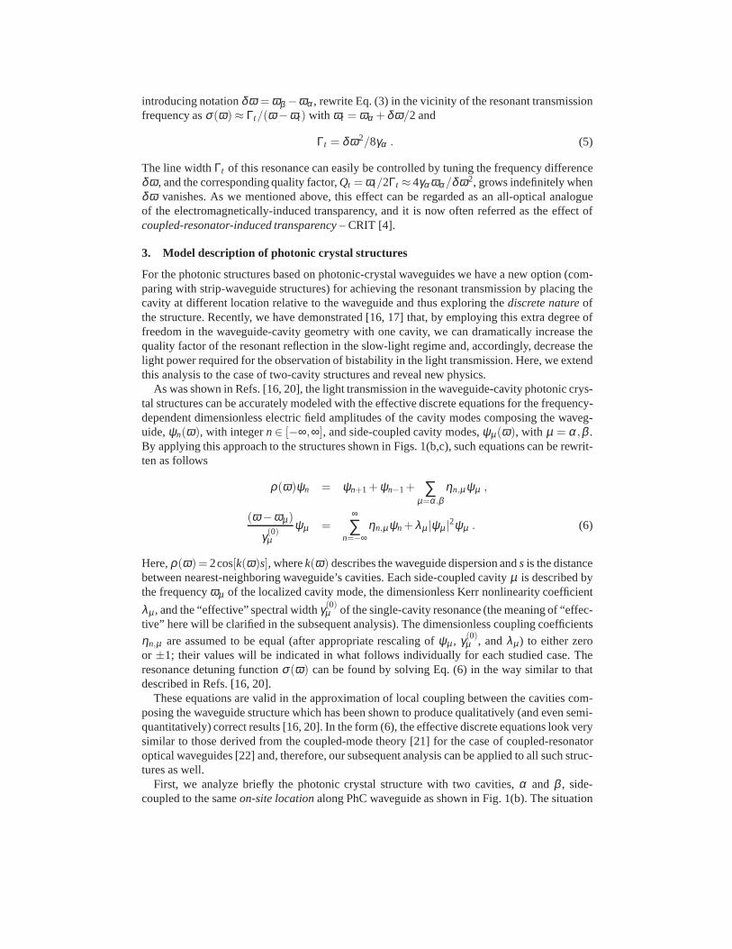
Fig. 2. Typical transmission curves for four different cases (a) two identical side-coupleddefectsωα = ωβ (solid). For reference we also put transmission for single side-coupledcavity (dashed); (b) two side-coupled cavities with largerdetuned eigenfrequencies|ωα −ωβ | ≫ 1; (c) and (d) correspond to two side-coupled cavities with slightly detuned eigen-frequencies|ωα −ωβ | ≪ 1 for two geometries: (c) on-site coupling shown in Fig. 1(b)and(d) inter-site coupling shown in Fig. 1(c).
cavities are coupled to the waveguide from the opposite sides, we obtain
σ(ω) ≃(ωα −ω)(ωβ −ω)
Γ(ωt −ω), (3)
with the total resonance widthΓ = γα + γβ and the frequency of perfect transmission
ωt =γα ωβ + γβ ωα
γα + γβ, (4)
lying in between the two frequencies,ωα andωβ , of the zero transmission. Importantly, thesefrequencies coincide with the frequencies of the localizedcavity modes of the isolated cavitiesα andβ .
In the case when the cavitiesα and β are identical, Eq. (3) reduces to the single-cavityresult (2) with a doubled resonance width,Γ = 2γα , as is illustrated in Fig. 2(a). When thecavitiesα andβ are significantly different, the structure exhibits two almost uncoupled single-cavity resonances, as is illustrated in Fig. 2(b). However,introducing only asmall differencebetween the parameters of the two cavities leads to opening an extremely narrow resonanttransmission on the background of the broader reflection line, as is illustrated in Fig. 2(c).Indeed, for a small difference between the cavity parameters we assume thatγβ ≈ γα , and
introducing notationδω = ωβ −ωα , rewrite Eq. (3) in the vicinity of the resonant transmissionfrequency asσ(ω) ≈ Γt/(ω −ωt) with ωt = ωα + δω/2 and
Γt = δω2/8γα . (5)
The line widthΓt of this resonance can easily be controlled by tuning the frequency differenceδω , and the corresponding quality factor,Qt = ωt/2Γt ≈ 4γα ωα/δω2, grows indefinitely whenδω vanishes. As we mentioned above, this effect can be regardedas an all-optical analogueof the electromagnetically-induced transparency, and it is now often referred as the effect ofcoupled-resonator-induced transparency– CRIT [4].
3. Model description of photonic crystal structures
For the photonic structures based on photonic-crystal waveguides we have a new option (com-paring with strip-waveguide structures) for achieving theresonant transmission by placing thecavity at different location relative to the waveguide and thus exploring thediscrete natureofthe structure. Recently, we have demonstrated [16, 17] that, by employing this extra degree offreedom in the waveguide-cavity geometry with one cavity, we can dramatically increase thequality factor of the resonant reflection in the slow-light regime and, accordingly, decrease thelight power required for the observation of bistability in the light transmission. Here, we extendthis analysis to the case of two-cavity structures and reveal new physics.
As was shown in Refs. [16, 20], the light transmission in the waveguide-cavity photonic crys-tal structures can be accurately modeled with the effectivediscrete equations for the frequency-dependent dimensionless electric field amplitudes of the cavity modes composing the waveg-uide,ψn(ω), with integern∈ [−∞,∞], and side-coupled cavity modes,ψµ(ω), with µ = α,β .By applying this approach to the structures shown in Figs. 1(b,c), such equations can be rewrit-ten as follows
ρ(ω)ψn = ψn+1 + ψn−1+ ∑µ=α ,β
ηn,µψµ ,
(ω −ωµ)
γ(0)µ
ψµ =∞
∑n=−∞
ηn,µψn + λµ |ψµ |2ψµ . (6)
Here,ρ(ω)= 2cos[k(ω)s], wherek(ω) describes the waveguide dispersion ands is the distancebetween nearest-neighboring waveguide’s cavities. Each side-coupled cavityµ is described bythe frequencyωµ of the localized cavity mode, the dimensionless Kerr nonlinearity coefficient
λµ , and the “effective” spectral widthγ(0)µ of the single-cavity resonance (the meaning of “effec-
tive” here will be clarified in the subsequent analysis). Thedimensionless coupling coefficients
ηn,µ are assumed to be equal (after appropriate rescaling ofψµ , γ(0)µ , andλµ) to either zero
or ±1; their values will be indicated in what follows individually for each studied case. Theresonance detuning functionσ(ω) can be found by solving Eq. (6) in the way similar to thatdescribed in Refs. [16, 20].
These equations are valid in the approximation of local coupling between the cavities com-posing the waveguide structure which has been shown to produce qualitatively (and even semi-quantitatively) correct results [16, 20]. In the form (6), the effective discrete equations look verysimilar to those derived from the coupled-mode theory [21] for the case of coupled-resonatoroptical waveguides [22] and, therefore, our subsequent analysis can be applied to all such struc-tures as well.
First, we analyze briefly the photonic crystal structure with two cavities,α and β , side-coupled to the sameon-site locationalong PhC waveguide as shown in Fig. 1(b). The situation
when only one of these cavities is coupled to the waveguide (with ηn,α = δn,0 andηn,β = 0,whereδn,m is the Kronecker symbol) has already been studied earlier inRefs. [16, 20]. Inthis case the model parameters introduced in Eq. (6) are related to the parameters introduced
in Eqs. (21)–(24) of Ref. [16] asψn ≡ An, ψα ≡ (V0,α/V1w)Aα , γ(0)α = να ωαV0,αVα ,0/V1w,
andλα = (κα χ (3)α /Vα ,0)(V1w/V0,α)3. Therefore, the linear (atλα = 0) detuning functionσ(ω)
found for this case in Ref. [16] takes the form of Eq. (2) with unchanged form ofωα and with
γα = γ(0)α /sin[k(ωα )s]. As one can see,γ(0)
α is the spectral width of the resonant reflection linethat would be produced by a single on-site side-coupled cavity in the case when its frequencyωα lies at the center of the waveguide transmission band,k(ωα) = π/2s.
In the same way, we can show that the detuning function of the on-site two-cavity structurewith ηn,µ = δn,0 for bothµ , shown in Fig. 1(b), takes the form of Eqs. (3)–(5) with unchanged
forms ofωα andωβ , and withγα = γ(0)α /sin[k(ωα )s] andγβ = γ(0)
β /sin[k(ωβ )s]. Correspond-ingly, this on-site two-cavity structure exhibits the same effect of coupled-resonator-inducedtransparency, illustrated in Fig. 2(c), as discussed in the previous section.
4. Coupled-resonator-induced reflection
Now let us analyze an alternative photonic crystal structure with two cavities,α andβ , side-coupled to the sameinter-site locationalong PhC waveguide as shown in Fig. 1(c). In this case,ηn,µ = (δn,0 ± δn,1), where the upper sign in “±” corresponds to the even-symmetry cavitymodes, while the bottom sign corresponds to the odd-symmetry cavity modes.
The situation when only one of the cavities (say, the cavityα) is coupled to the waveguide(with ηn,α = (δn,0±δn,1), butηn,β = 0) has already been studied for the even-symmetry cavitymodes in Refs. [16, 20]. Extending those results to the case of both even- and odd-symmetrycavity modes, the detuning parameter for the inter-site single-cavity structure can be obtainedin the form
σ(ω) ≃(ω̃±
α −ω)
γ±α, (7)
where the resonant reflection frequencyω̃±α = ωα ∓ γ(0)
α is shifted to one or the other side fromthe frequencyωα of the cavity mode, depending on its symmetry. The spectral width γ±α =
γ(0)α / [tan(k(ω̃±
α )s/2)]±1 of this resonance line equals toγ(0)
α at the center of waveguide pass-band, but it vanishes at one of the band edges, giving birth toextremely high-quality resonantreflection lines in the slow-light regime[16, 17].
For the problem of the light transmission in the inter-site two-cavity structure shown inFig. 1(c), we solve Eq. (6) and obtain the detuning parameterin the form,
σ(ω) ≃(ω±
r1−ω)(ω±r2−ω)
Γ±(ωt −ω), (8)
that looks qualitatively similar to Eq. (3). Moreover, the frequencyωt of the perfect transmis-
sion is determined by the same equation for the CRIT effect (4) with γµ = γ(0)µ . However, now
the total resonance widthΓ± = [tan(k(ωt )s/2)]∓1(γ(0)α + γ(0)
β ) depends on the waveguide dis-persion,k(ωt ), at the resonance frequency leading to the same enhancementof the resonancequality factor at one of the edges of waveguide pass-band as obtained above for the inter-siteone-cavity structure. More importantly, the resonant reflection frequencies,
ω±r1 =
ωα + ωβ
2∓
γ(0)α + γ(0)
β
2
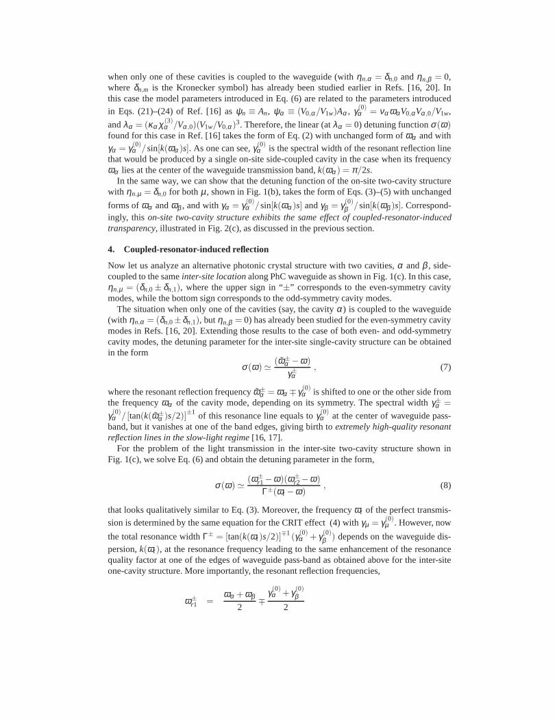
0.31696 0.31698 0.317 0.31702 0.31704Frequency, ωa/2πc
0
0.1
0.2
0.3
0.4
0.5
0.6
0.7
0.8
0.9
1
Tra
nsm
issi
on,
T
Group velocity, vg/c
0.025
(b)(a)
Fig. 3. (a) Schematic structure of a photonic-crystal waveguide coupled to two side cavities.(b) Linear transmission coefficient of the photonic-crystal waveguide for: (i) single side-couple cavity withεα = 12. (dotted); (ii) two identical side-couple cavities withεα =εβ = 12. (dashed); (iii) two side-coupled cavities with different permittivitiesεα = 12. andεβ = 12.001 (solid).
+12
√
(ωα −ωβ ∓ γ(0)α ± γ(0)
β )2 +4γ(0)α γ(0)
β ,
ω±r2 =
ωα + ωβ
2∓
γ(0)α + γ(0)
β
2
−12
√
(ωα −ωβ ∓ γ(0)α ± γ(0)
β )2 +4γ(0)α γ(0)
β , (9)
do not coincide with the cavity-mode frequenciesωα andωβ . Moreover, these two resonant
reflection frequencies are always separated by a finite distance exceeding the value 2√
γ(0)α γ(0)
βand, therefore, the existence of a narrow resonant transmission becomes merely impossible.
In contrast, the inter-coupling between the waveguide and two cavities in this system man-ifests itself in a qualitatively new effectof coupled-resonator-induced reflection: for smallδω = ωβ −ωα one of the resonant reflection frequencies moves very close to the perfect trans-mission frequency,ωt , producing anarrow resonant reflection line, as is illustrated in Fig. 2(d).The frequency of this line is always close to the frequencyωα of the cavity mode, while its spec-tral width is determined by the frequency differenceδω growing indefinitely asδω vanishes.
For a small difference between the cavity frequencies, assuming γ(0)β ≈ γ(0)
α , we can estimatethat the spectral width of this narrow reflection line is
Γ±r = [tan(k(ωt )s/2)]∓1 γ(0)
α
(
1−1/
√
1+(δω/2γ(0)α )2
)
≈ [tan(k(ωt )s/2)]∓1 δω2/8γ(0)α , (10)
At smallδω andωt lying at the center of the passing band, this spectral width almost coincideswith the corresponding width (5) of the narrow resonant transmission line in the structuresexhibiting the CRIT effect.
In addition to this narrow resonant reflection line, there always exists the second resonant
reflection line located (at smallδω) at the frequencyω±r = ωα ∓2γ(0)
α , significantly shifted
0.317035 0.31704 0.317045 0.31705Frequency, ωa/2πc
0
0.2
0.4
0.6
0.8
1
Tra
nsm
issi
on,
T
a b c d e
0.001 0.002 0.003 0.0040.005detuning, ∆ε
105
106
107
Q fa
ctor
ab
c
d
e
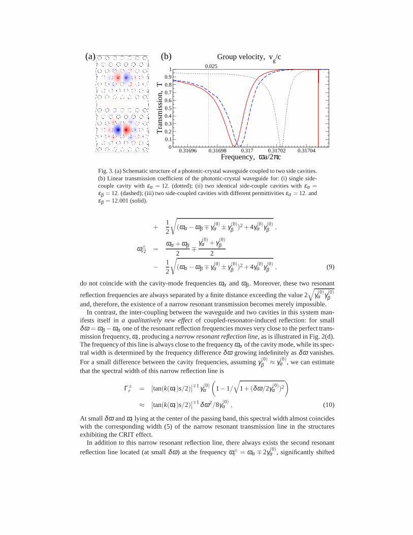
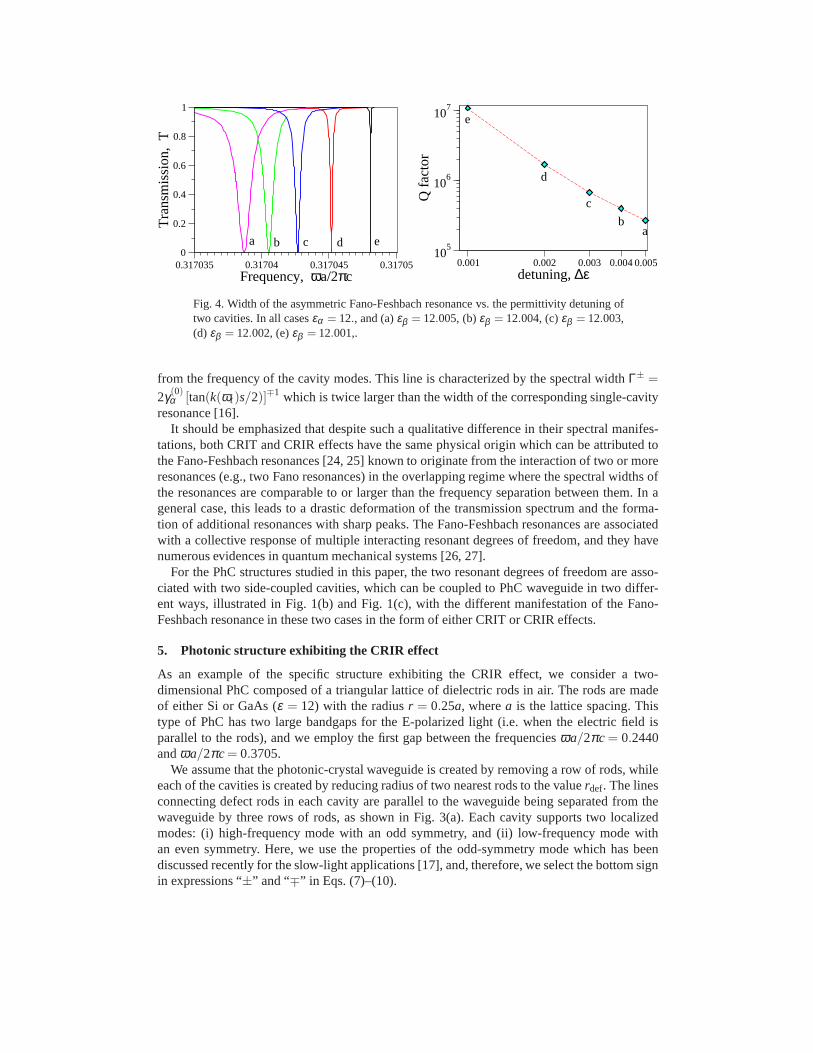
Fig. 4. Width of the asymmetric Fano-Feshbach resonance vs.the permittivity detuning oftwo cavities. In all casesεα = 12., and (a)εβ = 12.005, (b)εβ = 12.004, (c)εβ = 12.003,(d) εβ = 12.002, (e)εβ = 12.001,.
from the frequency of the cavity modes. This line is characterized by the spectral widthΓ± =
2γ(0)α [tan(k(ωt )s/2)]∓1 which is twice larger than the width of the corresponding single-cavity
resonance [16].It should be emphasized that despite such a qualitative difference in their spectral manifes-
tations, both CRIT and CRIR effects have the same physical origin which can be attributed tothe Fano-Feshbach resonances [24, 25] known to originate from the interaction of two or moreresonances (e.g., two Fano resonances) in the overlapping regime where the spectral widths ofthe resonances are comparable to or larger than the frequency separation between them. In ageneral case, this leads to a drastic deformation of the transmission spectrum and the forma-tion of additional resonances with sharp peaks. The Fano-Feshbach resonances are associatedwith a collective response of multiple interacting resonant degrees of freedom, and they havenumerous evidences in quantum mechanical systems [26, 27].
For the PhC structures studied in this paper, the two resonant degrees of freedom are asso-ciated with two side-coupled cavities, which can be coupledto PhC waveguide in two differ-ent ways, illustrated in Fig. 1(b) and Fig. 1(c), with the different manifestation of the Fano-Feshbach resonance in these two cases in the form of either CRIT or CRIR effects.
5. Photonic structure exhibiting the CRIR effect
As an example of the specific structure exhibiting the CRIR effect, we consider a two-dimensional PhC composed of a triangular lattice of dielectric rods in air. The rods are madeof either Si or GaAs (ε = 12) with the radiusr = 0.25a, wherea is the lattice spacing. Thistype of PhC has two large bandgaps for the E-polarized light (i.e. when the electric field isparallel to the rods), and we employ the first gap between the frequenciesωa/2πc = 0.2440andωa/2πc= 0.3705.
We assume that the photonic-crystal waveguide is created byremoving a row of rods, whileeach of the cavities is created by reducing radius of two nearest rods to the valuerdef. The linesconnecting defect rods in each cavity are parallel to the waveguide being separated from thewaveguide by three rows of rods, as shown in Fig. 3(a). Each cavity supports two localizedmodes: (i) high-frequency mode with an odd symmetry, and (ii) low-frequency mode withan even symmetry. Here, we use the properties of the odd-symmetry mode which has beendiscussed recently for the slow-light applications [17], and, therefore, we select the bottom signin expressions “±” and “∓” in Eqs. (7)–(10).
0 0.5 1 1.5 2
104x P
inχα
(3)/c
0
0.2
0.4
0.6
0.8
1
Tra
nsm
issi
on
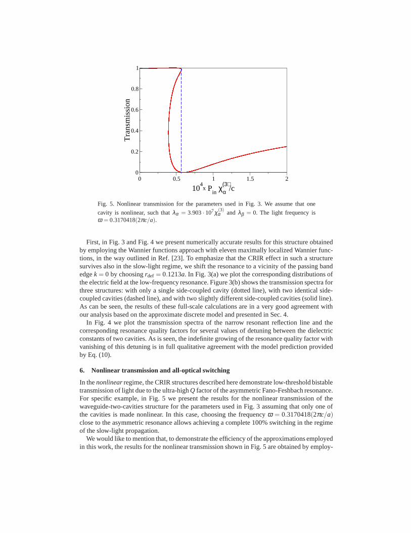
Fig. 5. Nonlinear transmission for the parameters used in Fig. 3. We assume that one
cavity is nonlinear, such thatλα = 3.903· 107χ(3)α and λβ = 0. The light frequency is
ω = 0.3170418(2πc/a).
First, in Fig. 3 and Fig. 4 we present numerically accurate results for this structure obtainedby employing the Wannier functions approach with eleven maximally localized Wannier func-tions, in the way outlined in Ref. [23]. To emphasize that theCRIR effect in such a structuresurvives also in the slow-light regime, we shift the resonance to a vicinity of the passing bandedgek = 0 by choosingrdef = 0.1213a. In Fig. 3(a) we plot the corresponding distributions ofthe electric field at the low-frequency resonance. Figure 3(b) shows the transmission spectra forthree structures: with only a single side-coupled cavity (dotted line), with two identical side-coupled cavities (dashed line), and with two slightly different side-coupled cavities (solid line).As can be seen, the results of these full-scale calculationsare in a very good agreement withour analysis based on the approximate discrete model and presented in Sec. 4.
In Fig. 4 we plot the transmission spectra of the narrow resonant reflection line and thecorresponding resonance quality factors for several values of detuning between the dielectricconstants of two cavities. As is seen, the indefinite growingof the resonance quality factor withvanishing of this detuning is in full qualitative agreementwith the model prediction providedby Eq. (10).
6. Nonlinear transmission and all-optical switching
In thenonlinearregime, the CRIR structures described here demonstrate low-threshold bistabletransmission of light due to the ultra-highQ factor of the asymmetric Fano-Feshbach resonance.For specific example, in Fig. 5 we present the results for the nonlinear transmission of thewaveguide-two-cavities structure for the parameters usedin Fig. 3 assuming that only one ofthe cavities is made nonlinear. In this case, choosing the frequencyω = 0.3170418(2πc/a)close to the asymmetric resonance allows achieving a complete 100% switching in the regimeof the slow-light propagation.
We would like to mention that, to demonstrate the efficiency of the approximations employedin this work, the results for the nonlinear transmission shown in Fig. 5 are obtained by employ-
ing the approximate discrete model based on Eq. (6) with the model parameters calculatedwith the the Wannier function approach [23], in contrast to the numerical results presented inFig. 3–Fig. 4. Using eleven maximally localized Wannier functions, we obtain the followingexpansions,
ωα ,β ≈ [0.317045+6.83·10−3(εα ,β −12)](2πc/a), (11)
andγ(0)
α ,β ≈± (4.3 ·10−6)(2πc/a), (12)
while the waveguide dispersion in the slow-light regime canbe approximated as
ω(k) ≈ [0.31680+0.89626(ka/2π)2](2πc/a). (13)
Thus, one of our major finding is that, in a sharp contrast to the CRIT effect, this novel CRIRresonant effect survives also in the slow-light regime and,due to its asymmetric line shape, itallows achieving a 100% all-optical switching of slow lightin the nonlinear regime. Currently,the slow-light applications of optical structures based onphotonic crystals attract a rapidlygrowing attention due to the recently achieved experimental success in the observation of slow-light propagation [28, 29, 30, 31]. However, many of the device concepts suggested so far inthe physics of photonic crystals cannot be extended to the slow-light regime, and it is importantto reveal and analyze novel types of the design concepts which would allow to perform usefuloperations such as all-optical switching and routing with low group velocities [32, 33, 16, 17].We therefore believe that the CRIR effect described in this work may be especially useful forelaborated control of slow light, however more extensive studies are beyond the scope of thispaper.
7. Conclusions
We have analyzed the resonant transmission of light in a coupled-resonator optical waveg-uide interacting with two nearly identical cavities, paying a particular attention to differencesbetween theon-siteand inter-site locations of the cavities relative to the waveguide. Whentwo cavities are strongly detuned and associated resonances are well separated [see Fig. 2(b)],both types of photonic-crystal structures are characterized by the similar transmission curveswith two distinct Fano resonances. However, when two cavities are only slightly detuned and,therefore, the associated resonances strongly overlap, the on-site and inter-site structures pro-duce quantitatively different transmission curves. Specifically, the on-site geometry shown inFig. 1(b) may lead to the CRIT effect with a sharp symmetric resonant transmission line [seeFig. 2(c)], while the inter-site geometry shown in Fig. 1(c)may lead to the CRIR effect witha sharp and asymmetric resonant reflection line [see Fig. 2(d)]. The new CRIR transmissionwe have described here is characterized by a very high and easily tunable quality factor of thereflection line, and this effect differs sharply from the CRIT effect being an all-optical ana-logue of the electromagnetically-induced transparency demonstrated recently for the structuresbased on micro-ring resonators. We have demonstrated that the CRIR effect survives also in theslow-light regime and, due to its asymmetric line shape, it allows achieving a 100% all-opticalswitching of slow light in the nonlinear regime.
Acknowledgements
This work has been supported by the Australian Research Council through the Discovery andCenter of Excellence research projects.


