Embed Size (px)
Citation preview

110IEICE TRANS. ELECTRON., VOL.E105–C, NO.3 MARCH 2022
PAPER
Effects of Lossy Mediums for Resonator-Coupled Type WirelessPower Transfer System using Conventional Single- and Dual-SpiralResonators
Nur Syafiera Azreen NORODIN†, Student Member, Kousuke NAKAMURA†, Nonmember,and Masashi HOTTA†a), Senior Member
SUMMARY To realize a stable and efficient wireless power transfer(WPT) system that can be used in any environment, it is necessary to in-spect the influence of environmental interference along the power trans-mission path of the WPT system. In this paper, attempts have been made toreduce the influence of the medium with a dielectric and conductive loss onthe WPT system using spiral resonators for resonator-coupled type wirelesspower transfer (RC-WPT) system. An important element of the RC-WPTsystem is the resonators because they improve resonant characteristics bychanging the shape or combination of spiral resonators to confine the elec-tric field that mainly causes electrical loss in the system as much as possibleinside the resonator. We proposed a novel dual-spiral resonator as a can-didate and compared the basic characteristics of the RC-WPT system withconventional single-spiral and dual-spiral resonators. The parametric val-ues of the spiral resonators, such as the quality factors and the coupling co-efficients between resonators with and without a lossy medium in the powertransmission path, were examined. For the lossy mediums, pure water ortap water filled with acryl bases was used. The maximum transmission ef-ficiency of the RC-WPT system was then observed by tuning the matchingcondition of the system. Following that, the transmission efficiency of thesystem with and without lossy medium was investigated. These inspec-tions revealed that the performance of the RC-WPT system with the lossymedium using the modified shape spiral resonator, which is the dual-spiralresonator proposed in our laboratory, outperformed the system using theconventional single-spiral resonator.key words: electromagnetic coupling, wireless power transfer, lossy medi-ums, power transmission efficiency, spiral resonator
1. Introduction
To realize a stable and efficient wireless power transfer(WPT) system that can be used in any environment, it isnecessary to inspect the influence of environmental interfer-ence along the power transmission path of the WPT system.Until now, many electric appliances have used WPT sys-tems that use electromagnetic induction, such as the Qi sys-tem [1], [2], but their power transmission distance is muchshorter, and they are sensitive to positioning misalignmentbetween transmission (Tx) and receiving (Rx) units. Fur-thermore, the power transmission efficiency of the elec-tromagnetic induction type WPT system through a lossymedium is quite low for practical application. Therefore,
Manuscript received June 4, 2021.Manuscript revised September 8, 2021.Manuscript publicized October 18, 2021.†The authors are with the Graduate School of Sciences & Tech-
nology for Innovation, Yamaguchi University, Ube-shi, 755–8611Japan.
a) E-mail: [email protected]: 10.1587/transele.2021ECP5025
a resonator-coupled type WPT (RC-WPT) system, whichcan transmit electric energy over a mid-range distance with-out power cable using electromagnetic near-field couplingbetween the resonators installed in Tx and Rx units, wasproposed [3], [4]. In this system, if a magnetic field isused for field coupling, electric energy can transmit wire-lessly through materials such as walls [5], water [6], andso on. Furthermore, the performance of the RC-WPT sys-tem is stable against the positioning tolerance between Txand Rx units [7]. This has resulted in significant develop-ments in power supply for electric appliances, electric vehi-cles [8], small robots [9], mobile devices [10], and medicaldevices [11]–[13].
Here, the electric loss of the materials is caused byacting on the electric fields rather than the magnetic fields.Therefore, planar spiral coil type resonators were used asresonators in our RC-WPT system to prevent the influencesof the lossy medium and ensure that the coupling betweenmagnetic fields is dominant. According to [14], the planarspiral coil is one of the most suitable resonators for the WPTsystem because of its compact size and low transfer loss.Until now, the conventional single-spiral has been used inthe RC-WPT system. However, when the lossy mediumsare adjacent to the system, the leaked electric fields aroundthe resonator act on the loss and reduce the transmission ef-ficiency [15]–[18]. To improve the efficiency, we proposeda coplanar type dual-spiral resonator [19], in which the elec-tric fields tend to lie on the spiral surface, and the capacitivecomponent is increased. Furthermore, the electric field istightly confined inside the dual-spiral resonator effectively.
In this paper, the performance of an RC-WPT systemswith conventional single-spiral and the proposed dual-spiralresonators was compared under the same resonant frequencyand outer diameter of the resonators. The performance ofthe RC-WPT system using dual-spiral resonators was pre-sented and compared with the system using conventionalsingle-spiral resonators based on experimental results forcases that lossy mediums existed around the Tx and Rxunits.
This paper supplements and extends the two Interna-tional Conference Proceedings [20], [21] with the additionalexperimental data and further discussions.
Copyright c⃝ 2022 The Institute of Electronics, Information and Communication Engineers
NORODIN et al.: EFFECTS OF LOSSY MEDIUMS FOR RESONATOR-COUPLED TYPE WIRELESS POWER TRANSFER SYSTEM111
2. Configuration Setup for RC-WPT System
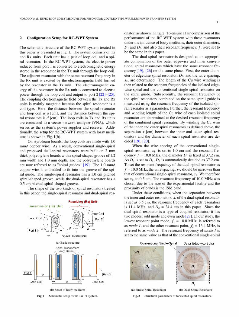
The schematic structure of the RC-WPT system treated inthis paper is presented in Fig. 1. The system consists of Txand Rx units. Each unit has a pair of loop coil and a spi-ral resonator. In the RC-WPT system, the electric powerinduced from port 1 is converted to electromagnetic energystored in the resonator in the Tx unit through the loop coil.The adjacent resonator with the same resonant frequency inthe Rx unit is excited by the electromagnetic field formedby the resonator in the Tx unit. The electromagnetic en-ergy of the resonator in the Rx unit is converted to electricpower through the loop coil and output to port 2 [22]–[25].The coupling electromagnetic field between the Tx and Rxunits is mainly magnetic because the spiral resonator is acoil type. Here, the distance between the spiral resonatorand loop coil is a [cm], and the distance between the spi-ral resonators is d [cm]. The loop coils in Tx and Rx unitsare connected to a vector network analyzer (VNA), whichserves as the system’s power supplier and receiver. Addi-tionally, the setup for the RC-WPT system with lossy medi-ums is shown in Fig. 1(b).
On styrofoam boards, the loop coils are made with 1.0mmϕ copper wire. As a result, conventional single-spiraland proposed dual-spiral resonators were built on 2 mmthick polyethylene boards with a spiral-shaped groove of 1.2mm width and 1.0 mm depth, and the polyethylene boardsare now referred to as ”spiral guides” [19]. The 1.0 mmϕcopper wire is embedded to fit into the groove of the spi-ral guide. The single-spiral resonator has a 1.0 cm pitchedspiral-shaped groove, while the dual-spiral resonator has a0.5 cm pitched spiral-shaped groove.
The shape of the two kinds of spiral resonators treatedin this paper, the single-spiral resonator and dual-spiral res-
Fig. 1 Schematic setup for RC-WPT system.
onator, as shown in Fig. 2. To ensure a fair comparison of theperformance of the RC-WPT system with these resonatorsunder the influence of lossy mediums, their outer diameters,D1 and D3, and also their resonant frequency, f , were set tobe the same in this paper.
The dual-spiral resonator is designed as an appropri-ate combination of the outer edgewise and inner conven-tional spiral resonators which have the same resonant fre-quency [19], [26] on the same plane. First, the outer diam-eter of edgewise spiral resonator, D3, and the wire spacing,s2, are determined. The length of the Cu wire winding isthen related to the resonant frequencies of the isolated edge-wise spiral and the conventional single-spiral resonator onthe spiral guide. Subsequently, the resonant frequency ofthe spiral resonators combined on the same spiral guide ismeasured using the resonant frequency of the isolated spi-ral resonator as a parameter. Further, the resonant frequencyand winding length of the Cu wire of each isolated spiralresonator are determined at the desired resonant frequencyof the combined spiral resonator. By winding the Cu wireof the inner and outer spiral resonators as defined above, theseparation x [cm] between the inner and outer spiral res-onators and the diameter of each spiral resonator are de-cided [19], [20].
When the wire spacing of the conventional single-spiral resonator, s1, is set to 1.0 cm and the resonant fre-quency f = 10.0 MHz, the diameter D1 is fixed at 37.2 cm.As D3 is set to D1, D3 is automatically decided as 37.2 cm.To set the resonant frequency of the dual-spiral resonator asf = 10.0 MHz, the wire spacing, s2, should be narrower thanthat of conventional single-spiral resonator, s1. We thereforeset s2, to 0.5 cm. The resonant frequency of 10.0 MHz waschosen due to the size of the experimental facility and theproximity of bands is the ISM band.
Under these conditions, when the separation betweenthe inner and outer resonators, x, of the dual-spiral resonatoris set as 3.5 cm, the resonant frequency of each resonatorsis 11.4 MHz, and D2 = 24.4 cm in this paper. Since thedual-spiral resonator is a type of coupled-resonator, it hastwo modes: odd mode and even mode [27]. In our study, thelowest resonant point mode, f1 = 10.0 MHz, is referred toas mode 1, and the other resonant point, f2 = 13.4 MHz, isreferred to as mode 2. The resonant frequency of mode 1 isset to the same value as that of the conventional single-spiral
Fig. 2 Structural parameters of fabricated spiral resonators.

112IEICE TRANS. ELECTRON., VOL.E105–C, NO.3 MARCH 2022
resonator because mode 1 is used for RC-WPT in this paperowing to its good stability and better performance.
The conductive and dielectric loss in the lossy mediumare caused by the electric field. Furthermore, a spiral res-onator with a capacitor exhibits higher Qu than a simple spi-ral resonator with no capacitor when wet object is adjacentto the resonator [28]. Here, the electric energy is stored in-side the capacitor itself, indicating that reducing the electricfield leakage from the resonator might realize an insensitivesystem against lossy objects. Although the simple spiral res-onator with a capacitor and the dual-spiral resonator havethe same mechanism of the loss reduction, our dual-spiralresonator has no lumped elements such as the capacitors; in-stead, the separation x between the resonators provides thecapacitance component of the dual-spiral resonator, whichis to be increase such that the electric field vector of theresonator lies in the spiral surface and the electric energy isconfined in the resonator [20], [21]. Therefore, the RC-WPTsystem with dual-spiral resonators is expected to be less sen-sitive to lossy medium than the RC-WPT system with con-ventional single-spiral resonators.
The performance of the RC-WPT system depends onthe quality factors and coupling coefficients between res-onators [4]. Thus, the measured results for typical qualityfactors, the unloaded Q, Qu, and the coupling coefficients, k,using single-spiral, and dual-spiral resonators, will be pre-sented in the following section.
3. Measurement of Fundamental Parameters
3.1 Measurement of Q Factor
To determine the resonator’s performance, the unloaded Q,Qu, which is proportional to the inverse of the dissipatedloss in the resonator through one cycle, should be investi-gated. The measurement setup for the Q factor of the res-onator with a water-filled acryl base as the lossy medium isshown in Fig. 3. In the Q factor measurement, one set ofloop coil and resonators was used. The measurement wasconducted using S-parameters, S 11. The detailed measure-ment procedure is detailed in Refs. [15] and [29]. The Qfactor without lossy medium can be determined by remov-ing the acryl base. By this setup, the external Q, Qe, and Qu
can be measured simultaneously; however, the results for Qu
are presented in this section.The measured Qu without lossy medium for each spiral
resonator as a function of a is shown in Fig. 4. Here, thecircle marks represent the Qu for the single-spiral resonator,while the solid and hollowed square marks represent the Qu
for modes 1 and 2 of the dual-spiral resonator, respectively.Based on the measured results, the Qu for mode 1 of
the dual-spiral resonator is slightly higher than that of thesingle-spiral resonator. As a exceeds 15.0 cm, the Qu ofthe dual-spiral resonator asymptotes to 870 whereas that ofthe single-spiral resonator asymptotes to 750. When a isup to 9.0 cm, Qu for mode 2 shows the same characteristic;however, as a exceeds 9.0 cm, Qu for mode 2 decreases and
cannot be measured in the range of a >12.0 cm. Therefore,our investigation for the dual-spiral resonator has been lim-ited to mode 1 because the operation mechanism of mode 2has yet to be determined.
Furthermore, Qu of the resonator with the lossymedium is examined to check the characteristics of the spi-ral resonator when lossy mediums are placed close together.Another parameter of this measurement is the distance be-tween the spiral resonator and acryl base, p, as shown inFig. 3(b). When p is short, it means the lossy medium isclose to the Tx or Rx units.
In this paper, tap or pure water-filled acryl bases areused as a lossy medium along the transmission path. Theacryl bases are kinds of lossy mediums with dielectric lossthat also serve as water containers. In this experiment, theconductivity of the tap water is approximately 223 µS/cm,whereas the conductivity of pure water is negligibly lessthan 0.1 µS/cm. Additionally, water is a dielectric mate-rial with a large permittivity. The tap water contains dis-solved ionic salts, whereas the pure water has been filteredand processed to remove impurities. Therefore, when elec-tric energy is transmitted through a tap or pure water in theRC-WPT system, the tap water will dissipate the extremelylarge electric energy more than the pure water.
Figure 5 (a) and (b) show the measured results of Qu forthe single-spiral and dual-spiral resonators when the lossymedium is closed to the system, p = 1.0 cm, with the hol-lowed marks, and those for p = 7.0 cm with the solid marks.In these figures, the Qu without a lossy medium in Fig. 4 isalso presented for comparison. In each result, the trianglemarks represent the Qu without lossy medium, whereas thediamond and circle marks represent the Qu with pure water-filled acryl base and tap water-filled acryl base, respectively.
From these results, when the water-filled acryl basesare closed to the resonator, the Qu significantly decreasedthan the case without the lossy medium. It was revealed
Fig. 3 Measurement setup for Q factors of RC-WPT systemwith lossy medium.

NORODIN et al.: EFFECTS OF LOSSY MEDIUMS FOR RESONATOR-COUPLED TYPE WIRELESS POWER TRANSFER SYSTEM113
that the lossy medium around the resonator affects the de-teriorating properties of the spiral resonators. Conversely,when the lossy medium was placed 7.0 cm from the res-onator, the Qu was obviously increased. Furthermore, whenpure or tap water-filled acryl base is inserted into the sys-tem, the Qu using a dual-spiral resonator is larger than thatusing a single-spiral resonator. It can be inferred that theelectric field leaked out from the dual-spiral resonator issmaller than those of the single-spiral resonator. Since Qu
is the inverse of the loss consumed within the resonator,the resonator with a higher Qu indicates a lower loss res-onator. Therefore, when a lossy medium exists around theresonators, the dual-spiral resonator has a lower loss thanthe single-spiral resonator.
Fig. 4 Measured Qu for the single- and dual-spiral resonators withoutlossy medium.
Fig. 5 Measured Qu with lossy medium where p = 1.0 and 7.0 cm. Thesymbol legends are depicted in (b).
3.2 Measurement of Coupling Coefficient
In the cases that p= 1.0 and 7.0 cm, the coupling coefficients
Fig. 6 Measured k for RC-WPT system with lossy mediums.

114IEICE TRANS. ELECTRON., VOL.E105–C, NO.3 MARCH 2022
for the RC-WPT system with lossy mediums were examinedin the measurement setup as shown in Fig. 1 (b).
The measurement was conducted using S-parameters,S 12. The measurement procedure is detailed in Refs. [15]and [29]. In the measurement, the distance between the loopcoil and spiral resonator, a, is fixed at 15.0 cm for eachunit because the Qu for single-spiral and mode 1 of dual-spiral resonators are asymptote to a constant in the range ofa greater than 15.0 cm [30]–[32]. In this situation, the influ-ence of the external parts has been prevented, and the purecoupling coefficients between the resonators can be mea-sured. In the case that the single-spiral and the dual-spiralresonators are used in the RC-WPT system, the measuredcoupling coefficients, k, between resonators as a function ofd with the lossy medium is presented in Fig. 6. The couplingcoefficients for each resonator were shown to be the low-est when using tap water-fill acryl bases, and this was onlyobserved over short distances d. Although the coupling co-efficients for the system without lossy medium are slightlyhigher than those with tap water-filled acryl bases and alsopure water-filled acryl bases, each measured curve presentedalmost the same tendency, and the differences were smallerthan those of Qu (see Fig. 5).
4. Power Transmission Efficiency with Lossy Mediums
The power transmission efficiency of the RC-WPT systemcan be evaluated after the quality factors and coupling co-efficients are examined. The measurement setup for thepower transmission efficiency of the RC-WPT system withthe lossy medium is shown in Fig. 1(b).
Here, the equivalent circuit of the RC-WPT systemcan be expressed by 2-stage Band Pass Filter (BPF) cir-cuit [33], [34]. According to the design theory of BPF cir-cuit, the system matching condition should be satisfied toobtain the maximum transmission efficiency for each RC-WPT system. The external Q, Qe, can be measured simulta-neously with Qu and the inverse of Qe defines the external k,(ke = 1/Qe) [32]. Then, the system matching condition forour RC-WPT system can be established when ke as a func-tion of a equals the coupling coefficient, k, as a functionof d. Therefore, the sets of a and d satisfying the systemmatching conditions would be obtained from the relation,k = ke [15], [32].
The theoretical value of transmission loss L on the sys-tem matching condition can be obtained using the BPF de-sign theory expressed as follows [4],
L =8.686kQu
dB (1)
where it is assumed that Qu of two spiral resonators usedin the RC-WPT system has the same resonant frequency.Here, the constant in the denominator of Eq. (1) depends onthe shape of the system’s equivalent circuit. Therefore, thisequation holds in the case of a system with no lossy medi-ums on the power transmission path; however, the fact thatthe transmission loss is proportional to the inverse of the
Fig. 7 Power transmission efficiency of RC-WPT system withoutlossy mediums.
product of kQu would hold in the case of a system with lossymediums.
Hence, using the k and Qu shown in the previous sec-tion, the theoretical value of transmission efficiency, ηth, canbe obtained from the transmission loss in Eq. (1) using thefollowing equation,
ηth = 10−L10 × 100 %. (2)
Using system-specific transmission loss, L, the ηth is thetransmission efficiency excluding the lossy medium alongthe power transmission path. In the practical measurements,to get the maximum power transmission efficiency, some ad-justments for d would be required.
To obtain the experimental value of the transmissionefficiency, ηex, the input port 1 and output port 2 of theRC-WPT system are connected to vector network ana-lyzer (VNA), and the S-parameters S 11 and S 21 are mea-sured [33], [34]. Using the measured S-parameters, ηex canbe estimated by the following equation,
ηex =10
|S 21 |10
1 − 10|S 11 |
10
× 100 %. (3)
ηex is the power transmission efficiency between the res-onators in Tx and Rx units as the effect of reflection fromthe input port is removed using the formula of the denomi-nator.
Figure 7 shows the comparison of the measurement re-sult between the theoretical and experimental value of trans-mission efficiency without a lossy medium in the RC-WPTsystem. Based on this result, the theoretical and experi-mental efficiency values of the RC-WPT system show goodagreement between them. Furthermore, as the distance d in-creases, the transmission efficiency of the system decreases.However, the dual-spiral resonator has a higher transmissionefficiency and the range of distance d where the transmis-sion efficiency is larger than 60% is wider than those of thesingle-spiral resonator. These results show that when thereare no lossy mediums inside the system, the dual-spiral res-onator effectively confined the electric field compared to thesingle-spiral resonator.
Furthermore, the transmission efficiency of the RC-

NORODIN et al.: EFFECTS OF LOSSY MEDIUMS FOR RESONATOR-COUPLED TYPE WIRELESS POWER TRANSFER SYSTEM115
Fig. 8 Measured power transmission efficiency of RC-WPT system with Single-Spiral Resonators through lossy mediums.The symbol legends are depicted in (b).
Fig. 9 Measured power transmission efficiency of RC-WPT system with Dual-Spiral Resonators through lossy mediums.The symbol legends are depicted in (b).
WPT system with the lossy medium is examined. The mea-sured results where the separation between the spiral res-onator and acryl base, p, are fixed at 1.0 and 7.0 cm, are pre-sented in Fig. 8 for the system with single-spiral resonatorsand Fig. 9 for the system with dual-spiral resonators. Thetransmission efficiency without a lossy medium in Fig. 7 isalso presented in the same figure for comparison. Here, thetriangle marks represent the transmission efficiency for thesystem without lossy mediums. Meanwhile, the diamondand circle marks indicate the measured experimental resultsin the systems with a pure water-filled acryl base and a tapwater-filled acryl base, respectively, and the dashed lines arethe theoretical results estimated by Eq. (2). The experimen-tal and theoretical results follow similar trends exceptingin the case of tap water-filled acryl bases at p = 1.0 cm(Fig. 8 (a)). In the RC-WPT system with the single-spiralresonators adjacent to tap water-filled acryl bases, the trans-mission efficiency was drastically reduced and the theoreti-cal system matching conditions were satisfied only at a fewpoints.
From the results in Figs. 8 and 9, the transmission effi-ciency of the RC-WPT system with lossy mediums with thesingle-spiral and dual-spiral resonators is lower than that ofthe system with no lossy medium. As previously stated, theacryl base is only a dielectric material, whereas tap and pure
waters are dielectric and conductive loss material with highpermittivity. Here, if water-filled acryl bases are insertedinto the system, the effect of dielectric and conductive losswill be dissipated from the water as well as dielectric lossfrom acryl bases. Thus, the electric fields leaked from thespiral resonators would be attenuated because of the dielec-tric and conductive loss [28], [33], [34]. These decays causea decrease in the electromagnetic energy and transmittedelectric power.
Furthermore, when a lossy medium is inserted in theRC-WPT system, the transmission efficiency of the systemwith tap water-filled acryl bases is lower than that with purewater-filled acryl bases. The decrease in this transmissionefficiency would be caused by the high conductivity of tapwater. Therefore, the tap water-filled acryl base has thelowest transmission efficiency of the RC-WPT system com-pared to other lossy mediums.
From the results in Fig. 8, when p = 1.0 and 7.0cm, the transmission efficiency for the conventional single-spiral with pure or tap water-filled acryl base is far lessthan the transmission efficiency without lossy medium in-side the RC-WPT system. However, using the dual-spiralin Fig. 9, the transmission efficiency for the system withpure or tap water-filled acryl base using the dual-spiral res-onator has improved compared with that using single-spiral

116IEICE TRANS. ELECTRON., VOL.E105–C, NO.3 MARCH 2022
resonator. Additionally, the transmission efficiency for thesystem with dual-spiral resonator approaches to that with-out lossy medium. These results show that when a lossymedium is introduced in the system, the dual-spiral res-onator has a smaller decreased rate of transmission effi-ciency than that of the single-spiral resonator. Furthermore,when the distance p is the same, the dual-spiral resonatorhas higher transmission efficiency of the system and widerange of distance d where the transmission efficiency islarger than 60%. Judging from the measurement results ofQu and k in Sect. 3, by inserting the lossy medium adjacentto the resonator, Qu decreases due to the strong influenceof that object, but the k does not change. From Eq. (1), thetransmission loss of the RC-WPT system is proportional tothe inverse of the product kQu. These facts tell us that theinsertion of lossy mediums would affect to the propertiesof resonator, especially in Qu, and lead to a decrease in thetransmission efficiency of the entire RC-WPT system.
Here, the dual-spiral resonator effectively confines theelectric field compared to single-spiral resonators. Since theinfluence of the lossy medium is caused by the interactionbetween the electric field and lossy medium, the spiral res-onator, which is the dual-spiral resonator, would be the mosteffective way to establish a strong resistance for the RC-WPT system against the lossy medium. To confirm thesestatements, we should investigate the modes of spiral res-onators more in detail using an electromagnetic simulator.
5. Conclusions
In this paper, the performance of the RC-WPT system withand without lossy mediums in the power transmission pathwas examined under conditions of the same resonant fre-quency and outer diameter of resonators between the con-ventional single-spiral and proposed dual-spiral resonators.From the measured results, when mediums comprising di-electrics with conductive loss are installed along the powertransmission path, the power transmission efficiency of RC-WPT system using conventional single-spiral resonators isdecayed. However, the system using the proposed dual-spiral resonators improves the decay of power transmis-sion efficiency. Therefore, it is confirmed that the sys-tem with dual-spiral resonators is less sensitive to a lossymedium than the system with single-spiral resonators. Inother words, the influence of lossy mediums can affect theproperties of the spiral resonators, and thereby decrease thetransmission efficiency of the entire RC-WPT system. Thedegradation effect is smaller in the dual-spiral resonator thanin the conventional single-spiral resonator.
In future work, the investigation of the performance ofthe RC-WPT system under the influence of saltwater-filledacryl base and the modal properties of mode 2 of dual-spiralresonator should be conducted in detail.
References
[1] D.V. Wageningen and T. Staring, “The Qi wireless power stan-dard,” Proc. 14th Int. Power Electro. and Motion Control Conf.
(EPE/PEMC), pp.S15-25–S15-32, Sept. 2010.DOI: 10.1109/EPEPEMC.2010.5606673
[2] S.Y. Hui, “Planar wireless charging technology for portable elec-tronic products and Qi,” Proc. IEEE, vol.101, no.6, pp.1290–1301,June 2013. DOI: 10.1109/JPROC.2013.2246531
[3] A. Kurs, A. Karalis, R. Moffat, J.D. Joannopoulos, P. Fisher, andM. Soljacic, “Wireless power transfer via strongly coupled magneticresonances,” Science, vol.317, no.5834, pp.83–86, July 2007.DOI: 10.1126/science.1143254
[4] I. Awai, “New theory for resonant-type wireless power transfer,”IEEJ Trans. Electron. Info. & Syst. (Japanese Ed.), vol.130, no.6,pp.966–971, June 2010. DOI: 10.1541/ieejeiss.130.966
[5] Y.S. Seo, Z. Hughes, M. Hoang, D. Isom, M. Nguyen, S. Rao, andJ.C. Chiao, “Investigation of wireless power transfer in through-wallapplications,” Proc. 2012 Asia-Pacific Microwave Conf. (APMC),pp.403–405, Kaohsiung, Taiwan, Dec. 2012.DOI: 10.1109/APMC.2012.6421612
[6] A. Askari, R. Stark, J. Curran, D. Rule, and K. Lin, “Underwaterwireless power transfer,” Proc. 2015 IEEE Wireless Power Trans.Conf. (WPTC), pp.1–4, May 2015. DOI:10.1109/WPT.2015.7139141
[7] N.S.A. Norodin and M. Hotta, “Performance improvement ofresonator-coupled wireless power transfer system using dual-spiralresonator with angular misalignments,” URSI J., Radio Science Bul-letin (RSB), no.372, pp.22–28, March 2020.DOI: 10.23919/URSIRSB.2020.9240098
[8] T. Imura, H. Okabe, and Y. Hori, “Basic experimental study on he-lical antennas of wireless power transfer for electric vehicles by us-ing magnetic resonant couplings,” Proc. 2009 IEEE Conf. on Vehi-cle Power and Propulsion, Michigan, USA, pp.936–940, Sept. 2009.DOI: 10.1109/VPPC.2009.5289747
[9] B.L. Cannon, J.F. Hoburg, D.D. Stancil, and S.C. Goldstein, “Mag-netic resonant coupling as a potential means for wireless powertransfer to multiple small receivers,” IEEE Trans. Power Electron.,vol.24, no.7, pp.1819–1825, July 2009.DOI: 10.1109/TPEL.2009.2017195
[10] W. Ahn, S. Jung, W. Lee, S. Kim, J. Park, J. Shin, H. Kim, and K.Koo, “Design of coupled resonators for wireless power transfer tomobile devices using magnetic field shaping,” Proc. 2012 IEEE Int.Sympo. on Electromag. Compat., Pennsylvania, USA, pp.772–776,Aug. 2012. DOI: 10.1109/ISEMC.2012.6351667
[11] A.K. RamRakhyani, S. Mirabbasi, and M. Chiao, “Design and op-timization of resonance-based efficient wireless power delivery sys-tems for biomedical implants,” IEEE Trans. Biomedical Circuits andSyst., vol.5, no.1, pp.48–63, Feb. 2011.DOI: 10.1109/TBCAS.2010.2072782
[12] S.K. Kelly, D.B. Shire, J. Chen, P. Doyle, M.D. Gingerich, S.F.Cogan, W.A. Drohan, S. Behan, L. Theogarajan, J.L. Wyatt, and J.F.Rizzo III, “A hermetic wireless subretinal neurostimulator for visionprostheses,” IEEE Trans. Biomedical Eng., vol.58, no.11, pp.3197–3205, Nov. 2011. DOI: 10.1109/TBME.2011.2165713
[13] K.H. Jung, Y.H. Kim, J. Kim, and Y.J. Kim, “Wireless power trans-mission for implantable devices using an inductive component ofthe closed magnetic circuit,” Electron. Lett., vol.45, no.1, pp.21–22,Jan. 2009. DOI: 10.1049/el:20092241
[14] T. Ishizaki, T. Komori, T. Ishida, and I. Awai, “Comparative study ofcoil resonators for wireless power transfer system in terms of trans-fer loss,” IEICE Electron. Express, vol.7, no.11, pp.785–790, June2010. DOI: 10.1587/elex.7.785
[15] M. Hotta, A. Nobu, T. Haruyama, T. Yuki, and M. Hano, “Effectof water and/or dielectric materials for resonant type wireless powertransfer system,” Jpn. J. IIAE, vol.2, no.2, pp.23–31, Sept. 2014.DOI: 10.12792/jjiiae.2.2.23-31
[16] Y. Iwasaki, T. Shioiri, K. Harauchi, K. Fukui, K. Hayashino, J.P.Ao, and Y. Ohno, “Effects of wetting to wireless power transmis-sion by open-ring resonators coupling,” Proc. 2012 IEEE MTT-SInt. Microwave Workshop on Innov. Wireless Power Transmission:Technol., Syst., and Appl., Kyoto, Japan, pp.97–100, May 2012.

NORODIN et al.: EFFECTS OF LOSSY MEDIUMS FOR RESONATOR-COUPLED TYPE WIRELESS POWER TRANSFER SYSTEM117
DOI: 10.1109/IMWS.2012.6215768[17] I. Awai, Y. Sawahara, K. Yamaguchi, M. Hotta, and T. Ishizaki,
“Miscellaneous electromagnetic phenomena in wireless powertransfer under water,” IEICE Trans. Commun. (Japanese Ed.),vol.J96-B, no.11, pp.1284–1293, 2013. ISSN: 1344-4697
[18] T. Haruyama, T. Yuki, M. Hotta, M. Hano, and I. Awai, “Effect ofwater for resonant type wireless power transfer systems,” Proc. 14thIEEE Hiroshima Sec. Student Sympo. (HISS), Okayama, Japan,no.B-17, pp.326–329, Nov. 2012. ISSN: 2188-0824
[19] X. Duan, K. Harada, H. Onari, and M. Hotta, “Fundamental char-acteristics of resonator-coupled type wireless power transfer systemby using planar type dual-spiral resonators,” Proc. 19th IEEE Hiro-shima Sec. Student Sympo. (HISS), Matsue, Japan, no.A1-7, pp.17–20, Dec. 2017. ISSN: 2188-0824
[20] M. Hotta, N.S.A. Norodin, N.N.M. Zakaria, H. Onari, and T.Takegami, “Influence of lossy objects for resonator-coupled typewireless power transfer system with coplanar dual-spiral res-onators,” Proc. 2018 Asia-Pacific Microwave Conf. (APMC), Kyoto,Japan, vol.1, no.WE1-C2-1, pp.40–42, Nov. 2018.DOI: 10.23919/APMC.2018.8617132
[21] N.S.A. Norodin, M. Hotta, and K. Nakamura, “Existence of lossyobjects through power transmission path of resonator-coupled typewireless power transfer system,” Proc. 2020 Asia-Pacific MicrowaveConf. (APMC), Hong Kong, China, no.RS07-03, pp.190–192, Dec.2020. DOI: 10.1109/APMC47863.2020.9331646
[22] V. Bhat, “Wireless power transfer by means of inductive coupling,”IUP J. Elect. & Electron. Eng., vol.11, no.1, pp.59–66, Jan. 2018.SSRN: https://ssrn.com/abstract=3220986
[23] T.S.C. Rao and K. Geetha, “Categories, standards and recent trendsin wireless power transfer: A survey,” Indian J. Sci. and Technol.,vol.9, no.20, May 2016. DOI: 10.17485/ijst/2016/v9i20/91041
[24] A. Mahmood, A. Ismail, Z. Zaman, H. Fakhar, Z. Najam, M.S.Hasan, and S.H. Ahmed, “A comparative study of wireless powertransmission techniques,” J. Basic and Appl. Sci. Research, vol.4,no.1, pp.321–326, 2014. ISSN 2090- 4304
[25] M.M.E. Rayes, G. Nagib, and W.G.A. Abdelaal, “A review onwireless power transfer,” Int. J. Eng. Trends and Technol. (IJETT),vol.40, no.5, pp.272–280, Oct. 2016. ISSN: 2231-5381
[26] X. Duan, N.S.A. Norodin, A. Sakata, and M. Hotta, “Fundamen-tal characteristics of some modified shape spiral resonators used forresonator coupled type wireless power transfer system,” Proc. 21thIEEE Hiroshima Sec. Student Sympo. (HISS), Yamaguchi, Japan,no.B1-10, pp.294–297, Nov. 2019. ISSN: 2188-0824
[27] R. Itoh, Y. Sawahara, T. Ishizaki, and I. Awai, “Wireless power trans-fer to moving ornamental robot fish in aquarium,” Proc. 2014 IEEE3rd Global Conf. on Consumer Electron. (GCCE), Tokyo, Japan,pp.459–460, Oct. 2014. DOI: 10.1109/GCCE.2014.7031277
[28] I. Awai, Y. Sawahara, and T. Ishizaki, “Choice of resonators for aWPT system in lossy materials,” Proc. 2014 IEEE Wireless PowerTransfer Conf., Jeju, South Korea, pp.106–109, May 2014.DOI: 10.1109/WPT.2014.6839605
[29] Y. Kobayashi, “Measurement techniques of microwave resonators,”Dig. MWE 2000 Microwave Workshop, pp.431–442, Nov. 2000.
[30] I. Awai, Y. Zhang, T. Komori, and T. Ishizaki, “Coupling coefficientof spiral resonators used for wireless power transfer system,” Proc.2010 Asia Pacific Microwave Conf. (APMC), Yokohama, Japan,pp.1328–1331, Nov. 2012.
[31] I. Awai and T. Ishida, “Design of resonator-coupled wireless powertransfer system by use of BPF theory,” J. Korean Inst. of Electromag.Eng. and Sci., vol.10, no.4, pp.237–243, Dec. 2010.DOI: 10.5515/JKIEES.2010.10.4.237
[32] I. Awai and T. Komori, “A simple design of resonator-coupled wire-less power transfer system,” IEEJ Trans. Electron., Info. & Syst.(Japanese Ed.), vol.130, no.12, pp.2198–2203, Dec. 2010.DOI: 10.1541/ieejeiss.130.2198
[33] N.A.M. Halim, M. Hotta, and M. Hano, “Influence of dielectricsand/or water for power transmission efficiency of resonator-coupled
type wireless power transfer system,” Proc. 17th IEEE HiroshimaSec. Student Sympo. (HISS), Okayama, Japan, no.A-22, pp.71–74,Nov. 2015. ISSN: 2188-0824
[34] N.N. M Zakaria, N.A.M. Halim, M. Hotta, and M. Hano, “Influenceof lossy materials for resonant coupling type wireless power transfersystem,” Proc. 18th IEEE Hiroshima Sec. Student Sympo. (HISS),Yamaguchi, Japan, no.B2-20, pp.294–297, Nov. 2016. ISSN: 2188-0824
Nur Syafiera Azreen Norodin received theB.E. and M.E. degrees from Yamaguchi Univer-sity, Ube, Japan in March 2017 and 2019, re-spectively. She is currently working toward doc-toral degree in Graduate School of Sciences andTechnology for Innovation, Yamaguchi Univer-sity. Her current research interests are fo-cused on the development of efficient resonator-coupled type wireless power transfer system.Ms. Norodin is a student member of IEEE.
Kousuke Nakamura received the B.E. de-gree from Yamaguchi University, Ube, Japan inMarch 2020. He is currently working towardM.E. degree in Graduate School of Sciences andTechnology for Innovation, Yamaguchi Uni-versity. His current research interests are fo-cused on the development of efficient resonator-coupled type wireless power transfer system.
Masashi Hotta received the B.E. andM.E. degrees in electronic engineering fromEhime University, Matsuyama, Japan in 1988and 1990, respectively, and the Dr. Eng. de-gree from Osaka Prefecture University, Sakai,Japan in 1995. In April 1990, he joined the De-partment of Electronic Engineering, Ehime Uni-versity, Matsuyama, Japan as an Assistant Pro-fessor of Electrical and Electronic Engineering,where he had been engaged in research and de-velopment of optical devices for optical commu-
nication. From April 1997 to February 1998, he was a visiting scholar atthe University of California, Los Angeles (UCLA), Los Angeles, USA, onleave from Ehime University. Since April 1999, he has joined to the Depart-ment of Electrical and Electronic Engineering, Yamaguchi University, Ube,Japan, where he is currently an Associate Professor in Graduate School ofSciences and Technology for Innovation. He served as Associate Editorsof the IEICE Transactions on Electronics, the Journal of IEICE, and Chair-man of IEEE Hiroshima Section. His current research interests are focusedon the development of efficiently wireless power transfer systems and themicrowave applications of metamaterials. Dr. Hotta is a senior member ofIEEE and URSI, and also a member of OSA, SPIE, and AAAS.


