Embed Size (px)
Citation preview
n as part
ections.al shapedhe plasticface doestresses in
Cover-Plate and Flange-Plate SteelMoment-Resisting Connections
T. Kim1; A. S. Whittaker, M.ASCE2; A. S. J. Gilani, M.ASCE3; V. V. Bertero, M.ASCE4;and S. M. Takhirov, A.M.ASCE5
Abstract: Nonlinear finite-element modeling of steel moment-resisting connections reinforced with steel plates was undertakeof the second phase of the SAC project. Five cover-plate and five flange-plate connections ofW143176 columns toW30399 beams werestudied. Connections reinforced with cover plates or flange plates will perform substantially better than unreinforced connFlange-plate connections are likely superior to cover-plate connections. Rectangular reinforcing plates are superior to trapezoidplates. Three-sided fillet welds should be used to join reinforcing plates to beam flanges. Bracing the beam flanges outside thinge remote from the column face to delay lateral-torsional buckling is not necessary. Beam web reinforcement at the columnnot affect the transfer of shear force from the reinforced beam to the column. Beam theory should not be used to estimate sreinforced connections.
DOI: 10.1061/~ASCE!0733-9445~2002!128:4~474!
CE Database keywords: Connections; Flanges; Plates; Steel; Moments.
tionamAC
age
off thew
thereinon-
thethe
nec-ingte-
pre-
50tecon-.pro-
e-re-ribed-ng
-
-in-
ple-eci-ma-
sis oflimi-
al.
ntsrein-es,
. of
tal.
entend,
ia,
nternd,
ntilidumusper28,
Introduction
The Federal Emergency Management Agency~FEMA! fundedstudies on the response of steel moment-resisting connecshortly after the 1994 Northridge earthquake caused much dage to steel moment-frame buildings. The first phase of the Sproject focused on evaluation and repair of earthquake-dambuildings and culminated in the publication of FEMA 267~FEMA1995a! and FEMA 267A~FEMA 1995b!, which provided interimguidelines for the evaluation, repair, modification, and designwelded steel moment-frame structures. The second phase oSAC project-commenced in mid-1996 with a focus on nwelded and bolted steel moment-frame construction.
One of the projects funded in this phase of work addressedresponse of steel moment-resisting connections that wereforced with flat steel plates. Two types of plate-reinforced cnections were studied: the cover-plate~CP! and flange-plate~FP!
1Graduate Student Researcher, Dept. of Civil Engineering, UnivCalifornia, Berkeley, CA 94720. E-mail: [email protected]
2Associate Professor, Dept. of Civil, Structural, and EnvironmenEngineering, Univ. at Buffalo, 230 Ketter Hall, Buffalo, NY 14260E-mail: [email protected]
3Research Engineer, Pacific Earthquake Engineering Research CUniv. of California at Berkeley, 1301 South 46th Street, RichmoCA 94804. E-mail: [email protected]
4Emeritus Professor, Dept. of Civil Engineering, Univ. of CalifornBerkeley, CA 94720.
5Visiting Scholar, Pacific Earthquake Engineering Research CeUniv. of California at Berkeley, 1301 South 46th Street, RichmoCA 94804. E-mail: [email protected]
Note. Associate Editor: Ronald D. Ziemian. Discussion open uSeptember 1, 2002. Separate discussions must be submitted for indivpapers. To extend the closing date by one month, a written requestbe filed with the ASCE Managing Editor. The manuscript for this pawas submitted for review and possible publication on December2000; approved on August 20, 2001. This paper is part of theJournal ofStructural Engineering, Vol. 128, No. 4, April 1, 2002. ©ASCE, ISSN0733-9445/2002/4-474–482/$8.001$.50 per page.
474 / JOURNAL OF STRUCTURAL ENGINEERING / APRIL 2002
s-
d
e
-
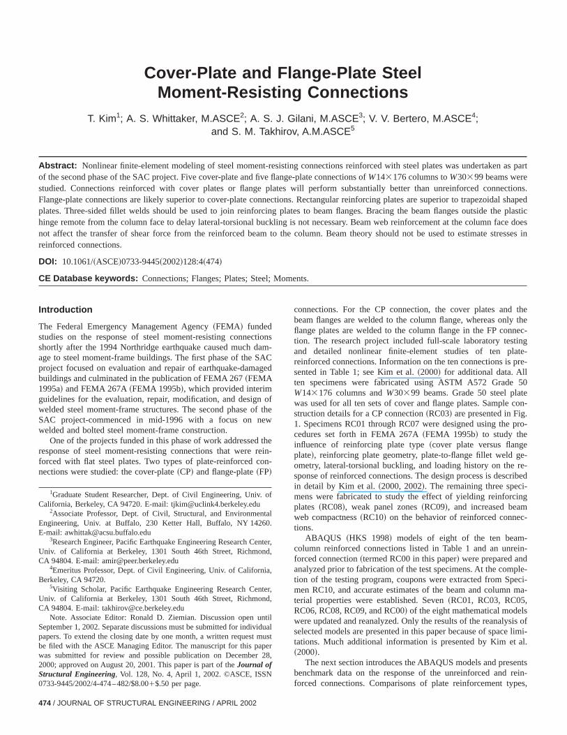
connections. For the CP connection, the cover plates andbeam flanges are welded to the column flange, whereas onlyflange plates are welded to the column flange in the FP contion. The research project included full-scale laboratory testand detailed nonlinear finite-element studies of ten plareinforced connections. Information on the ten connections issented in Table 1; see Kim et al.~2000! for additional data. Allten specimens were fabricated using ASTM A572 GradeW143176 columns andW30399 beams. Grade 50 steel plawas used for all ten sets of cover and flange plates. Samplestruction details for a CP connection~RC03! are presented in Fig1. Specimens RC01 through RC07 were designed using thecedures set forth in FEMA 267A~FEMA 1995b! to study theinfluence of reinforcing plate type~cover plate versus flangeplate!, reinforcing plate geometry, plate-to-flange fillet weld gometry, lateral-torsional buckling, and loading history on thesponse of reinforced connections. The design process is descin detail by Kim et al.~2000, 2002!. The remaining three specimens were fabricated to study the effect of yielding reinforciplates ~RC08!, weak panel zones~RC09!, and increased beamweb compactness~RC10! on the behavior of reinforced connections.
ABAQUS ~HKS 1998! models of eight of the ten beamcolumn reinforced connections listed in Table 1 and an unreforced connection~termed RC00 in this paper! were prepared andanalyzed prior to fabrication of the test specimens. At the comtion of the testing program, coupons were extracted from Spmen RC10, and accurate estimates of the beam and columnterial properties were established. Seven~RC01, RC03, RC05,RC06, RC08, RC09, and RC00! of the eight mathematical modelwere updated and reanalyzed. Only the results of the reanalysselected models are presented in this paper because of spacetations. Much additional information is presented by Kim et~2000!.
The next section introduces the ABAQUS models and presebenchmark data on the response of the unreinforced andforced connections. Comparisons of plate reinforcement typ
r,
,
alt
ctangular
Table 1. Summary Information on Test Specimens
Specimen RC
01 02 03 04 05 06 07 08 09 10
Connection type Coverplate
Coverplate
Coverplate
Flangeplate
Coverplate
Flangeplate
Flangeplate
Flangeplate
Flangeplate
Coverplate
Reinforcing-plategeometry
Rectangular Rectangular Rectangular Swallowtail Trapezoidal Rectangular Rectangular Rectangular Rectangular Re
Reinforcing-platewidth
305 305 305 330 267 337 337 337 337 305
Reinforcing-platethickness
16 16 16 29 17 25 25 22 22 16
Fillet weld:a L, T 14,0 14,0 11,11 14,19 16,16 16,16 16,16 14,14 14,14 11,14
Doubler plate 10 10 10 10 10 10 10 10 0 10Continuity-platethickness
29 29 29 29 29 25 25 22 16 29
Loading history Cyclic Cyclic Cyclic Cyclic Cyclic Cyclic Near field Cyclic Cyclic CyclicRestraint to lateraltorsional buckling
No Yes No No No No No No No No
Note: All dimensions in mm.aL5longitudinal fillet weld;T5transverse fillet weld.
nceebper
y-Theere
ingcol-or-
conholonsre-s-amth
be
dis-ift,rift.sta-al-eredriftg thehanipsde-
chsym-
is
e ofane.3
o.2
andentn beoningele-lid-
ationfor
thehetedentthe
reinforcement plate geometries, fillet weld geometries, influeof restraint to lateral-torsional buckling, and alternate beam wconnections, based on the analytical results and selected exmental data, are then presented in the following section.
Nonlinear Finite-Element Analysis
Solid-Element Models
Solid-element~Type SOL! models were prepared for the reanalsis of RC00, RC01, RC03, RC05, RC06, RC08, and RC09.beam, column, plates, and fillet welds in these connections wdiscretized using three-dimensional solid~brick! elements. Thegroove welds joining the beam to the column, the reinforcplates to the column flange, and the continuity plates to theumn flanges and web were not modeled explicitly. Rather, codinates common to components joined by groove welds werestrained to have identical displacements. The weld accesswas included in the Type SOL models. Data from tests of coupextracted from the beam and column of RC10, which are psented by Kim et al.~2000!, were used to establish the stresstrain relationships for the beam and column elements. The beand columns for all tests were from the same heats and so
Fig. 1. Construction details for RC03
i-
-e
se
stress-strain relationships for the components of RC10 couldused to model the other nine specimens.
The SOL models were used to study the stress and straintributions in these connections at different levels of story drand to evaluate selected indices at different levels of story dThe SOL models were not used to capture local and global inbilities such as flange and web local buckling, and latertorsional buckling. Because flange and web local buckling wobserved in the beams of all ten test specimens at storyangles greater than 2.0% rad, the results of the analyses usinSOL models are not presented for story drift angles greater t2.0% rad. Up to 2.0% rad, the force-displacement relationshpredicted by the SOL models matched well the relationshipstermined by experimentation~Kim et al. 2000!.
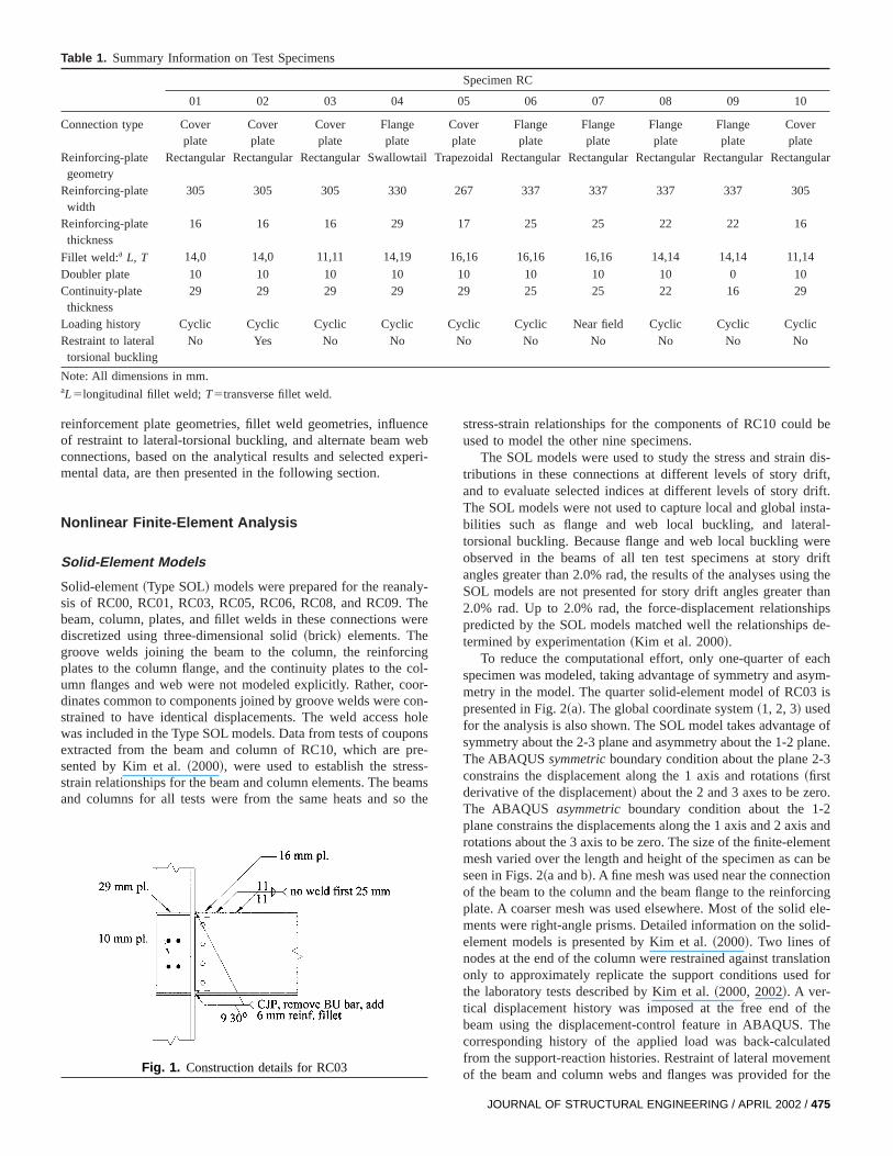
To reduce the computational effort, only one-quarter of easpecimen was modeled, taking advantage of symmetry and ametry in the model. The quarter solid-element model of RC03presented in Fig. 2~a!. The global coordinate system~1, 2, 3! usedfor the analysis is also shown. The SOL model takes advantagsymmetry about the 2-3 plane and asymmetry about the 1-2 plThe ABAQUSsymmetricboundary condition about the plane 2-constrains the displacement along the 1 axis and rotations~firstderivative of the displacement! about the 2 and 3 axes to be zerThe ABAQUS asymmetricboundary condition about the 1-plane constrains the displacements along the 1 axis and 2 axisrotations about the 3 axis to be zero. The size of the finite-elemmesh varied over the length and height of the specimen as caseen in Figs. 2~a and b!. A fine mesh was used near the connectiof the beam to the column and the beam flange to the reinforcplate. A coarser mesh was used elsewhere. Most of the solidments were right-angle prisms. Detailed information on the soelement models is presented by Kim et al.~2000!. Two lines ofnodes at the end of the column were restrained against translonly to approximately replicate the support conditions usedthe laboratory tests described by Kim et al.~2000, 2002!. A ver-tical displacement history was imposed at the free end ofbeam using the displacement-control feature in ABAQUS. Tcorresponding history of the applied load was back-calculafrom the support-reaction histories. Restraint of lateral movemof the beam and column webs and flanges was provided for
JOURNAL OF STRUCTURAL ENGINEERING / APRIL 2002 / 475
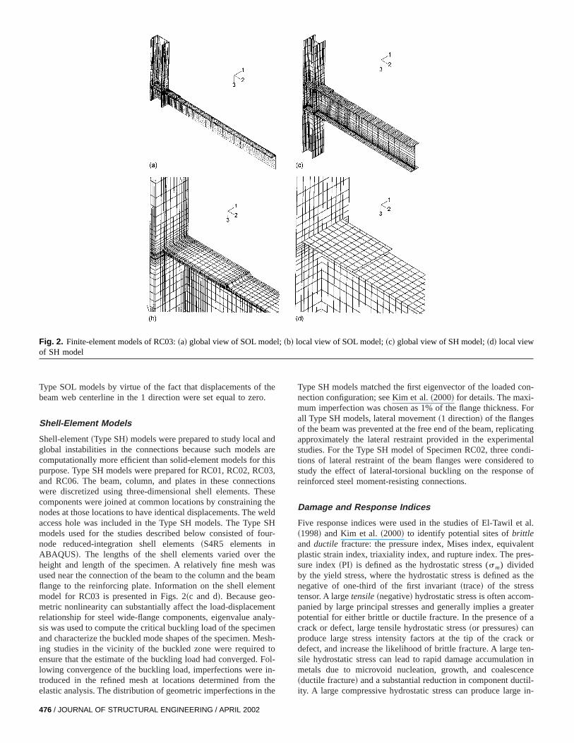
Fig. 2. Finite-element models of RC03:~a! global view of SOL model;~b! local view of SOL model;~c! global view of SH model;~d! local viewof SH model
the.
ndar
his03
tionhesthe
welSH
our
theasea
ent
entalyenestoFolin-thethe
on-
For
tingtal
ndi-d to
of
t al.
entes-
the
-aterf a
orn-n inncetil-
in-
Type SOL models by virtue of the fact that displacements ofbeam web centerline in the 1 direction were set equal to zero
Shell-Element Models
Shell-element~Type SH! models were prepared to study local aglobal instabilities in the connections because such modelscomputationally more efficient than solid-element models for tpurpose. Type SH models were prepared for RC01, RC02, RCand RC06. The beam, column, and plates in these connecwere discretized using three-dimensional shell elements. Tcomponents were joined at common locations by constrainingnodes at those locations to have identical displacements. Theaccess hole was included in the Type SH models. The Typemodels used for the studies described below consisted of fnode reduced-integration shell elements~S4R5 elements inABAQUS!. The lengths of the shell elements varied overheight and length of the specimen. A relatively fine mesh wused near the connection of the beam to the column and the bflange to the reinforcing plate. Information on the shell elemmodel for RC03 is presented in Figs. 2~c and d!. Because geo-metric nonlinearity can substantially affect the load-displacemrelationship for steel wide-flange components, eigenvalue ansis was used to compute the critical buckling load of the specimand characterize the buckled mode shapes of the specimen. Ming studies in the vicinity of the buckled zone were requiredensure that the estimate of the buckling load had converged.lowing convergence of the buckling load, imperfections weretroduced in the refined mesh at locations determined fromelastic analysis. The distribution of geometric imperfections in
476 / JOURNAL OF STRUCTURAL ENGINEERING / APRIL 2002
e
,se
d
-
m
-
h-
-
Type SH models matched the first eigenvector of the loaded cnection configuration; see Kim et al.~2000! for details. The maxi-mum imperfection was chosen as 1% of the flange thickness.all Type SH models, lateral movement~1 direction! of the flangesof the beam was prevented at the free end of the beam, replicaapproximately the lateral restraint provided in the experimenstudies. For the Type SH model of Specimen RC02, three cotions of lateral restraint of the beam flanges were considerestudy the effect of lateral-torsional buckling on the responsereinforced steel moment-resisting connections.
Damage and Response Indices
Five response indices were used in the studies of El-Tawil e~1998! and Kim et al.~2000! to identify potential sites ofbrittleand ductile fracture: the pressure index, Mises index, equivalplastic strain index, triaxiality index, and rupture index. The prsure index~PI! is defined as the hydrostatic stress (sm) dividedby the yield stress, where the hydrostatic stress is defined asnegative of one-third of the first invariant~trace! of the stresstensor. A largetensile~negative! hydrostatic stress is often accompanied by large principal stresses and generally implies a grepotential for either brittle or ductile fracture. In the presence ocrack or defect, large tensile hydrostatic stress~or pressures! canproduce large stress intensity factors at the tip of the crackdefect, and increase the likelihood of brittle fracture. A large tesile hydrostatic stress can lead to rapid damage accumulatiometals due to microvoid nucleation, growth, and coalesce~ductile fracture! and a substantial reduction in component ducity. A large compressive hydrostatic stress can produce large
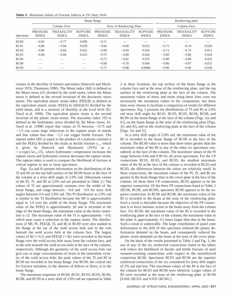
Table 2. Maximum Values of Fracture Indices at 2% Story Drift
Specimen
Beam flange Reinforcing plate
Column Face Nose of Reinforcing Plate Column Face
PRESSUREINDEX
TRIAXIALITYINDEX
RUPTUREINDEX
PRESSUREINDEX
TRIAXIALITYINDEX
RUPTUREINDEX
PRESSUREINDEX
TRIAXIALITYINDEX
RUPTUREINDEX
RC00 20.82 20.77 0.099 20.71 — — — — —RC01 20.86 20.84 0.029 20.66 20.66 0.052 20.75 20.74 0.020RC03 20.86 20.84 0.025 20.68 20.69 0.026 20.73 20.76 0.015RC05 20.84 20.84 0.025 20.75 20.68 0.024 20.80 20.80 0.024RC06 — — — 20.71 20.81 0.035 20.89 20.88 0.025RC08 — — — 20.68 20.78 0.046 20.86 20.87 0.023RC09 — — — 20.71 20.88 0.0084 20.90 20.90 0.028
estres
nd
. E
tals
t
thetrai
at
ee of
the
radlyumthente
ibu-inwebrges
anumncanin-I insitethe
06ble
thetophenoteseent.0%nd
n
ethethe
on-PI
e CPumnd
l. Inaref the
thele 2u-theate.nec-
mnthein
am.onede-
thelate.
, theleselcederiorlesofof06
creases in the ductility of tension specimens~Hancock and Mack-enzie 1976; Thomason 1990!. The Mises index~MI ! is defined asthe Mises stress (s̄) divided by the yield stress, where the Misstress is defined as the second invariant of the deviatoric stensor. The equivalent plastic strain index~PEEQI! is defined asthe equivalent plastic strain~PEEQ in ABAQUS! divided by theyield strain, and is a measure of ductility at the local level~El-Tawil et al. 1998!. The equivalent plastic strain is the secoinvariant of the plastic strain tensor. The triaxiality index~TI! isdefined as the hydrostatic stress divided by the Mises stressTawil et al. ~1998! report that values of TI between20.75 and21.5 can cause large reductions in the rupture strain of meand that values less than21.5 can trigger brittle fracture. Therupture index~RI! is equal to the product of a material constanaand the PEEQ divided by the strain at ductile fracture« r , whichis given by Hancock and Mackenzie~1976! as « r
5a exp(1.5sm /s̄), where hydrostatic compression increasesrupture strain and hydrostatic tension decreases the rupture sThe rupture index is used to compare the likelihood of fracturecritical regions in one or more specimens.
Figs. 3~a and b! present information on the distributions of thTI and RI on the top half surface of the RC00 beam at the facthe column at a story drift angle of 2.0% rad.~Maximum valuesof the PI, TI, and RI at 2.0% rad are presented in Table 2.! Thevalues of TI are approximately constant over the width ofbeam flange, and range between20.6 and20.8 for story driftangles between 0.0 and 2.0% rad. The PI distribution at 2.0%is similar to the TI distribution because the MI is approximateequal to 1.0 over the width of the beam flange. The maximvalue of the PEEQ is approximately 20 and is recorded atedge of the beam flange; the maximum value at the beam celine is 13. The maximum value of the TI is approximately20.8,which may cause a reduction in the rupture strain. The distrtions of MI, PI, PEEQI, TI, and RI in RC00 were also studiedthe flange at the toe of the weld access hole and in thebeneath the weld access hole at the column face. The lavalues of RI~50.2! and PEEQI~536! were recorded in the beamflange over the weld access hole away from the column face,in the web beneath the weld access hole at the face of the colrespectively. Although the geometry of the weld access holegive rise to large concentrations of strain in the immediate vicity of the weld access hole, the peak values of the TI and RRC00 are recorded in the beam flange. For RC00, the criticalfor fracture initiation, in the absence of defects or flaws, is inbeam flange.
The maximum responses of RC00, RC01, RC03, RC05, RCRC08, and RC09 at a story drift of 2.0% rad are reported in Ta
s
l-
n.
r-
t
d,
,
2 at three locations, the top surface of the beam flange atcolumn face and at the nose of the reinforcing plate, and thesurface of the reinforcing plate at the face of the column. Tmaximum values of stress and strain along these lines werenecessarily the maximum values in the components, but thlines were chosen to facilitate a comparison of results for differspecimens. Fig. 3 presents the distributions of TI and RI at 2rad story drift angle for RC01, RC03, RC05, RC06, RC08, aRC09 on the beam flange at the face of the column@Figs. 3~a andb!#, on the beam flange at the nose of the reinforcing [email protected]~c and d!#, and on the reinforcing plate at the face of the colum@Figs. 3~e and f!#.
At a story drift angle of 2.0% rad, the maximum value of thRI is recorded in the beam flange of RC00 at the face ofcolumn. The RC00 value is more than three times greater thanmaximum value of the RI in any of the other six specimens csidered, at the face of the column. The maximum values of therange between 0.66 and 0.90 for all seven specimens. For thconnections RC01, RC03, and RC05, the smallest maximvalue of the RI at the face of the column is recorded in RC03 aRC05; the differences between the values are relatively smalthese connections, the maximum values of the PI, TI, and RIgreater in the beam flange than in the cover plate at the face ocolumn. Of these three CP connections, RC03 appears to besuperior connection. Of the three FP connections listed in Tab~RC06, RC08, and RC09!, specimen RC06 appears to be the sperior connection. In RC06 and RC08, the maximum value ofRI is recorded in the beam at the nose of the reinforcing plSuch a result is desirable because the objective of the FP contion is to force inelastic action in the beam away from the coluface. For RC09, the maximum value of the RI is recorded inreinforcing plate at the face of the column; the maximum valuethe plate is approximately 3.5 times larger than that in the beSuch a result is undesirable. The large contribution of panel zdeformation to the drift of this specimen reduced the plasticformation demand on the beam, and consequently reducedplastic strain demands on the beam at the nose of the cover p
On the basis of the results presented in Table 2 and Fig. 3use of any of the six reinforced connections listed in the tabwill reduce the likelihood of ductile and brittle fracture of stemoment-resisting connections with respect to the unreinforconnection RC00. Specimens RC03 and RC06 are the supreinforced connections of the six considered for story drift angof 2% rad and less. The maximum values of the RI at the facethe column for RC03 and RC06 were identical. Larger valuesRI were recorded at the nose of the reinforcing plate of [email protected]~RC03! and 0.035~RC06!.#
JOURNAL OF STRUCTURAL ENGINEERING / APRIL 2002 / 477
Fig. 3. Distribution of triaxiality and rupture indices at 2.0% rad. story drift:~a and b! beam flange at column face;~c and d! beam flange at noseof reinforcing plate;~e and f! reinforcing plate at column face
nge.op-tagese onc-
uldson
eriop-lle
necss.
iggemnss
in-ouldand
ivethesub-nsethe. 5eamf thendthein
rce
etheof
Analytical and Experimental Response Evaluation
Plate Reinforcement Type
Consider the beam top flange/plate reinforcement-column flaconnections shown in Fig. 4. Fig. 4~a! is a CP connection and Fig4~b! is the corresponding FP connection. Two groove-weldtions are shown for the CP connection. One possible disadvanof the CP connection is that the connection geometry producstress riser near the face of the column flange at the interfacthe reinforcing plate and the flange. This stress riser in conjution with a triaxial state of tension at the face of the column colead to unacceptable fractures of column flanges. For this reathe FP connection was considered by many to be the supreinforcement detail of the two. Of the two CP groove weld otions A and B, A uses less filler metal than B and produces smawelding-induced residual stresses. However, the option A contion is composed of two groove welds, each with a root paSuch root passes may include substantial defects that can trbrittle fracture. Although the root pass of the flange-to-coluweld can be inspected and replaced if necessary, the root pa
478 / JOURNAL OF STRUCTURAL ENGINEERING / APRIL 2002
eaf
,r
r-
r
of
the plate-to-column flange groove weld can be neither easilyspected nor replaced. As such, any defect in this root pass walign with the stress riser identified in the previous paragraph,potentially increase the likelihood of brittle fracture.
The experimental studies provided no insight into the relatmerits of the reinforcing-plate types because local buckling inbeam flanges and web protected the reinforcing plates fromstantial plastic straining. To gain further insight into the respoof the cover-plate and flange-plate reinforcement details,ABAQUS models of RC03 and RC06 were studied further. Figis a view of the displaced shapes of the cover plate and bflange in RC03 along the beam web centerline near the face ocolumn at a story drift angle of 1.0% rad. Both the flange acover plate are in tension. The separation of the flange fromcover plate near the face of the column is due to deformationthe beam flange that results from the transfer of shear fothrough the beam flange to the column flange.
Kim et al. ~2000! present the distributions of MI and PI in thbeam top flange and the plate reinforcement at the face ofcolumn at a story drift angle of 1.0% rad, and the distribution
t th03sigesseameC.
o ththethe
om
atislate
inumat
thecalor tpe-
il
vedby
ap-eld
1,ared
el to
andeiruchthe
webci-fillet
srift
overnaluchamd on
theC03
am7-
en-of
s ofcaleld-the
rt byift
and
thee ines ofeoryol-
PEEQ in the beam top flange and the plate reinforcement aface of the column at a story drift angle of 2.0% rad, for RCand RC06. At 1.0% rad, the maximum stresses in RC06 arenificantly smaller than those in RC03. In RC03, the Mises strat 1.0% rad is largest at the top of the beam flange over the bweb @point C of Fig. 4~a!#. Much of the RC03 beam flange at thcolumn face is in triaxial tension with the largest value at pointThe maximum stresses in the cover plate~point A! are smallerthan the maximum stresses in the beam flange and counter ttrend predicted by beam theory. Point C lies at the top ofgroove weld of the beam flange to the column flange whereweld quality is likely good. The stresses at point B at the bottof the cover plate~immediately above point C! are substantiallysmaller than those at point C. The likelihood of brittle fractureB is substantially smaller than at point C if the weld qualityuniform throughout the depth of the beam flange–cover pgroove weld. At 2.0% rad, the maximum values of the PEEQRC06 and RC03 are approximately the same. The maximvalue in RC03 is at point C and the maximum value in RC06 ispoint A.
It is inappropriate to draw broad conclusions regardingoptimal type of reinforcement plate based on limited analytidata. However, the FP connection appears marginally superithe CP connection, and the option B groove-weld detail is surior to the option A detail in CP connections.
Fig. 4. Plate reinforcement type:~a! cover and~b! flange plate
Fig. 5. Deformations in cover plate and beam flange at face of cumn
e
-
e
o
Reinforcing Plate and Fillet Weld Profiles
Three reinforcing-plate~rectangular, trapezoidal, and swallowta!and two fillet weld~two-sided and three-sided! profiles were stud-ied in the research program. Because the swallowtail plate prodifficult to fabricate and no substantial advantage was gainedits use, the following discussion is limited to rectangular and trezoidal plates. To compare the reinforcing-plate and fillet wprofiles, the responses of three CP specimens RC01~rectangularplate,L-L fillet weld!, RC03~rectangular plate,L-L-T fillet weld!,and RC05~trapezoidal plate,L-L-T fillet weld! are comparedbelow. Fig. 6 is a plan view of the plates and fillet welds of RC0RC03, and RC05; the longitudinal and transverse fillet weldsdenoted byL andT, respectively. The cover plates of RC01 anRC03 were wider than theW30399 beam flange whereas thmaximum width of the trapezoidal plates of RC05 was equathe width of the beam flange.
The maximum measured resistances of RC01, RC03,RC05 were virtually identical and the differences between thmoment-beam plastic rotation hysteresis loops were small. San observation is not surprising because the properties ofbeam~yield stress, tensile strength, flange compactness, andcompactness! controlled the global response of the three spemens and served to protect the plate reinforcement and thewelds from substantial damage~yielding!.
In Specimen RC01~L-L fillet weld!, the beam flange bucklethat formed beyond the nose of the cover plate at a story dangle of 3.0% rad penetrated back beyond the nose of the cplate toward the column at 4.0% rad and tore the longitudifillet welds that joined the cover plate to the beam flange. Stearing did not lead to failure because local buckling of the beflanges and web led to a loss of strength and reduced demanthe fillet weld. The transverse fillet welds joining the RC03~L-L-T fillet weld! cover plates to the beam flanges preventedbuckle penetration observed in RC01 and no tearing of the Rfillet welds was observed.
The cover plates in RC03 and RC05 were welded to the beflanges with longitudinal and transverse fillet welds. The 26mm-long transverse fillet welds of RC03 served to prevent petration of yielding and flange local buckling beyond the nosethe rectangular plate. The 127-mm-long transverse fillet weldRC05 permitted some penetration of yielding and flange lobuckling beyond the nose of the trapezoidal plate, but such yiing and buckling penetration appeared to have no impact onresponse of RC05. These observations were confirmed in pathe ABAQUS distributions of the PEEQ at 2.0% rad story drangle~Kim et al. 2000!.
The normal stress distributions in the 2 direction@see Fig.2~a!# on the upper surface of the cover plates of RC01, RC03,RC05 are presented in Kim et al.~2000!. None of the cover plateswere effectively mobilized near the nose of the plate, andnormal stresses in the beam flanges typically exceeded thosthe plates at the same distance from the column face. The statstress in reinforced connections are most complex; beam thcannot be used to calculate stresses in such connections.
Fig. 6. Reinforcing plate and fillet weld profiles
JOURNAL OF STRUCTURAL ENGINEERING / APRIL 2002 / 479
sse ogle.at
esee Tthein
e 3altheis
webalsorsethein-
endri-edi-ofe aInnc-
UStrap
acket
oe isiondi-igheethethe
lats a
erseichthendlaresslity
ed aus
ct oe oC01
d end
ela-ly-sis:
m
iffinem
ao-testoni-rce-g. 7.forto
ocalinga-
d
amomadtialamt is
ingforrt-ingb-int.
rift18
7%sign-
Kim et al. ~2000! present detailed information on the streand strain distributions in RC01, RC03, and RC05 at the nosthe reinforcing plates at 0.5, 1.0, and 2.0% rad story drift anThe distributions of the triaxiality index and the rupture index2.0% rad story drift are reproduced in Figs. 3~c and d!. Considerfirst the distributions of TI in Fig. 3~c!. The values of the Misesindex across the nose of the reinforcing plate for each of thspecimens are approximately constant and equal to 1, so thdistributions also approximately represent the distributions ofpressure index. The maximum value of the TI is recordedRC05 above the beam web centerline where restraint in thdirection is provided by the web of the beam. All the principstresses at this location are tensile. The value of the TI atjunction of the longitudinal and transverse fillet welds of RC05substantially smaller than the maximum value at the beamcenterline, but all the principal stresses at the junction aretensile. Values of the TI for the two specimens with transvefillet welds, RC03 and RC05, are smaller across the nose ofRC03 cover plate. Of the two specimens with rectangular reforcing plates, the maximum value of the TI is recorded at theof the longitudinal fillet weld of RC01. Consider now the distbutions of the RI in Fig. 3~b!. Of RC01, RC03, and RC05, thmaximum value of the RI is recorded at the end of the longitunal fillet weld of RC01. The distribution of RI across the nosethe RC03 plate is somewhat constant with the maximum valuthe junction of the longitudinal and transverse fillet welds.RC05, the maximum value of the RI is also recorded at the jution of the longitudinal and transverse fillet welds.
Construction-related issues aside and based on the ABAQanalysis data only, the rectangular plates are superior to theezoidal plates. Three-sided~L-L-T! fillet welds should be usedregardless of the adopted plate shape because~1! the transverseweld effectively prevents flange buckles from penetrating bbeyond the nose of the plate,~2! the transverse weld closes thpseudodefect~or stress riser! at the end of the longitudinal weld athe base of its throat~Kim et al. 2000!, ~3! the maximum valuesof the RI are reduced, and~4! smaller fillet welds can be used tjoin the reinforcing plates to the flanges. If the nose of the platsufficiently wide so as to mitigate the restraint in the 3 directprovided by the web of the beam at the junction of the longitunal and transverse fillet welds and prevent the formation of htriaxial tensile stresses, the differences in performance betwthese two plate shapes will be small. Recommendations forminimum width of the nose of the trapezoidal plate, based onanalytical and experimental studies, are presented later.
The rectangular plate shape is superior to the trapezoidal pfor two reasons. First, the use of a rectangular plate providegreater length for the placement of the longitudinal and transvfillet welds than a trapezoidal plate of the same length, whleads to a reduction in the size of the fillet weld. Second,quality of the weld metal at the junction of the longitudinal atransverse fillet welds will likely be better for the rectanguplate shape because these welds are separated by the thicknthe flange and runoff tabs can be used to provide high-quaweld metal at the end of each weld. Such tabs cannot be usthe junction of the welds for the trapezoidal plate shape becathe welds are in the same plane.
Restraint of Lateral-Torsional Buckling
The Type SH model of RC02 was prepared to assess the effelateral-torsional buckling on the force-displacement responsreinforced connections. Specimen RC02 was identical to R
480 / JOURNAL OF STRUCTURAL ENGINEERING / APRIL 2002
f
I
t
-
n
e
of
te
ff
except that lateral restraint of the beam flanges at the assumeof the plastic hinge~508 mm from the nose of the cover plate!was provided to RC02. The measured force-displacement rtions ~backbone curves! for RC01 and RC02 were essentialidentical ~Kim et al. 2000, 2002!. Three conditions of lateral restraint in the plastic hinge zone were considered for the analy~1! no restraint at the end of the plastic hinge~replicating RC01!;~2! infinitely stiff lateral restraint to the beam flanges 508 mfrom the nose of the reinforcement plate~similar to RC02 exceptthat the braces used in the experiment were not infinitely st!;and~3! continuous lateral and rotational restraint to the centerlof the beam top flange; infinitely stiff lateral restraint to the beabottom flange 508 mm from the nose of the cover plate~similar toCondition 2 but including the restraint that would be offered bycomposite slab!. For all three models, lateral restraint was prvided at the beam tip to replicate the restraint provided in thefixture to protect the actuator. Each model was loaded monotcally to produce compression in the beam top flange. The fodisplacement relations for these models are presented in FiAlso shown in this figure is the force-displacement relationModel 3 but with the load applied in the opposite directionproduce tension in the beam top flange~Model 4!. The drop instrength at story drift angles greater than 2.0% rad is due to lbuckling of the beam flanges and web outside the reinforcplate. The restraint condition for each model is identified in prentheses in the legend.
Compare first the responses for Models 1~no restraint!, 2 ~re-straint!, and 3~restraint!. The addition of lateral bracing at the enof the plastic hinge zone~Model 2! to delay lateral-torsionalbuckling of the beam has minimal effect on the beam load–betip displacement relationship, identical to the result observed frthe experimental program. Likewise, the restraint of Model 3 hvirtually no effect on the load-displacement relation. A substanimprovement in response is evident for Model 4, where the betop flange is in compression and lateral and rotational restrainprovided along the centerline of this flange. Flange local bucklis substantially delayed by the restraint. The loss of strengthModel 4 follows web local buckling that accompanies the shoening of the beam due to flange local buckling. Such shortenwould be difficult, but not impossible, to realize in the field. Sustantial forces develop in the braces providing the lateral restraFor Model 2, the maximum brace force is 116 kN at a story dangle of 5.07% rad. For Model 3, the maximum brace force is 1kN at a story drift angle of 5.14% rad. These brace forces ofof the squash load of the beam flange are greater than the deforce specified in AISC~1997! but less than the maximum mea
Fig. 7. Lateral-torsional buckling of reinforced connections
nge
Table 3. RC00 Beam Web Reinforcement Effectiveness at 0.5 and 2% Story Drift
Configuration
Web tab size Story drift angle50.5% Story drift angle52.0%
Width~mm!
Thickness~mm! % Beam Web % Beam Flange % Beam Web % Beam Fla
1a 0 0 54 46 85 152 127 13 56 44 88 123 127 25 57 43 87 134 254 13 54 46 87 135 254 25 54 46 87 13aThickness of beam web513 mm.
atio
earrce
rma
s oestheceeingeamap
and
centh
in-
Thehole
ebtheely
hat
r-at
.cedamngerre
0hattaging
tuden-use
theFP
erredfor
ed to
mn
t ofceding
fives inite-
aredroms areon-uld
tesc-
orlatecol-dmn
s areith-an
idalges
to-arer ofto
am
ec-otsis.w.
sured brace forces because the force component due to elongof the brace is not included in the analytical result.
Shear Force Transfer in Reinforced Connections
For steel beam-column connections, it is well established~Leeet al. 1997! that the beam web transfers only part of the shforce in the beam to the column and that much of the shear fois transferred through the beam flanges. Table 3 presents infotion on the distribution of shear force in RC00~Configuration 1!at story drift angles of 0.5 and 2.0% rad. The average valuethe equivalent plastic strain index in the beam flanges at thdrift angles are 0.0 and 5.1, respectively. Plastic straining ofbeam flanges leads to a redistribution of shear stress at the fathe column, with a greater percentage of the shear force bpassed through the beam web. Larger plastic strains in the bflanges would be needed for the shear force distribution toproach that of beam theory~97% web; 3% flanges! but suchstrains at the column face must be avoided in unreinforcedreinforced connections.
One strategy that has been proposed for increasing the perage of the beam shear transferred through the beam web tocolumn involves the addition of welded web shear tabs tocrease the stiffness of the beam web. Five reinforcedW30399beam web configurations were studied as listed in Table 3.tab plate depth was equal to the distance between the copeand the plate was assumed to be fully welded to the beam weffectively increasing the thickness of the beam web overelevation of the tab plate. Configurations 2–5 bound the likcost-effective sizes~width and thickness! of web reinforcementplates. For reference, the thickness of theW30399 web is 13mm. The values listed in columns 4–7 of the table indicate tbeam web reinforcement with welded web tab plates~installedbetween the weld access holes! does not serve the intended pupose of increasing the percentage of the beam shear force thtransferred to the column flange through the web connection
The addition of flange reinforcement plates to an unreinforconnection will intuitively reduce the percentage of the beshear transferred through the beam web to the column flaInformation on the percentage of the beam shear force transfethrough theW30399 beam web to theW143176 column flangefor three cover-plate thicknesses~0, 16, and 32 mm! is presentedin Kim et al. ~2000!. An increase in cover-plate thickness fromto 32 mm increased the percentage of the beam shear force ttransferred through the flange-plate assembly, but the percenincrease was not proportional in the flanges and the reinforcplates.
Shear force transfer in flange-plate connections was also sied for different thicknesses of the flange plate. The trends idtified above for CP connections hold for FP connections. Beca
n
-
fe
of
-
t-e
s,
is
.d
ise
-
the load path from the beam web to the column flange viabeam flange and reinforcing plate is less circuitous for theconnection, a smaller percentage of the beam shear is transfto the column flange through the beam web in FP connectionsthe same cross-sectional area of flange-plate assembly weldthe column.
Conclusions
Ten large-size reinforced steel moment-resisting beam-coluconnections, composed of ASTM A572 Grade 50W143176 col-umns andW30399 beams, were analyzed and tested as parthe SAC Phase II project. Five of the specimens were reinforwith cover plates; both the beam flanges and the reinforcplates were welded to the column flange. The remainingspecimens were reinforced with flange plates; the beam flangethese specimens were not welded to the column flange. Finelement models of seven of the ten specimens were prepusing solid and shell elements. The key conclusions drawn fthe analytical studies and the associated experimental resultlisted below. Extrapolation of these conclusions to reinforced cnections of a substantially different size or configuration shobe undertaken with care.1. Connections reinforced with cover plates and flange pla
will perform substantially better than unreinforced connetions.
2. FP connections are marginally less likely to suffer brittleductile fracture than CP connections. If used, the beam-passembly of the CP connection should be welded to theumn flange with asinglegroove weld. Beam webs in FP anCP connections should be groove welded to the coluflange.
3. The states of stress and strain in FP and CP connectioncomplex and cannot be predicted with beam theory. Notwstanding this observation, the procedures of FEMA 267A cbe used to analyze and design CP and FP connections.
4. Rectangular reinforcing plates are superior to trapezoplates. Reinforcing plates should be joined to beam flanusing three-sided fillet welds. Runoff tabs should be usedprovide high-quality filler metal of the correct throat thickness at the ends of the fillet welds. If trapezoidal platesused, the nose of the plate should exceed the smalleeither 50% of the width of the beam flange or 150 mm,mitigate the effects of the restraint provided by the beweb.
5. Bracing the bottom flange of beams in FP and CP conntions immediately beyond the plastic hinge zone will nlead to significant improvements in connection hystereRules for the design of lateral bracing warrant further revie
JOURNAL OF STRUCTURAL ENGINEERING / APRIL 2002 / 481
f thffec
tedbe
thered
ointeerlyucoci-yle
in-gnerchou
p.
,
o
ess
S.el
S.nt-
ley,
i-
6. Reinforcement of the beam web using plates~of a heightequal to the distance between the cope holes! welded to theweb and the column flange, to increase the percentage obeam shear transferred through the beam web, is not etive.
7. The use of thick reinforcing plates to reduce the calculanormal stresses at the column face is not recommendedcause large fillet welds will be needed to join the plate toflange, and much or all of the beam shear will be transferto the column via the plates.
Acknowledgments
The work described in this paper was funded by the SAC JVenture through a contract with the Pacific Earthquake Engining Research~PEER! Center. This financial support is gratefulacknowledged. Rolled steel sections were supplied by the NYamato Company, of Blytheville, Arkansas. The ten test spemens were fabricated and shipped to the University by GaManufacturing Company, Woodland, California. Fabricationspection services and testing services were provided by SiTesting Laboratories, Inc., of Hayward California. The reseadescribed in this report could not have been undertaken withthis generous support.
Notation
The following symbols are used in this paper:a 5 material constant;
« r 5 rupture strain;
482 / JOURNAL OF STRUCTURAL ENGINEERING / APRIL 2002
e-
-
-
r
t
t
s̄ 5 Mises stress; andsm 5 hydrostatic pressure.
References
AISC. ~1997!. Seismic provisions for structural steel buildings, AISCPublication No. S341, Chicago.
El-Tawil, S., Mikesell, T., Vidarsson, E., and Kunnath, S.~1998!.‘‘Strength and ductility of FR welded-bolted connections.’’ SAC ReNo. 98-01, SAC Joint Venture, Sacramento, Calif.
FEMA. ~1995a!. ‘‘Interim guidelines: Evaluation, repair, modificationand design of welded steel moment frame structures.’’Rep. No. 267,Washington, D.C.
FEMA. ~1995b!. ‘‘Interim guidelines: Advisory no. 1, supplement tFEMA-267.’’ Rep. No. 267A, Washington, D.C.
Hancock, J. W., and Mackenzie, A. C.~1976!. ‘‘On the mechanism ofductile fracture in high-strength steels subjected to multi-axial strstates.’’J. Mech. Phys. Solids,24, 147–69.
Hibbit, Karlsson, and Sorenson, Inc.~HKS!. ~1998!. ABAQUS theorymanual, Pawtuket, R.I.
Kim, T., Whittaker, A. S., Gilani, A. S. J., Bertero, V. V., and Takhirov,M., ~2002!. ‘‘Experimental evaluation of plate-reinforced stemoment-resisting connections.’’J. Struct. Eng.,128~4!, 483–491.
Kim, T., Whittaker, A. S., Gilani, A. S. J., Bertero, V. V., and Takhirov,M. ~2000!. ‘‘Cover-plate and flange-plate reinforced steel momeresisting connections.’’Rep. No. PEER 2000/07, Pacific EarthquakeEngineering Research Center, University of California at BerkeBerkeley, Calif.
Lee, K-H., Goel, S. C., and Stojadinovic, B.~1997!. ‘‘Boundary effects inwelded steel moment connections.’’Rep. No. UMCEE 97-20, Depart-ment of Civil and Environmental Engineering, University of Michgan at Ann Arbor, Ann Arbor, Mich.
Thomason, P. F.~1990!. Ductile fracture of metals, Pergamon, New York.


