Embed Size (px)
Citation preview
.10.111.1.11001.7"
Ow
.aimvorm
111.4100ot
BR
ISBA
NE
WA
TE
R
SP 047 CR
EE
K R
D
GE
NE
RA
TO
R C
ON
NE
CT
ION
O
PER
AT
ION
and MA
INT
EN
AN
CE
MA
NU
AL
B
ook 1 of 1
pavedarox.f.
Creek Road Cannon Hill SPS SP047 Generator Connection OM Manual
Q-Pulse Id TMS743 Active 29/01/2014 Page 1 of 77
COMMON LOGIC PTY LTD ACN. 011 029 262
Electrical Contractors
Contract BVV.30178-02/03 Switchboard Connection
Facilities for Backup Generator Sets at Sewerage PS
Electrical Manual - WB47 Creek Road
ISSUE NO 1
AS BUILT 21/06/2004
Unit 9/58 Wecker Road, Mansfield, Queensland 4122 Telephone (07) 3849 7449 Fax (07) 3343 5210
JHO5
JHO5Mj47Creek Road
Creek Road Cannon Hill SPS SP047 Generator Connection OM Manual
Q-Pulse Id TMS743 Active 29/01/2014 Page 2 of 77

Operation and Maintenance Data Manual
ui
BfisbaneCit
. Brisbane Project WaterManagement No
BRISBANE WATER
GENERATOR CONNECTION 0 & M Manual
Section 1 Generator Connection Description ATS Connection Diagram
Section 2 Parts List
Section 3 Asbuilt Drawings Construction Markups
Section 4 Site Testing Site Testing Functional description Site Testing NCS alarms Site Testing Generator Electrical Test Certificate
Section 5 Parts information
Creek Road Cannon Hill SPS SP047 Generator Connection OM Manual
Q-Pulse Id TMS743 Active 29/01/2014 Page 3 of 77
Brisbane City
Brisbane 14fater jagtood
BRISBANE WATER
GENERATOR CONNECTION 0 & M Manual
Section 1
Generator Connection Description
Creek Road Cannon Hill SPS SP047 Generator Connection OM Manual
Q-Pulse Id TMS743 Active 29/01/2014 Page 4 of 77
COMMON LOGIC Pty Ltd Electrical Manual Specialist Electrical Contractors
Subject: Semi Permanent Generator Change Over Switchgear Sheet: 1
O 10
Section
1
Page Revision No: Date: 21/06/04 Manual Issue No: 1 Date: 21/06/04
1.0 GENERAL 2.
2.0 OPERATIONAL DESCRIPTION 3
2.1 GENERATOR . 3 2.2 RTU 3 2.3 PUMP STARTER MCC 3
2.3.1. MCC MAIN SWITCH 3
2.3.2. MAINS AVAILABLE INDICATOR 4 2.3.3. MAINS FAIL IN MCC 4 2.3.4. GENERATOR RUNNING. 4 2.4 ATS CUBICLE 4 2.4.1. GENERATOR INTERFACE 4 2.4.2. RTU INTERFACE 5
2.4.3. ATS AND CONTROL 5
. 3.0 DRAWINGS 7
4.0 PART LIST 8
5.0 TEST SHEETS 9
6.0 TECHNICAL INFORMATION 10
Authorised By: Grant Kerr
Creek Road Cannon Hill SPS SP047 Generator Connection OM Manual
Q-Pulse Id TMS743 Active 29/01/2014 Page 5 of 77
COMMON LOGIC Pty Ltd Electrical Manual Specialist Electrical Contractors
Subject: Semi Permanent Generator Change Over Switchgear Sheet: 2 Of: 10
I Section 1
Page Revision No: Date: 21/06/04 Manual Issue No: 1 Date: 21/06/04
1.0 GENERAL
The following document describes the operation of the switchgear and relays installed into the change over switchgear cubicle. The document does NOT describe the detailed operation of the generator PLC or the operation of the pump starters on the site. The generator is a plug in device and can be removed from site by BW at their discretion. All sites are identical with respect to the control mechanism with only the size of the circuit breakers and associated switchgear changing.
Authorised By: Grant Kerr .
Creek Road Cannon Hill SPS SP047 Generator Connection OM Manual
Q-Pulse Id TMS743 Active 29/01/2014 Page 6 of 77
COMMON LOGIC Pty Ltd Electrical Manual Specialist Electrical Contractors
Subject: Semi Permanent Generator Change Over Switchgear Sheet: 3 Of: 10
Section 2
Page Revision No: Date: 21/06/04 Manual Issue No: 1 Date: 21/06/04
2.0
2.1
2.2
2.3
2.3.1.
OPERATIONAL DESCRIPTION
There are four components to the system. These are the Generator, RTU, Pump MCC, and the Generator change over switchgear. The last component will be described within this document in detail. The remaining devices will be described in the BW manual.
GENERATOR
The generator and associated PLC control all automatic aspects of the change over switchgear, in affect making the basic transfer switch into an Automatic Transfer switch (ATS). The ATS will only operate if the generator PLC is fully operational.
The operation of the ATS is NOT fail safe and will NOT return to a predetermined condition on failure of the generator PLC or associated wiring.
Mains fail timing and return to mains timing is all controlled within the generator PLC.
RTU
The RTU monitors several generator alarm conditions and will report these conditions to the system as required.
The RTU can remotely start and stop the generator. The remote start will initiate a change over of the station to the generator. Stopping the generator will initiate a return to mains if available.
PUMP STARTER MCC
The pump starter MCC automatically starts and stops the pumps on demand determined by the wet well levels. The starter has not been modified in any way to accommodate the generator ATS with the exception of the re-routing of the sub-mains cabling.
MCC MAIN SWITCH
The Main Switch in all cases refers to the Energex supply point of isolation.
The existing main switch in the pump starter MCC, when labelled as the "Main Switch", will isolate the incoming Energex Mains Supply.
For complete isolation of the switchboards where an automatic generator system is supplied the generator must also be isolated.
This must be carried out at the generator CB in the generator canopy as well as switching the control to the "OFF" position.
Where a separate main switchboard has been installed the MCC Main Switch will
Authorised By: Grant Kerr
JHO5MC01
Creek Road Cannon Hill SPS SP047 Generator Connection OM Manual
Q-Pulse Id TMS743 Active 29/01/2014 Page 7 of 77
COMMON LOGIC Pty Ltd Electrical Manual Specialist Electrical Contractors
Subject: Semi Permanent Generator Change Over Switchgear Sheet: 4 Of: 10
Section 2
Page Revision No: Date: 21/06/04 Manual Issue No: 1 Date: 21/06/04
become the MCC Main Isolator. This isolator will isolate all incoming power to the MCC regardless of the generator condition.
2.3.2. MAINS AVAILABLE INDICATOR
The mains available indicator mounted on the common control escutcheon is supplied by a 24VDC signal originating from the RTU control supply. The polarity of the signal on the unit is dependent on the type of RTU on the site. The signal will be "ON" when the mains are healthy.
This relay does not monitor the level or the rotation of the generator supply and has no bearing on the running of the pumps.
2.3.3. MAINS FAIL IN MCC
The mains fail relay in the MCC is the only device that assures the system has the correct rotation and supply available for the pumps to operate. When re-connecting the generator to a site it is necessary to check the rotation is also correct.
2.3.4. GENERATOR RUNNING.
The generator running indicator is supplied by a 24VDC signal from the generator battery system. The indicator will be "ON" when the generator is running as determined by the generator PLC.
2.4 ATS CUBICLE
The ATS cubicle comprises 3 sections as described below. The control function of all sites is identical including all relays and components with the exception of the size of the transfer switch and associated connection hardware.
2.4.1. GENERATOR INTERFACE
The generator interface is via a Clipsal 27 Pin plug and socket. The multicore cable is connected core 1 to pin 1 and 2-2 etc. The Multicore cable is labelled wire No. 601 for core 1 to pin 1 and No.602 -Core2- Pin2 etc. This enables simple and quick reference to all wiring between the plug and the hardware within the ATS cubicle. All signals received from the generator are arranged to switch a relay powered from the generator 24VDC system. The exceptio to this is the "Generator Not On Site" signal, which wires directly to the RTU via the interface terminals.
All control signals to the Generator are via clean contacts. Both sides of the contact are issued to the generator. These contacts switch relays in the generator panel and are powered via the generator 24VDC system.
Authorised By: Grant Kerr
JHO5MC01
Creek Road Cannon Hill SPS SP047 Generator Connection OM Manual
Q-Pulse Id TMS743 Active 29/01/2014 Page 8 of 77
COMMON LOGIC Pty Ltd Electrical Manual Specialist Electrical Contractors
Subject: Semi Permanent Generator Change Over Switchgear Sheet: 5 Of: 10
Section 2
Page Revision No: Date: 21/06/04 Manual Issue No: 1 Date: 21/06/04
2.4.2. RTU INTERFACE
. The RTU interface is via a hard wired loom or multicore cable and terminals. The Loom cable is specially numbered with the terminal numbers within the ATS cubicle. IE Core 23 is connected to terminal 23 and is labelled wire 623. If a Multicore cable is utilised then core 1 is connected to Terminal 23 the labelled wire No. 623 for core 2 to terminal 24 and No.624 etc.
This enables simple and quick reference to all wiring between the RTU and the hardware within the ATS cubicle.
The RTU connections are different for each site and may also have different polarities for each site according to the site hardware.
All signals received from the RTU are arranged to switch a relay powered from the RTU 24VDC system. IE Remote Start and Remote Stop only.
All signals to the RTU are via clean contacts. Both sides of the contact are issued to the RTU system. These contacts switch directly into the RTU Input cards. The voltage on these signal cables is 24VDC supplied from the RTU power supply.
2.4.3. ATS AND CONTROL
The transfer switch is a Terasaki Basic Transfer switch. The control of this switch is only achieved from the generator PLC. The PLC controls the relays GTSM and GTSG within the ATS panel.
Energising GTSM if the Mains Volts are available will open the Generator CB and Close the Mains CB.
Energising GTSG if the Generator Volts are available will open the Mains CB and Close the Generator CB.
If volts are not available the motors in the BTS will not operate. (IE stay in the last condition. If the BTS does not operate the PLC will remove the transfer signal and assume a fault condition. This condition required manual operator intervention.
Manual Operation: If manual operation is desired then the following steps must be carried out.
Please note that it is not necessary to remove any covers when manually operating the CB's.
If the PLC is issuing an undesirable status then the operation of the CB motors must first be isolated. This is best achieved by switching the CB's QM2 and QG1 to the off position. This removes the motor charge and open close commands to the operators.
Authorised By: Grant Kerr
JHO5MC01
Creek Road Cannon Hill SPS SP047 Generator Connection OM Manual
Q-Pulse Id TMS743 Active 29/01/2014 Page 9 of 77
COMMON LOGIC Pty Ltd Electrical Manual Specialist Electrical Contractors
Subject: Semi Permanent Generator Change Over Switchgear Sheet: 6 Of: 10
Section 2
Page Revision No: Date: 21/06/04 Manual Issue No: 1 Date: 21/06/04
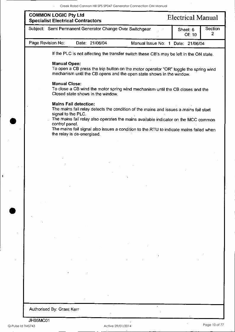
If the PLC is not affecting the transfer switch these CB's may be left in the ON state.
Manual Open: To open a CB press the trip button on the motor operator "OR" toggle the spring wind mechanism until the CB opens and the open state shows in the window.
Manual Close: To close a CB wind the motor spring wind mechanism until the CB closes and the Closed state shows in the window.
Mains Fail detection: .
The mains fail relay detects the condition of the mains and issues a mains fail start signal to the PLC. .
The mains fail relay also operates the mains available indicator on the MCC common control panel. The mains fail signal also issues a condition to the RTU to indicate mains failed when the relay is de-energised.
Authorised By: Grant Kerr
JHO5MC01
Creek Road Cannon Hill SPS SP047 Generator Connection OM Manual
Q-Pulse Id TMS743 Active 29/01/2014 Page 10 of 77
Operation and Maintenance Data Manual
Brisbane aty Brisbane Mks:An tow
BRISBANE WATER
GENERATOR CONNECTION 0 & M Manual
Section IA
ATS Connection Diagram
Creek Road Cannon Hill SPS SP047 Generator Connection OM Manual
Q-Pulse Id TMS743 Active 29/01/2014 Page 11 of 77
N
tll It IL. GO not scale.
POWER SUPPLY -9.-t aRcutLf CflicAYER ortixot.R eiHRFAKR 1
: r------"---- ------------, . , . . . . ( - v, . a. 4n Z I 4 o 4.4 4 0 -.1 I a. ( -4 cO . r 4 0 --4- ---4- ---1-:--* - - -4- - --4
I 1 I 1 I I I
MSC LH_ C/13 t t . OPEN ECU .C/0
t t
I - . 'E-'-'.0-1-1.1-77".-"6-:-1 (-I t (- "
i 4306.1E -. WAD.:OCC-. t 11
*t - - "
4-
A.
i aosc Rif_ cia- I I -
. _.t. 1 .
OPEN ILK CAI I I --r --s - fr 1 I I
I 9 I
1
I
PROPOSED EXT ERN& (USER) CONNECTIONS FOR B. T. S. OPERATION
6
4-
OK
21
POWER SUPPLY R W 8 N R W N
)
nom
IAUT
.03
( I II I Mal
oennew. 1
14Etn-Fugt REcki41:0) vat 4( POLL 8PS_AKERS
;
r Ii
10
111
IlL111111 II
l
1
Ilta 1101 1
1 I
111111111111111111111
71ii- I lam _ff_i_ ._:_, _ ____i It
1 _4
asTcmc 0.- . .
.
=t
L 4
=cE0c
l"000C"
sAtio4 ori
4.
OCT 4 0
'
-.-, . - . - - . -:,-. - _ - . - . - . - . - -
I V
Allo aCiET Sv wooKAL
"WI
IART
62 r
II - 10
1
H. CIRCUIT BREAKER
0.AStiC0 urteS clocc&TE COST044CR voR4,4Cs Z. L- - - toEs riNcATE °moo& CO(dhCTS uktikat.-0. 3. 00M0 II ICS II-OC_ATE LOOC- 4. C.OtITROl_ 501ELIE SI-40101 w1111 TUC CONTACTS 0u: s. ratut4Aks ON 0. t. S.: G. cx-TERvAL CONTROt_ staws uusT OC UCCICAZOCALL.Y OR (tICTRICALIV 814TERLOCKEO: Z. SaECTort StRTO I CAN 0£ ReetAcco woo 14/0 COMACTS 11204.4 RCLAYS 0(1 COMACTO0S: 8. flRtAKAS 10("t ItItS IAC03 110TOR /111 -DAC C0.0( 9. ITRIARALS WS 4.4033 & 120T0(1 ARC "CRC( COtOuR. 10. te.ITRAI_ 6c MTh TCRuNALS ARE FOR can( RICS & (US. %I. i94i" ONLY FOR ELECTRONIC oftEAK-Eo.
IARKEO REr
R W 9 N
LOAD
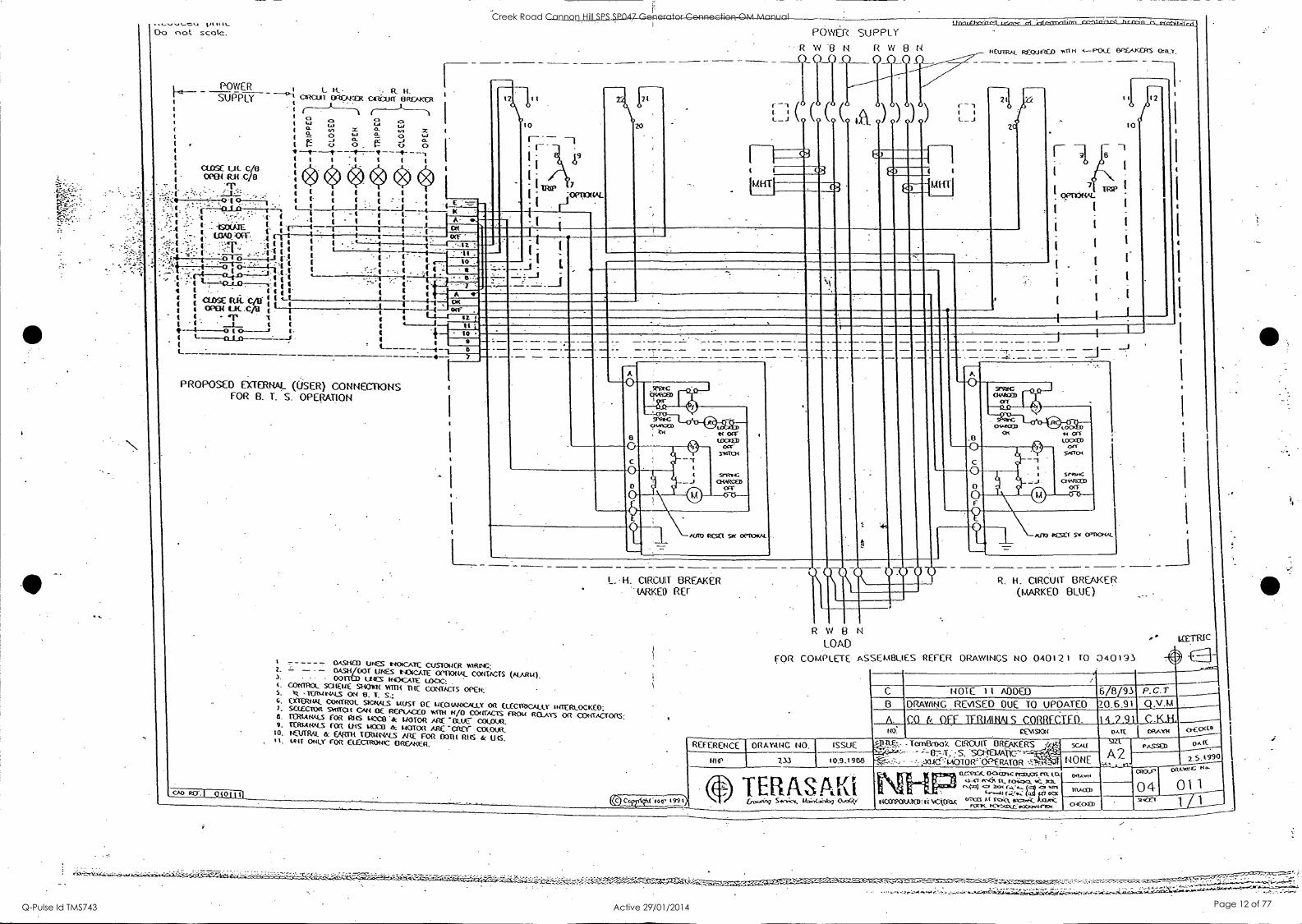
FOR COMPLETE ASSEmBuES REFER DRAWINGS NO 040t2i TO 040191
Q H. CIRCUIT BREAKER (1,4ARKE0 BLUE)
12
LfETRic
P. C T Q.V .TA
0 .9 .1 9 00
I t 9 Itt Ternec0oX CIRCUIT OREAKERS
etzzl";:s_ scc- :,X1.(Cr"--1AOTOR'OPERATOR
art,r_A_ 04:v0nc Taws ru. 34-1 ("Cik U.. rakon, r.ori 1.44 (0411
t4COVORMED: t: Nocktou ircz,4"<_ rant( 4c-.4-::-c:cc4w4-4-vo*
Creek Road Cannon Hill SPS SP047 Generator Connection OM Manual
Q-Pulse Id TMS743 Active 29/01/2014 Page 12 of 77

Operation and Maintenance Data Manual
Brisbane erwct
141ater ageftemt:
BRISBANE WATER
GENERATOR CONNECTION 0 & M Manual
Section 2
Parts list
Creek Road Cannon Hill SPS SP047 Generator Connection OM Manual
Q-Pulse Id TMS743 Active 29/01/2014 Page 13 of 77
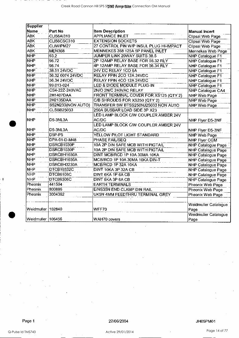
250 Amp Site
Supplier Name Part No Item Description Manual Incert ABK CLI56A1310 APPLIANCE INLET Clipsal Web Page ABK CLI56CSC310 EXTENSION SOCKETS Clipsal Web Page ABK CLIWIPM27 27 CONTROL PIN W/P INSUL PLUG HI-IMPACT Clipsal Web Page ABK MEN368 MENNEKES 368 125A 5P PANEL INLET Mennekes Web Page NHP 93.2 JUMPER LINK 20WAY SUITS 38.5 NHP Catalogue Fl NHP 96.72 2P 12AMP RELAY BASE FOR 56.32 RLY NHP Catalogue Fl NHP 96.74 4P 12AMP RELAY BASE FOR 56.34 RLY NHP Catalogue Fl NHP 38.51 24VDC 24V DC RELAY 1C0 6A
_. NHP Catalogue Fl
Catalogue Fl NHP Catalogue Fl
NHP 56.32 0074 24VDC RELAY FPIN CO 2- 12A 24VDC RELAY FPIN 4C0 12A 24VDC
1NHP NHP 56.34 24VDC NHP 99.013-024 LED & DIODE MODULE PLUG-IN NHP Catalogue Fl NHP CS4-22Z-240VAC 2N/0 2N/C 240VAC RELAY NHP Catalogue CA4 NHP 2H1407DAA FRONT TERMINAL COVER FOR XS125 (QTY 2) NHP Web Page NHP 2H2135DAA C/B SHROUDS FOR XS250 (QTY 2) NHP Web Page NHP BS2N233(NON AUTO) TRANSFER SW BTSS250NJ25033 NON AUTO NHP Web Page NHP CLSBB25033 250A BUSBAR LOAD SIDE 3P X23
NHP D5-3NL3A LED LAMP BLOCK CAN COUPLER AMBER 24V AC/DC NHP. Flyer D5-3NF
NHP D5-3NL3A LED LAMP BLOCK CAN COUPLER AMBER 24V AC/DC NHP Flyer D5-3NF
NHP D5P-P5 YELLOW PILOT LIGHT STANDARD NHP Web Page NHP DPA-01-D-M48 PHASE FAIUSEQ NHP Flyer CGM NHP DSRCB1030P 10A 2P DIN SAFE MCB WITH PIGTAIL NHP Catalogue Page NHP DSRCB1030P 10A 2P DIN SAFE MCB WITH PIGTAIL NHP Catalogue Page NHP DSRCBH1030A DINT MCB/RCD 1P 10A 30MA 10KA NHP Catalogue Page NHP 7
NHP DSRCBH1030A MCB/RCD 1P 10A 30MA 10KA DIN-T NHP Catalogue Page DSRCBH3230A . MCB/RCD 1P 32A 10KA NHP Catalogue Page
NHP DTCB10332C DINT 10KA 3P 32A CB NHP Catalogue Page NHP DTCB6106C DINT 6KA 1P 6A CB NHP Catalogue Page NHP DTCB6306C DINT 6KA 3P 6A CB NHP Catalogue Page Pheonix 441504 EARTH TERMINALS Pheonix Web Page Pheonix 800886 E/NS35N END CLAMP DIN RAIL Pheonix Web Page Pheonix 3004362 UK5N 4MM FEEDTHRU TERMINAL GREY Pheonix Web Page
Weidmuller 102840 WFF70 Weidmuller Catalogue Page
Weidmuller 106456 WAH70 covers Weidmuller Catalogue Page
Page 1 22/06/2004 JHO5PM01
Creek Road Cannon Hill SPS SP047 Generator Connection OM Manual
Q-Pulse Id TMS743 Active 29/01/2014 Page 14 of 77
Operation and Maintenance Data Manual
Brisbane aty Brisbane
WaterAW'rke:i
BRISBANE WATER
GENERATOR CONNECTION 0 & M Manual
Section 3
Asbuilt Drawings
Creek Road Cannon Hill SPS SP047 Generator Connection OM Manual
Q-Pulse Id TMS743 Active 29/01/2014 Page 15 of 77

Operation and Maintenance Data Manual
Eldsbane ady p .d WaterjagraQ
BRISBANE WATER
GENERATOR CONNECTION 0 & M Manual
Section 3A
Construction Markups
Creek Road Cannon Hill SPS SP047 Generator Connection OM Manual
Q-Pulse Id TMS743 Active 29/01/2014 Page 16 of 77
1
1 2
CC4411141JED FROM
SHEET 04
3 4
C-7...-t.0
5 6
21111010NISLIMIL
NOTES 1. CICIHODID PROT=0111 - FUTURE
(UT 10 BE SUPPLIED BY OHMS.
A 2400C oar s mum 10
come PROTECTION /REA MIK FOR comEcnot4 BY CIIHERS
2. TOON& NIMBI WS EITHER mcrwaELY
BELOW. WWI OR LEFT OF wow_
A
GHD 201 Mai* Sad %We, CPO Ba EN Woe. CID 031
Imo/ Tdefisale (L17) 3316 Mb Wale (07) 3316 ZVI
Eneit baselb:ffileam DOWERING Effila0IIIENt CID p g - I01 CO AO A3
B 021403 GENERATOR ADDED ALT.
A $/W96 AS BURT
Na DATE WOW
AMENDMENT & ISSUE REGISTER
DATE
DIRECTOR OF
lEOMOLOGY SERVICES
DATE
DIREaOR OF-
PLANING I DESIGN
DATE:
DIETOR OF
WATER SUPPLY
OATh
DRECTOR OF
CONSTRUCTION
DATE
2VIV% ENGINEER
I CHOSE
DRAWN 3/7/% SUFERVISING
EIMER
OM 8 POTE2/
ci
C, .)
LEGEND:
REIAY OR
CONTACTOR COIL
HELD
11:12. FUSE MINK Rill LIE TERMIKAL
SWITCHBOARD TEIVOIAL
(MIME PPATECRON
TERNINAL
RTUCUTALN'UT
RN DIGITAL OUTPUT
RTU ANALOG INPUT
EOUPMENT RN No.
A2 1 Nom
INEXPZES
CADD EU lb TIIS ORM16 WAS PRODUCED
USING AUTOCAD'
COPYRIGHT 1®6
in whale or in wlinal be ceased of
BREAM WY COUNCIL
BMW WATER
Brisbane Water_Mo
twaGeiENT Brisbane City pgassidtitug--ERNas
VW 4
In WI *3 Ilt 110 OKI 11// go 111II - - -.
III - - 11111/ WA RR OBI SKI
1 1 .
Of 11 1 .
110 -
If' --411 -NB
- VW
6
1111
!
a '
__
AM .411. .00
-
I V
_
a 4
,
WI
.11B 4SIN
WO
$ I I 60 -1I ON -Urn
.1110
6 6
V
IPA 01 -104 .16/6
6
-
I I .
- - 10 .411C .1
. sat
9 6 0
4 01 41-
.17116
.04
_
6 4
1 I 11
1011 .011 -KA
-OM ft .1161.
.1.1 .11 -11K
II
4 i 6
4
1 11
11
100 .111 .101 .1.10
6 II .
a
4 -
AO .01. PO1 40
6 6
1 ' -SIM .0C
a 6 .
at -at -10/ .1114
.11111
1 6 1
1
II
11111 .01. 401 .160
1
1 .
1
OW .111. .11111
PM 0 .1011
/
A
I.
011 .41L ' -NV
)
. I RN -Al 40 1 4 me -as
.1160
.KA
s 4 .
s ) .
WU .411 .10 .1011
a 6
16
.
WiEr A111110060
011 .
404 UV
.10 AA
II 11
0
11
11
1
OW .10 . 11
se ... -KA -101
s
.
i 11
. 110 -SIC
*AA 401
6 11
. 1111101111111 11010.10101
6 01 .1/6
.101 -VA -MK - MI
I 4 1 I 1
1
1
.
V
I 11
1
. 010 -1 , I &
A .11L -API
-6 1 a IS .11K
-KA 4 II
A 11
SC .1m 11 '10101
NIMINIPO
1111 .01 -04/1 .1/06 -MK
4 1 4 11
A li NB .1111
.K01 6 6
V 1
. 10 -10
.110 a
6 4
a
6 s
,tattasaa ..4A .11111 V
1 6
10 ..ga .10II ......megis
AK -AK
all 0106 .41K
.0111
-OA -IVO
-..
.
......................"-"'-'
1
/1
1
a
I -PA 6 6 -
a 6 -
VIA -0 -1 IIB1
a
6 6
g 11
A -06 . SAO I 03 -01
AI" .1116
a 11
1 4
i ,111
' 0 -OIL .041
6 1
a .KA 404
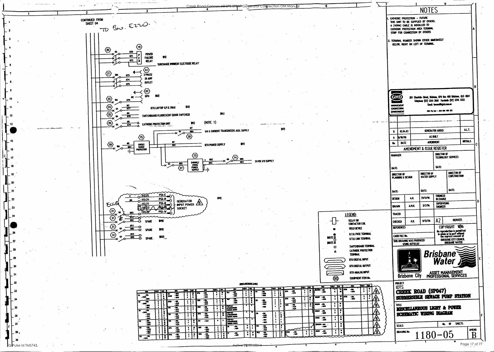
PROJECT
IDTS
WM ROAD (8P047) SUMS= SWAGE PUMP /MON
TiCINICLIANSOUS LIM & POIMI II SCHINATIC
SCALE k OF SHEETS
DRAWIIG b). 1180-05 a
D
E
Creek Road Cannon Hill SPS SP047 Generator Connection OM Manual
Q-Pulse Id TMS743 Active 29/01/2014 Page 17 of 77
1 2
ELV CONTROL
IELMS sj
4 LCP41,
_5
6
_7
6
9
10
11
12
h 13
14
15
smc
L C>
3 4
LOP (EN. SITE POWER 131
9613146E ININENT ALARM
LOCAL TOON
SITE ATTRITION ALMS 015E1 PURIBUTTON
73
PO IS
16 V
FROM 17 SICET OS LIE IC
18
19
r- 20 2
21
22
23
24
23
_26
27
_28
_29
111
IN
Itt
04
SHEET 07 LIE 3
- RTU OUTPUTS
31
32
33
" 07
34 > WAS
35 " 36
1311
IN
13/10_1___( ) SPARE
CATHODIC PROTECTION
CAME PROTECTION
CATHODIC PROTECTION
SPARE
SPARE
0103_( IS
0 IN
0 111
37 <c==s> wm 2
38
RTU
24Y DC ISHT
A q9 o
n U Ike
U V.2
I n
®
SPARE
SPARE
SPARE
ATTENTION ICTCATOR
ISWITOOARDI
24Y OCISHT Si
- CATHODIC PROTECTION
DE-ENERGISE
RECT1FER un
MET REFERENCE
ELECTRCOES
"3 CATHODIC PROTECTION ALARM
TOP
TOR
GENERATOR REMOTE
START
GENERATOR REMOTE
241Y AC RIM SUB-015TRIBUTION
BOARD
(Slit 5)
lAri AC FROM
SLO-DISTROUDON
BOARD
(sit 5)
WU LEN. 1104111131
NIL LEV°.
NOTE
1611
NUNN OR MUSK SOISOR
pumas;
21,0V AC CONTROL
5
LCR61 ® u 91001ARGE MIST
C 10 ALARM
653 al 91101/416EI1IENT 4 ELECTRODE
r-- EROTECTIOR MIT
WES Tr Si
RTU ANALOG INPUTS
FOR INSTRUMENTS
I I-2 °M
E-23-;-A
176 sA
I
L_P:'3.TA CATHODIC
PROTECTION
UNIT
DOTE 2 & SI
RTU ANALOG INPUTS
FOR CATHODIC PROTECTION
(Nam 2)
MCIVER OINTMENT
PLOW VOLTAGE
IN # ow.
REFERENCE ELECTRODE I PUMP No.1 t NUS. J FOE No2
Ni I REFERENCE ELECTRODE
118.. AIUS-
SPARE_
AMR
PO Am N 1 SPARE
IRSICUIREINIB
--o
MOD RaAY OR
COITACTOR COIL
FHD orni
VIM FERFOIAL
R.T.O. URI TETIOLIL
SWITOIBOARD MAUL CATHODIC PROTECTION
15211110/
DIU DOTAL INPUT
RN DOTAL OUTPUT
RN Alt41061111
NONIENT INN Na
NOTES AIMS t , WILE CMS ME Man MI
OLIECIPULA comma MUM. INEMINNINSPORGSAII 110110.1b.11 111101111115.3.2
COMMON 6101.01,1110.103:01113 '
MODE PROTECTION - RIME 1116 UNIT IS SUPPU1/ BY CDROM
RR/ VO 0816 6 1150 WIED 10 RIM CATHODIC PROTECT= 'ORDINAL STRP FOR
CCVNECTION BY ODUS.
NUMBER 9001 COFER IWIEDIVErf
DEUX RIGHT OR LEFT OF TERISOL
. NIL FUSED TERMS ARE 10 ETE RITED MTN 1001tA
FUSE -UNICS N= OTHERIRSE MOW
- ALL EQUIPIIDa SHOO 0011ED S RARE
ISO
201 Oak* Sbael, Mak WO Ba = Nam OD 4011
Idgkes (3))) 336 IRO hale {1013318 INT
lawall*LaaLla
OD IO OA - as OS as
B 02.04.03
A
No
AMENDMENT & ISSUE
MIXER
DATE
°RECTOR OF
PLANNING & 00301
DATE:
REGISTER
WHO OF .
TECTIOLO6Y.SERVICES
NIECTOR OF
WATER SIPPLY
DRAWN
TRACED
-XG CG-TS
CG-1.116) \ i
CONTROL
GT. I.S.......1 AST A CG-17
[ Ja ::) GE ) NESOCKREAT TI:RART (PART
- ....----.4)
AD
-9/121W'
XX AV VII A 9133 U its Ai UM 41 A IA Nes gar t al - spla in 1101
- Ali sat we
- I
a III A 30
-MO
NI.
3 1 133
On -11614 -1 -Ai
6 5 16
A ..al .160 -an
I .
..
V 4 .
1163 -011 .011 .01 .
1
4 .6
4 6
a .a. -A -IA
1
6 I I -int II
-0 -KA
3 1 1
ninitr.nr 4 I V
111 -In -WV 1
a -al .3 -lin -10
I 3
6 11
3
UM -411. -011 IN
fa -01. -44 -41 - -
- -NV .40
T
at .at -IA -.1 ow .1116
1
1
V
1
A .0 .1G
, i W -Si
-011 .
11
a 4 -al
.111 1
3
I 4
In -al -NA -an
S
.
4 I -
A .0 -A .165 . -
WAS 111111111 lainu
De -in -Ka -A
? 3
X 6140 .116. AM
3 it
le - 40 4 .0 .sas
1 I
3
ow -at -5/0 XX
6 1
A -in -KA . .
~IQ S unar a .at
11611 -ale -ma .iall
I 1 1
1
s 13
1
N1 -at .011
4 I I
_ap, -A .
4161 1 5
$ re .al
-up 6 - .
at -10 I 3 1411.1 461611111 alliataal
1 11 MIX 411.
-WA 1 s
02 -al -A -WO .1K
e II
MI -404. -WO 1
an -OIL -WV
Alt .1 1
PO -os. -Ili 1 I 1
-MOM -(11
I
-IWO I
MI AI -A 6 6 -
31
. VP .al -1
-an 6
a
-al -a,
,.____-..--
NU .ss -NI -IOC
4
1
---, i 6
140_ 1 3
1 I Ms -011.
1 .till 4
I I
.*=1......._,.............",
I. C1.-..... as -en 6
I a V
MS DRAWING WAS PRODUCED
USIT6 AUTOCAD 1,...-- Brisbane,
Water_Suio
Brisbane City PROFESSIONAL SERVICES ASSET MANAGEMENT
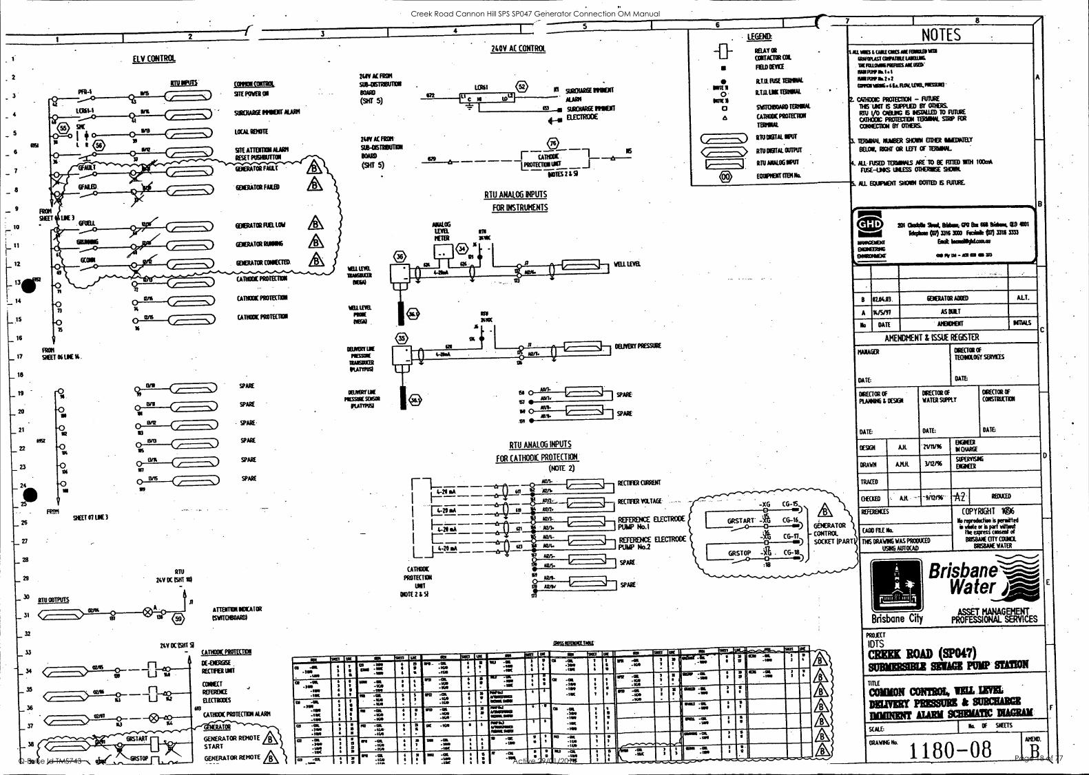
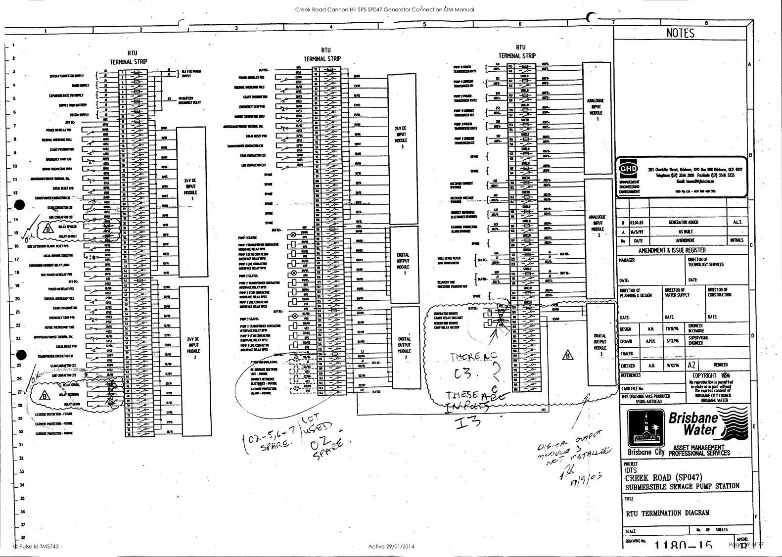
PROJECT
IDTS
CREEK ROAD WOO SUBMEMSMIX EMIFMa PUMP =ION
Creek Road Cannon Hill SPS SP047 Generator Connection OM Manual
Q-Pulse Id TMS743 Active 29/01/2014 Page 18 of 77
ea
1.4.J 1- C
D
N-§
cC
4 $
a. IN. a
ig
g N
............. ..............
11111 111111111111111111111111111101OMOON
11111111111111UNMMU IUMMINIMI
IEREBBIREIZIEBEIMIE
esest tstitStst
vs
isms amsascossaato staple
s
s
stessijT7_772,!!;
sl isl
If
151§61 IS
S516
1.;,!:t-,:ci, kliA
ji _47 j\it\
Win
r.'j
aalifilla i
I PP
NW
dila I im
p!
111111111111111 I
I SE
ISE'S!!
S
unann 1111111111111111111111111111111111111151111111111111111111111111111
1111111111111111INIM
IIIMM
UU
NIIIIIIII
P"1111111 IM
IER
ElitM
1111111g
1231:17122:1CIC
CE
CC
EIC
ZE
CE
1 O
XIM
MIC
11:11:11:11:10021:10:1121173130=1:1=
3:13MIL
ICIE
MO
GIC
KE
I
rPitsts estssts est titstststitsisim
(1) 111
414,210MO
RO
MIN
S L.,. 0,1 La.,.
V
V I I I I I
N
WI
0 0
N.
0 0
0
I I S
v I
cJJt J J 5 I
V
1-
V
14 A
a I
St X
St
Si R
9I
Creek Road Cannon Hill SPS SP047 Generator Connection OM Manual
Q-Pulse Id TMS743 Active 29/01/2014 Page 19 of 77
CIEBISSBE Calk magas bola** gale Sbadio651 116ra 6b011beet GlIniesk 666.111be is 11-11r mai lb a Alb sonad jib l4allG6 kw Irso filar adimularob dm =GA Woad Mrs al ens Ofellulkbia ISM NI gb teL
61* bob AId rirt idcOds tra Orb} IS Ea* sob Obi I.leM diet attipleoldwa ud *ad oak slam bur sahors.fr dap. alb 664 Gelbowle Wes* IOW
Ain Awe cm OM. talrel own al andig pods RMiRdi Irdnmeibesats
Bra/ Miles abiulbellro foGlaib. Shalltalegmligiablublvlbrio Ohl dadisbc liblIGIale sob altaielbalikadilaillab Sal Ode dap an NIT art la ISIGG4011*Or WOO
Inn Sdutri Oat Vat waders Wed air Alligtonts WallEaLla Wed& 111141611b4e Sidrk 111141/310 as labosel 111wftlbdt bka *MO air ral 64616111046.641611.106146 rds belabor kr Odic**
Jested Sleds: 111/49/146 Sdedrit sum lot as fit IWO rascal Mitubind 661111ras lb MOW pia 6611606bas fishilSbia Ism1164141
innartMenn Great 1 Frqpaq 6111builimi Masa IOW Iriaras 141boell Oki losibry *Saw L ie{ bend NOW Marl ORO fowilla bribe ol brit GI MIES& Nome holaboir ad Gednires
bryke CrOlos
Ica GI Sagregibm
Eartliq Spho
MSS /*alimeSblablbsenin. Sabss.04 al opal gib. dal* &salt al&plamllarbob. Swhon irehasteed bacanba %OAS till & AS 66eing
& NW ail dill elsor.lbaced amniumbibs, I abea alb duo
NOTES
kl AL Rik 461K GOV
SO ANS SY I so IPSIGAS
OS IV OS -JOG Ote OS 36
B 112.8413
Min I* kw I VIE
Gyll MOE OPIIATEDI 1111 mar calf komigvheertourosilbw COW MOVE OrPOSITS.16.1106tbew 0661166 Ai& ORM MS Wig pads. midden. dd. MSC kify 161.1121111
ilkiese Wig Ilidieu solaos7
If v irile X be fiCX. 111 UM Gab 4111 Owl beidet.
QOM adtoshesdalaOW WRrikapesaa.4trtalb dor bilks tlehielichor. riendsv* 66 aol breiablif 14104
swisisk pre-bsdaleihribleg4 Pow tag Pk aim Lbw drab/war asilibvtibb t a w Ned as MOW law. Um led Intrunialbs sip* I 4-21Mlipis wind's diddelpIr
Olinda Ilia 11.5apa Lilted al et al sq. beff albs Bibb Ebro bat Oars al lirpl boWers Wed ahlops Salk tab Ob.
lee amitibp WI legal bffshibit 6611 skin Wout Nabors ate readable %NO. bp Mar is dor
=5111-
LAM 106 TUr vaar Ma !IL IMMO IRMO seranrv
* ORLY AVSOINTICONIEL Ilma I
I OM MN lb& ISO& I
C Atei .16 SW 61011116111611111166.610166161
SWUM 116 VEIL= OISIEOLUNIRVIS OSUMI
be 114 /OM
0 NOSE 0106 661116 64111161101RE ME 160611.6114 SW
Ss Haar VW I
E 1116014V Ire 111 246 I
IF SOLT AMOY 00611116/1661606 Os Ila& 316124 I
Mewl bleb be 64.111grab stains do& find 4114 PO IS stales led ad* break
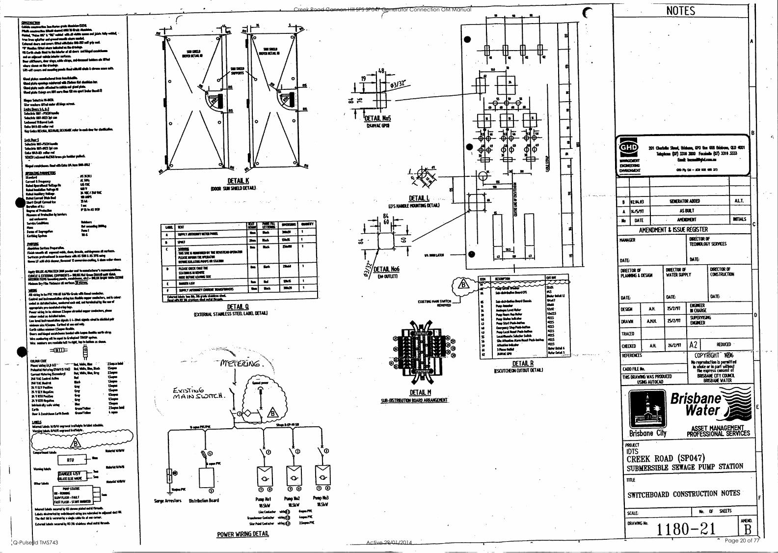
DETAIL 1:1
tEXT132NAL STAINLESS STEEL LABEL OETAL)
AMENDMD4T & ISSUE REGISTER
EIRELTOR OF
TECIRIOLOGY SERVICES
'DETAIL No6
OUTLET)
ttitaw OME
Obi bibs Meld own:9mm via id Sas SIG IA Owed 110/146enalaryl On.frq 24111/E Went Adie AM
NA EX Odra Mai
6 VELVPInibe fovr
I4 Yin Neeirse Grer
V RSV Parse Era 6 RP1 *Om loGriisirdr sok . 1116
Ealb beaffellw Dm 1 bcohbrawabob Enarldwr
HEN IESOWNO ORM
1314
SO-4debefins 64NOS KS behr Ikt6 I/
6 So.61,66. UN Ostia 6447
6 Pub /am* ltriwinleveltlefer
ibil X 12,6
hop bus Salk* 11 ISMS
4i kb Stabs bide GELS
II Pop Sad PGGIANGIsa as II laircySlopits44166 VW
I Pop WI &set Publatke GUS
S ladelist. Solider Soldo 41275
S4 Sim Mobs Mamba' *14441*.a 166
St Mtatir *duly 625
41 I haw 061* bier Odd 6
Q NM GPO *fir RIO S .,..
DEUR. R
OESCUTOON CUTOUT DETAIL)
DIRECTOR OF
PLANNING L DESIGN
DIRECTOR OF
WATER SUPPLY
DIRECTOR OF
CONSTRUCTION
INS DRAWRIG WAS PRODUCED
USING AUTOCAD
UMW W e n d l a b d s WON twang !rind'!" Wad *id&
ivtalels RNA enrael
RTU
Brisbane City
PROJECT
IDTS
CREEK ROAD (SP047) SUBMERSIBLE SEWAGE PUMP STATION
Mt SLOW
a - MOS SUN Ri91- fAtlf GAARAO -SzW MUD
I-
Wend tads mod ty ID *me Oaf sett taro&
Lids isbutal t ob, d4iile>R Nimbi IG sliabot *ad IL The **I I4; mond IT as:* bib*, al am arr. Wend bids banilb00 b **ass *deed 1606
0 0 0 0 0 0 Pump Nal Pump lig hap lid
SSW ;LW LWOW*/ viri0 rar.ric
Srasskraff Wady a** 4*. FIE
611 021,1 LS*INGINC
SWITCHBOARD CONSTRUCTION NOTES
SCALE: I Kt OF SOTS
POWER WIRING DETAIL
Creek Road Cannon Hill SPS SP047 Generator Connection OM Manual
Q-Pulse Id TMS743 Active 29/01/2014 Page 20 of 77
E
CC
1
11
RESERVE
PUMP STN. SITE
CREEK RD.
(REEK RD.
II PARK
N CIPY ST. ,"\-.ct
LOCALITY MAP
BROW [EXISTING)
CREEK STORM
WATER
LEGEND
BRIDGE
IEXISTINGI '
4, 4, W 4,
4/ W 4,
sa, W 4, CO,CRETXSL
IENTSTING s W MEDIAN. STRIP 4, se
'11 GRASSED AREA st, 4,
OhlATT LOCI(14 IRtSTAI /
REIM BO
ME.WAN ST Rie
GRASSED AREA 4,
>LIMP WELT
ACCESS
!EXISTING
IEXISTINGI IA iiii ..,'
9, II"
A1 , 1-,i1,r
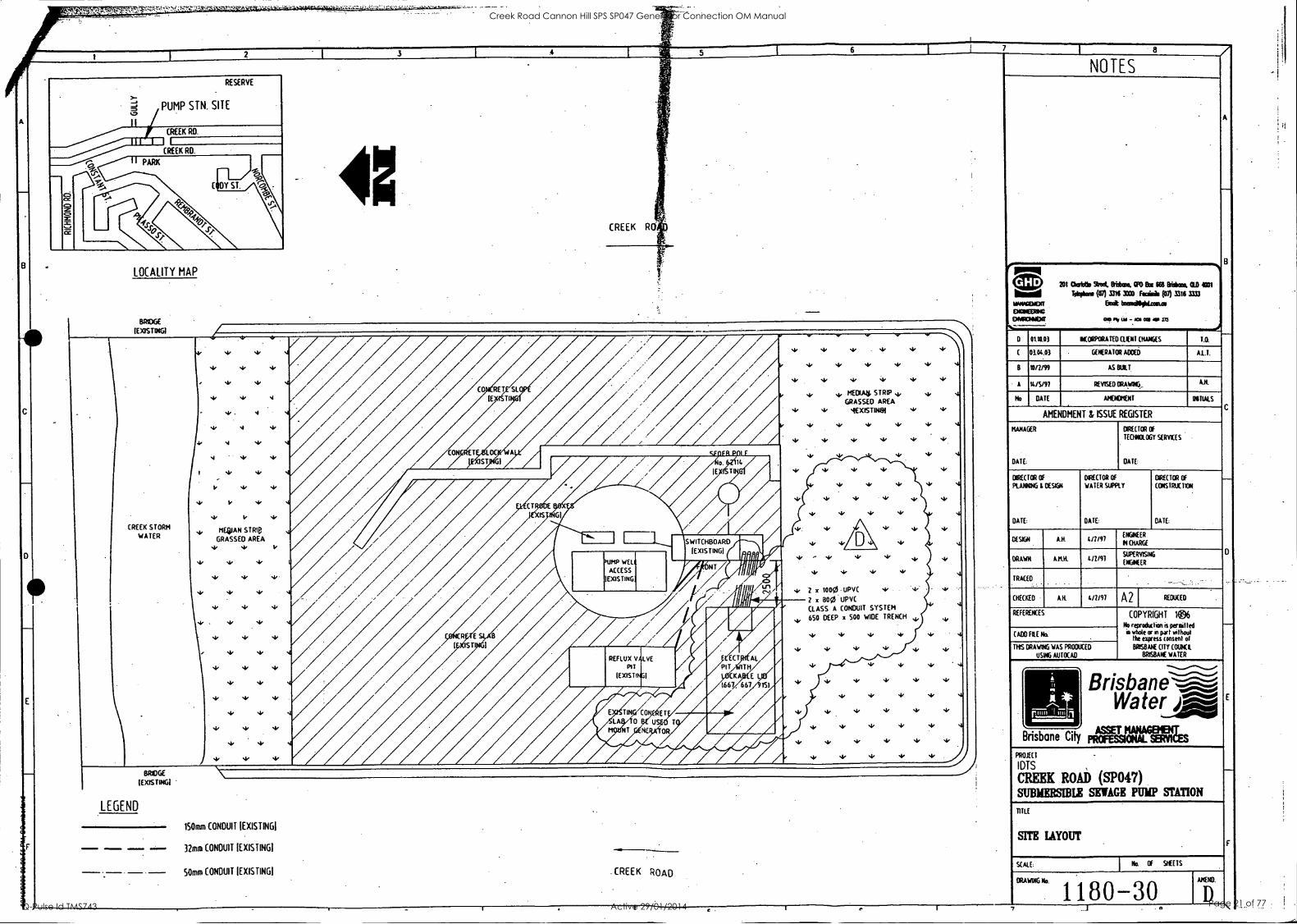
Allirdlisplin" st, 2 x 1000.- UPVC
2 x 800 UPVC
CLASS A CONDUIT SYSTEM
650 DEEP x SOO WIDE TRENCH 4.,
REFLUX VALVE PIT
!EXISTING'
TINyCONC,RET
LW 0 Or USE() T
NUAN9j605
150mm CONDUIT IEXISTINGI
32mm CONDUIT IEXISTINGI
50mm CONDUIT !EXISTING' CREEK ROAD
GHD
INNAGEMENT
ENGINEERING
EINGIONINLNE
NOTES
201 (21aristb Shot. BrisIcan, COG Eta 165 MMus 01.11 4001
*is* (07) 1316 XCO Arai (07) 3316 3131
Brat temaillmlitoseum
OOP om ma ma
0 0110.03 ItORPORA TED CLIENT CHANGES
0104.03 GENERATOR ADDED A.L.T.
B 10/2/99 AS BUILT
A 14/5/97 REVISED ORAWNG,
No DATE AMENDMENT INITIALS
AMENDMENT & ISSUE REGISTER
MANAGER
DATE:
DIRECTOR OF
TEORIOLOGY SERVICES
DATE:
DIRECTOR OF
PLANNING i DESIGN
DATE:
DO (TOR OF
WATER SUPPLY
DATE
DIRECTOR OF
CONSTRUCTION
DATE:
DESIGN 4/2/97 ENGINEER
II CHARGE
DRAWN AMR 4n191 SUPERVISING
ENGINEER
TRACED
CHECKED A.H. I 4/2/97 A2 REDUCED
REFERENCES
(ADD FILE No
THOS DRAWING WAS PRODUCED
USING AUTOCAD
COPYRIGHT 1
No reproduction is permitted in whole or in part without
the express consent at
BRISBANE CITY COUNCIL
BRISBANE WATER
Brisbane Water jloke __dad
' ASSET Brisbane City pRoFEssimALIW4A6esERIEs
PROJECT
I DTS
CUBIC ROAD (SP047) SUBMERSIBLE SEWAGE PUMP STATION
TITLE
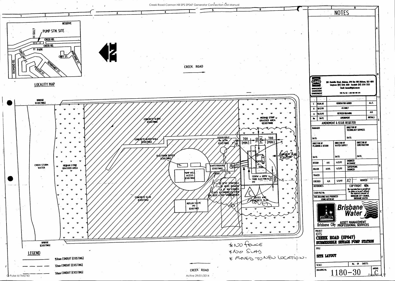
SITE LAYOUT
SCALE: I Na OF SHEETS
CRAWINGN° 1180-30 REND.
is
I
Creek Road Cannon Hill SPS SP047 Generator Connection OM Manual
Q-Pulse Id TMS743 Active 29/01/2014 Page 21 of 77
00-09T I
51336 JD VI I
1111 ONIAVIKI
:31V)S
MOM SIB
Jun
NOILUS &tad 1181811:111= (Ltoas) ON DWI
sial IBM
S331A213S 11/NOISSA02k1 OUNSI.18 IN3W39VNVILOSSY
3
nine) eM °Limps
VIM WON 101033 .U13 31116011
p prap3sasba raltfailrd4=1:91
9ES :1HERlic10)
.00311W 9msn 033103id SVA 911AV80 5141
.
S311343.431
a
3
a
1,61Z/1 NY 03903H)
ODUL
03380 3161143d115
1.61U, lfWY MAIO
300100111 1331903
LUZI, NY IfEE30
3111
NOLLTOILS193)
11311330
3110
Alia EOM 40 00L1330
,31.V0
1E633 1 911011Yld
00D390
3100
SIVAS A901011031
1) ammo
9110
039VW61
1131S193111SSI IN340,1310
1NMIGIV 31Y0 I 133
BIAY03 03S1A31 1.66/111 Y
1100 SY 664/6 8
TTY (900V 001103103 100191 )
ti
at sa. aux - se
..tWN738wal
annaan InkeWsPosi
- DOPONIMI
est sue (gal *Psi coot tut (84 searkpi was ILO GE lunlie 699 me OdS IN61111100 IOC
S31ON
OV08 )1338)
6)_2_194---xf) (-lacy c-v-A3
i9t411SI)(31 11110NO) agnOS
I9NIISIX31 IMO) tutla
INISIX31 IMO) tinnOSi
CIN3931
1*i snot 114
3A1YA X111:130
ONLLSD(3
SSIDV 314
OWN' )13320
dVW All1V301
z
Creek Road Cannon Hill SPS SP047 Generator Connection OM Manual
Q-Pulse Id TMS743 Active 29/01/2014 Page 22 of 77
Ca. 0 0
La
cu
0 E
-o
_o
0
-o 0
a)
zt-
0 0
C 0 CV CO CV
c's1 O
0
0 E E 0
C.)
. 15
Q. 0 0.
ffl
C
0
0
15
58
FRONT
H
-t
450
SIDE VIEW
CREEK RD
PAINT COLOUR
MATERIAL
(IF IN DOUBT, ASK.)
ROOF TYPE 2
ROOF SIDE VIEW
FALL OF ROOF
OVER 450mm
35
F 13
SIDE
0/HANG
CENORTOR ICOWIR
1420
EXISTING NEW SW/BD EXTENSION
d
C FRONT VIEW 495
160 D
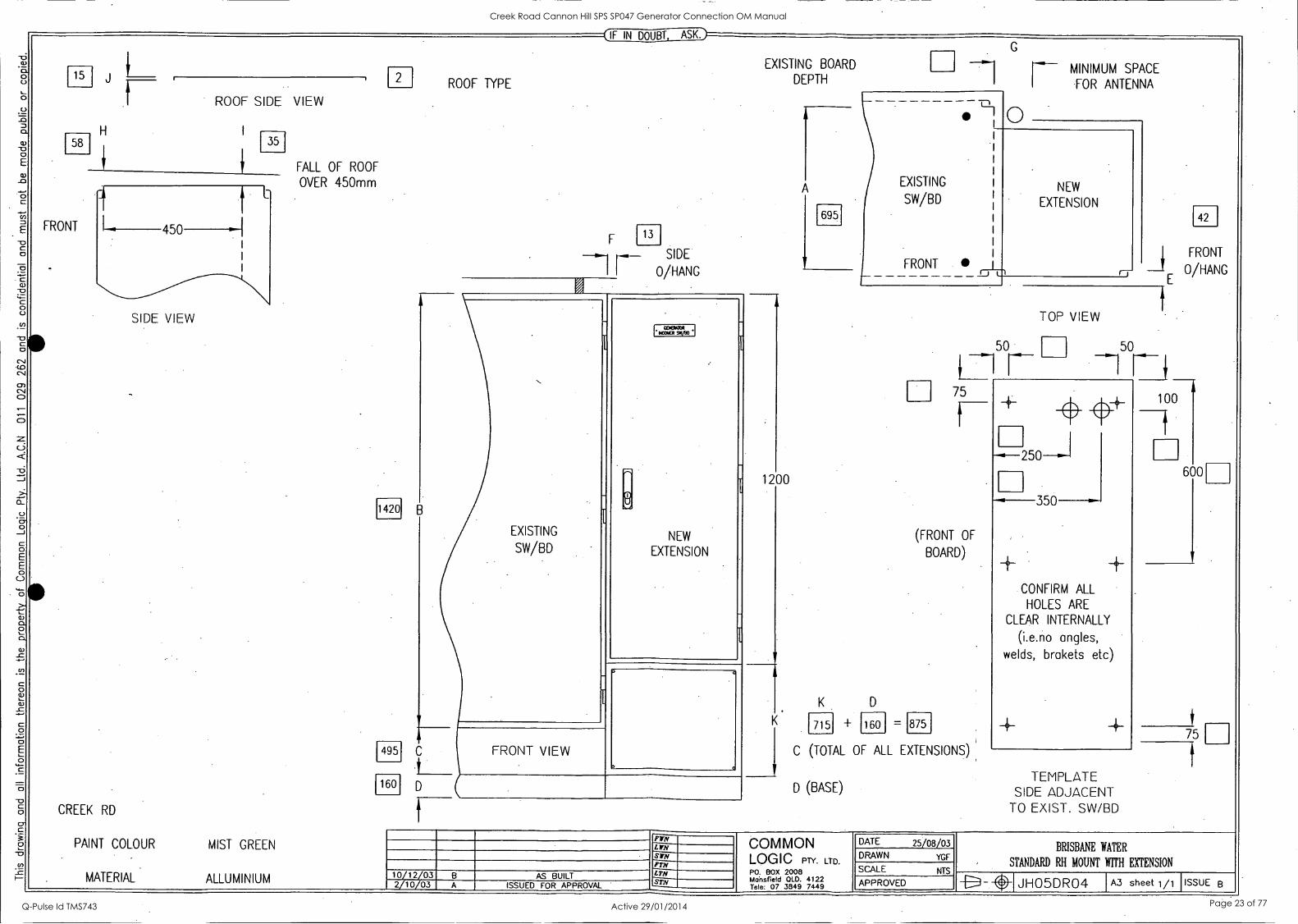
PlIN MIST GREEN LWN
SUN W771
ALLUMINIUM 10/12/03 B AS BUILT LTN
2/10/03 A ISSUED FOR APPROVAL STN
EXISTING BOARD
DEPTH
1200
695
EXISTING
SW/BD
FRONT
MINIMUM SPACE
FOR ANTENNA
NEW
EXTENSION
K D
K . 715 + 160 =
C (TOTAL OF ALL EXTENSIONS)
D (BASE)
42
--2 FRONT
E 0/HANG
TOP VIEW
75 100
(FRONT OF
BOARD)
875
350
CONFIRM ALL
HOLES ARE
CLEAR INTERNALLY
(i.e.no angles, welds, brakets etc)
-4-
TEMPLATE SIDE ADJACENT
TO EXIST. SW/BD
600
75
1
COMMON LOGIC PTY. LTD.
P0. BOX 2008 Mansfield OLD. 4122 Tele: 07 3849 7449
DATE 25/08/03
DRAWN YGF
SCALE NTS
APPROVED
BRISBANE WATER
STANDARD RH MOUNT WITH EXTENSION
JHO5DRO4 F sheet 1/1 ISSUE B
Creek Road Cannon Hill SPS SP047 Generator Connection OM Manual
Q-Pulse Id TMS743 Active 29/01/2014 Page 23 of 77
0. 0
0 7 0. a)
E
c_.
el
C -0 C 0
4=
0
C)
E
0
a) ca 2 a
rn
0 0)
C
0
O
0 CP
e. -v
I-
I.
390
Door Switch Bracket
BOTTOM VIEW
Light Bracket Screw on Perspex Shroud support angle
C T I ON D-D
1200
DOOR HEAT INSULATION
Note: Required only on external sites. Fix to door with studs.
or IN DOUBT, ASK
SECTION C -C
WAS COMM*
AVALLIM 0)111X5{ Bar at fICIIMIMS
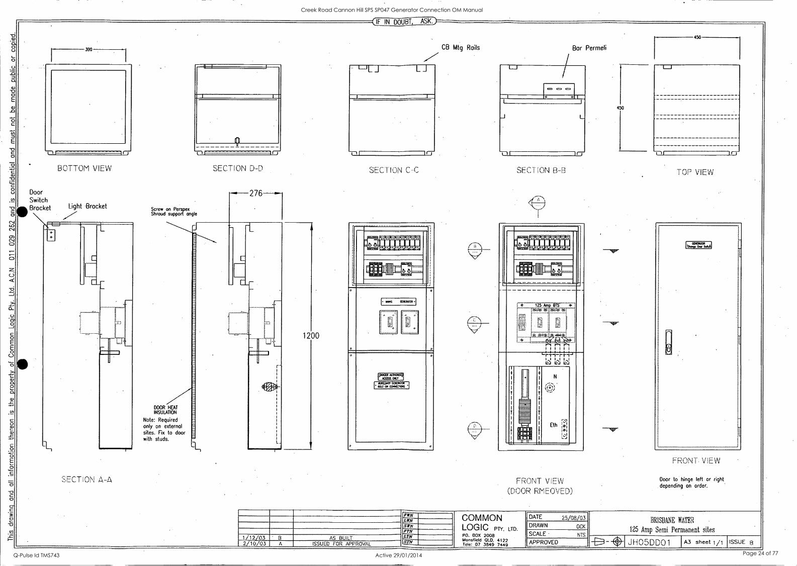
CB Mtg Rails Bar Permeli
SEC T ON B-B
*".'" Z9Z9a3a3Z82303a3 ..--6 611111E11N - FPEIRIPEE'REPIP
114 ill - !.1 PA I
+ 125 Am BTS +
;;x: .,"
i
;.,:;.;
4,7:i."4:1,-.t. -.4f4c1,
+ :------4041. t--1 r--1 r--t IIIIii IIIIII L. rT-i-rr-T I I I $ I I
CZJ Lt-J L'-
I
+
I
I
I
t I
1
NMI MI
I
+
I N
I ,...:-...
I V.,))
4.
1
I I
I I
irei ' I
1 Eth
:al rail U. I : NI
I
FRONT V Et.N
(DOOR RMEOVFn)
450
450
TOP VI E.ii
Maga! amp Owr Satoh
FRONT. VIEW
Door to hinge left or right depending on order.
PWN LWN srm Frrf
1 /12/03 ' 3 AS BUILT LTN STN 2/10/03 ISSUED FOR APPROVAL
COMMON LOGIC PTY. LTD. PO. BOX 2008 Mansfield OLD. 4122 Tele: 07 3849 7449
DATE 25108/03 DRAWN GCK
SCALE - NTS
APPROVED
BR1SBINE WATER
125 Amp Semi Permanent sites
J1-105DDO 1 A3 sheet 1/1 ISSUE 8
Creek Road Cannon Hill SPS SP047 Generator Connection OM Manual
Q-Pulse Id TMS743 Active 29/01/2014 Page 24 of 77

Operation and Maintenance Data Manual
BrisbaneCity
Brisbane %-.,.emiect INaterArigelad
BRISBANE WATER
GENERATOR CONNECTION 0 & M Manual
Section 4
Site Testing
Creek Road Cannon Hill SPS SP047 Generator Connection OM Manual
Q-Pulse Id TMS743 Active 29/01/2014 Page 25 of 77
COMMON LOGIC Pty Ltd Specialist Electrical Contractors Site Acceptance Tests
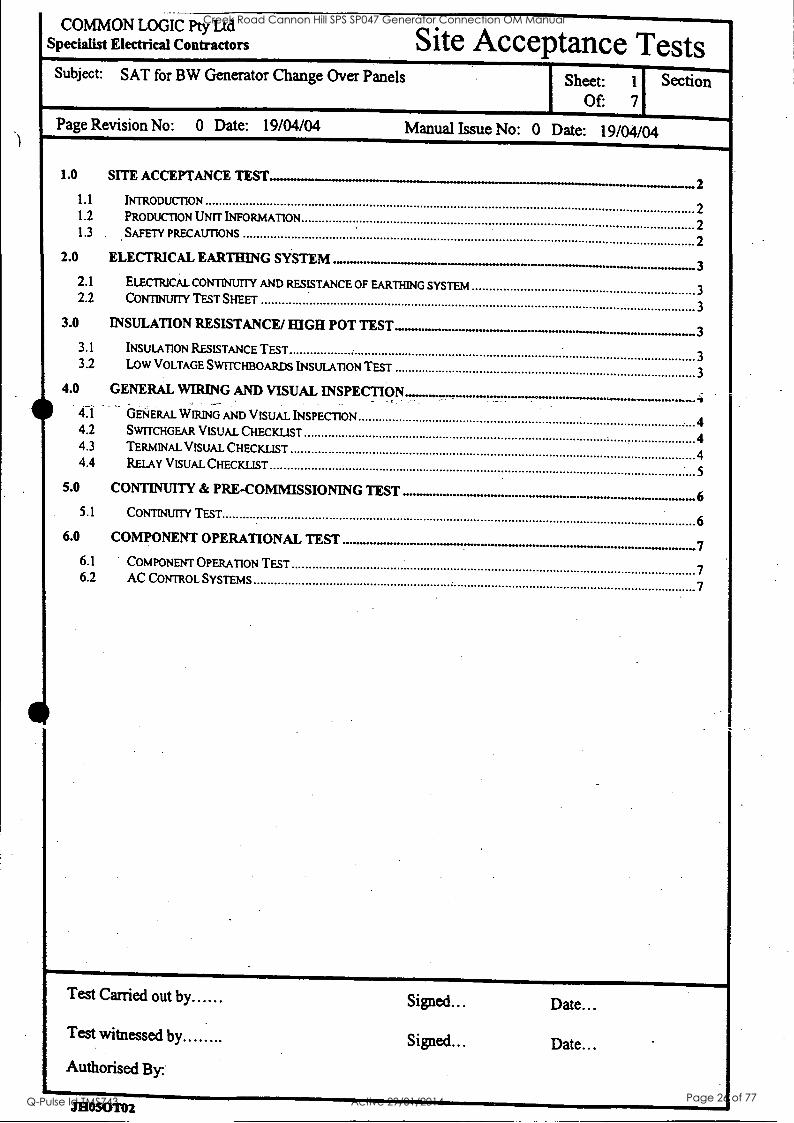
Subject: SAT for BW Generator Change Over Panels Sheet: 1 Section Of: 7
Page Revision No: 0 Date: 19104/04 Manual Issue No: 0 Date: 19104/04
1.0 SITE ACCEPTANCE TEST 2
- 1.1 INTRODUCTION
2 1.2 PRODUCTION UNIT INFORMATION
2 1.3 SAFETY PRECAUTIONS
2 2.0 ELECTRICAL EARTHING SYSTEM 000 .1.011. 3
2.1 ELECTRICAL CONTINUITY AND RESISTANCE OF EARTHING SYSTEM 3 2.2 CONTINUITY TEST SHEET
3
3.0 INSULATION RESISTANCE/ HIGH POT TEST 3 3.1 INSULATION RESISTANCE TEST
3 3.2 LOW VOLTAGE SWITCHBOARDS INSULATION TEST
3 4.0 GENERAL WIRING AND VISUAL INSPECTION
GENERAL WIRING AND VISUAL INSPECTION 4 4.2 SWITCHGEAR VISUAL CHECKLIST 4 4.3 TERMINAL VISUAL CHECKLIST 4 4.4 RELAY VISUAL CHECKLIST
5
5.0 CONTINUITY & PRE-COMMISSIONING TEST . 6 5.1 CONTINUITY TEST
6 6.0 COMPONENT OPERATIONAL TEST 7
6.1 COMPONENT OPERATION TEST 7 6.2 AC CONTROL SYSTEMS
7
Test Carried out by Signed... Date...
Test witnessed by Signed... Date... Authorised By
JHOSOTO2
Creek Road Cannon Hill SPS SP047 Generator Connection OM Manual
Q-Pulse Id TMS743 Active 29/01/2014 Page 26 of 77
COMMON LOGIC Pty Ltd Specialist Electrical Contractors Site Acceptance Tests
Subject: SAT for BW Generator Change Over Panels Sheet: 2 Section Of: 7
Page Revision No: 0 Date: 19/04/04 Manual Issue No: 0 Date: 19/04/04
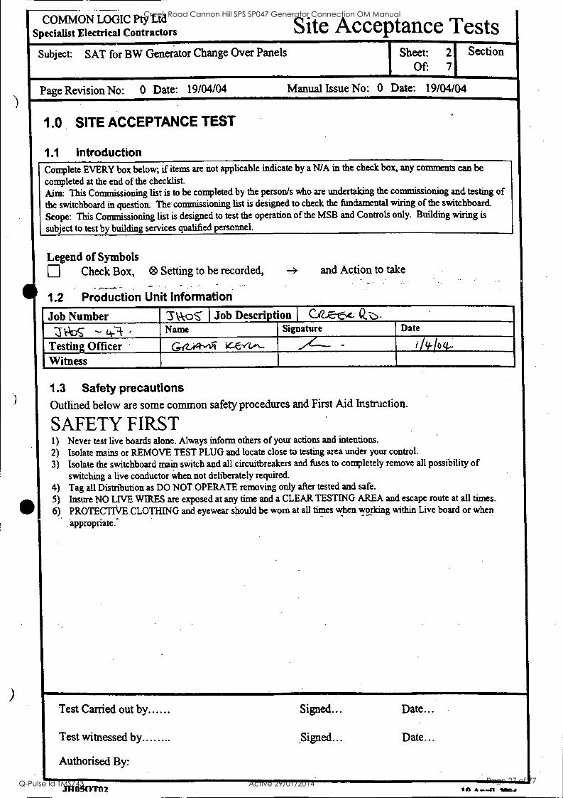
1.0 SITE ACCEPTANCE TEST
1.1 Introduction Complete EVERY box below; if items are not applicable indicate by a N/A in the check box, any comments can be completed at the end of the checklist. Aim: This Commissioning list is to be completed by the person/s who are undertaking the commissioning and testing of the switchboard in question. The commissioning list is designed to check the fundamental wiring of the switchboard.
Scope: This Commissioning list is designed to test the operation of the MSB and Controls only. Building wiring is
subject to test by building services qualified personnel.
Legend of Symbols Check Box, Setting to be recorded, -4 and Action to take
1.2 Production Unit Information
Job Number I\ AcoS I Job Description 1 e. Q.-. 6c. 'V DS - 1+-1- Name Signature Date
Testing Officer G-ez.A-vIR 4.E-iv-.. .."----- - iiliqp(- Witness _
1.3 Safety precautions Outlined below are some common safety procedures and First Aid Instruction.
SAFETY FIRST 1) Never test live boards alone. Always inform others of your actions and intentions.
2) Isolate mains or REMOVE TEST PLUG and locate close to testing area under your control.
3) Isolate the switchboard main switch and all circuitbreakers and fuses to completely remove all possibility of switching a live conductor when not deliberately required.
4) Tag all Distribution as DO NOT OPERATE removing only after tested and safe.
5) Insure NO LIVE WIRES are exposed at any time and a CLEAR TESTING AREA and escape route at all times. 6) PROTECTIVE CLOTHING and eyewear should be worn at all times when working within Live board or when
appropriate. a .
Test Carried out by Signed... Date...
Test witnessed by Signed... Date...
Authorised By:
Creek Road Cannon Hill SPS SP047 Generator Connection OM Manual
Q-Pulse Id TMS743 Active 29/01/2014 Page 27 of 77

COMMON LOGIC Pty Ltd Specialist Electrical Contractors Site Acceptance Tests
Subject: SAT for BW Generator Change Over Panels - Sheet: 3
Of: 7
Section
Page Revision No: 0 Date: 19/04/04 Manual Issue No: 0 Date: 19/04/04
2.0 ELECTRICAL EARTHING SYSTEM
2.1 Electrical continuity and resistance
R Maximum resistance of the Earthing
3000:2000) 0 Test resistance of the Earthing system
2.2 Continuity Test Sheet
of earthing system system within the switchboard
-,- -06--Q_ . ohms
is 0.5 ohms (AS/NZS
ITEM DETAIL COMPARTMENT DESIGNATION AND TEST RESULT Test resistance of Earthing system to
compartment Answer in Ohms Extension Main Eth Bar Generator
1 All Earth's wired and continuous - toi ,L.---... :..---
. s- 2 -All metal work earthed where required' -
3 Isolate Individual Earth Systems and check continuity.
,.--- _
",...0.-Z-7A)
3.0
3.1
Insulation (AS/NZS
3.2
MEGGAR INSTRUMENT
ACROSS
Join Red, Neutral,
INSULATION RESISTANCE/ HIGH POT TEST
Insulation Resistance Test resistance of whole or part of an installation must
3000:2000) Insulation test conducted on all internal circuits
All Selector Switches, Isolators and CB's are in the off All electronic equipment susceptible to high voltage damage
Low Voltage Switchboards Insulation Test
VOLTAGE too.° '1/4/ VOLTS
be a minimum
position
of 1 Meg/ohm
to be isolated.
High Pot
DETAILS `101..S-08-0
White & Blue Phases and TeSt to Earth
RESULT (M.OHN/1)
N 400 cost_ Red Phase to White, Blue & N > L. f.0 o don st, White Phase to Red, Blue and N > 4-oem _cl.
Blue Phase to Red, White & N > 4-oofel SI...
N to Red, White & Blue 5 4.0o al SI .
Test Carried out by grEE 4rw, . lk Signed... Date...
Test witnessed by Signed... Date...
Authorised By:
----
Creek Road Cannon Hill SPS SP047 Generator Connection OM Manual
Q-Pulse Id TMS743 Active 29/01/2014 Page 28 of 77
COMMON LOGIC Pty Ltd Specialist Electrical Contractors
Subject: SAT for BW Generator Change Over Panels
Site Acceptance Tests Sheet: 4 Section
Of: 7
Page Revision No: 0 Date: 19/04/04 Manual Issue' o: 0 Date: 19/04/04
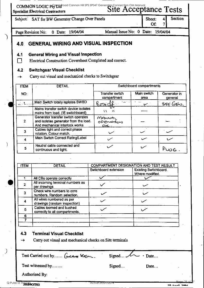
4.0. GENERAL WIRING AND VISUAL INSPECTION
4.1 General Wiring and Visual Inspection Electrical Construction Coversheet Completed and correct.
4.2 Switchgear Visual Checklist --> Carry out visual and mechanical checks to Switchgear
ITEM
NO:
DETAIL Switchboard compartments
Transfer switch compartment
Main switch area
Generator in general
4 Main Switch totally isplates SW SD St-f- GC-s,3- Mains transfer switch device isolates mains from load. (IE switchboard)
\ ll k
2 Generator transfer switch operates and isolates generator from the load. And mechanical interlock works
fyliq),,,Vh.., op e,,,,a-iti..,
OK- - -
3 Cables tight and correct phase rotation. Colour match. --.
4 Main Switch Correct Rating/Label 1/4.--- L.----
5 Neutral cable connected and continuous and tight.
%./- PLO G .
ITEM DETAIL COMPARTMENT DESIGNATION AND TEST RESULT Switchboard extension Existing Switchboard.
Where modified. 1 All CBs operate correctly 1/4/ 1/4/-
2 All incoming terminal numbers as per drawings .....-
3 Check wire numbers to core numbers. Random selection. ../ 1/4/
4 All wires numbered as per '
drawings (random inspection) ;../
Cables loomed and bushed correctly to all compartments.
k/- 6 7
4.3 Terminal Visual Checklist -* Carry out visual and mechanical checks on Site terminals
Test Carried out by GA Signed...., Date...
Test witnessed by Signed... Date...
Authorised By:
Creek Road Cannon Hill SPS SP047 Generator Connection OM Manual
Q-Pulse Id TMS743 Active 29/01/2014 Page 29 of 77
COMMON LOGIC Pty Ltd Specialist Electrical Contractors Site Acceptance Tests
Subject: SAT for BW Generator Change Over Panels
Page Revision No: 0 Date: 19/04/04
Sheet: 51-Sea---= Of: 7
Manual Issue No: 0 Date: 19/04/04
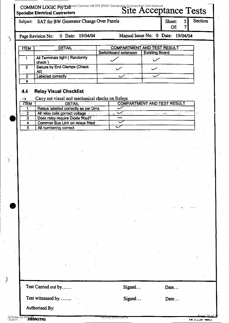
ITEM DETAIL COMPARTMENT AND TEST RESULT Switchboard extension Existing Board
1 All Terminals tight ( Randomly check )
4./ 2 Secure by End Clamps (Check
All) ,..---
3 Labelled correctly N./ .../ 4
4.4 Relay Visual Checklist al checks on Relays
ITEM DETAIL COMPARTMENT AND TEST RESULT 1 Relays labelled correctly as per Dms
- 2 All relay coils_correct voltage..- _..-..
3 Does relay require Diode fitted? 4 Common Bus Link on relays fitted %.../-
5 All numbering correct
. Test Carried out by Signed... Date...
Test witnessed by Signed... Date...
Authorised By
Creek Road Cannon Hill SPS SP047 Generator Connection OM Manual
Q-Pulse Id TMS743 Active 29/01/2014 Page 30 of 77
U)MMON LOGIC Pty Ltd Specialist Electrical Contractors Site Acceptance Tests
Subject: SAT for BW Generator Change Over Panels
Page Revision No: 0 Date: 19/04/04
Sheet: 6 Of: 7
Manual Issue No: 0 Date: 19/04/04
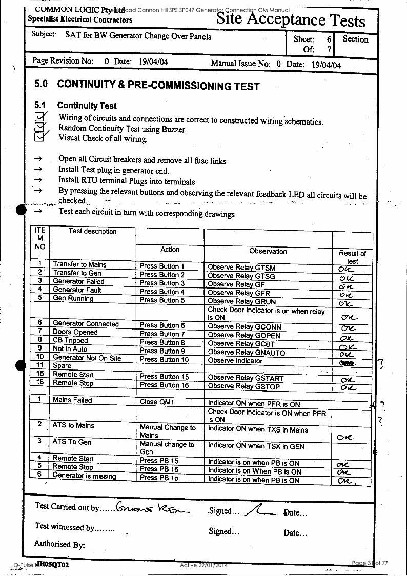
5.0 CONTINUITY & PRE -COMMISSIONING TEST
5.1 Continuity Test [j" Wiring of circuits and connections are correct to constructed wiring schematics. Er Random Continuity Test using Buzzer.
Visual Check of all wiring.
-> Open all Circuit breakers and remove all fuse links -> Install Test plug in generator end. --> Install RTU terminal Plugs into terminals -> By pressing the relevant buttons and observing the relevant feedback LED all circuits will be
-+ Test each circuit in turn with corresponding drawings
ITE M
NO .
Test description
Action Observation Result of test 1 Transfer to Mains Press Button 1 Observe Relay GTSM 012_ 2 Transfer to Gen Press Button 2 Observe Relay GTSG c.) tz., 3 Generator Failed Press Button 3 Observe Relay GF oet. 4 Generator Fault Press Button 4 Observe Relay GFR vit. 5 Gen Running Press Button 5 Observe Relay GRUN G
Check Door Indicator is on when relay is ON OW-
6 Generator Connected Press Button 6 Observe Relay GCONN 7 Doors Opened Press Button 7 Observe Relay GOPEN V1e- 8 CB Tripped Press Button 8 Observe Relay GCBT 0 ie.- 9 Not in Auto . Press Button 9 Observe Relay GNAUTO ovf.... 10 Generator Not On Site Press Button 10 Observe Indicator CM* 11 Spare - 15 Remote Start Press Button 15 Observe Relay GSTART 16 Remote Stop Press Button 16 Observe Relay GSTOP 064-
1 Mains Failed Close QM1 Indicator ON when PFR is ON 6.
Check Door Indicator is ON when PFR is ON
2 ATS to Mains Manual Change to Mains
Indicator ON when TXS in Mains 0 K- 3 ATS To Gen Manual change to Gen
Indicator ON when TSX in GEN
4 Remote Start Press PB 15 Indicator is on when PB is ON ' OK- 5 Remote Stop Press PB 16 Indicator is on When PB is ON Mt_ 6 Generator is missing Press PB 10 Indicator is on when PB is ON OK- ,
Test Carried out by Signed...
Test witnessed by ......
Authorised By:
Signed... Date...
JHOSQT02
Creek Road Cannon Hill SPS SP047 Generator Connection OM Manual
Q-Pulse Id TMS743 Active 29/01/2014 Page 31 of 77
COMMON LOGIC Pty Ltd Specialist Electrical Contractors
Subject: SAT for BW Generator Change Over Panels
Site Acceptance Tests Sheet: 7
Of: 7
Page Revision No: 0 Date: 19/04/04 Manual Issue No: 0 Date: 19/04/04
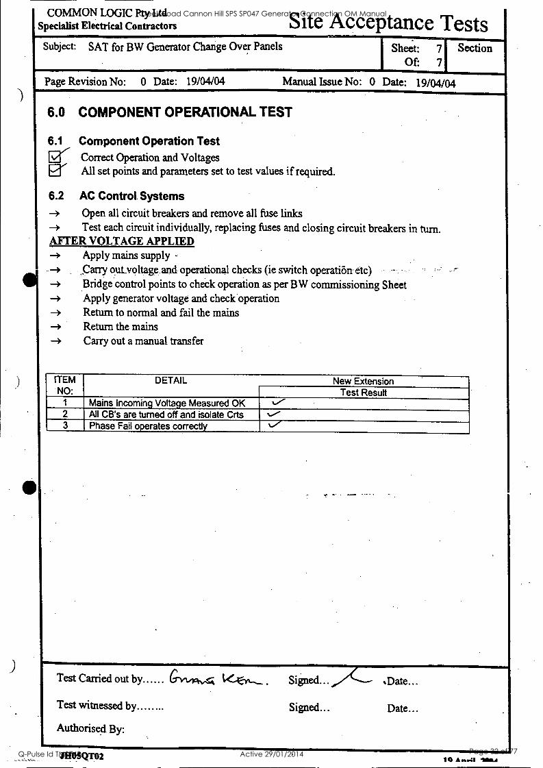
6.0 COMPONENT OPERATIONAL TEST
6.1 Component Operation Test Eg Correct Operation and Voltages Er All set points and parameters set to test values if required.
6.2 AC Control. Systems -> Open all circuit breakers and remove all fuse links -> Test each circuit individually, replacing fuses and closing circuit breakers in turn. AFTER VOLTAGE APPLIED -> Apply mains supply
Carry outyoltage and operational checks (ie switch operation etc) --
-> Bridge control points to check operation as per BW commissioning Sheet -> Apply generator voltage and check operation
Return to normal and fail the mains -> Return the mains -> Carry out a manual transfer
ITEM NO:
DETAIL New Extension Test Result
1 Mains Incoming Voltage Measured OK %./- 2 All CB's are turned off and isolate Crts %./ 3 Phase Fail operates correctly ,./
Test Carried out by GYx4=KA
Test witnessed by
Authorised By:
.Date...
Signed... Date...
JHOSQT02 10 A ...:1 111111k4
Creek Road Cannon Hill SPS SP047 Generator Connection OM Manual
Q-Pulse Id TMS743 Active 29/01/2014 Page 32 of 77

Brisbane Cfty WaterAkita"FQ
BRISBANE WATER
GENERATOR CONNECTION 0 & M Manual
Section 4A
Site Testing Functional Description
Creek Road Cannon Hill SPS SP047 Generator Connection OM Manual
Q-Pulse Id TMS743 Active 29/01/2014 Page 33 of 77
Sewerage System Performance Improvements
a
Brisbane City
Backup Diesel Generators for Pump Stations
Brisbane Water ),,V,
PROJECTS - ENGINEERING
Sewerage System Performance Improvements Backup Diesel Generators for Pump Stations
FUNCTIONAL SITE TESTS FOR GENERATOR, AUTOMATIC TRANSFER SWITCH, AND RTU
Prepared by
Document ID
Date of Issue
Revision
Alan Mooney Telephone - 07 3403 3356 Facsimile - 07 3403 0205
Genset Functional Tests
June 2003
Rev 1
C:\Documents and Settings\CM2IBW\Local Settings\Temp\Genset Functional Tests Revl .doc 1
Creek Road Cannon Hill SPS SP047 Generator Connection OM Manual
Q-Pulse Id TMS743 Active 29/01/2014 Page 34 of 77
Sewerage System Performance Improvements Backup Diesel Generators for Pump Stations
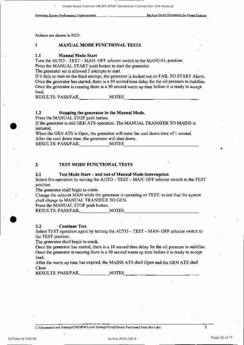
Actions are shown in RED
1 MANUAL MODE FUNCTIONAL TESTS
1.1 Manual Mode Start Turn the AUTO - TEST - MAN- OFF selector switch to the MANUAL position. Press the MANUAL START push button to start the generator. The generator set is allowed 3 attempts to start. If it fails to start on the third attempt, the generator is locked out on FAIL TO START Alarm. Once the generator has started, there is a 10 second time delay for the oil pressure to stabilise. Once the generator is running there is a 30 second warm up time before it is ready to accept load. RESULTS: PASS/FAIL NOTES
1.2 Stopping the generator in the Manual Mode. Press the MANUAL STOP push button. If the generator is still GEN ATS operation. The MANUAL TRANSFER TO MAINS is initiated. When the GEN ATS is Open, the generator will enter the cool down time of 1 second. After the cool down time, the generator will shut down. RESULTS: PASS/FAIL NOTES
2 TEST MODE FUNCTIONAL TESTS
2.1 Test Mode Start - and test of Manual Mode interruption Select this operation by turning the AUTO - TEST - MAN- OFF selector switch to the TEST position. The generator shall begin to crank. Change the selector MAN while the generator is operating on TEST: to test that the system shall change to MANUAL TRANSFER TO GEN. Press the MANUAL STOP push button. RESULTS: PASS/FAIL NOTES
2.2 Continue Test Select TEST operation again by turning the, AUTO - TEST - MAN- OFF selector switch to the TEST position. The generator shall begin to crank. Once the generator has started, there is a 10 second time delay for the oil pressure to stabilise. Once the generator is running there is a 30 second warm up time before it is ready to accept load. After the warm up time has expired, the MAINS ATS shall Open and the GEN ATS shall Close RESULTS: PASS/FAIL NOTES
C: \Documents and Settings\CM2IBW\Local Settings\Temp\Genset Functional Tests Revl .doc 2
Creek Road Cannon Hill SPS SP047 Generator Connection OM Manual
Q-Pulse Id TMS743 Active 29/01/2014 Page 35 of 77

Sewerage System Performance Improvements Backup Diesel Generators for Pump Stations
2.3 Stopping Generator In The Test Mode - To Test Mains Failure /Genset Restart During Shutdown
Select this operation by turning the AUTO - TEST - MAN- OFF selector switch to the AUTO or OFF position. The GEN ATS shall Open and the MAINS ATS shall Close When the GEN ATS is Open, the generator will enter the cool down time of 5 minutes.
During this time turn off the Mains to the site When Mains Failure occurs during the cool down period the generator shall transfer back to the GENERATOR ATS without shutting down. RESULTS: PASS/FAIL NOTES
2.4 Stopping generator in the Test Mode. Select this operation by turning the AUTO - TEST - MAN- OFF selector switch to the AUTO or OFF position. The GEN ATS shall Open and the MAINS ATS shall Close After the cool down time of 5 minutes, the generator will shut down. RESULTS: PASS/FAIL NOTES
2.5 Test Mode Selected with genset unavailable (fault or GEN CB off). Make GENSET unavailable Select this operation by turning the AUTO - TEST - MAN- OFF selector switch to the TEST position. Observe results - Genset discussion of preferred results (unit should not start?) RESULTS: PASS/FAIL NOTES
3 AUTOMATIC MODE FUNCTIONAL TESTS
3.1 Automatic Start Select this operation by turning the AUTO - TEST - MAN- OFF selector switch to the AUTO position. Turn off the Mains to the switchboard. The Phase Failure Relay from the clients switch board shall give a Start Signal for the generators to run. Once the generator has started, there is a 10 second time delay for the oil pressure to stabilise. Once the generator is running there is a 30 second warm up time before it is ready to accept load. After the warm up time has expired, the MAINS ATS shall Open and the GEN ATS shall Close. RESULTS: PASS/FAIL NOTES
C:\Documents and Settings\CM2IBW\Local Settings\Temp\Genset Functional Tests Revl.doc 3
Creek Road Cannon Hill SPS SP047 Generator Connection OM Manual
Q-Pulse Id TMS743 Active 29/01/2014 Page 36 of 77

Sewerage System Performance Improvements Backup Diesel Generators for Pump Stations
3.2 Stopping the generator in the Auto Mode -and testing genset restart for mains failure during cool-down.
Turn on the Mains to the switchboard The Phase Failure Relay from the clients switch board shall give a Stop Signal for the generator There is a 2 minute proving time for the Phase Failure Relay. After the 2 minute proving time the GENATS shall Open and the MAINS ATS shall Close When the GEN ATS is Open, the generator will enter the cool down time of 5 minutes.
During this time turn off the Mains to the site When Mains Failure occurs during the cool down period the generator shall transfer back to the GENERATOR ATS without shutting down. RESULTS: PASS/FAIL NOTES
3.3 Stopping the generator in the Auto Mode - continued. Turn on the Mains to the switchboard The Phase Failure Relay from the clients switch board shall give a Stop Signal for the generator There is a 2 minute proving time for the Phase Failure Relay. After the 2 minute proving time the GEN ATS shall Open and the MAINS ATS shall Close When the GEN ATS is Open, the generator will enter the cool down time of 5 minutes. After the cool down time, the generator will shut down. RESULTS: PASS/FAIL NOTES
3.4 Automatic ATS Transfer To Genset- Mains ATS Failure Disable MAINS ATS CB Restart the generator in Auto by turning off the Mains The MAINS ATS will fail to Open: After a 5 second delay an Alarm shall be generated and the MAINS CONNECTED indicator shall flash to indicate the Alarm. The system shall then return back to MAINS ATS operation. Stop the generator using the Stop button RESULTS: PASS/FAIL NOTES
3.5 Automatic ATS Transfer - Gen ATS Failure Re-enable the MAINS ATS CB Disable GEN ATS CB Restart the generator in Auto by turning off the Mains The GEN ATS will fail to Close: After a 5 second delay an Alarm shall be generated and the GENERATOR CONNECTED indicator shall flash to indicate the Alarm. The system shall return back to MAINS ATS operation. Stop the generator using the Stop button RESULTS: PASS/FAIL NOTES
C:\Documents and Settings\CM2IBW\Local Settings\Temp\Genset Functional Tests Revl.doc 4
Creek Road Cannon Hill SPS SP047 Generator Connection OM Manual
Q-Pulse Id TMS743 Active 29/01/2014 Page 37 of 77

Sewerage System Performance Improvements Backup Diesel Generators for Pump Stations
3.6 Automatic ATS Transfer To Mains - Gen ATS Failure Disable GEN ATS CB Restart the generator in Auto by turning of the Mains The GEN ATS will fail to Open. After a 5 second delay an Alarm shall be generated and the GENERATOR CONNECTED indicator shall flash to indicate the Alarm. The system shall return back to GEN ATS operation. Stop the generator using the Stop button RESULTS: PASS/FAIL NOTES
3.7 Automatic ATS Transfer To Mains - Mains ATS Failure Re-enable the GEN ATS CB Disable MAINS ATS CB Restart the generator in Auto by turning off the Mains The MAINS ATS will fail to Close. After a 5 second delay an Alarm shall be generated and the MAINS CONNECTED indicator shall flash to indicate the Alarm. The system shall return back to GEN ATS operation. RESULTS: PASS/FAIL NOTES
3.8 Running in Auto and umbilical looses connection. Select this operation by turning the AUTO - TEST - MAN- OFF selector switch to the AUTO position. Turn off the Mains to the switchboard. The Phase Failure Relay from the clients switch board shall give a Start Signal for the generators to run. Once the generator has started, there is a 10 second time delay for the oil pressure to stabilise. Once the generator is running there is a 30 second warm up time before it is ready to accept load. After the warm up time has expired, the MAINS ATS shall Open and the GEN ATS shall Close. Remove umbilical plug Observe results - Genset discussion of preferred results (ATS returns to MAINS?) RESULTS: PASS/FAIL NOTES
3.9 Running in Auto and genset trips or faults. Select this operation by turning the AUTO - TEST - MAN -.OFF selector switch to the AUTO position. Turn off the Mains to the switchboard. The Phase Failure Relay from the clients switch board shall give a Start Signal for the generators to run. Once the generator has started, there is a 10 second time delay for the oil pressure to stabilise. Once the generator is running there is a 30 second warm up time before it is ready to accept load. After the warm up time has expired, the MAINS ATS shall Open and the GEN ATS shall Close. Cause Genset trip or fault Observe results - Genset discussion of preferred results (ATS returns to MAINS?) RESULTS: PASS/FAIL NOTES
C:\Documents and Settings\CM2IBW\Local Settings\Temp\Genset Functional Tests Revl.doc 5
Creek Road Cannon Hill SPS SP047 Generator Connection OM Manual
Q-Pulse Id TMS743 Active 29/01/2014 Page 38 of 77
Sewerage System Performance Improvements Backup Diesel Generators for Pump Stations
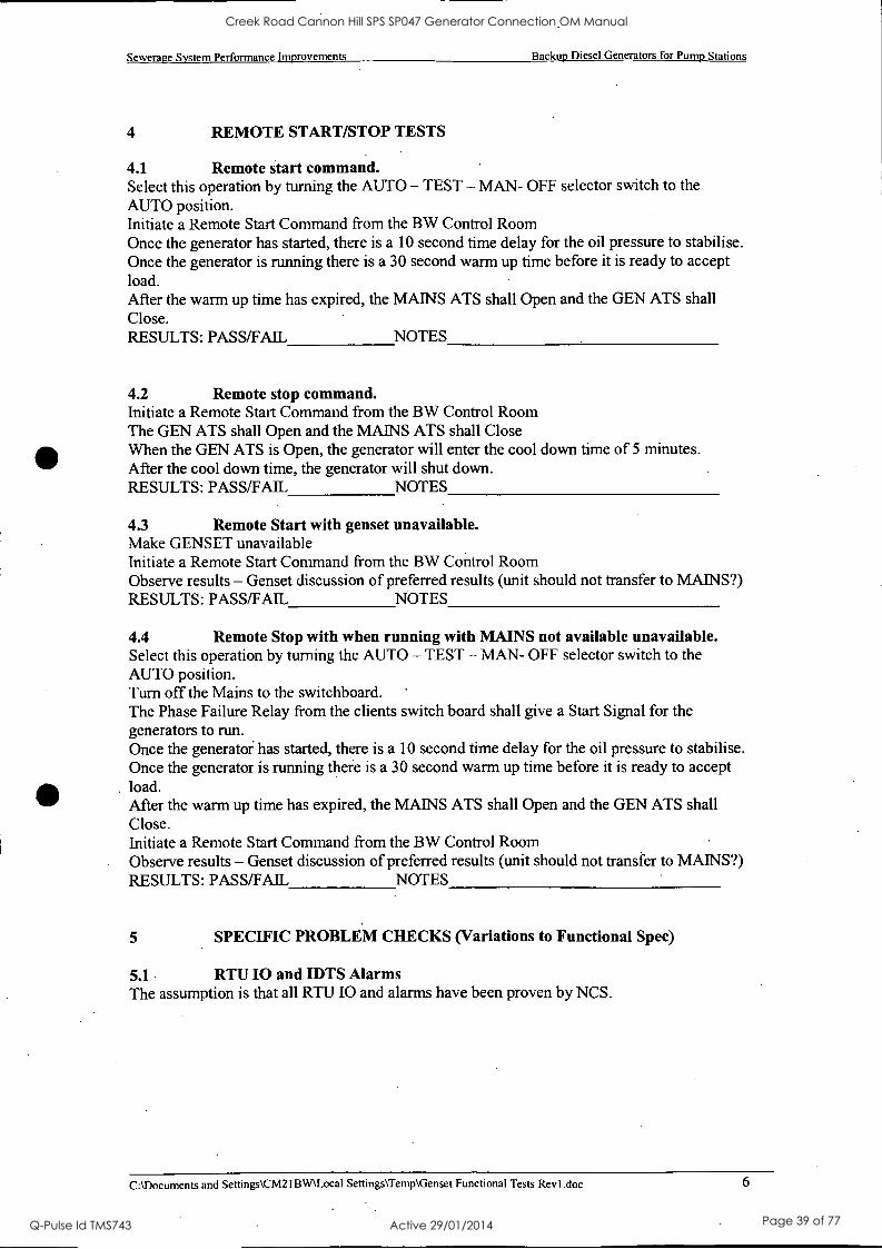
4 REMOTE START/STOP TESTS
4.1 Remote start command. Select this operation by turning the AUTO - TEST - MAN- OFF selector switch to the AUTO position. Initiate a Remote Start Command from the BW Control Room Once the generator has started, there is a 10 second time delay for the oil pressure to stabilise. Once the generator is running there is a 30 second warm up time before it is ready to accept load. After the warm up time has expired, the MAINS ATS shall Open and the GEN ATS shall Close. RESULTS: PASS/FAIL NOTES
4.2 Remote stop command. Initiate a Remote Start Command from the BW Control Room The GEN ATS shall Open and the MAINS ATS shall Close When the GEN ATS is Open, the generator will enter the cool down time of 5 minutes. After the cool down time, the generator will shut down. RESULTS: PASS/FAIL NOTES
4.3 Remote Start with genset unavailable. Make GENSET unavailable Initiate a Remote Start Command from the BW Control Room Observe results - Genset discussion of preferred results (unit should not transfer to MAINS?) RESULTS: PASS/FAIL NOTES
4.4 Remote Stop with when running with MAINS not available unavailable. Select this operation by turning the AUTO - TEST - MAN- OFF selector switch to the AUTO position. Turn off the Mains to the switchboard. '
The Phase Failure Relay from the clients switch board shall give a Start Signal for the generators to run. Once the generator has started, there is a 10 second time delay for the oil pressure to stabilise. Once the generator is running there is a 30 second warm up time before it is ready to accept load. After the warm up time has expired, the MAINS ATS shall Open and the GEN ATS shall Close. Initiate a Remote Start Command from the BW Control Room Observe results - Genset discussion of preferred results (unit should not transfer to MAINS?) RESULTS: PASS/FAIL NOTES
5 SPECIFIC PROBLEM CHECKS (Variations to Functional Spec)
5.1 RTU I0 and IDTS Alarms The assumption is that all RTU I0 and alarms have been proven by NCS.
C:\Documents and Settings\CM2IBW\Local Settings\Temp\Genset Functional Tests Revl .doc 6
Creek Road Cannon Hill SPS SP047 Generator Connection OM Manual
Q-Pulse Id TMS743 Active 29/01/2014 Page 39 of 77
Sewerage System Performance Improvements Backup Diesel Generators for Pump Stations
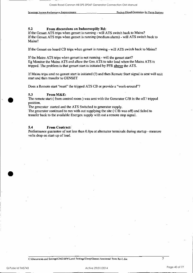
5.2 From discussions on Indooroopilly Rd: If the Genset ATS trips when genset is running - will ATS switch back to Mains? If the Genset ATS trips when genset is running (medium alarm) - will ATS switch back to Mains?
If the Genset on-board CB trips when genset is running - will ATS switch back to Mains?
If the Mains ATS trips when genset is not running - will the genset start? Eg Monitor the Mains ATS and allow the Gen ATS to take load when the Mains ATS is tripped. The problem is that genset start is initiated by PFR above the ATS.
If Mains trips amd no genset start is initiated (?) and then Remote Start signal is sent will unit start and then transfer to GENSET
Does a Remote start "reset" the tripped ATS CB or provide a "work-around"?
5.3 From M&E: The remote start ( from control room ) was sent with the Generator C/B in the off / tripped position. The generator started and the ATS Switched to generator supply. The generator continued to run with out supplying the site ( C/B was off) and failed to transfer back to the available Energex supply with out a remote stop signal.
5.4 From Contract: Performance guarantee of not less than 0.8pu at alternator terminals during startup - measure volts drop on start-up of load.
C:\Documents and Settings\CM2IB\V\ Local Settings\Temp\Genset Functional Tests Revl.doe 7
Creek Road Cannon Hill SPS SP047 Generator Connection OM Manual
Q-Pulse Id TMS743 Active 29/01/2014 Page 40 of 77
Sewerage System Performance Improvements Backup Diesel Generators for Pump Stations
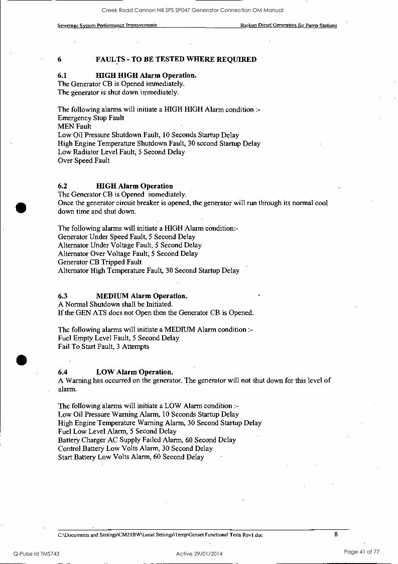
6 FAULTS - TO BE TESTED WHERE REQUIRED
6.1 HIGH HIGH Alarm Operation. The Generator CB is Opened immediately. The generator is shut down immediately.
The following alarms will initiate a HIGH HIGH Alarm condition :-
Emergency Stop Fault MEN Fault Low Oil Pressure Shutdown Fault, 10 Seconds Startup Delay High Engine Temperature Shutdown Fault, 30 second Startup Delay Low Radiator Level Fault, 5 Second Delay Over Speed Fault
6.2 HIGH Alarm Operation The Generator CB is Opened immediately. Once the generator circuit breaker is opened, the generator will run through its normal cool down time and shut down.
The following alarms will initiate a HIGH Alarm condition: - Generator Under Speed Fault, 5 Second Delay Alternator Under Voltage Fault, 5 Second Delay Alternator Over Voltage Fault, 5 Second Delay Generator CB Tripped Fault Alternator High Temperature Fault, 30 Second Startup Delay
6.3 MEDIUM Alarm Operation. A Normal Shutdown shall be Initiated. If the GEN ATS does not Open then the Generator CB is Opened.
The following alarms will initiate a MEDIUM Alarm condition :-
Fuel Empty Level Fault, 5 Second Delay Fail To Start Fault, 3 Attempts
6.4 LOW Alarm Operation. A Warning has occurred on the generator. The generator will not shut down for this level of alarm.
The following alarms will initiate a LOW Alarm condition :-
Low Oil Pressure Warning Alarm, 10 Seconds Startup Delay High Engine Temperature Warning Alarm, 30 Second Startup Delay Fuel Low Level Alarm, 5 Second Delay Battery Charger AC Supply Failed Alarm, 60 Second Delay Control Battery Low Volts Alarm, 30 Second Delay Start Battery Low Volts Alarm, 60 Second Delay
C:\Documents and Settings\CM21BW\ Local Settings\Temp\Genset Functional Tests Revl.doc 8
Creek Road Cannon Hill SPS SP047 Generator Connection OM Manual
Q-Pulse Id TMS743 Active 29/01/2014 Page 41 of 77
Sewerage System Performance Improvements Backup Diesel Generators for Pump Stations
AT A LATER DATE ? ??
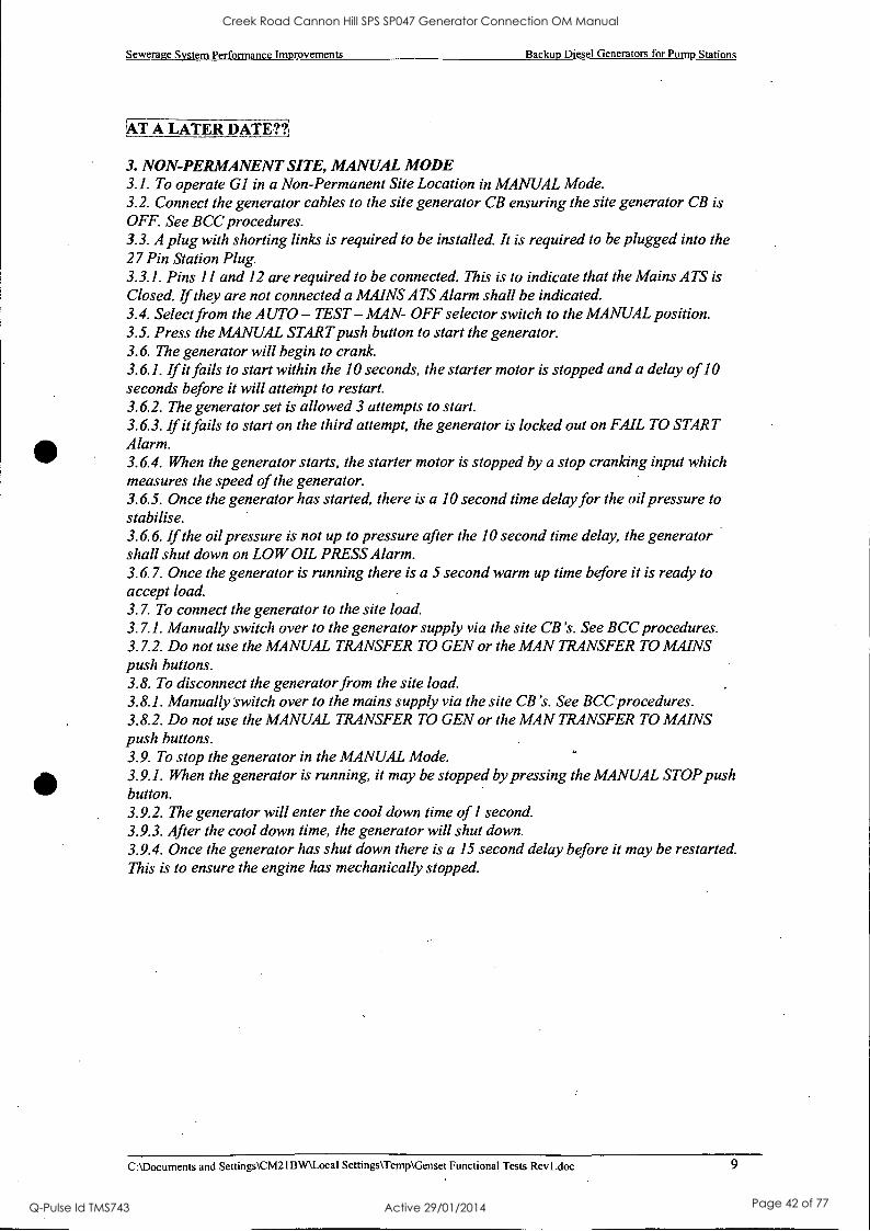
3. NON-PERMANENT SITE, MANUAL MODE 3.1. To operate G1 in a Non-Permanent Site Location in MANUAL Mode. 3.2. Connect the generator cables to the site generator CB ensuring the site generator CB is OFF. See BCC procedures. 3.3. A plug with shorting links is required to be installed. It is required to be plugged into the 27 Pin Station Plug. 3.3.1. Pins 11 and 12 are required to be connected. This is to indicate that the Mains ATS is Closed. If they are not connected a MAINS ATS Alarm shall be indicated. 3.4. Select from the AUTO - TEST - MAN- OFF selector switch to the MANUAL position. 3.5. Press the MANUAL START push button to start the generator. 3.6. The generator will begin to crank. 3.6.1. If it fails to start within the 10 seconds, the starter motor is stopped and a delay of 10 seconds before it will attempt to restart. 3.6.2. The generator set is allowed 3 attempts to start. 3.6.3. If it fails to start on the third attempt, the generator is locked out on FAIL TO START Alarm. 3.6.4. When the generator starts, the starter motor is stopped by a stop cranking input which measures the speed of the generator. 3.6.5. Once the generator has started, there is a 10 second time delay for the oil pressure to stabilise. 3.6.6. If the oil pressure is not up to pressure after the 10 second time delay, the generator shall shut down on LOW OIL PRESS Alarm. 3.6.7. Once the generator is running there is a 5 second warm up time before it is ready to accept load. 3.7. To connect the generator to the site load. 3.7.1. Manually switch over to the generator supply via the site CB's. See BCC procedures. 3.7.2. Do not use the MANUAL TRANSFER TO GEN or the MAN TRANSFER TO MAINS push buttons. 3.8. To disconnect the generator from the site load. 3.8.1. Manually switch over to the mains supply via the site CB's. See BCC procedures. 3.8.2. Do not use the MANUAL TRANSFER TO GEN or the MAN TRANSFER TO MAINS push buttons. 3.9. To stop the generator in the MANUAL Mode. 3.9.1. When the generator is running, it may be stopped by pressing the MANUAL STOP push button. 3.9.2. The generator will enter the cool down time of 1 second. 3.9.3. After the cool down time, the generator will shut down. 3.9.4. Once the generator has shut down there is a 15 second delay before it may be restarted. This is to ensure the engine has mechanically stopped.
C:\Documents and Settings\CM2IBW\Local Settings\Temp\Genset Functional Tests Rev I .doc 9
Creek Road Cannon Hill SPS SP047 Generator Connection OM Manual
Q-Pulse Id TMS743 Active 29/01/2014 Page 42 of 77

Operation and Maintenance Data Manual
,01=1
Btisbarie City Bigisbahe-1.zete.i
Water jamtssId.
BRISBANE WATER
GENERATOR CONNECTION 0 & M Manual
Section 4B
Site Testing NCS Alarms
Creek Road Cannon Hill SPS SP047 Generator Connection OM Manual
Q-Pulse Id TMS743 Active 29/01/2014 Page 43 of 77
Bilsbane City
Brisbane Water
BRISBANE WATER Network Control Systems
IDTS POINT COMMISSIONING SHEET
AND GENERATOR SUPPLY
OPERATIONAL CHECKS
Pump Station Generator Connection Project (STTX-I910)
DATE: 18/5/04
Site Name: SP 049 Creek Rd
Creek Road Cannon Hill SPS SP047 Generator Connection OM Manual
Q-Pulse Id TMS743 Active 29/01/2014 Page 44 of 77
Brisbane Water - Network Control Systems Section
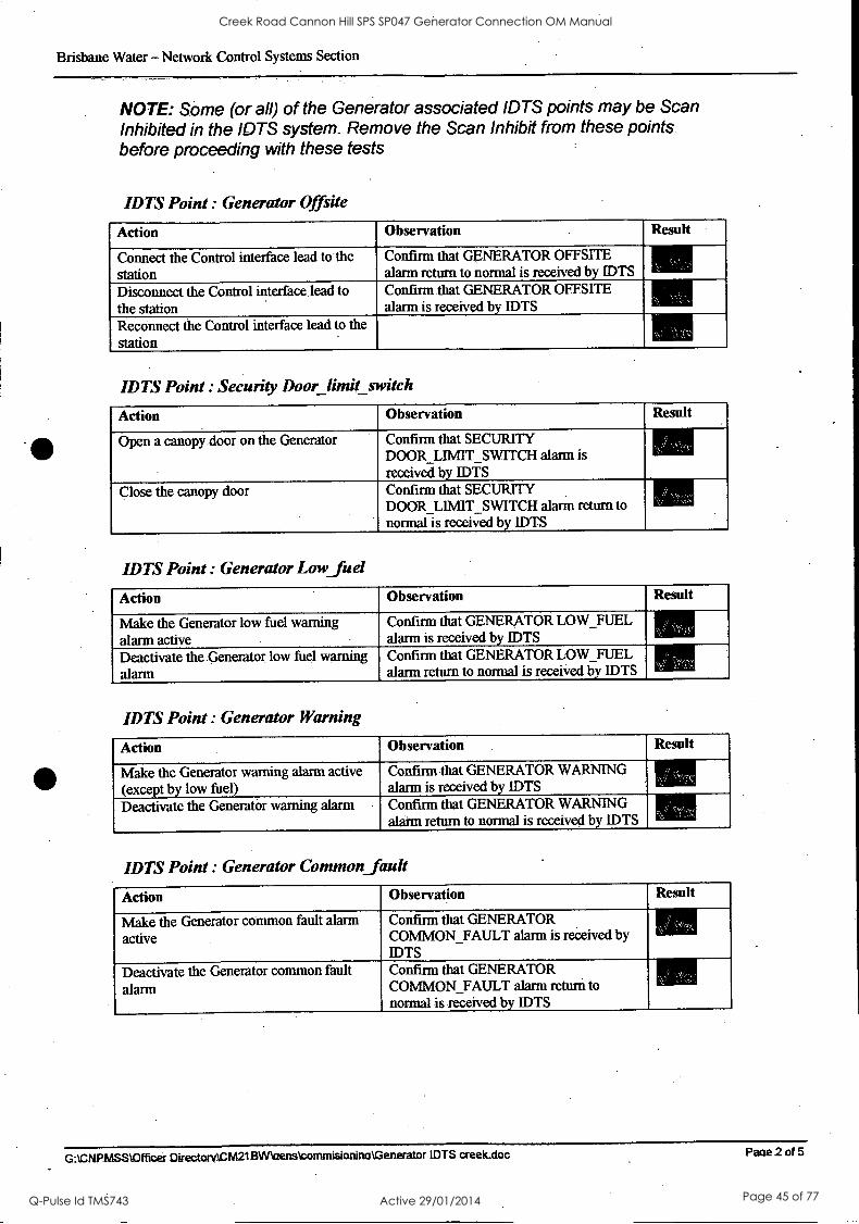
NOTE: Some (or all) of the Generator associated IDTS points may be Scan Inhibited in the IDTS system. Remove the Scan Inhibit from these points before proceeding with these tests
IDTS Point : Generator Offsite
Action .,.
Observation . Result
Connect the Control interface lead to the station
Confirm that GENERATOR OFFSITE alarm return to normal is received by IDTS
Disconnect the Control interface lead to the station
Confirm that GENERATOR OFFSITE alarm is received by IDTS
Reconnect the Control interface lead to the station
IDTS Point : Security Door limit switch
Action Observation Result
Open a canopy-door on the Generator Confirm that SECURITY DOOR_LIMIT_SWITCH alarm is received by IDTS
Close the canopy door Confirm that SECURITY DOOR LIMIT SWITCH alarm return to normal is received by IDTS
i , -'
IDTS Point: Generator Low_fuel
Action Observation Result
Make the Generator low fuel warning alarm active
Confirm that GENERATOR LOW_FUEL alarm is received by IDTS
Deactivate the. Generator low fuel warning alarm
Confirm that GENERATOR LOW_FUEL alarm return to normal is received by IDTS
IDTS Point : Generator Warning
Action Observation Result
Make the Generator warning alarm active (except by low fuel)
Confirm that GENERATOR WARNING alarm is received by IDTS
Deactivate the Generator warning alarm Confirm that GENERATOR WARNING alarm return to normal is received by IDTS
IDTS Point : Generator Common_ ault
Action Observation Result
Make the Generator common fault alarm active
Confirm that GENERATOR COMMON_FAULT alarm is received by IDTS
Deactivate the Generator common fault alarm
Confirm that GENERATOR COMMON_FAULT alarm return to normal is received by IDTS
G: \CNRASS !Officer Directory CM21BWIaens\corarnisionina \Generator IDTS creek.doc Paae 2 of 5
Creek Road Cannon Hill SPS SP047 Generator Connection OM Manual
Q-Pulse Id TMS743 Active 29/01/2014 Page 45 of 77
Brisbane Water Network Control Systems Section
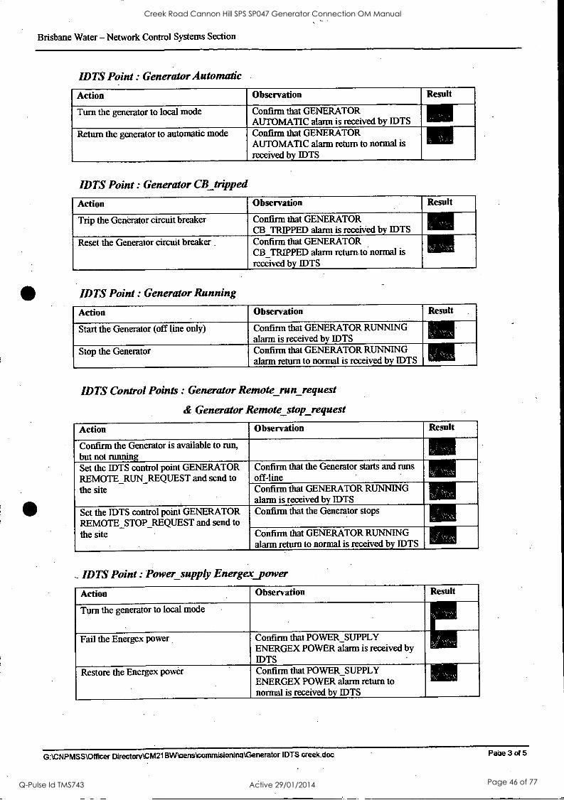
IDTS Point : Generator Automatic
Action Observation Result
Turn the generator to local mode Confirm that GENERATOR AUTOMATIC alarm is received by IDTS
Return the generator to automatic mode Confirm that GENERATOR AUTOMATIC alarm return to normal is received by IDTS
IDTS Point : Generator CB tripped
Action Observation Result
Trip the Generator circuit breaker Confirm that GENERATOR CB TRIPPED alarm is received by IDTS
Reset the Generator circuit breaker Confirm that GENERATOR CB_TRIPPED alarm return to normal is received by IDTS
IDTS Point : Generator Running
Action Observation Result
Start the Generator (off line only) Confirm that GENERATOR RUNNING alarm is received by IDTS
Stop the Generator Confirm that GENERATOR RUNNING alarm return to normal is received by IDTS
IDTS Control Points : Generator Remote run request
& Generator Remote stop request
Action Observation Result
Confirm the Generator is available to run, but not running Set the IDTS control point GENERATOR REMOTE_RUN_REQUEST and send to the site
Confirm that the Generator starts and runs off -line Confirm that GENERATOR RUNNING alarm is received by IDTS
Set the IDTS control point GENERATOR REMOTE_STOP_REQUEST and send to the site
Confirm that the Generator stops
Confirm that GENERATOR RUNNING alarm return to normal is received by IDTS
IDTS Point Power supply Energez_power
Action Observation Result
Turn the generator to local mode
Fail the Energex power Confirm that POWER SUPPLY ENERGEX POWER Wlarm is received by IDTS
Restore the Energex power Confirm that POWER SUPPLY ENERGEX POWER alarm return to normal is received by IDTS
-
G:\CNPMSS \Officer Directory \CM21 BVAoens\commisioniruAGenerator IDTS creek.doc. Paire 3 of 5
Creek Road Cannon Hill SPS SP047 Generator Connection OM Manual
Q-Pulse Id TMS743 Active 29/01/2014 Page 46 of 77
Brisbarie Water - Network Control Systems Section
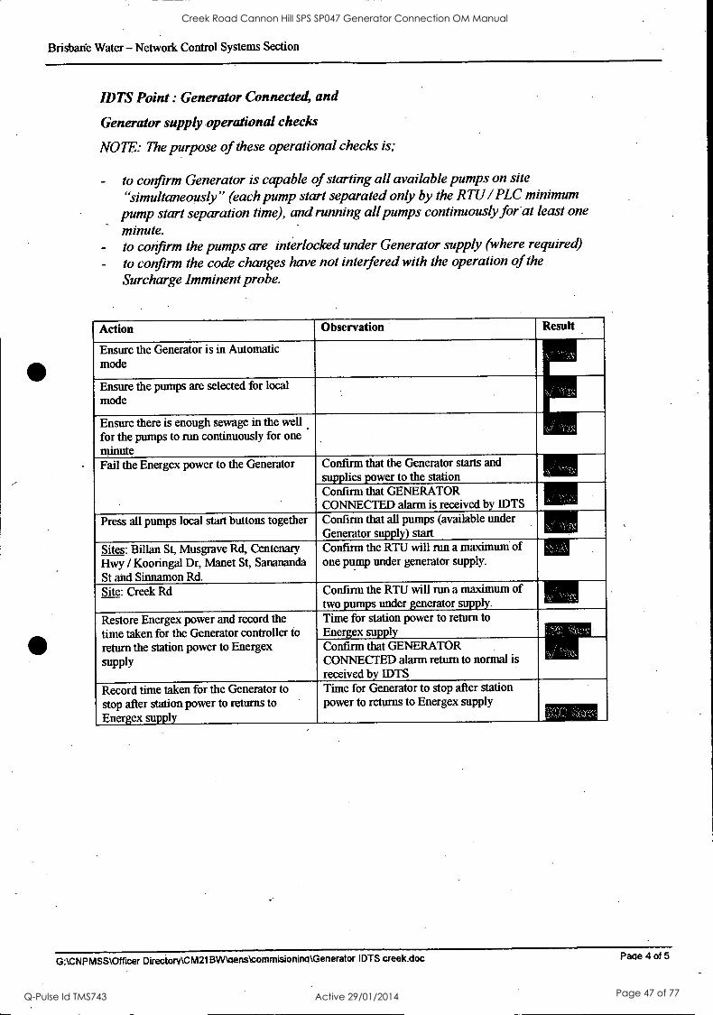
IDTS Point : Generator Connected, and
Generator supply operational checks
NOTE: The purpose of these operational checks is;
to confirm Generator is capable of starting all available pumps on site "simultaneously" (each pump start separated only by the RTU /PLC minimum
pump start separation time), and running all pumps continuously for at least one
minute. to confirm the pumps are interlocked under Generator supply (where required) to confirm the code changes have not interfered with the operation of the Surcharge Imminent probe.
Action Observation Result
Ensure the Generator is in Automatic mode
Ensure the pumps are selected for local mode
Ensure there is enough sewage in the well for the pumps to run continuously for one minute Fail the Energex power to the Generator Confirm that the Generator starts and
supplies power to the station Confirm that GENERATOR CONNECTED alarm is received by IDTS
Press all pumps local start buttons together Confirm that all pumps (available under Generator supply) start
Sites: Billan St, Musgrave Rd, Centenary Confirm the RTU will run a maximum of one pump under generator supply. Hwy / Kooringal Dr, Manet St, Sanananda
St and Sinnamon Rd. Site: Creek Rd Confirm the RTU will run a maximum of
two pumps under generator supply.
Restore Energex power and record the time taken for the Generator controller to return the station power to Energex
supply
Time for station power to return to Energex supply Confirm that GENERATOR CONNECTED alarm return to normal is received by IDTS
Record time taken for the Generator to
stop after station power to returns to Energex supply
Time for Generator to stop after station power to returns to Energex supply
G:\CNPMSS \Officer Directorv\CM21BIARaens\commisionina \Generator IDTS creek.doc Paae 4 of 5
Creek Road Cannon Hill SPS SP047 Generator Connection OM Manual
Q-Pulse Id TMS743 Active 29/01/2014 Page 47 of 77
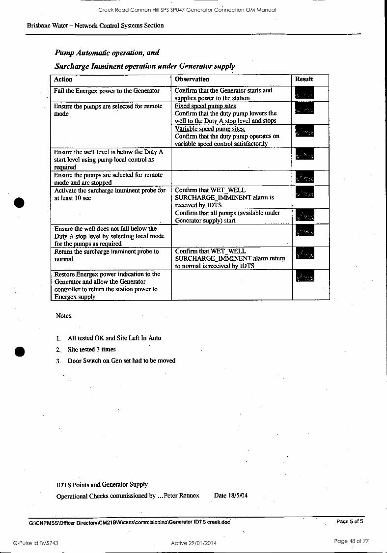
Brisbane Water - Network Control Systems Section
Pump Automatic operation, and
Surcharge Imminent operation under Generator supply
Action Observation Result
Fail the Energex power-to the Generator Confirm that the Generator starts and supplies power to the station
Ensure the pumps are selected for remote mode
Fixed speed pump sites: Confirm that the duty pump lowers the well to the Duty A stop level and stops Variable speed pump sites: Confirm that the duty pump operates on variable speed control satisfactorily
Ensure the well level is below the Duty A start level using pump local control as required Ensure the pumps are selected for remote mode and are stopped Activate the surcharge imminent probe for at least 10 sec
Confirm that VVET WELL SURCHARGE livilvII- NENT alarm is received by IDTS Confirm that all pumps (available under Generator supply) start
Ensure the well does not fall below the Duty A stop level by selecting local mode for the pumps as required Return the surcharge imminent probe to normal
Confirm that WET WELL SURCHARGELMIAINENT alarm return to normal is received by IDTS
Restore Energex power indication to the Generator and allow the Generator controller to return the station power to Energex supply
Notes:
1. All tested OK and Site Left In Auto
2. Site tested 3 limas
3. Door Switch on Gen set had to be moved
IDTS Points and Generator Supply
Operational Checks commissioned by ...Peter Rennex Date 18/5/04
G: \CNPMSS \Officer Directorv\CM21BW\aenstommisionina \Generator IDTS creek.doc Pain 5 of 5
Creek Road Cannon Hill SPS SP047 Generator Connection OM Manual
Q-Pulse Id TMS743 Active 29/01/2014 Page 48 of 77
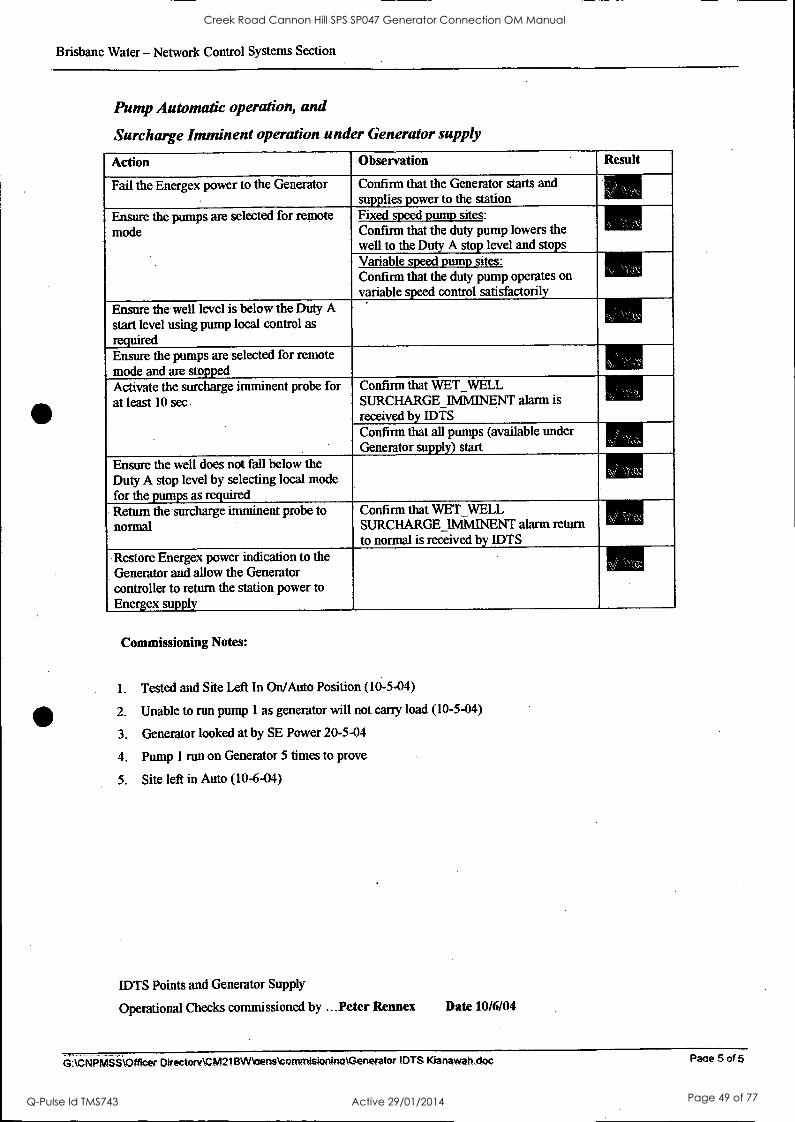
Brisbane Water - Network Control Systems Section
Pump Automatic operation, and
Surcharge Imminent operation under Generator supply
Action Observation Result
Fail the Energex power to the Generator Confirm that the Generator starts and supplies power to the station
Ensure the pumps are selected for remote mode
Fixed speed pump sites: Confirm that the duty pump lowers the well to the Duty A stop level and stops Variable speed pump sites: Confirm that the duty pump operates on variable speed control satisfactorily
Ensure the well level is below the Duty A
start level using pump local control as required Ensure the pumps are selected for remote mode and are stopped Activate the surcharge imminent probe for at least 10 sec
Confirm that WET WELL SURCHARGE 11v1M- lNENT alarm is received by IDTS Confirm that all pumps (available under Generator supply) start
Ensure the well does not fall below the Duty A stop level by selecting local mode for the pumps as required
`-,.. r
Return the surcharge imminent probe to normal
Confirm that WET WELL SURCHARGE _IMMINENT alarm return to normal is received by IDTS
, Restore Energex power indication to the Generator and allow the Generator controller to return the station power to Energex supply
Commissioning Notes:
1. Tested and Site Left In On/Auto Position (10-5-04)
411 2. Unable to run pump 1 as generator will not carry load (10-5-04)
3. Generator looked at by SE Power 20-5-04
4. Pump 1 run on Generator 5 times to prove
5. Site left in Auto (10-6-04)
IDTS Points and Generator Supply
Operational Checks commissioned by ...Peter Rennes Date 10/6/04
6--.61113iiii,4tticer Directory \CM211MaensoorturtIsiortinoGenerator IDTS Kianawah.cloo Paae 5 of 5
Creek Road Cannon Hill SPS SP047 Generator Connection OM Manual
Q-Pulse Id TMS743 Active 29/01/2014 Page 49 of 77

Brisbane City
Bribane ..,--..Przedgminti Waterja %ad
BRISBANE WATER
GENERATOR CONNECTION 0 & M Manual
Section 4C
Site Testing Generator
Creek Road Cannon Hill SPS SP047 Generator Connection OM Manual
Q-Pulse Id TMS743 Active 29/01/2014 Page 50 of 77
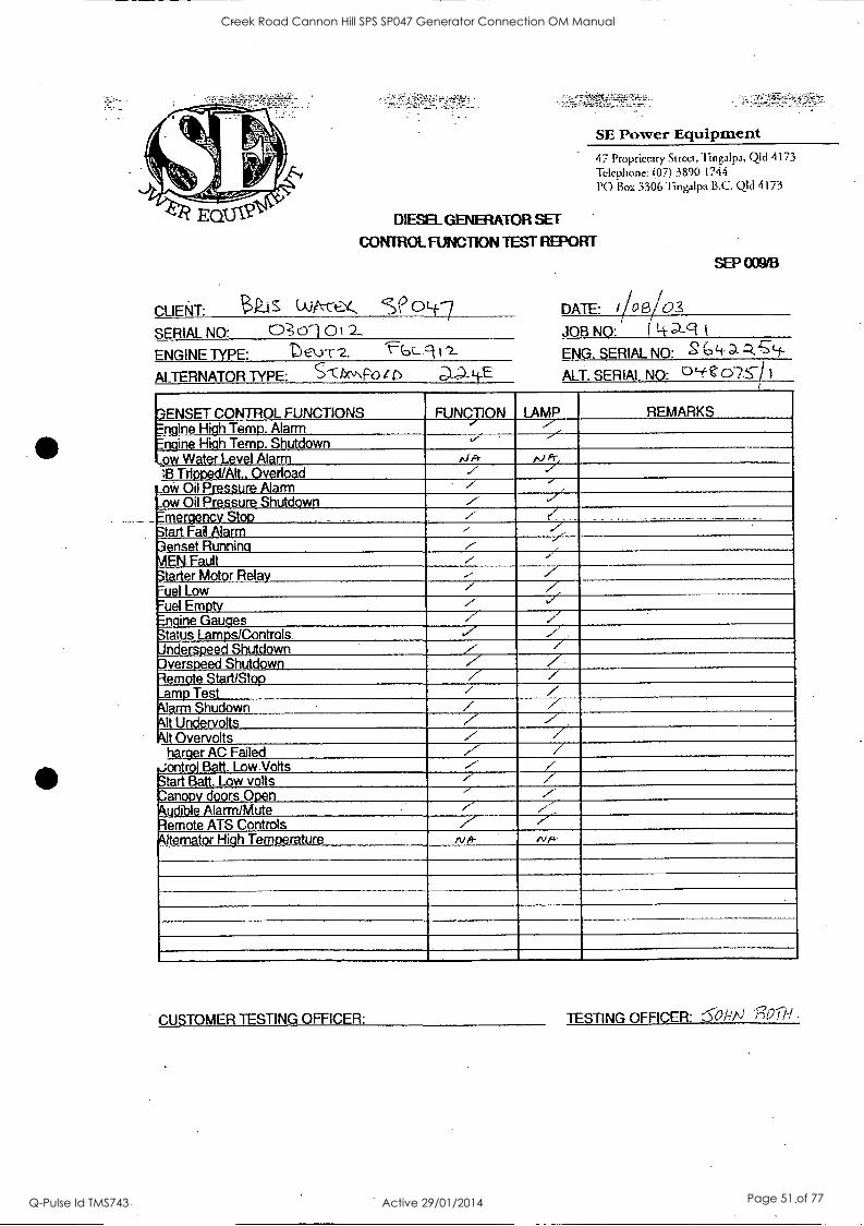
SE Power Equipment 47 Proprietary Street, Tingalpa, QId 4173 Telephone: (07) 3390 1744 PO Box 3306 Tingalpa B.C. QM 4173
DIESEL GENERATOR SET
CONTROL FUNCTION TEST REPORT
CLIENT: $LtS (Ags-rez, seoLf.---/
SERIAL NO: 03 Cri 0 2_
ENGINE TYPE: DEk.Yr (.,c-9
ALTERNATOR TYPE: S'0tt
SEP 009/B
DATE: //oet/ JOB NO: j-'-It ENG. SERIAL NO: 2 GLi-
ALT. SERIAL NO:
3ENSET CONTROL FUNCTIONS FUNCTION LAMP REMARKS Engine High Temp. Alarm Engine High Temp. Shutdown v ..ow Water Level Alarm
13 Trioped/Alt.. Overload ./ ow Oil Pressure Alarm ./
,._ow Oil Pressure Shutdown 7 riefloyp
Start Fail Alarm ,-
3enset Running ,--
\AEN Fault ,
Starter Motor Relay .- -/ 7.- uel Low / -'uel Empty V ./ Engine Gauges 7 Status Lamps/Controls. Jnderspeed Shutdown ,-- / Dverspeed Shutdown / / .,
Remote Start/Stop / / _amp lest / Alarm Shudown / , Alt Undervolts .7 --/-
Alt Overvolts 7 / harger AC Failed ./"' /
Jontrol Batt. Low Volts ,-- Start Batt. Low volts z' /
anoolv doors Open 7' Audible Alarm/Mute
. Remote ATS Controls Alternator High Temperature
CUSTOMER TESTING OFFICER: TESTING OFFICER: 6O/I) '13t217I
Creek Road Cannon Hill SPS SP047 Generator Connection OM Manual
Q-Pulse Id TMS743 Active 29/01/2014 Page 51 of 77
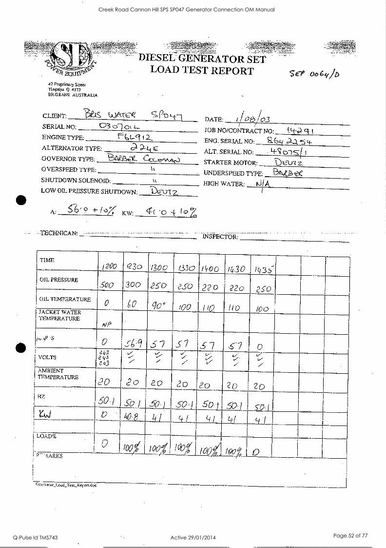
47 Proprictzry Street Tingalpa Q 4173 BRISBANE AUSTRALIA
DIESEL SET LOAD TEST REPORT
CLIENT: 3is
SERIAL NO: 03 61 Ok 2--
ENGINE TYPE: (2, ALTERNATOR TYPE: 0- D- If GOVERNOR TYPE: cct.._,L,v\Aco
OVERSPEED TYPE: k
SHUTDOWN SOLENOID:
LOW OIL PRESSURE SHUTDOWN:
A: 9 4- i'D'X KW: 4:( toZ
TECHINIICAN:
ser 006q1D
DATE: / 1 00 /03 JOB NO/CONTRACT NO: t Lt-- 9 ENG.SERJAL NO:
ALT. SERIAL. NO:
a&4A.3.5L-1-. 4-7 cnS
STARTER MOTOR: '0 UNDERSPEED TYPE: 3 NP.,.. to HIGH WATER:
INSPECTOR:
TIME L.. 1200 i230 1300 1330 1400 1430 /43b.-
OIL PRESSURE SOO 300 25-o ?30 22 o 220 2S 0
OIL TEMPERATURE 0 0 q 0 too 110 110 100 JACKET WATER TEMPERATURE
i..ce S p c6,61 ,5-2 51 ,3 7 .
VOLTS e ii_.1
e y3 2.43 ,/ ./ v' / i',/' V
,/ . v,
." r. v-- 1"
1 ATCM--.:IPIEENRIE4TURE coo 20 ag 20 20 2C) "Zo Hz
50.1 S17-1 50.) SO.]
( i 1
50.1
' -1 )
50-1
Li-!
57) I
Li i ! rAiJ V . 4CI:Lhl
LOAD%
U.'-' /00d _1 100? , 1°4 /00 100° 1 PThIARKS
Ikucralor_i_oad_Tesi_Reportdoc
Creek Road Cannon Hill SPS SP047 Generator Connection OM Manual
Q-Pulse Id TMS743 Active 29/01/2014 Page 52 of 77
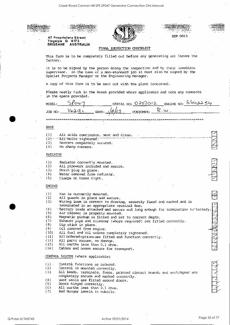
47 Proprietary Street Tingalpa 0 4173 BRISBANE AUSTRALIA
SEP 0013
"FINAL INSPECTION CHECKLIST
This form is to be completely filled out before any generating set leaves the
factory.
It is to be signed by the person doing the inspection and by their inuediate
superyisor. In the case of a non-standard job it must also be signed by the Special Projects Manager or the Engineering Manager.
A copy of this form is to be sent out with the plant concerned.
Please neatly tick in the boxes provided where applicable and note any comments in the space provided.
MODEL: e Lf--7 SERIAL NO: C) ;?6-1 01 2L ENGINE NO:
JOB NO: t4 DATE: 3 CUSTOMER: R.w .
BASE
(1) All welds continuous, neat and clean. 121----AII-boIts-tightened:------------ -
(3) Bearers completely secured. (4) No sharp corners.
RADIATOR
ENGINE
Radiator correctly mounted. All pipework included and secure. Drain plug in place. Water removed from radiator. Clamps on hoses tight.
'77 ,....--
(1) Fan is correctly mounted. (2) All guards in place and secure. (3) Wiring loom is correct to drawing, securely fixed and marked and is
terminated in an appropriate terminal box. (4) Battery learls attached and secure and long enough for termination to battery. (5) Air cleaner is properly mounted. (6) Magnetic pickup is fitted and set to correct depth. (7) Exhaust pipe and silencer (where required) are fitted correctly. (8) Dip stick in place. (9) Oil removed from engine. (10) All fuel and oil unions completely tightened. (11) Allorderedoptionsare fitted and function correctly. (12) All parts secure, no damage. (13) All earths less than 0.1 ohms. '(14) Cables and hoses secure for transport.
CONTROL SYSTEM (where applicable)
(1) .
(2)
(3)
(4)
(5)
(6)
(7)
Control functions as ordered. Control is mounted correctly. All leads, terminals, fuses, printed circuit boards arid switchgear, are completely secure and marked correctly. Dust seals are fitted around doors. Dbors hinged correctly. All earths less than 0.1 01-MS.
Red Danger labels in cubicle.
Creek Road Cannon Hill SPS SP047 Generator Connection OM Manual
Q-Pulse Id TMS743 Active 29/01/2014 Page 53 of 77
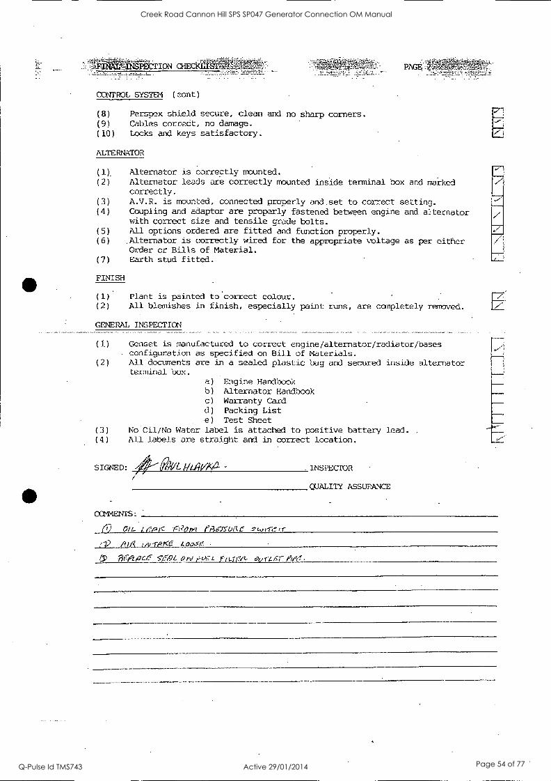
CONTROL SYSTEM (eont)
(8) Perspex shield secure, clean and no sharp corners.
(9) Cables correct, no damage.
(10) Locks and keys satisfactory.
ALTERNATOR
(1), Alternator is correctly mounted. (2) Alternator leads are correctly mounted inside terminal box and marked
correctly.
(3) A.V.R. is mounted, connected properly and set to correct setting. (4) Coupling and adaptor are properly fastened between engine and alternator
with correct size and tensile grade bolts.
(5) All options ordered are fitted and function properly. (6) .Alternator is correctly wired for the appropriate voltage as per either
Order or Bills of Material.
(7) Earth stud fitted.
FINISH
(1) Plant is painted to correct colour. (2) All blemishes in finish, especially paint runs, are completely removed.
GMERAL INSPECTION
(1) Genset is manufactured to correct engine/alternator/radiator/bases . configuration as specified on Bill of Materials.
(2) All documents are in a sealed plastic bag and secured inside alternator terminal box.
(3) (4)
a) Engine Handbook b) Alternator Handbook c) Warranty Card d) Packing List e) Test Sheet
No Oil/No Water label is attached to positive battery lead.
All labels are straight and in correct location.
SIGNED: 01/0/LAVAa .INSPECTOR
QUALITY ASSURANCE
COWEN'S:
6) °IL (13exs.t.,Ae ,r
.LV10111_121/TPK6 LOos15
-015.1q0=2C.4: S-',/r-,9t a tv 1;1-1=7 t fli-Tr7/t- ourLis.7-
Creek Road Cannon Hill SPS SP047 Generator Connection OM Manual
Q-Pulse Id TMS743 Active 29/01/2014 Page 54 of 77
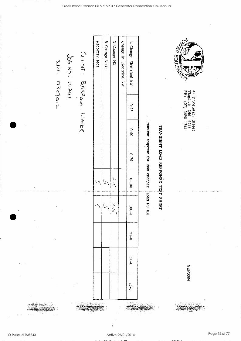
47 Proprietary Street
Tingalpa
Qid
4173 PH
: (07)
3890 1744
TR
AN
SIEN
T L
OA
D
RE
SPON
SE T
EST
SH
EE
T
Transient response for
load changes: L
oad PF 0.8
SEP0084
%
Change E
lectrical kW
0-25
. 0-50
0-75 0-100
. 100-0
75-0 50-0
25-0
Change
In E
lectrical kW
% C
hange H
Z
, .4,
.
% C
hange V
olts
Recovery secs
CA
A ovi
loG
No
k
Aj
0 '3 <51
1
Creek Road Cannon Hill SPS SP047 Generator Connection OM Manual
Q-Pulse Id TMS743 Active 29/01/2014 Page 55 of 77
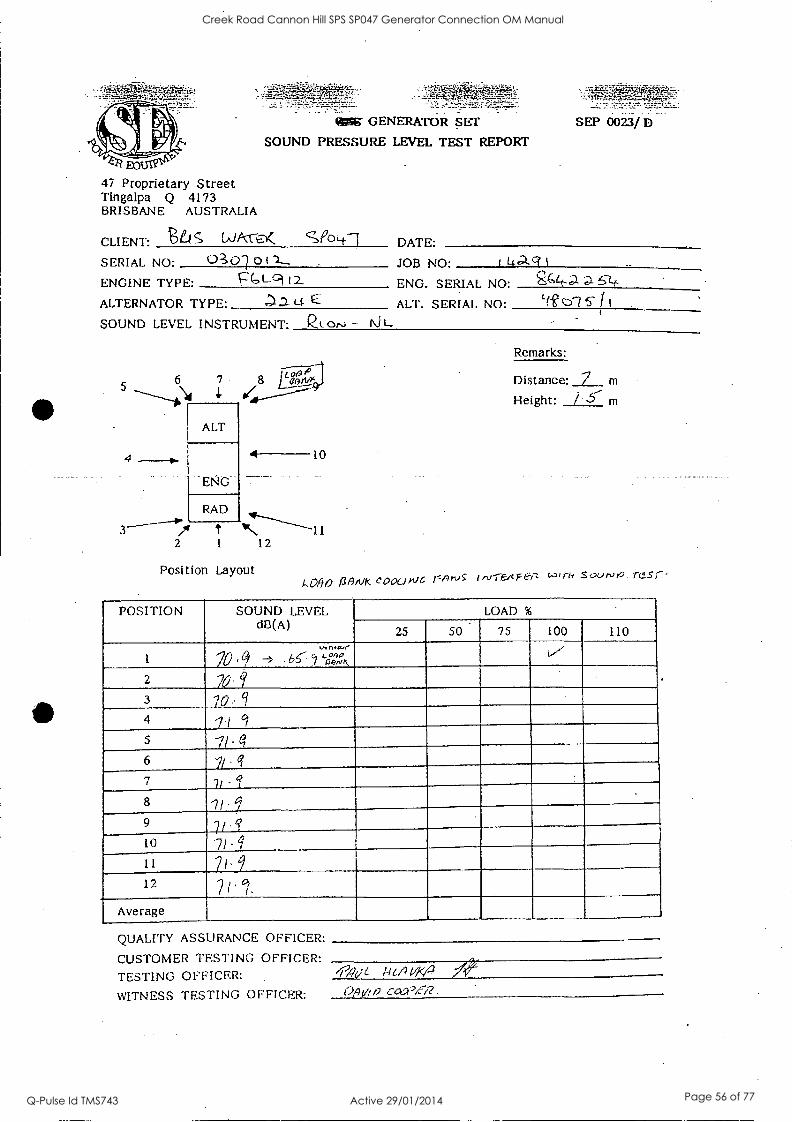
47 Proprietary Street Tingalpa Q 4173 BRISBANE AUSTRALIA
%Mg GENERATOR SET
SOUND PRESSURE LEVEL TEST REPORT
CLIENT: LAJAvo( SPOLt1
SERIAL NO: 0 (..)-) 011- ENGINE TYPE: Pc:A-9 12.
ALTERNATOR TYPE: a Lc E
SOUND LEVEL INSTRUMENT: Qt ors; - 1\i
4
SEP 0023/ D
DATE:
JOB NO' 14aci't --
ENG. SERIAL NO' g("e ALT. SERIAL NO: Lfe c:C7 I i
1/.001°1 '7 8 1. jAwv,"9.J
ALT
4 10
EPJG
RAD
---1 2 1 12
Position Layout
Remarks:
Distance: 7 m
Height: m
1,0 fi /9 136,14( COOC.1 fr'J ArJ I 1V-i.EAFet-Z C.0, fir SOurvt0 Tr-S
POSITION SOUND LEVEL dB(A)
LOAD %
25 50 75 100 110
1
VI n.e..Jr
70 ' q -> 66-- 5 'if::k 4,
2
3 20 q 4 i i Gi
5
6 ji q 7 7, - I 8 ii 9 V e?
10
11 2/' 9 12
7 l cl.
Average
QUALITY ASSURANCE OFFICER:
CUSTOMER TESTING OFFICER:
TESTING OFFICER:
WITNESS TESTING OFFICER:
0"(je 0,40 a coc.Vei?
Creek Road Cannon Hill SPS SP047 Generator Connection OM Manual
Q-Pulse Id TMS743 Active 29/01/2014 Page 56 of 77

Operation and Maintenance Data Manual
,g111.,
Blisbane City Brisbane,.Azzle,di
Vilater tad BRISBANE WATER
GENERATOR CONNECTION 0 & M Manual
Section 4D
Electrical Testing Certificate
Creek Road Cannon Hill SPS SP047 Generator Connection OM Manual
Q-Pulse Id TMS743 Active 29/01/2014 Page 57 of 77
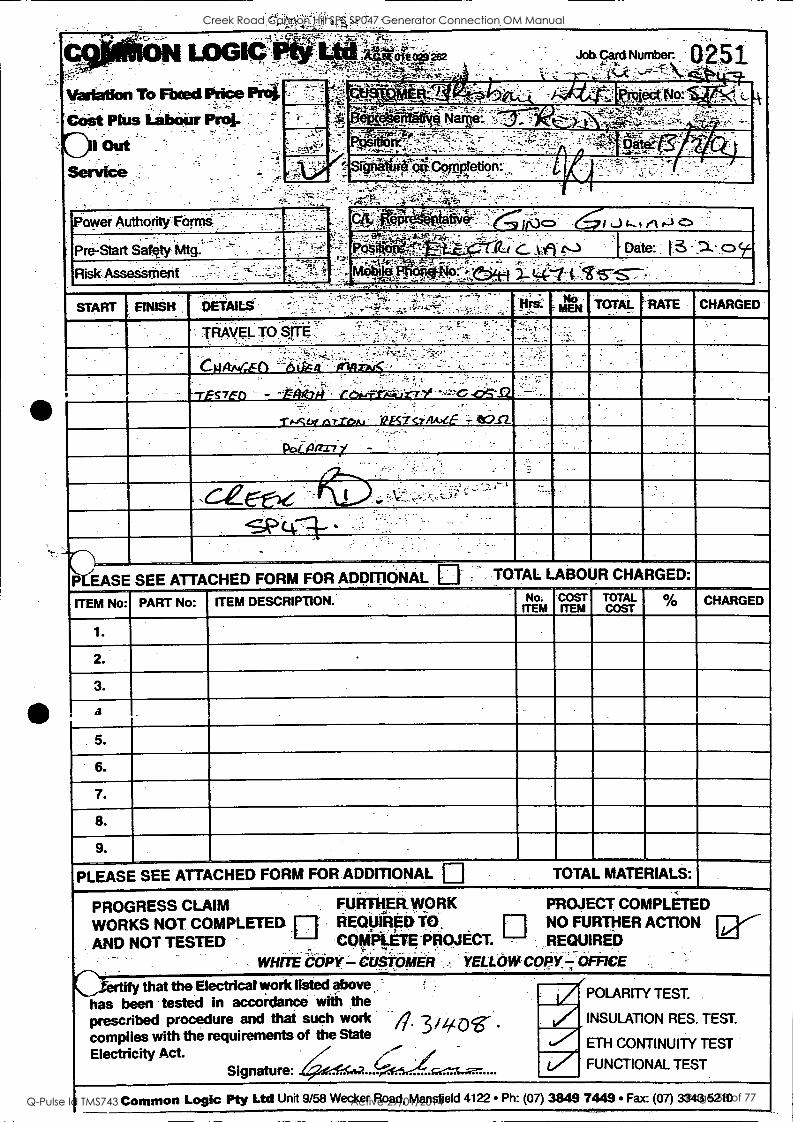
,..
4t - Olt 2E2 Job. 910:1 Number: 0251
4._ Variation To Fixed Price Prod
,,..-....-
Cost Plus ialrerrir Prol.
D Out .
Service
ME -; 74,,, - '
eLe*,i:iNart6:. ;., ....
..,-.-'-; 'Fgiripiit-?..f----=:,-.- ._,,.. ....,_,.,....... ... .....
srinattieu Co ptetion:. ..,........w.
... _
pow& Authority" Forms - . [Na' -1L.Jc..sfetr-lc: ,
: 'i.. _._-- Pre-Start Salqty 'Mtg.
4.-- ... -, - r . _ . _t:i9. t--) i Date: t:3 -,-- <DSc-
Risk. Assesritent .
'r4iibi- 14: - - :-';C:iit-1 411-:"Ps.--s-- .. _.....-k . )"?:-.:4-,;-..._---1---- - = z-~ - - - -
-
START FINISH - ,...,. ..
DETAILS ' -, , . TOTAL !-RATE CHARGED
TRAVEL TO, SITE . t _.
. 7'
Catuczo -..-Aik
"TES7E0 - - Atitt row-E6=-itir-rY ---=.-C
- ,
-r.-asof larzoe, 9A774A)LE - e6s2.
aril
44.
P EASE SEE ATTACHED FORM FOR ADDITIONAL TOTAL LABOUR CHARGED:
ITEM No: PART No: [ ITEM DESCRIPTION, No. ITEM
COST ITEM
TOTAL COST
CHARGED
1.
2.
3.
a
5.
6.
7.
8.
9. .
PLEASE SEE ATTACHED FORM FOR ADDMONAL 0 TOTAL MATERIALS:
PROGRESS CLAIM FURTHER. WORK PROJECT COMPLETED
WORKS NOT COMPLETED ri REopiRgiiiti. El NO FURTHER ACTION
AND NOT NOT TESTED ' COMPETE PROJECT. ' REQUIRED
WHITE COPY -CUSTOMER , YELLOW COPY ,,V OF*7CE
CiertifY that the Electrical work listed above '
has been tested in accordance with the prescribed procedure and that such work 3 4 oir
-
complies with the requirements of the State
Electricity Act. Signature: 6 Q-::.-1....--
POLARITY TEST.
INSULATION RES. TEST.
ETH CONTINUITY TEST
FUNCTIONAL TEST
Common Logic Pty Ltd Unit 9/58 Wecker Road, Mansfield 4122 Ph: (07) 3849 7449 Fax: (07) 3343 5210
Creek Road Cannon Hill SPS SP047 Generator Connection OM Manual
Q-Pulse Id TMS743 Active 29/01/2014 Page 58 of 77

Brisbane City
Brisbane holed 14friateriiii1. BRISBANE WATER
GENERATOR CONNECTION 0 & M Manual
Section 5
Parts Information
Creek Road Cannon Hill SPS SP047 Generator Connection OM Manual
Q-Pulse Id TMS743 Active 29/01/2014 Page 59 of 77
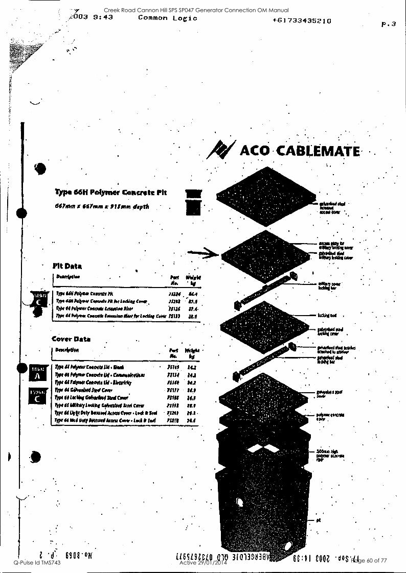
.z003 9:43 Common Logic
Typo 66H Polymer Can crate Ph
647xtin X Wrong x JP1.4 pm depth
Pit Data Ie fete lieigke
X..
I W14.
C
0
I'm /kJ Poirot a mart,1k 11111. !ILA ko. sat Ilelgow Cwart. 111 he WEIR. Car* 11.1 tWit 44 Pelmet Caw& 141440. lkr )1124 21.4. yt 44 Mpg* CDO/Ot 180M1il ilk, fro Lodi*, GM/ 71131 21.1
Cover Data
1
ganuirtiod .
rye weak Ni. kg
nits 14.1
71114 14.11
WO te1 14.1
75112 2/.1
71111 ILL 712t? 111.)
132111 1
thot 44 Myatt Good/ III . tied lyet 44 helms Cam* tit. Cwiewiedlou Iypi it Mu& °motto 114 tkevicky Wee 04 Giffee1$4 AN C.viv Mr! *pi 41 Ilia/ Goiok/oot SIM Covet
rrp/ /11 illtAityladtkg Gsfretstlif kml My Inot if DM 0o1i Woo/ Amos Cow toe & Sag
Type id Na Pirry Mimi Amu Om . 1mi & WI -
1..w..................."In.,w.o............7.
1 6908'011.
+61733435210
ACO CABLEMATE
gtegf4i IMO 03VW
401annlowe
. .
LLEALSICLO 010 310313$838V
eiteov6(444
Wit"
104404 Kati . pr*
potem cermee OW.
=ma NO POW orstm rtW
9$
COOZ
p.3
Creek Road Cannon Hill SPS SP047 Generator Connection OM Manual
Q-Pulse Id TMS743 Active 29/01/2014 Page 60 of 77
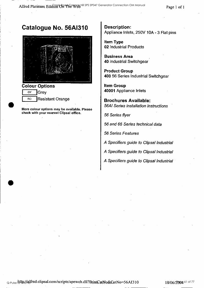
Alfred Platinum Edition On The Web Page 1 of 1
Catalogue No. 56A1310
Colour Options Grey
Resistant Orange
GY
RO
More colour options may be available. Please check with your nearest Clipsal office.
Description: Appliance Inlets, 250V 10A - 3 Flat pins
Item Type 02 Industrial Products
Business Area 40 Industrial Switchgear
Product Group 400 56 Series Industrial Switchgear
Item Group 40001 Appliance Inlets
Brochures Available: 56A1 Series installation instructions
56 Series flyer
56 and 66 Series technical data
56 Series Features
A Specifiers guide to Clipsal Industrial
A Specifiers guide to Clipsal Industrial
A Specifiers guide to Clipsal Industrial
http ://alfred. clip sal. com/scripts/ap eweb .dll?PrintC atNo &CatNo=56A1310 18/06/2004
Creek Road Cannon Hill SPS SP047 Generator Connection OM Manual
Q-Pulse Id TMS743 Active 29/01/2014 Page 61 of 77
Alfred Platinum Edition On The Web Page 1 of 1
Catalogue No. 56CSC310
Colour Options Electric Orange
Resistant Orange
EO
RO
More colour options may be available. Please check with your nearest Clipsal office.
Description: Plugs And Extension Sockets, 250V 10A -
3 Flat pins
Item Type 02 Industrial Products
Business Area 40 Industrial Switchgear
Product Group 400 56 Series Industrial Switchgear
Item Group 40004 Plugs & Extension Sockets
Brochures Available: 56CSC and 56P0 series wiring instructions
56CSC310, 56CSC315 wiring instructions
56 Series flyer
56 and 66 Series technical data
56 Series Features
A Specifiers guide to Clipsal Industrial
A Specifiers guide to Clipsal Industrial
A Specifiers guide to Clipsal Industrial
http://alfred.clipsal.com/scripts/apeweb.dll?PrintCatNo&CatNo=56CSC310 18/06/2004
Creek Road Cannon Hill SPS SP047 Generator Connection OM Manual
Q-Pulse Id TMS743 Active 29/01/2014 Page 62 of 77
Alfred Platinum Edition On The Web
Catalogue No. WIPM27
Colour Options No colour options
Transparent TR
More colour options may be available. Please check with your nearest Clipsal office.
Page 1 of 1
Description: Plugs And Extension Sockets - Wilco, Low Voltage, Multipin - 27 pin maximum
Item Type 02 Industrial Products
Business Area 40 Industrial Switchgear
Product Group 403 Wilco Hi-Impact Industrial Switchgear
Item Group 40303 Plugs & Extension Sockets
Brochures Available: A Specifiers guide to Clipsal Industrial
A Specifiers guide to Clipsal Industrial
A Specifiers guide to Clipsal Industrial
http://alfred.clipsal.com/scripts/apeweb.dll?PrintCatNo&CatNo=WIPM27 18/06/2004
Creek Road Cannon Hill SPS SP047 Generator Connection OM Manual
Q-Pulse Id TMS743 Active 29/01/2014 Page 63 of 77
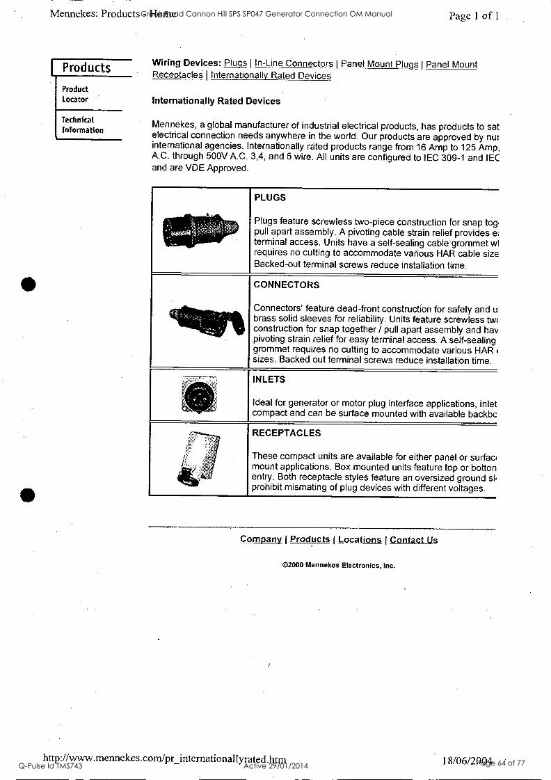
Mennekes: Products - Home
I Products
Product Locator
Technical
Information
Page 1 of 1
Wiring Devices: Plugs I In-Line Connectors I Panel Mount Plugs I Panel Mount Receptacles I Internationally Rated Devices
Internationally Rated Devices
Mennekes, a global manufacturer of industrial electrical products, has products to sat electrical connection needs anywhere in the world. Our products are approved by nur international agencies. Internationally rated products range from 16 Amp to 125 Amp, A.C. through 500V A.C. 3,4, and 5 wire. All units are configured to IEC 309-1 and IEC and are VDE Approved.
PLUGS
Plugs feature screwless two-piece construction for snap tog. pull apart assembly. A pivoting cable strain relief provides e terminal access. Units have a self-sealing cable grommet wl requires no cutting to accommodate various HAR cable size Backed-out terminal screws reduce installation time.
CONNECTORS
Connectors' feature dead-front construction for safety and u brass solid sleeves for reliability. Units feature screwless twi construction for snap together / pull apart assembly and hay pivoting strain relief for easy terminal access. A self-sealing grommet requires no cutting to accommodate various HAR sizes. Backed out terminal screws reduce installation time.
INLETS
Ideal for generator or motor plug interface applications, inlet compact and can be surface mounted with available backbc
RECEPTACLES
These compact units are available for either panel or surfac, mount applications. Box mounted units feature top or botton entry. Both receptacle styles feature an oversized ground sb prohibit mismating of plug devices with different voltages.
Company I Products Locations I Contact Us
©2000 Mennekes Electronics, Inc.
http://www.mennekes.com/pr_internationallyrated.htm 18/06/2004
Creek Road Cannon Hill SPS SP047 Generator Connection OM Manual
Q-Pulse Id TMS743 Active 29/01/2014 Page 64 of 77
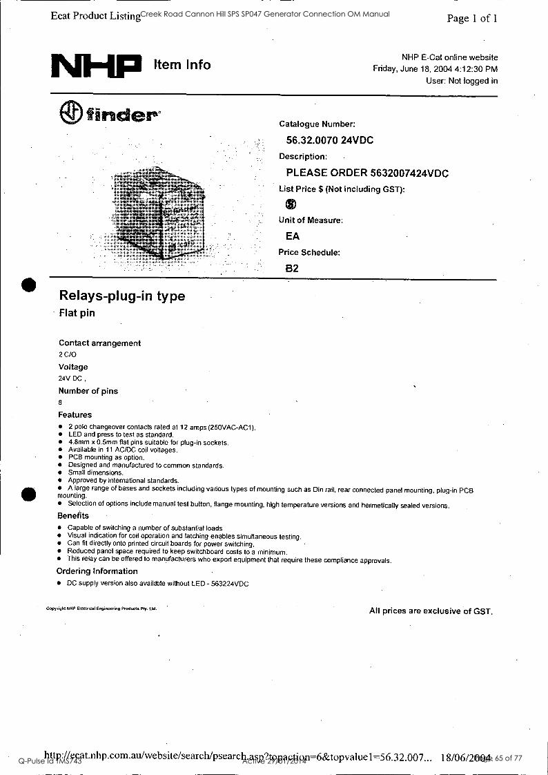
Ecat Product Listing
IN0Hp Item Info
Page 1 of 1
NHP E-Cat online website Friday, June 18, 2004 4:12:30 PM
User: Not logged in
({DI nderee
Relays-plug-in type Flat pin
Contact arrangement 2 C/O
Voltage 24V DC ,
Number of pins 8
Catalogue Number:
56.32.0070 24VDC
Description:
PLEASE ORDER 5632007424VDC List Price $ (Not including GST):
Unit of Measure:
EA
Price Schedule:
B2
Features 2 pole changeover contacts rated at 12 amps (250VAC-AC1). LED and press to test as standard. 4.8mm x 0.5mm flat pins suitable for plug-in sockets. Available in 11 AC/DC coil voltages. PCB mounting as option. Designed and manufactured to common standards. Small dimensions. Approved by international standards. A large range of bases and sockets including various types of mounting such as Din rail, rear connected panel mounting, plug-in PCB
mounting. Selection of options include manual test button, flange mounting, high temperature versions and hermetically sealed versions.
Benefits Capable of switching a number of substantial loads. Visual indication for coil operation and latching enables simultaneous testing. Can fit directly onto printed circuit boards for power switching. Reduced panel space required to keep switchboard costs to a minimum. This relay can be offered to manufacturers who export equipment that require these compliance approvals.
Ordering Information DC supply version also available without LED - 563224VDC
Copyright NHP Electrical Engineering Products Pty. Ltd. All prices are exclusive of GST.
http://ecat.nhp. c om.au/website/search/psearch.asp?topaction=6&topvaluel=56.32 .007... 18/06/2004.
Creek Road Cannon Hill SPS SP047 Generator Connection OM Manual
Q-Pulse Id TMS743 Active 29/01/2014 Page 65 of 77
teat rroauct Lisung
Item Info
Page 1 of 1
NHP E-Cat online website Friday, June 18, 2004 12:29:23 PM
User: Not logged in
(0.0 [ERASAKI Jtavroma.0% Catalogue Number:
2H1407DAA
Description:
COVER TERMINAL 3P FC X1
List Price $ (Not including GST):
Unit of Measure:
EA
Price Schedule:
T2
Circuit breakers-Moulded Case (MCCB) Accessories-Terminal covers
Type 3 Pole FC terminal cover
Frame size 125A
Features Protective terminal cover 3 pole (set of 2) for front connected terminals on the Tembreak XS125 series & -1130F series MCCB's. Made from high impact dear plastic
Benefits The terminal cover is designed to protect breaker terminals and other live parts from expbsure, Terminal covers are available for front or rear connection, and plug-in types.
Copyright NHP Electrical Engineering Products Pty. Ltd. All prices are exclusive of GST.
http://ecat.nhp.com.atilwebsite/searchipsearch.asp?topaction=6&topvaluel=2H1407D... 18/06/2004
Creek Road Cannon Hill SPS SP047 Generator Connection OM Manual
Q-Pulse Id TMS743 Active 29/01/2014 Page 66 of 77
slU L...13t111g
NHFI Item Info'
rage I or
NHP E-Cat online website Friday, June 18, 2004 12:37:55 PM
User: Not logged in
Catalogue Number:
BS2N233
Description:
TRANSFER SW BTSS250NJ25033 List Price $ (Not including GST):
Unit of Measure:
EA
Price Schedule:
Transfer switches Basic (BTS)
Amp rating 250A 3P / 250A 3P
kA rating 35
Features Standard model features a proven design walking beam interlock. Fully wired to terminals for 3 wire control. Terminals and wires- are numbered. Optional insulated common loadside busbars 250A - 1250A. Standard TemLogic panel standardized design. Up to 12 additional features can be added to a logic panel. Logic panels can be relay or PLC logic. As an option motor operators may be padlockable in sizes up to 250A. Standard for larger sizes.
Benefits Needs to maintenance or adjustment once installed There are no coils to burn out or consume energy. Simple installation: easy connection. Fully numbered schematic diagrams are supplied. Increases safety during routine maintenance. Convenient for switchboard builders. Fast track delivery from stocked parts.
Ordering Information Assembled to order. 4 pole and other configurations available on request.
Copyrignt NHP Electrical Engineering Products Pty. Ltd. All prices are exclusive of GST.
http://ecar.nhp.eormau/website/search/psearch.asp?topaction=6&topvalue1=BS2N233... 18/06/2004
Creek Road Cannon Hill SPS SP047 Generator Connection OM Manual
Q-Pulse Id TMS743 Active 29/01/2014 Page 67 of 77

sprecher+ Schuh /4z it44ate
A
rB =?;_wll),0-j- gjo
5 Colour choices Available in voltages up to 240 VAC
etV
11 year lamp life (100,000 hours) Maintenance free
Vibration and shock resistant Snap lock fit to existing D5 coupling latch
Superior illumination qualities IP 20 finger protection on live components
Clear identification of function Suitable for use with existing
/ D5 illuminated operators and pilot lights
1\11-11P ELECTRICAL ENGINEERING PRODUCTS PTY LTD -A.B.N. 84 004 304 812
Creek Road Cannon Hill SPS SP047 Generator Connection OM Manual
Q-Pulse Id TMS743 Active 29/01/2014 Page 68 of 77

hcat Froduct Listing
NHFI Item Info
Page 1 of 1
NHP E-Cat online website Friday, June 18, 2004 2:59:42 PM
User: Not logged in
m sprecher+ Oischuh
Pushbutton Products Pilot Light and Buzer
Catalogue Number:
D5P-P5 Description:
PILOT LIGHT ELEMENT YELLOW List Price $ (Not including GST):
Unit of Measure:
EA
Price Schedule:
A2
Mounting Size 22.5mm
Specification Lamp Body Only
Shape Round
Style / Frame Standard
Colour Yellow
Lamp Block Operator Only
Features .
Si Part of the vast D5 range of matching 22.5 mm. control and signalling units providing IP 66 front protection Assembled round plastic pilot light front element Standard yellow lens cap with diffuser 4 other colours available Easy to mount Accepts coupling plate with clip-on standard lamp holder Wide range of legends availble to complete the assembly Individually packaged component
Benefits The D5 range combines aesthetic appeal with robust flexibility to suit heavy-duty industrial control applications Readily visible Choice of pre-assembled clip-on rear elements When fixing pliot light it will hold in place without a notched panel hole, Saves time and allows fitting by one person only Simplified ordering and spares holding
Copyright NHP Electrical Engineering Products Ply. Ltd. All prices are exclusive of GST.
http://ecat.nhp.com.au/website/search/psearch.asp?topaction=6&topvalue1=D5P-P5&... 18/06/2004
Creek Road Cannon Hill SPS SP047 Generator Connection OM Manual
Q-Pulse Id TMS743 Active 29/01/2014 Page 69 of 77
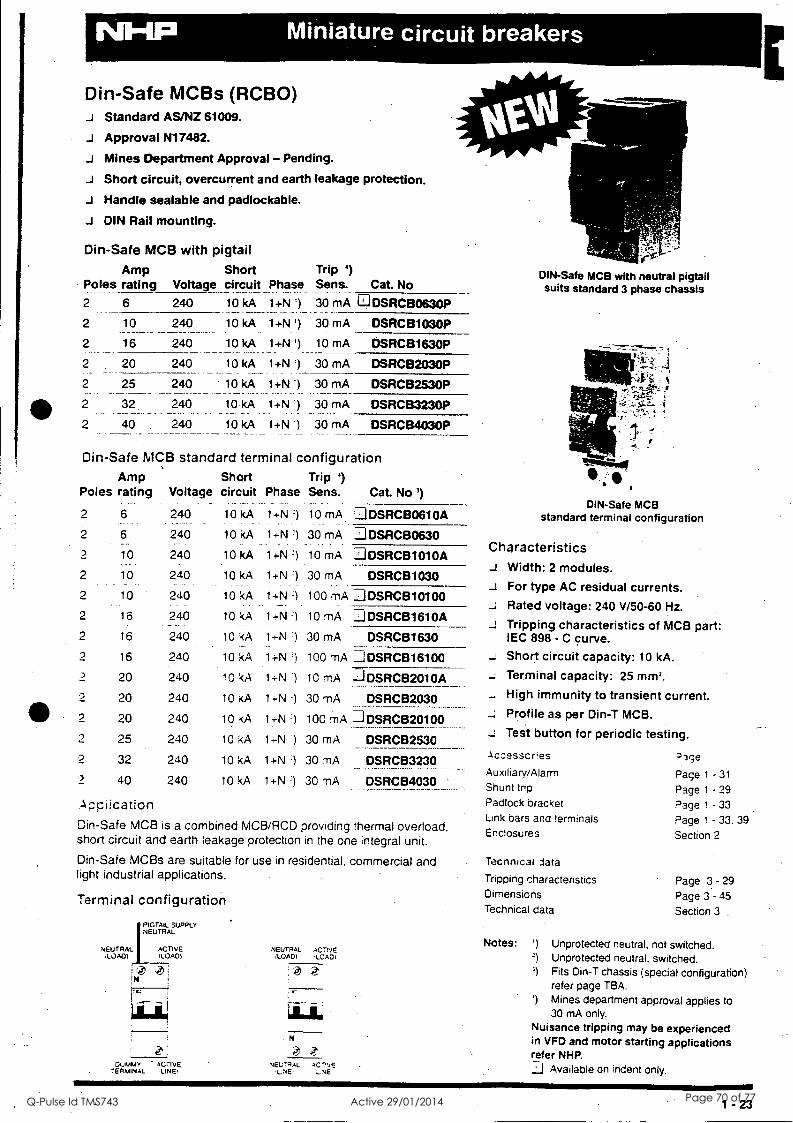
411
-
Din-Safe MCBs (RCBO) Standard AS/NZ 61009.
J Approval N17482.
Mines Department Approval - Pending.
J Short circuit, overcurrent and earth leakage protection.
J Handle sealable and padlockable.
J DIN Rail mounting.
Din-Safe MCB with pigtail
Po_ les Amp rating
Short Voltage circuit Phase
Trip ') Sens. Cat. No
2 6 240 10 kA 1+N ') 30 mA m DSRCB0630P
2 10 240 10 kA 1+N ') 30 mA DSRCB1030P
2 16 240 10 kA 1+N ') 10 mA DSRCB1630P
2 20 240 10 kA 1+N ') 30 mA DSRCB2030P
2 25 240 10 kA 1+N ') 30 mA DSRCB2530P
2 32 240 10.kA 1+N ') 30 mA DSRCB3230P
2 40 240 10 kA 1+N ') 30 mA DSRCB4030P
Din-Safe MCB standard terminal configuration Amp Short Trip 1)
Poles rating Voltage circuit Phase Sens. Cat. No ')
2 6 240 10 kA 1+N 1 10 mA ::JDSRCB0610A
2 6 240 10 kA 1+N 1 30 mA DDSRCB0630
2 10 240 10 kA 1+N 1 10 mA DSRCB1010A
2 10 240 10 kA 1+N 30 mA DSRCB1030
2 10 240 10 kA 1+N 1 100 mA DDSRCB10100 2 16 240
- -- .-
10 kA 1+N 1 10 rnA. IIDSRCB1610A
DSRCB1630 2 16 240 10 kA 1-i-N 1 30 mA
2 16 240 10 kA 1+N ') 100 rnA =_IDSRCB16100 -) 20 240 10 kA 14-N 1 10 mA -=IDSRCB2010A
2 20 240 10 kA 1+N-) 30 mA DSRCB2030 __ ..... ______.
2 20 240 10 kA 1+N -) 100 mA -1DSRCB20100
2 25 240 10 kA 14-N :) 30 mA DSRCB2530
2 32 240 10 kA 1+N ') 30 mA DSRCB3230
2 40 240 10 kA 1+N ') 30 mA DSRCB4030
.Appiication
Din-Safe MCB is a combined MCB/RCD providing thermal overload, short circuit and earth leakage protection in the one integral unit.
Din-Safe MCBs are suitable for use in residential, commercial and light industrial applications.
Terminal configuration
0 DIN-Safe MCB with neutral pigtail suits standard 3 phase chassis
DIN-Safe MCB standard terminal configuration
Characteristics J Width: 2 modules.
For type AC residual currents. ...: Rated voltage: 240 V/50-60 Hz.
a Tripping characteristics of MCB part: IEC 898 - C curve.
- Short circuit capacity: 10 kA.
- Terminal capacity: 25 mm2.
High immunity to transient current. Profile as per Din-T MCB.
Test button for periodic testing.
.ccesscres AuxiliaryiAlarm Shunt trip .
Padlock bracket Link bars and terminals Enclosures
Tecnnical data
Tripping characteristics Dimensions Technical data
NEUTRAL :LOAD)
PIGTAIL SUPPLY NEUTRAL
ACTIVE LOADI
NEUTRAL (LOAD)
Notes: AC 7-NE LCAC I
')
2)
') ; @ 4 i 1N i
21 21
21.
DUMMY ACTIVE TERMINAL . LINE,
N
vEL;,RAL AC-"LE UNE! L.NE:
ar;e
Page 1 - 31
Page 1 - 29
Page 1 - 33
Page 1 - 33. 39
Section 2
Page 3 - 29
Page 3 - 45
Section 3
Unprotected neutral, not switched. Unprotected neutral. switched. Fits Din-T chassis (special configuration) refer page TBA.
l) Mines department approval applies to 30 mA only.
Nuisance tripping may be experienced in VFD and motor starting applications refer NHP. .1.1 Available on indent only.
1 - 23
Creek Road Cannon Hill SPS SP047 Generator Connection OM Manual
Q-Pulse Id TMS743 Active 29/01/2014 Page 70 of 77
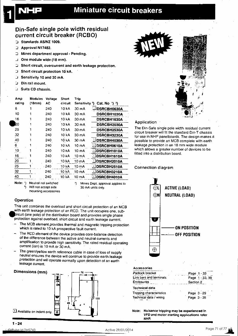
Din-Safe single pole width residual current circuit breaker (RCBO) II Standards AS/NZ 1009.
Approval N17482.
D Mines department approval - Pending.
One module wide (18 mm).
1:11 Short circuit, overcurrent and earth leakage protection. Short circuit protection 10 kA.
J Sensitivity 10 and 30 mA.
Din rail mount.
J Suits CD chassis.
Amp rating
Modules (18mm)
Voltage AC
Short circuit
Trip Sensitivity ') Cat. No ') 2)
6 1 240 10 kA 30 mA 11DSRCBH0630A 10 1 240 10 kA 30 mA DSRCBH1030A 16 1 240 10 kA 30 mA DSRCBH1630A
.0 1 240 10 kA 30 mA DSRCBH2030A 25 1 240 10 kA 30 mA DSRCBH2530A 32 1 240 10 kA 30 mA DSRCBH3230A 40 1 240 10 kA 30 mA :23 DSRCBH4030A 6 1 240 10 kA 10 mA DSRCBH0610A 10 1 240 10 kA 10 mA DSRCBH1010A 16 1 240 10 kA 10 mA .1.1DSRCBH1610A
20 1 240 10 kA 10 mA DSRCBH2010A 25 1 240 10 kA 10 mA 3 DSRCBH2510A 32 1 240 10 kA 10 mA DSRCBH3210A 40 1 240 10 kA 10 mA DSRCBH4010A
Note: ')
2)
Neutral not switched Will not accept side mounting accessories
3) Mines Dept. approval applies to 30 mA units only.
Operation This unit combines the overload and short circuit protection of an MCB with earth leakage protection of an RCD. The unit occupies one, sub- ircuit (one pole) of the distribution board and provides single phase protection against overload, short circuit and earth leakage current. - The MCB element provides thermal and magnetic tripping protection
which is rated to 10 kA prospective fault current. - The RCD element of the device provides core-balance detection
of the difference between the active and neutral currents and amplification to provide high sensitivity. The rated residual operating current (1,6,n) is 10 mA or 30 mA.
- The green/yellow earth reference cable in case of loss of supply neutral ensures the device will continue to provide earth leakage protection and will operate normally upon detection of an earth leakage current.
Dimensions (mm) 18
Available on indent only.
"
Application The Din-Safe single pole width residual current circuit breaker will fit the standard Din-T chassis for use in NHP panelboards. The design makes it possible to provide an MCB complete with earth leakage protection in an 18 mm wide module which allows a greater number of devices to be fitted into a distribution board.
Connection diagram
EL
EDN
lar
I I
ACTIVE (LOAD)
NEUTRAL (LOAD)
Accessories Padlock bracket Link bars and terminals
nclosures_
Technical data
Tripping characteristics Technical data / wiring
. _
ON POSITION
OFF POSITION
Page 1 - 33 Page 1 - 33, 39_
Section 2
Page 3 - 29 Page 3 - 35
Note: Nuisance tripping may be experienced in VFD and motor starting applications refer NHP.
1 - 24
Creek Road Cannon Hill SPS SP047 Generator Connection OM Manual
Q-Pulse Id TMS743 Active 29/01/2014 Page 71 of 77
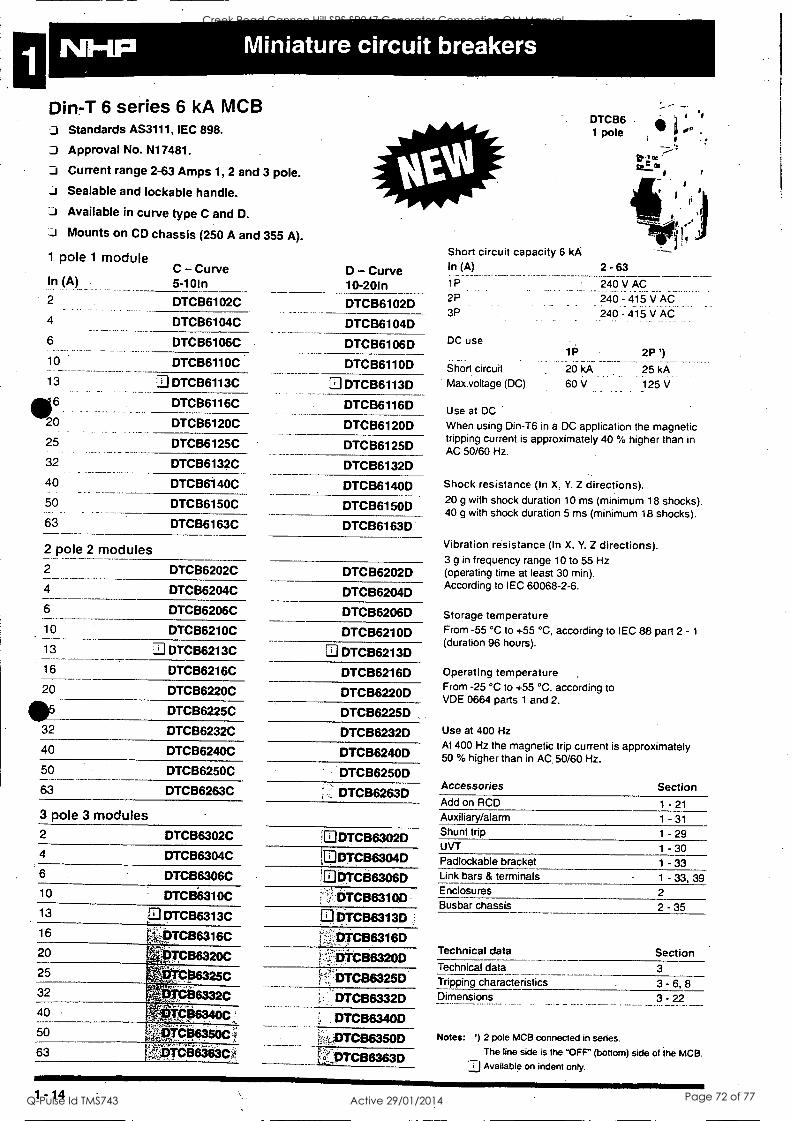
Din-T 6 series 6 kA MCB Standards AS3111, IEC 898.
Approval No. N17481.
Current range 2-63 Amps 1, 2 and 3 pole.
Sealable and lockable handle. J Available in curve type C and D.
Mounts on CD chassis (250 A and 355 A).
1 pole 1 module
In (A)
2
4
6
10
13
6 DTCB6116C
20 DTCB6120C
25 DTCB6125C
32 DTCB6132C
40 DTCB6140C
DTCB6 1 pole
C - Curve 5-10In
D - Curve 10-20In
Short circuit capacity 6 kA In (A)
1P
2P
3P
DC use 1P
Short circuit 20 kA
Max.voltage (DC) 60 V
2 -63 240 V AC
240 -415V AC 240 - 415 V AC
2P ')
25 kA._
125 V
DTCB6102C DTCB6102D
DTCB6104C DTCB6104D
DTCB6106C DTCB6106D
DTCB6110C DTCB6110D
3 DTCB6113C 3 DTCB6113D
50 DTCB6150C
63 DTCB6163C
2 pole 2 modules 2
4
DTCB6202C
DTCB6204C
6
10
13
16
DTCB6206C
DTCB6210C
3 DTCB6213C
DTCB6216C
DTCB6116D
DTCB6120D
DTCB6125D
DTCB6132D
DTCB6140D
DTCB6150D
DTCB6163D
DTCB6202D
DTCB6204D
DTCB6206D
DTCB62100
DTCB6213D
DTCB6216D 20 DTCB6220C DTCB6220D
411V DTCB6225C DTCB6225D 32 DTCB6232C DTCB6232D 40 DTCB6240C DTCB6240D 50
63
DTCB6250C
DTCB6263C
3 pole 3 modules 2 DTCB6302C
4 DTCB6304C 6 DTCB6306C 10 DTCB6310C 13 I21 DTC136313C
16 -V9TC136316C 20 g. gra36320C
1,00136325C 25
32 i . ,.
- 06332C :- s
40 - c f prosoc L
50 . q#64,56ei
63 . - - - TCB6363C'4".
4 ...., r
DTCB6250D
DTCB6263D
DTCB6302D
IDDTCB6304D U DTCB6306D
(..:DTCB6310D
D.DTCB6313D :
-4',:pTCB6316D
CB6320D
DTCB6325D
DTCB6332D
DTCB6340D
k,DTCB6350D
1DTCB6363D
Use at DC
When using Din-T6 in a DC application the magnetic tripping current is approximately 40 % higher than in AC 50/60 Hz.
Shock resistance (In X. Y. Z directions). 20 g with shock duration 10 ms (minimum 18 shocks). 40 g with shock duration 5 ms (minimum 18 shocks).
Vibration resistance (In X. Y. Z directions). 3 g in frequency range 10 to 55 Hz (operating time at least 30 min). According to IEC 60068-2-6.
Storage temperature From -55 °C to +55 °C, according to IEC 88 part 2 - 1
(duration 96 hours).
Operating temperature .
From -25 °C to +55 °C, according to VDE 0664 parts 1 and 2.
Use at 400 Hz At 400 Hz the magnetic trip current is approximately 50 % higher than in AC. 50/60 Hz.
Accessories Section Add on RCD
Auxiliary/alarm Shunt trip UVT Padlockable bracket Link bars & terminals Enclosures
1 -21 1 - 31
1 - 29 1 - 30 1 - 33 1 - 33, 39 2
Busbar chassis 2 - 35
Technical data Section Technical data 3 Tripping characteristics 3 - 6, 8 Dimensions 3 - 22
Notes: ') 2 pole MCB connected in series.
The line side is the "OFF" (bottom) side of the MCB. .-zj Available on indent only.
1 -14
Creek Road Cannon Hill SPS SP047 Generator Connection OM Manual
Q-Pulse Id TMS743 Active 29/01/2014 Page 72 of 77
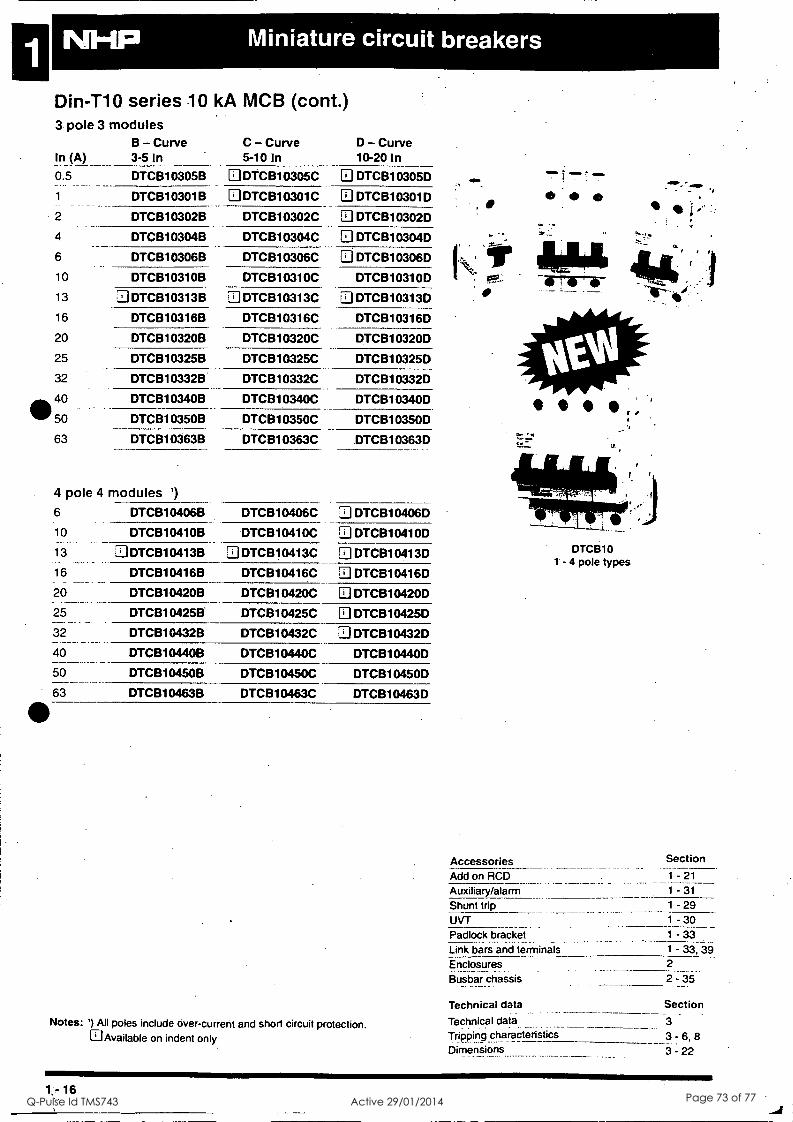
Din-T10 3 pole
In (A)
0.5
1
2
4
6
10
13
16
20
25
32
40
50
63
NM
series 10 kA MCB (cont.) 3 modules
B - Curve C - Curve D - Curve 3-5 In 5-10 In 10-20 In
DTCB10305B N DTCB10305C DTCB10305D
DTCB10301B DTCB10301C DTCB10301D
DTCB10302B DTCB10302C DTCB10302D
DTCB10304B DTCB10304C 3 DTCB10304D
DTCB10306B DTCB10306C DTCB10306D
DTCB10310B DTCB10310C DTCB10310D
DTCB10313B 3 DTCB10313C 3 DTCB10313D
DTCB10316B DTCB10316C DTCB10316D
DTCB10320B DTCB10320C DTCB10320D
DTCB10325B DTCB10325C DTCB10325D
DTCB10332B DTCB10332C DTCB10332D
DTCB10340B DTCB10340C DTCB10340D
DTCB10350B DTCB10350C DTCB10350D
DTCB10363B DTCB10363C DTCB10363D
4 pole 4 modules 1)
6
10
13
16
20
25
32
40
50
DTCB10406B DTCB10406C DTCB10406D
DTCB10410B DTCB10410C DTCB10410D
3 DTCB10413B DTCB10413C DTCB10413D
DTCB10416B DTCB10416C DTCB10416D
DTCB10420B DTCB10420C 3 DTCB10420D
DTCB10425B DTCB10425C DTCB10425D
DTCB10432B DTCB10432C 3 DTCB10432D
DTCB10440B DTCB10440C DTCB10440D
DTCB10450B DTCB10450C DTCB10450D
63 DTCB10463B DTCB10463C DTCB10463D
Notes: ') All poles include over-current and short circuit protection. a Available on indent only
,
4110
qb ,
DTCB10 1 - 4 pole types
Accessories Add on RCD Auxiliary/alarm Shunt trip UVT Padlock bracket Link bars and terminals
Enclosures Busbar chassis
Technical data
Technical data Tripping characteristics Dimensions
Section
1 -21 1 -31 1 - 29 1 - 30 1 - 33 1 - 33, 39 2
2 -35
Section
3
3= 6,8 3 -22
16
Creek Road Cannon Hill SPS SP047 Generator Connection OM Manual
Q-Pulse Id TMS743 Active 29/01/2014 Page 73 of 77
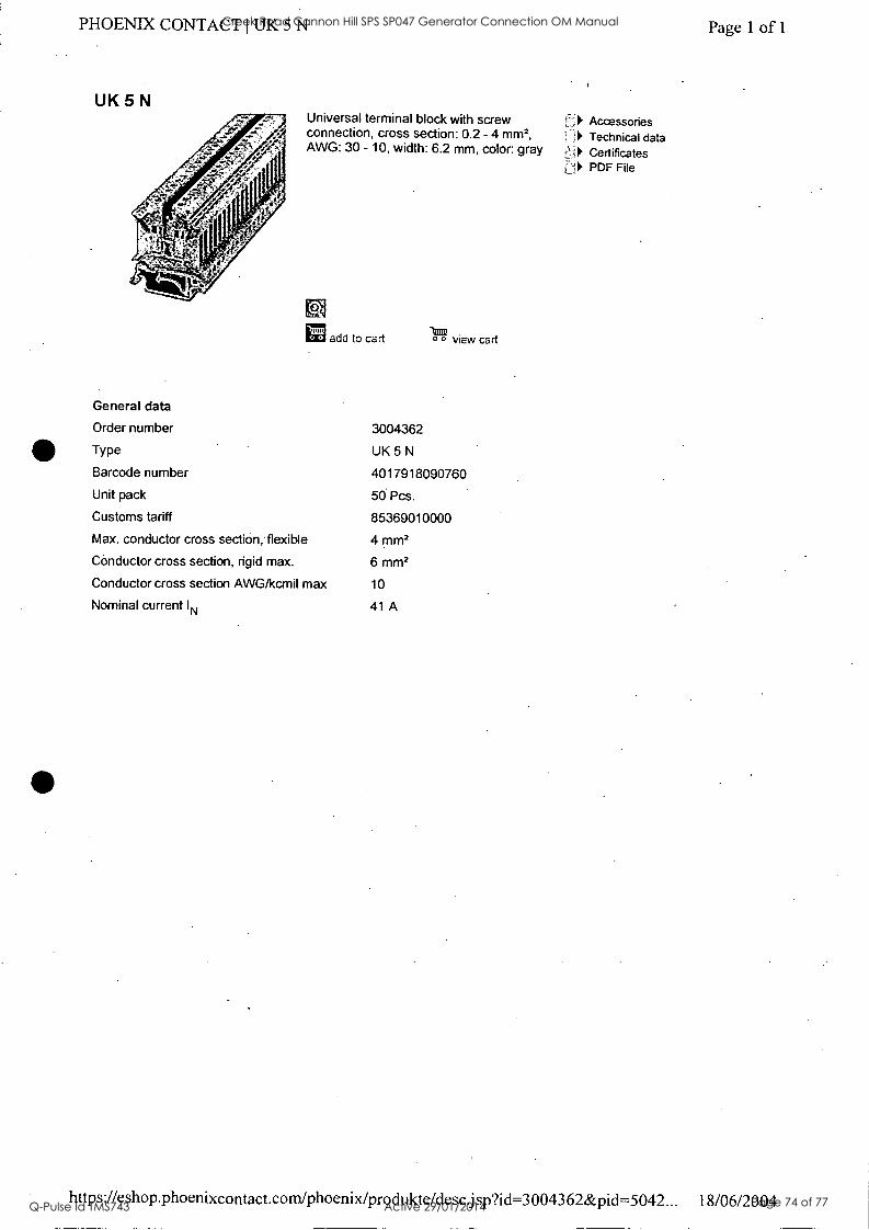
PHOENIX CONTACT I UK 5 N
UK Universal terminal block with screw connection, cross section: 0.2 - 4 mm2, AWG: 30 - 10, width: 6.2 mm, color: gray
to
General data
Order number
Type
1E12 add to cart ° view cart
3004362
UK5N Barcode number 4017918090760
Unit pack 50 Pcs.
Customs tariff 85369010000
Max. conductor cross section, flexible 4 mm2
Conductor cross section, rigid max. 6 mm2
Conductor cross section AWG/kcmil max 10
Nominal current IN 41 A
is =! Accessories 1 Technical data
t\! Certificates LI PDF File
Page 1 of 1
https://eshop.phoenixcontact.com/phoenix/produkte/descjsp?id=3004362&pid=5042... 18/06/2004
Creek Road Cannon Hill SPS SP047 Generator Connection OM Manual
Q-Pulse Id TMS743 Active 29/01/2014 Page 74 of 77
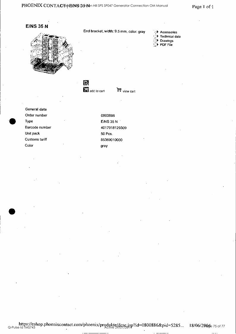
PHOENIX CONTACT I E/NS 35 N Page 1 of 1
E/NS 35 N End bracket, width: 9.5 mm, color: gray
General data
add to cart 0 view cart
Order number 0800886
Type E/NS 35 N
Barcode number 4017918129309
Unit pack 50 Pcs.
Customs tariff 85369010000
Color gray
Accessories Technical data
.:;:1 Drawings ;:' PDF File
https://eshop.phoenixcontact.com/phoenix/produkte/descjsp?id=0800886&pid=5285... 18/06/2004
Creek Road Cannon Hill SPS SP047 Generator Connection OM Manual
Q-Pulse Id TMS743 Active 29/01/2014 Page 75 of 77
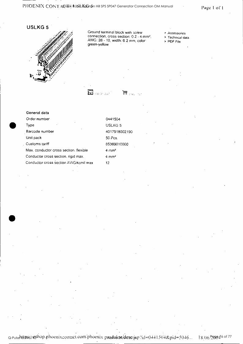
PHOENIX CONTACT I .SL.KG 5
USLKG 5 Ground terminal block with screw connection, cross section: 0.2 - 4 mm2, 'WIG: 26 - 10, width: 6.2 mm, color: green-yellow
Itim2 0 0
General data
Order number 0441504
Type USLKG 5
Barcode number 4017918002190
Unit pack 50 Pcs.
Customs tariff 85369010000
Max. conductor cross section. flexible 4 mm2
Conductor cross section. rigid max. 4 mm2
Conductor cross section AWG/kcmil max 12
Accessories > Technical data > PDF File
Patze I of
https:. esiloP.Phoenixcontact.com:phoenix produkteAlesejsp?ic1=0-I4 I 50-ILK:pid---5046... 1 8.:06:
Creek Road Cannon Hill SPS SP047 Generator Connection OM Manual
Q-Pulse Id TMS743 Active 29/01/2014 Page 76 of 77
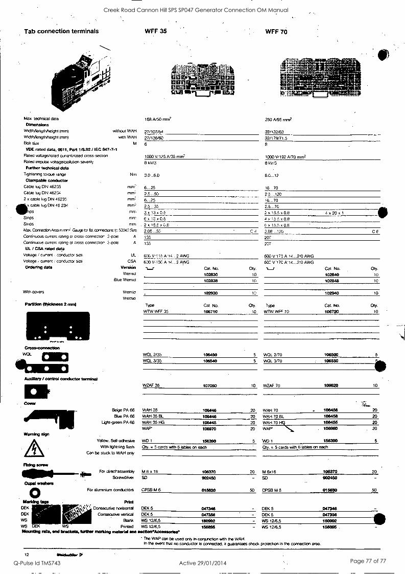
Tab connection terminals
Max. technical data
Dimensions WidthAerigt1Vheight Imm) without WAH
Width/length/height Imm) with WAH
Bolt size
WFF 35
168 A/50 mm2
27/107/54
27/136/60
6
#e ms ""~z
111:10 mon EMU
12.12111ai_rinl ilttSt
VDE rated data, 0611, Part 1/8.92 / IEC 947-7-1 Rated voltage/rated currenVrated cross-section 1000 V/125-A,'35 mm2 Rated impulse voltage/pollution severity 8 kV/3 8 kV/3 Further technical data
Tightening torque range Nm 3.0...6.0 6.0...12 Clampable conductor
Cable lug DIN 46235 MM. ,
6...25 16...70 Cable lug DIN 46234 rnm: 2.5...50 2.5...120 2 x cable lug DIN 46235 mm:-. 6...25 16...70
cable lug DIN 46 234 mm2 rimm2 2.5...35 2.5...70 m 3 x 13 x as. 2 x 15.E. x 0.8 m 4 x 20 x 1
Stnps mm 6x 12 x0.5 4X 15.2 x 0.8 Stnps mm 2 x 15..5 x 0.5 E. x 15.5 x 0.5 Max. Connection Area en rnmr--Gaay for Oat ccrriectorts lc 53043 Size 2.06...50 C z 2.08...120 C E
Continuous current rating of cross-connector 2-pole A 135 207 Continuous current rating of cross-connector 3-poie A 135
UL / CSA rated data Voltage i current . conductor size UL 600 v.1:5 A'14...2 AWG Voltage ! current .. conductor size CSA 600 V,.130 Al z 2 AWG Ordering data Version l_r Cat. No.
Wernol 102830 Blue Wemid 102838
WFF 70
250 A/95 mm2
32/132/63
32/179171.5
8
1000 V/192 A/70 mm2
With covers Wemid 102930 Wemid
Partition (thickness 2 men) Type Cat. No.
VVTW WFF 35 106710
111111 Gross -correction
WOL alp 41011:1M
Carer
Warning sign
WOL 2/35 106490
WQL 3/35 106540
WZAF 35 107050
Beige PA 66 WAH 35 106446
Blue PA 66 WAH 35 BL 106448
Light-green PA 66 WAH 35 HG 106445 WAP 106970
Yellow. Self-adhesive WD 1 156390 With lightning flash Oty. = 5 cards with 6 tables on each
Can be stuck to WAH only
Rdng screw
40.1
CupM wadters
For directassembly M 6 x 16
Screwdriver SD
For aluminium conductors CPSB M 6
106370
902450
015620
Marldng tags Print DEK \ 4:1' Consecutive horizontal DEK 5 047346 ' k \ DEK Consecutive vertical DEK 5 047358 WS Blank WS 12/6.5 180992 WS . WS . Printed WS 12/6.5 156895 Mounting rails, end brackets, further marking material see section"Accessortes"
207
600 V.175 A-14...2,0 AWG
Oty.
10
603 V '17C A'14...2/0 AWG
-r__r Cat. No.
102840
Oty.
10
10 102848 10
to 102940 10
Oty.
10
Type Cat. No.
WAN WFF 70 106720
Oty.
10
5 WOL 2/70 106500 5
5 WQL 3/70 106550
10 WZAF 70 106620 10
20 WAH 70 106456
;&..
20
20 WAH 70 BL 106458 20
20 WAH 70 Fib 106455 20
20
5
WAP* 106980
WD 1 158390
. 20
5
. Oty. = 5 cards with 6 tables on each
20 M 6x16 106370 20
-
50
SD 902450
CPSB M 8 015830 50
- DEK 5 047346
- DEK 5 047358 - WS 12/6.5 180992
- WS 12/6.5 156895 .
The WAP can be used only in conjunction with the WAH. In the event that no conductor is connected. it guarantees shock protection in the connection area.
12 Wakkalliktir
Creek Road Cannon Hill SPS SP047 Generator Connection OM Manual
Q-Pulse Id TMS743 Active 29/01/2014 Page 77 of 77


