Embed Size (px)
Citation preview
DRAFT
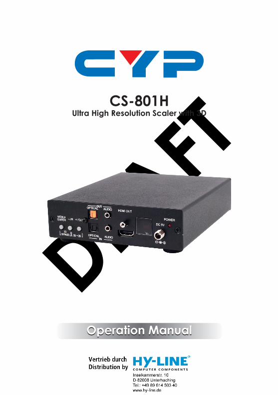
CS-801HUltra High Resolution Scaler with 3D
Operation ManualOperation Manual

DRAFT

DRAFT
DISCLAIMERSThe information in this manual has been carefully checked and is believed to be accurate. Cypress Technology assumes no responsibility for any infringements of patents or other rights of third parties which may result from its use.Cypress Technology assumes no responsibility for any inaccuracies that may be contained in this document. Cypress also makes no commitment to update or to keep current the information contained in this document.Cypress Technology reserves the right to make improvements to this document and/or product at any time and without notice.
COPYRIGHT NOTICENo part of this document may be reproduced, transmitted, transcribed, stored in a retrieval system, or any of its part translated into any language or computer file, in any form or by any means—electronic, mechanical, magnetic, optical, chemical, manual, or otherwise—without express written permission and consent from Cypress Technology.© Copyright 2012 by Cypress Technology.All Rights Reserved.Version VR1.0 January 2012
TRADEMARK ACKNOWLEDGMENTSAll products or service names mentioned in this document may be trademarks of the companies with which they are associated.

DRAFT
SAFETY PRECAUTIONSPlease read all instructions before attempting to unpack, install or operate this equipment and before connecting the power supply.Please keep the following in mind as you unpack and install this equipment:• Always follow basic safety precautions to reduce the risk of fire,
electrical shock and injury to persons.• To prevent fire or shock hazard, do not expose the unit to rain,
moisture or install this product near water.• Never spill liquid of any kind on or into this product.• Never push an object of any kind into this product through any
openings or empty slots in the unit, as you may damage parts inside the unit.
• Do not attach the power supply cabling to building surfaces.• Use only the supplied power supply unit (PSU). Do not use the PSU
if it is damaged.• Do not allow anything to rest on the power cabling or allow any
weight to be placed upon it or any person walk on it.• To protect the unit from overheating, do not block any vents or
openings in the unit housing that provide ventilation and allow for sufficient space for air to circulate around the unit.
REVISION HISTORY
VERSION NO. DATE DD/MM/YY SUMMARY OF CHANGERDV1 06/01/12 Preliminary Release
RDV2 07/02/12
RDV3 31/07/12 Add RS-232 Commands
RDV4 22/12/12 Support timing change

DRAFT
CONTENTS
1. Introduction ............................................ 12. Applications ........................................... 13. Package Contents ................................ 14. System Requirements ............................ 15. Features .................................................. 16. Operation Controls and Functions ....... 2
6.1 Front Panel ........................................26.2 Rear Panel .........................................4
7.OSD Menu and Function List .................. 58. Remote Control ...................................... 6
8.1 RS-232 Protocols ...............................78.2 RS-232 Commands ...........................8
9. Connection and Installation ............... 1010. Specifications .................................... 11
10.1 PC, HDMI, DP Input Timing ..........1210.2 Output Resolution ........................14
11. Acronyms ........................................... 15

DRAFT
1
1. INTRODUCTIONThis high performance video processor which allows 3D movies to be watched on a 2D display. With HDMI, DisplayPort and PC/Component inputs to its HDMI output and the associated audio signal processed synchronously. The operation of both 3D-to-2D and scaling features can be handled easily through on-panel buttons, IR remote control, or RS-232 protocol.
2. APPLICATIONS• Convert 3D signal to 2D signal for 2D display• 3D source bypass to 3D display without scaling• Scale HDMI, DisplayPort and PC/Component inputs to HDMI output
3. PACKAGE CONTENTS• Ultra High Resolution Scaler with 3D• 5V/2.6A DC power adaptor• Operation Manual
4. SYSTEM REQUIREMENTS• Input HDMI/DisplayPort/PC sources and output with 2D or 3D HDMI
display.
5. FEATURES• Supports HDMI 3D processing on Frame Packing and Top-
and-Bottom of 720p@50/60Hz and 1080p@24Hz, Side-by-Side Half signals of 720p@50/60Hz, 1080i@50/60Hz(input only) and 1080p@24/50/60Hz
• Supports HDMI / Component input timing up to 1080p@50/60Hz, DisplayPort up to 2560 x 1600@60HzRB and PC up to 1920 x 1200@60/75Hz
• Supports digital and analog audio bidirectional conversion, extraction and insertion for the audio signals from individual inputs or from the HDMI source
• Supports component input when connected VGA to 3RCA adaptor
DRAFT
2
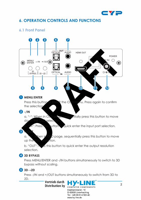
6. OPERATION CONTROLS AND FUNCTIONS
6.1 Front Panel
3DBYPASS 3D→2D
ENTERMENU/
OPTICALOUT
IN
AUDIO HDMI OUT
DC 5V
POWER
OPTICAL AUDIO
1
4 5 8 9 10 11 12
2 3 6 7
1 MENU/ENTER Press this button to ENTER the OSD menu. Press again to confirm
the selection.
2 -/IN a. “-“: When in OSD page, sequentially press this button to move
down the OSD selection.
b. “IN”: Press this button to quick enter the input port selection.
3 +/OUT a. “+”: When in OSD page, sequentially press this button to move
up the OSD selection.
b. “OUT”: Press this button to quick enter the output resolution selection.
4 3D BYPASS Press MENU/ENTER and -/IN buttons simultaneously to switch to 3D
bypass without scaling.
5 3D→2D Press -/IN and +/OUT buttons simultaneously to switch from 3D to
2D.

DRAFT
3
6 OPTICAL OUT This slot is where you connect the amplifier with OPTICAL cable
and from amplifier to speaker.
7 AUDIO L/R OUT This slot is where you connect the speaker or amplifier with audio
phone jack to the display.
8 OPTICAL IN This slot is where you connect the input OPTICAL audio source.
9 AUDIO L/R IN This slot is where you connect the L/R input audio source.
10 HDMI OUT This slot is where you connect the HDMI display with HDMI cable.
11 IR sensor12 DC 5V Plug the 5V DC power supply into the unit and connect the
adaptor to AC wall outlet. Once the system turns on the LED will turn RED.

DRAFT
4
6.2 Rear Panel
1
2 3 4 5
HDMI 1 HDMI 2 PC/COMP
SERVICE DisplayPort
RS232
IN
1 RS232 This slot is to connect with D-Sub 9pin cable from the PC/NB device
for RS-232 control.
2 SERVICE This slot is to connect with USB cable for manufacturers’ firmware
update only.
3 DisplayPort IN This slot is where you connect the DisplayPort source output for
DisplayPort signal sending.
4 HDMI 1/2 IN These slots are where you connect the HDMI sources output for
HDMI signal sending.
5 PC/COMP IN This slot is where you connect the PC/NB or DVD/Set-Top Box
source equipment with D-Sub 15-pin cable for PC source signal input or with D-Sub 15-pin to 3 RCA adaptor for component signal input.

DRAFT
5
7.OSD MENU AND FUNCTION LIST
Input Video PC
COMP
HDMI 1
HDMI 2
DP
Exit
Input Audio AUDIO
Optical
HDMI/DP
Mute
Exit
Output Resolution 720x480P
1280x720P
1920x1080P
640x480
800x600
1024x768
1280x1024
1600x1200
1920x1200
By Native
3D Bypass
Exit
Output Format 3D→2D
3D Bypass
Exit

DRAFT
6
Main Menu 2nd Layer 3rd Layer
Misc. Setup EDID Mode Internal / External / Exit
Info. OSD Mode Off / On / Exit
About CS-801H FW Ver.
Factory Reset System Reset
Exit
Exit
8. REMOTE CONTROL1 VIDEO IN
Press to select HDMI 1/HDMI 2/DP/PC/Component input source.
2 AUDIO IN Press to select AUDIO/
OPTICAL/HDMI/DP input audio or MUTE the system.
3 EXIT Press the EXIT the OSD
selection.
4 MENU Press this button to ENTER the
OSD menu.
5 ENTER Press to confirm the selection.
6 INFO To show input and output resolution information.
7 OUTPUT Press to show the output resolution table.
8 ▲/▼ Press up/down buttons to select OSD selection.
DP
HDMI/DP
MENU
OUTPUTINFO
HDMI 1
PC
AUDIO
MUTE
EXIT
NATIVE3D→2D 3D BYPASS
HDMI 2
COMP
OPTICAL
ENTER
CR-111
AUDIO IN
VIDEO IN
1
2
4
7
11
8
3
6
910
5

DRAFT
7
9 3D→2D Press to switch from 3D to 2D.
10 3D Bypass Press to switch to 3D bypass.
11 Native
Press to switch to Native resolution.
8.1 RS-232 ProtocolsRS-232 modem cable.Pins definition of modem cable
CS-801H Remote Controller
PIN Definition PIN Definition
1 NC 1 NC
2 TxD 2 RxD
3 RxD → 3 TxD
4 NC 4 NC
5 GND ← 5 GND
6 NC 6 NC
7 NC 7 NC
8 NC 8 NC
9 NC 9 NC
Baud Rate: 19200 bps Data Bit: 8 bits Parity: None Stop Bit: 1 bit Flow Control: None

DRAFT
8
8.2 RS-232 Commands
User Command Code Description
POWER ? Power Status
POWER ON Power On
POWER OFF Power Off
3D ? 3D Status
3D TO 2D 3D In, 2D Out
3D BYPASS 3D In, 3D Bypass Out
VIDEO ? Video Input Source
HDMI 1 Video Input in HDMI1
HDMI 2 Video Input in HDMI2
DP Video Input in DisplayPort
PC Video Input in PC
COMP Video Input in Component
AUDIO ? Audio Input Source
AUDIO Audio Input in AUDIO
OPTICAL Audio Input in OPTICAL
HDMI/DP Audio Input in HDMI/DP
MUTE ON Mute On
MUTE OFF Mute Off
INFO ? Info.OSD Status
INFO ON Info.OSD On

DRAFT
9
INFO OFF Info.OSD Off
OUTPUT ? Output Status
480P Output in 480P
720P Output in 720P
1080P Output in 1080P
VGA Output in VGA(640x480)
SVGA Output in SVGA(800x600)
XGA Output in XGA(1024x768)
SXGA Output in SXGA(1280x1024)
UXGA Output in UXGA(1600x1200)
WUXGA Output in WUXGA(1920x1200)
NATIVE Output by Native
EDID ? EDID Status
EDID INT EDID By Internal
EDID EXT EDID By External
FEEDBACK ? Feedback Status
FEEDBACK ON RS232 Feedback Enable
FEEDBACK OFF RS232 Feedback Disable
STATE ? Video Input Signal Status
VERSION ? Firmware Version
DEFAULT Reset to Factory Default
Note: Any commands will not be executed unless followed by a carriage return. Commands are not case-sensitive.

DRAFT
10
9. CONNECTION AND INSTALLATION
HDMI 1 HDMI 2 VGA
SERVICE DisplayPort
RS232
IN
OR
3DBYPASS 3D→2D
ENTERMENU/
OPTICALOUT
IN
AUDIO HDMI OUT
DC 5V
POWER
OPTICAL AUDIO
OR
PC PCNB
VGAOptical HDMI
Optical 3.5Ø audio
D-Sub15pin
HDMI
HDMI
DP
Dell PCBlu-ray
PC NB
DVD
Amplifier
HD TV

DRAFT
11
10. SPECIFICATIONSVideo Bandwidth 255MHz/6.75Gbps
DP Input Frequency Bandwidth
2.7Gbps & 1.62Gbps/Lane
Input Port 2 x HDMI (Female type), 1 x DisplayPort, 1 x VGA
Audio Input Port 1 x L/R, 1xOptical
Output Port 1 x HDMI, 1 x L/R, 1 x Optical
Power Supply 5V DC/ 2.6A (US/EU standards, CE/FCC/UL certified)
ESD Protection Human body model: ±8 kV (air-gap discharge)
±4 kV (contact discharge)
Dimensions (mm) 142(W) x 180(D) x 43(H)
Weight(g) 700
Chassis Material Aluminum
Silkscreen Color Black
Operating Temperature 0˚C ~ 40˚C / 32 ˚F ~ 104 ˚F
Storage Temperature -20˚C ~ 60˚C / -4 ˚F ~ 140 ˚F
Relative Humidity 20 ~ 90% RH (non-condensing)
Power Consumption 9W

DRAFT
12
10.1 PC, HDMI, DP Input Timing
2D Input Resolution PC HDMI DPCOMP Input
Resolution640*350@85 ˇ ˇ
640*400@85 ˇ ˇ
720*400@85 ˇ ˇ
VGA640*480@60/72/75/85
ˇ ˇ ˇ
SVGA800*600@56/60/72/75/85/120
ˇ ˇ ˇ
848*480@60Hz ˇ ˇ
XGA1024*768@43i/60/75/85/120
ˇ ˇ
XGA+1152*864@75 ˇ ˇ
1280*720@60 ˇ ˇ
1280*768@60R/60/75/85/120R
ˇ ˇ ˇ
1280*800@60R/60/75/85/120R
ˇ ˇ
1280*960@60/85/120R ˇ@60/85 ˇ
1280*1024@60/75/85 ˇ ˇ ˇ+120R
1360*768@60/120R ˇ ˇ ˇ
1366*768@60 ˇ ˇ
SXGA+1400*1050@60R/60/75
ˇ
WXGA+1440*900@60R/60/75/85
ˇ ˇ
1440*1050@85/120R ˇ ˇ

DRAFT
13
1600*900@60R ˇ ˇ
UXGA1600*1200@60/65/70/75/85/120R
ˇ@60 only ˇ ˇ
WSXGA1680*1050@60R/75/85
ˇ@60CVT/60 ˇ
1792*1366@60/75 ˇ
1856*1392@60 ˇ
1920*1080@60 ˇ ˇ
1920*1200(@60R/60/75Hz)
ˇ@60 ˇ ˇ
1920*1440@60 ˇ
720*480I/P ˇ ˇ ˇ
720*576I/P ˇ ˇ
720I/P@50/60 ˇ ˇ
1080I/P@50/60 ˇ ˇ
1080P@24 ˇ
2048*1152@60R ˇ
2560*1600@R ˇ
3D Input Resolution HDMI
1080p@24Hz Frame packing
ˇ
1080p@24Hz Top-and-Bottom
ˇ
1080p@24Hz Side-by-Side
ˇ
1080i@50/60Hz Side-by-Side
ˇ
720p@50/60Hz Side-by-Side
ˇ

DRAFT
14
720p@50 / 60Hz Frame packing
ˇ
720p@50 /60Hz Top-and-Bottom
ˇ
10.2 Output ResolutionHDMI 3D to 2D and 2D to 2D output Resolution@60Hz
640*480800*6001024*7681280*10241600*1200
1920*1200RB480P720P1080P
HDMI 3D to 3D Bypass Output Resolution
Frame Packing: 720p@50/60Hz, 1080i@60Hz, 1080p@24/30HzTop-and-Bottom: 720p@50/60Hz, 1080i@60Hz, 1080p@24/30HzSide-by-Side: 720p@50/60Hz, 1080i@60Hz, 1080p@24Hz
Note: Some output display may not support 3D@50Hz and therefore,some 3D 50Hz signal may not be display.

DRAFT
15
11. ACRONYMS
ACRONYM COMPLETE TERM
HDMI High-Definition Multimedia Interface

DRAFT

DRAFT

DRAFT

DRAFT
Home page: http://www.cypress.com.twCYPRESS TECHNOLOGY CO., LTD
20120803 MPM-CS801H