Embed Size (px)
Citation preview
5022-D063737 Revision: 03
cyber® kit line Frameless servo motors
Project planning guide

cyber® kit line
5022-D063737 Revision: 03
WITTENSTEIN cyber motor GmbH
Walter-Wittenstein-Straße 1
D-97999 Igersheim
Germany
Customer Service
© WITTENSTEIN cyber motor GmbH 2022
This documentation is protected by copyright.
WITTENSTEIN cyber motor GmbH reserves all the rights to photo-mechanical reproduction,
copying, and the distribution by special processes (such as computers, file media, data
networks), even in parts.
Subject to technical and content changes without notice.
cyber® kit line
Revision: 03 5022-D063737 en-1
Table of Contents
1 Product presentation ......................................................................................................................... 3
1.1 Name plate ................................................................................................................................... 3
2 Intended use ....................................................................................................................................... 6
2.1 Intended use ................................................................................................................................. 6
2.2 Application range .......................................................................................................................... 7
2.3 Standards and certificates ............................................................................................................ 8
3 Safety instructions .......................................................................................................................... 13
3.1 Application and passing on of safety instructions ....................................................................... 13
3.2 Warning symbols and hazard classes ........................................................................................ 14
3.3 Hazard-related safety instructions .............................................................................................. 16
3.4 Minimizing risks .......................................................................................................................... 18
4 Transport and storage ..................................................................................................................... 19
4.1 Scope of delivery ........................................................................................................................ 21
5 Technical data .................................................................................................................................. 22
5.1 Definitions ................................................................................................................................... 22
5.2 Technical product data ............................................................................................................... 29
5.2.1 Size 050 .............................................................................................................................. 29
5.2.2 Size 085 .............................................................................................................................. 32
5.2.3 Size 290 .............................................................................................................................. 35
5.2.4 Size 360 .............................................................................................................................. 37
5.2.5 Size 420 .............................................................................................................................. 39
5.2.6 Size 530 .............................................................................................................................. 41
5.3 Dimensional drawings ................................................................................................................ 42
5.4 Type code ................................................................................................................................... 42
5.5 Installed components .................................................................................................................. 46
5.5.1 Temperature sensor ............................................................................................................ 46
5.5.2 Encoder ............................................................................................................................... 50
5.5.3 Brake ................................................................................................................................... 51
5.6 Accessories ................................................................................................................................ 51
6 Assembly .......................................................................................................................................... 52
6.1 General information .................................................................................................................... 52
6.2 Assembly of stators .................................................................................................................... 52
6.2.1 Stators of size 050 and 085 ................................................................................................. 52
6.2.2 Stators of size 290 to 530 .................................................................................................... 54
6.3 Assembly of rotors ...................................................................................................................... 55
6.3.1 Rotors of size 050 and 085 ................................................................................................. 56
6.3.2 Rotors of size 290 to 530 .................................................................................................... 57
6.4 Assembly of rotor/stator in the application .................................................................................. 58
6.5 Coolant connection ..................................................................................................................... 58
6.6 Electrical connection ................................................................................................................... 59
cyber® kit line
en-2 5022-D063737 Revision: 03
7 Connection technology .................................................................................................................. 60
7.1 General information ................................................................................................................... 60
7.2 Safety instructions ..................................................................................................................... 60
7.3 Connection schematics .............................................................................................................. 61
8 Startup and operation ..................................................................................................................... 65
8.1 General instructions for commissioning ..................................................................................... 65
8.2 Safety instructions ..................................................................................................................... 65
8.3 Preconditions and auxiliaries ..................................................................................................... 66
8.4 General procedure for commissioning ....................................................................................... 68
8.4.1 Commissioning of brakes ................................................................................................... 69
9 Maintenance .................................................................................................................................... 70
9.1 Cleaning ..................................................................................................................................... 70
9.2 Visual inspection ........................................................................................................................ 71
9.3 Disassembly .............................................................................................................................. 71
9.4 Disposal ..................................................................................................................................... 73
10 Service & support .................................................................................................................... 74
cyber® kit line
Revision: 03 5022-D063737 en-3
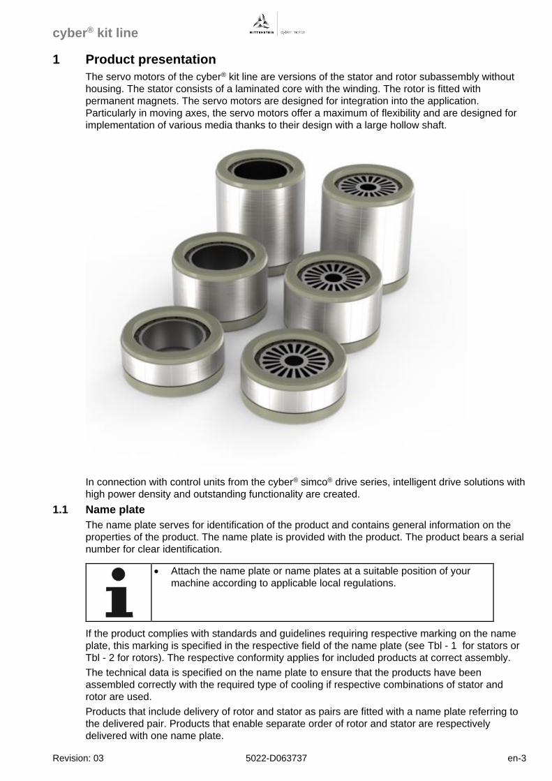
1 Product presentation
The servo motors of the cyber® kit line are versions of the stator and rotor subassembly without
housing. The stator consists of a laminated core with the winding. The rotor is fitted with
permanent magnets. The servo motors are designed for integration into the application.
Particularly in moving axes, the servo motors offer a maximum of flexibility and are designed for
implementation of various media thanks to their design with a large hollow shaft.
In connection with control units from the cyber® simco® drive series, intelligent drive solutions with
high power density and outstanding functionality are created.
1.1 Name plate
The name plate serves for identification of the product and contains general information on the
properties of the product. The name plate is provided with the product. The product bears a serial
number for clear identification.
• Attach the name plate or name plates at a suitable position of your
machine according to applicable local regulations.
If the product complies with standards and guidelines requiring respective marking on the name
plate, this marking is specified in the respective field of the name plate (see Tbl - 1 for stators or
Tbl - 2 for rotors). The respective conformity applies for included products at correct assembly.
The technical data is specified on the name plate to ensure that the products have been
assembled correctly with the required type of cooling if respective combinations of stator and
rotor are used.
Products that include delivery of rotor and stator as pairs are fitted with a name plate referring to
the delivered pair. Products that enable separate order of rotor and stator are respectively
delivered with one name plate.
cyber® kit line
en-4 5022-D063737 Revision: 03
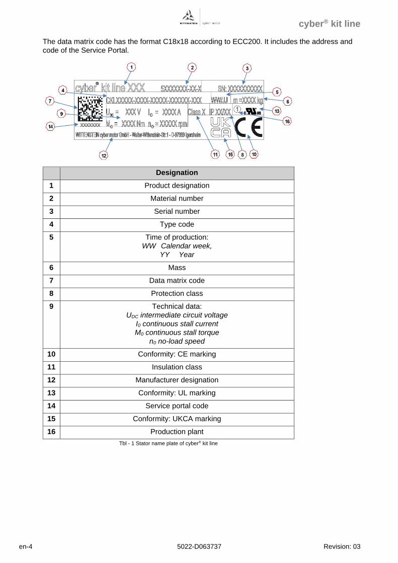
The data matrix code has the format C18x18 according to ECC200. It includes the address and
code of the Service Portal.
Designation
1 Product designation
2 Material number
3 Serial number
4 Type code
5 Time of production:
WW Calendar week,
YY Year
6 Mass
7 Data matrix code
8 Protection class
9 Technical data:
UDC intermediate circuit voltage
I0 continuous stall current
M0 continuous stall torque
n0 no-load speed
10 Conformity: CE marking
11 Insulation class
12 Manufacturer designation
13 Conformity: UL marking
14 Service portal code
15 Conformity: UKCA marking
16 Production plant
Tbl - 1 Stator name plate of cyber® kit line
cyber® kit line
Revision: 03 5022-D063737 en-5
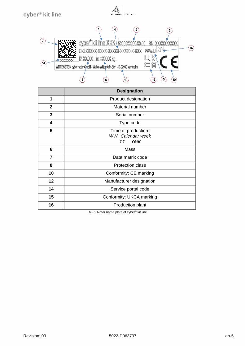
Designation
1 Product designation
2 Material number
3 Serial number
4 Type code
5 Time of production:
WW Calendar week
YY Year
6 Mass
7 Data matrix code
8 Protection class
10 Conformity: CE marking
12 Manufacturer designation
14 Service portal code
15 Conformity: UKCA marking
16 Production plant
Tbl - 2 Rotor name plate of cyber® kit line
cyber® kit line
en-6 5022-D063737 Revision: 03
2 Intended use
The products of WITTENSTEIN cyber motor are developed and produced according to the latest
standards.
The products may only be used in compliance with their intended use. If they are not used as
intended, property damage and personal injury may be the consequence.
Before using the products, the following requirements must be observed to ensure use of the
products as intended:
• Ensure that everybody working with one of the products has read and understood the
applicable safety regulations and instructions on the intended use.
• Leave the products in their original condition. Do not change or manipulate the structure of
the product.
Software products must not be decompiled and source codes must not be changed.
• Do not subject the products to external force.
• Ensure that damaged or incorrect products are not installed or taken into operation.
2.1 Intended use
Only properly qualified and professionally trained personnel who are able to assess the safe
condition of the product are allowed to work at the product. For example, this qualification is
verified by the following points:
- Professional and/or technical training
- Knowledge of applicable standards and regulations
- Knowledge of accident prevention regulations and operating conditions
- Ability to recognize and assess potential danger
Electrical connection may only be realized by qualified personnel who are able to recognize,
assess and prevent any potential electrical hazards.
All instructions in these project specifications, information on packaging and the product as well
as the assembly instructions of your company must be observed at all times. If applicable, any
local requirements must be observed.
WITTENSTEIN cyber motor GmbH is not informed about the installation conditions into your
product. These project specifications highlight only the general conditions of use and limits of the
building kit motor. It is the responsibility of your company to create and use the corresponding
internal documents (e.g. assembly instructions, circuit diagrams etc.) on this basis.
The product may only be mounted with the intended attachment elements as described in the
assembly instructions of your company.
In case of any differences between these project specifications, the instructions on the
packaging, the instructions on the product, the local requirements and the assembly instructions
of your company, clarify the correct approach with the responsible personnel at your company
and notify the competent positions of the recognized differences.
cyber® kit line
Revision: 03 5022-D063737 en-7
2.2 Application range
The products of the cyber® kit line are exclusively intended for use in industrial systems as rotary
drive motor in machinery.
For control and monitoring of motors, connection of additional sensors and components may be
required. The products may only be used with the accessories and attachments specified in these
project specifications. These particularly include the housing for the stator or the shaft for the
rotor. Components which are not specifically stated must not be mounted nor connected.
Operation is only allowed in compliance with explicitly stated configurations and combinations of
components.
Before commissioning, every connected drive control unit must be parameterized for the motor to
execute specific functions for the application.
The motors may only be used in compliance with the ambient conditions specified in these
project specifications (e.g. temperature, protection class, cooling, etc.) and in the applications
specified by your company.
Applicable ambient conditions during operation of products:
- IEC 60721-3-3, class 3K3 with expansion of the low air temperature from +5 °C to +0 °C and
of the relative humidity from 85% to 95%.
- IEC 60721-3-3, class 3B1
- IEC 60721-3-3, class 3C1
- IEC 60721-3-3, class 3S1
- IEC 60721-3-3, class 3M8
Tbl - 3 contains an excerpt of the ambient conditions during operation for the products.
Ambient conditions during operation
Property Value Standard Class
Temperature range +0 °C ... +40 °C a IEC 60721-3-3 3K3
Relative humidity 5 % … 95 % a IEC 60721-3-3 3K3
Absolute humidity 1 g/m³ … 25 g/m³ IEC 60721-3-3 3K3
Rate of temperature
change 0.5 °C/min IEC 60721-3-3 3K3
Max. vibration load (9 –
200 Hz) 50 m/s² a IEC 60721-3-3 3M8
Max. axial shock load
(6 ms) 250 m/s² a IEC 60721-3-3 3M8
Max. radial shock load
(6 ms) 250 m/s² a IEC 60721-3-3 3M8
a: Values adjusted compared to standard
Tbl - 3 Excerpt of ambient conditions during operation
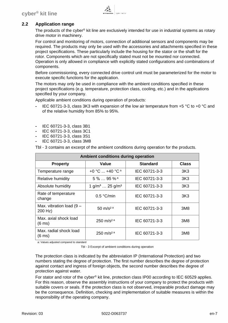
The protection class is indicated by the abbreviation IP (International Protection) and two
numbers stating the degree of protection. The first number describes the degree of protection
against contact and ingress of foreign objects, the second number describes the degree of
protection against water.
For stator and rotor of the cyber® kit line, protection class IP00 according to IEC 60529 applies.
For this reason, observe the assembly instructions of your company to protect the products with
suitable covers or seals. If the protection class is not observed, irreparable product damage may
be the consequence. Definition, checking and implementation of suitable measures is within the
responsibility of the operating company.
cyber® kit line
en-8 5022-D063737 Revision: 03
Power converted to heat is dissipated via neighboring components. For this reason, products
may only be operated if sufficient power dissipation is ensured. The cooling system and materials
used must be designed accordingly. Please observe that heat can be dissipated as well as
introduced via attached components.
2.3 Standards and certificates
In these project specifications, German, European and international technical standards are
mentioned. Standard documents and standard sheets are subject to copyright protection. As
required, please contact the authorized distributors.
All products of the cyber® kit line comply with the following standards and regulations if applicable
for the products:
- IEC 60034 Rotating electrical machines
- 2014/35/EU Low Voltage Directive
- 2006/42/EC Machinery Directive
- 2011/65/EU RoHS Directive
- 640/2009 Regulation on Ecodesign Directive
- 2014/30/EU EMC Directive
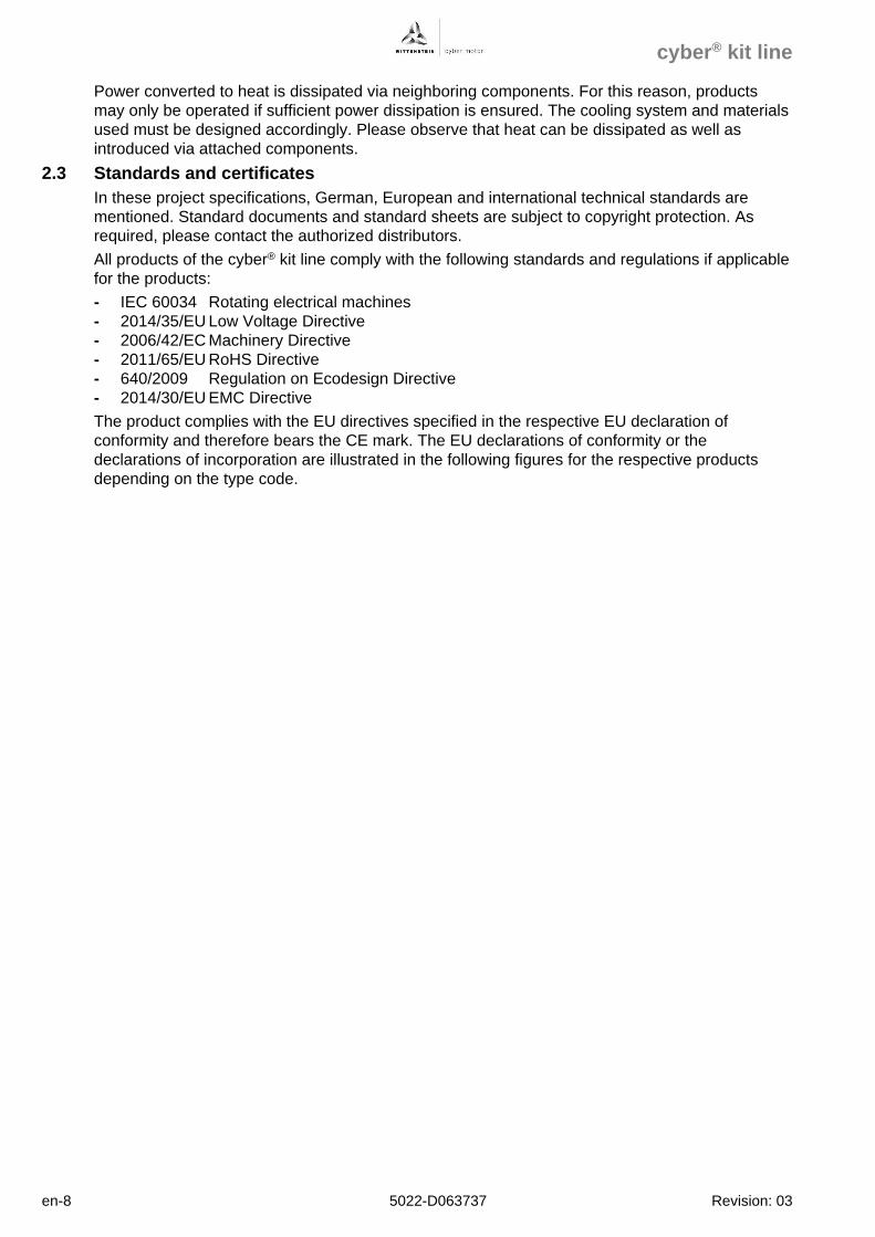
The product complies with the EU directives specified in the respective EU declaration of
conformity and therefore bears the CE mark. The EU declarations of conformity or the
declarations of incorporation are illustrated in the following figures for the respective products
depending on the type code.
cyber® kit line
Revision: 03 5022-D063737 en-9
Fig. 2-1 Declaration of incorporation of cyber® kit line, cooling type "C", voltage class "B" (page 1)
cyber® kit line
en-10 5022-D063737 Revision: 03
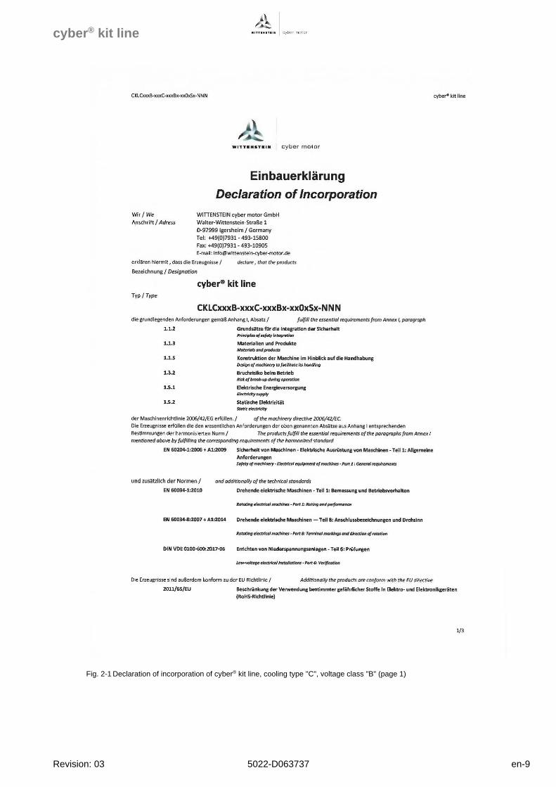
Fig. 2-2 Declaration of incorporation of cyber® kit line, cooling type "C", voltage class "B" (page 2)
cyber® kit line
Revision: 03 5022-D063737 en-11
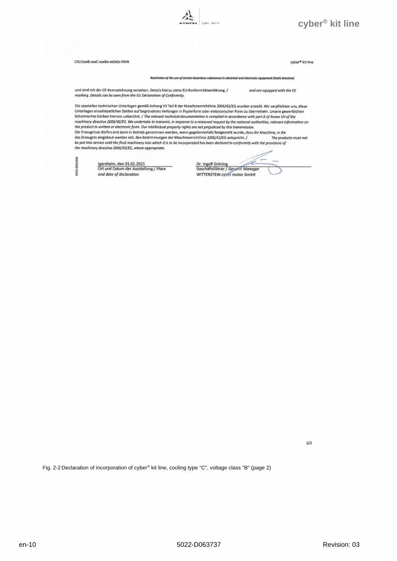
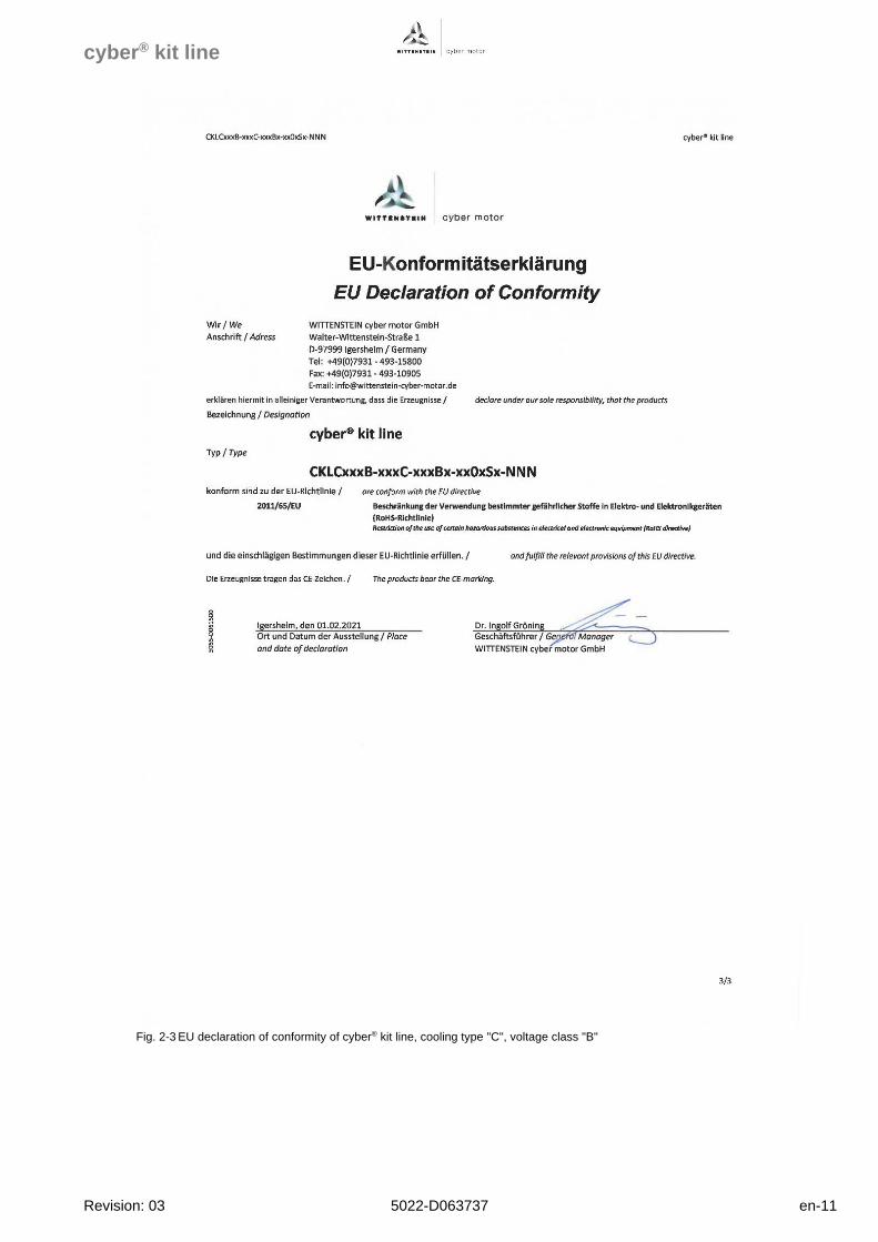
Fig. 2-3 EU declaration of conformity of cyber® kit line, cooling type "C", voltage class "B"
cyber® kit line
en-12 5022-D063737 Revision: 03
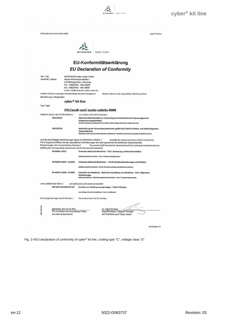
Fig. 2-4 EU declaration of conformity of cyber® kit line, cooling type "C", voltage class "S"
cyber® kit line
Revision: 03 5022-D063737 en-13
Products with the UL mark are certified according to the following "Standard(s) for Safety":
- Motors, certification for USA:
o UL 1004-1: Standard for Rotating Electrical Machines – General Requirements
o UL 1004-6: Standard for Servo and Stepper Motors
o UL 840: Standard for Safety Insulation Coordination including Clearances and Creepage
Distances for Electrical Equipment
- Motors, certification for Canada:
o C22.2, No. 100: Standard for Motor and Generators
- Control units, certification for USA:
o UL 61800-5-1: Standard for Adjustable Speed Electric Power Drive Systems, Safety
Requirements – Electrical, Thermal and Energy
- Control units, certification for USA and Canada:
o C22.2, No. 274: Standard for Adjustable Speed Drives
- Insulation system:
o UL 1446: Standard for Systems of Insulating Materials – General
- Safety:
o UL 746C: Standard for Safety. Polymeric Materials – use in Electrical Equipment
3 Safety instructions
3.1 Application and passing on of safety instructions
Do not install and commission the product before having thoroughly read all provided documents.
These safety instructions and all user instructions must be read each time before working with the
product. If the product is sold, borrowed and/or passed on in any other way, these safety
instructions must also be passed on as part of the project specifications in the national language
of the user.
Incorrect handling of this product, non-compliance with the warnings
in this document or unauthorized modification of safeguards can
lead to damage, injury, electric shock or even death.
The safety instructions and any measures derived by your company must be included by your
company into the assembly and installation instructions after carrying out a risk assessment.
Inform yourself about the safety instructions already during project planning. Also observe any
national regulations and include them into the assembly and installation instructions.
In addition to the safety instructions mentioned in these project specifications, generally
applicable and local regulations on prevention of accidents and environmental protection must be
observed. If necessary, use suitable personal protective equipment.
cyber® kit line
en-14 5022-D063737 Revision: 03
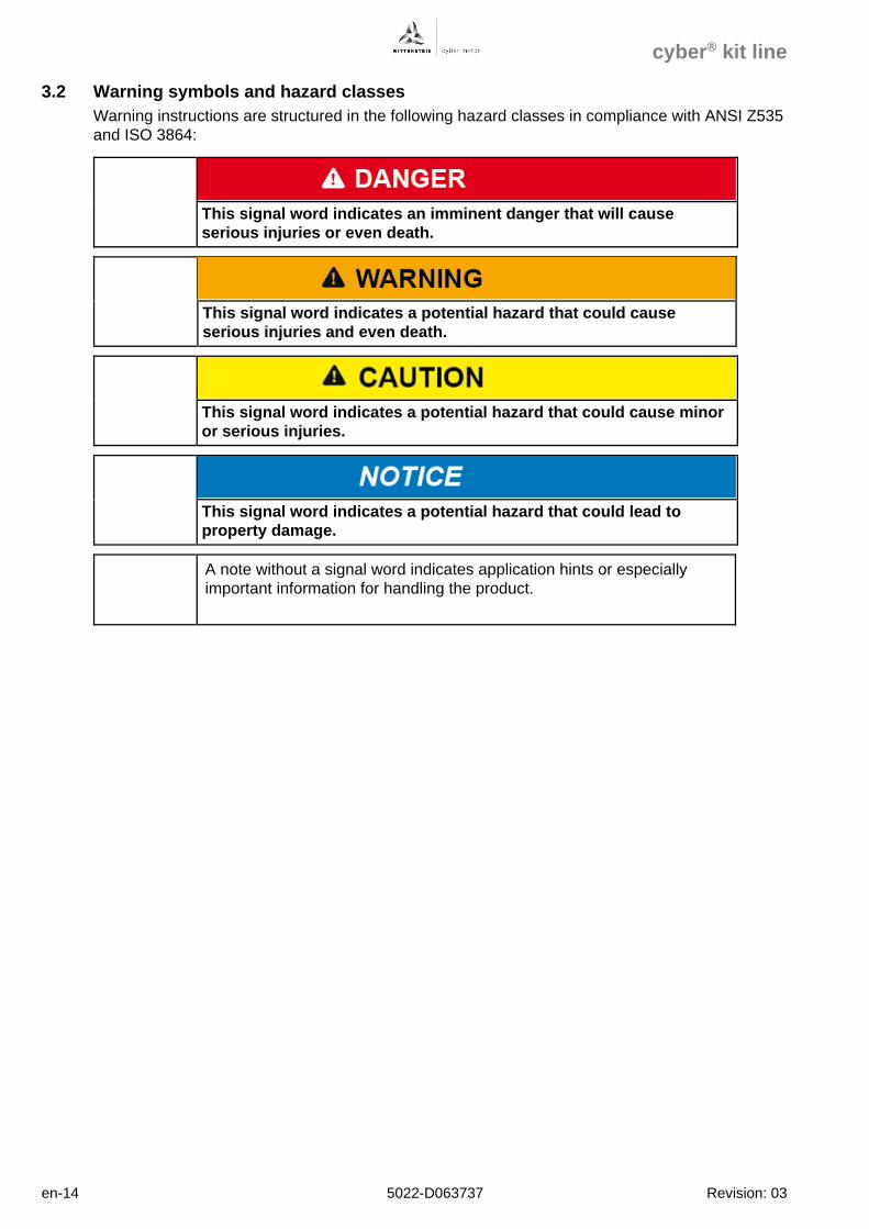
3.2 Warning symbols and hazard classes
Warning instructions are structured in the following hazard classes in compliance with ANSI Z535
and ISO 3864:
This signal word indicates an imminent danger that will cause
serious injuries or even death.
This signal word indicates a potential hazard that could cause
serious injuries and even death.
This signal word indicates a potential hazard that could cause minor
or serious injuries.
This signal word indicates a potential hazard that could lead to
property damage.
A note without a signal word indicates application hints or especially
important information for handling the product.
cyber® kit line
Revision: 03 5022-D063737 en-15
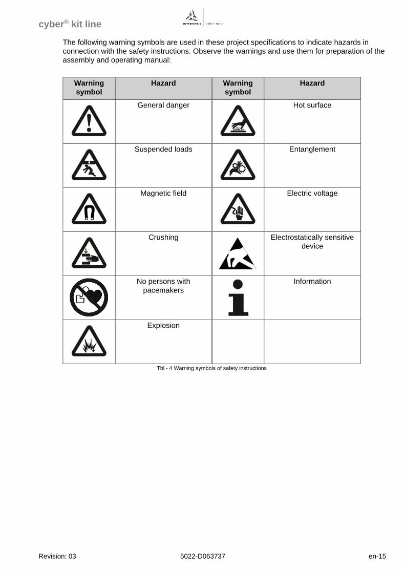
The following warning symbols are used in these project specifications to indicate hazards in
connection with the safety instructions. Observe the warnings and use them for preparation of the
assembly and operating manual:
Warning
symbol
Hazard Warning
symbol
Hazard
General danger
Hot surface
Suspended loads
Entanglement
Magnetic field
Electric voltage
Crushing
Electrostatically sensitive
device
No persons with
pacemakers
Information
Explosion
Tbl - 4 Warning symbols of safety instructions
cyber® kit line
en-16 5022-D063737 Revision: 03
3.3 Hazard-related safety instructions
Faulty electrical connections or unapproved, current-carrying
components can cause serious injuries and even death.
• Ensure that electrical connections are only established by qualified
personnel.
• Observe valid standards and directives.
• Carry out connection work only with suitable tools.
• Immediately replace damaged cables or plugs.
Electrically live parts may result in electric shocks if touched and can
cause serious injuries and even death. Electrical work performed in
damp areas may result in electric shocks and can cause serious
injuries and even death.
• Ensure that electrical connections are only established by qualified
personnel.
• Observe valid standards and directives.
• Carry out connection work only with suitable tools.
• Observe the general installation and safety regulations for work at
electrical systems.
• Before accessing electrical parts with voltages exceeding 50V,
disconnect the product from the voltage supply. Secure the product
against reactivation.
• Do not make contact with electrical connections of the product while it
is activated under any circumstances.
When the shaft is still turning or when the product is driven
externally (generator operation), voltage is induced. This can cause
lethal current surges.
• Ensure that connections and connectors are not open and unprotected
against contact.
• Do not make contact with electrical connections of the product while it
is activated under any circumstances.
Connecting or disconnecting the power and signal supply lines
under voltage can lead to machine damage, serious injury or even
death.
• Make sure that the product and the connections of the electronics
(power and signal) are in a voltage-free state before connecting.
• Observe any discharge time of your components.
cyber® kit line
Revision: 03 5022-D063737 en-17
Components equipped with permanent magnets and components
that emit magnetic fields can influence/impede the function of active
medical implants (e.g. pacemakers, defibrillators). This can lead to
serious injuries or even death.
• Assembly and storage areas must not be accessed by personnel with
active body implants, which may be affected by permanent magnetic
fields.
• Include the warning into the assembly instructions of your company.
• Make sure that the warning remains at the product as long as a hazard
exists.
Moving components on the product can pull in or crush parts of the
body or eject objects and cause serious injuries and even death. A
wrong direction of rotation or direction of movement may result in
serious injury or death.
• Remove objects and tools from the motor before putting it into
operation.
• Make sure that all components at the product are secured according to
the assembly instructions of your company.
• Keep a sufficient distance to moving machine components when the
motor is running.
• Secure the machine against restarting and unintentional movement
during assembly and maintenance work.
• Before and during startup, ensure that the motor has the correct
direction of rotation.
• Avoid collisions (e.g. moving against an end stop).
• Check the direction of rotation in a slow motion, ideally by limiting the
current and torque in a secured danger area.
During the mechanical assembly of the product onto the application,
handling errors can lead to serious crushing injuries as well as to
damage to the product or the application.
• Secure the machine against restarting and unintentional movement
during assembly and maintenance work.
• Have all mechanical assembly and maintenance work carried out by
qualified personnel only.
• Only use suitable tools for assembly and maintenance work.
cyber® kit line
en-18 5022-D063737 Revision: 03
During the mechanical assembly of kit motors, the attraction forces
of the magnets can cause serious crushing injuries and damage to
the motor or the application.
• Avoid unwanted movement of components of the kit motors by suitable
auxiliaries for assembly.
• Have all mechanical assembly and maintenance work carried out by
qualified personnel only.
• Only use suitable non-magnetic tools for assembly and maintenance
work.
Hot surfaces at the product (e.g. housing, motor housing) can cause
serious injuries.
During and after operation, the temperatures of the products and
surrounding components can exceed 60 °C (140 °F) depending on the
operating conditions and the cooling.
• Let the product cool down for a sufficient period after switching it off.
• When working with hot surfaces, always wear protective gloves.
• For specific applications, plan suitable measures to prevent burning
injuries.
• Check for your application whether safety measures and warnings are
required.
If present, the temperature sensors and rotor position encoders,
particularly Hall effect sensors and encoders, can be damaged by
electrostatic discharge.
• Carry out the work in an ESD-protected work environment and suitable
personal protective equipment.
• Do not remove ESD safeguards from the connections before they are
established.
3.4 Minimizing risks
The building kit motor is developed and produced according to the latest standards.
The responsibility for the intended use of the building kit motor and minimizing risks on the overall
product lies with the manufacturer of this overall product.
For minimizing risks on the overall product, we recommend the
following approach to you:
• Prepare an application-specific risk assessment in the form of a FMEA,
for example. If necessary, introduce measures for minimizing risks.
cyber® kit line
Revision: 03 5022-D063737 en-19
4 Transport and storage
The products of the cyber® kit line are delivered with an outer cardboard packaging (sizes 050,
085) or packaged individually in outer wood packaging (sizes 290 to 530). Outer packaging and
packaging units on pallets are secured with straps.
Risk of injury when disengaging the straps due to uncontrolled
movements when cutting open the cardboard boxes.
• Carefully disengage the straps and keep sufficient safety distance.
• Use suitable tools, e.g. safety cutter and personal protective equipment
when cutting open the cardboard boxes.
Inside the outer packaging, the products are protected by cardboard boxes, plastic enclosures,
VCI paper, VCI pad, silicate bags and/or ESD bags.
• Dispose of the packaging materials at the recycling sites intended for this purpose and
observe applicable national regulations.
Before shipping, the products of the cyber® kit line are tested in a standardized process and
separate high-voltage testing by the customer is not required. The products may be damaged if
the high-voltage test is repeated.
Risk of destruction of motor components due to incorrect high-
voltage testing.
• Observe the specifications on high-voltage testing in IEC 60034.
• Avoid repeating the test.
The overall scope of delivery is described in the delivery or shipping note and the contents may
be distributed on several packages. Every package can be identified by the shipping sticker on its
outside.
• Check the received goods pursuant to chapter 4.1.
• Note the weight of the product and use an appropriate transport device.
Information on the weight of the product can be found on the name plate.
cyber® kit line
en-20 5022-D063737 Revision: 03
Risk of crushing and injury due to the permanent magnets of the
rotor.
• Be careful when handling the rotors.
• Remove any moving, ferromagnetic objects or secure them against
intended movements.
For protection of the product, WITTENSTEIN cyber motor recommends transporting the product
to its intended location of installation inside the product packaging of WITTENSTEIN cyber
motor.
Damage due to incorrect handling.
• Have the product transported in its original packaging and by qualified
personnel.
• Observe the ambient conditions during transport and storage of the
products.
The ambient conditions to be observed for transport of the products inside the packaging of
WITTENSTEIN cyber motor are as follows:
- IEC 60721-3-3, class 3K6
- IEC 60721-3-3, class 3B1
- IEC 60721-3-3, class 3C1
- IEC 60721-3-3, class 3S2
- IEC 60721-3-3, class 3M2
Always store the product in horizontal position in the original packaging. The ambient conditions
must be dry and clean. Store the product for a maximum of 2 years. For storage logistics, we
recommend the "first in – first out" method.
The ambient conditions to be observed for storage of the products inside the packaging of
WITTENSTEIN cyber motor are as follows:
- IEC 60721-3-3, class 3K3
- IEC 60721-3-3, class 3B1
- IEC 60721-3-3, class 3C1
- IEC 60721-3-3, class 3S1
- IEC 60721-3-3, class 3M1
cyber® kit line
Revision: 03 5022-D063737 en-21
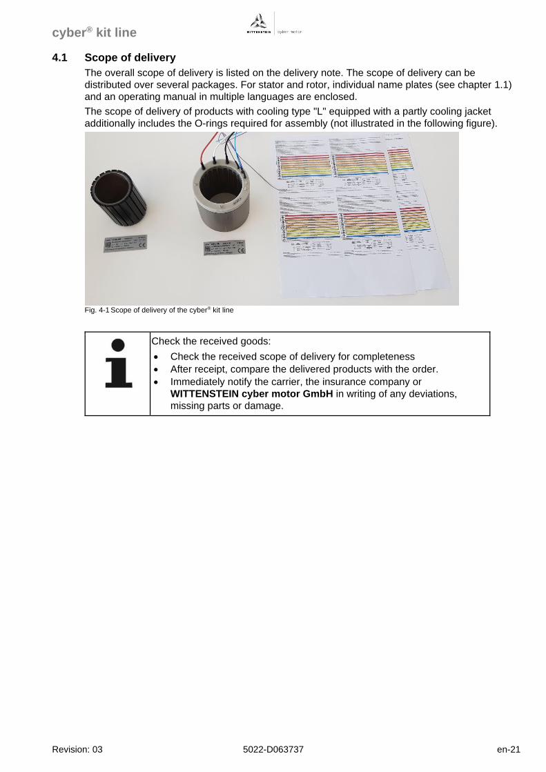
4.1 Scope of delivery
The overall scope of delivery is listed on the delivery note. The scope of delivery can be
distributed over several packages. For stator and rotor, individual name plates (see chapter 1.1)
and an operating manual in multiple languages are enclosed.
The scope of delivery of products with cooling type "L" equipped with a partly cooling jacket
additionally includes the O-rings required for assembly (not illustrated in the following figure).
Fig. 4-1 Scope of delivery of the cyber® kit line
Check the received goods:
• Check the received scope of delivery for completeness
• After receipt, compare the delivered products with the order.
• Immediately notify the carrier, the insurance company or
WITTENSTEIN cyber motor GmbH in writing of any deviations,
missing parts or damage.
cyber® kit line
en-22 5022-D063737 Revision: 03
5 Technical data
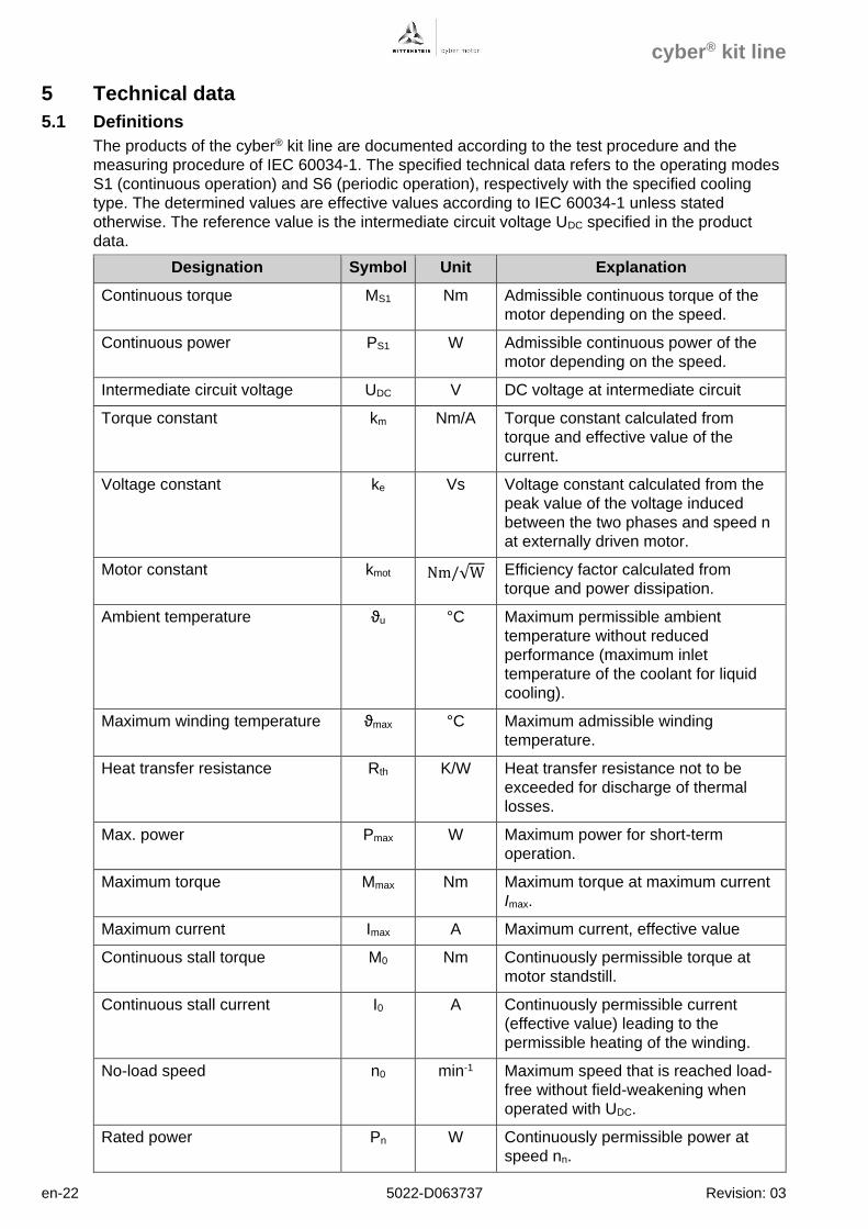
5.1 Definitions
The products of the cyber® kit line are documented according to the test procedure and the
measuring procedure of IEC 60034-1. The specified technical data refers to the operating modes
S1 (continuous operation) and S6 (periodic operation), respectively with the specified cooling
type. The determined values are effective values according to IEC 60034-1 unless stated
otherwise. The reference value is the intermediate circuit voltage UDC specified in the product
data.
Designation Symbol Unit Explanation
Continuous torque MS1 Nm Admissible continuous torque of the
motor depending on the speed.
Continuous power PS1 W Admissible continuous power of the
motor depending on the speed.
Intermediate circuit voltage UDC V DC voltage at intermediate circuit
Torque constant km Nm/A Torque constant calculated from
torque and effective value of the
current.
Voltage constant ke Vs Voltage constant calculated from the
peak value of the voltage induced
between the two phases and speed n
at externally driven motor.
Motor constant kmot Nm/√W Efficiency factor calculated from
torque and power dissipation.
Ambient temperature ϑu °C Maximum permissible ambient
temperature without reduced
performance (maximum inlet
temperature of the coolant for liquid
cooling).
Maximum winding temperature ϑmax °C Maximum admissible winding
temperature.
Heat transfer resistance Rth K/W Heat transfer resistance not to be
exceeded for discharge of thermal
losses.
Max. power Pmax W Maximum power for short-term
operation.
Maximum torque Mmax Nm Maximum torque at maximum current
Imax.
Maximum current Imax A Maximum current, effective value
Continuous stall torque M0 Nm Continuously permissible torque at
motor standstill.
Continuous stall current I0 A Continuously permissible current
(effective value) leading to the
permissible heating of the winding.
No-load speed n0 min-1 Maximum speed that is reached load-
free without field-weakening when
operated with UDC.
Rated power Pn W Continuously permissible power at
speed nn.
cyber® kit line
Revision: 03 5022-D063737 en-23
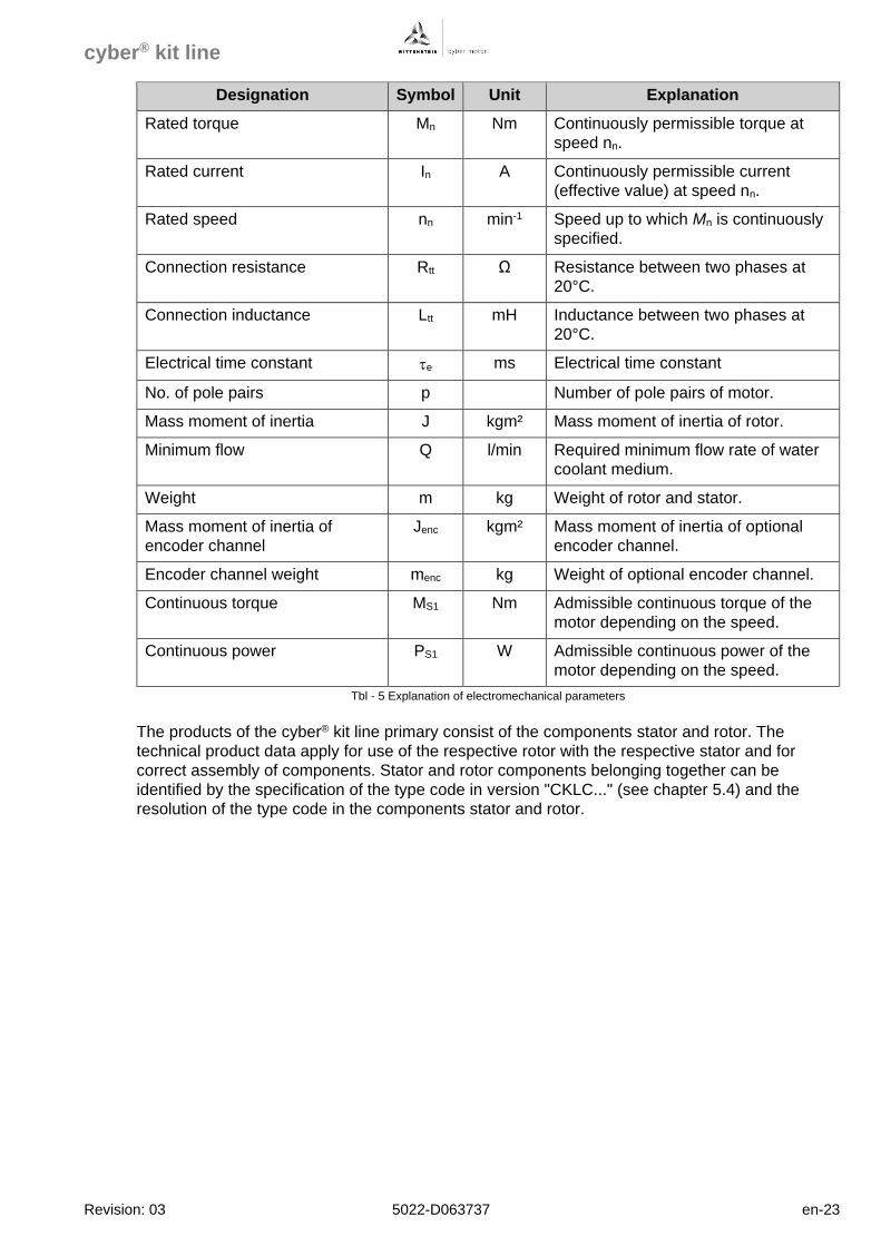
Designation Symbol Unit Explanation
Rated torque Mn Nm Continuously permissible torque at
speed nn.
Rated current In A Continuously permissible current
(effective value) at speed nn.
Rated speed nn min-1 Speed up to which Mn is continuously
specified.
Connection resistance Rtt Ω Resistance between two phases at
20°C.
Connection inductance Ltt mH Inductance between two phases at
20°C.
Electrical time constant e ms Electrical time constant
No. of pole pairs p Number of pole pairs of motor.
Mass moment of inertia J kgm² Mass moment of inertia of rotor.
Minimum flow Q l/min Required minimum flow rate of water
coolant medium.
Weight m kg Weight of rotor and stator.
Mass moment of inertia of
encoder channel
Jenc kgm² Mass moment of inertia of optional
encoder channel.
Encoder channel weight menc kg Weight of optional encoder channel.
Continuous torque MS1 Nm Admissible continuous torque of the
motor depending on the speed.
Continuous power PS1 W Admissible continuous power of the
motor depending on the speed.
Tbl - 5 Explanation of electromechanical parameters
The products of the cyber® kit line primary consist of the components stator and rotor. The
technical product data apply for use of the respective rotor with the respective stator and for
correct assembly of components. Stator and rotor components belonging together can be
identified by the specification of the type code in version "CKLC..." (see chapter 5.4) and the
resolution of the type code in the components stator and rotor.
cyber® kit line
en-24 5022-D063737 Revision: 03
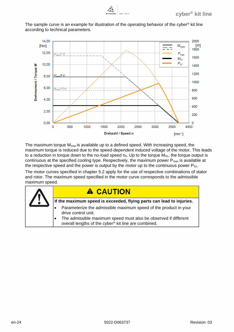
The sample curve is an example for illustration of the operating behavior of the cyber® kit line
according to technical parameters.
The maximum torque Mmax is available up to a defined speed. With increasing speed, the
maximum torque is reduced due to the speed-dependent induced voltage of the motor. This leads
to a reduction in torque down to the no-load speed n0. Up to the torque MS1, the torque output is
continuous at the specified cooling type. Respectively, the maximum power Pmax is available at
the respective speed and the power is output by the motor up to the continuous power PS1.
The motor curves specified in chapter 5.2 apply for the use of respective combinations of stator
and rotor. The maximum speed specified in the motor curve corresponds to the admissible
maximum speed.
If the maximum speed is exceeded, flying parts can lead to injuries.
• Parameterize the admissible maximum speed of the product in your
drive control unit.
• The admissible maximum speed must also be observed if different
overall lengths of the cyber® kit line are combined.
cyber® kit line
Revision: 03 5022-D063737 en-25
The specified technical data apply according to IEC 60034-1 for installation heights of up to
1000 m above sea level. At installation heights of more than 1000 m above sea level, the
performance data is reduced by 13% / 1000 m for cooling type "C" or 2.5% / 1000 m for cooling
type "L". The maximum admissible installation height of motors with power connection "A" is
5000 m above sea level. For the use of connectors, sockets or terminal boxes, the installation
height may be limited. Regarding the installation height and its impact, not only observe the motor
but the entire drive system.
For products with cooling type "L", the minimum flow is specified for a temperature increase of
5 °C for the cooling medium water between coolant inlet and coolant outlet. If the flow is
deviating, linear conversion of the temperature increase is possible.
In case of a deviating intermediate circuit voltage, linear conversion of the specified characteristic
curves based on the specified intermediate circuit voltage UDC is possible.
An electrical breakdown due to the maximum intermediate circuit
voltage UDC being exceeded can lead to injuries (electric shock).
• For operation of the product, do not exceed the intermediate circuit
voltage specified on the name plate.
If the product is operated with a current exceeding the continuous stall current, the power
dissipation in the product and the temperature are increased. Depending on the installation
situation, sufficient discharge of thermal energy is not always ensured. For this reason, limit the
duration for which the product is operated with a current exceeding the continuous stall current -
and particularly the maximum current.
Extended operation with high current can lead to inadmissible
heating of the product.
• Limit the duration for which the product can be operated with a current
exceeding the permanently admissible current depending on the
current rating, the installation situation and the thermal connection. At a
maximum winding temperature of 40 °C, operation with maximum
current is possible for up to 5.0 s in typical applications.
• If exact calculation is not available, limit the duration of the maximum
current to 1.0 s.
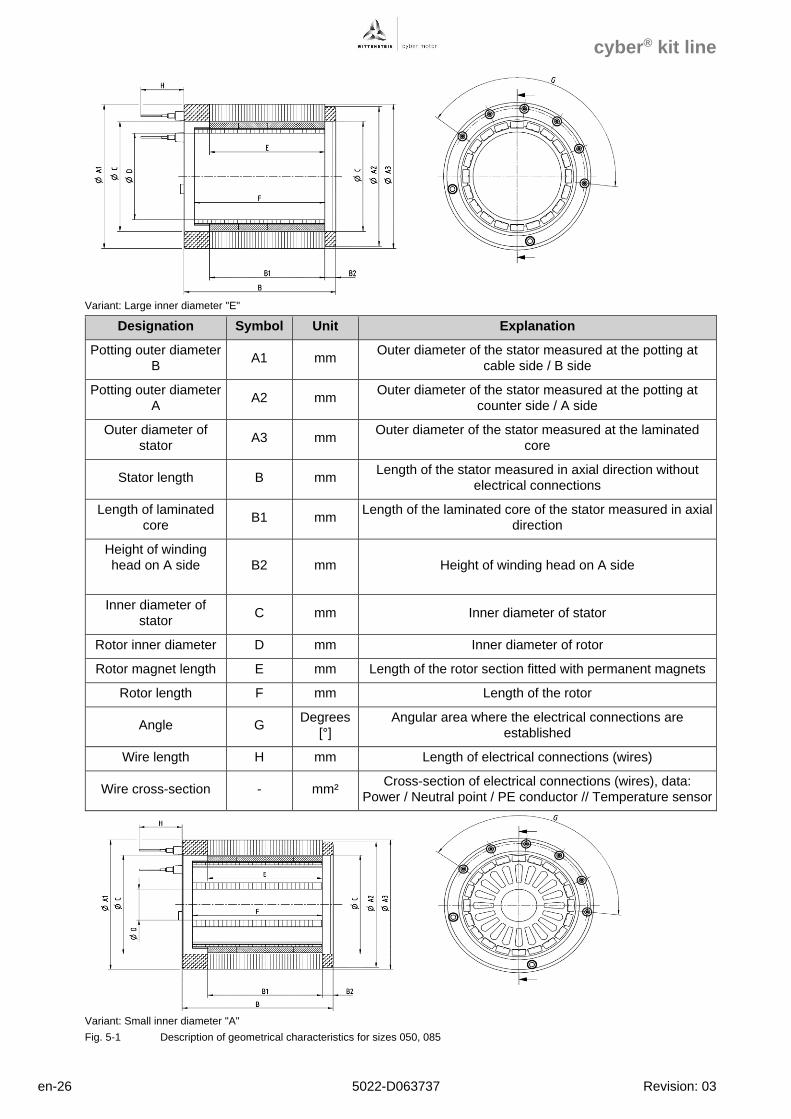
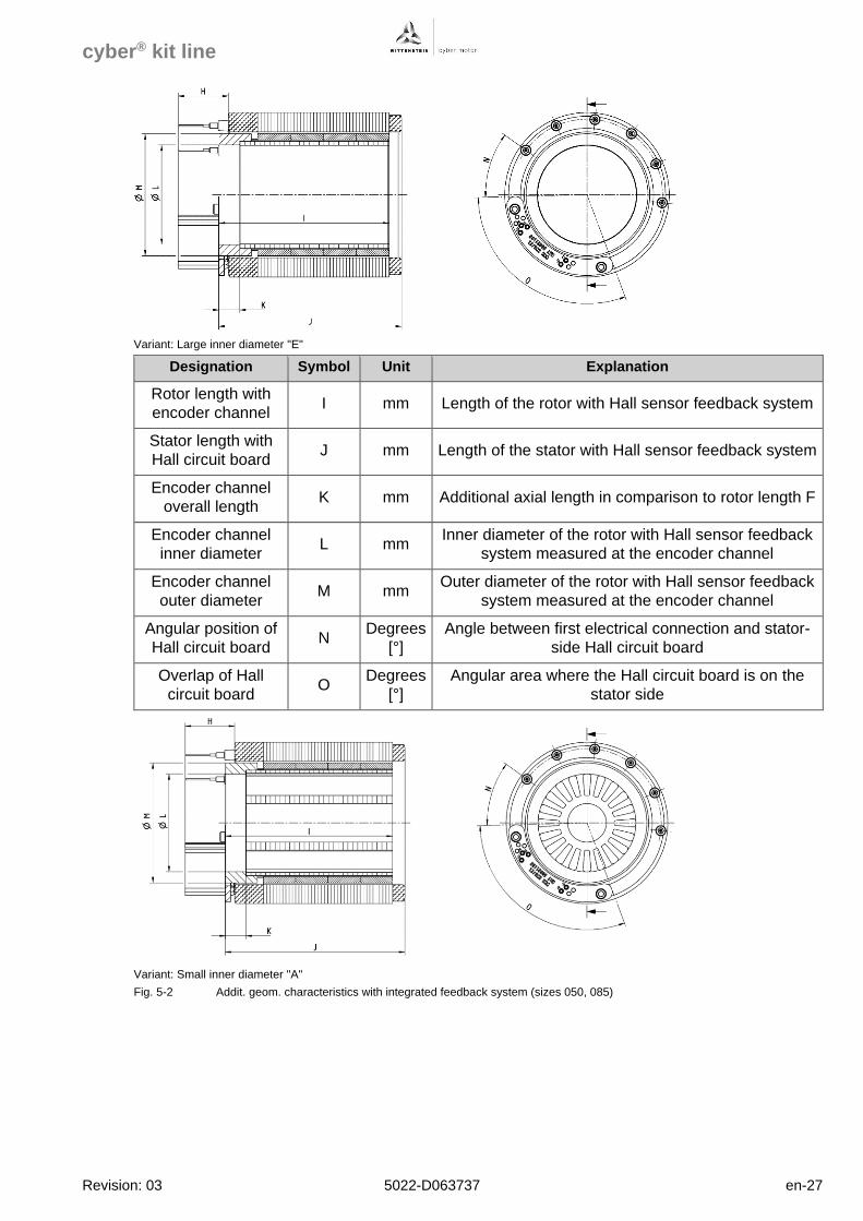
The geometrical product data in Fig. 5-1 and the additional geometrical product data for products
with integrated feedback system in Fig. 5-2 offer a quick overview of the dimensions of the
products of the cyber® kit line. For exact dimensions and tolerances, please refer to the
dimensional drawings in chapter 5.3.
cyber® kit line
en-26 5022-D063737 Revision: 03
Variant: Large inner diameter "E"
Designation Symbol Unit Explanation
Potting outer diameter
B A1 mm
Outer diameter of the stator measured at the potting at
cable side / B side
Potting outer diameter
A A2 mm
Outer diameter of the stator measured at the potting at
counter side / A side
Outer diameter of
stator A3 mm
Outer diameter of the stator measured at the laminated
core
Stator length B mm Length of the stator measured in axial direction without
electrical connections
Length of laminated
core B1 mm
Length of the laminated core of the stator measured in axial
direction
Height of winding
head on A side
B2 mm Height of winding head on A side
Inner diameter of
stator C mm Inner diameter of stator
Rotor inner diameter D mm Inner diameter of rotor
Rotor magnet length E mm Length of the rotor section fitted with permanent magnets
Rotor length F mm Length of the rotor
Angle G Degrees
[°]
Angular area where the electrical connections are
established
Wire length H mm Length of electrical connections (wires)
Wire cross-section - mm² Cross-section of electrical connections (wires), data:
Power / Neutral point / PE conductor // Temperature sensor
Variant: Small inner diameter "A"
Fig. 5-1 Description of geometrical characteristics for sizes 050, 085
cyber® kit line
Revision: 03 5022-D063737 en-27
Variant: Large inner diameter "E"
Designation Symbol Unit Explanation
Rotor length with
encoder channel I mm Length of the rotor with Hall sensor feedback system
Stator length with
Hall circuit board J mm Length of the stator with Hall sensor feedback system
Encoder channel
overall length K mm Additional axial length in comparison to rotor length F
Encoder channel
inner diameter L mm
Inner diameter of the rotor with Hall sensor feedback
system measured at the encoder channel
Encoder channel
outer diameter M mm
Outer diameter of the rotor with Hall sensor feedback
system measured at the encoder channel
Angular position of
Hall circuit board N
Degrees
[°]
Angle between first electrical connection and stator-
side Hall circuit board
Overlap of Hall
circuit board O
Degrees
[°]
Angular area where the Hall circuit board is on the
stator side
Variant: Small inner diameter "A"
Fig. 5-2 Addit. geom. characteristics with integrated feedback system (sizes 050, 085)
cyber® kit line
en-28 5022-D063737 Revision: 03
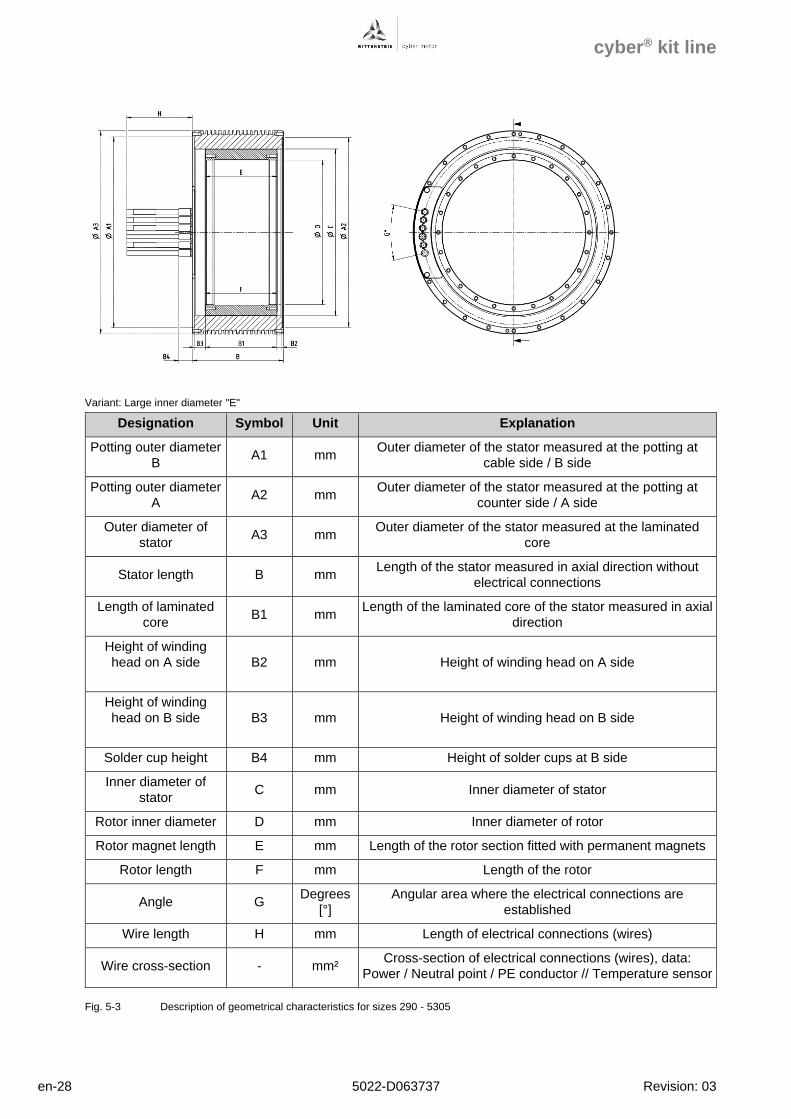
Variant: Large inner diameter "E"
Designation Symbol Unit Explanation
Potting outer diameter
B A1 mm
Outer diameter of the stator measured at the potting at
cable side / B side
Potting outer diameter
A A2 mm
Outer diameter of the stator measured at the potting at
counter side / A side
Outer diameter of
stator A3 mm
Outer diameter of the stator measured at the laminated
core
Stator length B mm Length of the stator measured in axial direction without
electrical connections
Length of laminated
core B1 mm
Length of the laminated core of the stator measured in axial
direction
Height of winding
head on A side
B2 mm Height of winding head on A side
Height of winding
head on B side
B3 mm Height of winding head on B side
Solder cup height B4 mm Height of solder cups at B side
Inner diameter of
stator C mm Inner diameter of stator
Rotor inner diameter D mm Inner diameter of rotor
Rotor magnet length E mm Length of the rotor section fitted with permanent magnets
Rotor length F mm Length of the rotor
Angle G Degrees
[°]
Angular area where the electrical connections are
established
Wire length H mm Length of electrical connections (wires)
Wire cross-section - mm² Cross-section of electrical connections (wires), data:
Power / Neutral point / PE conductor // Temperature sensor
Fig. 5-3 Description of geometrical characteristics for sizes 290 - 5305
cyber® kit line
Revision: 03 5022-D063737 en-29
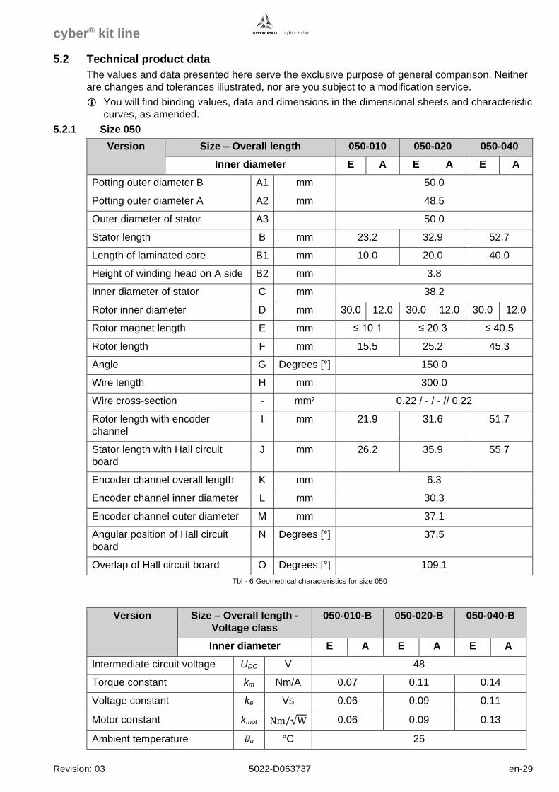
5.2 Technical product data
The values and data presented here serve the exclusive purpose of general comparison. Neither
are changes and tolerances illustrated, nor are you subject to a modification service.
You will find binding values, data and dimensions in the dimensional sheets and characteristic
curves, as amended.
5.2.1 Size 050
Version Size – Overall length 050-010 050-020 050-040
Inner diameter E A E A E A
Potting outer diameter B A1 mm 50.0
Potting outer diameter A A2 mm 48.5
Outer diameter of stator A3 50.0
Stator length B mm 23.2 32.9 52.7
Length of laminated core B1 mm 10.0 20.0 40.0
Height of winding head on A side B2 mm 3.8
Inner diameter of stator C mm 38.2
Rotor inner diameter D mm 30.0 12.0 30.0 12.0 30.0 12.0
Rotor magnet length E mm ≤ 10.1 ≤ 20.3 ≤ 40.5
Rotor length F mm 15.5 25.2 45.3
Angle G Degrees [°] 150.0
Wire length H mm 300.0
Wire cross-section - mm² 0.22 / - / - // 0.22
Rotor length with encoder
channel
I mm 21.9 31.6 51.7
Stator length with Hall circuit
board
J mm 26.2 35.9 55.7
Encoder channel overall length K mm 6.3
Encoder channel inner diameter L mm 30.3
Encoder channel outer diameter M mm 37.1
Angular position of Hall circuit
board
N Degrees [°] 37.5
Overlap of Hall circuit board O Degrees [°] 109.1
Tbl - 6 Geometrical characteristics for size 050
Version Size – Overall length -
Voltage class
050-010-B 050-020-B 050-040-B
Inner diameter E A E A E A
Intermediate circuit voltage UDC V 48
Torque constant km Nm/A 0.07 0.11 0.14
Voltage constant ke Vs 0.06 0.09 0.11
Motor constant kmot Nm/√W 0.06 0.09 0.13
Ambient temperature ϑu °C 25
cyber® kit line
en-30 5022-D063737 Revision: 03
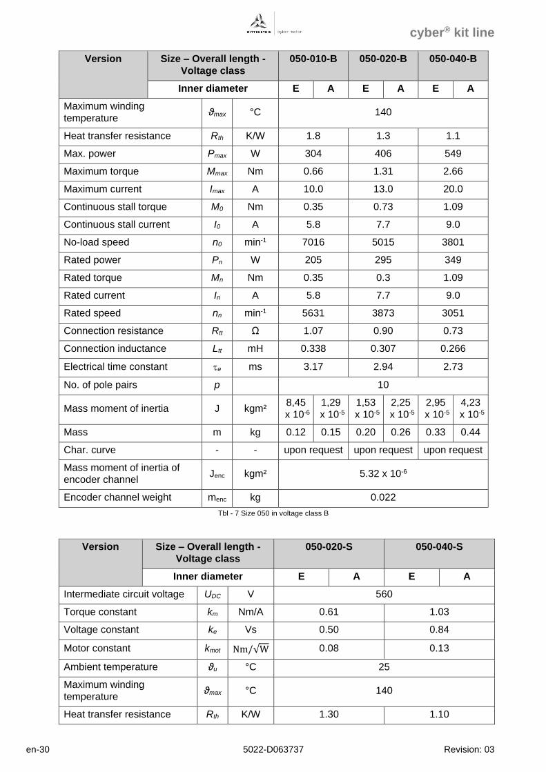
Version Size – Overall length -
Voltage class
050-010-B 050-020-B 050-040-B
Inner diameter E A E A E A
Maximum winding
temperature ϑmax °C 140
Heat transfer resistance Rth K/W 1.8 1.3 1.1
Max. power Pmax W 304 406 549
Maximum torque Mmax Nm 0.66 1.31 2.66
Maximum current Imax A 10.0 13.0 20.0
Continuous stall torque M0 Nm 0.35 0.73 1.09
Continuous stall current I0 A 5.8 7.7 9.0
No-load speed n0 min-1 7016 5015 3801
Rated power Pn W 205 295 349
Rated torque Mn Nm 0.35 0.3 1.09
Rated current In A 5.8 7.7 9.0
Rated speed nn min-1 5631 3873 3051
Connection resistance Rtt Ω 1.07 0.90 0.73
Connection inductance Ltt mH 0.338 0.307 0.266
Electrical time constant e ms 3.17 2.94 2.73
No. of pole pairs p 10
Mass moment of inertia J kgm² 8,45
x 10-6
1,29
x 10-5
1,53
x 10-5
2,25
x 10-5
2,95
x 10-5
4,23
x 10-5
Mass m kg 0.12 0.15 0.20 0.26 0.33 0.44
Char. curve - - upon request upon request upon request
Mass moment of inertia of
encoder channel Jenc kgm² 5.32 x 10⁻⁶
Encoder channel weight menc kg 0.022
Tbl - 7 Size 050 in voltage class B
Version Size – Overall length -
Voltage class
050-020-S 050-040-S
Inner diameter E A E A
Intermediate circuit voltage UDC V 560
Torque constant km Nm/A 0.61 1.03
Voltage constant ke Vs 0.50 0.84
Motor constant kmot Nm/√W 0.08 0.13
Ambient temperature ϑu °C 25
Maximum winding
temperature ϑmax °C 140
Heat transfer resistance Rth K/W 1.30 1.10
cyber® kit line
Revision: 03 5022-D063737 en-31
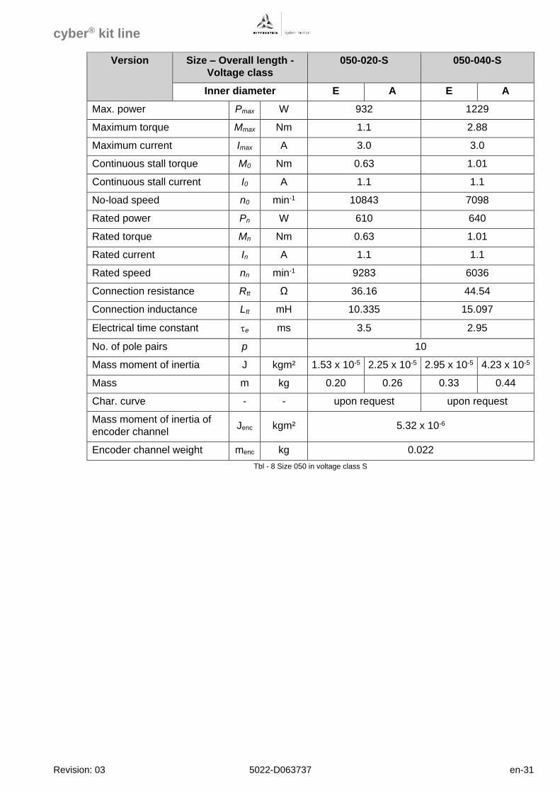
Version Size – Overall length -
Voltage class
050-020-S 050-040-S
Inner diameter E A E A
Max. power Pmax W 932 1229
Maximum torque Mmax Nm 1.1 2.88
Maximum current Imax A 3.0 3.0
Continuous stall torque M0 Nm 0.63 1.01
Continuous stall current I0 A 1.1 1.1
No-load speed n0 min-1 10843 7098
Rated power Pn W 610 640
Rated torque Mn Nm 0.63 1.01
Rated current In A 1.1 1.1
Rated speed nn min-1 9283 6036
Connection resistance Rtt Ω 36.16 44.54
Connection inductance Ltt mH 10.335 15.097
Electrical time constant e ms 3.5 2.95
No. of pole pairs p 10
Mass moment of inertia J kgm² 1.53 x 10⁻⁵ 2.25 x 10⁻⁵ 2.95 x 10⁻⁵ 4.23 x 10⁻⁵
Mass m kg 0.20 0.26 0.33 0.44
Char. curve - - upon request upon request
Mass moment of inertia of
encoder channel Jenc kgm² 5.32 x 10⁻⁶
Encoder channel weight menc kg 0.022
Tbl - 8 Size 050 in voltage class S
cyber® kit line
en-32 5022-D063737 Revision: 03
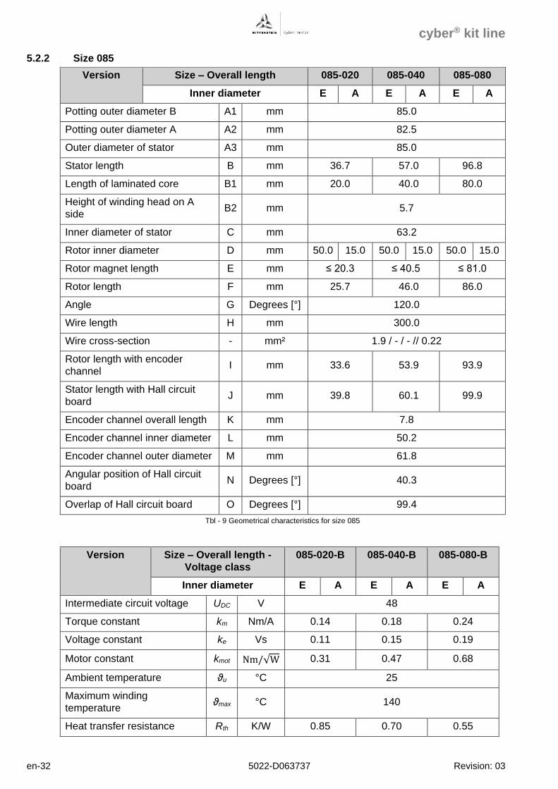
5.2.2 Size 085
Version Size – Overall length 085-020 085-040 085-080
Inner diameter E A E A E A
Potting outer diameter B A1 mm 85.0
Potting outer diameter A A2 mm 82.5
Outer diameter of stator A3 mm 85.0
Stator length B mm 36.7 57.0 96.8
Length of laminated core B1 mm 20.0 40.0 80.0
Height of winding head on A
side B2 mm 5.7
Inner diameter of stator C mm 63.2
Rotor inner diameter D mm 50.0 15.0 50.0 15.0 50.0 15.0
Rotor magnet length E mm ≤ 20.3 ≤ 40.5 ≤ 81.0
Rotor length F mm 25.7 46.0 86.0
Angle G Degrees [°] 120.0
Wire length H mm 300.0
Wire cross-section - mm² 1.9 / - / - // 0.22
Rotor length with encoder
channel I mm 33.6 53.9 93.9
Stator length with Hall circuit
board J mm 39.8 60.1 99.9
Encoder channel overall length K mm 7.8
Encoder channel inner diameter L mm 50.2
Encoder channel outer diameter M mm 61.8
Angular position of Hall circuit
board N Degrees [°] 40.3
Overlap of Hall circuit board O Degrees [°] 99.4
Tbl - 9 Geometrical characteristics for size 085
Version Size – Overall length -
Voltage class
085-020-B 085-040-B 085-080-B
Inner diameter E A E A E A
Intermediate circuit voltage UDC V 48
Torque constant km Nm/A 0.14 0.18 0.24
Voltage constant ke Vs 0.11 0.15 0.19
Motor constant kmot Nm/√W 0.31 0.47 0.68
Ambient temperature ϑu °C 25
Maximum winding
temperature ϑmax °C 140
Heat transfer resistance Rth K/W 0.85 0.70 0.55
cyber® kit line
Revision: 03 5022-D063737 en-33
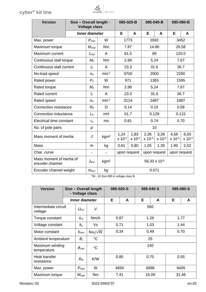
Version Size – Overall length -
Voltage class
085-020-B 085-040-B 085-080-B
Inner diameter E A E A E A
Max. power Pmax W 1773 2692 3452
Maximum torque Mmax Nm 7.87 14.86 26.58
Maximum current Imax A 61.5 89 120.0
Continuous stall torque M0 Nm 2.98 5.24 7.67
Continuous stall current I0 A 23.3 31.6 36.7
No-load speed n0 min-1 3700 2900 2290
Rated power Pn W 971 1365 1595
Rated torque Mn Nm 2.98 5.24 7.67
Rated current In A 23.3 31.6 36.7
Rated speed nn min-1 3114 2487 1987
Connection resistance Rtt Ω 0.14 0.10 0.08
Connection inductance Ltt mH 01.7 0.129 0.115
Electrical time constant e ms 0.81 0.74 0.70
No. of pole pairs p 10
Mass moment of inertia J kgm² 1,24
x 10-4
1,83
x 10-4
2,36
x 10-4
3,39
x 10-4
4,58
x 10-4
6,50
x 10-4
Mass m kg 0.61 0.80 1.05 1.39 1.90 2.52
Char. curve - - upon request upon request upon request
Mass moment of inertia of
encoder channel Jenc kgm² 56.33 x 10⁻⁶
Encoder channel weight menc kg 0.071
Tbl - 10 Size 085 in voltage class B
Version Size – Overall length
- Voltage class
085-020-S 085-040-S 085-080-S
Inner diameter E A E A E A
Intermediate circuit
voltage UDC V
560
Torque constant km Nm/A 0.87 1.26 1.77
Voltage constant ke Vs 0.71 1.03 1.44
Motor constant kmot Nm/√W 0.34 0.49 0.70
Ambient temperature ϑu °C 25
Maximum winding
temperature ϑmax °C
140
Heat transfer
resistance Rth K/W
0.85 0.70 0.55
Max. power Pmax W 4656 6996 9405
Maximum torque Mmax Nm 7.41 16.09 31.46
cyber® kit line
en-34 5022-D063737 Revision: 03
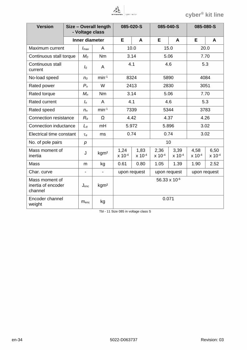
Version Size – Overall length
- Voltage class
085-020-S 085-040-S 085-080-S
Inner diameter E A E A E A
Maximum current Imax A 10.0 15.0 20.0
Continuous stall torque M0 Nm 3.14 5.06 7.70
Continuous stall
current I0 A
4.1 4.6 5.3
No-load speed n0 min-1 8324 5890 4084
Rated power Pn W 2413 2830 3051
Rated torque Mn Nm 3.14 5.06 7.70
Rated current In A 4.1 4.6 5.3
Rated speed nn min-1 7339 5344 3783
Connection resistance Rtt Ω 4.42 4.37 4.26
Connection inductance Ltt mH 5.972 5.896 3.02
Electrical time constant e ms 0.74 0.74 3.02
No. of pole pairs p 10
Mass moment of
inertia J kgm²
1,24
x 10-4
1,83
x 10-4
2,36
x 10-4
3,39
x 10-4
4,58
x 10-4
6,50
x 10-4
Mass m kg 0.61 0.80 1.05 1.39 1.90 2.52
Char. curve - - upon request upon request upon request
Mass moment of
inertia of encoder
channel
Jenc kgm²
56.33 x 10⁻⁶
Encoder channel
weight menc kg
0.071
Tbl - 11 Size 085 in voltage class S
cyber® kit line
Revision: 03 5022-D063737 en-35
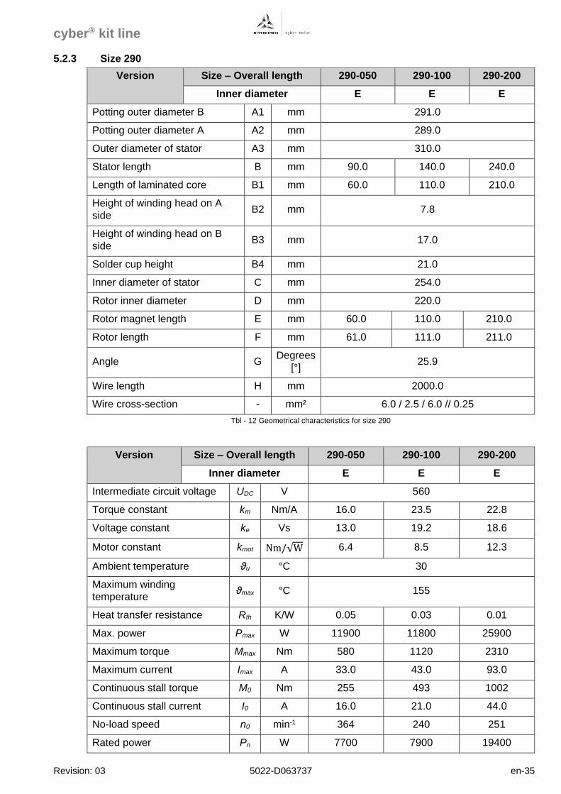
5.2.3 Size 290
Version Size – Overall length 290-050 290-100 290-200
Inner diameter E E E
Potting outer diameter B A1 mm 291.0
Potting outer diameter A A2 mm 289.0
Outer diameter of stator A3 mm 310.0
Stator length B mm 90.0 140.0 240.0
Length of laminated core B1 mm 60.0 110.0 210.0
Height of winding head on A
side B2 mm 7.8
Height of winding head on B
side B3 mm 17.0
Solder cup height B4 mm 21.0
Inner diameter of stator C mm 254.0
Rotor inner diameter D mm 220.0
Rotor magnet length E mm 60.0 110.0 210.0
Rotor length F mm 61.0 111.0 211.0
Angle G Degrees
[°] 25.9
Wire length H mm 2000.0
Wire cross-section - mm² 6.0 / 2.5 / 6.0 // 0.25
Tbl - 12 Geometrical characteristics for size 290
Version Size – Overall length 290-050 290-100 290-200
Inner diameter E E E
Intermediate circuit voltage UDC V 560
Torque constant km Nm/A 16.0 23.5 22.8
Voltage constant ke Vs 13.0 19.2 18.6
Motor constant kmot Nm/√W 6.4 8.5 12.3
Ambient temperature ϑu °C 30
Maximum winding
temperature ϑmax °C 155
Heat transfer resistance Rth K/W 0.05 0.03 0.01
Max. power Pmax W 11900 11800 25900
Maximum torque Mmax Nm 580 1120 2310
Maximum current Imax A 33.0 43.0 93.0
Continuous stall torque M0 Nm 255 493 1002
Continuous stall current I0 A 16.0 21.0 44.0
No-load speed n0 min-1 364 240 251
Rated power Pn W 7700 7900 19400
cyber® kit line
en-36 5022-D063737 Revision: 03
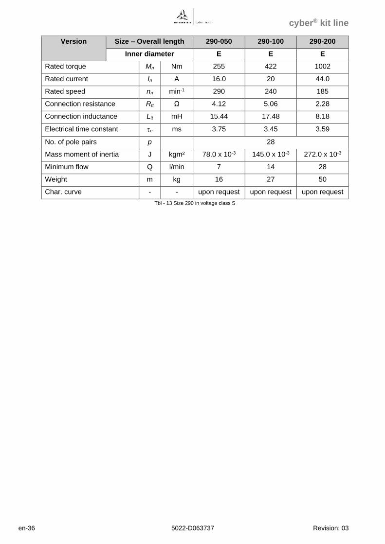
Version Size – Overall length 290-050 290-100 290-200
Inner diameter E E E
Rated torque Mn Nm 255 422 1002
Rated current In A 16.0 20 44.0
Rated speed nn min-1 290 240 185
Connection resistance Rtt Ω 4.12 5.06 2.28
Connection inductance Ltt mH 15.44 17.48 8.18
Electrical time constant e ms 3.75 3.45 3.59
No. of pole pairs p 28
Mass moment of inertia J kgm² 78.0 x 10⁻³ 145.0 x 10⁻³ 272.0 x 10⁻³
Minimum flow Q l/min 7 14 28
Weight m kg 16 27 50
Char. curve - - upon request upon request upon request
Tbl - 13 Size 290 in voltage class S
cyber® kit line
Revision: 03 5022-D063737 en-37
5.2.4 Size 360
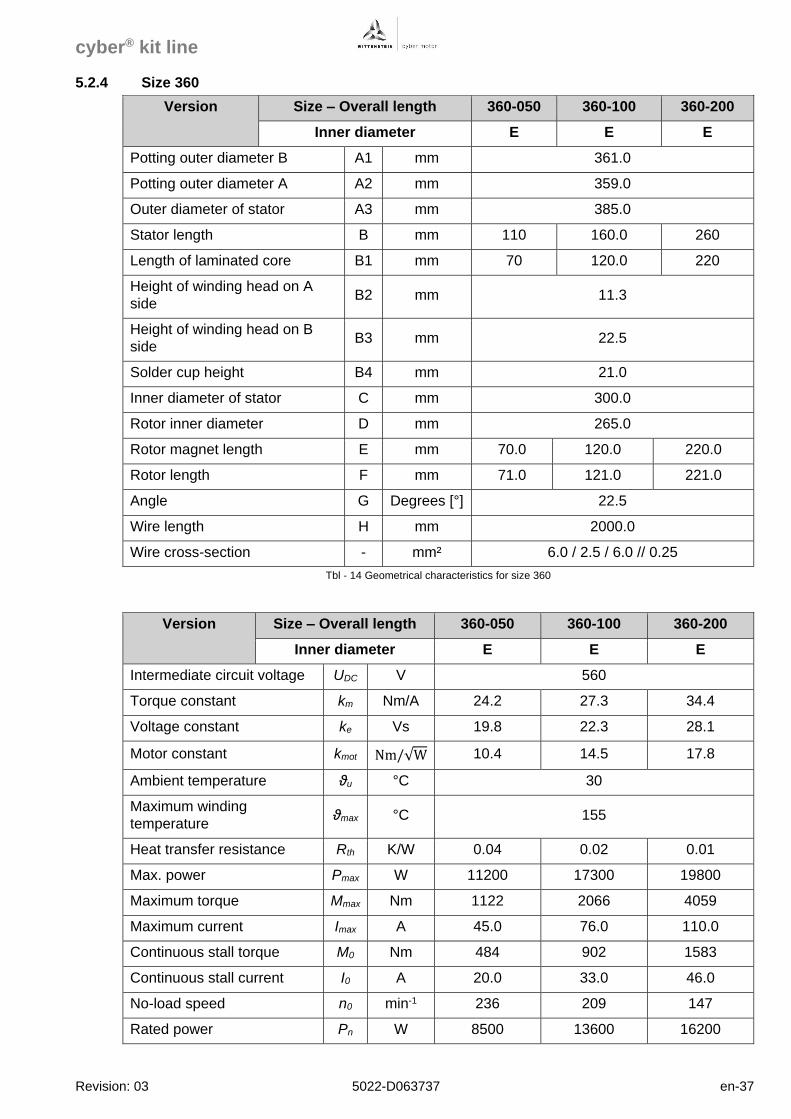
Version Size – Overall length 360-050 360-100 360-200
Inner diameter E E E
Potting outer diameter B A1 mm 361.0
Potting outer diameter A A2 mm 359.0
Outer diameter of stator A3 mm 385.0
Stator length B mm 110 160.0 260
Length of laminated core B1 mm 70 120.0 220
Height of winding head on A
side B2 mm 11.3
Height of winding head on B
side B3 mm 22.5
Solder cup height B4 mm 21.0
Inner diameter of stator C mm 300.0
Rotor inner diameter D mm 265.0
Rotor magnet length E mm 70.0 120.0 220.0
Rotor length F mm 71.0 121.0 221.0
Angle G Degrees [°] 22.5
Wire length H mm 2000.0
Wire cross-section - mm² 6.0 / 2.5 / 6.0 // 0.25
Tbl - 14 Geometrical characteristics for size 360
Version Size – Overall length 360-050 360-100 360-200
Inner diameter E E E
Intermediate circuit voltage UDC V 560
Torque constant km Nm/A 24.2 27.3 34.4
Voltage constant ke Vs 19.8 22.3 28.1
Motor constant kmot Nm/√W 10.4 14.5 17.8
Ambient temperature ϑu °C 30
Maximum winding
temperature ϑmax °C 155
Heat transfer resistance Rth K/W 0.04 0.02 0.01
Max. power Pmax W 11200 17300 19800
Maximum torque Mmax Nm 1122 2066 4059
Maximum current Imax A 45.0 76.0 110.0
Continuous stall torque M0 Nm 484 902 1583
Continuous stall current I0 A 20.0 33.0 46.0
No-load speed n0 min-1 236 209 147
Rated power Pn W 8500 13600 16200
cyber® kit line
en-38 5022-D063737 Revision: 03
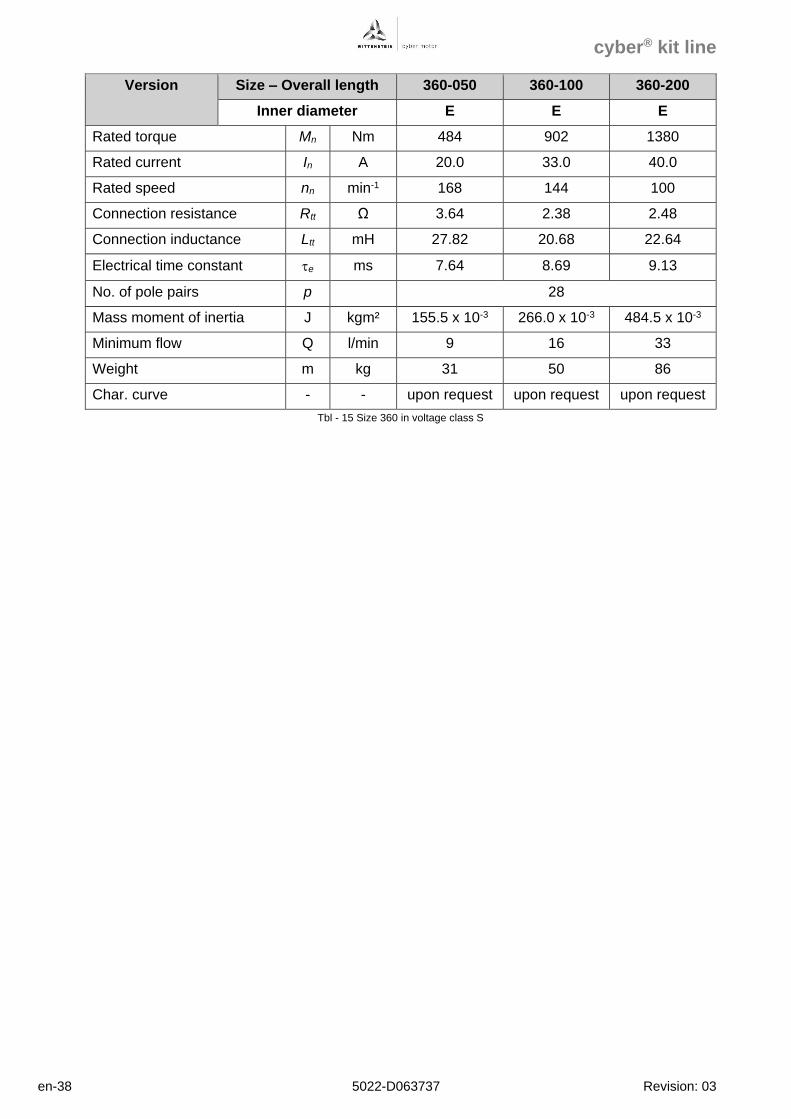
Version Size – Overall length 360-050 360-100 360-200
Inner diameter E E E
Rated torque Mn Nm 484 902 1380
Rated current In A 20.0 33.0 40.0
Rated speed nn min-1 168 144 100
Connection resistance Rtt Ω 3.64 2.38 2.48
Connection inductance Ltt mH 27.82 20.68 22.64
Electrical time constant e ms 7.64 8.69 9.13
No. of pole pairs p 28
Mass moment of inertia J kgm² 155.5 x 10⁻³ 266.0 x 10⁻³ 484.5 x 10⁻³
Minimum flow Q l/min 9 16 33
Weight m kg 31 50 86
Char. curve - - upon request upon request upon request
Tbl - 15 Size 360 in voltage class S
cyber® kit line
Revision: 03 5022-D063737 en-39
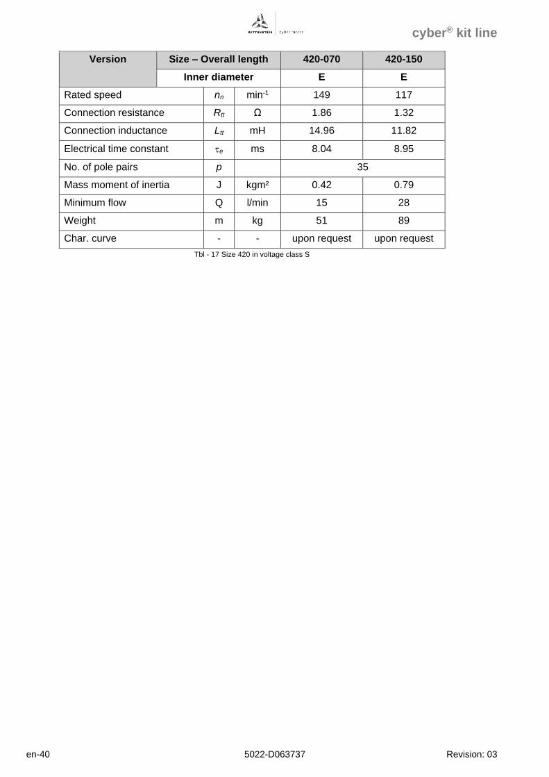
5.2.5 Size 420
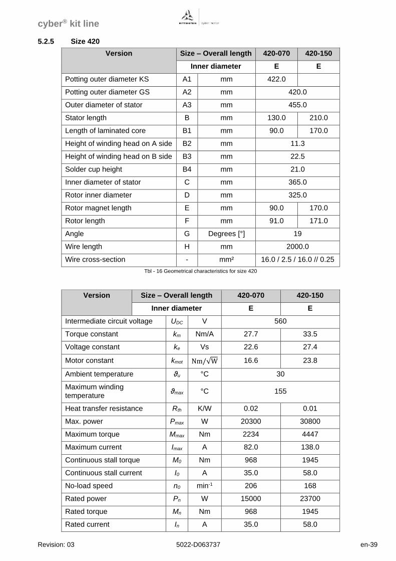
Version Size – Overall length 420-070 420-150
Inner diameter E E
Potting outer diameter KS A1 mm 422.0
Potting outer diameter GS A2 mm 420.0
Outer diameter of stator A3 mm 455.0
Stator length B mm 130.0 210.0
Length of laminated core B1 mm 90.0 170.0
Height of winding head on A side B2 mm 11.3
Height of winding head on B side B3 mm 22.5
Solder cup height B4 mm 21.0
Inner diameter of stator C mm 365.0
Rotor inner diameter D mm 325.0
Rotor magnet length E mm 90.0 170.0
Rotor length F mm 91.0 171.0
Angle G Degrees [°] 19
Wire length H mm 2000.0
Wire cross-section - mm² 16.0 / 2.5 / 16.0 // 0.25
Tbl - 16 Geometrical characteristics for size 420
Version Size – Overall length 420-070 420-150
Inner diameter E E
Intermediate circuit voltage UDC V 560
Torque constant km Nm/A 27.7 33.5
Voltage constant ke Vs 22.6 27.4
Motor constant kmot Nm/√W 16.6 23.8
Ambient temperature ϑu °C 30
Maximum winding
temperature ϑmax °C 155
Heat transfer resistance Rth K/W 0.02 0.01
Max. power Pmax W 20300 30800
Maximum torque Mmax Nm 2234 4447
Maximum current Imax A 82.0 138.0
Continuous stall torque M0 Nm 968 1945
Continuous stall current I0 A 35.0 58.0
No-load speed n0 min-1 206 168
Rated power Pn W 15000 23700
Rated torque Mn Nm 968 1945
Rated current In A 35.0 58.0
cyber® kit line
en-40 5022-D063737 Revision: 03
Version Size – Overall length 420-070 420-150
Inner diameter E E
Rated speed nn min-1 149 117
Connection resistance Rtt Ω 1.86 1.32
Connection inductance Ltt mH 14.96 11.82
Electrical time constant e ms 8.04 8.95
No. of pole pairs p 35
Mass moment of inertia J kgm² 0.42 0.79
Minimum flow Q l/min 15 28
Weight m kg 51 89
Char. curve - - upon request upon request
Tbl - 17 Size 420 in voltage class S
cyber® kit line
Revision: 03 5022-D063737 en-41
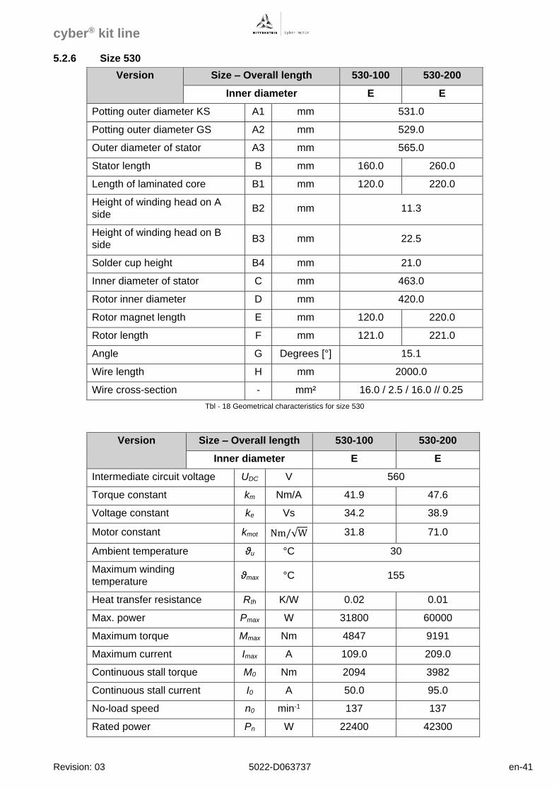
5.2.6 Size 530
Version Size – Overall length 530-100 530-200
Inner diameter E E
Potting outer diameter KS A1 mm 531.0
Potting outer diameter GS A2 mm 529.0
Outer diameter of stator A3 mm 565.0
Stator length B mm 160.0 260.0
Length of laminated core B1 mm 120.0 220.0
Height of winding head on A
side B2 mm 11.3
Height of winding head on B
side B3 mm 22.5
Solder cup height B4 mm 21.0
Inner diameter of stator C mm 463.0
Rotor inner diameter D mm 420.0
Rotor magnet length E mm 120.0 220.0
Rotor length F mm 121.0 221.0
Angle G Degrees [°] 15.1
Wire length H mm 2000.0
Wire cross-section - mm² 16.0 / 2.5 / 16.0 // 0.25
Tbl - 18 Geometrical characteristics for size 530
Version Size – Overall length 530-100 530-200
Inner diameter E E
Intermediate circuit voltage UDC V 560
Torque constant km Nm/A 41.9 47.6
Voltage constant ke Vs 34.2 38.9
Motor constant kmot Nm/√W 31.8 71.0
Ambient temperature ϑu °C 30
Maximum winding
temperature ϑmax °C 155
Heat transfer resistance Rth K/W 0.02 0.01
Max. power Pmax W 31800 60000
Maximum torque Mmax Nm 4847 9191
Maximum current Imax A 109.0 209.0
Continuous stall torque M0 Nm 2094 3982
Continuous stall current I0 A 50.0 95.0
No-load speed n0 min-1 137 137
Rated power Pn W 22400 42300
cyber® kit line
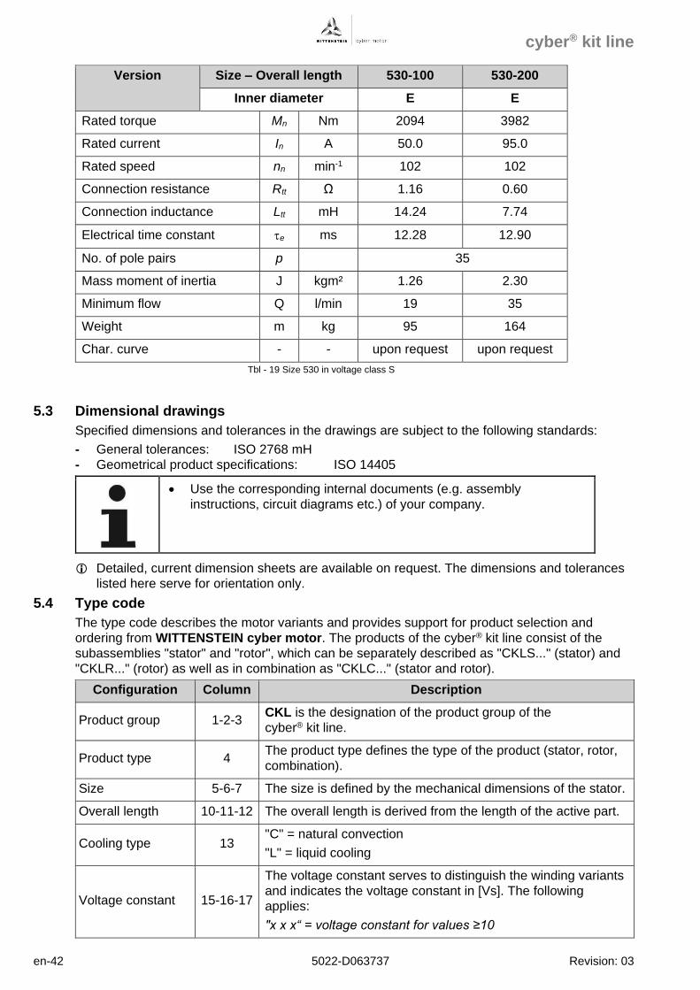
en-42 5022-D063737 Revision: 03
Version Size – Overall length 530-100 530-200
Inner diameter E E
Rated torque Mn Nm 2094 3982
Rated current In A 50.0 95.0
Rated speed nn min-1 102 102
Connection resistance Rtt Ω 1.16 0.60
Connection inductance Ltt mH 14.24 7.74
Electrical time constant e ms 12.28 12.90
No. of pole pairs p 35
Mass moment of inertia J kgm² 1.26 2.30
Minimum flow Q l/min 19 35
Weight m kg 95 164
Char. curve - - upon request upon request
Tbl - 19 Size 530 in voltage class S
5.3 Dimensional drawings
Specified dimensions and tolerances in the drawings are subject to the following standards:
- General tolerances: ISO 2768 mH
- Geometrical product specifications: ISO 14405
• Use the corresponding internal documents (e.g. assembly
instructions, circuit diagrams etc.) of your company.
Detailed, current dimension sheets are available on request. The dimensions and tolerances
listed here serve for orientation only.
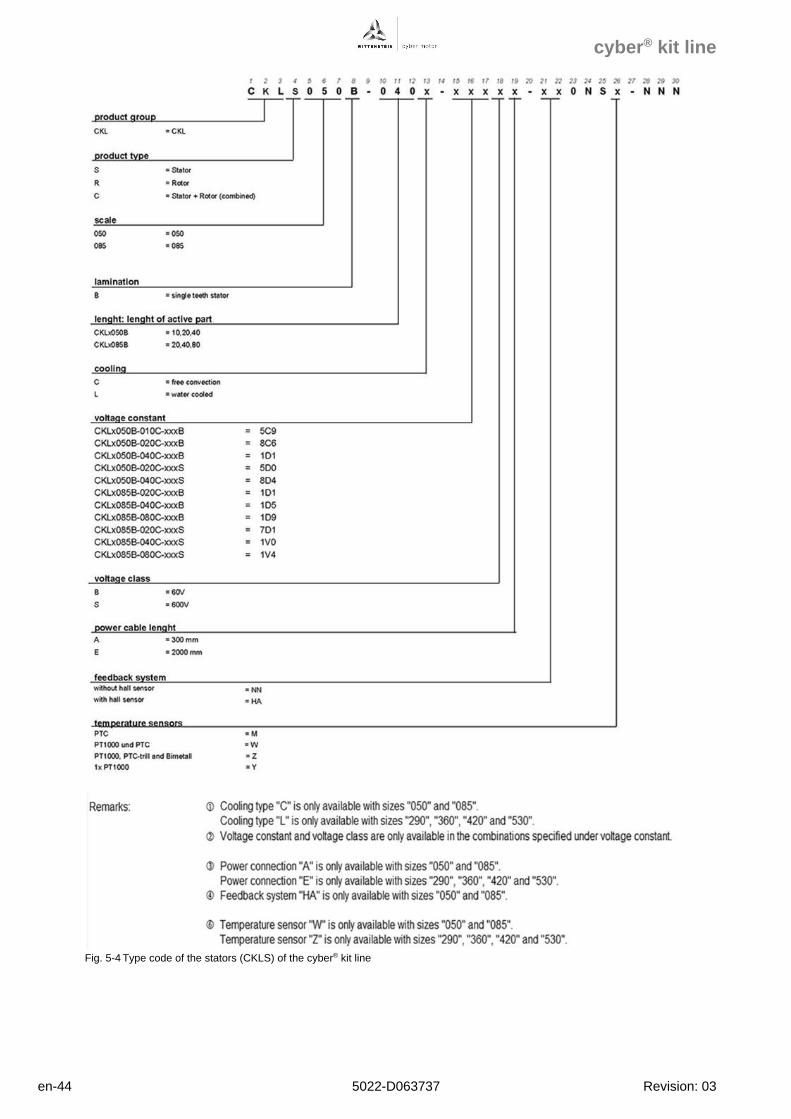
5.4 Type code
The type code describes the motor variants and provides support for product selection and
ordering from WITTENSTEIN cyber motor. The products of the cyber® kit line consist of the
subassemblies "stator" and "rotor", which can be separately described as "CKLS..." (stator) and
"CKLR..." (rotor) as well as in combination as "CKLC..." (stator and rotor).
Configuration Column Description
Product group 1-2-3 CKL is the designation of the product group of the
cyber® kit line.
Product type 4 The product type defines the type of the product (stator, rotor,
combination).
Size 5-6-7 The size is defined by the mechanical dimensions of the stator.
Overall length 10-11-12 The overall length is derived from the length of the active part.
Cooling type 13 "C" = natural convection
"L" = liquid cooling
Voltage constant 15-16-17
The voltage constant serves to distinguish the winding variants
and indicates the voltage constant in [Vs]. The following
applies:
"x x x“ = voltage constant for values ≥10
cyber® kit line
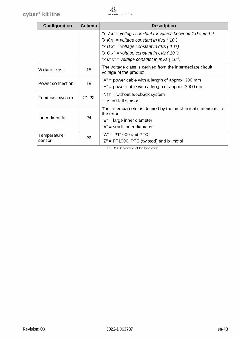
Revision: 03 5022-D063737 en-43
Configuration Column Description
"x V x“ = voltage constant for values between 1.0 and 9.9
"x K x" = voltage constant in kVs (·103)
"x D x" = voltage constant in dVs (·10-1)
"x C x" = voltage constant in cVs (·10-2)
"x M x" = voltage constant in mVs (·10-3)
Voltage class 18 The voltage class is derived from the intermediate circuit
voltage of the product.
Power connection 19 "A" = power cable with a length of approx. 300 mm
"E" = power cable with a length of approx. 2000 mm
Feedback system 21-22 "NN" = without feedback system
"HA" = Hall sensor
Inner diameter 24
The inner diameter is defined by the mechanical dimensions of
the rotor.
"E" = large inner diameter
"A" = small inner diameter
Temperature
sensor 26
"W" = PT1000 and PTC
"Z" = PT1000, PTC (twisted) and bi-metal
Tbl - 20 Description of the type code
cyber® kit line
en-44 5022-D063737 Revision: 03
Fig. 5-4 Type code of the stators (CKLS) of the cyber® kit line
cyber® kit line
Revision: 03 5022-D063737 en-45
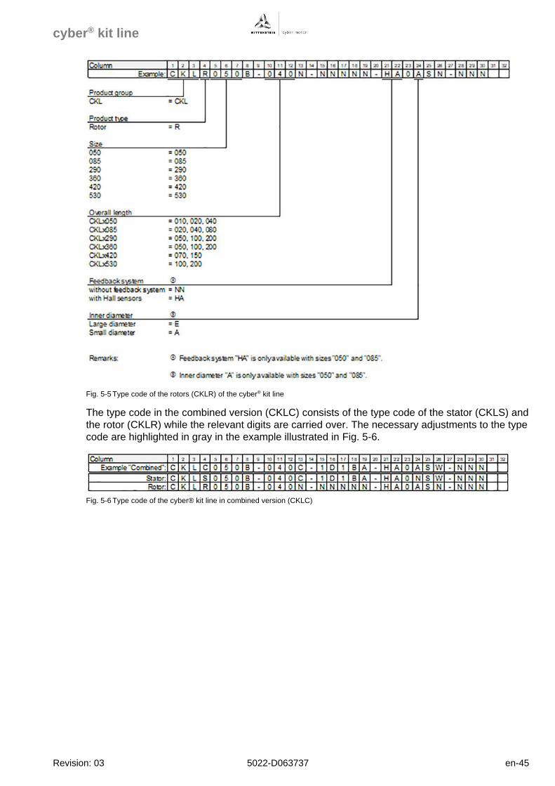
Fig. 5-5 Type code of the rotors (CKLR) of the cyber® kit line
The type code in the combined version (CKLC) consists of the type code of the stator (CKLS) and
the rotor (CKLR) while the relevant digits are carried over. The necessary adjustments to the type
code are highlighted in gray in the example illustrated in Fig. 5-6.
Fig. 5-6 Type code of the cyber® kit line in combined version (CKLC)
cyber® kit line
en-46 5022-D063737 Revision: 03
5.5 Installed components
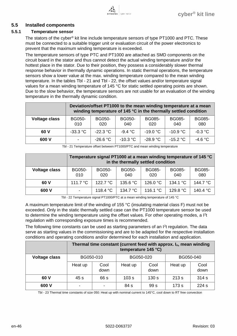
5.5.1 Temperature sensor
The stators of the cyber® kit line include temperature sensors of type PT1000 and PTC. These
must be connected to a suitable trigger unit or evaluation circuit of the power electronics to
prevent that the maximum winding temperature is exceeded.
The temperature sensors of type PTC and PT1000 are attached as SMD components on the
circuit board in the stator and thus cannot detect the actual winding temperature and/or the
hottest place in the stator. Due to their position, they possess a considerably slower thermal
response behavior in thermally dynamic operations. In static thermal operations, the temperature
sensors show a lower value at the max. winding temperature compared to the mean winding
temperature. In the tables Tbl - 21 and Tbl - 22, the offset values and/or temperature signal
values for a mean winding temperature of 145 °C for static settled operating points are shown.
Due to the slow behavior, the temperature sensors are not usable for an evaluation of the winding
temperature in the thermally dynamic condition.
Deviation/offset PT1000 to the mean winding temperature at a mean
winding temperature of 145 °C in the thermally settled condition
Voltage class BG050-
010
BG050-
020
BG050-
040
BG085-
020
BG085-
040
BG085-
080
60 V -33.3 °C -22.3 °C -9.4 °C -19.0 °C -10.9 °C -0.3 °C
600 V - -26.6 °C -10.3 °C -28.9 °C -15.2 °C -4.6 °C
Tbl - 21 Temperature offset between PT1000/PTC and mean winding temperature
Temperature signal PT1000 at a mean winding temperature of 145 °C
in the thermally settled condition
Voltage class BG050-
010
BG050-
020
BG050-
040
BG085-
020
BG085-
040
BG085-
080
60 V 111.7 °C 122.7 °C 135.6 °C 126.0 °C 134.1 °C 144.7 °C
600 V - 118.4 °C 134.7 °C 116.1 °C 129.8 °C 140.4 °C
Tbl - 22 Temperature signal PT1000/PTC at a mean winding temperature of 145 °C
A maximum temperature limit of the winding of 155 °C (insulating material class F) must not be
exceeded. Only in the static thermally settled case can the PT1000 temperature sensor be used
to determine the winding temperature using the offset values. For other operating modes, a I2t
regulation with corresponding exposure times is recommended.
The following time constants can be used as starting parameters of an I2t regulation. The data
serve as starting values in the commissioning and are to be adapted for the respective installation
conditions and operating conditions and/or determined for each installation and application.
Thermal time constant (current feed with approx. In, mean winding
temperature 145 °C)
Voltage class BG050-010 BG050-020 BG050-040
Heat up Cool
down
Heat up Cool
down
Heat up Cool
down
60 V 45 s 66 s 103 s 130 s 213 s 314 s
600 V - - 84 s 99 s 173 s 224 s
Tbl - 23 Thermal time constants of size 050: Heat up with nominal current to 145°C, cool down to RT free convection
cyber® kit line
Revision: 03 5022-D063737 en-47
Thermal time constant (current feed with approx. In, mean
winding temperature 145 °C)
Voltage class BG085-020 BG085-040 BG085-080
Heat up Cool
down
Heat up Cool
down
Heat up Cool
down
60 V 258 s 315 s 513 s 649 s 870 s 1085 s
600 V 232 s 319 s 464 s 559 s 839 s 1094 s
Tbl - 24 Thermal time constants of size 085: Heat up with nominal current to 145°C, cool down to RT free convection
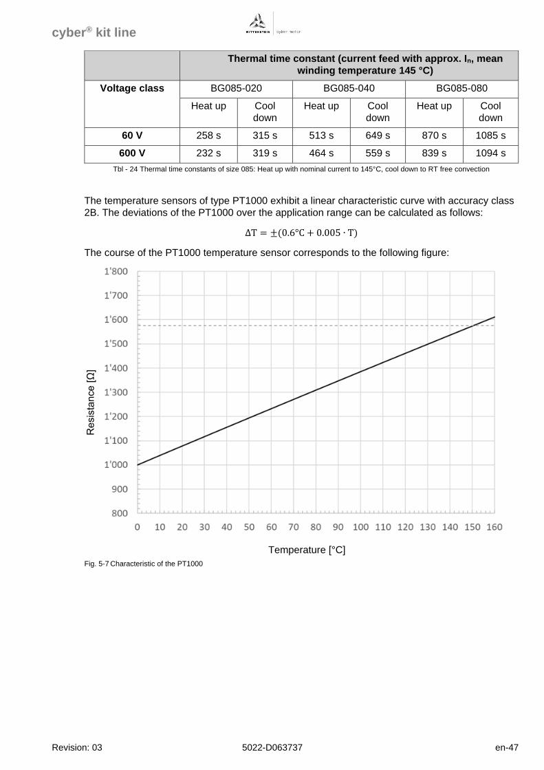
The temperature sensors of type PT1000 exhibit a linear characteristic curve with accuracy class
2B. The deviations of the PT1000 over the application range can be calculated as follows:
∆T = ±(0.6°C + 0.005 ∙ T)
The course of the PT1000 temperature sensor corresponds to the following figure:
Resis
tan
ce
[Ω
]
Temperature [°C]
Fig. 5-7 Characteristic of the PT1000
cyber® kit line
en-48 5022-D063737 Revision: 03
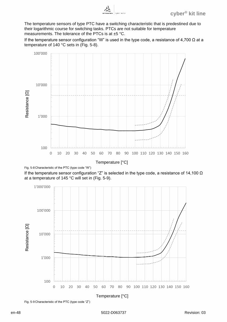
The temperature sensors of type PTC have a switching characteristic that is predestined due to
their logarithmic course for switching tasks. PTCs are not suitable for temperature
measurements. The tolerance of the PTCs is at ±5 °C.
If the temperature sensor configuration “W” is used in the type code, a resistance of 4,700 Ω at a
temperature of 140 °C sets in (Fig. 5-8).
Resis
tan
ce
[Ω
]
Temperature [°C]
Fig. 5-8 Characteristic of the PTC (type code “W”)
If the temperature sensor configuration “Z” is selected in the type code, a resistance of 14,100 Ω
at a temperature of 145 °C will set in (Fig. 5-9).
Resis
tan
ce
[Ω
]
Temperature [°C]
Fig. 5-9 Characteristic of the PTC (type code “Z”)
100
1'000
10'000
100'000
0 10 20 30 40 50 60 70 80 90 100 110 120 130 140 150 160
cyber® kit line
Revision: 03 5022-D063737 en-49
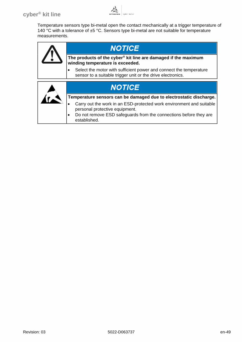
Temperature sensors type bi-metal open the contact mechanically at a trigger temperature of
140 °C with a tolerance of ±5 °C. Sensors type bi-metal are not suitable for temperature
measurements.
The products of the cyber® kit line are damaged if the maximum
winding temperature is exceeded.
• Select the motor with sufficient power and connect the temperature
sensor to a suitable trigger unit or the drive electronics.
Temperature sensors can be damaged due to electrostatic discharge.
• Carry out the work in an ESD-protected work environment and suitable
personal protective equipment.
• Do not remove ESD safeguards from the connections before they are
established.
cyber® kit line
en-50 5022-D063737 Revision: 03
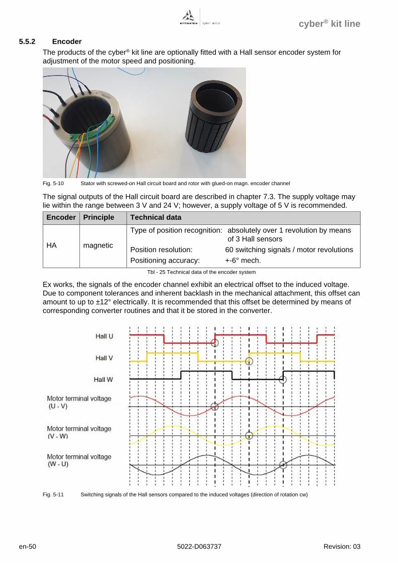
5.5.2 Encoder
The products of the cyber® kit line are optionally fitted with a Hall sensor encoder system for
adjustment of the motor speed and positioning.
Fig. 5-10 Stator with screwed-on Hall circuit board and rotor with glued-on magn. encoder channel
The signal outputs of the Hall circuit board are described in chapter 7.3. The supply voltage may
lie within the range between 3 V and 24 V; however, a supply voltage of 5 V is recommended.
Encoder Principle Technical data
HA magnetic
Type of position recognition: absolutely over 1 revolution by means
of 3 Hall sensors
Position resolution: 60 switching signals / motor revolutions
Positioning accuracy: +-6° mech.
Tbl - 25 Technical data of the encoder system
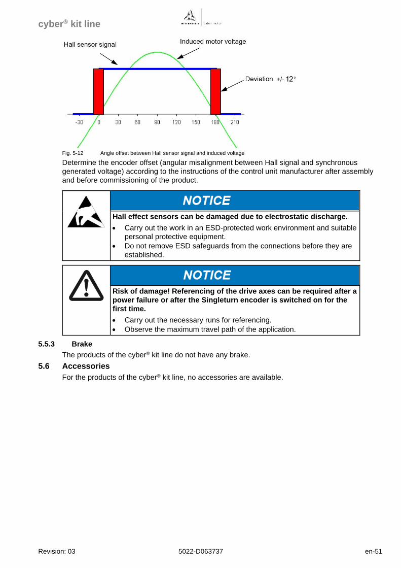
Ex works, the signals of the encoder channel exhibit an electrical offset to the induced voltage.
Due to component tolerances and inherent backlash in the mechanical attachment, this offset can
amount to up to ±12° electrically. It is recommended that this offset be determined by means of
corresponding converter routines and that it be stored in the converter.
Fig. 5-11 Switching signals of the Hall sensors compared to the induced voltages (direction of rotation cw)
cyber® kit line
Revision: 03 5022-D063737 en-51
Fig. 5-12 Angle offset between Hall sensor signal and induced voltage
Determine the encoder offset (angular misalignment between Hall signal and synchronous
generated voltage) according to the instructions of the control unit manufacturer after assembly
and before commissioning of the product.
Hall effect sensors can be damaged due to electrostatic discharge.
• Carry out the work in an ESD-protected work environment and suitable
personal protective equipment.
• Do not remove ESD safeguards from the connections before they are
established.
Risk of damage! Referencing of the drive axes can be required after a
power failure or after the Singleturn encoder is switched on for the
first time.
• Carry out the necessary runs for referencing.
• Observe the maximum travel path of the application.
5.5.3 Brake
The products of the cyber® kit line do not have any brake.
5.6 Accessories
For the products of the cyber® kit line, no accessories are available.
cyber® kit line
en-52 5022-D063737 Revision: 03
6 Assembly
6.1 General information
Type, scope and order of the assembly steps are influenced by the individual features of your
machine design and can deviate from the schematic procedure.
Risk of injury due to live components and during lifting of heavy
loads. Risk of damage to the product due to incorrect handling.
• Carefully carry out all steps.
• Use suitable hoisting equipment and personal protective equipment.
• Do not lift or move the product at the cables.
• Do not install motors under voltage.
• Observe the safety and handling instructions.
• Before assembly, prepare instructions which fully describe all work and
assembly steps.
• Observe work and assembly instructions of your company.
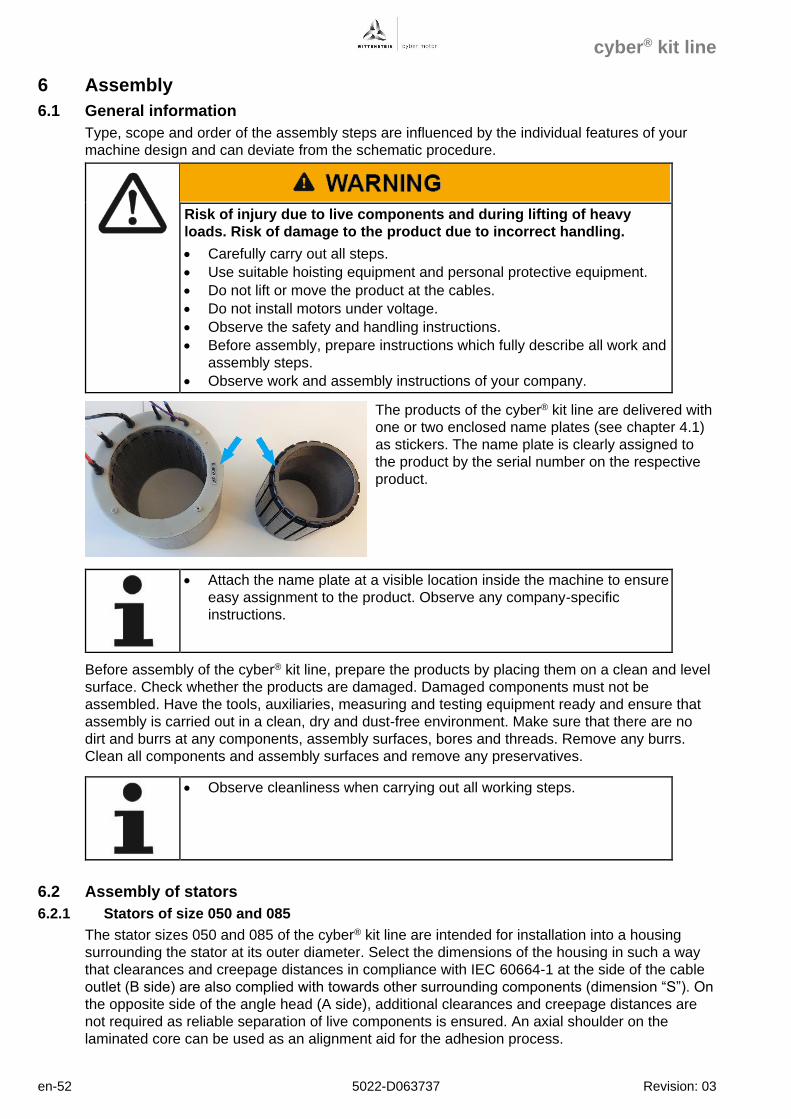
The products of the cyber® kit line are delivered with
one or two enclosed name plates (see chapter 4.1)
as stickers. The name plate is clearly assigned to
the product by the serial number on the respective
product.
• Attach the name plate at a visible location inside the machine to ensure
easy assignment to the product. Observe any company-specific
instructions.
Before assembly of the cyber® kit line, prepare the products by placing them on a clean and level
surface. Check whether the products are damaged. Damaged components must not be
assembled. Have the tools, auxiliaries, measuring and testing equipment ready and ensure that
assembly is carried out in a clean, dry and dust-free environment. Make sure that there are no
dirt and burrs at any components, assembly surfaces, bores and threads. Remove any burrs.
Clean all components and assembly surfaces and remove any preservatives.
• Observe cleanliness when carrying out all working steps.
6.2 Assembly of stators
6.2.1 Stators of size 050 and 085
The stator sizes 050 and 085 of the cyber® kit line are intended for installation into a housing
surrounding the stator at its outer diameter. Select the dimensions of the housing in such a way
that clearances and creepage distances in compliance with IEC 60664-1 at the side of the cable
outlet (B side) are also complied with towards other surrounding components (dimension “S”). On
the opposite side of the angle head (A side), additional clearances and creepage distances are
not required as reliable separation of live components is ensured. An axial shoulder on the
laminated core can be used as an alignment aid for the adhesion process.
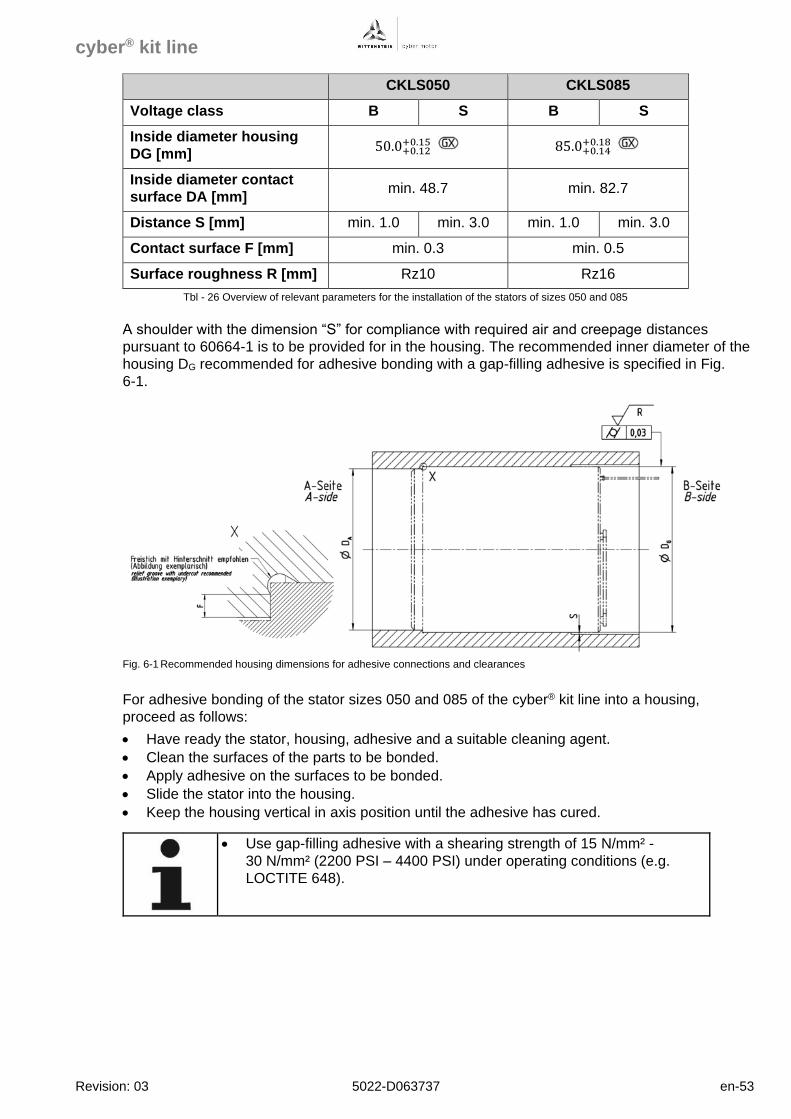
cyber® kit line
Revision: 03 5022-D063737 en-53
CKLS050 CKLS085
Voltage class B S B S
Inside diameter housing
DG [mm] 50.0+0.12
+0.15 85.0+0.14+0.18
Inside diameter contact
surface DA [mm] min. 48.7 min. 82.7
Distance S [mm] min. 1.0 min. 3.0 min. 1.0 min. 3.0
Contact surface F [mm] min. 0.3 min. 0.5
Surface roughness R [mm] Rz10 Rz16
Tbl - 26 Overview of relevant parameters for the installation of the stators of sizes 050 and 085
A shoulder with the dimension “S” for compliance with required air and creepage distances
pursuant to 60664-1 is to be provided for in the housing. The recommended inner diameter of the
housing DG recommended for adhesive bonding with a gap-filling adhesive is specified in Fig.
6-1.
Fig. 6-1 Recommended housing dimensions for adhesive connections and clearances
For adhesive bonding of the stator sizes 050 and 085 of the cyber® kit line into a housing,
proceed as follows:
• Have ready the stator, housing, adhesive and a suitable cleaning agent.
• Clean the surfaces of the parts to be bonded.
• Apply adhesive on the surfaces to be bonded.
• Slide the stator into the housing.
• Keep the housing vertical in axis position until the adhesive has cured.
• Use gap-filling adhesive with a shearing strength of 15 N/mm² -
30 N/mm² (2200 PSI – 4400 PSI) under operating conditions (e.g.
LOCTITE 648).
cyber® kit line
en-54 5022-D063737 Revision: 03
6.2.2 Stators of size 290 to 530
The stator sizes 290 to 530 of the cyber® kit line are fitted with a part of the cooling jacket and
intended for incorporation into a housing with the second part of the cooling jacket. Select the
dimensions of the housing in such a way that the connection dimensions in the respective
dimensional drawing are observed and that clearances and creepage distances in compliance
with IEC 60664-1 at the side of the cable outlet (B side) are also complied with towards other
surrounding components. On the opposite side of the angle head (A side), additional clearances
and creepage distances are not required as reliable separation of live components is ensured.
Make sure that the surface roughness at the sealing surfaces of the housing does not exceed
Rz 8.
For assembly of the stator sizes 290 and 530 of the cyber® kit line into a housing, proceed as
follows:
• Have ready the stator, housing, O-rings, required tools, auxiliaries, assembly equipment and
a suitable cleaning agent.
• Clean the surfaces of the parts to be assembled.
• Apply a conventional grease on the O-rings and assemble the O-rings into the dedicated
stator grooves. Avoid twisting and dirt at the O-rings.
• For safe transport, screw suitable ring bolts into opposite threads on a side of the stator.
• Lift the stator with suitable hoisting equipment and guide it without jamming and centrally into
the housing to the end position. As necessary, use a centering device. When routing the
connection cable, make sure that it is not damaged.
• Secure the stator at the machine housing with suitable fastening screws.
cyber® kit line
Revision: 03 5022-D063737 en-55
6.3 Assembly of rotors
The rotors are not prebalanced as an integration kit and must still be balanced as a group after
assembly onto the shaft, as required.
The rotors of the cyber® kit line are fitted with permanent magnets. During all work at the rotors,
observe the occurring radial and axial forces. These also occur if the rotors are inserted into the
stator. For first approximation, calculate these forces:
𝐹𝑎𝑥𝑖𝑎𝑙 = 0,33 ∙ 𝑠𝑖𝑧𝑒1,2 [𝑁]
𝐹𝑟𝑎𝑑𝑖𝑎𝑙 = 0,0033 ∙ 𝑠𝑖𝑧𝑒1,5 ∙ 𝑙𝑒𝑛𝑔𝑡ℎ [𝑁]
Respectively, the following forces apply during introduction of the rotor CKLR360B-100N-
NNNNN-NN0ESN:
𝐹𝑎𝑥𝑖𝑎𝑙 = 0,33 ∙ 3601,2 𝑁 = 386 𝑁
𝐹𝑟𝑎𝑑𝑖𝑎𝑙 = 0,0033 ∙ 𝑠𝑖𝑧𝑒1,5 ∙ 𝑙𝑒𝑛𝑔𝑡ℎ 𝑁 = 0,0033 ∙ 3601,5 ∙ 100 𝑁 = 2254 𝑁
Components equipped with permanent magnets and components
that emit magnetic fields can influence/impede the function of active
medical implants (e.g. pacemakers, defibrillators). This can lead to
serious injuries or even death.
• Assembly and storage areas must not be accessed by personnel with
active body implants, which may be affected by permanent magnetic
fields.
• Include the warning into the assembly instructions of your company.
• Make sure that the warning remains at the product as long as a hazard
exists.
During the mechanical assembly of kit motors, the attraction forces
of the magnets can cause serious crushing injuries and damage to
the motor or the application.
• Avoid unwanted movement of components of the kit motors by suitable
auxiliaries for assembly.
• Have all mechanical assembly and maintenance work carried out by
qualified personnel only.
• Only use suitable non-magnetic tools for assembly and maintenance
work.
Incorrect assembly of kit motors can lead to damage at products.
• Use suitable assembly accessories to ensure that the rotor does not
get into contact with the stator when it is inserted.
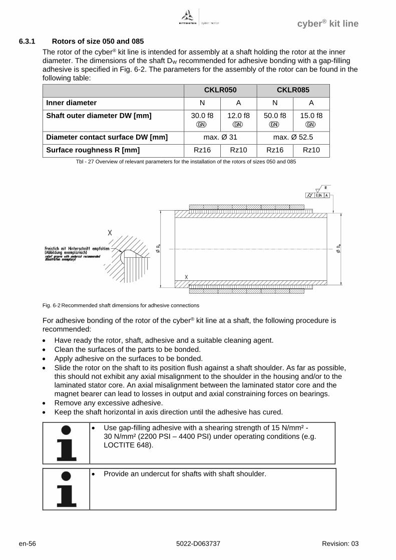
cyber® kit line
en-56 5022-D063737 Revision: 03
6.3.1 Rotors of size 050 and 085
The rotor of the cyber® kit line is intended for assembly at a shaft holding the rotor at the inner
diameter. The dimensions of the shaft DW recommended for adhesive bonding with a gap-filling
adhesive is specified in Fig. 6-2. The parameters for the assembly of the rotor can be found in the
following table:
CKLR050 CKLR085
Inner diameter N A N A
Shaft outer diameter DW [mm] 30.0 f8
12.0 f8
50.0 f8
15.0 f8
Diameter contact surface DW [mm] max. Ø 31 max. Ø 52.5
Surface roughness R [mm] Rz16 Rz10 Rz16 Rz10
Tbl - 27 Overview of relevant parameters for the installation of the rotors of sizes 050 and 085
Fig. 6-2 Recommended shaft dimensions for adhesive connections
For adhesive bonding of the rotor of the cyber® kit line at a shaft, the following procedure is
recommended:
• Have ready the rotor, shaft, adhesive and a suitable cleaning agent.
• Clean the surfaces of the parts to be bonded.
• Apply adhesive on the surfaces to be bonded.
• Slide the rotor on the shaft to its position flush against a shaft shoulder. As far as possible,
this should not exhibit any axial misalignment to the shoulder in the housing and/or to the
laminated stator core. An axial misalignment between the laminated stator core and the
magnet bearer can lead to losses in output and axial constraining forces on bearings.
• Remove any excessive adhesive.
• Keep the shaft horizontal in axis direction until the adhesive has cured.
• Use gap-filling adhesive with a shearing strength of 15 N/mm² -
30 N/mm² (2200 PSI – 4400 PSI) under operating conditions (e.g.
LOCTITE 648).
• Provide an undercut for shafts with shaft shoulder.
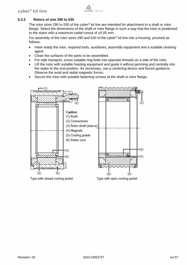
cyber® kit line
Revision: 03 5022-D063737 en-57
6.3.2 Rotors of size 290 to 530
The rotor sizes 290 to 530 of the cyber® kit line are intended for attachment to a shaft or rotor
flange. Select the dimensions of the shaft or rotor flange in such a way that the rotor is positioned
to the stator with a maximum radial runout of ±0.05 mm.
For assembly of the rotor sizes 290 and 530 of the cyber® kit line into a housing, proceed as
follows:
• Have ready the rotor, required tools, auxiliaries, assembly equipment and a suitable cleaning
agent.
• Clean the surfaces of the parts to be assembled.
• For safe transport, screw suitable ring bolts into opposite threads on a side of the rotor.
• Lift the rotor with suitable hoisting equipment and guide it without jamming and centrally into
the stator to the end position. As necessary, use a centering device and forced guidance.
Observe the axial and radial magnetic forces.
• Secure the rotor with suitable fastening screws at the shaft or rotor flange.
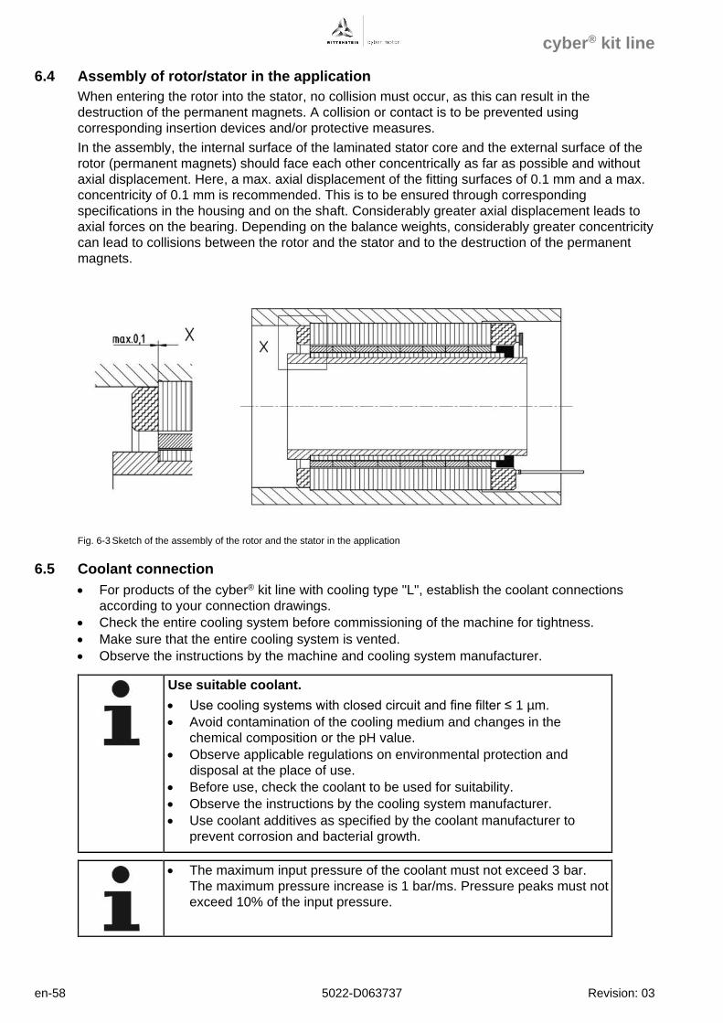
cyber® kit line
en-58 5022-D063737 Revision: 03
6.4 Assembly of rotor/stator in the application
When entering the rotor into the stator, no collision must occur, as this can result in the
destruction of the permanent magnets. A collision or contact is to be prevented using
corresponding insertion devices and/or protective measures.
In the assembly, the internal surface of the laminated stator core and the external surface of the
rotor (permanent magnets) should face each other concentrically as far as possible and without
axial displacement. Here, a max. axial displacement of the fitting surfaces of 0.1 mm and a max.
concentricity of 0.1 mm is recommended. This is to be ensured through corresponding
specifications in the housing and on the shaft. Considerably greater axial displacement leads to
axial forces on the bearing. Depending on the balance weights, considerably greater concentricity
can lead to collisions between the rotor and the stator and to the destruction of the permanent
magnets.
Fig. 6-3 Sketch of the assembly of the rotor and the stator in the application
6.5 Coolant connection
• For products of the cyber® kit line with cooling type "L", establish the coolant connections
according to your connection drawings.
• Check the entire cooling system before commissioning of the machine for tightness.
• Make sure that the entire cooling system is vented.
• Observe the instructions by the machine and cooling system manufacturer.
Use suitable coolant.
• Use cooling systems with closed circuit and fine filter ≤ 1 µm.
• Avoid contamination of the cooling medium and changes in the
chemical composition or the pH value.
• Observe applicable regulations on environmental protection and
disposal at the place of use.
• Before use, check the coolant to be used for suitability.
• Observe the instructions by the cooling system manufacturer.
• Use coolant additives as specified by the coolant manufacturer to
prevent corrosion and bacterial growth.
• The maximum input pressure of the coolant must not exceed 3 bar.
The maximum pressure increase is 1 bar/ms. Pressure peaks must not
exceed 10% of the input pressure.
cyber® kit line
Revision: 03 5022-D063737 en-59
• No force on the attachment of the product may be applied via the
coolant connections.
The products of the cyber® kit line are designed for operation with a coolant temperature of
+10 °C … +40 °C. This temperature range must always be complied with. At higher coolant
temperatures, the available torque is further reduced. Low coolant temperatures can lead to
condensation and destroy the product.
Set the coolant input temperature correctly.
• Observe the ambient temperature.
• The coolant input temperature may only be 5 °C below the ambient
temperature.
• Observe the instructions by the cooling system manufacturer.
6.6 Electrical connection
The products of the cyber® kit line are intended for connection to a suitable drive control unit with
variable output voltage and frequency.
Risk of injury (electric shock) and destruction of the products
at direct power supply connection.
• Always connect the products to a suitable drive control unit.
• Establish the electrical connection according to the connection diagrams.
• Ensure correct fitting of connectors and cables for strain relief.
The electrical connection of the stators is established with a connection cable via a terminal box
or connector. Make sure that the current rating of the connection elements and the connection
cable is sufficient for the type of installation. Observe the connection schematics in chapter 7.
The electrical connection of the stators is not suitable for drag
chains.
• In drag chains, only use suitable cables.
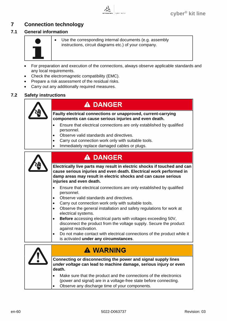
cyber® kit line
en-60 5022-D063737 Revision: 03
7 Connection technology
7.1 General information
• Use the corresponding internal documents (e.g. assembly
instructions, circuit diagrams etc.) of your company.
• For preparation and execution of the connections, always observe applicable standards and
any local requirements.
• Check the electromagnetic compatibility (EMC).
• Prepare a risk assessment of the residual risks.
• Carry out any additionally required measures.
7.2 Safety instructions
Faulty electrical connections or unapproved, current-carrying
components can cause serious injuries and even death.
• Ensure that electrical connections are only established by qualified
personnel.
• Observe valid standards and directives.
• Carry out connection work only with suitable tools.
• Immediately replace damaged cables or plugs.
Electrically live parts may result in electric shocks if touched and can
cause serious injuries and even death. Electrical work performed in
damp areas may result in electric shocks and can cause serious
injuries and even death.
• Ensure that electrical connections are only established by qualified
personnel.
• Observe valid standards and directives.
• Carry out connection work only with suitable tools.
• Observe the general installation and safety regulations for work at
electrical systems.
• Before accessing electrical parts with voltages exceeding 50V,
disconnect the product from the voltage supply. Secure the product
against reactivation.
• Do not make contact with electrical connections of the product while it
is activated under any circumstances.
Connecting or disconnecting the power and signal supply lines
under voltage can lead to machine damage, serious injury or even
death.
• Make sure that the product and the connections of the electronics
(power and signal) are in a voltage-free state before connecting.
• Observe any discharge time of your components.
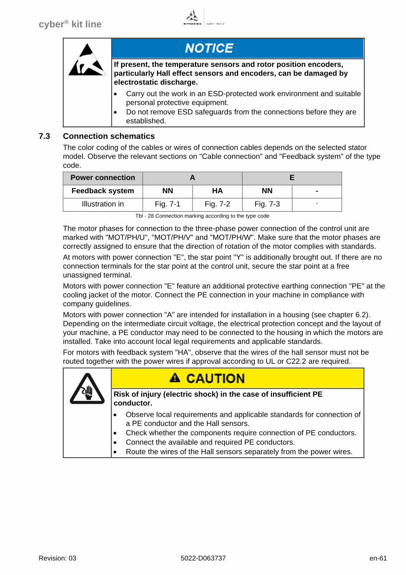
cyber® kit line
Revision: 03 5022-D063737 en-61
If present, the temperature sensors and rotor position encoders,
particularly Hall effect sensors and encoders, can be damaged by
electrostatic discharge.
• Carry out the work in an ESD-protected work environment and suitable
personal protective equipment.
• Do not remove ESD safeguards from the connections before they are
established.
7.3 Connection schematics
The color coding of the cables or wires of connection cables depends on the selected stator
model. Observe the relevant sections on "Cable connection" and "Feedback system" of the type
code.
Power connection A E
Feedback system NN HA NN -
Illustration in Fig. 7-1 Fig. 7-2 Fig. 7-3 -
Tbl - 28 Connection marking according to the type code
The motor phases for connection to the three-phase power connection of the control unit are
marked with "MOT/PH/U", "MOT/PH/V" and "MOT/PH/W". Make sure that the motor phases are
correctly assigned to ensure that the direction of rotation of the motor complies with standards.
At motors with power connection "E", the star point "Y" is additionally brought out. If there are no
connection terminals for the star point at the control unit, secure the star point at a free
unassigned terminal.
Motors with power connection "E" feature an additional protective earthing connection "PE" at the
cooling jacket of the motor. Connect the PE connection in your machine in compliance with
company guidelines.
Motors with power connection "A" are intended for installation in a housing (see chapter 6.2).
Depending on the intermediate circuit voltage, the electrical protection concept and the layout of
your machine, a PE conductor may need to be connected to the housing in which the motors are
installed. Take into account local legal requirements and applicable standards.
For motors with feedback system "HA", observe that the wires of the hall sensor must not be
routed together with the power wires if approval according to UL or C22.2 are required.
Risk of injury (electric shock) in the case of insufficient PE
conductor.
• Observe local requirements and applicable standards for connection of
a PE conductor and the Hall sensors.
• Check whether the components require connection of PE conductors.
• Connect the available and required PE conductors.
• Route the wires of the Hall sensors separately from the power wires.
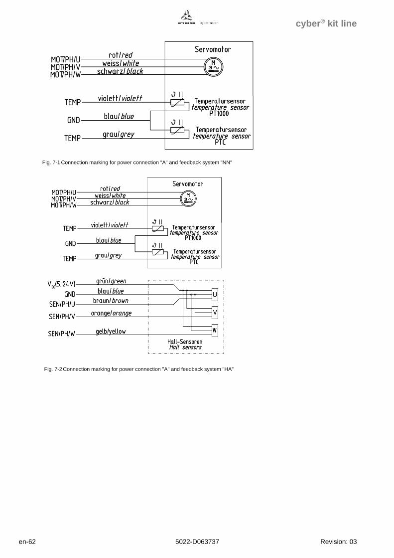
cyber® kit line
en-62 5022-D063737 Revision: 03
Fig. 7-1 Connection marking for power connection "A" and feedback system "NN"
Fig. 7-2 Connection marking for power connection "A" and feedback system "HA"
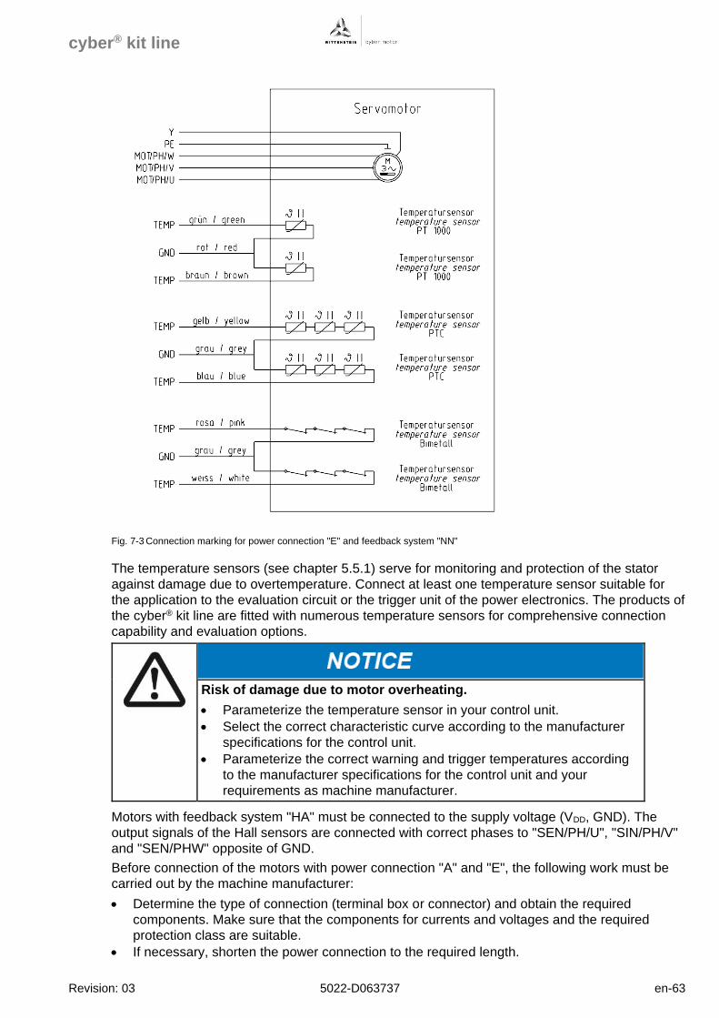
cyber® kit line
Revision: 03 5022-D063737 en-63
Fig. 7-3 Connection marking for power connection "E" and feedback system "NN"
The temperature sensors (see chapter 5.5.1) serve for monitoring and protection of the stator
against damage due to overtemperature. Connect at least one temperature sensor suitable for
the application to the evaluation circuit or the trigger unit of the power electronics. The products of
the cyber® kit line are fitted with numerous temperature sensors for comprehensive connection
capability and evaluation options.
Risk of damage due to motor overheating.
• Parameterize the temperature sensor in your control unit.
• Select the correct characteristic curve according to the manufacturer
specifications for the control unit.
• Parameterize the correct warning and trigger temperatures according
to the manufacturer specifications for the control unit and your
requirements as machine manufacturer.
Motors with feedback system "HA" must be connected to the supply voltage (VDD, GND). The
output signals of the Hall sensors are connected with correct phases to "SEN/PH/U", "SIN/PH/V"
and "SEN/PHW" opposite of GND.
Before connection of the motors with power connection "A" and "E", the following work must be
carried out by the machine manufacturer:
• Determine the type of connection (terminal box or connector) and obtain the required
components. Make sure that the components for currents and voltages and the required
protection class are suitable.
• If necessary, shorten the power connection to the required length.
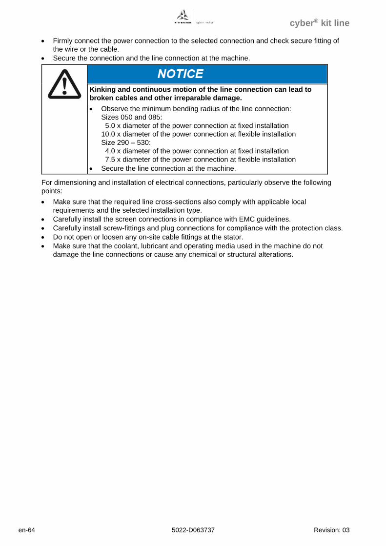
cyber® kit line
en-64 5022-D063737 Revision: 03
• Firmly connect the power connection to the selected connection and check secure fitting of
the wire or the cable.
• Secure the connection and the line connection at the machine.
Kinking and continuous motion of the line connection can lead to
broken cables and other irreparable damage.
• Observe the minimum bending radius of the line connection:
Sizes 050 and 085:
5.0 x diameter of the power connection at fixed installation
10.0 x diameter of the power connection at flexible installation
Size 290 – 530:
4.0 x diameter of the power connection at fixed installation
7.5 x diameter of the power connection at flexible installation
• Secure the line connection at the machine.
For dimensioning and installation of electrical connections, particularly observe the following
points:
• Make sure that the required line cross-sections also comply with applicable local
requirements and the selected installation type.
• Carefully install the screen connections in compliance with EMC guidelines.
• Carefully install screw-fittings and plug connections for compliance with the protection class.
• Do not open or loosen any on-site cable fittings at the stator.
• Make sure that the coolant, lubricant and operating media used in the machine do not
damage the line connections or cause any chemical or structural alterations.
cyber® kit line
Revision: 03 5022-D063737 en-65
8 Startup and operation
8.1 General instructions for commissioning
The instructions for commissioning refer to the motor as part of a drive system with at least one
control unit.
Errors during control of motors and moving elements can lead to
machine damage as well as serious injury or even death.
• Do not commission the product if connections, operating states or
product data are missing or unclear.
• Do not commission the product if safeguards and monitoring
equipment at the system are damaged or defective.
• Make sure that the product is suitable for the intended application.
• Observe the technical cleanliness.
• Ensure that only properly qualified and professionally trained personnel
who are able to assess the safe condition of the product work at the
product.
• Use the corresponding internal documents (e.g. assembly
instructions, circuit diagrams etc.) of your company.
Before commissioning, the following typical steps must be carried out:
• Keep ready the documentation of all used products.
• Protocol all work carried out.
• Check the products and machine for damage.
• Check all mechanical and electrical connections.
• When setting up and programming the machine, observe the assignments of the directions of
rotation of the motor and the encoder.
• Activate the safeguards and monitoring systems of the machine.
Commissioning of control units and controllers can require further steps. Checking the
functionality and performance of the machine is not part of these project specifications and must
be carried out by the machine manufacturer in the course of overall commissioning of the
machine. Observe the specifications and instructions of the machine manufacturer.
8.2 Safety instructions
When the shaft is still turning or when the product is driven
externally (generator operation), voltage is induced. This can cause
lethal current surges.
• Ensure that connections and connectors are not open and unprotected
against contact.
• Do not make contact with electrical connections of the product while it
is activated under any circumstances.
cyber® kit line
en-66 5022-D063737 Revision: 03
Moving components on the product can pull in or crush parts of the
body or eject objects and cause serious injuries and even death. A
wrong direction of rotation or direction of movement may result in
serious injury or death.
• Remove objects and tools from the motor before putting it into
operation.
• Make sure that all components at the product are secured according to
the assembly instructions of your company.
• Keep a sufficient distance to moving machine components when the
motor is running.
• Secure the machine against restarting and unintentional movement
during assembly and maintenance work.
• Before and during startup, ensure that the motor has the correct
direction of rotation.
• Avoid collisions (e.g. moving against an end stop).
• Check the direction of rotation in a slow motion, ideally by limiting the
current and torque in a secured danger area.
Some control units of different manufacturers use proprietary data
specifications. If the data convention is not observed, the motor
and/or the control unit may be damaged.
• Observe the listed units precisely and check their conformance with the
units of the control unit.
• The technical data of WITTENSTEIN cyber motor are specified in SI
units according to IEC 80000 and coherent units. Have the
manufacturer provide you with the regulations on conversion of SI units
to the notation of the control unit.
The products of the cyber® kit line are kit motors with individual components to be installed into
the machine by the machine manufacturer. Kit motors do not feature a data memory for provision
of motor parameters and/or parameters of the control unit. All parameters must be entered
manually during commissioning or loaded into the control unit.
Take into account that these parameters also apply for the direction of rotation of the encoder
and the commutation offset.
8.3 Preconditions and auxiliaries
For successful commissioning, the following preconditions must be complied with:
- Compliance with safety instructions and information.
- Checking of all electrical and mechanical components for safe function
- Availability of all required auxiliaries
- Availability of a suitable control unit
cyber® kit line
Revision: 03 5022-D063737 en-67
The control units of different manufacturers may lead to early failure
of the insulation system.
• Select a suitable control unit for the intermediate circuit voltage UDC of
the motor.
• Make sure that the voltage gradient of the pulsed voltage at the control
unit does not exceed a limit value of 8 kV/µs at the cable connections
of the motor.
• Parameterize the control unit in such a way that the admissible
maximum current Imax is not exceeded.
• If applicable, use thermal protective equipment.
The performance of the control units of different manufacturers may
not be sufficient.
• Select a suitable control unit for the speed of the application. Observe
the required output frequency of the control unit.
• Make sure that the control unit provides the maximum current required
in the application for the required duration.
The converter performance data required for an intended operation can be found in the
characteristic curve.
The output frequency of the control unit and/or the necessary rotary field frequency fU can be
calculated with the pole pair number p and the speed nM of the motor.
fU = p * nM
The motors of the cyber® kit line are multi-pole (p>10). Therefore,
high output frequencies on the converter are required for
corresponding speeds.
With the sizes BG50 and BG85 (p=10), rotary field frequencies of
600 Hz are already reached at 3600 rpm.
• Ensure that the selected control unit exhibits corresponding output
frequencies.
Commissioning is realized with the commissioning software of your drive control unit or controller.
If a cyber® simco® drive 2 control unit is used, the MotionGUI 2 software is recommended. It
requires a standard PC with Windows operating system. For commissioning via your controller by
means of a control terminal, access to all drive parameters and functions must be ensured.
For drive optimization, an oscilloscope is required. The MotionGUI 2 software features an
integrated oscilloscope function for graphical illustration of signals.
For troubleshooting and checking of components, a multimeter may be useful for current, voltage
and resistance measurement.
cyber® kit line
en-68 5022-D063737 Revision: 03
8.4 General procedure for commissioning
The general procedure for commissioning requires the following steps. If control units of other
manufacturers are used and for the specific installation situation of the machine, other and
additional steps may be required. Firstly, observe the specifications and instructions of the
machine manufacturer and any applicable local standards and regulations:
• Make sure that all connections, functions and safeguards are functional without faults.
• In case of initial commissioning, load the default settings of the control unit ("default values").
• Parameterize the control unit with the specific motor parameters. For this, use the technical
data in these project specifications (chapter 5) and take into account any necessary
conversions and the units in the control unit.
• Parameterize any position encoders and/or other feedback systems.
• Parameterize the drive limits like maximum positions, maximum velocities, maximum
acceleration, maximum stroke, etc.
• Parameterize any necessary application-specific parameters.
• Determine the encoder polarity. If the direction of rotation of the drive deviates from the
direction of rotation of the encoder, invert the parameter for the direction of rotation of the
encoder of your control unit. To do so, please refer to the instructions for your control unit.
Carry out this step until the direction of rotation of the drive complies with the direction of
rotation of the encoder.
• Determine the optimum commutation setting and store it in the control unit. Refer to the
instructions for your control unit.
• Carry out the settings and optimize the control circuits. Refer to the instructions for your
control unit.
Moving components on the product can pull in or crush parts of the
body or eject objects and cause serious injuries and even death. A
wrong direction of rotation or direction of movement may result in
serious injury or death.
• Remove objects and tools from the motor before putting it into
operation.
• Make sure that all components at the product are secured according to
the assembly instructions of your company.
• Keep a sufficient distance to moving machine components when the
motor is running.
• Secure the machine against restarting and unintentional movement
during assembly and maintenance work.
• Avoid collisions (e.g. moving against an end stop).
• Check the direction of rotation in a slow motion, ideally by limiting the
current and torque in a secured danger area.
• If the encoder system is replaced, repeat all necessary steps for
commissioning.
• Thoroughly carry out all steps for commissioning. Optimum
parameterization enables maximum efficiency of the product and
supports the correct function of your machinery.
cyber® kit line
Revision: 03 5022-D063737 en-69
8.4.1 Commissioning of brakes
In electrical machines, holding brakes can be installed to hold the drive axes in voltage-free state
of the machine. In normal operation, holding brakes are only used in standstill. Additionally, brake
tests can be executed by the drive control unit.
The products of the cyber® kit line do not have any brake.
• Make sure that necessary movements during commissioning of the
cyber® kit line are not prevented by any brakes in the drive axis.
cyber® kit line
en-70 5022-D063737 Revision: 03
9 Maintenance
Within their service life and the specified ambient and operating conditions, the products of the
cyber® kit line do not require any maintenance. Regular preventative maintenance according to
the machine maintenance plan of the machine manufacturer increases the reliability of the
machine. WITTENSTEIN cyber motor recommends carrying out the following maintenance:
- Checking of mechanical and electrical connections according to the machine maintenance
plan and at least every 1000 operating hours or every 3 months.
- Checking of flexible cables and lines according to the machine maintenance plan and at least
every 500 operating hours or monthly.
- Checking of the machine for smooth operation, vibration and noise according to the machine
maintenance plan and at least every 1000 operating hours or every 3 months.
- Checking of the function and cleanliness of the cooling system according to the machine
maintenance plan and at least every 1000 operating hours or every 3 months.
- Removal of dust, chipping and other dirt from motor housings, cooling rips and other
connections depending on the degree of pollution, however, at least every 8000 operating
hours or 12 months.
Risk of serious crushing injury due to incorrect handling during
maintenance.
• During maintenance, secure the machine against restarting and
unintended movement.
• Have all mechanical maintenance carried out by qualified personnel
only.
• For maintenance, only use suitable tools.
Hot surfaces can cause serious injuries.
• Let the products cool down for a sufficient period after switching them
off and before maintenance.
• When working with hot surfaces, always wear protective gloves.
9.1 Cleaning
Cleaning of the machine according to specifications of the machine manufacturer increases the
reliability of the machine. The products of the cyber® kit line are kit motors installed into the
machine according to the specifications of the machine manufacturer. WITTENSTEIN cyber
motor recommends the following basic approach for cleaning of products:
• Remove dust, chipping and other dirt from the product.
• If necessary, use suitable non-aggressive cleaning agents.
• Check compatibility before cleaning.
Risk of serious crushing injury due to incorrect cleaning during
maintenance.
• During cleaning, secure the machine against restarting and unintended
movement.
• For cleaning, only use suitable tools.
cyber® kit line
Revision: 03 5022-D063737 en-71
Hot surfaces can cause serious injuries.
• Let the products cool down for a sufficient period after switching them
off and before cleaning.
• When working with hot surfaces, always wear protective gloves.
9.2 Visual inspection
During maintenance, carry out a visual inspection according to specifications of the machine
manufacturer and record all irregularities in the machine maintenance plan. WITTENSTEIN
cyber motor recommends the following basic approach for visual inspection:
• Visually inspect all mechanical and electrical connections.
• Check cables and lines for visible damage.
• Check mechanical components for damage and wear.
• Check the machine for leakage and dirt.
Regular visual inspection and definition of measures help to prevent
malfunctions and unscheduled downtimes.
9.3 Disassembly
Components equipped with permanent magnets and components
that emit magnetic fields can influence/impede the function of active
medical implants (e.g. pacemakers, defibrillators). This can lead to
serious injuries or even death.
• Assembly and storage areas must not be accessed by personnel with
active body implants, which may be affected by permanent magnetic
fields.
• Include the warning into the assembly instructions of your company.
• Make sure that the warning remains at the product as long as a hazard
exists.
During mechanical disassembly, handling errors can lead to serious
crushing injuries as well as to damage to the product or the
application.
• During disassembly, secure the machine against restarting and
unintended movement.
• Have all mechanical disassembly carried out by qualified personnel
only.
• For disassembly, only use suitable tools.
cyber® kit line
en-72 5022-D063737 Revision: 03
During the mechanical disassembly of kit motors, the attraction
forces of the magnets can cause serious crushing injuries and
damage to the motor or the application.
• Avoid unwanted movement of components of the kit motors by suitable
auxiliaries for assembly.
• Have all mechanical disassembly carried out by qualified personnel
only.
• For disassembly, only use suitable non-magnetic tools.
Hot surfaces at the product (e.g. housing, motor housing) can cause
serious injuries.
• Let the product cool down for a sufficient period after switching it off.
• When working with hot surfaces, always wear protective gloves.
Before disassembly of the products of the cyber® kit line, shut down the machine. For shut down,
observe the instructions in the machine documentation. WITTENSTEIN cyber motor
recommends the following general approach:
• Switch off all line and control voltages including the main switch of the machine.
• Secure the machine against unintended movements, restarting and unauthorized operation.
• Wait for all electrical systems to fully discharge and disconnect any electrical connections if
necessary.
• Before disassembly and loosening of mechanical connections, secure all components against
falling or movements.
• Drain any coolant channels before opening.
• Disassemble the axis or motor from the machine and store the motor or motor components
according to instructions.
• Please note that, for example, disassembly of glued connections may not be possible and
connected components may need to be disassembled as a whole.
• Protocol all work carried out in the machine maintenance plan.
cyber® kit line
Revision: 03 5022-D063737 en-73
9.4 Disposal
For free-of-charge disposal, the products of the cyber® kit line can be returned to WITTENSTEIN
cyber motor after removal of any residues of oil, grease or adhesives and other dirt. Additionally,
the products must not contain any inadmissible foreign substances or components.
Please send the products for disposal postage paid to the following address:
WITTENSTEIN cyber motor GmbH Customer Service Walter-Wittenstein-Straße 1 D-97999 Igersheim
Packaging materials include wood, cardboard, plastic, VCI paper, VCI pad, foam, ESD bags,
silicate bags and/or adhesive tape. Dispose of the packaging materials at the recycling sites
intended for this purpose and observe applicable national regulations. For ecological reasons, the
packaging materials should not be returned.
The products of the cyber® kit line have a high metal content and are therefore suitable for
recycling. To achieve optimum recycling of metals and materials, disassembly into individual
subassemblies is required. WITTENSTEIN cyber motor recommends separation of glued parts
for recycling of materials. After separation, plastics must be forwarded to thermal processing.
cyber® kit line
en-74 5022-D063737 Revision: 03
10 Service & support
WITTENTSTEIN cyber motor offers service and support services. You can reach our Customer
Service this way:
Customer Service
Phone +49 (0) 7931 493 15900
Email [email protected]
Address WITTENSTEIN cyber motor GmbH
Customer Service
Walter-Wittenstein-Straße 1
D-97999 Igersheim
Tbl - 29 Contact data: WITTENSTEIN cyber® motor Customer Service
• Please have the following information ready:
- Detailed description of the malfunction and the circumstances
- Type code and serial number of respective products
- Phone number and Email address for contact
• Observe the assembly instructions of your company regarding possible
malfunctions and information on troubleshooting.
cyber® kit line
Revision: 03 5022-D063737
Revision history
Revision Date Comment Chapter
01 05/05/2021 New version All
02 15/06/2021 Addition of data 5
03 03/02/2022 Standardization,
editorial revision
All
WITTENSTEIN – one with the future www.wittenstein-cyber-motor.de