Embed Size (px)
Citation preview
FORD 4R44E, 4R55E, 5R44E, 5R55EZIP KIT®
PART NUMBER 4R44E-5R55E-ZIP QUICK GUIDE
4A
4B
6C
5
5
5
8
8
8
4E
4D 8
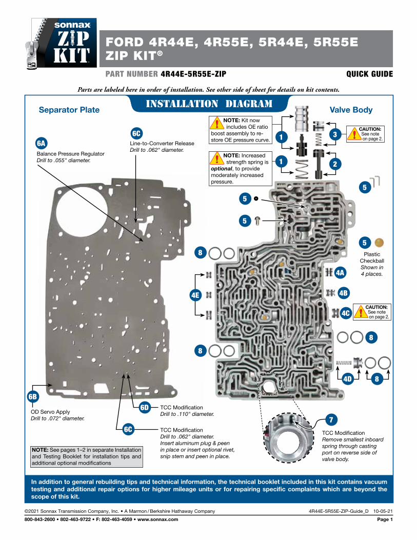
Separator Plate Valve Body
5Plastic
Checkball Shown in 4 places.
2Balance Pressure Regulator Drill to .055" diameter.
Line-to-Converter Release Drill to .062" diameter.
6A
OD Servo Apply Drill to .072" diameter.
6B
TCC Modification Drill to .062" diameter. Insert aluminum plug & peen in place or insert optional rivet, snip stem and peen in place.
6C
TCC Modification Drill to .110" diameter.
6D
TCC Modification Remove smallest inboard spring through casting port on reverse side of valve body.
7
1
NOTE: See pages 1–2 in separate Installation and Testing Booklet for installation tips and additional optional modifications
NOTE: Kit now includes OE ratio boost assembly to re- store OE pressure curve.
NOTE: Increased strength spring is optional, to provide moderately increased pressure.
1
4C CAUTION: See note on page 2.
CAUTION: See note on page 2.
3
©2021 Sonnax Transmission Company, Inc. • A Marmon / Berkshire Hathaway Company 4R44E-5R55E-ZIP-Guide_D 10-05-21
800-843-2600 • 802-463-9722 • F: 802-463-4059 • www.sonnax.com Page 1
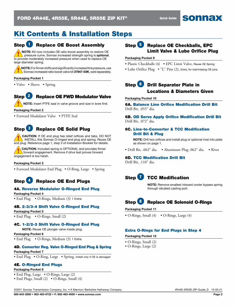
Parts are labeled here in order of installation. See other side of sheet for details on kit contents.
installation Diagram
In addition to general rebuilding tips and technical information, the technical booklet included in this kit contains vacuum testing and additional repair options for higher mileage units or for repairing specific complaints which are beyond the scope of this kit.
installation Diagram
Step Replace OE Boost Assembly NOTE: Kit now includes OE ratio boost assembly to restore OE pressure curve. Sonnax increased strength spring is optional, to provide moderately increased pressure when used to replace OE large diameter spring.
NOTE: For firmer shifts and significantly increased line pressure, use Sonnax increased ratio boost valve kit 37947-03K, sold separately.
Packaging Pocket 1
• Valve • Sleeve • Spring
Step Replace OE FWD Modulator Valve NOTE: Insert PTFE seal in valve groove and size in bore first.
Packaging Pocket 2
• Forward Modulator Valve • PTFE Seal
Step Replace OE Solid Plug CAUTION: If OE end plug has relief orifices and tabs, DO NOT INSTALL this Sonnax O-ringed end plug and spring. Reuse OE end plug. Reference page 1, step 3 of Installation Booklet for details.
CAUTION: Included spring is OPTIONAL and provides firmer forward engagement. Remove if drive test proves forward engagement is too harsh.
Packaging Pocket 3
• Forward Modulator End Plug • O-Ring, Large • Spring
Step Replace OE End Plugs
4A. Reverse Modulator O-Ringed End PlugPackaging Pocket 4
• End Plug • O-Rings, Medium (3) 1 Extra
4B. 2-3/3-4 Shift Valve O-Ringed End PlugPackaging Pocket 5
• End Plug • O-Rings, Small (2)
4C. 1-2/2-3 Shift Valve O-Ringed End Plug NOTE: Reuse OE plunger valve inside plug.
Packaging Pocket 6
• End Plug • O-Rings, Medium (3) 1 Extra
4D. Converter Reg. Valve O-Ringed End Plug & SpringPackaging Pocket 7
• End Plug • O-Ring, Large • Spring, Install only if OE is damaged
4E. O-Ringed End PlugsPackaging Pocket 8
• End Plug, Large • O-Rings, Large (2)• End Plugs, Small (2) • O-Rings, Small (4)
1
2
3
4
Step Replace OE Checkballs, EPC Limit Valve & Lube Orifice Plug
Packaging Pocket 9
• Plastic Checkballs (4) • EPC Limit Valve, Reuse OE Spring
• Lube Orifice Plug • "L" Pins (2), Extra, for lost/missing OE pins
Step Drill Separator Plate in Locations & Diameters Given
Packaging Pocket 10
6A. Balance Line Orifice Modification Drill BitDrill Bit, .055" dia.
6B. OD Servo Apply Orifice Modification Drill BitDrill Bit, .072" dia.
6C. Line-to-Converter & TCC Modification Drill Bit & Plug
NOTE: Drill two orifices and install plug or optional rivet into plate as shown on page 1.
• Drill Bit, .062" dia. • Aluminum Plug .062" dia. • Rivet
6D. TCC Modification Drill BitDrill Bit, .110" dia.
Step TCC Modification NOTE: Remove smallest inboard cooler bypass spring
through idicated casting port.
Step Replace OE Solenoid O-RingsPackaging Pocket 11
• O-Rings, Small (4) • O-Rings, Large (4)
Extra O-Rings for End Plugs in Step 4Packaging Pocket 12
• O-Rings, Small (2) • O-Rings, Large (2)
5
6
7
8
©2021 Sonnax Transmission Company, Inc. • A Marmon / Berkshire Hathaway Company 4R44E-5R55E-ZIP-Guide_D 10-05-21
800-843-2600 • 802-463-9722 • F: 802-463-4059 • www.sonnax.com Page 2
Kit Contents & Installation Steps
FORD 4R44E, 4R55E, 5R44E, 5R55E ZIP KIT® Quick Guide
Valve Body Rebuild Tips & TechniquesBore-by-bore tips for removal, installation, options and checks of valve body components. The detailed steps below correlate to the quick guide steps.
1. Replace OE Boost AssemblyKit now includes an OE ratio boost assembly to restore OE pressure curve. Sonnax increased strength spring is optional, and will provide moderately increased pressure (approximately 5 psi in Drive and 6 psi in Reverse) when used to replace the OE large diameter spring. For firmer shifts and significantly increased line pressure, use Sonnax increased ratio boost valve kit 37947-03K, sold separately. This increased ratio kit is NOT recommended for smaller 4-cylinder applications, or if testing determines that the Sonnax EPC and engagement control kit 37947-11K (sold separately) is necessary and installed.
2. Replace OE Forward Modulator ValveBy positioning the manual valve furthest into the bore, air pressure can be used to blow the modulator valve out. If there is any visible wear or ridge in the bore, buff this area with Scotch-Brite™ placed on a twisted wire and inserted into drill. Install the PTFE seal onto the Sonnax valve. Invert the valve and push into the bore just far enough to size the PTFE seal. After sizing the seal, install the OE forward modulator spring into the end of the Sonnax valve and install into the bore (illustrated in Quick Guide).
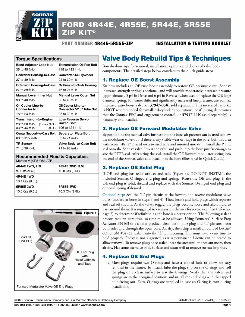
3. Replace OE Solid PlugIf OE end plug has relief orifices and tabs (Figure 1), DO NOT INSTALL the included Sonnax O-ringed end plug and spring. Reuse the OE end plug. If the OE end plug is solid, discard and replace with the Sonnax O-ringed end plug and optional spring if desired.
Optional Step: Seal the “L” pin circuits at the forward and reverse modulator valve bores (inboard at bores in steps 3 and 4). These locate and hold plugs which separate and seal oil circuits. As the valves toggle, the plugs become loose and allow fluid to pass around them. It is suggested to vacuum test the area for severe wear first (reference page 7) to determine if refurbishing the bore is a better option. The following sealant process requires cure time, so time must be allowed. Using Permatex® Surface Prep Activator #24163 or a similar product, clean the middle plug and “L” pin area from both sides and through the open bore. Air dry, then drip a small amount of Loctite® 609 or 3M #04732 sealant into the “L” pin opening. This must have a cure time to hold properly. Epoxy is not suggested, as it is permanent. Loctite can be heated to allow removal. To remove plugs once sealed, heat the area until the sealant melts, then air dry. Flat stone the valve body surface and clean well to remove surface imprints.
4. Replace OE End Plugsa. Most plugs require two O-rings and have a tapped hole to allow for easy
removal in the future. To install, lube the plug, slip on the O-rings and roll the plug on a clean surface to seat the O-rings. Verify that the valves and springs are in their original positions and install the end plugs with the tapped hole facing out. Extra O-rings are supplied in case an O-ring is torn during installation.
Torque SpecificationsBand Adjuster Lock Nut35 to 45 ft-lb
Transmission Oil Pan Bolt115 to 133 in-lb
Converter Housing-to-Case27 to 39 ft-lb
Converter-to-Flywheel22 to 30 ft-lb
Extension Housing-to-Case27 to 39 ft-lb
Oil Pump-to-Cnvtr Housing16 to 21 ft-lb
Manual Lever Inner Nut30 to 40 ft-lb
Manual Lever Outer Nut30 to 40 ft-lb
Oil Cooler Line-to-Connector Nut18 to 23 ft-lb
Oil Cooler Line-to-Connector 5/16" Tube Nut26 to 32 ft-lb
Transmission-to-Engine28 to 38 ft-lb (Except 3.0L) 33 to 44 ft-lb (3.0L)
Low-Reverse Servo Cover Bolt106 to 124 in-lb
Center Support-to-Case Bolt80 to 115 in-lb
Separator Plate Bolt53 to 71 in-lb
TR Sensor71 to 98 in-lb
Valve Body-to-Case Bolt71 to 98 in-lb
Recommended Fluid & Capacities Mercon V (XT-5-QM) ATF
4R44E 2WD, 2.3L9.9 Qts (9.4L)
4R44E 2WD, 3.0L10.0 Qts (9.5L)
4R44E 4WD10.4 Qts (9.8L)
5R55E 2WD10.0 Qts (9.5L)
5R55E 4WD10.3 Qts (9.8L)
Figure 1
Solid OE End Plug
OE End Plug with
Relief Orifices and Tabs
Forward Modulator Valve OE End Plugs
FORD 4R44E, 4R55E, 5R44E, 5R55EZIP KIT®
PART NUMBER 4R44E-5R55E-ZIP INSTALLATION & TESTING BOOKLET
©2021 Sonnax Transmission Company, Inc. • A Marmon / Berkshire Hathaway Company 4R44E-5R55E-ZIP-Booklet_D 10-05-21
800-843-2600 • 802-463-9722 • F: 802-463-4059 • www.sonnax.com Page 1
4. Replace OE End Plugs (continued)b. The OE “U”-shaped retainer is used to hold the plug into the casting, and
should be inserted into the plug groove between the two O-rings. The outer plug groove will protrude from the bore and is used to help retain the OE solenoid bracket.
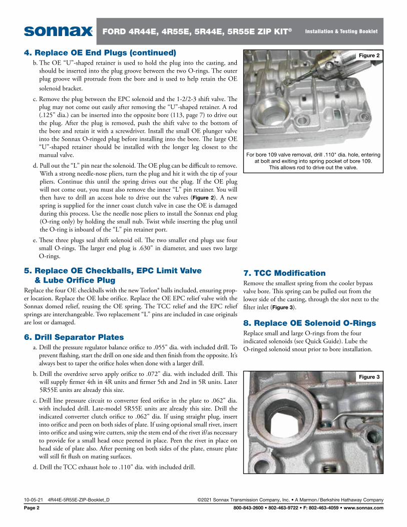
c. Remove the plug between the EPC solenoid and the 1-2/2-3 shift valve. The plug may not come out easily after removing the “U”-shaped retainer. A rod (.125" dia.) can be inserted into the opposite bore (113, page 7) to drive out the plug. After the plug is removed, push the shift valve to the bottom of the bore and retain it with a screwdriver. Install the small OE plunger valve into the Sonnax O-ringed plug before installing into the bore. The large OE “U”-shaped retainer should be installed with the longer leg closest to the manual valve.
d. Pull out the “L” pin near the solenoid. The OE plug can be difficult to remove. With a strong needle-nose pliers, turn the plug and hit it with the tip of your pliers. Continue this until the spring drives out the plug. If the OE plug will not come out, you must also remove the inner “L” pin retainer. You will then have to drill an access hole to drive out the valves (Figure 2). A new spring is supplied for the inner coast clutch valve in case the OE is damaged during this process. Use the needle nose pliers to install the Sonnax end plug (O-ring only) by holding the small nub. Twist while inserting the plug until the O-ring is inboard of the “L” pin retainer port.
e. These three plugs seal shift solenoid oil. The two smaller end plugs use four small O-rings. The larger end plug is .630" in diameter, and uses two large O-rings.
5. Replace OE Checkballs, EPC Limit Valve & Lube Orifice Plug
Replace the four OE checkballs with the new Torlon® balls included, ensuring prop-er location. Replace the OE lube orifice. Replace the OE EPC relief valve with the Sonnax domed relief, reusing the OE spring. The TCC relief and the EPC relief springs are interchangeable. Two replacement “L” pins are included in case originals are lost or damaged.
6. Drill Separator Platesa. Drill the pressure regulator balance orifice to .055" dia. with included drill. To
prevent flashing, start the drill on one side and then finish from the opposite. It’s always best to taper the orifice holes when done with a larger drill.
b. Drill the overdrive servo apply orifice to .072" dia. with included drill. This will supply firmer 4th in 4R units and firmer 5th and 2nd in 5R units. Later 5R55E units are already this size.
c. Drill line pressure circuit to converter feed orifice in the plate to .062" dia. with included drill. Late-model 5R55E units are already this size. Drill the indicated converter clutch orifice to .062" dia. If using straight plug, insert into orifice and peen on both sides of plate. If using optional small rivet, insert into orifice and using wire cutters, snip the stem end of the rivet if/as necessary to provide for a small head once peened in place. Peen the rivet in place on head side of plate also. After peening on both sides of the plate, ensure plate will still fit flush on mating surfaces.
d. Drill the TCC exhaust hole to .110" dia. with included drill.
Figure 2
For bore 109 valve removal, drill .110" dia. hole, entering at bolt and exiting into spring pocket of bore 109.
This allows rod to drive out the valve.
Figure 3
7. TCC ModificationRemove the smallest spring from the cooler bypass valve bore. This spring can be pulled out from the lower side of the casting, through the slot next to the filter inlet (Figure 3).
8. Replace OE Solenoid O-RingsReplace small and large O-rings from the four indicated solenoids (see Quick Guide). Lube the O-ringed solenoid snout prior to bore installation.
10-05-21 4R44E-5R55E-ZIP-Booklet_D ©2021 Sonnax Transmission Company, Inc. • A Marmon / Berkshire Hathaway Company
Page 2 800-843-2600 • 802-463-9722 • F: 802-463-4059 • www.sonnax.com
FORD 4R44E, 4R55E, 5R44E, 5R55E ZIP KIT® Installation & Testing Booklet
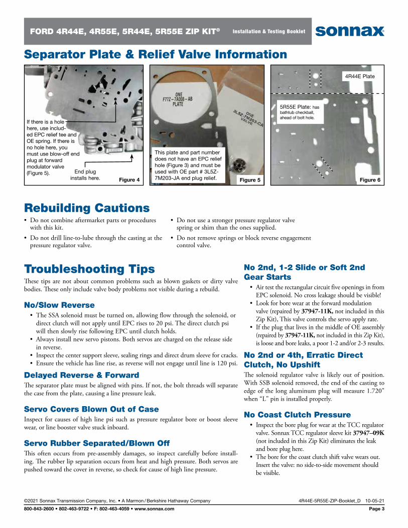
Figure 4
If there is a hole here, use includ- ed EPC relief tee and OE spring. If there is no hole here, you must use blow-off end plug at forward modulator valve (Figure 5). End plug
installs here. Figure 5
This plate and part number does not have an EPC relief hole (Figure 3) and must be used with OE part # 3L5Z-7M203-JA end plug relief. Figure 6
4R44E Plate
5R55E Plate: has bathtub checkball, ahead of bolt hole.
Rebuilding Cautions• Do not combine aftermarket parts or procedures
with this kit.• Do not drill line-to-lube through the casting at the
pressure regulator valve.
• Do not use a stronger pressure regulator valve spring or shim than the ones supplied.
• Do not remove springs or block reverse engagement control valve.
Troubleshooting TipsThese tips are not about common problems such as blown gaskets or dirty valve bodies. These only include valve body problems not visible during a rebuild.
No/Slow Reverse• The SSA solenoid must be turned on, allowing flow through the solenoid, or
direct clutch will not apply until EPC rises to 20 psi. The direct clutch psi will then slowly rise following EPC until clutch holds.
• Always install new servo pistons. Both servos are charged on the release side in reverse.
• Inspect the center support sleeve, sealing rings and direct drum sleeve for cracks. • Ensure the vehicle has line rise, as reverse will not engage until line is 120 psi.
Delayed Reverse & ForwardThe separator plate must be aligned with pins. If not, the bolt threads will separate the case from the plate, causing a line pressure leak.
Servo Covers Blown Out of CaseInspect for causes of high line psi such as pressure regulator bore or boost sleeve wear, or line booster valve stuck inboard.
Servo Rubber Separated/Blown OffThis often occurs from pre-assembly damages, so inspect carefully before install-ing. The rubber lip separation occurs from heat and high pressure. Both servos are pushed toward the cover in reverse, so check for cause of high line pressure.
No 2nd, 1-2 Slide or Soft 2nd Gear Starts
• Air test the rectangular circuit five openings in from EPC solenoid. No cross leakage should be visible!
• Look for bore wear at the forward modulation valve (repaired by 37947-11K, not included in this Zip Kit), This valve controls the servo apply rate.
• If the plug that lives in the middle of OE assembly (repaired by 37947-11K, not included in this Zip Kit), is loose and bore leaks, a poor 1-2 and/or 2-3 results.
No 2nd or 4th, Erratic Direct Clutch, No UpshiftThe solenoid regulator valve is likely out of position. With SSB solenoid removed, the end of the casting to edge of the long aluminum plug will measure 1.720" when “L” pin is installed properly.
No Coast Clutch Pressure• Inspect the bore plug for wear at the TCC regulator
valve. Sonnax TCC regulator sleeve kit 37947–09K (not included in this Zip Kit) eliminates the leak and bore plug here.
• The bore for the coast clutch shift valve wears out. Insert the valve: no side-to-side movement should be visible.
Separator Plate & Relief Valve Information
©2021 Sonnax Transmission Company, Inc. • A Marmon / Berkshire Hathaway Company 4R44E-5R55E-ZIP-Booklet_D 10-05-21
800-843-2600 • 802-463-9722 • F: 802-463-4059 • www.sonnax.com Page 3
FORD 4R44E, 4R55E, 5R44E, 5R55E ZIP KIT® Installation & Testing Booklet
Troubleshooting Tips (continued)No Overdrive Servo Apply psi
• The coast clutch shift valve may be out of position, the bore worn severely or the dumbbell-shaped valve (opposite bore from the TCC modulator) is not being retained correctly.
• This “L” pin falls out of position easily. • Timing valve may be stuck toward the end plug or the spring is not on
center, which causes it to coil bind. • Kickdown valve may be stuck or spring missing.
No OD Servo Release (No Overdriven 2nd in 5R & No 4th in 4R)Mismatched separator plate at 5R/4R identification (Figure 6).
OD Band Failure, No Overdrive Release psiThe 3-4 shift valve may not be positioned due to a loose SSC solenoid. Bracket must hold it in flush.
Broken Bands, No EPC Blow-Off, EPC psi Too HighRelief Tee near the pressure regulator is not opening or mismatched plate without a hole here and no relief used at forward modulator end plug. The EPC spring bore is often tapered, which alters spring operation. The Sonnax EPC and engagement control kit 37947-11K (not included in this Zip Kit) addresses this problem.
Low EPC, Soft Shifts, Slip in 3rdMultiple EPC leakage points. Use the Sonnax EPC and engagement control kit 37947-11K (not included in this Zip Kit), which address this entire circuit. Good maximum EPC is 125-130 psi in OD and maximum of 144 in reverse. EPC should not drop more that 15 psi during TCC apply.
Low EPC Pressure & No Lockup ControlIf TCC modulator valve sticks, EPC will only obtain about 65 psi.
Flare on 2-3 Shift, 4R (3-4 on 5 Speed)The servo pin bore is worn on the intermediate servo, or the spring on the piston is too strong.
No 3rd or 4thThe 2-3 shift valve spring is missing or installed wrong. Also, the 1-2 shift valve should stroke during wet air test (WAT) at the rectangular circuit five openings in from EPC solenoid.
TCC Applied Prematurely, Harsh ShiftsIf the solenoid is restricted or grounded, the TCC valve can stroke and apply the converter clutch.
Poor Converter Charge, Delayed EngagementsThe balance spool or innermost bore for the pressure regulator is worn out.
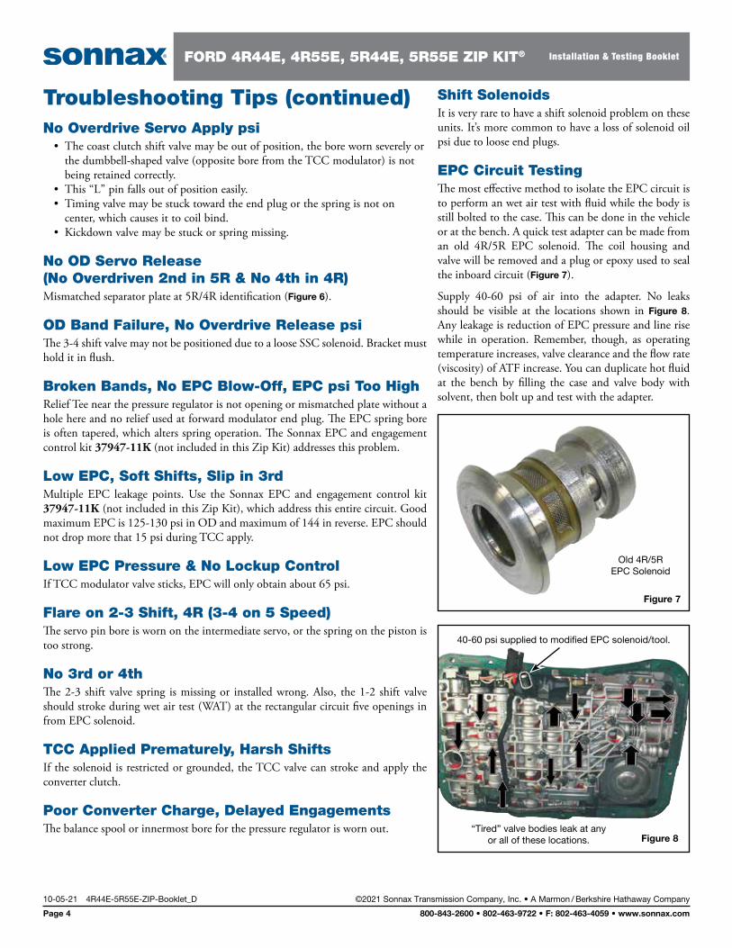
Shift SolenoidsIt is very rare to have a shift solenoid problem on these units. It’s more common to have a loss of solenoid oil psi due to loose end plugs.
EPC Circuit TestingThe most effective method to isolate the EPC circuit is to perform an wet air test with fluid while the body is still bolted to the case. This can be done in the vehicle or at the bench. A quick test adapter can be made from an old 4R/5R EPC solenoid. The coil housing and valve will be removed and a plug or epoxy used to seal the inboard circuit (Figure 7).
Supply 40-60 psi of air into the adapter. No leaks should be visible at the locations shown in Figure 8. Any leakage is reduction of EPC pressure and line rise while in operation. Remember, though, as operating temperature increases, valve clearance and the flow rate (viscosity) of ATF increase. You can duplicate hot fluid at the bench by filling the case and valve body with solvent, then bolt up and test with the adapter.
Figure 7
Old 4R/5R EPC Solenoid
Figure 8“Tired” valve bodies leak at any
or all of these locations.
40-60 psi supplied to modified EPC solenoid/tool.
10-05-21 4R44E-5R55E-ZIP-Booklet_D ©2021 Sonnax Transmission Company, Inc. • A Marmon / Berkshire Hathaway Company
Page 4 800-843-2600 • 802-463-9722 • F: 802-463-4059 • www.sonnax.com
FORD 4R44E, 4R55E, 5R44E, 5R55E ZIP KIT® Installation & Testing Booklet
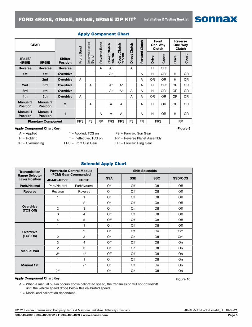
Apply Component Chart
GEAR
Shifter Position Fr
ont
Ban
d
Inte
rmed
iate
d
Ban
d
Rev
erse
Ban
d
Co
ast
Clu
tch
‘95-
‘96
Co
ast
Clu
tch
‘97-
‘00
Dir
ect
Clu
tch
Forw
ard
Clu
tch Front
One-Way Clutch
Reverse One-Way
Clutch
4R44E/ 4R55E 5R55E D
rive
Co
ast
Dri
ve
Co
ast
Reverse Reverse Reverse A A* A H OR†
1st 1st Overdrive A* A H OR† H OR
2nd Overdrive A A OR OR H OR
2nd 3rd Overdrive A A* A* A H OR† OR OR
3rd 4th Overdrive A* A* A A H OR† OR OR
4th 5th Overdrive A A A OR OR OR OR
Manual 2 Position
Manual 2 Position
2 A A A A H OR OR OR
Manual 1 Position
Manual 1 Position
1 A A A A H OR H OR
Planetary Component FRS FS RP FRS FRS FS FR FRS RP
Figure 9 A = Applied
H = Holding
OR = Overrunning
* = Applied, TCS on † = Ineffective, TCS on
FRS = Front Sun Gear
FS = Forward Sun Gear
RP = Reverse Planet Assembly
FR = Forward Ring Gear
Apply Component Chart Key:
Solenoid Apply Chart
Transmission Range Selector Lever Position
Powertrain Control Module (PCM) Gear Commanded
Shift Solenoids
SSA SSB SSC SSD/CCS4R44E/4R55E 5R55E
Park/Neutral Park/Neutral Park/Neutral On Off Off Off
Reverse Reverse Reverse On Off Off Off
Overdrive (TCS Off)
1 1 On Off Off Off
2 On Off On Off
2 3 On On Off Off
3 4 Off Off Off Off
4 5 Off Off On Off
Overdrive (TCS On)
1 1 On Off Off Off
2 On Off On On*
2 3 On On Off On*
3 4 Off Off Off On
Manual 2nd2 3 On On Off On
3A 4A Off Off Off On
Manual 1st
1 1 On Off Off On
2A On Off On On
2A* On On Off On
Figure 10 A = When a manual pull-in occurs above calibrated speed, the transmission will not downshift
until the vehicle speed drops below this calibrated speed.
* = Model and calibration dependent.
Apply Component Chart Key:
©2021 Sonnax Transmission Company, Inc. • A Marmon / Berkshire Hathaway Company 4R44E-5R55E-ZIP-Booklet_D 10-05-21
800-843-2600 • 802-463-9722 • F: 802-463-4059 • www.sonnax.com Page 5
FORD 4R44E, 4R55E, 5R44E, 5R55E ZIP KIT® Installation & Testing Booklet
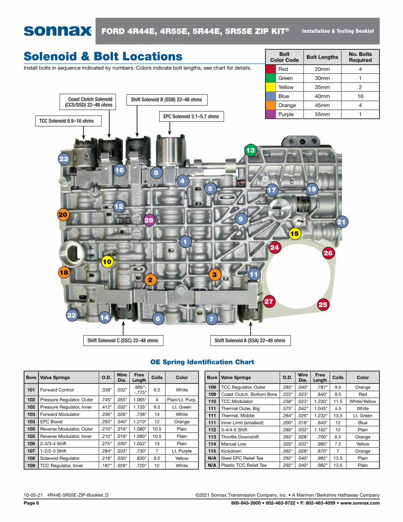
Solenoid & Bolt LocationsInstall bolts in sequence indicated by numbers. Colors indicate bolt lengths, see chart for details.
Bolt Color Code Bolt Lengths No. Bolts
Required
Red 20mm 4
Green 30mm 1
Yellow 35mm 2
Blue 40mm 16
Orange 45mm 4
Purple 55mm 1
Bore Valve Springs O.D. Wire Dia.
Free Length Coils Color
101 Forward Control .338" .032" .665"- -.775" 6.5 White
102 Pressure Regulator, Outer .745" .055" 1.065" 4 Plain/Lt. Purp.
102 Pressure Regulator, Inner .412" .032" 1.135" 9.5 Lt. Green
103 Forward Modulator .236" .026" .738" 14 White
103 EPC Boost .293" .040" 1.210" 12 Orange
105 Reverse Modulator, Outer .210" .018" 1.080" 10.5 Plain
105 Reverse Modulator, Inner .210" .018" 1.080" 10.5 Plain
106 2-3/3-4 Shift .275" .030" 1.052" 13 Plain
107 1-2/2-3 Shift .284" .033" .730" 7 Lt. Purple
108 Solenoid Regulator .218" .030" .830" 8.5 Yellow
109 TCC Regulator, Inner .187" .028" .720" 12 White
27
13
10
1
2028
23
16 84
5
9
17 19
21
11
761422
12
2426
25
15
182
3
Shift Solenoid B (SSB) 22–48 ohms
EPC Solenoid 3.1–5.7 ohms
Coast Clutch Solenoid (CCS/SSD) 22–48 ohms
TCC Solenoid 8.9–16 ohms
Shift Solenoid C (SSC) 22–48 ohms Shift Solenoid A (SSA) 22–48 ohms
Bore Valve Springs O.D. Wire Dia.
Free Length Coils Color
109 TCC Regulator, Outer .285" .040" .787" 9.5 Orange
109 Coast Clutch. Bottom Bore .222" .023" .840" 9.5 Red
110 TCC Modulator .238" .023" 1.230" 11.5 White/Yellow
111 Thermal Outer, Big .575" .042" 1.045" 4.5 White
111 Thermal, Middle .264" .026" 1.232" 13.5 Lt. Green
111 Inner Limit (smallest) .200" .018" .840" 12 Blue
112 3-4/4-5 Shift .280" .032" 1.162" 12 Plain
113 Throttle Downshift .263" .028" .700" 6.5 Orange
114 Manual Low .320" .032" .985" 7.5 Yellow
115 Kickdown .262" .028" .670" 7 Orange
N/A Steel EPC Relief Tee .292" .040" .982" 13.5 Plain
N/A Plastic TCC Relief Tee .292" .040" .982" 13.5 Plain
OE Spring Identification Chart
10-05-21 4R44E-5R55E-ZIP-Booklet_D ©2021 Sonnax Transmission Company, Inc. • A Marmon / Berkshire Hathaway Company
Page 6 800-843-2600 • 802-463-9722 • F: 802-463-4059 • www.sonnax.com
FORD 4R44E, 4R55E, 5R44E, 5R55E ZIP KIT® Installation & Testing Booklet
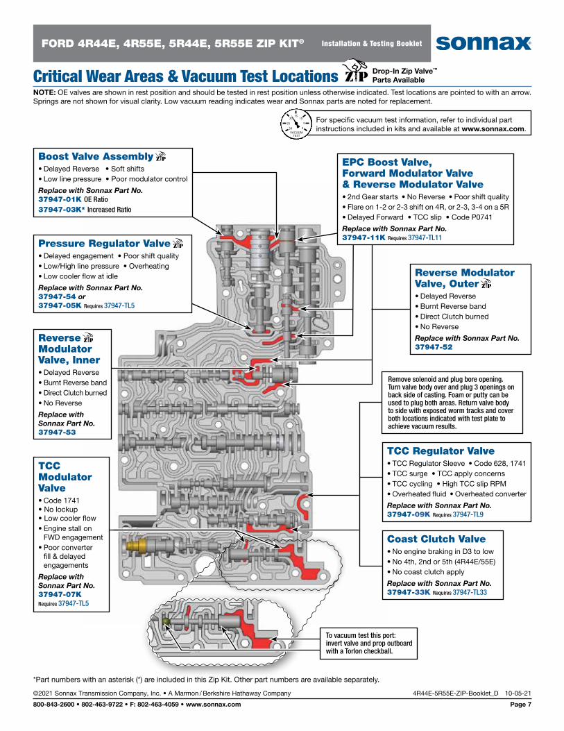
*Part numbers with an asterisk (*) are included in this Zip Kit. Other part numbers are available separately.
ReverseModulator Valve, Inner• Delayed Reverse• Burnt Reverse band• Direct Clutch burned• No Reverse
Replace with Sonnax Part No.37947-53
Boost Valve Assembly• Delayed Reverse • Soft shifts• Low line pressure • Poor modulator control
Replace with Sonnax Part No.37947-01K OE Ratio37947-03K* Increased Ratio
Pressure Regulator Valve• Delayed engagement • Poor shift quality• Low/High line pressure • Overheating • Low cooler flow at idle
Replace with Sonnax Part No.37947-54 or 37947-05K Requires 37947-TL5
EPC Boost Valve, Forward Modulator Valve & Reverse Modulator Valve• 2nd Gear starts • No Reverse • Poor shift quality• Flare on 1-2 or 2-3 shift on 4R, or 2-3, 3-4 on a 5R• Delayed Forward • TCC slip • Code P0741
Replace with Sonnax Part No.37947-11K Requires 37947-TL11
Reverse Modulator Valve, Outer• Delayed Reverse• Burnt Reverse band• Direct Clutch burned• No Reverse
Replace with Sonnax Part No.37947-52
TCC Modulator Valve• Code 1741 • No lockup • Low cooler flow• Engine stall on
FWD engagement• Poor converter
fill & delayed engagements
Replace with Sonnax Part No.37947-07K Requires 37947-TL5
To vacuum test this port: invert valve and prop outboard with a Torlon checkball.
Coast Clutch Valve• No engine braking in D3 to low• No 4th, 2nd or 5th (4R44E/55E)• No coast clutch apply
Replace with Sonnax Part No.37947-33K Requires 37947-TL33
TCC Regulator Valve• TCC Regulator Sleeve • Code 628, 1741• TCC surge • TCC apply concerns• TCC cycling • High TCC slip RPM• Overheated fluid • Overheated converter
Replace with Sonnax Part No.37947-09K Requires 37947-TL9
Remove solenoid and plug bore opening. Turn valve body over and plug 3 openings on back side of casting. Foam or putty can be used to plug both areas. Return valve body to side with exposed worm tracks and cover both locations indicated with test plate to achieve vacuum results.
©2021 Sonnax Transmission Company, Inc. • A Marmon / Berkshire Hathaway Company 4R44E-5R55E-ZIP-Booklet_D 10-05-21
800-843-2600 • 802-463-9722 • F: 802-463-4059 • www.sonnax.com Page 7
FORD 4R44E, 4R55E, 5R44E, 5R55E ZIP KIT® Installation & Testing Booklet
Drop-In Zip Valve™ Parts Available Critical Wear Areas & Vacuum Test Locations
NOTE: OE valves are shown in rest position and should be tested in rest position unless otherwise indicated. Test locations are pointed to with an arrow. Springs are not shown for visual clarity. Low vacuum reading indicates wear and Sonnax parts are noted for replacement.
For specific vacuum test information, refer to individual part instructions included in kits and available at www.sonnax.com.
20
25
15
0
10
5
30VACUUMTEST
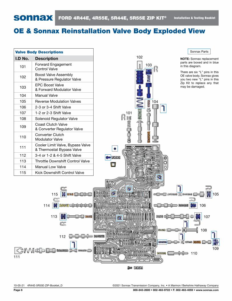
Valve Body Descriptions
I.D No. Description
101Forward Engagement Control Valve
102Boost Valve Assembly & Pressure Regulator Valve
103EPC Boost Valve & Forward Modulator Valve
104 Manual Valve
105 Reverse Modulation Valves
106 2-3 or 3-4 Shift Valve
107 1-2 or 2-3 Shift Valve
108 Solenoid Regulator Valve
109Coast Clutch Valve & Converter Regulator Valve
110Converter Clutch Modulator Valve
111Cooler Limit Valve, Bypass Valve & Thermostat Bypass Valve
112 3-4 or 1-2 & 4-5 Shift Valve
113 Throttle Downshift Control Valve
114 Manual Low Valve
115 Kick Downshift Control Valve
OE & Sonnax Reinstallation Valve Body Exploded View
101
102
106
105
104
103
107
108
109110
111
115
114
113
112
Sonnax Parts
NOTE: Sonnax replacement parts are boxed and in blue in this diagram.
There are six “L” pins in this OE valve body. Sonnax gives you two new “L” pins in this Zip Kit to replace any that may be damaged.
10-05-21 4R44E-5R55E-ZIP-Booklet_D ©2021 Sonnax Transmission Company, Inc. • A Marmon / Berkshire Hathaway Company
Page 8 800-843-2600 • 802-463-9722 • F: 802-463-4059 • www.sonnax.com
FORD 4R44E, 4R55E, 5R44E, 5R55E ZIP KIT® Installation & Testing Booklet