Embed Size (px)
Citation preview
Cyclo Drive 6000Gearmotors & Speed Reducers Getriebemotoren & Getriebe
Catalogue 991296 08/2021

Copyright Sumitomo (SHI) Cyclo Drive Germany GmbH 2021. Alle Rechte vorbehalten. Nachdruck, auch auszugsweise, nur mit unserer Genehmigung gestattet. Die Angaben in diesem Katalog wurden mit größter Sorgfalt auf ihre Richtigkeit überprüft. Trotzdem kann für eventuell fehlerhafte oder unvollständige Angaben keine Haftung übernommen werden. Änderungen behalten wir uns vor.
Copyright Sumitomo (SHI) Cyclo Drive Germany GmbH 2021. All rights reserved. Copying, including extracts, is only permitted with our approval. The information in this catalogue has been checked for correctness with extreme care. However, no liability can be accepted for any incorrect or incomplete information. We reserve the right to make modifications.
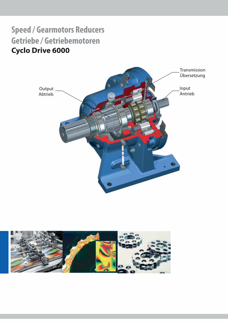
Speed / Gearmotors Reducers Getriebe / Getriebemotoren Cyclo Drive 6000
Input Antrieb
Output Abtrieb
Transmission Übersetzung
Page Seite
Drive 6000 991296 08/2021
Drive 6000
3
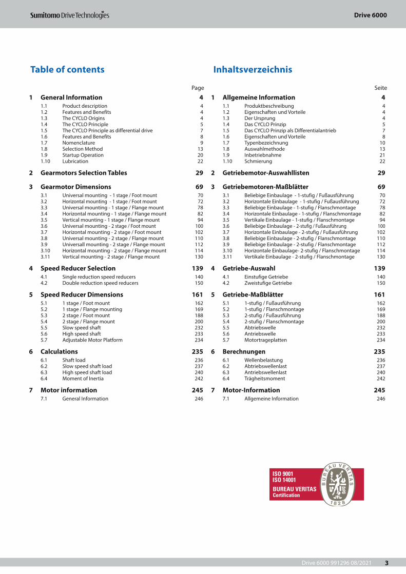
Table of contents Inhaltsverzeichnis
1 Allgemeine Information 41.1 Produktbeschreibung 41.2 Eigenschaften und Vorteile 41.3 Der Ursprung 41.4 Das CYCLO Prinzip 51.5 Das CYCLO Prinzip als Differentialantrieb 71.6 Eigenschaften und Vorteile 81.7 Typenbezeichnung 101.8 Auswahlmethode 131.9 Inbetriebnahme 211.10 Schmierung 22
2 Getriebemotor-Auswahllisten 29
3 Getriebemotoren-Maßblätter 693.1 Beliebige Einbaulage - 1-stufig / Fußausführung 703.2 Horizontale Einbaulage - 1-stufig / Fußausführung 723.3 Beliebige Einbaulage - 1-stufig / Flanschmontage 783.4 Horizontale Einbaulage - 1-stufig / Flanschmontage 823.5 Vertikale Einbaulage - 1-stufig / Flanschmontage 943.6 Beliebige Einbaulage - 2-stufig / Fußausführung 1003.7 Horizontale Einbaulage - 2-stufig / Fußausführung 1023.8 Beliebige Einbaulage - 2-stufig / Flanschmontage 1103.9 Beliebige Einbaulage - 2-stufig / Flanschmontage 1123.10 Horizontale Einbaulage- 2-stufig / Flanschmontage 1143.11 Vertikale Einbaulage - 2-stufig / Flanschmontage 130
4 Getriebe-Auswahl 1394.1 Einstufige Getriebe 1404.2 Zweistufige Getriebe 150
5 Getriebe-Maßblätter 1615.1 1-stufig / Fußausführung 1625.2 1-stufig / Flanschmontage 1695.3 2-stufig / Fußausführung 1885.4 2-stufig / Flanschmontage 2005.5 Abtriebswelle 2325.6 Antriebswelle 2335.7 Motortrageplatten 234
6 Berechnungen 2356.1 Wellenbelastung 2366.2 Abtriebswellenlast 2376.3 Antriebswellenlast 2406.4 Trägheitsmoment 242
7 Motor-Information 2457.1 Allgemeine Information 246
1 General Information 41.1 Product description 41.2 Features and Benefits 41.3 The CYCLO Origins 41.4 The CYCLO Principle 51.5 The CYCLO Principle as differential drive 71.6 Features and Benefits 81.7 Nomenclature 91.8 Selection Method 131.9 Startup Operation 201.10 Lubrication 22
2 Gearmotors Selection Tables 29
3 Gearmotor Dimensions 693.1 Universal mounting - 1 stage / Foot mount 703.2 Horizontal mounting - 1 stage / Foot mount 723.3 Universal mounting - 1 stage / Flange mount 783.4 Horizontal mounting - 1 stage / Flange mount 823.5 Vertical mounting - 1 stage / Flange mount 943.6 Universal mounting - 2 stage / Foot mount 1003.7 Horizontal mounting - 2 stage / Foot mount 1023.8 Universal mounting - 2 stage / Flange mount 1103.9 Universall mounting - 2 stage / Flange mount 1123.10 Horizontal mounting - 2 stage / Flange mount 1143.11 Vertical mounting - 2 stage / Flange mount 130
4 Speed Reducer Selection 1394.1 Single reduction speed reducers 1404.2 Double reduction speed reducers 150
5 Speed Reducer Dimensions 1615.1 1 stage / Foot mount 1625.2 1 stage / Flange mounting 1695.3 2 stage / Foot mount 1885.4 2 stage / Flange mount 2005.5 Slow speed shaft 2325.6 High speed shaft 2335.7 Adjustable Motor Platform 234
6 Calculations 2356.1 Shaft load 2366.2 Slow speed shaft load 2376.3 High speed shaft load 2406.4 Moment of Inertia 242
7 Motor information 2457.1 General Information 246
Drive 6000 991296 08/2021
General Information / Allgemeine Information
4
1.1 Produktbeschreibung1.1 Product description
1.2 Eigenschaften und Vorteile1.2 Features and Benefits
1.3 Der Ursprung1.3 The CYCLO Origins
Das Sumitomo CYCLO Drive-Getriebe ist unübertroffen im Vergleich zu herkömmlichen Getrieben. Das einzigartige Zykloidengetriebe hat durch den wälzenden Ablauf einen erheblichen Vorteil gegenüber einem Zahnradgetriebe. Im Gegensatz zu den herkömmlichen Stirnradgetrieben, bei denen ein bis zwei Zähne die gesamte Belastung aufnehmen, wird bei einem CYCLO Getriebe die Last auf mindestens 30 % der Kurvenscheiben verteilt. CYCLO Getriebe und -Getriebemotoren bieten ausgezeichnete Leistung, Zuverlässigkeit und lange Lebensdauer selbst unter härtesten Einsatzbedingungen.
The Sumitomo CYCLO Drive is unsurpassed by any other inline drive available in the market today. The CYCLO unique cycloidal design has advantages superior to speed reducers using common involute gears. CYCLO components operate incompression, not in shear. Unlike gear teeth with limited con-tact points, a CYCLO has 30 % of its reduction components in contact at all times. CYCLO speed reducers and gearmotors provide exceptional performance, reliability and long lifein the most severe applications.
Der Name CYCLO wurde abgeleitet von Kyklos, dem griechischen Wort für Kreis. CYCLO steht heute für Exzentergetriebe, deren Außenprofil der Kurvenscheibe einen Zykloiden-Kurvenzug beschreibt.Das einzigartige CYCLO Prinzip wurde 1931 von dem deutschen Ingenieur Lorenz Braren erfunden. Das geniale Prinzip wird seitdem ständig weiter entwickelt.
The name CYCLO derives from Kyklos, the Greek word for circ-le and refers to the CYCLO disc, whose outer profile describes a cycloidal curve. The unique CYCLO operating principle was invented by the German engineer Lorenz Braren in 1931and the ingenious design has continued its progressivedevelopment up to the present day.
• Kompakte Bauform• Hohe Zuverlässigkeit• Hohe Überlastreserven• Großer Übersetzungsbereich• Wirtschaftlich• Besondere Eignung für dynamische Applikationen• Niedriger Geräuschpegel• Hoher Wirkungsgrad auch bei hoher Übersetzung• Lange Lebensdauer• Energiesparende Motoren• Keine thermische Begrenzung
• Compact size• Unmatched reliability• High shock load capacity• Wide range of ratios• Overall economy• Ideal for highly dynamic applications• Low noise• Exceptional performance, even at high ratios• Long lifetime• Energy saving motors• No thermal factor limitations
1 Allgemeine Information 1 General Information
Drive 6000 991296 08/2021
General Information / Allgemeine Information
5
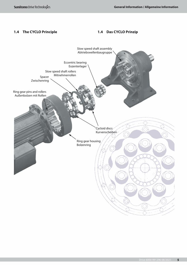
1.4 The CYCLO Principle 1.4 Das CYCLO Prinzip
1 Allgemeine Information
Slow speed shaft assembly Abtriebswellenbaugruppe
Eccentric bearing Exzenterlager
Slow speed shaft rollers MitnehmerrollenSpacer
Zwischenring
Cycloid discs Kurvenscheiben
Ring gear housing Bolzenring
Ring gear pins and rollers Außenbolzen mit Rollen
Drive 6000 991296 08/2021
General Information / Allgemeine Information
6
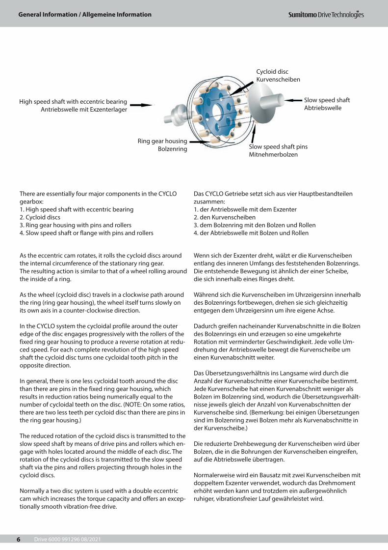
Das CYCLO Getriebe setzt sich aus vier Hauptbestandteilen zusammen:1. der Antriebswelle mit dem Exzenter2. den Kurvenscheiben3. dem Bolzenring mit den Bolzen und Rollen4. der Abtriebswelle mit Bolzen und Rollen
There are essentially four major components in the CYCLO gearbox:1. High speed shaft with eccentric bearing2. Cycloid discs3. Ring gear housing with pins and rollers4. Slow speed shaft or flange with pins and rollers
Wenn sich der Exzenter dreht, wälzt er die Kurvenscheiben entlang des inneren Umfangs des feststehenden Bolzenrings. Die entstehende Bewegung ist ähnlich der einer Scheibe, die sich innerhalb eines Ringes dreht.
Während sich die Kurvenscheiben im Uhrzeigersinn innerhalb des Bolzenrings fortbewegen, drehen sie sich gleichzeitig entgegen dem Uhrzeigersinn um ihre eigene Achse. Dadurch greifen nacheinander Kurvenabschnitte in die Bolzen des Bolzenrings ein und erzeugen so eine umgekehrte Rotation mit verminderter Geschwindigkeit. Jede volle Um-drehung der Antriebswelle bewegt die Kurvenscheibe um einen Kurvenabschnitt weiter.
Das Übersetzungsverhältnis ins Langsame wird durch die Anzahl der Kurvenabschnitte einer Kurvenscheibe bestimmt. Jede Kurvenscheibe hat einen Kurvenabschnitt weniger als Bolzen im Bolzenring sind, wodurch die Übersetzungsverhält-nisse jeweils gleich der Anzahl von Kurvenabschnitten der Kurvenscheibe sind. (Bemerkung: bei einigen Übersetzungen sind im Bolzenring zwei Bolzen mehr als Kurvenabschnitte in der Kurvenscheibe.)
Die reduzierte Drehbewegung der Kurvenscheiben wird über Bolzen, die in die Bohrungen der Kurvenscheiben eingreifen, auf die Abtriebswelle übertragen.
Normalerweise wird ein Bausatz mit zwei Kurvenscheiben mit doppeltem Exzenter verwendet, wodurch das Drehmoment erhöht werden kann und trotzdem ein außergewöhnlich ruhiger, vibrationsfreier Lauf gewährleistet wird.
As the eccentric cam rotates, it rolls the cycloid discs around the internal circumference of the stationary ring gear. The resulting action is similar to that of a wheel rolling around the inside of a ring.
As the wheel (cycloid disc) travels in a clockwise path around the ring (ring gear housing), the wheel itself turns slowly on its own axis in a counter-clockwise direction.
In the CYCLO system the cycloidal profile around the outer edge of the disc engages progressively with the rollers of the fixed ring gear housing to produce a reverse rotation at redu-ced speed. For each complete revolution of the high speed shaft the cycloid disc turns one cycloidal tooth pitch in the opposite direction.
In general, there is one less cycloidal tooth around the disc than there are pins in the fixed ring gear housing, which results in reduction ratios being numerically equal to the number of cycloidal teeth on the disc. (NOTE: On some ratios, there are two less teeth per cycloid disc than there are pins in the ring gear housing.)
The reduced rotation of the cycloid discs is transmitted to the slow speed shaft by means of drive pins and rollers which en-gage with holes located around the middle of each disc. The rotation of the cycloid discs is transmitted to the slow speed shaft via the pins and rollers projecting through holes in the cycloid discs.
Normally a two disc system is used with a double eccentric cam which increases the torque capacity and offers an excep-tionally smooth vibration-free drive.
Slow speed shaft Abtriebswelle
Cycloid disc Kurvenscheiben
Slow speed shaft pins Mitnehmerbolzen
High speed shaft with eccentric bearing Antriebswelle mit Exzenterlager
Ring gear housing Bolzenring
Drive 6000 991296 08/2021
General Information / Allgemeine Information
7
1.5 Das CYCLO Prinzip als Differentialantrieb1.5 The CYCLO Principle as differential drive
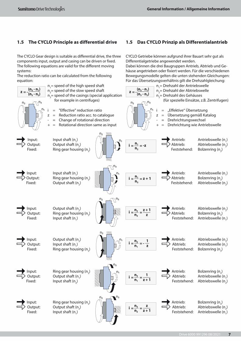
CYCLO Getriebe können aufgrund ihrer Bauart sehr gut als Differentialgetriebe angewendet werden.Dabei können die drei Baugruppen Antrieb, Abtrieb und Ge-häuse angetrieben oder fixiert werden. Für die verschiedenen Bewegungsmodelle gelten die unten stehenden Gleichungen:Für das Übersetzungsverhältnis gilt die Drehzahlgleichung:
The CYCLO Gear design is suitable as differential drive, the three components input, output and casing can be driven or fixed.The following equations are valid for the different moving systems:The reduction ratio can be calculated from the following equation:
Antrieb: Antriebswelle (n1) Abtrieb: Abtriebswelle (n2)
Feststehend: Bolzenring (n3)
Input: Input shaft (n1) Output: Output shaft (n2)
Fixed: Ring gear housing (n3)
Antrieb: Antriebswelle (n1) Abtrieb: Bolzenring (n3)
Feststehend: Abtriebswelle (n2)
Input: Input shaft (n1) Output: Ring gear housing (n3)
Fixed: Output shaft (n2)
Antrieb: Abtriebswelle (n2) Abtrieb: Bolzenring (n3)
Feststehend: Antriebswelle (n1)
Input: Output shaft (n2) Output: Ring gear housing (n3)
Fixed: Input shaft (n1)
Antrieb: Abtriebswelle (n2) Abtrieb: Antriebswelle (n1)
Feststehend: Bolzenring (n3)
Input: Output shaft (n2) Output: Input shaft (n1)
Fixed: Ring gear housing (n3)
Antrieb: Bolzenring (n3) Abtrieb: Antriebswelle (n1)
Feststehend: Abtriebswelle (n2)
Input: Ring gear housing (n3) Output: Output shaft (n1)
Fixed: Input shaft (n2)
Antrieb: Bolzenring (n3) Abtrieb: Abtriebswelle (n2)
Feststehend: Antriebswelle (n1)
Input: Ring gear housing (n3) Output: Output shaft (n2)
Fixed: Input shaft (n1)
i = „Effektive“ Übersetzungz = Übersetzung gemäß Katalog- = Drehrichtungswechsel+ = Drehrichtung wie Antriebswelle
i = "Effective" reduction ratioz = Reduction ratio acc. to catalogue- = Change of rotational direction+ = Rotational direction same as input
n1= Drehzahl der Antriebswelle n2= Drehzahl der Abtriebswelle n3= Drehzahl des Gehäuses (für spezielle Einsätze, z.B. Zentrifugen)
n1= speed of the high speed shaft n2= speed of the slow speed shaftn3= speed of the casings (special application for example in centrifuges)
z = -
(n3 - n1)(n3 - n2)z
= - (n3 - n1)(n3 - n2)
i = = -z
i = = z + 1
i = =
i = =
i = =
i = = -
n1
n2
n1
n3
n2
n3
n3
n1
n3
n2
n2
n1
z + 1z
1z + 1
zz + 1
1z
n1
n3n2
n1
n3n2
n1
n2
n3
n1
n3n2
n1
n2
n3
n1
n3n2
Drive 6000 991296 08/2021
General Information / Allgemeine Information
8
1.6 Features and Benefits 1.6 Eigenschaften und Vorteile
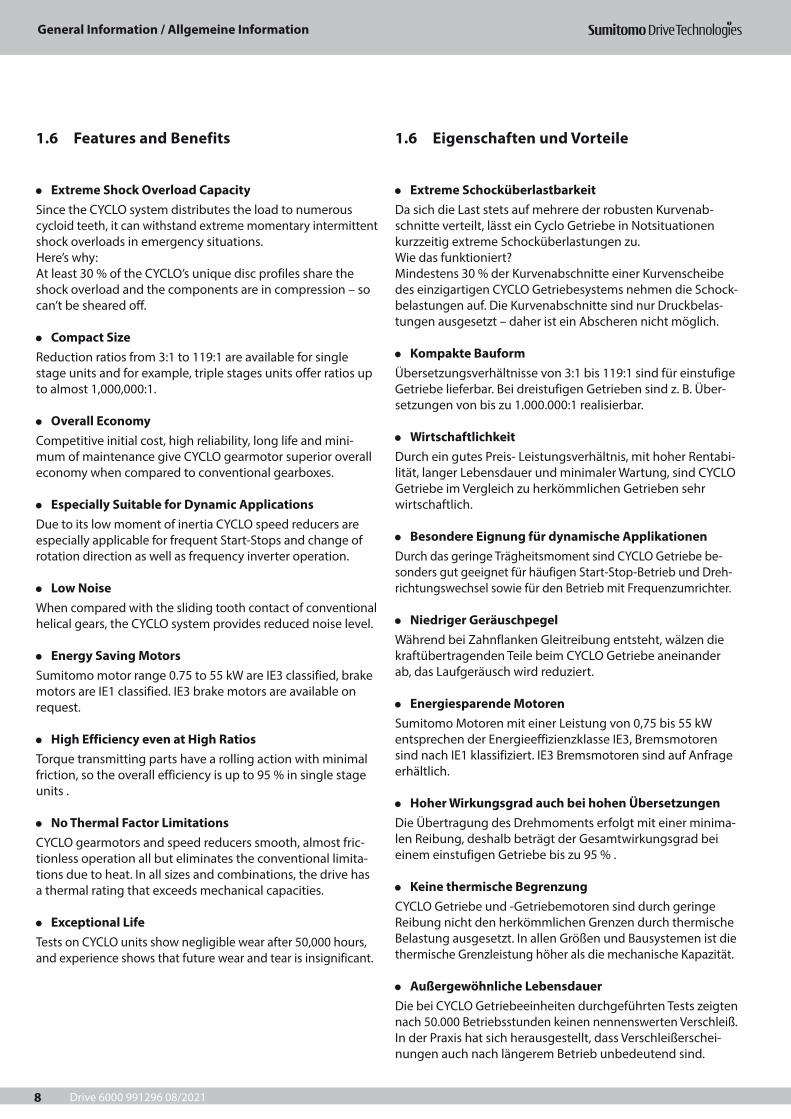
• Extreme Shock Overload CapacitySince the CYCLO system distributes the load to numerous cycloid teeth, it can withstand extreme momentary intermittent shock overloads in emergency situations.Here’s why:At least 30 % of the CYCLO’s unique disc profiles share the shock overload and the components are in compression – so can’t be sheared off.
• Compact SizeReduction ratios from 3:1 to 119:1 are available for single stage units and for example, triple stages units offer ratios up to almost 1,000,000:1.
• Overall EconomyCompetitive initial cost, high reliability, long life and mini-mum of maintenance give CYCLO gearmotor superior overall economy when compared to conventional gearboxes.
• Especially Suitable for Dynamic ApplicationsDue to its low moment of inertia CYCLO speed reducers are especially applicable for frequent Start-Stops and change of rotation direction as well as frequency inverter operation.
• Low NoiseWhen compared with the sliding tooth contact of conventional helical gears, the CYCLO system provides reduced noise level.
• Energy Saving MotorsSumitomo motor range 0.75 to 55 kW are IE3 classified, brake motors are IE1 classified. IE3 brake motors are available on request.
• High Efficiency even at High RatiosTorque transmitting parts have a rolling action with minimal friction, so the overall efficiency is up to 95 % in single stage units .
• No Thermal Factor LimitationsCYCLO gearmotors and speed reducers smooth, almost fric-tionless operation all but eliminates the conventional limita-tions due to heat. In all sizes and combinations, the drive has a thermal rating that exceeds mechanical capacities.
• Exceptional LifeTests on CYCLO units show negligible wear after 50,000 hours, and experience shows that future wear and tear is insignificant.
• Extreme SchocküberlastbarkeitDa sich die Last stets auf mehrere der robusten Kurvenab-schnitte verteilt, lässt ein Cyclo Getriebe in Notsituationen kurzzeitig extreme Schocküberlastungen zu.Wie das funktioniert?Mindestens 30 % der Kurvenabschnitte einer Kurvenscheibe des einzigartigen CYCLO Getriebesystems nehmen die Schock-belastungen auf. Die Kurvenabschnitte sind nur Druckbelas-tungen ausgesetzt – daher ist ein Abscheren nicht möglich.
• Kompakte BauformÜbersetzungsverhältnisse von 3:1 bis 119:1 sind für einstufige Getriebe lieferbar. Bei dreistufigen Getrieben sind z. B. Über-setzungen von bis zu 1.000.000:1 realisierbar.
• WirtschaftlichkeitDurch ein gutes Preis- Leistungsverhältnis, mit hoher Rentabi-lität, langer Lebensdauer und minimaler Wartung, sind CYCLO Getriebe im Vergleich zu herkömmlichen Getrieben sehr wirtschaftlich.
• Besondere Eignung für dynamische ApplikationenDurch das geringe Trägheitsmoment sind CYCLO Getriebe be-sonders gut geeignet für häufigen Start-Stop-Betrieb und Dreh-richtungswechsel sowie für den Betrieb mit Frequenzumrichter.
• Niedriger GeräuschpegelWährend bei Zahnflanken Gleitreibung entsteht, wälzen die kraftübertragenden Teile beim CYCLO Getriebe aneinander ab, das Laufgeräusch wird reduziert.
• Energiesparende MotorenSumitomo Motoren mit einer Leistung von 0,75 bis 55 kW entsprechen der Energieeffizienzklasse IE3, Bremsmotoren sind nach IE1 klassifiziert. IE3 Bremsmotoren sind auf Anfrage erhältlich.
• Hoher Wirkungsgrad auch bei hohen ÜbersetzungenDie Übertragung des Drehmoments erfolgt mit einer minima-len Reibung, deshalb beträgt der Gesamtwirkungsgrad bei einem einstufigen Getriebe bis zu 95 % .
• Keine thermische BegrenzungCYCLO Getriebe und -Getriebemotoren sind durch geringe Reibung nicht den herkömmlichen Grenzen durch thermische Belastung ausgesetzt. In allen Größen und Bausystemen ist die thermische Grenzleistung höher als die mechanische Kapazität.
• Außergewöhnliche LebensdauerDie bei CYCLO Getriebeeinheiten durchgeführten Tests zeigten nach 50.000 Betriebsstunden keinen nennenswerten Verschleiß. In der Praxis hat sich herausgestellt, dass Verschleißerschei-nungen auch nach längerem Betrieb unbedeutend sind.
Drive 6000 991296 08/2021
General Information / Allgemeine Information
9
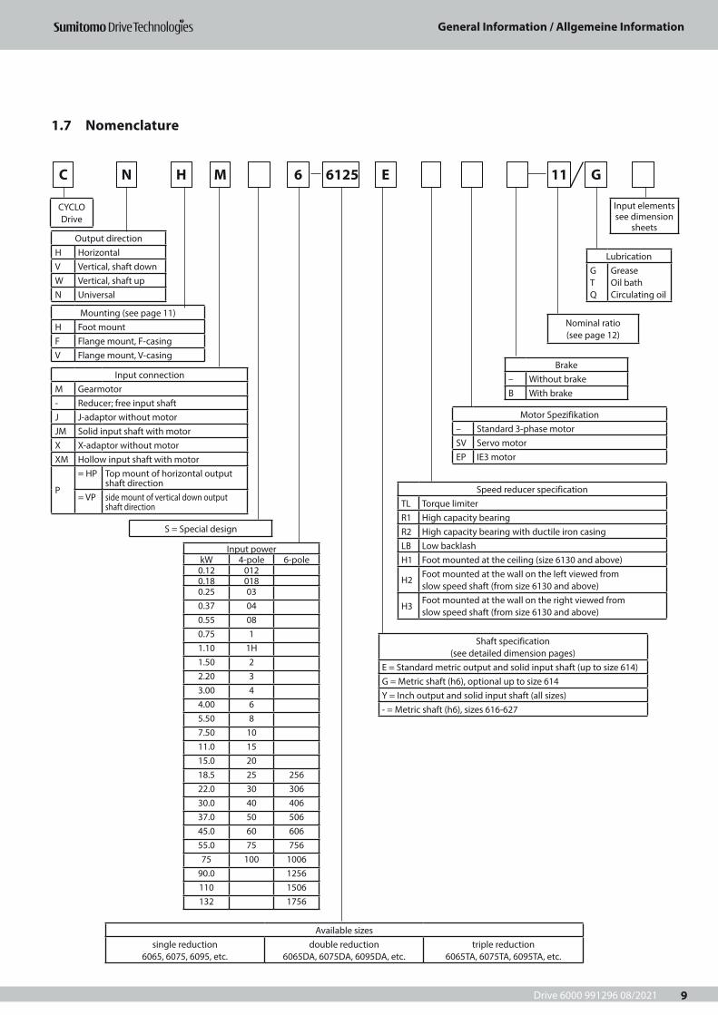
1.7 Nomenclature
C N H M 6 6125 E 11 G
Output directionH HorizontalV Vertical, shaft downW Vertical, shaft upN Universal
LubricationG T Q
Grease Oil bath Circulating oil
Brake– Without brakeB With brake
Motor Spezifikation– Standard 3-phase motorSV Servo motorEP IE3 motor
Shaft specification (see detailed dimension pages)
E = Standard metric output and solid input shaft (up to size 614)G = Metric shaft (h6), optional up to size 614Y = Inch output and solid input shaft (all sizes)- = Metric shaft (h6), sizes 616-627
Available sizessingle reduction
6065, 6075, 6095, etc.double reduction
6065DA, 6075DA, 6095DA, etc.triple reduction
6065TA, 6075TA, 6095TA, etc.
Input connectionM Gearmotor- Reducer; free input shaftJ J-adaptor without motorJM Solid input shaft with motorX X-adaptor without motorXM Hollow input shaft with motor
P
= HP Top mount of horizontal output shaft direction
= VP side mount of vertical down output shaft direction
Mounting (see page 11)H Foot mountF Flange mount, F-casingV Flange mount, V-casing
CYCLO Drive
S = Special design
Input elements see dimension
sheets
Nominal ratio (see page 12)
Input powerkW 4-pole 6-pole
0.12 0120.18 0180.25 030.37 040.55 080.75 11.10 1H1.50 22.20 33.00 44.00 65.50 87.50 1011.0 1515.0 2018.5 25 25622.0 30 30630.0 40 40637.0 50 50645.0 60 60655.0 75 75675 100 1006
90.0 1256110 1506132 1756
Speed reducer specificationTL Torque limiterR1 High capacity bearingR2 High capacity bearing with ductile iron casingLB Low backlashH1 Foot mounted at the ceiling (size 6130 and above)
H2Foot mounted at the wall on the left viewed from slow speed shaft (from size 6130 and above)
H3Foot mounted at the wall on the right viewed from slow speed shaft (from size 6130 and above)
Drive 6000 991296 08/2021
General Information / Allgemeine Information
10
C N H M 6 6125 E 11 G
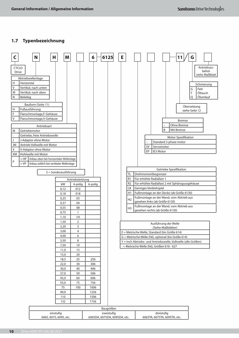
1.7 Typenbezeichnung
AbtriebwellenlageH HorizontalV Vertikal, nach untenW Vertikal, nach oben N Beliebig
SchmierungG T Q
Fett Öltauch Ölumlauf
Bremse– Ohne BremseB Mit Bremse
Motor Spezifikation– Standard 3-phase motorSV ServomotorEP IE3 Motor
Getriebe SpezifikationTL DrehmomentbegrenzerR1 Für erhöhte Radiallast 1R2 Für erhöhte Radiallast 2 mit Sphärogussgehäuse LB Geringes VerdrehspielH1 Fußmontage an der Decke (ab Größe 6130)
H2Fußmontage an der Wand, vom Abtrieb aus gesehen links (ab Größe 6130)
H3Fußmontage an der Wand, vom Abtrieb aus gesehen rechts (ab Größe 6130)
Ausführung der Welle (Siehe Maßblätter)
E = Metrische Welle, Standard (bis Größe 614)G = Metrische Welle (h6), optional (bis Größe 614)Y = Inch Abtriebs- und Antriebswelle, Vollwelle (alle Größen)- = Metrische Welle (h6), Größen 616 - 627
Baugrößeneinstufig
6065, 6075, 6095, etc.zweistufig
6065DA, 6075DA, 6095DA, etc.dreistufig
6065TA, 6075TA, 6095TA, etc.
AntriebsartM Getriebemotor- Getriebe, freie AntriebswelleJ J-Adaptor ohne MotorJM Antrieb Vollwelle mit MotorX X-Adaptor ohne MotorXM Hohlwelle mit Motor
P= HP Anbau oben bei horizontaler Wellenlage= VP Anbau seitlich bei vertikaler Wellenlage
Bauform (Seite 11)H FußausführungF Flanschmontage,F-GehäuseV Flanschmontage,V-Gehäuse
CYCLO Drive
S = Sonderausführung
Antriebszu-behör
siehe Maßblatt
Übersetzung siehe Seite 12
AntriebsleistungkW 4-polig 6-polig
0,12 0120,18 0180,25 030,37 040,55 080,75 11,10 1H1,50 22,20 33,00 44,00 65,50 87,50 1011,0 1515,0 2018,5 25 25622,0 30 30630,0 40 40637,0 50 50645,0 60 60655,0 75 75675 100 1006
90,0 1256110 1506132 1756
Drive 6000 991296 08/2021
General Information / Allgemeine Information
11
CHHM CHVMCHFM
CNHM
CWHM
CVHM CVFM CVVM
CNVMCNFM
CWFM CWVM
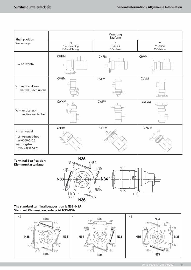
Shaft position Wellenlage
Mounting Bauform
H Foot mounting Fußausführung
F F-Casing
F-Gehäuse
V V-Casing
V-Gehäuse
H = horizontal
V = vertical down vertikal nach unten
W = vertical up vertikal nach oben
N = universal
maintenance-free size 6060-6125 wartungsfrei Größe 6060-6125
Terminal Box Position: Klemmenkastenlage:
The standard terminal box position is N33- N3A Standard Klemmenkastenlage ist N33-N3A
Drive 6000 991296 08/2021
General Information / Allgemeine Information
12
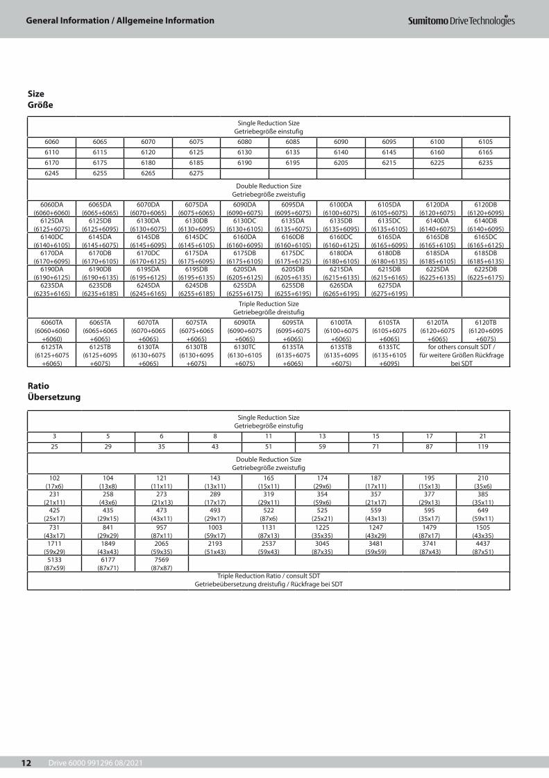
Size Größe
Ratio Übersetzung
Single Reduction Size Getriebegröße einstufig
6060 6065 6070 6075 6080 6085 6090 6095 6100 6105
6110 6115 6120 6125 6130 6135 6140 6145 6160 6165
6170 6175 6180 6185 6190 6195 6205 6215 6225 6235
6245 6255 6265 6275
Double Reduction Size Getriebegröße zweistufig
6060DA (6060+6060)
6065DA (6065+6065)
6070DA (6070+6065)
6075DA (6075+6065)
6090DA (6090+6075)
6095DA (6095+6075)
6100DA (6100+6075)
6105DA (6105+6075)
6120DA (6120+6075)
6120DB (6120+6095)
6125DA (6125+6075)
6125DB (6125+6095)
6130DA (6130+6075)
6130DB (6130+6095)
6130DC (6130+6105)
6135DA (6135+6075)
6135DB (6135+6095)
6135DC (6135+6105)
6140DA (6140+6075)
6140DB (6140+6095)
6140DC (6140+6105)
6145DA (6145+6075)
6145DB (6145+6095)
6145DC (6145+6105)
6160DA (6160+6095)
6160DB (6160+6105)
6160DC (6160+6125)
6165DA (6165+6095)
6165DB (6165+6105)
6165DC (6165+6125)
6170DA (6170+6095)
6170DB (6170+6105)
6170DC (6170+6125)
6175DA (6175+6095)
6175DB (6175+6105)
6175DC (6175+6125)
6180DA (6180+6105)
6180DB (6180+6135)
6185DA (6185+6105)
6185DB (6185+6135)
6190DA (6190+6125)
6190DB (6190+6135)
6195DA (6195+6125)
6195DB (6195+6135)
6205DA (6205+6125)
6205DB (6205+6135)
6215DA (6215+6135)
6215DB (6215+6165)
6225DA (6225+6135)
6225DB (6225+6175)
6235DA (6235+6165)
6235DB (6235+6185)
6245DA (6245+6165)
6245DB (6255+6185)
6255DA (6255+6175)
6255DB (6255+6195)
6265DA (6265+6195)
6275DA (6275+6195)
Triple Reduction Size Getriebegröße dreistufig
6060TA(6060+6060
+6060)
6065TA(6065+6065
+6065)
6070TA(6070+6065
+6065)
6075TA(6075+6065
+6065)
6090TA(6090+6075
+6065)
6095TA(6095+6075
+6065)
6100TA(6100+6075
+6065)
6105TA(6105+6075
+6065)
6120TA(6120+6075
+6065)
6120TB(6120+6095
+6075)6125TA
(6125+6075+6065)
6125TB (6125+6095
+6075)
6130TA (6130+6075
+6065)
6130TB (6130+6095
+6075)
6130TC (6130+6105
+6075)
6135TA (6135+6075
+6065)
6135TB (6135+6095
+6075)
6135TC (6135+6105
+6095)
for others consult SDT / für weitere Größen Rückfrage
bei SDT
Single Reduction Size Getriebegröße einstufig
3 5 6 8 11 13 15 17 21
25 29 35 43 51 59 71 87 119
Double Reduction Size Getriebegröße zweistufig
102 (17x6)
104 (13x8)
121 (11x11)
143 (13x11)
165 (15x11)
174 (29x6)
187(17x11)
195 (15x13)
210(35x6)
231 (21x11)
258(43x6)
273 (21x13)
289(17x17)
319 (29x11)
354 (59x6)
357 (21x17)
377 (29x13)
385 (35x11)
425 (25x17)
435 (29x15)
473 (43x11)
493 (29x17)
522 (87x6)
525 (25x21)
559 (43x13)
595 (35x17)
649 (59x11)
731 (43x17)
841(29x29)
957 (87x11)
1003(59x17)
1131(87x13)
1225(35x35)
1247(43x29)
1479(87x17)
1505(43x35)
1711(59x29)
1849(43x43)
2065(59x35)
2193(51x43)
2537 (59x43)
3045(87x35)
3481(59x59)
3741 (87x43)
4437 (87x51)
5133(87x59)
6177(87x71)
7569 (87x87)
Triple Reduction Ratio / consult SDTGetriebeübersetzung dreistufig / Rückfrage bei SDT
Drive 6000 991296 08/2021
General Information / Allgemeine Information
13
1.8 Selection Method 1.8 Auswahlmethode
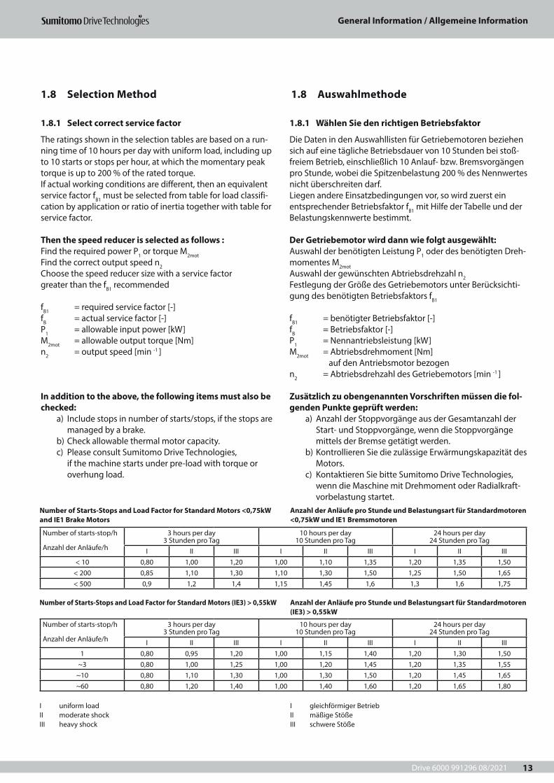
1.8.1 Select correct service factor
The ratings shown in the selection tables are based on a run-ning time of 10 hours per day with uniform load, including up to 10 starts or stops per hour, at which the momentary peak torque is up to 200 % of the rated torque.If actual working conditions are different, then an equivalent service factor fB1 must be selected from table for load classifi-cation by application or ratio of inertia together with table for service factor.
Then the speed reducer is selected as follows :Find the required power P1 or torque M2mot Find the correct output speed n2Choose the speed reducer size with a service factor greater than the fB1 recommended
fB1 = required service factor [-] fB = actual service factor [-]P1 = allowable input power [kW] M2mot = allowable output torque [Nm] n2 = output speed [min -1 ]
In addition to the above, the following items must also be checked:
a) Include stops in number of starts/stops, if the stops are managed by a brake.
b) Check allowable thermal motor capacity.c) Please consult Sumitomo Drive Technologies,
if the machine starts under pre-load with torque or overhung load.
1.8.1 Wählen Sie den richtigen Betriebsfaktor
Die Daten in den Auswahllisten für Getriebemotoren beziehen sich auf eine tägliche Betriebsdauer von 10 Stunden bei stoß-freiem Betrieb, einschließlich 10 Anlauf- bzw. Bremsvorgängen pro Stunde, wobei die Spitzenbelastung 200 % des Nennwertes nicht überschreiten darf.Liegen andere Einsatzbedingungen vor, so wird zuerst ein entsprechender Betriebsfaktor fB1 mit Hilfe der Tabelle und der Belastungskennwerte bestimmt.
Der Getriebemotor wird dann wie folgt ausgewählt: Auswahl der benötigten Leistung P1 oder des benötigten Dreh-momentes M2mot Auswahl der gewünschten Abtriebsdrehzahl n2 Festlegung der Größe des Getriebemotors unter Berücksichti-gung des benötigten Betriebsfaktors fB1
fB1 = benötigter Betriebsfaktor [-] fB = Betriebsfaktor [-]P1 = Nennantriebsleistung [kW]M2mot = Abtriebsdrehmoment [Nm] auf den Antriebsmotor bezogenn2 = Abtriebsdrehzahl des Getriebemotors [min -1 ]
Zusätzlich zu obengenannten Vorschriften müssen die fol-genden Punkte geprüft werden:
a) Anzahl der Stoppvorgänge aus der Gesamtanzahl der Start- und Stoppvorgänge, wenn die Stoppvorgänge mittels der Bremse getätigt werden.
b) Kontrollieren Sie die zulässige Erwärmungskapazität des Motors.
c) Kontaktieren Sie bitte Sumitomo Drive Technologies, wenn die Maschine mit Drehmoment oder Radialkraft-vorbelastung startet.
Number of starts-stop/h
Anzahl der Anläufe/h
3 hours per day 3 Stunden pro Tag
10 hours per day 10 Stunden pro Tag
24 hours per day 24 Stunden pro Tag
I II III I II III I II III< 10 0,80 1,00 1,20 1,00 1,10 1,35 1,20 1,35 1,50
< 200 0,85 1,10 1,30 1,10 1,30 1,50 1,25 1,50 1,65< 500 0,9 1,2 1,4 1,15 1,45 1,6 1,3 1,6 1,75
Number of starts-stop/h
Anzahl der Anläufe/h
3 hours per day 3 Stunden pro Tag
10 hours per day 10 Stunden pro Tag
24 hours per day 24 Stunden pro Tag
I II III I II III I II III1 0,80 0,95 1,20 1,00 1,15 1,40 1,20 1,30 1,50
~3 0,80 1,00 1,25 1,00 1,20 1,45 1,20 1,35 1,55~10 0,80 1,10 1,30 1,00 1,30 1,50 1,20 1,45 1,65~60 0,80 1,20 1,40 1,00 1,40 1,60 1,20 1,65 1,80
Number of Starts-Stops and Load Factor for Standard Motors <0,75kW and IE1 Brake Motors
I uniform load II moderate shock III heavy shock
I gleichförmiger Betrieb II mäßige Stöße III schwere Stöße
Number of Starts-Stops and Load Factor for Standard Motors (IE3) > 0,55kW
Anzahl der Anläufe pro Stunde und Belastungsart für Standardmotoren <0,75kW und IE1 Bremsmotoren
Anzahl der Anläufe pro Stunde und Belastungsart für Standardmotoren (IE3) > 0,55kW
Drive 6000 991296 08/2021
General Information / Allgemeine Information
14
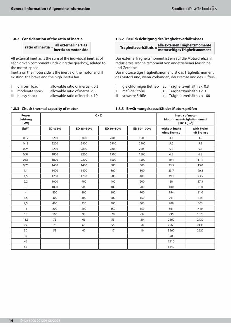
1.8.2 Consideration of the ratio of inertia
All external inertias is the sum of the individual inertias of each driven component (including the gearbox), related to the motor speed.Inertia on the motor side is the inertia of the motor and, if existing, the brake and the high inertia fan.
I uniform load allowable ratio of inertia < 0,3 II moderate shock allowable ratio of inertia < 3 III heavy shock allowable ratio of inertia < 10
1.8.3 Check thermal capacity of motor
1.8.2 Berücksichtigung des Trägheitsverhältnisses
Das externe Trägheitsmoment ist ein auf die Motordrehzahl reduziertes Trägheitsmoment von angetriebener Maschineund Getriebe.Das motorseitige Trägheitsmoment ist das Trägheitsmoment des Motors und, wenn vorhanden, der Bremse und des Lüfters.
I gleichförmiger Betrieb zul. Trägheitsverhältnis < 0,3 II mäßige Stöße zul. Trägheitsverhältnis < 3 III schwere Stöße zul. Trägheitsverhältnis < 100
1.8.3 Erwärmungskapazität des Motors prüfen
ratio of inertia = all external inertias
inertia on motor side Trägheitsverhältnis =
alle externen Trägheitsmomente motorseitiges Trägheitsmoment
Power Leistung
[kW]
C x Z Inertia of motor Motormassenträgheitsmoment
[10-4 kgm²]
[kW ] ED <35% ED 35~50% ED 50~80% ED 80~100% without brake ohne Bremse
with brake mit Bremse
0,12 3200 3000 2000 1200 3,3 3,5
0,18 2200 2800 2800 2500 5,0 5,5
0,25 2200 2800 2800 2500 5,0 5,5
0,37 1800 2200 1500 1500 6,5 6,8
0,55 1800 2200 1500 1500 10,1 11,1
0,75 1400 1400 800 500 23,5 13,0
1,1 1400 1400 800 500 33,7 20,8
1,5 1200 1200 500 400 39,1 23,5
2,2 1000 900 400 200 88 37,3
3 1000 900 400 200 100 81,0
4 800 800 800 700 194 81,0
5,5 300 300 200 150 291 125
7,5 400 350 300 300 409 303
11 200 200 150 150 561 410
15 100 90 78 68 995 1070
18,5 75 65 55 50 2560 2430
22 75 65 55 50 2560 2430
30 55 40 17 10 3260 2620
37 3900
45 7310
55 8640
Drive 6000 991296 08/2021
General Information / Allgemeine Information
15
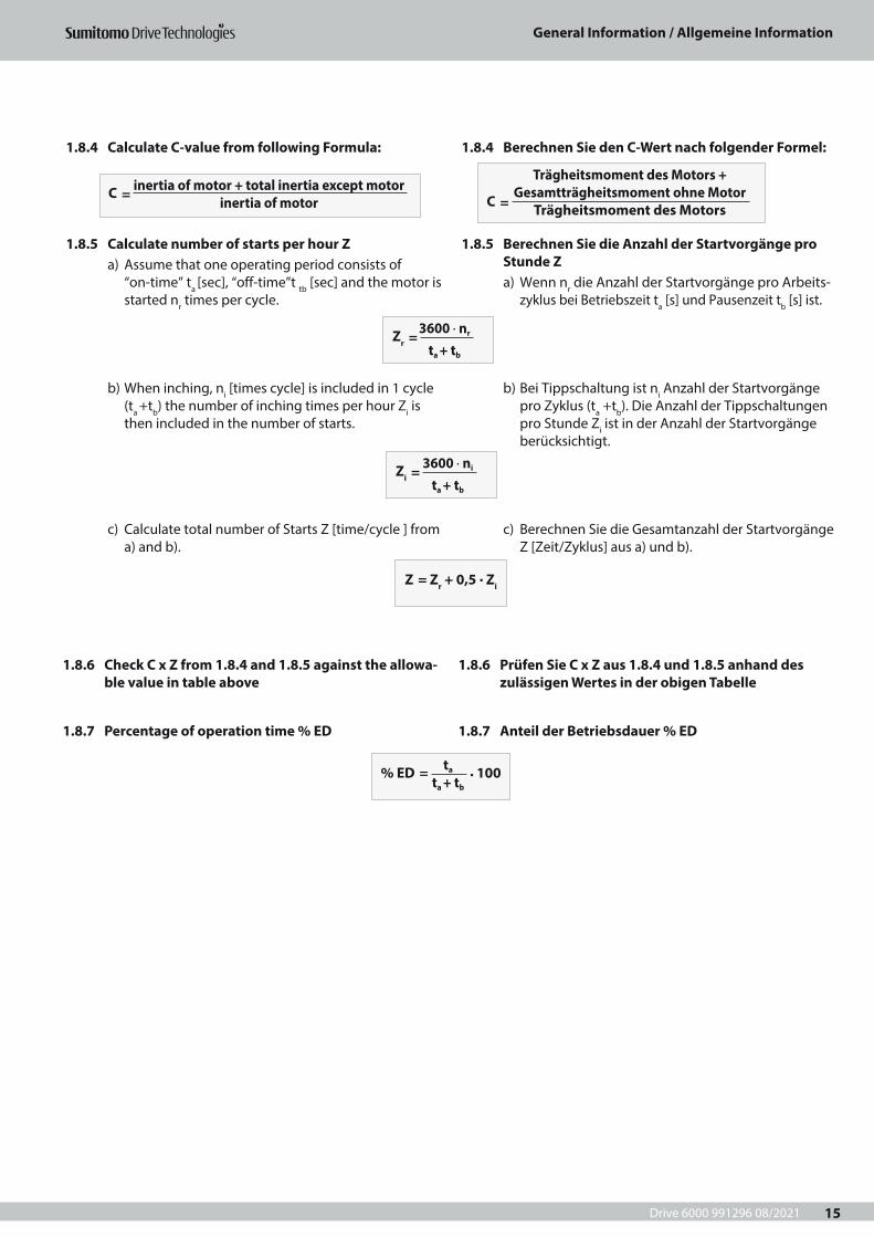
1.8.4 Calculate C-value from following Formula:
1.8.5 Calculate number of starts per hour Za) Assume that one operating period consists of
“on-time” ta [sec], “off-time”t tb [sec] and the motor is started nr times per cycle.
b) When inching, ni [times cycle] is included in 1 cycle (ta +tb) the number of inching times per hour Zi is then included in the number of starts.
c) Calculate total number of Starts Z [time/cycle ] from a) and b).
1.8.6 Check C x Z from 1.8.4 and 1.8.5 against the allowa-ble value in table above
1.8.7 Percentage of operation time % ED
1.8.4 Berechnen Sie den C-Wert nach folgender Formel:
1.8.5 Berechnen Sie die Anzahl der Startvorgänge pro Stunde Za) Wenn nr die Anzahl der Startvorgänge pro Arbeits-
zyklus bei Betriebszeit ta [s] und Pausenzeit tb [s] ist.
b) Bei Tippschaltung ist ni Anzahl der Startvorgänge pro Zyklus (ta +tb). Die Anzahl der Tippschaltungen pro Stunde Zi ist in der Anzahl der Startvorgänge berücksichtigt.
c) Berechnen Sie die Gesamtanzahl der Startvorgänge Z [Zeit/Zyklus] aus a) und b).
1.8.6 Prüfen Sie C x Z aus 1.8.4 und 1.8.5 anhand des zulässigen Wertes in der obigen Tabelle
1.8.7 Anteil der Betriebsdauer % ED
C = C
= inertia of motor + total inertia except motor
inertia of motor
Trägheitsmoment des Motors +Gesamtträgheitsmoment ohne Motor
Trägheitsmoment des Motors
Zr = 3600 · nr
ta + tb
% ED = . 100ta
ta + tb
Zi = 3600 · ni
ta + tb
Z = Zr + 0,5 . Zi
Drive 6000 991296 08/2021
General Information / Allgemeine Information
16
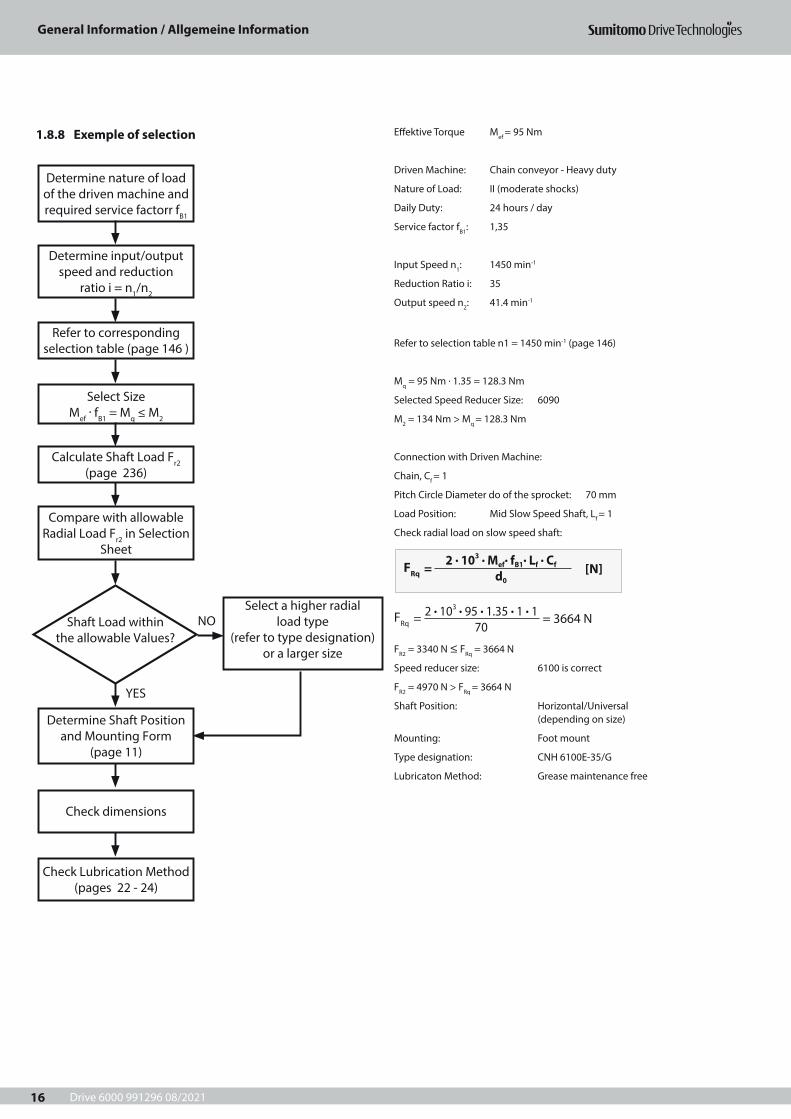
1.8.8 Exemple of selection
Determine nature of load of the driven machine and required service factorr fB1
Determine input/output speed and reduction
ratio i = n1/n2
Refer to corresponding selection table (page 146 )
Calculate Shaft Load Fr2 (page 236)
Compare with allowable Radial Load Fr2 in Selection
Sheet
Determine Shaft Position and Mounting Form
(page 11)
Check dimensions
Check Lubrication Method (pages 22 - 24)
Select a higher radial load type
(refer to type designation) or a larger size
Shaft Load within the allowable Values?
NO
YES
Select SizeMef
. fB1 = Mq ≤ M2
Effektive Torque Mef = 95 Nm
Driven Machine: Chain conveyor - Heavy duty
Nature of Load: II (moderate shocks)
Daily Duty: 24 hours / day
Service factor fB1: 1,35
Input Speed n1: 1450 min-1
Reduction Ratio i: 35
Output speed n2: 41.4 min-1
Refer to selection table n1 = 1450 min-1 (page 146)
Mq = 95 Nm . 1.35 = 128.3 Nm
Selected Speed Reducer Size: 6090
M2 = 134 Nm > Mq = 128.3 Nm
Connection with Driven Machine:
Chain, Cf = 1
Pitch Circle Diameter do of the sprocket: 70 mm
Load Position: Mid Slow Speed Shaft, Lf = 1
Check radial load on slow speed shaft:
FR2 = 3340 N ≤ FRq = 3664 N
Speed reducer size: 6100 is correct
FR2 = 4970 N > FRq = 3664 N
Shaft Position: Horizontal/Universal (depending on size)
Mounting: Foot mount
Type designation: CNH 6100E-35/G
Lubricaton Method: Grease maintenance free
FRq = [N]
FRq = = 3664 N
2 . 103 . Mef. fB1
. Lf . Cf
d0
2 . 103 . 95 . 1.35 . 1 . 1 70
Drive 6000 991296 08/2021
General Information / Allgemeine Information
17
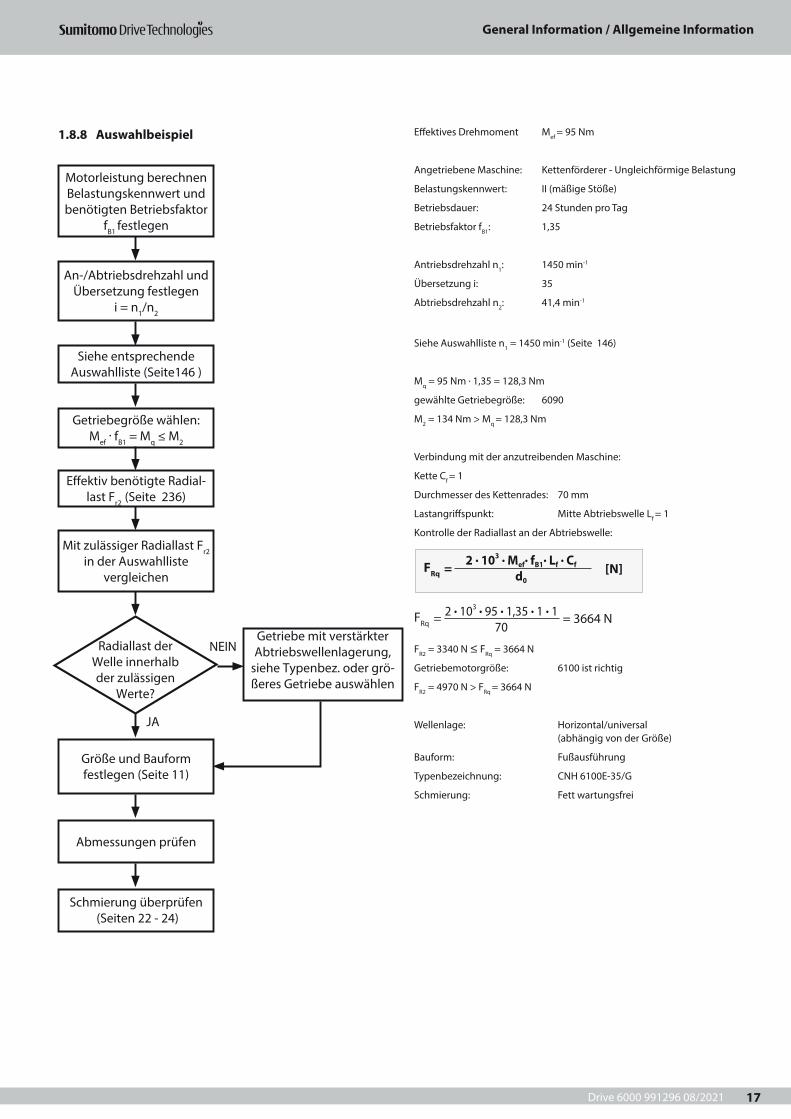
1.8.8 Auswahlbeispiel
Motorleistung berechnen Belastungskennwert und benötigten Betriebsfaktor
fB1 festlegen
An-/Abtriebsdrehzahl und Übersetzung festlegen
i = n1/n2
Siehe entsprechende Auswahlliste (Seite146 )
Effektiv benötigte Radial-last Fr2 (Seite 236)
Mit zulässiger Radiallast Fr2 in der Auswahlliste
vergleichen
Größe und Bauform festlegen (Seite 11)
Abmessungen prüfen
Schmierung überprüfen (Seiten 22 - 24)
Getriebe mit verstärkter Abtriebswellenlagerung,
siehe Typenbez. oder grö-ßeres Getriebe auswählen
NEIN
JA
Radiallast der Welle innerhalb der zulässigen
Werte?
Getriebegröße wählen:Mef
. fB1 = Mq ≤ M2
Effektives Drehmoment Mef = 95 Nm
Angetriebene Maschine: Kettenförderer - Ungleichförmige Belastung
Belastungskennwert: II (mäßige Stöße)
Betriebsdauer: 24 Stunden pro Tag
Betriebsfaktor fB1: 1,35
Antriebsdrehzahl n1: 1450 min-1
Übersetzung i: 35
Abtriebsdrehzahl n2: 41,4 min-1
Siehe Auswahlliste n1 = 1450 min-1 (Seite 146)
Mq = 95 Nm . 1,35 = 128,3 Nm
gewählte Getriebegröße: 6090
M2 = 134 Nm > Mq = 128,3 Nm
Verbindung mit der anzutreibenden Maschine:
Kette Cf = 1
Durchmesser des Kettenrades: 70 mm
Lastangriffspunkt: Mitte Abtriebswelle Lf = 1
Kontrolle der Radiallast an der Abtriebswelle:
FR2 = 3340 N ≤ FRq = 3664 N
Getriebemotorgröße: 6100 ist richtig
FR2 = 4970 N > FRq = 3664 N
Wellenlage: Horizontal/universal (abhängig von der Größe)
Bauform: Fußausführung
Typenbezeichnung: CNH 6100E-35/G
Schmierung: Fett wartungsfrei
FRq = [N]
FRq = = 3664 N
2 . 103 . Mef. fB1
. Lf . Cf
d0
2 . 103 . 95 . 1,35 . 1 . 1 70
Drive 6000 991296 08/2021
General Information / Allgemeine Information
18
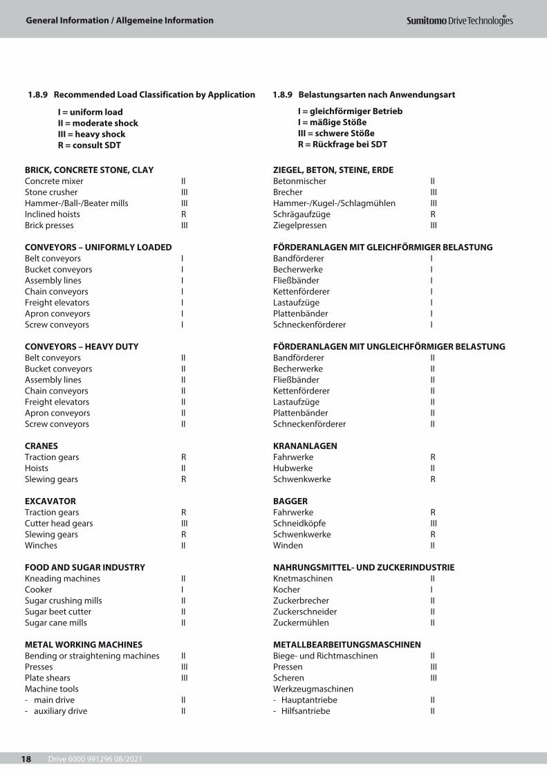
1.8.9 Recommended Load Classification by Application 1.8.9 Belastungsarten nach Anwendungsart
I = uniform load II = moderate shock III = heavy shock R = consult SDT
BRICK, CONCRETE STONE, CLAYConcrete mixer IIStone crusher IIIHammer-/Ball-/Beater mills IIIInclined hoists RBrick presses III
CONVEYORS – UNIFORMLY LOADEDBelt conveyors IBucket conveyors IAssembly lines IChain conveyors IFreight elevators IApron conveyors IScrew conveyors I
CONVEYORS – HEAVY DUTYBelt conveyors IIBucket conveyors IIAssembly lines IIChain conveyors IIFreight elevators IIApron conveyors IIScrew conveyors II
CRANESTraction gears RHoists IISlewing gears R
EXCAVATORTraction gears RCutter head gears IIISlewing gears RWinches II
FOOD AND SUGAR INDUSTRYKneading machines IICooker ISugar crushing mills IISugar beet cutter IISugar cane mills II
METAL WORKING MACHINESBending or straightening machines IIPresses IIIPlate shears IIIMachine tools- main drive II- auxiliary drive II
ZIEGEL, BETON, STEINE, ERDEBetonmischer IIBrecher IIIHammer-/Kugel-/Schlagmühlen IIISchrägaufzüge RZiegelpressen III
FÖRDERANLAGEN MIT GLEICHFÖRMIGER BELASTUNGBandförderer IBecherwerke IFließbänder IKettenförderer ILastaufzüge IPlattenbänder ISchneckenförderer I
FÖRDERANLAGEN MIT UNGLEICHFÖRMIGER BELASTUNGBandförderer IIBecherwerke IIFließbänder IIKettenförderer IILastaufzüge IIPlattenbänder IISchneckenförderer II
KRANANLAGENFahrwerke RHubwerke IISchwenkwerke R
BAGGERFahrwerke RSchneidköpfe IIISchwenkwerke RWinden II
NAHRUNGSMITTEL- UND ZUCKERINDUSTRIEKnetmaschinen IIKocher IZuckerbrecher IIZuckerschneider IIZuckermühlen II
METALLBEARBEITUNGSMASCHINENBiege- und Richtmaschinen IIPressen IIIScheren IIIWerkzeugmaschinen- Hauptantriebe II- Hilfsantriebe II
I = gleichförmiger Betrieb I = mäßige Stöße III = schwere StößeR = Rückfrage bei SDT
Drive 6000 991296 08/2021
General Information / Allgemeine Information
19
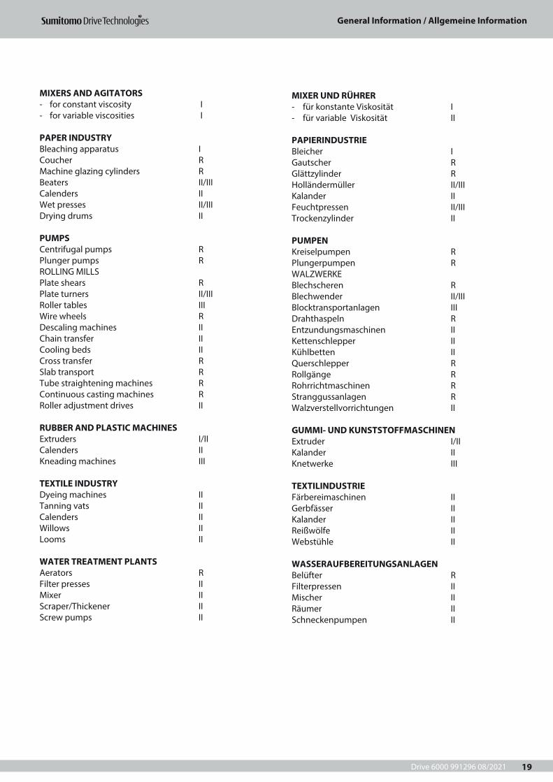
MIXERS AND AGITATORS- for constant viscosity I- for variable viscosities I
PAPER INDUSTRYBleaching apparatus ICoucher RMachine glazing cylinders RBeaters II/IIICalenders IIWet presses II/IIIDrying drums II
PUMPSCentrifugal pumps RPlunger pumps RROLLING MILLSPlate shears RPlate turners II/IIIRoller tables IIIWire wheels RDescaling machines IIChain transfer IICooling beds IICross transfer RSlab transport RTube straightening machines RContinuous casting machines RRoller adjustment drives II
RUBBER AND PLASTIC MACHINESExtruders I/IICalenders IIKneading machines III
TEXTILE INDUSTRYDyeing machines IITanning vats IICalenders IIWillows IILooms II
WATER TREATMENT PLANTSAerators RFilter presses IIMixer IIScraper/Thickener IIScrew pumps II
MIXER UND RÜHRER- für konstante Viskosität I- für variable Viskosität II
PAPIERINDUSTRIEBleicher IGautscher RGlättzylinder RHolländermüller II/IIIKalander IIFeuchtpressen II/IIITrockenzylinder II
PUMPENKreiselpumpen RPlungerpumpen RWALZWERKEBlechscheren RBlechwender II/IIIBlocktransportanlagen IIIDrahthaspeln REntzundungsmaschinen IIKettenschlepper IIKühlbetten IIQuerschlepper RRollgänge RRohrrichtmaschinen RStranggussanlagen RWalzverstellvorrichtungen II
GUMMI- UND KUNSTSTOFFMASCHINENExtruder I/IIKalander IIKnetwerke III
TEXTILINDUSTRIEFärbereimaschinen IIGerbfässer IIKalander IIReißwölfe IIWebstühle II
WASSERAUFBEREITUNGSANLAGENBelüfter RFilterpressen IIMischer IIRäumer IISchneckenpumpen II
Drive 6000 991296 08/2021
General Information / Allgemeine Information
20
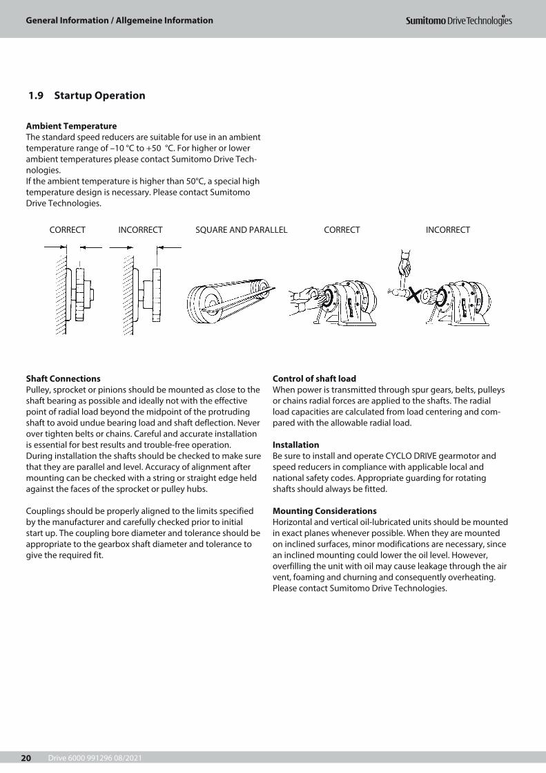
1.9 Startup Operation
Ambient TemperatureThe standard speed reducers are suitable for use in an ambient temperature range of –10 °C to +50 °C. For higher or lower ambient temperatures please contact Sumitomo Drive Tech-nologies.If the ambient temperature is higher than 50°C, a special high temperature design is necessary. Please contact Sumitomo Drive Technologies.
CORRECT INCORRECT SQUARE AND PARALLEL CORRECT INCORRECT
Shaft ConnectionsPulley, sprocket or pinions should be mounted as close to the shaft bearing as possible and ideally not with the effective point of radial load beyond the midpoint of the protruding shaft to avoid undue bearing load and shaft deflection. Never over tighten belts or chains. Careful and accurate installation is essential for best results and trouble-free operation. During installation the shafts should be checked to make sure that they are parallel and level. Accuracy of alignment after mounting can be checked with a string or straight edge held against the faces of the sprocket or pulley hubs.
Couplings should be properly aligned to the limits specified by the manufacturer and carefully checked prior to initial start up. The coupling bore diameter and tolerance should be appropriate to the gearbox shaft diameter and tolerance to give the required fit.
Control of shaft loadWhen power is transmitted through spur gears, belts, pulleys or chains radial forces are applied to the shafts. The radial load capacities are calculated from load centering and com-pared with the allowable radial load.
InstallationBe sure to install and operate CYCLO DRIVE gearmotor and speed reducers in compliance with applicable local and national safety codes. Appropriate guarding for rotating shafts should always be fitted.
Mounting ConsiderationsHorizontal and vertical oil-lubricated units should be mounted in exact planes whenever possible. When they are mounted on inclined surfaces, minor modifications are necessary, since an inclined mounting could lower the oil level. However, overfilling the unit with oil may cause leakage through the air vent, foaming and churning and consequently overheating. Please contact Sumitomo Drive Technologies.
Drive 6000 991296 08/2021
General Information / Allgemeine Information
21
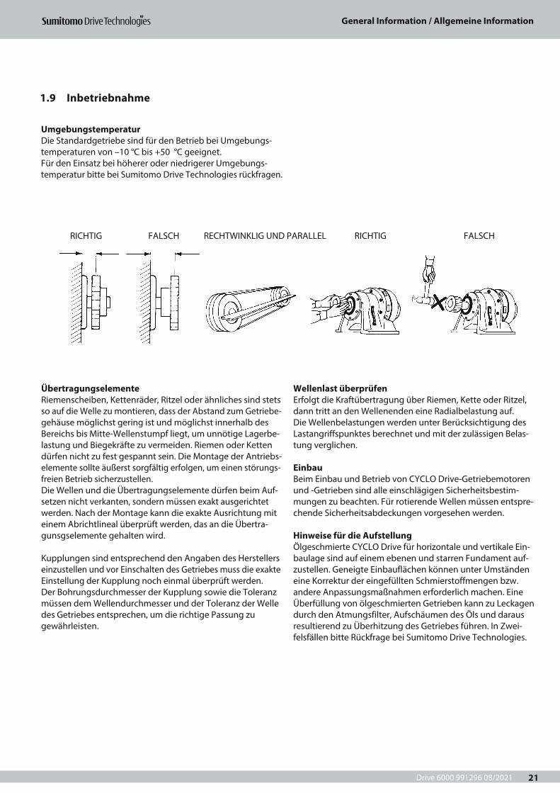
1.9 Inbetriebnahme
RICHTIG FALSCH RECHTWINKLIG UND PARALLEL RICHTIG FALSCH
UmgebungstemperaturDie Standardgetriebe sind für den Betrieb bei Umgebungs-temperaturen von –10 °C bis +50 °C geeignet.Für den Einsatz bei höherer oder niedrigerer Umgebungs-temperatur bitte bei Sumitomo Drive Technologies rückfragen.
ÜbertragungselementeRiemenscheiben, Kettenräder, Ritzel oder ähnliches sind stets so auf die Welle zu montieren, dass der Abstand zum Getriebe-gehäuse möglichst gering ist und möglichst innerhalb des Bereichs bis Mitte-Wellenstumpf liegt, um unnötige Lagerbe-lastung und Biegekräfte zu vermeiden. Riemen oder Ketten dürfen nicht zu fest gespannt sein. Die Montage der Antriebs-elemente sollte äußerst sorgfältig erfolgen, um einen störungs-freien Betrieb sicherzustellen.Die Wellen und die Übertragungselemente dürfen beim Auf-setzen nicht verkanten, sondern müssen exakt ausgerichtet werden. Nach der Montage kann die exakte Ausrichtung mit einem Abrichtlineal überprüft werden, das an die Übertra-gunsgselemente gehalten wird.
Kupplungen sind entsprechend den Angaben des Herstellers einzustellen und vor Einschalten des Getriebes muss die exakte Einstellung der Kupplung noch einmal überprüft werden. Der Bohrungsdurchmesser der Kupplung sowie die Toleranz müssen dem Wellendurchmesser und der Toleranz der Welle des Getriebes entsprechen, um die richtige Passung zu gewährleisten.
Wellenlast überprüfenErfolgt die Kraftübertragung über Riemen, Kette oder Ritzel, dann tritt an den Wellenenden eine Radialbelastung auf. Die Wellenbelastungen werden unter Berücksichtigung des Lastangriffspunktes berechnet und mit der zulässigen Belas-tung verglichen.
EinbauBeim Einbau und Betrieb von CYCLO Drive-Getriebemotoren und -Getrieben sind alle einschlägigen Sicherheitsbestim-mungen zu beachten. Für rotierende Wellen müssen entspre-chende Sicherheitsabdeckungen vorgesehen werden.
Hinweise für die AufstellungÖlgeschmierte CYCLO Drive für horizontale und vertikale Ein-baulage sind auf einem ebenen und starren Fundament auf-zustellen. Geneigte Einbauflächen können unter Umständen eine Korrektur der eingefüllten Schmierstoffmengen bzw. andere Anpassungsmaßnahmen erforderlich machen. Eine Überfüllung von ölgeschmierten Getrieben kann zu Leckagen durch den Atmungsfilter, Aufschäumen des Öls und daraus resultierend zu Überhitzung des Getriebes führen. In Zwei-felsfällen bitte Rückfrage bei Sumitomo Drive Technologies.
Drive 6000 991296 08/2021
General Information / Allgemeine Information
22
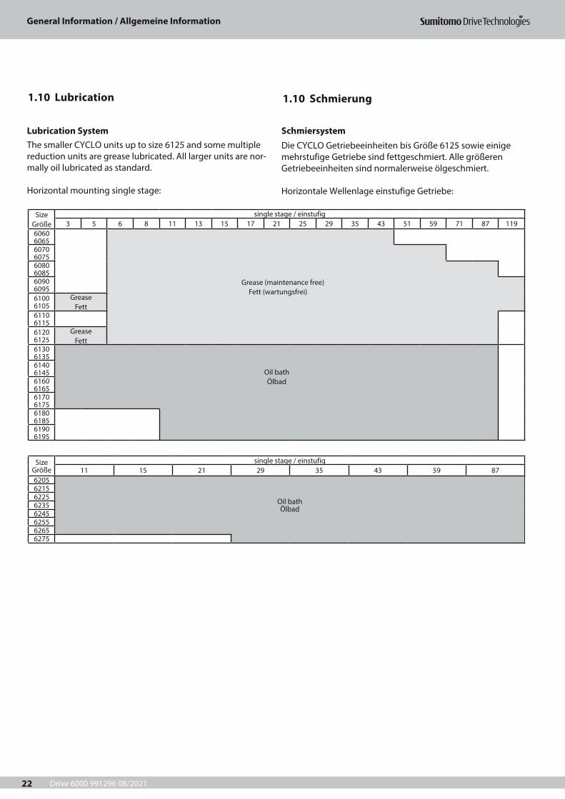
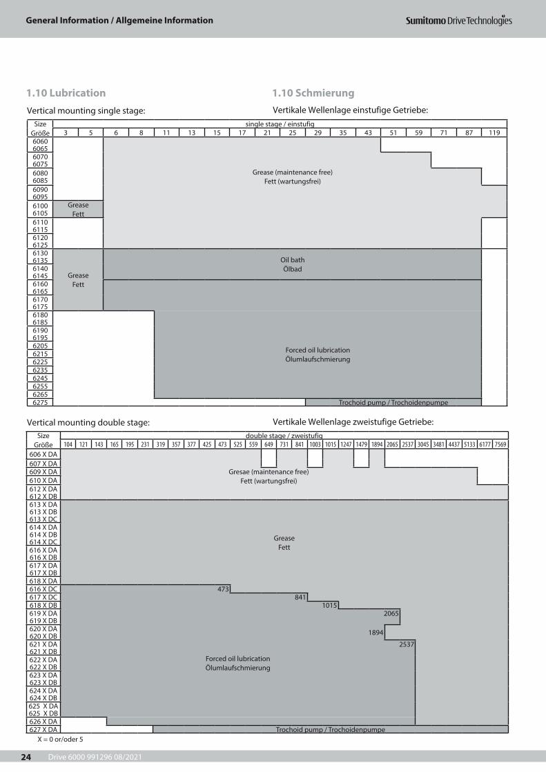
1.10 Lubrication 1.10 Schmierung
Lubrication SystemThe smaller CYCLO units up to size 6125 and some multiple reduction units are grease lubricated. All larger units are nor-mally oil lubricated as standard.
Horizontal mounting single stage:
Size Größe
single stage / einstufig3 5 6 8 11 13 15 17 21 25 29 35 43 51 59 71 87 119
6060 6065
Grease (maintenance free) Fett (wartungsfrei)
6070 60756080 60856090 60956100 6105
Grease Fett
6110 61156120 6125
Grease Fett
6130 6135
Oil bath Ölbad
6140 61456160 61656170 61756180 61856190 6195
Size Größe
single stage / einstufig11 15 21 29 35 43 59 87
6205
Oil bath Ölbad
6215622562356245625562656275
SchmiersystemDie CYCLO Getriebeeinheiten bis Größe 6125 sowie einige mehrstufige Getriebe sind fettgeschmiert. Alle größeren Getriebeeinheiten sind normalerweise ölgeschmiert.
Horizontale Wellenlage einstufige Getriebe:
Drive 6000 991296 08/2021
General Information / Allgemeine Information
23
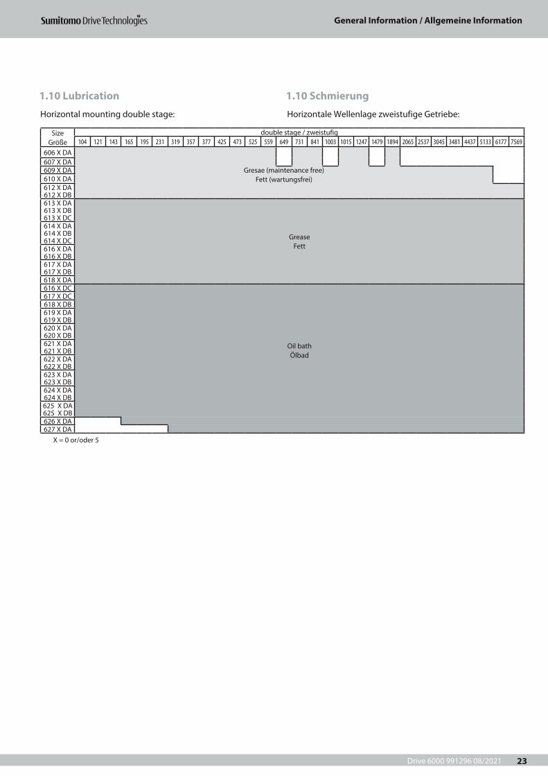
Horizontal mounting double stage:
Size Größe
double stage / zweistufig104 121 143 165 195 231 319 357 377 425 473 525 559 649 731 841 1003 1015 1247 1479 1894 2065 2537 3045 3481 4437 5133 6177 7569
606 X DA607 X DA609 X DA Gresae (maintenance free)
Fett (wartungsfrei)610 X DA612 X DA 612 X DB613 X DA 613 X DB 613 X DC
Grease Fett
614 X DA 614 X DB 614 X DC616 X DA 616 X DB617 X DA 617 X DB618 X DA616 X DC
Oil bath Ölbad
617 X DC618 X DB619 X DA 619 X DB620 X DA 620 X DB621 X DA 621 X DB622 X DA 622 X DB623 X DA 623 X DB624 X DA 624 X DB625 X DA 625 X DB626 X DA627 X DA
Horizontale Wellenlage zweistufige Getriebe:
1.10 Schmierung1.10 Lubrication
X = 0 or/oder 5
Drive 6000 991296 08/2021
General Information / Allgemeine Information
24
Vertical mounting single stage:
Vertical mounting double stage:
Size Größe
single stage / einstufig3 5 6 8 11 13 15 17 21 25 29 35 43 51 59 71 87 119
6060 60656070 60756080 6085
Grease (maintenance free) Fett (wartungsfrei)
6090 60956100 6105
Grease Fett
6110 61156120 61256130 6135
Grease Fett
Oil bath Ölbad6140
61456160 61656170 61756180 6185
Forced oil lubrication Ölumlaufschmierung
6190 619562056215622562356245625562656275 Trochoid pump / Trochoidenpumpe
Vertikale Wellenlage einstufige Getriebe:
Vertikale Wellenlage zweistufige Getriebe:Size
Größedouble stage / zweistufig
104 121 143 165 195 231 319 357 377 425 473 525 559 649 731 841 1003 1015 1247 1479 1894 2065 2537 3045 3481 4437 5133 6177 7569606 X DA607 X DA609 X DA Gresae (maintenance free)
Fett (wartungsfrei)610 X DA612 X DA 612 X DB613 X DA 613 X DB 613 X DC
Grease Fett
614 X DA 614 X DB 614 X DC616 X DA 616 X DB617 X DA 617 X DB618 X DA616 X DC 473617 X DC 841618 X DB 1015619 X DA 619 X DB
2065
620 X DA 620 X DB 1894
621 X DA 621 X DB
2537
Forced oil lubrication Ölumlaufschmierung
622 X DA 622 X DB623 X DA 623 X DB624 X DA 624 X DB625 X DA 625 X DB626 X DA627 X DA Trochoid pump / Trochoidenpumpe
1.10 Schmierung1.10 Lubrication
X = 0 or/oder 5
Drive 6000 991296 08/2021
General Information / Allgemeine Information
25
1.10 Schmierung1.10 Lubrication
Grease LubricationAll grease lubricated units are filled with grease at the factory and are ready for use.
Lifetime Grease LubricationCYCLO Drive gearmotor and speed reducers up to size 6125 single stage and multi stage are grease lubricated for life and suitable for any mounting position. They are supplied filled with ESSO Unirex N2 grease and are maintenance free for 20,000 operating hours or 4 to 5 years.
Other Grease LubricationGrease lubricated CYCLO Drive gearmotor and speed reducers from size 6130 single- and multistage with all ratios have to be regreased for the first time after 500 hours of operation, but at least after 2 months. Further regreasing is recommend-ed every 3 - 6 months of operation, but at least every 2 years. These units are provided with grease nipples and vent plugs to allow for periodic regreasing. Grease lubricated units have a tag which specifies the filled in grease. For recharge or renewal the same kind of grease must be used. Mixing of dif-ferent grease types is not allowed.
Oil-LubricationAll oil-lubricated CYCLO Drive gearmotors and speed reducers are shipped without oil.They require pre-filling with oil prior to operation. Some models need to be supplied with oil in distinct locations. The location of the oil accessories are shown in the operation manual. Please consult Sumitomo Drive Technologies if oil lubricated units are used with grease lubrication, in case of special requirements.
Oil change intervalsOil levels must be checked every 5,000 hours. If the oil is con-taminated, burned or waxed, change the oil immediately, and flush the gear if necessary. Under normal operating con-ditions oil should be changed every 10,000 hours or after 2 years at the latest. A more regular oil change (every 3,000 or 5,000 hours) will increase the gear lifetime.We recommend changing the oil after the first 500 hours of operation.The recommendations above do not apply to abnormal oper-ating conditions, i.e. high temperature, high humidity or cor-rosive environments. If any of these situations exist, the lubri-cant may have to be changed more frequently.
FettschmierungAlle fettgeschmierten Getriebe sind werksseitig mit Fett befüllt und werden betriebsbereit geliefert.
Lebensdauer-FettschmierungCYCLO Drive-Getriebemotoren und -Getriebe bis zu Größe 6125 einstufig und mehrstufig sind lebensdauer- fettge-schmiert und für jede Einbaulage geeignet. Diese Getriebe werden werksseitig mit Fett ESSO Unirex N2 befüllt und sind wartungsfrei für 20.000 Betriebsstunden oder 4 bis 5 Jahre.
Weitere FettschmierungDie fettgeschmierten CYCLO Drive-Getriebemotoren und -Getriebe ab der Größe 6130 ein- und mehrstufig mit allen Übersetzungsverhältnissen, sollten nach den ersten 500 Betriebsstunden nachgeschmiert werden, spätestens jedoch nach 2 Monaten. Weitere Nachschmierungen werden alle 3 bis 6 Monate empfohlen, oder spätestens nach 2 Jahren. Diese Getriebeeinheiten sind mit Schmiernippel und Atmungsfil-tern für periodische Nachschmierung ausgerüstet. Für Nach-füllung oder Fetterneuerung muss stets dasselbe Fett wie bei der Originalbefüllung verwendet werden. Das Mischen ver-schiedener Fettsorten ist nicht zulässig.
ÖlschmierungAlle ölgeschmierten CYCLO Drive-Getriebemotoren und -Getriebe werden aus Sicherheitsgründen ohne Ölbefüllung geliefert.Vor Inbetriebnahme ist Erstbefüllung erforderlich. Manche Getriebe erfordern Ölbefüllung an mehreren Stellen. Hinweise zur Ölbefüllung und Ölstandskontrolle finden Sie in den Betriebsanleitungen.Wenn ölgeschmierte CYCLO Drive-Getriebe aufgrund beson-derer Anforderungen mit Fett geschmiert werden sollen, bitte vorher mit Sumitomo Drive Technologies Rücksprachenehmen.
ÖlwechselintervalleDer richtige Ölstand sollte alle 5.000 Stunden überprüft werden.Wenn das Öl verschmutzt, verbrannt oder zähflüssig ist, wechseln Sie das Öl sofort und spülen Sie, falls erforderlich, das Getriebe.Unter normalen Betriebsbedingungen empfehlen wir einen Ölwechsel alle 10.000 Stunden. Die Intervalle sollten nicht länger als 2 Jahre sein. Kürzere Ölwechselintervalle (alle 3.000 bis 5.000 Stunden) erhöhen die Lebensdauer.Ein Ölwechsel nach den ersten 500 Stunden ist sehr empfeh-lenswert. Obige Empfehlungen können unter anderen Betriebsbedingungen wie hohe Temperatur, hohe Feuchtig-keit oder korrosive Umgebung geändert werden.Wenn eine dieser Situationen vorliegt, müssen häufigere Ölwechsel stattfinden.
Drive 6000 991296 08/2021
General Information / Allgemeine Information
26
1.10 Schmierung1.10 Lubrication
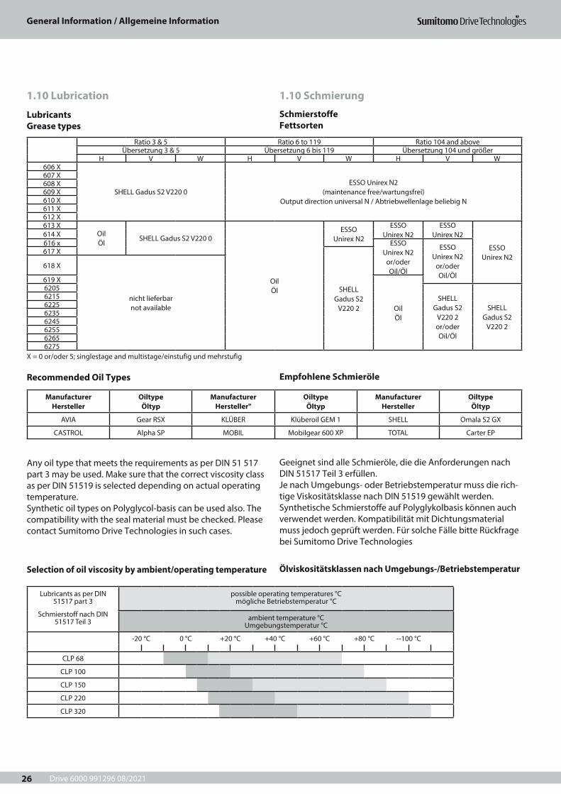
LubricantsGrease types
Recommended Oil Types
Selection of oil viscosity by ambient/operating temperature
Any oil type that meets the requirements as per DIN 51 517 part 3 may be used. Make sure that the correct viscosity class as per DIN 51519 is selected depending on actual operating temperature.Synthetic oil types on Polyglycol-basis can be used also. The compatibility with the seal material must be checked. Please contact Sumitomo Drive Technologies in such cases.
Lubricants as per DIN 51517 part 3
Schmierstoff nach DIN 51517 Teil 3
possible operating temperatures °C mögliche Betriebstemperatur °C
ambient temperature °C Umgebungstemperatur °C
-20 °C 0 °C +20 °C +40 °C +60 °C +80 °C --100 °C
CLP 68
CLP 100
CLP 150
CLP 220
CLP 320
Manufacturer Hersteller
Oiltype Öltyp
Manufacturer Hersteller"
Oiltype Öltyp
Manufacturer Hersteller
Oiltype Öltyp
AVIA Gear RSX KLÜBER Klüberoil GEM 1 SHELL Omala S2 GX
CASTROL Alpha SP MOBIL Mobilgear 600 XP TOTAL Carter EP
Ratio 3 & 5 Ratio 6 to 119 Ratio 104 and aboveÜbersetzung 3 & 5 Übersetzung 6 bis 119 Übersetzung 104 und größer
H V W H V W H V W606 X
SHELL Gadus S2 V220 0ESSO Unirex N2
(maintenance free/wartungsfrei) Output direction universal N / Abtriebwellenlage beliebig N
607 X608 X609 X610 X611 X612 X613 X
Oil Öl
SHELL Gadus S2 V220 0
Oil Öl
ESSO Unirex N2
ESSO Unirex N2
ESSO Unirex N2
ESSO Unirex N2
614 X616 x ESSO
Unirex N2 or/oder Oil/Öl
ESSO Unirex N2
or/oder Oil/Öl
617 X
SHELL Gadus S2
V220 2
618 X
nicht lieferbar not available
619 X
Oil Öl
6205SHELL
Gadus S2 V220 2 or/oder Oil/Öl
SHELL Gadus S2
V220 2
6215622562356245625562656275
X = 0 or/oder 5; singlestage and multistage/einstufig und mehrstufig
SchmierstoffeFettsorten
Empfohlene Schmieröle
Ölviskositätsklassen nach Umgebungs-/Betriebstemperatur
Geeignet sind alle Schmieröle, die die Anforderungen nach DIN 51517 Teil 3 erfüllen.Je nach Umgebungs- oder Betriebstemperatur muss die rich-tige Viskositätsklasse nach DIN 51519 gewählt werden.Synthetische Schmierstoffe auf Polyglykolbasis können auch verwendet werden. Kompatibilität mit Dichtungsmaterial muss jedoch geprüft werden. Für solche Fälle bitte Rückfrage bei Sumitomo Drive Technologies
Drive 6000 991296 08/2021
General Information / Allgemeine Information
27
1.10 Schmierung1.10 Lubrication
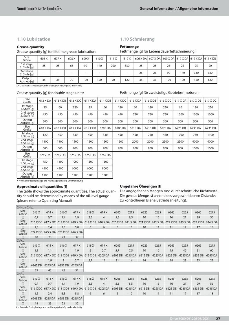
Grease quantityGrease quantity [g] for lifetime grease lubrication:
Approximate oil quantities [l]The table shows the approximate quantities. The actual quan-tity should be determined by means of the oil level gauge (please refer to Operating Manual)
CHH... / CHV...Size
Größe 613 X 614 X 616 X 617 X 618 X 619 X 6205 6215 6225 6235 6245 6255 6265 6275
[l] 0,7 0,7 1,4 1,9 2,5 4 5,5 8,5 10 15 16 21 29 56Size
Größe 616 X DC 617 X DC 618 X DB 619 X DA 619 X DB 620 X DA 620 X DB 621 X DA 621 X DB 622 X DA 622 X DB 623 X DA 623 X DB 624 X DA
[l] 1,5 2,4 3,5 5,8 6 6 6 10 10 11 11 17 17 18Size
Größe 624 X DB 625 X DA 625 X DB 626 X DA
[l] 18 23 23 32CVV...
Size Größe 613 X 614 X 616 X 617 X 618 X 619 X 6205 6215 6225 6235 6245 6255 6265 6275
[l] 1,1 1,1 1 1,9 2 2,7 5,7 7,5 10 12 15 42 51 60Size
Größe 616 X DC 617 X DC 618 X DB 619 X DA 619 X DB 6205 DA 6205 DB 6215 DA 6215 DB 6225 DA 6225 DB 6235 DA 6235 DB 6245 DA
[l] 1 1,9 2 2,7 2,7 11 11 14 14 18 18 23 23 29Size
Größe 6245 DB 6255 DA 6255 DB 6265 DA
[l] 29 42 42 51CHF...
Size Größe 613 X 614 X 616 X 617 X 618 X 619 X 6205 6215 6225 6235 6245 6255 6265 6275
[l] 0,7 0,7 1,4 1,9 2,5 4 5,5 8,5 10 15 16 21 29 56Size
Größe 616 X DC 617 X DC 618 X DB 619 X DA 619 X DB 6205 DA 6205 DB 6215 DA 6215 DB 6225 DA 6225 DB 6235 DA 6235 DB 6245 DA
[l] 1,5 2,4 3,5 5,8 6 6 6 10 10 11 11 17 17 18Size
Größe 6245 DB 6255 DA 6255 DB 6265 DA
[l] 18 23 23 32X = 0 or/oder 5; singlestage and multistage/einstufig und mehrstufig
Grease quantity [g] for double stage units:
Size Größe 613 X DA 613 X DB 613 X DC 614 X DA 614 X DB 614 X DC 616 X DA 616 X DB 616 X DC 617 X DA 617 X DB 617 X DC
1st stage 1. Stufe [g] 25 60 120 25 60 120 60 120 250 60 120 250
2nd stage 2. Stufe [g] 450 450 450 450 450 450 750 750 750 1000 1000 1000
Output Abtrieb [g] 300 300 300 300 300 300 300 300 300 500 500 500
Size Größe 618 X DA 618 X DB 619 X DA 619 X DB 6205 DA 6205 DB 6215 DA 6215 DB 6225 DA 6225 DB 6235 DA 6235 DB
1st stage 1. Stufe [g] 120 450 330 450 330 450 450 750 450 1000 750 1100
2nd stage 2. Stufe [g] 1100 1100 1500 1500 1500 1500 2000 2000 2500 2500 4000 4000
Output Abtrieb [g] 600 600 700 700 700 700 800 800 900 900 1000 1000
Size Größe 6245 DA 6245 DB 6255 DA 6255 DB 6265 DA
1st stage 1. Stufe [g] 750 1100 1000 1500 1500
2nd stage 2. Stufe [g] 4500 4500 6000 6000 8000
Output Abtrieb [g] 1100 1100 1200 1200 1300
X = 0 or/oder 5; singlestage and multistage/einstufig und mehrstufig
Size Größe 606 X 607 X 608 X 609 X 610 X 611 X 612 X 606 X DA 607 X DA 609 X DA 610 X DA 612 X DA 612 X DB
1st stage 1. Stufe [g] 25 25 65 90 140 200 330 25 25 25 25 25 90
2nd stage 2. Stufe [g] - - - - - - - 25 25 90 140 330 330
Output Abtrieb [g] 35 35 70 100 100 90 120 35 35 100 100 120 120
X = 0 or/oder 5; singlestage and multistage/einstufig und mehrstufig
FettmengeFettmenge [g] für Lebensdauerfettschmierung:
Ungefähre Ölmengen [l]Die angegebenen Mengen sind durchschnittliche Richtwerte. Die genaue Menge ist anhand des vorgeschriebenen Ölstandes zu kontrollieren (siehe Betriebsanleitung).
Fettmenge [g] für zweistufige Getriebe/-motoren;
Drive 6000 991296 08/2021
General Information / Allgemeine Information
28

Drive 6000 991091 10/2020
Gearmotor Selection Tables / Getriebemotor-Auswahllisten
29
2 Getriebemotor-Auswahllisten 2 Gearmotors Selection Tables
Gearmotor Selection Tables / Getriebemotor-Auswahllisten
Drive 6000 991296 08/2021
Gearmotor Selection Tables / Getriebemotor-Auswahllisten
30
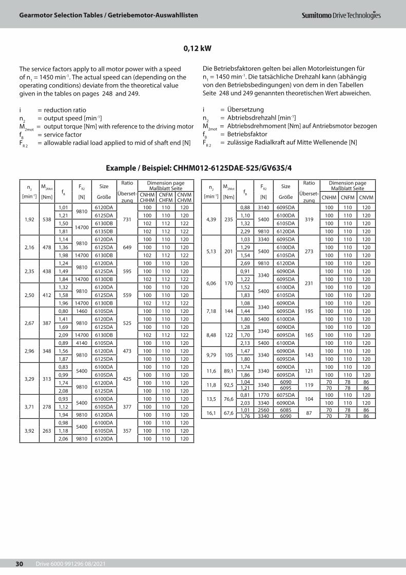
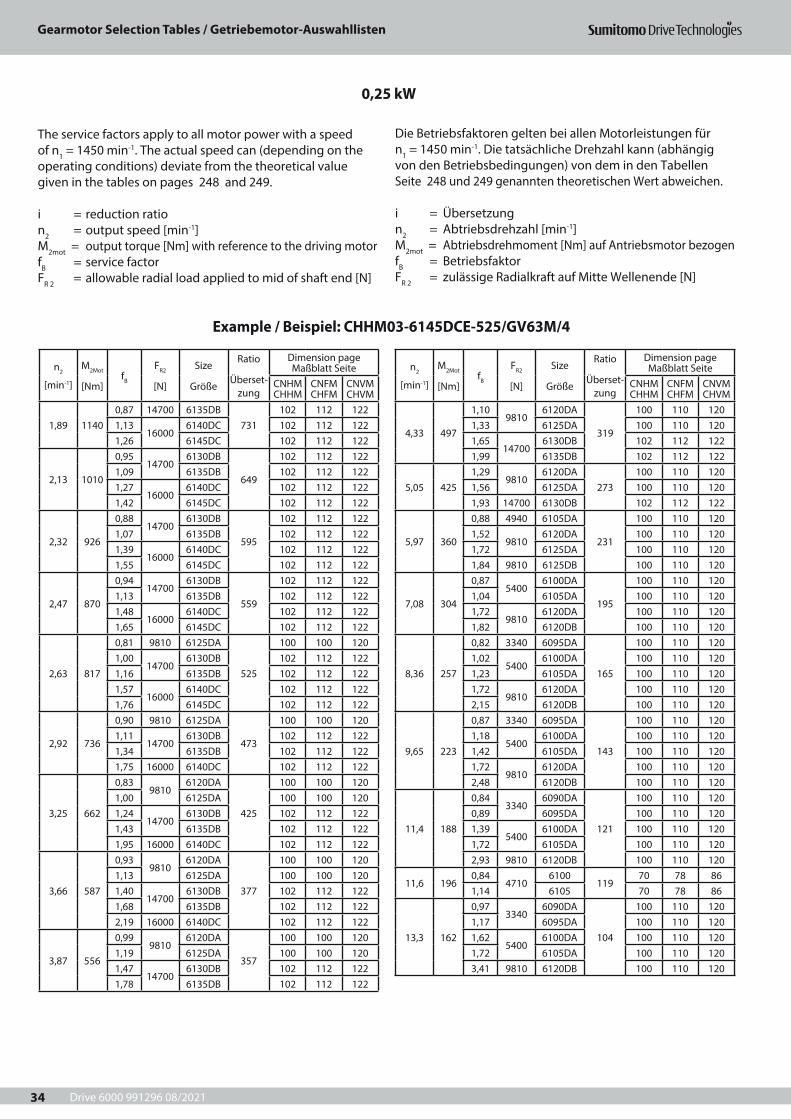
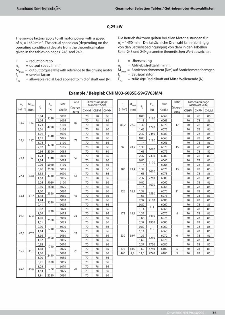
The service factors apply to all motor power with a speed of n1 = 1450 min-1. The actual speed can (depending on the operating conditions) deviate from the theoretical value given in the tables on pages 248 and 249.
i = reduction ration2 = output speed [min-1]M2mot = output torque [Nm] with reference to the driving motorfB = service factorFR 2 = allowable radial load applied to mid of shaft end [N]
n2
[min-1]
M2Mot
[Nm]fB
FR2
[N]
Size
Größe
Ratio
Überset-zung
Dimension page Maßblatt Seite
CNHM CHHM
CNFM CHFM
CNVM CHVM
1,92 538
1,019810
6120DA
731
100 110 1201,21 6125DA 100 110 1201,50
147006130DB 102 112 122
1,81 6135DB 102 112 122
2,16 4781,14
98106120DA
649100 110 120
1,36 6125DA 100 110 1201,98 14700 6130DB 102 112 122
2,35 4381,24
98106120DA
595100 110 120
1,49 6125DA 100 110 1201,84 14700 6130DB 102 112 122
2,50 4121,32
98106120DA
559100 110 120
1,58 6125DA 100 110 1201,96 14700 6130DB 102 112 122
2,67 387
0,80 1460 6105DA
525
100 110 1201,41
98106120DA 100 110 120
1,69 6125DA 100 110 1202,09 14700 6130DB 102 112 122
2,96 3480,89 4140 6105DA
473100 110 120
1,569810
6120DA 100 110 1201,87 6125DA 100 110 120
3,29 313
0,835400
6100DA
425
100 110 1200,99 6105DA 100 110 1201,74
98106120DA 100 110 120
2,08 6125DA 100 110 120
3,71 2780,93
54006100DA
377100 110 120
1,12 6105DA 100 110 1201,94 9810 6120DA 100 110 120
3,92 2630,98
54006100DA
357100 110 120
1,18 6105DA 100 110 1202,06 9810 6120DA 100 110 120
n2
[min-1]
M2Mot
[Nm]fB
FR2
[N]
Size
Größe
Ratio
Überset-zung
Dimension page Maßblatt Seite
CNHM CNFM CNVM
4,39 235
0,88 3140 6095DA
319
100 110 1201,10
54006100DA 100 110 120
1,32 6105DA 100 110 1202,29 9810 6120DA 100 110 120
5,13 201
1,03 3340 6095DA
273
100 110 1201,29
54006100DA 100 110 120
1,54 6105DA 100 110 1202,69 9810 6120DA 100 110 120
6,06 170
0,913340
6090DA
231
100 110 1201,22 6095DA 100 110 1201,52
54006100DA 100 110 120
1,83 6105DA 100 110 120
7,18 1441,08
33406090DA
195100 110 120
1,44 6095DA 100 110 1201,80 5400 6100DA 100 110 120
8,48 1221,28
33406090DA
165100 110 120
1,70 6095DA 100 110 1202,13 5400 6100DA 100 110 120
9,79 1051,47
33406090DA
143100 110 120
1,80 6095DA 100 110 120
11,6 89,11,74
33406090DA
121100 110 120
1,86 6095DA 100 110 120
11,8 92,5 1,04 3340 6090 119 70 78 861,21 6095 70 78 86
13,5 76,60,81 1770 6075DA
104100 110 120
2,03 3340 6090DA 100 110 120
16,1 67,6 1,01 2560 6085 87 70 78 861,76 3340 6090 70 78 86
Die Betriebsfaktoren gelten bei allen Motorleistungen für n1 = 1450 min-1. Die tatsächliche Drehzahl kann (abhängig von den Betriebsbedingungen) von dem in den Tabellen Seite 248 und 249 genannten theoretischen Wert abweichen.
i = Übersetzungn2 = Abtriebsdrehzahl [min-1] M2mot = Abtriebsdrehmoment [Nm] auf Antriebsmotor bezogenfB = BetriebsfaktorFR 2 = zulässige Radialkraft auf Mitte Wellenende [N]
0,12 kW
Example / Beispiel: CHHM012-6125DAE-525/GV63S/4
Drive 6000 991296 08/2021
Gearmotor Selection Tables / Getriebemotor-Auswahllisten
31
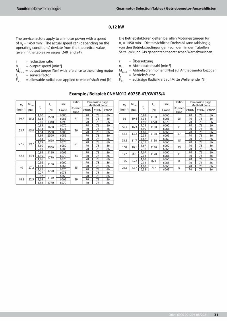
The service factors apply to all motor power with a speed of n1 = 1450 min-1. The actual speed can (depending on the operating conditions) deviate from the theoretical value given in the tables on pages 248 and 249.
i = reduction ration2 = output speed [min-1]M2mot = output torque [Nm] with reference to the driving motorfB = service factorFR 2 = allowable radial load applied to mid of shaft end [N]
n2
[min-1]
M2Mot
[Nm]fB
FR2
[N]
Size
Größe
Ratio
Überset-zung
Dimension page Maßblatt Seite
CNHM CNFM CNVM
19,7 55,21,00 2560 6080
7170 78 86
1,38 6085 70 78 862,10 3340 6090 70 78 86
23,7 45,9
0,83 1630 6070
59
70 78 861,13 6075 70 78 861,54 2560 6080 70 78 861,95 2560 6085 70 78 86
27,5 39,7
0,83 1660 6070
51
70 78 861,19 6075 70 78 861,60 2560 6080 70 78 862,01 6085 70 78 86
32,6 33,40,93 1180 6065
4370 78 86
1,39 1770 6070 70 78 861,86 6075 70 78 86
40 27,2
0,92 1180 6060
35
70 78 861,14 6065 70 78 861,71 1770 6070 70 78 862,27 6075 70 78 86
48,3 22,50,92 1180 6060
2970 78 86
1,38 6065 70 78 861,88 1770 6070 70 78 86
n2
[min-1]
M2Mot
[Nm]fB
FR2
[N]
Size
Größe
Ratio
Überset-zung
Dimension page Maßblatt Seite
CNHM CNFM CNVM
56 19,40,92 1180 6060
2570 78 86
1,38 6065 70 78 861,92 1770 6070 70 78 86
66,7 16,3 1,53 1180 6060 21 70 78 861,90 6065 70 78 86
82,4 13,2 1,67 1180 6060 17 70 78 862,35 6065 70 78 86
93,3 11,7 1,67 1180 6060 15 70 78 862,38 6065 70 78 86
108 10,1 1,67 1180 6060 13 70 78 862,38 6065 70 78 86
127 8,6 1,67 1120 6060 11 70 78 862,38 6065 70 78 86
175 6,22 1,67 821 6060 8 70 78 862,38 6065 70 78 86
233 4,67 1,67 717 6060 6 70 78 862,38 6065 70 78 86
Die Betriebsfaktoren gelten bei allen Motorleistungen für n1 = 1450 min-1. Die tatsächliche Drehzahl kann (abhängig von den Betriebsbedingungen) von dem in den Tabellen Seite 248 und 249 genannten theoretischen Wert abweichen.
i = Übersetzungn2 = Abtriebsdrehzahl [min-1] M2mot = Abtriebsdrehmoment [Nm] auf Antriebsmotor bezogenfB = BetriebsfaktorFR 2 = zulässige Radialkraft auf Mitte Wellenende [N]
0,12 kW
Example / Beispiel: CNHM012-6075E-43/GV63S/4

Drive 6000 991296 08/2021
Gearmotor Selection Tables / Getriebemotor-Auswahllisten
32
n2
[min-1]
M2Mot
[Nm]fB
FR2
[N]
Size
Größe
Ratio
Überset-zung
Dimension page Maßblatt Seite
CNHM CNFM CNVM
4,45 3480,88 4520 6105DA
319100 110 120
1,539810
6120DA 100 110 1201,85 6125DA 100 110 120
5,2 2970,86
54006100DA
273100 110 120
1,03 6105DA 100 110 1201,79 9810 6120DA 100 110 120
6,15 252
0,81 3240 6095DA
231
100 110 1201,01
54006100DA 100 110 120
1,22 6105DA 100 110 1202,12 9810 6120DA 100 110 120
7,28 212
0,96 3340 6095DA
195
100 110 1201,20
54006100DA 100 110 120
1,44 6105DA 100 110 1202,39 9810 6120DA 100 110 120
8,61 180
0,853340
6090DA
165
100 110 1201,14 6095DA 100 110 1201,42
54006100DA 100 110 120
1,70 6105DA 100 110 1202,39 9810 6120DA 100 110 120
9,93 156
0,983340
6090DA
143
100 110 1201,20 6095DA 100 110 1201,64
54006100DA 100 110 120
1,97 6105DA 100 110 120
11,7 1321,16
33406090DA
121100 110 120
1,24 6095DA 100 110 1201,94 5400 6100DA 100 110 120
11,9 1370,81 3340 6095
11970 78 86
1,174740
6100 70 78 861,59 6105 70 78 86
13,7 1131,35
33406090DA
104100 110 120
1,63 6095DA 100 110 1202,25 5400 6100DA 100 110 120
16,3 1001,17
33406090
8770 78 86
1,46 6095 70 78 862,41 4810 6100 70 78 86
n2
[min-1]
M2Mot
[Nm]fB
FR2
[N]
Size
Größe
Ratio
Überset-zung
Dimension page Maßblatt Seite
CNHM CHHM
CNFM CHFM
CNVM CHVM
1,94 796
0,81 9810 6125DA
731
100 110 1201,00
147006130DB 102 112 122
1,21 6135DB 102 112 1221,57
160006140DC 102 112 122
1,76 6145DC 102 112 122
2,19 707
0,91 9810 6125DA
649
100 110 1201,32
147006130DB 102 112 122
1,52 6135DB 102 112 1221,77 16000 6140DC 102 112 122
2,39 648
0,839810
6120DA
595
100 110 1200,99 6125DA 100 110 1201,23
147006130DB 102 112 122
1,48 6135DB 102 112 1221,93 16000 6140DC 102 112 122
2,54 609
0,889810
6120DA
559
100 110 1201,06 6125DA 100 110 1201,31
147006130DB 102 112 122
1,58 6135DB 102 112 1222,05 16000 6140DC 102 112 122
2,70 572
0,949810
6120DA
525
100 110 1201,12 6125DA 100 110 1201,39
147006130DB 102 112 122
1,61 6135DB 102 112 1222,19 16000 6140DC 102 112 122
3,00 515
1,049810
6120DA
473
100 110 1201,25 6125DA 100 110 1201,55
147006130DB 102 112 122
1,86 6135DB 102 112 122
3,34 463
1,169810
6120DA
425
100 110 1201,39 6125DA 100 110 1201,72
147006130DB 102 112 122
1,98 6135DB 102 112 122
3,77 4111,29
98106120DA
377100 110 120
1,57 6125DA 100 110 1201,94 14700 6130DB 102 112 122
3,98 3891,37
98106120DA
357102 112 122
1,65 6125DA 102 112 1222,05 14700 6130DB 102 112 122
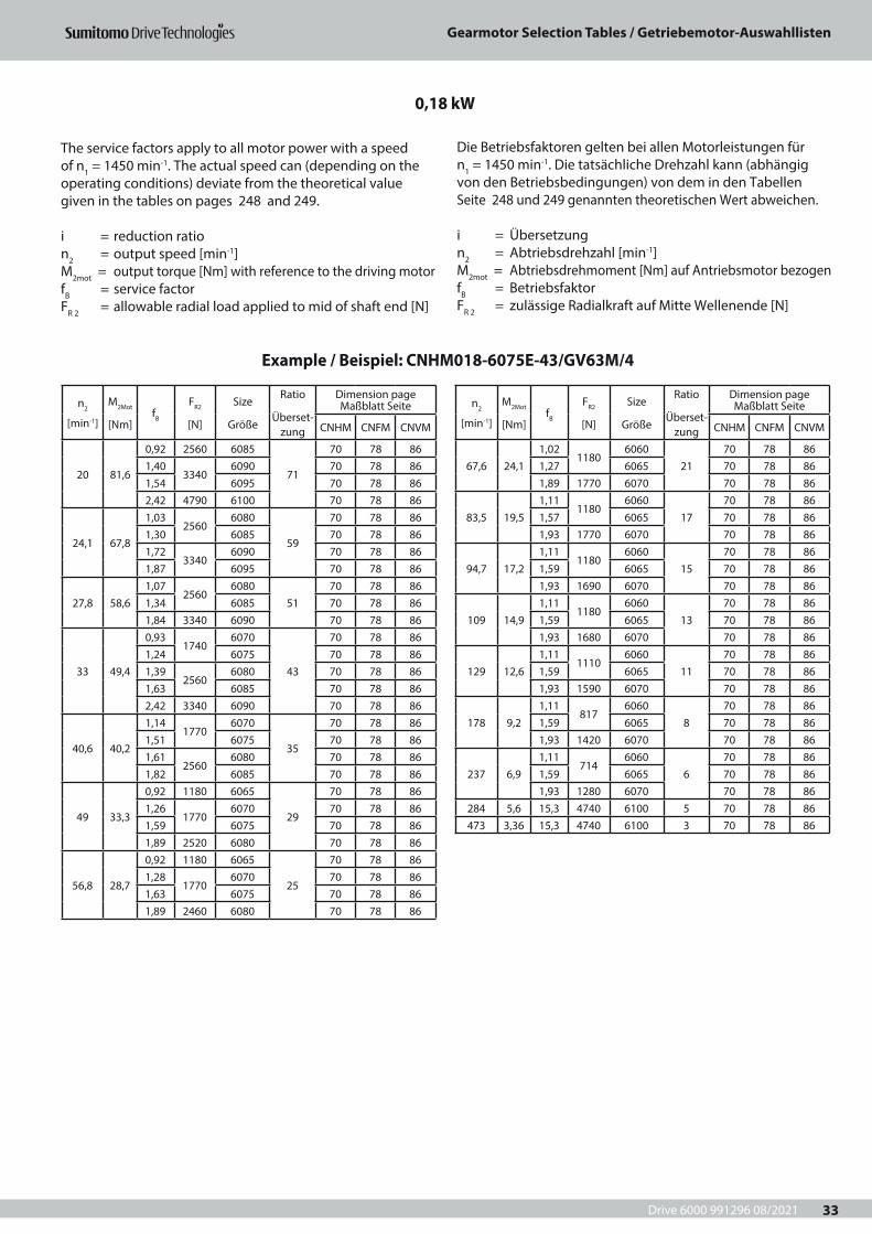
0,18 kW
Example / Beispiel: CHHM018-6135DBG-473/GV63M/4
The service factors apply to all motor power with a speed of n1 = 1450 min-1. The actual speed can (depending on the operating conditions) deviate from the theoretical value given in the tables on pages 248 and 249.
i = reduction ration2 = output speed [min-1]M2mot = output torque [Nm] with reference to the driving motorfB = service factorFR 2 = allowable radial load applied to mid of shaft end [N]
Die Betriebsfaktoren gelten bei allen Motorleistungen für n1 = 1450 min-1. Die tatsächliche Drehzahl kann (abhängig von den Betriebsbedingungen) von dem in den Tabellen Seite 248 und 249 genannten theoretischen Wert abweichen.
i = Übersetzungn2 = Abtriebsdrehzahl [min-1] M2mot = Abtriebsdrehmoment [Nm] auf Antriebsmotor bezogenfB = BetriebsfaktorFR 2 = zulässige Radialkraft auf Mitte Wellenende [N]
Drive 6000 991296 08/2021
Gearmotor Selection Tables / Getriebemotor-Auswahllisten
33
n2
[min-1]
M2Mot
[Nm]fB
FR2
[N]
Size
Größe
Ratio
Überset-zung
Dimension page Maßblatt Seite
CNHM CNFM CNVM
20 81,6
0,92 2560 6085
71
70 78 861,40
33406090 70 78 86
1,54 6095 70 78 862,42 4790 6100 70 78 86
24,1 67,8
1,032560
6080
59
70 78 861,30 6085 70 78 861,72
33406090 70 78 86
1,87 6095 70 78 86
27,8 58,61,07
25606080
5170 78 86
1,34 6085 70 78 861,84 3340 6090 70 78 86
33 49,4
0,931740
6070
43
70 78 861,24 6075 70 78 861,39
25606080 70 78 86
1,63 6085 70 78 862,42 3340 6090 70 78 86
40,6 40,2
1,141770
6070
35
70 78 861,51 6075 70 78 861,61
25606080 70 78 86
1,82 6085 70 78 86
49 33,3
0,92 1180 6065
29
70 78 861,26
17706070 70 78 86
1,59 6075 70 78 861,89 2520 6080 70 78 86
56,8 28,7
0,92 1180 6065
25
70 78 861,28
17706070 70 78 86
1,63 6075 70 78 861,89 2460 6080 70 78 86
n2
[min-1]
M2Mot
[Nm]fB
FR2
[N]
Size
Größe
Ratio
Überset-zung
Dimension page Maßblatt Seite
CNHM CNFM CNVM
67,6 24,11,02
11806060
2170 78 86
1,27 6065 70 78 861,89 1770 6070 70 78 86
83,5 19,51,11
11806060
1770 78 86
1,57 6065 70 78 861,93 1770 6070 70 78 86
94,7 17,21,11
11806060
1570 78 86
1,59 6065 70 78 861,93 1690 6070 70 78 86
109 14,91,11
11806060
1370 78 86
1,59 6065 70 78 861,93 1680 6070 70 78 86
129 12,61,11
11106060
1170 78 86
1,59 6065 70 78 861,93 1590 6070 70 78 86
178 9,21,11
8176060
870 78 86
1,59 6065 70 78 861,93 1420 6070 70 78 86
237 6,91,11
7146060
670 78 86
1,59 6065 70 78 861,93 1280 6070 70 78 86
284 5,6 15,3 4740 6100 5 70 78 86473 3,36 15,3 4740 6100 3 70 78 86
0,18 kW
Example / Beispiel: CNHM018-6075E-43/GV63M/4
The service factors apply to all motor power with a speed of n1 = 1450 min-1. The actual speed can (depending on the operating conditions) deviate from the theoretical value given in the tables on pages 248 and 249.
i = reduction ration2 = output speed [min-1]M2mot = output torque [Nm] with reference to the driving motorfB = service factorFR 2 = allowable radial load applied to mid of shaft end [N]
Die Betriebsfaktoren gelten bei allen Motorleistungen für n1 = 1450 min-1. Die tatsächliche Drehzahl kann (abhängig von den Betriebsbedingungen) von dem in den Tabellen Seite 248 und 249 genannten theoretischen Wert abweichen.
i = Übersetzungn2 = Abtriebsdrehzahl [min-1] M2mot = Abtriebsdrehmoment [Nm] auf Antriebsmotor bezogenfB = BetriebsfaktorFR 2 = zulässige Radialkraft auf Mitte Wellenende [N]
Drive 6000 991296 08/2021
Gearmotor Selection Tables / Getriebemotor-Auswahllisten
34
n2
[min-1]
M2Mot
[Nm]fB
FR2
[N]
Size
Größe
Ratio
Überset-zung
Dimension page Maßblatt Seite
CNHM CHHM
CNFM CHFM
CNVM CHVM
1,89 11400,87 14700 6135DB
731102 112 122
1,1316000
6140DC 102 112 1221,26 6145DC 102 112 122
2,13 1010
0,9514700
6130DB
649
102 112 1221,09 6135DB 102 112 1221,27
160006140DC 102 112 122
1,42 6145DC 102 112 122
2,32 926
0,8814700
6130DB
595
102 112 1221,07 6135DB 102 112 1221,39
160006140DC 102 112 122
1,55 6145DC 102 112 122
2,47 870
0,9414700
6130DB
559
102 112 1221,13 6135DB 102 112 1221,48
160006140DC 102 112 122
1,65 6145DC 102 112 122
2,63 817
0,81 9810 6125DA
525
100 100 1201,00
147006130DB 102 112 122
1,16 6135DB 102 112 1221,57
160006140DC 102 112 122
1,76 6145DC 102 112 122
2,92 736
0,90 9810 6125DA
473
100 100 1201,11
147006130DB 102 112 122
1,34 6135DB 102 112 1221,75 16000 6140DC 102 112 122
3,25 662
0,839810
6120DA
425
100 100 1201,00 6125DA 100 100 1201,24
147006130DB 102 112 122
1,43 6135DB 102 112 1221,95 16000 6140DC 102 112 122
3,66 587
0,939810
6120DA
377
100 100 1201,13 6125DA 100 100 1201,40
147006130DB 102 112 122
1,68 6135DB 102 112 1222,19 16000 6140DC 102 112 122
3,87 556
0,999810
6120DA
357
100 100 1201,19 6125DA 100 100 1201,47
147006130DB 102 112 122
1,78 6135DB 102 112 122
n2
[min-1]
M2Mot
[Nm]fB
FR2
[N]
Size
Größe
Ratio
Überset-zung
Dimension page Maßblatt Seite
CNHM CHHM
CNFM CHFM
CNVM CHVM
4,33 497
1,109810
6120DA
319
100 110 1201,33 6125DA 100 110 1201,65
147006130DB 102 112 122
1,99 6135DB 102 112 122
5,05 4251,29
98106120DA
273100 110 120
1,56 6125DA 100 110 1201,93 14700 6130DB 102 112 122
5,97 360
0,88 4940 6105DA
231
100 110 1201,52
98106120DA 100 110 120
1,72 6125DA 100 110 1201,84 9810 6125DB 100 110 120
7,08 304
0,875400
6100DA
195
100 110 1201,04 6105DA 100 110 1201,72
98106120DA 100 110 120
1,82 6120DB 100 110 120
8,36 257
0,82 3340 6095DA
165
100 110 1201,02
54006100DA 100 110 120
1,23 6105DA 100 110 1201,72
98106120DA 100 110 120
2,15 6120DB 100 110 120
9,65 223
0,87 3340 6095DA
143
100 110 1201,18
54006100DA 100 110 120
1,42 6105DA 100 110 1201,72
98106120DA 100 110 120
2,48 6120DB 100 110 120
11,4 188
0,843340
6090DA
121
100 110 1200,89 6095DA 100 110 1201,39
54006100DA 100 110 120
1,72 6105DA 100 110 1202,93 9810 6120DB 100 110 120
11,6 1960,84
47106100
11970 78 86
1,14 6105 70 78 86
13,3 162
0,973340
6090DA
104
100 110 1201,17 6095DA 100 110 1201,62
54006100DA 100 110 120
1,72 6105DA 100 110 1203,41 9810 6120DB 100 110 120
0,25 kW
Example / Beispiel: CHHM03-6145DCE-525/GV63M/4
The service factors apply to all motor power with a speed of n1 = 1450 min-1. The actual speed can (depending on the operating conditions) deviate from the theoretical value given in the tables on pages 248 and 249.
i = reduction ration2 = output speed [min-1]M2mot = output torque [Nm] with reference to the driving motorfB = service factorFR 2 = allowable radial load applied to mid of shaft end [N]
Die Betriebsfaktoren gelten bei allen Motorleistungen für n1 = 1450 min-1. Die tatsächliche Drehzahl kann (abhängig von den Betriebsbedingungen) von dem in den Tabellen Seite 248 und 249 genannten theoretischen Wert abweichen.
i = Übersetzungn2 = Abtriebsdrehzahl [min-1] M2mot = Abtriebsdrehmoment [Nm] auf Antriebsmotor bezogenfB = BetriebsfaktorFR 2 = zulässige Radialkraft auf Mitte Wellenende [N]
Drive 6000 991296 08/2021
Gearmotor Selection Tables / Getriebemotor-Auswahllisten
35
n2
[min-1]
M2Mot
[Nm]fB
FR2
[N]
Size
Größe
Ratio
Überset-zung
Dimension page Maßblatt Seite
CNHM CNFM CNVM
15,9 143
0,843340
6090
87
70 78 861,05 6095 70 78 861,73
47906100 70 78 86
2,01 6105 70 78 86
19,4 117
1,013340
6090
71
70 78 861,11 6095 70 78 861,74
47706100 70 78 86
2,02 6105 70 78 86
23,4 86
0,94 2560 6085
59
70 78 861,24
33406090 70 78 86
1,34 6095 70 78 862,06 5010 6100 70 78 86
27,1 83,8
0,96 2560 6085
51
70 78 861,33
33406090 70 78 86
1,63 6095 70 78 862,24 5080 6100 70 78 86
32,1 81,7
0,89 1620 6075
43
70 78 861,00
25606080 70 78 86
1,18 6085 70 78 861,74
33406090 70 78 86
2,41 6095 70 78 86
39,4 57,5
0,821730
6070
35
70 78 861,09 6075 70 78 861,16
25606080 70 78 86
1,31 6085 70 78 86
47,6 47,7
0,901730
6070
29
70 78 861,14 6075 70 78 861,36
25006080 70 78 86
1,87 6085 70 78 86
55,2 41,1
0,921740
6070
25
70 78 861,18 6075 70 78 861,36
24506080 70 78 86
1,90 6085 70 78 86
65,7 34,5
0,91 1180 6065
21
70 78 861,28
17706070 70 78 86
1,63 6075 70 78 861,91 2380 6080 70 78 86
n2
[min-1]
M2Mot
[Nm]fB
FR2
[N]
Size
Größe
Ratio
Überset-zung
Dimension page Maßblatt Seite
CNHM CNFM CNVM
81,2 27,9
0,801180
6060
17
70 78 861,13 6065 70 78 861,39
17706070 70 78 86
1,63 6075 70 78 862,37 2450 6080 70 78 86
92 24,7
0,801180
6060
15
70 78 861,14 6065 70 78 861,39
16706070 70 78 86
1,63 6075 70 78 862,37 2330 6080 70 78 86
106 21,4
0,801170
6060
13
70 78 861,14 6065 70 78 861,39
16706070 70 78 86
1,63 6075 70 78 862,37 2260 6080 70 78 86
125 18,1
0,801090
6060
11
70 78 861,14 6065 70 78 861,39
15806070 70 78 86
1,63 6075 70 78 862,37 2100 6080 70 78 86
173 13,1
0,80811
6060
8
70 78 861,14 6065 70 78 861,39
14106070 70 78 86
1,63 6075 70 78 862,37 1900 6080 70 78 86
230 9,97
0,80710
6060
6
70 78 861,14 6065 70 78 861,39
12806070 70 78 86
1,63 6075 70 78 862,37 1750 6080 70 78 86
276 8,00 11,0 4740 6100 5 70 78 86460 4,8 11,0 4740 6100 3 70 78 86
0,25 kW
Example / Beispiel: CNHM03-6085E-59/GV63M/4
The service factors apply to all motor power with a speed of n1 = 1450 min-1. The actual speed can (depending on the operating conditions) deviate from the theoretical value given in the tables on pages 248 and 249.
i = reduction ration2 = output speed [min-1]M2mot = output torque [Nm] with reference to the driving motorfB = service factorFR 2 = allowable radial load applied to mid of shaft end [N]
Die Betriebsfaktoren gelten bei allen Motorleistungen für n1 = 1450 min-1. Die tatsächliche Drehzahl kann (abhängig von den Betriebsbedingungen) von dem in den Tabellen Seite 248 und 249 genannten theoretischen Wert abweichen.
i = Übersetzungn2 = Abtriebsdrehzahl [min-1] M2mot = Abtriebsdrehmoment [Nm] auf Antriebsmotor bezogenfB = BetriebsfaktorFR 2 = zulässige Radialkraft auf Mitte Wellenende [N]
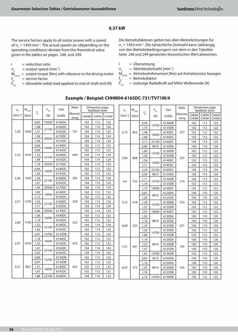
Drive 6000 991296 08/2021
Gearmotor Selection Tables / Getriebemotor-Auswahllisten
36
n2
[min-1]
M2Mot
[Nm]fB
FR2
[N]
Size
Größe
Ratio
Überset-zung
Dimension page Maßblatt Seite
CHHM CHFM CHVM
1,92 1650
0,85 14500 6145DC
731
102 112 1221,08
221006160DC 104 114 124
1,31 6165DC 104 114 1241,58
295006170DC 104 114 124
1,96 6175DC 104 114 124
2,16 1470
0,8616000
6140DC
649
102 112 1220,96 6145DC 102 112 1221,23
221006160DC 104 114 124
1,48 6165DC 104 114 1241,78 29500 6170DC 104 114 124
2,36 1350
0,9416000
6140DC
595
102 112 1221,05 6145DC 102 112 1221,34
221006160DC 104 114 124
1,61 6165DC 104 114 1241,94 29500 6170DC 104 114 124
2,51 1270
1,0016000
6140DC
559
102 112 1221,12 6145DC 102 112 1221,42
221006160DC 104 114 124
1,71 6165DC 104 114 1242,06 29500 6170DC 104 114 124
2,68 1190
1,0616000
6140DC
525
102 112 1221,19 6145DC 102 112 1221,52
221006160DC 104 114 124
1,82 6165DC 104 114 124
2,97 1070
0,91 14700 6135DB
473
102 112 1221,18
160006140DC 102 112 122
1,32 6145DC 102 112 1221,67
221006160DC 104 114 124
2,02 6165DC 104 114 124
3,31 962
0,8414700
6130DB
425
102 112 1220,97 6135DB 102 112 1221,31
160006140DC 102 112 122
1,47 6145DC 102 112 1221,88 22100 6160DC 104 114 124
n2
[min-1]
M2Mot
[Nm]fB
FR2
[N]
Size
Größe
Ratio
Überset-zung
Dimension page Maßblatt Seite
CNHM CHHM
CNFM CHFM
CNVM CHVM
3,73 853
0,9414700
6130DB
377
102 112 1221,14 6135DB 102 112 1221,48
160006140DC 102 112 122
1,66 6145DC 102 112 1222,12 22100 6160DC 104 114 124
3,94 808
0,80 9810 6125DA
357
100 110 1201,00
147006130DB 102 112 122
1,20 6135DB 102 112 1221,56
160006140DC 102 112 122
1,71 6145DC 102 112 1222,24 22100 6160DC 104 114 124
4,4 722
0,90 9810 6125DA
319
100 110 1201,11
147006130DB 102 112 122
1,34 6135DB 102 112 1221,75 16000 6140DC 102 112 122
5,15 618
0,879810
6120DA
273
100 110 1201,05 6125DA 100 110 1201,30
147006130DB 102 112 122
1,57 6135DB 102 112 1222,05 16000 6140DC 102 112 122
6,08 523
1,039810
6120DA
231
100 110 1201,16 6125DA 100 110 1201,24 6125DB 100 110 1201,54
147006130DB 102 112 122
1,86 6135DB 102 112 122
7,21 441
1,169810
6120DA
195
100 110 1201,23 6120DB 100 110 1201,47 6125DB 100 110 1201,82 14700 6130DB 102 112 122
8,52 373
0,83 3610 6105DA
165
100 110 1201,16
98106120DA 100 110 120
1,45 6120DB 100 110 1201,74 6125DB 100 110 1202,16 14700 6130DB 102 112 122
0,37 kW
Example / Beispiel: CHHM04-6165DC-731/TV71M/4
The service factors apply to all motor power with a speed of n1 = 1450 min-1. The actual speed can (depending on the operating conditions) deviate from the theoretical value given in the tables on pages 248 and 249.
i = reduction ration2 = output speed [min-1]M2mot = output torque [Nm] with reference to the driving motorfB = service factorFR 2 = allowable radial load applied to mid of shaft end [N]
Die Betriebsfaktoren gelten bei allen Motorleistungen für n1 = 1450 min-1. Die tatsächliche Drehzahl kann (abhängig von den Betriebsbedingungen) von dem in den Tabellen Seite 248 und 249 genannten theoretischen Wert abweichen.
i = Übersetzungn2 = Abtriebsdrehzahl [min-1] M2mot = Abtriebsdrehmoment [Nm] auf Antriebsmotor bezogenfB = BetriebsfaktorFR 2 = zulässige Radialkraft auf Mitte Wellenende [N]
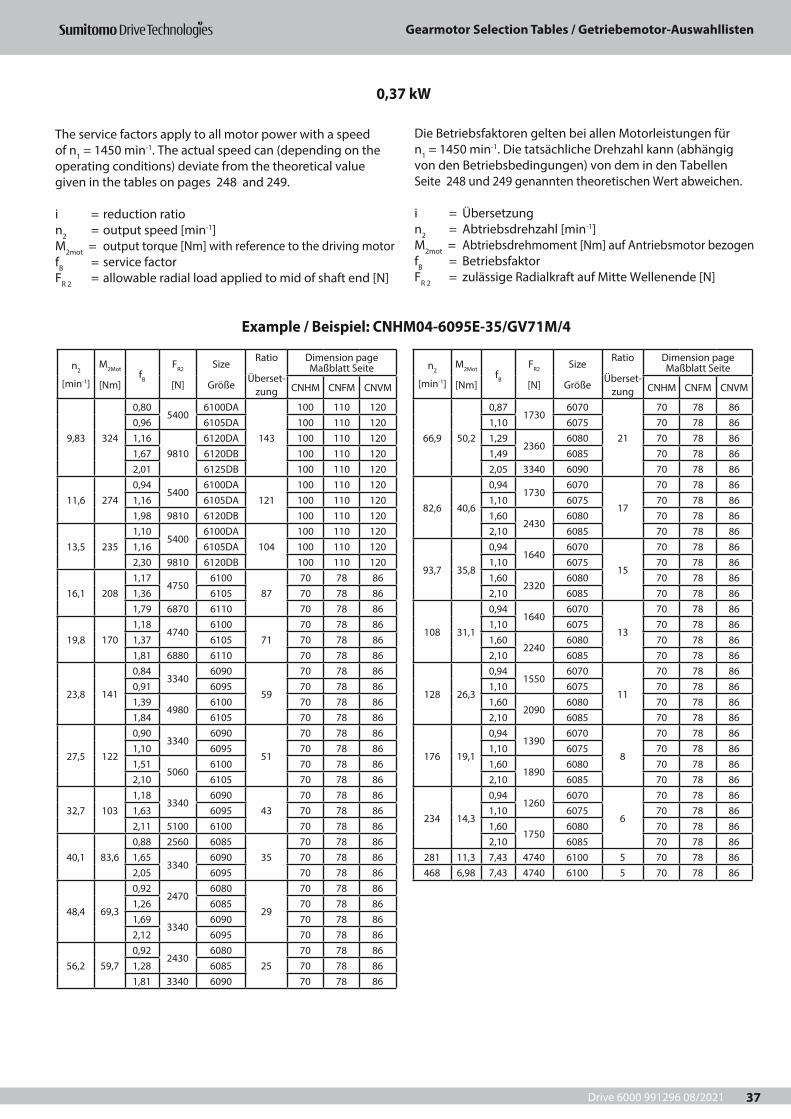
Drive 6000 991296 08/2021
Gearmotor Selection Tables / Getriebemotor-Auswahllisten
37
n2
[min-1]
M2Mot
[Nm]fB
FR2
[N]
Size
Größe
Ratio
Überset-zung
Dimension page Maßblatt Seite
CNHM CNFM CNVM
9,83 324
0,805400
6100DA
143
100 110 1200,96 6105DA 100 110 1201,16
98106120DA 100 110 120
1,67 6120DB 100 110 1202,01 6125DB 100 110 120
11,6 2740,94
54006100DA
121100 110 120
1,16 6105DA 100 110 1201,98 9810 6120DB 100 110 120
13,5 2351,10
54006100DA
104100 110 120
1,16 6105DA 100 110 1202,30 9810 6120DB 100 110 120
16,1 2081,17
47506100
8770 78 86
1,36 6105 70 78 861,79 6870 6110 70 78 86
19,8 1701,18
47406100
7170 78 86
1,37 6105 70 78 861,81 6880 6110 70 78 86
23,8 141
0,843340
6090
59
70 78 860,91 6095 70 78 861,39
49806100 70 78 86
1,84 6105 70 78 86
27,5 122
0,903340
6090
51
70 78 861,10 6095 70 78 861,51
50606100 70 78 86
2,10 6105 70 78 86
32,7 1031,18
33406090
4370 78 86
1,63 6095 70 78 862,11 5100 6100 70 78 86
40,1 83,60,88 2560 6085
3570 78 86
1,653340
6090 70 78 862,05 6095 70 78 86
48,4 69,3
0,922470
6080
29
70 78 861,26 6085 70 78 861,69
33406090 70 78 86
2,12 6095 70 78 86
56,2 59,70,92
24306080
2570 78 86
1,28 6085 70 78 861,81 3340 6090 70 78 86
n2
[min-1]
M2Mot
[Nm]fB
FR2
[N]
Size
Größe
Ratio
Überset-zung
Dimension page Maßblatt Seite
CNHM CNFM CNVM
66,9 50,2
0,871730
6070
21
70 78 861,10 6075 70 78 861,29
23606080 70 78 86
1,49 6085 70 78 862,05 3340 6090 70 78 86
82,6 40,6
0,941730
6070
17
70 78 861,10 6075 70 78 861,60
24306080 70 78 86
2,10 6085 70 78 86
93,7 35,8
0,941640
6070
15
70 78 861,10 6075 70 78 861,60
23206080 70 78 86
2,10 6085 70 78 86
108 31,1
0,941640
6070
13
70 78 861,10 6075 70 78 861,60
22406080 70 78 86
2,10 6085 70 78 86
128 26,3
0,941550
6070
11
70 78 861,10 6075 70 78 861,60
20906080 70 78 86
2,10 6085 70 78 86
176 19,1
0,941390
6070
8
70 78 861,10 6075 70 78 861,60
18906080 70 78 86
2,10 6085 70 78 86
234 14,3
0,941260
6070
6
70 78 861,10 6075 70 78 861,60
17506080 70 78 86
2,10 6085 70 78 86281 11,3 7,43 4740 6100 5 70 78 86468 6,98 7,43 4740 6100 5 70 78 86
0,37 kW
Example / Beispiel: CNHM04-6095E-35/GV71M/4
The service factors apply to all motor power with a speed of n1 = 1450 min-1. The actual speed can (depending on the operating conditions) deviate from the theoretical value given in the tables on pages 248 and 249.
i = reduction ration2 = output speed [min-1]M2mot = output torque [Nm] with reference to the driving motorfB = service factorFR 2 = allowable radial load applied to mid of shaft end [N]
Die Betriebsfaktoren gelten bei allen Motorleistungen für n1 = 1450 min-1. Die tatsächliche Drehzahl kann (abhängig von den Betriebsbedingungen) von dem in den Tabellen Seite 248 und 249 genannten theoretischen Wert abweichen.
i = Übersetzungn2 = Abtriebsdrehzahl [min-1] M2mot = Abtriebsdrehmoment [Nm] auf Antriebsmotor bezogenfB = BetriebsfaktorFR 2 = zulässige Radialkraft auf Mitte Wellenende [N]
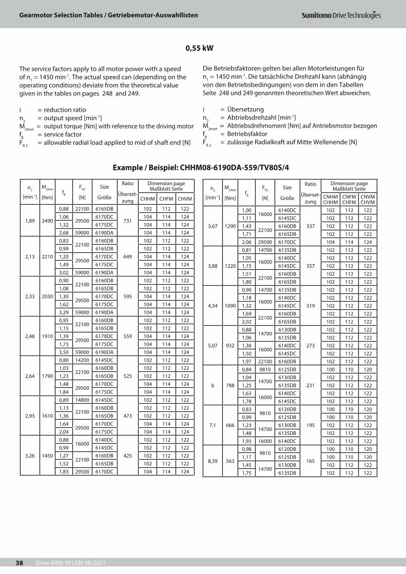
Drive 6000 991296 08/2021
Gearmotor Selection Tables / Getriebemotor-Auswahllisten
38
n2
[min-1]
M2Mot
[Nm]fB
FR2
[N]
Size
Größe
Ratio
Überset-zung
Dimension page Maßblatt Seite
CHHM CHFM CHVM
1,89 2490
0,88 22100 6165DB
731
102 112 1221,06
295006170DC 104 114 124
1,32 6175DC 104 114 1242,68 59000 6190DA 104 114 124
2,13 2210
0,8322100
6160DB
649
102 112 1220,99 6165DB 102 112 1221,20
295006170DC 104 114 124
1,49 6175DC 104 114 1243,02 59000 6190DA 104 114 124
2,33 2030
0,9022100
6160DB
595
102 112 1221,08 6165DB 102 112 1221,30
295006170DC 104 114 124
1,62 6175DC 104 114 1243,29 59000 6190DA 104 114 124
2,48 1910
0,9522100
6160DB
559
102 112 1221,15 6165DB 102 112 1221,39
295006170DC 104 114 124
1,73 6175DC 104 114 1243,50 59000 6190DA 104 114 124
2,64 1790
0,80 14200 6145DC
525
102 112 1221,03
221006160DB 102 112 122
1,23 6165DB 102 112 1221,48
295006170DC 104 114 124
1,84 6175DC 104 114 124
2,93 1610
0,89 14800 6145DC
473
102 112 1221,13
221006160DB 102 112 122
1,36 6165DB 102 112 1221,64
295006170DC 104 114 124
2,04 6175DC 104 114 124
3,26 1450
0,8816000
6140DC
425
102 112 1220,99 6145DC 102 112 1221,27
221006160DB 102 112 122
1,52 6165DB 102 112 1221,83 29500 6170DC 104 114 124
n2
[min-1]
M2Mot
[Nm]fB
FR2
[N]
Size
Größe
Ratio
Überset-zung
Dimension page Maßblatt Seite
CNHM CHHM
CNFM CHFM
CNVM CHVM
3,67 1290
1,0016000
6140DC
337
102 112 1221,11 6145DC 102 112 1221,43
221006160DB 102 112 122
1,71 6165DB 102 112 1222,06 29500 6170DC 104 114 124
3,88 1220
0,81 14700 6135DB
357
102 112 1221,05
160006140DC 102 112 122
1,15 6145DC 102 112 1221,51
221006160DB 102 112 122
1,80 6165DB 102 112 122
4,34 1090
0,90 14700 6135DB
319
102 112 1221,18
160006140DC 102 112 122
1,32 6145DC 102 112 1221,69
221006160DB 102 112 122
2,02 6165DB 102 112 122
5,07 932
0,8814700
6130DB
273
102 112 1221,06 6135DB 102 112 1221,38
160006140DC 102 112 122
1,50 6145DC 102 112 1221,97 22100 6160DB 102 112 122
6 788
0,84 9810 6125DB
231
100 110 1201,04
147006130DB 102 112 122
1,25 6135DB 102 112 1221,63
160006140DC 102 112 122
1,78 6145DC 102 112 122
7,1 666
0,839810
6120DB
195
100 110 1200,99 6125DB 100 110 1201,23
147006130DB 102 112 122
1,48 6135DB 102 112 1221,93 16000 6140DC 102 112 122
8,39 563
0,989810
6120DB
165
100 110 1201,17 6125DB 100 110 1201,45
147006130DB 102 112 122
1,75 6135DB 102 112 122
0,55 kW
Example / Beispiel: CHHM08-6190DA-559/TV80S/4
The service factors apply to all motor power with a speed of n1 = 1450 min-1. The actual speed can (depending on the operating conditions) deviate from the theoretical value given in the tables on pages 248 and 249.
i = reduction ration2 = output speed [min-1]M2mot = output torque [Nm] with reference to the driving motorfB = service factorFR 2 = allowable radial load applied to mid of shaft end [N]
Die Betriebsfaktoren gelten bei allen Motorleistungen für n1 = 1450 min-1. Die tatsächliche Drehzahl kann (abhängig von den Betriebsbedingungen) von dem in den Tabellen Seite 248 und 249 genannten theoretischen Wert abweichen.
i = Übersetzungn2 = Abtriebsdrehzahl [min-1] M2mot = Abtriebsdrehmoment [Nm] auf Antriebsmotor bezogenfB = BetriebsfaktorFR 2 = zulässige Radialkraft auf Mitte Wellenende [N]
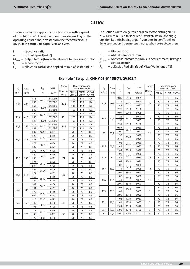
Drive 6000 991296 08/2021
Gearmotor Selection Tables / Getriebemotor-Auswahllisten
39
n2
[min-1]
M2Mot
[Nm]fB
FR2
[N]
Size
Größe
Ratio
Überset-zung
Dimension page Maßblatt Seite
CNHM CHHM
CNFM CHFM
CNVM CHVM
9,69 488
1,139810
6120DB
143
100 110 1201,35 6125DB 100 110 1201,67
147006130DB 102 112 122
2,02 6135DB 102 112 122
11,4 4131,33
98106120DB
121100 110 120
1,58 6125DB 100 110 1201,98 14700 6130DB 102 112 122
13,3 3551,55
98106120DB
104100 110 120
1,97 6125DB 100 110 120
15,9 313
0,92 4690 6105
87
70 78 861,20
67806110 70 78 86
1,38 6115 70 78 861,72
98106120 70 78 86
1,87 6125 70 78 86
19,5 256
0,92 4690 6105
71
70 78 861,22
68106110 70 78 86
1,38 6115 70 78 861,74
98106120 70 78 86
2,07 6125 70 78 86
23,5 213
0,944940
6100
59
70 78 861,24 6105 70 78 861,56
68806110 70 78 86
1,84 6115 70 78 86
27,2 184
1,025020
6100
51
70 78 861,41 6105 70 78 861,72
68906110 70 78 86
2,02 6115 70 78 86
32,2 1551,10 3340 6095
4370 78 86
1,425070
6100 70 78 861,96 6105 70 78 86
39,6 1261,11
33406090
3570 78 86
1,38 6095 70 78 861,77 5080 6100 70 78 86
n2
[min-1]
M2Mot
[Nm]fB
FR2
[N]
Size
Größe
Ratio
Überset-zung
Dimension page Maßblatt Seite
CNHM CNFM CNVM
47,8 104
0,85 2430 6085
29
70 78 861,14
33406090 70 78 86
1,43 6095 70 78 862,20 5120 6100 70 78 86
55,4 90,1
0,97 2390 6085
25
70 78 861,22
33406090 70 78 86
1,57 6095 70 78 862,31 5120 6100 70 78 86
66 75,7
0,872330
6080
21
70 78 861,00 6085 70 78 861,38
33406090 70 78 86
2,75 6095 70 78 86
81,5 61,21,08
23906080
1770 78 86
1,41 6085 70 78 862,09 3340 6090 70 78 86
92,3 541,08
22906080
1570 78 86
1,41 6085 70 78 862,09 3340 6090 70 78 86
107 46,81,08
22206080
1370 78 86
1,41 6085 70 78 862,09 3340 6090 70 78 86
126 39,61,08
20706080
1170 78 86
1,41 6085 70 78 862,09 3340 6090 70 78 86
173 28,81,08
18806080
870 78 86
1,41 6085 70 78 862,09 3340 6090 70 78 86
231 21,61,08 1730 6080
670 78 86
1,41 1730 6085 70 78 862,09 3340 6090 70 78 86
277 17,5 5,00 4740 6100 5 70 78 86462 10,5 5,00 4740 6100 3 70 78 86
0,55 kW
Example / Beispiel: CNHM08-6115E-71/GV80S/4
The service factors apply to all motor power with a speed of n1 = 1450 min-1. The actual speed can (depending on the operating conditions) deviate from the theoretical value given in the tables on pages 248 and 249.
i = reduction ration2 = output speed [min-1]M2mot = output torque [Nm] with reference to the driving motorfB = service factorFR 2 = allowable radial load applied to mid of shaft end [N]
Die Betriebsfaktoren gelten bei allen Motorleistungen für n1 = 1450 min-1. Die tatsächliche Drehzahl kann (abhängig von den Betriebsbedingungen) von dem in den Tabellen Seite 248 und 249 genannten theoretischen Wert abweichen.
i = Übersetzungn2 = Abtriebsdrehzahl [min-1] M2mot = Abtriebsdrehmoment [Nm] auf Antriebsmotor bezogenfB = BetriebsfaktorFR 2 = zulässige Radialkraft auf Mitte Wellenende [N]
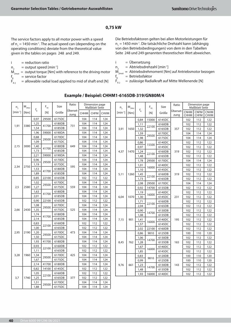
Drive 6000 991296 08/2021
Gearmotor Selection Tables / Getriebemotor-Auswahllisten
40
n2
[min-1]
M2Mot
[Nm]fB
FR2
[N]
Size
Größe
Ratio
Überset-zung
Dimension page Maßblatt Seite
CHHM CHFM CHVM
1,91 3380
0,97 29500 6175DC
731
104 114 1241,25
417006180DB 104 114 124
1,54 6185DB 104 114 1241,96 59000 6190DA 104 114 124
2,15 3000
0,8829500
6170DC
649
104 114 1241,09 6175DC 104 114 1241,40
417006180DB 104 114 124
1,73 6185DB 104 114 1242,21 59000 6190DA 104 114 124
2,34 2750
0,9629500
6170DC
595
104 114 1241,19 6175DC 104 114 1241,53
417006180DB 104 114 124
1,89 6185DB 104 114 124
2,5 2580
0,85 22100 6165DB
559
102 112 1221,02
295006170DC 104 114 124
1,27 6175DC 104 114 1241,63
417006180DB 104 114 124
2,01 6185DB 104 114 124
2,66 2430
0,90 22100 6165DB
525
102 112 1221,08
295006170DC 104 114 124
1,35 6175DC 104 114 1241,74
417006180DB 104 114 124
2,14 6185DB 104 114 124
2,95 2190
0,8322100
6160DB
473
102 112 1221,00 6165DB 102 112 1221,20
295006170DC 104 114 124
1,50 6175DC 104 114 1241,93 41700 6180DB 104 114 124
3,28 1960
0,9322100
6160DB
425
102 112 1221,11 6165DB 102 112 1221,34
295006170DC 104 114 124
1,67 6175DC 104 114 1242,14 41700 6180DB 104 114 124
3,7 1740
0,82 14100 6145DC
377
102 112 1221,05
221006160DB 102 112 122
1,25 6165DB 102 112 1221,51
295006170DC 104 114 124
1,88 6175DC 104 114 124
n2
[min-1]
M2Mot
[Nm]fB
FR2
[N]
Size
Größe
Ratio
Überset-zung
Dimension page Maßblatt Seite
CNHM CHHM
CNFM CHFM
CNVM CHVM
3,91 1650
0,84 15000 6145DC
357
102 112 1221,11
221006160DB 102 112 122
1,32 6165DB 102 112 1221,59
295006170DC 104 114 124
1,98 6175DC 104 114 124
4,37 1470
0,8615500
6140DC
319
102 112 1220,97 6145DC 102 112 1221,24
221006160DB 102 112 122
1,48 6165DB 102 112 1221,78 29500 6170DC 104 114 124
5,11 1260
1,0116000
6140DC
319
102 112 1221,10 6145DC 102 112 1221,45
221006160DB 102 112 122
1,73 6165DB 102 112 1222,08 29500 6170DC 104 114 124
6,04 1070
0,92 14700 6135DB
231
102 112 1221,19
160006140DC 102 112 122
1,30 6145DC 102 112 1221,71
221006160DB 102 112 122
2,04 6165DB 102 112 122
7,15 901
0,9014700
6130DB
195
102 112 1221,08 6135DB 102 112 1221,41
160006140DC 102 112 122
1,57 6145DC 102 112 1222,02 22100 6160DB 102 112 122
8,45 762
0,86 9810 6125DB
165
100 110 1201,06
147006130DB 102 112 122
1,28 6135DB 102 112 1221,67
160006140DC 102 112 122
1,85 6145DC 102 112 122
9,76 661
0,839810
6120DB
143
100 110 1200,99 6125DB 100 110 1201,23
147006130DB 102 112 122
1,48 6135DB 102 112 1221,93 16000 6140DC 102 112 122
0,75 kW
Example / Beispiel: CHHM1-6165DB-319/GN80M/4
The service factors apply to all motor power with a speed of n1 = 1450 min-1. The actual speed can (depending on the operating conditions) deviate from the theoretical value given in the tables on pages 248 and 249.
i = reduction ration2 = output speed [min-1]M2mot = output torque [Nm] with reference to the driving motorfB = service factorFR 2 = allowable radial load applied to mid of shaft end [N]
Die Betriebsfaktoren gelten bei allen Motorleistungen für n1 = 1450 min-1. Die tatsächliche Drehzahl kann (abhängig von den Betriebsbedingungen) von dem in den Tabellen Seite 248 und 249 genannten theoretischen Wert abweichen.
i = Übersetzungn2 = Abtriebsdrehzahl [min-1] M2mot = Abtriebsdrehmoment [Nm] auf Antriebsmotor bezogenfB = BetriebsfaktorFR 2 = zulässige Radialkraft auf Mitte Wellenende [N]
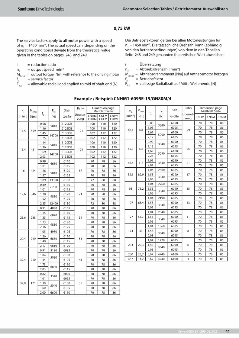
Drive 6000 991296 08/2021
Gearmotor Selection Tables / Getriebemotor-Auswahllisten
41
n2
[min-1]
M2Mot
[Nm]fB
FR2
[N]
Size
Größe
Ratio
Überset-zung
Dimension page Maßblatt Seite
CNHM CHHM
CNFM CHFM
CNVM CHVM
11,5 559
0,989810
6120DB
121
100 110 1201,16 6125DB 100 110 1201,45
147006130DB 102 112 122
1,75 6135DB 102 112 122
13,4 481
1,149810
6120DB
104
100 110 1201,36 6125DB 100 110 1201,69
147006130DB 102 112 122
2,03 6135DB 102 112 122
16 424
0,986680
6110
87
70 78 861,01 6115 70 78 861,26
98106120 70 78 86
1,37 6125 70 78 861,89 13300 6130 72 80 88
19,6 346
0,896730
6110
71
70 78 861,01 6115 70 78 861,28
98106120 70 78 86
1,52 6125 70 78 862,35 12400 6130 72 80 88
23,6 288
0,91 4890 6105
59
70 78 861,15
68206110 70 78 86
1,35 6115 70 78 861,73
98106120 70 78 86
2,16 6125 70 78 86
27,4 249
1,03 4980 6105
51
70 78 861,26
68306110 70 78 86
1,48 6115 70 78 862,17 9810 6120 70 78 86
32,4 210
0,91 3190 6095
43
70 78 861,04
50306100 70 78 86
1,44 6105 70 78 861,73
68406110 70 78 86
2,03 6115 70 78 86
39,9 171
0,823340
6090
35
70 78 861,01 6095 70 78 861,30
50406100 70 78 86
1,60 6105 70 78 862,00 6600 6110 70 78 86
n2
[min-1]
M2Mot
[Nm]fB
FR2
[N]
Size
Größe
Ratio
Überset-zung
Dimension page Maßblatt Seite
CNHM CNFM CNVM
48,1 141
0,833340
6090
29
70 78 861,05 6095 70 78 861,61
50906100 70 78 86
2,12 6105 70 78 86
55,8 133
0,903340
6090
25
70 78 861,15 6095 70 78 861,69
50906100 70 78 86
2,23 6105 70 78 86
66,4 1131,01
33406090
2170 78 86
2,01 6095 70 78 86
82,1 82,91,04 2360 6085
1770 78 86
1,533340
6090 70 78 862,03 6095 70 78 86
93 73,21,04 2260 6085
1570 78 86
1,533340
6090 70 78 862,03 6095 70 78 86
107 63,41,04 2190 6085
1370 78 86
1,533340
6090 70 78 862,03 6095 70 78 86
127 53,71,04 2040 6085
1170 78 86
1,533340
6090 70 78 862,03 6095 70 78 86
174 391,04 1860 6085
870 78 86
1,533340
6090 70 78 862,03 6095 70 78 86
233 29,31,04 1720 6085
670 78 86
1,533340
6090 70 78 862,03 6095 70 78 86
280 23,7 3,67 4740 6100 5 70 78 86467 14,2 3,67 4740 6100 3 70 78 86
0,75 kW
Example / Beispiel: CNHM1-6095E-15/GN80M/4
The service factors apply to all motor power with a speed of n1 = 1450 min-1. The actual speed can (depending on the operating conditions) deviate from the theoretical value given in the tables on pages 248 and 249.
i = reduction ration2 = output speed [min-1]M2mot = output torque [Nm] with reference to the driving motorfB = service factorFR 2 = allowable radial load applied to mid of shaft end [N]
Die Betriebsfaktoren gelten bei allen Motorleistungen für n1 = 1450 min-1. Die tatsächliche Drehzahl kann (abhängig von den Betriebsbedingungen) von dem in den Tabellen Seite 248 und 249 genannten theoretischen Wert abweichen.
i = Übersetzungn2 = Abtriebsdrehzahl [min-1] M2mot = Abtriebsdrehmoment [Nm] auf Antriebsmotor bezogenfB = BetriebsfaktorFR 2 = zulässige Radialkraft auf Mitte Wellenende [N]
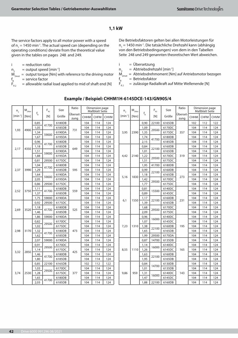
Drive 6000 991296 08/2021
Gearmotor Selection Tables / Getriebemotor-Auswahllisten
42
n2
[min-1]
M2Mot
[Nm]fB
FR2
[N]
Size
Größe
Ratio
Überset-zung
Dimension page Maßblatt Seite
CHHM CHFM CHVM
1,93 4900
0,8541700
6180DB
731
104 114 1241,05 6185DB 104 114 1241,34
590006190DA 104 114 124
1,67 6195DA 104 114 124
2,17 4350
0,9641700
6180DB
649
104 114 1241,18 6185DB 104 114 1241,51
590006190DA 104 114 124
1,88 6195DA 104 114 124
2,37 3990
0,81 29500 6175DC
595
104 114 1241,04
417006180DB 104 114 124
1,29 6185DB 104 114 1241,64
590006190DA 104 114 124
2,05 6195DA 104 114 124
2,52 3750
0,86 29500 6175DC
559
104 114 1241,11
417006180DB 104 114 124
1,37 6185DB 104 114 1241,75 59000 6190DA 104 114 124
2,69 3520
0,92 29500 6175DC
525
104 114 1241,18
417006180DB 104 114 124
1,46 6185DB 104 114 1241,86 59000 6190DA 104 114 124
2,98 3170
0,8229500
6170DC
473
104 114 1241,02 6175DC 104 114 1241,32
417006180DB 104 114 124
1,62 6185DB 104 114 1242,07 59000 6190DA 104 114 124
3,32 2850
0,9129500
6170DC
425
104 114 1241,14 6175DC 104 114 1241,46
417006180DB 104 114 124
1,80 6185DB 104 114 124
3,74 2530
0,85 22100 6165DB
377
102 112 1221,03
295006170DC 104 114 124
1,28 6175DC 104 114 1241,65
417006180DB 104 114 124
2,03 6185DB 104 114 124
n2
[min-1]
M2Mot
[Nm]fB
FR2
[N]
Size
Größe
Ratio
Überset-zung
Dimension page Maßblatt Seite
CHHM CHFM CHVM
3,95 2390
0,90 22100 6165DB
357
102 112 1221,09
295006170DC 104 114 124
1,35 6175DC 104 114 1241,74
417006180DB 104 114 124
2,15 6185DB 104 114 124
4,42 2140
0,8422100
6160DB
319
104 114 1241,01 6165DB 104 114 1241,22
295006170DC 104 114 124
1,51 6175DC 104 114 1241,95 41700 6180DB 104 114 124
5,16 1830
0,9922100
6160DB
273
104 114 1241,18 6165DB 104 114 1241,42
295006170DC 104 114 124
1,77 6175DC 104 114 124
6,1 1550
0,8115500
6140DC
231
104 114 1240,89 6145DC 104 114 1241,17
221006160DB 104 114 124
1,39 6165DB 104 114 1241,68
295006170DC 104 114 124
2,09 6175DC 104 114 124
7,23 1310
0,9616000
6140DC
195
104 114 1241,07 6145DC 104 114 1241,38
221006160DB 104 114 124
1,65 6165DB 104 114 1241,99 29500 6170DA 104 114 124
8,55 1110
0,87 14700 6135DB
165
104 114 1241,14
160006140DC 104 114 124
1,26 6145DC 104 114 1241,63
221006160DB 104 114 124
1,95 6165DB 104 114 124
9,86 959
0,8414700
6130DB
143
104 114 1241,01 6135DB 104 114 1241,31
160006140DC 104 114 124
1,47 6145DC 104 114 1241,88 22100 6160DB 104 114 124
1,1 kW
Example / Beispiel: CHHM1H-6145DCE-143/GN90S/4
The service factors apply to all motor power with a speed of n1 = 1450 min-1. The actual speed can (depending on the operating conditions) deviate from the theoretical value given in the tables on pages 248 and 249.
i = reduction ration2 = output speed [min-1]M2mot = output torque [Nm] with reference to the driving motorfB = service factorFR 2 = allowable radial load applied to mid of shaft end [N]
Die Betriebsfaktoren gelten bei allen Motorleistungen für n1 = 1450 min-1. Die tatsächliche Drehzahl kann (abhängig von den Betriebsbedingungen) von dem in den Tabellen Seite 248 und 249 genannten theoretischen Wert abweichen.
i = Übersetzungn2 = Abtriebsdrehzahl [min-1] M2mot = Abtriebsdrehmoment [Nm] auf Antriebsmotor bezogenfB = BetriebsfaktorFR 2 = zulässige Radialkraft auf Mitte Wellenende [N]
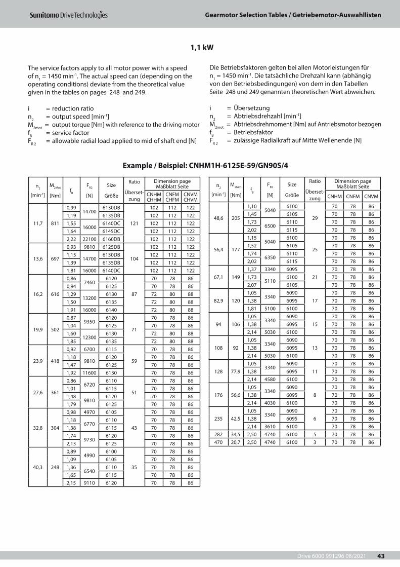
Drive 6000 991296 08/2021
Gearmotor Selection Tables / Getriebemotor-Auswahllisten
43
n2
[min-1]
M2Mot
[Nm]fB
FR2
[N]
Size
Größe
Ratio
Überset-zung
Dimension page Maßblatt Seite
CNHM CHHM
CNFM CHFM
CNVM CHVM
11,7 811
0,9914700
6130DB
121
102 112 1221,19 6135DB 102 112 1221,55
160006140DC 102 112 122
1,64 6145DC 102 112 1222,22 22100 6160DB 102 112 122
13,6 697
0,93 9810 6125DB
104
102 112 1221,15
147006130DB 102 112 122
1,39 6135DB 102 112 1221,81 16000 6140DC 102 112 122
16,2 616
0,867460
6120
87
70 78 860,94 6125 70 78 861,29
132006130 72 80 88
1,50 6135 72 80 881,91 16000 6140 72 80 88
19,9 502
0,879350
6120
71
70 78 861,04 6125 70 78 861,60
123006130 72 80 88
1,85 6135 72 80 88
23,9 418
0,92 6700 6115
59
70 78 861,18
98106120 70 78 86
1,47 6125 70 78 861,92 11600 6130 70 78 86
27,6 361
0,866720
6110
51
70 78 861,01 6115 70 78 861,48
98106120 70 78 86
1,79 6125 70 78 86
32,8 304
0,98 4970 6105
43
70 78 861,18
67706110 70 78 86
1,38 6115 70 78 861,74
97306120 70 78 86
2,13 6125 70 78 86
40,3 248
0,894990
6100
35
70 78 861,09 6105 70 78 861,36
65406110 70 78 86
1,65 6115 70 78 862,15 9110 6120 70 78 86
n2
[min-1]
M2Mot
[Nm]fB
FR2
[N]
Size
Größe
Ratio
Überset-zung
Dimension page Maßblatt Seite
CNHM CNFM CNVM
48,6 205
1,105040
6100
29
70 78 861,45 6105 70 78 861,73
65006110 70 78 86
2,02 6115 70 78 86
56,4 177
1,155040
6100
25
70 78 861,52 6105 70 78 861,74
63506110 70 78 86
2,02 6115 70 78 86
67,1 1491,37 3340 6095
2170 78 86
1,735110
6100 70 78 862,07 6105 70 78 86
82,9 1201,05
33406090
1770 78 86
1,38 6095 70 78 861,81 5100 6100 70 78 86
94 1061,05
33406090
1570 78 86
1,38 6095 70 78 862,14 5030 6100 70 78 86
108 921,05
33406090
1370 78 86
1,38 6095 70 78 862,14 5030 6100 70 78 86
128 77,91,05
33406090
1170 78 86
1,38 6095 70 78 862,14 4580 6100 70 78 86
176 56,61,05
33406090
870 78 86
1,38 6095 70 78 862,14 4030 6100 70 78 86
235 42,51,05
33406090
670 78 86
1,38 6095 70 78 862,14 3610 6100 70 78 86
282 34,5 2,50 4740 6100 5 70 78 86470 20,7 2,50 4740 6100 3 70 78 86
1,1 kW
Example / Beispiel: CNHM1H-6125E-59/GN90S/4
The service factors apply to all motor power with a speed of n1 = 1450 min-1. The actual speed can (depending on the operating conditions) deviate from the theoretical value given in the tables on pages 248 and 249.
i = reduction ration2 = output speed [min-1]M2mot = output torque [Nm] with reference to the driving motorfB = service factorFR 2 = allowable radial load applied to mid of shaft end [N]
Die Betriebsfaktoren gelten bei allen Motorleistungen für n1 = 1450 min-1. Die tatsächliche Drehzahl kann (abhängig von den Betriebsbedingungen) von dem in den Tabellen Seite 248 und 249 genannten theoretischen Wert abweichen.
i = Übersetzungn2 = Abtriebsdrehzahl [min-1] M2mot = Abtriebsdrehmoment [Nm] auf Antriebsmotor bezogenfB = BetriebsfaktorFR 2 = zulässige Radialkraft auf Mitte Wellenende [N]

Drive 6000 991296 08/2021
Gearmotor Selection Tables / Getriebemotor-Auswahllisten
44
n2
[min-1]
M2Mot
[Nm]fB
FR2
[N]
Size
Größe
Ratio
Überset-zung
Dimension page Maßblatt Seite
CHHM CHFM CHVM
1,92 67100,98
590006190DA
731104 114 124
1,22 6195DA 104 114 124
2,16 59500,87 41300 6185DB
649104 114 124
1,1158700
6190DA 104 114 1241,38 6195DA 104 114 124
2,36 54600,95 41700 6185DB
595104 114 124
1,2159000
6190DA 104 114 1241,50 6195DA 104 114 124
2,51 5130
0,8241700
6180DB
559
104 114 1241,01 6185DB 104 114 1241,28
590006190DA 104 114 124
1,60 6195DA 104 114 124
2,68 4820
0,8741700
6180DB
525
104 114 1241,07 6185DB 104 114 1241,37
590006190DA 104 114 124
1,71 6195DA 104 114 124
2,97 4340
0,9641700
6180DB
473
104 114 1241,19 6185DB 104 114 1241,52
590006190DA 104 114 124
1,89 6195DA 104 114 124
3,31 3900
0,83 29500 6175DC
425
104 114 1241,07
417006180DB 104 114 124
1,32 6185DB 104 114 1241,69
590006190DA 104 114 124
2,11 6195DA 104 114 124
3,73 3460
0,94 29500 6175DC
377
104 114 1241,21
417006180DB 104 114 124
1,49 6185DB 104 114 1241,90 59000 6190DA 104 114 124
3,94 3280
0,8029500
6170DC
357
104 114 1240,99 6175DC 104 114 1241,28
417006180DB 104 114 124
1,58 6185DB 104 114 1242,01 59000 6190DA 104 114 124
4,4 2930
0,8929500
6170DC
319
104 114 1241,11 6175DC 104 114 1241,43
417006180DB 104 114 124
1,76 6185DB 104 114 124
n2
[min-1]
M2Mot
[Nm]fB
FR2
[N]
Size
Größe
Ratio
Überset-zung
Dimension page Maßblatt Seite
CHHM CHFM CHVM
5,15 2500
0,87 22100 6165DB
273
102 112 1221,04
295006170DC 104 114 124
1,30 6175DC 104 114 1241,67
417006180DB 104 114 124
2,06 6185DB 104 114 124
6,08 2120
0,8522100
6160DB
231
102 112 1221,02 6165DB 102 112 1221,23
295006170DC 104 114 124
1,53 6175DC 104 114 1241,97 41700 6180DB 104 114 124
7,21 1790
1,0122100
6160DB
195
102 112 1221,21 6165DB 102 112 1221,46
295006170DC 104 114 124
1,82 6175DC 104 114 124
8,52 1510
0,8315500
6140DC
165
102 112 1220,93 6145DC 102 112 1221,20
221006160DB 102 112 122
1,43 6165DB 102 112 1221,72
295006170DC 104 114 124
2,15 6175DC 104 114 124
9,83 1310
0,9616000
6140DC
143
102 112 1221,08 6145DC 102 112 1221,38
221006160DB 102 112 122
1,65 6165DB 102 112 1221,99 29500 6170DC 104 114 124
11,6 1110
0,87 14700 6135DB
121
102 112 1221,14
160006140DC 102 112 122
1,20 6145DC 102 112 1221,63
221006160DB 102 112 122
1,95 6165DB 102 112 122
13,5 954
0,8414700
6130DB
104
102 112 1221,02 6135DB 102 112 1221,32
160006140DC 102 112 122
1,48 6145DC 102 112 1221,90 22100 6160DB 102 112 122
1,5 kW
Example / Beispiel: CHHM2-6175DC-273/TN90L/4
The service factors apply to all motor power with a speed of n1 = 1450 min-1. The actual speed can (depending on the operating conditions) deviate from the theoretical value given in the tables on pages 248 and 249.
i = reduction ration2 = output speed [min-1]M2mot = output torque [Nm] with reference to the driving motorfB = service factorFR 2 = allowable radial load applied to mid of shaft end [N]
Die Betriebsfaktoren gelten bei allen Motorleistungen für n1 = 1450 min-1. Die tatsächliche Drehzahl kann (abhängig von den Betriebsbedingungen) von dem in den Tabellen Seite 248 und 249 genannten theoretischen Wert abweichen.
i = Übersetzungn2 = Abtriebsdrehzahl [min-1] M2mot = Abtriebsdrehmoment [Nm] auf Antriebsmotor bezogenfB = BetriebsfaktorFR 2 = zulässige Radialkraft auf Mitte Wellenende [N]
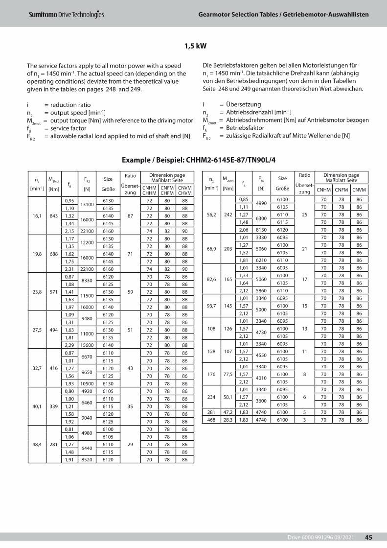
Drive 6000 991296 08/2021
Gearmotor Selection Tables / Getriebemotor-Auswahllisten
45
n2
[min-1]
M2Mot
[Nm]fB
FR2
[N]
Size
Größe
Ratio
Überset-zung
Dimension page Maßblatt Seite
CNHM CHHM
CNFM CHFM
CNVM CHVM
16,1 843
0,9513100
6130
87
72 80 881,10 6135 72 80 881,32
160006140 72 80 88
1,44 6145 72 80 882,15 22100 6160 74 82 90
19,8 688
1,1712200
6130
71
72 80 881,35 6135 72 80 881,62
160006140 72 80 88
1,75 6145 72 80 882,31 22100 6160 74 82 90
23,8 571
0,878330
6120
59
70 78 861,08 6125 70 78 861,41
115006130 72 80 88
1,63 6135 72 80 881,97 16000 6140 72 80 88
27,5 494
1,099480
6120
51
70 78 861,31 6125 70 78 861,63
110006130 72 80 88
1,81 6135 72 80 882,29 15600 6140 72 80 88
32,7 416
0,876670
6110
43
70 78 86
1,01 6115 70 78 861,27
96506120 70 78 86
1,56 6125 70 78 861,93 10500 6130 70 78 86
40,1 339
0,80 4920 6105
35
70 78 861,00
64606110 70 78 86
1,21 6115 70 78 861,58
90406120 70 78 86
1,92 6125 70 78 86
48,4 281
0,814980
6100
29
70 78 861,06 6105 70 78 861,27
64406110 70 78 86
1,48 6115 70 78 861,91 8520 6120 70 78 86
n2
[min-1]
M2Mot
[Nm]fB
FR2
[N]
Size
Größe
Ratio
Überset-zung
Dimension page Maßblatt Seite
CNHM CNFM CNVM
56,2 242
0,854990
6100
25
70 78 861,11 6105 70 78 861,27
63006110 70 78 86
1,48 6115 70 78 862,06 8130 6120 70 78 86
66,9 203
1,01 3330 6095
21
70 78 861,27
50606100 70 78 86
1,52 6105 70 78 861,81 6210 6110 70 78 86
82,6 165
1,01 3340 6095
17
70 78 861,33
50606100 70 78 86
1,64 6105 70 78 862,12 5860 6110 70 78 86
93,7 1451,01 3340 6095
1570 78 86
1,575000
6100 70 78 862,12 6105 70 78 86
108 1261,01 3340 6095
1370 78 86
1,574730
6100 70 78 862,12 6105 70 78 86
128 1071,01 3340 6095
1170 78 86
1,574550
6100 70 78 862,12 6105 70 78 86
176 77,51,01 3340 6095
870 78 86
1,574010
6100 70 78 862,12 6105 70 78 86
234 58,11,01 3340 6095
670 78 86
1,573600
6100 70 78 862,12 6105 70 78 86
281 47,2 1,83 4740 6100 5 70 78 86468 28,3 1,83 4740 6100 3 70 78 86
1,5 kW
Example / Beispiel: CHHM2-6145E-87/TN90L/4
The service factors apply to all motor power with a speed of n1 = 1450 min-1. The actual speed can (depending on the operating conditions) deviate from the theoretical value given in the tables on pages 248 and 249.
i = reduction ration2 = output speed [min-1]M2mot = output torque [Nm] with reference to the driving motorfB = service factorFR 2 = allowable radial load applied to mid of shaft end [N]
Die Betriebsfaktoren gelten bei allen Motorleistungen für n1 = 1450 min-1. Die tatsächliche Drehzahl kann (abhängig von den Betriebsbedingungen) von dem in den Tabellen Seite 248 und 249 genannten theoretischen Wert abweichen.
i = Übersetzungn2 = Abtriebsdrehzahl [min-1] M2mot = Abtriebsdrehmoment [Nm] auf Antriebsmotor bezogenfB = BetriebsfaktorFR 2 = zulässige Radialkraft auf Mitte Wellenende [N]
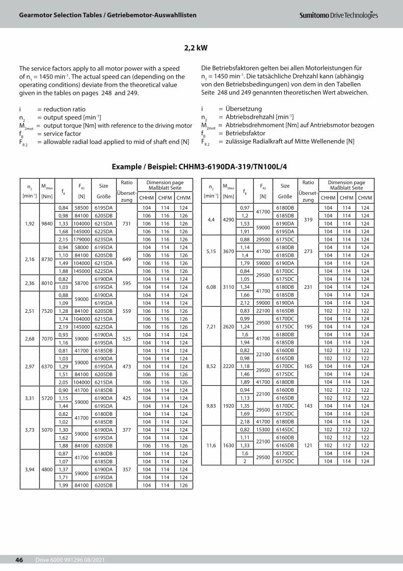
Drive 6000 991296 08/2021
Gearmotor Selection Tables / Getriebemotor-Auswahllisten
46
n2
[min-1]
M2Mot
[Nm]fB
FR2
[N]
Size
Größe
Ratio
Überset-zung
Dimension page Maßblatt Seite
CHHM CHFM CHVM
1,92 9840
0,84 58500 6195DA
731
104 114 1240,98 84100 6205DB 106 116 1261,33 104000 6215DA 106 116 1261,68 145000 6225DA 106 116 1262,15 179000 6235DA 106 116 126
2,16 8730
0,94 58000 6195DA
649
104 114 1241,10 84100 6205DB 106 116 1261,49 104000 6215DA 106 116 1261,88 145000 6225DA 106 116 126
2,36 80100,82
587006190DA
595104 114 124
1,03 6195DA 104 114 124
2,51 7520
0,8859000
6190DA
559
104 114 1241,09 6195DA 104 114 1241,28 84100 6205DB 106 116 1261,74 104000 6215DA 106 116 1262,19 145000 6225DA 106 116 126
2,68 70700,93
590006190DA
525104 114 124
1,16 6195DA 104 114 124
2,97 6370
0,81 41700 6185DB
473
104 114 1241,03
590006190DA 104 114 124
1,29 6195DA 104 114 1241,51 84100 6205DB 106 116 1262,05 104000 6215DA 106 116 126
3,31 57200,90 41700 6185DB
425104 114 124
1,1559000
6190DA 104 114 1241,44 6195DA 104 114 124
3,73 5070
0,8241700
6180DB
377
104 114 1241,02 6185DB 104 114 1241,30
590006190DA 104 114 124
1,62 6195DA 104 114 1241,88 84100 6205DB 106 116 126
3,94 4800
0,8741700
6180DB
357
104 114 1241,07 6185DB 104 114 1241,37
590006190DA 104 114 124
1,71 6195DA 104 114 1241,99 84100 6205DB 104 114 126
n2
[min-1]
M2Mot
[Nm]fB
FR2
[N]
Size
Größe
Ratio
Überset-zung
Dimension page Maßblatt Seite
CHHM CHFM CHVM
4,4 4290
0,9741700
6180DB
319
104 114 1241,2 6185DB 104 114 124
1,5359000
6190DA 104 114 1241,91 6195DA 104 114 124
5,15 3670
0,88 29500 6175DC
273
104 114 1241,14
417006180DB 104 114 124
1,4 6185DB 104 114 1241,79 59000 6190DA 104 114 124
6,08 3110
0,8429500
6170DC
231
104 114 1241,05 6175DC 104 114 1241,34
417006180DB 104 114 124
1,66 6185DB 104 114 1242,12 59000 6190DA 104 114 124
7,21 2620
0,83 22100 6165DB
195
102 112 1220,99
295006170DC 104 114 124
1,24 6175DC 104 114 1241,6
417006180DB 104 114 124
1,94 6185DB 104 114 124
8,52 2220
0,8222100
6160DB
165
102 112 1220,98 6165DB 102 112 1221,18
295006170DC 104 114 124
1,46 6175DC 104 114 1241,89 41700 6180DB 104 114 124
9,83 1920
0,9422100
6160DB
143
102 112 1221,13 6165DB 102 112 1221,35
295006170DC 104 114 124
1,69 6175DC 104 114 1242,18 41700 6180DB 104 114 124
11,6 1630
0,82 15300 6145DC
121
102 112 1221,11
221006160DB 102 112 122
1,33 6165DB 102 112 1221,6
295006170DC 104 114 124
2 6175DC 104 114 124
2,2 kW
Example / Beispiel: CHHM3-6190DA-319/TN100L/4
The service factors apply to all motor power with a speed of n1 = 1450 min-1. The actual speed can (depending on the operating conditions) deviate from the theoretical value given in the tables on pages 248 and 249.
i = reduction ration2 = output speed [min-1]M2mot = output torque [Nm] with reference to the driving motorfB = service factorFR 2 = allowable radial load applied to mid of shaft end [N]
Die Betriebsfaktoren gelten bei allen Motorleistungen für n1 = 1450 min-1. Die tatsächliche Drehzahl kann (abhängig von den Betriebsbedingungen) von dem in den Tabellen Seite 248 und 249 genannten theoretischen Wert abweichen.
i = Übersetzungn2 = Abtriebsdrehzahl [min-1] M2mot = Abtriebsdrehmoment [Nm] auf Antriebsmotor bezogenfB = BetriebsfaktorFR 2 = zulässige Radialkraft auf Mitte Wellenende [N]
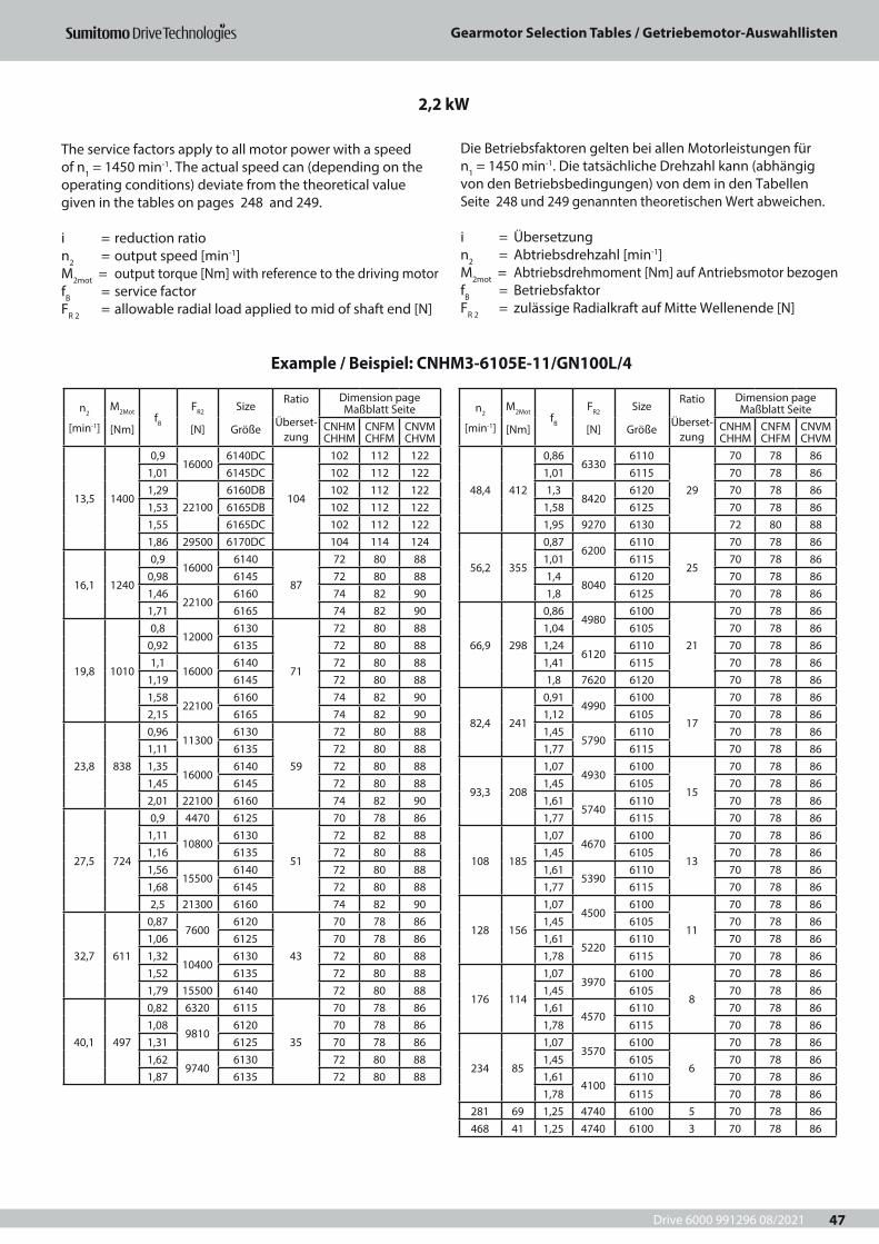
Drive 6000 991296 08/2021
Gearmotor Selection Tables / Getriebemotor-Auswahllisten
47
n2
[min-1]
M2Mot
[Nm]fB
FR2
[N]
Size
Größe
Ratio
Überset-zung
Dimension page Maßblatt Seite
CNHM CHHM
CNFM CHFM
CNVM CHVM
48,4 412
0,866330
6110
29
70 78 861,01 6115 70 78 861,3
84206120 70 78 86
1,58 6125 70 78 861,95 9270 6130 72 80 88
56,2 355
0,876200
6110
25
70 78 861,01 6115 70 78 861,4
80406120 70 78 86
1,8 6125 70 78 86
66,9 298
0,864980
6100
21
70 78 861,04 6105 70 78 861,24
61206110 70 78 86
1,41 6115 70 78 861,8 7620 6120 70 78 86
82,4 241
0,914990
6100
17
70 78 861,12 6105 70 78 861,45
57906110 70 78 86
1,77 6115 70 78 86
93,3 208
1,074930
6100
15
70 78 861,45 6105 70 78 861,61
57406110 70 78 86
1,77 6115 70 78 86
108 185
1,074670
6100
13
70 78 861,45 6105 70 78 861,61
53906110 70 78 86
1,77 6115 70 78 86
128 156
1,074500
6100
11
70 78 861,45 6105 70 78 861,61
52206110 70 78 86
1,78 6115 70 78 86
176 114
1,073970
6100
8
70 78 861,45 6105 70 78 861,61
45706110 70 78 86
1,78 6115 70 78 86
234 85
1,073570
6100
6
70 78 861,45 6105 70 78 861,61
41006110 70 78 86
1,78 6115 70 78 86281 69 1,25 4740 6100 5 70 78 86468 41 1,25 4740 6100 3 70 78 86
2,2 kW
Example / Beispiel: CNHM3-6105E-11/GN100L/4
n2
[min-1]
M2Mot
[Nm]fB
FR2
[N]
Size
Größe
Ratio
Überset-zung
Dimension page Maßblatt Seite
CNHM CHHM
CNFM CHFM
CNVM CHVM
13,5 1400
0,916000
6140DC
104
102 112 1221,01 6145DC 102 112 1221,29
221006160DB 102 112 122
1,53 6165DB 102 112 1221,55 6165DC 102 112 1221,86 29500 6170DC 104 114 124
16,1 1240
0,916000
6140
87
72 80 880,98 6145 72 80 881,46
221006160 74 82 90
1,71 6165 74 82 90
19,8 1010
0,812000
6130
71
72 80 880,92 6135 72 80 881,1
160006140 72 80 88
1,19 6145 72 80 881,58
221006160 74 82 90
2,15 6165 74 82 90
23,8 838
0,9611300
6130
59
72 80 881,11 6135 72 80 881,35
160006140 72 80 88
1,45 6145 72 80 882,01 22100 6160 74 82 90
27,5 724
0,9 4470 6125
51
70 78 861,11
108006130 72 82 88
1,16 6135 72 80 881,56
155006140 72 80 88
1,68 6145 72 80 882,5 21300 6160 74 82 90
32,7 611
0,877600
6120
43
70 78 861,06 6125 70 78 861,32
104006130 72 80 88
1,52 6135 72 80 881,79 15500 6140 72 80 88
40,1 497
0,82 6320 6115
35
70 78 861,08
98106120 70 78 86
1,31 6125 70 78 861,62
97406130 72 80 88
1,87 6135 72 80 88
The service factors apply to all motor power with a speed of n1 = 1450 min-1. The actual speed can (depending on the operating conditions) deviate from the theoretical value given in the tables on pages 248 and 249.
i = reduction ration2 = output speed [min-1]M2mot = output torque [Nm] with reference to the driving motorfB = service factorFR 2 = allowable radial load applied to mid of shaft end [N]
Die Betriebsfaktoren gelten bei allen Motorleistungen für n1 = 1450 min-1. Die tatsächliche Drehzahl kann (abhängig von den Betriebsbedingungen) von dem in den Tabellen Seite 248 und 249 genannten theoretischen Wert abweichen.
i = Übersetzungn2 = Abtriebsdrehzahl [min-1] M2mot = Abtriebsdrehmoment [Nm] auf Antriebsmotor bezogenfB = BetriebsfaktorFR 2 = zulässige Radialkraft auf Mitte Wellenende [N]
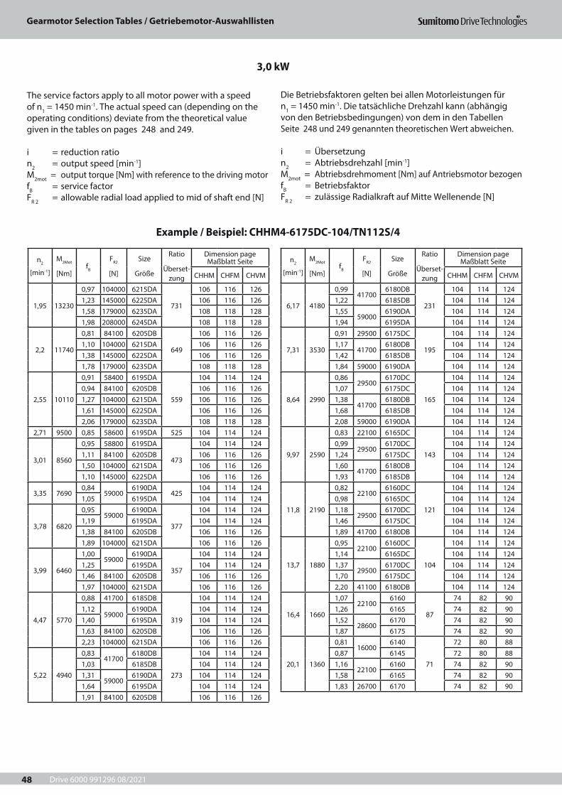
Drive 6000 991296 08/2021
Gearmotor Selection Tables / Getriebemotor-Auswahllisten
48
n2
[min-1]
M2Mot
[Nm]fB
FR2
[N]
Size
Größe
Ratio
Überset-zung
Dimension page Maßblatt Seite
CHHM CHFM CHVM
1,95 13230
0,97 104000 6215DA
731
106 116 1261,23 145000 6225DA 106 116 1261,58 179000 6235DA 108 118 1281,98 208000 6245DA 108 118 128
2,2 11740
0,81 84100 6205DB
649
106 116 1261,10 104000 6215DA 106 116 1261,38 145000 6225DA 106 116 1261,78 179000 6235DA 108 118 128
2,55 10110
0,91 58400 6195DA
559
104 114 1240,94 84100 6205DB 106 116 1261,27 104000 6215DA 106 116 1261,61 145000 6225DA 106 116 1262,06 179000 6235DA 108 118 128
2,71 9500 0,85 58600 6195DA 525 104 114 124
3,01 8560
0,95 58800 6195DA
473
104 114 1241,11 84100 6205DB 106 116 1261,50 104000 6215DA 106 116 1261,10 145000 6225DA 106 116 126
3,35 76900,84
590006190DA
425104 114 124
1,05 6195DA 104 114 124
3,78 6820
0,9559000
6190DA
377
104 114 1241,19 6195DA 104 114 1241,38 84100 6205DB 106 116 1261,89 104000 6215DA 106 116 126
3,99 6460
1,0059000
6190DA
357
104 114 1241,25 6195DA 104 114 1241,46 84100 6205DB 106 116 1261,97 104000 6215DA 106 116 126
4,47 5770
0,88 41700 6185DB
319
104 114 1241,12
590006190DA 104 114 124
1,40 6195DA 104 114 1241,63 84100 6205DB 106 116 1262,23 104000 6215DA 106 116 126
5,22 4940
0,8341700
6180DB
273
104 114 1241,03 6185DB 104 114 1241,31
590006190DA 104 114 124
1,64 6195DA 104 114 1241,91 84100 6205DB 106 116 126
n2
[min-1]
M2Mot
[Nm]fB
FR2
[N]
Size
Größe
Ratio
Überset-zung
Dimension page Maßblatt Seite
CHHM CHFM CHVM
6,17 4180
0,9941700
6180DB
231
104 114 1241,22 6185DB 104 114 1241,55
590006190DA 104 114 124
1,94 6195DA 104 114 124
7,31 3530
0,91 29500 6175DC
195
104 114 1241,17
417006180DB 104 114 124
1,42 6185DB 104 114 1241,84 59000 6190DA 104 114 124
8,64 2990
0,8629500
6170DC
165
104 114 1241,07 6175DC 104 114 1241,38
417006180DB 104 114 124
1,68 6185DB 104 114 1242,08 59000 6190DA 104 114 124
9,97 2590
0,83 22100 6165DC
143
104 114 1240,99
295006170DC 104 114 124
1,24 6175DC 104 114 1241,60
417006180DB 104 114 124
1,93 6185DB 104 114 124
11,8 2190
0,8222100
6160DC
121
104 114 1240,98 6165DC 104 114 1241,18
295006170DC 104 114 124
1,46 6175DC 104 114 1241,89 41700 6180DB 104 114 124
13,7 1880
0,9522100
6160DC
104
104 114 1241,14 6165DC 104 114 1241,37
295006170DC 104 114 124
1,70 6175DC 104 114 1242,20 41100 6180DB 104 114 124
16,4 1660
1,0722100
6160
87
74 82 901,26 6165 74 82 901,52
286006170 74 82 90
1,87 6175 74 82 90
20,1 1360
0,8116000
6140
71
72 80 880,87 6145 72 80 881,16
221006160 74 82 90
1,58 6165 74 82 901,83 26700 6170 74 82 90
3,0 kW
Example / Beispiel: CHHM4-6175DC-104/TN112S/4
The service factors apply to all motor power with a speed of n1 = 1450 min-1. The actual speed can (depending on the operating conditions) deviate from the theoretical value given in the tables on pages 248 and 249.
i = reduction ration2 = output speed [min-1]M2mot = output torque [Nm] with reference to the driving motorfB = service factorFR 2 = allowable radial load applied to mid of shaft end [N]
Die Betriebsfaktoren gelten bei allen Motorleistungen für n1 = 1450 min-1. Die tatsächliche Drehzahl kann (abhängig von den Betriebsbedingungen) von dem in den Tabellen Seite 248 und 249 genannten theoretischen Wert abweichen.
i = Übersetzungn2 = Abtriebsdrehzahl [min-1] M2mot = Abtriebsdrehmoment [Nm] auf Antriebsmotor bezogenfB = BetriebsfaktorFR 2 = zulässige Radialkraft auf Mitte Wellenende [N]
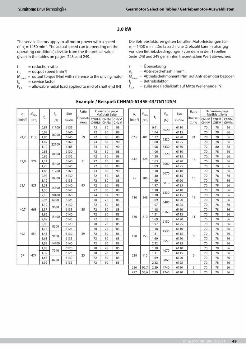
Drive 6000 991296 08/2021
Gearmotor Selection Tables / Getriebemotor-Auswahllisten
49
n2
[min-1]
M2Mot
[Nm]fB
FR2
[N]
Size
Größe
Ratio
Überset-zung
Dimension page Maßblatt Seite
CNHM CHHM
CNFM CHFM
CNVM CHVM
24,2 1130
0,81 11100 6135
59
72 80 880,99
160006140 72 80 88
1,06 6145 72 80 881,47
221006160 74 82 90
1,10 6165 74 82 90
27,9 974
0,8110600
6130
51
72 80 880,85 6135 72 80 881,14
154006140 72 80 88
1,23 6145 72 80 881,83 21200 6160 74 82 90
33,1 821
0,9710300
6130
43
72 80 881,12 6135 72 80 881,31
155006140 72 80 88
1,56 6145 72 80 882,15 20400 6160 74 82 90
40,7 668
0,96 6020 6125
35
70 78 861,19
96306130 72 80 88
1,37 6135 72 80 881,85
154006140 72 80 88
2,09 6145 72 80 88
49,1 554
0,968300
6120
29
70 78 861,16 6125 70 78 861,43
91806130 72 80 88
1,63 6135 72 80 881,98 14400 6140 72 80 88
57 477
1,037940
6120
25
70 78 861,32 6125 70 78 861,66
87506130 72 80 88
1,92 6135 72 80 88
n2
[min-1]
M2Mot
[Nm]fB
FR2
[N]
Size
Größe
Ratio
Überset-zung
Dimension page Maßblatt Seite
CNHM CHHM
CNFM CHFM
CNVM CHVM
67,9 401
0,916020
6110
21
70 78 861,04 6115 70 78 861,32
75306120 70 78 86
1,60 6125 70 78 861,98 8430 6130 72 80 88
83,8 325
1,065720
6110
17
70 78 861,30 6115 70 78 861,63
70606120 70 78 86
1,89 6125 70 78 86
95 286
1,185670
6110
15
70 78 861,30 6115 70 78 861,69
68106120 70 78 86
1,97 6125 70 78 86
110 248
1,185330
6110
13
70 78 861,30 6115 70 78 861,69
64806120 70 78 86
1,97 6125 70 78 86
130 210
1,185160
6110
11
70 78 861,31 6115 70 78 861,69
61506120 70 78 86
1,97 6125 70 78 86
178 153
1,184530
6110
8
70 78 861,31 6115 70 78 861,69
55506120 70 78 86
2,32 6125 70 78 86
238 115
1,184070
6110
6
70 78 861,31 6115 70 78 861,69
50606120 70 78 86
2,32 6125 70 78 86286 92,7 2,29 4740 6120 5 70 78 86477 55,6 2,29 4740 6120 3 70 78 86
3,0 kW
Example / Beispiel: CHHM4-6145E-43/TN112S/4
The service factors apply to all motor power with a speed of n1 = 1450 min-1. The actual speed can (depending on the operating conditions) deviate from the theoretical value given in the tables on pages 248 and 249.
i = reduction ration2 = output speed [min-1]M2mot = output torque [Nm] with reference to the driving motorfB = service factorFR 2 = allowable radial load applied to mid of shaft end [N]
Die Betriebsfaktoren gelten bei allen Motorleistungen für n1 = 1450 min-1. Die tatsächliche Drehzahl kann (abhängig von den Betriebsbedingungen) von dem in den Tabellen Seite 248 und 249 genannten theoretischen Wert abweichen.
i = Übersetzungn2 = Abtriebsdrehzahl [min-1] M2mot = Abtriebsdrehmoment [Nm] auf Antriebsmotor bezogenfB = BetriebsfaktorFR 2 = zulässige Radialkraft auf Mitte Wellenende [N]
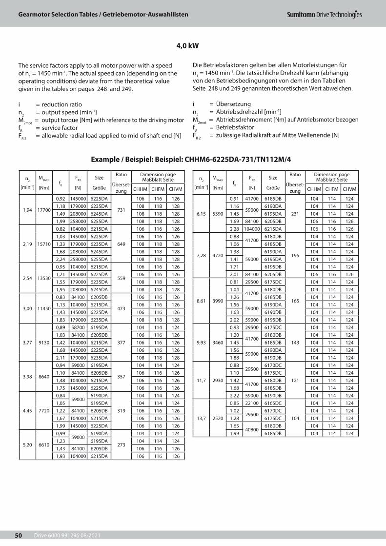
Drive 6000 991296 08/2021
Gearmotor Selection Tables / Getriebemotor-Auswahllisten
50
n2
[min-1]
M2Mot
[Nm]fB
FR2
[N]
Size
Größe
Ratio
Überset-zung
Dimension page Maßblatt Seite
CHHM CHFM CHVM
1,94 17700
0,92 145000 6225DA
731
106 116 1261,18 179000 6235DA 108 118 1281,49 208000 6245DA 108 118 1281,99 258000 6255DA 108 118 128
2,19 15710
0,82 104000 6215DA
649
106 116 1261,03 145000 6225DA 106 116 1261,33 179000 6235DA 108 118 1281,68 208000 6245DA 108 118 1282,24 258000 6255DA 108 118 128
2,54 13530
0,95 104000 6215DA
559
106 116 1261,21 145000 6225DA 106 116 1261,55 179000 6235DA 108 118 1281,95 208000 6245DA 108 118 128
3,00 11450
0,83 84100 6205DB
473
106 116 1261,13 104000 6215DA 106 116 1261,43 145000 6225DA 106 116 1261,83 179000 6235DA 108 118 128
3,77 9130
0,89 58700 6195DA
377
104 114 1241,03 84100 6205DB 106 116 1261,42 104000 6215DA 106 116 1261,68 145000 6225DA 106 116 1262,11 179000 6235DA 108 118 128
3,98 8640
0,94 59000 6195DA
357
104 114 1241,10 84100 6205DB 106 116 1261,48 104000 6215DA 106 116 1261,75 145000 6225DA 106 116 126
4,45 7720
0,8459000
6190DA
319
104 114 1241,05 6195DA 104 114 1241,22 84100 6205DB 106 116 1261,67 104000 6215DA 106 116 1261,99 145000 6225DA 106 116 126
5,20 6610
0,9959000
6190DA
273
104 114 1241,23 6195DA 104 114 1241,43 84100 6205DB 106 116 1261,93 104000 6215DA 106 116 126
n2
[min-1]
M2Mot
[Nm]fB
FR2
[N]
Size
Größe
Ratio
Überset-zung
Dimension page Maßblatt Seite
CHHM CHFM CHVM
6,15 5590
0,91 41700 6185DB
231
104 114 1241,16
590006190DA 104 114 124
1,45 6195DA 104 114 1241,69 84100 6205DB 106 116 1262,28 104000 6215DA 106 116 126
7,28 4720
0,8841700
6180DB
195
104 114 1241,06 6185DB 104 114 1241,38
590006190DA 104 114 124
1,41 6195DA 104 114 1241,71 6195DB 104 114 1242,01 84100 6205DB 106 116 126
8,61 3990
0,81 29500 6175DC
165
104 114 1241,04
417006180DB 104 114 124
1,26 6185DB 104 114 1241,56
590006190DA 104 114 124
1,63 6190DB 104 114 1242,02 59000 6195DB 104 114 124
9,93 3460
0,93 29500 6175DC
143
104 114 1241,20
417006180DB 104 114 124
1,45 6185DB 104 114 1241,56
590006190DA 104 114 124
1,88 6190DB 104 114 124
11,7 2930
0,8829500
6170DC
121
104 114 1241,10 6175DC 104 114 1241,42
417006180DB 104 114 124
1,68 6185DB 104 114 1242,22 59000 6190DB 104 114 124
13,7 2520
0,85 22100 6165DC
104
104 114 1241,02
295006170DC 104 114 124
1,28 6175DC 104 114 1241,65
408006180DB 104 114 124
1,99 6185DB 104 114 124
4,0 kW
Example / Beispiel: Beispiel: CHHM6-6225DA-731/TN112M/4
The service factors apply to all motor power with a speed of n1 = 1450 min-1. The actual speed can (depending on the operating conditions) deviate from the theoretical value given in the tables on pages 248 and 249.
i = reduction ration2 = output speed [min-1]M2mot = output torque [Nm] with reference to the driving motorfB = service factorFR 2 = allowable radial load applied to mid of shaft end [N]
Die Betriebsfaktoren gelten bei allen Motorleistungen für n1 = 1450 min-1. Die tatsächliche Drehzahl kann (abhängig von den Betriebsbedingungen) von dem in den Tabellen Seite 248 und 249 genannten theoretischen Wert abweichen.
i = Übersetzungn2 = Abtriebsdrehzahl [min-1] M2mot = Abtriebsdrehmoment [Nm] auf Antriebsmotor bezogenfB = BetriebsfaktorFR 2 = zulässige Radialkraft auf Mitte Wellenende [N]
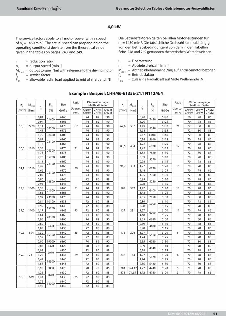
Drive 6000 991296 08/2021
Gearmotor Selection Tables / Getriebemotor-Auswahllisten
51
n2
[min-1]
M2Mot
[Nm]fB
FR2
[N]
Size
Größe
Ratio
Überset-zung
Dimension page Maßblatt Seite
CNHM CHHM
CNFM CHFM
CNVM CHVM
16,3 2220
0,8121600
6160
87
74 82 900,94 6165 74 82 901,14
283006170 74 82 90
1,41 6175 74 82 901,79 38400 6180 74 82 90
20,0 1810
0,8722100
6160
71
74 82 901,18 6165 74 82 901,38
265006170 74 82 90
1,75 6175 74 82 902,20 35700 6180 74 82 90
24,1 1510
1,1122100
6160
59
74 82 901,42 6165 74 82 901,66
251006170 74 82 90
2,07 6175 74 82 90
27,8 1300
0,8614500
6140
51
72 80 880,93 6145 72 80 881,38
210006160 74 82 90
1,65 6165 74 82 901,92 23900 6170 74 82 90
33,0 1100
0,84 10100 6135
43
72 80 880,99
152006140 72 80 88
1,17 6145 72 80 881,61
203006160 74 82 90
1,95 6165 74 82 90
40,6 894
0,899490
6130
35
72 80 881,03 6135 72 80 881,30
153006140 72 80 88
1,57 6145 72 80 882,00 19000 6160 74 82 90
49,0 741
0,87 3320 6125
29
70 78 861,08
90706130 72 80 88
1,22 6135 72 80 881,49
143006140 72 80 88
1,88 6145 72 80 88
56,8 639
0,98 6850 6125
25
70 78 861,25
86506130 72 80 88
1,44 6135 72 80 881,72
140006140 72 80 88
1,98 6145 72 80 88
n2
[min-1]
M2Mot
[Nm]fB
FR2
[N]
Size
Größe
Ratio
Überset-zung
Dimension page Maßblatt Seite
CNHM CHHM
CNFM CHFM
CNVM CHVM
67,6 537
0,987420
6120
21
70 78 861,20 6125 70 78 861,49
83406130 72 80 88
1,68 6135 72 80 882,17 13400 6140 72 80 88
83,5 434
0,98 5610 6115
17
70 78 861,22
69706120 70 78 86
1,42 6125 70 78 861,82 7820 6130 72 80 88
94,7 383
0,895570
6110
15
70 78 860,98 6115 70 78 861,27
67306120 70 78 86
1,48 6125 70 78 861,95 7300 6130 72 80 88
109 332
0,895250
6110
13
70 78 860,98 6115 70 78 861,27
64006120 70 78 86
1,48 6125 70 78 862,35 7150 6130 72 80 88
129 281
0,895090
6110
11
70 78 860,98 6115 70 78 861,27
60906120 70 78 86
1,48 6125 70 78 862,35 6880 6130 72 80 88
178 204
0,894480
6110
8
70 78 860,98 6115 70 78 861,27
55106120 70 78 86
1,74 6125 70 78 862,35 6030 6130 72 80 88
237 153
0,894040
6110
6
70 78 860,98 6115 70 78 861,27
50206120 70 78 86
1,74 6125 70 78 862,35 5420 6130 72 80 88
284 124,42 1,72 4740 6120 5 70 78 86473 74,65 1,72 4740 6120 3 70 78 86
4,0 kW
Example / Beispiel: CHHM6-6135E-21/TN112M/4
The service factors apply to all motor power with a speed of n1 = 1450 min-1. The actual speed can (depending on the operating conditions) deviate from the theoretical value given in the tables on pages 248 and 249.
i = reduction ration2 = output speed [min-1]M2mot = output torque [Nm] with reference to the driving motorfB = service factorFR 2 = allowable radial load applied to mid of shaft end [N]
Die Betriebsfaktoren gelten bei allen Motorleistungen für n1 = 1450 min-1. Die tatsächliche Drehzahl kann (abhängig von den Betriebsbedingungen) von dem in den Tabellen Seite 248 und 249 genannten theoretischen Wert abweichen.
i = Übersetzungn2 = Abtriebsdrehzahl [min-1] M2mot = Abtriebsdrehmoment [Nm] auf Antriebsmotor bezogenfB = BetriebsfaktorFR 2 = zulässige Radialkraft auf Mitte Wellenende [N]

Drive 6000 991296 08/2021
Gearmotor Selection Tables / Getriebemotor-Auswahllisten
52
n2
[min-1]
M2Mot
[Nm]fB
FR2
[N]
Size
Größe
Ratio
Überset-zung
Dimension page Maßblatt Seite
CHHM CHFM CHVM
1,96 24160
0,86 179000 6235DA
731
108 118 1281,08 208000 6245DA 108 118 1281,45 258000 6255DA 108 118 1281,93 276000 6265DA 108 118 128
2,2 21450
0,97 179000 6235DA
649
108 118 1281,22 208000 6245DA 108 118 1281,63 258000 6255DA 108 118 1282,17 276000 6265DA 108 118 128
2,56 18480
0,88 145000 6225DA
559
106 116 1261,12 179000 6235DA 108 118 1281,42 208000 6245DA 108 118 1281,89 258000 6255DA 108 118 128
3,02 15640
0,82 104000 6215DA
473
106 116 1261,04 145000 6225DA 106 116 1261,33 179000 6235DA 108 118 1281,67 208000 6245DA 108 118 1282,24 258000 6255DA 108 118 128
3,79 12460
1,03 104000 6215DA
377
106 116 1261,22 145000 6225DA 106 116 1261,54 179000 6235DA 108 118 1282,10 208000 6245DA 108 118 128
4,01 11800
0,80 84100 6205DB
357
106 116 1261,07 104000 6215DA 106 116 1261,27 145000 6225DA 106 116 1261,62 179000 6235DA 108 118 1282,22 208000 6245DA 108 118 128
4,48 10540
0,89 84100 6205DB
319
106 116 1261,22 104000 6215DA 106 116 1261,45 145000 6225DA 106 116 1261,82 179000 6235DA 108 118 128
5,24 9020
0,89 59000 6195DA
273
104 114 1241,04 84100 6205DB 106 116 1261,40 104000 6215DA 106 116 1261,66 145000 6225DA 106 116 1262,12 179000 6235DA 108 120 128
n2
[min-1]
M2Mot
[Nm]fB
FR2
[N]
Size
Größe
Ratio
Überset-zung
Dimension page Maßblatt Seite
CHHM CHFM CHVM
6,19 7640
0,8559000
6190DA
231
104 114 1241,06 6195DA 104 114 1241,23 84100 6205DB 106 116 1261,66 104000 6215DA 106 116 1261,97 139000 6225DA 106 116 126
7,33 6450
1,0058900
6190DA
195
104 114 1241,02 6195DA 104 114 1241,24 6195DB 104 114 1241,46 84100 6205DB 106 116 1261,91 104000 6215DA 106 116 126
8,67 5450
0,92 41700 6185DB
165
104 114 1241,14
590006190DA 104 114 124
1,19 6190DB 104 114 1241,47 6195DB 104 114 1241,72 84100 6205DB 106 116 1262,17 104000 6215DA 106 116 126
10 4730
0,8741700
6180DB
143
104 114 1241,05 6185DB 104 114 1241,14
590006190DA 104 114 124
1,37 6190DB 104 114 1241,64 6195DB 104 114 124
11,8 4000
0,80 29500 6175DC
121
104 114 1241,03
417006180DB 104 114 124
1,22 6185DB 104 114 1241,62
590006190DB 104 114 124
1,92 6195DB 104 114 124
13,8 3440
0,93 29500 6175DC
104
104 114 1241,20
405006180DB 104 114 124
1,45 6185DB 104 114 1241,88 56800 6190DB 104 114 124
16,4 3040
0,8327900
6170
87
74 82 901,02 6175 74 82 901,30
381006180 74 82 90
1,56 6185 74 82 902,13 53600 6190 74 82 90
5,5 kW
Example / Beispiel: CHHM8-6225DA-357/TN132S/4
The service factors apply to all motor power with a speed of n1 = 1450 min-1. The actual speed can (depending on the operating conditions) deviate from the theoretical value given in the tables on pages 248 and 249.
i = reduction ration2 = output speed [min-1]M2mot = output torque [Nm] with reference to the driving motorfB = service factorFR 2 = allowable radial load applied to mid of shaft end [N]
Die Betriebsfaktoren gelten bei allen Motorleistungen für n1 = 1450 min-1. Die tatsächliche Drehzahl kann (abhängig von den Betriebsbedingungen) von dem in den Tabellen Seite 248 und 249 genannten theoretischen Wert abweichen.
i = Übersetzungn2 = Abtriebsdrehzahl [min-1] M2mot = Abtriebsdrehmoment [Nm] auf Antriebsmotor bezogenfB = BetriebsfaktorFR 2 = zulässige Radialkraft auf Mitte Wellenende [N]
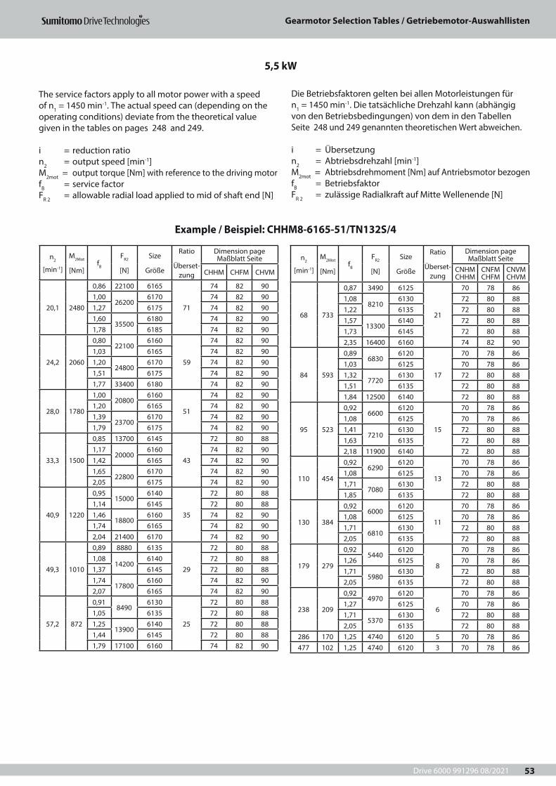
Drive 6000 991296 08/2021
Gearmotor Selection Tables / Getriebemotor-Auswahllisten
53
n2
[min-1]
M2Mot
[Nm]fB
FR2
[N]
Size
Größe
Ratio
Überset-zung
Dimension page Maßblatt Seite
CHHM CHFM CHVM
20,1 2480
0,86 22100 6165
71
74 82 901,00
262006170 74 82 90
1,27 6175 74 82 901,60
355006180 74 82 90
1,78 6185 74 82 90
24,2 2060
0,8022100
6160
59
74 82 901,03 6165 74 82 901,20
248006170 74 82 90
1,51 6175 74 82 901,77 33400 6180 74 82 90
28,0 1780
1,0020800
6160
51
74 82 901,20 6165 74 82 901,39
237006170 74 82 90
1,79 6175 74 82 90
33,3 1500
0,85 13700 6145
43
72 80 881,17
200006160 74 82 90
1,42 6165 74 82 901,65
228006170 74 82 90
2,05 6175 74 82 90
40,9 1220
0,9515000
6140
35
72 80 881,14 6145 72 80 881,46
188006160 74 82 90
1,74 6165 74 82 902,04 21400 6170 74 82 90
49,3 1010
0,89 8880 6135
29
72 80 881,08
142006140 72 80 88
1,37 6145 72 80 881,74
178006160 74 82 90
2,07 6165 74 82 90
57,2 872
0,918490
6130
25
72 80 881,05 6135 72 80 881,25
139006140 72 80 88
1,44 6145 72 80 881,79 17100 6160 74 82 90
n2
[min-1]
M2Mot
[Nm]fB
FR2
[N]
Size
Größe
Ratio
Überset-zung
Dimension page Maßblatt Seite
CNHM CHHM
CNFM CHFM
CNVM CHVM
68 733
0,87 3490 6125
21
70 78 861,08
82106130 72 80 88
1,22 6135 72 80 881,57
133006140 72 80 88
1,73 6145 72 80 882,35 16400 6160 74 82 90
84 593
0,896830
6120
17
70 78 861,03 6125 70 78 861,32
77206130 72 80 88
1,51 6135 72 80 881,84 12500 6140 72 80 88
95 523
0,926600
6120
15
70 78 861,08 6125 70 78 861,41
72106130 72 80 88
1,63 6135 72 80 882,18 11900 6140 72 80 88
110 454
0,926290
6120
13
70 78 861,08 6125 70 78 861,71
70806130 72 80 88
1,85 6135 72 80 88
130 384
0,926000
6120
11
70 78 861,08 6125 70 78 861,71
68106130 72 80 88
2,05 6135 72 80 88
179 279
0,925440
6120
8
70 78 861,26 6125 70 78 861,71
59806130 72 80 88
2,05 6135 72 80 88
238 209
0,924970
6120
6
70 78 861,27 6125 70 78 861,71
53706130 72 80 88
2,05 6135 72 80 88286 170 1,25 4740 6120 5 70 78 86477 102 1,25 4740 6120 3 70 78 86
5,5 kW
Example / Beispiel: CHHM8-6165-51/TN132S/4
The service factors apply to all motor power with a speed of n1 = 1450 min-1. The actual speed can (depending on the operating conditions) deviate from the theoretical value given in the tables on pages 248 and 249.
i = reduction ration2 = output speed [min-1]M2mot = output torque [Nm] with reference to the driving motorfB = service factorFR 2 = allowable radial load applied to mid of shaft end [N]
Die Betriebsfaktoren gelten bei allen Motorleistungen für n1 = 1450 min-1. Die tatsächliche Drehzahl kann (abhängig von den Betriebsbedingungen) von dem in den Tabellen Seite 248 und 249 genannten theoretischen Wert abweichen.
i = Übersetzungn2 = Abtriebsdrehzahl [min-1] M2mot = Abtriebsdrehmoment [Nm] auf Antriebsmotor bezogenfB = BetriebsfaktorFR 2 = zulässige Radialkraft auf Mitte Wellenende [N]
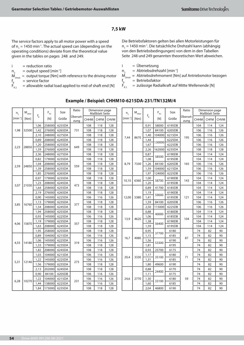
Drive 6000 991296 08/2021
Gearmotor Selection Tables / Getriebemotor-Auswahllisten
54
n2
[min-1]
M2Mot
[Nm]fB
FR2
[N]
Size
Größe
Ratio
Überset-zung
Dimension page Maßblatt Seite
CHHM CHFM CHVM
1,98 325001,06 258000 6255DA
731108 118 128
1,42 276000 6265DA 108 118 1282,10 248000 6275DA 108 118 128
2,23 28850
0,89 208000 6245DA
649
108 118 1281,20 258000 6255DA 108 118 1281,59 276000 6265DA 108 118 1282,36 248000 6275DA 108 118 128
2,59 24850
0,82 179000 6235DA
559
108 118 1281,04 208000 6245DA 108 118 1281,39 258000 6255DA 108 118 1281,85 276000 6265DA 108 118 128
3,07 21030
0,97 179000 6235DA
473
108 118 1281,23 208000 6245DA 108 118 1281,64 258000 6255DA 108 118 1282,19 276000 6265DA 108 118 128
3,85 16760
0,90 145000 6225DA
377
106 116 1261,13 179000 6235DA 108 118 1281,54 208000 6245DA 108 118 1281,94 258000 6255DA 108 118 128
4,06 15870
0,93 145000 6225DA
357
106 116 1261,19 179000 6235DA 108 118 1281,63 208000 6245DA 108 118 1281,95 258000 6255DA 108 118 128
4,55 14180
0,89 104000 6215DA
319
106 116 1261,06 145000 6225DA 106 116 1261,33 179000 6235DA 108 118 1281,82 208000 6245DA 108 118 128
5,31 12140
1,03 104000 6215DA
273
106 116 1261,22 145000 6225DA 106 116 1261,56 179000 6235DA 108 118 1282,13 202000 6245DA 108 118 128
6,28 10270
0,90 84100 6205DB
231
106 116 1261,22 104000 6215DA 106 116 1261,44 138000 6225DA 106 116 1261,84 173000 6235DA 108 118 128
n2
[min-1]
M2Mot
[Nm]fB
FR2
[N]
Size
Größe
Ratio
Überset-zung
Dimension page Maßblatt Seite
CHHM CHFM CHVM
7,44 8670
0,91 58000 6195DB
195
104 114 1241,07 84100 6205DB 106 116 1261,40 104000 6215DA 106 116 1261,44
1300006225DA 106 116 126
1,67 6225DB 106 116 1262,26 162000 6235DA 108 118 128
8,79 7330
0,8758500
6190DB
165
104 114 1241,08 6195DB 104 114 1241,26 84100 6205DB 106 116 1261,59 104000 6215DA 106 116 1261,97 124000 6225DB 106 116 126
10,10 63601,00
587006190DB
143104 114 124
1,20 6195DB 104 114 124
12,00 5380
0,89 41700 6185DB
121
104 114 1241,19
590006190DB 104 114 124
1,41 6195DB 104 114 1241,59 84100 6205DB 106 116 1262,50 115000 6225DB 106 116 126
13,9 4620
0,8840000
6180DB
104
104 114 1241,06 6185DB 104 114 1241,38
564006190DB 104 114 124
1,59 6195DB 104 114 124
16,7 4080
0,9537700
6180
87
74 82 901,15 6185 74 82 901,56
533006190 74 82 90
1,81 6195 74 82 90
20,4 3330
0,93 25700 6175
71
74 82 901,17
351006180 74 82 90
1,31 6185 74 82 901,80 49600 6190 74 82 90
24,6 2770
0,8824400
6170
59
74 82 901,11 6175 74 82 901,30
331006180 74 82 90
1,60 6185 74 82 902,04 46800 6190 74 82 90
7,5 kW
Example / Beispiel: CHHM10-6215DA-231/TN132M/4
The service factors apply to all motor power with a speed of n1 = 1450 min-1. The actual speed can (depending on the operating conditions) deviate from the theoretical value given in the tables on pages 248 and 249.
i = reduction ration2 = output speed [min-1]M2mot = output torque [Nm] with reference to the driving motorfB = service factorFR 2 = allowable radial load applied to mid of shaft end [N]
Die Betriebsfaktoren gelten bei allen Motorleistungen für n1 = 1450 min-1. Die tatsächliche Drehzahl kann (abhängig von den Betriebsbedingungen) von dem in den Tabellen Seite 248 und 249 genannten theoretischen Wert abweichen.
i = Übersetzungn2 = Abtriebsdrehzahl [min-1] M2mot = Abtriebsdrehmoment [Nm] auf Antriebsmotor bezogenfB = BetriebsfaktorFR 2 = zulässige Radialkraft auf Mitte Wellenende [N]
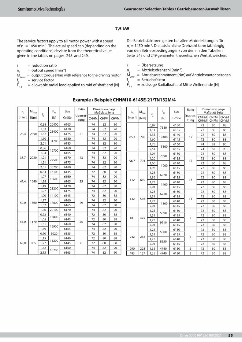
Drive 6000 991296 08/2021
Gearmotor Selection Tables / Getriebemotor-Auswahllisten
55
n2
[min-1]
M2Mot
[Nm]fB
FR2
[N]
Size
Größe
Ratio
Überset-zung
Dimension page Maßblatt Seite
CHHM CHFM CHVM
28,4 2390
0,88 20400 6165
51
74 82 901,02
234006170 74 82 90
1,32 6175 74 82 901,60
317006180 74 82 90
2,01 6185 74 82 90
33,7 2020
0,8619700
6160
43
74 82 901,04 6165 74 82 901,21
225006170 74 82 90
1,51 6175 74 82 902,01 30700 6180 74 82 90
41,4 1640
0,84 13100 6145
35
72 80 881,07
186006160 74 82 90
1,28 6165 74 82 901,49
212006170 74 82 90
1,92 6175 74 82 90
50,0 1360
1,00 14100 6145
29
72 80 881,27
176006160 74 82 90
1,52 6165 74 82 901,80 20100 6170 74 82 90
58,0 1170
0,9213800
6140
25
72 80 881,05 6145 72 80 881,31
169006160 74 82 90
1,79 6165 74 82 90
69,0 985
0,90 8020 6135
21
72 80 881,15
132006140 72 80 88
1,27 6145 72 80 881,72
162006160 74 82 90
2,13 6165 74 82 90
n2
[min-1]
M2Mot
[Nm]fB
FR2
[N]
Size
Größe
Ratio
Überset-zung
Dimension page Maßblatt Seite
CNHM CHHM
CNFM CHFM
CNVM CHVM
85,3 798
0,977580
6130
17
72 80 881,11 6135 72 80 881,35
124006140 72 80 88
1,60 6145 72 80 881,75
151006160 74 82 90
2,51 6165 74 82 90
96,7 704
1,047090
6130
15
72 80 881,20 6135 72 80 881,60
119006140 72 80 88
1,93 6145 72 80 88
112 610
1,256970
6130
13
72 80 881,36 6135 72 80 881,73
114006140 72 80 88
2,01 6145 72 80 88
132 516
1,256710
6130
11
72 80 881,51 6135 72 80 881,73
111006140 72 80 88
2,01 6145 72 80 88
181 375
1,255890
6130
8
72 80 881,51 6135 72 80 881,73
99106140 72 80 88
2,01 6145 72 80 88
242 282
1,255300
6130
6
72 80 881,51 6135 72 80 881,73
89506140 72 80 88
2,01 6145 72 80 88290 228 1,35 4740 6130 5 72 80 88483 137 1,35 4740 6130 3 72 80 88
7,5 kW
Example / Beispiel: CHHM10-6145E-21/TN132M/4
The service factors apply to all motor power with a speed of n1 = 1450 min-1. The actual speed can (depending on the operating conditions) deviate from the theoretical value given in the tables on pages 248 and 249.
i = reduction ration2 = output speed [min-1]M2mot = output torque [Nm] with reference to the driving motorfB = service factorFR 2 = allowable radial load applied to mid of shaft end [N]
Die Betriebsfaktoren gelten bei allen Motorleistungen für n1 = 1450 min-1. Die tatsächliche Drehzahl kann (abhängig von den Betriebsbedingungen) von dem in den Tabellen Seite 248 und 249 genannten theoretischen Wert abweichen.
i = Übersetzungn2 = Abtriebsdrehzahl [min-1] M2mot = Abtriebsdrehmoment [Nm] auf Antriebsmotor bezogenfB = BetriebsfaktorFR 2 = zulässige Radialkraft auf Mitte Wellenende [N]
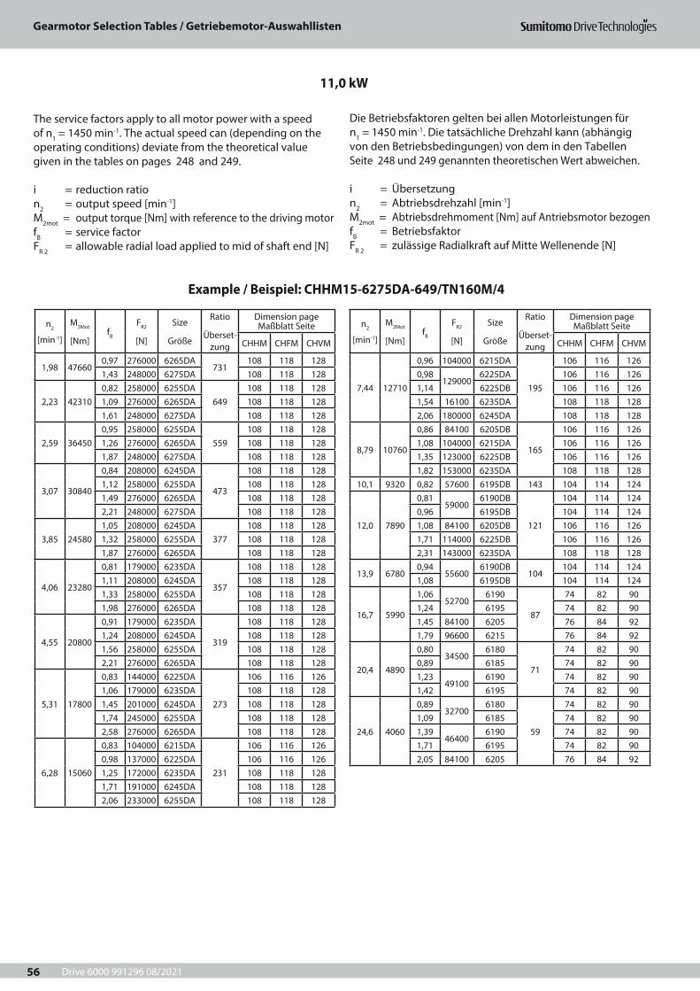
Drive 6000 991296 08/2021
Gearmotor Selection Tables / Getriebemotor-Auswahllisten
56
n2
[min-1]
M2Mot
[Nm]fB
FR2
[N]
Size
Größe
Ratio
Überset-zung
Dimension page Maßblatt Seite
CHHM CHFM CHVM
1,98 476600,97 276000 6265DA
731108 118 128
1,43 248000 6275DA 108 118 128
2,23 423100,82 258000 6255DA
649108 118 128
1,09 276000 6265DA 108 118 1281,61 248000 6275DA 108 118 128
2,59 364500,95 258000 6255DA
559108 118 128
1,26 276000 6265DA 108 118 1281,87 248000 6275DA 108 118 128
3,07 30840
0,84 208000 6245DA
473
108 118 1281,12 258000 6255DA 108 118 1281,49 276000 6265DA 108 118 1282,21 248000 6275DA 108 118 128
3,85 245801,05 208000 6245DA
377108 118 128
1,32 258000 6255DA 108 118 1281,87 276000 6265DA 108 118 128
4,06 23280
0,81 179000 6235DA
357
108 118 1281,11 208000 6245DA 108 118 1281,33 258000 6255DA 108 118 1281,98 276000 6265DA 108 118 128
4,55 20800
0,91 179000 6235DA
319
108 118 1281,24 208000 6245DA 108 118 1281,56 258000 6255DA 108 118 1282,21 276000 6265DA 108 118 128
5,31 17800
0,83 144000 6225DA
273
106 116 1261,06 179000 6235DA 108 118 1281,45 201000 6245DA 108 118 1281,74 245000 6255DA 108 118 1282,58 276000 6265DA 108 118 128
6,28 15060
0,83 104000 6215DA
231
106 116 1260,98 137000 6225DA 106 116 1261,25 172000 6235DA 108 118 1281,71 191000 6245DA 108 118 1282,06 233000 6255DA 108 118 128
n2
[min-1]
M2Mot
[Nm]fB
FR2
[N]
Size
Größe
Ratio
Überset-zung
Dimension page Maßblatt Seite
CHHM CHFM CHVM
7,44 12710
0,96 104000 6215DA
195
106 116 1260,98
1290006225DA 106 116 126
1,14 6225DB 106 116 1261,54 16100 6235DA 108 118 1282,06 180000 6245DA 108 118 128
8,79 10760
0,86 84100 6205DB
165
106 116 1261,08 104000 6215DA 106 116 1261,35 123000 6225DB 106 116 1261,82 153000 6235DA 108 118 128
10,1 9320 0,82 57600 6195DB 143 104 114 124
12,0 7890
0,8159000
6190DB
121
104 114 1240,96 6195DB 104 114 1241,08 84100 6205DB 106 116 1261,71 114000 6225DB 106 116 1262,31 143000 6235DA 108 118 128
13,9 67800,94
556006190DB
104104 114 124
1,08 6195DB 104 114 124
16,7 5990
1,0652700
6190
87
74 82 901,24 6195 74 82 901,45 84100 6205 76 84 921,79 96600 6215 76 84 92
20,4 4890
0,8034500
6180
71
74 82 900,89 6185 74 82 901,23
491006190 74 82 90
1,42 6195 74 82 90
24,6 4060
0,8932700
6180
59
74 82 901,09 6185 74 82 901,39
464006190 74 82 90
1,71 6195 74 82 902,05 84100 6205 76 84 92
11,0 kW
Example / Beispiel: CHHM15-6275DA-649/TN160M/4
The service factors apply to all motor power with a speed of n1 = 1450 min-1. The actual speed can (depending on the operating conditions) deviate from the theoretical value given in the tables on pages 248 and 249.
i = reduction ration2 = output speed [min-1]M2mot = output torque [Nm] with reference to the driving motorfB = service factorFR 2 = allowable radial load applied to mid of shaft end [N]
Die Betriebsfaktoren gelten bei allen Motorleistungen für n1 = 1450 min-1. Die tatsächliche Drehzahl kann (abhängig von den Betriebsbedingungen) von dem in den Tabellen Seite 248 und 249 genannten theoretischen Wert abweichen.
i = Übersetzungn2 = Abtriebsdrehzahl [min-1] M2mot = Abtriebsdrehmoment [Nm] auf Antriebsmotor bezogenfB = BetriebsfaktorFR 2 = zulässige Radialkraft auf Mitte Wellenende [N]
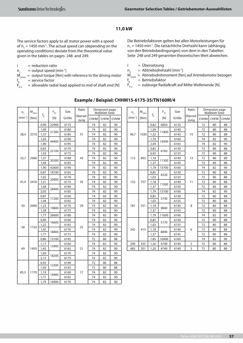
Drive 6000 991296 08/2021
Gearmotor Selection Tables / Getriebemotor-Auswahllisten
57
n2
[min-1]
M2Mot
[Nm]fB
FR2
[N]
Size
Größe
Ratio
Überset-zung
Dimension page Maßblatt Seite
CHHM CHFM CHVM
28,4 3510
0,90 22900 6175
51
74 82 901,09
313006180 74 82 90
1,37 6185 74 82 901,65
444006190 74 82 90
1,90 6195 74 82 90
33,7 2960
0,8322100
6170
43
74 82 901,03 6175 74 82 901,37
303006180 74 82 90
1,69 6185 74 82 901,90 42600 6190 74 82 90
41,4 2410
0,87 18100 6165
35
74 82 901,02
209006170 74 82 90
1,31 6175 74 82 901,68
284006180 74 82 90
2,05 6185 74 82 90
50 2000
0,8717200
6160
29
74 82 901,04 6165 74 82 901,23
198006170 74 82 90
1,58 6175 74 82 901,77 26600 6180 74 82 90
58 1720
0,9016600
6160
25
74 82 901,22 6165 74 82 901,42
188006170 74 82 90
1,77 6175 74 82 90
69 1450
0,86 13100 6145
21
72 80 881,17
159006160 74 82 90
1,45 6165 74 82 901,69
182006170 74 82 90
2,15 6175 74 82 90
85,3 1170
0,9212300
6140
17
72 80 881,09 6145 72 80 881,19
149006160 74 82 90
1,71 6165 74 82 901,79 16900 6170 74 82 90
n2
[min-1]
M2Mot
[Nm]fB
FR2
[N]
Size
Größe
Ratio
Überset-zung
Dimension page Maßblatt Seite
CHHM CHFM CHVM
96,7 1030
0,82 6850 6135
15
72 80 881,09
118006140 72 80 88
1,32 6145 72 80 881,70
145006160 74 82 90
2,04 6165 74 82 90
112 895
0,856760
6130
13
72 80 880,93 6135 72 80 881,18
113006140 72 80 88
1,37 6145 72 80 881,79 13700 6160 74 82 90
132 757
0,856520
6130
11
72 80 881,03 6135 72 80 881,18
110006140 72 80 88
1,37 6145 72 80 881,79 13100 6160 74 82 90
181 551
0,855740
6130
8
72 80 881,03 6135 72 80 881,18
98406140 72 80 88
1,37 6145 72 80 881,79 11600 6160 74 82 90
242 413
0,855170
6130
6
72 80 881,03 6135 72 80 881,18
88906140 72 80 88
1,37 6145 72 80 881,85 10400 6160 74 82 90
290 335 1,20 4740 6140 5 72 80 88483 201 1,20 4740 6140 3 72 80 88
11,0 kW
Example / Beispiel: CHHM15-6175-35/TN160M/4
The service factors apply to all motor power with a speed of n1 = 1450 min-1. The actual speed can (depending on the operating conditions) deviate from the theoretical value given in the tables on pages 248 and 249.
i = reduction ration2 = output speed [min-1]M2mot = output torque [Nm] with reference to the driving motorfB = service factorFR 2 = allowable radial load applied to mid of shaft end [N]
Die Betriebsfaktoren gelten bei allen Motorleistungen für n1 = 1450 min-1. Die tatsächliche Drehzahl kann (abhängig von den Betriebsbedingungen) von dem in den Tabellen Seite 248 und 249 genannten theoretischen Wert abweichen.
i = Übersetzungn2 = Abtriebsdrehzahl [min-1] M2mot = Abtriebsdrehmoment [Nm] auf Antriebsmotor bezogenfB = BetriebsfaktorFR 2 = zulässige Radialkraft auf Mitte Wellenende [N]
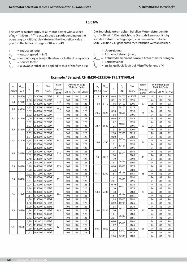
Drive 6000 991296 08/2021
Gearmotor Selection Tables / Getriebemotor-Auswahllisten
58
n2
[min-1]
M2Mot
[Nm]fB
FR2
[N]
Size
Größe
Ratio
Überset-zung
Dimension page Maßblatt Seite
CHHM CHFM CHVM
2 64550 1,05 248000 6275DA 731 108 118 128
2,3 573100,80 276000 6265DA
649108 118 128
1,18 248000 6275DA 108 118 128
2,6 493600,93 276000 6265DA
559108 118 128
1,37 248000 6275DA 108 118 128
3,1 417700,82 258000 6255DA
473108 118 128
1,09 276000 6265DA 108 118 1281,62 248000 6275DA 108 118 128
3,9 332900,97 258000 6255DA
377108 118 128
1,37 276000 6265DA 108 118 1282,03 248000 6275DA 108 118 128
4,1 315200,81 208000 6245DA
357108 118 128
0,98 258000 6255DA 108 118 1281,45 276000 6265DA 108 118 128
4,6 28170
0,91 208000 6245DA
319
108 118 1281,14 256000 6255DA 108 118 1281,62 276000 6265DA 108 118 1282,40 248000 6275DA 108 118 128
5,3 241101,06 200000 6245DA
273108 118 128
1,28 244000 6255DA 108 118 1281,90 276000 6265DA 108 118 128
6,3 20400
0,92 171000 6235DA
231
108 118 1281,26 190000 6245DA 108 118 1281,51 232000 6255DA 108 118 1282,24 276000 6265DA 108 118 128
7,5 17220
0,84 128000 6225DB
195
106 116 1261,13 160000 6235DA 108 118 1281,51 179000 6245DA 108 118 1281,80 219000 6255DA 108 118 128
8,8 14570
0,80 104000 6215DA
165
106 116 1260,99 122000 6225DB 106 116 1261,34 152000 6235DA 108 118 1281,69 170000 6245DA 108 118 1282,12 209000 6255DA 108 118 128
12,1 10680
0,80 84100 6205DB
121
106 116 1261,25 113000 6225DB 106 116 1261,69 142000 6235DA 108 118 1282,12 194000 6255DA 108 118 128
n2
[min-1]
M2Mot
[Nm]fB
FR2
[N]
Size
Größe
Ratio
Überset-zung
Dimension page Maßblatt Seite
CHHM CHFM CHVM
14 9180 0,80 54700 6195DB 104 104 114 124
16,8 81100,91 52100 6195
8774 82 90
1,06 84100 6205 76 84 921,31 96100 6215 76 84 92
20,6 66200,90
486006190
7174 82 90
1,04 6195 74 82 90
24,7 5500
0,80 32100 6185
59
74 82 901,02
460006190 74 82 90
1,25 6195 74 82 901,51 84100 6205 76 84 922,26 85900 6215 76 84 92
28,6 4750
0,8030900
6180
51
74 82 901,01 6185 74 82 901,21
441006190 74 82 90
1,39 6195 74 82 90
34 4010
1,0129900
6180
43
74 82 901,24 6185 74 82 901,39
423006190 74 82 90
1,81 6195 74 82 90
41,7 3260
0,96 20400 6175
35
74 82 901,23
281006180 74 82 90
1,51 6185 74 82 901,62
394006190 74 82 90
2,01 6195 74 82 90
50,3 2700
0,1019400
6170
29
74 82 901,16 6175 74 82 901,30
264006180 74 82 90
1,61 6185 74 82 902,05 37400 6190 74 82 90
58,4 2330
0,89 16200 6165
25
74 82 901,04
185006170 74 82 90
1,30 6175 74 82 901,61
253006180 74 82 90
2,01 6185 74 82 90
69,5 1960
0,8615600
6160
21
74 82 901,07 6165 74 82 901,24
179006170 74 82 90
1,57 6175 74 82 902,00 24300 6180 74 82 90
15,0 kW
Example / Beispiel: CHHM20-6235DA-195/TN160L/4
The service factors apply to all motor power with a speed of n1 = 1450 min-1. The actual speed can (depending on the operating conditions) deviate from the theoretical value given in the tables on pages 248 and 249.
i = reduction ration2 = output speed [min-1]M2mot = output torque [Nm] with reference to the driving motorfB = service factorFR 2 = allowable radial load applied to mid of shaft end [N]
Die Betriebsfaktoren gelten bei allen Motorleistungen für n1 = 1450 min-1. Die tatsächliche Drehzahl kann (abhängig von den Betriebsbedingungen) von dem in den Tabellen Seite 248 und 249 genannten theoretischen Wert abweichen.
i = Übersetzungn2 = Abtriebsdrehzahl [min-1] M2mot = Abtriebsdrehmoment [Nm] auf Antriebsmotor bezogenfB = BetriebsfaktorFR 2 = zulässige Radialkraft auf Mitte Wellenende [N]
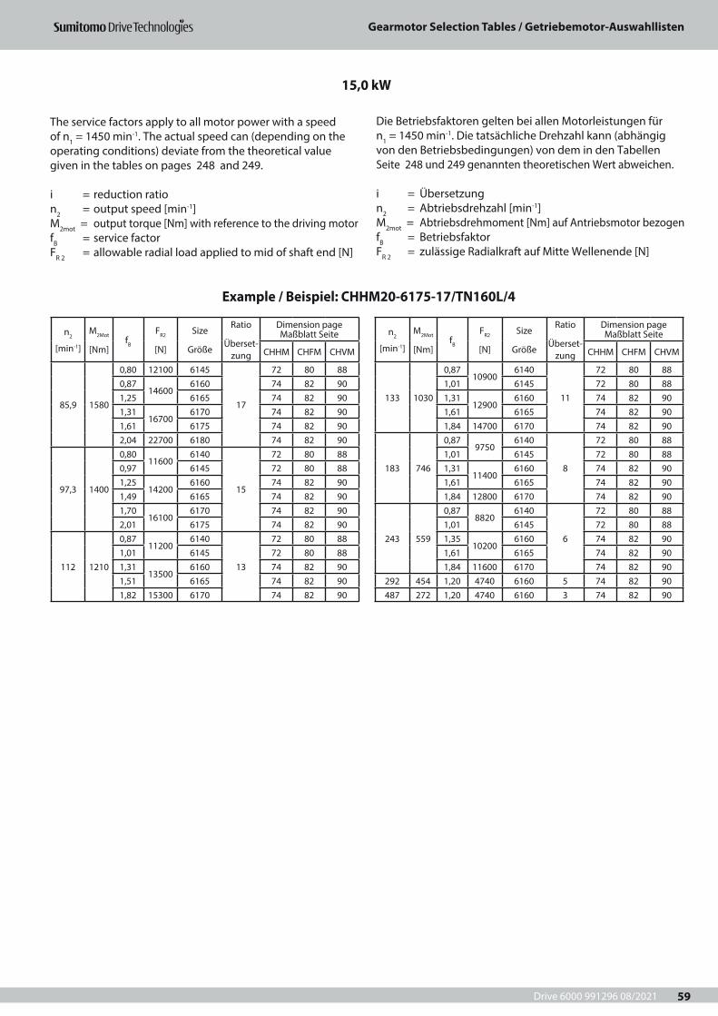
Drive 6000 991296 08/2021
Gearmotor Selection Tables / Getriebemotor-Auswahllisten
59
n2
[min-1]
M2Mot
[Nm]fB
FR2
[N]
Size
Größe
Ratio
Überset-zung
Dimension page Maßblatt Seite
CHHM CHFM CHVM
85,9 1580
0,80 12100 6145
17
72 80 880,87
146006160 74 82 90
1,25 6165 74 82 901,31
167006170 74 82 90
1,61 6175 74 82 902,04 22700 6180 74 82 90
97,3 1400
0,8011600
6140
15
72 80 880,97 6145 72 80 881,25
142006160 74 82 90
1,49 6165 74 82 901,70
161006170 74 82 90
2,01 6175 74 82 90
112 1210
0,8711200
6140
13
72 80 881,01 6145 72 80 881,31
135006160 74 82 90
1,51 6165 74 82 901,82 15300 6170 74 82 90
n2
[min-1]
M2Mot
[Nm]fB
FR2
[N]
Size
Größe
Ratio
Überset-zung
Dimension page Maßblatt Seite
CHHM CHFM CHVM
133 1030
0,8710900
6140
11
72 80 881,01 6145 72 80 881,31
129006160 74 82 90
1,61 6165 74 82 901,84 14700 6170 74 82 90
183 746
0,879750
6140
8
72 80 881,01 6145 72 80 881,31
114006160 74 82 90
1,61 6165 74 82 901,84 12800 6170 74 82 90
243 559
0,878820
6140
6
72 80 881,01 6145 72 80 881,35
102006160 74 82 90
1,61 6165 74 82 901,84 11600 6170 74 82 90
292 454 1,20 4740 6160 5 74 82 90487 272 1,20 4740 6160 3 74 82 90
15,0 kW
Example / Beispiel: CHHM20-6175-17/TN160L/4
The service factors apply to all motor power with a speed of n1 = 1450 min-1. The actual speed can (depending on the operating conditions) deviate from the theoretical value given in the tables on pages 248 and 249.
i = reduction ration2 = output speed [min-1]M2mot = output torque [Nm] with reference to the driving motorfB = service factorFR 2 = allowable radial load applied to mid of shaft end [N]
Die Betriebsfaktoren gelten bei allen Motorleistungen für n1 = 1450 min-1. Die tatsächliche Drehzahl kann (abhängig von den Betriebsbedingungen) von dem in den Tabellen Seite 248 und 249 genannten theoretischen Wert abweichen.
i = Übersetzungn2 = Abtriebsdrehzahl [min-1] M2mot = Abtriebsdrehmoment [Nm] auf Antriebsmotor bezogenfB = BetriebsfaktorFR 2 = zulässige Radialkraft auf Mitte Wellenende [N]
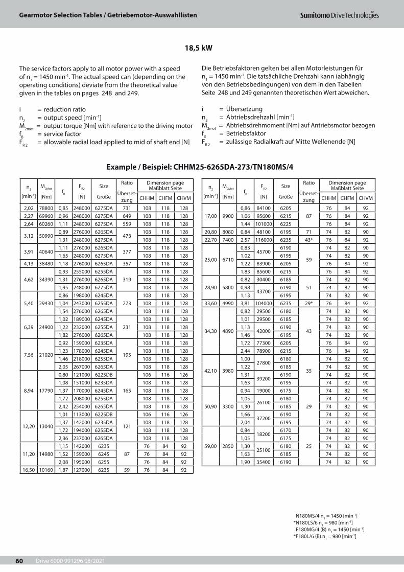
Drive 6000 991296 08/2021
Gearmotor Selection Tables / Getriebemotor-Auswahllisten
60
18,5 kW
Example / Beispiel: CHHM25-6265DA-273/TN180MS/4
N180MS/4 n1 = 1450 [min-1] *N180LS/6 n1 = 980 [min-1] F180MG/4 (B) n1 = 1450 [min-1] *F180L/6 (B) n1 = 980 [min-1]
n2
[min-1]
M2Mot
[Nm]fB
FR2
[N]
Size
Größe
Ratio
Überset-zung
Dimension page Maßblatt Seite
CHHM CHFM CHVM
2,02 78800 0,85 248000 6275DA 731 108 118 1282,27 69960 0,96 248000 6275DA 649 108 118 1282,64 60260 1,11 248000 6275DA 559 108 118 128
3,12 509900,89 276000 6265DA
473108 118 128
1,31 248000 6275DA 108 118 128
3,91 406401,11 276000 6265DA
377108 118 128
1,65 248000 6275DA 108 118 1284,13 38480 1,18 276000 6265DA 357 108 118 128
4,62 343900,93 255000 6255DA
319108 118 128
1,31 276000 6265DA 108 118 1281,95 248000 6275DA 108 118 128
5,40 294300,86 198000 6245DA
273108 118 128
1,04 243000 6255DA 108 118 1281,54 276000 6265DA 108 118 128
6,39 249001,02 189000 6245DA
231108 118 128
1,22 232000 6255DA 108 118 1281,82 276000 6265DA 108 118 128
7,56 21020
0,92 159000 6235DA
195
108 118 1281,23 178000 6245DA 108 118 1281,46 218000 6255DA 108 118 1282,05 267000 6265DA 108 118 128
8,94 17790
0,80 121000 6225DB
165
106 116 1261,08 151000 6235DA 108 118 1281,37 170000 6245DA 108 118 1281,72 208000 6255DA 108 118 1282,42 254000 6265DA 108 118 128
12,20 13040
1,01 113000 6225DB
121
106 116 1261,37 142000 6235DA 108 118 1281,72 194000 6255DA 108 118 1282,36 237000 6265DA 108 118 128
11,20 149801,15 142000 6235
8776 84 92
1,52 159000 6245 76 84 922,08 195000 6255 76 84 92
16,50 10160 1,87 127000 6235 59 76 84 92
n2
[min-1]
M2Mot
[Nm]fB
FR2
[N]
Size
Größe
Ratio
Überset-zung
Dimension page Maßblatt Seite
CHHM CHFM CHVM
17,00 99000,86 84100 6205
8776 84 92
1,06 95600 6215 76 84 921,44 101000 6225 76 84 92
20,80 8080 0,84 48100 6195 71 74 82 9022,70 7400 2,57 116000 6235 43* 76 84 92
25,00 6710
0,8345700
6190
59
74 82 901,02 6195 74 82 901,22 83900 6205 76 84 921,83 85600 6215 76 84 92
28,90 58000,82 30400 6185
5174 82 90
0,9843700
6190 74 82 901,13 6195 74 82 90
33,60 4990 3,81 104000 6235 29* 76 84 92
34,30 4890
0,82 29500 6180
43
74 82 901,01 29500 6185 74 82 901,13
420006190 74 82 90
1,46 6195 74 82 901,72 77300 6205 76 84 922,44 78900 6215 76 84 92
42,10 3980
1,0027800
6180
35
74 82 901,22 6185 74 82 901,31
392006190 74 82 90
1,63 6195 74 82 90
50,90 3300
0,94 19000 6175
29
74 82 901,05
261006180 74 82 90
1,30 6185 74 82 901,66
372006190 74 82 90
2,04 6195 74 82 90
59,00 2850
0,8418200
6170
25
74 82 901,05 6175 74 82 901,30
251006180 74 82 90
1,63 6185 74 82 901,90 35400 6190 74 82 90
The service factors apply to all motor power with a speed of n1 = 1450 min-1. The actual speed can (depending on the operating conditions) deviate from the theoretical value given in the tables on pages 248 and 249.
i = reduction ration2 = output speed [min-1]M2mot = output torque [Nm] with reference to the driving motorfB = service factorFR 2 = allowable radial load applied to mid of shaft end [N]
Die Betriebsfaktoren gelten bei allen Motorleistungen für n1 = 1450 min-1. Die tatsächliche Drehzahl kann (abhängig von den Betriebsbedingungen) von dem in den Tabellen Seite 248 und 249 genannten theoretischen Wert abweichen.
i = Übersetzungn2 = Abtriebsdrehzahl [min-1] M2mot = Abtriebsdrehmoment [Nm] auf Antriebsmotor bezogenfB = BetriebsfaktorFR 2 = zulässige Radialkraft auf Mitte Wellenende [N]
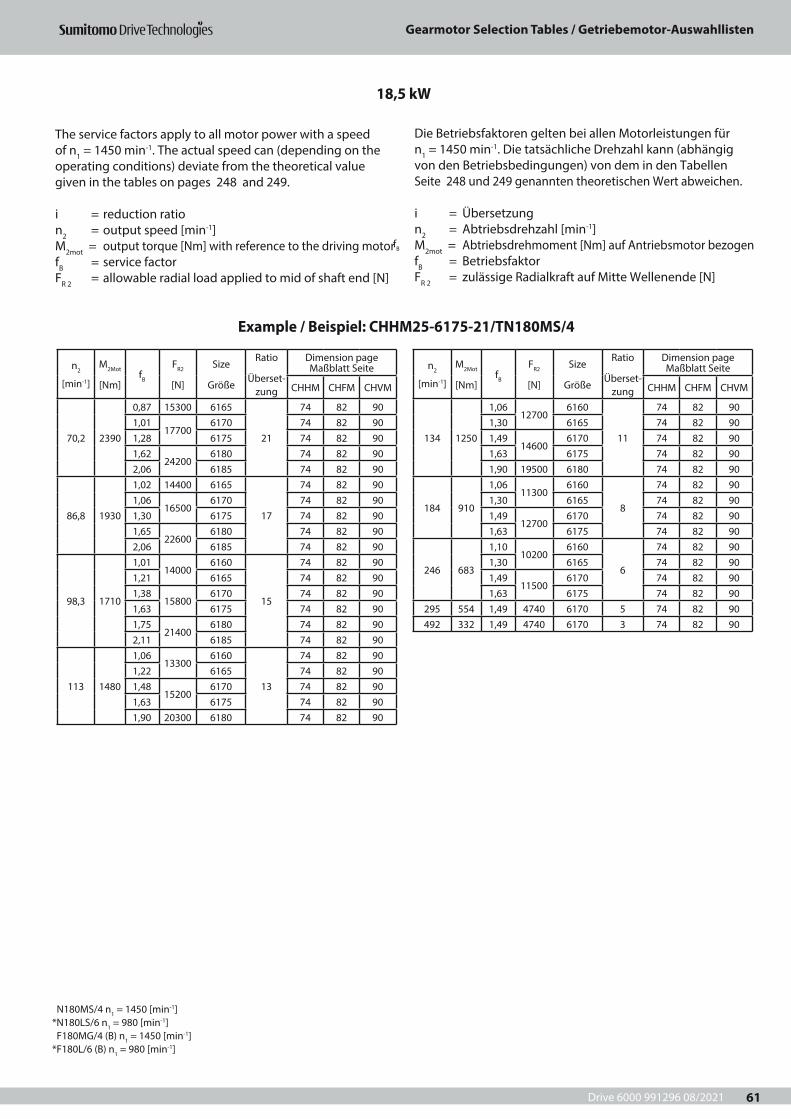
Drive 6000 991296 08/2021
Gearmotor Selection Tables / Getriebemotor-Auswahllisten
61
n2
[min-1]
M2Mot
[Nm]fB
FR2
[N]
Size
Größe
Ratio
Überset-zung
Dimension page Maßblatt Seite
CHHM CHFM CHVM
70,2 2390
0,87 15300 6165
21
74 82 901,01
177006170 74 82 90
1,28 6175 74 82 901,62
242006180 74 82 90
2,06 6185 74 82 90
86,8 1930
1,02 14400 6165
17
74 82 901,06
165006170 74 82 90
1,30 6175 74 82 901,65
226006180 74 82 90
2,06 6185 74 82 90
98,3 1710
1,0114000
6160
15
74 82 901,21 6165 74 82 901,38
158006170 74 82 90
1,63 6175 74 82 901,75
214006180 74 82 90
2,11 6185 74 82 90
113 1480
1,0613300
6160
13
74 82 901,22 6165 74 82 901,48
152006170 74 82 90
1,63 6175 74 82 901,90 20300 6180 74 82 90
n2
[min-1]
M2Mot
[Nm]fB
FR2
[N]
Size
Größe
Ratio
Überset-zung
Dimension page Maßblatt Seite
CHHM CHFM CHVM
134 1250
1,0612700
6160
11
74 82 901,30 6165 74 82 901,49
146006170 74 82 90
1,63 6175 74 82 901,90 19500 6180 74 82 90
184 910
1,0611300
6160
8
74 82 901,30 6165 74 82 901,49
127006170 74 82 90
1,63 6175 74 82 90
246 683
1,1010200
6160
6
74 82 901,30 6165 74 82 901,49
115006170 74 82 90
1,63 6175 74 82 90295 554 1,49 4740 6170 5 74 82 90492 332 1,49 4740 6170 3 74 82 90
18,5 kW
Example / Beispiel: CHHM25-6175-21/TN180MS/4
N180MS/4 n1 = 1450 [min-1] *N180LS/6 n1 = 980 [min-1] F180MG/4 (B) n1 = 1450 [min-1] *F180L/6 (B) n1 = 980 [min-1]
The service factors apply to all motor power with a speed of n1 = 1450 min-1. The actual speed can (depending on the operating conditions) deviate from the theoretical value given in the tables on pages 248 and 249.
i = reduction ration2 = output speed [min-1]M2mot = output torque [Nm] with reference to the driving motorfB = service factorFR 2 = allowable radial load applied to mid of shaft end [N]
Die Betriebsfaktoren gelten bei allen Motorleistungen für n1 = 1450 min-1. Die tatsächliche Drehzahl kann (abhängig von den Betriebsbedingungen) von dem in den Tabellen Seite 248 und 249 genannten theoretischen Wert abweichen.
i = Übersetzungn2 = Abtriebsdrehzahl [min-1] M2mot = Abtriebsdrehmoment [Nm] auf Antriebsmotor bezogenfB = BetriebsfaktorFR 2 = zulässige Radialkraft auf Mitte Wellenende [N]
fB
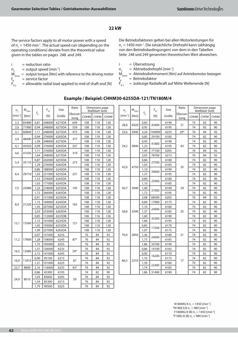
Drive 6000 991296 08/2021
Gearmotor Selection Tables / Getriebemotor-Auswahllisten
62
n2
[min-1]
M2Mot
[Nm]fB
FR2
[N]
Size
Größe
Ratio
Überset-zung
Dimension page Maßblatt Seite
CHHM CHFM CHVM
2,3 83480 0,81 248000 6275DA 649 108 118 1282,6 71900 0,94 248000 6275DA 559 108 118 1283,1 60840 1,11 248000 6275DA 473 108 118 128
3,9 484900,94 276000 6265DA
377108 118 128
1,39 248000 6275DA 108 118 1284,1 45920 0,99 276000 6265DA 357 108 118 128
4,6 410301,11 276000 6265DA
319108 118 128
1,64 248000 6275DA 108 118 128
5,4 351100,87 242000 6255DA
273108 118 128
1,29 276000 6265DA 108 118 128
6,4 297100,86 188000 6245DA
231108 118 128
1,03 231000 6255DA 108 118 1281,53 276000 6265DA 108 118 128
7,5 250801,03 177000 6245DA
195108 118 128
1,23 218000 6255DA 108 118 1281,72 266000 6265DA 108 118 128
8,9 21220
0,91 151000 6235DA
165
108 118 1281,15 169000 6245DA 108 118 1281,45 207000 6255DA 108 118 1282,03 253000 6265DA 108 118 128
12,1 15560
0,85 112000 6225DB
121
106 116 1261,15 141000 6235DA 108 118 1281,45 193000 6255DA 108 118 1281,99 237000 6265DA 108 118 128
11,2 178000,97 141000 6235
87*76 84 92
1,28 158000 6245 76 84 921,75 195000 6255 76 84 92
16,5 120801,57 126000 6235
59*76 84 92
2,15 141000 6245 76 84 92
16,9 118100,90 95100 6215
8776 84 92
1,21 101000 6225 76 84 9222,7 8800 2,16 116000 6235 43* 76 84 92
24,9 8010
0,86 45300 6195
59
74 82 901,03 83600 6205 76 84 921,54 85300 6215 76 84 921,79 90500 6225 76 84 92
n2
[min-1]
M2Mot
[Nm]fB
FR2
[N]
Size
Größe
Ratio
Überset-zung
Dimension page Maßblatt Seite
CHHM CHFM CHVM
28,8 69200,83
434006190
5174 82 90
0,95 6195 74 82 9033,6 5940 3,20 104000 6235 29* 76 84 92
34,2 5840
0,85 29100 6185
43
74 82 900,95
418006190 74 82 90
1,23 6195 74 82 901,45 77100 6205 76 84 922,05 78700 6215 76 84 92
42,0 4750
0,8427500
6180
35
74 82 901,03 6185 74 82 901,10
390006190 74 82 90
1,37 6195 74 82 90
50,7 3940
0,8925900
6180
29
74 82 901,10 6185 74 82 901,40
370006190 74 82 90
1,72 6195 74 82 902,08 68500 6205 76 84 92
58,8 3390
0,89 17900 6175
25
74 82 901,10
249006180 74 82 90
1,37 6185 74 82 901,60
353006190 74 82 90
1,84 6195 74 82 90
70,0 2850
0,8517500
6170
21
74 82 901,07 6175 74 82 901,36
240006180 74 82 90
1,73 6185 74 82 901,86 33700 6190 74 82 90
86,5 2310
0,86 14100 6165
17
74 82 900,90
162006170 74 82 90
1,10 6175 74 82 901,39
224006180 74 82 90
1,74 6185 74 82 901,86 31400 6190 74 82 90
22 kW
Example / Beispiel: CHHM30-6255DA-121/TN180M/4
The service factors apply to all motor power with a speed of n1 = 1450 min-1. The actual speed can (depending on the operating conditions) deviate from the theoretical value given in the tables on pages 248 and 249.
i = reduction ration2 = output speed [min-1]M2mot = output torque [Nm] with reference to the driving motorfB = service factorFR 2 = allowable radial load applied to mid of shaft end [N]
Die Betriebsfaktoren gelten bei allen Motorleistungen für n1 = 1450 min-1. Die tatsächliche Drehzahl kann (abhängig von den Betriebsbedingungen) von dem in den Tabellen Seite 248 und 249 genannten theoretischen Wert abweichen.
i = Übersetzungn2 = Abtriebsdrehzahl [min-1] M2mot = Abtriebsdrehmoment [Nm] auf Antriebsmotor bezogenfB = BetriebsfaktorFR 2 = zulässige Radialkraft auf Mitte Wellenende [N]
N180MS/4 n1 = 1450 [min-1] *N180LS/6 n1 = 980 [min-1] F180MG/4 (B) n1 = 1450 [min-1] *F180L/6 (B) n1 = 980 [min-1]
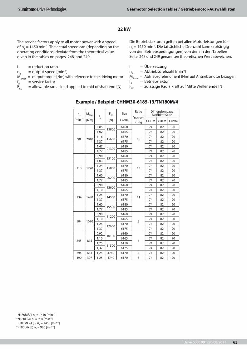
Drive 6000 991296 08/2021
Gearmotor Selection Tables / Getriebemotor-Auswahllisten
63
n2
[min-1]
M2Mot
[Nm]fB
FR2
[N]
Size
Größe
Ratio
Überset-zung
Dimension page Maßblatt Seite
CHHM CHFM CHVM
98 2040
0,8513800
6160
15
74 82 901,02 6165 74 82 901,16
156006170 74 82 90
1,37 6175 74 82 901,47
213006180 74 82 90
1,77 6185 74 82 90
113 1770
0,9013100
6160
13
74 82 901,03 6165 74 82 901,24
150006170 74 82 90
1,37 6175 74 82 901,60
202006180 74 82 90
1,77 6185 74 82 90
134 1490
0,9012600
6160
11
74 82 901,10 6165 74 82 901,25
145006170 74 82 90
1,37 6175 74 82 901,60
195006180 74 82 90
1,77 6185 74 82 90
184 1090
0,9011200
6160
8
74 82 901,10 6165 74 82 901,25
126006170 74 82 90
1,37 6175 74 82 90
245 815
0,9210100
6160
6
74 82 901,10 6165 74 82 901,25
115006170 74 82 90
1,37 6175 74 82 90294 661 1,25 4740 6170 5 74 82 90490 397 1,25 4740 6170 3 74 82 90
22 kW
Example / Beispiel: CHHM30-6185-13/TN180M/4
The service factors apply to all motor power with a speed of n1 = 1450 min-1. The actual speed can (depending on the operating conditions) deviate from the theoretical value given in the tables on pages 248 and 249.
i = reduction ration2 = output speed [min-1]M2mot = output torque [Nm] with reference to the driving motorfB = service factorFR 2 = allowable radial load applied to mid of shaft end [N]
Die Betriebsfaktoren gelten bei allen Motorleistungen für n1 = 1450 min-1. Die tatsächliche Drehzahl kann (abhängig von den Betriebsbedingungen) von dem in den Tabellen Seite 248 und 249 genannten theoretischen Wert abweichen.
i = Übersetzungn2 = Abtriebsdrehzahl [min-1] M2mot = Abtriebsdrehmoment [Nm] auf Antriebsmotor bezogenfB = BetriebsfaktorFR 2 = zulässige Radialkraft auf Mitte Wellenende [N]
N180MS/4 n1 = 1450 [min-1] *N180LS/6 n1 = 980 [min-1] F180MG/4 (B) n1 = 1450 [min-1] *F180L/6 (B) n1 = 980 [min-1]
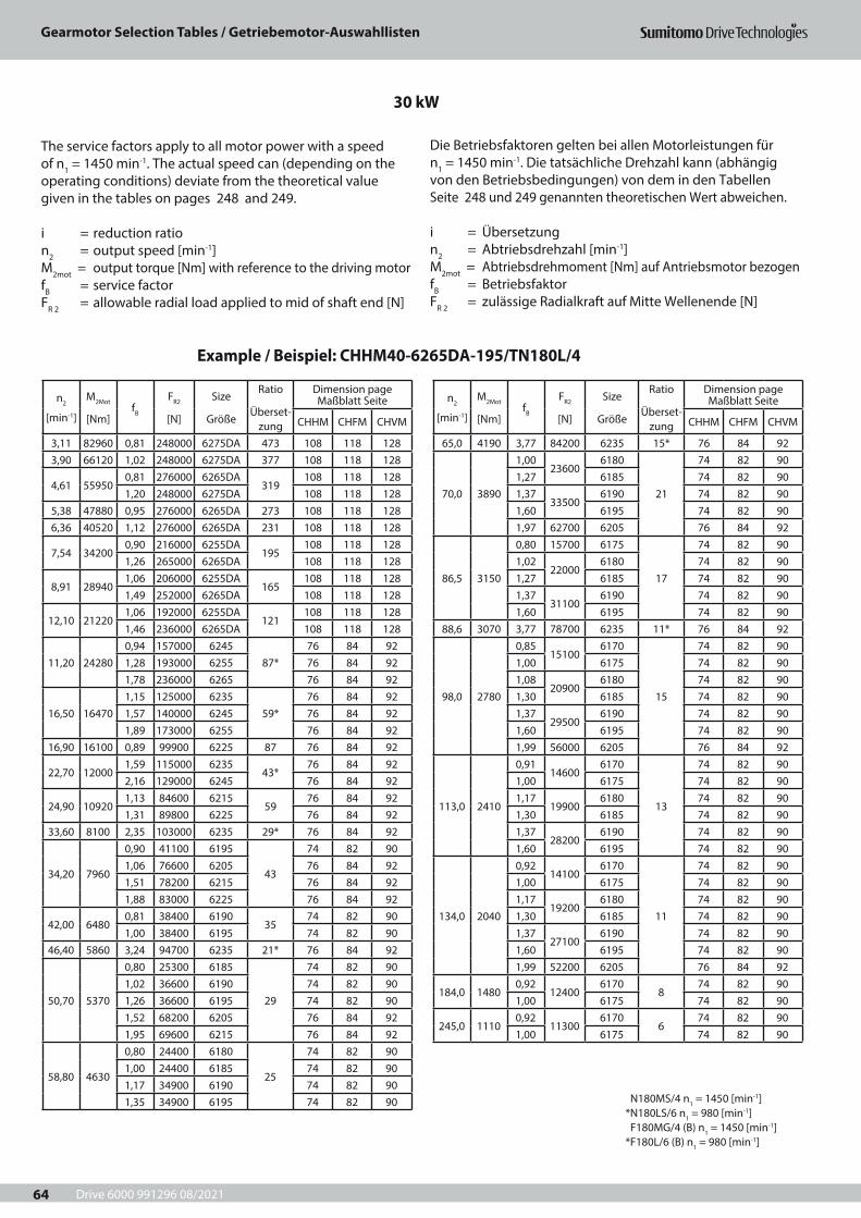
Drive 6000 991296 08/2021
Gearmotor Selection Tables / Getriebemotor-Auswahllisten
64
n2
[min-1]
M2Mot
[Nm]fB
FR2
[N]
Size
Größe
Ratio
Überset-zung
Dimension page Maßblatt Seite
CHHM CHFM CHVM
3,11 82960 0,81 248000 6275DA 473 108 118 1283,90 66120 1,02 248000 6275DA 377 108 118 128
4,61 559500,81 276000 6265DA
319108 118 128
1,20 248000 6275DA 108 118 1285,38 47880 0,95 276000 6265DA 273 108 118 1286,36 40520 1,12 276000 6265DA 231 108 118 128
7,54 342000,90 216000 6255DA
195108 118 128
1,26 265000 6265DA 108 118 128
8,91 289401,06 206000 6255DA
165108 118 128
1,49 252000 6265DA 108 118 128
12,10 212201,06 192000 6255DA
121108 118 128
1,46 236000 6265DA 108 118 128
11,20 242800,94 157000 6245
87*76 84 92
1,28 193000 6255 76 84 921,78 236000 6265 76 84 92
16,50 164701,15 125000 6235
59*76 84 92
1,57 140000 6245 76 84 921,89 173000 6255 76 84 92
16,90 16100 0,89 99900 6225 87 76 84 92
22,70 120001,59 115000 6235
43*76 84 92
2,16 129000 6245 76 84 92
24,90 109201,13 84600 6215
5976 84 92
1,31 89800 6225 76 84 9233,60 8100 2,35 103000 6235 29* 76 84 92
34,20 7960
0,90 41100 6195
43
74 82 901,06 76600 6205 76 84 921,51 78200 6215 76 84 921,88 83000 6225 76 84 92
42,00 64800,81 38400 6190
3574 82 90
1,00 38400 6195 74 82 9046,40 5860 3,24 94700 6235 21* 76 84 92
50,70 5370
0,80 25300 6185
29
74 82 901,02 36600 6190 74 82 901,26 36600 6195 74 82 901,52 68200 6205 76 84 921,95 69600 6215 76 84 92
58,80 4630
0,80 24400 6180
25
74 82 901,00 24400 6185 74 82 901,17 34900 6190 74 82 901,35 34900 6195 74 82 90
n2
[min-1]
M2Mot
[Nm]fB
FR2
[N]
Size
Größe
Ratio
Überset-zung
Dimension page Maßblatt Seite
CHHM CHFM CHVM
65,0 4190 3,77 84200 6235 15* 76 84 92
70,0 3890
1,0023600
6180
21
74 82 901,27 6185 74 82 901,37
335006190 74 82 90
1,60 6195 74 82 901,97 62700 6205 76 84 92
86,5 3150
0,80 15700 6175
17
74 82 901,02
220006180 74 82 90
1,27 6185 74 82 901,37
311006190 74 82 90
1,60 6195 74 82 9088,6 3070 3,77 78700 6235 11* 76 84 92
98,0 2780
0,8515100
6170
15
74 82 901,00 6175 74 82 901,08
209006180 74 82 90
1,30 6185 74 82 901,37
295006190 74 82 90
1,60 6195 74 82 901,99 56000 6205 76 84 92
113,0 2410
0,9114600
6170
13
74 82 901,00 6175 74 82 901,17
199006180 74 82 90
1,30 6185 74 82 901,37
282006190 74 82 90
1,60 6195 74 82 90
134,0 2040
0,9214100
6170
11
74 82 901,00 6175 74 82 901,17
192006180 74 82 90
1,30 6185 74 82 901,37
271006190 74 82 90
1,60 6195 74 82 901,99 52200 6205 76 84 92
184,0 14800,92
124006170
874 82 90
1,00 6175 74 82 90
245,0 11100,92
113006170
674 82 90
1,00 6175 74 82 90
30 kW
Example / Beispiel: CHHM40-6265DA-195/TN180L/4
The service factors apply to all motor power with a speed of n1 = 1450 min-1. The actual speed can (depending on the operating conditions) deviate from the theoretical value given in the tables on pages 248 and 249.
i = reduction ration2 = output speed [min-1]M2mot = output torque [Nm] with reference to the driving motorfB = service factorFR 2 = allowable radial load applied to mid of shaft end [N]
Die Betriebsfaktoren gelten bei allen Motorleistungen für n1 = 1450 min-1. Die tatsächliche Drehzahl kann (abhängig von den Betriebsbedingungen) von dem in den Tabellen Seite 248 und 249 genannten theoretischen Wert abweichen.
i = Übersetzungn2 = Abtriebsdrehzahl [min-1] M2mot = Abtriebsdrehmoment [Nm] auf Antriebsmotor bezogenfB = BetriebsfaktorFR 2 = zulässige Radialkraft auf Mitte Wellenende [N]
N180MS/4 n1 = 1450 [min-1] *N180LS/6 n1 = 980 [min-1] F180MG/4 (B) n1 = 1450 [min-1] *F180L/6 (B) n1 = 980 [min-1]
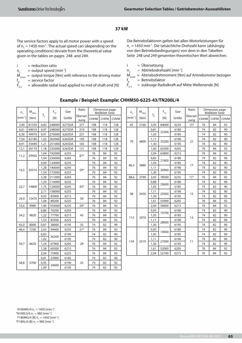
Drive 6000 991296 08/2021
Gearmotor Selection Tables / Getriebemotor-Auswahllisten
65
n2
[min-1]
M2Mot
[Nm]fB
FR2
[N]
Size
Größe
Ratio
Überset-zung
Dimension page Maßblatt Seite
CHHM CHFM CHVM
3,90 81550 0,82 248000 6275DA 377 108 118 1284,61 69010 0,97 248000 6275DA 319 108 118 1286,36 49970 0,91 276000 6265DA 231 108 118 1287,54 42180 1,02 263000 6265DA 195 108 118 1288,91 35690 1,21 251000 6265DA 165 108 118 12812,1 26170 1,18 235000 6265DA 121 108 118 128
11,2 299501,04 192000 6255
87*76 84 92
1,44 236000 6265 76 84 92
16,5 20310
0,94 124000 6235
59*
76 84 921,28 140000 6245 76 84 921,54 172000 6255 76 84 922,28 211000 6265 76 84 92
22,7 148001,29 114000 6235
43*76 84 92
1,75 129000 6245 76 84 922,11 158000 6255 76 84 92
24,9 134700,92 83900 6215
5976 84 92
1,06 89200 6225 76 84 9233,6 9980 1,90 103000 6235 29* 76 84 92
34,2 98200,86 76200 6205
4376 84 92
1,22 77700 6215 76 84 921,53 82500 6225 76 84 92
42,0 8000 0,81 38000 6195 35 74 82 9046,4 7230 2,63 94400 6235 21* 76 84 92
50,7 6620
0,8336200
6190
29
74 82 901,02 6195 74 82 901,24 67900 6205 76 84 921,58 69300 6215 76 84 922,04 73400 6225 76 84 92
58,8 57000,81 23900 6185
2574 82 90
0,9534600
6190 74 82 921,09 6195 74 82 92
n2
[min-1]
M2Mot
[Nm]fB
FR2
[N]
Size
Größe
Ratio
Überset-zung
Dimension page Maßblatt Seite
CHHM CHFM CHVM
65 5160 3,05 84000 6235 15* 76 84 92
70 4800
0,8123300
6180
21
74 82 901,03 6185 74 82 901,11
332006190 74 82 90
1,30 6195 74 82 901,60 62500 6205 76 84 922,04 63800 6215 76 84 92
86,5 3880
0,8321600
6180
17
74 82 901,03 6185 74 82 901,11
309006190 74 82 90
1,30 6195 74 82 9088,6 3790 3,05 78500 6235 11* 76 84 92
98 3430
0,8820600
6180
15
74 82 901,05 6185 74 82 901,11
293006190 74 82 90
1,30 6195 74 82 901,61 55900 6205 76 84 922,04 56600 6215 76 84 92
113 2970
0,9519700
6180
13
74 82 901,05 6185 74 82 901,11
280006190 74 82 90
1,30 6195 74 82 90
134 2510
0,9519000
6180
11
74 82 901,05 6185 74 82 901,11
270006190 74 82 90
1,30 6195 74 82 901,61 52000 6205 76 84 922,04 52700 6215 76 84 92
37 kW
Example / Beispiel: Example: CHHM50-6225-43/TN200L/4
The service factors apply to all motor power with a speed of n1 = 1450 min-1. The actual speed can (depending on the operating conditions) deviate from the theoretical value given in the tables on pages 248 and 249.
i = reduction ration2 = output speed [min-1]M2mot = output torque [Nm] with reference to the driving motorfB = service factorFR 2 = allowable radial load applied to mid of shaft end [N]
Die Betriebsfaktoren gelten bei allen Motorleistungen für n1 = 1450 min-1. Die tatsächliche Drehzahl kann (abhängig von den Betriebsbedingungen) von dem in den Tabellen Seite 248 und 249 genannten theoretischen Wert abweichen.
i = Übersetzungn2 = Abtriebsdrehzahl [min-1] M2mot = Abtriebsdrehmoment [Nm] auf Antriebsmotor bezogenfB = BetriebsfaktorFR 2 = zulässige Radialkraft auf Mitte Wellenende [N]
N180MS/4 n1 = 1450 [min-1] *N180LS/6 n1 = 980 [min-1] F180MG/4 (B) n1 = 1450 [min-1] *F180L/6 (B) n1 = 980 [min-1]
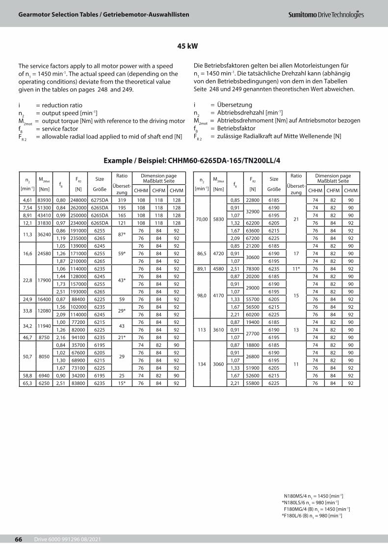
Drive 6000 991296 08/2021
Gearmotor Selection Tables / Getriebemotor-Auswahllisten
66
n2
[min-1]
M2Mot
[Nm]fB
FR2
[N]
Size
Größe
Ratio
Überset-zung
Dimension page Maßblatt Seite
CHHM CHFM CHVM
4,61 83930 0,80 248000 6275DA 319 108 118 1287,54 51300 0,84 262000 6265DA 195 108 118 1288,91 43410 0,99 250000 6265DA 165 108 118 12812,1 31830 0,97 234000 6265DA 121 108 118 128
11,3 362400,86 191000 6255
87*76 84 92
1,19 235000 6265 76 84 92
16,6 245801,05 139000 6245
59*76 84 92
1,26 171000 6255 76 84 921,87 210000 6265 76 84 92
22,8 17900
1,06 114000 6235
43*
76 84 921,44 128000 6245 76 84 921,73 157000 6255 76 84 922,51 193000 6265 76 84 92
24,9 16400 0,87 88400 6225 59 76 84 92
33,8 120801,56 102000 6235
29*76 84 92
2,09 114000 6245 76 84 92
34,2 119401,00 77200 6215
4376 84 92
1,26 82000 6225 76 84 9246,7 8750 2,16 94100 6235 21* 76 84 92
50,7 8050
0,84 35700 6195
29
74 82 901,02 67600 6205 76 84 921,30 68900 6215 76 84 921,67 73100 6225 76 84 92
58,8 6940 0,90 34200 6195 25 74 82 9065,3 6250 2,51 83800 6235 15* 76 84 92
n2
[min-1]
M2Mot
[Nm]fB
FR2
[N]
Size
Größe
Ratio
Überset-zung
Dimension page Maßblatt Seite
CHHM CHFM CHVM
70,00 5830
0,85 22800 6185
21
74 82 900,91
329006190 74 82 90
1,07 6195 74 82 901,32 62200 6205 76 84 921,67 63600 6215 76 84 922,09 67200 6225 76 84 92
86,5 47200,85 21200 6185
1774 82 90
0,9130600
6190 74 82 901,07 6195 74 82 90
89,1 4580 2,51 78300 6235 11* 76 84 92
98,0 4170
0,87 20200 6185
15
74 82 900,91
290006190 74 82 90
1,07 6195 74 82 901,33 55700 6205 76 84 921,67 56500 6215 76 84 922,21 60200 6225 76 84 92
113 36100,87 19400 6185
1374 82 90
0,9127700
6190 74 82 901,07 6195 74 82 90
134 3060
0,87 18800 6185
11
74 82 900,91
268006190 74 82 90
1,07 6195 74 82 901,33 51900 6205 76 84 921,67 52600 6215 76 84 922,21 55800 6225 76 84 92
45 kW
Example / Beispiel: CHHM60-6265DA-165/TN200LL/4
The service factors apply to all motor power with a speed of n1 = 1450 min-1. The actual speed can (depending on the operating conditions) deviate from the theoretical value given in the tables on pages 248 and 249.
i = reduction ration2 = output speed [min-1]M2mot = output torque [Nm] with reference to the driving motorfB = service factorFR 2 = allowable radial load applied to mid of shaft end [N]
Die Betriebsfaktoren gelten bei allen Motorleistungen für n1 = 1450 min-1. Die tatsächliche Drehzahl kann (abhängig von den Betriebsbedingungen) von dem in den Tabellen Seite 248 und 249 genannten theoretischen Wert abweichen.
i = Übersetzungn2 = Abtriebsdrehzahl [min-1] M2mot = Abtriebsdrehmoment [Nm] auf Antriebsmotor bezogenfB = BetriebsfaktorFR 2 = zulässige Radialkraft auf Mitte Wellenende [N]
N180MS/4 n1 = 1450 [min-1] *N180LS/6 n1 = 980 [min-1] F180MG/4 (B) n1 = 1450 [min-1] *F180L/6 (B) n1 = 980 [min-1]
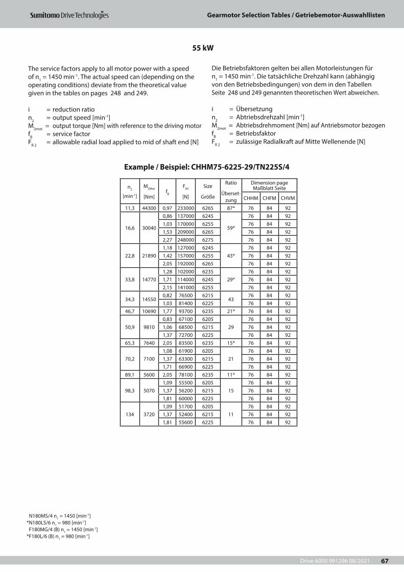
Drive 6000 991296 08/2021
Gearmotor Selection Tables / Getriebemotor-Auswahllisten
67
n2
[min-1]
M2Mot
[Nm]fB
FR2
[N]
Size
Größe
Ratio
Überset-zung
Dimension page Maßblatt Seite
CHHM CHFM CHVM
11,3 44300 0,97 233000 6265 87* 76 84 92
16,6 30040
0,86 137000 6245
59*
76 84 921,03 170000 6255 76 84 921,53 209000 6265 76 84 922,27 248000 6275 76 84 92
22,8 218901,18 127000 6245
43*76 84 92
1,42 157000 6255 76 84 922,05 192000 6265 76 84 92
33,8 147701,28 102000 6235
29*76 84 92
1,71 114000 6245 76 84 922,15 141000 6255 76 84 92
34,3 145500,82 76500 6215
4376 84 92
1,03 81400 6225 76 84 9246,7 10690 1,77 93700 6235 21* 76 84 92
50,9 98100,83 67100 6205
2976 84 92
1,06 68500 6215 76 84 921,37 72700 6225 76 84 92
65,3 7640 2,05 83500 6235 15* 76 84 92
70,2 71001,08 61900 6205
2176 84 92
1,37 63300 6215 76 84 921,71 66900 6225 76 84 92
89,1 5600 2,05 78100 6235 11* 76 84 92
98,3 50701,09 55500 6205
1576 84 92
1,37 56200 6215 76 84 921,81 60000 6225 76 84 92
134 37201,09 51700 6205
1176 84 92
1,37 52400 6215 76 84 921,81 55600 6225 76 84 92
55 kW
Example / Beispiel: CHHM75-6225-29/TN225S/4
The service factors apply to all motor power with a speed of n1 = 1450 min-1. The actual speed can (depending on the operating conditions) deviate from the theoretical value given in the tables on pages 248 and 249.
i = reduction ration2 = output speed [min-1]M2mot = output torque [Nm] with reference to the driving motorfB = service factorFR 2 = allowable radial load applied to mid of shaft end [N]
Die Betriebsfaktoren gelten bei allen Motorleistungen für n1 = 1450 min-1. Die tatsächliche Drehzahl kann (abhängig von den Betriebsbedingungen) von dem in den Tabellen Seite 248 und 249 genannten theoretischen Wert abweichen.
i = Übersetzungn2 = Abtriebsdrehzahl [min-1] M2mot = Abtriebsdrehmoment [Nm] auf Antriebsmotor bezogenfB = BetriebsfaktorFR 2 = zulässige Radialkraft auf Mitte Wellenende [N]
N180MS/4 n1 = 1450 [min-1] *N180LS/6 n1 = 980 [min-1] F180MG/4 (B) n1 = 1450 [min-1] *F180L/6 (B) n1 = 980 [min-1]
Drive 6000 991296 08/2021
Gearmotor Dimensions / Getriebemotoren-Maßblätter
68
Drive 6000 991296 08/2021
Gearmotor Dimensions / Getriebemotoren-Maßblätter
69
3 Getriebemotoren-Maßblätter 3 Gearmotor Dimensions
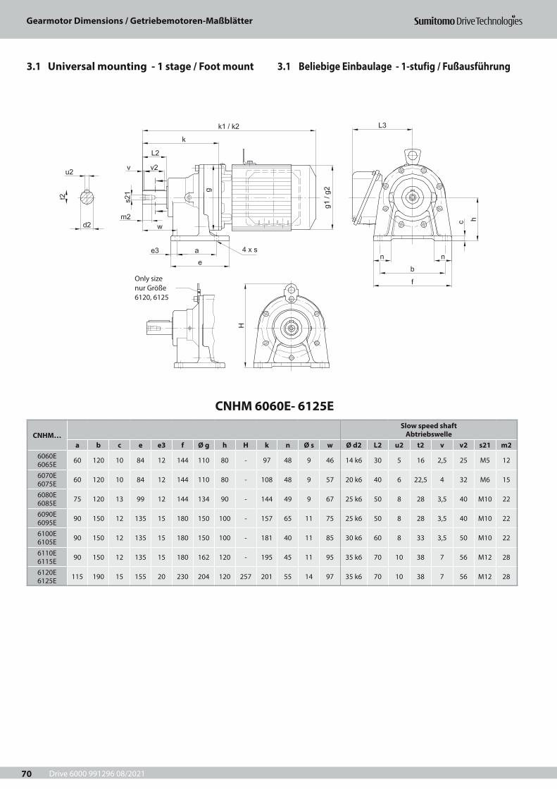
Drive 6000 991296 08/2021
Gearmotor Dimensions / Getriebemotoren-Maßblätter
70
3.1 Beliebige Einbaulage - 1-stufig / Fußausführung3.1 Universal mounting - 1 stage / Foot mount
CNHM 6060E- 6125E
CNHM…Slow speed shaft
Abtriebswellea b c e e3 f Ø g h H k n Ø s w Ø d2 L2 u2 t2 v v2 s21 m2
6060E 6065E 60 120 10 84 12 144 110 80 - 97 48 9 46 14 k6 30 5 16 2,5 25 M5 12
6070E 6075E 60 120 10 84 12 144 110 80 - 108 48 9 57 20 k6 40 6 22,5 4 32 M6 15
6080E 6085E 75 120 13 99 12 144 134 90 - 144 49 9 67 25 k6 50 8 28 3,5 40 M10 22
6090E 6095E 90 150 12 135 15 180 150 100 - 157 65 11 75 25 k6 50 8 28 3,5 40 M10 22
6100E 6105E 90 150 12 135 15 180 150 100 - 181 40 11 85 30 k6 60 8 33 3,5 50 M10 22
6110E 6115E 90 150 12 135 15 180 162 120 - 195 45 11 95 35 k6 70 10 38 7 56 M12 28
6120E 6125E 115 190 15 155 20 230 204 120 257 201 55 14 97 35 k6 70 10 38 7 56 M12 28
Only size nur Größe 6120, 6125
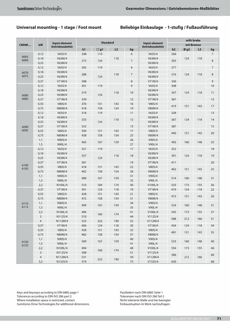
Drive 6000 991296 08/2021
Gearmotor Dimensions / Getriebemotoren-Maßblätter
71
CNHM… kW Input element Antriebszubehör
Standard Input element Antriebszubehör
with brakemit Bremse
k1 ¨ g1 L3 kg k2 Ø g2 L3 kg
6065 6060
0,12 V63S/4 248 119118
6 V63S/4 266124 118
70,18 V63M/4
273 124 7V63M/4
305 80,25 V63M/4 V63M/4
6070 6075
0,12 V63S/4 265 119
118
6 V63S/4 277
124 118
70,18 V63M/4
288124
7V63M/4
316 80,25 V63M/4 V63M/4
0,37 V71M/4 308 8 V71M/4 336 9
6080 6085
0,12 V63S/4 301 119
118
9 V63S/4 308
124 118
100,18 V63M/4
319124
10V63M/4
347 110,25 V63M/4 V63M/40,37 V71M/4 339 12 V71M/4 367 130,55 V80S/4 376 151 143 16 V80S/4
419 151 143 170,75 N80M/4 418 158 154 19 V80M/4
6090 6095
0,12 V63S/4 318 119
118
11 V63S/4 328
124 118
130,18 V63M/4
333124
12V63M/4
367 140,25 V63M/4 V63M/40,37 V71M/4 353 13 V71M/4 387 150,55 V80S/4 394 151 143 17 V80S/4
440 151 143 200,75 N80M/4 438 158 154 23 V80M/41,1 N90S/4
465 167 15926 V90S/4
492 160 148 251,5 N90L/4 27 V90L/4
6100 6105
0,12 V63S/4 331 119
118
17 V63S/4 352
124 118
180,18 V63M/4
357124
18V63M/4
391 190,25 V63M/4 V63M/40,37 V71M/4 381 19 V71M/4 411 200,55 V80S/4 418 151 143 22 V80S/4
462 151 143 250,75 N80M/4 462 158 154 28 V80M/41,1 N90S/4
489 167 15931 V90S/4
514 160 148 311,5 N90L/4 32 V90L/42,2 N100L/4 510 184 174 40 V100L/4 535 173 155 36
6110 6115
0,37 V71M/4 391 124 118 19 V71M/4 419 124 118 220,55 V80S/4 428 151 143 21 V80S/4
472 151 143 260,75 N80M/4 472 158 154 31 V80M/41,1 N90S/4
499 167 15934 V90S/4
524 160 148 311,5 N90L/4 35 V90L/42,2 N100L/4 496
184 17441 V100L/4 545 173 155 37
3 N112S/4 510 44 V112S/4588 212 166 51
4 N112M/4 523 222 190 52 V112M/4
6120 6125
0,37 V71M/4 406 124 118 30 V71M/4 434 124 118 340,55 V80S/4 438 151 143 32 V80S/4
481 151 143 350,75 N80M/4 482 158 154 37 V80M/41,1 N90S/4
509 167 15940 V90S/4
533 160 148 401,5 N90L/4 41 V90L/42,2 N100L/4 494
184 17448 V100L/4 554 173 155 46
3 N112S/4 508 51 V112S/4586
212 16660
4 N112M/4 531222 190
59 V112M/45,5 N132S/4 574 75 V132S/4 630 68
Beliebige Einbaulage - 1-stufig / FußausführungUniversal mounting - 1 stage / Foot mount
Keys and keyways according to DIN 6885 page 1Tolerances according to DIN ISO 286 part 2Where installation space is restricted, contactSumitomo Drive Technologies for additional dimensions.
Passfedern nach DIN 6885 Seite 1Toleranzen nach DIN ISO 286 Teil 2Nicht tolerierte Maße sind bei beengterEinbausituation im Werk nachzufragen.
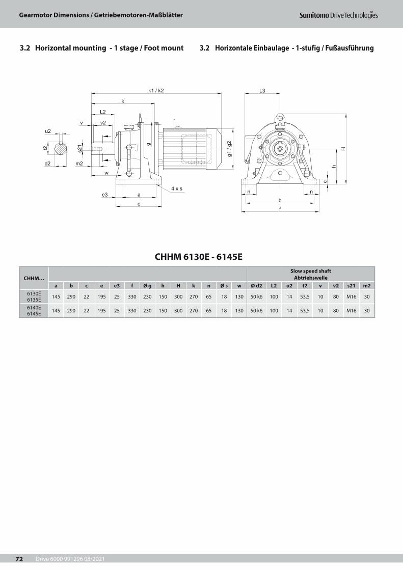
Drive 6000 991296 08/2021
Gearmotor Dimensions / Getriebemotoren-Maßblätter
72
CHHM 6130E - 6145E
CHHM…Slow speed shaft
Abtriebswellea b c e e3 f Ø g h H k n Ø s w Ø d2 L2 u2 t2 v v2 s21 m2
6130E 6135E 145 290 22 195 25 330 230 150 300 270 65 18 130 50 k6 100 14 53,5 10 80 M16 30
6140E 6145E 145 290 22 195 25 330 230 150 300 270 65 18 130 50 k6 100 14 53,5 10 80 M16 30
3.2 Horizontale Einbaulage - 1-stufig / Fußausführung3.2 Horizontal mounting - 1 stage / Foot mount
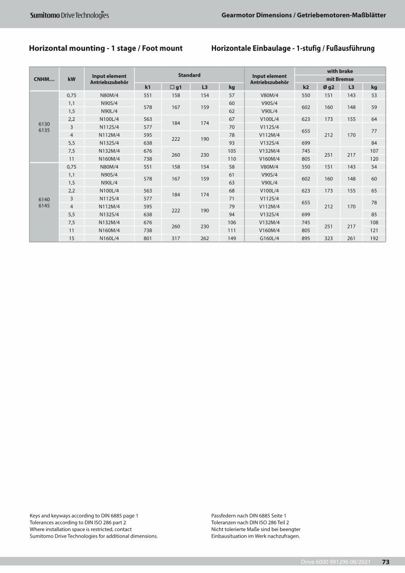
Drive 6000 991296 08/2021
Gearmotor Dimensions / Getriebemotoren-Maßblätter
73
CNHM… kW Input element Antriebszubehör
Standard Input element Antriebszubehör
with brakemit Bremse
k1 ¨ g1 L3 kg k2 Ø g2 L3 kg
6130 6135
0,75 N80M/4 551 158 154 57 V80M/4 550 151 143 531,1 N90S/4
578 167 15960 V90S/4
602 160 148 591,5 N90L/4 62 V90L/4 2,2 N100L/4 563
184 17467 V100L/4 623 173 155 64
3 N112S/4 577 70 V112S/4 655
212 17077
4 N112M/4 595222 190
78 V112M/4 5,5 N132S/4 638 93 V132S/4 699 847,5 N132M/4 676
260 230105 V132M/4 745
251 217107
11 N160M/4 738 110 V160M/4 805 120
6140 6145
0,75 N80M/4 551 158 154 58 V80M/4 550 151 143 541,1 N90S/4
578 167 15961 V90S/4
602 160 148 601,5 N90L/4 63 V90L/4 2,2 N100L/4 563
184 17468 V100L/4 623 173 155 65
3 N112S/4 577 71 V112S/4 655
212 17078
4 N112M/4 595222 190
79 V112M/4 5,5 N132S/4 638 94 V132S/4 699 857,5 N132M/4 676
260 230106 V132M/4 745
251 217108
11 N160M/4 738 111 V160M/4 805 12115 N160L/4 801 317 262 149 G160L/4 895 323 261 192
Keys and keyways according to DIN 6885 page 1Tolerances according to DIN ISO 286 part 2Where installation space is restricted, contactSumitomo Drive Technologies for additional dimensions.
Passfedern nach DIN 6885 Seite 1Toleranzen nach DIN ISO 286 Teil 2Nicht tolerierte Maße sind bei beengterEinbausituation im Werk nachzufragen.
Horizontale Einbaulage - 1-stufig / FußausführungHorizontal mounting - 1 stage / Foot mount
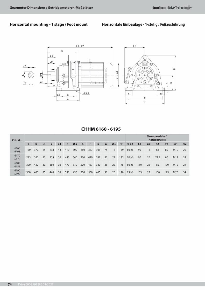
Drive 6000 991296 08/2021
Gearmotor Dimensions / Getriebemotoren-Maßblätter
74
CHHM 6160 - 6195
CHHM…Slow speed shaft
Abtriebswellea b c e e3 f Ø g h H k n Ø s w Ø d2 L2 u2 t2 v2 s21 m2
6160 6165
150 370 25 238 44 410 300 160 367 308 75 18 139 60 h6 90 18 64 80 M10 20
6170 6175
275 380 30 335 30 430 340 200 429 352 80 22 125 70 h6 90 20 74,5 80 M12 24
6180 6185
320 420 30 380 30 470 370 220 467 389 85 22 145 80 h6 110 22 85 100 M12 24
6190 6195
380 480 35 440 30 530 430 250 538 465 90 26 170 95 h6 135 25 100 125 M20 34
Horizontale Einbaulage - 1-stufig / FußausführungHorizontal mounting - 1 stage / Foot mount
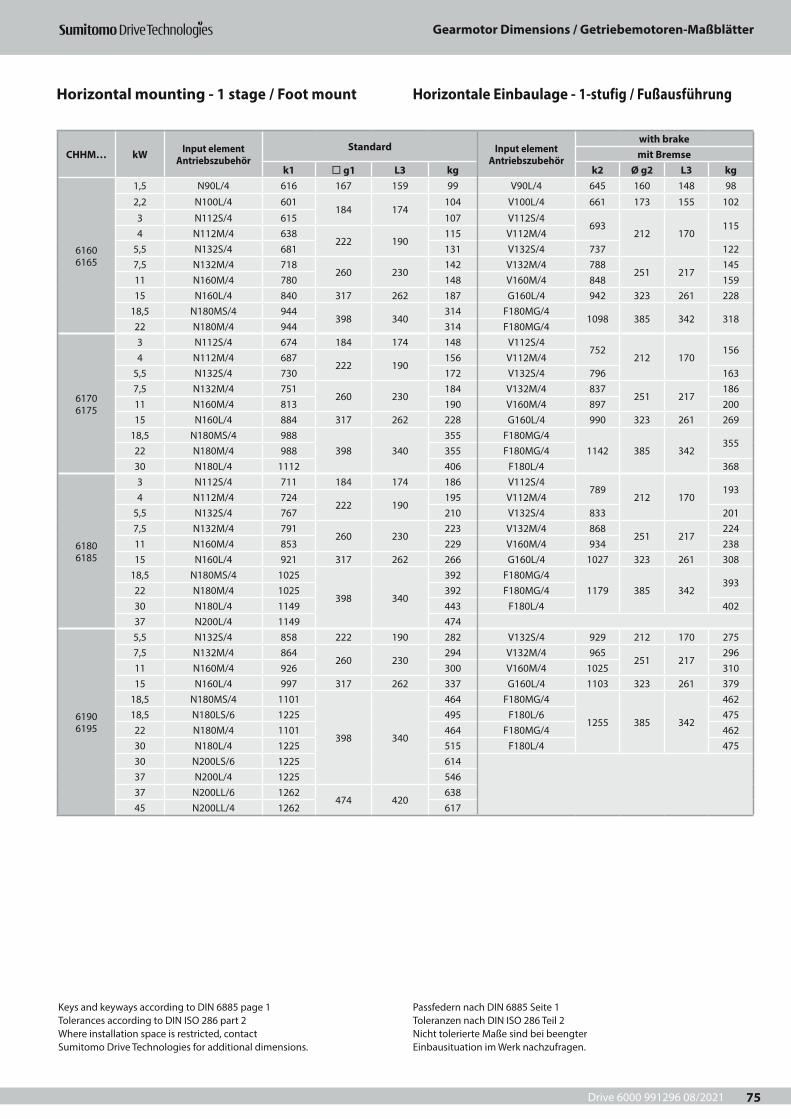
Drive 6000 991296 08/2021
Gearmotor Dimensions / Getriebemotoren-Maßblätter
75
CHHM… kW Input element Antriebszubehör
Standard Input element Antriebszubehör
with brakemit Bremse
k1 ¨ g1 L3 kg k2 Ø g2 L3 kg
6160 6165
1,5 N90L/4 616 167 159 99 V90L/4 645 160 148 98
2,2 N100L/4 601184 174
104 V100L/4 661 173 155 102
3 N112S/4 615 107 V112S/4 693
212 170115
4 N112M/4 638222 190
115 V112M/4 5,5 N132S/4 681 131 V132S/4 737 1227,5 N132M/4 718
260 230142 V132M/4 788
251 217145
11 N160M/4 780 148 V160M/4 848 15915 N160L/4 840 317 262 187 G160L/4 942 323 261 228
18,5 N180MS/4 944398 340
314 F180MG/41098 385 342 318
22 N180M/4 944 314 F180MG/4
6170 6175
3 N112S/4 674 184 174 148 V112S/4 752
212 170156
4 N112M/4 687222 190
156 V112M/4 5,5 N132S/4 730 172 V132S/4 796 1637,5 N132M/4 751
260 230184 V132M/4 837
251 217186
11 N160M/4 813 190 V160M/4 897 20015 N160L/4 884 317 262 228 G160L/4 990 323 261 269
18,5 N180MS/4 988398 340
355 F180MG/41142 385 342
35522 N180M/4 988 355 F180MG/430 N180L/4 1112 406 F180L/4 368
6180 6185
3 N112S/4 711 184 174 186 V112S/4 789
212 170193
4 N112M/4 724222 190
195 V112M/4 5,5 N132S/4 767 210 V132S/4 833 2017,5 N132M/4 791
260 230223 V132M/4 868
251 217224
11 N160M/4 853 229 V160M/4 934 23815 N160L/4 921 317 262 266 G160L/4 1027 323 261 308
18,5 N180MS/4 1025
398 340
392 F180MG/41179 385 342
39322 N180M/4 1025 392 F180MG/430 N180L/4 1149 443 F180L/4 40237 N200L/4 1149 474
6190 6195
5,5 N132S/4 858 222 190 282 V132S/4 929 212 170 2757,5 N132M/4 864
260 230294 V132M/4 965
251 217296
11 N160M/4 926 300 V160M/4 1025 31015 N160L/4 997 317 262 337 G160L/4 1103 323 261 379
18,5 N180MS/4 1101
398 340
464 F180MG/4
1255 385 342
46218,5 N180LS/6 1225 495 F180L/6 47522 N180M/4 1101 464 F180MG/4 46230 N180L/4 1225 515 F180L/4 47530 N200LS/6 1225 61437 N200L/4 1225 54637 N200LL/6 1262
474 420638
45 N200LL/4 1262 617
Keys and keyways according to DIN 6885 page 1Tolerances according to DIN ISO 286 part 2Where installation space is restricted, contactSumitomo Drive Technologies for additional dimensions.
Passfedern nach DIN 6885 Seite 1Toleranzen nach DIN ISO 286 Teil 2Nicht tolerierte Maße sind bei beengterEinbausituation im Werk nachzufragen.
Horizontale Einbaulage - 1-stufig / FußausführungHorizontal mounting - 1 stage / Foot mount
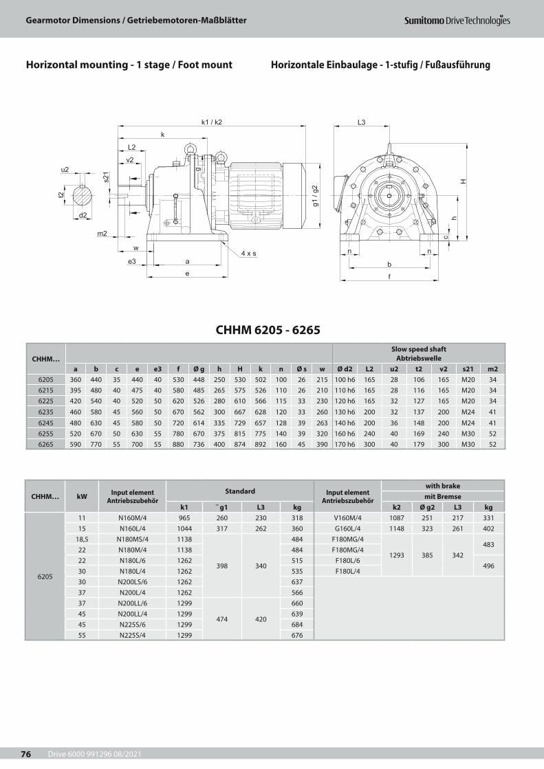
Drive 6000 991296 08/2021
Gearmotor Dimensions / Getriebemotoren-Maßblätter
76
CHHM 6205 - 6265
CHHM…Slow speed shaft
Abtriebswellea b c e e3 f Ø g h H k n Ø s w Ø d2 L2 u2 t2 v2 s21 m2
6205 360 440 35 440 40 530 448 250 530 502 100 26 215 100 h6 165 28 106 165 M20 346215 395 480 40 475 40 580 485 265 575 526 110 26 210 110 h6 165 28 116 165 M20 346225 420 540 40 520 50 620 526 280 610 566 115 33 230 120 h6 165 32 127 165 M20 34
6235 460 580 45 560 50 670 562 300 667 628 120 33 260 130 h6 200 32 137 200 M24 41
6245 480 630 45 580 50 720 614 335 729 657 128 39 263 140 h6 200 36 148 200 M24 416255 520 670 50 630 55 780 670 375 815 775 140 39 320 160 h6 240 40 169 240 M30 526265 590 770 55 700 55 880 736 400 874 892 160 45 390 170 h6 300 40 179 300 M30 52
CHHM… kW Input element Antriebszubehör
Standard Input element Antriebszubehör
with brakemit Bremse
k1 ¨ g1 L3 kg k2 Ø g2 L3 kg
6205
11 N160M/4 965 260 230 318 V160M/4 1087 251 217 33115 N160L/4 1044 317 262 360 G160L/4 1148 323 261 402
18,5 N180MS/4 1138
398 340
484 F180MG/4
1293 385 342483
22 N180M/4 1138 484 F180MG/422 N180L/6 1262 515 F180L/6
49630 N180L/4 1262 535 F180L/430 N200LS/6 1262 63737 N200L/4 1262 56637 N200LL/6 1299
474 420
66045 N200LL/4 1299 63945 N225S/6 1299 68455 N225S/4 1299 676
Horizontale Einbaulage - 1-stufig / FußausführungHorizontal mounting - 1 stage / Foot mount
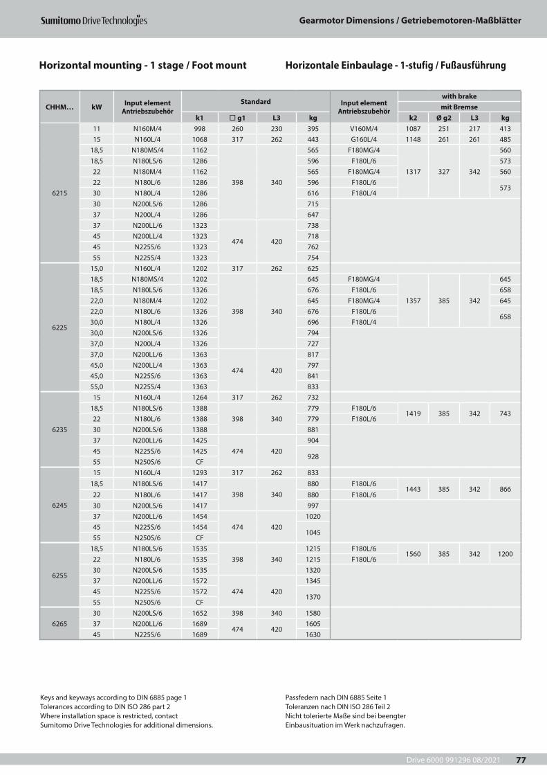
Drive 6000 991296 08/2021
Gearmotor Dimensions / Getriebemotoren-Maßblätter
77
CHHM… kW Input element Antriebszubehör
Standard Input element Antriebszubehör
with brakemit Bremse
k1 ¨ g1 L3 kg k2 Ø g2 L3 kg
6215
11 N160M/4 998 260 230 395 V160M/4 1087 251 217 41315 N160L/4 1068 317 262 443 G160L/4 1148 261 261 485
18,5 N180MS/4 1162
398 340
565 F180MG/4
1317 327 342
56018,5 N180LS/6 1286 596 F180L/6 57322 N180M/4 1162 565 F180MG/4 56022 N180L/6 1286 596 F180L/6
57330 N180L/4 1286 616 F180L/430 N200LS/6 1286 71537 N200L/4 1286 64737 N200LL/6 1323
474 420
73845 N200LL/4 1323 71845 N225S/6 1323 76255 N225S/4 1323 754
6225
15,0 N160L/4 1202 317 262 62518,5 N180MS/4 1202
398 340
645 F180MG/4
1357 385 342
64518,5 N180LS/6 1326 676 F180L/6 65822,0 N180M/4 1202 645 F180MG/4 64522,0 N180L/6 1326 676 F180L/6
65830,0 N180L/4 1326 696 F180L/430,0 N200LS/6 1326 79437,0 N200L/4 1326 72737,0 N200LL/6 1363
474 420
81745,0 N200LL/4 1363 79745,0 N225S/6 1363 84155,0 N225S/4 1363 833
6235
15 N160L/4 1264 317 262 73218,5 N180LS/6 1388
398 340779 F180L/6
1419 385 342 74322 N180L/6 1388 779 F180L/630 N200LS/6 1388 88137 N200LL/6 1425
474 420904
45 N225S/6 1425928
55 N250S/6 CF
6245
15 N160L/4 1293 317 262 833
18,5 N180LS/6 1417398 340
880 F180L/61443 385 342 866
22 N180L/6 1417 880 F180L/630 N200LS/6 1417 99737 N200LL/6 1454
474 4201020
45 N225S/6 14541045
55 N250S/6 CF
6255
18,5 N180LS/6 1535398 340
1215 F180L/61560 385 342 1200
22 N180L/6 1535 1215 F180L/630 N200LS/6 1535 132037 N200LL/6 1572
474 4201345
45 N225S/6 15721370
55 N250S/6 CF
626530 N200LS/6 1652 398 340 158037 N200LL/6 1689
474 4201605
45 N225S/6 1689 1630
Keys and keyways according to DIN 6885 page 1Tolerances according to DIN ISO 286 part 2Where installation space is restricted, contactSumitomo Drive Technologies for additional dimensions.
Passfedern nach DIN 6885 Seite 1Toleranzen nach DIN ISO 286 Teil 2Nicht tolerierte Maße sind bei beengterEinbausituation im Werk nachzufragen.
Horizontale Einbaulage - 1-stufig / FußausführungHorizontal mounting - 1 stage / Foot mount
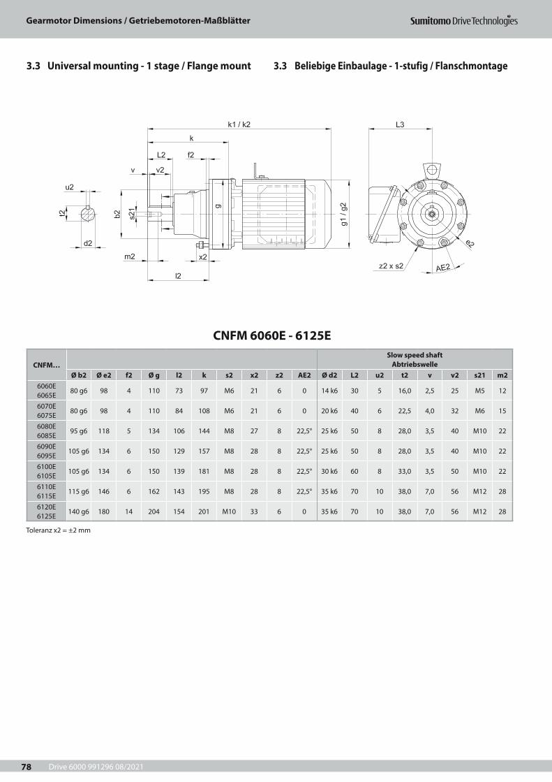
Drive 6000 991296 08/2021
Gearmotor Dimensions / Getriebemotoren-Maßblätter
78
CNFM 6060E - 6125E
CNFM…Slow speed shaft
AbtriebswelleØ b2 Ø e2 f2 Ø g l2 k s2 x2 z2 AE2 Ø d2 L2 u2 t2 v v2 s21 m2
6060E 6065E
80 g6 98 4 110 73 97 M6 21 6 0 14 k6 30 5 16,0 2,5 25 M5 12
6070E 6075E
80 g6 98 4 110 84 108 M6 21 6 0 20 k6 40 6 22,5 4,0 32 M6 15
6080E 6085E
95 g6 118 5 134 106 144 M8 27 8 22,5° 25 k6 50 8 28,0 3,5 40 M10 22
6090E 6095E
105 g6 134 6 150 129 157 M8 28 8 22,5° 25 k6 50 8 28,0 3,5 40 M10 22
6100E 6105E
105 g6 134 6 150 139 181 M8 28 8 22,5° 30 k6 60 8 33,0 3,5 50 M10 22
6110E 6115E
115 g6 146 6 162 143 195 M8 28 8 22,5° 35 k6 70 10 38,0 7,0 56 M12 28
6120E 6125E
140 g6 180 14 204 154 201 M10 33 6 0 35 k6 70 10 38,0 7,0 56 M12 28
Toleranz x2 = ±2 mm
3.3 Beliebige Einbaulage - 1-stufig / Flanschmontage3.3 Universal mounting - 1 stage / Flange mount
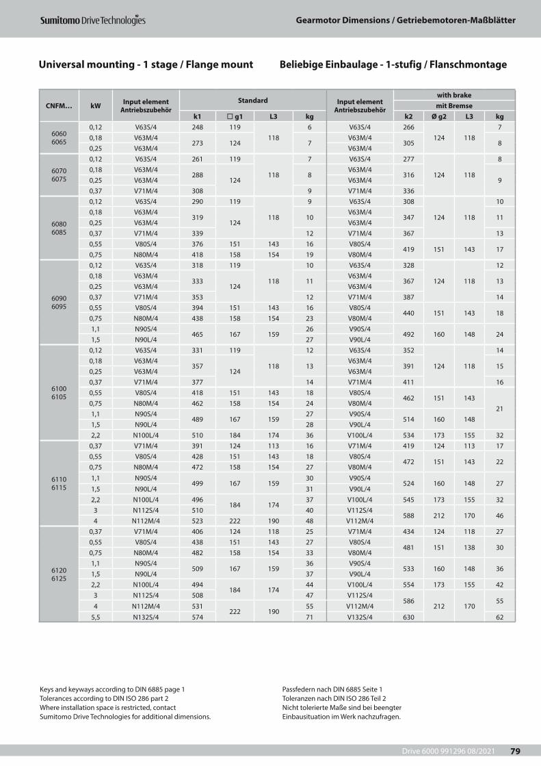
Drive 6000 991296 08/2021
Gearmotor Dimensions / Getriebemotoren-Maßblätter
79
CNFM… kW Input element Antriebszubehör
Standard Input element Antriebszubehör
with brakemit Bremse
k1 ¨ g1 L3 kg k2 Ø g2 L3 kg
6060 6065
0,12 V63S/4 248 119118
6 V63S/4 266124 118
70,18 V63M/4
273 124 7V63M/4
305 80,25 V63M/4 V63M/4
6070 6075
0,12 V63S/4 261 119
118
7 V63S/4 277
124 118
80,18 V63M/4
288124
8V63M/4
31690,25 V63M/4 V63M/4
0,37 V71M/4 308 9 V71M/4 336
6080 6085
0,12 V63S/4 290 119
118
9 V63S/4 308
124 118
100,18 V63M/4
319124
10V63M/4
347 110,25 V63M/4 V63M/40,37 V71M/4 339 12 V71M/4 367 130,55 V80S/4 376 151 143 16 V80S/4
419 151 143 170,75 N80M/4 418 158 154 19 V80M/4
6090 6095
0,12 V63S/4 318 119
118
10 V63S/4 328
124 118
120,18 V63M/4
333124
11V63M/4
367 130,25 V63M/4 V63M/40,37 V71M/4 353 12 V71M/4 387 140,55 V80S/4 394 151 143 16 V80S/4
440 151 143 180,75 N80M/4 438 158 154 23 V80M/41,1 N90S/4
465 167 15926 V90S/4
492 160 148 241,5 N90L/4 27 V90L/4
6100 6105
0,12 V63S/4 331 119
118
12 V63S/4 352
124 118
140,18 V63M/4
357124
13V63M/4
391 150,25 V63M/4 V63M/40,37 V71M/4 377 14 V71M/4 411 160,55 V80S/4 418 151 143 18 V80S/4
462 151 14321
0,75 N80M/4 462 158 154 24 V80M/41,1 N90S/4
489 167 15927 V90S/4
514 160 1481,5 N90L/4 28 V90L/42,2 N100L/4 510 184 174 36 V100L/4 534 173 155 32
6110 6115
0,37 V71M/4 391 124 113 16 V71M/4 419 124 113 170,55 V80S/4 428 151 143 18 V80S/4
472 151 143 220,75 N80M/4 472 158 154 27 V80M/4
1,1 N90S/4499 167 159
30 V90S/4524 160 148 27
1,5 N90L/4 31 V90L/42,2 N100L/4 496
184 17437 V100L/4 545 173 155 32
3 N112S/4 510 40 V112S/4588 212 170 46
4 N112M/4 523 222 190 48 V112M/4
6120 6125
0,37 V71M/4 406 124 118 25 V71M/4 434 124 118 270,55 V80S/4 438 151 143 27 V80S/4
481 151 138 300,75 N80M/4 482 158 154 33 V80M/41,1 N90S/4
509 167 15936 V90S/4
533 160 148 361,5 N90L/4 37 V90L/42,2 N100L/4 494
184 17444 V100L/4 554 173 155 42
3 N112S/4 508 47 V112S/4586
212 17055
4 N112M/4 531222 190
55 V112M/4
5,5 N132S/4 574 71 V132S/4 630 62
Keys and keyways according to DIN 6885 page 1Tolerances according to DIN ISO 286 part 2Where installation space is restricted, contactSumitomo Drive Technologies for additional dimensions.
Passfedern nach DIN 6885 Seite 1Toleranzen nach DIN ISO 286 Teil 2Nicht tolerierte Maße sind bei beengterEinbausituation im Werk nachzufragen.
Beliebige Einbaulage - 1-stufig / FlanschmontageUniversal mounting - 1 stage / Flange mount
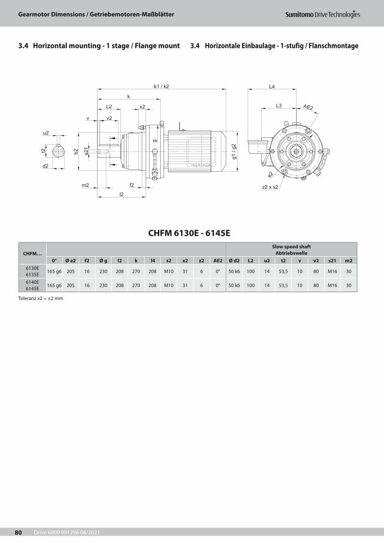
Drive 6000 991296 08/2021
Gearmotor Dimensions / Getriebemotoren-Maßblätter
80
CHFM 6130E - 6145E
CHFM…Slow speed shaft
Abtriebswelle0° Ø e2 f2 Ø g l2 k l4 s2 x2 z2 AE2 Ø d2 L2 u2 t2 v v2 s21 m2
6130E 6135E
165 g6 205 16 230 208 270 208 M10 31 6 0° 50 k6 100 14 53,5 10 80 M16 30
6140E 6145E
165 g6 205 16 230 208 270 208 M10 31 6 0° 50 k6 100 14 53,5 10 80 M16 30
Toleranz x2 = ±2 mm
3.4 Horizontale Einbaulage - 1-stufig / Flanschmontage3.4 Horizontal mounting - 1 stage / Flange mount
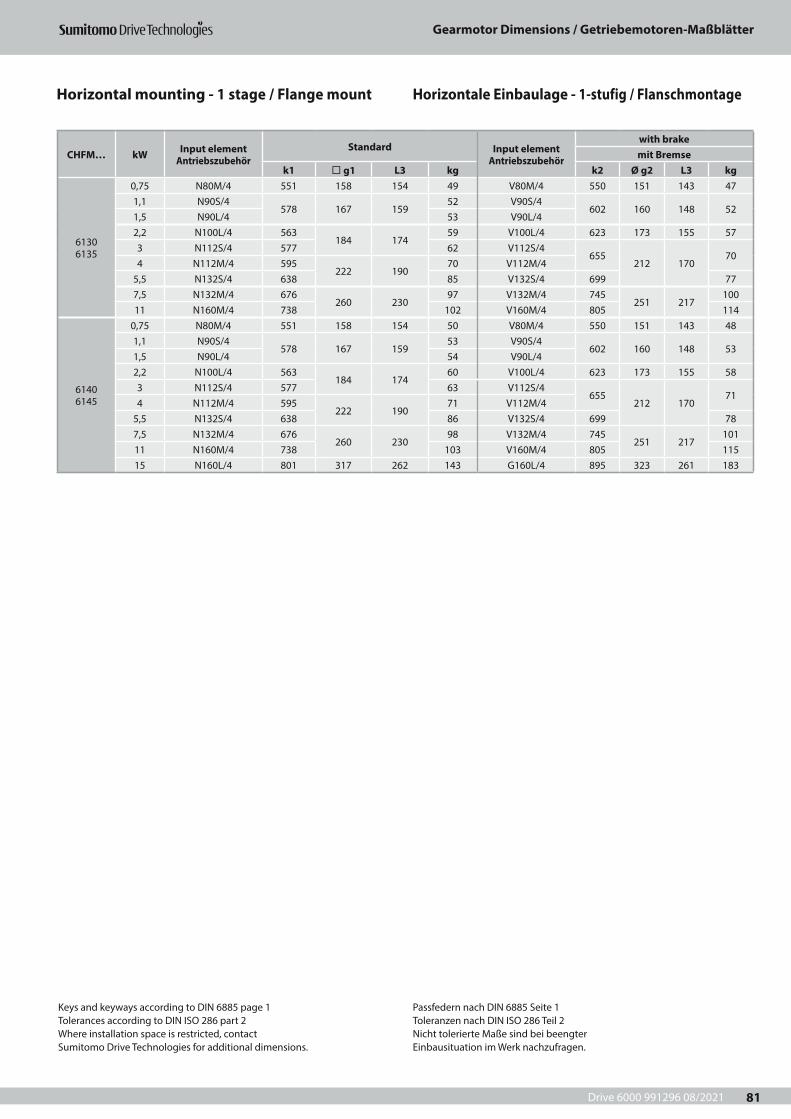
Drive 6000 991296 08/2021
Gearmotor Dimensions / Getriebemotoren-Maßblätter
81
CHFM… kW Input element Antriebszubehör
Standard Input element Antriebszubehör
with brakemit Bremse
k1 ¨ g1 L3 kg k2 Ø g2 L3 kg
6130 6135
0,75 N80M/4 551 158 154 49 V80M/4 550 151 143 471,1 N90S/4
578 167 15952 V90S/4
602 160 148 521,5 N90L/4 53 V90L/42,2 N100L/4 563
184 17459 V100L/4 623 173 155 57
3 N112S/4 577 62 V112S/4655
212 17070
4 N112M/4 595222 190
70 V112M/45,5 N132S/4 638 85 V132S/4 699 777,5 N132M/4 676
260 23097 V132M/4 745
251 217100
11 N160M/4 738 102 V160M/4 805 114
6140 6145
0,75 N80M/4 551 158 154 50 V80M/4 550 151 143 481,1 N90S/4
578 167 15953 V90S/4
602 160 148 531,5 N90L/4 54 V90L/42,2 N100L/4 563
184 17460 V100L/4 623 173 155 58
3 N112S/4 577 63 V112S/4655
212 17071
4 N112M/4 595222 190
71 V112M/45,5 N132S/4 638 86 V132S/4 699 787,5 N132M/4 676
260 23098 V132M/4 745
251 217101
11 N160M/4 738 103 V160M/4 805 11515 N160L/4 801 317 262 143 G160L/4 895 323 261 183
Keys and keyways according to DIN 6885 page 1Tolerances according to DIN ISO 286 part 2Where installation space is restricted, contactSumitomo Drive Technologies for additional dimensions.
Passfedern nach DIN 6885 Seite 1Toleranzen nach DIN ISO 286 Teil 2Nicht tolerierte Maße sind bei beengterEinbausituation im Werk nachzufragen.
Horizontale Einbaulage - 1-stufig / FlanschmontageHorizontal mounting - 1 stage / Flange mount
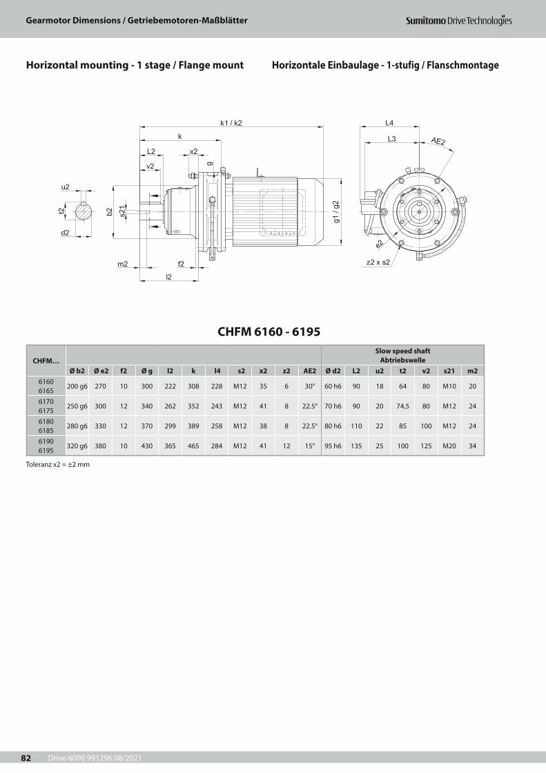
Drive 6000 991296 08/2021
Gearmotor Dimensions / Getriebemotoren-Maßblätter
82
CHFM 6160 - 6195
CHFM…Slow speed shaft
AbtriebswelleØ b2 Ø e2 f2 Ø g l2 k l4 s2 x2 z2 AE2 Ø d2 L2 u2 t2 v2 s21 m2
6160 6165
200 g6 270 10 300 222 308 228 M12 35 6 30° 60 h6 90 18 64 80 M10 20
6170 6175
250 g6 300 12 340 262 352 243 M12 41 8 22.5° 70 h6 90 20 74,5 80 M12 24
6180 6185
280 g6 330 12 370 299 389 258 M12 38 8 22.5° 80 h6 110 22 85 100 M12 24
6190 6195
320 g6 380 10 430 365 465 284 M12 41 12 15° 95 h6 135 25 100 125 M20 34
Toleranz x2 = ±2 mm
Horizontale Einbaulage - 1-stufig / FlanschmontageHorizontal mounting - 1 stage / Flange mount
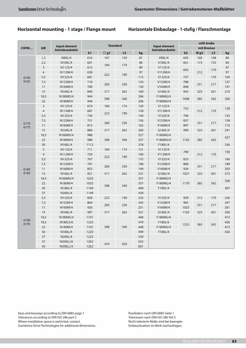
Drive 6000 991296 08/2021
Gearmotor Dimensions / Getriebemotoren-Maßblätter
83
CHFM… kW Input element Antriebszubehör
Standard Input element Antriebszubehör
with brakemit Bremse
k1 ¨ g1 L3 kg k2 Ø g2 L3 kg
6160 6165
1,5 N90L/4 616 167 159 81 V90L/4 645 160 148 802,2 N100L/4 601
184 17486 V100L/4 661 173 155 84
3 N112S/4 615 89 V112S/4693
212170
974 N112M/4 638
222 19097 V112M/4 97
5,5 N132S/4 681 113 V132S/4 737 170 1047,5 N132M/4 718
260 230124 V132M/4 788
251 217127
11 N160M/4 780 130 V160M/4 848 14115 N160L/4 840 317 262 169 G160L/4 942 323 261 210
18,5 N180MS/4 944398 340
296 F180MG/41098 385 342 300
22 N180M/4 944 296 F180MG/4
6170 6175
3 N112S/4 674 184 174 120 V112S/4752
212 170128
4 N112M/4 687222 190
128 V112M/45,5 N132S/4 730 144 V132S/4 796 1357,5 N132M/4 751
260 230156 V132M/4 837
251 217158
11 N160M/4 813 162 V160M/4 897 17215 N160L/4 884 317 262 200 G160L/4 990 323 261 241
18,5 N180MS/4 988398 340
327 F180MG/41142 385 342
32722 N180M/4 988 327 F180MG/430 N180L/4 1112 378 F180L/4 336
6180 6185
3 N112S/4 711 184 174 151 V112S/4789
212 170158
4 N112M/4 724222 190
160 V112M/45,5 N132S/4 767 175 V132S/4 833 1667,5 N132M/4 791
260 230188 V132M/4 868
251 217189
11 N160M/4 853 194 V160M/4 934 20315 N160L/4 921 317 262 231 G160L/4 1027 323 261 273
18,5 N180MS/4 1025
398 340
357 F180MG/41179 385 342
35822 N180M/4 1025 357 F180MG/430 N180L/4 1149 408 F180L/4 36737 N200L/4 1149 439
6190 6195
5,5 N132S/4 858 222 190 233 V132S/4 929 212 170 2267,5 N132M/4 864
260 230245 V132M/4 965
251 217247
11 N160M/4 926 251 V160M/4 1025 26115 N160L/4 997 317 262 321 G160L/4 1103 323 261 330
18,5 N180MS/4 1101
398 340
448 F180MG/4
1255 385 342
413
18,5 N180LS/6 1225 479 F180L/6 42622 N180M/4 1101 448 F180MG/4 41330 N180L/4 1225 499 F180L/4 42637 N200L/4 1225 53037 N200LL/6 1262
474 420622
45 N200LL/4 1262 601
Keys and keyways according to DIN 6885 page 1Tolerances according to DIN ISO 286 part 2Where installation space is restricted, contactSumitomo Drive Technologies for additional dimensions.
Passfedern nach DIN 6885 Seite 1Toleranzen nach DIN ISO 286 Teil 2Nicht tolerierte Maße sind bei beengterEinbausituation im Werk nachzufragen.
Horizontale Einbaulage - 1-stufig / FlanschmontageHorizontal mounting - 1 stage / Flange mount
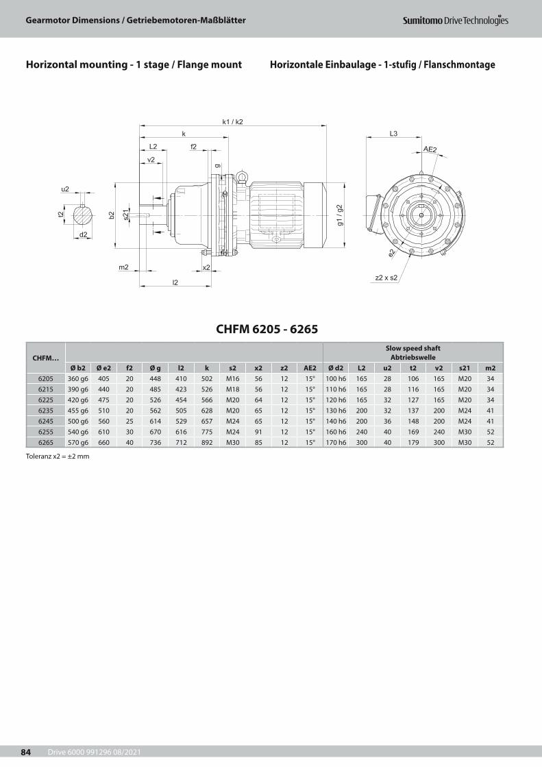
Drive 6000 991296 08/2021
Gearmotor Dimensions / Getriebemotoren-Maßblätter
84
CHFM 6205 - 6265
CHFM…Slow speed shaft
AbtriebswelleØ b2 Ø e2 f2 Ø g l2 k s2 x2 z2 AE2 Ø d2 L2 u2 t2 v2 s21 m2
6205 360 g6 405 20 448 410 502 M16 56 12 15° 100 h6 165 28 106 165 M20 346215 390 g6 440 20 485 423 526 M18 56 12 15° 110 h6 165 28 116 165 M20 346225 420 g6 475 20 526 454 566 M20 64 12 15° 120 h6 165 32 127 165 M20 346235 455 g6 510 20 562 505 628 M20 65 12 15° 130 h6 200 32 137 200 M24 416245 500 g6 560 25 614 529 657 M24 65 12 15° 140 h6 200 36 148 200 M24 416255 540 g6 610 30 670 616 775 M24 91 12 15° 160 h6 240 40 169 240 M30 526265 570 g6 660 40 736 712 892 M30 85 12 15° 170 h6 300 40 179 300 M30 52
Toleranz x2 = ±2 mm
Horizontale Einbaulage - 1-stufig / FlanschmontageHorizontal mounting - 1 stage / Flange mount

Drive 6000 991296 08/2021
Gearmotor Dimensions / Getriebemotoren-Maßblätter
85
CHFM… kW Input element Antriebszubehör
Standard Input element Antriebszubehör
with brakemit Bremse
k1 ¨ g1 L3 kg k2 Ø g2 L3 kg
6205
11 N160M/4 965 260 230 274 V160M/4 1087 251 217 28715 N160L/4 1044 317 262 316 G160L/4 1148 323 261 358
18,5 N180MS/4 1138
398 340
440 F180MG/41293 385 342
43922 N180M/4 1138 440 F180MG/430 N180L/4 1262 491 F180L/4 45237 N200L/4 1262 52245 N200LL/4 1299
474 420595
55 N225S/4 1299 632
6215
11 N160M/4 998 260 230 357 V160M/4 1091 251 217 36715 N160L/4 1068 317 262 397 G160L/4 1172 323 261 439
18,5 N180MS/4 1162
398 340
519 F180MG/41317 385 342
51422 N180M/4 1162 519 F180MG/430 N180L/4 1286 570 F180L/4 52737 N200L/4 1286 60145 N200LL/4 1323
474 420672
55 N225S/4 1323 708
6225
15 N160L/4 1202 317 262 56218,5 N180MS/4 1202
398 340
582 F180MG/41357 385 342
58222 N180M/4 1202 582 F180MG/430 N180L/4 1326 633 F180L/4 59537 N200L/4 1326 66445 N200LL/4 1363
474 420734
55 N225S/4 1363 770
6235
15 N160L/4 1264 317 262 65618,5 N180LS/6 1388
398 340703 F180L/6
1419 385 342 66722 N180L/6 1388 703 F180L/630 N200LS/6 1388 80537 N200LL/6 1425
474 420828
45 N225S/6 1425 85255 N250S/6 CF
6245
15 N160L/4 1293 317 262 75618,5 N180LS/6 1417
398 340
803 F180L/61443 385 342 789
22 N180L/6 1417 803 F180L/6
30 N200LS/6 1417 920
37 N200LL/6 1454474 420
94345 N225S/6 1454 96855 N250S/6 CF
6255
18,5 N180LS/6 1535398 340
1060 F180L/61560 385 342 1035
22 N180L/6 1535 1060 F180L/630 N200LS/6 1535 116537 N200LL/6 1572
474 4201190
45 N225S/6 1572 121055 N250S/6 CF
6265
30 N200LS/6 1652 398 340 141537 N200LL/6 1689
474 4201440
45 N225S/6 1689 1465
Keys and keyways according to DIN 6885 page 1Tolerances according to DIN ISO 286 part 2Where installation space is restricted, contactSumitomo Drive Technologies for additional dimensions.
Passfedern nach DIN 6885 Seite 1Toleranzen nach DIN ISO 286 Teil 2Nicht tolerierte Maße sind bei beengterEinbausituation im Werk nachzufragen.
Horizontale Einbaulage - 1-stufig / FlanschmontageHorizontal mounting - 1 stage / Flange mount
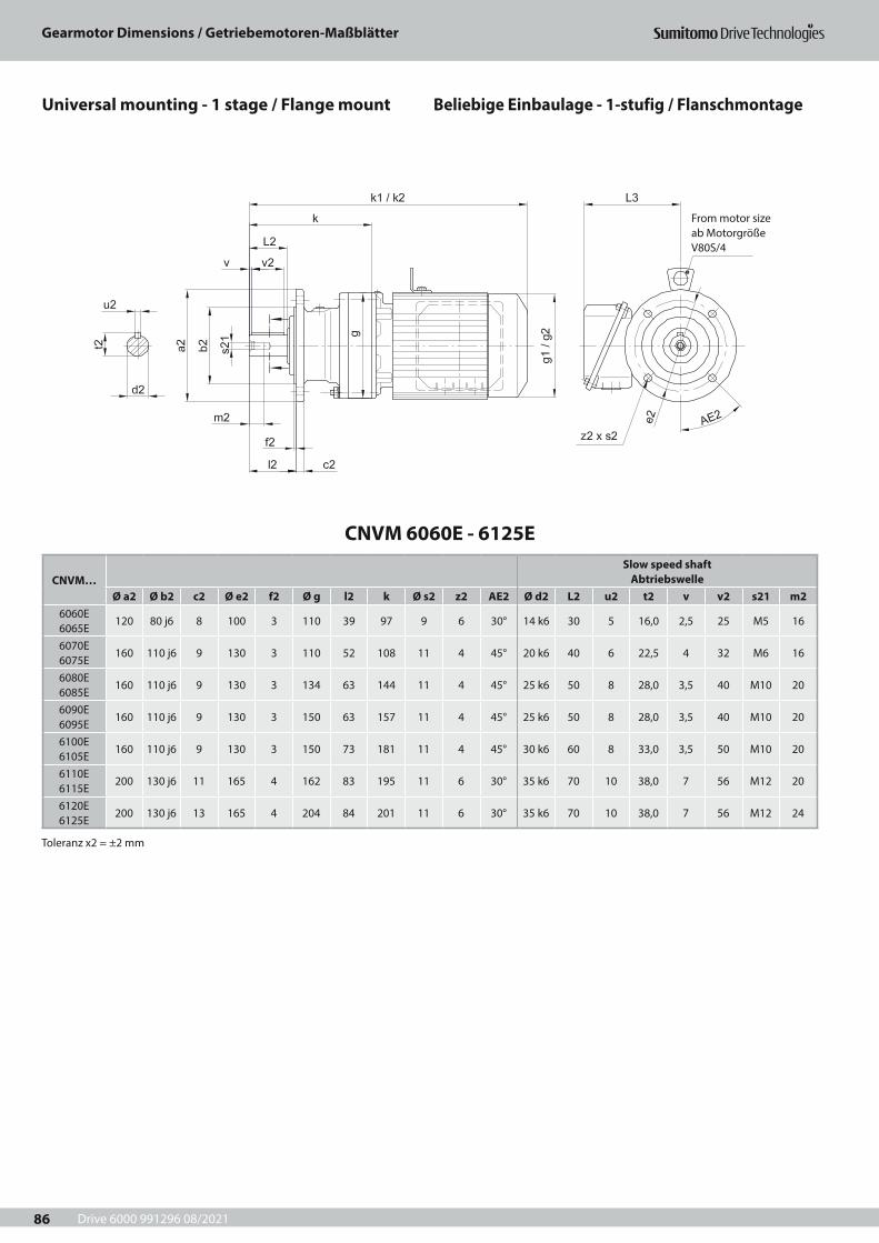
Drive 6000 991296 08/2021
Gearmotor Dimensions / Getriebemotoren-Maßblätter
86
CNVM 6060E - 6125E
CNVM…Slow speed shaft
AbtriebswelleØ a2 Ø b2 c2 Ø e2 f2 Ø g l2 k Ø s2 z2 AE2 Ø d2 L2 u2 t2 v v2 s21 m2
6060E 6065E
120 80 j6 8 100 3 110 39 97 9 6 30° 14 k6 30 5 16,0 2,5 25 M5 16
6070E 6075E
160 110 j6 9 130 3 110 52 108 11 4 45° 20 k6 40 6 22,5 4 32 M6 16
6080E 6085E
160 110 j6 9 130 3 134 63 144 11 4 45° 25 k6 50 8 28,0 3,5 40 M10 20
6090E 6095E
160 110 j6 9 130 3 150 63 157 11 4 45° 25 k6 50 8 28,0 3,5 40 M10 20
6100E 6105E
160 110 j6 9 130 3 150 73 181 11 4 45° 30 k6 60 8 33,0 3,5 50 M10 20
6110E 6115E
200 130 j6 11 165 4 162 83 195 11 6 30° 35 k6 70 10 38,0 7 56 M12 20
6120E 6125E
200 130 j6 13 165 4 204 84 201 11 6 30° 35 k6 70 10 38,0 7 56 M12 24
Toleranz x2 = ±2 mm
From motor sizeab MotorgrößeV80S/4
Beliebige Einbaulage - 1-stufig / FlanschmontageUniversal mounting - 1 stage / Flange mount

Drive 6000 991296 08/2021
Gearmotor Dimensions / Getriebemotoren-Maßblätter
87
CNVM… kW Input element Antriebszubehör
Standard Input element Antriebszubehör
with brakemit Bremse
k1 ¨ g1 L3 kg k2 Ø g2 L3 kg
6060 6065
0,12 V63S/4 248 119118
7 V63S/4 266124 118
80,18 V63M/4
273 124 8 V63M/4
305 90,25 V63M/4 V63M/4
6070 6075
0,12 V63S/4 261 119
118
8 V63S/4 277
124 118
90,18 V63M/4
288124
9 V63M/4
316 100,25 V63M/4 V63M/40,37 V71M/4 308 10 V71M/4 336 11
6080 6085
0,12 V63S/4 290 119
118
11 V63S/4 308
124 118
120,18 V63M/4
319124
12 V63M/4
347 130,25 V63M/4 V63M/40,37 V71M/4 339 14 V71M/4 367 150,55 V80S/4 376 151 143 18 V80S/4
419 151 143 190,75 N80M/4 418 158 154 20 V80M/4
6090 6095
0,12 V63S/4 318 119
118
12 V63S/4 328
124 118
140,18 V63M/4
333124
13 V63M/4
367 150,25 V63M/4 V63M/40,37 V71M/4 353 14 V71M/4 387 160,55 V80S/4 394 151 143 18 V80S/4
440 151 143 210,75 N80M/4 438 158 154 24 V80M/41,1 N90S/4
465 167 15927 V90S/4
492 160 148 261,5 N90L/4 28 V90L/4
6100 6105
0,12 V63S/4 331 119
118
14 V63S/4 352
124 118
160,18 V63M/4
357124
15 V63M/4
391 170,25 V63M/4 V63M/40,37 V71M/4 377 16 V71M/4 411 180,55 V80S/4 418 151 143 20 V80S/4
462 151 143 230,75 N80M/4 462 158 154 26 V80M/41,1 N90S/4
489 167 15929 V90S/4
514 160 148 291,5 N90L/4 30 V90L/42,2 N100L/4 510 184 174 38 V100L/4 534 173 155 34
6110 6115
0,37 V71M/4 391 124 113 18 V71M/4 419 124 118 200,55 V80S/4 428 151 143 21 V80S/4
472 151 143 240,75 N80M/4 472 158 154 29 V80M/4
1,1 N90S/4499 167 159
32 V90S/4524 160 148 30
1,5 N90L/4 33 V90L/42,2 N100L/4 496
184 17439 V100L/4 545 173 155 35
3 N112S/4 510 42 V112S/4588 212 170 48
4 N112M/4 523 222 190 50 V112M/4
6120 6125
0,37 V71M/4 406 124 118 28 V71M/4 434 124 118 300,55 V80S/4 438 151 143 30 V80S/4
481 151 143 330,75 N80M/4 482 158 154 36 V80M/41,1 N90S/4
509 167 15939 V90S/4
533 160 148 391,5 N90L/4 41 V90L/42,2 N100L/4 494
184 17447 V100L/4 554 173 155 45
3 N112S/4 508 50 V112S/4586
212 17058
4 N112M/4 531222 190
58 V112M/4
5,5 N132S/4 574 74 V132S/4 630 65
Keys and keyways according to DIN 6885 page 1Tolerances according to DIN ISO 286 part 2Where installation space is restricted, contactSumitomo Drive Technologies for additional dimensions.
Passfedern nach DIN 6885 Seite 1Toleranzen nach DIN ISO 286 Teil 2Nicht tolerierte Maße sind bei beengterEinbausituation im Werk nachzufragen.
Beliebige Einbaulage - 1-stufig / FlanschmontageUniversal mounting - 1 stage / Flange mount
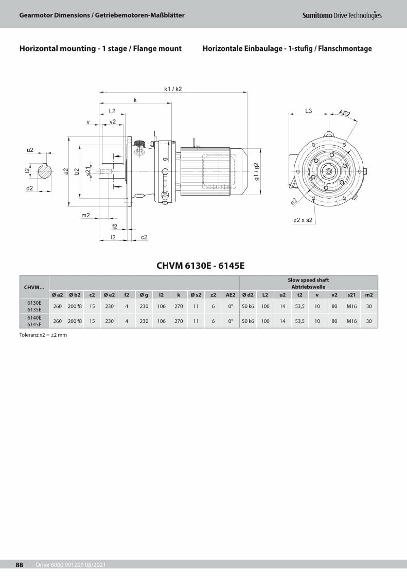
Drive 6000 991296 08/2021
Gearmotor Dimensions / Getriebemotoren-Maßblätter
88
CHVM 6130E - 6145E
CHVM…Slow speed shaft
AbtriebswelleØ a2 Ø b2 c2 Ø e2 f2 Ø g l2 k Ø s2 z2 AE2 Ø d2 L2 u2 t2 v v2 s21 m2
6130E 6135E
260 200 f8 15 230 4 230 106 270 11 6 0° 50 k6 100 14 53,5 10 80 M16 30
6140E 6145E
260 200 f8 15 230 4 230 106 270 11 6 0° 50 k6 100 14 53,5 10 80 M16 30
Toleranz x2 = ±2 mm
Horizontale Einbaulage - 1-stufig / FlanschmontageHorizontal mounting - 1 stage / Flange mount

Drive 6000 991296 08/2021
Gearmotor Dimensions / Getriebemotoren-Maßblätter
89
CHVM… kW Input element Antriebszubehör
Standard Input element Antriebszubehör
with brakemit Bremse
k1 ¨ g1 L3 kg k2 Ø g2 L3 kg
6130 6135
0,75 N80M/4 551 158 154 56 V80M/4 550 151 143 531,1 N90S/4
578 167 15959 V90S/4
602 160 148 591,5 N90L/4 61 V90L/42,2 N100L/4 563
184 17466 V100L/4 623 173 155 64
3 N112S/4 577 69 V112S/4655
212 17077
4 N112M/4 595222 190
77 V112M/45,5 N132S/4 638 92 V132S/4 699 847,5 N132M/4 676
260 230104 V132M/4 745
251 217107
11 N160M/4 738 109 V160M/4 805 120
6140 6145
0,75 N80M/4 551 158 154 57 V80M/4 550 151 143 541,1 N90S/4
578 167 15960 V90S/4
602 160 148 601,5 N90L/4 62 V90L/42,2 N100L/4 563
184 17467 V100L/4 623 173 155 65
3 N112S/4 577 70 V112S/4655
212 17078
4 N112M/4 595222 190
78 V112M/45,5 N132S/4 638 93 V132S/4 699 857,5 N132M/4 676
260 230105 V132M/4 745
251 217108
11 N160M/4 738 110 V160M/4 805 12115 N160L/4 801 317 262 148 G160L/4 895 323 261 191
Keys and keyways according to DIN 6885 page 1Tolerances according to DIN ISO 286 part 2Where installation space is restricted, contactSumitomo Drive Technologies for additional dimensions.
Passfedern nach DIN 6885 Seite 1Toleranzen nach DIN ISO 286 Teil 2Nicht tolerierte Maße sind bei beengterEinbausituation im Werk nachzufragen.
Horizontale Einbaulage - 1-stufig / FlanschmontageHorizontal mounting - 1 stage / Flange mount
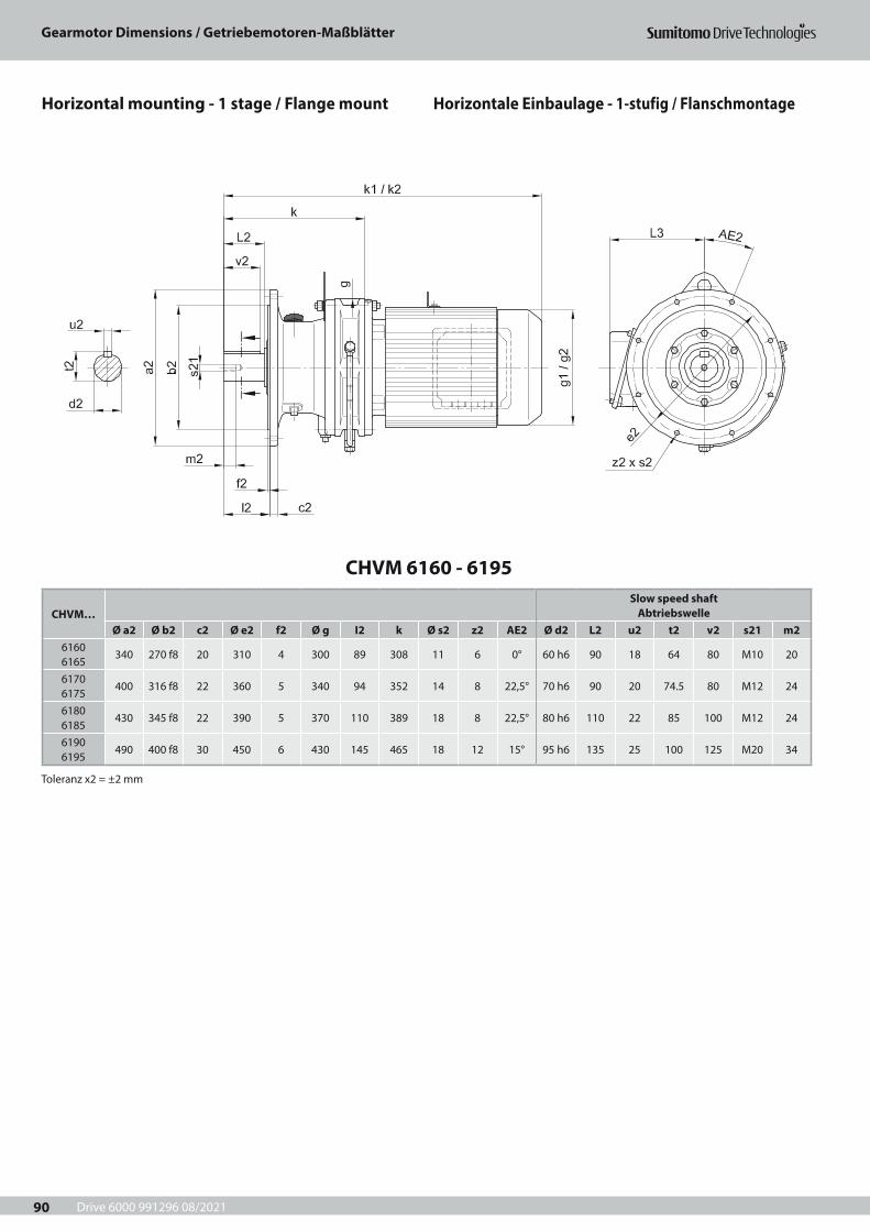
Drive 6000 991296 08/2021
Gearmotor Dimensions / Getriebemotoren-Maßblätter
90
CHVM 6160 - 6195
CHVM…Slow speed shaft
AbtriebswelleØ a2 Ø b2 c2 Ø e2 f2 Ø g I2 k Ø s2 z2 AE2 Ø d2 L2 u2 t2 v2 s21 m2
6160 6165
340 270 f8 20 310 4 300 89 308 11 6 0° 60 h6 90 18 64 80 M10 20
6170 6175
400 316 f8 22 360 5 340 94 352 14 8 22,5° 70 h6 90 20 74.5 80 M12 24
6180 6185
430 345 f8 22 390 5 370 110 389 18 8 22,5° 80 h6 110 22 85 100 M12 24
6190 6195
490 400 f8 30 450 6 430 145 465 18 12 15° 95 h6 135 25 100 125 M20 34
Toleranz x2 = ±2 mm
Horizontale Einbaulage - 1-stufig / FlanschmontageHorizontal mounting - 1 stage / Flange mount
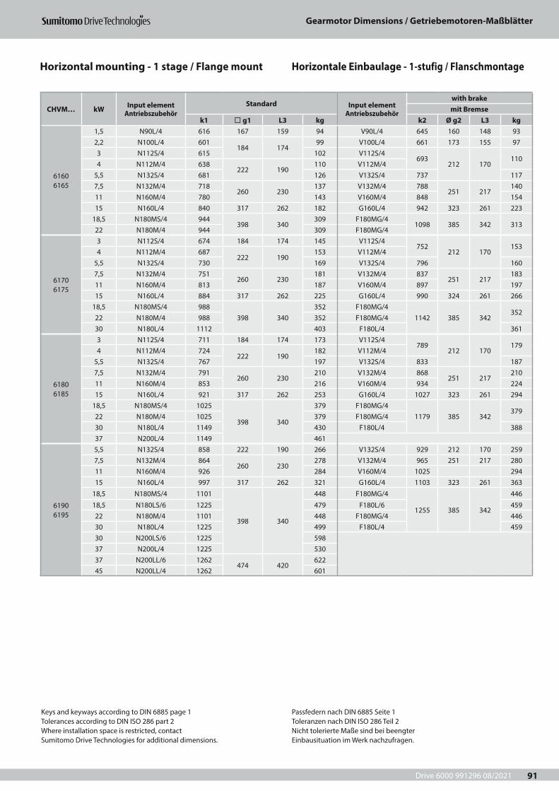
Drive 6000 991296 08/2021
Gearmotor Dimensions / Getriebemotoren-Maßblätter
91
CHVM… kW Input element Antriebszubehör
Standard Input element Antriebszubehör
with brakemit Bremse
k1 ¨ g1 L3 kg k2 Ø g2 L3 kg
6160 6165
1,5 N90L/4 616 167 159 94 V90L/4 645 160 148 932,2 N100L/4 601
184 17499 V100L/4 661 173 155 97
3 N112S/4 615 102 V112S/4693
212 170110
4 N112M/4 638222 190
110 V112M/45,5 N132S/4 681 126 V132S/4 737 1177,5 N132M/4 718
260 230137 V132M/4 788
251 217140
11 N160M/4 780 143 V160M/4 848 15415 N160L/4 840 317 262 182 G160L/4 942 323 261 223
18,5 N180MS/4 944398 340
309 F180MG/41098 385 342 313
22 N180M/4 944 309 F180MG/4
6170 6175
3 N112S/4 674 184 174 145 V112S/4752
212 170153
4 N112M/4 687222 190
153 V112M/45,5 N132S/4 730 169 V132S/4 796 1607,5 N132M/4 751
260 230181 V132M/4 837
251 217183
11 N160M/4 813 187 V160M/4 897 19715 N160L/4 884 317 262 225 G160L/4 990 324 261 266
18,5 N180MS/4 988398 340
352 F180MG/41142 385 342
35222 N180M/4 988 352 F180MG/430 N180L/4 1112 403 F180L/4 361
6180 6185
3 N112S/4 711 184 174 173 V112S/4789
212 170179
4 N112M/4 724222 190
182 V112M/45,5 N132S/4 767 197 V132S/4 833 1877,5 N132M/4 791
260 230210 V132M/4 868
251 217210
11 N160M/4 853 216 V160M/4 934 22415 N160L/4 921 317 262 253 G160L/4 1027 323 261 294
18,5 N180MS/4 1025
398 340
379 F180MG/41179 385 342
37922 N180M/4 1025 379 F180MG/430 N180L/4 1149 430 F180L/4 38837 N200L/4 1149 461
6190 6195
5,5 N132S/4 858 222 190 266 V132S/4 929 212 170 2597,5 N132M/4 864
260 230278 V132M/4 965 251 217 280
11 N160M/4 926 284 V160M/4 1025 29415 N160L/4 997 317 262 321 G160L/4 1103 323 261 363
18,5 N180MS/4 1101
398 340
448 F180MG/4
1255 385 342
446
18,5 N180LS/6 1225 479 F180L/6 45922 N180M/4 1101 448 F180MG/4 44630 N180L/4 1225 499 F180L/4 45930 N200LS/6 1225 59837 N200L/4 1225 53037 N200LL/6 1262
474 420622
45 N200LL/4 1262 601
Keys and keyways according to DIN 6885 page 1Tolerances according to DIN ISO 286 part 2Where installation space is restricted, contactSumitomo Drive Technologies for additional dimensions.
Passfedern nach DIN 6885 Seite 1Toleranzen nach DIN ISO 286 Teil 2Nicht tolerierte Maße sind bei beengterEinbausituation im Werk nachzufragen.
Horizontale Einbaulage - 1-stufig / FlanschmontageHorizontal mounting - 1 stage / Flange mount
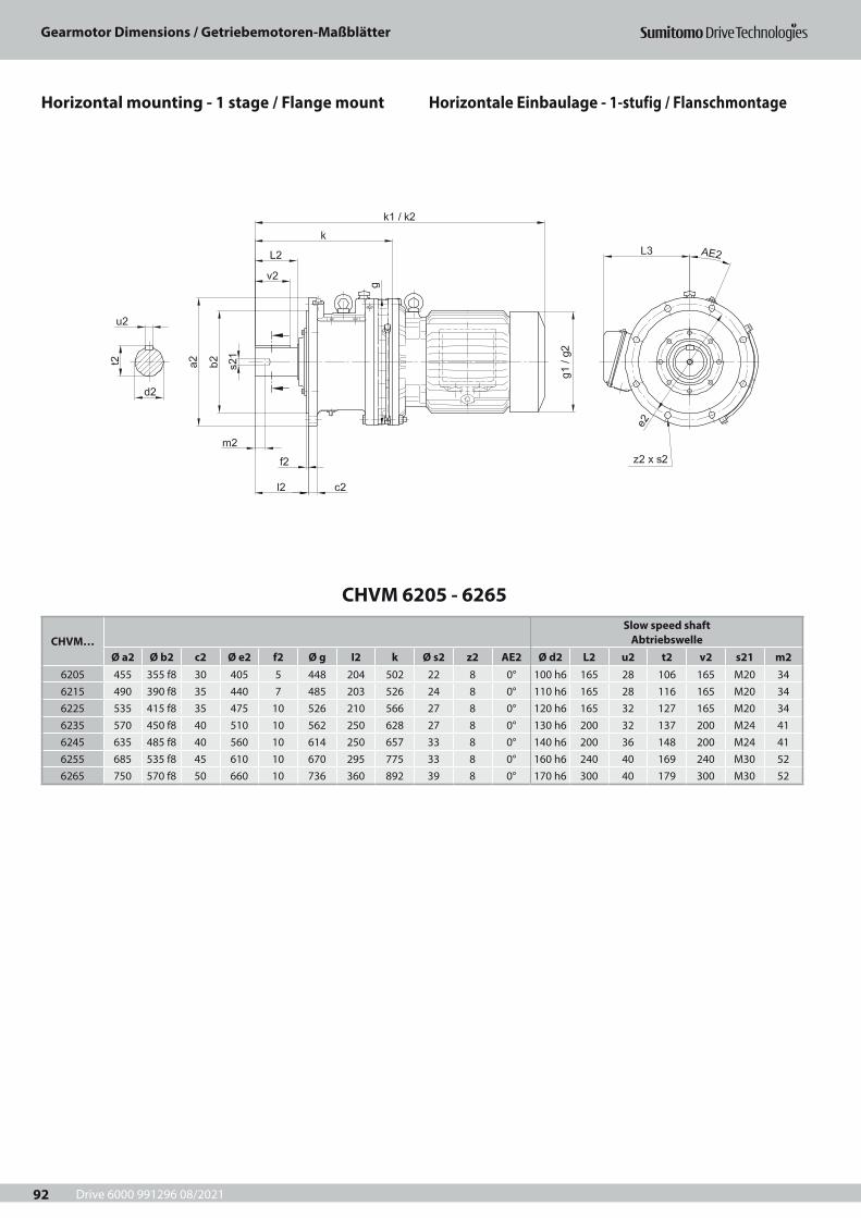
Drive 6000 991296 08/2021
Gearmotor Dimensions / Getriebemotoren-Maßblätter
92
CHVM 6205 - 6265
CHVM…Slow speed shaft
AbtriebswelleØ a2 Ø b2 c2 Ø e2 f2 Ø g I2 k Ø s2 z2 AE2 Ø d2 L2 u2 t2 v2 s21 m2
6205 455 355 f8 30 405 5 448 204 502 22 8 0° 100 h6 165 28 106 165 M20 346215 490 390 f8 35 440 7 485 203 526 24 8 0° 110 h6 165 28 116 165 M20 346225 535 415 f8 35 475 10 526 210 566 27 8 0° 120 h6 165 32 127 165 M20 346235 570 450 f8 40 510 10 562 250 628 27 8 0° 130 h6 200 32 137 200 M24 416245 635 485 f8 40 560 10 614 250 657 33 8 0° 140 h6 200 36 148 200 M24 416255 685 535 f8 45 610 10 670 295 775 33 8 0° 160 h6 240 40 169 240 M30 526265 750 570 f8 50 660 10 736 360 892 39 8 0° 170 h6 300 40 179 300 M30 52
Horizontale Einbaulage - 1-stufig / FlanschmontageHorizontal mounting - 1 stage / Flange mount
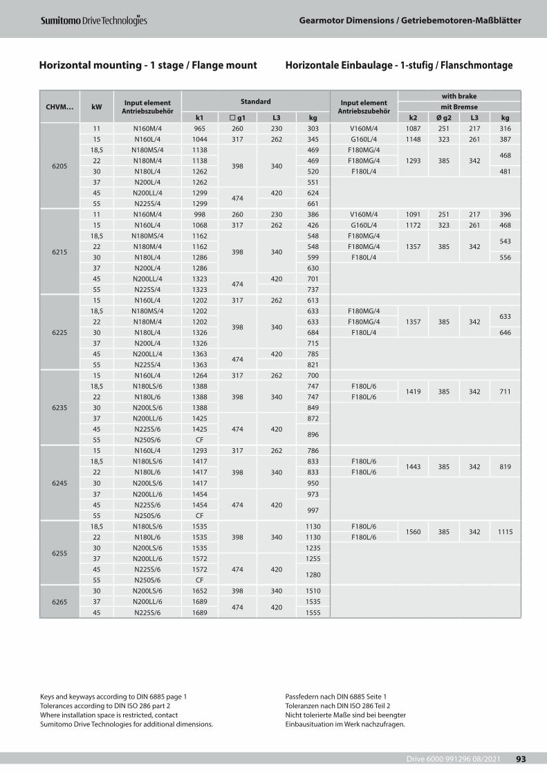
Drive 6000 991296 08/2021
Gearmotor Dimensions / Getriebemotoren-Maßblätter
93
CHVM… kW Input element Antriebszubehör
Standard Input element Antriebszubehör
with brakemit Bremse
k1 ¨ g1 L3 kg k2 Ø g2 L3 kg
6205
11 N160M/4 965 260 230 303 V160M/4 1087 251 217 31615 N160L/4 1044 317 262 345 G160L/4 1148 323 261 387
18,5 N180MS/4 1138
398 340
469 F180MG/41293 385 342
46822 N180M/4 1138 469 F180MG/430 N180L/4 1262 520 F180L/4 48137 N200L/4 1262 55145 N200LL/4 1299
474420 624
55 N225S/4 1299 661
6215
11 N160M/4 998 260 230 386 V160M/4 1091 251 217 39615 N160L/4 1068 317 262 426 G160L/4 1172 323 261 468
18,5 N180MS/4 1162
398 340
548 F180MG/41357 385 342
54322 N180M/4 1162 548 F180MG/430 N180L/4 1286 599 F180L/4 55637 N200L/4 1286 63045 N200LL/4 1323
474420 701
55 N225S/4 1323 737
6225
15 N160L/4 1202 317 262 61318,5 N180MS/4 1202
398 340
633 F180MG/41357 385 342
63322 N180M/4 1202 633 F180MG/430 N180L/4 1326 684 F180L/4 64637 N200L/4 1326 71545 N200LL/4 1363
474420 785
55 N225S/4 1363 821
6235
15 N160L/4 1264 317 262 70018,5 N180LS/6 1388
398 340747 F180L/6
1419 385 342 71122 N180L/6 1388 747 F180L/630 N200LS/6 1388 84937 N200LL/6 1425
474 420872
45 N225S/6 1425896
55 N250S/6 CF
6245
15 N160L/4 1293 317 262 78618,5 N180LS/6 1417
398 340
833 F180L/61443 385 342 819
22 N180L/6 1417 833 F180L/6
30 N200LS/6 1417 950
37 N200LL/6 1454474 420
97345 N225S/6 1454
99755 N250S/6 CF
6255
18,5 N180LS/6 1535398 340
1130 F180L/61560 385 342 1115
22 N180L/6 1535 1130 F180L/630 N200LS/6 1535 123537 N200LL/6 1572
474 4201255
45 N225S/6 15721280
55 N250S/6 CF
6265
30 N200LS/6 1652 398 340 151037 N200LL/6 1689
474 4201535
45 N225S/6 1689 1555
Keys and keyways according to DIN 6885 page 1Tolerances according to DIN ISO 286 part 2Where installation space is restricted, contactSumitomo Drive Technologies for additional dimensions.
Passfedern nach DIN 6885 Seite 1Toleranzen nach DIN ISO 286 Teil 2Nicht tolerierte Maße sind bei beengterEinbausituation im Werk nachzufragen.
Horizontale Einbaulage - 1-stufig / FlanschmontageHorizontal mounting - 1 stage / Flange mount
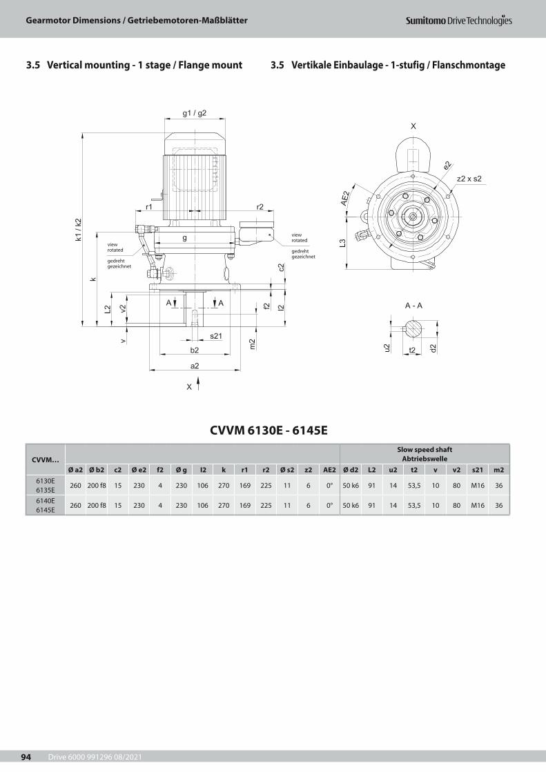
Drive 6000 991296 08/2021
Gearmotor Dimensions / Getriebemotoren-Maßblätter
94
CVVM 6130E - 6145E
CVVM…Slow speed shaft
AbtriebswelleØ a2 Ø b2 c2 Ø e2 f2 Ø g I2 k r1 r2 Ø s2 z2 AE2 Ø d2 L2 u2 t2 v v2 s21 m2
6130E 6135E
260 200 f8 15 230 4 230 106 270 169 225 11 6 0° 50 k6 91 14 53,5 10 80 M16 36
6140E 6145E
260 200 f8 15 230 4 230 106 270 169 225 11 6 0° 50 k6 91 14 53,5 10 80 M16 36
view rotated
gedreht gezeichnet
view rotated
gedreht gezeichnet
3.5 Vertikale Einbaulage - 1-stufig / Flanschmontage3.5 Vertical mounting - 1 stage / Flange mount
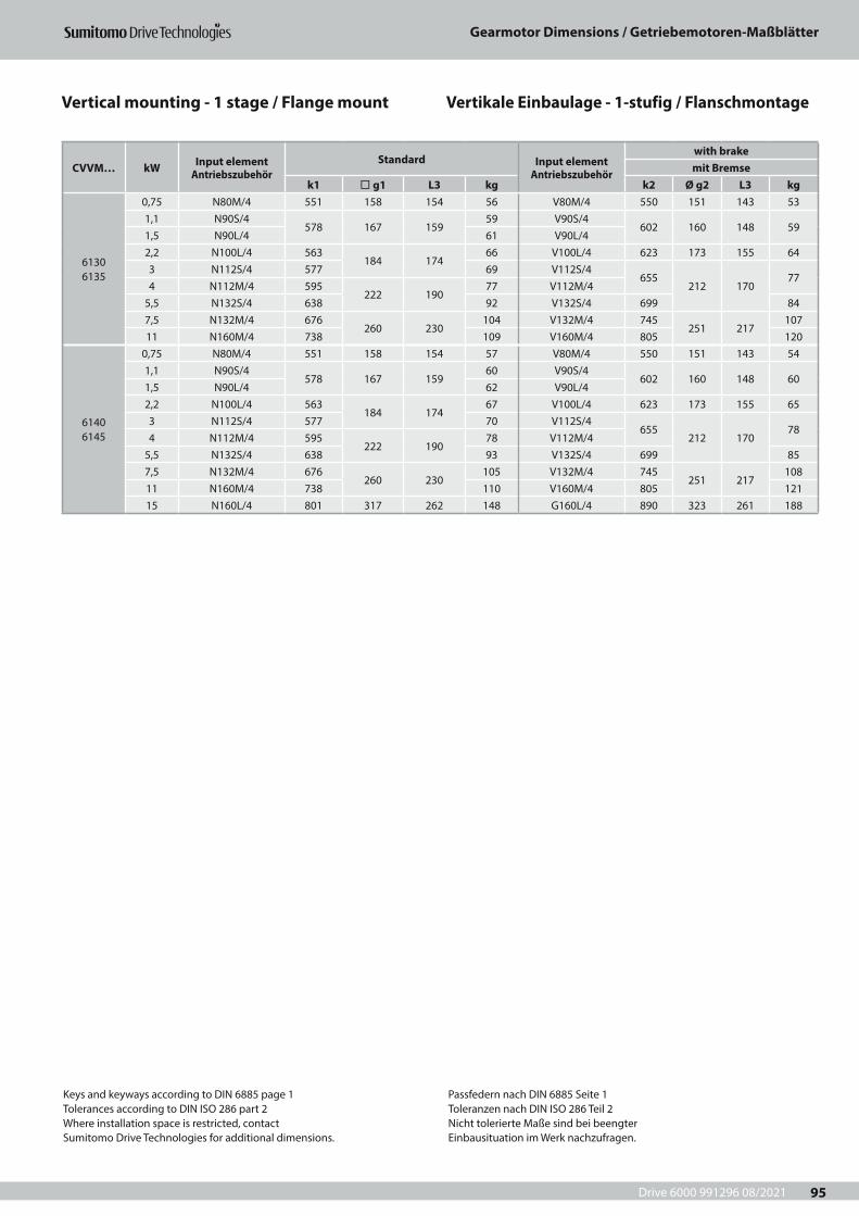
Drive 6000 991296 08/2021
Gearmotor Dimensions / Getriebemotoren-Maßblätter
95
CVVM… kW Input element Antriebszubehör
Standard Input element Antriebszubehör
with brakemit Bremse
k1 ¨ g1 L3 kg k2 Ø g2 L3 kg
6130 6135
0,75 N80M/4 551 158 154 56 V80M/4 550 151 143 531,1 N90S/4
578 167 15959 V90S/4
602 160 148 591,5 N90L/4 61 V90L/42,2 N100L/4 563
184 17466 V100L/4 623 173 155 64
3 N112S/4 577 69 V112S/4655
212 17077
4 N112M/4 595222 190
77 V112M/45,5 N132S/4 638 92 V132S/4 699 847,5 N132M/4 676
260 230104 V132M/4 745
251 217107
11 N160M/4 738 109 V160M/4 805 120
6140 6145
0,75 N80M/4 551 158 154 57 V80M/4 550 151 143 541,1 N90S/4
578 167 15960 V90S/4
602 160 148 601,5 N90L/4 62 V90L/42,2 N100L/4 563
184 17467 V100L/4 623 173 155 65
3 N112S/4 577 70 V112S/4655
212 17078
4 N112M/4 595222 190
78 V112M/45,5 N132S/4 638 93 V132S/4 699 857,5 N132M/4 676
260 230105 V132M/4 745
251 217108
11 N160M/4 738 110 V160M/4 805 12115 N160L/4 801 317 262 148 G160L/4 890 323 261 188
Keys and keyways according to DIN 6885 page 1Tolerances according to DIN ISO 286 part 2Where installation space is restricted, contactSumitomo Drive Technologies for additional dimensions.
Passfedern nach DIN 6885 Seite 1Toleranzen nach DIN ISO 286 Teil 2Nicht tolerierte Maße sind bei beengterEinbausituation im Werk nachzufragen.
Vertikale Einbaulage - 1-stufig / FlanschmontageVertical mounting - 1 stage / Flange mount
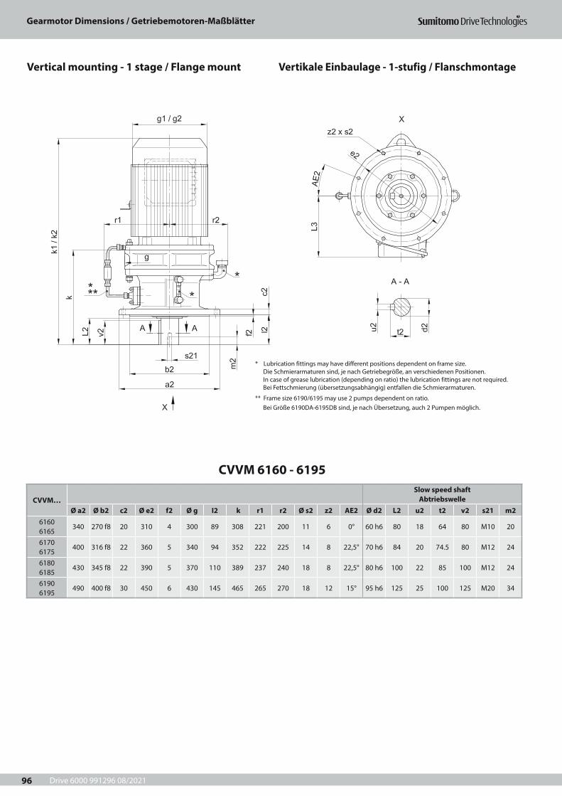
Drive 6000 991296 08/2021
Gearmotor Dimensions / Getriebemotoren-Maßblätter
96
CVVM 6160 - 6195
CVVM…Slow speed shaft
AbtriebswelleØ a2 Ø b2 c2 Ø e2 f2 Ø g I2 k r1 r2 Ø s2 z2 AE2 Ø d2 L2 u2 t2 v2 s21 m2
6160 6165
340 270 f8 20 310 4 300 89 308 221 200 11 6 0° 60 h6 80 18 64 80 M10 20
6170 6175
400 316 f8 22 360 5 340 94 352 222 225 14 8 22,5° 70 h6 84 20 74.5 80 M12 24
6180 6185
430 345 f8 22 390 5 370 110 389 237 240 18 8 22,5° 80 h6 100 22 85 100 M12 24
6190 6195
490 400 f8 30 450 6 430 145 465 265 270 18 12 15° 95 h6 125 25 100 125 M20 34
* Lubrication fittings may have different positions dependent on frame size.Die Schmierarmaturen sind, je nach Getriebegröße, an verschiedenen Positionen.In case of grease lubrication (depending on ratio) the lubrication fittings are not required.Bei Fettschmierung (übersetzungsabhängig) entfallen die Schmierarmaturen.
** Frame size 6190/6195 may use 2 pumps dependent on ratio.Bei Größe 6190DA-6195DB sind, je nach Übersetzung, auch 2 Pumpen möglich.
Vertikale Einbaulage - 1-stufig / FlanschmontageVertical mounting - 1 stage / Flange mount
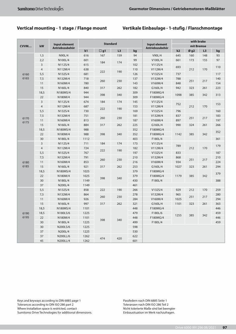
Drive 6000 991296 08/2021
Gearmotor Dimensions / Getriebemotoren-Maßblätter
97
CVVM… kW Input element Antriebszubehör
Standard Input element Antriebszubehör
with brakemit Bremse
k1 ¨ g1 L3 kg k2 Ø g2 L3 kg
6160 6165
1,5 N90L/4 616 167 159 94 V90L/4 645 160 148 932,2 N100L/4 601
184 17499 V100L/4 661 173 155 97
3 N112S/4 615 102 V112S/4 693
212 170110
4 N112M/4 638222 190
110 V112M/4 5,5 N132S/4 681 126 V132S/4 737 1177,5 N132M/4 718
260 230137 V132M/4 788
251 217140
11 N160M/4 780 143 V160M/4 848 15415 N160L/4 840 317 262 182 G160L/4 942 323 261 223
18,5 N180MS/4 944398 340
309 F180MG/41098 385 342 313
22 N180M/4 944 309 F180MG/4
6170 6175
3 N112S/4 674 184 174 145 V112S/4 752
212 170153
4 N112M/4 687222 190
153 V112M/4 5,5 N132S/4 730 169 V132S/4 796 1607,5 N132M/4 751
260 230181 V132M/4 837
251 217183
11 N160M/4 813 187 V160M/4 897 19715 N160L/4 884 317 262 225 G160L/4 990 324 261 266
18,5 N180MS/4 988398 340
352 F180MG/41142 385 342
35222 N180M/4 988 352 F180MG/430 N180L/4 1112 403 F180L/4 361
6180 6185
3 N112S/4 711 184 174 173 V112S/4 789
212 170179
4 N112M/4 724222 190
182 V112M/4 5,5 N132S/4 767 197 V132S/4 833 1877,5 N132M/4 791
260 230210 V132M/4 868
251 217210
11 N160M/4 853 216 V160M/4 934 22415 N160L/4 921 317 262 253 G160L/4 1027 323 261 294
18,5 N180MS/4 1025
398 340
379 F180MG/41179 385 342
37922 N180M/4 1025 379 F180MG/430 N180L/4 1149 430 F180L/4 38837 N200L/4 1149 461
6190 6195
5,5 N132S/4 858 222 190 266 V132S/4 929 212 170 2597,5 N132M/4 864
260 230278 V132M/4 965
251 217280
11 N160M/4 926 284 V160M/4 1025 29415 N160L/4 997 317 262 321 G160L/4 1101 323 261 363
18,5 N180MS/4 1101
398 340
448 F180MG/4
1255 385 342
44618,5 N180LS/6 1225 479 F180L/6 45922 N180M/4 1101 448 F180MG/4 44630 N180L/4 1225 499 F180L/4 45930 N200LS/6 1225 59837 N200L/4 1225 53037 N200LL/6 1262
474 420622
45 N200LL/4 1262 601
Keys and keyways according to DIN 6885 page 1Tolerances according to DIN ISO 286 part 2Where installation space is restricted, contactSumitomo Drive Technologies for additional dimensions.
Passfedern nach DIN 6885 Seite 1Toleranzen nach DIN ISO 286 Teil 2Nicht tolerierte Maße sind bei beengterEinbausituation im Werk nachzufragen.
Vertikale Einbaulage - 1-stufig / FlanschmontageVertical mounting - 1 stage / Flange mount
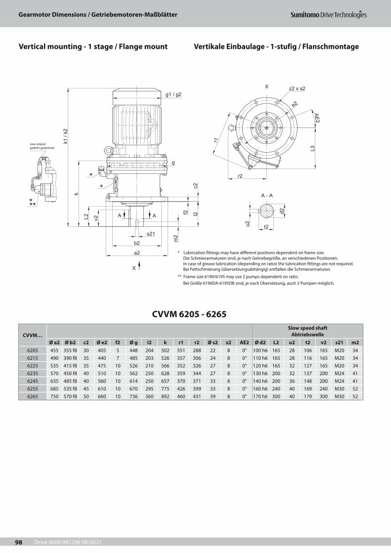
Drive 6000 991296 08/2021
Gearmotor Dimensions / Getriebemotoren-Maßblätter
98
CVVM 6205 - 6265
CVVM…Slow speed shaft
AbtriebswelleØ a2 Ø b2 c2 Ø e2 f2 Ø g I2 k r1 r2 Ø s2 z2 AE2 Ø d2 L2 u2 t2 v2 s21 m2
6205 455 355 f8 30 405 5 448 204 502 351 288 22 8 0° 100 h6 165 28 106 165 M20 346215 490 390 f8 35 440 7 485 203 526 357 306 24 8 0° 110 h6 165 28 116 165 M20 346225 535 415 f8 35 475 10 526 210 566 352 326 27 8 0° 120 h6 165 32 127 165 M20 346235 570 450 f8 40 510 10 562 250 628 359 344 27 8 0° 130 h6 200 32 137 200 M24 416245 635 485 f8 40 560 10 614 250 657 370 371 33 8 0° 140 h6 200 36 148 200 M24 416255 685 535 f8 45 610 10 670 295 775 426 399 33 8 0° 160 h6 240 40 169 240 M30 526265 750 570 f8 50 660 10 736 360 892 460 431 39 8 0° 170 h6 300 40 179 300 M30 52
view rotatedgedreht gezeichnet
* Lubrication fittings may have different positions dependent on frame size.Die Schmierarmaturen sind, je nach Getriebegröße, an verschiedenen Positionen.In case of grease lubrication (depending on ratio) the lubrication fittings are not required.Bei Fettschmierung (übersetzungsabhängig) entfallen die Schmierarmaturen.
** Frame size 6190/6195 may use 2 pumps dependent on ratio.Bei Größe 6190DA-6195DB sind, je nach Übersetzung, auch 2 Pumpen möglich.
Vertikale Einbaulage - 1-stufig / FlanschmontageVertical mounting - 1 stage / Flange mount

Drive 6000 991296 08/2021
Gearmotor Dimensions / Getriebemotoren-Maßblätter
99
CVVM… kW Input element Antriebszubehör
Standard Input element Antriebszubehör
with brakemit Bremse
k1 ¨ g1 L3 kg k2 Ø g2 L3 kg
6205
11 N160M/4 965 260 230 303 V160M/4 1087 251 217 31615 N160L/4 1044 317 262 345 G160L/4 1148 323 261 387
18,5 N180MS/4 1138
398 340
469 F180MG/41293 385 342
46822 N180M/4 1138 469 F180MG/430 N180L/4 1262 520 F180L/4 48137 N200L/4 1262 55145 N200LL/4 1299
474 420624
55 N225S/4 1299 661
6215
11 N160M/4 998 260 230 386 V160M/4 1091 251 217 39615 N160L/4 1068 317 262 426 G160L/4 1172 323 261 468
18,5 N180MS/4 1162
398 340
548 F180MG/41357 385 342
54322 N180M/4 1162 548 F180MG/430 N180L/4 1286 599 F180L/4 55637 N200L/4 1286 63045 N200LL/4 1323
474 420701
55 N225S/4 1323 737
6225
15 N160L/4 1202 317 262 61318,5 N180MS/4 1202
398 340
633 F180MG/41357 385 342
63322 N180M/4 1202 633 F180MG/430 N180L/4 1326 684 F180L/4 64637 N200L/4 1326 71545 N200LL/4 1363
474 420785
55 N225S/4 1363 821
6235
15 N160L/4 1264 317 262 70018,5 N180LS/6 1388
398 340747 F180L/6
1419 385 342 71122 N180L/6 1388 747 F180L/630 N200LS/6 1388 84937 N200LL/6 1425
474 420872
45 N225S/6 1425 89655 N250S/6 CF
6245
15 N160L/4 1293 317 262 78618,5 N180LS/6 1417
398 340833 F180L/6
1443 385 342 81922 N180L/6 1417 833 F180L/630 N200LS/6 1417 95037 N200LL/6 1454
474 420973
45 N225S/6 1454 99755 N250S/6 CF
6255
18,5 N180LS/6 1535398 340
1130 F180L/61560 385 342 1115
22 N180L/6 1535 1130 F180L/630 N200LS/6 1535 123537 N200LL/6 1572
474 4201255
45 N225S/6 1572 128055 N250S/6 CF
626530 N200LS/6 1652 398 340 151037 N200LL/6 1689
474 4201535
45 N225S/6 1689 1555
Keys and keyways according to DIN 6885 page 1Tolerances according to DIN ISO 286 part 2Where installation space is restricted, contactSumitomo Drive Technologies for additional dimensions.
Passfedern nach DIN 6885 Seite 1Toleranzen nach DIN ISO 286 Teil 2Nicht tolerierte Maße sind bei beengterEinbausituation im Werk nachzufragen.
Vertikale Einbaulage - 1-stufig / FlanschmontageVertical mounting - 1 stage / Flange mount
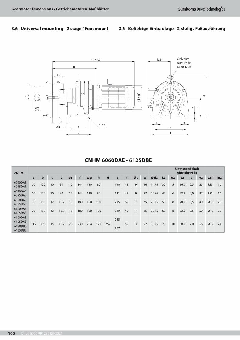
Drive 6000 991296 08/2021
Gearmotor Dimensions / Getriebemotoren-Maßblätter
100
3.6 Beliebige Einbaulage - 2-stufig / Fußausführung3.6 Universal mounting - 2 stage / Foot mount
Only size nur Größe 6120, 6125
CNHM 6060DAE - 6125DBE
CNHM…Slow speed shaft
Abtriebswellea b c e e3 f Ø g h H k n Ø s w Ø d2 L2 u2 t2 v v2 s21 m2
6060DAE 6065DAE
60 120 10 84 12 144 110 80 130 48 9 46 14 k6 30 5 16,0 2,5 25 M5 16
6070DAE 6075DAE
60 120 10 84 12 144 110 80 141 48 9 57 20 k6 40 6 22,5 4,0 32 M6 16
6090DAE 6095DAE
90 150 12 135 15 180 150 100 205 65 11 75 25 k6 50 8 28,0 3,5 40 M10 20
6100DAE 6105DAE
90 150 12 135 15 180 150 100 229 40 11 85 30 k6 60 8 33,0 3,5 50 M10 20
6120DAE 6125DAE
115 190 15 155 20 230 204 120 257255
55 14 97 35 k6 70 10 38,0 7,0 56 M12 246120DBE 6125DBE
267
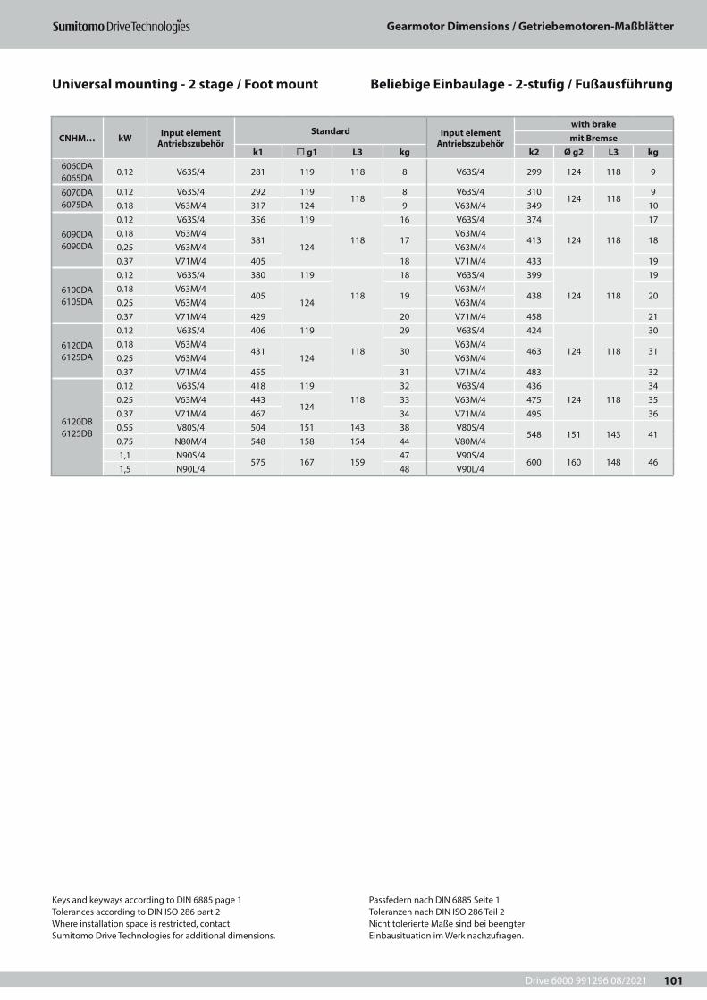
Drive 6000 991296 08/2021
Gearmotor Dimensions / Getriebemotoren-Maßblätter
101
CNHM… kW Input element Antriebszubehör
Standard Input element Antriebszubehör
with brakemit Bremse
k1 ¨ g1 L3 kg k2 Ø g2 L3 kg6060DA 6065DA
0,12 V63S/4 281 119 118 8 V63S/4 299 124 118 9
6070DA 6075DA
0,12 V63S/4 292 119118
8 V63S/4 310124 118
90,18 V63M/4 317 124 9 V63M/4 349 10
6090DA 6090DA
0,12 V63S/4 356 119
118
16 V63S/4 374
124 118
170,18 V63M/4
381124
17V63M/4
413 180,25 V63M/4 V63M/40,37 V71M/4 405 18 V71M/4 433 19
6100DA 6105DA
0,12 V63S/4 380 119
118
18 V63S/4 399
124 118
190,18 V63M/4
405124
19V63M/4
438 200,25 V63M/4 V63M/40,37 V71M/4 429 20 V71M/4 458 21
6120DA 6125DA
0,12 V63S/4 406 119
118
29 V63S/4 424
124 118
300,18 V63M/4
431124
30V63M/4
463 310,25 V63M/4 V63M/40,37 V71M/4 455 31 V71M/4 483 32
6120DB 6125DB
0,12 V63S/4 418 119118
32 V63S/4 436124 118
340,25 V63M/4 443
12433 V63M/4 475 35
0,37 V71M/4 467 34 V71M/4 495 360,55 V80S/4 504 151 143 38 V80S/4
548 151 143 410,75 N80M/4 548 158 154 44 V80M/41,1 N90S/4
575 167 15947 V90S/4
600 160 148 461,5 N90L/4 48 V90L/4
Beliebige Einbaulage - 2-stufig / FußausführungUniversal mounting - 2 stage / Foot mount
Keys and keyways according to DIN 6885 page 1Tolerances according to DIN ISO 286 part 2Where installation space is restricted, contactSumitomo Drive Technologies for additional dimensions.
Passfedern nach DIN 6885 Seite 1Toleranzen nach DIN ISO 286 Teil 2Nicht tolerierte Maße sind bei beengterEinbausituation im Werk nachzufragen.
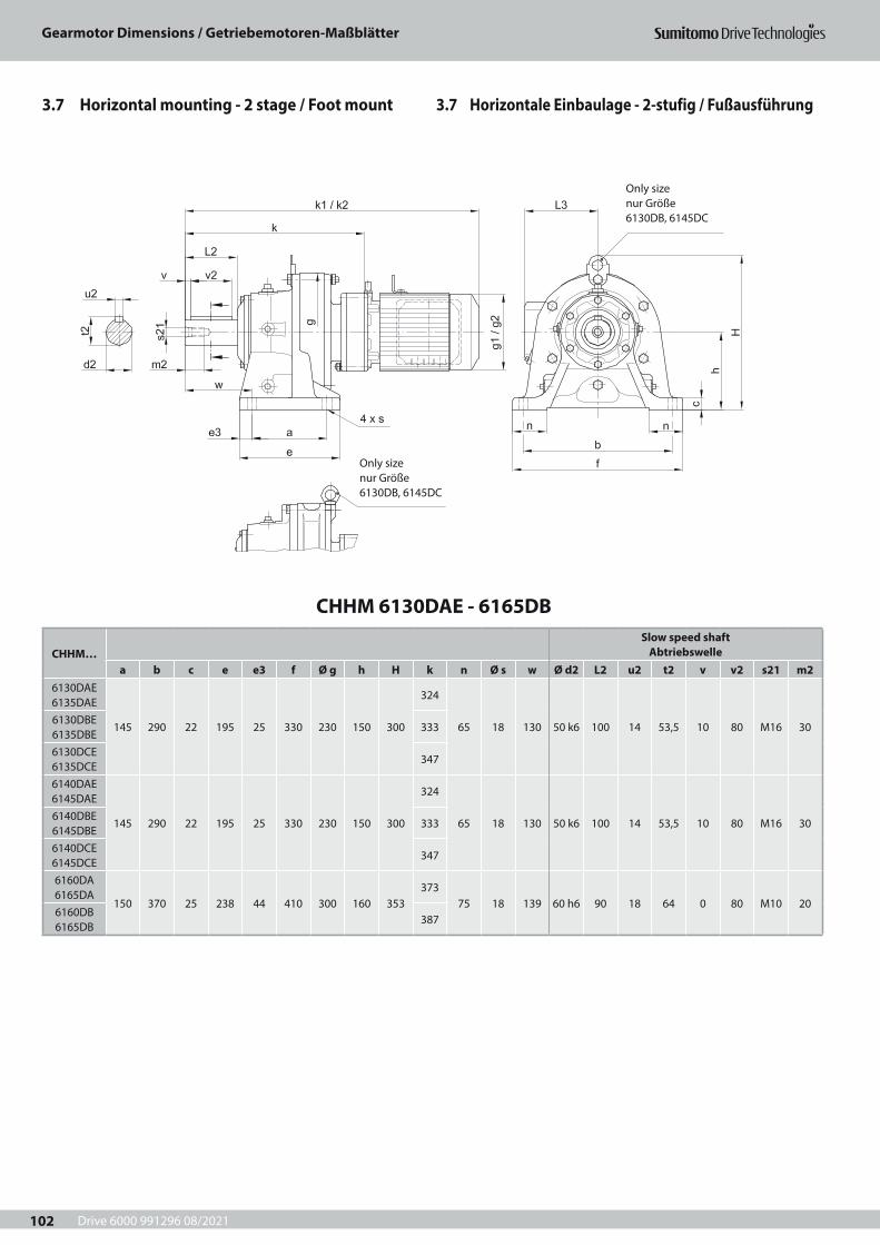
Drive 6000 991296 08/2021
Gearmotor Dimensions / Getriebemotoren-Maßblätter
102
Only size nur Größe 6130DB, 6145DC
Only size nur Größe 6130DB, 6145DC
CHHM 6130DAE - 6165DB
CHHM…Slow speed shaft
Abtriebswellea b c e e3 f Ø g h H k n Ø s w Ø d2 L2 u2 t2 v v2 s21 m2
6130DAE 6135DAE
145 290 22 195 25 330 230 150 300
324
65 18 130 50 k6 100 14 53,5 10 80 M16 306130DBE 6135DBE
333
6130DCE 6135DCE
347
6140DAE 6145DAE
145 290 22 195 25 330 230 150 300
324
65 18 130 50 k6 100 14 53,5 10 80 M16 306140DBE 6145DBE
333
6140DCE 6145DCE
347
6160DA 6165DA
150 370 25 238 44 410 300 160 353373
75 18 139 60 h6 90 18 64 0 80 M10 206160DB 6165DB
387
3.7 Horizontale Einbaulage - 2-stufig / Fußausführung3.7 Horizontal mounting - 2 stage / Foot mount

Drive 6000 991296 08/2021
Gearmotor Dimensions / Getriebemotoren-Maßblätter
103
CHHM… kW Input element Antriebszubehör
Standard Input element Antriebszubehör
with brakemit Bremse
k1 ¨ g1 L3 kg k2 Ø g2 L3 kg
6130DA 6135DA
0,12 V63S/4 475 119
118
47 V63S/4 493
124 118
490,18 V63M/4
500124
48V63M/4
532 500,25 V63M/4 V63M/40,37 V71M/4 524 49 V71M/4 552 51
6130DB 6135DB
0,12 V63S/4 484 119
118
47 V63S/4 502
124 118
490,18 V63M/4
509124
48V63M/4
541 500,25 V63M/4 V63M/40,37 V71M/4 533 49 V71M/4 561 510,55 V80S/4 570 151 143 53 V80S/4
614 151 143 560,75 N80M/4 614 158 154 63 V80M/41,1 N90S/4
641 167 15966 V90S/4
666 160 148 611,5 N90L/4 67 V90L/4
6130DC 6135DC
0,55 V80S/4 584 151 143 55 V80S/4628 151 143 58
0,75 N80M/4 628 158 154 65 V80M/41,1 N90S/4
655 167 15968 V90S/4
680 160 148 641,5 N90L/4 69 V90L/42,2 N100L/4 676 184 174 77 V100L/4 701 173 155 69
6140DA 6145DA
0,18 V63M/4500
124 11850
V63M/4532
124 11852
0,25 V63M/4 V63M/40,37 V71M/4 524 51 V71M/4 552 53
6140DB 6145DB
0,18 V63M/4509
124 11850
V63M/4541
124 11852
0,25 V63M/4 V63M/40,37 V71M/4 533 51 V71M/4 561 530,55 V80S/4 570 151 143 55 V80S/4
614 151 143 580,75 N80M/4 614 158 154 63 V80M/41,1 N90S/4
641 167 15966 V90S/4
666 160 148 641,5 N90L/4 67 V90L/4
6140DC 6145DC
0,18 V63M/4523
124 11850
V63M/4555
124 11852
0,25 V63M/4 V63M/40,37 V71M/4 547 51 V71M/4 575 530,55 V80S/4 584 151 143 55 V80S/4
628 151 143 580,75 N80M/4 628 158 154 65 V80M/41,1 N90S/4
655 167 15968 V90S/4
680 160 148 641,5 N90L/4 69 V90L/42,2 N100L/4 676 184 174 77 V100L/4 701 173 155 69
6160DA 6165DA
0,18 V63M/4549
124 11892
V63M/4581
124 11893
0,25 V63M/4 V63M/40,37 V71M/4 573 93 V71M/4 601 940,55 V80S/4 610 151 143 96 V80S/4
654 151 143 990,75 N80M/4 654 158 154 100 V80M/41,1 N90S/4
681 167 159104 V90S/4
706 160 148 1051,5 N90L/4 105 V90L/4
6160DB 6165DB
0,18 V63M/4563
124 11892
V63M/4595
124 11893
0,25 V63M/4 V63M/40,37 V71M/4 587 93 V71M/4 615 940,55 V80S/4 624 151 143 96 V80S/4
668 151 143 990,75 N80M/4 668 158 154 102 V80M/41,1 N90S/4
695 167 159105 V90S/4
720 160 148 1051,5 N90L/4 106 V90L/42,2 N100L/4 716 184 174 114 V100L/4 741 173 155 110
Keys and keyways according to DIN 6885 page 1Tolerances according to DIN ISO 286 part 2Where installation space is restricted, contactSumitomo Drive Technologies for additional dimensions.
Passfedern nach DIN 6885 Seite 1Toleranzen nach DIN ISO 286 Teil 2Nicht tolerierte Maße sind bei beengterEinbausituation im Werk nachzufragen.
Horizontal mounting - 2 stage / Foot mount Horizontale Einbaulage - 2-stufig / Fußausführung
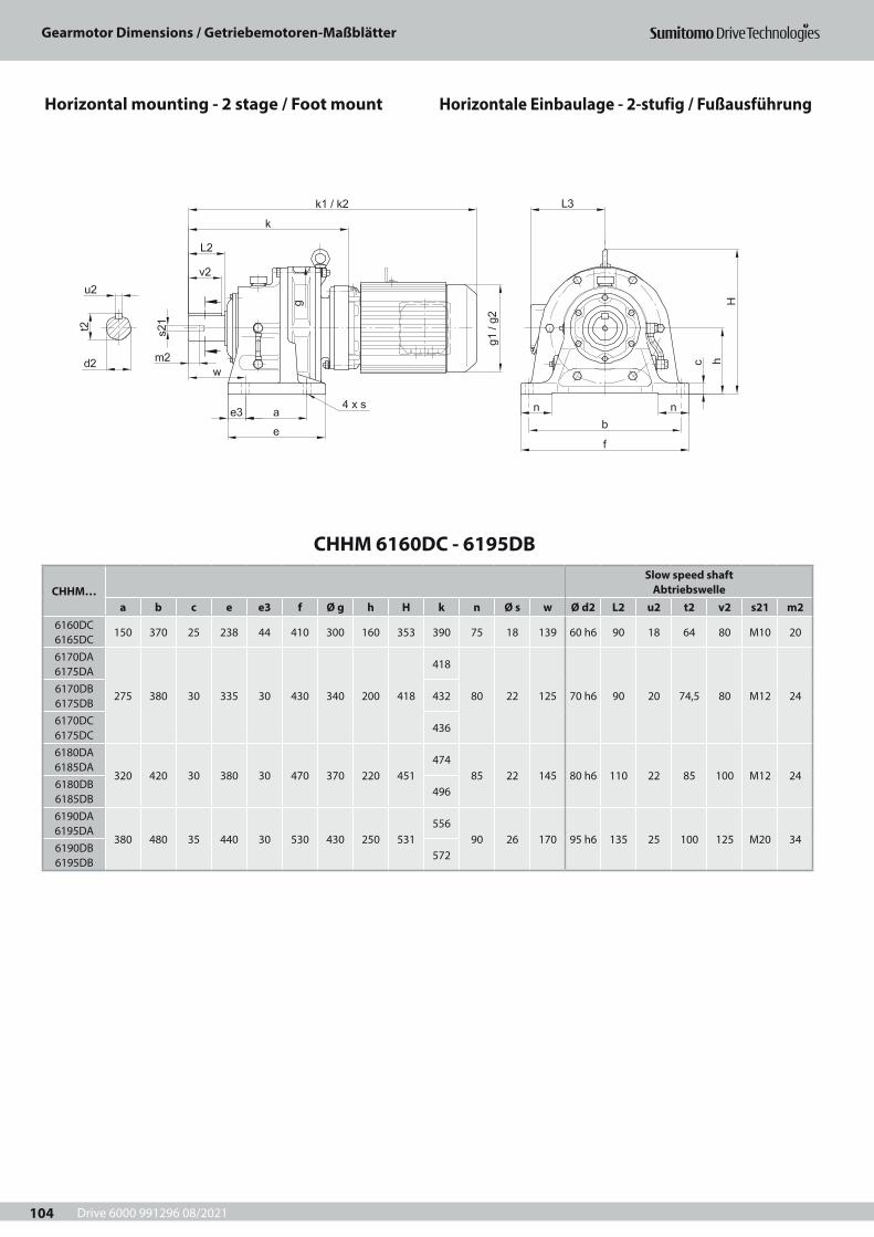
Drive 6000 991296 08/2021
Gearmotor Dimensions / Getriebemotoren-Maßblätter
104
CHHM 6160DC - 6195DB
CHHM…Slow speed shaft
Abtriebswellea b c e e3 f Ø g h H k n Ø s w Ø d2 L2 u2 t2 v2 s21 m2
6160DC 6165DC
150 370 25 238 44 410 300 160 353 390 75 18 139 60 h6 90 18 64 80 M10 20
6170DA 6175DA
275 380 30 335 30 430 340 200 418
418
80 22 125 70 h6 90 20 74,5 80 M12 246170DB 6175DB
432
6170DC 6175DC
436
6180DA 6185DA
320 420 30 380 30 470 370 220 451474
85 22 145 80 h6 110 22 85 100 M12 246180DB 6185DB
496
6190DA 6195DA
380 480 35 440 30 530 430 250 531556
90 26 170 95 h6 135 25 100 125 M20 346190DB 6195DB
572
Horizontal mounting - 2 stage / Foot mount Horizontale Einbaulage - 2-stufig / Fußausführung

Drive 6000 991296 08/2021
Gearmotor Dimensions / Getriebemotoren-Maßblätter
105
CHHM… kW Input element Antriebszubehör
Standard Input element Antriebszubehör
with brakemit Bremse
k1 ¨ g1 L3 kg k2 Ø g2 L3 kg
6160DC 6165DC
2,2 N100L/4 683184 174
119 V100L/4 743 173 155 1173 N112S/4 697 122 V112S/4
775212 166
1304 N112M/4 720
222 190130 V112M/4
5,5 N132S/4 763 146 V132S/4 819 137
6170DA 6175DA
0,37 V71M/4 618 124 118 126 V71M/4 646 124 118 1280,55 V80S/4 655 151 143 130 V80S/4
699 151 143 1330,75 N80M/4 699 158 154 135 V80M/41,1 N90S/4
726 167 159139 V90S/4
751 160 148 1381,5 N90L/4 140 V90L/4
6170DB 6175DB
0,37 V71M/4 632 124 118 124 V71M/4 660 124 118 1290,55 V80S/4 669 151 143 127 V80S/4
713 151 143 1340,75 N80M/4 713 158 154 137 V80M/41,1 N90S/4
740 167 159141 V90S/4
764 160 148 1411,5 N90L/4 142 V90L/42,2 N100L/4 761 184 174 149 V100L/4 785 173 155 146
6170DC 6175DC
0,37 V71M/4 641 124 118 133 V71M/4 669 124 118 1350,55 V80S/4 673 151 143 137 V80S/4
717 151 143 1400,75 N80M/4 717 158 154 143 V80M/41,1 N90S/4
744 167 159145 V90S/4
769 160 148 1451,5 N90L/4 147 V90L/42,2 N100L/4 729
184 174153 V100L/4 790 173 155 151
3 N112S/4 743 156 V112S/4821
212 166164
4 N112M/4 766222 190
164 V112M/45,5 N132S/4 809 180 V132S/4 865 171
6180DA 6185DA
0,75 N80M/4 755 158 154 183 V80M/4 755 151 143 1781,1 N90S/4
782 167 159187 V90S/4
807 160 148 1841,5 N90L/4 188 V90L/42,2 N100L/4 803 184 174 195 V100L/4 828 173 155 189
6180DB 6185DB
0,75 N80M/4 777 158 154 199 V80M/4 777 151 143 1921,1 N90S/4
804 167 159201 V90S/4
829 160 148 1971,5 N90L/4 202 V90L/42,2 N100L/4 789
184 174208 V100L/4 850 173 155 203
3 N112S/4 803 211 V112S/4881
212 166216
4 N112M/4 821222 190
219 V112M/45,5 N132S/4 864 234 V132S/4 925 2237,5 N132M/4 902
260 230246 V132M/4 971
251 217246
11 N160M/4 964 251 V160M/4 1031 260
6190DA 6195DA
0,55 V80S/4 793 151 143 249 V80S/4837 151 143 252
0,75 N80M/4 837 158 154 257 V80M/41,1 N90S/4
864 167 159260 V90S/4
889 160 148 2581,5 N90L/4 262 V90L/42,2 N100L/4 849
184 174268 V100L/4 910 173 155 264
3 N112S/4 863 271 V112S/4941
212 166277
4 N112M/4 886222 190
279 V112M/45,5 N132S/4 929 295 V132S/4 985 284
6190DB 6195DB
2,2 N100L/4 865184 174
275 V100L/4 926 173 155 2713 N112S/4 879 278 V112S/4
957212 166
2844 N112M/4 897
222 190286 V112M/4
5,5 N132S/4 940 301 V132S/4 1001 2917,5 N132M/4 978
260 230313 V132M/4 1047
251 217314
11 N160M/4 1040 318 V160M/4 1107 32815 N160L/4 1104 317 264 355 G160LG/4 1192 323 261 395
Keys and keyways according to DIN 6885 page 1Tolerances according to DIN ISO 286 part 2Where installation space is restricted, contactSumitomo Drive Technologies for additional dimensions.
Passfedern nach DIN 6885 Seite 1Toleranzen nach DIN ISO 286 Teil 2Nicht tolerierte Maße sind bei beengterEinbausituation im Werk nachzufragen.
Horizontal mounting - 2 stage / Foot mount Horizontale Einbaulage - 2-stufig / Fußausführung
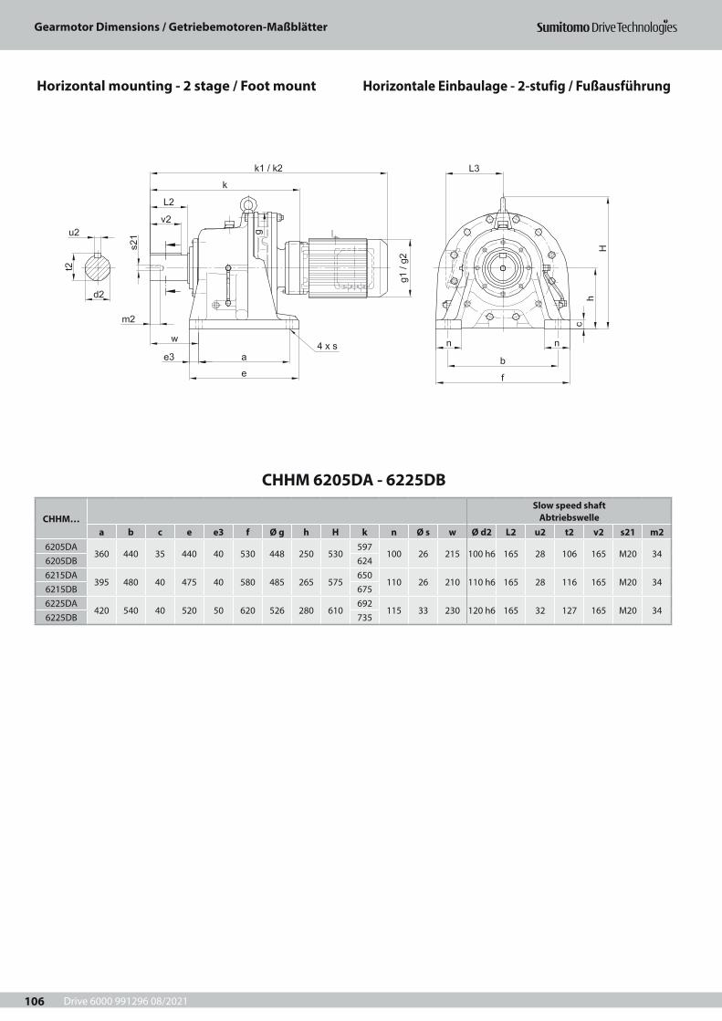
Drive 6000 991296 08/2021
Gearmotor Dimensions / Getriebemotoren-Maßblätter
106
CHHM 6205DA - 6225DB
CHHM…Slow speed shaft
Abtriebswellea b c e e3 f Ø g h H k n Ø s w Ø d2 L2 u2 t2 v2 s21 m2
6205DA360 440 35 440 40 530 448 250 530
597100 26 215 100 h6 165 28 106 165 M20 34
6205DB 6246215DA
395 480 40 475 40 580 485 265 575650
110 26 210 110 h6 165 28 116 165 M20 346215DB 6756225DA
420 540 40 520 50 620 526 280 610692
115 33 230 120 h6 165 32 127 165 M20 346225DB 735
Horizontal mounting - 2 stage / Foot mount Horizontale Einbaulage - 2-stufig / Fußausführung
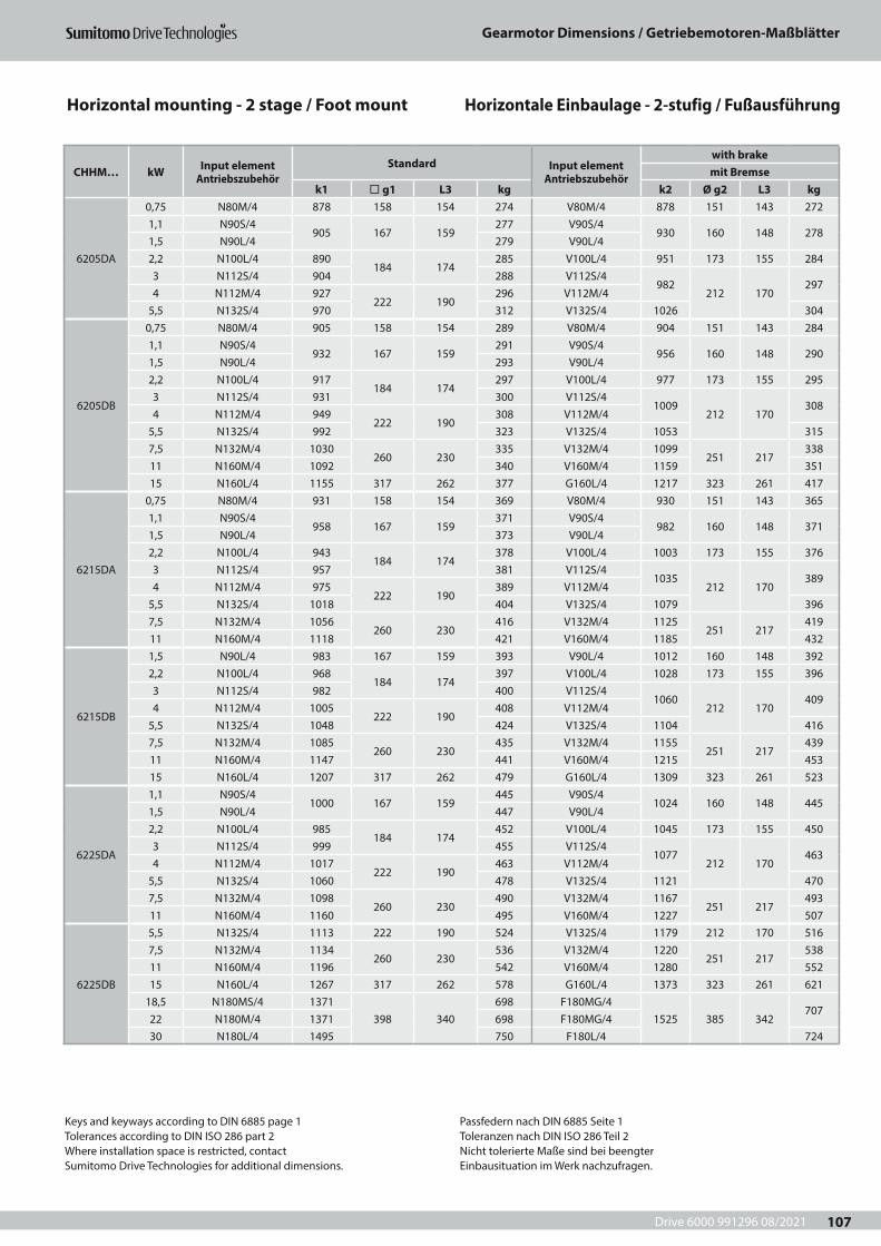
Drive 6000 991296 08/2021
Gearmotor Dimensions / Getriebemotoren-Maßblätter
107
CHHM… kW Input element Antriebszubehör
Standard Input element Antriebszubehör
with brakemit Bremse
k1 ¨ g1 L3 kg k2 Ø g2 L3 kg
6205DA
0,75 N80M/4 878 158 154 274 V80M/4 878 151 143 2721,1 N90S/4
905 167 159277 V90S/4
930 160 148 2781,5 N90L/4 279 V90L/42,2 N100L/4 890
184 174285 V100L/4 951 173 155 284
3 N112S/4 904 288 V112S/4982
212 170297
4 N112M/4 927222 190
296 V112M/45,5 N132S/4 970 312 V132S/4 1026 304
6205DB
0,75 N80M/4 905 158 154 289 V80M/4 904 151 143 2841,1 N90S/4
932 167 159291 V90S/4
956 160 148 2901,5 N90L/4 293 V90L/42,2 N100L/4 917
184 174297 V100L/4 977 173 155 295
3 N112S/4 931 300 V112S/41009
212 170308
4 N112M/4 949222 190
308 V112M/45,5 N132S/4 992 323 V132S/4 1053 3157,5 N132M/4 1030
260 230335 V132M/4 1099
251 217338
11 N160M/4 1092 340 V160M/4 1159 35115 N160L/4 1155 317 262 377 G160L/4 1217 323 261 417
6215DA
0,75 N80M/4 931 158 154 369 V80M/4 930 151 143 3651,1 N90S/4
958 167 159371 V90S/4
982 160 148 3711,5 N90L/4 373 V90L/42,2 N100L/4 943
184 174378 V100L/4 1003 173 155 376
3 N112S/4 957 381 V112S/41035
212 170389
4 N112M/4 975222 190
389 V112M/45,5 N132S/4 1018 404 V132S/4 1079 3967,5 N132M/4 1056
260 230416 V132M/4 1125
251 217419
11 N160M/4 1118 421 V160M/4 1185 432
6215DB
1,5 N90L/4 983 167 159 393 V90L/4 1012 160 148 3922,2 N100L/4 968
184 174397 V100L/4 1028 173 155 396
3 N112S/4 982 400 V112S/41060
212 170409
4 N112M/4 1005222 190
408 V112M/45,5 N132S/4 1048 424 V132S/4 1104 4167,5 N132M/4 1085
260 230435 V132M/4 1155
251 217439
11 N160M/4 1147 441 V160M/4 1215 45315 N160L/4 1207 317 262 479 G160L/4 1309 323 261 523
6225DA
1,1 N90S/41000 167 159
445 V90S/41024 160 148 445
1,5 N90L/4 447 V90L/42,2 N100L/4 985
184 174452 V100L/4 1045 173 155 450
3 N112S/4 999 455 V112S/41077
212 170463
4 N112M/4 1017222 190
463 V112M/45,5 N132S/4 1060 478 V132S/4 1121 4707,5 N132M/4 1098
260 230490 V132M/4 1167
251 217493
11 N160M/4 1160 495 V160M/4 1227 507
6225DB
5,5 N132S/4 1113 222 190 524 V132S/4 1179 212 170 5167,5 N132M/4 1134
260 230536 V132M/4 1220
251 217538
11 N160M/4 1196 542 V160M/4 1280 55215 N160L/4 1267 317 262 578 G160L/4 1373 323 261 621
18,5 N180MS/4 1371398 340
698 F180MG/41525 385 342
70722 N180M/4 1371 698 F180MG/430 N180L/4 1495 750 F180L/4 724
Keys and keyways according to DIN 6885 page 1Tolerances according to DIN ISO 286 part 2Where installation space is restricted, contactSumitomo Drive Technologies for additional dimensions.
Passfedern nach DIN 6885 Seite 1Toleranzen nach DIN ISO 286 Teil 2Nicht tolerierte Maße sind bei beengterEinbausituation im Werk nachzufragen.
Horizontal mounting - 2 stage / Foot mount Horizontale Einbaulage - 2-stufig / Fußausführung
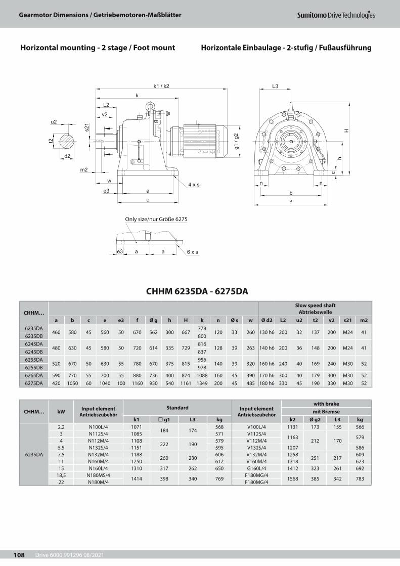
Drive 6000 991296 08/2021
Gearmotor Dimensions / Getriebemotoren-Maßblätter
108
Only size/nur Größe 6275
CHHM… kW Input element Antriebszubehör
Standard Input element Antriebszubehör
with brakemit Bremse
k1 ¨ g1 L3 kg k2 Ø g2 L3 kg
6235DA
2,2 N100L/4 1071184 174
568 V100L/4 1131 173 155 5663 N112S/4 1085 571 V112S/4
1163212 170
5794 N112M/4 1108
222 190579 V112M/4
5,5 N132S/4 1151 595 V132S/4 1207 5867,5 N132M/4 1188
260 230606 V132M/4 1258
251 217609
11 N160M/4 1250 612 V160M/4 1318 62315 N160L/4 1310 317 262 650 G160L/4 1412 323 261 692
18,5 N180MS/41414 398 340 769
F180MG/41568 385 342 783
22 N180M/4 F180MG/4
CHHM 6235DA - 6275DA
CHHM…Slow speed shaft
Abtriebswellea b c e e3 f Ø g h H k n Ø s w Ø d2 L2 u2 t2 v2 s21 m2
6235DA460 580 45 560 50 670 562 300 667
778120 33 260 130 h6 200 32 137 200 M24 41
6235DB 8006245DA
480 630 45 580 50 720 614 335 729816
128 39 263 140 h6 200 36 148 200 M24 416245DB 8376255DA
520 670 50 630 55 780 670 375 815956
140 39 320 160 h6 240 40 169 240 M30 526255DB 9786265DA 590 770 55 700 55 880 736 400 874 1088 160 45 390 170 h6 300 40 179 300 M30 526275DA 420 1050 60 1040 100 1160 950 540 1161 1349 200 45 485 180 h6 330 45 190 330 M30 52
Horizontal mounting - 2 stage / Foot mount Horizontale Einbaulage - 2-stufig / Fußausführung
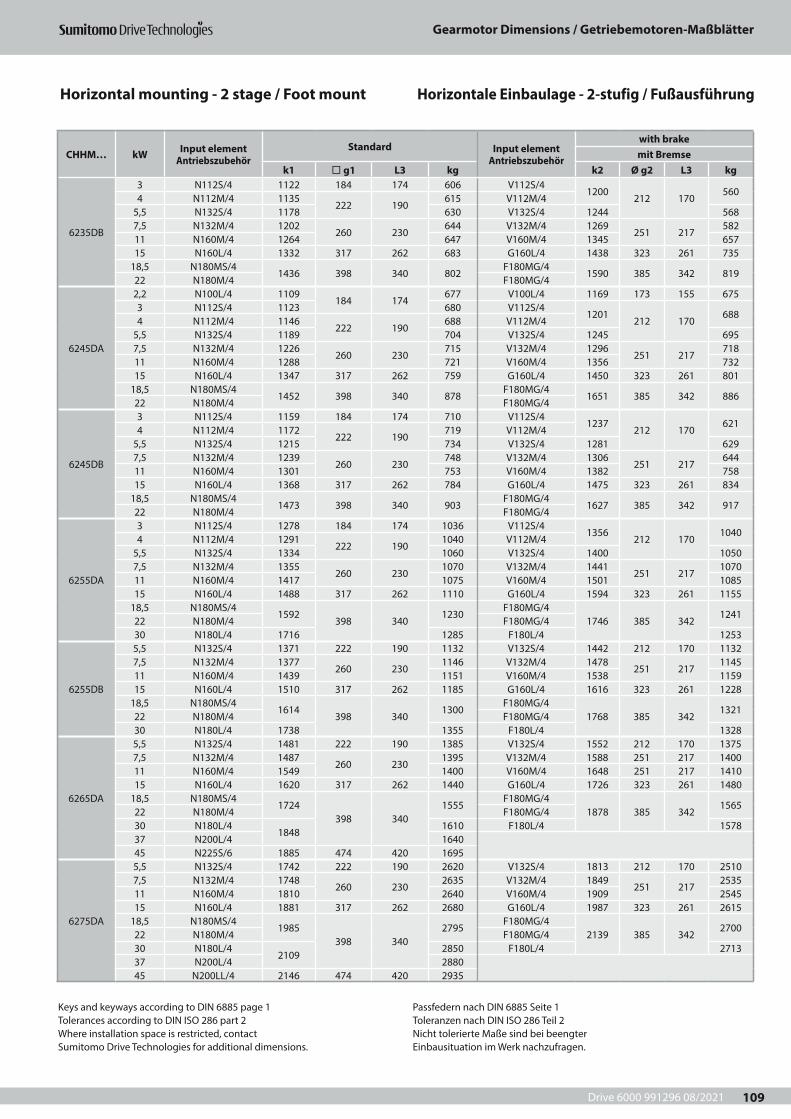
Drive 6000 991296 08/2021
Gearmotor Dimensions / Getriebemotoren-Maßblätter
109
CHHM… kW Input element Antriebszubehör
Standard Input element Antriebszubehör
with brakemit Bremse
k1 ¨ g1 L3 kg k2 Ø g2 L3 kg
6235DB
3 N112S/4 1122 184 174 606 V112S/41200
212 170560
4 N112M/4 1135222 190
615 V112M/45,5 N132S/4 1178 630 V132S/4 1244 5687,5 N132M/4 1202
260 230644 V132M/4 1269
251 217582
11 N160M/4 1264 647 V160M/4 1345 65715 N160L/4 1332 317 262 683 G160L/4 1438 323 261 735
18,5 N180MS/41436 398 340 802
F180MG/41590 385 342 819
22 N180M/4 F180MG/4
6245DA
2,2 N100L/4 1109184 174
677 V100L/4 1169 173 155 6753 N112S/4 1123 680 V112S/4
1201212 170
6884 N112M/4 1146
222 190688 V112M/4
5,5 N132S/4 1189 704 V132S/4 1245 6957,5 N132M/4 1226
260 230715 V132M/4 1296
251 217718
11 N160M/4 1288 721 V160M/4 1356 73215 N160L/4 1347 317 262 759 G160L/4 1450 323 261 801
18,5 N180MS/41452 398 340 878
F180MG/41651 385 342 886
22 N180M/4 F180MG/4
6245DB
3 N112S/4 1159 184 174 710 V112S/41237
212 170621
4 N112M/4 1172222 190
719 V112M/45,5 N132S/4 1215 734 V132S/4 1281 6297,5 N132M/4 1239
260 230748 V132M/4 1306
251 217644
11 N160M/4 1301 753 V160M/4 1382 75815 N160L/4 1368 317 262 784 G160L/4 1475 323 261 834
18,5 N180MS/41473 398 340 903
F180MG/41627 385 342 917
22 N180M/4 F180MG/4
6255DA
3 N112S/4 1278 184 174 1036 V112S/41356
212 1701040
4 N112M/4 1291222 190
1040 V112M/45,5 N132S/4 1334 1060 V132S/4 1400 10507,5 N132M/4 1355
260 2301070 V132M/4 1441
251 2171070
11 N160M/4 1417 1075 V160M/4 1501 108515 N160L/4 1488 317 262 1110 G160L/4 1594 323 261 1155
18,5 N180MS/41592
398 3401230
F180MG/41746 385 342
124122 N180M/4 F180MG/430 N180L/4 1716 1285 F180L/4 1253
6255DB
5,5 N132S/4 1371 222 190 1132 V132S/4 1442 212 170 11327,5 N132M/4 1377
260 2301146 V132M/4 1478
251 2171145
11 N160M/4 1439 1151 V160M/4 1538 115915 N160L/4 1510 317 262 1185 G160L/4 1616 323 261 1228
18,5 N180MS/41614
398 3401300
F180MG/41768 385 342
132122 N180M/4 F180MG/430 N180L/4 1738 1355 F180L/4 1328
6265DA
5,5 N132S/4 1481 222 190 1385 V132S/4 1552 212 170 13757,5 N132M/4 1487
260 2301395 V132M/4 1588 251 217 1400
11 N160M/4 1549 1400 V160M/4 1648 251 217 141015 N160L/4 1620 317 262 1440 G160L/4 1726 323 261 1480
18,5 N180MS/41724
398 3401555
F180MG/41878 385 342
156522 N180M/4 F180MG/430 N180L/4
18481610 F180L/4 1578
37 N200L/4 164045 N225S/6 1885 474 420 1695
6275DA
5,5 N132S/4 1742 222 190 2620 V132S/4 1813 212 170 25107,5 N132M/4 1748
260 2302635 V132M/4 1849
251 2172535
11 N160M/4 1810 2640 V160M/4 1909 254515 N160L/4 1881 317 262 2680 G160L/4 1987 323 261 2615
18,5 N180MS/41985
398 3402795
F180MG/42139 385 342
270022 N180M/4 F180MG/430 N180L/4
21092850 F180L/4 2713
37 N200L/4 288045 N200LL/4 2146 474 420 2935
Keys and keyways according to DIN 6885 page 1Tolerances according to DIN ISO 286 part 2Where installation space is restricted, contactSumitomo Drive Technologies for additional dimensions.
Passfedern nach DIN 6885 Seite 1Toleranzen nach DIN ISO 286 Teil 2Nicht tolerierte Maße sind bei beengterEinbausituation im Werk nachzufragen.
Horizontal mounting - 2 stage / Foot mount Horizontale Einbaulage - 2-stufig / Fußausführung
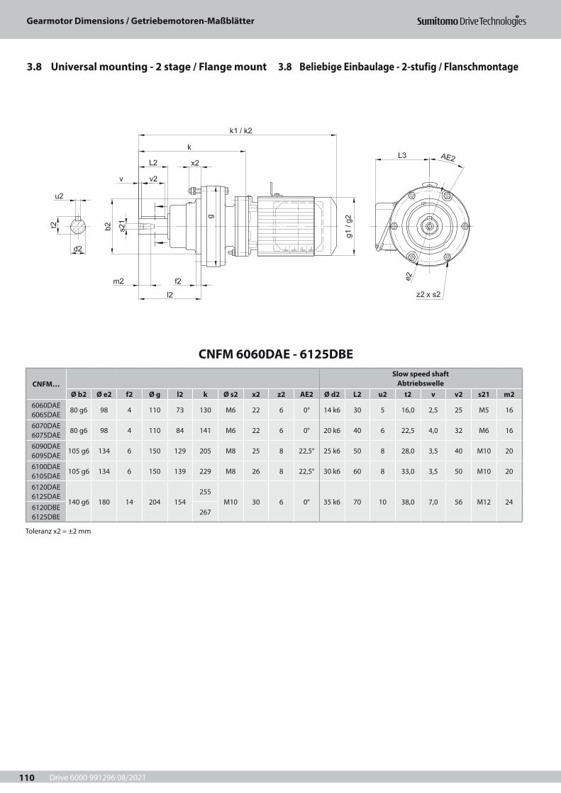
Drive 6000 991296 08/2021
Gearmotor Dimensions / Getriebemotoren-Maßblätter
110
CNFM 6060DAE - 6125DBE
CNFM…Slow speed shaft
AbtriebswelleØ b2 Ø e2 f2 Ø g l2 k Ø s2 x2 z2 AE2 Ø d2 L2 u2 t2 v v2 s21 m2
6060DAE 6065DAE
80 g6 98 4 110 73 130 M6 22 6 0° 14 k6 30 5 16,0 2,5 25 M5 16
6070DAE 6075DAE
80 g6 98 4 110 84 141 M6 22 6 0° 20 k6 40 6 22,5 4,0 32 M6 16
6090DAE 6095DAE
105 g6 134 6 150 129 205 M8 25 8 22,5° 25 k6 50 8 28,0 3,5 40 M10 20
6100DAE 6105DAE
105 g6 134 6 150 139 229 M8 26 8 22,5° 30 k6 60 8 33,0 3,5 50 M10 20
6120DAE 6125DAE
140 g6 180 14 204 154255
M10 30 6 0° 35 k6 70 10 38,0 7,0 56 M12 246120DBE 6125DBE
267
Toleranz x2 = ±2 mm
3.8 Beliebige Einbaulage - 2-stufig / Flanschmontage3.8 Universal mounting - 2 stage / Flange mount
Drive 6000 991296 08/2021
Gearmotor Dimensions / Getriebemotoren-Maßblätter
111
CNFM… kW Input element Antriebszubehör
Standard Input element Antriebszubehör
with brakemit Bremse
k1 ¨ g1 L3 kg k2 Ø g2 L3 kg6060DA 6065DA
0,12 V63S/4 281 119 118 7 V63S/4 299 124 118 8,5
6070DA 6075DA
0,12 V63S/4 292 119118
8 V63S/4 310124 118
9,50,18 V63M/4 317 124 9 V63M/4 349 11
6090DA 6090DA
0,12 V63S/4 356 119
118
13 V63S/4 374
124 118
140,18 V63M/4
381124
14V63M/4
413 150,25 V63M/4 V63M/40,37 V71M/4 405 15 V71M/4 433 16
6100DA 6105DA
0,12 V63S/4 380 119
118
14 V63S/4 398
124 118
150,18 V63M/4
405124
15V63M/4
437 160,25 V63M/4 V63M/40,37 V71M/4 429 16 V71M/4 457 17
6120DA 6125DA
0,12 V63S/4 406 119
118
25 V63S/4 424
124 118
260,18 V63M/4
431124
26V63M/4
463 270,25 V63M/4 V63M/40,37 V71M/4 455 27 V71M/4 483 28
6120DB 6125DB
0,12 V63S/4 418 119118
28 V63S/4 436124 118
300,25 V63M/4 443
12429 V63M/4 475 31
0,37 V71M/4 467 30 V71M/4 495 320,55 V80S/4 504 151 143 34 V80S/4
548 151 143 370,75 N80M/4 548 158 154 40 V80M/41,1 N90S/4
575 167 15943 V90S/4
600 160 148 431,5 N90L/4 44 V90L/4
Keys and keyways according to DIN 6885 page 1Tolerances according to DIN ISO 286 part 2Where installation space is restricted, contactSumitomo Drive Technologies for additional dimensions.
Passfedern nach DIN 6885 Seite 1Toleranzen nach DIN ISO 286 Teil 2Nicht tolerierte Maße sind bei beengterEinbausituation im Werk nachzufragen.
Universal mounting - 2 stage / Flange mount Beliebige Einbaulage - 2-stufig / Flanschmontage
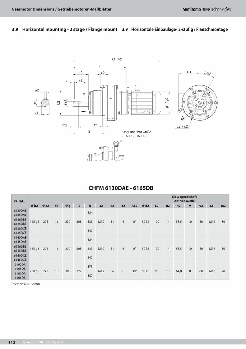
Drive 6000 991296 08/2021
Gearmotor Dimensions / Getriebemotoren-Maßblätter
112
CHFM 6130DAE - 6165DB
CHFM…Slow speed shaft
AbtriebswelleØ b2 Ø e2 f2 Ø g l2 k s2 x2 z2 AE2 Ø d2 L2 u2 t2 v v2 s21 m2
6130DAE 6135DAE
165 g6 205 16 230 208
324
M10 31 6 0° 50 k6 100 14 53,5 10 80 M16 306130DBE 6135DBE
333
6130DCE 6135DCE
347
6140DAE 6145DAE
165 g6 205 16 230 208
324
M10 31 6 0° 50 k6 100 14 53,5 10 80 M16 306140DBE 6145DBE
333
6140DCE 6145DCE
347
6160DA 6165DB
200 g6 270 10 300 222373
M12 36 6 30° 60 h6 90 18 64,0 0 80 M10 206160DA 6165DB
387
Toleranz x2 = ±2 mm
3.9 Horizontale Einbaulage- 2-stufig / Flanschmontage3.9 Horizontal mounting - 2 stage / Flange mount
Only size / nur Größe 6160DB, 6165DB

Drive 6000 991296 08/2021
Gearmotor Dimensions / Getriebemotoren-Maßblätter
113
CHFM… kW Input element Antriebszubehör
Standard Input element Antriebszubehör
with brakemit Bremse
k1 ¨ g1 L3 kg k2 Ø g2 L3 kg
6130DA 6135DA
0,12 V63S/4 475 119
118
42 V63S/4 493
124 118
440,18 V63M/4
500124
43V63M/4
532 450,25 V63M/4 V63M/40,37 V71M/4 524 44 V71M/4 552 46
6130DB 6135DB
0,12 V63S/4 484 119
118
40 V63S/4 502
124 118
420,18 V63M/4
509124
41V63M/4
541 430,25 V63M/4 V63M/40,37 V71M/4 533 42 V71M/4 561 440,55 V80S/4 570 151 143 46 V80S/4
614 151 143 490,75 N80M/4 614 158 154 57 V80M/41,10 N90S/4
641 167 15960 V90S/4
666 160 148 551,50 N90L/4 61 V90L/4
6130DC 6135DC
0,55 V80S/4 584 151 143 48 V80S/4628 151 143 51
0,75 N80M/4 628 158 154 58 V80M/41,10 N90S/4
655 167 15961 V90S/4
680 160 148 571,50 N90L/4 62 V90L/42,20 N100L/4 676 184 174 70 V100L/4 701 173 155 62
6140DA 6145DA
0,18 V63M/4500
124 11845
V63M/4532
124 11847
0,25 V63M/4 V63M/40,37 V71M/4 524 46 V71M/4 552 48
6140DB 6145DB
0,18 V63M/4509
124 11845
V63M/4541
124 11847
0,25 V63M/4 V63M/40,37 V71M/4 533 46 V71M/4 561 480,55 V80S/4 570 151 143 50 V80S/4
614 151 143 530,75 N80M/4 614 158 154 57 V80M/41,10 N90S/4
641 167 15960 V90S/4
666 160 148 591,50 N90L/4 61 V90L/4
6140DC 6145DC
0,18 V63M/4523
124 11843
V63M/4555
124 11844
0,25 V63M/4 V63M/40,37 V71M/4 547 44 V71M/4 575 450,55 V80S/4 584 151 143 47 V80S/4
628 151 143 500,75 N80M/4 628 158 154 58 V80M/41,10 N90S/4
655 167 15961 V90S/4
680 160 148 571,50 N90L/4 62 V90L/42,20 N100L/4 676 184 174 70 V100L/4 701 173 155 62
6160DA 6165DA
0,18 V63M/4549
124 11875
V63M/4581
124 11876
0,25 V63M/4 V63M/40,37 V71M/4 573 76 V71M/4 601 770,55 V80S/4 610 151 143 79 V80S/4
654 151 143 820,75 N80M/4 654 158 154 83 V80M/41,10 N90S/4
681 167 15987 V90S/4
706 160 148 881,50 N90L/4 88 V90L/4
6160DB 6165DB
0,18 V63M/4563
124 11874
V63M/4595
124 11875
0,25 V63M/4 V63M/40,37 V71M/4 587 75 V71M/4 615 760,55 V80S/4 624 151 143 78 V80S/4
668 151 143 810,75 N80M/4 668 158 154 85 V80M/41,10 N90S/4
695 167 15988 V90S/4
720 160 148 871,50 N90L/4 89 V90L/42,20 N100L/4 716 184 174 97 V100L/4 741 173 155 92
Keys and keyways according to DIN 6885 page 1Tolerances according to DIN ISO 286 part 2Where installation space is restricted, contactSumitomo Drive Technologies for additional dimensions.
Passfedern nach DIN 6885 Seite 1Toleranzen nach DIN ISO 286 Teil 2Nicht tolerierte Maße sind bei beengterEinbausituation im Werk nachzufragen.
Horizontal mounting - 2 stage / Flange mount Horizontale Einbaulage - 2-stufig / Flanschmontage
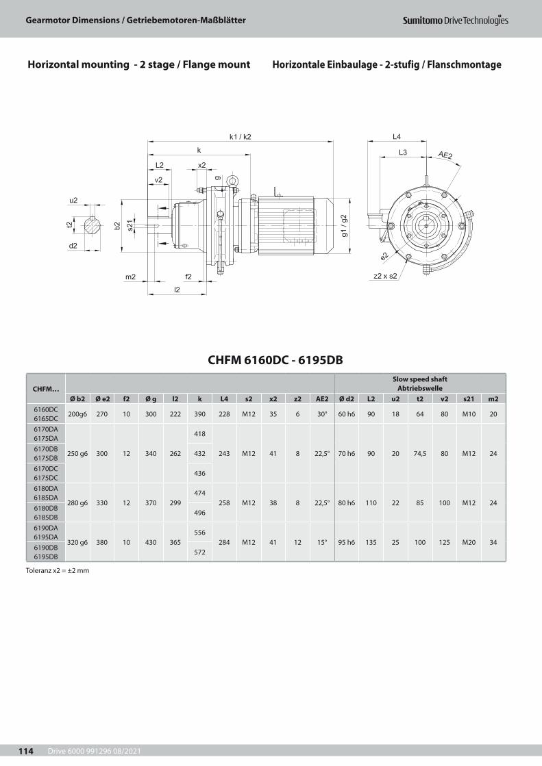
Drive 6000 991296 08/2021
Gearmotor Dimensions / Getriebemotoren-Maßblätter
114
CHFM 6160DC - 6195DB
CHFM…Slow speed shaft
AbtriebswelleØ b2 Ø e2 f2 Ø g l2 k L4 s2 x2 z2 AE2 Ø d2 L2 u2 t2 v2 s21 m2
6160DC 6165DC
200g6 270 10 300 222 390 228 M12 35 6 30° 60 h6 90 18 64 80 M10 20
6170DA 6175DA
250 g6 300 12 340 262
418
243 M12 41 8 22,5° 70 h6 90 20 74,5 80 M12 246170DB 6175DB
432
6170DC 6175DC
436
6180DA 6185DA
280 g6 330 12 370 299474
258 M12 38 8 22,5° 80 h6 110 22 85 100 M12 246180DB 6185DB
496
6190DA 6195DA
320 g6 380 10 430 365556
284 M12 41 12 15° 95 h6 135 25 100 125 M20 346190DB 6195DB
572
Toleranz x2 = ±2 mm
Horizontal mounting - 2 stage / Flange mount Horizontale Einbaulage - 2-stufig / Flanschmontage

Drive 6000 991296 08/2021
Gearmotor Dimensions / Getriebemotoren-Maßblätter
115
CHFM… kW Input element Antriebszubehör
Standard Input element Antriebszubehör
with brakemit Bremse
k1 ¨ g1 L3 kg k2 Ø g2 L3 kg
6160DC 6165DC
2,2 N100L/4 683184 174
106 V100L/4 743 173 155 993 N112S/4 697 109 V112S/4
775212 166
1124 N112M/4 720
222 190117 V112M/4
5,5 N132S/4 763 133 V132S/4 819 119
6170DA 6175DA
0,37 V71M/4 618 124 118 93 V71M/4 646 124 118 950,55 V80S/4 655 151 143 97 V80S/4
699 151 143 1000,75 N80M/4 699 158 154 107 V80M/41,1 N90S/4
726 167 159110 V90S/4
751 160 148 1061,5 N90L/4 111 V90L/4
6170DB 6175DB
0,37 V71M/4 632 124 118 95 V71M/4 660 124 118 960,55 V80S/4 669 151 143 98 V80S/4
713 151 143 1010,75 N80M/4 713 158 154 109 V80M/41,1 N90S/4
740 167 159112 V90S/4
764 160 148 1071,5 N90L/4 113 V90L/42,2 N100L/4 761 184 174 121 V100L/4 785 173 155 112
6170DC 6175DC
0,37 V71M/4 641 124 118 106 V71M/4 670 124 118 1100,55 V80S/4 673 151 143 108 V80S/4
717 151 143 1110,75 N80M/4 717 158 154 119 V80M/41,1 N90S/4
744 167 159121 V90S/4
769 160 148 1161,5 N90L/4 122 V90L/42,2 N100L/4 729
184 174129 V100L/4 790 173 155 123
3 N112S/4 743 132 V112S/4821
212 166136
4 N112M/4 766222 190
140 V112M/45,5 N132S/4 809 156 V132S/4 865 143
6180DA 6185DA
0,75 N80M/4 755 158 154 144 V80M/4 755 151 143 1431,1 N90S/4
782 167 159147 V90S/4
807 160 148 1491,5 N90L/4 148 V90L/42,2 N100L/4 803 184 174 156 V100L/4 828 173 155 154
6180DB 6185DB
0,75 N80M/4 777 158 154 161 V80M/4 777 151 143 1591,1 N90S/4
804 167 159163 V90S/4
829 160 148 1651,5 N90L/4 164 V90L/42,2 N100L/4 789
184 174170 V100L/4 850 173 155 168
3 N112S/4 803 173 V112S/4881
212 166181
4 N112M/4 821222 190
181 V112M/45,5 N132S/4 864 196 V132S/4 925 1887,5 N132M/4 902
260 230208 V132M/4 971
251 217211
11 N160M/4 964 213 V160M/4 1031 225
6190DA 6195DA
0,55 V80S/4 793 151 143 200 V80S/4837 151 143 203
0,75 N80M/4 837 158 154 214 V80M/41,1 N90S/4
864 167 159217 V90S/4
889 160 148 2091,5 N90L/4 219 V90L/42,2 N100L/4 849
184 174225 V100L/4 910 173 155 215
3 N112S/4 863 228 V112S/4941
212 166228
4 N112M/4 887222 190
236 V112M/45,5 N132S/4 930 252 V132S/4 985 235
6190DB 6195DB
2,2 N100L/4 865184 174
227 V100L/4 926 173 155 2223 N112S/4 879 230 V112S/4
957212 166
2354 N112M/4 897
222 190238 V112M/4
5,5 N132S/4 940 253 V132S/4 1001 2427,5 N132M/4 978
260 230265 V132M/4 1047
251 217265
11 N160M/4 1040 270 V160M/4 1107 27915 N160L/4 1104 317 264 307 G160L/4 1165 324 261 346
Keys and keyways according to DIN 6885 page 1Tolerances according to DIN ISO 286 part 2Where installation space is restricted, contactSumitomo Drive Technologies for additional dimensions.
Passfedern nach DIN 6885 Seite 1Toleranzen nach DIN ISO 286 Teil 2Nicht tolerierte Maße sind bei beengterEinbausituation im Werk nachzufragen.
Horizontal mounting - 2 stage / Flange mount Horizontale Einbaulage - 2-stufig / Flanschmontage
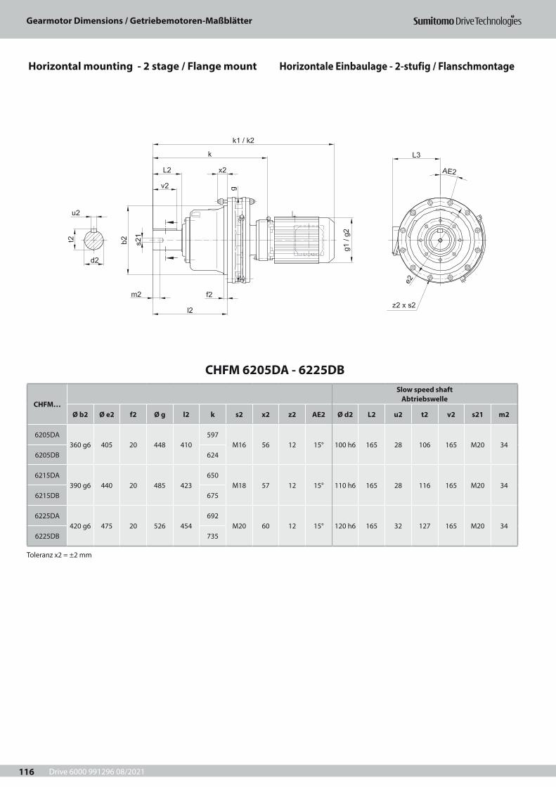
Drive 6000 991296 08/2021
Gearmotor Dimensions / Getriebemotoren-Maßblätter
116
CHFM 6205DA - 6225DB
CHFM…
Slow speed shaft Abtriebswelle
Ø b2 Ø e2 f2 Ø g l2 k s2 x2 z2 AE2 Ø d2 L2 u2 t2 v2 s21 m2
6205DA360 g6 405 20 448 410
597M16 56 12 15° 100 h6 165 28 106 165 M20 34
6205DB 624
6215DA390 g6 440 20 485 423
650M18 57 12 15° 110 h6 165 28 116 165 M20 34
6215DB 675
6225DA420 g6 475 20 526 454
692M20 60 12 15° 120 h6 165 32 127 165 M20 34
6225DB 735
Toleranz x2 = ±2 mm
Horizontal mounting - 2 stage / Flange mount Horizontale Einbaulage - 2-stufig / Flanschmontage

Drive 6000 991296 08/2021
Gearmotor Dimensions / Getriebemotoren-Maßblätter
117
CHFM… kW Input element Antriebszubehör
Standard Input element Antriebszubehör
with brakemit Bremse
k1 ¨ g1 L3 kg k2 Ø g2 L3 kg
6205DA
0,75 N80M/4 878 158 154 230 V80M/4 878 151 143 2281,1 N90S/4
905 167 159233 V90S/4
930 160 148 2341,5 N90L/4 235 V90L/42,2 N100L/4 890
184 174241 V100L/4 951 173 155 240
3 N112S/4 904 244 V112S/4982
212 170253
4 N112M/4 927222 190
252 V112M/45,5 N132S/4 970 268 V132S/4 1026 260
6205DB
0,75 N80M/4 905 158 154 244 V80M/4 904 151 143 2501,1 N90S/4
932 167 159246 V90S/4
956 160 148 2561,5 N90L/4 248 V90L/42,2 N100L/4 917
184 174253 V100L/4 977 173 155 251
3 N112S/4 931 256 V112S/41009
212 170264
4 N112M/4 949222 190
264 V112M/45,5 N132S/4 992 279 V132S/4 1053 2717,5 N132M/4 1030
260 230291 V132M/4 1099
251 217294
11 N160M/4 1092 296 V160M/4 1159 30715 N160L/4 1155 317 262 333 G160L/4 1234 323 261 373
6215DA
0,75 N80M/4 931 158 154 306 V80M/4 930 151 143 3191,1 N90S/4
958 167 159308 V90S/4
982 160 148 3251,5 N90L/4 310 V90L/42,2 N100L/4 943
184 174315 V100L/4 1003 173 155 330
3 N112S/4 957 318 V112S/41035
212 170343
4 N112M/4 975222 190
326 V112M/45,5 N132S/4 1018 341 V132S/4 1079 3507,5 N132M/4 1056
260 230353 V132M/4 1125
251 217373
11 N160M/4 1118 358 V160M/4 1185 38615 N160L/4 1180 317 262 395 G160L/4 1275 323 261 453
6215DB
1,5 V90L/4 983 167 159 345 V90L/4 1012 160 148 3462,2 N100L/4 968
184 174349 V100L/4 1028 173 155 350
3 N112S/4 982 352 V112S/41060
212 170363
4 N112M/4 1005222 190
359 V112M/45,5 N132S/4 1048 375 V132S/4 1104 3707,5 N132M/4 1085
260 230386 V132M/4 1155
251 217393
11 N160M/4 1147 392 V160M/4 1215 40715 N160L/4 1207 317 262 430 G160L/4 1309 323 261 477
6225DA
1,1 N90S/41000 167 159
373 V90S/41024 160 148 382
1,5 N90L/4 375 V90L/42,2 N100L/4 985
184 174380 V100L/4 1045 173 155 387
3 N112S/4 999 383 V112S/41077
212 170400
4 N112M/4 1017222 190
391 V112M/45,5 N132S/4 1060 406 V132S/4 1121 4077,5 N132M/4 1098
260 230418 V132M/4 1167
251 217430
11 N160M/4 1160 423 V160M/4 1227 44415 N160L/4 1224 317 262 460 G160L/4 1312 323 261 511
6225DB
5,5 N132S/4 1113 222 190 453 V132S/4 1179 212 170 4527,5 N132M/4 1134
260 230465 V132M/4 1220
251 217475
11 N160M/4 1196 471 V160M/4 1280 48915 N160L/4 1267 317 262 507 G160L/4 1373 323 261 558
18,5 N180MS/4 1371398 340
627F180MG/4
1525 394 342644
22 N180M/4 1371 F180MG/430 N180L/4 1495 679 F180L/4 661
Keys and keyways according to DIN 6885 page 1Tolerances according to DIN ISO 286 part 2Where installation space is restricted, contactSumitomo Drive Technologies for additional dimensions.
Passfedern nach DIN 6885 Seite 1Toleranzen nach DIN ISO 286 Teil 2Nicht tolerierte Maße sind bei beengterEinbausituation im Werk nachzufragen.
Horizontal mounting - 2 stage / Flange mount Horizontale Einbaulage - 2-stufig / Flanschmontage
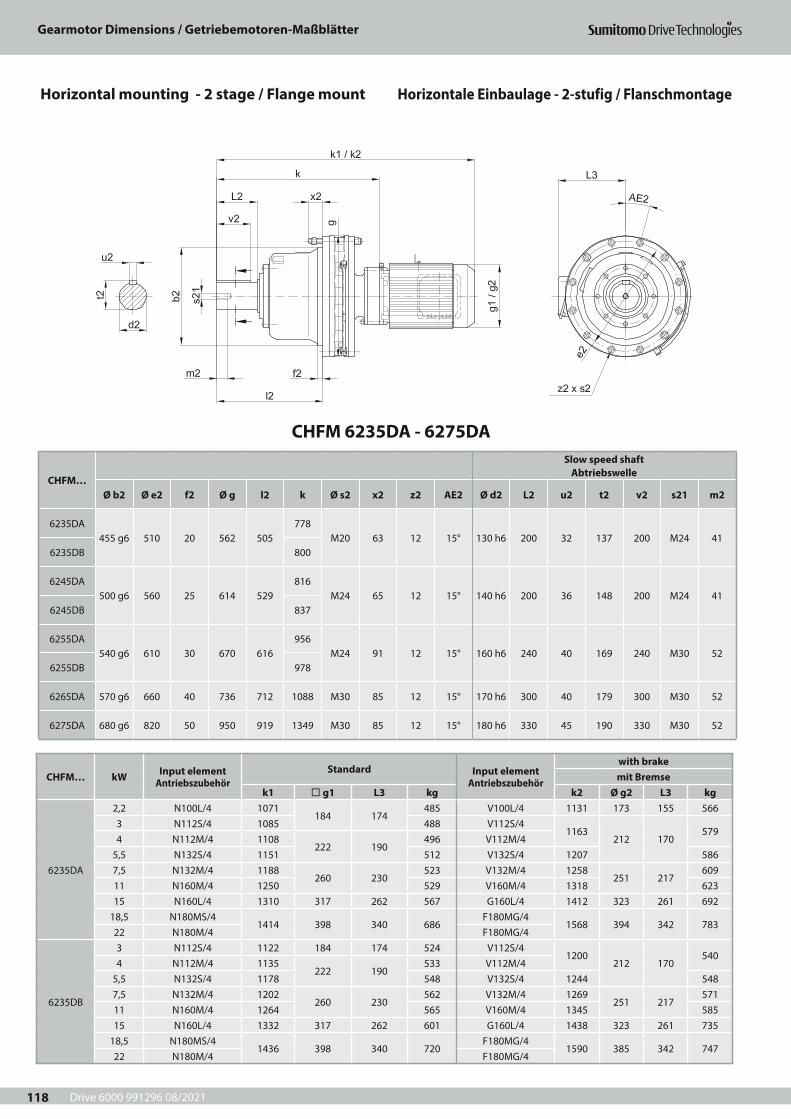
Drive 6000 991296 08/2021
Gearmotor Dimensions / Getriebemotoren-Maßblätter
118
CHFM 6235DA - 6275DA
CHFM…
Slow speed shaft Abtriebswelle
Ø b2 Ø e2 f2 Ø g l2 k Ø s2 x2 z2 AE2 Ø d2 L2 u2 t2 v2 s21 m2
6235DA455 g6 510 20 562 505
778M20 63 12 15° 130 h6 200 32 137 200 M24 41
6235DB 800
6245DA500 g6 560 25 614 529
816M24 65 12 15° 140 h6 200 36 148 200 M24 41
6245DB 837
6255DA540 g6 610 30 670 616
956M24 91 12 15° 160 h6 240 40 169 240 M30 52
6255DB 978
6265DA 570 g6 660 40 736 712 1088 M30 85 12 15° 170 h6 300 40 179 300 M30 52
6275DA 680 g6 820 50 950 919 1349 M30 85 12 15° 180 h6 330 45 190 330 M30 52
CHFM… kW Input element Antriebszubehör
Standard Input element Antriebszubehör
with brakemit Bremse
k1 ¨ g1 L3 kg k2 Ø g2 L3 kg
6235DA
2,2 N100L/4 1071184 174
485 V100L/4 1131 173 155 5663 N112S/4 1085 488 V112S/4
1163212 170
5794 N112M/4 1108
222 190496 V112M/4
5,5 N132S/4 1151 512 V132S/4 1207 5867,5 N132M/4 1188
260 230523 V132M/4 1258
251 217609
11 N160M/4 1250 529 V160M/4 1318 62315 N160L/4 1310 317 262 567 G160L/4 1412 323 261 692
18,5 N180MS/41414 398 340 686
F180MG/41568 394 342 783
22 N180M/4 F180MG/4
6235DB
3 N112S/4 1122 184 174 524 V112S/41200
212 170540
4 N112M/4 1135222 190
533 V112M/45,5 N132S/4 1178 548 V132S/4 1244 5487,5 N132M/4 1202
260 230562 V132M/4 1269
251 217571
11 N160M/4 1264 565 V160M/4 1345 58515 N160L/4 1332 317 262 601 G160L/4 1438 323 261 735
18,5 N180MS/41436 398 340 720
F180MG/41590 385 342 747
22 N180M/4 F180MG/4
Horizontal mounting - 2 stage / Flange mount Horizontale Einbaulage - 2-stufig / Flanschmontage
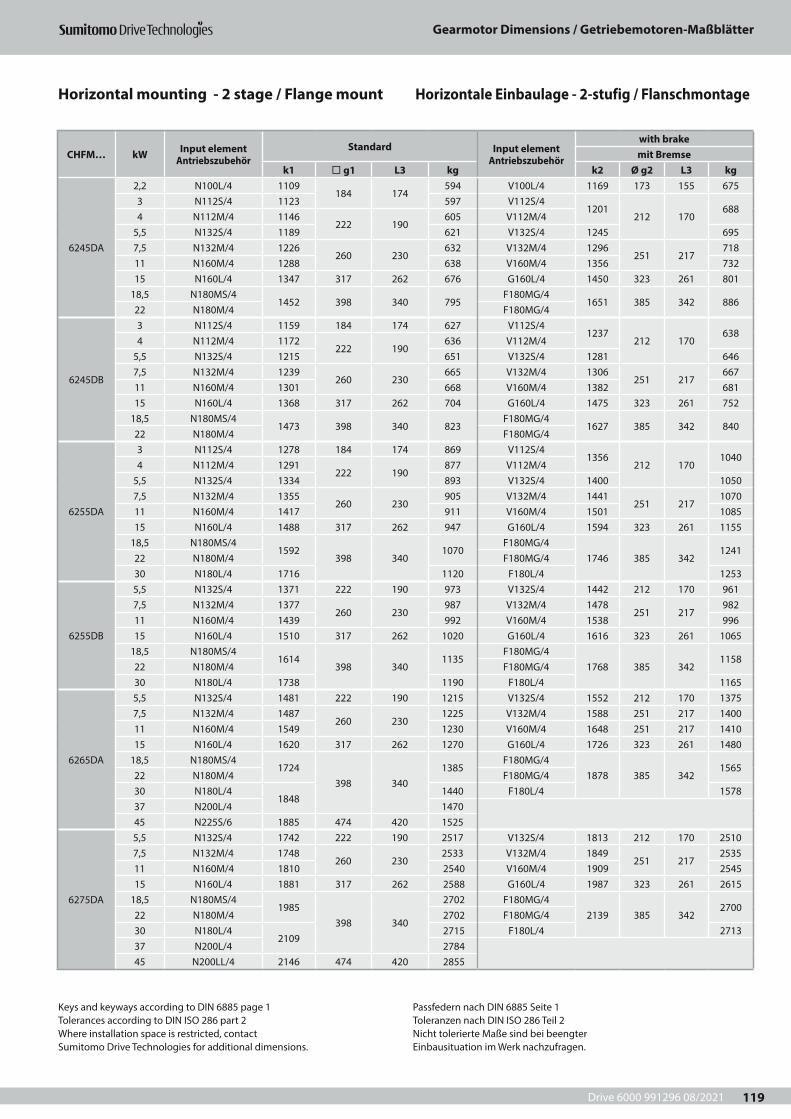
Drive 6000 991296 08/2021
Gearmotor Dimensions / Getriebemotoren-Maßblätter
119
CHFM… kW Input element Antriebszubehör
Standard Input element Antriebszubehör
with brakemit Bremse
k1 ¨ g1 L3 kg k2 Ø g2 L3 kg
6245DA
2,2 N100L/4 1109184 174
594 V100L/4 1169 173 155 6753 N112S/4 1123 597 V112S/4
1201212 170
6884 N112M/4 1146
222 190605 V112M/4
5,5 N132S/4 1189 621 V132S/4 1245 6957,5 N132M/4 1226
260 230632 V132M/4 1296
251 217718
11 N160M/4 1288 638 V160M/4 1356 73215 N160L/4 1347 317 262 676 G160L/4 1450 323 261 801
18,5 N180MS/41452 398 340 795
F180MG/41651 385 342 886
22 N180M/4 F180MG/4
6245DB
3 N112S/4 1159 184 174 627 V112S/41237
212 170638
4 N112M/4 1172222 190
636 V112M/45,5 N132S/4 1215 651 V132S/4 1281 6467,5 N132M/4 1239
260 230665 V132M/4 1306
251 217667
11 N160M/4 1301 668 V160M/4 1382 68115 N160L/4 1368 317 262 704 G160L/4 1475 323 261 752
18,5 N180MS/41473 398 340 823
F180MG/41627 385 342 840
22 N180M/4 F180MG/4
6255DA
3 N112S/4 1278 184 174 869 V112S/41356
212 1701040
4 N112M/4 1291222 190
877 V112M/45,5 N132S/4 1334 893 V132S/4 1400 10507,5 N132M/4 1355
260 230905 V132M/4 1441
251 2171070
11 N160M/4 1417 911 V160M/4 1501 108515 N160L/4 1488 317 262 947 G160L/4 1594 323 261 1155
18,5 N180MS/41592
398 3401070
F180MG/41746 385 342
124122 N180M/4 F180MG/430 N180L/4 1716 1120 F180L/4 1253
6255DB
5,5 N132S/4 1371 222 190 973 V132S/4 1442 212 170 9617,5 N132M/4 1377
260 230987 V132M/4 1478
251 217982
11 N160M/4 1439 992 V160M/4 1538 99615 N160L/4 1510 317 262 1020 G160L/4 1616 323 261 1065
18,5 N180MS/41614
398 3401135
F180MG/41768 385 342
115822 N180M/4 F180MG/430 N180L/4 1738 1190 F180L/4 1165
6265DA
5,5 N132S/4 1481 222 190 1215 V132S/4 1552 212 170 13757,5 N132M/4 1487
260 2301225 V132M/4 1588 251 217 1400
11 N160M/4 1549 1230 V160M/4 1648 251 217 141015 N160L/4 1620 317 262 1270 G160L/4 1726 323 261 1480
18,5 N180MS/41724
398 3401385
F180MG/41878 385 342
156522 N180M/4 F180MG/430 N180L/4
18481440 F180L/4 1578
37 N200L/4 147045 N225S/6 1885 474 420 1525
6275DA
5,5 N132S/4 1742 222 190 2517 V132S/4 1813 212 170 25107,5 N132M/4 1748
260 2302533 V132M/4 1849
251 2172535
11 N160M/4 1810 2540 V160M/4 1909 254515 N160L/4 1881 317 262 2588 G160L/4 1987 323 261 2615
18,5 N180MS/41985
398 340
2702 F180MG/42139 385 342
270022 N180M/4 2702 F180MG/430 N180L/4
2109 2715 F180L/4 2713
37 N200L/4 278445 N200LL/4 2146 474 420 2855
CHFM… kW Input element Antriebszubehör
Standard Input element Antriebszubehör
with brakemit Bremse
k1 ¨ g1 L3 kg k2 Ø g2 L3 kg
6235DA
2,2 N100L/4 1071184 174
485 V100L/4 1131 173 155 5663 N112S/4 1085 488 V112S/4
1163212 170
5794 N112M/4 1108
222 190496 V112M/4
5,5 N132S/4 1151 512 V132S/4 1207 5867,5 N132M/4 1188
260 230523 V132M/4 1258
251 217609
11 N160M/4 1250 529 V160M/4 1318 62315 N160L/4 1310 317 262 567 G160L/4 1412 323 261 692
18,5 N180MS/41414 398 340 686
F180MG/41568 394 342 783
22 N180M/4 F180MG/4
6235DB
3 N112S/4 1122 184 174 524 V112S/41200
212 170540
4 N112M/4 1135222 190
533 V112M/45,5 N132S/4 1178 548 V132S/4 1244 5487,5 N132M/4 1202
260 230562 V132M/4 1269
251 217571
11 N160M/4 1264 565 V160M/4 1345 58515 N160L/4 1332 317 262 601 G160L/4 1438 323 261 735
18,5 N180MS/41436 398 340 720
F180MG/41590 385 342 747
22 N180M/4 F180MG/4
Keys and keyways according to DIN 6885 page 1Tolerances according to DIN ISO 286 part 2Where installation space is restricted, contactSumitomo Drive Technologies for additional dimensions.
Passfedern nach DIN 6885 Seite 1Toleranzen nach DIN ISO 286 Teil 2Nicht tolerierte Maße sind bei beengterEinbausituation im Werk nachzufragen.
Horizontal mounting - 2 stage / Flange mount Horizontale Einbaulage - 2-stufig / Flanschmontage
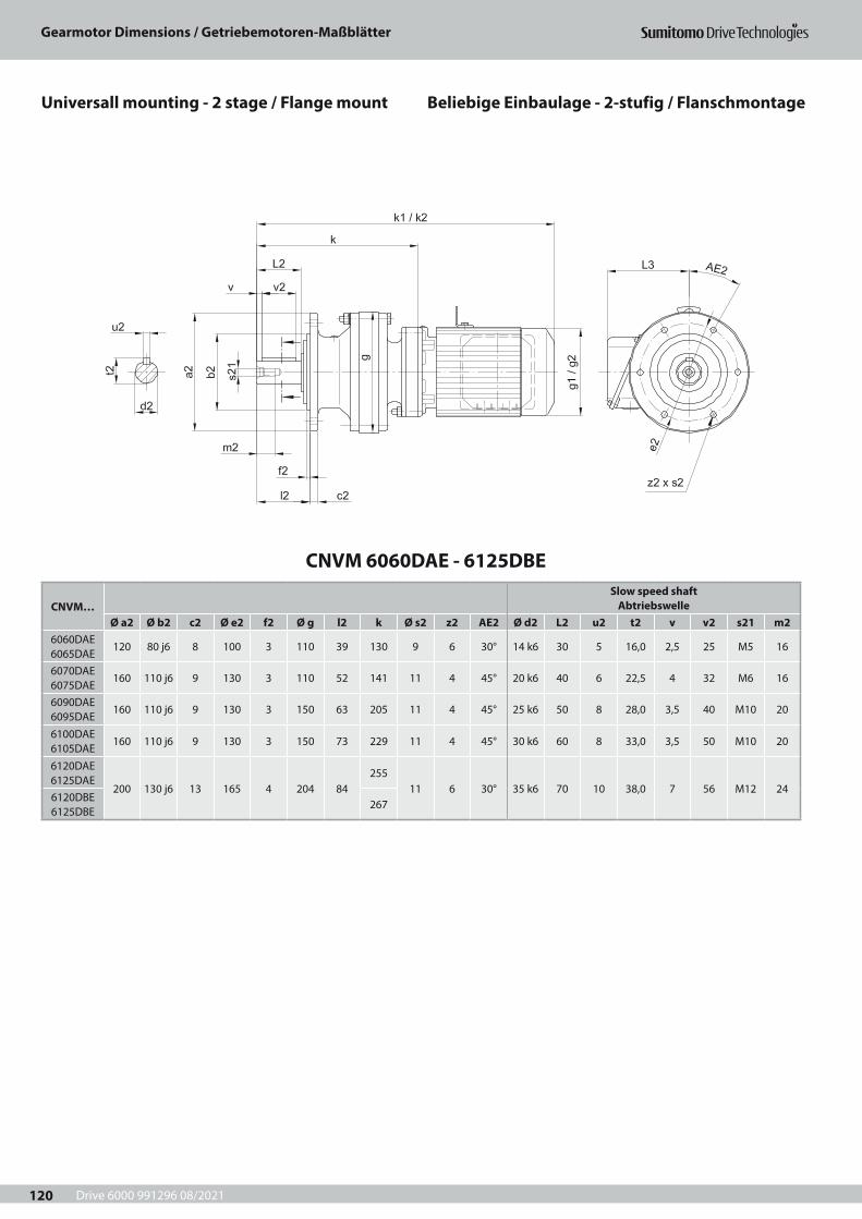
Drive 6000 991296 08/2021
Gearmotor Dimensions / Getriebemotoren-Maßblätter
120
Beliebige Einbaulage - 2-stufig / FlanschmontageUniversall mounting - 2 stage / Flange mount
CNVM 6060DAE - 6125DBE
CNVM…Slow speed shaft
AbtriebswelleØ a2 Ø b2 c2 Ø e2 f2 Ø g l2 k Ø s2 z2 AE2 Ø d2 L2 u2 t2 v v2 s21 m2
6060DAE 6065DAE
120 80 j6 8 100 3 110 39 130 9 6 30° 14 k6 30 5 16,0 2,5 25 M5 16
6070DAE 6075DAE
160 110 j6 9 130 3 110 52 141 11 4 45° 20 k6 40 6 22,5 4 32 M6 16
6090DAE 6095DAE
160 110 j6 9 130 3 150 63 205 11 4 45° 25 k6 50 8 28,0 3,5 40 M10 20
6100DAE 6105DAE
160 110 j6 9 130 3 150 73 229 11 4 45° 30 k6 60 8 33,0 3,5 50 M10 20
6120DAE 6125DAE
200 130 j6 13 165 4 204 84255
11 6 30° 35 k6 70 10 38,0 7 56 M12 246120DBE 6125DBE
267
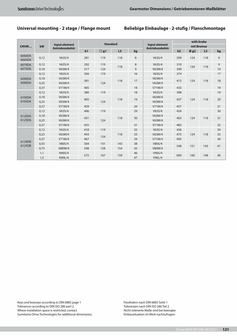
Drive 6000 991296 08/2021
Gearmotor Dimensions / Getriebemotoren-Maßblätter
121
CNVM… kW Input element Antriebszubehör
Standard Input element Antriebszubehör
with brakemit Bremse
k1 ¨ g1 L3 kg k2 Ø g2 L3 kg6060DA 6065DA
0,12 V63S/4 281 119 118 8 V63S/4 299 124 118 9
6070DA 6075DA
0,12 V63S/4 292 119118
8 V63S/4 310124 118
90,18 V63M/4 317 124 9 V63M/4 349 10
6090DA 6090DA
0,12 V63S/4 356 119
118
16 V63S/4 374
124 118
170,18 V63M/4
381124
17V63M/4
413 180,25 V63M/4 V63M/40,37 V71M/4 405 18 V71M/4 433 19
6100DA 6105DA
0,12 V63S/4 380 119
118
18 V63S/4 398
124 118
190,18 V63M/4
405124
19V63M/4
437 200,25 V63M/4 V63M/40,37 V71M/4 429 20 V71M/4 457 21
6120DA 6125DA
0,12 V63S/4 406 119
118
29 V63S/4 424
124 118
300,18 V63M/4
431124
30V63M/4
463 310,25 V63M/4 V63M/40,37 V71M/4 455 31 V71M/4 483 32
6120DB 6125DB
0,12 V63S/4 418 119118
32 V63S/4 436124 118
340,25 V63M/4 443
12433 V63M/4 475 35
0,37 V71M/4 467 34 V71M/4 495 360,55 V80S/4 504 151 143 38 V80S/4
548 151 143 410,75 N80M/4 548 158 154 43 V80M/41,1 N90S/4
575 167 15946 V90S/4
600 160 148 461,5 N90L/4 47 V90L/4
Keys and keyways according to DIN 6885 page 1Tolerances according to DIN ISO 286 part 2Where installation space is restricted, contactSumitomo Drive Technologies for additional dimensions.
Passfedern nach DIN 6885 Seite 1Toleranzen nach DIN ISO 286 Teil 2Nicht tolerierte Maße sind bei beengterEinbausituation im Werk nachzufragen.
Universal mounting - 2 stage / Flange mount Beliebige Einbaulage - 2-stufig / Flanschmontage
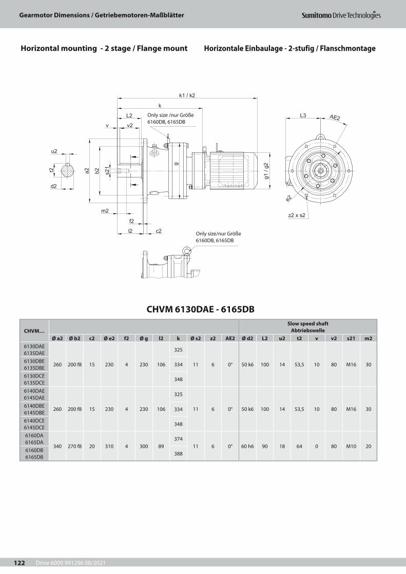
Drive 6000 991296 08/2021
Gearmotor Dimensions / Getriebemotoren-Maßblätter
122
CHVM 6130DAE - 6165DB
CHVM…Slow speed shaft
AbtriebswelleØ a2 Ø b2 c2 Ø e2 f2 Ø g l2 k Ø s2 z2 AE2 Ø d2 L2 u2 t2 v v2 s21 m2
6130DAE 6135DAE
260 200 f8 15 230 4 230 106
325
11 6 0° 50 k6 100 14 53,5 10 80 M16 306130DBE 6135DBE
334
6130DCE 6135DCE
348
6140DAE 6145DAE
260 200 f8 15 230 4 230 106
325
11 6 0° 50 k6 100 14 53,5 10 80 M16 306140DBE 6145DBE
334
6140DCE 6145DCE
348
6160DA 6165DA
340 270 f8 20 310 4 300 89374
11 6 0° 60 h6 90 18 64 0 80 M10 206160DB 6165DB
388
Only size/nur Größe 6160DB, 6165DB
Only size /nur Größe 6160DB, 6165DB
Horizontal mounting - 2 stage / Flange mount Horizontale Einbaulage - 2-stufig / Flanschmontage

Drive 6000 991296 08/2021
Gearmotor Dimensions / Getriebemotoren-Maßblätter
123
CHVM… kW Input element Antriebszubehör
Standard Input element Antriebszubehör
with brakemit Bremse
k1 ¨ g1 L3 kg k2 Ø g2 L3 kg
6130DA 6135DA
0,12 V63S/4 475 119
118
46 V63S/4 493
124 118
480,18 V63M/4
500124
47V63M/4
532 490,25 V63M/4 V63M/40,37 V71M/4 524 48 V71M/4 552 50
6130DB 6135DB
0,12 V63S/4 484 119
118
47 V63S/4 502
124 118
490,18 V63M/4
509124
48V63M/4
541 500,25 V63M/4 V63M/40,37 V71M/4 533 49 V71M/4 561 510,55 V80S/4 570 151 143 53 V80S/4
614 151 143 560,75 N80M/4 614 158 154 61 V80M/41,1 N90S/4
641 167 15964 V90S/4
666 160 148 611,5 N90L/4 65 V90L/4
6130DC 6135DC
0,55 V80S/4 584 151 143 55 V80S/4628 151 143 58
0,75 N80M/4 628 158 154 62 V80M/41,1 N90S/4
655 167 15965 V90S/4
680 160 148 641,5 N90L/4 66 V90L/42,2 N100L/4 676 184 174 74 V100L/4 701 173 155 69
6140DA 6145DA
0,18 V63M/4500
124 11849
V63M/4532
124 11851
0,25 V63M/4 V63M/40,37 V71M/4 524 50 V71M/4 552 52
6140DB 6145DB
0,18 V63M/4509
124 11849
V63M/4541
124 12851
0,25 V63M/4 V63M/40,37 V71M/4 533 50 V71M/4 561 520,55 V80S/4 570 151 143 54 V80S/4
614 151 143 570,75 N80M/4 614 158 154 61 V80M/41,1 N90S/4
641 167 15964 V90S/4
666 160 148 631,5 N90L/4 65 V90L/4
6140DC 6145DC
0,18 V63M/4523
124 11850
V63M/4555
124 11852
0,25 V63M/4 V63M/40,37 V71M/4 547 51 V71M/4 575 530,55 V80S/4 584 151 143 55 V80S/4
628 151 143 580,75 N80M/4 628 158 154 62 V80M/41,1 N90S/4
655 167 15965 V90S/4
680 160 148 641,5 N90L/4 66 V90L/42,2 N100L/4 676 184 174 74 V100L/4 701 173 155 69
6160DA 6165DA
0,18 V63M/4549
124 11887
V63M/4581
124 11888
0,25 V63M/4 V63M/40,37 V71M/4 573 88 V71M/4 601 890,55 V80S/4 610 151 143 91 V80S/4
654 151 143 980,75 N80M/4 654 158 154 94 V80M/41,1 N90S/4
681 167 15998 V90S/4
706 160 148 1041,5 N90L/4 99 V90L/4
6160DB 6165DB
0,18 V63M/4563
124 11892
V63M/4595
124 11893
0,25 V63M/4 V63M/40,37 V71M/4 587 93 V71M/4 615 940,55 V80S/4 624 151 143 96 V80S/4
668 151 143 990,75 N80M/4 668 158 154 96 V80M/41,1 N90S/4
695 167 15999 V90S/4
720 160 148 1051,5 N90L/4 100 V90L/42,2 N100L/4 716 184 174 108 V100L/4 741 173 155 110
Keys and keyways according to DIN 6885 page 1Tolerances according to DIN ISO 286 part 2Where installation space is restricted, contactSumitomo Drive Technologies for additional dimensions.
Passfedern nach DIN 6885 Seite 1Toleranzen nach DIN ISO 286 Teil 2Nicht tolerierte Maße sind bei beengterEinbausituation im Werk nachzufragen.
Horizontal mounting - 2 stage / Flange mount Horizontale Einbaulage - 2-stufig / Flanschmontage
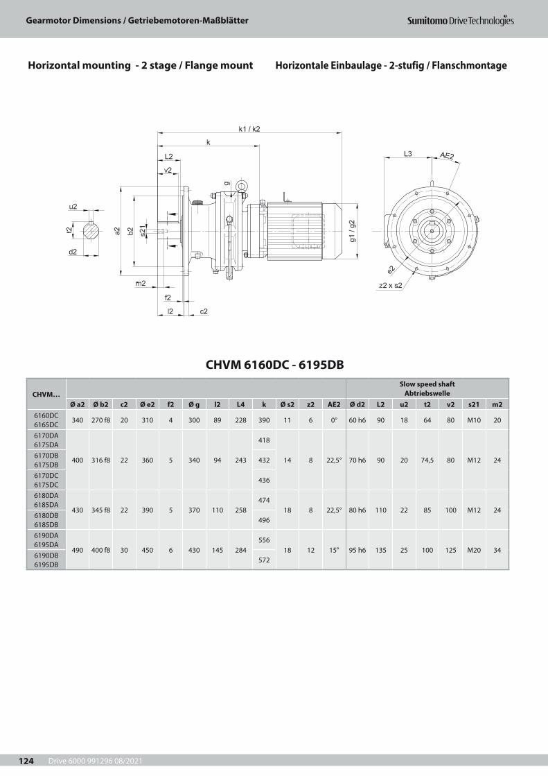
Drive 6000 991296 08/2021
Gearmotor Dimensions / Getriebemotoren-Maßblätter
124
CHVM 6160DC - 6195DB
CHVM…Slow speed shaft
AbtriebswelleØ a2 Ø b2 c2 Ø e2 f2 Ø g l2 L4 k Ø s2 z2 AE2 Ø d2 L2 u2 t2 v2 s21 m2
6160DC 6165DC
340 270 f8 20 310 4 300 89 228 390 11 6 0° 60 h6 90 18 64 80 M10 20
6170DA 6175DA
400 316 f8 22 360 5 340 94 243
418
14 8 22,5° 70 h6 90 20 74,5 80 M12 246170DB 6175DB
432
6170DC 6175DC
436
6180DA 6185DA
430 345 f8 22 390 5 370 110 258474
18 8 22,5° 80 h6 110 22 85 100 M12 246180DB 6185DB
496
6190DA 6195DA
490 400 f8 30 450 6 430 145 284556
18 12 15° 95 h6 135 25 100 125 M20 346190DB 6195DB
572
Horizontal mounting - 2 stage / Flange mount Horizontale Einbaulage - 2-stufig / Flanschmontage
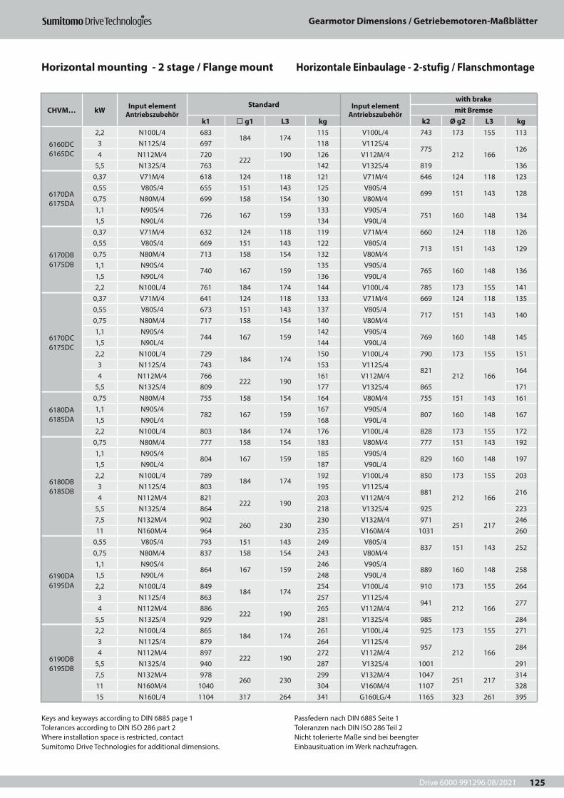
Drive 6000 991296 08/2021
Gearmotor Dimensions / Getriebemotoren-Maßblätter
125
CHVM… kW Input element Antriebszubehör
Standard Input element Antriebszubehör
with brakemit Bremse
k1 ¨ g1 L3 kg k2 Ø g2 L3 kg
6160DC 6165DC
2,2 N100L/4 683184 174
115 V100L/4 743 173 155 1133 N112S/4 697 118 V112S/4
775212 166
1264 N112M/4 720
222190 126 V112M/4
5,5 N132S/4 763 142 V132S/4 819 136
6170DA 6175DA
0,37 V71M/4 618 124 118 121 V71M/4 646 124 118 1230,55 V80S/4 655 151 143 125 V80S/4
699 151 143 1280,75 N80M/4 699 158 154 130 V80M/41,1 N90S/4
726 167 159133 V90S/4
751 160 148 1341,5 N90L/4 134 V90L/4
6170DB 6175DB
0,37 V71M/4 632 124 118 119 V71M/4 660 124 118 1260,55 V80S/4 669 151 143 122 V80S/4
713 151 143 1290,75 N80M/4 713 158 154 132 V80M/41,1 N90S/4
740 167 159135 V90S/4
765 160 148 1361,5 N90L/4 136 V90L/42,2 N100L/4 761 184 174 144 V100L/4 785 173 155 141
6170DC 6175DC
0,37 V71M/4 641 124 118 133 V71M/4 669 124 118 1350,55 V80S/4 673 151 143 137 V80S/4
717 151 143 1400,75 N80M/4 717 158 154 140 V80M/41,1 N90S/4
744 167 159142 V90S/4
769 160 148 1451,5 N90L/4 144 V90L/42,2 N100L/4 729
184 174150 V100L/4 790 173 155 151
3 N112S/4 743 153 V112S/4821
212 166164
4 N112M/4 766222 190
161 V112M/45,5 N132S/4 809 177 V132S/4 865 171
6180DA 6185DA
0,75 N80M/4 755 158 154 164 V80M/4 755 151 143 1611,1 N90S/4
782 167 159167 V90S/4
807 160 148 1671,5 N90L/4 168 V90L/42,2 N100L/4 803 184 174 176 V100L/4 828 173 155 172
6180DB 6185DB
0,75 N80M/4 777 158 154 183 V80M/4 777 151 143 1921,1 N90S/4
804 167 159185 V90S/4
829 160 148 1971,5 N90L/4 187 V90L/42,2 N100L/4 789
184 174192 V100L/4 850 173 155 203
3 N112S/4 803 195 V112S/4881
212 166216
4 N112M/4 821222 190
203 V112M/45,5 N132S/4 864 218 V132S/4 925 2237,5 N132M/4 902
260 230230 V132M/4 971
251 217246
11 N160M/4 964 235 V160M/4 1031 260
6190DA 6195DA
0,55 V80S/4 793 151 143 249 V80S/4837 151 143 252
0,75 N80M/4 837 158 154 243 V80M/41,1 N90S/4
864 167 159246 V90S/4
889 160 148 2581,5 N90L/4 248 V90L/42,2 N100L/4 849
184 174254 V100L/4 910 173 155 264
3 N112S/4 863 257 V112S/4941
212 166277
4 N112M/4 886222 190
265 V112M/45,5 N132S/4 929 281 V132S/4 985 284
6190DB 6195DB
2,2 N100L/4 865184 174
261 V100L/4 925 173 155 2713 N112S/4 879 264 V112S/4
957212 166
2844 N112M/4 897
222 190272 V112M/4
5,5 N132S/4 940 287 V132S/4 1001 2917,5 N132M/4 978
260 230299 V132M/4 1047
251 217314
11 N160M/4 1040 304 V160M/4 1107 32815 N160L/4 1104 317 264 341 G160LG/4 1165 323 261 395
Keys and keyways according to DIN 6885 page 1Tolerances according to DIN ISO 286 part 2Where installation space is restricted, contactSumitomo Drive Technologies for additional dimensions.
Passfedern nach DIN 6885 Seite 1Toleranzen nach DIN ISO 286 Teil 2Nicht tolerierte Maße sind bei beengterEinbausituation im Werk nachzufragen.
Horizontal mounting - 2 stage / Flange mount Horizontale Einbaulage - 2-stufig / Flanschmontage
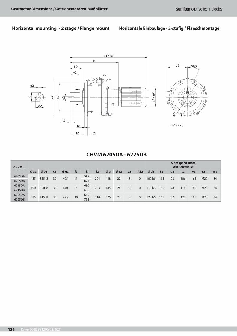
Drive 6000 991296 08/2021
Gearmotor Dimensions / Getriebemotoren-Maßblätter
126
CHVM 6205DA - 6225DB
CHVM…Slow speed shaft
AbtriebswelleØ a2 Ø b2 c2 Ø e2 f2 k l2 Ø g Ø s2 z2 AE2 Ø d2 L2 u2 t2 v2 s21 m2
6205DA455 355 f8 30 405 5
597204 448 22 8 0° 100 h6 165 28 106 165 M20 34
6205DB 6246215DA
490 390 f8 35 440 7650
203 485 24 8 0° 110 h6 165 28 116 165 M20 346215DB 6756225DA
535 415 f8 35 475 10692
210 526 27 8 0° 120 h6 165 32 127 165 M20 346225DB 735
Horizontal mounting - 2 stage / Flange mount Horizontale Einbaulage - 2-stufig / Flanschmontage
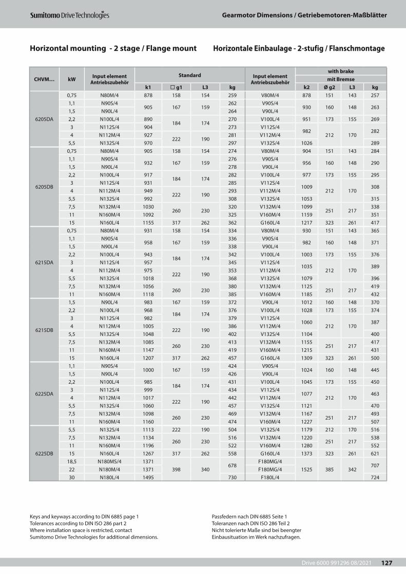
Drive 6000 991296 08/2021
Gearmotor Dimensions / Getriebemotoren-Maßblätter
127
CHVM… kW Input element Antriebszubehör
Standard Input element Antriebszubehör
with brakemit Bremse
k1 ¨ g1 L3 kg k2 Ø g2 L3 kg
6205DA
0,75 N80M/4 878 158 154 259 V80M/4 878 151 143 2571,1 N90S/4
905 167 159262 V90S/4
930 160 148 2631,5 N90L/4 264 V90L/42,2 N100L/4 890
184 174270 V100L/4 951 173 155 269
3 N112S/4 904 273 V112S/4982
212 170282
4 N112M/4 927222 190
281 V112M/45,5 N132S/4 970 297 V132S/4 1026 289
6205DB
0,75 N80M/4 905 158 154 274 V80M/4 904 151 143 2841,1 N90S/4
932 167 159276 V90S/4
956 160 148 2901,5 N90L/4 278 V90L/42,2 N100L/4 917
184 174282 V100L/4 977 173 155 295
3 N112S/4 931 285 V112S/41009
212 170308
4 N112M/4 949222 190
293 V112M/45,5 N132S/4 992 308 V132S/4 1053 3157,5 N132M/4 1030
260 230320 V132M/4 1099
251 217338
11 N160M/4 1092 325 V160M/4 1159 35115 N160L/4 1155 317 262 362 G160L/4 1217 323 261 417
6215DA
0,75 N80M/4 931 158 154 334 V80M/4 930 151 143 3651,1 N90S/4
958 167 159336 V90S/4
982 160 148 3711,5 N90L/4 338 V90L/42,2 N100L/4 943
184 174342 V100L/4 1003 173 155 376
3 N112S/4 957 345 V112S/41035
212 170389
4 N112M/4 975222 190
353 V112M/45,5 N132S/4 1018 368 V132S/4 1079 3967,5 N132M/4 1056
260 230380 V132M/4 1125
251 217419
11 N160M/4 1118 385 V160M/4 1185 432
6215DB
1,5 N90L/4 983 167 159 372 V90L/4 1012 160 148 3702,2 N100L/4 968
184 174376 V100L/4 1028 173 155 374
3 N112S/4 982 379 V112S/41060
212 170387
4 N112M/4 1005222 190
386 V112M/45,5 N132S/4 1048 402 V132S/4 1104 4007,5 N132M/4 1085
260 230413 V132M/4 1155
251 217417
11 N160M/4 1147 419 V160M/4 1215 43115 N160L/4 1207 317 262 457 G160L/4 1309 323 261 500
6225DA
1,1 N90S/41000 167 159
424 V90S/41024 160 148 445
1,5 N90L/4 426 V90L/42,2 N100L/4 985
184 174431 V100L/4 1045 173 155 450
3 N112S/4 999 434 V112S/41077
212 170463
4 N112M/4 1017222 190
442 V112M/45,5 N132S/4 1060 457 V132S/4 1121 4707,5 N132M/4 1098
260 230469 V132M/4 1167
251 217493
11 N160M/4 1160 474 V160M/4 1227 507
6225DB
5,5 N132S/4 1113 222 190 504 V132S/4 1179 212 170 5167,5 N132M/4 1134
260 230516 V132M/4 1220
251 217538
11 N160M/4 1196 522 V160M/4 1280 55215 N160L/4 1267 317 262 558 G160L/4 1373 323 261 621
18,5 N180MS/4 1371398 340
678F180MG/4
1525 385 342707
22 N180M/4 1371 F180MG/430 N180L/4 1495 730 F180L/4 724
Keys and keyways according to DIN 6885 page 1Tolerances according to DIN ISO 286 part 2Where installation space is restricted, contactSumitomo Drive Technologies for additional dimensions.
Passfedern nach DIN 6885 Seite 1Toleranzen nach DIN ISO 286 Teil 2Nicht tolerierte Maße sind bei beengterEinbausituation im Werk nachzufragen.
Horizontal mounting - 2 stage / Flange mount Horizontale Einbaulage - 2-stufig / Flanschmontage
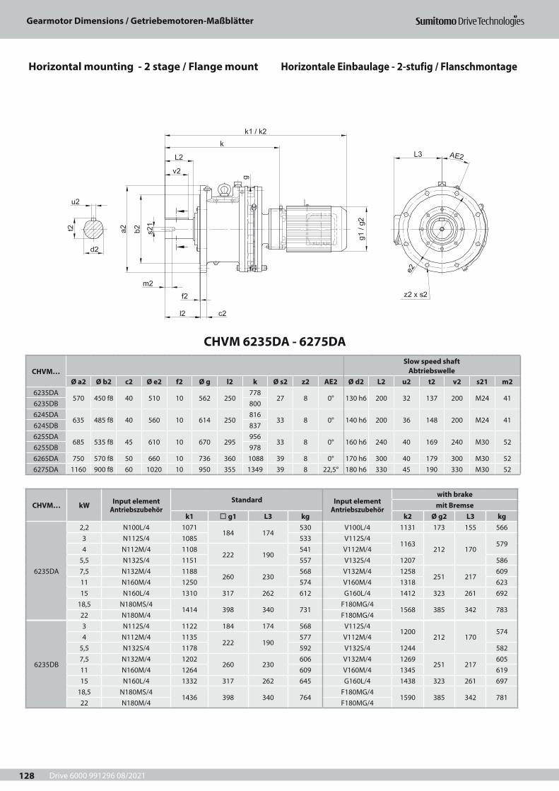
Drive 6000 991296 08/2021
Gearmotor Dimensions / Getriebemotoren-Maßblätter
128
CHVM… kW Input element Antriebszubehör
Standard Input element Antriebszubehör
with brakemit Bremse
k1 ¨ g1 L3 kg k2 Ø g2 L3 kg
6235DA
2,2 N100L/4 1071184 174
530 V100L/4 1131 173 155 5663 N112S/4 1085 533 V112S/4
1163212 170
5794 N112M/4 1108
222 190541 V112M/4
5,5 N132S/4 1151 557 V132S/4 1207 5867,5 N132M/4 1188
260 230568 V132M/4 1258
251 217609
11 N160M/4 1250 574 V160M/4 1318 62315 N160L/4 1310 317 262 612 G160L/4 1412 323 261 692
18,5 N180MS/41414 398 340 731
F180MG/41568 385 342 783
22 N180M/4 F180MG/4
6235DB
3 N112S/4 1122 184 174 568 V112S/41200
212 170574
4 N112M/4 1135222 190
577 V112M/45,5 N132S/4 1178 592 V132S/4 1244 5827,5 N132M/4 1202
260 230606 V132M/4 1269
251 217605
11 N160M/4 1264 609 V160M/4 1345 61915 N160L/4 1332 317 262 645 G160L/4 1438 323 261 697
18,5 N180MS/41436 398 340 764
F180MG/41590 385 342 781
22 N180M/4 F180MG/4
CHVM 6235DA - 6275DA
CHVM…Slow speed shaft
AbtriebswelleØ a2 Ø b2 c2 Ø e2 f2 Ø g l2 k Ø s2 z2 AE2 Ø d2 L2 u2 t2 v2 s21 m2
6235DA570 450 f8 40 510 10 562 250
77827 8 0° 130 h6 200 32 137 200 M24 41
6235DB 8006245DA
635 485 f8 40 560 10 614 250816
33 8 0° 140 h6 200 36 148 200 M24 416245DB 8376255DA
685 535 f8 45 610 10 670 295956
33 8 0° 160 h6 240 40 169 240 M30 526255DB 9786265DA 750 570 f8 50 660 10 736 360 1088 39 8 0° 170 h6 300 40 179 300 M30 526275DA 1160 900 f8 60 1020 10 950 355 1349 39 8 22,5° 180 h6 330 45 190 330 M30 52
Horizontal mounting - 2 stage / Flange mount Horizontale Einbaulage - 2-stufig / Flanschmontage
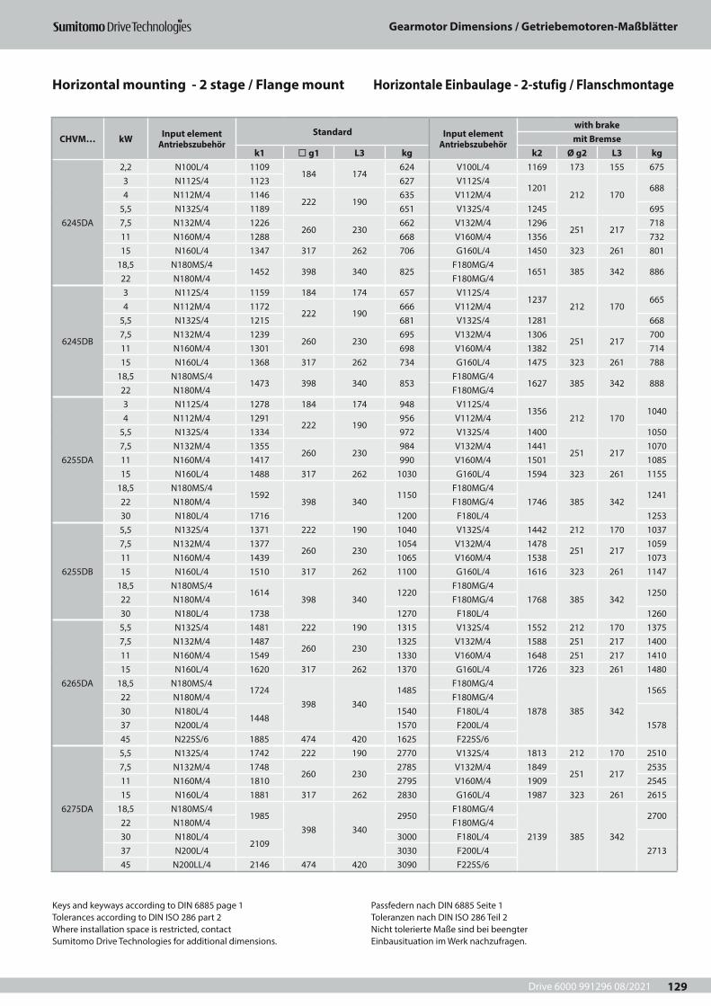
Drive 6000 991296 08/2021
Gearmotor Dimensions / Getriebemotoren-Maßblätter
129
CHVM… kW Input element Antriebszubehör
Standard Input element Antriebszubehör
with brakemit Bremse
k1 ¨ g1 L3 kg k2 Ø g2 L3 kg
6245DA
2,2 N100L/4 1109184 174
624 V100L/4 1169 173 155 6753 N112S/4 1123 627 V112S/4
1201212 170
6884 N112M/4 1146
222 190635 V112M/4
5,5 N132S/4 1189 651 V132S/4 1245 6957,5 N132M/4 1226
260 230662 V132M/4 1296
251 217718
11 N160M/4 1288 668 V160M/4 1356 73215 N160L/4 1347 317 262 706 G160L/4 1450 323 261 801
18,5 N180MS/41452 398 340 825
F180MG/41651 385 342 886
22 N180M/4 F180MG/4
6245DB
3 N112S/4 1159 184 174 657 V112S/41237
212 170665
4 N112M/4 1172222 190
666 V112M/45,5 N132S/4 1215 681 V132S/4 1281 6687,5 N132M/4 1239
260 230695 V132M/4 1306
251 217700
11 N160M/4 1301 698 V160M/4 1382 71415 N160L/4 1368 317 262 734 G160L/4 1475 323 261 788
18,5 N180MS/41473 398 340 853
F180MG/41627 385 342 888
22 N180M/4 F180MG/4
6255DA
3 N112S/4 1278 184 174 948 V112S/41356
212 1701040
4 N112M/4 1291222 190
956 V112M/45,5 N132S/4 1334 972 V132S/4 1400 10507,5 N132M/4 1355
260 230984 V132M/4 1441
251 2171070
11 N160M/4 1417 990 V160M/4 1501 108515 N160L/4 1488 317 262 1030 G160L/4 1594 323 261 1155
18,5 N180MS/41592
398 3401150
F180MG/41746 385 342
124122 N180M/4 F180MG/430 N180L/4 1716 1200 F180L/4 1253
6255DB
5,5 N132S/4 1371 222 190 1040 V132S/4 1442 212 170 10377,5 N132M/4 1377
260 2301054 V132M/4 1478
251 2171059
11 N160M/4 1439 1065 V160M/4 1538 107315 N160L/4 1510 317 262 1100 G160L/4 1616 323 261 1147
18,5 N180MS/41614
398 3401220
F180MG/41768 385 342
125022 N180M/4 F180MG/430 N180L/4 1738 1270 F180L/4 1260
6265DA
5,5 N132S/4 1481 222 190 1315 V132S/4 1552 212 170 13757,5 N132M/4 1487
260 2301325 V132M/4 1588 251 217 1400
11 N160M/4 1549 1330 V160M/4 1648 251 217 141015 N160L/4 1620 317 262 1370 G160L/4 1726 323 261 1480
18,5 N180MS/41724
398 3401485
F180MG/4
1878 385 342
156522 N180M/4 F180MG/430 N180L/4
14481540 F180L/4
157837 N200L/4 1570 F200L/445 N225S/6 1885 474 420 1625 F225S/6
6275DA
5,5 N132S/4 1742 222 190 2770 V132S/4 1813 212 170 25107,5 N132M/4 1748
260 2302785 V132M/4 1849
251 2172535
11 N160M/4 1810 2795 V160M/4 1909 254515 N160L/4 1881 317 262 2830 G160L/4 1987 323 261 2615
18,5 N180MS/41985
398 3402950
F180MG/4
2139 385 342
270022 N180M/4 F180MG/430 N180L/4
21093000 F180L/4
271337 N200L/4 3030 F200L/445 N200LL/4 2146 474 420 3090 F225S/6
CHVM… kW Input element Antriebszubehör
Standard Input element Antriebszubehör
with brakemit Bremse
k1 ¨ g1 L3 kg k2 Ø g2 L3 kg
6235DA
2,2 N100L/4 1071184 174
530 V100L/4 1131 173 155 5663 N112S/4 1085 533 V112S/4
1163212 170
5794 N112M/4 1108
222 190541 V112M/4
5,5 N132S/4 1151 557 V132S/4 1207 5867,5 N132M/4 1188
260 230568 V132M/4 1258
251 217609
11 N160M/4 1250 574 V160M/4 1318 62315 N160L/4 1310 317 262 612 G160L/4 1412 323 261 692
18,5 N180MS/41414 398 340 731
F180MG/41568 385 342 783
22 N180M/4 F180MG/4
6235DB
3 N112S/4 1122 184 174 568 V112S/41200
212 170574
4 N112M/4 1135222 190
577 V112M/45,5 N132S/4 1178 592 V132S/4 1244 5827,5 N132M/4 1202
260 230606 V132M/4 1269
251 217605
11 N160M/4 1264 609 V160M/4 1345 61915 N160L/4 1332 317 262 645 G160L/4 1438 323 261 697
18,5 N180MS/41436 398 340 764
F180MG/41590 385 342 781
22 N180M/4 F180MG/4Keys and keyways according to DIN 6885 page 1Tolerances according to DIN ISO 286 part 2Where installation space is restricted, contactSumitomo Drive Technologies for additional dimensions.
Passfedern nach DIN 6885 Seite 1Toleranzen nach DIN ISO 286 Teil 2Nicht tolerierte Maße sind bei beengterEinbausituation im Werk nachzufragen.
Horizontal mounting - 2 stage / Flange mount Horizontale Einbaulage - 2-stufig / Flanschmontage
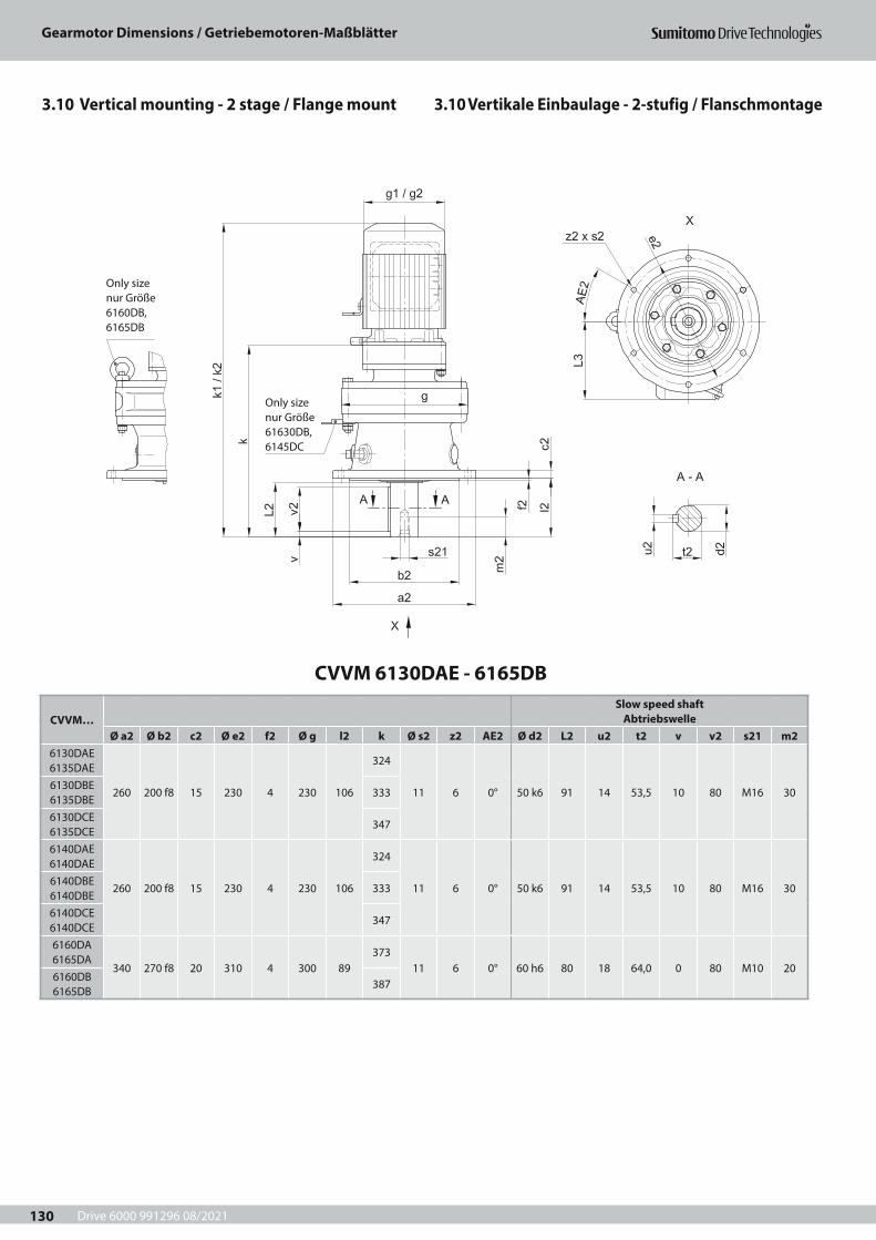
Drive 6000 991296 08/2021
Gearmotor Dimensions / Getriebemotoren-Maßblätter
130
CVVM 6130DAE - 6165DB
CVVM…Slow speed shaft
AbtriebswelleØ a2 Ø b2 c2 Ø e2 f2 Ø g l2 k Ø s2 z2 AE2 Ø d2 L2 u2 t2 v v2 s21 m2
6130DAE 6135DAE
260 200 f8 15 230 4 230 106
324
11 6 0° 50 k6 91 14 53,5 10 80 M16 306130DBE 6135DBE
333
6130DCE 6135DCE
347
6140DAE 6140DAE
260 200 f8 15 230 4 230 106
324
11 6 0° 50 k6 91 14 53,5 10 80 M16 306140DBE 6140DBE
333
6140DCE 6140DCE
347
6160DA 6165DA
340 270 f8 20 310 4 300 89373
11 6 0° 60 h6 80 18 64,0 0 80 M10 206160DB 6165DB
387
Only size nur Größe 61630DB, 6145DC
Only size nur Größe 6160DB, 6165DB
3.10 Vertikale Einbaulage - 2-stufig / Flanschmontage3.10 Vertical mounting - 2 stage / Flange mount
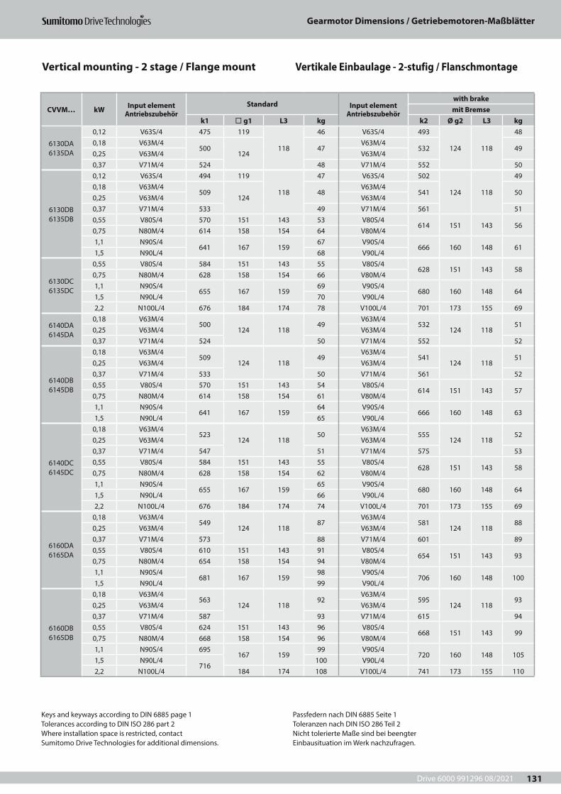
Drive 6000 991296 08/2021
Gearmotor Dimensions / Getriebemotoren-Maßblätter
131
CVVM… kW Input element Antriebszubehör
Standard Input element Antriebszubehör
with brakemit Bremse
k1 ¨ g1 L3 kg k2 Ø g2 L3 kg
6130DA 6135DA
0,12 V63S/4 475 119
118
46 V63S/4 493
124 118
480,18 V63M/4
500124
47V63M/4
532 490,25 V63M/4 V63M/40,37 V71M/4 524 48 V71M/4 552 50
6130DB 6135DB
0,12 V63S/4 494 119
118
47 V63S/4 502
124 118
490,18 V63M/4
509124
48V63M/4
541 500,25 V63M/4 V63M/40,37 V71M/4 533 49 V71M/4 561 510,55 V80S/4 570 151 143 53 V80S/4
614 151 143 560,75 N80M/4 614 158 154 64 V80M/41,1 N90S/4
641 167 15967 V90S/4
666 160 148 611,5 N90L/4 68 V90L/4
6130DC 6135DC
0,55 V80S/4 584 151 143 55 V80S/4628 151 143 58
0,75 N80M/4 628 158 154 66 V80M/41,1 N90S/4
655 167 15969 V90S/4
680 160 148 641,5 N90L/4 70 V90L/42,2 N100L/4 676 184 174 78 V100L/4 701 173 155 69
6140DA 6145DA
0,18 V63M/4500
124 11849
V63M/4532
124 11851
0,25 V63M/4 V63M/40,37 V71M/4 524 50 V71M/4 552 52
6140DB 6145DB
0,18 V63M/4509
124 11849
V63M/4541
124 11851
0,25 V63M/4 V63M/40,37 V71M/4 533 50 V71M/4 561 520,55 V80S/4 570 151 143 54 V80S/4
614 151 143 570,75 N80M/4 614 158 154 61 V80M/41,1 N90S/4
641 167 15964 V90S/4
666 160 148 631,5 N90L/4 65 V90L/4
6140DC 6145DC
0,18 V63M/4523
124 11850
V63M/4555
124 11852
0,25 V63M/4 V63M/40,37 V71M/4 547 51 V71M/4 575 530,55 V80S/4 584 151 143 55 V80S/4
628 151 143 580,75 N80M/4 628 158 154 62 V80M/41,1 N90S/4
655 167 15965 V90S/4
680 160 148 641,5 N90L/4 66 V90L/42,2 N100L/4 676 184 174 74 V100L/4 701 173 155 69
6160DA 6165DA
0,18 V63M/4549
124 11887
V63M/4581
124 11888
0,25 V63M/4 V63M/40,37 V71M/4 573 88 V71M/4 601 890,55 V80S/4 610 151 143 91 V80S/4
654 151 143 930,75 N80M/4 654 158 154 94 V80M/41,1 N90S/4
681 167 15998 V90S/4
706 160 148 1001,5 N90L/4 99 V90L/4
6160DB 6165DB
0,18 V63M/4563
124 11892
V63M/4595
124 11893
0,25 V63M/4 V63M/40,37 V71M/4 587 93 V71M/4 615 940,55 V80S/4 624 151 143 96 V80S/4
668 151 143 990,75 N80M/4 668 158 154 96 V80M/41,1 N90S/4 695
167 15999 V90S/4
720 160 148 1051,5 N90L/4
716100 V90L/4
2,2 N100L/4 184 174 108 V100L/4 741 173 155 110
Keys and keyways according to DIN 6885 page 1Tolerances according to DIN ISO 286 part 2Where installation space is restricted, contactSumitomo Drive Technologies for additional dimensions.
Passfedern nach DIN 6885 Seite 1Toleranzen nach DIN ISO 286 Teil 2Nicht tolerierte Maße sind bei beengterEinbausituation im Werk nachzufragen.
Vertical mounting - 2 stage / Flange mount Vertikale Einbaulage - 2-stufig / Flanschmontage
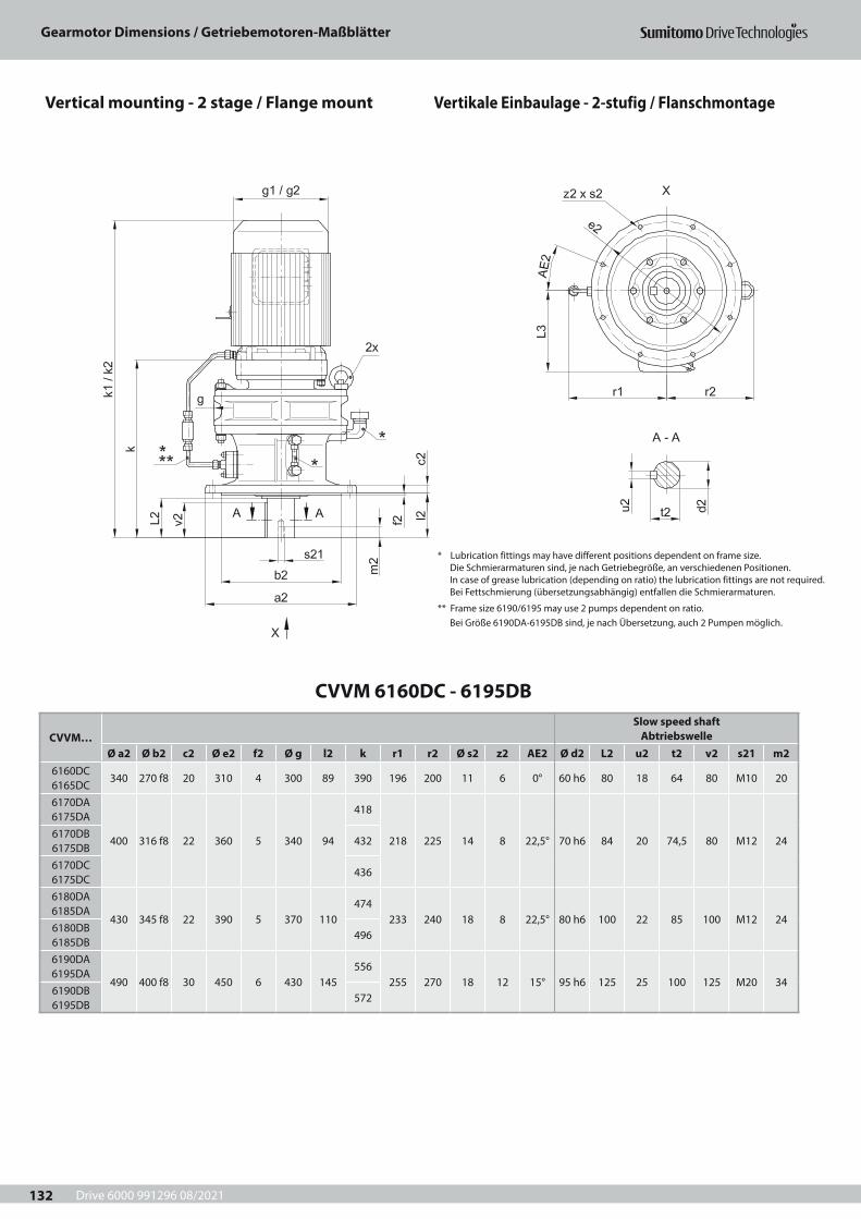
Drive 6000 991296 08/2021
Gearmotor Dimensions / Getriebemotoren-Maßblätter
132
CVVM 6160DC - 6195DB
CVVM…Slow speed shaft
AbtriebswelleØ a2 Ø b2 c2 Ø e2 f2 Ø g l2 k r1 r2 Ø s2 z2 AE2 Ø d2 L2 u2 t2 v2 s21 m2
6160DC 6165DC
340 270 f8 20 310 4 300 89 390 196 200 11 6 0° 60 h6 80 18 64 80 M10 20
6170DA 6175DA
400 316 f8 22 360 5 340 94
418
218 225 14 8 22,5° 70 h6 84 20 74,5 80 M12 246170DB 6175DB
432
6170DC 6175DC
436
6180DA 6185DA
430 345 f8 22 390 5 370 110474
233 240 18 8 22,5° 80 h6 100 22 85 100 M12 246180DB 6185DB
496
6190DA 6195DA
490 400 f8 30 450 6 430 145556
255 270 18 12 15° 95 h6 125 25 100 125 M20 346190DB 6195DB
572
* Lubrication fittings may have different positions dependent on frame size.Die Schmierarmaturen sind, je nach Getriebegröße, an verschiedenen Positionen.In case of grease lubrication (depending on ratio) the lubrication fittings are not required.Bei Fettschmierung (übersetzungsabhängig) entfallen die Schmierarmaturen.
** Frame size 6190/6195 may use 2 pumps dependent on ratio.Bei Größe 6190DA-6195DB sind, je nach Übersetzung, auch 2 Pumpen möglich.
Vertical mounting - 2 stage / Flange mount Vertikale Einbaulage - 2-stufig / Flanschmontage

Drive 6000 991296 08/2021
Gearmotor Dimensions / Getriebemotoren-Maßblätter
133
CVVM… kW Input element Antriebszubehör
Standard Input element Antriebszubehör
with brakemit Bremse
k1 ¨ g1 L3 kg k2 Ø g2 L3 kg
6160DC 6165DC
2,2 N100L/4 683184 174
115 V100L/4 743 173 155 993 N112S/4 697 118 V112S/4
775212 166
1124 N112M/4 720
222 190126 V112M/4
5,5 N132S/4 763 142 V132S/4 819 119
6170DA 6175DA
0,37 V71M/4 618 124 118 121 V71M/4 646 124 118 1230,55 V80S/4 655 151 143 125 V80S/4
699 151 143 1280,75 N80M/4 699 158 154 130 V80M/41,1 N90S/4
726 167 159133 V90S/4
751 160 148 1341,5 N90L/4 134 V90L/4
6170DB 6175DB
0,37 V71M/4 632 124 118 119 V71M/4 660 124 118 1260,55 V80S/4 669 151 143 122 V80S/4
713 151 143 1290,75 N80M/4 713 158 154 132 V80M/41,1 N90S/4
740 167 159135 V90S/4
764 160 148 1361,5 N90L/4 136 V90L/42,2 N100L/4 761 184 174 144 V100L/4 785 173 155 141
6170DC 6175DC
0,37 V71M/4 641 124 128 133 V71M/4 670 124 128 1100,55 V80S/4 673 151 143 137 V80S/4
717 151 143 1110,75 N80M/4 717 158 154 140 V80M/41,1 N90S/4
744 167 159142 V90S/4
769 160 148 1161,5 N90L/4 144 V90L/42,2 N100L/4 729
184 174150 V100L/4 790 173 155 123
3 N112S/4 743 153 V112S/4821
212 166136
4 N112M/4 766222 190
161 V112M/45,5 N132S/4 809 177 V132S/4 865 143
6180DA 6185DA
0,75 N80M/4 755 158 154 164 V80M/4 755 151 143 1611,1 N90S/4
782 167 159167 V90S/4
807 160 148 1671,5 N90L/4 168 V90L/42,2 N100L/4 803 184 174 176 V100L/4 828 173 155 172
6180DB 6185DB
0,75 N80M/4 777 158 154 183 V80M/4 777 151 143 1591,1 N90S/4
804 167 159185 V90S/4
829 160 148 1651,5 N90L/4 187 V90L/42,2 N100L/4 789
184 174192 V100L/4 850 173 155 168
3 N112S/4 803 195 V112S/4881
212 166181
4 N112M/4 821222 190
203 V112M/45,5 N132S/4 864 218 V132S/4 925 1887,5 N132M/4 902
260 230230 V132M/4 971
251 217211
11 N160M/4 964 235 V160M/4 1031 225
6190DA 6195DA
0,55 V80S/4 793 151 143 249 V80S/4837 151 143 203
0,75 N80M/4 837 158 154 243 V80M/41,1 N90S/4
864 167 159246 V90S/4
889 160 148 2091,5 N90L/4 248 V90L/42,2 N100L/4 849
184 174254 V100L/4 910 173 155 215
3 N112S/4 863 257 V112S/4941
212 166228
4 N112M/4 886222 190
265 V112M/45,5 N132S/4 929 281 V132S/4 985 235
6190DB 6195DB
2,2 N100L/4 865184 174
261 V100L/4 926 173 155 2223 N112S/4 879 264 V112S/4
957212 166
2354 N112M/4 897
222 190272 V112M/4
5,5 N132S/4 940 287 V132S/4 1001 2427,5 N132M/4 978
260 230299 V132M/4 1047
251 217265
11 N160M/4 1040 304 V160M/4 1107 27915 N160L/4 1104 317 264 341 G160L/4 1165 324 261 346
Keys and keyways according to DIN 6885 page 1Tolerances according to DIN ISO 286 part 2Where installation space is restricted, contactSumitomo Drive Technologies for additional dimensions.
Passfedern nach DIN 6885 Seite 1Toleranzen nach DIN ISO 286 Teil 2Nicht tolerierte Maße sind bei beengterEinbausituation im Werk nachzufragen.
Vertical mounting - 2 stage / Flange mount Vertikale Einbaulage - 2-stufig / Flanschmontage
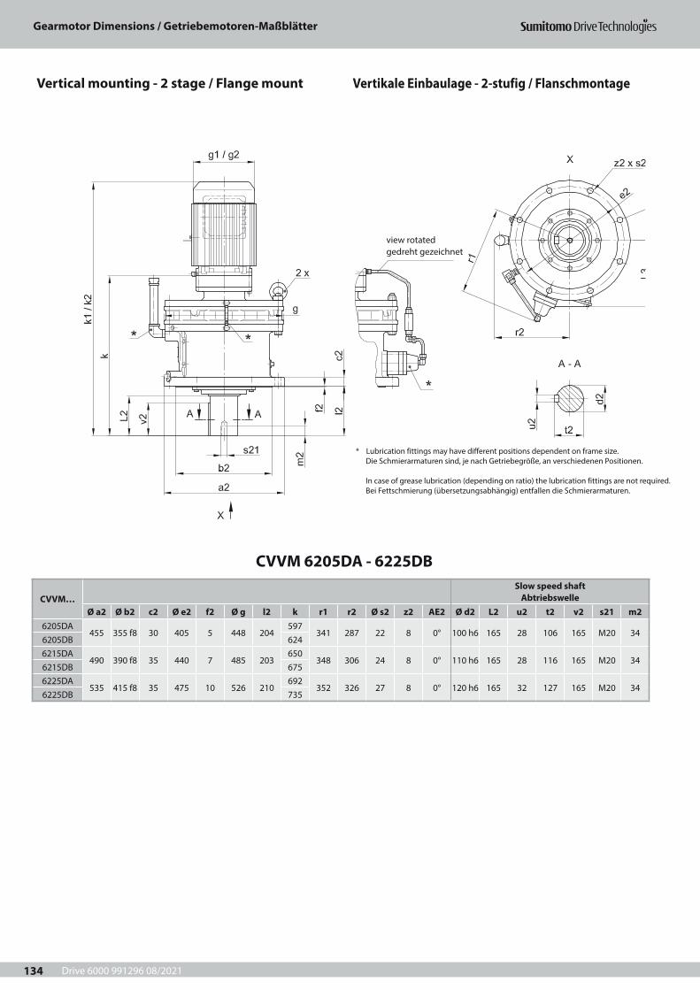
Drive 6000 991296 08/2021
Gearmotor Dimensions / Getriebemotoren-Maßblätter
134
view rotatedgedreht gezeichnet
CVVM 6205DA - 6225DB
CVVM…Slow speed shaft
AbtriebswelleØ a2 Ø b2 c2 Ø e2 f2 Ø g l2 k r1 r2 Ø s2 z2 AE2 Ø d2 L2 u2 t2 v2 s21 m2
6205DA455 355 f8 30 405 5 448 204
597341 287 22 8 0° 100 h6 165 28 106 165 M20 34
6205DB 6246215DA
490 390 f8 35 440 7 485 203650
348 306 24 8 0° 110 h6 165 28 116 165 M20 346215DB 6756225DA
535 415 f8 35 475 10 526 210692
352 326 27 8 0° 120 h6 165 32 127 165 M20 346225DB 735
* Lubrication fittings may have different positions dependent on frame size.Die Schmierarmaturen sind, je nach Getriebegröße, an verschiedenen Positionen.
In case of grease lubrication (depending on ratio) the lubrication fittings are not required.Bei Fettschmierung (übersetzungsabhängig) entfallen die Schmierarmaturen.
Vertical mounting - 2 stage / Flange mount Vertikale Einbaulage - 2-stufig / Flanschmontage
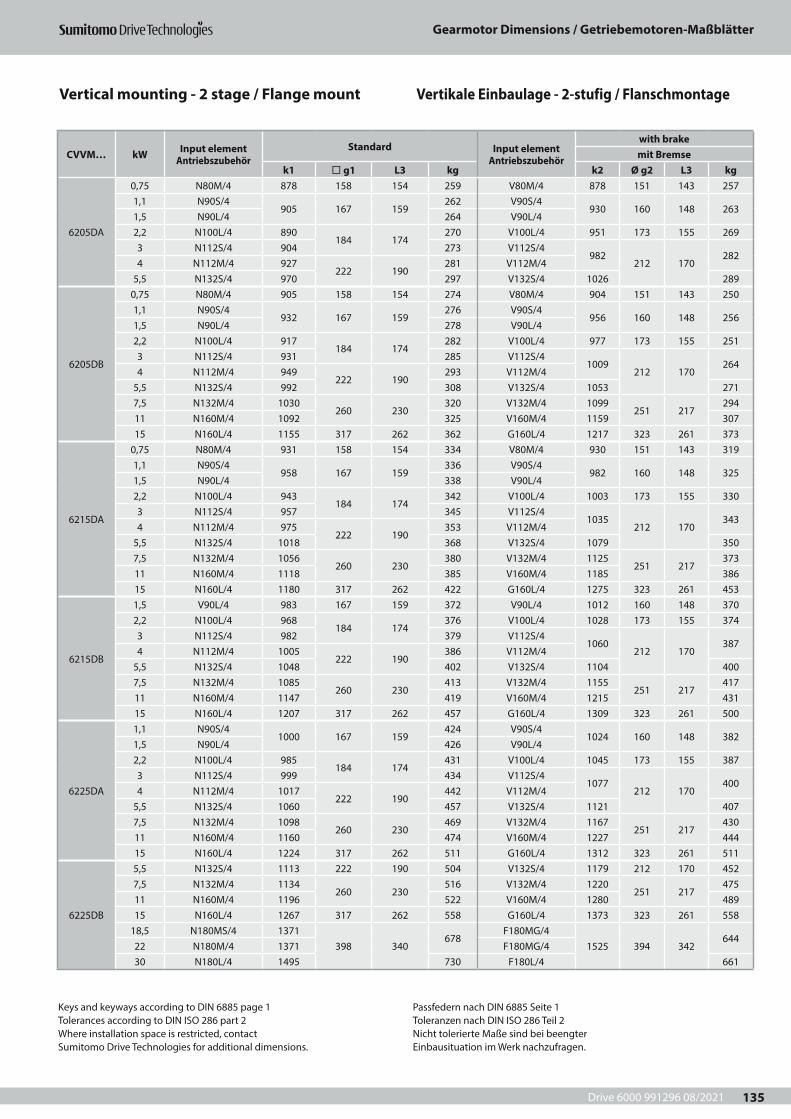
Drive 6000 991296 08/2021
Gearmotor Dimensions / Getriebemotoren-Maßblätter
135
CVVM… kW Input element Antriebszubehör
Standard Input element Antriebszubehör
with brakemit Bremse
k1 ¨ g1 L3 kg k2 Ø g2 L3 kg
6205DA
0,75 N80M/4 878 158 154 259 V80M/4 878 151 143 2571,1 N90S/4
905 167 159262 V90S/4
930 160 148 2631,5 N90L/4 264 V90L/42,2 N100L/4 890
184 174270 V100L/4 951 173 155 269
3 N112S/4 904 273 V112S/4982
212 170282
4 N112M/4 927222 190
281 V112M/45,5 N132S/4 970 297 V132S/4 1026 289
6205DB
0,75 N80M/4 905 158 154 274 V80M/4 904 151 143 2501,1 N90S/4
932 167 159276 V90S/4
956 160 148 2561,5 N90L/4 278 V90L/42,2 N100L/4 917
184 174282 V100L/4 977 173 155 251
3 N112S/4 931 285 V112S/41009
212 170264
4 N112M/4 949222 190
293 V112M/45,5 N132S/4 992 308 V132S/4 1053 2717,5 N132M/4 1030
260 230320 V132M/4 1099
251 217294
11 N160M/4 1092 325 V160M/4 1159 30715 N160L/4 1155 317 262 362 G160L/4 1217 323 261 373
6215DA
0,75 N80M/4 931 158 154 334 V80M/4 930 151 143 3191,1 N90S/4
958 167 159336 V90S/4
982 160 148 3251,5 N90L/4 338 V90L/42,2 N100L/4 943
184 174342 V100L/4 1003 173 155 330
3 N112S/4 957 345 V112S/41035
212 170343
4 N112M/4 975222 190
353 V112M/45,5 N132S/4 1018 368 V132S/4 1079 3507,5 N132M/4 1056
260 230380 V132M/4 1125
251 217373
11 N160M/4 1118 385 V160M/4 1185 38615 N160L/4 1180 317 262 422 G160L/4 1275 323 261 453
6215DB
1,5 V90L/4 983 167 159 372 V90L/4 1012 160 148 3702,2 N100L/4 968
184 174376 V100L/4 1028 173 155 374
3 N112S/4 982 379 V112S/41060
212 170387
4 N112M/4 1005222 190
386 V112M/45,5 N132S/4 1048 402 V132S/4 1104 4007,5 N132M/4 1085
260 230413 V132M/4 1155
251 217417
11 N160M/4 1147 419 V160M/4 1215 43115 N160L/4 1207 317 262 457 G160L/4 1309 323 261 500
6225DA
1,1 N90S/41000 167 159
424 V90S/41024 160 148 382
1,5 N90L/4 426 V90L/42,2 N100L/4 985
184 174431 V100L/4 1045 173 155 387
3 N112S/4 999 434 V112S/41077
212 170400
4 N112M/4 1017222 190
442 V112M/45,5 N132S/4 1060 457 V132S/4 1121 4077,5 N132M/4 1098
260 230469 V132M/4 1167
251 217430
11 N160M/4 1160 474 V160M/4 1227 44415 N160L/4 1224 317 262 511 G160L/4 1312 323 261 511
6225DB
5,5 N132S/4 1113 222 190 504 V132S/4 1179 212 170 4527,5 N132M/4 1134
260 230516 V132M/4 1220
251 217475
11 N160M/4 1196 522 V160M/4 1280 48915 N160L/4 1267 317 262 558 G160L/4 1373 323 261 558
18,5 N180MS/4 1371398 340
678F180MG/4
1525 394 342644
22 N180M/4 1371 F180MG/430 N180L/4 1495 730 F180L/4 661
Keys and keyways according to DIN 6885 page 1Tolerances according to DIN ISO 286 part 2Where installation space is restricted, contactSumitomo Drive Technologies for additional dimensions.
Passfedern nach DIN 6885 Seite 1Toleranzen nach DIN ISO 286 Teil 2Nicht tolerierte Maße sind bei beengterEinbausituation im Werk nachzufragen.
Vertical mounting - 2 stage / Flange mount Vertikale Einbaulage - 2-stufig / Flanschmontage
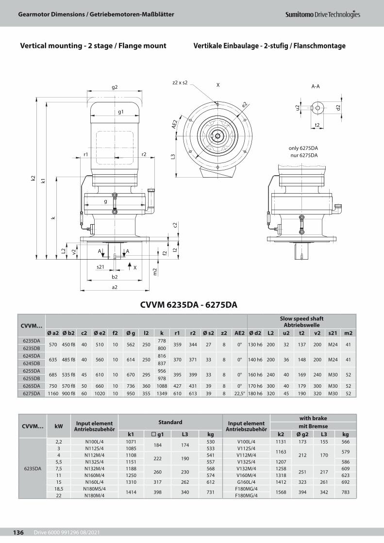
Drive 6000 991296 08/2021
Gearmotor Dimensions / Getriebemotoren-Maßblätter
136
A-AX
A
X
A
only 6275DAnur 6275DA
t2
u2 d2
L3AE
2
e2
z2 x s2
I2c2
k2 k1
a2
b2
v2L2
s21
m2
f2
r1 r2
g1
g2
k
g
CVVM… kW Input element Antriebszubehör
Standard Input element Antriebszubehör
with brakemit Bremse
k1 ¨ g1 L3 kg k2 Ø g2 L3 kg
6235DA
2,2 N100L/4 1071184 174
530 V100L/4 1131 173 155 5663 N112S/4 1085 533 V112S/4
1163212 170
5794 N112M/4 1108
222 190541 V112M/4
5,5 N132S/4 1151 557 V132S/4 1207 5867,5 N132M/4 1188
260 230568 V132M/4 1258
251 217609
11 N160M/4 1250 574 V160M/4 1318 62315 N160L/4 1310 317 262 612 G160L/4 1412 323 261 692
18,5 N180MS/41414 398 340 731
F180MG/41568 394 342 783
22 N180M/4 F180MG/4
CVVM 6235DA - 6275DA
CVVM…Slow speed shaft
AbtriebswelleØ a2 Ø b2 c2 Ø e2 f2 Ø g l2 k r1 r2 Ø s2 z2 AE2 Ø d2 L2 u2 t2 v2 s21 m2
6235DA570 450 f8 40 510 10 562 250
778359 344 27 8 0° 130 h6 200 32 137 200 M24 41
6235DB 8006245DA
635 485 f8 40 560 10 614 250816
370 371 33 8 0° 140 h6 200 36 148 200 M24 416245DB 8376255DA
685 535 f8 45 610 10 670 295956
395 399 33 8 0° 160 h6 240 40 169 240 M30 526255DB 9786265DA 750 570 f8 50 660 10 736 360 1088 427 431 39 8 0° 170 h6 300 40 179 300 M30 526275DA 1160 900 f8 60 1020 10 950 355 1349 610 613 39 8 22,5° 180 h6 320 45 190 320 M30 52
Vertical mounting - 2 stage / Flange mount Vertikale Einbaulage - 2-stufig / Flanschmontage
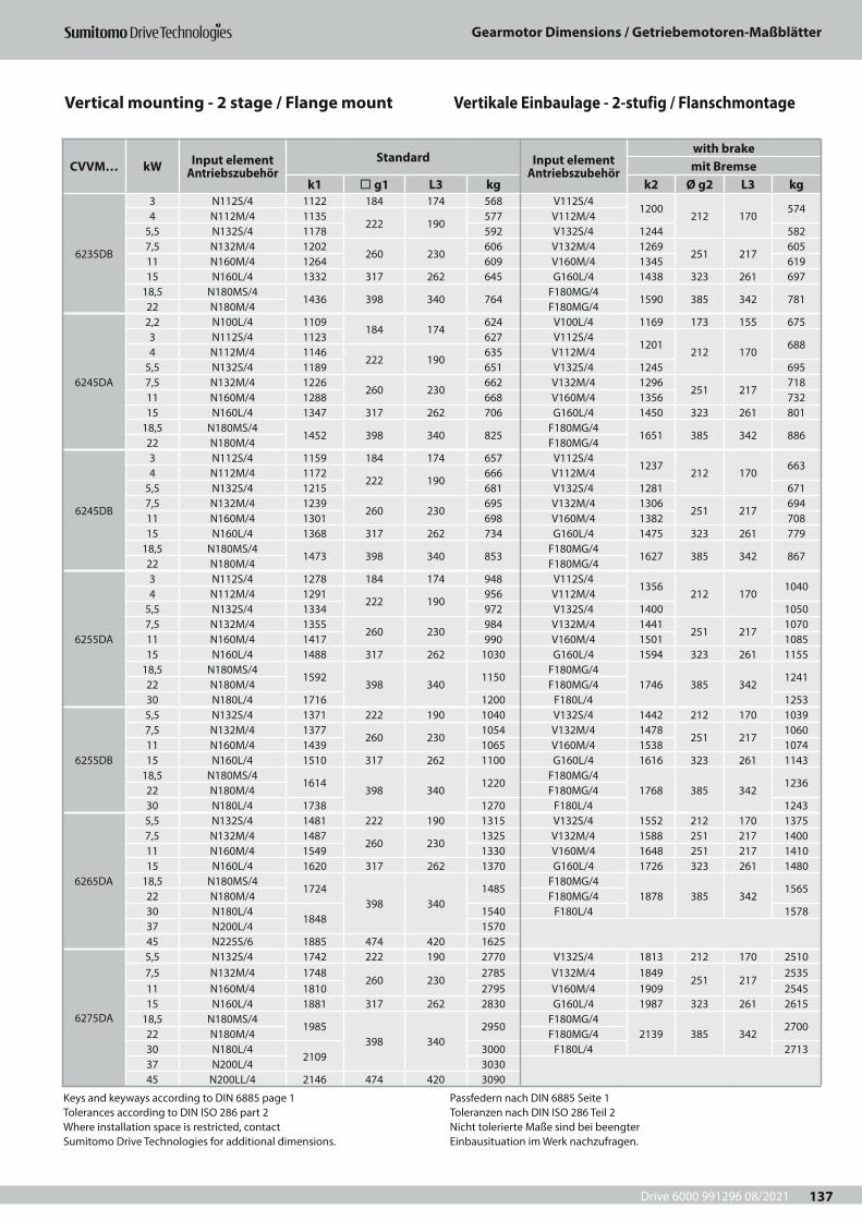
Drive 6000 991296 08/2021
Gearmotor Dimensions / Getriebemotoren-Maßblätter
137
Keys and keyways according to DIN 6885 page 1Tolerances according to DIN ISO 286 part 2Where installation space is restricted, contactSumitomo Drive Technologies for additional dimensions.
Passfedern nach DIN 6885 Seite 1Toleranzen nach DIN ISO 286 Teil 2Nicht tolerierte Maße sind bei beengterEinbausituation im Werk nachzufragen.
CVVM… kW Input element Antriebszubehör
Standard Input element Antriebszubehör
with brakemit Bremse
k1 ¨ g1 L3 kg k2 Ø g2 L3 kg
6235DB
3 N112S/4 1122 184 174 568 V112S/41200
212 170574
4 N112M/4 1135222 190
577 V112M/45,5 N132S/4 1178 592 V132S/4 1244 5827,5 N132M/4 1202
260 230606 V132M/4 1269
251 217605
11 N160M/4 1264 609 V160M/4 1345 61915 N160L/4 1332 317 262 645 G160L/4 1438 323 261 697
18,5 N180MS/41436 398 340 764
F180MG/41590 385 342 781
22 N180M/4 F180MG/4
6245DA
2,2 N100L/4 1109184 174
624 V100L/4 1169 173 155 6753 N112S/4 1123 627 V112S/4
1201212 170
6884 N112M/4 1146
222 190635 V112M/4
5,5 N132S/4 1189 651 V132S/4 1245 6957,5 N132M/4 1226
260 230662 V132M/4 1296
251 217718
11 N160M/4 1288 668 V160M/4 1356 73215 N160L/4 1347 317 262 706 G160L/4 1450 323 261 801
18,5 N180MS/41452 398 340 825
F180MG/41651 385 342 886
22 N180M/4 F180MG/4
6245DB
3 N112S/4 1159 184 174 657 V112S/41237
212 170663
4 N112M/4 1172222 190
666 V112M/45,5 N132S/4 1215 681 V132S/4 1281 6717,5 N132M/4 1239
260 230695 V132M/4 1306
251 217694
11 N160M/4 1301 698 V160M/4 1382 70815 N160L/4 1368 317 262 734 G160L/4 1475 323 261 779
18,5 N180MS/41473 398 340 853
F180MG/41627 385 342 867
22 N180M/4 F180MG/4
6255DA
3 N112S/4 1278 184 174 948 V112S/41356
212 1701040
4 N112M/4 1291222 190
956 V112M/45,5 N132S/4 1334 972 V132S/4 1400 10507,5 N132M/4 1355
260 230984 V132M/4 1441
251 2171070
11 N160M/4 1417 990 V160M/4 1501 108515 N160L/4 1488 317 262 1030 G160L/4 1594 323 261 1155
18,5 N180MS/41592
398 3401150
F180MG/41746 385 342
124122 N180M/4 F180MG/430 N180L/4 1716 1200 F180L/4 1253
6255DB
5,5 N132S/4 1371 222 190 1040 V132S/4 1442 212 170 10397,5 N132M/4 1377
260 2301054 V132M/4 1478
251 2171060
11 N160M/4 1439 1065 V160M/4 1538 107415 N160L/4 1510 317 262 1100 G160L/4 1616 323 261 1143
18,5 N180MS/41614
398 3401220
F180MG/41768 385 342
123622 N180M/4 F180MG/430 N180L/4 1738 1270 F180L/4 1243
6265DA
5,5 N132S/4 1481 222 190 1315 V132S/4 1552 212 170 13757,5 N132M/4 1487
260 2301325 V132M/4 1588 251 217 1400
11 N160M/4 1549 1330 V160M/4 1648 251 217 141015 N160L/4 1620 317 262 1370 G160L/4 1726 323 261 1480
18,5 N180MS/41724
398 3401485
F180MG/41878 385 342
156522 N180M/4 F180MG/430 N180L/4
18481540 F180L/4 1578
37 N200L/4 157045 N225S/6 1885 474 420 1625
6275DA
5,5 N132S/4 1742 222 190 2770 V132S/4 1813 212 170 25107,5 N132M/4 1748
260 2302785 V132M/4 1849
251 2172535
11 N160M/4 1810 2795 V160M/4 1909 254515 N160L/4 1881 317 262 2830 G160L/4 1987 323 261 2615
18,5 N180MS/41985
398 3402950
F180MG/42139 385 342
270022 N180M/4 F180MG/430 N180L/4
21093000 F180L/4 2713
37 N200L/4 303045 N200LL/4 2146 474 420 3090
Vertical mounting - 2 stage / Flange mount Vertikale Einbaulage - 2-stufig / Flanschmontage
Drive 6000 991296 082021
Speed Reducer Selection / Getriebe-Auswahl
138

Drive 6000 991296 08/2021
Speed Reducer Selection / Getriebe-Auswahl
139
4 Getriebe-Auswahl 4 Speed Reducer Selection
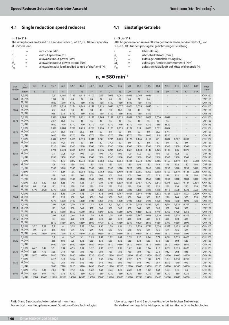
Drive 6000 991296 082021
Speed Reducer Selection / Getriebe-Auswahl
140
4.1 Einstufige Getriebe4.1 Single reduction speed reducers
i = 3 to 119The rating tables are based on a service factor fB1 of 1.0, i.e. 10 hours per day at uniform load.
i = reduction ration2 = output speed [min-1]P1 = allowable input power [kW]M2 = allowable output power torque [Nm]FR2 = allowable radial load applied to mid of shaft end [N]
i = 3 bis 119Alle Angaben in den Auswahllisten gelten für einen Service Faktor fB1 von 1,0, d.h. 10 Stunden pro Tag bei gleichförmiger Belastung.
i = Übersetzungn2 = Abtriebsdrehzahl [min-1]P1 = zulässige Antriebsleistung [kW]M2 = zulässiges Abtriebsdrehmoment [ [Nm]FR2 = zulässige Radialkraft auf Mitte Wellenende [N]
n1 = 580 min-1
Size Größe
n2 [min-1] 193 116 96,7 72,5 52,7 44,6 38,7 34,1 27,6 23,2 20 16,6 13,5 11,4 9,83 8,17 6,67 4,87 Page
SeiteRatio 3 5 6 8 11 13 15 17 21 25 29 35 43 51 59 71 87 119
6060P1[kW] 0,2 0,192 0,139 0,118 0,102 0,09 0,073 0,061 0,053 0,044 0,036 - - - - - CNH 162M2 [Nm] 18,8 24 24 24 24 24 24 24 24 24 24 - - - - - CNF 169FR2 [N] 1020 1010 1180 1180 1180 1180 1180 1180 1180 1180 1180 - - - - - CNV 175
6065P1[kW] 0,267 0,216 0,174 0,148 0,128 0,113 0,091 0,077 0,066 0,055 0,045 - - - - - CNH 162M2 [Nm] 25 27,1 30 30 30 30 30 30,0 30 30 30 - - - - - CNF 169FR2 [N] 958 974 1140 1180 1180 1180 1180 1180 1180 1180 1180 - - - - - CNV 175
6070P1[kW] 0,316 0,288 0,262 0,221 0,192 0,169 0,137 0,115 0,099 0,082 0,067 0,056 0,049 - - - CNH 162M2 [Nm] 29,7 36,1 45 45 45 45 45 45 45 45 45 45 45 - - - CNF 169FR2 [N] 1680 1770 1770 1770 1770 1770 1770 1770 1770 1770 1750 1610 1620 - - - CNV 175
6075P1[kW] 0,316 0,288 0,291 0,273 0,256 0,226 0,183 0,153 0,132 0,11 0,089 0,071 0,062 - - - CNH 162M2 [Nm] 29,7 36,1 50,1 55,5 60 60 60 60 60 60 60 56,9 57,4 - - - CNF 169FR2 [N] 1680 1770 1770 1770 1770 1770 1770 1770 1770 1770 1660 1540 1550 - - - CNV 175
6080P1[kW] 0,592 0,592 0,465 0,393 0,341 0,301 0,235 0,205 0,176 0,146 0,119 0,1 0,087 0,072 0,059 - CNH 162M2 [Nm] 55,6 74,1 80 80 80 80 77,2 80 80 80 80 80 80 80 80 - CNF 169FR2 [N] 2310 2490 2560 2560 2560 2560 2560 2560 2560 2560 2560 2560 2560 2560 2560 - CNV 175
6085P1[kW] 0,778 0,778 0,581 0,492 0,426 0,376 0,235 0,256 0,22 0,178 0,149 0,125 0,108 0,09 0,073 - CNH 162M2 [Nm] 73 97,3 100 100 100 100 77,2 100 100 97,2 100 100 100 99,5 100 - CNF 169FR2 [N] 2280 2450 2560 2560 2560 2560 2560 2560 2560 2560 2560 2560 2560 2560 2560 - CNV 175
6090P1[kW] 1,15 1,15 0,872 0,738 0,639 0,564 0,457 0,384 0,331 0,274 0,223 0,186 0,158 0,119 0,11 0,058 CNH 162M2 [Nm] 108 143 150 150 150 150 150 150 150 150 150 149 146 132 150 108 CNF 169FR2 [N] 3340 3340 3340 3340 3340 3340 3160 3010 3020 3030 3040 3020 3030 3040 3050 3040 CNV 175
6095P1[kW] 1,47 1,34 1,05 0,984 0,852 0,752 0,609 0,499 0,441 0,365 0,297 0,192 0,158 0,119 0,131 0,058 CNH 162M2 [Nm] 138 168 181 200 200 200 200 195 200 200 200 153 146 132 178 108 CNF 169FR2 [N] 3340 3340 3340 3340 3340 3280 3070 2930 2940 2940 2960 3010 3030 3040 3000 3040 CNV 175
6100P1[kW] 1,82 1,82 1,82 1,86 1,45 1,23 1,07 0,94 0,761 0,639 0,551 0,457 0,372 0,313 0,271 0,225 0,184 0,134 CNH 162M2 [Nm] 80 134 171 233 250 250 250 250 250 250 250 250 250 250 250 250 250 250 CNF 169FR2 [N] 4770 4770 4770 5300 5400 5400 5400 5400 5400 5400 5400 5400 5400 5160 4910 4690 4720 4670 CNV 175
6105P1[kW] 1,82 1,86 1,79 1,48 1,28 1,13 0,913 0,767 0,661 0,548 0,446 0,372 0,321 0,238 0,22 0,139 CNH 162M2 [Nm] 171 233 308 300 300 300 300 300 300 300 300 297 296 264 300 258 CNF 169FR2 [N] 4770 5300 5400 5400 5400 5400 5400 5400 5400 5400 5400 5120 4880 4680 4690 4660 CNV 175
6110P1[kW] 2,06 2,88 2,09 1,77 1,53 1,35 1,1 0,921 0,794 0,658 0,535 0,451 0,39 0,324 0,265 - CNH 162M2 [Nm] 193 360 360 360 360 360 360 360 360 360 360 360 360 360 360 - CNF 169FR2 [N] 5510 6010 6950 6910 7050 6840 6780 6510 6390 6460 6730 6740 6760 6720 6750 - CNV 175
6115P1[kW] 2,06 3,25 2,44 2,07 1,79 1,58 1,28 1,07 0,926 0,767 0,624 0,526 0,455 0,378 0,309 - CNH 162M2 [Nm] 193 406 420 420 420 420 420 420 420 420 420 420 420 420 420 - CNF 169FR2 [N] 5510 5960 6890 6850 6980 6790 6710 6450 6340 6400 6680 6680 6700 6660 6690 - CNV 175
6120P1[kW] 3,27 3,27 3,9 4 3,05 2,58 2,24 1,96 1,59 1,34 1,15 0,959 0,781 0,658 0,569 0,473 0,386 - CNH 162M2 [Nm] 145 241 366 501 525 525 525 520 522 525 520 525 525 525 525 525 525 - CNF 169FR2 [N] 5490 5490 6400 7090 8130 8440 9120 9250 9810 9810 9810 9810 9810 9810 9810 9550 9090 - CNV 175
6125P1[kW] 3,9 4 3,47 3,1 2,69 2,37 1,92 1,61 1,39 1,15 0,94 0,79 0,68 0,533 0,463 - CNH 162M2 [Nm] 366 501 596 630 630 630 630 630 630 630 630 630 630 592 630 - CNF 169FR2 [N] 6400 7090 8060 8350 9020 9160 9810 9810 9810 9810 9810 9810 9810 9420 8880 - CNV 175
6130P1[kW] 6,47 6,47 5,91 5,94 4,53 3,84 3,32 2,93 2,37 1,99 1,72 1,42 1,16 1,16 0,99 0,813 0,623 - CHH 163M2 [Nm] 286 476 555 744 780 780 780 780 780 780 780 780 780 928 912 902 848 - CHF 170FR2 [N] 6970 6970 7030 7800 9040 9490 9730 10500 11300 11800 12400 13100 13900 13400 14500 14600 14700 - CHV 176
6135P1[kW] 6,47 6,11 5,46 4,62 4,01 3,53 2,86 2,30 2,07 1,72 1,40 1,21 1,14 0,938 0,719 - CHH 163M2 [Nm] 607 764 940 940 940 940 940 900 940 940 940 967 1050 1040 979 - CHF 170FR2 [N] 6980 7790 8920 9380 9630 10400 11200 11700 12300 13000 13700 13300 14300 14300 14500 - CHV 176
6140P1[kW] 7,45 7,45 7,64 7,8 7,12 6,02 5,22 4,61 3,73 3,13 2,70 2,24 1,82 1,54 1,33 1,10 0,9 - CHH 163M2 [Nm] 329 549 717 976 1230 1230 1230 1230 1230 1230 1230 1230 1230 1230 1230 1230 1230 - CHF 170FR2 [N] 11600 11600 11700 12900 14500 14900 15600 15800 15900 15800 15500 15700 15400 15400 16000 16000 16000 - CHV 176
Ratio 3 and 5 not available for universal mounting. For vertical mounting please consult Sumitomo Drive Technologies.
Übersetzungen 3 und 5 nicht verfügbar bei beliebiger Einbaulage. Bei Vertikalmontage bitte Rücksprache mit Sumitomo Drive Technologies.
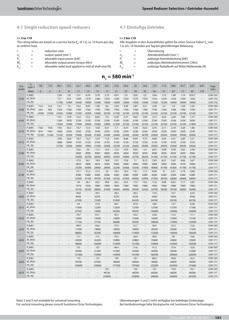
Drive 6000 991296 08/2021
Speed Reducer Selection / Getriebe-Auswahl
141
4.1 Einstufige Getriebe4.1 Single reduction speed reducers
i = 3 to 119The rating tables are based on a service factor fB1 of 1.0, i.e. 10 hours per day at uniform load.
i = reduction ration2 = output speed [min-1] P1 = allowable input power [kW]M2 = allowable output power torque [Nm]FR2 = allowable radial load applied to mid of shaft end [N]
i = 3 bis 119Alle Angaben in den Auswahllisten gelten für einen Service Faktor fB1 von 1,0, d.h. 10 Stunden pro Tag bei gleichförmiger Belastung.
i = Übersetzungn2 = Abtriebsdrehzahl [min-1]P1 = zulässige Antriebsleistung [kW]M2 = zulässiges Abtriebsdrehmoment [ [Nm]FR2 = zulässige Radialkraft auf Mitte Wellenende [N]
n1 = 580 min-1
Size Größe
n2 [min-1] 193 116 96,7 72,5 52,7 44,6 38,7 34,1 27,6 23,2 20 16,6 13,5 11,4 9,83 8,17 6,67 4,87 Page
SeiteRatio 3 5 6 8 11 13 15 17 21 25 29 35 43 51 59 71 87 119
6145P1[kW] 7,64 7,8 7,51 6,74 5,79 5,15 4,07 3,5 3,02 2,5 2,04 1,72 1,48 1,19 0,917 - CHH 163M2 [Nm] 717 976 1290 1370 1360 1370 1340 1370 1370 1370 1370 1370 1370 1320 1250 - CHF 170FR2 [N] 11700 12900 14500 14800 15500 15800 15800 15800 15400 15600 15300 15300 16000 16000 16000 - CHV 176
6160P1[kW] 12,3 12,3 14,1 14 10,2 8,63 7,48 6,6 5,34 4,49 3,87 3,21 2,58 2,2 1,9 1,58 1,29 - CHH 164M2 [Nm] 543 905 1320 1760 1760 1760 1760 1760 1760 1760 1760 1760 1740 1760 1760 1760 1760 - CHF 171FR2 [N] 13500 13500 13500 15000 17300 18200 19400 20100 21700 22100 22100 22100 22100 22100 22100 22100 22100 - CHV 177
6165P1[kW] 14,1 14,9 12,2 10,3 8,95 7,9 6,39 5,37 4,63 3,84 3,12 2,63 2,28 1,89 1,51 - CHH 164M2 [Nm] 1320 1870 2100 2100 2100 2100 2100 2100 2100 2100 2100 2100 2100 2100 2050 - CHF 171FR2 [N] 13500 14900 17000 18000 19200 19900 21500 22100 22100 22100 22100 22100 22100 22100 21800 - CHV 177
6170P1[kW] 19,8 19,8 19,8 20,2 14,7 12,4 10,8 9,51 7,7 6,47 5,58 4,62 3,76 3,17 2,74 2,28 1,86 - CHH 164M2 [Nm] 874 1457 1860 2530 2530 2530 2530 2530 2530 2530 2530 2530 2530 2530 2530 2530 2530 - CHF 171FR2 [N] 15100 15100 15100 16500 19300 20300 21400 22400 24400 25400 26900 28700 29500 29500 29500 29500 29500 - CHV 177
6175P1[kW] 19,8 20,8 18,3 15,5 13,4 11,8 9,59 8,06 6,94 5,75 4,68 3,95 3,41 2,84 2,31 - CHH 164M2 [Nm] 1860 2600 3150 3150 3150 3150 3150 3150 3150 3150 3150 3150 3150 3150 3150 - CHF 171FR2 [N] 15100 16500 18900 19900 21000 22000 24100 25100 26600 28400 29500 29500 29500 29500 29500 - CHV 177
6180P1[kW] - - 23,6 20 17,3 15,3 12,3 10,4 8,93 7,4 6,03 5,08 4,39 3,65 2,98 - CHH 164M2 [Nm] - - 4060 4060 4060 4060 4050 4050 4050 4050 4060 4050 4050 4050 4060 - CHF 171FR2 [N] - - 25600 26700 28300 30000 32600 34000 35700 38200 41200 41700 41700 41700 41700 - CHV 177
6185P1[kW] - - 27,9 24,1 19,9 18,8 15,2 12,8 11 9,13 7,43 6,27 5,42 4,06 3,67 - CHH 164M2 [Nm] - - 4810 4900 4670 5000 5000 5000 5000 5000 5000 5000 5000 4510 5000 - CHF 171FR2 [N] - - 25200 26400 28000 29600 32200 33600 35300 37900 40800 41700 41600 41700 41700 - CHV 177
6190P1[kW] - - 37,1 31,4 27,2 24 19,4 16,3 14,1 11,7 9,49 8 6,91 5,74 4,69 - CHH 164M2 [Nm] - - 6380 6380 6380 6380 6380 6380 6380 6380 6380 6380 6380 6380 6380 - CHF 171FR2 [N] - - 35500 37100 39100 41500 45100 47400 49900 52900 57200 58700 58600 58400 58900 - CHV 177
6195P1[kW] - - 44 36,1 33,2 29,9 24,2 20,4 17,5 14,5 11,8 9,98 8,63 7,17 5,85 - CHH 164M2 [Nm] - - 7570 7350 7800 7960 7960 7960 7960 7960 7960 7960 7960 7960 7960 - CHF 171FR2 [N] - - 35100 36700 38600 41000 44600 46900 49500 52500 56700 58200 58100 58000 58400 - CHV 177
6205P1[kW] - - 46,8 - 39,5 - 28,2 - 20,3 - 13,8 - 10,1 - 6,43 - CHH 165M2 [Nm] - - 8050 - 9270 - 9270 - 9230 - 9300 - 9300 - 8760 - CHF 171FR2 [N] - - 67300 - 72500 - 81600 - 84100 - 84100 - 84100 - 84100 - CHV 177
6215P1[kW] - - 64 - 51,9 - 38,1 - 27,9 - 18,8 - 13,7 - 8,28 - CHH 165M2 [Nm] - - 11000 - 12200 - 12500 - 12700 - 12700 - 12700 - 11300 - CHF 171FR2 [N] - - 67300 - 72600 - 82500 - 90200 - 102000 - 104000 - 104000 - CHV 177
6225P1[kW] - - 74,7 - 61,7 - 45,1 - 33,2 - 23,8 - 17,2 - 11,1 - CHH 165M2 [Nm] - - 12900 - 14500 - 14800 - 15000 - 16000 - 15900 - 15100 - CHF 171FR2 [N] - - 71100 - 77100 - 86900 - 95200 - 108000 - 118000 - 133000 - CHV 177
6235P1[kW] - - 99,9 - 83,6 - 57,5 - 41,7 - 30,5 - 22,2 - 12,6 - CHH 165M2 [Nm] - - 17200 - 19600 - 18900 - 18900 - 20500 - 20500 - 17200 - CHF 171FR2 [N] - - 88800 - 95300 - 108000 - 119000 - 133000 - 146000 - 166000 - CHV 177
6245P1[kW] - - 117 - 112 - 78,5 - 56,9 - 38,4 - 28 - 16,6 - CHH 165M2 [Nm] - - 20200 - 26200 - 25800 - 25800 - 25800 - 25800 - 22600 - CHF 171FR2 [N] - - 98600 - 106000 - 119000 - 131000 - 149000 - 163000 - 185000 - CHV 177
6255P1[kW] - - 151 - 133 - 94,4 - 71,6 - 51,3 - 37,4 - 22,8 - CHH 165M2 [Nm] - - 25900 - 31200 - 31000 - 32500 - 34500 - 34500 - 31000 - CHF 171FR2 [N] - - 121000 - 130000 - 146000 - 161000 - 182000 - 200000 - 226000 - CHV 177
6265P1[kW] - - 175 - 175 - 140 - 101 - 68,4 - 49,8 - 32,3 - CHH 165M2 [Nm] - - 30100 - 41000 - 46000 - 46000 - 46000 - 46000 - 44000 - CHF 171FR2 [N] - - 148000 - 158000 - 177000 - 197000 - 222000 - 243000 - 274000 - CHV 177
6275P1[kW] - - - - - 181 - - 150 - 101 - 73,9 - 50,1 - CHH 165M2 [Nm] - - - - - 48100 - - 68200 - 68200 - 68200 - 68200 - CHF 171FR2 [N] - - - - - 229000 - - 228000 - 248000 - 248000 - 245000 - CHV 177
Ratio 3 and 5 not available for universal mounting. For vertical mounting please consult Sumitomo Drive Technologies.
Übersetzungen 3 und 5 nicht verfügbar bei beliebiger Einbaulage. Bei Vertikalmontage bitte Rücksprache mit Sumitomo Drive Technologies.
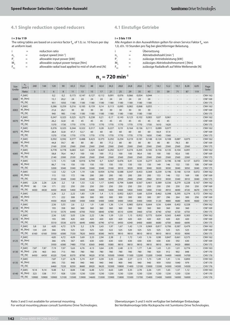
Drive 6000 991296 082021
Speed Reducer Selection / Getriebe-Auswahl
142
4.1 Einstufige Getriebe4.1 Single reduction speed reducers
n1 = 720 min-1
Size Größe
n2 [min-1] 240 144 120 90 65,5 55,4 48 42,4 34,3 28,8 24,8 20,6 16,7 14,1 12,2 10,1 8,28 6,05 Page
SeiteRatio 3 5 6 8 11 13 15 17 21 25 29 35 43 51 59 71 87 119
6060P1[kW] 0,2 0,2 0,173 0,147 0,127 0,112 0,091 0,076 0,066 0,054 0,044 - - - - - CNH 162M2 [Nm] 15,1 20,2 24 24 24 24 24 24 24 24 24 - - - - - CNF 169FR2 [N] 951 1050 1180 1180 1180 1180 1180 1180 1180 1180 1180 - - - - - CNV 175
6065P1[kW] 0,286 0,259 0,216 0,183 0,159 0,14 0,113 0,095 0,082 0,068 0,055 - - - - - CNH 162M2 [Nm] 21,6 26,1 30 30 30 30 30 30 30 30 30 - - - - - CNF 169FR2 [N] 940 985 1140 1180 1180 1180 1180 1180 1180 1180 1180 - - - - - CNV 175
6070P1[kW] 0,347 0,325 0,325 0,275 0,238 0,21 0,17 0,143 0,123 0,102 0,083 0,07 0,061 - - - CNH 162M2 [Nm] 26,2 32,8 45 45 45 45 45 45 45 45 45 45 45 - - - CNF 169FR2 [N] 1570 1730 1770 1770 1770 1770 1770 1770 1770 1770 1750 1610 1620 - - - CNV 175
6075P1[kW] 0,376 0,325 0,344 0,322 0,317 0,28 0,227 0,19 0,164 0,136 0,111 0,089 0,077 - - - CNH 162M2 [Nm] 28,4 32,8 47,7 52,7 60 60 60 60 60 60 60 56,9 57,4 - - - CNF 169FR2 [N] 1570 1730 1770 1770 1770 1770 1770 1770 1770 1770 1650 1540 1560 - - - CNV 175
6080P1[kW] 0,592 0,592 0,577 0,488 0,423 0,373 0,292 0,254 0,219 0,181 0,148 0,124 0,108 0,087 0,073 - CNH 162M2 [Nm] 44,8 59,7 80 80 80 80 77,2 80 80 80 80 80 80 78,5 80 - CNF 169FR2 [N] 2160 2330 2560 2560 2560 2560 2560 2560 2560 2560 2560 2560 2560 2560 2560 - CNV 175
6085P1[kW] 0,778 0,778 0,683 0,61 0,529 0,467 0,292 0,317 0,274 0,205 0,185 0,156 0,135 0,104 0,091 - CNH 162M2 [Nm] 58,8 78,4 94,7 100 100 100 77,2 100 100 90,4 100 100 100 92,6 100 - CNF 169FR2 [N] 2140 2300 2530 2560 2560 2560 2560 2560 2560 2560 2560 2560 2560 2560 2260 - CNV 175
6090P1[kW] 1,15 1,15 1,08 0,916 0,794 0,7 0,567 0,476 0,41 0,34 0,277 0,231 0,196 0,148 0,137 0,072 CNH 162M2 [Nm] 86,7 116 150 150 150 150 150 150 150 150 150 149 146 132 150 108 CNF 169FR2 [N] 3200 3340 3340 3340 3340 3340 3160 3010 3020 3030 3040 3020 3030 3040 3050 3040 CNV 175
6095P1[kW] 1,52 1,52 1,24 1,19 1,06 0,934 0,756 0,588 0,547 0,453 0,369 0,239 0,196 0,148 0,154 0,072 CNH 162M2 [Nm] 115 153 172 196 200 200 200 185 200 200 200 153 146 132 169 108 CNF 169FR2 [N] 3150 3340 3340 3340 3340 3280 3070 2950 2940 2940 2960 3010 3030 3340 3010 3040 CNV 175
6100P1[kW] 2,26 2,26 2,26 2,2 1,8 1,53 1,32 1,17 0,945 0,794 0,684 0,567 0,461 0,389 0,336 0,279 0,228 0,167 CNH 162M2 [Nm] 80 134 171 222 250 250 250 250 250 250 250 250 250 250 250 250 250 250 CNF 169FR2 [N] 4430 4430 4430 4920 5400 5400 5400 5400 5400 5400 5400 5400 5400 5160 4910 4690 4720 4670 CNV 175
6105P1[kW] 2,26 2,2 2,22 1,83 1,59 1,4 1,13 0,952 0,821 0,68 0,554 0,462 0,398 0,295 0,274 0,172 CNH 162M2 [Nm] 171 222 308 300 300 300 300 300 300 300 300 297 296 264 300 258 CNF 169FR2 [N] 4430 4920 5400 5400 5400 5400 5400 5400 5400 5400 5400 5120 4880 4680 4690 4660 CNV 175
6110P1[kW] 2,56 3,55 2,6 2,2 1,9 1,68 1,36 1,14 0,985 0,816 0,664 0,56 0,484 0,402 0,328 - CNH 162M2 [Nm] 193 358 360 360 360 360 360 360 360 360 360 360 360 360 360 - CNF 169FR2 [N] 5110 5570 6440 6700 7050 6840 6780 6510 6390 3460 6730 6740 6760 6720 6750 - CNV 175
6115P1[kW] 2,56 3,92 3,03 2,56 2,22 1,96 1,59 1,33 1,15 0,952 0,775 0,654 0,565 0,469 0,383 - CNH 162M2 [Nm] 193 395 420 420 420 420 420 420 420 420 420 420 420 420 420 - CNF 169FR2 [N] 5510 5530 6370 6640 6980 6790 6710 6450 6340 6400 6680 6680 6700 6660 6690 - CNV 175
6120P1[kW] 3,8 3,8 4,85 4,72 3,79 3,2 2,78 2,43 1,97 1,67 1,42 1,19 0,969 0,817 0,706 0,587 0,479 - CNH 162M2 [Nm] 134 224 366 476 525 525 525 520 522 525 520 525 525 525 525 525 525 - CNF 169FR2 [N] 6160 6160 5930 6580 7530 7820 8450 8580 9470 9810 9810 9810 9810 9810 9810 9550 9090 - CNV 175
6125P1[kW] 4,85 4,72 4,09 3,69 3,33 2,94 2,38 2 1,72 1,43 1,16 0,98 0,847 0,661 0,575 - CNH 162M2 [Nm] 366 476 567 605 630 630 630 630 630 630 630 630 630 592 630 - CNF 169FR2 [N] 5930 6580 7480 7750 8360 8480 9380 9810 9810 9810 9810 9810 9810 9420 8880 - CNV 175
6130P1[kW] 7,87 7,87 7,19 7,07 5,63 4,76 4,13 3,64 2,95 2,48 2,13 1,77 1,44 1,43 1,23 1,01 0,774 - CHH 163M2 [Nm] 278 463 543 713 780 780 780 780 780 780 780 780 780 920 912 902 848 - CHF 170FR2 [N] 6450 6450 6520 7240 8370 8790 9020 9730 10500 10900 11500 12200 13200 13400 14400 14600 14700 - CHV 176
6135P1[kW] 7,87 7,27 6,78 5,74 4,97 4,39 3,55 2,86 2,57 2,13 1,73 1,49 1,41 1,16 0,893 - CHH 163M2 [Nm] 595 733 940 940 940 940 940 900 940 940 940 959 1050 1040 979 - CHF 170FR2 [N] 6460 7220 8250 8680 8920 9620 10300 10800 11400 12100 13000 13300 14300 14300 14500 - CHV 176
6140P1[kW] 9,14 9,14 9,48 9,2 8,84 7,48 6,48 5,72 4,63 3,89 3,35 2,78 2,26 1,91 1,65 1,37 1,12 - CHH 163M2 [Nm] 323 538 717 928 1230 1230 1230 1230 1230 1230 1230 1230 1230 1230 1230 1230 1230 - CHF 170FR2 [N] 10900 10900 10900 12100 13500 13900 14600 15300 15900 15800 15500 15700 15400 15400 16000 16000 16000 - CHV 176
Ratio 3 and 5 not available for universal mounting. For vertical mounting please consult Sumitomo Drive Technologies.
Übersetzungen 3 und 5 nicht verfügbar bei beliebiger Einbaulage. Bei Vertikalmontage bitte Rücksprache mit Sumitomo Drive Technologies.
i = 3 to 119The rating tables are based on a service factor fB1 of 1.0, i.e. 10 hours per day at uniform load.
i = reduction ration2 = output speed [min-1]P1 = allowable input power [kW]M2 = allowable output power torque [Nm]FR2 = allowable radial load applied to mid of shaft end [N]
i = 3 bis 119Alle Angaben in den Auswahllisten gelten für einen Service Faktor fB1 von 1,0, d.h. 10 Stunden pro Tag bei gleichförmiger Belastung.
i = Übersetzungn2 = Abtriebsdrehzahl [min-1]P1 = zulässige Antriebsleistung [kW]M2 = zulässiges Abtriebsdrehmoment [ [Nm]FR2 = zulässige Radialkraft auf Mitte Wellenende [N]
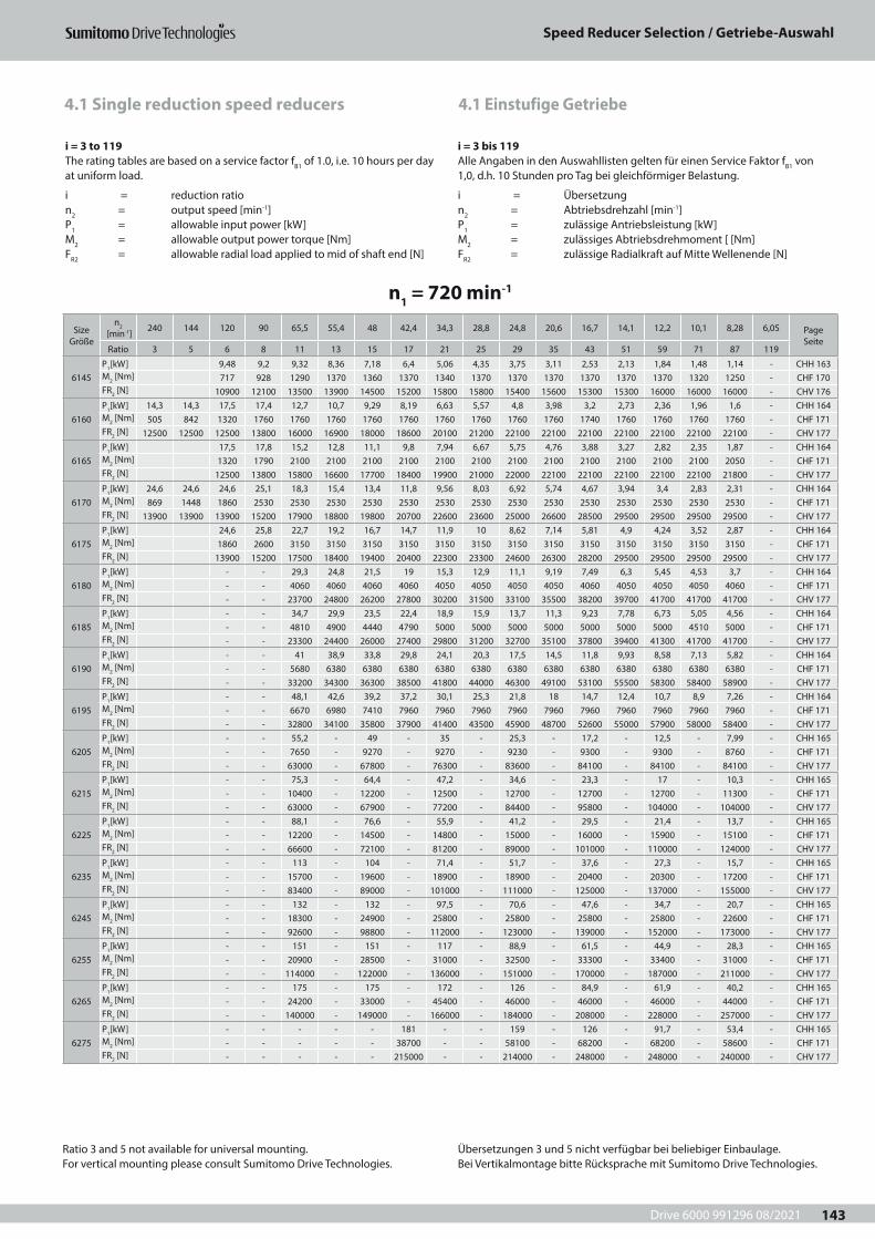
Drive 6000 991296 08/2021
Speed Reducer Selection / Getriebe-Auswahl
143
4.1 Einstufige Getriebe4.1 Single reduction speed reducers
n1 = 720 min-1
Size Größe
n2 [min-1] 240 144 120 90 65,5 55,4 48 42,4 34,3 28,8 24,8 20,6 16,7 14,1 12,2 10,1 8,28 6,05 Page
SeiteRatio 3 5 6 8 11 13 15 17 21 25 29 35 43 51 59 71 87 119
6145P1[kW] 9,48 9,2 9,32 8,36 7,18 6,4 5,06 4,35 3,75 3,11 2,53 2,13 1,84 1,48 1,14 - CHH 163M2 [Nm] 717 928 1290 1370 1360 1370 1340 1370 1370 1370 1370 1370 1370 1320 1250 - CHF 170FR2 [N] 10900 12100 13500 13900 14500 15200 15800 15800 15400 15600 15300 15300 16000 16000 16000 - CHV 176
6160P1[kW] 14,3 14,3 17,5 17,4 12,7 10,7 9,29 8,19 6,63 5,57 4,8 3,98 3,2 2,73 2,36 1,96 1,6 - CHH 164M2 [Nm] 505 842 1320 1760 1760 1760 1760 1760 1760 1760 1760 1760 1740 1760 1760 1760 1760 - CHF 171FR2 [N] 12500 12500 12500 13800 16000 16900 18000 18600 20100 21200 22100 22100 22100 22100 22100 22100 22100 - CHV 177
6165P1[kW] 17,5 17,8 15,2 12,8 11,1 9,8 7,94 6,67 5,75 4,76 3,88 3,27 2,82 2,35 1,87 - CHH 164M2 [Nm] 1320 1790 2100 2100 2100 2100 2100 2100 2100 2100 2100 2100 2100 2100 2050 - CHF 171FR2 [N] 12500 13800 15800 16600 17700 18400 19900 21000 22000 22100 22100 22100 22100 22100 21800 - CHV 177
6170P1[kW] 24,6 24,6 24,6 25,1 18,3 15,4 13,4 11,8 9,56 8,03 6,92 5,74 4,67 3,94 3,4 2,83 2,31 - CHH 164M2 [Nm] 869 1448 1860 2530 2530 2530 2530 2530 2530 2530 2530 2530 2530 2530 2530 2530 2530 - CHF 171FR2 [N] 13900 13900 13900 15200 17900 18800 19800 20700 22600 23600 25000 26600 28500 29500 29500 29500 29500 - CHV 177
6175P1[kW] 24,6 25,8 22,7 19,2 16,7 14,7 11,9 10 8,62 7,14 5,81 4,9 4,24 3,52 2,87 - CHH 164M2 [Nm] 1860 2600 3150 3150 3150 3150 3150 3150 3150 3150 3150 3150 3150 3150 3150 - CHF 171FR2 [N] 13900 15200 17500 18400 19400 20400 22300 23300 24600 26300 28200 29500 29500 29500 29500 - CHV 177
6180P1[kW] - - 29,3 24,8 21,5 19 15,3 12,9 11,1 9,19 7,49 6,3 5,45 4,53 3,7 - CHH 164M2 [Nm] - - 4060 4060 4060 4060 4050 4050 4050 4050 4060 4050 4050 4050 4060 - CHF 171FR2 [N] - - 23700 24800 26200 27800 30200 31500 33100 35500 38200 39700 41700 41700 41700 - CHV 177
6185P1[kW] - - 34,7 29,9 23,5 22,4 18,9 15,9 13,7 11,3 9,23 7,78 6,73 5,05 4,56 - CHH 164M2 [Nm] - - 4810 4900 4440 4790 5000 5000 5000 5000 5000 5000 5000 4510 5000 - CHF 171FR2 [N] - - 23300 24400 26000 27400 29800 31200 32700 35100 37800 39400 41300 41700 41700 - CHV 177
6190P1[kW] - - 41 38,9 33,8 29,8 24,1 20,3 17,5 14,5 11,8 9,93 8,58 7,13 5,82 - CHH 164M2 [Nm] - - 5680 6380 6380 6380 6380 6380 6380 6380 6380 6380 6380 6380 6380 - CHF 171FR2 [N] - - 33200 34300 36300 38500 41800 44000 46300 49100 53100 55500 58300 58400 58900 - CHV 177
6195P1[kW] - - 48,1 42,6 39,2 37,2 30,1 25,3 21,8 18 14,7 12,4 10,7 8,9 7,26 - CHH 164M2 [Nm] - - 6670 6980 7410 7960 7960 7960 7960 7960 7960 7960 7960 7960 7960 - CHF 171FR2 [N] - - 32800 34100 35800 37900 41400 43500 45900 48700 52600 55000 57900 58000 58400 - CHV 177
6205P1[kW] - - 55,2 - 49 - 35 - 25,3 - 17,2 - 12,5 - 7,99 - CHH 165M2 [Nm] - - 7650 - 9270 - 9270 - 9230 - 9300 - 9300 - 8760 - CHF 171FR2 [N] - - 63000 - 67800 - 76300 - 83600 - 84100 - 84100 - 84100 - CHV 177
6215P1[kW] - - 75,3 - 64,4 - 47,2 - 34,6 - 23,3 - 17 - 10,3 - CHH 165M2 [Nm] - - 10400 - 12200 - 12500 - 12700 - 12700 - 12700 - 11300 - CHF 171FR2 [N] - - 63000 - 67900 - 77200 - 84400 - 95800 - 104000 - 104000 - CHV 177
6225P1[kW] - - 88,1 - 76,6 - 55,9 - 41,2 - 29,5 - 21,4 - 13,7 - CHH 165M2 [Nm] - - 12200 - 14500 - 14800 - 15000 - 16000 - 15900 - 15100 - CHF 171FR2 [N] - - 66600 - 72100 - 81200 - 89000 - 101000 - 110000 - 124000 - CHV 177
6235P1[kW] - - 113 - 104 - 71,4 - 51,7 - 37,6 - 27,3 - 15,7 - CHH 165M2 [Nm] - - 15700 - 19600 - 18900 - 18900 - 20400 - 20300 - 17200 - CHF 171FR2 [N] - - 83400 - 89000 - 101000 - 111000 - 125000 - 137000 - 155000 - CHV 177
6245P1[kW] - - 132 - 132 - 97,5 - 70,6 - 47,6 - 34,7 - 20,7 - CHH 165M2 [Nm] - - 18300 - 24900 - 25800 - 25800 - 25800 - 25800 - 22600 - CHF 171FR2 [N] - - 92600 - 98800 - 112000 - 123000 - 139000 - 152000 - 173000 - CHV 177
6255P1[kW] - - 151 - 151 - 117 - 88,9 - 61,5 - 44,9 - 28,3 - CHH 165M2 [Nm] - - 20900 - 28500 - 31000 - 32500 - 33300 - 33400 - 31000 - CHF 171FR2 [N] - - 114000 - 122000 - 136000 - 151000 - 170000 - 187000 - 211000 - CHV 177
6265P1[kW] - - 175 - 175 - 172 - 126 - 84,9 - 61,9 - 40,2 - CHH 165M2 [Nm] - - 24200 - 33000 - 45400 - 46000 - 46000 - 46000 - 44000 - CHF 171FR2 [N] - - 140000 - 149000 - 166000 - 184000 - 208000 - 228000 - 257000 - CHV 177
6275P1[kW] - - - - - 181 - - 159 - 126 - 91,7 - 53,4 - CHH 165M2 [Nm] - - - - - 38700 - - 58100 - 68200 - 68200 - 58600 - CHF 171FR2 [N] - - - - - 215000 - - 214000 - 248000 - 248000 - 240000 - CHV 177
Ratio 3 and 5 not available for universal mounting. For vertical mounting please consult Sumitomo Drive Technologies.
Übersetzungen 3 und 5 nicht verfügbar bei beliebiger Einbaulage. Bei Vertikalmontage bitte Rücksprache mit Sumitomo Drive Technologies.
i = 3 to 119The rating tables are based on a service factor fB1 of 1.0, i.e. 10 hours per day at uniform load.
i = reduction ration2 = output speed [min-1] P1 = allowable input power [kW]M2 = allowable output power torque [Nm]FR2 = allowable radial load applied to mid of shaft end [N]
i = 3 bis 119Alle Angaben in den Auswahllisten gelten für einen Service Faktor fB1 von 1,0, d.h. 10 Stunden pro Tag bei gleichförmiger Belastung.
i = Übersetzungn2 = Abtriebsdrehzahl [min-1]P1 = zulässige Antriebsleistung [kW]M2 = zulässiges Abtriebsdrehmoment [ [Nm]FR2 = zulässige Radialkraft auf Mitte Wellenende [N]
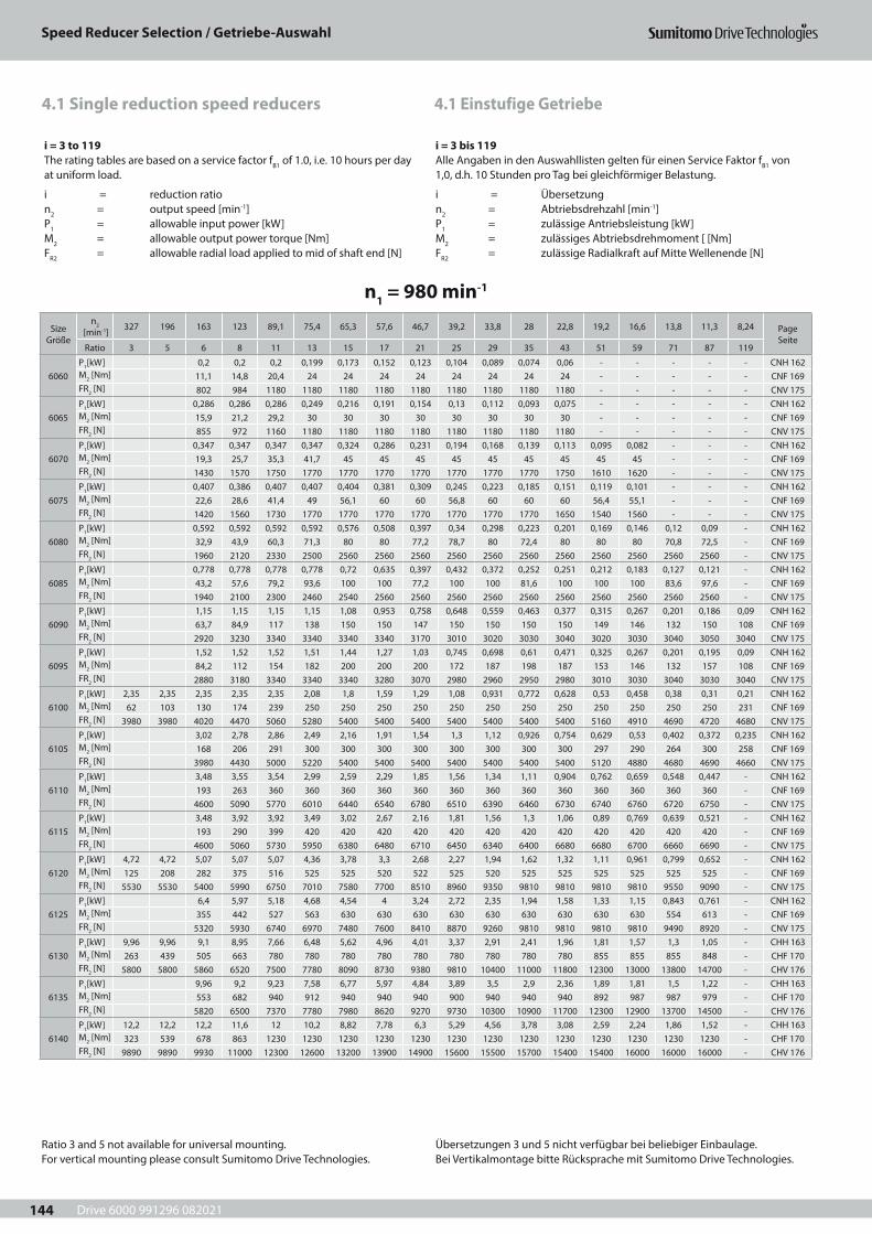
Drive 6000 991296 082021
Speed Reducer Selection / Getriebe-Auswahl
144
4.1 Einstufige Getriebe4.1 Single reduction speed reducers
i = 3 to 119The rating tables are based on a service factor fB1 of 1.0, i.e. 10 hours per day at uniform load.
i = reduction ration2 = output speed [min-1]P1 = allowable input power [kW]M2 = allowable output power torque [Nm]FR2 = allowable radial load applied to mid of shaft end [N]
i = 3 bis 119Alle Angaben in den Auswahllisten gelten für einen Service Faktor fB1 von 1,0, d.h. 10 Stunden pro Tag bei gleichförmiger Belastung.
i = Übersetzungn2 = Abtriebsdrehzahl [min-1]P1 = zulässige Antriebsleistung [kW]M2 = zulässiges Abtriebsdrehmoment [ [Nm]FR2 = zulässige Radialkraft auf Mitte Wellenende [N]
n1 = 980 min-1
Size Größe
n2 [min-1] 327 196 163 123 89,1 75,4 65,3 57,6 46,7 39,2 33,8 28 22,8 19,2 16,6 13,8 11,3 8,24 Page
SeiteRatio 3 5 6 8 11 13 15 17 21 25 29 35 43 51 59 71 87 119
6060P1[kW] 0,2 0,2 0,2 0,199 0,173 0,152 0,123 0,104 0,089 0,074 0,06 - - - - - CNH 162M2 [Nm] 11,1 14,8 20,4 24 24 24 24 24 24 24 24 - - - - - CNF 169FR2 [N] 802 984 1180 1180 1180 1180 1180 1180 1180 1180 1180 - - - - - CNV 175
6065P1[kW] 0,286 0,286 0,286 0,249 0,216 0,191 0,154 0,13 0,112 0,093 0,075 - - - - - CNH 162M2 [Nm] 15,9 21,2 29,2 30 30 30 30 30 30 30 30 - - - - - CNF 169FR2 [N] 855 972 1160 1180 1180 1180 1180 1180 1180 1180 1180 - - - - - CNV 175
6070P1[kW] 0,347 0,347 0,347 0,347 0,324 0,286 0,231 0,194 0,168 0,139 0,113 0,095 0,082 - - - CNH 162M2 [Nm] 19,3 25,7 35,3 41,7 45 45 45 45 45 45 45 45 45 - - - CNF 169FR2 [N] 1430 1570 1750 1770 1770 1770 1770 1770 1770 1770 1750 1610 1620 - - - CNV 175
6075P1[kW] 0,407 0,386 0,407 0,407 0,404 0,381 0,309 0,245 0,223 0,185 0,151 0,119 0,101 - - - CNH 162M2 [Nm] 22,6 28,6 41,4 49 56,1 60 60 56,8 60 60 60 56,4 55,1 - - - CNF 169FR2 [N] 1420 1560 1730 1770 1770 1770 1770 1770 1770 1770 1650 1540 1560 - - - CNV 175
6080P1[kW] 0,592 0,592 0,592 0,592 0,576 0,508 0,397 0,34 0,298 0,223 0,201 0,169 0,146 0,12 0,09 - CNH 162M2 [Nm] 32,9 43,9 60,3 71,3 80 80 77,2 78,7 80 72,4 80 80 80 70,8 72,5 - CNF 169FR2 [N] 1960 2120 2330 2500 2560 2560 2560 2560 2560 2560 2560 2560 2560 2560 2560 - CNV 175
6085P1[kW] 0,778 0,778 0,778 0,778 0,72 0,635 0,397 0,432 0,372 0,252 0,251 0,212 0,183 0,127 0,121 - CNH 162M2 [Nm] 43,2 57,6 79,2 93,6 100 100 77,2 100 100 81,6 100 100 100 83,6 97,6 - CNF 169FR2 [N] 1940 2100 2300 2460 2540 2560 2560 2560 2560 2560 2560 2560 2560 2560 2560 - CNV 175
6090P1[kW] 1,15 1,15 1,15 1,15 1,08 0,953 0,758 0,648 0,559 0,463 0,377 0,315 0,267 0,201 0,186 0,09 CNH 162M2 [Nm] 63,7 84,9 117 138 150 150 147 150 150 150 150 149 146 132 150 108 CNF 169FR2 [N] 2920 3230 3340 3340 3340 3340 3170 3010 3020 3030 3040 3020 3030 3040 3050 3040 CNV 175
6095P1[kW] 1,52 1,52 1,52 1,51 1,44 1,27 1,03 0,745 0,698 0,61 0,471 0,325 0,267 0,201 0,195 0,09 CNH 162M2 [Nm] 84,2 112 154 182 200 200 200 172 187 198 187 153 146 132 157 108 CNF 169FR2 [N] 2880 3180 3340 3340 3340 3280 3070 2980 2960 2950 2980 3010 3030 3040 3030 3040 CNV 175
6100P1[kW] 2,35 2,35 2,35 2,35 2,35 2,08 1,8 1,59 1,29 1,08 0,931 0,772 0,628 0,53 0,458 0,38 0,31 0,21 CNH 162M2 [Nm] 62 103 130 174 239 250 250 250 250 250 250 250 250 250 250 250 250 231 CNF 169FR2 [N] 3980 3980 4020 4470 5060 5280 5400 5400 5400 5400 5400 5400 5400 5160 4910 4690 4720 4680 CNV 175
6105P1[kW] 3,02 2,78 2,86 2,49 2,16 1,91 1,54 1,3 1,12 0,926 0,754 0,629 0,53 0,402 0,372 0,235 CNH 162M2 [Nm] 168 206 291 300 300 300 300 300 300 300 300 297 290 264 300 258 CNF 169FR2 [N] 3980 4430 5000 5220 5400 5400 5400 5400 5400 5400 5400 5120 4880 4680 4690 4660 CNV 175
6110P1[kW] 3,48 3,55 3,54 2,99 2,59 2,29 1,85 1,56 1,34 1,11 0,904 0,762 0,659 0,548 0,447 - CNH 162M2 [Nm] 193 263 360 360 360 360 360 360 360 360 360 360 360 360 360 - CNF 169FR2 [N] 4600 5090 5770 6010 6440 6540 6780 6510 6390 6460 6730 6740 6760 6720 6750 - CNV 175
6115P1[kW] 3,48 3,92 3,92 3,49 3,02 2,67 2,16 1,81 1,56 1,3 1,06 0,89 0,769 0,639 0,521 - CNH 162M2 [Nm] 193 290 399 420 420 420 420 420 420 420 420 420 420 420 420 - CNF 169FR2 [N] 4600 5060 5730 5950 6380 6480 6710 6450 6340 6400 6680 6680 6700 6660 6690 - CNV 175
6120P1[kW] 4,72 4,72 5,07 5,07 5,07 4,36 3,78 3,3 2,68 2,27 1,94 1,62 1,32 1,11 0,961 0,799 0,652 - CNH 162M2 [Nm] 125 208 282 375 516 525 525 520 522 525 520 525 525 525 525 525 525 - CNF 169FR2 [N] 5530 5530 5400 5990 6750 7010 7580 7700 8510 8960 9350 9810 9810 9810 9810 9550 9090 - CNV 175
6125P1[kW] 6,4 5,97 5,18 4,68 4,54 4 3,24 2,72 2,35 1,94 1,58 1,33 1,15 0,843 0,761 - CNH 162M2 [Nm] 355 442 527 563 630 630 630 630 630 630 630 630 630 554 613 - CNF 169FR2 [N] 5320 5930 6740 6970 7480 7600 8410 8870 9260 9810 9810 9810 9810 9490 8920 - CNV 175
6130P1[kW] 9,96 9,96 9,1 8,95 7,66 6,48 5,62 4,96 4,01 3,37 2,91 2,41 1,96 1,81 1,57 1,3 1,05 - CHH 163M2 [Nm] 263 439 505 663 780 780 780 780 780 780 780 780 780 855 855 855 848 - CHF 170FR2 [N] 5800 5800 5860 6520 7500 7780 8090 8730 9380 9810 10400 11000 11800 12300 13000 13800 14700 - CHV 176
6135P1[kW] 9,96 9,2 9,23 7,58 6,77 5,97 4,84 3,89 3,5 2,9 2,36 1,89 1,81 1,5 1,22 - CHH 163M2 [Nm] 553 682 940 912 940 940 940 900 940 940 940 892 987 987 979 - CHF 170FR2 [N] 5820 6500 7370 7780 7980 8620 9270 9730 10300 10900 11700 12300 12900 13700 14500 - CHV 176
6140P1[kW] 12,2 12,2 12,2 11,6 12 10,2 8,82 7,78 6,3 5,29 4,56 3,78 3,08 2,59 2,24 1,86 1,52 - CHH 163M2 [Nm] 323 539 678 863 1230 1230 1230 1230 1230 1230 1230 1230 1230 1230 1230 1230 1230 - CHF 170FR2 [N] 9890 9890 9930 11000 12300 12600 13200 13900 14900 15600 15500 15700 15400 15400 16000 16000 16000 - CHV 176
Ratio 3 and 5 not available for universal mounting. For vertical mounting please consult Sumitomo Drive Technologies.
Übersetzungen 3 und 5 nicht verfügbar bei beliebiger Einbaulage. Bei Vertikalmontage bitte Rücksprache mit Sumitomo Drive Technologies.
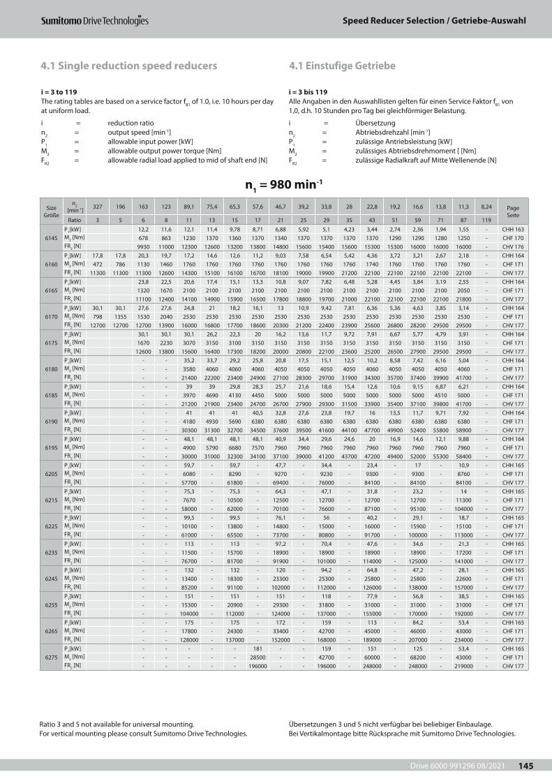
Drive 6000 991296 08/2021
Speed Reducer Selection / Getriebe-Auswahl
145
4.1 Einstufige Getriebe4.1 Single reduction speed reducers
i = 3 to 119The rating tables are based on a service factor fB1 of 1.0, i.e. 10 hours per day at uniform load.
i = reduction ration2 = output speed [min-1]P1 = allowable input power [kW]M2 = allowable output power torque [Nm]FR2 = allowable radial load applied to mid of shaft end [N]
i = 3 bis 119Alle Angaben in den Auswahllisten gelten für einen Service Faktor fB1 von 1,0, d.h. 10 Stunden pro Tag bei gleichförmiger Belastung.
i = Übersetzungn2 = Abtriebsdrehzahl [min-1]P1 = zulässige Antriebsleistung [kW]M2 = zulässiges Abtriebsdrehmoment [ [Nm]FR2 = zulässige Radialkraft auf Mitte Wellenende [N]
n1 = 980 min-1
Size Größe
n2 [min-1] 327 196 163 123 89,1 75,4 65,3 57,6 46,7 39,2 33,8 28 22,8 19,2 16,6 13,8 11,3 8,24 Page
SeiteRatio 3 5 6 8 11 13 15 17 21 25 29 35 43 51 59 71 87 119
6145P1[kW] 12,2 11,6 12,1 11,4 9,78 8,71 6,88 5,92 5,1 4,23 3,44 2,74 2,36 1,94 1,55 - CHH 163M2 [Nm] 678 863 1230 1370 1360 1370 1340 1370 1370 1370 1370 1290 1290 1280 1250 - CHF 170FR2 [N] 9930 11000 12300 12600 13200 13800 14800 15600 15400 15600 15300 15300 16000 16000 16000 - CHV 176
6160P1[kW] 17,8 17,8 20,3 19,7 17,2 14,6 12,6 11,2 9,03 7,58 6,54 5,42 4,36 3,72 3,21 2,67 2,18 - CHH 164M2 [Nm] 472 786 1130 1460 1760 1760 1760 1760 1760 1760 1760 1760 1740 1760 1760 1760 1760 - CHF 171FR2 [N] 11300 11300 11300 12600 14300 15100 16100 16700 18100 19000 19900 21200 22100 22100 22100 22100 22100 - CHV 177
6165P1[kW] 23,8 22,5 20,6 17,4 15,1 13,3 10,8 9,07 7,82 6,48 5,28 4,45 3,84 3,19 2,55 - CHH 164M2 [Nm] 1320 1670 2100 2100 2100 2100 2100 2100 2100 2100 2100 2100 2100 2100 2050 - CHF 171FR2 [N] 11100 12400 14100 14900 15900 16500 17800 18800 19700 21000 22100 22100 22100 22100 21800 - CHV 177
6170P1[kW] 30,1 30,1 27,6 27,6 24,8 21 18,2 16,1 13 10,9 9,42 7,81 6,36 5,36 4,63 3,85 3,14 - CHH 164M2 [Nm] 798 1355 1530 2040 2530 2530 2530 2530 2530 2530 2530 2530 2530 2530 2530 2530 2530 - CHF 171FR2 [N] 12700 12700 12700 13900 16000 16800 17700 18600 20300 21200 22400 23900 25600 26800 28200 29500 29500 - CHV 177
6175P1[kW] 30,1 30,1 30,1 26,2 22,3 20 16,2 13,6 11,7 9,72 7,91 6,67 5,77 4,79 3,91 - CHH 164M2 [Nm] 1670 2230 3070 3150 3100 3150 3150 3150 3150 3150 3150 3150 3150 3150 3150 - CHF 171FR2 [N] 12600 13800 15600 16400 17300 18200 20000 20800 22100 23600 25200 26500 27900 29500 29500 - CHV 177
6180P1[kW] - - 35,2 33,7 29,2 25,8 20,8 17,5 15,1 12,5 10,2 8,58 7,42 6,16 5,04 - CHH 164M2 [Nm] - - 3580 4060 4060 4060 4050 4050 4050 4050 4060 4050 4050 4050 4060 - CHF 171FR2 [N] - - 21400 22200 23400 24900 27100 28300 29700 31900 34300 35700 37400 39900 41700 - CHV 177
6185P1[kW] - - 39 39 29,8 28,3 25,7 21,6 18,6 15,4 12,6 10,6 9,15 6,87 6,21 - CHH 164M2 [Nm] - - 3970 4690 4130 4450 5000 5000 5000 5000 5000 5000 5000 4510 5000 - CHF 171FR2 [N] - - 21200 21900 23400 24700 26700 27900 29300 31500 33900 35400 37100 39800 41700 - CHV 177
6190P1[kW] - - 41 41 41 40,5 32,8 27,6 23,8 19,7 16 13,5 11,7 9,71 7,92 - CHH 164M2 [Nm] - - 4180 4930 5690 6380 6380 6380 6380 6380 6380 6380 6380 6380 6380 - CHF 171FR2 [N] - - 30300 31300 32700 34500 37600 39500 41600 44100 47700 49900 52400 55800 58900 - CHV 177
6195P1[kW] - - 48,1 48,1 48,1 48,1 40,9 34,4 29,6 24,6 20 16,9 14,6 12,1 9,88 - CHH 164M2 [Nm] - - 4900 5790 6680 7570 7960 7960 7960 7960 7960 7960 7960 7960 7960 - CHF 171FR2 [N] - - 30000 31000 32300 34100 37100 39000 41200 43700 47200 49400 52000 55300 58400 - CHV 177
6205P1[kW] - - 59,7 - 59,7 - 47,7 - 34,4 - 23,4 - 17 - 10,9 - CHH 165M2 [Nm] - - 6080 - 8290 - 9270 - 9230 - 9300 - 9300 - 8760 - CHF 171FR2 [N] - - 57700 - 61800 - 69400 - 76000 - 84100 - 84100 - 84100 - CHV 177
6215P1[kW] - - 75,3 - 75,3 - 64,3 - 47,1 - 31,8 - 23,2 - 14 - CHH 165M2 [Nm] - - 7670 - 10500 - 12500 - 12700 - 12700 - 12700 - 11300 - CHF 171FR2 [N] - - 58000 - 62000 - 70100 - 76600 - 87100 - 95100 - 104000 - CHV 177
6225P1[kW] - - 99,5 - 99,5 - 76,1 - 56 - 40,2 - 29,1 - 18,7 - CHH 165M2 [Nm] - - 10100 - 13800 - 14800 - 15000 - 16000 - 15900 - 15100 - CHF 171FR2 [N] - - 61000 - 65500 - 73700 - 80800 - 91700 - 100000 - 113000 - CHV 177
6235P1[kW] - - 113 - 113 - 97,2 - 70,4 - 47,6 - 34,6 - 21,3 - CHH 165M2 [Nm] - - 11500 - 15700 - 18900 - 18900 - 18900 - 18900 - 17200 - CHF 171FR2 [N] - - 76700 - 81700 - 91900 - 101000 - 114000 - 125000 - 141000 - CHV 177
6245P1[kW] - - 132 - 132 - 120 - 94,2 - 64,8 - 47,2 - 28,1 - CHH 165M2 [Nm] - - 13400 - 18300 - 23300 - 25300 - 25800 - 25800 - 22600 - CHF 171FR2 [N] - - 85200 - 91100 - 102000 - 112000 - 126000 - 138000 - 157000 - CHV 177
6255P1[kW] - - 151 - 151 - 151 - 118 - 77,9 - 56,8 - 38,5 - CHH 165M2 [Nm] - - 15300 - 20900 - 29300 - 31800 - 31000 - 31000 - 31000 - CHF 171FR2 [N] - - 104000 - 112000 - 124000 - 137000 - 155000 - 170000 - 192000 - CHV 177
6265P1[kW] - - 175 - 175 - 172 - 159 - 113 - 84,2 - 53,4 - CHH 165M2 [Nm] - - 17800 - 24300 - 33400 - 42700 - 45000 - 46000 - 43000 - CHF 171FR2 [N] - - 128000 - 137000 - 152000 - 168000 - 189000 - 207000 - 234000 - CHV 177
6275P1[kW] - - - - - 181 - - 159 - 151 - 125 - 53,4 - CHH 165M2 [Nm] - - - - - 28500 - - 42700 - 60000 - 68200 - 43000 - CHF 171FR2 [N] - - - - - 196000 - - 196000 - 248000 - 248000 - 219000 - CHV 177
Ratio 3 and 5 not available for universal mounting. For vertical mounting please consult Sumitomo Drive Technologies.
Übersetzungen 3 und 5 nicht verfügbar bei beliebiger Einbaulage. Bei Vertikalmontage bitte Rücksprache mit Sumitomo Drive Technologies.
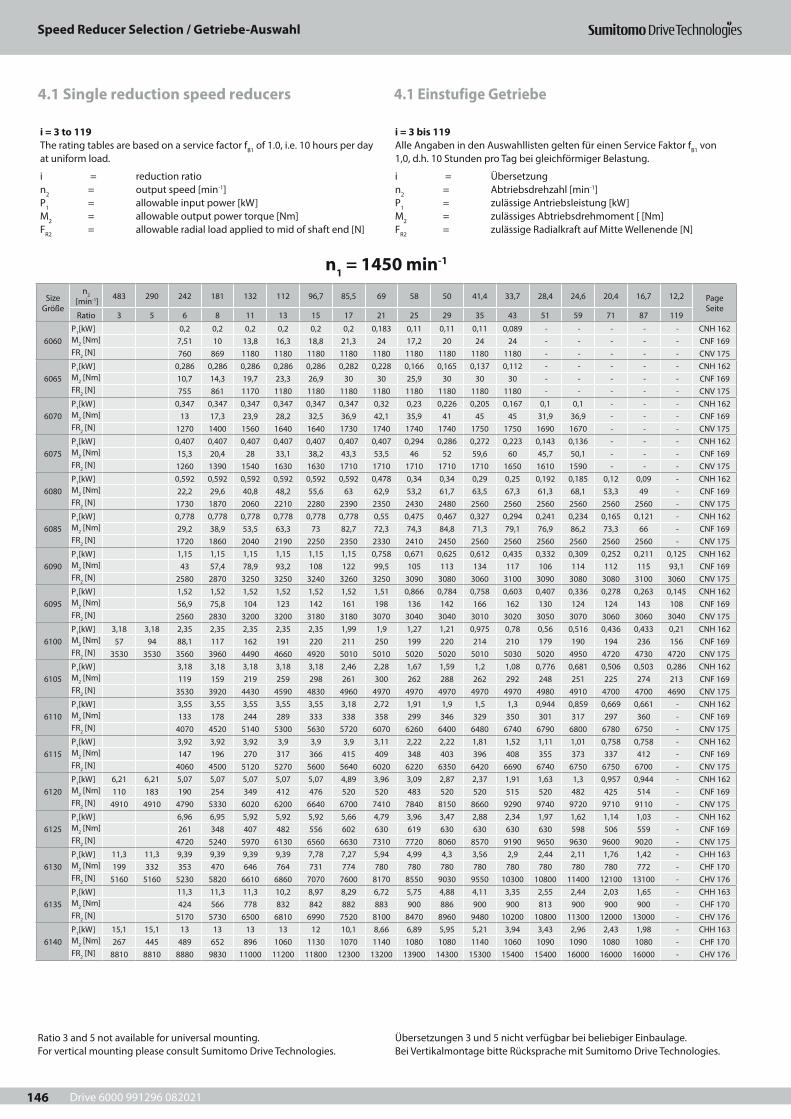
Drive 6000 991296 082021
Speed Reducer Selection / Getriebe-Auswahl
146
4.1 Einstufige Getriebe4.1 Single reduction speed reducers
i = 3 to 119The rating tables are based on a service factor fB1 of 1.0, i.e. 10 hours per day at uniform load.
i = reduction ration2 = output speed [min-1]P1 = allowable input power [kW]M2 = allowable output power torque [Nm]FR2 = allowable radial load applied to mid of shaft end [N]
i = 3 bis 119Alle Angaben in den Auswahllisten gelten für einen Service Faktor fB1 von 1,0, d.h. 10 Stunden pro Tag bei gleichförmiger Belastung.
i = Übersetzungn2 = Abtriebsdrehzahl [min-1]P1 = zulässige Antriebsleistung [kW]M2 = zulässiges Abtriebsdrehmoment [ [Nm]FR2 = zulässige Radialkraft auf Mitte Wellenende [N]
n1 = 1450 min-1
Size Größe
n2 [min-1] 483 290 242 181 132 112 96,7 85,5 69 58 50 41,4 33,7 28,4 24,6 20,4 16,7 12,2 Page
SeiteRatio 3 5 6 8 11 13 15 17 21 25 29 35 43 51 59 71 87 119
6060P1[kW] 0,2 0,2 0,2 0,2 0,2 0,2 0,183 0,11 0,11 0,11 0,089 - - - - - CNH 162M2 [Nm] 7,51 10 13,8 16,3 18,8 21,3 24 17,2 20 24 24 - - - - - CNF 169FR2 [N] 760 869 1180 1180 1180 1180 1180 1180 1180 1180 1180 - - - - - CNV 175
6065P1[kW] 0,286 0,286 0,286 0,286 0,286 0,282 0,228 0,166 0,165 0,137 0,112 - - - - - CNH 162M2 [Nm] 10,7 14,3 19,7 23,3 26,9 30 30 25,9 30 30 30 - - - - - CNF 169FR2 [N] 755 861 1170 1180 1180 1180 1180 1180 1180 1180 1180 - - - - - CNV 175
6070P1[kW] 0,347 0,347 0,347 0,347 0,347 0,347 0,32 0,23 0,226 0,205 0,167 0,1 0,1 - - - CNH 162M2 [Nm] 13 17,3 23,9 28,2 32,5 36,9 42,1 35,9 41 45 45 31,9 36,9 - - - CNF 169FR2 [N] 1270 1400 1560 1640 1640 1730 1740 1740 1740 1750 1750 1690 1670 - - - CNV 175
6075P1[kW] 0,407 0,407 0,407 0,407 0,407 0,407 0,407 0,294 0,286 0,272 0,223 0,143 0,136 - - - CNH 162M2 [Nm] 15,3 20,4 28 33,1 38,2 43,3 53,5 46 52 59,6 60 45,7 50,1 - - - CNF 169FR2 [N] 1260 1390 1540 1630 1630 1710 1710 1710 1710 1710 1650 1610 1590 - - - CNV 175
6080P1[kW] 0,592 0,592 0,592 0,592 0,592 0,592 0,478 0,34 0,34 0,29 0,25 0,192 0,185 0,12 0,09 - CNH 162M2 [Nm] 22,2 29,6 40,8 48,2 55,6 63 62,9 53,2 61,7 63,5 67,3 61,3 68,1 53,3 49 - CNF 169FR2 [N] 1730 1870 2060 2210 2280 2390 2350 2430 2480 2560 2560 2560 2560 2560 2560 - CNV 175
6085P1[kW] 0,778 0,778 0,778 0,778 0,778 0,778 0,55 0,475 0,467 0,327 0,294 0,241 0,234 0,165 0,121 - CNH 162M2 [Nm] 29,2 38,9 53,5 63,3 73 82,7 72,3 74,3 84,8 71,3 79,1 76,9 86,2 73,3 66 - CNF 169FR2 [N] 1720 1860 2040 2190 2250 2350 2330 2410 2450 2560 2560 2560 2560 2560 2560 - CNV 175
6090P1[kW] 1,15 1,15 1,15 1,15 1,15 1,15 0,758 0,671 0,625 0,612 0,435 0,332 0,309 0,252 0,211 0,125 CNH 162M2 [Nm] 43 57,4 78,9 93,2 108 122 99,5 105 113 134 117 106 114 112 115 93,1 CNF 169FR2 [N] 2580 2870 3250 3250 3240 3260 3250 3090 3080 3060 3100 3090 3080 3080 3100 3060 CNV 175
6095P1[kW] 1,52 1,52 1,52 1,52 1,52 1,52 1,51 0,866 0,784 0,758 0,603 0,407 0,336 0,278 0,263 0,145 CNH 162M2 [Nm] 56,9 75,8 104 123 142 161 198 136 142 166 162 130 124 124 143 108 CNF 169FR2 [N] 2560 2830 3200 3200 3180 3180 3070 3040 3040 3010 3020 3050 3070 3060 3060 3040 CNV 175
6100P1[kW] 3,18 3,18 2,35 2,35 2,35 2,35 2,35 1,99 1,9 1,27 1,21 0,975 0,78 0,56 0,516 0,436 0,433 0,21 CNH 162M2 [Nm] 57 94 88,1 117 162 191 220 211 250 199 220 214 210 179 190 194 236 156 CNF 169FR2 [N] 3530 3530 3560 3960 4490 4660 4920 5010 5010 5020 5020 5010 5030 5020 4950 4720 4730 4720 CNV 175
6105P1[kW] 3,18 3,18 3,18 3,18 3,18 2,46 2,28 1,67 1,59 1,2 1,08 0,776 0,681 0,506 0,503 0,286 CNH 162M2 [Nm] 119 159 219 259 298 261 300 262 288 262 292 248 251 225 274 213 CNF 169FR2 [N] 3530 3920 4430 4590 4830 4960 4970 4970 4970 4970 4970 4980 4910 4700 4700 4690 CNV 175
6110P1[kW] 3,55 3,55 3,55 3,55 3,55 3,18 2,72 1,91 1,9 1,5 1,3 0,944 0,859 0,669 0,661 - CNH 162M2 [Nm] 133 178 244 289 333 338 358 299 346 329 350 301 317 297 360 - CNF 169FR2 [N] 4070 4520 5140 5300 5630 5720 6070 6260 6400 6480 6740 6790 6800 6780 6750 - CNV 175
6115P1[kW] 3,92 3,92 3,92 3,9 3,9 3,9 3,11 2,22 2,22 1,81 1,52 1,11 1,01 0,758 0,758 - CNH 162M2 [Nm] 147 196 270 317 366 415 409 348 403 396 408 355 373 337 412 - CNF 169FR2 [N] 4060 4500 5120 5270 5600 5640 6020 6220 6350 6420 6690 6740 6750 6750 6700 - CNV 175
6120P1[kW] 6,21 6,21 5,07 5,07 5,07 5,07 5,07 4,89 3,96 3,09 2,87 2,37 1,91 1,63 1,3 0,957 0,944 - CNH 162M2 [Nm] 110 183 190 254 349 412 476 520 520 483 520 520 515 520 482 425 514 - CNF 169FR2 [N] 4910 4910 4790 5330 6020 6200 6640 6700 7410 7840 8150 8660 9290 9740 9720 9710 9110 - CNV 175
6125P1[kW] 6,96 6,95 5,92 5,92 5,92 5,66 4,79 3,96 3,47 2,88 2,34 1,97 1,62 1,14 1,03 - CNH 162M2 [Nm] 261 348 407 482 556 602 630 619 630 630 630 630 598 506 559 - CNF 169FR2 [N] 4720 5240 5970 6130 6560 6630 7310 7720 8060 8570 9190 9650 9630 9600 9020 - CNV 175
6130P1[kW] 11,3 11,3 9,39 9,39 9,39 9,39 7,78 7,27 5,94 4,99 4,3 3,56 2,9 2,44 2,11 1,76 1,42 - CHH 163M2 [Nm] 199 332 353 470 646 764 731 774 780 780 780 780 780 780 780 780 772 - CHF 170FR2 [N] 5160 5160 5230 5820 6610 6860 7070 7600 8170 8550 9030 9550 10300 10800 11400 12100 13100 - CHV 176
6135P1[kW] 11,3 11,3 11,3 10,2 8,97 8,29 6,72 5,75 4,88 4,11 3,35 2,55 2,44 2,03 1,65 - CHH 163M2 [Nm] 424 566 778 832 842 882 883 900 886 900 900 813 900 900 900 - CHF 170FR2 [N] 5170 5730 6500 6810 6990 7520 8100 8470 8960 9480 10200 10800 11300 12000 13000 - CHV 176
6140P1[kW] 15,1 15,1 13 13 13 13 12 10,1 8,66 6,89 5,95 5,21 3,94 3,43 2,96 2,43 1,98 - CHH 163M2 [Nm] 267 445 489 652 896 1060 1130 1070 1140 1080 1080 1140 1060 1090 1090 1080 1080 - CHF 170FR2 [N] 8810 8810 8880 9830 11000 11200 11800 12300 13200 13900 14300 15300 15400 15400 16000 16000 16000 - CHV 176
Ratio 3 and 5 not available for universal mounting. For vertical mounting please consult Sumitomo Drive Technologies.
Übersetzungen 3 und 5 nicht verfügbar bei beliebiger Einbaulage. Bei Vertikalmontage bitte Rücksprache mit Sumitomo Drive Technologies.
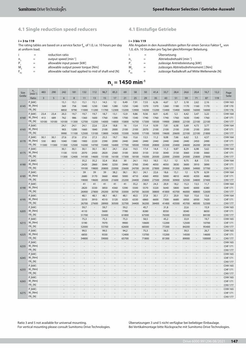
Drive 6000 991296 08/2021
Speed Reducer Selection / Getriebe-Auswahl
147
4.1 Einstufige Getriebe4.1 Single reduction speed reducers
i = 3 to 119The rating tables are based on a service factor fB1 of 1.0, i.e. 10 hours per day at uniform load.
i = reduction ration2 = output speed [min-1]P1 = allowable input power [kW]M2 = allowable output power torque [Nm]FR2 = allowable radial load applied to mid of shaft end [N]
i = 3 bis 119Alle Angaben in den Auswahllisten gelten für einen Service Faktor fB1 von 1,0, d.h. 10 Stunden pro Tag bei gleichförmiger Belastung.
i = Übersetzungn2 = Abtriebsdrehzahl [min-1]P1 = zulässige Antriebsleistung [kW]M2 = zulässiges Abtriebsdrehmoment [ [Nm]FR2 = zulässige Radialkraft auf Mitte Wellenende [N]
n1 = 1450 min-1
Size Größe
n2 [min-1] 483 290 242 181 132 112 96,7 85,3 69 58 50 41,4 33,7 28,4 24,6 20,4 16,7 12,2 Page
SeiteRatio 3 5 6 8 11 13 15 17 21 25 29 35 43 51 59 71 87 119
6145P1[kW] 15,1 15,1 15,1 15,1 14,5 12 9,49 7,91 7,53 6,26 4,67 3,7 3,18 2,62 2,16 - CHH 163M2 [Nm] 569 758 1040 1230 1360 1280 1250 1240 1370 1370 1260 1180 1170 1160 1170 - CHF 170FR2 [N] 8850 9790 11000 11200 11700 12300 13200 13900 14200 15200 15400 15400 16000 16000 16000 - CHV 176
6160P1[kW] 23,4 23,4 20,3 19,7 19,7 19,7 18,7 13,1 12,9 9,86 9,56 8,01 6,45 5,5 4,42 3,47 3,22 - CHH 164M2 [Nm] 413 689 762 986 1360 1600 1760 1390 1700 1540 1740 1760 1740 1760 1630 1540 1760 - CHF 171FR2 [N] 10100 10100 10100 11300 12700 13200 14000 14800 15800 16700 17300 18500 19900 20800 22100 22100 22100 - CHV 177
6165P1[kW] 24,1 24,1 24,1 22,6 22,4 18,8 16 13,4 11,4 9,59 7,81 6,58 5,69 4,73 3,77 - CHH 164M2 [Nm] 903 1200 1660 1840 2100 2000 2100 2100 2070 2100 2100 2100 2100 2100 2050 - CHF 171FR2 [N] 9990 11100 12500 13100 13800 14300 15500 16300 17100 18300 19600 20600 22100 22100 21800 - CHV 177
6170P1[kW] 30,1 30,1 27,6 27,6 27,6 27,3 25,5 19,7 18,6 15,6 13,5 11,2 9,08 7,66 6,62 5,5 4,57 - CHH 164M2 [Nm] 530 883 1040 1380 1900 2220 2390 2090 2440 2440 2440 2440 2440 2440 2440 2450 2490 - CHF 171FR2 [N] 11300 11300 11300 12500 14200 14700 15400 16400 17700 18500 19500 20800 22300 23400 24600 26200 28100 - CHV 177
6175P1[kW] 30,1 30,1 30,1 30,1 30,1 24,1 23,6 19,5 17,4 14,4 11,3 9,87 8,29 6,98 5,62 - CHH 164M2 [Nm] 1130 1510 2070 2450 2820 2560 3100 3050 3150 3150 3040 3150 3060 3100 3060 - CHF 171FR2 [N] 11300 12400 14100 14600 15100 16100 17300 18100 19200 20500 22000 23000 24300 25800 27800 - CHV 177
6180P1[kW] - - 35,2 35,2 32,4 30,6 30 24,1 19,5 18,5 15,1 12 9,75 8,8 7,15 - CHH 164M2 [Nm] - - 2420 2860 3040 3250 3940 3760 3540 4050 4050 3830 3600 3910 3890 - CHF 171FR2 [N] - - 19100 19800 20800 22000 23600 24700 26100 27800 29900 31200 32800 34900 37700 - CHV 177
6185P1[kW] - - 39 39 39 38,2 38,1 30,1 24,1 22,6 18,6 15,1 12 9,79 8,59 - CHH 164M2 [Nm] - - 2680 3170 3660 4060 5000 4710 4360 4950 5000 4810 4430 4350 4680 - CHF 171FR2 [N] - - 19000 19600 20500 21600 23200 24400 25800 27500 29500 30900 32500 34800 37400 - CHV 177
6190P1[kW] - - 41 41 41 41 41 35,2 30,7 24,3 20,9 18,2 15,3 13,5 11,7 - CHH 164M2 [Nm] - - 2820 3330 3850 4360 5390 5500 5570 5320 5640 5800 5640 6000 6380 - CHF 171FR2 [N] - - 26900 27800 29200 30700 33000 34700 36500 38800 41800 43700 46000 48800 52600 - CHV 177
6195P1[kW] - - 48,1 48,1 48,1 48,1 48,1 40,5 37,8 30,1 27,1 20,9 18,8 15,6 13,6 - CHH 164M2 [Nm] - - 3310 3910 4510 5120 6320 6330 6860 6600 7300 6680 6950 6930 7420 - CHF 171FR2 [N] - - 26700 27600 28900 30500 32700 34400 36200 38400 41400 43500 45700 48500 52300 - CHV 177
6205P1[kW] - - 59,7 - 59,7 - 59,2 - 45,7 - 31,8 - 22,6 - 15,9 - CHH 165M2 [Nm] - - 4110 - 5600 - 7780 - 8280 - 8550 - 8340 - 8650 - CHF 171FR2 [N] - - 51700 - 55400 - 61800 - 67500 - 76500 - 83500 - 84100 - CHV 177
6215P1[kW] - - 75,3 - 75,3 - 75,3 - 58,5 - 45,2 - 33,9 - 19,7 - CHH 165M2 [Nm] - - 5190 - 7070 - 9900 - 10600 - 12200 - 12500 - 10700 - CHF 171FR2 [N] - - 52000 - 55700 - 62600 - 68300 - 77200 - 84200 - 95400 - CHV 177
6225P1[kW] - - 99,5 - 99,5 - 94,2 - 75,3 - 56,5 - 39,3 - 26,7 - CHH 165M2 [Nm] - - 6850 - 9330 - 12400 - 13700 - 15200 - 14500 - 14600 - CHF 171FR2 [N] - - 54800 - 59000 - 65700 - 71800 - 81300 - 89000 - 100000 - CHV 177
6235P1[kW] - - - - - - - - - - - - - - - - CHH 165M2 [Nm] - - - - - - - - - - - - - - - - CHF 171FR2 [N] - - - - - - - - - - - - - - - - CHV 177
6245P1[kW] - - - - - - - - - - - - - - - - CHH 165M2 [Nm] - - - - - - - - - - - - - - - - CHF 171FR2 [N] - - - - - - - - - - - - - - - - CHV 177
6255P1[kW] - - - - - - - - - - - - - - - - CHH 165M2 [Nm] - - - - - - - - - - - - - - - - CHF 171FR2 [N] - - - - - - - - - - - - - - - - CHV 177
6265P1[kW] - - - - - - - - - - - - - - - - CHH 165M2 [Nm] - - - - - - - - - - - - - - - - CHF 171FR2 [N] - - - - - - - - - - - - - - - - CHV 177
6275P1[kW] - - - - - - - - - - - - - - - - CHH 165M2 [Nm] - - - - - - - - - - - - - - - - CHF 171FR2 [N] - - - - - - - - - - - - - - - - CHV 177
Ratio 3 and 5 not available for universal mounting. For vertical mounting please consult Sumitomo Drive Technologies.
Übersetzungen 3 und 5 nicht verfügbar bei beliebiger Einbaulage. Bei Vertikalmontage bitte Rücksprache mit Sumitomo Drive Technologies.
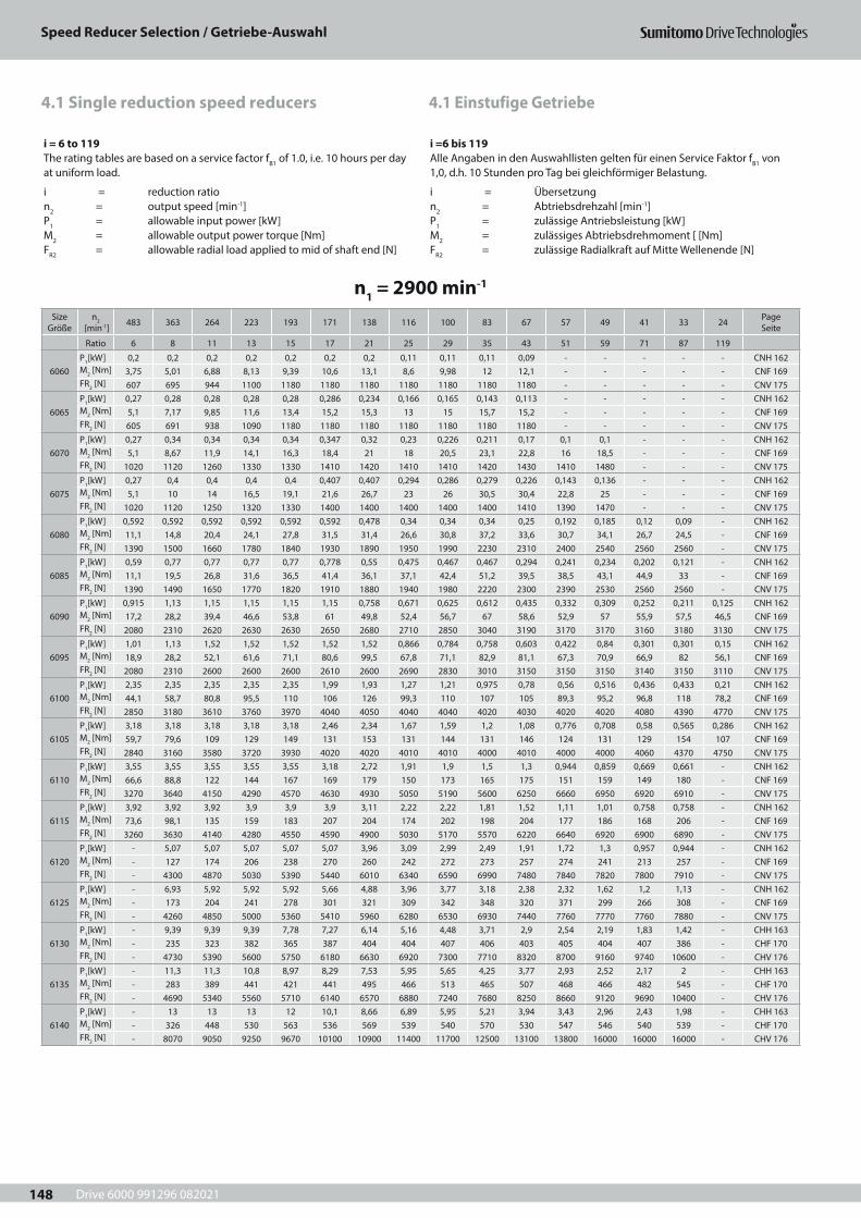
Drive 6000 991296 082021
Speed Reducer Selection / Getriebe-Auswahl
148
4.1 Einstufige Getriebe4.1 Single reduction speed reducers
i = 6 to 119The rating tables are based on a service factor fB1 of 1.0, i.e. 10 hours per day at uniform load.
i = reduction ration2 = output speed [min-1]P1 = allowable input power [kW]M2 = allowable output power torque [Nm]FR2 = allowable radial load applied to mid of shaft end [N]
i =6 bis 119Alle Angaben in den Auswahllisten gelten für einen Service Faktor fB1 von 1,0, d.h. 10 Stunden pro Tag bei gleichförmiger Belastung.
i = Übersetzungn2 = Abtriebsdrehzahl [min-1]P1 = zulässige Antriebsleistung [kW]M2 = zulässiges Abtriebsdrehmoment [ [Nm]FR2 = zulässige Radialkraft auf Mitte Wellenende [N]
n1 = 2900 min-1
Size Größe
n2 [min-1] 483 363 264 223 193 171 138 116 100 83 67 57 49 41 33 24 Page
Seite
Ratio 6 8 11 13 15 17 21 25 29 35 43 51 59 71 87 119
6060P1[kW] 0,2 0,2 0,2 0,2 0,2 0,2 0,2 0,11 0,11 0,11 0,09 - - - - - CNH 162M2 [Nm] 3,75 5,01 6,88 8,13 9,39 10,6 13,1 8,6 9,98 12 12,1 - - - - - CNF 169FR2 [N] 607 695 944 1100 1180 1180 1180 1180 1180 1180 1180 - - - - - CNV 175
6065P1[kW] 0,27 0,28 0,28 0,28 0,28 0,286 0,234 0,166 0,165 0,143 0,113 - - - - - CNH 162M2 [Nm] 5,1 7,17 9,85 11,6 13,4 15,2 15,3 13 15 15,7 15,2 - - - - - CNF 169FR2 [N] 605 691 938 1090 1180 1180 1180 1180 1180 1180 1180 - - - - - CNV 175
6070P1[kW] 0,27 0,34 0,34 0,34 0,34 0,347 0,32 0,23 0,226 0,211 0,17 0,1 0,1 - - - CNH 162M2 [Nm] 5,1 8,67 11,9 14,1 16,3 18,4 21 18 20,5 23,1 22,8 16 18,5 - - - CNF 169FR2 [N] 1020 1120 1260 1330 1330 1410 1420 1410 1410 1420 1430 1410 1480 - - - CNV 175
6075P1[kW] 0,27 0,4 0,4 0,4 0,4 0,407 0,407 0,294 0,286 0,279 0,226 0,143 0,136 - - - CNH 162M2 [Nm] 5,1 10 14 16,5 19,1 21,6 26,7 23 26 30,5 30,4 22,8 25 - - - CNF 169FR2 [N] 1020 1120 1250 1320 1330 1400 1400 1400 1400 1400 1410 1390 1470 - - - CNV 175
6080P1[kW] 0,592 0,592 0,592 0,592 0,592 0,592 0,478 0,34 0,34 0,34 0,25 0,192 0,185 0,12 0,09 - CNH 162M2 [Nm] 11,1 14,8 20,4 24,1 27,8 31,5 31,4 26,6 30,8 37,2 33,6 30,7 34,1 26,7 24,5 - CNF 169FR2 [N] 1390 1500 1660 1780 1840 1930 1890 1950 1990 2230 2310 2400 2540 2560 2560 - CNV 175
6085P1[kW] 0,59 0,77 0,77 0,77 0,77 0,778 0,55 0,475 0,467 0,467 0,294 0,241 0,234 0,202 0,121 - CNH 162M2 [Nm] 11,1 19,5 26,8 31,6 36,5 41,4 36,1 37,1 42,4 51,2 39,5 38,5 43,1 44,9 33 - CNF 169FR2 [N] 1390 1490 1650 1770 1820 1910 1880 1940 1980 2220 2300 2390 2530 2560 2560 - CNV 175
6090P1[kW] 0,915 1,13 1,15 1,15 1,15 1,15 0,758 0,671 0,625 0,612 0,435 0,332 0,309 0,252 0,211 0,125 CNH 162M2 [Nm] 17,2 28,2 39,4 46,6 53,8 61 49,8 52,4 56,7 67 58,6 52,9 57 55,9 57,5 46,5 CNF 169FR2 [N] 2080 2310 2620 2630 2630 2650 2680 2710 2850 3040 3190 3170 3170 3160 3180 3130 CNV 175
6095P1[kW] 1,01 1,13 1,52 1,52 1,52 1,52 1,52 0,866 0,784 0,758 0,603 0,422 0,84 0,301 0,301 0,15 CNH 162M2 [Nm] 18,9 28,2 52,1 61,6 71,1 80,6 99,5 67,8 71,1 82,9 81,1 67,3 70,9 66,9 82 56,1 CNF 169FR2 [N] 2080 2310 2600 2600 2600 2610 2600 2690 2830 3010 3150 3150 3150 3140 3150 3110 CNV 175
6100P1[kW] 2,35 2,35 2,35 2,35 2,35 1,99 1,93 1,27 1,21 0,975 0,78 0,56 0,516 0,436 0,433 0,21 CNH 162M2 [Nm] 44,1 58,7 80,8 95,5 110 106 126 99,3 110 107 105 89,3 95,2 96,8 118 78,2 CNF 169FR2 [N] 2850 3180 3610 3760 3970 4040 4050 4040 4040 4020 4030 4020 4020 4080 4390 4770 CNV 175
6105P1[kW] 3,18 3,18 3,18 3,18 3,18 2,46 2,34 1,67 1,59 1,2 1,08 0,776 0,708 0,58 0,565 0,286 CNH 162M2 [Nm] 59,7 79,6 109 129 149 131 153 131 144 131 146 124 131 129 154 107 CNF 169FR2 [N] 2840 3160 3580 3720 3930 4020 4020 4010 4010 4000 4010 4000 4000 4060 4370 4750 CNV 175
6110P1[kW] 3,55 3,55 3,55 3,55 3,55 3,18 2,72 1,91 1,9 1,5 1,3 0,944 0,859 0,669 0,661 - CNH 162M2 [Nm] 66,6 88,8 122 144 167 169 179 150 173 165 175 151 159 149 180 - CNF 169FR2 [N] 3270 3640 4150 4290 4570 4630 4930 5050 5190 5600 6250 6660 6950 6920 6910 - CNV 175
6115P1[kW] 3,92 3,92 3,92 3,9 3,9 3,9 3,11 2,22 2,22 1,81 1,52 1,11 1,01 0,758 0,758 - CNH 162M2 [Nm] 73,6 98,1 135 159 183 207 204 174 202 198 204 177 186 168 206 - CNF 169FR2 [N] 3260 3630 4140 4280 4550 4590 4900 5030 5170 5570 6220 6640 6920 6900 6890 - CNV 175
6120P1[kW] - 5,07 5,07 5,07 5,07 5,07 3,96 3,09 2,99 2,49 1,91 1,72 1,3 0,957 0,944 - CNH 162M2 [Nm] - 127 174 206 238 270 260 242 272 273 257 274 241 213 257 - CNF 169FR2 [N] - 4300 4870 5030 5390 5440 6010 6340 6590 6990 7480 7840 7820 7800 7910 - CNV 175
6125P1[kW] - 6,93 5,92 5,92 5,92 5,66 4,88 3,96 3,77 3,18 2,38 2,32 1,62 1,2 1,13 - CNH 162M2 [Nm] - 173 204 241 278 301 321 309 342 348 320 371 299 266 308 - CNF 169FR2 [N] - 4260 4850 5000 5360 5410 5960 6280 6530 6930 7440 7760 7770 7760 7880 - CNV 175
6130P1[kW] - 9,39 9,39 9,39 7,78 7,27 6,14 5,16 4,48 3,71 2,9 2,54 2,19 1,83 1,42 - CHH 163M2 [Nm] - 235 323 382 365 387 404 404 407 406 403 405 404 407 386 - CHF 170FR2 [N] - 4730 5390 5600 5750 6180 6630 6920 7300 7710 8320 8700 9160 9740 10600 - CHV 176
6135P1[kW] - 11,3 11,3 10,8 8,97 8,29 7,53 5,95 5,65 4,25 3,77 2,93 2,52 2,17 2 - CHH 163M2 [Nm] - 283 389 441 421 441 495 466 513 465 507 468 466 482 545 - CHF 170FR2 [N] - 4690 5340 5560 5710 6140 6570 6880 7240 7680 8250 8660 9120 9690 10400 - CHV 176
6140P1[kW] - 13 13 13 12 10,1 8,66 6,89 5,95 5,21 3,94 3,43 2,96 2,43 1,98 - CHH 163M2 [Nm] - 326 448 530 563 536 569 539 540 570 530 547 546 540 539 - CHF 170FR2 [N] - 8070 9050 9250 9670 10100 10900 11400 11700 12500 13100 13800 16000 16000 16000 - CHV 176
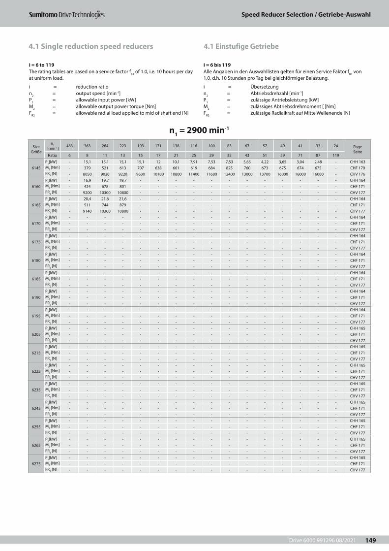
Drive 6000 991296 08/2021
Speed Reducer Selection / Getriebe-Auswahl
149
4.1 Einstufige Getriebe4.1 Single reduction speed reducers
i = 6 to 119The rating tables are based on a service factor fB1 of 1.0, i.e. 10 hours per day at uniform load.
i = reduction ration2 = output speed [min-1]P1 = allowable input power [kW]M2 = allowable output power torque [Nm]FR2 = allowable radial load applied to mid of shaft end [N]
i = 6 bis 119Alle Angaben in den Auswahllisten gelten für einen Service Faktor fB1 von 1,0, d.h. 10 Stunden pro Tag bei gleichförmiger Belastung.
i = Übersetzungn2 = Abtriebsdrehzahl [min-1]P1 = zulässige Antriebsleistung [kW]M2 = zulässiges Abtriebsdrehmoment [ [Nm]FR2 = zulässige Radialkraft auf Mitte Wellenende [N]
n1 = 2900 min-1
Size Größe
n2 [min-1] 483 363 264 223 193 171 138 116 100 83 67 57 49 41 33 24 Page
SeiteRatio 6 8 11 13 15 17 21 25 29 35 43 51 59 71 87 119
6145P1[kW] - 15,1 15,1 15,1 15,1 12 10,1 7,91 7,53 7,53 5,65 4,22 3,65 3,04 2,48 - CHH 163M2 [Nm] - 379 521 613 707 638 661 619 684 825 760 673 675 674 675 - CHF 170FR2 [N] - 8050 9020 9220 9630 10100 10800 11400 11600 12400 13000 13700 16000 16000 16000 - CHV 176
6160P1[kW] - 16,9 19,7 19,7 - - - - - - - - - - - - CHH 164M2 [Nm] - 424 678 801 - - - - - - - - - - - - CHF 171FR2 [N] - 9200 10300 10800 - - - - - - - - - - - - CHV 177
6165P1[kW] - 20,4 21,6 21,6 - - - - - - - - - - - - CHH 164M2 [Nm] - 511 744 879 - - - - - - - - - - - - CHF 171FR2 [N] - 9140 10300 10800 - - - - - - - - - - - - CHV 177
6170P1[kW] - - - - - - - - - - - - - - - - CHH 164M2 [Nm] - - - - - - - - - - - - - - - - CHF 171FR2 [N] - - - - - - - - - - - - - - - - CHV 177
6175P1[kW] - - - - - - - - - - - - - - - - CHH 164M2 [Nm] - - - - - - - - - - - - - - - - CHF 171FR2 [N] - - - - - - - - - - - - - - - - CHV 177
6180P1[kW] - - - - - - - - - - - - - - - - CHH 164M2 [Nm] - - - - - - - - - - - - - - - - CHF 171FR2 [N] - - - - - - - - - - - - - - - - CHV 177
6185P1[kW] - - - - - - - - - - - - - - - - CHH 164M2 [Nm] - - - - - - - - - - - - - - - - CHF 171FR2 [N] - - - - - - - - - - - - - - - - CHV 177
6190P1[kW] - - - - - - - - - - - - - - - - CHH 164M2 [Nm] - - - - - - - - - - - - - - - - CHF 171FR2 [N] - - - - - - - - - - - - - - - - CHV 177
6195P1[kW] - - - - - - - - - - - - - - - - CHH 164M2 [Nm] - - - - - - - - - - - - - - - - CHF 171FR2 [N] - - - - - - - - - - - - - - - - CHV 177
6205P1[kW] - - - - - - - - - - - - - - - - CHH 165M2 [Nm] - - - - - - - - - - - - - - - - CHF 171FR2 [N] - - - - - - - - - - - - - - - - CHV 177
6215P1[kW] - - - - - - - - - - - - - - - - CHH 165M2 [Nm] - - - - - - - - - - - - - - - - CHF 171FR2 [N] - - - - - - - - - - - - - - - - CHV 177
6225P1[kW] - - - - - - - - - - - - - - - - CHH 165M2 [Nm] - - - - - - - - - - - - - - - - CHF 171FR2 [N] - - - - - - - - - - - - - - - - CHV 177
6235P1[kW] - - - - - - - - - - - - - - - - CHH 165M2 [Nm] - - - - - - - - - - - - - - - - CHF 171FR2 [N] - - - - - - - - - - - - - - - - CHV 177
6245P1[kW] - - - - - - - - - - - - - - - - CHH 165M2 [Nm] - - - - - - - - - - - - - - - - CHF 171FR2 [N] - - - - - - - - - - - - - - - - CHV 177
6255P1[kW] - - - - - - - - - - - - - - - - CHH 165M2 [Nm] - - - - - - - - - - - - - - - - CHF 171FR2 [N] - - - - - - - - - - - - - - - - CHV 177
6265P1[kW] - - - - - - - - - - - - - - - - CHH 165M2 [Nm] - - - - - - - - - - - - - - - - CHF 171FR2 [N] - - - - - - - - - - - - - - - - CHV 177
6275P1[kW] - - - - - - - - - - - - - - - - CHH 165M2 [Nm] - - - - - - - - - - - - - - - - CHF 171FR2 [N] - - - - - - - - - - - - - - - - CHV 177
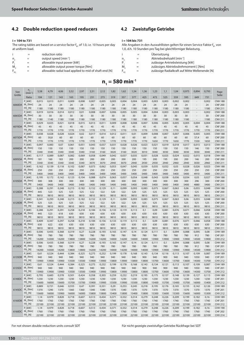
Drive 6000 991296 082021
Speed Reducer Selection / Getriebe-Auswahl
150
4.2 Zweistufige Getriebe4.2 Double reduction speed reducers
i = 104 to 731The rating tables are based on a service factor fB1 of 1.0, i.e. 10 hours per day at uniform load.
i = reduction ration2 = output speed [min-1]P1 = allowable input power [kW]M2 = allowable output power torque [Nm]FR2 = allowable radial load applied to mid of shaft end [N]
i = 104 bis 731Alle Angaben in den Auswahllisten gelten für einen Service Faktor fB1 von 1,0, d.h. 10 Stunden pro Tag bei gleichförmiger Belastung.
i = Übersetzungn2 = Abtriebsdrehzahl [min-1]P1 = zulässige Antriebsleistung [kW]M2 = zulässiges Abtriebsdrehmoment [ [Nm]FR2 = zulässige Radialkraft auf Mitte Wellenende [N]
n1 = 580 min-1
Size Größe
n2 [min-1] 5,58 4,79 4,06 3,52 2,97 2,51 2,12 1,82 1,62 1,54 1,36 1,23 1,1 1,04 0,975 0,894 0,793 Page
SeiteRatio 104 121 143 165 195 231 273 319 357 377 425 473 525 559 595 649 731
6060DAP1[kW] 0,015 0,013 0,011 0,009 0,008 0,007 0,005 0,005 0,004 0,004 0,003 0,003 0,003 0,002 0,002 - 0,002 CNH 188M2 [Nm] 24 24 24 24 24 24 24 24 24 24 24 24 24 24 24 - 24 CNF 200FR2 [N] 1180 1180 1180 1180 1180 1180 1180 1180 1180 1180 1180 1180 1180 1180 1180 - 1180 CNV 211
6065DAP1[kW] 0,019 0,016 0,014 0,012 0,01 0,008 0,007 0,006 0,005 0,005 0,004 0,004 0,003 0,003 0,003 - 0,002 CNH 188M2 [Nm] 30 30 30 30 30 30 30 30 30 30 30 30 30 30 30 - 30 CNF 200FR2 [N] 1180 1140 1180 1180 1180 1180 1180 1180 1180 1180 1180 1180 1180 1180 1180 - 1180 CNV 211
6070DAP1[kW] 0,029 0,025 0,021 0,018 0,015 0,013 0,011 0,009 0,008 0,008 0,007 0,006 0,005 0,005 0,005 0,004 0,004 CNH 188M2 [Nm] 45 45 45 45 45 45 45 45 45 45 45 45 45 45 45 45 45 CNF 200FR2 [N] 1770 1770 1770 1770 1770 1770 1770 1770 1770 1770 1770 1770 1770 1770 1770 1770 1770 CNV 211
6075DAP1[kW] 0,038 0,028 0,028 0,024 0,02 0,017 0,014 0,012 0,011 0,01 0,009 0,008 0,007 0,007 0,006 0,005 0,005 CNH 188M2 [Nm] 60 50,8 60 60 60 60 60 60 60 60 60 60 60 60 60 57,4 60 CNF 200FR2 [N] 1770 1770 1770 1770 1770 1770 1770 1770 1770 1770 1770 1650 1770 1650 1770 1550 1650 CNV 211
6090DAP1[kW] 0,097 0,083 0,07 0,061 0,051 0,043 0,037 0,031 0,028 0,026 0,023 0,021 0,019 0,018 0,017 0,015 0,013 CNH 188M2 [Nm] 150 150 150 150 150 150 150 150 150 150 150 150 150 150 150 146 150 CNF 200FR2 [N] 3340 3340 3340 3340 3340 3160 3160 3020 3160 3020 3010 3040 3030 3040 3030 3030 3040 CNV 211
6095DAP1[kW] 0,117 0,089 0,087 0,082 0,069 0,058 0,049 0,042 0,037 0,035 0,031 0,028 0,025 0,024 0,022 0,015 0,018 CNH 188M2 [Nm] 181 160 183 200 200 200 200 200 200 200 195 200 195 200 200 146 200 CNF 200FR2 [N] 3340 3340 3340 3340 3340 3070 3070 2940 3070 2940 2930 2930 2940 2960 2940 3030 2960 CNV 211
6100DAP1[kW] 0,162 0,139 0,118 0,102 0,087 0,073 0,062 0,053 0,047 0,045 0,039 0,035 0,032 0,03 0,028 0,026 0,023 CNH 188M2 [Nm] 250 250 250 250 250 250 250 250 250 250 250 250 250 250 250 250 250 CNF 200FR2 [N] 5400 5400 5400 5400 5400 5400 5400 5400 5400 5400 5400 5400 5400 5400 5400 4910 5400 CNV 211
6105DAP1[kW] 0,195 0,172 0,142 0,123 0,104 0,088 0,074 0,063 0,057 0,054 0,048 0,043 0,038 0,036 0,034 0,03 0,027 CNH 188M2 [Nm] 300 308 300 300 300 300 300 300 300 300 300 300 300 300 300 296 300 CNF 200FR2 [N] 5400 5400 5400 5400 5400 5400 5400 5400 5400 5400 5400 5400 5400 5400 5400 4880 5400 CNV 211
6120DAP1[kW] 0,288 0,291 0,248 0,215 0,182 0,152 0,129 0,11 0,099 0,093 0,083 0,075 0,067 0,063 0,06 0,055 0,048 CNH 188M2 [Nm] 445 523 525 525 525 522 522 520 522 520 525 525 525 525 525 525 525 CNF 200FR2 [N] 9810 9810 9810 9810 9810 9810 9810 9810 9810 9810 9810 9810 9810 9810 9810 9810 9810 CNV 211
6120DBP1[kW] 0,341 0,293 0,248 0,215 0,182 0,152 0,129 0,11 0,099 0,093 0,083 0,075 0,067 0,063 0,06 0,055 0,048 CNH 188M2 [Nm] 525 525 525 525 525 522 522 520 522 520 525 525 525 525 525 525 525 CNF 200FR2 [N] 9810 9810 9810 9810 9810 9810 9810 9810 9810 9810 9810 9810 9810 9810 9810 9810 9810 CNV 211
6125DAP1[kW] 0,288 0,291 0,291 0,258 0,218 0,184 0,156 0,133 0,119 0,113 0,1 0,09 0,081 0,076 0,071 0,066 0,058 CNH 188M2 [Nm] 445 523 618 630 630 630 630 630 630 630 630 630 630 630 630 630 630 CNF 200FR2 [N] 9810 9810 9810 9810 9810 9810 9810 9810 9810 9810 9810 9810 9810 9810 9810 9810 9810 CNV 211
6125DBP1[kW] 0,409 0,347 0,297 0,258 0,218 0,184 0,156 0,133 0,119 0,113 0,1 0,09 0,081 0,076 0,071 0,066 0,058 CNH 188M2 [Nm] 630 622 630 630 630 630 630 630 630 630 630 630 630 630 630 630 630 CNF 200FR2 [N] 9810 9810 9810 9810 9810 9810 9810 9810 9810 9810 9810 9810 9810 9810 9810 9810 9810 CNV 211
6130DBP1[kW] 0,506 0,435 0,368 0,319 0,27 0,228 0,193 0,165 0,147 0,14 0,124 0,111 0,1 0,094 0,088 0,095 0,08 CHH 189M2 [Nm] 780 780 780 780 780 780 780 780 780 780 780 780 780 780 780 912 780 CHF 201FR2 [N] 14200 14300 14200 13800 13800 14200 14200 14000 14200 14000 14000 13900 13900 13900 13900 14500 13900 CHV 212
6130DCP1[kW] 0,506 0,435 0,368 0,319 0,27 0,228 0,193 0,165 0,147 0,14 0,124 0,111 0,1 0,094 0,088 0,095 0,08 CHH 189M2 [Nm] 780 780 780 780 780 780 780 780 780 780 780 780 780 780 780 912 780 CHF 201FR2 [N] 14200 14300 14200 13800 13800 14200 14200 14000 14200 14000 14000 13900 13900 13900 13900 14500 13900 CHV 212
6135DBP1[kW] 0,61 0,524 0,444 0,384 0,325 0,275 0,232 0,199 0,178 0,168 0,143 0,134 0,116 0,113 0,107 0,109 0,087 CHH 189M2 [Nm] 940 940 940 940 940 940 940 940 940 940 900 940 900 940 940 1050 940 CHF 201FR2 [N] 13900 13900 13900 13500 13500 13900 13900 13800 13900 13800 13800 13700 13600 13700 13600 14300 13700 CHV 212
6135DCP1[kW] 0,61 0,524 0,444 0,384 0,325 0,275 0,232 0,199 0,178 0,168 0,143 0,134 0,121 0,113 0,107 0,109 0,087 CHH 189M2 [Nm] 940 940 940 940 940 940 940 940 940 940 900 940 900 940 940 1050 940 CHF 201FR2 [N] 13900 13900 13900 13500 13500 13900 13900 13800 13900 13800 13800 13700 13600 13700 13600 14300 13700 CHV 212
6140DCP1[kW] 0,795 0,683 0,578 0,501 0,424 0,358 0,303 0,259 0,232 0,219 0,195 0,175 0,157 0,148 0,139 0,127 0,113 CHH 189M2 [Nm] 1230 1230 1230 1230 1230 1230 1230 1230 1230 1230 1230 1230 1230 1230 1230 1230 1230 CHF 201FR2 [N] 15600 16000 15600 15700 15700 15900 15900 15500 15900 15500 15800 15400 15700 15400 15700 16000 15400 CHV 212
6145DCP1[kW] 0,889 0,721 0,646 0,555 0,47 0,391 0,331 0,29 0,253 0,245 0,218 0,195 0,176 0,165 0,155 0,142 0,126 CHH 189M2 [Nm] 1370 1290 1370 1360 1360 1340 1340 1370 1340 1370 1370 1370 1370 1370 1370 1370 1370 CHF 201FR2 [N] 15600 16000 15900 16000 16000 15800 15800 15400 15800 15400 15800 15300 15600 15300 15600 16000 15300 CHV 212
6160DBP1[kW] 1,14 0,979 0,828 0,718 0,607 0,513 0,434 0,371 0,332 0,314 0,279 0,248 0,226 0,209 0,199 0,182 0,16 CHH 189M2 [Nm] 1760 1760 1760 1760 1760 1760 1760 1760 1760 1760 1760 1740 1760 1740 1760 1760 1740 CHF 201FR2 [N] 22100 22100 22100 22100 22100 22100 22100 22100 22100 22100 22100 22100 22100 22100 22100 22100 22100 CHV 212
6160DCP1[kW] 1,14 0,979 0,828 0,718 0,607 0,513 0,434 0,371 0,332 0,314 0,279 0,248 0,226 0,209 0,199 0,182 0,16 CHH 190M2 [Nm] 1760 1760 1760 1760 1760 1760 1760 1760 1760 1760 1760 1740 1760 1740 1760 1760 1740 CHF 202FR2 [N] 22100 22100 22100 22100 22100 22100 22100 22100 22100 22100 22100 22100 22100 22100 22100 22100 22100 CHV 214
For not shown double reduction units consult SDT Für nicht gezeigte zweistufige Getriebe Rückfrage bei SDT
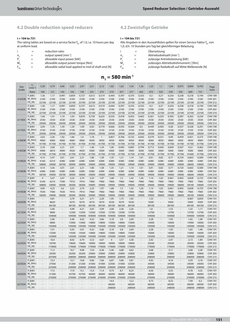
Drive 6000 991296 08/2021
Speed Reducer Selection / Getriebe-Auswahl
151
4.2 Zweistufige Getriebe4.2 Double reduction speed reducers
i = 104 to 731The rating tables are based on a service factor fB1 of 1.0, i.e. 10 hours per day at uniform load.
i = reduction ration2 = output speed [min-1]P1 = allowable input power [kW]M2 = allowable output power torque [Nm]FR2 = allowable radial load applied to mid of shaft end [N]
i = 104 bis 731Alle Angaben in den Auswahllisten gelten für einen Service Faktor fB1 von 1,0, d.h. 10 Stunden pro Tag bei gleichförmiger Belastung.
i = Übersetzungn2 = Abtriebsdrehzahl [min-1]P1 = zulässige Antriebsleistung [kW]M2 = zulässiges Abtriebsdrehmoment [ [Nm]FR2 = zulässige Radialkraft auf Mitte Wellenende [N]
n1 = 580 min-1
Size Größe
n2 [min-1] 5,58 4,79 4,06 3,52 2,97 2,51 2,12 1,82 1,62 1,54 1,36 1,23 1,1 1,04 0,975 0,894 0,793 Page
SeiteRatio 104 121 143 165 195 231 273 319 357 377 425 473 525 559 595 649 731
6165DBP1[kW] 1,36 1,17 0,991 0,859 0,727 0,613 0,519 0,444 0,397 0,376 0,333 0,3 0,27 0,254 0,238 0,218 0,194 CHH 189M2 [Nm] 2100 2100 2100 2100 2100 2100 2100 2100 2100 2100 2100 2100 2100 2100 2100 2100 2100 CHF 201FR2 [N] 22100 22100 22100 22100 22100 22100 22100 22100 22100 22100 22100 22100 22100 22100 22100 22100 22100 CHV 212
6165DCP1[kW] 1,36 1,17 0,991 0,859 0,727 0,613 0,519 0,444 0,397 0,376 0,333 0,3 0,27 0,254 0,238 0,218 0,194 CHH 190M2 [Nm] 2100 2100 2100 2100 2100 2100 2100 2100 2100 2100 2100 2100 2100 2100 2100 2100 2100 CHF 202FR2 [N] 22100 22100 22100 22100 22100 22100 22100 22100 22100 22100 22100 22100 22100 22100 22100 22100 22100 CHV 214
6170DCP1[kW] 1,64 1,41 1,19 1,03 0,876 0,739 0,625 0,535 0,478 0,453 0,402 0,361 0,325 0,305 0,287 0,263 0,234 CHH 190M2 [Nm] 2530 2530 2530 2530 2530 2530 2530 2530 2530 2530 2530 2530 2530 2530 2530 2530 2530 CHF 202FR2 [N] 29500 29500 29500 29500 29500 29500 29500 29500 29500 29500 29500 29500 29500 29500 29500 29500 29500 CHV 214
6175DCP1[kW] 2,04 1,76 1,49 1,29 1,09 0,92 0,779 0,666 0,595 0,564 0,5 0,449 0,405 0,38 0,357 0,328 0,291 CHH 190M2 [Nm] 3150 3150 3150 3150 3150 3150 3150 3150 3150 3150 3150 3150 3150 3150 3150 3150 3150 CHF 202FR2 [N] 29500 29500 29500 29500 29500 29500 29500 29500 29500 29500 29500 29500 29500 29500 29500 29500 29500 CHV 214
6180DBP1[kW] 2,63 2,26 1,92 1,66 1,4 1,18 1 0,857 0,766 0,725 0,643 0,579 0,521 0,49 0,459 0,421 0,375 CHH 190M2 [Nm] 4060 4060 4060 4060 4060 4050 4050 4050 4050 4050 4050 4060 4050 4060 4050 4050 4060 CHF 202FR2 [N] 41700 41700 41700 41700 41700 41700 41700 41700 41700 41700 41700 41700 41700 41700 41700 41700 41700 CHV 214
6185DBP1[kW] 3,18 2,68 2,31 2,01 1,7 1,46 1,24 1,06 0,945 0,895 0,794 0,713 0,643 0,604 0,567 0,52 0,462 CHH 190M2 [Nm] 4900 4810 4900 4920 4920 5000 5000 5000 5000 5000 5000 5000 5000 5000 5000 5000 5000 CHF 202FR2 [N] 41700 41700 41700 41700 41700 41700 41700 41700 41700 41700 41700 41700 41700 41700 41700 41600 41700 CHV 214
6190DAP1[kW] 4,14 3,47 3,01 2,61 2,21 1,86 1,58 1,35 1,21 1,14 1,01 0,91 0,82 0,77 0,724 0,663 0,589 CHH 190M2 [Nm] 6160 6210 6380 6380 6380 6380 6380 6380 6380 6380 6380 6380 6380 6380 6380 6380 6380 CHF 202FR2 [N] 58800 59000 58700 58900 58900 59000 59000 59000 59000 59000 59000 59000 59000 59000 59000 58600 59000 CHV 214
6190DBP1[kW] 4,14 3,56 3,01 2,61 2,21 1,86 1,58 1,35 1,21 1,14 1,01 0,91 0,82 0,77 0,724 0,663 0,589 CHH 190M2 [Nm] 6380 6380 6380 6380 6380 6380 6380 6380 6380 6380 6380 6380 6380 6380 6380 6380 6380 CHF 202FR2 [N] 58700 59000 58700 58900 58900 59000 59000 59000 59000 59000 59000 59000 59000 59000 59000 58600 59000 CHV 214
6195DAP1[kW] 4 3,47 3,47 3,23 2,74 2,33 1,97 1,68 1,5 1,42 1,26 1,14 1,02 0,961 0,903 0,828 0,735 CHH 190M2 [Nm] 6160 6210 7340 7910 7910 7960 7960 7960 7960 7960 7960 7960 7960 7960 7960 7960 7960 CHF 202FR2 [N] 58800 59000 58300 58300 58300 59000 59000 59000 59000 59000 59000 59000 59000 59000 58600 58100 59000 CHV 214
6195DBP1[kW] 4,95 4,23 3,6 3,23 2,74 2,33 1,97 1,68 1,5 1,42 1,26 1,14 1,02 0,961 0,903 0,828 0,735 CHH 190M2 [Nm] 7630 7580 7630 7910 7910 7960 7960 7960 7960 7960 7960 7960 7960 7960 7960 7960 7960 CHF 202FR2 [N] 58200 59000 58200 58300 58300 59000 59000 59000 59000 59000 59000 59000 58600 59000 58600 58100 59000 CHV 214
6205DBP1[kW] - 4,81 - 3,79 3,21 2,71 2,29 1,95 1,75 1,65 - 1,33 - 1,12 - 0,967 0,859 CHH 191M2 [Nm] - 8620 - 9270 9270 9270 9270 9230 9270 9230 - 9300 - 9300 - 9300 9300 CHF 203FR2 [N] - 84100 - 84100 84100 84100 84100 84100 84100 84100 - 84100 - 84100 - 84100 84100 CHV 215
6215DAP1[kW] - 5,46 - 4,98 4,21 3,65 3,09 2,68 2,36 2,26 - 1,8 - 1,53 - 1,32 1,17 CHH 191M2 [Nm] - 9800 - 12200 12200 12500 12500 12700 12500 12700 - 12700 - 12700 - 12700 12700 CHF 203FR2 [N] - 104000 - 104000 104000 104000 104000 104000 104000 104000 - 104000 - 104000 - 104000 104000 CHV 215
6225DAP1[kW] - 5,46 - 5,46 4,62 4,32 3,66 3,18 2,8 2,69 - 2,28 - 1,93 - 1,65 1,48 CHH 191M2 [Nm] - 9800 - 13400 13400 14800 14800 15000 14800 15000 - 16000 - 16000 - 15900 16000 CHF 203FR2 [N] - 145000 - 145000 145000 145000 145000 145000 145000 145000 - 145000 - 145000 - 145000 145000 CHV 215
6225DBP1[kW] - 7,51 - 5,92 5,01 4,32 3,66 3,18 2,8 2,69 - 2,28 - 1,93 - 1,65 1,48 CHH 191M2 [Nm] - 13500 - 14500 14500 14800 14800 15000 14800 15000 - 16000 - 16000 - 15900 16000 CHF 203FR2 [N] - 145000 - 145000 145000 145000 145000 145000 145000 145000 - 145000 - 145000 - 145000 145000 CHV 215
6235DAP1[kW] - 10,4 - 8,02 6,79 5,52 4,67 4 3,57 3,38 - 2,92 - 2,47 - 2,13 1,89 CHH 191M2 [Nm] - 18700 - 19600 19600 18900 18900 18900 18900 18900 - 20500 - 20500 - 20500 20500 CHF 203FR2 [N] - 179000 - 179000 179000 179000 179000 179000 179000 179000 - 179000 - 179000 - 179000 179000 CHV 215
6245DAP1[kW] - 11,5 - 10,7 9,08 7,54 6,38 5,46 4,88 4,62 - 3,68 - 3,11 - 2,68 2,38 CHH 191M2 [Nm] - 20500 - 26200 26200 25800 25800 25800 25800 25800 - 25800 - 25800 - 25800 25800 CHF 203FR2 [N] - 207000 - 208000 208000 208000 208000 208000 208000 208000 - 208000 - 208000 - 208000 208000 CHV 215
6255DAP1[kW] - 15,3 - 12,7 10,8 9,06 7,66 6,87 5,86 5,81 - 4,92 - 4,16 - 3,59 3,18 CHH 191M2 [Nm] - 27500 - 31200 31200 31000 31000 32500 31000 32500 - 34500 - 34500 - 34500 34500 CHF 203FR2 [N] - 253000 - 258000 258000 258000 258000 258000 258000 258000 - 258000 - 258000 - 258000 258000 CHV 215
6265DAP1[kW] - 17,5 - 17,9 15,1 13,4 11,4 9,73 8,7 8,23 - 6,56 - 5,55 - 4,78 4,25 CHH 191M2 [Nm] - 31300 - 43700 43700 46000 46000 46000 46000 46000 - 46000 - 46000 - 46000 46000 CHF 203FR2 [N] - 276000 - 276000 276000 276000 276000 276000 276000 276000 - 276000 - 276000 - 276000 276000 CHV 215
6275DAP1[kW] - - - - - - - 14,4 - 12,2 - 9,73 - 8,23 - 7,09 6,3 CHH 191M2 [Nm] - - - - - - - 68200 - 68200 - 68200 - 68200 - 68200 68200 CHF 203FR2 [N] - - - - - - - 248000 - 248000 - 248000 - 248000 - 248000 248000 CHV 215
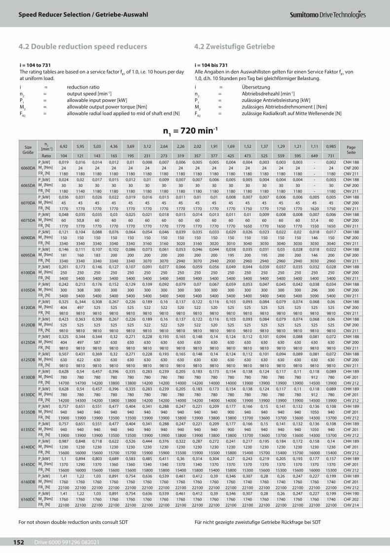
Drive 6000 991296 082021
Speed Reducer Selection / Getriebe-Auswahl
152
4.2 Zweistufige Getriebe4.2 Double reduction speed reducers
i = 104 to 731The rating tables are based on a service factor fB1 of 1.0, i.e. 10 hours per day at uniform load.
i = reduction ration2 = output speed [min-1]P1 = allowable input power [kW]M2 = allowable output power torque [Nm]FR2 = allowable radial load applied to mid of shaft end [N]
i = 104 bis 731Alle Angaben in den Auswahllisten gelten für einen Service Faktor fB1 von 1,0, d.h. 10 Stunden pro Tag bei gleichförmiger Belastung.
i = Übersetzungn2 = Abtriebsdrehzahl [min-1]P1 = zulässige Antriebsleistung [kW]M2 = zulässiges Abtriebsdrehmoment [ [Nm]FR2 = zulässige Radialkraft auf Mitte Wellenende [N]
n1 = 720 min-1
Size Größe
n2 [min-1] 6,92 5,95 5,03 4,36 3,69 3,12 2,64 2,26 2,02 1,91 1,69 1,52 1,37 1,29 1,21 1,11 0,985 Page
SeiteRatio 104 121 143 165 195 231 273 319 357 377 425 473 525 559 595 649 731
6060DAP1[kW] 0,019 0,016 0,014 0,012 0,01 0,008 0,007 0,006 0,005 0,005 0,004 0,004 0,003 0,003 0,003 - 0,002 CNH 188M2 [Nm] 24 24 24 24 24 24 24 24 24 24 24 24 24 24 24 - 24 CNF 200FR2 [N] 1180 1180 1180 1180 1180 1180 1180 1180 1180 1180 1180 1180 1180 1180 1180 - 1180 CNV 211
6065DAP1[kW] 0,024 0,02 0,017 0,015 0,012 0,01 0,009 0,007 0,007 0,006 0,005 0,005 0,004 0,004 0,004 - 0,003 CNH 188M2 [Nm] 30 30 30 30 30 30 30 30 30 30 30 30 30 30 30 - 30 CNF 200FR2 [N] 1180 1140 1180 1180 1180 1180 1180 1180 1180 1180 1180 1180 1180 1180 1180 - 1180 CNV 211
6070DAP1[kW] 0,036 0,031 0,026 0,022 0,019 0,016 0,013 0,011 0,01 0,01 0,008 0,007 0,007 0,006 0,006 0,005 0,005 CNH 188M2 [Nm] 45 45 45 45 45 45 45 45 45 45 45 45 45 45 45 45 45 CNF 200FR2 [N] 1770 1770 1770 1770 1770 1770 1770 1770 1770 1770 1770 1750 1770 1750 1770 1620 1750 CNV 211
6075DAP1[kW] 0,048 0,035 0,035 0,03 0,025 0,021 0,018 0,015 0,014 0,013 0,011 0,01 0,009 0,008 0,008 0,007 0,006 CNH 188M2 [Nm] 60 50,8 60 60 60 60 60 60 60 60 60 60 60 60 60 57,4 60 CNF 200FR2 [N] 1770 1770 1770 1770 1770 1770 1770 1770 1770 1770 1770 1650 1770 1650 1770 1550 1650 CNV 211
6090DAP1[kW] 0,121 0,104 0,088 0,076 0,064 0,054 0,046 0,039 0,035 0,033 0,029 0,026 0,023 0,022 0,02 0,018 0,017 CNH 188M2 [Nm] 150 150 150 150 150 150 150 150 150 150 150 150 150 150 150 146 150 CNF 200FR2 [N] 3340 3340 3340 3340 3340 3160 3160 3020 3160 3020 3010 3040 3030 3040 3030 3030 3040 CNV 211
6095DAP1[kW] 0,146 0,111 0,107 0,102 0,086 0,073 0,061 0,053 0,046 0,044 0,038 0,035 0,031 0,03 0,028 0,018 0,022 CNH 188M2 [Nm] 181 160 183 200 200 200 200 200 200 200 195 200 195 200 200 146 200 CNF 200FR2 [N] 3340 3340 3340 3340 3340 3070 3070 2940 3070 2940 2930 2960 2940 2960 2940 3030 2960 CNV 211
6100DAP1[kW] 0,201 0,173 0,146 0,127 0,107 0,091 0,077 0,066 0,059 0,056 0,049 0,044 0,039 0,037 0,035 0,032 0,028 CNH 188M2 [Nm] 250 250 250 250 250 250 250 250 250 250 250 250 250 250 250 250 250 CNF 200FR2 [N] 5400 5400 5400 5400 5400 5400 5400 5400 5400 5400 5400 5400 5400 5400 5400 5400 5400 CNV 211
6105DAP1[kW] 0,242 0,213 0,176 0,152 0,129 0,109 0,092 0,079 0,07 0,067 0,059 0,053 0,047 0,045 0,042 0,038 0,034 CNH 188M2 [Nm] 300 308 300 300 300 300 300 300 300 300 300 300 300 300 300 296 300 CNF 200FR2 [N] 5400 5400 5400 5400 5400 5400 5400 5400 5400 5400 5400 5400 5400 5400 5400 5090 5400 CNV 211
6120DAP1[kW] 0,325 0,,344 0,308 0,267 0,226 0,189 0,16 0,137 0,122 0,116 0,103 0,093 0,084 0,079 0,074 0,068 0,06 CNH 188M2 [Nm] 404 497 525 525 525 522 522 520 522 520 525 525 525 525 525 525 525 CNF 200FR2 [N] 9810 9810 9810 9810 9810 9810 9810 9810 9810 9810 9810 9810 9810 9810 9810 9810 9810 CNV 211
6120DBP1[kW] 0,423 0,363 0,308 0,267 0,226 0,189 0,16 0,137 0,122 0,116 0,103 0,093 0,084 0,079 0,074 0,068 0,06 CNH 188M2 [Nm] 525 525 525 525 525 522 522 520 522 520 525 525 525 525 525 525 525 CNF 200FR2 [N] 9810 9810 9810 9810 9810 9810 9810 9810 9810 9810 9810 9810 9810 9810 9810 9810 9810 CNV 211
6125DAP1[kW] 0,325 0,344 0,344 0,32 0,271 0,228 0,193 0,165 0,148 0,14 0,124 0,112 0,101 0,094 0,088 0,081 0,072 CNH 188M2 [Nm] 404 497 587 630 630 630 630 630 630 630 630 630 630 630 630 630 630 CNF 200FR2 [N] 9810 9810 9810 9810 9810 9810 9810 9810 9810 9810 9810 9810 9810 9810 9810 9810 9810 CNV 211
6125DBP1[kW] 0,507 0,431 0,369 0,32 0,271 0,228 0,193 0,165 0,148 0,14 0,124 0,112 0,101 0,094 0,089 0,081 0,072 CNH 188M2 [Nm] 630 622 630 630 630 630 630 630 630 630 630 630 630 630 630 630 630 CNF 200FR2 [N] 9810 9810 9810 9810 9810 9810 9810 9810 9810 9810 9810 9810 9810 9810 9810 9810 9810 CNV 211
6130DBP1[kW] 0,628 0,54 0,457 0,396 0,335 0,283 0,239 0,205 0,183 0,173 0,154 0,138 0,124 0,117 0,11 0,118 0,089 CHH 189M2 [Nm] 780 780 780 780 780 780 780 780 780 780 780 780 780 780 780 912 780 CHF 201FR2 [N] 14700 14700 14200 13800 13800 14200 14200 14000 14200 14000 14000 13900 13900 13900 13900 14500 13900 CHV 212
6130DCP1[kW] 0,628 0,54 0,457 0,396 0,335 0,283 0,239 0,205 0,183 0,173 0,154 0,138 0,124 0,117 0,11 0,118 0,089 CHH 189M2 [Nm] 780 780 780 780 780 780 780 780 780 780 780 780 780 780 780 912 780 CHF 201FR2 [N] 14200 14300 14200 13800 13800 14200 14200 14000 14200 14000 14000 13900 13900 13900 13900 14500 13900 CHV 212
6135DBP1[kW] 0,757 0,651 0,551 0,477 0,404 0,341 0,288 0,247 0,221 0,209 0,177 0,166 0,15 0,141 0,132 0,136 0,108 CHH 189M2 [Nm] 940 940 940 940 940 940 940 940 940 940 900 940 940 940 940 1050 940 CHF 201FR2 [N] 13900 13900 13900 13500 13500 13900 13900 13800 13900 13800 13800 13700 13600 13700 13600 14300 13700 CHV 212
6135DCP1[kW] 0,757 0,651 0,551 0,477 0,404 0,341 0,288 0,247 0,221 0,209 0,177 0,166 0,15 0,141 0,132 0,136 0,108 CHH 189M2 [Nm] 940 940 940 940 940 940 940 940 940 940 900 940 940 940 940 1050 940 CHF 201FR2 [N] 13900 13900 13900 13500 13500 13900 13900 13800 13900 13800 13800 13700 13600 13700 13600 14300 13700 CHV 212
6140DCP1[kW] 0,987 0,848 0,718 0,622 0,526 0,444 0,376 0,322 0,287 0,272 0,241 0,217 0,195 0,184 0,172 0,158 0,14 CHH 189M2 [Nm] 1230 1230 1230 1230 1230 1230 1230 1230 1230 1230 1230 1230 1230 1230 1230 1230 1230 CHF 201FR2 [N] 15600 16000 15600 15700 15700 15900 15900 15500 15900 15500 15800 15400 15700 15400 15700 16000 15400 CHV 212
6145DCP1[kW] 1,1 0,894 0,803 0,689 0,583 0,485 0,411 0,36 0,314 0,304 0,27 0,243 0,219 0,205 0,193 0,177 0,157 CHH 189M2 [Nm] 1370 1290 1370 1360 1360 1340 1340 1370 1340 1370 1370 1370 1370 1370 1370 1370 1370 CHF 201FR2 [N] 15600 16000 15600 15600 15600 15800 15800 15400 15800 15400 15800 15300 15600 15300 15600 16000 15300 CHV 212
6160DBP1[kW] 1,41 1,22 1,03 0,891 0,754 0,636 0,539 0,461 0,412 0,39 0,346 0,307 0,28 0,26 0,247 0,227 0,199 CHH 189M2 [Nm] 1760 1760 1760 1760 1760 1760 1760 1760 1760 1760 1760 1740 1760 1740 1760 1760 1740 CHF 201FR2 [N] 22100 22100 22100 22100 22100 22100 22100 22100 22100 22100 22100 22100 22100 22100 22100 22100 22100 CHV 212
6160DCP1[kW] 1,41 1,22 1,03 0,891 0,754 0,636 0,539 0,461 0,412 0,39 0,346 0,307 0,28 0,26 0,247 0,227 0,199 CHH 190M2 [Nm] 1760 1760 1760 1760 1760 1760 1760 1760 1760 1760 1760 1740 1760 1740 1760 1760 1740 CHF 202FR2 [N] 22100 22100 22100 22100 22100 22100 22100 22100 22100 22100 22100 22100 22100 22100 22100 22100 22100 CHV 214
For not shown double reduction units consult SDT Für nicht gezeigte zweistufige Getriebe Rückfrage bei SDT
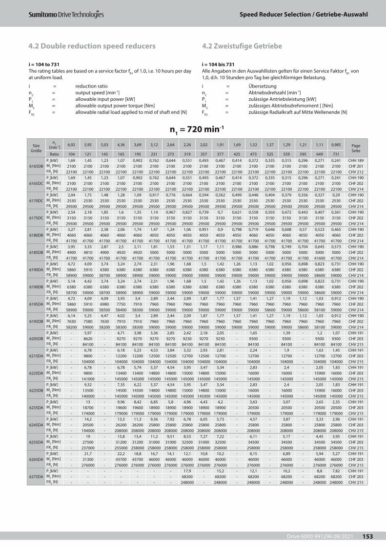
Drive 6000 991296 08/2021
Speed Reducer Selection / Getriebe-Auswahl
153
4.2 Zweistufige Getriebe4.2 Double reduction speed reducers
i = 104 to 731The rating tables are based on a service factor fB1 of 1.0, i.e. 10 hours per day at uniform load.
i = reduction ration2 = output speed [min-1]P1 = allowable input power [kW]M2 = allowable output power torque [Nm]FR2 = allowable radial load applied to mid of shaft end [N]
i = 104 bis 731Alle Angaben in den Auswahllisten gelten für einen Service Faktor fB1 von 1,0, d.h. 10 Stunden pro Tag bei gleichförmiger Belastung.
i = Übersetzungn2 = Abtriebsdrehzahl [min-1]P1 = zulässige Antriebsleistung [kW]M2 = zulässiges Abtriebsdrehmoment [ [Nm]FR2 = zulässige Radialkraft auf Mitte Wellenende [N]
n1 = 720 min-1
Size Größe
n2 [min-1] 6,92 5,95 5,03 4,36 3,69 3,12 2,64 2,26 2,02 1,91 1,69 1,52 1,37 1,29 1,21 1,11 0,985 Page
SeiteRatio 104 121 143 165 195 231 273 319 357 377 425 473 525 559 595 649 731
6165DBP1[kW] 1,69 1,45 1,23 1,07 0,902 0,762 0,644 0,551 0,493 0,467 0,414 0,372 0,335 0,315 0,296 0,271 0,241 CHH 189M2 [Nm] 2100 2100 2100 2100 2100 2100 2100 2100 2100 2100 2100 2100 2100 2100 2100 2100 2100 CHF 201FR2 [N] 22100 22100 22100 22100 22100 22100 22100 22100 22100 22100 22100 22100 22100 22100 22100 22100 22100 CHV 212
6165DCP1[kW] 1,69 1,45 1,23 1,07 0,902 0,762 0,644 0,551 0,493 0,467 0,414 0,372 0,335 0,315 0,296 0,271 0,241 CHH 190M2 [Nm] 2100 2100 2100 2100 2100 2100 2100 2100 2100 2100 2100 2100 2100 2100 2100 2100 2100 CHF 202FR2 [N] 22100 22100 22100 22100 22100 22100 22100 22100 22100 22100 22100 22100 22100 22100 22100 22100 22100 CHV 214
6170DCP1[kW] 2,04 1,75 1,48 1,28 1,09 0,917 0,776 0,664 0,594 0,562 0,499 0,448 0,404 0,379 0,356 0,327 0,29 CHH 190M2 [Nm] 2530 2530 2530 2530 2530 2530 2530 2530 2530 2530 2530 2530 2530 2530 2530 2530 2530 CHF 202FR2 [N] 29500 29500 29500 29500 29500 29500 29500 29500 29500 29500 29500 29500 29500 29500 29500 29500 29500 CHV 214
6175DCP1[kW] 2,54 2,18 1,85 1,6 1,35 1,14 0,967 0,827 0,739 0,7 0,621 0,558 0,503 0,472 0,443 0,407 0,361 CHH 190M2 [Nm] 3150 3150 3150 3150 3150 3150 3150 3150 3150 3150 3150 3150 3150 3150 3150 3150 3150 CHF 202FR2 [N] 29500 29500 29500 29500 29500 29500 29500 29500 29500 29500 29500 29500 29500 29500 29500 29500 29500 CHV 214
6180DBP1[kW] 3,27 2,81 2,38 2,06 1,74 1,47 1,24 1,06 0,951 0,9 0,798 0,719 0,646 0,608 0,57 0,523 0,465 CHH 190M2 [Nm] 4060 4060 4060 4060 4060 4050 4050 4050 4050 4050 4050 4060 4050 4060 4050 4050 4060 CHF 202FR2 [N] 41700 41700 41700 41700 41700 41700 41700 41700 41700 41700 41700 41700 41700 41700 41700 41700 41700 CHV 214
6185DBP1[kW] 3,95 3,33 2,87 2,5 2,11 1,81 1,53 1,31 1,17 1,11 0,986 0,886 0,798 0,749 0,704 0,645 0,573 CHH 190M2 [Nm] 4900 4810 4900 4920 4920 5000 5000 5000 5000 5000 5000 5000 5000 5000 5000 5000 5000 CHF 202FR2 [N] 41700 41700 41700 41700 41700 41700 41700 41700 41700 41700 41700 41700 41700 41700 41700 41600 41700 CHV 214
6190DAP1[kW] 4,72 4,09 3,74 3,24 2,74 2,31 1,96 1,68 1,5 1,42 1,26 1,13 1,02 0,956 0,898 0,823 0,731 CHH 190M2 [Nm] 5860 5910 6380 6380 6380 6380 6380 6380 6380 6380 6380 6380 6380 6380 6380 6380 6380 CHF 202FR2 [N] 58900 59000 58700 58900 58900 59000 59000 59000 59000 59000 59000 59000 59000 59000 59000 58600 59000 CHV 214
6190DBP1[kW] 5,14 4,42 3,74 3,24 2,74 2,31 1,96 1,68 1,5 1,42 1,26 1,13 1,02 0,956 0,898 0,823 0,731 CHH 190M2 [Nm] 6380 6380 6380 6380 6380 6380 6380 6380 6380 6380 6380 6380 6380 6380 6380 6380 6380 CHF 202FR2 [N] 58700 59000 58700 58900 58900 59000 59000 59000 59000 59000 59000 59000 59000 59000 59000 58600 59000 CHV 214
6195DAP1[kW] 4,72 4,09 4,09 3,93 3,4 2,89 2,44 2,09 1,87 1,77 1,57 1,41 1,27 1,19 1,12 1,03 0,912 CHH 190M2 [Nm] 5860 5910 6980 7750 7910 7960 7960 7960 7960 7960 7960 7960 7960 7960 7960 7960 7960 CHF 202FR2 [N] 58900 59000 58500 58400 58300 59000 59000 59000 59000 59000 59000 59000 58600 59000 58600 58100 59000 CHV 214
6195DBP1[kW] 6,14 5,25 4,47 4,02 3,4 2,89 2,44 2,09 1,87 1,77 1,57 1,41 1,27 1,19 1,12 1,03 0,912 CHH 190M2 [Nm] 7630 7580 7630 7910 7910 7960 7960 7960 7960 7960 7960 7960 7960 7960 7960 7960 7960 CHF 202FR2 [N] 58200 59000 58200 58300 58300 59000 59000 59000 59000 59000 59000 59000 59000 59000 58600 58100 59000 CHV 214
6205DBP1[kW] - 5,97 - 4,71 3,98 3,36 2,85 2,42 2,18 2,05 - 1,65 - 1,39 - 1,2 1,07 CHH 191M2 [Nm] - 8620 - 9270 9270 9270 9270 9230 9270 9230 - 9300 - 9300 - 9300 9300 CHF 203FR2 [N] - 84100 - 84100 84100 84100 84100 84100 84100 84100 - 84100 - 84100 - 84100 84100 CHV 215
6215DAP1[kW] - 6,78 - 6,18 5,23 4,53 3,84 3,32 2,93 2,81 - 2,24 - 1,9 - 1,63 1,45 CHH 191M2 [Nm] - 9800 - 12200 12200 12500 12500 12700 12500 12700 - 12700 - 12700 - 12700 12700 CHF 203FR2 [N] - 104000 - 104000 104000 104000 104000 104000 104000 104000 - 104000 - 104000 - 104000 104000 CHV 215
6225DAP1[kW] - 6,78 - 6,78 5,74 5,37 4,54 3,95 3,47 3,34 - 2,83 - 2,4 - 2,05 1,83 CHH 191M2 [Nm] - 9800 - 13400 13400 14800 14800 15000 14800 15000 - 16000 - 16000 - 15900 16000 CHF 203FR2 [N] - 141000 - 145000 145000 145000 145000 145000 145000 145000 - 145000 - 145000 - 145000 145000 CHV 215
6225DBP1[kW] - 9,32 - 7,35 6,22 5,37 4,54 3,95 3,47 3,34 - 2,83 - 2,4 - 2,05 1,83 CHH 191M2 [Nm] - 13500 - 14500 14500 14800 14800 15000 14800 15000 - 16000 - 16000 - 15900 16000 CHF 203FR2 [N] - 140000 - 145000 145000 145000 145000 145000 145000 145000 - 145000 - 145000 - 145000 145000 CHV 215
6235DAP1[kW] - 13 - 9,96 8,42 6,85 5,8 4,96 4,43 4,2 - 3,63 - 3,07 - 2,65 2,35 CHH 191M2 [Nm] - 18700 - 19600 19600 18900 18900 18900 18900 18900 - 20500 - 20500 - 20500 20500 CHF 203FR2 [N] - 174000 - 179000 179000 179000 179000 179000 179000 179000 - 179000 - 179000 - 179000 179000 CHV 215
6245DAP1[kW] - 14,2 - 13,3 11,3 9,36 7,92 6,78 6,05 5,73 - 4,57 - 3,87 - 3,33 2,96 CHH 191M2 [Nm] - 20500 - 26200 26200 25800 25800 25800 25800 25800 - 25800 - 25800 - 25800 25800 CHF 203FR2 [N] - 194000 - 208000 208000 208000 208000 208000 208000 208000 - 208000 - 208000 - 208000 208000 CHV 215
6255DAP1[kW] - 19 - 15,8 13,4 11,2 9,51 8,53 7,27 7,22 - 6,11 - 5,17 - 4,45 3,95 CHH 191M2 [Nm] - 27500 - 31200 31200 31000 31000 32500 31000 32500 - 34500 - 34500 - 34500 34500 CHF 203FR2 [N] - 237000 - 255000 258000 258000 258000 258000 258000 258000 - 258000 - 258000 - 258000 258000 CHV 215
6265DAP1[kW] - 21,7 - 22,2 18,8 16,7 14,1 12,1 10,8 10,2 - 8,15 - 6,89 - 5,94 5,27 CHH 191M2 [Nm] - 31300 - 43700 43700 46000 46000 46000 46000 46000 - 46000 - 46000 - 46000 46000 CHF 203FR2 [N] - 276000 - 276000 276000 276000 276000 276000 276000 276000 - 276000 - 276000 - 276000 276000 CHV 215
6275DAP1[kW] - - - - - - - 17,9 - 15,2 - 12,1 - 10,2 - 8,8 7,82 CHH 191M2 [Nm] - - - - - - - 68200 - 68200 - 68200 - 68200 - 68200 68200 CHF 203FR2 [N] - - - - - - - 248000 - 248000 - 248000 - 248000 - 248000 248000 CHV 215

Drive 6000 991296 082021
Speed Reducer Selection / Getriebe-Auswahl
154
4.2 Zweistufige Getriebe4.2 Double reduction speed reducers
i = 104 to 731The rating tables are based on a service factor fB1 of 1.0, i.e. 10 hours per day at uniform load.
i = reduction ration2 = output speed [min-1]P1 = allowable input power [kW]M2 = allowable output power torque [Nm]FR2 = allowable radial load applied to mid of shaft end [N]
i = 104 bis 731Alle Angaben in den Auswahllisten gelten für einen Service Faktor fB1 von 1,0, d.h. 10 Stunden pro Tag bei gleichförmiger Belastung.
i = Übersetzungn2 = Abtriebsdrehzahl [min-1]P1 = zulässige Antriebsleistung [kW]M2 = zulässiges Abtriebsdrehmoment [ [Nm]FR2 = zulässige Radialkraft auf Mitte Wellenende [N]
n1 = 980 min-1
Size Größe
n2 [min-1] 9,42 8,1 6,85 5,94 5,03 4,24 3,59 3,07 2,75 2,6 2,31 2,07 1,87 1,75 1,65 1,51 1,34 Page
SeiteRatio 104 121 143 165 195 231 273 319 357 377 425 473 525 559 595 649 731
6060DAP1[kW] 0,026 0,022 0,019 0,016 0,014 0,011 0,010 0,008 0,007 0,007 0,006 0,005 0,005 0,004 0,004 - 0,003 CNH 188M2 [Nm] 24,0 24,0 24,0 24,0 24,0 24,0 24,0 24,0 24,0 24,0 24,0 24,0 24,0 24,0 24,0 - 24,0 CNF 200FR2 [N] 1180 1180 1180 1180 1180 1180 1180 1180 1180 1180 1180 1180 1180 1180 1180 - 1180 CNV 211
6065DAP1[kW] 0,032 0,028 0,023 0,020 0,017 0,014 0,012 0,010 0,009 0,009 0,008 0,007 0,006 0,006 0,005 - 0,004 CNH 188M2 [Nm] 30,0 30,0 30,0 30,0 30,0 30,0 30,0 30,0 30,0 30,0 30,0 30,0 30,0 30,0 30,0 - 30,0 CNF 200FR2 [N] 1180 1140 1180 1180 1180 1180 1180 1180 1180 1180 1180 1180 1180 1180 1180 - 1180 CNV 211
6070DAP1[kW] 0,049 0,042 0,035 0,031 0,026 0,022 0,018 0,016 0,014 0,013 0,012 0,010 0,009 0,009 0,008 0,007 0,007 CNH 188M2 [Nm] 45,0 45,0 45,0 45,0 45,0 45,0 45,0 45,0 45,0 45,0 45,0 45,0 45,0 45,0 45,0 45,0 45,0 CNF 200FR2 [N] 1770 1770 1770 1770 1770 1770 1770 1770 1770 1770 1770 1750 1770 1750 1770 1620 1750 CNV 211
6075DAP1[kW] 0,065 0,047 0,047 0,041 0,035 0,029 0,025 0,021 0,019 0,018 0,016 0,014 0,013 0,012 0,011 0,010 0,009 CNH 188M2 [Nm] 60,0 50,8 60,0 60,0 60,0 60,0 60,0 60,0 60,0 60,0 60,0 60,0 60,0 60,0 60,0 57,4 60,0 CNF 200FR2 [N] 1770 1770 1770 1770 1770 1770 1770 1770 1770 1770 1770 1650 1770 1650 1770 1550 1660 CNV 211
6090DAP1[kW] 0,164 0,141 0,120 0,104 0,088 0,074 0,062 0,053 0,047 0,045 0,040 0,036 0,032 0,030 0,028 0,025 0,023 CNH 188M2 [Nm] 150,0 150,0 150,0 150,0 150,0 150,0 150,0 150,0 150,0 150,0 150,0 150,0 150,0 150,0 150,0 146,0 150,0 CNF 200FR2 [N] 3340 3340 3340 3340 3340 3160 3160 3020 3160 3020 3010 3040 3030 3040 3030 3030 3040 CNV 211
6095DAP1[kW] 0,198 0,151 0,146 0,138 0,117 0,098 0,083 0,071 0,063 0,065 0,052 0,048 0,043 0,040 0,038 0,025 0,031 CNH 188M2 [Nm] 181 160 183 200 200 200 200 200 200 200 195 200 200 200 200 146 200 CNF 200FR2 [N] 3340 3340 3340 3340 3340 3070 3070 2940 3070 2940 2930 2960 2940 2960 2940 3030 2960 CNV 211
6100DAP1[kW] 0,274 0,236 0,199 0,173 0,146 0,123 0,104 0,089 0,079 0,075 0,067 0,060 0,054 0,051 0,047 0,043 0,039 CNH 188M2 [Nm] 250 250 250 250 250 250 250 250 250 250 250 250 250 250 250 250 250 CNF 200FR2 [N] 5400 5400 5400 5400 5400 5400 5400 5400 5400 5400 5400 5400 5400 5400 5400 4910 5400 CNV 211
6105DAP1[kW] 0,329 0,290 0,239 0,207 0,175 0,148 0,125 0,107 0,095 0,090 0,080 0,072 0,065 0,061 0,057 0,052 0,046 CNH 188M2 [Nm] 300 308 300 300 300 300 300 300 300 300 300 300 300 300 300 296 300 CNF 200FR2 [N] 5400 5400 5400 5400 5400 5400 5400 5400 5400 5400 5400 5400 5400 5400 5400 4880 5400 CNV 211
6120DAP1[kW] 0,386 0,407 0,407 0,363 0,307 0,258 0,218 0,186 0,167 0,157 0,141 0,127 0,114 0,107 0,101 0,092 0,081 CNH 188M2 [Nm] 352 432 510 525 525 522 522 520 522 520 525 525 525 525 525 525 525 CNF 200FR2 [N] 9810 9810 9810 9810 9810 9810 9810 9810 9810 9810 9810 9810 9810 9810 9810 9810 9810 CNV 211
6120DBP1[kW] 0,576 0,495 0,419 0,363 0,307 0,258 0,218 0,186 0,167 0,157 0,141 0,127 0,114 0,107 0,101 0,092 0,081 CNH 188M2 [Nm] 525 525 525 525 525 522 522 520 522 520 525 525 525 525 525 525 525 CNF 200FR2 [N] 9810 9810 9810 9810 9810 9810 9810 9810 9810 9810 9810 9810 9810 9810 9810 9810 9810 CNV 211
6125DAP1[kW] 0,386 0,407 0,407 0,407 0,368 0,311 0,263 0,225 0,201 0,191 0,169 0,152 0,137 0,129 0,121 0,111 0,098 CNH 188M2 [Nm] 352 432 510 589 630 630 630 630 630 630 630 630 630 630 630 630 630 CNF 200FR2 [N] 9810 9810 9810 9810 9810 9810 9810 9810 9810 9810 9810 9810 9810 9810 9810 9810 9810 CNV 211
6125DBP1[kW] 0,691 0,586 0,502 0,435 0,368 0,311 0,263 0,225 0,201 0,191 0,169 0,152 0,137 0,129 0,121 0,111 0,098 CNH 188M2 [Nm] 630 622 630 630 630 630 630 630 630 630 630 630 630 630 630 630 630 CNF 200FR2 [N] 9810 9810 9810 9810 9810 9810 9810 9810 9810 9810 9810 9810 9810 9810 9810 9810 9810 CNV 211
6130DBP1[kW] 0,855 0,735 0,622 0,539 0,456 0,385 0,326 0,279 0,249 0,236 0,209 0,188 0,169 0,159 0,149 0,160 0,122 CHH 189M2 [Nm] 780 780 780 780 780 780 780 780 780 780 780 780 780 780 780 912 780 CHF 201FR2 [N] 14200 14300 14200 13800 13800 14200 14200 14000 14200 14000 14000 13900 13900 13900 13900 14500 13900 CHV 212
6130DCP1[kW] 0,855 0,735 0,622 0,539 0,456 0,385 0,326 0,279 0,249 0,236 0,209 0,188 0,169 0,159 0,149 0,160 0,122 CHH 189M2 [Nm] 780 780 780 780 780 780 780 780 780 780 780 780 780 780 780 912 780 CHF 201FR2 [N] 14200 14300 14200 13800 13800 14200 14200 14000 14200 14000 14000 13900 13900 13900 13900 14500 13900 CHV 212
6135DBP1[kW] 1,030 0,886 0,750 0,650 0,550 0,464 0,393 0,336 0,300 0,284 0,241 0,227 0,204 0,192 0,180 0,184 0,147 CHH 189M2 [Nm] 940 940 940 940 940 940 940 940 940 940 900 940 940 940 940 1050 940 CHF 201FR2 [N] 13900 13900 13900 13500 13500 13900 13900 13800 13900 13800 13800 13700 13600 13700 13600 14300 13700 CHV 212
6135DCP1[kW] 1,03 0,88 0,75 0,65 0,55 0,46 0,39 0,33 0,30 0,28 0,24 0,22 0,20 0,19 0,18 0,18 0,14 CHH 189M2 [Nm] 940 940 940 940 940 940 940 940 940 940 900 940 940 940 940 1050 940 CHF 201FR2 [N] 13900 13900 13900 13500 13500 13900 13900 13800 13900 13800 13800 13700 13600 13700 13600 14300 13700 CHV 212
6140DCP1[kW] 1,34 1,15 0,97 0,84 0,71 0,60 0,51 0,43 0,39 0,37 0,32 0,29 0,26 0,25 0,23 0,21 0,19 CHH 189M2 [Nm] 1230 1230 1230 1230 1230 1230 1230 1230 1230 1230 1230 1230 1230 1230 1230 1230 1230 CHF 201FR2 [N] 15600 16000 15600 15700 15700 15900 15900 15500 15900 15500 15800 15400 15700 15400 15700 16000 15400 CHV 212
6145DCP1[kW] 1,50 1,22 1,09 0,93 0,79 0,66 0,55 0,49 0,42 0,41 0,36 0,33 0,29 0,27 0,26 0,24 0,21 CHH 189M2 [Nm] 1370 1290 1370 1360 1360 1340 1340 1370 1340 1370 1370 1370 1370 1370 1370 1370 1370 CHF 201FR2 [N] 15600 16000 15600 15600 15600 15800 15800 15400 15800 15400 15800 15300 15600 15300 15600 16000 15300 CHV 212
6160DBP1[kW] 1,92 1,65 1,40 1,21 1,03 0,86 0,73 0,62 0,56 0,53 0,47 0,42 0,38 0,35 0,34 0,30 0,27 CHH 189M2 [Nm] 1760 1760 1760 1760 1760 1760 1760 1760 1760 1760 1760 1740 1760 1740 1760 1760 1740 CHF 201FR2 [N] 22100 22100 22100 22100 22100 22100 22100 22100 22100 22100 22100 22100 22100 22100 22100 22100 22100 CHV 212
6160DCP1[kW] 1,92 1,65 1,40 1,21 1,03 0,86 0,73 0,62 0,56 0,53 0,47 0,41 0,38 0,35 0,33 0,30 0,27 CHH 190M2 [Nm] 1760 1760 1760 1760 1760 1760 1760 1760 1760 1760 1760 1740 1760 1740 1760 1760 1740 CHF 202FR2 [N] 22100 22100 22100 22100 22100 22100 22100 22100 22100 22100 22100 22100 22100 22100 22100 22100 22100 CHV 214
For not shown double reduction units consult SDT Für nicht gezeigte zweistufige Getriebe Rückfrage bei SDT
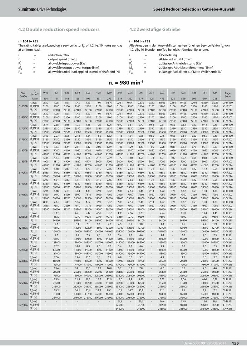
Drive 6000 991296 08/2021
Speed Reducer Selection / Getriebe-Auswahl
155
4.2 Zweistufige Getriebe4.2 Double reduction speed reducers
i = 104 to 731The rating tables are based on a service factor fB1 of 1.0, i.e. 10 hours per day at uniform load.
i = reduction ration2 = output speed [min-1]P1 = allowable input power [kW]M2 = allowable output power torque [Nm]FR2 = allowable radial load applied to mid of shaft end [N]
i = 104 bis 731Alle Angaben in den Auswahllisten gelten für einen Service Faktor fB1 von 1,0, d.h. 10 Stunden pro Tag bei gleichförmiger Belastung.
i = Übersetzungn2 = Abtriebsdrehzahl [min-1]P1 = zulässige Antriebsleistung [kW]M2 = zulässiges Abtriebsdrehmoment [ [Nm]FR2 = zulässige Radialkraft auf Mitte Wellenende [N]
n1 = 980 min-1
Size Größe
n2 [min-1] 9,42 8,1 6,85 5,94 5,03 4,24 3,59 3,07 2,75 2,6 2,31 2,07 1,87 1,75 1,65 1,51 1,34 Page
SeiteRatio 104 121 143 165 195 231 273 319 357 377 425 473 525 559 595 649 731
6165DBP1[kW] 2,30 1,98 1,67 1,45 1,23 1,04 0,877 0,751 0,671 0,635 0,563 0,506 0,456 0,428 0,402 0,369 0,328 CHH 189M2 [Nm] 2100 2100 2100 2100 2100 2100 2100 2100 2100 2100 2100 2100 2100 2100 2100 2100 2100 CHF 201FR2 [N] 22100 22100 22100 22100 22100 22100 22100 22100 22100 22100 22100 22100 22100 22100 22100 22100 22100 CHV 212
6165DCP1[kW] 2,30 1,98 1,67 1,45 1,23 1,04 0,877 0,751 0,671 0,635 0,563 0,506 0,456 0,428 0,402 0,369 0,328 CHH 190M2 [Nm] 2100 2100 2100 2100 2100 2100 2100 2100 2100 2100 2100 2100 2100 2100 2100 2100 2100 CHF 202FR2 [N] 22100 22100 22100 22100 22100 22100 22100 22100 22100 22100 22100 22100 22100 22100 22100 22100 22100 CHV 214
6170DCP1[kW] 2,77 2,38 2,01 1,75 1,48 1,25 1,06 0,90 0,81 0,77 0,68 0,61 0,55 0,52 0,49 0,44 0,40 CHH 190M2 [Nm] 2530 2530 2530 2530 2530 2530 2530 2530 2530 2530 2530 2530 2530 2530 2530 2530 2530 CHF 202FR2 [N] 29500 29500 29500 29500 29500 29500 29500 29500 29500 29500 29500 29500 29500 29500 29500 29500 29500 CHV 214
6175DCP1[kW] 3,45 2,97 2,51 2,18 1,84 1,55 1,32 1,13 1,01 0,95 0,85 0,76 0,68 0,64 0,60 0,55 0,49 CHH 190M2 [Nm] 3150 3150 3150 3150 3150 3150 3150 3150 3150 3150 3150 3150 3150 3150 3150 3150 3150 CHF 202FR2 [N] 29500 29500 29500 29500 29500 29500 29500 29500 29500 29500 29500 29500 29500 29500 29500 29500 29500 CHV 214
6180DBP1[kW] 4,45 3,83 3,24 2,81 2,37 2,00 1,69 1,45 1,29 1,23 1,09 0,98 0,88 0,83 0,78 0,71 0,63 CHH 190M2 [Nm] 4060 4060 4060 4060 4060 4050 4050 4050 4050 4050 4050 4060 4050 4060 4050 4050 4060 CHF 202FR2 [N] 41700 41700 41700 41700 41700 41700 41700 41700 41700 41700 41700 41700 41700 41700 41700 41700 41700 CHV 214
6185DBP1[kW] 5,37 4,53 3,91 3,40 2,88 2,47 2,09 1,79 1,60 1,51 1,34 1,21 1,09 1,02 0,96 0,88 0,78 CHH 190M2 [Nm] 4900 4810 4900 4920 4920 5000 5000 5000 5000 5000 5000 5000 5000 5000 5000 5000 5000 CHF 202FR2 [N] 41700 41700 41700 41700 41700 41700 41700 41700 41700 41700 41700 41700 41700 41700 41700 41600 41700 CHV 214
6190DAP1[kW] 5,97 5,18 5,09 4,41 3,73 3,15 2,66 2,28 2,04 1,93 1,71 1,54 1,39 1,30 1,22 1,12 0,99 CHH 190M2 [Nm] 5450 5490 6380 6380 6380 6380 6380 6380 6380 6380 6380 6380 6380 6380 6380 6380 6380 CHF 202FR2 [N] 59000 59000 58700 58900 58900 59000 59000 59000 59000 59000 59000 59000 59000 59000 59000 58600 59000 CHV 214
6190DBP1[kW] 6,99 6,01 5,09 4,41 3,73 3,15 2,66 2,28 2,04 1,93 1,71 1,54 1,39 1,30 1,22 1,12 0,99 CHH 190M2 [Nm] 6380 6380 6380 6380 6380 6380 6380 6380 6380 6380 6380 6380 6380 6380 6380 6380 6380 CHF 202FR2 [N] 58700 59000 58700 58900 58900 59000 59000 59000 59000 59000 59000 59000 59000 59000 59000 58600 59000 CHV 214
6195DAP1[kW] 5,97 5,18 5,18 4,83 4,33 3,93 3,32 2,85 2,54 2,41 2,14 1,92 1,73 1,62 1,53 1,40 1,24 CHH 190M2 [Nm] 5450 5490 6490 6990 7410 7960 7960 7960 7960 7960 7960 7960 7960 7960 7960 7960 7960 CHF 202FR2 [N] 59000 59000 58700 58600 58500 59000 59000 59000 59000 59000 59000 59000 59000 59000 58600 58100 59000 CHV 214
6195DBP1[kW] 8,36 7,14 6,08 5,46 4,62 3,93 3,32 2,85 2,54 2,41 2,14 1,92 1,73 1,62 1,53 1,40 1,24 CHH 190M2 [Nm] 7630 7580 7630 7910 7910 7960 7960 7960 7960 7960 7960 7960 7960 7960 7960 7960 7960 CHF 202FR2 [N] 58200 59000 58200 58300 58300 59000 59000 59000 59000 59000 59000 59000 58600 59000 58600 58100 59000 CHV 214
6205DBP1[kW] - 8,12 - 6,41 5,42 4,58 3,87 3,30 2,96 2,79 - 2,24 - 1,90 - 1,63 1,45 CHH 191M2 [Nm] - 8620 - 9270 9270 9270 9270 9230 9270 9230 - 9300 - 9300 - 9300 9300 CHF 203FR2 [N] - 84100 - 84100 84100 84100 84100 84100 84100 84100 - 84100 - 84100 - 84100 84100 CHV 215
6215DAP1[kW] - 9,2 - 8,4 7,1 6,1 5,2 4,5 3,9 3,8 - 3,0 - 2,5 - 2,2 1,9 CHH 191M2 [Nm] - 9800 - 12200 12200 12500 12500 12700 12500 12700 - 12700 - 12700 - 12700 12700 CHF 203FR2 [N] - 104000 - 104000 104000 104000 104000 104000 104000 104000 - 104000 - 104000 - 104000 104000 CHV 215
6225DAP1[kW] - 9,7 - 9,2 7,5 7,3 6,2 5,4 4,7 4,6 - 3,8 - 3,3 - 2,8 2,5 CHH 191M2 [Nm] - 9800 - 13400 13000 14800 14800 15000 14800 15000 - 16000 - 16000 - 15900 16000 CHF 203FR2 [N] - 128000 - 138000 145000 145000 145000 145000 145000 145000 - 145000 - 145000 - 145000 145000 CHV 215
6225DBP1[kW] - 12,7 - 10,0 8,5 7,3 6,2 5,4 4,7 4,6 - 3,9 - 3,3 - 2,8 2,5 CHH 191M2 [Nm] - 13500 - 14500 14500 14800 14800 15000 14800 15000 - 16000 - 16000 - 15900 16000 CHF 203FR2 [N] - 127000 - 138000 145000 145000 145000 145000 145000 145000 - 145000 - 145000 - 145000 145000 CHV 215
6235DAP1[kW] - 17,6 - 13,6 11,5 9,3 7,9 6,8 6,0 5,7 - 4,9 - 4,2 - 3,6 3,2 CHH 191M2 [Nm] - 18700 - 19600 19600 18900 18900 18900 18900 18900 - 20500 - 20500 - 20500 20500 CHF 203FR2 [N] - 159000 - 171000 179000 179000 179000 179000 179000 179000 - 179000 - 179000 - 179000 179000 CHV 215
6245DAP1[kW] - 19,4 - 18,1 15,3 12,7 10,8 9,2 8,2 7,8 - 6,2 - 5,3 - 4,5 4,0 CHH 191M2 [Nm] - 20500 - 26200 26200 25800 25800 25800 25800 25800 - 25800 - 25800 - 25800 25800 CHF 203FR2 [N] - 176000 - 189000 199000 208000 208000 208000 208000 208000 - 208000 - 208000 - 208000 208000 CHV 215
6255DAP1[kW] - 25,9 - 21,5 18,2 15,3 12,9 11,6 9,9 9,82 - 8,32 - 7,04 - 6,06 5,38 CHH 191M2 [Nm] - 27500 - 31200 31200 31000 31000 32500 31000 32500 - 34500 - 34500 - 34500 34500 CHF 203FR2 [N] - 215000 - 232000 244000 258000 258000 258000 258000 258000 - 258000 - 258000 - 258000 258000 CHV 215
6265DAP1[kW] - 29,5 - 30,2 25,6 22,7 19,2 16,4 14,7 13,9 - 11,1 - 9,4 - 8,1 7,2 CHH 191M2 [Nm] - 31300 - 43700 43700 46000 46000 46000 46000 46000 - 46000 - 46000 - 46000 46000 CHF 203FR2 [N] - 264000 - 276000 276000 276000 276000 276000 276000 276000 - 276000 - 276000 - 276000 276000 CHV 215
6275DAP1[kW] - - - - - - - 24,4 - 20,6 - 16,4 - 13,9 - 12,0 10,6 CHH 191M2 [Nm] - - - - - - - 68200 - 68200 - 68200 - 68200 - 68200 68200 CHF 203FR2 [N] - - - - - - - 248000 - 248000 - 248000 - 248000 - 248000 248000 CHV 215

Drive 6000 991296 082021
Speed Reducer Selection / Getriebe-Auswahl
156
4.2 Zweistufige Getriebe4.2 Double reduction speed reducers
i = 104 to 731The rating tables are based on a service factor fB1 of 1.0, i.e. 10 hours per day at uniform load.
i = reduction ration2 = output speed [min-1]P1 = allowable input power [kW]M2 = allowable output power torque [Nm]FR2 = allowable radial load applied to mid of shaft end [N]
i = 104 bis 731Alle Angaben in den Auswahllisten gelten für einen Service Faktor fB1 von 1,0, d.h. 10 Stunden pro Tag bei gleichförmiger Belastung.
i = Übersetzungn2 = Abtriebsdrehzahl [min-1]P1 = zulässige Antriebsleistung [kW]M2 = zulässiges Abtriebsdrehmoment [ [Nm]FR2 = zulässige Radialkraft auf Mitte Wellenende [N]
n1 = 1450 min-1
Size Größe
n2 [min-1] 13,9 12 10,1 8,79 7,44 6,28 5,31 4,55 4,06 3,85 3,41 3,07 2,76 2,59 2,44 2,23 1,98 Page
SeiteRatio 104 121 143 165 195 231 273 319 357 377 425 473 525 559 595 649 731
6060DAP1[kW] 0,038 0,033 0,028 0,024 0,02 0,017 0,014 0,012 0,011 0,01 0,009 0,008 0,007 0,007 0,006 - 0,005 CNH 188M2 [Nm] 24 24 24 24 24 24 24 24 24 24 24 24 24 24 24 - 24 CNF 200FR2 [N] 1180 1180 1180 1180 1180 1180 1180 1180 1180 1180 1180 1180 1180 1180 1180 - 1180 CNV 211
6065DAP1[kW] 0,048 0,041 0,035 0,03 0,026 0,021 0,018 0,015 0,014 0,013 0,011 0,01 0,009 0,009 0,008 - 0,006 CNH 188M2 [Nm] 30 30 30 30 30 30 30 30 30 30 30 30 30 30 30 - 30 CNF 200FR2 [N] 1180 1140 1180 1180 1180 1180 1180 1180 1180 1180 1180 1180 1180 1180 1180 - 1180 CNV 211
6070DAP1[kW] 0,073 0,062 0,053 0,046 0,038 0,032 0,027 0,023 0,021 0,02 0,017 0,016 0,014 0,013 0,012 0,011 0,01 CNH 188M2 [Nm] 45 45 45 45 45 45 45 45 45 45 45 45 45 45 45 45 45 CNF 200FR2 [N] 1770 1770 1770 1770 1770 1770 1770 1770 1770 1770 1770 1770 1770 1770 1770 1620 1750 CNV 211
6075DAP1[kW] 0,097 0,07 0,07 0,06 0,051 0,043 0,037 0,031 0,028 0,026 0,023 0,021 0,019 0,018 0,017 0,014 0,013 CNH 188M2 [Nm] 60 50,8 60 60 60 60 60 60 60 60 60 60 60 60 60 57,4 60 CNF 200FR2 [N] 1770 1770 1770 1770 1770 1770 1770 1770 1770 1770 1770 1650 1770 1650 1770 1550 1650 CNV 211
6090DAP1[kW] 0,243 0,209 0,177 0,153 0,13 0,11 0,092 0,079 0,07 0,06 0,05 0,05 0,048 0,045 0,042 0,038 0,034 CNH 188M2 [Nm] 150 150 150 150 150 150 150 150 150 150 150 150 150 150 150 146 150 CNF 200FR2 [N] 3340 3340 3340 3340 3340 3160 3160 3020 3160 3020 3010 3040 3030 3040 3030 3030 3040 CNV 211
6095DAP1[kW] 0,293 0,224 0,216 0,204 0,173 0,146 0,124 0,106 0,094 0,089 0,077 0,071 0,06 0,06 0,056 0,038 0,046 CNH 188M2 [Nm] 181 160 183 200 200 200 200 200 200 200 195 200 195 200 200 146 200 CNF 200FR2 [N] 3340 3340 3340 3340 3340 3070 3070 2940 3070 2940 2930 2960 2940 2960 2940 3030 2960 CNV 211
6100DAP1[kW] 0,406 0,349 0,295 0,256 0,216 0,183 0,154 0,132 0,118 0,112 0,099 0,089 0,08 0,075 0,07 0,065 0,057 CNH 188M2 [Nm] 250 250 250 250 250 250 250 250 250 250 250 250 250 250 250 250 250 CNF 200FR2 [N] 5400 5400 5400 5400 5400 5400 5400 5400 5400 5400 5400 5400 5400 5400 5400 4910 5400 CNV 211
6105DAP1[kW] 0,407 0,407 0,354 0,307 0,26 0,219 0,185 0,159 0,142 0,134 0,119 0,107 0,096 0,09 0,085 0,076 0,069 CNH 188M2 [Nm] 251 292 300 300 300 300 300 300 300 300 300 300 300 300 300 296 300 CNF 200FR2 [N] 5400 5400 5400 5400 5400 5400 5400 5400 5400 5400 5400 5400 5400 5400 5400 4880 5400 CNV 211
6120DAP1[kW] 0,407 0,407 0,407 0,407 0,407 0,381 0,322 0,275 0,247 0,233 0,208 0,187 0,169 0,158 0,149 0,136 0,121 CNH 188M2 [Nm] 251 292 345 398 470 522 522 520 522 520 525 525 525 525 525 525 525 CNF 200FR2 [N] 9810 9810 9810 9810 9810 9810 9810 9810 9810 9810 9810 9810 9810 9810 9810 9810 9810 CNV 211
6120DBP1[kW] 0,852 0,732 0,619 0,537 0,454 0,381 0,322 0,275 0,247 0,233 0,208 0,187 0,169 0,158 0,149 0,136 0,121 CNH 188M2 [Nm] 525 525 525 525 525 522 522 520 522 520 525 525 525 525 525 525 525 CNF 200FR2 [N] 9810 9810 9810 9810 9810 9810 9810 9810 9810 9810 9810 9810 9810 9810 9810 9810 9810 CNV 211
6125DAP1[kW] 0,407 0,407 0,407 0,407 0,407 0,407 0,389 0,333 0,298 0,282 0,25 0,225 0,202 0,19 0,179 0,164 0,145 CNH 188M2 [Nm] 251 292 345 398 470 557 630 630 630 630 630 630 630 630 630 630 630 CNF 200FR2 [N] 9810 9810 9810 9810 9810 9810 9810 9810 9810 9810 9810 9810 9810 9810 9810 9810 9810 CNV 211
6125DBP1[kW] 1,02 0,867 0,743 0,644 0,545 0,46 0,389 0,333 0,298 0,282 0,25 0,225 0,202 0,19 0,179 0,164 0,145 CNH 188M2 [Nm] 630 622 630 630 630 630 630 630 630 630 630 630 630 630 630 630 630 CNF 200FR2 [N] 9810 9810 9810 9810 9810 9810 9810 9810 9810 9810 9810 9810 9810 9810 9810 9810 9810 CNV 211
6130DBP1[kW] 1,27 1,09 0,92 0,798 0,675 0,57 0,482 0,413 0,369 0,349 0,31 0,278 0,251 0,235 0,221 0,237 0,18 CHH 189M2 [Nm] 780 780 780 780 780 780 780 780 780 780 780 780 780 780 780 912 780 CHF 201FR2 [N] 14200 14300 14200 13800 13800 14200 14020 14000 14020 14000 14000 13900 13900 13900 13900 14500 13900 CHV 212
6130DCP1[kW] 1,27 1,09 0,92 0,798 0,675 0,57 0,482 0,413 0,369 0,349 0,31 0,278 0,251 0,235 0,221 0,237 0,18 CHH 189M2 [Nm] 780 780 780 780 780 780 780 780 780 780 780 780 780 780 780 912 780 CHF 201FR2 [N] 14200 14300 14200 13800 13800 14200 14200 14000 14200 14000 14000 13900 13900 13900 13900 14500 13900 CHV 212
6135DBP1[kW] 1,52 1,31 1,11 0,961 0,813 0,686 0,581 0,497 0,444 0,421 0,357 0,335 0,302 0,284 0,267 0,273 0,217 CHH 189M2 [Nm] 940 940 940 940 940 940 940 940 940 940 900 940 940 940 940 1050 940 CHF 201FR2 [N] 13900 13900 13900 13500 13500 13900 13900 13800 13900 13800 13800 13700 13600 13700 13600 14300 13700 CHV 212
6135DCP1[kW] 1,52 1,31 1,11 0,961 0,813 0,686 0,581 0,497 0,444 0,421 0,357 0,335 0,302 0,284 0,267 0,273 0,217 CHH 189M2 [Nm] 940 940 940 940 940 940 940 940 940 940 900 940 940 940 940 1050 940 CHF 201FR2 [N] 13900 13900 13900 13500 13500 13900 13900 13800 13900 13800 13800 13700 13600 13700 13600 14300 13700 CHV 212
6140DCP1[kW] 1,99 1,71 1,45 1,25 1,06 0,895 0,757 0,648 0,579 0,548 0,486 0,437 0,394 0,37 0,347 0,318 0,283 CHH 189M2 [Nm] 1230 1230 1230 1230 1230 1230 1230 1230 1230 1230 1230 1230 1230 1230 1230 1230 1230 CHF 201FR2 [N] 15600 16000 15600 15700 15700 15900 15900 15500 15900 15500 15800 15400 15700 15400 15700 16000 15400 CHV 212
6145DCP1[kW] 2,22 1,8 1,62 1,39 1,17 0,977 0,827 0,725 0,632 0,613 0,544 0,489 0,44 0,413 0,388 0,356 0,316 CHH 189M2 [Nm] 1370 1290 1370 1360 1360 1340 1340 1370 1340 1370 1370 1370 1370 1370 1370 1370 1370 CHF 201FR2 [N] 15600 16000 15600 15600 15600 15800 15800 15400 15800 15400 15800 15300 15600 15300 15600 16000 15300 CHV 212
6160DBP1[kW] 2,85 2,45 2,07 1,79 1,52 1,28 1,08 0,928 0,829 0,785 0,697 0,619 0,564 0,524 0,498 0,456 0,4 CHH 189M2 [Nm] 1760 1760 1760 1760 1760 1760 1760 1760 1760 1760 1760 1740 1760 1740 1760 1760 1740 CHF 201FR2 [N] 22100 22100 22100 22100 22100 22100 22100 22100 22100 22100 22100 22100 22100 22100 22100 22100 22100 CHV 212
6160DCP1[kW] 2,85 2,45 2,07 1,79 1,52 1,28 1,08 0,928 0,829 0,785 0,697 0,619 0,564 0,524 0,498 0,456 0,4 CHH 190M2 [Nm] 1760 1760 1760 1760 1760 1760 1760 1760 1760 1760 1760 1740 1760 1740 1760 1760 1740 CHF 202FR2 [N] 22100 22100 22100 22100 22100 22100 22100 22100 22100 22100 22100 22100 22100 22100 22100 22100 22100 CHV 214
For not shown double reduction units consult SDT Für nicht gezeigte zweistufige Getriebe Rückfrage bei SDT
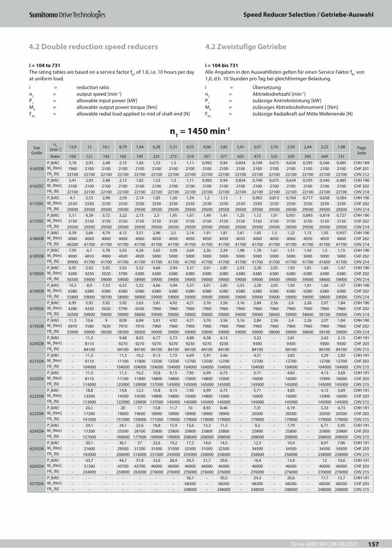
Drive 6000 991296 08/2021
Speed Reducer Selection / Getriebe-Auswahl
157
4.2 Zweistufige Getriebe4.2 Double reduction speed reducers
i = 104 to 731The rating tables are based on a service factor fB1 of 1.0, i.e. 10 hours per day at uniform load.
i = reduction ration2 = output speed [min-1]P1 = allowable input power [kW]M2 = allowable output power torque [Nm]FR2 = allowable radial load applied to mid of shaft end [N]
i = 104 bis 731Alle Angaben in den Auswahllisten gelten für einen Service Faktor fB1 von 1,0, d.h. 10 Stunden pro Tag bei gleichförmiger Belastung.
i = Übersetzungn2 = Abtriebsdrehzahl [min-1]P1 = zulässige Antriebsleistung [kW]M2 = zulässiges Abtriebsdrehmoment [ [Nm]FR2 = zulässige Radialkraft auf Mitte Wellenende [N]
n1 = 1450 min-1
Size Größe
n2 [min-1] 13,9 12 10,1 8,79 7,44 6,28 5,31 4,55 4,06 3,85 3,41 3,07 2,76 2,59 2,44 2,23 1,98 Page
SeiteRatio 104 121 143 165 195 231 273 319 357 377 425 473 525 559 595 649 731
6165DBP1[kW] 3,18 2,93 2,48 2,15 1,82 1,53 1,3 1,11 0,992 0,94 0,834 0,749 0,675 0,634 0,595 0,546 0,485 CHH 189M2 [Nm] 1960 2100 2100 2100 2100 2100 2100 2100 2100 2100 2100 2100 2100 2100 2100 2100 2100 CHF 201FR2 [N] 22100 22100 22100 22100 22100 22100 22100 22100 22100 22100 22100 22100 22100 22100 22100 22100 22100 CHV 212
6165DCP1[kW] 3,41 2,93 2,48 2,15 1,82 1,53 1,3 1,11 0,992 0,94 0,834 0,749 0,675 0,634 0,595 0,546 0,485 CHH 190M2 [Nm] 2100 2100 2100 2100 2100 2100 2100 2100 2100 2100 2100 2100 2100 2100 2100 2100 2100 CHF 202FR2 [N] 22100 22100 22100 22100 22100 22100 22100 22100 22100 22100 22100 22100 22100 22100 22100 22100 22100 CHV 214
6170DCP1[kW] 4,1 3,53 2,98 2,59 2,19 1,85 1,56 1,34 1,2 1,13 1 0,902 0,813 0,764 0,717 0,658 0,584 CHH 190M2 [Nm] 2530 2530 2530 2530 2530 2530 2530 2530 2530 2530 2530 2530 2530 2530 2530 2530 2530 CHF 202FR2 [N] 29500 29500 29500 29500 29500 29500 29500 29500 29500 29500 29500 29500 29500 29500 29500 29500 29500 CHV 214
6175DCP1[kW] 5,11 4,39 3,72 3,22 2,73 2,3 1,95 1,67 1,49 1,41 1,25 1,12 1,01 0,951 0,893 0,819 0,727 CHH 190M2 [Nm] 3150 3150 3150 3150 3150 3150 3150 3150 3150 3150 3150 3150 3150 3150 3150 3150 3150 CHF 202FR2 [N] 29500 29500 29500 29500 29500 29500 29500 29500 29500 29500 29500 29500 29500 29500 29500 29500 29500 CHV 214
6180DBP1[kW] 6,59 5,66 4,79 4,15 3,51 2,96 2,5 2,14 1,91 1,81 1,61 1,45 1,3 1,22 1,15 1,05 0,937 CHH 190M2 [Nm] 4060 4060 4060 4060 4060 4050 4050 4050 4050 4050 4050 4060 4050 4060 4050 4050 4060 CHF 202FR2 [N] 40200 41700 41700 41700 41700 41700 41700 41700 41700 41700 41700 41700 41700 41700 41700 41700 41700 CHV 214
6185DBP1[kW] 7,95 6,7 5,78 5,03 4,26 3,65 3,09 2,64 2,36 2,24 1,98 1,78 1,61 1,51 1,42 1,3 1,15 CHH 190M2 [Nm] 4900 4810 4900 4920 4920 5000 5000 5000 5000 5000 5000 5000 5000 5000 5000 5000 5000 CHF 202FR2 [N] 39900 41700 41700 41700 41700 41700 41700 41700 41700 41700 41700 41700 41700 41700 41700 41600 41700 CHV 214
6190DAP1[kW] 6,95 5,92 5,92 5,92 5,52 4,66 3,94 3,37 3,01 2,85 2,53 2,28 2,05 1,93 1,81 1,66 1,47 CHH 190M2 [Nm] 4280 4250 5020 5790 6380 6380 6380 6380 6380 6380 6380 6380 6380 6380 6380 6380 6380 CHF 202FR2 [N] 56500 59000 59000 59000 58900 59000 59000 59000 59000 59000 59000 59000 59000 59000 59000 58600 59000 CHV 214
6190DBP1[kW] 10,3 8,9 7,53 6,52 5,52 4,66 3,94 3,37 3,01 2,85 2,53 2,28 2,05 1,93 1,81 1,66 1,47 CHH 190M2 [Nm] 6380 6380 6380 6380 6380 6380 6380 6380 6380 6380 6380 6380 6380 6380 6380 6380 6380 CHF 202FR2 [N] 55800 59000 58700 58900 58900 59000 59000 59000 59000 59000 59000 59000 59000 59000 59000 58600 59000 CHV 214
6195DAP1[kW] 6,95 5,92 5,92 5,92 5,63 5,81 4,92 4,21 3,76 3,56 3,16 2,84 2,56 2,4 2,26 2,07 1,84 CHH 190M2 [Nm] 4280 4250 5020 5790 6500 7960 7960 7960 7960 7960 7960 7960 7960 7960 7960 7960 7960 CHF 202FR2 [N] 56500 59000 59000 59000 58800 59000 59000 59000 59000 59000 59000 59000 58600 59000 58600 58100 59000 CHV 214
6195DBP1[kW] 11,3 10,6 9 8,09 6,84 5,81 4,92 4,21 3,76 3,56 3,16 2,84 2,56 2,4 2,26 2,07 1,84 CHH 190M2 [Nm] 6970 7580 7630 7910 7910 7960 7960 7960 7960 7960 7960 7960 7960 7960 7960 7960 7960 CHF 202FR2 [N] 55600 59000 58200 58300 58300 59000 59000 59000 59000 59000 59000 59000 58600 59000 58600 58100 59000 CHV 214
6205DBP1[kW] - 11,3 - 9,48 8,02 6,77 5,73 4,88 4,38 4,13 - 3,32 - 2,81 - 2,42 2,15 CHH 191M2 [Nm] - 8110 - 9270 9270 9270 9270 9230 9270 9230 - 9300 - 9300 - 9300 9300 CHF 203FR2 [N] - 84100 - 84100 84100 84100 84100 84100 84100 84100 - 84100 - 84100 - 84100 84100 CHV 215
6215DAP1[kW] - 11,3 - 11,3 10,2 9,13 7,72 6,69 5,91 5,66 - 4,51 - 3,82 - 3,29 2,92 CHH 191M2 [Nm] - 8110 - 11100 11800 12500 12500 12700 12500 12700 - 12700 - 12700 - 12700 12700 CHF 203FR2 [N] - 104000 - 104000 104000 104000 104000 104000 104000 104000 - 104000 - 104000 - 104000 104000 CHV 215
6225DAP1[kW] - 11,3 - 11,3 10,2 10,8 9,15 7,95 6,99 6,73 - 5,71 - 4,83 - 4,13 3,69 CHH 191M2 [Nm] - 8110 - 11100 11800 14800 14800 15000 14800 15000 - 16000 - 16000 - 15900 16000 CHF 203FR2 [N] - 114000 - 123000 129000 137000 145000 145000 145000 145000 - 145000 - 145000 - 145000 145000 CHV 215
6225DBP1[kW] - 18,8 - 14,8 12,5 10,8 9,15 7,95 6,99 6,73 - 5,71 - 4,83 - 4,13 3,69 CHH 191M2 [Nm] - 13500 - 14500 14500 14800 14800 15000 14800 15000 - 16000 - 16000 - 15900 16000 CHF 203FR2 [N] - 113000 - 122000 129000 137000 145000 145000 145000 145000 - 145000 - 145000 - 145000 145000 CHV 215
6235DAP1[kW] - 24,1 - 20 17 13,8 11,7 10 8,93 8,46 - 7,31 - 6,19 - 5,33 4,73 CHH 191M2 [Nm] - 17200 - 19600 19600 18900 18900 18900 18900 18900 - 20500 - 20500 - 20500 20500 CHF 203FR2 [N] - 141000 - 151000 159000 171000 179000 179000 179000 179000 - 179000 - 179000 - 179000 179000 CHV 215
6245DAP1[kW] - 24,1 - 24,1 22,6 18,8 15,9 13,6 12,2 11,5 - 9,2 - 7,79 - 6,71 5,95 CHH 191M2 [Nm] - 17200 - 23500 26100 25800 25800 25800 25800 25800 - 25800 - 25800 - 25800 25800 CHF 203FR2 [N] - 157000 - 168000 177000 189000 199000 208000 208000 208000 - 208000 - 208000 - 208000 208000 CHV 215
6255DAP1[kW] - 30,1 - 30,1 27 22,6 19,2 17,2 14,6 14,5 - 12,3 - 10,4 - 8,97 7,96 CHH 191M2 [Nm] - 21600 - 29500 31200 31000 31000 32500 31000 32500 - 34500 - 34500 - 34500 34500 CHF 203FR2 [N] - 192000 - 206000 216000 231000 243000 255000 258000 258000 - 258000 - 258000 - 258000 258000 CHV 215
6265DAP1[kW] - 43,7 - 44,7 37,8 33,6 28,4 24,3 21,7 20,6 - 16,4 - 13,9 - 12 10,6 CHH 191M2 [Nm] - 31300 - 43700 43700 46000 46000 46000 46000 46000 - 46000 - 46000 - 46000 46000 CHF 203FR2 [N] - 234000 - 250000 263000 276000 276000 276000 276000 276000 - 276000 - 276000 - 276000 276000 CHV 215
6275DAP1[kW] - - - - - - - 36,1 - 30,5 - 24,3 - 20,6 - 17,7 15,7 CHH 191M2 [Nm] - - - - - - - 68200 - 68200 - 68200 - 68200 - 68200 68200 CHF 203FR2 [N] - - - - - - - 248000 - 248000 - 248000 - 248000 - 248000 248000 CHV 215
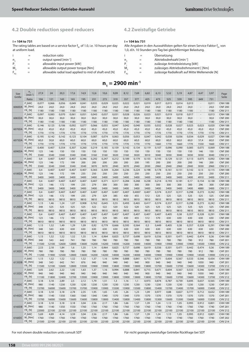
Drive 6000 991296 082021
Speed Reducer Selection / Getriebe-Auswahl
158
4.2 Zweistufige Getriebe4.2 Double reduction speed reducers
i = 104 to 731The rating tables are based on a service factor fB1 of 1.0, i.e. 10 hours per day at uniform load.
i = reduction ration2 = output speed [min-1]P1 = allowable input power [kW]M2 = allowable output power torque [Nm]FR2 = allowable radial load applied to mid of shaft end [N]
i = 104 bis 731Alle Angaben in den Auswahllisten gelten für einen Service Faktor fB1 von 1,0, d.h. 10 Stunden pro Tag bei gleichförmiger Belastung.
i = Übersetzungn2 = Abtriebsdrehzahl [min-1]P1 = zulässige Antriebsleistung [kW]M2 = zulässiges Abtriebsdrehmoment [ [Nm]FR2 = zulässige Radialkraft auf Mitte Wellenende [N]
n1 = 2900 min-1
Size Größe
n2 [min-1] 27,9 24 20,3 17,6 14,9 12,6 10,6 9,09 8,12 7,69 6,82 6,13 5,52 5,19 4,87 4,47 3,97 Page
SeiteRatio 104 121 143 165 195 231 273 319 357 377 425 473 525 559 595 649 731
6060DAP1[kW] 0,077 0,066 0,056 0,049 0,041 0,035 0,029 0,025 0,022 0,021 0,019 0,017 0,015 0,014 0,013 - 0,011 CNH 188M2 [Nm] 24,0 24,0 24,0 24,0 24,0 24,0 24,0 24,0 24,0 24,0 24,0 24,0 24,0 24,0 24,0 - 24,0 CNF 200FR2 [N] 1180 1180 1180 1180 1180 1180 1180 1180 1180 1180 1180 1180 1180 1180 1180 - 1180 CNV 211
6065DAP1[kW] 0,097 0,083 0,070 0,061 0,051 0,043 0,037 0,031 0,028 0,026 0,023 0,021 0,019 0,018 0,017 - 0,013 CNH 188M2 [Nm] 30,0 30,0 30,0 30,0 30,0 30,0 30,0 30,0 30,0 30,0 30,0 30,0 30,0 30,0 30,0 - 30,0 CNF 200FR2 [N] 1180 1140 1180 1180 1180 1180 1180 1180 1180 1180 1180 1180 1180 1180 1180 - 1180 CNV 211
6070DAP1[kW] 0,146 0,125 0,106 0,092 0,077 0,066 0,055 0,047 0,042 0,040 0,035 0,032 0,028 0,027 0,025 0,023 0,020 CNH 188M2 [Nm] 45,0 45,0 45,0 45,0 45,0 45,0 45,0 45,0 45,0 45,0 45,0 45,0 45,0 45,0 45,0 45,0 45,0 CNF 200FR2 [N] 1770 1770 1770 1770 1770 1770 1770 1770 1770 1770 1770 1770 1770 1770 1770 1770 1770 CNV 211
6075DAP1[kW] 0,195 0,142 0,142 0,123 0,104 0,087 0,074 0,063 0,056 0,053 0,047 0,042 0,038 0,036 0,034 0,029 0,027 CNH 188M2 [Nm] 60,0 50,8 60,0 60,0 60,0 60,0 60,0 60,0 60,0 60,0 60,0 60,0 60,0 60,0 60,0 57,4 60,0 CNF 200FR2 [N] 1770 1770 1770 1770 1770 1770 1770 1770 1770 1770 1770 1660 1770 1660 1770 1550 1660 CNV 211
6090DAP1[kW] 0,400 0,407 0,354 0,307 0,260 0,219 0,185 0,159 0,142 0,134 0,119 0,107 0,096 0,090 0,085 0,075 0,069 CNH 188M2 [Nm] 123 146 150 150 150 150 150 150 150 150 150 150 150 150 150 146 150 CNF 200FR2 [N] 3340 3340 3340 3340 3340 3160 3160 3020 3160 3020 3010 3040 3030 3040 3030 3030 3040 CNV 211
6095DAP1[kW] 0,4 0,407 0,407 0,407 0,346 0,292 0,247 0,212 0,189 0,179 0,155 0,143 0,129 0,121 0,113 0,075 0,092 CNH 188M2 [Nm] 123 146 172 199 200 200 200 200 200 200 195 200 200 200 200 146 200 CNF 200FR2 [N] 3340 3340 3340 3340 3340 3070 3070 2940 3070 2940 2930 2960 2940 2960 2940 3030 2960 CNV 211
6100DAP1[kW] 0,4 0,407 0,407 0,407 0,407 0,365 0,309 0,264 0,236 0,224 0,198 0,178 0,161 0,151 0,142 0,13 0,115 CNH 188M2 [Nm] 123 146 172 199 235 250 250 250 250 250 250 250 250 250 250 250 250 CNF 200FR2 [N] 5400 5400 5400 5400 5400 5400 5400 5400 5400 5400 5400 5400 5400 5400 5400 4910 5400 CNV 211
6105DAP1[kW] 0,4 0,407 0,407 0,407 0,407 0,407 0,371 0,317 0,284 0,268 0,238 0,214 0,193 0,181 0,17 0,154 0,138 CNH 188M2 [Nm] 123 146 172 199 235 279 300 300 300 300 300 300 300 300 300 296 300 CNF 200FR2 [N] 5400 5400 5400 5400 5400 5400 5400 5400 5400 5400 5400 5400 5400 5400 5400 4880 5400 CNV 211
6120DAP1[kW] 0,4 0,407 0,407 0,407 0,407 0,407 0,407 0,407 0,407 0,4007 0,407 0,374 0,337 0,317 0,298 0,273 0,242 CNH 188M2 [Nm] 123 146 172 199 235 279 329 385 430 455 512 525 525 525 525 525 525 CNF 200FR2 [N] 9810 9810 9810 9810 9810 9810 9810 9810 9810 9810 9810 9810 9810 9810 9810 9810 9810 CNV 211
6120DBP1[kW] 1,13 1,46 1,24 1,07 0,908 0,762 0,645 0,55 0,493 0,465 0,417 0,374 0,337 0,317 0,298 0,273 0,242 CNH 188M2 [Nm] 348 525 525 525 525 522 522 520 522 520 525 525 525 525 525 525 525 CNF 200FR2 [N] 9810 9810 9810 9810 9810 9810 9810 9810 9810 9810 9810 9810 9810 9810 9810 9810 9810 CNV 211
6125DAP1[kW] 0,4 0,407 0,407 0,407 0,407 0,407 0,407 0,407 0,407 0,407 0,407 0,407 0,405 0,38 0,357 0,328 0,291 CNH 188M2 [Nm] 123 146 172 199 235 279 329 385 430 455 512 570 630 630 630 630 630 CNF 200FR2 [N] 9810 9810 9810 9810 9810 9810 9810 9810 9810 9810 9810 9810 9810 9810 9810 9810 9810 CNV 211
6125DBP1[kW] 1,13 1,52 1,49 1,29 1,09 0,92 0,779 0,666 0,595 0,564 0,5 0,449 0,405 0,38 0,357 0,328 0,291 CNH 188M2 [Nm] 348 543 630 630 630 630 630 630 630 630 630 630 630 630 630 630 630 CNF 200FR2 [N] 9810 9810 9810 9810 9810 9810 9810 9810 9810 9810 9810 9810 9810 9810 9810 9810 9810 CNV 211
6130DBP1[kW] 1,13 1,52 1,52 1,52 1,35 1,14 0,964 0,825 0,737 0,698 0,619 0,556 0,501 0,471 0,442 0,474 0,36 CHH 189M2 [Nm] 348 543 642 741 780 780 780 780 780 780 780 780 780 780 780 912 780 CHF 201FR2 [N] 11500 12100 12600 12800 13600 14200 14200 14000 14200 14000 14000 13900 13900 13900 13900 14500 13900 CHV 212
6130DCP1[kW] 2,53 2,18 1,84 1,6 1,35 1,14 0,964 0,825 0,737 0,698 0,619 0,556 0,501 0,471 0,442 0,474 0,36 CHH 189M2 [Nm] 780 780 780 780 780 780 780 780 780 780 780 780 780 780 780 912 780 CHF 201FR2 [N] 11200 11900 12500 12800 13600 14200 14200 14000 14200 14000 14000 13900 13900 13900 13900 14500 13900 CHV 212
6135DBP1[kW] 1,13 1,52 1,52 1,52 1,52 1,37 1,16 0,994 0,888 0,841 0,715 0,671 0,604 0,567 0,533 0,546 0,434 CHH 189M2 [Nm] 348 543 642 741 876 940 940 940 940 940 900 940 940 940 940 1050 940 CHF 201FR2 [N] 11500 12100 12600 12800 13500 13900 13900 13800 13900 13800 13800 13700 13600 13700 13600 14300 13700 CHV 212
6135DCP1[kW] 3,05 2,62 2,22 1,92 1,63 1,37 1,16 0,994 0,888 0,841 0,715 0,671 0,604 0,567 0,533 0,546 0,434 CHH 189M2 [Nm] 940 940 940 940 940 940 940 940 940 940 900 940 940 940 940 1050 940 CHF 201FR2 [N] 11100 11800 12400 12700 13500 13900 13900 13800 13900 13800 13800 13700 13600 13700 13600 14300 13700 CHV 212
6140DCP1[kW] 3,18 3,18 2,89 2,5 2,12 1,79 1,51 1,3 1,16 1,1 0,973 0,874 0,787 0,739 0,695 0,637 0,565 CHH 189M2 [Nm] 980 1140 1230 1230 1230 1230 1230 1230 1230 1230 1230 1230 1230 1230 1230 1230 1230 CHF 201FR2 [N] 15700 16000 15600 15700 15700 15900 15900 15500 15900 15500 15800 15400 15700 15400 15700 16000 15400 CHV 212
6145DCP1[kW] 3,18 3,18 3,18 2,78 2,35 1,95 1,65 1,45 1,26 1,23 1,09 0,977 0,88 0,827 0,777 0,712 0,632 CHH 189M2 [Nm] 980 1140 1350 1360 1360 1340 1340 1370 1340 1370 1370 1370 1370 1370 1370 1370 1370 CHF 201FR2 [N] 15700 16000 15600 15600 15600 15800 15800 15400 15800 15400 15800 15300 15600 15300 15600 16000 15300 CHV 212
6160DBP1[kW] 3,18 3,18 3,18 3,18 3,04 2,56 2,17 1,86 1,66 1,57 1,39 1,24 1,13 1,05 0,995 0,912 0,801 CHH 189M2 [Nm] 980 1140 1350 1550 1760 1760 1760 1760 1760 1760 1760 1740 1760 1740 1760 1760 1740 CHF 201FR2 [N] 22000 22100 22100 22100 22100 22100 22100 22100 22100 22100 22100 22100 22100 22100 22100 22100 22100 CHV 212
6160DCP1[kW] 5,69 4,89 4,14 3,59 3,04 2,56 2,17 1,86 1,66 1,57 1,39 1,24 1,13 1,05 0,995 0,912 0,801 CHH 190M2 [Nm] 1760 1760 1760 1760 1760 1760 1760 1760 1760 1760 1760 1740 1760 1740 1760 1760 1740 CHF 202FR2 [N] 21500 22100 22100 22100 22100 22100 22100 22100 22100 22100 22100 22100 22100 22100 22100 22100 22100 CHV 214
For not shown double reduction units consult SDT Für nicht gezeigte zweistufige Getriebe Rückfrage bei SDT
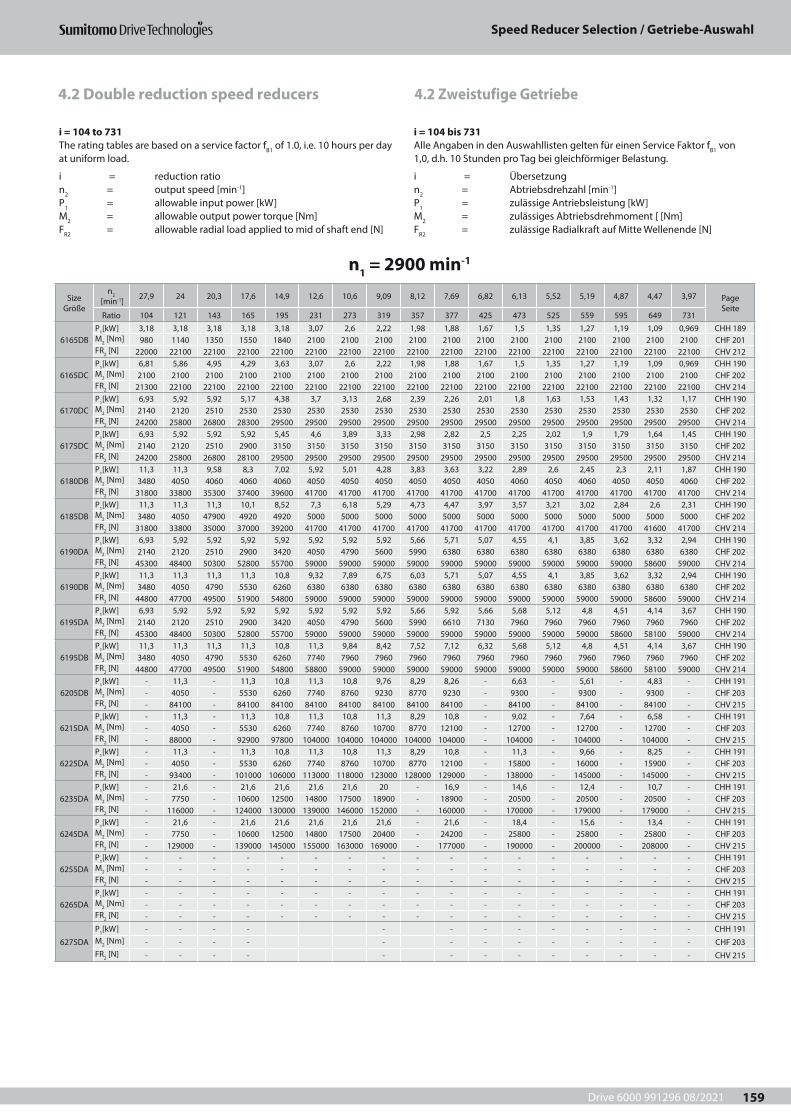
Drive 6000 991296 08/2021
Speed Reducer Selection / Getriebe-Auswahl
159
4.2 Zweistufige Getriebe4.2 Double reduction speed reducers
i = 104 to 731The rating tables are based on a service factor fB1 of 1.0, i.e. 10 hours per day at uniform load.
i = reduction ration2 = output speed [min-1]P1 = allowable input power [kW]M2 = allowable output power torque [Nm]FR2 = allowable radial load applied to mid of shaft end [N]
i = 104 bis 731Alle Angaben in den Auswahllisten gelten für einen Service Faktor fB1 von 1,0, d.h. 10 Stunden pro Tag bei gleichförmiger Belastung.
i = Übersetzungn2 = Abtriebsdrehzahl [min-1]P1 = zulässige Antriebsleistung [kW]M2 = zulässiges Abtriebsdrehmoment [ [Nm]FR2 = zulässige Radialkraft auf Mitte Wellenende [N]
n1 = 2900 min-1
Size Größe
n2 [min-1] 27,9 24 20,3 17,6 14,9 12,6 10,6 9,09 8,12 7,69 6,82 6,13 5,52 5,19 4,87 4,47 3,97 Page
SeiteRatio 104 121 143 165 195 231 273 319 357 377 425 473 525 559 595 649 731
6165DBP1[kW] 3,18 3,18 3,18 3,18 3,18 3,07 2,6 2,22 1,98 1,88 1,67 1,5 1,35 1,27 1,19 1,09 0,969 CHH 189M2 [Nm] 980 1140 1350 1550 1840 2100 2100 2100 2100 2100 2100 2100 2100 2100 2100 2100 2100 CHF 201FR2 [N] 22000 22100 22100 22100 22100 22100 22100 22100 22100 22100 22100 22100 22100 22100 22100 22100 22100 CHV 212
6165DCP1[kW] 6,81 5,86 4,95 4,29 3,63 3,07 2,6 2,22 1,98 1,88 1,67 1,5 1,35 1,27 1,19 1,09 0,969 CHH 190M2 [Nm] 2100 2100 2100 2100 2100 2100 2100 2100 2100 2100 2100 2100 2100 2100 2100 2100 2100 CHF 202FR2 [N] 21300 22100 22100 22100 22100 22100 22100 22100 22100 22100 22100 22100 22100 22100 22100 22100 22100 CHV 214
6170DCP1[kW] 6,93 5,92 5,92 5,17 4,38 3,7 3,13 2,68 2,39 2,26 2,01 1,8 1,63 1,53 1,43 1,32 1,17 CHH 190M2 [Nm] 2140 2120 2510 2530 2530 2530 2530 2530 2530 2530 2530 2530 2530 2530 2530 2530 2530 CHF 202FR2 [N] 24200 25800 26800 28300 29500 29500 29500 29500 29500 29500 29500 29500 29500 29500 29500 29500 29500 CHV 214
6175DCP1[kW] 6,93 5,92 5,92 5,92 5,45 4,6 3,89 3,33 2,98 2,82 2,5 2,25 2,02 1,9 1,79 1,64 1,45 CHH 190M2 [Nm] 2140 2120 2510 2900 3150 3150 3150 3150 3150 3150 3150 3150 3150 3150 3150 3150 3150 CHF 202FR2 [N] 24200 25800 26800 28100 29500 29500 29500 29500 29500 29500 29500 29500 29500 29500 29500 29500 29500 CHV 214
6180DBP1[kW] 11,3 11,3 9,58 8,3 7,02 5,92 5,01 4,28 3,83 3,63 3,22 2,89 2,6 2,45 2,3 2,11 1,87 CHH 190M2 [Nm] 3480 4050 4060 4060 4060 4050 4050 4050 4050 4050 4050 4060 4050 4060 4050 4050 4060 CHF 202FR2 [N] 31800 33800 35300 37400 39600 41700 41700 41700 41700 41700 41700 41700 41700 41700 41700 41700 41700 CHV 214
6185DBP1[kW] 11,3 11,3 11,3 10,1 8,52 7,3 6,18 5,29 4,73 4,47 3,97 3,57 3,21 3,02 2,84 2,6 2,31 CHH 190M2 [Nm] 3480 4050 47900 4920 4920 5000 5000 5000 5000 5000 5000 5000 5000 5000 5000 5000 5000 CHF 202FR2 [N] 31800 33800 35000 37000 39200 41700 41700 41700 41700 41700 41700 41700 41700 41700 41700 41600 41700 CHV 214
6190DAP1[kW] 6,93 5,92 5,92 5,92 5,92 5,92 5,92 5,92 5,66 5,71 5,07 4,55 4,1 3,85 3,62 3,32 2,94 CHH 190M2 [Nm] 2140 2120 2510 2900 3420 4050 4790 5600 5990 6380 6380 6380 6380 6380 6380 6380 6380 CHF 202FR2 [N] 45300 48400 50300 52800 55700 59000 59000 59000 59000 59000 59000 59000 59000 59000 59000 58600 59000 CHV 214
6190DBP1[kW] 11,3 11,3 11,3 11,3 10,8 9,32 7,89 6,75 6,03 5,71 5,07 4,55 4,1 3,85 3,62 3,32 2,94 CHH 190M2 [Nm] 3480 4050 4790 5530 6260 6380 6380 6380 6380 6380 6380 6380 6380 6380 6380 6380 6380 CHF 202FR2 [N] 44800 47700 49500 51900 54800 59000 59000 59000 59000 59000 59000 59000 59000 59000 59000 58600 59000 CHV 214
6195DAP1[kW] 6,93 5,92 5,92 5,92 5,92 5,92 5,92 5,92 5,66 5,92 5,66 5,68 5,12 4,8 4,51 4,14 3,67 CHH 190M2 [Nm] 2140 2120 2510 2900 3420 4050 4790 5600 5990 6610 7130 7960 7960 7960 7960 7960 7960 CHF 202FR2 [N] 45300 48400 50300 52800 55700 59000 59000 59000 59000 59000 59000 59000 59000 59000 58600 58100 59000 CHV 214
6195DBP1[kW] 11,3 11,3 11,3 11,3 10,8 11,3 9,84 8,42 7,52 7,12 6,32 5,68 5,12 4,8 4,51 4,14 3,67 CHH 190M2 [Nm] 3480 4050 4790 5530 6260 7740 7960 7960 7960 7960 7960 7960 7960 7960 7960 7960 7960 CHF 202FR2 [N] 44800 47700 49500 51900 54800 58800 59000 59000 59000 59000 59000 59000 59000 59000 58600 58100 59000 CHV 214
6205DBP1[kW] - 11,3 - 11,3 10,8 11,3 10,8 9,76 8,29 8,26 - 6,63 - 5,61 - 4,83 - CHH 191M2 [Nm] - 4050 - 5530 6260 7740 8760 9230 8770 9230 - 9300 - 9300 - 9300 - CHF 203FR2 [N] - 84100 - 84100 84100 84100 84100 84100 84100 84100 - 84100 - 84100 - 84100 - CHV 215
6215DAP1[kW] - 11,3 - 11,3 10,8 11,3 10,8 11,3 8,29 10,8 - 9,02 - 7,64 - 6,58 - CHH 191M2 [Nm] - 4050 - 5530 6260 7740 8760 10700 8770 12100 - 12700 - 12700 - 12700 - CHF 203FR2 [N] - 88000 - 92900 97800 104000 104000 104000 104000 104000 - 104000 - 104000 - 104000 - CHV 215
6225DAP1[kW] - 11,3 - 11,3 10,8 11,3 10,8 11,3 8,29 10,8 - 11,3 - 9,66 - 8,25 - CHH 191M2 [Nm] - 4050 - 5530 6260 7740 8760 10700 8770 12100 - 15800 - 16000 - 15900 - CHF 203FR2 [N] - 93400 - 101000 106000 113000 118000 123000 128000 129000 - 138000 - 145000 - 145000 - CHV 215
6235DAP1[kW] - 21,6 - 21,6 21,6 21,6 21,6 20 - 16,9 - 14,6 - 12,4 - 10,7 - CHH 191M2 [Nm] - 7750 - 10600 12500 14800 17500 18900 - 18900 - 20500 - 20500 - 20500 - CHF 203FR2 [N] - 116000 - 124000 130000 139000 146000 152000 - 160000 - 170000 - 179000 - 179000 - CHV 215
6245DAP1[kW] - 21,6 - 21,6 21,6 21,6 21,6 21,6 - 21,6 - 18,4 - 15,6 - 13,4 - CHH 191M2 [Nm] - 7750 - 10600 12500 14800 17500 20400 - 24200 - 25800 - 25800 - 25800 - CHF 203FR2 [N] - 129000 - 139000 145000 155000 163000 169000 - 177000 - 190000 - 200000 - 208000 - CHV 215
6255DAP1[kW] - - - - - - - - - - - - - - - - - CHH 191M2 [Nm] - - - - - - - - - - - - - - - - - CHF 203FR2 [N] - - - - - - - - - - - - - - - - - CHV 215
6265DAP1[kW] - - - - - - - - - - - - - - - - - CHH 191M2 [Nm] - - - - - - - - - - - - - - - - - CHF 203FR2 [N] - - - - - - - - - - - - - - - - - CHV 215
6275DA
P1[kW] - - - - - - - - - - - - - CHH 191M2 [Nm] - - - - - - - - - - - - - CHF 203FR2 [N] - - - - - - - - - - - - - CHV 215
Drive 6000 991296 08/2021
Speed reducer Dimensions / Getriebe-Maßblätter
160
Drive 6000 991296 08/2021
Speed reducer Dimensions / Getriebe-Maßblätter
161
5 Getriebe-Maßblätter 5 Speed Reducer Dimensions
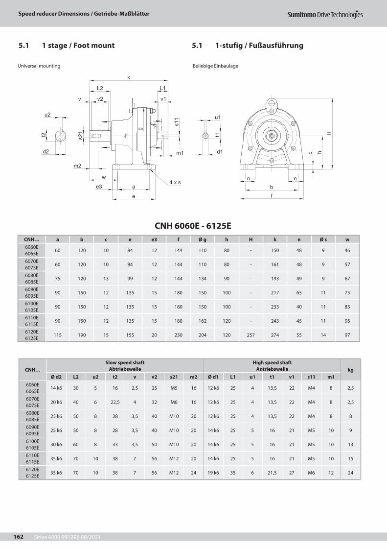
Drive 6000 991296 08/2021
Speed reducer Dimensions / Getriebe-Maßblätter
162
CNH 6060E - 6125ECNH… a b c e e3 f Ø g h H k n Ø s w6060E 6065E
60 120 10 84 12 144 110 80 - 150 48 9 46
6070E 6075E
60 120 10 84 12 144 110 80 - 161 48 9 57
6080E 6085E
75 120 13 99 12 144 134 90 - 193 49 9 67
6090E 6095E
90 150 12 135 15 180 150 100 - 217 65 11 75
6100E 6105E
90 150 12 135 15 180 150 100 - 233 40 11 85
6110E 6115E
90 150 12 135 15 180 162 120 - 243 45 11 95
6120E 6125E
115 190 15 155 20 230 204 120 257 274 55 14 97
Universal mounting Beliebige Einbaulage
5.1 1-stufig / Fußausführung5.1 1 stage / Foot mount
CNH…Slow speed shaft
AbtriebswelleHigh speed shaft
Antriebswelle kgØ d2 L2 u2 t2 v v2 s21 m2 Ø d1 L1 u1 t1 v1 s11 m1
6060E 6065E
14 k6 30 5 16 2,5 25 M5 16 12 k6 25 4 13,5 22 M4 8 2,5
6070E 6075E
20 k6 40 6 22,5 4 32 M6 16 12 k6 25 4 13,5 22 M4 8 2,5
6080E 6085E
25 k6 50 8 28 3,5 40 M10 20 12 k6 25 4 13,5 22 M4 8 8
6090E 6095E
25 k6 50 8 28 3,5 40 M10 20 14 k6 25 5 16 21 M5 10 9
6100E 6105E
30 k6 60 8 33 3,5 50 M10 20 14 k6 25 5 16 21 M5 10 13
6110E 6115E
35 k6 70 10 38 7 56 M12 20 14 k6 25 5 16 21 M5 10 15
6120E 6125E
35 k6 70 10 38 7 56 M12 24 19 k6 35 6 21,5 27 M6 12 24
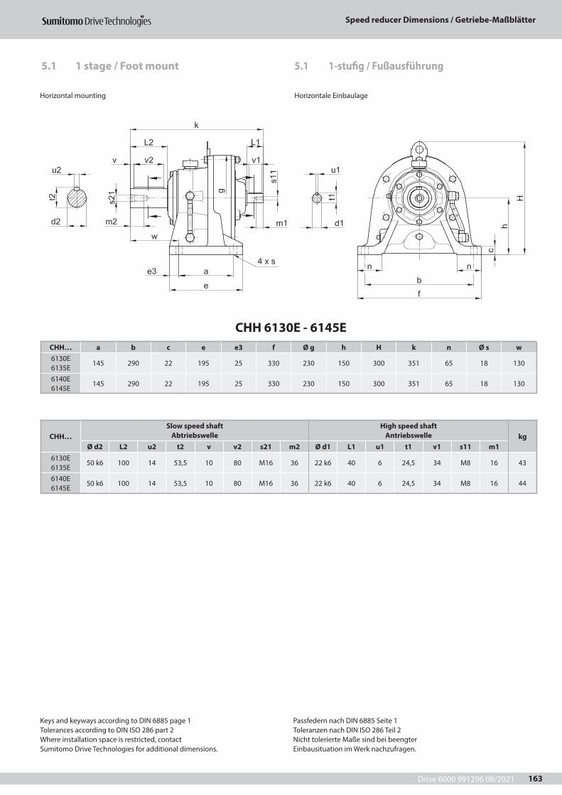
Drive 6000 991296 08/2021
Speed reducer Dimensions / Getriebe-Maßblätter
163
5.1 1-stufig / Fußausführung5.1 1 stage / Foot mount
CHH 6130E - 6145ECHH… a b c e e3 f Ø g h H k n Ø s w6130E 6135E
145 290 22 195 25 330 230 150 300 351 65 18 130
6140E 6145E
145 290 22 195 25 330 230 150 300 351 65 18 130
Horizontal mounting Horizontale Einbaulage
CHH…Slow speed shaft
AbtriebswelleHigh speed shaft
Antriebswelle kgØ d2 L2 u2 t2 v v2 s21 m2 Ø d1 L1 u1 t1 v1 s11 m1
6130E 6135E
50 k6 100 14 53,5 10 80 M16 36 22 k6 40 6 24,5 34 M8 16 43
6140E 6145E
50 k6 100 14 53,5 10 80 M16 36 22 k6 40 6 24,5 34 M8 16 44
Keys and keyways according to DIN 6885 page 1Tolerances according to DIN ISO 286 part 2Where installation space is restricted, contactSumitomo Drive Technologies for additional dimensions.
Passfedern nach DIN 6885 Seite 1Toleranzen nach DIN ISO 286 Teil 2Nicht tolerierte Maße sind bei beengterEinbausituation im Werk nachzufragen.
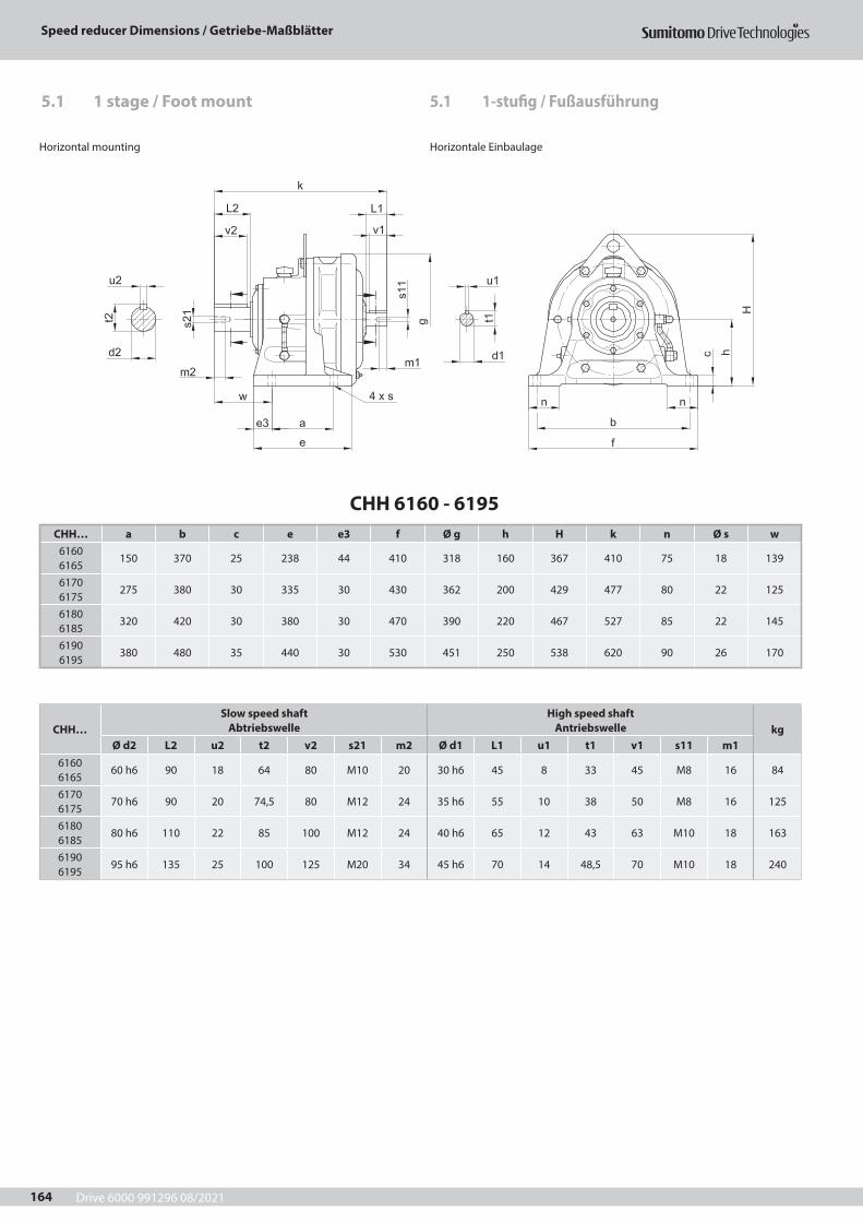
Drive 6000 991296 08/2021
Speed reducer Dimensions / Getriebe-Maßblätter
164
CHH 6160 - 6195CHH… a b c e e3 f Ø g h H k n Ø s w
6160 6165
150 370 25 238 44 410 318 160 367 410 75 18 139
6170 6175
275 380 30 335 30 430 362 200 429 477 80 22 125
6180 6185
320 420 30 380 30 470 390 220 467 527 85 22 145
6190 6195
380 480 35 440 30 530 451 250 538 620 90 26 170
Horizontal mounting Horizontale Einbaulage
CHH…Slow speed shaft
AbtriebswelleHigh speed shaft
Antriebswelle kgØ d2 L2 u2 t2 v2 s21 m2 Ø d1 L1 u1 t1 v1 s11 m1
6160 6165
60 h6 90 18 64 80 M10 20 30 h6 45 8 33 45 M8 16 84
6170 6175
70 h6 90 20 74,5 80 M12 24 35 h6 55 10 38 50 M8 16 125
6180 6185
80 h6 110 22 85 100 M12 24 40 h6 65 12 43 63 M10 18 163
6190 6195
95 h6 135 25 100 125 M20 34 45 h6 70 14 48,5 70 M10 18 240
5.1 1-stufig / Fußausführung5.1 1 stage / Foot mount
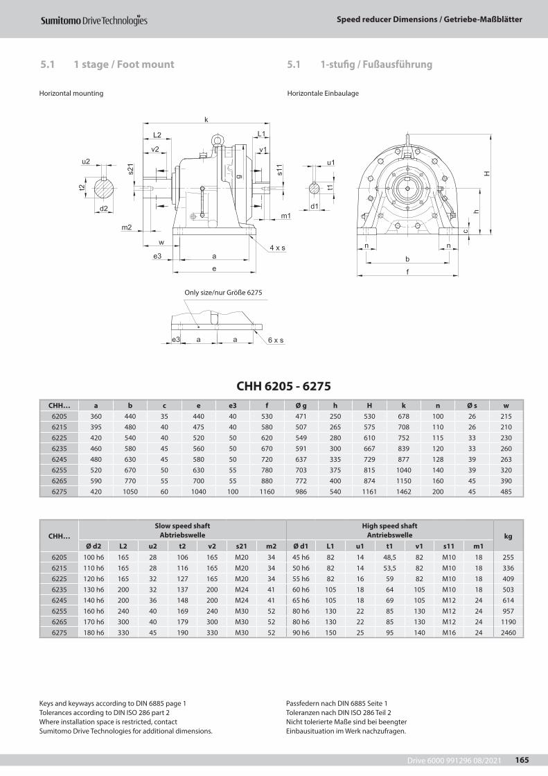
Drive 6000 991296 08/2021
Speed reducer Dimensions / Getriebe-Maßblätter
165
CHH 6205 - 6275CHH… a b c e e3 f Ø g h H k n Ø s w
6205 360 440 35 440 40 530 471 250 530 678 100 26 2156215 395 480 40 475 40 580 507 265 575 708 110 26 2106225 420 540 40 520 50 620 549 280 610 752 115 33 2306235 460 580 45 560 50 670 591 300 667 839 120 33 2606245 480 630 45 580 50 720 637 335 729 877 128 39 2636255 520 670 50 630 55 780 703 375 815 1040 140 39 3206265 590 770 55 700 55 880 772 400 874 1150 160 45 3906275 420 1050 60 1040 100 1160 986 540 1161 1462 200 45 485
Horizontal mounting Horizontale Einbaulage
CHH…Slow speed shaft
AbtriebswelleHigh speed shaft
Antriebswelle kgØ d2 L2 u2 t2 v2 s21 m2 Ø d1 L1 u1 t1 v1 s11 m1
6205 100 h6 165 28 106 165 M20 34 45 h6 82 14 48,5 82 M10 18 2556215 110 h6 165 28 116 165 M20 34 50 h6 82 14 53,5 82 M10 18 3366225 120 h6 165 32 127 165 M20 34 55 h6 82 16 59 82 M10 18 4096235 130 h6 200 32 137 200 M24 41 60 h6 105 18 64 105 M10 18 5036245 140 h6 200 36 148 200 M24 41 65 h6 105 18 69 105 M12 24 6146255 160 h6 240 40 169 240 M30 52 80 h6 130 22 85 130 M12 24 9576265 170 h6 300 40 179 300 M30 52 80 h6 130 22 85 130 M12 24 11906275 180 h6 330 45 190 330 M30 52 90 h6 150 25 95 140 M16 24 2460
Only size/nur Größe 6275
Keys and keyways according to DIN 6885 page 1Tolerances according to DIN ISO 286 part 2Where installation space is restricted, contactSumitomo Drive Technologies for additional dimensions.
Passfedern nach DIN 6885 Seite 1Toleranzen nach DIN ISO 286 Teil 2Nicht tolerierte Maße sind bei beengterEinbausituation im Werk nachzufragen.
5.1 1-stufig / Fußausführung5.1 1 stage / Foot mount
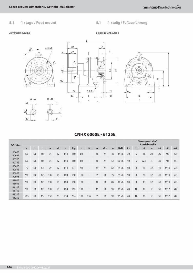
Drive 6000 991296 08/2021
Speed reducer Dimensions / Getriebe-Maßblätter
166
CNHX 6060E - 6125E
CNHX…Slow speed shaft
Abtriebswellea b c e e3 f Ø g h H n Ø s w Ø d2 L2 u2 t2 v v2 s21 m2
6060E 6065E
60 120 10 84 12 144 110 80 - 48 9 46 14 k6 30 5 16 2,5 25 M5 12
6070E 6075E
60 120 10 84 12 144 110 80 - 48 9 57 20 k6 40 6 22,5 4 32 M6 15
6080E 6085E
75 120 13 99 12 144 134 90 - 49 9 67 25 k6 50 8 28 3,5 40 M10 22
6090E 6095E
90 150 12 135 15 180 150 100 - 65 11 75 25 k6 50 8 28 3,5 40 M10 22
6100E 6105E
90 150 12 135 15 180 150 100 - 40 11 85 30 k6 60 8 33 3,5 50 M10 22
6110E 6115E
90 150 12 135 15 180 162 120 - 45 11 95 35 k6 70 10 38 7 56 M12 28
6120E 6125E
115 190 15 155 20 230 204 120 257 55 14 97 35 k6 70 10 38 7 56 M12 28
Universal mounting Beliebige Einbaulage
5.1 1-stufig / Fußausführung5.1 1 stage / Foot mount
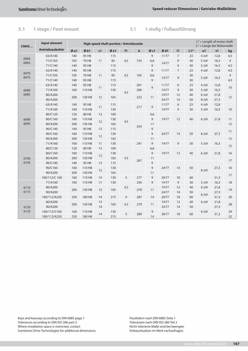
Drive 6000 991296 08/2021
Speed reducer Dimensions / Getriebe-Maßblätter
167
CNHX…Input element
Antriebszubehör
High speed shaft portion / Antriebsseite L* = Length of motor shaft L* = Länge der Motorwelle
Ø a1 Ø b1 c1 Ø e1 f1 k Ø s1 Ø d1 l1 L1* u1 t1 kg
6060 6065
63/A140 140 95 H811
1154,5 154
9 11 F7 7 23 4 Js9 12,8 4,571/C105 105 70 H8 85 6,6
14 F79 30 5 Js9 16,3 4
71/C140 140 95 H8 115 9 9 30 5 Js9 16.3 4,5
6070 6075
63/A140 140 95 H811
1154,5 165
9 11 F7 7 23 4 Js9 12,8 4,571/C105 105 70 H8 85 6,6
14 F7 930
5 Js9 16,34
71/C140 140 95 H8 115 9 30 4,5
6080 6085
63/A140 140 95 H811
115
4,5
2019
11 F7 6 23 4 Js9 12,810
71/A160 160 110 H8 130 206 14 F7 9 30 5 Js9 16,380/A200
200 130 H8 12 165 223 1119 F7 12 40 6 Js9 21,8
1290/A200 24 F7 14 50 8 Js9 27,3
6090 6095
63/A140 140 95 H811
115
4,5
217 911 F7 6 23 4 Js9 12,8
1071/A160 160 110 H8 130 14 F7 9 30 5 Js9 16,380/C120 120 80 H8 13 100
243
6,619 F7 12 40 6 Js9 21,880/C160 160 110 H8
12130 9 11
80/A200 200 130 H8 165 11 1290/C140 140 95 H8 13 115 9
24 F7 14 50 8 Js9 27,311
90/C160 160 110 H812
130 990/A200 200 130 H8 165 11 12
6100 6105
71/A160 160 110 H8 11 130
4,5
241 9 14 F7 9 30 5 Js9 16,315
80/C120 120 80 H8 13 100
267
6,619 F7 12 40 6 Js9 21,880/C160 160 110 H8
12130 9 16
80/A200 200 130 H8 165 1117
90/C140 140 95 H8 13 115 924 F7 14 50
8 Js927,390/C160 160 110 H8
12130 9 16
90/A200 200 130 H8 165 1117
100/112/C 160 160 110 H8 14 130 5 277 9 28 F7 18 60 31,3
6110 6115
71/A160 160 110 H8 11 1304,5
256 9 14 F7 9 30 5 Js9 16,3 1880/A200
200 130 H8 12 165 278 1119 F7 12 40 6 Js9 21,8
1990/A200 24 F7 14 50
8 Js927,3
100/112/A250 250 180 H8 14 215 6 287 14 28 F7 18 60 31,3 20
6120 6125
80/A200200 130 H8
13165 4.5 279 11
19 F7 12 40 6 Js9 21,828
90/A200 14 24 F7 14 508 Js9
27,3100/112/C160 160 110 H8
14130
5 2899
28 F7 18 60 31,329
100/112/A250 250 180 H8 215 14 32
Keys and keyways according to DIN 6885 page 1Tolerances according to DIN ISO 286 part 2Where installation space is restricted, contactSumitomo Drive Technologies for additional dimensions.
Passfedern nach DIN 6885 Seite 1Toleranzen nach DIN ISO 286 Teil 2Nicht tolerierte Maße sind bei beengterEinbausituation im Werk nachzufragen.
5.1 1-stufig / Fußausführung5.1 1 stage / Foot mount

Drive 6000 991296 08/2021
Speed reducer Dimensions / Getriebe-Maßblätter
168
CHHX 6130E - 6165
CHHX…Slow speed shaft
Abtriebswellea b c e e3 f Ø g h n Ø s w Ø d2 L2 u2 t2 v v2 s21 m2
6130E 6135E
145 290 22 195 25 330 230 150 65 18 130 50 k6 100 14 53,5 10 80 M16 30
6140E 6145E
145 290 22 195 25 330 230 150 65 18 130 50 k6 100 14 53,5 10 80 M16 30
6160 6165
150 370 25 238 44 410 300 160 75 18 139 60 h6 90 18 64 0 80 M10 20
Horizontal mounting Horizontale Einbaulage
Size / Größe 6160, 6165
Size / Größe 6130 - 6145
CHHX…Input element
Antriebszubehör
High speed shaft portion / Antriebsseite L* = Length of motor shaft L* = Länge der Motorwelle
Ø a1 Ø b1 c1 Ø e1 f1 H k Ø s1 Ø d1 l1 L1* u1 t1 kg
6130 6135
90/A200 200 130 H8 11 165 4,5 295 351 11 24 F7 14 50 8 Js9 27,3 46100/112/A250 250 180 H8 13 215
5320 361
1428 F7 18 60 8 Js9 31,3 48
132/A300 300 230 H8 17 265 345 387 38 F7 23 80 10 Js9 41,3 53
6140 6145
90/A200 200 130 H8 11 165 4,5 295 351 11 24 F7 14 50 8 Js9 27,3 47100/112/A250 250 180 H8 13 215
5320 361
1428 F7 18 60 8 Js9 31,3 49
132/A300 300 230 H8 17 265 345 387 38 F7 23 80 10 Js9 41,3 54
6160 6165
100/112/A250 250 180 H8 14 2155
361 39414
28 F7 18 60 8 Js9 31,3 88132/A300 300 230 H8 16 265 361 416 38 F7 23 80 10 Js9 41,3 93160/A350 350 250 H8 16 300 6 361 452 18 42 F7 47 110 12 Js9 45,3 98
5.1 1-stufig / Fußausführung5.1 1 stage / Foot mount
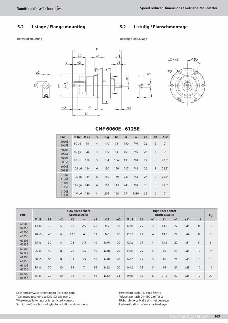
Drive 6000 991296 08/2021
Speed reducer Dimensions / Getriebe-Maßblätter
169
CNF 6060E - 6125ECNF… Ø b2 Ø e2 f2 Ø g l2 k s2 x2 z2 AE26060E 6065E
80 g6 98 4 110 73 150 M6 26 6 0°
6070E 6075E
80 g6 98 4 110 84 161 M6 26 6 0°
6080E 6085E
95 g6 118 5 134 106 193 M8 27 8 22,5°
6090E 6095E
105 g6 134 6 150 129 217 M8 26 8 22,5°
6100E 6105E
105 g6 134 6 150 139 233 M8 27 8 22,5°
6110E 6115E
115 g6 146 6 162 143 243 M8 28 8 22,5°
6120E 6125E
140 g6 180 14 204 154 274 M10 32 6 0°
Universal mounting Beliebige Einbaulage
Keys and keyways according to DIN 6885 page 1Tolerances according to DIN ISO 286 part 2Where installation space is restricted, contactSumitomo Drive Technologies for additional dimensions.
Passfedern nach DIN 6885 Seite 1Toleranzen nach DIN ISO 286 Teil 2Nicht tolerierte Maße sind bei beengterEinbausituation im Werk nachzufragen.
CNF…Slow speed shaft
AbtriebswelleHigh speed shaft
Antriebswelle kgØ d2 L2 u2 t2 v v2 s21 m2 Ø d1 L1 u1 t1 v1 s11 m1
6060E 6065E
14 k6 30 5 16 2,5 25 M5 16 12 k6 25 4 13,5 22 M4 8 3
6070E 6075E
20 k6 40 6 22,5 4 32 M6 16 12 k6 25 4 13,5 22 M4 8 3
6080E 6085E
25 k6 50 8 28 3,5 40 M10 20 12 k6 25 4 13,5 22 M4 8 8
6090E 6095E
25 k6 50 8 28 3,5 40 M10 20 14 k6 25 5 16 21 M5 10 9
6100E 6105E
30 k6 60 8 33 3,5 50 M10 20 14 k6 25 5 16 21 M5 10 10
6110E 6115E
35 k6 70 10 38 7 56 M12 20 14 k6 25 5 16 21 M5 10 11
6120E 6125E
35 k6 70 10 38 7 56 M12 24 19 k6 35 6 21,5 27 M6 12 20
5.2 1-stufig / Flanschmontage5.2 1 stage / Flange mounting
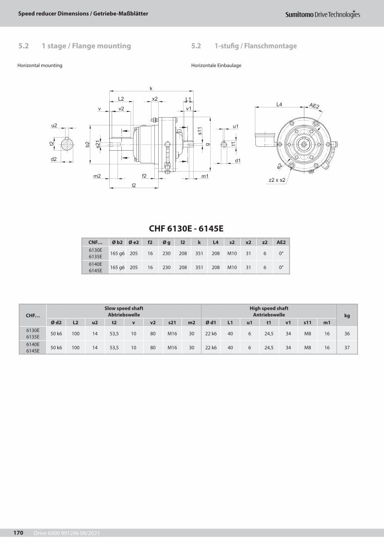
Drive 6000 991296 08/2021
Speed reducer Dimensions / Getriebe-Maßblätter
170
5.2 1-stufig / Flanschmontage5.2 1 stage / Flange mounting
CHF 6130E - 6145ECNF… Ø b2 Ø e2 f2 Ø g l2 k L4 s2 x2 z2 AE26130E 6135E
165 g6 205 16 230 208 351 208 M10 31 6 0°
6140E 6145E
165 g6 205 16 230 208 351 208 M10 31 6 0°
CHF…Slow speed shaft
AbtriebswelleHigh speed shaft
Antriebswelle kgØ d2 L2 u2 t2 v v2 s21 m2 Ø d1 L1 u1 t1 v1 s11 m1
6130E 6135E
50 k6 100 14 53,5 10 80 M16 30 22 k6 40 6 24,5 34 M8 16 36
6140E 6145E
50 k6 100 14 53,5 10 80 M16 30 22 k6 40 6 24,5 34 M8 16 37
Horizontal mounting Horizontale Einbaulage
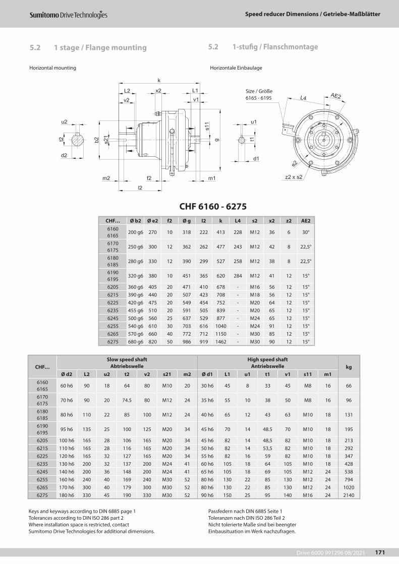
Drive 6000 991296 08/2021
Speed reducer Dimensions / Getriebe-Maßblätter
171
5.2 1 stage / Flange mounting
CHF 6160 - 6275CHF… Ø b2 Ø e2 f2 Ø g I2 k L4 s2 x2 z2 AE26160 6165
200 g6 270 10 318 222 413 228 M12 36 6 30°
6170 6175
250 g6 300 12 362 262 477 243 M12 42 8 22,5°
6180 6185
280 g6 330 12 390 299 527 258 M12 38 8 22,5°
6190 6195
320 g6 380 10 451 365 620 284 M12 41 12 15°
6205 360 g6 405 20 471 410 678 - M16 56 12 15°6215 390 g6 440 20 507 423 708 - M18 56 12 15°6225 420 g6 475 20 549 454 752 - M20 64 12 15°6235 455 g6 510 20 591 505 839 - M20 65 12 15°6245 500 g6 560 25 637 529 877 - M24 65 12 15°6255 540 g6 610 30 703 616 1040 - M24 91 12 15°6265 570 g6 660 40 772 712 1150 - M30 85 12 15°6275 680 g6 820 50 986 919 1462 - M30 90 12 15°
Keys and keyways according to DIN 6885 page 1Tolerances according to DIN ISO 286 part 2Where installation space is restricted, contactSumitomo Drive Technologies for additional dimensions.
Passfedern nach DIN 6885 Seite 1Toleranzen nach DIN ISO 286 Teil 2Nicht tolerierte Maße sind bei beengterEinbausituation im Werk nachzufragen.
CHF…Slow speed shaft
AbtriebswelleHigh speed shaft
Antriebswelle kgØ d2 L2 u2 t2 v2 s21 m2 Ø d1 L1 u1 t1 v1 s11 m1
6160 6165
60 h6 90 18 64 80 M10 20 30 h6 45 8 33 45 M8 16 66
6170 6175
70 h6 90 20 74.5 80 M12 24 35 h6 55 10 38 50 M8 16 96
6180 6185
80 h6 110 22 85 100 M12 24 40 h6 65 12 43 63 M10 18 131
6190 6195
95 h6 135 25 100 125 M20 34 45 h6 70 14 48.5 70 M10 18 195
6205 100 h6 165 28 106 165 M20 34 45 h6 82 14 48,5 82 M10 18 2136215 110 h6 165 28 116 165 M20 34 50 h6 82 14 53,5 82 M10 18 2926225 120 h6 165 32 127 165 M20 34 55 h6 82 16 59 82 M10 18 3476235 130 h6 200 32 137 200 M24 41 60 h6 105 18 64 105 M10 18 4286245 140 h6 200 36 148 200 M24 41 65 h6 105 18 69 105 M12 24 5386255 160 h6 240 40 169 240 M30 52 80 h6 130 22 85 130 M12 24 7946265 170 h6 300 40 179 300 M30 52 80 h6 130 22 85 130 M12 24 10206275 180 h6 330 45 190 330 M30 52 90 h6 150 25 95 140 M16 24 2140
Horizontal mounting Horizontale Einbaulage
Size / Größe 6165 - 6195
5.2 1-stufig / Flanschmontage
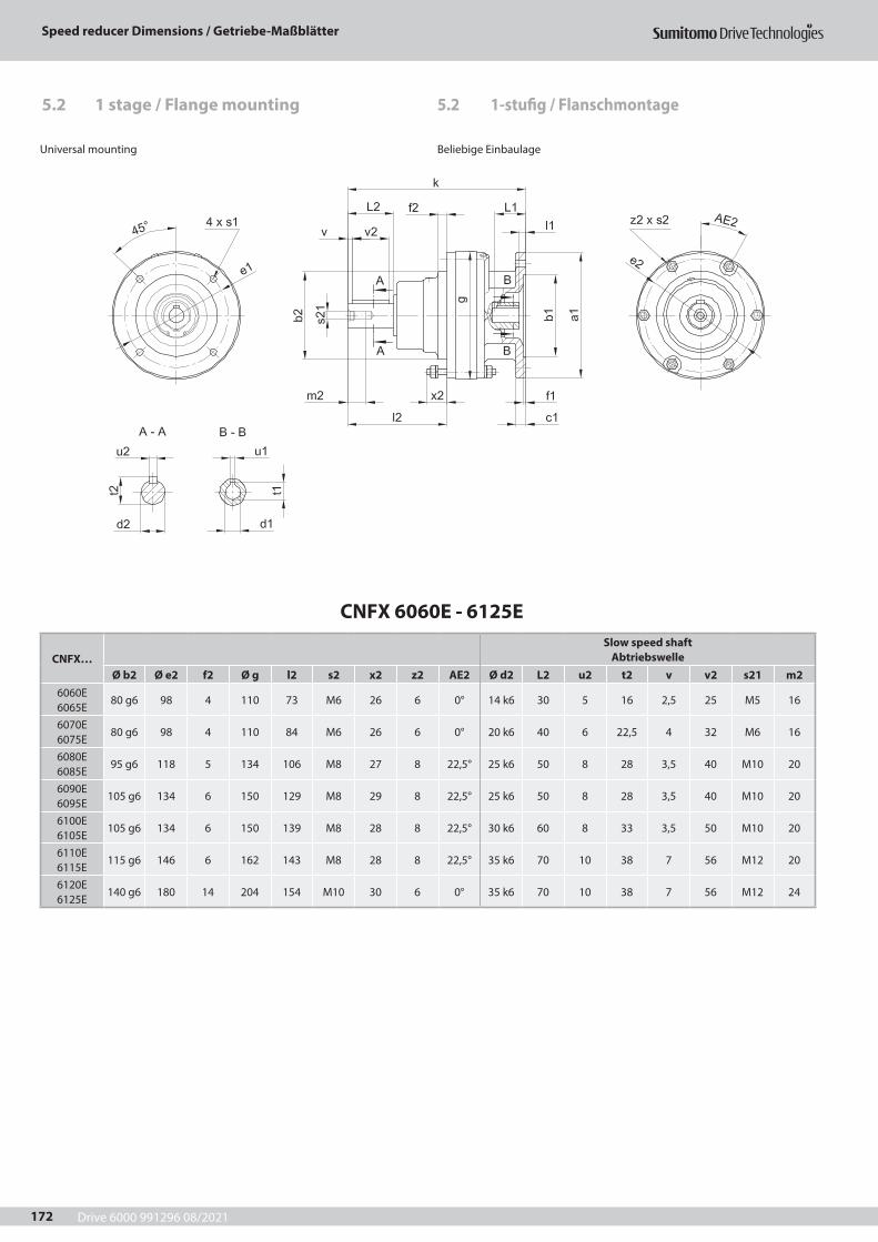
Drive 6000 991296 08/2021
Speed reducer Dimensions / Getriebe-Maßblätter
172
5.2 1-stufig / Flanschmontage
Universal mounting Beliebige Einbaulage
CNFX 6060E - 6125E
CNFX…Slow speed shaft
AbtriebswelleØ b2 Ø e2 f2 Ø g l2 s2 x2 z2 AE2 Ø d2 L2 u2 t2 v v2 s21 m2
6060E 6065E
80 g6 98 4 110 73 M6 26 6 0° 14 k6 30 5 16 2,5 25 M5 16
6070E 6075E
80 g6 98 4 110 84 M6 26 6 0° 20 k6 40 6 22,5 4 32 M6 16
6080E 6085E
95 g6 118 5 134 106 M8 27 8 22,5° 25 k6 50 8 28 3,5 40 M10 20
6090E 6095E
105 g6 134 6 150 129 M8 29 8 22,5° 25 k6 50 8 28 3,5 40 M10 20
6100E 6105E
105 g6 134 6 150 139 M8 28 8 22,5° 30 k6 60 8 33 3,5 50 M10 20
6110E 6115E
115 g6 146 6 162 143 M8 28 8 22,5° 35 k6 70 10 38 7 56 M12 20
6120E 6125E
140 g6 180 14 204 154 M10 30 6 0° 35 k6 70 10 38 7 56 M12 24
5.2 1 stage / Flange mounting
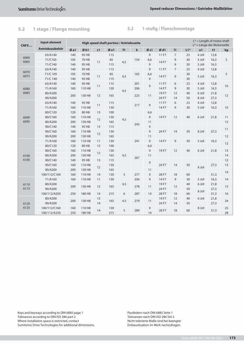
Drive 6000 991296 08/2021
Speed reducer Dimensions / Getriebe-Maßblätter
173
CNFX…Input element
Antriebszubehör
High speed shaft portion / Antriebsseite L* = Length of motor shaft L* = Länge der Motorwelle
Ø a1 Ø b1 c1 Ø e1 f1 k Ø s1 Ø d1 l1 L1* u1 t1 kg
6060 6065
63/A140 140 95 H8
11
115
4,5154
9 11 F7 7 23 4 Js9 12,8571/C105 105 70 H8 85 6,6
14 F79 30 5 Js9 16,3
71/C140 140 95 H8 115 9 9 30 5 Js9 16.3
6070 6075
63/A140 140 95 H8 115165
9 11 F7 7 23 4 Js9 12,8571/C 105 105 70 H8
1185
4,56,6
14 F7 930
5 Js9 16,371/C 140 140 95 H8 115 9 30
6080 6085
63/A140 140 95 H811
115
4,5
2019
11 F7 6 23 4 Js9 12,810
71/A160 160 110 H8 130 206 14 F7 9 30 5 Js9 16,380/A200
200 130 H8 12 165 223 1119 F7 12 40 6 Js9 21,8
1290/A200 24 F7 14 50 8 Js9 27,3
6090 6095
63/A140 140 95 H811
115
4,5
217 911 F7 6 23 4 Js9 12,8
1071/A160 160 110 H8 130 14 F7 9 30 5 Js9 16,380/C120 120 80 H8 13 100
243
6,619 F7 12 40 6 Js9 21,880/C160 160 110 H8
12130 9 11
80/A200 200 130 H8 165 11 1290/C140 140 95 H8 13 115 9
24 F7 14 50 8 Js9 27,311
90/C160 160 110 H812
130 990/A200 200 130 H8 165 11 12
6100 6105
71/A160 160 110 H8 11 130
4,5
241 9 14 F7 9 30 5 Js9 16,312
80/C120 120 80 H8 13 100
267
6,619 F7 12 40 6 Js9 21,880/C160 160 110 H8
12130 9 13
80/A200 200 130 H8 165 11 1490/C140 140 95 H8 13 115
924 F7 14 50
8 Js927,3
1290/C160 160 110 H8
12130 13
90/A200 200 130 H8 165 1114
100/112/C160 160 110 H8 14 130 5 277 9 28 F7 18 60 31,3
6110 6115
71/A160 160 110 H8 11 1304,5
256 9 14 F7 9 30 5 Js9 16,3 1480/A200
200 130 H8 12 165 278 1119 F7
1240 6 Js9 21,8
1590/A200 24 F7 50
8 Js927,3
100/112/A250 250 180 H8 14 215 6 287 14 28 F7 18 60 31,3 16
6120 6125
80/A200200 130 H8
13165 4.5 279 11
19 F7 12 40 6 Js9 21,824
90/A200 14 24 F7 14 508 Js9
27,3100/112/C160 160 110 H8
14130
5 2899
28 F7 18 60 31,325
100/112/A250 250 180 H8 215 14 28
Keys and keyways according to DIN 6885 page 1Tolerances according to DIN ISO 286 part 2Where installation space is restricted, contactSumitomo Drive Technologies for additional dimensions.
Passfedern nach DIN 6885 Seite 1Toleranzen nach DIN ISO 286 Teil 2Nicht tolerierte Maße sind bei beengterEinbausituation im Werk nachzufragen.
5.2 1-stufig / Flanschmontage5.2 1 stage / Flange mounting
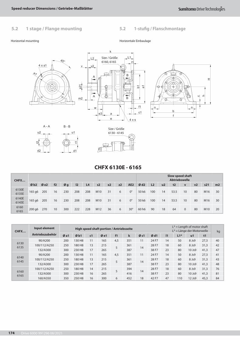
Drive 6000 991296 08/2021
Speed reducer Dimensions / Getriebe-Maßblätter
174
CHFX 6130E - 6165
CHFX…Slow speed shaft
AbtriebswelleØ b2 Ø e2 f2 Ø g l2 L4 s2 x2 z2 AE2 Ø d2 L2 u2 t2 v v2 s21 m2
6130E 6135E
165 g6 205 16 230 208 208 M10 31 6 0° 50 k6 100 14 53.5 10 80 M16 30
6140E 6145E
165 g6 205 16 230 208 208 M10 31 6 0° 50 k6 100 14 53.5 10 80 M16 30
6160 6165
200 g6 270 10 300 222 228 M12 36 6 30° 60 h6 90 18 64 0 80 M10 20
Horizontal mounting Horizontale Einbaulage
Size / Größe 6160, 6165
CHFX…Input element
Antriebszubehör
High speed shaft portion / Antriebsseite L* = Length of motor shaft L* = Länge der Motorwelle kg
Ø a1 Ø b1 c1 Ø e1 f1 k Ø s1 Ø d1 l1 L1* u1 t1
6130 6135
90/A200 200 130 H8 11 165 4,5 351 11 24 F7 14 50 8 Js9 27,3 40100/112/A250 250 180 H8 13 215
5361
1428 F7 18 60 8 Js9 31,3 42
132/A300 300 230 H8 17 265 387 38 F7 23 80 10 Js9 41,3 47
6140 6145
90/A200 200 130 H8 11 165 4,5 351 11 24 F7 14 50 8 Js9 27,3 41100/112/A250 250 180 H8 13 215
5361
1428 F7 18 60 8 Js9 31,3 43
132/A300 300 230 H8 17 265 387 38 F7 23 80 10 Js9 41,3 48
6160 6165
100/112/A250 250 180 H8 14 2155
39414
28 F7 18 60 8 Js9 31,3 76132/A300 300 230 H8 16 265 416 38 F7 23 80 10 Js9 41,3 81160/A350 350 250 H8 16 300 6 452 18 42 F7 47 110 12 Js9 45,3 84
5.2 1-stufig / Flanschmontage5.2 1 stage / Flange mounting
Size / Größe 6130 - 6145
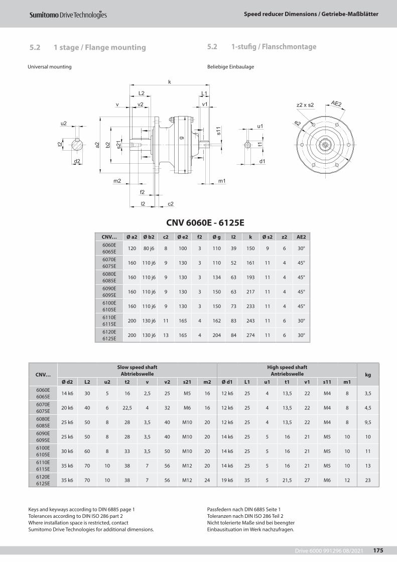
Drive 6000 991296 08/2021
Speed reducer Dimensions / Getriebe-Maßblätter
175
CNV 6060E - 6125ECNV… Ø a2 Ø b2 c2 Ø e2 f2 Ø g I2 k Ø s2 z2 AE26060E 6065E
120 80 j6 8 100 3 110 39 150 9 6 30°
6070E 6075E
160 110 j6 9 130 3 110 52 161 11 4 45°
6080E 6085E
160 110 j6 9 130 3 134 63 193 11 4 45°
6090E 6095E
160 110 j6 9 130 3 150 63 217 11 4 45°
6100E 6105E
160 110 j6 9 130 3 150 73 233 11 4 45°
6110E 6115E
200 130 j6 11 165 4 162 83 243 11 6 30°
6120E 6125E
200 130 j6 13 165 4 204 84 274 11 6 30°
CNV…Slow speed shaft
AbtriebswelleHigh speed shaft
Antriebswelle kgØ d2 L2 u2 t2 v v2 s21 m2 Ø d1 L1 u1 t1 v1 s11 m1
6060E 6065E
14 k6 30 5 16 2,5 25 M5 16 12 k6 25 4 13,5 22 M4 8 3,5
6070E 6075E
20 k6 40 6 22,5 4 32 M6 16 12 k6 25 4 13,5 22 M4 8 4,5
6080E 6085E
25 k6 50 8 28 3,5 40 M10 20 12 k6 25 4 13,5 22 M4 8 9,5
6090E 6095E
25 k6 50 8 28 3,5 40 M10 20 14 k6 25 5 16 21 M5 10 10
6100E 6105E
30 k6 60 8 33 3,5 50 M10 20 14 k6 25 5 16 21 M5 10 11
6110E 6115E
35 k6 70 10 38 7 56 M12 20 14 k6 25 5 16 21 M5 10 13
6120E 6125E
35 k6 70 10 38 7 56 M12 24 19 k6 35 5 21,5 27 M6 12 23
Universal mounting Beliebige Einbaulage
Keys and keyways according to DIN 6885 page 1Tolerances according to DIN ISO 286 part 2Where installation space is restricted, contactSumitomo Drive Technologies for additional dimensions.
Passfedern nach DIN 6885 Seite 1Toleranzen nach DIN ISO 286 Teil 2Nicht tolerierte Maße sind bei beengterEinbausituation im Werk nachzufragen.
5.2 1-stufig / Flanschmontage5.2 1 stage / Flange mounting
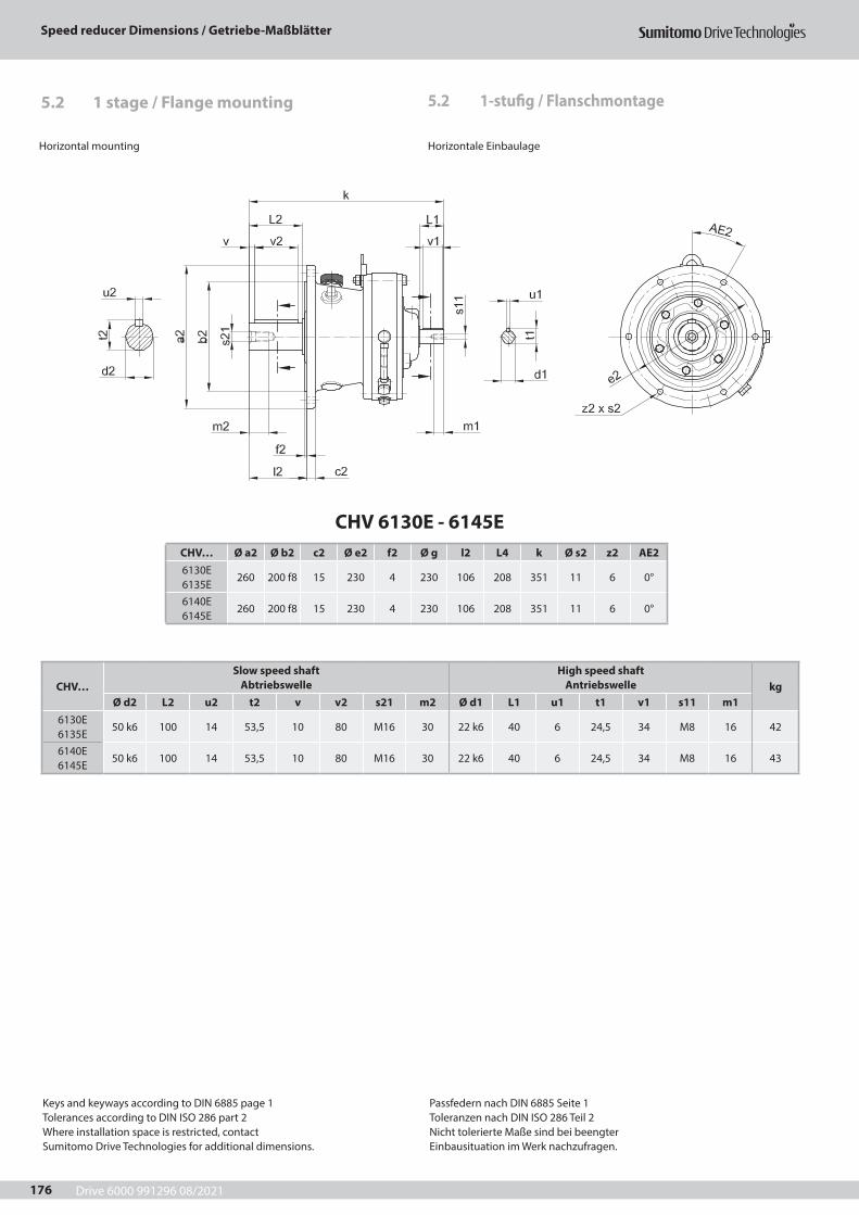
Drive 6000 991296 08/2021
Speed reducer Dimensions / Getriebe-Maßblätter
176
CHV 6130E - 6145ECHV… Ø a2 Ø b2 c2 Ø e2 f2 Ø g l2 L4 k Ø s2 z2 AE26130E 6135E
260 200 f8 15 230 4 230 106 208 351 11 6 0°
6140E 6145E
260 200 f8 15 230 4 230 106 208 351 11 6 0°
CHV…Slow speed shaft
AbtriebswelleHigh speed shaft
Antriebswelle kgØ d2 L2 u2 t2 v v2 s21 m2 Ø d1 L1 u1 t1 v1 s11 m1
6130E 6135E
50 k6 100 14 53,5 10 80 M16 30 22 k6 40 6 24,5 34 M8 16 42
6140E 6145E
50 k6 100 14 53,5 10 80 M16 30 22 k6 40 6 24,5 34 M8 16 43
5.2 1-stufig / Flanschmontage
Horizontal mounting Horizontale Einbaulage
Keys and keyways according to DIN 6885 page 1Tolerances according to DIN ISO 286 part 2Where installation space is restricted, contactSumitomo Drive Technologies for additional dimensions.
Passfedern nach DIN 6885 Seite 1Toleranzen nach DIN ISO 286 Teil 2Nicht tolerierte Maße sind bei beengterEinbausituation im Werk nachzufragen.
5.2 1 stage / Flange mounting
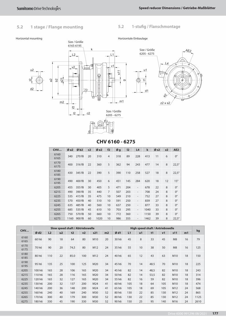
Drive 6000 991296 08/2021
Speed reducer Dimensions / Getriebe-Maßblätter
177
CHV 6160 - 6275CHV… Ø a2 Ø b2 c2 Ø e2 f2 Ø g l2 L4 k Ø s2 z2 AE26160 6165
340 270 f8 20 310 4 318 89 228 413 11 6 0°
6170 6175
400 316 f8 22 360 5 362 94 243 477 14 8 22,5°
6180 6185
430 345 f8 22 390 5 390 110 258 527 18 8 22,5°
6190 6195
490 400 f8 30 450 6 451 145 284 620 18 12 15°
6205 455 355 f8 30 405 5 471 204 - 678 22 8 0°6215 490 390 f8 35 440 7 507 203 - 708 24 8 0°6225 535 415 f8 35 475 10 549 210 - 752 27 8 0°6235 570 450 f8 40 510 10 591 250 - 839 27 8 0°6245 635 485 f8 40 560 10 637 250 - 877 33 8 0°6255 685 535 f8 45 610 10 703 295 - 1040 33 8 0°6265 750 570 f8 50 660 10 772 360 - 1150 39 8 0°6275 1160 900 f8 60 1020 10 986 355 - 1462 39 8 22,5°
CHV…Slow speed shaft / Abtriebswelle High speed shaft / Antriebswelle
kgØ d2 L2 u2 t2 v2 s21 m2 Ø d1 L1 u1 t1 v1 s11 m1
6160 6165
60 h6 90 18 64 80 M10 20 30 h6 45 8 33 45 M8 16 79
6170 6175
70 h6 90 20 74,5 80 M12 24 35 h6 55 10 38 50 M8 16 125
6180 6185
80 h6 110 22 85.0 100 M12 24 40 h6 65 12 43 63 M10 18 150
6190 6195
95 h6 135 25 100 125 M20 34 45 h6 70 14 48.5 70 M10 18 225
6205 100 h6 165 28 106 165 M20 34 45 h6 82 14 48,5 82 M10 18 2436215 110 h6 165 28 116 165 M20 34 50 h6 82 14 53,5 82 M10 18 3146225 120 h6 165 32 127 165 M20 34 55 h6 82 16 59 82 M10 18 3966235 130 h6 200 32 137 200 M24 41 60 h6 105 18 64 105 M10 18 4746245 140 h6 200 36 148 200 M24 41 65 h6 105 18 69 105 M12 24 5686255 160 h6 240 40 169 240 M30 52 80 h6 130 22 85 130 M12 24 8656265 170 h6 300 40 179 300 M30 52 80 h6 130 22 85 130 M12 24 11256275 180 h6 330 45 190 330 M30 52 90 h6 150 25 95 140 M16 24 2610
5.2 1-stufig / Flanschmontage
d2
u2
t2
v2
m2
L2
s21
u1
t1
d1
f2
L4
s11
m1
k
L1
v1
l2
ga2 b2
c2
AE2
z2 x s2
e2
Horizontal mounting Horizontale Einbaulage
Size / Größe 6205 - 6275
Size / Größe 6205 - 6275
Size / Größe 6165-6195
5.2 1 stage / Flange mounting
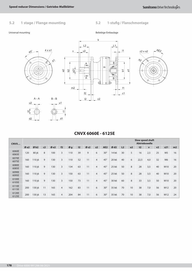
Drive 6000 991296 08/2021
Speed reducer Dimensions / Getriebe-Maßblätter
178
5.2 1-stufig / Flanschmontage
Universal mounting Beliebige Einbaulage
CNVX 6060E - 6125E
CNVX…Slow speed shaft
AbtriebswelleØ a2 Ø b2 c2 Ø e2 f2 Ø g I2 Ø s2 z2 AE2 Ø d2 L2 u2 t2 v v2 s21 m2
6060E 6065E
120 80 j6 8 100 3 110 39 9 6 30° 14 k6 30 5 16 2,5 25 M5 16
6070E 6075E
160 110 j6 9 130 3 110 52 11 4 45° 20 k6 40 6 22,5 4,0 32 M6 16
6080E 6085E
160 110 j6 9 130 3 134 63 11 4 45° 25 k6 50 8 28 3,5 40 M10 20
6090E 6095E
160 110 j6 9 130 3 150 63 11 4 45° 25 k6 50 8 28 3,5 40 M10 20
6100E 6105E
160 110 j6 9 130 3 150 73 11 4 45° 30 k6 60 8 33 3,5 50 M10 20
6110E 6115E
200 130 j6 11 165 4 162 83 11 6 30° 35 k6 70 10 38 7,0 56 M12 20
6120E 6125E
200 130 j6 13 165 4 204 84 11 6 30° 35 k6 70 10 38 7,0 56 M12 24
5.2 1 stage / Flange mounting
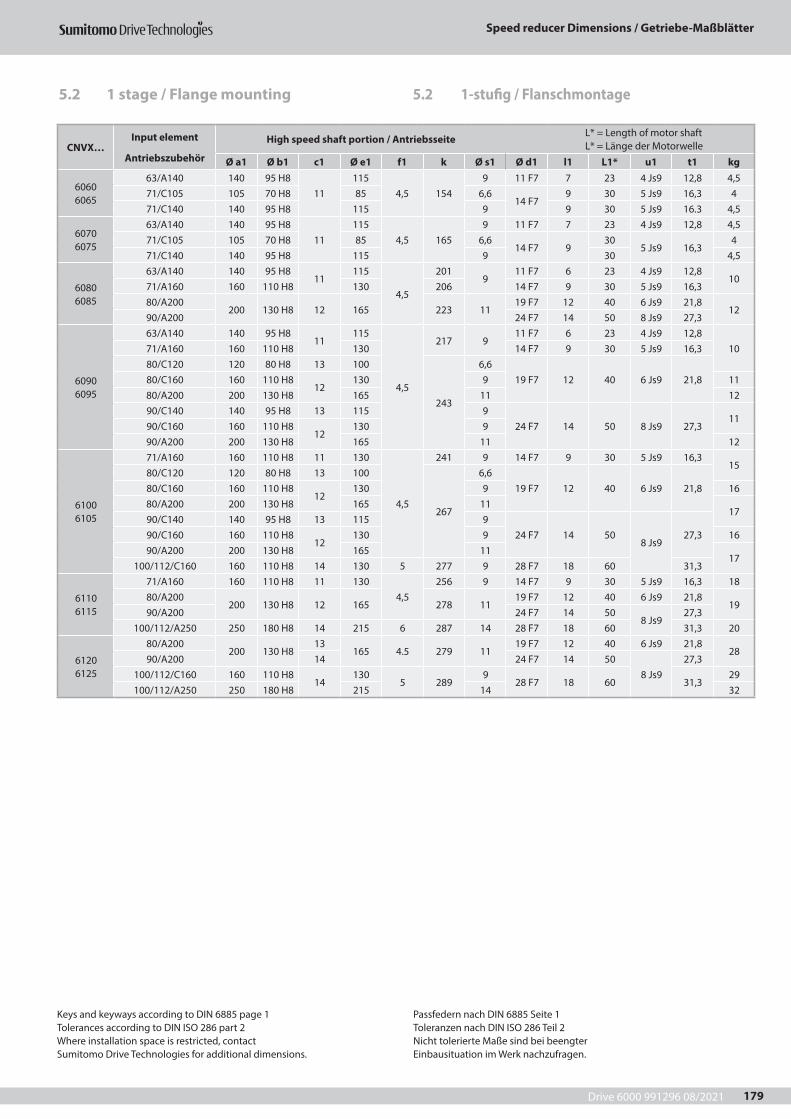
Drive 6000 991296 08/2021
Speed reducer Dimensions / Getriebe-Maßblätter
179
5.2 1-stufig / Flanschmontage
CNVX…Input element
Antriebszubehör
High speed shaft portion / Antriebsseite L* = Length of motor shaft L* = Länge der Motorwelle
Ø a1 Ø b1 c1 Ø e1 f1 k Ø s1 Ø d1 l1 L1* u1 t1 kg
6060 6065
63/A140 140 95 H811
1154,5 154
9 11 F7 7 23 4 Js9 12,8 4,571/C105 105 70 H8 85 6,6
14 F79 30 5 Js9 16,3 4
71/C140 140 95 H8 115 9 9 30 5 Js9 16.3 4,5
6070 6075
63/A140 140 95 H811
1154,5 165
9 11 F7 7 23 4 Js9 12,8 4,571/C105 105 70 H8 85 6,6
14 F7 930
5 Js9 16,34
71/C140 140 95 H8 115 9 30 4,5
6080 6085
63/A140 140 95 H811
115
4,5
2019
11 F7 6 23 4 Js9 12,810
71/A160 160 110 H8 130 206 14 F7 9 30 5 Js9 16,380/A200
200 130 H8 12 165 223 1119 F7 12 40 6 Js9 21,8
1290/A200 24 F7 14 50 8 Js9 27,3
6090 6095
63/A140 140 95 H811
115
4,5
217 911 F7 6 23 4 Js9 12,8
1071/A160 160 110 H8 130 14 F7 9 30 5 Js9 16,380/C120 120 80 H8 13 100
243
6,619 F7 12 40 6 Js9 21,880/C160 160 110 H8
12130 9 11
80/A200 200 130 H8 165 11 1290/C140 140 95 H8 13 115 9
24 F7 14 50 8 Js9 27,311
90/C160 160 110 H812
130 990/A200 200 130 H8 165 11 12
6100 6105
71/A160 160 110 H8 11 130
4,5
241 9 14 F7 9 30 5 Js9 16,315
80/C120 120 80 H8 13 100
267
6,619 F7 12 40 6 Js9 21,880/C160 160 110 H8
12130 9 16
80/A200 200 130 H8 165 1117
90/C140 140 95 H8 13 115 924 F7 14 50
8 Js927,390/C160 160 110 H8
12130 9 16
90/A200 200 130 H8 165 1117
100/112/C160 160 110 H8 14 130 5 277 9 28 F7 18 60 31,3
6110 6115
71/A160 160 110 H8 11 1304,5
256 9 14 F7 9 30 5 Js9 16,3 1880/A200
200 130 H8 12 165 278 1119 F7 12 40 6 Js9 21,8
1990/A200 24 F7 14 50
8 Js927,3
100/112/A250 250 180 H8 14 215 6 287 14 28 F7 18 60 31,3 20
6120 6125
80/A200200 130 H8
13165 4.5 279 11
19 F7 12 40 6 Js9 21,828
90/A200 14 24 F7 14 508 Js9
27,3100/112/C160 160 110 H8
14130
5 2899
28 F7 18 60 31,329
100/112/A250 250 180 H8 215 14 32
Keys and keyways according to DIN 6885 page 1Tolerances according to DIN ISO 286 part 2Where installation space is restricted, contactSumitomo Drive Technologies for additional dimensions.
Passfedern nach DIN 6885 Seite 1Toleranzen nach DIN ISO 286 Teil 2Nicht tolerierte Maße sind bei beengterEinbausituation im Werk nachzufragen.
5.2 1 stage / Flange mounting
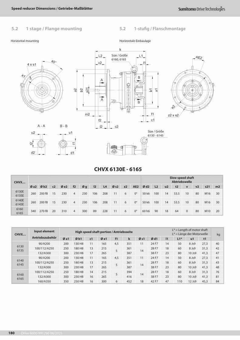
Drive 6000 991296 08/2021
Speed reducer Dimensions / Getriebe-Maßblätter
180
CHVX 6130E - 6165
CHVX…Slow speed shaft
AbtriebswelleØ a2 Ø b2 c2 Ø e2 f2 Ø g l2 L4 Ø s2 z2 AE2 Ø d2 L2 u2 t2 v v2 s21 m2
6130E 6135E
260 200 f8 15 230 4 230 106 208 11 6 0° 50 k6 100 14 53.5 10 80 M16 30
6140E 6145E
260 200 f8 15 230 4 230 106 208 11 6 0° 50 k6 100 14 53.5 10 80 M16 30
6160 6165
340 270 f8 20 310 4 300 89 228 11 6 0° 60 h6 90 18 64 0 80 M10 20
Horizontal mounting Horizontale Einbaulage
Size / Größe 6160, 6165
Size / Größe 6130 - 6145
CHVX…Input element
Antriebszubehör
High speed shaft portion / Antriebsseite L* = Length of motor shaft L* = Länge der Motorwelle kg
Ø a1 Ø b1 c1 Ø e1 f1 k Ø s1 Ø d1 l1 L1* u1 t1
6130 6135
90/A200 200 130 H8 11 165 4,5 351 11 24 F7 14 50 8 Js9 27,3 40100/112/A250 250 180 H8 13 215
5361
1428 F7 18 60 8 Js9 31,3 42
132/A300 300 230 H8 17 265 387 38 F7 23 80 10 Js9 41,3 47
6140 6145
90/A200 200 130 H8 11 165 4,5 351 11 24 F7 14 50 8 Js9 27,3 41100/112/A250 250 180 H8 13 215
5361
1428 F7 18 60 8 Js9 31,3 43
132/A300 300 230 H8 17 265 387 38 F7 23 80 10 Js9 41,3 48
6160 6165
100/112/A250 250 180 H8 14 2155
39414
28 F7 18 60 8 Js9 31,3 76132/A300 300 230 H8 16 265 416 38 F7 23 80 10 Js9 41,3 81160/A350 350 250 H8 16 300 6 452 18 42 F7 47 110 12 Js9 45,3 84
5.2 1-stufig / Flanschmontage5.2 1 stage / Flange mounting
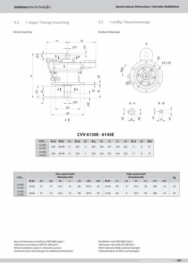
Drive 6000 991296 08/2021
Speed reducer Dimensions / Getriebe-Maßblätter
181
CVV 6130E - 6145ECVV… Ø a2 Ø b2 c2 Ø e2 f2 Ø g l2 k r1 r2 Ø s2 z2 AE26130E 6135E
260 200 f8 15 230 4 230 106 351 169 225 11 6 0°
6140E 6145E
260 200 f8 15 230 4 230 106 351 169 225 11 6 0°
CVV…Slow speed shaft
AbtriebswelleHigh speed shaft
Antriebswelle kgØ d2 L2 u2 t2 v v2 s21 m2 Ø d1 L1 u1 t1 v1 s11 m1
6130E 6135E
50 k6 91 14 53,5 10 80 M16 30 22 k6 40 6 24,5 34 M8 16 42
6140E 6145E
50 k6 91 14 53,5 10 80 M16 30 22 k6 40 6 24,5 34 M8 16 43
5.2 1-stufig / Flanschmontage
Vertical mounting Vertikale Einbaulage
Keys and keyways according to DIN 6885 page 1Tolerances according to DIN ISO 286 part 2Where installation space is restricted, contactSumitomo Drive Technologies for additional dimensions.
Passfedern nach DIN 6885 Seite 1Toleranzen nach DIN ISO 286 Teil 2Nicht tolerierte Maße sind bei beengterEinbausituation im Werk nachzufragen.
5.2 1 stage / Flange mounting
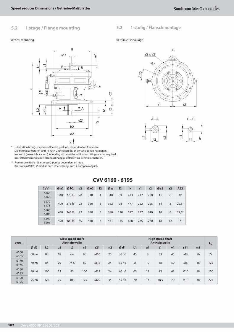
Drive 6000 991296 08/2021
Speed reducer Dimensions / Getriebe-Maßblätter
182
CVV 6160 - 6195CVV… Ø a2 Ø b2 c2 Ø e2 f2 Ø g l2 k r1 r2 Ø s2 z2 AE26160 6165
340 270 f8 20 310 4 318 89 413 217 200 11 6 0°
6170 6175
400 316 f8 22 360 5 362 94 477 222 225 14 8 22,5°
6180 6185
430 345 f8 22 390 5 390 110 527 237 240 18 8 22,5°
6190 6195
490 400 f8 30 450 6 451 145 620 265 270 18 12 15°
CVV…Slow speed shaft
AbtriebswelleHigh speed shaft
Antriebswelle kgØ d2 L2 u2 t2 v2 s21 m2 Ø d1 L1 u1 t1 v1 s11 m1
6160 6165
60 h6 80 18 64 80 M10 20 30 h6 45 8 33 45 M8 16 79
6170 6175
70 h6 84 20 74,5 80 M12 24 35 h6 55 10 38 50 M8 16 125
6180 6185
80 h6 100 22 85 100 M12 24 40 h6 65 12 43 63 M10 18 150
6190 6195
95 h6 125 25 100 125 M20 34 45 h6 70 14 48.5 70 M10 18 225
5.2 1-stufig / Flanschmontage
Vertical mounting Vertikale Einbaulage
* Lubrication fittings may have different positions dependent on frame size.Die Schmierarmaturen sind, je nach Getriebegröße, an verschiedenen Positionen.In case of grease lubrication (depending on ratio) the lubrication fittings are not required.Bei Fettschmierung (übersetzungsabhängig) entfallen die Schmierarmaturen.
** Frame size 6190/6195 may use 2 pumps dependent on ratio.Bei Größe 6190/6195 sind, je nach Übersetzung, auch 2 Pumpen möglich.
5.2 1 stage / Flange mounting
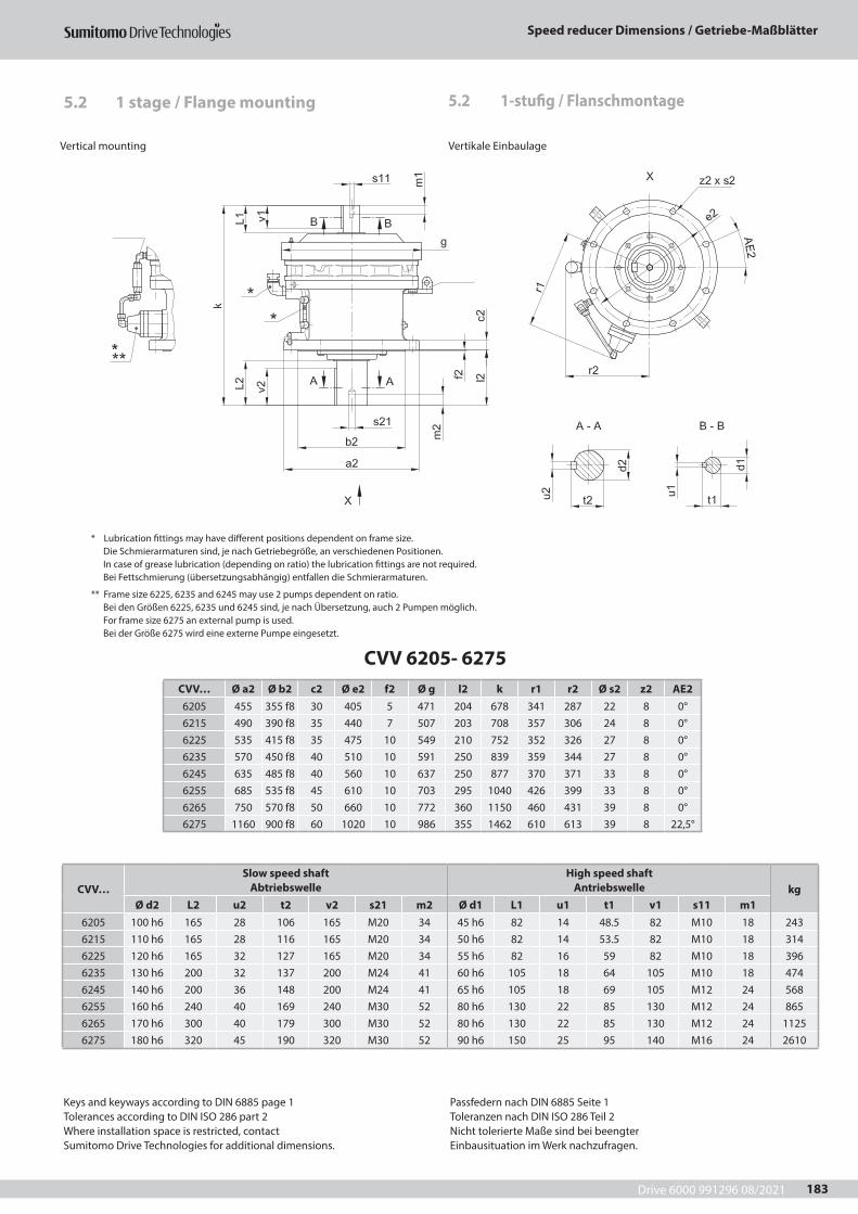
Drive 6000 991296 08/2021
Speed reducer Dimensions / Getriebe-Maßblätter
183
CVV 6205- 6275CVV… Ø a2 Ø b2 c2 Ø e2 f2 Ø g l2 k r1 r2 Ø s2 z2 AE26205 455 355 f8 30 405 5 471 204 678 341 287 22 8 0°6215 490 390 f8 35 440 7 507 203 708 357 306 24 8 0°6225 535 415 f8 35 475 10 549 210 752 352 326 27 8 0°6235 570 450 f8 40 510 10 591 250 839 359 344 27 8 0°6245 635 485 f8 40 560 10 637 250 877 370 371 33 8 0°6255 685 535 f8 45 610 10 703 295 1040 426 399 33 8 0°6265 750 570 f8 50 660 10 772 360 1150 460 431 39 8 0°6275 1160 900 f8 60 1020 10 986 355 1462 610 613 39 8 22,5°
CVV…Slow speed shaft
AbtriebswelleHigh speed shaft
Antriebswelle kgØ d2 L2 u2 t2 v2 s21 m2 Ø d1 L1 u1 t1 v1 s11 m1
6205 100 h6 165 28 106 165 M20 34 45 h6 82 14 48.5 82 M10 18 2436215 110 h6 165 28 116 165 M20 34 50 h6 82 14 53.5 82 M10 18 3146225 120 h6 165 32 127 165 M20 34 55 h6 82 16 59 82 M10 18 3966235 130 h6 200 32 137 200 M24 41 60 h6 105 18 64 105 M10 18 4746245 140 h6 200 36 148 200 M24 41 65 h6 105 18 69 105 M12 24 5686255 160 h6 240 40 169 240 M30 52 80 h6 130 22 85 130 M12 24 8656265 170 h6 300 40 179 300 M30 52 80 h6 130 22 85 130 M12 24 11256275 180 h6 320 45 190 320 M30 52 90 h6 150 25 95 140 M16 24 2610
5.2 1-stufig / Flanschmontage
Vertical mounting Vertikale Einbaulage
* Lubrication fittings may have different positions dependent on frame size.Die Schmierarmaturen sind, je nach Getriebegröße, an verschiedenen Positionen.In case of grease lubrication (depending on ratio) the lubrication fittings are not required.Bei Fettschmierung (übersetzungsabhängig) entfallen die Schmierarmaturen.
** Frame size 6225, 6235 and 6245 may use 2 pumps dependent on ratio.Bei den Größen 6225, 6235 und 6245 sind, je nach Übersetzung, auch 2 Pumpen möglich.For frame size 6275 an external pump is used.Bei der Größe 6275 wird eine externe Pumpe eingesetzt.
Keys and keyways according to DIN 6885 page 1Tolerances according to DIN ISO 286 part 2Where installation space is restricted, contactSumitomo Drive Technologies for additional dimensions.
Passfedern nach DIN 6885 Seite 1Toleranzen nach DIN ISO 286 Teil 2Nicht tolerierte Maße sind bei beengterEinbausituation im Werk nachzufragen.
5.2 1 stage / Flange mounting
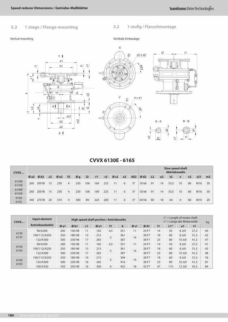
Drive 6000 991296 08/2021
Speed reducer Dimensions / Getriebe-Maßblätter
184
5.2 1-stufig / Flanschmontage
Vertical mounting Vertikale Einbaulage
CVVX 6130E - 6165
CVVX…Slow speed shaft
AbtriebswelleØ a2 Ø b2 c2 Ø e2 f2 Ø g l2 r1 r2 Ø s2 z2 AE2 Ø d2 L2 u2 t2 v v2 s21 m2
6130E 6135E
260 200 f8 15 230 4 230 106 169 225 11 6 0° 50 k6 91 14 53,5 10 80 M16 30
6140E 6145E
260 200 f8 15 230 4 230 106 169 225 11 6 0° 50 k6 91 14 53,5 10 80 M16 30
6160 6165
340 270 f8 20 310 4 300 89 224 200 11 6 0° 60 h6 80 18 64 0 80 M10 20
CVVX…Input element
Antriebszubehör
High speed shaft portion / Antriebsseite L* = Length of motor shaft L* = Länge der Motorwelle kg
Ø a1 Ø b1 c1 Ø e1 f1 k Ø s1 Ø d1 l1 L1* u1 t1
6130 6135
90/A200 200 130 H8 11 165 4,5 351 11 24 F7 14 50 8 Js9 27,3 40100/112/A250 250 180 H8 13 215
5361
1428 F7 18 60 8 Js9 31,3 42
132/A300 300 230 H8 17 265 387 38 F7 23 80 10 Js9 41,3 47
6140 6145
90/A200 200 130 H8 11 165 4,5 351 11 24 F7 14 50 8 Js9 27,3 41100/112/A250 250 180 H8 13 215
5361
1428 F7 18 60 8 Js9 31,3 43
132/A300 300 230 H8 17 265 387 38 F7 23 80 10 Js9 41,3 48
6160 6165
100/112/A250 250 180 H8 14 2155
39414
28 F7 18 60 8 Js9 31,3 76132/A300 300 230 H8 16 265 416 38 F7 23 80 10 Js9 41,3 81160/A350 350 250 H8 16 300 6 452 18 42 F7 47 110 12 Js9 45,3 84
5.2 1 stage / Flange mounting
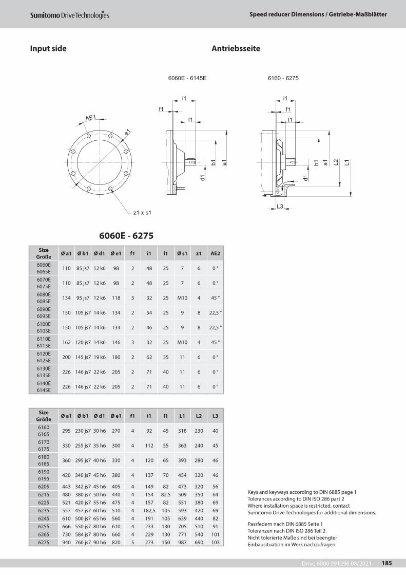
Drive 6000 991296 08/2021
Speed reducer Dimensions / Getriebe-Maßblätter
185
6060E - 6145E 6160 - 6275
d1
e1
AE1
z1 x s1
l1
i1
f1
l1
i1
f1
d1
L1b1 a1
L3
L2b1 a1
6060E - 6275Size
GrößeØ a1 Ø b1 Ø d1 Ø e1 f1 i1 l1 Ø s1 z1 AE2
6060E 6065E
110 85 js7 12 k6 98 2 48 25 7 6 0 °
6070E 6075E
110 85 js7 12 k6 98 2 48 25 7 6 0 °
6080E 6085E
134 95 js7 12 k6 118 3 32 25 M10 4 45 °
6090E 6095E
150 105 js7 14 k6 134 2 54 25 9 8 22,5 °
6100E 6105E
150 105 js7 14 k6 134 2 46 25 9 8 22,5 °
6110E 6115E
162 120 js7 14 k6 146 3 32 25 M10 4 45 °
6120E 6125E
200 145 js7 19 k6 180 2 62 35 11 6 0 °
6130E 6135E
226 146 js7 22 k6 205 2 71 40 11 6 0 °
6140E 6145E
226 146 js7 22 k6 205 2 71 40 11 6 0 °
Size Größe
Ø a1 Ø b1 Ø d1 Ø e1 f1 i1 l1 L1 L2 L3
6160 6165
295 230 js7 30 h6 270 4 92 45 318 230 40
6170 6175
330 255 js7 35 h6 300 4 112 55 363 240 45
6180 6185
360 295 js7 40 h6 330 4 120 65 393 280 46
6190 6195
420 340 js7 45 h6 380 4 137 70 454 320 46
6205 443 342 js7 45 h6 405 4 149 82 473 320 566215 480 380 js7 50 h6 440 4 154 82.5 509 350 646225 521 420 js7 55 h6 475 4 157 82 551 380 696235 557 457 js7 60 h6 510 4 182,5 105 593 420 696245 610 500 js7 65 h6 560 4 191 105 639 440 826255 666 550 js7 80 h6 610 4 233 130 705 510 916265 730 584 js7 80 h6 660 4 229 130 771 540 1016275 940 760 js7 90 h6 820 5 273 150 987 690 103
Input side Antriebsseite
Keys and keyways according to DIN 6885 page 1Tolerances according to DIN ISO 286 part 2Where installation space is restricted, contactSumitomo Drive Technologies for additional dimensions.
Passfedern nach DIN 6885 Seite 1Toleranzen nach DIN ISO 286 Teil 2Nicht tolerierte Maße sind bei beengterEinbausituation im Werk nachzufragen.
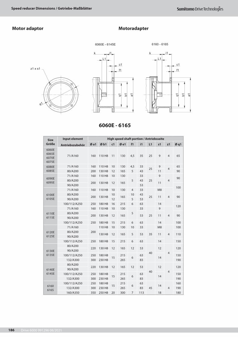
Drive 6000 991296 08/2021
Speed reducer Dimensions / Getriebe-Maßblätter
186
Motor adaptor Motoradapter
6060E - 6145E 6160 - 6165
a1b1
L1
i1k
e1
z1 x s1
q1a1b1q1
f1
c1
L1
i1k
f1
c1
Size Größe
Input element
Antriebszubehör
High speed shaft portion / Antriebsseite
Ø a1 Ø b1 c1 Ø e1 f1 i1 L1 s1 z1 Ø q1
6060E 6065E 6070E 6075E
71/A160 160 110 H8 11 130 4,5 35 25 9 4 65
6080E 6085E
71/A160 160 110 H8 10 130 4,5 3325
94
6580/A200 200 130 H8 12 165 5 43 11 90
6090E 6095E
71/A160 160 110 H8 10 1305
3325
94
9080/A200
200 130 H8 12 16543
1190/A200 53
100
6100E 6105E
71/A160 160 110 H8 10 130 4 33
25
M8
480/A200
200 130 H810
16510 43
11 9090/A200 12 5 53
100/112/A250 250 180 H8 16 215 6 63 14120
6110E 6115E
71/A160 160 110 H8 10 1305
33
25
9
480/A200
200 130 H8 12 165 53 11 9090/A200
100/112/A250 250 180 H8 15 215 6 63 14 100
6120E 6125E
71/A160200
110 H8 10 130 10 33
35
M8
4
10080/A200
130 H8 12 165 5 53 11 11090/A200
100/112/A250 250 180 H8 15 215 6 63 14 150
6130E 6135E
80/A200220 130 H8 12 165 12 53
4012
4120
90/A200100/112/A250 250 180 H8
15215
663
14150
132/A300 300 230 H8 265 83 190
6140E 6145E
80/A200220 130 H8 12 165 12 53
4012
4120
90/A200100/112/A250 250 180 H8
15215
663
14150
132/A300 300 230 H8 265 83 190
6160 6165
100/112/A250 250 180 H815
2156
6345
144
160132/A300 300 230 H8 265 83 190160/A350 350 250 H8 20 300 7 113 18 180
6060E - 6165
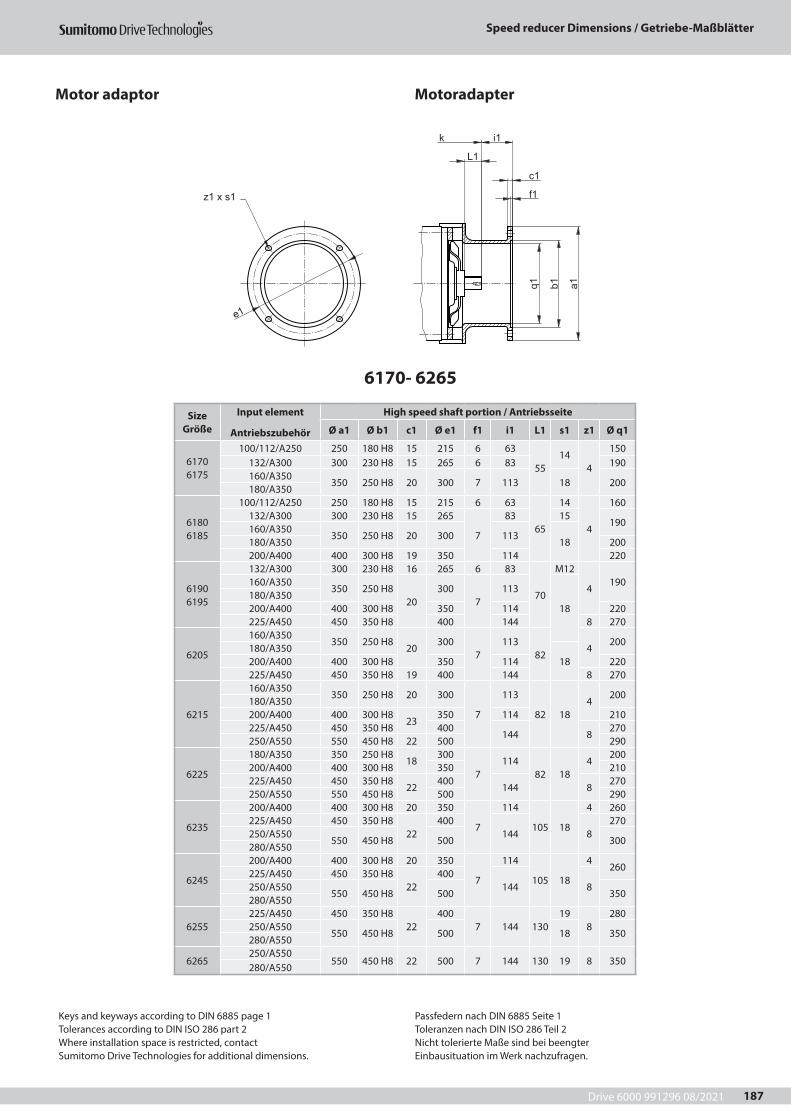
Drive 6000 991296 08/2021
Speed reducer Dimensions / Getriebe-Maßblätter
187
Motor adaptor Motoradapter
a1b1
c1
L1
f1
i1k
e1
z1 x s1
q1
Size Größe
Input element
Antriebszubehör
High speed shaft portion / Antriebsseite
Ø a1 Ø b1 c1 Ø e1 f1 i1 L1 s1 z1 Ø q1
6170 6175
100/112/A250 250 180 H8 15 215 6 63
5514
4
150132/A300 300 230 H8 15 265 6 83 190160/A350
350 250 H8 20 300 7 113 18 200180/A350
6180 6185
100/112/A250 250 180 H8 15 215 6 63
65
14
4
160132/A300 300 230 H8 15 265
7
83 15190
160/A350350 250 H8 20 300 113
18180/A350 200200/A400 400 300 H8 19 350 114 220
6190 6195
132/A300 300 230 H8 16 265 6 83
70
M12
4190160/A350
350 250 H820
3007
113
18180/A350200/A400 400 300 H8 350 114 220225/A450 450 350 H8 400 144 8 270
6205
160/A350350 250 H8
20300
7113
824
200180/A350
18200/A400 400 300 H8 350 114 220225/A450 450 350 H8 19 400 144 8 270
6215
160/A350350 250 H8 20 300
7
113
82 184
200180/A350200/A400 400 300 H8
23350 114 210
225/A450 450 350 H8 400144 8
270250/A550 550 450 H8 22 500 290
6225
180/A350 350 250 H818
300
7114
82 184
200200/A400 400 300 H8 350 210225/A450 450 350 H8
22400
144 8270
250/A550 550 450 H8 500 290
6235
200/A400 400 300 H8 20 350
7
114
105 18
4 260225/A450 450 350 H8
22400
144 8270
250/A550550 450 H8 500 300
280/A550
6245
200/A400 400 300 H8 20 350
7
114
105 18
4260
225/A450 450 350 H822
400144 8250/A550
550 450 H8 500 350280/A550
6255225/A450 450 350 H8
22400
7 144 13019
8280
250/A550550 450 H8 500 18 350
280/A550
6265250/A550
550 450 H8 22 500 7 144 130 19 8 350280/A550
6170- 6265
Keys and keyways according to DIN 6885 page 1Tolerances according to DIN ISO 286 part 2Where installation space is restricted, contactSumitomo Drive Technologies for additional dimensions.
Passfedern nach DIN 6885 Seite 1Toleranzen nach DIN ISO 286 Teil 2Nicht tolerierte Maße sind bei beengterEinbausituation im Werk nachzufragen.
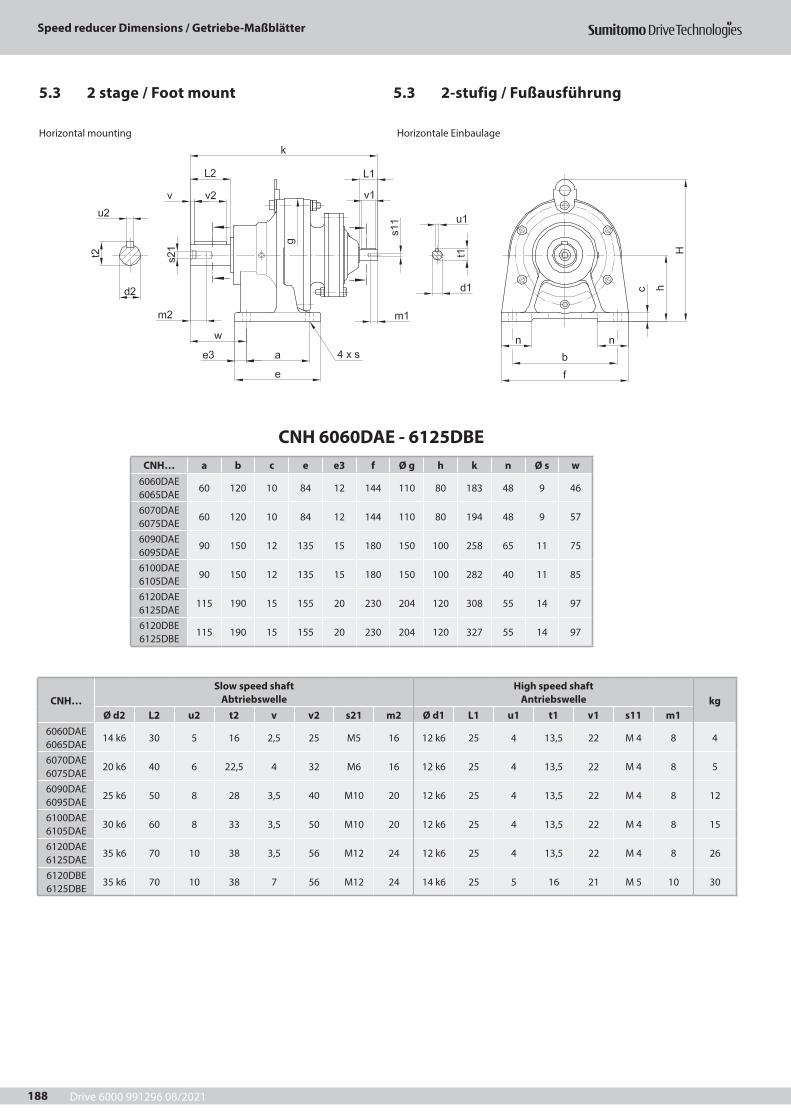
Drive 6000 991296 08/2021
Speed reducer Dimensions / Getriebe-Maßblätter
188
5.3 2-stufig / Fußausführung5.3 2 stage / Foot mount
CNH 6060DAE - 6125DBECNH… a b c e e3 f Ø g h k n Ø s w
6060DAE 6065DAE
60 120 10 84 12 144 110 80 183 48 9 46
6070DAE 6075DAE
60 120 10 84 12 144 110 80 194 48 9 57
6090DAE 6095DAE
90 150 12 135 15 180 150 100 258 65 11 75
6100DAE 6105DAE
90 150 12 135 15 180 150 100 282 40 11 85
6120DAE 6125DAE
115 190 15 155 20 230 204 120 308 55 14 97
6120DBE 6125DBE
115 190 15 155 20 230 204 120 327 55 14 97
CNH…Slow speed shaft
AbtriebswelleHigh speed shaft
Antriebswelle kgØ d2 L2 u2 t2 v v2 s21 m2 Ø d1 L1 u1 t1 v1 s11 m1
6060DAE 6065DAE
14 k6 30 5 16 2,5 25 M5 16 12 k6 25 4 13,5 22 M 4 8 4
6070DAE 6075DAE
20 k6 40 6 22,5 4 32 M6 16 12 k6 25 4 13,5 22 M 4 8 5
6090DAE 6095DAE
25 k6 50 8 28 3,5 40 M10 20 12 k6 25 4 13,5 22 M 4 8 12
6100DAE 6105DAE
30 k6 60 8 33 3,5 50 M10 20 12 k6 25 4 13,5 22 M 4 8 15
6120DAE 6125DAE
35 k6 70 10 38 3,5 56 M12 24 12 k6 25 4 13,5 22 M 4 8 26
6120DBE 6125DBE
35 k6 70 10 38 7 56 M12 24 14 k6 25 5 16 21 M 5 10 30
Horizontal mounting Horizontale Einbaulage
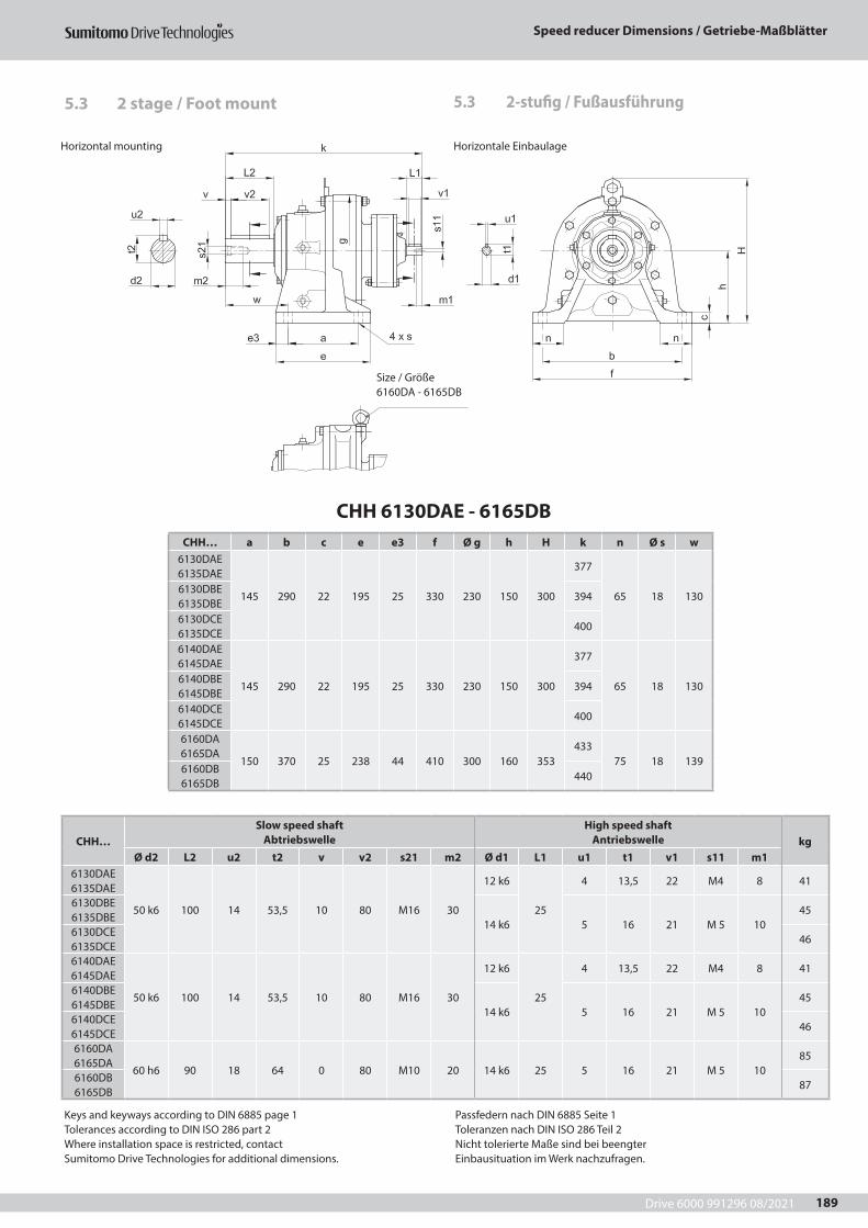
Drive 6000 991296 08/2021
Speed reducer Dimensions / Getriebe-Maßblätter
189
CHH 6130DAE - 6165DBCHH… a b c e e3 f Ø g h H k n Ø s w
6130DAE 6135DAE
145 290 22 195 25 330 230 150 300
377
65 18 1306130DBE 6135DBE
394
6130DCE 6135DCE
400
6140DAE 6145DAE
145 290 22 195 25 330 230 150 300
377
65 18 1306140DBE 6145DBE
394
6140DCE 6145DCE
400
6160DA 6165DA
150 370 25 238 44 410 300 160 353433
75 18 1396160DB 6165DB
440
CHH…Slow speed shaft
AbtriebswelleHigh speed shaft
Antriebswelle kgØ d2 L2 u2 t2 v v2 s21 m2 Ø d1 L1 u1 t1 v1 s11 m1
6130DAE 6135DAE
50 k6 100 14 53,5 10 80 M16 30
12 k6
25
4 13,5 22 M4 8 41
6130DBE 6135DBE
14 k6 5 16 21 M 5 1045
6130DCE 6135DCE
46
6140DAE 6145DAE
50 k6 100 14 53,5 10 80 M16 30
12 k6
25
4 13,5 22 M4 8 41
6140DBE 6145DBE
14 k6 5 16 21 M 5 1045
6140DCE 6145DCE
46
6160DA 6165DA
60 h6 90 18 64 0 80 M10 20 14 k6 25 5 16 21 M 5 1085
6160DB 6165DB
87
5.3 2-stufig / Fußausführung5.3 2 stage / Foot mount
Size / Größe 6160DA - 6165DB
Keys and keyways according to DIN 6885 page 1Tolerances according to DIN ISO 286 part 2Where installation space is restricted, contactSumitomo Drive Technologies for additional dimensions.
Passfedern nach DIN 6885 Seite 1Toleranzen nach DIN ISO 286 Teil 2Nicht tolerierte Maße sind bei beengterEinbausituation im Werk nachzufragen.
Horizontal mounting Horizontale Einbaulage
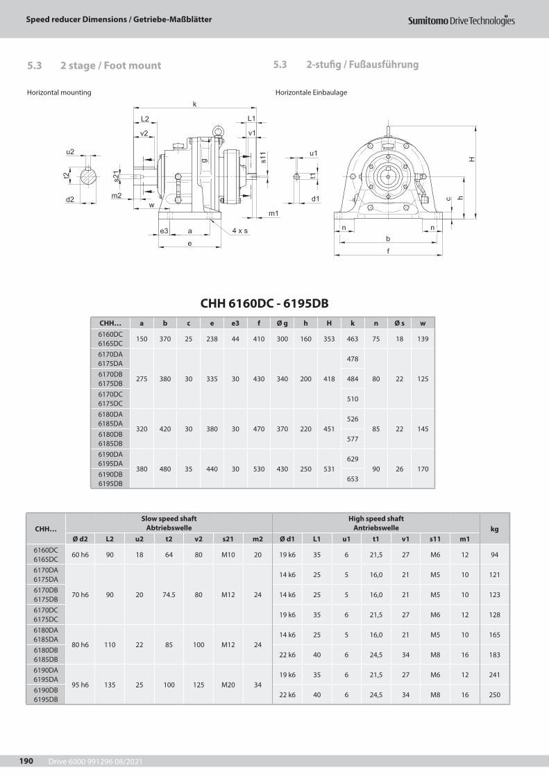
Drive 6000 991296 08/2021
Speed reducer Dimensions / Getriebe-Maßblätter
190
CHH 6160DC - 6195DBCHH… a b c e e3 f Ø g h H k n Ø s w6160DC 6165DC
150 370 25 238 44 410 300 160 353 463 75 18 139
6170DA 6175DA
275 380 30 335 30 430 340 200 418
478
80 22 1256170DB 6175DB
484
6170DC 6175DC
510
6180DA 6185DA
320 420 30 380 30 470 370 220 451526
85 22 1456180DB 6185DB
577
6190DA 6195DA
380 480 35 440 30 530 430 250 531629
90 26 1706190DB 6195DB
653
CHH…Slow speed shaft
AbtriebswelleHigh speed shaft
Antriebswelle kgØ d2 L2 u2 t2 v2 s21 m2 Ø d1 L1 u1 t1 v1 s11 m1
6160DC 6165DC
60 h6 90 18 64 80 M10 20 19 k6 35 6 21,5 27 M6 12 94
6170DA 6175DA
70 h6 90 20 74.5 80 M12 24
14 k6 25 5 16,0 21 M5 10 121
6170DB 6175DB
14 k6 25 5 16,0 21 M5 10 123
6170DC 6175DC
19 k6 35 6 21,5 27 M6 12 128
6180DA 6185DA
80 h6 110 22 85 100 M12 2414 k6 25 5 16,0 21 M5 10 165
6180DB 6185DB
22 k6 40 6 24,5 34 M8 16 183
6190DA 6195DA
95 h6 135 25 100 125 M20 3419 k6 35 6 21,5 27 M6 12 241
6190DB 6195DB
22 k6 40 6 24,5 34 M8 16 250
Horizontal mounting Horizontale Einbaulage
5.3 2-stufig / Fußausführung5.3 2 stage / Foot mount
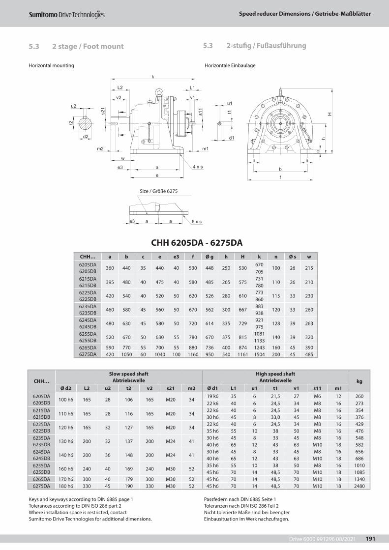
Drive 6000 991296 08/2021
Speed reducer Dimensions / Getriebe-Maßblätter
191
CHH 6205DA - 6275DACHH… a b c e e3 f Ø g h H k n Ø s w6205DA 6205DB
360 440 35 440 40 530 448 250 530670
100 26 215705
6215DA 6215DB
395 480 40 475 40 580 485 265 575731
110 26 210780
6225DA 6225DB
420 540 40 520 50 620 526 280 610773
115 33 230860
6235DA 6235DB
460 580 45 560 50 670 562 300 667883
120 33 260938
6245DA 6245DB
480 630 45 580 50 720 614 335 729921
128 39 263975
6255DA 6255DB
520 670 50 630 55 780 670 375 8151081
140 39 3201133
6265DA 6275DA
590 770 55 700 55 880 736 400 874 1243 160 45 390420 1050 60 1040 100 1160 950 540 1161 1504 200 45 485
CHH…Slow speed shaft
AbtriebswelleHigh speed shaft
Antriebswelle kgØ d2 L2 u2 t2 v2 s21 m2 Ø d1 L1 u1 t1 v1 s11 m1
6205DA 6205DB
100 h6 165 28 106 165 M20 3419 k6 35 6 21,5 27 M6 12 26022 k6 40 6 24,5 34 M8 16 273
6215DA 6215DB
110 h6 165 28 116 165 M20 3422 k6 40 6 24,5 34 M8 16 35430 h6 45 8 33,0 45 M8 16 376
6225DA 6225DB
120 h6 165 32 127 165 M20 3422 k6 40 6 24,5 34 M8 16 42935 h6 55 10 38 50 M8 16 476
6235DA 6235DB
130 h6 200 32 137 200 M24 4130 h6 45 8 33 45 M8 16 54840 h6 65 12 43 63 M10 18 582
6245DA 6245DB
140 h6 200 36 148 200 M24 4130 h6 45 8 33 45 M8 16 65640 h6 65 12 43 63 M10 18 686
6255DA 6255DB
160 h6 240 40 169 240 M30 5235 h6 55 10 38 50 M8 16 101045 h6 70 14 48,5 70 M10 18 1085
6265DA 170 h6 300 40 179 300 M30 52 45 h6 70 14 48,5 70 M10 18 13406275DA 180 h6 330 45 190 330 M30 52 45 h6 70 14 48,5 70 M10 18 2480
Horizontal mounting Horizontale Einbaulage
5.3 2-stufig / Fußausführung5.3 2 stage / Foot mount
Size / Größe 6275
Keys and keyways according to DIN 6885 page 1Tolerances according to DIN ISO 286 part 2Where installation space is restricted, contactSumitomo Drive Technologies for additional dimensions.
Passfedern nach DIN 6885 Seite 1Toleranzen nach DIN ISO 286 Teil 2Nicht tolerierte Maße sind bei beengterEinbausituation im Werk nachzufragen.
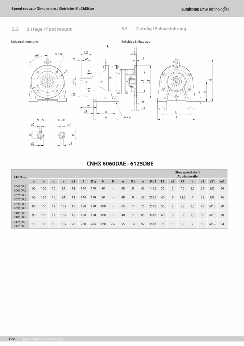
Drive 6000 991296 08/2021
Speed reducer Dimensions / Getriebe-Maßblätter
192
CNHX 6060DAE - 6125DBE
CNHX…Slow speed shaft
Abtriebswellea b c e e3 f Ø g h H n Ø s w Ø d2 L2 u2 t2 v v2 s21 m2
6060DAE 6065DAE
60 120 10 84 12 144 110 80 - 48 9 46 14 k6 30 5 16 2,5 25 M5 16
6070DAE 6075DAE
60 120 10 84 12 144 110 80 - 48 9 57 20 k6 40 6 22,5 4 32 M6 16
6090DAE 6095DAE
90 150 12 135 15 180 150 100 - 65 11 75 25 k6 50 8 28 3,5 40 M10 20
6100DAE 6105DAE
90 150 12 135 15 180 150 100 - 40 11 85 30 k6 60 8 33 3,5 50 M10 20
6120DAE 6125DAE
115 190 15 155 20 230 204 120 257 55 14 97 35 k6 70 10 38 7 56 M12 24
5.3 2-stufig / Fußausführung5.3 2 stage / Foot mount
Universal mounting Beliebige Einbaulage
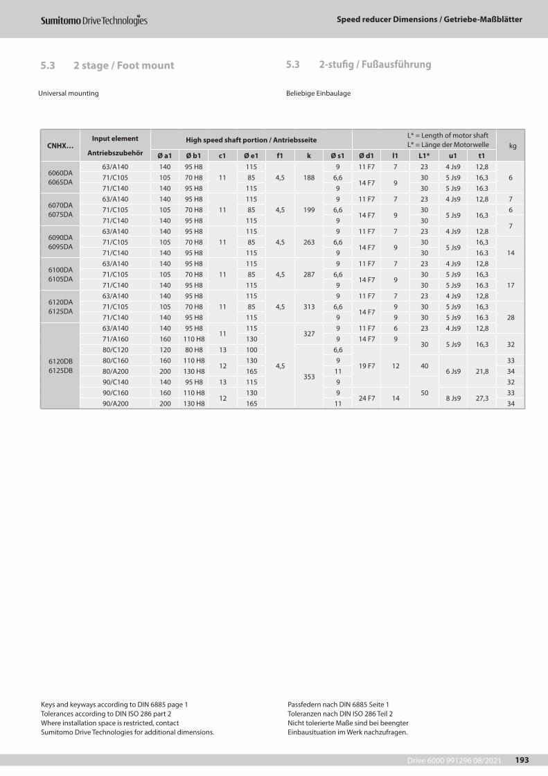
Drive 6000 991296 08/2021
Speed reducer Dimensions / Getriebe-Maßblätter
193
5.3 2-stufig / Fußausführung5.3 2 stage / Foot mount
Universal mounting Beliebige Einbaulage
CNHX…Input element
Antriebszubehör
High speed shaft portion / Antriebsseite L* = Length of motor shaft L* = Länge der Motorwelle kg
Ø a1 Ø b1 c1 Ø e1 f1 k Ø s1 Ø d1 l1 L1* u1 t1
6060DA 6065DA
63/A140 140 95 H811
1154,5 188
9 11 F7 7 23 4 Js9 12,8671/C105 105 70 H8 85 6,6
14 F7 930 5 Js9 16,3
71/C140 140 95 H8 115 9 30 5 Js9 16.3
6070DA 6075DA
63/A140 140 95 H811
1154,5 199
9 11 F7 7 23 4 Js9 12,8 771/C105 105 70 H8 85 6,6
14 F7 930
5 Js9 16,36
71/C140 140 95 H8 115 9 307
6090DA 6095DA
63/A140 140 95 H811
1154,5 263
9 11 F7 7 23 4 Js9 12,871/C105 105 70 H8 85 6,6
14 F7 930
5 Js916,3
1471/C140 140 95 H8 115 9 30 16.3
6100DA 6105DA
63/A140 140 95 H811
1154,5 287
9 11 F7 7 23 4 Js9 12,871/C105 105 70 H8 85 6,6
14 F7 930 5 Js9 16,3
1771/C140 140 95 H8 115 9 30 5 Js9 16.3
6120DA 6125DA
63/A140 140 95 H811
1154,5 313
9 11 F7 7 23 4 Js9 12,871/C105 105 70 H8 85 6,6
14 F79 30 5 Js9 16,3
2871/C140 140 95 H8 115 9 9 30 5 Js9 16.3
6120DB 6125DB
63/A140 140 95 H811
115
4,5
3279 11 F7 6 23 4 Js9 12,8
71/A160 160 110 H8 130 9 14 F7 930 5 Js9 16,3 32
80/C120 120 80 H8 13 100
353
6,6
19 F7 1280/C160 160 110 H8
12130 9
406 Js9 21,8
3380/A200 200 130 H8 165 11 3490/C140 140 95 H8 13 115 9
5032
90/C160 160 110 H812
130 924 F7 14 8 Js9 27,3
3390/A200 200 130 H8 165 11 34
Keys and keyways according to DIN 6885 page 1Tolerances according to DIN ISO 286 part 2Where installation space is restricted, contactSumitomo Drive Technologies for additional dimensions.
Passfedern nach DIN 6885 Seite 1Toleranzen nach DIN ISO 286 Teil 2Nicht tolerierte Maße sind bei beengterEinbausituation im Werk nachzufragen.
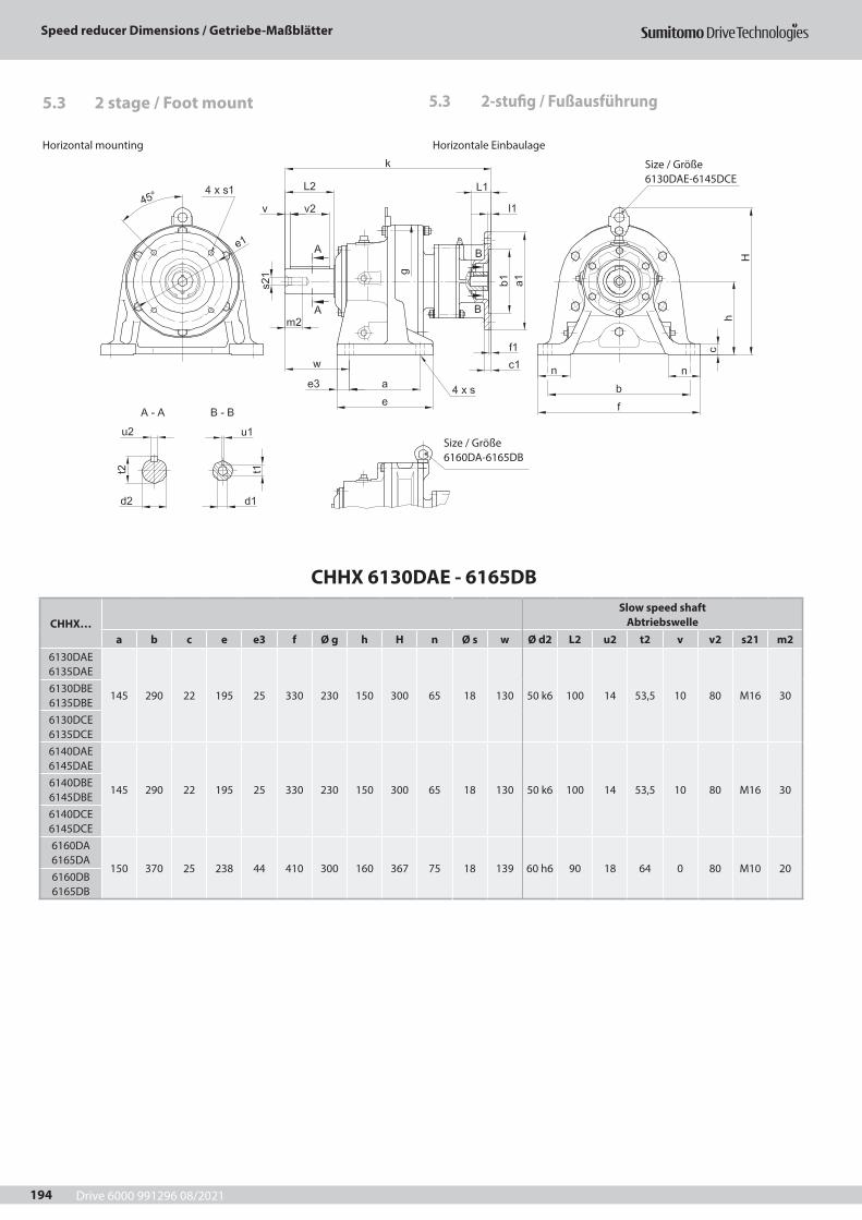
Drive 6000 991296 08/2021
Speed reducer Dimensions / Getriebe-Maßblätter
194
CHHX 6130DAE - 6165DB
CHHX…Slow speed shaft
Abtriebswellea b c e e3 f Ø g h H n Ø s w Ø d2 L2 u2 t2 v v2 s21 m2
6130DAE 6135DAE
145 290 22 195 25 330 230 150 300 65 18 130 50 k6 100 14 53,5 10 80 M16 306130DBE 6135DBE6130DCE 6135DCE6140DAE 6145DAE
145 290 22 195 25 330 230 150 300 65 18 130 50 k6 100 14 53,5 10 80 M16 306140DBE 6145DBE6140DCE 6145DCE6160DA 6165DA
150 370 25 238 44 410 300 160 367 75 18 139 60 h6 90 18 64 0 80 M10 206160DB 6165DB
5.3 2-stufig / Fußausführung5.3 2 stage / Foot mount
Size / Größe 6160DA-6165DB
Horizontal mounting Horizontale Einbaulage
Size / Größe 6130DAE-6145DCE
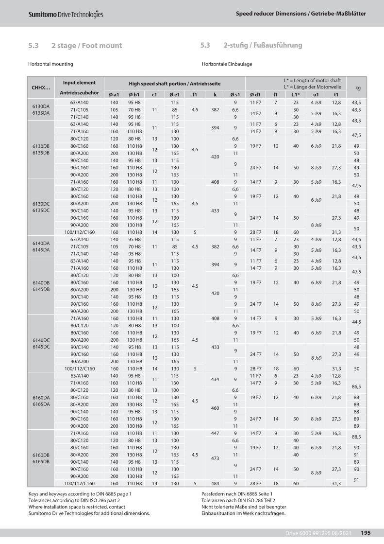
Drive 6000 991296 08/2021
Speed reducer Dimensions / Getriebe-Maßblätter
195
Horizontal mounting Horizontale Einbaulage
5.3 2-stufig / Fußausführung5.3 2 stage / Foot mount
CHHX…Input element
Antriebszubehör
High speed shaft portion / Antriebsseite L* = Length of motor shaft L* = Länge der Motorwelle kg
Ø a1 Ø b1 c1 Ø e1 f1 k Ø s1 Ø d1 l1 L1* u1 t1
6130DA 6135DA
63/A140 140 95 H811
1154,5 382
9 11 F7 7 23 4 Js9 12,8 43,571/C105 105 70 H8 85 6,6
14 F7 930
5 Js9 16,343,5
71/C140 140 95 H8 115 9 3043,5
6130DB 6135DB
63/A140 140 95 H811
115
4,5
394 911 F7 6 23 4 Js9 12,8
71/A160 160 110 H8 130 14 F7 9 30 5 Js9 16,347,5
80/C120 120 80 H8 13 100
420
6,619 F7 12 40 6 Js9 21,880/C160 160 110 H8
12130 9 49
80/A200 200 130 H8 165 11 5090/C140 140 95 H8 13 115
924 F7 14 50 8 Js9 27,3
4890/C160 160 110 H8
12130 49
90/A200 200 130 H8 165 11 50
6130DC 6135DC
71/A160 160 110 H8 11 130
4,5
408 9 14 F7 9 30 5 Js9 16,347,5
80/C120 120 80 H8 13 100
433
6,619 F7 12 40
6 Js921,880/C160 160 110 H8
12130 9 49
80/A200 200 130 H8 165 11 5090/C140 140 95 H8 13 115
924 F7 14 50 27,3
4890/C160 160 110 H8
12130
8 Js949
90/A200 200 130 H8 165 1150
100/112/C160 160 110 H8 14 130 5 9 28 F7 18 60 31,3
6140DA 6145DA
63/A140 140 95 H811
1154,5 382
9 11 F7 7 23 4 Js9 12,8 43,571/C105 105 70 H8 85 6,6
14 F7 930
5 Js9 16,343,5
71/C140 140 95 H8 115 9 3043,5
6140DB 6145DB
63/A140 140 95 H811
115
4,5
394 911 F7 6 23 4 Js9 12,8
71/A160 160 110 H8 130 14 F7 9 30 5 Js9 16,347,5
80/C120 120 80 H8 13 100
420
6,619 F7 12 40 6 Js9 21,880/C160 160 110 H8
12130 9 49
80/A200 200 130 H8 165 11 5090/C140 140 95 H8 13 115 9
24 F7 14 50 8 Js9 27,348
90/C160 160 110 H812
130 9 4990/A200 200 130 H8 165 11 50
6140DC 6145DC
71/A160 160 110 H8 11 130
4,5
408 9 14 F7 9 30 5 Js9 16,344,5
80/C120 120 80 H8 13 100
433
6,619 F7 12 40 6 Js9 21,880/C160 160 110 H8
12130 9 49
80/A200 200 130 H8 165 11 5090/C140 140 95 H8 13 115
924 F7 14 50
8 Js927,3
4890/C160 160 110 H8
12130 49
90/A200 200 130 H8 165 1150100/112/C160 160 110 H8 14 130 5 9 28 F7 18 60 31,3
6160DA 6165DA
63/A140 140 95 H811
115
4,5
434 911 F7 6 23 4 Js9 12,8
71/A160 160 110 H8 130 14 F7 9 30 5 Js9 16,386,5
80/C120 120 80 H8 13 100
460
6,619 F7 12 40 6 Js9 21,880/C160 160 110 H8
12130 9 88
80/A200 200 130 H8 165 11 8990/C140 140 95 H8 13 115 9
24 F7 14 50 8 Js9 27,388
90/C160 160 110 H812
130 9 8990/A200 200 130 H8 165 11 89
6160DB 6165DB
71/A160 160 110 H8 11 130
4,5
447 9 14 F7 9 30 5 Js9 16,388,5
80/C120 120 80 H8 13 100
473
6,619 F7 12
406 Js9 21,880/C160 160 110 H8
12130 9 40 90
80/A200 200 130 H8 165 11 40 9190/C140 140 95 H8 13 115
924 F7 14 50
8 Js927,3
8990/C160 160 110 H8
12130 90
90/A200 200 130 H8 165 1191
100/112/C160 160 110 H8 14 130 5 484 9 28 F7 18 60 31,3
Keys and keyways according to DIN 6885 page 1Tolerances according to DIN ISO 286 part 2Where installation space is restricted, contactSumitomo Drive Technologies for additional dimensions.
Passfedern nach DIN 6885 Seite 1Toleranzen nach DIN ISO 286 Teil 2Nicht tolerierte Maße sind bei beengterEinbausituation im Werk nachzufragen.
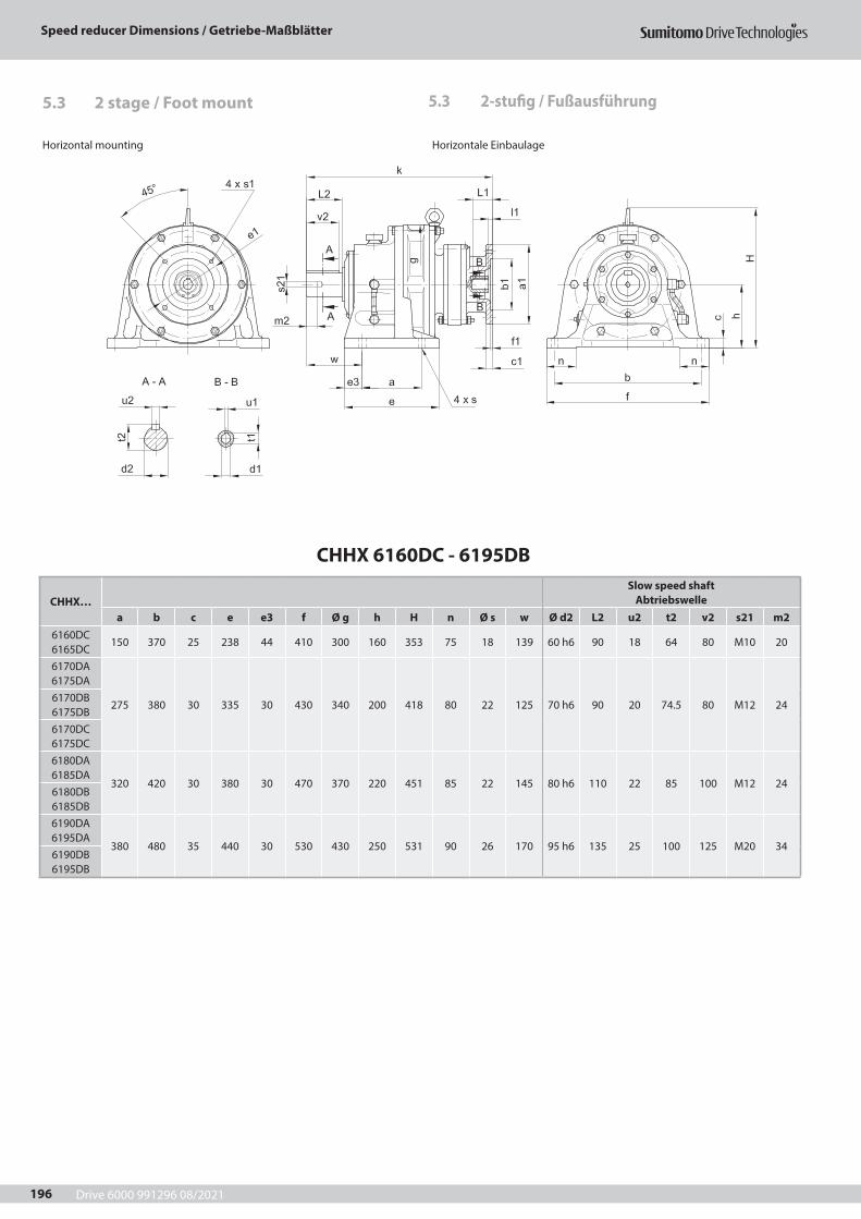
Drive 6000 991296 08/2021
Speed reducer Dimensions / Getriebe-Maßblätter
196
CHHX 6160DC - 6195DB
CHHX…Slow speed shaft
Abtriebswellea b c e e3 f Ø g h H n Ø s w Ø d2 L2 u2 t2 v2 s21 m2
6160DC 6165DC
150 370 25 238 44 410 300 160 353 75 18 139 60 h6 90 18 64 80 M10 20
6170DA 6175DA
275 380 30 335 30 430 340 200 418 80 22 125 70 h6 90 20 74.5 80 M12 246170DB 6175DB6170DC 6175DC6180DA 6185DA
320 420 30 380 30 470 370 220 451 85 22 145 80 h6 110 22 85 100 M12 246180DB 6185DB6190DA 6195DA
380 480 35 440 30 530 430 250 531 90 26 170 95 h6 135 25 100 125 M20 346190DB 6195DB
5.3 2-stufig / Fußausführung5.3 2 stage / Foot mount
Horizontal mounting Horizontale Einbaulage

Drive 6000 991296 08/2021
Speed reducer Dimensions / Getriebe-Maßblätter
197
Horizontal mounting Horizontale Einbaulage
5.3 2-stufig / Fußausführung5.3 2 stage / Foot mount
CHHX…Input element
Antriebszubehör
High speed shaft portion / Antriebsseite L* = Length of motor shaft L* = Länge der Motorwelle kg
Ø a1 Ø b1 c1 Ø e1 f1 k Ø s1 Ø d1 l1 L1* u1 t1
6160DC 6165DC
80/A200200 130 H8 13 165 4,5 468 11
19 F7 12 40 6 Js9 21,898
90/A200 24 F7 14 508 Js9
27,3100/112/C160 160 110 H8
14130
5 4789
28 F7 18 60 31,399
100/112/A250 250 180 H8 215 14 102
6170DA 6175DA
63/A140 140 95 H811
115
4,5
478 911 F7 6 23 4 Js9 12,8
12271/A160 160 110 H8 130 14 F7 9 30 5 Js9 16,380/C120 120 80 H8 13 100
504
6,619 F7 12 40 6 Js9 21,880/C160 160 110 H8
12130 9 123
80/A200 200 130 H8 165 11 12490/C140 140 95 H8 13 115 9
24 F7 14 50 8 Js9 27,3123
90/C160 160 110 H812
130 990/A200 200 130 H8 165 11 124
6170DB 6175DB
71/A160 160 110 H8 11 130
4,5
492 9 14 F7 9 30 5 Js9 16,3125
80/C120 120 80 H8 13 100
518
6,619 F7 12 40 6 Js9 21,880/C160 160 110 H8
12130 9 126
80/A200 200 130 H8 165 11127
90/C140 140 95 H8 13 115 924 F7 14 50
8 Js927,390/C160 160 110 H8
12130 9 126
90/A200 200 130 H8 165 11127
100/112/C160 160 110 H8 14 130 5 528 9 28 F7 18 60 31,3
6170DC 6175DC
80/A200200 130 H8 13 165 4,5 515 11
19 F7 12 40 6 Js9 21,8131,5
90/A200 24 F7 14 508 Js9
27,3100/112/C160 160 110 H8
14130
5 5259
28 F7 18 60 31,3132,5
100/112/A250 250 180 H8 215 14 135,5
6180DA 6185DA
71/A160 160 110 H8 11 130
4,5
534 9 14 F7 9 30 5 Js9 16,3167
80/C120 120 80 H8 13 100
560
6,619 F7 12 40 6 Js9 21,880/C160 160 110 H8
12130 9 168
80/A200 200 130 H8 165 11 16990/C140 140 95 H8 13 115 9
24 F7 14 508 Js9
27,3168
90/C160 160 110 H812
130 990/A200 200 130 H8 165 11 169
100/112/C 160 160 110 H8 14 130 5 570 9 28 F7 18 60 31,3 170
6180DB 6185DB
90/A200 200 130 H8 11 165 4,5 577 11 24 F7 14 508 Js9
27,3 186100/112/A250 250 180 H8 13 215
5587
1428 F7 18 60 31,3 188
132/A300 300 230 H8 17 265 613 38 F7 23 80 10 Js9 41,3 193
6190DA 6195DA
80/A200200 130 H8 13 165 4,5 635 11
19 F7 12 40 6 Js9 21,8 24690/A200 24 F7 14 50
8 Js927,3 249
100/112/C160 160 110 H814
1305 645
928 F7 18 60 31,3
254100/112/A250 250 180 H8 215 14 257
6190DB 6195DB
90/A200 200 130 H8 11 165 4,5 653 11 24 F7 14 508 Js9
27,3 253100/112/A250 250 180 H8 13 215
5663
1428 F7 18 60 31,3 256
132/A300 300 230 H8 17 265 689 38 F7 23 80 10 Js9 41,3 261
Keys and keyways according to DIN 6885 page 1Tolerances according to DIN ISO 286 part 2Where installation space is restricted, contactSumitomo Drive Technologies for additional dimensions.
Passfedern nach DIN 6885 Seite 1Toleranzen nach DIN ISO 286 Teil 2Nicht tolerierte Maße sind bei beengterEinbausituation im Werk nachzufragen.
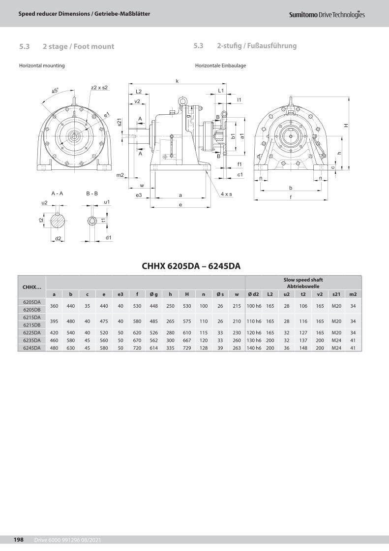
Drive 6000 991296 08/2021
Speed reducer Dimensions / Getriebe-Maßblätter
198
CHHX 6205DA – 6245DA
CHHX…Slow speed shaft
Abtriebswellea b c e e3 f Ø g h H n Ø s w Ø d2 L2 u2 t2 v2 s21 m2
6205DA360 440 35 440 40 530 448 250 530 100 26 215 100 h6 165 28 106 165 M20 34
6205DB6215DA
395 480 40 475 40 580 485 265 575 110 26 210 110 h6 165 28 116 165 M20 346215DB6225DA 420 540 40 520 50 620 526 280 610 115 33 230 120 h6 165 32 127 165 M20 346235DA 460 580 45 560 50 670 562 300 667 120 33 260 130 h6 200 32 137 200 M24 416245DA 480 630 45 580 50 720 614 335 729 128 39 263 140 h6 200 36 148 200 M24 41
5.3 2-stufig / Fußausführung5.3 2 stage / Foot mount
Horizontal mounting Horizontale Einbaulage

Drive 6000 991296 08/2021
Speed reducer Dimensions / Getriebe-Maßblätter
199
Horizontal mounting Horizontale Einbaulage
5.3 2-stufig / Fußausführung5.3 2 stage / Foot mount
CHHX…Input element
Antriebszubehör
High speed shaft portion / Antriebsseite L* = Length of motor shaft L* = Länge der Motorwelle kg
Ø a1 Ø b1 c1 Ø e1 f1 k Ø s1 Ø d1 l1 L1* u1 t1
6205DA
80/A200200 130 H8
13165 4.5 675 11
19 F7 12 40 6 Js9 21,8264
90/A200 14 24 F7 14 508 Js9
27,3100/112/C160 160 110 H8
14130
5 6859
28 F7 18 60 31,3265
100/112/A250 250 180 H8 215 14 268
6205DB90/A200 200 130 H8 11 165 4,5 705 11 24 F7 14 50 8 Js9 27,3 276
100/112/A250 250 180 H8 13 2155
71514
28 F7 18 60 8 Js9 31,3 278132/A300 300 230 H8 17 265 741 38 F7 23 80 10 Js9 41,3 283
6215DA90/A200 200 130 H8 11 165 4,5 732 11 24 F7 14 50 8 Js9 27,3 357
100/112/A250 250 180H8 13 2155
74214
28 F7 18 60 8 Js9 31,3 359132/A300 300 230 H8 17 265 768 38 F7 23 80 10 Js9 41,3 364
6215DB100/112/A250 250 180 H8 14 215
5761
1428 F7 18 60 8 Js9 31,3 380
132/A300 300 230 H8 16 265 783 38 F7 23 80 10 Js9 41,3 385160/A350 350 250 H8 16 300 6 819 18 42 F7 47 110 12 Js9 45,3 390
6225DA90/A200 200 130 H8 11 165 4,5 773 11 24 F7 14 50 8 Js9 27,3 432
100/112/A250 250 180 H8 13 2155
78314
28 F7 18 60 8 Js9 31,3 434132/A300 300 230 H8 17 265 809 38 F7 23 80 10 Js9 41,3 439
6235DA100/112/A250 250 180 H8 14 215
5864
1428 F7 18 60 8 Js9 31,3 552
132/A300 300 230 H816
265 876 38 F7 23 80 10 Js9 41,3 557160/A350 350 250 H8 300 6 922 18 42 F7 47 110 12 Js9 45,3 562
6245DA100/112/A250 250 180 H8 14 215
5902
1428 F7 18 60 8 Js9 31,3 660
132/A300 300 230 H816
265 924 38 F7 23 80 10 Js9 41,3 665160/A350 350 250 H8 300 6 960 18 42 F7 47 110 12 Js9 45,3 670
Keys and keyways according to DIN 6885 page 1Tolerances according to DIN ISO 286 part 2Where installation space is restricted, contactSumitomo Drive Technologies for additional dimensions.
Passfedern nach DIN 6885 Seite 1Toleranzen nach DIN ISO 286 Teil 2Nicht tolerierte Maße sind bei beengterEinbausituation im Werk nachzufragen.
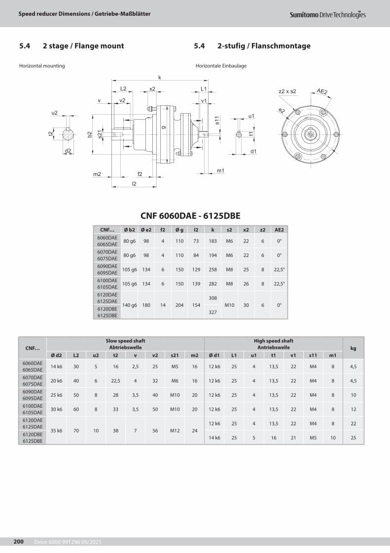
Drive 6000 991296 08/2021
Speed reducer Dimensions / Getriebe-Maßblätter
200
CNF 6060DAE - 6125DBECNF… Ø b2 Ø e2 f2 Ø g I2 k s2 x2 z2 AE2
6060DAE 6065DAE
80 g6 98 4 110 73 183 M6 22 6 0°
6070DAE 6075DAE
80 g6 98 4 110 84 194 M6 22 6 0°
6090DAE 6095DAE
105 g6 134 6 150 129 258 M8 25 8 22,5°
6100DAE 6105DAE
105 g6 134 6 150 139 282 M8 26 8 22,5°
6120DAE 6125DAE
140 g6 180 14 204 154308
M10 30 6 0°6120DBE 6125DBE
327
CNF…Slow speed shaft
AbtriebswelleHigh speed shaft
Antriebswelle kgØ d2 L2 u2 t2 v v2 s21 m2 Ø d1 L1 u1 t1 v1 s11 m1
6060DAE 6065DAE
14 k6 30 5 16 2,5 25 M5 16 12 k6 25 4 13,5 22 M4 8 4,5
6070DAE 6075DAE
20 k6 40 6 22,5 4 32 M6 16 12 k6 25 4 13,5 22 M4 8 4,5
6090DAE 6095DAE
25 k6 50 8 28 3,5 40 M10 20 12 k6 25 4 13,5 22 M4 8 10
6100DAE 6105DAE
30 k6 60 8 33 3,5 50 M10 20 12 k6 25 4 13,5 22 M4 8 12
6120DAE 6125DAE
35 k6 70 10 38 7 56 M12 2412 k6 25 4 13,5 22 M4 8 22
6120DBE 6125DBE
14 k6 25 5 16 21 M5 10 25
Horizontal mounting Horizontale Einbaulage
5.4 2-stufig / Flanschmontage5.4 2 stage / Flange mount
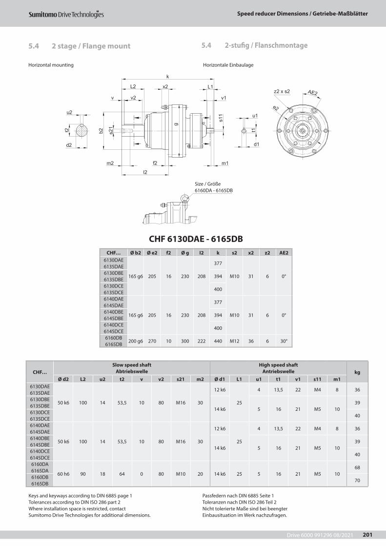
Drive 6000 991296 08/2021
Speed reducer Dimensions / Getriebe-Maßblätter
201
CHF 6130DAE - 6165DBCHF… Ø b2 Ø e2 f2 Ø g I2 k s2 x2 z2 AE2
6130DAE 6135DAE
165 g6 205 16 230 208
377
M10 31 6 0°6130DBE 6135DBE
394
6130DCE 6135DCE
400
6140DAE 6145DAE
165 g6 205 16 230 208
377
M10 31 6 0°6140DBE 6145DBE
394
6140DCE 6145DCE
400
6160DB 6165DB
200 g6 270 10 300 222 440 M12 36 6 30°
CHF…Slow speed shaft
AbtriebswelleHigh speed shaft
Antriebswelle kgØ d2 L2 u2 t2 v v2 s21 m2 Ø d1 L1 u1 t1 v1 s11 m1
6130DAE 6135DAE
50 k6 100 14 53,5 10 80 M16 30
12 k6
25
4 13,5 22 M4 8 36
6130DBE 6135DBE
14 k6 5 16 21 M5 1039
6130DCE 6135DCE
40
6140DAE 6145DAE
50 k6 100 14 53,5 10 80 M16 30
12 k6
25
4 13,5 22 M4 8 36
6140DBE 6145DBE
14 k6 5 16 21 M5 1039
6140DCE 6145DCE
40
6160DA 6165DA
60 h6 90 18 64 0 80 M10 20 14 k6 25 5 16 21 M5 1068
6160DB 6165DB
70
Horizontal mounting Horizontale Einbaulage
5.4 2-stufig / Flanschmontage5.4 2 stage / Flange mount
Size / Größe 6160DA - 6165DB
Keys and keyways according to DIN 6885 page 1Tolerances according to DIN ISO 286 part 2Where installation space is restricted, contactSumitomo Drive Technologies for additional dimensions.
Passfedern nach DIN 6885 Seite 1Toleranzen nach DIN ISO 286 Teil 2Nicht tolerierte Maße sind bei beengterEinbausituation im Werk nachzufragen.
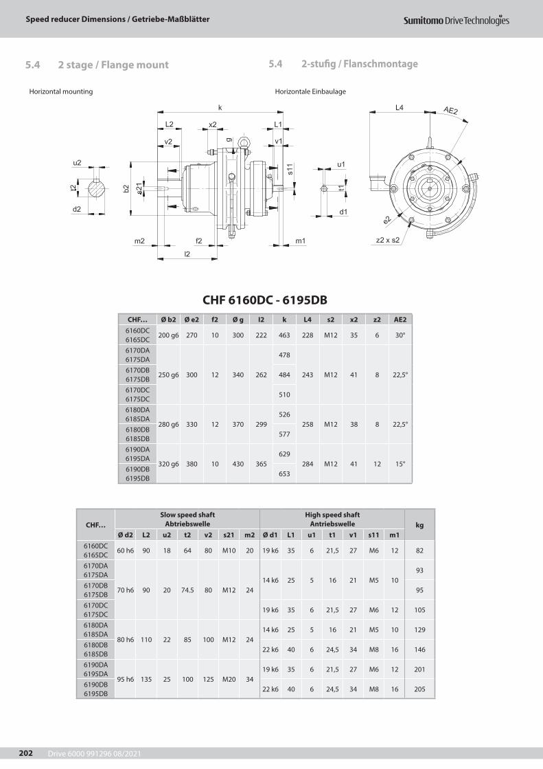
Drive 6000 991296 08/2021
Speed reducer Dimensions / Getriebe-Maßblätter
202
CHF 6160DC - 6195DBCHF… Ø b2 Ø e2 f2 Ø g I2 k L4 s2 x2 z2 AE2
6160DC 6165DC
200 g6 270 10 300 222 463 228 M12 35 6 30°
6170DA 6175DA
250 g6 300 12 340 262
478
243 M12 41 8 22,5°6170DB 6175DB
484
6170DC 6175DC
510
6180DA 6185DA
280 g6 330 12 370 299526
258 M12 38 8 22,5°6180DB 6185DB
577
6190DA 6195DA
320 g6 380 10 430 365629
284 M12 41 12 15°6190DB 6195DB
653
CHF…Slow speed shaft
AbtriebswelleHigh speed shaft
Antriebswelle kgØ d2 L2 u2 t2 v2 s21 m2 Ø d1 L1 u1 t1 v1 s11 m1
6160DC 6165DC
60 h6 90 18 64 80 M10 20 19 k6 35 6 21,5 27 M6 12 82
6170DA 6175DA
70 h6 90 20 74.5 80 M12 2414 k6 25 5 16 21 M5 10
93
6170DB 6175DB
95
6170DC 6175DC
19 k6 35 6 21,5 27 M6 12 105
6180DA 6185DA
80 h6 110 22 85 100 M12 2414 k6 25 5 16 21 M5 10 129
6180DB 6185DB
22 k6 40 6 24,5 34 M8 16 146
6190DA 6195DA
95 h6 135 25 100 125 M20 3419 k6 35 6 21,5 27 M6 12 201
6190DB 6195DB
22 k6 40 6 24,5 34 M8 16 205
Horizontal mounting Horizontale Einbaulage
5.4 2-stufig / Flanschmontage5.4 2 stage / Flange mount
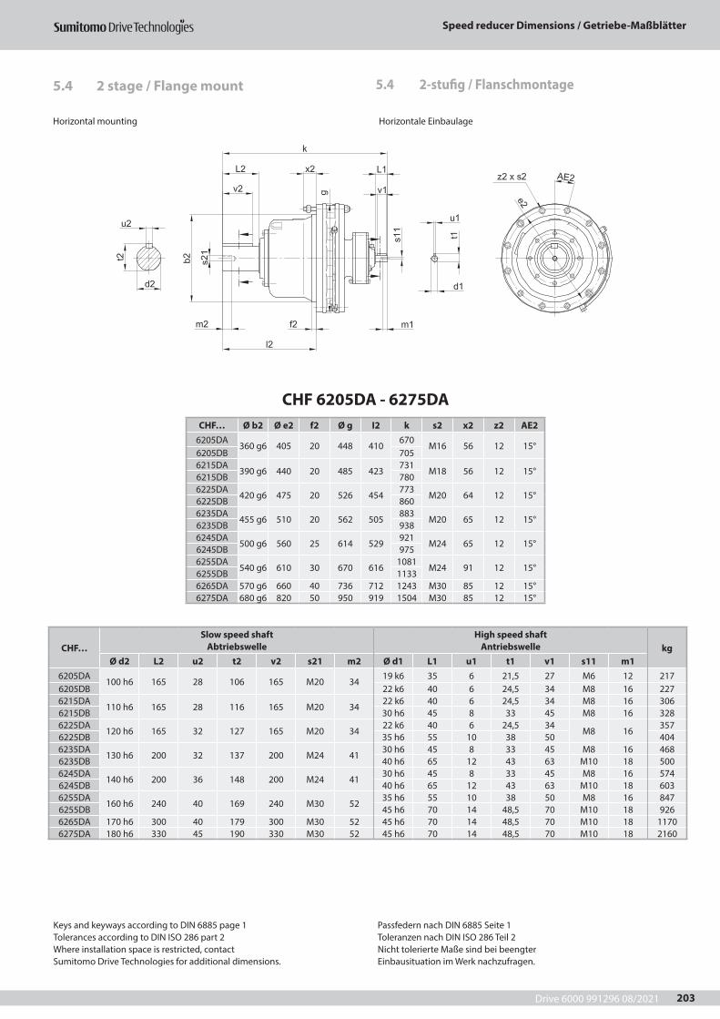
Drive 6000 991296 08/2021
Speed reducer Dimensions / Getriebe-Maßblätter
203
CHF 6205DA - 6275DACHF… Ø b2 Ø e2 f2 Ø g I2 k s2 x2 z2 AE2
6205DA360 g6 405 20 448 410
670M16 56 12 15°
6205DB 7056215DA
390 g6 440 20 485 423731
M18 56 12 15°6215DB 7806225DA
420 g6 475 20 526 454773
M20 64 12 15°6225DB 8606235DA
455 g6 510 20 562 505883
M20 65 12 15°6235DB 9386245DA
500 g6 560 25 614 529921
M24 65 12 15°6245DB 9756255DA
540 g6 610 30 670 6161081
M24 91 12 15°6255DB 11336265DA 570 g6 660 40 736 712 1243 M30 85 12 15°6275DA 680 g6 820 50 950 919 1504 M30 85 12 15°
CHF…Slow speed shaft
AbtriebswelleHigh speed shaft
Antriebswelle kgØ d2 L2 u2 t2 v2 s21 m2 Ø d1 L1 u1 t1 v1 s11 m1
6205DA100 h6 165 28 106 165 M20 34
19 k6 35 6 21,5 27 M6 12 2176205DB 22 k6 40 6 24,5 34 M8 16 2276215DA
110 h6 165 28 116 165 M20 3422 k6 40 6 24,5 34 M8 16 306
6215DB 30 h6 45 8 33 45 M8 16 3286225DA
120 h6 165 32 127 165 M20 3422 k6 40 6 24,5 34
M8 16357
6225DB 35 h6 55 10 38 50 4046235DA
130 h6 200 32 137 200 M24 4130 h6 45 8 33 45 M8 16 468
6235DB 40 h6 65 12 43 63 M10 18 5006245DA
140 h6 200 36 148 200 M24 4130 h6 45 8 33 45 M8 16 574
6245DB 40 h6 65 12 43 63 M10 18 6036255DA
160 h6 240 40 169 240 M30 5235 h6 55 10 38 50 M8 16 847
6255DB 45 h6 70 14 48,5 70 M10 18 9266265DA 170 h6 300 40 179 300 M30 52 45 h6 70 14 48,5 70 M10 18 11706275DA 180 h6 330 45 190 330 M30 52 45 h6 70 14 48,5 70 M10 18 2160
Horizontal mounting Horizontale Einbaulage
5.4 2-stufig / Flanschmontage5.4 2 stage / Flange mount
Keys and keyways according to DIN 6885 page 1Tolerances according to DIN ISO 286 part 2Where installation space is restricted, contactSumitomo Drive Technologies for additional dimensions.
Passfedern nach DIN 6885 Seite 1Toleranzen nach DIN ISO 286 Teil 2Nicht tolerierte Maße sind bei beengterEinbausituation im Werk nachzufragen.
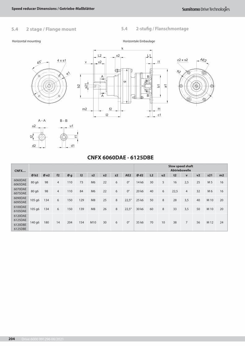
Drive 6000 991296 08/2021
Speed reducer Dimensions / Getriebe-Maßblätter
204
CNFX 6060DAE - 6125DBE
CNFX…Slow speed shaft
AbtriebswelleØ b2 Ø e2 f2 Ø g I2 s2 x2 z2 AE2 Ø d2 L2 u2 t2 v v2 s21 m2
6060DAE 6065DAE
80 g6 98 4 110 73 M6 22 6 0° 14 k6 30 5 16 2,5 25 M 5 16
6070DAE 6075DAE
80 g6 98 4 110 84 M6 22 6 0° 20 k6 40 6 22,5 4 32 M 6 16
6090DAE 6095DAE
105 g6 134 6 150 129 M8 25 8 22,5° 25 k6 50 8 28 3,5 40 M 10 20
6100DAE 6105DAE
105 g6 134 6 150 139 M8 26 8 22,5° 30 k6 60 8 33 3,5 50 M 10 20
6120DAE 6125DAE
140 g6 180 14 204 154 M10 30 6 0° 35 k6 70 10 38 7 56 M 12 246120DBE 6125DBE
Horizontal mounting Horizontale Einbaulage
5.4 2-stufig / Flanschmontage5.4 2 stage / Flange mount
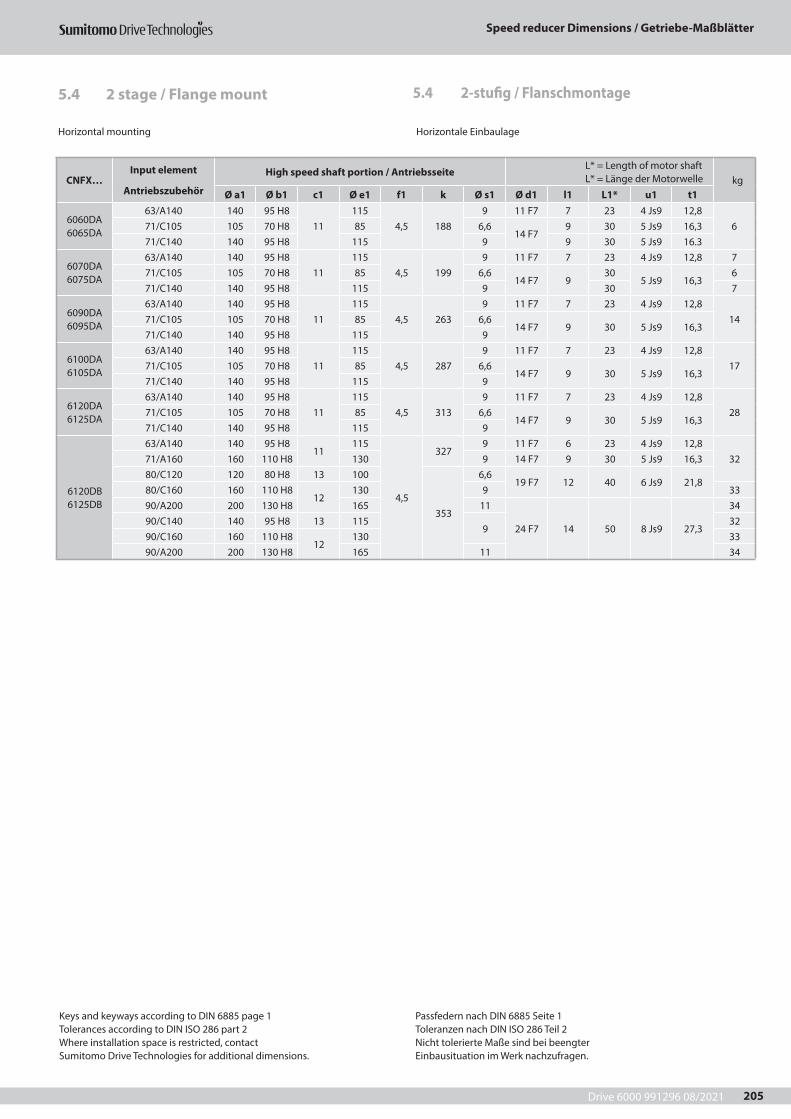
Drive 6000 991296 08/2021
Speed reducer Dimensions / Getriebe-Maßblätter
205
Horizontal mounting Horizontale Einbaulage
CNFX…Input element
Antriebszubehör
High speed shaft portion / Antriebsseite L* = Length of motor shaft L* = Länge der Motorwelle kg
Ø a1 Ø b1 c1 Ø e1 f1 k Ø s1 Ø d1 l1 L1* u1 t1
6060DA 6065DA
63/A140 140 95 H811
1154,5 188
9 11 F7 7 23 4 Js9 12,8671/C105 105 70 H8 85 6,6
14 F79 30 5 Js9 16,3
71/C140 140 95 H8 115 9 9 30 5 Js9 16.3
6070DA 6075DA
63/A140 140 95 H811
1154,5 199
9 11 F7 7 23 4 Js9 12,8 771/C105 105 70 H8 85 6,6
14 F7 930
5 Js9 16,36
71/C140 140 95 H8 115 9 30 7
6090DA 6095DA
63/A140 140 95 H811
1154,5 263
9 11 F7 7 23 4 Js9 12,81471/C105 105 70 H8 85 6,6
14 F7 9 30 5 Js9 16,371/C140 140 95 H8 115 9
6100DA 6105DA
63/A140 140 95 H811
1154,5 287
9 11 F7 7 23 4 Js9 12,81771/C105 105 70 H8 85 6,6
14 F7 9 30 5 Js9 16,371/C140 140 95 H8 115 9
6120DA 6125DA
63/A140 140 95 H811
1154,5 313
9 11 F7 7 23 4 Js9 12,82871/C105 105 70 H8 85 6,6
14 F7 9 30 5 Js9 16,371/C140 140 95 H8 115 9
6120DB 6125DB
63/A140 140 95 H811
115
4,5
3279 11 F7 6 23 4 Js9 12,8
3271/A160 160 110 H8 130 9 14 F7 9 30 5 Js9 16,380/C120 120 80 H8 13 100
353
6,619 F7 12 40 6 Js9 21,8
80/C160 160 110 H812
130 9 3390/A200 200 130 H8 165 11
24 F7 14 50 8 Js9 27,3
3490/C140 140 95 H8 13 115
932
90/C160 160 110 H812
130 3390/A200 200 130 H8 165 11 34
Keys and keyways according to DIN 6885 page 1Tolerances according to DIN ISO 286 part 2Where installation space is restricted, contactSumitomo Drive Technologies for additional dimensions.
Passfedern nach DIN 6885 Seite 1Toleranzen nach DIN ISO 286 Teil 2Nicht tolerierte Maße sind bei beengterEinbausituation im Werk nachzufragen.
5.4 2-stufig / Flanschmontage5.4 2 stage / Flange mount
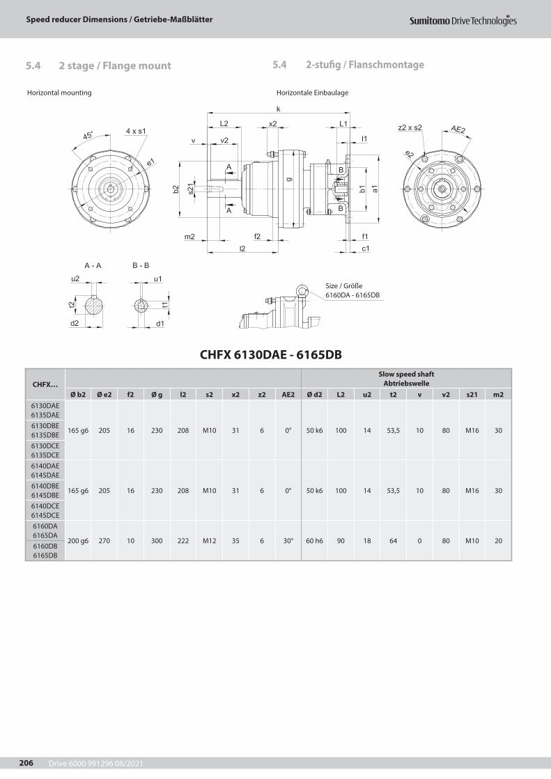
Drive 6000 991296 08/2021
Speed reducer Dimensions / Getriebe-Maßblätter
206
CHFX 6130DAE - 6165DB
CHFX…Slow speed shaft
AbtriebswelleØ b2 Ø e2 f2 Ø g l2 s2 x2 z2 AE2 Ø d2 L2 u2 t2 v v2 s21 m2
6130DAE 6135DAE
165 g6 205 16 230 208 M10 31 6 0° 50 k6 100 14 53,5 10 80 M16 306130DBE 6135DBE6130DCE 6135DCE6140DAE 6145DAE
165 g6 205 16 230 208 M10 31 6 0° 50 k6 100 14 53,5 10 80 M16 306140DBE 6145DBE6140DCE 6145DCE6160DA 6165DA
200 g6 270 10 300 222 M12 35 6 30° 60 h6 90 18 64 0 80 M10 206160DB 6165DB
Horizontal mounting Horizontale Einbaulage
5.4 2-stufig / Flanschmontage5.4 2 stage / Flange mount
Size / Größe 6160DA - 6165DB
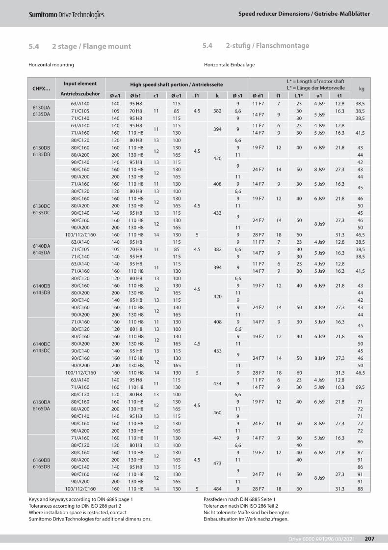
Drive 6000 991296 08/2021
Speed reducer Dimensions / Getriebe-Maßblätter
207
Horizontal mounting Horizontale Einbaulage
CHFX…Input element
Antriebszubehör
High speed shaft portion / Antriebsseite L* = Length of motor shaft L* = Länge der Motorwelle kg
Ø a1 Ø b1 c1 Ø e1 f1 k Ø s1 Ø d1 l1 L1* u1 t1
6130DA 6135DA
63/A140 140 95 H811
1154,5 382
9 11 F7 7 23 4 Js9 12,8 38,571/C105 105 70 H8 85 6,6
14 F7 930
5 Js916,3 38,5
71/C140 140 95 H8 115 9 30 38,5
6130DB 6135DB
63/A140 140 95 H811
115
4,5
394 911 F7 6 23 4 Js9 12,8
41,571/A160 160 110 H8 130 14 F7 9 30 5 Js9 16,380/C120 120 80 H8 13 100
420
6,619 F7 12 40 6 Js9 21,880/C160 160 110 H8
12130 9 43
80/A200 200 130 H8 165 11 4490/C140 140 95 H8 13 115
924 F7 14 50 8 Js9 27,3
4290/C160 160 110 H8
12130 43
90/A200 200 130 H8 165 11 44
6130DC 6135DC
71/A160 160 110 H8 11 130
4,5
408 9 14 F7 9 30 5 Js9 16,345
80/C120 120 80 H8 13 100
433
6,619 F7 12 40 6 Js9 21,880/C160 160 110 H8
12130 9 46
80/A200 200 130 H8 165 11 5090/C140 140 95 H8 13 115
924 F7 14 50
8 Js927,3
4590/C160 160 110 H8
12130 46
90/A200 200 130 H8 165 11 50100/112/C160 160 110 H8 14 130 5 9 28 F7 18 60 31,3 46,5
6140DA 6145DA
63/A140 140 95 H811
1154,5 382
9 11 F7 7 23 4 Js9 12,8 38,571/C105 105 70 H8 85 6,6
14 F7 930
5 Js9 16,338,5
71/C140 140 95 H8 115 9 30 38,5
6140DB 6145DB
63/A140 140 95 H811
115
4,5
394 911 F7 6 23 4 Js9 12,8
41,571/A160 160 110 H8 130 14 F7 9 30 5 Js9 16,380/C120 120 80 H8 13 100
420
6,619 F7 12 40 6 Js9 21,880/C160 160 110 H8
12130 9 43
80/A200 200 130 H8 165 11 4490/C140 140 95 H8 13 115 9
24 F7 14 50 8 Js9 27,342
90/C160 160 110 H812
130 9 4390/A200 200 130 H8 165 11 44
6140DC 6145DC
71/A160 160 110 H8 11 130
4,5
408 9 14 F7 9 30 5 Js9 16,345
80/C120 120 80 H8 13 100
433
6,619 F7 12 40 6 Js9 21,880/C160 160 110 H8
12130 9 46
80/A200 200 130 H8 165 11 5090/C140 140 95 H8 13 115
924 F7 14 50 8 Js9 27,3
4590/C160 160 110 H8
12130 46
90/A200 200 130 H8 165 11 50100/112/C160 160 110 H8 14 130 5 9 28 F7 18 60 31,3 46,5
6160DA 6165DA
63/A140 140 95 H811
115
4,5
434 911 F7 6 23 4 Js9 12,8
69,571/A160 160 110 H8 130 14 F7 9 30 5 Js9 16,380/C120 120 80 H8 13 100
460
6,619 F7 12 40 6 Js9 21,880/C160 160 110 H8
12130 9 71
80/A200 200 130 H8 165 11 7290/C140 140 95 H8 13 115 9
24 F7 14 50 8 Js9 27,371
90/C160 160 110 H812
130 9 7290/A200 200 130 H8 165 11 72
6160DB 6165DB
71/A160 160 110 H8 11 130
4,5
447 9 14 F7 9 30 5 Js9 16,386
80/C120 120 80 H8 13 100
473
6,619 F7 12
406 Js9 21,880/C160 160 110 H8
12130 9 40 87
80/A200 200 130 H8 165 11 40 9190/C140 140 95 H8 13 115
924 F7 14 50
8 Js927,3
8690/C160 160 110 H8
12130 91
90/A200 200 130 H8 165 11 91100/112/C160 160 110 H8 14 130 5 484 9 28 F7 18 60 31,3 88
Keys and keyways according to DIN 6885 page 1Tolerances according to DIN ISO 286 part 2Where installation space is restricted, contactSumitomo Drive Technologies for additional dimensions.
Passfedern nach DIN 6885 Seite 1Toleranzen nach DIN ISO 286 Teil 2Nicht tolerierte Maße sind bei beengterEinbausituation im Werk nachzufragen.
5.4 2-stufig / Flanschmontage5.4 2 stage / Flange mount
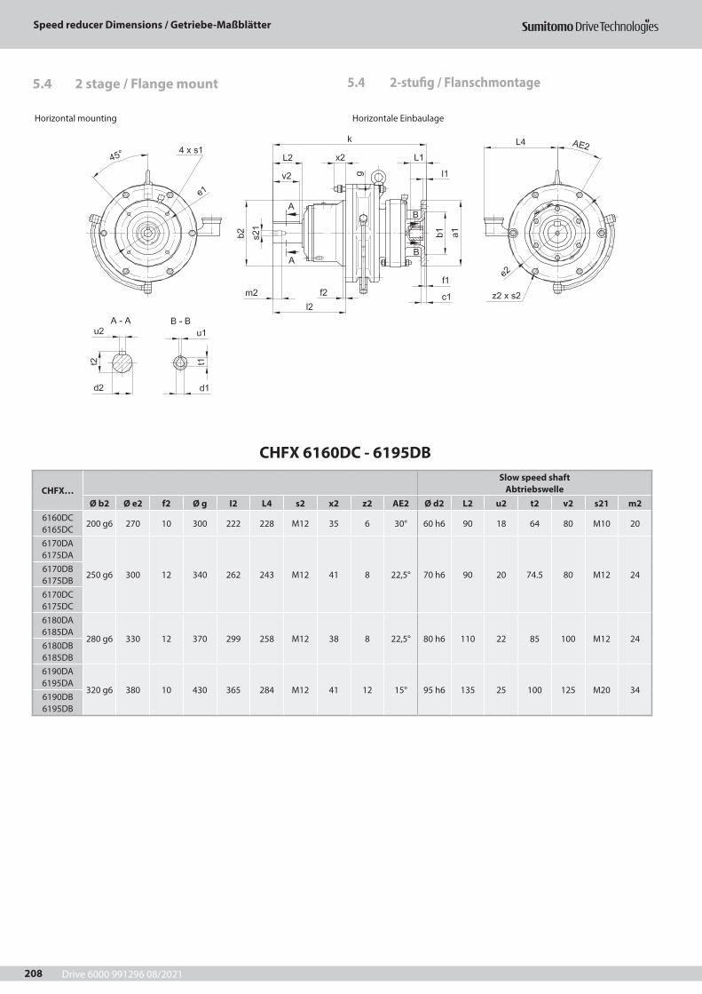
Drive 6000 991296 08/2021
Speed reducer Dimensions / Getriebe-Maßblätter
208
CHFX 6160DC - 6195DB
CHFX…Slow speed shaft
AbtriebswelleØ b2 Ø e2 f2 Ø g I2 L4 s2 x2 z2 AE2 Ø d2 L2 u2 t2 v2 s21 m2
6160DC 6165DC
200 g6 270 10 300 222 228 M12 35 6 30° 60 h6 90 18 64 80 M10 20
6170DA 6175DA
250 g6 300 12 340 262 243 M12 41 8 22,5° 70 h6 90 20 74.5 80 M12 246170DB 6175DB6170DC 6175DC6180DA 6185DA
280 g6 330 12 370 299 258 M12 38 8 22,5° 80 h6 110 22 85 100 M12 246180DB 6185DB6190DA 6195DA
320 g6 380 10 430 365 284 M12 41 12 15° 95 h6 135 25 100 125 M20 346190DB 6195DB
Horizontal mounting Horizontale Einbaulage
5.4 2-stufig / Flanschmontage5.4 2 stage / Flange mount

Drive 6000 991296 08/2021
Speed reducer Dimensions / Getriebe-Maßblätter
209
Horizontal mounting Horizontale Einbaulage
CHFX…Input element
Antriebszubehör
High speed shaft portion / Antriebsseite L* = Length of motor shaft L* = Länge der Motorwelle kg
Ø a1 Ø b1 c1 Ø e1 f1 k Ø s1 Ø d1 l1 L1* u1 t1
6160DC 6165DC
80/A200200 130 H8 13 165 4,5 468 11
19 F7 12 40 6 Js9 21,894
90/A200 24 F7 14 508 Js9
27,3100/112/C160 160 110 H8
14130
5 4789
28 F7 18 60 31,395
100/112/A250 250 180 H8 215 14 102
6170DA 6175DA
63/A140 140 95 H811
115
4,5
478 911 F7 6 23 4 Js9 12,8
9471/A160 160 110 H8 130 14 F7 9 30 5 Js9 16,380/C120 120 80 H8 13 100
504
6,619 F7 12 40 6 Js9 21,880/C160 160 110 H8
12130 9 95
80/A200 200 130 H8 165 11 9690/C140 140 95 H8 13 115 9
24 F7 14 50 8 Js9 27,395
90/C160 160 110 H812
130 990/A200 200 130 H8 165 11 96
6170DB 6175DB
71/A160 160 110 H8 11 130
4,5
492 9 14 F7 9 30 5 Js9 16,397
80/C120 120 80 H8 13 100
518
6,619 F7 12 40 6 Js9 21,880/C160 160 110 H8
12130 9 98
80/A200 200 130 H8 165 1199
90/C140 140 95 H8 13 115 924 F7 14 50
8 Js927,390/C160 160 110 H8
12130 9 98
90/A200 200 130 H8 165 1199
100/112/C 160 160 110 H8 14 130 5 528 9 28 F7 18 60 31,3
6170DC 6175DC
80/A200200 130 H8 13 165 4,5 515 11
19 F7 12 40 6 Js9 21,8128
90/A200 24 F7 14 508 Js9
27,3100/112/C160 160 110 H8
14130
5 5259
28 F7 18 60 31,3129
100/112/A250 250 180 H8 215 14 136
6180DA 6185DA
71/A160 160 110 H8 11 130
4,5
534 9 14 F7 9 30 5 Js9 16,3131
80/C120 120 80 H8 13 100
560
6,619 F7 12 40 6 Js9 21,880/C160 160 110 H8
12130 9 132
80/A200 200 130 H8 165 11 13390/C140 140 95 H8 13 115 9
24 F7 14 508 Js9
27,3132
90/C160 160 110 H812
130 990/A200 200 130 H8 165 11 133
100/112/C 160 160 110 H8 14 130 5 570 9 28 F7 18 60 31,3 134
6180DB 6185DB
90/A200 200 130 H8 11 165 4,5 577 11 24 F7 14 508 Js9
27,3 180100/112/A250 250 180 H8 13 215
5587
1428 F7 18 60 31,3 182
132/A300 300 230 H8 17 265 613 38 F7 23 80 10 Js9 41,3 187
6190DA 6195DA
80/A200200 130 H8 13 165 4,5 635 11
19 F7 12 406 Js9
21,8 24390/A200 24 F7 14 50 27,3
248100/112/C160 160 110 H8
14130
5 6459
28 F7 18 60 8 Js9 31,3100/112/A250 250 180 H8 215 14 257
6190DB 6195DB
90/A200 200 130 H8 11 165 4,5 653 11 24 F7 14 508 Js9
27,3 247100/112/A250 250 180 H8 13 215
5663
1428 F7 18 60 31,3 250
132/A300 300 230 H8 17 265 689 38 F7 23 80 10 Js9 41,3 255
Keys and keyways according to DIN 6885 page 1Tolerances according to DIN ISO 286 part 2Where installation space is restricted, contactSumitomo Drive Technologies for additional dimensions.
Passfedern nach DIN 6885 Seite 1Toleranzen nach DIN ISO 286 Teil 2Nicht tolerierte Maße sind bei beengterEinbausituation im Werk nachzufragen.
5.4 2-stufig / Flanschmontage5.4 2 stage / Flange mount
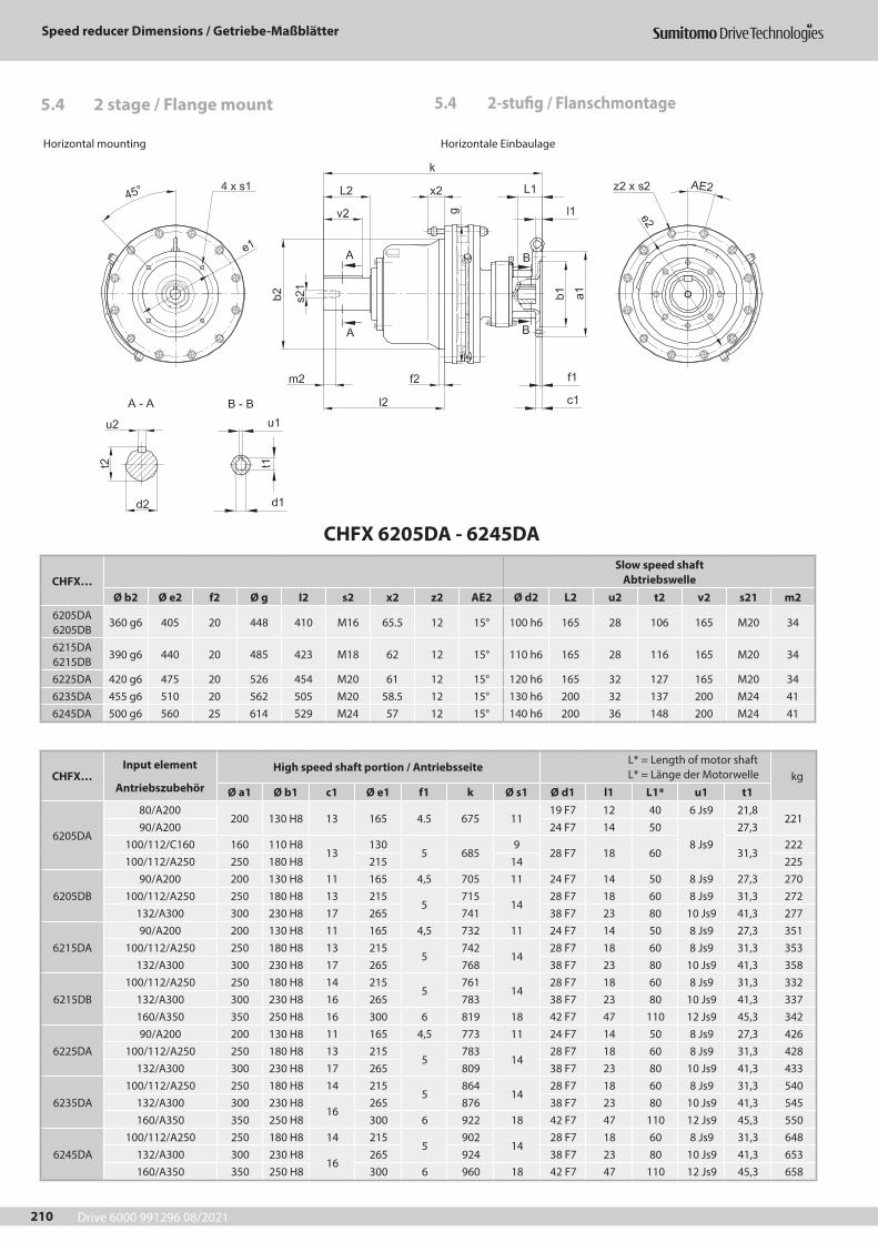
Drive 6000 991296 08/2021
Speed reducer Dimensions / Getriebe-Maßblätter
210
CHFX 6205DA - 6245DA
CHFX…Slow speed shaft
AbtriebswelleØ b2 Ø e2 f2 Ø g I2 s2 x2 z2 AE2 Ø d2 L2 u2 t2 v2 s21 m2
6205DA 6205DB
360 g6 405 20 448 410 M16 65.5 12 15° 100 h6 165 28 106 165 M20 34
6215DA 6215DB
390 g6 440 20 485 423 M18 62 12 15° 110 h6 165 28 116 165 M20 34
6225DA 420 g6 475 20 526 454 M20 61 12 15° 120 h6 165 32 127 165 M20 346235DA 455 g6 510 20 562 505 M20 58.5 12 15° 130 h6 200 32 137 200 M24 416245DA 500 g6 560 25 614 529 M24 57 12 15° 140 h6 200 36 148 200 M24 41
Horizontal mounting Horizontale Einbaulage
5.4 2-stufig / Flanschmontage5.4 2 stage / Flange mount
CHFX…Input element
Antriebszubehör
High speed shaft portion / Antriebsseite L* = Length of motor shaft L* = Länge der Motorwelle kg
Ø a1 Ø b1 c1 Ø e1 f1 k Ø s1 Ø d1 l1 L1* u1 t1
6205DA
80/A200200 130 H8 13 165 4.5 675 11
19 F7 12 40 6 Js9 21,8221
90/A200 24 F7 14 508 Js9
27,3100/112/C160 160 110 H8
13130
5 6859
28 F7 18 60 31,3222
100/112/A250 250 180 H8 215 14 225
6205DB90/A200 200 130 H8 11 165 4,5 705 11 24 F7 14 50 8 Js9 27,3 270
100/112/A250 250 180 H8 13 2155
71514
28 F7 18 60 8 Js9 31,3 272132/A300 300 230 H8 17 265 741 38 F7 23 80 10 Js9 41,3 277
6215DA90/A200 200 130 H8 11 165 4,5 732 11 24 F7 14 50 8 Js9 27,3 351
100/112/A250 250 180 H8 13 2155
74214
28 F7 18 60 8 Js9 31,3 353132/A300 300 230 H8 17 265 768 38 F7 23 80 10 Js9 41,3 358
6215DB100/112/A250 250 180 H8 14 215
5761
1428 F7 18 60 8 Js9 31,3 332
132/A300 300 230 H8 16 265 783 38 F7 23 80 10 Js9 41,3 337160/A350 350 250 H8 16 300 6 819 18 42 F7 47 110 12 Js9 45,3 342
6225DA90/A200 200 130 H8 11 165 4,5 773 11 24 F7 14 50 8 Js9 27,3 426
100/112/A250 250 180 H8 13 2155
78314
28 F7 18 60 8 Js9 31,3 428132/A300 300 230 H8 17 265 809 38 F7 23 80 10 Js9 41,3 433
6235DA100/112/A250 250 180 H8 14 215
5864
1428 F7 18 60 8 Js9 31,3 540
132/A300 300 230 H816
265 876 38 F7 23 80 10 Js9 41,3 545160/A350 350 250 H8 300 6 922 18 42 F7 47 110 12 Js9 45,3 550
6245DA100/112/A250 250 180 H8 14 215
5902
1428 F7 18 60 8 Js9 31,3 648
132/A300 300 230 H816
265 924 38 F7 23 80 10 Js9 41,3 653160/A350 350 250 H8 300 6 960 18 42 F7 47 110 12 Js9 45,3 658
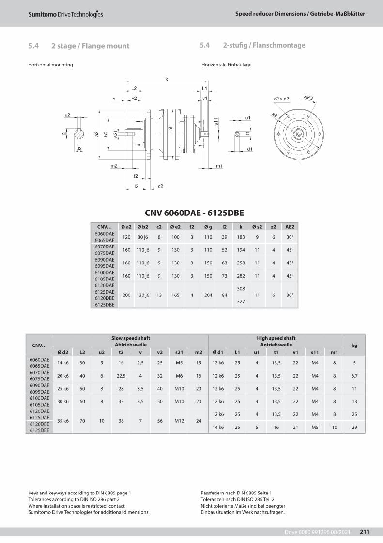
Drive 6000 991296 08/2021
Speed reducer Dimensions / Getriebe-Maßblätter
211
CNV 6060DAE - 6125DBECNV… Ø a2 Ø b2 c2 Ø e2 f2 Ø g I2 k Ø s2 z2 AE2
6060DAE 6065DAE
120 80 j6 8 100 3 110 39 183 9 6 30°
6070DAE 6075DAE
160 110 j6 9 130 3 110 52 194 11 4 45°
6090DAE 6095DAE
160 110 j6 9 130 3 150 63 258 11 4 45°
6100DAE 6105DAE
160 110 j6 9 130 3 150 73 282 11 4 45°
6120DAE 6125DAE
200 130 j6 13 165 4 204 84308
11 6 30°6120DBE 6125DBE
327
CNV…Slow speed shaft
AbtriebswelleHigh speed shaft
Antriebswelle kgØ d2 L2 u2 t2 v v2 s21 m2 Ø d1 L1 u1 t1 v1 s11 m1
6060DAE 6065DAE
14 k6 30 5 16 2,5 25 M5 15 12 k6 25 4 13,5 22 M4 8 5
6070DAE 6075DAE
20 k6 40 6 22,5 4 32 M6 16 12 k6 25 4 13,5 22 M4 8 6,7
6090DAE 6095DAE
25 k6 50 8 28 3,5 40 M10 20 12 k6 25 4 13,5 22 M4 8 11
6100DAE 6105DAE
30 k6 60 8 33 3,5 50 M10 20 12 k6 25 4 13,5 22 M4 8 13
6120DAE 6125DAE
35 k6 70 10 38 7 56 M12 2412 k6 25 4 13,5 22 M4 8 25
6120DBE 6125DBE
14 k6 25 5 16 21 M5 10 29
Horizontal mounting Horizontale Einbaulage
5.4 2-stufig / Flanschmontage5.4 2 stage / Flange mount
Keys and keyways according to DIN 6885 page 1Tolerances according to DIN ISO 286 part 2Where installation space is restricted, contactSumitomo Drive Technologies for additional dimensions.
Passfedern nach DIN 6885 Seite 1Toleranzen nach DIN ISO 286 Teil 2Nicht tolerierte Maße sind bei beengterEinbausituation im Werk nachzufragen.
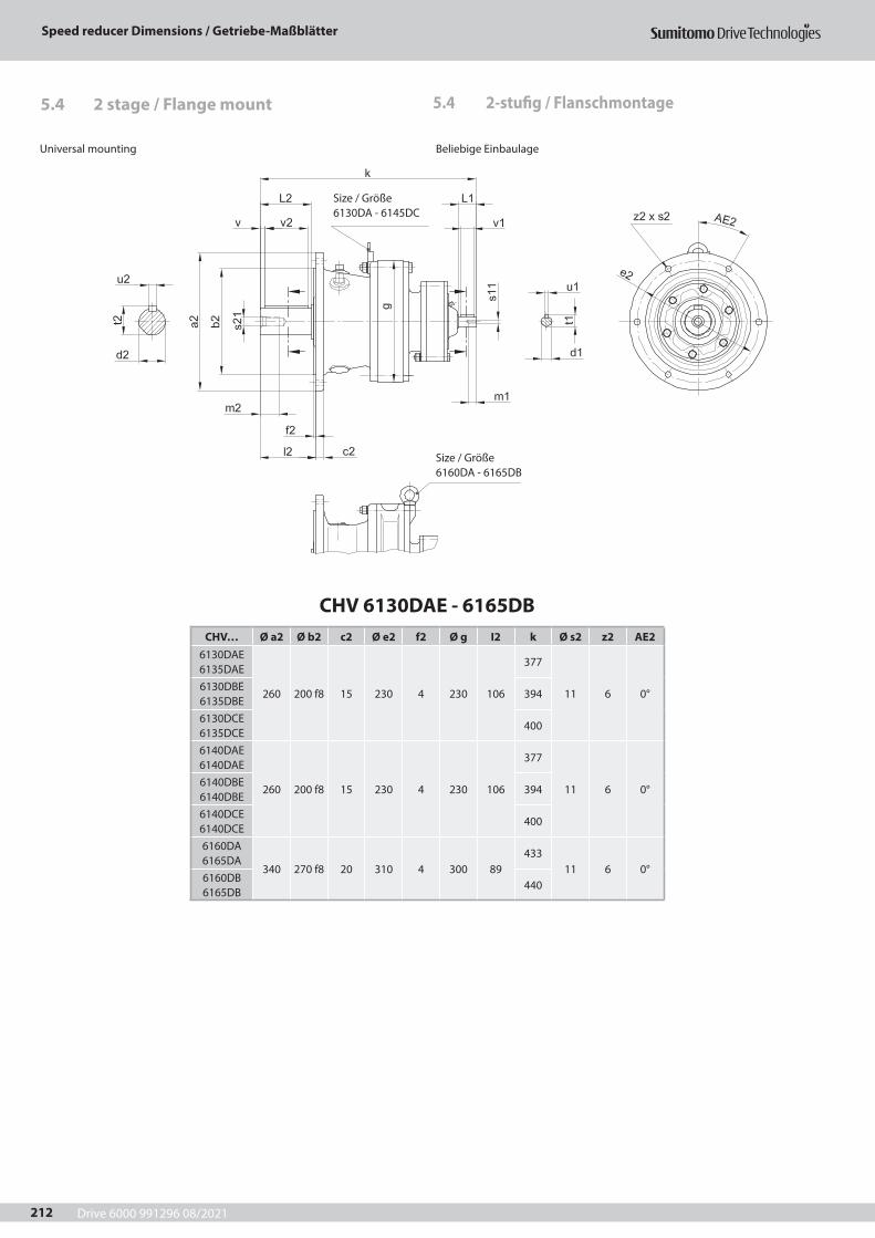
Drive 6000 991296 08/2021
Speed reducer Dimensions / Getriebe-Maßblätter
212
CHV 6130DAE - 6165DBCHV… Ø a2 Ø b2 c2 Ø e2 f2 Ø g I2 k Ø s2 z2 AE2
6130DAE 6135DAE
260 200 f8 15 230 4 230 106
377
11 6 0°6130DBE 6135DBE
394
6130DCE 6135DCE
400
6140DAE 6140DAE
260 200 f8 15 230 4 230 106
377
11 6 0°6140DBE 6140DBE
394
6140DCE 6140DCE
400
6160DA 6165DA
340 270 f8 20 310 4 300 89433
11 6 0°6160DB 6165DB
440
5.4 2-stufig / Flanschmontage5.4 2 stage / Flange mount
Universal mounting Beliebige Einbaulage
Size / Größe 6160DA - 6165DB
Size / Größe 6130DA - 6145DC
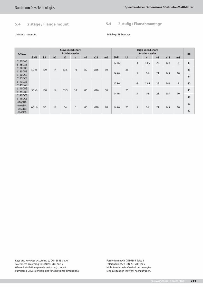
Drive 6000 991296 08/2021
Speed reducer Dimensions / Getriebe-Maßblätter
213
5.4 2-stufig / Flanschmontage5.4 2 stage / Flange mount
Universal mounting Beliebige Einbaulage
CHV…Slow speed shaft
AbtriebswelleHigh speed shaft
Antriebswelle kgØ d2 L2 u2 t2 v v2 s21 m2 Ø d1 L1 u1 t1 v1 s11 m1
6130DAE 6135DAE
50 k6 100 14 53,5 10 80 M16 30
12 k6
25
4 13,5 22 M4 8 40
6130DBE 6135DBE
14 k6 5 16 21 M5 1043
6130DCE 6135DCE
44
6140DAE 6145DAE
50 k6 100 14 53,5 10 80 M16 30
12 k6
25
4 13,5 22 M4 8 40
6140DBE 6145DBE
14 k6 5 16 21 M5 1043
6140DCE 6145DCE
44
6160DA 6165DA
60 h6 90 18 64 0 80 M10 20 14 k6 25 5 16 21 M5 1080
6160DB 6165DB
82
Keys and keyways according to DIN 6885 page 1Tolerances according to DIN ISO 286 part 2Where installation space is restricted, contactSumitomo Drive Technologies for additional dimensions.
Passfedern nach DIN 6885 Seite 1Toleranzen nach DIN ISO 286 Teil 2Nicht tolerierte Maße sind bei beengterEinbausituation im Werk nachzufragen.
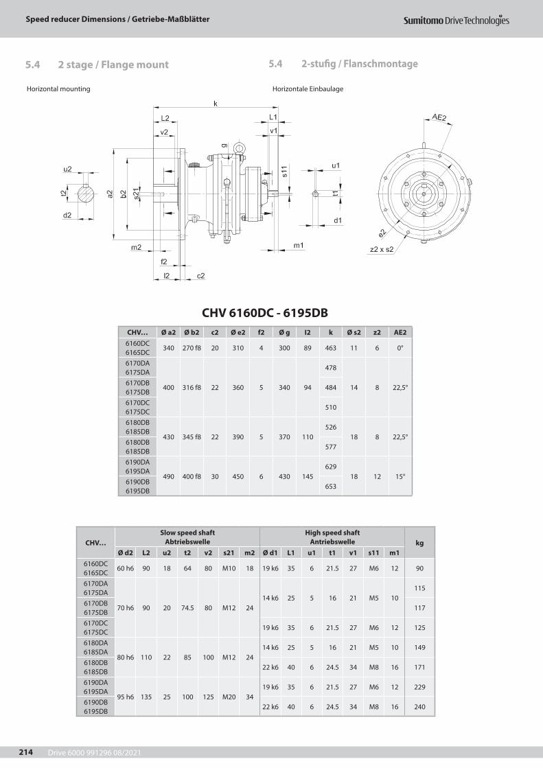
Drive 6000 991296 08/2021
Speed reducer Dimensions / Getriebe-Maßblätter
214
Horizontal mounting Horizontale Einbaulage
5.4 2-stufig / Flanschmontage5.4 2 stage / Flange mount
CHV 6160DC - 6195DBCHV… Ø a2 Ø b2 c2 Ø e2 f2 Ø g I2 k Ø s2 z2 AE2
6160DC 6165DC
340 270 f8 20 310 4 300 89 463 11 6 0°
6170DA 6175DA
400 316 f8 22 360 5 340 94
478
14 8 22,5°6170DB 6175DB
484
6170DC 6175DC
510
6180DB 6185DB
430 345 f8 22 390 5 370 110526
18 8 22,5°6180DB 6185DB
577
6190DA 6195DA
490 400 f8 30 450 6 430 145629
18 12 15°6190DB 6195DB
653
CHV…Slow speed shaft
AbtriebswelleHigh speed shaft
Antriebswelle kgØ d2 L2 u2 t2 v2 s21 m2 Ø d1 L1 u1 t1 v1 s11 m1
6160DC 6165DC
60 h6 90 18 64 80 M10 18 19 k6 35 6 21.5 27 M6 12 90
6170DA 6175DA
70 h6 90 20 74.5 80 M12 2414 k6 25 5 16 21 M5 10
115
6170DB 6175DB
117
6170DC 6175DC
19 k6 35 6 21.5 27 M6 12 125
6180DA 6185DA
80 h6 110 22 85 100 M12 2414 k6 25 5 16 21 M5 10 149
6180DB 6185DB
22 k6 40 6 24.5 34 M8 16 171
6190DA 6195DA
95 h6 135 25 100 125 M20 3419 k6 35 6 21.5 27 M6 12 229
6190DB 6195DB
22 k6 40 6 24.5 34 M8 16 240
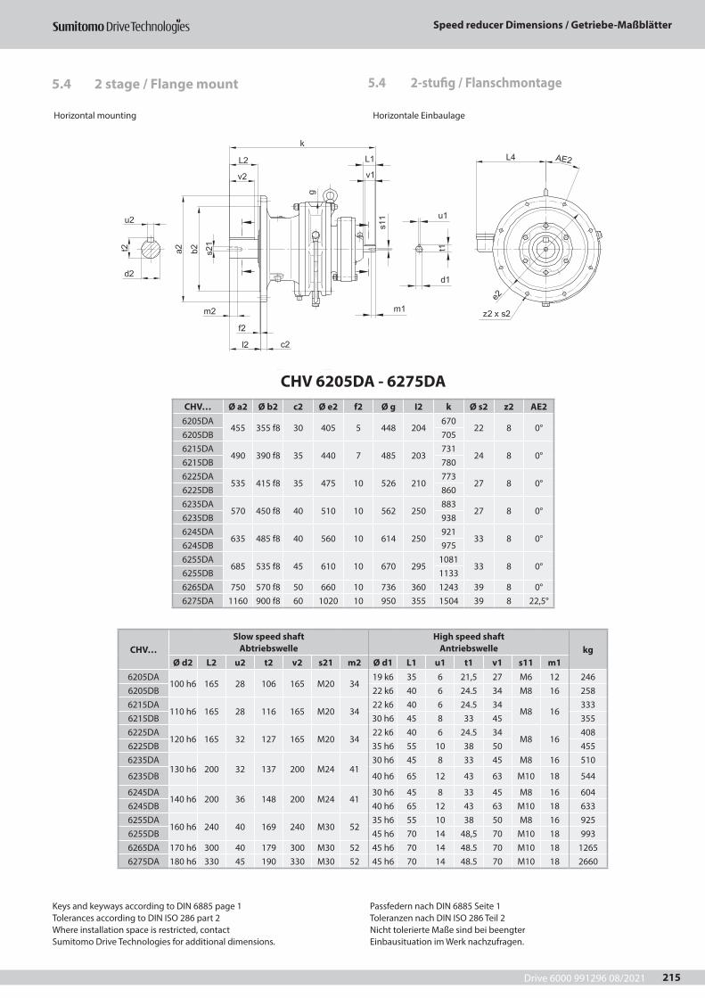
Drive 6000 991296 08/2021
Speed reducer Dimensions / Getriebe-Maßblätter
215
Horizontal mounting Horizontale Einbaulage
5.4 2-stufig / Flanschmontage5.4 2 stage / Flange mount
CHV 6205DA - 6275DACHV… Ø a2 Ø b2 c2 Ø e2 f2 Ø g I2 k Ø s2 z2 AE2
6205DA455 355 f8 30 405 5 448 204
67022 8 0°
6205DB 7056215DA
490 390 f8 35 440 7 485 203731
24 8 0°6215DB 7806225DA
535 415 f8 35 475 10 526 210773
27 8 0°6225DB 8606235DA
570 450 f8 40 510 10 562 250883
27 8 0°6235DB 9386245DA
635 485 f8 40 560 10 614 250921
33 8 0°6245DB 9756255DA
685 535 f8 45 610 10 670 2951081
33 8 0°6255DB 11336265DA 750 570 f8 50 660 10 736 360 1243 39 8 0°6275DA 1160 900 f8 60 1020 10 950 355 1504 39 8 22,5°
CHV…Slow speed shaft
AbtriebswelleHigh speed shaft
Antriebswelle kgØ d2 L2 u2 t2 v2 s21 m2 Ø d1 L1 u1 t1 v1 s11 m1
6205DA100 h6 165 28 106 165 M20 34
19 k6 35 6 21,5 27 M6 12 2466205DB 22 k6 40 6 24.5 34 M8 16 2586215DA
110 h6 165 28 116 165 M20 3422 k6 40 6 24.5 34
M8 16333
6215DB 30 h6 45 8 33 45 3556225DA
120 h6 165 32 127 165 M20 3422 k6 40 6 24.5 34
M8 16408
6225DB 35 h6 55 10 38 50 4556235DA
130 h6 200 32 137 200 M24 4130 h6 45 8 33 45 M8 16 510
6235DB 40 h6 65 12 43 63 M10 18 544
6245DA140 h6 200 36 148 200 M24 41
30 h6 45 8 33 45 M8 16 6046245DB 40 h6 65 12 43 63 M10 18 6336255DA
160 h6 240 40 169 240 M30 5235 h6 55 10 38 50 M8 16 925
6255DB 45 h6 70 14 48,5 70 M10 18 9936265DA 170 h6 300 40 179 300 M30 52 45 h6 70 14 48.5 70 M10 18 12656275DA 180 h6 330 45 190 330 M30 52 45 h6 70 14 48.5 70 M10 18 2660
Keys and keyways according to DIN 6885 page 1Tolerances according to DIN ISO 286 part 2Where installation space is restricted, contactSumitomo Drive Technologies for additional dimensions.
Passfedern nach DIN 6885 Seite 1Toleranzen nach DIN ISO 286 Teil 2Nicht tolerierte Maße sind bei beengterEinbausituation im Werk nachzufragen.
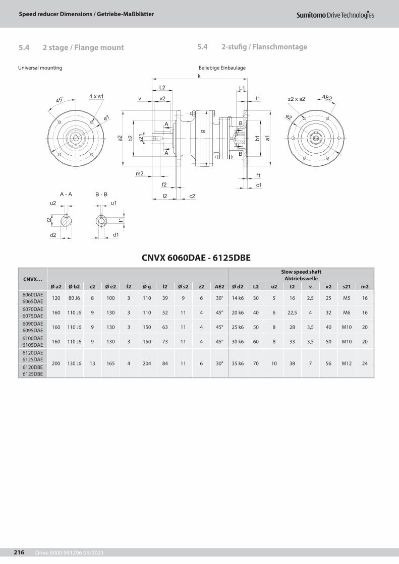
Drive 6000 991296 08/2021
Speed reducer Dimensions / Getriebe-Maßblätter
216
CNVX 6060DAE - 6125DBE
CNVX…Slow speed shaft
AbtriebswelleØ a2 Ø b2 c2 Ø e2 f2 Ø g l2 Ø s2 z2 AE2 Ø d2 L2 u2 t2 v v2 s21 m2
6060DAE 6065DAE
120 80 J6 8 100 3 110 39 9 6 30° 14 k6 30 5 16 2,5 25 M5 16
6070DAE 6075DAE
160 110 J6 9 130 3 110 52 11 4 45° 20 k6 40 6 22,5 4 32 M6 16
6090DAE 6095DAE
160 110 J6 9 130 3 150 63 11 4 45° 25 k6 50 8 28 3,5 40 M10 20
6100DAE 6105DAE
160 110 J6 9 130 3 150 73 11 4 45° 30 k6 60 8 33 3,5 50 M10 20
6120DAE 6125DAE
200 130 J6 13 165 4 204 84 11 6 30° 35 k6 70 10 38 7 56 M12 246120DBE 6125DBE
5.4 2-stufig / Flanschmontage5.4 2 stage / Flange mount
Universal mounting Beliebige Einbaulage

Drive 6000 991296 08/2021
Speed reducer Dimensions / Getriebe-Maßblätter
217
Universal mounting Beliebige Einbaulage
CNVX…Input element
Antriebszubehör
High speed shaft portion / Antriebsseite L* = Length of motor shaft L* = Länge der Motorwelle kg
Ø a1 Ø b1 c1 Ø e1 f1 k Ø s1 Ø d1 l1 L1* u1 t1
6060DA 6065DA
63/A140 140 95 H811
1154,5 188
9 11 F7 7 23 4 Js9 12,8771/C105 105 70 H8 85 6,6
14 F7 9 30 5 Js9 16,371/C140 140 95 H8 115 9
6070DA 6075DA
63/A140 140 95 H811
1154,5 199
9 11 F7 7 23 4 Js9 12,8871/C105 105 70 H8 85 6,6
14 F7 9 30 5 Js9 16,371/C140 140 95 H8 115 9
6090DA 6095DA
63/A140 140 95 H811
1154,5 263
9 11 F7 7 23 4 Js9 12,8 1371/C105 105 70 H8 85 6,6
14 F7 9 30 5 Js9 16,3 1371/C140 140 95 H8 115 9
6100DA 6105DA
63/A140 140 95 H811
1154,5 287
9 11 F7 7 23 4 Js9 12,81571/C105 105 70 H8 85 6,6
14 F7 9 30 5 Js9 16,371/C140 140 95 H8 115 9
6120DA 6125DA
63/A140 140 95 H811
1154,5 313
9 11 F7 7 23 4 Js9 12,82771/C105 105 70 H8 85 6,6
14 F7 9 30 5 Js9 16,371/C140 140 95 H8 115 9
6120DB 6125DB
63/A140 140 95 H811
115
4,5
327 911 F7 6 23 4 Js9 12,8
3171/A160 160 110 H8 130 14 F7 9 30 5 Js9 16,380/C120 120 80 H8 13 100
353
6,619 F7 12 40 6 Js9 21,880/C160 160 110 H8
12130 9 32
80/A200 200 130 H8 165 11 3490/C140 140 95 H8 13 115
924 F7 14 50 8 Js9 27,3
3190/C160 160 110 H8
12130 32
90/A200 200 130 H8 165 11 34
Keys and keyways according to DIN 6885 page 1Tolerances according to DIN ISO 286 part 2Where installation space is restricted, contactSumitomo Drive Technologies for additional dimensions.
Passfedern nach DIN 6885 Seite 1Toleranzen nach DIN ISO 286 Teil 2Nicht tolerierte Maße sind bei beengterEinbausituation im Werk nachzufragen.
5.4 2-stufig / Flanschmontage5.4 2 stage / Flange mount
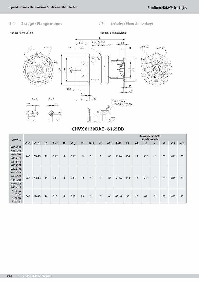
Drive 6000 991296 08/2021
Speed reducer Dimensions / Getriebe-Maßblätter
218
CHVX 6130DAE - 6165DB
CHVX…Slow speed shaft
AbtriebswelleØ a2 Ø b2 c2 Ø e2 f2 Ø g l2 Ø s2 z2 AE2 Ø d2 L2 u2 t2 v v2 s21 m2
6130DAE 6135DAE
260 200 f8 15 230 4 230 106 11 6 0° 50 k6 100 14 53,5 10 80 M16 306130DBE 6135DBE6130DCE 6135DCE6140DAE 6145DAE
260 200 f8 15 230 4 230 106 11 6 0° 50 k6 100 14 53,5 10 80 M16 306140DBE 6145DBE6140DCE 6145DCE6160DA 6165DA
340 270 f8 20 310 4 300 89 11 6 0° 60 h6 90 18 64 0 80 M10 206160DB 6165DB
5.4 2-stufig / Flanschmontage5.4 2 stage / Flange mount
Horizontal mounting Horizontale Einbaulage
Size / Größe 6160DA - 6165DB
Size / Größe 6130DA - 6145DC

Drive 6000 991296 08/2021
Speed reducer Dimensions / Getriebe-Maßblätter
219
Horizontal mounting Horizontale Einbaulage
CHVX…Input element
Antriebszubehör
High speed shaft portion / Antriebsseite L* = Length of motor shaft L* = Länge der Motorwelle kg
Ø a1 Ø b1 c1 Ø e1 f1 k Ø s1 Ø d1 l1 L1* u1 t1
6130DA 6135DA
63/A140 140 95 H811
1154,5 382
9 11 F7 7 23 4 Js9 12,8 42,571/C105 105 70 H8 85 6,6
14 F7 930 5 Js9 16,3 42,5
71/C140 140 95 H8 115 9 30 42,5
6130DB 6135DB
63/A140 140 95 H811
115
4,5
394 911 F7 6 23 4 Js9 12,8
45,571/A160 160 110 H8 130 14 F7 9 30 5 Js9 16,380/C120 120 80 H8 13 100
420
6,619 F7 12 40 6 Js9 21,880/C160 160 110 H8
12130 9 47
80/A200 200 130 H8 165 11 4890/C140 140 95 H8 13 115
924 F7 14 50 8 Js9 27,3
4690/C160 160 110 H8
12130 47
90/A200 200 130 H8 165 11 48
6130DC 6135DC
71/A160 160 110 h8 11 130
4,5
408 9 14 F7 9 30 5 Js9 16,346
80/C120 120 80 H8 13 100
433
6,619 F7 12 40 6 Js9 21,880/C160 160 110 H8
12130 9 47
80/A200 200 130 H8 165 11 5090/C140 140 95 H8 13 115
924 F7 14 50
8 Js927,3
4690/C160 160 110 H8
12130 47
90/A200 200 130 H8 165 11 50100/112/C160 160 110 H8 14 130 5 9 28 F7 18 60 31,3 48
6140DA 6145DA
63/A140 140 95 H811
1154,5 382
9 11 F7 7 23 4 Js9 12,8 42,571/C105 105 70 H8 85 6,6
14 F7 930
5 Js9 16,342,5
71/C140 140 95 H8 115 9 30 42,5
6140DB 6145DB
63/A140 140 95 H811
115
4,5
394 911 F7 6 23 4 Js9 12,8
45,571/A160 160 110 H8 130 14 F7 9 30 5 Js9 16,380/C120 120 80 H8 13 100
420
6,619 F7 12 40 6 Js9 21,880/C160 160 110 H8
12130 9 47
80/A200 200 130 H8 165 11 4890/C140 140 95 H8 13 115 9
24 F7 14 50 8 Js9 27,346
90/C160 160 110 H812
130 9 4790/A200 200 130 H8 165 11 48
6140DC 6145DC
71/A160 160 110 H8 11 130
4,5
408 9 14 F7 9 30 5 Js9 16,346
80/C120 120 80 H8 13 100
433
6,619 F7 12 40 6 Js9 21,880/C160 160 110 H8
12130 9 47
80/A200 200 130 H8 165 11 5090/C140 140 95 H8 13 115
924 F7 14 50
8 Js927,3
4690/C160 160 110 H8
12130 47
90/A200 200 130 H8 165 11 50100/112/C160 160 110 H8 14 130 5 9 28 F7 18 60 31,3 48
6160DA 6165DA
63/A140 140 95 H811
115
4,5
434 911 F7 6 23 4 Js9 12,8
81,571/A160 160 110 H8 130 14 F7 9 30 5 Js9 16,380/C120 120 80 H8 13 100
460
6,619 F7 12 40 6 Js9 21,880/C160 160 110 H8
12130 9 83
80/A200 200 130 H8 165 11 8490/C140 140 95 H8 13 115 9
24 F7 14 50 8 Js9 27,383
90/C160 160 110 H812
130 9 8490/A200 200 130 H8 165 11 84
6160DB 6165DB
71/A160 160 110 H8 11 130
4,5
447 9 14 F7 9 30 5 Js9 16,387
80/C120 120 80 H8 13 100
473
6,619 F7 12
406 Js9 21,880/C160 160 110 H8
12130 9 40 88
80/A200 200 130 H8 165 11 40 9190/C140 140 95 H8 13 115
924 F7 14 50
8 Js927,3
8790/C160 160 110 H8
12130 88
90/A200 200 130 H8 165 11 91100/112/C160 160 110 h8 14 130 5 484 9 28 F7 18 60 31,3 89
Keys and keyways according to DIN 6885 page 1Tolerances according to DIN ISO 286 part 2Where installation space is restricted, contactSumitomo Drive Technologies for additional dimensions.
Passfedern nach DIN 6885 Seite 1Toleranzen nach DIN ISO 286 Teil 2Nicht tolerierte Maße sind bei beengterEinbausituation im Werk nachzufragen.
5.4 2-stufig / Flanschmontage5.4 2 stage / Flange mount
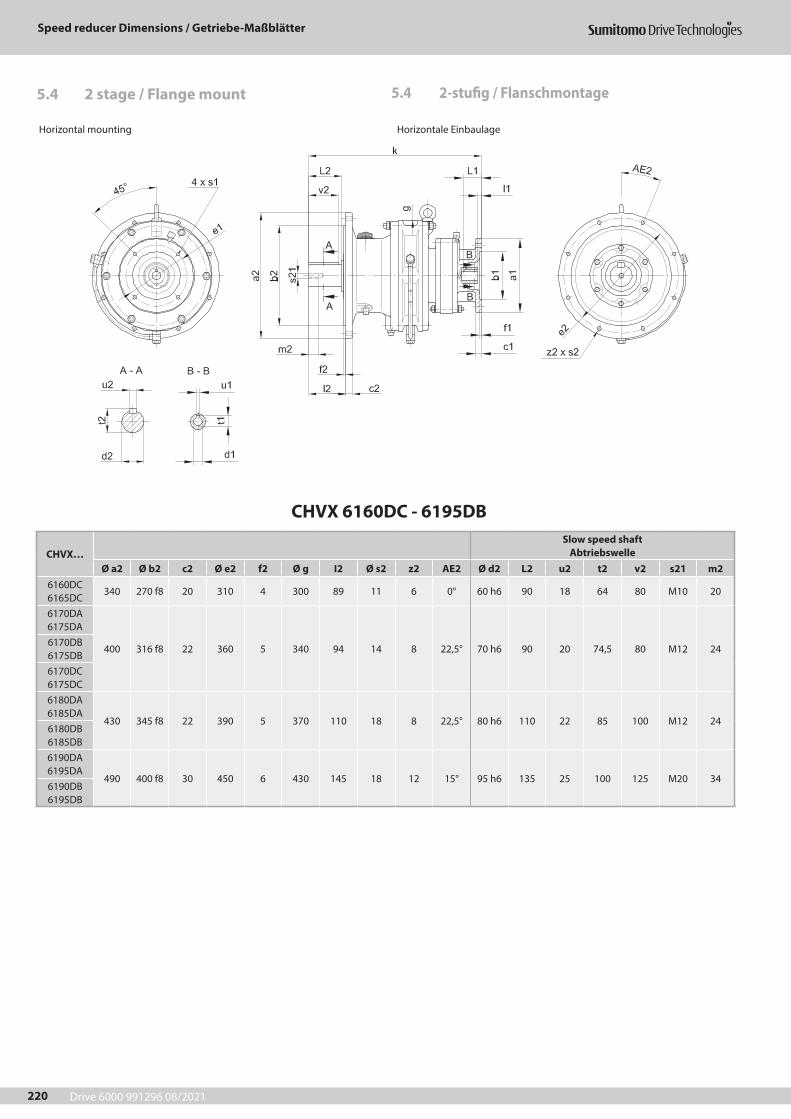
Drive 6000 991296 08/2021
Speed reducer Dimensions / Getriebe-Maßblätter
220
CHVX 6160DC - 6195DB
CHVX…Slow speed shaft
AbtriebswelleØ a2 Ø b2 c2 Ø e2 f2 Ø g I2 Ø s2 z2 AE2 Ø d2 L2 u2 t2 v2 s21 m2
6160DC 6165DC
340 270 f8 20 310 4 300 89 11 6 0° 60 h6 90 18 64 80 M10 20
6170DA 6175DA
400 316 f8 22 360 5 340 94 14 8 22,5° 70 h6 90 20 74,5 80 M12 246170DB 6175DB6170DC 6175DC6180DA 6185DA
430 345 f8 22 390 5 370 110 18 8 22,5° 80 h6 110 22 85 100 M12 246180DB 6185DB6190DA 6195DA
490 400 f8 30 450 6 430 145 18 12 15° 95 h6 135 25 100 125 M20 346190DB 6195DB
5.4 2-stufig / Flanschmontage5.4 2 stage / Flange mount
Horizontal mounting Horizontale Einbaulage
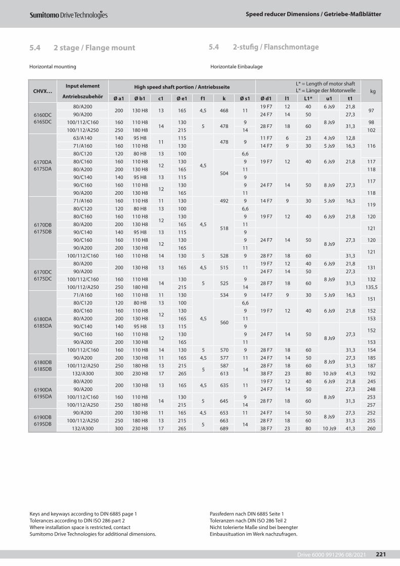
Drive 6000 991296 08/2021
Speed reducer Dimensions / Getriebe-Maßblätter
221
Horizontal mounting Horizontale Einbaulage
CHVX…Input element
Antriebszubehör
High speed shaft portion / Antriebsseite L* = Length of motor shaft L* = Länge der Motorwelle kg
Ø a1 Ø b1 c1 Ø e1 f1 k Ø s1 Ø d1 l1 L1* u1 t1
6160DC 6165DC
80/A200200 130 H8 13 165 4,5 468 11
19 F7 12 40 6 Js9 21,897
90/A200 24 F7 14 508 Js9
27,3100/112/C160 160 110 H8
14130
5 4789
28 F7 18 60 31,398
100/112/A250 250 180 H8 215 14 102
6170DA 6175DA
63/A140 140 95 H811
115
4,5
478 911 F7 6 23 4 Js9 12,8
11671/A160 160 110 H8 130 14 F7 9 30 5 Js9 16,380/C120 120 80 H8 13 100
504
6,619 F7 12 40 6 Js9 21,880/C160 160 110 H8
12130 9 117
80/A200 200 130 H8 165 11 11890/C140 140 95 H8 13 115 9
24 F7 14 50 8 Js9 27,3117
90/C160 160 110 H812
130 990/A200 200 130 H8 165 11 118
6170DB 6175DB
71/A160 160 110 H8 11 130
4,5
492 9 14 F7 9 30 5 Js9 16,3119
80/C120 120 80 H8 13 100
518
6,619 F7 12 40 6 Js9 21,880/C160 160 110 H8
12130 9 120
80/A200 200 130 H8 165 11121
90/C140 140 95 H8 13 115 924 F7 14 50
8 Js927,390/C160 160 110 H8
12130 9 120
90/A200 200 130 H8 165 11121
100/112/C160 160 110 H8 14 130 5 528 9 28 F7 18 60 31,3
6170DC 6175DC
80/A200200 130 H8 13 165 4,5 515 11
19 F7 12 40 6 Js9 21,8131
90/A200 24 F7 14 508 Js9
27,3100/112/C160 160 110 H8
14130
5 5259
28 F7 18 60 31,3132
100/112/A250 250 180 H8 215 14 135,5
6180DA 6185DA
71/A160 160 110 H8 11 130
4,5
534 9 14 F7 9 30 5 Js9 16,3151
80/C120 120 80 H8 13 100
560
6,619 F7 12 40 6 Js9 21,880/C160 160 110 H8
12130 9 152
80/A200 200 130 H8 165 11 15390/C140 140 95 H8 13 115 9
24 F7 14 508 Js9
27,3152
90/C160 160 110 H812
130 990/A200 200 130 H8 165 11 153
100/112/C160 160 110 H8 14 130 5 570 9 28 F7 18 60 31,3 154
6180DB 6185DB
90/A200 200 130 H8 11 165 4,5 577 11 24 F7 14 508 Js9
27,3 185100/112/A250 250 180 H8 13 215
5587
1428 F7 18 60 31,3 187
132/A300 300 230 H8 17 265 613 38 F7 23 80 10 Js9 41,3 192
6190DA 6195DA
80/A200200 130 H8 13 165 4,5 635 11
19 F7 12 40 6 Js9 21,8 24590/A200 24 F7 14 50
8 Js927,3 248
100/112/C160 160 110 H814
1305 645
928 F7 18 60 31,3
253100/112/A250 250 180 H8 215 14 257
6190DB 6195DB
90/A200 200 130 H8 11 165 4,5 653 11 24 F7 14 508 Js9
27,3 252100/112/A250 250 180 H8 13 215
5663
1428 F7 18 60 31,3 255
132/A300 300 230 H8 17 265 689 38 F7 23 80 10 Js9 41,3 260
Keys and keyways according to DIN 6885 page 1Tolerances according to DIN ISO 286 part 2Where installation space is restricted, contactSumitomo Drive Technologies for additional dimensions.
Passfedern nach DIN 6885 Seite 1Toleranzen nach DIN ISO 286 Teil 2Nicht tolerierte Maße sind bei beengterEinbausituation im Werk nachzufragen.
5.4 2-stufig / Flanschmontage5.4 2 stage / Flange mount
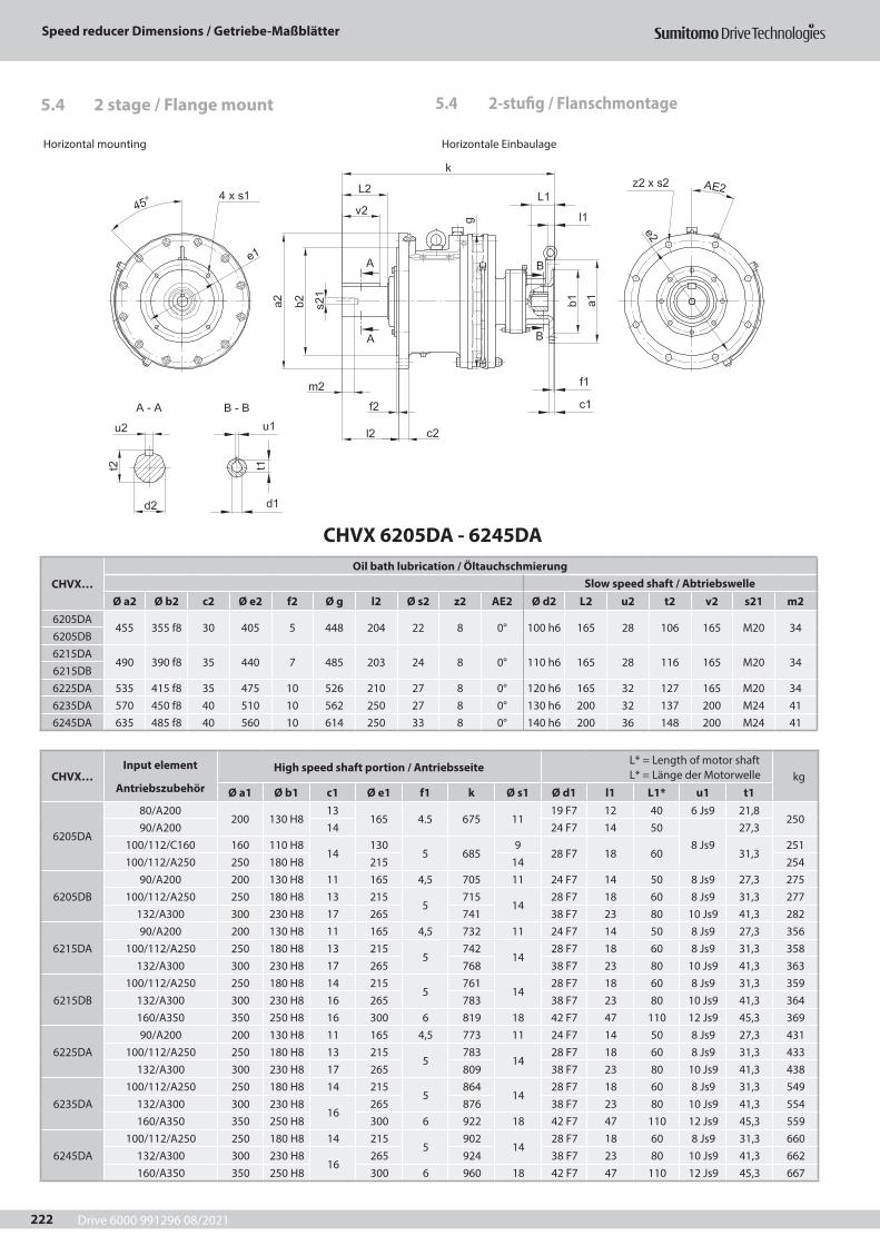
Drive 6000 991296 08/2021
Speed reducer Dimensions / Getriebe-Maßblätter
222
CHVX 6205DA - 6245DA
CHVX…Oil bath lubrication / Öltauchschmierung
Slow speed shaft / AbtriebswelleØ a2 Ø b2 c2 Ø e2 f2 Ø g l2 Ø s2 z2 AE2 Ø d2 L2 u2 t2 v2 s21 m2
6205DA455 355 f8 30 405 5 448 204 22 8 0° 100 h6 165 28 106 165 M20 34
6205DB6215DA
490 390 f8 35 440 7 485 203 24 8 0° 110 h6 165 28 116 165 M20 346215DB6225DA 535 415 f8 35 475 10 526 210 27 8 0° 120 h6 165 32 127 165 M20 346235DA 570 450 f8 40 510 10 562 250 27 8 0° 130 h6 200 32 137 200 M24 416245DA 635 485 f8 40 560 10 614 250 33 8 0° 140 h6 200 36 148 200 M24 41
Horizontal mounting Horizontale Einbaulage
5.4 2-stufig / Flanschmontage5.4 2 stage / Flange mount
CHVX…Input element
Antriebszubehör
High speed shaft portion / Antriebsseite L* = Length of motor shaft L* = Länge der Motorwelle kg
Ø a1 Ø b1 c1 Ø e1 f1 k Ø s1 Ø d1 l1 L1* u1 t1
6205DA
80/A200200 130 H8
13165 4.5 675 11
19 F7 12 40 6 Js9 21,8250
90/A200 14 24 F7 14 508 Js9
27,3100/112/C160 160 110 H8
14130
5 6859
28 F7 18 60 31,3251
100/112/A250 250 180 H8 215 14 254
6205DB90/A200 200 130 H8 11 165 4,5 705 11 24 F7 14 50 8 Js9 27,3 275
100/112/A250 250 180 H8 13 2155
71514
28 F7 18 60 8 Js9 31,3 277132/A300 300 230 H8 17 265 741 38 F7 23 80 10 Js9 41,3 282
6215DA90/A200 200 130 H8 11 165 4,5 732 11 24 F7 14 50 8 Js9 27,3 356
100/112/A250 250 180 H8 13 2155
74214
28 F7 18 60 8 Js9 31,3 358132/A300 300 230 H8 17 265 768 38 F7 23 80 10 Js9 41,3 363
6215DB100/112/A250 250 180 H8 14 215
5761
1428 F7 18 60 8 Js9 31,3 359
132/A300 300 230 H8 16 265 783 38 F7 23 80 10 Js9 41,3 364160/A350 350 250 H8 16 300 6 819 18 42 F7 47 110 12 Js9 45,3 369
6225DA90/A200 200 130 H8 11 165 4,5 773 11 24 F7 14 50 8 Js9 27,3 431
100/112/A250 250 180 H8 13 2155
78314
28 F7 18 60 8 Js9 31,3 433132/A300 300 230 H8 17 265 809 38 F7 23 80 10 Js9 41,3 438
6235DA100/112/A250 250 180 H8 14 215
5864
1428 F7 18 60 8 Js9 31,3 549
132/A300 300 230 H816
265 876 38 F7 23 80 10 Js9 41,3 554160/A350 350 250 H8 300 6 922 18 42 F7 47 110 12 Js9 45,3 559
6245DA100/112/A250 250 180 H8 14 215
5902
1428 F7 18 60 8 Js9 31,3 660
132/A300 300 230 H816
265 924 38 F7 23 80 10 Js9 41,3 662160/A350 350 250 H8 300 6 960 18 42 F7 47 110 12 Js9 45,3 667
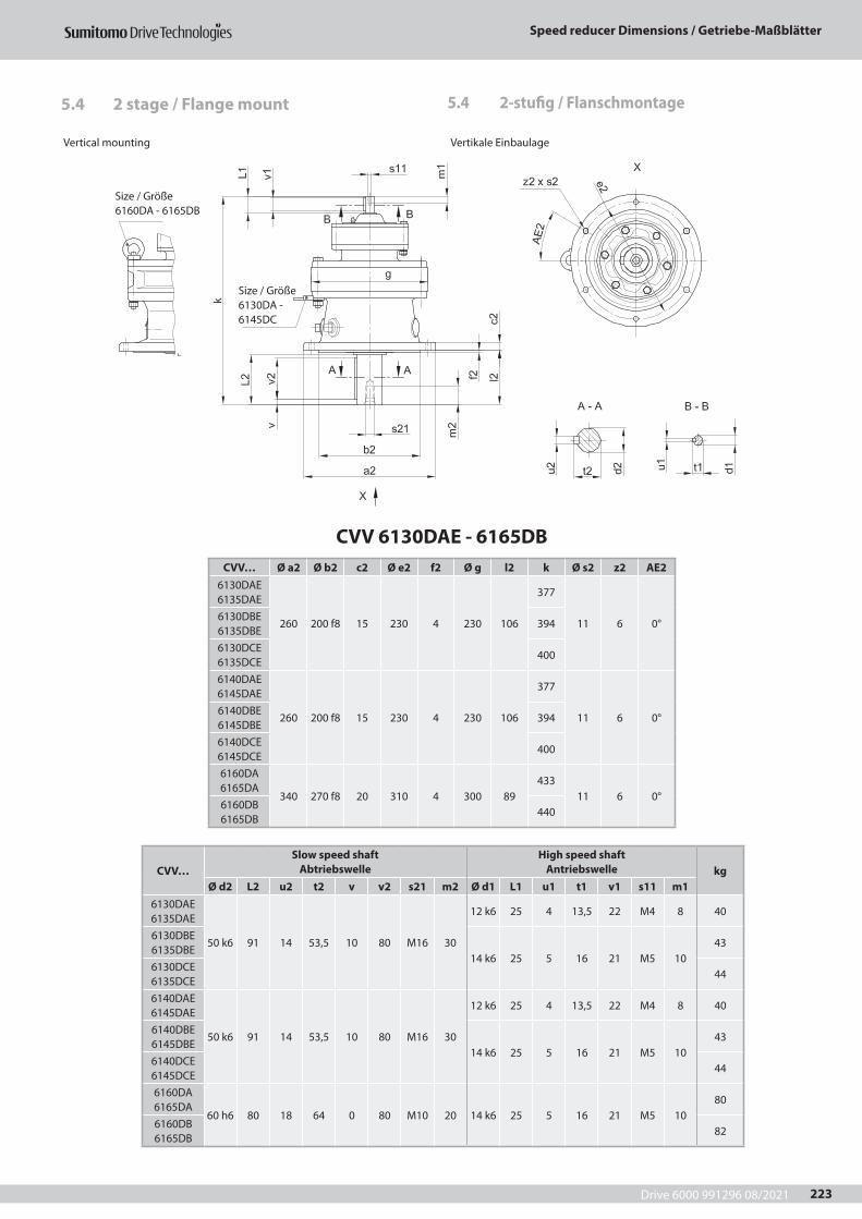
Drive 6000 991296 08/2021
Speed reducer Dimensions / Getriebe-Maßblätter
223
Vertical mounting Vertikale Einbaulage
5.4 2-stufig / Flanschmontage5.4 2 stage / Flange mount
CVV 6130DAE - 6165DBCVV… Ø a2 Ø b2 c2 Ø e2 f2 Ø g l2 k Ø s2 z2 AE2
6130DAE 6135DAE
260 200 f8 15 230 4 230 106
377
11 6 0°6130DBE 6135DBE
394
6130DCE 6135DCE
400
6140DAE 6145DAE
260 200 f8 15 230 4 230 106
377
11 6 0°6140DBE 6145DBE
394
6140DCE 6145DCE
400
6160DA 6165DA
340 270 f8 20 310 4 300 89433
11 6 0°6160DB 6165DB
440
CVV…Slow speed shaft
AbtriebswelleHigh speed shaft
Antriebswelle kgØ d2 L2 u2 t2 v v2 s21 m2 Ø d1 L1 u1 t1 v1 s11 m1
6130DAE 6135DAE
50 k6 91 14 53,5 10 80 M16 30
12 k6 25 4 13,5 22 M4 8 40
6130DBE 6135DBE
14 k6 25 5 16 21 M5 1043
6130DCE 6135DCE
44
6140DAE 6145DAE
50 k6 91 14 53,5 10 80 M16 30
12 k6 25 4 13,5 22 M4 8 40
6140DBE 6145DBE
14 k6 25 5 16 21 M5 1043
6140DCE 6145DCE
44
6160DA 6165DA
60 h6 80 18 64 0 80 M10 20 14 k6 25 5 16 21 M5 1080
6160DB 6165DB
82
Size / Größe 6160DA - 6165DB
Size / Größe 6130DA - 6145DC
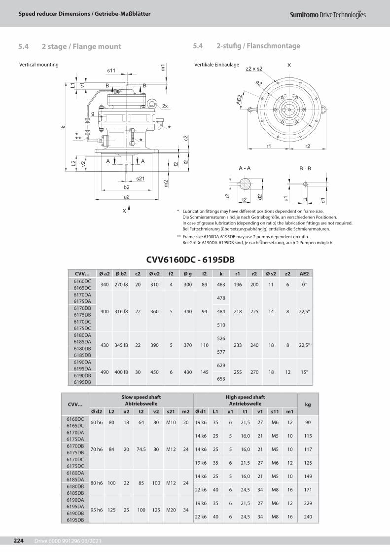
Drive 6000 991296 08/2021
Speed reducer Dimensions / Getriebe-Maßblätter
224
5.4 2-stufig / Flanschmontage5.4 2 stage / Flange mount
CVV6160DC - 6195DBCVV… Ø a2 Ø b2 c2 Ø e2 f2 Ø g I2 k r1 r2 Ø s2 z2 AE2
6160DC 6165DC
340 270 f8 20 310 4 300 89 463 196 200 11 6 0°
6170DA 6175DA
400 316 f8 22 360 5 340 94
478
218 225 14 8 22,5°6170DB 6175DB
484
6170DC 6175DC
510
6180DA 6185DA
430 345 f8 22 390 5 370 110526
233 240 18 8 22,5°6180DB 6185DB
577
6190DA 6195DA
490 400 f8 30 450 6 430 145629
255 270 18 12 15°6190DB 6195DB
653
CVV…Slow speed shaft
AbtriebswelleHigh speed shaft
Antriebswelle kgØ d2 L2 u2 t2 v2 s21 m2 Ø d1 L1 u1 t1 v1 s11 m1
6160DC 6165DC
60 h6 80 18 64 80 M10 20 19 k6 35 6 21,5 27 M6 12 90
6170DA 6175DA
70 h6 84 20 74.5 80 M12 24
14 k6 25 5 16,0 21 M5 10 115
6170DB 6175DB
14 k6 25 5 16,0 21 M5 10 117
6170DC 6175DC
19 k6 35 6 21,5 27 M6 12 125
6180DA 6185DA
80 h6 100 22 85 100 M12 2414 k6 25 5 16,0 21 M5 10 149
6180DB 6185DB
22 k6 40 6 24,5 34 M8 16 171
6190DA 6195DA
95 h6 125 25 100 125 M20 3419 k6 35 6 21,5 27 M6 12 229
6190DB 6195DB
22 k6 40 6 24,5 34 M8 16 240
Vertical mounting Vertikale Einbaulage
* Lubrication fittings may have different positions dependent on frame size.Die Schmierarmaturen sind, je nach Getriebegröße, an verschiedenen Positionen.In case of grease lubrication (depending on ratio) the lubrication fittings are not required.Bei Fettschmierung (übersetzungsabhängig) entfallen die Schmierarmaturen.
** Frame size 6190DA-6195DB may use 2 pumps dependent on ratio.Bei Größe 6190DA-6195DB sind, je nach Übersetzung, auch 2 Pumpen möglich.
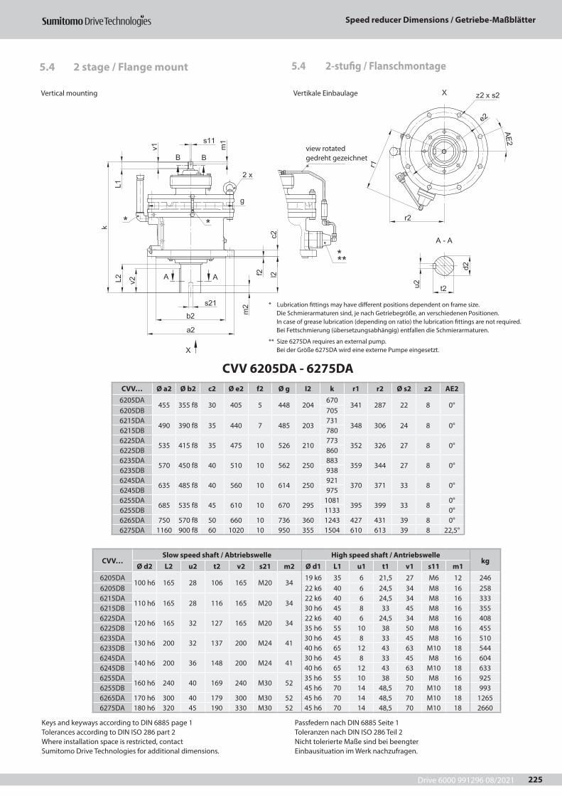
Drive 6000 991296 08/2021
Speed reducer Dimensions / Getriebe-Maßblätter
225
5.4 2-stufig / Flanschmontage5.4 2 stage / Flange mount
CVV 6205DA - 6275DACVV… Ø a2 Ø b2 c2 Ø e2 f2 Ø g I2 k r1 r2 Ø s2 z2 AE2
6205DA455 355 f8 30 405 5 448 204
670341 287 22 8 0°
6205DB 7056215DA
490 390 f8 35 440 7 485 203731
348 306 24 8 0°6215DB 7806225DA
535 415 f8 35 475 10 526 210773
352 326 27 8 0°6225DB 8606235DA
570 450 f8 40 510 10 562 250883
359 344 27 8 0°6235DB 9386245DA
635 485 f8 40 560 10 614 250921
370 371 33 8 0°6245DB 9756255DA
685 535 f8 45 610 10 670 2951081
395 399 33 80°
6255DB 1133 0°6265DA 750 570 f8 50 660 10 736 360 1243 427 431 39 8 0°6275DA 1160 900 f8 60 1020 10 950 355 1504 610 613 39 8 22,5°
CVV…Slow speed shaft / Abtriebswelle High speed shaft / Antriebswelle
kgØ d2 L2 u2 t2 v2 s21 m2 Ø d1 L1 u1 t1 v1 s11 m1
6205DA100 h6 165 28 106 165 M20 34
19 k6 35 6 21,5 27 M6 12 2466205DB 22 k6 40 6 24,5 34 M8 16 2586215DA
110 h6 165 28 116 165 M20 3422 k6 40 6 24,5 34 M8 16 333
6215DB 30 h6 45 8 33 45 M8 16 3556225DA
120 h6 165 32 127 165 M20 3422 k6 40 6 24,5 34 M8 16 408
6225DB 35 h6 55 10 38 50 M8 16 4556235DA
130 h6 200 32 137 200 M24 4130 h6 45 8 33 45 M8 16 510
6235DB 40 h6 65 12 43 63 M10 18 5446245DA
140 h6 200 36 148 200 M24 4130 h6 45 8 33 45 M8 16 604
6245DB 40 h6 65 12 43 63 M10 18 6336255DA
160 h6 240 40 169 240 M30 5235 h6 55 10 38 50 M8 16 925
6255DB 45 h6 70 14 48,5 70 M10 18 9936265DA 170 h6 300 40 179 300 M30 52 45 h6 70 14 48,5 70 M10 18 12656275DA 180 h6 320 45 190 330 M30 52 45 h6 70 14 48,5 70 M10 18 2660
Vertical mounting Vertikale Einbaulage
* Lubrication fittings may have different positions dependent on frame size.Die Schmierarmaturen sind, je nach Getriebegröße, an verschiedenen Positionen.In case of grease lubrication (depending on ratio) the lubrication fittings are not required.Bei Fettschmierung (übersetzungsabhängig) entfallen die Schmierarmaturen.
** Size 6275DA requires an external pump.Bei der Größe 6275DA wird eine externe Pumpe eingesetzt.
Keys and keyways according to DIN 6885 page 1Tolerances according to DIN ISO 286 part 2Where installation space is restricted, contactSumitomo Drive Technologies for additional dimensions.
Passfedern nach DIN 6885 Seite 1Toleranzen nach DIN ISO 286 Teil 2Nicht tolerierte Maße sind bei beengterEinbausituation im Werk nachzufragen.
view rotatedgedreht gezeichnet*
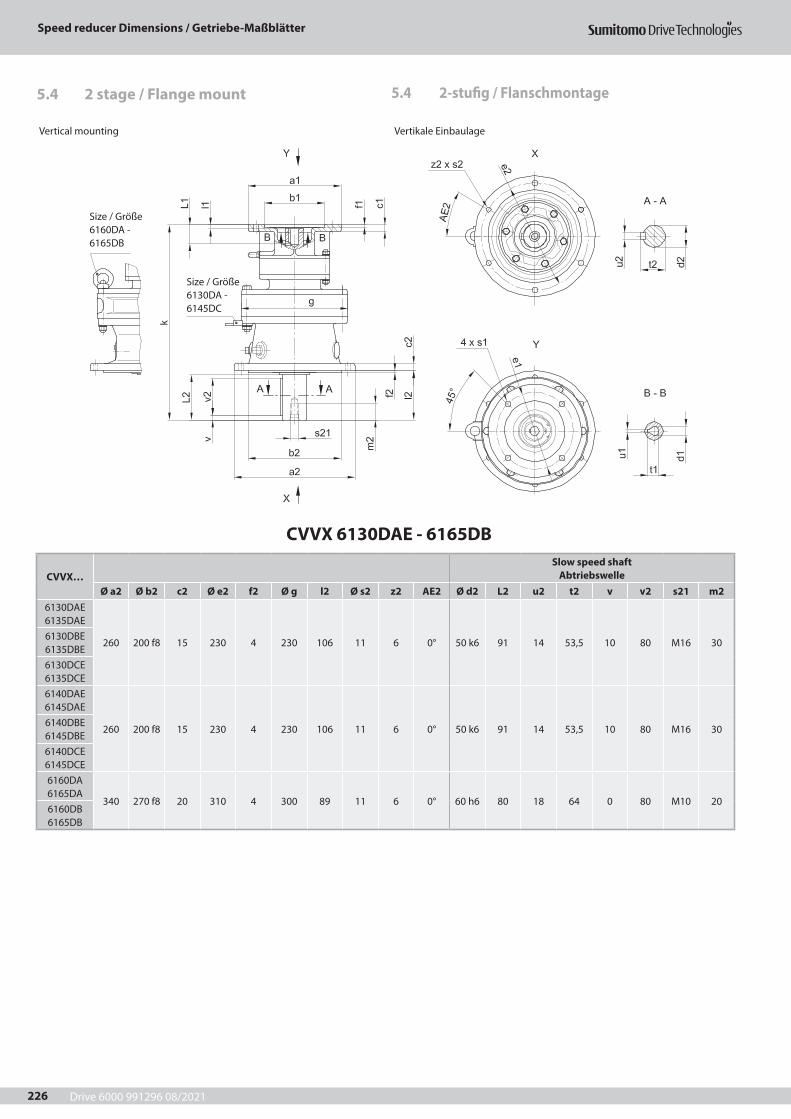
Drive 6000 991296 08/2021
Speed reducer Dimensions / Getriebe-Maßblätter
226
CVVX 6130DAE - 6165DB
CVVX…Slow speed shaft
AbtriebswelleØ a2 Ø b2 c2 Ø e2 f2 Ø g l2 Ø s2 z2 AE2 Ø d2 L2 u2 t2 v v2 s21 m2
6130DAE 6135DAE
260 200 f8 15 230 4 230 106 11 6 0° 50 k6 91 14 53,5 10 80 M16 306130DBE 6135DBE6130DCE 6135DCE6140DAE 6145DAE
260 200 f8 15 230 4 230 106 11 6 0° 50 k6 91 14 53,5 10 80 M16 306140DBE 6145DBE6140DCE 6145DCE6160DA 6165DA
340 270 f8 20 310 4 300 89 11 6 0° 60 h6 80 18 64 0 80 M10 206160DB 6165DB
5.4 2-stufig / Flanschmontage5.4 2 stage / Flange mount
Vertical mounting Vertikale Einbaulage
Size / Größe 6160DA - 6165DB
Size / Größe 6130DA -6145DC

Drive 6000 991296 08/2021
Speed reducer Dimensions / Getriebe-Maßblätter
227
Vertical mounting Vertikale Einbaulage
CVVX…Input element
Antriebszubehör
High speed shaft portion / Antriebsseite L* = Length of motor shaft L* = Länge der Motorwelle kg
Ø a1 Ø b1 c1 Ø e1 f1 k Ø s1 Ø d1 l1 L1* u1 t1
6130DA 6135DA
63/A140 140 95 H811
1154,5 382
9 11 F7 7 23 4 Js9 12,8 42,571/C105 105 70 H8 85 6,6
14 F7 930
5 Js9 16,342,5
71/C140 140 95 H8 115 9 30 42,5
6130DB 6135DB
63/A140 140 95 H811
115
4,5
394 911 F7 6 23 4 Js9 12,8
45,571/A160 160 110 H8 130 14 F7 9 30 5 Js9 16,380/C120 120 80 H8 13 100
420
6,619 F7 12 40 6 Js9 21,880/C160 160 110 H8
12130 9 47
80/A200 200 130 H8 165 11 4890/C140 140 95 H8 13 115
924 F7 14 50 8 Js9 27,3
4690/C160 160 110 H8
12130 47
90/A200 200 130 H8 165 11 48
6130DC 6135DC
71/A160 160 110 H8 11 130
4,5
408 9 14 F7 9 30 5 Js9 16,348
80/C120 120 80 H8 13 100
433
6,619 F7 12 40 6 Js9 21,880/C160 160 110 H8
12130 9 49
80/A200 200 130 H8 165 11 5090/C140 140 95 H8 13 115
924 F7 14 50
8 Js927,3
4890/C160 160 110 H8
12130 49
90/A200 200 130 H8 165 11 50100/112/C160 160 110 H8 14 130 5 9 28 F7 18 60 31,3 49
6140DA 6145DA
63/A140 140 95 H811
1154,5 382
9 11 F7 7 23 4 Js9 12,8 42,571/C105 105 70 H8 85 6,6
14 F7 930
5 Js9 16,342,5
71/C140 140 95 H8 115 9 30 42,5
6140DB 6145DB
63/A140 140 95 H811
115
4,5
394 911 F7 6 23 4 Js9 12,8
45,571/A160 160 110 H8 130 14 F7 9 30 5 Js9 16,380/C120 120 80 H8 13 100
420
6,619 F7 12 40 6 Js9 21,880/C160 160 110 H8
12130 9 47
80/A200 200 130 H8 165 11 4890/C140 140 95 H8 13 115 9
24 F7 14 50 8 Js9 27,346
90/C160 160 110 H812
130 9 4790/A200 200 130 H8 165 11 48
6140DC 6145DC
71/A160 160 110 H8 11 130
4,5
408 9 14 F7 9 30 5 Js9 16,344,5
80/C120 120 80 H8 13 100
433
6,619 F7 12 40 6 Js9 21,880/C160 160 110 H8
12130 9 49
80/A200 200 130 H8 165 11 5090/C140 140 95 H8 13 115
924 F7 14 50
8 Js927,3
4890/C160 160 110 H8
12130 49
90/A200 200 130 H8 165 1150
100/112/C160 160 110 H8 14 130 5 9 28 F7 18 60 31,3
6160DA 6165DA
63/A140 140 95 H811
115
4,5
434 911 F7 6 23 4 Js9 12,8
81,571/A160 160 110 H8 130 14 F7 9 30 5 Js9 16,380/C120 120 80 H8 13 100
460
6,619 F7 12 40 6 Js9 21,880/C160 160 110 H8
12130 9 83
80/A200 200 130 H8 165 11 8490/C140 140 95 H8 13 115 9
24 F7 14 50 8 Js9 27,383
90/C160 160 110 H812
130 9 8490/A200 200 130 H8 165 11 84
6160DB 6165DB
71/A160 160 110 H8 11 130
4,5
447 9 14 F7 9 30 5 Js9 16,389
80/C120 120 80 H8 13 100
473
6,619 F7 12
406 Js9 21,880/C160 160 110 H8
12130 9 40 90
80/A200 200 130 H8 165 11 40 9190/C140 140 95 H8 13 115
924 F7 14 50
8 Js927,3
8990/C160 160 110 H8
12130 90
90/A200 200 130 H8 165 11 91100/112/C160 160 110 H8 14 130 5 484 9 28 F7 18 60 31,3 90
Keys and keyways according to DIN 6885 page 1Tolerances according to DIN ISO 286 part 2Where installation space is restricted, contactSumitomo Drive Technologies for additional dimensions.
Passfedern nach DIN 6885 Seite 1Toleranzen nach DIN ISO 286 Teil 2Nicht tolerierte Maße sind bei beengterEinbausituation im Werk nachzufragen.
5.4 2-stufig / Flanschmontage5.4 2 stage / Flange mount
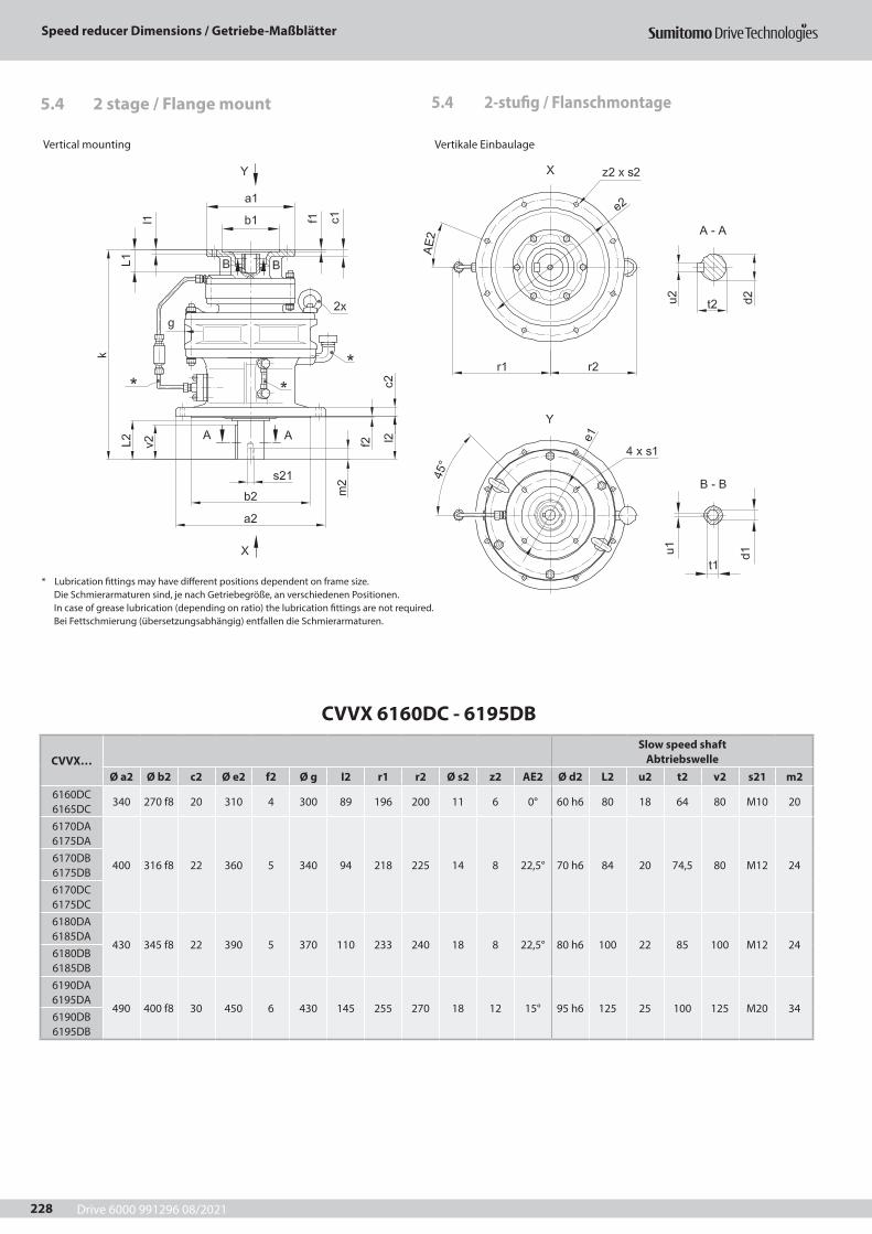
Drive 6000 991296 08/2021
Speed reducer Dimensions / Getriebe-Maßblätter
228
5.4 2-stufig / Flanschmontage5.4 2 stage / Flange mount
Vertical mounting Vertikale Einbaulage
* Lubrication fittings may have different positions dependent on frame size.Die Schmierarmaturen sind, je nach Getriebegröße, an verschiedenen Positionen.In case of grease lubrication (depending on ratio) the lubrication fittings are not required.Bei Fettschmierung (übersetzungsabhängig) entfallen die Schmierarmaturen.
CVVX 6160DC - 6195DB
CVVX…Slow speed shaft
AbtriebswelleØ a2 Ø b2 c2 Ø e2 f2 Ø g I2 r1 r2 Ø s2 z2 AE2 Ø d2 L2 u2 t2 v2 s21 m2
6160DC 6165DC
340 270 f8 20 310 4 300 89 196 200 11 6 0° 60 h6 80 18 64 80 M10 20
6170DA 6175DA
400 316 f8 22 360 5 340 94 218 225 14 8 22,5° 70 h6 84 20 74,5 80 M12 246170DB 6175DB6170DC 6175DC6180DA 6185DA
430 345 f8 22 390 5 370 110 233 240 18 8 22,5° 80 h6 100 22 85 100 M12 246180DB 6185DB6190DA 6195DA
490 400 f8 30 450 6 430 145 255 270 18 12 15° 95 h6 125 25 100 125 M20 346190DB 6195DB

Drive 6000 991296 08/2021
Speed reducer Dimensions / Getriebe-Maßblätter
229
Vertical mounting Vertikale Einbaulage
CVVX…Input element
Antriebszubehör
High speed shaft portion / Antriebsseite L* = Length of motor shaft L* = Länge der Motorwelle kg
Ø a1 Ø b1 c1 Ø e1 f1 k Ø s1 Ø d1 l1 L1* u1 t1
6160DC 6165DC
80/A200200 130 H8 13 165 4,5 468 11
19 F7 12 40 6 Js9 21,898
90/A200 24 F7 14 508 Js9
27,3100/112/C160 160 110 H8
14130
5 4789
28 F7 18 60 31,399
100/112/A250 250 180 H8 215 14 102
6170DA 6175DA
63/A140 140 95 H811
115
4,5
478 911 F7 6 23 4 Js9 12,8
11671/A160 160 110 H8 130 14 F7 9 30 5 Js9 16,380/C120 120 80 H8 13 100
504
6,619 F7 12 40 6 Js9 21,880/C160 160 110 H8
12130 9 117
80/A200 200 130 H8 165 11 11890/C140 140 95 H8 13 115 9
24 F7 14 50 8 Js9 27,3117
90/C160 160 110 H812
130 990/A200 200 130 H8 165 11 118
6170DB 6175DB
71/A160 160 110 H8 11 130
4,5
492 9 14 F7 9 30 5 Js9 16,3119
80/C120 120 80 H8 13 100
518
6,619 F7 12 40 6 Js9 21,880/C160 160 110 H8
12130 9 120
80/A200 200 130 H8 165 11121
90/C140 140 95 H8 13 115 924 F7 14 50
8 Js927,390/C160 160 110 H8
12130 9 120
90/A200 200 130 H8 165 11121
100/112/C160 160 110 H8 14 130 5 528 9 28 F7 18 60 31,3
6170DC 6175DC
80/A200200 130 H8 13 165 4,5 515 11
19 F7 12 40 6 Js9 21,8132
90/A200 24 F7 14 50
8 Js9
27,3
100/112/C160 160 110 H814
1305 525
928 F7 18 60
31,3 133
100/112/A250 250 180 H8 215 14 136
6180DA 6185DA
71/A160 160 110 H8 11 130
4,5
534 9 14 F7 9 30 5 Js9 16,3151
80/C120 120 80 H8 13 100
560
6,619 F7 12 40 6 Js9 21,880/C160 160 110 H8
12130 9 152
80/A200 200 130 H8 165 11 15390/C140 140 95 H8 13 115 9
24 F7 14 50 8 Js9 27,3152
90/C160 160 110 H812
130 990/A200 200 130 H8 165 11 153
100/112/C160 160 110 H8 14 130 5 9 28 F7 18 608 Js9
31,3 154
6180DB 6185DB
90/A200 200 130 H8 11 165 4,5 577 11 24 F7 14 50 27,3 186100/112/A250 250 180 H8 13 215
5587
1428 F7 18 60 31,3 188
132/A300 300 230 H8 17 265 613 38 F7 23 80 10 Js9 41,3 193
6190DA 6195DA
80/A200200 130 H8 13 165 4,5 635 11
19 F7 12 40 6 Js9 21,8 24690/A200 24 F7 14 50
8 Js927,3 249
100/112/C160 160 110 H814
1305 645
928 F7 18 60 31,3
254100/112/A250 250 180 H8 215 14 257
6190DB 6195DB
90/A200 200 130 H8 11 165 4,5 653 11 24 F7 14 508 Js9
27,3 253100/112/A250 250 180 H8 13 215
5663
1428 F7 18 60 31,3 256
132/A300 300 230 H8 17 265 689 38 F7 23 80 10 Js9 41,3 261
Keys and keyways according to DIN 6885 page 1Tolerances according to DIN ISO 286 part 2Where installation space is restricted, contactSumitomo Drive Technologies for additional dimensions.
Passfedern nach DIN 6885 Seite 1Toleranzen nach DIN ISO 286 Teil 2Nicht tolerierte Maße sind bei beengterEinbausituation im Werk nachzufragen.
5.4 2-stufig / Flanschmontage5.4 2 stage / Flange mount
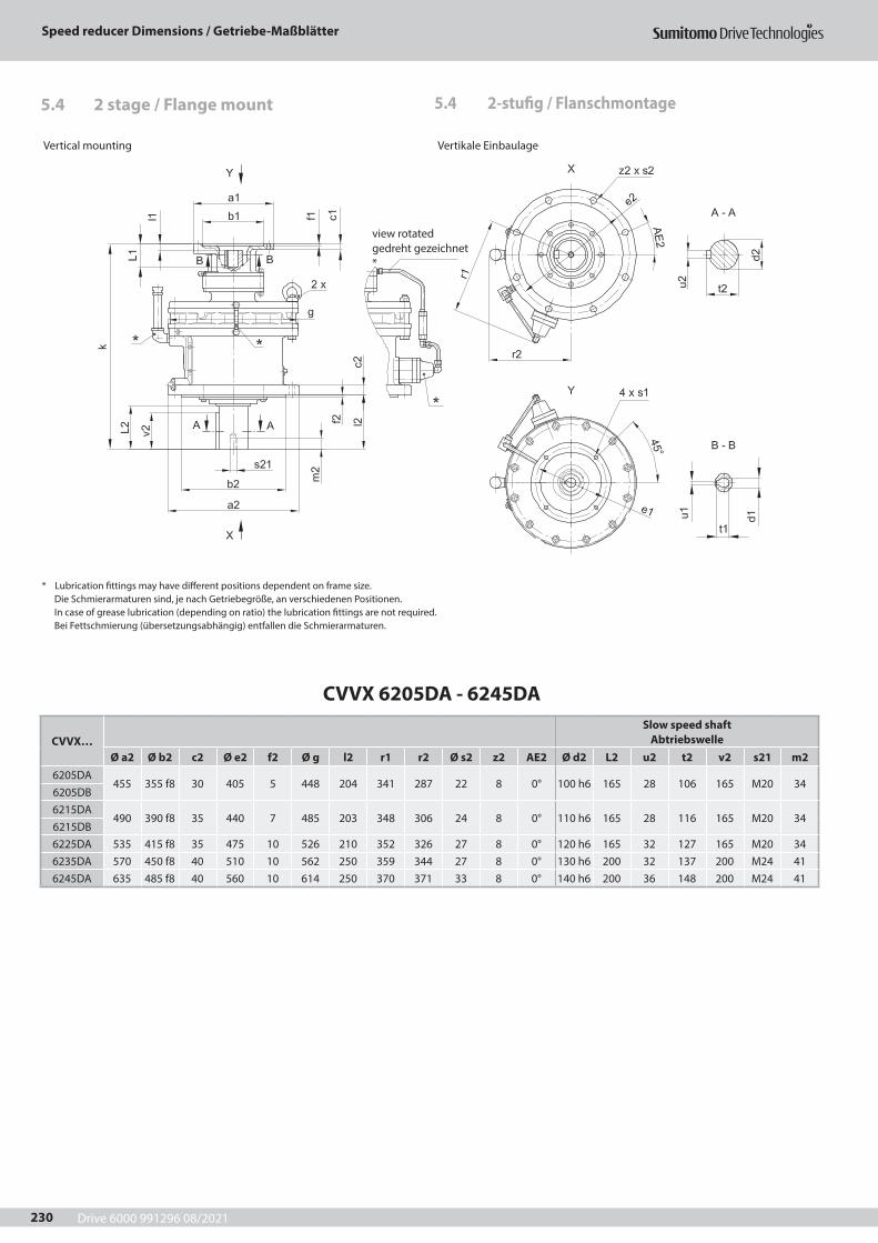
Drive 6000 991296 08/2021
Speed reducer Dimensions / Getriebe-Maßblätter
230
5.4 2-stufig / Flanschmontage5.4 2 stage / Flange mount
Vertical mounting Vertikale Einbaulage
* Lubrication fittings may have different positions dependent on frame size.Die Schmierarmaturen sind, je nach Getriebegröße, an verschiedenen Positionen.In case of grease lubrication (depending on ratio) the lubrication fittings are not required.Bei Fettschmierung (übersetzungsabhängig) entfallen die Schmierarmaturen.
CVVX 6205DA - 6245DA
CVVX…Slow speed shaft
AbtriebswelleØ a2 Ø b2 c2 Ø e2 f2 Ø g l2 r1 r2 Ø s2 z2 AE2 Ø d2 L2 u2 t2 v2 s21 m2
6205DA455 355 f8 30 405 5 448 204 341 287 22 8 0° 100 h6 165 28 106 165 M20 34
6205DB6215DA
490 390 f8 35 440 7 485 203 348 306 24 8 0° 110 h6 165 28 116 165 M20 346215DB6225DA 535 415 f8 35 475 10 526 210 352 326 27 8 0° 120 h6 165 32 127 165 M20 346235DA 570 450 f8 40 510 10 562 250 359 344 27 8 0° 130 h6 200 32 137 200 M24 416245DA 635 485 f8 40 560 10 614 250 370 371 33 8 0° 140 h6 200 36 148 200 M24 41
view rotatedgedreht gezeichnet*
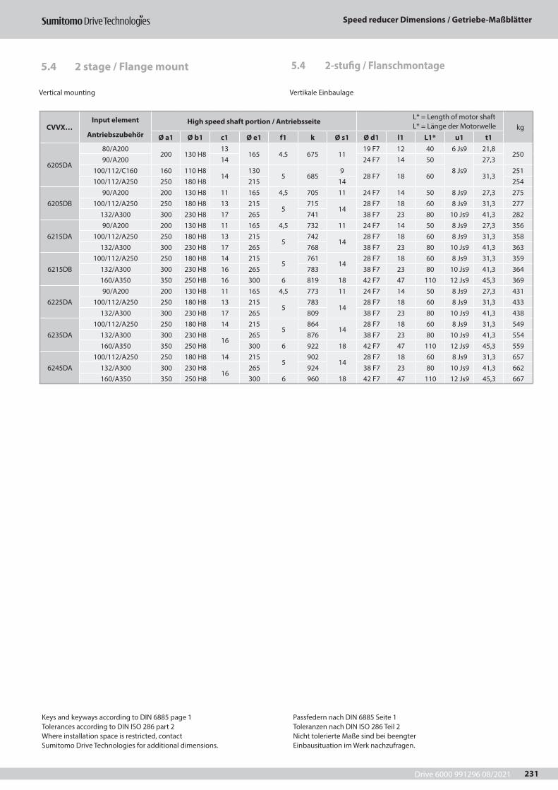
Drive 6000 991296 08/2021
Speed reducer Dimensions / Getriebe-Maßblätter
231
Vertical mounting Vertikale Einbaulage
CVVX…Input element
Antriebszubehör
High speed shaft portion / Antriebsseite L* = Length of motor shaft L* = Länge der Motorwelle kg
Ø a1 Ø b1 c1 Ø e1 f1 k Ø s1 Ø d1 l1 L1* u1 t1
6205DA
80/A200200 130 H8
13165 4.5 675 11
19 F7 12 40 6 Js9 21,8250
90/A200 14 24 F7 14 508 Js9
27,3100/112/C160 160 110 H8
14130
5 6859
28 F7 18 60 31,3251
100/112/A250 250 180 H8 215 14 254
6205DB90/A200 200 130 H8 11 165 4,5 705 11 24 F7 14 50 8 Js9 27,3 275
100/112/A250 250 180 H8 13 2155
71514
28 F7 18 60 8 Js9 31,3 277132/A300 300 230 H8 17 265 741 38 F7 23 80 10 Js9 41,3 282
6215DA90/A200 200 130 H8 11 165 4,5 732 11 24 F7 14 50 8 Js9 27,3 356
100/112/A250 250 180 H8 13 2155
74214
28 F7 18 60 8 Js9 31,3 358132/A300 300 230 H8 17 265 768 38 F7 23 80 10 Js9 41,3 363
6215DB100/112/A250 250 180 H8 14 215
5761
1428 F7 18 60 8 Js9 31,3 359
132/A300 300 230 H8 16 265 783 38 F7 23 80 10 Js9 41,3 364160/A350 350 250 H8 16 300 6 819 18 42 F7 47 110 12 Js9 45,3 369
6225DA90/A200 200 130 H8 11 165 4,5 773 11 24 F7 14 50 8 Js9 27,3 431
100/112/A250 250 180 H8 13 2155
78314
28 F7 18 60 8 Js9 31,3 433132/A300 300 230 H8 17 265 809 38 F7 23 80 10 Js9 41,3 438
6235DA100/112/A250 250 180 H8 14 215
5864
1428 F7 18 60 8 Js9 31,3 549
132/A300 300 230 H816
265 876 38 F7 23 80 10 Js9 41,3 554160/A350 350 250 H8 300 6 922 18 42 F7 47 110 12 Js9 45,3 559
6245DA100/112/A250 250 180 H8 14 215
5902
1428 F7 18 60 8 Js9 31,3 657
132/A300 300 230 H816
265 924 38 F7 23 80 10 Js9 41,3 662160/A350 350 250 H8 300 6 960 18 42 F7 47 110 12 Js9 45,3 667
Keys and keyways according to DIN 6885 page 1Tolerances according to DIN ISO 286 part 2Where installation space is restricted, contactSumitomo Drive Technologies for additional dimensions.
Passfedern nach DIN 6885 Seite 1Toleranzen nach DIN ISO 286 Teil 2Nicht tolerierte Maße sind bei beengterEinbausituation im Werk nachzufragen.
5.4 2-stufig / Flanschmontage5.4 2 stage / Flange mount
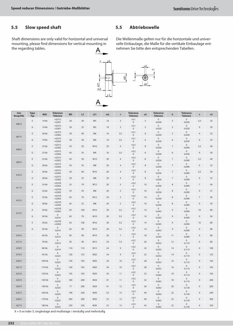
Drive 6000 991296 08/2021
Speed reducer Dimensions / Getriebe-Maßblätter
232
5.5 Abtriebswelle5.5 Slow speed shaft
A
A
t
s21
v2v
h
m2
ØD
L2
u2
d2
Size Baugröße Ød1 Tolerance
Toleranz ØD L1 s11 m1 t Tolerance Toleranz u1 Tolerance
Toleranz h v11 v1
606 X 606 X DA 606 X DA 12 k6 +0,012
+0,001 17 25 M4 8 2,5 +0,1 0 4 0
-0,030 4 1 22
607 X
609 X DA 610 X DA 612 X DA 613 X DA 614 X DA
12 k6 +0,012 +0,001 17 25 M4 8 2,5 +0,1
0 4 0 -0,030 4 1 22
608 X 12 k6 +0,012 +0,001 17 25 M4 8 2,5 +0,1
0 4 0 -0,036 4 1 22
609 X
612 X DB 613 X DB 614 X DB 616 X DA 617 X DA
14 k6 +0,012 +0,001 20 25 M5 10 3 +0,1
0 5 0 -0,036 5 1 21
610 X
613 X DC 614 X DC 616 X DB 617 X DB 618 X DA
14 k6 +0,012 +0,001 20 25 M5 10 3 +0,1
0 5 0 -0,036 5 1 21
611 X 14 k6 +0,012 +0,001 20 25 M5 10 3 +0,1
0 5 0 -0,036 5 1 21
612 X
616 X DC 617 X DC 619 X DA 620 X DA
19 k6 +0,015 +0,002 32 35 M6 12 3,5 +0,1
0 6 0 -0,036 6 1 27
613 X
618 X DB 619 X DB 620 X DB 621 X DA 622 X DA
22 k6 0 -0,013 38 40 M8 16 3,5 +0,1
0 6 0 -0,043 6 1 34
614 X 22 k6 0 -0,013 38 40 M8 16 3,5 +0,1
0 6 0 -0,043 6 1 34
616 X621 X DB 623 X DA 624 X DA
30 h6 0 -0,013 70 45 M8 16 4 +0,2
0 8 0 -0,043 7 0 45
617 X 622 X DB 625 X DA 35 h6 0
-0,016 70 55 M8 16 5 +0,2 0 10 0
-0,052 8 0 50
618 X 623 X DB 624 X DB 40 h6 0
-0,016 70 65 M10 18 5 +0,2 0 12 0
-0,052 8 0 63
619 X625 X DB 626 X DA 627 X DA
45 h6 0 -0,016 82 70 M10 18 5,5 +0,2
0 14 0 -0,052 9 0 70
620 X 45 h6 0 -0,016 82 82 M10 18 5,5 +0,2
0 14 0 -0,052 9 0 82
621 X 50 h6 0 -0,019 82 82 M10 18 5,5 +0,2
0 14 0 -0,052 9 0 82
622 X 55 h6 0 -0,019 90 82 M10 18 6 +0,2
0 16 0 -0,062 10 0 82
623 X 60 h6 0 -0,019 110 105 M10 18 7 +0,2
0 18 0 -0,062 11 0 105
624 X 65 h6 0 -0,019 110 105 M12 24 7 +0,2
0 18 0 -0,062 11 0 105
625 X 80 h6 0 -0,019 130 130 M12 24 9 +0,2
0 22 0 -0,062 14 0 130
626 X 80 h6 0 -0,019 130 130 M12 24 9 +0,2
0 22 0 -0,062 14 0 130
627 X 90 h6 0 -0,022 140 130 M16 24 9 +0,2
0 25 0 -0,062 14 0 140
X = 0 or/oder 5; singlestage and multistage / einstufig und mehrstufig
Size Baugröße
Type Typ Ød2 Tolerance
Toleranz ØD L2 s21 m2 t Tolerance Toleranz u2 Tolerance
Toleranz h Tolerance Toleranz v v2
606 XE 14 k6 +0,012
+0,001 20 30 M5 16 3 +0,1 0 5 0
-0,030 5 0 -0,030 2,5 25
G 14 k6 +0,012 +0,001 20 25 M5 16 3 +0,1
0 5 0 -0,030 5 0
-0,030 0 20
607 XE 20 k6 +0,015
+0,002 30 40 M6 16 3,5 +0,1 0 6 0
-0,030 5 0 -0,030 4 32
G 19 k6 +0,015 +0,002 30 30 M6 16 3,5 +0,1
0 6 0 -0,030 6 0
-0,030 0 25
608 XE 25 k6 +0,015
+0,002 45 50 M10 20 4 +0,2 0 8 0
-0,036 7 0 -0,090 3,5 40
G 22 k6 +0,015 +0,002 45 35 M6 16 3,5 +0,2
0 6 0 -0,036 6 0
-0,030 0 30
609 XE 25 k6 +0,015
+0,002 45 50 M10 20 4 +0,2 0 8 0
-0,036 7 0 -0,090 3,5 40
G 28 k6 +0,015 +0,002 45 35 M8 20 4 +0,2
0 8 0 -0,036 7 0
-0,090 0 32
610 XE 30 k6 +0,015
+0,002 50 60 M10 20 4 +0,2 0 8 0
-0,036 7 0 -0,090 3,5 50
G 28 k6 +0,015 +0,002 50 35 M8 20 4 +0,2
0 8 0 -0,036 7 0
-0,090 0 32
611 XE 35 k6 +0,018
+0,002 55 70 M12 20 5 +0,2 0 10 0
-0,036 8 0 -0,090 7 56
G 32 k6 +0,018 +0,002 55 45 M8 20 5 +0,2
0 10 0 -0,036 8 0
-0,090 0 37
612 XE 35 k6 +0,018
+0,002 65 70 M12 24 5 +0,2 0 10 0
-0,036 8 0 -0,090 7 56
G 38 k6 +0,018 +0,002 65 55 M8 20 5 +0,2
0 10 0 -0,036 8 0
-0,090 0 50
613 XE 50 k6 +0,018
+0,002 65 100 M16 30 5,5 +0,2 0 14 0
-0,043 9 0 -0,090 10 80
G 50 h6 0 -0,016 65 70 M10 20 5,5 +0,2
0 14 0 -0,043 9 0
-0,090 0 56
614 XE 50 k6 +0,018
+0,002 65 100 M16 30 5,5 +0,2 0 14 0
-0,043 9 0 -0,090 10 80
G 50 h6 0 -0,016 65 90 M10 20 5,5 +0,2
0 14 0 -0,043 9 0
-0,090 0 80
616 X - 60 h6 0 -0,019 85 90 M10 20 7 +0,2
0 18 0 -0,043 11 0
-0,090 0 80
617 X - 70 h6 0 -0,019 95 90 M12 24 7,5 +0,2
0 20 0 -0,052 12 0
-0,110 0 80
618 X - 80 h6 0 -0,019 110 110 M12 24 9 +0,2
0 22 0 -0,052 14 0
-0,110 0 100
619 X - 95 h6 0 -0,022 120 135 M20 34 9 +0,2
0 25 0 -0,052 14 0
-0,110 0 125
620 X - 100 h6 0 -0,022 120 165 M20 34 10 +0,2
0 28 0 -0,052 16 0
-0,110 0 165
621 X - 110 h6 0 -0,022 130 165 M20 34 10 +0,2
0 28 0 -0,052 16 0
-0,110 0 165
622 X - 120 h6 0 -0,022 145 165 M20 34 11 +0,2
0 32 0 -0,062 18 0
-0,110 0 165
623 X - 130 h6 0 -0,025 160 200 M24 41 11 +0,2
0 32 0 -0,062 18 0
-0,110 0 200
624 X - 140 h6 0 -0,025 17 200 M24 41 12 +0,3
0 36 0 -0,062 20 0
-0,130 0 200
625 X - 160 h6 0 -0,025 190 240 M30 52 13 +0,3
0 40 0 -0,062 22 0
-0,130 0 240
626 X - 170 h6 0 -0,025 200 300 M30 52 13 +0,3
0 40 0 -0,062 22 0
-0,130 0 300
627 X - 180 h6 0 -0,025 230 330 M30 52 15 +0,3
0 45 0 -0,062 22 0
-0,130 0 330
Shaft dimensions are only valid for horizontal and universal mounting, please find dimensions for vertical mounting in the regarding tables.
Die Wellenmaße gelten nur für die horizontale und univer-selle Einbaulage, die Maße für die vertikale Einbaulage ent-nehmen Sie bitte den entsprechenden Tabellen.
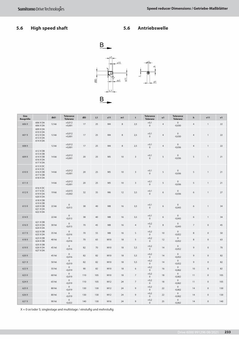
Drive 6000 991296 08/2021
Speed reducer Dimensions / Getriebe-Maßblätter
233
5.6 Antriebswelle5.6 High speed shaft
B
B
d1
u1
v1
m1 s11
v11
t
h
ØD
R1
L1
Size Baugröße Ød1 Tolerance
Toleranz ØD L1 s11 m1 t Tolerance Toleranz u1 Tolerance
Toleranz h v11 v1
606 X 606 X DA 606 X DA 12 k6 +0,012
+0,001 17 25 M4 8 2,5 +0,1 0 4 0
-0,030 4 1 22
607 X
609 X DA 610 X DA 612 X DA 613 X DA 614 X DA
12 k6 +0,012 +0,001 17 25 M4 8 2,5 +0,1
0 4 0 -0,030 4 1 22
608 X 12 k6 +0,012 +0,001 17 25 M4 8 2,5 +0,1
0 4 0 -0,036 4 1 22
609 X
612 X DB 613 X DB 614 X DB 616 X DA 617 X DA
14 k6 +0,012 +0,001 20 25 M5 10 3 +0,1
0 5 0 -0,036 5 1 21
610 X
613 X DC 614 X DC 616 X DB 617 X DB 618 X DA
14 k6 +0,012 +0,001 20 25 M5 10 3 +0,1
0 5 0 -0,036 5 1 21
611 X 14 k6 +0,012 +0,001 20 25 M5 10 3 +0,1
0 5 0 -0,036 5 1 21
612 X
616 X DC 617 X DC 619 X DA 620 X DA
19 k6 +0,015 +0,002 32 35 M6 12 3,5 +0,1
0 6 0 -0,036 6 1 27
613 X
618 X DB 619 X DB 620 X DB 621 X DA 622 X DA
22 k6 0 -0,013 38 40 M8 16 3,5 +0,1
0 6 0 -0,043 6 1 34
614 X 22 k6 0 -0,013 38 40 M8 16 3,5 +0,1
0 6 0 -0,043 6 1 34
616 X621 X DB 623 X DA 624 X DA
30 h6 0 -0,013 70 45 M8 16 4 +0,2
0 8 0 -0,043 7 0 45
617 X 622 X DB 625 X DA 35 h6 0
-0,016 70 55 M8 16 5 +0,2 0 10 0
-0,052 8 0 50
618 X 623 X DB 624 X DB 40 h6 0
-0,016 70 65 M10 18 5 +0,2 0 12 0
-0,052 8 0 63
619 X625 X DB 626 X DA 627 X DA
45 h6 0 -0,016 82 70 M10 18 5,5 +0,2
0 14 0 -0,052 9 0 70
620 X 45 h6 0 -0,016 82 82 M10 18 5,5 +0,2
0 14 0 -0,052 9 0 82
621 X 50 h6 0 -0,019 82 82 M10 18 5,5 +0,2
0 14 0 -0,052 9 0 82
622 X 55 h6 0 -0,019 90 82 M10 18 6 +0,2
0 16 0 -0,062 10 0 82
623 X 60 h6 0 -0,019 110 105 M10 18 7 +0,2
0 18 0 -0,062 11 0 105
624 X 65 h6 0 -0,019 110 105 M12 24 7 +0,2
0 18 0 -0,062 11 0 105
625 X 80 h6 0 -0,019 130 130 M12 24 9 +0,2
0 22 0 -0,062 14 0 130
626 X 80 h6 0 -0,019 130 130 M12 24 9 +0,2
0 22 0 -0,062 14 0 130
627 X 90 h6 0 -0,022 140 130 M16 24 9 +0,2
0 25 0 -0,062 14 0 140
X = 0 or/oder 5; singlestage and multistage / einstufig und mehrstufig
X = 0 or/oder 5; singlestage and multistage / einstufig und mehrstufig
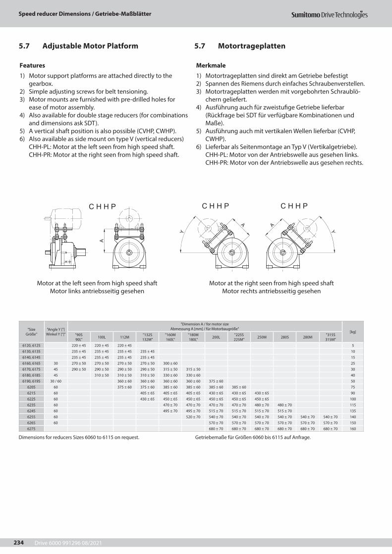
Drive 6000 991296 08/2021
Speed reducer Dimensions / Getriebe-Maßblätter
234
5.7 Motortrageplatten5.7 Adjustable Motor Platform
A
Y
A A
Y
C H H P C H H P C H H P
"Size Größe"
"Angle Y [°] Winkel Y [°]"
"Dimension A / for motor size Abmessung A [mm] / für Motorbaugröße"
[kg]"90S 90L" 100L 112M "132S
132M""160M 160L"
"180M 180L" 200L "225S
225M" 250M 280S 280M "315S 315M"
6120, 6125 220 ± 45 220 ± 45 220 ± 45 5
6130, 6135 235 ± 45 235 ± 45 235 ± 45 235 ± 45 10
6140, 6145 235 ± 45 235 ± 45 235 ± 45 235 ± 45 15
6160, 6165 30 270 ± 50 270 ± 50 270 ± 50 270 ± 50 300 ± 60 25
6170, 6175 45 290 ± 50 290 ± 50 290 ± 50 290 ± 50 315 ± 50 315 ± 50 30
6180, 6185 45 310 ± 50 310 ± 50 310 ± 50 330 ± 60 330 ± 60 40
6190, 6195 30 / 60 360 ± 60 360 ± 60 360 ± 60 360 ± 60 375 ± 60 50
6205 60 375 ± 60 375 ± 60 385 ± 60 385 ± 60 385 ± 60 385 ± 60 75
6215 60 405 ± 65 405 ± 65 405 ± 65 430 ± 65 430 ± 65 430 ± 65 90
6225 60 430 ± 65 450 ± 65 450 ± 65 450 ± 65 450 ± 65 450 ± 65 100
6235 60 470 ± 70 470 ± 70 470 ± 70 470 ± 70 480 ± 70 480 ± 70 115
6245 60 495 ± 70 495 ± 70 515 ± 70 515 ± 70 515 ± 70 515 ± 70 135
6255 60 520 ± 70 540 ± 70 540 ± 70 540 ± 70 540 ± 70 540 ± 70 540 ± 70 140
6265 60 570 ± 70 570 ± 70 570 ± 70 570 ± 70 570 ± 70 570 ± 70 150
6275 680 ± 70 680 ± 70 680 ± 70 680 ± 70 680 ± 70 680 ± 70 160
Dimensions for reducers Sizes 6060 to 6115 on request. Getriebemaße für Größen 6060 bis 6115 auf Anfrage.
Features
1) Motor support platforms are attached directly to the gearbox.
2) Simple adjusting screws for belt tensioning.3) Motor mounts are furnished with pre-drilled holes for
ease of motor assembly.4) Also available for double stage reducers (for combinations
and dimensions ask SDT).5) A vertical shaft position is also possible (CVHP, CWHP).6) Also available as side mount on type V (vertical reducers)
CHH-PL: Motor at the left seen from high speed shaft. CHH-PR: Motor at the right seen from high speed shaft.
Merkmale
1) Motortrageplatten sind direkt am Getriebe befestigt2) Spannen des Riemens durch einfaches Schraubenverstellen.3) Motortrageplatten werden mit vorgebohrten Schraublö-
chern geliefert.4) Ausführung auch für zweistufige Getriebe lieferbar
(Rückfrage bei SDT für verfügbare Kombinationen und Maße).
5) Ausführung auch mit vertikalen Wellen lieferbar (CVHP, CWHP).
6) Lieferbar als Seitenmontage an Typ V (Vertikalgetriebe). CHH-PL: Motor von der Antriebswelle aus gesehen links. CHH-PR: Motor von der Antriebswelle aus gesehen rechts.
Motor at the left seen from high speed shaftMotor links antriebsseitig gesehen
Motor at the right seen from high speed shaftMotor rechts antriebsseitig gesehen

Drive 6000 991296 08/2021
Calculations / Berechnungen
235
6 Berechnungen 6 Calculations
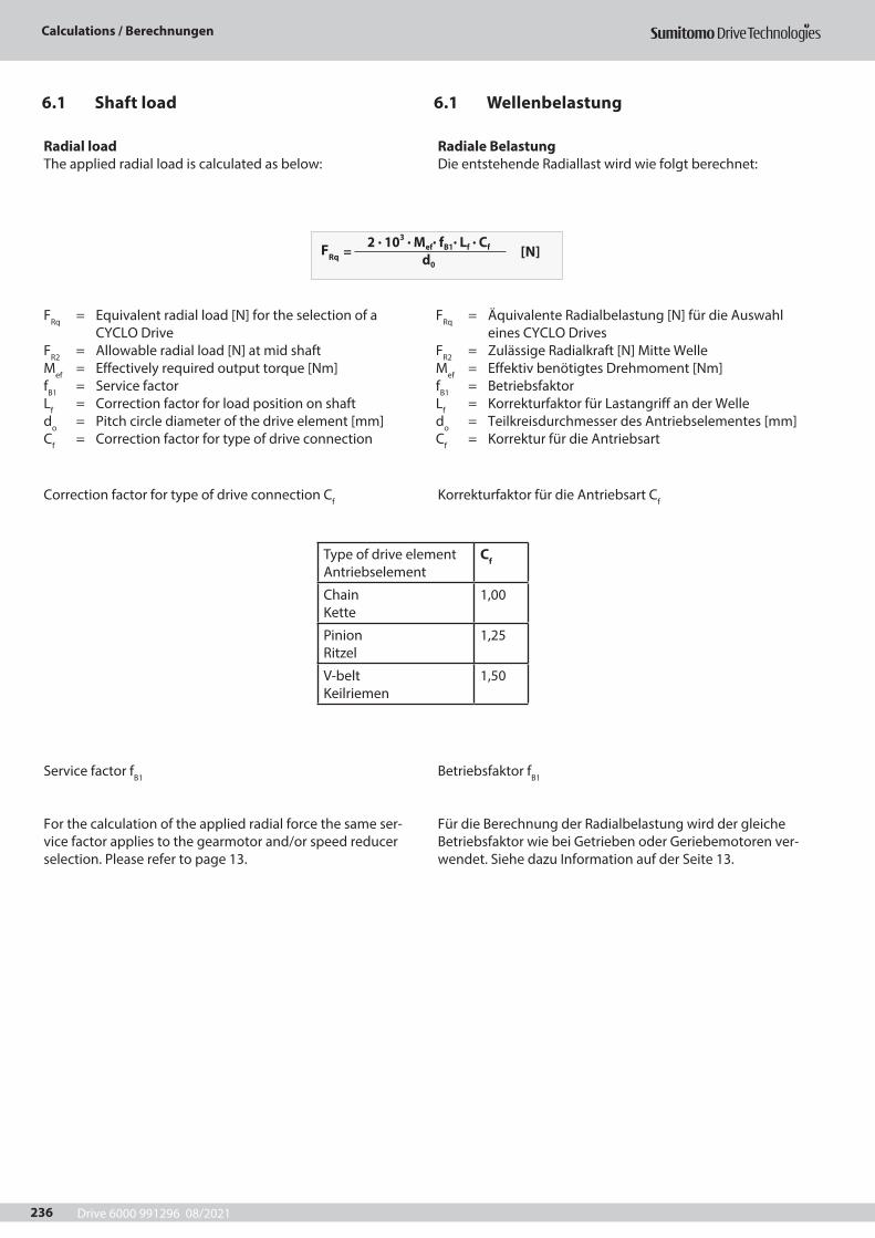
Drive 6000 991296 08/2021
Calculations / Berechnungen
236
6.1 Wellenbelastung6.1 Shaft load
Radial loadThe applied radial load is calculated as below:
Correction factor for type of drive connection Cf
Service factor fB1
For the calculation of the applied radial force the same ser-vice factor applies to the gearmotor and/or speed reducerselection. Please refer to page 13.
FRq = Equivalent radial load [N] for the selection of a CYCLO Drive
FR2 = Allowable radial load [N] at mid shaftMef = Effectively required output torque [Nm]fB1 = Service factorLf = Correction factor for load position on shaftdo = Pitch circle diameter of the drive element [mm]Cf = Correction factor for type of drive connection
FRq = Äquivalente Radialbelastung [N] für die Auswahl eines CYCLO Drives
FR2 = Zulässige Radialkraft [N] Mitte WelleMef = Effektiv benötigtes Drehmoment [Nm]fB1 = BetriebsfaktorLf = Korrekturfaktor für Lastangriff an der Welledo = Teilkreisdurchmesser des Antriebselementes [mm]Cf = Korrektur für die Antriebsart
Radiale BelastungDie entstehende Radiallast wird wie folgt berechnet:
Korrekturfaktor für die Antriebsart Cf
Betriebsfaktor fB1
Für die Berechnung der Radialbelastung wird der gleiche Betriebsfaktor wie bei Getrieben oder Geriebemotoren ver-wendet. Siehe dazu Information auf der Seite 13.
Type of drive element Antriebselement
Cf
Chain Kette
1,00
Pinion Ritzel
1,25
V-belt Keilriemen
1,50
FRq = [N]
2 . 103 . Mef. fB1
. Lf . Cf
d0
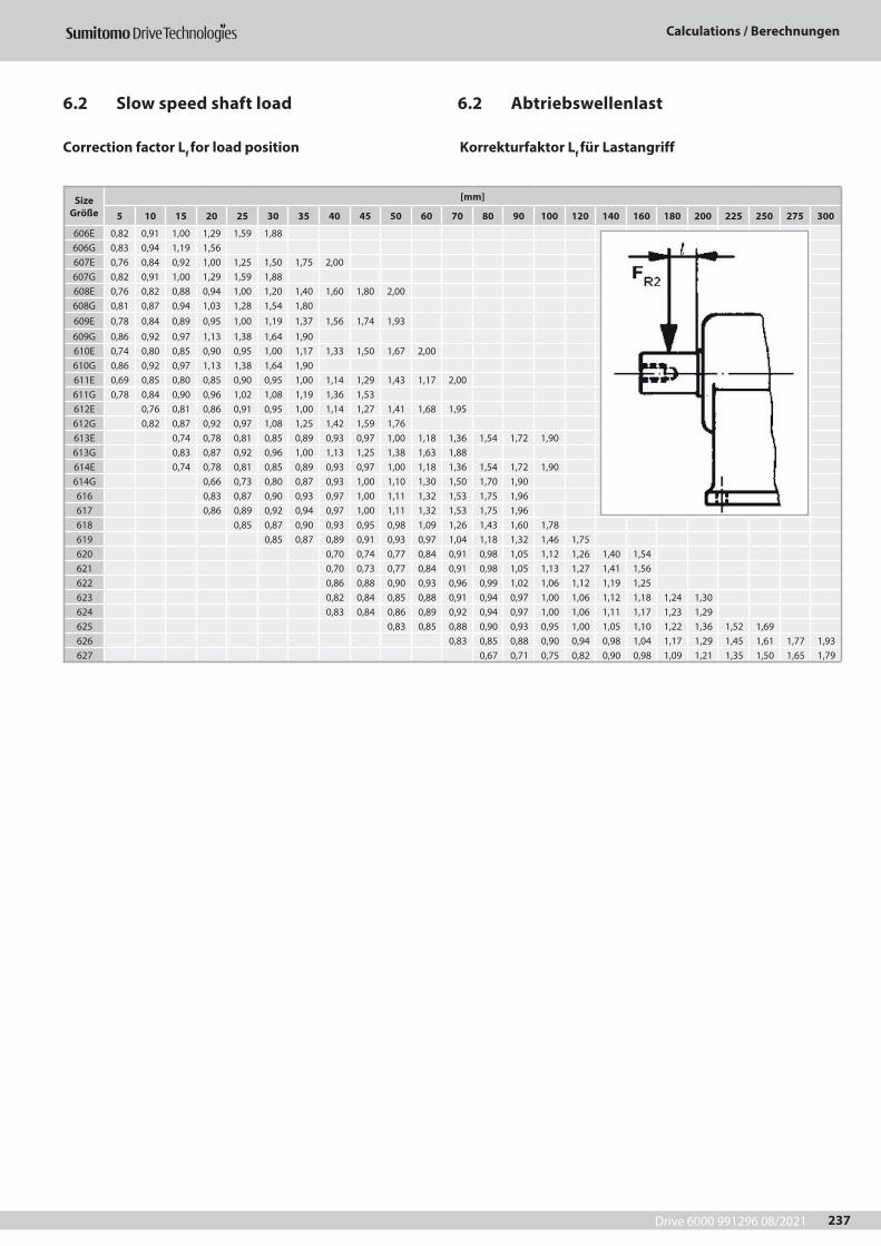
Drive 6000 991296 08/2021
Calculations / Berechnungen
237
6.2 Abtriebswellenlast6.2 Slow speed shaft load
Correction factor Lf for load position Korrekturfaktor Lf für Lastangriff
SizeGröße
[mm]
5 10 15 20 25 30 35 40 45 50 60 70 80 90 100 120 140 160 180 200 225 250 275 300
606E 0,82 0,91 1,00 1,29 1,59 1,88606G 0,83 0,94 1,19 1,56607E 0,76 0,84 0,92 1,00 1,25 1,50 1,75 2,00607G 0,82 0,91 1,00 1,29 1,59 1,88608E 0,76 0,82 0,88 0,94 1,00 1,20 1,40 1,60 1,80 2,00608G 0,81 0,87 0,94 1,03 1,28 1,54 1,80609E 0,78 0,84 0,89 0,95 1,00 1,19 1,37 1,56 1,74 1,93609G 0,86 0,92 0,97 1,13 1,38 1,64 1,90610E 0,74 0,80 0,85 0,90 0,95 1,00 1,17 1,33 1,50 1,67 2,00610G 0,86 0,92 0,97 1,13 1,38 1,64 1,90611E 0,69 0,85 0,80 0,85 0,90 0,95 1,00 1,14 1,29 1,43 1,17 2,00611G 0,78 0,84 0,90 0,96 1,02 1,08 1,19 1,36 1,53612E 0,76 0,81 0,86 0,91 0,95 1,00 1,14 1,27 1,41 1,68 1,95612G 0,82 0,87 0,92 0,97 1,08 1,25 1,42 1,59 1,76613E 0,74 0,78 0,81 0,85 0,89 0,93 0,97 1,00 1,18 1,36 1,54 1,72 1,90613G 0,83 0,87 0,92 0,96 1,00 1,13 1,25 1,38 1,63 1,88614E 0,74 0,78 0,81 0,85 0,89 0,93 0,97 1,00 1,18 1,36 1,54 1,72 1,90614G 0,66 0,73 0,80 0,87 0,93 1,00 1,10 1,30 1,50 1,70 1,90616 0,83 0,87 0,90 0,93 0,97 1,00 1,11 1,32 1,53 1,75 1,96617 0,86 0,89 0,92 0,94 0,97 1,00 1,11 1,32 1,53 1,75 1,96618 0,85 0,87 0,90 0,93 0,95 0,98 1,09 1,26 1,43 1,60 1,78619 0,85 0,87 0,89 0,91 0,93 0,97 1,04 1,18 1,32 1,46 1,75620 0,70 0,74 0,77 0,84 0,91 0,98 1,05 1,12 1,26 1,40 1,54621 0,70 0,73 0,77 0,84 0,91 0,98 1,05 1,13 1,27 1,41 1,56622 0,86 0,88 0,90 0,93 0,96 0,99 1,02 1,06 1,12 1,19 1,25623 0,82 0,84 0,85 0,88 0,91 0,94 0,97 1,00 1,06 1,12 1,18 1,24 1,30624 0,83 0,84 0,86 0,89 0,92 0,94 0,97 1,00 1,06 1,11 1,17 1,23 1,29625 0,83 0,85 0,88 0,90 0,93 0,95 1,00 1,05 1,10 1,22 1,36 1,52 1,69626 0,83 0,85 0,88 0,90 0,94 0,98 1,04 1,17 1,29 1,45 1,61 1,77 1,93627 0,67 0,71 0,75 0,82 0,90 0,98 1,09 1,21 1,35 1,50 1,65 1,79
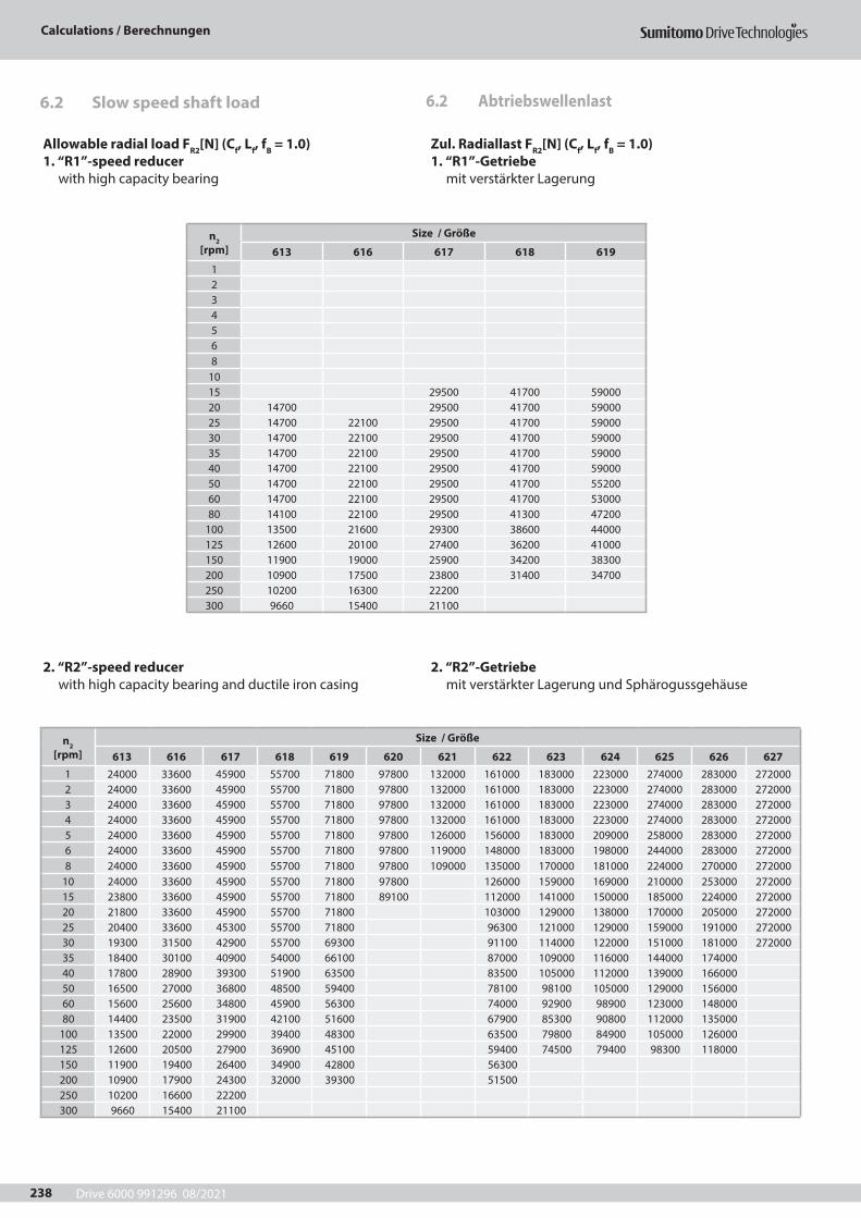
Drive 6000 991296 08/2021
Calculations / Berechnungen
238
6.2 Abtriebswellenlast6.2 Slow speed shaft load
Allowable radial load FR2[N] (Cf, Lf, fB = 1.0)1. “R1”-speed reducer with high capacity bearing
2. “R2”-speed reducer with high capacity bearing and ductile iron casing
Zul. Radiallast FR2[N] (Cf, Lf, fB = 1.0)1. “R1”-Getriebe mit verstärkter Lagerung
2. “R2”-Getriebe mit verstärkter Lagerung und Sphärogussgehäuse
n2 [rpm]
Size / Größe
613 616 617 618 619 620 621 622 623 624 625 626 6271 24000 33600 45900 55700 71800 97800 132000 161000 183000 223000 274000 283000 2720002 24000 33600 45900 55700 71800 97800 132000 161000 183000 223000 274000 283000 2720003 24000 33600 45900 55700 71800 97800 132000 161000 183000 223000 274000 283000 2720004 24000 33600 45900 55700 71800 97800 132000 161000 183000 223000 274000 283000 2720005 24000 33600 45900 55700 71800 97800 126000 156000 183000 209000 258000 283000 2720006 24000 33600 45900 55700 71800 97800 119000 148000 183000 198000 244000 283000 2720008 24000 33600 45900 55700 71800 97800 109000 135000 170000 181000 224000 270000 272000
10 24000 33600 45900 55700 71800 97800 126000 159000 169000 210000 253000 27200015 23800 33600 45900 55700 71800 89100 112000 141000 150000 185000 224000 27200020 21800 33600 45900 55700 71800 103000 129000 138000 170000 205000 27200025 20400 33600 45300 55700 71800 96300 121000 129000 159000 191000 27200030 19300 31500 42900 55700 69300 91100 114000 122000 151000 181000 27200035 18400 30100 40900 54000 66100 87000 109000 116000 144000 17400040 17800 28900 39300 51900 63500 83500 105000 112000 139000 16600050 16500 27000 36800 48500 59400 78100 98100 105000 129000 15600060 15600 25600 34800 45900 56300 74000 92900 98900 123000 14800080 14400 23500 31900 42100 51600 67900 85300 90800 112000 135000
100 13500 22000 29900 39400 48300 63500 79800 84900 105000 126000125 12600 20500 27900 36900 45100 59400 74500 79400 98300 118000150 11900 19400 26400 34900 42800 56300200 10900 17900 24300 32000 39300 51500250 10200 16600 22200300 9660 15400 21100
n2 [rpm]
Size / Größe
613 616 617 618 6191234568
1015 29500 41700 5900020 14700 29500 41700 5900025 14700 22100 29500 41700 5900030 14700 22100 29500 41700 5900035 14700 22100 29500 41700 5900040 14700 22100 29500 41700 5900050 14700 22100 29500 41700 5520060 14700 22100 29500 41700 5300080 14100 22100 29500 41300 47200
100 13500 21600 29300 38600 44000125 12600 20100 27400 36200 41000150 11900 19000 25900 34200 38300200 10900 17500 23800 31400 34700250 10200 16300 22200300 9660 15400 21100
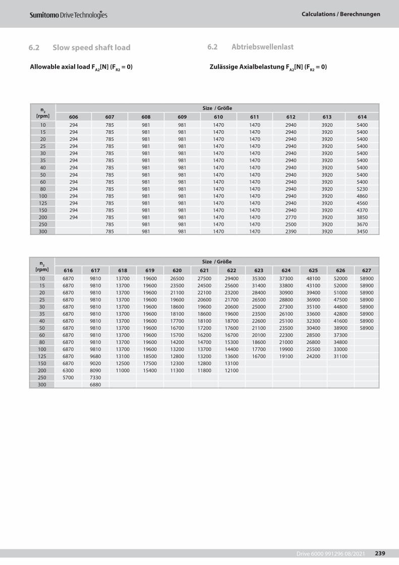
Drive 6000 991296 08/2021
Calculations / Berechnungen
239
6.2 Abtriebswellenlast6.2 Slow speed shaft load
Allowable axial load FA2[N] (FR2 = 0) Zulässige Axialbelastung FA2[N] (FR2 = 0)
n2 [rpm]
Size / Größe
616 617 618 619 620 621 622 623 624 625 626 62710 6870 9810 13700 19600 26500 27500 29400 35300 37300 48100 52000 5890015 6870 9810 13700 19600 23500 24500 25600 31400 33800 43100 52000 5890020 6870 9810 13700 19600 21100 22100 23200 28400 30900 39400 51000 5890025 6870 9810 13700 19600 19600 20600 21700 26500 28800 36900 47500 5890030 6870 9810 13700 19600 18600 19600 20600 25000 27300 35100 44800 5890035 6870 9810 13700 19600 18100 18600 19600 23500 26100 33600 42800 5890040 6870 9810 13700 19600 17700 18100 18700 22600 25100 32300 41600 5890050 6870 9810 13700 19600 16700 17200 17600 21100 23500 30400 38900 5890060 6870 9810 13700 19600 15700 16200 16700 20100 22300 28500 3730080 6870 9810 13700 19600 14200 14700 15300 18600 21000 26800 34800
100 6870 9810 13700 19600 13200 13700 14400 17700 19900 25500 33000125 6870 9680 13100 18500 12800 13200 13600 16700 19100 24200 31100150 6870 9020 12500 17500 12300 12800 13100200 6300 8090 11000 15400 11300 11800 12100250 5700 7330300 6880
n2 [rpm]
Size / Größe
606 607 608 609 610 611 612 613 61410 294 785 981 981 1470 1470 2940 3920 540015 294 785 981 981 1470 1470 2940 3920 540020 294 785 981 981 1470 1470 2940 3920 540025 294 785 981 981 1470 1470 2940 3920 540030 294 785 981 981 1470 1470 2940 3920 540035 294 785 981 981 1470 1470 2940 3920 540040 294 785 981 981 1470 1470 2940 3920 540050 294 785 981 981 1470 1470 2940 3920 540060 294 785 981 981 1470 1470 2940 3920 540080 294 785 981 981 1470 1470 2940 3920 5230
100 294 785 981 981 1470 1470 2940 3920 4860125 294 785 981 981 1470 1470 2940 3920 4560150 294 785 981 981 1470 1470 2940 3920 4370200 294 785 981 981 1470 1470 2770 3920 3850250 785 981 981 1470 1470 2500 3920 3670300 785 981 981 1470 1470 2390 3920 3450
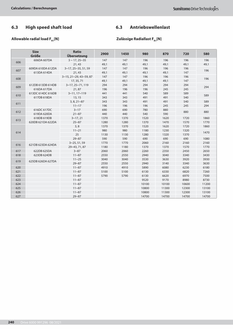
Drive 6000 991296 08/2021
Calculations / Berechnungen
240
6.3 Antriebswellenlast6.3 High speed shaft load
Allowable radial load FR1[N] Zulässige Radiallast FR1[N]
SizeGröße
Ratio Übersetzung 2900 1450 980 870 720 580
606606DA 607DA 3 ~ 17, 25~35 147 147 196 196 196 196
21, 43 49,1 49,1 49,1 49,1 49,1 49,1
607609DA 610DA 612DA 3~17, 25~35, 51, 59 147 147 196 196 196
196613DA 614DA 21, 43 49,1 49,1 49,1 49,1 147
6083~15, 21~29, 43~59, 87 147 147 196 196 196
19617, 35, 71 49,1 49,1 49,1 49,1 147
609612DB 613DB 614DB 3~17, 25~71, 119 294 294 294 294 294
294616DA 617DA 21, 87 196 196 196 245 245
610613DC 614DC 616DB 3~11, 17~119 441 441 540 589 589
589617DB 618DA 13, 15 343 343 491 491 540
6113, 8, 21~87 343 343 491 491 540 589
11~17 196 196 196 245 245 294
612616DC 617DC 3~17 690 690 780 880
880 880619DA 620DA 21~87 440 440 540 590
613618DB 619DB 3~17, 21 1370 1370 1520 1620 1720 1860
620DB 621DA 622DA 25~87 1280 1280 1370 1470 1570 1770
614
3, 8 1370 1370 1520 1620 1720 186011~21 980 980 1180 1230 1320
147025 1130 1130 1280 1320 1370
29~87 590 590 690 690 690 1080
616 621DB 623DA 624DA3~25, 51, 59 1770 1770 2060 2160 2160 2160
29~43, 71, 87 1180 1180 1370 1370 1570 1770617 622DB 625DA 3~87 2060 2060 2260 2350 2450 2650618 623DB 624DB 11~87 2550 2550 2940 3040 3340 3430
619 625DB 626DA 627DA11~25 3040 3040 3530 3630 3920 393029~87 2550 2550 2940 3140 3340 3630
620 11~87 4910 4910 5890 6080 6230 6180621 11~87 5100 5100 6130 6330 6820 7260622 11~87 5790 5790 6130 6620 6970 7500623 11~87 9520 9170 8980 8730624 11~87 10100 10100 10600 11200625 11~87 10800 11300 12300 13100626 11~87 10800 11300 12300 13100627 29~87 14700 14700 14700 14700
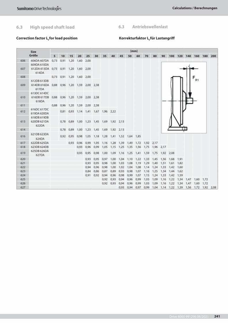
Drive 6000 991296 08/2021
Calculations / Berechnungen
241
Correction factor Lf for load position Korrekturfaktor Lf für Lastangriff
SizeGröße
[mm]
5 10 15 20 25 30 35 40 45 50 60 70 80 90 100 120 140 160 180 200606 606DA 607DA 0,73 0,91 1,20 1,60 2,00
607609DA 610DA
0,73 0,91 1,20 1,60 2,00 612DA 613DA 614DA
608 0,73 0,91 1,20 1,60 2,00
609612DB 613DB
0,88 0,96 1,20 1,59 2,00 2,38 614DB 616DA 617DA
610613DC 614DC
0,88 0,96 1,20 1,59 2,00 2,38 616DB 617DB 618DA
611 0,88 0,96 1,20 1,59 2,00 2,38
612616DC 617DC
0,81 0,93 1,14 1,41 1,67 1,96 2,22619DA 620DA
613618DB 619DB
0,78 0,89 1,00 1,23 1,45 1,69 1,92 2,13620DB 621DA 622DA
614 0,78 0,89 1,00 1,23 1,45 1,69 1,92 2,13
616621DB 623DA
0,92 0,95 0,98 1,05 1,18 1,28 1,41 1,52 1,64 1,85 624DA
617 622DB 625DA 0,93 0,96 0,99 1,05 1,16 1,28 1,39 1,49 1,72 1,92 2,17618 623DB 624DB 0,93 0,96 0,99 1,05 1,15 1,25 1,35 1,56 1,75 1,96 2,17
619625DB 626DA
0,93 0,95 0,98 1,00 1,09 1,16 1,25 1,41 1,59 1,75 1,92 2,08 627DA
620 0,93 0,95 0,97 1,00 1,04 1,10 1,22 1,33 1,45 1,56 1,68 1,91621 0,93 0,95 0,98 1,00 1,03 1,08 1,19 1,29 1,40 1,51 1,61 1,82622 0,94 0,96 0,98 1,00 1,02 1,04 1,08 1,14 1,24 1,33 1,42 1,60623 0,84 0,86 0,87 0,89 0,93 0,98 1,07 1,16 1,25 1,34 1,44 1,62624 0,91 0,92 0,94 0,96 0,98 0,99 1,07 1,15 1,24 1,33 1,42 1,59625 0,92 0,93 0,94 0,96 0,99 1,03 1,09 1,16 1,22 1,34 1,47 1,60 1,72626 0,92 0,93 0,94 0,96 0,99 1,03 1,09 1,16 1,22 1,34 1,47 1,60 1,72627 0,93 0,94 0,97 0,99 1,04 1,14 1,22 1,39 1,56 1,72 1,92 2,08
6.3 Antriebswellenlast6.3 High speed shaft load
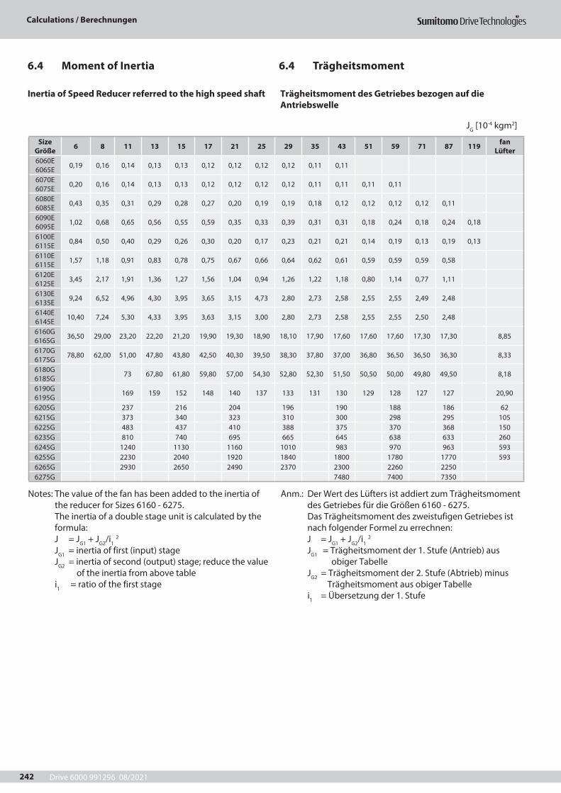
Drive 6000 991296 08/2021
Calculations / Berechnungen
242
6.4 Trägheitsmoment6.4 Moment of Inertia
Inertia of Speed Reducer referred to the high speed shaft Trägheitsmoment des Getriebes bezogen auf die Antriebswelle
JG [10-4 kgm2]
Size Größe 6 8 11 13 15 17 21 25 29 35 43 51 59 71 87 119 fan
Lüfter6060E 6065E 0,19 0,16 0,14 0,13 0,13 0,12 0,12 0,12 0,12 0,11 0,11
6070E 6075E 0,20 0,16 0,14 0,13 0,13 0,12 0,12 0,12 0,12 0,11 0,11 0,11 0,11
6080E 6085E 0,43 0,35 0,31 0,29 0,28 0,27 0,20 0,19 0,19 0,18 0,12 0,12 0,12 0,12 0,11
6090E 6095E 1,02 0,68 0,65 0,56 0,55 0,59 0,35 0,33 0,39 0,31 0,31 0,18 0,24 0,18 0,24 0,18
6100E 6115E 0,84 0,50 0,40 0,29 0,26 0,30 0,20 0,17 0,23 0,21 0,21 0,14 0,19 0,13 0,19 0,13
6110E 6115E 1,57 1,18 0,91 0,83 0,78 0,75 0,67 0,66 0,64 0,62 0,61 0,59 0,59 0,59 0,58
6120E 6125E 3,45 2,17 1,91 1,36 1,27 1,56 1,04 0,94 1,26 1,22 1,18 0,80 1,14 0,77 1,11
6130E 6135E 9,24 6,52 4,96 4,30 3,95 3,65 3,15 4,73 2,80 2,73 2,58 2,55 2,55 2,49 2,48
6140E 6145E 10,40 7,24 5,30 4,33 3,95 3,63 3,15 3,00 2,80 2,73 2,58 2,55 2,55 2,50 2,48
6160G 6165G 36,50 29,00 23,20 22,20 21,20 19,90 19,30 18,90 18,10 17,90 17,60 17,60 17,60 17,30 17,30 8,85
6170G 6175G 78,80 62,00 51,00 47,80 43,80 42,50 40,30 39,50 38,30 37,80 37,00 36,80 36,50 36,50 36,30 8,33
6180G 6185G 73 67,80 61,80 59,80 57,00 54,30 52,80 52,30 51,50 50,50 50,00 49,80 49,50 8,18
6190G 6195G 169 159 152 148 140 137 133 131 130 129 128 127 127 20,90
6205G 237 216 204 196 190 188 186 626215G 373 340 323 310 300 298 295 1056225G 483 437 410 388 375 370 368 1506235G 810 740 695 665 645 638 633 2606245G 1240 1130 1160 1010 983 970 963 5936255G 2230 2040 1920 1840 1800 1780 1770 5936265G 2930 2650 2490 2370 2300 2260 22506275G 7480 7400 7350
Notes: The value of the fan has been added to the inertia of the reducer for Sizes 6160 - 6275. The inertia of a double stage unit is calculated by the formula: J = JG1 + JG2/i1 2 JG1 = inertia of first (input) stage JG2 = inertia of second (output) stage; reduce the value of the inertia from above table i1 = ratio of the first stage
Anm.: Der Wert des Lüfters ist addiert zum Trägheitsmoment des Getriebes für die Größen 6160 - 6275. Das Trägheitsmoment des zweistufigen Getriebes ist nach folgender Formel zu errechnen: J = JG1 + JG2/i1 2 JG1 = Trägheitsmoment der 1. Stufe (Antrieb) aus obiger Tabelle JG2 = Trägheitsmoment der 2. Stufe (Abtrieb) minus Trägheitsmoment aus obiger Tabelle i1 = Übersetzung der 1. Stufe
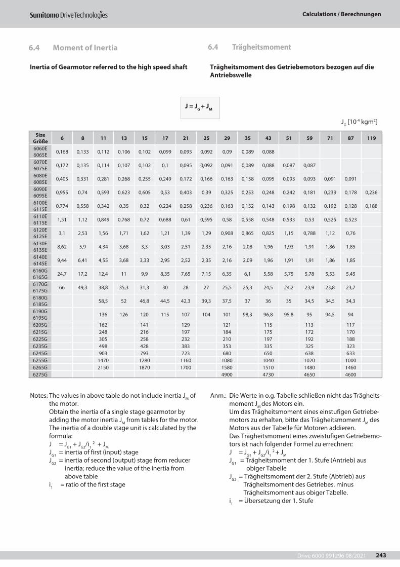
Drive 6000 991296 08/2021
Calculations / Berechnungen
243
Inertia of Gearmotor referred to the high speed shaft Trägheitsmoment des Getriebemotors bezogen auf die Antriebswelle
JG [10-4 kgm2]
Size Größe 6 8 11 13 15 17 21 25 29 35 43 51 59 71 87 119
6060E 6065E 0,168 0,133 0,112 0,106 0,102 0,099 0,095 0,092 0,09 0,089 0,088
6070E 6075E 0,172 0,135 0,114 0,107 0,102 0,1 0,095 0,092 0,091 0,089 0,088 0,087 0,087
6080E 6085E 0,405 0,331 0,281 0,268 0,255 0,249 0,172 0,166 0,163 0,158 0,095 0,093 0,093 0,091 0,091
6090E 6095E 0,955 0,74 0,593 0,623 0,605 0,53 0,403 0,39 0,325 0,253 0,248 0,242 0,181 0,239 0,178 0,236
6100E 6115E 0,774 0,558 0,342 0,35 0,32 0,224 0,258 0,236 0,163 0,152 0,143 0,198 0,132 0,192 0,128 0,188
6110E 6115E 1,51 1,12 0,849 0,768 0,72 0,688 0,61 0,595 0,58 0,558 0,548 0,533 0,53 0,525 0,523
6120E 6125E 3,1 2,53 1,56 1,71 1,62 1,21 1,39 1,29 0,908 0,865 0,825 1,15 0,788 1,12 0,76
6130E 6135E 8,62 5,9 4,34 3,68 3,3 3,03 2,51 2,35 2,16 2,08 1,96 1,93 1,91 1,86 1,85
6140E 6145E 9,44 6,41 4,55 3,68 3,33 2,95 2,52 2,35 2,16 2,09 1,96 1,91 1,91 1,86 1,85
6160G 6165G 24,7 17,2 12,4 11 9,9 8,35 7,65 7,15 6,35 6,1 5,58 5,75 5,78 5,53 5,45
6170G 6175G 66 49,3 38,8 35,3 31,3 30 28 27 25,5 25,3 24,5 24,2 23,9 23,8 23,7
6180G 6185G 58,5 52 46,8 44,5 42,3 39,3 37,5 37 36 35 34,5 34,5 34,3
6190G 6195G 136 126 120 115 107 104 101 98,3 96,8 95,8 95 94,5 94
6205G 162 141 129 121 115 113 1176215G 248 216 197 184 175 172 1706225G 305 258 232 210 197 192 1886235G 498 428 383 353 335 325 3236245G 903 793 723 680 650 638 6336255G 1470 1280 1160 1080 1040 1020 10006265G 2150 1870 1700 1580 1510 1480 14606275G 4900 4730 4650 4600
Notes: The values in above table do not include inertia JM of the motor. Obtain the inertia of a single stage gearmotor by adding the motor inertia JM from tables for the motor. The inertia of a double stage unit is calculated by the formula: J = JG1 + JG2/i1 2 + JM JG1 = inertia of first (input) stage JG2 = inertia of second (output) stage from reducer inertia; reduce the value of the inertia from above table i1 = ratio of the first stage
Anm.: Die Werte in o.g. Tabelle schließen nicht das Trägheits-moment JM des Motors ein. Um das Trägheitsmoment eines einstufigen Getriebe-motors zu erhalten, bitte das Trägheitsmoment JM des Motors aus der Tabelle für Motoren addieren. Das Trägheitsmoment eines zweistufigen Getriebemo-tors ist nach folgender Formel zu errechnen: J = JG1 + JG2/i1 2 + JM JG1 = Trägheitsmoment der 1. Stufe (Antrieb) aus obiger Tabelle JG2 = Trägheitsmoment der 2. Stufe (Abtrieb) aus Trägheitsmoment des Getriebes, minus Trägheitsmoment aus obiger Tabelle. i1 = Übersetzung der 1. Stufe
6.4 Trägheitsmoment6.4 Moment of Inertia
J = JG + JM
Drive 6000 991296 08/2021
Calculations / Berechnungen
244

Drive 6000 991296 08/2021
Motor information / Motor-Information
245
7 Motor-Information7 Motor information
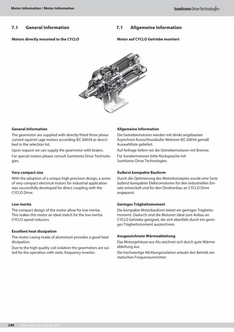
Drive 6000 991296 08/2021
Motor information / Motor-Information
246
Motors directly mounted to the CYCLO
General InformationThe gearmotor are supplied with directly fitted three phase current squirrel cage motors according IEC 60034 as descri-bed in the selection list. Upon request we can supply the gearmotor with brakes. For special motors please consult Sumitomo Drive Technolo-gies.
Very compact size With the adoption of a unique high precision design, a series of very compact electrical motors for industrial application was successfully developed for direct coupling with the CYCLO Drive.
Low inertia The compact design of the motor allow for low inertia. This makes this motor an ideal match for the low inertia CYCLO speed reducers.
Excellent heat dissipation The motor casing made of aluminium provides a good heat dissipation. Due to the high quality coil isolation the gearmotors are sui-ted for the operation with static frequency inverter.
Motor auf CYCLO Getriebe montiert
Allgemeine InformationDie Getriebemotoren werden mit direkt angebauten Asynchron-Kurzschlussläufer-Motoren IEC 60034 gemäß Auswahlliste geliefert.Auf Anfrage liefern wir die Getriebemotoren mit Bremse.Für Sondermotoren bitte Rücksprache mit Sumitomo Drive Technologies.
Äußerst kompakte BauformDurch die Optimierung des Motorkonzeptes wurde eine Serie äußerst kompakter Elektromotoren für den industriellen Ein-satz entwickelt und für den Direktanbau an CYCLO Drive angepasst.
Geringes TrägheitsmomentDie kompakte Motorbauform bietet ein geringes Trägheits-moment. Dadurch sind die Motoren ideal zum Anbau an CYCLO Getriebe geeignet, die sich ebenfalls durch ein gerin-ges Trägheitsmoment auszeichnen.
Ausgezeichnete WärmeableitungDas Motorgehäuse aus Alu zeichnet sich durch gute Wärme-ableitung aus.Die hochwertige Wicklungsisolation erlaubt den Betrieb am statischen Frequenzumrichter.
7.1 Allgemeine Information7.1 General Information
Drive 6000 991296 08/2021
Motor information / Motor-Information
247
Energy saving motors
Sumitomo‘s 4-pole AC motors from 0.75 kW to 55 kW fulfil the requirements of the efficiency class IE3. Brake motors ful-fil the requirements of of the efficiency class IE1, brake motors in IE3 efficiency class are available on request.
Standards and RegulationsThe CYCLO gearmotor comply with the following standards and regulations
EN60034- 1, IEC 34-1General requirements for rotating electrical machines
EN60034- 6, IEC 34-6Methods of cooling rotating electrical machines
EN60034- 7, IEC 34-7Types of construction of rotating electrical
machinesEN60034- 14, IEC 34-14Mechanical vibrations of rotating electrical machines
EN60034-5; IEC 34-5Degrees of protection by enclosures for rotating electrical machinery
EN60034- 8; IEC 34-8Terminal designations and direction of rotation of electrical machines
Other Standards and RegulationsMotors in accordance with all usual national and internatio-nal standards are also available on request.For further details please contact Sumitomo Drive Technologies.
Energiesparende Motoren
Die 4-poligen Sumitomo Drehstrommotoren von 0,75 kW bis 55 kW erfüllen die Anforderungen der Wirkungsgradklasse IE3. Bremsmotoren sind in der Wirkungsgradklasse IE1 ausge-führt, IE3 Bremsmotoren sind auf Anfrage erhältlich.
Normen und VorschriftenDie CYCLO Getriebemotoren entsprechen folgenden Normen und Vorschriften:
EN60034- 1, IEC 34-1Allgemeine Bestimmungen für umlaufende, elektrische Maschinen
EN60034- 6, IEC 34-6Kühlarten umlaufender elektrischer Maschinen
EN60034- 7, IEC 34-7Bauformen umlaufender elektrischer Maschinen
EN60034- 14, IEC 34-14Mechanische Schwingungen von umlaufenden elektrischen Maschinen
EN60034-5; IEC 34-5Schutzarten umlaufender elektrischer Betriebsmittel
EN60034- 8; IEC 34-8Anschlussbezeichnungen und Drehsinn von umlaufenden elektrischen Maschinen
Weitere Normen und VorschriftenAuf Anfrage sind auch Motoren nach allen gängigen nationa-len und internationalen Normen erhältlich.Für weitere Informationen wenden Sie sich bitte an Sumitomo Drive Technologies.
7.1 Allgemeine Information7.1 General Information
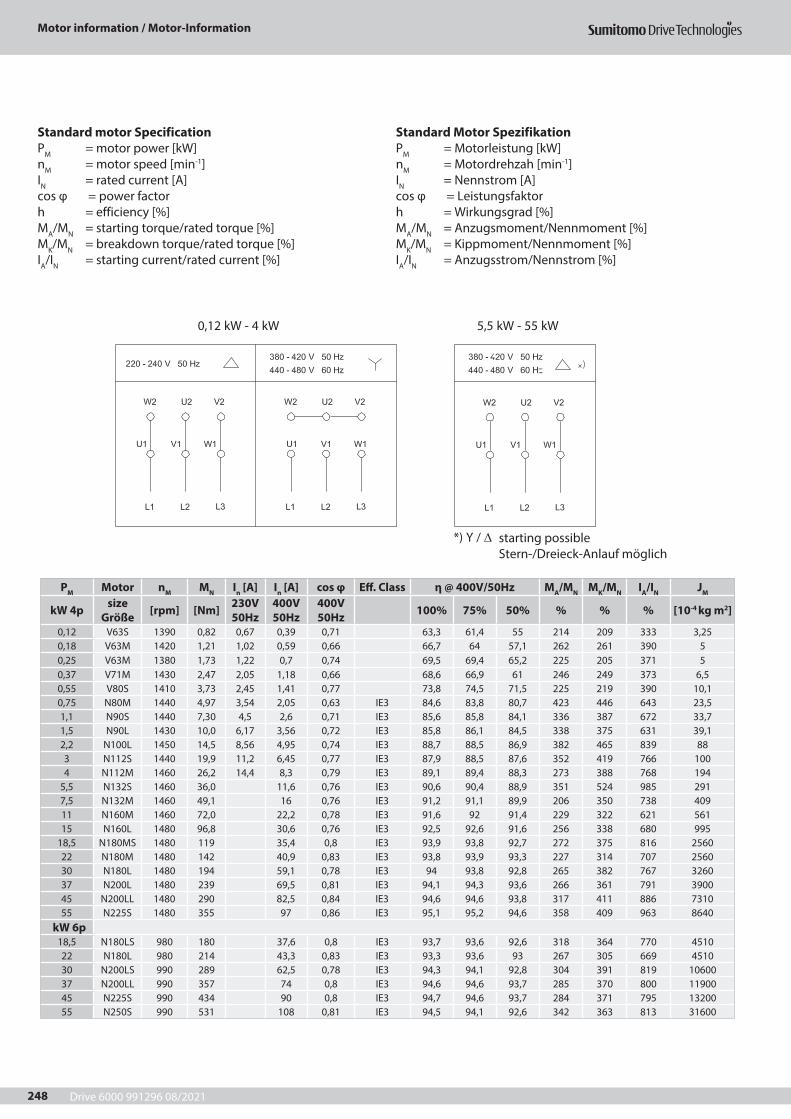
Drive 6000 991296 08/2021
Motor information / Motor-Information
248
Standard motor SpecificationPM = motor power [kW]nM = motor speed [min-1]IN = rated current [A]cos φ = power factorh = efficiency [%]MA/MN = starting torque/rated torque [%]MK/MN = breakdown torque/rated torque [%]IA/IN = starting current/rated current [%]
Standard Motor SpezifikationPM = Motorleistung [kW]nM = Motordrehzah [min-1]IN = Nennstrom [A]cos φ = Leistungsfaktorh = Wirkungsgrad [%]MA/MN = Anzugsmoment/Nennmoment [%]MK/MN = Kippmoment/Nennmoment [%]IA/IN = Anzugsstrom/Nennstrom [%]
0,12 kW - 4 kW 5,5 kW - 55 kW
*) Y / ∆ starting possibleStern-/Dreieck-Anlauf möglich
PM Motor nM MN In [A] In [A] cos φ Eff. Class η @ 400V/50Hz MA/MN MK/MN IA/IN JM
kW 4p size Größe [rpm] [Nm] 230V
50Hz400V 50Hz
400V 50Hz 100% 75% 50% % % % [10-4 kg m2]
0,12 V63S 1390 0,82 0,67 0,39 0,71 63,3 61,4 55 214 209 333 3,250,18 V63M 1420 1,21 1,02 0,59 0,66 66,7 64 57,1 262 261 390 50,25 V63M 1380 1,73 1,22 0,7 0,74 69,5 69,4 65,2 225 205 371 50,37 V71M 1430 2,47 2,05 1,18 0,66 68,6 66,9 61 246 249 373 6,50,55 V80S 1410 3,73 2,45 1,41 0,77 73,8 74,5 71,5 225 219 390 10,10,75 N80M 1440 4,97 3,54 2,05 0,63 IE3 84,6 83,8 80,7 423 446 643 23,51,1 N90S 1440 7,30 4,5 2,6 0,71 IE3 85,6 85,8 84,1 336 387 672 33,71,5 N90L 1430 10,0 6,17 3,56 0,72 IE3 85,8 86,1 84,5 338 375 631 39,12,2 N100L 1450 14,5 8,56 4,95 0,74 IE3 88,7 88,5 86,9 382 465 839 883 N112S 1440 19,9 11,2 6,45 0,77 IE3 87,9 88,5 87,6 352 419 766 1004 N112M 1460 26,2 14,4 8,3 0,79 IE3 89,1 89,4 88,3 273 388 768 194
5,5 N132S 1460 36,0 11,6 0,76 IE3 90,6 90,4 88,9 351 524 985 2917,5 N132M 1460 49,1 16 0,76 IE3 91,2 91,1 89,9 206 350 738 40911 N160M 1460 72,0 22,2 0,78 IE3 91,6 92 91,4 229 322 621 56115 N160L 1480 96,8 30,6 0,76 IE3 92,5 92,6 91,6 256 338 680 995
18,5 N180MS 1480 119 35,4 0,8 IE3 93,9 93,8 92,7 272 375 816 256022 N180M 1480 142 40,9 0,83 IE3 93,8 93,9 93,3 227 314 707 256030 N180L 1480 194 59,1 0,78 IE3 94 93,8 92,8 265 382 767 326037 N200L 1480 239 69,5 0,81 IE3 94,1 94,3 93,6 266 361 791 390045 N200LL 1480 290 82,5 0,84 IE3 94,6 94,6 93,8 317 411 886 731055 N225S 1480 355 97 0,86 IE3 95,1 95,2 94,6 358 409 963 8640
kW 6p18,5 N180LS 980 180 37,6 0,8 IE3 93,7 93,6 92,6 318 364 770 451022 N180L 980 214 43,3 0,83 IE3 93,3 93,6 93 267 305 669 451030 N200LS 990 289 62,5 0,78 IE3 94,3 94,1 92,8 304 391 819 1060037 N200LL 990 357 74 0,8 IE3 94,6 94,6 93,7 285 370 800 1190045 N225S 990 434 90 0,8 IE3 94,7 94,6 93,7 284 371 795 1320055 N250S 990 531 108 0,81 IE3 94,5 94,1 92,6 342 363 813 31600
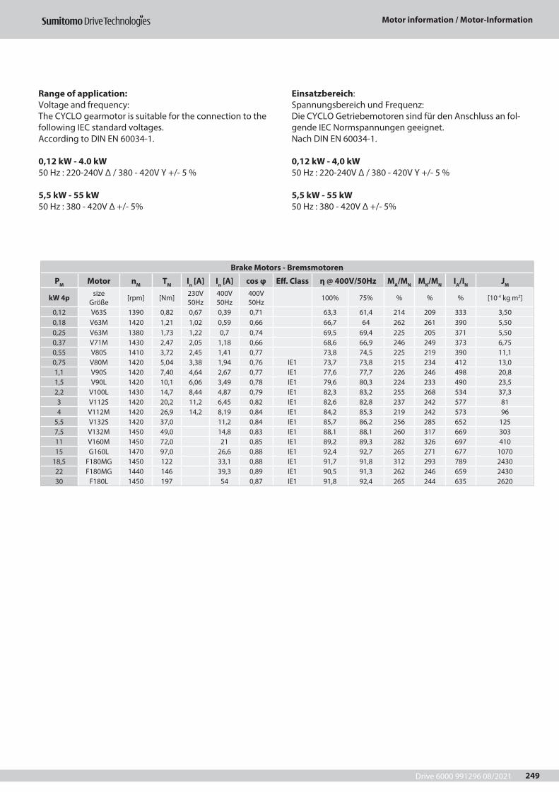
Drive 6000 991296 08/2021
Motor information / Motor-Information
249
Range of application:Voltage and frequency:The CYCLO gearmotor is suitable for the connection to the following IEC standard voltages.According to DIN EN 60034-1.
0,12 kW - 4.0 kW50 Hz : 220-240V Δ / 380 - 420V Y +/- 5 %
5,5 kW - 55 kW50 Hz : 380 - 420V Δ +/- 5%
Einsatzbereich:Spannungsbereich und Frequenz:Die CYCLO Getriebemotoren sind für den Anschluss an fol-gende IEC Normspannungen geeignet.Nach DIN EN 60034-1.
0,12 kW - 4,0 kW50 Hz : 220-240V Δ / 380 - 420V Y +/- 5 %
5,5 kW - 55 kW50 Hz : 380 - 420V Δ +/- 5%
Brake Motors - Bremsmotoren
PM Motor nM TM In [A] In [A] cos φ Eff. Class η @ 400V/50Hz MA/MN MK/MN IA/IN JM
kW 4p size Größe [rpm] [Nm] 230V
50Hz400V 50Hz
400V 50Hz 100% 75% % % % [10-4 kg m2]
0,12 V63S 1390 0,82 0,67 0,39 0,71 63,3 61,4 214 209 333 3,500,18 V63M 1420 1,21 1,02 0,59 0,66 66,7 64 262 261 390 5,500,25 V63M 1380 1,73 1,22 0,7 0,74 69,5 69,4 225 205 371 5,500,37 V71M 1430 2,47 2,05 1,18 0,66 68,6 66,9 246 249 373 6,750,55 V80S 1410 3,72 2,45 1,41 0,77 73,8 74,5 225 219 390 11,10,75 V80M 1420 5,04 3,38 1,94 0,76 IE1 73,7 73,8 215 234 412 13,01,1 V90S 1420 7,40 4,64 2,67 0,77 IE1 77,6 77,7 226 246 498 20,81,5 V90L 1420 10,1 6,06 3,49 0,78 IE1 79,6 80,3 224 233 490 23,52,2 V100L 1430 14,7 8,44 4,87 0,79 IE1 82,3 83,2 255 268 534 37,33 V112S 1420 20,2 11,2 6,45 0,82 IE1 82,6 82,8 237 242 577 814 V112M 1420 26,9 14,2 8,19 0,84 IE1 84,2 85,3 219 242 573 96
5,5 V132S 1420 37,0 11,2 0,84 IE1 85,7 86,2 256 285 652 1257,5 V132M 1450 49,0 14,8 0,83 IE1 88,1 88,1 260 317 669 30311 V160M 1450 72,0 21 0,85 IE1 89,2 89,3 282 326 697 41015 G160L 1470 97,0 26,6 0,88 IE1 92,4 92,7 265 271 677 1070
18,5 F180MG 1450 122 33,1 0,88 IE1 91,7 91,8 312 293 789 243022 F180MG 1440 146 39,3 0,89 IE1 90,5 91,3 262 246 659 243030 F180L 1450 197 54 0,87 IE1 91,8 92,4 265 244 635 2620
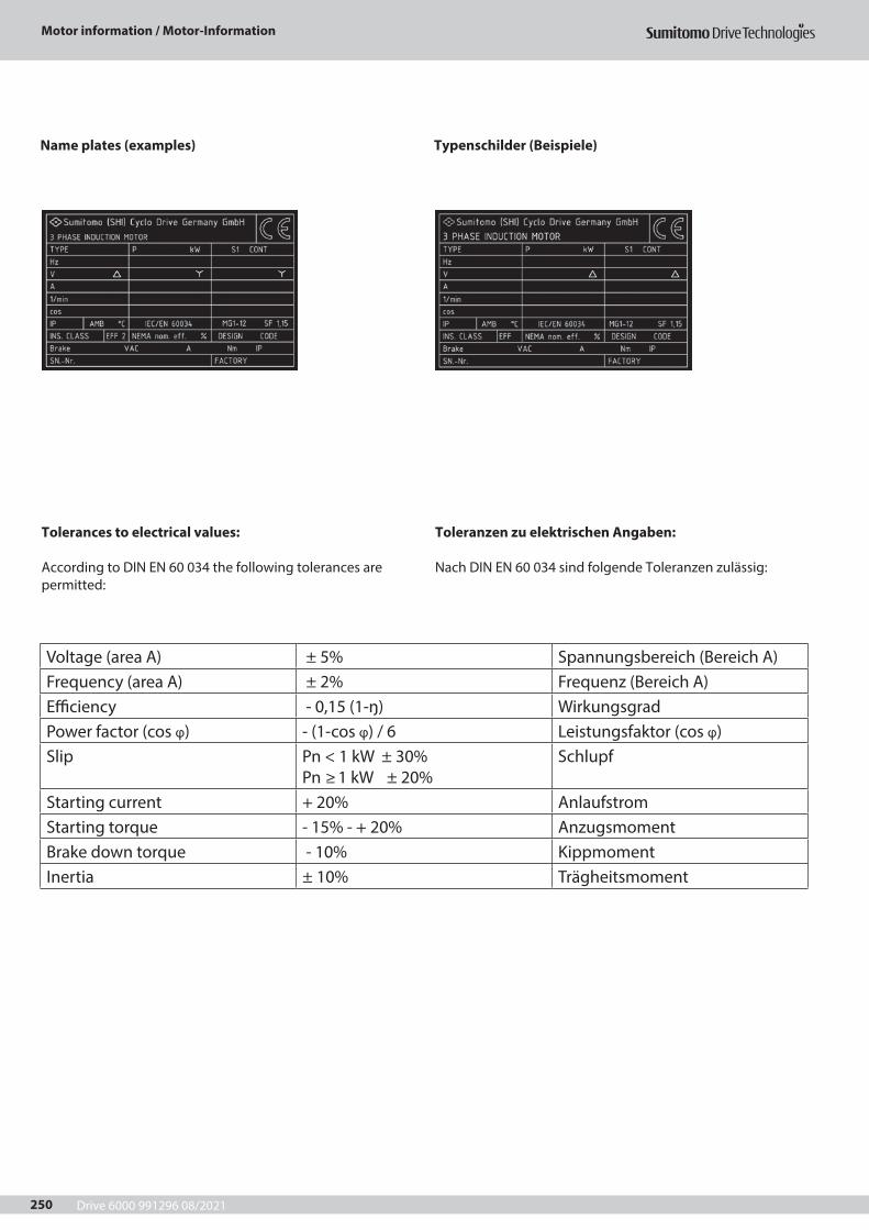
Drive 6000 991296 08/2021
Motor information / Motor-Information
250
Name plates (examples) Typenschilder (Beispiele)
Tolerances to electrical values:
According to DIN EN 60 034 the following tolerances arepermitted:
Toleranzen zu elektrischen Angaben:
Nach DIN EN 60 034 sind folgende Toleranzen zulässig:
Voltage (area A) ± 5% Spannungsbereich (Bereich A)Frequency (area A) ± 2% Frequenz (Bereich A)Efficiency - 0,15 (1-ŋ) WirkungsgradPower factor (cos φ) - (1-cos φ) / 6 Leistungsfaktor (cos φ)Slip Pn < 1 kW ± 30%
Pn ≥ 1 kW ± 20% Schlupf
Starting current + 20% AnlaufstromStarting torque - 15% - + 20% AnzugsmomentBrake down torque - 10% KippmomentInertia ± 10% Trägheitsmoment
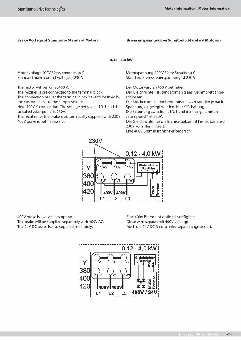
Drive 6000 991296 08/2021
Motor information / Motor-Information
251
Brake Voltage of Sumitomo Standard Motors
Motor voltage 400V 50Hz, connection YStandard brake control voltage is 230 V
The motor will be run at 400 V.The rectifier is pre connected to the terminal block.The connection bars at the terminal block have to be fixed by the customer acc. to the supply voltage.Here 400V Y-connection. The voltage between L1/U1 and the so called „star-point“ is 230V.The rectifier for the brake is automatically supplied with 230V.400V brake is not necessary.
400V brake is available as option.The brake will be supplied separately with 400V AC.The 24V DC brake is also supplied separately.
0,12 - 4,0 kW
Bremsenspannung bei Sumitomo Standard Motoren
Motorspannung 400 V 50 Hz Schaltung YStandard Bremssteuerspannung ist 230 V
Der Motor wird an 400 V betrieben.Der Gleichrichter ist standardmäßig ans Klemmbrett ange-schlossen.Die Brücken am Klemmbrett müssen vom Kunden je nach Spannung eingelegt werden. Hier Y-Schaltung.Die Spannung zwischen L1/U1 und dem so genannten „Sternpunkt“ ist 230V.Der Gleichrichter für die Bremse bekommt hier automatisch 230V vom Klemmbrett.Eine 400V Bremse ist nicht erforderlich.
Eine 400V Bremse ist optional verfügbar. Diese wird separat mit 400V versorgt.Auch die 24V DC Bremse wird separat angesteuert.
Wk 0,4 - 21,0
Y 380 400 420 Br
ake
Brem
se U1 V1 W1
W2 U2 V2
400V 400V L1 L2 L3
230V
Gleichrichter Rectifier
1 2 3 4
Wk 0,4 - 21,0
Y 380 400 4 Br
ake
Brem
se U1 V1 W1
W2 U2 V2
400V 400V L1 L2 L3
230V
Gleichrichter Rectifier
1 2 3 4 Gleichrichter
Rectifier 1 2 3 4
Wk 0,4 - 21,0
Y 380 400 420
U1 V1 W1
W2 U2 V2
400V 400V L1 L2 L3
Brak
e Br
emse
Gleichrichter Rectifier
1 2 3 4
400V / 24V
Wk 0,4 - 21,0
Y 380 400 4
U1 V1 W1
W2 U2 V2
400V 400V L1 L2 L3
Brak
e Br
emse
Gleichrichter Rectifier
1 2 3 4 Gleichrichter
Rectifier 1 2 3 4
400V / 24V
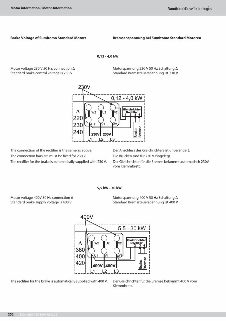
Drive 6000 991296 08/2021
Motor information / Motor-Information
252
Brake Voltage of Sumitomo Standard Motors
Motor voltage 230 V 50 Hz, connection Δ Standard brake control voltage is 230 V
Motor voltage 400V 50 Hz connection ΔStandard brake supply voltage is 400 V
The connection of the rectifier is the same as above.The connection bars are must be fixed for 230 V.The rectifier for the brake is automatically supplied with 230 V.
The rectifier for the brake is automatically supplied with 400 V.
0,12 - 4,0 kW
5,5 kW - 30 kW
Bremsenspannung bei Sumitomo Standard Motoren
Motorspannung 230 V 50 Hz Schaltung ΔStandard Bremssteuerspannung ist 230 V
Motorspannung 400 V 50 Hz Schaltung ΔStandard Bremssteuerspannung ist 400 V
Der Anschluss des Gleichrichters ist unverändert.Die Brücken sind für 230 V eingelegt.Der Gleichrichter für die Bremse bekommt automatisch 230V vom Klemmbrett.
Der Gleichrichter für die Bremse bekommt 400 V vom Klemmbrett.
0,12 - 4,0 kW
Brak
eBr
emse
U1 V1 W1
W2 U2 V2 Gleichrichter
Rectifier1 2 3 4
∆220230240
L1 L2 L3230V 230V
230V
0,12 - 4,0 kW
Brak
eBr
emse
U1 V1 W1
W2 U2 V2 Gleichrichter
Rectifier1 2 3 4
GleichrichterRectifier
1 2 3 4∆
220230240
L1 L2 L3230V 230V
230V
- 5,5
Brak
e Br
emse
U1 V1 W1
W2 U2 V2 ∆ 380 400 420
L1 L2 L3 400V 400V
400V
Gleichrichter Rectifier
1 2 3 4
03 - 5,5
Brak
e Br
emse
U1 V1 W1
W2 U2 V2 ∆ 380 400 4
L1 L2 L3 400V 400V
400V
Gleichrichter Rectifier
1 2 3 4 Gleichrichter
Rectifier 1 2 3 4
kW
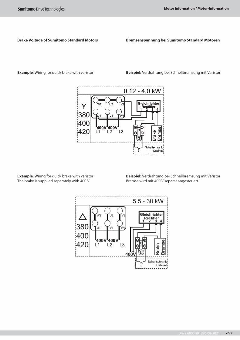
Drive 6000 991296 08/2021
Motor information / Motor-Information
253
Brake Voltage of Sumitomo Standard Motors
Example: Wiring for quick brake with varistor
Example: Wiring for quick brake with varistorThe brake is supplied separately with 400 V
Bremsenspannung bei Sumitomo Standard Motoren
Beispiel: Verdrahtung bei Schnellbremsung mit Varistor
Beispiel: Verdrahtung bei Schnellbremsung mit VaristorBremse wird mit 400 V separat angesteuert.
Wk 0,4 - 21,0
Y 380 400 4
Brak
e Br
emse
400V 400V L1 L2 L3
U1 V1 W1
W2 U2 V2 Gleichrichter Rectifier
1 2 3 4
Schaltschrank Cabinet
Wk 0,4 - 21,0
Y 380 400 420
Brak
e Br
emse
400V 400V L1 L2 L3
U1 V1 W1
W2 U2 V2 Gleichrichter Rectifier
1 2 3 4
Schaltschrank Cabinet
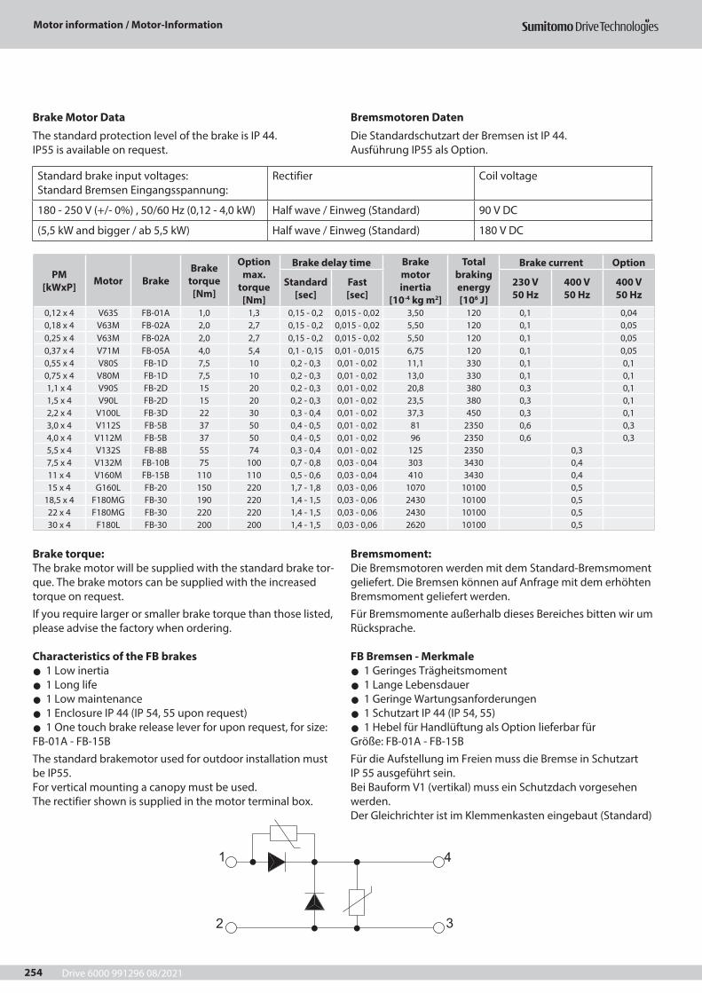
Drive 6000 991296 08/2021
Motor information / Motor-Information
254
Brake Motor Data
The standard protection level of the brake is IP 44.IP55 is available on request.
Brake torque:The brake motor will be supplied with the standard brake tor-que. The brake motors can be supplied with the increased torque on request.If you require larger or smaller brake torque than those listed, please advise the factory when ordering.
Characteristics of the FB brakes z 1 Low inertia z 1 Long life z 1 Low maintenance z 1 Enclosure IP 44 (IP 54, 55 upon request) z 1 One touch brake release lever for upon request, for size:
FB-01A - FB-15BThe standard brakemotor used for outdoor installation must be IP55.For vertical mounting a canopy must be used.The rectifier shown is supplied in the motor terminal box.
Bremsmotoren Daten
Die Standardschutzart der Bremsen ist IP 44.Ausführung IP55 als Option.
Bremsmoment:Die Bremsmotoren werden mit dem Standard-Bremsmoment geliefert. Die Bremsen können auf Anfrage mit dem erhöhten Bremsmoment geliefert werden.Für Bremsmomente außerhalb dieses Bereiches bitten wir um Rücksprache.
FB Bremsen - Merkmale z 1 Geringes Trägheitsmoment z 1 Lange Lebensdauer z 1 Geringe Wartungsanforderungen z 1 Schutzart IP 44 (IP 54, 55) z 1 Hebel für Handlüftung als Option lieferbar für
Größe: FB-01A - FB-15BFür die Aufstellung im Freien muss die Bremse in Schutzart IP 55 ausgeführt sein.Bei Bauform V1 (vertikal) muss ein Schutzdach vorgesehen werden.Der Gleichrichter ist im Klemmenkasten eingebaut (Standard)
Standard brake input voltages: Standard Bremsen Eingangsspannung:
Rectifier Coil voltage
180 - 250 V (+/- 0%) , 50/60 Hz (0,12 - 4,0 kW) Half wave / Einweg (Standard) 90 V DC
(5,5 kW and bigger / ab 5,5 kW) Half wave / Einweg (Standard) 180 V DC
PM[kWxP] Motor Brake
Braketorque
[Nm]
Optionmax.
torque[Nm]
Brake delay time Brakemotorinertia
[10-4 kg m2]
Totalbrakingenergy[106 J]
Brake current Option
Standard[sec]
Fast[sec]
230 V50 Hz
400 V50 Hz
400 V50 Hz
0,12 x 4 V63S FB-01A 1,0 1,3 0,15 - 0,2 0,015 - 0,02 3,50 120 0,1 0,040,18 x 4 V63M FB-02A 2,0 2,7 0,15 - 0,2 0,015 - 0,02 5,50 120 0,1 0,050,25 x 4 V63M FB-02A 2,0 2,7 0,15 - 0,2 0,015 - 0,02 5,50 120 0,1 0,050,37 x 4 V71M FB-05A 4,0 5,4 0,1 - 0,15 0,01 - 0,015 6,75 120 0,1 0,050,55 x 4 V80S FB-1D 7,5 10 0,2 - 0,3 0,01 - 0,02 11,1 330 0,1 0,10,75 x 4 V80M FB-1D 7,5 10 0,2 - 0,3 0,01 - 0,02 13,0 330 0,1 0,11,1 x 4 V90S FB-2D 15 20 0,2 - 0,3 0,01 - 0,02 20,8 380 0,3 0,11,5 x 4 V90L FB-2D 15 20 0,2 - 0,3 0,01 - 0,02 23,5 380 0,3 0,12,2 x 4 V100L FB-3D 22 30 0,3 - 0,4 0,01 - 0,02 37,3 450 0,3 0,13,0 x 4 V112S FB-5B 37 50 0,4 - 0,5 0,01 - 0,02 81 2350 0,6 0,34,0 x 4 V112M FB-5B 37 50 0,4 - 0,5 0,01 - 0,02 96 2350 0,6 0,35,5 x 4 V132S FB-8B 55 74 0,3 - 0,4 0,01 - 0,02 125 2350 0,37,5 x 4 V132M FB-10B 75 100 0,7 - 0,8 0,03 - 0,04 303 3430 0,411 x 4 V160M FB-15B 110 110 0,5 - 0,6 0,03 - 0,04 410 3430 0,415 x 4 G160L FB-20 150 220 1,7 - 1,8 0,03 - 0,06 1070 10100 0,5
18,5 x 4 F180MG FB-30 190 220 1,4 - 1,5 0,03 - 0,06 2430 10100 0,522 x 4 F180MG FB-30 220 220 1,4 - 1,5 0,03 - 0,06 2430 10100 0,530 x 4 F180L FB-30 200 200 1,4 - 1,5 0,03 - 0,06 2620 10100 0,5
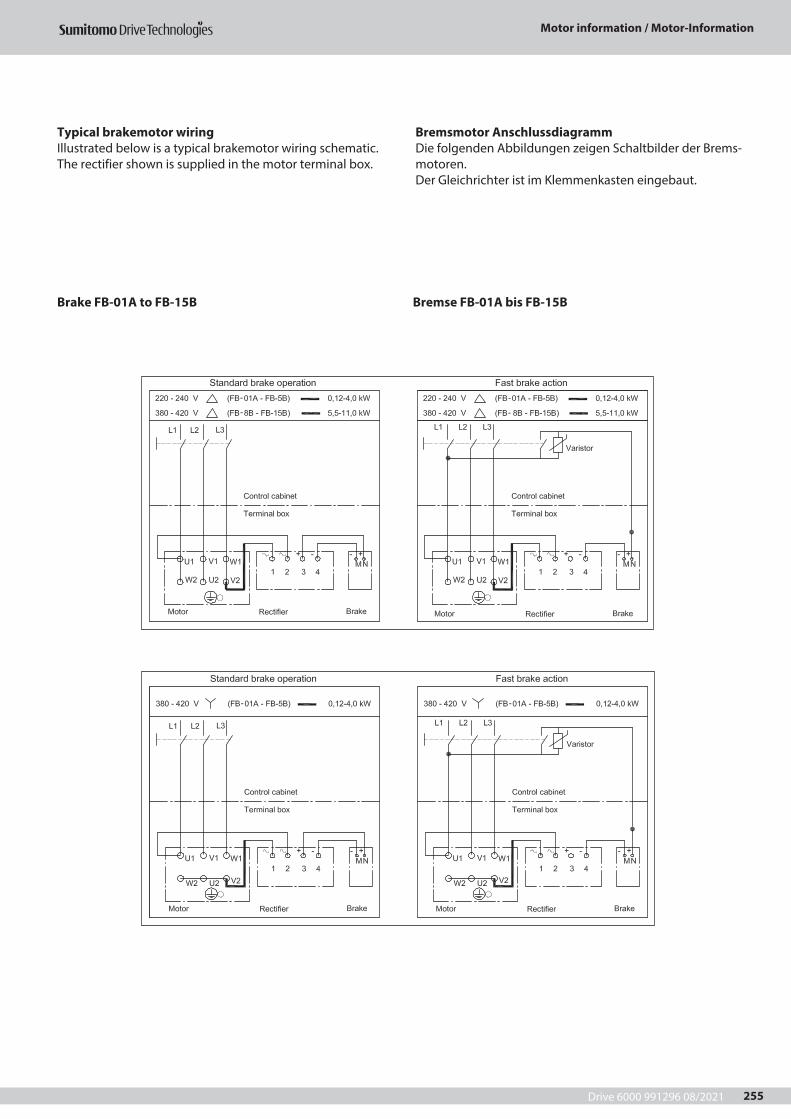
Drive 6000 991296 08/2021
Motor information / Motor-Information
255
Typical brakemotor wiringIllustrated below is a typical brakemotor wiring schematic.The rectifier shown is supplied in the motor terminal box.
Brake FB-01A to FB-15B
Bremsmotor AnschlussdiagrammDie folgenden Abbildungen zeigen Schaltbilder der Brems-motoren.Der Gleichrichter ist im Klemmenkasten eingebaut.
Bremse FB-01A bis FB-15B
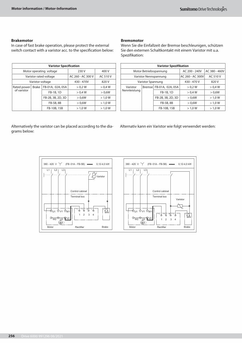
Drive 6000 991296 08/2021
Motor information / Motor-Information
256
BrakemotorIn case of fast brake operation, please protect the external switch contact with a varistor acc. to the specification below:
Alternatively the varistor can be placed according to the dia-grams below:
BremsmotorWenn Sie die Einfallzeit der Bremse beschleunigen, schützen Sie den externen Schaltkontakt mit einem Varistor mit u.a. Spezifikation:
Alternativ kann ein Varistor wie folgt verwendet werden:
Varistor Specification
Motor operating voltage 230 V 400 V
Varistor rated voltage AC 260 - AC 300 V AC 510 V
Varistor voltage 430 - 470V 820 V
Rated power of varistor
Brake FB-01A, 02A, 05A > 0,2 W > 0,4 W
FB-1B, 1D > 0,4 W > 0,6W
FB-2B, 3B, 2D, 3D > 0,6W > 1,0 W
FB-5B, 8B > 0,6W > 1,0 W
FB-10B, 15B > 1,0 W > 1,0 W
Varistor Spezifikation
Motor Betriebsspannung AC 200 - 240V AC 380 - 460V
Varistor Nennspannung AC 260 - AC 300V AC 510 V
Varistor Spannung 430 - 470 V 820 V
Varistor Nennleistung
Bremse FB-01A, 02A, 05A > 0,2 W > 0,4 W
FB-1B, 1D > 0,4 W > 0,6W
FB-2B, 3B, 2D, 3D > 0,6W > 1,0 W
FB-5B, 8B > 0,6W > 1,0 W
FB-10B, 15B > 1,0 W > 1,0 W
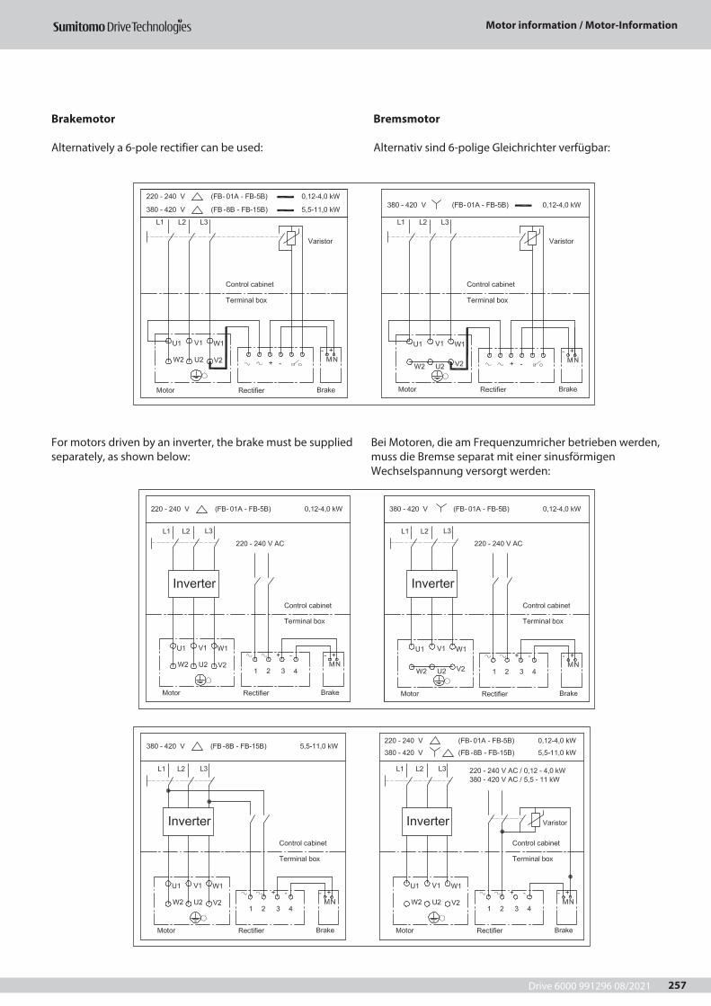
Drive 6000 991296 08/2021
Motor information / Motor-Information
257
Brakemotor
Alternatively a 6-pole rectifier can be used:
For motors driven by an inverter, the brake must be supplied separately, as shown below:
Bremsmotor
Alternativ sind 6-polige Gleichrichter verfügbar:
Bei Motoren, die am Frequenzumricher betrieben werden, muss die Bremse separat mit einer sinusförmigen Wechselspannung versorgt werden:
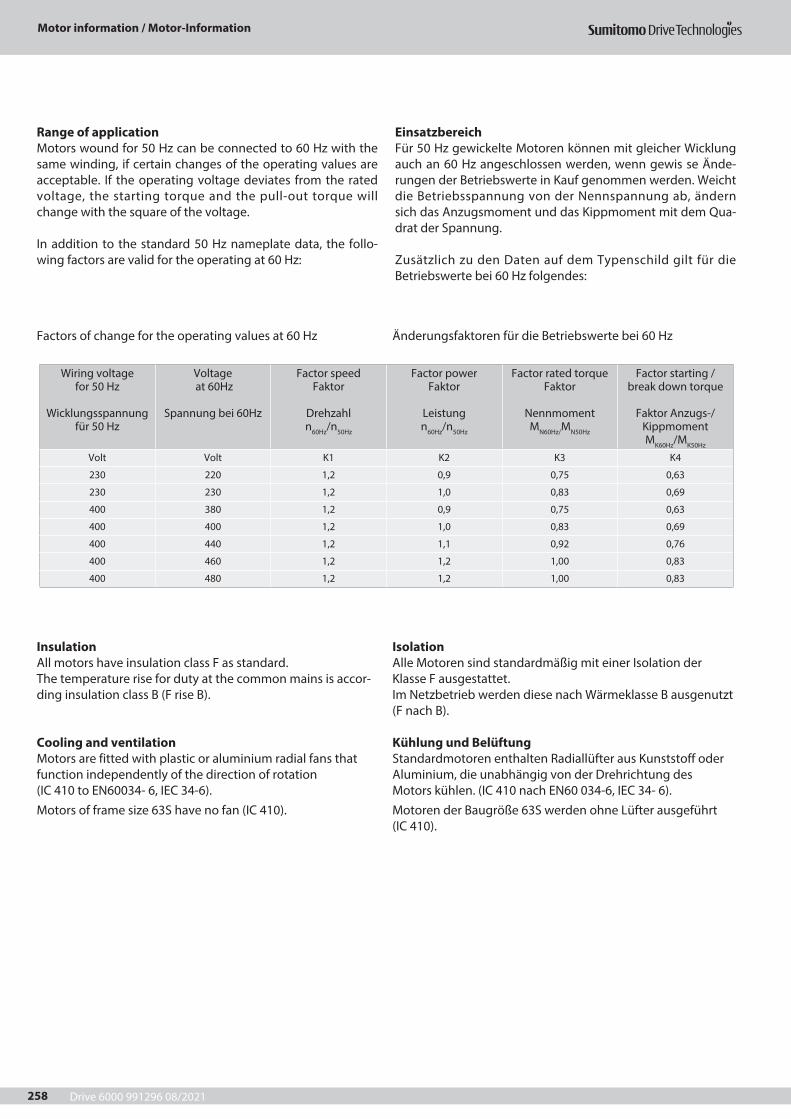
Drive 6000 991296 08/2021
Motor information / Motor-Information
258
Range of applicationMotors wound for 50 Hz can be connected to 60 Hz with the same winding, if certain changes of the operating values are acceptable. If the operating voltage deviates from the rated voltage, the starting torque and the pull-out torque will change with the square of the voltage.
In addition to the standard 50 Hz nameplate data, the follo-wing factors are valid for the operating at 60 Hz:
Factors of change for the operating values at 60 Hz
InsulationAll motors have insulation class F as standard.The temperature rise for duty at the common mains is accor-ding insulation class B (F rise B).
Cooling and ventilationMotors are fitted with plastic or aluminium radial fans that function independently of the direction of rotation (IC 410 to EN60034- 6, IEC 34-6).Motors of frame size 63S have no fan (IC 410).
EinsatzbereichFür 50 Hz gewickelte Motoren können mit gleicher Wicklung auch an 60 Hz angeschlossen werden, wenn gewis se Ände-rungen der Betriebswerte in Kauf genommen werden. Weicht die Betriebsspannung von der Nennspannung ab, ändern sich das Anzugsmoment und das Kippmoment mit dem Qua-drat der Spannung.
Zusätzlich zu den Daten auf dem Typenschild gilt für die Betriebswerte bei 60 Hz folgendes:
Änderungsfaktoren für die Betriebswerte bei 60 Hz
IsolationAlle Motoren sind standardmäßig mit einer Isolation der Klasse F ausgestattet.Im Netzbetrieb werden diese nach Wärmeklasse B ausgenutzt(F nach B).
Kühlung und BelüftungStandardmotoren enthalten Radiallüfter aus Kunststoff oder Aluminium, die unabhängig von der Drehrichtung des Motors kühlen. (IC 410 nach EN60 034-6, IEC 34- 6).Motoren der Baugröße 63S werden ohne Lüfter ausgeführt (IC 410).
Wiring voltage for 50 Hz
Wicklungsspannung
für 50 Hz
Voltage at 60Hz
Spannung bei 60Hz
Factor speed Faktor
Drehzahl n60Hz/n50Hz
Factor power Faktor
Leistung n60Hz/n50Hz
Factor rated torque Faktor
Nennmoment MN60Hz/MN50Hz
Factor starting / break down torque
Faktor Anzugs-/
Kippmoment MK60Hz/MK50Hz
Volt Volt K1 K2 K3 K4
230 220 1,2 0,9 0,75 0,63
230 230 1,2 1,0 0,83 0,69
400 380 1,2 0,9 0,75 0,63
400 400 1,2 1,0 0,83 0,69
400 440 1,2 1,1 0,92 0,76
400 460 1,2 1,2 1,00 0,83
400 480 1,2 1,2 1,00 0,83
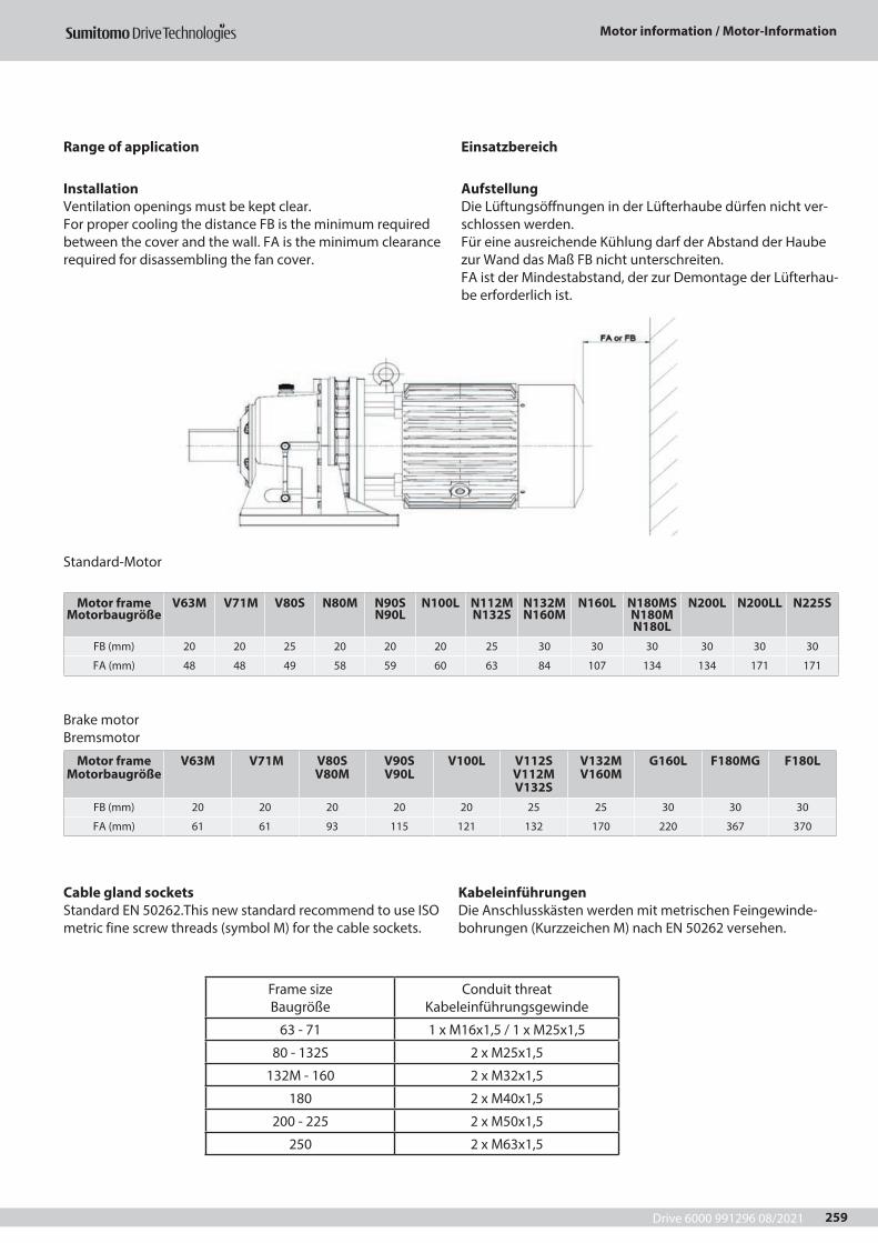
Drive 6000 991296 08/2021
Motor information / Motor-Information
259
Range of application
InstallationVentilation openings must be kept clear.For proper cooling the distance FB is the minimum required between the cover and the wall. FA is the minimum clearance required for disassembling the fan cover.
Cable gland socketsStandard EN 50262.This new standard recommend to use ISO metric fine screw threads (symbol M) for the cable sockets.
Frame size Baugröße
Conduit threat Kabeleinführungsgewinde
63 - 71 1 x M16x1,5 / 1 x M25x1,5
80 - 132S 2 x M25x1,5
132M - 160 2 x M32x1,5
180 2 x M40x1,5
200 - 225 2 x M50x1,5
250 2 x M63x1,5
Standard-Motor
Motor frame Motorbaugröße
V63M V71M V80S N80M N90S N90L
N100L N112M N132S
N132M N160M
N160L N180MS N180M N180L
N200L N200LL N225S
FB (mm) 20 20 25 20 20 20 25 30 30 30 30 30 30
FA (mm) 48 48 49 58 59 60 63 84 107 134 134 171 171
Brake motorBremsmotor
Motor frame Motorbaugröße
V63M V71M V80S V80M
V90S V90L
V100L V112S V112M V132S
V132M V160M
G160L F180MG F180L
FB (mm) 20 20 20 20 20 25 25 30 30 30
FA (mm) 61 61 93 115 121 132 170 220 367 370
Einsatzbereich
AufstellungDie Lüftungsöffnungen in der Lüfterhaube dürfen nicht ver-schlossen werden.Für eine ausreichende Kühlung darf der Abstand der Haube zur Wand das Maß FB nicht unterschreiten.FA ist der Mindestabstand, der zur Demontage der Lüfterhau-be erforderlich ist.
KabeleinführungenDie Anschlusskästen werden mit metrischen Feingewinde-bohrungen (Kurzzeichen M) nach EN 50262 versehen.
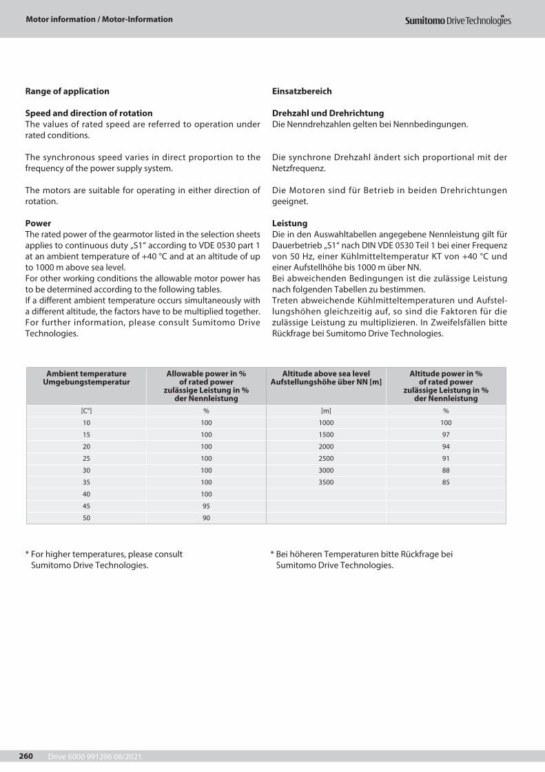
Drive 6000 991296 08/2021
Motor information / Motor-Information
260
Range of application
Speed and direction of rotationThe values of rated speed are referred to operation under rated conditions.
The synchronous speed varies in direct proportion to the frequency of the power supply system.
The motors are suitable for operating in either direction of rotation.
PowerThe rated power of the gearmotor listed in the selection sheets applies to continuous duty „S1“ according to VDE 0530 part 1 at an ambient temperature of +40 °C and at an altitude of up to 1000 m above sea level.For other working conditions the allowable motor power has to be determined according to the following tables.If a different ambient temperature occurs simultaneously with a different altitude, the factors have to be multiplied together. For further information, please consult Sumitomo Drive Technologies.
* For higher temperatures, please consult Sumitomo Drive Technologies.
Einsatzbereich
Drehzahl und DrehrichtungDie Nenndrehzahlen gelten bei Nennbedingungen.
Die synchrone Drehzahl ändert sich proportional mit der Netzfrequenz.
Die Motoren sind für Betrieb in beiden Drehrichtungen geeignet.
LeistungDie in den Auswahltabellen angegebene Nennleistung gilt für Dauerbetrieb „S1“ nach DIN VDE 0530 Teil 1 bei einer Frequenz von 50 Hz, einer Kühlmitteltemperatur KT von +40 °C und einer Aufstellhöhe bis 1000 m über NN.Bei abweichenden Bedingungen ist die zulässige Leistung nach folgenden Tabellen zu bestimmen.Treten abweichende Kühlmitteltemperaturen und Aufstel-lungshöhen gleichzeitig auf, so sind die Faktoren für die zulässige Leistung zu multiplizieren. In Zweifelsfällen bitte Rückfrage bei Sumitomo Drive Technologies.
* Bei höheren Temperaturen bitte Rückfrage bei Sumitomo Drive Technologies.
Ambient temperature Umgebungstemperatur
Allowable power in % of rated power
zulässige Leistung in % der Nennleistung
Altitude above sea level Aufstellungshöhe über NN [m]
Altitude power in % of rated power
zulässige Leistung in % der Nennleistung
[C°] % [m] %
10 100 1000 100
15 100 1500 97
20 100 2000 94
25 100 2500 91
30 100 3000 88
35 100 3500 85
40 100
45 95
50 90
Drive 6000 991296 08/2021
Motor information / Motor-Information
261
Mechanical Features
ProtectionThe motors are totally enclosed and fan cooled. Standard protection is IP 55, and with brake IP 44.For further details please refer to the table below.Regarding other enclosures please contact Sumitomo Drive Technologies.
1st Index Protection n against Human/Tool Contact0 No special protection1 Large foreign bodies, diam, >50mm2 Medium-sized foreign bodies, diam, >123 Small foreign bodies, diam, >2,5mm4 Granular foreign bodies, diam, >1mm5 Dust protected; dust deposits are permitted,
but their volume must not affect the function of the unit,
6 Dust- proof
2nd Index Protection against water0 No special protection1 Water dripping/falling vertically2 Water sprayed at an angle
(up to 15º degrees from the vertical)3 Spray water
(any direction up to 60º degrees from the vertical4 Spray water from all directions,
(limited ingress permitted)5 Low pressure water jets from all directions,
(limited ingress permitted)6 High pressure jets from all directions,
(limited ingress permitted)7 Temporary immersion, 15 cm to 1m8 Permanent Immersion, under pressure
Note: In case of increased water protection requirements use Motor IP 56, not IP 65! At higher humidity with condensation, an anti-conden-sation heater is required (space heater). Depending on the application, IP67 or IP68 can be necessary. For dusty ambients IP65 shall be used.
Mechanische Merkmale
SchutzartDie Motoren sind völlig verschlossen und luftgekühlt.Standardschutzart ist IP55 mit Bremse IP44.Weitere Details sind in der Tabelle unten enthalten.Für weitere Fragen wenden Sie sich bitte an Sumitomo Drive Technologies.
1ter Index Schutz gegen Berührung und Fremdkörper0 kein besonderer Schutz1 LSchutz gegen Eindringen fester
Fremdkörper mit Ø > 50 mm2 Schutz gegen Eindringen fester
Fremdkörper mit Ø > 12 mm3 Schutz gegen Eindringen fester
Fremdkörper mit Ø > 2,5 mm4 Schutz gegen Eindringen fester
Fremdkörper mit Ø > 1 mm5 Schutz gegen schädliche
Staubablagerungen (staubgeschützt)6 Dust- proof
2ter Index Schutz gegen Wasser0 kein besonderer Schutz1 Schutz gegen senkrecht tropfendes Wasser2 Schutz gegen senkrecht tropfendes
Wasser, Betriebsmittel bis 15° gekippt3 Schutz gegen Sprühwasser bis zu
einem Winkel von 60° zur Senkrechten4 Schutz gegen Spritzwasser aus allen Richtungen 5 Schutz gegen Strahlwasser (Düse) aus allen
Richtungen6 Schutz gegen starken Wasserstrahl oder schwere See7 Schutz gegen Wasser bei Eintauchen des Betriebs
mittels unter Druck- u. Zeitbedingungen8 Schutz gegen Wasser bei dauerndem Eintauchen
des Betriebsmittels in Wasser
Bem.: Bei erhöhten Anforderungen an Wasserschutz sollten Motoren in IP 56 ausgeführt werden und nicht in IP 65! Bei feuchter Umgebung mit Betauung ist eine Still-standsheizung erforderlich. Je nach Applikation ist IP67 oder IP68 erforderlich. Bei staubiger Umgebung kann IP65 verwendet werden.
Drive 6000 991296 08/2021
Motor information / Motor-Information
262
Mechanical Features
Protection for vertically mounted motorsA motor with canopy is recommended for gearmotor desig-ned with slow speed shaft pointing downwards.
Anti-condensation heatersAnti-condensation heaters can be fitted to motors whose windings are exposed to the danger of condensation due to damp environment or wide fluctuations in temperature.The anti-condensation heaters must not be switched on while the motors are running.
BalancingThe motors comply with the vibration severity grade N toDIN EN 60 034-14
Mechanische Merkmale
Motoren für vertikale EinbaulageGetriebemotoren, die mit der Abtriebswelle nach unten ein-gebaut werden, sollten ein Motorschutzdach erhalten.
StillstandsheizungMotoren, deren Wicklung aufgrund feuchter Umgebung oder starker Temperaturschwankungen der Betauungsgefahr aus-gesetzt sind, können mit einer Stillstandsheizung ausgerüstet werden.Während des Betriebs darf die Stillstandsheizung nicht einge-schaltet werden.
SchwingstärkeDie Rotoren der Motoren sind nach IEC 34 entsprechend der Schwingstärke „N“ ausgeführt.Dynamisches Wuchten erfolgt gemäß DIN ISO 1940 T1,Gütestufe G 2,5.
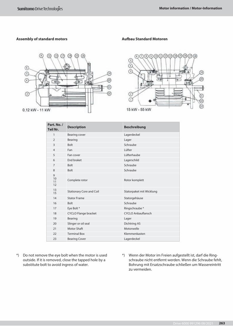
Drive 6000 991296 08/2021
Motor information / Motor-Information
263
Assembly of standard motors
*) Do not remove the eye bolt when the motor is used outside. If it is removed, close the tapped hole by a substitute bolt to avoid ingress of water.
*) Wenn der Motor im Freien aufgestellt ist, darf die Ring-schraube nicht entfernt werden. Wenn die Schraube fehlt, Bohrung mit Ersatzschraube schließen um Wassereintritt zu vermeiden.
Aufbau Standard Motoren
Part. No. / Teil Nr.
Description Beschreibung
1 Bearing cover Lagerdeckel
2 Bearing Lager
3 Bolt Schraube
4 Fan Lüfter
5 Fan cover Lüfterhaube
6 End braket Lagerschild
7 Bolt Schraube
8 Bolt Schraube
9101112
Complete rotor Rotor komplett
1315 Stationary Core and Coil Statorpaket mit Wicklung
14 Stator Frame Statorgehäuse
16 Bolt Schraube
17 Eye Bolt * Ringschraube *
18 CYCLO Flange bracket CYCLO Anbauflansch
19 Bearing Lager
20 Slinger or oil seal Dichtring AS
21 Motor Shaft Motorwelle
22 Terminal Box Klemmenkasten
23 Bearing Cover Lagerdeckel
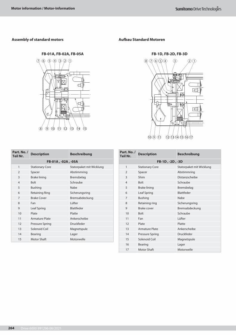
Drive 6000 991296 08/2021
Motor information / Motor-Information
264
Assembly of standard motors
FB-01A, FB-02A, FB-05A
Aufbau Standard Motoren
FB-1D, FB-2D, FB-3D
Part. No. / Teil Nr. Description Beschreibung
FB-01A , -02A , -05A1 Stationary Core Statorpaket mit Wicklung
2 Spacer Abstimmring
3 Brake lining Bremsbelag
4 Bolt Schraube
5 Bushing Nabe
6 Retaining Ring Sicherungsring
7 Brake Cover Bremsabdeckung
8 Fan Lüfter
9 Leaf Spring Blattfeder
10 Plate Platte
11 Armature Plate Ankerscheibe
12 Pressure Spring Druckfeder
13 Solenoid Coil Magnetspule
14 Bearing Lager
15 Motor Shaft Motorwelle
Part. No. / Teil Nr. Description Beschreibung
FB-1D , -2D , -3D1 Stationary Core Statorpaket mit Wicklung
2 Spacer Abstimmring
3 Shim Distanzscheibe
4 Bolt Schraube
5 Brake lining Bremsbelag
6 Leaf Spring Blattfeder
7 Bushing Nabe
8 Retaining ring Sicherungsring
9 Brake cover Bremsabdeckung
10 Bolt Schraube
11 Fan Lüfter
12 Plate Platte
13 Armature Plate Ankerscheibe
14 Pressure Spring Druckfeder
15 Solenoid Coil Magnetspule
16 Bearing Lager
17 Motor Shaft Motorwelle
G
8
7 6 5 4 3 2 1
10 11 12 13 14 159
G
8
10 9 11 12 13 14 15 16 17
7 6 5 4 3 2 1
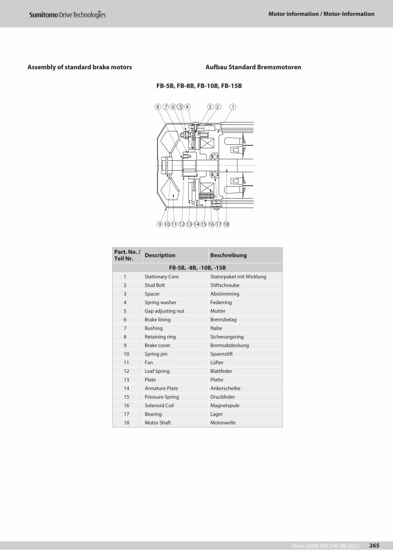
Drive 6000 991296 08/2021
Motor information / Motor-Information
265
Assembly of standard brake motors Aufbau Standard Bremsmotoren
FB-5B, FB-8B, FB-10B, FB-15B
Part. No. / Teil Nr. Description Beschreibung
FB-5B, -8B, -10B, -15B1 Stationary Core Statorpaket mit Wicklung
2 Stud Bolt Stiftschraube
3 Spacer Abstimmring
4 Spring washer Federring
5 Gap adjusting nut Mutter
6 Brake lining Bremsbelag
7 Bushing Nabe
8 Retaining ring Sicherungsring
9 Brake cover Bremsabdeckung
10 Spring pin Spannstift
11 Fan Lüfter
12 Leaf Spring Blattfeder
13 Plate Platte
14 Armature Plate Ankerscheibe
15 Pressure Spring Druckfeder
16 Solenoid Coil Magnetspule
17 Bearing Lager
18 Motor Shaft Motorwelle
G
8
9 10 11 12 13 14 15 16 17 18
7 6 5 4 3 2 1
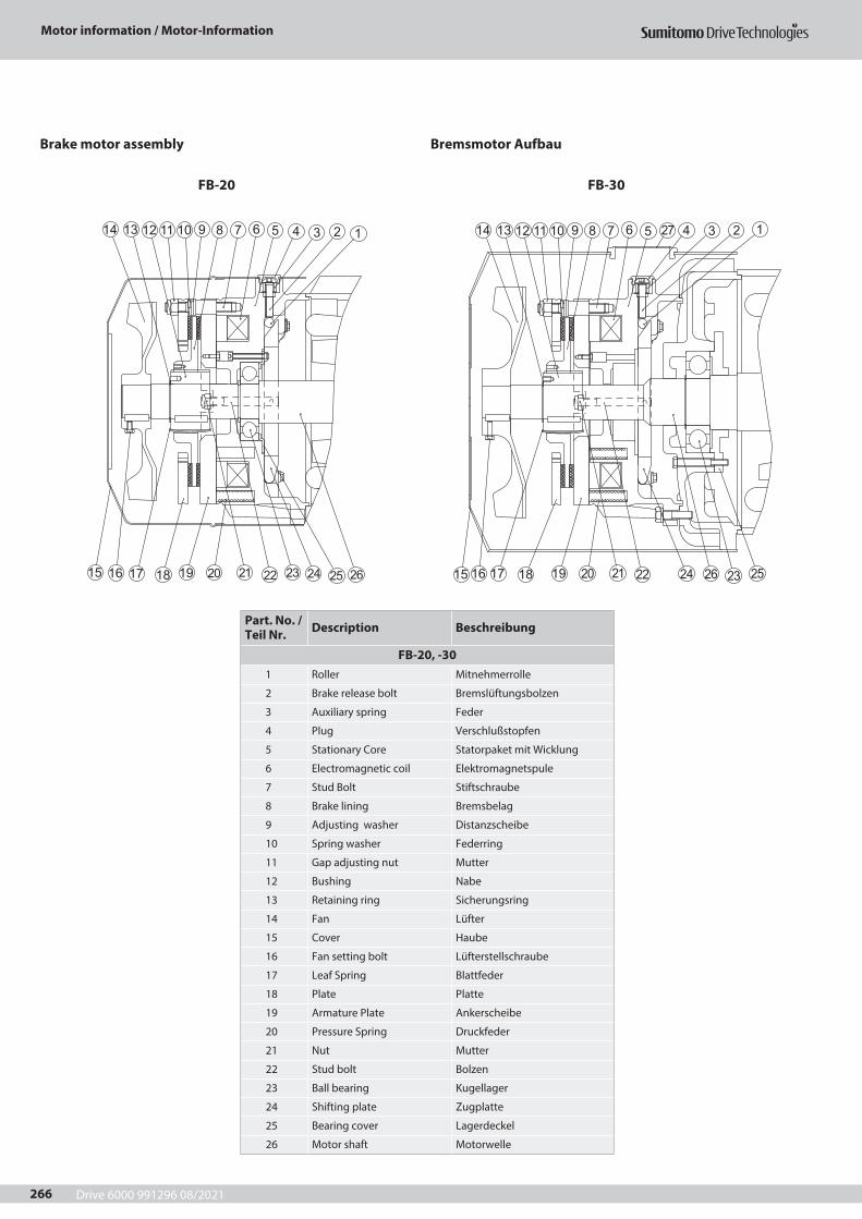
Drive 6000 991296 08/2021
Motor information / Motor-Information
266
Brake motor assembly Bremsmotor Aufbau
FB-20 FB-30
Part. No. / Teil Nr. Description Beschreibung
FB-20, -301 Roller Mitnehmerrolle
2 Brake release bolt Bremslüftungsbolzen
3 Auxiliary spring Feder
4 Plug Verschlußstopfen
5 Stationary Core Statorpaket mit Wicklung
6 Electromagnetic coil Elektromagnetspule
7 Stud Bolt Stiftschraube
8 Brake lining Bremsbelag
9 Adjusting washer Distanzscheibe
10 Spring washer Federring
11 Gap adjusting nut Mutter
12 Bushing Nabe
13 Retaining ring Sicherungsring
14 Fan Lüfter
15 Cover Haube
16 Fan setting bolt Lüfterstellschraube
17 Leaf Spring Blattfeder
18 Plate Platte
19 Armature Plate Ankerscheibe
20 Pressure Spring Druckfeder
21 Nut Mutter
22 Stud bolt Bolzen
23 Ball bearing Kugellager
24 Shifting plate Zugplatte
25 Bearing cover Lagerdeckel
26 Motor shaft Motorwelle
123456791011 8121314
15 16 17 18 19 20 21 22 23 24 25 26
123456791011 8121314
15 16 17 18 19 20 21 22 2324 2526
27
Drive 6000 991296 08/2021
Motor information / Motor-Information
267
Motor Options
Motor Options
In addition to brake the following options are available:
Motor standard options:- Hand release lever for brake- 6-pole rectifier- Thermistor PTC- TOC (bimetal, break contact)- Canopy- External fan- Incremental encoder- Space heater- Harting connector (Han Drive, 10-pin)
Further available options:- Pole changing motors- High inertia fan- UL or CSA- design- NEMA electrical- Insulation class H- 2nd shaft (IEC)- IP 56 / IP 65 (no heavy sea)- Special winding with free voltage/Frequency relation
IP 55 brake
Motor Ausführungen
Motor Optionen
Neben der Bremse sind folgende Optionen verfügbar:
Motor, Standard Optionen:- Handlüftung der Bremse- 6-poliger Gleichrichter- Kaltleiter PTC- Bimetall Temperaturwächter- Schutzdach- Fremdlüfter- Inkrementalgeber- Stillstandsheizung- Harting Stecker (Han Drive, 10-polig)
Weitere lieferbare Optionen:- Polumschaltbare Motoren- Schwungmassen- Lüfter- UL oder CSA- Ausführung- NEMA elektrisch- ISO Klasse H- 2. Wellenende nach IEC- IP 56 / IP 65 (keine schwere See)- Sonderwicklungen mit beliebiger Spannungs- /
Frequenz Zuordnung IP 55 Bremse
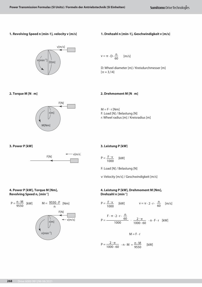
Drive 6000 991296 08/2021268
Power Transmission Formulas (SI Units) / Formeln der Antriebstechnik (SI Einheiten)
1. Revolving Speed n [min-1], velocity v [m/s]
2. Torque M [N · m]
3. Power P [kW]
4. Power P [kW], Torque M [Nm],Revolving Speed n, [min-1]
2. Drehmoment M [N · m]
3. Leistung P [kW]
4. Leistung P [kW], Drehmoment M [Nm],Drehzahl n [min-1]
1. Drehzahl n [min-1], Geschwindigkeit v [m/s]
v = p · D · [m/s]
v = p · 2 · r · [m/s]
P = [kW]
M = F · r
P = [kW]
P = · n · M = [kW]
P = [kW] M = [Nm]
P = · · n · F · r [kW]
D: Wheel diameter [m] / Kreisdurchmesser [m][p = 3,14]
F: Load [N] / Belastung [N]
v: Velocity [m/s] / Geschwindigkeit [m/s]
M = F · r [Nm]F: Load [N] / Belastung [N]r: Wheel radius [m] / Kreisradius [m]
n60
n60
F · v1000
F · v1000
n · M9550
n · M9550
9550 · Pn
2 · p1000 · 60
2 · p1000 · 60
F · p · 2 · r · n60
1000
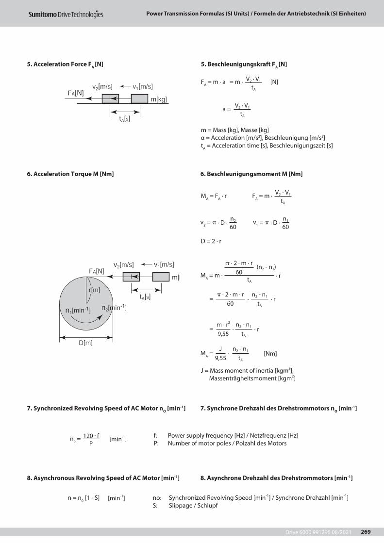
Drive 6000 991296 08/2021 269
Power Transmission Formulas (SI Units) / Formeln der Antriebstechnik (SI Einheiten)
5. Acceleration Force FA [N]
6. Acceleration Torque M [Nm]
7. Synchronized Revolving Speed of AC Motor nO [min-1]
8. Asynchronous Revolving Speed of AC Motor [min-1]
6. Beschleunigungsmoment M [Nm]
7. Synchrone Drehzahl des Drehstrommotors nO [min-1]
8. Asynchrone Drehzahl des Drehstrommotors [min-1]
5. Beschleunigungskraft FA [N]
v2 = p · D ·
= · · r
= · · r
v1 = p · D ·
FA = m · a = m · [N]
MA = FA · r
D = 2 · r
J = Mass moment of inertia [kgm2], Massenträgheitsmoment [kgm2]
f: Power supply frequency [Hz] / Netzfrequenz [Hz]P: Number of motor poles / Polzahl des Motors
no: Synchronized Revolving Speed [min-1] / Synchrone Drehzahl [min-1]S: Slippage / Schlupf
FA = m ·
a =
n0 = [min-1]
n = n0 [1 - S] [min-1]
MA = m · · r
MA = · [Nm]
m = Mass [kg], Masse [kg]α = Acceleration [m/s2], Beschleunigung [m/s2]tA = Acceleration time [s], Beschleunigungszeit [s]
n2
60n1
60
V2 · V1
tA
V2 - V1
tA
V2 · V1
tA
120 · fP
p · 2 · m · r 60
(n2 - n1)
tA
p · 2 · m · r 60
m · r2 9,55
J 9,55
n2 - n1
tA
n2 - n1
tA
n2 - n1
tA

Drive 6000 991296 08/2021270
Drive 6000 991296 08/2021 271
Drive 6000 991296 08/2021272
Cyclo Drive 6000Gearm
otors & Speed Reducers / Getriebemotoren & Getriebe
Sumitomo (SHI) Cyclo Drive Germany GmbH
Worldwide locationsWorld Headquarters JAPANSumitomo Heavy Industries Ltd.PTC GroupThink Park Tower, 1-1Osaki 2-chomeShinagawa-ku, Tokyo 141-6025, Japanwww.cyclo.shi.co.jpwww.sumitomodrive.com
Headquarters & Manufacturing CHINASumitomo (SHI) Cyclo Drive China, Ltd. Shanghai Branch10F, SMEG Plaza, No.1386Hongqiao RoadShanghai, China (P.C.200336)
Headquarters & Manufacturing EUROPEGermanySumitomo (SHI) Cyclo Drive Germany GmbHEuropean HeadquartersCyclostraße 9285229 Markt IndersdorfGermanyTel. +49 8136 66-0www.sumitomodrive.com
Our Subsidiaries & Sales Offices in EUROPE, MIDDLE EAST, AFRICA & INDIAAustriaSumitomo (SHI) Cyclo Drive Germany GmbHSales Office AustriaGruentalerstraße 30 A4020 Linz, AustriaTel. +43 732 330958
Belgium, Netherlands, LuxemburgHansen Industrial Transmissions NVLeonardo da Vincilaan 1-32650 Edegem, BelgiumTel. +32 3 450 12 11
FranceSM-Cyclo France S.A.S.8 Avenue Christian Doppler77700 Serris, FranceTel. +33 1 64171717
IndiaSumi-Cyclo Drive India Pvt. Ltd.Gat No. 186, Global Raisoni Industrial ParkAlandi Markal Road, Fulgao Pune 411 033, IndiaTel. +91 20 6674 2900
ItalySM-Cyclo Italy S.R.L.Via dell’Artigianato 2320007 Cornaredo (MI), ItalyTel. +39 02 93481101
Middle EastHansen Industrial Transmissions NVLeonardo da Vincilaan 1-32650 Edegem, BelgiumTel. +32 3 450 12 11
Headquarters & Manufacturing AMERICASSumitomo Drive TechnologiesSumitomo Machinery Corp. of America4200 Holland BoulevardChesapeake, VA 23323, USAwww.sumitomodrive.com
Headquarters ASIA PACIFICSumitomo (SHI) Cyclo Drive Asia Pacific Pte. Ltd.15 Kwong Min RoadSingapore, 628718 Singapore
BelgiumHansen Industrial Transmissions NVLeonardo da Vincilaan 1-32650 EdegemBelgiumTel. +32 3 450 12 11www.sumitomodrive.com
Sweden, Denmark, Norway, Finland, Estonia, Latvia – NORDICSM-Cyclo UK, Ltd.Unit 29, Bergen Way,Sutton Fields Industrial EstateKingston upon HullHU7 0YQ, East Yorkshire, United KingdomTel. +44 1482 790340
SpainSIT Sociedad Industrial de Transmisiones S.A.Paseo Ubarburu, 67Polígono 27 – Martutene20014 San SebastiánTel. + 34 943 457 200
South Africa, Sub-Saharan Africa – Sales PartnerBMG BEARING MAN GROUP (PTY) LTDPO Box 33431; Jeppestown Johannesburg 2043; South AfricaTel. +27 11 620 1615
TurkeySumitomo Cyclo Güç Aktarım Sis. Tic. Ltd.Sti.Barbaros Mh. Çiğdem Sk. Ağaoğlu My Office İş Mrk.No:1 Kat:4 D.18 34746 Ataşehir / Istanbul – TurkeyTel . +90 216 250 6069
United KingdomSM-Cyclo UK, Ltd.Unit 29, Bergen Way,Sutton Fields Industrial EstateKingston upon HullHU7 0YQ, East Yorkshire, United KingdomTel. +44 1482 790340