Embed Size (px)
Citation preview
TECHNICAL MANUAL A100K10652
INSTALLATION & CONFIGURATION GUIDE
IP DECT 6000 System

Zenitel Norway AS and its subsidiaries assume no responsibilities for any errors that may appear in this publication, or for damages arising from the information in it. No information in this publication should be regarded as a warranty made by Zenitel Norway AS.
The information in this publication may be revised or changed without notice. Product names mentioned in this publication may be trademarks of others and are used only for identification.
Zenitel Norway AS © 2009

3IP DECT 6000 System Installation & Configuration GuideA100K10652
Contents1 About this Document .....................................................................................................7
1.1 Before You Begin ......................................................................................................71.2 Publication Log .........................................................................................................71.3 Related Documentation ............................................................................................7
2 The IP DECT 6000 System .............................................................................................82.1 IP DECT Server 6000 ...............................................................................................92.2 Wireless Bands .........................................................................................................92.3 Base Station ..............................................................................................................92.4 Repeater .................................................................................................................10
2.4.1 Programming Software ..................................................................................102.5 Handset ...................................................................................................................10
2.5.1 Handover .......................................................................................................102.6 Administrative Computer .........................................................................................102.7 Requirements for the IP DECT 6000 System .........................................................10
2.7.1 IP DECT Server 6000 ....................................................................................102.7.1.1 Environmental Requirements............................................................................... 102.7.1.2 Electrical Requirements ........................................................................................11
2.7.2 Base Stations and Repeaters ........................................................................ 112.7.2.1 Environmental Requirements................................................................................112.7.2.2 Electrical Requirements for Base Station .............................................................112.7.2.3 Electrical Requirements for Repeater .................................................................. 12
2.7.3 Handsets ........................................................................................................122.7.3.1 Environmental Requirements............................................................................... 122.7.3.2 Electrical Requirements ....................................................................................... 12
2.7.4 Maintenance Software ...................................................................................122.7.4.1 Software Requirements ....................................................................................... 12
2.8 Installation Prerequisites .........................................................................................12
3 Deploying the IP DECT Server 6000 ............................................................................143.1 Recommendations for Base Station / Repeater Placement ...................................143.2 Deployment of a Server 6000 Multi-Cell System ....................................................15
3.2.1 Sync over Air ..................................................................................................153.2.2 Examples of Synchronization Chains ............................................................15
3.2.2.1 Sync Chain With One Sync Master (Primary Sync Ways) ................................... 163.2.2.2 Synchronization Chain With Secondary Sync Ways ............................................ 173.2.2.3 Sync Chain With and Without Secondary Sync Ways ......................................... 19
4 Installing the IP DECT Server 6000 .............................................................................204.1 Description of the Server 6000 ...............................................................................20
4.1.1 Type and Part Number ...................................................................................204.1.2 Server 6000 Appearance and Components ...................................................204.1.3 Server 6000 LED Indicators .........................................................................20
4.1.3.1 Front Cover .......................................................................................................... 204.1.3.2 Faceplate ............................................................................................................. 21
4.1.4 Server 6000 Reset Button ..............................................................................214.1.4.1 Resetting the Server 6000 Hardware................................................................... 21
4.2 Mounting/Connecting the Server 6000 ...................................................................22
5 Installing the Base Station ...........................................................................................235.1 Base Station Description .........................................................................................23
5.1.1 Base Station provides RF Channels to Handsets ..........................................235.1.2 Base Station Type and Part Number .............................................................235.1.3 Base Station Appearance and Components ..................................................245.1.4 Base Station LED Indicators ..........................................................................24
5.1.4.1 Front Cover .......................................................................................................... 245.1.4.2 Faceplate ............................................................................................................. 25
5.1.5 Base Station Reset Button .............................................................................255.1.5.1 Resetting the Base Station .................................................................................. 25
5.2 Mounting/Connecting the Base Station ...................................................................255.2.1 Wall Mounted (Vertical) Installation RF Coverage .........................................25
5.3 Recording the Installation Information ....................................................................26

4 A100K10652IP DECT 6000 System Installation & Configuration Guide
6 Installing the Repeater .................................................................................................276.1 Repeater Description ..............................................................................................27
6.1.1 Repeater provides RF Channels to Handsets ...............................................276.1.2 Repeater Type and Part Number ...................................................................276.1.3 Repeater Appearance and Components ........................................................276.1.4 Repeater LED Indicator .................................................................................28
6.2 Installing the Repeater ............................................................................................286.2.1 Environmental requirements .........................................................................28
6.3 Recording the Installation Information ....................................................................296.4 Checking Indicators ................................................................................................296.5 Powering the Repeater ...........................................................................................29
6.5.1 Power Options ...............................................................................................296.6 Programming a Repeater with the Programming Kit ..............................................29
6.6.1 Contents of the Repeater Programming Kit ...................................................296.6.2 Setting up the Hardware for Repeater Programming .....................................306.6.3 Programming the Repeater with ServiceTool .................................................30
7 Preparing the Handset for Use ....................................................................................377.1 Handset Description ................................................................................................37
7.1.1 Handset Types and Item Numbers ................................................................377.1.2 Charger Types and Item Numbers .................................................................37
7.2 Installing the Battery ...............................................................................................387.2.1 Installing the Battery on EX Handset .............................................................387.2.2 InstallingBatteryonOfficeHandset ...............................................................387.2.3 Installing Battery on Rough Handset .............................................................39
7.3 Charging Handsets .................................................................................................397.3.1 Using the Charger ..........................................................................................397.3.2 Charging the Battery ......................................................................................40
7.3.2.1 EX Handset .......................................................................................................... 407.3.2.2 Rough/OfficeHandset.......................................................................................... 40
7.4 Retrieving the Serial Number of the Handset .........................................................417.4.1 Retrieving Serial Number on EX Handset ......................................................417.4.2 RetrievingSerialNumberonOfficeHandset .................................................42
8 ConfiguringtheIPDECTServer6000 .........................................................................438.1 Powering up the Server 6000 .................................................................................43
8.1.1 Local Power Supply .......................................................................................438.2 Connecting a Computer to the Server 6000 ...........................................................438.3 Accessing the Server 6000 .....................................................................................44
8.3.1 Changing the Internet Protocol Properties using Windows ............................448.3.2 Accessing the Server 6000 ............................................................................46
8.4 ConfiguringtheServer6000UsingaStaticIPAddress .........................................478.4.1 GeneralConfiguration ....................................................................................478.4.2 WirelessServerConfiguration .......................................................................488.4.3 SIPConfiguration ...........................................................................................488.4.4 Rebooting the Server 6000 ............................................................................518.4.5 SecurityConfiguration ....................................................................................51
8.5 Checking the LED Indicator ....................................................................................51
9 ConfiguringtheBaseStation ......................................................................................529.1 Powering up the Base Station .................................................................................529.2 Connecting a Computer to the Base Station ...........................................................529.3 Accessing the Base Station ....................................................................................529.4 ConfiguringtheBaseStationUsingDHCP .............................................................54
9.4.1 GeneralConfiguration ....................................................................................549.4.2 BaseStationConfiguration ............................................................................559.4.3 SecurityConfiguration ....................................................................................559.4.4 SynchronizationWaysConfiguration .............................................................55
9.5 Checking the LED Indicator ....................................................................................56
10 Handset Registration and Subscription .....................................................................5710.1 Registering Handsets ..............................................................................................5710.2 Subscribing Handsets .............................................................................................59
10.2.1 Subscribing an EX Handset ...........................................................................5910.2.1.1 Subscribing EX Handset to Different Systems ..................................................... 60

5IP DECT 6000 System Installation & Configuration GuideA100K10652
10.2.2 Rough/OfficeHandsetSubscription ...............................................................6110.2.3 Subscribing a Rough Handset ......................................................................6110.2.4 SubscribinganOfficeHandset .....................................................................62
10.2.4.1 SubscribingOfficeHandsettoDifferentSystems ................................................ 63
11 Handset Management ...................................................................................................6411.1ViewingHandset/UserConfiguration ......................................................................6411.2 Searching for Handset/User Information ................................................................6511.3 Unsubscribing Handsets .........................................................................................65
11.3.1 EX Handset ....................................................................................................6511.3.2 Rough/OfficeHandset ....................................................................................65
11.4 Deleting Users/Handsets from the List (Deregistering) ...........................................6611.5ChangingUserConfigurations ................................................................................6711.6 Exporting Handset Registration Data ......................................................................6811.7 Importing Handset Registration Data - CSV Format ...............................................69
12 System Management ....................................................................................................7112.1 IP DECT Server 6000 .............................................................................................71
12.1.1 Changing System User Name and Password ................................................7112.1.2 Reading System Information ..........................................................................71
12.1.2.1 General Status Information .................................................................................. 7212.1.2.2 Logs Information .................................................................................................. 7212.1.2.3 Wireless Server Information ................................................................................. 74
12.1.3 Reading Statistics ..........................................................................................7412.1.3.1 Wireless Server .................................................................................................... 7412.1.3.2 Base Station ......................................................................................................... 7512.1.3.3 Active Calls .......................................................................................................... 7512.1.3.4 Abnormal Releases .............................................................................................. 7512.1.3.5 TrafficDistribution ................................................................................................ 76
12.1.4 Exporting/BackingUptheConfigurationFile ...............................................7612.1.5 Importing/RestoringtheConfigurationFile ....................................................7712.1.6 Updating the Server 6000 ..............................................................................78
12.1.6.1 Updating Server 6000 Firmware .......................................................................... 7812.1.7 Rebooting/Restarting the Server 6000 ...........................................................80
12.2 Base Station ............................................................................................................8112.2.1 Changing System User Name and Password ................................................8112.2.2 Reading System Information ..........................................................................81
12.2.2.1 General Status Information .................................................................................. 8212.2.2.2 Logs Information .................................................................................................. 82
12.2.3 Synchronization State of Base Station ...........................................................8312.2.3.1 Checking Sync State ............................................................................................ 84
12.2.4 Updating the Base Station Firmware .............................................................84
13ConfiguringtheAlphaCom/ACMExchange ..............................................................8613.1 Adding a DECT User/Handset ................................................................................8613.2 Updating the Exchange ...........................................................................................87
A Acronyms ......................................................................................................................88
B Regulatory Notices .......................................................................................................89B.1 International Regulatory Information .......................................................................89B.2 Important Safety Instructions ..................................................................................93

6 A100K10652IP DECT 6000 System Installation & Configuration Guide
FiguresFigure1 IPDECT6000SystemConfiguration .................................................................... 8Figure 2 Synchronization Chain ......................................................................................... 16Figure 3 Synchronization Chain Layout without Secondary Sync Ways ............................ 16Figure 4 Synchronization Chain with Secondary Sync Ways ............................................ 17Figure 5 Synchronization Chain with Secondary Sync Ways ............................................ 17Figure 6 Synchronization Chain with Secondary Sync Ways ............................................ 18Figure 7 Synchronization Chain Layout with Secondary Sync Ways ................................. 18Figure 8 Sync Chain With and Without Secondary Sync Ways ......................................... 19Figure 9 Synchronization Chain With Repeaters ............................................................... 19Figure 10 Server 6000 - Front view ...................................................................................... 20Figure 11 Server 6000 - Faceplate ...................................................................................... 21Figure 12 Server 6000 Wall Mounting .................................................................................. 22Figure 13 Base Station - Front view ..................................................................................... 24Figure 14 Base Station - Faceplate...................................................................................... 25Figure 15 Base Station - Wall Mounting ............................................................................... 26Figure 16 Base Station - Ethernet Connector ...................................................................... 26Figure 17 Repeater Programming Kit .................................................................................. 29Figure 18 Removing Back Cover from EX Handset ............................................................. 38Figure19 RemovingBackCoverfromOfficeHandset ........................................................ 39Figure 20 Single Charger for EX Handset............................................................................ 39Figure 21 Removing Back Cover from EX Handset ............................................................. 41Figure22 RemovingBackCoverfromRough/OfficeHandset............................................. 42Figure 23 Faceplate showing Ethernet port ......................................................................... 43
TablesTable 1 Overview of System Capacity ................................................................................ 9Table 2 LED Indicator Description - Front Cover .............................................................. 20Table 3 LED Indicator Description - Faceplate ................................................................. 21Table 4 Reset Button Description ..................................................................................... 21Table 5 LED Indicator Description - Front Cover .............................................................. 24Table 6 LED Indicator Description - Faceplate ................................................................. 25Table 7 Reset Button Description ..................................................................................... 25Table 8 Repeater Numbering in a Multi-Cell Solution ....................................................... 30Table9 ExampleofaNormalBaseStation/RepeaterConfiguration ................................ 36Table10 ExampleofRepeaterJumpConfiguration ........................................................... 36Table 11 Handset Types ..................................................................................................... 37Table 12 Charger Types ..................................................................................................... 37

7IP DECT 6000 System Installation & Configuration GuideA100K10652
1 About this DocumentThisdocumentisintendedforqualifiedtechnicianswhowillinstall,configureandmaintaintheIPDECT6000System.Thedocumentalsoprovides information on the web browser-based user interface of the Server6000andbasestationaswellastheconfigurationoftheIPDECT handsets in the AlphaCom/ACM exchange so that they can be used as mobile intercom stations.
The IP DECT 6000 System comprises the following:
Product Part NumberIP DECT Server 6000 2211000100IP DECT Base Station 2211000600Repeater Wall / Repeater Ceiling 2211050100 / 2211050110IP DECT Handsets 2211100501, 2211100502,
2211100505, 2211100506IP DECT Alarm Server 2210020000, 2210020002
) The configuration of the Alarm Server is described in the corresponding manual as listed under Related Documentation below.
1.1 Before You BeginThis document assumes the following:
● You have a working knowledge of AlphaCom/ACM exchange operations and the exchange is installed and initialized and is working properly.
● You have a working knowledge of deployment in general.
● A site survey has been conducted and the installer has access to these plans. The site survey should determine the number of handsets and RF channels that are needed.
1.2 Publication LogRev. Date Author Comments1.0 02-11-2009 HKL Published1.5 28-1-2011 HKL handsets
1.6 12-3-2012 HKL Rough handsets Subscription
1.3 Related DocumentationFor further information about the IP DECT 6000 System not covered by thismanual,refertothefollowingdocumentation:
Doc. no. Subject DocumentationA100K10676 IP DECT Planning & Deployment IP DECT Deployment Guide on Ships A100K10677 IP DECT Alarm Server IP DECT Alarm Server Configuration GuideA100K10777 IP DECT Configuration IP DECT Quick Configuration Guide
IP DECT Handset Operation IP DECT Handset User Guides

8 A100K10652IP DECT 6000 System Installation & Configuration Guide
2 The IP DECT 6000 SystemThis section provides a description of the IP DECT 6000 System.
The IP DECT Server 6000 communicates with the AlphaCom/ACM exchange over a LAN (Local Area Network).
A typical IP DECT 6000 System comprises the following components:
● IP DECT Server 6000
● Base Stations
● Repeaters
● Administrative Computer
● Handsets and accessories
● Alarm Server
Figure 1 IP DECT 6000 System Configuration
Base Station
Repeater
DECT Handset Rough
DECT Handset Office
DECT Handset EXDECT Handset Rough Bluetooth
DECT Handset OfficeDECT Handset EX
Repeater Repeater
Base Station Base Station Base Station Base Station Base Station
AlphaCom/ACM Exchange
LAN
PBX / PSTN
SIP Gateway
IP DECTServer 6000
AdministrativeComputer
IntercomStation
Alarm Server

9IP DECT 6000 System Installation & Configuration GuideA100K10652
2.1 IP DECT Server 6000Below is an overview of the system capacity of the IP DECT Server 6000.
Table 1 Overview of System CapacityDescription CapacityMax. number of base stationsNote: A minimum of 1 base station is required as the Server 6000 does not have a built-in radio.
255
Max. number of simultaneous calls on each base station 11Max. number of repeaters on each base station 6Max. number of simultaneous calls on an IP DECT Server 6000 (G.711) 30Max. number of registered handsets 500
The Server 6000 controls the wireless infrastructure of the IP DECT system.Itmanagesbasestations,repeatersandtheIPinterfacetotheAlphaCom/ACM exchange.
SIP (Session Initiation Protocol) is the protocol used for controlling communication sessions between the Server 6000 and the AlphaCom/ACM exchange.
A Server 6000 is installed directly on the Local Area Network (LAN) and must be managed as part of the corporate network.
2.2 Wireless BandsThewirelesssolutionsupportstwowirelessbands,allowingoperationinvarious countries and regions. Supported wireless bands are:
● ETSIDECT(1880-1900MHz),referredtoasDECT
● USADECT(1920-1930MHz),referredtoas1G9
The wireless band used by an IP DECT 6000 System is determined by the base stations and handsets delivered with the solution.
) This document only describes equipment in the ETSI DECT band.
2.3 Base StationThe base stations are positioned in the area to send and receive calls,i.e.betweenthewirelessserverandthehandset.Thebasestation contains internal antennas and handles 11 speech channels simultaneously. A base station is able to synchronize with other base stations.Whenthebasestationissynchronizedwithotherbasestations,a person speaking on a handset can move between base stations (i.e. handover) without any interference.
The transmission length is up to 100 meters/329 feet according to IEEE 802.3uonatwistedpaircable,e.g.cat.5e.Thebasestationisaclass1 PoE device (802.3af) and must be powered accordingly (maximum power supply consumption is 3.0W according to PoE 802.3af). The radius coverage of the base station is up to 90 meters/295 feet indoors and up to 300 meters/984 feet outdoors with a handset in line-of-sight (coverage area onboard ship is 50 meters indoors and 150 meters outdoors).
Coverage area decreases depending on the type of building materials and obstructive elements. To ensure proper coverage in the areas

10 A100K10652IP DECT 6000 System Installation & Configuration Guide
required,itisnecessarytoeitherconductasitesurveyorbasethedeployment plan on the deployment guidelines.
2.4 RepeaterThe repeater can be used to extend the coverage area in a wireless radiosynchronizationsolution,whereitservesasareceiverandtransmitterinrelayingradiosignals.Dependingontherepeatertype,it can be mounted either on the wall or on the ceiling. The wireless repeaterisusedinareaswithlimitedvoicetraffic,wherecablingisdifficult.Therepeaterdoesnotincreasethenumberoftrafficchannels,but increases the coverage area established with the base station. Up to three repeaters can be placed in cascade formation directing coverage in acertaindirection.Iftheradioenvironmentisdifficult,oneshouldavoidinstalling repeaters.
Each base station can support up to 6 repeaters.
2.4.1 Programming SoftwareThe application software for programming the repeater and software downloads to the repeater is called ServiceTool.
) ServiceTool is not used for adjusting the Rough/Office Handset.
The ServiceTool software is available as a download from the STENTOFON AlphaWiki website.
2.5 HandsetThehandsetisalightweight,ergonomicallydesignedwirelessunitthatincludes an LCD display and keypad.
2.5.1 HandoverHandover refers to the ability to move between the coverage areas ofdifferentradiounitsonthesamesystemwhiletalking,withoutinterruptions in the conversation.
2.6 Administrative ComputerAnadministrativecomputerisrequiredforconfigurationandmaintenance of the Server 6000 and base station. This computer may be temporarily connected directly to the device or to the network. A dedicated computer is not required.
2.7 Requirements for the IP DECT 6000 SystemThissectionprovidesinformationabouttheenvironmental,electrical,and software requirements for the IP DECT 6000 System.
2.7.1 IP DECT Server 6000
2.7.1.1 Environmental RequirementsThe installation area must be:
● clean,freeoftrafficandexcessdust,dry,andwellventilated
● within the temperature range of 10°C/50°F and 40°C/104°F

11IP DECT 6000 System Installation & Configuration GuideA100K10652
● between 20% and 80% non-condensing relative humidity
) The installation area must be of sufficient height from the floor to prevent water damage.
2.7.1.2 Electrical RequirementsThe following electrical requirements must be met:
● Power consumption: 8V/500 mA
● Typical power consumption: 5W per unit
● The supplied power for the AC adaptor power supply must be 110 to 240acnominal,50/60Hz.
2.7.2 Base Stations and Repeaters
2.7.2.1 Environmental Requirements
● Avoid installing base stations and repeaters on large concrete or marblecolumnsbecausetheyaffectradiocoverage.Ifpossible,place the base station a minimum of one meter/3.3 feet from these types of columns.
● Avoid installing a base station or repeater with the antenna housing near metal objects. Be careful not to damage existing wiring or panels. - Onships,theradiatingcablesolutionisusedinstead.
● Ifpossible,keepthebasestationandrepeaterawayfromsteelconstructions. - Onships,theradiatingcablesolutionisusedinstead.
● Only position base stations and repeaters where the signal is needed.
● Theinstallationareamustbeclean,freeoftrafficandexcessdust,dry,andwellventilated.
● The installation area must be within the temperature range of 10°C/50°F and 40°C/104°F.
● The installation area must be between 20% and 80% non-condensing relative humidity.
● The minimum distance between two base stations varies depending onthematerialandconstructionofbuildings,buttheremustalwaysbe synchronization chains and radio coverage overlap between the two base stations or handover between radio units.
● The time it takes a person to cross the common coverage area (of at least2basestations)mustbe10secondsormore,asthehandsetneeds time to scan for an alternative base station.
2.7.2.2 Electrical Requirements for Base StationThe following electrical requirements must be met:
● The base station operates on standard twisted pair Ethernet cable - e.g. minimum Cat.5e - to prevent disturbances from other equipment.
● Maximum power supply consumption is 3.0W (IEEE 802.3af class 1 device).
● The maximum average radiated output power for the antenna is 10mW – peak radiation is 250 mW (over a time period of 0.4 ms) EIRP/channel.

12 A100K10652IP DECT 6000 System Installation & Configuration Guide
2.7.2.3 Electrical Requirements for Repeater
● The power supply for the repeater must be 110 V to 120 V ac nominalor220Vto230Vacnominal,50/60Hz.
2.7.3 Handsets
2.7.3.1 Environmental Requirements
● The area where the handset is used must be within the temperature range of 0°C/32°F and 40°C/104°F.
● Forcorrectbatterycharging,theroomtemperaturemustbebetween0°C/32°Fand25°C/77°F.Therefore,thehandsetmustnotbeplacedin direct sunlight. The battery has a built-in heat sensor which will stop battery charging if the temperature is too high.
● The area where the handset is used must be between 20% and 80% non-condensing relative humidity.
2.7.3.2 Electrical RequirementsThe following electrical requirement must be met:
● The power supply for the charger must be 110 V to 120 V ac nominal or220Vto230Vacnominal,50/60Hz.
2.7.4 Maintenance SoftwareThis section describes the computer requirements to run the installation and maintenance tools of the handset and repeater.
2.7.4.1 Software Requirements
● OperatingSystem:Windows2000(SP4),WindowsXP(SP2),Windows Vista
● CPU:Minimum400MHz(2000/XP),1GHz(Vista)
● RAM:Minimum256MB(2000/XP),1GB(Vista)
● GPU/Display: XGA (1024x768)
● Harddisk: Minimum recommended harddisk size by OS and other installed applications + 25 MB free space for the application.
) Depending on other applications running on the system, CPU, RAM and harddisk values may vary.
2.8 Installation Prerequisites ) Ensure that a deployment plan has been conducted and that the installer has
access to these plans before proceeding any further. For more information about deployment, see “Deploying the IP DECT Server 6000”
Beforeyoustarttheinstallationyouneedtofindthefollowinginformationand perform the following tasks:
● ARI codes (serial numbers) for the Server 6000 (see label on the rear of the package unit)
● Serial numbers for handsets. Refer to “Retrieving the Serial Number of the Handset”.
● AC (Authentication Codes)
13IP DECT 6000 System Installation & Configuration GuideA100K10652
- TheACisacustomer-definedoptionalsubscriptionPINcodeofa maximum of eight digits for the individual handset. The AC can be used when connecting the handset to the Server 6000. The AC doesnotneedtobeconfiguredforthehandsetstofunction.
● Repeaters: - Mark each repeater with the number of the related base station. Thiswayyoucaneasilyconfigurethesystemonsite.
● Handsets: - Tousethehandsets,youmustfirstinstalltheradioinfrastructure,e.g. base stations and repeaters to transmit and receive radio signals to and from the handsets. There are no direct connections between the handset and the system. For more information about basestationandrepeaterinstallation,referto“InstallingBaseStation” and “Installing the Repeater”.
● Charging battery - Whenchargingthehandsetbatteryforthefirsttime,leavethehandset in the charger for 14 - 16 hours to ensure that the battery is fully charged and the handset ready for use. Refer to “Charging Handsets”.

14 A100K10652IP DECT 6000 System Installation & Configuration Guide
3 Deploying the IP DECT Server 6000BeforeyouinstalltheIPDECTServer6000solution,itisnecessaryto carry out a complete site design – at the minimum on the basis of environmentaldrawings(likeGAforships,orfloorplansforbuildings)-todeterminetheexactlocationoftheServer6000,basestations,repeaters and the number of handsets required.
) For deployment on ships, see Zenitel’s IP DECT Deployment on Ships.
) Due to the unexpected nature of RF propagation in an indoor environment, an actual on-site test may need to be carried out before the installation is complete.
While an extensive guide to effective RF coverage planning is beyond thescopeofthismanual,thefollowingpointsshouldbetakenintoconsiderationwhenplanningthesite,priortobasestationandrepeaterinstallation:
● The base station/repeater provides typical RF coverage of up to 50meters/164feetinatypicalindoorofficeenvironmentandupto300meters/984feetinanopenarea(line-of-sight),extendinginalldirections from the base station/repeater. The exact coverage range dependsonthebuildingarchitecture,wallmaterialandsurroundings.
● The wireless solution can support a maximum of 500 handsets and 255 base stations. (See Table 1 in section 2.1).
● Handset handover: handsets can move between coverage areas of base stations and repeaters while receiving continuous service and maintainingconversationsinprogress.However,forsteelcontainer-like rooms (such as ship cargo rooms) it is not to be expected that the standard radio antenna base stations will be able to support handover. - Fordeploymentonships,theradiatingcablesolutionmaybeused.
● Forefficienthandoverofconversationsbetweenbasestations,deploy base stations with wide overlap between them (i.e. plan for some areas to be covered by more than one base station). Overlaps are necessary to maintain seamless handover and to establish synchronization chains. A good example may be a cafeteria during lunch hour where temporary concentrations of handsets may occur. The overlap carries the excess call load to adjacent base stations to provide uninterrupted services to subscribers.
● Typically,installationssuchasofficebuildings,hotelsandhospitalsshouldbeequippedwithbasestations/repeatersonseveralfloorstocreate uniform and complete RF coverage.
● Open areas can be covered with a sparse network of base stations. Insuchapplications,thebasestations/repeaterscoveranextendedrange due to the extended line-of-sight RF propagation capability.
● Ensure that there is no residential DECT system (home DECT) on the site.
3.1 RecommendationsforBaseStation/RepeaterPlacement
● Inlargehalls,thebasestation/repeater(wall)shouldbeinstalledvertically in the middle of the space below the drop ceiling.
● Incorridors,thebasestation/repeater(wall)shouldbeinstalledvertically,preferablyatcorridorintersectionswherepropagationpatterns follow the corridor patterns. The base station/repeater should point towards the corridor and preferably at mid-height betweenthefloorandtheactualceiling.Incaseswheretherearetallobjectsinthearea,thebasestation/repeatershouldbeinstalled

15IP DECT 6000 System Installation & Configuration GuideA100K10652
above those objects but still kept distant from the ceiling.
● Inmulti-storybuildings,basestations/repeatersmaybeinstalledonoppositesidesofthefloorstotakeadvantageofthefloor-to-floorcoverage.Thecoveragedesigncannotrelyentirelyonfloor-to-floorpropagation;duetovariationsinlocalattenuationpatterns,eachcasemustbeverified.
● If the building contains a central open space with windows to the otherareas,basestations/repeatersmaybeinstalledinthisopenspace to provide a good coverage for the rooms in the inner circle on allfloors(e.g.hotels).
● Ifabasestation/repeater(wall)hangsverticallyonawall,theRFcoverage in front of it is twice as large as the coverage at the rear. When a base station/repeater is installed on the outside of an outer wall,theRFcoveragebehinditisstronglyattenuatedbythewall.
● Base stations/repeaters should preferably not be installed near large metallic objects.
● Reinforced concrete structures have a high attenuation factor inside abuilding.Consequently,ahighernumberofbasestations/repeatershave to be installed in the building as these structures decrease their coverage range. Lighter types of construction require fewer base stationssinceattenuationfiguresareconsiderablylower.
3.2 Deployment of a Server 6000 Multi-Cell System
3.2.1 Sync over AirAsausermovesfromonebasestationradiocoverageareatoanother,the call must be handed over to the next radio unit. To create handover betweenradiounits,itisnecessarytoestablishsynchronizationchains.Ifthesynchronizationbetweenradiounitsislost,thenhandoverisnotpossible and ongoing calls will be terminated.
) Each base station must be placed within the radio coverage area of at least one other base station or repeater (radio units).
3.2.2 ExamplesofSynchronizationChainsCertain rules must be taken into consideration when establishing synchronization chains:
● The distance over which synchronization can take place is limited to a distance similar to a loss not exceeding 25 dB. If signal loss exceeds25dB,itisnotcertainthatsynchronizationwillbestable. - Forexample,thesignalmeasurednexttothebasestationis100dB. The handset with test display active is moved away from the base station until the reading in the display shows 75 dB. This is the spot where the next base station should be installed.
● It is recommended that a base station synchronizes with at least two otherradiounits,andthatasecondarysyncwayisdefinedtoensuresystemredundancy.Iftheprimarysyncwayisnotworking,thenthesecondary sync way takes over and the synchronization chain is not broken.
● Synchronization chains for the Server 6000 Solution can be made with base stations and repeaters.
● AsyoucanonlyconfigurearepeatertosynchronizeononeradioID,itisnotpossibletodefinesecondarysyncwaysforrepeaters.

16 A100K10652IP DECT 6000 System Installation & Configuration Guide
AstheServer6000usestheDECTinterfacetosynchronizeon,onebasestationisconfiguredastheSyncMaster.Itisrecommendedtoplace the Sync Master in the middle of the building or on the deck that is mid-way between the decks of a ship.
) It is recommended to make a site plan. Every base station must be numbered with Radio ID, Primary sync Radio ID, and Secondary sync Radio ID.
3.2.2.1 Sync Chain With One Sync Master (Primary Sync Ways)
Figure 2 Synchronization Chain
- The synchronization chain must always overlap with the base station to sync on.
- No. 0 is the Sync Master (can be numbered 0 to 255). - Other radio units are connected to the Sync Master through the synchronization chain.
- Ifoneoftheradiounitsinthesynchronizationchainisnotworking,then all radio units behind are also not working.
Figure 3 Synchronization Chain Layout without Secondary Sync Ways
● No. 0 is the Sync Master (can be numbered 0 to 255).
● Green line: Shows the primary sync ways.
● Brown line: Only handover overlap is needed.

17IP DECT 6000 System Installation & Configuration GuideA100K10652
3.2.2.2 SynchronizationChainWithSecondarySyncWaysFigure 4 Synchronization Chain with Secondary Sync Ways
- No. 0 is the Sync Master (may be numbered 0 to 255). - No. 10 and No. 20: Primary and secondary sync on No. 0. - No. 11: Primary sync on No. 10 and secondary sync on No. 21.
Figure 5 Synchronization Chain with Secondary Sync Ways
- No. 0 is the Sync Master (may be numbered 0 to 255). - No. 10 and No. 20: Primary and secondary sync on No. 0. - No. 11: Primary sync on No. 10 and secondary sync on No. 21.
Intheexampleabove,basestationNo.10isdown.Asaconsequence,base station No. 11 must use the secondary sync way on base station No. 21.

18 A100K10652IP DECT 6000 System Installation & Configuration Guide
Figure 6 Synchronization Chain with Secondary Sync Ways
- No. 0 is the Sync Master (may be numbered 0 to 255). - No.10,No.20,No.30,andNo.40:Primaryandsecondarysyncon No. 0.
- No. 11: Primary sync on No. 10 and secondary sync on No. 21. - No. 21: Primary sync on No. 20 and secondary sync on No. 11. - No. 31: Primary sync on No. 30 and secondary sync on No. 41. - No. 41: Primary sync on No. 40 and secondary sync on No. 31.
Figure 7 Synchronization Chain Layout with Secondary Sync Ways
● No. 0 is the Sync Master (may be numbered 0 to 255).
● Green line: Shows the primary sync ways.
● Red line: Shows the secondary sync ways.
19IP DECT 6000 System Installation & Configuration GuideA100K10652
3.2.2.3 Sync Chain With and Without Secondary Sync Ways
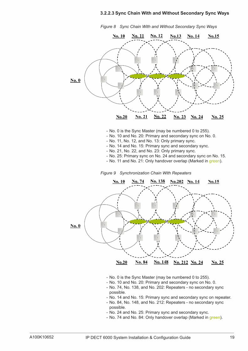
Figure 8 Sync Chain With and Without Secondary Sync Ways
- No. 0 is the Sync Master (may be numbered 0 to 255). - No. 10 and No. 20: Primary and secondary sync on No. 0. - No.11,No.12,andNo.13:Onlyprimarysync. - No. 14 and No. 15: Primary sync and secondary sync. - No.21,No.22,andNo.23:Onlyprimarysync. - No. 25: Primary sync on No. 24 and secondary sync on No. 15. - No. 11 and No. 21: Only handover overlap (Marked in green).
Figure 9 Synchronization Chain With Repeaters
- No. 0 is the Sync Master (may be numbered 0 to 255). - No. 10 and No. 20: Primary and secondary sync on No. 0. - No.74,No.138,andNo.202:Repeaters-nosecondarysyncpossible.
- No. 14 and No. 15: Primary sync and secondary sync on repeater. - No.84,No.148,andNo.212:Repeaters-nosecondarysyncpossible.
- No. 24 and No. 25: Primary sync and secondary sync. - No. 74 and No. 84: Only handover overlap (Marked in green).

20 A100K10652IP DECT 6000 System Installation & Configuration Guide
4 Installing the IP DECT Server 6000This section provides a general description of the IP DECT Server 6000 as well as information about resetting the hardware using the Reset buttononthefaceplate.Beforeyouinstalltheequipment,ensurethatasiteplanhasbeenpreparedthatdefinesthelocationoftheServer6000.
4.1 Description of the Server 6000
4.1.1 Type and Part NumberThe Server 6000 contains RF circuitry that comply with the local band standards ETSI DECT and USA DECT 6.0.
Model type: IP DECT Server 6000 1.8/1.9 GHz with SIP Protocol
Part Number: 221 100 0100
4.1.2 Server 6000 Appearance and ComponentsThe Server 6000 front cover has a LED located in the middle that indicates the operating status of the unit.
Figure 10 Server 6000 - Front view
4.1.3 Server 6000 LED Indicators
4.1.3.1 Front CoverThe Server 6000 front cover has one LED indicator showing the faults and failures of the device. The indicator is off when the Server 6000 is notpowered.TheLEDflasheswhentheServer6000initializes.Theindicator is on when the Server 6000 is operating.
Table 2 LED Indicator Description - Front CoverLED Indicator MeaningSteady green OK and idleSlow green flashing OK and active voice callFast green flashing Active, in operation with maximum active connections (busy)Slow red flashing Missing base station Fast red flashing ErrorSteady red Reset/shutdown in progressSteady red for 5 seconds followed by fast red flashing
Reset to factory settings
LED

21IP DECT 6000 System Installation & Configuration GuideA100K10652
4.1.3.2 FaceplateThe various stages of the LED indicator on the faceplate are described below.
Table 3 LED Indicator Description - FaceplateLED Indicator MeaningLINK/Activity Indicator - green Link layer SW has established connectionLINK/Activity Indicator - green flashing ActivityPower Indicator - green Server 6000 is connected to power
4.1.4 Server 6000 Reset ButtonIt is possible to restart or reset the Server 6000 by pressing the Reset button on the faceplate.
Figure 11 Server 6000 - Faceplate
4.1.4.1 Resetting the Server 6000 HardwareThis section contains a description of the different actions that occur when the Reset button is pressed.
Table 4 Reset Button DescriptionButton Press ActionShort press (2 to 5 sec.) System restarts when button is released.Long press (5 to 9 sec.) until front LED flashes red, then release button.
Resets the system to factory default settings (original IP settings and empty user data base) and restarts the system. Firmware version is not affected.
LINK/Activity Indicator
Reset Button
Power Supply
Power Indicator
Ethernet Port

22 A100K10652IP DECT 6000 System Installation & Configuration Guide
4.2 Mounting/ConnectingtheServer6000
The Server 6000 is suitable for mounting indoors on a wall. The procedure is as follows:
1. MounttheServer6000onthewall,usingtheanchorsandscrewsprovided.
2. Connect the power supply cable into the RJ45 plug on the Server 6000.
, When you place the Server 6000 on the screws, ensure that the screws do not touch the printed circuit board.
Figure 12 Server 6000 Wall Mounting

23IP DECT 6000 System Installation & Configuration GuideA100K10652
5 Installing the Base StationThis section provides information about the base station and how to install it.
Beforeyouinstalltheequipment,ensurethatasiteplanhasalreadydefinedthelocationofthebasestations.
This section includes information about:
“Base Station Description”
“Installing the Base Station”
“Recording the Installation Information”
5.1 Base Station Description
5.1.1 Base Station provides RF Channels to HandsetsThe base station is a compact device that contains RF circuitry and transmit/receive antennas. The main function of the base station is to provide audio and data communication between the handsets and the Server 6000. The base station supports 11 RF channels for DECT or USA DECT bands.
) The base station is also termed the RFP (Radio Fixed Part) by some manufacturers.
The RF communication is provided according to the band standard at the site:
● DECTBasestationprovides11RFchannelsof1.8GHz,DECTstandard,usedinEurope,AustraliaandSouthAmerica.
● USADECTBasestationprovides11RFchannelsof1.9GHz,USADECTstandard,usedinNorthAmerica(pleaseaskyourZeniteldistributor for order information about this equipment).
5.1.2 Base Station Type and Part NumberThe base station contains RF circuitry that comply with the local band standards:UPCS,DECT,orETSIDECT.
Model type: IP DECT Base for Server 6000
Part Number: 221 100 0600

24 A100K10652IP DECT 6000 System Installation & Configuration Guide
5.1.3 Base Station Appearance and ComponentsThe base station front cover has a LED that indicates the operating status of the unit
Figure 13 Base Station - Front view
ThebasestationfaceplateincludesaResetButton,aLINK/ActivityIndicator,andanEthernetPort(PowersupplythroughPoE).
FormoreinformationontheResetbutton,referto“ResettingtheBaseStation Hardware”.
5.1.4 Base Station LED Indicators
5.1.4.1 Front CoverThe base station front cover has one indicator describing the base station faults and failures. The indicator is off when the base station is notpowered.TheLEDflasheswhenthebasestationinitializes.Theindicator is on when the base station is operating.
Table 5 LED Indicator Description - Front CoverLED Indicator MeaningSteady green OK and idleSlow green flashing OK and active voice callFast green flashing Active, in operation with max. active connections (busy)Fast red flashing ErrorSteady red Reset/shutdown in progressSteady red for 5 seconds followed by fast red flashing
Reset to factory settings
LED

25IP DECT 6000 System Installation & Configuration GuideA100K10652
5.1.4.2 Faceplate
Table 6 LED Indicator Description - FaceplateLED Indicator MeaningLINK/Activity Indicator - green Link layer SW has established connectionLINK/Activity Indicator - green flashing ActivityPower Indicator - green Base is connected to Power
5.1.5 Base Station Reset ButtonIt is possible to restart or reset the base station by pressing the Reset button on the faceplate of the base station.
5.1.5.1 Resetting the Base StationThe table below shows the different processes that are put into motion when the Reset button is pressed.
Figure 14 Base Station - Faceplate
Table 7 Reset Button DescriptionPress button ActionShort press (2 to 5 sec.) System restarts when button is
released.Long press (5 to 9 sec.) until front LED flashes red, then release button.
Resets the system to factory default settings (original IP settings and empty user database) and restarts the system. Firmware version is not affected.
5.2 Mounting/ConnectingtheBaseStationThe base station is suitable for mounting indoors on a wall.
) Before beginning the installation, determine the position of the base station for best coverage. The coverage depends on the construction of the building, architecture, and the choice of building materials. Refer to “Environmental Requirements” for more information about the environmental requirements for base stations.
5.2.1 Wall Mounted (Vertical) Installation RF CoverageForbestRFcoverage,thebasestationmustbemountedverticallyonwalls.Theantennasmustalwaysbekeptperpendiculartothefloor.
, Caution: The base station must not be installed at any angle other than vertical. If the base station is placed upside-down, the coverage area of the base station is decreased by 40% - 50% and it might not transmit or receive effectively. If possible, avoid mounting the base station on soft-surfaced walls such as those covered with canvas, metal or sponge-like materials.
LINK/ActivityIndicator
Reset Button
Ethernet Port(PoE)

26 A100K10652IP DECT 6000 System Installation & Configuration Guide
Figure 15 Base Station - Wall Mounting
Tomountandconnectthebasestation,dothefollowing:
1. Mount the base station on the wall using the anchors and screws accompanying the product.
2. Insert the RJ45 plug into the Ethernet connector at the bottom of the base station.
, When you place the base station on the screws, ensure that the screws do not touch the printed circuit board.
Figure 16 Base Station - Ethernet Connector
5.3 Recording the Installation Information
Aftercompletingtheinstallationofthebasestations,recordthelocationof each base station and add a descriptive text in the web interface of the Server 6000 under Administration > Base stations.

27IP DECT 6000 System Installation & Configuration GuideA100K10652
6 Installing the RepeaterThis section provides information about the repeater and how to unpack andinstallit.Thearetwopartstoinstallingtherepeater,i.e.asoftwareinstallation and a hardware installation.
Beforeyouinstalltheequipment,ensurethatasiteplannerhasdefinedthe location of the repeaters.
This section includes information about:
● “Repeater Description”
● “Installing the Repeater”
● “Recording the Installation Information”
● “Checking Indicators”
● “Powering the Repeater”
● “Programming a Repeater with the Programming Kit”
6.1 Repeater Description
6.1.1 Repeater provides RF Channels to HandsetsThe repeater is a building block used to extend the coverage area in a system.Therepeaterdoesnotincreasethenumberoftrafficchannels.However,itprovidesalargerphysicalspreadingofthetrafficchannelsand thereby increases the coverage area established with the base stations.Therepeatersaremainlyusedinareaswithlimitedtraffic.Therepeater is available with 4 voice channels. It is wireless and does not needaphysicalconnectiontothewirelessserver,makingitveryeasytoinstall. The repeaters can be supplied with an external antenna making it possible to create radio coverage in a remote area without cabling to the rest of the installation.
) The repeater is also termed WRFP (Wireless Radio Fixed Part) by some manu-facturers.
6.1.2 Repeater Type and Part NumberThe repeater contains RF circuitry that is compliant with the local band standards:UPCS,DECT,orETSIDECT.Thewall-mountedrepeateris available as a full slot repeater. A full slot repeater covers four simultaneous speech channels. These channels are borrowed from theattachedbasestation,andarenotadditionalchannelstothetotalnumber of channels on the system.
Type Part NumberRepeater Wall 221 105 0100Repeater Ceiling 221 105 0110
6.1.3 Repeater Appearance and ComponentsThe repeater connection panel includes the following:
● Power supply connection (also connection for programming the repeater). - The power supply for the repeater is ordered separately.
● Antenna connector for repeaters supplied with external antenna connection. - The external antenna including antenna cable is ordered separately.
● LED that indicates whether or not the unit is functioning.

28 A100K10652IP DECT 6000 System Installation & Configuration Guide
6.1.4 Repeater LED IndicatorThe repeater has one LED indicator describing the repeater operations. TheLEDisoffwhentherepeaterisnotpowered.WhentheLEDflashesaftertherepeaterhasbeenpowered,synchasstillnotbeenestablished.Assoonassynchasbeenestablished,theLEDison.Eachtimeahandsetconnectstotherepeater,theLEDflashesbriefly.Eachtimeahandsetmakesahandovertoarepeater,theLEDflashesbriefly.
6.2 Installing the RepeaterBeforebeginningtheinstallation,determinethepositionforbestcoverage of the repeater. The coverage depends on the construction of thebuilding,architecture,andthetypeofbuildingmaterials.
6.2.1 Environmental requirements ● Avoid installing repeaters on large concrete or marble columns becausethesecolumnsaffectradiocoverage.Ifpossible,placethe repeater a minimum of 1 meter or 3.3 feet from these types of columns.
● Avoid installing a repeater with the antenna housings near metal objects. Be careful not to damage existing wiring or panels.
● Avoidpositioningrepeatersinducts,plenumsorhollowspacesusedtotransportenvironmentalairexceptwheretheduct,plenumorhollow space is created by a suspended ceiling having lay-in panels.
● Avoidpositioningrepeatersdirectlyonmetallicsurfaces.Ifpossible,place the repeater a minimum of 1 meter or 3.3 feet from these types of surfaces.
● Avoid positioning repeaters behind furniture.
● Only position repeaters where the signal is needed.
● Theinstallationareamustbeclean,freeoftrafficandexcessdust,dry,andwellventilated.
● The installation area must be within the temperature ranges of 10°C/50°F and 40°C/104°F.
● The installation area must have non-condensing relative humidity between 20% and 80% .
) The repeater does not add channels, it only adds additional coverage area.
The repeater can be registered on the system:
● when placed within the coverage area of a base station
● when placed within the coverage area of an already-installed repeater
ForbestRFcoverage,therepeatermustbemountedverticallyonwalls.
, The repeater must not be installed at any angle other than vertical. If the repeater is placed upside-down, the coverage area of the repeater is decreased by 40% - 50% and it may not transmit or receive effectively.

29IP DECT 6000 System Installation & Configuration GuideA100K10652
To install and mount the repeater:
1. Connect the power supply cable into the RJ11 connector at the bottom of the repeater.
2. Mount the repeater onto the wall using the screws accompanying the repeater.
6.3 Recording the Installation InformationAftercompletingtheinstallationoftherepeaters,recordthelocationofeach repeater.
6.4 Checking IndicatorsVerifythattherepeaterLEDindicatorissteadilyon,indicatingthattherepeater is functioning.
6.5 Powering the Repeater
6.5.1 Power OptionsThepowersupplyfortherepeateris9VDC,300mA.
6.6 Programming a Repeater with the Programming Kit
6.6.1 Contents of the Repeater Programming KitThe Repeater Programming Kit (part no. 2211050130) comprises:
● splitter
● serial cable
) For programming the repeater you also need the ServiceTool programming software and the power supply for the repeater. ServiceTool is not part of the Repeater Programming Kit and is available as a download from the STENTOFON AlphaWiki website. The power supply for the repeater is ordered separately (part no. 2211050200).
Figure 17 Repeater Programming Kit

30 A100K10652IP DECT 6000 System Installation & Configuration Guide
6.6.2 Setting up the Hardware for Repeater Programming
1. Unplug the repeater power supply and insert the splitter.
2. Connect the repeater power supply to the splitter and the mains. The LEDshouldstarttoflash.
3. Ensure that you have the appropriate power supply for the local requirements.
4. Connect the serial cable to the splitter and COM port of your computer. The repeater is now ready for programming via ServiceTool.
) The order sequence (steps 1, 2 and 3) of the setup should be followed.
6.6.3 Programming the Repeater with ServiceToolServiceTool is the application software installed on your computer that you use for repeater programming and software downloading to the repeater.
ServiceToolidentifiesthetypeofrepeater,andwiththissoftwareitis possible to program the repeater to connect to the DECT Radio Infrastructure solutions.
Beforeyoustartprogrammingtherepeater,ensurethattherepeaterisconnected to the computer and the mains.
Inasinglecellsolution,thenumbersassignedtotherepeatersmustbebetween 2 and 7. The number of the base station is set to 1 by default.
Inamulti-cellsolution,thenumberingofthebasestationsandrepeatershas to follow the numbering in the table below.
Table 8 Repeater Numbering in a Multi-Cell Solution
Base Station Repeater 1 Repeater 2 Repeater 30 64 128 1921 65 129 1932 66 130 1943 67 131 1954 68 132 1965 69 133 1976 70 134 1987 71 135 1998 72 136 2009 73 137 201
10 74 138 20211 75 139 20312 76 140 20413 77 141 20514 78 142 20615 79 143 20716 80 144 208

31IP DECT 6000 System Installation & Configuration GuideA100K10652
17 81 145 20918 82 146 21019 83 147 21120 84 148 21221 85 149 21322 86 150 21423 87 151 21524 88 152 21625 89 153 21726 90 154 21827 91 155 21928 92 156 22029 93 157 22130 94 158 22231 95 159 22332 96 160 22433 97 161 22534 98 162 22635 99 163 22736 100 164 22837 101 165 22938 102 166 23039 103 167 23140 104 168 23241 105 169 23342 106 170 23443 107 171 23544 108 172 23645 109 173 23746 110 174 23847 111 175 23948 112 176 24049 113 177 24150 114 178 24251 115 179 24352 116 180 24453 117 181 24554 118 182 24655 119 183 24756 120 184 24857 121 185 24958 122 186 25059 123 187 25160 124 188 25261 125 189 25362 126 190 25463 127 191 25564 128 192 065 129 193 166 130 194 2

32 A100K10652IP DECT 6000 System Installation & Configuration Guide
67 131 195 368 132 196 469 133 197 570 134 198 671 135 199 772 136 200 873 137 201 974 138 202 1075 139 203 1176 140 204 1277 141 205 1378 142 206 1479 143 207 1580 144 208 1681 145 209 1782 146 210 1883 147 211 1984 148 212 2085 149 213 2186 150 214 2287 151 215 2388 152 216 2489 153 217 2590 154 218 2691 155 219 2792 156 220 2893 157 221 2994 158 222 3095 159 223 3196 160 224 3297 161 225 3398 162 226 3499 163 227 35
100 164 228 36101 165 229 37102 166 230 38103 167 231 39104 168 232 40105 169 233 41106 170 234 42107 171 235 43108 172 236 44109 173 237 45110 174 238 46111 175 239 47112 176 240 48113 177 241 49114 178 242 50115 179 243 51116 180 244 52

33IP DECT 6000 System Installation & Configuration GuideA100K10652
117 181 245 53118 182 246 54119 183 247 55120 184 248 56121 185 249 57122 186 250 58123 187 251 59124 188 252 60125 189 253 61126 190 254 62127 191 255 63128 192 0 64129 193 1 65130 194 2 66131 195 3 67132 196 4 68133 197 5 69134 198 6 70135 199 7 71136 200 8 72137 201 9 73138 202 10 74139 203 11 75140 204 12 76141 205 13 77142 206 14 78143 207 15 79144 208 16 80145 209 17 81146 210 18 82147 211 19 83148 212 20 84149 213 21 85150 214 22 86151 215 23 87152 216 24 88153 217 25 89154 218 26 90155 219 27 91156 220 28 92157 221 29 93158 222 30 94159 223 31 95160 224 32 96161 225 33 97162 226 34 98163 227 35 99164 228 36 100165 229 37 101166 230 38 102

34 A100K10652IP DECT 6000 System Installation & Configuration Guide
167 231 39 103168 232 40 104169 233 41 105170 234 42 106171 235 43 107172 236 44 108173 237 45 109174 238 46 110175 239 47 111176 240 48 112177 241 49 113178 242 50 114179 243 51 115180 244 52 116181 245 53 117182 246 54 118183 247 55 119184 248 56 120185 249 57 121186 250 58 122187 251 59 123188 252 60 124189 253 61 125190 254 62 126191 255 63 127192 0 64 128193 1 65 129194 2 66 130195 3 67 131196 4 68 132197 5 69 133198 6 70 134199 7 71 135200 8 72 136201 9 73 137202 10 74 138203 11 75 139204 12 76 140205 13 77 141206 14 78 142207 15 79 143208 16 80 144209 17 81 145210 18 82 146211 19 83 147212 20 84 148213 21 85 149214 22 86 150215 23 87 151216 24 88 152

35IP DECT 6000 System Installation & Configuration GuideA100K10652
217 25 89 153218 26 90 154219 27 91 155220 28 92 156221 29 93 157222 30 94 158223 31 95 159224 32 96 160225 33 97 161226 34 98 162227 35 99 163228 36 100 164229 37 101 165230 38 102 166231 39 103 167232 40 104 168233 41 105 169234 42 106 170235 43 107 171236 44 108 172237 45 109 173238 46 110 174239 47 111 175240 48 112 176241 49 113 177242 50 114 178243 51 115 179244 52 116 180245 53 117 181246 54 118 182247 55 119 183248 56 120 184249 57 121 185250 58 122 186251 59 123 187252 60 124 188253 61 125 189254 62 126 190255 63 127 191
, Repeaters and base stations cannot have the same number. Neither can the repeater have a number identical to another base station or another re-peater in a situation where common overlap is present between the actual units (Numbers in red indicate where numbering could be identical between different units). If this occurs, handover between the different units is not possible.
36 A100K10652IP DECT 6000 System Installation & Configuration Guide
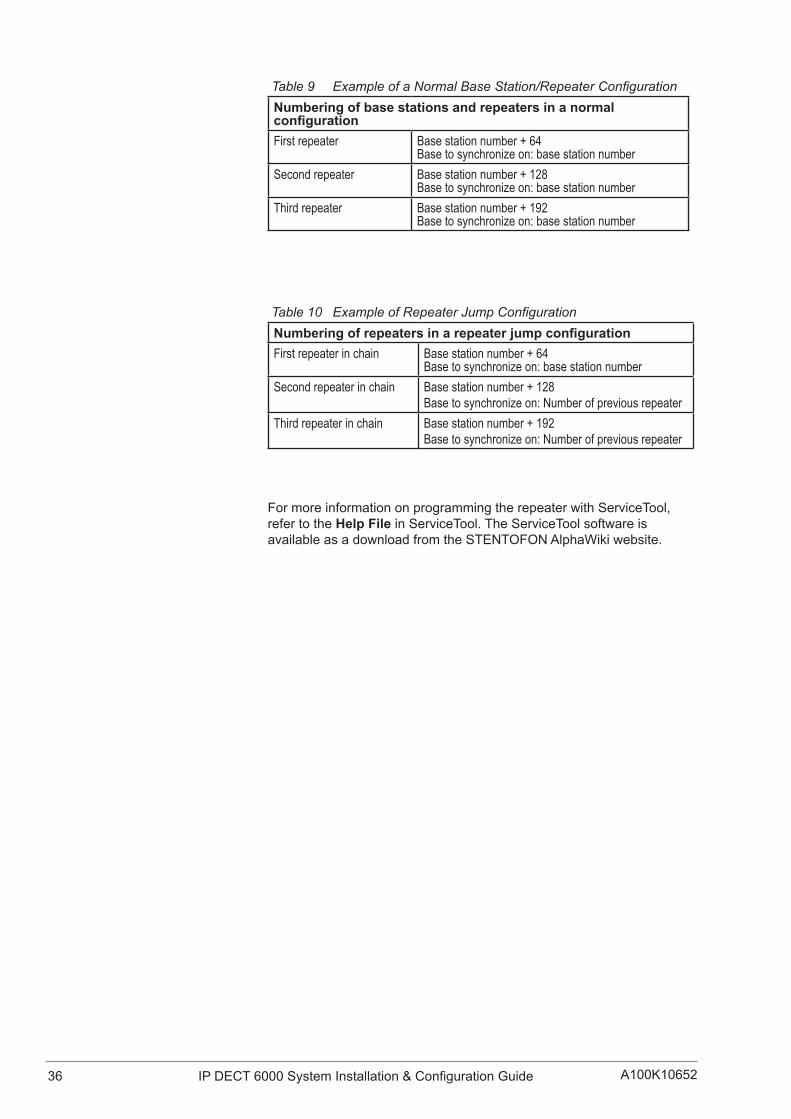
Table 9 Example of a Normal Base Station/Repeater ConfigurationNumbering of base stations and repeaters in a normal configurationFirst repeater Base station number + 64
Base to synchronize on: base station numberSecond repeater Base station number + 128
Base to synchronize on: base station numberThird repeater Base station number + 192
Base to synchronize on: base station number
Table 10 Example of Repeater Jump ConfigurationNumberingofrepeatersinarepeaterjumpconfigurationFirst repeater in chain Base station number + 64
Base to synchronize on: base station numberSecond repeater in chain Base station number + 128
Base to synchronize on: Number of previous repeaterThird repeater in chain Base station number + 192
Base to synchronize on: Number of previous repeater
FormoreinformationonprogrammingtherepeaterwithServiceTool,refer to the Help File in ServiceTool. The ServiceTool software is available as a download from the STENTOFON AlphaWiki website.
37IP DECT 6000 System Installation & Configuration GuideA100K10652
7 Preparing the Handset for UseThissectionprovidesinformationonhowtopreparethehandsetforuse,installandchargethebattery,andretrievetheserialnumbersonthedifferent handsets.
This section includes information about:
● “Handset Description”
● “Installing Battery”
● “Charging Handsets”
● “Retrieving the Serial Number of the Handset”
Formoreinformationonthedifferenthandsets,refertotheHandsetUserGuides.
The charger and the power supply for the charger are ordered separately (refer to the sections below on “Charger Types and Part Numbers” and “Power Supply Types and Part Numbers” for information on part numbers).
7.1 Handset DescriptionThehandsetisalightweight,ergonomicallydesignedwirelessunitthatincludes an LCD display and keyboard.
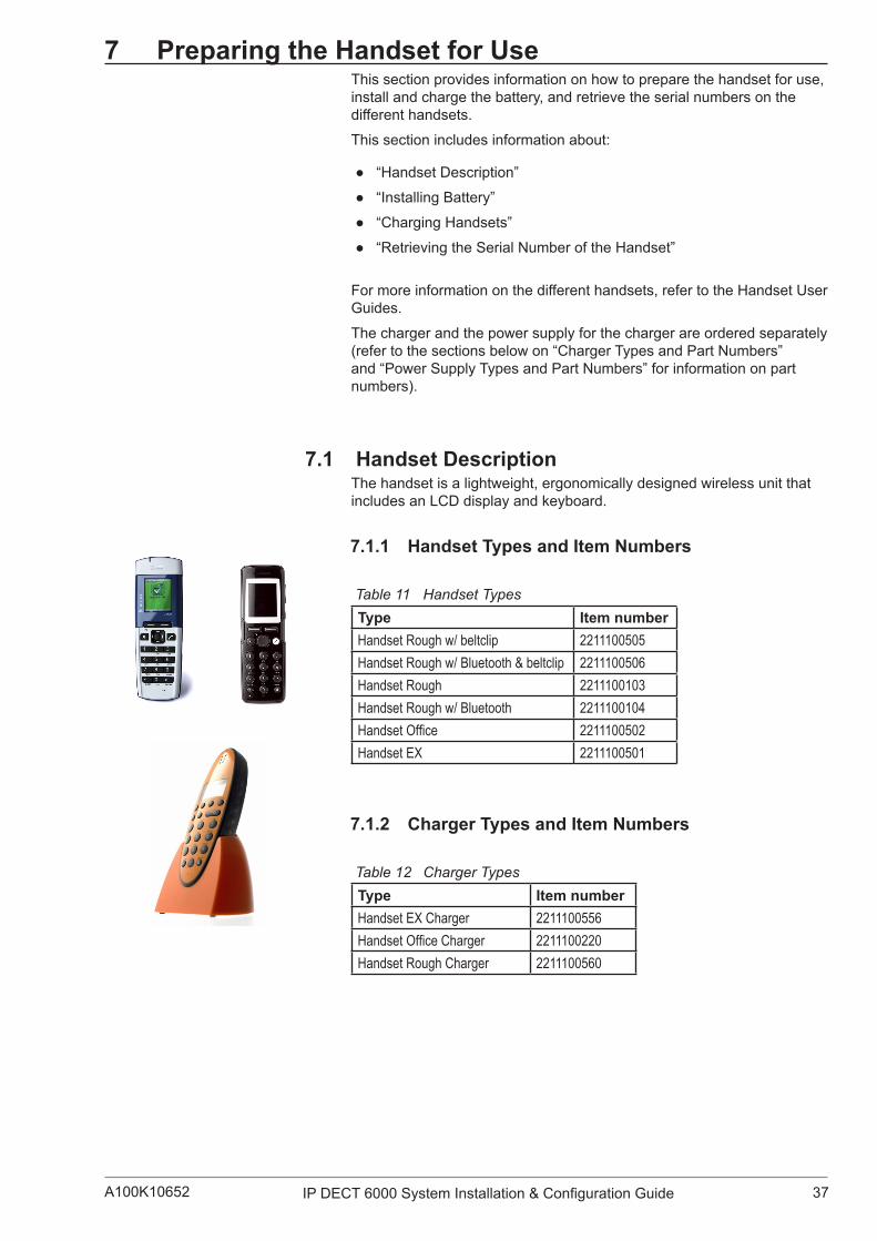
7.1.1 Handset Types and Item Numbers
Table 11 Handset TypesType Item numberHandset Rough w/ beltclip 2211100505Handset Rough w/ Bluetooth & beltclip 2211100506Handset Rough 2211100103Handset Rough w/ Bluetooth 2211100104Handset Office 2211100502Handset EX 2211100501
7.1.2 Charger Types and Item Numbers
Table 12 Charger TypesType Item numberHandset EX Charger 2211100556Handset Office Charger 2211100220Handset Rough Charger 2211100560

38 A100K10652IP DECT 6000 System Installation & Configuration Guide
7.2 Installing the Battery , Take the following precautions before you handle the batteries:
● Do not replace the batteries in potentially explosive environments suchasroomswhereflammableliquidsorgasesarepresent.
● Donotdisposeofthebatteryinafireasitwillexplode.
● Only use the proper batteries and the approved charger to charge the batteries.
● Only use battery with part no. 84743411 in the EX Handset. Do not use these batteries with other products. These batteries were designedspecificallyforusewiththeEXHandsetandthechargerONLY. Improper use of the batteries may cause them to become a firehazard.
● Only use battery with part no. 84743418 (ICP73048) in the Rough/OfficeHandset.Donotusethisbatterywithotherproducts.ThisbatterywasdesignedspecificallyforusewiththeRough/OfficeHandset and the charger ONLY. Improper use of the battery may causethemtobecomeafirehazard.
● Do not do anything that would cause the battery to short circuit.
● Do not let the battery or the charger come into contact with conductive metal objects.
7.2.1 Installing the Battery on EX HandsetTo change the battery:
5. Unscrew the plate on the rear of the handset to access the battery compartment. Use a normal screw driver.
6. Insert the screwdriver into the small crack behind the back cover and lift to remove it.
7. Place the battery plug in the slot in the battery box.
8. Insert battery with its label showing.
9. Replace the back cover.
Figure 18 Removing Back Cover from EX Handset
7.2.2 InstallingBatteryonOfficeHandsetTo install the battery:

39IP DECT 6000 System Installation & Configuration GuideA100K10652
1. Press down the back cover and slide it towards the bottom of the handset.
2. Lift off the back cover.
3. Insert the battery with its label showing.
4. Replace the back cover by pressing it back into the locked position (whenyouhearaclick,thebackcoverisinposition).
Figure 19 Removing Back Cover from Office Handset
7.2.3 Installing Battery on Rough HandsetTo install the battery:
1. Remove the battery cover by unfastening the four screws at the back-bottom part of the handset.
2. Carefully remove the battery cover.
3. Insert the battery with its label showing.
4. Replace the battery cover by refastening the four screws.
7.3 Charging Handsets
7.3.1 Using the ChargerEachhandsetischargedusingahandsetcharger,whichisacompactdesktop unit designed to charge and automatically maintain the correct battery charge levels and voltage.
The charger for the EX Handset is powered by an AC (115VAC or 230VAC) adapter that supplies the 9VDC at 230mA charger requirement.
ThechargerfortheRough/OfficeHandsetispoweredbyanAC(110VAC to 240VAC) adapter that supplies the 8VDC at 350mA charger requirement.
Figure 20 Single Charger for EX Handset

40 A100K10652IP DECT 6000 System Installation & Configuration Guide
7.3.2 Charging the Battery
7.3.2.1 EX HandsetWhenchargingthebatteryforthefirsttime,itisnecessarytoleavethe handset in the charger for 14 - 16 hours for the battery to be fully charged and the handset ready for use.
) Normally, it takes approximately 3½ hours to charge the handset to its full capacity starting from being completely discharged.
To charge the battery:
● Place the handset in the charger.
Forcorrectcharging,ensurethattheroomtemperatureisbetween0°C/32°F and 25°C/77°F. Do not place the handset in direct sunlight. The battery has a built-in heat sensor which will stop charging if the battery temperature is too high.
Ifthehandsetisturnedoffwhenplacedinthecharger,onlytheLEDindicatescharging.Whenthehandsetisturnedoff,theLEDflashesata low frequency while charging and lights steadily when the charging is finished.Therewillbenoreactionforincomingcalls.
Ifthehandsetisturnedonwhencharging,thedisplayshowsthecharging status. It will not vibrate and B-answer is inactive. The handset reacts normally for incoming calls. The display goes back to normal mode when fully charged.
It is necessary to recharge the battery when the display shows “BATTERY LOW” or if the handset cannot be turned on. When the batteryisfullydischarged,upto10minutesmaypassbeforechargingbegins(displaylightsup).Whenthechargerbeginsthecharging,thestatus is shown on the display if the handset is turned on.
The handset displays a progress indicator bar that shows how fully charged the battery is.
The handset LED has the following indication:
● LED steadily on = handset is fully charged
● LEDflashing=handsetischarging
7.3.2.2 Rough/OfficeHandsetWhenchargingthebatteryforthefirsttime,itisnecessarytoleavethe handset in the charger for 14 - 16 hours for the battery to be fully charged and the handset ready for use.
) During normal operation, it takes approximately 4 hours to charge the handset from being fully discharged to its full capacity.
To charge the battery:
● Place the handset in the charger.
Forcorrectcharging,ensurethattheroomtemperatureisbetween0°C/32°F and 40°C/104°F. Do not place the handset in direct sunlight. The battery has a built-in heat sensor which will stop charging if the battery temperature is too high.

41IP DECT 6000 System Installation & Configuration GuideA100K10652
Ifthehandsetisturnedoffwhenplacedinthecharger,thereisnothingtoindicate that it is charging. There will be no reaction for incoming calls.
Ifthehandsetisturnedonwhencharging,thedisplayshowsabluecharging icon. The charging icon turns green when fully charged (when thehandsetisremovedfromthecharger,thechargingicondisappears).It will not vibrate. B-answer is inactive. The handset reacts normally for incoming calls.
It is necessary to recharge the battery when the handset display shows the‘batterylow’icon,orifthehandsetcannotbeturnedon.
Aftercharging,agreeniconwillbedisplayedtoindicatethatthebatteryis fully charged.
7.4 Retrieving the Serial Number of the HandsetToenableservicetothehandset,theserialnumbermustbeprogrammed into the system database via the web-based user interface oftheIPDECTServer6000.(Formoreinformation,referto“RegisteringHandsets”).
The serial number (IPEI number) of each handset is found either on a label,whichisplacedbehindthebattery,oronthepackaginglabel.
7.4.1 Retrieving Serial Number on EX HandsetTo show the serial number on the handset display for an EX Handset:
1. Enter *99984*2. Press a
- the serial number will appear on the handset display.
3. Press < for 5 seconds to exit the menu.
To retrieve the serial number on an EX Handset:
1. Use a screwdriver to unscrew the plate on the rear of the handset to access the battery compartment.
2. The plate on the rear of the Handset must not be removed in a potentially explosive environment.
3. Insert the screwdriver into the small crack behind the back cover and lift to open the handset.
4. Lift the battery and read the serial number on the back label.
5. Replace the battery and back cover.
Figure 21 Removing Back Cover from EX Handset

42 A100K10652IP DECT 6000 System Installation & Configuration Guide
7.4.2 RetrievingSerialNumberonOfficeHandsetTo display the serial or IPEI number on the handset:
1. Press Menu
2. Scroll to Status and press Select3. Scroll to Firmware version and press Select
- The IPEI number will be displayed.
4. Press Back and Exit to exit the menu
ToretrievetheserialnumberontheRough/OfficeHandset.
1. Press down the back cover and slide it towards the bottom of the handset.
2. Lift off the back cover.
3. Lift the battery and read the serial number.
4. Replace the battery and back cover.
Figure 22 Removing Back Cover from Rough/Office Handset

43IP DECT 6000 System Installation & Configuration GuideA100K10652
8 ConfiguringtheIPDECTServer6000This section provides you with information on how to power up the IP DECT Server 6000 and connect the unit to a computer. It also contains informationonhowtoconfigureaServer6000throughtheweb-baseduser interface using either DHCP or a static IP address.
) The IP DECT Server 6000 is pre-configured to use a static IP address.
This section includes information about:
● “Powering up the Server 6000”
● “Connecting a Computer to the Server 6000”
● “Accessing the Server 6000”
● “ConfiguringtheServer6000UsingStaticIPAddress”
● “Checking the LED Indicator”
8.1 Powering up the Server 6000After installing the Server 6000 you need to power up the unit using a local power supply.
PoweroptionsfortheServer6000is48VDC,1Wmaximumwhenusinglocal power supply.
8.1.1 Local Power SupplyPowering the Server 6000 with a local power supply can be done using the power input on the unit.
) The power supply for the IP DECT Server 6000 is ordered separately (Part no. 221 110 0225).
8.2 Connecting a Computer to the Server 6000The Server 6000 communicates with the computer through a cross-over patch cable.
) The Ethernet port of the Server 6000 is an RJ45 connector.
To connect the Server 6000 to a computer:
1. Connect the cross-over patch cable to the computer.
2. Connect the cross-over patch cable to the Ethernet (ETH) port of the Server 6000.
Figure 23 Faceplate showing Ethernet port

44 A100K10652IP DECT 6000 System Installation & Configuration Guide
8.3 Accessing the Server 6000The Server 6000 has default IP address: 192.168.0.1
InorderforyourcomputertocommunicatewiththeServer6000,itisnecessary to change the computer’s Internet Protocol Properties to the following:
● IP address: 192.168.0.2
● Subnet mask: 255.255.255.0
8.3.1 Changing the Internet Protocol Properties using Windows
) The example below describes the procedures for changing IP properties using Windows XP. Follow the procedures that are relevant to the Windows version that is installed on your computer.
To change the IP properties in Windows XP:
1. Click Start 2. Point to Connect To and then click Show all connections.
- A Network Connections window appears.

45IP DECT 6000 System Installation & Configuration GuideA100K10652
3. Under LAN or High-Speed Internet,right-clickLocal Area Connection and click Properties. - A Local Area Connection Properties dialog box appears.
4. Under the Generaltab,clickInternetProtocol(TCP/IP),andthenclick Properties.
An InternetProtocol(TCP/IP)Properties dialog box appears.
5. Click Use the following IP address and in the IP addressfield,enter 192.168.0.2.
6. In the Subnet maskfield,enter255.255.255.0
7. Click OK.

46 A100K10652IP DECT 6000 System Installation & Configuration Guide
You can now communicate with the IP DECT Server 6000 from your computer using a standard web browser.
8.3.2 Accessing the Server 6000ToaccesstheServer6000,logintothewebinterfaceusingastandardweb browser.
1. Open a web browser.
2. In the browser’s Addressbar,enterIPaddress192.168.0.1,andpress the ENTER key.
The Login page appears.
WhenyouaccesstheServer6000webinterfaceforthefirsttime,youneed to log in with a user name and password.
) The default user name is admin and the default password is ip6000. It is strongly recommended to change the password, refer to “Changing System User Name and Password”.
To log in:
1. In the User namefield,enteradmin.
2. In the Passwordfield,enterip6000.
3. Click OK.
The General Status page of the Server 6000 web interface is displayed.
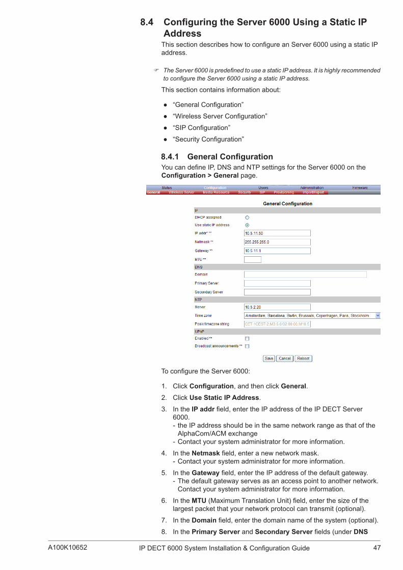
47IP DECT 6000 System Installation & Configuration GuideA100K10652
8.4 ConfiguringtheServer6000UsingaStaticIPAddressThissectiondescribeshowtoconfigureanServer6000usingastaticIPaddress.
) The Server 6000 is predefined to use a static IP address. It is highly recommended to configure the Server 6000 using a static IP address.
This section contains information about:
● “GeneralConfiguration”
● “WirelessServerConfiguration”
● “SIPConfiguration”
● “SecurityConfiguration”
8.4.1 GeneralConfigurationYoucandefineIP,DNSandNTPsettingsfortheServer6000ontheConfiguration>General page.
ToconfiguretheServer6000:
1. Click Configuration,andthenclickGeneral.2. Click Use Static IP Address.
3. In the IP addrfield,entertheIPaddressoftheIPDECTServer6000. - the IP address should be in the same network range as that of the AlphaCom/ACM exchange
- Contact your system administrator for more information.
4. In the Netmaskfield,enteranewnetworkmask. - Contact your system administrator for more information.
5. In the Gatewayfield,entertheIPaddressofthedefaultgateway. - The default gateway serves as an access point to another network. Contact your system administrator for more information.
6. In the MTU(MaximumTranslationUnit)field,enterthesizeofthelargest packet that your network protocol can transmit (optional).
7. In the Domainfield,enterthedomainnameofthesystem(optional).8. In the Primary Server and Secondary Serverfields(underDNS

48 A100K10652IP DECT 6000 System Installation & Configuration Guide
-DomainNameSystem),entertheIPaddressoftheDNSserver(optional).
9. In the Serverfield(underNTP-NetworkTimeProtocol),entertheIP address of the NTP server from which the system will obtain the current time (optional).
10. From the Time Zonedropdownlist,selectthedesiredtimezone(optional).
11. For UPnP (Universal Plug and Play) leave both Enabled and Broadcast announcements with their default values (optional).
12. Click Savetosaveyourgeneralconfigurationdata.
8.4.2 WirelessServerConfigurationOn the Configuration>WirelessServerpage,youcanconfigurethe Server 6000 to allow subscription. If the system does not allow subscription,itisnotpossibletosubscribeahandset.
ToconfiguretheServer6000:
1. Click Configuration,andthenclickWireless Server.2. Check the Subscription Allowed checkbox.
- Ifthisisnotchecked,youcannotsubscribeahandset.
3. Uncheck the Autocreate users checkbox
4. Enter an access code in the System access codefield(optional)5. Check the Send date and time checkbox (optional)
6. ForallthefieldsunderApplication interface leave them with their default values.
7. Click Save.
8.4.3 SIPConfigurationOn the Configuration>SIPpage,youcandefinegeneralSIPsettings,informationaboutauthentication,DTMFsignalling,messagewaitingindication and media.
1. Click Configuration,andthenclickSIP.

49IP DECT 6000 System Installation & Configuration GuideA100K10652

50 A100K10652IP DECT 6000 System Installation & Configuration Guide
2. In the Local portfield,enterthelocalportnumber.Thedefaultlocalport number is 5060. - The local port is the port on which the Server 6000 listens for incoming SIP signalling.
3. For the Transportdropdownlist,selectUDP only.
4. In the Default domainfield,entertheIPaddressoftheAlphaCom/ACM exchange.
5. Uncheck the Register each endpoint on separate port checkbox.
6. Uncheck the Send all messages to current registrar checkbox.
7. For the Registrationexpire(sec)fieldforthenumberofsecondsbeforeaSIPregistrationisrenewed,acceptthedefaultvalue.
8. For the Maxforwardsfield,acceptthedefaultvalue.9. For the SIPtypeofservice(TOS/Diffserv)field,acceptthedefault
value.
10. It is possible to enter up to four proxies. In the Proxy1field,enterthe IP address of the AlphaCom/ACM exchange. - Theprefixsip: will be automatically added to the IP address after theconfigurationdatahasbeensaved,e.g.sip:10.5.11.99
- The proxy is the SIP URI of the SIP proxy. The Server 6000 will routealloutgoingSIPsignallingtotheproxy,e.g.SIPregistrationsand outgoing calls.
11. In the Default userfield,acceptthedefaultvalue.12. For the Default passwordfield,leaveitblank.
- Ifnohandsetspecificauthenticationusername/passwordisconfigured,handsetsregisteredontheServer6000willusethedefault user name/password for authentication.
13. Uncheck the Send as RTP (rfc2833) checkbox. - Real-time Transport Protocol - WhenusingtheAlphaCom/ACMexchangeserver,keypadsignalling should NOT be sent as RTP packets with DTMF code.
14. For the Offered rfc2833 payload typefield,leaveitasdefault96.
15. Check the Send as SIP INFO checkbox. - Keypad signalling should be sent as SIP INFO to the AlphaCom/ACM exchange server.
16. In the Tone duration(msec)fieldforthetimelengthofthetoneinmilliseconds,acceptthedefaultvalue.
17. Uncheck the Enable indication checkbox. - We do NOT want to handle MWI messages.
18. Uncheck the Enable subscription checkbox. - We do NOT want to subscribe to MWI messages from the SIP proxy.
19. For the Subscriptionexpire(sec)field,acceptthedefaultvalue.20. From the Packet duration (msec)dropdownlist,select20.
21. For the Mediatypeofservice(TOS/Diffserv)field,acceptthedefault value.
22. For the Port range startfield,enterthevalue6104023. In the Codec prioritydropdownlists,selectPCMU/8000asfirst
priority.Fortheotherprioritycodecs,selectNone.
24. Check the Require symmetric RTP checkbox.
25. Check the Play on-hold tone checkbox. 26. Check the Display status messages checkbox.
27. Uncheck the ‘#’ key ends overlap dialing checkbox.
28. Click SavetosaveyourSIPconfigurationdata.

51IP DECT 6000 System Installation & Configuration GuideA100K10652
8.4.4 Rebooting the Server 6000
AfterSIPconfigurationhasbeencarriedout,youshouldreboottheServer 6000 in the Administration > Wireless Server page.
To reboot:
1. Click Administration,andthenclickWireless Server.2. Click Reboot next to Wireless Server Uptime.
) After rebooting, change the IP address of your computer to one that is in the same LAN range as that of the Server 6000 or set the TCP/IP properties to obtain an IP address automatically.
8.4.5 SecurityConfigurationIt is possible to change the password for the Server 6000 from the Configuration>Security page.
1. Click Configuration,andthenclickSecurity.
2. In the Current passwordfield,enterthecurrentpassword.3. In the New usernamefield,enteranewusername.4. In the New passwordfield,enteranewpassword.5. In the New password againfield,re-enterthenewpassword.6. Uncheck the Force secure HTTP (TLS) checkbox.
7. Uncheck the Allow remote logging checkbox.
8. Click Save.
8.5 Checking the LED IndicatorVerifythattheServer6000LEDislightingasteadygreen,indicatingthatit is now operational.

52 A100K10652IP DECT 6000 System Installation & Configuration Guide
9 ConfiguringtheBaseStationThis section provides you with information on how to connect the base stationtoanIPDECTServer6000andhowtoconfigurethebasestationthrough the web-based user interface using either DHCP or a static IP address.
This section includes information about:
● “Powering up the Base Station”
● “Connecting a Computer to the Base Station”
● “Accessing the Base Station”
● ”ConfiguringtheBaseStationUsingDHCP”
● “Checking the LED Indicator”
9.1 Powering up the Base StationAfter installing the base station you need to power it up. The base station uses:
● Power over Ethernet (PoE 802.3af).
● Maximum power supply consumption is 3.0W (IEEE 802.3af class 1 device).
Use a standard PoE adapter or a PoE-enabled port on a switch adhering to PoE 802.3af when connecting the base station to a PoE power source.
9.2 Connecting a Computer to the Base StationThe base station itself has the IP address 192.168.0.1 from factory default settings. The computer communicates with the base station either through a cross-over patch cable or through a network with an identical net mask.
) The LAN port of the base station is an RJ45 connector.
To connect the computer to the base station:
1. Connect the LAN cable or cross-over patch cable to the PoE switch.
2. Connect the LAN cable or cross-over patch cable to the Ethernet connector on the base station.
3. Connect the PoE switch to the computer.
) If the base station has been used, reset it to factory default settings such that its IP address reverts to 192.168.0.1
9.3 Accessing the Base StationBeforeaccessingtheuserinterfaceofthebasestation,communicationbetween the computer and the base station has to be set up by changing the IP properties of the computer to IP address: 192.168.0.2 and Subnet mask: 255.255.255.0 in Windows.
TheprocedurefordoingthisisidenticaltothatfortheServer6000,andis described in section 8.3.

53IP DECT 6000 System Installation & Configuration GuideA100K10652
After setting up communication between the base station and the computer,accessthebasestationbyloggingintoitswebinterfaceusinga standard web browser.
1. Open a web browser.
2. In the browser’s Addressbar,enterIPaddress192.168.0.1,andpress the ENTER key.
The Login page is displayed.
Whenyouaccesstheuserinterfaceforthefirsttime,youneedtologinwith a user name and password.
) The default user name of the system is admin and the default password of the system is ip6000. It is strongly recommended to change the password - see “Changing System User Name and Password”.
To log in:
1. In the User Namefield,enteradmin.
2. In the Passwordfield,enterip6000.
3. Click OK.
The Base Station General Status page is displayed.

54 A100K10652IP DECT 6000 System Installation & Configuration Guide
9.4 ConfiguringtheBaseStationUsingDHCPThissectiondescribeshowtoconfigureabasestationusingDHCP.
) It is strongly recommended to configure the base station using DHCP.
9.4.1 GeneralConfigurationOn the GeneralConfigurationpage,youcandefineDNSsettingsforthe base station.
1. Click Configuration,andthenclickGeneral.2. Click the DHCP assigned radio button.
3. For the MTU(MaximumTranslationUnit)field,forenteringthesizeofthelargestpacketthatyournetworkprotocolcantransmit,leaveitblank.
4. Leavethefollowingfieldsblank: - Domain - Primary Server - Secondary Server
5. For UPnP (Universal Plug and Play) leave both Enabled and Broadcast announcements with their default values (optional).
6. Click Save.

55IP DECT 6000 System Installation & Configuration GuideA100K10652
9.4.2 BaseStationConfiguration
Toconfigurethebasestation:
1. Click Configuration,andthenclickBase Station.
2. In the Hostfield,entertheIP address of the Server 6000.
3. Click Save.
4. Click Reboottoenabletheconfigurationchanges.
9.4.3 SecurityConfigurationThe procedures for administrating username and password for the base stationisidenticaltothatfortheServer6000,andaredescribedinsection 8.4.5.
● Click Configuration,andthenclickSecurity.
Youwillnowbeabletochangeyourpassword,etc.
9.4.4 SynchronizationWaysConfigurationThesynchronizationwaysofthebasestationhavetobedefinedintheAdministration > Base station page of the Server 6000.
You will now have to connect the base station to a PoE switch that is on the same network as the Server 6000 and the AlphaCom/ACM exchange.
1. Log into the web interface for the Server 6000.
2. Click Administration,andthenclickBase station.
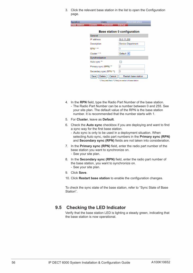
56 A100K10652IP DECT 6000 System Installation & Configuration Guide
3. ClicktherelevantbasestationinthelisttoopentheConfigurationpage.
4. In the RPNfield,typetheRadioPartNumberofthebasestation. - The Radio Part Number can be a number between 0 and 255. See your site plan. The default value of the RPN is the base station number. It is recommended that the number starts with 1.
5. For Cluster,leaveasDefault.6. Check the Auto synccheckboxifyouaredeployingandwanttofind
asyncwayforthefirstbasestation. - Auto sync is only to be used in a deployment situation. When selectingAutosync,radiopartnumbersinthePrimary sync (RPN) and Secondary sync (RPN)fieldsarenottakenintoconsideration.
7. In the Primary sync (RPN)field,entertheradiopartnumberofthebase station you want to synchronize on. - See your site plan.
8. In the Secondary sync (RPN)field,entertheradiopartnumberofthebasestation,youwanttosynchronizeon. - See your site plan.
9. Click Save.
10. Click Restart base stationtoenabletheconfigurationchanges.
Tocheckthesyncstateofthebasestation,referto“SyncStateofBaseStation”.
9.5 Checking the LED IndicatorVerifythatthebasestationLEDislightingasteadygreen,indicatingthatthe base station is now operational.

57IP DECT 6000 System Installation & Configuration GuideA100K10652
10 Handset Registration and SubscriptionThis section provides information about handset registration and subscription. You must register and subscribe a handset before you can use it.
) This section only describes how to register handsets on the Server 6000. You also need to register the users on the call handler/AlphaCom/ACM. For regis-tering users on the call handler/AlphaCom/ACM, refer to the relevant user and system guides.
Whenregisteringhandset,informationonhandsetssettingssuchastheserialnumber(IPEI),name,etc.isenteredintothesystemdatabase.When subscribing handsets you subscribe a registered handset to the system for usage. If the handset is not registered in the system database,subscriptionofthehandsetisnotpossible.
This section includes information about:
● “Registering Handsets”
● “Subscribing Handsets”
10.1 Registering HandsetsThe Users page of the web-based interface of the Server 6000 is used to register handsets.
Each handset in the wireless solution must be programmed with the serial number (IPEI) before it can operate. This serial number must be registered in the Users page of the web-based user interface of theServer6000.Theserialnumberisauniquefingerprintofeachhandset. The serial number is programmed into the handset during the manufacturingprocessandcannotbechangedbyfieldpersonnel.
) The Server 6000 will not provide any service to a handset if its serial number is not registered in the web-based user interface.
To register a handset:
1. Click Users,andthenclickList Users.
2. Under User List,clickNew.

58 A100K10652IP DECT 6000 System Installation & Configuration Guide
Thedataconfiguredforeachhandsetcanbesplitintotwocategories:DECT data which is necessary for the correct handling of the DECT protocolstack,andSIPdatawhichisnecessaryforthehandlingofaSIPuser agent.
, For Rough/Office handsets, it is NOT necessary to enter the IPEI number as the auto-subscription feature will locate the IPEI numbers automatically.
3. In the IPEIfield,entertheIPEInumber(serialnumber)oftheEX handset. - Theserialnumberconsistofafive-digithandsettype(manufacturercode) and a seven-digit handset number.
- For more general information about the IPEI number (serial number)andhowtoretrieveit,referto“RetrievingtheSerialNumber of the Handset”.
- ToviewtheIPEInumberforEXhandset,enter*99984* and then press a - the number starts with 00077...
4. In the Access codefield,entertheauthenticationcode(AC)(optional) - The authentication code is a subscription password of a maximum ofeightdigits,definedbythetechniciansandcanbeusedwhenconnecting the handset to an Server 6000. The authentication code is a subscription PIN code for the individual handset.
5. In the Standbytextfield,enteratexttobedisplayedwhenthehandset is on hook (optional).
6. In the Username/Extensionfield,enteradirectorynumber. - ThevalueofthisfieldshouldbethesameastheAlphaCom/ACMdirectory number.
7. Leave the Domainfieldblank.8. In the Displaynamefield,enterthenametobedisplayed(callerID),
e.g. John Doe in John Doe<sip:[email protected]> (optional).
9. In the Authentication userfield,enteradirectorynumber(optional). - This should be the same as the directory number registered in the AlphaCom/ACM exchange.
- The user name will override the Default userfieldunderSIP Configuration(referto“SIPConfiguration”).
10. Leave the Authentication passwordfieldblank. - ThisisnotnecessaryforanAlphaCom/ACMconfiguration. - The password will override the Default PasswordfieldunderSIPConfiguration(referto“SIPConfiguration”).
11. Uncheck the Disabled checkbox.
12. Click Save to save the registration data.
13. Click OK on the next page.

59IP DECT 6000 System Installation & Configuration GuideA100K10652
The newly registered user/handset is now listed:
Repeat the whole procedure to register each new handset.
10.2 Subscribing HandsetsThesubscriptionprocedureforEX,RoughandOfficeHandsetsiscarried out on the handset itself.
) Subscription of handsets requires the use of each registered handset.
) For subscriptions to work, the system must allow subscriptions to be made (refer to “Server 6000 Configuration”). Some systems also require an Authentication Code (AC). If more than one system currently permits subscription, you will need to know the ID of the system (ARI code) to which you wish to subscribe. Authen-tication Codes and system IDs (ARI code on the label at the rear of the Server 6000) may be provided by the system administrator.
Before subscribing handsets you need to ensure:
● that handset battery has been charged (see “Charging Battery”). Low battery could cause subscription problems.
● that the handsets have been registered to the system (see “Registering Handsets”).
10.2.1 Subscribing an EX Handset
To Subscribe a EX Handset:
1. Press MENU and go to MENU LOGIN.
2. Press a and go to SUBSCRIPTION CREATE.
3. Press a. - The handset will start searching for the ARI code or serial number of the Server 6000.
4. Use the < > keys to scroll between the ARI codes if there is more than one Server 6000 available. - Duringsubscription,thehandsetsearchesforfreepositionsandcarriesoutsubscriptiononthefirstfreeposition.
5. As soon as the correct ARI code of the Server 6000 appears in the display,pressa. - The ARI code can be found on the label at the back of the Server 6000.
6. EntertheAC(ifrequired)usingthekeypad,andpressa.

60 A100K10652IP DECT 6000 System Installation & Configuration Guide
An antenna symbol and user name should appear on the display to indicateasuccessfulsubscription.Ifnot,thesubscriptionhasfailedandthe procedure should be repeated.
10.2.1.1 Subscribing EX Handset to Different SystemsThe handset can be subscribed (connected) to a maximum of 10 different systems.
) To be able to log on to a system, subscription to the system must be established.
Changing to another System Automatically Using Auto Login A
) Auto Login A should only be used when systems are separate with no overlaps.
To change to another system automatically:
1. Press MENU and go to MENU LOGIN.
2. Press a and go to SELECT LOGIN.
3. Press a and go to SELECT LOGIN AUTO A.
4. Press a.
The handset automatically selects a system.
The selected system is marked with an A.
Changing to another System Automatically Using Auto Login B
) Auto Login B can be used in separate systems which overlap each other.
To change to another system automatically:
1. Press MENU and go to MENU LOGIN.
2. Press a and go to SELECT LOGIN.
3. Press a and go to SELECT LOGIN AUTO B.
4. Press a.
The handset automatically selects a system.
The selected system is marked with a B.
Changing to another System ManuallyTo change to another system:
1. Press MENU and go to MENU LOGIN.
2. Press a and go to SELECT LOGIN to subscribe to a system. - The actual chosen system is marked with an * or an A (if Auto Login is selected).
3. Press a and use the < > keys to scroll between the IDs of the differentsystemstofindthesystemtowhichyouwanttoconnect. - Under SELECT LOGIN,onlysubscriptionsaredisplayed.Freepositions are not displayed.
4. Press atoconfirm.

61IP DECT 6000 System Installation & Configuration GuideA100K10652
10.2.2 Rough/OfficeHandsetSubscriptionA handset can be subscribed to more than one system and will automatically log on to the relevant system. If a handset is subscribed to twoormoresystems,youcanuseAutoLogintypeAtochangebetweenthe systems automatically.
) Auto Login A should only be used in separate systems without overlaps.
If a handset loses signal from the system (the display shows a no-signal icon),after20secondsthehandsetwillstartsearchingforanalternativesystem available from the Login list and automatically change to this system.
) When using Auto Login A, any call will be dropped when changing to an alternative system.
) Subscription of handsets requires the use of each registered handset.
) For subscriptions to work, the system must allow subscriptions to be made (refer to “6000 Server Configuration”). Some systems also require an Authentication Code (AC). If more than one system currently permits subscription, you will need to know the ID of the system (ARI code) to which you wish to subscribe. Consult the system administrator for Authentication Codes and system IDs (ARI code on the label at the rear of the Server 6000).
Before subscribing handsets you need to ensure that:
● the handset battery has been charged (see “Charging Battery”). Low battery could cause subscription problems.
● the handsets have been registered to the system (see “Registering Handsets”).
10.2.3 Subscribing a Rough Handset Beforestartingthesubscriptionprocess,registerthehandsetintheIPDECT server:
1. Select Users > List Users and click Newtodefineanewuserwithout entering the IPEI number
Afterregisteringthehandsets,theUserListontheDECTservermaylook something like this:

62 A100K10652IP DECT 6000 System Installation & Configuration Guide
To subscribe the handset to the system:
1. Turn on the handset
2. Press Menu3. Scroll to Settings and press Select4. Scroll to Advanced and press Select5. Scroll to Login and press Select6. Scroll to Create login and press Select7. Whenthehandset’sARInumberappears,pressSelect8. Press OK when asked for the AC (Authentication Code)
- AC is normally not required - Connecting... is displayed as the handset acquires the user ID from the user list
9. When Connecting...OKisdisplayed,pressOK
10. Press the Back button to return to the main page to check that the handset is now subscribed to the system
The List Users page on the DECT server should now automatically display the IPEI number of the subscribed handset:
10.2.4 SubscribinganOfficeHandsetBeforestartingthesubscriptionprocess,registerthehandsetintheIPDECT server without the IPEI number as for the Rough handset above.
The Auto-subcriptionfeatureisusedtosubscribeanOfficeHandset.Some systems may require an Authentication Code (AC).
To subscribe the handset to the system:
1. Turn on the handset

63IP DECT 6000 System Installation & Configuration GuideA100K10652
2. Press OK to start Auto-subscription - Connecting... will be displayed
3. When Connecting...OKisdisplayed,pressOK
The handset is now subscribed to the system and the List Users page on the DECT server should now automatically display the IPEI number of the subscribed handset.
10.2.4.1 SubscribingOfficeHandsettoDifferentSystemsThe handset can be subscribed (connected) to a maximum of 10 different systems.
) To be able to log on to a system, subscription to the system must be established.
Changing to another System Automatically Using Auto Login AAutoLoginAshouldonlybeusedwhensystemsareseparate,withnooverlaps.
) To activate Auto login, your handset must be subscribed to at least two systems.
To change to another system automatically:
1. Press Menu to enter the main menu.
2. Scroll to Settings and press Select.3. Scroll to Advanced and press Select.4. Scroll to Login and press Select.5. Scroll to Auto login and press Select.6. If Offisalreadyset,pressChange to select On.
7. Press R to return to standby mode. - The handset automatically selects a system. - The selected system is marked with an A.
Changing to another System ManuallyTo change to another system manually:
1. Press Menu to enter the main menu.
2. Scroll to Settings and press Select.3. Scroll to Advanced and press Select.4. Scroll to Login and press Select.5. Scroll to Select login and press Select.6. Scroll to the desired login and press Select.

64 A100K10652IP DECT 6000 System Installation & Configuration Guide
11 Handset ManagementThis section provides information about handset management such as viewinghandsetconfiguration,deregisteringhandsetsandchanginguserconfigurationsusingtheweb-baseduserinterface.Italsoprovidesinformationaboutunsubscribinghandsets,exporting/restoring/importinghandset registration data and handset adjustment.
This section includes information about:
● “ViewingHandset/UserConfiguration”
● “Searching for Handset/User Information”
● “Unsubscribing Handsets”
● “Deleting Handsets from the List (Deregistering)”
● “ChangingUserConfigurations”
● “Exporting Handset Registration Data”
● “Restoring Handset Registration Data”
● “Importing Handset Registration Data - CSV Format”
11.1 ViewingHandset/UserConfigurationThroughtheweb-baseduserinterface,itispossibletoviewalltheuserconfigurationsofthewirelesssystem.
Toviewuserconfiguration:
● Click Users,andthenclickList Users.

65IP DECT 6000 System Installation & Configuration GuideA100K10652
11.2 SearchingforHandset/UserInformationThroughtheweb-baseduserinterface,itispossibletosearchforaregistered handset/user in the system.
1. Click Users,andthenclickList Users.
2. In the Searchfield,typethebeginningofausername,displaynameorIPEInumbertosearchforinthetextfield,andthenclickSearch.
11.3 Unsubscribing Handsets ) Removing a subscription from the system requires a password. The default
password is 0000.
11.3.1 EX HandsetTo unsubscribe a handset:
1. Press MENU.
2. Press < and go to MENU LOGIN.
3. Press a.
4. Press < and go to SUBSCRIPTION REMOVE.
5. Press a.
6. Enter password: 00007. Press a.
8. Ifthehandsetissubscribedtomorethanonesystem,selectthesystem ARI in question.
The handset is now unsubscribed.
11.3.2 Rough/OfficeHandsetLogins can be removed from the system in use and from the 9 other systems (if connected).
) Removing a login requires a password. The default password is 0000.
To remove a Login:
1. Press Menu to enter the main menu.
2. Scroll to Settings and press Select.3. Scroll to Advanced and press Select.4. Scroll to Login and press Select.5. Scroll to Remove login and press Select.6. Scroll to the desired login and press Select.7. Enter the password and press Ok.
) If the system in use is removed, it is necessary to select one of the remaining systems or to subscribe to a new one.

66 A100K10652IP DECT 6000 System Installation & Configuration Guide
11.4 DeletingUsers/HandsetsfromtheList(Deregistering)
You can deregister handsets from the Server 6000.
This is necessary when:
● you have to replace the user/handset due to loss or breakage.
● you want to assign the handset to a user with a different phone number.
1. Click Users,andthenclickList Users.
2. Select the user/handset you wish to delete by clicking on the user information,forexample,user2501“HeidiKlum”.
The following page is displayed:
3. Click Delete.

67IP DECT 6000 System Installation & Configuration GuideA100K10652
A warning box will appear.
4. Click OKtoconfirm.
The user/handset will now be deregistered from the system.
11.5 ChangingUserConfigurationsYoucanchangeuserconfigurations,suchastheAC(authenticationcode) using the web-based user interface.
1. Click Users,andthenclickList Users.
2. Select the handset you wish to change by clicking on the user information,forexample,user2501“HeidiKlum”.
3. Changethesettingsaccordingly,andthenclickSave.
The new settings will now be enabled in the system.

68 A100K10652IP DECT 6000 System Installation & Configuration Guide
11.6 ExportingHandsetRegistrationDataYou can export handset registration data using the web-based user interface. It is possible to export a user database with subscriptions and withoutsubscriptions(configurationdataonly).
● Click Users,andthenclickImport/Export.
Under ExportUserDatado one of the following:
- export user data in CSV format - exportuserdatainXMLformat,clickSave for XML format.
To export user data in CSV format:
1. Click Save for CSV format.
A File Download dialog box appears.
2. Click Savetoconfirm.
A Save As dialog box appears.
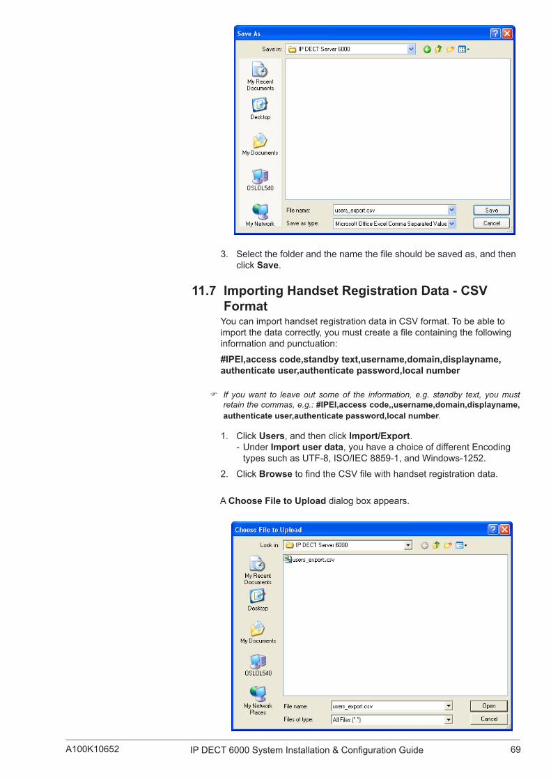
69IP DECT 6000 System Installation & Configuration GuideA100K10652
3. Selectthefolderandthenamethefileshouldbesavedas,andthenclick Save.
11.7 Importing Handset Registration Data - CSV Format
You can import handset registration data in CSV format. To be able to importthedatacorrectly,youmustcreateafilecontainingthefollowinginformation and punctuation:
#IPEI,accesscode,standbytext,username,domain,displayname, authenticate user,authenticate password,local number
) If you want to leave out some of the information, e.g. standby text, you must retain the commas, e.g.: #IPEI,access code,,username,domain,displayname, authenticate user,authenticate password,local number.
1. Click Users,andthenclickImport/Export. - Under Import user data,youhaveachoiceofdifferentEncodingtypessuchasUTF-8,ISO/IEC8859-1,andWindows-1252.
2. Click BrowsetofindtheCSVfilewithhandsetregistrationdata.
A Choose File to Upload dialog box appears.
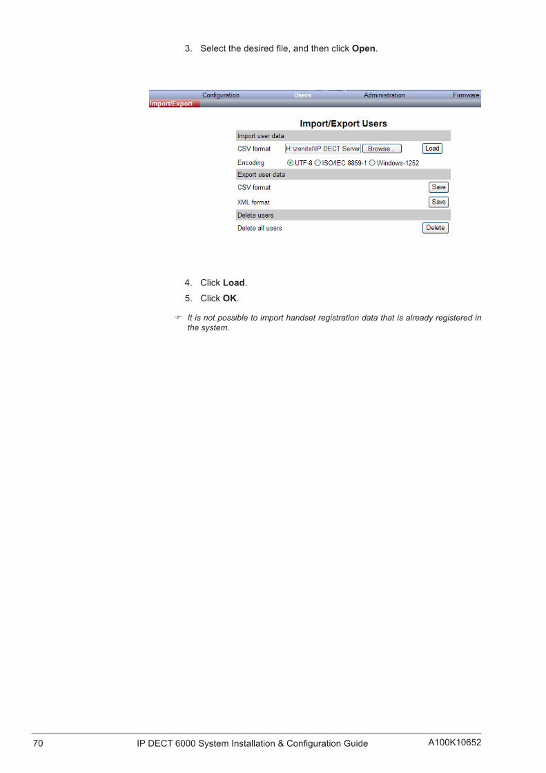
70 A100K10652IP DECT 6000 System Installation & Configuration Guide
3. Selectthedesiredfile,andthenclickOpen.
4. Click Load.
5. Click OK.
) It is not possible to import handset registration data that is already registered in the system.

71IP DECT 6000 System Installation & Configuration GuideA100K10652
12 System ManagementThis section provides you with information about system management using the web-based user interface of the IP DECT Server 6000.
Throughtheweb-baseduserinterfaceoftheServer6000,itispossibletodefineandviewdifferentsettingsofthesystem,readstatistics,makeabackupoftheconfigurationfile,updatesystemsoftware,andresetthesystem.
12.1 IP DECT Server 6000
12.1.1 Changing System User Name and PasswordFrom the user interface it is possible to change the user name and password for the system.
Log into the user interface of the Server 6000.
1. Click Configuration,andthenclickSecurity.
2. In the Current passwordfield,typethecurrentpassword.3. In the New usernamefield,typeanewusername.4. In the New passwordfield,typeanewpassword5. In the New password againfield,typethenewpasswordagainto
confirmit.
6. Uncheck the Force secure HTTP (TLS) checkbox.
7. Uncheck the Allow remote logging checkbox.
8. Click Save to change the user name and password.
12.1.2 Reading System InformationUnder Status,itispossibletogetgeneralinformationabouthardwareversion,firmwareandmessagelogging.Thisinformationisusefulfortroubleshooting. The web-based user interface of the wireless server providesanoverviewofthesolution,e.g.howthebasestationsarefunctioning.

72 A100K10652IP DECT 6000 System Installation & Configuration Guide
12.1.2.1 General Status InformationThispageprovidesgeneralsysteminformationsuchashardware,firmwareandOSStatusinformation.
Log into the web interface of the Server 6000.
● Click Status,andthenclickGeneral.
On theStatus/General page you can read information about:
● firmwareandhardwarebeingused
● MAC address (physical number) of the system
● NTP Server from which the system receives its time information
● time information - (if a time server is valid)
12.1.2.2 Logs InformationThis page provides logs information such as base station connections and different types of status.
1. Click Status,andthenclickLogs.
2. From the Displayfilterdropdownlist,selectemergency,critical,

73IP DECT 6000 System Installation & Configuration GuideA100K10652
error,warning,notice,info,ordebug depending on the logs you want to view.
The meaning of the different types of status are:
● emergency - errors causing the system to malfunction for all calls
● critical-eventsthatdonotoccurundernormaloperation,causingminor malfunction
● error-eventsthatdonotoccurundernormaloperation,causingminor malfunction
● warning-eventsthatdonotoccurundernormaloperation,maycause malfunction
● notice/info-eventsthatoccurundernormaloperation,relevanttoanadministrator
● debug-eventsthatoccurundernormaloperation,mayberelevantto an administrator
3. Click Exportifyouwanttosavethelogsinafile.
A File Download dialog box appears.
4. Click Save.A Save As dialog box appears.
5. Indicatethefolderandthenamethefileshouldbesavedas,andthen click Save.
Thelogfilescannowbesenttoauthorizedtechniciansforfurthersupport and troubleshooting.

74 A100K10652IP DECT 6000 System Installation & Configuration Guide
12.1.2.3 Wireless Server InformationThispageprovidesinformationaboutthefirmwareversion,ARIcode,licenseinformation,andservicestatusoftheServer6000.
● Click Status,andthenclickWireless Server.
12.1.3 Reading StatisticsUnder Statistics,itispossibletoviewstatisticinformationabouttheServer6000suchasbasestations,calls,handoversandabnormalreleasesinthesystem.Fromthis,youcangetanoverviewofhowthesystem is running.
12.1.3.1 Wireless ServerThispageisusefulforgettinginformationabouttrafficontheServer6000suchasvoicecalltrafficandmessagecalltrafficanditprovidesa summary of subscription and handover statistics. It also provides informationaboutthetrafficload(Erlang)oftheinstallation.
● Click Statistics,andthenclickWireless Server.
Ifyouwanttodeleteallstatistictrafficinformation:

75IP DECT 6000 System Installation & Configuration GuideA100K10652
1. Click Reset Statistics - A warning message appears.
2. Click OKtoconfirm.
12.1.3.2 Base StationThis page provides statistic information about the base station.
● Click Statistics,andthenclickBase Station.
12.1.3.3 Active CallsThis page provides statistic information about active calls in the Server 6000 installation.
● Click Statistics,andthenclickActive Calls.
12.1.3.4 Abnormal ReleasesThis page provides statistic information about abnormal call releases in an Server 6000 installation.
● Click Statistics,andthenclickAbnormal Releases.

76 A100K10652IP DECT 6000 System Installation & Configuration Guide
12.1.3.5 TrafficDistributionThispageprovidesstatisticinformationabouttrafficdistributionduringthe last 24 hours in an Server 6000 installation.
● Click Statistics,andthenclickTrafficDistribution.
12.1.4 Exporting/BackingUptheConfigurationFileThis section provides information about exporting and saving the configurationdataoftheServer6000,registrationandsubscriptiondataof the handset and system information.
Whenyousavetheconfigurationdata,youareablelatertogetanoverview of the Wireless Server which is useful for troubleshooting.
1. Click Configuration,andthenclickImport/Export.
2. Click Save toexporttheconfigurationfile.

77IP DECT 6000 System Installation & Configuration GuideA100K10652
A File Download dialog box appears.
3. Click Savetosavethefiletoaspecificfolder.
A Save As dialog box appears.
4. Indicateinwhichfolderandunderwhatnamethefileshouldbesaved,andthenclickSave.
12.1.5 Importing/RestoringtheConfigurationFileThissectiondescribeshowtoimportorrestoreaconfigurationfile.
1. Click Configuration,andthenclickImport/Export.
2. Click Browse.

78 A100K10652IP DECT 6000 System Installation & Configuration Guide
A Choose File to Upload dialog box appears.
3. Selectthedesiredfile,andthenclickOpen.
4. Click Load.
5. Click OK.
Theconfigurationfileshouldnowbeimportedandrestoredtothesystem.
12.1.6 Updating the Server 6000ThefirmwareoftheServer6000canbeupdatedfromafilethatisloaded to the system.
) Contact your distributor for the latest firmware.
UpdatingthefirmwareisdonethroughthewebinterfaceoftheServer6000.
12.1.6.1 Updating Server 6000 Firmware
1. Click Firmware,andthenclickWireless Server.

79IP DECT 6000 System Installation & Configuration GuideA100K10652
2. Click Browse.
A Choose File to Upload dialog box appears.
3. Selectthefirmwareupdatefile,andthenclickOpen.
4. Click Update.
Waitforthesystemtofinishupdating.
, Do not cut the power during the updating process.
5. Click ReboottoupdatetheServer6000firmware.
Optionally,youcanblocknewcallsduringafirmwareupdatebydoingthe following:
1. Click Administration,andthenclickWireless Server.
2. Under Service Status click Block.
Ifyouhaveblockednewcallsduringafirmwareupdate,enablenewcallsagain by doing the following:
3. Click Allow.

80 A100K10652IP DECT 6000 System Installation & Configuration Guide
12.1.7 Rebooting/RestartingtheServer6000Someconfigurationchangesrequirearebootinordertotakeeffect.Youmust reboot the system after the following procedures:
● configuring
● uploadingconfigurationdata
● uploadingfirmware
WhenrebootingtheServer6000,allcallsareterminatedandthe6000isreset.
1. Click Administration,andthenclickWireless Server.
2. For Wireless Server Uptime click Reboot.
A warning box appears.
3. Click OK.

81IP DECT 6000 System Installation & Configuration GuideA100K10652
12.2 Base Station
12.2.1 Changing System User Name and Password
It is possible to change the user name and password for the system from the web interface of the Base Station.
1. Click Configuration,andthenclickSecurity.
2. In the Current passwordfield,enterthecurrentpassword.3. In the New usernamefield,enteranewusername.4. In the New passwordfield,enteranewpassword.5. In the New password againfield,re-enterthenewpassword.6. Uncheck the Force secure HTTP (TLS) checkbox.
7. Uncheck the Allow remote logging checkbox.
8. Click Save.
12.2.2 Reading System InformationUnder Status it is possible to get general information about hardware version,firmwareandmessagelogging.Thisinformationisusefulincase of troubleshooting.

82 A100K10652IP DECT 6000 System Installation & Configuration Guide
12.2.2.1 General Status InformationThispageprovidesgeneralsysteminformationsuchashardware,firmwareandOSStatusinformation.
Log into the web interface of the Base Station.
● Click Status,andthenclickGeneral.
On theStatus/General page you can read information about:
● firmwareandhardwarebeingused
● MAC address (physical number) of the system
● NTP Server from which the system receives its time information
● Time for time information - (if a time server is valid)
12.2.2.2 Logs InformationThis page provides logs information such as base station connection and different types of status.
1. Click Status,andthenclickLogs.
2. From the Displayfilterdropdownlist,selectemergency,critical,error,warning,notice,info,ordebug depending on the logs you want to view.

83IP DECT 6000 System Installation & Configuration GuideA100K10652
The meaning of the different types of status are:
● emergency - errors causing the system to malfunction for all calls
● critical-eventsthatdonotoccurundernormaloperation,causingminor malfunction
● error-eventsthatdonotoccurundernormaloperation,causingminor malfunction
● warning-eventsthatdonotoccurundernormaloperation,maycause malfunction
● notice/info-eventsthatoccurundernormaloperation,relevanttoan administrator
● debug-eventsthatoccurundernormaloperation,mayberelevantto an administrator
3. Click Exportifyouwanttosavethelogsinafile.4. Click Save when a File Download dialog box appears.
- A Save As dialog box appears.
5. Selectthefolderandthenamethefileshouldbesavedas,andthenclick Save.
Thelogfilescannowbesenttoauthorizedtechniciansforfurthersupport and troubleshooting.
12.2.3 SynchronizationStateofBaseStationYou can get information about the synchronization state of the base station,i.e.theuptimeandtowhichradiounititsynchronizeson.Thisis useful when you want to get an overview of the base stations and in case of problem solving.
Information about the synchronization state of the base station can be retrieved from the web interface of the Server 6000.

84 A100K10652IP DECT 6000 System Installation & Configuration Guide
12.2.3.1 Checking Sync StateIn the web interface of the Server 6000:
● Click Administration,andthenclickBase Station.
Atthebottomofthepage,thereisacolordescriptionofthevarioussyncstates.
The sync states of the base stations are as follows:
● Blue: Free running (Sync Master)
● Green: Synchronized to primary (Primary Sync Master)
● Yellow: Synchronized to secondary (Secondary Sync Master)
● Red: Searching (not in sync with any radio unit)
● Grey: Unknown (not connected - base station removed from installation)
Double-click a base station in the list to check the RSSI values of the base stations it is synchronizing on (Primary sync or Secondary sync).
12.2.4 Updating the Base Station FirmwareToupdatethefirmware,youhavetoloadafiletothesystem.Contactyourdistributorforthelatestfirmware.
ThebasestationfirmwareisupdatedfromtheFirmware page of the Server 6000.
You can specify a range of base stations to be updated with the new firmware.
Toupdatethebasestationfirmware:

85IP DECT 6000 System Installation & Configuration GuideA100K10652
1. Click Firmware,andthenclickBase Station.
2. Next to the Firmwarefilefield,clickBrowse. - A Choose File to Upload dialog box appears.
3. Selectthefirmwareupdatefile,andthenclickOpen. - Thefilehastheextension.bin.
4. In the Start RFP Nofield,typethenumberofthefirstbasestationtobe updated. - You can check base station numbers under Administration > Base station.
5. In the End RFP Nofield,typethenumberofthelastbasestationtobe updated.
6. Click Update.
Waitforthesystemtofinishuploading.Allbasestationsintherangespecifiedwillbeupdated.
) You can check the update status under Administration > Base station while the update is progressing. Each update takes approximately 30 seconds.
7. Whentheupdateiscompleted,clickReboot to enable the changes.
Optionally,youcanblocknewcallsduringafirmwareupdatebydoingthe following:
1. Click Administration,andthenclickWireless Server.
2. Under Service Status for Call establishment,clickBlock.
Ifyouhaveblockednewcallsduringafirmwareupdate,enablenewcallsagain by doing the following:
3. Under Service Status,forCall establishment,clickAllow.
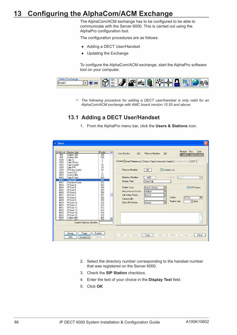
86 A100K10652IP DECT 6000 System Installation & Configuration Guide
13 ConfiguringtheAlphaCom/ACMExchangeTheAlphaCom/ACMexchangehastobeconfiguredtobeabletocommunicate with the Server 6000. This is carried out using the AlphaProconfigurationtool.
Theconfigurationproceduresareasfollows:
● Adding a DECT User/Handset
● Updating the Exchange
ToconfiguretheAlphaCom/ACMexchange,starttheAlphaProsoftwaretool on your computer.
) The following procedure for adding a DECT user/handset is only valid for an AlphaCom/ACM exchange with AMC board version 10.55 and above.
13.1 AddingaDECTUser/Handset1. FromtheAlphaPromenubar,clicktheUsers & Stations icon.
2. Select the directory number corresponding to the handset number that was registered on the Server 6000.
3. Check the SIP Station checkbox.
4. Enter the text of your choice in the DisplayTextfield.5. Click OK

87IP DECT 6000 System Installation & Configuration GuideA100K10652
13.2 UpdatingtheExchangeLog on to the AlphaCom/ACM exchange.
To update the exchange:
● Click SendAll
Reset the AMC board when the transfer is completed.
You should now be able to use the IP DECT handsets as mobile intercom stations and make calls to/from any stations connected to the AlphaCom/ACM exchange.

88 A100K10652IP DECT 6000 System Installation & Configuration Guide
A AcronymsAC Authentication Code
ACM AlphaCom Marine
- VINGTOR’s IP exchange
AlphaCom STENTOFON’s IP exchange
ARI Access Rights Identity - Serial number of the IP DECT Server 6000
dB Decibel
DECT Digital Enhanced Cordless Telecommunications
DHCP DynamicHostConfigurationProtocol
DNS Domain Name System
EIRP Equivalent Isotropically Radiated Power
ETSI European Telecommunications Standards Institute
GAP GenericAccessProfile
IP Internet Protocol
IPEI International Portable Equipment Identity - Serial number of the handset
WS Wireless Server
LAN Local Area Network
LED Light Emitting Diode
MAC Media Access Control - hardware address of a device connected to a network
MTU Maximum Translation Unit
MWI Message Waiting Indicator
NTP Network Time Protocol
PBX Private Branch eXchange
PoE Power over Ethernet
PSTN Public Switched Telephone Network
RFP Radio Fixed Part
RSSI Received Signal Strength Indicator
RTP Real-time Transport Protocol
SIP Session Initiated Protocol
VoIP Voice over Internet Protocol
WLAN Wireless Local Area Network
WRFP Wireless Radio Fixed Part - Wireless Repeater

89IP DECT 6000 System Installation & Configuration GuideA100K10652
B Regulatory NoticesThis section contains important safety regulations for the Server 6000.
B.1 International Regulatory Information
This product has been marked with the CE mark. This mark indicates compliance with EEC Directives89/336/EEC,73/23/EEC1999/5/EC.Afull copy of the Declaration of Conformity can be obtained from Zenitel Norway AS, P.O. BOX 4498 NYDALEN, NO-0403 Oslo, Norway.
Cesky [Czech]: Vášdodavateltímtoprohlašuje,žetentoproduktjeveshodesezákladnímipožadavkyadalšímipríslušnýmiustanovenímismernice1999/5/ES.
Dansk [Danish]: Deresleverandørerklærerherved,atudstyretoverholderdevæsentligekrav og øvrige relevante krav i direktiv 1 999/5/EF.
Deutsch [German]: HiermiterklärtIhrLieferant,dasssichdasGerätinÜbereinstimmungmit den grundlegenden Anforderungen und den übrigen einschlägigen BestimmungenderRichtlinie1999/5/EGbefindet.
Eesti [Estonian]: KäesolevagakinnitabTeietarnija,etseadeonvastavusesdirektiivi1999/5/EÜpõhinõueteganingnimetatuddirektiivisttulenevateteisteasjakohastesätetega.
English: Hereby,yoursupplierdeclaresthatthisproductisincompliancewiththeessential requirements and other relevant provisions of Directive 1999/5/EC.
Español [Spanish]: Por medio de la presente su proveedor declara que este producto cumple con los requisitos esenciales y cualesquiera otras disposiciones aplicables o exigibles de la Directiva 1999/5/CE.
Ellivtiai [Greek]: METHNIIAPOYEA,OIIPOMHOETHEEAEAHACNEIOTITOEYFKEKPIMENO IIPOION EYMMOPMENETAI IIPOE TIE OYEIMEIE AIIAITHEEIEKAITIEAOIIIEEEXETIKEEAIATAZEEIETHEOAHFIAE1999/5/EK.
Français [French]: Par la présente votre fournisseur déclare que l’appareil conforme aux exigences essentielles et aux autres dispositions pertinentes de la directive 1999/5/CE.
Italiano [Italian]: Con la presente il Suo fornitore dichiara che questo prodotto è conforme ai requisiti essenziali ed alle altre disposizioni pertinenti stabilite dalla direttiva 1999/5/CE.

90 A100K10652IP DECT 6000 System Installation & Configuration Guide
Íslenska (Icelandic): Hérmeðlýsirbirgirinnþinnþviyfiraðþessivaraséísamræmiviðgrunnkröfurogaðrarkröfur,semgerðareruítilskipun1999/5/EC
Latviski [Latvian]: Piegadatajspazino,kašisproduktsatbilstDirektivas1999/5/EKpamatprasibam un citiem attiecigajiem tas noteikumiem.
Lietuviu [Lithuanian]: Šiuojusutiekejasdeklaruoja,kadšisproduktasatitinkaesminiusreikalavimus ir kitas 1999/5/EB Direktyvos nuostatas.
Nederlands [Dutch]: Hierbij verklaart uw leverancier dat dit product in overeenstemming is met de essentiële eisen en de andere relevante bepalingen van richtlijn1999/5/EG.
Malti [Maltese]: Ghalhekk,il-forniturjiddikjaralidanil-prodottjikkonformamal-htigijietijietessenzjaliumaprovvedimentirelevantiohrajnlihemmfid-Dirrettiva1999/5/EC.
Magyar [Hungarian]: Alulírott,beszállítónyilatkozom,hogyezatermékmegfelelavonatkozóalapvetõkövetelményeknekésaz1999/5/ECirányelvegyébelõírásainak
Norsk [Norwegian]: Din leverandør erklærer herved at dette produkt er i samsvar med de grunnleggende krav og øvrige relevante krav i direktiv 1999/5/EF.
Polski [Polish]: Niniejszymdostawcaoswiadcza,zeprodukttenjestzgodnezpodstawowymi wymaganiami oraz innymi stosownymi postanowieniami Dyrektywy 1 999/5/WE.
Português [Portuguese]: Porestemeio,oseufornecedordeclaraqueesteprodutoestáconformecomosrequisitosessenciaiseoutrasdisposiçõesdaDirectiva1999/5/CE.
Slovensko [Slovenian]: Dobaviteljizjavlja,dajetaizdelekvskladuzbistvenimizahtevamiinostalimi relevantnimi dolocili direktive 1999/5/ES.
Slovensky [Slovak]: Dodávatelzárovenvyhlasuje,žetentoproduktsplnazákladnépožiadavkya všetky príslušné ustanovenia Smernice 1999/5/ES.
Suomi [Finnish]: Tätentoimittajannevakuuttaa,ettätämätuoteondirektiivin1999/5/EY oleellisten vaatimusten ja sitä koskevien direktiivin muiden ehtojen mukainen.
Svenska [Swedish]: Härmed intygar leverantören att denna produkt står iöverensstämmelse
91IP DECT 6000 System Installation & Configuration GuideA100K10652
med de väsentliga egenskapskrav och övriga relevanta bestämmelser som framgår av direktiv 1 999/5/EG.
ExplosiveDeviceProximityWarning
Warning Do not operate your wireless network device near unshielded blasting capsorinanexplosiveenvironmentunlessthedevicehasbeenmodifiedtobeespeciallyqualifiedforsuchuse.
Waarschuwing Gebruik dit draadloos netwerkapparaat alleen in de buurt van onbeschermdeontstekersofineenomgevingmetexplosievenindienhet apparaat speciaal is aangepast om aan de eisen voor een dergelijk gebruik te voldoen.
Varoitus Älä käytä johdotonta verkkolaitetta suojaamattomien räjäytysnallien läheisyydessä tai räjäytysalueella, jos laitetta ei ole erityisesti muunnettu sopivaksi sellaiseen käyttöön.oen. Attention Nejamaisutiliserunéquipementderéseausansfilàproximitéd’un détonateur non blindé ou dans un lieu présentant des risques d’explosion,saufsil’équipementaétémodifiéàceteffet.
Warnung BenutzenSieIhrdrahtlosesNetzwerkgerätnichtinderNäheungeschützterSprengkapselnoderandererexplosiverStoffe,esseidenn,IhrGerätwurdeeigensfürdiesenGebrauchmodifiziertundbestimmt.
Avvertenza Nonutilizzarelaperifericadiretesenzafiliinprossimitàdiundetonatore non protetto o di esplosivi a meno che la periferica non sia statamodificataataleproposito.
Advarsel Ikke bruk den trådløse nettverksenheten nært inntil uisolerte fenghetterellerieteksplosivtmiljømedmindreenhetenermodifisertslik at den tåler slik bruk.
Aviso Nãoopereodispositivoderedesemfiospertodecápsulasexplosivasnãoprotegidasounumambienteexplosivo,anãoserqueodispositivotenhasidomodificadoparasequalificarespecialmenteparaessautilização.
¡Advertencia! Noutilizarunaparatodelaredsincablecercadeundetonadorquenoestéprotegidonitampocoenunentornoexplosivoamenosqueelaparatohayasidomodificadoconesefin.
!

92 A100K10652IP DECT 6000 System Installation & Configuration Guide
Varning! Använd inte den trådlösa nätverksenheten i närheten av oskyddade tändhattarellerienexplosivmiljöominteenhetenmodifieratsförattkunna användas i sådana sammanhang.
The WEEE Marking on this equipment indicates that the product must not be disposed of with unsorted waste, but must be collected separately.
AppropriateRFsafety/installationinformationThe product is intended to be installed by authorized personal. The product shall be installed in accordance with FCC rules.
RFExposureStatementThe EUT is considered as a mobile device according to OET Bulletin 65,Edition97-01.Thereforedistancetohumanbodyofmin.20cmisdetermined.
The internal/external antennas used for this mobile transmitter must provide a separation distance of at least 20 cm from all persons and must not be co-located or operating in conjunction with any other antenna or transmitter.
WARNINGThis is a class A product. In a domestic environment this product may cause radio interference in which case the user may be required to take adequate measures. The above warning is inserted for regulatory reasons.Ifanycustomerbelievesthattheyhaveaninterferenceproblem,either because their product seems to cause interference or suffers frominterference,theyshouldcontacttheirdistributorimmediately.Thedistributor will assist with a remedy for any problems.
Safety WARNING!Onlyqualifiedservicepersonnelmayinstallthisequipment.Theinstructionsinthismanualareintendedforusebyqualifiedservicepersonnel only.
Onlyqualifiedpersonsshouldservicethesystem.The installation and service of this hardware is to be performed only by service personnel having appropriate training and experience necessary to be aware of hazards to which they are exposed in performing a task and of measures to minimize the danger to themselves or other persons.
Electrical shock hazards from the telecommunication network and AC mains are possible with this equipment. To minimize risk to service personnelandusers,thesystemmustbeconnectedtoanoutletwithathird-wire Earth.
Service personnel must be alert to the possibility of high leakage currents becoming available on metal system surfaces during power line fault eventsnearnetworklines.TheseleakagecurrentsnormallysafelyflowtoProtectiveEarthviathepowercord.Therefore,itismandatorythatconnectiontoanearthedoutletisperformedfirstandremovedlastwhen
!

93IP DECT 6000 System Installation & Configuration GuideA100K10652
cablingtotheunit.Specifically,operationsrequiringtheunittobepowereddownmusthavethenetworkconnections(exchangelines)removedfirst.
B.2 Important Safety InstructionsBeforeusingyourtelephoneequipment,youshouldalwaysfollowbasicsafetyinstructiontoreducetheriskoffire,electricalshockandinjurytopersons,anddamagetoproperty.
● Read and understand all instructions.
● Follow all warnings and instructions including those marked on the product.
● Unplug this product before cleaning. Do not use liquid cleaners or aerosol cleaners. Use damp cloth for cleaning.
● Do not install the telephone equipment in the bathroom or near a washbowl,kitchensink,orlaundrytub,inawetbasement,ornearaswimming pool.
● The product should be operated only from the type of power source indicated on the instructions. If you are not sure of the type of power supply,consultyourdealerorlocalpowercompany.
● Do not overload wall outlets and extension cords as this can result in fireorelectricalshock.
● Never push objects of any kind into this product through cabinet slots as they may touch dangerous voltage points or short out parts that couldresultinfire,electricalshock,orinjury.Neverspillliquidofanykind into this product.
● Toreducetheriskofelectricalshockorburns,donotdisassemblethis product. Opening or removing covers may expose you to dangerousvoltages,dangerouselectricalcurrent,orotherrisks.Incorrect reassemble can cause electrical shock when the appliance issubsequentlyused.Iftheproductneedsrepair,consultyourdealer.
● This product does not support connections to outside plant.
● Referservicingtoqualifiedservicepersonnelunderthefollowingconditions: - If liquid has been spilled into the product - If the product has been exposed to rain or water - If the product does not operate normally when following the operating instructions in the manual. Adjust only those controls that are covered by the operation instructions. Improper adjustment of other controls may result in damage and will often require extensive workbyqualifiedservicepersonneltorestoretheproducttonormaloperation.
- If the product has been dropped or cabinet has been damaged - If the product exhibits a distinct change in performance
Warning
● Avoid using the telephone during an electrical storm. There may be a risk of electrical shock from lightning.
● Do not use the telephone to report a gas leak in the vicinity of the leak.
● Donotplacetheunitnearmicrowaveovens,radioequipment,ornon-ground connected televisions. These appliances may cause electrical interference to the base or handset.
● Installation must be performed in accordance with all relevant national wiring rules.

94 A100K10652IP DECT 6000 System Installation & Configuration Guide
● Plug acts as Disconnect Device - The socket outlet to which this apparatus is connected must be installed near the equipment and must always be readily accessible.
● The system will not operate in the event of a blackout. Please keep a backup phone for emergencies.
Intrinsic safetyDo not install the unit in conditions where there is a danger of electrically ignited explosions.
Exposuretosunlight,heatandmoistureDo not expose the unit to direct sunlight for long periods. Keep away from excessive heat and moisture.
Spare parts and accessoriesUse only approved spare parts and accessories. The operation of non-approved parts cannot be guaranteed and may even cause damage.
RF compliance informationThe user manual or instruction manual for an intentional or unintentional radiatorshallcautiontheuserthatchangesormodificationsnotexpressly approved by the party responsible for compliance could void the user’s authority to operate the equipment.
NOTICESFCC Note: This device complies with Part 15 of the FCC rules. Operation is subject to the following two conditions: (1) This device may notcauseharmfulinterference,and(2)thisdevicemustacceptanyinterferencereceived,includinginterferencethatmaycauseundesiredoperation.
IC Note: Operation is subject to the following two conditions: (1) This devicemaynotcauseinterference,and(2)thisdevicemustacceptanyinterference,includinginterferencethatmaycauseundesiredoperationofthedevice.Theterm“IC:”beforethecertification/registrationnumberonlysignifiesthattheIndustryCanadatechnicalspecificationsweremet.
Privacy of communications may not be ensured when using this telephone.
Information to user: The user manual or instruction manual for an intentional or unintentional radiator shall caution the user that changes ormodificationsnotexpresslyapprovedbythepartyresponsibleforcompliance could void the user’s authority to operate the equipment.
LIMITED WARRANTYThislimited,non-transferablewarrantyisprovidedtotheoriginalpurchaser. The product is warranted to be free from defects in materials andworkmanshipundernormalinstallation,useandserviceforaperiodof one (1) year from the date of purchase as shown on the purchaser’s receipt.
Our obligation under this warranty is limited to repair or replacement (at our option) of the product or any part(s) which are defective provided that the product is returned to the original place of purchase or an authorized service location during the warranty period. Products returned must be accompanied by a copy of the purchase receipt. In the absence of a

95IP DECT 6000 System Installation & Configuration GuideA100K10652
purchasereceipt,thewarrantyperiodshallbeone(1)yearfromthedateof manufacture. Repair or replacement of the product is your sole and exclusive remedy.
Iftheproductisrepaired,reconditionedcomponentpartsormaterialsmaybeused.Iftheproductisreplaced,wemayreplaceitwithanewor reconditioned product of the same or similar design. The repaired product will be warranted for either (a) 90 days or (b) the remainder of theoriginalone(1)yearwarrantyperiod,whicheverislonger.
Thiswarrantydoesnotapplytothedefectsoutsideofourcontrol,includingbutnotlimitedtoactsofGod,fire,floodanddamagewhilein transit to service facility. We do not warranty that the product will be compatiblewithanytelephoneequipment,systemsorpartylines.
This warranty shall be void if the product is damaged as a result of defacement,misuse,abuse,neglect,accident,destructionoralterationoftheserialnumber,improperelectricalvoltagesorcurrents,repair,alteration or maintenance by any person or party other than our authorizedservicefacility,oranyviolationofinstructionsfurnishedbyus.
This warranty is also void if this product is removed from the country inwhichitwaspurchasedbytheoriginalpurchaser,ifitisusedinacountryinwhichitisnotregisteredforuse,orifitisusedinacountryfor which it was not designed. Due to variations in telephone systems andcommunicationslaws,thisproductmaybeillegalforuseinsomecountries. We assume no responsibilities for damages or penalties incurred resulting from the use of this product in a manner or location other than that for which it was intended.
THIS LIMITED WARRANTY IS IN LIEU OF ALL OTHER WARRANTIES EXPRESS OR IMPLIED. ANY IMPLIED WARRANTIES INCLUDING BUT NOT LIMITED TO THE IMPLIED WARRANTIES OF MERCHANTABILITY AND FITNESS FOR A PARTICULAR PURPOSE,SHALLBELIMITEDTOTHEDURATIONOFTHISWRITTEN LIMITED WARRANTY. WE DISCLAIM ANY LIABILITY FOR DAMAGESFORLOSSOFUSEOFTHEPRODUCTS,LOSSOFTIME,INCONVENIENCE,INJURYTOANYPERSON,ORDAMAGETOPROPERTYCAUSEDBYTHEPRODUCT,LOSSOFREVENUEOR PROFIT OR DAMAGES FOR ANY FAILURE TO PERFORM. IN NOEVENTSHALLWEBELIABLEFORANYSPECIAL,INCIDENTAL,PUNITIVE OR CONSEQUENTIAL DAMAGES EVEN IF WE ARE ADVISED OF THE POSSIBILITY OF SUCH DAMAGES.
Some states do not allow limitations on how long an implied warranty lasts,sotheabovelimitationsmaynotapplytoyou.Thiswarrantyisthesole and exclusive warranty provided for the product. There are no other expresswarranties.Thiswarrantygivesyouspecificlegalrights,andyoumayalsohaveotherrights,whichvaryfromstatetostate.

www.stentofon.com Zenitel Norway ASP.O. Box 4498 NydalenNO-0403 OSLONorway
STENTOFON and VINGTOR products are developed and marketed by Zenitel Norway AS. The company’s Quality Assurance System is certified to meet the requirements in NS-EN ISO 9001:2008. Zenitel Norway AS reserves the right to modify designs and alter specifications without prior notice, in pursuance of a policy of continuous improvement. © 2009 Zenitel Norway AS.


