Embed Size (px)
Citation preview
Danfoss Heat Pump scroll compressors, HHP-Series50Hz - R407C
Application guidelines
http://cc.danfoss.com


Content
Scroll compression principle ........................................................................................... 6Scroll compressor components ................................................................................................................................. 6The scroll compression process ................................................................................................................................. 7Performance ..................................................................................................................................................................... 7
Compressor model designation ...................................................................................... 8Nomenclature .................................................................................................................................................................. 8Label .................................................................................................................................................................................... 8
Technical specifications ................................................................................................... 950-Hz data ......................................................................................................................................................................... 9Performance table .......................................................................................................................................................... 9
Dimensions ...................................................................................................................... 10HHP015-019-021-026 ...................................................................................................................................................10HHP030-038-045 ............................................................................................................................................................11
Electrical data, connections and wiring ......................................................................... 12Motor voltage .................................................................................................................................................................12Wiring connections .......................................................................................................................................................12IP rating .............................................................................................................................................................................13LRA (Locked Rotor Amp) .............................................................................................................................................13MCC (Maximum Continuous Current) ....................................................................................................................13Max Oper. A (Maximum Operating Amp) .............................................................................................................13Winding resistance ........................................................................................................................................................13Electrical connections ..................................................................................................................................................13Nominal capacitor value .............................................................................................................................................14Internal motor protection ...........................................................................................................................................14Phase sequence and reverse rotation protection ..............................................................................................14Voltage imbalance ........................................................................................................................................................14
Approvals and certifications ........................................................................................... 15Approvals and certificates ..........................................................................................................................................15Pressure equipment directive 97/23/EC ................................................................................................................15Low voltage directive 73/23/EC, 93/68/EC ...........................................................................................................15Internal free volume .....................................................................................................................................................15
Operating conditions ...................................................................................................... 16Refrigerant and lubricants ..........................................................................................................................................16Motor supply ...................................................................................................................................................................16Compressor ambient temperature ..........................................................................................................................16Application envelope ...................................................................................................................................................17R407C ................................................................................................................................................................................17Maximum discharge gas temperature ...................................................................................................................17High and low pressure protection ...........................................................................................................................18On/off cycling (cycle rate limit) .................................................................................................................................18
4 FRCC.PC.017.A2.02
Application Guidelines
Content
System design recommendations .................................................................................. 19General ..............................................................................................................................................................................19Essential piping design considerations .................................................................................................................19Refrigerant charge limit ..............................................................................................................................................20Reversible heat pump systems .................................................................................................................................20Crankcase heater............................................................................................................................................................22Minimum sump superheat .........................................................................................................................................22Loss of charge protection ...........................................................................................................................................22Oil level checking and top-up ...................................................................................................................................22High pressure ratio ........................................................................................................................................................22Preventing liquid flood back .....................................................................................................................................22Testing for excessive liquid flood back ..................................................................................................................22Water utilising systems ................................................................................................................................................22
Sound and vibration management ................................................................................ 23Running sound level .....................................................................................................................................................23Sound generation in a refrigeration system / air conditioning system .....................................................23Compressor sound radiation .....................................................................................................................................23Mechanical vibrations ..................................................................................................................................................23Gas pulsation ...................................................................................................................................................................23
Installation ....................................................................................................................... 24System cleanliness.........................................................................................................................................................24Compressor handling and storage ..........................................................................................................................24Compressor mounting .................................................................................................................................................24Compressor holding charge ......................................................................................................................................24Tube brazing procedure ..............................................................................................................................................24Brazing material .............................................................................................................................................................24Vacuum evacuation and moisture removal .........................................................................................................25Liquid line filter driers ..................................................................................................................................................26Refrigerant charging .....................................................................................................................................................26Insulation resistance and dielectric strength ......................................................................................................26Compressor replacement after motor burn out .................................................................................................26
Ordering information and packaging ............................................................................ 27Packaging .........................................................................................................................................................................27Packaging details ...........................................................................................................................................................27Ordering information and packaging ....................................................................................................................27
Spare parts & accessories ................................................................................................ 28Run capacitors for PSC wiring ...................................................................................................................................28Rotolock adaptor set ....................................................................................................................................................28Rotolock adaptor ...........................................................................................................................................................28Crankcase heater............................................................................................................................................................28Discharge temperature protection .........................................................................................................................29Lubricant ...........................................................................................................................................................................29Mounting hardware ......................................................................................................................................................29
5FRCC.PC.017.A2.02
Application Guidelines
Scroll compression principle
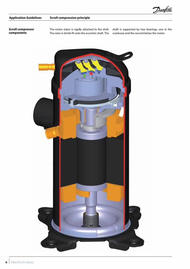
The motor stator is rigidly attached to the shell. The rotor is shrink-fit onto the eccentric shaft. The
shaft is supported by two bearings, one in the crankcase and the second below the motor.
Scroll compressor components
6 FRCC.PC.017.A2.02
Application Guidelines
Scroll compression principle
Danfoss Heat Pump scroll compressors are manufactured using the most advanced machining, assembly, and process control techniques. In design of both the compressor
and the factory, very high standards of reliability and process control were first priority. The result is a highly efficient product with the highest reliability obtainable, and a low sound level.
The Danfoss Heat Pump scroll compressor referenced in this guide is a fully compliant scroll and actually improves with run time in
it's early commissioning. A seventy-two hour run-in is recommended to meet performance expectations.
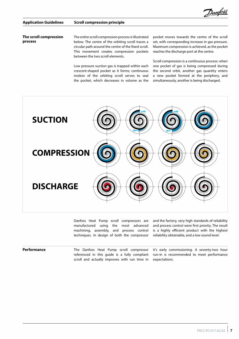
The entire scroll compression process is illustrated below. The centre of the orbiting scroll traces a circular path around the centre of the fixed scroll. This movement creates compression pockets between the two scroll elements.
Low pressure suction gas is trapped within each crescent-shaped pocket as it forms; continuous motion of the orbiting scroll serves to seal the pocket, which decreases in volume as the
pocket moves towards the centre of the scroll set, with corresponding increase in gas pressure. Maximum compression is achieved, as the pocket reaches the discharge port at the centre.
Scroll compression is a continuous process: when one pocket of gas is being compressed during the second orbit, another gas quantity enters a new pocket formed at the periphery, and simultaneously, another is being discharged.
The scroll compression process
SUCTION
COMPRESSION
DISCHARGE
Performance
7FRCC.PC.017.A2.02
Application Guidelines
Compressor model designation
Label
Nomenclature
Serial number
S K 123450903
Production year
Production week
Manufacturing location
Incremental number
Type FeaturesMotorSize
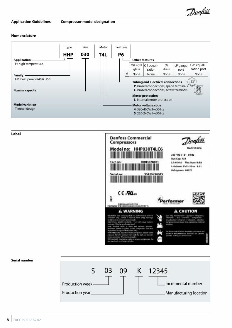
HHP P6T4L030Application:
H: high temperature
Family:HP: heat pump R407C PVE
Nominal capacity:
Model variationT motor design
Motor voltage code4: 380-400V/3~/50 Hz5: 220-240V/1~/50 Hz
Motor protectionL: internal motor protection
Tubing and electrical connectionsP: brazed connections, spade terminalsC: brazed connections, screw terminals
Other features
Oil sight glass
Oil equali-sation
Oil drain
LP gauge port
Gas equali-sation port
None6 None None None None
8 FRCC.PC.017.A2.02
Application Guidelines
Technical specifications
Performance table
50-Hz data
Model
Heatingcapacity Power input Max. A. Heating
efficiency Swept volume Displacement Oil charge Net weight
W W A COP W/W (cm3/rev) m3/hr @2900 rpm L kg
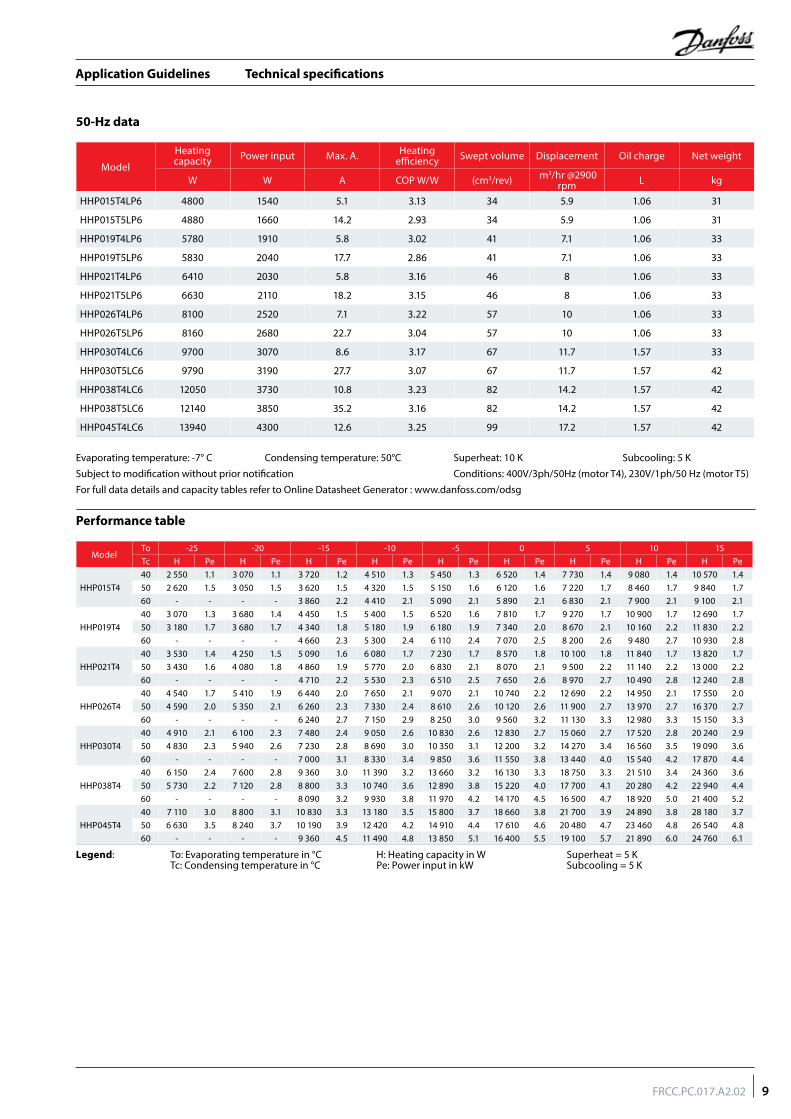
HHP015T4LP6 4800 1540 5.1 3.13 34 5.9 1.06 31
HHP015T5LP6 4880 1660 14.2 2.93 34 5.9 1.06 31
HHP019T4LP6 5780 1910 5.8 3.02 41 7.1 1.06 33
HHP019T5LP6 5830 2040 17.7 2.86 41 7.1 1.06 33
HHP021T4LP6 6410 2030 5.8 3.16 46 8 1.06 33
HHP021T5LP6 6630 2110 18.2 3.15 46 8 1.06 33
HHP026T4LP6 8100 2520 7.1 3.22 57 10 1.06 33
HHP026T5LP6 8160 2680 22.7 3.04 57 10 1.06 33
HHP030T4LC6 9700 3070 8.6 3.17 67 11.7 1.57 33
HHP030T5LC6 9790 3190 27.7 3.07 67 11.7 1.57 42
HHP038T4LC6 12050 3730 10.8 3.23 82 14.2 1.57 42
HHP038T5LC6 12140 3850 35.2 3.16 82 14.2 1.57 42
HHP045T4LC6 13940 4300 12.6 3.25 99 17.2 1.57 42
Evaporating temperature: -7° C Condensing temperature: 50°C Superheat: 10 K Subcooling: 5 KSubject to modification without prior notification Conditions: 400V/3ph/50Hz (motor T4), 230V/1ph/50 Hz (motor T5)For full data details and capacity tables refer to Online Datasheet Generator : www.danfoss.com/odsg
ModelTo -25 -20 -15 -10 -5 0 5 10 15Tc H Pe H Pe H Pe H Pe H Pe H Pe H Pe H Pe H Pe
HHP015T440 2 550 1.1 3 070 1.1 3 720 1.2 4 510 1.3 5 450 1.3 6 520 1.4 7 730 1.4 9 080 1.4 10 570 1.450 2 620 1.5 3 050 1.5 3 620 1.5 4 320 1.5 5 150 1.6 6 120 1.6 7 220 1.7 8 460 1.7 9 840 1.760 - - - - 3 860 2.2 4 410 2.1 5 090 2.1 5 890 2.1 6 830 2.1 7 900 2.1 9 100 2.1
HHP019T440 3 070 1.3 3 680 1.4 4 450 1.5 5 400 1.5 6 520 1.6 7 810 1.7 9 270 1.7 10 900 1.7 12 690 1.750 3 180 1.7 3 680 1.7 4 340 1.8 5 180 1.9 6 180 1.9 7 340 2.0 8 670 2.1 10 160 2.2 11 830 2.260 - - - - 4 660 2.3 5 300 2.4 6 110 2.4 7 070 2.5 8 200 2.6 9 480 2.7 10 930 2.8
HHP021T440 3 530 1.4 4 250 1.5 5 090 1.6 6 080 1.7 7 230 1.7 8 570 1.8 10 100 1.8 11 840 1.7 13 820 1.750 3 430 1.6 4 080 1.8 4 860 1.9 5 770 2.0 6 830 2.1 8 070 2.1 9 500 2.2 11 140 2.2 13 000 2.260 - - - - 4 710 2.2 5 530 2.3 6 510 2.5 7 650 2.6 8 970 2.7 10 490 2.8 12 240 2.8
HHP026T440 4 540 1.7 5 410 1.9 6 440 2.0 7 650 2.1 9 070 2.1 10 740 2.2 12 690 2.2 14 950 2.1 17 550 2.050 4 590 2.0 5 350 2.1 6 260 2.3 7 330 2.4 8 610 2.6 10 120 2.6 11 900 2.7 13 970 2.7 16 370 2.760 - - - - 6 240 2.7 7 150 2.9 8 250 3.0 9 560 3.2 11 130 3.3 12 980 3.3 15 150 3.3
HHP030T440 4 910 2.1 6 100 2.3 7 480 2.4 9 050 2.6 10 830 2.6 12 830 2.7 15 060 2.7 17 520 2.8 20 240 2.950 4 830 2.3 5 940 2.6 7 230 2.8 8 690 3.0 10 350 3.1 12 200 3.2 14 270 3.4 16 560 3.5 19 090 3.660 - - - - 7 000 3.1 8 330 3.4 9 850 3.6 11 550 3.8 13 440 4.0 15 540 4.2 17 870 4.4
HHP038T440 6 150 2.4 7 600 2.8 9 360 3.0 11 390 3.2 13 660 3.2 16 130 3.3 18 750 3.3 21 510 3.4 24 360 3.650 5 730 2.2 7 120 2.8 8 800 3.3 10 740 3.6 12 890 3.8 15 220 4.0 17 700 4.1 20 280 4.2 22 940 4.460 - - - - 8 090 3.2 9 930 3.8 11 970 4.2 14 170 4.5 16 500 4.7 18 920 5.0 21 400 5.2
HHP045T440 7 110 3.0 8 800 3.1 10 830 3.3 13 180 3.5 15 800 3.7 18 660 3.8 21 700 3.9 24 890 3.8 28 180 3.750 6 630 3.5 8 240 3.7 10 190 3.9 12 420 4.2 14 910 4.4 17 610 4.6 20 480 4.7 23 460 4.8 26 540 4.860 - - - - 9 360 4.5 11 490 4.8 13 850 5.1 16 400 5.5 19 100 5.7 21 890 6.0 24 760 6.1
Legend: To: Evaporating temperature in °C H: Heating capacity in W Superheat = 5 K Tc: Condensing temperature in °C Pe: Power input in kW Subcooling = 5 K
9FRCC.PC.017.A2.02
Application Guidelines
Dimensions
Mounting grommetTerminal box
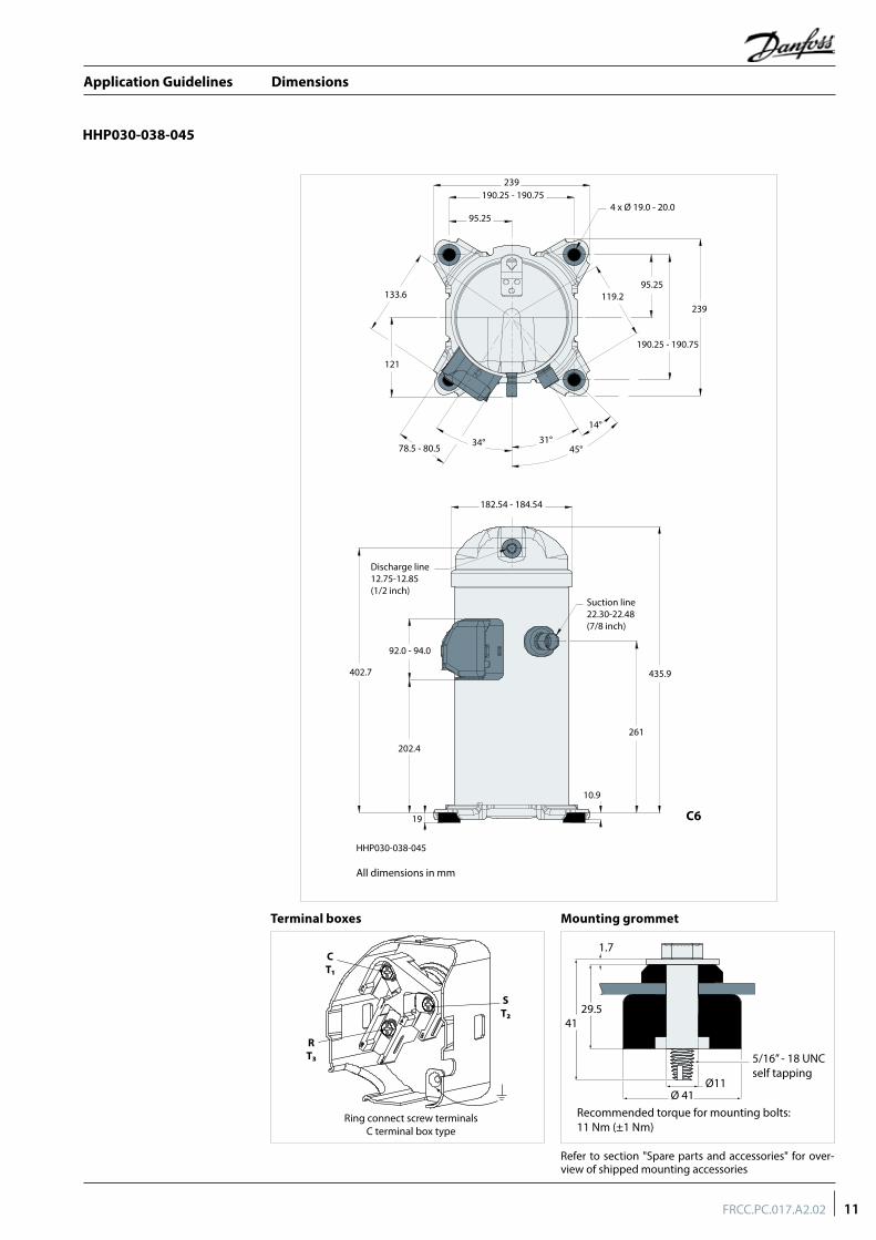
Refer to section "Spare parts and accessories" for over-view of shipped mounting accessories
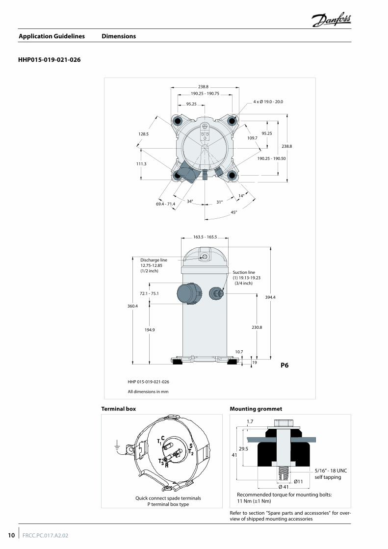
HHP015-019-021-026
Quick connect spade terminalsP terminal box type
1.7
41
Ø 41
29.5
5/16” - 18 UNCself tapping
Recommended torque for mounting bolts:11 Nm (±1 Nm)
Ø11
238.8
4 x Ø 19.0 - 20.095.25
128.5
111.3
69.4 - 71.4 34° 31°
45°
14°
109.795.25
190.25 - 190.50
238.8
190.25 - 190.75
HHP 015-019-021-026
394.4
Suction line (1) 19.13-19.23 (3/4 inch)
163.5 - 165.5
72.1 - 75.1
360.4
194.9 230.8
10.7
19
Discharge line 12.75-12.85 (1/2 inch)
P6
All dimensions in mm
10 FRCC.PC.017.A2.02
Application Guidelines
Dimensions
Mounting grommetTerminal boxes
Refer to section "Spare parts and accessories" for over-view of shipped mounting accessories
HHP030-038-045
1.7
41
Ø 41
29.5
5/16” - 18 UNCself tapping
Recommended torque for mounting bolts:11 Nm (±1 Nm)
Ø11
Ring connect screw terminalsC terminal box type
CT₁
ST₂
RT₃
239190.25 - 190.75
95.25
133.6
121
78.5 - 80.5
182.54 - 184.54
Suction line22.30-22.48(7/8 inch)
Discharge line12.75-12.85(1/2 inch)
92.0 - 94.0
402.7
202.4
261
19
10.9
435.9
34° 31°45°
14°
4 x Ø 19.0 - 20.0
239
190.25 - 190.75
119.295.25
HHP030-038-045
All dimensions in mm
C6
11FRCC.PC.017.A2.02
Application Guidelines
Electrical data, connections and wiring
Danfoss Heat Pump scroll compressors are available in 2 different motor voltages.Motor voltage
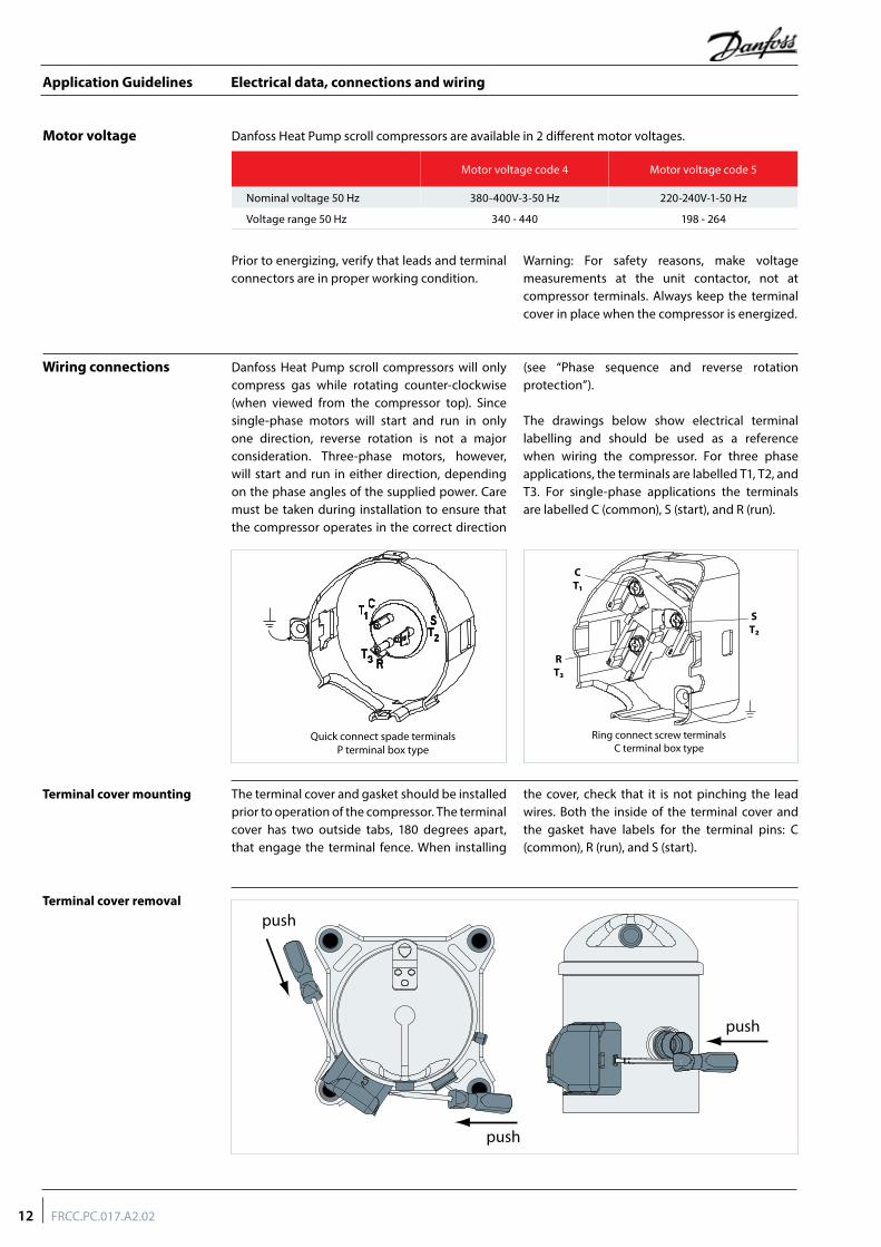
Danfoss Heat Pump scroll compressors will only compress gas while rotating counter-clockwise (when viewed from the compressor top). Since single-phase motors will start and run in only one direction, reverse rotation is not a major consideration. Three-phase motors, however, will start and run in either direction, depending on the phase angles of the supplied power. Care must be taken during installation to ensure that the compressor operates in the correct direction
(see “Phase sequence and reverse rotation protection”).
The drawings below show electrical terminal labelling and should be used as a reference when wiring the compressor. For three phase applications, the terminals are labelled T1, T2, and T3. For single-phase applications the terminals are labelled C (common), S (start), and R (run).
Prior to energizing, verify that leads and terminal connectors are in proper working condition.
Warning: For safety reasons, make voltage measurements at the unit contactor, not at compressor terminals. Always keep the terminal cover in place when the compressor is energized.
The terminal cover and gasket should be installed prior to operation of the compressor. The terminal cover has two outside tabs, 180 degrees apart, that engage the terminal fence. When installing
the cover, check that it is not pinching the lead wires. Both the inside of the terminal cover and the gasket have labels for the terminal pins: C (common), R (run), and S (start).
Wiring connections
Terminal cover mounting
Terminal cover removal
Quick connect spade terminalsP terminal box type
push
push
push
Motor voltage code 4 Motor voltage code 5
Nominal voltage 50 Hz 380-400V-3-50 Hz 220-240V-1-50 Hz
Voltage range 50 Hz 340 - 440 198 - 264
Ring connect screw terminalsC terminal box type
CT₁
ST₂
RT₃
12 FRCC.PC.017.A2.02
Application Guidelines
Electrical data, connections and wiring
The compressor terminal box IP rating according to CEI 529 is IP22 for all models. IP ratings is only valid when correctly sized cable glands of the IP rating is applied.
• First numeral, level of protection against contact and foreign objects2 protection against object size over 12.5 mm (fingers of similar)
• Second numeral, level of protection against water2 protection against dripping water when tilted up to 15°
IP rating
LRA is the higher average current as measured on a mechanically blocked compressor tested under nominal voltage. LRA is printed on the nameplate.
The LRA value can be used as a rough estimation for the starting current. However in most cases, the real starting current will be lower. Many countries have defined limits for the starting current in domestic use. A soft starter can be applied to reduce starting current.
The MCC is the current at which the internal motor protection trips under maximum load and low voltage conditions.
This MCC value is the maximum at which the compressor can be operated in transient conditions and out of the application envelope. Above this value the overload will switch off to protect the motor.
MCC (Maximum Continuous Current)
LRA (Locked Rotor Amp)
Winding resistance Winding resistance is the resistance between indicated terminal pins at 25°C (resistance value +/- 7%).Winding resistance is generally low and it requires adapted tools for precise measurement. Use a digital ohm-meter, a ‘4 wires’ method and measure under stabilised ambient temperature. Winding resistance varies strongly with winding temperature ; If the compressor is stabilised at a different value than 25°C, the measured resistance must be corrected with following formula:
a + tambRtamb = R25°C a + t25°C
t25°C: reference temperature = 25°C
tamb: temperature during measurement (°C)
R25°C: winding resistance at 25°C
Ramb: winding resistance at tamb
coefficient a= 234.5
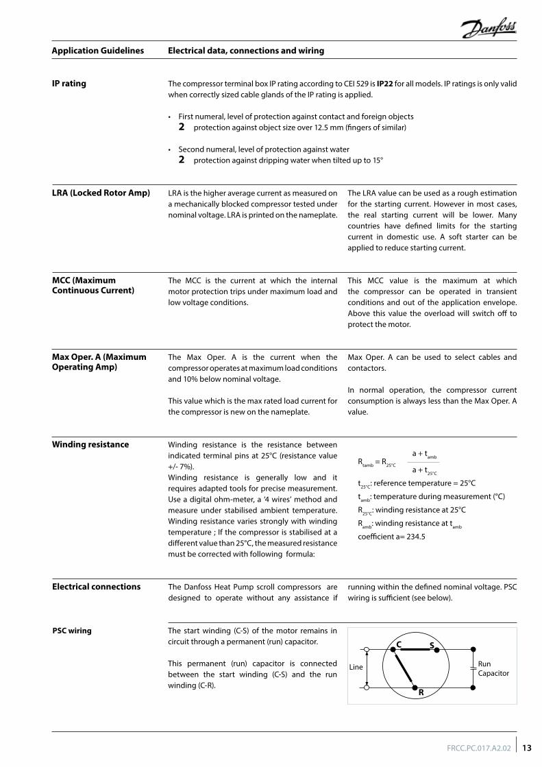
The Danfoss Heat Pump scroll compressors are designed to operate without any assistance if
running within the defined nominal voltage. PSC wiring is sufficient (see below).
Electrical connections
The start winding (C-S) of the motor remains in circuit through a permanent (run) capacitor.
This permanent (run) capacitor is connected between the start winding (C-S) and the run winding (C-R).
PSC wiring
The Max Oper. A is the current when the compressor operates at maximum load conditions and 10% below nominal voltage.
This value which is the max rated load current for the compressor is new on the nameplate.
Max Oper. A can be used to select cables and contactors.
In normal operation, the compressor current consumption is always less than the Max Oper. A value.
Max Oper. A (Maximum Operating Amp)
C S
R
Line Run Capacitor
13FRCC.PC.017.A2.02
Application Guidelines
Electrical data, connections and wiring
Nominal capacitor value
The Danfoss Heat Pump scroll compressors will only operate properly in a single direction. Use a phase meter to establish the phase orders and connect line phases L1, L2 and L3 to terminals T1, T2 and T3, respectively. For three-phase compressors, the motor will run equally well in both directions. Reverse rotation results in excessive noise; no pressure differential between suction and discharge; and suction line warming rather than immediate cooling. A service technician should be present at initial start-up to verify that supply power is properly phased and that compressor and auxiliaries are rotating in the correct direction.
Danfoss Heat Pump scroll compressors are designed to operate for a maximum of 150 hours in reverse, but as a reverse rotation situation can go unnoticed for longer periods, phase monitors are recommended.
At brief power interruptions, reverse rotation can occur with single phase compressors. In this case the internal protector will stop the compressor. It will have to cool down and will restart safely afterwards.
For three-phase applications the voltage measured at the compressor terminals for each
phase should be within ± 2% of the average for all phases.
Phase sequence and reverse rotation protection
Voltage imbalance
Internal motor protection The Danfoss Heat Pump scroll compressors are equipped with an internal line break protector mounted on the motor windings. The protector is an automatic reset device, containing a snap action bimetal switch.
Internal protectors respond to over-current and overheating. They are designed to interrupt motor current under a variety of fault conditions, such as failure to start, running overload, and fan failure.
If the internal overload protector trips out, it must cool down to about 60°C to reset. Depending on ambient temperature, this may take up to several hours.
In single-phase compressors, internal protectors guard against external miswiring, such as reversing electrical connections to the Run (R) and Start (S) terminals. In three-phase compressors the internal protectors provide protection during secondary single-phase conditions (loss of phase).
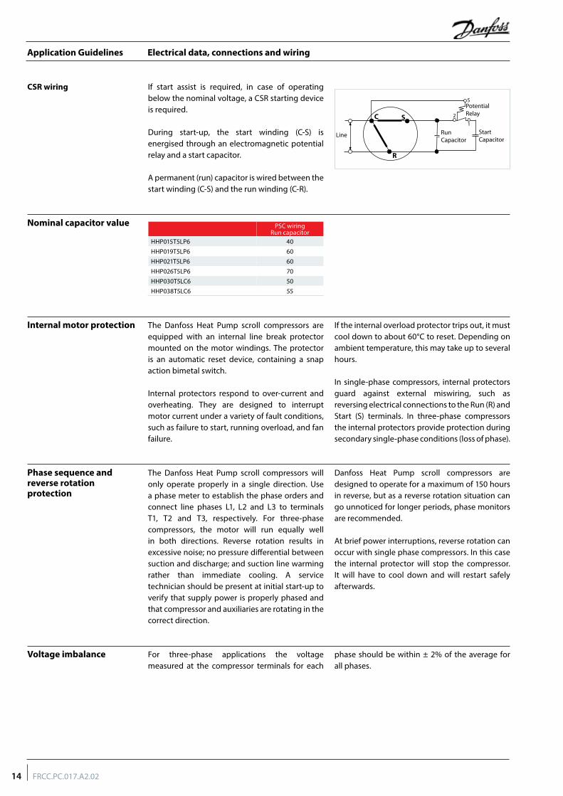
If start assist is required, in case of operating below the nominal voltage, a CSR starting device is required.
During start-up, the start winding (C-S) is energised through an electromagnetic potential relay and a start capacitor.
A permanent (run) capacitor is wired between the start winding (C-S) and the run winding (C-R).
CSR wiring
PSC wiringRun capacitor
HHP015T5LP6 40HHP019T5LP6 60HHP021T5LP6 60HHP026T5LP6 70HHP030T5LC6 50HHP038T5LC6 55
Start Capacitor
Potential Relay
1
2
5
C S
R
Line Run Capacitor
14 FRCC.PC.017.A2.02
Application Guidelines
Approvals and certifications
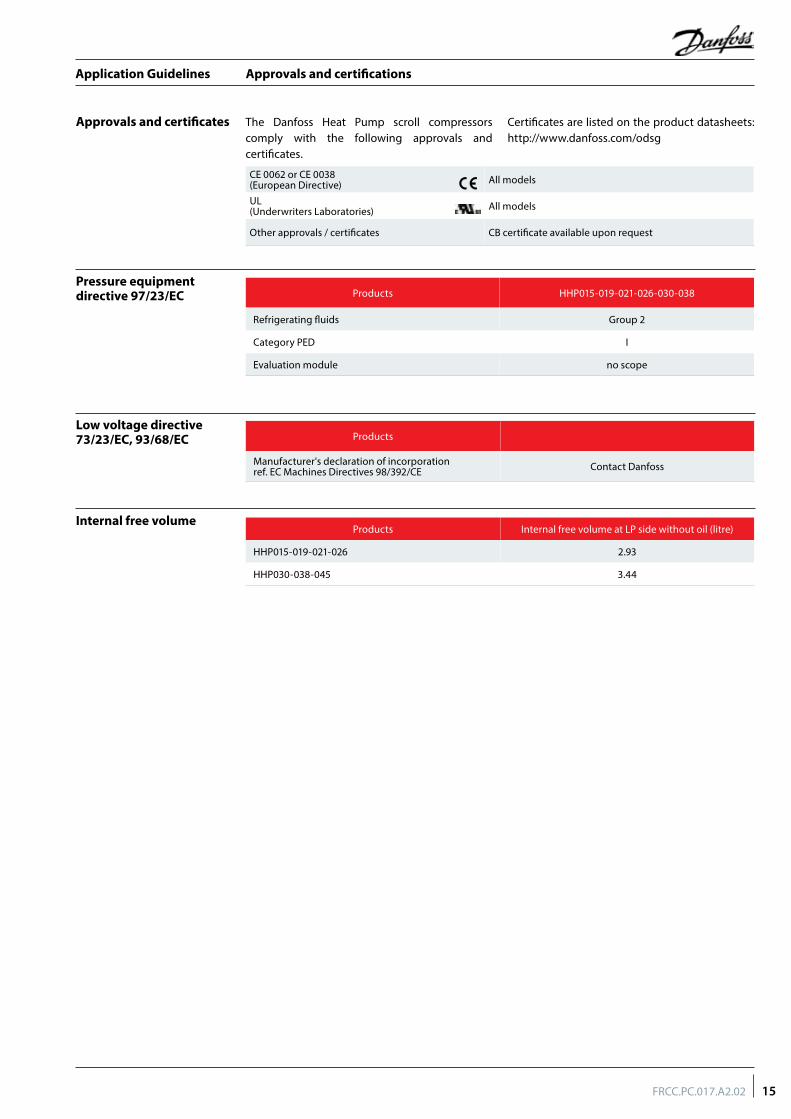
The Danfoss Heat Pump scroll compressors comply with the following approvals and certificates.
Certificates are listed on the product datasheets: http://www.danfoss.com/odsg
Approvals and certificates
Pressure equipment directive 97/23/EC
Low voltage directive 73/23/EC, 93/68/EC
Internal free volume
CE 0062 or CE 0038 (European Directive) All models
UL (Underwriters Laboratories) All models
Other approvals / certificates CB certificate available upon request
Products
Manufacturer's declaration of incorporation ref. EC Machines Directives 98/392/CE Contact Danfoss
Products Internal free volume at LP side without oil (litre)
HHP015-019-021-026 2.93
HHP030-038-045 3.44
Products HHP015-019-021-026-030-038
Refrigerating fluids Group 2
Category PED I
Evaluation module no scope
15FRCC.PC.017.A2.02
Application Guidelines
Operating conditions
The Danfoss Heat Pump scroll compressors application range is influenced by several parameters which need to be monitored for a safe and reliable operation.These parameters and the main recommendations for good practice and safety devices are explained hereunder.
• Refrigerant and lubricants• Motor supply• Compressor ambient temperature• Application envelope (evaporating
temperature, condensing temperature, return gas temperature)
General information
Refrigerant and lubricants
When choosing a refrigerant, different aspects must be taken into consideration:• Legislation (now and in the future)• Safety• Application envelope in relation to expected
running conditions• Compressor capacity and efficiency• Compressor manufacturer recommendations &
guidelines
Additional points could influence the final choice:• Environmental considerations• Standardisation of refrigerants and lubricants• Refrigerant cost• Refrigerant availability
Oil type - PVE Polyvinyl ether (PVE) is an innovative refrigeration lubricant for HFC refrigerant systems. PVE is as hygroscopic as existing polyolester lubricants (POE), but PVE doesn’t chemically react with water; no acids are formed and compressor evacuation is easier.
The compressor technology applied in the Danfoss Heat Pump scroll compressors in combination with PVE lubricant provides the best possible result in terms of reliability and compressor lifetime. The PVE lubricant is compatible with R22 which makes the Danfoss Heat Pump scroll compressors a very versatile multi- refrigerant solution.
Motor supply The Danfoss Heat Pump scroll compressors can be operated at nominal voltages as indicated in section "Electrical data, connections and wiring". Under-voltage and over-voltage operation is allowed within the indicated voltage ranges. In
case of risk of under-voltage operation, special attention must be paid to current draw and start assist for single-phase compressors may be required.
The Danfoss Heat Pump scroll compressors can be applied from -35°C to 50°C ambient temperature. The compressors are designed
as 100 % suction gas cooled without need for additional fan cooling. Ambient temperature has very little effect on the compressor performance.
In case of enclosed fitting and high ambient temperature it’s recommend to check the temperature of power wires and conformity to their insulation specification.
In case of safe tripping by the internal compressor overload protection the compressor must cool down to about 60°C before the overload will reset. A high ambient temperature can strongly delay this cool-down process.
Although the compressor itself can withstand low ambient temperature, the system may require specific design features to ensure safe and reliable
operation. See section ‘Specific application recommendations’.
Compressor ambient temperature
High ambient temperature
Low ambient temperature
16 FRCC.PC.017.A2.02
Application Guidelines
Operating conditions
Application envelope
The discharge temperature depends mainly on the combination of evaporating temperature, condensing temperature and suction gas superheat. Discharge gas temperature should be controlled with an isolated thermocouple or
thermostat attached to the discharge line 15 cm from the compressor shell. Maximum discharge gas temperature must not exceed 140°C when the compressor is running within the approved operating envelope.
Maximum discharge gas temperature
Discharge gas temperature protection (DGT)
DGT protection is required if the high and low pressure switch settings do not protect the compressor against operations beyond its specific application envelope. Please refer to the examples below, which illustrate where DGT protection is required (n°1) and where it is not (n°2).
The compressor must not be allowed to cycle on the discharge gas thermostat. Continuous operations beyond the compressor’s operating range will cause serious damage to the compressor!
A DGT accessory is available from Danfoss: refer to section "Spare parts and accessories".
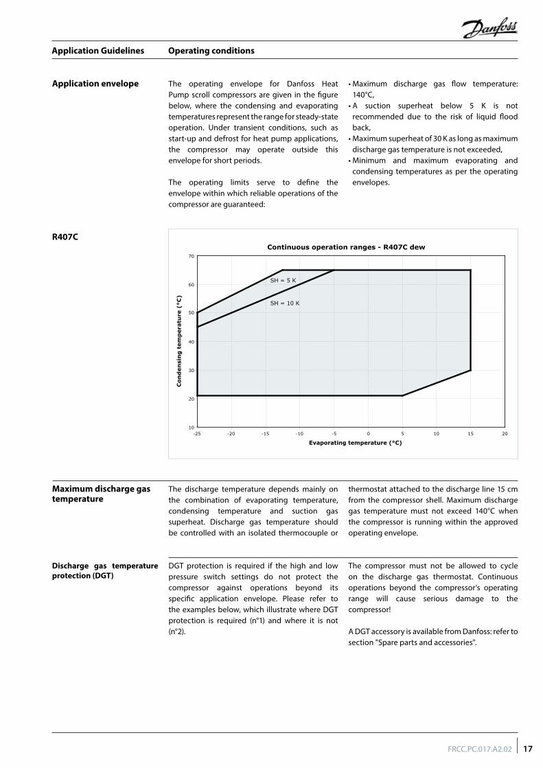
The operating envelope for Danfoss Heat Pump scroll compressors are given in the figure below, where the condensing and evaporating temperatures represent the range for steady-state operation. Under transient conditions, such as start-up and defrost for heat pump applications, the compressor may operate outside this envelope for short periods.
The operating limits serve to define the envelope within which reliable operations of the compressor are guaranteed:
• Maximum discharge gas flow temperature: 140°C,
• A suction superheat below 5 K is not recommended due to the risk of liquid flood back,
• Maximum superheat of 30 K as long as maximum discharge gas temperature is not exceeded,
• Minimum and maximum evaporating and condensing temperatures as per the operating envelopes.
R407C
10
20
30
40
50
60
70
-25 -20 -15 -10 -5 0 5 10 15 20
Continuous operation ranges - R407C dew
Evaporating temperature (°C)
Con
den
sin
g t
emp
erat
ure
(°C
)
SH = 5 K
SH = 10 K
17FRCC.PC.017.A2.02
Application Guidelines
Operating conditions
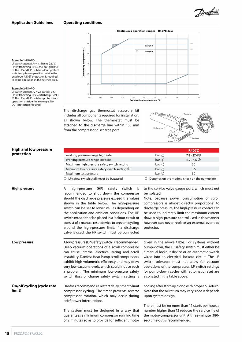
Example 1 (R407C) LP switch setting: LP1= 1.1 bar (g) (-20°C) HP switch setting: HP1= 24.3 bar (g) (60°C) The LP and HP switches don't protect sufficiently from operation outside the envelope. A DGT protection is required to avoid operation in the hatched area.
Example 2 (R407C) LP switch setting: LP2 = 2.3 bar (g) (-9°C) HP switch setting: HP2 = 18.8 bar (g) (50°C) The LP and HP switches protect from operation outside the envelope. No DGT protection required.
A high-pressure (HP) safety switch is recommended to shut down the compressor should the discharge pressure exceed the values shown in the table below. The high-pressure switch can be set to lower values depending on the application and ambient conditions. The HP switch must either be placed in a lockout circuit or consist of a manual reset device to prevent cycling around the high-pressure limit. If a discharge valve is used, the HP switch must be connected
to the service valve gauge port, which must not be isolated.Note: because power consumption of scroll compressors is almost directly proportional to discharge pressure, the high-pressure control can be used to indirectly limit the maximum current draw. A high-pressure control used in this manner however can never replace an external overload protector.
High pressure
High and low pressure protection
A low pressure (LP) safety switch is recommended. Deep vacuum operations of a scroll compressor can cause internal electrical arcing and scroll instability. Danfoss Heat Pump scroll compressors exhibit high volumetric efficiency and may draw very low vacuum levels, which could induce such a problem. The minimum low-pressure safety switch (loss of charge safety switch) setting is
given in the above table. For systems without pump-down, the LP safety switch must either be a manual lockout device or an automatic switch wired into an electrical lockout circuit. The LP switch tolerance must not allow for vacuum operations of the compressor. LP switch settings for pump-down cycles with automatic reset are also listed in the table above.
Low pressure
On/off cycling (cycle rate limit)
Danfoss recommends a restart delay timer to limit compressor cycling. The timer prevents reverse compressor rotation, which may occur during brief power interruptions.
The system must be designed in a way that guarantees a minimum compressor running time of 2 minutes so as to provide for sufficient motor
cooling after start-up along with proper oil return. Note that the oil return may vary since it depends upon system design.
There must be no more than 12 starts per hour, a number higher than 12 reduces the service life of the motor-compressor unit. A three-minute (180-sec) time out is recommended.
The discharge gas thermostat accessory kit includes all components required for installation, as shown below. The thermostat must be attached to the discharge line within 150 mm from the compressor discharge port.
Continuous operation ranges - R407C dew
10
20
30
40
50
60
70
-30 -25 -20 -15 -10 -5 0 5 10 15 20
Evaporating temperature °C
Con
den
sin
g t
emp
erat
ure
°C
Example 1
HP2
LP2LP1
HP1
Example 2
R407CWorking pressure range high side bar (g) 7.8 - 27.4Working pressure range low side bar (g) 0.7 - 6.6 Maximum high pressure safety switch setting bar (g) 30Minimum low pressure safety switch setting bar (g) 0.5Maximum test pressure bar (g) 30
LP safety switch shall never be bypassed. Depends on the models, check on the nameplate
Discharge line
Insulation
Bracket
Thermostat
18 FRCC.PC.017.A2.02
Application Guidelines
System design recommendations
Essential piping design considerations
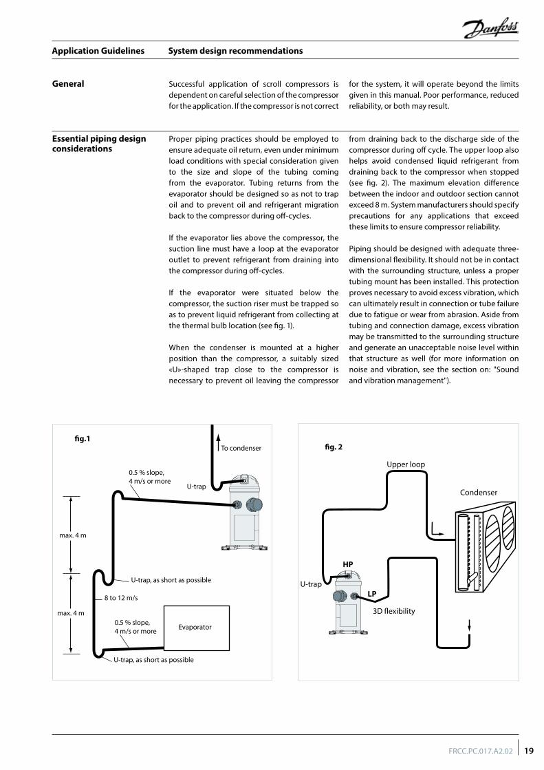
Proper piping practices should be employed to ensure adequate oil return, even under minimum load conditions with special consideration given to the size and slope of the tubing coming from the evaporator. Tubing returns from the evaporator should be designed so as not to trap oil and to prevent oil and refrigerant migration back to the compressor during off-cycles.
If the evaporator lies above the compressor, the suction line must have a loop at the evaporator outlet to prevent refrigerant from draining into the compressor during off-cycles.
If the evaporator were situated below the compressor, the suction riser must be trapped so as to prevent liquid refrigerant from collecting at the thermal bulb location (see fig. 1).
When the condenser is mounted at a higher position than the compressor, a suitably sized «U»-shaped trap close to the compressor is necessary to prevent oil leaving the compressor
from draining back to the discharge side of the compressor during off cycle. The upper loop also helps avoid condensed liquid refrigerant from draining back to the compressor when stopped (see fig. 2). The maximum elevation difference between the indoor and outdoor section cannot exceed 8 m. System manufacturers should specify precautions for any applications that exceed these limits to ensure compressor reliability.
Piping should be designed with adequate three-dimensional flexibility. It should not be in contact with the surrounding structure, unless a proper tubing mount has been installed. This protection proves necessary to avoid excess vibration, which can ultimately result in connection or tube failure due to fatigue or wear from abrasion. Aside from tubing and connection damage, excess vibration may be transmitted to the surrounding structure and generate an unacceptable noise level within that structure as well (for more information on noise and vibration, see the section on: "Sound and vibration management").
General Successful application of scroll compressors is dependent on careful selection of the compressor for the application. If the compressor is not correct
for the system, it will operate beyond the limits given in this manual. Poor performance, reduced reliability, or both may result.
0.5 % slope,4 m/s or more
0.5 % slope,4 m/s or more
U-trap
U-trap, as short as possible
U-trap, as short as possible
max. 4 m
g.1
max. 4 m
8 to 12 m/s
To condenser
Evaporator
Condenser
HP
U-trap
3D exibility
Upper loop
LP
g. 2
19FRCC.PC.017.A2.02
Application Guidelines
System design recommendations
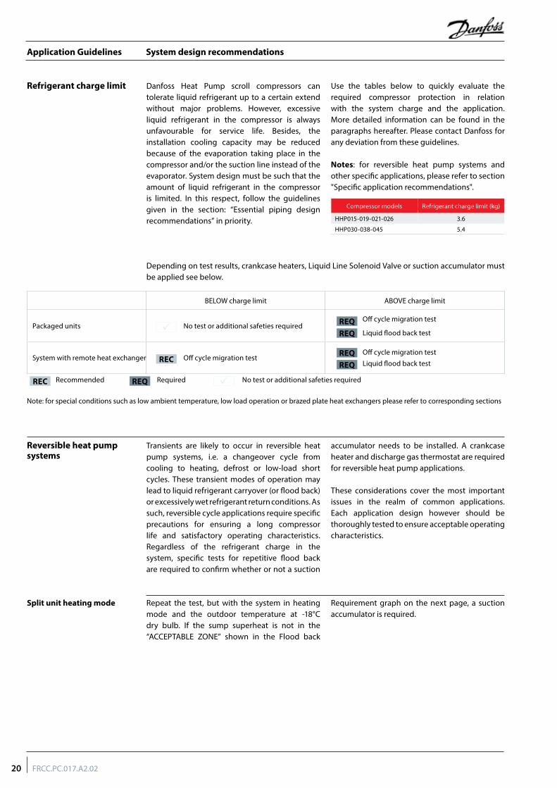
Refrigerant charge limit Danfoss Heat Pump scroll compressors can tolerate liquid refrigerant up to a certain extend without major problems. However, excessive liquid refrigerant in the compressor is always unfavourable for service life. Besides, the installation cooling capacity may be reduced because of the evaporation taking place in the compressor and/or the suction line instead of the evaporator. System design must be such that the amount of liquid refrigerant in the compressor is limited. In this respect, follow the guidelines given in the section: “Essential piping design recommendations” in priority.
Use the tables below to quickly evaluate the required compressor protection in relation with the system charge and the application. More detailed information can be found in the paragraphs hereafter. Please contact Danfoss for any deviation from these guidelines.
Notes: for reversible heat pump systems and other specific applications, please refer to section "Specific application recommendations".
Reversible heat pump systems
Transients are likely to occur in reversible heat pump systems, i.e. a changeover cycle from cooling to heating, defrost or low-load short cycles. These transient modes of operation may lead to liquid refrigerant carryover (or flood back) or excessively wet refrigerant return conditions. As such, reversible cycle applications require specific precautions for ensuring a long compressor life and satisfactory operating characteristics. Regardless of the refrigerant charge in the system, specific tests for repetitive flood back are required to confirm whether or not a suction
accumulator needs to be installed. A crankcase heater and discharge gas thermostat are required for reversible heat pump applications.
These considerations cover the most important issues in the realm of common applications. Each application design however should be thoroughly tested to ensure acceptable operating characteristics.
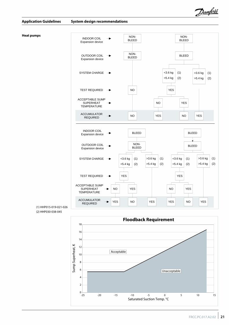
Split unit heating mode Repeat the test, but with the system in heating mode and the outdoor temperature at -18°C dry bulb. If the sump superheat is not in the “ACCEPTABLE ZONE” shown in the Flood back
Requirement graph on the next page, a suction accumulator is required.
Note: for special conditions such as low ambient temperature, low load operation or brazed plate heat exchangers please refer to corresponding sections
Recommended Required No test or additional safeties requiredREQREC
BELOW charge limit ABOVE charge limit
Packaged units No test or additional safeties requiredOff cycle migration test
Liquid flood back test
System with remote heat exchanger Off cycle migration testOff cycle migration test Liquid flood back testREC
REQ
REQ
REQ
REQ
Depending on test results, crankcase heaters, Liquid Line Solenoid Valve or suction accumulator must be applied see below.
Compressor models Refrigerant charge limit (kg)
HHP015-019-021-026 3.6
HHP030-038-045 5.4
20 FRCC.PC.017.A2.02
Application Guidelines
System design recommendations
Heat pumps
(1) HHP015-019-021-026(2) HHP030-038-045
NON-BLEED
NON-BLEED
NON-BLEED
BLEED
<3.6 kg (1)
<5.4 kg (2)
YES
NO YES
YES NO YES
NO
NO
BLEED BLEED
NON-BLEED
BLEED
YES
NO YES
YES NO YES
YES
NO YES
YES NO YES
INDOOR COILExpansion device
OUTDOOR COILExpansion device
SYSTEM CHARGE
TEST REQUIRED
ACCEPTABLE SUMPSUPERHEAT
TEMPERATURE
ACCUMULATORREQUIRED
SYSTEM CHARGE
TEST REQUIRED
ACCEPTABLE SUMPSUPERHEAT
TEMPERATURE
ACCUMULATORREQUIRED
`
>3.6 kg (1)
>5.4 kg (2)
<3.6 kg (1)
<5.4 kg (2)
<3.6 kg (1)
<5.4 kg (2)
>3.6 kg (1)
>5.4 kg (2)
>3.6 kg (1)
>5.4 kg (2)
INDOOR COILExpansion device
OUTDOOR COILExpansion device
0
2
4
6
8
10
12
14
16
18
-25 -20 -15 -10 -5 0 5 10 15
Sum
p Su
perh
eat,
K
Floodback Requirement
Saturated Suction Temp. °C
Acceptable
Unacceptable
21FRCC.PC.017.A2.02
Application Guidelines
System design recommendations
Crankcase heater Crankcase heaters provide extra compressor protection, and should be considered for all applications. For initial installation of precharged
systems and for any extended power interruptions, the crankcase heater should be energized for 24 hours prior to compressor startup.
The minimum sump temperature is in the range from 6K to 17K above saturated suction
temperature. Refer to the flood back test criteria section "System design recommendations".
Minimum sump superheat
Loss of charge protection Danfoss Heat Pump scroll compressors do not include a thermal valve protection; therefore, all applications should consider loss of charge protection :
• A low pressure switch in the low pressure side of the system is required.
• A discharge line thermostat set no higher than 140°C is recommended. The thermostat must be a manual lockout type device (or electrical lockout circuit) and be located within 150 mm of the compressor discharge connection. The discharge line thermostat must be insulated to insure proper sensing and operation.
In installations with good oil return and line runs up to 15 m, no additional oil is required. If installation lines exceed 15 m, additional oil may be needed. 1 or 2% of the total system refrigerant charge (in weight) can be used to roughly define the required oil top-up quantity.
Always use oil from new cans.Top-up the oil while the compressor is idle. Use any accessible connector on the compressor suction line and a suitable pump.
Oil level checking and top-up
Danfoss Heat Pump scroll compressors are machines with fixed volume ratio, and operate more efficiently near the design pressure ratio. In the extreme, do not exceed a 11:1 pressure ratio (absolute discharge pressure to absolute suction
pressure) for extended periods. The Danfoss Heat Pump scroll compressor is equipped with an internal pressure relief valve for protection against blocked condenser and fan failure conditions.
High pressure ratio
Danfoss recommends the use of a thermostatic expansion valve for all air conditioning and heat pump applications. A TXV has two key benefits: it provides modulating control of the system under varying load conditions, and it protects the compressors from flood back during adverse running conditions.
Excessive liquid refrigerant flood back during steady state operation is a major system design consideration for all types of compressors. Oil dilution that occurs with excessive flood back can have a significant adverse effect on bearing reliability. Suction accumulators may be required in some applications to prevent flood back.
When the use of fixed orifice devices is specified in the system design, and when a TXV is applied at the limit of its control range, the following tests should be conducted to determine if a suction
accumulator is needed. Refer to the flowcharts section "System design recommendations" to determine when to apply the excessive liquid flood back test.
Preventing liquid flood back
Testing for excessive liquid flood back
Water utilising systems Apart from residual moisture in the system after commissioning, water could also enter the refrigeration circuit during operation. Water in the system shall always be avoided. Not only because it can shortly lead to electrical failure, sludge in sump and corrosion but in particular because it can cause serious safety risks.
Common causes for water leaks are corrosion and freezing.
Corrosion: Materials in the system shall be compliant with water and protected against corrosion.
Freezing: When water freezes into ice its volume expands which can damage heat exchanger walls and cause leaks. During off periods water inside heat exchangers could start freezing when ambient temperature is lower than 0°C. During on periods ice banking could occur when the circuit is running continuously at too low load. Both situations should be avoided by connecting a pressure and thermostat switch in the safety line.
22 FRCC.PC.017.A2.02
Application Guidelines
Sound and vibration management
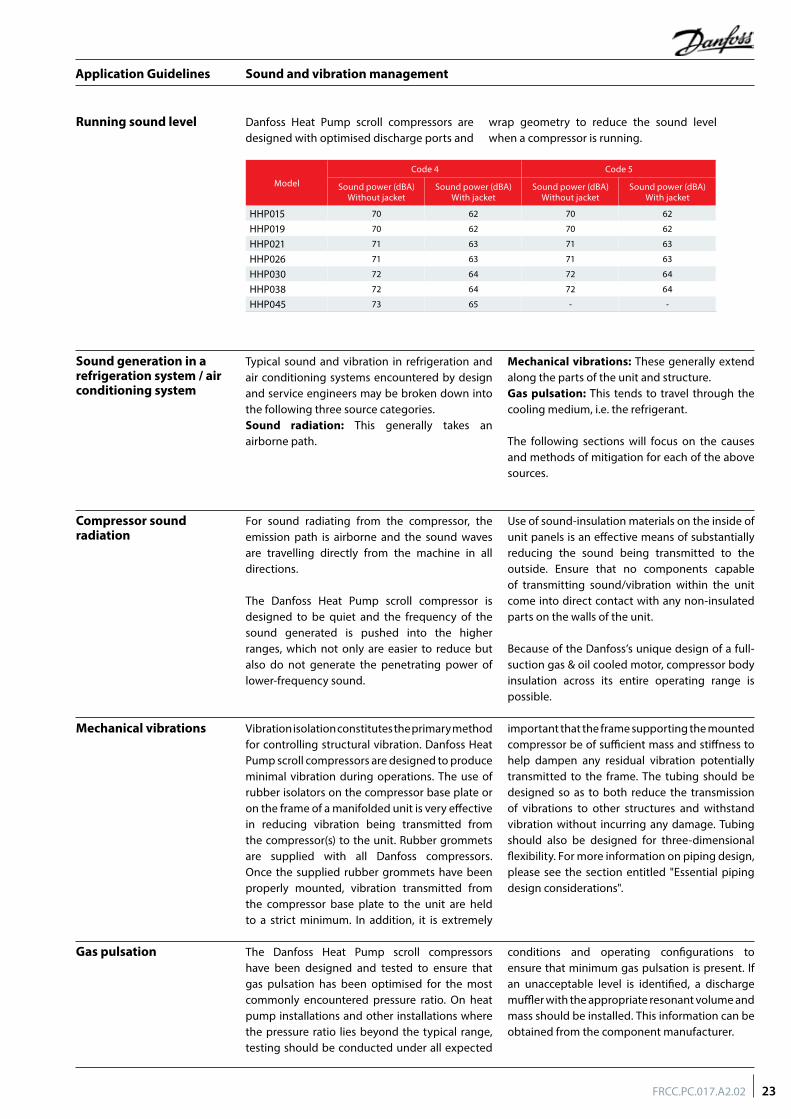
Running sound level
Sound generation in a refrigeration system / air conditioning system
Compressor sound radiation
Danfoss Heat Pump scroll compressors are designed with optimised discharge ports and
wrap geometry to reduce the sound level when a compressor is running.
Typical sound and vibration in refrigeration and air conditioning systems encountered by design and service engineers may be broken down into the following three source categories.Sound radiation: This generally takes an airborne path.
Mechanical vibrations: These generally extend along the parts of the unit and structure.Gas pulsation: This tends to travel through the cooling medium, i.e. the refrigerant.
The following sections will focus on the causes and methods of mitigation for each of the above sources.
For sound radiating from the compressor, the emission path is airborne and the sound waves are travelling directly from the machine in all directions.
The Danfoss Heat Pump scroll compressor is designed to be quiet and the frequency of the sound generated is pushed into the higher ranges, which not only are easier to reduce but also do not generate the penetrating power of lower-frequency sound.
Use of sound-insulation materials on the inside of unit panels is an effective means of substantially reducing the sound being transmitted to the outside. Ensure that no components capable of transmitting sound/vibration within the unit come into direct contact with any non-insulated parts on the walls of the unit.
Because of the Danfoss’s unique design of a full-suction gas & oil cooled motor, compressor body insulation across its entire operating range is possible.
Model
Code 4 Code 5
Sound power (dBA)Without jacket
Sound power (dBA)With jacket
Sound power (dBA)Without jacket
Sound power (dBA)With jacket
HHP015 70 62 70 62
HHP019 70 62 70 62
HHP021 71 63 71 63
HHP026 71 63 71 63
HHP030 72 64 72 64
HHP038 72 64 72 64
HHP045 73 65 - -
Mechanical vibrations Vibration isolation constitutes the primary method for controlling structural vibration. Danfoss Heat Pump scroll compressors are designed to produce minimal vibration during operations. The use of rubber isolators on the compressor base plate or on the frame of a manifolded unit is very effective in reducing vibration being transmitted from the compressor(s) to the unit. Rubber grommets are supplied with all Danfoss compressors. Once the supplied rubber grommets have been properly mounted, vibration transmitted from the compressor base plate to the unit are held to a strict minimum. In addition, it is extremely
important that the frame supporting the mounted compressor be of sufficient mass and stiffness to help dampen any residual vibration potentially transmitted to the frame. The tubing should be designed so as to both reduce the transmission of vibrations to other structures and withstand vibration without incurring any damage. Tubing should also be designed for three-dimensional flexibility. For more information on piping design, please see the section entitled "Essential piping design considerations".
Gas pulsation The Danfoss Heat Pump scroll compressors have been designed and tested to ensure that gas pulsation has been optimised for the most commonly encountered pressure ratio. On heat pump installations and other installations where the pressure ratio lies beyond the typical range, testing should be conducted under all expected
conditions and operating configurations to ensure that minimum gas pulsation is present. If an unacceptable level is identified, a discharge muffler with the appropriate resonant volume and mass should be installed. This information can be obtained from the component manufacturer.
23FRCC.PC.017.A2.02
Application Guidelines
Installation
Each Danfoss Heat Pump scroll compressor is shipped with printed Instructions for installation.
Compressor handling and storage
Compressor holding charge
Compressors are provided with a lifting lug. This lug should always be used to lift the compressor. Once the compressor is installed, the lifting lug should never be used to lift the complete installation. The compressor must be handled
with caution in the vertical position, with a maximum inclination of 15° from vertical. Store the compressor between -35°C and 50°C, not exposed to rain or corrosive atmosphere.
Each compressor is shipped with a nominal dry nitrogen holding charge between 0.4 bar and 0.7 bar, and is sealed with elastomer plugs. The plugs should be removed with care to avoid oil loss when the holding charge is released. Remove the suction plug first and the discharge
plug afterwards. The plugs shall be removed only just before connecting the compressor to the installation in order to avoid moisture entering the compressor. When the plugs are removed, it is essential to keep the compressor in an upright position to avoid oil spillage.
System cleanliness The refrigerant compression system, regardless of the type of compressor used, will only provide high efficiency and good reliability, along with a long operating life, if the system contains solely the refrigerant and oil it was designed for. Any other substances within the system will not improve performance and, in most cases, will be highly detrimental to system operations.
The presence of non-condensable substances and system contaminants, such as metal shavings, solder and flux, have a negative impact on compressor service life. Many of these contaminants are small enough to pass through a mesh screen and can cause considerable damage within a bearing assembly. The use of highly hygroscopic POE and PVE oils in R407C and R410A compressors requires that the oil be exposed to the atmosphere just as little as possible.
System contamination is one of main factors affecting equipment reliability and compressor service life. It is important therefore to take system cleanliness into account when assembling a refrigeration system.
During the manufacturing process, circuit contamination may be caused by:• Brazing and welding oxides,• Filings and particles from the removal of burrs in pipe-work,• Brazing flux,• Moisture and air.
Consequently, when building equipment and assemblies, the following precautions must be taken: never drill holes into the pipe-work after installation.
Compressor mounting Maximum inclination from the vertical plane, while operating must not exceed 7 degrees. All compressors are delivered with 4 rubber
grommets and metal sleeves. Compressors must always be mounted with these grommets.
Brazing material For copper suction and discharge fittings, use copper-phosphorus brazing material. Sil-Fos® and other silver brazing materials are also acceptable.
If flux is required for the brazing operation, use coated rod or flux core wire. To avoid system contamination, do not brush flux on.
Tube brazing procedure Do not bend the compressor discharge or suction lines or force system piping into the compressor connections, because this will increase stresses
that are a potential cause of failure. Recommended brazing procedures and material, are described on following page.
24 FRCC.PC.017.A2.02
Application Guidelines
Installation
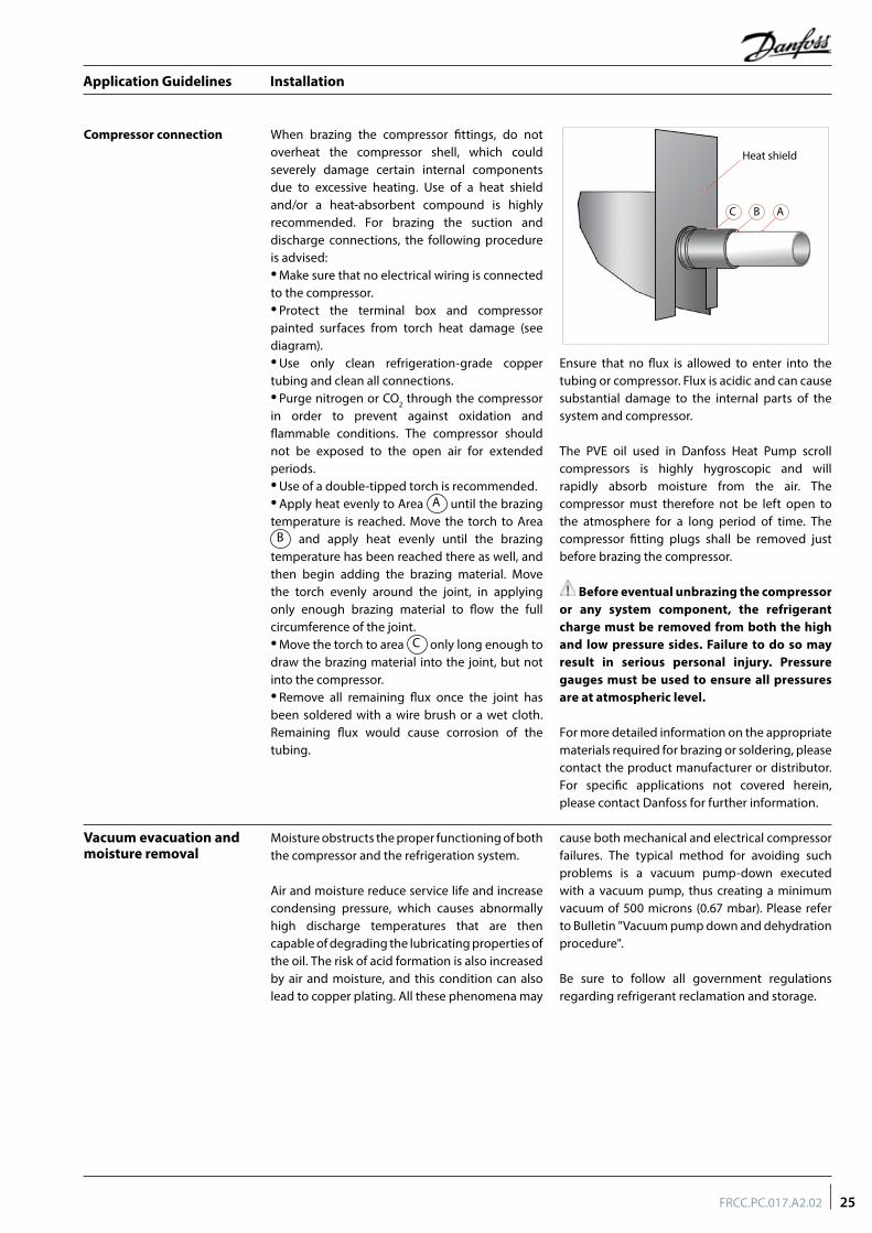
Compressor connection When brazing the compressor fittings, do not overheat the compressor shell, which could severely damage certain internal components due to excessive heating. Use of a heat shield and/or a heat-absorbent compound is highly recommended. For brazing the suction and discharge connections, the following procedure is advised:• Make sure that no electrical wiring is connected to the compressor.• Protect the terminal box and compressor painted surfaces from torch heat damage (see diagram).• Use only clean refrigeration-grade copper tubing and clean all connections.• Purge nitrogen or CO2 through the compressor in order to prevent against oxidation and flammable conditions. The compressor should not be exposed to the open air for extended periods.• Use of a double-tipped torch is recommended.• Apply heat evenly to Area A until the brazing temperature is reached. Move the torch to Area
B and apply heat evenly until the brazing temperature has been reached there as well, and then begin adding the brazing material. Move the torch evenly around the joint, in applying only enough brazing material to flow the full circumference of the joint.• Move the torch to area C only long enough to draw the brazing material into the joint, but not into the compressor.• Remove all remaining flux once the joint has been soldered with a wire brush or a wet cloth. Remaining flux would cause corrosion of the tubing.
Ensure that no flux is allowed to enter into the tubing or compressor. Flux is acidic and can cause substantial damage to the internal parts of the system and compressor.
The PVE oil used in Danfoss Heat Pump scroll compressors is highly hygroscopic and will rapidly absorb moisture from the air. The compressor must therefore not be left open to the atmosphere for a long period of time. The compressor fitting plugs shall be removed just before brazing the compressor.
Before eventual unbrazing the compressor or any system component, the refrigerant charge must be removed from both the high and low pressure sides. Failure to do so may result in serious personal injury. Pressure gauges must be used to ensure all pressures are at atmospheric level.
For more detailed information on the appropriate materials required for brazing or soldering, please contact the product manufacturer or distributor. For specific applications not covered herein, please contact Danfoss for further information.
Moisture obstructs the proper functioning of both the compressor and the refrigeration system.
Air and moisture reduce service life and increase condensing pressure, which causes abnormally high discharge temperatures that are then capable of degrading the lubricating properties of the oil. The risk of acid formation is also increased by air and moisture, and this condition can also lead to copper plating. All these phenomena may
cause both mechanical and electrical compressor failures. The typical method for avoiding such problems is a vacuum pump-down executed with a vacuum pump, thus creating a minimum vacuum of 500 microns (0.67 mbar). Please refer to Bulletin "Vacuum pump down and dehydration procedure".
Be sure to follow all government regulations regarding refrigerant reclamation and storage.
Vacuum evacuation and moisture removal
Heat shield
C B A
25FRCC.PC.017.A2.02
Application Guidelines
Installation
Refrigerant charging
Compressor replacement after motor burn out
It is recommended that system charging be done using the weighed charge method, adding refrigerant to the high side of the system. Charging the high and low sides of a system
with gas simultaneously at a controlled rate is also an acceptable method. Do not exceed the recommended unit charge, and never charge liquid to the low side.
If there has been a motor burnout follow the evacuation procedure described on previous page. Remove and replace the liquid line filter drier and install a Danfoss type DAS burnout drier of appropriate capacity.
Refer to the DAS drier instructions and technical information on correct use and monitoring of the burnout drier and the liquid line and suction line filter driers.
Liquid line filter driers A properly sized filter drier is required for all Danfoss scroll applications. Danfoss recommends DML (100% molecular seives) driers for HFC refrigerants R407C with PVE oil. For servicing of existing installations where acid formation is present the Danfoss DCL solid core filter driers
containing activated alumina are recommended. The drier is to be oversized rather than under sized. When selecting a drier, always take into account its capacity (water content capacity), the system refrigeration capacity and the system refrigerant charge.
Insulation resistance and dielectric strength
Insulation resistance must be greater than 1 megohm when measured with a 500 volt direct current megohm tester.
Each compressor motor is tested at the factory with a high potential voltage (hi-pot) that exceeds the UL requirement both in potential and in duration. Leakage current is less than 0.5 mA.
Danfoss Heat Pump scroll compressors are configured with the pump assembly at the top of the shell, and the motor below. As a result, the motor can be partially immersed in refrigerant
and oil. The presence of refrigerant around the motor windings will result in lower resistance values to ground and higher leakage current readings. Such readings do not indicate a faulty compressor, and should not be cause for concern.
In testing insulation resistance, Danfoss recommends that the system be first operated briefly to distribute refrigerant throughout the system. Following this brief operation, retest the compressor for insulation resistance or current leakage.
26 FRCC.PC.017.A2.02
Application Guidelines
Ordering information and packaging
Industrial pack
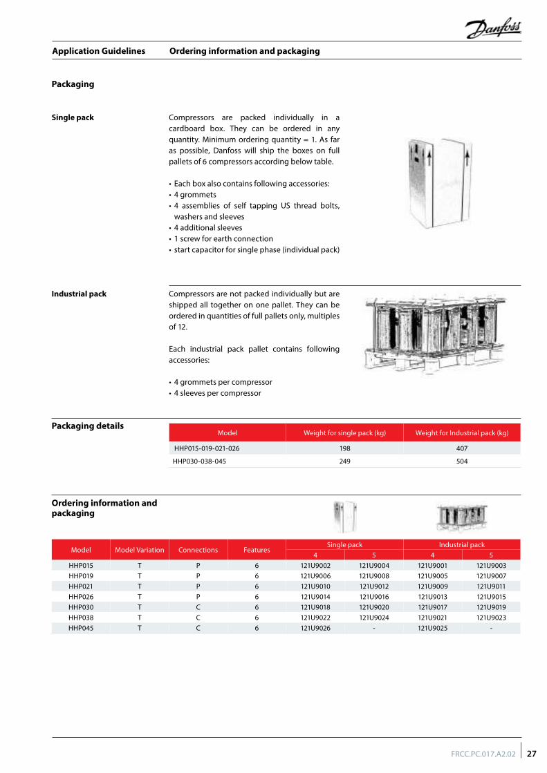
Compressors are packed individually in a cardboard box. They can be ordered in any quantity. Minimum ordering quantity = 1. As far as possible, Danfoss will ship the boxes on full pallets of 6 compressors according below table.
• Each box also contains following accessories:• 4 grommets• 4 assemblies of self tapping US thread bolts,
washers and sleeves• 4 additional sleeves• 1 screw for earth connection• start capacitor for single phase (individual pack)
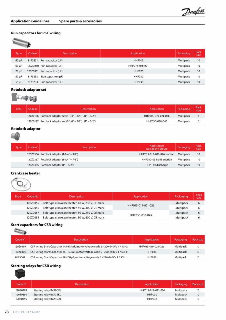
Compressors are not packed individually but are shipped all together on one pallet. They can be ordered in quantities of full pallets only, multiples of 12.
Each industrial pack pallet contains following accessories:
• 4 grommets per compressor• 4 sleeves per compressor
Packaging
Single pack
Packaging details
Ordering information and packaging
Model Weight for single pack (kg) Weight for Industrial pack (kg)
HHP015-019-021-026 198 407
HHP030-038-045 249 504
Model Model Variation Connections Features Single pack Industrial pack
4 5 4 5HHP015 T P 6 121U9002 121U9004 121U9001 121U9003HHP019 T P 6 121U9006 121U9008 121U9005 121U9007HHP021 T P 6 121U9010 121U9012 121U9009 121U9011HHP026 T P 6 121U9014 121U9016 121U9013 121U9015HHP030 T C 6 121U9018 121U9020 121U9017 121U9019HHP038 T C 6 121U9022 121U9024 121U9021 121U9023HHP045 T C 6 121U9026 - 121U9025 -
27FRCC.PC.017.A2.02
Application Guidelines
Spare parts & accessories
Run capacitors for PSC wiring
Rotolock adaptor set
Rotolock adaptor
Crankcase heater
Type Code n° Description Application Packaging Pack size
120Z0126 Rotolock adaptor set (1-1/4" ~ 3/4") , (1" ~ 1/2") HHP015-019-021-026 Multipack 6
120Z0127 Rotolock adaptor set (1-1/4" ~ 7/8") , (1" ~ 1/2") HHP030-038-045 Multipack 6
Type Code n° Description Application(see above group) Packaging Pack
size
120Z0366 Rotolock adaptor (1-1/4" ~ 3/4") HHP015-019-021-026 suction Multipack 10
120Z0367 Rotolock adaptor (1-1/4" ~ 7/8") HHP030-038-045 suction Multipack 10
120Z0365 Rotolock adaptor (1" ~ 1/2") HHP - all discharge Multipack 10
Type Code n° Description Application Packaging Pack size
40 µF 8173231 Run capacitor (µF) HHP015 Multipack 10
60 µF 120Z0050 Run capacitor (µF) HHP019, HHP021 Multipack 10
70 µF 120Z0051 Run capacitor (µF) HHP026 Multipack 10
50 µF 8173233 Run capacitor (µF) HHP030 Multipack 10
55 µF 8173234 Run capacitor (µF) HHP038 Multipack 10
Type Code No Description Application Packaging Pack Size
120Z0055 Belt type crankcase heater, 40 W, 230 V, CE markHHP015-019-021-026
Multipack 6
120Z0056 Belt type crankcase heater, 40 W, 400 V, CE mark Multipack 6
120Z0057 Belt type crankcase heater, 50 W, 230 V, CE markHHP030-038-045
Multipack 6
120Z0058 Belt type crankcase heater, 50 W, 400 V, CE mark Multipack 6
Start capacitors for CSR wiring
Code n° Description Application Packaging Pack size
120Z0399 CSR wiring Start Capacitor 145-175 µF, motor voltage code 5 - 220-240V / 1 / 50Hz HHP015-019-021-026 Multipack 10
120Z0400 CSR wiring Start Capacitor 161-193 µF, motor voltage code 5 - 220-240V / 1 / 50Hz HHP030 Multipack 10
8173001 CSR wiring Start Capacitor 88-108 µF, motor voltage code 5 - 220-240V / 1 / 50Hz HHP038 Multipack 10
Code n° Description Application Packaging Pack size
120Z0393 Starting relay RVA9CKL HHP015-019-021-026 Multipack 10
120Z0394 Starting relay RVA3EKL HHP030 Multipack 10
120Z0395 Starting relay RVA4GKL HHP038 Multipack 10
Starting relays for CSR wiring
28 FRCC.PC.017.A2.02
Application Guidelines
Spare parts & accessories
Lubricant
Mounting hardware
Discharge temperature protection
Type Code No Description Application Packaging Pack Size
120Z5034 PVE (0.95 liter can) HHP015 to 045 Multipack 1
Type Code No Description Application Packaging Pack Size
120Z5005 Mounting kit for 1 scroll compressor including 4 grommets, 4 sleeves, 4 bolts, 4 washers All models Single pack 1
Type Code No Description Application Packaging Pack Size
7750009 Discharge thermostat kit All models Multipack 10
7973008 Discharge thermostat kit All models Industry pack 50
29FRCC.PC.017.A2.02
Application Guidelines


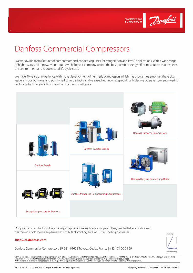
Danfoss Commercial Compressors is a worldwide manufacturer of compressors and condensing units for refrigeration and HVAC applications. With a wide range of high quality and innovative products we help your company to find the best possible energy efficient solution that respects the environment and reduces total life cycle costs.
We have 40 years of experience within the development of hermetic compressors which has brought us amongst the global leaders in our business, and positioned us as distinct variable speed technology specialists. Today we operate from engineering and manufacturing facilities spread across three continents.
FRCC.PC.017.A2.02 - January 2015 - Replaces FRCC.PC.017.A1.02 April 2010 © Copyright Danfoss | Commercial Compressors | 2015.01
Our products can be found in a variety of applications such as rooftops, chillers, residential air conditioners, heatpumps, coldrooms, supermarkets, milk tank cooling and industrial cooling processes.
http://cc.danfoss.com
Danfoss Inverter Scrolls
Danfoss Turbocor Compressors
Danfoss Scrolls
Danfoss Optyma Condensing Units
Secop Compressors for Danfoss
Danfoss Maneurop Reciprocating Compressors
Danfoss Commercial Compressors, BP 331, 01603 Trévoux Cedex, France | +334 74 00 28 29
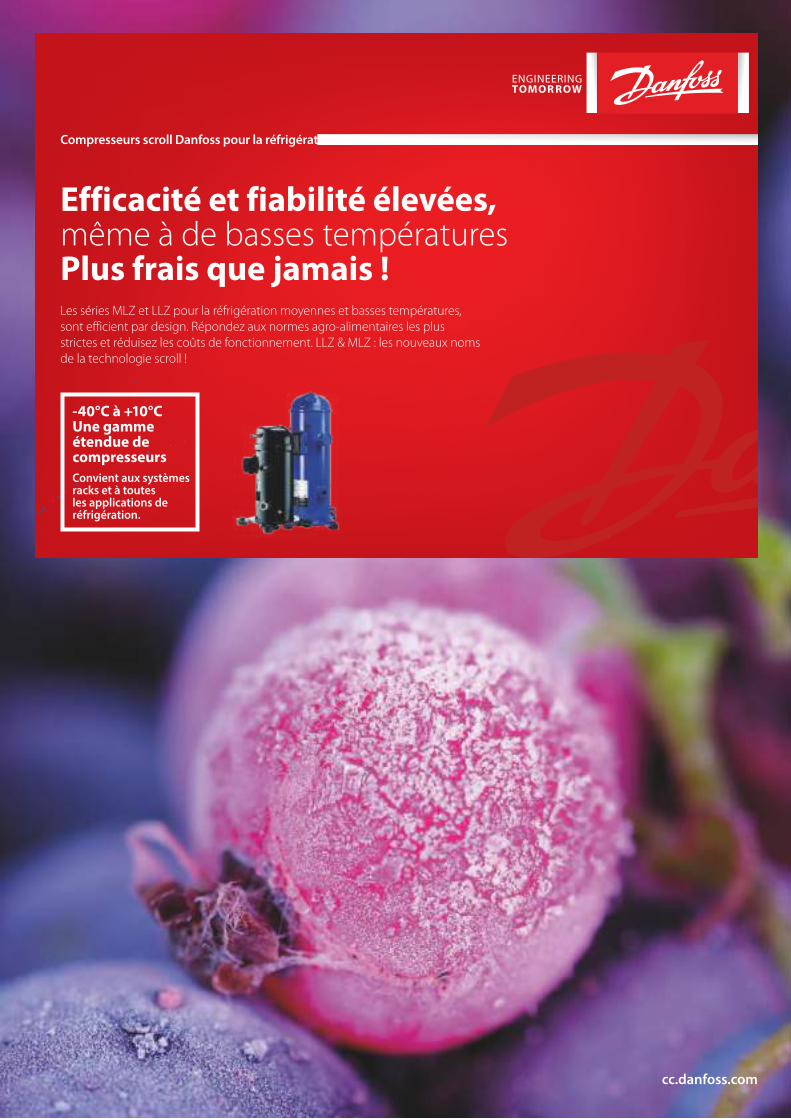
Efficacité et fiabilité élevées, même à de basses températuresPlus frais que jamais !Les séries MLZ et LLZ pour la réfrigération moyennes et basses températures, sont efficient par design. Répondez aux normes agro-alimentaires les plus strictes et réduisez les coûts de fonctionnement. LLZ & MLZ : les nouveaux noms de la technologie scroll !
Compresseurs scroll Danfoss pour la réfrigération
cc.danfoss.com
-40°C à +10°C Une gamme étendue de compresseursConvient aux systèmes racks et à toutes les applications de réfrigération.
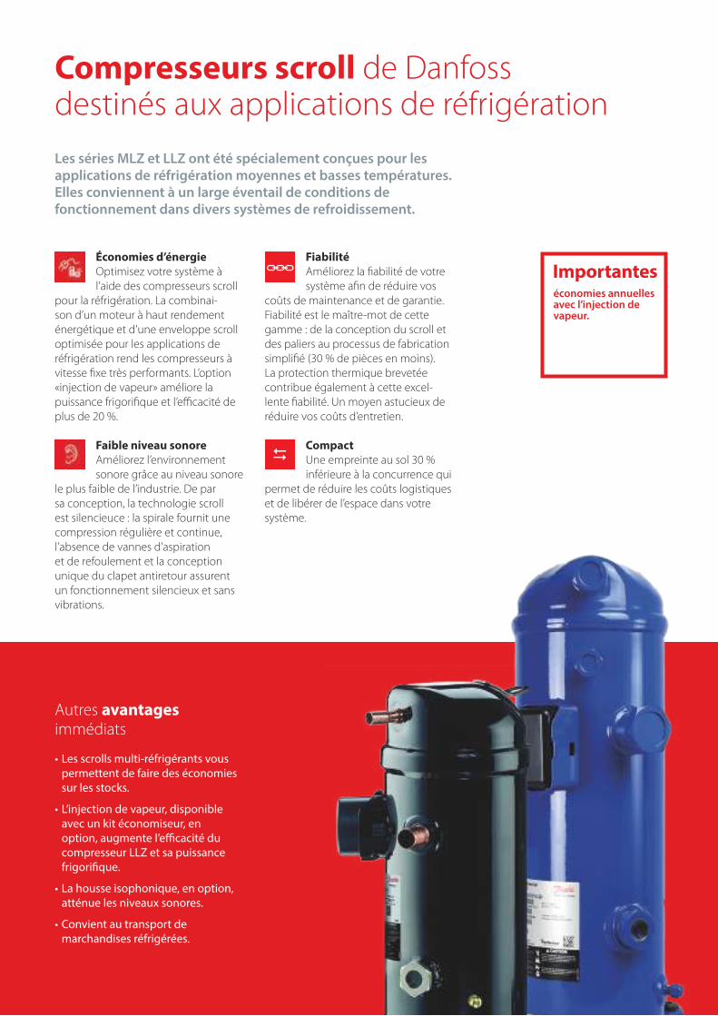
Autres avantages immédiats
• Les scrolls multi-réfrigérants vous permettent de faire des économies sur les stocks.
• L’injection de vapeur, disponible avec un kit économiseur, en option, augmente l’efficacité du compresseur LLZ et sa puissance frigorifique.
• La housse isophonique, en option, atténue les niveaux sonores.
• Convient au transport de marchandises réfrigérées.
Compresseurs scroll de Danfoss destinés aux applications de réfrigérationLes séries MLZ et LLZ ont été spécialement conçues pour les applications de réfrigération moyennes et basses températures. Elles conviennent à un large éventail de conditions de fonctionnement dans divers systèmes de refroidissement.
Économies d’énergieOptimisez votre système à l’aide des compresseurs scroll
pour la réfrigération. La combinai-son d’un moteur à haut rendement énergétique et d’une enveloppe scroll optimisée pour les applications de réfrigération rend les compresseurs à vitesse fixe très performants. L’option «injection de vapeur» améliore la puissance frigorifique et l’efficacité de plus de 20 %.
Faible niveau sonoreAméliorez l’environnement sonore grâce au niveau sonore
le plus faible de l’industrie. De par sa conception, la technologie scroll est silencieuce : la spirale fournit une compression régulière et continue, l’absence de vannes d’aspiration et de refoulement et la conception unique du clapet antiretour assurent un fonctionnement silencieux et sans vibrations.
FiabilitéAméliorez la fiabilité de votre système afin de réduire vos
coûts de maintenance et de garantie.Fiabilité est le maître-mot de cette gamme : de la conception du scroll et des paliers au processus de fabrication simplifié (30 % de pièces en moins). La protection thermique brevetée contribue également à cette excel-lente fiabilité. Un moyen astucieux de réduire vos coûts d’entretien.
CompactUne empreinte au sol 30 % inférieure à la concurrence qui
permet de réduire les coûts logistiques et de libérer de l’espace dans votre système.
économies annuelles avec l’injection de vapeur.
Importantes
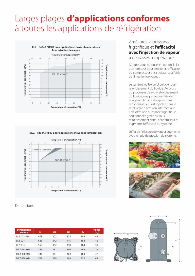
Améliorez la puissance frigorifique et l’efficacité avec l’injection de vapeur à de basses températuresDanfoss vous propose, en option, le kit économiseur pour améliorer l’efficacité du compresseur et sa puissance à l’aide de l’injection de vapeur.
Le système utilise un circuit de sous-refroidissement du liquide. Au cours du processus de sous-refroidissement du liquide, une petite quantité de réfrigérant liquide s’évapore dans l’économiseur et est injectée dans le scroll réglé à pression intermédiaire. Cela offre une puissance frigorifique additionnelle grâce au sous-refroidissement dans l’économiseur et augmente l’efficacité du système.
L’effet de l’injection de vapeur augmente avec le ratio de pression du système.
Larges plages d’applications conformes à toutes les applications de réfrigération
D
HH2
H1
239
239
190
190
Dimensions
41
50
59
68
77
86
95
104
113
122
131
140
149-49 -40 -31 -22 -13 -4 5 14 23
32
65
60
55
50
45
40
35
30
25
20
15
10
5
0
-45 -40 -35 -30 -25 -20 -15 -10 -5
-31 -22 -13 -4 5 14 23 32 41 50 59
-35 -30 -25 -20 -15 -10 -5 0 5 10 15
5
10
15
20
25
30
35
40
45
50
55
60
65
50
59
68
77
86
95
104
113
122
131
140
149
41
LLZ – R404A / R507 pour applications basses températures Avec injection de vapeur
MLZ – R404A / R507 pour applications moyennes températures
Température d’évaporation(°F)
Température d’évaporation (°F)
RGT : 20 °C / 68 °F
RGT : 20 °C / 68 °F
Conditions transitoires
Température d’évaporation (°C)
Température d’évaporation (°C)
Température de condensation (°F)
Température de condensation (°F)
Tem
péra
ture
de
cond
ensa
tion
(°C)
Tem
péra
ture
de
cond
ensa
tion
(°C)
Dimensions en mm H H1 H2 D
Poids (kg)
LLZ 013-018 478 302 375 184 42
LLZ 024 533 342 415 184 46
LLZ 034 558 367 440 184 51
MLZ 015-026 393 231 360 165 31
MLZ 030-048 436 261 403 184 37
MLZ 058-076 528 350 499 232 45
Plages d’applications
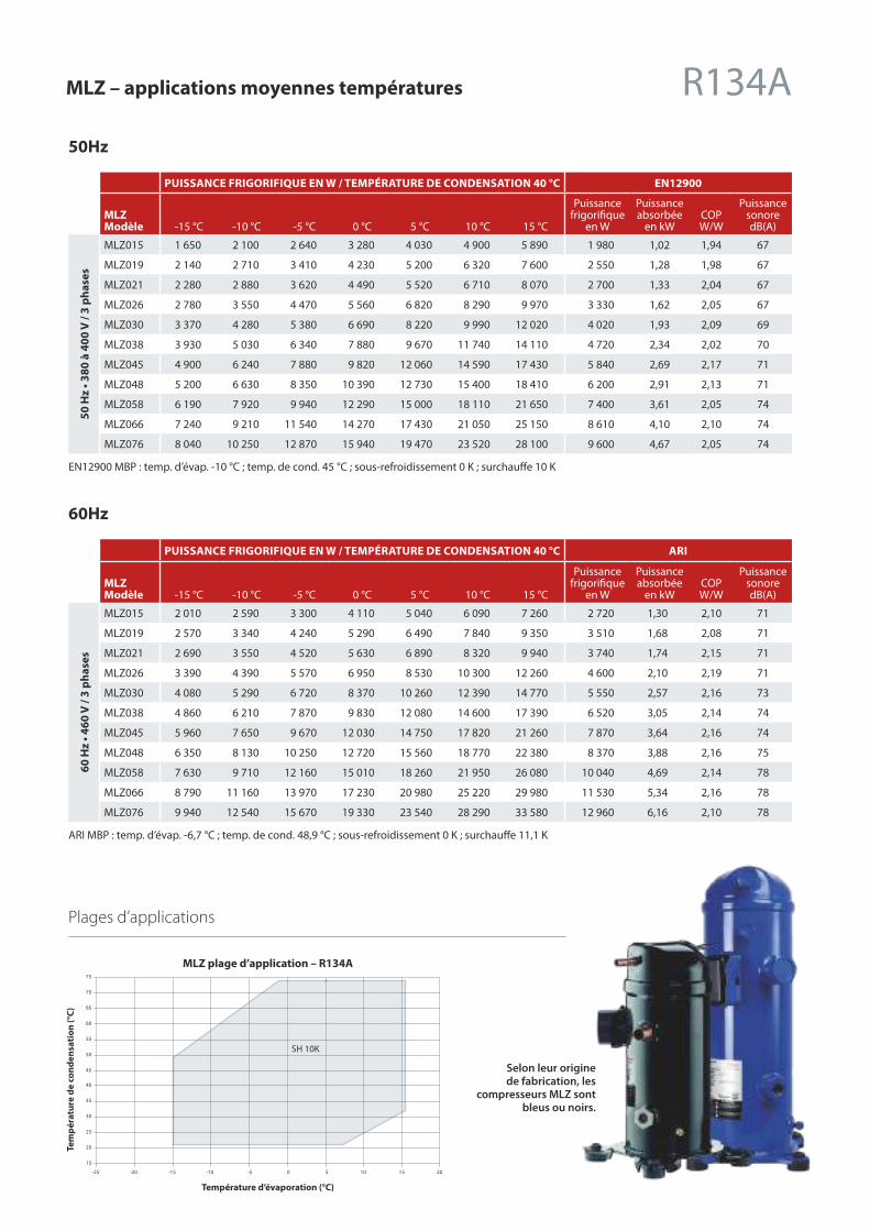
MLZ – applications moyennes températures R134A
Selon leur origine de fabrication, les
compresseurs MLZ sont bleus ou noirs.
15
20
25
30
35
40
45
50
55
60
65
70
75
-25 -20 -15 -10 -5 0 5 10 15 20
Température d’évaporation (°C)
MLZ plage d’application – R134A
SH 10K
Tem
péra
ture
de
cond
ensa
tion
(°C)
50Hz
PUISSANCE FRIGORIFIQUE EN W / TEMPÉRATURE DE CONDENSATION 40 °C EN12900
MLZ Modèle -15 °C -10 °C -5 °C 0 °C 5 °C 10 °C 15 °C
Puissance frigorifique
en W
Puissance absorbée
en kWCOP W/W
Puissance sonore dB(A)
50 H
z • 3
80 à
400
V /
3 ph
ases
MLZ015 1 650 2 100 2 640 3 280 4 030 4 900 5 890 1 980 1,02 1,94 67
MLZ019 2 140 2 710 3 410 4 230 5 200 6 320 7 600 2 550 1,28 1,98 67
MLZ021 2 280 2 880 3 620 4 490 5 520 6 710 8 070 2 700 1,33 2,04 67
MLZ026 2 780 3 550 4 470 5 560 6 820 8 290 9 970 3 330 1,62 2,05 67
MLZ030 3 370 4 280 5 380 6 690 8 220 9 990 12 020 4 020 1,93 2,09 69
MLZ038 3 930 5 030 6 340 7 880 9 670 11 740 14 110 4 720 2,34 2,02 70
MLZ045 4 900 6 240 7 880 9 820 12 060 14 590 17 430 5 840 2,69 2,17 71
MLZ048 5 200 6 630 8 350 10 390 12 730 15 400 18 410 6 200 2,91 2,13 71
MLZ058 6 190 7 920 9 940 12 290 15 000 18 110 21 650 7 400 3,61 2,05 74
MLZ066 7 240 9 210 11 540 14 270 17 430 21 050 25 150 8 610 4,10 2,10 74
MLZ076 8 040 10 250 12 870 15 940 19 470 23 520 28 100 9 600 4,67 2,05 74
EN12900 MBP : temp. d’évap. -10 °C ; temp. de cond. 45 °C ; sous-refroidissement 0 K ; surchauffe 10 K
60Hz
PUISSANCE FRIGORIFIQUE EN W / TEMPÉRATURE DE CONDENSATION 40 °C ARI
MLZ Modèle -15 °C -10 °C -5 °C 0 °C 5 °C 10 °C 15 °C
Puissance frigorifique
en W
Puissance absorbée
en kWCOP W/W
Puissance sonore dB(A)
60 H
z • 4
60 V
/ 3
phas
es
MLZ015 2 010 2 590 3 300 4 110 5 040 6 090 7 260 2 720 1,30 2,10 71
MLZ019 2 570 3 340 4 240 5 290 6 490 7 840 9 350 3 510 1,68 2,08 71
MLZ021 2 690 3 550 4 520 5 630 6 890 8 320 9 940 3 740 1,74 2,15 71
MLZ026 3 390 4 390 5 570 6 950 8 530 10 300 12 260 4 600 2,10 2,19 71
MLZ030 4 080 5 290 6 720 8 370 10 260 12 390 14 770 5 550 2,57 2,16 73
MLZ038 4 860 6 210 7 870 9 830 12 080 14 600 17 390 6 520 3,05 2,14 74
MLZ045 5 960 7 650 9 670 12 030 14 750 17 820 21 260 7 870 3,64 2,16 74
MLZ048 6 350 8 130 10 250 12 720 15 560 18 770 22 380 8 370 3,88 2,16 75
MLZ058 7 630 9 710 12 160 15 010 18 260 21 950 26 080 10 040 4,69 2,14 78
MLZ066 8 790 11 160 13 970 17 230 20 980 25 220 29 980 11 530 5,34 2,16 78
MLZ076 9 940 12 540 15 670 19 330 23 540 28 290 33 580 12 960 6,16 2,10 78
ARI MBP : temp. d’évap. -6,7 °C ; temp. de cond. 48,9 °C ; sous-refroidissement 0 K ; surchauffe 11,1 K
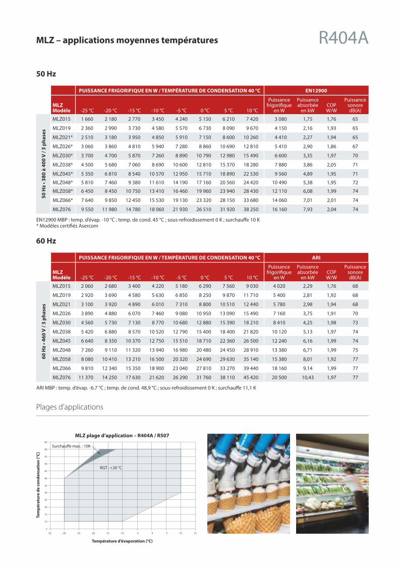
50 Hz
PUISSANCE FRIGORIFIQUE EN W / TEMPÉRATURE DE CONDENSATION 40 °C EN12900
MLZ Modèle -25 °C -20 °C -15 °C -10 °C -5 °C 0 °C 5 °C 10 °C
Puissance frigorifique
en W
Puissance absorbée
en kWCOPW/W
Puissance sonore dB(A)
50 H
z • 3
80 à
400
V /
3 ph
ases
MLZ015 1 660 2 180 2 770 3 450 4 240 5 150 6 210 7 420 3 080 1,75 1,76 65
MLZ019 2 360 2 990 3 730 4 580 5 570 6 730 8 090 9 670 4 150 2,16 1,93 65
MLZ021* 2 510 3 180 3 950 4 850 5 910 7 150 8 600 10 260 4 410 2,27 1,94 65
MLZ026* 3 060 3 860 4 810 5 940 7 280 8 860 10 690 12 810 5 410 2,90 1,86 67
MLZ030* 3 700 4 700 5 870 7 260 8 890 10 790 12 980 15 490 6 600 3,35 1,97 70
MLZ038* 4 500 5 680 7 060 8 690 10 600 12 810 15 370 18 280 7 880 3,86 2,05 71
MLZ045* 5 350 6 810 8 540 10 570 12 950 15 710 18 890 22 530 9 560 4,89 1,95 71
MLZ048* 5 810 7 460 9 380 11 610 14 190 17 160 20 560 24 420 10 490 5,38 1,95 72
MLZ058* 6 450 8 450 10 750 13 410 16 460 19 960 23 940 28 430 12 110 6,08 1,99 74
MLZ066* 7 640 9 850 12 450 15 530 19 130 23 320 28 150 33 680 14 060 7,01 2,01 74
MLZ076 9 550 11 980 14 780 18 060 21 930 26 510 31 920 38 250 16 160 7,93 2,04 74
EN12900 MBP : temp. d’évap. -10 °C ; temp. de cond. 45 °C ; sous-refroidissement 0 K ; surchauffe 10 K* Modèles certifiés Asercom
60 Hz
PUISSANCE FRIGORIFIQUE EN W / TEMPÉRATURE DE CONDENSATION 40 °C ARI
MLZ Modèle -25 °C -20 °C -15 °C -10 °C -5 °C 0 °C 5 °C 10 °C
Puissance frigorifique
en W
Puissance absorbée
en kWCOPW/W
Puissance sonore dB(A)
60 H
z • 4
60 V
/ 3
phas
es
MLZ015 2 060 2 680 3 400 4 220 5 180 6 290 7 560 9 030 4 020 2,29 1,76 68
MLZ019 2 920 3 690 4 580 5 630 6 850 8 250 9 870 11 710 5 400 2,81 1,92 68
MLZ021 3 100 3 920 4 890 6 010 7 310 8 800 10 510 12 440 5 780 2,98 1,94 68
MLZ026 3 890 4 880 6 070 7 460 9 080 10 950 13 090 15 490 7 160 3,75 1,91 70
MLZ030 4 560 5 730 7 130 8 770 10 680 12 880 15 390 18 210 8 410 4,25 1,98 73
MLZ038 5 420 6 880 8 570 10 520 12 790 15 400 18 400 21 820 10 120 5,13 1,97 74
MLZ045 6 640 8 350 10 370 12 750 15 510 18 710 22 360 26 500 12 240 6,16 1,99 74
MLZ048 7 260 9 110 11 320 13 940 16 980 20 480 24 450 28 910 13 380 6,71 1,99 75
MLZ058 8 080 10 410 13 210 16 500 20 320 24 690 29 630 35 140 15 380 8,01 1,92 77
MLZ066 9 810 12 340 15 350 18 900 23 040 27 810 33 270 39 440 18 160 9,14 1,99 77
MLZ076 11 370 14 250 17 630 21 620 26 290 31 760 38 110 45 420 20 500 10,43 1,97 77
ARI MBP : temp. d’évap. -6.7 °C ; temp. de cond. 48,9 °C ; sous-refroidissement 0 K ; surchauffe 11,1 K
Plages d’applications
MLZ – applications moyennes températures R404A
-35 -30 -25 -20 -15 -10 -5 0 5 10 15
5
10
15
20
25
30
35
40
45
50
55
60
65
MLZ plage d’application – R404A / R507
RGT : +20 °C
Surchauffe max. : 10K
Tem
péra
ture
de
cond
ensa
tion
(°C)
Température d’évaporation (°C)
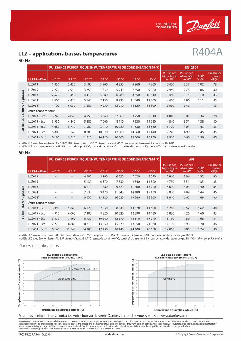
Plages d’applications
50 Hz PUISSANCE FRIGORIFIQUE EN W / TEMPÉRATURE DE CONDENSATION 40 °C EN12900
LLZ Modèles -40 °C -35 °C -30 °C -25 °C -20 °C -15 °C -10 °C
Puissance frigorifique
en W
Puissance absorbée
en kWCOP W/W
Puissance sonore dB(A)
50 H
z • 3
80 à
400
V /
3 ph
ases
LLZ013 1 850 2 420 3 100 3 900 4 850 5 960 7 260 2 420 2,37 1,02 78
LLZ015 2 270 2 940 3 750 4 750 5 940 7 350 9 020 2 940 2,78 1,06 80
LLZ018 2 670 3 450 4 410 5 580 6 980 8 650 10 610 3 450 3,15 1,10 83
LLZ024 3 400 4 410 5 640 7 130 8 920 11 040 13 560 4 410 3,96 1,11 85
LLZ034* 4 700 6 050 7 680 9 650 12 010 14 820 18 160 6 050 5,46 1,11 85
Avec économiseur
LLZ013 - Eco 3 240 4 040 4 950 5 960 7 060 8 250 9 510 4 040 3,01 1,34 78
LLZ015 - Eco 3 930 4 840 5 880 7 060 8 410 9 930 11 650 4 840 3,51 1,38 80
LLZ018 - Eco 4 680 5 770 7 000 8 410 10 020 11 830 13 880 5 770 4,04 1,43 83
LLZ024 - Eco 5 880 7 240 8 800 10 570 12 580 14 860 17 440 7 240 4,99 1,45 85
LLZ034 - Eco* 8 190 9 910 11 910 14 220 16 860 19 860 23 230 9 910 6,60 1,50 85
Modèle LLZ sans économiseur : AN 12900 LBP : temp. d’évap. -35 °C ; temp. de cond. 40 °C ; sous-refroidissement 0 K ; surchauffe 10 KModèle LLZ avec économiseur : ARI LBP : temp. d’évap. -35 °C ; temp. de cond. 40 °C ; sous-refroidissement 5 K ; surchauffe 10 K – * données préliminaires
60 Hz PUISSANCE FRIGORIFIQUE EN W / TEMPÉRATURE DE CONDENSATION 40 °C ARI
LLZ Modèles -40 °C -35 °C -30 °C -25 °C -20 °C -15 °C -10 °C
Puissance frigorifique
en W
Puissance absorbée
en kWCOP W/W
Puissance sonore dB(A)
60 H
z • 4
60 V
/ 3
phas
es
LLZ013 - - 4 200 5 180 6 320 7 620 9 090 3 860 2,94 1,32 80
LLZ015 - - 5 130 6 370 7 830 9 540 11 520 4 730 3,51 1,35 83
LLZ018 - - 6 110 7 580 9 320 11 360 13 720 5 630 4,03 1,40 84
LLZ024 - - 7 630 9 470 11 640 14 180 17 130 7 020 4,89 1,44 86
LLZ034* - - 10 630 13 120 16 020 19 380 23 260 9 810 6,62 1,48 86
Avec économiseur
LLZ013 - Eco 3 990 5 060 6 170 7 350 8 640 10 070 11 670 5 780 3,57 1,62 80
LLZ015 - Eco 4 910 6 000 7 300 8 820 10 520 12 390 14 430 6 830 4,26 1,60 83
LLZ018 - Eco 5 870 7 160 8 730 10 540 12 570 14 810 17 240 8 160 4,86 1,68 84
LLZ024 - Eco 7 270 8 880 10 810 13 050 15 570 18 350 21 360 10 110 5,93 1,70 86
LLZ034 - Eco* 10 140 12 540 14 900 17 450 20 440 24 100 28 690 14 050 8,05 1,74 86
Modèle LLZ sans économiseur : ARI LBP : temp. d’évap. -31,7 °C ; temp. de cond. 40,6 °C ; sous-refroidissement 0 K ; température de retour de gaz 18,3 °CModèle LLZ avec économiseur : ARI LBP : temp. d’évap. -31,7 °C ; temp. de cond. 40,6 °C ; sous-refroidissement 5 K ; température de retour de gaz 18,3 °C – * données préliminaires
LLZ – applications basses températures R404A
© Copyright Danfoss Commercial CompressorsFRCC.PB.027.A5.04_Oct2014 cc.danfoss.com
-45 -40 -35 -30 -25 -20 -15 -10 -5
5
0
10
15
20
25
30
35
40
45
50
55
60
65
-45 -40 -35 -30 -25 -20 -15 -10 -5
5
0
10
15
20
25
30
35
40
45
50
55
60
65
LLZ plage d’applications avec économiseur (R404A / R507)
LLZ plage d’applications sans économiseur (R404A / R507)
RGT 18,3 °C
Tem
péra
ture
de
refo
ulem
ent s
atur
ée (°
C)
Tem
péra
ture
de
refo
ulem
ent s
atur
ée (°
C)
Température d’aspiration saturée (°C) Température d’aspiration saturée (°C)
Pour plus d’informations, contactez votre bureau de vente Danfoss ou rendez-vous sur le site www.danfoss.comDanfoss n’assume aucune responsabilité quant aux erreurs qui se seraient glissées dans les catalogues, brochures ou autres documentations écrites. Dans un souci constant d’amélioration, Danfoss se réserve le droit d’apporter sans préavis toutes modications à ses produits, y compris ceux se trouvant déjà en commande, sous réserve, toutefois, que ces modications n’aectent pas les caractéristiques déjà arrêtées en accord avec le client. Toutes les marques de fabrique de cette documentation sont la propriété des sociétés correspondantes. Danfoss et le logotype Danfoss sont des marques de fabrique de Danfoss A/S. Tous droits réservés.
LLZ san eco et RGT 18,3 °C
Surchauffe 20K
1 CYLINDRE2 CYLINDRES4 CYLINDRES8 CYLINDRES
Guide de sélection et d’application
RECIPROCATING COMPRESSORS
50 HzR22
R407CR134a
R404A / R507
MT/MTZ
Refrigeration andAir Conditioning Demandez-nous
toujours plus
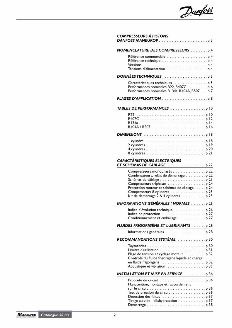
2Catalogue 50 HzRECIPROCATING COMPRESSORS
COMPRESSEURS À PISTONSDANFOSS MANEUROP . . . . . . . . . . . . . . . . . . . . . . . . . . . . . . p 3
NOMENCLATURE DES COMPRESSEURS . . . . . . . . . . p 4
Référence commerciale . . . . . . . . . . . . . . . . . . . . . . . . . p 4Référence technique . . . . . . . . . . . . . . . . . . . . . . . . . . . . p 4Versions . . . . . . . . . . . . . . . . . . . . . . . . . . . . . . . . . . . . . . . . p 4Tensions d’alimentation . . . . . . . . . . . . . . . . . . . . . . . . . p 4
DONNÉES TECHNIQUES . . . . . . . . . . . . . . . . . . . . . . . . . . . p 5
Caractéristiques techniques . . . . . . . . . . . . . . . . . . . . . p 5Performances nominales R22, R407C . . . . . . . . . . . . p 6Performances nominales R134a, R404A, R507 . . . . p 7
PLAGES D’APPLICATION . . . . . . . . . . . . . . . . . . . . . . . . . . . . p 8
TABLES DE PERFORMANCES . . . . . . . . . . . . . . . . . . . . . . p 10
R22 . . . . . . . . . . . . . . . . . . . . . . . . . . . . . . . . . . . . . . . . . . . p 10R407C . . . . . . . . . . . . . . . . . . . . . . . . . . . . . . . . . . . . . . . . p 12R134a . . . . . . . . . . . . . . . . . . . . . . . . . . . . . . . . . . . . . . . . . p 14R404A / R507 . . . . . . . . . . . . . . . . . . . . . . . . . . . . . . . . . p 16
DIMENSIONS . . . . . . . . . . . . . . . . . . . . . . . . . . . . . . . . . . . . . . p 18
1 cylindre . . . . . . . . . . . . . . . . . . . . . . . . . . . . . . . . . . . . . p 182 cylindres . . . . . . . . . . . . . . . . . . . . . . . . . . . . . . . . . . . . p 194 cylindres . . . . . . . . . . . . . . . . . . . . . . . . . . . . . . . . . . . . p 208 cylindres . . . . . . . . . . . . . . . . . . . . . . . . . . . . . . . . . . . . p 21
CARACTÉRISTIQUES ÉLECTRIQUESET SCHÉMAS DE CÂBLAGE . . . . . . . . . . . . . . . . . . . . . . . . p 22
Compresseurs monophasés . . . . . . . . . . . . . . . . . . . . p 22Condensateurs, relais de démarrage . . . . . . . . . . . . p 22Schémas de câblage . . . . . . . . . . . . . . . . . . . . . . . . . . . . p 23Compresseurs triphasés . . . . . . . . . . . . . . . . . . . . . . . p 24Protection moteur et schémas de câblage . . . . . . p 24Compresseurs 8 cylindres . . . . . . . . . . . . . . . . . . . . . p 25Kit de démarrage 2 & 4 cylindres . . . . . . . . . . . . . . . p 25
INFORMATIONS GÉNÉRALES / NORMES . . . . . . . . . p 26
Indice d’évolution technique . . . . . . . . . . . . . . . . . . . p 26Indice de protection . . . . . . . . . . . . . . . . . . . . . . . . . . . p 27Conditionnement et emballage . . . . . . . . . . . . . . . . . p 27
FLUIDES FRIGORIGÈNE ET LUBRIFIANTS . . . . . . . . p 28
Informations générales . . . . . . . . . . . . . . . . . . . . . . . . . p 28
RECOMMANDATIONS SYSTÈME . . . . . . . . . . . . . . . . . p 30
Tuyauteries . . . . . . . . . . . . . . . . . . . . . . . . . . . . . . . . . . . . p 30Limites d’utilisation . . . . . . . . . . . . . . . . . . . . . . . . . . . . p 31Plage de tension et cyclage moteur . . . . . . . . . . . . . p 32Contrôle du fluide frigorigène liquide et chargeen fluide frigorigène . . . . . . . . . . . . . . . . . . . . . . . . . . . p 32Acoustique et vibration . . . . . . . . . . . . . . . . . . . . . . . . p 35
INSTALLATION ET MISE EN SERVICE . . . . . . . . . . . . . p 36
Propreté du circuit . . . . . . . . . . . . . . . . . . . . . . . . . . . . p 36Manutention, montage et raccordementsur le circuit . . . . . . . . . . . . . . . . . . . . . . . . . . . . . . . . . . . p 36Test de pression du circuit . . . . . . . . . . . . . . . . . . . . . p 36Détection des fuites . . . . . . . . . . . . . . . . . . . . . . . . . . . p 37Tirage au vide - déshydratation . . . . . . . . . . . . . . . . . p 37Démarrage . . . . . . . . . . . . . . . . . . . . . . . . . . . . . . . . . . . . p 38
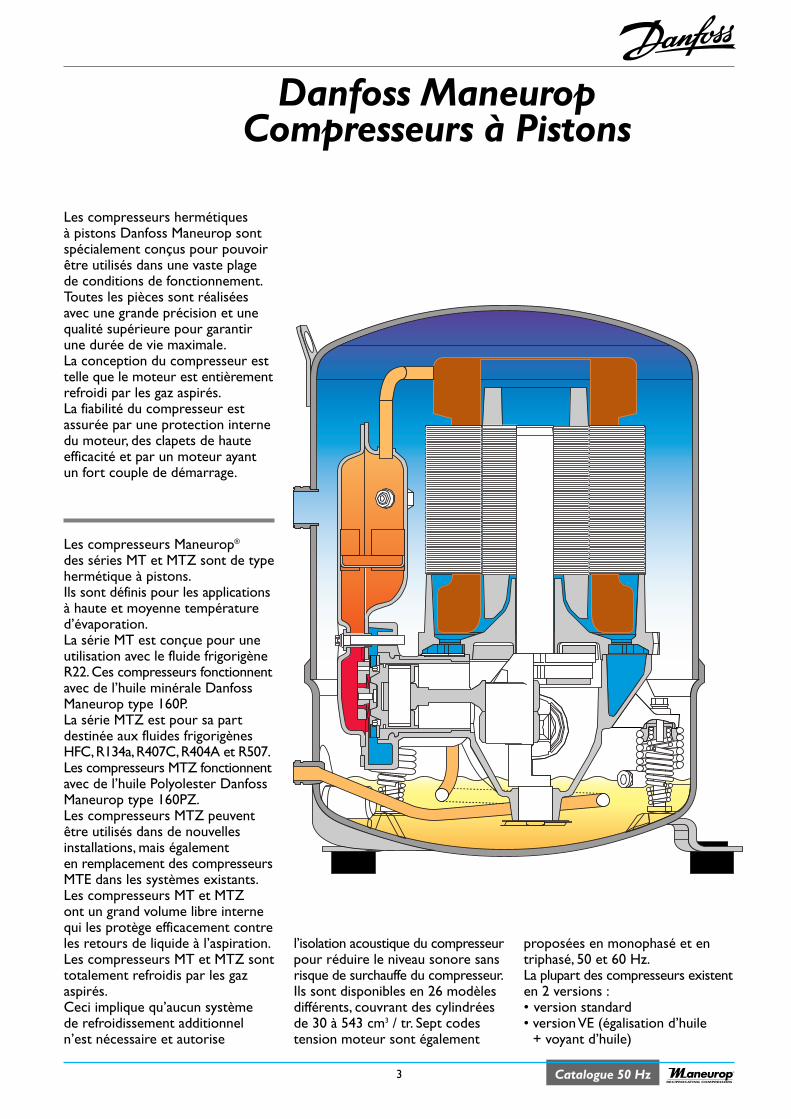
Danfoss ManeuropCompresseurs à Pistons
3 Catalogue 50 HzRECIPROCATING COMPRESSORS
Les compresseurs hermétiquesà pistons Danfoss Maneurop sontspécialement conçus pour pouvoirêtre utilisés dans une vaste plagede conditions de fonctionnement.Toutes les pièces sont réaliséesavec une grande précision et unequalité supérieure pour garantirune durée de vie maximale.La conception du compresseur esttelle que le moteur est entièrementrefroidi par les gaz aspirés.La fiabilité du compresseur estassurée par une protection internedu moteur, des clapets de hauteefficacité et par un moteur ayantun fort couple de démarrage.
Les compresseurs Maneurop®
des séries MT et MTZ sont de typehermétique à pistons.Ils sont définis pour les applicationsà haute et moyenne températured’évaporation.La série MT est conçue pour uneutilisation avec le fluide frigorigèneR22.Ces compresseurs fonctionnentavec de l’huile minérale DanfossManeurop type 160P.La série MTZ est pour sa partdestinée aux fluides frigorigènesHFC,R134a,R407C,R404A et R507.Les compresseurs MTZ fonctionnentavec de l’huile Polyolester DanfossManeurop type 160PZ.Les compresseurs MTZ peuventêtre utilisés dans de nouvellesinstallations, mais égalementen remplacement des compresseursMTE dans les systèmes existants.Les compresseurs MT et MTZont un grand volume libre internequi les protège efficacement contreles retours de liquide à l’aspiration.Les compresseurs MT et MTZ sonttotalement refroidis par les gazaspirés.Ceci implique qu’aucun systèmede refroidissement additionneln’est nécessaire et autorise
l’isolation acoustique du compresseurpour réduire le niveau sonore sansrisque de surchauffe du compresseur.Ils sont disponibles en 26 modèlesdifférents, couvrant des cylindréesde 30 à 543 cm3 / tr. Sept codestension moteur sont également
proposées en monophasé et entriphasé, 50 et 60 Hz.La plupart des compresseurs existenten 2 versions :• version standard• version VE (égalisation d’huile
+ voyant d’huile)
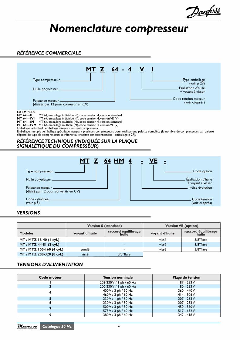
Catalogue 50 Hz
Nomenclature compresseur
RÉFÉRENCE COMMERCIALE
4RECIPROCATING COMPRESSORS
Version S (standard) Version VE (option)
Modèles voyant d’huile raccord équilibrage voyant d’huile raccord équilibragehuile huile
MT / MTZ 18-40 (1 cyl.) - - vissé 3/8’’flareMT / MTZ 44-81 (2 cyl.) - - vissé 3/8’’flareMT / MTZ 100-160 (4 cyl.) soudé - vissé 3/8’’flareMT / MTZ 200-320 (8 cyl.) vissé 3/8’’flare
Code moteur Tension nominale Plage de tension1 208-230 V / 1 ph / 60 Hz 187 - 253 V3 200-230 V / 3 ph / 60 Hz 180 - 253 V
400 V / 3 ph / 50 Hz 360 - 440 V4460 V / 3 ph / 60 Hz 414 - 506 V
5 230 V / 1 ph / 50 Hz 207 - 253 V6 230 V / 3 ph / 50 Hz 207 - 253 V
500 V / 3 ph / 50 Hz 450 - 550 V7575 V / 3 ph / 60 Hz 517 - 632 V
9 380 V / 3 ph / 60 Hz 342 - 418 V
VERSIONS
TENSIONS D’ALIMENTATION
Type emballage(voir p 27)
Égalisation d'huile+ voyant à visser
MT Z 4 V64 -
Type compresseur
Code tension moteur(voir ci-après)
Huile polyolester
Puissance moteur(diviser par 12 pour convertir en CV)
I
Code option
Indice évolution
Égalisation d'huile+ voyant à visser
MT Z 4 -64 HM
Type compresseur
Code tension(voir ci-après)
Huile polyolester
Puissance moteur(divisé par 12 pour convertir en CV)
Code cylindrée(voir p 5)
VE -
EXEMPLES :MT 64 - 4I MT 64, emballage individuel (I), code tension 4, version standardMT 64 - 4VI MT 64, emballage individuel (I), code tension 4, version VE (V)MT 64 - 4M MT 64, emballage multiple (M), code tension 4, version standardMT 64 - 4VM MT 64, emballage multiple (M), code tension 4, version VE (V)Emballage individuel : emballage intégrant un seul compresseur.Emballage multiple : emballage spécifique intégrant plusieurs compresseurs pour réaliser une palette complète (le nombre de compresseurs par palettedépend du type de compresseur; se référer au chapitre conditionnement - emballage p 27).
RÉFÉRENCE TECHNIQUE (INDIQUÉE SUR LA PLAQUESIGNALÉTIQUE DU COMPRESSEUR)
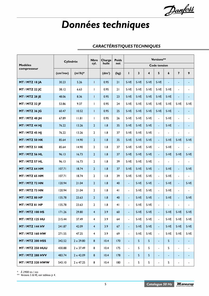
Données techniques
5 Catalogue 50 HzRECIPROCATING COMPRESSORS
* À 2900 trs / mn** Versions S & VE, voir tableau p 4.
Cylindrée Nbre Charge Poids Versions**
Modèles cyl. huile netCode tension
compresseur(cm3/rev) (m3/h)* (dm3) (kg) 1 3 4 5 6 7 9
MT / MTZ 18 JA 30.23 5.26 1 0.95 21 S-VE S-VE S-VE S-VE - - -
MT / MTZ 22 JC 38.12 6.63 1 0.95 21 S-VE S-VE S-VE S-VE S-VE - -
MT / MTZ 28 JE 48.06 8.36 1 0.95 23 S-VE S-VE S-VE S-VE S-VE - -
MT / MTZ 32 JF 53.86 9.37 1 0.95 24 S-VE S-VE S-VE S-VE S-VE S-VE S-VE
MT / MTZ 36 JG 60.47 10.52 1 0.95 25 S-VE S-VE S-VE S-VE S-VE - -
MT / MTZ 40 JH 67.89 11.81 1 0.95 26 S-VE S-VE S-VE - S-VE - -
MT / MTZ 44 HJ 76.22 13.26 2 1.8 35 S-VE S-VE S-VE - S-VE - -
MT / MTZ 45 HJ 76.22 13.26 2 1.8 37 S-VE S-VE S-VE - - - -
MT / MTZ 50 HK 85.64 14.90 2 1.8 35 S-VE S-VE S-VE - S-VE S-VE S-VE
MT / MTZ 51 HK 85.64 14.90 2 1.8 37 S-VE S-VE S-VE - S-VE - -
MT / MTZ 56 HL 96.13 16.73 2 1.8 37 S-VE S-VE S-VE - S-VE S-VE S-VE
MT / MTZ 57 HL 96.13 16.73 2 1.8 39 S-VE S-VE S-VE - - - -
MT / MTZ 64 HM 107.71 18.74 2 1.8 37 S-VE S-VE S-VE - S-VE - S-VE
MT / MTZ 65 HM 107.71 18.74 2 1.8 39 S-VE S-VE S-VE - S-VE - -
MT / MTZ 72 HN 120.94 21.04 2 1.8 40 - S-VE S-VE - S-VE - S-VE
MT / MTZ 73 HN 120.94 21.04 2 1.8 41 - S-VE S-VE - S-VE - -
MT / MTZ 80 HP 135.78 23.63 2 1.8 40 - S-VE S-VE - S-VE - S-VE
MT / MTZ 81 HP 135.78 23.63 2 1.8 41 - S-VE S-VE - - - -
MT / MTZ 100 HS 171.26 29.80 4 3.9 60 - S-VE S-VE - S-VE S-VE S-VE
MT / MTZ 125 HU 215.44 37.49 4 3.9 64 - S-VE S-VE - S-VE S-VE S-VE
MT / MTZ 144 HV 241.87 42.09 4 3.9 67 - S-VE S-VE - S-VE S-VE S-VE
MT / MTZ 160 HW 271.55 47.25 4 3.9 69 - S-VE S-VE - S-VE S-VE S-VE
MT / MTZ 200 HSS 342.52 2 x 29.80 8 10.4 170 - S S - S - -
MT / MTZ 250 HUU 430.88 2 x 37.49 8 10.4 175 - S S - S - -
MT / MTZ 288 HVV 483.74 2 x 42.09 8 10.4 178 - S S - - - -
MT / MTZ 320 HWW 543.10 2 x 47.25 8 10.4 180 - S S - S - -
CARACTÉRISTIQUES TECHNIQUES
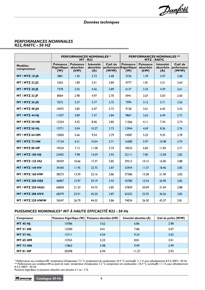
Données techniques
6Catalogue 50 HzRECIPROCATING COMPRESSORS
PERFORMANCES NOMINALESR22, R407C - 50 HZ
* Performances aux conditions ARI : température d’évaporation 7.2 °C, température de condensation 54.4 °C, surchauffe 11.1 K, sous refroidissement 8.3 K, 400 V - 50 Hz** Performances aux conditions ARI au point de rosée : température d’évaporation 7.2 °C, température de condensation : 54,4 °C, surchauffe 11.1 K, sous refroidissement8.3 K, 400 V - 50 HzPuissance frigorifique et puissance absorbée sont données à + ou - 5 %
PUISSANCES NOMINALES* MT À HAUTE EFFICACITÉ R22 - 50 Hz
PERFORMANCES NOMINALES * PERFORMANCES NOMINALES **MT - R22 MTZ - R407C
Modèles Puissance Puissance Intensité Cœf. de Puissance Puissance Intensité Cœf. decompresseur frigorifique absorbée absorbée performance frigorifique absorbée absorbée performance
(W) (kW) (A) (W/W) (W) (kW) (A) (W/W)
MT / MTZ 18 JA 3881 1.45 2.73 2.68 3726 1.39 2.47 2.68
MT / MTZ 22 JC 5363 1.89 3.31 2.84 4777 1.81 3.31 2.64
MT / MTZ 28 JE 7378 2.55 4.56 2.89 6137 2.35 4.39 2.61
MT / MTZ 32 JF 8064 2.98 4.97 2.70 6941 2.67 5.03 2.60
MT / MTZ 36 JG 9272 3.37 5.77 2.75 7994 3.12 5.71 2.56
MT / MTZ 40 JH 10475 3.85 6.47 2.72 9128 3.61 6.45 2.53
MT / MTZ 44 HJ 11037 3.89 7.37 2.84 9867 3.63 6.49 2.72
MT / MTZ 50 HK 12324 4.32 8.46 2.85 11266 4.11 7.34 2.74
MT / MTZ 56 HL 13771 5.04 10.27 2.73 12944 4.69 8.36 2.76
MT / MTZ 64 HM 15820 5.66 9.54 2.79 14587 5.25 9.35 2.78
MT / MTZ 72 HN 17124 6.31 10.54 2.71 16380 5.97 10.48 2.74
MT / MTZ 80 HP 19534 7.13 11.58 2.74 18525 6.83 11.83 2.71
MT / MTZ 100 HS 23403 7.98 14.59 2.93 22111 7.85 13.58 2.82
MT / MTZ 125 HU 30429 10.66 17.37 2.85 29212 10.15 16.00 2.88
MT / MTZ 144 HV 34340 11.95 22.75 2.87 32934 11.57 18.46 2.85
MT / MTZ 160 HW 38273 13.39 22.16 2.86 37386 13.28 21.40 2.82
MT / MTZ 200 HSS 46807 15.97 29.19 2.93 43780 15.54 26.90 2.82
MT / MTZ 250 HUU 60858 21.33 34.75 2.85 57839 20.09 31.69 2.88
MT / MTZ 288 HVV 68379 23.91 45.50 2.87 65225 22.92 36.56 2.85
MT / MTZ 320 HWW 76547 26.79 44.32 2.86 74024 26.30 42.37 2.81
Compresseur Puissance frigorifique (W) Puissance absorbée (kW) Intensité absorbée (A) Cœf. de perfor. (W/W)
MT 45 HJ 10786 3.62 6.86 2.98
MT 51 HK 12300 4.01 7.86 3.07
MT 57 HL 13711 4.54 9.24 3.02
MT 65 HM 15763 5.23 8.81 3.01
MT 73 HN 17863 5.98 9.99 2.99
MT 81 HP 20298 6.94 11.27 2.93
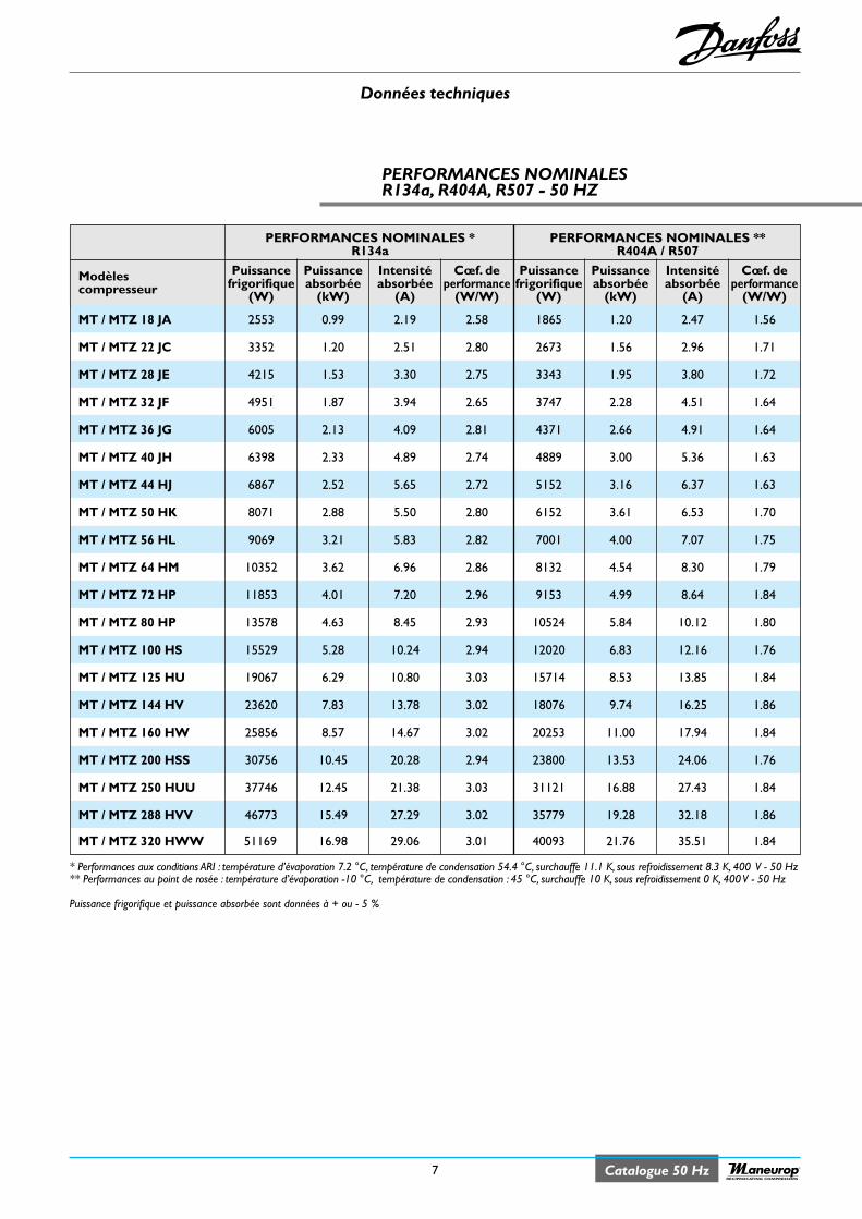
Données techniques
7 Catalogue 50 HzRECIPROCATING COMPRESSORS
PERFORMANCES NOMINALESR134a, R404A, R507 - 50 HZ
* Performances aux conditions ARI : température d’évaporation 7.2 °C, température de condensation 54.4 °C, surchauffe 11.1 K, sous refroidissement 8.3 K, 400 V - 50 Hz** Performances au point de rosée : température d’évaporation -10 °C, température de condensation : 45 °C, surchauffe 10 K, sous refroidissement 0 K, 400 V - 50 Hz
Puissance frigorifique et puissance absorbée sont données à + ou - 5 %
PERFORMANCES NOMINALES * PERFORMANCES NOMINALES **R134a R404A / R507
Modèles Puissance Puissance Intensité Cœf. de Puissance Puissance Intensité Cœf. decompresseur frigorifique absorbée absorbée performance frigorifique absorbée absorbée performance
(W) (kW) (A) (W/W) (W) (kW) (A) (W/W)
MT / MTZ 18 JA 2553 0.99 2.19 2.58 1865 1.20 2.47 1.56
MT / MTZ 22 JC 3352 1.20 2.51 2.80 2673 1.56 2.96 1.71
MT / MTZ 28 JE 4215 1.53 3.30 2.75 3343 1.95 3.80 1.72
MT / MTZ 32 JF 4951 1.87 3.94 2.65 3747 2.28 4.51 1.64
MT / MTZ 36 JG 6005 2.13 4.09 2.81 4371 2.66 4.91 1.64
MT / MTZ 40 JH 6398 2.33 4.89 2.74 4889 3.00 5.36 1.63
MT / MTZ 44 HJ 6867 2.52 5.65 2.72 5152 3.16 6.37 1.63
MT / MTZ 50 HK 8071 2.88 5.50 2.80 6152 3.61 6.53 1.70
MT / MTZ 56 HL 9069 3.21 5.83 2.82 7001 4.00 7.07 1.75
MT / MTZ 64 HM 10352 3.62 6.96 2.86 8132 4.54 8.30 1.79
MT / MTZ 72 HP 11853 4.01 7.20 2.96 9153 4.99 8.64 1.84
MT / MTZ 80 HP 13578 4.63 8.45 2.93 10524 5.84 10.12 1.80
MT / MTZ 100 HS 15529 5.28 10.24 2.94 12020 6.83 12.16 1.76
MT / MTZ 125 HU 19067 6.29 10.80 3.03 15714 8.53 13.85 1.84
MT / MTZ 144 HV 23620 7.83 13.78 3.02 18076 9.74 16.25 1.86
MT / MTZ 160 HW 25856 8.57 14.67 3.02 20253 11.00 17.94 1.84
MT / MTZ 200 HSS 30756 10.45 20.28 2.94 23800 13.53 24.06 1.76
MT / MTZ 250 HUU 37746 12.45 21.38 3.03 31121 16.88 27.43 1.84
MT / MTZ 288 HVV 46773 15.49 27.29 3.02 35779 19.28 32.18 1.86
MT / MTZ 320 HWW 51169 16.98 29.06 3.01 40093 21.76 35.51 1.84
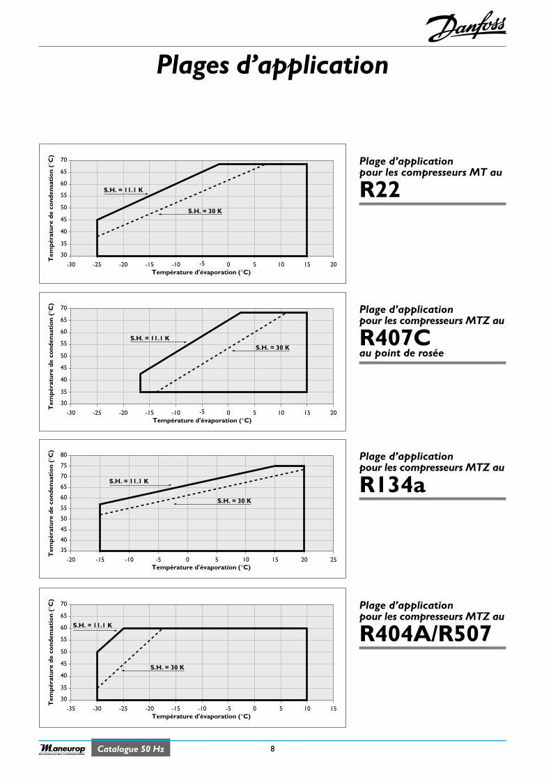
Plages d’application
8Catalogue 50 HzRECIPROCATING COMPRESSORS
80
35
-20 25
Tem
péra
ture
de
cond
ensa
tio
n (°
C)
Température d'évaporation (°C) -15 -10 -5 0 5 10 15 20
S.H. = 30 K
S.H. = 11.1 K
75
70
65
60
55
50
45
40
70
65
60
55
50
45
40
35
30
-25-30 -20 -15 -10 -5 0 5 10 15 20
Tem
péra
ture
de
cond
ensa
tio
n (°
C)
Température d'évaporation (°C)
S.H. = 30 KS.H. = 11.1 K
70
65
60
55
50
45
40
35
30
-25-30 -20 -15 -10 -5 0 5 10 15 20
Tem
péra
ture
de
cond
ensa
tio
n (°
C)
Température d'évaporation (°C)
S.H. = 30 K
S.H. = 11.1 K
Plage d’applicationpour les compresseurs MT au
R22
Plage d’applicationpour les compresseurs MTZ au
R134a
Plage d’applicationpour les compresseurs MTZ au
R407Cau point de rosée
70
65
60
55
50
45
40
35
30
-30-35 -25 -20 -15 -10 -5 0 5 10 15
Tem
péra
ture
de
cond
ensa
tio
n (°
C)
Température d'évaporation (°C)
S.H. = 30 K
S.H. = 11.1 K
Plage d’applicationpour les compresseurs MTZ au
R404A/R507
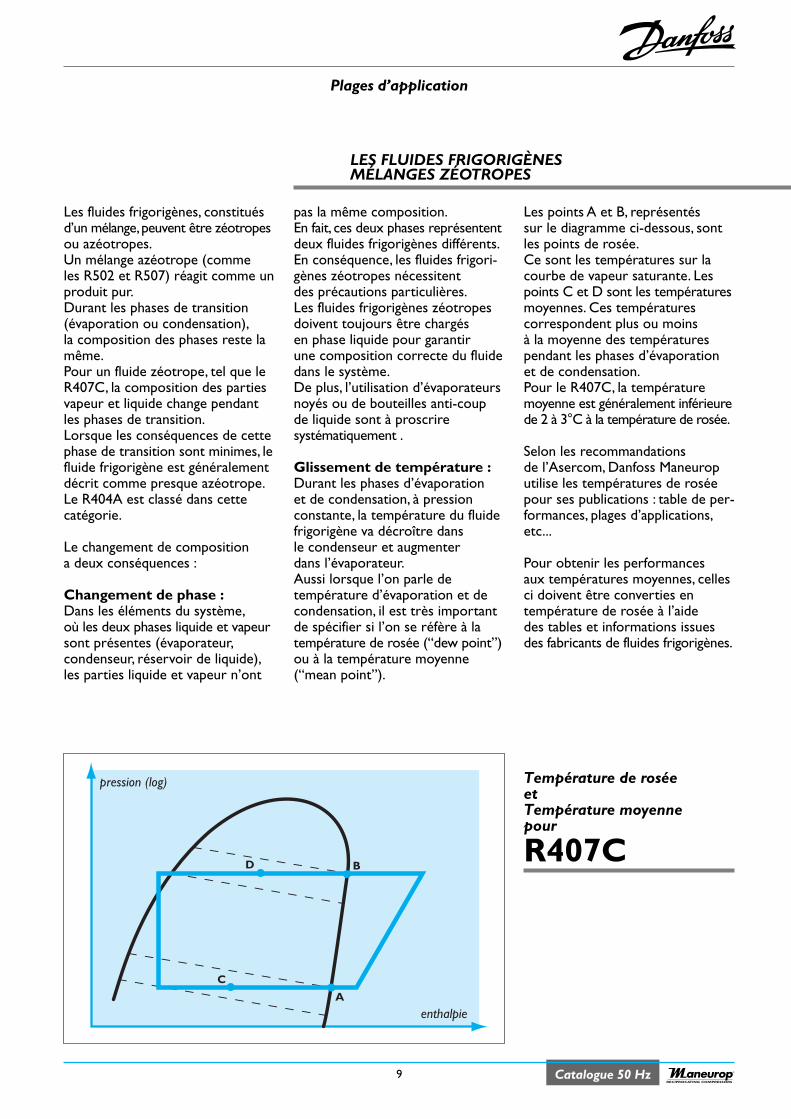
Plages d’application
9 Catalogue 50 HzRECIPROCATING COMPRESSORS
LES FLUIDES FRIGORIGÈNESMÉLANGES ZÉOTROPES
pression (log)
enthalpieA
B
C
D
Température de roséeetTempérature moyennepour
R407C
Les fluides frigorigènes, constituésd’un mélange,peuvent être zéotropesou azéotropes.Un mélange azéotrope (commeles R502 et R507) réagit comme unproduit pur.Durant les phases de transition(évaporation ou condensation),la composition des phases reste lamême.Pour un fluide zéotrope, tel que leR407C, la composition des partiesvapeur et liquide change pendantles phases de transition.Lorsque les conséquences de cettephase de transition sont minimes, lefluide frigorigène est généralementdécrit comme presque azéotrope.Le R404A est classé dans cettecatégorie.
Le changement de compositiona deux conséquences :
Changement de phase :Dans les éléments du système,où les deux phases liquide et vapeursont présentes (évaporateur,condenseur, réservoir de liquide),les parties liquide et vapeur n’ont
pas la même composition.En fait, ces deux phases représententdeux fluides frigorigènes différents.En conséquence, les fluides frigori-gènes zéotropes nécessitentdes précautions particulières.Les fluides frigorigènes zéotropesdoivent toujours être chargésen phase liquide pour garantirune composition correcte du fluidedans le système.De plus, l’utilisation d’évaporateursnoyés ou de bouteilles anti-coupde liquide sont à proscriresystématiquement .
Glissement de température :Durant les phases d’évaporationet de condensation, à pressionconstante, la température du fluidefrigorigène va décroître dansle condenseur et augmenterdans l’évaporateur.Aussi lorsque l’on parle detempérature d’évaporation et decondensation, il est très importantde spécifier si l’on se réfère à latempérature de rosée (“dew point”)ou à la température moyenne(“mean point”).
Les points A et B, représentéssur le diagramme ci-dessous, sontles points de rosée.Ce sont les températures sur lacourbe de vapeur saturante. Lespoints C et D sont les températuresmoyennes. Ces températurescorrespondent plus ou moinsà la moyenne des températurespendant les phases d’évaporationet de condensation.Pour le R407C, la températuremoyenne est généralement inférieurede 2 à 3°C à la température de rosée.
Selon les recommandationsde l’Asercom, Danfoss Maneuroputilise les températures de roséepour ses publications : table de per-formances, plages d’applications,etc...
Pour obtenir les performancesaux températures moyennes, cellesci doivent être converties entempérature de rosée à l’aidedes tables et informations issuesdes fabricants de fluides frigorigènes.
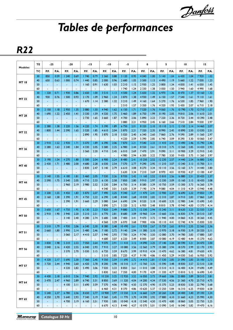
Catalogue 50 Hz 10RECIPROCATING COMPRESSORS
R22
Tables de performances
ModèlesTE -25 -20 -15 -10 -5 0 5 10 15
TC P.F. P.A. P.F. P.A. P.F. P.A. P.F. P.A. P.F. P.A. P.F. P.A. P.F. P.A. P.F. P.A. P.F. P.A.
30 850 0.59 1 240 0.69 1 740 0.79 2 360 0.88 3 120 0.95 4 040 1.00 5 140 1.04 6 430 1.04 7 920 1.02
MT 1840 650 0.63 1 000 0.74 1 440 0.85 2 000 0.96 2 680 1.05 3 500 1.13 4 490 1.19 5 660 1.22 7 030 1.2350 - - - - 1 160 0.91 1 630 1.03 2 210 1.15 2 930 1.25 3 800 1.34 4 830 1.41 6 050 1.4560 - - - - - - - - 1 740 1.24 2 330 1.38 3 050 1.50 3 940 1.60 4 990 1.6830 1 320 0.71 1 930 0.86 2 650 1.00 3 510 1.13 4 500 1.24 5 650 1.32 6 970 1.36 8 470 1.37 10 160 1.32
MT 2240 930 0.76 1 500 0.93 2 170 1.09 2 960 1.24 3 870 1.38 4 930 1.49 6 150 1.57 7 540 1.61 9 110 1.6150 - - - - 1 670 1.14 2 380 1.32 3 210 1.49 4 160 1.64 5 270 1.76 6 530 1.85 7 960 1.9060 - - - - - - - - 2 510 1.57 3 350 1.76 4 320 1.93 5 430 2.07 6 710 2.1830 2 150 1.18 2 950 1.35 3 880 1.50 4 940 1.62 6 150 1.71 7 520 1.76 9 060 1.76 10 790 1.70 12 710 1.57
MT 2840 1 690 1.22 2 450 1.41 3 330 1.59 4 320 1.75 5 460 1.89 6 750 1.99 8 190 2.05 9 810 2.06 11 610 2.0150 - - - - 2 730 1.65 3 660 1.87 4 700 2.06 5 890 2.23 7 220 2.36 8 720 2.44 10 390 2.4860 - - - - - - - - 3 880 2.21 4 950 2.45 6 160 2.66 7 510 2.84 9 030 2.9730 2 380 1.38 3 220 1.56 4 220 1.74 5 390 1.89 6 750 2.01 8 320 2.10 10 110 2.15 12 150 2.14 14 460 2.07
MT 3240 1 800 1.44 2 590 1.65 3 520 1.85 4 610 2.04 5 870 2.21 7 320 2.35 8 990 2.45 10 890 2.50 13 030 2.5150 - - - - 2 890 1.95 3 870 2.18 5 020 2.40 6 340 2.60 7 860 2.76 9 590 2.89 11 560 2.9760 - - - - - - - - 4 220 2.59 5 390 2.85 6 740 3.09 8 290 3.30 10 060 3.4730 2 910 1.52 3 920 1.71 5 070 1.89 6 390 2.06 7 870 2.21 9 540 2.33 11 410 2.41 13 490 2.46 15 790 2.46
MT 3640 2 280 1.63 3 240 1.84 4 330 2.05 5 580 2.25 6 980 2.44 8 550 2.61 10 310 2.75 12 260 2.85 14 420 2.9250 - - - - 3 560 2.20 4 710 2.45 6 010 2.69 7 470 2.91 9 090 3.11 10 900 3.29 12 910 3.4360 - - - - - - - - 4 980 2.94 6 300 3.22 7 780 3.50 9 430 3.75 11 260 3.9730 3 190 1.54 4 270 1.80 5 500 2.04 6 900 2.24 8 480 2.41 10 250 2.52 12 230 2.57 14 440 2.54 16 880 2.43
MT 4040 2 430 1.71 3 480 2.00 4 680 2.28 6 030 2.54 7 570 2.77 9 290 2.95 11 210 3.07 13 340 3.13 15 700 3.1150 - - - - 3 830 2.47 5 140 2.79 6 610 3.08 8 270 3.34 10 110 3.56 12 160 3.71 14 440 3.8060 - - - - - - - - 5 630 3.34 7 210 3.69 8 970 4.01 10 930 4.27 13 100 4.4730 3 140 1.55 4 180 1.81 5 460 2.05 7 030 2.26 8 920 2.42 11 160 2.52 13 810 2.56 16 880 2.51 20 420 2.37
MT 4440 2 590 1.75 3 540 2.05 4 710 2.33 6 130 2.58 7 850 2.80 9 910 2.97 12 330 3.09 15 160 3.13 18 430 3.0850 - - 2 960 2.19 3 980 2.52 5 230 2.84 6 750 3.14 8 580 3.39 10 750 3.59 13 300 3.73 16 260 3.7960 - - - - - - 4 340 3.01 5 630 3.39 7 190 3.74 9 080 4.04 11 310 4.29 13 940 4.4830 3 200 1,55 4 450 1,83 5 870 2,07 7 490 2,25 9 340 2,37 11 470 2,41 13 900 2,37 16 690 2,22 19 850 1,95
MT 4540 2 160 1,58 3 390 1,91 4 750 2,22 6 290 2,48 8 040 2,68 10 030 2,82 12 310 2,87 14 910 2,83 17 860 2,6950 - - 2 390 1,91 3 660 2,29 5 080 2,64 6 690 2,94 8 520 3,18 10 600 3,35 12 980 3,44 15 690 3,4360 - - - - - - 3 890 2,71 5 320 3,12 6 950 3,48 8 810 3,78 10 940 4,00 13 370 4,1430 3 650 1.67 4 750 1.95 6 130 2.23 7 820 2.49 9 880 2.73 12 330 2.94 15 240 3.11 18 630 3.23 22 550 3.29
MT 5040 2 910 1.90 3 940 2.20 5 210 2.51 6 770 2.81 8 680 3.09 10 960 3.34 13 660 3.56 16 830 3.74 20 510 3.8750 - - 3 140 2.40 4 280 2.74 5 680 3.08 7 400 3.41 9 470 3.72 11 940 4.00 14 860 4.25 18 260 4.4560 - - - - - - 4 560 3.29 6 070 3.68 7 900 4.06 10 110 4.41 12 740 4.74 15 830 5.0230 3 510 1,79 4 930 2,06 6 540 2,30 8 380 2,48 10 490 2,61 12 920 2,67 15 720 2,65 18 910 2,55 22 560 2,36
MT 5140 2 660 1,80 3 990 2,14 5 480 2,46 7 180 2,72 9 140 2,94 11 380 3,10 13 970 3,18 16 930 3,19 20 320 3,1150 - - 3 060 2,17 4 410 2,57 5 940 2,93 7 700 3,24 9 740 3,50 12 080 3,70 14 780 3,83 17 880 3,8760 - - - - - - 4 680 3,07 6 220 3,49 8 000 3,87 10 080 4,19 12 480 4,44 15 270 4,6230 3 830 1.98 5 310 2.33 7 050 2.64 9 070 2.91 11 410 3.12 14 090 3.25 17 140 3.28 20 590 3.21 24 470 3.00
MT 5640 3 040 2.16 4 420 2.55 6 040 2.93 7 910 3.27 10 080 3.56 12 560 3.79 15 380 3.94 18 570 3.99 22 170 3.9350 - - 3 570 2.70 5 030 3.15 6 720 3.59 8 670 3.99 10 910 4.34 13 470 4.62 16 380 4.81 19 650 4.9160 - - - - - - 5 510 3.85 7 220 4.37 9 190 4.86 11 450 5.29 14 030 5.65 16 950 5.9230 4 320 2,17 5 690 2,30 7 360 2,45 9 350 2,59 11 690 2,72 14 410 2,81 17 530 2,85 21 090 2,83 25 100 2,73
MT 5740 3 720 2,44 4 940 2,60 6 420 2,78 8 200 2,98 10 310 3,17 12 760 3,35 15 590 3,48 18 830 3,57 22 510 3,5850 - - 4 220 2,82 5 490 3,06 7 020 3,33 8 850 3,61 11 010 3,88 13 510 4,13 16 400 4,34 19 690 4,4960 - - - - - - 5 830 3,62 7 350 4,00 9 170 4,39 11 320 4,77 13 810 5,12 16 690 5,4330 4 400 2.18 6 010 2.56 7 940 2.92 10 230 3.25 12 920 3.52 16 050 3.73 19 660 3.86 23 800 3.89 28 510 3.81
MT 6440 3 470 2.47 4 960 2.89 6 740 3.31 8 850 3.69 11 320 4.04 14 200 4.34 17 530 4.56 21 360 4.70 25 710 4.7550 - - 4 100 3.11 5 690 3.59 7 570 4.06 9 780 4.50 12 370 4.90 15 370 5.23 18 830 5.50 22 790 5.6860 - - - - - - 6 460 4.31 8 370 4.86 10 620 5.37 13 250 5.84 16 310 6.25 19 830 6.5830 5 240 2,37 6 780 2,56 8 650 2,77 10 900 2,97 13 550 3,14 16 660 3,29 20 260 3,38 24 400 3,40 29 100 3,34
MT 6540 4 250 2,70 5 640 2,93 7 340 3,19 9 360 3,45 11 770 3,70 14 590 3,92 17 880 4,10 21 660 4,23 25 990 4,3050 - - 4 700 3,19 6 160 3,51 7 930 3,85 10 040 4,18 12 540 4,50 15 470 4,80 18 860 5,05 22 750 5,2560 - - - - - - 6 670 4,13 8 440 4,57 10 570 5,01 13 090 5,43 16 040 5,82 19 470 6,16
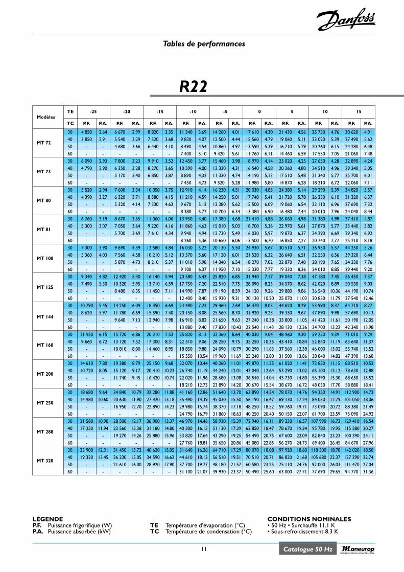
R22
ModèlesTE -25 -20 -15 -10 -5 0 5 10 15
TC P.F. P.A. P.F. P.A. P.F. P.A. P.F. P.A. P.F. P.A. P.F. P.A. P.F. P.A. P.F. P.A. P.F. P.A.
30 4 850 2.64 6 670 2.99 8 820 3.35 11 340 3.69 14 260 4.01 17 610 4.30 21 430 4.56 25 750 4.76 30 620 4.91
MT 7240 3 850 2.91 5 540 3.29 7 520 3.68 9 830 4.07 12 500 4.44 15 560 4.79 19 060 5.11 23 020 5.39 27 490 5.6250 - - 4 680 3.66 6 440 4.10 8 490 4.54 10 860 4.97 13 590 5.39 16 710 5.79 20 260 6.15 24 280 6.4860 - - - - - - 7 400 5.10 9 420 5.61 11 760 6.11 14 460 6.59 17 550 7.05 21 060 7.4830 6 090 2,93 7 800 3,23 9 910 3,52 12 450 3,77 15 460 3,98 18 970 4,14 23 020 4,25 27 650 4,28 32 890 4,24
MT 7340 4 790 2,90 6 350 3,28 8 270 3,65 10 590 4,00 13 330 4,31 16 540 4,58 20 260 4,80 24 510 4,96 29 340 5,0550 - - 5 170 3,40 6 850 3,87 8 890 4,32 11 330 4,74 14 190 5,13 17 510 5,48 21 340 5,77 25 700 6,0160 - - - - - - 7 450 4,73 9 520 5,28 11 980 5,80 14 870 6,28 18 210 6,72 22 060 7,1130 5 520 2.94 7 600 3.34 10 050 3.75 12 910 4.14 16 230 4.51 20 030 4.85 24 380 5.14 29 290 5.39 34 820 5.57
MT 8040 4 390 3.27 6 320 3.71 8 580 4.15 11 210 4.59 14 250 5.01 17 740 5.41 21 720 5.78 26 230 6.10 31 320 6.3750 - - 5 320 4.14 7 330 4.63 9 670 5.12 12 380 5.62 15 500 6.09 19 060 6.54 23 110 6.96 27 690 7.3260 - - - - - - 8 380 5.77 10 700 6.34 13 380 6.90 16 480 7.44 20 010 7.96 24 040 8.4430 6 760 3,19 8 670 3,65 11 060 4,06 13 950 4,40 17 380 4,68 21 410 4,88 26 060 4,98 31 380 4,98 37 410 4,87
MT 8140 5 300 3,07 7 050 3,64 9 220 4,16 11 860 4,63 15 010 5,03 18 700 5,36 22 970 5,61 27 870 5,77 33 440 5,8250 - - 5 700 3,69 7 610 4,34 9 940 4,94 12 730 5,49 16 030 5,97 19 870 6,37 24 290 6,69 29 340 6,9260 - - - - - - 8 260 5,36 10 650 6,06 13 500 6,70 16 850 7,27 20 740 7,77 25 210 8,1830 7 300 3.90 9 690 4.39 12 580 4.84 16 030 5.22 20 130 5.50 24 930 5.67 30 510 5.71 36 930 5.57 44 250 5.26
MT 10040 5 360 4.03 7 560 4.58 10 210 5.12 13 370 5.60 17 120 6.01 21 520 6.32 26 640 6.51 32 550 6.56 39 320 6.4450 - - 5 870 4.73 8 210 5.37 11 010 5.98 14 340 6.54 18 270 7.02 22 870 7.40 28 190 7.65 34 330 7.7660 - - - - - - 9 100 6.37 11 950 7.10 15 330 7.77 19 330 8.36 24 010 8.85 29 440 9.2030 9 340 4.82 12 420 5.40 16 140 5.94 20 580 6.43 25 820 6.85 31 940 7.17 39 040 7.38 47 180 7.45 56 450 7.37
MT 12540 7 490 5.30 10 320 5.95 13 710 6.59 17 750 7.20 22 510 7.75 28 090 8.23 34 570 8.62 42 020 8.89 50 530 9.0350 - - 8 480 6.35 11 450 7.11 14 990 7.87 19 190 8.59 24 120 9.26 29 880 9.86 36 540 10.36 44 190 10.7460 - - - - - - 12 400 8.40 15 930 9.31 20 130 10.20 25 070 11.03 30 850 11.79 37 540 12.4630 10 790 5.45 14 250 6.09 18 450 6.69 23 490 7.23 29 460 7.69 36 470 8.05 44 620 8.29 53 990 8.37 64 710 8.27
MT 14440 8 620 5.97 11 780 6.69 15 590 7.40 20 150 8.08 25 560 8.70 31 920 9.23 39 330 9.67 47 890 9.98 57 690 10.1350 - - 9 640 7.13 12 940 7.98 16 910 8.82 21 650 9.63 27 240 10.38 33 800 11.05 41 420 11.61 50 190 12.0560 - - - - - - 13 880 9.40 17 820 10.43 22 540 11.43 28 130 12.36 34 700 13.22 42 340 13.9830 11 950 6.15 15 720 6.86 20 310 7.53 25 820 8.13 32 360 8.64 40 030 9.04 48 960 9.30 59 250 9.39 71 010 9.29
MT 16040 9 660 6.72 13 120 7.52 17 300 8.31 22 310 9.06 28 250 9.75 35 250 10.35 43 410 10.84 52 840 11.19 63 640 11.3750 - - 10 810 8.00 14 460 8.95 18 850 9.88 24 090 10.79 30 290 11.63 37 560 12.38 46 000 13.02 55 740 13.5260 - - - - - - 15 550 10.54 19 960 11.69 25 240 12.80 31 500 13.86 38 840 14.82 47 390 15.6830 14 610 7.80 19 380 8.79 25 150 9.68 32 070 10.44 40 260 11.01 49 870 11.35 61 020 11.41 73 850 11.15 88 510 10.52
MT 20040 10 720 8.05 15 120 9.17 20 410 10.23 26 740 11.19 34 240 12.01 43 040 12.64 53 290 13.02 65 100 13.12 78 630 12.8850 - - 11 740 9.45 16 420 10.74 22 020 11.96 28 680 13.08 36 540 14.04 45 730 14.80 56 390 15.30 68 650 15.5260 - - - - - - 18 210 12.73 23 890 14.20 30 670 15.54 38 670 16.72 48 030 17.70 58 880 18.4130 18 680 9.64 24 840 10.79 32 280 11.88 41 160 12.86 51 640 13.70 63 890 14.34 78 070 14.76 94 350 14.91 112 900 14.73
MT 25040 14 980 10.60 20 630 11.90 27 420 13.18 35 490 14.39 45 030 15.50 56 190 16.47 69 130 17.24 84 030 17.79 101 050 18.0650 - - 16 950 12.70 22 890 14.23 29 980 15.74 38 370 17.18 48 250 18.52 59 760 19.71 73 090 20.72 88 380 21.4960 - - - - - - 24 790 16.79 31 860 18.63 40 250 20.40 50 150 22.07 61 700 23.59 75 090 24.9230 21 580 10.90 28 500 12.17 36 900 13.37 46 970 14.46 58 920 15.39 72 940 16.11 89 230 16.57 107 990 16.73 129 410 16.54
MT 28840 17 250 11.94 23 560 13.38 31 180 14.80 40 300 16.15 51 130 17.39 63 850 18.47 78 670 19.34 95 780 19.95 115 380 20.2750 - - 19 270 14.26 25 880 15.96 33 820 17.64 43 290 19.25 54 490 20.75 67 600 22.09 82 840 23.23 100 390 24.1160 - - - - - - 27 760 18.81 35 650 20.86 45 080 22.85 56 270 24.73 69 400 26.45 84 670 27.9630 23 900 12.31 31 450 13.72 40 620 15.05 51 640 16.26 64 710 17.29 80 070 18.08 97 920 18.60 118 500 18.78 142 020 18.58
MT 32040 19 320 13.45 26 230 15.05 34 590 16.62 44 610 18.13 56 510 19.51 70 510 20.71 86 820 21.68 105 680 22.37 127 290 22.7450 - - 21 610 16.00 28 920 17.90 37 700 19.77 48 180 21.57 60 580 23.25 75 110 24.76 92 000 26.03 111 470 27.0460 - - - - - - 31 100 21.07 39 930 23.37 50 490 25.60 63 000 27.71 77 690 29.65 94 770 31.36
Catalogue 50 Hz
Tables de performances
11RECIPROCATING COMPRESSORS
TE Température d’évaporation (°C)TC Température de condensation (°C)
CONDITIONS NOMINALES• 50 Hz • Surchauffe 11.1 K• Sous-refroidissement 8.3 K
LÉGENDEP.F. Puissance frigorifique (W)P.A. Puissance absorbée (kW)
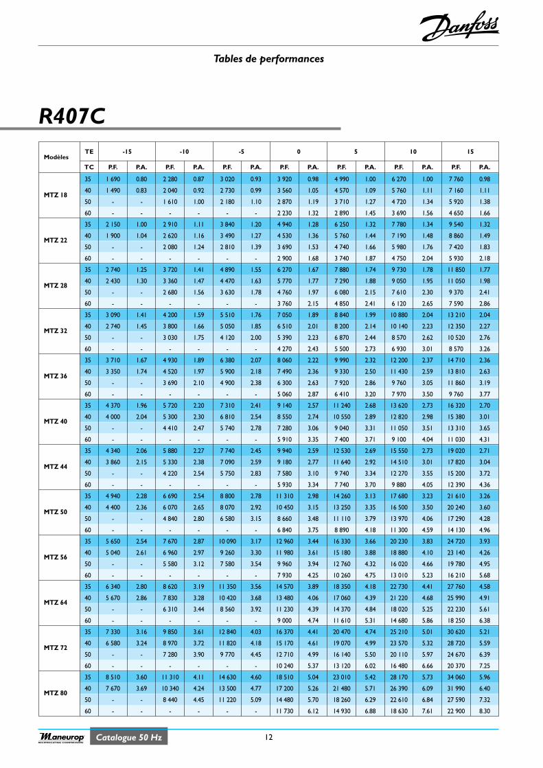
Catalogue 50 Hz
Tables de performances
12RECIPROCATING COMPRESSORS
R407C
ModèlesTE -15 -10 -5 0 5 10 15
TC P.F. P.A. P.F. P.A. P.F. P.A. P.F. P.A. P.F. P.A. P.F. P.A. P.F. P.A.
35 1 690 0.80 2 280 0.87 3 020 0.93 3 920 0.98 4 990 1.00 6 270 1.00 7 760 0.98
MTZ 1840 1 490 0.83 2 040 0.92 2 730 0.99 3 560 1.05 4 570 1.09 5 760 1.11 7 160 1.11
50 - - 1 610 1.00 2 180 1.10 2 870 1.19 3 710 1.27 4 720 1.34 5 920 1.38
60 - - - - - - 2 230 1.32 2 890 1.45 3 690 1.56 4 650 1.66
35 2 150 1.00 2 910 1.11 3 840 1.20 4 940 1.28 6 250 1.32 7 780 1.34 9 540 1.32
MTZ 2240 1 900 1.04 2 620 1.16 3 490 1.27 4 530 1.36 5 760 1.44 7 190 1.48 8 860 1.49
50 - - 2 080 1.24 2 810 1.39 3 690 1.53 4 740 1.66 5 980 1.76 7 420 1.83
60 - - - - - - 2 900 1.68 3 740 1.87 4 750 2.04 5 930 2.18
35 2 740 1.25 3 720 1.41 4 890 1.55 6 270 1.67 7 880 1.74 9 730 1.78 11 850 1.77
MTZ 2840 2 430 1.30 3 360 1.47 4 470 1.63 5 770 1.77 7 290 1.88 9 050 1.95 11 050 1.98
50 - - 2 680 1.56 3 630 1.78 4 760 1.97 6 080 2.15 7 610 2.30 9 370 2.41
60 - - - - - - 3 760 2.15 4 850 2.41 6 120 2.65 7 590 2.86
35 3 090 1.41 4 200 1.59 5 510 1.76 7 050 1.89 8 840 1.99 10 880 2.04 13 210 2.04
MTZ 3240 2 740 1.45 3 800 1.66 5 050 1.85 6 510 2.01 8 200 2.14 10 140 2.23 12 350 2.27
50 - - 3 030 1.75 4 120 2.00 5 390 2.23 6 870 2.44 8 570 2.62 10 520 2.76
60 - - - - - - 4 270 2.43 5 500 2.73 6 930 3.01 8 570 3.26
35 3 710 1.67 4 930 1.89 6 380 2.07 8 060 2.22 9 990 2.32 12 200 2.37 14 710 2.36
MTZ 3640 3 350 1.74 4 520 1.97 5 900 2.18 7 490 2.36 9 330 2.50 11 430 2.59 13 810 2.63
50 - - 3 690 2.10 4 900 2.38 6 300 2.63 7 920 2.86 9 760 3.05 11 860 3.19
60 - - - - - - 5 060 2.87 6 410 3.20 7 970 3.50 9 760 3.77
35 4 370 1.96 5 720 2.20 7 310 2.41 9 140 2.57 11 240 2.68 13 620 2.73 16 320 2.70
MTZ 4040 4 000 2.04 5 300 2.30 6 810 2.54 8 550 2.74 10 550 2.89 12 820 2.98 15 380 3.01
50 - - 4 410 2.47 5 740 2.78 7 280 3.06 9 040 3.31 11 050 3.51 13 310 3.65
60 - - - - - - 5 910 3.35 7 400 3.71 9 100 4.04 11 030 4.31
35 4 340 2.06 5 880 2.27 7 740 2.45 9 940 2.59 12 530 2.69 15 550 2.73 19 020 2.71
MTZ 4440 3 860 2.15 5 330 2.38 7 090 2.59 9 180 2.77 11 640 2.92 14 510 3.01 17 820 3.04
50 - - 4 220 2.54 5 750 2.83 7 580 3.10 9 740 3.34 12 270 3.55 15 200 3.72
60 - - - - - - 5 930 3.34 7 740 3.70 9 880 4.05 12 390 4.36
35 4 940 2.28 6 690 2.54 8 800 2.78 11 310 2.98 14 260 3.13 17 680 3.23 21 610 3.26
MTZ 5040 4 400 2.36 6 070 2.65 8 070 2.92 10 450 3.15 13 250 3.35 16 500 3.50 20 240 3.60
50 - - 4 840 2.80 6 580 3.15 8 660 3.48 11 110 3.79 13 970 4.06 17 290 4.28
60 - - - - - - 6 840 3.75 8 890 4.18 11 300 4.59 14 130 4.96
35 5 650 2.54 7 670 2.87 10 090 3.17 12 960 3.44 16 330 3.66 20 230 3.83 24 720 3.93
MTZ 5640 5 040 2.61 6 960 2.97 9 260 3.30 11 980 3.61 15 180 3.88 18 880 4.10 23 140 4.26
50 - - 5 580 3.12 7 580 3.54 9 960 3.94 12 760 4.32 16 020 4.66 19 780 4.95
60 - - - - - - 7 930 4.25 10 260 4.75 13 010 5.23 16 210 5.68
35 6 340 2.80 8 620 3.19 11 350 3.56 14 570 3.89 18 350 4.18 22 730 4.41 27 760 4.58
MTZ 6440 5 670 2.86 7 830 3.28 10 420 3.68 13 480 4.06 17 060 4.39 21 220 4.68 25 990 4.91
50 - - 6 310 3.44 8 560 3.92 11 230 4.39 14 370 4.84 18 020 5.25 22 230 5.61
60 - - - - - - 9 000 4.74 11 610 5.31 14 680 5.86 18 250 6.38
35 7 330 3.16 9 850 3.61 12 840 4.03 16 370 4.41 20 470 4.74 25 210 5.01 30 620 5.21
MTZ 7240 6 580 3.24 8 970 3.72 11 820 4.18 15 170 4.61 19 070 4.99 23 570 5.32 28 720 5.59
50 - - 7 280 3.90 9 770 4.45 12 710 4.99 16 140 5.50 20 110 5.97 24 670 6.39
60 - - - - - - 10 240 5.37 13 120 6.02 16 480 6.66 20 370 7.25
35 8 510 3.60 11 310 4.11 14 630 4.60 18 510 5.04 23 010 5.42 28 170 5.73 34 060 5.96
MTZ 8040 7 670 3.69 10 340 4.24 13 500 4.77 17 200 5.26 21 480 5.71 26 390 6.09 31 990 6.40
50 - - 8 440 4.45 11 220 5.09 14 480 5.70 18 260 6.29 22 610 6.84 27 590 7.32
60 - - - - - - 11 730 6.12 14 930 6.88 18 630 7.61 22 900 8.30
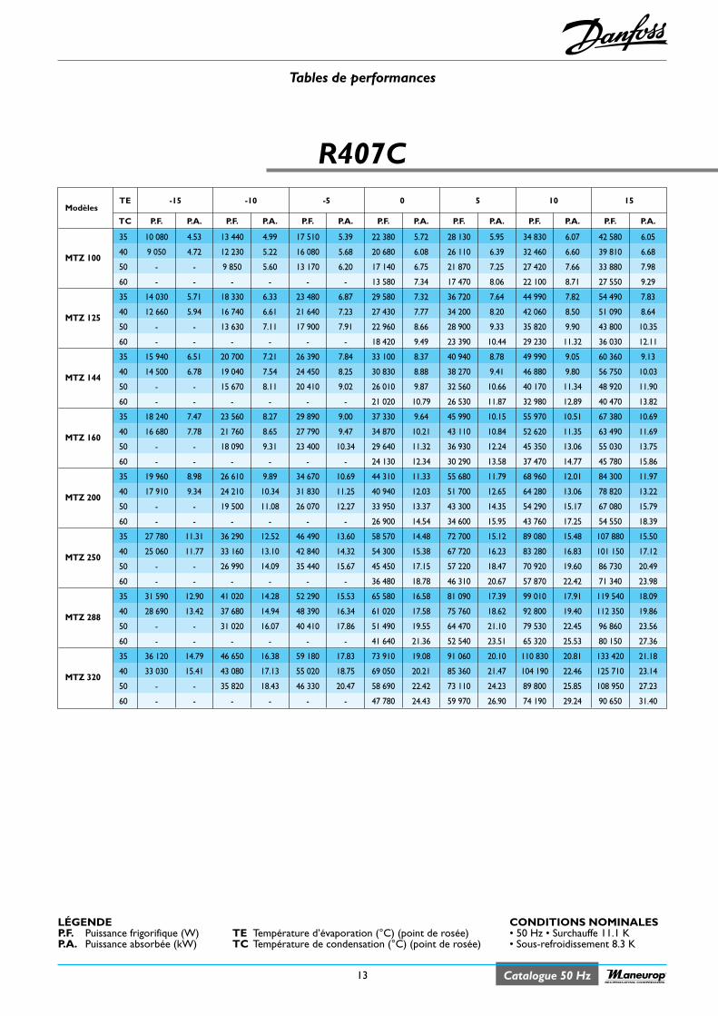
Catalogue 50 Hz
Tables de performances
13RECIPROCATING COMPRESSORS
R407C
ModèlesTE -15 -10 -5 0 5 10 15
TC P.F. P.A. P.F. P.A. P.F. P.A. P.F. P.A. P.F. P.A. P.F. P.A. P.F. P.A.
35 10 080 4.53 13 440 4.99 17 510 5.39 22 380 5.72 28 130 5.95 34 830 6.07 42 580 6.05
MTZ 10040 9 050 4.72 12 230 5.22 16 080 5.68 20 680 6.08 26 110 6.39 32 460 6.60 39 810 6.68
50 - - 9 850 5.60 13 170 6.20 17 140 6.75 21 870 7.25 27 420 7.66 33 880 7.98
60 - - - - - - 13 580 7.34 17 470 8.06 22 100 8.71 27 550 9.29
35 14 030 5.71 18 330 6.33 23 480 6.87 29 580 7.32 36 720 7.64 44 990 7.82 54 490 7.83
MTZ 12540 12 660 5.94 16 740 6.61 21 640 7.23 27 430 7.77 34 200 8.20 42 060 8.50 51 090 8.64
50 - - 13 630 7.11 17 900 7.91 22 960 8.66 28 900 9.33 35 820 9.90 43 800 10.35
60 - - - - - - 18 420 9.49 23 390 10.44 29 230 11.32 36 030 12.11
35 15 940 6.51 20 700 7.21 26 390 7.84 33 100 8.37 40 940 8.78 49 990 9.05 60 360 9.13
MTZ 14440 14 500 6.78 19 040 7.54 24 450 8.25 30 830 8.88 38 270 9.41 46 880 9.80 56 750 10.03
50 - - 15 670 8.11 20 410 9.02 26 010 9.87 32 560 10.66 40 170 11.34 48 920 11.90
60 - - - - - - 21 020 10.79 26 530 11.87 32 980 12.89 40 470 13.82
35 18 240 7.47 23 560 8.27 29 890 9.00 37 330 9.64 45 990 10.15 55 970 10.51 67 380 10.69
MTZ 16040 16 680 7.78 21 760 8.65 27 790 9.47 34 870 10.21 43 110 10.84 52 620 11.35 63 490 11.69
50 - - 18 090 9.31 23 400 10.34 29 640 11.32 36 930 12.24 45 350 13.06 55 030 13.75
60 - - - - - - 24 130 12.34 30 290 13.58 37 470 14.77 45 780 15.86
35 19 960 8.98 26 610 9.89 34 670 10.69 44 310 11.33 55 680 11.79 68 960 12.01 84 300 11.97
MTZ 20040 17 910 9.34 24 210 10.34 31 830 11.25 40 940 12.03 51 700 12.65 64 280 13.06 78 820 13.22
50 - - 19 500 11.08 26 070 12.27 33 950 13.37 43 300 14.35 54 290 15.17 67 080 15.79
60 - - - - - - 26 900 14.54 34 600 15.95 43 760 17.25 54 550 18.39
35 27 780 11.31 36 290 12.52 46 490 13.60 58 570 14.48 72 700 15.12 89 080 15.48 107 880 15.50
MTZ 25040 25 060 11.77 33 160 13.10 42 840 14.32 54 300 15.38 67 720 16.23 83 280 16.83 101 150 17.12
50 - - 26 990 14.09 35 440 15.67 45 450 17.15 57 220 18.47 70 920 19.60 86 730 20.49
60 - - - - - - 36 480 18.78 46 310 20.67 57 870 22.42 71 340 23.98
35 31 590 12.90 41 020 14.28 52 290 15.53 65 580 16.58 81 090 17.39 99 010 17.91 119 540 18.09
MTZ 28840 28 690 13.42 37 680 14.94 48 390 16.34 61 020 17.58 75 760 18.62 92 800 19.40 112 350 19.86
50 - - 31 020 16.07 40 410 17.86 51 490 19.55 64 470 21.10 79 530 22.45 96 860 23.56
60 - - - - - - 41 640 21.36 52 540 23.51 65 320 25.53 80 150 27.36
35 36 120 14.79 46 650 16.38 59 180 17.83 73 910 19.08 91 060 20.10 110 830 20.81 133 420 21.18
MTZ 32040 33 030 15.41 43 080 17.13 55 020 18.75 69 050 20.21 85 360 21.47 104 190 22.46 125 710 23.14
50 - - 35 820 18.43 46 330 20.47 58 690 22.42 73 110 24.23 89 800 25.85 108 950 27.23
60 - - - - - - 47 780 24.43 59 970 26.90 74 190 29.24 90 650 31.40
TE Température d’évaporation (°C) (point de rosée)TC Température de condensation (°C) (point de rosée)
CONDITIONS NOMINALES• 50 Hz • Surchauffe 11.1 K• Sous-refroidissement 8.3 K
LÉGENDEP.F. Puissance frigorifique (W)P.A. Puissance absorbée (kW)
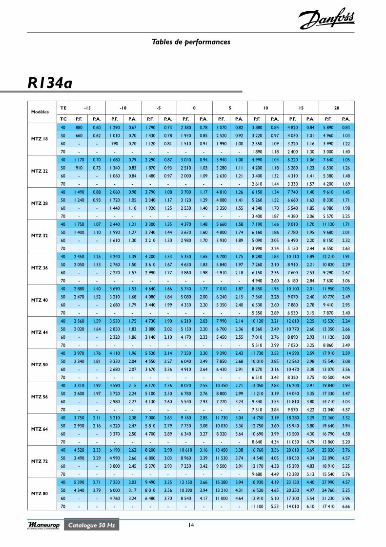
Tables de performances
14Catalogue 50 HzRECIPROCATING COMPRESSORS
R134a
ModèlesTE -15 -10 -5 0 5 10 15 20
TC P.F. P.A. P.F. P.A. P.F. P.A. P.F. P.A. P.F. P.A. P.F. P.A. P.F. P.A. P.F. P.A.
40 880 0.60 1 290 0.67 1 790 0.73 2 380 0.78 3 070 0.82 3 880 0.84 4 820 0.84 5 890 0.83
MTZ 1850 660 0.62 1 010 0.70 1 430 0.78 1 930 0.85 2 520 0.92 3 220 0.97 4 030 1.01 4 960 1.03
60 - - 790 0.70 1 120 0.81 1 510 0.91 1 990 1.00 2 550 1.09 3 220 1.16 3 990 1.22
70 - - - - - - - - - - 1 890 1.18 2 400 1.30 3 000 1.40
40 1 170 0.70 1 680 0.79 2 290 0.87 3 040 0.94 3 940 1.00 4 990 1.04 6 220 1.06 7 640 1.05
MTZ 2250 910 0.73 1 340 0.83 1 870 0.93 2 510 1.03 3 280 1.11 4 200 1.18 5 280 1.23 6 530 1.26
60 - - 1 060 0.84 1 480 0.97 2 000 1.09 2 630 1.21 3 400 1.32 4 310 1.41 5 380 1.48
70 - - - - - - - - - - 2 610 1.44 3 330 1.57 4 200 1.69
40 1 490 0.88 2 060 0.98 2 790 1.08 3 700 1.17 4 810 1.26 6 150 1.34 7 740 1.40 9 610 1.45
MTZ 2850 1 240 0.93 1 720 1.05 2 340 1.17 3 120 1.29 4 080 1.41 5 260 1.52 6 660 1.62 8 330 1.71
60 - - 1 440 1.10 1 920 1.25 2 550 1.40 3 350 1.55 4 340 1.70 5 540 1.85 6 980 1.98
70 - - - - - - - - - - 3 400 1.87 4 380 2.06 5 570 2.25
40 1 750 1.07 2 440 1.21 3 300 1.35 4 370 1.48 5 660 1.58 7 190 1.66 9 010 1.70 11 120 1.71
MTZ 3250 1 400 1.10 1 990 1.27 2 740 1.44 3 670 1.60 4 800 1.74 6 160 1.86 7 780 1.95 9 680 2.01
60 - - 1 610 1.30 2 210 1.50 2 980 1.70 3 930 1.89 5 090 2.05 6 490 2.20 8 150 2.32
70 - - - - - - - - - - 3 990 2.24 5 150 2.44 6 550 2.63
40 2 450 1.25 3 240 1.39 4 200 1.53 5 350 1.65 6 700 1.75 8 280 1.83 10 110 1.89 12 210 1.91
MTZ 3650 2 050 1.33 2 760 1.50 3 610 1.67 4 630 1.83 5 840 1.97 7 260 2.10 8 910 2.21 10 820 2.29
60 - - 2 270 1.57 2 990 1.77 3 860 1.98 4 910 2.18 6 150 2.36 7 600 2.53 9 290 2.67
70 - - - - - - - - - - 4 940 2.60 6 180 2.84 7 630 3.06
40 2 880 1.40 3 690 1.53 4 640 1.66 5 740 1.77 7 010 1.87 8 450 1.95 10 100 2.01 11 950 2.05
MTZ 4050 2 470 1.52 3 210 1.68 4 080 1.84 5 080 2.00 6 240 2.15 7 560 2.28 9 070 2.40 10 770 2.49
60 - - 2 680 1.79 3 440 1.99 4 330 2.20 5 350 2.40 6 530 2.60 7 880 2.78 9 410 2.95
70 - - - - - - - - - - 5 350 2.89 6 530 3.15 7 870 3.40
40 2 560 1.59 3 530 1.75 4 730 1.90 6 210 2.03 7 990 2.14 10 120 2.21 12 610 2.25 15 520 2.24
MTZ 4450 2 020 1.64 2 850 1.83 3 880 2.02 5 150 2.20 6 700 2.36 8 560 2.49 10 770 2.60 13 350 2.66
60 - - 2 320 1.86 3 140 2.10 4 170 2.33 5 450 2.55 7 010 2.76 8 890 2.93 11 120 3.08
70 - - - - - - - - - - 5 510 2.99 7 020 3.25 8 860 3.49
40 2 970 1.76 4 110 1.96 5 520 2.14 7 230 2.30 9 290 2.43 11 730 2.53 14 590 2.59 17 910 2.59
MTZ 5050 2 340 1.81 3 330 2.04 4 550 2.27 6 040 2.49 7 850 2.68 10 010 2.85 12 560 2.98 15 540 3.08
60 - - 2 680 2.07 3 670 2.36 4 910 2.64 6 430 2.91 8 270 3.16 10 470 3.38 13 070 3.56
70 - - - - - - - - - - 6 510 3.43 8 320 3.75 10 500 4.04
40 3 310 1.92 4 590 2.15 6 170 2.36 8 070 2.55 10 350 2.71 13 050 2.83 16 200 2.91 19 840 2.93
MTZ 5650 2 600 1.97 3 720 2.24 5 100 2.50 6 780 2.76 8 800 2.99 11 210 3.19 14 040 3.35 17 330 3.47
60 - - 2 980 2.27 4 130 2.60 5 540 2.93 7 270 3.24 9 340 3.53 11 810 3.80 14 710 4.03
70 - - - - - - - - - - 7 510 3.84 9 570 4.22 12 040 4.57
40 3 750 2.11 5 210 2.38 7 000 2.63 9 160 2.85 11 730 3.04 14 750 3.19 18 280 3.29 22 360 3.32
MTZ 6450 2 930 2.16 4 220 2.47 5 810 2.79 7 730 3.08 10 030 3.36 12 750 3.60 15 940 3.80 19 640 3.94
60 - - 3 370 2.50 4 700 2.89 6 340 3.27 8 320 3.64 10 690 3.99 13 500 4.30 16 790 4.58
70 - - - - - - - - - - 8 640 4.34 11 030 4.79 13 860 5.20
40 4 520 2.33 6 190 2.62 8 200 2.90 10 610 3.16 13 450 3.38 16 760 3.56 20 610 3.69 25 020 3.76
MTZ 7250 3 490 2.29 4 990 2.66 6 800 3.03 8 960 3.39 11 530 3.74 14 540 4.05 18 050 4.34 22 090 4.57
60 - - 3 800 2.45 5 370 2.93 7 250 3.42 9 500 3.91 12 170 4.38 15 290 4.83 18 910 5.25
70 - - - - - - - - - - 9 680 4.49 12 380 5.13 15 540 5.76
40 5 390 2.71 7 250 3.03 9 490 3.35 12 150 3.66 15 280 3.94 18 930 4.19 23 150 4.40 27 990 4.57
MTZ 8050 4 340 2.79 6 000 3.17 8 010 3.56 10 390 3.94 13 210 4.31 16 520 4.65 20 350 4.97 24 760 5.25
60 - - 4 760 3.24 6 480 3.70 8 540 4.17 11 000 4.64 13 910 5.10 17 300 5.54 21 230 5.96
70 - - - - - - - - - - 11 100 5.53 14 010 6.10 17 410 6.66

Tables de performances
15 Catalogue 50 HzRECIPROCATING COMPRESSORS
R134a
ModèlesTE -15 -10 -5 0 5 10 15 20
TC P.F. P.A. P.F. P.A. P.F. P.A. P.F. P.A. P.F. P.A. P.F. P.A. P.F. P.A. P.F. P.A.
40 5 700 3.16 7 880 3.52 10 560 3.85 13 790 4.14 17 650 4.36 22 210 4.50 27 520 4.55 33 670 4.49
MTZ 10050 4 590 3.31 6 490 3.74 8 820 4.16 11 660 4.55 15 070 4.89 19 110 5.17 23 860 5.37 29 390 5.48
60 - - 5 340 3.86 7 270 4.39 9 630 4.91 12 520 5.39 15 980 5.83 20 090 6.20 24 920 6.49
70 - - - - - - - - - - 12 870 6.43 16 270 6.99 20 330 7.49
40 7 270 3.58 9 980 4.08 13 260 4.54 17 180 4.95 21 820 5.28 27 250 5.51 33 550 5.62 40 790 5.60
MTZ 12550 5 650 3.63 8 050 4.23 10 960 4.81 14 440 5.35 18 580 5.84 23 450 6.25 29 130 6.56 35 680 6.75
60 - - 6 300 4.21 8 750 4.94 11 720 5.65 15 280 6.32 19 510 6.93 24 480 7.46 30 260 7.90
70 - - - - - - - - - - 15 450 7.54 19 640 8.32 24 580 9.03
40 9 530 4.70 12 750 5.22 16 620 5.71 21 220 6.16 26 630 6.57 32 930 6.91 40 220 7.17 48 560 7.33
MTZ 14450 7 770 4.98 10 630 5.57 14 070 6.16 18 170 6.74 23 010 7.27 28 680 7.76 35 250 8.18 42 810 8.52
60 - - 8 630 5.83 11 550 6.54 15 060 7.25 19 240 7.94 24 180 8.60 29 950 9.20 36 640 9.75
70 - - - - - - - - - - 19 500 9.38 24 380 10.20 30 110 10.96
40 10 540 5.07 14 030 5.65 18 270 6.22 23 330 6.78 29 330 7.31 36 350 7.81 44 490 8.26 53 850 8.64
MTZ 16050 8 740 5.37 11 800 6.01 15 510 6.67 19 960 7.33 25 260 7.98 31 500 8.60 38 770 9.19 47 180 9.74
60 - - 9 650 6.31 12 720 7.07 16 460 7.85 20 950 8.63 26 290 9.41 32 580 10.16 39 920 10.87
70 - - - - - - - - - - 20 670 10.21 25 870 11.14 32 030 12.05
40 11 270 6.26 15 600 6.98 20 900 7.63 27 310 8.19 34 950 8.63 43 960 8.91 54 490 9.01 66 650 8.89
MTZ 20050 9 080 6.55 12 850 7.41 17 470 8.25 23 090 9.02 29 840 9.69 37 850 10.24 47 250 10.64 58 190 10.85
60 - - 10 570 7.65 14 380 8.70 19 070 9.72 24 770 10.68 31 630 11.54 39 770 12.27 49 340 12.85
70 - - - - - - - - - - 25 300 12.76 32 040 13.87 40 090 14.85
40 14 390 7.09 19 770 8.08 26 260 9.00 34 030 9.80 43 220 10.45 53 970 10.91 66 440 11.13 80 760 11.09
MTZ 25050 11 190 7.18 15 940 8.37 21 690 9.52 28 600 10.60 36 790 11.56 46 430 12.37 57 670 12.99 70 640 13.37
60 - - 12 480 8.34 17 330 9.78 23 210 11.18 30 260 12.51 38 630 13.72 48 470 14.78 59 930 15.65
70 - - - - - - - - - - 30 720 14.92 39 010 16.48 48 790 17.87
40 18 870 9.32 25 250 10.33 32 900 11.30 42 010 12.21 52 720 13.01 65 210 13.69 79 630 14.20 96 150 14.51
MTZ 28850 15 390 9.85 21 060 11.03 27 860 12.20 35 980 13.34 45 570 14.40 56 780 15.37 69 800 16.20 84 770 16.87
60 - - 17 090 11.54 22 870 12.95 29 810 14.35 38 090 15.72 47 860 17.02 59 290 18.23 72 540 19.30
70 - - - - - - - - - - 38 520 18.65 48 180 20.26 59 520 21.77
40 20 890 10.04 27 810 11.18 36 190 12.31 46 220 13.42 58 090 14.48 71 990 15.46 88 120 16.35 106 650 17.11
MTZ 32050 17 290 10.63 23 350 11.90 30 690 13.21 39 510 14.51 50 000 15.80 62 350 17.04 76 750 18.21 93 400 19.28
60 - - 19 140 12.49 25 220 14.00 32 610 15.55 41 500 17.09 52 080 18.62 64 540 20.11 79 070 21.53
70 - - - - - - - - - - 41 420 20.19 51 720 22.03 63 910 23.83
TE Température d’évaporation (°C)TC Température de condensation (°C)
CONDITIONS NOMINALES• 50 Hz • Surchauffe 11.1 K• Sous-refroidissement 8.3 K
LÉGENDEP.F. Puissance frigorifique (W)P.A. Puissance absorbée (kW)
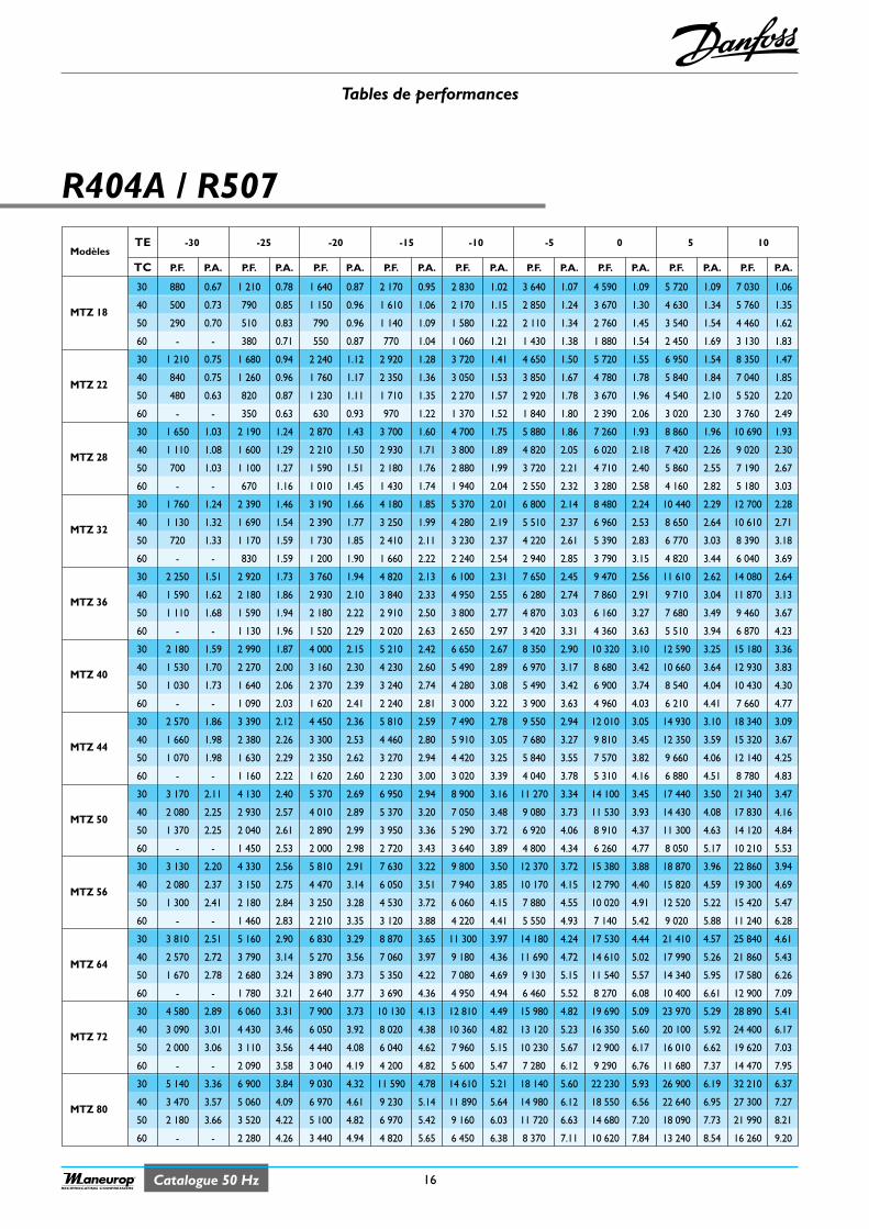
Tables de performances
16Catalogue 50 HzRECIPROCATING COMPRESSORS
R404A / R507
ModèlesTE -30 -25 -20 -15 -10 -5 0 5 10
TC P.F. P.A. P.F. P.A. P.F. P.A. P.F. P.A. P.F. P.A. P.F. P.A. P.F. P.A. P.F. P.A. P.F. P.A.
30 880 0.67 1 210 0.78 1 640 0.87 2 170 0.95 2 830 1.02 3 640 1.07 4 590 1.09 5 720 1.09 7 030 1.06
MTZ 1840 500 0.73 790 0.85 1 150 0.96 1 610 1.06 2 170 1.15 2 850 1.24 3 670 1.30 4 630 1.34 5 760 1.35
50 290 0.70 510 0.83 790 0.96 1 140 1.09 1 580 1.22 2 110 1.34 2 760 1.45 3 540 1.54 4 460 1.62
60 - - 380 0.71 550 0.87 770 1.04 1 060 1.21 1 430 1.38 1 880 1.54 2 450 1.69 3 130 1.83
30 1 210 0.75 1 680 0.94 2 240 1.12 2 920 1.28 3 720 1.41 4 650 1.50 5 720 1.55 6 950 1.54 8 350 1.47
MTZ 2240 840 0.75 1 260 0.96 1 760 1.17 2 350 1.36 3 050 1.53 3 850 1.67 4 780 1.78 5 840 1.84 7 040 1.85
50 480 0.63 820 0.87 1 230 1.11 1 710 1.35 2 270 1.57 2 920 1.78 3 670 1.96 4 540 2.10 5 520 2.20
60 - - 350 0.63 630 0.93 970 1.22 1 370 1.52 1 840 1.80 2 390 2.06 3 020 2.30 3 760 2.49
30 1 650 1.03 2 190 1.24 2 870 1.43 3 700 1.60 4 700 1.75 5 880 1.86 7 260 1.93 8 860 1.96 10 690 1.93
MTZ 2840 1 110 1.08 1 600 1.29 2 210 1.50 2 930 1.71 3 800 1.89 4 820 2.05 6 020 2.18 7 420 2.26 9 020 2.30
50 700 1.03 1 100 1.27 1 590 1.51 2 180 1.76 2 880 1.99 3 720 2.21 4 710 2.40 5 860 2.55 7 190 2.67
60 - - 670 1.16 1 010 1.45 1 430 1.74 1 940 2.04 2 550 2.32 3 280 2.58 4 160 2.82 5 180 3.03
30 1 760 1.24 2 390 1.46 3 190 1.66 4 180 1.85 5 370 2.01 6 800 2.14 8 480 2.24 10 440 2.29 12 700 2.28
MTZ 3240 1 130 1.32 1 690 1.54 2 390 1.77 3 250 1.99 4 280 2.19 5 510 2.37 6 960 2.53 8 650 2.64 10 610 2.71
50 720 1.33 1 170 1.59 1 730 1.85 2 410 2.11 3 230 2.37 4 220 2.61 5 390 2.83 6 770 3.03 8 390 3.18
60 - - 830 1.59 1 200 1.90 1 660 2.22 2 240 2.54 2 940 2.85 3 790 3.15 4 820 3.44 6 040 3.69
30 2 250 1.51 2 920 1.73 3 760 1.94 4 820 2.13 6 100 2.31 7 650 2.45 9 470 2.56 11 610 2.62 14 080 2.64
MTZ 3640 1 590 1.62 2 180 1.86 2 930 2.10 3 840 2.33 4 950 2.55 6 280 2.74 7 860 2.91 9 710 3.04 11 870 3.13
50 1 110 1.68 1 590 1.94 2 180 2.22 2 910 2.50 3 800 2.77 4 870 3.03 6 160 3.27 7 680 3.49 9 460 3.67
60 - - 1 130 1.96 1 520 2.29 2 020 2.63 2 650 2.97 3 420 3.31 4 360 3.63 5 510 3.94 6 870 4.23
30 2 180 1.59 2 990 1.87 4 000 2.15 5 210 2.42 6 650 2.67 8 350 2.90 10 320 3.10 12 590 3.25 15 180 3.36
MTZ 4040 1 530 1.70 2 270 2.00 3 160 2.30 4 230 2.60 5 490 2.89 6 970 3.17 8 680 3.42 10 660 3.64 12 930 3.83
50 1 030 1.73 1 640 2.06 2 370 2.39 3 240 2.74 4 280 3.08 5 490 3.42 6 900 3.74 8 540 4.04 10 430 4.30
60 - - 1 090 2.03 1 620 2.41 2 240 2.81 3 000 3.22 3 900 3.63 4 960 4.03 6 210 4.41 7 660 4.77
30 2 570 1.86 3 390 2.12 4 450 2.36 5 810 2.59 7 490 2.78 9 550 2.94 12 010 3.05 14 930 3.10 18 340 3.09
MTZ 4440 1 660 1.98 2 380 2.26 3 300 2.53 4 460 2.80 5 910 3.05 7 680 3.27 9 810 3.45 12 350 3.59 15 320 3.67
50 1 070 1.98 1 630 2.29 2 350 2.62 3 270 2.94 4 420 3.25 5 840 3.55 7 570 3.82 9 660 4.06 12 140 4.25
60 - - 1 160 2.22 1 620 2.60 2 230 3.00 3 020 3.39 4 040 3.78 5 310 4.16 6 880 4.51 8 780 4.83
30 3 170 2.11 4 130 2.40 5 370 2.69 6 950 2.94 8 900 3.16 11 270 3.34 14 100 3.45 17 440 3.50 21 340 3.47
MTZ 5040 2 080 2.25 2 930 2.57 4 010 2.89 5 370 3.20 7 050 3.48 9 080 3.73 11 530 3.93 14 430 4.08 17 830 4.16
50 1 370 2.25 2 040 2.61 2 890 2.99 3 950 3.36 5 290 3.72 6 920 4.06 8 910 4.37 11 300 4.63 14 120 4.84
60 - - 1 450 2.53 2 000 2.98 2 720 3.43 3 640 3.89 4 800 4.34 6 260 4.77 8 050 5.17 10 210 5.53
30 3 130 2.20 4 330 2.56 5 810 2.91 7 630 3.22 9 800 3.50 12 370 3.72 15 380 3.88 18 870 3.96 22 860 3.94
MTZ 5640 2 080 2.37 3 150 2.75 4 470 3.14 6 050 3.51 7 940 3.85 10 170 4.15 12 790 4.40 15 820 4.59 19 300 4.69
50 1 300 2.41 2 180 2.84 3 250 3.28 4 530 3.72 6 060 4.15 7 880 4.55 10 020 4.91 12 520 5.22 15 420 5.47
60 - - 1 460 2.83 2 210 3.35 3 120 3.88 4 220 4.41 5 550 4.93 7 140 5.42 9 020 5.88 11 240 6.28
30 3 810 2.51 5 160 2.90 6 830 3.29 8 870 3.65 11 300 3.97 14 180 4.24 17 530 4.44 21 410 4.57 25 840 4.61
MTZ 6440 2 570 2.72 3 790 3.14 5 270 3.56 7 060 3.97 9 180 4.36 11 690 4.72 14 610 5.02 17 990 5.26 21 860 5.43
50 1 670 2.78 2 680 3.24 3 890 3.73 5 350 4.22 7 080 4.69 9 130 5.15 11 540 5.57 14 340 5.95 17 580 6.26
60 - - 1 780 3.21 2 640 3.77 3 690 4.36 4 950 4.94 6 460 5.52 8 270 6.08 10 400 6.61 12 900 7.09
30 4 580 2.89 6 060 3.31 7 900 3.73 10 130 4.13 12 810 4.49 15 980 4.82 19 690 5.09 23 970 5.29 28 890 5.41
MTZ 7240 3 090 3.01 4 430 3.46 6 050 3.92 8 020 4.38 10 360 4.82 13 120 5.23 16 350 5.60 20 100 5.92 24 400 6.17
50 2 000 3.06 3 110 3.56 4 440 4.08 6 040 4.62 7 960 5.15 10 230 5.67 12 900 6.17 16 010 6.62 19 620 7.03
60 - - 2 090 3.58 3 040 4.19 4 200 4.82 5 600 5.47 7 280 6.12 9 290 6.76 11 680 7.37 14 470 7.95
30 5 140 3.36 6 900 3.84 9 030 4.32 11 590 4.78 14 610 5.21 18 140 5.60 22 230 5.93 26 900 6.19 32 210 6.37
MTZ 8040 3 470 3.57 5 060 4.09 6 970 4.61 9 230 5.14 11 890 5.64 14 980 6.12 18 550 6.56 22 640 6.95 27 300 7.27
50 2 180 3.66 3 520 4.22 5 100 4.82 6 970 5.42 9 160 6.03 11 720 6.63 14 680 7.20 18 090 7.73 21 990 8.21
60 - - 2 280 4.26 3 440 4.94 4 820 5.65 6 450 6.38 8 370 7.11 10 620 7.84 13 240 8.54 16 260 9.20
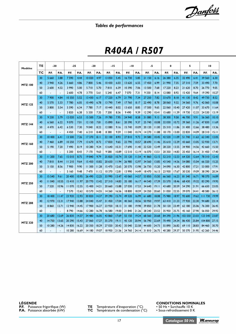
Tables de performances
17 Catalogue 50 HzRECIPROCATING COMPRESSORS
R404A / R507
ModèlesTE -30 -25 -20 -15 -10 -5 0 5 10
TC P.F. P.A. P.F. P.A. P.F. P.A. P.F. P.A. P.F. P.A. P.F. P.A. P.F. P.A. P.F. P.A. P.F. P.A.
30 5 660 3.88 7 590 4.44 10 020 4.97 13 050 5.45 16 730 5.85 21 150 6.16 26 380 6.35 32 490 6.41 39 560 6.30
MTZ 10040 3 940 4.26 5 660 4.86 7 800 5.46 10 430 6.03 13 620 6.55 17 450 6.99 21 990 7.35 27 310 7.59 33 490 7.70
50 2 600 4.32 3 990 5.00 5 710 5.70 7 810 6.39 10 390 7.06 13 500 7.68 17 220 8.23 21 620 8.70 26 770 9.05
60 - - 2 600 4.78 3 770 5.61 5 240 6.47 7 070 7.31 9 330 8.14 12 080 8.92 15 420 9.64 19 390 10.27
30 7 900 4.84 10 350 5.52 13 430 6.17 17 220 6.79 21 790 7.34 27 250 7.82 33 670 8.18 41 130 8.42 49 730 8.52
MTZ 12540 5 570 5.33 7 780 6.05 10 490 6.78 13 790 7.49 17 760 8.17 22 490 8.78 28 060 9.32 34 560 9.76 42 060 10.08
50 3 800 5.54 5 590 6.34 7 780 7.17 10 440 8.02 13 650 8.85 17 500 9.65 22 060 10.40 27 420 11.07 33 670 11.64
60 - - 3 820 6.38 5 330 7.35 7 200 8.36 9 490 9.39 12 290 10.41 15 680 11.39 19 730 12.33 24 530 13.19
30 9 230 5.79 12 020 6.53 15 500 7.26 19 780 7.95 24 940 8.58 31 080 9.13 38 300 9.58 46 700 9.91 56 360 10.10
MTZ 14440 6 560 6.22 9 070 7.01 12 150 7.81 15 890 8.61 20 390 9.37 25 740 10.08 32 030 10.72 39 360 11.26 47 830 11.69
50 4 470 6.42 6 530 7.30 9 040 8.22 12 080 9.16 15 740 10.09 20 120 11.00 25 310 11.86 31 400 12.66 38 480 13.36
60 - - 4 450 7.40 6 210 8.48 8 380 9.59 11 040 10.74 14 270 11.88 18 170 13.00 22 820 14.09 28 310 15.11
30 10 400 6.41 13 500 7.26 17 370 8.11 22 100 8.93 27 810 9.72 34 580 10.45 42 520 11.09 51 740 11.63 62 340 12.05
MTZ 16040 7 460 6.89 10 250 7.79 13 670 8.72 17 820 9.65 22 790 10.57 28 690 11.46 35 610 12.29 43 660 13.05 52 930 13.71
50 5 190 7.20 7 490 8.19 10 280 9.24 13 640 10.31 17 690 11.40 22 520 12.49 28 220 13.55 34 900 14.56 42 660 15.50
60 - - 5 200 8.43 7 170 9.63 9 580 10.89 12 510 12.19 16 070 13.51 20 350 14.83 25 450 16.14 31 450 17.40
30 11 200 7.65 15 010 8.75 19 840 9.79 25 820 10.74 33 120 11.54 41 860 12.15 52 210 12.53 64 320 12.64 78 310 12.43
MTZ 20040 7 810 8.44 11 210 9.64 15 450 10.82 20 650 11.94 26 980 12.97 34 560 13.85 43 540 14.56 54 080 15.04 66 320 15.25
50 5 150 8.56 7 900 9.90 11 300 11.28 15 470 12.65 20 570 13.98 26 730 15.20 34 090 16.30 42 800 17.21 53 000 17.91
60 - - 5 160 9.48 7 470 11.12 10 370 12.81 13 990 14.49 18 470 16.13 23 930 17.67 30 530 19.09 38 390 20.34
30 15 540 9.61 20 400 10.95 26 490 12.25 33 990 13.47 43 060 14.57 53 850 15.50 66 560 16.23 81 340 16.71 98 370 16.89
MTZ 25040 11 040 10.55 15 410 11.97 20 770 13.42 27 310 14.83 35 180 16.17 44 540 17.39 55 570 18.46 68 430 19.32 83 290 19.95
50 7 520 10.96 11 070 12.55 15 400 14.21 20 660 15.88 27 030 17.53 34 640 19.11 43 680 20.59 54 290 21.91 66 650 23.05
60 - - 7 570 12.62 10 570 14.55 14 260 16.56 18 800 18.59 24 350 20.60 31 050 22.55 39 070 24.41 48 580 26.12
30 18 400 11.47 23 920 12.93 30 820 14.37 39 290 15.74 49 520 16.99 61 680 18.08 75 980 18.97 92 600 19.62 111 730 19.99
MTZ 28840 12 970 12.31 17 940 13.88 24 040 15.47 31 450 17.04 40 360 18.56 50 950 19.97 63 410 21.23 77 920 22.30 94 680 23.14
50 8 860 12.71 12 940 14.45 17 900 16.27 23 920 18.13 31 180 19.98 39 850 21.78 50 120 23.49 62 180 25.06 76 200 26.45
60 - - 8 790 14.66 12 280 16.78 16 580 19.00 21 840 21.26 28 240 23.52 35 950 25.75 45 160 27.90 56 050 29.92
30 20 680 12.69 26 830 14.37 34 480 16.05 43 860 17.69 55 150 19.24 68 560 20.68 84 290 21.96 102 550 23.03 123 540 23.87
MTZ 32040 14 750 13.65 20 290 15.43 27 060 17.27 35 270 19.11 45 120 20.94 56 790 22.69 70 490 24.34 86 430 25.84 104 800 27.15
50 10 280 14.26 14 830 16.22 20 350 18.29 27 020 20.42 35 040 22.58 44 600 24.73 55 890 26.82 69 110 28.83 84 460 30.70
60 - - 10 280 16.69 14 180 19.07 18 950 21.56 24 760 24.14 31 810 26.75 40 280 29.37 50 370 31.95 62 260 34.46
TE Température d’évaporation (°C)TC Température de condensation (°C)
CONDITIONS NOMINALES• 50 Hz • Surchauffe 10 K• Sous-refroidissement 0 K
LÉGENDEP.F. Puissance frigorifique (W)P.A. Puissance absorbée (kW)
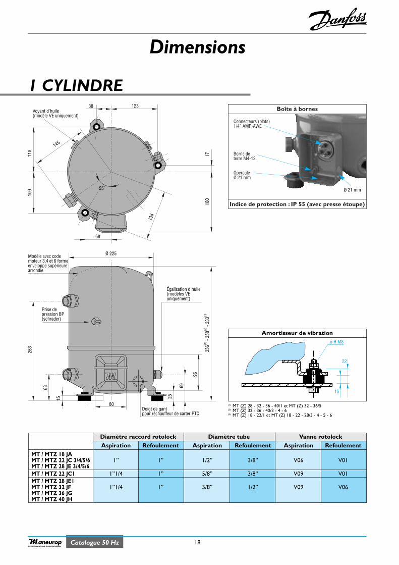
Dimensions
18Catalogue 50 HzRECIPROCATING COMPRESSORS
Amortisseur de vibration
1 CYLINDRE
Diamètre raccord rotolock Diamètre tube Vanne rotolockAspiration Refoulement Aspiration Refoulement Aspiration Refoulement
MT / MTZ 18 JAMT / MTZ 22 JC 3/4/5/6 1” 1” 1/2” 3/8” V06 V01MT / MTZ 28 JE 3/4/5/6MT / MTZ 22 JC1 1”1/4 1” 5/8” 3/8” V09 V01MT / MTZ 28 JE1MT / MTZ 32 JF 1”1/4 1” 5/8” 1/2” V09 V06MT / MTZ 36 JGMT / MTZ 40 JH
(1) MT (Z) 28 - 32 - 36 - 40/1 et MT (Z) 32 - 36/5(2) MT (Z) 32 - 36 - 40/3 - 4 - 6(3) MT (Z) 18 - 22/1 et MT (Z) 18 - 22 - 28/3 - 4 - 5 - 6
356(1
) - 35
8(2) -
333(3
)
96
263
68
15 25
80
69
Ø 225Modèle avec codemoteur 3,4 et 6 formeenveloppe supérieurearrondie
Prise depression BP(schrader)
Égalisation d'huile(modèles VEuniquement)
Doigt de gantpour réchauffeur de carter PTC
38 123
145
118
109
68
134
1716
0
55˚
Voyant d'huile(modèle VE uniquement)
ø H M8
22
15
Boîte à bornes
Indice de protection : IP 55 (avec presse étoupe)
Connecteurs (plats)1/4” AMP-AWE
Borne deterre M4-12
OperculeØ 21 mm
Ø 21 mm
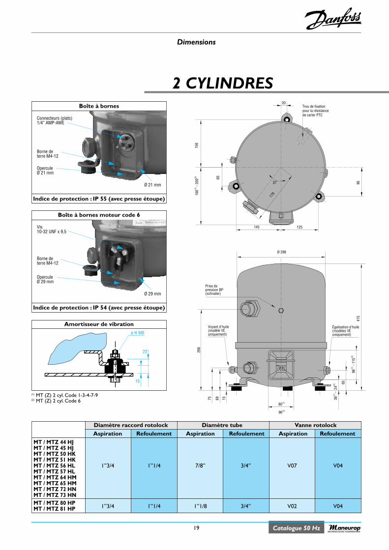
Dimensions
19 Catalogue 50 HzRECIPROCATING COMPRESSORS
2 CYLINDRES
Diamètre raccord rotolock Diamètre tube Vanne rotolockAspiration Refoulement Aspiration Refoulement Aspiration Refoulement
MT / MTZ 44 HJMT / MTZ 45 HJMT / MTZ 50 HKMT / MTZ 51 HKMT / MTZ 56 HL 1”3/4 1”1/4 7/8” 3/4” V07 V04MT / MTZ 57 HLMT / MTZ 64 HMMT / MTZ 65 HMMT / MTZ 72 HNMT / MTZ 73 HNMT / MTZ 80 HP 1”3/4 1”1/4 1”1/8 3/4” V02 V04MT / MTZ 81 HP
(1) MT (Z) 2 cyl. Code 1-3-4-7-9(2) MT (Z) 2 cyl. Code 6
156
190(1
) - 20
0(2)
60
37˚ 96
145 125
20
179
Trou de fixationpour la résistancede carter PTC
415
65
266
80(1)
96(2)
Ø 288
6975 15 36(1
) - 2
4(2)
96(1
) - 11
5(2)
Prise depression BP(schrader)
Voyant d'huile(modèle VEuniquement)
Égalisation d'huile(modèles VEuniquement)
Amortisseur de vibration ø H M8
22
15
Boîte à bornes
Indice de protection : IP 55 (avec presse étoupe)
Connecteurs (plats)1/4” AMP-AWE
Borne deterre M4-12
OperculeØ 21 mm
Ø 21 mm
Boîte à bornes moteur code 6
Indice de protection : IP 54 (avec presse étoupe)
Vis10-32 UNF x 9,5
Borne deterre M4-12
OperculeØ 29 mm
Ø 29 mm
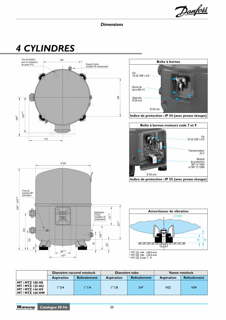
Dimensions
Amortisseur de vibration
20Catalogue 50 HzRECIPROCATING COMPRESSORS
4 CYLINDRES
(1) MT (Z) 144 - 160/3-4-6(2) MT (Z) 100 - 125/3-4-6(3) MT (Z) Code 7 - 9
540(1
) - 51
9(2)(
3)
95
233
125
Ø 352
19
179(3)
96(1)(2)
60(3
)
158(1
)(2)
115(1
)(2)
227(3
)
Prise depression BP(schrader)
Égalisationd'huile(modèles VEuniquement)
246
255(3
)
212
246
232(1
)(2)
Trou de fixationpour la résistancede carter PTC Voyant d'huile
(modèle VE uniquement)
3019
ø H M12
Boîte à bornes
Indice de protection : IP 54 (avec presse étoupe)
Vis10-32 UNF x 9,5
Borne deterre M4-12
OperculeØ 29 mm
Ø 29 mm
Boîte à bornes moteurs code 7 et 9
Indice de protection : IP 55 (avec presse étoupe)
Vis10-32 UNF x 9,5
Transformateur24 V
Modulede protectionMP 12-1064
or MP 12-1069
Diamètre raccord rotolock Diamètre tube Vanne rotolockAspiration Refoulement Aspiration Refoulement Aspiration Refoulement
MT / MTZ 100 HSMT / MTZ 125 HU 1”3/4 1”1/4 1”1/8 3/4” V02 V04MT / MTZ 144 HVMT / MTZ 160 HW
Ø 29 mm
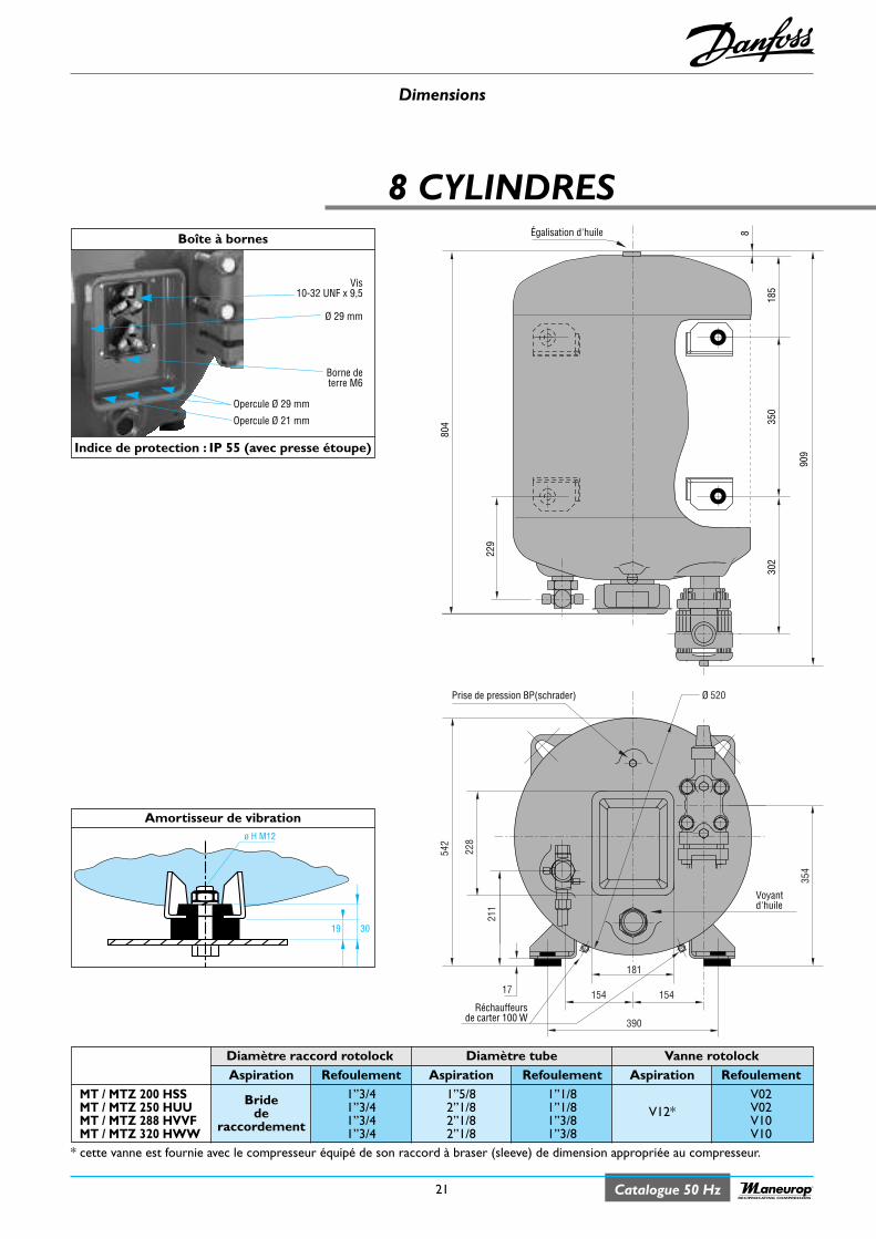
Dimensions
21 Catalogue 50 HzRECIPROCATING COMPRESSORS
8 CYLINDRES
542
228
17
Réchauffeursde carter 100 W
211
Ø 520
354
181
154 154
390
Prise de pression BP(schrader)
Voyantd'huile
909
350
185
804
302
8
229
Égalisation d'huile
Amortisseur de vibration
3019
ø H M12
Diamètre raccord rotolock Diamètre tube Vanne rotolockAspiration Refoulement Aspiration Refoulement Aspiration Refoulement
MT / MTZ 200 HSS 1”3/4 1”5/8 1”1/8 V02MT / MTZ 250 HUU Bride 1”3/4 2”1/8 1”1/8 V12* V02MT / MTZ 288 HVVF de 1”3/4 2”1/8 1”3/8 V10MT / MTZ 320 HWW raccordement 1”3/4 2”1/8 1”3/8 V10
Boîte à bornes
Indice de protection : IP 55 (avec presse étoupe)
Vis10-32 UNF x 9,5
Borne deterre M6
Ø 29 mm
Opercule Ø 29 mm
Opercule Ø 21 mm
* cette vanne est fournie avec le compresseur équipé de son raccord à braser (sleeve) de dimension appropriée au compresseur.
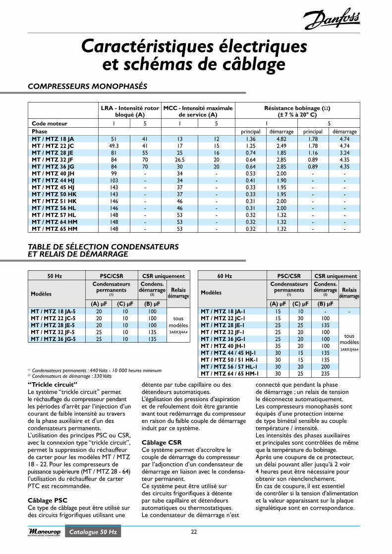
Catalogue 50 Hz 22RECIPROCATING COMPRESSORS
COMPRESSEURS MONOPHASÉS
Caractéristiques électriqueset schémas de câblage
TABLE DE SÉLECTION CONDENSATEURSET RELAIS DE DÉMARRAGE
“Trickle circuit” Le système “trickle circuit” permetle réchauffage du compresseur pendantles périodes d’arrêt par l’injection d’uncourant de faible intensité au traversde la phase auxiliaire et d’un descondensateurs permanents.L’utilisation des principes PSC ou CSR,avec la connexion type “trickle circuit”,permet la suppression du réchauffeurde carter pour les modèles MT / MTZ18 - 22. Pour les compresseurs depuissance supérieure (MT / MTZ 28 - 64)l’utilisation du réchauffeur de carterPTC est recommandée.
Câblage PSC Ce type de câblage peut être utilisé surdes circuits frigorifiques utilisant une
détente par tube capillaire ou desdétendeurs automatiques.L’égalisation des pressions d’aspirationet de refoulement doit être garantieavant tout redémarrage du compresseuren raison du faible couple de démarrageinduit par ce système.
Câblage CSR Ce système permet d’accroître lecouple de démarrage du compresseurpar l’adjonction d’un condensateur dedémarrage en liaison avec le condensa-teur permanent.Ce système peut être utilisé surdes circuits frigorifiques à détentepar tube capillaire et détendeursautomatiques ou thermostatiques.Le condensateur de démarrage n’est
connecté que pendant la phasede démarrage ; un relais de tensionle déconnecte automatiquement.Les compresseurs monophasés sontéquipés d’une protection internede type bimétal sensible au coupletempérature / intensité.Les intensités des phases auxiliaireset principales sont contrôlées de mêmeque la température du bobinage.Après une coupure de ce protecteur,un délai pouvant aller jusqu’à 2 voir4 heures peut être nécessaire pourobtenir son réenclenchement.En cas de coupure, il est essentielde contrôler si la tension d’alimentationet la valeur apparaissant sur la plaquesignalétique sont en correspondance.
LRA - Intensité rotor MCC - Intensité maximale Résistance bobinage (Ω)bloqué (A) de service (A) (± 7 % à 20° C)
Code moteur 1 5 1 5 1 5Phase principal démarrage principal démarrageMT / MTZ 18 JA 51 41 13 12 1.36 4.82 1.78 4.74MT / MTZ 22 JC 49.3 41 17 15 1.25 2.49 1.78 4.74MT / MTZ 28 JE 81 55 25 16 0.74 1.85 1.16 3.24MT / MTZ 32 JF 84 70 26.5 20 0.64 2.85 0.89 4.35MT / MTZ 36 JG 84 70 30 20 0.64 2.85 0.89 4.35MT / MTZ 40 JH 99 - 34 - 0.53 2.00 - -MT / MTZ 44 HJ 103 - 34 - 0.41 1.90 - -MT / MTZ 45 HJ 143 - 37 - 0.33 1.95 - -MT / MTZ 50 HK 143 - 37 - 0.33 1.95 - -MT / MTZ 51 HK 146 - 46 - 0.31 2.00 - -MT / MTZ 56 HL 146 - 46 - 0.31 2.00 - -MT / MTZ 57 HL 148 - 53 - 0.32 1.32 - -MT / MTZ 64 HM 148 - 53 - 0.32 1.32 - -MT / MTZ 65 HM 148 - 53 - 0.32 1.32 - -
50 Hz PSC/CSR CSR uniquementCondensateurs Condens.
Modèlespermanents démarrage Relais
(1) (2) démarrage(A) µF (C) µF (B) µF
MT / MTZ 18 JA-5 20 10 100MT / MTZ 22 JC-5 20 10 100 tousMT / MTZ 28 JE-5 20 10 100 modèlesMT / MTZ 32 JF-5 25 10 135 3ARR3J4A4
MT / MTZ 36 JG-5 25 10 135
60 Hz PSC/CSR CSR uniquementCondensateurs Condens.
Modèles permanents démarrage Relais(1) (2) démarrage
(A) µF (C) µF (B) µFMT / MTZ 18 JA-1 15 10 - -MT / MTZ 22 JC-1 15 30 100MT / MTZ 28 JE-1 25 25 135MT / MTZ 32 JF-1 25 20 100MT / MTZ 36 JG-1 25 20 100 tous
MT / MTZ 40 JH-1 35 20 100modèles
MT / MTZ 44 / 45 HJ-1 30 15 1353ARR3J4A4
MT / MTZ 50 / 51 HK-1 30 15 135MT / MTZ 56 / 57 HL-1 30 20 200MT / MTZ 64 / 65 HM-1 30 25 235
(1) Condensateurs permanents : 440 Volts - 10 000 heures minimum(2) Condensateurs de démarrage : 330 Volts
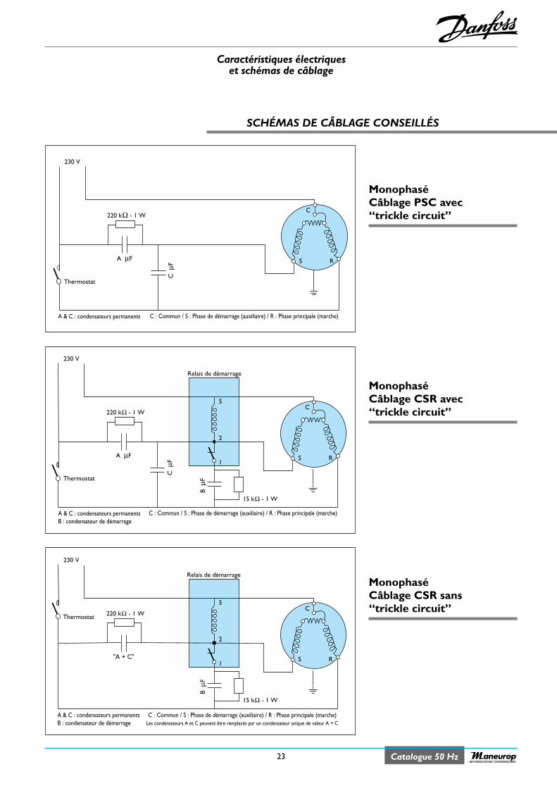
Caractéristiques électriqueset schémas de câblage
23 Catalogue 50 HzRECIPROCATING COMPRESSORS
MonophaséCâblage PSC avec“trickle circuit”
MonophaséCâblage CSR avec“trickle circuit”
MonophaséCâblage CSR sans“trickle circuit”
SCHÉMAS DE CÂBLAGE CONSEILLÉS
220 kΩ - 1 W
230 V
A µF
Thermostat
C µ
F S R
A & C : condensateurs permanents
C
C : Commun / S : Phase de démarrage (auxiliaire) / R : Phase principale (marche)
220 kΩ - 1 W
15 kΩ - 1 W
230 V
A µF
C µ
F
B µ
F
5
Relais de démarrage
2
1S R
A & C : condensateurs permanentsB : condensateur de démarrage
C
C : Commun / S : Phase de démarrage (auxiliaire) / R : Phase principale (marche)
Thermostat
15 kΩ - 1 W
230 V
"A + C"
B µ
F
5
Relais de démarrage
2
1S R
C
Les condensateurs A et C peuvent être remplacés par un condensateur unique de valeur A + C
220 kΩ - 1 W
A & C : condensateurs permanentsB : condensateur de démarrage
C : Commun / S : Phase de démarrage (auxiliaire) / R : Phase principale (marche)
Thermostat
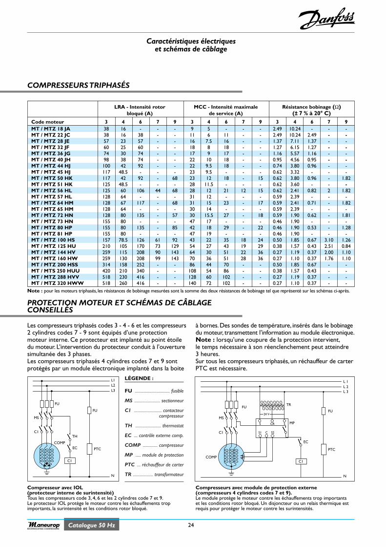
Caractéristiques électriqueset schémas de câblage
24Catalogue 50 HzRECIPROCATING COMPRESSORS
COMPRESSEURS TRIPHASÉS
PROTECTION MOTEUR ET SCHÉMAS DE CÂBLAGECONSEILLÉS
LRA - Intensité rotor MCC - Intensité maximale Résistance bobinage (Ω)bloqué (A) de service (A) (± 7 % à 20° C)
Code moteur 3 4 6 7 9 3 4 6 7 9 3 4 6 7 9MT / MTZ 18 JA 38 16 - - - 9 5 - - - 2.49 10.24 - - -MT / MTZ 22 JC 38 16 38 - - 11 6 11 - - 2.49 10.24 2.49 - -MT / MTZ 28 JE 57 23 57 - - 16 7.5 16 - - 1.37 7.11 1.37 - -MT / MTZ 32 JF 60 25 60 - - 18 8 18 - - 1.27 6.15 1.27 - -MT / MTZ 36 JG 74 30 74 - - 17 9 17 - - 1.16 5.57 1.16 - -MT / MTZ 40 JH 98 38 74 - - 22 10 18 - - 0.95 4.56 0.95 - -MT / MTZ 44 HJ 100 42 92 - - 22 9.5 18 - - 0.74 3.80 0.96 - -MT / MTZ 45 HJ 117 48.5 - - - 23 9.5 - - - 0.62 3.32 - - -MT / MTZ 50 HK 117 42 92 - 68 23 12 18 - 15 0.62 3.80 0.96 - 1.82MT / MTZ 51 HK 125 48.5 - - - 28 11.5 - - - 0.62 3.60 - - -MT / MTZ 56 HL 125 60 106 44 68 28 12 21 12 15 0.62 2.41 0.82 2 1.82MT / MTZ 57 HL 128 64 - - - 31 12 - - - 0.59 2.39 - - -MT / MTZ 64 HM 128 67 117 - 68 31 15 23 - 17 0.59 2.41 0.71 - 1.82MT / MTZ 65 HM 128 64 - - - 30 14 - - - 0.59 2.39 - - -MT / MTZ 72 HN 128 80 135 - 57 30 15.5 27 - 18 0.59 1.90 0.62 - 1.81MT / MTZ 73 HN 155 80 - - - 47 17 - - - 0.46 1.90 - - -MT / MTZ 80 HP 155 80 135 - 85 42 18 29 - 22 0.46 1.90 0.53 - 1.28MT / MTZ 81 HP 155 80 - - - 47 19 - - - 0.46 1.90 - - -MT / MTZ 100 HS 157 78.5 126 61 92 43 22 35 18 24 0.50 1.85 0.67 3.10 1.26MT / MTZ 125 HU 210 105 170 73 129 54 27 43 19 29 0.38 1.57 0.43 2.51 0.84MT / MTZ 144 HV 259 115 208 90 143 64 30 51 22 36 0.27 1.19 0.37 2.00 1.10MT / MTZ 160 HW 259 130 208 99 143 70 36 51 28 36 0.27 1.10 0.37 1.76 1.10MT / MTZ 200 HSS 314 158 252 - - 86 44 70 - - 0.50 1.85 0.67 - -MT / MTS 250 HUU 420 210 340 - - 108 54 86 - - 0.38 1.57 0.43 - -MT / MTZ 288 HVV 518 230 416 - - 128 60 102 - - 0.27 1.19 0.37 - -MT / MTZ 320 HWW 518 260 416 - - 140 72 102 - - 0.27 1.10 0.37 - -
Note : pour les moteurs triphasés, les résistances de bobinage mesurées sont la somme des deux résistances de bobinage tel que représenté sur les schémas ci-après.
Les compresseurs triphasés codes 3 - 4 - 6 et les compresseurs2 cylindres codes 7 - 9 sont équipés d’une protectionmoteur interne. Ce protecteur est implanté au point étoiledu moteur. L’intervention du protecteur conduit à l’ouverturesimultanée des 3 phases.Les compresseurs triphasés 4 cylindres codes 7 et 9 sontprotégés par un module électronique implanté dans la boite
à bornes.Des sondes de température, insérés dans le bobinagedu moteur, transmettent l’information au module électronique.Note : lorsqu’une coupure de la protection intervient,le temps nécessaire à son réenclenchement peut atteindre3 heures.Sur tous les compresseurs triphasés, un réchauffeur de carterPTC est nécessaire.
Compresseur avec IOL(protecteur interne de surintensité)Tous les compresseurs code 3, 4, 6 et les 2 cylindres code 7 et 9.Le protecteur IOL protège le moteur contre les échauffements tropimportants, la surintensité et les conditions rotor bloqué.
Compresseurs avec module de protection externe(compresseurs 4 cylindres codes 7 et 9).Le module protège le moteur contre les échauffements trop importantset les conditions rotor bloqué. Un disjoncteur ou un relais thermique estrequis pour protéger le moteur contre les surintensités.
PTC
COMP
FU
FU
C1
EC
TH
N
L1L2L3
C1
MS
L 1L 2L 3
EC
MP
TR
PTC
COMP
C1
MS
FU
S1
S
24 V
CR S
C S2
N
FU
C1
LÉGENDE :
FU ...................................... fusible
MS ............................ sectionneur
C1 .............................. contacteurcompresseur
TH ............................ thermostat
EC .... contrôle externe comp.
COMP ................ compresseur
MP ...... module de protection
PTC .... réchauffeur de carter
TR ...................... transformateur
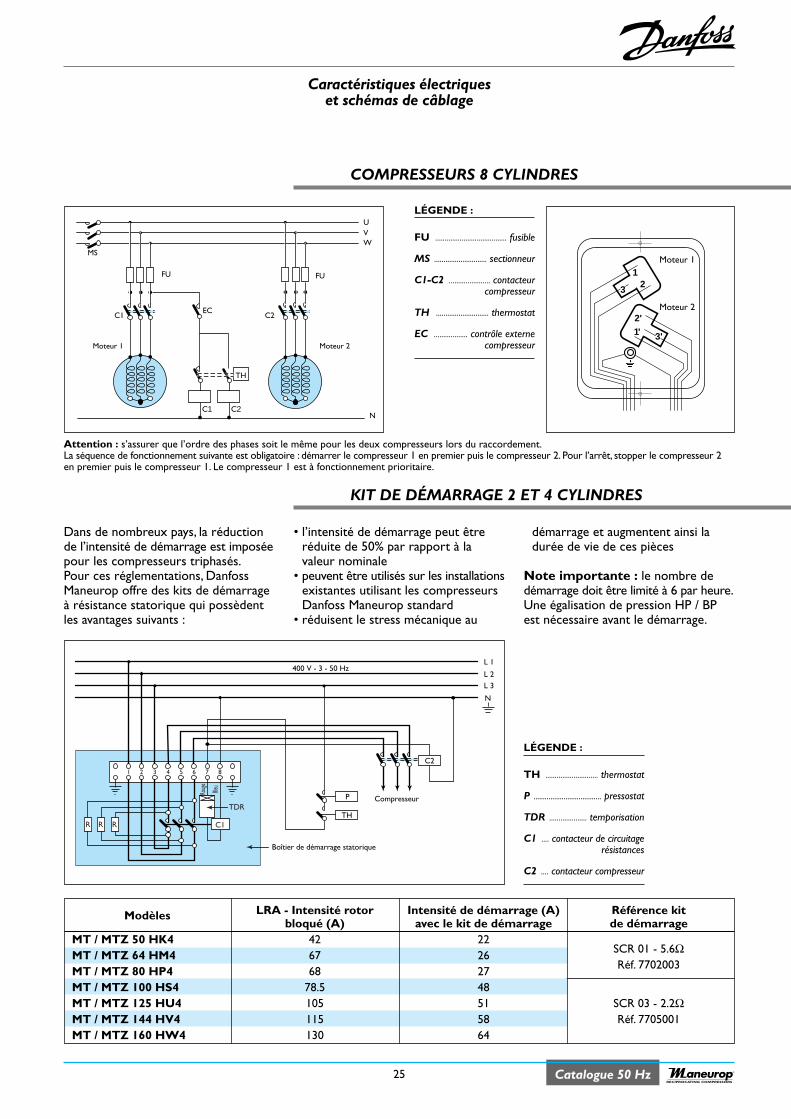
Caractéristiques électriqueset schémas de câblage
25 Catalogue 50 HzRECIPROCATING COMPRESSORS
COMPRESSEURS 8 CYLINDRES
KIT DE DÉMARRAGE 2 ET 4 CYLINDRES
UVW
C1
FU
N
MS
EC
C1 C2
TH
Moteur 1
FU
C2
Moteur 2
L 1400 V - 3 - 50 Hz
L 2L 3
N
1 2 3 4 5 6 7 8
R R R
P
TH
C2
Compresseur
Boîtier de démarrage statorique
Bleu
Rouge
C1
TDR
12
1'2'
3'
3
Moteur 1
Moteur 2
LÉGENDE :
FU ...................................... fusible
MS ............................ sectionneur
C1-C2 ...................... contacteurcompresseur
TH ............................ thermostat
EC .................. contrôle externecompresseur
Modèles LRA - Intensité rotor Intensité de démarrage (A) Référence kitbloqué (A) avec le kit de démarrage de démarrage
MT / MTZ 50 HK4 42 22MT / MTZ 64 HM4 67 26 SCR 01 - 5.6Ω
MT / MTZ 80 HP4 68 27 Réf. 7702003
MT / MTZ 100 HS4 78.5 48MT / MTZ 125 HU4 105 51 SCR 03 - 2.2ΩMT / MTZ 144 HV4 115 58 Réf. 7705001MT / MTZ 160 HW4 130 64
• l’intensité de démarrage peut êtreréduite de 50% par rapport à lavaleur nominale
• peuvent être utilisés sur les installationsexistantes utilisant les compresseursDanfoss Maneurop standard
• réduisent le stress mécanique au
démarrage et augmentent ainsi ladurée de vie de ces pièces
Note importante : le nombre dedémarrage doit être limité à 6 par heure.Une égalisation de pression HP / BPest nécessaire avant le démarrage.
Dans de nombreux pays, la réductionde l’intensité de démarrage est imposéepour les compresseurs triphasés.Pour ces réglementations, DanfossManeurop offre des kits de démarrageà résistance statorique qui possèdentles avantages suivants :
Attention : s’assurer que l’ordre des phases soit le même pour les deux compresseurs lors du raccordement.La séquence de fonctionnement suivante est obligatoire : démarrer le compresseur 1 en premier puis le compresseur 2. Pour l’arrêt, stopper le compresseur 2en premier puis le compresseur 1. Le compresseur 1 est à fonctionnement prioritaire.
LÉGENDE :
TH ............................ thermostat
P .................................... pressostat
TDR .................... temporisation
C1 .... contacteur de circuitagerésistances
C2 .... contacteur compresseur
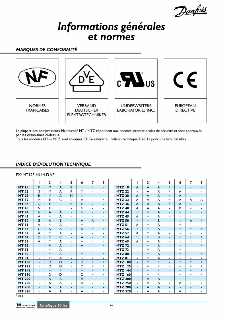
VERBANDDEUTSCHER
ELEKTROTECHNIKER
UNDERWRITERSLABORATORIES INC.
EUROPEANDIRECTIVE
Catalogue 50 Hz 26RECIPROCATING COMPRESSORS
MARQUES DE CONFORMITÉ
Informations généraleset normes
La plupart des compresseurs Maneurop® MT / MTZ répondent aux normes internationales de sécurité et sont approuvéspar les organismes ci-dessus.Tous les modèles MT & MTZ sont marqués CE. Se référer au bulletin technique TI2-011 pour une liste détaillée.
NORMESFRANÇAISES
1 3 4 5 6 7 9MT 18 P M A B - - -MT 22 S M A P M - -MT 28 R M A N M - -MT 32 M E C L A - *MT 36 Q F E B F - -MT 40 N F E - G - -MT 44 E A A - * - -MT 45 A * A - - - -MT 50 E A B - A A *MT 51 A * A - * - -MT 56 C A A - A * *MT 57 A * A - - - -MT 64 D C C - A - *MT 65 A * A - * - -MT 72 - A A - A - *MT 73 - * A - - - -MT 80 - * A - * - *MT 81 - * A - - - -MT 100 - D D - D * *MT 125 - D D - D * *MT 144 - * * - * * *MT 160 - D D - D * *MT 200 - A A - A - -MT 250 - A A - A - -MT 288 - A A - - - -MT 320 - A A - A - -
EX: MT125 HU 4 DVE
INDICE D’ÉVOLUTION TECHNIQUE
1 3 4 5 6 7 9MTZ 18 A A A * - - -MTZ 22 * A A * A - -MTZ 28 A A A * A - -MTZ 32 A A A * A A AMTZ 36 A A A * A - -MTZ 40 A A A - B - -MTZ 44 * * A - * - -MTZ 45 A * A - - - -MTZ 50 * * B - * A *MTZ 51 A * A - * - -MTZ 56 * * A - * * *MTZ 57 A * A - - - -MTZ 64 * * B - * - *MTZ 65 A * A - - - -MTZ 72 - * A - * - *MTZ 73 - * A - * - -MTZ 80 - * A - * - *MTZ 81 - * A - - - -MTZ 100 - * * - * * *MTZ 125 - * * - * * *MTZ 144 - * * - * * *MTZ 160 - * * - * * *MTZ 200 - A A - - - -MTZ 250 - A A - A - -MTZ 288 - A A - - - -MTZ 320 - A A - A - -
* vide
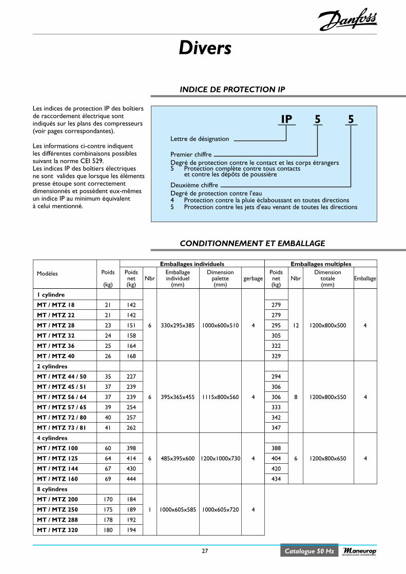
Divers
27 Catalogue 50 HzRECIPROCATING COMPRESSORS
INDICE DE PROTECTION IP
Les indices de protection IP des boîtiersde raccordement électrique sontindiqués sur les plans des compresseurs(voir pages correspondantes).
Les informations ci-contre indiquentles différentes combinaisons possiblessuivant la norme CEI 529.Les indices IP des boîtiers électriquesne sont valides que lorsque les élémentspresse étoupe sont correctementdimensionnés et possèdent eux-mêmesun indice IP au minimum équivalentà celui mentionné.
IP 5 5
Lettre de désignation
Premier chiffreDegré de protection contre le contact et les corps étrangers5 Protection complète contre tous contacts
et contre les dépôts de poussière
Deuxième chiffreDegré de protection contre l'eau4 Protection contre la pluie éclaboussant en toutes directions5 Protection contre les jets d'eau venant de toutes les directions
CONDITIONNEMENT ET EMBALLAGE
Emballages individuelsPoids Poids Emballage DimensionModèles
net Nbr individuel palette gerbage(kg) (kg) (mm) (mm)
1 cylindre
MT / MTZ 18 21 142
MT / MTZ 22 21 142
MT / MTZ 28 23 151 6 330x295x385 1000x600x510 4
MT / MTZ 32 24 158
MT / MTZ 36 25 164
MT / MTZ 40 26 168
2 cylindres
MT / MTZ 44 / 50 35 227
MT / MTZ 45 / 51 37 239
MT / MTZ 56 / 64 37 239 6 395x365x455 1115x800x560 4
MT / MTZ 57 / 65 39 254
MT / MTZ 72 / 80 40 257
MT / MTZ 73 / 81 41 262
4 cylindres
MT / MTZ 100 60 398
MT / MTZ 125 64 414 6 485x395x600 1200x1000x730 4
MT / MTZ 144 67 430
MT / MTZ 160 69 444
8 cylindres
MT / MTZ 200 170 184
MT / MTZ 250 175 189 1 1000x605x585 1000x605x720 4
MT / MTZ 288 178 192
MT / MTZ 320 180 194
Emballages multiplesPoids Dimensionnet Nbr totale Emballage(kg) (mm)
279
279
295 12 1200x800x500 4
305
322
329
294
306
306 8 1200x800x550 4
333
342
347
388
404 6 1200x800x650 4
420
434
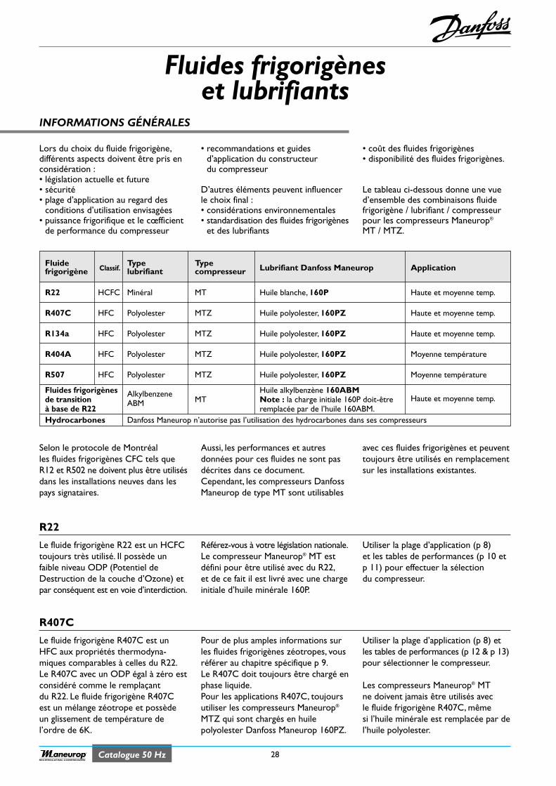
Catalogue 50 Hz 28RECIPROCATING COMPRESSORS
INFORMATIONS GÉNÉRALES
Fluides frigorigèneset lubrifiants
R22
Lors du choix du fluide frigorigène,différents aspects doivent être pris enconsidération :• législation actuelle et future• sécurité• plage d’application au regard des
conditions d’utilisation envisagées• puissance frigorifique et le cœfficient
de performance du compresseur
• recommandations et guidesd’application du constructeurdu compresseur
D’autres éléments peuvent influencerle choix final :• considérations environnementales• standardisation des fluides frigorigènes
et des lubrifiants
• coût des fluides frigorigènes• disponibilité des fluides frigorigènes.
Le tableau ci-dessous donne une vued’ensemble des combinaisons fluidefrigorigène / lubrifiant / compresseurpour les compresseurs Maneurop®
MT / MTZ.
Le fluide frigorigène R22 est un HCFCtoujours très utilisé. Il possède unfaible niveau ODP (Potentiel deDestruction de la couche d’Ozone) etpar conséquent est en voie d’interdiction.
Référez-vous à votre législation nationale.Le compresseur Maneurop® MT estdéfini pour être utilisé avec du R22,et de ce fait il est livré avec une chargeinitiale d’huile minérale 160P.
Utiliser la plage d’application (p 8)et les tables de performances (p 10 etp 11) pour effectuer la sélectiondu compresseur.
R407C
Le fluide frigorigène R407C est unHFC aux propriétés thermodyna-miques comparables à celles du R22.Le R407C avec un ODP égal à zéro estconsidéré comme le remplaçantdu R22. Le fluide frigorigène R407Cest un mélange zéotrope et possèdeun glissement de température del’ordre de 6K.
Pour de plus amples informations surles fluides frigorigènes zéotropes, vousréférer au chapitre spécifique p 9.Le R407C doit toujours être chargé enphase liquide.Pour les applications R407C, toujoursutiliser les compresseurs Maneurop®
MTZ qui sont chargés en huilepolyolester Danfoss Maneurop 160PZ.
Utiliser la plage d’application (p 8) etles tables de performances (p 12 & p 13)pour sélectionner le compresseur.
Les compresseurs Maneurop® MTne doivent jamais être utilisés avecle fluide frigorigène R407C, mêmesi l’huile minérale est remplacée par del’huile polyolester.
Selon le protocole de Montréalles fluides frigorigènes CFC tels queR12 et R502 ne doivent plus être utilisésdans les installations neuves dans lespays signataires.
Aussi, les performances et autresdonnées pour ces fluides ne sont pasdécrites dans ce document.Cependant, les compresseurs DanfossManeurop de type MT sont utilisables
avec ces fluides frigorigènes et peuventtoujours être utilisés en remplacementsur les installations existantes.
Fluide Type Typefrigorigène Classif. lubrifiant compresseur Lubrifiant Danfoss Maneurop Application
R22 HCFC Minéral MT Huile blanche, 160P Haute et moyenne temp.
R407C HFC Polyolester MTZ Huile polyolester, 160PZ Haute et moyenne temp.
R134a HFC Polyolester MTZ Huile polyolester, 160PZ Haute et moyenne temp.
R404A HFC Polyolester MTZ Huile polyolester, 160PZ Moyenne température
R507 HFC Polyolester MTZ Huile polyolester, 160PZ Moyenne température
Fluides frigorigènes Huile alkylbenzène 160ABMde transition
AlkylbenzeneMT Note : la charge initiale 160P doit-être Haute et moyenne temp.
à base de R22ABM
remplacée par de l’huile 160ABM.Hydrocarbones Danfoss Maneurop n’autorise pas l’utilisation des hydrocarbones dans ses compresseurs
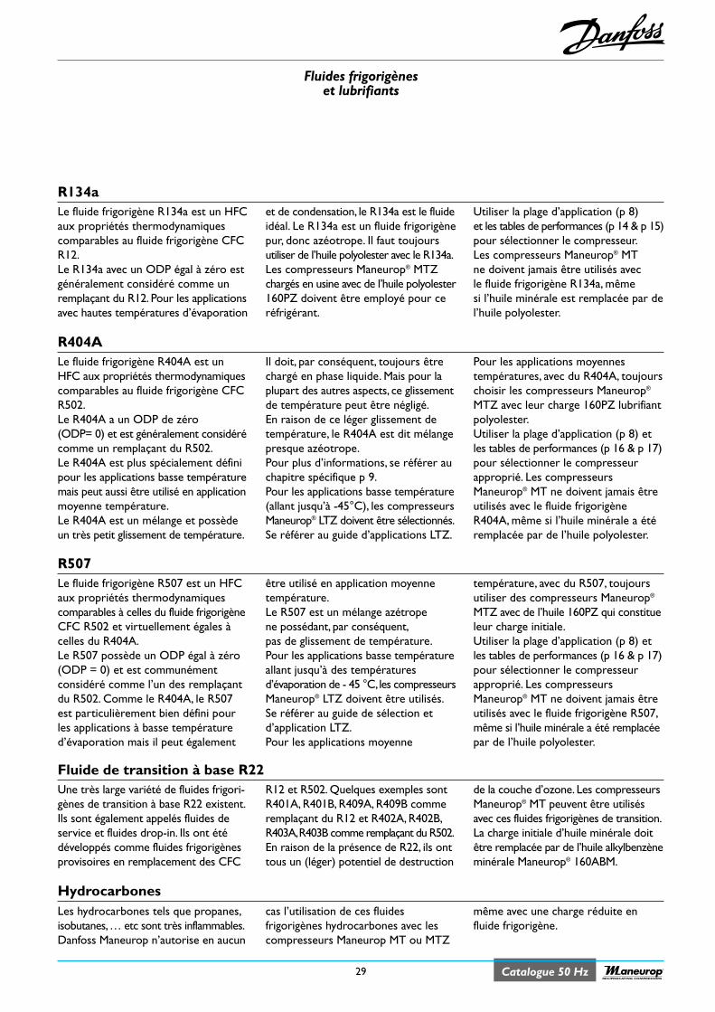
Fluides frigorigèneset lubrifiants
29 Catalogue 50 HzRECIPROCATING COMPRESSORS
R134aLe fluide frigorigène R134a est un HFCaux propriétés thermodynamiquescomparables au fluide frigorigène CFCR12.Le R134a avec un ODP égal à zéro estgénéralement considéré comme unremplaçant du R12. Pour les applicationsavec hautes températures d’évaporation
et de condensation, le R134a est le fluideidéal. Le R134a est un fluide frigorigènepur, donc azéotrope. Il faut toujoursutiliser de l’huile polyolester avec le R134a.Les compresseurs Maneurop® MTZchargés en usine avec de l’huile polyolester160PZ doivent être employé pour ceréfrigérant.
Utiliser la plage d’application (p 8)et les tables de performances (p 14 & p 15)pour sélectionner le compresseur.Les compresseurs Maneurop® MTne doivent jamais être utilisés avecle fluide frigorigène R134a, mêmesi l’huile minérale est remplacée par del’huile polyolester.
R404ALe fluide frigorigène R404A est unHFC aux propriétés thermodynamiquescomparables au fluide frigorigène CFCR502.Le R404A a un ODP de zéro(ODP= 0) et est généralement considérécomme un remplaçant du R502.Le R404A est plus spécialement définipour les applications basse températuremais peut aussi être utilisé en applicationmoyenne température.Le R404A est un mélange et possèdeun très petit glissement de température.
Il doit, par conséquent, toujours êtrechargé en phase liquide. Mais pour laplupart des autres aspects, ce glissementde température peut être négligé.En raison de ce léger glissement detempérature, le R404A est dit mélangepresque azéotrope.Pour plus d’informations, se référer auchapitre spécifique p 9.Pour les applications basse température(allant jusqu’à -45°C), les compresseursManeurop® LTZ doivent être sélectionnés.Se référer au guide d’applications LTZ.
Pour les applications moyennestempératures, avec du R404A, toujourschoisir les compresseurs Maneurop®
MTZ avec leur charge 160PZ lubrifiantpolyolester.Utiliser la plage d’application (p 8) etles tables de performances (p 16 & p 17)pour sélectionner le compresseurapproprié. Les compresseursManeurop® MT ne doivent jamais êtreutilisés avec le fluide frigorigèneR404A, même si l’huile minérale a étéremplacée par de l’huile polyolester.
R507Le fluide frigorigène R507 est un HFCaux propriétés thermodynamiquescomparables à celles du fluide frigorigèneCFC R502 et virtuellement égales àcelles du R404A.Le R507 possède un ODP égal à zéro(ODP = 0) et est communémentconsidéré comme l’un des remplaçantdu R502. Comme le R404A, le R507est particulièrement bien défini pourles applications à basse températured’évaporation mais il peut également
être utilisé en application moyennetempérature.Le R507 est un mélange azétropene possédant, par conséquent,pas de glissement de température.Pour les applications basse températureallant jusqu’à des températuresd’évaporation de - 45 °C,les compresseursManeurop® LTZ doivent être utilisés.Se référer au guide de sélection etd’application LTZ.Pour les applications moyenne
température, avec du R507, toujoursutiliser des compresseurs Maneurop®
MTZ avec de l’huile 160PZ qui constitueleur charge initiale.Utiliser la plage d’application (p 8) etles tables de performances (p 16 & p 17)pour sélectionner le compresseurapproprié. Les compresseursManeurop® MT ne doivent jamais êtreutilisés avec le fluide frigorigène R507,même si l’huile minérale a été remplacéepar de l’huile polyolester.
Fluide de transition à base R22Une très large variété de fluides frigori-gènes de transition à base R22 existent.Ils sont également appelés fluides deservice et fluides drop-in. Ils ont étédéveloppés comme fluides frigorigènesprovisoires en remplacement des CFC
R12 et R502. Quelques exemples sontR401A, R401B, R409A, R409B commeremplaçant du R12 et R402A, R402B,R403A,R403B comme remplaçant du R502.En raison de la présence de R22, ils onttous un (léger) potentiel de destruction
de la couche d’ozone. Les compresseursManeurop® MT peuvent être utilisésavec ces fluides frigorigènes de transition.La charge initiale d’huile minérale doitêtre remplacée par de l’huile alkylbenzèneminérale Maneurop® 160ABM.
HydrocarbonesLes hydrocarbones tels que propanes,isobutanes,… etc sont très inflammables.Danfoss Maneurop n’autorise en aucun
cas l’utilisation de ces fluidesfrigorigènes hydrocarbones avec lescompresseurs Maneurop MT ou MTZ
même avec une charge réduite enfluide frigorigène.
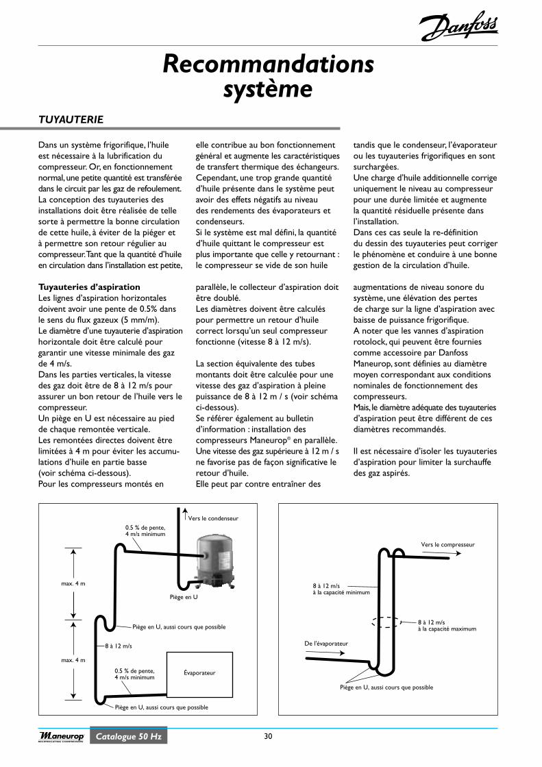
Catalogue 50 Hz 30RECIPROCATING COMPRESSORS
TUYAUTERIE
Recommandationssystème
Dans un système frigorifique, l’huileest nécessaire à la lubrification ducompresseur. Or, en fonctionnementnormal, une petite quantité est transféréedans le circuit par les gaz de refoulement.La conception des tuyauteries desinstallations doit être réalisée de tellesorte à permettre la bonne circulationde cette huile, à éviter de la piéger età permettre son retour régulier aucompresseur.Tant que la quantité d’huileen circulation dans l’installation est petite,
elle contribue au bon fonctionnementgénéral et augmente les caractéristiquesde transfert thermique des échangeurs.Cependant, une trop grande quantitéd’huile présente dans le système peutavoir des effets négatifs au niveaudes rendements des évaporateurs etcondenseurs.Si le système est mal défini, la quantitéd’huile quittant le compresseur estplus importante que celle y retournant :le compresseur se vide de son huile
tandis que le condenseur, l’évaporateurou les tuyauteries frigorifiques en sontsurchargées.Une charge d’huile additionnelle corrigeuniquement le niveau au compresseurpour une durée limitée et augmentela quantité résiduelle présente dansl’installation.Dans ces cas seule la re-définitiondu dessin des tuyauteries peut corrigerle phénomène et conduire à une bonnegestion de la circulation d’huile.
Tuyauteries d’aspiration Les lignes d’aspiration horizontalesdoivent avoir une pente de 0.5% dansle sens du flux gazeux (5 mm/m).Le diamètre d’une tuyauterie d’aspirationhorizontale doit être calculé pourgarantir une vitesse minimale des gazde 4 m/s.Dans les parties verticales, la vitessedes gaz doit être de 8 à 12 m/s pourassurer un bon retour de l’huile vers lecompresseur.Un piège en U est nécessaire au piedde chaque remontée verticale.Les remontées directes doivent êtrelimitées à 4 m pour éviter les accumu-lations d’huile en partie basse(voir schéma ci-dessous).Pour les compresseurs montés en
parallèle, le collecteur d’aspiration doitêtre doublé.Les diamètres doivent être calculéspour permettre un retour d’huilecorrect lorsqu’un seul compresseurfonctionne (vitesse 8 à 12 m/s).
La section équivalente des tubesmontants doit être calculée pour unevitesse des gaz d’aspiration à pleinepuissance de 8 à 12 m / s (voir schémaci-dessous).Se référer également au bulletind’information : installation descompresseurs Maneurop® en parallèle.Une vitesse des gaz supérieure à 12 m / sne favorise pas de façon significative leretour d’huile.Elle peut par contre entraîner des
augmentations de niveau sonore dusystème, une élévation des pertesde charge sur la ligne d’aspiration avecbaisse de puissance frigorifique.A noter que les vannes d’aspirationrotolock, qui peuvent être fourniescomme accessoire par DanfossManeurop, sont définies au diamètremoyen correspondant aux conditionsnominales de fonctionnement descompresseurs.Mais, le diamètre adéquate des tuyauteriesd’aspiration peut être différent de cesdiamètres recommandés.
Il est nécessaire d’isoler les tuyauteriesd’aspiration pour limiter la surchauffedes gaz aspirés.
Vers le compresseur
De l'évaporateur
8 à 12 m/sà la capacité minimum
8 à 12 m/sà la capacité maximum
Piège en U, aussi cours que possible
Évaporateur
Vers le condenseur
max. 4 m
max. 4 m
Piège en U, aussi cours que possible
Piège en U
8 à 12 m/s
0.5 % de pente,4 m/s minimum
Piège en U, aussi cours que possible
0.5 % de pente,4 m/s minimum
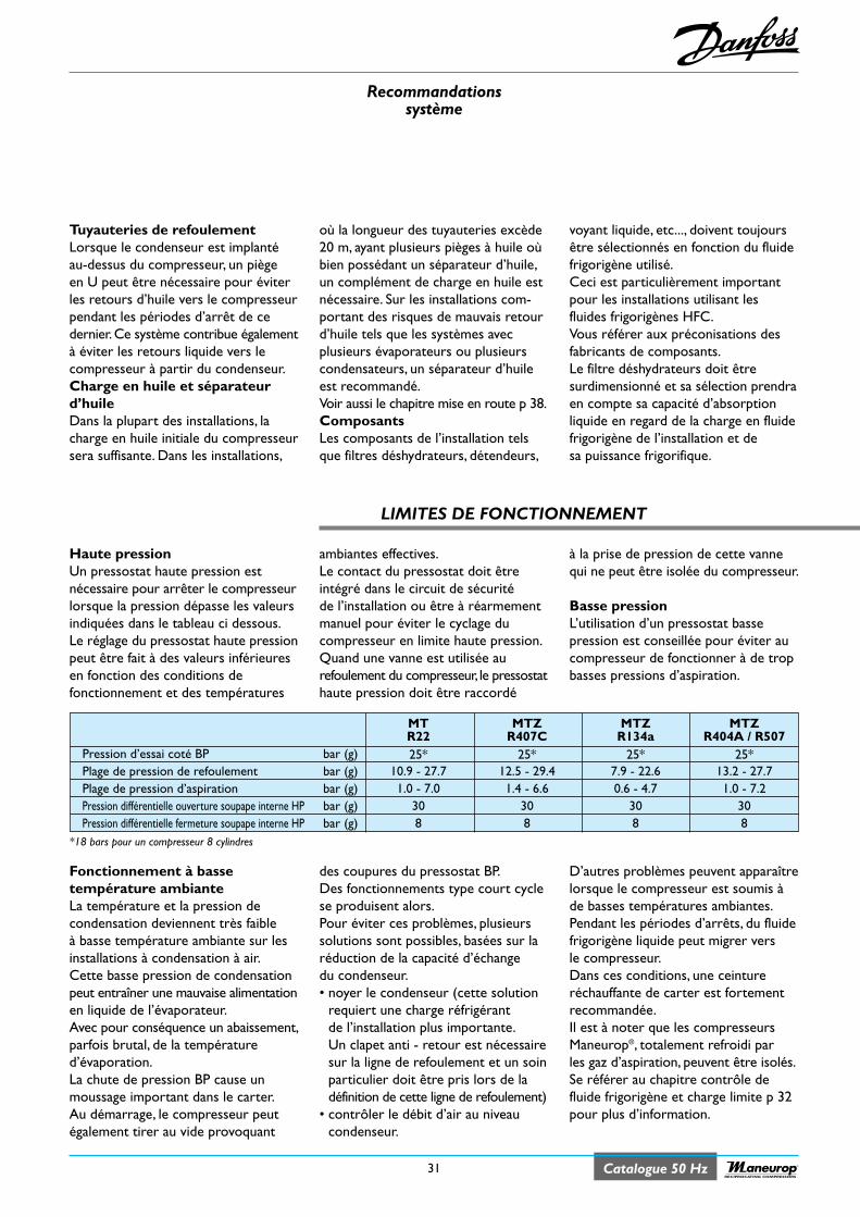
Recommandationssystème
31 Catalogue 50 HzRECIPROCATING COMPRESSORS
Tuyauteries de refoulementLorsque le condenseur est implantéau-dessus du compresseur, un piègeen U peut être nécessaire pour éviterles retours d’huile vers le compresseurpendant les périodes d’arrêt de cedernier.Ce système contribue égalementà éviter les retours liquide vers lecompresseur à partir du condenseur.Charge en huile et séparateurd’huileDans la plupart des installations, lacharge en huile initiale du compresseursera suffisante. Dans les installations,
où la longueur des tuyauteries excède20 m, ayant plusieurs pièges à huile oùbien possédant un séparateur d’huile,un complément de charge en huile estnécessaire. Sur les installations com-portant des risques de mauvais retourd’huile tels que les systèmes avecplusieurs évaporateurs ou plusieurscondensateurs, un séparateur d’huileest recommandé.Voir aussi le chapitre mise en route p 38.ComposantsLes composants de l’installation telsque filtres déshydrateurs, détendeurs,
voyant liquide, etc..., doivent toujoursêtre sélectionnés en fonction du fluidefrigorigène utilisé.Ceci est particulièrement importantpour les installations utilisant lesfluides frigorigènes HFC.Vous référer aux préconisations desfabricants de composants.Le filtre déshydrateurs doit êtresurdimensionné et sa sélection prendraen compte sa capacité d’absorptionliquide en regard de la charge en fluidefrigorigène de l’installation et desa puissance frigorifique.
ambiantes effectives.Le contact du pressostat doit êtreintégré dans le circuit de sécuritéde l’installation ou être à réarmementmanuel pour éviter le cyclage ducompresseur en limite haute pression.Quand une vanne est utilisée aurefoulement du compresseur, le pressostathaute pression doit être raccordé
à la prise de pression de cette vannequi ne peut être isolée du compresseur.
Basse pressionL’utilisation d’un pressostat bassepression est conseillée pour éviter aucompresseur de fonctionner à de tropbasses pressions d’aspiration.
Haute pressionUn pressostat haute pression estnécessaire pour arrêter le compresseurlorsque la pression dépasse les valeursindiquées dans le tableau ci dessous.Le réglage du pressostat haute pressionpeut être fait à des valeurs inférieuresen fonction des conditions defonctionnement et des températures
des coupures du pressostat BP.Des fonctionnements type court cyclese produisent alors.Pour éviter ces problèmes, plusieurssolutions sont possibles, basées sur laréduction de la capacité d’échangedu condenseur.• noyer le condenseur (cette solution
requiert une charge réfrigérantde l’installation plus importante.Un clapet anti - retour est nécessairesur la ligne de refoulement et un soinparticulier doit être pris lors de ladéfinition de cette ligne de refoulement)
• contrôler le débit d’air au niveaucondenseur.
D’autres problèmes peuvent apparaîtrelorsque le compresseur est soumis àde basses températures ambiantes.Pendant les périodes d’arrêts, du fluidefrigorigène liquide peut migrer versle compresseur.Dans ces conditions, une ceintureréchauffante de carter est fortementrecommandée.Il est à noter que les compresseursManeurop®, totalement refroidi parles gaz d’aspiration, peuvent être isolés.Se référer au chapitre contrôle defluide frigorigène et charge limite p 32pour plus d’information.
Fonctionnement à bassetempérature ambianteLa température et la pression decondensation deviennent très faibleà basse température ambiante sur lesinstallations à condensation à air.Cette basse pression de condensationpeut entraîner une mauvaise alimentationen liquide de l’évaporateur.Avec pour conséquence un abaissement,parfois brutal, de la températured’évaporation.La chute de pression BP cause unmoussage important dans le carter.Au démarrage, le compresseur peutégalement tirer au vide provoquant
LIMITES DE FONCTIONNEMENT
MT MTZ MTZ MTZR22 R407C R134a R404A / R507
Pression d’essai coté BP bar (g) 25* 25* 25* 25*Plage de pression de refoulement bar (g) 10.9 - 27.7 12.5 - 29.4 7.9 - 22.6 13.2 - 27.7Plage de pression d’aspiration bar (g) 1.0 - 7.0 1.4 - 6.6 0.6 - 4.7 1.0 - 7.2Pression différentielle ouverture soupape interne HP bar (g) 30 30 30 30Pression différentielle fermeture soupape interne HP bar (g) 8 8 8 8
*18 bars pour un compresseur 8 cylindres
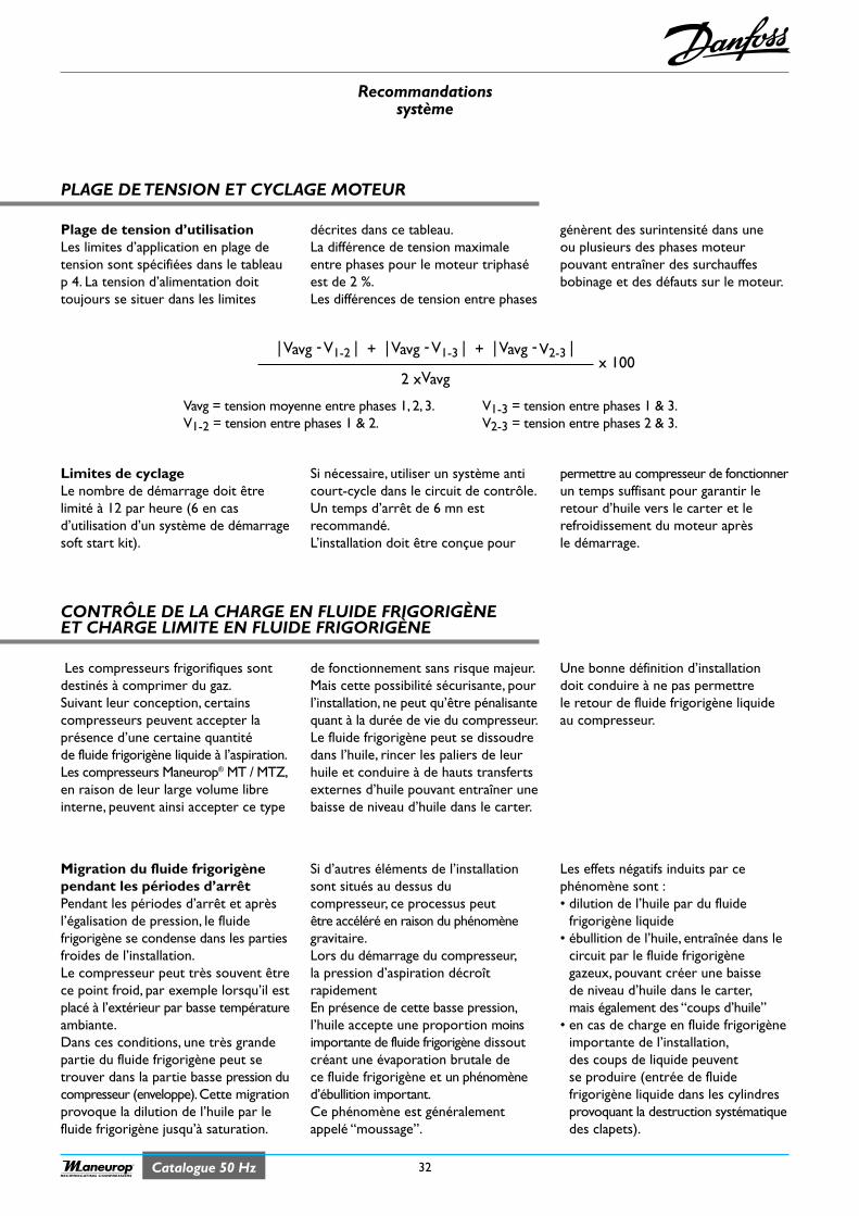
Recommandationssystème
32Catalogue 50 HzRECIPROCATING COMPRESSORS
Si nécessaire, utiliser un système anticourt-cycle dans le circuit de contrôle.Un temps d’arrêt de 6 mn estrecommandé.L’installation doit être conçue pour
permettre au compresseur de fonctionnerun temps suffisant pour garantir leretour d’huile vers le carter et lerefroidissement du moteur aprèsle démarrage.
Limites de cyclageLe nombre de démarrage doit êtrelimité à 12 par heure (6 en casd’utilisation d’un système de démarragesoft start kit).
décrites dans ce tableau.La différence de tension maximaleentre phases pour le moteur triphaséest de 2 %.Les différences de tension entre phases
génèrent des surintensité dans uneou plusieurs des phases moteurpouvant entraîner des surchauffesbobinage et des défauts sur le moteur.
Plage de tension d’utilisation Les limites d’application en plage detension sont spécifiées dans le tableaup 4. La tension d’alimentation doittoujours se situer dans les limites
Vavg = tension moyenne entre phases 1, 2, 3.V1-2 = tension entre phases 1 & 2.
V1-3 = tension entre phases 1 & 3.V2-3 = tension entre phases 2 & 3.
CONTRÔLE DE LA CHARGE EN FLUIDE FRIGORIGÈNEET CHARGE LIMITE EN FLUIDE FRIGORIGÈNE
de fonctionnement sans risque majeur.Mais cette possibilité sécurisante, pourl’installation, ne peut qu’être pénalisantequant à la durée de vie du compresseur.Le fluide frigorigène peut se dissoudredans l’huile, rincer les paliers de leurhuile et conduire à de hauts transfertsexternes d’huile pouvant entraîner unebaisse de niveau d’huile dans le carter.
Une bonne définition d’installationdoit conduire à ne pas permettrele retour de fluide frigorigène liquideau compresseur.
Les compresseurs frigorifiques sontdestinés à comprimer du gaz.Suivant leur conception, certainscompresseurs peuvent accepter laprésence d’une certaine quantitéde fluide frigorigène liquide à l’aspiration.Les compresseurs Maneurop® MT / MTZ,en raison de leur large volume libreinterne, peuvent ainsi accepter ce type
PLAGE DE TENSION ET CYCLAGE MOTEUR
Migration du fluide frigorigènependant les périodes d’arrêtPendant les périodes d’arrêt et aprèsl’égalisation de pression, le fluidefrigorigène se condense dans les partiesfroides de l’installation.Le compresseur peut très souvent êtrece point froid, par exemple lorsqu’il estplacé à l’extérieur par basse températureambiante.Dans ces conditions, une très grandepartie du fluide frigorigène peut setrouver dans la partie basse pression ducompresseur (enveloppe).Cette migrationprovoque la dilution de l’huile par lefluide frigorigène jusqu’à saturation.
Si d’autres éléments de l’installationsont situés au dessus ducompresseur, ce processus peutêtre accéléré en raison du phénomènegravitaire.Lors du démarrage du compresseur,la pression d’aspiration décroîtrapidementEn présence de cette basse pression,l’huile accepte une proportion moinsimportante de fluide frigorigène dissoutcréant une évaporation brutale dece fluide frigorigène et un phénomèned’ébullition important.Ce phénomène est généralementappelé “moussage”.
Les effets négatifs induits par cephénomène sont :• dilution de l’huile par du fluide
frigorigène liquide• ébullition de l’huile, entraînée dans le
circuit par le fluide frigorigènegazeux, pouvant créer une baissede niveau d’huile dans le carter,mais également des “coups d’huile”
• en cas de charge en fluide frigorigèneimportante de l’installation,des coups de liquide peuventse produire (entrée de fluidefrigorigène liquide dans les cylindresprovoquant la destruction systématiquedes clapets).
| Vavg -V1-2 | + | Vavg -V1-3 | + | Vavg -V2-3 |
2 xVavgx 100
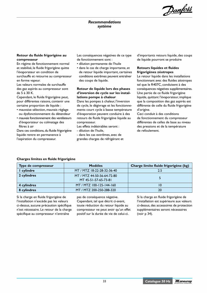
Recommandationssystème
33 Catalogue 50 HzRECIPROCATING COMPRESSORS
Les conséquences négatives de ce typede fonctionnement sont :• dilution permanente de l’huile• dans le cas de charge importante, et
de retour liquide important, certainesconditions extrêmes peuvent entraînerdes coups de liquide.
Retour de liquide lors des phasesd’inversion de cycle sur les instal-lations pompe à chaleurDans les pompes à chaleur, l’inversionde cycle, le dégivrage et les fonctionne-ments court cycle à basse températured’évaporation peuvent conduire à desretours de fluide frigorigène liquide aucompresseur.Les effets indésirables seront :- dilution de l’huile,- dans les cas extrêmes, avec degrandes charges de réfrigérant et
d’importants retours liquide, des coupsde liquide pourront se produire
Retours liquides et fluidesfrigorigènes zéotropesLe retour liquide dans les installationsfonctionnant avec des fluides zéotropestel que le R407C, conduisent à desconséquences négatives supplémentaires.Une partie de ce fluide frigorigèneliquide, quittant l’évaporateur, impliqueque la composition des gaz aspirés estdifférente de celle du fluide frigorigèned’origine.Ceci conduit à des conditionsde fonctionnement du compresseurdifférentes de celles de base au niveaudes pressions et de la températurede refoulement.
Retour du fluide frigorigène aucompresseurEn régime de fonctionnement normalet stabilisé, le fluide frigorigène quittel’évaporateur en condition desurchauffe et retourne au compresseuren forme vapeur.Les valeurs normales de surchauffedes gaz aspirés au compresseur sontde 5 à 30 K.Cependant, le fluide frigorigène peut,pour différentes raisons, contenir unecertaine proportion de liquide :• mauvaise sélection, mauvais réglage
ou dysfonctionnement du détendeur• mauvais fonctionnement des ventilateurs
d’évaporateur ou colmatage desfiltres à air
Dans ces conditions, du fluide frigorigèneliquide rentre en permanence àl’aspiration du compresseur.
pas de conséquence négative.Cependant, tel que décrit ci-avant,toute réduction du retour liquide aucompresseur ne peut avoir qu’un effetpositif sur la durée de vie de celui-ci.
Si la charge en fluide frigorigène del’installation est supérieure aux valeursci-dessus, des accessoires de protectionsupplémentaires seront nécessaires(voir p 34).
Si la charge en fluide frigorigène del’installation n’excède pas les valeursci-dessus, aucune précaution spécifiquen’est nécessaire. Le retour de la chargespécifique au compresseur n’entraîne
Type de compresseur Modèles Charge limite fluide frigorigène (kg)1 cylindre MT / MTZ 18-22-28-32-36-40 2.52 cylindres MT / MTZ 44-50-56-64-72-80
MT 45-51-57-65-73-81 5
4 cylindres MT / MTZ 100-125-144-160 108 cylindres MT / MTZ 200-250-288-320 20
Charges limites en fluide frigorigène
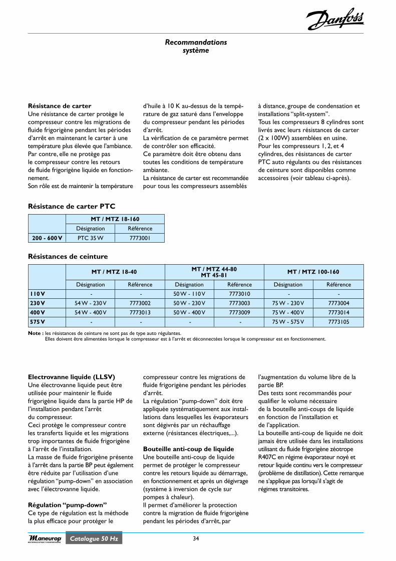
Recommandationssystème
34Catalogue 50 HzRECIPROCATING COMPRESSORS
d’huile à 10 K au-dessus de la tempé-rature de gaz saturé dans l’enveloppedu compresseur pendant les périodesd’arrêt.La vérification de ce paramètre permetde contrôler son efficacité.Ce paramètre doit être obtenu danstoutes les conditions de températureambiante.La résistance de carter est recommandéepour tous les compresseurs assemblés
à distance, groupe de condensation etinstallations “split-system”.Tous les compresseurs 8 cylindres sontlivrés avec leurs résistances de carter(2 x 100W) assemblées en usine.Pour les compresseurs 1, 2, et 4cylindres, des résistances de carterPTC auto régulants ou des résistancesde ceinture sont disponibles commeaccessoires (voir tableau ci-après).
Résistance de carterUne résistance de carter protège lecompresseur contre les migrations defluide frigorigène pendant les périodesd’arrêt en maintenant le carter à unetempérature plus élevée que l’ambiance.Par contre, elle ne protège pasle compresseur contre les retoursde fluide frigorigène liquide en fonction-nement.Son rôle est de maintenir la température
MT / MTZ 18-160
Désignation Référence
200 - 600 V PTC 35 W 7773001
MT / MTZ 18-40 MT / MTZ 44-80 MT / MTZ 100-160MT 45-81
Désignation Référence Désignation Référence Désignation Référence
110 V - - 50 W - 110 V 7773010 - -
230 V 54 W - 230 V 7773002 50 W - 230 V 7773003 75 W - 230 V 7773004
400 V 54 W - 400 V 7773013 50 W - 400 V 7773009 75 W - 400 V 7773014
575 V - - - - 75 W - 575 V 7773105
Note : les résistances de ceinture ne sont pas de type auto régulantes.Elles doivent être alimentées lorsque le compresseur est à l’arrêt et déconnectées lorsque le compresseur est en fonctionnement.
Résistance de carter PTC
Résistances de ceinture
compresseur contre les migrations defluide frigorigène pendant les périodesd’arrêt.La régulation “pump-down” doit êtreappliquée systématiquement aux instal-lations dans lesquelles les évaporateurssont dégivrés par un réchauffageexterne (résistances électriques,...).
Bouteille anti-coup de liquideUne bouteille anti-coup de liquidepermet de protéger le compresseurcontre les retours liquide au démarrage,en fonctionnement et après un dégivrage(système à inversion de cycle surpompes à chaleur).Il permet d’améliorer la protectioncontre la migration de fluide frigorigènependant les périodes d’arrêt, par
l’augmentation du volume libre de lapartie BP.Des tests sont recommandés pourqualifier le volume nécessairede la bouteille anti-coups de liquideen fonction de l’installation etde l’application.La bouteille anti-coup de liquide ne doitjamais être utilisée dans les installationsutilisant du fluide frigorigène zéotropeR407C en régime évaporateur noyé etretour liquide continu vers le compresseur(problème de distillation).Cette remarquene s’applique pas lorsqu’il s’agit derégimes transitoires.
Electrovanne liquide (LLSV)Une électrovanne liquide peut êtreutilisée pour maintenir le fluidefrigorigène liquide dans la partie HP del’installation pendant l’arrêtdu compresseur.Ceci protège le compresseur contreles transferts liquide et les migrationstrop importantes de fluide frigorigèneà l’arrêt de l’installation.La masse de fluide frigorigène présenteà l’arrêt dans la partie BP peut égalementêtre réduite par l’utilisation d’unerégulation “pump-down” en associationavec l’électrovanne liquide.
Régulation “pump-down”Ce type de régulation est la méthodela plus efficace pour protéger le
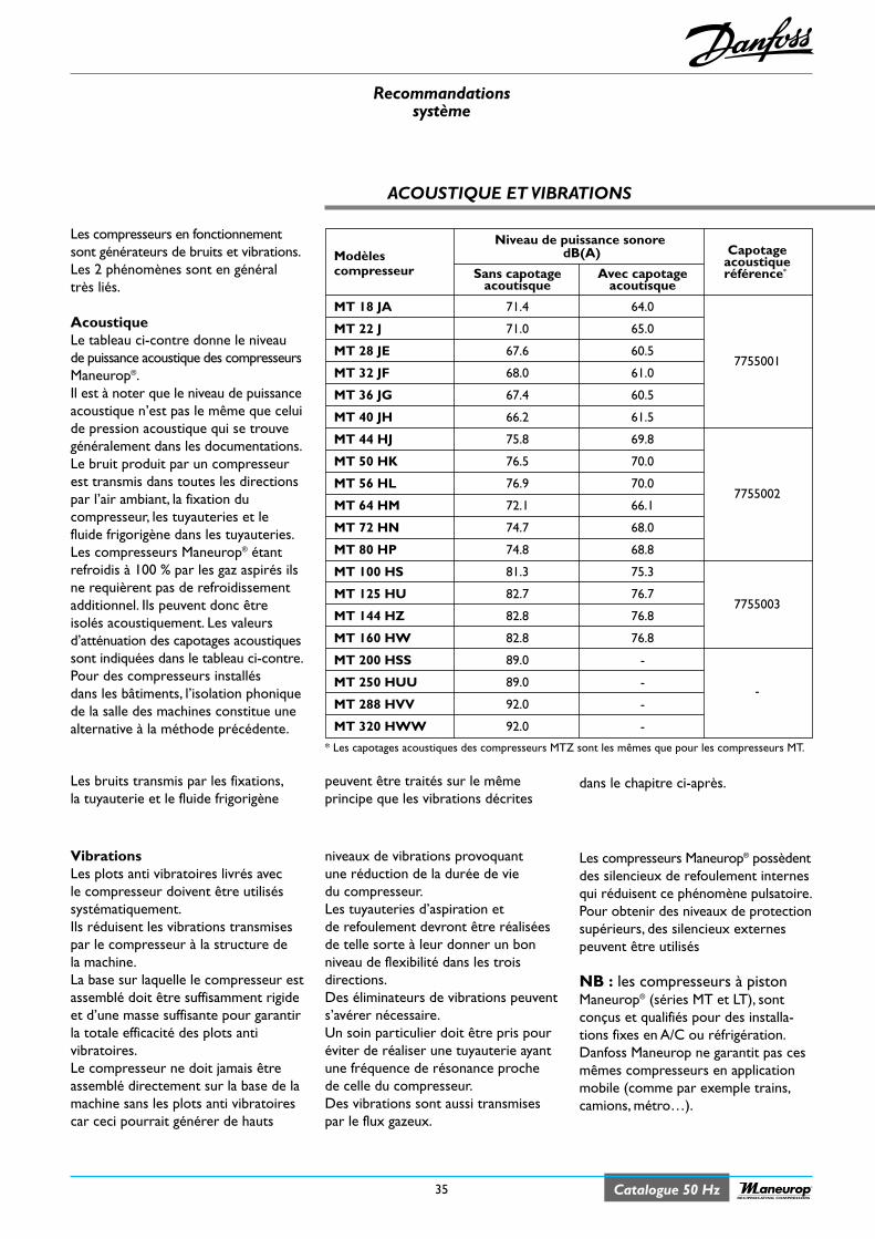
Recommandationssystème
35 Catalogue 50 HzRECIPROCATING COMPRESSORS
ACOUSTIQUE ET VIBRATIONS
Les compresseurs en fonctionnementsont générateurs de bruits et vibrations.Les 2 phénomènes sont en généraltrès liés.
AcoustiqueLe tableau ci-contre donne le niveaude puissance acoustique des compresseursManeurop®.Il est à noter que le niveau de puissanceacoustique n’est pas le même que celuide pression acoustique qui se trouvegénéralement dans les documentations.Le bruit produit par un compresseurest transmis dans toutes les directionspar l’air ambiant, la fixation ducompresseur, les tuyauteries et lefluide frigorigène dans les tuyauteries.Les compresseurs Maneurop® étantrefroidis à 100 % par les gaz aspirés ilsne requièrent pas de refroidissementadditionnel. Ils peuvent donc êtreisolés acoustiquement. Les valeursd’atténuation des capotages acoustiquessont indiquées dans le tableau ci-contre.Pour des compresseurs installésdans les bâtiments, l’isolation phoniquede la salle des machines constitue unealternative à la méthode précédente.
Niveau de puissance sonoreCapotageModèles dB(A)
acoustiquecompresseur Sans capotage Avec capotage référence*
acoutisque acoutisque
MT 18 JA 71.4 64.0
MT 22 J 71.0 65.0
MT 28 JE 67.6 60.57755001
MT 32 JF 68.0 61.0
MT 36 JG 67.4 60.5
MT 40 JH 66.2 61.5
MT 44 HJ 75.8 69.8
MT 50 HK 76.5 70.0
MT 56 HL 76.9 70.07755002
MT 64 HM 72.1 66.1
MT 72 HN 74.7 68.0
MT 80 HP 74.8 68.8
MT 100 HS 81.3 75.3
MT 125 HU 82.7 76.77755003
MT 144 HZ 82.8 76.8
MT 160 HW 82.8 76.8
MT 200 HSS 89.0 -
MT 250 HUU 89.0 --
MT 288 HVV 92.0 -
MT 320 HWW 92.0 -
niveaux de vibrations provoquantune réduction de la durée de viedu compresseur.Les tuyauteries d’aspiration etde refoulement devront être réaliséesde telle sorte à leur donner un bonniveau de flexibilité dans les troisdirections.Des éliminateurs de vibrations peuvents’avérer nécessaire.Un soin particulier doit être pris pouréviter de réaliser une tuyauterie ayantune fréquence de résonance prochede celle du compresseur.Des vibrations sont aussi transmisespar le flux gazeux.
Les compresseurs Maneurop® possèdentdes silencieux de refoulement internesqui réduisent ce phénomène pulsatoire.Pour obtenir des niveaux de protectionsupérieurs, des silencieux externespeuvent être utilisés
NB : les compresseurs à pistonManeurop® (séries MT et LT), sontconçus et qualifiés pour des installa-tions fixes en A/C ou réfrigération.Danfoss Maneurop ne garantit pas cesmêmes compresseurs en applicationmobile (comme par exemple trains,camions, métro…).
VibrationsLes plots anti vibratoires livrés avecle compresseur doivent être utiliséssystématiquement.Ils réduisent les vibrations transmisespar le compresseur à la structure dela machine.La base sur laquelle le compresseur estassemblé doit être suffisamment rigideet d’une masse suffisante pour garantirla totale efficacité des plots antivibratoires.Le compresseur ne doit jamais êtreassemblé directement sur la base de lamachine sans les plots anti vibratoirescar ceci pourrait générer de hauts
peuvent être traités sur le mêmeprincipe que les vibrations décrites
dans le chapitre ci-après.Les bruits transmis par les fixations,la tuyauterie et le fluide frigorigène
* Les capotages acoustiques des compresseurs MTZ sont les mêmes que pour les compresseurs MT.
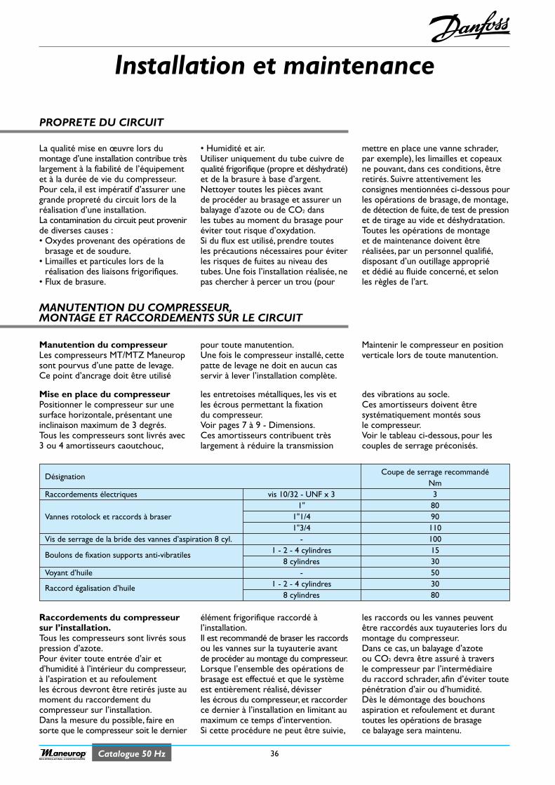
Installation et maintenance
36Catalogue 50 HzRECIPROCATING COMPRESSORS
Désignation Coupe de serrage recommandéNm
Raccordements électriques vis 10/32 - UNF x 3 31" 80
Vannes rotolock et raccords à braser 1"1/4 901"3/4 110
Vis de serrage de la bride des vannes d’aspiration 8 cyl. - 100
Boulons de fixation supports anti-vibratiles 1 - 2 - 4 cylindres 158 cylindres 30
Voyant d’huile - 50
Raccord égalisation d’huile 1 - 2 - 4 cylindres 308 cylindres 80
PROPRETE DU CIRCUIT
La qualité mise en œuvre lors dumontage d’une installation contribue trèslargement à la fiabilité de l’équipementet à la durée de vie du compresseur.Pour cela, il est impératif d’assurer unegrande propreté du circuit lors de laréalisation d’une installation.La contamination du circuit peut provenirde diverses causes :• Oxydes provenant des opérations de
brasage et de soudure.• Limailles et particules lors de la
réalisation des liaisons frigorifiques.• Flux de brasure.
• Humidité et air.Utiliser uniquement du tube cuivre dequalité frigorifique (propre et déshydraté)et de la brasure à base d’argent.Nettoyer toutes les pièces avantde procéder au brasage et assurer unbalayage d’azote ou de CO2 dansles tubes au moment du brasage pouréviter tout risque d’oxydation.Si du flux est utilisé, prendre toutesles précautions nécessaires pour éviterles risques de fuites au niveau destubes. Une fois l’installation réalisée, nepas chercher à percer un trou (pour
mettre en place une vanne schrader,par exemple), les limailles et copeauxne pouvant, dans ces conditions, êtreretirés. Suivre attentivement lesconsignes mentionnées ci-dessous pourles opérations de brasage, de montage,de détection de fuite, de test de pressionet de tirage au vide et déshydratation.Toutes les opérations de montageet de maintenance doivent êtreréalisées, par un personnel qualifié,disposant d’un outillage appropriéet dédié au fluide concerné, et selonles règles de l’art.
MANUTENTION DU COMPRESSEUR,MONTAGE ET RACCORDEMENTS SUR LE CIRCUIT
Manutention du compresseurLes compresseurs MT/MTZ Maneuropsont pourvus d’une patte de levage.Ce point d’ancrage doit être utilisé
pour toute manutention.Une fois le compresseur installé, cettepatte de levage ne doit en aucun casservir à lever l’installation complète.
Maintenir le compresseur en positionverticale lors de toute manutention.
Mise en place du compresseurPositionner le compresseur sur unesurface horizontale, présentant uneinclinaison maximum de 3 degrés.Tous les compresseurs sont livrés avec3 ou 4 amortisseurs caoutchouc,
les entretoises métalliques, les vis etles écrous permettant la fixationdu compresseur.Voir pages 7 à 9 - Dimensions.Ces amortisseurs contribuent trèslargement à réduire la transmission
des vibrations au socle.Ces amortisseurs doivent êtresystématiquement montés sousle compresseur.Voir le tableau ci-dessous, pour lescouples de serrage préconisés.
Raccordements du compresseursur l’installation.Tous les compresseurs sont livrés souspression d’azote.Pour éviter toute entrée d’air etd’humidité à l’intérieur du compresseur,à l’aspiration et au refoulementles écrous devront être retirés juste aumoment du raccordement ducompresseur sur l’installation.Dans la mesure du possible, faire ensorte que le compresseur soit le dernier
élément frigorifique raccordé àl’installation.Il est recommandé de braser les raccordsou les vannes sur la tuyauterie avantde procéder au montage du compresseur.Lorsque l’ensemble des opérations debrasage est effectué et que le systèmeest entièrement réalisé, dévisserles écrous du compresseur, et raccorderce dernier à l’installation en limitant aumaximum ce temps d’intervention.Si cette procédure ne peut être suivie,
les raccords ou les vannes peuventêtre raccordés aux tuyauteries lors dumontage du compresseur.Dans ce cas, un balayage d’azoteou CO2 devra être assuré à traversle compresseur par l’intermédiairedu raccord schrader, afin d’éviter toutepénétration d’air ou d’humidité.Dès le démontage des bouchonsaspiration et refoulement et duranttoutes les opérations de brasagece balayage sera maintenu.
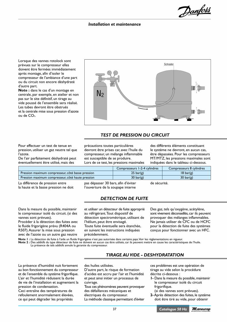
Installation et maintenance
37 Catalogue 50 HzRECIPROCATING COMPRESSORS
Compresseurs 1-2-4 cylindres Compresseurs 8 cylindresPression maximum compresseur, côté basse pression 25 bar(g) 18 bar(g)Pression maximum compresseur, côté haute pression 30 bar(g) 30 bar(g)
précautions toutes particulièresdevront être prises car, avec l’huile ducompresseur, un mélange inflammableest susceptible de se produire.Lors de ce test, les pressions maximales
des différents éléments constituantle système ne devront, en aucun cas,être dépassées. Pour les compresseursMT/MTZ, les pressions maximales sontindiquées dans le tableau ci-dessous.
Pour effectuer un test de tenue enpression, utiliser un gaz neutre tel quel’azote.De l’air parfaitement déshydraté peutéventuellement être utilisé, mais des
La différence de pression entrela haute et la basse pression ne doit
pas dépasser 30 bars, afin d’éviterl’ouverture de la soupape interne
de sécurité.
TEST DE PRESSION DU CIRCUIT
Lorsque des vannes rotolock sontprévues sur le compresseur ellesdoivent être fermées immédiatementaprès montage, afin d’isoler lecompresseur de l’ambiance d’une partou du circuit non encore déshydratéd’autre part.Note : dans le cas d’un montage encentrale, par exemple, en atelier et nonpas sur le site définitif, un tirage auvide poussé de l’ensemble sera réalisé.Les tubes devront être obstruéset la centrale mise sous pression d’azoteou de CO2.
N2
Schrader
DETECTION DE FUITE
et utiliser un détecteur de fuite appropriéau réfrigérant.Tout dispositif dedétection spectrométrique, utilisant del’hélium, peut être envisagé.Toute fuite éventuelle sera étanchée,en suivant les instructions indiquéesprécédemment.
Des gaz, tels qu’oxygène, acétylène,sont vivement déconseillés, car ils peuventprovoquer des mélanges inflammables.Ne jamais utiliser de CFC ou de HCFCpour la détection de fuite des systèmesconçus pour fonctionner avec un HFC.
Dans la mesure du possible, maintenirle compresseur isolé du circuit. (si desvannes sont prévues).Procéder à la détection des fuites avecle fluide frigorigène prévu (R404A ouR507).Assurer la mise sous pressionavec de l’azote ou un autre gaz neutre
La présence d’humidité nuit fortementau bon fonctionnement du compresseuret de l’ensemble du système frigorifique.L’air et l’humidité réduisent la duréede vie de l’installation et augmentent lapression de condensation.Ceci entraîne des températures derefoulement anormalement élevées,ce qui peut dégrader les propriétés
des huiles utilisées.D’autre part, le risque de formationd’acides est accru par l’air et l’humiditéet peut ainsi initier un processus decuivrage.Tous ces phénomènes peuvent provoquerdes défaillances mécaniques etélectriques du compresseur.La méthode classique permettant d’éviter
ces problèmes est une opération detirage au vide selon la procéduredécrite ci-dessous :1- Dans la mesure du possible,maintenir
le compresseur isolé du circuitfrigorifique.(si des vannes sont prévues).
2- Après détection des fuites, le systèmedoit être tiré au vide, pour obtenir
Note 1 : La détection de fuite à l’aide un fluide frigorigène n’est pas autorisée dans certains pays.Voir les réglementations en vigueur.Note 2 : Des additifs du type détecteur de fuite ne doivent en aucun cas être utilisés, car ils peuvent mettre en cause les caractéristiques de l’huile.
La présence de tels additifs annule la garantie du compresseur.
TIRAGE AU VIDE - DESHYDRATATION
38Catalogue 50 HzRECIPROCATING COMPRESSORS
s’accroît rapidement, le systèmen’est pas étanche.Procéder de nouveau à une opérationde détection et de tirage au vide enreprenant tout à partir de l’étape 1.Si la pression augmente lentement,cela indique la présence d’humidité.Dans ce cas, les étapes 2 et 3 sontà renouveler.
4- Raccorder le compresseur à l’instal-lation en ouvrant les vannes.Reprendre les étapes 2 et 3.
5- Casser le vide avec de l’azote oule fluide frigorigène prévu dansl’installation.
6- Répéter les étapes 2 et 3 surl’ensemble de l’installation.
Lors de la mise en service, le taux
d’humidité dans l’installation peutatteindre 100 ppm.En fonctionnement, l’utilisation d’unfiltre déshydrateur doit permettre deréduire ce taux à une valeur inférieureà 20 ppm.
Attention : Ne pas utiliser demégohmmètre et ne pas mettre soustension le compresseur tant que levide n’a pas été cassé.Risque de détérioration des bobinagesdu moteur.Ne jamais faire tourner le compresseurtant que le vide n’a pas été cassé.Risque de moteur grillé.
un niveau de vide de 500 microns(0.67 mbar).Une pompe à vide appropriéeà 2 étages sera utilisée en tenantcompte du volume interne du système.Pour éviter de trop fortes pertes decharge, il est recommandé d’utiliserdes flexibles de liaison de grandsdiamètres et de connecter ceux-cisur les vannes de maintenance etnon pas sur les raccords schrader.
3- Quand le vide a atteint 500 microns,isoler le circuit frigorifique de lapompe à vide.Attendre 30 minutes.Au bout de ce laps de temps,la pression du système ne doit pasavoir augmenté. Si la pression
DÉMARRAGE
Avant le premier démarrage ou aprèsune longue période d’arrêt, mettrela résistance de carter sous tension12 heures avant la mise en route ducompresseur. Pour les compresseursmonophasés, la fonction de préchauffagedu carter du compresseur à l’arrêt estréalisée par le passage d’un courant(mA) dans l’enroulement de démarrageau travers du condensateur.Le R404A est un mélange ternaire“quasi azéotrope”, et de ce fait il doitêtre chargé en phase liquide.Lors de la première charge, le compresseurdoit être à l’arrêt avec ses vannesfermées. Faire en sorte que la chargeinitiale corresponde à la chargenominale prévue pour l’installation.Puis, lentement, assurer un complémentde charge, en phase liquide, côté bassepression, le plus loin possible del’entrée du compresseur.Attention : Lorsqu’une vanne solénoïdeest montée sur la ligne liquide, le vide,côté basse pression, doit être, aupréalable, cassé avant de procéder à lamise sous tension de l’installation.Note : Le R507 est un mélangeazéotrope, et peut de ce fait êtrechargé aussi bien en phase liquidequ’en phase gazeuse.Vérifier que la charge en réfrigérantsoit correcte aussi bien pour unfonctionnement dans les conditionsd’été que pour les conditions hivernales.
Voir également le paragraphe relatifaux charges limites de réfrigérant.
Charge en huile et niveau d’huileLa charge en huile doit être vérifiéeavant la mise en route.(le niveau devant se situer entre 1/4 et3/4 du voyant d’huile).Vérifier de nouveau le niveau d’huileaprès un fonctionnement minimum de2 heures aux conditions nominales.Dans la plupart des cas la charge initialeen huile s’avère être suffisante.Dans les cas suivants un complémentde charge peut être nécessaire :installations dont la longueur des tubesexcède 20 m, installations présentantdes siphons ou munies d’un séparateurd’huile. Normalement, ce complémentde charge en huile ne doit pas dépas-ser 2% de la charge totale de réfrigé-rant. (ce pourcentage ne tient pascompte de la quantité d’huile contenuedans les éléments tels que séparateursd’huile ou siphons).Si ce complément de charge a étéeffectué alors que le niveau d’huileapparaissant au voyant du compresseurdécroît régulièrement, un mauvaisretour de l’huile vers le compresseurest à l’origine de ce constat.Voir également le paragraphe relatifaux dimensionnements des tuyauteries.Pour les installations mettant en œuvredes évaporateurs multiples et / ou des
condenseurs multiples, il est recommandéde prévoir un séparateur d’huile.
Vérifications de l’installationAprès quelques heures de fonctionne-ment, tous les paramètres de l’installa-tion doivent être vérifiés, en particulierles points suivants :• Puissance et intensité absorbées.• Température d’évaporation• Température à la sortie
de l’évaporateur• Température d’aspiration• Température de condensation• Température de refoulementCes différents paramètres donnentdes informations précieuses sur lesconditions de fonctionnements desdivers éléments constituant le circuitfrigorifique.Ils nous informent sur d’éventuelsréglages à effectuer pour optimiserl’ensemble de l’installation.• La température d’évaporation, par
exemple, est le reflet du fluide dansl’évaporateur.
• La surchauffe à l’évaporateur doitêtre ajustée pour optimiser lesperformances de l’évaporateur.En règle générale une valeur de 5 à 6 Kest préconisée.
• la température à l’aspiration ducompresseur donne des informationssur la surchauffe des gaz aspirés. Lasurchauffe doit être maintenue aussi
Installation et maintenance
faible que possible car elleaugmente les performances decompresseur et aussi sa durée de vie.A noter, cependant, que des valeurstrop faibles de surchauffe peuventaugmenter les risques de coups deliquide et de dilution d’huile.La surchauffe maximale est d’environ30 K. Quand une surchauffe tropimportante (> 30 k) est constatéealors que le réglage du détendeur
s’avère être correct, il est impératifde vérifier l’isolation de la ligned’aspiration entre l’évaporateur et lecompresseur.
• la température de refoulement peutrévéler divers dysfonctionnements.Une température de refoulementtrop élevée est la conséquence deproblèmes qui peuvent être liés à :
- un condenseur sous-dimensionné ouencrassé
- la présence de gaz incondensables- une surchauffe excessive- une charge de réfrigérant trop
importante etc…La température maximale de refoulementest de 130 °C.Quand, après la mise en route,le voyant de liquide indique la présenced’humidité dans le circuit, le filtredéshydrateur doit être immédiatementchangé.
Installation et maintenance
GA
035
- 0
6/01
F r
empl
ace
GA
035
- 1
0/99
F
LawrencevilleGeorgia - USA
TrévouxFrance
AnseFrance
Les unités de productionde Danfoss Maneurop
Danfoss s.a.r.l.Siège Social :7, av. Roger Hennequin78190 Trappes
Département Réfrigération et Conditionnement d’Air :Lyon - 110, avenue jean Jaurès - 69007 Lyon Tél. 04 37 65 28 00 Fax 04 37 65 28 69
Agences commerciales :Lille - 11 ter, allée Gabriel - 59700 Marcq en Barœul Tél. 03 20 65 94 94 Fax 03 20 65 94 95Lyon - 110, avenue jean Jaurès - 69007 Lyon Tél. 04 37 65 28 00 Fax 04 37 65 28 69Nantes - 17, rue de la Cornouaille - 44300 Nantes Tél. 02 51 89 16 16 Fax 02 51 89 16 17Trappes - 7, av. Roger Hennequin - 78190 Trappes Tél. 01 30 62 51 00 Fax 01 30 62 50 06
Tous les efforts ont été faits pour publier les performances et descriptions les plus précises possibles. Cependant, du fait de l’amélioration et l’évolution constante de nos produits, ces informations sont susceptibles d’être modifiées sans avis préalable.Maneurop® est une marque de Danfoss.
Danfoss ManeuropCommercial Compressors
BP 331 F-01603 Trévoux FranceTél. 04 74 00 28 29 - + 33 4 74 00 28 29Fax 04 74 00 52 44 - + 33 4 74 00 52 44www.danfoss-maneurop.com
Danfoss Scroll for Refrigeration MLM / MLZ
50-60Hz - R404A - R507 - R134a - R22 - R407A - R407F
Application guidelines
http://cc.danfoss.com

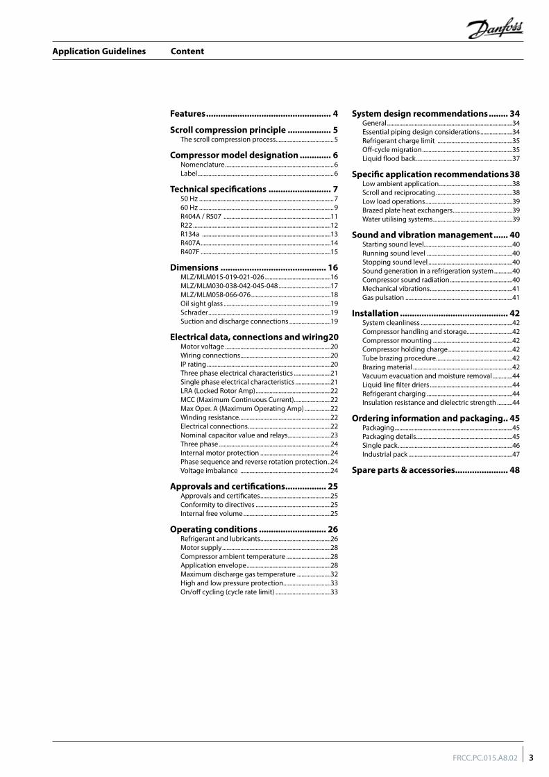
Content
3FRCC.PC.015.A8.02
Features .................................................... 4
Scroll compression principle .................. 5The scroll compression process......................................5
Compressor model designation ............. 6Nomenclature .......................................................................6Label .........................................................................................6
Technical specifications .......................... 750 Hz ........................................................................................760 Hz ........................................................................................9R404A / R507 ......................................................................11R22 ..........................................................................................12R134a ....................................................................................13R407A .....................................................................................14R407F .....................................................................................15
Dimensions ............................................ 16MLZ/MLM015-019-021-026 ...........................................16MLZ/MLM030-038-042-045-048 ..................................17MLZ/MLM058-066-076 ....................................................18Oil sight glass ......................................................................19Schrader ................................................................................19Suction and discharge connections ...........................19
Electrical data, connections and wiring 20Motor voltage .....................................................................20Wiring connections ...........................................................20IP rating .................................................................................20Three phase electrical characteristics ........................21Single phase electrical characteristics .......................21LRA (Locked Rotor Amp) .................................................22MCC (Maximum Continuous Current) ........................22Max Oper. A (Maximum Operating Amp) .................22Winding resistance............................................................22Electrical connections ......................................................22Nominal capacitor value and relays ............................23Three phase .........................................................................24Internal motor protection ..............................................24Phase sequence and reverse rotation protection ..24Voltage imbalance ...........................................................24
Approvals and certifications ................. 25Approvals and certificates ..............................................25Conformity to directives .................................................25Internal free volume .........................................................25
Operating conditions ............................ 26Refrigerant and lubricants..............................................26Motor supply .......................................................................28Compressor ambient temperature .............................28Application envelope .......................................................28Maximum discharge gas temperature ......................32High and low pressure protection...............................33On/off cycling (cycle rate limit) ....................................33
System design recommendations ........ 34General ..................................................................................34Essential piping design considerations .....................34Refrigerant charge limit .................................................35Off-cycle migration ...........................................................35Liquid flood back ...............................................................37
Specific application recommendations 38Low ambient application ................................................38Scroll and reciprocating ..................................................38Low load operations .........................................................39Brazed plate heat exchangers .......................................39Water utilising systems ....................................................39
Sound and vibration management ...... 40Starting sound level..........................................................40Running sound level ........................................................40Stopping sound level .......................................................40Sound generation in a refrigeration system ............40Compressor sound radiation .........................................40Mechanical vibrations ......................................................41Gas pulsation ......................................................................41
Installation ............................................. 42System cleanliness ............................................................42Compressor handling and storage..............................42Compressor mounting ....................................................42Compressor holding charge ..........................................42Tube brazing procedure ..................................................42Brazing material .................................................................42Vacuum evacuation and moisture removal .............44Liquid line filter driers ......................................................44Refrigerant charging ........................................................44Insulation resistance and dielectric strength ..........44
Ordering information and packaging .. 45Packaging .............................................................................45Packaging details ...............................................................45Single pack ...........................................................................46Industrial pack ....................................................................47
Spare parts & accessories ...................... 48
Application Guidelines
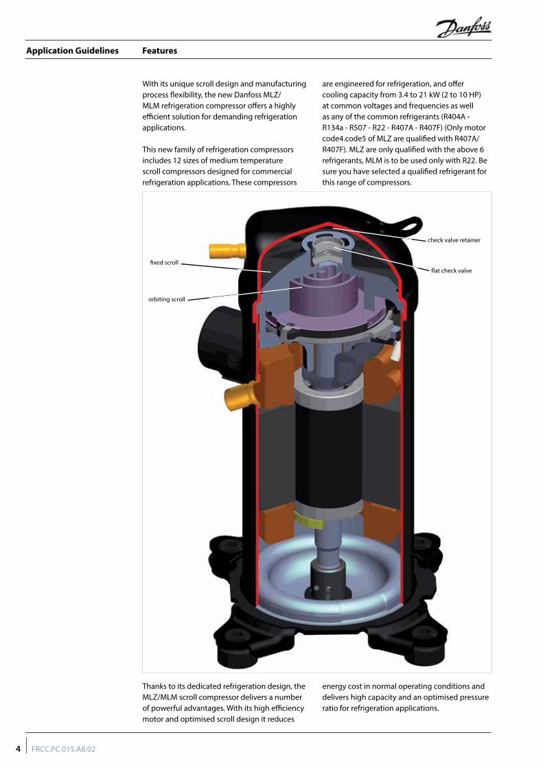
Features
With its unique scroll design and manufacturing process flexibility, the new Danfoss MLZ/MLM refrigeration compressor offers a highly efficient solution for demanding refrigeration applications.
This new family of refrigeration compressors includes 12 sizes of medium temperature scroll compressors designed for commercial refrigeration applications. These compressors
are engineered for refrigeration, and offer cooling capacity from 3.4 to 21 kW (2 to 10 HP) at common voltages and frequencies as well as any of the common refrigerants (R404A - R134a - R507 - R22 - R407A - R407F) (Only motor code4.code5 of MLZ are qualified with R407A/R407F). MLZ are only qualified with the above 6 refrigerants, MLM is to be used only with R22. Be sure you have selected a qualified refrigerant for this range of compressors.
Thanks to its dedicated refrigeration design, the MLZ/MLM scroll compressor delivers a number of powerful advantages. With its high efficiency motor and optimised scroll design it reduces
energy cost in normal operating conditions and delivers high capacity and an optimised pressure ratio for refrigeration applications.
fixed scroll
check valve retainer
flat check valve
orbiting scroll
4 FRCC.PC.015.A8.02
Application Guidelines
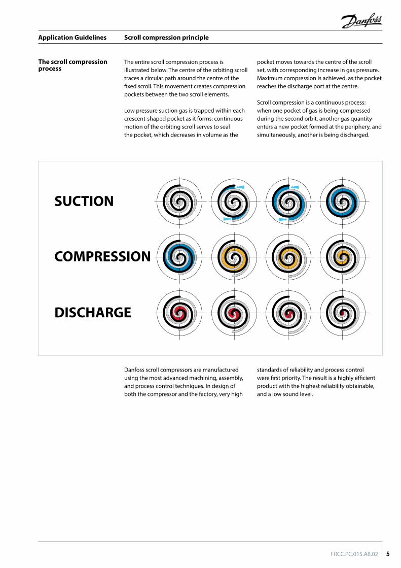
Scroll compression principle
Danfoss scroll compressors are manufactured using the most advanced machining, assembly, and process control techniques. In design of both the compressor and the factory, very high
standards of reliability and process control were first priority. The result is a highly efficient product with the highest reliability obtainable, and a low sound level.
The entire scroll compression process is illustrated below. The centre of the orbiting scroll traces a circular path around the centre of the fixed scroll. This movement creates compression pockets between the two scroll elements.
Low pressure suction gas is trapped within each crescent-shaped pocket as it forms; continuous motion of the orbiting scroll serves to seal the pocket, which decreases in volume as the
pocket moves towards the centre of the scroll set, with corresponding increase in gas pressure. Maximum compression is achieved, as the pocket reaches the discharge port at the centre.
Scroll compression is a continuous process: when one pocket of gas is being compressed during the second orbit, another gas quantity enters a new pocket formed at the periphery, and simultaneously, another is being discharged.
The scroll compression process
SUCTION
COMPRESSION
DISCHARGE
5FRCC.PC.015.A8.02
Application Guidelines
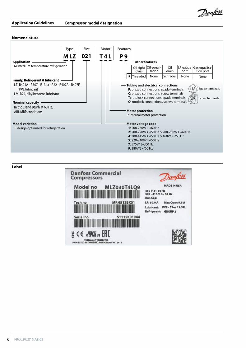
Compressor model designation
Label
Nomenclature
Type FeaturesMotorSize
M LZ P 9T 4 L021Application
M: medium temperature refrigeration
Family, Refrigerant & lubricantLZ: R404A - R507 - R134a - R22 - R407A - R407F, PVE lubricantLM: R22, alkylbenzene lubricant
Nominal capacityIn thousand Btu/h at 60 Hz,ARI, MBP conditions
Model variationT: design optimised for refrigeration
Motor protectionL: internal motor protection
Tubing and electrical connectionsP: brazed connections, spade terminalsC: brazed connections, screw terminalsT: rotolock connections, spade terminalsQ: rotolock connections, screws terminals
Motor voltage code1: 208-230V/1~/60 Hz2: 200-220V/3~/50 Hz & 208-230V/3~/60 Hz4: 380-415V/3~/50 Hz & 460V/3~/60 Hz5: 220-240V/1~/50 Hz 7: 575V/ 3~/60 Hz9: 380V/3~/60 Hz
Spade terminals
Screw terminals
Other features
Oil sight glass
Oil equali-sation
Oil drain
LP gauge port
Gas equalisa-tion port
9 None Schrader None NoneThreaded
6 FRCC.PC.015.A8.02
Application Guidelines
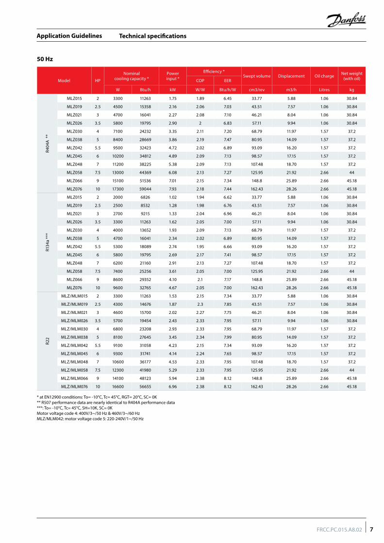
Technical specifications
50 Hz
Model HP
Nominalcooling capacity *
Powerinput *
Efficiency *Swept volume Displacement Oil charge Net weight
(with oil)COP EER
W Btu/h kW W/W Btu/h/W cm3/rev m3/h Litres kg
R404
A *
*
MLZ015 2 3300 11263 1.75 1.89 6.45 33.77 5.88 1.06 30.84
MLZ019 2.5 4500 15358 2.16 2.06 7.03 43.51 7.57 1.06 30.84
MLZ021 3 4700 16041 2.27 2.08 7.10 46.21 8.04 1.06 30.84
MLZ026 3.5 5800 19795 2.90 2 6.83 57.11 9.94 1.06 30.84
MLZ030 4 7100 24232 3.35 2.11 7.20 68.79 11.97 1.57 37.2
MLZ038 5 8400 28669 3.86 2.19 7.47 80.95 14.09 1.57 37.2
MLZ042 5.5 9500 32423 4.72 2.02 6.89 93.09 16.20 1.57 37.2
MLZ045 6 10200 34812 4.89 2.09 7.13 98.57 17.15 1.57 37.2
MLZ048 7 11200 38225 5.38 2.09 7.13 107.48 18.70 1.57 37.2
MLZ058 7.5 13000 44369 6.08 2.13 7.27 125.95 21.92 2.66 44
MLZ066 9 15100 51536 7.01 2.15 7.34 148.8 25.89 2.66 45.18
MLZ076 10 17300 59044 7.93 2.18 7.44 162.43 28.26 2.66 45.18
R134
a **
*
MLZ015 2 2000 6826 1.02 1.94 6.62 33.77 5.88 1.06 30.84
MLZ019 2.5 2500 8532 1.28 1.98 6.76 43.51 7.57 1.06 30.84
MLZ021 3 2700 9215 1.33 2.04 6.96 46.21 8.04 1.06 30.84
MLZ026 3.5 3300 11263 1.62 2.05 7.00 57.11 9.94 1.06 30.84
MLZ030 4 4000 13652 1.93 2.09 7.13 68.79 11.97 1.57 37.2
MLZ038 5 4700 16041 2.34 2.02 6.89 80.95 14.09 1.57 37.2
MLZ042 5.5 5300 18089 2.74 1.95 6.66 93.09 16.20 1.57 37.2
MLZ045 6 5800 19795 2.69 2.17 7.41 98.57 17.15 1.57 37.2
MLZ048 7 6200 21160 2.91 2.13 7.27 107.48 18.70 1.57 37.2
MLZ058 7.5 7400 25256 3.61 2.05 7.00 125.95 21.92 2.66 44
MLZ066 9 8600 29352 4.10 2.1 7.17 148.8 25.89 2.66 45.18
MLZ076 10 9600 32765 4.67 2.05 7.00 162.43 28.26 2.66 45.18
R22
MLZ/MLM015 2 3300 11263 1.53 2.15 7.34 33.77 5.88 1.06 30.84
MLZ/MLM019 2.5 4300 14676 1.87 2.3 7.85 43.51 7.57 1.06 30.84
MLZ/MLM021 3 4600 15700 2.02 2.27 7.75 46.21 8.04 1.06 30.84
MLZ/MLM026 3.5 5700 19454 2.43 2.33 7.95 57.11 9.94 1.06 30.84
MLZ/MLM030 4 6800 23208 2.93 2.33 7.95 68.79 11.97 1.57 37.2
MLZ/MLM038 5 8100 27645 3.45 2.34 7.99 80.95 14.09 1.57 37.2
MLZ/MLM042 5.5 9100 31058 4.23 2.15 7.34 93.09 16.20 1.57 37.2
MLZ/MLM045 6 9300 31741 4.14 2.24 7.65 98.57 17.15 1.57 37.2
MLZ/MLM048 7 10600 36177 4.53 2.33 7.95 107.48 18.70 1.57 37.2
MLZ/MLM058 7.5 12300 41980 5.29 2.33 7.95 125.95 21.92 2.66 44
MLZ/MLM066 9 14100 48123 5.94 2.38 8.12 148.8 25.89 2.66 45.18
MLZ/MLM076 10 16600 56655 6.96 2.38 8.12 162.43 28.26 2.66 45.18
* at EN12900 conditions: To= -10°C, Tc= 45°C, RGT= 20°C, SC= 0K ** R507 performance data are nearly identical to R404A performance data***: To= -10°C, Tc= 45°C, SH=10K, SC= 0KMotor voltage code 4: 400V/3~/50 Hz & 460V/3~/60 HzMLZ/MLM042: motor voltage code 5: 220-240V/1~/50 Hz
7FRCC.PC.015.A8.02
Application Guidelines
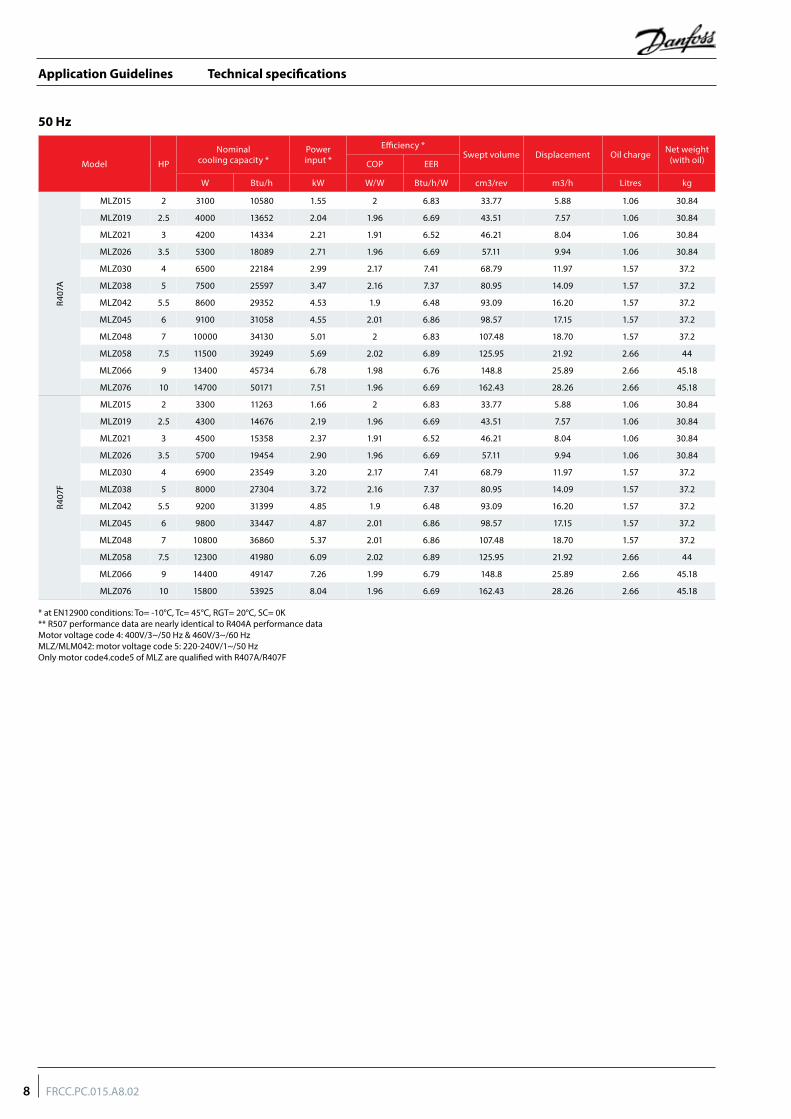
Technical specifications
50 Hz
Model HP
Nominalcooling capacity *
Powerinput *
Efficiency *Swept volume Displacement Oil charge Net weight
(with oil)COP EER
W Btu/h kW W/W Btu/h/W cm3/rev m3/h Litres kg
R407
A
MLZ015 2 3100 10580 1.55 2 6.83 33.77 5.88 1.06 30.84
MLZ019 2.5 4000 13652 2.04 1.96 6.69 43.51 7.57 1.06 30.84
MLZ021 3 4200 14334 2.21 1.91 6.52 46.21 8.04 1.06 30.84
MLZ026 3.5 5300 18089 2.71 1.96 6.69 57.11 9.94 1.06 30.84
MLZ030 4 6500 22184 2.99 2.17 7.41 68.79 11.97 1.57 37.2
MLZ038 5 7500 25597 3.47 2.16 7.37 80.95 14.09 1.57 37.2
MLZ042 5.5 8600 29352 4.53 1.9 6.48 93.09 16.20 1.57 37.2
MLZ045 6 9100 31058 4.55 2.01 6.86 98.57 17.15 1.57 37.2
MLZ048 7 10000 34130 5.01 2 6.83 107.48 18.70 1.57 37.2
MLZ058 7.5 11500 39249 5.69 2.02 6.89 125.95 21.92 2.66 44
MLZ066 9 13400 45734 6.78 1.98 6.76 148.8 25.89 2.66 45.18
MLZ076 10 14700 50171 7.51 1.96 6.69 162.43 28.26 2.66 45.18
R407
F
MLZ015 2 3300 11263 1.66 2 6.83 33.77 5.88 1.06 30.84
MLZ019 2.5 4300 14676 2.19 1.96 6.69 43.51 7.57 1.06 30.84
MLZ021 3 4500 15358 2.37 1.91 6.52 46.21 8.04 1.06 30.84
MLZ026 3.5 5700 19454 2.90 1.96 6.69 57.11 9.94 1.06 30.84
MLZ030 4 6900 23549 3.20 2.17 7.41 68.79 11.97 1.57 37.2
MLZ038 5 8000 27304 3.72 2.16 7.37 80.95 14.09 1.57 37.2
MLZ042 5.5 9200 31399 4.85 1.9 6.48 93.09 16.20 1.57 37.2
MLZ045 6 9800 33447 4.87 2.01 6.86 98.57 17.15 1.57 37.2
MLZ048 7 10800 36860 5.37 2.01 6.86 107.48 18.70 1.57 37.2
MLZ058 7.5 12300 41980 6.09 2.02 6.89 125.95 21.92 2.66 44
MLZ066 9 14400 49147 7.26 1.99 6.79 148.8 25.89 2.66 45.18
MLZ076 10 15800 53925 8.04 1.96 6.69 162.43 28.26 2.66 45.18
* at EN12900 conditions: To= -10°C, Tc= 45°C, RGT= 20°C, SC= 0K ** R507 performance data are nearly identical to R404A performance dataMotor voltage code 4: 400V/3~/50 Hz & 460V/3~/60 HzMLZ/MLM042: motor voltage code 5: 220-240V/1~/50 HzOnly motor code4.code5 of MLZ are qualified with R407A/R407F
8 FRCC.PC.015.A8.02
Application Guidelines
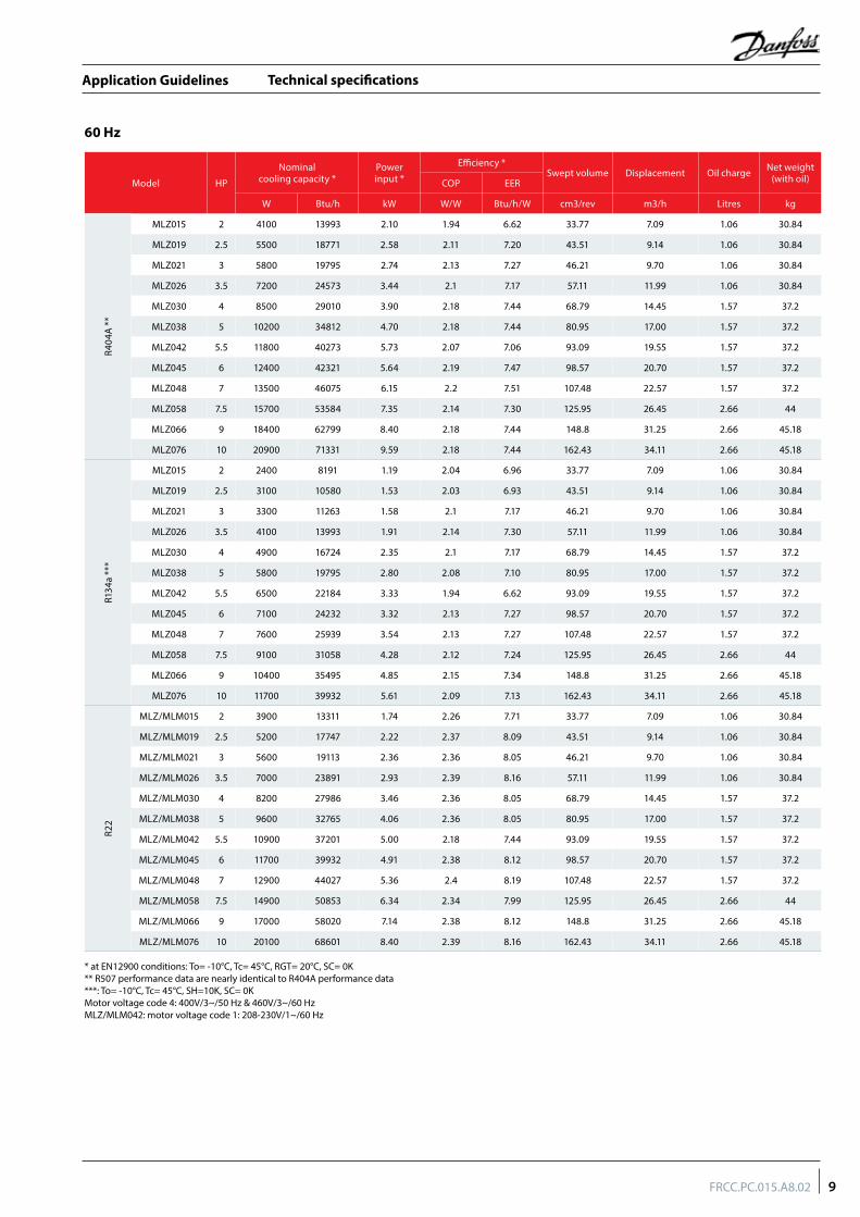
Technical specifications
Model HP
Nominalcooling capacity *
Powerinput *
Efficiency *Swept volume Displacement Oil charge Net weight
(with oil)COP EER
W Btu/h kW W/W Btu/h/W cm3/rev m3/h Litres kg
R404
A *
*
MLZ015 2 4100 13993 2.10 1.94 6.62 33.77 7.09 1.06 30.84
MLZ019 2.5 5500 18771 2.58 2.11 7.20 43.51 9.14 1.06 30.84
MLZ021 3 5800 19795 2.74 2.13 7.27 46.21 9.70 1.06 30.84
MLZ026 3.5 7200 24573 3.44 2.1 7.17 57.11 11.99 1.06 30.84
MLZ030 4 8500 29010 3.90 2.18 7.44 68.79 14.45 1.57 37.2
MLZ038 5 10200 34812 4.70 2.18 7.44 80.95 17.00 1.57 37.2
MLZ042 5.5 11800 40273 5.73 2.07 7.06 93.09 19.55 1.57 37.2
MLZ045 6 12400 42321 5.64 2.19 7.47 98.57 20.70 1.57 37.2
MLZ048 7 13500 46075 6.15 2.2 7.51 107.48 22.57 1.57 37.2
MLZ058 7.5 15700 53584 7.35 2.14 7.30 125.95 26.45 2.66 44
MLZ066 9 18400 62799 8.40 2.18 7.44 148.8 31.25 2.66 45.18
MLZ076 10 20900 71331 9.59 2.18 7.44 162.43 34.11 2.66 45.18
R134
a **
*
MLZ015 2 2400 8191 1.19 2.04 6.96 33.77 7.09 1.06 30.84
MLZ019 2.5 3100 10580 1.53 2.03 6.93 43.51 9.14 1.06 30.84
MLZ021 3 3300 11263 1.58 2.1 7.17 46.21 9.70 1.06 30.84
MLZ026 3.5 4100 13993 1.91 2.14 7.30 57.11 11.99 1.06 30.84
MLZ030 4 4900 16724 2.35 2.1 7.17 68.79 14.45 1.57 37.2
MLZ038 5 5800 19795 2.80 2.08 7.10 80.95 17.00 1.57 37.2
MLZ042 5.5 6500 22184 3.33 1.94 6.62 93.09 19.55 1.57 37.2
MLZ045 6 7100 24232 3.32 2.13 7.27 98.57 20.70 1.57 37.2
MLZ048 7 7600 25939 3.54 2.13 7.27 107.48 22.57 1.57 37.2
MLZ058 7.5 9100 31058 4.28 2.12 7.24 125.95 26.45 2.66 44
MLZ066 9 10400 35495 4.85 2.15 7.34 148.8 31.25 2.66 45.18
MLZ076 10 11700 39932 5.61 2.09 7.13 162.43 34.11 2.66 45.18
R22
MLZ/MLM015 2 3900 13311 1.74 2.26 7.71 33.77 7.09 1.06 30.84
MLZ/MLM019 2.5 5200 17747 2.22 2.37 8.09 43.51 9.14 1.06 30.84
MLZ/MLM021 3 5600 19113 2.36 2.36 8.05 46.21 9.70 1.06 30.84
MLZ/MLM026 3.5 7000 23891 2.93 2.39 8.16 57.11 11.99 1.06 30.84
MLZ/MLM030 4 8200 27986 3.46 2.36 8.05 68.79 14.45 1.57 37.2
MLZ/MLM038 5 9600 32765 4.06 2.36 8.05 80.95 17.00 1.57 37.2
MLZ/MLM042 5.5 10900 37201 5.00 2.18 7.44 93.09 19.55 1.57 37.2
MLZ/MLM045 6 11700 39932 4.91 2.38 8.12 98.57 20.70 1.57 37.2
MLZ/MLM048 7 12900 44027 5.36 2.4 8.19 107.48 22.57 1.57 37.2
MLZ/MLM058 7.5 14900 50853 6.34 2.34 7.99 125.95 26.45 2.66 44
MLZ/MLM066 9 17000 58020 7.14 2.38 8.12 148.8 31.25 2.66 45.18
MLZ/MLM076 10 20100 68601 8.40 2.39 8.16 162.43 34.11 2.66 45.18
* at EN12900 conditions: To= -10°C, Tc= 45°C, RGT= 20°C, SC= 0K ** R507 performance data are nearly identical to R404A performance data***: To= -10°C, Tc= 45°C, SH=10K, SC= 0KMotor voltage code 4: 400V/3~/50 Hz & 460V/3~/60 HzMLZ/MLM042: motor voltage code 1: 208-230V/1~/60 Hz
60 Hz
9FRCC.PC.015.A8.02
Application Guidelines
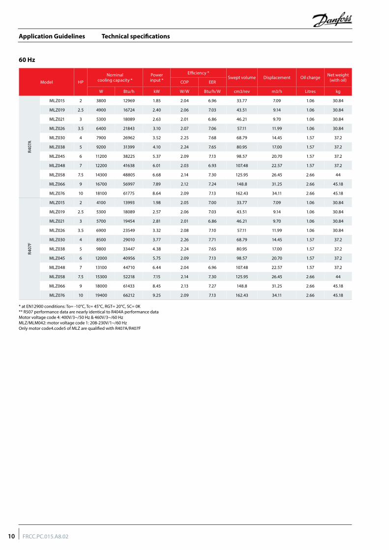
Technical specifications
Model HP
Nominalcooling capacity *
Powerinput *
Efficiency *Swept volume Displacement Oil charge Net weight
(with oil)COP EER
W Btu/h kW W/W Btu/h/W cm3/rev m3/h Litres kg
R407
A
MLZ015 2 3800 12969 1.85 2.04 6.96 33.77 7.09 1.06 30.84
MLZ019 2.5 4900 16724 2.40 2.06 7.03 43.51 9.14 1.06 30.84
MLZ021 3 5300 18089 2.63 2.01 6.86 46.21 9.70 1.06 30.84
MLZ026 3.5 6400 21843 3.10 2.07 7.06 57.11 11.99 1.06 30.84
MLZ030 4 7900 26962 3.52 2.25 7.68 68.79 14.45 1.57 37.2
MLZ038 5 9200 31399 4.10 2.24 7.65 80.95 17.00 1.57 37.2
MLZ045 6 11200 38225 5.37 2.09 7.13 98.57 20.70 1.57 37.2
MLZ048 7 12200 41638 6.01 2.03 6.93 107.48 22.57 1.57 37.2
MLZ058 7.5 14300 48805 6.68 2.14 7.30 125.95 26.45 2.66 44
MLZ066 9 16700 56997 7.89 2.12 7.24 148.8 31.25 2.66 45.18
MLZ076 10 18100 61775 8.64 2.09 7.13 162.43 34.11 2.66 45.18
R407
F
MLZ015 2 4100 13993 1.98 2.05 7.00 33.77 7.09 1.06 30.84
MLZ019 2.5 5300 18089 2.57 2.06 7.03 43.51 9.14 1.06 30.84
MLZ021 3 5700 19454 2.81 2.01 6.86 46.21 9.70 1.06 30.84
MLZ026 3.5 6900 23549 3.32 2.08 7.10 57.11 11.99 1.06 30.84
MLZ030 4 8500 29010 3.77 2.26 7.71 68.79 14.45 1.57 37.2
MLZ038 5 9800 33447 4.38 2.24 7.65 80.95 17.00 1.57 37.2
MLZ045 6 12000 40956 5.75 2.09 7.13 98.57 20.70 1.57 37.2
MLZ048 7 13100 44710 6.44 2.04 6.96 107.48 22.57 1.57 37.2
MLZ058 7.5 15300 52218 7.15 2.14 7.30 125.95 26.45 2.66 44
MLZ066 9 18000 61433 8.45 2.13 7.27 148.8 31.25 2.66 45.18
MLZ076 10 19400 66212 9.25 2.09 7.13 162.43 34.11 2.66 45.18
* at EN12900 conditions: To= -10°C, Tc= 45°C, RGT= 20°C, SC= 0K ** R507 performance data are nearly identical to R404A performance dataMotor voltage code 4: 400V/3~/50 Hz & 460V/3~/60 HzMLZ/MLM042: motor voltage code 1: 208-230V/1~/60 HzOnly motor code4.code5 of MLZ are qualified with R407A/R407F
60 Hz
10 FRCC.PC.015.A8.02
Application Guidelines
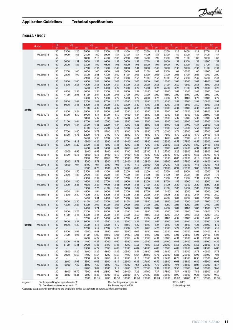
Technical specifications
R404A / R507
ModelTo -25 -20 -15 -10 -5 0 5 10Tc Qo Pe Qo Pe Qo Pe Qo Pe Qo Pe Qo Pe Qo Pe Qo Pe
50 Hz
MLZ015T430 2300 1.25 2900 1.24 3500 1.22 4300 1.20 5200 1.18 6200 1.16 7400 1.14 8700 1.1440 1900 1.63 2400 1.60 3000 1.57 3700 1.54 4400 1.51 5300 1.49 6300 1.47 7400 1.4750 - - 1800 2.10 2400 2.05 2900 2.00 3600 1.95 4300 1.91 5100 1.88 6000 1.86
MLZ019T430 3000 1.51 3800 1.53 4600 1.53 5600 1.53 6700 1.52 8000 1.52 9500 1.53 11200 1.5740 2600 1.88 3300 1.92 4000 1.93 4800 1.93 5800 1.91 6900 1.90 8200 1.89 9700 1.8950 - - 2700 2.36 3300 2.40 4000 2.41 4800 2.40 5800 2.38 6800 2.36 8100 2.34
MLZ021T430 3200 1.60 4000 1.60 4900 1.61 5900 1.62 7100 1.63 8500 1.64 10000 1.66 11800 1.6840 2800 1.99 3500 2.01 4300 2.02 5100 2.03 6200 2.03 7300 2.03 8700 2.01 10300 2.0050 - - 2900 2.52 3500 2.54 4300 2.55 5100 2.55 6100 2.53 7300 2.49 8600 2.44
MLZ026T430 3900 2.00 4900 2.02 6000 2.03 7300 2.05 8800 2.06 10500 2.06 12500 2.07 14800 2.0740 3400 2.55 4200 2.56 5200 2.57 6300 2.58 7600 2.58 9100 2.59 10800 2.58 12800 2.5850 - - 3600 3.26 4400 3.27 5300 3.27 6400 3.26 7600 3.25 9100 3.24 10800 3.23
MLZ030T430 4800 2.33 6000 2.36 7300 2.38 8800 2.39 10600 2.40 12700 2.42 15000 2.43 17700 2.4440 4100 2.95 5100 2.97 6300 2.98 7700 2.99 9300 3.00 11100 3.00 13100 3.00 15500 3.0050 - - 4300 3.77 5300 3.77 6400 3.77 7800 3.76 9300 3.75 11100 3.73 13100 3.72
MLZ038T430 5800 2.69 7200 2.69 8700 2.70 10500 2.72 12600 2.76 15000 2.81 17700 2.88 20800 2.9740 5000 3.45 6200 3.43 7600 3.42 9200 3.42 11000 3.43 13200 3.46 15600 3.50 18300 3.5650 - - 5100 4.39 6300 4.37 7600 4.35 9200 4.34 11000 4.34 13100 4.35 15400 4.38
MLZ042T530 6300 3.24 7900 3.33 9800 3.42 12000 3.50 14500 3.57 17500 3.60 20900 3.58 24800 3.5140 5500 4.12 6900 4.14 8500 4.19 10400 4.24 12500 4.28 15000 4.31 18000 4.32 21500 4.2850 - - 5800 5.32 7100 5.30 8600 5.30 10400 5.31 12600 5.32 15100 5.33 18100 5.31
MLZ045T430 7100 3.46 8700 3.45 10700 3.44 12900 3.44 15500 3.44 18500 3.46 21900 3.49 25700 3.5440 6000 4.34 7500 4.35 9200 4.34 11200 4.33 13500 4.33 16100 4.33 19100 4.34 22500 4.3650 - - 6100 5.53 7500 5.54 9200 5.54 11200 5.53 13500 5.53 16000 5.53 19000 5.53
MLZ048T430 7700 3.80 9600 3.78 11700 3.76 14100 3.74 16900 3.72 20100 3.71 23700 3.69 27700 3.6740 6500 4.78 8200 4.78 10100 4.79 12300 4.79 14800 4.79 17600 4.79 20800 4.79 24400 4.7850 - - 6600 5.93 8200 5.97 10100 6.01 12300 6.04 14700 6.07 17500 6.10 20600 6.12
MLZ058T430 8700 4.18 10900 4.25 13500 4.33 16400 4.40 19800 4.46 23500 4.53 27800 4.59 32500 4.6440 7200 5.29 9300 5.33 11600 5.38 14200 5.43 17200 5.49 20500 5.55 24200 5.60 28400 5.6650 - - 7400 6.81 9400 6.81 11700 6.83 14300 6.85 17100 6.88 20400 6.92 24000 6.96
MLZ066T430 10000 4.92 12600 4.93 15600 4.96 19100 5.02 23100 5.12 27700 5.25 32900 5.43 38900 5.6640 8500 6.18 10800 6.18 13400 6.19 16400 6.23 19900 6.30 23900 6.40 28500 6.55 33700 6.7350 - - 8900 7.90 11100 7.90 13600 7.92 16600 7.97 19900 8.05 23800 8.16 28200 8.32
MLZ076T430 12200 5.71 15200 5.71 18500 5.75 22400 5.83 26800 5.94 31900 6.07 37800 6.21 44600 6.3440 10600 7.04 13100 7.04 15900 7.08 19100 7.15 22900 7.23 27200 7.33 32300 7.43 38200 7.5150 - - 11000 8.70 13000 8.74 15400 8.80 18300 8.87 21800 8.94 25900 9.00 30800 9.04
60 Hz
MLZ015T430 2800 1.50 3500 1.49 4300 1.49 5200 1.48 6200 1.46 7500 1.45 8900 1.42 10500 1.3840 2300 1.87 2900 1.87 3600 1.87 4500 1.87 5400 1.86 6400 1.84 7600 1.81 9000 1.7850 - - 2300 2.34 3000 2.35 3700 2.35 4400 2.35 5300 2.33 6300 2.31 7500 2.27
MLZ019T430 3800 1.80 4600 1.82 5700 1.82 6900 1.81 8200 1.81 9700 1.82 11500 1.86 13500 1.9440 3200 2.21 4000 2.28 4900 2.31 5900 2.31 7100 2.30 8400 2.29 10000 2.29 11700 2.3150 - - 3300 2.76 4100 2.84 5000 2.87 6000 2.87 7100 2.85 8400 2.83 9900 2.81
MLZ021T430 4000 1.84 4900 1.94 6000 1.97 7300 1.98 8700 1.97 10400 1.96 12200 1.99 14200 2.0640 3400 2.29 4300 2.40 5200 2.45 6300 2.46 7600 2.44 9000 2.43 10600 2.44 12400 2.5050 - - 3600 3.01 4400 3.06 5300 3.07 6400 3.05 7600 3.02 9000 3.02 10500 3.04
MLZ026T430 5000 2.30 6100 2.40 7500 2.45 9100 2.47 10900 2.47 12900 2.47 15200 2.47 17800 2.5040 4300 2.85 5300 2.98 6500 3.05 7900 3.08 9400 3.09 11200 3.08 13200 3.07 15400 3.0850 - - 4400 3.71 5400 3.80 6600 3.84 7900 3.84 9400 3.82 11100 3.80 13000 3.7830 5800 2.75 7200 2.77 8800 2.81 10700 2.84 12800 2.86 15200 2.86 17800 2.84 20800 2.78
MLZ030T4 40 5100 3.45 6300 3.46 7600 3.47 9300 3.50 11100 3.53 13200 3.54 15500 3.53 18200 3.5050 - - 5200 4.35 6400 4.34 7700 4.35 9300 4.36 11100 4.37 13100 4.37 15400 4.3630 7000 3.37 8600 3.35 10500 3.36 12700 3.39 15300 3.42 18100 3.42 21400 3.39 25100 3.31
MLZ038T4 40 6000 4.20 7500 4.18 9200 4.19 11100 4.22 13300 4.24 15800 4.25 18600 4.23 21800 4.1550 - - 6200 5.19 7700 5.20 9300 5.23 11200 5.26 13300 5.27 15600 5.25 18300 5.1830 8500 3.95 10500 4.01 12800 4.04 15500 4.05 18600 4.06 22000 4.06 26000 4.08 30400 4.11
MLZ045T4 40 7400 4.93 9100 5.00 11100 5.03 13400 5.05 16100 5.05 19100 5.05 22600 5.06 26400 5.0850 - - 7600 6.27 9300 6.30 11300 6.32 13500 6.31 16100 6.31 19000 6.31 22300 6.3230 9300 4.31 11400 4.35 14000 4.40 16900 4.44 20300 4.48 24100 4.48 28400 4.43 33100 4.32
MLZ048T4 40 8100 5.41 9900 5.43 12100 5.48 14700 5.53 17600 5.56 21000 5.58 24700 5.55 28800 5.4650 - - 8300 6.77 10100 6.80 12300 6.84 14800 6.88 17600 6.89 20800 6.87 24300 6.8030 10800 5.22 13600 5.29 16800 5.39 20500 5.51 24800 5.63 29600 5.72 35000 5.78 40900 5.78
MLZ058T4 40 9000 6.57 11400 6.54 14200 6.57 17400 6.64 21100 6.75 25300 6.86 29900 6.95 35100 7.0150 - - 8900 8.27 11200 8.19 13900 8.17 17000 8.21 20400 8.29 24300 8.38 28500 8.4630 12600 5.95 15500 6.05 18900 6.19 22900 6.35 27600 6.52 32800 6.68 38800 6.82 45500 6.93
MLZ066T4 40 10900 7.32 13500 7.39 16500 7.50 19900 7.64 23900 7.79 28500 7.94 33600 8.07 39300 8.1750 - - 11200 9.07 13800 9.15 16700 9.25 20100 9.37 23800 9.50 28100 9.61 32900 9.6930 14600 6.72 17900 6.93 21800 7.09 26400 7.22 31700 7.37 37800 7.57 44800 7.86 52900 8.27
MLZ076T4 40 12600 8.21 15500 8.43 18900 8.59 22800 8.70 27300 8.83 32500 8.99 38500 9.23 45300 9.5950 - - 12900 10.35 15700 10.50 18900 10.60 22600 10.69 26800 10.82 31700 11.01 37300 11.30
Legend: To: Evaporating temperature in °C Qo: Cooling capacity in W RGT= 20°C Tc: Condensing temperature in °C Pe: Power input in kW Subooling= 0KCapacity data at other conditions are available in the datasheets at: www.danfoss.com/odsg
11FRCC.PC.015.A8.02
Application Guidelines
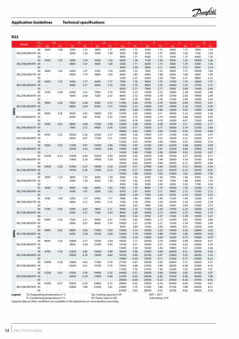
Technical specifications
R22
ModelTo -20 -15 -10 -5 0 5 10Tc Qo Pe Qo Pe Qo Pe Qo Pe Qo Pe Qo Pe Qo Pe
50H
z
MLZ/MLM015T430 2600 1.08 3200 1.10 3800 1.11 4600 1.13 5500 1.15 6600 1.17 7800 1.1940 - - 2800 1.36 3500 1.38 4200 1.40 5100 1.41 6000 1.42 7100 1.4450 - - - - - - 3800 1.71 4500 1.73 5400 1.75 6400 1.76
MLZ/MLM019T430 3400 1.32 4200 1.34 5000 1.36 6000 1.38 7100 1.40 8500 1.43 10000 1.4640 - - 3800 1.67 4600 1.69 5500 1.71 6500 1.72 7800 1.74 9200 1.7650 - - - - - - 4900 2.09 5800 2.11 6900 2.13 8300 2.14
MLZ/MLM021T430 3600 1.43 4400 1.47 5300 1.50 6400 1.52 7600 1.55 9000 1.57 10600 1.6040 - - 4000 1.79 4800 1.83 5800 1.85 6900 1.88 8200 1.89 9800 1.9050 - - - - - - 5200 2.27 6200 2.30 7400 2.31 8800 2.32
MLZ/MLM026T430 4400 1.76 5400 1.77 6600 1.77 7900 1.76 9600 1.75 11500 1.74 13800 1.7540 - - 4900 2.17 6000 2.19 7200 2.19 8800 2.18 10600 2.16 12700 2.1550 - - - - - - 6500 2.71 7900 2.71 9500 2.69 11400 2.66
MLZ/MLM030T430 5100 2.08 6400 2.14 7900 2.19 9700 2.25 11600 2.32 13800 2.38 16200 2.4640 - - 5800 2.60 7200 2.67 8800 2.72 10700 2.78 12700 2.83 14900 2.8950 - - - - - - 7900 3.30 9600 3.36 11500 3.40 13600 3.44
MLZ/MLM038T430 5800 2.40 7400 2.48 9200 2.57 11300 2.66 13700 2.76 16300 2.84 19100 2.9140 - - 6800 3.04 8500 3.13 10400 3.22 12600 3.29 14900 3.36 17500 3.4050 - - - - - - 9400 3.90 11400 3.98 13600 4.03 15900 4.0630 9000 3.18 9500 3.05 10800 3.01 12700 3.03 15400 3.11 18500 3.23 22000 3.36
MLZ/MLM042T5 40 - - 8400 3.81 9700 3.75 11600 3.75 14000 3.79 16600 3.86 19600 3.9350 - - - - - - 10300 4.78 12600 4.79 15000 4.81 17600 4.82
MLZ/MLM045T430 7000 3.05 8800 3.08 11000 3.08 13600 3.08 16500 3.08 19700 3.11 23200 3.1740 - - 7900 3.72 9900 3.76 12300 3.77 15000 3.77 18000 3.79 21200 3.8450 - - - - - - 10800 4.62 13300 4.64 16100 4.65 19100 4.68
MLZ/MLM048T430 8100 3.32 10000 3.36 12200 3.37 14800 3.36 17800 3.37 21300 3.40 25300 3.4740 - - 9000 4.07 11100 4.11 13500 4.12 16300 4.12 19500 4.13 23200 4.1750 - - - - - - 12200 5.05 14700 5.06 17600 5.07 20900 5.10
MLZ/MLM058T430 9200 3.93 11500 3.97 14300 3.96 17400 3.95 21100 3.94 25300 3.98 30200 4.0940 - - 10500 4.76 13000 4.80 15900 4.80 19300 4.81 23200 4.84 27800 4.9250 - - - - - - 14100 5.89 17300 5.90 20900 5.92 25100 5.97
MLZ/MLM066T430 10200 4.34 12900 4.40 16200 4.43 20000 4.45 24300 4.49 29100 4.57 34400 4.7140 - - 11900 5.34 14900 5.39 18300 5.43 22300 5.48 26800 5.54 31600 5.6650 - - - - - - 16500 6.62 20200 6.66 24200 6.72 28700 6.80
MLZ/MLM076T430 12400 5.26 15400 5.27 19000 5.20 23200 5.11 27900 5.06 33300 5.12 39300 5.3440 - - 14100 6.36 17400 6.33 21300 6.27 25600 6.22 30500 6.25 36100 6.4250 - - - - - - 19100 7.68 23100 7.64 27600 7.65 32600 7.78
60H
z
MLZ/MLM015T430 3000 1.22 3800 1.25 4600 1.29 5600 1.32 6700 1.36 7900 1.40 9300 1.4540 - - 3400 1.54 4200 1.58 5100 1.62 6100 1.65 7200 1.68 8500 1.7050 - - - - - - 4500 1.96 5500 2.00 6500 2.03 7700 2.04
MLZ/MLM019T430 3900 1.56 4900 1.60 6000 1.65 7300 1.70 8800 1.74 10400 1.76 12200 1.7640 - - 4500 1.97 5500 2.02 6700 2.07 8100 2.11 9600 2.13 11300 2.1250 - - - - - - 6000 2.49 7300 2.53 8700 2.54 10200 2.53
MLZ/MLM021T430 4100 1.69 5200 1.73 6400 1.77 7800 1.80 9400 1.84 11200 1.90 13200 1.9740 - - 4800 2.12 5900 2.15 7200 2.18 8700 2.20 10300 2.24 12100 2.2950 - - - - - - 6400 2.63 7800 2.66 9300 2.69 11000 2.73
MLZ/MLM026T430 5100 2.02 6300 2.07 7800 2.11 9500 2.16 11500 2.20 13700 2.23 16300 2.2440 - - 5900 2.57 7300 2.64 8900 2.69 10600 2.73 12600 2.75 14900 2.7450 - - - - - - 8100 3.32 9700 3.37 11500 3.39 13500 3.37
MLZ/MLM030T430 6000 2.44 7500 2.51 9400 2.57 11500 2.65 13800 2.72 16400 2.81 19300 2.8940 - - 6900 3.07 8600 3.14 10500 3.21 12700 3.27 15100 3.34 17800 3.4050 - - - - - - 9500 3.89 11500 3.96 13800 4.01 16200 4.06
MLZ/MLM038T430 6900 2.83 8800 2.92 11000 3.03 13500 3.14 16300 3.25 19400 3.35 22800 3.4240 - - 8100 3.58 10100 3.68 12400 3.79 15000 3.88 17900 3.96 20900 4.0050 - - - - - - 11200 4.59 13600 4.68 16200 4.75 19000 4.79
MLZ/MLM045T430 8600 3.50 10800 3.57 13500 3.64 16500 3.71 20000 3.79 23800 3.89 28000 4.0140 - - 9800 4.38 12300 4.45 15100 4.51 18400 4.57 21900 4.63 25800 4.7050 - - - - - - 13600 5.50 16500 5.56 19800 5.61 23400 5.66
MLZ/MLM048T430 9700 3.76 12200 3.82 15000 3.89 18300 3.98 21900 4.08 26000 4.21 30500 4.3640 - - 10900 4.74 13600 4.82 16700 4.90 20100 4.97 23900 5.05 28200 5.1450 - - - - - - 14900 6.04 18100 6.11 21600 6.17 25600 6.22
MLZ/MLM058T430 10900 4.50 13800 4.62 17200 4.74 21100 4.87 25600 5.00 30600 5.13 36200 5.2740 - - 12600 5.61 15700 5.75 19300 5.88 23500 5.99 28200 6.08 33400 6.1650 - - - - - - 17300 7.16 21100 7.26 25500 7.33 30400 7.37
MLZ/MLM066T430 12200 5.03 15500 5.18 19400 5.35 24000 5.51 29200 5.68 35000 5.83 41300 5.9740 - - 14200 6.30 17800 6.48 22100 6.65 26900 6.82 32300 6.96 38200 7.0850 - - - - - - 20000 8.06 24500 8.22 29400 8.36 34700 8.46
MLZ/MLM076T430 14500 6.07 18300 6.20 22800 6.31 28000 6.42 33900 6.54 40400 6.69 47400 6.8740 - - 16900 7.48 21000 7.62 25800 7.74 31200 7.86 37100 7.98 43500 8.1350 - - - - - - 23400 9.43 28300 9.55 33700 9.66 39600 9.78
Legend: To: Evaporating temperature in °C Qo: Cooling capacity in W RGT = 20°C Tc: Condensing temperature in °C Pe: Power input in kW Subcooling =0 KCapacity data at other conditions are available in the datasheets at: www.danfoss.com/odsg
12 FRCC.PC.015.A8.02
Application Guidelines

Technical specifications
R134a
ModelTo -10 -5 0 5 10 15Tc Qo Pe Qo Pe Qo Pe Qo Pe Qo Pe Qo Pe
50H
z
MLZ015T430 2400 0.74 3000 0.75 3700 0.75 4500 0.76 5400 0.77 - -40 - - 2700 0.92 3300 0.93 4100 0.94 4900 0.95 5900 0.9650 - - 2400 1.14 3000 1.15 3600 1.16 4400 1.17 5200 1.18
MLZ019T430 3100 0.95 3800 0.96 4700 0.96 5800 0.97 7000 0.99 - -40 - - 3500 1.18 4300 1.19 5200 1.20 6300 1.21 7600 1.2250 - - 3100 1.44 3800 1.46 4700 1.48 5600 1.49 6700 1.50
MLZ021T430 3300 0.98 4100 0.99 5000 1.00 6100 1.01 7400 1.03 - -40 - - 3700 1.22 4600 1.23 5600 1.25 6700 1.26 8000 1.2850 - - 3300 1.49 4000 1.51 4900 1.53 6000 1.54 7200 1.56
MLZ026T430 4100 1.19 5100 1.20 6200 1.22 7600 1.23 9100 1.25 - -40 - - 4600 1.48 5600 1.50 6900 1.52 8300 1.54 9900 1.5550 - - 4100 1.82 5000 1.85 6100 1.87 7400 1.89 8900 1.91
MLZ030T430 4900 1.42 6100 1.43 7500 1.45 9100 1.46 11000 1.48 - -40 - - 5500 1.76 6800 1.78 8300 1.80 10000 1.82 12000 1.8450 - - 4900 2.16 6000 2.19 7400 2.21 8900 2.23 10700 2.26
MLZ038T430 5800 1.73 7200 1.75 8800 1.77 10700 1.79 12900 1.81 - -40 - - 6500 2.15 8000 2.18 9700 2.20 11700 2.22 14000 2.2450 - - 5700 2.64 7100 2.68 8700 2.71 10500 2.73 12500 2.7530 6600 2.15 8200 2.20 10100 2.23 12100 2.28 14400 2.35 - -
MLZ042T5 40 - - 7500 2.60 9200 2.64 11100 2.68 13200 2.72 15700 2.7850 - - 6500 3.08 8100 3.15 9900 3.19 11800 3.22 14100 3.25
MLZ045T430 7100 1.96 8900 1.99 11000 2.00 13300 2.01 16000 2.02 - -40 - - 8000 2.46 9900 2.49 12100 2.51 14600 2.53 17400 2.5550 - - 7100 3.03 8800 3.07 10800 3.10 13000 3.13 15600 3.17
MLZ048T430 7600 2.12 9500 2.15 11600 2.18 14100 2.20 16900 2.22 - -40 - - 8500 2.66 10500 2.70 12800 2.72 15400 2.74 18300 2.7550 - - 7500 3.27 9300 3.32 11400 3.36 13800 3.38 16400 3.39
MLZ058T430 9100 2.64 11300 2.69 13800 2.77 16600 2.83 20000 2.87 - -40 - - 10100 3.33 12400 3.40 15100 3.44 18100 3.45 21600 3.4050 - - 9000 4.06 11100 4.15 13400 4.20 16100 4.20 19200 4.12
MLZ066T430 10500 3.01 13000 3.07 16000 3.14 19300 3.20 23200 3.24 - -40 - - 11800 3.79 14500 3.85 17500 3.89 21100 3.90 25000 3.8650 - - 10400 4.62 12800 4.70 15600 4.75 18800 4.75 22300 4.69
MLZ076T430 11800 3.41 - 3.49 17900 3.58 21600 3.65 25800 3.69 - -40 - - 13100 4.31 16100 4.39 19600 4.44 23500 4.45 28000 4.3950 - - 11600 5.26 14300 5.36 17400 5.42 21000 5.42 25000 5.34
60H
z
MLZ015T430 3000 0.89 3700 0.90 4600 0.92 5500 0.94 6600 0.96 - -40 - - 3400 1.10 4200 1.12 5100 1.14 6100 1.16 7200 1.1850 - - 3000 1.33 3700 1.36 4600 1.38 5500 1.40 6500 1.43
MLZ019T430 3800 1.15 4800 1.18 5900 1.20 7100 1.22 8500 1.25 - -40 - - 4300 1.43 5400 1.46 6500 1.48 7800 1.50 9300 1.5450 - - 3900 1.73 4800 1.77 5900 1.79 7100 1.82 8400 1.84
MLZ021T430 4100 1.19 5100 1.21 6200 1.23 7600 1.25 9100 1.28 - -40 - - 4600 1.48 5700 1.50 6900 1.52 8300 1.54 9900 1.5750 - - 4100 1.79 5100 1.83 6200 1.85 7500 1.87 8900 1.90
MLZ026T430 5000 1.44 6300 1.46 7700 1.49 9300 1.52 11200 1.57 - -40 - - 5700 1.78 7000 1.82 8600 1.85 10300 1.88 12200 1.9150 - - 5100 2.16 6300 2.22 7700 2.26 9300 2.29 11000 2.30
MLZ030T430 6000 1.75 7500 1.78 9300 1.81 11300 1.85 13500 1.90 - -40 - - 6800 2.18 8500 2.21 10300 2.24 12400 2.28 14700 2.3350 - - 6100 2.64 7600 2.68 9300 2.72 11200 2.76 13300 2.81
MLZ038T430 7100 2.06 8800 2.10 10900 2.15 13200 2.21 15900 2.26 - -40 - - 8000 2.57 9900 2.62 12100 2.67 14600 2.72 17300 2.7750 - - 7200 3.14 8900 3.19 10900 3.24 13200 3.29 15700 3.34
MLZ045T430 8800 2.45 11000 2.49 13500 2.53 16300 2.58 19500 2.65 - -40 - - 9900 3.05 12200 3.09 14800 3.13 17800 3.18 21100 3.2650 - - 8600 3.74 10700 3.79 13100 3.83 15800 3.88 18900 3.94
MLZ048T430 9300 2.61 11600 2.66 14200 2.72 17200 2.78 20600 2.86 - -40 - - 10400 3.26 12900 3.31 15600 3.37 18800 3.43 22200 3.4950 - - 9200 3.99 11300 4.06 13900 4.11 16700 4.16 19900 4.21
MLZ058T430 11100 3.14 13700 3.23 16800 3.35 20200 3.47 24000 3.57 - -40 - - 12400 3.96 15200 4.07 18300 4.17 21900 4.24 25900 4.2750 - - 11000 4.84 13500 4.96 16300 5.06 19600 5.12 23300 5.13
MLZ066T430 12700 3.60 15700 3.70 19200 3.83 23200 3.97 27600 4.10 - -40 - - 14200 4.53 17400 4.66 21100 4.77 25200 4.85 29800 4.9050 - - 12600 5.52 15500 5.68 18800 5.79 22500 5.86 26700 5.85
MLZ076T430 14300 4.12 17600 4.23 21500 4.38 26000 4.54 31000 4.70 - -40 - - 16000 5.19 19600 5.33 23600 5.46 28300 5.56 33400 5.6150 - - 14200 6.35 17400 6.51 21100 6.64 25300 6.71 29800 6.71
Legend: To: Evaporating temperature in °C Qo: Cooling capacity in W RGT = 20°C Tc: Condensing temperature in °C Pe: Power input in kW Subcooling =0 KCapacity data at other conditions are available in the datasheets at: www.danfoss.com/odsg
13FRCC.PC.015.A8.02
Application Guidelines
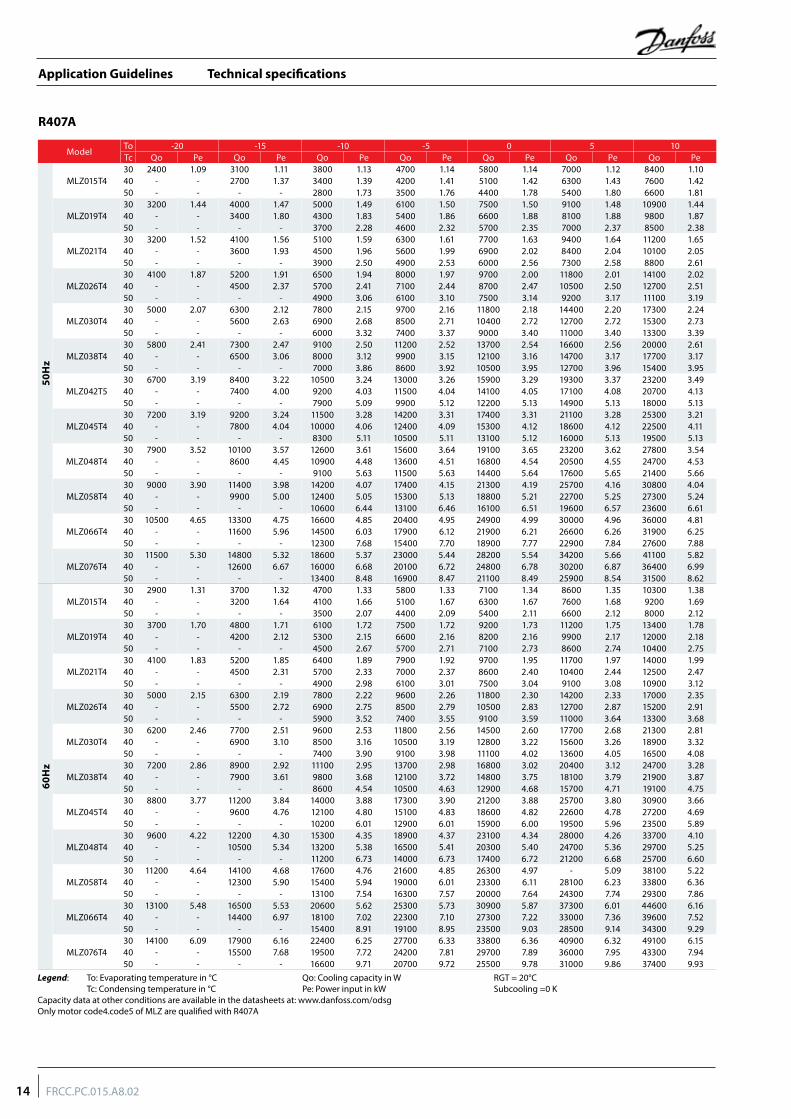
Technical specifications
ModelTo -20 -15 -10 -5 0 5 10Tc Qo Pe Qo Pe Qo Pe Qo Pe Qo Pe Qo Pe Qo Pe
50H
z
MLZ015T430 2400 1.09 3100 1.11 3800 1.13 4700 1.14 5800 1.14 7000 1.12 8400 1.1040 - - 2700 1.37 3400 1.39 4200 1.41 5100 1.42 6300 1.43 7600 1.4250 - - - - 2800 1.73 3500 1.76 4400 1.78 5400 1.80 6600 1.81
MLZ019T430 3200 1.44 4000 1.47 5000 1.49 6100 1.50 7500 1.50 9100 1.48 10900 1.4440 - - 3400 1.80 4300 1.83 5400 1.86 6600 1.88 8100 1.88 9800 1.8750 - - - - 3700 2.28 4600 2.32 5700 2.35 7000 2.37 8500 2.38
MLZ021T430 3200 1.52 4100 1.56 5100 1.59 6300 1.61 7700 1.63 9400 1.64 11200 1.6540 - - 3600 1.93 4500 1.96 5600 1.99 6900 2.02 8400 2.04 10100 2.0550 - - - - 3900 2.50 4900 2.53 6000 2.56 7300 2.58 8800 2.61
MLZ026T430 4100 1.87 5200 1.91 6500 1.94 8000 1.97 9700 2.00 11800 2.01 14100 2.0240 - - 4500 2.37 5700 2.41 7100 2.44 8700 2.47 10500 2.50 12700 2.5150 - - - - 4900 3.06 6100 3.10 7500 3.14 9200 3.17 11100 3.19
MLZ030T430 5000 2.07 6300 2.12 7800 2.15 9700 2.16 11800 2.18 14400 2.20 17300 2.2440 - - 5600 2.63 6900 2.68 8500 2.71 10400 2.72 12700 2.72 15300 2.7350 - - - - 6000 3.32 7400 3.37 9000 3.40 11000 3.40 13300 3.39
MLZ038T430 5800 2.41 7300 2.47 9100 2.50 11200 2.52 13700 2.54 16600 2.56 20000 2.6140 - - 6500 3.06 8000 3.12 9900 3.15 12100 3.16 14700 3.17 17700 3.1750 - - - - 7000 3.86 8600 3.92 10500 3.95 12700 3.96 15400 3.9530 6700 3.19 8400 3.22 10500 3.24 13000 3.26 15900 3.29 19300 3.37 23200 3.49
MLZ042T5 40 - - 7400 4.00 9200 4.03 11500 4.04 14100 4.05 17100 4.08 20700 4.1350 - - - - 7900 5.09 9900 5.12 12200 5.13 14900 5.13 18000 5.13
MLZ045T430 7200 3.19 9200 3.24 11500 3.28 14200 3.31 17400 3.31 21100 3.28 25300 3.2140 - - 7800 4.04 10000 4.06 12400 4.09 15300 4.12 18600 4.12 22500 4.1150 - - - - 8300 5.11 10500 5.11 13100 5.12 16000 5.13 19500 5.13
MLZ048T430 7900 3.52 10100 3.57 12600 3.61 15600 3.64 19100 3.65 23200 3.62 27800 3.5440 - - 8600 4.45 10900 4.48 13600 4.51 16800 4.54 20500 4.55 24700 4.5350 - - - - 9100 5.63 11500 5.63 14400 5.64 17600 5.65 21400 5.66
MLZ058T430 9000 3.90 11400 3.98 14200 4.07 17400 4.15 21300 4.19 25700 4.16 30800 4.0440 - - 9900 5.00 12400 5.05 15300 5.13 18800 5.21 22700 5.25 27300 5.2450 - - - - 10600 6.44 13100 6.46 16100 6.51 19600 6.57 23600 6.61
MLZ066T430 10500 4.65 13300 4.75 16600 4.85 20400 4.95 24900 4.99 30000 4.96 36000 4.8140 - - 11600 5.96 14500 6.03 17900 6.12 21900 6.21 26600 6.26 31900 6.2550 - - - - 12300 7.68 15400 7.70 18900 7.77 22900 7.84 27600 7.88
MLZ076T430 11500 5.30 14800 5.32 18600 5.37 23000 5.44 28200 5.54 34200 5.66 41100 5.8240 - - 12600 6.67 16000 6.68 20100 6.72 24800 6.78 30200 6.87 36400 6.9950 - - - - 13400 8.48 16900 8.47 21100 8.49 25900 8.54 31500 8.62
60H
z
MLZ015T430 2900 1.31 3700 1.32 4700 1.33 5800 1.33 7100 1.34 8600 1.35 10300 1.3840 - - 3200 1.64 4100 1.66 5100 1.67 6300 1.67 7600 1.68 9200 1.6950 - - - - 3500 2.07 4400 2.09 5400 2.11 6600 2.12 8000 2.12
MLZ019T430 3700 1.70 4800 1.71 6100 1.72 7500 1.72 9200 1.73 11200 1.75 13400 1.7840 - - 4200 2.12 5300 2.15 6600 2.16 8200 2.16 9900 2.17 12000 2.1850 - - - - 4500 2.67 5700 2.71 7100 2.73 8600 2.74 10400 2.75
MLZ021T430 4100 1.83 5200 1.85 6400 1.89 7900 1.92 9700 1.95 11700 1.97 14000 1.9940 - - 4500 2.31 5700 2.33 7000 2.37 8600 2.40 10400 2.44 12500 2.4750 - - - - 4900 2.98 6100 3.01 7500 3.04 9100 3.08 10900 3.12
MLZ026T430 5000 2.15 6300 2.19 7800 2.22 9600 2.26 11800 2.30 14200 2.33 17000 2.3540 - - 5500 2.72 6900 2.75 8500 2.79 10500 2.83 12700 2.87 15200 2.9150 - - - - 5900 3.52 7400 3.55 9100 3.59 11000 3.64 13300 3.68
MLZ030T430 6200 2.46 7700 2.51 9600 2.53 11800 2.56 14500 2.60 17700 2.68 21300 2.8140 - - 6900 3.10 8500 3.16 10500 3.19 12800 3.22 15600 3.26 18900 3.3250 - - - - 7400 3.90 9100 3.98 11100 4.02 13600 4.05 16500 4.08
MLZ038T430 7200 2.86 8900 2.92 11100 2.95 13700 2.98 16800 3.02 20400 3.12 24700 3.2840 - - 7900 3.61 9800 3.68 12100 3.72 14800 3.75 18100 3.79 21900 3.8750 - - - - 8600 4.54 10500 4.63 12900 4.68 15700 4.71 19100 4.75
MLZ045T430 8800 3.77 11200 3.84 14000 3.88 17300 3.90 21200 3.88 25700 3.80 30900 3.6640 - - 9600 4.76 12100 4.80 15100 4.83 18600 4.82 22600 4.78 27200 4.6950 - - - - 10200 6.01 12900 6.01 15900 6.00 19500 5.96 23500 5.89
MLZ048T430 9600 4.22 12200 4.30 15300 4.35 18900 4.37 23100 4.34 28000 4.26 33700 4.1040 - - 10500 5.34 13200 5.38 16500 5.41 20300 5.40 24700 5.36 29700 5.2550 - - - - 11200 6.73 14000 6.73 17400 6.72 21200 6.68 25700 6.60
MLZ058T430 11200 4.64 14100 4.68 17600 4.76 21600 4.85 26300 4.97 - 5.09 38100 5.2240 - - 12300 5.90 15400 5.94 19000 6.01 23300 6.11 28100 6.23 33800 6.3650 - - - - 13100 7.54 16300 7.57 20000 7.64 24300 7.74 29300 7.86
MLZ066T430 13100 5.48 16500 5.53 20600 5.62 25300 5.73 30900 5.87 37300 6.01 44600 6.1640 - - 14400 6.97 18100 7.02 22300 7.10 27300 7.22 33000 7.36 39600 7.5250 - - - - 15400 8.91 19100 8.95 23500 9.03 28500 9.14 34300 9.29
MLZ076T430 14100 6.09 17900 6.16 22400 6.25 27700 6.33 33800 6.36 40900 6.32 49100 6.1540 - - 15500 7.68 19500 7.72 24200 7.81 29700 7.89 36000 7.95 43300 7.9450 - - - - 16600 9.71 20700 9.72 25500 9.78 31000 9.86 37400 9.93
Legend: To: Evaporating temperature in °C Qo: Cooling capacity in W RGT = 20°C Tc: Condensing temperature in °C Pe: Power input in kW Subcooling =0 KCapacity data at other conditions are available in the datasheets at: www.danfoss.com/odsgOnly motor code4.code5 of MLZ are qualified with R407A
R407A
14 FRCC.PC.015.A8.02
Application Guidelines
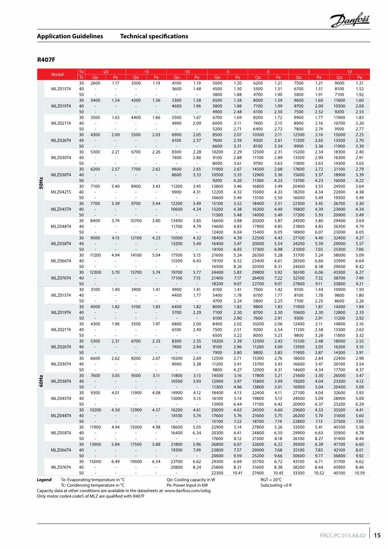
Technical specifications
ModelTo -20 -15 -10 -5 0 5 10Tc Qo Pe Qo Pe Qo Pe Qo Pe Qo Pe Qo Pe Qo Pe
50H
z
MLZ015T430 2600 1.17 3300 1.19 4100 1.19 5000 1.20 6200 1.21 7500 1.21 9000 1.2140 - - - - 3600 1.48 4500 1.50 5500 1.51 6700 1.51 8100 1.5250 - - - - - - 3800 1.88 4700 1.90 5800 1.91 7100 1.92
MLZ019T430 3400 1.54 4200 1.56 5300 1.58 6500 1.58 8000 1.59 9600 1.60 11600 1.6040 - - - - 4600 1.96 5800 1.98 7100 1.99 8700 2.00 10500 2.0050 - - - - - - 4900 2.48 6100 2.50 7500 2.52 9200 2.53
MLZ021T430 3500 1.63 4400 1.66 5500 1.67 6700 1.69 8200 1.72 9900 1.77 11900 1.8340 - - - - 4900 2.09 6000 2.11 7400 2.13 8900 2.16 10700 2.2050 - - - - - - 5200 2.71 6400 2.72 7800 2.74 9500 2.77
MLZ026T430 4300 2.00 5500 2.03 6900 2.05 8500 2.07 10300 2.11 12500 2.16 15000 2.2540 - - - - 6100 2.57 7600 2.59 9300 2.61 11200 2.65 13500 2.7050 - - - - - - 6600 3.31 8100 3.34 9900 3.36 11900 3.39
MLZ030T430 5300 2.21 6700 2.26 8300 2.28 10200 2.29 12500 2.31 15200 2.34 18300 2.4040 - - - - 7400 2.86 9100 2.88 11100 2.89 13500 2.90 16300 2.9150 - - - - - - 8000 3.61 9700 3.63 11800 3.63 14300 3.63
MLZ038T430 6200 2.57 7700 2.62 9600 2.65 11900 2.67 14500 2.68 17600 2.72 21100 2.7940 - - - - 8600 3.33 10500 3.35 12900 3.36 15600 3.37 18900 3.3950 - - - - - - 9200 4.20 11300 4.23 13700 4.23 16500 4.2230 7100 3.40 8900 3.43 11200 3.45 13800 3.46 16800 3.49 20400 3.55 24500 3.64
MLZ042T5 40 - - - - 9900 4.31 12200 4.32 15000 4.33 18200 4.34 22000 4.3850 - - - - - - 10600 5.49 13100 5.50 16000 5.49 19300 5.49
MLZ045T430 7700 3.39 9700 3.44 12200 3.49 15100 3.52 18400 3.51 22300 3.45 26700 3.3040 - - - - 10600 4.34 13200 4.38 16300 4.40 19800 4.39 23900 4.3450 - - - - - - 11300 5.48 14000 5.49 17200 5.50 20900 5.49
MLZ048T430 8400 3.74 10700 3.80 13400 3.85 16600 3.88 20200 3.87 24500 3.80 29400 3.6440 - - - - 11700 4.79 14600 4.83 17900 4.85 21800 4.85 26300 4.7950 - - - - - - 12400 6.04 15400 6.05 18900 6.07 23000 6.05
MLZ058T430 9500 4.15 12100 4.23 15000 4.32 18400 4.39 22500 4.43 27100 4.40 32400 4.2740 - - - - 13200 5.40 16400 5.47 20000 5.54 24200 5.59 29000 5.5750 - - - - - - 14100 6.93 17300 6.98 21000 7.03 25300 7.06
MLZ066T430 11200 4.94 14100 5.04 17500 5.15 21600 5.24 26300 5.28 31700 5.24 38000 5.0940 - - - - 15500 6.43 19100 6.52 23400 6.61 28300 6.66 33900 6.6450 - - - - - - 16500 8.26 20300 8.31 24600 8.38 29600 8.42
MLZ076T430 12300 5.70 15700 5.74 19700 5.77 24400 5.83 29800 5.92 36100 6.06 43300 6.2740 - - - - 17100 7.15 21400 7.17 26400 7.22 32100 7.32 38700 7.4950 - - - - - - 18200 9.07 22700 9.07 27800 9.11 33800 9.21
60H
z
MLZ015T430 3100 1.40 3900 1.41 4900 1.41 6100 1.41 7500 1.42 9100 1.44 10900 1.5040 - - - - 4400 1.77 5400 1.78 6700 1.77 8100 1.78 9800 1.8050 - - - - - - 4700 2.24 5800 2.25 7100 2.25 8600 2.26
MLZ019T430 4000 1.82 5100 1.83 6400 1.82 8000 1.82 9800 1.83 11900 1.87 14300 1.9440 - - - - 5700 2.29 7100 2.30 8700 2.30 10600 2.30 12800 2.3350 - - - - - - 6100 2.90 7600 2.91 9300 2.91 11200 2.92
MLZ021T430 4300 1.96 5500 1.97 6800 2.00 8400 2.02 10200 2.06 12400 2.11 14800 2.1640 - - - - 6100 2.49 7500 2.51 9200 2.54 11100 2.58 13300 2.6350 - - - - - - 6500 3.22 8000 3.25 9800 3.28 11800 3.32
MLZ026T430 5300 2.31 6700 2.33 8300 2.35 10200 2.39 12500 2.43 15100 2.48 18000 2.5540 - - - - 7400 2.94 9100 2.96 11200 3.00 13500 3.05 16200 3.1050 - - - - - - 7900 3.80 9800 3.83 11900 3.87 14300 3.91
MLZ030T430 6600 2.62 8200 2.67 10200 2.69 12500 2.71 15300 2.76 18600 2.84 22400 2.9840 - - - - 9000 3.38 11200 3.41 13700 3.43 16600 3.47 20100 3.5450 - - - - - - 9800 4.27 12000 4.31 14600 4.34 17700 4.37
MLZ038T430 7600 3.05 9500 3.11 11800 3.13 14500 3.16 17800 3.21 21600 3.30 26000 3.4740 - - - - 10500 3.93 12900 3.97 15800 3.99 19200 4.04 23300 4.1250 - - - - - - 11300 4.96 13800 5.01 16900 5.04 20400 5.09
MLZ045T430 9300 4.01 11900 4.08 14900 4.12 18400 4.13 22400 4.11 27100 4.04 32600 3.9340 - - - - 13000 5.13 16100 5.14 19800 5.13 24000 5.09 28900 5.0050 - - - - - - 13900 6.44 17100 6.42 20900 6.37 25200 6.29
MLZ048T430 10200 4.50 12900 4.57 16200 4.61 20000 4.63 24500 4.60 29600 4.53 35500 4.4140 - - - - 14100 5.74 17600 5.76 21600 5.75 26200 5.70 31600 5.6050 - - - - - - 15100 7.22 18700 7.19 22800 7.13 27500 7.05
MLZ058T430 11900 4.94 15000 4.98 18600 5.05 22900 5.14 27800 5.26 33500 5.41 40100 5.5840 - - - - 16400 6.34 20300 6.41 24800 6.50 29900 6.63 35900 6.7850 - - - - - - 17600 8.12 21500 8.18 26100 8.27 31400 8.40
MLZ066T430 13900 5.84 17500 5.88 21800 5.96 26800 6.07 32600 6.22 39300 6.39 47100 6.6040 - - - - 19300 7.49 23800 7.57 29000 7.68 35100 7.83 42100 8.0150 - - - - - - 20600 9.59 25200 9.66 30600 9.77 36800 9.92
MLZ076T430 15000 6.49 19000 6.54 23700 6.62 29300 6.69 35700 6.72 43100 6.71 51700 6.6240 - - - - 20800 8.24 25800 8.31 31600 8.38 38200 8.44 45900 8.4650 - - - - - - 22300 10.41 27400 10.45 33300 10.52 40100 10.59
Legend: To: Evaporating temperature in °C Qo: Cooling capacity in W RGT = 20°C Tc: Condensing temperature in °C Pe: Power input in kW Subcooling =0 KCapacity data at other conditions are available in the datasheets at: www.danfoss.com/odsgOnly motor code4.code5 of MLZ are qualified with R407F
R407F
15FRCC.PC.015.A8.02
Application Guidelines
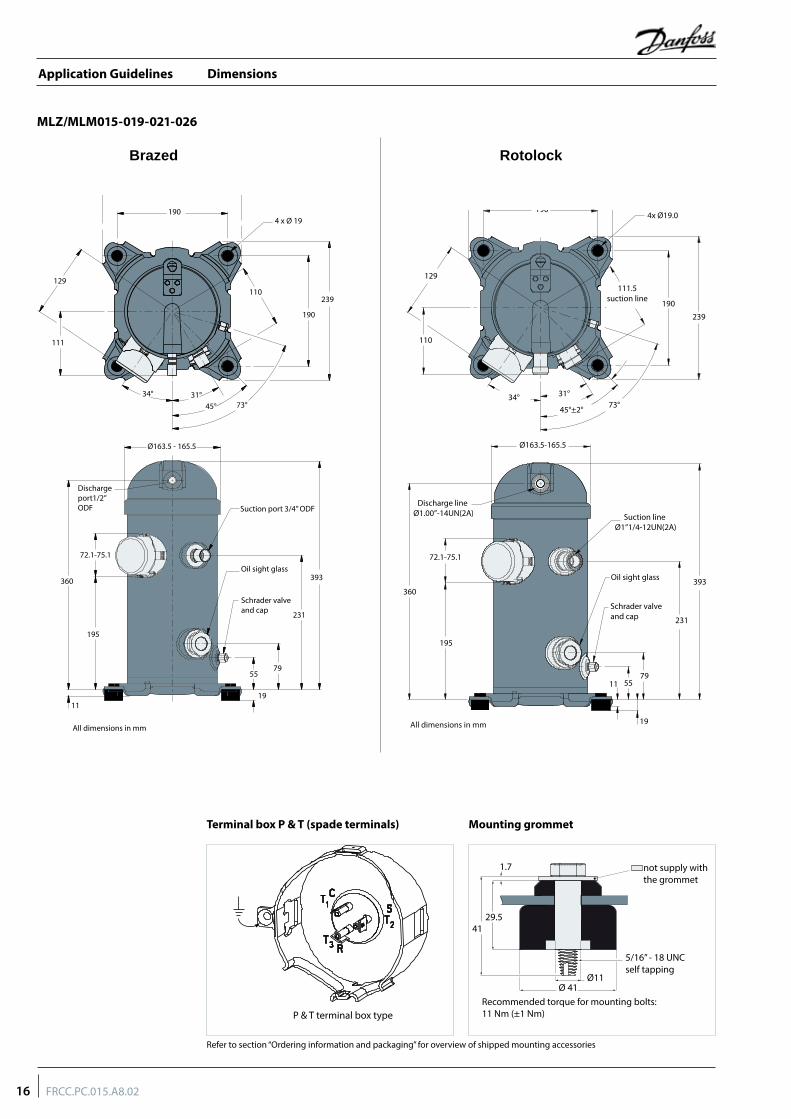
Dimensions
MLZ/MLM015-019-021-026
Mounting grommetTerminal box P & T (spade terminals)
Refer to section “Ordering information and packaging” for overview of shipped mounting accessories
RotolockBrazed
239
1904 x Ø 19
110239
190
73°45°31°34°
111
129
Ø163.5 - 165.5
Suction port 3/4” ODF
Dischargeport1/2”ODF
72.1-75.1
360
195
55
19
79
11
231
393
Schrader valveand cap
Oil sight glass
All dimensions in mm
P & T terminal box type
1.7
41
Ø 41
29.5
5/16” - 18 UNCself tapping
Recommended torque for mounting bolts:11 Nm (±1 Nm)
Ø11
not supply withthe grommet
239
4x Ø19.0
Ø163.5-165.5
Discharge line Ø1.00”-14UN(2A) Suction line
Ø1”1/4-12UN(2A)
Oil sight glass
Schrader valveand cap
129
110
72.1-75.1
360393
231
11
19
7955
195
45°±2° 73°31°34°
190
190
239
111.5suction line
All dimensions in mm
16 FRCC.PC.015.A8.02
Application Guidelines
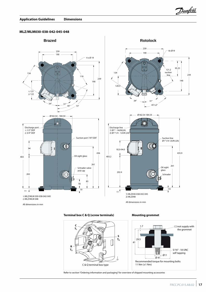
Dimensions
MLZ/MLM030-038-042-045-048
Mounting grommetTerminal box C & Q (screw terminals)
Refer to section “Ordering information and packaging” for overview of shipped mounting accessories
94
403
202
Discharge port1) 1/2” ODF2) 3/4” ODF
436
261
1911
8556
Schrader valveand cap
Suction port 7/8” ODF
Ø182.54 - 184.54
Oil sight glass
239190
134
1) 1212) 122
34° 31°45° 73°
190239
118
4 x Ø 19
1) MLZ/MLM 030-038-042-0452) MLZ/MLM 048
All dimensions in mm
C & Q terminal box type
CT1
ST2
RT3
1.7
41
Ø 41
29.5
5/16” - 18 UNCself tapping
Recommended torque for mounting bolts:11 Nm (±1 Nm)
Ø11
not supply withthe grommet
RotolockBrazed
239
121.2suction
line
95.25
134
120.3
92.0-94.0
403.2
202.4
261Oil sightglass
Schrader
435.9
1911
34° 31°
45°±2°
239
190
190
4x Ø19
Ø182.54-184.54
Suction lineØ1”1/4-12UN (2A)
Discharge line1) Ø1” - 14UN(2A)2) Ø1”1/4 - 12UN (2A)
1) MLZ030-038-042-0452) MLZ048
All dimensions in mm
17FRCC.PC.015.A8.02
Application Guidelines
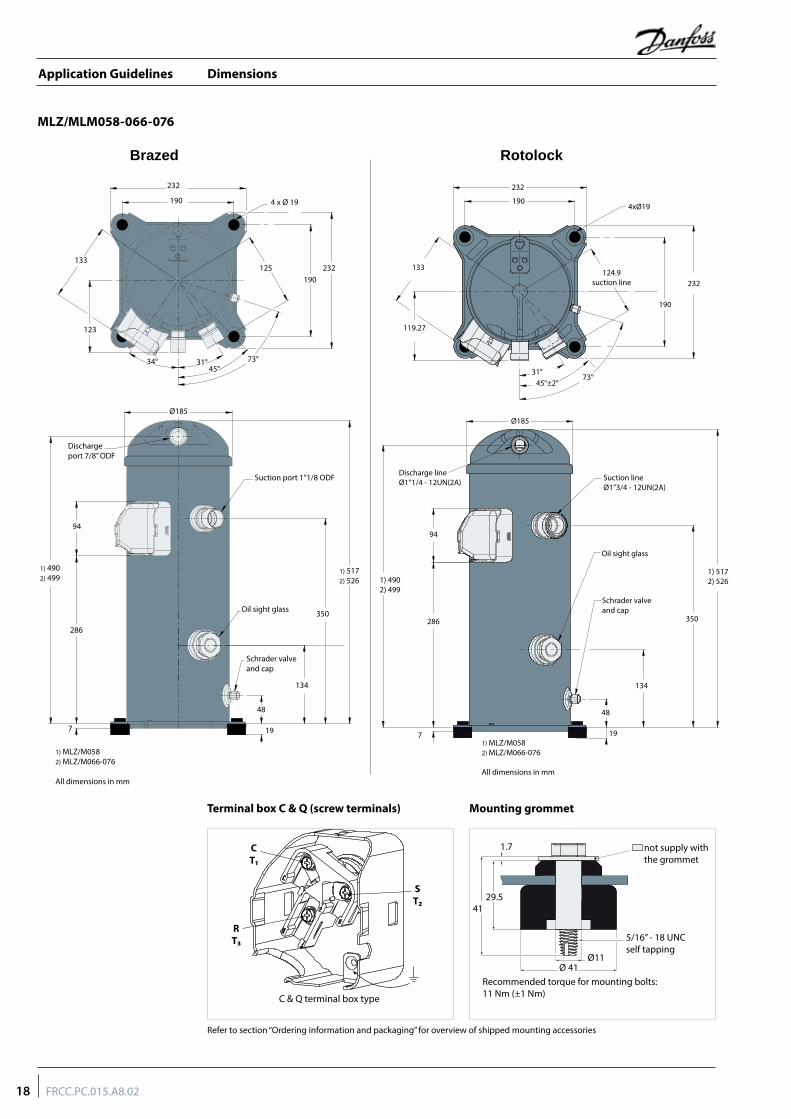
Dimensions
MLZ/MLM058-066-076
Mounting grommet
Refer to section “Ordering information and packaging” for overview of shipped mounting accessories
Terminal box C & Q (screw terminals)
RotolockBrazed
232
190
133
123
Ø185
Dischargeport 7/8” ODF
286
Schrader valve and cap
Oil sight glass
Suction port 1”1/8 ODF
48
197
134
350
1) 5172) 526
94
1) 4902) 499
1) MLZ/M0582) MLZ/M066-076
All dimensions in mm
34° 31°45°
73°
190232
4 x Ø 19
125
C & Q terminal box type
CT1
ST2
RT3
1.7
41
Ø 41
29.5
5/16” - 18 UNCself tapping
Recommended torque for mounting bolts:11 Nm (±1 Nm)
Ø11
not supply withthe grommet
232
232124.9
suction line
133
31°73°
45°±2°
119.27
4xØ19
Ø185
94
286 350
134
7
48
19
1) 4902) 499
1) 5172) 526
Suction lineØ1”3/4 - 12UN(2A)
Oil sight glass
Schrader valve and cap
Discharge lineØ1”1/4 - 12UN(2A)
190
190
1) MLZ/M0582) MLZ/M066-076
All dimensions in mm
18 FRCC.PC.015.A8.02
Application Guidelines
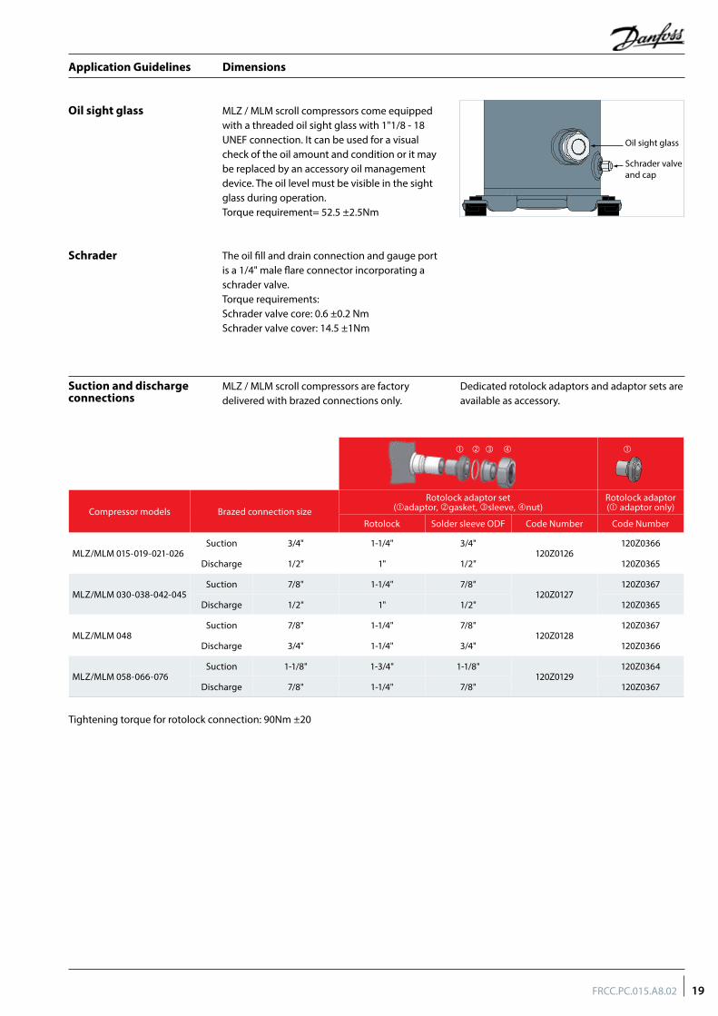
Dimensions
MLZ / MLM scroll compressors are factory delivered with brazed connections only.
Dedicated rotolock adaptors and adaptor sets are available as accessory.
Oil sight glass
Suction and discharge connections
MLZ / MLM scroll compressors come equipped with a threaded oil sight glass with 1"1/8 - 18 UNEF connection. It can be used for a visual check of the oil amount and condition or it may be replaced by an accessory oil management device. The oil level must be visible in the sight glass during operation.Torque requirement= 52.5 ±2.5Nm
The oil fill and drain connection and gauge port is a 1/4" male flare connector incorporating a schrader valve.Torque requirements:Schrader valve core: 0.6 ±0.2 NmSchrader valve cover: 14.5 ±1Nm
Schrader
Compressor models Brazed connection sizeRotolock adaptor set
(adaptor, gasket, sleeve, nut)Rotolock adaptor( adaptor only)
Rotolock Solder sleeve ODF Code Number Code Number
MLZ/MLM 015-019-021-026Suction 3/4" 1-1/4" 3/4"
120Z0126120Z0366
Discharge 1/2" 1" 1/2" 120Z0365
MLZ/MLM 030-038-042-045Suction 7/8" 1-1/4" 7/8"
120Z0127120Z0367
Discharge 1/2" 1" 1/2" 120Z0365
MLZ/MLM 048Suction 7/8" 1-1/4" 7/8"
120Z0128120Z0367
Discharge 3/4" 1-1/4" 3/4" 120Z0366
MLZ/MLM 058-066-076Suction 1-1/8" 1-3/4" 1-1/8"
120Z0129120Z0364
Discharge 7/8" 1-1/4" 7/8" 120Z0367
Tightening torque for rotolock connection: 90Nm ±20
Oil sight glass
Schrader valveand cap
19FRCC.PC.015.A8.02
Application Guidelines
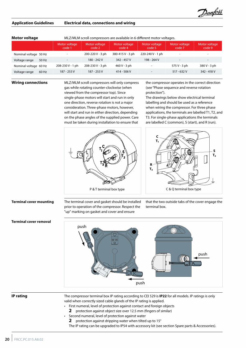
Electrical data, connections and wiring
MLZ/MLM scroll compressors are available in 6 different motor voltages.Motor voltage
The compressor terminal box IP rating according to CEI 529 is IP22 for all models. IP ratings is only valid when correctly sized cable glands of the IP rating is applied.• First numeral, level of protection against contact and foreign objects
2 protection against object size over 12.5 mm (fingers of similar)• Second numeral, level of protection against water
2 protection against dripping water when tilted up to 15°The IP rating can be upgraded to IP54 with accessory kit (see section Spare parts & Accessories).
IP rating
MLZ/MLM scroll compressors will only compress gas while rotating counter-clockwise (when viewed from the compressor top). Since single-phase motors will start and run in only one direction, reverse rotation is not a major consideration. Three-phase motors, however, will start and run in either direction, depending on the phase angles of the supplied power. Care must be taken during installation to ensure that
the compressor operates in the correct direction (see “Phase sequence and reverse rotation protection”). The drawings below show electrical terminal labelling and should be used as a reference when wiring the compressor. For three phase applications, the terminals are labelled T1, T2, and T3. For single-phase applications the terminals are labelled C (common), S (start), and R (run).
The terminal cover and gasket should be installed prior to operation of the compressor. Respect the "up" marking on gasket and cover and ensure
that the two outside tabs of the cover engage the terminal box.
Wiring connections
Terminal cover mounting
Terminal cover removal
C & Q terminal box type
CT1
ST2
RT3
P & T terminal box type
push
push
push
Motor voltage code 1
Motor voltage code 2
Motor voltage code 4
Motor voltage code 5
Motor voltage code 7
Motor voltage code 9
Nominal voltage 50 Hz - 200-220 V - 3 ph 380-415 V - 3 ph 220-240 V - 1 ph - -
Voltage range 50 Hz - 180 - 242 V 342 - 457 V 198 - 264 V - -
Nominal voltage 60 Hz 208-230 V - 1 ph 208-230 V - 3 ph 460 V - 3 ph - 575 V - 3 ph 380 V - 3 ph
Voltage range 60 Hz 187 - 253 V 187 - 253 V 414 - 506 V - 517 - 632 V 342 - 418 V
20 FRCC.PC.015.A8.02
Application Guidelines
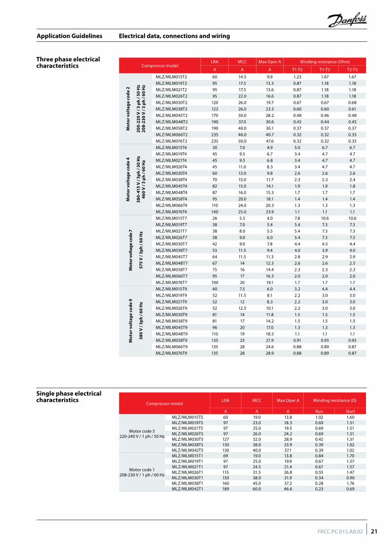
Electrical data, connections and wiring
Three phase electrical characteristics
Single phase electrical characteristics
Compressor model LRA MCC Max Oper A Winding resistance (Ohm)
A A A T1-T3 T1-T2 T2-T3
Mot
or v
olta
ge c
ode
2
200-
220
V /
3 ph
/ 50
Hz
208-
230
V /
3 ph
/ 60
Hz
MLZ/MLM015T2 60 14.5 9.9 1.23 1.67 1.67MLZ/MLM019T2 95 17.5 13.3 0.87 1.18 1.18MLZ/MLM021T2 95 17.5 13.6 0.87 1.18 1.18MLZ/MLM026T2 95 22.0 16.6 0.87 1.18 1.18MLZ/MLM030T2 120 26.0 19.7 0.67 0.67 0.68MLZ/MLM038T2 123 26.0 23.5 0.60 0.60 0.61MLZ/MLM045T2 170 30.0 28.2 0.48 0.46 0.48MLZ/MLM048T2 190 37.0 30.6 0.43 0.44 0.43MLZ/MLM058T2 190 40.0 36.1 0.37 0.37 0.37MLZ/MLM066T2 235 46.0 40.7 0.32 0.32 0.33MLZ/MLM076T2 235 50.0 47.6 0.32 0.32 0.33
Mot
or v
olta
ge c
ode
4
380-
415
V /
3ph
/ 50
Hz
460
V /
3 ph
/ 60
Hz
MLZ/MLM015T4 30 7.0 4.9 5.0 6.7 6.7MLZ/MLM019T4 45 9.5 6.7 3.4 4.7 4.7MLZ/MLM021T4 45 9.5 6.8 3.4 4.7 4.7MLZ/MLM026T4 45 11.0 8.3 3.4 4.7 4.7MLZ/MLM030T4 60 13.0 9.8 2.6 2.6 2.6MLZ/MLM038T4 70 15.0 11.7 2.3 2.3 2.4MLZ/MLM045T4 82 15.0 14.1 1.9 1.9 1.8MLZ/MLM048T4 87 16.0 15.3 1.7 1.7 1.7MLZ/MLM058T4 95 20.0 18.1 1.4 1.4 1.4MLZ/MLM066T4 110 24.0 20.3 1.3 1.3 1.3MLZ/MLM076T4 140 25.0 23.9 1.1 1.1 1.1
Mot
or v
olta
ge co
de 7
575
V /
3ph
/ 60
Hz
MLZ/MLM015T7 26 5.5 4.0 7.8 10.6 10.6MLZ/MLM019T7 38 7.0 5.4 5.4 7.3 7.3MLZ/MLM021T7 38 8.0 5.5 5.4 7.3 7.3MLZ/MLM026T7 38 9.0 6.0 5.4 7.3 7.3MLZ/MLM030T7 42 9.0 7.8 4.4 4.5 4.4MLZ/MLM038T7 53 11.5 9.4 4.0 3.9 4.0MLZ/MLM045T7 64 11.5 11.3 2.8 2.9 2.9MLZ/MLM048T7 67 14 12.3 2.6 2.6 2.5MLZ/MLM058T7 75 16 14.4 2.3 2.3 2.3MLZ/MLM066T7 95 17 16.3 2.0 2.0 2.0MLZ/MLM076T7 100 20 19.1 1.7 1.7 1.7
Mot
or v
olta
ge c
ode
9
380
V /
3ph
/ 60
Hz
MLZ/MLM015T9 40 7.5 6.0 3.2 4.4 4.4MLZ/MLM019T9 52 11.5 8.1 2.2 3.0 3.0MLZ/MLM021T9 52 12 8.3 2.2 3.0 3.0MLZ/MLM026T9 52 12.5 10.1 2.2 3.0 3.0MLZ/MLM030T9 81 14 11.8 1.5 1.5 1.5MLZ/MLM038T9 81 17 14.2 1.5 1.5 1.5MLZ/MLM045T9 96 20 17.0 1.3 1.3 1.3MLZ/MLM048T9 110 19 18.5 1.1 1.1 1.1MLZ/MLM058T9 135 25 21.9 0.91 0.93 0.93MLZ/MLM066T9 135 28 24.6 0.88 0.89 0.87MLZ/MLM076T9 135 28 28.9 0.88 0.89 0.87
Compressor modelLRA MCC Max.Oper.A Winding resistance (Ω)
A A A Run Start
Motor code 5 220-240 V / 1 ph / 50 Hz
MLZ/MLM015T5 60 19.0 13.8 1.02 1.60MLZ/MLM019T5 97 23.0 18.3 0.69 1.51MLZ/MLM021T5 97 25.0 19.5 0.69 1.51MLZ/MLM026T5 97 26.0 24.2 0.69 1.51MLZ/MLM030T5 127 32.0 28.9 0.42 1.31MLZ/MLM038T5 130 38.0 33.9 0.39 1.02MLZ/MLM042T5 130 40.0 37.1 0.39 1.02
Motor code 1208-230 V / 1 ph / 60 Hz
MLZ/MLM015T1 69 19.0 13.8 0.84 1.70MLZ/MLM019T1 97 25.0 19.9 0.67 1.57MLZ/MLM021T1 97 24.5 21.4 0.67 1.57MLZ/MLM026T1 115 31.5 26.8 0.55 1.47MLZ/MLM030T1 150 38.0 31.9 0.34 0.90MLZ/MLM038T1 160 45.0 37.2 0.28 1.76MLZ/MLM042T1 189 60.0 46.6 0.23 0.69
21FRCC.PC.015.A8.02
Application Guidelines
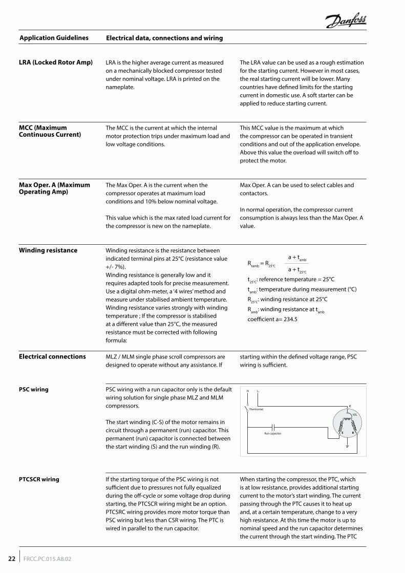
Electrical data, connections and wiring
MLZ / MLM single phase scroll compressors are designed to operate without any assistance. If
starting within the defined voltage range, PSC wiring is sufficient.
PSC wiring with a run capacitor only is the default wiring solution for single phase MLZ and MLM compressors.
The start winding (C-S) of the motor remains in circuit through a permanent (run) capacitor. This permanent (run) capacitor is connected between the start winding (S) and the run winding (R).
If the starting torque of the PSC wiring is not sufficient due to pressures not fully equalized during the off-cycle or some voltage drop during starting, the PTCSCR wiring might be an option. PTCSRC wiring provides more motor torque than PSC wiring but less than CSR wiring. The PTC is wired in parallel to the run capacitor.
When starting the compressor, the PTC, which is at low resistance, provides additional starting current to the motor’s start winding. The current passing through the PTC causes it to heat up and, at a certain temperature, change to a very high resistance. At this time the motor is up to nominal speed and the run capacitor determines the current through the start winding. The PTC
Electrical connections
PSC wiring
PTCSCR wiring
Winding resistance Winding resistance is the resistance between indicated terminal pins at 25°C (resistance value +/- 7%).Winding resistance is generally low and it requires adapted tools for precise measurement. Use a digital ohm-meter, a ‘4 wires’ method and measure under stabilised ambient temperature. Winding resistance varies strongly with winding temperature ; If the compressor is stabilised at a different value than 25°C, the measured resistance must be corrected with following formula:
a + tambRtamb = R25°C a + t25°C
t25°C: reference temperature = 25°C
tamb: temperature during measurement (°C)
R25°C: winding resistance at 25°C
Ramb: winding resistance at tamb
coefficient a= 234.5
LRA is the higher average current as measured on a mechanically blocked compressor tested under nominal voltage. LRA is printed on the nameplate.
The LRA value can be used as a rough estimation for the starting current. However in most cases, the real starting current will be lower. Many countries have defined limits for the starting current in domestic use. A soft starter can be applied to reduce starting current.
The MCC is the current at which the internal motor protection trips under maximum load and low voltage conditions.
This MCC value is the maximum at which the compressor can be operated in transient conditions and out of the application envelope. Above this value the overload will switch off to protect the motor.
MCC (Maximum Continuous Current)
LRA (Locked Rotor Amp)
The Max Oper. A is the current when the compressor operates at maximum load conditions and 10% below nominal voltage.
This value which is the max rated load current for the compressor is new on the nameplate.
Max Oper. A can be used to select cables and contactors.
In normal operation, the compressor current consumption is always less than the Max Oper. A value.
Max Oper. A (Maximum Operating Amp)
N L1
Run capacitor
ThermostatC
S R
IOL
22 FRCC.PC.015.A8.02
Application Guidelines
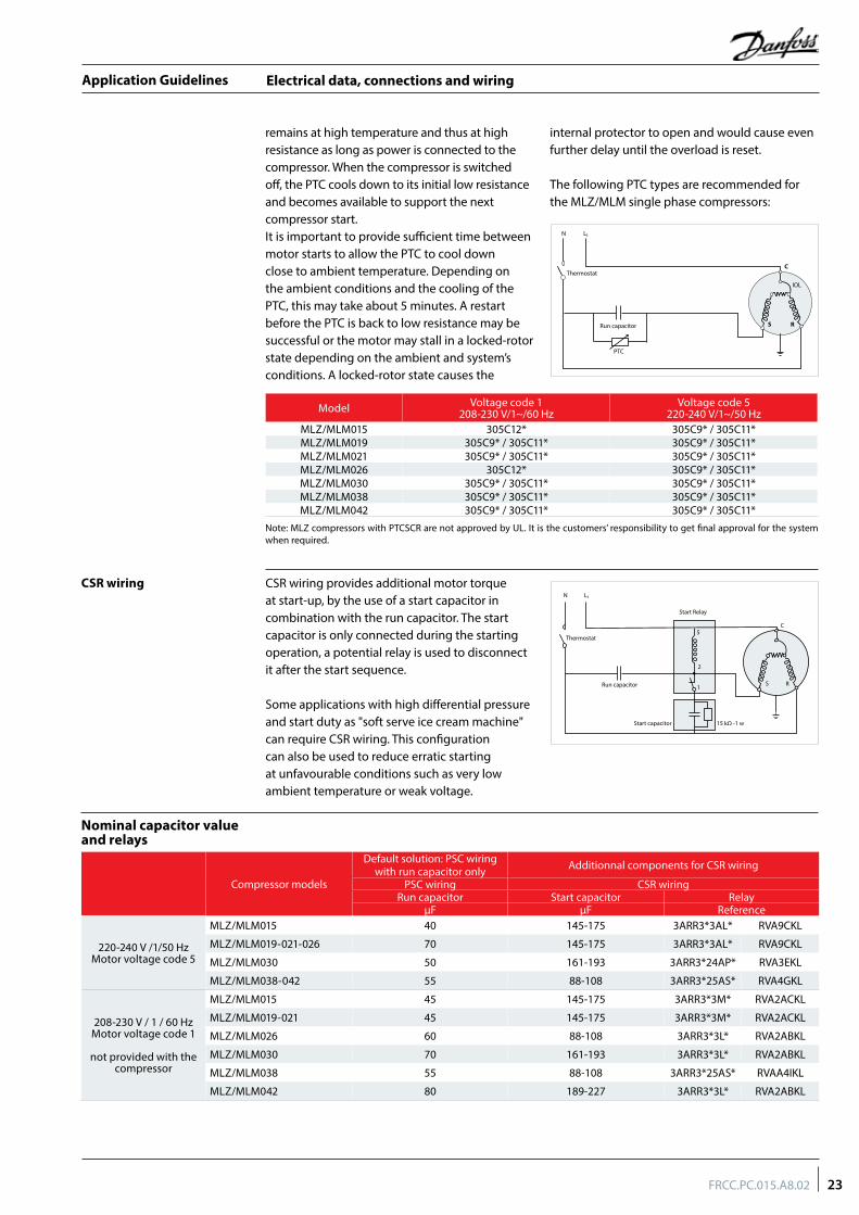
Electrical data, connections and wiring
CSR wiring provides additional motor torque at start-up, by the use of a start capacitor in combination with the run capacitor. The start capacitor is only connected during the starting operation, a potential relay is used to disconnect it after the start sequence.
Some applications with high differential pressure and start duty as "soft serve ice cream machine" can require CSR wiring. This configuration can also be used to reduce erratic starting at unfavourable conditions such as very low ambient temperature or weak voltage.
remains at high temperature and thus at high resistance as long as power is connected to the compressor. When the compressor is switched off, the PTC cools down to its initial low resistance and becomes available to support the next compressor start.It is important to provide sufficient time between motor starts to allow the PTC to cool down close to ambient temperature. Depending on the ambient conditions and the cooling of the PTC, this may take about 5 minutes. A restart before the PTC is back to low resistance may be successful or the motor may stall in a locked-rotor state depending on the ambient and system’s conditions. A locked-rotor state causes the
internal protector to open and would cause even further delay until the overload is reset.
The following PTC types are recommended for the MLZ/MLM single phase compressors:
CSR wiring
Nominal capacitor value and relays
Model Voltage code 1208-230 V/1~/60 Hz
Voltage code 5220-240 V/1~/50 Hz
MLZ/MLM015 305C12* 305C9* / 305C11*MLZ/MLM019 305C9* / 305C11* 305C9* / 305C11*MLZ/MLM021 305C9* / 305C11* 305C9* / 305C11*MLZ/MLM026 305C12* 305C9* / 305C11*MLZ/MLM030 305C9* / 305C11* 305C9* / 305C11*MLZ/MLM038 305C9* / 305C11* 305C9* / 305C11*MLZ/MLM042 305C9* / 305C11* 305C9* / 305C11*
Note: MLZ compressors with PTCSCR are not approved by UL. It is the customers’ responsibility to get final approval for the system when required.
Compressor models
Default solution: PSC wiring with run capacitor only Additionnal components for CSR wiring
PSC wiring CSR wiringRun capacitor Start capacitor Relay
µF µF Reference
220-240 V /1/50 HzMotor voltage code 5
MLZ/MLM015 40 145-175 3ARR3*3AL* RVA9CKL
MLZ/MLM019-021-026 70 145-175 3ARR3*3AL* RVA9CKL
MLZ/MLM030 50 161-193 3ARR3*24AP* RVA3EKL
MLZ/MLM038-042 55 88-108 3ARR3*25AS* RVA4GKL
208-230 V / 1 / 60 HzMotor voltage code 1
not provided with the compressor
MLZ/MLM015 45 145-175 3ARR3*3M* RVA2ACKL
MLZ/MLM019-021 45 145-175 3ARR3*3M* RVA2ACKL
MLZ/MLM026 60 88-108 3ARR3*3L* RVA2ABKL
MLZ/MLM030 70 161-193 3ARR3*3L* RVA2ABKL
MLZ/MLM038 55 88-108 3ARR3*25AS* RVAA4IKL
MLZ/MLM042 80 189-227 3ARR3*3L* RVA2ABKL
N L1
Run capacitor
PTC
ThermostatC
S R
IOL
N L1
Thermostat
Start capacitor
Start Relay
5
2
1
15 kΩ -1 w
C
S RRun capacitor
23FRCC.PC.015.A8.02
Application Guidelines
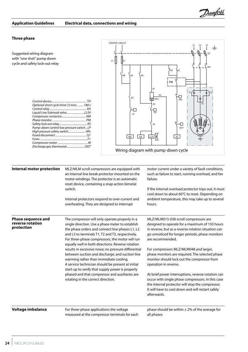
Electrical data, connections and wiring
The compressor will only operate properly in a single direction. Use a phase meter to establish the phase orders and connect line phases L1, L2 and L3 to terminals T1, T2 and T3, respectively. For three-phase compressors, the motor will run equally well in both directions. Reverse rotation results in excessive noise; no pressure differential between suction and discharge; and suction line warming rather than immediate cooling. A service technician should be present at initial start-up to verify that supply power is properly phased and that compressor and auxiliaries are rotating in the correct direction.
MLZ/MLM015-038 scroll compressors are designed to operate for a maximum of 150 hours in reverse, but as a reverse rotation situation can go unnoticed for longer periods, phase monitors are recommended.
For compressors MLZ/MLM048 and larger, phase monitors are required. The selected phase monitor should lock out the compressor from operation in reverse.
At brief power interruptions, reverse rotation can occur with single phase compressors. In this case the internal protector will stop the compressor. It will have to cool down and will restart safely afterwards.
For three-phase applications the voltage measured at the compressor terminals for each
phase should be within ± 2% of the average for all phases.
Phase sequence and reverse rotation protection
Voltage imbalance
Internal motor protection MLZ/MLM scroll compressors are equipped with an internal line break protector mounted on the motor windings. The protector is an automatic reset device, containing a snap action bimetal switch.
Internal protectors respond to over-current and overheating. They are designed to interrupt
motor current under a variety of fault conditions, such as failure to start, running overload, and fan failure.
If the internal overload protector trips out, it must cool down to about 60°C to reset. Depending on ambient temperature, this may take up to several hours.
Three phase
Suggested wiring diagram with "one shot" pump down cycle and safety lock-out relay
Control device .................................................. THOptional short cycle timer (3 min) .........180 sControl relay .................................................... KALiquid Line Solenoid valve .........................LLSVCompressor contactor .................................. KMPhase monitor ................................................ PMSafety lock out relay ........................................KSPump-down control low pressure switch .. LPHigh pressure safety switch........................ HPsFused disconnect ............................................ Q1Fuses ...................................................................F1Compressor motor ...........................................MDischarge gas thermostat ......................... DGT
MDGT
HPs180 s
THLP
CONTROL CIRCUIT
F1F1
KM
KM
KM
KA KA
A1
A2
A3
KA
KA
KS
KS
KS
L1 L3 L2
Q1
T1
T3
T2
LLSV KS
Wiring diagram with pump-down cycle
PM
24 FRCC.PC.015.A8.02
Application Guidelines
Approvals and certifications
MLZ scroll compressors comply with the following approvals and certificates.
Certificates are listed on the product datasheets: http://www.danfoss.com/odsg
Approvals and certificates
Conformity to directives
Internal free volume
CE (European Directive) All MLZ models
UL (Underwriters Laboratories)
Models with motor code 1, 5 except when using PTCSCR system
Other approvals / certificates Contact Danfoss
Products Internal free volume at LP side without oil (litre)
MLZ/MLM 015 - 026 1.85MLZ/MLM 030-048 1.85MLZ/MLM 058-076 6.15
Products MLZ / MLM 015 to 076
Refrigerating fluids Group 2Category PED IEvaluation module no scopeService temperature - Ts -35°C < Ts < 55°cMLZ - Service pressure - Ps 25.44 bar(g)MLM - Service pressure - Ps 20.74 bar(g)Declaration of conformity contact DanfossMarking of conformity CE
Pressure equipment directive 2014/68/EUMachinery directive 2006/42/EC
Low voltage directive 2014/35/EU
25FRCC.PC.015.A8.02
Application Guidelines
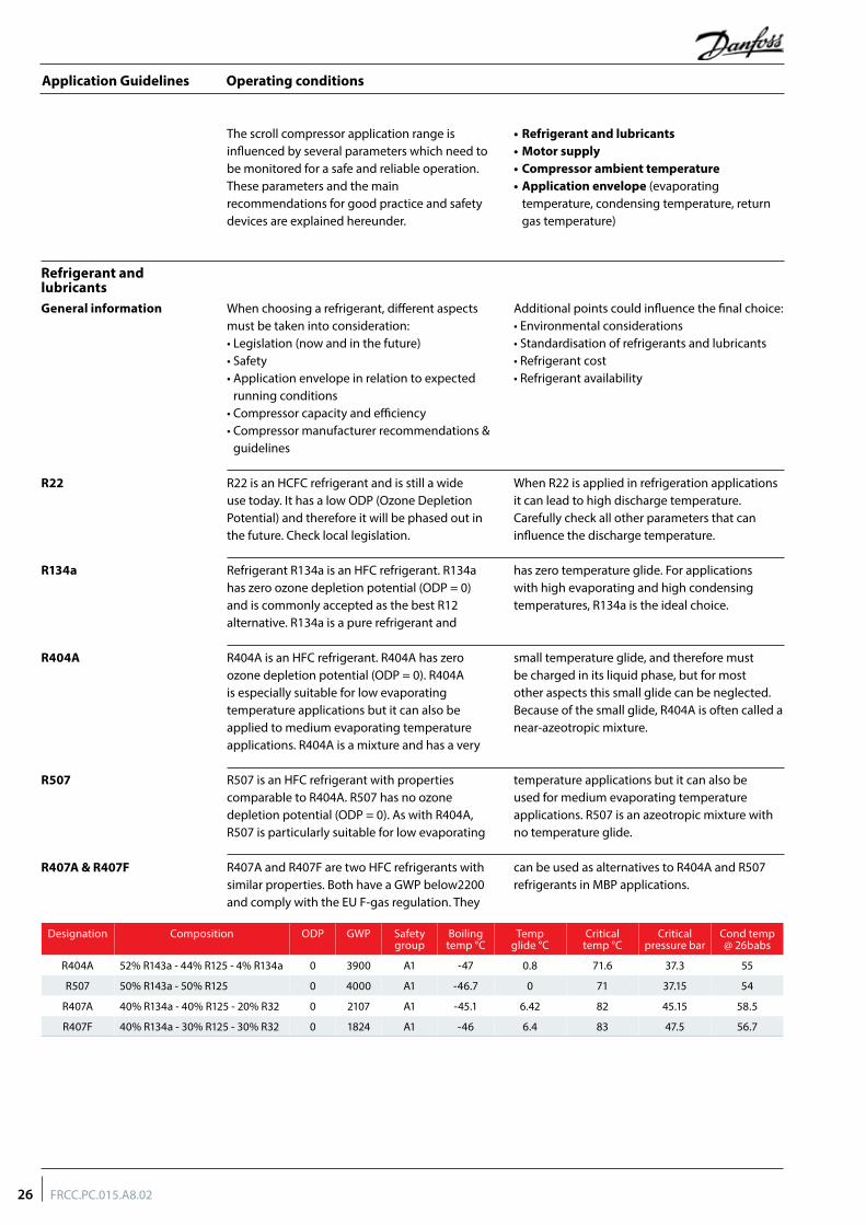
Operating conditions
The scroll compressor application range is influenced by several parameters which need to be monitored for a safe and reliable operation.These parameters and the main recommendations for good practice and safety devices are explained hereunder.
• Refrigerant and lubricants• Motor supply• Compressor ambient temperature• Application envelope (evaporating
temperature, condensing temperature, return gas temperature)
General information
Refrigerant and lubricants
When choosing a refrigerant, different aspects must be taken into consideration:• Legislation (now and in the future)• Safety• Application envelope in relation to expected
running conditions• Compressor capacity and efficiency• Compressor manufacturer recommendations &
guidelines
Additional points could influence the final choice:• Environmental considerations• Standardisation of refrigerants and lubricants• Refrigerant cost• Refrigerant availability
R22 R22 is an HCFC refrigerant and is still a wide use today. It has a low ODP (Ozone Depletion Potential) and therefore it will be phased out in the future. Check local legislation.
When R22 is applied in refrigeration applications it can lead to high discharge temperature. Carefully check all other parameters that can influence the discharge temperature.
R404A
R507
R407A & R407F
R404A is an HFC refrigerant. R404A has zero ozone depletion potential (ODP = 0). R404A is especially suitable for low evaporating temperature applications but it can also be applied to medium evaporating temperature applications. R404A is a mixture and has a very
small temperature glide, and therefore must be charged in its liquid phase, but for most other aspects this small glide can be neglected. Because of the small glide, R404A is often called a near-azeotropic mixture.
R507 is an HFC refrigerant with properties comparable to R404A. R507 has no ozone depletion potential (ODP = 0). As with R404A, R507 is particularly suitable for low evaporating
temperature applications but it can also be used for medium evaporating temperature applications. R507 is an azeotropic mixture with no temperature glide.
R407A and R407F are two HFC refrigerants with similar properties. Both have a GWP below2200 and comply with the EU F-gas regulation. They
can be used as alternatives to R404A and R507 refrigerants in MBP applications.
Refrigerant R134a is an HFC refrigerant. R134a has zero ozone depletion potential (ODP = 0) and is commonly accepted as the best R12 alternative. R134a is a pure refrigerant and
has zero temperature glide. For applications with high evaporating and high condensing temperatures, R134a is the ideal choice.
R134a
Designation Composition ODP GWP Safetygroup
Boilingtemp °C
Tempglide °C
Criticaltemp °C
Criticalpressure bar
Cond temp@ 26babs
R404A 52% R143a - 44% R125 - 4% R134a 0 3900 A1 -47 0.8 71.6 37.3 55
R507 50% R143a - 50% R125 0 4000 A1 -46.7 0 71 37.15 54
R407A 40% R134a - 40% R125 - 20% R32 0 2107 A1 -45.1 6.42 82 45.15 58.5
R407F 40% R134a - 30% R125 - 30% R32 0 1824 A1 -46 6.4 83 47.5 56.7
26 FRCC.PC.015.A8.02
Application Guidelines
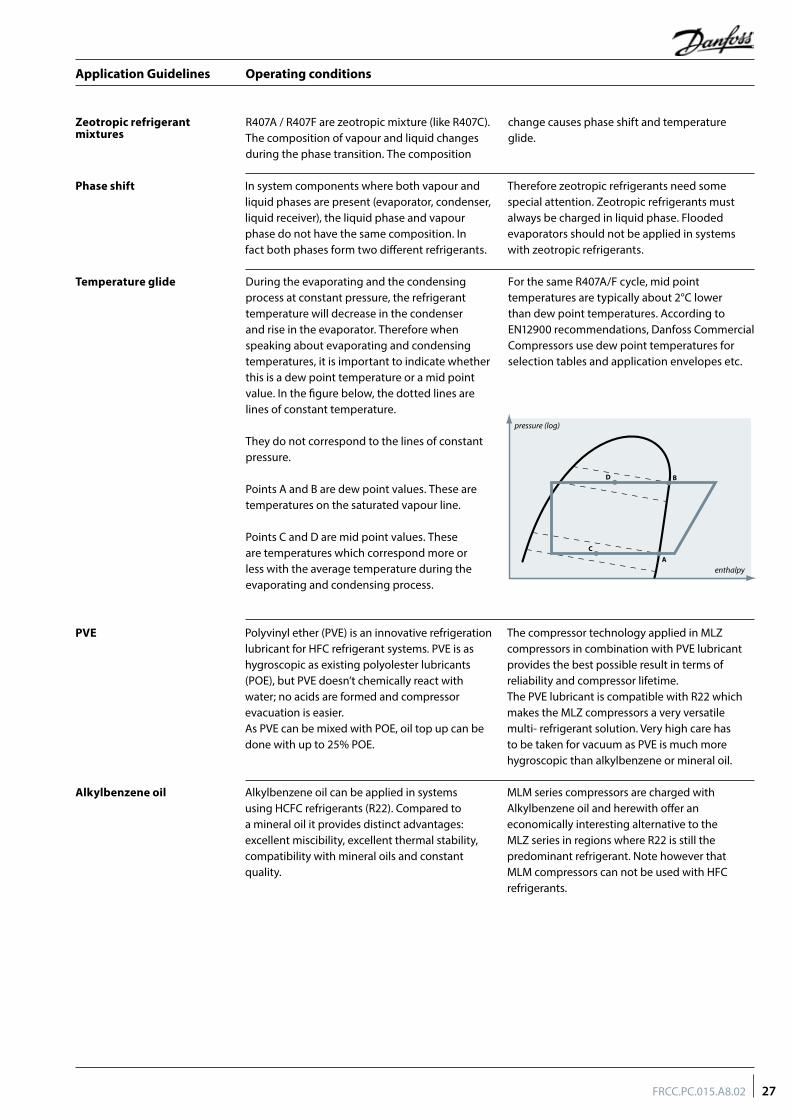
Operating conditions
Alkylbenzene oil
PVE Polyvinyl ether (PVE) is an innovative refrigeration lubricant for HFC refrigerant systems. PVE is as hygroscopic as existing polyolester lubricants (POE), but PVE doesn’t chemically react with water; no acids are formed and compressor evacuation is easier. As PVE can be mixed with POE, oil top up can be done with up to 25% POE.
The compressor technology applied in MLZ compressors in combination with PVE lubricant provides the best possible result in terms of reliability and compressor lifetime. The PVE lubricant is compatible with R22 which makes the MLZ compressors a very versatile multi- refrigerant solution. Very high care has to be taken for vacuum as PVE is much more hygroscopic than alkylbenzene or mineral oil.
Alkylbenzene oil can be applied in systems using HCFC refrigerants (R22). Compared to a mineral oil it provides distinct advantages: excellent miscibility, excellent thermal stability, compatibility with mineral oils and constant quality.
MLM series compressors are charged with Alkylbenzene oil and herewith offer an economically interesting alternative to the MLZ series in regions where R22 is still the predominant refrigerant. Note however that MLM compressors can not be used with HFC refrigerants.
Phase shift
Temperature glide
Zeotropic refrigerant mixtures
R407A / R407F are zeotropic mixture (like R407C). The composition of vapour and liquid changes during the phase transition. The composition
change causes phase shift and temperature glide.
In system components where both vapour and liquid phases are present (evaporator, condenser, liquid receiver), the liquid phase and vapour phase do not have the same composition. In fact both phases form two different refrigerants.
Therefore zeotropic refrigerants need some special attention. Zeotropic refrigerants must always be charged in liquid phase. Flooded evaporators should not be applied in systems with zeotropic refrigerants.
During the evaporating and the condensing process at constant pressure, the refrigerant temperature will decrease in the condenser and rise in the evaporator. Therefore when speaking about evaporating and condensing temperatures, it is important to indicate whether this is a dew point temperature or a mid point value. In the figure below, the dotted lines are lines of constant temperature.
They do not correspond to the lines of constant pressure.
Points A and B are dew point values. These are temperatures on the saturated vapour line.
Points C and D are mid point values. These are temperatures which correspond more or less with the average temperature during the evaporating and condensing process.
For the same R407A/F cycle, mid point temperatures are typically about 2°C lower than dew point temperatures. According to EN12900 recommendations, Danfoss Commercial Compressors use dew point temperatures for selection tables and application envelopes etc.
27FRCC.PC.015.A8.02
Application Guidelines
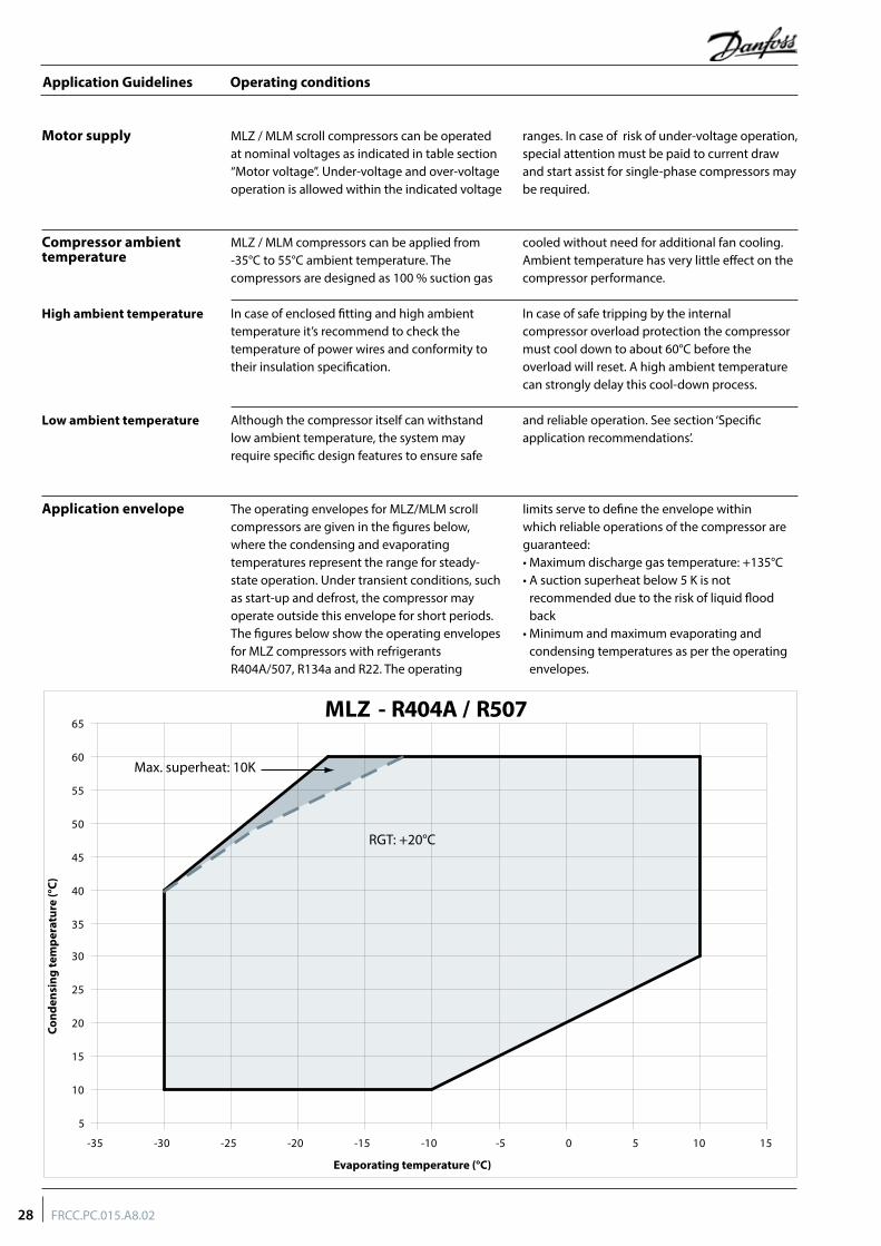
Operating conditions
Motor supply MLZ / MLM scroll compressors can be operated at nominal voltages as indicated in table section “Motor voltage”. Under-voltage and over-voltage operation is allowed within the indicated voltage
ranges. In case of risk of under-voltage operation, special attention must be paid to current draw and start assist for single-phase compressors may be required.
The operating envelopes for MLZ/MLM scroll compressors are given in the figures below, where the condensing and evaporating temperatures represent the range for steady-state operation. Under transient conditions, such as start-up and defrost, the compressor may operate outside this envelope for short periods. The figures below show the operating envelopes for MLZ compressors with refrigerants R404A/507, R134a and R22. The operating
limits serve to define the envelope within which reliable operations of the compressor are guaranteed:• Maximum discharge gas temperature: +135°C• A suction superheat below 5 K is not
recommended due to the risk of liquid flood back
• Minimum and maximum evaporating and condensing temperatures as per the operating envelopes.
MLZ / MLM compressors can be applied from -35°C to 55°C ambient temperature. The compressors are designed as 100 % suction gas
cooled without need for additional fan cooling. Ambient temperature has very little effect on the compressor performance.
In case of enclosed fitting and high ambient temperature it’s recommend to check the temperature of power wires and conformity to their insulation specification.
In case of safe tripping by the internal compressor overload protection the compressor must cool down to about 60°C before the overload will reset. A high ambient temperature can strongly delay this cool-down process.
Although the compressor itself can withstand low ambient temperature, the system may require specific design features to ensure safe
and reliable operation. See section ‘Specific application recommendations’.
Application envelope
Compressor ambient temperature
High ambient temperature
Low ambient temperature
MLZ - R404A / R507
RGT: +20°C
Max. superheat: 10K
Cond
ensi
ng te
mpe
ratu
re (°
C)
Evaporating temperature (°C)
-35 -30 -25 -20 -15 -10 -5 0 5 10 15
5
10
15
20
25
30
35
40
45
50
55
60
65
28 FRCC.PC.015.A8.02
Application Guidelines
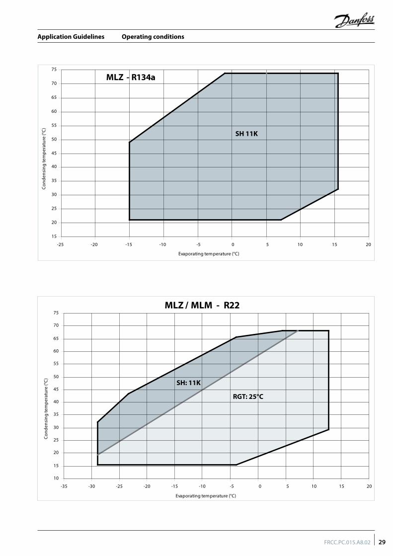
Operating conditions
MLZ - R134a
15
20
25
30
35
40
45
50
55
60
65
70
75
-25 -20 -15 -10 -5 0 5 10 15 20
Evaporating temperature (°C)
Con
dens
ing
tem
pera
ture
(°C
)
SH 11K
RGT: 25°C
SH: 11K
MLZ / MLM - R22
10
15
20
25
30
35
40
45
50
55
60
65
70
75
-35 -30 -25 -20 -15 -10 -5 0 5 10 15 20
Evaporating temperature (°C)
Con
dens
ing
tem
pera
ture
(°C
)
29FRCC.PC.015.A8.02
Application Guidelines
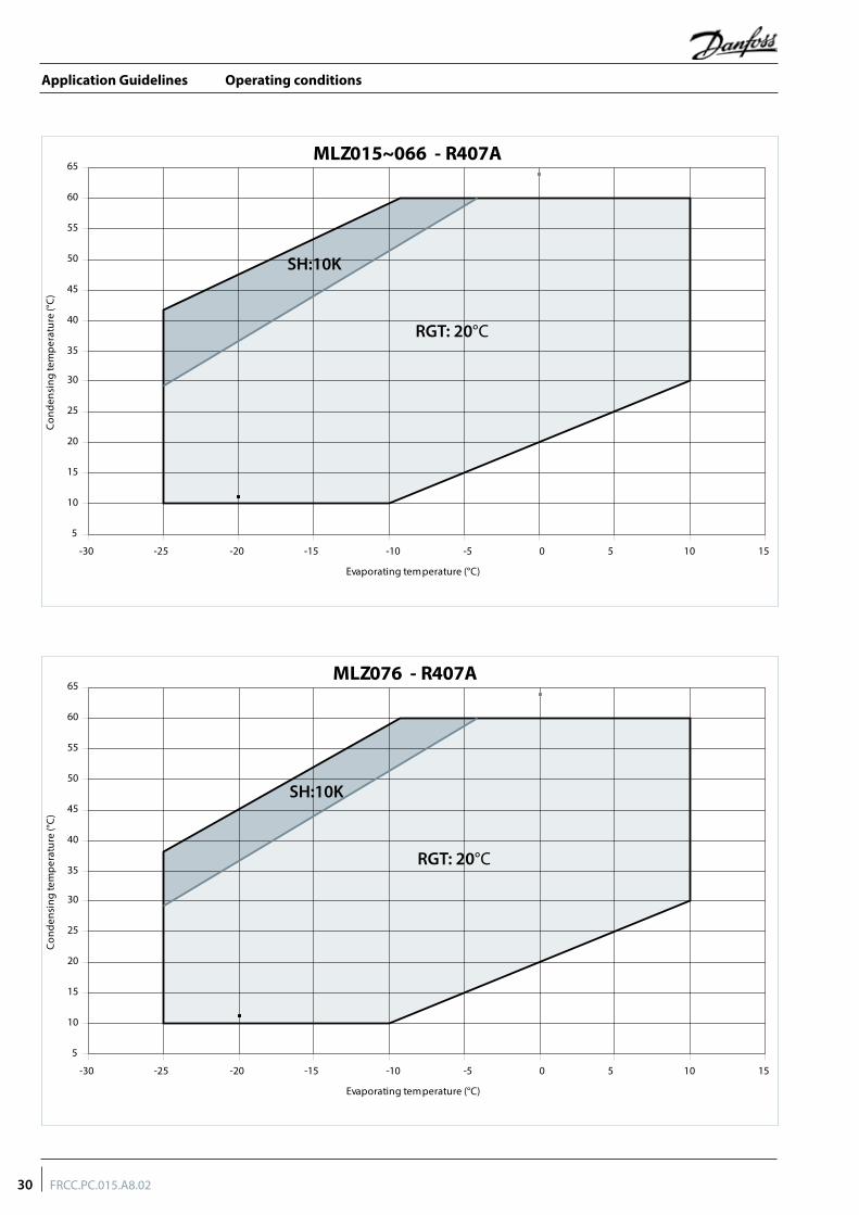
Operating conditions
SH:10K
RGT: 20°C
MLZ015~066 - R407A
5
10
15
20
25
30
35
40
45
50
55
60
65
-30 -25 -20 -15 -10 -5 0 5 10 15
Evaporating temperature (°C)
Con
dens
ing
tem
pera
ture
(°C
)
SH:10K
RGT: 20°C
MLZ076 - R407A
5
10
15
20
25
30
35
40
45
50
55
60
65
-30 -25 -20 -15 -10 -5 0 5 10 15
Evaporating temperature (°C)
Con
dens
ing
tem
pera
ture
(°C
)
30 FRCC.PC.015.A8.02
Application Guidelines
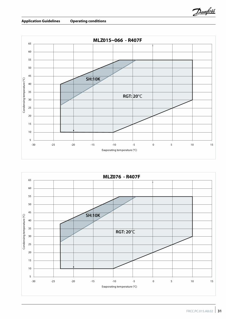
Operating conditions
SH:10K
RGT: 20°C
MLZ015~066 - R407F
5
10
15
20
25
30
35
40
45
50
55
60
65
-30 -25 -20 -15 -10 -5 0 5 10 15
Evaporating temperature (°C)
Con
dens
ing
tem
pera
ture
(°C
)
SH:10K
RGT: 20°C
MLZ076 - R407F
5
10
15
20
25
30
35
40
45
50
55
60
65
-30 -25 -20 -15 -10 -5 0 5 10 15
Evaporating temperature (°C)
Con
dens
ing
tem
pera
ture
(°C
)
31FRCC.PC.015.A8.02
Application Guidelines
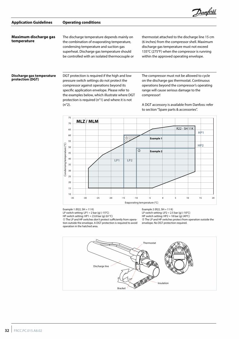
Operating conditions
Discharge gas temperature protection (DGT)
DGT protection is required if the high and low pressure switch settings do not protect the compressor against operations beyond its specific application envelope. Please refer to the examples below, which illustrate where DGT protection is required (n°1) and where it is not (n°2).
The compressor must not be allowed to cycle on the discharge gas thermostat. Continuous operations beyond the compressor’s operating range will cause serious damage to the compressor!
A DGT accessory is available from Danfoss: refer to section “Spare parts & accessories”.
The discharge temperature depends mainly on the combination of evaporating temperature, condensing temperature and suction gas superheat. Discharge gas temperature should be controlled with an isolated thermocouple or
thermostat attached to the discharge line 15 cm (6 inches) from the compressor shell. Maximum discharge gas temperature must not exceed 135°C (275°F) when the compressor is running within the approved operating envelope.
Maximum discharge gas temperature
R22 - SH 11K
MLZ / MLM
10
15
20
25
30
35
40
45
50
55
60
65
70
75
-35 -30 -25 -20 -15 -10 -5 0 5 10 15 20
Evaporating temperature (°C)
Con
dens
ing
tem
pera
ture
(°C
)
Example 1
Example 2
LP1 LP2
HP1
HP2
Example 1 (R22, SH = 11 K) LP switch setting: LP1 = 2 bar (g) (-15°C) HP switch setting: HP1 = 23.8 bar (g) (61°C) The LP and HP switches don't protect sufficiently from opera-tion outside the envelope. A DGT protection is required to avoid operation in the hatched area.
Example 2 (R22, SH = 11 K) LP switch setting: LP2 = 2.5 bar (g) (-10°C) HP switch setting: HP2 = 18 bar (g) (49°C) The LP and HP switches protect from operation outside the envelope. No DGT protection required.
Discharge line
Insulation
Bracket
Thermostat
32 FRCC.PC.015.A8.02
Application Guidelines
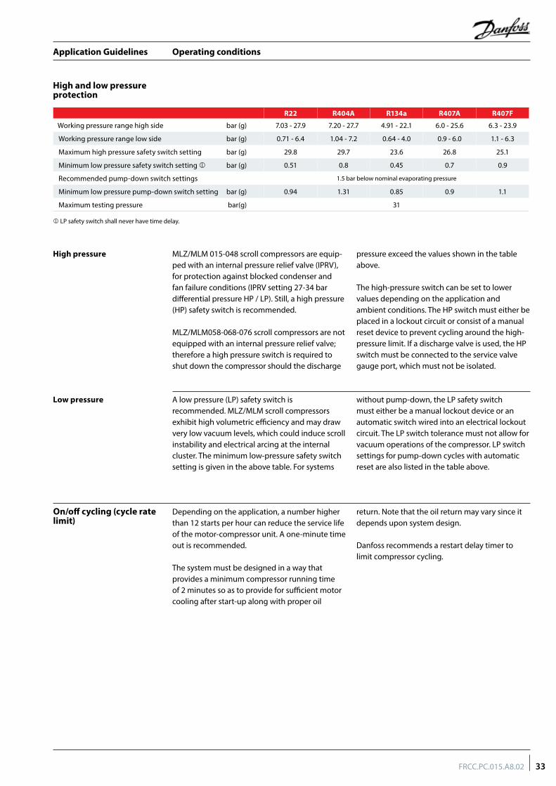
Operating conditions
A low pressure (LP) safety switch is recommended. MLZ/MLM scroll compressors exhibit high volumetric efficiency and may draw very low vacuum levels, which could induce scroll instability and electrical arcing at the internal cluster. The minimum low-pressure safety switch setting is given in the above table. For systems
without pump-down, the LP safety switch must either be a manual lockout device or an automatic switch wired into an electrical lockout circuit. The LP switch tolerance must not allow for vacuum operations of the compressor. LP switch settings for pump-down cycles with automatic reset are also listed in the table above.
Low pressure
On/off cycling (cycle rate limit)
Depending on the application, a number higher than 12 starts per hour can reduce the service life of the motor-compressor unit. A one-minute time out is recommended.
The system must be designed in a way that provides a minimum compressor running time of 2 minutes so as to provide for sufficient motor cooling after start-up along with proper oil
return. Note that the oil return may vary since it depends upon system design.
Danfoss recommends a restart delay timer to limit compressor cycling.
R22 R404A R134a R407A R407F
Working pressure range high side bar (g) 7.03 - 27.9 7.20 - 27.7 4.91 - 22.1 6.0 - 25.6 6.3 - 23.9
Working pressure range low side bar (g) 0.71 - 6.4 1.04 - 7.2 0.64 - 4.0 0.9 - 6.0 1.1 - 6.3
Maximum high pressure safety switch setting bar (g) 29.8 29.7 23.6 26.8 25.1
Minimum low pressure safety switch setting bar (g) 0.51 0.8 0.45 0.7 0.9
Recommended pump-down switch settings 1.5 bar below nominal evaporating pressure
Minimum low pressure pump-down switch setting bar (g) 0.94 1.31 0.85 0.9 1.1
Maximum testing pressure bar(g) 31
LP safety switch shall never have time delay.
MLZ/MLM 015-048 scroll compressors are equip-ped with an internal pressure relief valve (IPRV), for protection against blocked condenser and fan failure conditions (IPRV setting 27-34 bar differential pressure HP / LP). Still, a high pressure (HP) safety switch is recommended.
MLZ/MLM058-068-076 scroll compressors are not equipped with an internal pressure relief valve; therefore a high pressure switch is required to shut down the compressor should the discharge
pressure exceed the values shown in the table above.
The high-pressure switch can be set to lower values depending on the application and ambient conditions. The HP switch must either be placed in a lockout circuit or consist of a manual reset device to prevent cycling around the high-pressure limit. If a discharge valve is used, the HP switch must be connected to the service valve gauge port, which must not be isolated.
High pressure
High and low pressure protection
33FRCC.PC.015.A8.02
Application Guidelines
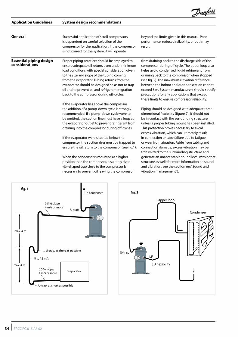
System design recommendations
Essential piping design considerations
Proper piping practices should be employed to ensure adequate oil return, even under minimum load conditions with special consideration given to the size and slope of the tubing coming from the evaporator. Tubing returns from the evaporator should be designed so as not to trap oil and to prevent oil and refrigerant migration back to the compressor during off-cycles.
If the evaporator lies above the compressor the addition of a pump-down cycle is strongly recommended. If a pump-down cycle were to be omitted, the suction line must have a loop at the evaporator outlet to prevent refrigerant from draining into the compressor during off-cycles.
If the evaporator were situated below the compressor, the suction riser must be trapped to ensure the oil return to the compressor (see fig.1).
When the condenser is mounted at a higher position than the compressor, a suitably sized «U»-shaped trap close to the compressor is necessary to prevent oil leaving the compressor
from draining back to the discharge side of the compressor during off cycle. The upper loop also helps avoid condensed liquid refrigerant from draining back to the compressor when stopped (see fig. 2). The maximum elevation difference between the indoor and outdoor section cannot exceed 8 m. System manufacturers should specify precautions for any applications that exceed these limits to ensure compressor reliability.
Piping should be designed with adequate three-dimensional flexibility (figure 2). It should not be in contact with the surrounding structure, unless a proper tubing mount has been installed. This protection proves necessary to avoid excess vibration, which can ultimately result in connection or tube failure due to fatigue or wear from abrasion. Aside from tubing and connection damage, excess vibration may be transmitted to the surrounding structure and generate an unacceptable sound level within that structure as well (for more information on sound and vibration, see the section on: “Sound and vibration management”).
General Successful application of scroll compressors is dependent on careful selection of the compressor for the application. If the compressor is not correct for the system, it will operate
beyond the limits given in this manual. Poor performance, reduced reliability, or both may result.
0.5 % slope,4 m/s or more
0.5 % slope,4 m/s or more
U-trap
U-trap, as short as possible
U-trap, as short as possible
max. 4 m
g.1
max. 4 m
8 to 12 m/s
To condenser
Evaporator
Condenser
HP
U-trap
3D flexibility
Upper loop
LP
fig. 2
34 FRCC.PC.015.A8.02
Application Guidelines
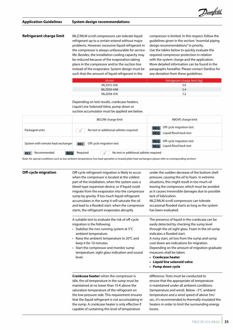
System design recommendations
Refrigerant charge limit MLZ/MLM scroll compressors can tolerate liquid refrigerant up to a certain extend without major problems. However, excessive liquid refrigerant in the compressor is always unfavourable for service life. Besides, the installation cooling capacity may be reduced because of the evaporation taking place in the compressor and/or the suction line instead of the evaporator. System design must be such that the amount of liquid refrigerant in the
compressor is limited. In this respect, follow the guidelines given in the section: “essential piping design recommendations” in priority.Use the tables below to quickly evaluate the required compressor protection in relation with the system charge and the application. More detailed information can be found in the paragraphs hereafter. Please contact Danfoss for any deviation from these guidelines.
Model Refrigerant charge limit (kg)MLZ015-026 3.6MLZ030-048 5.4MLZ058-076 7.2
Off-cycle migration Off-cycle refrigerant migration is likely to occur when the compressor is located at the coldest part of the installation, when the system uses a bleed-type expansion device, or if liquid could migrate from the evaporator into the compressor sump by gravity. If too much liquid refrigerant accumulates in the sump it will saturate the oil and lead to a flooded start: when the compressor starts, the refrigerant evaporates abruptly
under the sudden decrease of the bottom shell pressure, causing the oil to foam. In extreme situations, this might result in too much oil leaving the compressor, which must be avoided as it causes irreversible damages due to possible lack of lubrication. MLZ/MLM scroll compressors can tolerate occasional flooded starts as long as the system has been evaluated.
A suitable test to evaluate the risk of off-cycle migration is the following:• Stabilize the non running system at 5°C
ambient temperature.• Raise the ambient temperature to 20°C and
keep it for 10 minutes.• Start the compressor and monitor sump
temperature, sight glass indication and sound level.
The presence of liquid in the crankcase can be easily detected by checking the sump level through the oil sight glass. Foam in the oil sump indicates a flooded start.A noisy start, oil loss from the sump and sump cool down are indications for migration. Depending on the amount of migration graduate measures shall be taken:• Crankcase heater• Liquid line solenoid valve• Pump down cycle
Note: for special conditions such as low ambient temperature, low load operation or brazed plate heat exchangers please refer to corresponding sections
Recommended Required No test or additional safeties requiredREQREC
BELOW charge limit ABOVE charge limit
Packaged units No test or additional safeties requiredOff cycle migration test
Liquid flood back test
System with remote heat exchanger Off cycle migration testOff cycle migration test Liquid flood back testREC
REQ
REQ
REQ
REQ
Crankcase heater: when the compressor is idle, the oil temperature in the sump must be maintained at no lower than 10 K above the saturation temperature of the refrigerant on the low-pressure side. This requirement ensures that the liquid refrigerant is not accumulating in the sump. A crankcase heater is only effective if capable of sustaining this level of temperature
difference. Tests must be conducted to ensure that the appropriate oil temperature is maintained under all ambient conditions (temperature and wind). Below –5°C ambient temperature and a wind speed of above 5m/sec, it's recommended to thermally insulated the heaters in order to limit the surrounding energy losses.
Depending on test results, crankcase heaters, Liquid Line Solenoid Valve, pump down or suction accumulator must be applied see below.
35FRCC.PC.015.A8.02
Application Guidelines
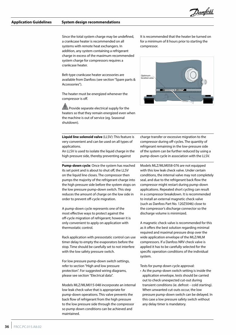
System design recommendations
Since the total system charge may be undefined, a crankcase heater is recommended on all systems with remote heat exchangers. In addition, any system containing a refrigerant charge in excess of the maximum recommended system charge for compressors requires a crankcase heater.
Belt-type crankcase heater accessories are available from Danfoss (see section “Spare parts & Accessories”).
The heater must be energized whenever the compressor is off.
! Provide separate electrical supply for the heaters so that they remain energized even when the machine is out of service (eg. Seasonal shutdown).
It is recommended that the heater be turned on for a minimum of 8 hours prior to starting the compressor.
Optimum location area
Pump-down cycle: Once the system has reached its set point and is about to shut off, the LLSV on the liquid line closes. The compressor then pumps the majority of the refrigerant charge into the high pressure side before the system stops on the low pressure pump-down switch. This step reduces the amount of charge on the low side in order to prevent off-cycle migration.
A pump-down cycle represents one of the most effective ways to protect against the off-cycle migration of refrigerant; however it is only convenient to apply on application with thermostatic control.
Rack application with pressostatic control can use timer delay to empty the evaporators before the stop. Time should be carefully set to not interfere with the low safety pressure switch.
For low pressure pump-down switch settings, refer to section "High and low pressure protection". For suggested wiring diagrams, please see section "Electrical data".
Models MLZ/MLM015-048 incorporate an internal low leak check valve that is appropriate for pump-down operations. This valve prevents the back flow of refrigerant from the high pressure to the low pressure side through the compressor so pump down conditions can be achieved and maintained.
Models MLZ/MLM058-076 are not equipped with this low leak check valve. Under certain conditions, the internal valve may not completely seal, and due to the refrigerant back flow the compressor might restart during pump-down applications. Repeated short cycling can result in a compressor breakdown. It is recommended to install an external magnetic check valve (such as Danfoss Part No. 120Z5046) close to the compressor’s discharge connector so the discharge volume is minimized.
A magnetic check valve is recommended for this as it offers the best solution regarding minimal required and maximal pressure drop over the wide application envelope of the MLZ/MLM compressors. If a Danfoss NRV check valve is applied it has to be carefully selected for the specific operation conditions of the individual system.
Tests for pump down cycle approval:• As the pump-down switch setting is inside the
application envelope, tests should be carried out to check unexpected cut-out during transient conditions (ie. defrost – cold starting). When unwanted cut-outs occur, the low pressure pump-down switch can be delayed. In this case a low pressure safety switch without any delay timer is mandatory.
Liquid line solenoid valve (LLSV): This feature is very convenient and can be used on all types of applications.An LLSV is used to isolate the liquid charge in the high pressure side, thereby preventing against
charge transfer or excessive migration to the compressor during off-cycles. The quantity of refrigerant remaining in the low-pressure side of the system can be further reduced by using a pump-down cycle in association with the LLSV.
36 FRCC.PC.015.A8.02
Application Guidelines
System design recommendations
Suction accumulator: a suction accumulator offers protection against refrigerant flood back at start-up, during operations or defrosting by trapping the liquid refrigerant upstream from the compressor. The suction accumulator also protects against off-cycle migration by providing additional internal free volume to the low side of the system.
A suction accumulator must be carefully dimensioned, taking into account the refrigerant charge as well as the gas velocity in the suction line. Depending on the operating conditions it may happen that the recommended connections of the accumulator are one size smaller than the suction line.
Liquid flood back During normal operation, refrigerant enters the compressor as a superheated vapour. Liquid flood back occurs when a part of the refrigerant entering the compressor is still in liquid state.
A continuous liquid flood back will cause oil dilution and, in extreme situations lead to lack of lubrication and high rate of oil leaving the compressor.
Liquid flood back test - Repetitive liquid flood back testing must be carried out under TXV threshold operating conditions: a high pressure ratio and minimum evaporator load, along with the measurement of suction superheat, oil sump temperature and discharge gas temperature.
During operations, liquid flood back may be detected by measuring either the oil sump temperature or the discharge gas temperature. If at any time during operations, the oil sump temperature drops to within 10K or less above the saturated suction temperature, or should
the discharge gas temperature be less than 35K above the saturated discharge temperature, this indicates liquid flood back.
Continuous liquid flood back can occur with a wrong dimensioning, a wrong setting or malfunction of the expansion device or in case of evaporator fan failure or blocked air filters.
A suction accumulator providing additional protection as explained hereunder can be used to solve light continuous liquid flood back.
• While the thermostat is off, the number of pressure switch resets should be limited to avoid short cycling of the compressor. Use dedicated wiring and an additional relay which allows for one shot pump-down.
The pump-down allows to store all the refrigerant in the high pressure side circuit. On unitary or close-coupled systems, where the system refrigerant charge is expected to be both correct and definable the entire system charge may be stored in the condenser during pump-down if all components have been properly sized.
Other application needs a liquid receiver to store the refrigerant.
Receiver dimensioning requires special attention. The receiver shall be large enough to contain part of the system refrigerant charge but it shall not be dimensioned too large. A large receiver easily leads to refrigerant overcharging during maintenance operation.
37FRCC.PC.015.A8.02
Application Guidelines
Specific application recommendations
Low ambient application
Low ambient operations It is recommended that the unit be tested and monitored at minimum load and low ambient conditions as well. The following considerations should be taken into account to ensure proper system operating characteristics.
The expansion device should be sized to ensure proper control of the refrigerant flow into the evaporator. An oversized valve may result in erratic control. This consideration is especially important in manifolded units where low load conditions may require the frequent cycling of compressors. This can lead to liquid refrigerant entering the compressor if the expansion valve does not provide stable refrigerant super-heat control under varying loads.
The superheat setting of the expansion device should be sufficient to ensure proper superheat levels during low loading periods. A minimum of 5 K stable superheat is required.
Head pressure control under low ambient conditions: Several possible solutions are available to prevent the risk of compressor to vacuum and low pressure differential between the suction and discharge pressures.
In air-cooled machines, cycling the fans with a head pressure controller will ensure that the fans remain off until the condensing pressure has reached a satisfactory level. Variable speed fans can also be used to control the condensing pressure. In water-cooled units, the same can be performed using a water regulator valve that is also operated by head pressure, thereby ensuring that the water valve does not open until the condensing pressure reaches a satisfactory level.The minimum condensing pressure must be set at the minimum saturated condensing temperature shown in the application envelopes.
Under very low ambient conditions, in which testing has revealed that the above procedures might not ensure satisfactory condensing and suction pressures, the use of a head pressure control valve is recommended. Note: This solution requires extra refrigerant charge, which can introduce other problems. A non-return valve in the discharge line is recommended and special care should be taken when designing the discharge line.
For further information, please contact Danfoss.
Low ambient start-up Under cold ambient conditions (<0°C), upon start-up the pressure in the condenser may be so low that a sufficient pressure differential across the expansion device cannot be developed to properly feed the evaporator.
As a result, the compressor may go into a deep vacuum, which can lead to compressor failure due to internal arcing and instability in the scroll wraps. Under no circumstances should the compressor be allowed to operate under vacuum. The low-pressure control must be set in accordance with the table “High and low pressure protection” in order to prevent this from happening.
Early feeding of the evaporator and management of the discharge pressure could help to attenuate these effects.
Low pressure differentials can also cause the expansion device to «hunt» erratically, which might cause surging conditions within the evaporator, with liquid spillover into the compressor. This effect is most pronounced during low load conditions, which frequently occur during low ambient conditions.
Unlike the reciprocating compressor, a scroll doesn’t have dead volume. Neither does it have a suction valve causing pressure drop. As a result a scroll compressor has a high volumetric efficiency even at low suction pressure. In systems such as ice makers and milk cooling tanks this high capacity at low temperature shortens the cooling time.
When moving from a reciprocating compressor to a scroll compressor, the selection shall always be made based on cooling capacity at the application rating point. Never make a selection based on equivalent displacement.
Scroll and reciprocating
38 FRCC.PC.015.A8.02
Application Guidelines
Specific application recommendations
Low load operations The compressor should be run for a minimum period to ensure that the oil has sufficient time to properly return to the compressor sump and
that the motor receives enough cooling under conditions of lowest refrigerant mass flow.
Brazed plate heat exchangers
A brazed plate heat exchanger needs very little internal volume to satisfy the heat transfer requirements. Consequently, the heat exchanger offers very little internal volume for the compressor to draw vapour from the suction side. The compressor can then quickly enter into a vacuum condition. It is therefore important that the expansion device be sized correctly and that a sufficient pressure differential across the expansion device be available to ensure adequate refrigerant feed into the evaporator. This aspect is of special concern when operating the unit under low ambient and load conditions. For further information on these conditions, please refer to the previous sections.
Due to the small volume of the brazed plate heat exchanger, no pump-down cycle is normally required. The suction line running from the heat exchanger to the compressor must be trapped to avoid refrigerant migration to the compressor.
When using a brazed plate condenser heat exchanger, a sufficient free volume for the discharge gas to accumulate is required in order to avoid excess pressure build-up. At least 1 meter of discharge line is necessary to generate this volume. To help reduce the discharge gas volume immediately after start-up, the supply of cooling water to the heat exchanger may be opened before the compressor starts, to remove superheat and condense the incoming discharge gas more quickly.
Water utilising systems Apart from residual moisture in the system after commissioning, water could also enter the refrigeration circuit during operation. Water in the system shall always be avoided. Not only because it can shortly lead to electrical failure, sludge in sump and corrosion but in particular because it can cause serious safety risks.
Common causes for water leaks are corrosion and freezing.
Corrosion: Materials in the system shall be compliant with water and protected against corrosion.
Freezing: When water freezes into ice its volume expands which can damage heat exchanger walls and cause leaks. During off periods water inside heat exchangers could start freezing when ambient temperature is lower than 0°C. During on periods ice banking could occur when the circuit is running continuously at too low load. Both situations should be avoided by connecting a pressure and thermostat switch in the safety line.
39FRCC.PC.015.A8.02
Application Guidelines
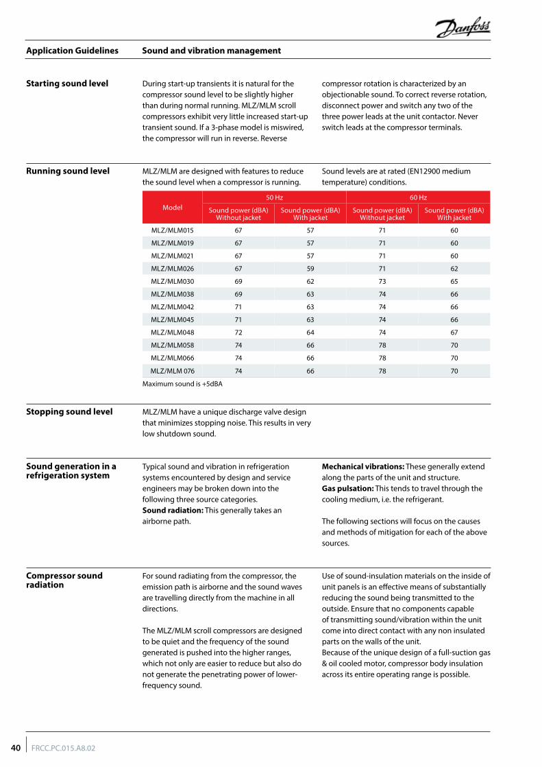
Sound and vibration management
Running sound level
Stopping sound level
Sound generation in a refrigeration system
Compressor sound radiation
MLZ/MLM are designed with features to reduce the sound level when a compressor is running.
Sound levels are at rated (EN12900 medium temperature) conditions.
MLZ/MLM have a unique discharge valve design that minimizes stopping noise. This results in very low shutdown sound.
Typical sound and vibration in refrigeration systems encountered by design and service engineers may be broken down into the following three source categories.Sound radiation: This generally takes an airborne path.
Mechanical vibrations: These generally extend along the parts of the unit and structure.Gas pulsation: This tends to travel through the cooling medium, i.e. the refrigerant.
The following sections will focus on the causes and methods of mitigation for each of the above sources.
For sound radiating from the compressor, the emission path is airborne and the sound waves are travelling directly from the machine in all directions.
The MLZ/MLM scroll compressors are designed to be quiet and the frequency of the sound generated is pushed into the higher ranges, which not only are easier to reduce but also do not generate the penetrating power of lower-frequency sound.
Use of sound-insulation materials on the inside of unit panels is an effective means of substantially reducing the sound being transmitted to the outside. Ensure that no components capable of transmitting sound/vibration within the unit come into direct contact with any non insulated parts on the walls of the unit.Because of the unique design of a full-suction gas & oil cooled motor, compressor body insulation across its entire operating range is possible.
During start-up transients it is natural for the compressor sound level to be slightly higher than during normal running. MLZ/MLM scroll compressors exhibit very little increased start-up transient sound. If a 3-phase model is miswired, the compressor will run in reverse. Reverse
compressor rotation is characterized by an objectionable sound. To correct reverse rotation, disconnect power and switch any two of the three power leads at the unit contactor. Never switch leads at the compressor terminals.
Starting sound level
Model50 Hz 60 Hz
Sound power (dBA)Without jacket
Sound power (dBA)With jacket
Sound power (dBA)Without jacket
Sound power (dBA)With jacket
MLZ/MLM015 67 57 71 60
MLZ/MLM019 67 57 71 60
MLZ/MLM021 67 57 71 60
MLZ/MLM026 67 59 71 62
MLZ/MLM030 69 62 73 65
MLZ/MLM038 69 63 74 66
MLZ/MLM042 71 63 74 66
MLZ/MLM045 71 63 74 66
MLZ/MLM048 72 64 74 67
MLZ/MLM058 74 66 78 70
MLZ/MLM066 74 66 78 70
MLZ/MLM 076 74 66 78 70
Maximum sound is +5dBA
40 FRCC.PC.015.A8.02
Application Guidelines
Sound and vibration management
Mechanical vibrations Vibration isolation constitutes the primary method for controlling structural vibration. MLZ/MLM scroll compressors are designed to produce minimal vibration during operations. The use of rubber isolators on the compressor base plate or on the frame of a manifolded unit is very effective in reducing vibration being transmitted from the compressor(s) to the unit. Rubber grommets are supplied with all MLZ/MLM compressors. Once the supplied rubber grommets have been properly mounted, vibration transmitted from the compressor base plate to the unit are held to a strict minimum.
In addition, it is extremely important that the frame supporting the mounted compressor be of sufficient mass and stiffness to help dampen any residual vibration potentially transmitted to the frame. The tubing should be designed so as to both reduce the transmission of vibrations to other structures and withstand vibration without incurring any damage. Tubing should also be designed for three-dimensional flexibility. For more information on piping design, please see the section entitled "Essential piping design considerations".
Gas pulsation The MLZ/MLM scroll compressors have been designed and tested to ensure that gas pulsation has been minimized for the most commonly encountered refrigeration pressure ratio. On installations where the pressure ratio lies beyond the typical range, testing should be conducted under all expected conditions and operating
configurations to ensure that minimum gas pulsation is present. If an unacceptable level is identified, a discharge muffler with the appropriate resonant volume and mass should be installed. This information can be obtained from the component manufacturer.
41FRCC.PC.015.A8.02
Application Guidelines
Installation
Each MLZ/MLM compressor is shipped with printed Instructions for installation. These Instructions can also be downloaded from our web site
www.danfoss.com or directly from:http://instructions.cc.danfoss.com
Compressor handling and storage
Compressor holding charge
Compressors are provided with a lifting lug. This lug should always be used to lift the compressor. Once the compressor is installed, the lifting lug should never be used to lift the complete installation. The compressor must be handled
with caution in the vertical position, with a maximum inclination of 15° from vertical. Store the compressor between -35°C and 55°C, not exposed to rain or corrosive atmosphere.
Each compressor is shipped with a nominal dry nitrogen holding charge between 0.4 bar and 0.7 bar, and is sealed with elastomer plugs. The plugs should be removed with care to avoid oil loss when the holding charge is released. Remove the suction plug first and the discharge plug
afterwards. The plugs shall be removed only just before connecting the compressor to the installation in order to avoid moisture entering the compressor. When the plugs are removed, it is essential to keep the compressor in an upright position to avoid oil spillage.
System cleanliness The refrigeration system, regardless of the type of compressor used, will only provide high efficiency and good reliability, along with a long operating life, if the system contains solely the refrigerant and oil it was designed for. Any other substances within the system will not improve performance and, in most cases, will be highly detrimental to system operations.
The presence of non-condensable substances and system contaminants, such as metal shavings, solder and flux, have a negative impact on compressor service life. Many of these contaminants are small enough to pass through a
mesh screen and can cause considerable damage within a bearing assembly. The use of highly hygroscopic PVE oil in MLZ compressors requires that the oil be exposed to the atmosphere just as little as possible.
During the manufacturing process, circuit contamination may be caused by:• Brazing and welding oxides,• Filings and particles from the removal of burrs in pipe-work,• Brazing flux,• Moisture and air.
Compressor mounting Maximum inclination from the vertical plane, while operating must not exceed 7 degrees. All compressors are delivered with 4 rubber grommets and metal sleeves. Compressors
must always be mounted with these grommets. Recommended torque for mounting bolts: 11 Nm (±1 Nm).
Brazing material For copper suction and discharge fittings, use copper-phosphorus brazing material. Sil-Fos® and other silver brazing materials are also acceptable.
If flux is required for the brazing operation, use coated rod or flux core wire. To avoid system contamination, do not brush flux on.
Tube brazing procedure Do not bend the compressor discharge or suction lines or force system piping into the compressor connections, because this will increase
stresses that are a potential cause of failure. Recommended brazing procedures and material, are described on following page.
42 FRCC.PC.015.A8.02
Application Guidelines
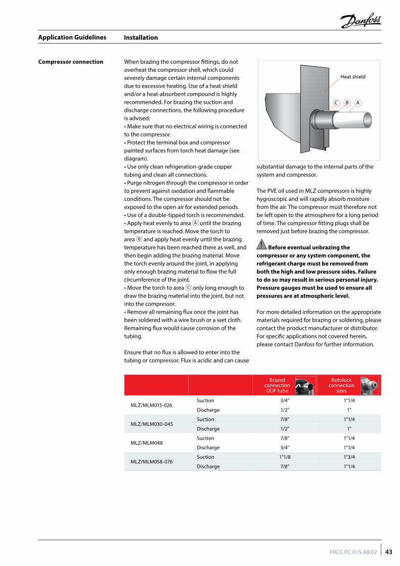
Installation
Compressor connection When brazing the compressor fittings, do not overheat the compressor shell, which could severely damage certain internal components due to excessive heating. Use of a heat shield and/or a heat-absorbent compound is highly recommended. For brazing the suction and discharge connections, the following procedure is advised:• Make sure that no electrical wiring is connected to the compressor.• Protect the terminal box and compressor painted surfaces from torch heat damage (see diagram).• Use only clean refrigeration-grade copper tubing and clean all connections.• Purge nitrogen through the compressor in order to prevent against oxidation and flammable conditions. The compressor should not be exposed to the open air for extended periods.• Use of a double-tipped torch is recommended.• Apply heat evenly to area A until the brazing temperature is reached. Move the torch to area B and apply heat evenly until the brazing temperature has been reached there as well, and then begin adding the brazing material. Move the torch evenly around the joint, in applying only enough brazing material to flow the full circumference of the joint.• Move the torch to area C only long enough to draw the brazing material into the joint, but not into the compressor.• Remove all remaining flux once the joint has been soldered with a wire brush or a wet cloth. Remaining flux would cause corrosion of the tubing.
Ensure that no flux is allowed to enter into the tubing or compressor. Flux is acidic and can cause
substantial damage to the internal parts of the system and compressor.
The PVE oil used in MLZ compressors is highly hygroscopic and will rapidly absorb moisture from the air. The compressor must therefore not be left open to the atmosphere for a long period of time. The compressor fitting plugs shall be removed just before brazing the compressor.
! Before eventual unbrazing the compressor or any system component, the refrigerant charge must be removed from both the high and low pressure sides. Failure to do so may result in serious personal injury. Pressure gauges must be used to ensure all pressures are at atmospheric level.
For more detailed information on the appropriate materials required for brazing or soldering, please contact the product manufacturer or distributor. For specific applications not covered herein, please contact Danfoss for further information.
Heat shield
C B A
Brazed connectionODF tube
Rotolock connection
sizes
MLZ/MLM015-026Suction 3/4" 1"1/4
Discharge 1/2" 1"
MLZ/MLM030-045Suction 7/8" 1"1/4
Discharge 1/2" 1"
MLZ/MLM048Suction 7/8" 1"1/4
Discharge 3/4" 1"1/4
MLZ/MLM058-076Suction 1"1/8 1"3/4
Discharge 7/8" 1"1/4
43FRCC.PC.015.A8.02
Application Guidelines
Installation
Moisture obstructs the proper functioning of the compressor and the refrigeration system.
Air and moisture reduce service life and increase condensing pressure, and cause excessively high discharge temperatures, which can destroy the lubricating properties of the oil. Air and moisture also increase the risk of acid formation, giving rise to copper platting. All these phenomena can cause mechanical and electrical compressor failure.
For these reasons it’s important to perform a vacuum dehydration on the system to remove all residual moisture from the pipe-work after assembly;
MLZ and MLM compressors are delivered with < 100 ppm moisture level. The required moisture level in the circuit after vacuum dehydration must be < 100 ppm for systems with an MLZ and < 300 ppm for systems with an MLM compressor.
• Never use the compressor to evacuate the system.
• Connect a vacuum pump to both the LP & HP sides.
• Evacuate the system to a pressure of 500 μm Hg (0.67 mbar) absolute.
• Do not use a megohm meter nor apply power to the compressor while it’s under vacuum as this may cause internal damage.
Vacuum evacuation and moisture removal
Refrigerant charging It is recommended that system charging be done using the weighed charge method, adding refrigerant to the high side of the system. Charging the high and low sides of a system with gas simultaneously at a controlled rate is also an acceptable method. Do not exceed the recommended unit charge, and never charge liquid to the low side.
Vacuum or charge from one side can seal the scrolls and result in a non-starting compressor. When servicing, always ensure that LP/HP pressures are balanced before starting the compressor.
Be sure to follow all government regulations regarding refrigerant reclamation and storage.
Liquid line filter driers A properly sized & type of drier is required. Important selection criteria include the driers water content capacity, the system refrigeration capacity, and the system refrigerant charge. The drier must be able to reach and maintain a moisture level of 50 ppm end point dryness (EPD). Danfoss recommends DCL (solid core) driers for the MLM compressor (R22 with Alkylbenzene) and DML (100% molecular sieve) driers for MLZ compressors (R407A,R407F,R404A, R507, R134a, R22) with PVE oil.
For servicing of existing installations where acid formation may be present, the Danfoss DCL solid core filter drier containing activated alumina is recommended.
After burn out, remove & replace the liquid line filter drier and install a Danfoss type DAS burnout drier of the appropriate capacity. Refer to the DAS drier instructions and technical information for correct use of the burnout drier on the liquid line.
Insulation resistance and dielectric strength
Insulation resistance must be higher than 1 megohm when measured with a 500 volt direct current megohm tester.
Each compressor motor is tested at the factory with a high potential voltage (hi-pot) that exceeds the UL requirement both in potential and in duration. Leakage current is less than 0.5 mA.
MLZ/MLM scroll compressors are configured with the pump assembly at the top of the shell, and the motor below. As a result, the motor can be partially immersed in refrigerant and oil. The presence of refrigerant around the motor windings will result in lower resistance
values to ground and higher leakage current readings. Such readings do not indicate a faulty compressor, and should not be cause for concern.
In testing insulation resistance, Danfoss recommends that the system be first operated briefly to distribute refrigerant throughout the system. Following this brief operation, retest the compressor for insulation resistance or current leakage.
Never reset a breaker or replace a fuse without first checking for a ground fault (a short circuit to ground). Be alert for sounds of arcing inside the compressor.
44 FRCC.PC.015.A8.02
Application Guidelines
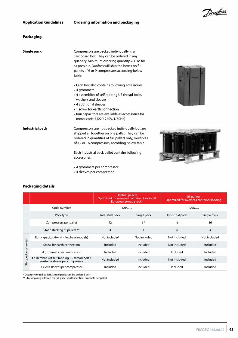
Ordering information and packaging
Industrial pack
Compressors are packed individually in a cardboard box. They can be ordered in any quantity. Minimum ordering quantity = 1. As far as possible, Danfoss will ship the boxes on full pallets of 6 or 9 compressors according below table.
• Each box also contains following accessories:• 4 grommets• 4 assemblies of self tapping US thread bolts,
washers and sleeves• 4 additional sleeves• 1 screw for earth connection• Run capacitors are available as accessories for
motor code 5 (220-240V/1/50Hz)
Compressors are not packed individually but are shipped all together on one pallet. They can be ordered in quantities of full pallets only, multiples of 12 or 16 compressors, according below table.
Each industrial pack pallet contains following accessories:
• 4 grommets per compressor• 4 sleeves per compressor
Packaging
Single pack
Packaging details
Danfoss palletsOptimized for overseas container loading &
European storage racksUS pallets
Optimized for overseas container loading
Code number 121U…. 120U….
Pack type Industrial pack Single pack Industrial pack Single pack
Compressors per pallet 12 6 * 16 16
Static stacking of pallets ** 4 4 4 4
Ship
ped
acce
ssor
ies Run capacitor (for single phase models) Not included Not included Not included Not included
Screw for earth connection Included Included Not included Included
4 grommets per compressor Included Included Included Included
4 assemblies of self tapping US thread bolt + washer + sleeve per compressor Not included Included Not included Included
4 extra sleeves per compressor Included Included Included Included
* Quantity for full pallets. Single packs can be ordered per 1.** Stacking only allowed for full pallets with identical products per pallet
45FRCC.PC.015.A8.02
Application Guidelines
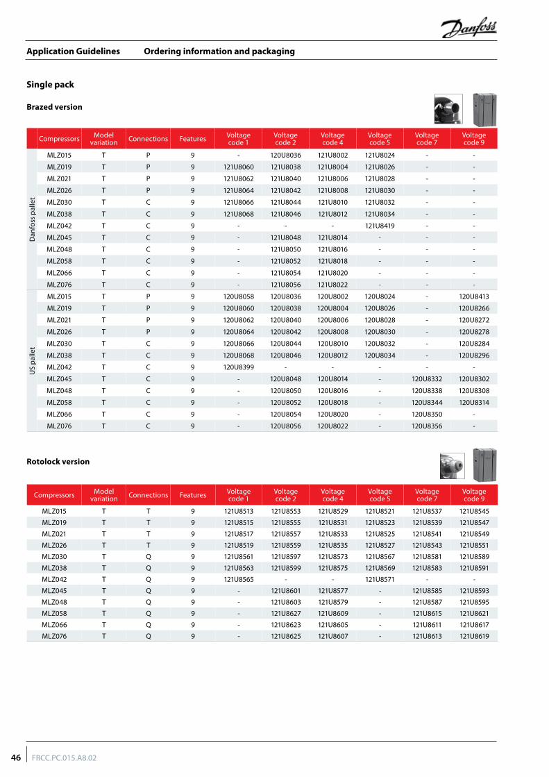
Ordering information and packaging
Single pack
Compressors Model variation Connections Features Voltage
code 1Voltage code 2
Voltage code 4
Voltage code 5
Voltage code 7
Voltage code 9
Dan
foss
pal
let
MLZ015 T P 9 - 120U8036 121U8002 121U8024 - -
MLZ019 T P 9 121U8060 121U8038 121U8004 121U8026 - -
MLZ021 T P 9 121U8062 121U8040 121U8006 121U8028 - -
MLZ026 T P 9 121U8064 121U8042 121U8008 121U8030 - -
MLZ030 T C 9 121U8066 121U8044 121U8010 121U8032 - -
MLZ038 T C 9 121U8068 121U8046 121U8012 121U8034 - -
MLZ042 T C 9 - - - 121U8419 - -
MLZ045 T C 9 - 121U8048 121U8014 - - -
MLZ048 T C 9 - 121U8050 121U8016 - - -
MLZ058 T C 9 - 121U8052 121U8018 - - -
MLZ066 T C 9 - 121U8054 121U8020 - - -
MLZ076 T C 9 - 121U8056 121U8022 - - -
US
palle
t
MLZ015 T P 9 120U8058 120U8036 120U8002 120U8024 - 120U8413
MLZ019 T P 9 120U8060 120U8038 120U8004 120U8026 - 120U8266
MLZ021 T P 9 120U8062 120U8040 120U8006 120U8028 - 120U8272
MLZ026 T P 9 120U8064 120U8042 120U8008 120U8030 - 120U8278
MLZ030 T C 9 120U8066 120U8044 120U8010 120U8032 - 120U8284
MLZ038 T C 9 120U8068 120U8046 120U8012 120U8034 - 120U8296
MLZ042 T C 9 120U8399 - - - - -
MLZ045 T C 9 - 120U8048 120U8014 - 120U8332 120U8302
MLZ048 T C 9 - 120U8050 120U8016 - 120U8338 120U8308
MLZ058 T C 9 - 120U8052 120U8018 - 120U8344 120U8314
MLZ066 T C 9 - 120U8054 120U8020 - 120U8350 -
MLZ076 T C 9 - 120U8056 120U8022 - 120U8356 -
Brazed version
Rotolock version
Compressors Model variation Connections Features Voltage
code 1Voltage code 2
Voltage code 4
Voltage code 5
Voltage code 7
Voltage code 9
MLZ015 T T 9 121U8513 121U8553 121U8529 121U8521 121U8537 121U8545
MLZ019 T T 9 121U8515 121U8555 121U8531 121U8523 121U8539 121U8547
MLZ021 T T 9 121U8517 121U8557 121U8533 121U8525 121U8541 121U8549
MLZ026 T T 9 121U8519 121U8559 121U8535 121U8527 121U8543 121U8551
MLZ030 T Q 9 121U8561 121U8597 121U8573 121U8567 121U8581 121U8589
MLZ038 T Q 9 121U8563 121U8599 121U8575 121U8569 121U8583 121U8591
MLZ042 T Q 9 121U8565 - - 121U8571 - -
MLZ045 T Q 9 - 121U8601 121U8577 - 121U8585 121U8593
MLZ048 T Q 9 - 121U8603 121U8579 - 121U8587 121U8595
MLZ058 T Q 9 - 121U8627 121U8609 - 121U8615 121U8621
MLZ066 T Q 9 - 121U8623 121U8605 - 121U8611 121U8617
MLZ076 T Q 9 - 121U8625 121U8607 - 121U8613 121U8619
46 FRCC.PC.015.A8.02
Application Guidelines
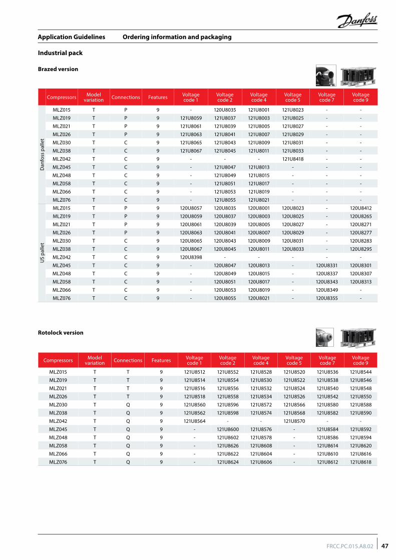
Ordering information and packaging
Industrial pack
Compressors Model variation Connections Features Voltage
code 1Voltage code 2
Voltage code 4
Voltage code 5
Voltage code 7
Voltage code 9
Dan
foss
pal
let
MLZ015 T P 9 - 120U8035 121U8001 121U8023 - -
MLZ019 T P 9 121U8059 121U8037 121U8003 121U8025 - -
MLZ021 T P 9 121U8061 121U8039 121U8005 121U8027 - -
MLZ026 T P 9 121U8063 121U8041 121U8007 121U8029 - -
MLZ030 T C 9 121U8065 121U8043 121U8009 121U8031 - -
MLZ038 T C 9 121U8067 121U8045 121U8011 121U8033 - -
MLZ042 T C 9 - - - 121U8418 - -
MLZ045 T C 9 - 121U8047 121U8013 - - -
MLZ048 T C 9 - 121U8049 121U8015 - - -
MLZ058 T C 9 - 121U8051 121U8017 - - -
MLZ066 T C 9 - 121U8053 121U8019 - - -
MLZ076 T C 9 - 121U8055 121U8021 - - -
US
palle
t
MLZ015 T P 9 120U8057 120U8035 120U8001 120U8023 - 120U8412
MLZ019 T P 9 120U8059 120U8037 120U8003 120U8025 - 120U8265
MLZ021 T P 9 120U8061 120U8039 120U8005 120U8027 - 120U8271
MLZ026 T P 9 120U8063 120U8041 120U8007 120U8029 - 120U8277
MLZ030 T C 9 120U8065 120U8043 120U8009 120U8031 - 120U8283
MLZ038 T C 9 120U8067 120U8045 120U8011 120U8033 - 120U8295
MLZ042 T C 9 120U8398 - - - - -
MLZ045 T C 9 - 120U8047 120U8013 - 120U8331 120U8301
MLZ048 T C 9 - 120U8049 120U8015 - 120U8337 120U8307
MLZ058 T C 9 - 120U8051 120U8017 - 120U8343 120U8313
MLZ066 T C 9 - 120U8053 120U8019 - 120U8349 -
MLZ076 T C 9 - 120U8055 120U8021 - 120U8355 -
Brazed version
Rotolock version
Compressors Model variation Connections Features Voltage
code 1Voltage code 2
Voltage code 4
Voltage code 5
Voltage code 7
Voltage code 9
MLZ015 T T 9 121U8512 121U8552 121U8528 121U8520 121U8536 121U8544
MLZ019 T T 9 121U8514 121U8554 121U8530 121U8522 121U8538 121U8546
MLZ021 T T 9 121U8516 121U8556 121U8532 121U8524 121U8540 121U8548
MLZ026 T T 9 121U8518 121U8558 121U8534 121U8526 121U8542 121U8550
MLZ030 T Q 9 121U8560 121U8596 121U8572 121U8566 121U8580 121U8588
MLZ038 T Q 9 121U8562 121U8598 121U8574 121U8568 121U8582 121U8590
MLZ042 T Q 9 121U8564 - - 121U8570 - -
MLZ045 T Q 9 - 121U8600 121U8576 - 121U8584 121U8592
MLZ048 T Q 9 - 121U8602 121U8578 - 121U8586 121U8594
MLZ058 T Q 9 - 121U8626 121U8608 - 121U8614 121U8620
MLZ066 T Q 9 - 121U8622 121U8604 - 121U8610 121U8616
MLZ076 T Q 9 - 121U8624 121U8606 - 121U8612 121U8618
47FRCC.PC.015.A8.02
Application Guidelines
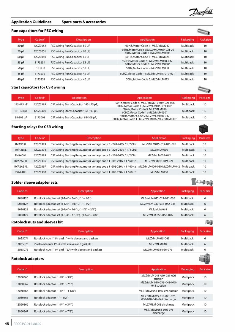
Spare parts & accessories
Run capacitors for PSC wiring
Start capacitors for CSR wiring
Solder sleeve adapter sets
Rotolock nuts and sleeves kit
Rotolock adapters
Code n° Description Application Packaging Pack size
120Z0126 Rotolock adaptor set (1-1/4" ~ 3/4") , (1" ~ 1/2") MLZ/MLM 015-019-021-026 Multipack 6
120Z0127 Rotolock adaptor set (1-1/4" ~ 7/8") , (1" ~ 1/2") MLZ/MLM 030-038-042-045 Multipack 6
120Z0128 Rotolock adaptor set (1-1/4" ~ 7/8") , (1-1/4" ~ 3/4") MLZ/MLM 048 Multipack 6
120Z0129 Rotolock adaptor set (1-3/4" ~ 1-1/8") , (1-1/4" ~ 7/8") MLZ/MLM 058-066-076 Multipack 6
Code n° Description Application Packaging Pack size
120Z5074 Rotolock nuts 1"1/4 and 1" with sleeves and gaskets MLZ/MLM015-045 Multipack 6
120Z5076 2 rotolock nuts 1"1/4 with sleeves and gaskets MLZ/MLM048 Multipack 6
120Z5075 Rotolock nuts 1"1/4 and 1"3/4 with sleeves and gaskets MLZ/MLM058-066-076 Multipack 6
Code n° Description Application Packaging Pack size
120Z0366 Rotolock adaptor (1-1/4" ~ 3/4") MLZ/MLM 015-019-021-026 suction Multipack 10
120Z0367 Rotolock adaptor (1-1/4" ~ 7/8") MLZ/MLM 030-038-042-045-048 suction Multipack 10
120Z0364 Rotolock adaptor (1-3/4" ~ 1-1/8") MLZ/MLM 058-066-076 suction Multipack 10
120Z0365 Rotolock adaptor (1" ~ 1/2") MLZ/MLM 015-019-021-026-030-038-042-045 discharge Multipack 10
120Z0366 Rotolock adaptor (1-1/4" ~ 3/4") MLZ/MLM 048 discharge Multipack 10
120Z0367 Rotolock adaptor (1-1/4" ~ 7/8") MLZ/MLM 058-066-076 discharge Multipack 10
Type Code n° Description Application Packaging Pack size
80 μF 120Z0052 PSC wiring Run Capacitor 80 μF, 60HZ,Motor Code 1 : MLZ/MLM042 Multipack 10
70 μF 120Z0051 PSC wiring Run Capacitor 70 μF, "50Hz,Motor Code 5: MLZ/MLM019-021-26 60HZ,Motor Code 1 : MLZ/MLM030" Multipack 10
60 μF 120Z0050 PSC wiring Run Capacitor 60 μF, 60HZ,Motor Code 1 : MLZ/MLM026 Multipack 10
55 μF 8173234 PSC wiring Run Capacitor 55 μF, "50Hz,Motor Code 5: MLZ/MLM038-042 60HZ,Motor Code 1: MLZ/MLM038" Multipack 10
50 μF 8173233 PSC wiring Run Capacitor 50 μF, 50Hz,Motor Code 5: MLZ/MLM030 Multipack 10
45 μF 8173232 PSC wiring Run Capacitor 45 μF, 60HZ,Motor Code 1 : MLZ/MLM015-019-021 Multipack 10
40 μF 8173231 PSC wiring Run Capacitor 40 μF, 50Hz,Motor Code 5: MLZ/MLM015 Multipack 10
Type Code n° Description Application Packaging Pack size
RVA9CKL 120Z0393 CSR wiring Starting Relay, motor voltage code 5 - 220-240V / 1 / 50Hz MLZ/MLM015-019-021-026 Multipack 10
RVA3EKL 120Z0394 CSR wiring Starting Relay, motor voltage code 5 - 220-240V / 1 / 50Hz MLZ/MLM030 Multipack 10
RVA4GKL 120Z0395 CSR wiring Starting Relay, motor voltage code 5 - 220-240V / 1 / 50Hz MLZ/MLM038-042 Multipack 10
RVA2ACKL 120Z0396 CSR wiring Starting Relay, motor voltage code 1 -208-230V / 1 / 60Hz MLZ/MLM015-019-021 Multipack 10
RVA2ABKL 120Z0397 CSR wiring Starting Relay, motor voltage code 1 -208-230V / 1 / 60Hz MLZ/MLM026-030,MLZ/MLM042 Multipack 10
RVAA4IKL 120Z0398 CSR wiring Starting Relay, motor voltage code 1 -208-230V / 1 / 60Hz MLZ/MLM038 Multipack 10
Type Code n° Description Application Packaging Pack size
145-175 μF 120Z0399 CSR wiring Start Capacitor 145-175 μF, "50Hz,Motor Code 5: MLZ/MLM015-019-021-026 60HZ,Motor Code 1 : MLZ/MLM015-019-021" Multipack 10
161-193 μF 120Z0400 CSR wiring Start Capacitor 161-193 μF, "50Hz,Motor Code 5: MLZ/MLM030 60HZ,Motor Code 1 : MLZ/MLM030" Multipack 10
88-108 μF 8173001 CSR wiring Start Capacitor 88-108 μF, "50Hz,Motor Code 5: MLZ/MLM038-042 60HZ,Motor Code 1 : MLZ/MLM026 ,MLZ/MLM038" Multipack 10
Starting relays for CSR wiring
48 FRCC.PC.015.A8.02
Application Guidelines
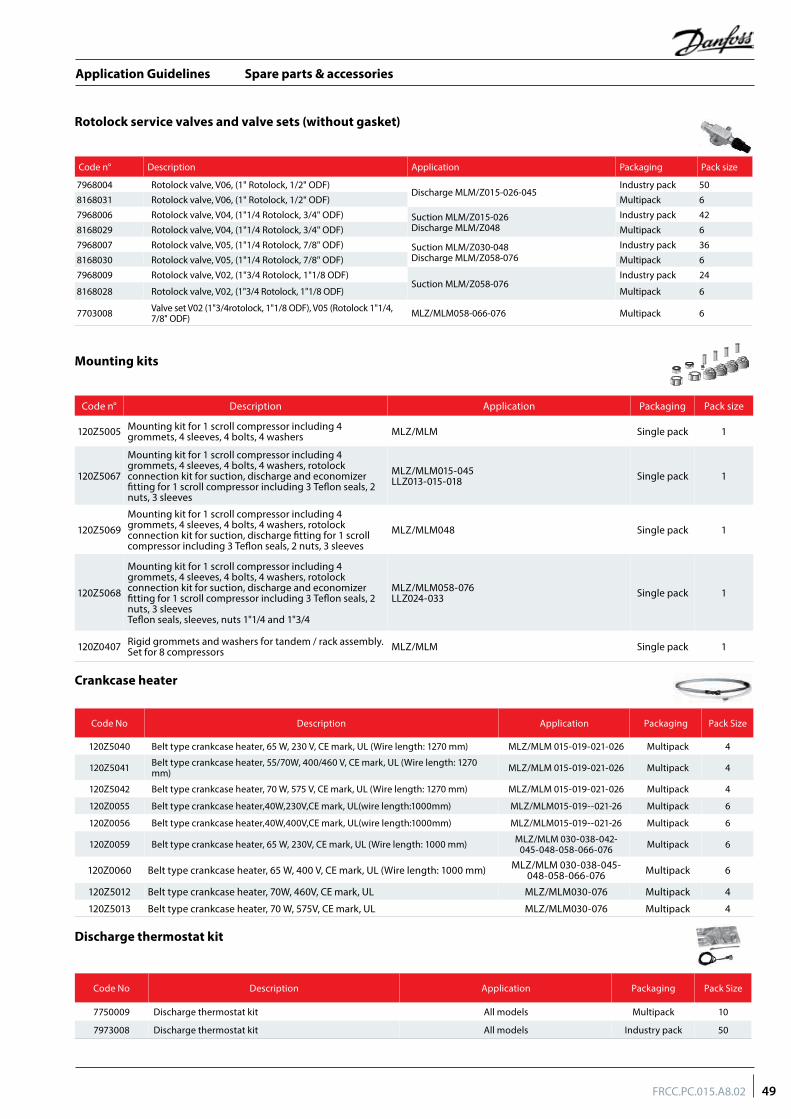
Spare parts & accessories
Mounting kits
Discharge thermostat kit
Crankcase heater
Rotolock service valves and valve sets (without gasket)
Code No Description Application Packaging Pack Size
7750009 Discharge thermostat kit All models Multipack 10
7973008 Discharge thermostat kit All models Industry pack 50
Code No Description Application Packaging Pack Size
120Z5040 Belt type crankcase heater, 65 W, 230 V, CE mark, UL (Wire length: 1270 mm) MLZ/MLM 015-019-021-026 Multipack 4
120Z5041 Belt type crankcase heater, 55/70W, 400/460 V, CE mark, UL (Wire length: 1270 mm) MLZ/MLM 015-019-021-026 Multipack 4
120Z5042 Belt type crankcase heater, 70 W, 575 V, CE mark, UL (Wire length: 1270 mm) MLZ/MLM 015-019-021-026 Multipack 4
120Z0055 Belt type crankcase heater,40W,230V,CE mark, UL(wire length:1000mm) MLZ/MLM015-019--021-26 Multipack 6
120Z0056 Belt type crankcase heater,40W,400V,CE mark, UL(wire length:1000mm) MLZ/MLM015-019--021-26 Multipack 6
120Z0059 Belt type crankcase heater, 65 W, 230V, CE mark, UL (Wire length: 1000 mm) MLZ/MLM 030-038-042-045-048-058-066-076 Multipack 6
120Z0060 Belt type crankcase heater, 65 W, 400 V, CE mark, UL (Wire length: 1000 mm) MLZ/MLM 030-038-045-048-058-066-076 Multipack 6
120Z5012 Belt type crankcase heater, 70W, 460V, CE mark, UL MLZ/MLM030-076 Multipack 4
120Z5013 Belt type crankcase heater, 70 W, 575V, CE mark, UL MLZ/MLM030-076 Multipack 4
Code n° Description Application Packaging Pack size
7968004 Rotolock valve, V06, (1" Rotolock, 1/2" ODF)Discharge MLM/Z015-026-045
Industry pack 50
8168031 Rotolock valve, V06, (1" Rotolock, 1/2" ODF) Multipack 6
7968006 Rotolock valve, V04, (1"1/4 Rotolock, 3/4" ODF) Suction MLM/Z015-026Discharge MLM/Z048
Industry pack 42
8168029 Rotolock valve, V04, (1"1/4 Rotolock, 3/4" ODF) Multipack 6
7968007 Rotolock valve, V05, (1"1/4 Rotolock, 7/8" ODF) Suction MLM/Z030-048Discharge MLM/Z058-076
Industry pack 36
8168030 Rotolock valve, V05, (1"1/4 Rotolock, 7/8" ODF) Multipack 6
7968009 Rotolock valve, V02, (1"3/4 Rotolock, 1"1/8 ODF)Suction MLM/Z058-076
Industry pack 24
8168028 Rotolock valve, V02, (1"3/4 Rotolock, 1"1/8 ODF) Multipack 6
7703008 Valve set V02 (1"3/4rotolock, 1"1/8 ODF), V05 (Rotolock 1"1/4, 7/8" ODF) MLZ/MLM058-066-076 Multipack 6
Code n° Description Application Packaging Pack size
120Z5005 Mounting kit for 1 scroll compressor including 4 grommets, 4 sleeves, 4 bolts, 4 washers MLZ/MLM Single pack 1
120Z5067
Mounting kit for 1 scroll compressor including 4 grommets, 4 sleeves, 4 bolts, 4 washers, rotolock connection kit for suction, discharge and economizer fitting for 1 scroll compressor including 3 Teflon seals, 2 nuts, 3 sleeves
MLZ/MLM015-045LLZ013-015-018 Single pack 1
120Z5069Mounting kit for 1 scroll compressor including 4 grommets, 4 sleeves, 4 bolts, 4 washers, rotolock connection kit for suction, discharge fitting for 1 scroll compressor including 3 Teflon seals, 2 nuts, 3 sleeves
MLZ/MLM048 Single pack 1
120Z5068
Mounting kit for 1 scroll compressor including 4 grommets, 4 sleeves, 4 bolts, 4 washers, rotolock connection kit for suction, discharge and economizer fitting for 1 scroll compressor including 3 Teflon seals, 2 nuts, 3 sleevesTeflon seals, sleeves, nuts 1"1/4 and 1"3/4
MLZ/MLM058-076LLZ024-033 Single pack 1
120Z0407 Rigid grommets and washers for tandem / rack assembly. Set for 8 compressors MLZ/MLM Single pack 1
49FRCC.PC.015.A8.02
Application Guidelines
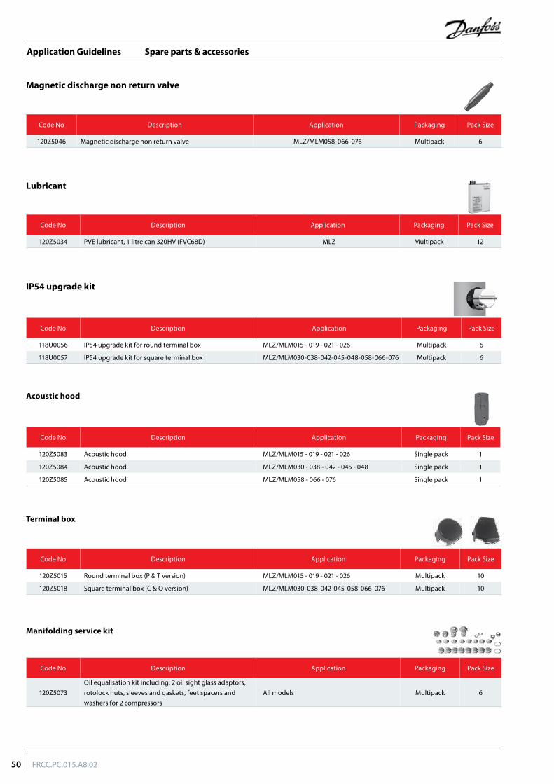
Spare parts & accessories
Magnetic discharge non return valve
Lubricant
IP54 upgrade kit
Code No Description Application Packaging Pack Size
120Z5046 Magnetic discharge non return valve MLZ/MLM058-066-076 Multipack 6
Code No Description Application Packaging Pack Size
120Z5034 PVE lubricant, 1 litre can 320HV (FVC68D) MLZ Multipack 12
Code No Description Application Packaging Pack Size
118U0056 IP54 upgrade kit for round terminal box MLZ/MLM015 - 019 - 021 - 026 Multipack 6
118U0057 IP54 upgrade kit for square terminal box MLZ/MLM030-038-042-045-048-058-066-076 Multipack 6
Acoustic hood
Terminal box
Manifolding service kit
Code No Description Application Packaging Pack Size
120Z5083 Acoustic hood MLZ/MLM015 - 019 - 021 - 026 Single pack 1
120Z5084 Acoustic hood MLZ/MLM030 - 038 - 042 - 045 - 048 Single pack 1
120Z5085 Acoustic hood MLZ/MLM058 - 066 - 076 Single pack 1
Code No Description Application Packaging Pack Size
120Z5015 Round terminal box (P & T version) MLZ/MLM015 - 019 - 021 - 026 Multipack 10
120Z5018 Square terminal box (C & Q version) MLZ/MLM030-038-042-045-058-066-076 Multipack 10
Code No Description Application Packaging Pack Size
120Z5073Oil equalisation kit including: 2 oil sight glass adaptors, rotolock nuts, sleeves and gaskets, feet spacers and washers for 2 compressors
All models Multipack 6
50 FRCC.PC.015.A8.02
Application Guidelines

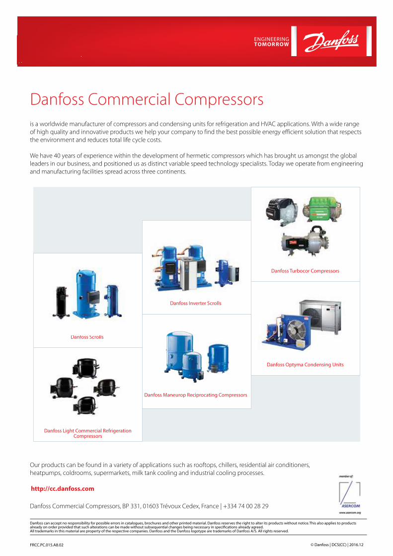
Danfoss Commercial Compressors is a worldwide manufacturer of compressors and condensing units for refrigeration and HVAC applications. With a wide range of high quality and innovative products we help your company to find the best possible energy efficient solution that respects the environment and reduces total life cycle costs.
We have 40 years of experience within the development of hermetic compressors which has brought us amongst the global leaders in our business, and positioned us as distinct variable speed technology specialists. Today we operate from engineering and manufacturing facilities spread across three continents.
FRCC.PC.015.A8.02 © Danfoss | DCS(CC) | 2016.12
Our products can be found in a variety of applications such as rooftops, chillers, residential air conditioners, heatpumps, coldrooms, supermarkets, milk tank cooling and industrial cooling processes.
http://cc.danfoss.com
Danfoss Inverter Scrolls
Danfoss Turbocor Compressors
Danfoss Scrolls
Danfoss Optyma Condensing Units
Danfoss Maneurop Reciprocating Compressors
Danfoss Commercial Compressors, BP 331, 01603 Trévoux Cedex, France | +334 74 00 28 29
Danfoss Light Commercial RefrigerationCompressors
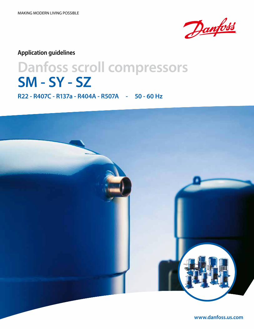
www.danfoss.us.com
Application guidelines
Danfoss scroll compressorsSM - SY - SZR22 - R407C - R137a - R404A - R507A - 50 - 60 Hz
MAKING MODERN LIVING POSSIBLE

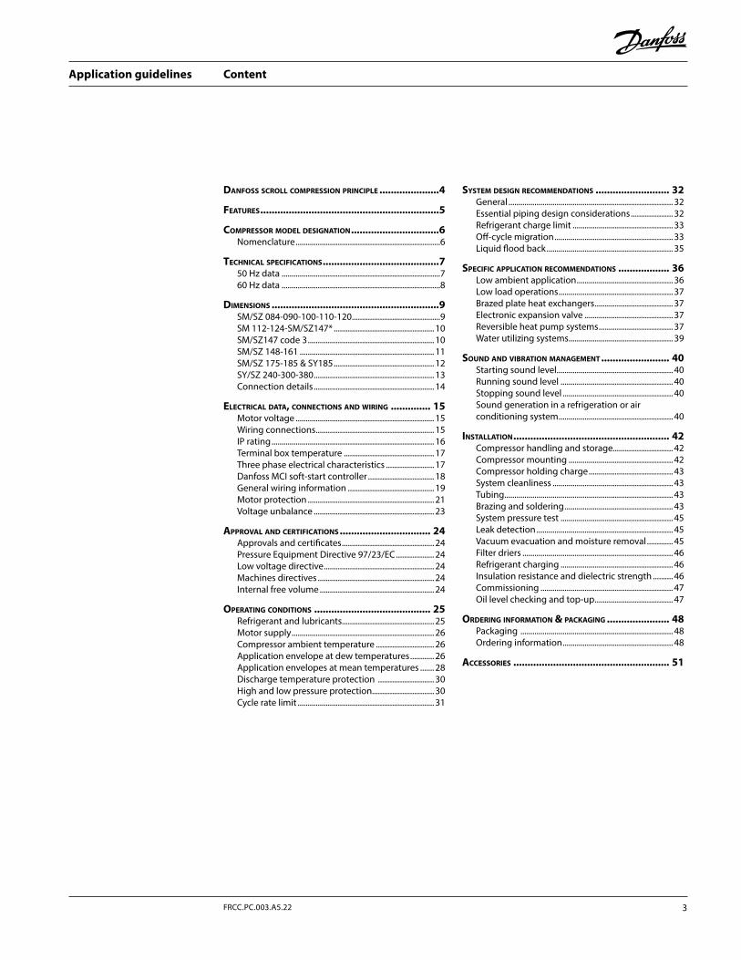
Content
Danfoss scroll compression principle .....................4
features ...............................................................5
compressor moDel Designation ...............................6Nomenclature ........................................................................6
technical specifications .........................................750 Hz data ...............................................................................760 Hz data ...............................................................................8
Dimensions ...........................................................9SM/SZ 084-090-100-110-120 ............................................9SM 112-124-SM/SZ147* .................................................. 10SM/SZ147 code 3 ............................................................... 10SM/SZ 148-161 ................................................................... 11SM/SZ 175-185 & SY185 .................................................. 12SY/SZ 240-300-380 ............................................................ 13Connection details ............................................................ 14
electrical Data, connections anD wiring .............. 15Motor voltage ..................................................................... 15Wiring connections ........................................................... 15IP rating ................................................................................. 16Terminal box temperature ............................................. 17Three phase electrical characteristics ........................ 17Danfoss MCI soft-start controller ................................. 18General wiring information ........................................... 19Motor protection ............................................................... 21Voltage unbalance ............................................................ 23
approval anD certifications ................................ 24Approvals and certificates .............................................. 24Pressure Equipment Directive 97/23/EC ................... 24Low voltage directive ....................................................... 24Machines directives .......................................................... 24Internal free volume ......................................................... 24
operating conDitions ......................................... 25Refrigerant and lubricants.............................................. 25Motor supply ....................................................................... 26Compressor ambient temperature ............................. 26Application envelope at dew temperatures ............ 26Application envelopes at mean temperatures ....... 28Discharge temperature protection ............................ 30High and low pressure protection............................... 30Cycle rate limit .................................................................... 31
system Design recommenDations .......................... 32General .................................................................................. 32Essential piping design considerations ..................... 32Refrigerant charge limit .................................................. 33Off-cycle migration ........................................................... 33Liquid flood back ............................................................... 35
specific application recommenDations .................. 36Low ambient application ................................................ 36Low load operations ......................................................... 37Brazed plate heat exchangers ....................................... 37Electronic expansion valve ............................................ 37Reversible heat pump systems ..................................... 37Water utilizing systems .................................................... 39
sounD anD vibration management ........................ 40Starting sound level.......................................................... 40Running sound level ........................................................ 40Stopping sound level ....................................................... 40Sound generation in a refrigeration or air conditioning system ......................................................... 40
installation ....................................................... 42Compressor handling and storage.............................. 42Compressor mounting .................................................... 42Compressor holding charge .......................................... 43System cleanliness ............................................................ 43Tubing .................................................................................... 43Brazing and soldering ...................................................... 43System pressure test ........................................................ 45Leak detection .................................................................... 45Vacuum evacuation and moisture removal ............. 45Filter driers ........................................................................... 46Refrigerant charging ........................................................ 46Insulation resistance and dielectric strength .......... 46Commissioning .................................................................. 47Oil level checking and top-up ....................................... 47
orDering information & packaging ...................... 48Packaging ............................................................................ 48Ordering information ....................................................... 48
accessories ....................................................... 51
3FRCC.PC.003.A5.22
Application guidelines
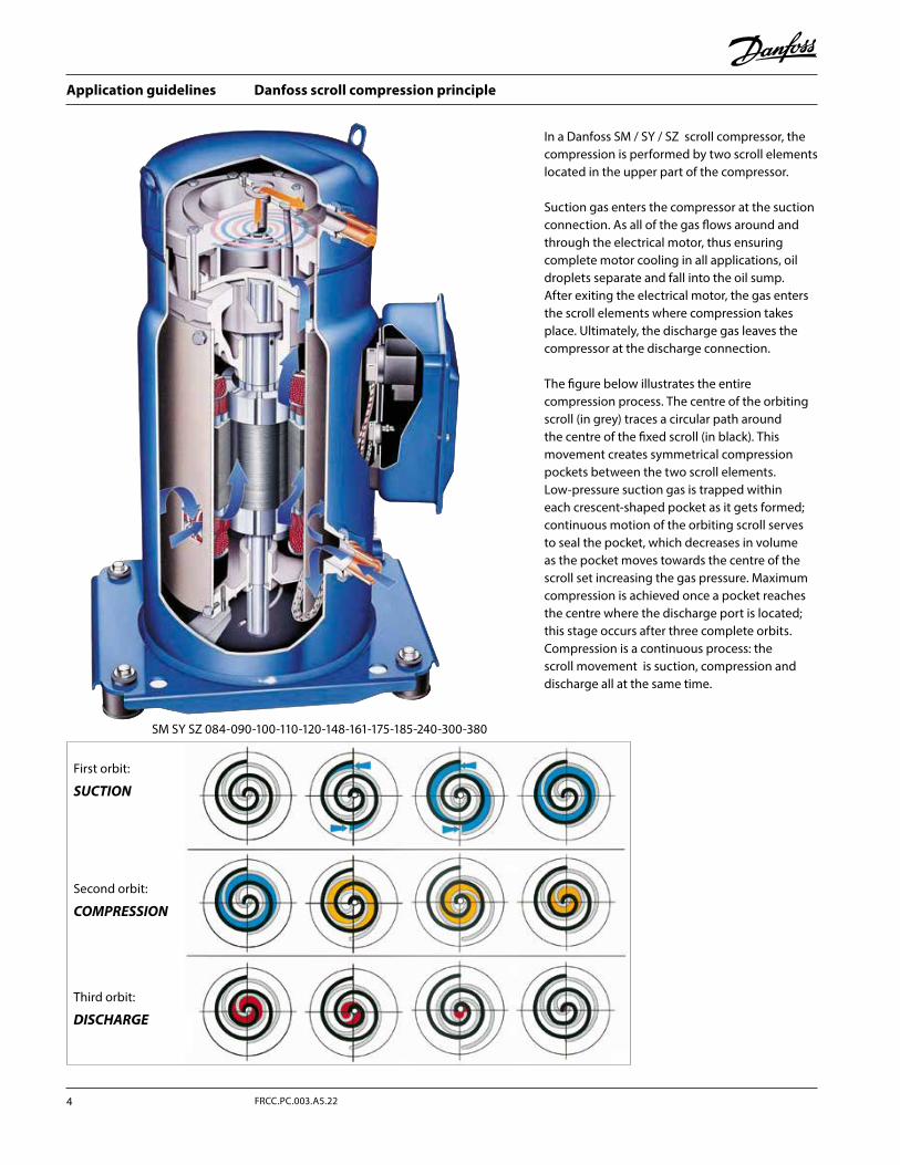
Danfoss scroll compression principle
In a Danfoss SM / SY / SZ scroll compressor, the compression is performed by two scroll elements located in the upper part of the compressor.
Suction gas enters the compressor at the suction connection. As all of the gas flows around and through the electrical motor, thus ensuring complete motor cooling in all applications, oil droplets separate and fall into the oil sump. After exiting the electrical motor, the gas enters the scroll elements where compression takes place. Ultimately, the discharge gas leaves the compressor at the discharge connection.
The figure below illustrates the entire compression process. The centre of the orbiting scroll (in grey) traces a circular path around the centre of the fixed scroll (in black). This movement creates symmetrical compression pockets between the two scroll elements. Low-pressure suction gas is trapped within each crescent-shaped pocket as it gets formed; continuous motion of the orbiting scroll serves to seal the pocket, which decreases in volume as the pocket moves towards the centre of the scroll set increasing the gas pressure. Maximum compression is achieved once a pocket reaches the centre where the discharge port is located; this stage occurs after three complete orbits. Compression is a continuous process: the scroll movement is suction, compression and discharge all at the same time.
SM SY SZ 084-090-100-110-120-148-161-175-185-240-300-380
First orbit:
SUCTION
Second orbit:
COMPRESSION
Third orbit:
DISCHARGE
Application guidelines
4 FRCC.PC.003.A5.22
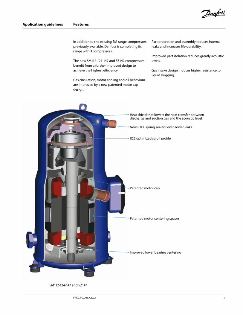
Features
In addition to the existing SM range compressors previously available, Danfoss is completing its range with 3 compressors.
The new SM112-124-147 and SZ147 compressors benefit from a further improved design to achieve the highest efficiency.
Gas circulation, motor cooling and oil behaviour are improved by a new patented motor cap design.
Part protection and assembly reduces internal leaks and increases life durability.
Improved part isolation reduces greatly acoustic levels.
Gas intake design induces higher resistance to liquid slugging.
Heat shield that lowers the heat transfer between discharge and suction gas and the acoustic level
R22 optimized scroll profile
Improved lower bearing centering
Patented motor centering spacer
Patented motor cap
New PTFE spring seal for even lower leaks
SM112-124-147 and SZ147
5FRCC.PC.003.A5.22
Application guidelines
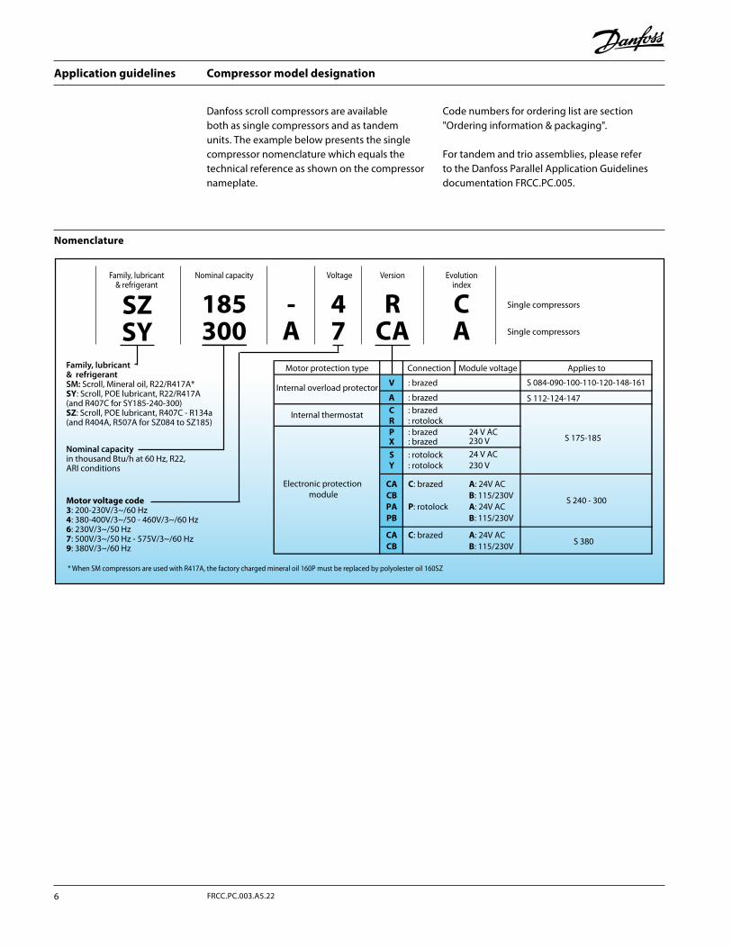
Compressor model designation
Danfoss scroll compressors are available both as single compressors and as tandem units. The example below presents the single compressor nomenclature which equals the technical reference as shown on the compressor nameplate.
Code numbers for ordering list are section "Ordering information & packaging".
For tandem and trio assemblies, please refer to the Danfoss Parallel Application Guidelines documentation FRCC.PC.005.
Nomenclature
Family, lubricant& refrigerant
Nominal capacity in thousand Btu/h at 60 Hz, R22, ARI conditions
Nominal capacity
Family, lubricant& refrigerantSM: Scroll, Mineral oil, R22/R417A*SY: Scroll, POE lubricant, R22/R417A(and R407C for SY185-240-300)SZ: Scroll, POE lubricant, R407C - R134a(and R404A, R507A for SZ084 to SZ185)
Voltage Version Evolutionindex
CA
47
SZSY
-A
RCA
185300
Single compressors
Single compressors
: brazedInternal overload protector
A S 112-124-147
230 V24 V AC
24 V AC230 V
C : brazed
Motor protection type
V : brazed S 084-090-100-110-120-148-161
Applies to
S
R : rotolock
XP : brazed
: brazed: rotolock
CBCA
Y : rotolock
C: brazed
PAB: 115/230VA: 24V AC
PBP: rotolock A: 24V AC
CB
B: 115/230V
CA C: brazed A: 24V ACB: 115/230V
Module voltageConnection
Internal thermostat
S 240 - 300
S 380
Electronic protection module
S 175-185
Motor voltage code3: 200-230V/3~/60 Hz4: 380-400V/3~/50 - 460V/3~/60 Hz6: 230V/3~/50 Hz7: 500V/3~/50 Hz - 575V/3~/60 Hz9: 380V/3~/60 Hz
* When SM compressors are used with R417A, the factory charged mineral oil 160P must be replaced by polyolester oil 160SZ
Application guidelines
6 FRCC.PC.003.A5.22
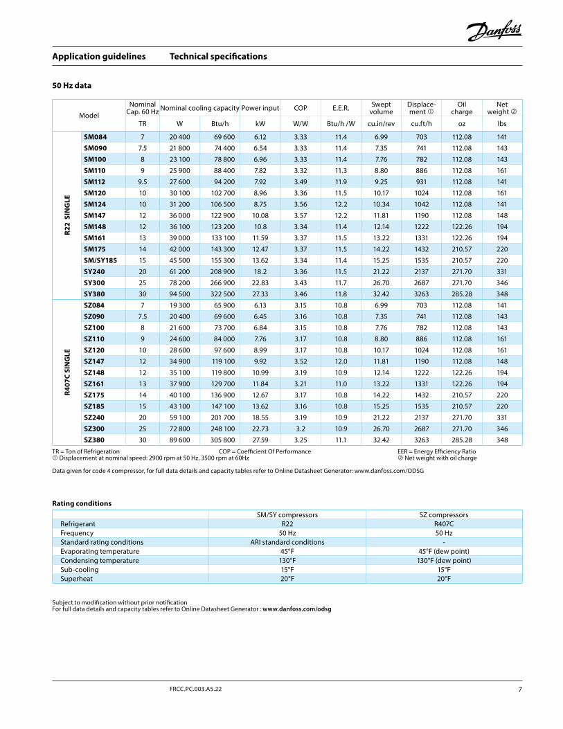
Technical specifications
50 Hz data
Subject to modification without prior notificationFor full data details and capacity tables refer to Online Datasheet Generator : www.danfoss.com/odsg
Rating conditions
Model
NominalCap. 60 Hz Nominal cooling capacity Power input COP E.E.R. Swept
volumeDisplace-ment
Oilcharge
Netweight
TR W Btu/h kW W/W Btu/h /W cu.in/rev cu.ft/h oz lbs
R22
SIN
GLE
SM084 7 20 400 69 600 6.12 3.33 11.4 6.99 703 112.08 141
SM090 7.5 21 800 74 400 6.54 3.33 11.4 7.35 741 112.08 143
SM100 8 23 100 78 800 6.96 3.33 11.4 7.76 782 112.08 143
SM110 9 25 900 88 400 7.82 3.32 11.3 8.80 886 112.08 161
SM112 9.5 27 600 94 200 7.92 3.49 11.9 9.25 931 112.08 141
SM120 10 30 100 102 700 8.96 3.36 11.5 10.17 1024 112.08 161
SM124 10 31 200 106 500 8.75 3.56 12.2 10.34 1042 112.08 141
SM147 12 36 000 122 900 10.08 3.57 12.2 11.81 1190 112.08 148
SM148 12 36 100 123 200 10.8 3.34 11.4 12.14 1222 122.26 194
SM161 13 39 000 133 100 11.59 3.37 11.5 13.22 1331 122.26 194
SM175 14 42 000 143 300 12.47 3.37 11.5 14.22 1432 210.57 220
SM/SY185 15 45 500 155 300 13.62 3.34 11.4 15.25 1535 210.57 220
SY240 20 61 200 208 900 18.2 3.36 11.5 21.22 2137 271.70 331
SY300 25 78 200 266 900 22.83 3.43 11.7 26.70 2687 271.70 346
SY380 30 94 500 322 500 27.33 3.46 11.8 32.42 3263 285.28 348
R407
C SI
NG
LE
SZ084 7 19 300 65 900 6.13 3.15 10.8 6.99 703 112.08 141
SZ090 7.5 20 400 69 600 6.45 3.16 10.8 7.35 741 112.08 143
SZ100 8 21 600 73 700 6.84 3.15 10.8 7.76 782 112.08 143
SZ110 9 24 600 84 000 7.76 3.17 10.8 8.80 886 112.08 161
SZ120 10 28 600 97 600 8.99 3.17 10.8 10.17 1024 112.08 161
SZ147 12 34 900 119 100 9.92 3.52 12.0 11.81 1190 112.08 148
SZ148 12 35 100 119 800 10.99 3.19 10.9 12.14 1222 122.26 194
SZ161 13 37 900 129 700 11.84 3.21 11.0 13.22 1331 122.26 194
SZ175 14 40 100 136 900 12.67 3.17 10.8 14.22 1432 210.57 220
SZ185 15 43 100 147 100 13.62 3.16 10.8 15.25 1535 210.57 220
SZ240 20 59 100 201 700 18.55 3.19 10.9 21.22 2137 271.70 331
SZ300 25 72 800 248 100 22.73 3.2 10.9 26.70 2687 271.70 346
SZ380 30 89 600 305 800 27.59 3.25 11.1 32.42 3263 285.28 348
TR = Ton of Refrigeration COP = Coefficient Of Performance EER = Energy Efficiency Ratio Displacement at nominal speed: 2900 rpm at 50 Hz, 3500 rpm at 60Hz Net weight with oil charge
Data given for code 4 compressor, for full data details and capacity tables refer to Online Datasheet Generator: www.danfoss.com/ODSG
SM/SY compressors SZ compressorsRefrigerant R22 R407CFrequency 50 Hz 50 HzStandard rating conditions ARI standard conditions -Evaporating temperature 45°F 45°F (dew point)Condensing temperature 130°F 130°F (dew point)Sub-cooling 15°F 15°FSuperheat 20°F 20°F
7FRCC.PC.003.A5.22
Application guidelines
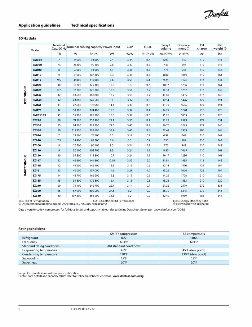
Technical specifications
60 Hz data
Subject to modification without prior notificationFor full data details and capacity tables refer to Online Datasheet Generator : www.danfoss.com/odsg
Rating conditionsSM/SY compressors SZ compressors
Refrigerant R22 R407CFrequency 60 Hz 60 HzStandard rating conditions ARI standard conditions -Evaporating temperature 45°F 45°F (dew point)Condensing temperature 130°F 130°F (dew point)Sub-cooling 15°F 15°FSuperheat 20°F 20°F
Model
NominalCap. 60 Hz Nominal cooling capacity Power input COP E.E.R. Swept
volumeDisplace-ment
Oilcharge
Netweight
TR W Btu/h kW W/W Btu/h /W cu.in/rev cu.ft/h oz lbs
R22
SIN
GLE
SM084 7 24600 84 000 7.4 3.34 11.4 6.99 849 110 141
SM090 7.5 26400 90 100 7.8 3.37 11.5 7.35 894 110 143
SM100 8 27500 93 900 8.1 3.38 11.5 7.76 943 110 143
SM110 9 31600 107 800 9.3 3.38 11.5 8.80 1069 110 161
SM112 9.5 34000 116 000 9.6 3.53 12.1 9.25 1124 112 141
SM120 10 36 700 125 300 10.8 3.4 11.6 10.17 1236 110 161
SM124 10.5 37 700 128 700 10.6 3.56 12.2 10.34 1257 112 142
SM147 12 43 600 148 800 12.2 3.58 12.2 11.81 1435 112 148
SM148 12 43 800 149 500 13 3.37 11.5 12.14 1476 122 194
SM161 13 47 600 162500 14.1 3.39 11.6 13.22 1606 122 194
SM175 14 51 100 174 400 15.3 3.34 11.4 14.22 1728 210 220
SM/SY185 15 55 300 188 700 16.3 3.39 11.6 15.25 1853 210 220
SY240 20 74 100 252 900 22.1 3.35 11.4 21.22 2579 272 331
SY300 25 94 500 322 500 27.5 3.43 11.7 26.70 3245 272 346
SY380 30 115 300 393 500 33.4 3.46 11.8 32.42 3939 285 348
R407
C SI
NG
LE
SZ084 7 22 500 76 800 7.1 3.19 10.9 6.99 849 110 141
SZ090 7.5 24 400 83 300 7.6 3.2 10.9 7.35 894 110 143
SZ100 8 26 500 90 400 8.2 3.24 11.1 7.76 943 110 143
SZ110 9 30 100 102 700 9.3 3.24 11.1 8.80 1069 110 161
SZ120 10 34 800 118 800 10.7 3.24 11.1 10.17 1236 110 161
SZ147 12 42 300 144 300 12.03 3.52 12.0 11.81 1435 112 148
SZ148 12 42 600 145 400 13.3 3.19 10.9 12.14 1476 122 194
SZ161 13 46 000 157 000 14.3 3.21 11.0 13.22 1606 122 194
SZ175 14 48 700 166 200 15.3 3.19 10.9 14.22 1728 210 220
SZ185 15 51 800 176 800 16.4 3.15 10.8 15.25 1853 210 220
SZ240 20 71 100 242 700 22.7 3.14 10.7 21.22 2579 272 331
SZ300 25 87 900 300 000 27.5 3.2 10.9 26.70 3245 272 346
SZ380 30 107 300 366 200 33.5 3.2 10.9 32.42 3939 285 348
TR = Ton of Refrigeration COP = Coefficient Of Performance EER = Energy Efficiency Ratio Displacement at nominal speed: 2900 rpm at 50 Hz, 3500 rpm at 60Hz Net weight with oil charge
Data given for code 4 compressor, for full data details and capacity tables refer to Online Datasheet Generator: www.danfoss.com/ODSG
Application guidelines
8 FRCC.PC.003.A5.22
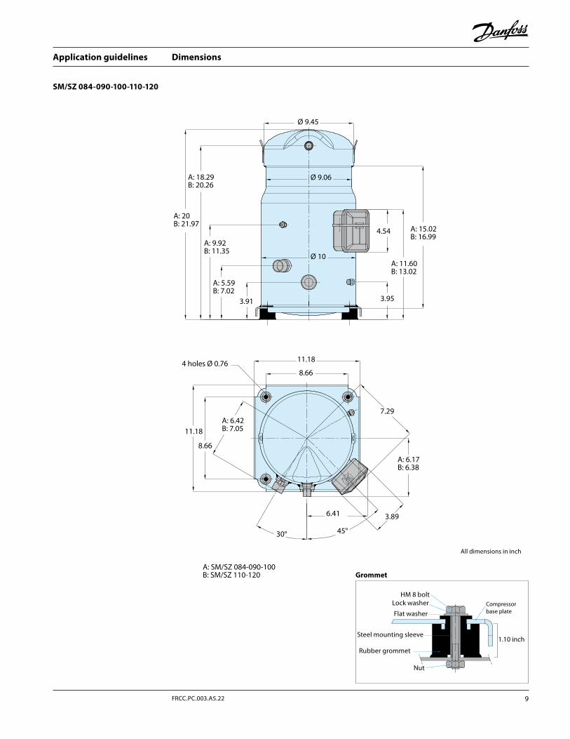
Dimensions
SM/SZ 084-090-100-110-120
All dimensions in inch
Grommet
Ø 9.45
Ø 9.06
Ø 10
A: 18.29B: 20.26
A: 15.02B: 16.99
4.54
A: 11.60B: 13.02
3.95
A: 20B: 21.97
A: 9.92B: 11.35
A: 5.59B: 7.02
3.91
11.18
11.18
8.66
8.66
A: 6.42B: 7.05
7.29
A: 6.17B: 6.38
A: SM/SZ 084-090-100B: SM/SZ 110-120
45°30°
6.41 3.89
4 holes Ø 0.76
HM 8 boltLock washer
Flat washer
Steel mounting sleeve
Rubber grommet
Nut
1.10 inch
Compressorbase plate
9FRCC.PC.003.A5.22
Application guidelines
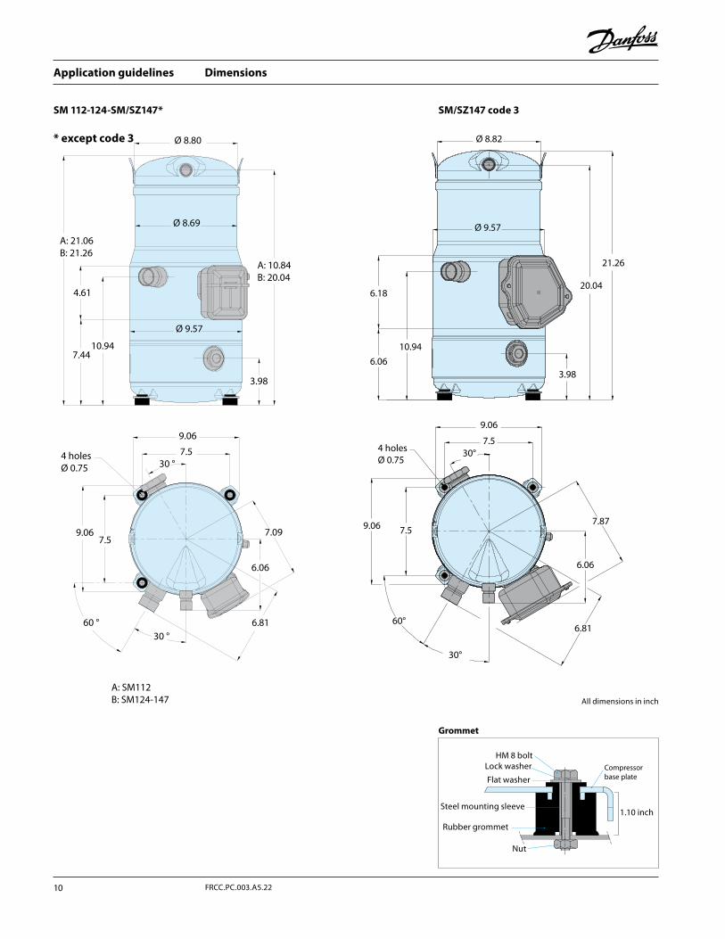
Dimensions
SM 112-124-SM/SZ147*
* except code 3
SM/SZ147 code 3
All dimensions in inch
Grommet
30 °7.5
Ø 8.69
A: 21.06B: 21.26
4.61
7.44
Ø 8.80
A: 10.84B: 20.04
A: SM112B: SM124-147
3.98
Ø 9.57
10.94
4 holesØ 0.75
60 °
7.09
6.06
9.067.5
6.8130 °
9.06
Ø 8.82
Ø 9.57
4 holes Ø 0.75
6.18
6.06
9.06
7.5
7.87
6.06
6.81
9.06 7.5
30°
30°
60°
3.98
20.04
21.26
10.94
HM 8 boltLock washer
Flat washer
Steel mounting sleeve
Rubber grommet
Nut
1.10 inch
Compressorbase plate
Application guidelines
10 FRCC.PC.003.A5.22
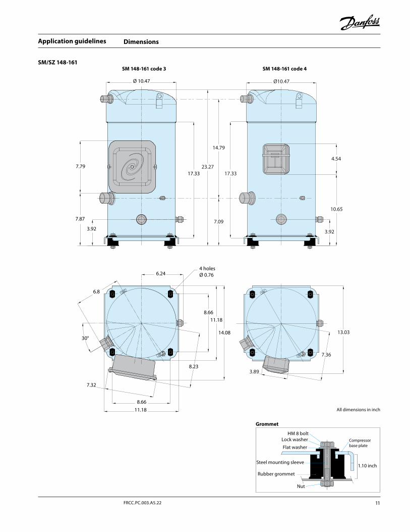
Dimensions
SM/SZ 148-161
Grommet
All dimensions in inch
Ø 10.47
7.32
7.7917.33
7.87
3.92
6.244 holesØ 0.76
6.8
8.66
8.6611.18
14.08
8.23
11.18
SM 148-161 code 3 SM 148-161 code 4
30°
23.27
7.09
14.79
4.54
10.65
Ø10.47
3.92
17.33
7.36
13.03
3.89
HM 8 boltLock washer
Flat washer
Steel mounting sleeve
Rubber grommet
Nut
1.10 inch
Compressorbase plate
11FRCC.PC.003.A5.22
Application guidelines
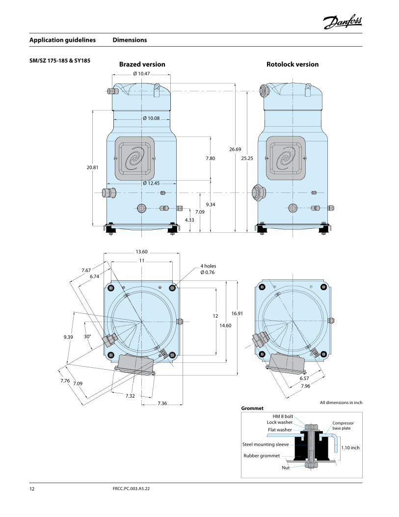
Dimensions
SM/SZ 175-185 & SY185
GrommetAll dimensions in inch
7.96
6.57
26.69
25.257.80
20.81
9.347.09
4.33
Ø 10.08
Ø 10.47
Brazed version Rotolock version
Ø 12.45
7.676.74
13.60
4 holesØ 0.76
11
14.60
12
7.76 7.09
16.91
9.39
7.36
7.32
30°
HM 8 boltLock washer
Flat washer
Steel mounting sleeve
Rubber grommet
Nut
1.10 inch
Compressorbase plate
Application guidelines
12 FRCC.PC.003.A5.22

Dimensions
SY/SZ 240-300-380
All dimensions in inch
Grommet
Lock washer * HM 10 Bolt *
Large flat *1.06 inch washer
Steel mounting sleeve
Rubber grommet
Nut *
1.41 inch
Compressor base plate
* not supplied with compressor
7.36
35°
4 holes Ø0.98
15.43
15.4312
7.958.11
7.32
17.87
11.58
7.62
30°
A: SY/SZ240B: SY/SZ300C: SY/SZ380
8.23A&B: 15.83 - C: 16.54
5.5
Ø13.54
Discharge A&B: 1”1/8C: 1”3/8
Ø13.11
A: 27.2±2B: 67.63±2C: 28.58
A: 24.33B: 24.76C: 25.71
A: 18.88±1.2B: 19.31±1.2C: 20.26±1.2
SuctionA&B: 1”5/8C: 2”1/8
8.507.7
3.433.86
6.29
90°
187
Discharge 1”1/8
SuctionA: 1”1/2B: 1”5/8
15.91
A: SY/SZ240B: SY/SZ300
15.90
8.19
90°
30°
35°
4 holes Ø0.98
15.43
15.43 12
7.95 7.32
17.87
11.58
7.62
8.235.5
Ø13.54
Ø13.11
A: 27.2±2B: 67.63±2
A: 24.33B: 24.76 A: 18.88±1.2
B: 19.31±1.2
8.507.7
3.43 3.866.29
Brazed version Rotolock version
13FRCC.PC.003.A5.22
Application guidelines
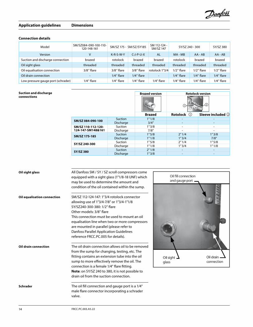
Dimensions
Connection details
Suction and discharge connections
Oil drain connection
Oil equalisation connection
Oil sight glass
Schrader
The oil drain connection allows oil to be removed from the sump for changing, testing, etc. The fitting contains an extension tube into the oil sump to more effectively remove the oil. The connection is a female 1/4" flare fitting.Note: on SY/SZ 240 to 380, it is not possible to drain oil from the suction connection.
SM/SZ 112-124-147: 1"3/4 rotolock connector allowing use of 1"3/4-7/8" or 1"3/4-1"1/8SY/SZ240-300-380: 1/2" flareOther models: 3/8" flareThis connection must be used to mount an oil equalisation line when two or more compressors are mounted in parallel (please refer to Danfoss Parallel Application Guide lines reference FRCC.PC.005 for details).
The oil fill connection and gauge port is a 1/4" male flare connector incorporating a schrader valve.
All Danfoss SM / SY / SZ scroll compressors come equipped with a sight glass (1"1/8-18 UNF) which may be used to determine the amount and condition of the oil contained within the sump.
Model SM/SZ084-090-100-110-120-148-161 SM/SZ 175 - SM/SZ/SY185 SM 112-124 -
SM/SZ 147 SY/SZ 240 - 300 SY/SZ 380
Version V K-R-S-W-Y C-J-P-U-X AL MA - MB AA - AB AA - AB
Suction and discharge connection brazed rotolock brazed brazed rotolock brazed brazed
Oil sight glass threaded threaded threaded threaded threaded threaded threaded
Oil equalisation connection 3/8’’ flare 3/8’’ flare 3/8’’ flare rotolock 1"3/4 1/2’’ flare 1/2’’ flare 1/2’’ flare
Oil drain connection - 1/4’’ flare 1/4’’ flare - 1/4’’ flare 1/4’’ flare 1/4’’ flare
Low pressure gauge port (schrader) 1/4’’ flare 1/4’’ flare 1/4’’ flare 1/4" flare 1/4’’ flare 1/4’’ flare 1/4’’ flare
Brazed version Rotolock version
Brazed Rotolock Sleeve included
SM/SZ 084-090-100 Suction 1’’ 1/8 - -Discharge 3/4’’ - -
SM/SZ 110-112-120-124-147-SM148&161
Suction 1’’ 3/8 - -Discharge 7/8’’ - -
SM/SZ 175-185 Suction 1’’ 5/8 2’’ 1/4 1’’ 3/8Discharge 1’’ 1/8 1’’ 3/4 7/8’’
SY/SZ 240-300 Suction 1’’ 5/8 2’’ 1/4 1’’ 5/8Discharge 1’’ 1/8 1’’ 3/4 1’’ 1/8
SY/SZ 380 Suction 2’’ 1/8 - -Discharge 1’’ 3/8 - -
1 2
21
Application guidelines
14 FRCC.PC.003.A5.22
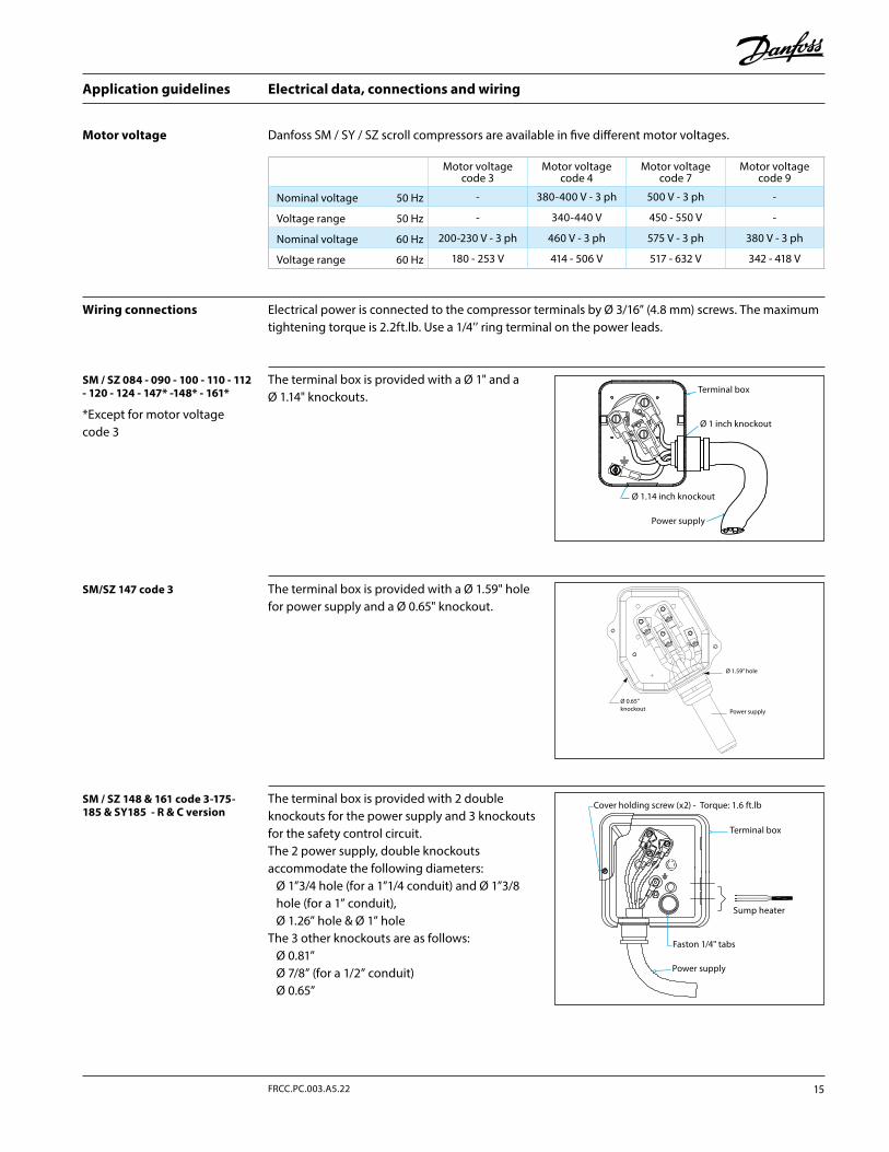
Electrical data, connections and wiring
The terminal box is provided with a Ø 1" and a Ø 1.14" knockouts.
Motor voltage
Wiring connections
Danfoss SM / SY / SZ scroll compressors are available in five different motor voltages.
Electrical power is connected to the compressor terminals by Ø 3/16” (4.8 mm) screws. The maximum tightening torque is 2.2ft.lb. Use a 1/4’’ ring terminal on the power leads.
The terminal box is provided with 2 double knockouts for the power supply and 3 knockouts for the safety control circuit. The 2 power supply, double knockouts accommodate the following diameters:
Ø 1”3/4 hole (for a 1”1/4 conduit) and Ø 1”3/8 hole (for a 1” conduit),Ø 1.26” hole & Ø 1” hole
The 3 other knockouts are as follows:Ø 0.81”Ø 7/8” (for a 1/2” conduit)Ø 0.65”
SM / SZ 084 - 090 - 100 - 110 - 112 - 120 - 124 - 147* -148* - 161*
*Except for motor voltage code 3
SM / SZ 148 & 161 code 3-175-185 & SY185 - R & C version
The terminal box is provided with a Ø 1.59" hole for power supply and a Ø 0.65" knockout.
SM/SZ 147 code 3
Motor voltage code 3
Motor voltage code 4
Motor voltage code 7
Motor voltage code 9
Nominal voltage 50 Hz - 380-400 V - 3 ph 500 V - 3 ph -
Voltage range 50 Hz - 340-440 V 450 - 550 V -
Nominal voltage 60 Hz 200-230 V - 3 ph 460 V - 3 ph 575 V - 3 ph 380 V - 3 ph
Voltage range 60 Hz 180 - 253 V 414 - 506 V 517 - 632 V 342 - 418 V
Terminal box
Ø 1 inch knockout
Power supply
Ø 1.14 inch knockout
Ø 1.59” hole
Ø 0.65”knockout Power supply
Cover holding screw (x2) - Torque: 1.6 ft.lb
Faston 1/4" tabs
Terminal box
Power supply
Sump heater
15FRCC.PC.003.A5.22
Application guidelines
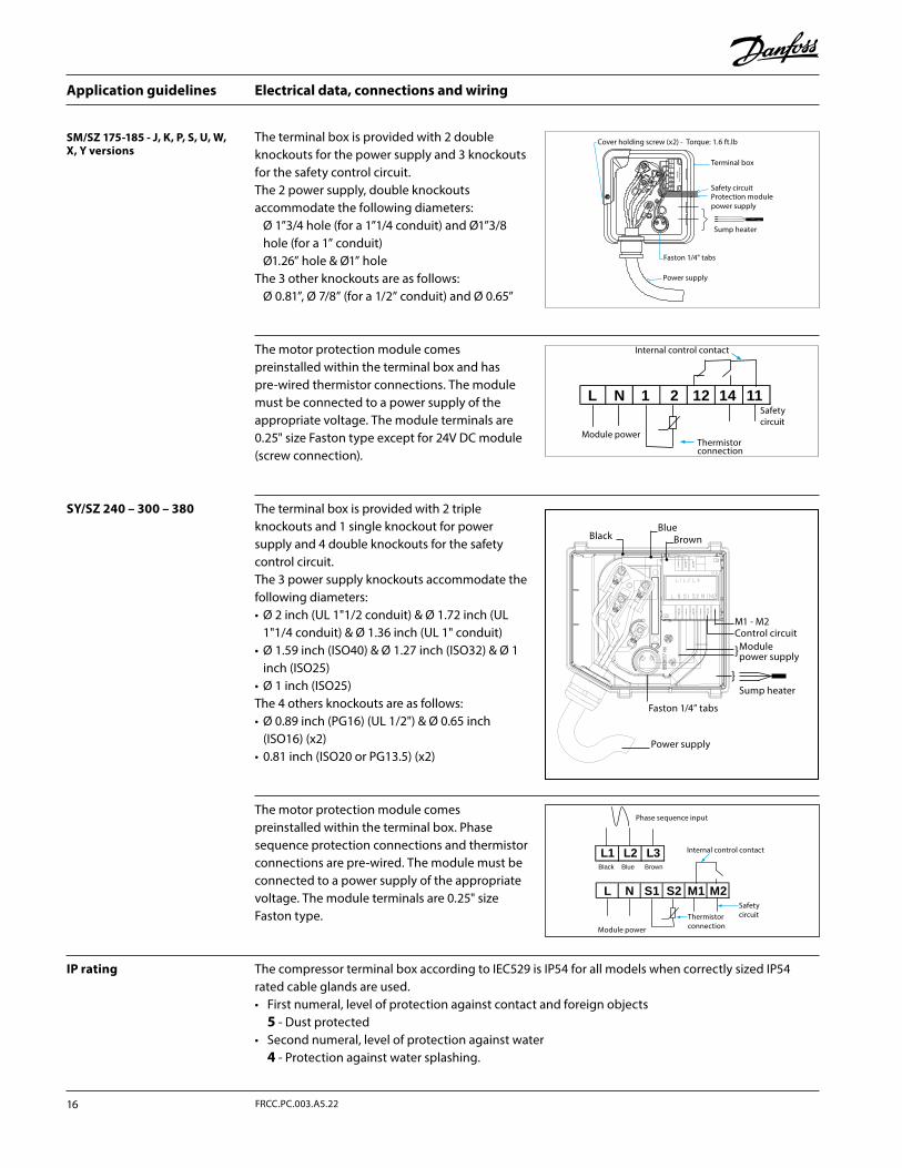
Electrical data, connections and wiring
The motor protection module comes preinstalled within the terminal box. Phase sequence protection connections and thermistor connections are pre-wired. The module must be connected to a power supply of the appropriate voltage. The module terminals are 0.25" size Faston type.
The motor protection module comes preinstalled within the terminal box and has pre-wired thermistor connections. The module must be connected to a power supply of the appropriate voltage. The module terminals are 0.25" size Faston type except for 24V DC module (screw connection).
SM/SZ 175-185 - J, K, P, S, U, W, X, Y versions
The terminal box is provided with 2 double knockouts for the power supply and 3 knockouts for the safety control circuit. The 2 power supply, double knockouts accommodate the following diameters:
Ø 1”3/4 hole (for a 1”1/4 conduit) and Ø1”3/8 hole (for a 1” conduit)Ø1.26” hole & Ø1” hole
The 3 other knockouts are as follows:Ø 0.81”, Ø 7/8” (for a 1/2” conduit) and Ø 0.65”
The compressor terminal box according to IEC529 is IP54 for all models when correctly sized IP54 rated cable glands are used.• First numeral, level of protection against contact and foreign objects
5 - Dust protected• Second numeral, level of protection against water
4 - Protection against water splashing.
IP rating
SY/SZ 240 – 300 – 380 The terminal box is provided with 2 triple knockouts and 1 single knockout for power supply and 4 double knockouts for the safety control circuit. The 3 power supply knockouts accommodate the following diameters:• Ø 2 inch (UL 1"1/2 conduit) & Ø 1.72 inch (UL
1"1/4 conduit) & Ø 1.36 inch (UL 1" conduit)• Ø 1.59 inch (ISO40) & Ø 1.27 inch (ISO32) & Ø 1
inch (ISO25)• Ø 1 inch (ISO25)The 4 others knockouts are as follows:• Ø 0.89 inch (PG16) (UL 1/2") & Ø 0.65 inch
(ISO16) (x2) • 0.81 inch (ISO20 or PG13.5) (x2)
BlackBlue
Brown
M1 - M2Control circuit
Faston 1/4” tabs
Power supply
Sump heater
Modulepower supply
L N 1 2 1412 11
Internal control contact
Safetycircuit
Thermistorconnection
Module power
L N S1 S2 M1 M2
L1 L2 L3Black Blue Brown
Phase sequence input
Internal control contact
SafetycircuitThermistor
connectionModule power
Motor Protection12
1411
N
21 M
odule
L1
Cover holding screw (x2) - Torque: 1.6 ft.lb
Faston 1/4" tabs
Terminal box
Power supply
Sump heater
Protection modulepower supply
Safety circuit
Application guidelines
16 FRCC.PC.003.A5.22
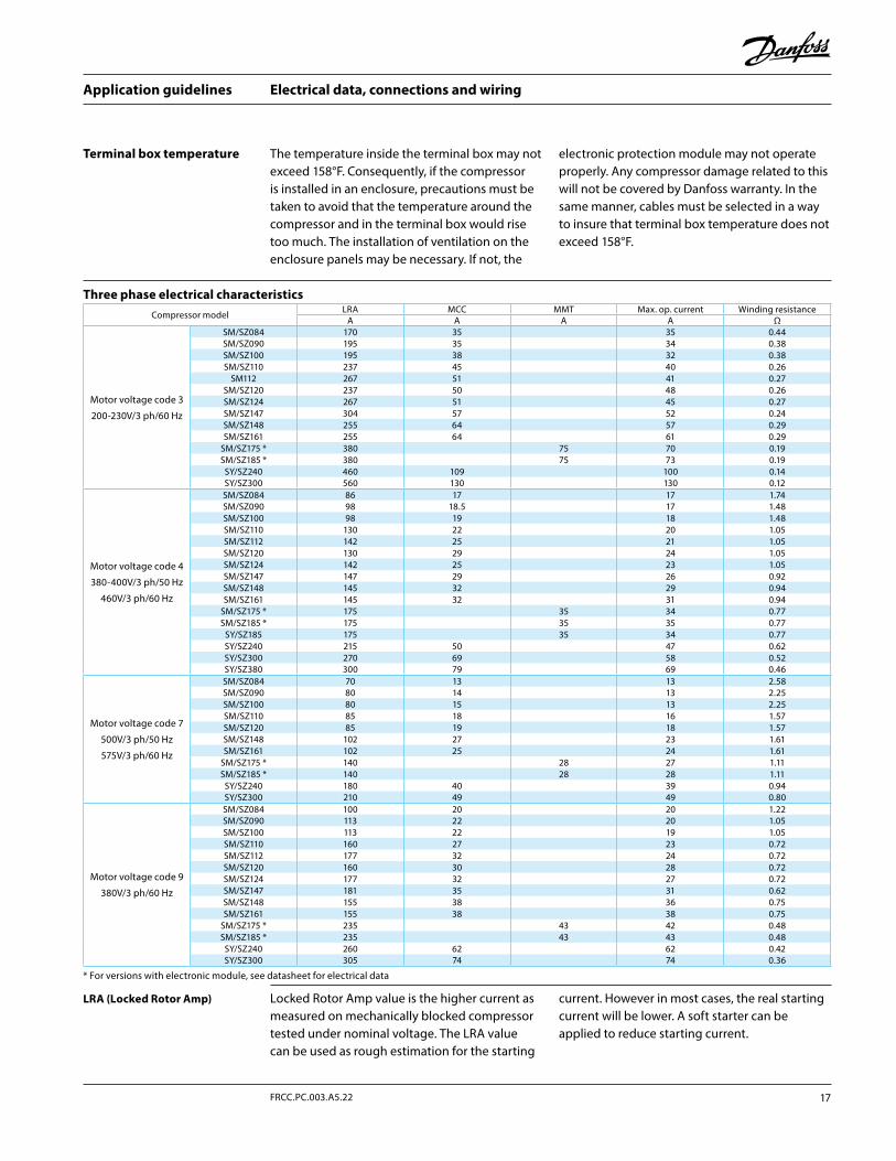
The temperature inside the terminal box may not exceed 158°F. Consequently, if the compressor is installed in an enclosure, precautions must be taken to avoid that the temperature around the compressor and in the terminal box would rise too much. The installation of ventilation on the enclosure panels may be necessary. If not, the
electronic protection module may not operate properly. Any compressor damage related to this will not be covered by Danfoss warranty. In the same manner, cables must be selected in a way to insure that terminal box temperature does not exceed 158°F.
Terminal box temperature
Electrical data, connections and wiring
Three phase electrical characteristics
Locked Rotor Amp value is the higher current as measured on mechanically blocked compressor tested under nominal voltage. The LRA value can be used as rough estimation for the starting
current. However in most cases, the real starting current will be lower. A soft starter can be applied to reduce starting current.
LRA (Locked Rotor Amp)
Compressor model LRA MCC MMT Max. op. current Winding resistanceA A A A Ω
Motor voltage code 3
200-230V/3 ph/60 Hz
SM/SZ084 170 35 35 0.44SM/SZ090 195 35 34 0.38SM/SZ100 195 38 32 0.38SM/SZ110 237 45 40 0.26
SM112 267 51 41 0.27SM/SZ120 237 50 48 0.26SM/SZ124 267 51 45 0.27SM/SZ147 304 57 52 0.24SM/SZ148 255 64 57 0.29SM/SZ161 255 64 61 0.29
SM/SZ175 * 380 75 70 0.19SM/SZ185 * 380 75 73 0.19
SY/SZ240 460 109 100 0.14SY/SZ300 560 130 130 0.12
Motor voltage code 4
380-400V/3 ph/50 Hz
460V/3 ph/60 Hz
SM/SZ084 86 17 17 1.74SM/SZ090 98 18.5 17 1.48SM/SZ100 98 19 18 1.48SM/SZ110 130 22 20 1.05SM/SZ112 142 25 21 1.05SM/SZ120 130 29 24 1.05SM/SZ124 142 25 23 1.05SM/SZ147 147 29 26 0.92SM/SZ148 145 32 29 0.94SM/SZ161 145 32 31 0.94
SM/SZ175 * 175 35 34 0.77SM/SZ185 * 175 35 35 0.77
SY/SZ185 175 35 34 0.77SY/SZ240 215 50 47 0.62SY/SZ300 270 69 58 0.52SY/SZ380 300 79 69 0.46
Motor voltage code 7
500V/3 ph/50 Hz
575V/3 ph/60 Hz
SM/SZ084 70 13 13 2.58SM/SZ090 80 14 13 2.25SM/SZ100 80 15 13 2.25SM/SZ110 85 18 16 1.57SM/SZ120 85 19 18 1.57SM/SZ148 102 27 23 1.61SM/SZ161 102 25 24 1.61
SM/SZ175 * 140 28 27 1.11SM/SZ185 * 140 28 28 1.11
SY/SZ240 180 40 39 0.94SY/SZ300 210 49 49 0.80
Motor voltage code 9
380V/3 ph/60 Hz
SM/SZ084 100 20 20 1.22SM/SZ090 113 22 20 1.05SM/SZ100 113 22 19 1.05SM/SZ110 160 27 23 0.72SM/SZ112 177 32 24 0.72SM/SZ120 160 30 28 0.72SM/SZ124 177 32 27 0.72SM/SZ147 181 35 31 0.62SM/SZ148 155 38 36 0.75SM/SZ161 155 38 38 0.75
SM/SZ175 * 235 43 42 0.48SM/SZ185 * 235 43 43 0.48
SY/SZ240 260 62 62 0.42SY/SZ300 305 74 74 0.36
* For versions with electronic module, see datasheet for electrical data
17FRCC.PC.003.A5.22
Application guidelines
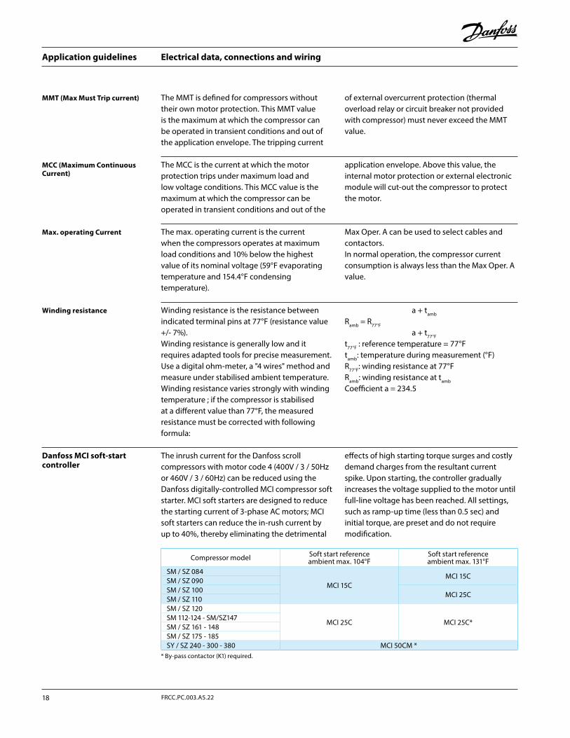
Electrical data, connections and wiring
Winding resistance is the resistance between indicated terminal pins at 77°F (resistance value +/- 7%).Winding resistance is generally low and it requires adapted tools for precise measurement. Use a digital ohm-meter, a "4 wires" method and measure under stabilised ambient temperature. Winding resistance varies strongly with winding temperature ; if the compressor is stabilised at a different value than 77°F, the measured resistance must be corrected with following formula:
a + tamb
Ramb = R77°F
a + t77°F
t77°F : reference temperature = 77°Ftamb: temperature during measurement (°F)R77°F: winding resistance at 77°FRamb: winding resistance at tamb
Coefficient a = 234.5
The MMT is defined for compressors without their own motor protection. This MMT value is the maximum at which the compressor can be operated in transient conditions and out of the application envelope. The tripping current
of external overcurrent protection (thermal overload relay or circuit breaker not provided with compressor) must never exceed the MMT value.
The max. operating current is the current when the compressors operates at maximum load conditions and 10% below the highest value of its nominal voltage (59°F evaporating temperature and 154.4°F condensing temperature).
Max Oper. A can be used to select cables and contactors. In normal operation, the compressor current consumption is always less than the Max Oper. A value.
The MCC is the current at which the motor protection trips under maximum load and low voltage conditions. This MCC value is the maximum at which the compressor can be operated in transient conditions and out of the
application envelope. Above this value, the internal motor protection or external electronic module will cut-out the compressor to protect the motor.
Winding resistance
MMT (Max Must Trip current)
Max. operating Current
MCC (Maximum Continuous Current)
Danfoss MCI soft-start controller
Compressor model Soft start reference ambient max. 104°F
Soft start reference ambient max. 131°F
SM / SZ 084
MCI 15CMCI 15C
SM / SZ 090SM / SZ 100
MCI 25CSM / SZ 110SM / SZ 120
MCI 25C MCI 25C*SM 112-124 - SM/SZ147SM / SZ 161 - 148 SM / SZ 175 - 185SY / SZ 240 - 300 - 380 MCI 50CM *
* By-pass contactor (K1) required.
The inrush current for the Danfoss scroll compressors with motor code 4 (400V / 3 / 50Hz or 460V / 3 / 60Hz) can be reduced using the Danfoss digitally-controlled MCI compressor soft starter. MCI soft starters are designed to reduce the starting current of 3-phase AC motors; MCI soft starters can reduce the in-rush current by up to 40%, thereby eliminating the detrimental
effects of high starting torque surges and costly demand charges from the resultant current spike. Upon starting, the controller gradually increases the voltage supplied to the motor until full-line voltage has been reached. All settings, such as ramp-up time (less than 0.5 sec) and initial torque, are preset and do not require modification.
Application guidelines
18 FRCC.PC.003.A5.22
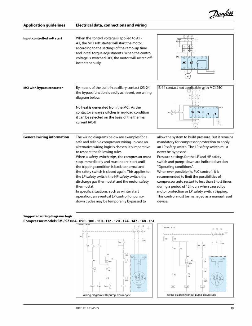
Electrical data, connections and wiring
MCI with bypass contactor
General wiring information
Input controlled soft start
By means of the built-in auxiliary contact (23-24) the bypass function is easily achieved, see wiring diagram below.
No heat is generated from the MCI. As the contactor always switches in no-load condition it can be selected on the basis of the thermal current (AC-1).
13-14 contact not applicable with MCI 25C
The wiring diagrams below are examples for a safe and reliable compressor wiring. In case an alternative wiring logic is chosen, it's imperative to respect the following rules.When a safety switch trips, the compressor must stop immediately and must not re-start until the tripping condition is back to normal and the safety switch is closed again. This applies to the LP safety switch, the HP safety switch, the discharge gas thermostat and the motor safety thermostat.In specific situations, such as winter start operation, an eventual LP control for pump-down cycles may be temporarily bypassed to
allow the system to build pressure. But it remains mandatory for compressor protection to apply an LP safety switch. The LP safety switch must never be bypassed.Pressure settings for the LP and HP safety switch and pump-down are indicated section “Operating conditions”.When ever possible (ie. PLC control), it is recommended to limit the possibilities of compressor auto restart to less than 3 to 5 times during a period of 12 hours when caused by motor protection or LP safety switch tripping. This control must be managed as a manual reset device.
When the control voltage is applied to A1 - A2, the MCI soft starter will start the motor, according to the settings of the ramp-up time and initial torque adjustments. When the control voltage is switched OFF, the motor will switch off instantaneously.
Compressor models SM / SZ 084 - 090 - 100 - 110 - 112 - 120 - 124 - 147 - 148 - 161Suggested wiring diagrams logic
MDGT
HP
LPS
180 s
THLP
CONTROL CIRCUIT
F1F1
KM
KM
KM
KA KA
A1
A2
A3
KA
KA
KS
KS
KS
L1 L3 L2
Q1
T1
T3
T2
LLSV KS
Wiring diagram with pump-down cycle
KM
L1 L3 L2
Q1
CONTROL CIRCUIT
F1F1
KM KA
KA KS
KS
KS
HP
DGT
TH
180 s
85 52 019 - A
T1 T2
M
T3
KA KA
A1
A2
A3
Wiring diagram without pump-down cycle
LPS
19FRCC.PC.003.A5.22
Application guidelines
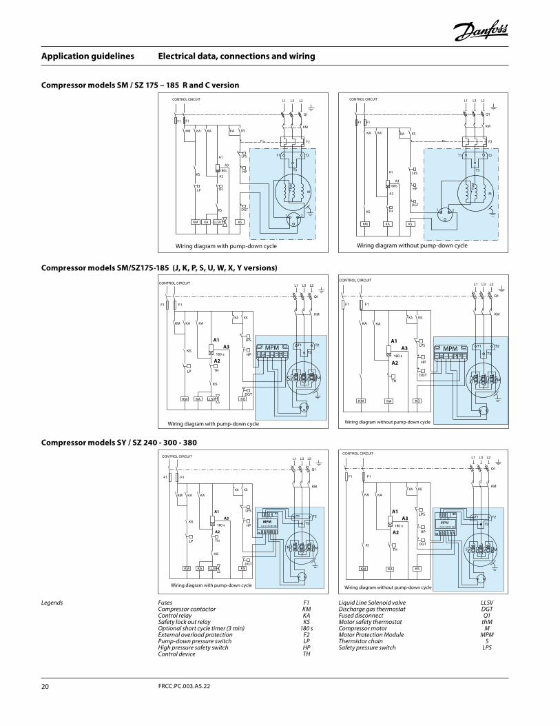
Electrical data, connections and wiring
Compressor models SM / SZ 175 – 185 R and C version
Legends
Compressor models SY / SZ 240 - 300 - 380
Compressor models SM/SZ175-185 (J, K, P, S, U, W, X, Y versions)
Fuses F1Compressor contactor KMControl relay KASafety lock out relay KSOptional short cycle timer (3 min) 180 sExternal overload protection F2Pump-down pressure switch LPHigh pressure safety switch HPControl device TH
Liquid Line Solenoid valve LLSVDischarge gas thermostat DGTFused disconnect Q1Motor safety thermostat thMCompressor motor MMotor Protection Module MPMThermistor chain SSafety pressure switch LPS
CONTROL CIRCUIT
F1F1
KA KAKA
HP
LPS T1 T2
T3
KM
DGT
KS
KS
1 2
M
ThM
KS
KS
KAKM
KM
LLSV
180s
TH
F2
Q1
L1 L3 L2
A1
A2
A3
Wiring diagram with pump-down cycle
LP
CONTROL CIRCUIT
F1 F1
KA KAKA
HP
T1 T2
T3
KM
DGT
KS
KS
1 2THKS
LPS
KAKM
180s
F2
Q1
L1 L3 L2
M
ThM
A1
A2
A3
Wiring diagram without pump-down cycle
A1
A3
A2
MPM
S
LPS
Wiring diagram with pump-down cycle
LP
A1A3
A2
MPM
SKS
Wiring diagram without pump-down cycle
LPS
A1A3
A2
LP
LPS
MPM
12 14 11N 21L1
S
Wiring diagram with pump-down cycle
A1A3
A2
LPSMPM
12 14 11N 21L1
Wiring diagram without pump-down cycle
Application guidelines
20 FRCC.PC.003.A5.22
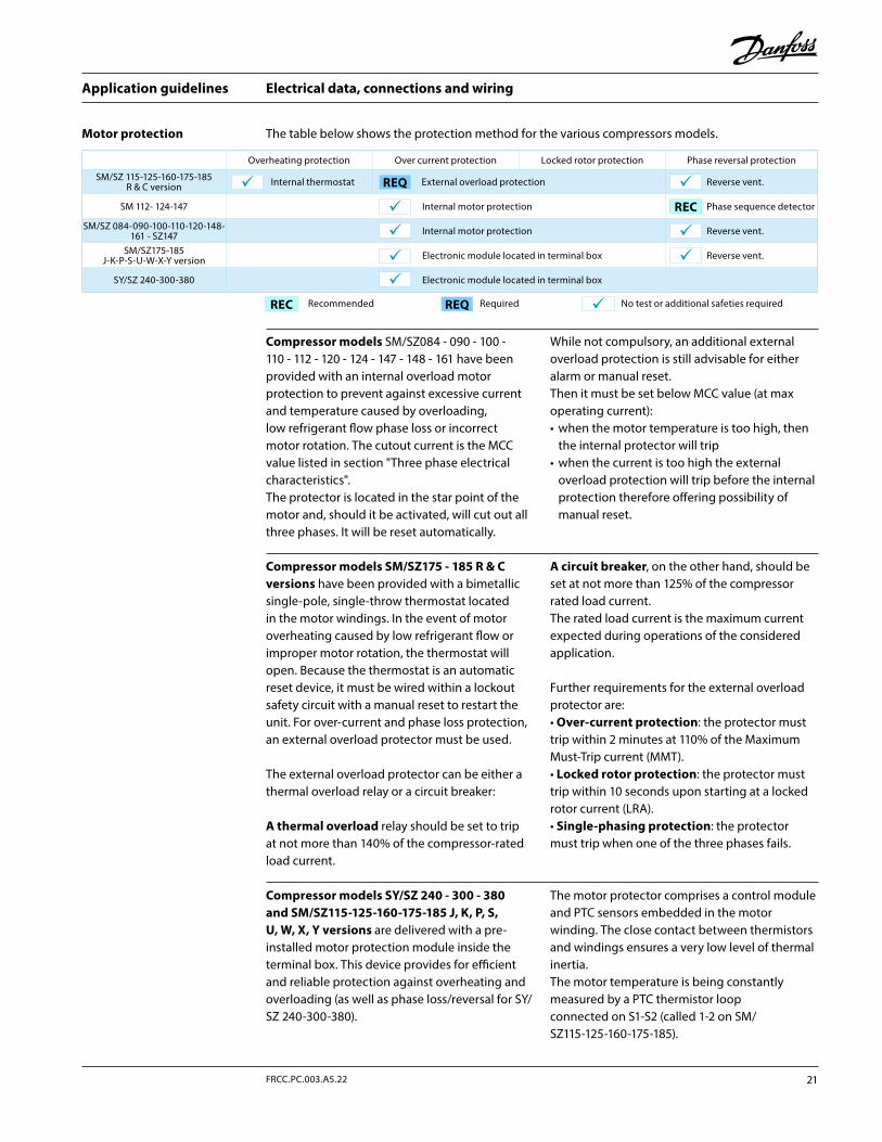
Electrical data, connections and wiring
Compressor models SM/SZ084 - 090 - 100 - 110 - 112 - 120 - 124 - 147 - 148 - 161 have been provided with an internal overload motor protection to prevent against excessive current and temperature caused by overloading, low refrigerant flow phase loss or incorrect motor rotation. The cutout current is the MCC value listed in section "Three phase electrical characteristics".The protector is located in the star point of the motor and, should it be activated, will cut out all three phases. It will be reset automatically.
While not compulsory, an additional external overload protection is still advisable for either alarm or manual reset. Then it must be set below MCC value (at max operating current):• when the motor temperature is too high, then
the internal protector will trip• when the current is too high the external
overload protection will trip before the internal protection therefore offering possibility of manual reset.
Compressor models SY/SZ 240 - 300 - 380 and SM/SZ115-125-160-175-185 J, K, P, S, U, W, X, Y versions are delivered with a pre-installed motor protection module inside the terminal box. This device provides for efficient and reliable protection against overheating and overloading (as well as phase loss/reversal for SY/SZ 240-300-380).
The motor protector comprises a control module and PTC sensors embedded in the motor winding. The close contact between thermistors and windings ensures a very low level of thermal inertia.The motor temperature is being constantly measured by a PTC thermistor loop connected on S1-S2 (called 1-2 on SM/SZ115-125-160-175-185).
Compressor models SM/SZ175 - 185 R & C versions have been provided with a bimetallic single-pole, single-throw thermostat located in the motor windings. In the event of motor overheating caused by low refrigerant flow or improper motor rotation, the thermostat will open. Because the thermostat is an automatic reset device, it must be wired within a lockout safety circuit with a manual reset to restart the unit. For over-current and phase loss protection, an external overload protector must be used.
The external overload protector can be either a thermal overload relay or a circuit breaker:
A thermal overload relay should be set to trip at not more than 140% of the compressor-rated load current.
A circuit breaker, on the other hand, should be set at not more than 125% of the compressor rated load current.The rated load current is the maximum current expected during operations of the considered application.
Further requirements for the external overload protector are:• Over-current protection: the protector must trip within 2 minutes at 110% of the Maximum Must-Trip current (MMT).• Locked rotor protection: the protector must trip within 10 seconds upon starting at a locked rotor current (LRA).• Single-phasing protection: the protector must trip when one of the three phases fails.
Motor protection The table below shows the protection method for the various compressors models.
Recommended Required No test or additional safeties requiredREQREC
Overheating protection Over current protection Locked rotor protection Phase reversal protection
SM/SZ 115-125-160-175-185 R & C version Internal thermostat External overload protection Reverse vent.
SM 112- 124-147 Internal motor protection Phase sequence detector
SM/SZ 084-090-100-110-120-148-161 - SZ147 Internal motor protection Reverse vent.
SM/SZ175-185 J-K-P-S-U-W-X-Y version Electronic module located in terminal box Reverse vent.
SY/SZ 240-300-380 Electronic module located in terminal box
REC
REQ
21FRCC.PC.003.A5.22
Application guidelines
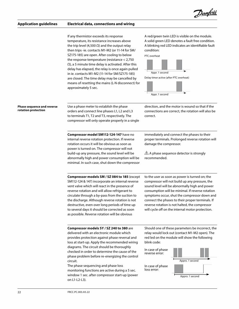
Electrical data, connections and wiring
If any thermistor exceeds its response temperature, its resistance increases above the trip level (4,500 Ω) and the output relay then trips -ie. contacts M1-M2 (or 11-14 for SM/SZ175-185) are open. After cooling to below the response temperature (resistance < 2,750 Ω), a 5 minute time delay is activated. After this delay has elapsed, the relay is once again pulled in ie. contacts M1-M2 (11-14 for SM/SZ175-185) are closed. The time delay may be cancelled by means of resetting the mains (L-N disconnect) for approximately 5 sec.
A red/green twin LED is visible on the module. A solid green LED denotes a fault free condition. A blinking red LED indicates an identifiable fault condition:
Phase sequence and reverse rotation protection
Use a phase meter to establish the phase orders and connect line phases L1, L2 and L3 to terminals T1, T2 and T3, respectively. The compressor will only operate properly in a single
direction, and the motor is wound so that if the connections are correct, the rotation will also be correct.
Compressor model SM112-124-147 have no internal reverse rotation protection. If reverse rotation occurs it will be obvious as soon as power is turned on. The compressor will not build-up any pressure, the sound level will be abnormally high and power consumption will be minimal. In such case, shut down the compressor
immediately and connect the phases to their proper terminals. Prolonged reverse rotation will damage the compressor.
A phase sequence detector is strongly recommended.
Compressor models SM / SZ 084 to 185 (except SM112-124 & 147) incorporate an internal reverse vent valve which will react in the presence of reverse rotation and will allow refrigerant to circulate through a by-pass from the suction to the discharge. Although reverse rotation is not destructive, even over long periods of time up to several days it should be corrected as soon as possible. Reverse rotation will be obvious
to the user as soon as power is turned on; the compressor will not build up any pressure, the sound level will be abnormally high and power consumption will be minimal. If reverse rotation symptoms occur, shut the compressor down and connect the phases to their proper terminals. If reverse rotation is not halted, the compressor will cycle off on the internal motor protection.
Compressor models SY / SZ 240 to 380 are delivered with an electronic module which provides protection against phase reversal and loss at start-up. Apply the recommended wiring diagrams. The circuit should be thoroughly checked in order to determine the cause of the phase problem before re-energizing the control circuit.The phase sequencing and phase loss monitoring functions are active during a 5 sec. window 1 sec. after compressor start-up (power on L1-L2-L3).
Should one of these parameters be incorrect, the relay would lock out (contact M1-M2 open). The red led on the module will show the following blink code:
In case of phase reverse error:
Appro. 1 second
In case of phase loss error:
Appro. 1 second
PTC overheat
Appr. 1 second
Delay timer active (after PTC overheat)
Appr. 1 second
Application guidelines
22 FRCC.PC.003.A5.22
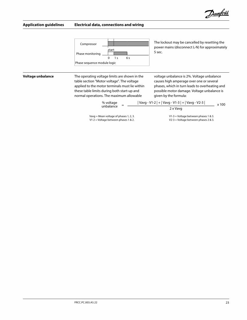
The lockout may be cancelled by resetting the power mains (disconnect L-N) for approximately 5 sec.
Electrical data, connections and wiring
The operating voltage limits are shown in the table section "Motor voltage". The voltage applied to the motor terminals must lie within these table limits during both start-up and normal operations. The maximum allowable
voltage unbalance is 2%. Voltage unbalance causes high amperage over one or several phases, which in turn leads to overheating and possible motor damage. Voltage unbalance is given by the formula:
Vavg = Mean voltage of phases 1, 2, 3.V1-2 = Voltage between phases 1 & 2.
V1-3 = Voltage between phases 1 & 3.V2-3 = Voltage between phases 2 & 3.
| Vavg - V1-2 | + | Vavg - V1-3 | + | Vavg - V2-3 |
2 x Vavg
% voltage unbalance = x 100
Voltage unbalance
Compressor
startPhase monitoring
0 1 s 6 s
Phase sequence module logic
23FRCC.PC.003.A5.22
Application guidelines
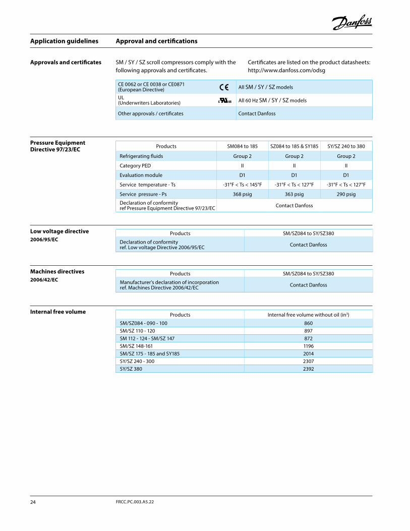
Approval and certifications
Approvals and certificates
Pressure Equipment Directive 97/23/EC
Machines directives2006/42/EC
Low voltage directive2006/95/EC
Internal free volume
SM / SY / SZ scroll compressors comply with the following approvals and certificates.
Certificates are listed on the product datasheets: http://www.danfoss.com/odsg
CE 0062 or CE 0038 or CE0871 (European Directive) All SM / SY / SZ models
UL (Underwriters Laboratories) All 60 Hz SM / SY / SZ models
Other approvals / certificates Contact Danfoss
Products SM/SZ084 to SY/SZ380
Manufacturer's declaration of incorporation ref. Machines Directive 2006/42/EC Contact Danfoss
Products SM/SZ084 to SY/SZ380
Declaration of conformity ref. Low voltage Directive 2006/95/EC Contact Danfoss
Products Internal free volume without oil (in3)
SM/SZ084 - 090 - 100 860SM/SZ 110 - 120 897SM 112 - 124 - SM/SZ 147 872SM/SZ 148-161 1196SM/SZ 175 - 185 and SY185 2014SY/SZ 240 - 300 2307SY/SZ 380 2392
Products SM084 to 185 SZ084 to 185 & SY185 SY/SZ 240 to 380
Refrigerating fluids Group 2 Group 2 Group 2
Category PED II II II
Evaluation module D1 D1 D1
Service temperature - Ts -31°F < Ts < 145°F -31°F < Ts < 127°F -31°F < Ts < 127°F
Service pressure - Ps 368 psig 363 psig 290 psig
Declaration of conformityref Pressure Equipment Directive 97/23/EC Contact Danfoss
Application guidelines
24 FRCC.PC.003.A5.22
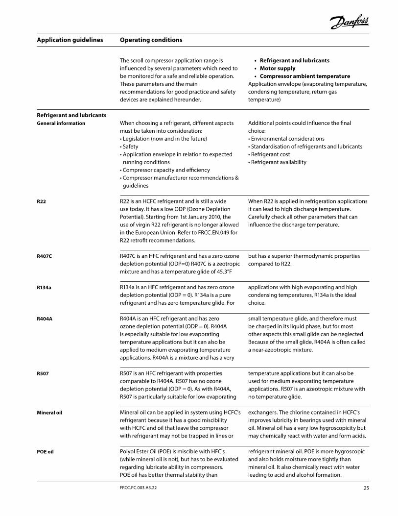
Operating conditions
When choosing a refrigerant, different aspects must be taken into consideration:• Legislation (now and in the future)• Safety• Application envelope in relation to expected
running conditions• Compressor capacity and efficiency• Compressor manufacturer recommendations &
guidelines
Additional points could influence the final choice:• Environmental considerations• Standardisation of refrigerants and lubricants• Refrigerant cost• Refrigerant availability
R22 is an HCFC refrigerant and is still a wide use today. It has a low ODP (Ozone Depletion Potential). Starting from 1st January 2010, the use of virgin R22 refrigerant is no longer allowed in the European Union. Refer to FRCC.EN.049 for R22 retrofit recommendations.
When R22 is applied in refrigeration applications it can lead to high discharge temperature. Carefully check all other parameters that can influence the discharge temperature.
R407C is an HFC refrigerant and has a zero ozone depletion potential (ODP=0) R407C is a zeotropic mixture and has a temperature glide of 45.3°F
but has a superior thermodynamic properties compared to R22.
R404A is an HFC refrigerant and has zero ozone depletion potential (ODP = 0). R404A is especially suitable for low evaporating temperature applications but it can also be applied to medium evaporating temperature applications. R404A is a mixture and has a very
small temperature glide, and therefore must be charged in its liquid phase, but for most other aspects this small glide can be neglected. Because of the small glide, R404A is often called a near-azeotropic mixture.
R507 is an HFC refrigerant with properties comparable to R404A. R507 has no ozone depletion potential (ODP = 0). As with R404A, R507 is particularly suitable for low evaporating
temperature applications but it can also be used for medium evaporating temperature applications. R507 is an azeotropic mixture with no temperature glide.
Mineral oil can be applied in system using HCFC's refrigerant because it has a good miscibility with HCFC and oil that leave the compressor with refrigerant may not be trapped in lines or
exchangers. The chlorine contained in HCFC's improves lubricity in bearings used with mineral oil. Mineral oil has a very low hygroscopicity but may chemically react with water and form acids.
Polyol Ester Oil (POE) is miscible with HFC's (while mineral oil is not), but has to be evaluated regarding lubricate ability in compressors.POE oil has better thermal stability than
refrigerant mineral oil. POE is more hygroscopic and also holds moisture more tightly than mineral oil. It also chemically react with water leading to acid and alcohol formation.
R134a is an HFC refrigerant and has zero ozone depletion potential (ODP = 0). R134a is a pure refrigerant and has zero temperature glide. For
applications with high evaporating and high condensing temperatures, R134a is the ideal choice.
General information
R22
R407C
R404A
R507
POE oil
Mineral oil
R134a
Refrigerant and lubricants
The scroll compressor application range is influenced by several parameters which need to be monitored for a safe and reliable operation.These parameters and the main recommendations for good practice and safety devices are explained hereunder.
• Refrigerant and lubricants• Motor supply• Compressor ambient temperature
Application envelope (evaporating temperature, condensing temperature, return gas temperature)
25FRCC.PC.003.A5.22
Application guidelines
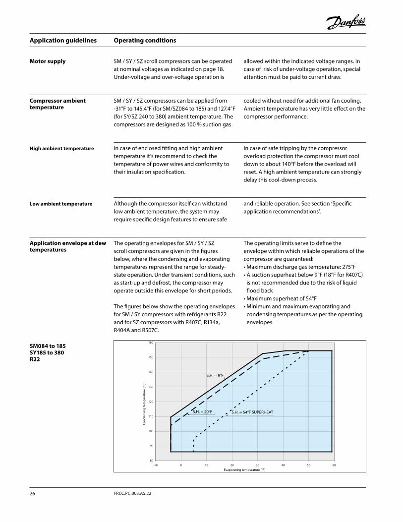
Operating conditions
SM084 to 185 SY185 to 380 R22
Motor supply SM / SY / SZ scroll compressors can be operated at nominal voltages as indicated on page 18. Under-voltage and over-voltage operation is
allowed within the indicated voltage ranges. In case of risk of under-voltage operation, special attention must be paid to current draw.
The operating envelopes for SM / SY / SZ scroll compressors are given in the figures below, where the condensing and evaporating temperatures represent the range for steady-state operation. Under transient conditions, such as start-up and defrost, the compressor may operate outside this envelope for short periods.
The figures below show the operating envelopes for SM / SY compressors with refrigerants R22 and for SZ compressors with R407C, R134a, R404A and R507C.
The operating limits serve to define the envelope within which reliable operations of the compressor are guaranteed:• Maximum discharge gas temperature: 275°F• A suction superheat below 9°F (18°F for R407C)
is not recommended due to the risk of liquid flood back
• Maximum superheat of 54°F• Minimum and maximum evaporating and
condensing temperatures as per the operating envelopes.
SM / SY / SZ compressors can be applied from -31°F to 145.4°F (for SM/SZ084 to 185) and 127.4°F (for SY/SZ 240 to 380) ambient temperature. The compressors are designed as 100 % suction gas
cooled without need for additional fan cooling. Ambient temperature has very little effect on the compressor performance.
In case of enclosed fitting and high ambient temperature it’s recommend to check the temperature of power wires and conformity to their insulation specification.
In case of safe tripping by the compressor overload protection the compressor must cool down to about 140°F before the overload will reset. A high ambient temperature can strongly delay this cool-down process.
Although the compressor itself can withstand low ambient temperature, the system may require specific design features to ensure safe
and reliable operation. See section ‘Specific application recommendations’.
Application envelope at dew temperatures
Compressor ambient temperature
High ambient temperature
Low ambient temperature
80
90
100
110
120
130
140
150
160
-10 0 10 20 30 40 50 60
Con
dens
ing
tem
per
atur
e (°
F)
Evaporating temperature (°F)
S.H. = 54°F SUPERHEATS.H. = 20°F
S.H. = 9°F
Application guidelines
26 FRCC.PC.003.A5.22
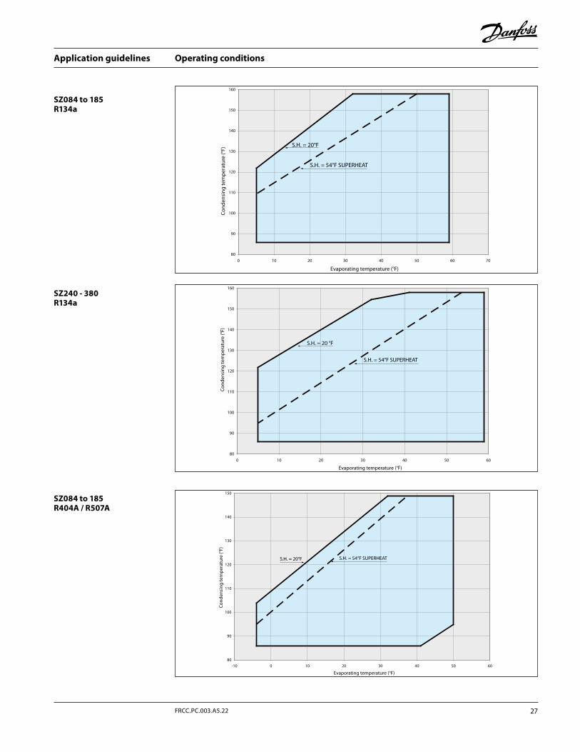
Operating conditions
SZ084 to 185 R134a
SZ240 - 380 R134a
SZ084 to 185 R404A / R507A
80
90
100
110
120
130
140
150
160
0 10 20 30 40 50 60 70
Con
dens
ing
tem
per
atur
e (°
F)
Evaporating temperature (°F)
S.H. = 54°F SUPERHEAT
S.H. = 20°F
80
90
100
110
120
130
140
150
160
0 10 20 30 40 50 60
Con
dens
ing
tem
per
atur
e (°
F)
S.H. = 20 °F
Evaporating temperature (°F)
S.H. = 54°F SUPERHEAT
80
90
100
110
120
130
140
150
-10 0 10 20 30 40 50 60
Evaporating temperature (°F)
S.H. = 20°F S.H. = 54°F SUPERHEAT
Con
dens
ing
tem
per
atur
e (°
F)
27FRCC.PC.003.A5.22
Application guidelines
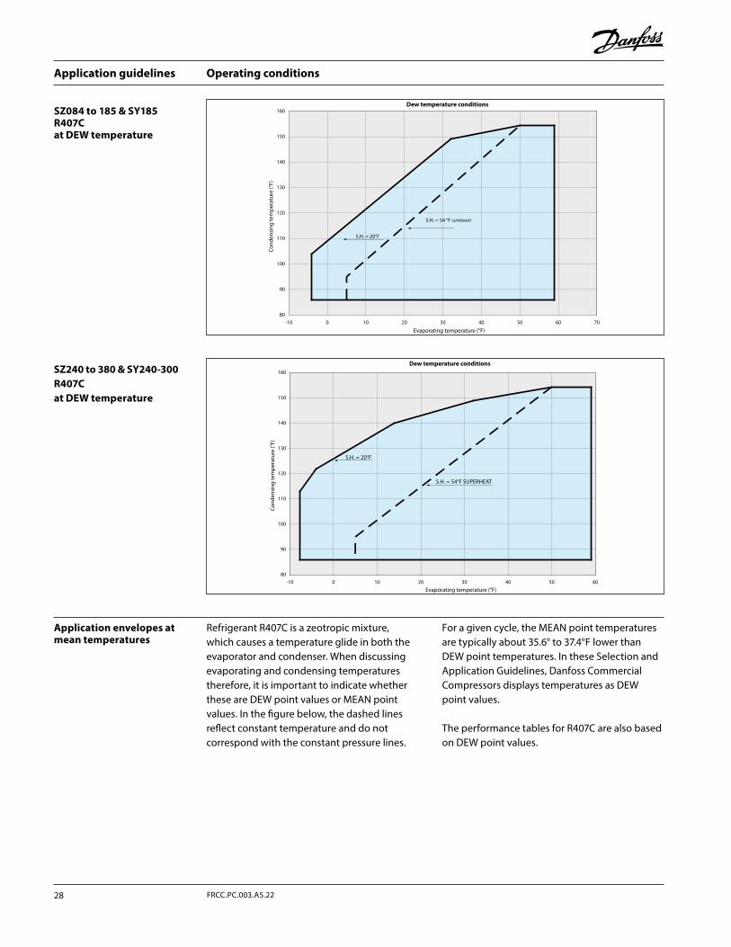
Operating conditions
SZ240 to 380 & SY240-300R407C at DEW temperature
SZ084 to 185 & SY185 R407C at DEW temperature
Application envelopes at mean temperatures
Refrigerant R407C is a zeotropic mixture, which causes a temperature glide in both the evaporator and condenser. When discussing evaporating and condensing temperatures therefore, it is important to indicate whether these are DEW point values or MEAN point values. In the figure below, the dashed lines reflect constant temperature and do not correspond with the constant pressure lines.
For a given cycle, the MEAN point temperatures are typically about 35.6° to 37.4°F lower than DEW point temperatures. In these Selection and Application Guidelines, Danfoss Commercial Compressors displays temperatures as DEW point values.
The performance tables for R407C are also based on DEW point values.
80
90
100
110
120
130
140
150
160
-10 0 10 20 30 40 50 60
Con
dens
ing
tem
per
atur
e (°
F)
Evaporating temperature (°F)
Dew temperature conditions
S.H. = 54°F SUPERHEAT
S.H. = 20°F
80
90
100
110
120
130
140
150
160
-10 0 10 20 30 40 50 60 70
S.H. = 54 °F SUPERHEAT
S.H. = 20°F
Con
dens
ing
tem
per
atur
e (°
F)
Evaporating temperature (°F)
Dew temperature conditions
Application guidelines
28 FRCC.PC.003.A5.22
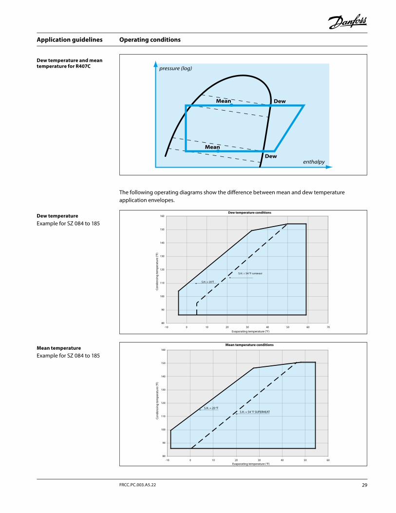
Operating conditions
Dew temperature and mean temperature for R407C
The following operating diagrams show the difference between mean and dew temperature application envelopes.
Dew temperatureExample for SZ 084 to 185
Mean temperatureExample for SZ 084 to 185
80
90
100
110
120
130
140
150
160
-10 0 10 20 30 40 50 60 70
S.H. = 54 °F SUPERHEAT
S.H. = 20°F
Con
dens
ing
tem
per
atur
e (°
F)
Evaporating temperature (°F)
Dew temperature conditions
80
90
100
110
120
130
140
150
160
-10 0 10 20 30 40 50 60
Con
dens
ing
tem
per
atur
e (°
F)
Evaporating temperature (°F)
Mean temperature conditions
S.H. = 20 °FS.H. = 54 °F SUPERHEAT
pressure (log)
enthalpy
Dew
Dew
Mean
Mean
29FRCC.PC.003.A5.22
Application guidelines
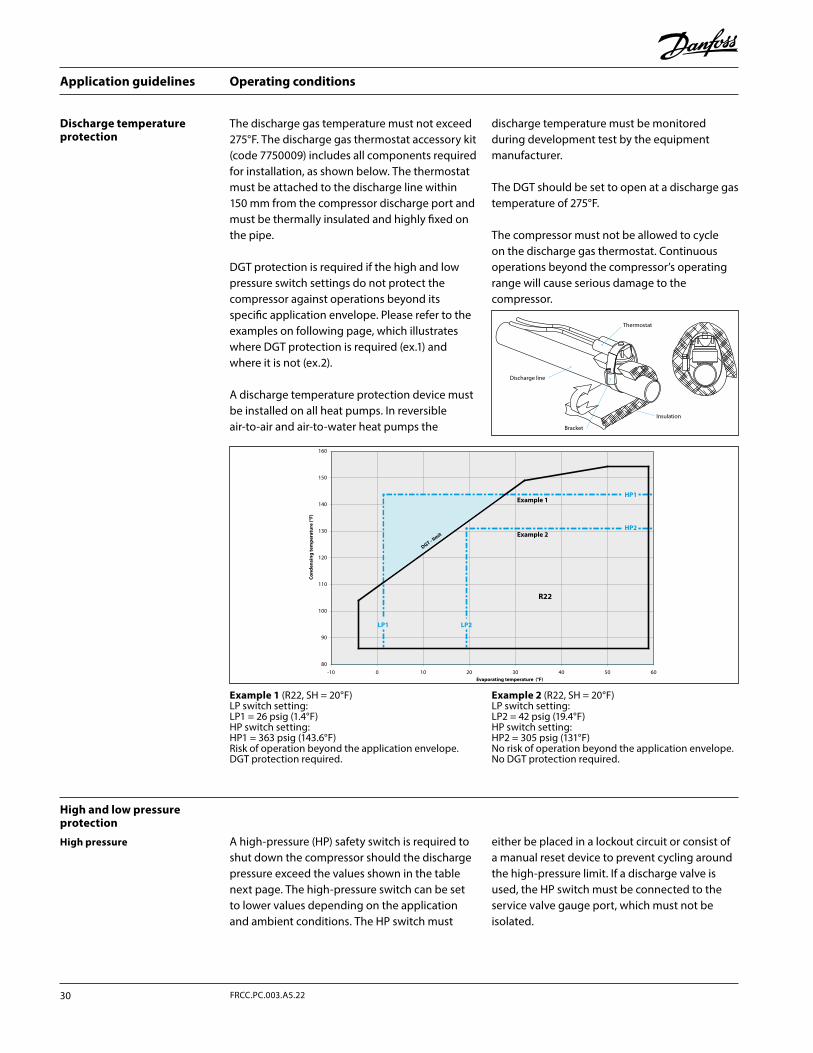
Operating conditions
The discharge gas temperature must not exceed 275°F. The discharge gas thermostat accessory kit (code 7750009) includes all components required for installation, as shown below. The thermostat must be attached to the discharge line within 150 mm from the compressor discharge port and must be thermally insulated and highly fixed on the pipe.
DGT protection is required if the high and low pressure switch settings do not protect the compressor against operations beyond its specific application envelope. Please refer to the examples on following page, which illustrates where DGT protection is required (ex.1) and where it is not (ex.2).
A discharge temperature protection device must be installed on all heat pumps. In reversible air-to-air and air-to-water heat pumps the
discharge temperature must be monitored during development test by the equipment manufacturer.
The DGT should be set to open at a discharge gas temperature of 275°F.
The compressor must not be allowed to cycle on the discharge gas thermostat. Continuous operations beyond the compressor’s operating range will cause serious damage to the compressor.
Discharge temperature protection
A high-pressure (HP) safety switch is required to shut down the compressor should the discharge pressure exceed the values shown in the table next page. The high-pressure switch can be set to lower values depending on the application and ambient conditions. The HP switch must
either be placed in a lockout circuit or consist of a manual reset device to prevent cycling around the high-pressure limit. If a discharge valve is used, the HP switch must be connected to the service valve gauge port, which must not be isolated.
High and low pressure protection
High pressure
Example 1 (R22, SH = 20°F)LP switch setting: LP1 = 26 psig (1.4°F)HP switch setting: HP1 = 363 psig (143.6°F)Risk of operation beyond the application envelope.DGT protection required.
Example 2 (R22, SH = 20°F)LP switch setting: LP2 = 42 psig (19.4°F)HP switch setting: HP2 = 305 psig (131°F)No risk of operation beyond the application envelope.No DGT protection required.
80
90
100
110
120
130
140
150
160
-10 0 10 20 30 40 50 60
Co
nd
ensi
ng
tem
per
atu
re (°
F)
Evaporating temperature (°F)
Example 2
DGT - lim
it
Example 1
R22
HP2
LP2LP1
HP1
Discharge line
Insulation
Bracket
Thermostat
Application guidelines
30 FRCC.PC.003.A5.22
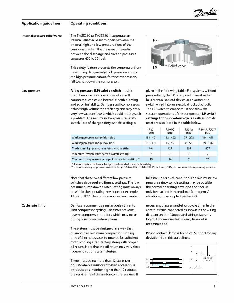
Operating conditions
A low pressure (LP) safety switch must be used. Deep vacuum operations of a scroll compressor can cause internal electrical arcing and scroll instability. Danfoss scroll compressors exhibit high volumetric efficiency and may draw very low vacuum levels, which could induce such a problem. The minimum low-pressure safety switch (loss of charge safety switch) setting is
given in the following table. For systems without pump-down, the LP safety switch must either be a manual lockout device or an automatic switch wired into an electrical lockout circuit. The LP switch tolerance must not allow for vacuum operations of the compressor. LP switch settings for pump-down cycles with automatic reset are also listed in the table below.
Low pressure
Internal pressure relief valve
Cycle rate limit Danfoss recommends a restart delay timer to limit compressor cycling. The timer prevents reverse compressor rotation, which may occur during brief power interruptions.
The system must be designed in a way that guarantees a minimum compressor running time of 2 minutes so as to provide for sufficient motor cooling after start-up along with proper oil return. Note that the oil return may vary since it depends upon system design.
There must be no more than 12 starts per hour (6 when a resistor soft-start accessory is introduced); a number higher than 12 reduces the service life of the motor-compressor unit. If
necessary, place an anti-short-cycle timer in the control circuit, connected as shown in the wiring diagram section "Suggested wiring diagrams logic". A three-minute (180-sec) time out is recommended.
Please contact Danfoss Technical Support for any deviation from this guidelines.
Note that these two different low pressure switches also require different settings. The low pressure pump down switch setting must always be within the operating envelope, for example 13 psi for R22. The compressor can be operated
full time under such condition. The minimum low pressure safety switch setting may be outside the normal operating envelope and should only be reached in exceptional (emergency) situations, for example 7 psi for R22.
The SY/SZ240 to SY/SZ380 incorporate an internal relief valve set to open between the internal high and low pressure sides of the compressor when the pressure differential between the discharge and suction pressures surpasses 450 to 551 psi.
This safety feature prevents the compressor from developing dangerously high pressures should the high pressure cutout, for whatever reason, fail to shut down the compressor.
HP
LP Relief valve
T T
THTH
KA
A1 A2 A3A1 180 s
A2 KA
~
~
R22psig
R407Cpsig
R134apsig
R404A/R507Apsig
Working pressure range high side 158 - 401 152 - 422 97 - 292 184 - 451
Working pressure range low side 20 - 100 15 - 92 8 - 56 29 - 106
Maximum high pressure safety switch setting 406 427 297 457
Minimum low pressure safety switch setting * 7 7 7 7
Minimum low pressure pump-down switch setting ** 18 14 7 26
*LP safety switch shall never be bypassed and shall have no time delay.** Recommended pump-down switch settings: 1.5 bar (R22, R407C, R404A) or 1 bar (R134a) below nominal evaporating pressure.
31FRCC.PC.003.A5.22
Application guidelines
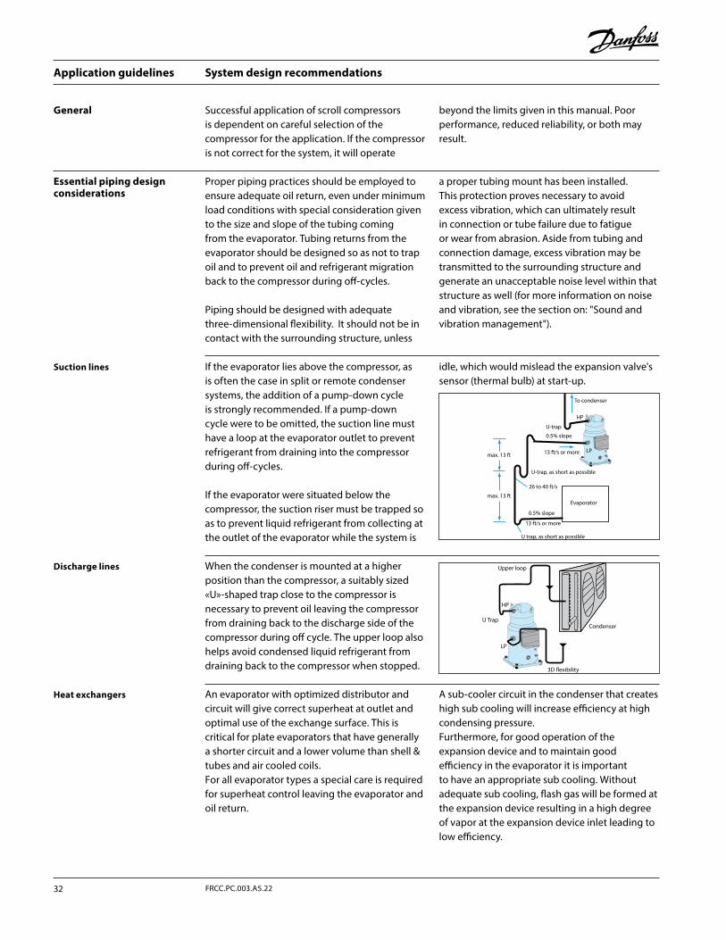
System design recommendations
Proper piping practices should be employed to ensure adequate oil return, even under minimum load conditions with special consideration given to the size and slope of the tubing coming from the evaporator. Tubing returns from the evaporator should be designed so as not to trap oil and to prevent oil and refrigerant migration back to the compressor during off-cycles.
Piping should be designed with adequate three-dimensional flexibility. It should not be in contact with the surrounding structure, unless
a proper tubing mount has been installed. This protection proves necessary to avoid excess vibration, which can ultimately result in connection or tube failure due to fatigue or wear from abrasion. Aside from tubing and connection damage, excess vibration may be transmitted to the surrounding structure and generate an unacceptable noise level within that structure as well (for more information on noise and vibration, see the section on: "Sound and vibration management").
Essential piping design considerations
Suction lines
Discharge lines
Heat exchangers
Successful application of scroll compressors is dependent on careful selection of the compressor for the application. If the compressor is not correct for the system, it will operate
beyond the limits given in this manual. Poor performance, reduced reliability, or both may result.
General
If the evaporator lies above the compressor, as is often the case in split or remote condenser systems, the addition of a pump-down cycle is strongly recommended. If a pump-down cycle were to be omitted, the suction line must have a loop at the evaporator outlet to prevent refrigerant from draining into the compressor during off-cycles.
If the evaporator were situated below the compressor, the suction riser must be trapped so as to prevent liquid refrigerant from collecting at the outlet of the evaporator while the system is
idle, which would mislead the expansion valve's sensor (thermal bulb) at start-up.
When the condenser is mounted at a higher position than the compressor, a suitably sized «U»-shaped trap close to the compressor is necessary to prevent oil leaving the compressor from draining back to the discharge side of the compressor during off cycle. The upper loop also helps avoid condensed liquid refrigerant from draining back to the compressor when stopped.
An evaporator with optimized distributor and circuit will give correct superheat at outlet and optimal use of the exchange surface. This is critical for plate evaporators that have generally a shorter circuit and a lower volume than shell & tubes and air cooled coils.For all evaporator types a special care is required for superheat control leaving the evaporator and oil return.
A sub-cooler circuit in the condenser that creates high sub cooling will increase efficiency at high condensing pressure.Furthermore, for good operation of the expansion device and to maintain good efficiency in the evaporator it is important to have an appropriate sub cooling. Without adequate sub cooling, flash gas will be formed at the expansion device resulting in a high degree of vapor at the expansion device inlet leading to low efficiency.
HP
13 ft/s or more
0.5% slope
To condenser
max. 13 ft
max. 13 ft
0.5% slope
U-trap, as short as possible
U-trap
13 ft/s or more
U trap, as short as possible
Evaporator
LP
26 to 40 ft/s
HP
LP
Condenser
3D flexibility
U Trap
Upper loop
Application guidelines
32 FRCC.PC.003.A5.22
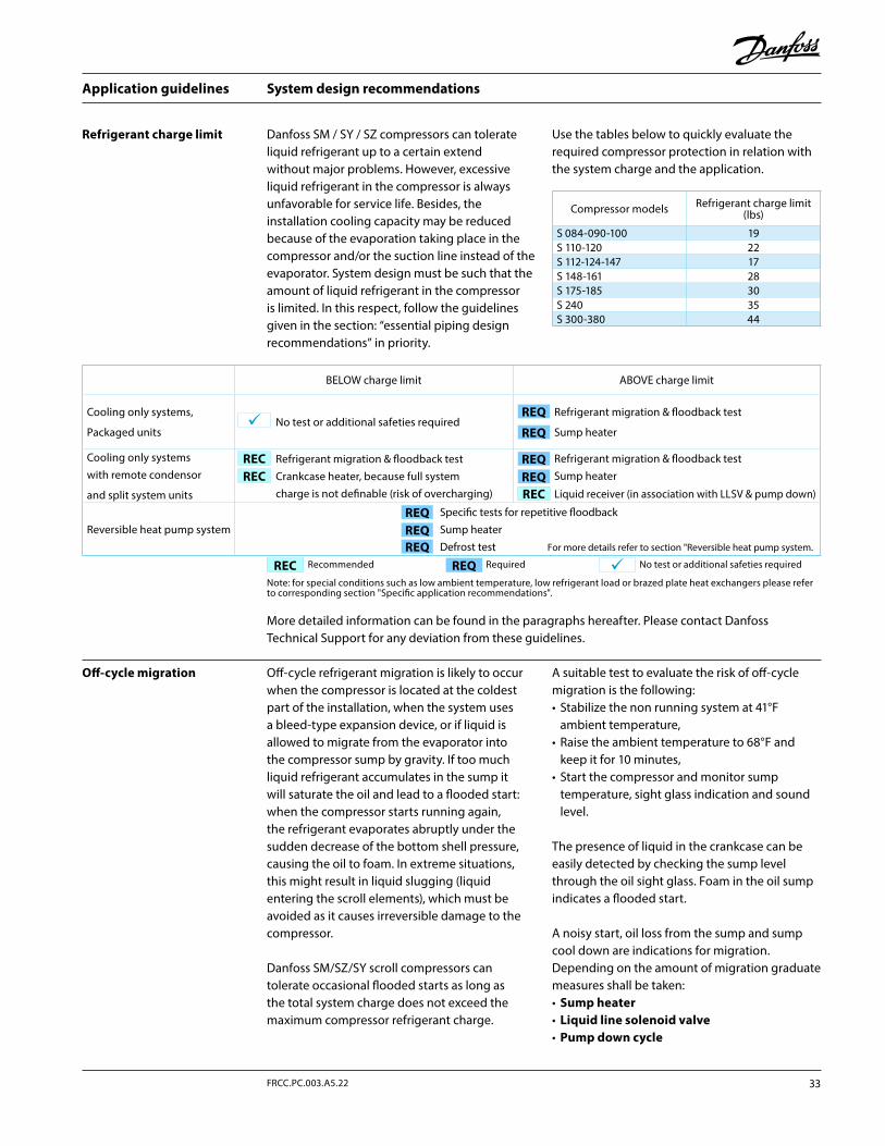
System design recommendations
Refrigerant charge limit Danfoss SM / SY / SZ compressors can tolerate liquid refrigerant up to a certain extend without major problems. However, excessive liquid refrigerant in the compressor is always unfavorable for service life. Besides, the installation cooling capacity may be reduced because of the evaporation taking place in the compressor and/or the suction line instead of the evaporator. System design must be such that the amount of liquid refrigerant in the compressor is limited. In this respect, follow the guidelines given in the section: “essential piping design recommendations” in priority.
Use the tables below to quickly evaluate the required compressor protection in relation with the system charge and the application.
More detailed information can be found in the paragraphs hereafter. Please contact Danfoss Technical Support for any deviation from these guidelines.
Off-cycle migration Off-cycle refrigerant migration is likely to occur when the compressor is located at the coldest part of the installation, when the system uses a bleed-type expansion device, or if liquid is allowed to migrate from the evaporator into the compressor sump by gravity. If too much liquid refrigerant accumulates in the sump it will saturate the oil and lead to a flooded start: when the compressor starts running again, the refrigerant evaporates abruptly under the sudden decrease of the bottom shell pressure, causing the oil to foam. In extreme situations, this might result in liquid slugging (liquid entering the scroll elements), which must be avoided as it causes irreversible damage to the compressor.
Danfoss SM/SZ/SY scroll compressors can tolerate occasional flooded starts as long as the total system charge does not exceed the maximum compressor refrigerant charge.
A suitable test to evaluate the risk of off-cycle migration is the following:• Stabilize the non running system at 41°F
ambient temperature,• Raise the ambient temperature to 68°F and
keep it for 10 minutes,• Start the compressor and monitor sump
temperature, sight glass indication and sound level.
The presence of liquid in the crankcase can be easily detected by checking the sump level through the oil sight glass. Foam in the oil sump indicates a flooded start.
A noisy start, oil loss from the sump and sump cool down are indications for migration. Depending on the amount of migration graduate measures shall be taken:• Sump heater• Liquid line solenoid valve• Pump down cycle
REQREC
BELOW charge limit ABOVE charge limit
Cooling only systems,
Packaged unitsNo test or additional safeties required
Refrigerant migration & floodback test
Sump heater
Cooling only systems with remote condensor
and split system units
Refrigerant migration & floodback test Crankcase heater, because full system charge is not definable (risk of overcharging)
Refrigerant migration & floodback testSump heater
Liquid receiver (in association with LLSV & pump down)
Reversible heat pump systemSpecific tests for repetitive floodbackSump heaterDefrost test For more details refer to section "Reversible heat pump system.
Recommended Required No test or additional safeties required
Note: for special conditions such as low ambient temperature, low refrigerant load or brazed plate heat exchangers please refer to corresponding section "Specific application recommendations".
REC
RECREQ
REQ
REQREQ
REQ
REQ
REQ
REC
Compressor models Refrigerant charge limit (lbs)
S 084-090-100 19S 110-120 22S 112-124-147 17S 148-161 28S 175-185 30S 240 35S 300-380 44
33FRCC.PC.003.A5.22
Application guidelines
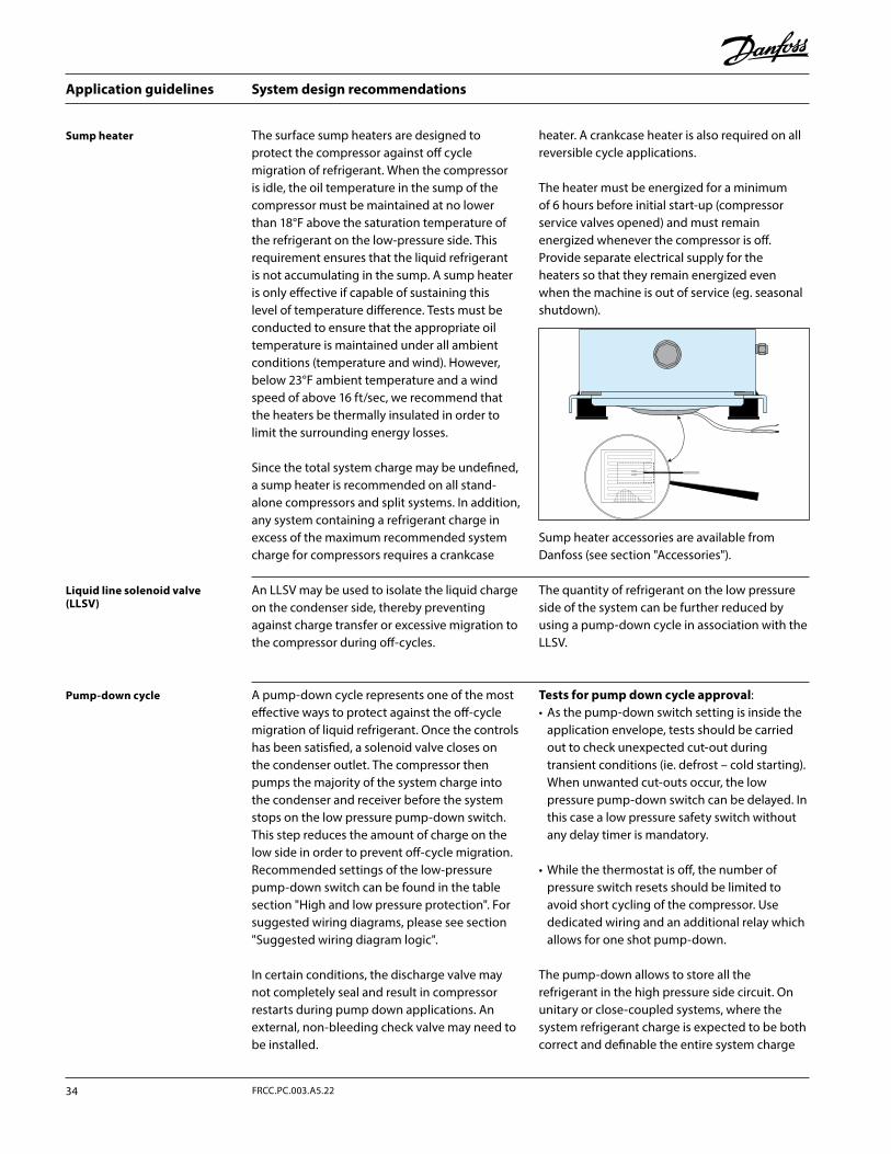
System design recommendations
Sump heater The surface sump heaters are designed to protect the compressor against off cycle migration of refrigerant. When the compressor is idle, the oil temperature in the sump of the compressor must be maintained at no lower than 18°F above the saturation temperature of the refrigerant on the low-pressure side. This requirement ensures that the liquid refrigerant is not accumulating in the sump. A sump heater is only effective if capable of sustaining this level of temperature difference. Tests must be conducted to ensure that the appropriate oil temperature is maintained under all ambient conditions (temperature and wind). However, below 23°F ambient temperature and a wind speed of above 16 ft/sec, we recommend that the heaters be thermally insulated in order to limit the surrounding energy losses.
Since the total system charge may be undefined, a sump heater is recommended on all stand-alone compressors and split systems. In addition, any system containing a refrigerant charge in excess of the maximum recommended system charge for compressors requires a crankcase
heater. A crankcase heater is also required on all reversible cycle applications.
The heater must be energized for a minimum of 6 hours before initial start-up (compressor service valves opened) and must remain energized whenever the compressor is off. Provide separate electrical supply for the heaters so that they remain energized even when the machine is out of service (eg. seasonal shutdown).
Sump heater accessories are available from Danfoss (see section "Accessories").
Liquid line solenoid valve (LLSV)
Pump-down cycle
An LLSV may be used to isolate the liquid charge on the condenser side, thereby preventing against charge transfer or excessive migration to the compressor during off-cycles.
The quantity of refrigerant on the low pressure side of the system can be further reduced by using a pump-down cycle in association with the LLSV.
A pump-down cycle represents one of the most effective ways to protect against the off-cycle migration of liquid refrigerant. Once the controls has been satisfied, a solenoid valve closes on the condenser outlet. The compressor then pumps the majority of the system charge into the condenser and receiver before the system stops on the low pressure pump-down switch. This step reduces the amount of charge on the low side in order to prevent off-cycle migration. Recommended settings of the low-pressure pump-down switch can be found in the table section "High and low pressure protection". For suggested wiring diagrams, please see section "Suggested wiring diagram logic".
In certain conditions, the discharge valve may not completely seal and result in compressor restarts during pump down applications. An external, non-bleeding check valve may need to be installed.
Tests for pump down cycle approval:• As the pump-down switch setting is inside the
application envelope, tests should be carried out to check unexpected cut-out during transient conditions (ie. defrost – cold starting). When unwanted cut-outs occur, the low pressure pump-down switch can be delayed. In this case a low pressure safety switch without any delay timer is mandatory.
• While the thermostat is off, the number of pressure switch resets should be limited to avoid short cycling of the compressor. Use dedicated wiring and an additional relay which allows for one shot pump-down.
The pump-down allows to store all the refrigerant in the high pressure side circuit. On unitary or close-coupled systems, where the system refrigerant charge is expected to be both correct and definable the entire system charge
Application guidelines
34 FRCC.PC.003.A5.22
System design recommendations
Suction accumulator
Liquid flood back
Suction accumulator: a suction accumulator offers protection against refrigerant flood back at start-up, during operations or defrosting by trapping the liquid refrigerant upstream from the compressor. The suction accumulator also protects against off-cycle migration by providing additional internal free volume to the low side of the system.
A suction accumulator must be carefully dimensioned, taking into account the refrigerant charge as well as the gas velocity in the suction line.
The accumulator should not be sized for less than 50% of the total system charge. Tests must be conducted to determine the actual refrigerant holding capacity needed for the application.
Depending on the operating conditions it may happen that the recommended connections of the accumulator are one size smaller than the suction line.
During normal operation, refrigerant enters the compressor as a superheated vapor. Liquid flood back occurs when a part of the refrigerant entering the compressor is still in liquid state.
Danfoss SM/SY/SZ scroll compressors can tolerate occasional liquid flood back. However
system design must be such that repeated and excessive flood back is not possible.
A continuous liquid flood back will cause oil dilution and, in extreme situations lead to lack of lubrication and high rate of oil leaving the compressor.
Liquid flood back test - Repetitive liquid flood back testing must be carried out under expansion valve threshold operating conditions: a high pressure ratio and minimum evaporator load, along with the measurement of suction superheat, oil sump temperature and discharge gas temperature.
During operations, liquid flood back may be detected by measuring either the oil sump temperature or the discharge gas temperature. If at any time during operations, the oil sump temperature drops to within 10K or less above
the saturated suction temperature, or should the discharge gas temperature be less than 54°F above the saturated discharge temperature, this indicates liquid flood back.
Continuous liquid flood back can occur with a wrong dimensioning, a wrong setting or malfunction of the expansion device or in case of evaporator fan failure or blocked air filters.
A suction accumulator providing additional protection as explained hereunder can be used to solve light continuous liquid flood back.
may be stored in the condenser during pump-down if all components have been properly sized.
Other application needs a liquid receiver to store the refrigerant.
Receiver dimensioning requires special attention. The receiver shall be large enough to contain part of the system refrigerant charge but it shall not be dimensioned too large. A large receiver easily leads to refrigerant overcharging during maintenance operation.
35FRCC.PC.003.A5.22
Application guidelines

Specific application recommendations
Low ambient operations
Low ambient start-up Under cold ambient conditions (<32°F), upon start-up the pressure in the condenser and, if present, the receiver may be so low that a sufficient pressure differential across the expansion device cannot be developed to properly feed the evaporator. As a result, the compressor may go into a deep vacuum, which can lead to compressor failure due to internal arcing and instability in the scroll members. Under no circumstances should the compressor be allowed to operate under vacuum. The low-pressure control must be set in accordance with the table section "High and low pressure
protection" in order to prevent this from happening.Early feeding of the evaporator and management of the discharge pressure could help to attenuate these effects.Low pressure differentials can also cause the expansion device to «hunt» erratically, which might cause surging conditions within the evaporator, with liquid spillover into the compressor. This effect is most pronounced during low load conditions, which frequently occur during low ambient conditions.
The Danfoss SM/SY/SZ scroll compressor requires a minimum pressure differential of 87 to 102 psi between the suction and discharge pressures to force the orbiting scroll down against the oil film on the thrust bearing. Anything less than this differential and the orbiting scroll can lift up, causing a metal-to-metal contact. It is therefore necessary to maintain sufficient discharge pressure in order to ensure this pressure differential. Care should be taken during low ambient operations when heat removal from air-cooled condensers is greatest and head pressure control may be required for low ambient temperature applications. Operation under low pressure differential may be observed by a significant increase in the sound power level generated by the compressor.
It is recommended that the unit be tested and monitored at minimum load and low ambient conditions as well. The following considerations should be taken into account to ensure proper system operating characteristics.
Expansion device: The expansion device should be sized to ensure proper control of the refrigerant flow into the evaporator. An oversized valve may result in erratic control. This consideration is especially important in manifolded units where low load conditions may require the frequent cycling of compressors. This can lead to liquid refrigerant entering the compressor if the expansion valve does not provide stable refrigerant super-heat control under varying loads.
The superheat setting of the expansion device should be sufficient to ensure proper superheat
levels during low loading periods. A minimum of 9 °F stable superheat is required.
Head pressure control under low ambient conditions: Several possible solutions are available to prevent the risk of compressor to vacuum and low pressure differential between the suction and discharge pressures.
In air-cooled machines, cycling the fans with a head pressure controller will ensure that the fans remain off until the condensing pressure has reached a satisfactory level. Variable speed fans can also be used to control the condensing pressure. In water-cooled units, the same can be performed using a water regulator valve that is also operated by head pressure, thereby ensuring that the water valve does not open until the condensing pressure reaches a satisfactory level.
The minimum condensing pressure must be set at the minimum saturated condensing temperature shown in the application envelopes.
Under very low ambient conditions, in which testing has revealed that the above procedures might not ensure satisfactory condensing and suction pressures, the use of a head pressure control valve is recommended. Note: This solution requires extra refrigerant charge, which can introduce other problems. A non-return valve in the discharge line is recommended and special care should be taken when designing the discharge line.
For further information, please contact Danfoss.
Low ambient application
Application guidelines
36 FRCC.PC.003.A5.22
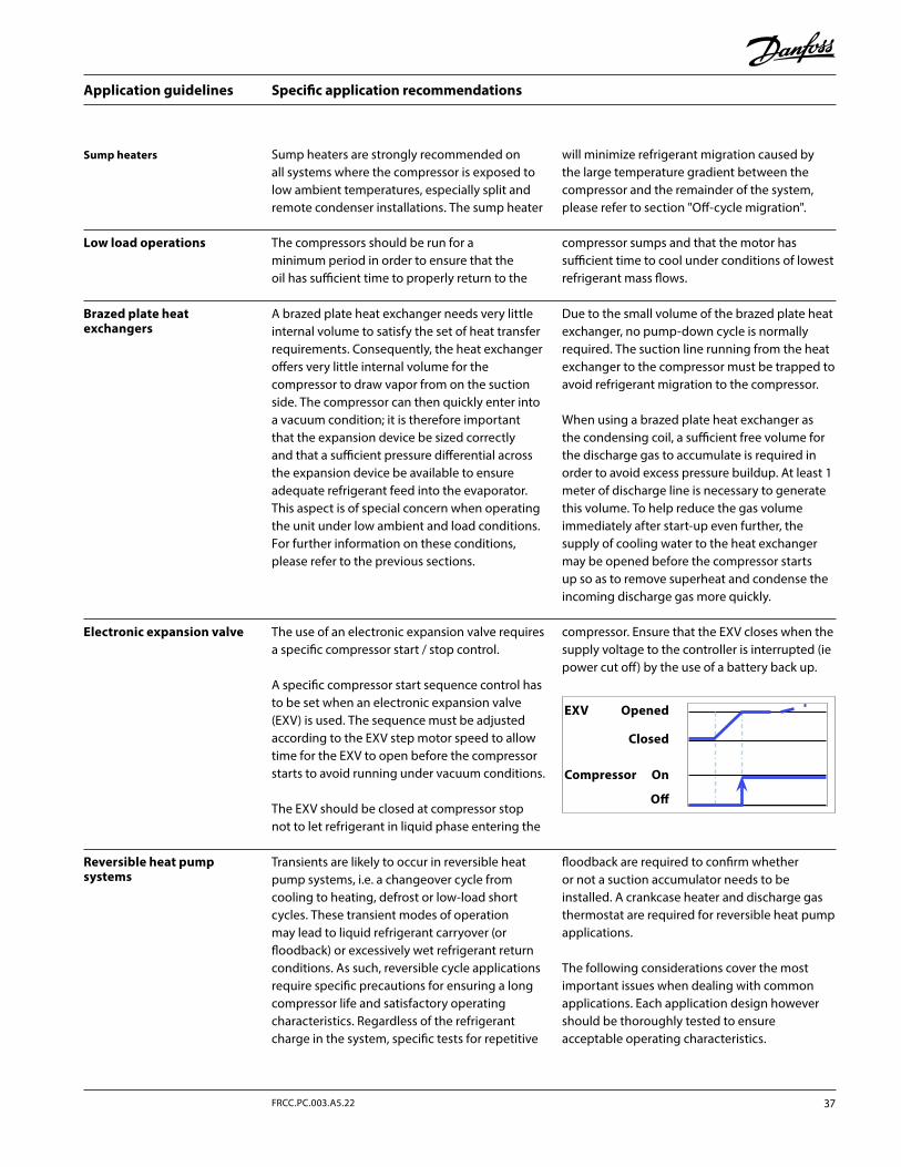
Sump heaters Sump heaters are strongly recommended on all systems where the compressor is exposed to low ambient temperatures, especially split and remote condenser installations. The sump heater
will minimize refrigerant migration caused by the large temperature gradient between the compressor and the remainder of the system, please refer to section "Off-cycle migration".
Specific application recommendations
Brazed plate heat exchangers
A brazed plate heat exchanger needs very little internal volume to satisfy the set of heat transfer requirements. Consequently, the heat exchanger offers very little internal volume for the compressor to draw vapor from on the suction side. The compressor can then quickly enter into a vacuum condition; it is therefore important that the expansion device be sized correctly and that a sufficient pressure differential across the expansion device be available to ensure adequate refrigerant feed into the evaporator. This aspect is of special concern when operating the unit under low ambient and load conditions. For further information on these conditions, please refer to the previous sections.
Due to the small volume of the brazed plate heat exchanger, no pump-down cycle is normally required. The suction line running from the heat exchanger to the compressor must be trapped to avoid refrigerant migration to the compressor.
When using a brazed plate heat exchanger as the condensing coil, a sufficient free volume for the discharge gas to accumulate is required in order to avoid excess pressure buildup. At least 1 meter of discharge line is necessary to generate this volume. To help reduce the gas volume immediately after start-up even further, the supply of cooling water to the heat exchanger may be opened before the compressor starts up so as to remove superheat and condense the incoming discharge gas more quickly.
Reversible heat pump systems
Transients are likely to occur in reversible heat pump systems, i.e. a changeover cycle from cooling to heating, defrost or low-load short cycles. These transient modes of operation may lead to liquid refrigerant carryover (or floodback) or excessively wet refrigerant return conditions. As such, reversible cycle applications require specific precautions for ensuring a long compressor life and satisfactory operating characteristics. Regardless of the refrigerant charge in the system, specific tests for repetitive
floodback are required to confirm whether or not a suction accumulator needs to be installed. A crankcase heater and discharge gas thermostat are required for reversible heat pump applications.
The following considerations cover the most important issues when dealing with common applications. Each application design however should be thoroughly tested to ensure acceptable operating characteristics.
Electronic expansion valve The use of an electronic expansion valve requires a specific compressor start / stop control.
A specific compressor start sequence control has to be set when an electronic expansion valve (EXV) is used. The sequence must be adjusted according to the EXV step motor speed to allow time for the EXV to open before the compressor starts to avoid running under vacuum conditions.
The EXV should be closed at compressor stop not to let refrigerant in liquid phase entering the
compressor. Ensure that the EXV closes when the supply voltage to the controller is interrupted (ie power cut off) by the use of a battery back up.
The compressors should be run for a minimum period in order to ensure that the oil has sufficient time to properly return to the
compressor sumps and that the motor has sufficient time to cool under conditions of lowest refrigerant mass flows.
Low load operations
EXV Opened
Closed
Compressor On
Off
37FRCC.PC.003.A5.22
Application guidelines
Specific application recommendations
Discharge temperature thermostat
Heat pumps frequently utilize high condensing temperatures in order to achieve a sufficient temperature rise in the medium being heated. At the same time, they often require low evaporator pressures to obtain sufficient temperature differentials between the evaporator and the outside temperature. This situation may result in high discharge temperature; as such, it is mandatory that a discharge gas thermostat be installed on the discharge line to protect
the compressor from excessive temperatures. Operating the compressor at too high discharge temperatures can result in mechanical damage to the compressor as well as thermal degradation of the compressor lubricating oil and a lack of sufficient lubrication.
The discharge gas thermostat should be set to shut down the compressor in the event discharge gas rises above 275°F.
Discharge line and reversing valve, solenoid valves
Defrost and reverse cycle
Sump heaters Sump heaters are mandatory on reversible cycle applications given the high probability of liquid migration back to the compressor sump
during off-cycles due to the outdoor location of most units and operations during low ambient conditions.
The Danfoss SM/SY/SZ scroll compressor is a high volumetric machine and, as such, can rapidly build up pressure in the discharge line if gas in the line becomes obstructed even for a very short period of time which situation may occur with slow-acting reversing valves in heat pumps. Discharge pressures exceeding the operating envelope may result in nuisance high-pressure switch cutouts and place excess strain on both the bearings and motor.
To prevent such occurrences, it is important that a 1-meter minimum discharge line length be allowed between the compressor discharge port and the reversing valve or any other restriction. This gives sufficient free volume for the discharge gas to collect and to reduce the pressure peak during the time it takes for the valve to change
position. At the same time, it is important that the selection and sizing of the reversing or 4-way valve ensure that the valve switches quickly enough to prevent against too high discharge pressure and nuisance high-pressure cutouts.
Check with the valve manufacturer for optimal sizing and recommended mounting positions.
In applications with heat recovery or condenser partialisation, servo piloted solenoid valve has to be properly sized or associated with a second small valve in parallel, in order to avoid quick discharge pressure drops when opening. This phenomenon could lead to hammering effects and create constraints on the non return valve integrated in discharge fitting (SM/SY/SZ180 to 380).
The Danfoss SM/SY/SZ scroll compressor has the ability to withstand a certain amount of liquid refrigerant dynamic slug.
When compressors are installed in parallel, in order to limit liquid amount handled per compressor when beginning and ending defrost, it is recommended to avoid running part load (keep all compressors running or keep them stopped when moving 4-way valves).
For further details, please refer to Parallel application guidelines FRCC.PC.005.
EXV can also be opened when compressors are stopped and before 4 way valve is moving in order to decrease pressure difference. Opening degree and time have to be set in order to keep a minimum pressure difference for 4 way valve moving.
Application guidelines
38 FRCC.PC.003.A5.22
Specific application recommendations
The use of a suction line accumulator is strongly recommended in reversible cycle applications as a result of the possibility of a substantial quantity of liquid refrigerant remaining in the evaporator, which acts as a condenser during the heating cycle.
This liquid refrigerant can then return to the compressor, either flooding the sump with refrigerant or as a dynamic liquid slug when
the cycle switches back to a defrost cycle or to normal cooling operations.
Sustained and repeated liquid slugging and floodback can seriously impair the oil’s ability to lubricate the compressor bearings. This situation can be observed in wet climates where it is necessary to frequently defrost the outdoor coil in an air source heat pump. In such cases a suction accumulator becomes mandatory.
Suction line accumulator
Apart from residual moisture in the system after commissioning, water could also enter the refrigeration circuit during operation. Water in the system shall always be avoided. Not only because it can shortly lead to electrical failure, sludge in sump and corrosion but in particular because it can cause serious safety risks. Common causes for water leaks are corrosion and freezing.Corrosion: Materials in the system shall be compliant with water and protected against corrosion.
Freezing: When water freezes into ice its volume expands which can damage heat exchanger walls and cause leaks. During off periods water inside heat exchangers could start freezing when ambient temperature is lower than 32°F. During on periods ice banking could occur when the circuit is running continuously at too low load. Both situations should be avoided by connecting a pressure and thermostat switch in the safety line.
Water utilizing systems
39FRCC.PC.003.A5.22
Application guidelines
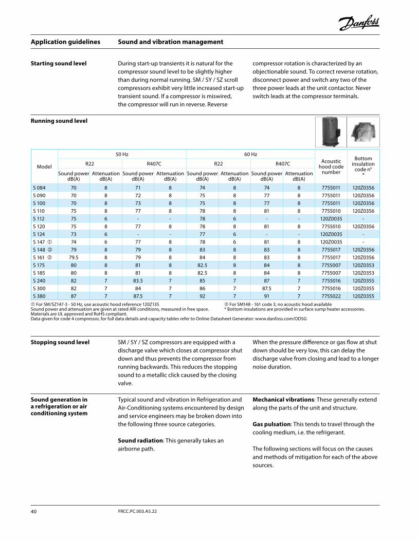
Sound and vibration management
SM / SY / SZ compressors are equipped with a discharge valve which closes at compressor shut down and thus prevents the compressor from running backwards. This reduces the stopping sound to a metallic click caused by the closing valve.
When the pressure difference or gas flow at shut down should be very low, this can delay the discharge valve from closing and lead to a longer noise duration.
Running sound level
Stopping sound level
During start-up transients it is natural for the compressor sound level to be slightly higher than during normal running. SM / SY / SZ scroll compressors exhibit very little increased start-up transient sound. If a compressor is miswired, the compressor will run in reverse. Reverse
compressor rotation is characterized by an objectionable sound. To correct reverse rotation, disconnect power and switch any two of the three power leads at the unit contactor. Never switch leads at the compressor terminals.
Starting sound level
Typical sound and vibration in Refrigeration and Air-Conditioning systems encountered by design and service engineers may be broken down into the following three source categories.
Sound radiation: This generally takes an airborne path.
Mechanical vibrations: These generally extend along the parts of the unit and structure.
Gas pulsation: This tends to travel through the cooling medium, i.e. the refrigerant.
The following sections will focus on the causes and methods of mitigation for each of the above sources.
Sound generation in a refrigeration or air conditioning system
Model
50 Hz 60 HzAcoustic
hood code number
Bottom insulation
code n°*
R22 R407C R22 R407C
Sound power dB(A)
Attenuation dB(A)
Sound power dB(A)
Attenuation dB(A)
Sound power dB(A)
Attenuation dB(A)
Sound power dB(A)
Attenuation dB(A)
S 084 70 8 71 8 74 8 74 8 7755011 120Z0356S 090 70 8 72 8 75 8 77 8 7755011 120Z0356S 100 70 8 73 8 75 8 77 8 7755011 120Z0356S 110 75 8 77 8 78 8 81 8 7755010 120Z0356S 112 75 6 - - 78 6 - - 120Z0035 -S 120 75 8 77 8 78 8 81 8 7755010 120Z0356S 124 73 6 - - 77 6 - - 120Z0035 -S 147 74 6 77 8 78 6 81 8 120Z0035 -S 148 79 8 79 8 83 8 83 8 7755017 120Z0356S 161 79.5 8 79 8 84 8 83 8 7755017 120Z0356S 175 80 8 81 8 82.5 8 84 8 7755007 120Z0353S 185 80 8 81 8 82.5 8 84 8 7755007 120Z0353S 240 82 7 83.5 7 85 7 87 7 7755016 120Z0355S 300 82 7 84 7 86 7 87.5 7 7755016 120Z0355S 380 87 7 87.5 7 92 7 91 7 7755022 120Z0355 For SM/SZ147-3 - 50 Hz, use acoustic hood reference 120Z135 For SM148 - 161 code 3, no acoustic hood availableSound power and attenuation are given at rated ARI conditions, measured in free space. * Bottom insulations are provided in surface sump heater accessories.Materials are UL approved and RoHS compliant.Data given for code 4 compressor, for full data details and capacity tables refer to Online Datasheet Generator: www.danfoss.com/ODSG
Application guidelines
40 FRCC.PC.003.A5.22
Sound and vibration management
Compressor sound radiation For sound radiating from the compressor, the emission path is airborne and the sound waves are travelling directly from the machine in all directions.
The Danfoss SM / SY / SZ scroll compressor is designed to be quiet and the frequency of the sound generated is pushed into the higher ranges, which not only are easier to reduce but also do not generate the penetrating power of lower-frequency sound.
Use of sound-insulation materials on the inside of unit panels is an effective means of substantially reducing the sound being transmitted to the outside. Ensure that no components capable of transmitting sound / vibration within the unit
come into direct contact with any non-insulated parts on the walls of the unit.
Because of the Danfoss’s unique design of a full-suction gas-cooled motor, compressor body insulation across its entire operating range is possible. Acoustic hoods are available from Danfoss Commercial Compressors as accessories. They have been developed to meet specific extra low noise requirement. They incorporate sound proofing materials and offer excellent high and low frequency attenuation. These hoods are quick and easy to install and do not increase the overall size of the compressors to a great extend. Refer to section "Running sound level" for sound attenuation and code numbers.
Mechanical vibrations Vibration isolation constitutes the primary method for controlling structural vibration. Danfoss SM / SY / SZ scroll compressors are designed to produce minimal vibration during operations. The use of rubber isolators on the compressor base plate or on the frame of a manifolded unit is very effective in reducing vibration being transmitted from the compressor(s) to the unit. Rubber grommets are supplied with all Danfoss compressors. Once the supplied rubber grommets have been properly mounted, vibration transmitted from the compressor base plate to the unit are held to a strict minimum. In addition, it is extremely important that the frame supporting the
mounted compressor be of sufficient mass and stiffness to help dampen any residual vibration potentially transmitted to the frame. For further information on mounting requirements, please refer to the section on mounting assembly.
The tubing should be designed so as to both reduce the transmission of vibrations to other structures and withstand vibration without incurring any damage. Tubing should also be designed for three-dimensional flexibility. For more information on piping design, please see the section entitled "Essential piping design considerations".
Gas pulsation The Danfoss SM / SY / SZ scroll compressor has been designed and tested to ensure that gas pulsation has been optimized for the most commonly encountered air conditioning pressure ratio. On heat pump installations and other installations where the pressure ratio lies beyond the typical range, testing should be conducted under all expected conditions
and operating configurations to ensure that minimum gas pulsation is present. If an unacceptable level is identified, a discharge muffler with the appropriate resonant volume and mass should be installed. This information can be obtained from the component manufacturer.
41FRCC.PC.003.A5.22
Application guidelines
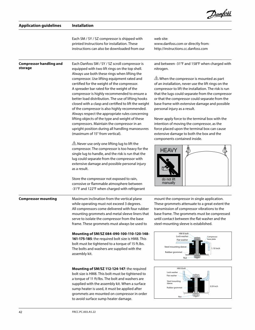
Installation
Maximum inclination from the vertical plane while operating must not exceed 3 degrees.All compressors come delivered with four rubber mounting grommets and metal sleeve liners that serve to isolate the compressor from the base frame. These grommets must always be used to
mount the compressor in single application.These grommets attenuate to a great extent the transmission of compressor vibrations to the base frame. The grommets must be compressed until contact between the flat washer and the steel-mounting sleeve is established.
Each Danfoss SM / SY / SZ scroll compressor is equipped with two lift rings on the top shell. Always use both these rings when lifting the compressor. Use lifting equipment rated and certified for the weight of the compressor. A spreader bar rated for the weight of the compressor is highly recommended to ensure a better load distribution. The use of lifting hooks closed with a clasp and certified to lift the weight of the compressor is also highly recommended. Always respect the appropriate rules concerning lifting objects of the type and weight of these compressors. Maintain the compressor in an upright position during all handling manoeuvres (maximum of 15° from vertical).
Never use only one lifting lug to lift the compressor. The compressor is too heavy for the single lug to handle, and the risk is run that the lug could separate from the compressor with extensive damage and possible personal injury as a result.
Store the compressor not exposed to rain, corrosive or flammable atmosphere between -31°F and 122°F when charged with refrigerant
and between -31°F and 158°F when charged with nitrogen.
When the compressor is mounted as part of an installation, never use the lift rings on the compressor to lift the installation. The risk is run that the lugs could separate from the compressor or that the compressor could separate from the base frame with extensive damage and possible personal injury as a result.
Never apply force to the terminal box with the intention of moving the compressor, as the force placed upon the terminal box can cause extensive damage to both the box and the components contained inside.
Each SM / SY / SZ compressor is shipped with printed Instructions for installation. These instructions can also be downloaded from our
web site: www.danfoss.com or directly from: http://instructions.cc.danfoss.com
Compressor mounting
Compressor handling and storage
Mounting of SM/SZ 084-090-100-110-120-148-161-175-185: the required bolt size is HM8. This bolt must be tightened to a torque of 15 ft.lbs. The bolts and washers are supplied with the assembly kit.
Mounting of SM/SZ 112-124-147: the required bolt size is HM8. This bolt must be tightened to a torque of 11 ft/lbs. The bolt and washers are supplied with the assembly kit. When a surface sump heater is used, it must be applied after grommets are mounted on compressor in order to avoid surface sump heater damage.
HEAVY
do not liftmanually
HM 8 boltLock washer
Flat washer
Steel mounting sleeve
Rubber grommet
Nut
1.10 inch
Compressorbase plate
0.59 inch
HM 8 bolt
Lock washer
Flat washer
Steel mountingsleeve
Rubber grommet
Nut
Application guidelines
42 FRCC.PC.003.A5.22
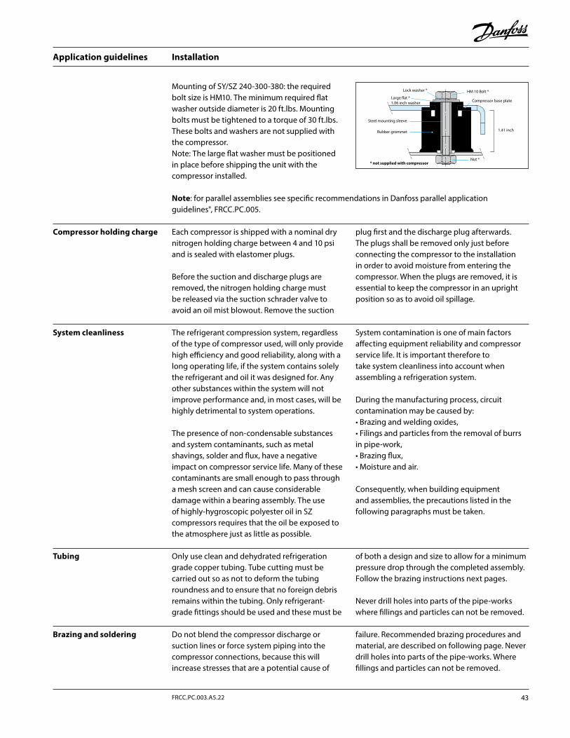
Installation
Compressor holding charge Each compressor is shipped with a nominal dry nitrogen holding charge between 4 and 10 psi and is sealed with elastomer plugs.
Before the suction and discharge plugs are removed, the nitrogen holding charge must be released via the suction schrader valve to avoid an oil mist blowout. Remove the suction
plug first and the discharge plug afterwards. The plugs shall be removed only just before connecting the compressor to the installation in order to avoid moisture from entering the compressor. When the plugs are removed, it is essential to keep the compressor in an upright position so as to avoid oil spillage.
System cleanliness The refrigerant compression system, regardless of the type of compressor used, will only provide high efficiency and good reliability, along with a long operating life, if the system contains solely the refrigerant and oil it was designed for. Any other substances within the system will not improve performance and, in most cases, will be highly detrimental to system operations.
The presence of non-condensable substances and system contaminants, such as metal shavings, solder and flux, have a negative impact on compressor service life. Many of these contaminants are small enough to pass through a mesh screen and can cause considerable damage within a bearing assembly. The use of highly-hygroscopic polyester oil in SZ compressors requires that the oil be exposed to the atmosphere just as little as possible.
System contamination is one of main factors affecting equipment reliability and compressor service life. It is important therefore to take system cleanliness into account when assembling a refrigeration system.
During the manufacturing process, circuit contamination may be caused by:• Brazing and welding oxides,• Filings and particles from the removal of burrs in pipe-work,• Brazing flux,• Moisture and air.
Consequently, when building equipment and assemblies, the precautions listed in the following paragraphs must be taken.
Tubing Only use clean and dehydrated refrigeration grade copper tubing. Tube cutting must be carried out so as not to deform the tubing roundness and to ensure that no foreign debris remains within the tubing. Only refrigerant-grade fittings should be used and these must be
of both a design and size to allow for a minimum pressure drop through the completed assembly. Follow the brazing instructions next pages.
Never drill holes into parts of the pipe-works where fillings and particles can not be removed.
Mounting of SY/SZ 240-300-380: the required bolt size is HM10. The minimum required flat washer outside diameter is 20 ft.lbs. Mounting bolts must be tightened to a torque of 30 ft.lbs. These bolts and washers are not supplied with the compressor.Note: The large flat washer must be positioned in place before shipping the unit with the compressor installed.
Note: for parallel assemblies see specific recommendations in Danfoss parallel application guidelines", FRCC.PC.005.
Do not blend the compressor discharge or suction lines or force system piping into the compressor connections, because this will increase stresses that are a potential cause of
failure. Recommended brazing procedures and material, are described on following page. Never drill holes into parts of the pipe-works. Where fillings and particles can not be removed.
Brazing and soldering
Lock washer * HM 10 Bolt *
Large flat *1.06 inch washer
Steel mounting sleeve
Rubber grommet
Nut *
1.41 inch
Compressor base plate
* not supplied with compressor
43FRCC.PC.003.A5.22
Application guidelines
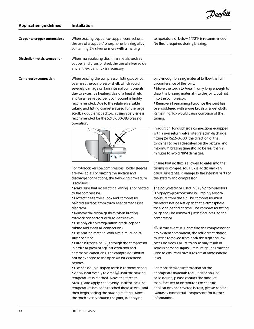
Installation
Copper to copper connections When brazing copper-to-copper connections, the use of a copper / phosphorus brazing alloy containing 5% silver or more with a melting
temperature of below 1472°F is recommended. No flux is required during brazing.
Compressor connection
Dissimilar metals connection When manipulating dissimilar metals such as copper and brass or steel, the use of silver solder and anti-oxidant flux is necessary.
When brazing the compressor fittings, do not overheat the compressor shell, which could severely damage certain internal components due to excessive heating. Use of a heat shield and/or a heat-absorbent compound is highly recommended. Due to the relatively sizable tubing and fitting diameters used for the large scroll, a double tipped torch using acetylene is recommended for the S240-300-380 brazing operation.
For rotolock version compressors, solder sleeves are available. For brazing the suction and discharge connections, the following procedure is advised:• Make sure that no electrical wiring is connected to the compressor.• Protect the terminal box and compressor painted surfaces from torch heat damage (see diagram).• Remove the teflon gaskets when brazing rotolock connectors with solder sleeves.• Use only clean refrigeration-grade copper tubing and clean all connections.• Use brazing material with a minimum of 5% silver content.• Purge nitrogen or CO2 through the compressor in order to prevent against oxidation and flammable conditions. The compressor should not be exposed to the open air for extended periods.• Use of a double-tipped torch is recommended.• Apply heat evenly to Area A until the brazing temperature is reached. Move the torch to Area B and apply heat evenly until the brazing temperature has been reached there as well, and then begin adding the brazing material. Move the torch evenly around the joint, in applying
only enough brazing material to flow the full circumference of the joint.• Move the torch to Area C only long enough to draw the brazing material into the joint, but not into the compressor.• Remove all remaining flux once the joint has been soldered with a wire brush or a wet cloth. Remaining flux would cause corrosion of the tubing.
In addition, for discharge connections equipped with a non return valve integrated in discharge fitting (SY/SZ240-300) the direction of the torch has to be as described on the picture, and maximum brazing time should be less than 2 minutes to avoid NRVI damages.
Ensure that no flux is allowed to enter into the tubing or compressor. Flux is acidic and can cause substantial d amage to the internal parts of the system and compressor.
The polyolester oil used in SY / SZ compressors is highly hygroscopic and will rapidly absorb moisture from the air. The compressor must therefore not be left open to the atmosphere for a long period of time. The compressor fitting plugs shall be removed just before brazing the compressor.
Before eventual unbrazing the compressor or any system component, the refrigerant charge must be removed from both the high and low pressure sides. Failure to do so may result in serious personal injury. Pressure gauges must be used to ensure all pressures are at atmospheric level.
For more detailed information on the appropriate materials required for brazing or soldering, please contact the product manufacturer or distributor. For specific applications not covered herein, please contact Danfoss Commercial Compressors for further information.
heat shield
C B A
Application guidelines
44 FRCC.PC.003.A5.22
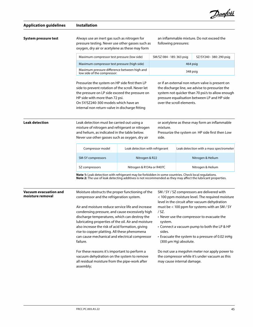
Installation
System pressure test
Pressurize the system on HP side first then LP side to prevent rotation of the scroll. Never let the pressure on LP side exceed the pressure on HP side with more than 72 psi. On SY/SZ240-300 models which have an internal non return-valve in discharge fitting
or if an external non return valve is present on the discharge line, we advise to pressurize the system not quicker than 70 psi/s to allow enough pressure equalisation between LP and HP side over the scroll elements.
Always use an inert gas such as nitrogen for pressure testing. Never use other gasses such as oxygen, dry air or acetylene as these may form
an inflammable mixture. Do not exceed the following pressures:
Moisture obstructs the proper functioning of the compressor and the refrigeration system.
Air and moisture reduce service life and increase condensing pressure, and cause excessively high discharge temperatures, which can destroy the lubricating properties of the oil. Air and moisture also increase the risk of acid formation, giving rise to copper platting. All these phenomena can cause mechanical and electrical compressor failure.
For these reasons it’s important to perform a vacuum dehydration on the system to remove all residual moisture from the pipe-work after assembly;
SM / SY / SZ compressors are delivered with < 100 ppm moisture level. The required moisture level in the circuit after vacuum dehydration must be < 100 ppm for systems with an SM / SY / SZ.• Never use the compressor to evacuate the
system.• Connect a vacuum pump to both the LP & HP
sides.• Evacuate the system to a pressure of 0.02 inHg
(300 μm Hg) absolute.
Do not use a megohm meter nor apply power to the compressor while it’s under vacuum as this may cause internal damage.
Vacuum evacuation and moisture removal
Leak detection must be carried out using a mixture of nitrogen and refrigerant or nitrogen and helium, as indicated in the table below. Never use other gasses such as oxygen, dry air
or acetylene as these may form an inflammable mixture.Pressurize the system on HP side first then Low side.
Leak detection
Maximum compressor test pressure (low side) SM/SZ 084 - 185: 363 psig SZ/SY240 - 380: 290 psig
Maximum compressor test pressure (high side) 464 psig
Maximum pressure difference between high and low side of the compressor: 348 psig
Compressor model Leak detection with refrigerant Leak detection with a mass spectrometer
SM-SY compressors Nitrogen & R22 Nitrogen & Helium
SZ compressors Nitrogen & R134a or R407C Nitrogen & Helium
Note 1: Leak detection with refrigerant may be forbidden in some countries. Check local regulations.Note 2: The use of leak detecting additives is not recommended as they may affect the lubricant properties.
45FRCC.PC.003.A5.22
Application guidelines
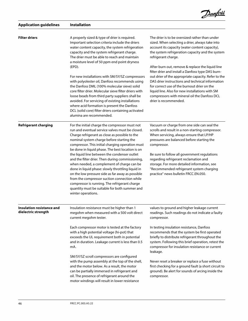
Installation
Filter driers A properly sized & type of drier is required. Important selection criteria include the driers water content capacity, the system refrigeration capacity and the system refrigerant charge. The drier must be able to reach and maintain a moisture level of 50 ppm end point dryness (EPD).
For new installations with SM/SY/SZ compressors with polyolester oil, Danfoss recommends using the Danfoss DML (100% molecular sieve) solid core filter drier. Molecular sieve filter driers with loose beads from third party suppliers shall be avoided. For servicing of existing installations where acid formation is present the Danfoss DCL (solid core) filter driers containing activated alumina are recommended.
The drier is to be oversized rather than under sized. When selecting a drier, always take into account its capacity (water content capacity), the system refrigeration capacity and the system refrigerant charge.
After burn out, remove & replace the liquid line filter drier and install a Danfoss type DAS burn-out drier of the appropriate capacity. Refer to the DAS drier instructions and technical information for correct use of the burnout drier on the liquid line. Also for new installations with SM compressors with mineral oil the Danfoss DCL drier is recommended.
For the initial charge the compressor must not run and eventual service valves must be closed. Charge refrigerant as close as possible to the nominal system charge before starting the compressor. This initial charging operation must be done in liquid phase. The best location is on the liquid line between the condenser outlet and the filter drier. Then during commissioning, when needed, a complement of charge can be done in liquid phase: slowly throttling liquid in on the low pressure side as far away as possible from the compressor suction connection while compressor is running. The refrigerant charge quantity must be suitable for both summer and winter operations.
Vacuum or charge from one side can seal the scrolls and result in a non-starting compressor. When servicing, always ensure that LP/HP pressures are balanced before starting the compressor.
Be sure to follow all government regulations regarding refrigerant reclamation and storage. For more detailed information, see "Recommended refrigerant system charging practice" news bulletin FRCC.EN.050.
Refrigerant charging
Insulation resistance and dielectric strength
Insulation resistance must be higher than 1 megohm when measured with a 500 volt direct current megohm tester.
Each compressor motor is tested at the factory with a high potential voltage (hi-pot) that exceeds the UL requirement both in potential and in duration. Leakage current is less than 0.5 mA.
SM/SY/SZ scroll compressors are configured with the pump assembly at the top of the shell, and the motor below. As a result, the motor can be partially immersed in refrigerant and oil. The presence of refrigerant around the motor windings will result in lower resistance
values to ground and higher leakage current readings. Such readings do not indicate a faulty compressor.
In testing insulation resistance, Danfoss recommends that the system be first operated briefly to distribute refrigerant throughout the system. Following this brief operation, retest the compressor for insulation resistance or current leakage.
Never reset a breaker or replace a fuse without first checking for a ground fault (a short circuit to ground). Be alert for sounds of arcing inside the compressor.
Application guidelines
46 FRCC.PC.003.A5.22
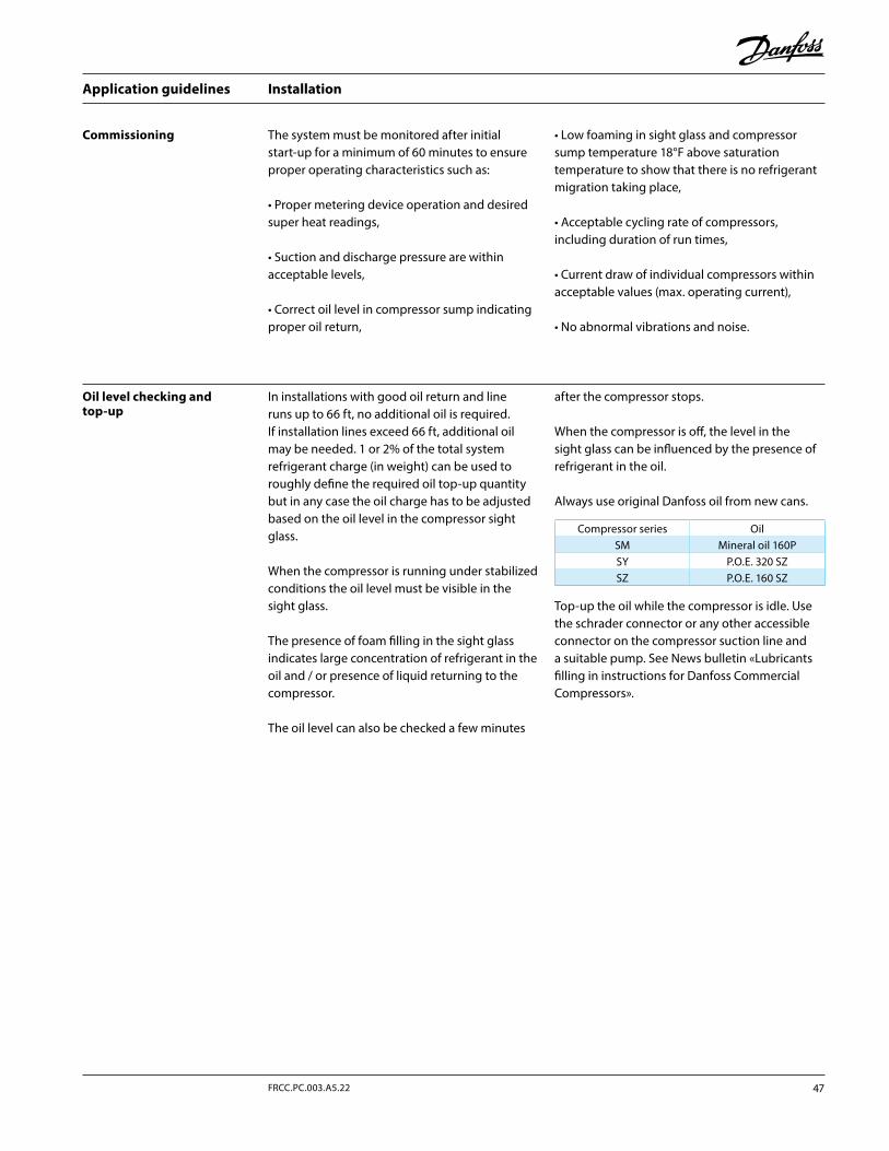
Installation
The system must be monitored after initial start-up for a minimum of 60 minutes to ensure proper operating characteristics such as:
• Proper metering device operation and desired super heat readings,
• Suction and discharge pressure are within acceptable levels,
• Correct oil level in compressor sump indicating proper oil return,
• Low foaming in sight glass and compressor sump temperature 18°F above saturation temperature to show that there is no refrigerant migration taking place,
• Acceptable cycling rate of compressors, including duration of run times,
• Current draw of individual compressors within acceptable values (max. operating current),
• No abnormal vibrations and noise.
Commissioning
Oil level checking and top-up
In installations with good oil return and line runs up to 66 ft, no additional oil is required. If installation lines exceed 66 ft, additional oil may be needed. 1 or 2% of the total system refrigerant charge (in weight) can be used to roughly define the required oil top-up quantity but in any case the oil charge has to be adjusted based on the oil level in the compressor sight glass.
When the compressor is running under stabilized conditions the oil level must be visible in the sight glass.
The presence of foam filling in the sight glass indicates large concentration of refrigerant in the oil and / or presence of liquid returning to the compressor.
The oil level can also be checked a few minutes
after the compressor stops.
When the compressor is off, the level in the sight glass can be influenced by the presence of refrigerant in the oil.
Always use original Danfoss oil from new cans.
Compressor series OilSM Mineral oil 160PSY P.O.E. 320 SZSZ P.O.E. 160 SZ
Top-up the oil while the compressor is idle. Use the schrader connector or any other accessible connector on the compressor suction line and a suitable pump. See News bulletin «Lubricants filling in instructions for Danfoss Commercial Compressors».
47FRCC.PC.003.A5.22
Application guidelines
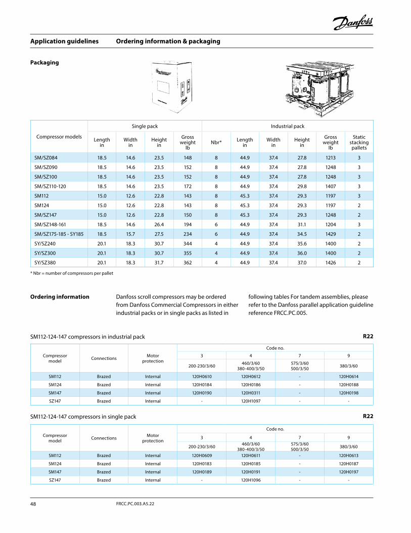
Ordering information & packaging
Packaging
Danfoss scroll compressors may be ordered from Danfoss Commercial Compressors in either industrial packs or in single packs as listed in
following tables For tandem assemblies, please refer to the Danfoss parallel application guideline reference FRCC.PC.005.
Ordering information
R22
R22SM112-124-147 compressors in industrial pack
SM112-124-147 compressors in single pack
Compressor models
Single pack Industrial pack
Lengthin
Widthin
Heightin
Gross weight
lbNbr* Length
inWidth
inHeight
inGross
weight lb
Static stacking pallets
SM/SZ084 18.5 14.6 23.5 148 8 44.9 37.4 27.8 1213 3
SM/SZ090 18.5 14.6 23.5 152 8 44.9 37.4 27.8 1248 3
SM/SZ100 18.5 14.6 23.5 152 8 44.9 37.4 27.8 1248 3
SM/SZ110-120 18.5 14.6 23.5 172 8 44.9 37.4 29.8 1407 3
SM112 15.0 12.6 22.8 143 8 45.3 37.4 29.3 1197 3
SM124 15.0 12.6 22.8 143 8 45.3 37.4 29.3 1197 2
SM/SZ147 15.0 12.6 22.8 150 8 45.3 37.4 29.3 1248 2
SM/SZ148-161 18.5 14.6 26.4 194 6 44.9 37.4 31.1 1204 3
SM/SZ175-185 - SY185 18.5 15.7 27.5 234 6 44.9 37.4 34.5 1429 2
SY/SZ240 20.1 18.3 30.7 344 4 44.9 37.4 35.6 1400 2
SY/SZ300 20.1 18.3 30.7 355 4 44.9 37.4 36.0 1400 2
SY/SZ380 20.1 18.3 31.7 362 4 44.9 37.4 37.0 1426 2
* Nbr = number of compressors per pallet
Compressor model Connections Motor
protection
Code no.
3 4 7 9
200-230/3/60 460/3/60380-400/3/50
575/3/60500/3/50 380/3/60
SM112 Brazed Internal 120H0610 120H0612 - 120H0614
SM124 Brazed Internal 120H0184 120H0186 - 120H0188
SM147 Brazed Internal 120H0190 120H0311 - 120H0198
SZ147 Brazed Internal - 120H1097 - -
Compressor model Connections Motor
protection
Code no.
3 4 7 9
200-230/3/60 460/3/60380-400/3/50
575/3/60500/3/50 380/3/60
SM112 Brazed Internal 120H0609 120H0611 - 120H0613
SM124 Brazed Internal 120H0183 120H0185 - 120H0187
SM147 Brazed Internal 120H0189 120H0191 - 120H0197
SZ147 Brazed Internal - 120H1096 - -
Application guidelines
48 FRCC.PC.003.A5.22
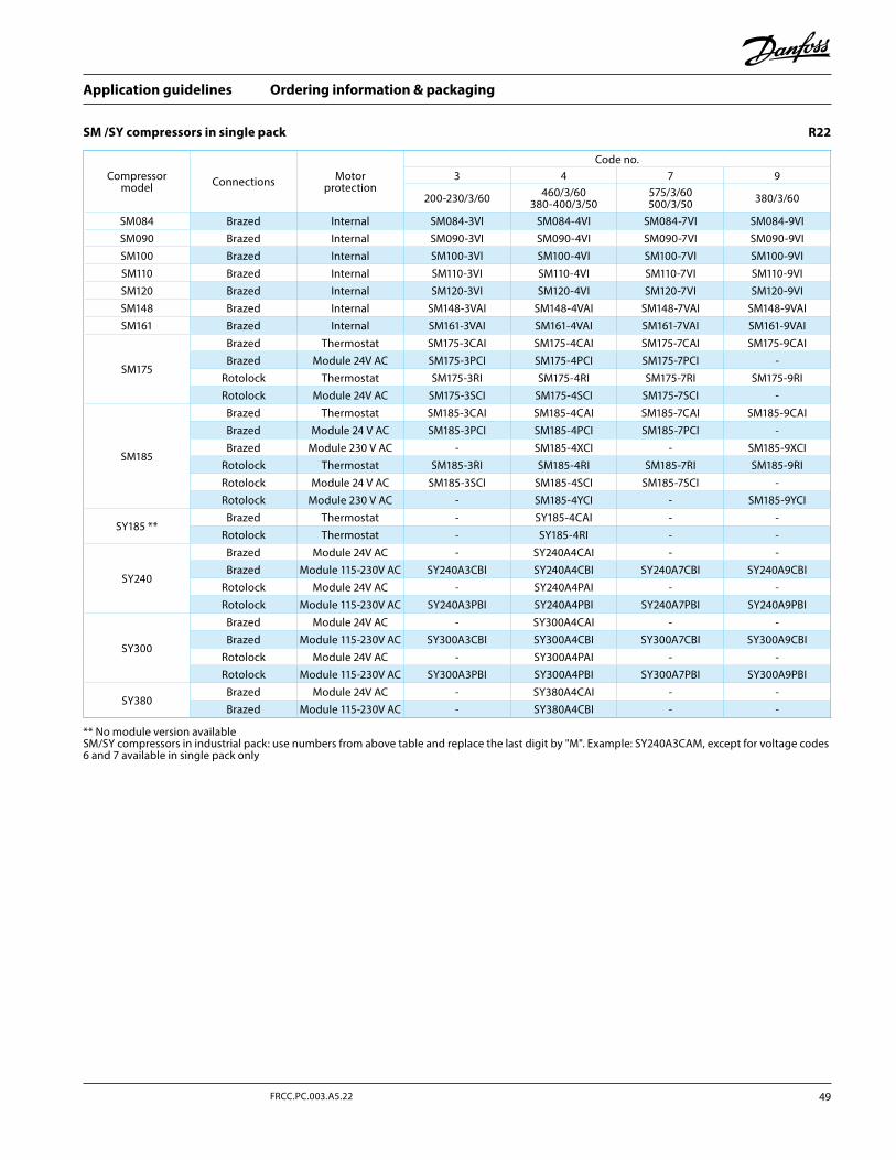
Ordering information & packaging
SM /SY compressors in single pack R22
Compressor model Connections Motor
protection
Code no.3 4 7 9
200-230/3/60 460/3/60380-400/3/50
575/3/60500/3/50 380/3/60
SM084 Brazed Internal SM084-3VI SM084-4VI SM084-7VI SM084-9VISM090 Brazed Internal SM090-3VI SM090-4VI SM090-7VI SM090-9VISM100 Brazed Internal SM100-3VI SM100-4VI SM100-7VI SM100-9VISM110 Brazed Internal SM110-3VI SM110-4VI SM110-7VI SM110-9VISM120 Brazed Internal SM120-3VI SM120-4VI SM120-7VI SM120-9VISM148 Brazed Internal SM148-3VAI SM148-4VAI SM148-7VAI SM148-9VAISM161 Brazed Internal SM161-3VAI SM161-4VAI SM161-7VAI SM161-9VAI
SM175
Brazed Thermostat SM175-3CAI SM175-4CAI SM175-7CAI SM175-9CAIBrazed Module 24V AC SM175-3PCI SM175-4PCI SM175-7PCI -
Rotolock Thermostat SM175-3RI SM175-4RI SM175-7RI SM175-9RIRotolock Module 24V AC SM175-3SCI SM175-4SCI SM175-7SCI -
SM185
Brazed Thermostat SM185-3CAI SM185-4CAI SM185-7CAI SM185-9CAIBrazed Module 24 V AC SM185-3PCI SM185-4PCI SM185-7PCI -Brazed Module 230 V AC - SM185-4XCI - SM185-9XCI
Rotolock Thermostat SM185-3RI SM185-4RI SM185-7RI SM185-9RIRotolock Module 24 V AC SM185-3SCI SM185-4SCI SM185-7SCI -Rotolock Module 230 V AC - SM185-4YCI - SM185-9YCI
SY185 **Brazed Thermostat - SY185-4CAI - -
Rotolock Thermostat - SY185-4RI - -
SY240
Brazed Module 24V AC - SY240A4CAI - -Brazed Module 115-230V AC SY240A3CBI SY240A4CBI SY240A7CBI SY240A9CBI
Rotolock Module 24V AC - SY240A4PAI - -Rotolock Module 115-230V AC SY240A3PBI SY240A4PBI SY240A7PBI SY240A9PBI
SY300
Brazed Module 24V AC - SY300A4CAI - -Brazed Module 115-230V AC SY300A3CBI SY300A4CBI SY300A7CBI SY300A9CBI
Rotolock Module 24V AC - SY300A4PAI - -Rotolock Module 115-230V AC SY300A3PBI SY300A4PBI SY300A7PBI SY300A9PBI
SY380Brazed Module 24V AC - SY380A4CAI - -Brazed Module 115-230V AC - SY380A4CBI - -
** No module version availableSM/SY compressors in industrial pack: use numbers from above table and replace the last digit by "M". Example: SY240A3CAM, except for voltage codes 6 and 7 available in single pack only
49FRCC.PC.003.A5.22
Application guidelines
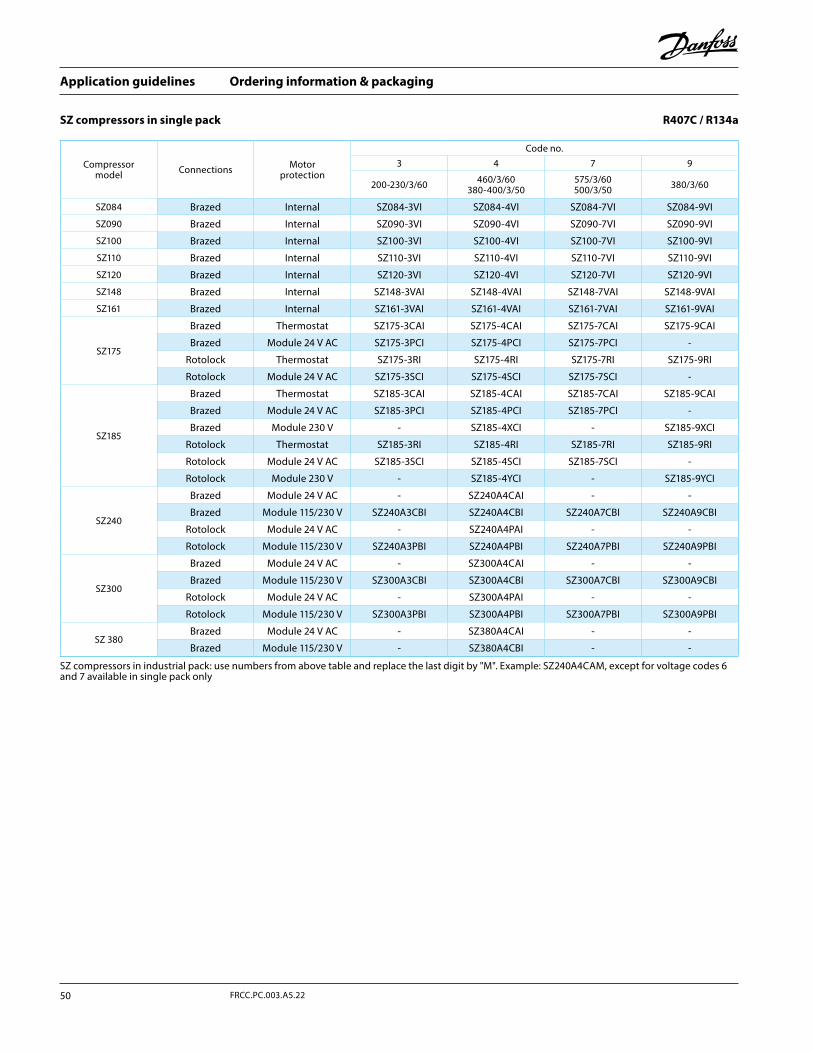
Ordering information & packaging
SZ compressors in single pack R407C / R134a
Compressor model Connections Motor
protection
Code no.
3 4 7 9
200-230/3/60 460/3/60380-400/3/50
575/3/60500/3/50 380/3/60
SZ084 Brazed Internal SZ084-3VI SZ084-4VI SZ084-7VI SZ084-9VI
SZ090 Brazed Internal SZ090-3VI SZ090-4VI SZ090-7VI SZ090-9VI
SZ100 Brazed Internal SZ100-3VI SZ100-4VI SZ100-7VI SZ100-9VI
SZ110 Brazed Internal SZ110-3VI SZ110-4VI SZ110-7VI SZ110-9VI
SZ120 Brazed Internal SZ120-3VI SZ120-4VI SZ120-7VI SZ120-9VI
SZ148 Brazed Internal SZ148-3VAI SZ148-4VAI SZ148-7VAI SZ148-9VAI
SZ161 Brazed Internal SZ161-3VAI SZ161-4VAI SZ161-7VAI SZ161-9VAI
SZ175
Brazed Thermostat SZ175-3CAI SZ175-4CAI SZ175-7CAI SZ175-9CAI
Brazed Module 24 V AC SZ175-3PCI SZ175-4PCI SZ175-7PCI -
Rotolock Thermostat SZ175-3RI SZ175-4RI SZ175-7RI SZ175-9RI
Rotolock Module 24 V AC SZ175-3SCI SZ175-4SCI SZ175-7SCI -
SZ185
Brazed Thermostat SZ185-3CAI SZ185-4CAI SZ185-7CAI SZ185-9CAI
Brazed Module 24 V AC SZ185-3PCI SZ185-4PCI SZ185-7PCI -
Brazed Module 230 V - SZ185-4XCI - SZ185-9XCI
Rotolock Thermostat SZ185-3RI SZ185-4RI SZ185-7RI SZ185-9RI
Rotolock Module 24 V AC SZ185-3SCI SZ185-4SCI SZ185-7SCI -
Rotolock Module 230 V - SZ185-4YCI - SZ185-9YCI
SZ240
Brazed Module 24 V AC - SZ240A4CAI - -
Brazed Module 115/230 V SZ240A3CBI SZ240A4CBI SZ240A7CBI SZ240A9CBI
Rotolock Module 24 V AC - SZ240A4PAI - -
Rotolock Module 115/230 V SZ240A3PBI SZ240A4PBI SZ240A7PBI SZ240A9PBI
SZ300
Brazed Module 24 V AC - SZ300A4CAI - -
Brazed Module 115/230 V SZ300A3CBI SZ300A4CBI SZ300A7CBI SZ300A9CBI
Rotolock Module 24 V AC - SZ300A4PAI - -
Rotolock Module 115/230 V SZ300A3PBI SZ300A4PBI SZ300A7PBI SZ300A9PBI
SZ 380Brazed Module 24 V AC - SZ380A4CAI - -
Brazed Module 115/230 V - SZ380A4CBI - -
SZ compressors in industrial pack: use numbers from above table and replace the last digit by "M". Example: SZ240A4CAM, except for voltage codes 6 and 7 available in single pack only
Application guidelines
50 FRCC.PC.003.A5.22
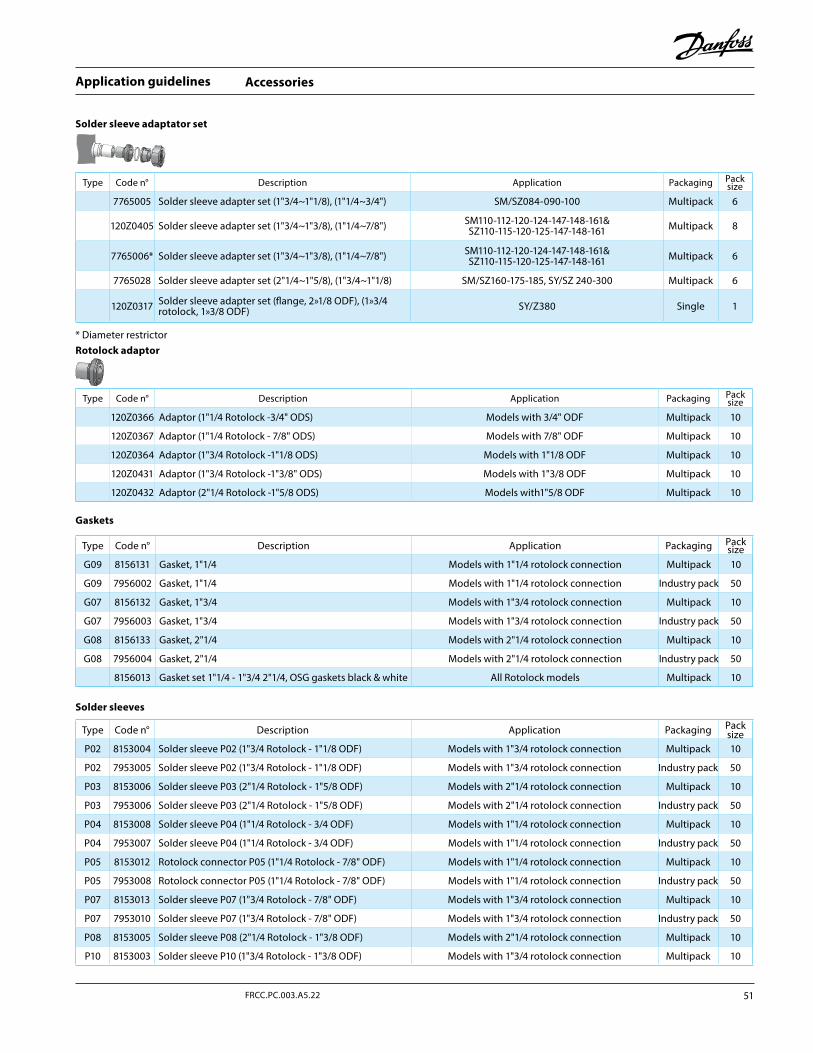
Accessories
Rotolock adaptor
Gaskets
Solder sleeve adaptator set
Solder sleeves
Type Code n° Description Application Packaging Pack size
7765005 Solder sleeve adapter set (1"3/4~1"1/8), (1"1/4~3/4") SM/SZ084-090-100 Multipack 6
120Z0405 Solder sleeve adapter set (1"3/4~1"3/8), (1"1/4~7/8") SM110-112-120-124-147-148-161&SZ110-115-120-125-147-148-161 Multipack 8
7765006* Solder sleeve adapter set (1"3/4~1"3/8), (1"1/4~7/8") SM110-112-120-124-147-148-161&SZ110-115-120-125-147-148-161 Multipack 6
7765028 Solder sleeve adapter set (2"1/4~1"5/8), (1"3/4~1"1/8) SM/SZ160-175-185, SY/SZ 240-300 Multipack 6
120Z0317 Solder sleeve adapter set (flange, 2»1/8 ODF), (1»3/4 rotolock, 1»3/8 ODF) SY/Z380 Single 1
* Diameter restrictor
Type Code n° Description Application Packaging Pack size
120Z0366 Adaptor (1"1/4 Rotolock -3/4" ODS) Models with 3/4" ODF Multipack 10
120Z0367 Adaptor (1"1/4 Rotolock - 7/8" ODS) Models with 7/8" ODF Multipack 10
120Z0364 Adaptor (1"3/4 Rotolock -1"1/8 ODS) Models with 1"1/8 ODF Multipack 10
120Z0431 Adaptor (1"3/4 Rotolock -1"3/8" ODS) Models with 1"3/8 ODF Multipack 10
120Z0432 Adaptor (2"1/4 Rotolock -1"5/8 ODS) Models with1"5/8 ODF Multipack 10
Type Code n° Description Application Packaging Pack size
G09 8156131 Gasket, 1"1/4 Models with 1"1/4 rotolock connection Multipack 10
G09 7956002 Gasket, 1"1/4 Models with 1"1/4 rotolock connection Industry pack 50
G07 8156132 Gasket, 1"3/4 Models with 1"3/4 rotolock connection Multipack 10
G07 7956003 Gasket, 1"3/4 Models with 1"3/4 rotolock connection Industry pack 50
G08 8156133 Gasket, 2"1/4 Models with 2"1/4 rotolock connection Multipack 10
G08 7956004 Gasket, 2"1/4 Models with 2"1/4 rotolock connection Industry pack 50
8156013 Gasket set 1"1/4 - 1"3/4 2"1/4, OSG gaskets black & white All Rotolock models Multipack 10
Type Code n° Description Application Packaging Pack size
P02 8153004 Solder sleeve P02 (1"3/4 Rotolock - 1"1/8 ODF) Models with 1"3/4 rotolock connection Multipack 10
P02 7953005 Solder sleeve P02 (1"3/4 Rotolock - 1"1/8 ODF) Models with 1"3/4 rotolock connection Industry pack 50
P03 8153006 Solder sleeve P03 (2"1/4 Rotolock - 1"5/8 ODF) Models with 2"1/4 rotolock connection Multipack 10
P03 7953006 Solder sleeve P03 (2"1/4 Rotolock - 1"5/8 ODF) Models with 2"1/4 rotolock connection Industry pack 50
P04 8153008 Solder sleeve P04 (1"1/4 Rotolock - 3/4 ODF) Models with 1"1/4 rotolock connection Multipack 10
P04 7953007 Solder sleeve P04 (1"1/4 Rotolock - 3/4 ODF) Models with 1"1/4 rotolock connection Industry pack 50
P05 8153012 Rotolock connector P05 (1"1/4 Rotolock - 7/8" ODF) Models with 1"1/4 rotolock connection Multipack 10
P05 7953008 Rotolock connector P05 (1"1/4 Rotolock - 7/8" ODF) Models with 1"1/4 rotolock connection Industry pack 50
P07 8153013 Solder sleeve P07 (1"3/4 Rotolock - 7/8" ODF) Models with 1"3/4 rotolock connection Multipack 10
P07 7953010 Solder sleeve P07 (1"3/4 Rotolock - 7/8" ODF) Models with 1"3/4 rotolock connection Industry pack 50
P08 8153005 Solder sleeve P08 (2"1/4 Rotolock - 1"3/8 ODF) Models with 2"1/4 rotolock connection Multipack 10
P10 8153003 Solder sleeve P10 (1"3/4 Rotolock - 1"3/8 ODF) Models with 1"3/4 rotolock connection Multipack 10
51FRCC.PC.003.A5.22
Application guidelines
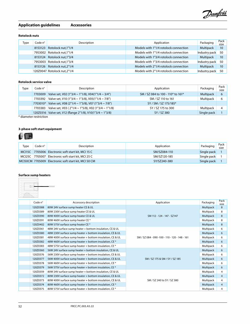
Accessories
Rotolock nuts
Rotolock service valve
3-phase soft start equipment
Surface sump heaters
Type Code n° Description Application Packaging Pack size
8153123 Rotolock nut,1"1/4 Models with 1"1/4 rotolock connection Multipack 107953002 Rotolock nut,1"1/4 Models with 1"1/4 rotolock connection Industry pack 508153124 Rotolock nut,1"3/4 Models with 1"3/4 rotolock connection Multipack 107953003 Rotolock nut,1"3/4 Models with 1"3/4 rotolock connection Industry pack 508153126 Rotolock nut,2"1/4 Models with 2"1/4 rotolock connection Multipack 10
120Z0047 Rotolock nut,2"1/4 Models with 2"1/4 rotolock connection Industry pack 50
Type Code n° Description Application Packaging Pack size
MCI15C 7705006 Electronic soft start kit, MCI 15 C SM/SZ084-110 Single pack 1MCI25C 7705007 Electronic soft start kit, MCI 25 C SM/SZ120-185 Single pack 1
MCI50CM 7705009 Electronic soft start kit, MCI 50 CM SY/SZ240-380 Single pack 1
Code n° Accessory description Application Packaging Pack size
120Z0388 80W 24V surface sump heater CE & UL
SM 112 - 124 - 147 - SZ147
Multipack 8120Z0389 80W 230V surface sump heater CE & UL Multipack 8120Z0390 80W 400V surface sump heater CE & UL Multipack 8120Z0391 80W 460V surface sump heater CE * Multipack 8120Z0402 80W 575V surface sump heater CE * Multipack 8120Z0361 48W 24V surface sump heater + bottom insulation, CE & UL
SM / SZ 084 - 090 -100 - 110 - 120 - 148 - 161
Multipack 6120Z0380 48W 230V surface sump heater + bottom insulation, CE & UL Multipack 6120Z0381 48W 400V surface sump heater + bottom insulation, CE & UL Multipack 6120Z0382 48W 460V surface sump heater + bottom insulation, CE * Multipack 6120Z0383 48W 575V surface sump heater + bottom insulation, CE * Multipack 6120Z0360 56W 24V surface sump heater + bottom insulation, CE & UL
SM / SZ 175 & SM / SY / SZ 185
Multipack 6120Z0376 56W 230V surface sump heater + bottom insulation, CE & UL Multipack 6120Z0377 56W 400V surface sump heater + bottom insulation, CE & UL Multipack 6120Z0378 56W 460V surface sump heater + bottom insulation, CE * Multipack 6120Z0379 56W 575V surface sump heater + bottom insulation, CE * Multipack 6120Z0359 80W 24V surface sump heater + bottom insulation, CE & UL
SM / SZ 240 to SY / SZ 380
Multipack 4120Z0372 80W 230V surface sump heater + bottom insulation, CE & UL Multipack 4120Z0373 80W 400V surface sump heater + bottom insulation, CE & UL Multipack 4120Z0374 80W 460V surface sump heater + bottom insulation, CE * Multipack 4120Z0375 80W 575V surface sump heater + bottom insulation, CE * Multipack 4
Type Code n° Description Application Packaging Pack size
7703009 Valve set, V02 (1"3/4 ~ 1"1/8), V04(1"1/4 ~ 3/4") SM / SZ 084 to 100 - 110* to 161* Multipack 67703392 Valve set, V10 (1"3/4 ~ 1"3/8), V05(1"1/4 ~ 7/8") SM / SZ 110 to 161 Multipack 67703010* Valve set, V08 (2"1/4 ~ 1"3/8), V07 (1"3/4 ~ 7/8") SY / SM / SZ 175/185*7703383 Valve set, V03 ( 2"1/4 ~ 1"5/8), V02 (1"3/4 ~ 1"1/8) SY / SZ 175 to 300 Multipack 4120Z0316 Valve set, V12 (flange 2"1/8), V10(1"3/4 ~ 1"3/8) SY / SZ 380 Single pack 1
* diameter restriction
Application guidelines
52 FRCC.PC.003.A5.22
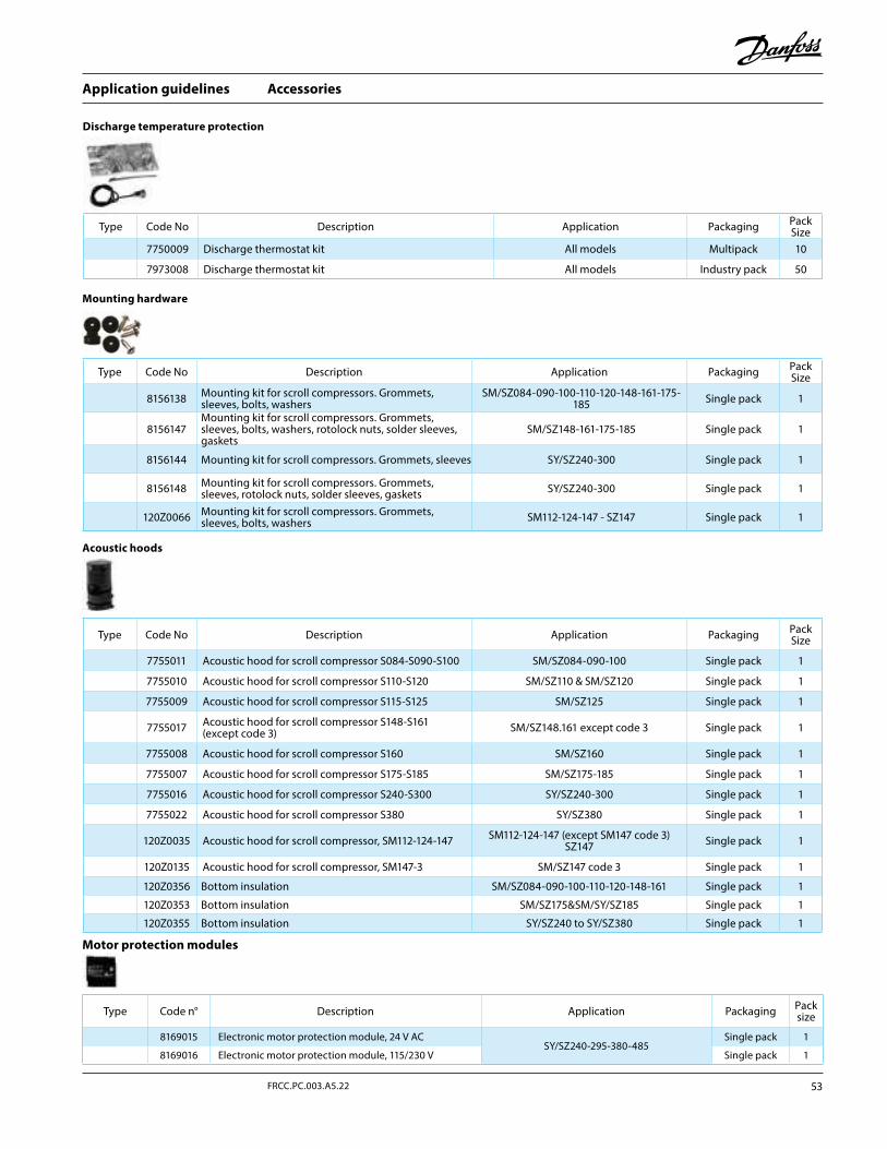
Accessories
Acoustic hoods
Mounting hardware
Discharge temperature protection
Motor protection modules
Type Code n° Description Application Packaging Pack size
8169015 Electronic motor protection module, 24 V ACSY/SZ240-295-380-485
Single pack 1
8169016 Electronic motor protection module, 115/230 V Single pack 1
Type Code No Description Application Packaging Pack Size
7755011 Acoustic hood for scroll compressor S084-S090-S100 SM/SZ084-090-100 Single pack 1
7755010 Acoustic hood for scroll compressor S110-S120 SM/SZ110 & SM/SZ120 Single pack 1
7755009 Acoustic hood for scroll compressor S115-S125 SM/SZ125 Single pack 1
7755017 Acoustic hood for scroll compressor S148-S161 (except code 3) SM/SZ148.161 except code 3 Single pack 1
7755008 Acoustic hood for scroll compressor S160 SM/SZ160 Single pack 1
7755007 Acoustic hood for scroll compressor S175-S185 SM/SZ175-185 Single pack 1
7755016 Acoustic hood for scroll compressor S240-S300 SY/SZ240-300 Single pack 1
7755022 Acoustic hood for scroll compressor S380 SY/SZ380 Single pack 1
120Z0035 Acoustic hood for scroll compressor, SM112-124-147 SM112-124-147 (except SM147 code 3)SZ147 Single pack 1
120Z0135 Acoustic hood for scroll compressor, SM147-3 SM/SZ147 code 3 Single pack 1
120Z0356 Bottom insulation SM/SZ084-090-100-110-120-148-161 Single pack 1
120Z0353 Bottom insulation SM/SZ175&SM/SY/SZ185 Single pack 1
120Z0355 Bottom insulation SY/SZ240 to SY/SZ380 Single pack 1
Type Code No Description Application Packaging Pack Size
8156138 Mounting kit for scroll compressors. Grommets, sleeves, bolts, washers
SM/SZ084-090-100-110-120-148-161-175-185 Single pack 1
8156147Mounting kit for scroll compressors. Grommets, sleeves, bolts, washers, rotolock nuts, solder sleeves, gaskets
SM/SZ148-161-175-185 Single pack 1
8156144 Mounting kit for scroll compressors. Grommets, sleeves SY/SZ240-300 Single pack 1
8156148 Mounting kit for scroll compressors. Grommets, sleeves, rotolock nuts, solder sleeves, gaskets SY/SZ240-300 Single pack 1
120Z0066 Mounting kit for scroll compressors. Grommets, sleeves, bolts, washers SM112-124-147 - SZ147 Single pack 1
Type Code No Description Application Packaging Pack Size
7750009 Discharge thermostat kit All models Multipack 10
7973008 Discharge thermostat kit All models Industry pack 50
53FRCC.PC.003.A5.22
Application guidelines
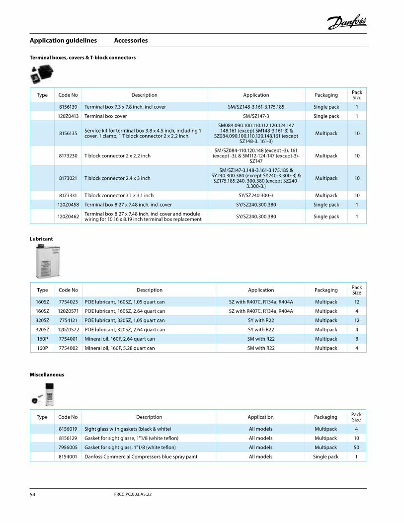
Accessories
Lubricant
Terminal boxes, covers & T-block connectors
Miscellaneous
Type Code No Description Application Packaging Pack Size
160SZ 7754023 POE lubricant, 160SZ, 1.05 quart can SZ with R407C, R134a, R404A Multipack 12
160SZ 120Z0571 POE lubricant, 160SZ, 2.64 quart can SZ with R407C, R134a, R404A Multipack 4
320SZ 7754121 POE lubricant, 320SZ, 1.05 quart can SY with R22 Multipack 12
320SZ 120Z0572 POE lubricant, 320SZ, 2.64 quart can SY with R22 Multipack 4
160P 7754001 Mineral oil, 160P, 2.64 quart can SM with R22 Multipack 8
160P 7754002 Mineral oil, 160P, 5.28 quart can SM with R22 Multipack 4
Type Code No Description Application Packaging Pack Size
8156139 Terminal box 7.3 x 7.8 inch, incl cover SM/SZ148-3.161-3.175.185 Single pack 1
120Z0413 Terminal box cover SM/SZ147-3 Single pack 1
8156135 Service kit for terminal box 3.8 x 4.5 inch, including 1 cover, 1 clamp, 1 T block connector 2 x 2.2 inch
SM084.090.100.110.112.120.124.147.148.161 (except SM148-3.161-3) &
SZ084.090.100.110.120.148.161 (except SZ148-3. 161-3)
Multipack 10
8173230 T block connector 2 x 2.2 inchSM/SZ084-110.120.148 (except -3). 161
(except -3). & SM112-124-147 (except-3)-SZ147
Multipack 10
8173021 T block connector 2.4 x 3 inchSM/SZ147-3.148-3.161-3.175.185 &
SY240.300.380 (except SY240-3.300-3) & SZ175.185.240. 300.380 (except SZ240-
3.300-3.)Multipack 10
8173331 T block connector 3.1 x 3.1 inch SY/SZ240.300-3 Multipack 10
120Z0458 Terminal box 8.27 x 7.48 inch, incl cover SY/SZ240.300.380 Single pack 1
120Z0462 Terminal box 8.27 x 7.48 inch, incl cover and module wiring for 10.16 x 8.19 inch terminal box replacement SY/SZ240.300.380 Single pack 1
Type Code No Description Application Packaging Pack Size
8156019 Sight glass with gaskets (black & white) All models Multipack 4
8156129 Gasket for sight glasse, 1"1/8 (white teflon) All models Multipack 10
7956005 Gasket for sight glass, 1"1/8 (white teflon) All models Multipack 50
8154001 Danfoss Commercial Compressors blue spray paint All models Single pack 1
Application guidelines
54 FRCC.PC.003.A5.22

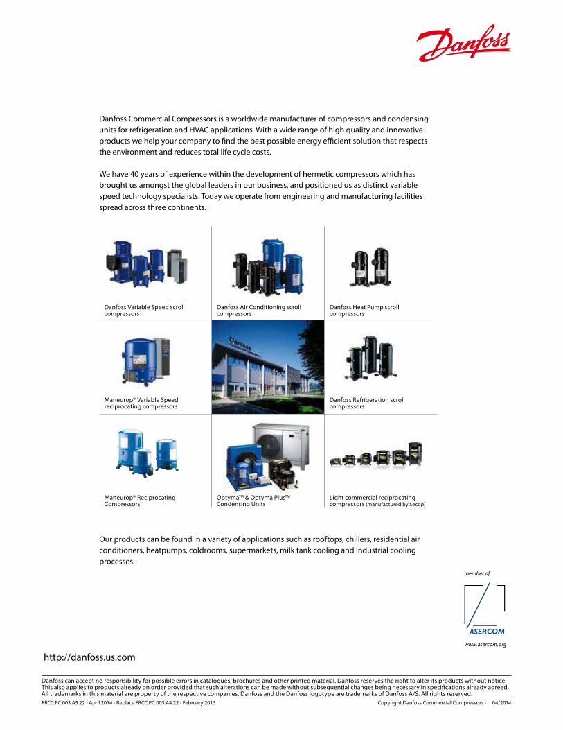
http://danfoss.us.com
Danfoss can accept no responsibility for possible errors in catalogues, brochures and other printed material. Danfoss reserves the right to alter its products without notice. This also applies to products already on order provided that such alterations can be made without subsequential changes being necessary in specifications already agreed.All trademarks in this material are property of the respective companies. Danfoss and the Danfoss logotype are trademarks of Danfoss A/S. All rights reserved.
member of:
www.asercom.org
FRCC.PC.003.A5.22 - April 2014 - Replace FRCC.PC.003.A4.22 - February 2013 Copyright Danfoss Commercial Compressors - 04/2014
Danfoss Commercial Compressors is a worldwide manufacturer of compressors and condensing units for refrigeration and HVAC applications. With a wide range of high quality and innovative products we help your company to find the best possible energy efficient solution that respects the environment and reduces total life cycle costs.
We have 40 years of experience within the development of hermetic compressors which has brought us amongst the global leaders in our business, and positioned us as distinct variable speed technology specialists. Today we operate from engineering and manufacturing facilities spread across three continents.
Our products can be found in a variety of applications such as rooftops, chillers, residential air conditioners, heatpumps, coldrooms, supermarkets, milk tank cooling and industrial cooling processes.
Danfoss Variable Speed scroll compressors
Danfoss Air Conditioning scroll compressors
Maneurop® Variable Speed reciprocating compressors
Light commercial reciprocating compressors (manufactured by Secop)
Danfoss Refrigeration scroll compressors
Maneurop® Reciprocating Compressors
OptymaTM & Optyma PlusTM Condensing Units
Danfoss Heat Pump scroll compressors


